CONFIGURATION GUIDE - bitsavers.org
190
HONEYWELL CONFIDENTIAL AND PROPRIETARY This document and the information contained herein are confidential to and the property of Honeywell Information Systems Inc. and are made available only to Honeywell employees for the sole purpose of con- ducting Honeywell's business. This document, any copy thereof and the information contained herein shall be maintained in strictest confi- dence; shall not be copied in whole orin part except as authorized by the em ployee' s manager; and shall not be disclosed or distributed (a) to persons who are not Honeywell employees, or (b) to Honeywell em ployees for whom such information is not necessary in connec- tion with their assigned responsibilities. Upon request, orwhen the em ployee in possession of this document no longer has need for the document for the authorized Honeywell purpose, this documentand any copies thereof shall be returned t the employe's manager. There shall be no exceptions to the terms and conditions set forth herein except as authorized in writing by the responsible Honeywell Vice President. DPS 8/C CONFIGURATION GUIDE
-
Upload
khangminh22 -
Category
Documents
-
view
2 -
download
0
Transcript of CONFIGURATION GUIDE - bitsavers.org

HONEYWELL CONFIDENTIAL AND PROPRIETARY This document and the information contained herein are confidential to and the property of Honeywell Information Systems Inc. and are made available only to Honeywell employees for the sole purpose of conducting Honeywell's business. This document, any copy thereof and the information contained herein shall be maintained in strictest confidence; shall not be copied in whole orin part except as authorized by the em ployee' s manager; and shall not be disclosed or distributed (a) to persons who are not Honeywell employees, or (b) to Honeywell em ployees for whom such information is not necessary in connec-tion with their assigned responsibilities. Upon request, orwhen the em ployee in possession of this document no longer has need for the document for the authorized Honeywell purpose, this documentand any copies thereof shall be returned t the employe's manager. There shall be no exceptions to the terms and conditions set forth herein except as authorized in writing by the responsible Honeywell Vice President.
DPS 8/C CONFIGURATION GUIDE


CP-6
DPS SIC CONFIGURATION GUIDE
HGNEYWELL CONFIDENTIAL & PROPRIETARY :£: f • •
This document and the information contained herein are confidential to and the property of Honeywell Information Systems Inc. and are made available only to Honeywell employees for the sole purpose of conducting Honeywell's business. This document, any copy thereof and the information contained herein shall be maintained in strictest confidence; shall not be copied in whole or in part except as authorized by the employee's manager; and shall not be disclosed or distributed (a) to persons who are not Honeywell employees, or (b) to Honeywell employees for whom such information is not necessary in connection with their assigned responsibilities. Upon request, or when the employee in possession of this document no longer has need for the document for the authorized Honeywell purpose, this document and any copies thereof shall be returned to the employee's manager. There shall be no exceptions to the terms and conditions set forth herein except as authorized in writing by the responsible Honeywell Vice President.
ORDER NUMBER
DP37-02 May 1983
Honeywell

CP-6 DPS 8/C Configuration Guide
PREFACE
This guide at·tempts to provide nearly complete freestanding information for configuring any portion of a CP-6 DPS 8/C system. Included in this outline are only the DPS 8/C systems announced in March 1981 and updated by subsequent announcements. In addition, this material covers all peripherals which are the most current for DPS 8/C and the Level 66/DPS Band C systems. To configure CP-6 central systems and front end processors for other than DPS 8/C systems use the CP-6 Configuration Guide, Revision 6, February 23, 1981, available from the CP-6 Program Office.
The guide is constructed to be as self-teaching as possible and to provide for configuring both initial system orders and subsequent add-ons.
Material in this outline dealing with DPS 8/C central systems consists mainly of a set of charts and brief summaries which are designed to be largely self-explanatory. By following the appropriate flowcharts and tables you will be able to configure any initial system order or add-on order accurately.
This material is divided into gross functional sections. Be sure to read the Table of Contents in full before using the configuration material. The table will show you the pattern of approach used in configuring.
Section 1 summarizes key general rules and policies which govern configuration of DPS 8/C systems. Before doing any configuring you should always review Section 1.
Section 2 provides master flowcharts which identify the sequence and components to be considered in configuring. Detach the pertinent flowchart(s) and keep it in view while you use it to access other portions of this material in order to configure easily, completely, and accurately. The flowchart has chapter references to other sections for detailed information on configuration of the components at each level of the flowchart.
Section 3 contains overview configurators to give you the perspectives for complete systems.
Section 4 covers the configuring of central systems and memory sizes. Included in this section are all marketing identifiers for all central systems.
The information and specifications in this document are subject to change without notice. This document contains information about Honeywell products or services that may not be available outside the United States. Consult your Honeywell Marketing Representative.
FileNo.:4AW2 DP37·02
HONEYWELL CONFIDENTIAL AND PROPRIETARY

CP-6 DPS 8/C Configuration Guide
Section 5 covers the configuring of the components needed within each IOM. Th~se components relate to physical and logical IOM channels for peripheral subsystems and IOM aggregate load considerations.
Sections 6 through 9 cover the configuring of unit record, magnetic tape, mass store, and console subsystems.
Section 10 introduces you to some generic terms and concepts related to data communications and front end processors (FEPs).
Section 11 covers the configuration of the DN8/C FEP.
Section 12 deals with manually controlled peripheral switches.
Section 13 includes the motor-generator sets and circumstances dealing with their use.
Section 14 covers CP-6 software products.
Site preparation information for DPS 8/C may be found in the Site Preparation Manual for DPS 8/20, 8/44 (Order Number DL64) and in the DPS 8 (Freestanding) Site Preparation Manual for DPS 8/52/62/70 (Order Number DN01). Site preparation information for configurable DPS 6 peripheral equipment may be found in the DPS 6 Systems Site Preparation Manual (Order Number CP77-00).
ill
HONEYWELL CONFIDENTIAL AND PROPRIETARY

CONTENTS
Section 1.
Section 2.
Section 3.
Section 4.
Section 5.
Peripheral and Communications Subsystems per CP-6 System
Lower Speed Subsystems Higher Speed Peripherals
Master Flowcharts for DPS 8/C Configuring DPS 8/47C/49C Systems DPS 8/52C/62C/70C Systems
Configura tor Overview DPS 8/47C/49C/20C/44C DPS 8/52C/62C/70C
Central System Configuring Ordering the Central System (CPS)
DPS 8/47C/49C CPS Identifiers DPS 8/52C/62C/70CCPS Identifiers
Ordering Extra CPUs, SCUs, IOMs for DPS 8/47C/49C Ordering Extra CPUs, SCUs, IOMs for DPS 8/52C/62C/70C DPS 8/C Memory Configura tors Computing Memory Requirements for DPS 8/C Memory Interleaving Aspects Configuration Examples for Initial Orders and
Additions
Configuring Within Any IOM Base IOM and Extra IOMs Physical Channels and Logic Boards Assigning Logical Channels to Physical IOM Channels
Subsystems Allowing Multiple Logical Channels Per Physical Channel
Unit Record Processor Subsystems Magnetic Tape Processor Subsystems Disk Subsystems
Subsystems Allowing Only a Single Logical Channel Per Physical Channel
FEPs Consoles
IOM Aggregate Load Considerations IOM Configuring - An Example
iv
HONEYWELL CONFIDENTIAL AND PROPRIETARY
Page
1-1 1-2
2-1 2-2
3-1 3-3
4-1 4-2 4-3 4-4 4-5 4-6 4-8 4-18 4-19
5-1 5-3 5-5 5-10
5-10 5-10 5-10 5-11
5-11 5-11 5-12 5-13
DP37-02

CONTENTS (Cont.)
Section 6.
Section 7.
Section 8.
Section 9.
Section 10.
Section 11.
Unit Record Subsystems Configuring the DPS 8 Unit Record Processor (URP) Subsystems
Example of DPS 8 URP Configuring Configuring Supported DPS 6 Unit Record Equipment
Example of DPS 6 Unit Record Configuring
Magnetic Tape Subsystems Configuring Magnetic Tape Subsystems
Magnetic Tape Subsystem Configuring Example
Mass Storage Subsystems Configuring Mass Storage Subsystems
Configurator for MSP8000 Subsystems (SingleChannel 1x1b) for DPS 8/47C/49C Only
Configurator for MSP8002 Subsystem (Dual-Channel 2x16) for DPS 8/47C/49C Only
Configurator for MSP0611 Freestanding Subsystem (Single-Channel 1x16) for any DPS 8/C Subsystem
Configurator for MSP0612 Freestanding Subsystem (2x16, 2x30, 2x32) for any DPS 8/C Subsystem
Configuring Example for Mass Storage
Configuring Consoles Configuration Rules for IO~Connected Console Subsystem for DPS 8/C Systems
Console Subsystem (CSU6601) Auxiliary Console Adapter (CSF6602) Console Switch Feature (CSF6606)
Generics of Data Communications - Front End Processors (FEPs)
Configuring DATANET 8/C Front End Processor (FEP) Required Configuration Components Networking Considerations Configuring the DATANET 8/C DN 8/C FEP-Related Marketing Identifiers and Their
Functions Supported Terminals
Async Profiles 3270 Profiles RBT Profiles
v
HONEYWELL CONFIDENTIAL AND PROPRIETARY
Page
6-1
6-8 6-9 6-11
7-1 7-11
8-1 8-7
8-9
8-11
8-13
8-15
9-1
9-1 9-3 9-5
10-1
11-1 11-2 11-3 11-6
11-12 11-12 11-15 11-15
DP37-02

CONTENTS (Cont.)
Section 11. Cont.
Section 12.
Section 13.
Section 14.
Appendix A.
FEP Throughput Calculations and CI Board Packaging Tables
CIBs Physical Board Size Throughput Load Factor
Protocol Type TP Forms Processing Unit Record Devices Remote FEPs
Determination of Remote FEP Link Speed DATANET 8/C Configuration Examples
Example #1 Example #2 Example 13 Example #4
Peripheral Switches Configuring Manual Peripheral Switch Subsystems Examples of U~e of Manual Peripheral Switches
Example 1 Example 2 Example 3
Configuring Motor-Generator and Control Sets
Software
Checklist Configura tor
vi
HONEYWELL CONFIDENTIAL AND PROPRIETARY
Page
11-16
11-16 11-16 11-18 11-18 11-28 11-33 11-34 11-35
11-36 11-38 11-40 11-43
12-1
12-3 12-4 12-5
13-1
14-1
DP37-02

CONTENTS (Cont.)
FIGURES
Figure 4-1. Figure 4-2. Figure 4-3. Figure 4-4.
Figure 5-1. Figure 5-2.
Figure 6-1. Figure 6-2. Figure 6-3. Figure 6-4. Figure 6-5. Figure 6-6.
Figure 7-1. Figure 7-2.
Figure B-1. Figure B-2. Figure B-3. Figure B-4.
Figure 9-1. Figure 9-2.
Figure 10-1.
Figure 11-1 • Figure 11-2. Figure 11-3. Figure 11-4. Figure 11-5. Figure 11-6. Figure 11-7. Figure 11-B. Figure 11-9. Figure 11-10. Figure 11-11. Figure 11-12. Figure 11-13.
Figure 11-14.
Figure 12-1. Figure 12-2. Figure 12-3. Figure 12-4. Figure 12-5.
DPS BIC Central System Components DPS BI20C/44C Memory Configurator DPS B/47C/49C Sample Memory Configurator DPS B/52C/62C/70C Memory Configurator
Physical Channel Configurator Physical Channel and Logical Channel Concepts
Configurator for URP0600lBOOO Configurator for URP in MFPBOO 1 Configurator for URAs and Associated Unit Record Devices Configurators for URPB011/B0121B013 Configurator for PRU0901/1201 Configurator for DPS 6 Unit Record Equipment
Single-Channel MTP Configurator Dual-Channel MTP Configurator
MSPBOOO Block Diagram MSPB002 Block Diagram MSP0611 Block Diagram MSP0612 Block Diagram
CSU6601 Block Diagram CSF6602 Block Diagram
Typical Front End Processor Components
DATANET BIC Block Diagram DATANET BIC Memory Configurability CI Physical Board Sizes ASYNC Input Performance ASYNC Output Performance, Non-Transparent ASYNC Output Performance, Transparent HASP, 27BO, 37BO Input & Output Performance 3270 Input Performance 3270 Output Performance FEP TP Forms Performance, Systems Input FEP TP Forms Performance, Systems Output URP Performance Remote FEP Performance - Input & Output, No Transaction
Processing DATANET BIC Configuration Example 14
PSU0200 Configurator PSU0201 Configurator Switching Between Two Device Processors Switching Between Two Physical IOM PSI Channels Switching Between Two Device Processors and Between
Two IOM Physical Channels
vii
HONEYWELL CONFIDENTIAL AND PROPRIETARY
Page
4-1 4-6 4-6 4-7
5-3 5-9
6-3 6-3 6-11 6-4 6-5 6-10
7-11 7-5
8-7 B-9 B-11 B-13
9-2 9-4
10-1
11-3 11-7 11-16 11-19 11-20 11-21 11-23 11-24 11-25 11-29 11-30 11-33 11-34
11-50
12-2 12-2 12-3 12-4 12-5
DP37-02

CONTENTS (Cont.)
Figure A-1 Figure A-2
Figure A-3 Figure A-4 Figure A-5 Figure A-6 Figure A-7 Figure A-8 Figure A-9 Figure A-10
TABLES
Table 5-1. Table 5-2. Table 5-3.
Table 6-1.
Table 7-1. Table 7-2. Table 7-3.
Table 8-1. Table 8-2. Table 8-3. Table 8-4.
Table 11-1. Table 11-2. Table 11-3.
DPS 8/47C/49C Central Systems and Major Subsystems DPS 8/52C/62C/70C Central Systems and Major
Subsystems IO~Connected Console Communications Subsystem Magnetic Tape Subsystem Mass Storage Subsystem Unit Record Subsystem DPS 6 Peripherals Peripheral Switches Motor Generators/Capacitor Ridethroughs
Configurator for Logical Channel Assignments Estimated Device Bandwidths Solution to 10M Configuration Example
DPS 8 Unit Record Devices
MTU Characteristics ReqUired Number of MTU Addressing Adapters MTU Density Features
MSP8000 Configuration MSP8002 Configuration MSP0611 Configuration MSP0612 Configuration
DATANET 8/C Board Slot Assignments CIB Throughput CapaCity DATANET 8/C Channel Interface Physical Board Sizes
viii
HONEYWELL CONFIDENTIAL AND PROPRIETARY
Page
A-5 A-6
A-7 A-8 A-9 A-10 A-11 A-13 A-14 A-15
5-6 5-12 5-14
6-2
7-2 7-8 7-10
8-8 8-10 8-12 8-14
11-5 11-16 11-17
DP37·02

SECTION 1 Peripheral and Communications Subsystems Per CP-6 System
LOWER SPEED SUBSYSTEMS
Min Max
Card reader or 0 As needed (See Note 2) card reader/punch
Card punch 0 As needed (See Note 2)
Printer 0 As needed (See Note 2)
FEP 1 (See Note 1 ) (See Note 3)
Console (IOM-connected) 4 (See Note 4)
Notes;
1. MaXimum of 12 local FEP's per system. Maximum of 4 remote FEP's per local FEP. Maximum of 16 FEP's per system (including both lo~al and remote FEPs). See Section 11.
2·. Maximum of 2 unit record devices on URP80 12/8013. Maximum of 4 unit record devices on URP8011 and on URP in MFP8001 for DPS 8/47C/49C. Maximum of 8 devices on other URPs. Maximum of 6 unit record devices on each Front End Processor.
3. One Front End Processor (FEP) included with CPS81XX. Every FEP reqUires a minimum of one CIB and one async CI, neither included in base price. One additional CIB and one sync CI (Bell 201C modem or equivalent) per CP-6 system (neither included in bas~ price) is strongly recommended for a sync line to interface to the automated system for software support and distribution of patches.
4. FEP-connected consoles may be added as needed.
1-1 DP37-02
HONEYWELL CONFIDENTIAL AND PROPRIETARY

HIGHER SPEED PERIPHERALS
Min Max
Magnetic tapes 1 (See Note 1) As needed (See Note 2)
Disk storage 157 M Bytes (See Note 3)
As needed (See Note 4)
Notes;
1. One tape unit is normally used for the initial system boot.
2. The maximum isB tape units on single-channel MTP, 16 on dual-channel MTP. "Maximum of B tapes on MFPB001.
3. Needed for CP-6 Operating System, support and temporary files.
4. See permissible maximum combinations per MSP in Section B.
1-2 DP37-02
HONEYWELL CONFIDENTIAL AND PROPRIETARY

SECTION 2 Master Flowcharts for DPS SIC Configuring
DPS 8/47C/49C SYSTEMS
DETERMINE
foIJDfL SIZE
DESIRED
ORDER BASIC
CPS NO.
CENTRAL SYSTEM
~4 <>6 ~R;R EX~ ;u! jORiR ~RP -;0 'l I SCU. 10M ~ OPS8 UR DEVICES
LAS DESIRED I I IF DESIRED I _--_J _-_-.J
ORDER
COHSOLE(S)
11
ORDER CIB(S); CI(S);
EXTRA FEP(S) AS DESlRED
QtJ __ , I ORDER
'fo«lTOR-GENERATOR :
l~T~ ~DE~ J
<> 14 r-- -j I ORDER
I OPTIONAL
L _ S~~R:" J
CONFIGURATOR
ORDER MTP
AND HTUs
CHECK
PERIPHERALS
MIN/MAX TABLES
8
ORDER MSP
AND MSUs
~~--l ~4 __ _
I ORDER DPS 6 I ORDER ott 1 I UR DEVICES ~MEMORY INCREMENTS,'
L IF DESIRED.J L AS NEEDED ---- --r-.J 05 <> 14
CONFIGURE
WITH 10M(S)
RECHECK
FOR
ACCURACY
2-1
<>
ORDER
REQUIRED
SOFTWARE
LEGEND
REQUIRED
OPTIONAl
REFERS TO SECTION CONTAINING DETAILED INFORMATION
HONEYWELL CONFIDENTIAL AND PROPRIETARY
DP37-02

DPS 8/52C/62C/7QC SYSTEMS
ORDER
CONSOLE(S)
DETERMINE
MODEL SIZE
DESIRED
ORDER
BAS I C CENTRAL SYSTEM CPS NO.
3
SEE DPS 8/52C/
62C/70C OVERVIEW
CONF I GURATDR
0'4 IO;E;-EX;; ..,
CPu&, Sr.lIs. rOMs I
CHECk
PERIPHERALS
'UN/MAX TABLES
, AS DESIRED I
_---.-~J-~ i>6J_.., <>7 J ORDER DPS H URP
, AND UR DEVICES
I IF REQUI REO I _-_-.J
11
ORDER ..... -3MCIB(S); Cl (S);
EXTRA FI!P(S) AS DESIRED
ORDER MOTOR GEN.
SET(S)/CAPACITOR
RIDE lliROUGHS
0.,L4 r--1 , . ORDER
I OPTIONAL
l_ SO~n.~E_ J
ORD[R
fITP AND
MTUs
8
ORDER,
H5P AND
MSUs
~~--T ~'---I ORDER DP5 6 UR·. I ORDER C... l I " DEVICES ~HEI10RY ~NCREHENTSI L~~E~~~ L_A~EEDE~..J
5
CONFIGURE
WITHIN
1(14(5 )
RECHECK
FOR
ACCURACY o 2-2
ORDER
REQUIRED
SOfTWARE
LEGEND
REQUIRED OPTIONAL
REFERS TO SECTlIII COIHAIMING DETAILED INfORMATION
HONEYWELL CONFIDENTIAL AND PROPRIETARY
DP37-02

SECTION 3 Configurator Overview
prs BI47C/4gC/20C/44C
, .•..•..... : Motor Central Shared Cabinet : Generator : Set •..........
URP0600 1 x 8
I MTP0611
1 x 8
MTP0611 MTF1151
2 x 16
...... l ..... : Auxiliary :
r---'--.L·C;;.;S~U 6602 : •
CSU6601 ••••••••
1 required ...... .. •
: CSF6601 : . . . . I .......... ..
Required Per System
1 MT Subsystem 1 MS Subsystem 1 CIB & 1 async line 1 CSU6601 console 1 212A modem & comm. line
OPS 8/20C, 8/44C Options
CPU
ON 8C OCU8011
Extra SCU - MXC8003 Maximum SCU Upgrade - MXK8007 }
Extra 10M _ MXU8003 1 each
(3 & 4 CPU configurations available via RPQ after s stem up rade with CPK8366)
(See p. 3-2 for notes)
•....•....•..•..•• , Upgrade Kit : (see note) : ••.•••••.........••
Power Supply
To 16, 64 or 128 lines
3-1
10M
Communication Subsystem with
Host Connect
•••• 1 ••••••••••• 1 ••• : URP8011 : : 1 x 4 : . . ....•••••..•.......• .......... .1 •••••••••• : URP8012/8013 : : 1 x 2 : ~ .•...•.......•... ~
OPS 8/47C, 8/49C Options
- CPS8119, OPS 8/47C, std. 12 MB memory
- CPS8121, OPS 8/49C, std. 16 MB memory
Extra CPU CPU8119 for OPS 8/47C Max 1 CPU8121 for OPS 8/49C Max 3
SCU Upgrade MXK8007 2-5 port expansion MXK8009 5-8 port expansion
Extra SCU MXC8003 (5 port) Max 1
Extra 10M MXU8003 Max 1
Tandem Systems use 1 RSF8001- Redundant System Facility 2 CPS81 XX-Central Systems 2 MXKB007 - SCU Expansions 2 CSU6601-Consoles
DP37-02
HONEYWELL CONFIDENTIAL AND PROPRIETARY

Notes: Performance upgrade Kit DPS 8/20C (CPS8114) to 8/44C (CPS8116) is CPK8113.
- CPU upgrade: Cpu8114 to CPU8116 is CPK8119. - Performance upgrade Kit DPS 8/44C (CPS8116) to 8/49C (CPS8121) is
CPK8366. - Performance upgrade Kit DPS 8/44CD (CPS8117) to 8/49C (CPS8121 and
CPU8121) is CPK8367. - CPU upgrade: cpu8116 to CPU8121 is CPK8368.
Central System upgrade DPS 8/47C (CPS8119) to 8/49C (CPS8121) is CPK8362.
- CPU upgrade: CPU8119 to CPU8121 is CPK8365.
3-2 DP37-02
HONEYWELL CONFIDENTIAL AND PROPRIETARY

DPS 8/52C/62C/70C
, ...•...•..••...•••..•.....•....•..........•................. , · ·
Capacitor Ridethrough PSS8000
Motor Generator
Set(s)
Battery Backup PSS8002 (1 per
SCU) or UPS
I URP0600
1 x 8
I
~ •••••••••••••••••• J
: Upgrade Kits - : : see note : ~ ........•..•......•
_.J •• .1~~ •• l.. : URP8011 : : 1 x 4 : ................
· · · · · · · · · · - DPS 8/52C, CPS 8173, Std. 16 MB Memory
- DPS 8/62C, CPS8174, Std. 16 MB Memory
- DPS 8/70C, CPS8178, Std. 16 MB Memory
•••••••• L....... ~~ ... ~ ... ~ ... ~~~~~
MTP0611 1 x 8
: URP8012 : ~ Upgrade DPS 8/50C I~
L.~.~{;.~~.~ .. l ~ !O !!~~ ~~~ 1?! ~ ................................................ 1 ~~~~d~CD~~K~~~~
----~~.--.--- r-upgr;;eDPS8~cl
MTP0611 MTF1151
2 x 16
MSP0611 1 x 16
..••..• 1 ...... . I Auxiliary i
_--"'----;.....,. CSU 6602 :
CSU6601 ~ ............ .
1 required ••••••••••••• • •
CSF6601 : • • • •..•.........•.•
DN 8C DCU8011
'--______ ...... To 16, 64 or 128 lines
Required per System
1 MT subsystem 1 MS subsystem 1 CSU6601 1 CIB and 1 async line 1 212A modem and comm. line 1 motor generator or PSS8000 fOr}
each CPU/10M 1 battery backup on each SCU
or UPS
Commumcatl~ns I to 8/70C CPK8172 ~ Subsystem with .. ______ 1 host connect
rs····s·· ···12 x 30 : MSP MSP : 2 x 32 . . : :2x16 r •••••••••••••• ~
MSP0612
DPS 8/52C, 8/62C, 8/70C Options:
Extra CPU CPU8173 for DPS 8/52C Max 1 CPU8174 for DPS 8/62C Max 1 CPU8178 for DPS 8/70C Max 5*
Extra SCU MXC8002 Max 3·* each
Extra 10M MXU8002 cross-barring included
Tandem Systems use 1 RSF8002 and 2 CPS8173/8174/8178
* Total CPUs and IOMs = 8 or less
~ CPU Upgrades: CPU8170 to CPU8173 is CPK8177j CPU8173 to CPU8174 is CPK8174j CPU8174 to CPU8178 is CPK8178
3-3 DP37-02
HONEYWELL CONFIDENTIAL AND PROPRIETARY


SECTION 4 Central System Configuring
ORDERING THE CENTRAL SYSTEM (CPS)
This is the configuration which is the heart of each initial order. It is obtained by use of the CPS marketing identifier for the model you want to order. The base CPS identifier is the first identifier that you write on your initial order. All additions at the time of the initial order or after the system has been installed are made to the base CPS system. The base CPS system is also known as the base system, basic system, or base mainframe.
The components of each DPS SIC Central System are illustrated in Fig 4 1 ure - .
CPU
~.
I L....J
MEMORY scu
1"""""1
I DATA COMMUNICATIONS·
L-J CONSOLE·· MXA
SUBSYSTEM
HOST 10M CONNECTION
• Includes diskette, for maintenance purposes •• 30 cp~ terminal, included for maintenance purposes
Figure 4-1. DPS SIC Central System Components
Each CPS identifier gives you a complete central system as shown:
~ CPU and ~ SCU, a base quantity of memory, one lQM, plus ~ Central Processor Addressing feature or port (CPA) in the CPU and ~ 10M Addressing feature or port (HIA) in the 10M, ~ Data Communications Subsystem, including one Host Connection, one Communications Subsystem connected, 30 cps Console and one diskette (the console and diskette are included for maintenance purposes). Components in the central system do not have individual identifiers.
DPS S/47C/49C central systems may be connected together via the Redundant Systems Facility (RSFS001), provided both systems have upgraded to a 5 port SCU with the SCU Expansion (HXKS007). DPS S/52C/62C/70C central systems may be connected together via the Redundant Systems Facility (RSFS002).
4-1 DP37-02
HONEYWELL CONFIDENTIAL AND PROPRIETARY

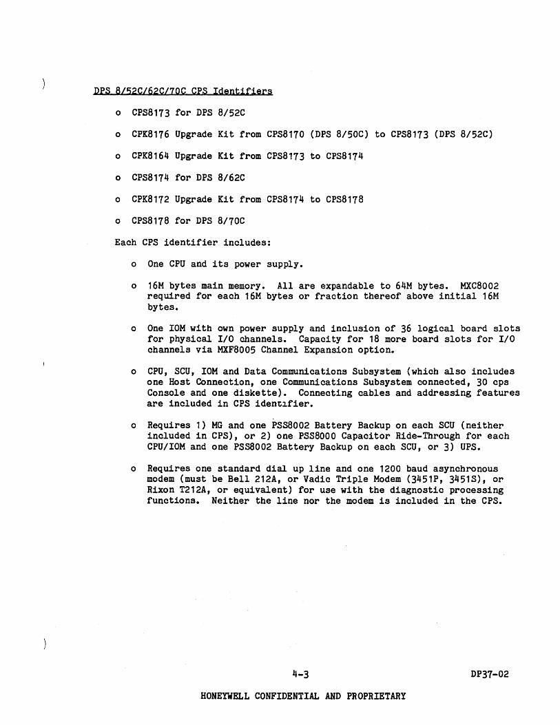
DPS 8/47C/4qC CPS Identifiers
o CPS8119 for DPS 8/47C
o CPK8362 Upgrade Kit from CPS8119 to CPS8121
o CPS8121 for DPS 8/49C
Each CPS identifier includes:
o Central system cabinet (CSC).
o CPU, SCU, 10M - 1 each, with connecting cables and addressing features. 10M includes 20 logic board slots for physical 1/0 channels.
o Memory: 12M bytes on the DPS 8/47C (expandable to 32M bytes in 2 or 4M byte increments - requires MXC8003, additional 5 port SCU, beyond 16M bytes). 16M bytes on the DPS 8/49C (expandable to 32M bytes in 2 or 4M byte increments--requires MXC8003, additional 5 port SCU).
o Power supply for all components within the central system cabinet.
o Space for one MSP8000 or one dual channel MSP8002.
o Space for one MFP8001 or one MTP8001 or one URP8000. The peripheral processors themselves are not included in CPS8119/8121 identifiers.
o All items above contained in the central system cabinet.
o One freestanding Data Communications subsystem with one Host Connection, one Communications Subsystem connected, 30 cps Console and one diskette (the console and diskette are included for maintenance purposes).
o Requires one standard dial up line and one 1200 baud asynchronous modem (must be Bell 212A, or Vadic Triple Modem (3ij51P, 3451S), or Rixon T212A, or equivalent) for use with the diagnostic processing functions. Neither the line nor the modem is included in the CPS.
4-2 DP37-02
HONEYWELL CONFIDENTIAL AND PROPRIETARY
DPS BI52C/62C/70C CPS Identifiers
0 CPS8173 for DPS 8/52C
0 CPK8176 Upgrade Kit from CPS8170 (DPS 8/50C) to CPS8173 (DPS 8/52C)
0 CPK8164 Upgrade Kit from CPS8173 to CPS8174
0 CPS8174 for DPS 8/62C
0 CPK8172 Upgrade Kit from CPS8174 to CPS8178
0 CPS8178 for DPS 8/70C
Each CPS identifier includes:
o One CPU and its power supply.
o 16M bytes main memory. All are expandable to 64M bytes. MXC8002 required for each 16M bytes or fraction thereof above initial 16M bytes.
o One IOM with own power supply and inclusion of 36 logical board slots for physical I/O channels. Capacity for 18 more board slots for I/O channels via MXF8005 Channel Expansion option.
o CPU, SCU, IOM and Data Communications Subsystem (which also includes one Host Connection, one Communications Subsystem connected, 30 cps Console and one diskette). Connecting cables and addressing features are included in CPS iden~~fier.
o Requires 1) MG and one PSS8002 Battery Backup on each SCU (neither included in CPS), or 2) one PSS8000 Capacitor Ride-Through for each CPU/IOM and one PSsa002 Battery Backup on each SCU, or 3) ups.
o Requires one standard dial up line and one 1200 baud asynchronous modem (must be Bell 212A, or Vadic Triple Modem (3451P, 3451S), or Rixon T212A, or equivalent) for use with the diagnostic processing functions. Neither the line nor the modem is included in the CPS.
4-3 DP37-02
HONEYWELL CONFIDENTIAL AND PROPRIETARY

ORDERING EXTRA CPUs, SCUs, IOMs FOR DPS 8/47C/4gc
One additional SCU, 10M and/or CPU can be ordered initially, or later as additions on DPS 8/47C. One additional SCU and 10M and up to three additional CPUs can be ordered initially, or later as additions on DPS 8/49C.
o Maximum of two SCUs, two IOMs and two CPUs per DPS 8/47C System.
o Maximum of two SCUs, two IOMs and four CPUs per DPS 8/49C System.
o Marketing identifiers
- SCU: MXK8007 MXK8009 MXC8003
10M: MXU8003
- CPU: CPK8113
CPK8119
CPU8119 CPU8121
CPK8362
CPK8365
CPK8366
CPK8367
CPK8368
- Tandem System: RSF8001
SCU Port Expansion (2 - 5 Port) SCU Port Expansion (5 - 8 Port) Additional (5 Port) SCU
Additional 10M (requires MXK8007)
Performance increase DPS 8/20C (CPS8114) to DPS 8/44C (CPS8116) - requires CPK8119 if system includes CPU8114; requires SFS6130, if installed, be replaced with SFS6135.
CPU8114 to CPU8116 performance increase (requires CPK8113).
Additional DPS 8/47C CPU (requires MXK8007). Additional DPS 8/49C CPU (requires MXK8007,
requires MXK8009 and 2nd CSU6601/6602 for 3rd CPU on a system).
Central System increase DPS 8/47C (CPS8119) to DPS 8/49C (CPS8121) - requires CPK8365 if system includes CPU8119; requires SFS6135, if installed, be replaced with SFS6145.
CPU8119 to CPU8121 performance increase (requires CPK8362).
Performance increase DPS 8/44C (CPS8116) to performance of DPS 8/49C (CPS8121) - requires CPK8368 if system includes CPU8116; requires SFS6135, if installed, be replaced with SFS6145.
Performance increase DPS 8/44CD (CPS8117) to performance of DPS 8/49C (CPS8121 and CPU8121); requires SFS6135, if installed, be replaced with SFS6145.
cpu8116 to CPQ8121 performance increase (requires CPK8366).
Redundant System Facility for CPS8119/8121 -requires MXK8007 installed in each SCQ.
All necessary connecting cables and addressing features are automatically included. Each CPU and each 10M is cross-barred to each SCQ by Customer Services at the site. You must supply cable lengths.
4-4 DP37-02
HONEYWELL CONFIDENTIAL AND PROPRIETARY

ORDERING EXTRA CPUs, SCUs, IOMs FOR DPS 8/52C/62C/70C
Up to 3 more SCUs and/or IOMs can be ordered initially, or later as additions on DPS 8/52C/62C/70C. One additional CPU may be ordered for DPS 8/52C/62C. Up to 5 more CPUs can be ordered initially, or later as additions on DPS 8/70C, provided that the combined total of CPUs and IOMs are less than or equal to 8.
o Maximum of four SCUs, IOMs per DPS 8/52C/62C/70C system. Maximum of two CPUs on DPS 8/52C/62C. Maximum of six CPUs on DPS 8/70C, so long as the combined total of CPUs plus IOMs are less than or equal to eight.
o Marketing identifiers
SCU: MXC8002
10M: MXU8002 MXF8005
CPU: CPU8173 CPU8174 CPU8178 CPK8176
CPK8164
CPK8172
CPK8177
CPK8174
CPK8178
Tandem System: RSF8002
Additional SCU
Additional 10M 10M Expansion (36 to 54 slots)
Additional DPS 8/52C CPU Additional DPS 8/62C CPU Additional DPS 8/70C CPU Performance increase, DPS 8/50C (CPS8170)
to DPS 8/52C (CPS8173) - requires CPK8177 if system includes CPU8170; requires SFS6140, if installed, be replaced with SFS6145.
Performance increase, DPS 8/52C (CPS8173) to DPS 8/62C (CPS8174) - requires CPK8174 if system includes CPU8173; requires SFS6145, if installed, be replaced with SFS6150.
Performance increase, DPS 8/62C (CPS8174) to DPS 8/70C (CPS8178) - requires CPK8178 if system includes CPU8174; requires SFS6150, if installed, be replaced with SFS6155.
CPU8170 to CPU8173 performance increase (requires CPK8176).
CPU8173 to CPU8174 performance increase (requires CPK8164).
CPU8174 to CPU8178 performance increase (requires CPK8172).
Redundant System Facility for CPS8173/8174/8178.
o All necessary connecting cables and addressing features are automatically included. Each CPU and each 10M is cross-barred to each SCU by Customer Services at the site. You must supply cable lengths.
4-5 DP37-02
HONEYWELL CONFIDENTIAL AND PROPRIETARY

DPS BIC MEMORY CONFIGURATORS
Drs BI20C, B/44C Total Memory Size
6MB 8MB 10 MB 12 MB 14 MB 16 MB
CPS8114 CMM8002 MXK8007 MXC8003 CMM8002 CMM8002 CMM8002 CMM8002 Standard
CPS8116 MXK8007 MXC8003 CMM8002 CMM8002 CMM8002 CMM8002
Figure 4-2 DPS B/20C, B/44C Memory Configurator
Drs B/47C, B/49C Total Memory Size
12MB 14MB 16MB 18MB 20 M8 22 MB 24 MB 26 MB 28 MB 30 MB 32 MB
CPS8119 CMM80021 CMM8002
MXC8003 CMM80021 CMM8002 CMM8002lCMM8002 CMM80021 CMM8002 CMM8002 J CMM8002
CMM8003 CMM8003 CMM8003 CMM8003 CMM8003
Standard CMM8002 I CMM8002 CMM80021 CMM8002 CMM80021 CMM8002 CMM80021 CMM8002
CPS8121 MXC8003 CMM8003 CMM8003 CMM8003 CMM8003
Figure 4-3 DPS B/47C, 8/49C Sample Memory Configurator
4-6 DP37-02
HONEYWELL CONFIDENTIAL AND PROPRIETARY

)
DPS 8/soC. 8/52C. 8/62C. 8/70C Total Memory Size
111.48 181.48 201.48 241.48 2111.48 211.41 301.41 32 1.48
CI'II170/1113/,11.,.,7. "'8ooZ- 8tanct.rd PS8800Z- MXC8002 CMM8oao CMM8020 CMM80Z0 CMMB020 CMM80Z0 CMM8020 CMMOOZO CMM8020 Dl'l1i1OC. IIIZC. IIIZC. 1170e
34MB J6 MB 3B.MJl 40 MB 4lMB 44 MB 411.48 411.41
eN.nOI.IU/.11.,.,7. PS88ooa- MXC800a CMMI020 CMM8oao CMMIOZO CMMDOZO CMMloao CMMloao CMMloao CMMloao ON 1l1OC. 1112C. IIUC. 1170e
10M. WM8 WM8 &11MB 61MB I!!IMD lIZ ... 14M,
eN.1701.173/.,141.,7. P888OOZ- MXC8OO2 CMMIoao CMM80Z0 CMMloao CMMIOZO CMMIOZO CMMloao CMMI020 CMMI020 Dl'l1i1OC. IIIZC. IIIZC. 1170e
• PSlBOOZ ...... for .. DP8 Bl5De. 8/5aC. 8/1aC. B/70C IV.tema without UPS.
Figure 4-4 DPS 8/50C, 8/52C, 8/62C, 8110C Memory Configurator
4-1 DP31-02
HONEYWELL CONFIDENTIAL AND PROPRIETARY

Marketing identifiers (MI) for memory are given in the following listing. (
System
DPS 8/20C/44C DPS 8/47C/49C DPS 8/47C/49C DPS 8/S0C/52C/62C/70C
CMM8002 CMM8002 CMM8003 CMM8020
Description·
2M bytes main memory 2M bytes main memory 4M bytes main memory 2M bytes main memory
The Control Unit Battery Backup (PSS8002) provides up to 4 minutes of power to storage units. One is required for each 16M bytes, or fraction thereof, on DPS 8/50C/52C/62C/70C without ups. Not available on DPS 8/20C/44C/47C/49C.
To upgrade memory size on an installed DPS 8/C system, using identifiers from the listing above, add the appropriate number of increment identifiers for the total size you want, less the identifiers already used for the currently installed memory size. On the DPS 8/50C/52C/62C/70C, add one MXC8002 for each 16M bytes or fraction thereof above the initial 16M bytes. If no UPS, add one PSS8002 for each 16M bytes or fraction thereof on the DPS 8/50C/S2C/62C/70C. On the DPS 8/20C/44C, add one MXK8007 and one MXC8003 if a total of more than 8MB is configured on the system. On the DPS 8/47C/49C, add one MXC8003 if a total of more than 16MB is configured on the system.
Example: To increase an installed DPS 8/S0C from its present 16 M-byte to 28 M-byte memory you order 6 CMM8020. 1 PSS8002 and 1 MXC8002.
Memory interleaving is not available on DPS 8/20C/44C/47C/49C. The memory interleaving aspects of the DPS 8/50C/S2C/62C/70C are discussed later in this section.
COMPUTING MEMORY REQUIREMENTS FOR DPS BIC
Memory requirements for DPS B/C systems are broken down into four parts.
Operating System Compilers Programs Other activities
The total estimated memory requirement for a DPS 8/C system is equal to the sum of the requirements for each of the four parts plus an allowance for growth and peak loads.
4-8 DP37-02
HONEYWELL CONFIDENTIAL AND PROPRIETARY

Operating System - The basic minimum operating system memory requirement is approx~mately 3.240K bytes. To this minimum, add the following, as needed:
Added Item
Additional CPUs (beyond 1 CPU) Additional FEPs (beyond 2 FEPs) Mail system Beam/Move system (SCOTTY) IDS (Data Base Control System) Transaction Processing Fortran/Basic/APL Lib (:SHARED_COMMON) COBOL/Sort Lib (:SHARED_COBOL) COBOL Lib without Sort (:SHARED_COB) RPG Lib (:SHARED_RPG) Pascal Lib (:SHARED_PASCAL)
Size (K bytes)
40 x (# CPUs - 1) 24 x (I FEPs - 2)
120 152 132 48
120 144 76 80 72
Compilers - Each compiler used requires a quantity of memory. For each compiler this memory consists of two parts, data and shared procedure. The table below shows the memory sizes for each compiler. In using the table, note that:
n = the number of concurrent users of the compiler. For FORTRAN and COBOL n = n1 (I users with programs <200 lines) + n2 (I users with programs )200 lines)
, m = the minimum of n or 4.
~gIlU2;Llfu:· S;Lze (K byt~~l .Ilat.a Shared Prgcedure
FORTRAN ( 128 x n1) + (160 x n2) + 172 + ( 80 x m) COBOL (160 x n1) + (200 x n2) + 82 + ( 120 x m) FPL ( 80 x n) + 192 PASCAL ( 140 x n) + 88 + ( 112 x m) PL6* ( 160 x n) + 40 + (200 x m) RPG ( 88 x n) + 76 + ( 48 x m)
* Note that users of SPSS have memory requirements similar to those shown here for PL6.
4-9 DP37-02
HONEYWELL CONFIDENTIAL AND PROPRIETARY

Programs - The numbers given below yield the minimum memory requirements for the program types shown. In all cases, compensation must be made for large programs and data sizes.
The constants represent sharable procedure. The coefficients of n represent data (i.e., n = the number of users for that program).
Program Type
FORTRAN PL6 RPG PASCAL COBOL (using:SHARED_COBOL) COBOL (using:SHARED_COB) Any above under DELTA Any above using IDS
(Note this must also be Any above running in TP TP instances
Size (K bytes) ~ Shared Procedure
( 4 x n) + 4 ( 4 x n) + 4 ( 8 x n) + 4 ( 4 x n) + 4 (32 x n) + 4 (20 x n) + 4 Add (40 x n) Add (52 x n)
added to APL or BASIC as required.) Add (12 x I of TP user slots) (52 x I of instances) + 64
Other Actiyities - The numbers given here are representative of moderate sized programs. As noted, compensation must be made for large programs. Again, n = the number of concurrent users of an activity.
Agt;Ly;l.ty S;l.z~ (K byt§~l ~ Shared Progedure
Each CP-6 User (16 x n) IBEX (16 x n) Editor (28 x n) + 84 APL (depends on program) (52 x n) + 352 BASIC (depends on program) (44 x n) + 324 IDP (32 x n) + 120 LINK (depends on program) (96 x n) + 152 SORT (uses as much memory (56 x n) + 56
as it is given) MERGE (uses as much memory (52 x n) + 56
as it is given) PCL (36 x n) + 96 STATS (32 x n) + 96 MAIL (28 x n) + 48 SEND (32 x n) + 28 TEXT (64 x n) + 196
Growth and peak load allowance - Use 10-20% of the sum of the memory requirements for compilers, programs ana other activities.
4-10 DP37-02
HONEYWELL CONFIDENTIAL AND PROPRIETARY

) Examples 1 and 2 point out the differences in memory requirements between installations exercising tight control of memory and those which do not constrain its use.
EXample 1
A single CPU system to run eighty users in a pure time sharing system for students with tight controls on on-line memory use. All compilations will be done in a single batch stream. Other off-hour data processing will be done, but will be less demanding than the peak hour student load. Fortran, Basic, APL, Pascal, and PL6 will be the languages used. COBOL and SORT will be required for the DP activities, but will not be used by students. The expected mix of users is: 20 in IBEX, 25 in EDIT, 2 in PCL, 10 in Basic, 5 in APL, and the remaining 18 running their own programs averaging 20K bytes data and 8K bytes procedure.
Operating System
.It§m Base Operating System Fortran/Basic/APL Lib Pascal Lib Cobol/Sort Lib
Operating System Total
Compilers
Size
=
(K bytes)
3240 120 72
144
3576K bytes
Note that all compilations will be done in a single batch stream (i.e., one at a time) and that this will handle the peak load. Hence the compiler requirement is equal to the worst case situation which in this example would be a greater than 200 line FORTRAN compila tion.
Data Shared Procedure Size (K bytes)
(160 x 1) 172 + (80 x 1) = 412
Programs
The problem states that the memory requirements for programs is:
Shared Procedure Size (K bytes)
18 x «20 x 1) + 8) = 504
Note that the problem states that each of 18 users are running ~heir own progr,ams, i.e., they are ~ using shared procedures. Also note that the sizes specified (in the problem) are above the minimum program sizes allowed.
4-11 DP37-02
HONEYWELL CONFIDENTIAL AND PROPRIETARY
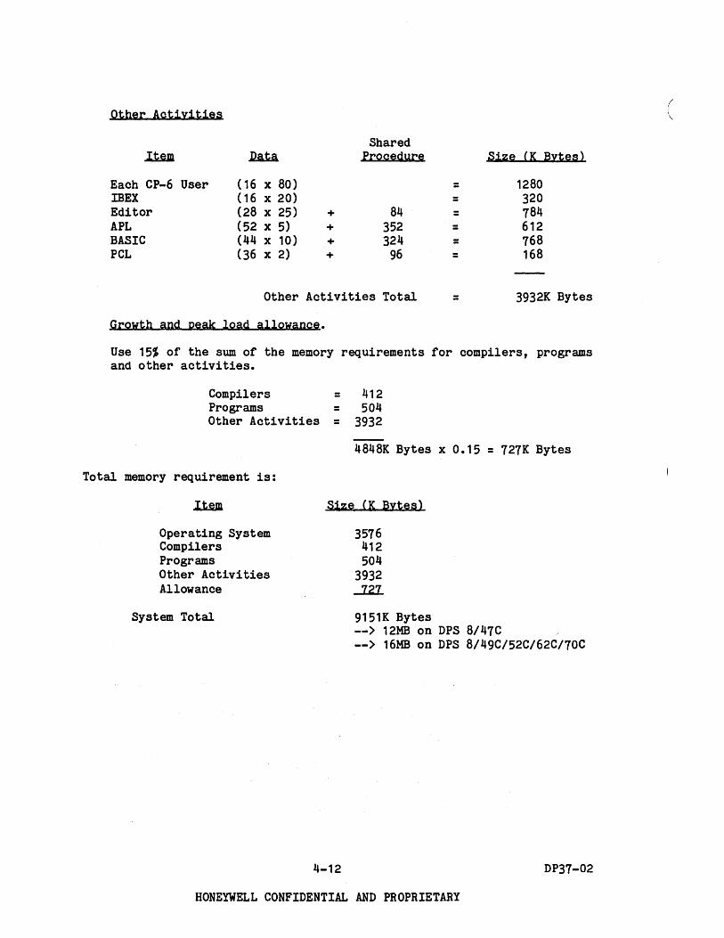
Other Actiyities
Shared .llim .I2ata Procedure Size (K Bytes)
Each CP-6 User (16 x 80) = 1280 IBEX (16 x 20) = 320 Editor (28 x 25) + 84 = 784 APL (52 x 5) + 352 = 612 BASIC (44 x 10) + 324 = 768 PCL (36 x 2) + 96 = 168
Other Activities Total = 3932K Bytes
Growth and peak load allowance.
Use 15% of the sum of the memory requirements for compilers, programs and other activities.
Compilers = 412 Programs = 504 Other Activities = 3932
4848K Bytes x 0.15 = 727K Bytes
Total memory requirement is:
Operating System Compilers Programs Other Activities Allowance
System Total
Size (K Bytes)
3576 412 504
3932 J..2.1..
9151K Bytes --> 12MB on DPS 8/47C --> 16MB on DPS 8/49C/52C/62C/70C
4-12 DP37-02
HONEYWELL CONFIDENTIAL AND PROPRIETARY
( \

Examole 2
The same single CPU system to run eighty time sharing users and off hours data processing work requiring COBOL and SORT. A smaller set of languages will be used than in Example 1. However, there is no plan to constrain compilations to batch, and heavy use of a large statistical package (SPSS) is anticipated. The expected mix of users is: 10 in IBEX, 10 in EDIT, 20 in SPSS, 10 in FORTRAN (5 small, 5 large), 10 in PASCAL, 2 in PL6, and 18 running assorted user programs averaging 20k bytes data and 8k bytes procedure.
Operating System
..Ia.m Base Operating System Fortran/Basic/APL Lib Pascal Lib Cobol/Sort Lib
Size (K bytes)
3240 120 72
144
Operating System Total = 3576K bytes
Compilers
Type .latA Shared Procedure
FORTRAN (128 x 5)+(160 x 5) + 172 + ( 80 x 4) PASCAL (140 x 10) + 88 + (112 x 4) PL6 (160 x 2) + 40 + (200 x 2) SPSS (160 x 20) + 40 + (200 x 4) COBOL N/A since run off hours, and with a small
Size (K Bytes)
= 1932 = 1936 = 760 = 4040
number of users. Thus, is guaranteed that size is less than sum of other compilers above.
Compilers Total = 8668K Bytes
Programs
The problem states that the memory requirements for programs is:
Shared Procedure Size (K bytes)
18 x «20 x 1) + 8) 504
Note that the problem states that each of 18 users are running their own programs, i.e., they are ~ using shared procedures. Also note that the sizes specified (in the problem) are above the minimum program sizes allowed.
4-13 DP37-02
HONEYWELL CONFIDENTIAL AND PROPRIETARY

Other Actiyities
Each CP-6 User IBEX Editor
(16 x 80) (16 x 10) (28 x 10) +
Shared Procedure
84
Other Activities Total
Growth and peak load allowance.
= = =
=
Size (K Bytes)
1280 160 364
1804K Bytes
Use 15% of the sum of the memory for compilers, programs, and other activities.
Compilers = 8668 Programs = 504 Other Activities = 1804
10976K Bytes x 0.15 = 1646K Bytes
Total memory requirement is:
Operating System Compilers Programs Other Activities Allowance
System Total
Size (K Bytes)
3576 8668 504
1804 ~
16198K Bytes
A 16MB DPS 8/C system would just minimally meet these memory requirements, 18MB might be preferable.
4-14
HONEYWELL CONFIDENTIAL AND PROPRIETARY
DP37-02

EXamole 3
A dual CPU system is to be configured with 5 FEPs to run a mixture of timesharing, batch, and TP. Approximately 200 TP terminals are expected to be connected to two TP instances, each of which will have 10 user slots. The TPAPS will be COBOL/IDS programs and approximately 10 distinct ones will be in use at any time. The batch load is expected to be 5 batch streams running an assortment of programs with an average total memory requirement of 200K bytes. 100 time sharing users are expected in two groups. The first group (50 users) run one of two large engineering design programs. The second group is doing program development. Tne users break down as follows:
TP 20 user slots each with 72K bytes data and 10 shared COBOL/IDS programs each with approximately 164K bytes procedure.
Batch Timesharing
5 users, average 200K bytes. 50 users, each with an average of 84K bytes data, using 2 shared Fortran programs, each with approximately 164K bytes procedure. 10 users IBEX 20 users EDIT
3 users Fortran Compiler 3 users Cobol Compiler 7 users debugging Fortran programs, with
an average size of 164K bytes procedure and 84K bytes data.
7 users debugging Cobol programs, with an average size of 164K bytes procedure and 72~ bytes data.
Memory requirements are derived as follows:
Operating System
~ Base Operating System Additional CPU Additional FEPs IDS TP Fortran/Basic/APL Lib Cobol/Sort Lib
Size (K bytes)
3240 40 72
132 48
120 144
Total Operating System = 3796K bytes
4-15
HONEYWELL CONFIDENTIAL AND PROPRIETARY
DP37-02

Compilers
Type .D.a..t.a Shared Procedure Size (K Bytes)
FORTRAN' (160 x 3) + 172 + ( 80 x 3) = 892 COBOL (200 x 3) + 82 + (120 x 3) = 1042
Total Compilers = 1934K Bytes
Programs
Batch
Timesharing FORTRAN
(200 x 5)
(42 x 50) + (42 x 50) +
Procedure
=
164 = 164 =
FORTRAN - debugAdd DELTA
(84 x 7) + +(40 x 7)
(164 x 7) =
TP
COBOL - debug Add DELTA
COBOL Add IDS Add TP
TP Instances
(72 x 7) + +(40 x 7)
(72 x 20) + +(52 x 20) +(12 x 20)
(52 x 2) +
(164 x 7) =
(164 x 10)
=
64 =
Total Programs =
- Note that programs being debugged are ~ shared.
Other Actiyities
Each CP-6 User IBEX Editor
(16 x 125) (16 x 10) (28 x 20) +
Shared Procedure
84
Total Other Activities
4-16
= = =
=
HONEYWELL CONFIDENTIAL AND PROPRIETARY
Size (K Bytes)
1000
2264 2264
2016
1932
4360
168
14,004K bytes
Size (K Bytes)
2000 160 644
2804K Bytes
DP37-02
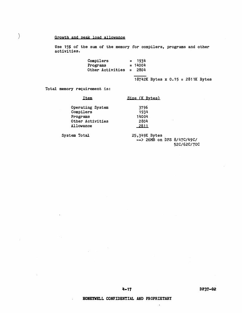
Growth and peak load allowance
Use 15% of the sum of the memory for compilers, programs and other activities.
Compilers Programs
= 1934 = 14004
2804 Other Activities =
18742K Bytes x 0.15 = 2811K Bytes
Total memory requirement is:
Operating System Compilers Programs Other Activities Allowance
System Total
Size (K Bytes)
"-17
3796 1934
14004 2804 2811
25,349K Bytes. --> 26MB on DPS 8/47C/49C/
52C/62C/70C
HONEYWELL CONFIDENTIAL AND PROPRIETARY
DP37-02·

Memory Interleaying Aspects
The DPS 8/50e, DPS 8/52e, DPS 8/62e and DPS 8/70e support 2-way interleaving on one seu with configurations of 16M bytes. Requires memory to be evenly divided on each of the two memory ports of scu. As noted above, memory interleaving is not available on DPS 8/47e/49C.
DPS 8/50e, DPS 8/52C, 8/62e and 8/70e may have more than one seu, to a total of four in one system.
o If two seus exist in one system, 4-way interleaving is possible. Requires same amount of memory on each of the four memory ports involved (two per SeU).
o If three seus exist in one system, 4-way interleaving is possible on two of the seus, 2-way interleaving on the third seu.
o If four seus exist in one system, two sets of 4-way interleaving are possible.
Interleaving causes physical memory addresses to be distributed sequentially across two memory ports on one seu (2-way) or across four memory ports (two ports· each for two seus for 4-way).
o Example of 2-way interleaving:
Addresses Port Port 2
Addresses 0-1 2-3 4-5 6-7 8-9 10-11 etc. etc.
0 Example of 4-way interleaving addresses
seu 1 seu 2
Port 1 Port 2 Port 1 Port 2
0-1 2-3 4-5 6-7 8-9 10-11 12-13 14-15
16-17 18-19 20-21 22-23 etc. etc. etc. etc.
Interleaving increases the effective speed of memory where memory locations are accessed in sequence. Allows the restore portion of a memory cycle on one memory port to be overlapped by the fetch portion of next memory cycle from next port in succession.
4-18 DP37-02
HONEYWELL CONFIDENTIAL AND PROPRIETARY

CONFIGURATION EXAMPLES FOR INITIAL ORDERS AND ADDITIONS
1. Examples of initial central system order.
o Customer wants DPS 8/47C system with 14M bytes memory
1 CPS8119 1 CMM8002
DPS 8/47C central system with 12M bytes 2M byte Expansion
o Customer wants DPS 8/49C with 16M bytes memory
1 CPS8121 DPS 8/49C central system with 16M bytes
o Customer wants dual DPS 8/70C with 32M bytes total
1 CPS8178 1 CPU8178 1 MXC8002 8 CMM8020 2 PSS8002 3 PSS8000
1 DPS 8/70C central system, 16M bytes 1 Additional CPU (Specify Cable Lengths) 1 Additional SCU (Specify Cable Lengths)
16M bytes Additional Memory 2 Control Unit Battery Backups 3 Capacitor Ride-Throughs
o Customer wants DPS 8/52C with 16M bytes memory
1 CPS8173 1 PSS8002 2 PSSBOOO
DPS 8/52C central system with 16M bytes 1 Control Unit Battery Backup 2 Capacitor Ride-Throughs
2. Examples of additions to central system orders.
o Customer has DPS 8/20C installed with 6M bytes. Wants memory upgrade to 8M bytes.
1 CMM8002 6M bytes to 8M bytes
o Customer has a 1-CPU, 1-IOM DPS 8/70C installed with 16M bytes and 2 SCUs (1 optional). Wants to add a second CPU.
1 CPU8178 1 PSS8000
2nd CPU (specify cable length) Capacitor Ride-Through for 2nd CPU
o Customer has DPS 8/44C installed. Wants a second IOM.
1 MXK8007 1 MXU8003
SCU Port Expansion 2nd 10M
4-19
HONEYWELL CONFIDENTIAL AND PROPRIETARY
DP37-02


SECTION 5 Configuring Within Any 10M
This section shows how to determine the number of physical and logical I/O cnannels required for the peripheral subsystems you wish for your system.
You must determine the quantity of logic boards required to contain the electronic logic for the number and type .. of physical I/O channels you desire. You must also determine whether there are sufficient channel board slots and logical channels available on a standard basis or via option to contain the needed logic boards in the DPS S/C system you wish to configure.
In addition, you must determine IOM aggregate loads for the quantity of physical I/O channels you wish. (CP-6 does not require the manual assignment of Data Rate expansion (DRE) facilities as does GCOS.)
BASE 10M AND EXTRA 10M'S
The IOM included within CPSSXXX identifier has no type number. All IOMs configured for the DPS S/47C/49C are integrated and all IOMs for the DPS S/52C/62C/70C are freestanding, i.e., not integrated. The designation nfreestandingn is retained for low profile components which are not physically integrated. These components may, however, be bolted together and may not actually be freestanding from one another.
Integrated IOMs may be obtained in three ways (DPS S/47C/49C only):
o One is included in the base DPS S/47C/49C.
o One more (MXUS003) may be ordered optionally on the initial DPS S/47C/49C. The SCU Port Expansion, MXKS007 is a prerequisite. Maximum quantity of integrated IOMs on the DPS S/47C/4gC is two.
o One more (MXUS003) may be ordered optionally as an add-on to an installed DPS S/47C/4gC. Prerequisites and limits are the same as in the preceding paragraph.
All necessary cables and addressing features are automatically included to crossbar each IOM to each SCU. You must specify cable lengths.
5-1 DP37-02
HONEYWELL CONFIDENTIAL AND PROPRIETARY

Freestanding IOMs may be obtained in three ways (DPS 8/52C/62C/70C only):
o One is included in base CPS identifier of freestanding systems.
o One (MXU8002) or more may be ordered optionally on your DPS 8/52C/62C/70C initial order along with the CPS components. Maximum quantity of freestanding IOMs on the DPS 8/52C/62C/70C is four.
o One (MXU8002) or more may be ordered optionally as add-on components to a DPS 8/52G/62C/70C after your system has been installed. Limits are the same as in the preceding paragraph.
Each freestanding IOM, whether optional or included in CPS identifier, has its own power supply.
For each extra IOM ordered for DPS 8/52C/62C/70C all necessary cables and addressing features are automatically included to cross-bar each IOM to each SCU. You must specify cable lengths.
When two or more IOMs exist in a DPS 8/52C/62C/70C system it is desirable to split the two channels of dual-channel MTPs and MSPs, one channel to each of two IOMs. This allows the entire HT or disk subsystem to be aooessible even if one IOM is lost.
5-2 DP37-02,
HONEYWELL CONFIDENTIAL AND PROPRIETARY

PHYSICAL CHANNELS AND LOGIC BOARDS
In order to determine the quantity of physical channels required, and the number of logic boards (board slots) needed and provided, use the Physical Channel Configurator illustrated in Figure 5-1.
.DPS 8lS2C/62C/70C
·SLOTS NEEDED 3
2
2
3
PHYSICAL CHANNEL CONFIGURATOR
LOGIC BOARD SLOTS IN 10M FOR PHYSICAL CHANNELS (~)
3 4
3 4
SLOT CONSUMPTION PER CHANNEL
3 3 3 3 3 1 1
PHYSICAL CHANNELS
MFP8001
PERIPHERAL URP MTP PROCESSOR 1x8
URP8000 (8)
, , , MTP8001 (a) 1 x 8
,
~ \ ,
URP0600 URPS012 URPS013
MFP8001(a)
MTP0611 1 x 8
3 3 3 3
MTP0611, MTF1151
2 X 16
MSP8000 (8) 1 x 16
3 3 3 3
3 3 3 3
r - .~ - - - j,-:" , IGGI L _______ :.l
(8) MSP8002
1
r. ':'..J... - - j,':' ~ IG8 1 B MSP0611
1 x 16
1
I CSU6601
1 REQ
L: ______ :J MSP0612
1
I CSU~602 I 1
I CSF6602
AUX CONS. ADAPTER
(a) For DPS 8/47C/4gC only. URP8000, MTP8001, MFP8001 are mutually exclusive within a cabinet.
(b) Each peripheral processor price includes 1 IOM channel except 2 are included for URP8011, MSP0612, MSP8002j also 2 are included for MFP8001, one for URP portion and one for MTP portion.
Figure 5-1. Physical Channel Configurator
5-3 DP37-02
HONEYWELL CONFIDENTIAL AND PROPRIETARY
The top portion of the Configurator in Figure 5-1 snows how many slots are provided and can be optionally obtained to hold the logic boards for physical I/O channels in IOM.
o DPS 8/47C/49C IOM provides a fixed complement of 20 slots included in CPS identifier price. No additional slots are available.
o DPS 8/52C/62C/70C IOMs provide a fixed complement of 36 slots included in CPS identifier price. One MXF8005 Channel Expansion option is available for each IOM to provide 18 more board slots. Each additional IOM on DPS 8/52C/62C/70C provides the same base complement of 36 slots in its price and provision for one MXF8005 option in each added IOM.
The lower portion of the Configurator in Figure 5-1 snows the quantity of logic boards (thus board slots) in IOM needed to terminate each I/O cable from a peripheral processor.
o Each solid line from a peripheral processor represents the main channel(s) for the processor. MSP8002, MSP0612 peripheral processors include two simultaneous main channels in their price. MTP0611 can be configured with a second simultaneous channel. The second MTP0611 simultaneous channel is required if the MTP0611 is to service 9 to 16 tape units in its subsystem.
o The dotted lines from certain peripheral processors imply the optional switched channel feature applied to a main channel. No switched channel path can have I/O simultaneously with its associated main channel. No dual-channel peripheral processor thus can have more than two data transfers in operation simultaneously, no matter how many switched channel features are used.
NOTE: Each switched channel feature defines a data transfer path and an IOM channel in its price.
o Total the board slots required for each data path termination required (main channels and swithced channels). Compare this to the total slots available.
5-1I DP37-02
HONEYWELL CONFIDENTIAL AND PROPRIETARY

If you cannot configure the desired number of peripheral subsystems and their complement of physical channels and switched paths, REGROUP and consider these alternatives:
o In case of a freestanding 10M use the Channel Expansion Option MXF8005.
o Bid a second 10M if the prospect will allow it.
o Use fewer simultaneous channels and/or switched paths.
o Use fewer subsystems of same type.
o Use fewer subsystems.
o Use different mix of sUbsystems.
o Change from DPS 8/41C/49C to DPS 8/52C/62C/10C, if possible.
o If possible, connect UR devices through DN8/C and use no unit record processor.
Determine next the logical channels or data paths which must be assigned to each physical channel and switched path. and the quantity which may optionally be assigned.
ASSIGNING LOGICAL CHANNELS TO PHYSICAL 10M CHANNELS
Each 10M supports up to 32 logical channels (up to 24 on DPS 8/41C/49C without MXK8001). No options are available. (A logical channel expansion, providing support for up to a total of 56 logical channels, may be requested via RPQ for DPS 8/52C/62C/10C.)
5-5 DP37-02
HONEYWELL CONFIDENTIAL AND PROPRIETARY

See Table 5-1 for a listing of Logical Channel Assignments.
TABLE 5-1. CONFIGURATION FOR LOGICAL CHANNEL ASSIGNMENTS
ADDED PHYSICAL LOGICAL USEFUL
PERIPHERAL CHANNELS CHANNELS LOGICAL PROCESSOR REQUIRED (b) REQUIRED (c) CHANNELS (d)
URP (PLUS 1-4/1-B PER DEVICES) (a) DEVICE
MSP SGL - CHANNEL 1 - 3
MSP DUAL - CHANNEL 2 2 1 - 3 PER PHY. CH.
(a) MTP SGL - CHANNEL 1 1 0-1
MTP DUAL - CHANNEL 2 2 0-1 PER PHY. CH.
CSU6601 1 1
DN B/C 1
(a) Including URP and MTP in MFPB001 for DPS B/47C/49C. (b) Each peripheral processor includes one physical IOM Channel in its
price, except URPB011, MSPB002/0612 which includes two. (c) Don't forget the freestanding MTP, MSP allow for switched path
features to be added to each Physical Channel. ~ termination in 10M is a Physical Channel and must be allotted separate logical channels(s), the same quantity for each termination.
Cd) Optional but valuable in increasing subsystem throughput.
5-6 DP37-02
HONEYWELL CONFIDENTIAL AND PROPRIETARY

The following paragraphs detail the rules for the assignment of IOM logical channels to physical channels.
o Every main and switched physical IOM channel must be assigned one logical channel or data path. URP, MTP, MSP may use more than one logical channel per physical channel, as explained below.
o Assignment is established onsite by Customer Services according to the mix of required and optional logical channels specified by you.
o A table showing the assignment of logical to physical channels and of physical channels to peripherals is given to CP-6 at system startup time. Accordingly, CP-6 always knows what logical channels to use (thus physical channels) to reach a given peripheral processor, console, or FEP.
In effect CP-6 "sees" the peripherals it wants to reach via the logical channels.
The logical channel concept provides a link to slave program buffer areas - their size and locations. Without such a link, the transfer path to/from memory could not be established.
The following paragraphs explain the reasons for assigning more than one IOM logical channel to a physical cnannel.
1. Use of multiple logical channels per physical channel allows multiple places to which CP-6 can send or can queue I/O commands.
o As long as a logical channel is available, CP-6 can queue in it the next I/O command for a given subsystem, even though the physical channel is busy with data transfers for a prior operation initiated through anut;.her logic"al channel. Otherwise, with a single logical channel, the physical and logical channel would be tied up during the data transfer and interrupt sequence, preventing the overlapped stacking of the next I/O command by CP-6. CP-6 would have to wait for an opportunity to gain access to the single channel.
o The effect here is potentially greater subsystem throughput by using the physical channel more efficiently, stacking commands in front of the subsystem at any time as long as a logical channel is available.
o Looking at it another way, the use of more than one logical channel per physical channel (block multiplexing) allows multiple I/O operations to be in some stage of execution concurrently. There can be as many concurrent stages as logical channels assigned to the subsystem involved. In the URP, e.g., there could be as many as eight card reading/card punching/line printing operations simultaneously, using one physical channel.
5-7 DP37-02
HONEYWELL CONFIDENTIAL AND PROPRIETARY

2. Assigning more than one logical channel to a physical channel can help achieve the following advantages:
o Greater subsystem throughput
o Use of fewer physical channels
o Larger number of I/O operations in some stage of execution concurrently
o Better use of physical channels
o Increased subsystem throughput by combining with rotational position sensing (RPS) in disk subsystems.
5-8 DP37-02
HONEYWELL CONFIDENTIAL AND PROPRIETARY

DEVICES
Figure 5-2 illustrates the concept of multiple logical channels/paths p3r physical channel.
DEVICE PRO·
CESSOR
10M
PHYSICAL CHANNEL PIPELINE
LOGICAL CHANNELS
NO.1 - --NO.2 - --
LOGICAL CHANNELS COMPLETE THE DATA PATHS TO MEMORY
(1 NO .. N)
MEMORY
~ROGRAM A
C
0
< TOTAL DATA TRANSFER PATH > ~---~--
Figure 5-2. Physical Channel and Logical Channel Concepts
5-9 DP37-02
HONEYWELL CONFIDENTIAL AND PROPRIETARY

Subsystems Allowing Multiple Logical Channels Per Physical Channel
UNIT RECORD PROCESSOR SUBSYSTEMS
In Unit Record Processor (URP) subsystems there must be one and only one logical channel aSSigned to each unit record device connected to URP. A specific logical channel is assigned to each device.
o URP can handle up to 8 unit record devices (URP0600/8000), or up to 4 unit record devices (URP in MFP8001, URP8011), or up to 2 unit record devices (URP8012/8013).
o URP, in combination with its channel and 1 to 8 logical channels in 10M, performs a block (unit record) multiplexing function, allowing up to 8 devices to run simultaneously. URP buffers a full physical record from/for each device and assigns each record to the 10M physical channel as soon as the last record has transferred. Each URP unit record device must be permanently preassigned to a logical channel to be used by CP-6 in issuing commands for it. The logical channel controls the transfer into memory into/from the proper buffer area for the device concerned.
MAGNETIC TAPE PROCESSOR SUBSYSTEMS
In MagnetiC Tape Processor (MTP) subsystems a second (added) logical channel may optionally be aSSigned to each physical channel.
The value of the second logical channel for each physical channel is that it allows CP-6 to send a new command to an open logical channel, even though the physical channel may be transferring data under command of another logical channel aSSigned to the subsystem. As soon as the first operation terminates, a second could be initiated immediately from the command standing by in the second logical channel. CP-6 could then send another command to the first logical channel, which is now open again, etc. If only one logical channel is used, CP-6 cannot have any next command standing by when a command is already in operation.
nISK SUBSYSTEMS
A normal useful maximum of logical channels for each 10M physical channel termination related to a mas~ store subsystem is four.
MSP and disk spindles obtain automatic latency reduction via rotational position senSing and block multiplexing of the physical channel(s) involved. Both features can increase subsystem throughput and should always be used, at least on single-channel subsystems. They depend on multiple logical channels per subsystem.
5-10 DP37-02
HONEYWELL CONFIDENTIAL AND PROPRIETARY

The number of logical channels assigned for a subsystem shoud not normally exceed the number of spindles in the subsystem. There is no gain with a greater number of logical channels.
In CP-6, using multiple logical channels gives relatively more performance improvement than does using multiple physical channels. It is desirable to have as many logical channels as it is expected to have concurrent seeks in progress.
With dual channel MSPs, subsystems commands are more frequently (than with single channel MSPs) serviced almost as soon as they are delivered to the subsystem. As a result, there is relatively less chance to have command queues build up and thus there is less relative effect from multiple logical channels in a dual-channel subsystem than in a single channel subsystem. Dual-channel subsystems will probably give greater throughput in all cases, especially where the subsystem includes more than four or five disk spindles.
Subsystems Allowing Only A Single Logical Channel Per Physical Channel
FEPs
One and only one logical channel must be assigned per IOM-connected (local) FEP. No optional logical channels are permitted.
CONSOLES
One and only one logical channel must be assigned per IOM-connected console. No optional logical cnannels are permitted.
5-11 DP37-02
HONEYWELL CONFIDENTIAL AND PROPRIETARY

10M AGGREGATE LOAD CONSIDERATIONS
Determine next the 10M aggregate load to ensure adequate 10M capacity.
The 10M's maximum aggregate bandwidth is 4000K bytes. One simple test of 10M load is based purely on bandwidth. By adding up the maximum bandwidth for those devices that will require individual data paths, a certain level of capacity can be perceived. However, due to peripheral processor buffering considerations, the actual bandwidth used may be less. This is especially true for communications equipment. Conversely, certain high speed magnetic tape and disk devices have a finite !tolerable delay factor' that, combined with the 10M channel priority of the devices, can restrict the 10M to a subset of the permissible bandwidth.
Table 5-2 lists estimated device bandwidths along with a constant 'T' (the tolerable delay factor) that attempts to take these variations into consideration. The devices have been listed in the recommended I/O channel priority order (from highest to lowest). It must be recognized that this method is offered as a general guide in estimating 10M loading and as such is not intended to establish any finite limit on peripheral configurations for a specific application. Unit Record and Communications Processor equipment values are excluded because of their negligible impact.
TABLE 5-2. ESTIMATED DEVICE BANDWIDTHS
Bandwidth Deyice Description K Bytes ..!..I.!.
MTU0610 200 ips 6250 bpi MTU 1250 19 MSU0402/0451 78.6/157.2 mb disk 803 21 MTU0630 125 ips 6250 bpi MTU 781 29 MTU0630 75 ips 6250 bpi MTU 469 31 MTU0610 200 ips 1600 bpi MTU 320 34 MTU0500/0630 125 ips 1600 bpi MTU 200 40 MTU0630 75 ips 1600 bpi MTU 120 51 MTU0500 125 ips 800 bpi MTU 100 80 MSU0501 1101 mb disk 1200 250 Unit Record Peripnerals
Channel Priority
Highest 2nd Highest 3rd Highest
Etc.
Communications Processor Lowest I
The 10M load equation is: L = 6 (N+1) - T
where: T = tolerable delay factor for specific peripheral characteristics.
T values are contained in Table 5-2.
N = 10M channel priority to 20 when using an integrated 10M, to 54 when using a freestanding 10M.
5-12 DP37-02
HONEYWELL CONFIDENTIAL AND PROPRIETARY

N = 1 for the highest priority device attached, N = 2 for the second highest priority device attached, etc.
If the value of L is negative, the peripheral, for which T was chosen, can be considered a qualified connection to an 10M channel with priority N. A positive value for L indicates that a timing overrun can occur, and the value of L indicates the probable occurrence of an overrun. If the value of L is 6 or less, the frequency of timing overruns, in most applications, will be minimal with no measurable effect on system performance. If the value of L is between 6 and 12, the application should be examined closely. If the vlaue of L is greater than 12, the configuration ~hould be considered invalid •.
10M CONFIGURING - AN EXAMPLE
Assume a CP-6 system includes the following:
1 Dual-Channel MSP using MSU0451s 1 Single-channel MTP using
1 URP
3 GCR tape units @ 200 ips, and 1 PE tape unit @ 75 ips
1 1600-lpm printer 1 1200-lpm printer 2 low-speed card readers 1 card punch 1 console 1 auxiliary console 4 FEPs
Table 5-3 lists the 10M-related features necessary for this configuraiton.
5-13 DP37-02
HONEYWELL CONFIDENTIAL AND PROPRIETARY

Quantity M.!.
1 MSP0612 1-16 MSU0451
1 MTP0611 3 MTU0610 1 MTU0630
1 URP0600 1 PRU1bOO 1 PRU1200 2 CRU0501 1 PCU0121 1 CSU6601 1 CSU6602 1 CPS81XX
3 DCU8011
TABLE 5-3. SOLUTION TO IOM CONFIGURATION EXAMPLE
Max. II of fJ of Physical Useful Logical
Description Slots Channels
Dual Channel MSP 6 8 157.2 mb disk
Single Channel MTP 3 2 GRC tape, 200 ips PE tape, 75 ips.
Unit Record Processor 3 1600 lpm printer 1 1200 lpm printer 1 500 lpm card reader 2 Card punch 1 Console 1 Auxiliary Console 1 Central System - includes 1
one FEP FEP ..3. -..3.
18 21
The number of.physical slots,18, is less than the 20 permitted on DPS 8/47C/49C and the 36 permitted on DPS 8/52C/62C/70C (without expansion).
The number of logical channels, 21, is less than the 32 available.
L ranges from -7 to +3, in all cases falling below the +6 value requiring close examination and well below the +12 value which indicates an invalid configuration.
Therefore, all equipment included can be configured on one IOM.
6(N ± 1) - T = L
6(2 + 1) - 21 = -3 6(3 + 1) - 21 = 3
6( 1 + 1) - 19 = -7 Covered by higher priority MTU0610 on same channel
5-14 DP37-02
HONEYWELL CONFIDENTIAL AND PROPRIETARY

SECTION 6 Unit Record Subsystems
DPS 8 Unit Record equipment may be attached to a CP-6 Central System and DPS 6 Unit Record equipment may be attached to a CP-6 FEP, although none is required. In this section, DPS 8 equipment is reviewed first, followed by ~he supported DPS 6 equipment.
CONFIGURING THE DPS 8 UNIT RECORD PROCESSOR (URP) SUBSYSTEMS
The following configuration elements must be included per DPS 8 unit record subsystem:
o URP (unit record processor) - MFP8001 for BPS 8/47C/4gC includes URP and MTP.
o URA (unit record addressing) - For each unit record unit/device, select the specific URA for that unit/device. Not required with URP8011/8012/8013.
o DPS 8 unit record devices from list in Table 6-1.
Multiple URPs can be used on a DPS 8/C system. The following URPs are available for DPS 8/C systems.
o URP0600 - freestanding, own power supply, usable with any DPS 8/C system. Up to 8 devices.
o URP8000 - contained in central system cabinet (CSC) of DPS 8/47C/4gC or in MXU~003 IOM cabinet. Shares power supply in cabinet. Mutually exclusive within a cabinet with MTP8001 and MFP8001. Up to 8 devices.
o MFP8001 - contained in central system cabinet (CSC) of DPS 8/47C/4gC or in MXU8003 10M cabinet. Snares power supply in cabinet. Up to 4 unit record devices supported by URP portion of MFP8001. MTP also included in MFP8001. MFP8001 is mutUally exclusive within a cabinet with URP8000 and MTP8001. URP and MTP portions have individual channels and can operate simultaneously.
o URP8011 - contained in the 10M of DPS 8/C.· Shares power supply in cabinet. Up to 2 printers and up to 2 card devices.
o URP8012 - contained in tbe 10M of DPS 8/C. Shares power supply in cabinet. Up to 2 card devices.
o URP8013 - contained in the 10M of DPS 8/C. Shares power supply in cabinet. Up to 2 printers.
6-1 DP37-02
HONEYWELL CONFIDENTIAL AND PROPRIETARY

TABLE 6-1. DPS 8 UNIT RECORD DEVICES
Device Model Max Per URP
Card readers CRU1050 1-2
CRU0501 1-2
Card punches PCU0121 1-2
Printers PRU1200 1-6 PRU1600 1-6
• PRU0901 1-2 • PRU1201 1-2
Speed
1050 cpm
500 cpm
100-400 cpm
To 1200 lpm To 1600 lpm To 900 lpm To 1200 lpm
• PRU0901/1201 supported only on URP8011/8013. The only printers supported on URP8011/8013 are the PRUu~01/1201.
The maximum number of unit record devices is two on URP8012/8013, four on URP8011/MFP8001, eight on other URPs. Maximums may be chosen from these for each type of device:
o 2 CRU1050 or 2 CRU0501 or 1 each
o 2 PCU0121
o 6 PRU1200/1600 printers
o 2 PRU0901/1201 printers
The following rules should be used in configuring a URP subsystem.
Every unit record device in URP subsystem must be configured with a specific unit record adapter or addressing feature (URA) which is related to the device type. (URA features not required for URP8011/ 801 2/801 3 • )
Options are identified by dotted lines or boxes. In general, options are priced features beyond the standard complement included in basic URP or device price.
You must show on your order any pertinent item with a type number.
6-2 DP37-02
HONEYWELL CONFIDENTIAL AND PROPRIETARY

) Figure 6-1 illustrates a configurator for URP0600/8000
o Order URAs and unit record devices as needed.
o URP0600 - freestanding, usable on any DPS 8/C system.
o URP8000 - in Central System Cabinet of DPS 8/47C/49C or in HXU8003 IOM cabinet. Cannot be used within the same cabinet with MTP8001 or MFP8001.
- TO 10M PHYSICA"L CHANNE L
BASIC CHANNEL (INCLUDED)
~ ORDER 1 URF0040 TO HANDLE
OVER 4 DEVICES BASIC URP
HANDLES 4 URAs IN ANY COMBINATION - - - - - URFOoiO - - ~ -
HANDLES 4 MORE URA IN ANY 1
URA SPACE
(4 DEVICES)
URA URA URA SPACE SPACE SPACE
URA SPACE
COMBINATION ,---,- ... ~ I URA I URA
SPACE I SPACE
__ J ___ J __
Figure 6-1. Configurator for URP0600/8000
, -I I
I URA I I SPACE I
1 ___ ..1
Figure 6-2 illustrates the configurator for URP in MFP8001.
o Order URAs and unit record devices as needed.
o MFP8001 - in Central System Cabinet of DPS 8/47C/49C or in MXU8003 IOM cabinet. Cannot be used within the same cabinet with MTP8001 or URP8000.
J~ TO 10M PHYSICAL ~~ CHANNELS
URP
URA SPACE FOR FOUR URAs (4 DEVICES)
I I I I
MTP
Figure 6-2. Configurator for URP in MFP8001
6-3
HONEYWELL CONFIDENTIAL AND PROPRIETARY
DP37-02

Configurator for URAs and associated unit record devices are illustrated in Figure 6-3. Each device must have one specific URA associated with it. These URAs relate to all URPs and to URP portion of MFP8001.
CRUOS01
CRF0030
Figure 6-3 •. Configurator for URAs and Associated Unit Record Devices
Figure 6-4 illustrates the configurators for URP8011/8012/8013.
J, TO 10M
h j~ TO 10M J. TO 10M PHYSICAL PHYSICA L PHYSICA L
L CHANNELS CHANNEL CHANNE
URP8011 URP8012 URP8013
1·2 ;·2
PRU0801/1201 CRU0601/1050/ PCU0121
1 ·2 CRU0I501/10&01
PCU0121
, ·2 PRU0901/1201
Figure 6-4. Configurators for URP8011/8012/8013
6-4 DP37-02
HONEYWELL CONFIDENTIAL AND PROPRIETARY
( \

Figure 6-5 illustrates the configurator for PRU0901/1201.
PRU0901/1201
PRB3XXX·
------- I PRFOO45 I
I~:::C~~:'0:J
* Two print belts included with PRU0901/1201. A single type must be specified from the supply catalog.
Figure 6-5. Configurator for PRU0901/1201
The following listing summarizes the marketing identifiers (MI) related to URP subsystems.
HI Description
URP0600 Freestanding URP (1xS)
URPSOOO URP in Central System Cabinet (1xS) or in MXUS003 cabinet
MFPS001 URP (1x4) and MTP (1xS) .in Central System Cabinet or in MXUS003 cabinet
URPS011 Embedded Unit Record Processor (1x4) Contained in IOM.
URPS012 Embedded Unit Record Processor (1x2) Contained in IOM.
URPS013 Embedded Unit Record Processor (1x2) Contained in IOM.
6-5
Remarks
All URPsinclude 1 rOM Channel. Any DPS SIC system.
DPS S/47C/49C only. Mutually exclusive within a cabinet with MFPS001 and MTPS001.
DPS S/47C/49C. Mutually exclusive within a cabinet with URPSOOO and MTPS001.
Up to 2 PRU0901/1201 and up to 2 card devices.
Up to 2 card devices.
Up to 2 PRU0901/1201.
DP37-02
HONEYWELL CONFIDENTIAL AND PROPRIETARY

Hi Description
URF0040 Unit Record Addressing (URA) Expansion for URP0600/8000
PCU0121 100 to 400-cpm Card Punch
URA0050 Unit Record Addressing for PCU0121
CRU1050 1050-cpm Card Reader
CRU0501 500-cpm Card Reader
URA0052 Unit Record Addressing for CRU1050
URA0056 Unit Record Addressing for CRU0501
CRF0030 Pedestal for CRU0501
PRU1200 Belt Printer
URA0054 Unit Record Addressing for PRU1200
PRK1216 PRU1200 to PRU1600 Upgrade Kit
PRU1600 Belt Printer
URA0055 Unit Record Addressing for PRU1600
PRF0022 Expansion of PRU1200/1600 from 136 to 160 Print Columns
PRB0500 64-character BCD Belt for PRU1200/1600
PRB0513 64-character ASCII Belt for PRU1200/1600
PRB0524 64-character Belt, with OCR-A/B numeric font for PRU1200/1600
6-6
Remarks
Handles up to 4 more intermixed URAs beyond standard maximum of 4. Required if more than 4 devices are configured.
Optional
1 required per Punch.
required per CRU1050
required per CRU0501
Optional
At least one belt required per PRU1200.
1 required per PRU1200
At least one belt required per PRU1600.
1 required per PRU1600
Nominal speed = 975 lpm for PRU1200 = 1325 lpm for PRU1600
Nominal speed = 975 lpm for PRU1200 = 1325 lpm for PRU1600
Nominal speed = 975 lpm for PRU1200 = 1325 lpm for PRU1600
DP37-02
HONEYWELL CONFIDENTIAL AND PROPRIETARY

) Description
PRB0600 96-character ASCII Belt for PRU1200/1600
PRU0901 Belt Printer. Price includes power stacker and two print belts. (Belts must be ordered from the supply catalog.)
PRU1201 Belt Printer. Price includes power stacker and two print belts. (Belts must be ordered from the supply catalog.)
PRB3600 96-character ASCII Belt for PRU0901/1201
PRB3500 64-character BCD Belt for PRU0901/1201
PRB3513 64-character ASCII Belt for PRU0901/1201
PRB3524 64-character ASCII Belt with OCR-AlB numeric font for PRU0901/1201
PRK0901 PRU0901 to PRU1201 Upgrade Kit
PRF0045 Static Eliminator for PRU09011 1201
URFBOOO Printer Optical Cable Adapter
FBO-YYYY Optical Cable with Connectors
MXFBOOB Exchange of URP Attachment Feature (to DPS B Systems only) -wire wrap to hard copper, in the 10M.
6-7
Remarks
Nominal speed = 700 lpm for PRU1200 = 9B5 lpm for PRU1600
Requires URP8011 or URPB013
Requires URPB011 or URPB013
Must be specified from the supply catalog.
Must be specified from the supply catalog.
Must be specified from the supply catalog.
Must be specified from the supply" catalog.
Desirable if humidity falls below 30%.
For PRU0901/1201 only. Requires FBO-YYYY.
Allows printer placement 100-2000 meters from cener-a! system. YYYY is length in meters. PrereqUisite is URFBOOO.
For URP0600 installed on non DPS-B systems (equipment removed and replaced by MXFB008 becomes the property of Honeywell upon removal.) One required for each peripheral processor channel.
DP37-02
HONEYWELL CONFIDENTIAL AND PROPRIETARY

Example of DPS 8 URP Configuring
Assume you are bidding a DPS 8/47C and that you want a URP subsystem with a card reader, card punch, and two 1600 lpm printefs. The 1600 lpm printers are each to have both 64-character (BCD) and 96-character (ASCII) printing capability. The URP and HTP are to be integrated within the Central System Cabinet.
You would order as follows:
.QlY. .HI Description
1 MFP8001 MTP and URP Integrated in Central System Cabinet 1 CRU0501 Card Reader 1 URA0056 Unit Record Addressing for CRU0501 1 PCU0121 Card Punch 1 URA0050 Unit Record Addressing for PCU0121 2 PRU1600 Belt Printer 2 URA0055 Unit Record Addressing for PRU1600 2 PRB0500 64-Character BCD Belt for PRU1600 2 PRB0600 96-Character ASCII Belt for PRU1600 1 CRF0030 Pedestal for CRU0501 (Optional)
6-8 DP37-02
HONEYWELL CONFIDENTIAL AND PROPRIETARY
(

CONFIGURING SUPPORTED DPS 6 UNIT RECORD EQUIPMENT
Each DN 8/C FEP included in CP-6 Central Systems and the DCU8011 FEP contains a Multiple Device Controller (MOC). Card reader and/or line printer device pacs may be attached to the MDC. Up to two DPS 6 Unit Record devices may be attached via this MOC. A second MOC (or MDC expander) may be ordered which allows attachment of up to four additional DPS 6 unit record devices. Thus, up to six DPS 6 unit record devices may be added via each FEP.
Model
MDC9640
CRM9630
PRM9630
PRU9617
PRU9618
PRB1600
PRB2600
PRF9618
PRU9609
CRU9611
Description
MOC Peripheral Port Expander, accommodates up to four additional peripheral Device Pacs.
Device Pac for Card Reader
Device Pac for Line Printer
300-lpm Band Printer with VFU~ 64 char. (uppercase only)
600-lpm Band; Printer with VFU, 64 char. (uppercase only)
96-Character Band (uppercase & lowercase), Reduces printer- to nominal speed = 240 Ipm (Must be ordered 'via a Supply Requisition)
96-Character Band (uppercase & lowercase), Reduces printer to nominal speed = 440 Ipm (Must be ordered via a Supply Requisition)
132- to 136-Print Position Extension Factory Installed Only
900-lpm Drum Printer with VFU, 64 char. (uppercase only)
500-cpm Card Reader (binary input not supported)
6-9
HONEYWELL CONFIDENTIAL AND PROPRIETARY
PrereQuisites
CPS81XX or DCU8011, DCE8002
CPS81XX or DCU8011
CPS81XX or DCU8011
PRM9630
PRM9630
PRU9617
PRU9618
PRU9618
PRM9630
CRM9630
DP37-02

Figure 6-6 illustrates a configuration diagram for DPS 6 Unit Record Equipment
I DATANET SIC MEGABUS
MoC
--------~o~--------~o~--------~o~--------~o~---------
MoC SLOTS
DISKETTE PAC (1ST MoC ONLY)
I I I I I ~ __ --, I I , !.. -, oISKETTE* \
\ J \ I ' .... ..,*'"
PRM9630 CRM9630
CRU9611
• A single diskette is included as part of the DN SIC for maintenance purposes.
Figure 6-6. Configurator for DPS 6 Unit Record Equipment
6-10 DP37-02
HONEYWELL CONFIDENTIAL AND PROPRIETARY

EXample of DPS 6 Unit Record Configuring
Assume you are bidding one DPS 6 440-lpm uppercase/lowercase printer attached to a DPS 8/C system via the FEP.
In addition to the Communications features ordered on the DATANET 8/C, you would order as follows:
1
1
1
.HI
PRM9630
PRU9618
PRB2600
Description
Device Pac for printer
Band printer
96 Character Band
6-11
HONEYWELL CONFIDENTIAL AND PROPRIETARY
DP37-02


SECTION ., Magnetic Tape ~ubsystems
CQNFIGURING MAGNETIC TAPE SUBSYSTEMS
The following configuration elements are required:
o MTP0611 (magnetic tape processor), MTPa001, or MFP8001 (contains MTP and URP). Each MTP handles any combination of MTUs described below. MTP0611 is freestanding, with own power supply, and can be used on any DPS 8/C system. MFP8001 and MTPa001 are contained in CSC of DPS 8/47C/49C and shares Central System Cabinet power supply (or can be available in the MXU8003 10M cabinet, sharing that cabinet's power supply) •
o MTU (magnetic tape units)
- Multiples of any MTU type number can be used in any combination.
- Must be a minimum of one tape unit per DPS 8/C system. Review Section 1 for minimum and maximum peripherals.
o MTU density feature
Every tape unit must be equipped with only one density feature from the MTU features table below. Density features are upgradeable onsite by Customer Services.
Each tape unit when equipped with the desired density feature has one 7-track read/write head or one 9-track read/write head, not both.
See Table 7-3 for a complete list of density features.
o MTA (magnetic tape addressing) - one per 4 tape units, two for first 8 units in case of dual-channel MTP. See Table 7-2.
o Second 10M physical channel (MTF1151) - required if more than 8 tape units will be configured in a tape subsystem; optional otherwise. Maximum of 16 MTUs per subsystem.
7-1 DP37-02
HONEYWELL CONFIDENTIAL AND PROPRIETARY

The following restrictions apply to 7-track tapes.
o Support by RPQ only.
o No ANS standard labeled tape support (i.e., no managed file formats).
o 7-track tapes may not be used as CP-6 Boot tapes or as any other system tape.
o CP-6 will not support a 7-track only system.
o From a resource management point of view, 7-track tapes will be supported in a "foreign device" mode and not be included in the general magnetic tape resource pool for general use. 7-track must be explicitly requested, in all cases.
Table 7-1 provides a listing of magnetic tape unit characteristics.
TABLE 7-1. HTU CHARACTERISTICS
MTU0500 (RPQ Only) HTU0610 MIU0630
Automatic threading Y Y Y
Forward speed (ips) 125 200 75/125
Cartridge load option Y Y Std.
Rewind speed (ips) 500 640 500
Power windows Y Y Y
Recording format NRZI/PE NRZI/PE/GCR NRZI/PE/GCR
7-track operation RPQ N N
Interrecord gap .75 in. NA NA
556-bpi character rate 52.3K Bytes NA NA
aOO-bpi character rate . 75. 2K Bytes NA NA
7-2 DP37-02
HONEYWELL CONFIDENTIAL AND PROPRIETARY
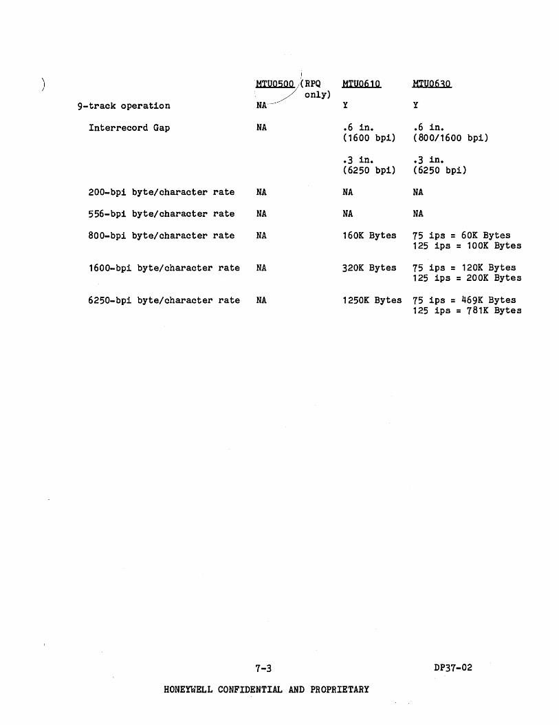
) !
MTU0500 ;( RPQ MTU0610 MIUQ630 " 7 only) 9-track operation NA-- y y
Interrecord Gap NA • 6 in. .6 in • (1600 bpi) (800/1600 bpi)
• 3 in. .3 in • (6250 bpi) (6250 bpi)
200-bpi byte/character rate NA NA NA
556-bpi byte/character rate NA NA NA
aOO-bpi byte/character rate NA 160K Bytes 75 ips = 60K Bytes 125 ips = 100K Bytes
1600-bpi byte/character rate NA 320K Bytes 75 ips = 120K Bytes 125 ips = 200K Bytes
6250-bpi byte/character rate NA 1250K Bytes 75 ips = 469K Bytes 125 ips = 781K Bytes
7-3 DP37-02
HONEYWELL CONFIDENTIAL AND PROPRIETARY

Figure 1-1 illustrates the configurator for a single-channel MTP (1x8 subsystem).
TO 10M CHANNELS
,-------~~~--------I , MTF1152 \.... BASIC MTP CHANNEL WITH ONE SWITCHABLE 111\ 10M CHANNEL INCLUDED CHANNEL PATH \ ONE 10M CHANNEL
MTF115S/1159/1160 7/9-TRACK
CAPABILITY FEATURES
~----------~----------~~----------------~ MTA1152
2ND MTA IF NEEDED
SEE TABLE 7-2.
1 DENSITY FEATURE
REQUIRED PER TAPE UNIT.
SEE TABLE 7-3.
Figure 1-1. Single-Channel HTP Configurator
MTP0611 MTPS001 MFPS001
1-4 DP31-02
HONEYWELL CONFIDENTIAL AND PROPRIETARY
I I

Figure 7-2 illustrates the configurator for a freestanding dual-channel MTP (2x16 subsystem).
o Second channel (MTF1151) required if more than 8 units are used in a subsystem.
o Each channel is cross-barred to each tape unit.
TO 10M TO 10M CHANNELS CHANNELS
........... r
~ \ I
4 MTF1152 BASIC MTP MTF1151 SWITCHABLE CHANNEL WITH WITH I
CHANNEL PATH \ I \ ONE 10M ONE 10M I WITH ONE 10M \ CHANNEL CHANNEL I
CHANNEL
MTF1158
MTP0611 MTF1159 MTF1160
MTA1152 2ND MTA 3RD MTA 4 TH MTA
IF NEEDED IF NEEDED IF NEEDED
Figure 7-2. Dual-Channel MTP Configurator
7-5
HONEYWELL CONFIDENTIAL AND PROPRIETARY
\ MTF1152 SWITCHABLE
CHANNEL PATH WITH ONE 10M
CHANNEL
7/9-TRACK CAPABILITY FEATURES
SEE TABLE 7-2.
1----1 DENSITY FEATURE REQUIRED PER TAPE UNIT. SEE
TABLE 7-3.
DP37-02

The following listing provides the magnetic tape processor (MTP) components with marketing identifiers (MI).
MTP0611
MFP8001
MTP8001
MTF1152
MTF1151
Descriotion
Freestanding Magnetic Tape Processor. Handles up to 8 tape units (1x8) or up to 16 with MTF1151 (2x16). Includes 10M physical channel. Requires MTF1159 and/or MTF1160 feature(s).
Contained in DPS 8/47C/49C CSC or in MXU8003 10M cabinet. Includes 1x8 MTP and MTP 10M physical channel, plus 1x4 URP and its 10M channel. Both URP and MTP operate simul~aneously. Cannot be used in the same cabinet with MTP8001 or URP8000. Requires MTF1159 and/or MTF1160 feature(s).
Contained in DPS 8/47C/49C CSC or in MXU8003 10M cabinet. 1x8 MTP, including MTP 10M physical channel. Cannot be used in the same cabinet with MFP8001 or URP8000. Requires MTF1159 and/or MTF1160 feature(s).
Switchable Non-simultaneous Channel. Makes an MTP channel software-switchable. Includes 10M physical channel for termination of switched channel path. Maximum of one per MTP0611/MTF1151/MFP8001/ MTP8001.
Dual Simultaneous Channel (device procesor channel) for MTP0611. Includes 10M channel.
7-6
Remarks
Required if MFP8001 or MTP8001 are not used.
Required if MTP8001 or MTP0611 are not used.
Required if MTP0611 or MFP8001 are not used.
Optional
Required to support more than 8 units. Optional otherwise. Requires redundant options MTF1158/1159/ 1160 if these were configured in MTP0611.
DP37-02
HONEYWELL CONFIDENTIAL AND PROPRIETARY
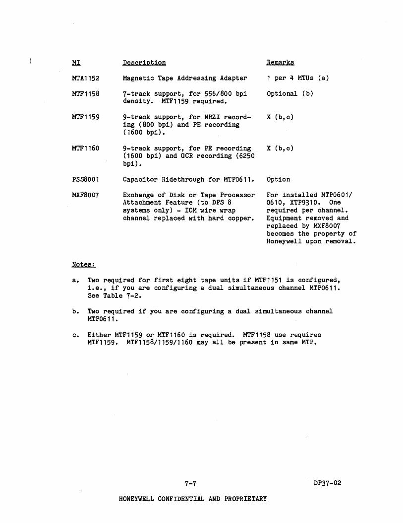
MTA1152
MTF1158
MTF1159
MTF1160
PSSB001
MXF8007
Notes:
Description
Magnetic Tape Addressing Adapter
7-track support, for 556/800 bpi density. MTF1159 required.
9-track support, for NRZI recording (800 bpi) and PE recording (1600 bpi).
9-track support, for PE recording (1600 bpi) and GCR recording (6250 bpi) •
CapaCitor Ridethrough for MTP0611.
Exchange of Disk or Tape Processor Attachment Feature (to DPS 8 systems only) - 10M wire wrap channel replaced with hard copper.
Remarks
1 per 4 MTUs (a)
Optional (b)
x (b,c)
x (b,c)
Option
For installed MTP0601/ 0610, XTP9310. One required per channel. Equipment removed and replaced by MXF8007 becomes the property of Honeywell upon removal.
a. Two required for first eight tape units if MTF1151 is configured, i.e., if you are configuring a dual simultaneous channel MTP0611. See Table 7-2.
b. Two required if you are configuring a dual simultaneous channel MTP0611.
c. Either MTF1159 or MTF1160 is required. MTF1158 use requires MTF1159. MTF1158/1159/1160 may all be present in same MTP.
7-7 DP37-02
HONEYWELL CONFIDENTIAL AND PROPRIETARY

Table 7-2 shows the quantities of required magnetic tape unit addressing adapters (MTA1152). Each MTA1152 interfaces to up to 4 tape units and to a device processor channel. Two MTAs are required for the first 8 tape units in a dual simultaneous channel MTP0611.
TABLE 7-2. REQUIRED NUMBER OF MTU ADDRESSING ADAPTERS
No. of Tape Units on HTP
1-4
5-8
9-12
13-16
MTP0611
1x8 HTP 2x16 MTP No. of MTAs No. of MTAs
1 2
2 2
3
4
7-8
HONEYWELL CONFIDENTIAL AND PROPRIETARY
I I I I I I I I I I I I I I I I I I I
DP37-02
The following listing provides descriptions and marketing identifiers for the magnetic tape unit components. After selectipg a tape unit, you must select a tape density feature from Table 7-3. Density feature establishes transfer rate. K Bytes injicate thousands of 8~bit bytes per second instantaneous transfer rate.
MTU0500 (RPQ only)
MTU0610
MTU0630
Description
125 ips, 25K Bytes to 200K Bytes.
200 ips, 160K Bytes to 1250K Bytes.
75/125 ips, 60K Bytes to 781K Bytes.
Table 7-3 lists MTU density and other features and marketing identifiers.
Every tape unit must have only one denSity feature. Density feature establishes the transfer rate. In addition to a density feature for each MTU, there must also be 7-track and/or 9-track support feature(s) in each MTP. These support features (MTF1158/1159/1160) are identified earlier in this section.
7-9 DP37-02
HONEYWELL CONFIDENTIAL AND PROPRIETARY

TABLE 7-3. MTU DENSITY FEATURES
MTU0500 (RPQ only) 125 inches per second
MTF0016: 7-track density, 556/800 bpi
MTF0018: Cartridge Load, factory installed option
MTF0019: Cartridge Load, field installed option
MTF0020: Optional High Altitude Adapter, for al ti tudes 4000-7500 ft.
MTF0021 : Optional High Altitude Adapter, field installed for altitudes 4000-7500 ft.
MTF0022: Optional DC Power-On Meter, factory installed only
MTF0023: Optional Tape Movement Meter, factory installed only
MTU0610 200 inches per second
MTF0607: 9-track density, 800/1600 bpi
MTF0608: 9-track density, 1600/6250 bpi
MTF0678: Kit to upgrade MTF0607 to MTF0608
7-10
MTU0630 9-track density
MTF0634 75 ips, PE/NRZI Feature, 800/1600 bpi
MTF0635 75 ips, PEIGCR Feature, 1600/6250 bpi
MTF0636 125 ips, PE/NRZI Feature, 800/1600 bpi
MTF0637 125 ips, PEIGCR Feature, 10uO/6250 bpi
MTK0630 Upgrade MTF0634 to MTF0635 Performance
MTK0631 Upgrade MTF0636 to MTF0637 Performance
MTK0632 Upgrade MTF0634 to MTF0636 Performance
MTK0633 Upgrade MTF0635 to MTF0637 Performance
MTK0634 High Altitude Adapter
DP37-02
HONEYWELL CONFIDENTIAL AND PROPRIETARY

Magnetic Tape Subsystem Configuring Example
A DPS 8/47C prospect wants a tape subsystem with six 9-track units, 4 of which are 890/1600 bpi units and 2 of which are 1600/6250 bpi units.
You should order as follows:
.Q.ll .HI. Descriotion
1 MFP8001 Magnetic tape processor with one 10M channel, plus UHP with one 10M channel.
1 MTF1159 9-track NRZI/PE support (800/1600 bpi).
1 MTF1160 9-track PE/GCR support (1600/6250 bpi).
2 MTA1152 Magnetic tape addressing features or ports on MTP. Each handles 4 tape units.
6 MTU0610 9-track, 200 ips tape units.
4 MTF0607 9-track density, 800/1600 bpi.
2 MTF0608 9-track density, 1600/6250 bpi.
7-11 DP37-02
HONEYWELL CONFIDENTIAL AND PROPRIETARY

(
SECTION 8 Mass Storage Subsystem
CONFIGURING MASS STORAGE SUBSYSTEMS
The following are the required mass storage subsystem configuration elements.
o HSPXXXX (mass store processor) - choose Qne or more MSPs consistent with packaging of DPS 8/C mainframe (CSC-oriented or freestanding), with number of simultaneous channels desired, and with type of disk spindle used. Every DPS 8/C system must include a mass storage subsystem. See Section 1 for minimum and maximum peripherals complement.
o Disk device adapter (MSF10XX) - required with MSU04XX spindles. These features supply the proper "personality" for the MSP to interface to MSU04XX spindles. Device adapters for MSU0501 are standard in each MSP.
o MSAXXXX (device addressing) - choose one for every four MSU04XX (4 spindles) and one for every two MSU0501 (4 spindles).
o HSUOXXX (mass store unit) - with announcement of MSU05XX, an ambiguity was introduced in use of the word "unitn • Prior to MSU05XX, a unit was equal to a spindle, but a MSU05XX (unit) provides for 2 spindles. In this section, "spindle" is used as the unambiguous term for the device which contains one disk reading/writing pack or head disk assembly (HDA).
o RPS (rotational position sensing) feature - one MSFOOOX required per MSU04XX spindle. MSU0501 includes RPS feature for each spindle.
o Dual access feature - one required per disk unit when two channels are cross-barred in the mass store subsystem. This feature provides an access path to each spindle from each channel. No more than two MSP channels can be used to access any given spindle.
o Two-channel cross-bar feature - included in dual-channel MSPs (MSP8002/ 0612) to allow each channel to access each spindle when dual access feature is installed in MSU.
o Device native mode feature (firmware to enable access of 512 word sectors used in MSU0501) - one required per MSP channel if MSU0501 used.
8-1 DP37-02
HONEYWELL CONFIDENTIAL AND PROPRIETARY

The following listing provides MSP and disk unit/spindle components and marketing identifiers (MI) or type number (CSC = Central System Cabinet)
MSP8000
MSP8002
Description
Integrated MSPs
Single-channel MSP for DPS 8/47C/ 49C. Contained in CSC or in MXU8003 10M cabinet. Maximum of two per system. One 10M channel included. Maximum of 16 spindles in specific combinations of MSU04XX and/or MSU0501.
Dual-channel MSP version of MSP8000 for DPS 8/47C/49C. Maximum of two per system. Consists of two crossbarred MSPs in CSC or in MXU8003 10M cabinet. Maximum of 16 spindles in specific combinations of MSU04XX and/or MSU0501. Two 10M channels included.
Features for MSr8oo0/8002
MSF8003 Switched 10M channel. Runs nonsimultaneously with main 10M channel on same MSP8000 or same MSP in MSP8002. Maximum of one to three per MSP8000 and one to three per MSP in MSP8002.
Features for MSP8000
MSF8000 Device adapter for MSU04XX on MSP8ooo. Maximum of one per MSP8000.
MSA8000 Addressing capability for 4 MSU04XX for MSP8000. Maximum 4 per MSP8000.
MSA8001 Addressing capability for 2 MSU0501 (4 spindles) for MSP8000. Maximum of 4 per MSP8000.
8-2
Required or Option
One MSP of some type required per DPS 8/C system.
One MSP of some type required per DPS 8/C system.
Option
Required for MSU04XX.
One required per 4 MSU04XX (4 spindles).
One required per 2 MSU0501 (4 spindles).
DP37-02
HONEYWELL CONFIDENTIAL AND PR0PRIETARY

) Description Required or Option
MSKBo02 Upgrade kit, MSPBOOO to MSPB002. Option
MSFB101
MSAB102
MSAB103
MSP0611
MSP0612
Includes MSP, second laM channel, and cross-barring of both to each spindle. Note that all disk units must have the dual access feature. In addition, the MSFBOOO, if present, must be replaced by separately ordered·MSFB101, if MSU04XX will be used on upgraded MSP. MSABOOO, if present, must be replaced by separately ordered MSAB102, if MSU04XX will be used on upgraded MSP.
Features for MSP8002
Device adapter for MSU04XX on MSP8002. Maximum of one per MSP8002.
Addressing capability for 4 MSU04XX for MSPB002. Maximum of 4 per MSPB002.
AddreSSing capability for 2 MSU0501 (4 spindles) for MSP8002. Maximum 4 per MSPB002.
Freestanding MSPs
Freestanding single-channel MSP for any DPS BIC system. One laM channel included. Maximum of 16 spindles - 16 MSU04XX or B MSU0501 or combinations totaling 16 spindles.
Freestanding dual-channel MSP for any DPS 8/C system. Consists of two cross-barred MSPs. Includes two laM channels. Maximum of 16 MSU04XX or 15 MSU0501 (30 spindles) or 16 MSU04XX and 8 MSU0501. Use of 9 to 15 MSU0501 requires MSF1142 MSU0501 Expansion Feature.
B-3
Required for MSU04XX.
One required per 4 MSU04XX (4 spindles).
One required per 2 MSU0501 (4 spindles).
One MSP of some type required per DPS BIC system.
One MSP of some type required per DPS 8/C system.
DP37-02
HONEYWELL CONFIDENTIAL AND PROPRIETARY

Description
Features for MSP0611/0612
MSF1144 Switched IOM channel. Runs nonsimultaneously with main IOM channel. Maximum of three per MSP0611 and three per MSP in MSP0612.
PSSB001 CapaCitor Ridethrough Option for MSP0611/0612.
Features for MSP0611
MSF1140 Device adapter for MSU04XX on MSP0611. Maximum one per MSP0611.
MSA1140 Addressing capability for 4 MSU04XX on MSP0611. Maximum 4 per MSP0611.
MSA1141 Addressing capability for 2 MSU0501 on MSP0611. Maximum 4 per MSP0611.
MSK0612 Upgrade kit, MSP0611 to MSP0612. Provides second MSP, second IOM channel and cross-barring of both IOM channels to each spindle. Existing MSF1140, MSA1140, MSA1141 must be replaced by separately ordered MSF1141, MSA1142, MSA1143 according to spindle types used (MSU04XX, MSU0501).
Features for MSP0612
MSF1141 Device adapter for MSU04XX on MSP0612. Maximum of one per MSP0612.
ReQuired or Option
Option
Option
Required to use MSU04XX.
One required per 4 MSU04XX (4 spindles).
One required per 2 MSU0501 (4 spindles).
Option
Required to use MSU04XX.
MSA1142 Addressing capability for 4 MSU04XX One required per 4 MSU04XX on MSP0612. Maximum of 4 on MSP0612. (4 spindles).
MSA1143 Addressing capability for 2 MSU0501 on MSP0612. Maximum of 8 on MSP0612.
MSF1142 MSU0501 Expansion for MSP0612. Provides support for 9 to 15 MSU0501. Maximum of one per MSP0612.
8-4
One required per 2 MSU0501 (4 spindles).
Required if 9 to 15 MSU0501 used, i.e., 18 to 30 spindles.
DP37-02
HONEYWELL CONFIDENTIAL AND PROPRIETARY
( \
MSF0015
MIF8007
MSU0501
MSF0011
MSF0501
Description
Features for MSP0611/0612/80CO/8002
Device Native Mode Feature. Fir~ ware to enable access of 512 word sectors used in MSU0501.
Exchange of Disk or Tape Processor Attachment Feature (to DPS 8 systems only) - 10M wire wrap channel replaced with hard copper.
Disk Unit/Spindle Components
1101MB disk unit with two spindles. Nonremovable disk modules. Includes rotational position sensing (RPS) feature per spindle. Hay be freely intermixed in same subsystem.
Dual access feature for MSU0501.
Additional (spare) MSU0501 HDA (disk module).
Note: Title to this HDA or upgrade passes to and vests in HIS when installed on lease or rental MSU0501. On written request by customer, HIS will pass title to the removed HDA in exchange for receiving title to the previously purchased spare when installed as a permanent substitute.
8-5
ReQuired or Option
One required for each HSP channel using HSU0501.
For installed HSP0603/06071 0609, ISP9310. One required per channel. Equipment removed and replaced by HXF8007 becomes the property of Honeywell upon removal.
At least one HSU0501 reqU1red if nonremovable storage wanted.
One required for each HSU0501 disk unit (2 spindles) for dual-channel HSPs (HSP8002, HSP0612). Permits each channel to be cross-barred to each
" spindle.
Option, purchase only.
DP37-02
HONEYWELL CONFIDENTIAL AND PROPRIETARY

HI Description
MSU0402 78.2MB removable-pack disk unit.
MSU0451
One spindle. Upgradeable onsite to MSU0451 by MSK4025.
15B.4MB removable-pack disk unit. One spindle. Same essential as MSU0402 except with double capacity.
MSF0007 RPS feature for MSU0402/0451
MSF0006 Dual-access feature for MSU0402/ 0451
B-6
]eguired or Option
MSU04XX required if removable storage wanted. MSU04XX mixable in same subsystem.
Required per MSU0402/0451 disk spindle.
One required per MSU0402/ 0451 (spindle) for dualchannel MSPs (MSPB002, MSP0612). Permits each channel to be cross-barred to each spindle.
DP37-02
HONEYWELL CONFIDENTIAL AND PROPRIETARY

) CQnfiguratQr FQr MSrBOOO Subsystem (Single-Channel lx16) - FQr DrS BI47C/49C Only
The blQck diagram fQr MSP8000 is illustrated in Figure 8-1.
10M
STANDARD MSP CHANNEL
BASE MSP8000
MSU0501 DEVICE ADAPTER - STANDARD
10M
/ MSF8003
REQUIRED FOR MSU0501 USE ---+-
MSF0015 NATIVE MODE FEATURE
ONE PER 2 MSU0501
(4 SPINDLES)
MSF8000 DEVICE REQUIRED FOR ADAPTER -+--- MSU04XX USE
~----------------------------~ MSK8002 UPGRADE UPGRADE TO
MSA8001 DEVICE
ADDRESSING
_ ....
MSU
" 0501.../
I SPINrLES
KIT MSP8002 IN PARl
MSA8000 DEVICE
ADDRESSING
ONE PER 4 -+-- MSU04XX (4
SPINDLES)
MSF0007 ~--- RPS REQUIRED ~
MSU PER MSU04XX.
,-04X~ -1
SPINDLE
-
Figure 8-1. MSP8000 B1Qck Diagram
8-7 DP37-02
HONEYWELL CONFIDENTIAL AND PROPRIETARY

Table 8-1 illustrates the configuration table for MSP8000.
TABLE 8-1. MSP8000 CONFIGURATION
The permissible maximum combinations of 16 spindles for MSP8000 are:
1 • 16 MSU04XX
2. 8 MSU0501
3. 12 MSU04XX and 2 MSU0501
4. 8 MSU04XX and 4 MSU0501
5. 4 MSU04XX and 6 MSU0501
COM- MSU04XX ITEMS MSU0501 ITEMS
BINA-MSK MSF
TION II MSFBOOO MSA MSF MSU MSA MSF ~Q02 8003
MSU (FROM DEVICE 8000 0007 0501 8001
0015 (d)
ABOVE) ADAPTER 04XX Addr (a) RPS (b) Addr (c)
1 1 1-16 1-4 1-16 - - -
'd/47C MSP - - 1-8 1-4 1 ..IN 0 2 - - ~o w 8/49C 8000 .-0 J:
a:= U'" 1 x 16 <~ .--, ~'" -w 1== ~z .-0 "'z
3 1 1-12 1-3 1-12 1-2 1 1 ~.- -'< <J: -'w z() <0 9== z< oa: '-0 -CJ ~-.-~
4 1 1-8 1-2 1-8 1-4 1-2 1 ~;:) C( ....
5 1 1-4 1 1-4 1-6 1-3 1
a) 1 per 4 MSU04XX (4 spindles) b) 1 per MSU04XX c) 1 per 2 MSU0501 (4 spindles) d) Maximum quantity is three
8-8 DP37-02
HONEYWELL CONFIDENTIAL AND PROPRIETARY
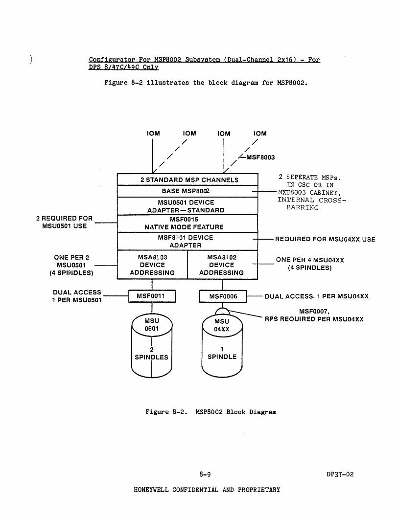
Configurator For MSP8002 Subsystem (Dual-Channel 2x16) - For DPS 8/47C/49C Only
Figure 8-2 illustrates the block diagram for MSP8002.
2 REQUIRED FOR MSUOS01 USE --""""'I
ONE PER 2 MSUOS01
(4 SPINDLES)
DUAL ACCESS ----t
1 PER MSU0501
10M 10M 10M 10M
/ /
/
/ / /
/-MSF8003 /
2 STANDARD MSP CHANNELS
BASE MSP80az
MSUOS01 DEVICE ,ADAPTER-STANDARD
MSF0015 NATIVE MODE FEATURE
2 SEPERATE MSPs. IN CSC OR IN
MXU8003 CABINET, IN1'ERNAL CROSS
BARRING
MSF8101 DEVICE ADAPTER
~- REQUIRED FOR MSU04XX USE
MSA8103 DEVICE
ADDRESSING
MSA8102 DEVICE
ADDRESSING
2 1 SPINDLES SPINDLE
--1---ONE PER 4 MSU04XX
(4 SPINDLES)
DUAL ACCESS. 1 PER MSU04XX
MSF0007, RPS REQUIRED PER MSU04XX
Figure 8-2. MSP8002 Block Diagram
8-9 DP37-02
HONEYWELL CONFIDENTIAL AND PROPRIETARY

8/47c:. MSP
8JA9~ 8002 2 x 16
Table 8-2 illustrates the configuration table for MSP8002.
TABLE 8-2. MSP8002 CONFIGURATION
The permissible maximum combinations of 16 spindles per MSP8002 are:
1 • 16 MSU04XX
2. 8 MSU0501
3. 12 HSU04XX and 2 HSU0501
4. 8 MSU04XX and 4 MSU0501
5. 4 MSU04XX and 6 MSU0501
COM· MSU04XX ITEMS BINA· TION' lSF810.J MSA MSF
MSU 8102 (FROM DEVICE 04XX
0007 ABOVE) ADAPTER ADDR (a) (b)
1 1 1·16 1·4 1·16
2 - - - -
3 1 1·12 1·3 1·12
4 1 1·8 1·2 1·8
5 1 1·4 1 1·4
a) b) c) d) e) f) g)
1 Per 4 MSU04XX (4 spindles) RPS feature required. 1 per 1 per 2 MSU0501 (4 spindles) Maximum quantity is six. 1-3 per MSP in MSP8001 Dual access feature required. Dual access feature required.
8-10
MSU0501 ITEMS
MSF MSA MSF 0006
MSU 8103 0011 MSF
0501 0015 (I) ADDR(c) (g)
1·16 - - - -
- 1·8 1·4 1·8 2
1·12 1·2 1 1·2 2
1·8 1·4 1·2 1·4 2
1·4 1·6 1·3 1·6 2
MSU04XX.
1 per MSU04XX (spindle) 1 per MSU0501 (2 spindles)
HONEYWELL CONFIDENTIAL AND PROPRIETARY
MSF 8003 (d)
0 w J:-o.!. t:cn ~....I cn W ....I Z <z z< oJ: _0 ... ~ :52 !
DP37-02
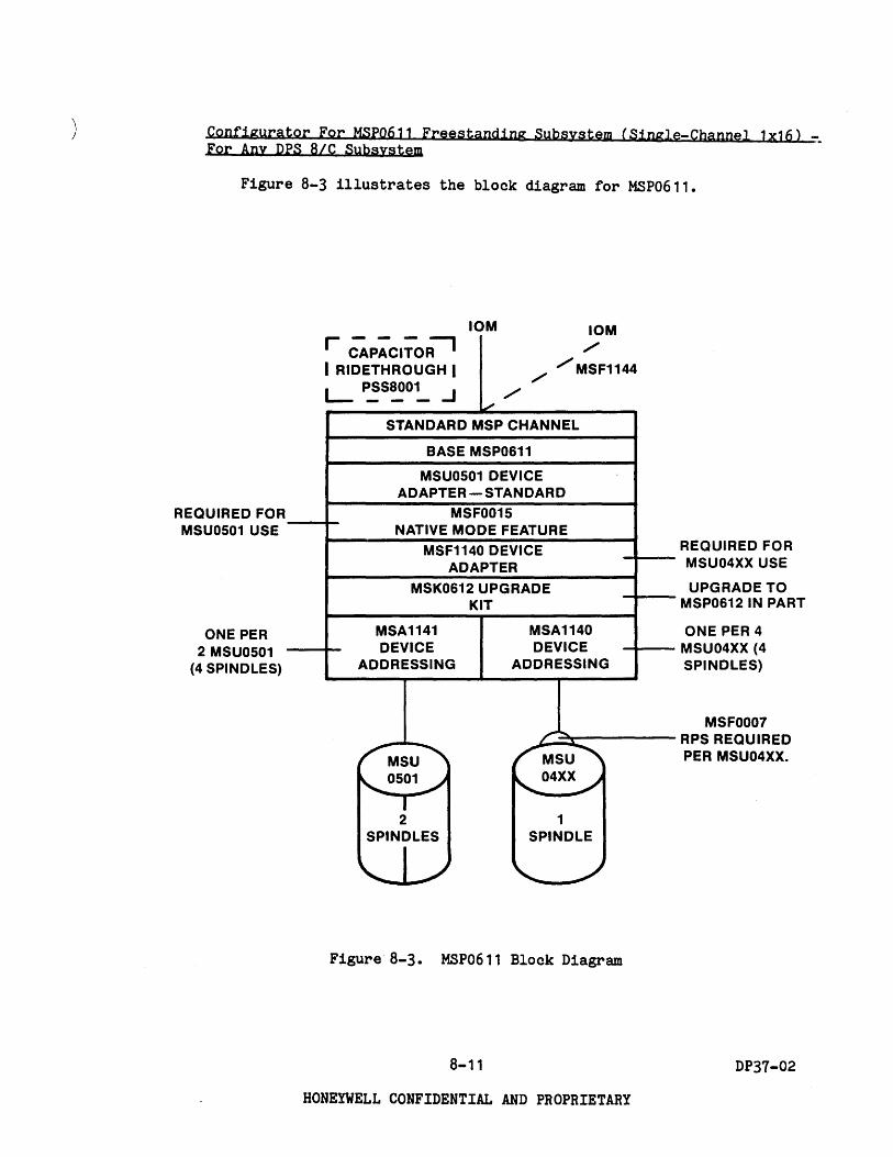
) Configura tor For MSr0611 Freestanding Subsystem (Single-Channel lx16) ~ For Any DrS BIC Subsystem
Figure B-3 illustrates the block diagram for MSP0611.
REQUIRED FOR MSU0501 USE
ONE PER 2 MSU0501
(4 SPINDLES)
10M 10M
r CAP;CI;:-O;-J ./
I RIDETHROUGH I ./ /MSF1144
L-~S~O~ ...J / /
STANDARD MSP CHANNEL
BASE MSP0611
MSU0501 DEVICE ADAPTER - STANDARD
MSFOO15 NATIVE MODE FEATURE
MSF1140 DEVICE ADAPTER
MSK0612 UPGRADE KIT
MSA1141 MSA1140 DEVICE DEVICE
ADDRESSING ADDRESSING
_ ..... ~
MSU rMSU
~O501~ ~04XX~
T -2 1
SPINDLES SPINDLE
1 -
Figure B-3. MSP0611 Block Diagram
B-11
HONEYWELL CONFIDENTIAL AND PROPRIETARY
REQUIRED FOR MSU04XX USE
UPGRADE TO MSP0612IN PART
ONE PER 4 MSU04XX (4 SPINDLES)
MSF0007 RPS REQUIRED PER MSU04XX.
DP37-02

Table 8-3 illustrates the configuration table for MSP0611.
TABLE 8-3. MSP0611 CONFIGURATION
The permissible maximum combinations of 16 spindles for MSP0611 are:
1 • 16 MSU04XX
2. 8 MSU0501
3. MSU04XX and MSU0501 totaling 16 spindles
COM· MSU04XX ITEMS MSU0501 ITEMS BINA· MSF TION, MSF1140 MSA MSF MSA MSF
MSK 1144 PSS
MSU MSU 0612 8001 (FROM DEVICE 04XX
1140 0007 0501 1141 0015 (d)
ABOVE) ADAPTER ADDR (a) RPS (b) ADDR (c)
..J 0 ANY 1 1 1-16 1-4 1-16 - - - ~~ w a:
DPS 8 MSP I-ID J: 0 a: o U(/) !::J: MODEL 0611 <Co I-..J U(!) Co(/) -w I=: 3: z <:J
(/)z Coo 1-0 <a: 2 - - - - 1-8 1-4 1 ~I- ..J< UJ: <J: ..Jw Zu ..JI-
<0 52=: <w z< Zo Oa: 1-0 0--(!) ~- j::a: I-Co Co
3 1 1-14 1-4 1-14 1-7 1-4 1 ~:J Z 0
a) 1 per 4 MSU04XX (4 spindles) b) 1 per MSU04XX c) 1 per 2 MSU0501 (4 spindles) d) Maximum quantity is three.
8-12 DP37-02
HONEYWELL CONFIDENTIAL AND PROPRIETARY
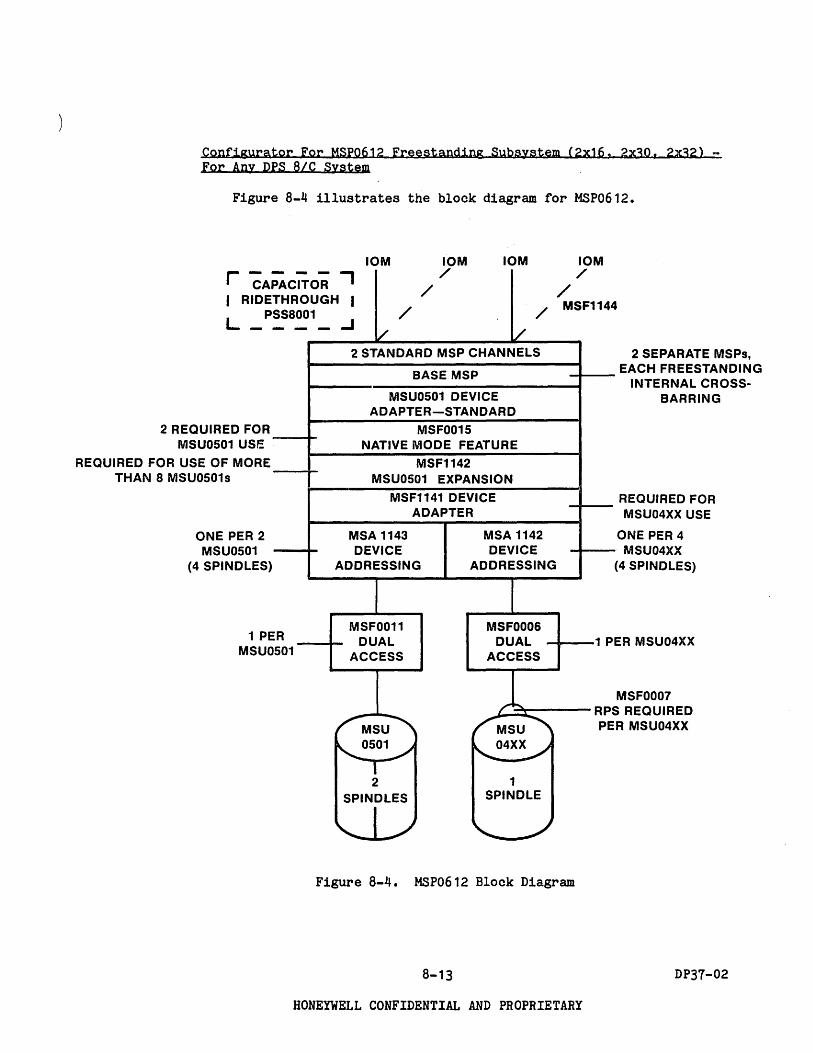
Configurator For MSpo612 Freestanding Subsystem (2x16, 2x30. 2x32) -For Any DPS 8/C System
Figure 8-4 illustrates the block diagram for MSP0612.
10M 10M 10M
PACITOR ., /
/ THROUGH I
/
2 REQUIRED FOR MSU0501 USE
REQUIRED FOR USE OF MORE THAN 8 MSU0501s
ONE PER 2 MSU0501
(4 SPINDLES)
SS8001 - --
R 1 PE MSUO 501
..J /
l/ V 2 STANDARD MSP CHANNELS
BASE MSP
MSU0501 DEVICE ADAPTER-STANDARD
MSF0015 NATIVE MODE FEATURE
MSF1142 MSU0501 EXPANSION
MSF1141 DEVICE ADAPTER
MSA 1143 MSA 1142 DEVICE DEVICE
ADDRESSING ADDRESSING
MSF0011 MSFOO06 DUAL DUAL
ACCESS ACCESS
_ .... ~ MSU MSU
",-0501,/ '-..,04XX../
T -2 1
SPINDLES SPINDLE
1 -
10M /
/ MSF1144
2 SEPARATE MSPs, EACH FREESTANDING
INTERNAL CROSSBARRING
REQUIRED FOR MSU04XX USE
ONE PER 4 MSU04XX
(4 SPINDLES)
1 P ER MSU04XX
MSF0007 RP S REQUIRED
R MSU04XX PE
Figure 8-4. MSP0612 Block Diagram
8-13 DP37-02
HONEYWELL CONFIDENTIAL AND PROPRIETARY
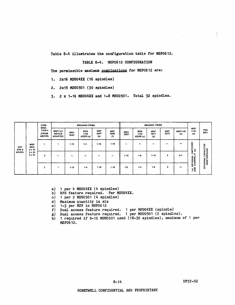
COM· BINA. TlON I
(FROM ABOVE)
MSP 1 ANY 0612
DPS 8 2 x 16 MODEL 2 x 30
2 x 32 2
3
Table 8-4 illustrates the configuration table for MSP0612.
TABLE 8-4. MSP0612 CONFIGURATION
The permissible maximum combinations for MSP0612 are:
1. 2x16 MSU04XX (16 spindles)
2. 2x15 MSU0501 (30 spindles)
3. 2 x 1-16 MSU04XX and 1-8 MSU0501. Total 32 spindles.
MSU04XX ITEMS MSU0501 ITEMS
MSF MSFl141
MSU MSA MSF MSF MSU MSA MSF MSF MSFl142 1144
DEVICE 1142 0007 0006 0501 1143 0011 0015 (h) (d) 04XX
ADAPTER ADDR (a) (b) (I) ADDR (e) (g)
1 1·16 1·4 1·16 1·16 - - - - - c w :r: u 1--~.!.
- - - - - 1·15 1·8 1·15 2 0·1 11111/ ..J J c(IiI ZZ OZ _c( I-:r:
1 1·16 1·4 1·16 1·16 1·8 1·4 1·8 2 - ~u CD== .:.2
a) 1 per 4 MSU04XX (4 spindles) b) RPS feature required. Per MSU04XX. c) 1 per 2 MSU0501 (4 spindles) d) Maximum quantity is six e) 1-3 per MSP in MSP0612 f) Dual access feature required. 1 per MSU04XX (spindle) g) Dual access feature required. 1 per HSU0501 (2 spindles). h) 1 required if 9-15 MSU0501 used (18-30 spindles), maximum of 1 per
MSP0612.
8-14 DP37-02
HONEYWELL CONFIDENTIAL AND PROPRIETARY
PSS 8001
:r:
" ::J 0 a: :r: I-W C a:

Configuring Example For Mass Storage
A DPS 8/47C prospect wants a 2-channel (2 MSPs) subsystem. Prospect will start with four MSU0451 spindles and three MSU0501 units (6 spindles).
1 4 4 4 1 1 3 3
2 2
MSP8002 MSU0451 MSF0007 MSF0006 MSF81 01 HSA81 02 MSF0501 MSF0011
MSA81 03 MSF0015
MSP for lowest price 4 Spindles RPS per MSU0451 spindle Dual access feature per MSU0451 spindle Device adapter for MSU0451 Device· addressing for HSU0451 6 spindles, 3 units Dual access feature per MSU0501 unit (2 spindles) Device addressing for MSU0501 Native Mode Features for MSU0501.
8-15 DP37-02
HONEYWELL CONFIDENTIAL AND PROPRIETARY


)
SECTION 9 Configuring Consoles
CONFIGURATION RULES FOR laM-CONNECTED CONSOLE SUBSYSTEMS FOR DPS BIC SYSTEMS
One IO~connected Console CSU6601 is required for each DPS 8/C system.
Console Subsystem (CSU6601)
At least one CSU6601 is required in each DPS 8/C system. Each base CSU6601 includes an adapter and IOM channel, a 12-inch CRT screen, keyboard, a 120-cps dot matrix printer, a connection to the DPS 8/C system DPU (Diagnostic Processor Unit), and a communication line interface for remote maintenance purposes.
The display screen (12-inch CRT) has space for 1920 characters (80 characters. times 24 lines).
The adapter unit provides two terminal-oriented communication line interfaces of EIA RS-232-C type. This allows the use of modem bypass units or modems to position the console printer, CRT, and keyboard remotely to the DPS 8 system, if desired.
o Master interface (MI) - prime connection for keyboard and CRT as part of base CSU6601.
o Slave interface (SI) - a connection slaved off the master interface. Base printer of CSU6601 connects to S1.
9-1 DP37-02
HONEYWELL CONFIDENTIAL AND PROPRIETARY
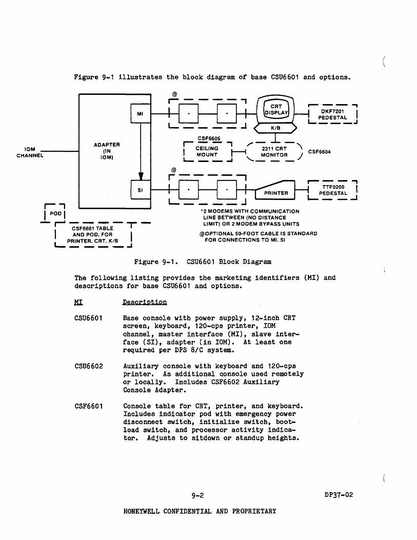
10M CHANNEL
r, 'I POD I
Figure 9-1 illustrates the block diagram of base CSU6601 and options •
ADAPTER (IN
10M)
MI
.-----, DKF7201 I
I PEDESTAL ---~--.1
CSF660S .--, ",--I CEILING 1--1 2311 CRT '\ CSF6604
MOUNT I \ MONITOR ) L.- __ ..J "' __ _
~--.., TTF0200 I
L-P~S~..J
-2 MODEMS WITH COMMUNICATION LINE BETWEEN (NO DISTANCE
..... II" 7sF;; T;;'E- T -AND POD, FOR I
I . PRINTER, CRT. KIB
LIMIT) OR 2 MODEM BYPASS UNITS
@OPTIONAL 50-FOOT CABLE IS STANDARD FOR CONNECTIONS TO MI. SI
a..- _ .-.. __ .J
Figure 9-1. CSU6601 Block Diagram
The following listing provides the marketing identifiers (MI) and descriptions for base CSU6601 and options.
CSU6601
CSU6602
CSF6601
Description
Base console with power supply, 12-inch CRT screen, keyboard, 120-cps printer, IOM channel, master interface (MI), slave interface (SI), adapter (in IOM). At least one required per DPS BIC system.
Auxiliary console with keyboard and 120-cps printer. As additional console used remotely or locally. Includes CSF6602 Auxiliary Console Adapter.
Console table for CRT, printer, and keyboard. Includes indicator pod with emergency power disconnect switch, initialize switch, bootload switch, and processor activity indicator. Adjusts to sitdown or standup heights.
9-2
HONEYWELL CONFIDENTIAL AND PROPRIETARY
DP37-02
(

TTF0200
DKF7201
CSF6604
CSF6605
A sitdown-height pedestal option for auxiliary printer and keyboard.
A sitdown-height pedestal for auxiliary 12-inch CRT and keyboard.
A 23-inch, large-screen monitor to be connected to 12-inch CRT and displaying what is shown on it. A 50-foot cable is supplied. Cable length up to 1000 feet can be obtained by ordering the W09-0001C cable assembly in the desired length. Refer to the Terminals Sales Reference Handbook Price Catalog (CG32), Section 4 for configuration and pricing.
Ceiling mount for CSF6604 to eliminate need for table for the 23-inch monitor.
Auxiliary Console Adapter - CSF6602
This adapter is similar to that for the CSU6601, but is not necessarily related to the CSU6601. It has its own rOM channel. Provides a lowcost means for use of a separate CRT and optional 23-inch, large-screen monitor. Use of CSF6602 is independent of CSU6601, except when the Extended System Control Feature (CSF6606) is used to link CSU6601 Base Console and CSF6602 with its attached CRT and keyboard. CSF6606 is discussed later in this section.
~: The official title of CSF6602 is Auxiliary Keyboard/Display Attachment Feature.
9-3 DP37-02
HONEYWELL CONFIDENTIAL AND PROPRIETARY

@
Figure 9-2 illustrates the block diagram of CSF6602 and related features.
CSF6602 @ CSF6603 --------
~--_4r-C ~~~ J~r- ;;;;7;;- II \ J L PEDESTAL '--_-' __ __...J
KIB
MI
AUXILIARY CONSOLE ADAPTER
-------TO 1000 CABLE FEET
/--2~--' (IN 10M) CSF
( CRT \ 6604 " MONITOR I
" SI
--...f@IOM _______________ ~ CHANNEL
---,---I I
r-.J...--, I CSF6605 I L ___ ..J CEILING MOUNT
FOR CSF6604
@ Optional 50-foot cable is standard for connection to MI. • 2 modems with communication line between (no distance limit)
modem bypass units with up to 2500 cable-feet between them. modems or bypasses are used, the cable length from Adapter to CRT/KB/printer is 50 feet.
Figure 9-2. CSF6602 Block Diagram
or 2 If no
9-4 DP37-02
HONEYWELL CONFIDENTIAL AND PROPRIETARY

) The following listing provides the marketing identifiers (MI) and descriptions for CSF6602 Auxiliary Console Adapter (Auxiliary Keyboard Display Attachment Feature).
HI Description
CSF6602 Auxiliary Console Adapter (in IOM) with power supply, IOM channel, master interface (HI), and slave interface (SI). Required to use CSF6603 and CSF6604. (Ordered separately, or included in price of CSU6602 Auxiliary Console.)
CSF6603 12-inch CRT with keyboard. Requires CSF6602.
DKF7201 Sitdown-height pedestal for auxiliary 12-inch CRT and Keyboard. Optional.
CSF6604 23-inch large-screen monitor, slaved off CSF6603 12-inch CRT. Displays what is shown on CSF6603. A 50-foot cable furnished. Cable up to 1000 feet can be obtained by ordering the W09-0001C cable assembly in the desired length. Refer to the Terminals Sales Reference Handbook Price Catalog, (CG32), Section 4 for configuration and pricing.
CSF6605 Ceiling mount for CSF6604. Eliminates need for table for the 23-inch monitor.
Console Switch Feature - CSF6606 (Official Title is Extended System Control Feature)
This switch feature provides a variety of switching functions for backup purposes.
o Where CSU6601 is used by itself, but with local or remote auxiliary console devices, the switch can be used to select which console device (local or auxiliary) will be the operational console device.
o Where CSU6601 and Auxiliary Console Adapter CSF6602 are used (thus two adapters and two IOM channels) the CSF6606 Console Switch Feature can be used to switch console devices between the two adapters.
o Requires CSF6601 Console Table to contain switch logic.
9-5 DP37-02
HONEYWELL CONFIDENTIAL AND PROPRIETARY

(

0 I TERMINAL
.( I TERMINAL
I TERMINAL ~
SECTION 10 Generics of Data Communications
Front End Processors (FEPs)
Figure 10-1 illustrates the block diagram of typical components of Front End Processors (FEPs). The numbers shown within the figure correlate to the paragraph numbers in the following discussion.
0 0 0 0 0
MODEM I
MODEM I I J
COMM- ~
8 UNICA· P--TION CHANNEL
INTER· LINE '--FACE MODEM I I MODEM I CHANNEL BASE BYPASS j I BYPASS I i!l
INTER· FACE (CIB)
0 CD (CI) .. DIRECT I--
CONNECT
·IN·PLANT CONNECTION. ALSO OBTAINABLE BY USE OF CURRENT LOOP INTERFACE TERMINALS
··AVAILABLE FROM SSTD
Figure 10-1. Typical Front End Processor Components
~ 10M
10-1 DP31-02
HONEYWELL CONFIDENTIAL AND PROPRIETARY

1. Terminal selection exerts a major configuring effect. Some terminal considerations:
o Terminal type: batch, keyboard (CRT, hardcopy, or both). May affect the choice of communication Channel Interface (CI).
o Terminal operating speed in bits per second, baud rate, or characters per second. Determines minimum line speed and modem speed to be selected.
o FDX (full-duplex) or HDX (half-duplex) operation of the line and terminal. May affect choice of modem, line type, or CI type. HDX is only supported for synchronous terminals.
o Synchronous or asynchronous physical transmission technique. Affects modem type and choice of CI.
o Line discipline or link protocol used by terminal. May affect CI choices in FEP; may determine whether synchronous or asynchronous transmission technique is to be used. BSC (Binary Synchronous Communications) protocol, for example, requires a specific BSCoriented CI.. HOLC and asynchronous protocols also require specific CIs. May affect choice of modem used.
o Modem selection is directly affected by terminal selection and line speed.
o In addition, some terminals use a current loop type of interface which sometimes does not use modems. (Current Loop is a transmission technique that recognizes current flow rather than voltage levels. It has traditionally been used in teletypewriter networks incorporating batteries as the transmissin power source.) Current loop is only supported for asynchronous terminals. (Modems are sometimes not used for RS-232, also.)
2. Modem stands for modulator-demodulator, a device for transforming signals between the line and the device at the end of the line. Other generic names -- data set, digital subset, subset, coupler.
o Most commonly a modem (or equivalent device) will be needed at each end of a line obtained from a public carrier company. Thus modem costs can become significant.
o Modems are often either for synchronous or asynchronous transmission. In synchronous operation the modem at each end furnishes timing signals to keep each end of the line in synchronization with the other. If the modem used does not provide timing Signals in synchronous transmission cases, a timing device must be attached to the terminal.
o The use of either 2-wire or 4-wire lines may affect modem choice or whether or not a modem is used.
10-2 DP37-02
HONEYWELL CONFIDENTIAL AND PROPRIETARY

) 3. Channel Interface (CI) is attached to a Channel Interface Base (CIB)
which is in turn contained within an FEP. (Another name sometimes used for CI is Communication Line Adapter - CLA.)
CI is a termination point or connection point into the FEP for one or two lines. The path for a given line through a CI is often called a channel, or sometimes, a subchannel.
This section refers to nlinen in the sense of (1) links provided directly or indirectly by public serviee carriers, such as telephone companies (such companies are also known as common carriers), and (2) "In-plantn type links or lines do not involve public service carriers and sometimes do not require modems. Some line considerations affecting configuring are:
o Whether public lines (also known as dialed, switched or dial-up lines) or private lines (also known as leased or direct lines) are used. Private lines do not involve dialing. There is, in effect, a permanent path established. This may affect modem choice and modem attachments.
o If private lines are involved, various levels of line conditioning are available from the telephone company to regulate line' quality -noise level, error probability, etc. Private lines mayor may not use modems depending on the type of interface: current loop without modems, EIA RS-232 or EIA RS-422 without modems (i.e., direct connect), EIA RS-232 with modems. Only one interface type may be used per line.
o Whether line is to be used on half-duplex (HOX), two-way alternate (TWA) basis, or full-duplex (FDX) basis. FDX lines can be used on either a TWA basis or two-way simultaneous basis (TWS). This may affect modem type.
o Whether line is used for both data and voice transmission, called DOV (data under voice). Normally the use of sucn transmission does not affect the modem or CI choice.
There are multiple types of CIs, some very general, some specialized. Some CIs interface one line each, some two lines each.
CIs are not included in the base FEP price but must be configured. Every line must terminate at a CI, regardless of the type of line, whether by common carrier or in-plant connection.
10-3 DP31-02
HONEYWELL CONFIDENTIAL AND PROPRIETARY
4. CIB (channel interface base) provides common service logic for a number of CIs, the number of CIs varying with CI type. (Another name sometimes used for CIB is Multi-Line Communications Processor - MLCP.)
The CIB is completely general in its capabilities. Any line speed, code set, link protocol, or transmission technique supported by our FEP hardware is supported by CIB.Cls on any given CIB must be of the same type; no mixing of ASYNC, SYNC, or HDLC on the same CIB. Mixing of SYNC (2780, 3780, HASP, 3270) on the same CIB is permitted.
CIBs are not included in the base FEP price but must be configured.
5. Base FEP. (Other names sometimes used for FEP are either Communications Processor, or Front-End Network Processor - FNP). Maximum of 12 local FEPs per system, maximum of 16 FEPs (local and remote) per system.
Attributes which may affect operation of the FEP include:
Echoplex (FDX only) - With echoplex (echo on), the FEP will echo back to the terminal whatever is entered or typed in. Without echoplex (echo off), no echo of the input stream is sent to the originating terminal. Echoplex is typically used with time sharing and other applications terminals. It would not be used when an FEP receives data from another computer.
Transparent terminal I/O - Permits a device to transmit data which will not in any way be edited by the FEP. The FEP essentially is transparent to the I/O operation. Typically used for special devices with unique control characters (e.g., graphics devices).
6. Connection to DPS 8/C 10M is provided by a DIA (direct interface adapter). Included in base CPS81XX FEP, not included in DCU8011. The DIA also includes a physical channel in the 10M.
7. Modem Bypass. Used for in-plant connections. No telephone line furnished by a common carrier such as AT&T. Modem bypass units perform same basic function as modems.
Cable length restrictions exist between two successive modem bypass units but additional units can be inserted into the line to act as repeaters or signal strengtheners. In-plant connection is considerably cheaper (long-term) than use of modems and common carrier lines.
8. Direct Connect. Another way to use in-plant connection. Direct connect features cannot be repeated in series. An in-plant line is established by a cable with no involvement of a common carrier. Advantage: lower costs. Disadvantage: no access to telephone network, no way to dial another destination.
RS232 asynchronous direct connect is assured to work for distances of up to 50 feet (up to 1000 feet under ideal conditions). The current loop asynchronous approach of in-plant connection is for distances up to 1000 cable feet. RS422 asynchronous direct connect is for distances up to 4000 feet at 19.2K baud.
10-4 DP37-02
HONEYWELL CONFIDENTIAL AND PROPRIETARY
(

SECTION 11 Configuring DATANET SIC Front End Processor (FEP)
REQUIRED CONFIGURATION COMPONENTS
o Base FEP (included in DPS SIC central system CPSS1XX or as DCUS011) (FEPs are also sometimes'calleo ~~ther Communications Processors, or Front-end Network Processors - FNPs).
o DPS SIC Host Connection (included in central system CPSS1XX; not included in DCUS011).
o Console (CIB connected. Required and included in central system CPSS1XX. Not required or included in DCUS011 but recommended for each site using DCUS011 as a remote FEP.). Requires one async line, not included in central system CPSS1XX or in DCUS011.
o One or more communication Channel Interfaces (CIs). (CIs are also sometimes called Communications Line Adapters (CLAs).) One CI per FEP is required for an async line for the console. One CI per CP-6 system is recommended for a sync line needed as a prerequisite for interfacing to the automated system for software support and distribution of patches.
Eyery line (sometimes called a sub channel or channel) must terminate in a CI from any common carrier or any in-plant connection.
Every CI represents electronic logic on circuit boards for which space is provided in "slots" in one or more general-purpose Channel Interface Bases (CIBs).
o Sufficient quantity of CIBs to connect the quantity of CIs needed to support the desired number of lines and protocols. Only one type of CI (SYNC, ASYNC, HDLC) per CIB is permitted. DN SIC does not include any CIBs in base price, but one or more must be configured in order to provide for the CIs needed to connect the lines to the FEP. (CIBs are also sometimes called Multi-Line Communications Processors (MLCPs).)
o One or more in-plant connection features if lines are not furnished by common carrier companies. In-plant connection is by use of modem bypass or direct connect features, or by use of terminals of the current loop interface type. Each must connect to an appropriate CI.
11-1 DP37-02
HONEYWELL CONFIDENTIAL AND PROPRIETARY

NETWORKING CONSIDERATIONS
CP-6 supports two kinds of FEPs: local (to the central system) and remote (from the central system). Local FEPs are connected to the central system via the DCE8006 Host Connection option. Remote FEPs are connected to local FEPs via High-Level Data Link Control (HDLC) lines. Other than for this method of connection to the system, local and remote FEPs are identical (i.e., they have the same line connectability and functionality).
DPS 8/C Networking constraints are as follows:
o Minimum of one local FEP required (included with CPS81XX). o Maximum of 12 local FEPs per system. o Maximum of 16 FEPs per system. o Maximum of 4 remote FEPs per local FEP. o Each local FEP can connect to one and only one host. o Each remote FEP can connect to one and only one local FEP. o Only one level of remote FEP is allowed (i.e., no remote FEP to remote
FEP connections are possible).
11-2 DP31-02
HONEYWELL CONFIDENTIAL AND PROPRIETARY

) CONFIGURING THE PATANET BIC
Figure 11-1 illustrates the DATANET BIC block diagram. CP-6 Basic System (M.I. SFS6120), Access Modes (M.I. SFS6121) and the Communications System (M.I. SFC6120) is the required software. (The Remote Communications Software (M.I. SFC6121) is required per each remote FEP.)
CPU AND COMMERCIAL INSTRUCTION PROCESSOR (CIP) (8) (b)
MULTIPLE DEVICE -CONTROLLER (MDC) (WITH DISKETTE) (8) (b) (f) I---
DPS 8/C HOST CONNECTION DCE8006 (ONE MAXIMUM) (8)
1-16 LINES CONNECTABILITY (8) (b)
eASE MEMORY l024K BYTES ("a) (b)
r - ;;M~ I~E-;;N':;- - l UP TO MAX OF L ___ 2~ ___ J
rL
16 TO 64 LINE EXPANSION DCE8002
-1 _J
(CIBa) MINIMUM OF 1 REQUIRED 2 CIBs FOR UP TO 16 LINES
8 CIBs FOR UP TO 64 LINES (d) 16 CIBs FOR UP TO 128 LINES (c) (e)
CHANNEL INTERFACE (CI)
l I 1-4 PER CIB, FOR 1-8 LINES PER CIB CONSOLE (8) It----t AT LEAST ONE ASYNC CI REQUIRED. MAXIMUM
OF 64 Cis AND 128 LINES
(See p. 11-4 for notes)
-1 I
IuN~RE~R~ DEVICE PACS
I UNIT RECORD I I DEVICES I L-(U~O ~0!....J
- ----, I
IA~TI~ALl MDC(d)
I UNIT RECORD I I DEVICE PACS I I UNIT RECORD I
DEVICES
~U~O FOUR2..J
NONE INCLUDED IN BASE PRICE. (BOTH CIBa AND
Cia MUST BE CONFIGURED)
Figure 11-1. DATANET BIC Block Diagram
11-3 DP37-02
HONEYWELL CONFIDENTIAL AND PROPRIETARY

Notes; (
(a) Part of FEP included with central system CPS81XX.
(b) Part of DCU8011.
(c) Expansion to 128 lines requires use of power supply in a second cabinet (included with DCE8004).
(d) Requires DCE8002 (64 line chassis).
(e) Requires DCE8002 (64 line chassis) and DCE8004 (128 line chassis).
(f) Diskette included in DN 8/C for maintenance purposes and for booting remote FEPs. (Blank media [Honeywell Product Number M4101, single sided diskette] for creating remote FEP boot diskette must be ordered via a Supply Requisition.)
• 512K bytes per memory increment, DCM8008, DCM8005. 1M byte per bus slot.
11-4 DP37-02
HONEYWELL CONFIDENTIAL AND PROPRIETARY

) Ta~le 11-1 illustrates the board slot assignments for the DATANET 8/C.
Total Slots
1 2 3 4 5 6 7 8 9
10 11 12 13 14 15 16 17 18 19 20 21 22 23 24 25 26 27 28 29 30
TABLE 11-1. DATANET 8/C BOARD SLOT ASSIGNMENTS
(CPS81XX or DCU8011)
(CPS81XX or + DCU8011 ) DCE8002
CPS81XX or + + DCU8011 DCE8002 DCE8004
SCF SCF SCF CPU Cache Cache CIP CPU CPU MDC 1 CIP CIP Coupler MDC 1 MDC 1 CIB 1 MDC2 MDC2 CIB 2 Coupler Coupler HEM 2 CIB 1 CIB 1 HEM 1 CIB 2 CIB 2 TERMINATOR CIB 3 CIB 3
CIB 4 ICIB 4 CIB 5 CIB 5 CIB 6 CIB 6 CIB 7 CIB 7 CIB 8 CIB 8 Reserved CIB 9 Reserved CIB 10 Reserved CIB 11 MEM2 CIB 12 HEM 1 Jumper
CIB 13 CIB 14 CIB 15 CIB 16 Reserved Reserved Reserved Reserved MEM2 HEM 1
Note: One CIB and one sync CI strongly recommended for a sync (HASP) line (Bell 201C modem or equivalent) as a prerequisite for interfacing to the automated system for software support and distribution of patches.
11-5 DP37-02
HONEYWELL CONFIDENTIAL AND PROPRIETARY

DATANET BIC FEP-RELATED MARKETING IDENTIFIERS AND THEIR FUNCTIONS
The following listing provides all DATANET 8/C FEP-related marketing identifiers (MI) and their functions. The list applies to base FEP included in CPS81XX and to DCU8011.
Hi Description
Base FEP
DCU8011 A freestanding FEP with 1024K bytes memory, a chassis for up to 16 line connections, and a 256K bytes diskette. No console, no DPS 8/C Host Connection, and no CIBs or CIs are included in the DCU8011. (The FEP included in the CPS81XX includes one DCU8011, one DCE8006, and one Communications Subsystem connected, 30 cps console, DCF8008 [included for maintenance purposes]. No ClBs or CIs are included with this FEP.) Maximum of 16 ClBs may be configured.
NOTE - Blank media (Honeywell Product Number M4101, Single sided diskette) for creating remote FEP boot diskette must be ordered via a Supply Requisition.
Host Connect Option (Coupler)
DCE8006 DPS 8/C Host Connection from the Dcu8011 FEP to the DPS 8/C IOM. A maximum of one may be configured. CPS81XX includes one DCU8011, one DCE8006, one Communications Subsystem connected, 30 cps console - a DCF8008, (included for maintenance purposes).
Console Options
DCF8006 120 cps communications console for the Datanet 8/C.
DCF8008 30 cps communications console for the Datanet 8/C. One is included with the CPS81XX. Requires one async line Channel
. Interface, which is not included in the CPS81XX. One console (terminal) of any type is recommended for each site using DCU8011 as a remote FEP.
11-6 DP37-02
HONEYWELL CONFIDENTIAL AND PROPRIETARY
( \

Memory Expansion
DCM8008 512K bytes memory increment for the Datanet 8/C, 1024-1536K bytes.
DCM8005 512K bytes memory increment for the Datanet 8/C, 1536-2048K bytes.
Figure 11-2 illustrates the FEP memory configurability.
DN8/C BASE SYSTEM
DCM8008
256KB 256KB DCM8005
Figure 11-2. DATANET 8/C Memory Configurability
11-7 DP37-02
HONEYWELL CONFIDENTIAL AND PROPRIETARY
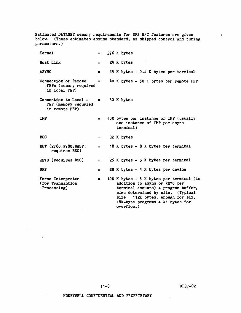
Estimated DATANET memory requirements for DPS 8/C features are given below. (These estimates assume standard, as shipped control and tuning parameters. )
Kernel
Host Link
ASYNC
Connection of Remote FEPs (memory required in local FEP)
Connection to Local -FEP (memory requried in remote FEP)
IMP
BSC
RBT (2780,3780,HASPj requires BSC)
3270 (requires BSC)
URP
Forms Interpreter (for Transaction Processing)
=
=
=
=
=
=
=
=
=
=
=
376 K bytes
24 K bytes
44 K bytes + 2.4 K bytes per terminal
40 K bytes + 66 K bytes per remote FEP
60 K bytes
400 bytes per instance of IMP (usually one instance of IMP per async terminal)
32 K bytes
18 K bytes + 8 K bytes per terminal
26 K bytes + 5 K bytes per terminal
28 K bytes + 4 K bytes per device
120 K bytes + 6 K bytes per terminal (in addition to async or 3270 per terminal amounts) + program buffer, size determined by site. (Typical size = 112K bytes, enough for six, 18K-byte programs + 4K bytes for overflow. )
11-8 DP37-02
HONEYWELL CONFIDENTIAL AND PROPRIETARY

) Performance Enhancement
DCEB003 Processor power module enhancement (cache) for the DN BIC FEP. Provides performanoe increase of approximately 20%. Prerequisite is DCEB002 (64 lines). Requirement for DCEB003 is dependent on throughput considerations. See "FEP Throughput Calculations and CI Board Packaging Tables" later in this section for a discussion of throughput factors.
Line Connection Expansion
DCEB002 Additional chassis for line configurability for the DCUB011, from the 16 base connections to a maximum of 64 lines. Only one can be configured.
DCEBo04 Additional chassis and cabinet for DCUB011 line configurability from 64 lines to a maximum of 12B lines. Prerequisite is DCEB002 (64 lines). Maximum of one can be configured.
Channel Interface Base (CIB)
DCFB007 Channel Interface Base (CIB) for the FEP. Maximum of 16 may be configured. Requires DCEB002 (64 line connections) if more than two CIBs are configured. Requires DCEB002 and DCEB004 if more than eight CIBs are configured.
One CIB accommodates up to four Channel Interface (CIs) with one transmission type (asynchronous, synchronous or HighLevel Data Link Control (HDLC» per CIB.
11-9 DP37-02
HONEYWELL CONFIDENTIAL AND PROPRIETARY

Channel Interface (CI) Options (all include 50 ft. cables)
DCF8009 Dual asynchronous channel package, EIA RS-422-A, up to 19,200 bps each. RPQ only.
DCF8011 Terminates two synchronous lines (2780, 3780, HASP or 3270) at up to 19,200 bps each. Each line can run at d~fferent speed. EIA RS-232-C interface. EBCDIC code. HOX only. Connects Dataphone 201, 208, 209, 212A, 303 or equivalent modems, DCF8026 modem by-pass, or direct connect.
DCF8012 Terminates two asynchronous lines at up to 19,200 bps each. Each line can run at different speed. EIA RS-232-C interface. FDX only. 8-11 format for 110 and 200 baud. 8-10 format for all other speeds. For Dataphone 103, 113, 212A or equiva- lent modem, modem bypass, or direct connect.
DCF8020 Terminates one line at up to 19,200 bps. For HDLC link protocol (e.g., remote FEP). Bit-oriented protocol. EIA RS-232-C interface. FDX only. For modems, modem bypass, or direct connect.
DCF8022 Terminates one line in broadband (wide band) range at up to 72,000 bps. HDLC link protocol (e.g., remote FEP). Bitoriented protocol. FDX only. Bell 301/303 compatible.
DCF8023 Terminates one line at up to 72,000 bps. HOLC link protocol (e.g., remote FEP). For CCITT V.35 interface. Bit-oriented protocol. FDX only.
DCF8036 Two async current loop ports, to 9,600 bps. FDX only.
Modem Bypass Option
DCF8026 Universal Modem Bypass feature for connection to one synchronous or asynchronous line (cable). Minimum of two per line: one at FEP end, other at terminal end. Maximum cable length between two successive bypass units is 2500 feet. Intermediate bypass units can be used as line signal repeaters or strengtheners. Cable used between the DCF8026 is customer-furnished and is specified as two pair of loosely twisted inside telephone cable equivalent to the Alpha Wire Inc. No. 1302. Speed to 19.2K bps for synchronous or 1800 bps for asynchronous.
11-10 DP37-02
HONEYWELL CONFIDENTIAL AND PROPRIETARY
( \

'Direct Connect Option
Connection may also be mC'.de without modems, using an adapter connector, cable Product Number W18-0001C (Honeywell Part Number 60128766, Rev C), which connects the CI cable to the terminal's cable or to another CI cable. Synchronous line clocking may be provided by either the CIB or the terminal (if so equipped); however, all CIs on the same CIB using CIB clocking must run at the same speed.
CIBs Packaged with Channel Interface Options
DCF8030 CIB and eight async RS-232-C ports
DCF8032 CIB and eight sync RS-232-C ports
DCF8034 CIB and eight current loop ports
DCF8038 CIB and one broadband sync port, Bell 301/303 compatible, with modem cable
DCF8040 CIB and one broadband HDLC port, V.35 CITT compatible, with modem cable
DCF8042 CIB and one broadband sync. port, V.35 CITT compatible, with modem cable
DCF8044 CIB and one broadband HDLC port, Bell 301/303 compatible, with modem cable
Unit Record Equipment
DPS 6 Unit Record equipment may be attached to the DN 8/C. See Section 6 for configuration information and example.
Attachment Feature
MXF8009 Exchange of FEP Attachment Feature (to DPS 8 systems only) -wire wrap to hard copper, in the 10M. For installed, non DPS 8 FEPs. Equipment removed and replaced by HXF8009 becomes the property of Honeywell upon removal.
11-11 DP37-02
HONEYWELL CONFIDENTIAL AND PROPRIETARY
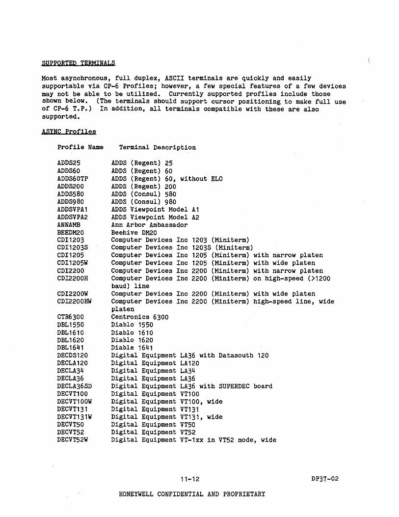
SUPPORTED TERMINALS
Most asynchronous, full duplex, ASCII terminals are quickly and easily supportable via CP-6 Profiles; however, a few special features of a few devices may not be able to be utilized. Currently supported profiles include those shown below. (The terminals should support cursor positioning to make full use of CP-6 T.P.) In addition, all terminals compatible with these are also supported.
ASYNC Profiles
Profile Name
ADDS25 ADDS60 ADDS60TP ADDS200 ADDS580 ADDS980 ADDSVPA1 ADDSVPA2 ANNAMB BEEDM20 CDI1203 CDI1203S CDI1205 CDI1205W CDI2200 CDI2200H
CDI2200W CDI2200HW
CTR6300 DBL1550 DBL1610 DBL1620 DBL1641 DECDS120 DECLA120 DECLA34 DECLA36 DECLA36SD DECVT100 DECVT100W DECVT131 DECVT131W DECVT50 DECVT52 DECVT52W
Terminal Description
ADDS (Regent) 25 ADDS (Regent) 60 ADDS (Regent) 60, without ELO ADDS (Regent) 200 ADDS (Consul) 580 ADDS (Consul) 980 ADDS Viewpoint Model A1 ADDS Viewpoint Model A2 Ann Arbor Ambassador Beehive DM20 Computer Devices Inc 1203 (Mini term) Computer Devices Inc 1203S (Miniterm) Computer Devices Inc 1205 (Mini term) with narrow platen Computer Devices Inc 1205 (Miniterm) with wide platen Computer Devices Inc 2200 (Mini term) with narrow platen Computer Devices Inc 2200 (Miniterm) on high-speed (>1200 baud) line Computer Devices Inc 2200 (Miniterm) with wide platen Computer Devices Inc 2200 (Miniterm) high-speed line, wide platen Centronics 6300 Diablo 1550 Diablo 1610 Diablo 1620 Diable 1641 Digital Equipment LA36 with Datasouth 120 Digital Equipment LA120 Digital Equipment LA34 Digital Equipment LA36 Digital Equipment LA36 with SUPERDEC board Digital Equipment VT100 Digital Equipment VT100, wide Digital Equipment VT131 Digital Equipment VT131, wide Digital Equipment VT50 Digital Equipment VT52 Digital Equipment VT-1xx in VT52 mode, wide
11-12
HONEYWELL CONFIDENTIAL AND PROPRIETARY
DP37-02

) Profile Name Terminal Description
DTM1520 DY4VGT100 GETN300 GT100 GT 400 GT400TP HP2645 HP9845 HTH14 HTH19 HTH19A HTH89 HZL1000 HZL1500 HZL1520 HZL2000 HZL2000P HZLMOD1 'IBM31 0 1-1 X IBM3101-2X IBMPC-H89 INFI100 INFI400 INFSTL INFVST INTI INTII INTSII LSIADM31 LSIADM3A LSIADM5 MCRACTIV NEC5510 NEC5515 NEC5520 NEC5525 PE550 PRU1002 PRU1003 PRU1005 SDS420 SNRKTM380 SOROC120 TEK4010 TEK4010L TEK4013 TEK4013L TEK4023
Datamedia Elite 1520A DY-4 Systems VGT-100 GE Terminet 300 General Terminal GT 100 General Terminal GT 400 General Terminal GT 400 for TP Hewlett Packard 2645 Hewlett Packard 9845 Heath H14 Printer Heath H19 Heath H19 (ANS mode) Heath H89 Hazeltine 1000 Hazeltine 1500 Hazeltine 1520 Hazel tine 2000 Hazeltine 2000 Printer Hazeltine Modular IBM 3101-1X IBM 3101-2X IBM Personal Computer in Heath H89 mode Infoton 1-100 Infoton 1-400 Infoton Satellite Infoton Vis tar Intertec Intertube I Intertec Intertube II Intertec Superbrain II Lear Siegler Inc ADM 31 Lear Siegler Inc ADM 3A Lear Siegler Inc ADM 5 Microterm ACT-IV NEC 5510 (Spinwriter) NEC 5515 (Spinwriter) NEC 5520 (Spinwriter) NEC 5525 (Spinwriter) Perkins Elmer 550 Honeywell' PRU1002 Honeywell PRU1003 Honeywell PRU1005 SDS (Scientific Data Systems) 420 Synertek KTM 3/80 Soroc 120 Tektronix lJ010 Tektronix lJ010, long, narrow Tektronix lJ013 Tektronix lJ013, long, narrow Tektronix 4023
11-13
HONEYWELL CONFIDENTIAL AND PROPRIETARY
DP37-02

Profile Name Terminal Description
TEK4024 TEK4025 TEK4027 TI725 TI733 TI743 TI745 TI783 TI785 TI787 TI810 TI820 TLR1000 TLR3300 TRS80H1 TRS80H2 TVI912A TVI912C TVI920 TVI950 TTY33 TTY35 TTY37 TTY43 TWU1002 TWU1003 TWU1005 TWU91 01 TWU91 04 TWU91 06 VC303A VC403A VC404 VC414H VIP7100 VIP( 1 05 VIP7200 VIP7201 VIP7205 VIP7301 VIP7801 VIP 7802 XRX850 XRX1760 XRX7015 ZEHZ19 ZENZ89
Tektronix 4024 Tektronix 4025 Tektronix 4027 Texas Instruments 725 Texas Instruments 733 Texas Instruments 743 Texas Instruments 745 Texas Instruments 783 Texas Instruments 785 Texas Instruments 187 Texas Instruments 810 Texas Instruments 820 Teleray 1000 Teleray 3300 Radio Shack TR5-80 Hodel 1 Radio Shack TnS-80 Hodel 2 Televideo TVI-912A Televideo TVI-912C Televideo TVI-920 Televideo TVI-950 Teletype Hodel 33 Teletype Model 35 Teletype Hodel 37 Teletype Hodel 43 Honeywell TWU1002 Honeywell TWU1003 Honeywell TWU1005 Honeywell TWU9101 Honeywell TWU9104 Honeywell TWU9106 Volker Craig VC303A Volker Craig VC403A Volker Craig VC404 Volker Craig VC414H Honeywell VIP 7100 Honeywell VIP 7105 Honeywell VIP 7200 Honeywell VIP 7201 Honeywell VIP 7205 Honeywell VIP 7301 Honeywell VIP 7801 Honeywell VIP 7802 Xerox 850 Xerox 1760 Xerox 7015 Zenith Z19 Zenith Za9
11-14
HONEYWELL CONFIDENTIAL AND PROPRIETARY
(
DP37-02
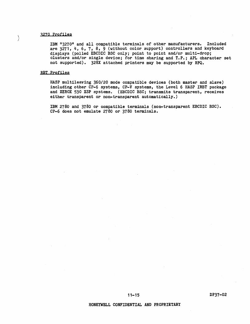
3270 Profiles
IBM n3270n and all compatible terminals of other manufacturers. Included are 3271, 4, 6, 7, 8, 9 (without color support) controllers and keyboard displays (polled EBCDIC BSC only; point to point and/or multi-drop; clusters and/or single device; for time sharing and T.P.; APL character set not supported). 328X attached printers may be supported by RPQ.
RBT Profiles
HASP multileaving 360/20 mode compatible devices (both master and slave) including other CP-6 systems, CP-V systems, the Level 6 HASP IRBT package and XEROX 530 XSP systems. (EBCDIC BSC; transmits transparent, receives either transparent or non-transparent automatically.)
IBM 2780 and 3780 or compatible terminals (non-transparent EBCDIC BSC). CP-6 does not emUlate 2780 or 3780 terminals.
11-15 DP37-02
HONEYWELL CONFIDENTIAL AND PROPRIETARY

FEP THROUGHPUT CALCULATIONS AND CI BOARD PACKAGING TABLES
The configurability of CIs is affected by three items: CIBs, physical board size, and throughput load factor.
CIs on any given CIB must be of the same type; no mixing of async, sync or HOLC on the same CIB. Mixing of sync (e.g., 2780, 3780, HASP, 3270) on the same CIB is permitted.
In addition, a maximum of 1 active broadband line per CIB should be observed. CIB maximum throughputs can be derived from
--------------------Tab~e-11-2 •• ----------------------------------------------------------
TABLE 11-2. CIB THROUGHPUT CAPACITY
Protocol Maximum Lines per CIB
Async (full duplex) 4 9600 baud, simultaneous input plus
Sync (half duplex)
HDLC (full duplex)
output (e.g., microcomputer), or, 8 9600 baud, mostly output (e.g., time
sharing).
8 9600 baud, or 1 72,000 baud
8 9600 baud, or, 1 72,000 baud.
(Preferred placement of CI types within the FEP cabinet, from top to bottom, is as follows: Async, Sync, HOLC, Broadband Sync,
'Broadband HOLC.)
Physical Board Size
Channel Interfaces are either quarter- or half-board sizes depending on their specific functionality. The physical capacity of each CIB is either four quarter-boards, two half-boards, or two quarter-boards and one half-board Channel Interfaces as illustrated in Figure 11-3.
HAL~BOARD
CHANNEL INTERFACE CHANNEL INTERFACE
BASE
Figure 11-3. CI Physical Board Sizes
11-16
HONEYWELL CONFIDENTIAL AND PROPRIETARY
QUARTER-BOARD CHANNEL INTERFACE
DP37-02
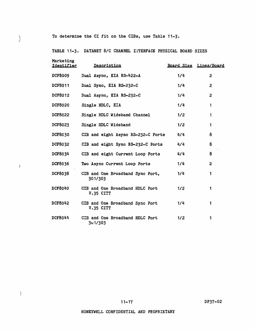
) To determine the CI fit on the CIBs, use Table 11-3.
TABLE 11-3. DATANET 8/C CHANNEL IHTERFACE PHYSICAL BOARD SIZES
Marketing Identifier Description
DCF8009 Dual Async, EIA R8-422-A
DCF8011 Dual Sync, EIA R8-232-C
DCF8012 Dual Async, EIA R8-232-C
DCF8020
DCF8022
DCF8023
DCF8030
DCF8032
DCF8034
DCF8036
DCF8038
DCF8040
DCF8042
DCF8044
Single HDLC, EIA
Single HDLC Wideband Channel
Single HDLC Wide band
CIB and eight Async R5-232-C Ports
CIB and eight Sync R8-232-C Ports
CIB and eight Current Loop Ports
Two Async Current Loop Ports
CIB·and One Broadband Sync Port, 301/303
CIB and One Broadband HDLC Port V.35 CITT
CIB and One Broadband Sync Port V.35 CITT
CIB and One Broadband HDLC Port 3u1/303
11-17
Board Size Lines/Board
1/4 2
1/4 2
1/4 2
1/4
1/2
1/2
4/4
4/4
4/4
1/4
1/4
1/2
1/4
1/2
8
8
8
2
1
DP37-02
HONEYWELL CONFIDENTIAL AND PROPRIETARY

Throughput Load Factor
The FEP has a limit to the total communication load it can handle. In order to calculate whether this limit has been exceeded, throughput factors based on protocol type have been estimated and_ are discussed below. These estimates should be used as guidelines to aid in configuring FEPs. Figures 11-4 through 11-13 assume standard tuning, SUPER, and FEPCOM parameters, and represent throughput characters (char/min) as measured between the host and the FEP.
Figures 11-4 through 11-13 assume 1024, 1536 or 2048K bytes of FEP memory. Configurations with 768, 1280 or 1792K bytes of FEP memory may experience performance penalties averaging approximately 10%.
In addition to protocol type, the effect of TP forms processing and the effect of DATANET-connected unit record devices and remote FEPs must also be considered in total throughput calculations. These factors are discussed at the end of this section.
In addition to total FEP throughput factors,-a maximum of 1 active broadband line per CIB should be observed.
PROTOCOL TYPE.
Communications processors, referred to as FEPs in this discussion, are normally configured to support a customer's required throughput expressed in characters per minute. The throughput available from a particular FEP is independent of the number of lines and the individual line speeds.
11-18 DP37-02
HONEYWELL CONFIDENTIAL AND PROPRIETARY
(

The charts describing the FEP consumption for each different protocol are broken down between asynchronous and synchronous cdmmunications. Communications load estimates can be plotted on these charts assuming you know the character rate/minute and the typical message length.
Figures 11-4 to 11-6 illustrate FEP consumption for asynchronous operations.
Char/Min
85,()()()
BO,()()()
75,()()()
70,()()()
, 65,()()()
60,()()()
55,()()()
50,()()()
45,000
40,000
35,000
30,000
25,000
20,000
15,000
10,000
5,000
I I I
i ,/ ./., ~ 1
'i /. ~. /'
.~.' / .~ ~ /' .'
/.' /' .' /.'/ / /
:~ ~, / I /' /'/'
~/~ ./ ~/. /
~ /. ,/' I~/~'~
~.,
kj ./ ~ :::::::: ~
~v./ ~ t::::::= ~ ~/ ---~ -4~'
10 20 30 40
% FEP Consumption
/." .I' ~'
"'~:/ /'/' /
,
' i' .I'
r;.' / .I'
/' /' ,,' ~.
/'
./
----~ t:::::== ----
Record Size in Characters
,~
.'L.~ /./.
~'/'
/. ,
" /
,/.,
!
I
! I
----~ ~
-
512 256
128
60
80 40 20
10 5
Transparent *
Non-Transparent * (Timesharing)
Figure 11-4. ASYNC Input Performance
• Non-transparent ASYNC input is for normal time-sharing. Transparent ASYNC input is for connections such as micro-computers and other devices that require a transparent data stream (i.e., no echo, no character translation, no IMP, ana no special character detection).
11-19 DP37-02
HONEYWELL CONFIDENTIAL AND PROPRIETARY

CHAR/MIN
280,000
260,000
240,000
220,000
200,000
180,000
160,000
140,000
120,000
100,000
80,000
60,000
40,000
20,000
20 40 60 80
0/0 FEP CONSUMPTION
Figure 11-5. ASYNC Output Performance· Non-Transparent (Time-Sharing)
60
40 RECORD SIZE IN CHARACTERS
30 i
20
10
100
• Based on VIP1801 profile - medium to high capability terminal with direct cursor control.
11-20 DP37-02
HONEYWELL CONFIDENTIAL AND PROPRIETARY

CHAR/MIN 2,400,000 ,....-.,.--~---.----'T--r---.,..--..,.----,----r-......, 2048
1024 2,200,000 I---+---+----+----+--r---+---+---+---+-+~
2,000,000 f---+--+---+---+---+---+---+----+-~~-~
8 512 1, 00,000 t---+---+---+---+----+---+----;-...,...f---~--:l1IIIt
1 ,600,000 1---+---+---+---+----if---+----"j~---1-____:~-___i
1 ,400,000 I---+---+---+---+--_+--J.".#--+-~~-+_~ 256
1 ,200,000 t---~-~--+---+---'t##-+--~-+-- -+-~----I
1 ,000,000 ~-+--+---+--~"..._+~~----I_:JIIA~t---+_---:::~ .. 256
120
120 600,000 t----t----+---M'-~~-+-~-+--". pr::;.----,::~-_+-~.--------
30
200,000~~~~~~E~E:E:t:[:[=[J 20 40 60 80 100
% FEP CONSUMPTION
Figure 11-6. ASYNC Output Performance Transparent
--- IS STANDARD TUNING PARAMETERS ...
- IS MODIFIED TUNING PARAMETERS **
RECORD SIZE IN CHARACTERS
• Dashed lines are for standard tuning parameters, which are optimized for normal time-sharing and do not provide high throughput for large records •
•• Solid lines are for modified tuning parameters, given below, which are recommended for record sizes greater than 120.
Async Blocking Value = 10,000 bytes (standard = 2000) Async Unblocking Value = 2,000 bytes (standard = 500) Big Output Buffer Byte Size = 1,024 bytes (standard = 256)
Memory requirements triple for those terminals which use these modified tuning parameters.
11-21 DP37-02
HONEYWELL CONFIDENTIAL AND PROPRIETARY

If the customer wishes to upgrade the line speeds for interactive asynchronous terminals, the following general rule may be used as a guideline.
Quadrupling the line speed (four times faster) causes a 50% increase in the output character rate. The input rate remains constant.
If the customer wishes to attach intelligent devices on a communications line (minicomputer w/instruments, peripherls, etc.), the required character rate and typical record length is determined by an analysis of the application. Record length may be defined, for example, as the average number of characters per read or per write.
In some cases asynchronous applications do not require echo operations on input. If so, use the top half of Figure 11-4 to determine FEP utilization.
To summarize, the following information must be obtained:
o Total asynchronous input rate from all terminals in characters per minute and/or desired input rate from minicomputers, etc. Also determine if echoplex (non-transparent mode) is required.
o Average asynchronous input message/line length (divide character rate by number of interactions).
o Total asynchronous output rate to all terminals and/or desired output rate to minicomputers, etc.
o Average asynchronous output message/line length (divide character rate by number of terminal writes).
Figures 11-7 to 11-9 illustrate FEP consumption for synchronous communications.
The HASP, 2780 and 3780 protocols require the same amount of FEP capacity for input and output. The FEP has a somewhat higher capacity for 3270 output than for 3270 input. The required character rate and message length is determined by an analysis of the application. Synchronous comunications activities occur at a lower priority than asynchronous activities. A temporary overload of the FEP capacity will result in slower synchronous I/O but no loss of data.
11-22 DP37-02
HONEYWELL CONFIDENTIAL AND PROPRIETARY

CHAR/MIN
) 360,000
340,000
320,000
300,000
280,000
260,000
240,000
220,000
200,000
180,000
160,000
140,000
120,000
100,000
80,000
60,000
40,000
20,000
20 40 60 80 % FEP CONSUMPTION
RECORD SIZE IN CHARACTERS
20
10
100
Figure 11-7. HASP, 2780, 3780 Input & Output Performance
11-23 DP37-02
HONEYWELL CONFIDENTIAL AND PROPRIETARY

16,000
14,000
12,000
10,000 z :E
8,000 " a: < l: CJ 6,000
4,000
2,000
RECORD SIZE IN
L---~--~--+---+---~~~~~~~~;-~30 CHARACTERS
10
20 40 60
0/0 FEP CONSUMPTION
Figure 11-8. 3270 Input Performance
11-24 DP37-02
HONEYWELL CONFIDENTIAL AND PROPRIETARY
(

)
180,000
80 160,000
60
140,000 50
40
z 120,000
2 30 RECORD ......
100,000 SIZE IN
a: CHARACTERS c( %: (J
80,000 20
60,000 10
40,000
20,000
20 40 60 80 100
0/0 FEP CONSUMPTION
Figure 11-9. 3270 Output Performance
11-25 DP37-02
HONEYWELL CONFIDENTIAL AND PROPRIETARY

Another term that is used to help determine the FEP load for synchronous applications is called the device duty cycle. This is determined by evaluation of the percentage of available time that a particular device (e.g., card reader, line printer, etc.) must run at its rated speed. If a 300 lpm printer is only required to run 25% of the time, then its duty cycle is 25%. This means that the applications load will permit printing to be slowed down to as much as 25% ot' 300 lpm or 75 lpm depending on the FEP consumption of other concurrent operations.
To calculate application dependent character rates per minute, use these three elements in the following way: Device rated speed (in units per minute) x average unit character length x duty cycle percentage = total characters/minute. For example, assume 60 characters per line (unit) for a 300 lpm printer with a 25% duty cycle. The formula would calculate as follbws: 300 lpm x 60 char/line x 25% duty cycle = 4500 char/min synchronous output.
COmmunications Load EXample
The following example may help clarify the load calculation process.
Assume that a customer desires the following communications equipment on his system:
Synchronous Operations:
HASP Workstation with 200-cpm reader, 600-lpm printer Average characters per card: 20; Duty cycle = 75% Average characters per line: 60; Duty cycle = 75%
HASP Workstation with 1200-lpm printer Average characters per line: 60; Duty cycle = 25%
Asynchronous Operations:
Time Sharing Terminals (111) Input rate (echo on): 60 char/min/terminal; Output rate: 500 char/min/terminal;
Graphic Scope (1)
10 char/message 40 char/message
Input rate (echo on): Output rate:
60 char/min; 1500 char/min;
10 char/message 40 char/message
Minicomputer (1) Input rate (echo off): 14,400 char/min; 60 char/message
11-26 DP37-02
HONEYWELL CONFIDENTIAL AND PROPRIETARY
( I

Communications Load Example (Continued)
Character Fates Message Length
.Q.t.y. Input
1st Workstation: 200 cpm 20
2nd Workstation:
Async Terminals: 112 In 60 cpm 111 Out 10
Graphic Scope: 1 In* 1 Out
Minicomputer: 14,400 cpm 60
Total FEP Load
* Included with Async. Terminals - In a Use the "Non-Transparent" scale b Use the "Transparent" scale
Output
600 lpm 60
1200 lpm 60
500 cpm 40
1500 cpm 40
Duty Total ~ Char/Min
75% Input 3,000 Output 27,000
25% Output 18,000
Input 6,720 Output 55,500
Output 1,500
Input 14,400
Thus 2 FEPs would be required to ensure desired throughput.
11-27
HONEYWELL CONFIDENTIAL AND PROPRIETARY
% From ~ Figure
3 11-7 10 11-7
7 11-7
65 11-4a 37 11-5
1 11-5
24 11-4b
147
DP37-02

TP FORMS PROCESSING
Figures 11-10. and 11-11. are used to estimate the FEP performance consumption used in handling a specified Forms Processing load.
In this document we refer to only two types of forms processing, "system input" and "system output" transactions. System input transactions are characterized as involving a read of some amount of information from a terminal and writing that information to the Host system for processing. System output transactions are characterized as involving a read from the Host for information that is subsequently displayed on a terminal.
SYSTEM INPUT SYSTEM OUTPUT
= TERMINAL READ + HOST WRITE = HOST READ + TERMINAL WRITE
For each transaction, find the correct slope on the appropriate chart for the average field size. Locate where this slope intersects with the appropriate number of fields. Read down to the horizontal axis for the % FEP consumption x 1000 for each transaction.
The % FEP consumption x 1000 for each transaction is multiplied by the actual transaction rate per hour/1000 (as the chart is based upon 1000 transactions per hour).
Do this for each forms application and sum to get the total transaction processing % FEP consumption.
Note that the number of physical terminals connected to the FEP does not dictate the performance of the machine. Only when the terminals are doing something as part of transactions do they affect the performance of the FEP. This aspect is implicit in Figures 11-10 and 11-11. Also, Figures 11-10 and 11-11 assume an average amount of user forms processing.
11-28 DP37-02
HONEYWELL CONFIDENTIAL AND PROPRIETARY

)
140
130
120
110
100
90 5
NUMBER 80 OF
FIELDS 70 PER
TRANSACTION 60
50
40 20
30
40 60 80
20 40 60 80 100
0/0 FEP CONSUMPTION X 1000
Figure 11-10. fEP TP Forms Performance, Systems Input (1000 Transactions Per Hour)
11-29
HONEYWELL CONFIDENTIAL AND PROPRIETARY
AVERAGE FIELD SIZE IN BYTES
DP37-02

380.---r---r---~--~--r---~--~--~--~~
1
3601----+_-
5 340r_--r---r---~--~--~--~--~--+---~~
320r---r---r---~~r--4---+---+---+~~~~10
300 1-----+----+---- --t---T---T--I---Jl--I-~~
280r_--r--r-----~-~-~--~~~~+--A
260r--+---r-----~--~--~--~~~-~~
240 1---+--+--- -t---t----f----l~~:.....-.+-..,'---+-~-I
NUMBER 220r_-r--r----~-~~~~~~+-~~~ OF
FIELDS PER ~OOr--r--r------~-~~~-~~~~~--J
TRANSACTION 180~-+--+----~~~~
100r--r--r-~~~~~~~~-+--+--+---~
60r--+-~~~~~~------~-+-'--+---~~
401---- ! ~~~+----+-- ~--
20
20
30
40
60
20 40 60 80 100
% FEP CONSUMPTION X 1000
F1gure 11-11. FEP TP Forms Performance, Systems Output (1000 Transactions Per Hour)
11-30
HONEYWELL CONFIDENTIAL AND PROPRIETARY
(
AVERAGE FIELD SIZE IN BYTES
DP37-02

The following example will help clarify the load calculation process for TP Forms Processing.
Suppose that we determine that a customer has four applications which we will call A, B, C, and D. Applications A and B are data collection applications (another way of saying they process system input transactions). Application C performs Inquiry and Response operations (another way of saying that C does both system input and system output operations). Finally, application D generates reports (another way of saying that it processes system output transactions).
Application A, which processes system input transactions, reads 2 fields from the terminal which total 20 characters. This application is expected to process 1800 system input transactions per hour.
Application B, which also processes system input transactions, reads 40 fields comprising 300 bytes of information. It is expected to handle 120 system input transactions per hour.
Application C, which processes system input and system output transactions, reads 3 fields totaling 12 bytes from the terminal which it sends to the Host for processing. It receives 550 bytes in response and displays those bytes in 40 fields. Application C is expected to process 1200 transactions per hour.
Application D, which processes system output transactions, receives 1000 bytes from the Host and writes them to the terminal as 100 fields. It is expected to produce 20 reports per hour.
This set of programs and their % FEP consumption can be described as follows:
Note that the numbers in the column labeled "Fields" are either Input Fields (if the transaction type is system input) or Output Fields (if the transaction type is system output). Note also that there are two entries (lines) for Application C which processes both system input and system output transactions.
Bytes/ Rate/ Trans Application Transaction Type Fields Total Bytes Field Hour %FEP/1000 Figure
A B C
D
System Input 2 20 10 1800 5 System Input 40 300 7.5 120 55 System Input 3 12 4 1200 5 System Output 40 550 13.75 1200 15 System Output 100 1000 10 20 33
Thus, the applications in this example would require approximately 41% , of a DN8/C FEP to complete their tasks.
11-31 DP37-02
HONEYWELL CONFIDENTIAL AND PROPRIETARY
11-10 11-10 11-10 11-11 11-11
Total
". "
% FEP
9 7 6
18
41%

A more precise estimate of the % FEP consumption may be made by using the following equations:
systems input: systems output:
tms = 64 + (17 x f) + (2.5 x b) tms = 56.4 + (7 x f) + (.112 x b)
where tms = the time in milliseconds required to process a transaction f = the number of fields in the transaction b = the total number of bytes in the transaction.
To get the % FEP consumption, compute tms for each transaction, multiply tms by the transaction rate per hour, sum the results for all transaction types and divide the total by 2.67 million.
Using this method in the above example yields the following:
Application Transaction Type Fields Bytes .t.mL Rate/Hr ms. used
A System Input 2 20 1~8 1800 266,400 B System Input 40 300 1494 120 179,280 C System Input 3 12 1~5 1200 174,000
System Output 40 550 398 1200 477,600 D System Output 100 1000 868 20 17,368
Total 1,114,648
1114648 = 42% of an FEP 2670000
11-32 DP37-02
HONEYWELL CONFIDENTIAL AND PROPRIETARY

) UNIT RECORD DEVICES
Figure 11-12 illustrates the FEP consumption for unit record devices. In Figure 11-12 use the "40 charlcter record" line for all card reader record lengths. Use the other lines as appropriate for line printer calculations.
340,000
320,000
300,000
280,000
260,000
240,000
220.000
I, / VI
V/~
I V )
/1 20
//1 00
I
/ 80
/ RECORD SIZE IN CHARACTERS
200,000 z
,VI ;j I
V 7 60
~ ~ 180,000 c( ::z: (.) 160,000
140,000
120,000
100,000
80,000
60,000
40,000
20,000 i °
I V I~ / ,/I V /
V /
h V V / .,
~
W V / ~
~V j W/ /~
/ /
~ f/ / ~
V~
~ ~ / "", V ~ ~
~ V ~ ~
~
~ ~ 20 40 60 80
% FEP CONSUMPTION
Figure 11-12. UHP Performance
11-33
/ V
~ ~
-""'"
/ USE THIS LINE
" FOR A!d:. CR INPUT
20
100
DP37-02
HONEYWELL CONFIDENTIAL AND PROPRIETARY

z :i "-cc c( ::c (,)
REMOTE FEPS
Figure 11-13 is used to compute the load a remote FEP places on a local FEP. It should be used in calculating local FEP consumption, both input and output.
Figure 11-13 should be used for all work on the remote FEP, except Transaction Processing. If Transaction Processing is done on the remote FEP, add 5% to the number computed by using Figure 11-13, to get the total load % the remote FEP places on its local FEP.
Use Figures 11-4 through 11-12 for calculating the remote FEP consumption from the devices attached to it.
Figure 11-13 assumes frame size of 1024 bytes, which is the CP-6 default for Non-Public Data Network (PDN) connections. PDN connections require a frame size of 146 bytes which doubles FEP consumption.
2,400,000 ~--~--~---r--~----~--~--~--~---T--~ 2048
2,200,000
2,000,000 ~--+---~---r--~----~--+---~--~~-+--~1024
1,800,000
1,600,000
1,400,000 512
1,200,000
240
1,000,000
800,000 120
80 600,000
60
400,000 40
200,000 20
20 40 60 80 100
0/0 FEP CONSUMPTION
Figure 11-13. Remote FEP Performance - Input and Output, No Transaction Processing
11-34
HONEYWELL CONFIDENTIAL AND PROPRIETARY
AVERAGE RECORD SIZE IN BYTES
DP37-02
(

Determination of Remote FEP Link Speed
One-half of the HDLC (X.25) link bandwidth in each direction between a local and a remote FEP is available for user data (i.e., terminals and devices on the remote FEP). If this is exceeded, non-symbiont output (e.g., timesharing terminals) has priority over symbiont output (e.g., URP, HASP, 2780, 3780), although symbiont output will never be completely locked out.
Example: The following devices are on a remote FEP:
o 20, 30 cps asynchronous time-sharing terminals, 15 of which may be outputting currently.
o 1,440 lpm URP printer with an average record length of 50 columns and a duty cycle of 40%.
The 15 outputting asynchronous time-sharing terminals will consume 450 bytes per second of bandwidth (30 cps x 15 terminals = 450 bytes per second). The 440 lpm printer will consume 146 bytes per second of bandwidth (440 lpm x 50 columns divided by 60 seconds per minute x .40 duty cycle = 146 bytes per second). Therefore, a 9600 baud link is needed between the local and the remote FEP (450 + 146 = 596 bytes per second; 596 x 8 bits per byte x 2 = 9536 baud). Input is insignificant in this example.
11-35 DP37-02
HONEYWELL CONFIDENTIAL AND PROPRIETARY

PATANET B/C CONFIGURATION EXAMPLES
Example 111
Customer requires
50 Time sharing (T/S) async lines
Assume
30 300 baud - Avg. input message size = 10 char/line Avg. output message size = 40 char/line Avg. input typing rate = 30 char/min. Avg. terminal output rate = 425 char/min.
and 20 1200 baud - Avg. input message size = 10 char/line Avg. output message size = 40 char/line Avg. input typing rate = 30 char/min. Avg. terminal output rate = 650 char/min.
9600 baud async line for input from a minicomputer - echo off; Avg. 60 char message; duty cycle 80%
Spare CIBs and async lines for backup.
Solution
Throughput calculations.
( 1 ) (2) (3) (1) x (3) Terminal Rate
Terminal # Avg. Msg. Char/Min Total % ~ Speed Lines Length Per Terminal Char/Min. f.Ef Figure
T/S 300 baud 30 10 30 Input
300 baud 30 40 425 Output
1200 baud 20 10 30 Input
1200 baud 20 40 650 Output
Minicomputer 9600 baud Async Line
*Assume 8-10 format. Therefore 9600 baud = 960 char/sec. 960 char/sec x 60 sec/min x 80% duty cycle = 46,080 char/min.
11-36
900 8%
12,750 7%
600 4%
13,000 8%
Total T.S. = 27%
46,080* 78%
11-4 Non-Transparent
11-5
11-4 Non-Transparent
11-5
11-4 Transparent
Total FEP = 105% --> Cache Required
DP37-02
HONEYWELL CONFIDENTIAL AND PROPRIETARY

) Memory calculations
Configuration 50 TIS Async Terminals + 1 Minicomputer (terminal)
51 Terminals
Kernel = 376K bytes
Host Link' = 24K bytes
Async = 44K bytes + (51 terminals x = 166.4K bytes 2.4K Bytes/terminal)
Total FEP = 566.4K bytes --> 1024K bytes
Required Configuration Components
Quantity
1
1
8
50
CPS81XX
DCE8002
DCE8003
DCE8030
VIP7801
11-37
Description
Central system - includes DATANET 8/C, console, coupler, diskette, 1024K bytes of FEP memory.
Additional chassis for 16 to 64 line configurability.
Processor Power Module - Cache
Channel Interface Base + 4 Async Channel Interfaces (8 Async Ports)
TIS Terminals
DP37-02
HONEYWELL CONFIDENTIAL AND PROPRIETARY

Example 12
Customer reQuires
75 Async Transaction Processing (T.P.) lines for 7 applications having the following attributes.
Application Transaction Type Fields Total Bytes Rate/Hour
A System Input 3 15 250 System Output 10 100 250
B System Input 1 10 600 System Output 4 120 600
C System Input 5 40 100 D System Input 2 20 400 E System Input 5 50 1500 F System Input 10 30 1000 G System Output 50 2000 30
These applications require 14 Forms Programs, each averaging 18K bytes, although only 10 of these programs are required to be active at one time.
1 FEP-connected printer 600-lpm;Avg. Print Line 60 char; Duty cycle 50%.
Spare CIBs and lines for backup
Solution
Throughput calculations
Total Bytes/ Rate/ Trans % % ~ Application Transaction Type Fields Bytes Field ~ FEP/l000 Figure ~
T.P. A System Input 3 15 5 250 6 11-10 1.5 System Output 10 100 10 250 6 11-11 1.5
B System Input 1 10 10 600 4 11-10 2.4 System Output 4 120 30 600 5 11-11 3.0
C System Input 5 40 8 100 8 11-10 0.8 D System Input 2 20 10 400 5 11-10 2.0 E System Input 5 50 10 1500 10 11-10 15.0 F System Input 10 30 3 1000 12 11-10 12.0 G System Output 50 2000 40 30 24 11-11 0.7
Total T.P. = 39%
FEP Device Duty Total Chart Char ~ Peripherals Speed-LPM Cycle Lines/Min .IJ.rut H1n.... Figure ~
Printer 600 50% 300 60 18000 11-12 6%
Total FEP = 44%
11-38 DP37-02
HONEYWELL CONFIDENTIAL AND PROPRIETARY
/
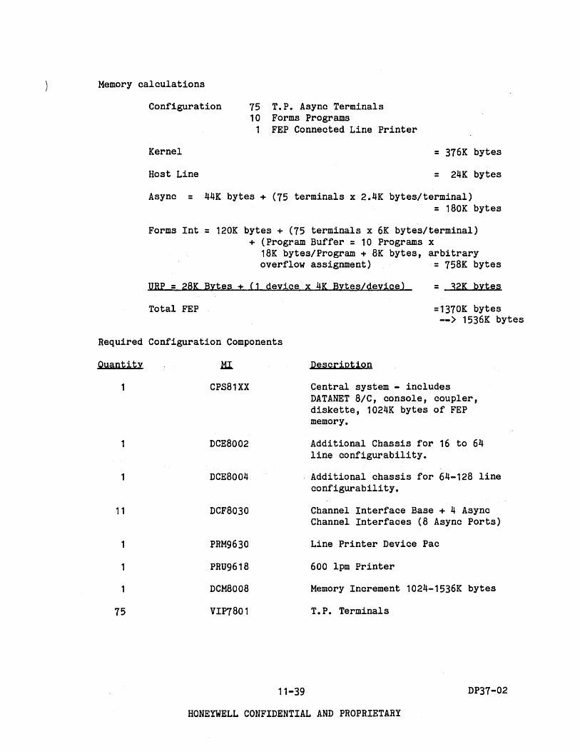
Memory calculations
Configuration
Kernel
Host Line
75 T.P. Async Terminals 10 Forms Programs
1 FEP Connected Line Printer
= 376K bytes
= 24K bytes
Async = 44K bytes + (75 terminals x 2.4K bytes/terminal) = 180K bytes
Forms Int = 120K bytes + (75 terminals x 6K bytes/terminal) + (Program Buffer = 10 Programs x
18K bytes/Program + 8K bytes, arbitrary overflow assignment) = 758K bytes
URP = 28K Bytes + (1 device x 4K Bytes/device) = 32K bytes
Total FEP =1370K bytes --> 1536K bytes
Required Configuration Components
Quantity
11
1
1
75
HI.
CPS81XX
DCE8002
DCE8004
DCF8030
PRM9630
PRU9618
DCM8008
VIP7801
11-39
Description
Central system - includes DATANET 8/C, console, coupler, diskette, 1024K bytes of FEP memory.
Additional Chassis for 16 to 64 line configurability.
Additional chassis for 64-128 line configurability.
Channel Interface Base + 4 Async Channel Interfaces (8 Async Ports)
Line Printer Device Pac
600 lpm Printer
Memory Increment 1024-1536K bytes
T.P. Terminals
DP37-02
HONEYWELL CONFIDENTIAL AND PROPRIETARY

EXample '3
Customer requires
50 Async Transaction Processing (T.P.) lines for 7 applications having the following attributes.
Application Transaction Type Fields Total Bytes Rate/Hour
A System Input 3 15 170 System Output 10 100 170
B System Input 1 10 400 System Output 4 120 400
C System Input 5 40 70 D System Input 2 20 225 E System Input 5 50 1000 F System Input 10 30 700 G System Output 50 2000 20
These applications require 14 Forms Programs, each averaging 18K bytes, although only 10 of these programs are required to be active at one time.
A minicomputer as a workstation, connected over a 2400 baud 3780 line •. The workstation will include:
1 Printer
1 Reader
600-lpm; Avg. print line 60 char; Duty cycle 30%
500-cpm; Avg. card length 20 char; Duty cycle 10%
1 Operator's Console - may be connected either through CP-6 IOM or via any spare FEP line.
Spare CIBs and Async lines for backup.
11-40 DP37-02
HONEYWELL CONFIDENTIAL AND PROPRIETARY

) Solution
Throughput calculations
Total Bytes/ Rate/ Trans % % ~ Application Transaction Type Fields Bytes Field .Hsmr. FEP/1OOO Figure ~
T.P. A System Input 3 15 5 170 6 11-10 1 System Output 10 100 10 170 6 .11-11 1
B System Input 1 10 10 400 3 11-10 1 System Output 4 120 30 400 4 11-11 2
C System Input 5 40 8 70 9 11-10 1 D System Input 2 20 10 225 4 11-10 1 E System Input 5 50 10 1000 10 11-10 10 F System Input 10 30 3 700 12 11-10 8 G System Output 50 2000 40 20 2·4 11-11
Total T. P. = 25%
Printer/Reader Work RBT I Avg. Hsg. Speed Duty Total % Stat. Device Lines Length LPH/CPH Cycle Char/Min. Figure FEP
(Char/Line)
3780 Printer 60 600 30% 10,800 11-7 4%
Reader 20 500 10% 1,000 11-7 -11
Total Workstation = 5%
Total FEP = 30%
11-41 DP37-02
HONEYWELL CONFIDENTIAL AND PROPRIETARY
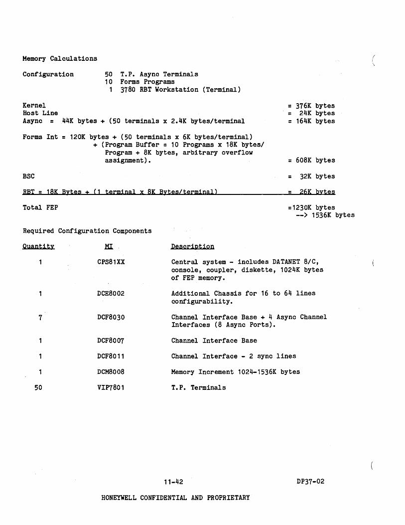
Memory Calculations (
Configuration 50 T.P. Async Terminals 10 Forms Programs
Kernel Host Line
1 3780 RBTWorkstation (Terminal)
Async = 44K bytes + (50 terminals x 2.4K bytes/terminal
= 376K bytes = 24K bytes = 164K bytes
Forms Int = 120K bytes + (50 terminals x 6K bytes/terminal)
BSC
+ (Program Buffer = 10 Programs x 18K bytes/ Program + 8K bytes, arbitrary overflow assignment) • = 608K bytes
= 32K bytes
RBT = 18K Bytes + (1 terminal x 8K Bytes/terminal) = 26K bytes
Total FEP
Required Configuration Components
Quantity
7
1
1
50
.HI
CPS81XX
DCE8002
DCF8030
DCF8007
DCF8011
DCM8008
VIP7801
=1230K bytes --> 1536K bytes
Description
Central system - includes DATANET 8/C, console, coupler, diskette, 1024K bytes of FEP memory.
Additional Chassis for 16 to 64 lines configurabili ty.
Channel Interface Base + 4 Async Channel Interfaces (8 Async Ports).
Channel Interface Base
Channel Interface - 2 sync lines
Memory Increment 1024-1536K bytes
T.P. Terminals
11-42 DP37-02
HONEYWELL CONFIDENTIAL AND PROPRIETARY
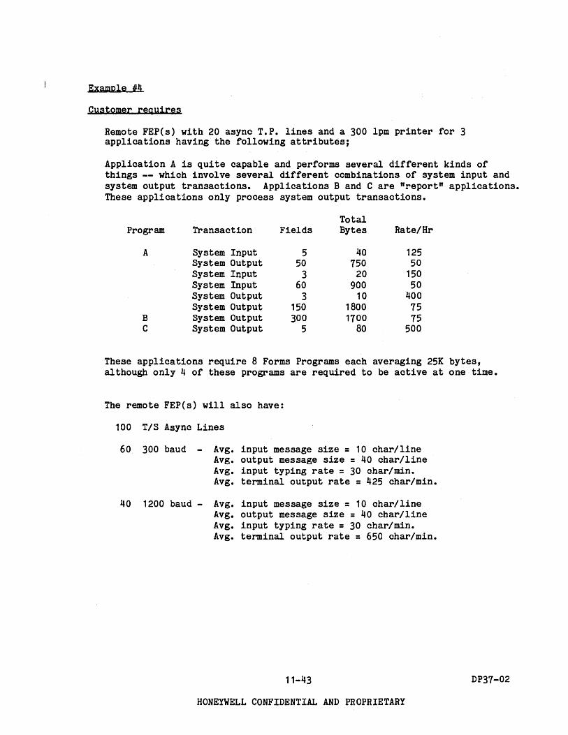
EXample {/4
Customer reQuires
Remote FEP(s) with 20 async T.P. lines and a 300 lpm printer for 3 applications having the following attributes;
Application A is quite capable and performs several different kinds of things -- which involve several different combinations of system input and system output transactions. Applications Band C are "report" applications. These applications only process system output transactions.
Program
A
B C
Transaction
System Input System Output System Input System Input System Output System Output System Output System Output
Fields
5 50
3 60
3 150 300
5
Total Bytes Rate/Hr
40 125 750 50
20 150 900 50
10 400 1800 75 1700 75
80 500
These applications require 8 Forms Programs each averaging 25K bytes, although only 4 of these programs are required to be active at one time.
The remote FEP(s) will also have:
100 T/S Async Lines
60 300 baud - Avg. input message size = 10 char/line Avg. output message size = 40 char/line Avg. input typing rate = 30 char/min. Avg. terminal output rate = 425 char/min.
40 1200 baud - Avg. input message size = 10 char/line Avg. output message size = 40 char/line Avg. input typing rate = 30 char/min. Avg. terminal output rate = 650 char/min.
11-43
HONEYWELL CONFIDENTIAL AND PROPRIETARY
DP37-02

Customer ReQuires (Con't)
In addition to the remote FEP requirements, the customer requires.
100 local T/S Async Lines
125
60 300 baud - Avg. input message size = 10 char/line Avg. output message size = 40 char/line Avg. input typing rate = 30 char/min. Avg. terminal output rate = 425 char/min.
40 1200 baud - Avg. input message size = 10 char/line Avg. output message size = 40 char/line Avg. input typing rate = 30 char/min. Avg. terminal output rate = 650 char/min.
local Async T.P. Lines, for 7 applications having the following attributes:
Application Transaction Type Fields Total Bytes Rate/Hour
A System Input 3 15 420 System Output 10 100 420
B System Input 1 10 1000 System Output 4 120 1000
C System Input 5 40 170 D System Input 2 20 625 E System Input 5 50 2500 F System Input 10 30 1700 G System Output 50 2000 50
These applications require 14 Forms Programs, each averaging 18K bytes, although only 10 of these programs are required to be active at one time.
1 9600 baud Async line for input from a minicomputer - echo off; Avg. 60 char. message; duty cycle 80%
11-44
HONEYWELL CONFIDENTIAL AND PROPRIETARY
DP37-02

) Customer ReQuires (Cont'd)
3 Sync lines for remote batch
CP-6 as a workstation to a foreign host
4800 baud HASP line FEP Printer - 600-lpmj Avg. Print Line 60 charj Duty cycle 40%
Host Connected Reader - 500-cpmj Avg. Card Length 40 char; Duty cycle 20%
Operator's Console
A minicomputer as a workstation
2400 baud 3780 line Printer 600-lpmj Avg. print line 60 char; Duty cycle 30%
Reader 500-cpmj Avg. card length 20 char; Duty cycle 10%
Operator's Console
2400 baud line to a CP-6 support computer (used·to expedite transmittal of software patches to the customer and transmittal of customer problems to Honeywell).
FEP Printer 600-lpmj Avg. Print line 60 char; Duty cycle 50%
Spare CIBs and lines for backup.
11-45 DP37-02
HONEYWELL CONFIDENTIAL AND PROPRIETARY
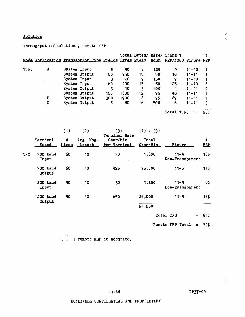
Solution ( Throughput calculations, remote FEP
Total Bytes/ Rate/ Trans % % ~ Application Transaction Type Fields Bytes Field .Ii2.w:. FEP/1OOO Figure n.f.
T.P. A System Input 5 40 8 125 9 11-10 1 System Output 50 750 15 50 18 11-11 1 System Input 3 20 7 150 7 11-10 1 System Input 60 900 15 50 125 11-10 6 System Output 3 10 3 400 4 11-11 2 System Output 150 1800 12 75 48 11-11 4
B System Output 300 1700 6 75 87 11-11 7 C System Output 5 80 16 500 6 11-11 3
Total T.P. = 25%
(1) (2) (3) (1) x (3) Terminal Rate
Terminal I Avg. Msg. Char/Min Total % Speed Lines Length Per Terminal Char/Min. Figure n.f.
T/S 300 baud 60 10 30 1,800 11-4 16% Input Non-Transparent
300 baud 60 40 425 25,500 11-5 14% Output
1200 baud 40 10 30 1,200 11-4 8% Input Non-Transparent
1200 baud 40 40 650 26,000 11-5 16% Output
54,500
Total T/S = 54%
Remote FEP Total = 79%
1 remote FEP is adequate.
11-46 DP37-02
HONEYWELL CONFIDENTIAL AND PROPRIETARY
Solution (Cont.)
Throughput calculations, local FEP.
Remote FEP T.P. TIS
Terminal Speed
TIS 300 baud Inp:ut
300 baud Output
1200 baud Input
1200 baud Output
Bytes/Record
25
( 1 ) (2)
IF Avg. Msg. Lines Length
60 10
60 40
40 10
40 40
Char/Min Figure % FEP
54,500 11-13
Total Remote FEP = 27%
(3) (1) x (3) Terminal Rate
Chari Min Total % Per Terminal Char/Min. Figure I.E.f.
30 1,800 11-4 16% Non-Transparent
425 25,500 11-5 14%
30 1,200 11-4 8% Non-Transparent
650 26,000 11-5 16%
Total TIS = 54%
Total Bytesl Ratel Trans % % Application Transaction TYDe Fields Bytes Field .H2J.u:. FEP/l000 Figure .fR
T.P. A System Input 3 15 5 420 6 11-10 3 System Output 10 100 10 420 6 11-11 3
B System Input 1 10 10 1000 3 11-10 3 System Output 4 120 30 1000 4 11-11 4
C System Input 5 40 8 170 9 11-10 2 D System Input 2 20 10 625 4 11-10 3 E System Input 5 50 10 2500 10 11-10 25 F System Input 10 30 3 1700 12 11-10 20 G System Output 50 2000 40 50 24 11-11 1
Total T.P. = 64%
11-47 DP37-02
HONEYWELL CONFIDENTIAL AND PROPRIETARY
Throughput calculations, local FEP (Cont.)
Printer/Reader Work RBT IF Avg. Msg. Speed Duty Total % Stat. Device Lines Length LPM/CPM Cycle Char/Min. FEP Figure
(Char/Line)
HASP Printer 60 600 40% 14,400 5% 11-7
Reader 40 500 20% 4,000 2% 11-7
3780 Printer 60 600 30% 10,800 4% 11-7
Reader 20 500 10% 1,000 1% 11-7
CP-6 Support .Jl!
Total RBT = 12%
Total Char/Min = Avg. Msg. Length * Device Speed * Duty Cycle
Minicomputer 9600 baud Async Line 46,080** 78% 11-4 Avg. Message Length = 60 Char/Line Transparent
* Infrequent, low levels of use. FEP consumption assumed negligible.
** Assume 8-10 format. Therefore 9600 baud = 960 char/sec. 960 char/sec x 60 sec/min x 80% duty cycle = 46,080 char/min.
11-48 DP37-02
HONEYWELL CONFIDENTIAL AND PROPRIETARY

) Throughput calculations, local FEP (Cont.)
FEP Peripherals
Printer
FEP 11
FEP 12
FEP '3
Device Duty Total CharI CharI % Speed-LPM Cycle Lines/Min .I.1M .M1n.... .f.Ef Figure
600 50% 300 60 18000 -M. 11-12
Total U/R = 6%
Total FEP = 241%
3 FEP's required
To configure these you assume the following.
50 TIS + Minicomputer 27% + 78% = 105% (Processor power module enhancement
(cache) required to handle volume on one FEP.)
50 TIS + HASP + CP-6 Support + RFEP + 3780 27% + 7% + 0% + 27% + 5% = 66%
125 T.P. + FEP Printer 64% + 6% = 70%
Note: Cache recommended above 90% FEP utilization to ensure adequate capacity for peak loads.
11-49 DP37-02
HONEYWELL CONFIDENTIAL AND PROPRIETARY

MINICOMPUTER 9600 BAUD ASYNC
ECHO OFF
2400 BAUD SYNC LINE
,--- ---- ---, t 1/0' I DEVICE I I
CP-6 , SUPPORT I
I COMPUTER WORKSTATION I I CONSOLE'
I I -.- ..... -~--------
SUPPORT COMPUTER WORKSTATION
50 TIS TERMINALS
FEP NO.1
FEP NO. 2
FEP NO.3
2400 BAUD
3780 LINE
,--~---"'--"'-"'-
I I ,
OPERATOR'S WORKSTATION
CONSOLE
600 lPM PRINTER
HOST CONNECTED 500 CPM CIR
I ________ .... ~-WORKSTATION TO FOREIGN HOST
r- --------, I OPERATOR'S 'I I WORKSTATION , CONSOLE" I I I I : I I I CIR lIP ! L ____________ l
MINICOMPUTER WORKSTATION
• May be connected either through CP-6 IOM or via any spare FEP line.
Figure 11-14. DATANET 8/C Configuration Example #4
11-50
HONEYWELL CONFIDENTIAL AND PROPRIETARY
DP37-02
Remote FEP link speed determination.
The remote FEP has both Transaction Processing and timesharing activities on it.
For Transaction Processing, the user data requirements are:
Total Program Transaction Bytes Rate/Hr Bytes/Hr
A System Input 40 125 5,000 System Output 750 50 37,500 System Input 20 150 3,000 System Input 900 50 45,000 System Output 10 400 4,000 System Output 1800 75 135,000
B System Output 1700 75 127,500 C System Output 80 500 40.000
Total T.P.
For timesharing, the user data requirements are (from throughput calculations, remote FEP)
54,500 ~ / 60 m1n = 908 char(bytes) min sec sec.
The total FEP user data requirement is 110 + 908 = 1018 Bytes sec.
The baud link required is thus:
1018 bytes x 8 hits x 2 = 16,288 bps --> 19,200 bps sec byte
Therefore, the DCF8020, 19,200 bps HDLC link can be used.
11-51
HONEYWELL CONFIDENTIAL AND PROPRIETARY
Bytes/Sec
1 10
1 13
1 38 35 11
= 110
DP37-02

FEP memory calculations are as shown below:
FEP #1
FEP 12
Configuration
Kernel
Host Link
50 T/S Async Terminals + 1 Minicomputer (terminal)
51 Terminals
= 376K bytes
= 24K bytes
Async = 44K bytes + (51 terminals x 2.4K bytes/ terminal) = l66.4K bytes
Total FEP 1
Configuration
Kernel
Host Link
Async = 44K bytes +
BSC
RBT = 18K bytes + (3
URP = 28K Bytes + (1
= 566.4K bytes --> 1u24K bytes
50 T/S Async Terminals 1 2400 Baud Sync line to CP-6 Support
(RBT terminal) 4800 Baud HASP line to foreign host (RBT terminal) with
1 FEP Connected Line Printer 1 3780 RBT Workstation (terminal) 1 Remote FEP
= 376K
= 24K
(50 terminals x 2.4K bytes/terminal) = 164K
= 32K
terminals x 8K bytes/ terminal) = 42K
device x 4K Bytes/device) = 32K
bytes
bytes
bytes
bytes
bytes
bytes
Connection of Remote FEP = lOOK bytes
Total FEP 2 = 770K bytes --> 1024K bytes
11-52 DP37-02
HONEYWELL CONFIDENTIAL AND PROPRIETARY

) FEP 13 Configuration
Kernel
Host Link
Async = 44K bytes +
125 T.P. Async Terminals 10 Forms Programs
1 FEP Connected Line Printer
(125 terminals x 2. 4K bytes/ terminal)
Forms Int = 120K bytes + (125 terminals x 6K bytes/ terminal) + (Program Buffer = 10 Programs x 18K bytes/Program + 8K bytes, arbitrary overflow assignment)
URP = 28K Bytes + (1 deVice x 4K Bytes/deyice)
Total FEP 3
Remote FEP
Configuration
Kernel
Async = 44K bytes +
Connection to local
100 T/S Async Terminals 20 T.P. AsyncTerminals 10 Forms Programs
1 FEP Connected Line Printer
(120 terminals x 2.4K bytes/ terminal)
FEP
URP = 28K bytes + (1 device x 4K bytes/device)
Forms lnt = 120K bytes + (20 terminals x 6K bytes/ terminal) + (Program Buffer = 4 Programs x 25K bytes/Program + 4K bytes, arbitrary overflow
= 376K bytes
= 24K bytes
= 344K bytes
. 1058K bytes
= 32K bytes
=1834K bytes --> 2048K bytes
= 376K bytes
= 332K bytes
= 60K bytes
= 32K bytes
assignment) = 344K bytes
Total Remote FEP
11-53
HONEYWELL CONFIDENTIAL AND PROPRIETARY
= 1144K bytes --> 1536K bytes
DP37-02

( "-
Required Configuration Components
Remote FEP1 FEP2 FEP3 FEP M.I. Description
1 CPS81XX Central System - includes DATANET 8/C, console, coupler, diskette, 1024K bytes of FEP memory.
1 1 DCU8011 Additional Freestanding FEP 1 DCF8008 30 cps Communications Console
1 1 1 DCE8002 Additional Chassis for 16 to 64 line configurability.
1 1 1 DCE8004 Additional Chassis for 64-128 line connectab1l1ty.
DCE8003 Processor Power Module-Cache 1 1 DCE8006 Host,Connect1on - Coupler
8 7 16 15 DCF8030 Cnannel Interface Base + 4 Async Cnannel Interface (8 Async Ports)
2 1 DCF8007 Channel Interface Base 2 DCF8011 Channel Interface - 2 Sync Lines 1 1 DCF8020 Channel Interface - 19,200 bps HDLC Link 1 1 1 PRM9630 Line Printer Device Pac
1 PRU9617 300 LPM Printer 1 1 PRU9618 600 LPM Printer
1 1 DCM8008 Memory Increment 1024-1536K bytes 1 DCM8005 Memory Increment 1536-2048K bytes
50 50 125 120 VIP7801 TIS and T.P. Terminals
11-54 DP37-02
HONEYWELL CONFIDENTIAL AND .PROPRIETARY

SECTION 12 Peripheral Switches
CONFIGURING MANUAL PERIPHERAL SWITCH SUBSYSTEMS
The following is a listing of manual peripheral switch subsystem marketing identifiers (MI) and ~neir functions.
HI Description
PSU0200 Switch console and power supply.
PSU0201
PSF0511
Includes one physical PSI channel (URP/MTP/MSP) in IOM and one PSFu511.
Switch console and power supply. Same as PSU0200 except that no IOM channel is included. Includes one PSF0511.
Manual switch unit to switch a device to one of two device processors or to select one of two devices to switch to a device processor. Does not include a cnannel in IOM. Usable with URP and MTP devices only. Could also be usea to switch a PSI channel in IOM between two device processors -URP, MTP, or MSP.
PSF0512 Manual switch unit to switch a device processor to one of two IOM PSI type physical channels. Includes one IOM PSI channel. Usable with URP, MTP, and MSP only.
12-1
Remarks
Every manual switch subsystem must include only one switch console, either PSU0200 or PSU0201. Each console handles up to 16 switch units.
Each console includes one. May be mixed with PSF0512 to maximum of 16 switch units per console.
May be mixed with PSF0511 to maximum of 16 switch units per console.
DP37-02
HONEYWELL CONFIDENTIAL" AND PROPRIETARY

Figure 12-1 illustrates the configurator for PSU0200 manual peripheral switch subsystem.
Standard To 15 More Optional Switch Units
r~----------~A~-----------'r~------------------JA~--------------___ , * 10M
Channel
PSU0200
Console, Power Supply
j---, 1* ,
.----, ,* I , 1 L __ J
I I '- __ J
----,----, PSF PSF I PSF I
0511 0512 I 0512 ,--/\ _/\.J -1\ _1
10M Channels in PSF0512 Price
Figure 12-1. PSU0200 Configurator
Figure 12-2 illustrates the configurator for PSU0201 manual peripheral switch subsystem.
Standard To 15 More Optional Switch Units
\, __ ----------~A~-----------r '"
PSU0201
Console, Power Supply
PSF 0511
/\
,- --, '*- -1 r*- -l 1* I I , 10M Channels in I I
I I I I PSFOs12 Price 1 L. __ -1 '- - - -' ' ___ ..J
-- - -l- - --. PSF I PSF 1 __ _
r - - - -,- -. ··1 _ _ _ I PSF I PSF 1
0512 , 0512 I -1\_J_7\ .J I 0511 I 0512 I
-l\-.J-I\~
*3 channel spaces (board slots) required in the 10M.
Figure 12-2. PSU0201 Configurator
12-2 DP37-02
HONEYWELL CONFIDENTIAL AND PROPRIETARY
'\

) EXAMPLES OF USE OF MANUAL PERIPHERAL SWITCHES
EXample
Figure 12-3 illustrates the switching of a peripheral device between two device processors. For example, to switch a tape unit between two MTPs or a card reader between two URPs.
Note: The reverse approach could also be used, i.e., to select one of two devices to connect a device processor.
10M PSI Channel
Device Processor
#1
*
Device
10M PSI Channel
Device Processor
112
PSF05ll
*lnterfaces included in each switch unit
Figure 12-3. Switching Between Two Device Processors
12-3
HONEYWELL CONFIDENTIAL AND PROPRIETARY
DP37-02

Example 2
Figure 12-4 illustrates the switching of a device processor between two physical IOM PSI channels. For example, to switch an MTP between two physical IOM PSI channels.
Note; The reverse approach could also be used, i.e., to select one of two device processor~ to connect to an IOM PSI channel. Since only one IOM channel is required, and one each would have been included in the prices of the device processors, PSU0201 would be the lower priced approach. PSU0201 price does not include an IOM channel, which would be superfluous in this case.
Memory
• PSU 0200 f
Device Processor
*
Device(s)
Memory
10M PSI Channel
PSFOSll
May be on same ,10M, dif ferent 10M in same system or in different systems. One rOM channel comes with the device processor, one with PSFOSll which is included in PSU0200 price
*lnterfaces included in each switch unit
Figure 12-4. Switching Between Two Physical IOM PSI Channels
12-4 DP37-02
HONEYWELL CONFIDENTIAL AND PROPRIETARY
(

) Example 3
Figure 12-5 illustrates the switching of a device between two device processors and switching a device processor between two IOM physical channels.
In this example you would order one PSF0511 switch unit in addition to the PSU0200 console, which includes one PSF0511. Note that this example could be handled by configuring a PSU0201 console and one PFS0512 switch unit at a slightly higher cost.
Memory
10M PSI Channel
PSU0200 Console
Memory
10M PSI Channel
" PSF ~5ll
*
Device Processor
o o
Device Processor
PSF J'e 05lV
Device
Device Processor
*Interfaces included in switch unit
Figure 12-5. Switching Between Two Device Processors and Between Two IOM Physical Channels
12-5 DP37-02
HONEYWELL CONFIDENTIAL AND PROPRIETARY

( \
) SECTION 13
Configuring Motor-Generator and Control Sets
The following are the marketing identifiers for the motor-generator control units and motor-generators.
MGS6001
MGS6002
MGS6003
MGS6004
Description
Motor-Generator Control Unit & Motor Generator 31.1 kVA, 60 Hz, 208/440 Vac Input
Motor-Generator Control Unit & Motor Generator 62.6 kVA, 60 Hz, 440/480 Vac Input
Motor-Generator Control Unit & Motor Generator 62.6 kVA, 50 Hz, 380 Vac Input
Motor-Generator Control Unit & Motor Generator 62.6 kVA, 60 Hz, 208 Vac Input
At least one set must be ordered for each DPS 8/52C/62C/70C system if the PSS8000 Capacitor Ride-Through options or UPS are not used. In some cases two may be desirable, depending on the size of the system. The DPS 8/47C/49C include a built-in power ride-through of 100ms, i.e., the ability to continue operation through a power interruption of up to 100ms. For components contained in the DPS 8/47C/49C Central System Cabinet, it may not be necessary to use a motor-generator set (MGS). An MGS may be desirable on these systems if they contain freestanding controllers in their configuration. The need or desirability of an MGS should always be carefully evaluated by the customer, in conjunction with an HIS Customer Services representative.
To be more competitive in bidding new systems, you may choose not to include the price of the motor~generator and control set as part of the system proposal. The motor-generator ride-through (duration of one second) and electrical noise reduction capabilities would be beneficial to most computer systems; therefore, it should be considered a site preparation item and included in the site prep section of your proposals, but denoted as "to be provided separately" or "not included in proposal pricing" so as to help avoid any confusion or claim.
13-1 DP37-02
HONEYWELL CONFIDENTIAL AND PROPRIETARY

Motor generator and control sets are used in applying power in an orderly fashion and in regulating the electrical quality fed to the hardware. They level out voltage variations and compensate for power interruptions for one second. The length of period is affected by the load imposed by the configuration. Check with Customer Services for specific figures.
Determine which model to order in the following way:
1. Decide on your complete system configuration - central system, peripherals, FEPs, and consoles.
2. Refer your configuration to your pertinent Customer Services branch. They will use data on the kVA load applied by each component in your configuration. Adding the individual kVA loads gives a total figure which determines which MGS type number to order. Do not skimp on the MGS used. Discuss with Customer Services the need or desirability of using two units in the specific customer case. The' price of these units is often significant in the typical total system price, but they serve a very important function in helping maintain the DPS 8/C system in an available condition.
3. The sets are heavy, bulky, noisy, and unattractive. They do not require the same air conditioning levels as the DPS 8/C systems themselves. Frequently, they are installed away from people in order to avoid noise and appearance problems. For ~his reason it may be undesirable to bid a minimal MGS. Your customer will grow. Where practicable discuss the alternatives ana costs with your customer and suggest some growth leeway before an MGS swap would be involved.
While electric utility power systems are reliable, they serve many loads of varying characteristics. The loaas are switched off and on continuously. Frequently, voltage transients upset computer systems. By using a flywheeltype, motor-generator set to supply power to critical devices, the effects of voltage transients and short duration voltage dips can be reduced.
It is recommended that battery backup units (PSSB002), when used, be connected directly to the main power system rather than through the motor generator unit. This is due to the fact that the motor generator will likely not be in the same room as the battery backup and thus in the event of a power interruption, the system operator may not be able to physically access and activate the MGS unit before the battery backup system loses power.
13-2 DP37-02
HONEYWELL CONFIDENTIAL AND PROPRIETARY
( \

SECTION 14 Software
A tiered packaging structure for CP-6 software is currently in effect. The CP-6 software packages are linked to the performance level of the host C~-6 hardware. Marketing Identifiers for CP-6 software packages are given below.
Marketing Identifier
SFS6135 SFS6145 SFS6150 SFS6155
Description
8/47C Software package 8/49C/52C Software package 8/62C Software package 8/70C Software package
For each of the Marketing Identifiers above, the package contains:
Control Program-6 (SFS6120) Access Modes (SFS6121) Local Communications (SFC6120) FORTRAN (SFL6120) APL (SFL6121) BASIC (SFL6122) RPG-II (SFL6123) COBOL 74 (SFL6124) PL-6 (SFL6125) Assembler (SFP6120) Math Library (SFR6001) TEXT ( SFP6 121 ) SORT/MERGE (SFU6120) SYSTEM AIDS (SFU6011) Transaction Processing (SFS6122) TP Forms Processor (SFU6121)
In the event of any Central Processor upgrade, the license for this CP-6 Software Package will terminate. Honeywell will license an equivalent CP-6 Software Package in accordance with license fees and terms as applicable to the upgraded Central Processor. (The new CP-6 Software Package Marketing Identifier must be ordered and the new Software Package must be installed.)
14-1 DP37-02
HONEYWELL CONFIDENTIAL AND PROPRIETARY

If the package is not chosen, the items may be ordered individually as follows:
Marketing Identifier
SFS6120 SFS6121 SFC6120 SFL6120 SFL6121 SFL6122 SFL6123 . SFL6124 SFL6125 SFP6120 SFR6001 SFP6121 SFU6120 SFU6011 SFS6122 SFU6121
Description
Control Program-6 Access Modes Local Communications FORTRAN APL BASIC RPG-II COBOL 74 PL-6 Assembler Math Library TEXT SORT/MERGE SYSTEM AIDS Transaction Processing TP Forms Processor
In addition, separate, non-packaged items are:
Marketing Identifier
SFD6121 SFD6120 SFC6121 SFH6200 SFD6110 SFH6201
EXample
Description
IDS II IDP Remote Communications (one required per remote FEP) Personal Computing Facility ARES Electronic Mail
An 8/52C customer desiring the software package, IDS II and IDP would order the software package on DPS 8/52C (SFS6145), IDS II (SFD6121) and IDP (SFD6120). Should the customer upgrade to 8/62C performance, the new software would be the software package on DPS 8/62C (SFS6150), IDS II (SFD6121) and IDP (SFD6120). (SFS6150 must be ordered and installed.)
14-2 DP37-02
HONEYWELL CONFIDENTIAL AND PROPRIETARY

)
APPENDIX A
CHECKLIST CONFIGURA TOR
This appendix is also published as a
freestanding document, Order No. DP54
A-1
HONEYWELL CONFIDENTIAL AND PROPRIETARY
DP37-02

(

PREFACE
This checklist configura tor provides helpful information for ordering
DPS 8/C system components and options. This document should be used
in conjunction with the DPS 8/C Configuration Guide, Order No. DP37.
©Honeywell Information Sytems Inc., 1983
A-2 DP37-02
HONEYWELL CONFIDENTIAL AND PROPRIETARY


) CONTENTS Page
Figure A-l. DPS 8/47C/49C Central Systems and Major Subsystems A-5
Figure A-2. DPS 8/52C/62C/70C Central Systems and Major A-6 Subsystems
Figure A-3. IOM-Connected Console A-7
Figure A-4. Communications Subsystem A-8
Figure A-5. Magnetic Tape Subsystem A-9
Figure A-6. Mass Storage Subsystem A-l0
Figure A-7. Unit Record Subsystem A-ll
Figure A-8. DPS 6 Peripherals A-13
Figure A-9. Peripheral Switches A-14
'Figure A-l0. Motor Generators/Capacitor Ridethroughs A-15
A-3 DP37-02
HONEYWELL CONFIDENTIAL AND PROPRIETARY

( \

This checklist configurator provides a convenient way to determine that 1) all required components of a CP-6 DPS SIC system are included in an order, and 2) that all required prerequisites are in fact· ordered for desired options. This checklist will assist in generating correct, connectable systems; it will not ensure that system or component performance, load balancing, redundancy, etc. requirements will be met. These parameters are discussed in the appropriate chapters of the CP-6 DPS 8/C Configuration Guide.
To use the checklist configurator, first determine which DPS SIC model is desired. Locate that model on either Figure A-1 or Figure A-2 and check the indicated marketing identifier (M.I.). For each DPS SIC model, required components are indicated by solid lines. (All items indicated as Basic are automatically included with the system M.I. and do not have to be ordered individually.) Optional components are indicated by dotted lines. Components having prerequisites are indented below their prerequired components. Additional relevant configuration rules are given in the indicated footnotes. By checking off the M.I.s for all required components, desired options, and necessary prerequisites, complete and accurate configurations may be established.
A-4 DP37-02
HONEYWELL CONFIDENTIAL AND PROPRIETARY


Central Systems
OPS 8/47C, 8/49C BaSiCT(OPS8/47C) ~O
~Upgrade to OPS 8/49C - - - - - - - -"'0
or LAdditional OP!j 8/47C CPU - - - - - - ~ 0
L L Add CPU upgrade to CPU 8121 - - - ~ 0
(OPS 8/49C) ... 0
LAdditional DPS 8/49C CPU(max. of 3) ~O
- SCU (Basic)
: ~SCU expansion (2 to 5 ports) ----....:------------- ~ I I-SCU expansion (5 to 8 ports) ------------------ ~
L-;-AdditionalSCU (5 ports) --------------------~ L -SCU expansion (5 to 8 ports) - - - - - - - - - - - - - - - - - ~
-10M (Basic) - 20 slots
LAdditionallOM - - - - - - - - - - - - - - - - - - - - - - - - - ~ - Memory (12 MB on DPS 8/47C Basic; 16 MB on DPS 8/49C Basic)
I I- - Additional 2 MB increments - - - - - - - - - - - - - - - - - - - ~
L -Additional 4 MB increments - - - - - - - - - - - - - - - - - - - ~ --10M-connected console (see Figure A - 3)
~ Communication subsystem (see Figure A - 4)
~Magnetic tape subsystem (see Figure A - 5)
r-Mass storage subsystem (see Figure A - 6)
r Unit record subsystem (see Figure A - 7)
~periPheral switches (see Figure A - 9)
t-Motor generators (see Figure A - 10)
0
0
0
0
0
0
0
(1 )
(5)
(3)
(4)
(1 )
(3,6)
(7)
(8)
(8)
(3)
(2)
(2)
LTandem systems -------------------------- ~ 0 (9)
Notes:
(1 ) Includes 1 processor, 1 SCU, 110M, a base quantity of memory, 1 communications subsystem with host connect, and 1 communications subsystem connected console.
CPS8119
CPK8362
CPU8119
CPK8365
CPS8121
CPU8121
MXK8007
MXK8009
MXC8003
MXK8009
MXU8003
CMM8002
CMM8003
RSF8001
(2) Up to a maximum of 32 MB on DPS 8/47C, 8/49C; requires MXC8003, additonal SCU beyond 16 M bytes.
(3)
(4)
(5)
(6)
(7)
(8)
(9)
Requires MXK8007, SCU port expansion
Requires CPK8362
Requires CPK8365 if system includes CPU8119.
Requires MXK8009 and second CSU6601/6602 for third CPU on a system.
Required for additional CPU, additional 10M. Required for each CPS of a tandem system.
Required on each SCU for third CPU of a DPS 8/49C system.
Two CPS 8119/8121, two CSU 6601/6602, two MKX8007, one RSF8001 required to comprise a tandem system.
CPS 8/47C, 8/49C Central Systems and Major Subsystems
Figure A - 1
A-5 DP37-02
HONEYWELL CONFIDENTIAL AND PROPRIETARY

Central Systems (OPS 8/52C) ... OPS 8/52C, ~ Upgrade to OPS 8/G2C ------- ..
8/G2C, 8/70C LAdditional DPS 8/52C CPU - - - - - ~ L -Add CPU upgrade to CPU8174 -I>
or- (OPS 8/G2C) ~ I
~ Upgrade toDPS 8/70C - - - - - - - ..
L~dditional OPS 8/G2C CPU - - - - - ~ L -Add CPU upgrade to CPU8178 -~
or- (CPS 8/70C) .. LAdditional CPUs (max. of 5) - - - - - ~
f-IOM (Basic) - 3G slots
i LAdditionallOMs - 36 slots (max. of 3) -- - -- --- - - - - -- -- J>
L - Channel expansion - to 54 slots - - - - - - - - - - - - - - - - - - J>
-SCU (Basic)
LAdditionalSCUs (max. of3) --------------------- ..
-Memory (1G MB Basic) I
(1 ) CPS8173
(10) CPK81G4
CPU8173
v (7) CPK8174
0 (1 ) CPS8174
0 (11 ) CPK8172
·0 CPU8174
0 (8) CPK8178
0 (1 ) CPS8178
0 (5) CPL!8178
0 (5) MXU8002 --, MXF8005 v
0 (2) MXC8002
L Additional 2 MB increments - - - - - - - - - - - - - - - - - - - - - .. 0 (2,3,4) CMM8020
-Battery back-up -----------------------..
-10M-connected console (see Figure A - 3)
- Communication subsystem (see Figure A - 4)
-Magnetic tape subsystem (see Figure A - 5)
I- Mass storage subsystem (see Figure A - G)
1'- Motor generatorslcapacitor ridethroughs (see Figure A - 10)
,Unit record subsystem (see Figure A - 7)
~Peripheral switches (see Figure A - 9)
L Tandem Systems - - - - - - - - - - - - - - - - - - - - - - - - - - - ..
Notes:
0 (3) PSS8002
(G) RSF8002
(1) Includes 1 CPU. SCU and 10M. 16 MB main memory. 1 communications subsystem with host connect. and 1 communications subsystem connected console. .
(2) 1 SCU required per 16 MB of memory or fraction thereof.
(3) 1 PSS8002 required per 16 MB of memory or fraction thereof for all CP6 systems without UPS. (4) Up to a max. of 64 MB.
(5) Total number of CPUs and lOMs must be 8 or less.
(6) Requires two CPS8173/8174/8178. oneRSF8002 to comprise a tandem system. (7) 8equires CPK8164. (8) Requires CPK8172.
(10) Requires CPK 81 74 if system includes CPU 81 73.
(11) Requires CPK8178 if system includes CPU8174.
DPS 8/S2C, 8/S2C, 8/70C Central Systems and Major Subsystems
Figure A - 2
A-6
HONEYWELL CONFIDENTIAL AND PROPRIETARY
DP37-02

10M-Connected Console
~ Base console .. 0 CSU6601
I L_ Console table ---------------------~ 0 CSF6601
'-r- Auxiliary console - - - - - - - - - - - - - - - - - - - - t> 0 (1 ) CSU6602
I ~-Sitdown pedestal for printer and keyboard - - - - - - - - .. 0 TTF0200
I L_ Sitdown pedestal for 1 2 inch CRT with keyboard - - - - - .. 0 DKF7201
/--- Auxiliary console adapter - - - - - - - - - - - - - - - - .. 0 (1 ) CSF6602 I I 1----12 inch CRT with keyboard ------------- .. 0 (2) CSF6603 I I I I L - - Sitdown pedestal for 12 inch CRT with keyboard - - ~ 0 DKF7201
I-L..-,-23 inch large screen monitor - - - - - - - - - - - - - ~ 0 CSF6604
I L.. - -Ceiling mount for 23 inch monitor - - - - - - - - - .. 0 CSF6605 I '--- Console switch feature - - - - - - - - - - - - - - - - - .. 0 (3) CSF6606
Notes: (1 ) Auxiliary console adapter CSF6602 included in price of CSU6602 auxiliary console. (2) Perequisite is auxiliary console adapter CSF6602. (3) Requires at least 2 console devices.
10M-Connected Console
-Figure A 3
A-7 DP37-02
HONEYWELL CONFIDENTIAL AND PROPRIETARY

Communications
Subsystem
t--I
-...,.-Front end processor (Basic -Included in CPSS1 XX)
I Host connect (Basic - included in CPSS1XX)
I I Console (Basic - included in CPSS1 XX)
I 1-30 cps console - - - - - - - - - - - - - - - - - - - - - - - - - - ~
I --120cpsconsole -------------------------~
t - -I-Additional FEP(s) - - - - - - - - - - - - - - - - - - - - - - - - - - ~ _ ,-Host connect( 1 only) - - - - - - - - - -....., - - - - - - - - - - - - ~
,-30 cps console - - - - - - - - - - - - - - - - - - - - - - - - - - ~
- -120 cps console - - - - - - - - - - - - - - - - - - - - - - - - - ~
~Multiple device controller (MDC) - Basic
- - DPS 6 peripherals (see figure A - S)
TMemory (1024 KB) - Basic
--512 KB memory increment (1024- 1536 KB) ---- --- --- -- ~
L - 512 KB memory increment (1536 - 204S KB) - - - - - - - - - - - ~ TConnectibiity (1 - 16 lines) - Basic
-,- Line connection expansion. up to 64 lines (max. 1) - - - - - - - - - - ~
,"·1- Line connection expansion. up to 12Slines (max. 1). - - - - - - - - - ~
L Processor power module enhancement - cache - - - - - - - - - - - - ~
CIBs and Cis -.-
- -Channel interface base (CIB) - - - - - - - - - - - - - - - - - - - - ~
I '-I-Channel interface (CII options .
I I--Dual sync channels- to 19.2 K bps ---------------~ I I--Dual Bsync channels - to 19.2 K bps -------------- ~ I 1--SingleHOLC RS232C-to 19.2 K bps--------------~ I --Single HOLC broadband -to 72 K bps -------------- ~
I :--Single HOLCV.35 -to 72 K bps ----------------~ - - Two async current loop ports - to 9600 bps - - - - - - - - - - - ~
I-I-CIBS packaged with Cis
1- -CIB and S async RS232C ports- - - - - - - - - - - - - - - - - - ~
--CIBand Ssync RS232Cports ------------------~
L - CIB and S current loop ports - - - - - - - - - - - - - - - - - - - ~ :- - CIB and 1 broadband sync port. Bell 301/303 compatible - - - - - - ~ 1- -CIB and 1 broadband HDLC port. V.35 CCITT compatible - - - - - - ~
- -CIB and 1 broadband sync port. V.35 CCITT compatible - - - - - - ~
L - CIB and 1 broadband HOLC port. 301/303 compatible - - - - - - - ~ - -Modem bypass - - - - - - - - - - - - - - - - - - - - - - - - - - - ~
Note.: (1) Max. of 15 (up to 11 may be local).
0 0
0 0 0 0
0 0
0 0 0
0
0 0 0 0 0 0
0 0 0 0 0 0 0 0
(1a)
(4) DCFSOOS (4) DCFS006
(1. 1 a) DCUS011
DCES006 (4) DCFSOOS (4) DCFS006
DCMSOOS
DCMS005
DCES002
OCES004
DCES003
(2)
DCFS007
DCFS011
DCFS012
OCFS020
OCFS022
DCFB023
DCFS036
DCFS030
OCFS032
OCFS034
DCFS03S
OCFS040
DCFS042
DCFS044
(3) OCFS026
(1 a) Each FEP Includa. 1 MOC with a maintananca di.katta. 1 - 16 lina. connactibility. and 1024 KB mamory a. ba.ic. All al.a not .hown a. ba.lc mu.t be configurad.
(2) At laa.t 1 CIB & 1 a.ync CI requirad per FEP: nona included in be.e prica 1 - 4 CI. per CIB. for 1 - 8 lina. per CIB. max. of 64 CI. and 128 lina. per FEP. Max. of 16 CIB. per FEP. Up to 2 CIB. for up to 16 Iina. in ba.a FEP. With OCEB002 up to 8 CIB. for up to 64 lina •. With OCE8004 up to 16 CIB. for up to 128 lina •.
(3) Minimum of 2 per affectad lina. 1 at FEP and. other at terminal and. (4) Raqulra. 1 a.ync lina. 1 con.ola (tarminal) of any type racommandad for aach lita uling OCU8011 a. a ramota FEP.
Communications Subsystem
Figure A - 4
A-8
HONEYWELL CONFIDENTIAL AND PROPRIETARY
DP37-02

) I Magnetic Tape Subsystem J
I-Ma~iC Tape Processors MTP (1 x 8) and URP (1 x 4) in central system cabinet ...
or
~MTP (1 x 8) in central system cabinet ... or
... TFreestanding MTP (1 x 8)
- -Dual simultaneous channel (up to 2 x 16) - - - - -- - - - - - - - - ... L - Capacitor ridethrough - - - - - - - - - - - - - - - - - - - - - - - ...
.... Required features and options
~Magnotlc tape addressing ... 9-track NRZI/PE (8~OJ1600 bpi) support ...
andlor
~ 9-track PE/GCR (1600/6250 bpi) support - ... --7-track(556/800 bpi) support -------------------- ... L -Switchable non-simultaneous channel ---------------- ...
-Magnetic Tape Units
~~5 ips tape unit ... I 7-track density (556/800 bpi) ...
- - Cartridge load, factory installed - - - - - - - - - - - - - - - - - - ...
L - Cartridge load, field installed - - - - - - - - - - - - - - - - - - - - ...
L - High altitude adapter - - - - - - - - - - - - - - - - - - - - - - - ... t -High altitude adapter, field installed - - - - - - - - - - - - - - - - - ... r -DC power-on meter, factory installed - - - - - - - - - - - - - - - - ... - - Tape movement meter, factory installed - - - - - - - - - - - - - - - ...
andlor
~oo Ips tape unit . .. 9-track density (800/1600) bpi ...
L - Upgrade 80011600 to 1600/6250 bpi - - - - - - - - - - - - - ... or L 9-track density (1600/6250 bpi) ...
andlor
r-75/125 ips 9-track tape unit ... ~75 ips - 800/1600 bpi ...
'- -Upgrade from 75 to 125 ips at 800/1600 bpi - - - - - - - - - - ...
: L - Upgrade from 800/1600 to 1600/6250 at 125 ips - - - - - - ...
- - Upgrade from 800/1600 to 1600/6250 at 75 ips - - - - - - - - ... L - Upgrade from 75 to 125 ips at 1600/6250 bpi - - - - - - - - ...
or
175 ips - 1600/6250 bpi ... L-Upgradefrom75to 125ips ------------------ ...
or
1125 ips -800/1600 bpi ... L-Upgradefrom 800/1600 to 1600/6250 bpi----------- ...
or ... L 125 ips -1600/6250 bpi
L - High altitude adapter - - - - - - - - - - - - - - - - - - - - - - - ...
MFP8001. URP8000. MTP8001 are mutually exclusive within a cabinet. Available on DPS 8/47C. 8/49C only.
0 (1,2) MFP8001
0 (1,2) MTP8001
0 MTP0611
0 (3) MTF1151
0 PSS8001
0 (4J MTA 1152
0 MTF1159
0 MTF1160
0 (5) MTF1158
0 MTF1152
0 (7) MTU0500
0 (6) MTF0016
0 MTF0018
0 MTF0019
0 MTF0020
0 MTF0021
0 MTF0022
0 MTF0023
0 MTU0610
0 (61 MTF0607
0 MTF0678
0 (61 MTF0608
0 MTU0630
0 (6) MTF0634
0 MTK0632
0 MTK0631
0 MTK0630
0 MTK0633
0 (6) MTF0635
0 MTK0633
0 (6) MTF0636
0 MTK0631
0 (6) MTF0637
0 MTK0634
Note.: (11 (21 (31 Required to .upport more than 8 unit •. Optional otherwise. Require. redundant feature. MTF 1158/59/60 if the.e are configured
in MTP0611. (41 (51 (61 (71
1 required per each 1 • 4 MTUs. 2 required for first 1 • 8 unit. if MTF 1151 configured. MTF 1159 required. 1 unique den.ity feature required per MTU. RPO only.
Magnetic Tape Subsystem
Figure A - 5
A-9
HONEYWELL CONFIDENTIAL AND PROPRIETARY
DP37-02

Mass Storaga Subsystam
~Mass Storaga Procassors
rSlnUle channel MSP In cen"al system cabinet ~
~dre"lnu for MSU050 1 • Device adapter for MSU 04XX • I Addressing for MSU 04XX •
- - Upgrade kit, MSP8000 to MSP8002 - - - - - - - - - - - - - - - • L - Switched 10M channel - - - - - - - - - - - - - - - - - - - - - • or
• ~r.'slnu for MSU050 1 • I Device adapter for MSU 04XX •
rDual channel MSP I~channol in cen"al system)
I Addressing for MSU 04XX • and/or - - Switched 10M channel - - - - - - - - - - - - - - - - - - - - - •
-Freestanding single channel MSP ~
~rasslnu for MSU0501 • I Device adapter for MSU04XX • I Addressing for MSU 04XX . ~
,-Upgrade kit, MSP0611 to MSP0612 - - - - - - - - - - - - - - - • - - Switched 10M channel - - - - - - - - - - - - - - - - - - - - - •
and/or L - Capacitor ridethrough - - - - - - - - - - - - - - - - - - - - - - •
L-Freestanding dual channel MSP ~
~ddre'Slnu for MSU050 1 ' • I Device adapter for MSU 04XX • I Addressing for MSU04XX • - - Switched 10M channel - - - - - - - - - - - - - - - - - - - - - • L - Capacitor ridethrough - - - - - - - - - - - - - - - - - - - - - - • 1- -MSU0501 expansion feature - support for 9-15 MSU0501 - - - - -.
-Disk unit/spindle components r Device native mode for MSU050 1 '. • r11 01 MB non-removable disk (2 spindles) • - - Dual accass for MSU050 1 - - - - - - - - - - - - - - - - - - - - • I . - -Spare MSU0501 - - - -- - - - - - ---- -- - - - -- - - -.
and/or ,
r-RPS feature for MSU 0451/0402 • r 78.2 M8 removable disk 11 spindle) •
- -Upgrade from MSU0402 to MSU0451 --------------.
and/or L - Dual access feature for MSU0451/0402 - - - - - - - - - - - - - •
Note.:
L-158.4 MB removable disk (1 spindle) ~
L-RPS feature for MSU0451/0402 • L - Dual access feature for MSU0451/0402 -------------. (1 ) (2)
(3)
(S)
DPS 8/47C. 8/49C only. Maximum of 1 per 10M.
Maximum of 16 spindles in specific combination. of MSU04XX and/or MSUOS01. 1 required per 2 MSUOSOl (4 spindles). Maximum of 4 per MSPXXXX.
1 required per 4 MSU04XX. Maximum of 4 per MSPXXXX.
0 (1,2) MSP8000 0 (3) MSA8001 0 MSF8000 0 (5) MSA8000 0 (6) MSK8002 0 (7) MSF8003
0 (1,2) MSP8002 0 (3) MSA8103 0 MSF8101 0 (5) MSA8102 0 (7) MSF8003
0 (8) MSP0611 0 (3) MSA1141 0 MSF1140 0 (5) MSA1140· 0 (9) MSK0612 0 (7) MSF1144 0 PSS8001
0 (10) MSP0612 0 (12) MSA 1143 0 MSF1141 0 (5) MSA 1142 0 (7) MSF1144 0 PSS8001 0 (11 ) MSF1142
0 (13) MSF0015 0 MSU0501 0 (14) MSF0011 0 MSF0501
0 MSU0402 0 (15) MSFOO07 0 MSK4025 0 (16) MSFOO06
0 MSU0451 0 (15) MSFOO07· 0 (16) MSFOO06
(6)
(7)
MSK8002 require. that all disk units must have dual access feature. If MSU04XX is to be used on upgraded MSP. then MSFSOOO if present must be replaced by MSFS101. and MSASoOlf present must be replaced by MSAS102. Maximum of 3 per single channel MSP and 3 per channel in dual channel MSP.
(8)
(9)
(10)
(11)
(121 (13)
(14)
(1S) (16)
Maximum of 16 spindles' 16 MSU04XX or 8 MSUOSOl or combinations totaling 16.
Existing MSFl 140. MSA 1140/41 must be replaced by MSFl 141. MSA 1142/43 according to spindle types used (MSU04XX. MSUOS01). Maximum of 16 MSU04XX or 1S MSUOSOl (30 spindle.) or 16 MSU04XX and 8 MSUOS01 .. Use of 9· 1S MSUOSOl
requires MSF 1142. MSUOSO 1 expansion feature. Maximum of 1 per MSP0612. 1 required per 2 MSUOSOl (4 spindles). Maximum of S per MSP0612.
1 required per MSP channel using MSUOSOls. 1 required for each MSUOSO 1 disk unit (2 spindles) for dual channel MSPs (MSP8002. MSP061 2).
1 required per MSU0402/04S1 disk spindle. 1 required per MSU0402/04S1 (spindle) for dual channel MSPs (MSP8002. MSP0612).
Mass Storage Subsystem
Figure A - 6
A-10
HONEYWELL CONFIDENTIAL AND PROPRIETARY
DP37-02
(
Unit Record Subsystem
I I IT-unit Record Processors·
I :- - URP (1 x 4) & MTP (1 x 8) in central system cabinet - - - - - - - - • I or I L-URP (1 x 8) in central system cabinet ---------------. I I L--URAddressingexpansion __________________ • I and/or I '--Freestanding URP(1 x 8) --------------------. I L - - UR addressing expansion - - - - - - - - - - - - - - - - - - •
!--, Card punch addressing - - - - - - - - - - - - - - - - - - - - - - - - - • I --100 to 400 cpmcard punch (2 max. perMFP/URP) -----------.
1- -,-Card reader (500 cpm) addressing- - - - - - - - - - - - - - - - - - - -. I -1- - 500 cpm card reader - - - - - - - - - - - - - - - - - - - - - - - - • I ---Pedestal for 500 cpm card reader -----------------.
1- __ Card reader (1050 cpm) addressing - - - - - - - - - - - - - - - - - - - • I I I ---1050 cpm card reader -----------------------.
1- __ Belt printer (1200 Ipm) addressing - - - - - - - - - - - - - - - - - - - • L - -1200 Ipm belt printer (136 columns) - - - - - - - - - - - - - - - - •
!-- - 64 character BCD belt - - - - - - - - - - - - - - - - - - - - - - • and/or
~- - - 64 character ASCII belt - - - - - - - - - - - - - - - - - - - - - • and/or
~- - - 64 character belt with OCR-AlB numeric font - - - - - - - - -- - - • and/or
,--- 96 characterASCllbelt---------------------. ~ - - Expansion to 160 print columns - - - - - - - - - - - - - - - ~ - - • - - - Upgrade to 1600 Ipm - - - - - - - - - - - - - - - - - - - - - - •
- - - Belt printer (1600 Ipm) addressing - - - - - - - - - - - - - - - -.;... - - ... L - -1600 Ipm belt printer - - - - - - - - - - - - - - - - - - - - - - - • ~ - - 64 character BCD belt - - - - - - - - - - - - - - - - - - - - - - •
and/or :- - - 64 character ASCII belt - - - - - - - - - - - - - - - - - - - - .;.. •
andlor l- - - 64 character belt with OCR-AlB numeric font - - - - - - - - - - - - •
andlor
Note.:
'- - - 96 character ASCII belt - - - - - - - - - - - - - - - - - - - - - • '- - - Expansion to 160 print columns - - - - - - - - - - - - - - - - - - •
(11 MFP8001. URP8000, MTP8001 are mutually exclu.ive within a cabinet.
(21 Available on CPS 8/47C, 8/49C only.
(31 URP0600/8000 only. Required if more than 4 device. are configured per URP.
0 (1,2)
0 (1,2)
0 (3)
0 0 (3)
0 (4)
0 (5)
0 (4)
0 (5,6)
0
0 (4)
0 (5,6)
0 (4)
0 (5,7)
0
0
0
0 0 0
0 (4)
0 (5,7)
0
0
0
0 0
(41 1 addre •• ing feature required per UR device. 1 URP required per 8 addre •• ing feature. or 1 MFP required per 4 addre •• ing feature •.
(51 Each UR device require. 1 addre.sing feature.
(61 Maximum 2 CRU0501 or 2 CRU1050 per MFP/URP, or one of each.
(71 At leeat 1 belt required per PRU 1200/1600.
Embedded URP'. , their devices and feature. are shown on Part 2 of Figure A - 7.
Unit Record Subsystem
Figure A - 7 Part 1
A-11
HONEYWELL CONFIDENTIAL AND,PROPRIETARY
MFP8001
URP8000 URF0040
URP0600 URF0040
URA0050 PCU0121
URA0056 CRU0501 CRF0030
URA0052 CRU1050
URA0054 PRU1200 PRB0500
PRB0513
PRB0524
PRB0600 PRF0022 PRK1216
URA0055 PRU1600 PRB0500
PRB0513
PRB0524
PRB0600 PRF0022
DP37-02

Unit Record Subsystem
I I-r---Embedded Unit RecordProcessors(contained in 10M)
I I---URP (1 x 4) ---------------------~
and/or I 1- - - URP (1 x 2) - - - - - - - - - - - - - - - - - - - - - - ~
and/or
'---URP(1 x2)----------------------~ - -,Belt printer (900 Ipm) - - - - - - - - - - - - - - - - - - - - - - - - ~
,- - - 64 character BCD belt - - - - - - - - - - - - - - - - - - - - - ~
and/or
~ - - 64 character ACSII belt - - - - - - - - - - - - - - - - - - - - - ~ and/or
~ - - - 96 character ASCII belt - - - - - - - - - - - - - - - - - - - - ~ IS' I' . - - - - tatlc e Imlnator - - - - - - - - - -- - - - - - - - - - - - - - - ~
L - - - Upgrade to PRU 1201 - - - - - - - - - - - - - - - - - - - - - ~ - - - - Belt printer (1200 Ipm) - - - - - - - - - - - - - - - - - - - - - - - - ~
I L - - - 64 character BCD belt - - - - - - - - - - - - - - - - - - - - - ~ I I and/or
I ~ - - - 64 character ASCII belt - - - - - - - - - - - - - - - - - - - - ~ I and/or
I (---96 character ASCII belt --------------------~
I - - - -Static eliminator - - - - - - - - - - - - - - - - - ...:.. - - - - - - ~
- - - -Card reader (500 cpm) - - - - - - - - - - - - - - - - - - - - - - - - ~
I L __ -Pedestal for 500 cpm card reader ---------------- ~ '----Card reader (1000cpm) - -------------------'--- ~ L - - - Card punch (100 -400 cpm) - - - - - - - - - - - - - - - - - - - - - ~
Note.:
(SI Up to 2 PRU0901/1201 and 2 card devices.
(91 Up to 2 card device. only. No printers.
(101 Up to 2 PRU0901/1201 only. No card devices.
(111 URPS0111S.13 only. Price includes 2 print belts of same type.
(121 Not available on URPS013.
(131 Print belts must be ordered from the supply catalog.
Unit Record Subsystem
Figure A - 7 Part 2
0 (8) URP8011
0 (9) URP8012
0 (10) URP8013
0 (11.13) PRU0901
0 (13) PRB3500
0 (13) PRB3513
0 (13) PRB3600
0 PRF0045
0 "9. PRK0901
0 (11.13) PRU1201
0 (13) PRB3500
0 (13) PR83513
0 (13) PRB3600
0 PRF0045
0 (12) CRU0501
0 CRF0030
0 (12) CRU1050
0 (12) PCU0121
A-12 DP37-02
HONEYWELL CONFIDENTIAL AND PROPRIETARY

)
DPS 6 Peripherals
rart of FEP - Communication Subsystem (see figure A - 41
'-----Multiple device controller (MDC) - Basic I .' 1----;-Device pac for card reader - - - - - - - - - - - - - - - - - - - - ..
1 L-Cardreader(SOOcpm) --------------------- .. I
and/or I
1---rDevice pac for printer- - - - - - - - - - - - - - - - - - - - - - - ..
I L-Drum printer, 900 Ipm, 64 character - - - - - - - - - - - - - - - ..
and/or
I D' f . 1---' eVlce pac or printer - - - - - - - - - - - - - - - - - - - - - - - ..
1 L..rBand printer, 300 Ipm, 64 character --- ----------- - ..
I L-96 character band ---------------------- ..
and/or
l---rDeVice pac for printer- - - - - - - - - - - - - - - - - - - - - - - ..
1- r Band printer, 600 Ipm, 64 character - - - - - - - - - - - - - - - ..
~ - 96 character band - - - - - - - - - - - - - - - - - .- - - - - ..
L -132 to 136 print position extension -------------- ..
L,---MDC expander (second MDC) - - - - - - - - - - - - - - - - - - - - ..
1---, Device pac for card reader - - - - - - - - - - - - - - - - - - - - ..
! L-Cardreader(SOOcpm) --------------------- ..
and/or
I D' f' I---r eVlce pac or printer - - - - - - - - - - - - - - - - - - - - - - - ..
1 L-Drum printer 900lpm 64 character--- ------- - - --- .. I "
and/or
i---,-Device pac for printer - - - - - - - - - - - - - - - - - - - - - - - ..
I L rBand printer, 300 Ipm, 64 character - - - - - - -- - - - - - - - ..
1 L-96 character band ---------------------- .. I
and/or
Notes:
I
'---,Device pac for printer - - - - - - - - - - - - - - - - - - - - - - - ..
L r Band printer, 600 Ipm, 64 character - - - - - - -- - - - - - - - ..
f- - 96 character band - - - - - - - - - - - - - - - - - - - - - - ..
L-1:l2 to 136 print position extension - - - - - -- - - - - - - - ..
(11 Maximum of 2 devices per basic MOC. Basic MOC included in all OATANET BCs.
(21 Requires OCEB002. Maximum of 4 devices per second MOC.
CPS 6 Peripherals
o o
o o
" v
()
o o o
( 1 )
o (2)
o o
o
o 'J
j
CRM9630
CRU9611
PRM9630
PRU9609
PRM9630
PRU9617
PRB1600
PRM9630
PRU9618
PRB2600
PRF9618
MDC9640
CRM9630
CRU9611
PRM9630
PRU9609
PRM9630
PRU9617
PRB1600
PRM9630
PRU9618
PRB2600
PRF9618
.... -----------------Figure A - 8 -------------------
A-13 DP37-02
HONEYWELL CONFIDENTIAL AND PROPRIETARY

I I
Peripheral Switches
l--r-Switch console (includes 110M PSI channel) - - - - - - - ~ I ~- Switch (no 10M channel included) - - - - - - - - - - - - ~ I I L_ Switch (110M PSI channel included) - - - - - - - - - - - ~ I
or 1 --1--Switch console(no 10M channel included) - - - - - - - - - ~
~- Switch (no 10M channel included) - - - - - - - - - - - - ~ L_ Switch (110M PSI channel included) - - - - - - - - - - - ~
Notes:
0 (1 ) PSU0200
0 (2) PSF0511
0 (2) PSF0512
0 (1 ) PSU0201
0 (2) PSF0511
:) (2) PSF0512
(1) Every manual switch subsystem must include only 1 switch console. PSU0200 or PSU0201. PSU0200 and PSU0201 each handles up to 16 switch units. 1 PSF0511 included in each.
(2) PSF0511 and PSF0512 may be mixed to a maximum of 16 switch units per console.
Peripheral Switches
.... --------------- Figure A - 9 ----------------....
A-14 DP37-02
HONEYWELL' CONFIDENTIAL AND" PROPRIETARY
(
Motor Generators/
Capacitor Ridethroughs
- Motor-generator control unit and motor generator 31 . 1 KV A,
60 Hz, 208/440 Vac input -----------.....p.. 0 (1) MGS6001
or
~Motor-generator control unit and motor generator 62.6 KVA.
I 60 Hz. 440/480 Vac input ... o (1)
or
~Motor-generator control unit and motor generator 62.6 KVA. I 50 Hz. 380 Vac input ... o (1)
or
~Motor-generator control unit and motor generator 62.6 KVA. I 60 Hz. 208 Vac input ... o (1)
or
L Capacitor ridethrough( 1 per each 10M/CPU) ------...... o (1)
Notes:
(1) At least 1 MGS or capacitor ridethroughs required for CPS 8/52C, 8/62C, 8/70C if UPS is not used.
Motor Generators/Capacitor Ridethroughs
Figure A - 10
A-15
HONEYWELL CONFIDENTIAL AND PROPRIETARY
MGS6002
MGS6003
MGS6004
PSS8000
DP37-02


)
HONEYWELL INFORMATION SYSTEMS Technical Publications Remarks Form
TITLE CP-6 DPS 8/C CONFIGURATION GUIDE
ERRORS IN PUBLICATION
SUGGESTIONS FOR IMPROVEMENT TO PUBLICATION
Your comments will be investigated by appropriate technical personnel and action will be taken as required. Receipt of all forms will be acknowledged; however, if you require a detailed reply, check here. D
FROM: NAME --------------------------------------------TITLE _____________________________________ __
COMPANY -----------ADDRESS ___________________________________________ _
ORDER No.1 DP37-02
DATED I MAY 1983
DATE
PLEASE FOLD AND TAPE-NOTE: U. S. Postal Service will not deliver stapled forms
I II II I
BUSINESS REPLY MAIL FIRST CLASS PERMIT NO. 39531 WALTHAM, MA02154
POSTAGE WILL BE PAID BY ADDRESSEE
HONEYWELL INFORMATION SYSTEMS 200 SMITH STREET WALTHAM, MA 02154
ATTN: PUBLICATIONS, MS486
Honeywell
NO POSTAGE NECESSARY IF MAILED
IN THE UNITED STATES
(


Together. we can find the answers.
Honey\Nell Honeywell Information Systems
U.S.A.: 200SmithSt., MS486, Waltham, MA02154 Canada: 155 Gordon Baker Rd., Willowdale, ON M2H 3N7
U.K.: Great West Rd., Brentford, Middlesex TW8 9DH Italy: 32 Via Pirelli, 20124 Milano Mexico: Avenida Nuevo Leon 250, Mexico 11 ,D.F. Japan: 2-2 Jinbou-Cho Kanda, Chiyoda-Ku Tokyo
Australia: 124 Walker St., North Sydney, N.S. W. 2060 S.E. Asia: Mandarin Plaza, Tsimshatsui East. H.K.
37231,683, Printed in U.S.A. DP37·02