
ISCOM2924GF-4GE/4C Configuration Guide
337
www.raisecom.com ISCOM2924GF-4GE/4C Configuration Guide
-
Upload
khangminh22 -
Category
Documents
-
view
0 -
download
0
Transcript of ISCOM2924GF-4GE/4C Configuration Guide

www.raisecom.com
ISCOM2924GF-4GE/4C Configuration Guide

Legal Notices
Raisecom Technology Co., Ltd makes no w arranty of a ny ki nd w ith r egard t o t his manual, including, but not l imited to, the implied warranties of merchantability and fitness for a pa rticular purpose. Raisecom Technology Co., Ltd shall not be held liable for errors contained herein or direct, indirect, special, incidental or consequential damages in connection with the furnishing, performance, or use of this material.
Warranty.
A copy of the specific warranty terms appl icable to your Raisecom product and replacement parts can be obtained from Service Office.
Restricted Rights Legend.
All r ights are reserved. No part of this document may be photocopied, reproduced, or translated to another language w ithout t he pr ior w ritten c onsent of Raisecom Technology Co., Ltd. The information contained in this document is subject to change without notice.
Copyright Notices.
Copyright ©2007 Raisecom. All rights reserved. No part of this publication may be excerpted, reproduced, translated or utilized in any form or by any means, e lectronic or m echanical, i ncluding phot ocopying a nd m icrofilm, w ithout pe rmission i n Writing from Raisecom Technology Co., Ltd.
Trademark Notices
is the trademark of Raisecom Technology Co., Ltd.
Java™ is a U.S. trademark of Sun Microsystems, Inc.
Microsoft® is a U.S. registered trademark of Microsoft Corporation.
Windows NT® is a U.S. registered trademark of Microsoft Corporation.
Windows® 2000 is a U.S. registered trademark of Microsoft Corporation.
Windows® XP is a U.S. registered trademark of Microsoft Corporation.
Windows® and MS Windows® are U.S. registered trademarks of
Microsoft Corporation.
Contact Information
Technical Assistance Center
The Raisecom TAC i s av ailable t o all cus tomers w ho need technical as sistance w ith a R aisecom product, technology, or, solution. You can communicate with us through the following methods:
Address: Building 2, No. 28 of the Shangdi 6th Street, Haidian District, Beijing 100085
Tel: +86-10-82883305
Fax: +86-10-82883056
World Wide Web
You c an a ccess t he m ost c urrent R aisecom pr oduct i nformation on t he World W ide Web a t t he following URL:
http://www.raisecom.com
Feedback
Comments a nd que stions a bout how t he ISCOM2924GF-4GE/4C system sof tware w orks a re welcomed. Please review the FAQ in the related manual, and if your question is not covered, send email by using the following web page:
http://www.raisecom.com/en/contact-us.html.
If you have comments on the ISCOM2924GF-4GE/4C specification, instead of the web page above, please send comments to:
We hope to hear from you!
CONTENTS Chapter 1 Function Overview ------------------------------------------------------------------------- 1 Chapter 2 Basic Configuration ----------------------------------------------------------------------- 3
2.1 Login device -------------------------------------------------------------------------------------------------------------- 3 2.1.1 Brief introduction ----------------------------------------------------------------------------------------------------------------------- 3 2.1.2 Login the device from Console port ----------------------------------------------------------------------------------------------- 3 2.1.3 Login the device from Telnet ------------------------------------------------------------------------------------------------------- 5 2.1.4 Login the device from SSHv2 ------------------------------------------------------------------------------------------------------ 7 2.1.5 Manage the login user ---------------------------------------------------------------------------------------------------------------- 8 2.1.6 Check the configuration -------------------------------------------------------------------------------------------------------------- 9
2.2 Command line ----------------------------------------------------------------------------------------------------------- 9 2.2.1 Brief introduction ----------------------------------------------------------------------------------------------------------------------- 9 2.2.2 Command line level ------------------------------------------------------------------------------------------------------------------- 9 2.2.3 Command line mode ---------------------------------------------------------------------------------------------------------------- 10 2.2.4 Command line shortcut -------------------------------------------------------------------------------------------------------------11 2.2.5 Command line help message ---------------------------------------------------------------------------------------------------- 12 2.2.6 Command line display message ------------------------------------------------------------------------------------------------- 14 2.2.7 Command line history message ------------------------------------------------------------------------------------------------- 15 2.2.8 Restore command line default value ------------------------------------------------------------------------------------------- 15
2.3 Manage files ------------------------------------------------------------------------------------------------------------ 16 2.3.1 Management of BootROM files -------------------------------------------------------------------------------------------------- 16 2.3.2 Management of system files ------------------------------------------------------------------------------------------------------ 17 2.3.3 Management of configuration files ---------------------------------------------------------------------------------------------- 17 2.3.4 Checking configuration ------------------------------------------------------------------------------------------------------------- 18
2.4 Upload and upgrade ------------------------------------------------------------------------------------------------- 18 2.4.1 Overview ------------------------------------------------------------------------------------------------------------------------------- 18 2.4.2 Configure TFTP auto-upload method ------------------------------------------------------------------------------------------- 19 2.4.3 Upgrade system software by BootROM --------------------------------------------------------------------------------------- 20 2.4.4 Upgrade system software by FTP/TFTP -------------------------------------------------------------------------------------- 21 2.4.5 Checking configuration ------------------------------------------------------------------------------------------------------------- 22
2.5 Configure clock management ------------------------------------------------------------------------------------ 22 2.5.1 Configure time and time zone ---------------------------------------------------------------------------------------------------- 22 2.5.2 Configure daylight saving time --------------------------------------------------------------------------------------------------- 23 2.5.3 Configure NTP ----------------------------------------------------------------------------------------------------------------------- 23 2.5.4 Configure SNTP --------------------------------------------------------------------------------------------------------------------- 24 2.5.5 Checking configuration ------------------------------------------------------------------------------------------------------------- 25
2.6 Configure interface management ------------------------------------------------------------------------------- 25 2.6.1 Default configuration of interface ------------------------------------------------------------------------------------------------ 25 2.6.2 Configure basic attributes for interface ----------------------------------------------------------------------------------------- 25 2.6.3 Configure interface statistics ------------------------------------------------------------------------------------------------------ 26 2.6.4 Configure interface flow control -------------------------------------------------------------------------------------------------- 27 2.6.5 Configure interface open/shutdown --------------------------------------------------------------------------------------------- 27 2.6.6 Checking configuration ------------------------------------------------------------------------------------------------------------- 27
2.7 Configure basic information for device ----------------------------------------------------------------------- 27 2.8 Configure task calling function ---------------------------------------------------------------------------------- 28 2.9 Configure watchdog ------------------------------------------------------------------------------------------------- 29 2.10 Configuration examples -------------------------------------------------------------------------------------------- 29
2.10.1 Configure TFTP auto-loading example ----------------------------------------------------------------------------------------- 29 Chapter 3 Ethernet -------------------------------------------------------------------------------------- 31
3.1 Overview ----------------------------------------------------------------------------------------------------------------- 31 3.1.1 Ethernet interface -------------------------------------------------------------------------------------------------------------------- 31 3.1.2 MAC address forwarding table --------------------------------------------------------------------------------------------------- 32 3.1.3 VLAN ----------------------------------------------------------------------------------------------------------------------------------- 35 3.1.4 QinQ ------------------------------------------------------------------------------------------------------------------------------------ 36 3.1.5 VLAN mapping ----------------------------------------------------------------------------------------------------------------------- 37 3.1.6 STP/RSTP/MSTP ------------------------------------------------------------------------------------------------------------------- 38 3.1.7 Loopback detection ----------------------------------------------------------------------------------------------------------------- 42 3.1.8 Interface protection ------------------------------------------------------------------------------------------------------------------ 43 3.1.9 Interface mirror ----------------------------------------------------------------------------------------------------------------------- 43 3.1.10 Layer-2 protocol transparent transmission ------------------------------------------------------------------------------------ 44
3.2 Configure MAC address forwarding table ------------------------------------------------------------------- 44

3.2.1 Preparation for configuration ----------------------------------------------------------------------------------------------------- 44 3.2.2 Default configuration of MAC address forwarding table ------------------------------------------------------------------- 45 3.2.3 Configure static MAC address --------------------------------------------------------------------------------------------------- 45 3.2.4 Configure MAC address learning ------------------------------------------------------------------------------------------------ 45 3.2.5 Configure MAC address learning amount limit ------------------------------------------------------------------------------- 46 3.2.6 Configure MAC address aging time --------------------------------------------------------------------------------------------- 46 3.2.7 Checking configuration ------------------------------------------------------------------------------------------------------------- 46
3.3 Configure VLAN ------------------------------------------------------------------------------------------------------- 47 3.3.1 Preparation for configuration ----------------------------------------------------------------------------------------------------- 47 3.3.2 Default configuration of VLAN ---------------------------------------------------------------------------------------------------- 47 3.3.3 Configure VLAN attributes -------------------------------------------------------------------------------------------------------- 48 3.3.4 Configure interface mode ---------------------------------------------------------------------------------------------------------- 48 3.3.5 Configure VLAN over Access interface ---------------------------------------------------------------------------------------- 48 3.3.6 Configure VLAN over Trunk interface ------------------------------------------------------------------------------------------ 49 3.3.7 Checking configuration ------------------------------------------------------------------------------------------------------------- 50
3.4 Configure QinQ -------------------------------------------------------------------------------------------------------- 50 3.4.1 Preparation for configuration ----------------------------------------------------------------------------------------------------- 50 3.4.2 Default configuration of QinQ ----------------------------------------------------------------------------------------------------- 50 3.4.3 Configure basic QinQ --------------------------------------------------------------------------------------------------------------- 51 3.4.4 Configure flexible QinQ ------------------------------------------------------------------------------------------------------------ 51 3.4.5 Configure egress interface in Trunk mode ------------------------------------------------------------------------------------ 51 3.4.6 Checking configuration ------------------------------------------------------------------------------------------------------------- 52
3.5 Configure VLAN mapping ----------------------------------------------------------------------------------------- 52 3.5.1 Preparation for configuration ----------------------------------------------------------------------------------------------------- 52 3.5.2 Configure 1:1 VLAN mapping ---------------------------------------------------------------------------------------------------- 52 3.5.3 Checking configuration ------------------------------------------------------------------------------------------------------------- 52
3.6 Configure STP --------------------------------------------------------------------------------------------------------- 53 3.6.1 Preparation for configuration ----------------------------------------------------------------------------------------------------- 53 3.6.2 Default configuration of STP ------------------------------------------------------------------------------------------------------ 53 3.6.3 Enable STP function ---------------------------------------------------------------------------------------------------------------- 53 3.6.4 Configure STP parameter --------------------------------------------------------------------------------------------------------- 54 3.6.5 Checking configuration ------------------------------------------------------------------------------------------------------------- 54
3.7 Configure MSTP------------------------------------------------------------------------------------------------------- 55 3.7.1 Preparation for configuration ----------------------------------------------------------------------------------------------------- 55 3.7.2 Default configuration of MSTP --------------------------------------------------------------------------------------------------- 55 3.7.3 Enable MSTP function-------------------------------------------------------------------------------------------------------------- 55 3.7.4 Configure MST domain and its maximum hop count ----------------------------------------------------------------------- 56 3.7.5 Configure root bridge/backup bridge ------------------------------------------------------------------------------------------- 56 3.7.6 Configure device interface and system priority ------------------------------------------------------------------------------ 57 3.7.7 Configure network diameter for switch network ------------------------------------------------------------------------------ 58 3.7.8 Configure inner path overhead for interface ---------------------------------------------------------------------------------- 58 3.7.9 Configure external path cost for interface ------------------------------------------------------------------------------------- 59 3.7.10 Configure maximum transmitting speed for interface ---------------------------------------------------------------------- 59 3.7.11 Configure MSTP timer -------------------------------------------------------------------------------------------------------------- 59 3.7.12 Configure edge port ----------------------------------------------------------------------------------------------------------------- 60 3.7.13 Configure link type ------------------------------------------------------------------------------------------------------------------ 60 3.7.14 Configure root interface protection ---------------------------------------------------------------------------------------------- 61 3.7.15 Configure loopguard for interface ----------------------------------------------------------------------------------------------- 61 3.7.16 Execute mcheck operation -------------------------------------------------------------------------------------------------------- 62 3.7.17 Checking configuration ------------------------------------------------------------------------------------------------------------- 62
3.8 Configure loopback detection ----------------------------------------------------------------------------------- 62 3.8.1 Preparation for configuration ----------------------------------------------------------------------------------------------------- 62 3.8.2 Default configuration of loopback detection ----------------------------------------------------------------------------------- 63 3.8.3 Configure loopback detection function ----------------------------------------------------------------------------------------- 63 3.8.4 Checking configuration ------------------------------------------------------------------------------------------------------------- 64
3.9 Configure interface protection ----------------------------------------------------------------------------------- 64 3.9.1 Preparation for configuration ----------------------------------------------------------------------------------------------------- 64 3.9.2 Default configuration for interface protection --------------------------------------------------------------------------------- 64 3.9.3 Configure interface protection ---------------------------------------------------------------------------------------------------- 64 3.9.4 Checking configuration ------------------------------------------------------------------------------------------------------------- 65
3.10 Configure interface mirror ----------------------------------------------------------------------------------------- 65 3.10.1 Preparation for configuration ----------------------------------------------------------------------------------------------------- 65 3.10.2 Default configuration for interface mirror -------------------------------------------------------------------------------------- 65 3.10.3 Configure mirror function for local interface ----------------------------------------------------------------------------------- 66 3.10.4 Checking configuration ------------------------------------------------------------------------------------------------------------- 66
3.11 Configure layer-2 protocol transparent transmission --------------------------------------------------- 66 3.11.1 Preparation for configuration ----------------------------------------------------------------------------------------------------- 66 3.11.2 Default configuration of layer-2 protocol transparent transmission ----------------------------------------------------- 67 3.11.3 Configure transparent transmission parameter ------------------------------------------------------------------------------ 67

3.11.4 (Optional) Configure transparent transmission speed for message ---------------------------------------------------- 68 3.11.5 Checking configuration ------------------------------------------------------------------------------------------------------------- 68
3.12 Maintenance ------------------------------------------------------------------------------------------------------------ 68 3.13 Configure examples ------------------------------------------------------------------------------------------------- 69
3.13.1 Configure MAC address forwarding table ------------------------------------------------------------------------------------- 69 3.13.2 Configure VLAN and interface protection ------------------------------------------------------------------------------------- 70 3.13.3 Configure basic QinQ --------------------------------------------------------------------------------------------------------------- 73 3.13.4 Configure flexible QinQ ------------------------------------------------------------------------------------------------------------ 75 3.13.5 Configure VLAN mapping --------------------------------------------------------------------------------------------------------- 77 3.13.6 Configure STP ------------------------------------------------------------------------------------------------------------------------ 79 3.13.7 Configure MSTP --------------------------------------------------------------------------------------------------------------------- 83 3.13.8 Configure loopback detection ---------------------------------------------------------------------------------------------------- 88 3.13.9 Configure interface mirror --------------------------------------------------------------------------------------------------------- 90 3.13.10 Configure layer-2 protocol transparent transmission ----------------------------------------------------------------------- 91
Chapter 4 Routing --------------------------------------------------------------------------------------- 94 4.1 Overview ----------------------------------------------------------------------------------------------------------------- 94
4.1.1 ARP ------------------------------------------------------------------------------------------------------------------------------------- 94 4.1.2 Layer-3 interface --------------------------------------------------------------------------------------------------------------------- 95 4.1.3 Routing --------------------------------------------------------------------------------------------------------------------------------- 95
4.2 Configure ARP --------------------------------------------------------------------------------------------------------- 96 4.2.1 Preparation for configuration ----------------------------------------------------------------------------------------------------- 96 4.2.2 Default configuration of ARP ------------------------------------------------------------------------------------------------------ 96 4.2.3 Configure static ARP table entry ------------------------------------------------------------------------------------------------- 96 4.2.4 Configure dynamic ARP table entry --------------------------------------------------------------------------------------------- 96 4.2.5 Checking configuration ------------------------------------------------------------------------------------------------------------- 97
4.3 Configure layer-3 interface ---------------------------------------------------------------------------------------- 97 4.3.1 Preparation for configuration ----------------------------------------------------------------------------------------------------- 97 4.3.2 Configure layer-3 interface -------------------------------------------------------------------------------------------------------- 97 4.3.3 Checking configuration ------------------------------------------------------------------------------------------------------------- 98
4.4 Configure statistic routing ---------------------------------------------------------------------------------------- 98 4.4.1 Preparation for configuration ----------------------------------------------------------------------------------------------------- 98 4.4.2 Configure default gateway -------------------------------------------------------------------------------------------------------- 98 4.4.3 Configure static routing ------------------------------------------------------------------------------------------------------------ 99 4.4.4 Checking configuration ------------------------------------------------------------------------------------------------------------- 99
4.5 Maintenance ------------------------------------------------------------------------------------------------------------ 99 4.6 Configuration examples -------------------------------------------------------------------------------------------- 99
4.6.1 Configure ARP ----------------------------------------------------------------------------------------------------------------------- 99 4.6.2 Configure layer-3 interface to intercommunicate with host -------------------------------------------------------------- 101 4.6.3 Configure static routing ----------------------------------------------------------------------------------------------------------- 102
Chapter 5 DHCP ----------------------------------------------------------------------------------------- 105 5.1 Overview --------------------------------------------------------------------------------------------------------------- 105
5.1.1 DHCP overview --------------------------------------------------------------------------------------------------------------------- 105 5.1.2 DHCP packet ------------------------------------------------------------------------------------------------------------------------ 106 5.1.3 DHCP Option ------------------------------------------------------------------------------------------------------------------------ 107 5.1.4 DHCP client -------------------------------------------------------------------------------------------------------------------------- 108 5.1.5 DHCP Snooping -------------------------------------------------------------------------------------------------------------------- 109
5.2 Configure DHCP client -------------------------------------------------------------------------------------------- 110 5.2.1 Preparation for configuration ---------------------------------------------------------------------------------------------------- 110 5.2.2 Default configuration of DHCP client ------------------------------------------------------------------------------------------ 110 5.2.3 Configure DHCP client ------------------------------------------------------------------------------------------------------------ 111 5.2.4 Checking configuration ------------------------------------------------------------------------------------------------------------ 111
5.3 Configure DHCP Snooping -------------------------------------------------------------------------------------- 112 5.3.1 Preparation for configuration ---------------------------------------------------------------------------------------------------- 112 5.3.2 Default configuration of DHCP Snooping ------------------------------------------------------------------------------------- 112 5.3.3 Configure DHCP Snooping------------------------------------------------------------------------------------------------------- 112 5.3.4 Checking configuration ------------------------------------------------------------------------------------------------------------ 114
5.4 Configure DHCP Option ------------------------------------------------------------------------------------------ 114 5.4.1 Preparation for configuration ---------------------------------------------------------------------------------------------------- 114 5.4.2 Default configuration of DHCP Option----------------------------------------------------------------------------------------- 115 5.4.3 Configure DHCP Option field over IPv4--------------------------------------------------------------------------------------- 115 5.4.4 Configure DHCP Option field over IPv6--------------------------------------------------------------------------------------- 116 5.4.5 Checking configuration ------------------------------------------------------------------------------------------------------------ 116
5.5 Configuring applications ---------------------------------------------------------------------------------------- 116 5.5.1 Configure DHCP clients application-------------------------------------------------------------------------------------------- 116 5.5.2 Configure DHCP Snooping application --------------------------------------------------------------------------------------- 118
Chapter 6 QoS ------------------------------------------------------------------------------------------- 120 6.1 Overview --------------------------------------------------------------------------------------------------------------- 120

6.1.1 Service model ----------------------------------------------------------------------------------------------------------------------- 120 6.1.2 Priority trust -------------------------------------------------------------------------------------------------------------------------- 122 6.1.3 Traffic classification ---------------------------------------------------------------------------------------------------------------- 122 6.1.4 Traffic policy -------------------------------------------------------------------------------------------------------------------------- 124 6.1.5 Priority mapping --------------------------------------------------------------------------------------------------------------------- 125 6.1.6 Queue schedule -------------------------------------------------------------------------------------------------------------------- 125 6.1.7 Rate limit over interface and VLAN -------------------------------------------------------------------------------------------- 126
6.2 Configure priority trust ------------------------------------------------------------------------------------------- 127 6.2.1 Preparation for configuration ---------------------------------------------------------------------------------------------------- 127 6.2.2 Default configuration of priority trust ------------------------------------------------------------------------------------------- 127 6.2.3 Configure interface priority trust ------------------------------------------------------------------------------------------------ 127 6.2.4 Checking configuration ------------------------------------------------------------------------------------------------------------ 127
6.3 Configure traffic classification and traffic policy -------------------------------------------------------- 128 6.3.1 Preparation for configuration ---------------------------------------------------------------------------------------------------- 128 6.3.2 Default configuration of traffic classification and traffic policy ----------------------------------------------------------- 128 6.3.3 Create and configure traffic classification ------------------------------------------------------------------------------------ 128 6.3.4 Create traffic rate limit rule ------------------------------------------------------------------------------------------------------- 129 6.3.5 Create and configure traffic policy ---------------------------------------------------------------------------------------------- 129 6.3.6 Checking configuration ------------------------------------------------------------------------------------------------------------ 130
6.4 Configure internal priority and queue schedule --------------------------------------------------------- 131 6.4.1 Preparation for configuration ---------------------------------------------------------------------------------------------------- 131 6.4.2 Configure mapping relationship between DSCP priority and local priority ------------------------------------------- 131 6.4.3 Configure mapping relationship between CoS priority and local priority --------------------------------------------- 131 6.4.4 Configure internal priority over interface -------------------------------------------------------------------------------------- 132 6.4.5 Configure SP queue schedule--------------------------------------------------------------------------------------------------- 132 6.4.6 Configure WRR or SP+WRR queue schedule ------------------------------------------------------------------------------ 132 6.4.7 Configure DRR or SP+DRR queue schedule ------------------------------------------------------------------------------- 133 6.4.8 Checking configuration ------------------------------------------------------------------------------------------------------------ 133
6.5 Configure traffic rate limit over interface and VLAN --------------------------------------------------- 133 6.5.1 Preparation for configuration ---------------------------------------------------------------------------------------------------- 133 6.5.2 Configure traffic rate limit over interface -------------------------------------------------------------------------------------- 133 6.5.3 Configure traffic rate limit over VLAN or QinQ ------------------------------------------------------------------------------ 134 6.5.4 Checking configuration ------------------------------------------------------------------------------------------------------------ 134
6.6 Maintenance ---------------------------------------------------------------------------------------------------------- 134 6.7 Configuring applications ---------------------------------------------------------------------------------------- 135
6.7.1 Configure traffic rate limit over traffic policy ---------------------------------------------------------------------------------- 135 6.7.2 Configure queue schedule application ---------------------------------------------------------------------------------------- 137 6.7.3 Configure traffic rate limit over interface application ----------------------------------------------------------------------- 139
Chapter 7 Multicast ------------------------------------------------------------------------------------ 141 7.1 Overview --------------------------------------------------------------------------------------------------------------- 141
7.1.1 Multicast overview ------------------------------------------------------------------------------------------------------------------ 141 7.1.2 Basic functions of IGMP ---------------------------------------------------------------------------------------------------------- 146 7.1.3 IGMP Snooping --------------------------------------------------------------------------------------------------------------------- 147 7.1.4 IGMP MVR --------------------------------------------------------------------------------------------------------------------------- 147 7.1.5 IGMP Proxy -------------------------------------------------------------------------------------------------------------------------- 147 7.1.6 IGMP filtering ------------------------------------------------------------------------------------------------------------------------ 148
7.2 Configure IGMP foundation ------------------------------------------------------------------------------------- 148 7.2.1 Configure basic function of IGMP ---------------------------------------------------------------------------------------------- 148 7.2.2 Check configuration ---------------------------------------------------------------------------------------------------------------- 149
7.3 Configure IGMP Snooping--------------------------------------------------------------------------------------- 149 7.3.1 Configuration preparation -------------------------------------------------------------------------------------------------------- 149 7.3.2 Default configuration of IGMP Snooping-------------------------------------------------------------------------------------- 150 7.3.3 Configure IGMP Snooping function -------------------------------------------------------------------------------------------- 150 7.3.4 Check configuration ---------------------------------------------------------------------------------------------------------------- 150
7.4 Configure IGMP MVR ---------------------------------------------------------------------------------------------- 151 7.4.1 Configuration preparation -------------------------------------------------------------------------------------------------------- 151 7.4.2 Default configuration of IGMP MVR-------------------------------------------------------------------------------------------- 151 7.4.3 Configure IGMP MVR function -------------------------------------------------------------------------------------------------- 152 7.4.4 Check configuration ---------------------------------------------------------------------------------------------------------------- 152
7.5 Configure IGMP Proxy -------------------------------------------------------------------------------------------- 152 7.5.1 Configuration preparation -------------------------------------------------------------------------------------------------------- 152 7.5.2 Default configuration of IGMP Proxy------------------------------------------------------------------------------------------- 153 7.5.3 Configure IGMP Proxy function ------------------------------------------------------------------------------------------------- 153 7.5.4 Check configuration ---------------------------------------------------------------------------------------------------------------- 154
7.6 Configure IGMP filtering ----------------------------------------------------------------------------------------- 154 7.6.1 Configuration preparation -------------------------------------------------------------------------------------------------------- 154 7.6.2 Default configuration of IGMP filtering----------------------------------------------------------------------------------------- 154 7.6.3 Configure to enable global IGMP filtering ------------------------------------------------------------------------------------ 154
7.6.4 Configure IGMP filtering template ---------------------------------------------------------------------------------------------- 155 7.6.5 Configure the maximum multicast group number restriction ------------------------------------------------------------ 155 7.6.6 Check configuration ---------------------------------------------------------------------------------------------------------------- 156
7.7 Maintenance ---------------------------------------------------------------------------------------------------------- 156 7.8 Configuration application --------------------------------------------------------------------------------------- 156
7.8.1 Configure IGMP Snooping and IGMP Proxy application ----------------------------------------------------------------- 156 7.8.2 Configure IGMP MVR application ---------------------------------------------------------------------------------------------- 158 7.8.3 Configure IGMP filtering example under the interface -------------------------------------------------------------------- 160 7.8.4 Configure ring network multicast application example -------------------------------------------------------------------- 162
Chapter 8 Security ------------------------------------------------------------------------------------- 165 8.1 Overview --------------------------------------------------------------------------------------------------------------- 165
8.1.1 ACL ------------------------------------------------------------------------------------------------------------------------------------ 165 8.1.2 RADIUS ------------------------------------------------------------------------------------------------------------------------------- 165 8.1.3 TACACS+ ----------------------------------------------------------------------------------------------------------------------------- 166 8.1.4 Storm suppression ----------------------------------------------------------------------------------------------------------------- 166
8.2 Configure ACL ------------------------------------------------------------------------------------------------------- 167 8.2.1 Preparation for configuration ---------------------------------------------------------------------------------------------------- 167 8.2.2 Default configuration of ACL ----------------------------------------------------------------------------------------------------- 167 8.2.3 Configure IP ACL ------------------------------------------------------------------------------------------------------------------- 168 8.2.4 Configure IPv6 ACL ---------------------------------------------------------------------------------------------------------------- 168 8.2.5 Configure MAC ACL --------------------------------------------------------------------------------------------------------------- 168 8.2.6 Configure MAP ACL---------------------------------------------------------------------------------------------------------------- 169 8.2.7 ACL application on device -------------------------------------------------------------------------------------------------------- 171 8.2.8 Checking configuration ------------------------------------------------------------------------------------------------------------ 172
8.3 Configure RADIUS ------------------------------------------------------------------------------------------------- 173 8.3.1 Preparation for configuration ---------------------------------------------------------------------------------------------------- 173 8.3.2 Default configuration of RADIUS ----------------------------------------------------------------------------------------------- 173 8.3.3 Configure RADIUS authentication ---------------------------------------------------------------------------------------------- 173 8.3.4 Configure RADIUS accounting -------------------------------------------------------------------------------------------------- 174 8.3.5 Checking configuration ------------------------------------------------------------------------------------------------------------ 175
8.4 Configure TACACS+ ----------------------------------------------------------------------------------------------- 175 8.4.1 Preparation for configuration ---------------------------------------------------------------------------------------------------- 175 8.4.2 Default configuration of TACACS+ --------------------------------------------------------------------------------------------- 175 8.4.3 Configure TACACS+ authentication ------------------------------------------------------------------------------------------- 175 8.4.4 Configure TACACS+ accountion------------------------------------------------------------------------------------------------ 176 8.4.5 Checking configuration ------------------------------------------------------------------------------------------------------------ 177
8.5 Configure storm suppression ---------------------------------------------------------------------------------- 177 8.5.1 Preparation for configuration ---------------------------------------------------------------------------------------------------- 177 8.5.2 Default configuration of storm suppression ---------------------------------------------------------------------------------- 177 8.5.3 Configure storm suppression function ----------------------------------------------------------------------------------------- 178 8.5.4 Checking configuration ------------------------------------------------------------------------------------------------------------ 178
8.6 Maintenance ---------------------------------------------------------------------------------------------------------- 178 8.7 Configuring applications ---------------------------------------------------------------------------------------- 178
8.7.1 Configure ACL application -------------------------------------------------------------------------------------------------------- 178 8.7.2 Configure RADIUS application -------------------------------------------------------------------------------------------------- 179 8.7.3 Configure TACACS+ application ------------------------------------------------------------------------------------------------ 181 8.7.4 Configure storm suppressionapplication -------------------------------------------------------------------------------------- 182
Chapter 9 Reliability ----------------------------------------------------------------------------------- 183 9.1 Overview --------------------------------------------------------------------------------------------------------------- 183
9.1.1 Link aggregation -------------------------------------------------------------------------------------------------------------------- 183 9.1.2 Interface backup -------------------------------------------------------------------------------------------------------------------- 184 9.1.3 ELPS ----------------------------------------------------------------------------------------------------------------------------------- 186 9.1.4 ERPS ---------------------------------------------------------------------------------------------------------------------------------- 186 9.1.5 Ethernet ring ------------------------------------------------------------------------------------------------------------------------- 186
9.2 Configure link aggregation -------------------------------------------------------------------------------------- 188 9.2.1 Preparation for configuration ---------------------------------------------------------------------------------------------------- 188 9.2.2 Default configuration of link aggregation ------------------------------------------------------------------------------------- 188 9.2.3 Configure link aggregation in manual mode --------------------------------------------------------------------------------- 189 9.2.4 Configure static LACP link aggregation --------------------------------------------------------------------------------------- 190 9.2.5 Checking configuration ------------------------------------------------------------------------------------------------------------ 191
9.3 Configure interface backup ------------------------------------------------------------------------------------- 191 9.3.1 Preparation for configuration ---------------------------------------------------------------------------------------------------- 191 9.3.2 Default configuration of interface backup ------------------------------------------------------------------------------------- 192 9.3.3 Configure the basic function of interface backup --------------------------------------------------------------------------- 192 9.3.4 (Optional) Configure interface forced switch --------------------------------------------------------------------------------- 193 9.3.5 Check configuration ---------------------------------------------------------------------------------------------------------------- 193
9.4 Configure ELPS ----------------------------------------------------------------------------------------------------- 194 9.4.1 Preparation for configuration ---------------------------------------------------------------------------------------------------- 194
9.4.2 Default configuration of ELPS --------------------------------------------------------------------------------------------------- 194 9.4.3 Create protection line -------------------------------------------------------------------------------------------------------------- 195 9.4.4 Configure ELPS fault detection mode ----------------------------------------------------------------------------------------- 196 9.4.5 (Optional) Configure ELPS switching control -------------------------------------------------------------------------------- 196 9.4.6 Check configuration ---------------------------------------------------------------------------------------------------------------- 197
9.5 Configure ERPS ----------------------------------------------------------------------------------------------------- 197 9.5.1 Preparation for configuration ---------------------------------------------------------------------------------------------------- 197 9.5.2 Default configuration of ERPS -------------------------------------------------------------------------------------------------- 197 9.5.3 Create ERPS protection ring ---------------------------------------------------------------------------------------------------- 198 9.5.4 (Optional) Create ERPS protection sub-ring --------------------------------------------------------------------------------- 200 9.5.5 Configure ERPS fault detection mode ---------------------------------------------------------------------------------------- 201 9.5.6 (Optional) Configure ERPS switching control ------------------------------------------------------------------------------- 201 9.5.7 Checking configuration ------------------------------------------------------------------------------------------------------------ 202
9.6 Configure Ethernet ring ------------------------------------------------------------------------------------------ 202 9.6.1 Preparation for configuration ---------------------------------------------------------------------------------------------------- 202 9.6.2 Default configuration of Ethernet ring ----------------------------------------------------------------------------------------- 203 9.6.3 Create Ethernet ring --------------------------------------------------------------------------------------------------------------- 203 9.6.4 Configure basic function of ring ------------------------------------------------------------------------------------------------- 203 9.6.5 Check configuration ---------------------------------------------------------------------------------------------------------------- 204
9.7 Maintenance ---------------------------------------------------------------------------------------------------------- 204 9.8 Configuring applications ---------------------------------------------------------------------------------------- 205
9.8.1 Configuring application of link aggregation in manual mode ------------------------------------------------------------ 205 9.8.2 Configuring application of link aggregation in static LACP mode ------------------------------------------------------ 207 9.8.3 Configure interface backup application --------------------------------------------------------------------------------------- 209 9.8.4 Configuring application of ELPS protection in 1:1 mode ----------------------------------------------------------------- 210 9.8.5 Configuring application of ELPS protection in 1+1 mode----------------------------------------------------------------- 212 9.8.6 Configuring application of single ring ERPS protection ------------------------------------------------------------------- 215 9.8.7 Configuring application of double ring ERPS protection ------------------------------------------------------------------ 218 9.8.8 Configure Ethernet ring application -------------------------------------------------------------------------------------------- 222
Chapter 10 OAM ------------------------------------------------------------------------------------------ 225 10.1 Overview --------------------------------------------------------------------------------------------------------------- 225
10.1.1 OAM overview ----------------------------------------------------------------------------------------------------------------------- 225 10.1.2 EFM ------------------------------------------------------------------------------------------------------------------------------------ 226 10.1.3 CFM ------------------------------------------------------------------------------------------------------------------------------------ 226 10.1.4 SLA ------------------------------------------------------------------------------------------------------------------------------------- 228 10.1.5 E-LMI ---------------------------------------------------------------------------------------------------------------------------------- 229
10.2 EFM ---------------------------------------------------------------------------------------------------------------------- 229 10.2.1 Preparation for configuration ---------------------------------------------------------------------------------------------------- 229 10.2.2 Default configuration of EFM ---------------------------------------------------------------------------------------------------- 229 10.2.3 Basic functions of EFM ------------------------------------------------------------------------------------------------------------ 230 10.2.4 Active functions of EFM ----------------------------------------------------------------------------------------------------------- 231 10.2.5 Passive functions of EFM -------------------------------------------------------------------------------------------------------- 232 10.2.6 Checking configuration ------------------------------------------------------------------------------------------------------------ 234
10.3 CFM --------------------------------------------------------------------------------------------------------------------- 234 10.3.1 Preparation for configuration ---------------------------------------------------------------------------------------------------- 234 10.3.2 Default configuration of CFM ---------------------------------------------------------------------------------------------------- 235 10.3.3 Enable CFM -------------------------------------------------------------------------------------------------------------------------- 236 10.3.4 Basic functions of CFM ----------------------------------------------------------------------------------------------------------- 237 10.3.5 Configure fault detection ---------------------------------------------------------------------------------------------------------- 238 10.3.6 Configure fault acknowledgement ---------------------------------------------------------------------------------------------- 239 10.3.7 Configure fault location ------------------------------------------------------------------------------------------------------------ 240 10.3.8 Configure AIS function ------------------------------------------------------------------------------------------------------------ 241 10.3.9 Configure Ethernet signal lockout function ----------------------------------------------------------------------------------- 241 10.3.10 Checking configuration ------------------------------------------------------------------------------------------------------------ 242
10.4 SLA ---------------------------------------------------------------------------------------------------------------------- 242 10.4.1 Preparation for configuration ---------------------------------------------------------------------------------------------------- 242 10.4.2 Default configuration of SLA ----------------------------------------------------------------------------------------------------- 243 10.4.3 Basic information of SLA --------------------------------------------------------------------------------------------------------- 243 10.4.4 Configure SLA schedule information and enable schedule -------------------------------------------------------------- 244 10.4.5 Check configuration ---------------------------------------------------------------------------------------------------------------- 244
10.5 E-LMI -------------------------------------------------------------------------------------------------------------------- 245 10.5.1 Preparation for configuration ---------------------------------------------------------------------------------------------------- 245 10.5.2 Default configuration of E-LMI --------------------------------------------------------------------------------------------------- 245 10.5.3 Configure E-LMI function for PE device -------------------------------------------------------------------------------------- 246 10.5.4 Configure E-LMI function for CE device -------------------------------------------------------------------------------------- 248 10.5.5 Check configuration ---------------------------------------------------------------------------------------------------------------- 249
10.6 Maintenance ---------------------------------------------------------------------------------------------------------- 249 10.7 Configuring applications ---------------------------------------------------------------------------------------- 249

10.7.1 Application of EFM ----------------------------------------------------------------------------------------------------------------- 249 10.7.2 Application of CFM ----------------------------------------------------------------------------------------------------------------- 251 10.7.3 Application of SLA ------------------------------------------------------------------------------------------------------------------ 254 10.7.4 Configure E-LMI application ----------------------------------------------------------------------------------------------------- 255
Chapter 11 System Management ------------------------------------------------------------------- 259 11.1 Overview --------------------------------------------------------------------------------------------------------------- 259
11.1.1 SNMP ---------------------------------------------------------------------------------------------------------------------------------- 259 11.1.2 KeepAlive ----------------------------------------------------------------------------------------------------------------------------- 261 11.1.3 RMON --------------------------------------------------------------------------------------------------------------------------------- 261 11.1.4 Cluster management -------------------------------------------------------------------------------------------------------------- 262 11.1.5 LLDP ----------------------------------------------------------------------------------------------------------------------------------- 264 11.1.6 Optical module digital diagnostics ---------------------------------------------------------------------------------------------- 266 11.1.7 System Log -------------------------------------------------------------------------------------------------------------------------- 266 11.1.8 Alarm management ---------------------------------------------------------------------------------------------------------------- 267 11.1.9 Hardware environment monitoring --------------------------------------------------------------------------------------------- 271 11.1.10 Fan monitor -------------------------------------------------------------------------------------------------------------------------- 274 11.1.11 CPU monitor ------------------------------------------------------------------------------------------------------------------------- 274 11.1.12 Ping ------------------------------------------------------------------------------------------------------------------------------------ 274 11.1.13 Traceroute ---------------------------------------------------------------------------------------------------------------------------- 275
11.2 SNMP ------------------------------------------------------------------------------------------------------------------- 276 11.2.1 Preparation for configuration ---------------------------------------------------------------------------------------------------- 276 11.2.2 Default configuration of SNMP -------------------------------------------------------------------------------------------------- 276 11.2.3 Configure basic function for SNMP v1/v2c ----------------------------------------------------------------------------------- 277 11.2.4 Configure basic function for SNMP v3 ---------------------------------------------------------------------------------------- 278 11.2.5 Configure other information of SNMP ----------------------------------------------------------------------------------------- 279 11.2.6 Configure Trap ---------------------------------------------------------------------------------------------------------------------- 279 11.2.7 Checking configuration ------------------------------------------------------------------------------------------------------------ 280
11.3 KeepAlive ------------------------------------------------------------------------------------------------------------- 280 11.3.1 Preparation for configuration ---------------------------------------------------------------------------------------------------- 280 11.3.2 Defaut configuration of KeepAlive ---------------------------------------------------------------------------------------------- 281 11.3.3 Configure KeepAlive function ---------------------------------------------------------------------------------------------------- 281 11.3.4 Check configuration ---------------------------------------------------------------------------------------------------------------- 281
11.4 RMON ------------------------------------------------------------------------------------------------------------------- 282 11.4.1 Preparation for configuration ---------------------------------------------------------------------------------------------------- 282 11.4.2 Default configuration of RMON ------------------------------------------------------------------------------------------------- 282 11.4.3 Configure RMON statistics function -------------------------------------------------------------------------------------------- 282 11.4.4 Configure RMON history statistics function ---------------------------------------------------------------------------------- 283 11.4.5 Configure RMON alarm group -------------------------------------------------------------------------------------------------- 283 11.4.6 Configure RMON event group --------------------------------------------------------------------------------------------------- 283 11.4.7 Checking configuration ------------------------------------------------------------------------------------------------------------ 284
11.5 Cluster management ---------------------------------------------------------------------------------------------- 284 11.5.1 Preparation for configuration ---------------------------------------------------------------------------------------------------- 284 11.5.2 Default configuration of cluster management ------------------------------------------------------------------------------- 284 11.5.3 Configure RNDP function --------------------------------------------------------------------------------------------------------- 285 11.5.4 Configure RTDP function --------------------------------------------------------------------------------------------------------- 285 11.5.5 Configure cluster management function -------------------------------------------------------------------------------------- 286 11.5.6 Check configuration ---------------------------------------------------------------------------------------------------------------- 287
11.6 LLDP -------------------------------------------------------------------------------------------------------------------- 288 11.6.1 Preparation for configuration ---------------------------------------------------------------------------------------------------- 288 11.6.2 Default configuration of LLDP --------------------------------------------------------------------------------------------------- 288 11.6.3 Configure to enable global LLDP function ------------------------------------------------------------------------------------ 289 11.6.4 Configure to enable interface LLDP function -------------------------------------------------------------------------------- 289 11.6.5 Configure basic LLDP function -------------------------------------------------------------------------------------------------- 289 11.6.6 Configure LLDP alarm function ------------------------------------------------------------------------------------------------- 290 11.6.7 Check configuration ---------------------------------------------------------------------------------------------------------------- 290
11.7 Optical module digital diagnostics --------------------------------------------------------------------------- 290 11.7.1 Preparation for configuration ---------------------------------------------------------------------------------------------------- 290 11.7.2 Default configuration of optical module digital diagnostics --------------------------------------------------------------- 291 11.7.3 Configure to enable optical module digital diagnostics ------------------------------------------------------------------- 291 11.7.4 Configure optical module digital diagnostics alarm sending Trap ------------------------------------------------------ 291 11.7.5 Check configuration ---------------------------------------------------------------------------------------------------------------- 292
11.8 System log ------------------------------------------------------------------------------------------------------------ 292 11.8.1 Preparation for configuration ---------------------------------------------------------------------------------------------------- 292 11.8.2 Default configuration of dydtem log -------------------------------------------------------------------------------------------- 292 11.8.3 Configure basic information for system log ---------------------------------------------------------------------------------- 293 11.8.4 Configure system log output ----------------------------------------------------------------------------------------------------- 294 11.8.5 Check configuration ---------------------------------------------------------------------------------------------------------------- 295
11.9 Alarm management ------------------------------------------------------------------------------------------------ 295 11.9.1 Preparation for configuration ---------------------------------------------------------------------------------------------------- 295
11.9.2 Default configuration of alarm management --------------------------------------------------------------------------------- 295 11.9.3 Configure basic alarm function -------------------------------------------------------------------------------------------------- 296 11.9.4 Check configuration ---------------------------------------------------------------------------------------------------------------- 297
11.10 Hardware environment monitoring --------------------------------------------------------------------------- 297 11.10.1 Preparation for configuration ---------------------------------------------------------------------------------------------------- 297 11.10.2 Default configuration of hardware environment monitoring -------------------------------------------------------------- 298 11.10.3 Configure to enable global hardware environment monitoring ---------------------------------------------------------- 298 11.10.4 Configure power monitoring alarm --------------------------------------------------------------------------------------------- 298 11.10.5 Configure temperature monitoring alarm ------------------------------------------------------------------------------------- 299 11.10.6 Configure voltage monitoring alarm -------------------------------------------------------------------------------------------- 299 11.10.7 Configure interface status monitoring alarm --------------------------------------------------------------------------------- 299 11.10.8 Clear all hareware environments monitoring alarm event manually --------------------------------------------------- 300 11.10.9 Check configuration ---------------------------------------------------------------------------------------------------------------- 300
11.11 Fan monitor ----------------------------------------------------------------------------------------------------------- 300 11.11.1 Preparation for configuration ---------------------------------------------------------------------------------------------------- 300 11.11.2 Configure fan monitor function -------------------------------------------------------------------------------------------------- 301 11.11.3 Check configuration ---------------------------------------------------------------------------------------------------------------- 301
11.12 CPU monitor ---------------------------------------------------------------------------------------------------------- 301 11.12.1 Preparation for configuration ---------------------------------------------------------------------------------------------------- 301 11.12.2 Defaut configuration of CPU monitor ------------------------------------------------------------------------------------------ 302 11.12.3 Check CPU monitor information ------------------------------------------------------------------------------------------------ 302 11.12.4 Configure CPU monitor alarm --------------------------------------------------------------------------------------------------- 302 11.12.5 Check configuration ---------------------------------------------------------------------------------------------------------------- 302
11.13 Check device information --------------------------------------------------------------------------------------- 303 11.14 Ping --------------------------------------------------------------------------------------------------------------------- 303 11.15 Traceroute ------------------------------------------------------------------------------------------------------------- 303 11.16 Maintenance ---------------------------------------------------------------------------------------------------------- 304 11.17 Configuring applications ---------------------------------------------------------------------------------------- 304
11.17.1 Configure SNMP v1/v2c and Trap application ------------------------------------------------------------------------------ 304 11.17.2 Configure SNMP v3 and Trap application ------------------------------------------------------------------------------------ 306 11.17.3 Configure KeepAlive application ------------------------------------------------------------------------------------------------ 307 11.17.4 Configure RMON alarm group application ----------------------------------------------------------------------------------- 308 11.17.5 Configure cluster management and realize remote access ------------------------------------------------------------- 310 11.17.6 Configure LLDP function application------------------------------------------------------------------------------------------- 312 11.17.7 Configure system log output to log host application ----------------------------------------------------------------------- 315 11.17.8 Configure hardware environment monitoring application ----------------------------------------------------------------- 316
Appendix A Glossary Table ----------------------------------------------------------------------------- 319 Appendix B Acronym ------------------------------------------------------------------------------------- 320
Preface
About This Manual
This manual introduces primary functions of the configuration management software for RC series products.
Who Should Read This Manual
This m anual i s a valuable r eference f or s ales and marketing staff, af ter s ervice s taff and telecommunication ne twork de signers. For those w ho w ant t o ha ve a n ov erview of t he f eatures, applications, s tructure a nd s pecifications of ISCOM2924GF-4GE/4C device, this is a lso a recommended document.
Organization
This manual is an introduction of the main functions of ISCOM2924GF-4GE/4C. To have a qui ck grasp of the using of the ISCOM2924GF-4GE/4C, please read this manual carefully. The manual is composed of the following chapters:
Chapter 1 Overview
Chapter 2 Basic Configuration
Chapter 3 Ethernet
Chapter 4 Routing
Chapter 5 DHCP
Chapter 6 QoS
Chapter 7 Multicast
Chapter 8 Security
Chapter 9 Reliability
Chapter 10 OAM
Chapter 11 System Management
Appendix A Glossary Table
Appendix B Acronym

Compliance
The RC series products developed by Raisecom are strictly complied with the following standards as well a s ITU-T, IEEE, IETF and related standards from other international telecommunication standard organizations:
YD/T900-1997 SDH Equipment Technical Requirements - Clock
YD/T973-1998 SDH 155Mb/s and 622Mb/s Technical conditions of optical transmitter module and receiver module
YD/T1017-1999 Network node interface for the Synchronous Digital Hierarchy (SDH)
YD/T1022-1999 Requirement of synchronous digital hierarchy (SDH) equipment function
YD/T1078-2000 S DH Transmission N etwork Technique R equirements-Interworking of N etwork Protection Architectures
YD/T1111.1-2001 Technical R equirements of S DH Optical Transmitter/Optical R eceiver Modules——2.488320 Gb/s Optical Receiver Modules
YD/T1111.2- 2001 Technical Requirements of S HD Optical Transmitter/Optical R eceiver Modules——2.488320 Gb/s Optical Transmitter Modules
YD/T1179- 2002 Technical Specification of Ethernet over SDH
G.703 Physical/electrical characteristics of hierarchical digital interfaces
G.704 Synchronous frame structures used at 1544, 6312, 2048, 8448 and 44 736 kbit/s hierarchical levels
G.707 Network node interface for the synchronous digital hierarchy (SDH)
G.774 Synchronous di gital hi erarchy ( SDH) - Management i nformation m odel f or t he n etwork element view
G.781 Synchronization layer functions
G.783 Characteristics of synchronous digital hierarchy (SDH) equipment functional blocks
G.784 Synchronous digital hierarchy (SDH) management
G.803 Architecture of transport networks based on the synchronous digital hierarchy (SDH)
G.813 Timing characteristics of SDH equipment slave clocks (SEC)
G.823 The control of j itter and wander within digital networks which are based on the 2048 kbit/s hierarchy
G.825 The control of jitter and wander within digital networks which are based on the synchronous digital hierarchy (SDH)
G.826 E nd-to-end e rror pe rformance pa rameters a nd o bjectives f or i nternational, c onstant bi t-rate digital paths and connections
G.828 Error performance parameters and objectives for international, constant bit-rate synchronous digital paths
G.829 Error performance events for SDH multiplex and regenerator sections
G.831 M anagement c apabilities of t ransport ne tworks ba sed on t he s ynchronous di gital hi erarchy (SDH)

G.841 Types and characteristics of SDH network protection architectures
G.842 Interworking of SDH network protection architectures
G.957 Optical interfaces for equipments and systems relating to the synchronous digital hierarchy
G.691 Optical interfaces for single channel STM-64 and other SDH systems with optical amplifiers
G.664 Optical safety procedures and requirements for optical transport systems
I.731 ATM Types and general characteristics of ATM equipment
I.732 ATM Functional characteristics of ATM equipment
IEEE 802.1Q Virtual Local Area Networks (LANs)
IEEE 802.1p Traffic Class Expediting and Dynamic Multicast Filtering
IEEE 802.3 CSMA/CD Access Method and Physical Layer Instruction

www.raisecom.com User Manual
1
Chapter 1 Function Overview
The f eatures, s tandards a nd s pecifications s upported by ISCOM2924GF-4GE/4C e nhanced aggregation Ethernet switch are shown in the following table:
Table 1-1 features, standards and specifications
Features Descriptions
Basic features Login device (RJ45 Console/USB Console/Telnet/SHHv2)
Command line
Management files (BootROM/system files/configuration files)
Load and upgrade (TFTP autoloading, BootROM upgrade, FTP/TFTP upgrade)
Time management
Interface management
Basic information (device name, switchover language mode, save/delete configuration, device restart)
Task scheduling
Ethernet MAC address (32×1024)
Jumbo frame (9250 bytes)
VLAN (4094)
QinQ (3000 flexible QinQ)
1:1 VLAN switch
STP/RSTP/MSTP
Loopback detection
Interface protection
Interface image
Layer-2 protocol transparent transmission (Dot1x message, GVRP message, LACP message, STP message)
Route ARP
Layer-3 interface
Static route and default gateway
DHCP DHCP client
DHCP Snooping
DHCP Option82 / DHCP Option61

www.raisecom.com User Manual
2
Features Descriptions
QoS Trust priority
Flow classification (ToS priority, DSCP priority, CoS priority) and Flow policy (Flow speed limit based on flow policy, redirection, heavy label)
Internal priority and queue scheduling
Flow speed limit based on interface and VLAN (The maximum speed:10Gbps, the minimum step: 8Kbps)
Multicast Multicast forwarding entries (1024)
IGMP Snooping
IGMP MVR
IGMP Proxy
IGMP filter
Safety ACL (999)
RADIUS authentication
TACACS+
Storm suppression
Reliability Link aggregation (8 aggregation groups)
Ethernet loop
Ethernet linear protection switching ELPS (ITU-T G.8031)
Ethernet ring protection switching ERPS (ITU-T G.8032)
OAM EFM (IEEE 802.3ah)
CFM (IEEE802.1ag/ITU-Y.1731)
E-LMI
SLA
System
management
SNMP
KeepAlive
RMON
Cluster management
LLDP
Extended OAM
Optical module digital diagnosis
System log
Alarm management
Hardware environment monitoring
Fan monitoring
CPU monitoring
Ping and Traceroute
Note: The four functions of STP, loopback detection, interface backup and Ethernet ring on device may influence each other; it is recommended not to enable them simultaneously.
www.raisecom.com User Manual
3
Chapter 2 Basic Configuration
This chapter i ntroduces t he ba sic c onfiguration and configuration process about I SCOM2924GF device and provides the related configuration cases.
Login device Command line Manage files Upload and upgrade Configure clock management Configure interface management Configure basic information for device Configure task calling function Configure watchdog Configuration cases
2.1 Login device
2.1.1 Brief introduction ISCOM2924GF s witch device can be configured and m anaged by the c ommand l ine C LI (Command-Line Interface) mode or NView NNM network management mode.
ISCOM2924GF switch command-line mode has a variety of configuration modes:
Console mode: it must use Console mode in the first configuration; the device is in support of RJ-45 Console port and USB Console port.
Telnet mode: log on through the Console mode, open Telnet service on the switch, configure Layer-3 interface IP address, set t he user na me and pa ssword and then take remote Telnet configuration.
SSHv2 mode: before logging on the device through SSHv2, you need to login the device and start the SSHv2 service through the Console interface.
When c onfiguring the device i n network management mode, you must f irst configure Layer-3 interface IP address by the command line mode, and then configure the device through NView NNM network management platform.
Note: The manual configuration steps uses command line mode.
2.1.2 Login the device from Console port Console port i s a v ery co mmand interface used for ne twork device to connect t erminal e mulation program w ith P C. Users c an t ake t his i nterface t o configure and manage l ocal de vice. This management method c an communicate di rect w ithout ne twork, s o i t i s c alled out -of-band management. User can also perform configuration and management on device through Console port when network running out of order.
In the below two conditions, user can only login device and configure it by through Console port:
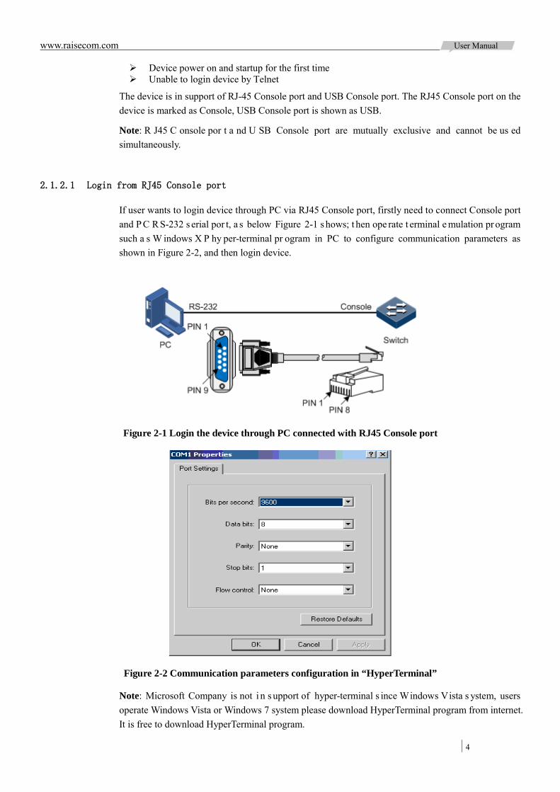
www.raisecom.com User Manual
4
Device power on and startup for the first time Unable to login device by Telnet
The device is in support of RJ-45 Console port and USB Console port. The RJ45 Console port on the device is marked as Console, USB Console port is shown as USB.
Note: R J45 C onsole por t a nd U SB Console port are mutually exclusive and cannot be us ed simultaneously.
2.1.2.1 Login from RJ45 Console port
If user wants to login device through PC via RJ45 Console port, firstly need to connect Console port and P C R S-232 s erial por t, a s below Figure 2-1 s hows; t hen ope rate t erminal e mulation pr ogram such a s W indows X P hy per-terminal pr ogram in PC to configure communication parameters as shown in Figure 2-2, and then login device.
Figure 2-1 Login the device through PC connected with RJ45 Console port
Figure 2-2 Communication parameters configuration in “HyperTerminal”
Note: Microsoft Company is not i n s upport of hyper-terminal s ince Windows Vista s ystem, users operate Windows Vista or Windows 7 system please download HyperTerminal program from internet. It is free to download HyperTerminal program.
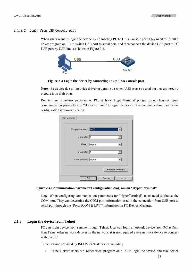
www.raisecom.com User Manual
5
2.1.2.2 Login from USB Console port
When users want to login the device by connecting PC to USB Console port, they need to install a driver program on PC to switch USB port to serial port, and then connect the device USB port to PC USB port by USB line, as shown in Figure 2-3.
Figure 2-3 Login the device by connecting PC to USB Console port
Note: t he de vice doe sn’t pr ovide dr iver pr ogram t o s witch U SB port t o s erial por t, us ers ne ed t o prepare it on their own.
Run terminal emulation pr ogram on PC, such a s "HyperTerminal" pr ogram, a nd t hen configure communication parameters on “HyperTerminal” to login the device. The communication parameters configuration is shown as below:
Figure 2-4 Communication parameters configuration diagram on “HyperTerminal”
Note: When configuring communication parameters for "HyperTerminal", users need to choose the COM port. They can determine the COM port information used in the connection from USB port to serial port through the "Ports (COM & LPT)" information in PC Device Manager.
2.1.3 Login the device from Telnet PC can login device from remote through Telnet. User can login a network device from PC at first, then Telnet other network devices in the network, it is not required every network device to connect with one PC.
Telnet service provided by ISCOM2924GF device including:
Telnet Server: users run Telnet client program on a PC to login the device, and take device
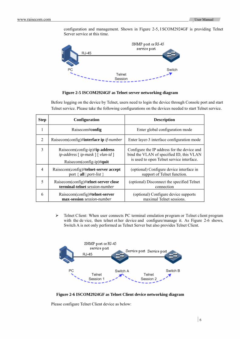
www.raisecom.com User Manual
6
configuration and management. Shown in Figure 2-5, I SCOM2924GF is providing Telnet Server service at this time.
Figure 2-5 ISCOM2924GF as Telnet server networking diagram
Before logging on the device by Telnet, users need to login the device through Console port and start Telnet service. Please take the following configurations on the devices needed to start Telnet service.
Step Configuration Description
1 Raisecom#config Enter global configuration mode
2 Raisecom(config)#interface ip if-number Enter layer-3 interface configuration mode
3 Raisecom(config-ip)#ip address ip-address [ ip-mask ] [ vlan-id ]
Raisecom(config-ip)#quit
Configure the IP address for the device and bind the VLAN of specified ID, this VLAN
is used to open Telnet service interface.
4 Raisecom(config)#telnet-server accept port { all | port-list }
(optional) Configure device interface in support of Telnet function.
5 Raisecom(config)#telnet-server close terminal-telnet session-number
(optional) Disconnect the specified Telnet connection
6 Raisecom(config)#telnet-server max-session session-number
(optional) Configure device supports maximal Telnet sessions.
Telnet Client: When user connects PC terminal emulation program or Telnet client program with the de vice, then telnet ot her device and configure/manage it. As Figure 2-6 shows, Switch A is not only performed as Telnet Server but also provides Telnet Client.
Figure 2-6 ISCOM2924GF as Telnet Client device networking diagram
Please configure Telnet Client device as below:

www.raisecom.com User Manual
7
Step Configuration Description
1 Raisecom#telnet ip-address [ port port-id ] Login other devices from Telnet
2.1.4 Login the device from SSHv2 Telnet is l ack of s ecurity a uthentication a nd i t t ransports m essage by T CP ( Transmission C ontrol Protocol) w hich e xists bi g pot ential s ecurity ha zard. Telnet s ervice m ay caus e D OS ( Deny of Service), host IP deceive, and routing deceive, etc. hostility attacks.
The traditional T elnet a nd FTP ( File T ransfer P rotocol) tr ansmits pa ssword and data in plaintext cannot satisfy users’ security demands.SSHv2 is a network security protocol, which can effectively prevent the disclosure of information in remote management through the network data encryption, and provides greater security for remote login and other network services in network environment.
SSHv2 allows data to be exchanged via TCP and it builds up a secure channel over TCP. Besides, SSHv2 is in support of other service ports besides standard port 22, thus to avoid illegal attack from network.
Before login device via SSHv2, user must login device through Console port and starts up SSH service.
The default configuration to login the device through SSHv2 is as follows.
Function Default value
SSHv2 server function status Prohibit
Local SSHv2 key pair length 512bit
Device authentication method password
SSHv2 authentication timeout 600s
The allowable failure number for SSHv2 authentication 20
SSHv2 snooping port number 22
SSHv2 session function status Enable
Please configure SSHv2 service for the device as below:
Step Configuration Description
1 Raisecom#config Enter global configuration mode
2 Raisecom(config)#generate ssh-key length
Generate local SSHv2 key pair and designate its length
3 Raisecom(config)#ssh2 server Start SSHv2 server
SSHv2 server can be shut down by command of no ssh2 server.
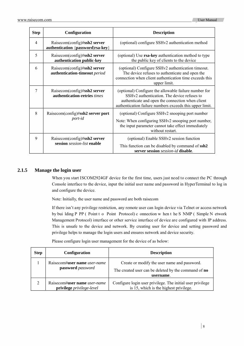
www.raisecom.com User Manual
8
Step Configuration Description
4 Raisecom(config)#ssh2 server authentication {password|rsa-key}
(optional) configure SSHv2 authentication method
5 Raisecom(config)#ssh2 server authentication public-key
(optional) Use rsa-key authentication method to type the public key of clients to the device
6 Raisecom(config)#ssh2 server authentication-timeout period
(optional) Configure SSHv2 authentication timeout. The device refuses to authenticate and open the
connection when client authentication time exceeds this upper limit.
7 Raisecom(config)#ssh2 server authentication-retries times
(optional) Configure the allowable failure number for SSHv2 authentication. The device refuses to
authenticate and open the connection when client authentication failure numbers exceeds this upper limit.
8 Raisecom(config)#ssh2 server port port-id
(optional) Configure SSHv2 snooping port number
Note: When configuring SSHv2 snooping port number, the input parameter cannot take effect immediately
without restart.
9 Raisecom(config)#ssh2 server session session-list enable
(optional) Enable SSHv2 session function
This function can be disabled by command of ssh2 server session session-id disable.
2.1.5 Manage the login user When you start ISCOM2924GF device for the first time, users just need to connect the PC through Console interface to the device, input the initial user name and password in HyperTerminal to log in and configure the device.
Note: Initially, the user name and password are both raisecom
If there isn’t any privilege restriction, any remote user can login device via Telnet or access network by bui lding P PP ( Point t o Point Protocol) c onnection w hen t he S NMP ( Simple N etwork Management Protocol) interface or other service interface of device are configured with IP address. This is unsafe to the device and network. By creating user for device and setting password and privilege helps to manage the login users and ensures network and device security.
Please configure login user management for the device of as below:
Step Configuration Description
1 Raisecom#user name user-name password password
Create or modify the user name and password.
The created user can be deleted by the command of no username.
2 Raisecom#user name user-name privilege privilege-level
Configure login user privilege. The initial user privilege is 15, which is the highest privilege.

www.raisecom.com User Manual
9
Step Configuration Description
3 Raisecom#user user-name { allow-exec | disallow-exec }
first-keyword [ second-keyword ]
Configure the priority rule for login user to perform the command line.
Specified allow-exec parameters will allow the user to perform commands higher than the current priority.
Specified disallow-exec parameters only allow the user to perform commands lower than the current priority.
2.1.6 Check the configuration Please perform the following command to check the configuration results:
No. Entry Description
1 Raisecom#show user [ detail ] Check the login user information
2 Raisecom#show telnet-server Check Telnet Server configuration
3 Raisecom#show ssh2 public-key [ authentication ]
Check the public key used for SSHv2 authentication in the device and client port
4 Raisecom#show ssh2 { server | session } Check SSHv2 server or session information.
2.2 Command line
2.2.1 Brief introduction Command l ine i s the pa th for communication be tween user and switch. User can complete device configuration, monitor and management by executing relative commands.
User can login this device through PC that run terminal emulation program or CPE device, enter into command line interface once the command prompt appears.
The features of command line interface:
Local configuration via Console port is available; Local or remote configuration via Telnet, SSHv2 (Secure Shell v2,) is available; Protection for different command levels, user in different level can only execute command in
related level; Different command types belong to different command modes, user can only execute a type
of configuration in its related command mode; User can operate the commands by shortcut keys; User can view or execute a history command by transferring history record, the device is in
support of saving the latest 20 pieces of history commands; Online help is available by user inputting “?” at anytime; Smart analysis methods such as incomplete matching and context association, etc. facilitates
user input.
2.2.2 Command line level ISCOM2924GF uses hierarchy protection method to divide command line into16 levels from low to high.
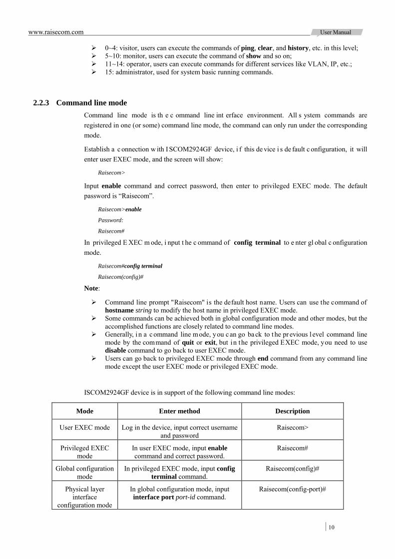
www.raisecom.com User Manual
10
0~4: visitor, users can execute the commands of ping, clear, and history, etc. in this level; 5~10: monitor, users can execute the command of show and so on; 11~14: operator, users can execute commands for different services like VLAN, IP, etc.; 15: administrator, used for system basic running commands.
2.2.3 Command line mode Command line mode is th e c ommand line int erface environment. All s ystem commands are registered in one (or some) command line mode, the command can only run under the corresponding mode.
Establish a c onnection w ith I SCOM2924GF device, i f this de vice i s de fault c onfiguration, it will enter user EXEC mode, and the screen will show:
Raisecom>
Input enable command and correct password, then enter to privileged EXEC mode. The default password is “Raisecom”.
Raisecom>enable
Password:
Raisecom#
In privileged E XEC m ode, i nput t he c ommand of config terminal to e nter gl obal c onfiguration mode.
Raisecom#config terminal
Raisecom(config)#
Note:
Command line prompt "Raisecom" is the default host name. Users can use the command of hostname string to modify the host name in privileged EXEC mode.
Some commands can be achieved both in global configuration mode and other modes, but the accomplished functions are closely related to command line modes.
Generally, i n a c ommand line mode, you c an go ba ck to t he pr evious l evel command line mode by the command of quit or exit, but in the privileged EXEC mode, you need to use disable command to go back to user EXEC mode.
Users can go back to privileged EXEC mode through end command from any command line mode except the user EXEC mode or privileged EXEC mode.
ISCOM2924GF device is in support of the following command line modes:
Mode Enter method Description
User EXEC mode Log in the device, input correct username and password
Raisecom>
Privileged EXEC mode
In user EXEC mode, input enable command and correct password.
Raisecom#
Global configuration mode
In privileged EXEC mode, input config terminal command.
Raisecom(config)#
Physical layer interface
configuration mode
In global configuration mode, input interface port port-id command.
Raisecom(config-port)#
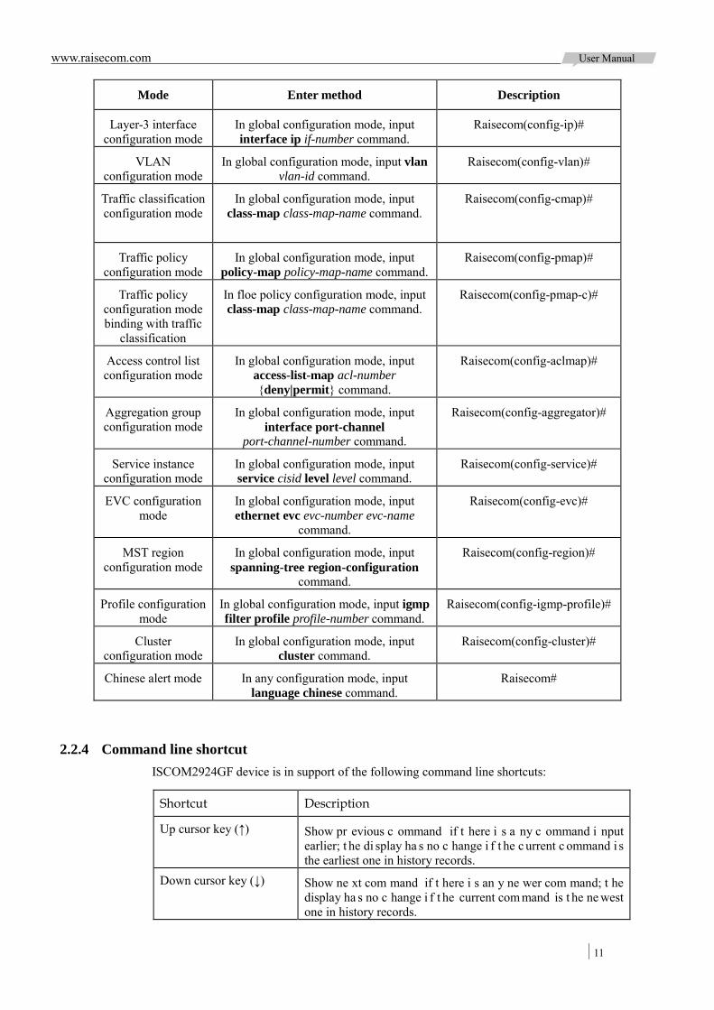
www.raisecom.com User Manual
11
Mode Enter method Description
Layer-3 interface configuration mode
In global configuration mode, input interface ip if-number command.
Raisecom(config-ip)#
VLAN configuration mode
In global configuration mode, input vlan vlan-id command.
Raisecom(config-vlan)#
Traffic classification configuration mode
In global configuration mode, input class-map class-map-name command.
Raisecom(config-cmap)#
Traffic policy configuration mode
In global configuration mode, input policy-map policy-map-name command.
Raisecom(config-pmap)#
Traffic policy configuration mode binding with traffic
classification
In floe policy configuration mode, input class-map class-map-name command.
Raisecom(config-pmap-c)#
Access control list configuration mode
In global configuration mode, input access-list-map acl-number {deny|permit} command.
Raisecom(config-aclmap)#
Aggregation group configuration mode
In global configuration mode, input interface port-channel
port-channel-number command.
Raisecom(config-aggregator)#
Service instance configuration mode
In global configuration mode, input service cisid level level command.
Raisecom(config-service)#
EVC configuration mode
In global configuration mode, input ethernet evc evc-number evc-name
command.
Raisecom(config-evc)#
MST region configuration mode
In global configuration mode, input spanning-tree region-configuration
command.
Raisecom(config-region)#
Profile configuration mode
In global configuration mode, input igmp filter profile profile-number command.
Raisecom(config-igmp-profile)#
Cluster configuration mode
In global configuration mode, input cluster command.
Raisecom(config-cluster)#
Chinese alert mode In any configuration mode, input language chinese command.
Raisecom#
2.2.4 Command line shortcut ISCOM2924GF device is in support of the following command line shortcuts:
Shortcut Description
Up cursor key (↑) Show pr evious c ommand if t here i s a ny c ommand i nput earlier; t he di splay ha s no c hange i f t he c urrent c ommand i s the earliest one in history records.
Down cursor key (↓) Show ne xt com mand if t here i s an y ne wer com mand; t he display ha s no c hange i f t he current com mand is t he ne west one in history records.
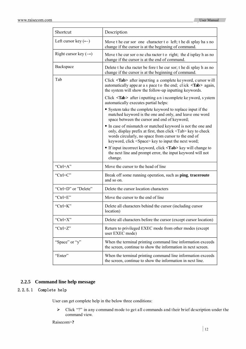
www.raisecom.com User Manual
12
Shortcut Description
Left cursor key (←) Move t he cur sor one character t o left; t he di splay ha s no change if the cursor is at the beginning of command.
Right cursor key (→) Move t he cur sor o ne cha racter t o right; the d isplay h as no change if the cursor is at the end of command.
Backspace Delete t he cha racter be fore t he cur sor; t he di splay h as no change if the cursor is at the beginning of command.
Tab Click <Tab> after input ting a complete ke yword, cursor will automatically appe ar a s pace t o the end; cl ick <Tab> again, the system will show the follow-up inputting keywords.
Click <Tab> after i nputting a n i ncomplete ke yword, s ystem automatically executes partial helps: System take the complete keyword to replace input if the
matched keyword is the one and only, and leave one word space between the cursor and end of keyword;
In case of mismatch or matched keyword is not the one and only, display prefix at first, then click <Tab> key to check words circularly, no space from cursor to the end of keyword, click <Space> key to input the next word;
If input incorrect keyword, click <Tab> key will change to the next line and prompt error, the input keyword will not change.
“Ctrl+A” Move the cursor to the head of line
“Ctrl+C” Break off some running operation, such as ping, traceroute and so on.
“Ctrl+D” or ”Delete” Delete the cursor location characters
“Ctrl+E” Move the cursor to the end of line
“Ctrl+K” Delete all characters behind the cursor (including cursor location)
“Ctrl+X” Delete all characters before the cursor (except cursor location)
“Ctrl+Z” Return to privileged EXEC mode from other modes (except user EXEC mode)
“Space” or “y” When the terminal printing command line information exceeds the screen, continue to show the information in next screen.
“Enter” When the terminal printing command line information exceeds the screen, continue to show the information in next line.
2.2.5 Command line help message 2.2.5.1 Complete help
User can get complete help in the below three conditions:
Click “?” in any command mode to get a ll commands and their br ief description under the command view.
Raisecom>?

www.raisecom.com User Manual
13
Display as below:
clear Clear screen
enable Turn on privileged mode command
exit Exit current mode and down to previous mode
help Message about help
history Most recent history command
language Language of help message
list List command
quit Exit current mode and down to previous mode
terminal Configure terminal
test Test command
Input a command and followed by a “?” after one character space, if the posi tion of “?” is keyword, list all keyword and brief description.
Raisecom(config)#ntp ?
Display as below:
peer Configure NTP peer
refclock-master Set local clock as reference clock
server Configure NTP server
Input a command and followed by a “?” after one character space, if the posi tion of “?” is parameter, list the range and brief description.
Raisecom(config)#interface ip ?
Display as below:
<0-14> IP interface number
2.2.5.2 Partial help
User can get partial help in the below three conditions:
Input a character string and followed by a “?”, the device will list all keywords start with the character string under current mode.
Raisecom(config)#c?
Display as below:
class-map Set class map
clear Clear screen
cpu Configure cpu parameters
create Create static VLAN
Input a c ommand a nd f ollowed by a c haracter s tring w ith “?”, the de vice w ill lis t a ll keywords start with the character string in the command of current mode.
Raisecom(config)#show li?
Display as below:
link-aggregation Link aggregation
link-state-tracking Link state tracking
Input t he f irst f ew l etters of a command ke yword a nd c lick <Tab> key to s how c omplete
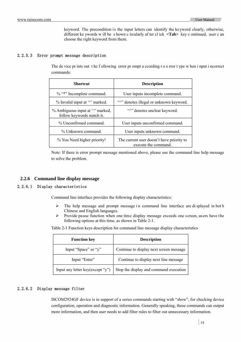
www.raisecom.com User Manual
14
keyword. The precondition i s the input letters can identify the ke yword clearly, otherwise, different ke ywords w ill be s hown c ircularly af ter cl ick <Tab> key c ontinued, user c an choose the right keyword from them.
2.2.5.3 Error prompt message description
The de vice pr ints out t he f ollowing error pr ompt a ccording t o e rror t ype w hen i nput i ncorrect commands:
Shortcut Description
% “*” Incomplete command. User inputs incomplete command.
% Invalid input at ‘^’ marked. “^” denotes illegal or unknown keyword.
% Ambiguous input at ‘^’ marked, follow keywords match it.
“^” denotes unclear keyword.
% Unconfirmed command. User inputs unconfirmed command.
% Unknown command. User inputs unknown command.
% You Need higher priority! The current user doesn’t have priority to execute the command.
Note: If there is error prompt message mentioned above, please use the command line help message to solve the problem.
2.2.6 Command line display message 2.2.6.1 Display characteristics
Command line interface provides the following display characteristics:
The help message and prompt message i n command line interface are di splayed in bot h Chinese and English languages.
Provide pause function when one time display message exceeds one screen, users have the following options at this time, as shown in Table 2-1.
Table 2-1 Function keys description for command line message display characteristics
Function key Description
Input “Space” or “y” Continue to display next screen message
Input “Enter” Continue to display next line message
Input any letter key(except “y”) Stop the display and command execution
2.2.6.2 Display message filter
ISCOM2924GF device is in support of a series commands starting with “show”, for checking device configuration, operation and diagnostic information. Generally speaking, these commands can output more information, and then user needs to add filter rules to filter out unnecessary information.
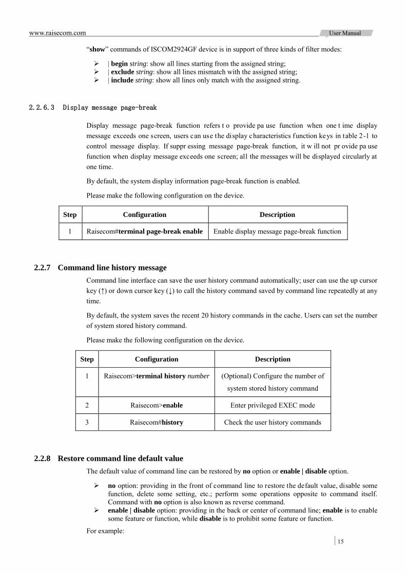
www.raisecom.com User Manual
15
“show” commands of ISCOM2924GF device is in support of three kinds of filter modes:
| begin string: show all lines starting from the assigned string; | exclude string: show all lines mismatch with the assigned string; | include string: show all lines only match with the assigned string.
2.2.6.3 Display message page-break
Display message page-break function refers t o provide pa use function when one t ime display message exceeds one screen, users can use the display characteristics function keys in table 2-1 to control message display. If suppr essing message page-break function, it w ill not pr ovide pa use function when display message exceeds one screen; all the messages will be displayed circularly at one time.
By default, the system display information page-break function is enabled.
Please make the following configuration on the device.
Step Configuration Description
1 Raisecom#terminal page-break enable Enable display message page-break function
2.2.7 Command line history message Command line interface can save the user history command automatically; user can use the up cursor key (↑) or down cursor key (↓) to call the history command saved by command line repeatedly at any time.
By default, the system saves the recent 20 history commands in the cache. Users can set the number of system stored history command.
Please make the following configuration on the device.
Step Configuration Description
1 Raisecom>terminal history number (Optional) Configure the number of
system stored history command
2 Raisecom>enable Enter privileged EXEC mode
3 Raisecom#history Check the user history commands
2.2.8 Restore command line default value The default value of command line can be restored by no option or enable | disable option.
no option: providing in the front of command line to restore the default value, disable some function, delete some setting, etc.; perform some operations opposite to command itself. Command with no option is also known as reverse command.
enable | disable option: providing in the back or center of command line; enable is to enable some feature or function, while disable is to prohibit some feature or function.
For example:
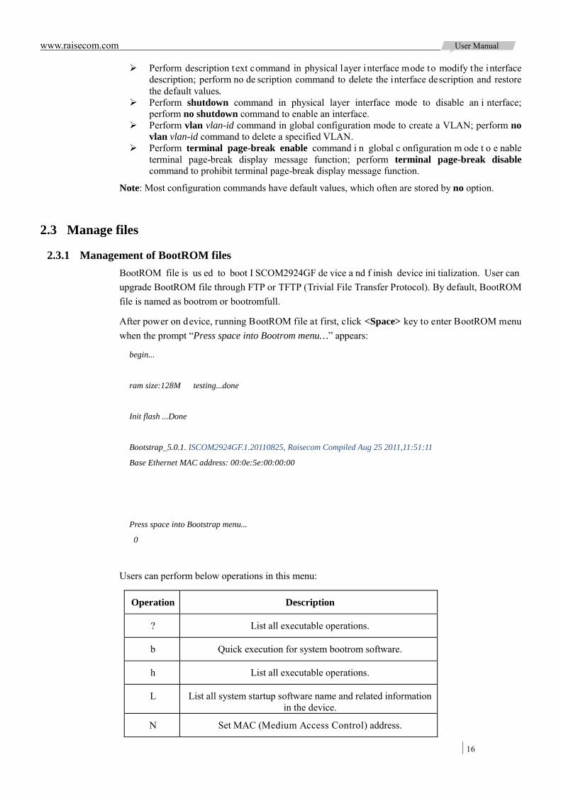
www.raisecom.com User Manual
16
Perform description text command in physical layer interface mode to modify the interface description; perform no de scription command to delete the interface description and restore the default values.
Perform shutdown command in physical layer interface mode to disable an i nterface; perform no shutdown command to enable an interface.
Perform vlan vlan-id command in global configuration mode to create a VLAN; perform no vlan vlan-id command to delete a specified VLAN.
Perform terminal page-break enable command i n global c onfiguration m ode t o e nable terminal page-break display message function; perform terminal page-break disable command to prohibit terminal page-break display message function.
Note: Most configuration commands have default values, which often are stored by no option.
2.3 Manage files
2.3.1 Management of BootROM files BootROM file is us ed to boot I SCOM2924GF de vice a nd f inish device ini tialization. User can upgrade BootROM file through FTP or TFTP (Trivial File Transfer Protocol). By default, BootROM file is named as bootrom or bootromfull.
After power on device, running BootROM file at first, click <Space> key to enter BootROM menu when the prompt “Press space into Bootrom menu…” appears:
begin...
ram size:128M testing...done
Init flash ...Done
Bootstrap_5.0.1. ISCOM2924GF.1.20110825, Raisecom Compiled Aug 25 2011,11:51:11
Base Ethernet MAC address: 00:0e:5e:00:00:00
Press space into Bootstrap menu...
0
Users can perform below operations in this menu:
Operation Description
? List all executable operations.
b Quick execution for system bootrom software.
h List all executable operations.
L List all system startup software name and related information in the device.
N Set MAC (Medium Access Control) address.

www.raisecom.com User Manual
17
Operation Description
R Reboot the device.
S List all system startup software name and related information in the device and assign system startup software name loaded
at the time of startup device.
T Download and replace system startup software by TFTP.
2.3.2 Management of system files System f iles i ndicate the f iles ne eded for de vice ope ration (like s ystem s tartup software, configuration file, etc.). These files are usually saved in device memory, the device manages them by a f ile system to facilitate user manage the memory. The file system contains functions of creating, deleting and modifying file and directory.
Besides, I SCOM2924GF de vice s upports dua l s ystem, that i s t o s ay it c an s tore t wo v ersions of system software in m emory. User c an shift to the o ther sof tware startup de vice w hen one de vice cannot use for system upgrading failure.
Please configure system files management for the device as below:
(All the following steps are optional and no sequencing.)
Step Configuration Description
1 Raisecom#download bootstrap { ftp ip-address user-name password file-name | tftp ip-address file-name }
(Optional) Download system bootstrap software via FTP or TFTP.
2 Raisecom#download system-boot { ftp ip-address user-name password file-name | tftp ip-address file-name }
(Optional) Download system boot software through FTP or TFTP.
3 Raisecom#upload system-boot { ftp [ ip-address user-name password file-name ] | tftp [ ip-address file-name ] }
(Optional) Upload system boot software by FTP or TFTP.
4 Raisecom#erase [ file-name ] (Optional) Delete the files from memory.
2.3.3 Management of configuration files Configuration files are loaded after starting the system; different files are used in different scenarios in order t o achi eve di fferent service functions. After s tarting the system, us er can configure the device and save the configuration files. New configuration will take effect in next boot.
Configuration f ile ha s a n a ffix “.cfg”, t hese f iles c an b e ope n by text book pr ogram in W indows system, the contents in the following format:
Saved as Mode+Command format; Just re serve t he non -defaulted parameters t o save s pace ( refer t o command reference f or
default values of configuration parameters); Take the command mode for basic frame to organize commands, put commands of one mode
together to form a section, the sections are separated by “!”.
ISCOM2924GF device s tarts initialization by r eading configuration files f rom m emory a fter powering on. Thus, the configuration in configuration files are called as initialization configuration,
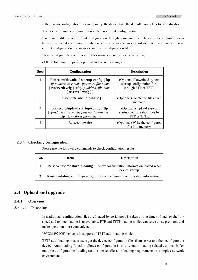
www.raisecom.com User Manual
18
if there is no configuration files in memory, the device take the default parameters for initialization.
The device running configuration is called as current configuration.
User can modify device current configuration through command line. The current configuration can be us ed as ini tial configuration when next t ime pow er on, us er must us e c ommand write to save current configuration into memory and form configuration file.
Please configure the configuration files management for device as below:
(All the following steps are optional and no sequencing.)
Step Configuration Description
1 Raisecom#download startup-config { ftp ip-address user-name password file-name
[ reservedevcfg ] | tftp ip-address file-name [ reservedevcfg ] }
(Optional) Download system startup configuration files
through FTP or TFTP.
2 Raisecom#erase [ file-name ] (Optional) Delete the files from memory.
3 Raisecom#upload startup-config { ftp [ ip-address user-name password file-name ] |
tftp [ ip-address file-name ] }
(Optional) Upload system startup configuration files by
FTP or TFTP.
4 Raisecom#write (Optional) Write the configured file into memory.
2.3.4 Checking configuration Please use the following commands to check configuration results:
No. Item Description
1 Raisecom#show startup-config Show configuration information loaded when device startup.
2 Raisecom#show running-config Show the current configuration information.
2.4 Upload and upgrade
2.4.1 Overview 2.4.1.1 Uploading
In t raditional, configuration f iles are loaded by serial port, i t takes a long t ime to load for the low speed and remote loading is unavailable. FTP and TFTP loading modes can solve those problems and make operation more convenient.
ISCOM2924GF device is in support of TFTP auto-loading mode.
TFTP auto-loading means users get the device configuration files from server and then configure the device. Auto-loading function allows configuration f iles to contain loading r elated c ommands f or multiple c onfigurations l oading s o a s t o m eet file auto-loading r equirements i n c omplex ne twork environment.
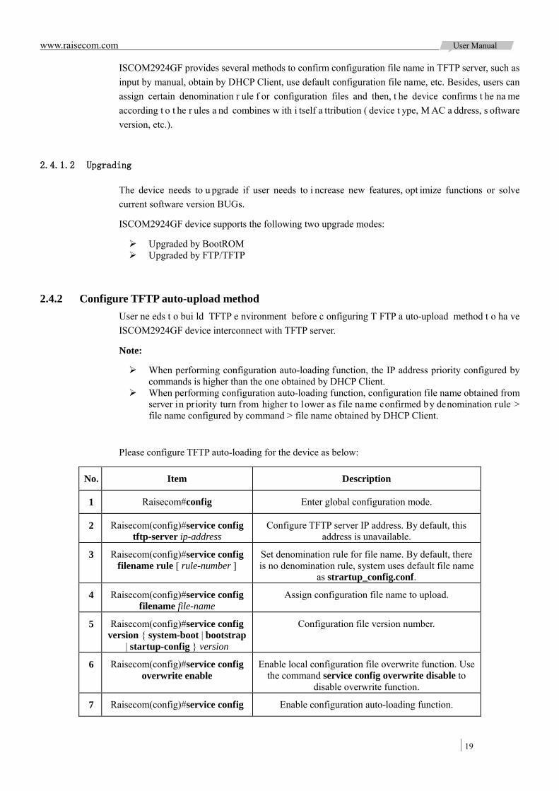
www.raisecom.com User Manual
19
ISCOM2924GF provides several methods to confirm configuration file name in TFTP server, such as input by manual, obtain by DHCP Client, use default configuration file name, etc. Besides, users can assign certain denomination r ule f or configuration files and then, t he device confirms t he na me according t o t he r ules a nd combines w ith i tself a ttribution ( device t ype, M AC a ddress, s oftware version, etc.).
2.4.1.2 Upgrading
The device needs to u pgrade if user needs to i ncrease new features, opt imize functions or solve current software version BUGs.
ISCOM2924GF device supports the following two upgrade modes:
Upgraded by BootROM Upgraded by FTP/TFTP
2.4.2 Configure TFTP auto-upload method User ne eds t o bui ld TFTP e nvironment before c onfiguring T FTP a uto-upload method t o ha ve ISCOM2924GF device interconnect with TFTP server.
Note:
When performing configuration auto-loading function, the IP address priority configured by commands is higher than the one obtained by DHCP Client.
When performing configuration auto-loading function, configuration file name obtained from server in priority turn from higher to lower as file name confirmed by denomination rule > file name configured by command > file name obtained by DHCP Client.
Please configure TFTP auto-loading for the device as below:
No. Item Description
1 Raisecom#config Enter global configuration mode.
2 Raisecom(config)#service config tftp-server ip-address
Configure TFTP server IP address. By default, this address is unavailable.
3 Raisecom(config)#service config filename rule [ rule-number ]
Set denomination rule for file name. By default, there is no denomination rule, system uses default file name
as strartup_config.conf.
4 Raisecom(config)#service config filename file-name
Assign configuration file name to upload.
5 Raisecom(config)#service config version { system-boot | bootstrap
| startup-config } version
Configuration file version number.
6 Raisecom(config)#service config overwrite enable
Enable local configuration file overwrite function. Use the command service config overwrite disable to
disable overwrite function.
7 Raisecom(config)#service config Enable configuration auto-loading function.

www.raisecom.com User Manual
20
No. Item Description
8 Raisecom(config)#service config trap enable
Enable Trap function. Use the command service config trap disable to prohibit this function.
2.4.3 Upgrade system software by BootROM In the below conditions, user needs to upgrade system software by BootROM:
Device first time startup System file damaged The card cannot startup in order
Before upgrading system software by BootROM, user should build TFTP environment, take PC as TFTP server, ISCOM2924GF device as client, basic requirements are as below:
ISCOM2924GF connects TFTP server by SNMP interface. Configure TFTP server, make sure the server is available; Configure IP a ddress for T FTP server; keep i t i n t he s ame ne twork s egment w ith
ISCOM2924GF IP address.
Steps for upgrading system software by BootROM:
Step Operation
1 Log in device through serial port as administrator and enter Privileged EXEC mode, reboot device by the command of reboot.
Raisecom#reboot Please input 'yes' to confirm:yes
Rebooting ...
Raisecom# begin...
ram size:128M testing...done
Init flash ...Done
Bootstrap_5.0.1.ISCOM2924GF.1.20110825, Raisecom Compiled Aug 25 2011,11:51:11
Base Ethernet MAC address: 00:0e:5e:00:00:00
Press space into Bootstrap menu...
0
2 Click <Space> key to enter i nterface of [ raisecom] when the di splay shows “Press space into Bootstrap menu...”, then input “?” to display command list:
[Raisecom]:? ? - List all available commands
h - List all available commands
b - Boot an executable image
T - Download both DOS file system
N - set ethernet address
R - Reboot
Note: The input letters are case sensitive.
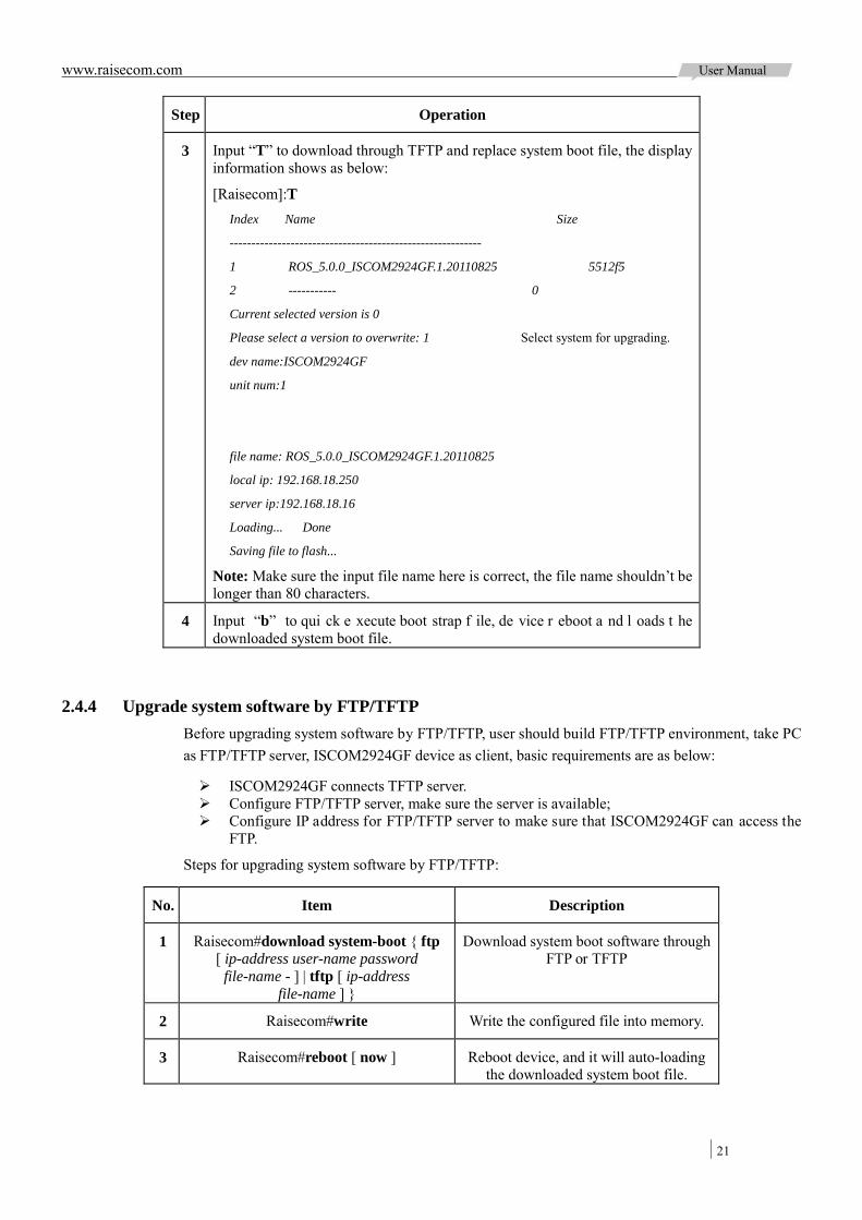
www.raisecom.com User Manual
21
Step Operation
3 Input “T” to download through TFTP and replace system boot file, the display information shows as below:
[Raisecom]:T Index Name Size
----------------------------------------------------------
1 ROS_5.0.0_ISCOM2924GF.1.20110825 5512f5
2 ----------- 0
Current selected version is 0
Please select a version to overwrite: 1 Select system for upgrading.
dev name:ISCOM2924GF
unit num:1
file name: ROS_5.0.0_ISCOM2924GF.1.20110825
local ip: 192.168.18.250
server ip:192.168.18.16
Loading... Done
Saving file to flash...
Note: Make sure the input file name here is correct, the file name shouldn’t be longer than 80 characters.
4 Input “b” to qui ck e xecute boot strap f ile, de vice r eboot a nd l oads t he downloaded system boot file.
2.4.4 Upgrade system software by FTP/TFTP Before upgrading system software by FTP/TFTP, user should build FTP/TFTP environment, take PC as FTP/TFTP server, ISCOM2924GF device as client, basic requirements are as below:
ISCOM2924GF connects TFTP server. Configure FTP/TFTP server, make sure the server is available; Configure IP address for FTP/TFTP server to make sure that ISCOM2924GF can access the
FTP.
Steps for upgrading system software by FTP/TFTP:
No. Item Description
1 Raisecom#download system-boot { ftp [ ip-address user-name password
file-name - ] | tftp [ ip-address file-name ] }
Download system boot software through FTP or TFTP
2 Raisecom#write Write the configured file into memory.
3 Raisecom#reboot [ now ] Reboot device, and it will auto-loading the downloaded system boot file.
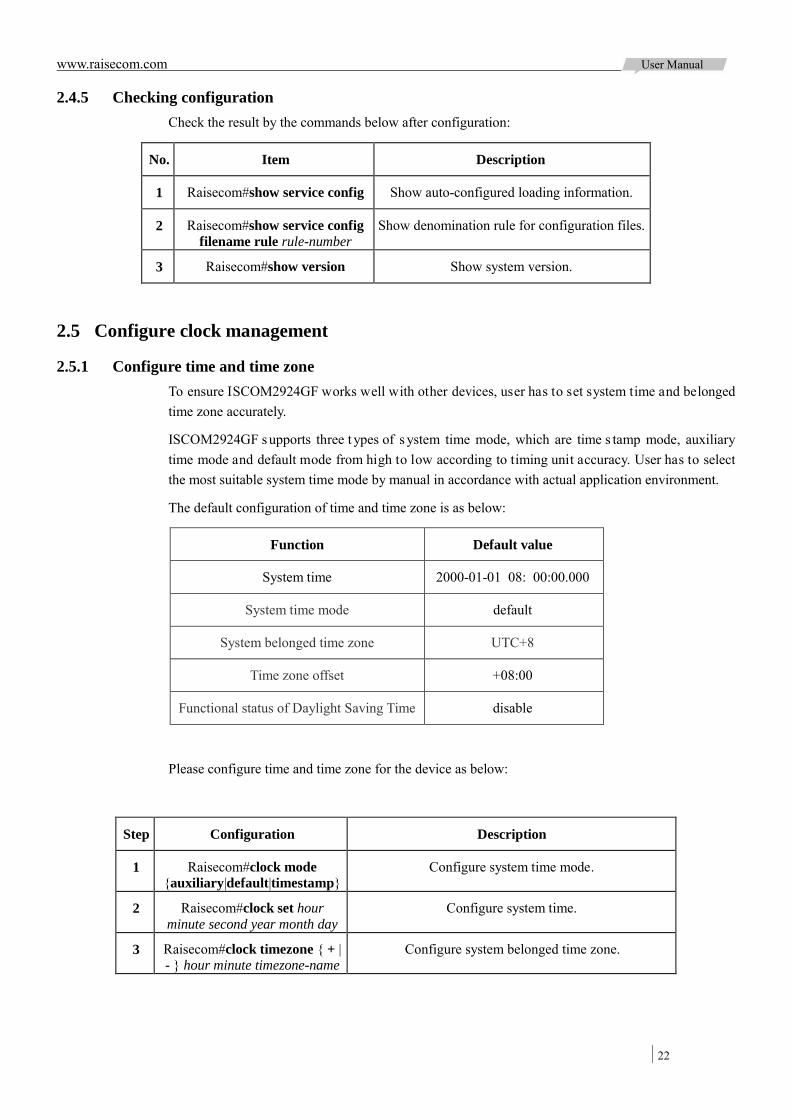
www.raisecom.com User Manual
22
2.4.5 Checking configuration Check the result by the commands below after configuration:
No. Item Description
1 Raisecom#show service config Show auto-configured loading information.
2 Raisecom#show service config filename rule rule-number
Show denomination rule for configuration files.
3 Raisecom#show version Show system version.
2.5 Configure clock management
2.5.1 Configure time and time zone To ensure ISCOM2924GF works well with other devices, user has to set system time and belonged time zone accurately.
ISCOM2924GF supports three t ypes of s ystem time mode, which are time s tamp mode, auxiliary time mode and default mode from high to low according to timing unit accuracy. User has to select the most suitable system time mode by manual in accordance with actual application environment.
The default configuration of time and time zone is as below:
Function Default value
System time 2000-01-01 08: 00:00.000
System time mode default
System belonged time zone UTC+8
Time zone offset +08:00
Functional status of Daylight Saving Time disable
Please configure time and time zone for the device as below:
Step Configuration Description
1 Raisecom#clock mode {auxiliary|default|timestamp}
Configure system time mode.
2 Raisecom#clock set hour minute second year month day
Configure system time.
3 Raisecom#clock timezone { + | - } hour minute timezone-name
Configure system belonged time zone.

www.raisecom.com User Manual
23
2.5.2 Configure daylight saving time DST (Daylight Saving Time) is a kind of artificial regulation local time system for saving energy. At present, there a re nearly 110 countries operate DST every summer a round the world, but di fferent country ha s di fferent s tipulation f or D ST, us ers s hould t ake t he a ctual c ondition of l ocal w hen configuring DST.
Please configure DST for the device as below:
Step Configuration Description
1 Raisecom#clock summer-time enable Enable DST function.
User can disable this function by the command of clock summer-time disable.
2 Raisecom#clock summer-time recurring { week | last } { fri | mon | sat | sun | thu |
tue | wed } month hour minute { week | last } { fri | mon | sat |sun | thu | tue | wed } month hour minute offset-mm
Configure calculate period for system DST.
Note:
When user set system time by manua, if the system uses DST, such as DST from 2 o’clock on the second Sunday, April to 2 o’clock on the second Sunday, September every year, users have to advance the clock one hour faster during this period, set time offset as 60 minutes and from 2 o’clock to 3 o’clock on the second Sunday, April each year is an inexistent time. The time setting by manual operation during this period shows failure.
The summer time in southern hemisphere is opposite to northern hemisphere, which is from September to April of next year. If user configures start time later than ending time, system will suppose it is in the Southern Hemisphere. That is to say, the summer time is the start time this year to the ending time of next year.
2.5.3 Configure NTP NTP (Network T ime P rotocol) i s a t ime s ynchronization pr otocol de fined by RFC1305, us ed t o synchronize time between distributed time servers and clients. NTP transportation is based on UDP, using port 123.
The pur pose of N TP i s t o synchronize a ll c locks i n a ne twork qui ckly a nd t hen the de vice c an provide different application over a unified t ime. Meanwhile, NTP can ensure very high accuracy, with accuracy of 10ms around.
The device in support of NTP can not only accept synchronization from other clock source, but also to synchronize other devices as a clock source.
ISCOM2924GF device adopts multiple NTP working mode for time synchronization:
Server/Client mode
In this mode, c lient sends c lock synchronization message to different servers. The server works in server mode b y automation a fter r eceiving s ynchronization message and send answering message. The client received answering message and perform clock filer and selection, then synchronize it to privileged server.
In this mode, client can synchronize to server but the server cannot synchronize to client.
Equity mode
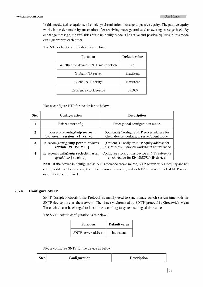
www.raisecom.com User Manual
24
In this mode, active equity send clock synchronization message to passive equity. The passive equity works in passive mode by automation after receiving message and send answering message back. By exchange message, the two sides build up equity mode. The active and passive equities in this mode can synchronize each other.
The NTP default configuration is as below:
Function Default value
Whether the device is NTP master clock no
Global NTP server inexistent
Global NTP equity inexistent
Reference clock source 0.0.0.0
Please configure NTP for the device as below:
Step Configuration Description
1 Raisecom#config Enter global configuration mode.
2 Raisecom(config)#ntp server ip-address [ version [ v1 | v2 | v3 ] ]
(Optional) Configure NTP server address for client device working in server/client mode.
3 Raisecom(config)#ntp peer ip-address [ version [ v1 | v2 | v3 ] ]
(Optional) Configure NTP equity address for ISCOM2924GF device working in equity mode.
4 Raisecom(config)#ntp reclock-master ip-address [ stratum ]
Configure clock of this device as NTP reference clock source for ISCOM2924GF device.
Note: If the device is configured as NTP reference clock source, NTP server or NTP equity are not configurable; and vice versa, the device cannot be configured as NTP reference clock if NTP server or equity are configured.
2.5.4 Configure SNTP SNTP (Simple Network Time Protocol) is mainly used to synchronize switch system time with the SNTP device tim e in the n etwork. The t ime s ynchronized by S NTP protocol i s Greenwich Mean Time, which can be changed to local time according to system setting of time zone.
The SNTP default configuration is as below:
Function Default value
SNTP server address inexistent
Please configure SNTP for the device as below:
Step Configuration Description
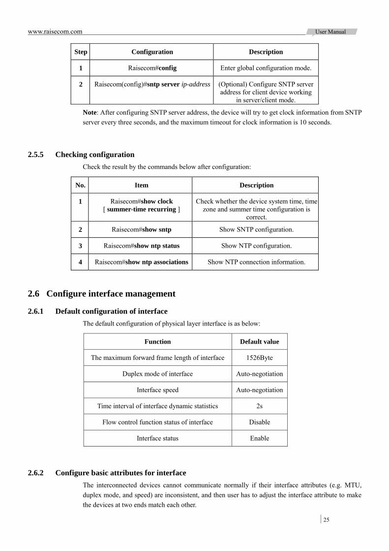
www.raisecom.com User Manual
25
Step Configuration Description
1 Raisecom#config Enter global configuration mode.
2 Raisecom(config)#sntp server ip-address (Optional) Configure SNTP server address for client device working
in server/client mode.
Note: After configuring SNTP server address, the device will try to get clock information from SNTP server every three seconds, and the maximum timeout for clock information is 10 seconds.
2.5.5 Checking configuration Check the result by the commands below after configuration:
No. Item Description
1 Raisecom#show clock [ summer-time recurring ]
Check whether the device system time, time zone and summer time configuration is
correct.
2 Raisecom#show sntp Show SNTP configuration.
3 Raisecom#show ntp status Show NTP configuration.
4 Raisecom#show ntp associations Show NTP connection information.
2.6 Configure interface management
2.6.1 Default configuration of interface The default configuration of physical layer interface is as below:
Function Default value
The maximum forward frame length of interface 1526Byte
Duplex mode of interface Auto-negotiation
Interface speed Auto-negotiation
Time interval of interface dynamic statistics 2s
Flow control function status of interface Disable
Interface status Enable
2.6.2 Configure basic attributes for interface The interconnected devices cannot communicate normally if their interface attributes (e.g. MTU, duplex mode, and speed) are inconsistent, and then user has to adjust the interface attribute to make the devices at two ends match each other.
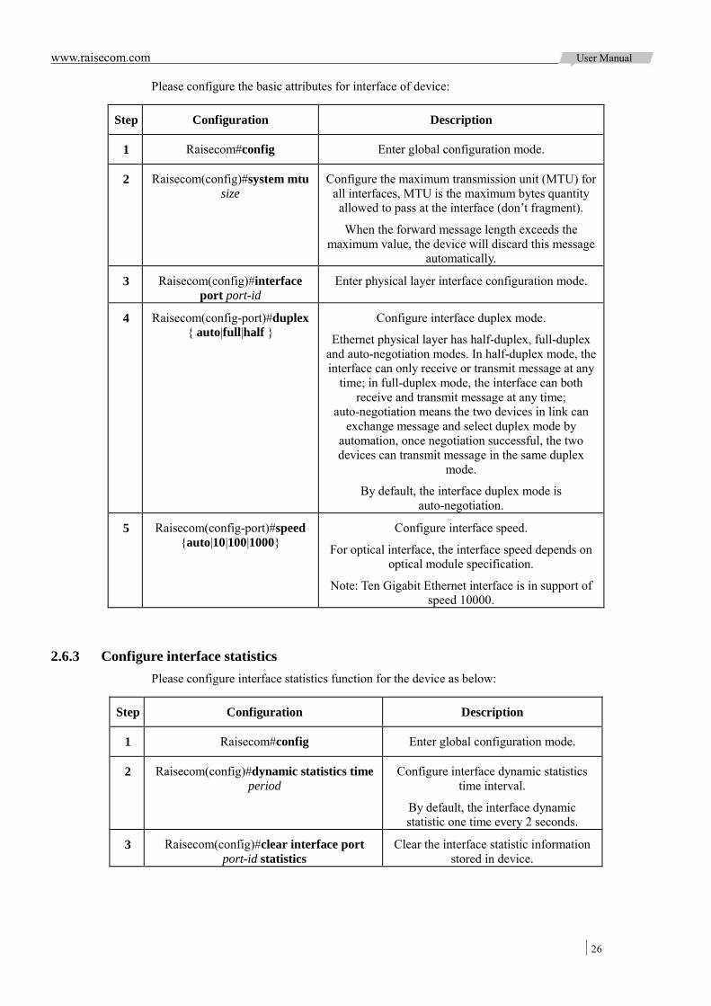
www.raisecom.com User Manual
26
Please configure the basic attributes for interface of device:
Step Configuration Description
1 Raisecom#config Enter global configuration mode.
2 Raisecom(config)#system mtu size
Configure the maximum transmission unit (MTU) for all interfaces, MTU is the maximum bytes quantity allowed to pass at the interface (don’t fragment).
When the forward message length exceeds the maximum value, the device will discard this message
automatically.
3 Raisecom(config)#interface port port-id
Enter physical layer interface configuration mode.
4 Raisecom(config-port)#duplex { auto|full|half }
Configure interface duplex mode.
Ethernet physical layer has half-duplex, full-duplex and auto-negotiation modes. In half-duplex mode, the interface can only receive or transmit message at any
time; in full-duplex mode, the interface can both receive and transmit message at any time;
auto-negotiation means the two devices in link can exchange message and select duplex mode by
automation, once negotiation successful, the two devices can transmit message in the same duplex
mode.
By default, the interface duplex mode is auto-negotiation.
5 Raisecom(config-port)#speed {auto|10|100|1000}
Configure interface speed.
For optical interface, the interface speed depends on optical module specification.
Note: Ten Gigabit Ethernet interface is in support of speed 10000.
2.6.3 Configure interface statistics Please configure interface statistics function for the device as below:
Step Configuration Description
1 Raisecom#config Enter global configuration mode.
2 Raisecom(config)#dynamic statistics time period
Configure interface dynamic statistics time interval.
By default, the interface dynamic statistic one time every 2 seconds.
3 Raisecom(config)#clear interface port port-id statistics
Clear the interface statistic information stored in device.
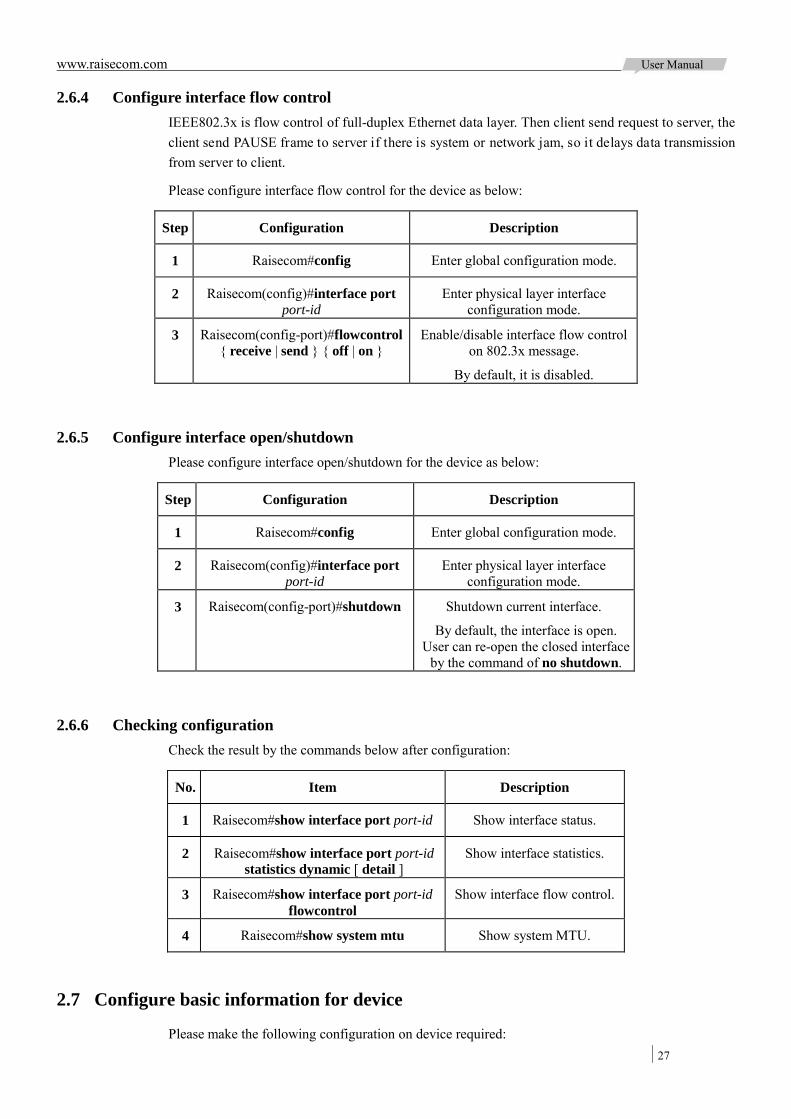
www.raisecom.com User Manual
27
2.6.4 Configure interface flow control IEEE802.3x is flow control of full-duplex Ethernet data layer. Then client send request to server, the client send PAUSE frame to server if there is system or network jam, so it delays data transmission from server to client.
Please configure interface flow control for the device as below:
Step Configuration Description
1 Raisecom#config Enter global configuration mode.
2 Raisecom(config)#interface port port-id
Enter physical layer interface configuration mode.
3 Raisecom(config-port)#flowcontrol { receive | send } { off | on }
Enable/disable interface flow control on 802.3x message.
By default, it is disabled.
2.6.5 Configure interface open/shutdown Please configure interface open/shutdown for the device as below:
Step Configuration Description
1 Raisecom#config Enter global configuration mode.
2 Raisecom(config)#interface port port-id
Enter physical layer interface configuration mode.
3 Raisecom(config-port)#shutdown Shutdown current interface.
By default, the interface is open. User can re-open the closed interface
by the command of no shutdown.
2.6.6 Checking configuration Check the result by the commands below after configuration:
No. Item Description
1 Raisecom#show interface port port-id Show interface status.
2 Raisecom#show interface port port-id statistics dynamic [ detail ]
Show interface statistics.
3 Raisecom#show interface port port-id flowcontrol
Show interface flow control.
4 Raisecom#show system mtu Show system MTU.
2.7 Configure basic information for device
Please make the following configuration on device required:
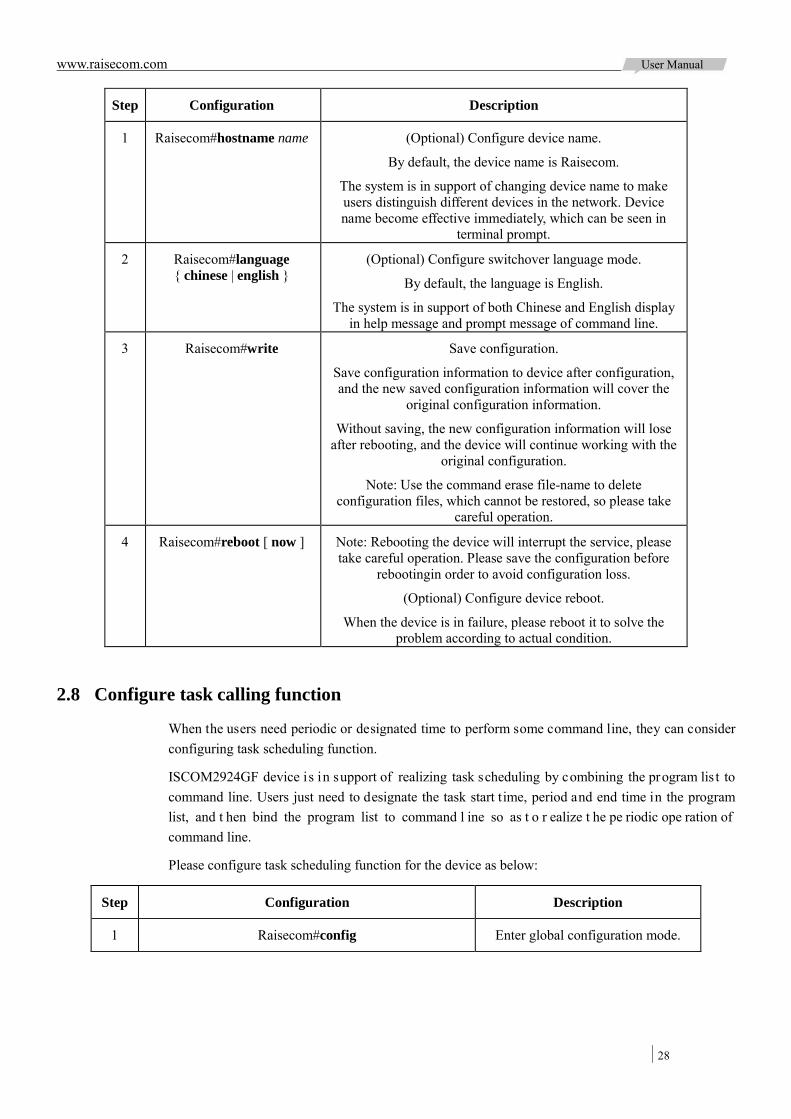
www.raisecom.com User Manual
28
Step Configuration Description
1 Raisecom#hostname name (Optional) Configure device name.
By default, the device name is Raisecom.
The system is in support of changing device name to make users distinguish different devices in the network. Device name become effective immediately, which can be seen in
terminal prompt.
2 Raisecom#language { chinese | english }
(Optional) Configure switchover language mode.
By default, the language is English.
The system is in support of both Chinese and English display in help message and prompt message of command line.
3 Raisecom#write Save configuration.
Save configuration information to device after configuration, and the new saved configuration information will cover the
original configuration information.
Without saving, the new configuration information will lose after rebooting, and the device will continue working with the
original configuration.
Note: Use the command erase file-name to delete configuration files, which cannot be restored, so please take
careful operation.
4 Raisecom#reboot [ now ] Note: Rebooting the device will interrupt the service, please take careful operation. Please save the configuration before
rebootingin order to avoid configuration loss.
(Optional) Configure device reboot.
When the device is in failure, please reboot it to solve the problem according to actual condition.
2.8 Configure task calling function
When the users need periodic or designated time to perform some command line, they can consider configuring task scheduling function.
ISCOM2924GF device is in support of realizing task scheduling by combining the program lis t to command line. Users just need to designate the task start time, period and end time in the program list, and t hen bind the program list to command l ine so as t o r ealize t he pe riodic ope ration of command line.
Please configure task scheduling function for the device as below:
Step Configuration Description
1 Raisecom#config Enter global configuration mode.

www.raisecom.com User Manual
29
Step Configuration Description
2 Raisecom(config)#schedule-list list-number start { date-time month-day-year hour:minute:second [ every
{ day | week | period hour:minute:second } ] stop month-day-year hour:minute:second | up-time period
hour:minute:second [ every period hour:minute:second ] [ stop period hour:minute:second ] }
Create and configure schedule list.
3 Raisecom(config)#command-string schedule-list list-number
Bind the command line which needs periodic execution and is in support of schedule list to the schedule list.
4 Raisecom#show schedule-list [ list-number ] Check whether the schedule list configuration is correct.
2.9 Configure watchdog
The i nterference of o utside el ectromagnetic f ield will i nfluence t he w orking of single chip microcomputer, and cause program fleet and de ad circulation so that the s ystem cannot work normally. Considering the real-time monitoring to the running state of single chip microcomputer, it generates a program s pecially us ed t o m onitoring t he r unning s tatus of s witch ha rdware de vice, which is commonly known as the "Watchdog" (Watchdog).
The system will reboot when the switch c an't c ontinue t o w ork for task suspension or dead circulation, and without feeding the dog within in a feeding dog cycle.
The watchdog function configuration can prevent the system program from dead circulation caused by uncertainty fault so as to improve the stability of system.
Please configure watchdog for the device as below:
Step Configuration Desription
1 Raisecom#watchdog enable Enable watchdog function.
Use the command of watchdog disable to prohibit this function.
2 Raisecom#show watchdog Check watchdog function status.
2.10 Configuration examples
2.10.1 Configure TFTP auto-loading example 2.10.1.1 Networking requirement
As Figure 2-7 shows be low, connect T FTP server with switch, configure auto-loading function in switch to let switch auto-loading configuration file f rom TFTP server. Hereinto, TFTP server IP is 192.168.1.1 and the denomination rule for configuration file name satisfies following conditions:
Device model is included in configuration file name Integrated MAC address is included in configuration file name Software version higher 2 bits is included in configuration file name No in support of extension rule
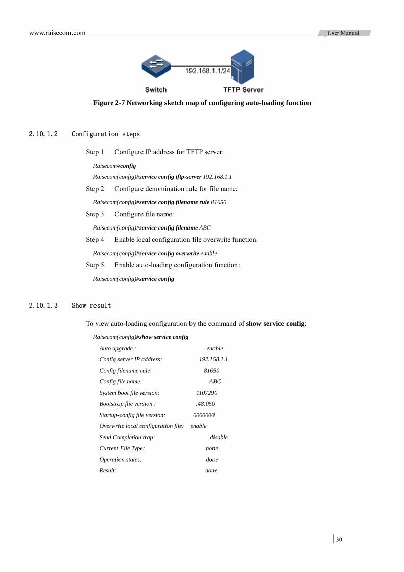
www.raisecom.com User Manual
30
Figure 2-7 Networking sketch map of configuring auto-loading function
2.10.1.2 Configuration steps
Step 1 Configure IP address for TFTP server:
Raisecom#config
Raisecom(config)#service config tftp-server 192.168.1.1
Step 2 Configure denomination rule for file name:
Raisecom(config)#service config filename rule 81650
Step 3 Configure file name:
Raisecom(config)#service config filename ABC
Step 4 Enable local configuration file overwrite function:
Raisecom(config)#service config overwrite enable
Step 5 Enable auto-loading configuration function:
Raisecom(config)#service config
2.10.1.3 Show result
To view auto-loading configuration by the command of show service config:
Raisecom(config)#show service config
Auto upgrade : enable
Config server IP address: 192.168.1.1
Config filename rule: 81650
Config file name: ABC
System boot file version: 1107290
Bootstrap flie version : :48:050
Startup-config file version: 0000000
Overwrite local configuration file: enable
Send Completion trap: disable
Current File Type: none
Operation states: done
Result: none
www.raisecom.com User Manual
31
Chapter 3 Ethernet
This chapter i ntroduces pr inciple and configuration procedure of E thernet f eatures, a lso providing related configuration applications:
Overview Configure MAC address forwarding table Configure VLAN Configure QinQ Configure VLNA conversion Configure STP Configure MSTP Configure loopback detection Configure interface protection Configure interface mirror Configure layer-2 protocol transparent transmission Maintenance Configuration Applications
3.1 Overview
3.1.1 Ethernet interface With the highly f lexible, relatively s imple, easy t o i mplement f eatures, Ethernet has be come an important LAN networking technology. Ethernet int erface is di vided into: E thernet e lectrical interface and Ethernet optical interface.
ISCOM2924GF device i s n s upport of Ethernet electrical interface and Ethernet o ptical i nterface. The s pecific interface mode depends on t he de vice, support s ituation of chip and achievement situation of drive.
3.1.1.1 Auto-negotiation function
The m ain f unction of a uto-negotiation i s t o m ake t he devices i n both e nds of physical link to automatically s elect the s ame working parameters through interaction information. The content of auto-negotiation mainly i ncludes dupl ex m ode, operating speed and flow cont rol p arameters, etc. Once the negotiation is passed, the devices in both ends of link will be locked in the same duplex mode and operating speed.
ISCOM2924GF-4C 10GE interface is only in support of full-duplex mode; ISCOM2924GF Combo electrical interface and 10/100/1000BASE-T photoelectric conversion module auto-negotiation is in support of 10M/100M/1000M operating s peeds, f ull-duplex a nd ha lf-duplex working mode configuration.

www.raisecom.com User Manual
32
3.1.1.2 Connecting cable
General standard Ethernet cabl e is di vided into direct-through cable MDI ( Medium D ependent Interface) and cross-over cable MDI-X (Medium Dependent Interface cross-over). MDI provides physic and circuit connections from terminal end to network trunk device. MDI-X offers the same device (terminal to terminal) connection. The interface type of host and router is MDI, the port type of hub a nd s witch is MDI-X. Generally, heterogeneous de vices i nterconnect with direct-through cable, while similar devices interconnect with cr oss-over cable. Adaptive connection need not to consider direct-through cable or cross-over cable.
ISCOM2924GF Ethernet connection is in support of adaptive MDI / MDI-X.
3.1.2 MAC address forwarding table 3.1.2.1 MAC address forwarding table
Ethernet device implements Ethernet message fast forwarding through MAC address forwarding rule; each device ha s a MAC address forwarding table t hat associate t he MAC address and forwarding interface. A ll of the ingress interface message will be forwarded according to the MAC address forwarding table, it is the base for Ethernet device realizing layer-2 message fast forwarding. MAC address forwarding table is saved in device cache, the capacity of cache decides saved MAC address amount.
Item of MAC address forwarding table contains the below information:
Destination MAC address Destination MAC address related interface ID Interface belonged VLAN ID
ISCOM2924GF de vice can check MAC addres s t able i nformation based on device, interface and VLAN.
3.1.2.2 MAC address forwarding mode
Ethernet device adopts following forwarding modes according to MAC address table items:
Unicast m ode: If the M AC a ddress f orwarding t able c ontains i tem r elated t o message destination MAC address, the device di rect transmits fr om the forwarding egress interface. As shown in Figure 3-1:
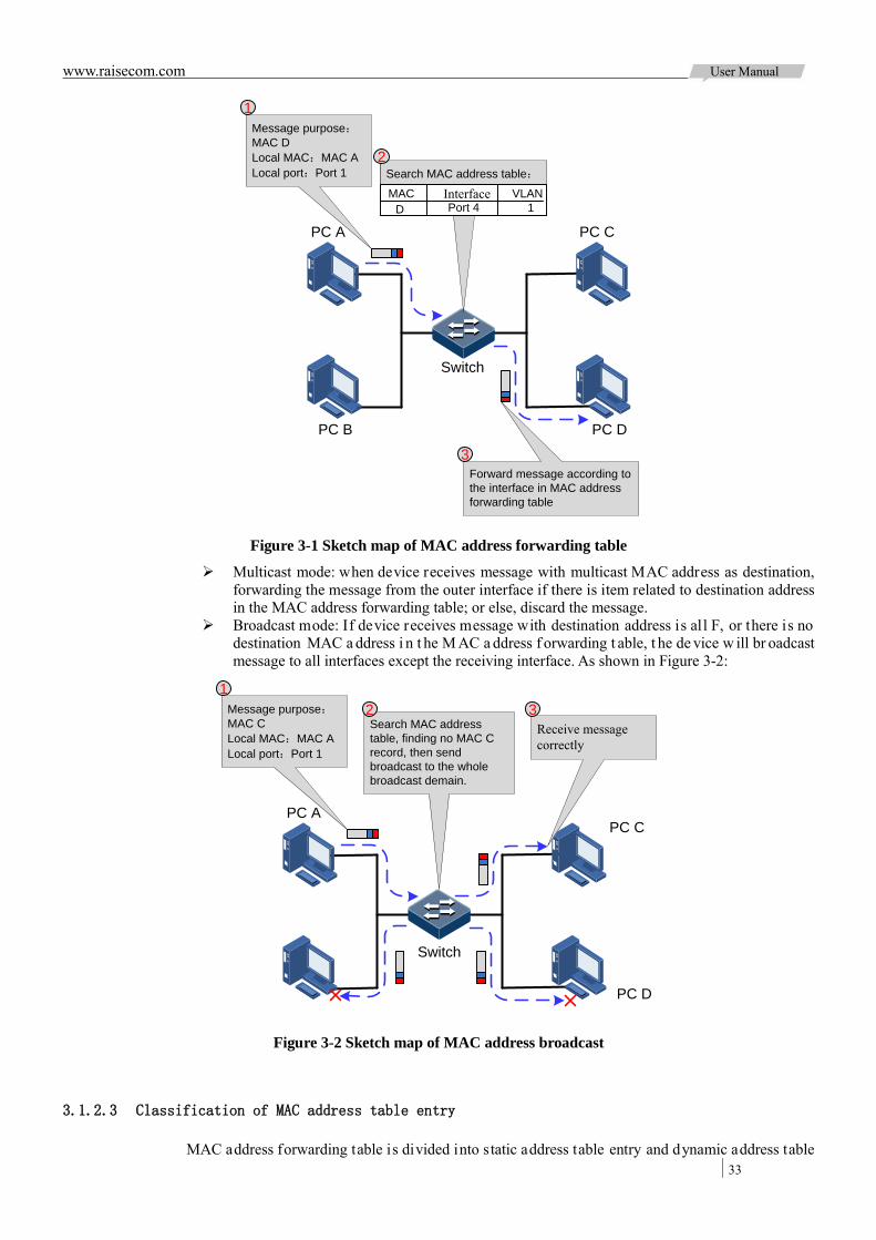
www.raisecom.com User Manual
33
PC A
PC B
PC C
PC D
Message purpose:MAC DLocal MAC:MAC ALocal port:Port 1 Search MAC address table:
MAC Interface VLAND Port 4 1
Forward message according to the interface in MAC address forwarding table
1
2
3
Switch
Figure 3-1 Sketch map of MAC address forwarding table
Multicast mode: when device receives message with multicast MAC address as destination, forwarding the message from the outer interface if there is item related to destination address in the MAC address forwarding table; or else, discard the message.
Broadcast mode: If device receives message with destination address is all F, or there is no destination MAC a ddress i n t he M AC a ddress f orwarding t able, t he de vice w ill br oadcast message to all interfaces except the receiving interface. As shown in Figure 3-2:
PC APC C
PC D
Message purpose:MAC CLocal MAC:MAC ALocal port:Port 1
Search MAC address table, finding no MAC C record, then send broadcast to the whole broadcast demain.
12
Receive message correctly
3
Switch
Figure 3-2 Sketch map of MAC address broadcast
3.1.2.3 Classification of MAC address table entry
MAC address forwarding table is divided into static address table entry and dynamic address table

www.raisecom.com User Manual
34
entry.
Static MAC address table entry: also called “permanent address”, added and removed by the user manually, does not age with time. For a network with small device change, adding static address table entry manually can reduce the network broadcast traffic, improve the security of the interface and prevent table entry f rom losing after the system reset, interface board hot swapping or interface board reset.
Dynamic M AC addres s t able entry: the switch can add dynamic M AC address t able ent ry through MAC address learning mechanism or manual establishment by users. The table entry will be aged according to the aging time configuration, and be empty after he system reset, interface board hot swapping or interface board reset.
ISCOM2924GF i s i n support of t he maximum 32k dy namic MAC addresses and 100 s tatic MAC addresses.
3.1.2.4 Aging time of MAC address
There i s capa city r estriction to the MAC a ddress forwarding table of Ethernet s witch. In or der t o maximize the use of address forwarding table resources, Ethernet switch uses the aging mechanism to update MAC address forwarding table, i.e. in the meantime of creating a cer tain dynamic table entry, ope n the aging timer, if the re is n o MAC a ddress m essage from t he t able e ntry dur ing t he aging time, the switch will delete the MAC address table entry.
ISCOM2924GF device is in support of MAC address auto-aging. The range of aging time is 10s~1 000000s.
Note:
When opening the "destination MAC address update" function, if the switch has transmitted some destination MAC address message during aging time, the MAC table entry will also be triggered update and restarted aging.
MAC address aging mechanism is only valid to dynamic MAC address table entry.
3.1.2.5 MAC address forwarding strategy
MAC address forwarding table has two kinds of forwarding strategies:
When message e nters de vice i nterface, the device w ill s earch interface associated with destination M AC a ddress i n t he M AC a ddress ta ble, if the re is de stination MAC in M AC address table, and forwarding the message from it; the source MAC address of message will be r ecorded and save i n MAC addr ess t able related to i ngress m essage i nterface I D an d VLAN ID. When other interface has message to the MAC address, the information can be forwarded to associated interface directly.
If there i s no de stination MAC for the message in MAC address table, address association relationship will f orward data pa ckets to all int erfaces w ith same br oadcast do main and record source MAC address to device MAC address table.
3.1.2.6 MAC address learning amount limit
MAC address learning amount limit function is mainly to restrict the number of MAC address entries, avoid extending the checking time of forwarding table entry caused by too large MAC address table and degrading the forwarding performance of Ethernet switch, and it is an effective way to manage MAC address table.
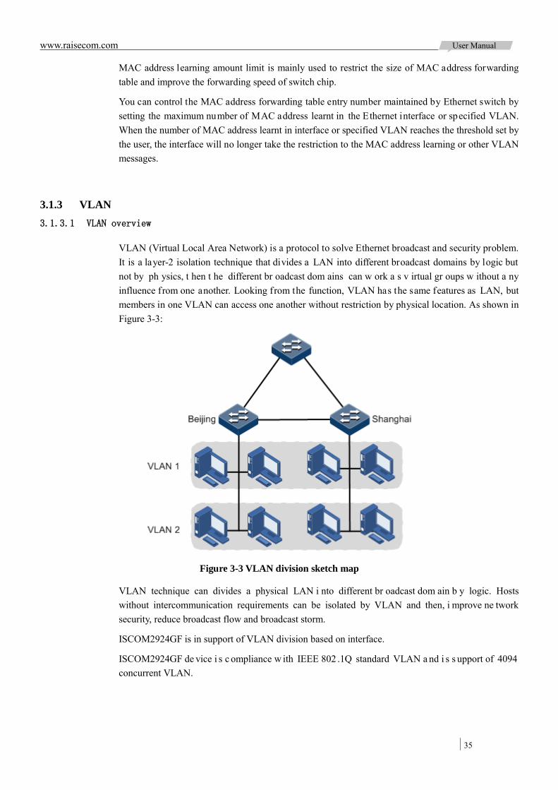
www.raisecom.com User Manual
35
MAC address learning amount limit is mainly used to restrict the size of MAC address forwarding table and improve the forwarding speed of switch chip.
You can control the MAC address forwarding table entry number maintained by Ethernet switch by setting the maximum number of MAC address learnt in the Ethernet interface or specified VLAN. When the number of MAC address learnt in interface or specified VLAN reaches the threshold set by the user, the interface will no longer take the restriction to the MAC address learning or other VLAN messages.
3.1.3 VLAN 3.1.3.1 VLAN overview
VLAN (Virtual Local Area Network) is a protocol to solve Ethernet broadcast and security problem. It is a layer-2 isolation technique that divides a LAN into different broadcast domains by logic but not by ph ysics, t hen t he different br oadcast dom ains can w ork a s v irtual gr oups w ithout a ny influence from one another. Looking from the function, VLAN has the same features as LAN, but members in one VLAN can access one another without restriction by physical location. As shown in Figure 3-3:
Figure 3-3 VLAN division sketch map
VLAN technique can divides a physical LAN i nto different br oadcast dom ain b y logic. Hosts without intercommunication requirements can be isolated by VLAN and then, i mprove ne twork security, reduce broadcast flow and broadcast storm.
ISCOM2924GF is in support of VLAN division based on interface.
ISCOM2924GF de vice i s c ompliance w ith IEEE 802 .1Q standard VLAN a nd i s s upport of 4094 concurrent VLAN.

www.raisecom.com User Manual
36
3.1.3.2 Interface mode and message forwarding
ISCOM2924GF has two interface modes: Access mode and Trunk mode. The method of dealing with message for the two modes shows as below.
Table 3-1 Interface mode and message transportation
Interface type
Deal with Ingress message Deal with Egress message
Untag message Tag message
Access Add default VLAN Tag for message
VLAN ID=default VLAN ID, receive the message VLAN ID≠default VLAN ID, discard the message
VLAN ID=default VLAN ID, remove Tag and transmit the message.
Trunk Default VLAN ID is included in interface permit passing VLAN ID list, receiving the message and adding default VLAN Tag.
Receive the message if the message VLAN ID is included in the permit passing VLAN ID list. Discard the message if the message VLAN ID is not included in the permit passing VLAN ID list.
VLAN ID=default VLAN ID, permit passing from interface, remove Tag and transmit the message VLAN ID≠default VLAN ID, permit passing from interface, transmit the message with Tag
3.1.4 QinQ QinQ ( also know n a s Stacked VLAN or Double V LAN) technique is a n e xtension f or 802. 1Q defined in IEEE 802.1ad standard.
3.1.4.1 Basic QinQ
Basic QinQ is a simple layer-2 VPN tunnel technique, which encapsulate outer VLAN Tag for user private network message at carrier access end, then the message takes double VLAN Tag to transmit through ba ckbone ne twork ( public ne twork) of c arrier. In publ ic ne twork, m essage j ust be transmitted in accordance with outer VLAN Tag (namely the public network VLAN Tag), the user private network VALN Tag is transmitted as data in message.
Figure 3-4 Typical networking of basic QinQ
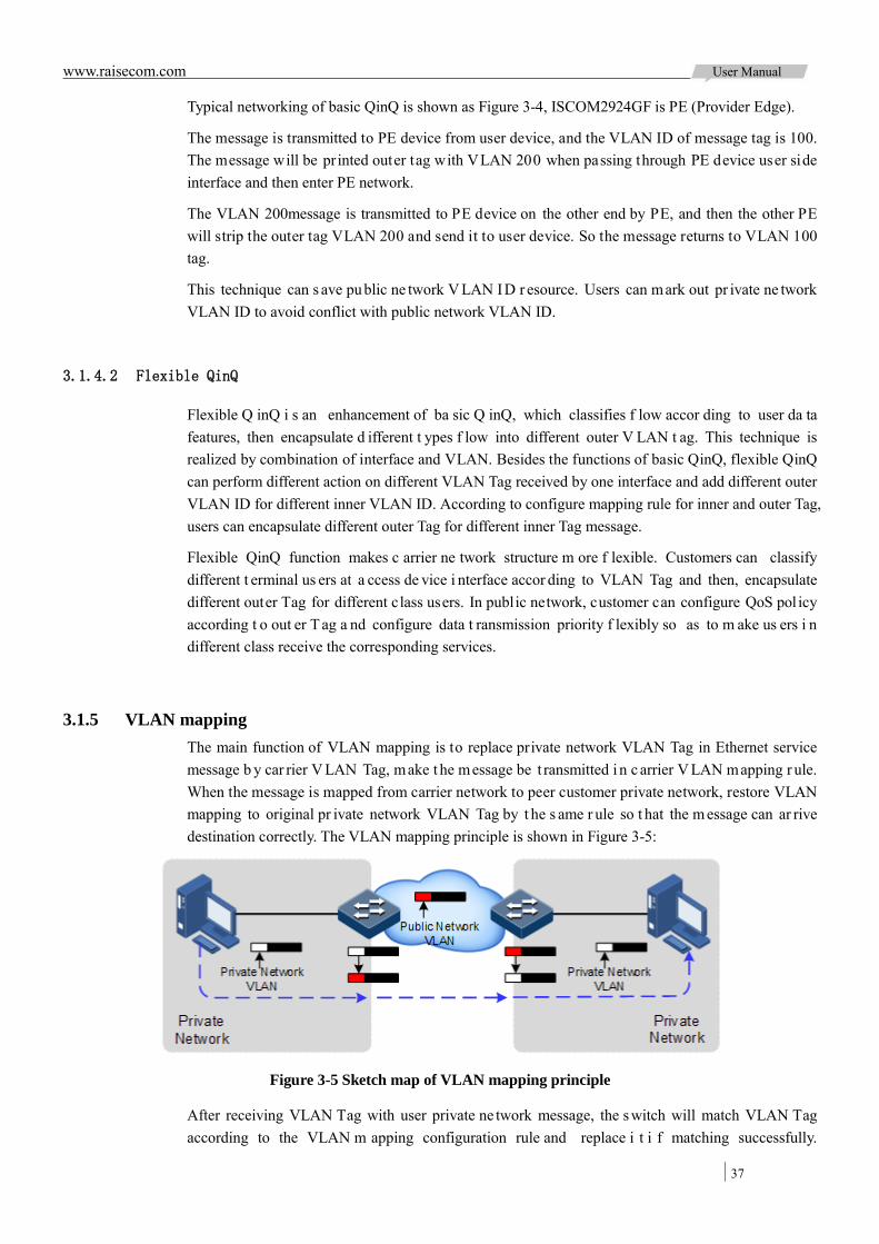
www.raisecom.com User Manual
37
Typical networking of basic QinQ is shown as Figure 3-4, ISCOM2924GF is PE (Provider Edge).
The message is transmitted to PE device from user device, and the VLAN ID of message tag is 100. The message will be pr inted outer tag with VLAN 200 when passing through PE device user side interface and then enter PE network.
The VLAN 200message is transmitted to PE device on the other end by PE, and then the other PE will strip the outer tag VLAN 200 and send it to user device. So the message returns to VLAN 100 tag.
This technique can s ave public ne twork V LAN ID r esource. Users can mark out pr ivate ne twork VLAN ID to avoid conflict with public network VLAN ID.
3.1.4.2 Flexible QinQ
Flexible Q inQ i s an enhancement of ba sic Q inQ, which classifies f low accor ding to user da ta features, then encapsulate d ifferent t ypes f low into different outer V LAN t ag. This technique is realized by combination of interface and VLAN. Besides the functions of basic QinQ, flexible QinQ can perform different action on different VLAN Tag received by one interface and add different outer VLAN ID for different inner VLAN ID. According to configure mapping rule for inner and outer Tag, users can encapsulate different outer Tag for different inner Tag message.
Flexible QinQ function makes c arrier ne twork structure m ore f lexible. Customers can classify different t erminal us ers at a ccess de vice i nterface accor ding to VLAN Tag and then, encapsulate different outer Tag for different class users. In public network, customer can configure QoS pol icy according t o out er T ag a nd configure data t ransmission priority f lexibly so as to m ake us ers i n different class receive the corresponding services.
3.1.5 VLAN mapping The main function of VLAN mapping is to replace private network VLAN Tag in Ethernet service message b y car rier V LAN Tag, make t he message be t ransmitted i n c arrier V LAN mapping r ule. When the message is mapped from carrier network to peer customer private network, restore VLAN mapping to original pr ivate network VLAN Tag by t he s ame r ule so t hat the m essage can ar rive destination correctly. The VLAN mapping principle is shown in Figure 3-5:
Figure 3-5 Sketch map of VLAN mapping principle
After receiving VLAN Tag with user private ne twork message, the s witch will match VLAN Tag according to the VLAN m apping configuration rule and replace i t i f matching successfully.

www.raisecom.com User Manual
38
ISCOM2924GF i s i n s upport of 1: 1 VLAN m apping t o r eplace VLAN Tag c arried by a c ertain VLAN message to new VLAN Tag.
Different from QinQ function, VLAN mapping needn’t to take multi-layer VLAN Tag encapsulation to message, but change VLAN Tag to make it transmit according to VLAN mapping forward rule.
3.1.6 STP/RSTP/MSTP 3.1.6.1 STP
With the increasing complexity of network structure and growing number of switches in the network, the E thernet ne twork loops become the most prominent problem. Because of the packet broadcast mechanism, network loop will make the network generate network storm, exhaust network resources, and have serious impact to the normal data forwarding. The network storm caused by network loops is shown in Figure 3-6.
Figure 3-6 Sketch map of network storm caused by network loops circuit
STP (Spanning Tree P rotocol) is c ompliant to IEEE 802.1d s tandard and us ed t o r emove da ta physical loop in data link layer in LAN.
STP running device can interact BPDU (Bridge Protocol Data Unit) packet with each other for the election of root switch and selection of root port and designated port. It also can block loop interface in the de vice logically according to the selection results, eventually trimming the loop ne twork structure to t ree ne twork s tructure without loop which takes a device as root, so as to prevent the continuous proliferation and limitless circulation of packet in loop network from causing broadcast storm a nd a void declining packet pr ocessing capacity caused by ceceiving the s ame packets repeatedly.
The loop network diagram running STP is shown in Figure 3-7.
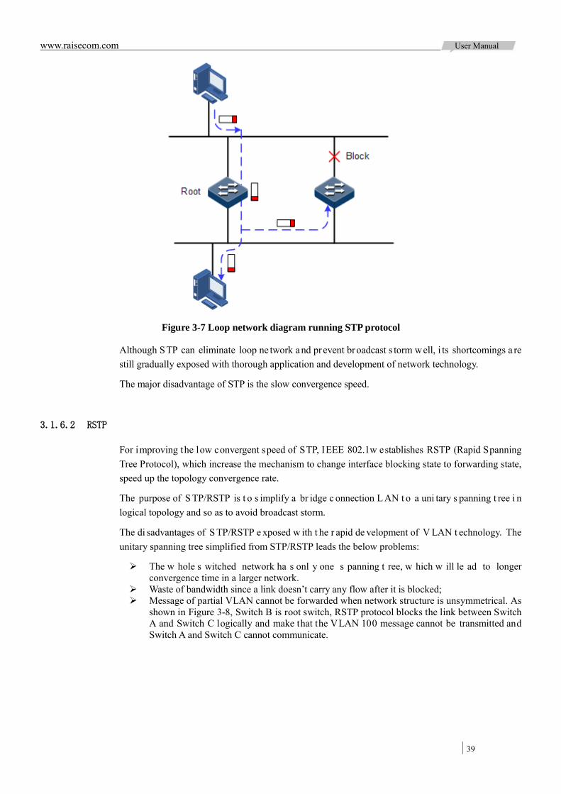
www.raisecom.com User Manual
39
Figure 3-7 Loop network diagram running STP protocol
Although STP can eliminate loop ne twork and prevent broadcast s torm well, i ts shortcomings a re still gradually exposed with thorough application and development of network technology.
The major disadvantage of STP is the slow convergence speed.
3.1.6.2 RSTP
For improving the low convergent speed of STP, IEEE 802.1w establishes RSTP (Rapid Spanning Tree Protocol), which increase the mechanism to change interface blocking state to forwarding state, speed up the topology convergence rate.
The purpose of S TP/RSTP is t o s implify a br idge c onnection L AN t o a uni tary s panning t ree i n logical topology and so as to avoid broadcast storm.
The di sadvantages of S TP/RSTP e xposed w ith t he r apid de velopment of V LAN t echnology. The unitary spanning tree simplified from STP/RSTP leads the below problems:
The w hole s witched network ha s onl y one s panning t ree, w hich w ill le ad to longer convergence time in a larger network.
Waste of bandwidth since a link doesn’t carry any flow after it is blocked; Message of partial VLAN cannot be forwarded when network structure is unsymmetrical. As
shown in Figure 3-8, Switch B is root switch, RSTP protocol blocks the link between Switch A and Switch C logically and make that the VLAN 100 message cannot be transmitted and Switch A and Switch C cannot communicate.
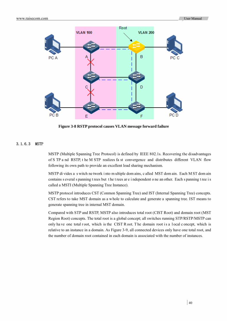
www.raisecom.com User Manual
40
Figure 3-8 RSTP protocol causes VLAN message forward failure
3.1.6.3 MSTP
MSTP (Multiple Spanning Tree Protocol) is defined by IEEE 802.1s. Recovering the disadvantages of S TP a nd RSTP, t he M STP realizes fa st convergence and distributes different VLAN flow following its own path to provide an excellent load sharing mechanism.
MSTP di vides a s witch ne twork i nto m ultiple dom ains, c alled MST dom ain. Each M ST dom ain contains s everal s panning t rees but t he t rees ar e i ndependent o ne an other. Each s panning t ree i s called a MSTI (Multiple Spanning Tree Instance).
MSTP protocol introduces CST (Conmon Spanning Tree) and IST (Internal Spanning Tree) concepts. CST refers to take MST domain as a whole to calculate and generate a spanning tree. IST means to generate spanning tree in internal MST domain.
Compared with STP and RSTP, MSTP also introduces total root (CIST Root) and domain root (MST Region Root) concepts. The total root is a global concept; all switches running STP/RSTP/MSTP can only ha ve one total r oot, which is the CIST R oot. T he domain root i s a l ocal c oncept, which is relative to an instance in a domain. As Figure 3-9, all connected devices only have one total root, and the number of domain root contained in each domain is associated with the number of instances.

www.raisecom.com User Manual
41
Figure 3-9 Basic concept sketch map of MSTI network
There can be different MST instance in each MST demain, which associates VLAN and MSTI by setting VLAN mapping table (relationship table of VLAN and MSTI). The concept sketch map of MSTI is shown in the Figure 3-10.
Figure 3-10 Concept sketch map of MSTI
Note: Each VLAN can only corresponding to one MSTI; that is to say, data of one VLAN can only be transmitted in one MSTI; while one MSTI may correspond to several VLAN.

www.raisecom.com User Manual
42
Compared with the previous STP and RSTP, MSTP has obvious advantages, including cognitive ability of VLAN, load balance sharing ability, similar RSTP port status switching ability as well as binding multiple VLAN to one MST instance to reduce resource occupancy rate. In addition, MSTP running devices in network are also compatible with the STP and RSTP running devices.
Figure 3-11 Networking of multiple spanning trees instances in MST domain
Applying MSTP in the network as Figure 3-11 above, after calculation, there are two spanning trees generated at last (two MST instances):
MSTI1 takes B as root switch, forwarding message of VLAN100;
MSTI2 takes F as root switch, forwarding message of VLAN200.
By this w ay, all V LAN can com municate at i nternal, different V LAN messages are f orwarded in different path to share loading.
3.1.7 Loopback detection The i nterface l oopback de tection f unction s olves i nfluence o n ne twork caused by s elf-loop or external loop, and then improves network error-detection, error tolerance and stability.
Procedure of loopback detection:
Each i nterface of device sends loopback-detection message by interval (the interval is configurable, by default is 4 seconds);
The device check source MAC field for interface received loopback detection packets, if the source M AC i s i dentical t o device M AC, some i nterfaces of t he de vice form a l oop; otherwise, discard the message;
It is self-loop if the sending interface ID is identical to receiving interface ID, shutdown the interface;
It is external loop if the sending interface ID is identical to receiving interface ID, shutdown

www.raisecom.com User Manual
43
the interface with bigger ID, and leave the smaller interface ID in UP status.
3.1.8 Interface protection User needs to take layer-2 data isolation among different interface and add the interface to different VLAN. Sometimes interfaces in the same VLAN also need to be taken data isolation by interface protection feature, which can isolate interfaces in one VLAN.
Through interface protection festure, user can enable the protection feature to interfaces needed to be controlled to achieve the layer-2 data isolation and reach physical isolation effect among interfaces, which improve network security and provide flexible networking solution to cutomer.
The packets among interfaces in a protection group cannot communicate after configuring interface protection, but the communication between i nterfaces enabling interface protection and disabling interface protection won’t be influenced.
3.1.9 Interface mirror Interface mirror func tion refers t o assign some packets m irror of s ource i nterface t o de stination interface, i.e. the m onitoring i nterface without a ffecting t he nor mal pa cket f orwarding f unction. Switch user can monitor the pa ckets s ending a nd r eceiving of one interface by t his f unction a nd analyze the relevant network conditions.
Figure 3-12 Sketch map of interface mirror function priciple
The basic principle of interface mirror is shown in Figure 3-12. PC 1 connects outside network via the Port 1; PC 3 is monitoring PC, connecting outside network through the Port 12.
When monitoring packets from the PC 1, user ne eds to assign Port 1 connected to PC1 as mirror source i nterface, enable m irror f unction of ingress i nterface and a ssign Port 12 as m oniroring interface, i.e. mirror destination interface.
When the service packets f rom PC 1 enter switch, the switch will forward the packet and copy to monitoring interface (Port 12). The monitoring device connected to mirror monitoring interface can

www.raisecom.com User Manual
44
receive and analyze these mirrored packets.
ISCOM2924GF is in support of the data s tream mirror over ingress interface and egress interface. The packets in ingress/egress mirror interface will be copied to the monitor interface after enabling the mirror function. Monitoring interface and mirror interface cannot be the same one.
3.1.10 Layer-2 protocol transparent transmission Transparent t ransmission f unction i s one of t he m ain Ethernet device f unctions, usually the e dge network devices of car rier take i n charge of l ayer-2 pr otocol m essage transparent transmission. Transparent t ransmission function is enabled at the interface that connects edge network device of carrier a nd us er ne twork. The i nterface i s i n A ccess mode, c onnecting t o Trunk i nterface on us er device. The layer-2 protocol message of user network enters from transparent transmission interface, encapsulated by edge network device (ingress end of message) and then enter carrier network. The message is transmitted through carrier network to arrive edge device (egress end of message) at the other end or carrier network. The edged device decapsulates outer layer-2 protocol message and transparent transmits it to customer network.
The t ransparent t ransmission f unction i ncludes message e ncapsulation a nd de capsulation f unction, the basic implementing principle as below:
Message en capsulation: at t he m essage i ngress end, de vice m odifies de stination MAC address from user network layer-2 protocol message to special multicast MAC address (it is 010E.5E00.0003 by default). In carrier network, the modified message is forwarded as data in user VLAN.
Message decapsulation: at the message egress end, t he device s enses message with special multicast M AC a ddress ( it i s 010E.5E00.0003 by de fault) a nd r evert the destination MAC address t o D MAC of l ayer-2 pr otocol m essage, t hen send t he m essage t o a ssigned us er network.
Layer-2 protocol t ransparent t ransmission function can be operated a t the same time with QinQ or operated i ndependently. In practice a pplication, a fter m odifying pr otocol message M AC a ddress, need to add outer Tag for transmit through carrier network.
ISCOM2924GF de vice is i n support of transparent transmission of BPDU m essage, DOT1X message, LACP message, CDP message, VTP message and PVST message.
3.2 Configure MAC address forwarding table
3.2.1 Preparation for configuration 3.2.1.1 Networking situation
Configure static MAC address forwarding table in the following situations:
Static MAC address can be set for fixed server, special persons (manager, financial staff, etc.) fixed and important hosts to make sure all data flow forwarding to these MAC addresses are forwarded from static MAC address related interface in priority.
For the interface with fixed static MAC address, user can disable MAC address learning to avoid other hosts visiting LAN data from the interface.
Configure aging t ime f or d ynamic M AC a ddress f orwarding t able t o avoid the explosive growth of MAC address forwarding table.

www.raisecom.com User Manual
45
3.2.1.2 Preconditions
N/A
3.2.2 Default configuration of MAC address forwarding table The default configuration of MAC address forwarding table is as below:
Function Default value
MAC address learning function status Enable
MAC address aging time 300s
MAC address learning amount limit unlimited
3.2.3 Configure static MAC address Please configure static MAC address as below:
Step Configuration Description
1 Raisecom#config Enter global configuration mode.
2 Raisecom(config)#mac-address-table static unicast mac-address vlan vlan-id port port-id
Configure static unicast MAC address.
Raisecom(config)#mac-address-table static multicast mac-address vlan vlan-id port
port-list
Configure static multicast MAC address.
Raisecom(config)#mac-address-table blackhole mac-address vlan vlan-id
Configure black hole MAC address.
3 Raisecom(config)#mac-address-table multicast filter { all | vlan vlan-list }
(Optional) Set multicast filter mode for MAC address table.
Note:
MAC address, multicast address, FFFF.FFFF.FFFF and 0000.0000.0000 of the device cannot be configured as static unicast MAC address.
At present, the configurable static unicast MAC address amount of ISCOM2924GF device is 100.
3.2.4 Configure MAC address learning Please configure MAC address learning as below:
Step Configuration Description
1 Raisecom#config Enter global configuration mode.
2 Raisecom(config)#mac-address-table learning { enable | disable } { port-list
{ all | port-list } | vlanlist vlan-list }
Enable or disable MAC address learning function.

www.raisecom.com User Manual
46
3.2.5 Configure MAC address learning amount limit Please configure MAC address learning amount limit as below:
Step Configuration Description
1 Raisecom#config Enter global configuration mode.
2 Raisecom(config)#interface port port-id Enter physical layer interface configuration mode.
3 Raisecom(config-port)#mac-address-table threshold threshold-value
Configure MAC address learning amount.
Raisecom(config-port)#mac-address-table threshold threshold-value vlan vlan-id
Configure specified VLAN MAC address learning amount.
3.2.6 Configure MAC address aging time Please configure MAC address aging time as below:
Step Configuration Description
1 Raisecom#config Enter global configuration mode.
2 Raisecom(config)#mac-address-table aging-time { 0 | period }
Set MAC address aging time. The time range: 10~1000000, unit: second. Set
the aging time 0 for non-aging.
3.2.7 Checking configuration Check the result by the commands below after configuration:
No. Item Description
1 Raisecom#show mac-address-table static [ port port-id | vlan vlan-id ]
Show static unicast MAC address.
2 Raisecom#show mac-address-table multicast [ vlan vlan-id ] [ count ]
Show layer-2 multicast address.
3 Raisecom#show mac-address-table blackhole Show black hole MAC address.
4 Raisecom#show mac-address-table l2-address [ count ] [ vlan vlan-id | port port-id ]
Show all layer-2 unicast addresses and the learning MAC address amount.
5 Raisecom#show mac-address-table threshold [ port-list { all | port-list } ]
Show MAC address learning amount limit value.
6 Raisecom#show mac aging-time Show MAC address aging time.
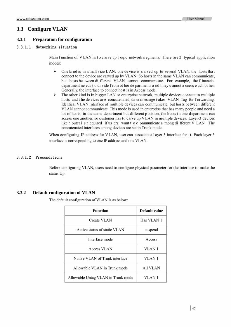
www.raisecom.com User Manual
47
3.3 Configure VLAN
3.3.1 Preparation for configuration 3.3.1.1 Networking situation
Main f unction of V LAN i s t o c arve up l ogic network s egments. There are 2 typical application modes:
One ki nd is in s mall s ize L AN, one de vice is c arved up to several VLAN, the hosts tha t connect to the device are carved up by VLAN. So hosts in the same VLAN can communicate, but hosts be tween di fferent VLAN cannot communicate. For example, the f inancial department ne eds t o di vide f rom ot her de partments a nd t hey c annot a ccess e ach ot her. Generally, the interface to connect host is in Access mode.
The other kind is in bigger LAN or enterprise network, multiple devices connect to multiple hosts and t he de vices ar e concatenated, da ta m essage t akes VLAN Tag for f orwarding. Identical VLAN interface of multiple devices can communicate, but hosts between different VLAN cannot communicate. This mode is used in enterprise that has many people and need a lot of hosts, in the same department but different position, the hosts in one department can access one another, so customer has to carve up VLAN in multiple devices. Layer-3 devices like r outer i s r equired if us ers want t o c ommunicate a mong di fferent V LAN. The concatenated interfaces among devices are set in Trunk mode.
When configuring IP address for VLAN, user can associate a l ayer-3 interface for i t. Each layer-3 interface is corresponding to one IP address and one VLAN.
3.3.1.2 Preconditions
Before configuring VLAN, users need to configure physical parameter for the interface to make the status Up.
3.3.2 Default configuration of VLAN The default configuration of VLAN is as below:
Function Default value
Create VLAN Has VLAN 1
Active status of static VLAN suspend
Interface mode Access
Access VLAN VLAN 1
Native VLAN of Trunk interface VLAN 1
Allowable VLAN in Trunk mode All VLAN
Allowable Untag VLAN in Trunk mode VLAN 1

www.raisecom.com User Manual
48
3.3.3 Configure VLAN attributes Please configure VLAN attributes as below:
Step Configuration Description
1 Raisecom#config Enter global configuration mode.
2 Raisecom(config)#create vlan vlan-list { active | suspend }
Create VLAN.
The command can also be used to create VLAN in batch.
3 Raisecom(config)#vlan vlan-id Enter VLAN configuration mode.
4 Raisecom(config-vlan)#name vlan-name (Optional) Configure VLAN name.
5 Raisecom(config-vlan)#state { active | suspend } Configure VLAN in active or suspend status.
Note:
The V LAN created by command vlan vlan-id is i n s uspend s tatus, us ers need t o us e command state active to activate VLAN if they want to make it effective in system.
By default, there are two VLAN in system, the default VLAN (VLAN 1) and cluster VLAN (VLAN 2) , a ll i nterfaces i n A ccess m ode be longed t o default V LAN. Both VLAN 1 and VLAN 2 cannot be created and deleted.
By de fault, the de fault V LAN ( VLAN 1) is c alled “Default”; cluster VLAN (VLAN 2) i s called “Cluster-Vlan”. Other V LAN i s na med as “VLAN” plus 4 di gits V LAN ID, f or example, VLAN10 is named “VLAN0010” by default, VLAN4094 is named as “VLAN4094” by default.
All configurations of VLAN are not effective until the VLAN is activated. When VLAN is in suspend s tatus, user can also configure the VLAN, such as delete/add interface, set VLAN name, etc. The system w ill ke ep t he c onfigurations, once the V LAN is activated, the configurations will take effect in the system.
3.3.4 Configure interface mode Please configure interface mode as below:
Step Configuration Description
1 Raisecom#config Enter global configuration mode.
2 Raisecom(config)#interface port port-id
Enter physical layer interface configuration mode.
3 Raisecom(config-port)#switchport mode { access | trunk }
Configure interface in Access or Trunk mode.
3.3.5 Configure VLAN over Access interface Please configure VLAN over Access interface for the device as below:
Step Configuration Description
1 Raisecom#config Enter global configuration mode.
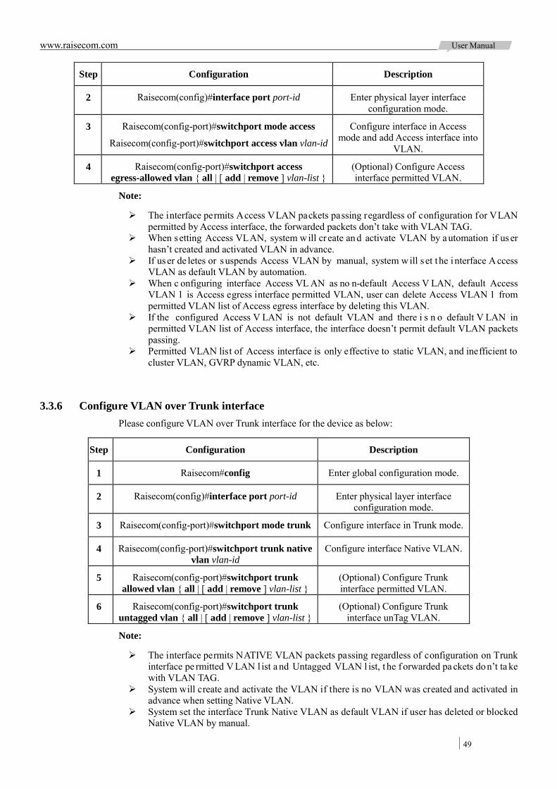
www.raisecom.com User Manual
49
Step Configuration Description
2 Raisecom(config)#interface port port-id Enter physical layer interface configuration mode.
3 Raisecom(config-port)#switchport mode access
Raisecom(config-port)#switchport access vlan vlan-id
Configure interface in Access mode and add Access interface into
VLAN.
4 Raisecom(config-port)#switchport access egress-allowed vlan { all | [ add | remove ] vlan-list }
(Optional) Configure Access interface permitted VLAN.
Note:
The interface permits Access VLAN packets passing regardless of configuration for VLAN permitted by Access interface, the forwarded packets don’t take with VLAN TAG.
When setting Access VLAN, system will cr eate an d activate VLAN by a utomation if us er hasn’t created and activated VLAN in advance.
If user de letes or suspends Access VLAN by manual, system will s et t he i nterface A ccess VLAN as default VLAN by automation.
When c onfiguring interface Access VL AN as no n-default Access V LAN, default Access VLAN 1 is Access egress interface permitted VLAN, user can delete Access VLAN 1 from permitted VLAN list of Access egress interface by deleting this VLAN.
If the configured Access V LAN is not default VLAN and there i s n o default V LAN in permitted VLAN list of Access interface, the interface doesn’t permit default VLAN packets passing.
Permitted VLAN list of Access interface is only effective to static VLAN, and inefficient to cluster VLAN, GVRP dynamic VLAN, etc.
3.3.6 Configure VLAN over Trunk interface Please configure VLAN over Trunk interface for the device as below:
Step Configuration Description
1 Raisecom#config Enter global configuration mode.
2 Raisecom(config)#interface port port-id Enter physical layer interface configuration mode.
3 Raisecom(config-port)#switchport mode trunk Configure interface in Trunk mode.
4 Raisecom(config-port)#switchport trunk native vlan vlan-id
Configure interface Native VLAN.
5 Raisecom(config-port)#switchport trunk allowed vlan { all | [ add | remove ] vlan-list }
(Optional) Configure Trunk interface permitted VLAN.
6 Raisecom(config-port)#switchport trunk untagged vlan { all | [ add | remove ] vlan-list }
(Optional) Configure Trunk interface unTag VLAN.
Note:
The interface permits NATIVE VLAN packets passing regardless of configuration on Trunk interface pe rmitted V LAN l ist a nd Untagged VLAN l ist, t he f orwarded pa ckets don’t ta ke with VLAN TAG.
System will create and activate the VLAN if there is no VLAN was created and activated in advance when setting Native VLAN.
System set the interface Trunk Native VLAN as default VLAN if user has deleted or blocked Native VLAN by manual.

www.raisecom.com User Manual
50
Interface pe rmits in a nd out of T runk A llowed VLAN m essage, i f t he V LAN i s T runk Untagged V LAN, the packets r emove V LAN T AG at egr ess i nterface, otherwise, don’t modify the packets.
If the configured Native VLAN is not default VLAN, and there is no default VLAN in Trunk interface permitted VLAN list, the interface won’t permit default VLAN packets passing.
When s etting Trunk Untagged V LAN l ist, s ystem a utomatically a dds a ll U ntagged V LAN into Trunk permitted VLAN.
Trunk permitted VLAN list and Trunk Untagged VLAN list are only effective to static VLAN, and ineffective for cluster VLAN, GVRP dynamic VLAN, etc.
3.3.7 Checking configuration Check the result by the commands below after configuration:
No. Item Description
1 Raisecom#show vlan [ vlan-list | static ] Show VLAN configuration.
2 Raisecom#show interface port [ port-id ] switchport
Show interface VLAN configuration.
3.4 Configure QinQ
3.4.1 Preparation for configuration 3.4.1.1 Networking situation
The basic QinQ configuration and flexible QinQ configuration for the device are based on di fferent service requirements.
Basic QinQ:
With application of basic QinQ, user can add outer VLAN Tag to layout Private VLAN ID freely so as to make the user device data at both ends of carrier network take transparent transmission without conflicting with VLAN ID in service provider network.
Flexible QinQ:
Different f rom ba sic Q inQ, out er V LAN T ag of f lexible Q inQ c an be selectable according t o different services. There are multiple services and different private VLAN ID in user network which are divided by adding different outer VLAN Tag for voice, video, and data services etc., then realize different distributaries and inner and outer VLAN mapping for different services forwarding.
3.4.1.2 Preconditions
Users must finish below operations before configuring QinQ.
Connect interface and configure interface physical parameters to make the physical layer Up. Create VLAN
3.4.2 Default configuration of QinQ The default configuration of QinQ is as below:
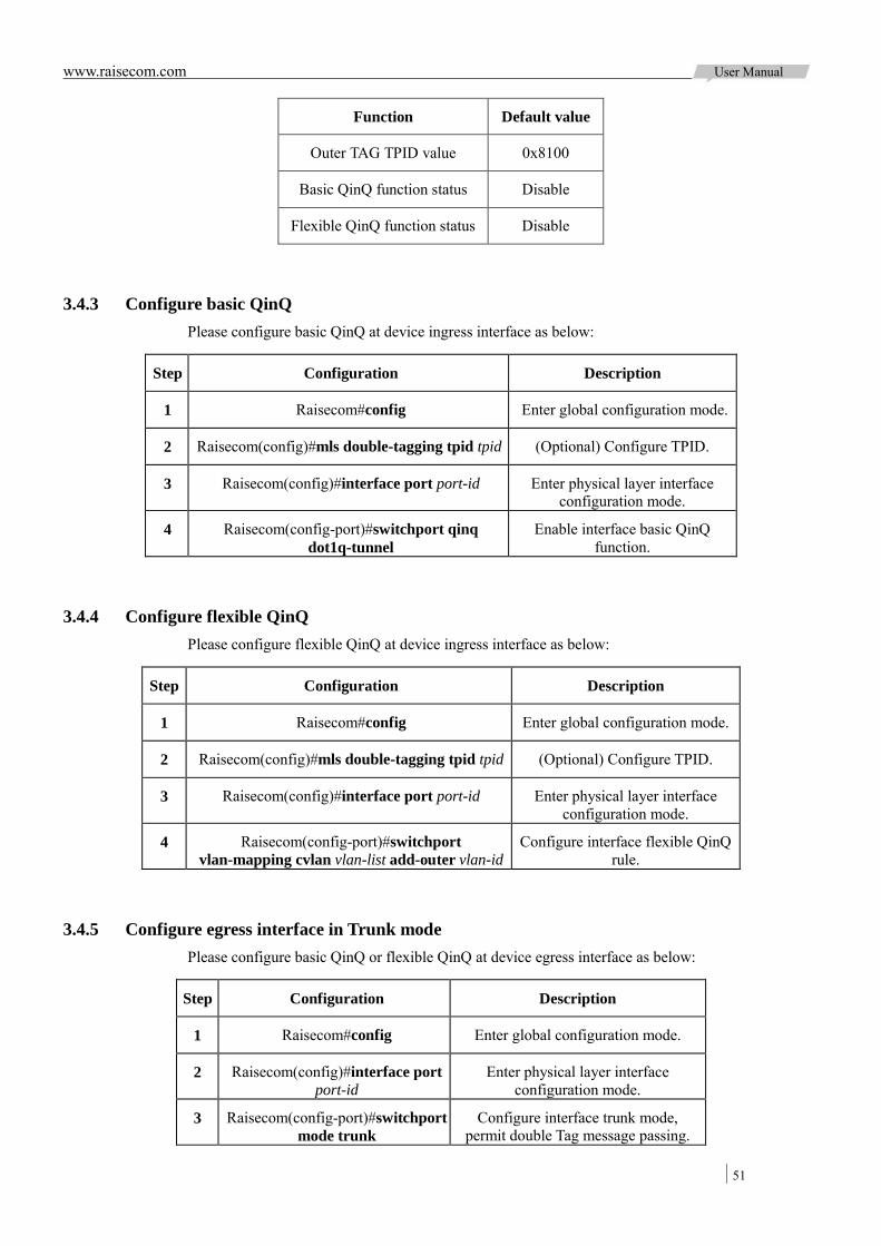
www.raisecom.com User Manual
51
Function Default value
Outer TAG TPID value 0x8100
Basic QinQ function status Disable
Flexible QinQ function status Disable
3.4.3 Configure basic QinQ Please configure basic QinQ at device ingress interface as below:
Step Configuration Description
1 Raisecom#config Enter global configuration mode.
2 Raisecom(config)#mls double-tagging tpid tpid (Optional) Configure TPID.
3 Raisecom(config)#interface port port-id Enter physical layer interface configuration mode.
4 Raisecom(config-port)#switchport qinq dot1q-tunnel
Enable interface basic QinQ function.
3.4.4 Configure flexible QinQ Please configure flexible QinQ at device ingress interface as below:
Step Configuration Description
1 Raisecom#config Enter global configuration mode.
2 Raisecom(config)#mls double-tagging tpid tpid (Optional) Configure TPID.
3 Raisecom(config)#interface port port-id Enter physical layer interface configuration mode.
4 Raisecom(config-port)#switchport vlan-mapping cvlan vlan-list add-outer vlan-id
Configure interface flexible QinQ rule.
3.4.5 Configure egress interface in Trunk mode Please configure basic QinQ or flexible QinQ at device egress interface as below:
Step Configuration Description
1 Raisecom#config Enter global configuration mode.
2 Raisecom(config)#interface port port-id
Enter physical layer interface configuration mode.
3 Raisecom(config-port)#switchport mode trunk
Configure interface trunk mode, permit double Tag message passing.
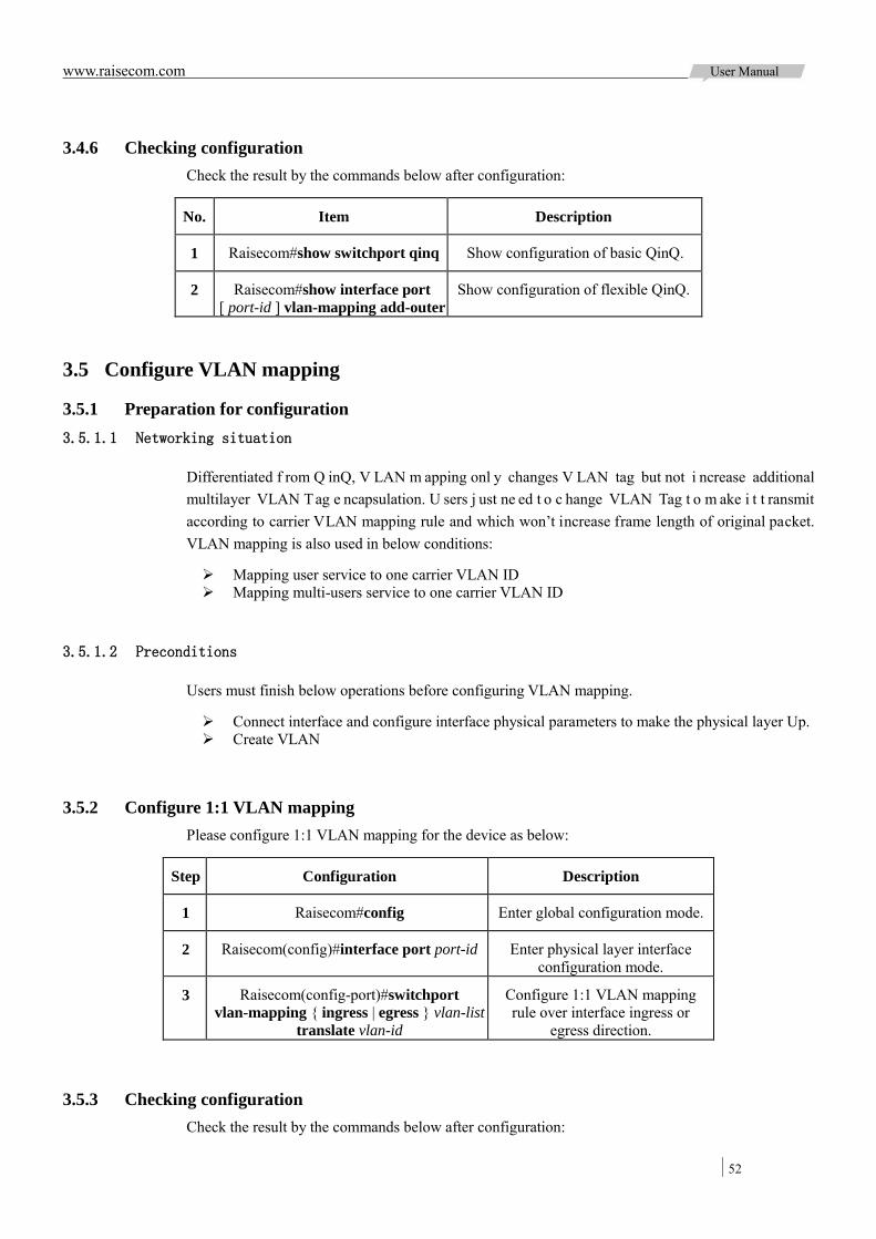
www.raisecom.com User Manual
52
3.4.6 Checking configuration Check the result by the commands below after configuration:
No. Item Description
1 Raisecom#show switchport qinq Show configuration of basic QinQ.
2 Raisecom#show interface port [ port-id ] vlan-mapping add-outer
Show configuration of flexible QinQ.
3.5 Configure VLAN mapping
3.5.1 Preparation for configuration 3.5.1.1 Networking situation
Differentiated f rom Q inQ, V LAN m apping onl y changes V LAN tag but not i ncrease additional multilayer VLAN T ag e ncapsulation. U sers j ust ne ed t o c hange VLAN Tag t o m ake i t t ransmit according to carrier VLAN mapping rule and which won’t increase frame length of original packet. VLAN mapping is also used in below conditions:
Mapping user service to one carrier VLAN ID Mapping multi-users service to one carrier VLAN ID
3.5.1.2 Preconditions
Users must finish below operations before configuring VLAN mapping.
Connect interface and configure interface physical parameters to make the physical layer Up. Create VLAN
3.5.2 Configure 1:1 VLAN mapping Please configure 1:1 VLAN mapping for the device as below:
Step Configuration Description
1 Raisecom#config Enter global configuration mode.
2 Raisecom(config)#interface port port-id Enter physical layer interface configuration mode.
3 Raisecom(config-port)#switchport vlan-mapping { ingress | egress } vlan-list
translate vlan-id
Configure 1:1 VLAN mapping rule over interface ingress or
egress direction.
3.5.3 Checking configuration Check the result by the commands below after configuration:
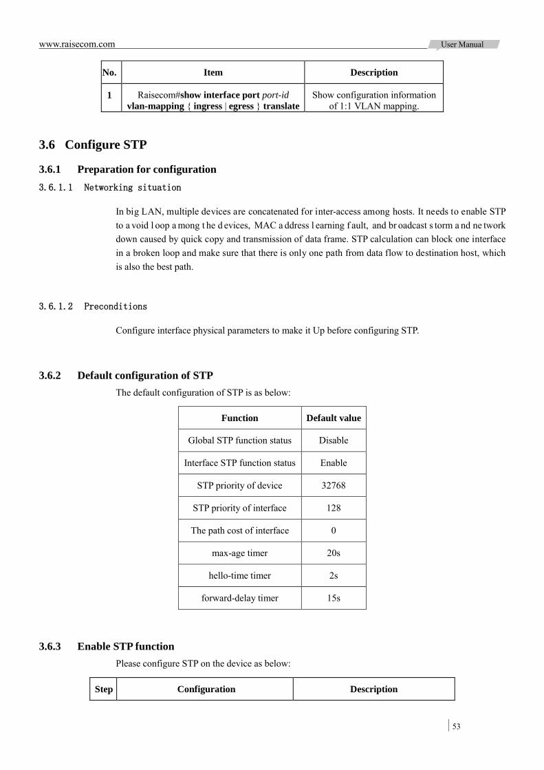
www.raisecom.com User Manual
53
No. Item Description
1 Raisecom#show interface port port-id vlan-mapping { ingress | egress } translate
Show configuration information of 1:1 VLAN mapping.
3.6 Configure STP
3.6.1 Preparation for configuration 3.6.1.1 Networking situation
In big LAN, multiple devices are concatenated for inter-access among hosts. It needs to enable STP to a void l oop a mong t he d evices, MAC a ddress l earning f ault, and br oadcast s torm a nd ne twork down caused by quick copy and transmission of data frame. STP calculation can block one interface in a broken loop and make sure that there is only one path from data flow to destination host, which is also the best path.
3.6.1.2 Preconditions
Configure interface physical parameters to make it Up before configuring STP.
3.6.2 Default configuration of STP The default configuration of STP is as below:
Function Default value
Global STP function status Disable
Interface STP function status Enable
STP priority of device 32768
STP priority of interface 128
The path cost of interface 0
max-age timer 20s
hello-time timer 2s
forward-delay timer 15s
3.6.3 Enable STP function Please configure STP on the device as below:
Step Configuration Description

www.raisecom.com User Manual
54
Step Configuration Description
1 Raisecom#config Enter global configuration mode.
2 Raisecom(config)#spanning-tree mode stp Configure spanning tree for STP mode.
3 Raisecom(config)#spanning-tree enable Enable spanning tree protocol.
3.6.4 Configure STP parameter Please configure STP enable for the device as below:
Step Configuration Description
1 Raisecom#config Enter global configuration mode.
2 Raisecom(config)#spanning-tree priority priority-value
(Optional) Configure device priority.
3 Raisecom(config)#spanning-tree root { primary | secondary }
(Optional) Configure the device as root or backup device.
4 Raisecom(config)#interface port port-id Raisecom(config-port)#spanning-tree
priority priority-value
(Optional) Configure device interface priority.
5 Raisecom(config-port)#spanning-tree inner-path-cost cost-value
(Optional) Configure path cost for device interface.
6 Raisecom(config)#spanning-tree hello-time value
(Optional) Configure Hello Time.
7 Raisecom(config)#spanning-tree transit-limit value
(Optional) Configure maximum transmitting speed of interface.
8 Raisecom(config)#spanning-tree forward-delay value
(Optional) Configure Forward Delay.
9 Raisecom(config)#spanning-tree max-age value
(Optional) Configure Max Age.
3.6.5 Checking configuration Check the result by the commands below after configuration:
No. Item Description
1 Raisecom#show spanning-tree Show basic configuration information of STP.
2 Raisecom#show spanning-tree port-list port-list
Show STP configuration under interface.

www.raisecom.com User Manual
55
3.7 Configure MSTP
3.7.1 Preparation for configuration 3.7.1.1 Networking situation
In big LAN or residential region aggregation, the aggregation devices will make up a ring for link backup, at the same time avoid loop and realize service load sharing. MSTP can select different and unique forwarding path for each one or a group of VLAN.
3.7.1.2 Preconditions
Configure interface physical parameters to make it Up before configuring MSTP.
3.7.2 Default configuration of MSTP The default configuration of MSTP is as below:
Function Default value
Global MSTP function status Disable
Interface MSTP function status Enable
The maximum hop count of MST domain 20
MSTP priority of device 32768
MSTP priority of interface 128
The path cost of interface 0
The biggest transmitting message count within each Hello time
3
max-age timer 20s
hello-time timer 2s
forward-delay timer 15s
The revision level of MST domain 0
3.7.3 Enable MSTP function Please configure MSTP for the device as below:
Step Configuration Description
1 Raisecom#config Enter global configuration mode.
2 Raisecom(config)#spanning-tree mode mstp Configure spanning tree for MSTP mode.

www.raisecom.com User Manual
56
Step Configuration Description
3 Raisecom(config)#spanning-tree enable Enable spanning tree protocol.
3.7.4 Configure MST domain and its maximum hop count User can set domain information for the device when it is running in MSTP mode. The device MST domain is decided by domain name, VLAN mapping table and configuration of MSTP revision level. User can set current device in a specific MST domain through following configuration.
MST dom ain scale i s r estricted by t he maximum hop count. S tarting f rom the r oot bridge of spanning tree in the domain, the configuration information (BPDU) reduces 1 hop count once it is forwarded passing a device; the device discards the configuration information with hop count 0. The device out of maximum hop count cannot j oin spanning tree calculation and then restrict MST domain scale.
Please configure MSTP domain and its maximum hop count for the device as below:
Step Configuration Description
1 Raisecom#config Enter global configuration mode.
2 Raisecom(config)#spanning-tree region-configuration
Enter MST domain configuration mode.
3 Raisecom(config-region)#name name Configure MST domain name.
4 Raisecom(config-region)#revision-level level-value
Set revision level for MST domain, it is 0 by default.
5 Raisecom(config-region)#instance instance-id vlan vlan-id
Raisecom(config-region)#exit
Set mapping relationship from MST domain VLAN to instance.
6 Raisecom(config)#spanning-tree max-hops hops-value
Configure the maximum hop count for MST domain.
Note: The maximum hop count is MST domain maximum hop count if and only if the configured device is root of the domain; other roots cannot configure this item effectively.
3.7.5 Configure root bridge/backup bridge Two methods for MSTP root s election: one is configure device pr iority and calculated by S TP to confirm STP root bridge or backup bridge; the other is to assign directly by this command. When root bridge has fault or power off, the backup bridge can take the place of root bridge for re lated instance. In this cast, if user has set new root bridge, the backup bridge won’t become root bridge. If user has configured several backup bridges for a spanning tree, once the root bridge stops working, MSTP will choose the backup root with the smallest MAC address as new root bridge.
Note: Users ha d better not modify the priority of any device i n the ne twork i f adopting direct
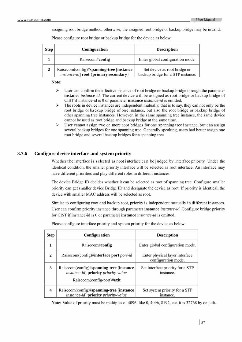
www.raisecom.com User Manual
57
assigning root bridge method, otherwise, the assigned root bridge or backup bridge may be invalid.
Please configure root bridge or backup bridge for the device as below:
Step Configuration Description
1 Raisecom#config Enter global configuration mode.
2 Raisecom(config)#spanning-tree [instance instance-id] root {primary|secondary}
Set device as root bridge or backup bridge for a STP instance.
Note:
User can confirm the effective instance of root bridge or backup bridge through the parameter instance instance-id. The current device will be assigned as root bridge or backup bridge of CIST if instance-id is 0 or parameter instance instance-id is omitted.
The roots in device instances are independent mutually, that is to say, they can not only be the root bridge or backup bridge of one instance, but also the root bridge or backup bridge of other spanning tree instances. However, in the same spanning tree instance, the same device cannot be used as root bridge and backup bridge at the same time.
User cannot assign two or more root bridges for one spanning tree instance, but can assign several backup bridges for one spanning tree. Generally speaking, users had better assign one root bridge and several backup bridges for a spanning tree.
3.7.6 Configure device interface and system priority Whether t he i nterface i s s elected as r oot i nterface ca n be j udged by i nterface pr iority. Under the identical condition, the smaller priority interface will be selected as root interface. An interface may have different priorities and play different roles in different instances.
The device Bridge ID decides whether it can be selected as root of spanning tree. Configure smaller priority can get smaller device Bridge ID and designate the device as root. If priority is identical, the device with smaller MAC address will be selected as root.
Similar to configuring root and backup root, priority is independent mutually in different instances. User can confirm priority instance through parameter instance instance-id. Configure bridge priority for CIST if instance-id is 0 or parameter instance instance-id is omitted.
Please configure interface priority and system priority for the device as below:
Step Configuration Description
1 Raisecom#config Enter global configuration mode.
2 Raisecom(config)#interface port port-id Enter physical layer interface configuration mode.
3 Raisecom(config)#spanning-tree [instance instance-id] priority priority-value
Raisecom(config-port)#exit
Set interface priority for a STP instance.
4 Raisecom(config)#spanning-tree [instance instance-id] priority priority-value
Set system priority for a STP instance.
Note: Value of priority must be multiples of 4096, like 0, 4096, 8192, etc. it is 32768 by default.
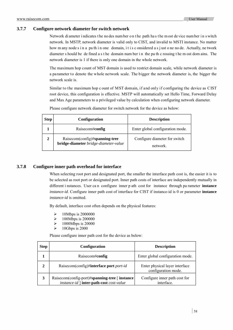
www.raisecom.com User Manual
58
3.7.7 Configure network diameter for switch network Network di ameter i ndicates t he no des num ber o n t he path ha s t he m ost de vice num ber i n s witch network. In MSTP, network diameter is valid only to CIST, and invalid to MSTI instance. No matter how m any node s i n a pa th i n one domain, i t i s c onsidered a s j ust o ne no de. Actually, ne twork diameter s hould be de fined a s t he domain num ber i n the pa th c rossing t he m ost dom ains. The network diameter is 1 if there is only one domain in the whole network.
The maximum hop count of MST domain is used to restrict domain scale, while network diameter is a parameter to denote the whole network scale. The bigger the network diameter is, the bigger the network scale is.
Similar to the maximum hop c ount of MST domain, if and only if configuring the device as CIST root device, this configuration is effective. MSTP will automatically set Hello Time, Forward Delay and Max Age parameters to a privileged value by calculation when configuring network diameter.
Please configure network diameter for switch network for the device as below:
Step Configuration Description
1 Raisecom#config Enter global configuration mode.
2 Raisecom(config)#spanning-tree bridge-diameter bridge-diameter-value
Configure diameter for switch
network.
3.7.8 Configure inner path overhead for interface When selecting root port and designated port, the smaller the interface path cost is, the easier it is to be selected as root port or designated port. Inner path costs of interface are independently mutually in different i nstances. User ca n configure inner p ath cost for instance through pa rameter instance instance-id. Configure inner path cost of interface for CIST if instance-id is 0 or parameter instance instance-id is omitted.
By default, interface cost often depends on the physical features:
10Mbps is 2000000 100Mbps is 200000 1000Mbps is 20000 10Gbps is 2000
Please configure inner path cost for the device as below:
Step Configuration Description
1 Raisecom#config Enter global configuration mode.
2 Raisecom(config)#interface port port-id Enter physical layer interface configuration mode.
3 Raisecom(config-port)#spanning-tree [ instance instance-id ] inter-path-cost cost-value
Configure inner path cost for interface.
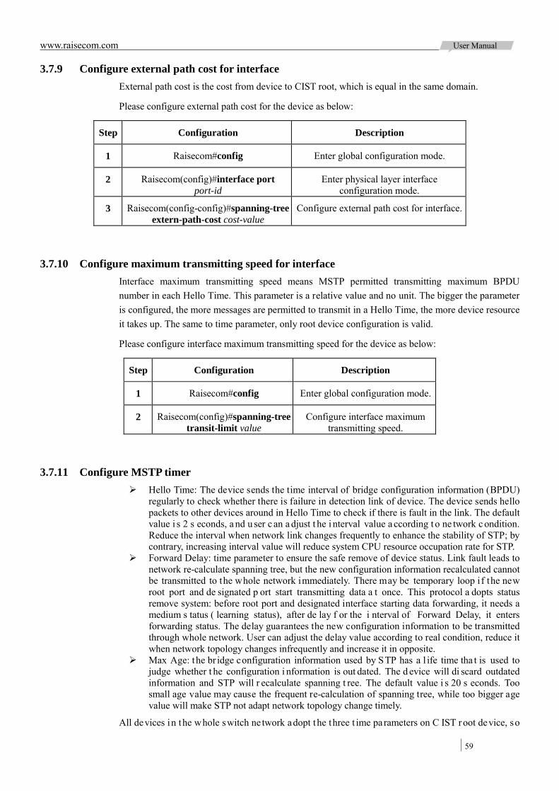
www.raisecom.com User Manual
59
3.7.9 Configure external path cost for interface External path cost is the cost from device to CIST root, which is equal in the same domain.
Please configure external path cost for the device as below:
Step Configuration Description
1 Raisecom#config Enter global configuration mode.
2 Raisecom(config)#interface port port-id
Enter physical layer interface configuration mode.
3 Raisecom(config-config)#spanning-tree extern-path-cost cost-value
Configure external path cost for interface.
3.7.10 Configure maximum transmitting speed for interface Interface maximum transmitting speed means MSTP permitted transmitting maximum BPDU number in each Hello Time. This parameter is a relative value and no unit. The bigger the parameter is configured, the more messages are permitted to transmit in a Hello Time, the more device resource it takes up. The same to time parameter, only root device configuration is valid.
Please configure interface maximum transmitting speed for the device as below:
Step Configuration Description
1 Raisecom#config Enter global configuration mode.
2 Raisecom(config)#spanning-tree transit-limit value
Configure interface maximum transmitting speed.
3.7.11 Configure MSTP timer Hello Time: The device sends the time interval of bridge configuration information (BPDU)
regularly to check whether there is failure in detection link of device. The device sends hello packets to other devices around in Hello Time to check if there is fault in the link. The default value i s 2 s econds, a nd u ser c an a djust t he i nterval value a ccording t o ne twork c ondition. Reduce the interval when network link changes frequently to enhance the stability of STP; by contrary, increasing interval value will reduce system CPU resource occupation rate for STP.
Forward Delay: time parameter to ensure the safe remove of device status. Link fault leads to network re-calculate spanning tree, but the new configuration information recalculated cannot be transmitted to the whole network immediately. There may be temporary loop if the new root port and de signated p ort start transmitting data a t once. This protocol a dopts status remove system: before root port and designated interface starting data forwarding, it needs a medium s tatus ( learning status), after de lay f or the i nterval of Forward Delay, it enters forwarding status. The delay guarantees the new configuration information to be transmitted through whole network. User can adjust the delay value according to real condition, reduce it when network topology changes infrequently and increase it in opposite.
Max Age: the br idge configuration information used by STP has a l ife time tha t is used to judge whether t he configuration i nformation is out dated. The d evice will di scard outdated information and STP will r ecalculate spanning t ree. The default value i s 20 s econds. Too small age value may cause the frequent re-calculation of spanning tree, while too bigger age value will make STP not adapt network topology change timely.
All devices in the whole switch ne twork adopt the three t ime parameters on C IST root device, so

www.raisecom.com User Manual
60
only the root device configuration is valid.
Please configure timer for the device as below:
Step Configuration Description
1 Raisecom#config Enter global configuration mode.
2 Raisecom(config)#spanning-tree hello-time value
Set Hello Time.
3 Raisecom(config)#spanning-tree forward-delay value
Set Forward Delay.
4 Raisecom(config)#spanning-tree max-age value
Set Max Age.
3.7.12 Configure edge port Edge port indicates the interface neither direct connects to any devices nor indirect connect to any device via network.
Edge por t c an change the int erface status t o f orward q uickly w ithout a ny w aiting t ime. You ha d better set the Ethernet interface connected to user client as edge port to make it quick to change to forward status.
The edge port attribute depends on actual condition when it is in auto-detection mode; the real port will change to false edge port after receiving BPDU when it is in force-true mode; when the interface is i n force-false mode, w hether it is t rue or false e dge por t i n r eal ope ration, i t will m aintain the force-false mode until the configuration is changed.
By default, all interfaces in Ethernet device are set in auto-detection attribute.
Please configure edge port for the device as below:
Step Configuration Description
1 Raisecom#config Enter global configuration mode.
2 Raisecom(config)#interface port port-id Enter physical layer interface configuration mode.
3 Raisecom(config-port)#spanning-tree edged-port { auto | force-true | force-false }
Configure edge port attributes.
3.7.13 Configure link type The poi nt-to-point link connected interface can qui ckly c hanges to f orward s tatus by tr ansmitting synchronous message. By default, M STP s et i nterface l ink t ype a ccording t o duplex m ode. Full-duplex i nterface i s c onsidered a s poi nt-to-point l ink, ha lf-duplex interface i s consi dered as shared link.
User can configure current Ethernet interface to connect point-to-point l ink by force, but it will go wrong if the link is not point-to-point. Generally, user had better set this item in auto status and the system will automatically detect whether the interface is connected to point-to-point link.

www.raisecom.com User Manual
61
Please configure link type for the device as below:
Step Configuration Description
1 Raisecom#config Enter global configuration mode.
Raisecom(config)#interface port port-id Enter physical layer interface configuration mode.
2 Raisecom(config-port)#spanning-tree link-type { auto | point-to-point | shared }
Configure link type for interface.
3.7.14 Configure root interface protection Network will select bridge again when it receives message from higher priority, which will influent network connectivity and also consume CPU resource. For MSTP network, if someone sends higher priority B PDU pa ckets, t he network may be come uns table for t he c ontinuous election. Generally, each bridge priority has already configured in network programming. The nearer to edge, the lower the bridge priority is. So the down-bound interface cannot receive the messages higher than bridge priority only if someone attacks. For these interfaces, user can enable rootguard function to refuse to deal with message higher t han br idge priority and meanwhile bl ock t he i nterface f or a pe riod t o prevent other attacks from attack source to damage the upper layer link.
Please configure root interface protection for the device as below:
Step Configuration Description
1 Raisecom#config Enter global configuration mode.
2 Raisecom(config)#interface port port-id
Enter physical layer interface configuration mode.
3 Raisecom(config-port)#spanning-tree rootguard { enable | disable }
Configure root interface protection attributes for interface.
3.7.15 Configure loopguard for interface The s panning t ree ha s t wo functions: l oopguard a nd l ink ba ckup. Loopguard requires c arving up topology network i nto t ree s tructure. T here m ust be r edundant l ink i n t opology i f r equiring link backup. Spanning t ree c an a void l oop by bl ocking the r edundant l ink and e nable link ba ckup function by opening redundant link when the link breaks down.
Spanning t ree module exchanges packets pe riodically, and the l ink ha s failed if it hasn’t received message in a pe riod. Then s elect a ne w link and enable backup interface. In actual ne twork application, the message cannot be received not only for link fault, then at this time, enable backup interface may lead to loop link.
Purpose of loopguard i s t o keep the or iginal interface s tatus w hen it cannot r eceive message in a period. NOTE: Loopguard and link backup functions are exclusive, loopguard requires disabling link backup to avoid loop.
Please configure interface loop protection for the device as below:
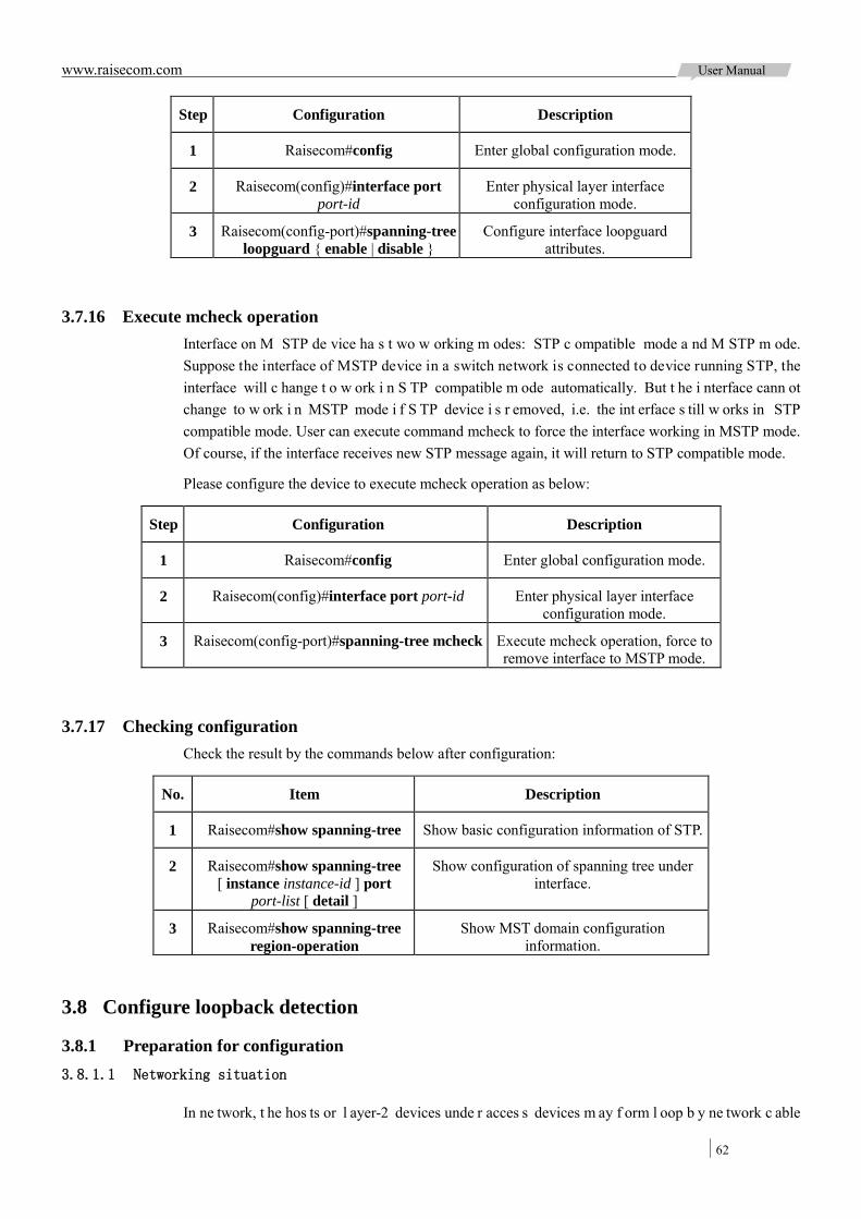
www.raisecom.com User Manual
62
Step Configuration Description
1 Raisecom#config Enter global configuration mode.
2 Raisecom(config)#interface port port-id
Enter physical layer interface configuration mode.
3 Raisecom(config-port)#spanning-tree loopguard { enable | disable }
Configure interface loopguard attributes.
3.7.16 Execute mcheck operation Interface on M STP de vice ha s t wo w orking m odes: STP c ompatible mode a nd M STP m ode. Suppose the interface of MSTP device in a switch network is connected to device running STP, the interface will c hange t o w ork i n S TP compatible m ode automatically. But t he i nterface cann ot change to w ork i n MSTP mode i f S TP device i s r emoved, i.e. the int erface s till w orks in STP compatible mode. User can execute command mcheck to force the interface working in MSTP mode. Of course, if the interface receives new STP message again, it will return to STP compatible mode.
Please configure the device to execute mcheck operation as below:
Step Configuration Description
1 Raisecom#config Enter global configuration mode.
2 Raisecom(config)#interface port port-id Enter physical layer interface configuration mode.
3 Raisecom(config-port)#spanning-tree mcheck Execute mcheck operation, force to remove interface to MSTP mode.
3.7.17 Checking configuration Check the result by the commands below after configuration:
No. Item Description
1 Raisecom#show spanning-tree Show basic configuration information of STP.
2 Raisecom#show spanning-tree [ instance instance-id ] port
port-list [ detail ]
Show configuration of spanning tree under interface.
3 Raisecom#show spanning-tree region-operation
Show MST domain configuration information.
3.8 Configure loopback detection
3.8.1 Preparation for configuration 3.8.1.1 Networking situation
In ne twork, t he hos ts or l ayer-2 devices unde r acces s devices m ay f orm l oop b y ne twork c able

www.raisecom.com User Manual
63
intentionally or i nvoluntary. Enable loopback de tection function at dow nlink i nterface of access device to av oid the network jam formed by unlimited copies of data traffic caused by downlink interface loop. Block the loop interface once there is a loop.
3.8.1.2 Preconditions
Configure interface physical parameters to make it Up before configuring loopback detection.
3.8.2 Default configuration of loopback detection The default configuration of loopback detection is as below:
Function Default value
Loopback detection function status Disable
The automatic recovery time for interface block No automatic recovery
The loop process mode of loopback detection trap-only
Loopback detection period 4s
Loopback detection mode VLAN mode
The automatic open blocked interface time for loopback detection
infinite
3.8.3 Configure loopback detection function Please configure loopback detection function as below:
Note:
Loopback detection function and STP are exclusive, only one can be enabled at one time. The straight connection device cannot enable loopback detection in both ends simultaneously;
otherwise the interfaces at both ends will be blocked.
Step Configuration Description
1 Raisecom#config Enter global configuration mode.
2 Raisecom(config)#loopback-detection { enable | disable } port-list port-list
Configure loopback detection function for interface.
3 Raisecom(config)#loopback-detection hello-time period
Configure message transmitting period for loopback detection.
4 Raisecom(config)#loopback-detection mode { port-based | vlan-based }
(Optional) Configure loopback detection mode.
5 Raisecom(config)#loopback-detection loop { discarding | trap-only } port-list port-list
(Optional) Configure the port process mode after receiving loopback detection message
from other devices.
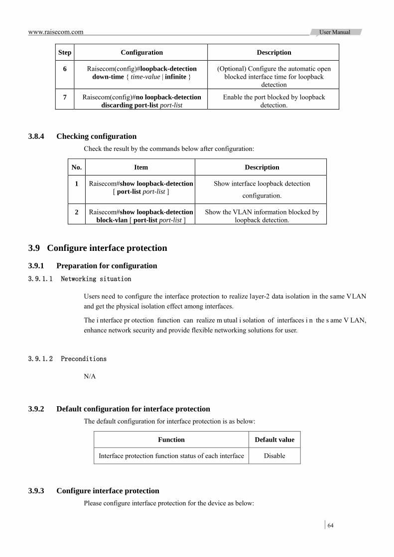
www.raisecom.com User Manual
64
Step Configuration Description
6 Raisecom(config)#loopback-detection down-time { time-value | infinite }
(Optional) Configure the automatic open blocked interface time for loopback
detection
7 Raisecom(config)#no loopback-detection discarding port-list port-list
Enable the port blocked by loopback detection.
3.8.4 Checking configuration Check the result by the commands below after configuration:
No. Item Description
1 Raisecom#show loopback-detection [ port-list port-list ]
Show interface loopback detection
configuration.
2 Raisecom#show loopback-detection block-vlan [ port-list port-list ]
Show the VLAN information blocked by loopback detection.
3.9 Configure interface protection
3.9.1 Preparation for configuration 3.9.1.1 Networking situation
Users need to configure the interface protection to realize layer-2 data isolation in the same VLAN and get the physical isolation effect among interfaces.
The i nterface pr otection function can realize m utual i solation of interfaces i n the s ame V LAN, enhance network security and provide flexible networking solutions for user.
3.9.1.2 Preconditions
N/A
3.9.2 Default configuration for interface protection The default configuration for interface protection is as below:
Function Default value
Interface protection function status of each interface Disable
3.9.3 Configure interface protection Please configure interface protection for the device as below:

www.raisecom.com User Manual
65
Step Configuration Description
1 Raisecom#config Enter global configuration mode.
2 Raisecom(config)#interface port port-id Enter physical layer interface configuration mode.
3 Raisecom(config-port)#switchport protect Enable interface protection.
3.9.4 Checking configuration Check the result by the commands below after configuration:
No. Item Description
1 Raisecom#show switchport protect
Show interface protection configuration.
3.10 Configure interface mirror
3.10.1 Preparation for configuration 3.10.1.1 Networking situation
Interface m irror f unction i s m ainly us ed t o m onitor n etwork data t ype and t raffic r egularly f or network administrator.
Interface mirroring function is to copy the interface traffic monitored to a monitor interface or CPU so as to obtain the ingress/egress interface failure or abnormal flow of data to analyze, discover the root cause and solve them timely.
3.10.1.2 Preconditions
N/A
3.10.2 Default configuration for interface mirror The default configuration for interface mirror is as below:
Function Default value
Interface mirror function status Disable
Mirror source interface N/A
Mirror monitoring interface Port 1
Mirror source interface ingress/egress message filter source MAC address
0000.0000.0000
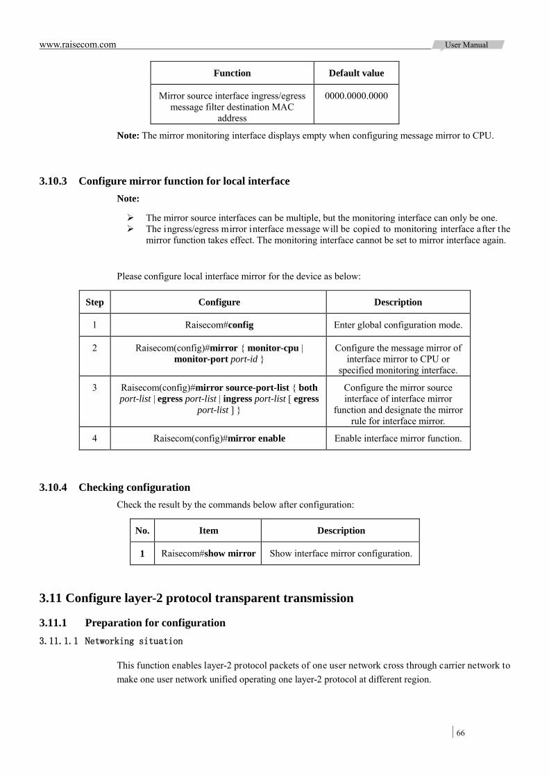
www.raisecom.com User Manual
66
Function Default value
Mirror source interface ingress/egress message filter destination MAC
address
0000.0000.0000
Note: The mirror monitoring interface displays empty when configuring message mirror to CPU.
3.10.3 Configure mirror function for local interface Note:
The mirror source interfaces can be multiple, but the monitoring interface can only be one. The ingress/egress mirror interface message will be copied to monitoring interface after the
mirror function takes effect. The monitoring interface cannot be set to mirror interface again.
Please configure local interface mirror for the device as below:
Step Configure Description
1 Raisecom#config Enter global configuration mode.
2 Raisecom(config)#mirror { monitor-cpu | monitor-port port-id }
Configure the message mirror of interface mirror to CPU or
specified monitoring interface.
3 Raisecom(config)#mirror source-port-list { both port-list | egress port-list | ingress port-list [ egress
port-list ] }
Configure the mirror source interface of interface mirror
function and designate the mirror rule for interface mirror.
4 Raisecom(config)#mirror enable Enable interface mirror function.
3.10.4 Checking configuration Check the result by the commands below after configuration:
No. Item Description
1 Raisecom#show mirror Show interface mirror configuration.
3.11 Configure layer-2 protocol transparent transmission
3.11.1 Preparation for configuration 3.11.1.1 Networking situation
This function enables layer-2 protocol packets of one user network cross through carrier network to make one user network unified operating one layer-2 protocol at different region.

www.raisecom.com User Manual
67
3.11.1.2 Preconditions
Configure physical pa rameters f or t he i nterface to set it in Up status be fore configuring layer-2 protocol transparent transmission function.
3.11.2 Default configuration of layer-2 protocol transparent transmission The default configuration of layer-2 protocol transparent transmission is as below:
Function Default value
layer-2 protocol transparent transmission function status
Disable
Egress interface and belonged VLAN of layer-2 protocol message
NULL
TAG CoS value of transparent transmission message
5
Destination MAC address of transparent transmission message
010E.5E00.0003
Packet loss threshold and ban threshold of transparent transmission message
NULL
3.11.3 Configure transparent transmission parameter Please configure transparent transmission parameter for the device as below:
Step Configuration Description
1 Raisecom#config Enter global configuration mode.
2 Raisecom(config)#relay destination-address mac-address
(Optional) Configure destination MAC for transparent transmission
message, default as 010E.5E00.0003.
3 Raisecom(config)#relay cos cos-value (Optional) Configure CoS value for transparent transmission message.
4 Raisecom(config)#interface port port-id Enter physical layer interface configuration mode.
5 Raisecom(config-port)#relay port port-id Configure specified egress interface for transparent transmission
message.
6 Raisecom(config-port)#relay vlan vlan-id Configure specified VLAN for transparent transmission message.
The specified VLAN configuration can transmit the message according to specified VLAN, but not VLAN configuration of ingress interface.
7 Raisecom(config-port)#relay { all | cdp | gvrp | dot1x | lacp | pvst | stp | vtp }
Configure transparent transmission packets type on interface and
disable related protocol.

www.raisecom.com User Manual
68
3.11.4 (Optional) Configure transparent transmission speed for message Please configure transparent transmission speed limit for the device as below:
Step Configuration Description
1 Raisecom#config Enter global configuration mode.
2 Raisecom(config)#interface port port-id Enter physical layer interface configuration mode.
3 Raisecom(config-port)#relay drop-threshold { cdp | dot1x | lacp | pvst |
stp | vtp } packet
Configure packet loss threshold for transparent transmission message.
4 Raisecom(config-port)#relay shutdown-threshold { cdp | dot1x | gvrp
|lacp | pvst | stp | vtp } value
Configure interface shutdown threshold for transparent transmission message.
Note: The range packet loss threshold and interface shutdown threshold of transparent transmission message are bot h 1 -4096. G enerally, please configure packet l oss threshold smaller tha n interface shutdown threshold.
3.11.5 Checking configuration Check the result by the commands below after configuration:
No. Item Description
1 Raisecom#show relay [ port-list port-list ]
Show configuration and status of transparent transmission.
2 Raisecom#show relay statistics [ port-list port-list ]
Show the statistics of transparent transmission packets.
3.12 Maintenance
Users can maintain Ethernet features by the following commands:
Commands Description
Raisecom(config)#clear mac-address-table { all | blackhole | dynamic | static }
Clear MAC address.
Raisecom(config)#search mac-address mac-address { all | dynamic | static } [ port
port-id ] [ vlan vlan-id ]
Search MAC address.
Raisecom(config-port)#spanning-tree clear statistics
Clear interface spanning tree statistics information.
Raisecom(config-port)#clear loopback-detection statistic
Clear loopback detection statistics information.
Raisecom(config)#clear relay statistics [ port-list port-list ]
Clear statistics information of transparent transmission message.

www.raisecom.com User Manual
69
3.13 Configure examples
3.13.1 Configure MAC address forwarding table 3.13.1.1 Networking requirement
As the Figure 3-13 shows be low, ope rating on S witch A , configure a s tatic uni cast MAC address 0001.0203.0405 at Port 2, the belonged VLAN is VLAN 10; configure MAC address aging time as 500 seconds.
Figure 3-13 MAC application networking
3.13.1.2 Configuration steps
Step 1 Create VLAN 10 and active it, add Port 2 into VLAN 10:
Raisecom#config
Raisecom(config)#create vlan 10 active
Raisecom(config)#interface port 2
Raisecom(config-port)#switchport mode access
Raisecom(config-port)#switchport access vlan 10
Raisecom(config-port)#exit
Step 2 Configure a static unicast MAC address 0001.0203.0405 at Port 2, belonged to VLAN10:
Raisecom(config)#mac-address-table static unicast 0001.0203.0405 vlan 10 port 2
Step 3 Configure MAC address aging time as 500 seconds:
Raisecom(config)#mac-address-table aging-time 500
3.13.1.3 Show result
Show M AC a ddress c onfiguration by t he c ommand of show mac-address-table l2-address port port-id:
Raisecom#show mac-address-table l2-address port 2

www.raisecom.com User Manual
70
Aging time: 500 seconds
Mac Address Port Vlan Flags
-------------------------------------------------------
0001.0203.0405 port2 10 Static
3.13.2 Configure VLAN and interface protection 3.13.2.1 Networking requirement
As the Figure 3-14 shows below, PC1, PC2, and PC5 belong to VLAN 10, PC3 and PC4 belong to VLAN 20; t he t wo de vices a re c onnected by Trunk i nterface, PC3 a nd PC4 cannot c ommunicate because VLAN20 is not permitted passing in the link; PC1 and PC2 under the same Switch B enable interface protection function so that they cannot communicate with each other, but can respectively communicate with PC5.
Figure 3-14 VLAN and interface protection networking
3.13.2.2 Configuration steps
Step 1 Create VLAN10 and VLAN20 on the two devices respectively and activate them.
Configure Switch A:
Raisecom#hostname SwitchA
SwitchA#config
SwitchA(config)#create vlan 10,20 active
Configure Switch B:
Raisecom#hostname SwitchB
SwitchB#config
SwitchB(config)#create vlan 10,20 active
Step 2 Add Access mode interface Port 2 and Port 3 of Switch B into VLAN 10, add Access mode

www.raisecom.com User Manual
71
interface Port 4 into VLAN20, interface Port 1 is in Trunk mode and permits VLAN 10 passing.
SwitchB(config)#interface port 2
SwitchB(config-port)#switchport mode access
SwitchB(config-port)#switchport access vlan 10
SwitchB(config-port)#exit
SwitchB(config)#interface port 3
SwitchB(config-port)#switchport mode access
SwitchB(config-port)#switchport access vlan 10
SwitchB(config-port)#exit
SwitchB(config)#interface port 4
SwitchB(config-port)#switchport mode access
SwitchB(config-port)#switchport access vlan 20
SwitchB(config-port)#exit
SwitchB(config)#interface port 1
SwitchB(config-port)#switchport mode trunk
SwitchB(config-port)#switchport trunk allowed vlan 10 confirm
SwitchB(config-port)#exit
Step 3 Add Access mode interface Port 2 of Switch A into VLAN 10, add Trunk mode interface Port 3 into VLAN20, interfacePort1 is in Trunk mode and permits VLAN 10 passing.
SwitchA(config)#interface port 2
SwitchA(config-port)#switchport mode access
SwitchA(config-port)#switchport access vlan 10
SwitchA(config-port)#exit
SwitchA(config)#interface port 3
SwitchA(config-port)#switchport mode trunk
SwitchA(config-port)#switchport trunk native vlan 20
SwitchA(config-port)#exit
SwitchA(config)#interface port 1
SwitchA(config-port)#switchport mode trunk
SwitchA(config-port)#switchport trunk allowed vlan 10 confirm
Step 4 Enable interface protection function for interface Port 2 and Port 3 of Switch B:
SwitchB(config)#interface port 2
SwitchB(config-port)#switchport protect
SwitchB(config-port)#exit
SwitchB(config)#interface port 3
SwitchB(config-port)#switchport protect
3.13.2.3 Show result
Check whether the VLAN configuration information is correct by the command of show vlan.

www.raisecom.com User Manual
72
Take Switch B for example:
SwitchB#show vlan
Switch Mode: --
VLAN Name State Status Priority Member-Ports
-------------------------------------------------------------------------------
1 Default active static -- 1-6
10 VLAN0010 active static -- 1,3-4
20 VLAN0020 active static -- 5
Check whether the interface VLAN configuration is correct by the command of show interface port port-id switchport.
Take Switch B for example:
SwitchB#show interface port 2 switchport
Interface: port2
Administrative Mode: access
Operational Mode: access
Access Mode VLAN: 10
Administrative Access Egress VLANs: 1
Operational Access Egress VLANs: 1,10
Trunk Native Mode VLAN: 1
Administrative Trunk Allowed VLANs: 1-4094
Operational Trunk Allowed VLANs: 1,10,20
Administrative Trunk Untagged VLANs: 1
Operational Trunk Untagged VLANs: 1
Check whether the interface protection configuration is correct by the command of show switchport protect
SwitchB#show switchport protect
Port Protected State
--------------------------
P1 enable
P2 enable
P3 enable
P4 enable
P5 disable
P6 disable
P7 disable
……
Check whether Trunk interface permitting VLAN passing is correct by operating PC1 ping PC5, PC2 ping PC5, PC3 ping PC4:
PC1 ping PC5, ping successfully, VLAN 10 communication is normal; PC2 ping PC5, ping successfully, VLAN 10 communication is normal; PC3 ping PC4, ping unsuccessfully, VLAN 20 communication is abnormal.
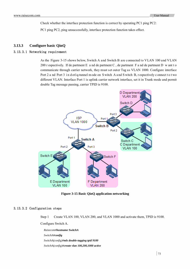
www.raisecom.com User Manual
73
Check whether the interface protection function is correct by operating PC1 ping PC2:
PC1 ping PC2, ping unsuccessfully, interface protection function takes effect.
3.13.3 Configure basic QinQ 3.13.3.1 Networking requirement
As the Figure 3-15 shows below, Switch A and Switch B are connected to VLAN 100 and VLAN 200 r espectively. If de partment E a nd de partment C , de partment F a nd de partment D w ant t o communicate through carrier network, they must set outer Tag as VLAN 1000. Configure interface Port 2 a nd Port 3 i n d ot1q-tunnel m ode on S witch A a nd S witch B, r espectively c onnect t o t wo different VLAN. Interface Port 1 is uplink carrier network interface, set it in Trunk mode and permit double Tag message passing, carrier TPID is 9100.
Figure 3-15 Basic QinQ application networking
3.13.3.2 Configuration steps
Step 1 Create VLAN 100, VLAN 200, and VLAN 1000 and activate them, TPID is 9100.
Configure Switch A.
Raisecom#hostname SwitchA
SwitchA#config
SwitchA(config)#mls double-tagging tpid 9100
SwitchA(config)#create vlan 100,200,1000 active
www.raisecom.com User Manual
74
Configure Switch B.
Raisecom#hostname SwitchB
SwitchB#config
SwitchB(config)#mls double-tagging tpid 9100
SwitchB(config)#create vlan 100,200,1000 active
Step 2 Set interface Port 2 and Port 3 in dot1q mode.
Configure Switch A.
SwitchA(config)#interface port 2
SwitchA(config-port)#switchport mode trunk
SwitchA(config-port)#switchport trunk native vlan 1000
SwitchA(config-port)#switchport qinq dot1q-tunnel
SwitchA(config-port)#exit
SwitchA(config)#interface port 3
SwitchA(config-port)#switchport mode trunk
SwitchA(config-port)#switchport trunk native vlan 1000
SwitchA(config-port)#switchport qinq dot1q-tunnel
SwitchA(config-port)#exit
Configure Switch B.
SwitchB(config)#interface port 2
SwitchB(config-port)#switchport mode trunk
SwitchB(config-port)#switchport trunk native vlan 1000
SwitchB(config-port)#switchport qinq dot1q-tunnel
SwitchB(config-port)#exit
SwitchB(config)#interface port 3
SwitchB(config-port)#switchport mode trunk
SwitchB(config-port)#switchport trunk native vlan 1000
SwitchB(config-port)#switchport qinq dot1q-tunnel
SwitchB(config-port)#exit
Step 3 Set interface Port 1 permitting double Tag message passing.
Configure Switch A.
SwitchA(config)#interface port 1
SwitchA(config-port)#switchport mode trunk
SwitchA(config-port)#switchport trunk allowed vlan 1000 confirm
Configure Switch B.
SwitchB(config)#interface port 1
SwitchB(config-port)#switchport mode trunk
SwitchB(config-port)#switchport trunk allowed vlan 1000 confirm
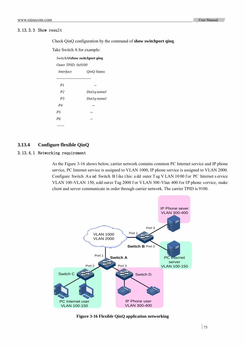
www.raisecom.com User Manual
75
3.13.3.3 Show result
Check QinQ configuration by the command of show switchport qinq.
Take Switch A for example:
SwitchA#show switchport qinq
Outer TPID: 0x9100
Interface QinQ Status
----------------------------
P1 --
P2 Dot1q-tunnel
P3 Dot1q-tunnel
P4 --
P5 --
P6 --
……
3.13.4 Configure flexible QinQ 3.13.4.1 Networking requirement
As the Figure 3-16 shows below, carrier network contains common PC Internet service and IP phone service, PC Internet service is assigned to VLAN 1000, IP phone service is assigned to VLAN 2000. Configure Switch A a nd Switch B l ike t his: a dd outer Tag V LAN 10 00 f or PC Internet s ervice VLAN 100-VLAN 150, add outer Tag 2000 f or VLAN 300-Vlan 400 for IP phone service, make client and server communicate in order through carrier network. The carrier TPID is 9100.
IP Phone severVLAN 300-400
Switch A
Switch C
Port 1
Port 2
Switch D
Switch B
Port 3
Port 1
Port 2
Port 3
PC Internet userVLAN 100-150
IP Phone userVLAN 300-400
PC Internet server
VLAN 100-150
IPIP IPIP
VLAN 1000VLAN 2000
Figure 3-16 Flexible QinQ application networking

www.raisecom.com User Manual
76
3.13.4.2 Configuration steps
Step 1 Create VLAN 100, VLAN 200, and VLAN 1000 and activate them, TPID is 9100.
Configure Switch A.
Raisecom#hostname SwitchA
SwitchA#config
SwitchA(config)#mls double-tagging tpid 9100
SwitchA(config)#create vlan 100-150, 300-400, 1000, 2000 active
Configure Switch B.
Raisecom#hostname SwitchB
SwitchB#config
SwitchB(config)#mls double-tagging tpid 9100
SwitchB(config)#create vlan 100-150, 300-400, 1000, 2000 active
Step 2 Set interface Port 2 and Port 3 in dot1q mode.
Configure Switch A.
SwitchA(config)#interface port 2
SwitchA(config-port)#switchport mode trunk
SwitchA(config-port)#switchport vlan-mapping cvlan 100-150 add-outer 1000
SwitchA(config-port)#switchport trunk untagged vlan 1000,2000 confirm
SwitchA(config-port)#exit
SwitchA(config)#interface port 3
SwitchA(config-port)#switchport mode trunk
SwitchA(config-port)#switchport vlan-mapping cvlan 300-400 add-outer 2000
SwitchA(config-port)#switchport trunk untagged vlan 1000,2000 confirm
SwitchA(config-port)#exit
Configure Switch B.
SwitchB(config)#interface port 2
SwitchB(config-port)#switchport mode trunk
SwitchB(config-port)#switchport vlan-mapping cvlan 100-150 add-outer 1000
SwitchB(config-port)#switchport trunk untagged vlan 1000,2000 confirm
SwitchB(config-port)#exit
SwitchB(config)#interface port 3
SwitchB(config-port)#switchport mode trunk
SwitchB(config-port)#switchport vlan-mapping cvlan 300-400 add-outer 2000
SwitchB(config-port)#switchport trunk untagged vlan 1000,2000 confirm
SwitchB(config-port)#exit
Step 3 Set interface Port 1 permitting double Tag message passing.
Configure Switch A.
www.raisecom.com User Manual
77
SwitchA(config)#interface port 1
SwitchA(config-port)#switchport mode trunk
SwitchA(config-port)#switchport trunk allowed vlan 1000,2000 confirm
Configure Switch B.
SwitchB(config)#interface port 1
SwitchB(config-port)#switchport mode trunk
SwitchB(config-port)#switchport trunk allowed vlan 1000,2000 confirm
3.13.4.3 Show result
Check QinQ c onfiguration b y t he c ommand of show interface port port-id vlan-mapping add-outer.
Take Switch A for example:
SwitchA#show interface port 2 vlan-mapping add-outer
Based outer VLAN QinQ mapping rule:
Original Original Add-outer Add-outer Hardware Hardware
Port Outer VLAN COS VLAN COS Status ID
-------------------------------------------------------------------------
P2 100-150 -- 1000 -- Enable 4
SwitchA#show interface port 3 vlan-mapping add-outer
Based outer VLAN QinQ mapping rule:
Original Original Add-outer Add-outer Hardware Hardware
Port Outer VLAN COS VLAN COS Status ID
--------------------------------------------------------------------
P3 300-400 -- 2000 -- Enable 5
3.13.5 Configure VLAN mapping 3.13.5.1 Networking requirement
As the Figure 3-17 shows below, Port 2 and Port 3 of Switch A respectively connect to department E by VLAN 100 and to department F by VLAN 200, Port 2 and Port 3 of Switch B respectively connect to department C by VLAN 100 and to department D by VLAN 200. Assigning VLAN 1000 for department E and C transmission in carrier network, assign VLAN 2008 for department F and D transmission.
Configure 1:1 VLAN mapping for Switch A and Switch B to realize normal communication between PC user and terminal user with servers.
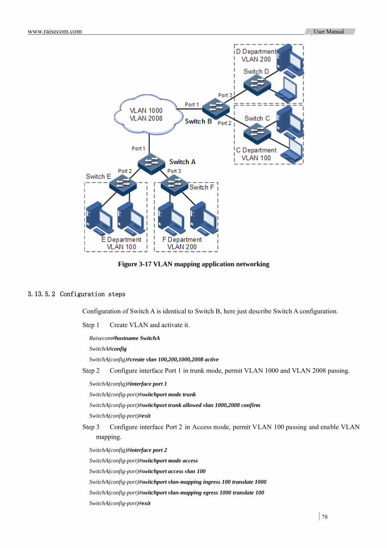
www.raisecom.com User Manual
78
Figure 3-17 VLAN mapping application networking
3.13.5.2 Configuration steps
Configuration of Switch A is identical to Switch B, here just describe Switch A configuration.
Step 1 Create VLAN and activate it.
Raisecom#hostname SwitchA
SwitchA#config
SwitchA(config)#create vlan 100,200,1000,2008 active
Step 2 Configure interface Port 1 in trunk mode, permit VLAN 1000 and VLAN 2008 passing.
SwitchA(config)#interface port 1
SwitchA(config-port)#switchport mode trunk
SwitchA(config-port)#switchport trunk allowed vlan 1000,2008 confirm
SwitchA(config-port)#exit
Step 3 Configure interface Port 2 in Access mode, permit VLAN 100 passing and enable VLAN mapping.
SwitchA(config)#interface port 2
SwitchA(config-port)#switchport mode access
SwitchA(config-port)#switchport access vlan 100
SwitchA(config-port)#switchport vlan-mapping ingress 100 translate 1000
SwitchA(config-port)#switchport vlan-mapping egress 1000 translate 100
SwitchA(config-port)#exit
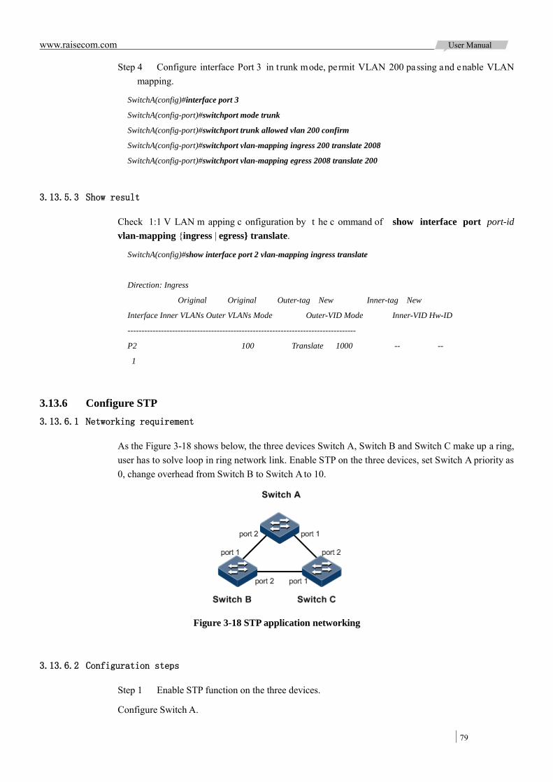
www.raisecom.com User Manual
79
Step 4 Configure interface Port 3 in t runk mode, permit VLAN 200 passing and enable VLAN mapping.
SwitchA(config)#interface port 3
SwitchA(config-port)#switchport mode trunk
SwitchA(config-port)#switchport trunk allowed vlan 200 confirm
SwitchA(config-port)#switchport vlan-mapping ingress 200 translate 2008
SwitchA(config-port)#switchport vlan-mapping egress 2008 translate 200
3.13.5.3 Show result
Check 1:1 V LAN m apping c onfiguration by t he c ommand of show interface port port-id vlan-mapping {ingress | egress} translate.
SwitchA(config)#show interface port 2 vlan-mapping ingress translate
Direction: Ingress
Original Original Outer-tag New Inner-tag New
Interface Inner VLANs Outer VLANs Mode Outer-VID Mode Inner-VID Hw-ID
----------------------------------------------------------------------------------
P2 100 Translate 1000 -- --
1
3.13.6 Configure STP 3.13.6.1 Networking requirement
As the Figure 3-18 shows below, the three devices Switch A, Switch B and Switch C make up a ring, user has to solve loop in ring network link. Enable STP on the three devices, set Switch A priority as 0, change overhead from Switch B to Switch A to 10.
Figure 3-18 STP application networking
3.13.6.2 Configuration steps
Step 1 Enable STP function on the three devices.
Configure Switch A.

www.raisecom.com User Manual
80
Raisecom#hostname SwitchA
SwitchA#config
SwitchA(config)#spanning-tree enable
SwitchA(config)#spanning-tree mode stp
Configure Switch B.
Raisecom#hostname SwitchB
SwitchB#config
SwitchB(config)#spanning-tree enable
SwitchB(config)#spanning-tree mode stp
Configure Switch C.
Raisecom#hostname SwitchC
SwitchC#config
SwitchC(config)#spanning-tree enable
SwitchC(config)#spanning-tree mode stp
Step 2 Configure interface mode for the three devices.
Configure Switch A.
SwitchA(config)#interface port 1
SwitchA(config-port)#switchport mode trunk
SwitchA(config-port)#exit
SwitchA(config)#interface port 2
SwitchA(config-port)#switchport mode trunk
SwitchA(config-port)#exit
Configure Switch B.
SwitchB(config)#interface port 1
SwitchB(config-port)#switchport mode trunk
SwitchB(config-port)#exit
SwitchB(config)#interface port 2
SwitchB(config-port)#switchport mode trunk
SwitchB(config-port)#exit
Configure Switch C.
SwitchC(config)#interface port 1
SwitchC(config-port)#switchport mode trunk
SwitchC(config-port)#exit
SwitchC(config)#interface port 2
SwitchC(config-port)#switchport mode trunk
SwitchC(config-port)#exit
Step 3 Configure priority and interface path overhead for spanning tree.
Configure Switch A.
SwitchA(config)#spanning-tree priority 0
SwitchA(config)#interface port 2
SwitchA(config-port)#spanning-tree inter-path-cost 10
Configure Switch B.
www.raisecom.com User Manual
81
SwitchB(config)#interface port 1
SwitchB(config-port)#spanning-tree inter-path-cost 10
3.13.6.3 Show result
Show bridge status by the command of show spanning-tree.
Switch A: Raisecom#show spanning-tree
MSTP Admin State: Enable
Protocol Mode: STP
BridgeId: Mac 000E.5E7B.C557 Priority 0
Root: Mac 000E.5E7B.C557 Priority 0 RootCost 0
Operational: HelloTime 2, ForwardDelay 15, MaxAge 20
Configured: HelloTime 2, ForwardDelay 15, MaxAge 20 TransmitLimit 3
Switch B: Raisecom#show spanning-tree
MSTP Admin State: Enable
Protocol Mode: STP
BridgeId: Mac 000E.5E83.ABD1 Priority 32768
Root: Mac 000E.5E7B.C557 Priority 0 RootCost 10
Operational: HelloTime 2, ForwardDelay 15, MaxAge 20
Configured: HelloTime 2, ForwardDelay 15, MaxAge 20 TransmitLimit 3
Switch C: Raisecom#show spanning-tree
MSTP Admin State: Enable
Protocol Mode: STP
BridgeId: Mac 000E.5E83.ABD5 Priority 32768
Root: Mac 000E.5E7B.C557 Priority 0 RootCost 200000
Operational: HelloTime 2, ForwardDelay 15, MaxAge 20
Configured: HelloTime 2, ForwardDelay 15, MaxAge 20 TransmitLimit 3
Show interface status by the command of show spanning-tree port port-list.
Switch A: Raisecom#show spanning-tree port 1, 2
Port ID:1
PortEnable: admin: enable oper: enable
Rootguard: disable
Loopguard: disable
ExternPathCost:10
Partner MSTP Mode: stp
Bpdus send: 279 (TCN<0> Config<279> RST<0> MST<0>)
Bpdus received:13 (TCN<13> Config<0> RST<0> MST<0>)
State:forwarding Role:designated Priority:128 Cost: 200000
www.raisecom.com User Manual
82
Root: Mac 000E.5E7B.C557 Priority 0 RootCost 0
DesignatedBridge: Mac 000E.5E7B.C557 Priority 0 DesignatedPort 32777
Port ID:2
PortEnable: admin: enable oper: enable
Rootguard: disable
Loopguard: disable
ExternPathCost:200000
Partner MSTP Mode: stp
Bpdus send: 279 (TCN<0> Config<279> RST<0> MST<0>)
Bpdus received:6 (TCN<6> Config<0> RST<0> MST<0>)
State:forwarding Role:designated Priority:128 Cost: 200000
Root: Mac 000E.5E7B.C557 Priority 0 RootCost 0
DesignatedBridge: Mac 000E.5E7B.C557 Priority 0 DesignatedPort 32778
Switch B: Raisecom#show spanning-tree port 1, 2
Port ID:1
PortEnable: admin: enable oper: enable
Rootguard: disable
Loopguard: disable
ExternPathCost:10
Partner MSTP Mode: stp
Bpdus send: 279 (TCN<0> Config<279> RST<0> MST<0>)
Bpdus received:13 (TCN<13> Config<0> RST<0> MST<0>)
State:forwarding Role:designated Priority:128 Cost: 200000
Root: Mac 000E.5E7B.C557 Priority 0 RootCost 0
DesignatedBridge: Mac 000E.5E7B.C557 Priority 0 DesignatedPort 32777
Port ID:2
PortEnable: admin: enable oper: enable
Rootguard: disable
Loopguard: disable
ExternPathCost:200000
Partner MSTP Mode: stp
Bpdus send: 279 (TCN<0> Config<279> RST<0> MST<0>)
Bpdus received:6 (TCN<6> Config<0> RST<0> MST<0>)
State:forwarding Role:designated Priority:128 Cost: 200000
Root: Mac 000E.5E7B.C557 Priority 0 RootCost 0
DesignatedBridge: Mac 000E.5E7B.C557 Priority 0 DesignatedPort 32778
Switch C: Raisecom#show spanning-tree port 1, 2

www.raisecom.com User Manual
83
Port ID:1
PortEnable: admin: enable oper: enable
Rootguard: disable
Loopguard: disable
ExternPathCost:200000
Partner MSTP Mode: stp
Bpdus send: 22 (TCN<12> Config<10> RST<0> MST<0>)
Bpdus received:390 (TCN<0> Config<390> RST<0> MST<0>)
State:blocking Role:non-designated Priority:128 Cost: 200000
Root: Mac 000E.5E7B.C557 Priority 0 RootCost 200000
DesignatedBridge: Mac 000E.5E83.ABD1 Priority 32768 DesignatedPort 32777
Port ID:2
PortEnable: admin: enable oper: enable
Rootguard: disable
Loopguard: disable
ExternPathCost:200000
Partner MSTP Mode: stp
Bpdus send: 38 (TCN<6> Config<32> RST<0> MST<0>)
Bpdus received:368 (TCN<0> Config<368> RST<0> MST<0>)
State:forwarding Role:root Priority:128 Cost: 200000
Root: Mac 000E.5E7B.C557 Priority 0 RootCost 200000
DesignatedBridge: Mac 000E.5E7B.C557 Priority 0 DesignatedPort 32778
3.13.7 Configure MSTP 3.13.7.1 Networking requirement
As the Figure 3-19 shows below, three ISCOM2924GF devices make up a ring network, run MSTP protocol, domain name is aaa. Switch B and Switch C respectively connect to two PC, which belong to VLAN 3 a nd VLAN 4 r espectively. Instance 3 associates with VLAN3 and instance 4 associates with VLAN4. Configure Switch B instance 3 path cost, make message of the two VLAN forward at the two paths, and then remove the loop and realize load sharing.
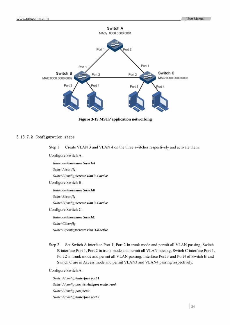
www.raisecom.com User Manual
84
Figure 3-19 MSTP application networking
3.13.7.2 Configuration steps
Step 1 Create VLAN 3 and VLAN 4 on the three switches respectively and activate them.
Configure Switch A.
Raisecom#hostname SwitchA
SwitchA#config
SwitchA(config)#create vlan 3-4 active
Configure Switch B.
Raisecom#hostname SwitchB
SwitchB#config
SwitchB(config)#create vlan 3-4 active
Configure Switch C.
Raisecom#hostname SwitchC
SwitchC#config
SwitchC(config)#create vlan 3-4 active
Step 2 Set Switch A interface Port 1, Port 2 in trunk mode and permit all VLAN passing, Switch B interface Port 1, Port 2 in trunk mode and permit all VLAN passing, Switch C interface Port 1, Port 2 in trunk mode and permit all VLAN passing. Interface Port 3 and Port4 of Switch B and Switch C are in Access mode and permit VLAN3 and VLAN4 passing respectively.
Configure Switch A.
SwitchA(config)#interface port 1
SwitchA(config-port)#switchport mode trunk
SwitchA(config-port)#exit
SwitchA(config)#interface port 2

www.raisecom.com User Manual
85
SwitchA(config-port)#switchport mode trunk
SwitchA(config-port)#exit
Configure Switch B.
SwitchB(config)#interface port 1
SwitchB(config-port)#switchport mode trunk
SwitchB(config-port)#exit
SwitchB(config)#interface port 2
SwitchB(config-port)#switchport mode trunk
SwitchB(config-port)#exit
SwitchB(config)#interface port 3
SwitchB(config-port)#switchport access vlan 3
SwitchB(config-port)#exit
SwitchB(config)#interface port 4
SwitchB(config-port)#switchport access vlan 4
SwitchB(config-port)#exit
Configure Switch C.
SwitchC(config)#interface port 1
SwitchC(config-port)#switchport mode trunk
SwitchC(config-port)#exit
SwitchC(config)#interface port 2
SwitchC(config-port)#switchport mode trunk
SwitchC(config-port)#exit
SwitchC(config)#interface port 3
SwitchC(config-port)#switchport access vlan 3
SwitchC(config-port)#exit
SwitchC(config)#interface port 4
SwitchC(config-port)#switchport access vlan 4
SwitchC(config-port)#exit
Step 3 Set MSTP mode for Switch A, Switch B, Switch C, enable spanning tree protocol. Enter MSTP configuration m ode a nd s et dom ain na me as aaa, revision version is 0, instance 3 mapping to VLAN 3, instance 4 mapping to VLAN 4, exit mst configuration mode.
Configure Switch A.
SwitchA(config)#spanning-tree mode mstp
SwitchA(config)#spanning-tree enable
SwitchA(config)#spanning-tree region-configuration
SwitchA(config-region)#name aaa
SwitchA(config-region)#revision-level 0
SwitchA(config-region)#instance 3 vlan 3
SwitchA(config-region)#instance 4 vlan 4
Configure Switch B.
SwitchB(config)#spanning-tree mode mstp
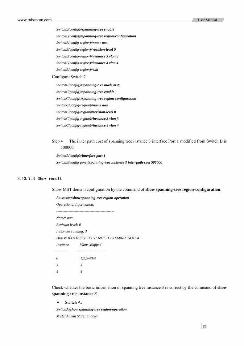
www.raisecom.com User Manual
86
SwitchB(config)#spanning-tree enable
SwitchB(config)#spanning-tree region-configuration
SwitchB(config-region)#name aaa
SwitchB(config-region)#revision-level 0
SwitchB(config-region)#instance 3 vlan 3
SwitchB(config-region)#instance 4 vlan 4
SwitchB(config-region)#exit
Configure Switch C.
SwitchC(config)#spanning-tree mode mstp
SwitchC(config)#spanning-tree enable
SwitchC(config)#spanning-tree region-configuration
SwitchC(config-region)#name aaa
SwitchC(config-region)#revision-level 0
SwitchC(config-region)#instance 3 vlan 3
SwitchC(config-region)#instance 4 vlan 4
Step 4 The inner path cost of spanning tree instance 3 interface Port 1 modified from Switch B is 500000.
SwitchB(config)#interface port 1
SwitchB(config-port)#spanning-tree instance 3 inter-path-cost 500000
3.13.7.3 Show result
Show MST domain configuration by the command of show spanning-tree region-configuration.
Raisecom#show spanning-tree region-operation
Operational Information:
-----------------------------------------------
Name: aaa
Revision level: 0
Instances running: 3
Digest: 0X7D28E66FDC1C693C1CC1F6B61C1431C4
Instance Vlans Mapped
-------- ----------------------
0 1,2,5-4094
3 3
4 4
Check whether the basic information of spanning tree instance 3 is correct by the command of show spanning-tree instance 3.
Switch A: SwitchA#show spanning-tree region-operation
MSTP Admin State: Enable
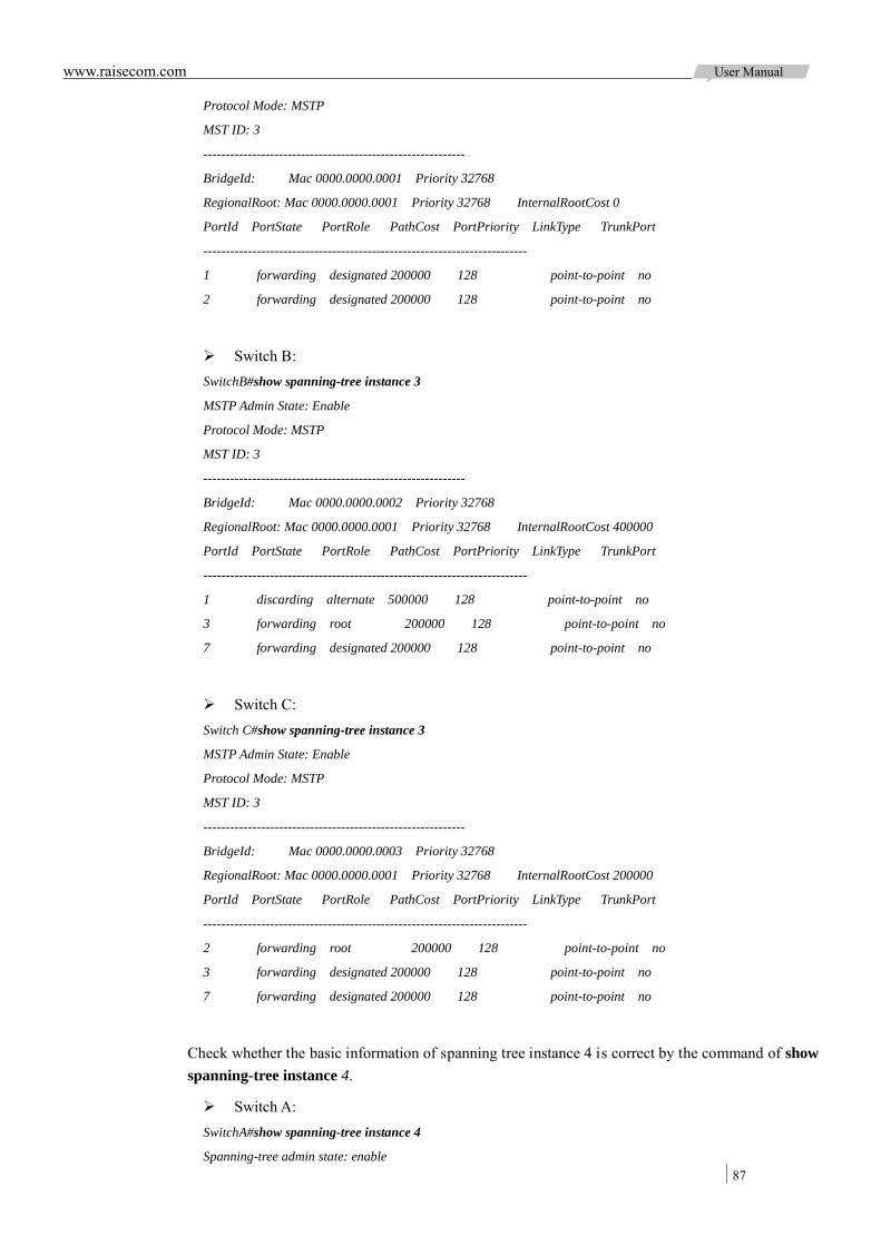
www.raisecom.com User Manual
87
Protocol Mode: MSTP
MST ID: 3
-----------------------------------------------------------
BridgeId: Mac 0000.0000.0001 Priority 32768
RegionalRoot: Mac 0000.0000.0001 Priority 32768 InternalRootCost 0
PortId PortState PortRole PathCost PortPriority LinkType TrunkPort
-------------------------------------------------------------------------
1 forwarding designated 200000 128 point-to-point no
2 forwarding designated 200000 128 point-to-point no
Switch B: SwitchB#show spanning-tree instance 3
MSTP Admin State: Enable
Protocol Mode: MSTP
MST ID: 3
-----------------------------------------------------------
BridgeId: Mac 0000.0000.0002 Priority 32768
RegionalRoot: Mac 0000.0000.0001 Priority 32768 InternalRootCost 400000
PortId PortState PortRole PathCost PortPriority LinkType TrunkPort
-------------------------------------------------------------------------
1 discarding alternate 500000 128 point-to-point no
3 forwarding root 200000 128 point-to-point no
7 forwarding designated 200000 128 point-to-point no
Switch C: Switch C#show spanning-tree instance 3
MSTP Admin State: Enable
Protocol Mode: MSTP
MST ID: 3
-----------------------------------------------------------
BridgeId: Mac 0000.0000.0003 Priority 32768
RegionalRoot: Mac 0000.0000.0001 Priority 32768 InternalRootCost 200000
PortId PortState PortRole PathCost PortPriority LinkType TrunkPort
-------------------------------------------------------------------------
2 forwarding root 200000 128 point-to-point no
3 forwarding designated 200000 128 point-to-point no
7 forwarding designated 200000 128 point-to-point no
Check whether the basic information of spanning tree instance 4 is correct by the command of show spanning-tree instance 4.
Switch A: SwitchA#show spanning-tree instance 4
Spanning-tree admin state: enable

www.raisecom.com User Manual
88
Spanning-tree protocol mode: MSTP
MST ID: 4
-----------------------------------------------------------
BridgeId: Mac 000E.5E00.0000 Priority 32768
RegionalRoot: Mac 000E.5E00.0000 Priority 32768 InternalRootCost 0
Port PortState PortRole PathCost PortPriority LinkType TrunkPort
--------------------------------------------------------------------------------
P1 discarding disabled 200000 128 point-to-point yes
P2 disabled disabled 200000 128 point-to-point yes
Switch B: SwitchB#show spanning-tree instance 4
MSTP Admin State: Enable
Protocol Mode: MSTP
MST ID: 4
-----------------------------------------------------------
BridgeId: Mac 0000.0000.0002 Priority 32768
RegionalRoot: Mac 0000.0000.0001 Priority 32768 InternalRootCost 200000
PortId PortState PortRole PathCost PortPriority LinkType TrunkPort
-------------------------------------------------------------------------
1 forwarding root 200000 128 point-to-point no
3 forwarding designated 200000 128 point-to-point no
8 discarding disabled 200000 128 point-to-point no
Switch C: SwitchC#show spanning-tree instance 4
MSTP Admin State: Enable
Protocol Mode: MSTP
MST ID: 4
-----------------------------------------------------------
BridgeId: Mac 0000.0000.0003 Priority 32768
RegionalRoot: Mac 0000.0000.0001 Priority 32768 InternalRootCost 200000
PortId PortState PortRole PathCost PortPriority LinkType TrunkPort
-------------------------------------------------------------------------
2 forwarding root 200000 128 point-to-point no
3 discarding alternate 200000 128 point-to-point no
8 discarding disabled 200000 128 point-to-point no
3.13.8 Configure loopback detection 3.13.8.1 Networking requirement
As the Figure 3-20 shows be low, Switch A Port 1 c onnects to core ne twork, Port 2 and Port 3 of Switch A connect to user network. There is loop in user network. Enable loopback detection function
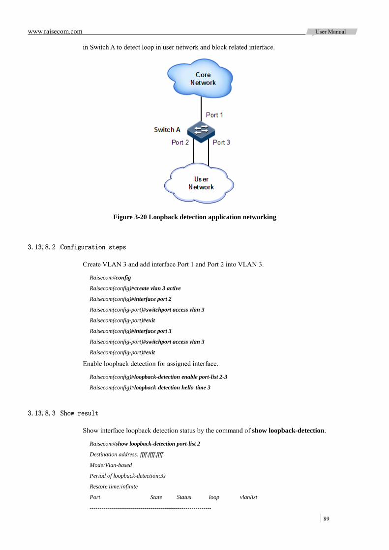
www.raisecom.com User Manual
89
in Switch A to detect loop in user network and block related interface.
Figure 3-20 Loopback detection application networking
3.13.8.2 Configuration steps
Create VLAN 3 and add interface Port 1 and Port 2 into VLAN 3.
Raisecom#config
Raisecom(config)#create vlan 3 active
Raisecom(config)#interface port 2
Raisecom(config-port)#switchport access vlan 3
Raisecom(config-port)#exit
Raisecom(config)#interface port 3
Raisecom(config-port)#switchport access vlan 3
Raisecom(config-port)#exit
Enable loopback detection for assigned interface.
Raisecom(config)#loopback-detection enable port-list 2-3
Raisecom(config)#loopback-detection hello-time 3
3.13.8.3 Show result
Show interface loopback detection status by the command of show loopback-detection.
Raisecom#show loopback-detection port-list 2
Destination address: ffff.ffff.ffff
Mode:Vlan-based
Period of loopback-detection:3s
Restore time:infinite
Port State Status loop vlanlist
--------------------------------------------------------------
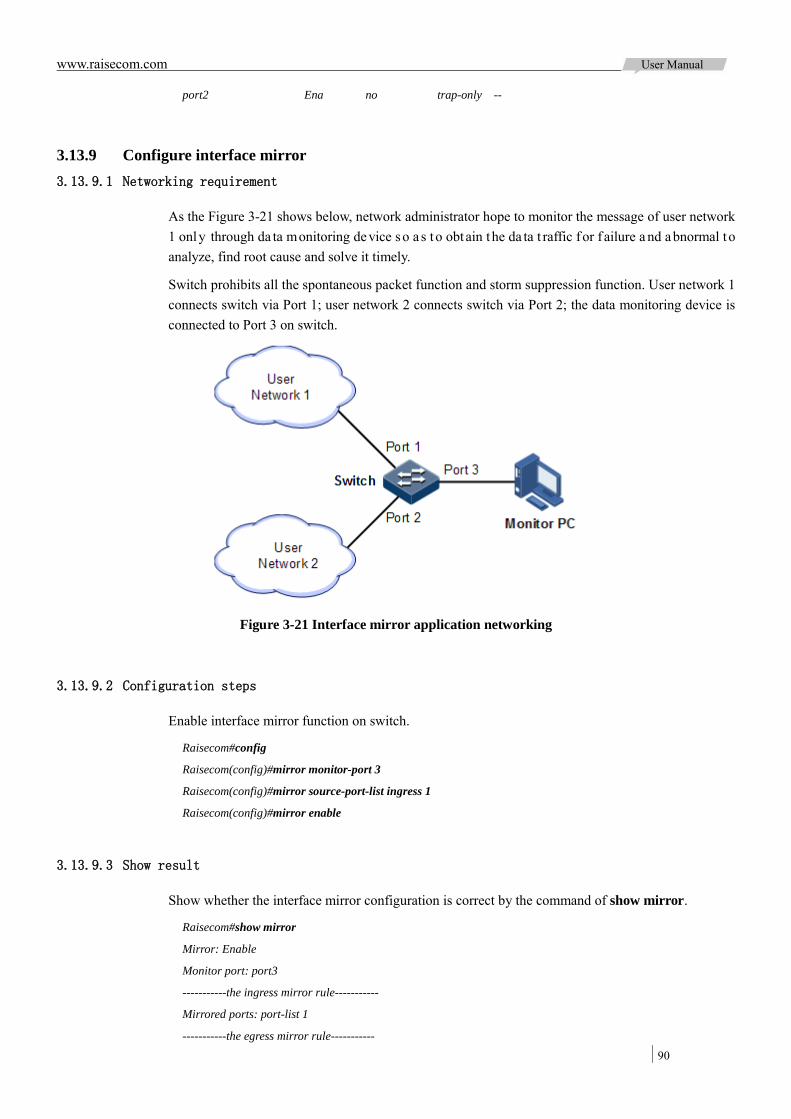
www.raisecom.com User Manual
90
port2 Ena no trap-only --
3.13.9 Configure interface mirror 3.13.9.1 Networking requirement
As the Figure 3-21 shows below, network administrator hope to monitor the message of user network 1 only through da ta monitoring device so a s t o obtain the da ta t raffic for f ailure a nd abnormal to analyze, find root cause and solve it timely.
Switch prohibits all the spontaneous packet function and storm suppression function. User network 1 connects switch via Port 1; user network 2 connects switch via Port 2; the data monitoring device is connected to Port 3 on switch.
Figure 3-21 Interface mirror application networking
3.13.9.2 Configuration steps
Enable interface mirror function on switch.
Raisecom#config
Raisecom(config)#mirror monitor-port 3
Raisecom(config)#mirror source-port-list ingress 1
Raisecom(config)#mirror enable
3.13.9.3 Show result
Show whether the interface mirror configuration is correct by the command of show mirror.
Raisecom#show mirror
Mirror: Enable
Monitor port: port3
-----------the ingress mirror rule-----------
Mirrored ports: port-list 1
-----------the egress mirror rule-----------

www.raisecom.com User Manual
91
Mirrored ports: --
3.13.10 Configure layer-2 protocol transparent transmission 3.13.10.1 Networking requirement
As the Figure 3-22 shows below, Switch A a nd Switch B connect to two user networks VLAN 100 and VLAN 2 00 respectively. User needs to configure layer-2 pr otocol t ransparent t ransmission function on Switch A and Switch B in order to make the same user network in different regions run STP entirely.
Figure 3-22 Layer-2 protocol transparent transmission application networking
3.13.10.2 Configuration steps
Step 1 Create VLAN 100, 200 and activate them.
Configure Switch A.
Raisecom#hostname SwitchASwitchA#config
SwitchA(config)#create vlan 100,200 active
Configure Switch B.
Raisecom#hostname SwitchB
SwitchB#config
SwitchB(config)#create vlan 100,200 active
Step 2 Configure interface port 2 in Access mode, Access VLAN is 100, enable STP transparent transmission, and set STP message transparent transmission threshold as 1500.
Configure Switch A.
SwitchA(config)#interface port 2
SwitchA(config-port)#switchport mode access
SwitchA(config-port)#switchport access vlan 100
SwitchA(config-port)#relay stp
SwitchA(config-port)#relay port 1
SwitchA(config-port)#relay drop-threshold stp 1500
SwitchA(config-port)#exit
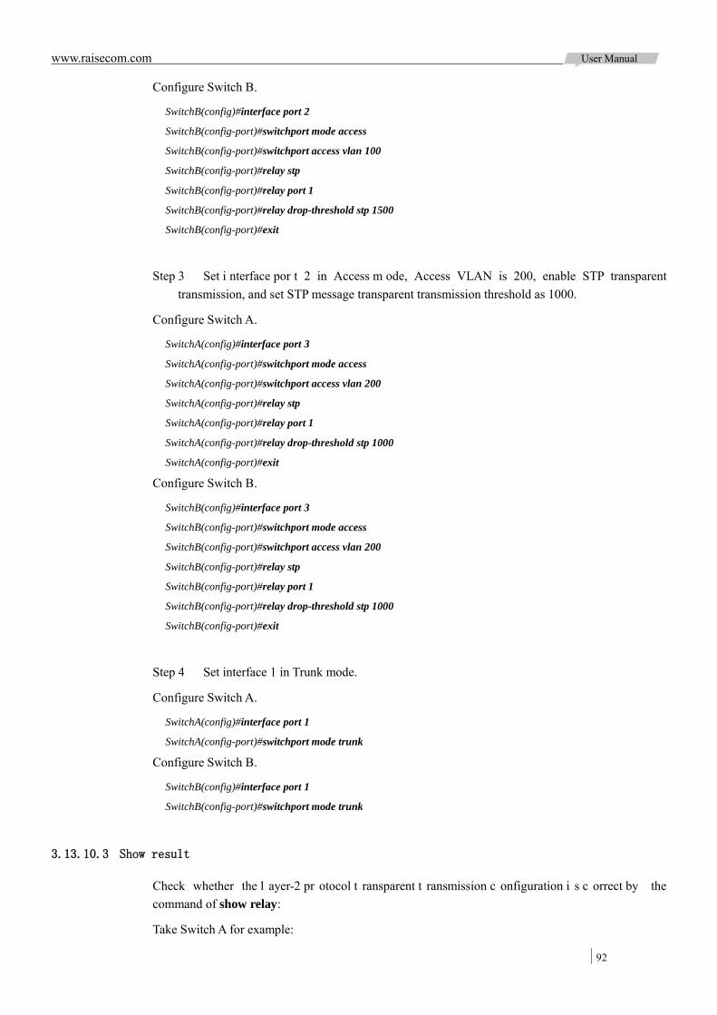
www.raisecom.com User Manual
92
Configure Switch B.
SwitchB(config)#interface port 2
SwitchB(config-port)#switchport mode access
SwitchB(config-port)#switchport access vlan 100
SwitchB(config-port)#relay stp
SwitchB(config-port)#relay port 1
SwitchB(config-port)#relay drop-threshold stp 1500
SwitchB(config-port)#exit
Step 3 Set i nterface por t 2 in Access m ode, Access VLAN is 200, enable STP transparent transmission, and set STP message transparent transmission threshold as 1000.
Configure Switch A.
SwitchA(config)#interface port 3
SwitchA(config-port)#switchport mode access
SwitchA(config-port)#switchport access vlan 200
SwitchA(config-port)#relay stp
SwitchA(config-port)#relay port 1
SwitchA(config-port)#relay drop-threshold stp 1000
SwitchA(config-port)#exit
Configure Switch B.
SwitchB(config)#interface port 3
SwitchB(config-port)#switchport mode access
SwitchB(config-port)#switchport access vlan 200
SwitchB(config-port)#relay stp
SwitchB(config-port)#relay port 1
SwitchB(config-port)#relay drop-threshold stp 1000
SwitchB(config-port)#exit
Step 4 Set interface 1 in Trunk mode.
Configure Switch A.
SwitchA(config)#interface port 1
SwitchA(config-port)#switchport mode trunk
Configure Switch B.
SwitchB(config)#interface port 1
SwitchB(config-port)#switchport mode trunk
3.13.10.3 Show result
Check whether the l ayer-2 pr otocol t ransparent t ransmission c onfiguration i s c orrect by the command of show relay:
Take Switch A for example:

www.raisecom.com User Manual
93
SwitchA#show relay port-list 1-3
COS for Encapsulated Packets: 5
Destination MAC Address for Encapsulated Packets: 010E.5E00.0003
Port vlan Egress-Port Protocol Drop-Threshold Shutdown-Threshold
-------------------------------------------------------------------------
port1(up) -- -- stp -- --
dot1x -- --
lacp -- --
gvrp -- --
cdp -- --
vtp -- --
pvst -- --
port2(up) -- port1 stp(enable) 1500 --
dot1x -- --
lacp -- --
gvrp -- --
cdp -- --
vtp -- --
pvst -- --
port3(up) -- port1 stp(enable) 1000 --
dot1x -- --
lacp -- --
gvrp -- --
cdp -- --
vtp -- --
pvst -- --

www.raisecom.com User Manual
94
Chapter 4 Routing
This chapter introduces basic principle and configuration of routing features, and provides the related configuration examples.
Overview Configuring ARP Configuring layer-3 interface Configuring static routing Maintenance Configuration examples
4.1 Overview
4.1.1 ARP In TCP/IP network environment, e ach host was assigned with a 32 -bit IP address that is a logical address us ed t o i dentify ho st be tween ne tworks. To t ransmit message i n ph ysical l ink, us er m ust know the physical address of destination host, which requires mapping IP address to physical address. In Ethernet environment, physical address is 48-bit MAC address. Users have to transfer the 32-bit destination hos t IP address to 48 -bit E thernet address for t ransmitting message to destination hos t correctly. Then ARP (Address Resolution Protocol) is applied to analyze IP address to MAC address and set mapping relationship between IP address and MAC address.
ARP address mapping table includes the following two types:
Static table entry: bi nd I P a ddress and MAC address to avoid A RP dy namic learning cheating. Static ARP address table entry needs to be added / deleted manually. No aging to static ARP address.
Dynamic table entry: MAC address automatically learned through ARP. This dynamic table entry is automatically generated by switch. User can adjust partial
parameters of it manually. The dynamic ARP address table entry will age at the aging time if no use.
The device i s in support of two kinds of dynamic learning modes for ARP address mapping table entry: learn-all and learn-reply-only.
ARP request packets and answer packets both learning when in learn-all mode. When device A s ends ARP r equest f or g rouping, it writes the mapping relationship of IP address and physical address into ARP request packets. After receiving ARP request packets from device A, Device B will learn the address mapping relationship to its own address mapping table. Then the device B can send packets to device A later without ARP request.
Only learn A RP answering packets when device is in learn-reply-only mode. Just answer ARP pa ckets f or t he A RP request f rom ot her de vices without ARP a ddress mapping t able learning. This m ode i ncreases network l oad but a voids some ne twork a ttack ove r ARP request packet.

www.raisecom.com User Manual
95
4.1.2 Layer-3 interface Layer-3 interface refers t o IP i nterface, is the v irtual int erface c onfiguration based on V LAN. Configuring L ayer-3 interface is generally us ed in the need for device network management or routing link c onnection of multiple de vices. Associate a l ayer-3 interface to VLAN r equired configuring IP address; each layer-3 interface will correspond to an IP address and associate with one VLAN at least.
4.1.3 Routing Routing function is required for communication among different devices in one VLAN, or different VLAN. Routing is to transmit packets through network to destination, which adopts routing table for packets forwarding.
There are three modes to execute routing function:
Default routing: f orwarding t he packets w ithout destination address to a n assigned de fault router.
Static routing: configure routing manually to f orward packets f rom t he a ssigned i nterface. This is suitable to simple network topology.
Dynamic routing: learning routing dynamically through routing protocol which can calculate the best route for packets forwarding. This mode will take up more bandwidth and network resource. Now, there are two dynamic routing protocols available: Distance vector protocol: each device maintains a vector t able, which lists the known
best di stance and pa th to other de stination devices. By e xchanging i nformation w ith neighbor devices, the device can update internal vector table continuously.
Link s tatus pr otocol: the devices bui ld l ink s tatus da tabase t hrough ne twork i nterface status notification; the database contains all links status straight-connected to all devices. All devices share the same network topology, but each device can judge the best path to each node in network topology. Link status protocol can response on topology changes quickly, but ne ed more b andwidth a nd r esources c ompared w ith di stance vector protocol.
The ISCOM2924GF device is only in support of default routing and static routing, dynamic routing function is unavailable at present.
4.1.3.1 Default routing
Default Routing is a special routing that only be used when there is no matched item searched from routing table. Default routing appears as a route to network 0.0.0.0 (with mask 0.0.0.0) in routing table. User can show default routing configuration by the command of show ip route. If destination address of packet c annot match with any i tem in the r outing t able, t he packet w ill choose default routing. If t he de vice ha sn’t configured de fault r outing a nd the destination I P of pa cket i s not i n routing table, the device will di scard the packet and return an IC MP packet to transmitting end to inform that the destination address or network is unavailable.
4.1.3.2 Static routing
Static routing is routing configured manually. It is available to simple, small and stable network. The disadvantage is it cannot a dapt t o n etwork t opology c hanges a utomatically and ne eds m anual intervention.
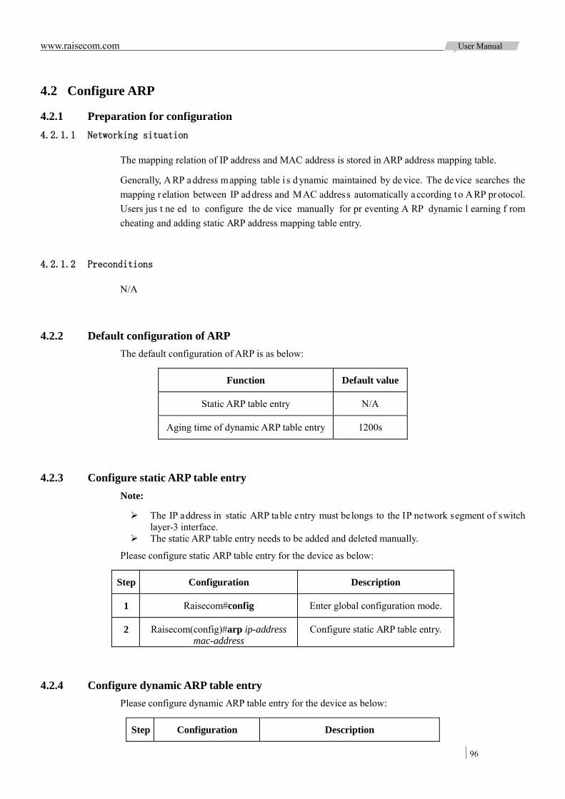
www.raisecom.com User Manual
96
4.2 Configure ARP
4.2.1 Preparation for configuration 4.2.1.1 Networking situation
The mapping relation of IP address and MAC address is stored in ARP address mapping table.
Generally, A RP address mapping table i s d ynamic maintained by de vice. The de vice searches the mapping r elation between IP address and MAC address automatically according to ARP protocol. Users jus t ne ed to configure the de vice manually for pr eventing A RP dynamic l earning f rom cheating and adding static ARP address mapping table entry.
4.2.1.2 Preconditions
N/A
4.2.2 Default configuration of ARP The default configuration of ARP is as below:
Function Default value
Static ARP table entry N/A
Aging time of dynamic ARP table entry 1200s
4.2.3 Configure static ARP table entry Note:
The IP address in static ARP table entry must belongs to the IP network segment of switch layer-3 interface.
The static ARP table entry needs to be added and deleted manually.
Please configure static ARP table entry for the device as below:
Step Configuration Description
1 Raisecom#config Enter global configuration mode.
2 Raisecom(config)#arp ip-address mac-address
Configure static ARP table entry.
4.2.4 Configure dynamic ARP table entry Please configure dynamic ARP table entry for the device as below:
Step Configuration Description
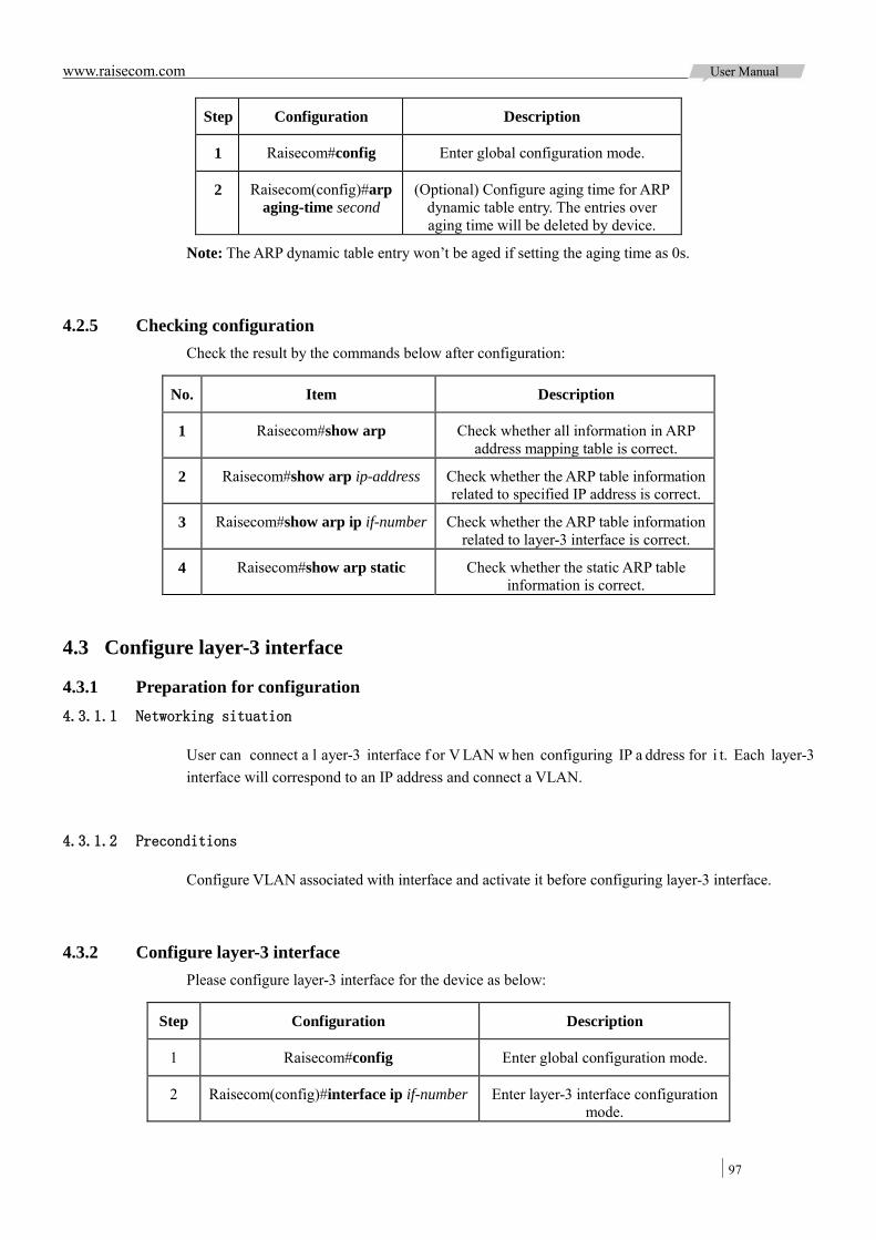
www.raisecom.com User Manual
97
Step Configuration Description
1 Raisecom#config Enter global configuration mode.
2 Raisecom(config)#arp aging-time second
(Optional) Configure aging time for ARP dynamic table entry. The entries over aging time will be deleted by device.
Note: The ARP dynamic table entry won’t be aged if setting the aging time as 0s.
4.2.5 Checking configuration Check the result by the commands below after configuration:
No. Item Description
1 Raisecom#show arp Check whether all information in ARP address mapping table is correct.
2 Raisecom#show arp ip-address Check whether the ARP table information related to specified IP address is correct.
3 Raisecom#show arp ip if-number Check whether the ARP table information related to layer-3 interface is correct.
4 Raisecom#show arp static Check whether the static ARP table information is correct.
4.3 Configure layer-3 interface
4.3.1 Preparation for configuration 4.3.1.1 Networking situation
User can connect a l ayer-3 interface f or V LAN w hen configuring IP a ddress for i t. Each layer-3 interface will correspond to an IP address and connect a VLAN.
4.3.1.2 Preconditions
Configure VLAN associated with interface and activate it before configuring layer-3 interface.
4.3.2 Configure layer-3 interface Please configure layer-3 interface for the device as below:
Step Configuration Description
1 Raisecom#config Enter global configuration mode.
2 Raisecom(config)#interface ip if-number Enter layer-3 interface configuration mode.

www.raisecom.com User Manual
98
Step Configuration Description
3 Raisecom(config-ip)#ip address ip-address [ ip-mask ] [ sub ] [ vlan-list ]
Configure IP address for layer-3 interface and interconnect to VLAN.
Note:
Configure VLAN associated with layer-3 interface and activate it. User can use the command state {active | suspend} to activate the suspending VLAN before configuring it.
Configure VLAN a ssociated with layer-3 interface, and user can specify m ore t han on e VLAN. I f configuring f or m any t imes, t he ne w configuration w ill cover the or iginal configuration, not to accumulate.
ISCOM2924GF device can be configured 15 Layer-3 interfaces with range from 0 to 14.
4.3.3 Checking configuration Check the result by the commands below after configuration:
No. Item Description
1 Raisecom#show interface ip Check IP address configuration for layer-3 interface.
2 Raisecom#show interface ip vlan Check the binding relation of layer-3 interface and VLAN.
4.4 Configure statistic routing
4.4.1 Preparation for configuration 4.4.1.1 Networking situation
Configure static r outing f or s imple ne twork t opology manually to build a n i ntercommunication network.
4.4.1.2 Preconditions
Configure IP address for layer-3 interface correctly.
4.4.2 Configure default gateway Please configure default gateway on the device as below.
Step Configuration Description
1 Raisecom#config Enter global configuration mode.

www.raisecom.com User Manual
99
Step Configuration Description
2 Raisecom(config)#ip default-gateway
ip-address
Configure IP address for default gateway.
Note: W hen message required to forward doesn’t ha ve related r outing i n t he d evice, t he c ommand of ip default-gateway can configure default ga teway, and forward this message to default gateway. The IP address of default ga teway must i n the s ame ne twork segment w ith the IP address of any local IP interface..
4.4.3 Configure static routing Please configure static routing for the device as below:
Step Configuration Description
1 Raisecom#config Enter global configuration mode.
2 Raisecom(config)#ip route ip-address ip-mask next-hop
Configure next hop address related to ip-address network as nexthop.
4.4.4 Checking configuration Check the result by the commands below after configuration:
No. Item Description
1 Raisecom#show ip route Check whether device routing table information is correct.
4.5 Maintenance
Use the following command to maintain IP feature:
Command Description
Raisecom(config)#clear arp Clear all table entries in ARP address mapping table.
4.6 Configuration examples
4.6.1 Configure ARP 4.6.1.1 Networking requirement
As the Figure 4-1 shows below, ISCOM2924GF connects to host, connects to upstream Router by interface Port 1. IP address of Router is 192.168.1.10/24, MAC address is 0050-8d4b-fd1e.
User ne eds t o configure dynamic A RP ta ble entry aging t ime a s 600 s econds. To i mprove communication security between ISCOM2924GF and Router, user needs to configure related static ARP table entry on ISCOM2924GF device.
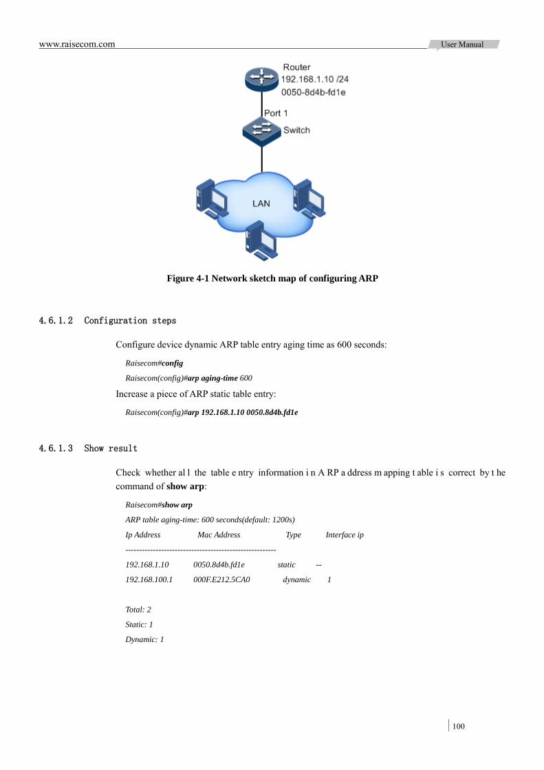
www.raisecom.com User Manual
100
Figure 4-1 Network sketch map of configuring ARP
4.6.1.2 Configuration steps
Configure device dynamic ARP table entry aging time as 600 seconds:
Raisecom#config
Raisecom(config)#arp aging-time 600
Increase a piece of ARP static table entry:
Raisecom(config)#arp 192.168.1.10 0050.8d4b.fd1e
4.6.1.3 Show result
Check whether al l the table e ntry information i n A RP a ddress m apping t able i s correct by t he command of show arp:
Raisecom#show arp
ARP table aging-time: 600 seconds(default: 1200s)
Ip Address Mac Address Type Interface ip
-------------------------------------------------------
192.168.1.10 0050.8d4b.fd1e static --
192.168.100.1 000F.E212.5CA0 dynamic 1
Total: 2
Static: 1
Dynamic: 1
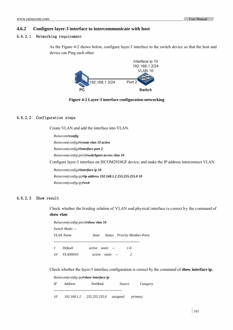
www.raisecom.com User Manual
101
4.6.2 Configure layer-3 interface to intercommunicate with host 4.6.2.1 Networking requirement
As the Figure 4-2 shows below, configure layer-3 interface to the switch device so that the host and device can Ping each other.
Figure 4-2 Layer-3 interface configuration networking
4.6.2.2 Configuration steps
Create VLAN and add the interface into VLAN.
Raisecom#config
Raisecom(config)#create vlan 10 active
Raisecom(config)#interface port 2
Raisecom(config-port)#switchport access vlan 10
Configure layer-3 interface on ISCOM2924GF device, and make the IP address interconnect VLAN.
Raisecom(config)#interface ip 10
Raisecom(config-ip)#ip address 192.168.1.2 255.255.255.0 10
Raisecom(config-ip)#exit
4.6.2.3 Show result
Check whether the binding relation of VLAN and physical interface is correct by the command of show vlan:
Raisecom(config-port)#show vlan 10
Switch Mode: --
VLAN Name State Status Priority Member-Ports
-------------------------------------------------------------------------
1 Default active static -- 1-6
10 VLAN0010 active static -- 2
Check whether the layer-3 interface configuration is correct by the command of show interface ip.
Raisecom(config-ip)#show interface ip
IF Address NetMask Source Catagory
----------------------------------------------------------
10 192.168.1.2 255.255.255.0 assigned primary
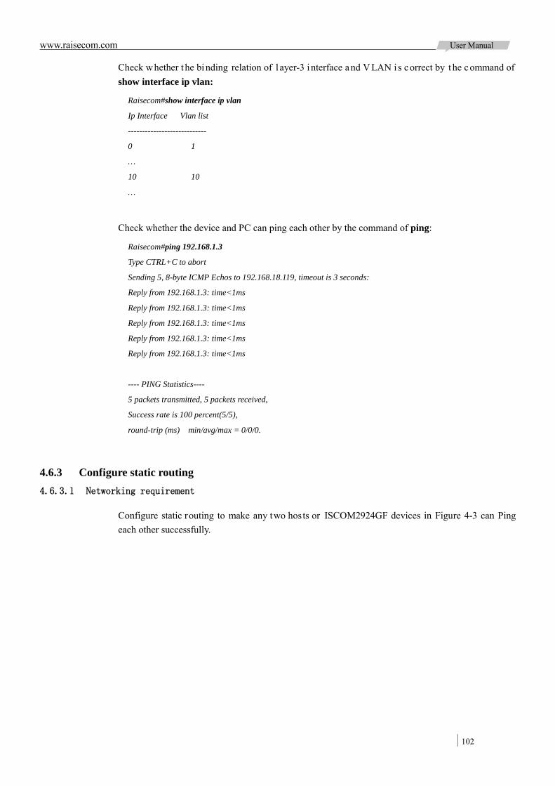
www.raisecom.com User Manual
102
Check whether t he binding relation of l ayer-3 interface and V LAN i s correct by t he command of show interface ip vlan:
Raisecom#show interface ip vlan
Ip Interface Vlan list
----------------------------
0 1
…
10 10
…
Check whether the device and PC can ping each other by the command of ping:
Raisecom#ping 192.168.1.3
Type CTRL+C to abort
Sending 5, 8-byte ICMP Echos to 192.168.18.119, timeout is 3 seconds:
Reply from 192.168.1.3: time<1ms
Reply from 192.168.1.3: time<1ms
Reply from 192.168.1.3: time<1ms
Reply from 192.168.1.3: time<1ms
Reply from 192.168.1.3: time<1ms
---- PING Statistics----
5 packets transmitted, 5 packets received,
Success rate is 100 percent(5/5),
round-trip (ms) min/avg/max = 0/0/0.
4.6.3 Configure static routing 4.6.3.1 Networking requirement
Configure static routing to make any two hosts or ISCOM2924GF devices in Figure 4-3 can Ping each other successfully.
www.raisecom.com User Manual
103
Figure 4-3 Static routing configuration networking
4.6.3.2 Configuration steps
Configure IP address for each device.
Enable routing function and configure static routing on Switch A.
Raisecom#hostname SwitchA
SwitchA#config
SwitchA(config)#ip routing
SwitchA(config)#ip route 10.1.1.0 255.255.255.0 10.1.2.4
SwitchA(config)#ip route 10.1.4.0 255.255.255.0 10.1.3.4
Enable routing function and configure default gateway on Switch B.
Raisecom#hostname SwitchB
SwitchB(config)#ip routing
SwitchB(config)#ip default-gateway 10.1.2.3
Enable routing function and configure default gateway on Switch C:
Raisecom#hostname SwitchC
SwitchC(config)#ip routing
SwitchC(config)#ip default-gateway 10.1.3.3
Configure default gateway for 10.1.5.3 on PC A, 10.1.1.3 on PC B, 10.1.4.3 on PC C respectively.

www.raisecom.com User Manual
104
4.6.3.3 Show result
Check whether all the devices can ping successfully with one another by the command of ping:
SwitchA#ping 10.1.1.3
Type CTRL+C to abort
Sending 5, 8-byte ICMP Echos to 192.168.18.119, timeout is 3 seconds:
Reply from 192.168.18.119: time<1ms
Reply from 192.168.18.119: time<1ms
Reply from 192.168.18.119: time<1ms
Reply from 192.168.18.119: time<1ms
Reply from 192.168.18.119: time<1ms
---- PING Statistics----
5 packets transmitted, 5 packets received,
Success rate is 100 percent(5/5),
round-trip (ms) min/avg/max = 0/0/0.

www.raisecom.com User Manual
105
Chapter 5 DHCP
This c hapter i ntroduces b asic pr inciple a nd c onfiguration of D HCP and pr ovides r elated configuration applications.
Overview Configure DHCP Client Configure DHCP Snooping Configure DHCP Option Configuring Applications
5.1 Overview
5.1.1 DHCP overview DHCP (Dynamic Host Configuration Protocol) refers to assign IP address configuration information dynamically for user in TCP/IP network. It is based on BOOTP (Bootstrap Protocol) protocol, and adds automatically specified available network address, network address re-use, and other extended configuration options over BOOTP protocol.
With enlargement of ne twork s cale a nd de velopment of ne twork c omplexity, qua ntity of PC i n network usually exceeds available distributing IP address amount. Meanwhile, the widely use of notebook and wireless network lead PC position changes frequently and also the related IP address must update frequently. As a result of that, network configuration becomes more and more complex. DHCP is developed to solve these problems.
DHCP adopts client/server communication mode. Client applies configuration to server (including IP address, Subnet mask, default gateway etc.) and server replies IP address for client and other related configuration information to realize dynamic configuration of IP address, etc.
It us ually includes a s et of DHCP s erver and s everal c lients in typical a pplication of DHCP (for example PC or Notebook), as the Figure 5-1 shows below.
Figure 5-1 DHCP typical application networking
Under n ormal ci rcumstances, use DHCP se rver to f inish IP a ddress distribution in following
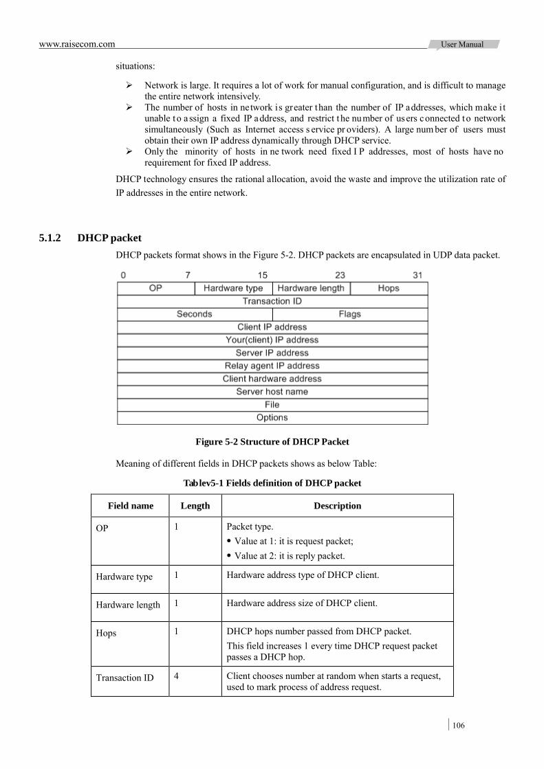
www.raisecom.com User Manual
106
situations:
Network is large. It requires a lot of work for manual configuration, and is difficult to manage the entire network intensively.
The number of hosts in network is greater than the number of IP addresses, which make i t unable to a ssign a fixed IP address, and restrict t he number of users connected to network simultaneously (Such as Internet access s ervice pr oviders). A large num ber of users must obtain their own IP address dynamically through DHCP service.
Only the minority of hosts in ne twork need fixed I P addresses, most of hosts have no requirement for fixed IP address.
DHCP technology ensures the rational allocation, avoid the waste and improve the utilization rate of IP addresses in the entire network.
5.1.2 DHCP packet DHCP packets format shows in the Figure 5-2. DHCP packets are encapsulated in UDP data packet.
Figure 5-2 Structure of DHCP Packet
Meaning of different fields in DHCP packets shows as below Table:
Tablev5-1 Fields definition of DHCP packet
Field name Length Description
OP 1 Packet type. Value at 1: it is request packet; Value at 2: it is reply packet.
Hardware type 1 Hardware address type of DHCP client.
Hardware length 1 Hardware address size of DHCP client.
Hops 1 DHCP hops number passed from DHCP packet. This field increases 1 every time DHCP request packet passes a DHCP hop.
Transaction ID 4 Client chooses number at random when starts a request, used to mark process of address request.
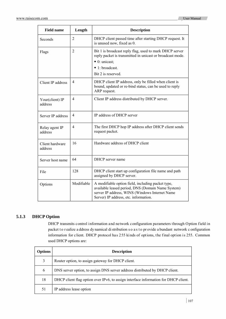
www.raisecom.com User Manual
107
Field name Length Description
Seconds 2 DHCP client passed time after starting DHCP request. It is unused now, fixed as 0.
Flags 2 Bit 1 is broadcast reply flag, used to mark DHCP server reply packet is transmitted in unicast or broadcast mode. 0: unicast; 1: broadcast. Bit 2 is reserved.
Client IP address 4 DHCP client IP address, only be filled when client is bound, updated or re-bind status, can be used to reply ARP request.
Your(client) IP address
4 Client IP address distributed by DHCP server.
Server IP address 4 IP address of DHCP server
Relay agent IP address
4 The first DHCP hop IP address after DHCP client sends request packet.
Client hardware address
16 Hardware address of DHCP client
Server host name 64 DHCP server name
File 128 DHCP client start up configuration file name and path assigned by DHCP server.
Options Modifiable A modifiable option field, including packet type, available leased period, DNS (Domain Name System) server IP address, WINS (Windows Internet Name Server) IP address, etc. information.
5.1.3 DHCP Option DHCP transmits control information and network configuration parameters through Option field in packet t o r ealize a ddress dy namical di stribution s o a s t o pr ovide a bundant network c onfiguration information for c lient. DHCP protocol has 255 kinds of opt ions, the f inal opt ion i s 255. Common used DHCP options are:
Options Description
3 Router option, to assign gateway for DHCP client.
6 DNS server option, to assign DNS server address distributed by DHCP client.
18 DHCP client flag option over IPv6, to assign interface information for DHCP client.
51 IP address lease option

www.raisecom.com User Manual
108
Options Description
53 DHCP packet type, to mark type for DHCP packets
55 Request parameter lis t option. Client uses this optical to indicate ne twork configuration parameters need to obtain f rom server. The content of this opt ion i s values corresponding to client requested parameters.
61 DHCP client flag option over IPv6, to assign device information for DHCP client.
66 TFTP server name, t o a ssign domain name for T FTP server di stributed b y DHCP client.
67 Start up file name, to assign start up file name distributed by DHCP client.
82 DHCP client f lag option over IPv4, user-defined, mainly used to mark position of DHCP client.
150 TFTP server address, to assign TFTP server address distributed by DHCP client.
184 DHCP reserved opt ion, a t present Option184 is m ainly used t o carry i nformation required by voice calling. Through Option184 it can distribute IP address for DHCP client with voice function and meanwhile provide voice calling related information.
255 Complete option
Fields 18, 37, 61 a nd 82 i n DHCP Option are r elay age nt information options i n DHCP packets. When r equest pa ckets f rom DHCP client a rrive D HCP s erver, if ne ed DHCP relay or DHCP Snooping, DHCP relay or DHCP Snooping increase Option field into request packets.
Fields Option18, 37, 61 and 82 implement r ecord DHCP client i nformation on DHCP server. By cooperating with other software, it can realize IP address distribution restriction and accounting, etc. functions. Such as cooperate with IP Source Guard to defend deceive of IP address+MAC address.
Field Option82 can i nclude a t m ost 255 s ub-options. If de fined f ield Option82, at l east one sub-option m ust be de fined. The d evice supports two s ub-option t ypes c urrently: Sub-Option 1 (Circuit ID) and Sub-Option 2 (Remote ID).
Sub-Option 1 contains interface ID of DHCP client request packet, interface VLAN and the additional information.
Sub-Option 2 is interface MAC address (DHCP relay) or device bridge MAC address (DHCP Snooping device) for receiving DHCP client request packets.
5.1.4 DHCP client ISCOM2924GF de vice can be us ed as DHCP cl ient t o get I P addr ess f rom D HCP s erver and management in future, as the Figure 5-3 shows below.

www.raisecom.com User Manual
109
Figure 5-3 DHCP client networking
5.1.5 DHCP Snooping 5.1.5.1 DHCP Snooping overview
DHCP Snooping is a security feature of DHCP with the below functions:
Guarantee DHCP client gets IP address from legal DHCP server;
If there is false DHCP server existing in network, DHCP client may get error IP address and network configuration pa rameters, b ut c annot c ommunicate nor mally. As the Figure 5-4 shows be low, i n order to make DHCP client get IP address from legal DHCP server, DHCP Snooping security system permits to set interface as trust interface and untrust interface: trust interface forwards DHCP packets normally; untrust interface discard the reply packets from DHCP server.
Figure 5-4 DHCP Snooping networking
Record corresponding relationship between DHCP client IP address and MAC address.
DHCP S nooping records e ntries t hrough m onitor r equest a nd r eply pa ckets r eceived b y t rust interface, including client MAC address, obtained IP address, DHCP client connected interface and VLAN of the interface, etc. Then implement following by the record information:

www.raisecom.com User Manual
110
ARP Detection: judge legality of user that sends ARP packet and avoid ARP attack from illegal user.
IP Source G uard: filter i nterface f orwarded packets b y d ynamically ge tting DHCP Snooping entry to avoid illegal packets pass the interface.
VLAN mapping: packets s ent to user modify mapped V LAN to original VLAN b y searching mapped V LAN related D HCP c lient IP a ddress, M AC address a nd or iginal VLAN information in DHCP Snooping entry.
5.1.5.2 DHCP Snooping supporting Option function
Option f ield in DHCP packet r ecords pos ition information of DHCP client. Administrator c an use this option to locate DHCP client and control client security and accounting.
If the device configured DHCP Snooping to support Option function:
When device r eceives D HCP r equest p ackets, deal w ith packets acc ording to Option field included or not a nd f illing m ode a s w ell a s pr ocessing pol icy configured by us er, t hen forwards the processed packet to DHCP server;
When device receives DHCP reply packets, if the packet doesn’t contain Option field, delete the field and forward to DHCP client; if the packet doesn’t contain Option field, forwarded directly.
5.2 Configure DHCP client
5.2.1 Preparation for configuration 5.2.1.1 Networking situation
As DHCP client, ISCOM2924GF device will get IP address from assigned DHCP server to manage the device in future.
The IP a ddress a ssigned by D HCP c lient is li mited with a cer tain lease pe riod w hen a dopting dynamic address distribution mode. DHCP server will take back the IP address when it is expired. DHCP client has to relet IP address foe continuous using. DHCP client can release IP address if i t doesn’t want to use it any more before its expiration.
We suggest that the number of DHCP relays is less than 4 if DHCP client needs to obtain IP address from DHCP server from multiple DHCP relays.
5.2.1.2 Preconditions
Finish the following tasks before configuring DHCP client:
Create VLAN and add layer-3 interface to it. The DHCP Snooping function is disabled.
5.2.2 Default configuration of DHCP client The default configuration of DHCP client is as below:
Function Default value

www.raisecom.com User Manual
111
Function Default value
hostname raisecom
class-id raisecom-ROS
client-id raisecom-SYSMAC- IF0
5.2.3 Configure DHCP client Only the interface IP 0 on switch is in support of DHCP client function.
When applying for IP address, DHCP client needs to create VLAN firstly, and add the interface with the IP address to VLAN, and at the same time, configure DHCP server, or the interface will fail to obtain IP address via DHCP.
For interface IP 0, the IP addresses obtained through DHCP and configured manually can overwrite each other.
Note:
If the switch starts DHCP Server or DHCP Relay, the DHCP client will not be enabled. If the switch starts DHCP client, DHCP Server or DHCP Relay will not be enabled.
By default, the device enables DHCP client function. The command of no ip address dhcp can disable it.
If t he device obtained IP address fr om a DHCP s erver t hrough D HCP previously, it w ill restart the application process for IP address i f user modified DHCP se rver address by the command of ip address dhcp.
Please configure DHCP client on the device as below.
Step Configuration Description
1 Raisecom#config Enter global configuration mode.
2 Raisecom(config)#interface ip 0 Enter layer-3 interface configuration mode.
3 Raisecom(config-ip)#ip address dhcp [ server-ip ip-address]
Apply for IP address by DHCP.
4 Raisecom(config-ip)#ip dhcp client { class-id class-id | client-id client-id |
hostname hostname }
(Optional) Configure DHCP client information, including class ID, client ID and host name.
5 Raisecom(config-ip)#ip dhcp client renew (Optional) Relet IP address. If the layer-3 interface of device has obtained IP address by
DHCP, the IP address will automatically renew when the lease expires.
6 Raisecom(config-ip)#no ip address dhcp (Optional) Release IP address.
5.2.4 Checking configuration Check the result by the commands below after configuration:

www.raisecom.com User Manual
112
No. Item Description
1 Raisecom#show ip dhcp client Show DHCP client configuration.
5.3 Configure DHCP Snooping
5.3.1 Preparation for configuration 5.3.1.1 Networking situation
DHCP Snooping is a security feature of DHCP, being used to guarantee DHCP client gets IP address from legal DHCP server and record corresponding relationship between DHCP client IP and MAC address.
Option field of DHCP packet records location of DHCP client. Administrator can locate DHCP client through Option field and control client security and accounting. ISCOM2924GF device configured with DHCP Snooping and Option can perform related process according to Option f ield existence status in packet.
5.3.1.2 Preconditions
N/A
5.3.2 Default configuration of DHCP Snooping The default configuration of DHCP Snooping is as below:
Function Default value
Global DHCP Snooping status Disable
Interface DHCP Snooping status Enable
Interface trust/untrust atatus Untrust
DHCP Snooping is in support of Option 82 Disable
5.3.3 Configure DHCP Snooping Generally, make sure that the device interface connected t o D HCP server is in trust state, while interface connected to user is in distrust state.
If enabling DHCP Snooping without configuring DHCP Snooping supporting Option function, the device will do nothing to Option fields in the packets. For packets without Option fields, the device still doesn’t do insertion operation.
By default, the DHCP Snooping function of all interfaces is enabled, but only to enable the global DHCP Snooping function, the interface DHCP Snooping function can take effect.
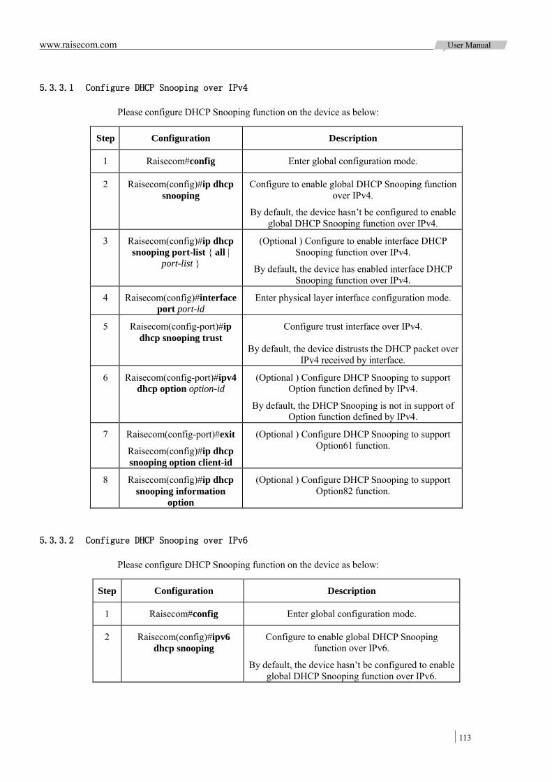
www.raisecom.com User Manual
113
5.3.3.1 Configure DHCP Snooping over IPv4
Please configure DHCP Snooping function on the device as below:
Step Configuration Description
1 Raisecom#config Enter global configuration mode.
2 Raisecom(config)#ip dhcp snooping
Configure to enable global DHCP Snooping function over IPv4.
By default, the device hasn’t be configured to enable global DHCP Snooping function over IPv4.
3 Raisecom(config)#ip dhcp snooping port-list { all |
port-list }
(Optional ) Configure to enable interface DHCP Snooping function over IPv4.
By default, the device has enabled interface DHCP Snooping function over IPv4.
4 Raisecom(config)#interface port port-id
Enter physical layer interface configuration mode.
5 Raisecom(config-port)#ip dhcp snooping trust
Configure trust interface over IPv4.
By default, the device distrusts the DHCP packet over IPv4 received by interface.
6 Raisecom(config-port)#ipv4 dhcp option option-id
(Optional ) Configure DHCP Snooping to support Option function defined by IPv4.
By default, the DHCP Snooping is not in support of Option function defined by IPv4.
7 Raisecom(config-port)#exit
Raisecom(config)#ip dhcp snooping option client-id
(Optional ) Configure DHCP Snooping to support Option61 function.
8 Raisecom(config)#ip dhcp snooping information
option
(Optional ) Configure DHCP Snooping to support Option82 function.
5.3.3.2 Configure DHCP Snooping over IPv6
Please configure DHCP Snooping function on the device as below:
Step Configuration Description
1 Raisecom#config Enter global configuration mode.
2 Raisecom(config)#ipv6 dhcp snooping
Configure to enable global DHCP Snooping function over IPv6.
By default, the device hasn’t be configured to enable global DHCP Snooping function over IPv6.
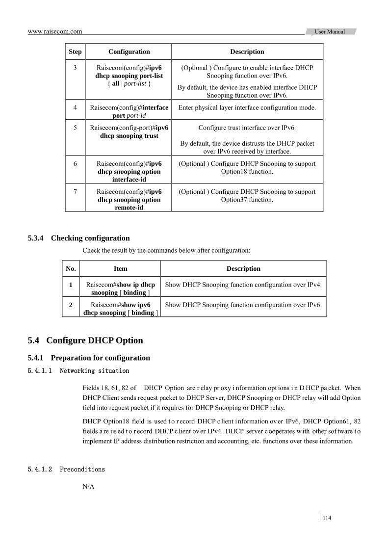
www.raisecom.com User Manual
114
Step Configuration Description
3 Raisecom(config)#ipv6 dhcp snooping port-list
{ all | port-list }
(Optional ) Configure to enable interface DHCP Snooping function over IPv6.
By default, the device has enabled interface DHCP Snooping function over IPv6.
4 Raisecom(config)#interface port port-id
Enter physical layer interface configuration mode.
5 Raisecom(config-port)#ipv6 dhcp snooping trust
Configure trust interface over IPv6.
By default, the device distrusts the DHCP packet over IPv6 received by interface.
6 Raisecom(config)#ipv6 dhcp snooping option
interface-id
(Optional ) Configure DHCP Snooping to support Option18 function.
7 Raisecom(config)#ipv6 dhcp snooping option
remote-id
(Optional ) Configure DHCP Snooping to support Option37 function.
5.3.4 Checking configuration Check the result by the commands below after configuration:
No. Item Description
1 Raisecom#show ip dhcp snooping [ binding ]
Show DHCP Snooping function configuration over IPv4.
2 Raisecom#show ipv6 dhcp snooping [ binding ]
Show DHCP Snooping function configuration over IPv6.
5.4 Configure DHCP Option
5.4.1 Preparation for configuration 5.4.1.1 Networking situation
Fields 18, 61, 82 of DHCP Option are r elay pr oxy i nformation opt ions i n D HCP pa cket. When DHCP Client sends request packet to DHCP Server, DHCP Snooping or DHCP relay will add Option field into request packet if it requires for DHCP Snooping or DHCP relay.
DHCP Option18 field is used t o r ecord DHCP c lient i nformation over IPv6, DHCP Option61, 82 fields a re us ed t o r ecord DHCP c lient over IPv4. DHCP server c ooperates w ith other sof tware t o implement IP address distribution restriction and accounting, etc. functions over these information.
5.4.1.2 Preconditions
N/A
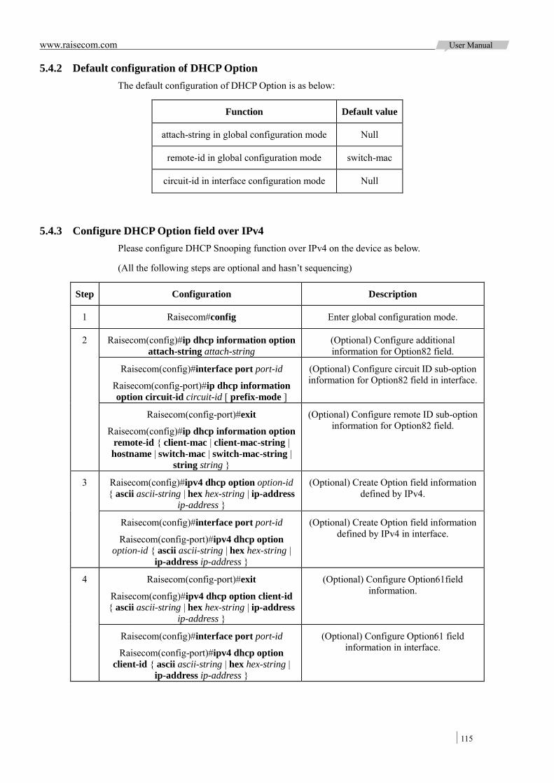
www.raisecom.com User Manual
115
5.4.2 Default configuration of DHCP Option The default configuration of DHCP Option is as below:
Function Default value
attach-string in global configuration mode Null
remote-id in global configuration mode switch-mac
circuit-id in interface configuration mode Null
5.4.3 Configure DHCP Option field over IPv4 Please configure DHCP Snooping function over IPv4 on the device as below.
(All the following steps are optional and hasn’t sequencing)
Step Configuration Description
1 Raisecom#config Enter global configuration mode.
2 Raisecom(config)#ip dhcp information option attach-string attach-string
(Optional) Configure additional information for Option82 field.
Raisecom(config)#interface port port-id
Raisecom(config-port)#ip dhcp information option circuit-id circuit-id [ prefix-mode ]
(Optional) Configure circuit ID sub-option information for Option82 field in interface.
Raisecom(config-port)#exit
Raisecom(config)#ip dhcp information option remote-id { client-mac | client-mac-string | hostname | switch-mac | switch-mac-string |
string string }
(Optional) Configure remote ID sub-option information for Option82 field.
3 Raisecom(config)#ipv4 dhcp option option-id { ascii ascii-string | hex hex-string | ip-address
ip-address }
(Optional) Create Option field information defined by IPv4.
Raisecom(config)#interface port port-id
Raisecom(config-port)#ipv4 dhcp option option-id { ascii ascii-string | hex hex-string |
ip-address ip-address }
(Optional) Create Option field information defined by IPv4 in interface.
4 Raisecom(config-port)#exit
Raisecom(config)#ipv4 dhcp option client-id { ascii ascii-string | hex hex-string | ip-address
ip-address }
(Optional) Configure Option61field information.
Raisecom(config)#interface port port-id
Raisecom(config-port)#ipv4 dhcp option client-id { ascii ascii-string | hex hex-string |
ip-address ip-address }
(Optional) Configure Option61 field information in interface.
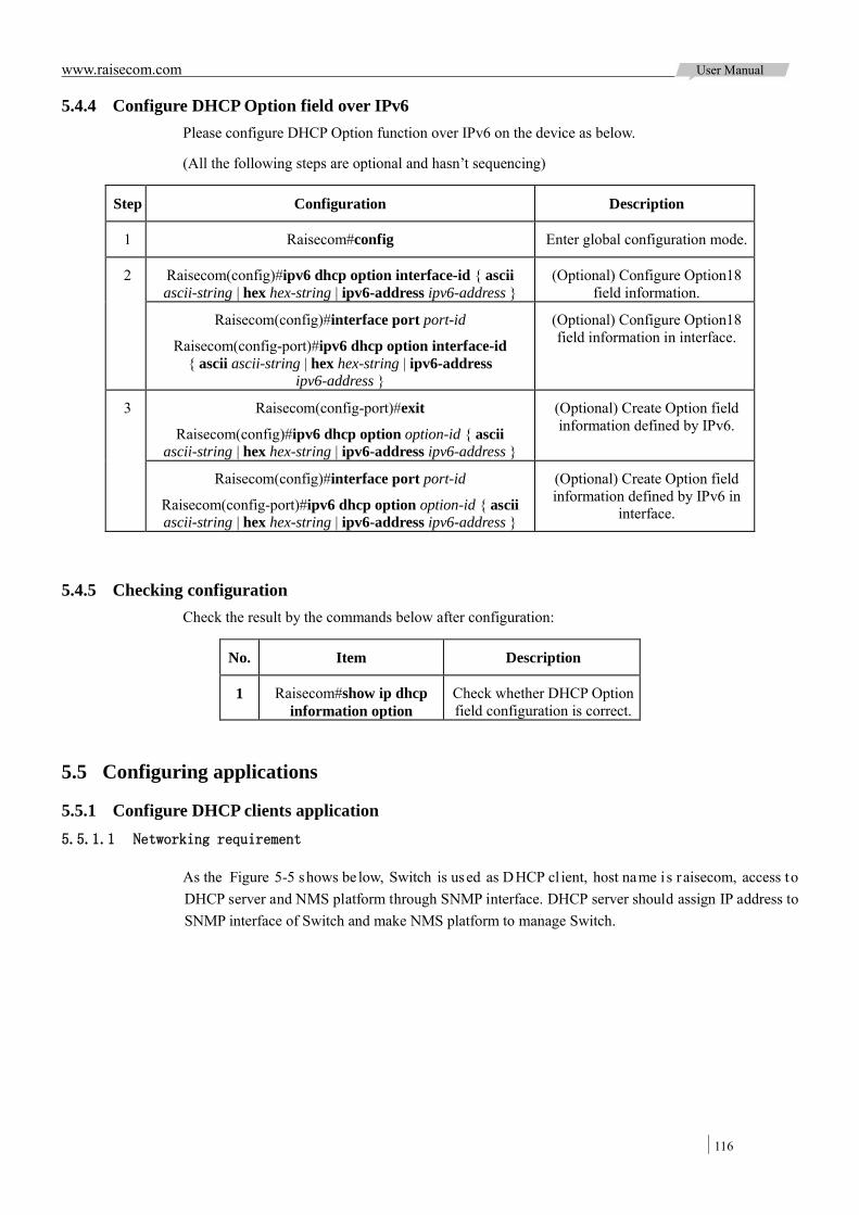
www.raisecom.com User Manual
116
5.4.4 Configure DHCP Option field over IPv6 Please configure DHCP Option function over IPv6 on the device as below.
(All the following steps are optional and hasn’t sequencing)
Step Configuration Description
1 Raisecom#config Enter global configuration mode.
2 Raisecom(config)#ipv6 dhcp option interface-id { ascii ascii-string | hex hex-string | ipv6-address ipv6-address }
(Optional) Configure Option18 field information.
Raisecom(config)#interface port port-id
Raisecom(config-port)#ipv6 dhcp option interface-id { ascii ascii-string | hex hex-string | ipv6-address
ipv6-address }
(Optional) Configure Option18 field information in interface.
3 Raisecom(config-port)#exit
Raisecom(config)#ipv6 dhcp option option-id { ascii ascii-string | hex hex-string | ipv6-address ipv6-address }
(Optional) Create Option field information defined by IPv6.
Raisecom(config)#interface port port-id
Raisecom(config-port)#ipv6 dhcp option option-id { ascii ascii-string | hex hex-string | ipv6-address ipv6-address }
(Optional) Create Option field information defined by IPv6 in
interface.
5.4.5 Checking configuration Check the result by the commands below after configuration:
No. Item Description
1 Raisecom#show ip dhcp information option
Check whether DHCP Option field configuration is correct.
5.5 Configuring applications
5.5.1 Configure DHCP clients application 5.5.1.1 Networking requirement
As the Figure 5-5 shows be low, Switch is used as DHCP cl ient, host name i s raisecom, access to DHCP server and NMS platform through SNMP interface. DHCP server should assign IP address to SNMP interface of Switch and make NMS platform to manage Switch.

www.raisecom.com User Manual
117
Figure 5-5 DHCP client networking
5.5.1.2 Configuration steps
Configure DHCP client information.
Raisecom#config
Raisecom(config)#interface ip 0
Raisecom(config-ip)#ip dhcp client hostname raisecom
Configure to apply for IP address by DHCP.
Raisecom(config-ip)#ip address dhcp server-ip 192.168.1.1
5.5.1.3 Show result
Check whether DHCP client configuration is correct by the command of show ip dhcp client.
Raisecom#show ip dhcp client
Hostname: raisecom
Class-ID: Raisecom-ROS
Client-ID: Raisecom-000e5e000000-IF0
DHCP Client is requesting for a lease.
Assigned IP Addr: 0.0.0.0
Subnet mask: 0.0.0.0
Default Gateway: --
Client lease Starts: Jan-01-1970 08:00:00
Client lease Ends: Jan-01-1970 08:00:00
Client lease duration: 0(sec)
DHCP Server: 0.0.0.0
Tftp server name: --
Tftp server IP Addr: --
Startup_config filename: --
NTP server IP Addr: --
Root path: --

www.raisecom.com User Manual
118
5.5.2 Configure DHCP Snooping application 5.5.2.1 Networking requirement
As the Figure 5-6 shows be low, S witch i s used a s DHCP Snooping device. The network r equires DHCP c lient ge ts I P a ddress f rom l egal D HCP s erver a nd s upports O ption82 to facilitate c lient management; user can configure circuit ID sub-option information on interface Port 3 as raisecom, remote ID sub-option as user01.
Figure 5-6 DHCP Snooping networking
5.5.2.2 Configuration steps
Configure global DHCP Snooping function.
Raisecom#config
Raisecom(config)#ip dhcp snooping
Configure trust interface.
Raisecom(config)#interface port 1
Raisecom(config-port)#ip dhcp snooping trust
Raisecom(config-port)#quit
Configure DHCP relay in support of Option82 function and configure field Option82.
Raisecom(config)#ip dhcp snooping information option
Raisecom(config)#ip dhcp information option remote-id string user01
Raisecom(config)#interface port 3
Raisecom(config-port)#ip dhcp information option circuit-id raisecom
5.5.2.3 Show result
Check whether DHCP client configuration is correct by the command of show ip dhcp information option.
Raisecom#show ip dhcp information option
DHCP Option Config Information

www.raisecom.com User Manual
119
Circuit-ID : default
Remote-ID Mode: string
Remote-ID String: user01
P3 Circuit ID: raisecom
ipv4Global
ipv4Port
P1:
P2:
P3:
…
P27:
P28:ipv6Global
ipv6Port
P1:
P2:
P3:
…
P27:
P28
www.raisecom.com User Manual
120
Chapter 6 QoS
This chapter introduces basic principle and configuration of QoS and provides related configuration applications.
Overview Priority trust Traffic classification and traffic policy Priority mapping and queue schedule Traffic rate limit over interface and VLAN Maintenance Configuring applications
6.1 Overview
User br ings f orce di fferent service qua lity de mands f or ne twork a pplication, t hen network s hould distribute and schedule resource for different network application according to user demands. QoS (Quality of Service) can ensure s ervice i n real-time and i ntegrity w hen network overload or congested and guarantee the whole network runs high-efficiently.
QoS is composed by a group of traffic management technology:
Service model Priority trust Traffic classification Traffic policy Priority mapping Queue schedule Rate limit over interface and VLAN
6.1.1 Service model QoS technical service contains three models:
Best-effort Service Integrated Services (IntServ) Differentiated Services (DiffServ)
6.1.1.1 Best-effort
Best-effort service is the most basic and simplest service model over store and forward mechanism Internet (IPv4 standard). In Best-effort service model, the application program can send any number of pa ckets at any time without permitting in advance and notifying the ne twork. F or B est-effort service, the network will send packets as possible as it can, but cannot guarantee the delay time and reliability.
Best-effort is the default Internet service model now, applying to most network applications, such as

www.raisecom.com User Manual
121
FTP, E -mail, etc. which is achieved by first in first out (FIFO) queue.
6.1.1.2 IntServ
IntServ model is a comprehensive service model, which can meet a variety of QoS requirements and needs t o s end specific s ervice r equest to ne twork b efore s ending m essages. This r equest is accomplished through signaling. Firstly, the application program need to apply for service quality it required f rom ne twork by s ignaling, s uch a s bandwidth, de lay time, pr iority, e tc. The a pplication program w ill s end messages onc e r eceiving t he c onfirmation f rom ne twork, w hich m eans t he network has already pr eset i ts corresponding s ervice qua lity r esource. At t he same t ime, the messages se nt b y program s hould be c ontrolled w ithin t he range described i n t he application parameters.
After r eceiving service qua lity application messages f rom a pplication pr ogram, t he ne twork w ill check r esource di stribution, i .e. w hether t he current network resource can m eet appl ication from application pr ogram, once m eeting the a pplication, network will return a ne twork r esource confirmation and allocate corresponding network resource for application program. In the process of sending messages, as l ong a s t he a pplication pa cket traffics a re controlled within the range of application parameters, the network will undertake to meet QoS requirements. In order to fulfill the commitment f or t ransmitting traffics, the ne twork will maintain a s tate for t hem, classifying messages, monitoring traffics and taking queue scheduling over the state.
In the IntServ service model, the signaling transmitting QoS request is RSVP (Resource Reservation Protocol), w hich i s r esponsible f or not ifying t he Q oS r equirements of application program to network. RSVP applies for network resource before the application program sending messages, so it is out of band signaling.
Intserv service model diagram is shown in Figure 6-1.
Figure 6-1 Sketch map of IntServ service model
The b iggest adv antage of IntServ model is to pr ovide end-to-end QoS service, while the bi ggest disadvantage is its poor scalability. Network node must maintain all reserved resource information. These m aintenance ope rations w ill consum e more pr ocessing time and memory requirements of

www.raisecom.com User Manual
122
network nodes. A fter expanding network scale, there will be a substantial increasing in the maintenance cost, which will have a serious impact to the packet wire-speed processing performance of the network nodes, especially the core nodes.
6.1.1.3 DiffServ
DiffServ model is a multi-service model, which can satisfy different QoS requirements. The largest difference from Intserv model is tha t it does not require RSVP signaling. In other words, DiffServ model doesn’t need to notify the network to reserve resources before sending messages.
DiffServ model does not need t o maintain state for each f low. I t provides differentiated s ervices according t o the QoS cl assification of each packet. Many different methods can be used for Q oS packet cl assification, such as I P pa cket pr iority ( IP precedence), t he pa cket s ource addres s or destination address and so on.
Generally, DiffServ i s us ed to pr ovide end t o e nd Q oS s ervices for a num ber of i mportant applications, which is achieved mainly through the following techniques:
CAR (Committed Access Rate): CAR refers to classify the messages according to the pre-set messages m atching rules, s uch a s IP m essages pr iority ( IP pr ecedence), t he pa cket s ource address or destination address, etc. Continue to send the messages if the flow is in line with the rules of token bucket. If it is beyond the specified flow, discard the messages or remark IP precedence, DSCP, EXP, etc. CAR not only can control the traffics, but also mark and remark the messages.
Queue t echnology: the queuing t echnologies of SP, WRR, DRR, SP + WRR, SP + DRR cache and schedule the congestion messages to achieve congestion management.
6.1.2 Priority trust Priority trust re fers to the de vice us es pr iority of pa ckets f or classification and pe rforms Q oS management. Generally speaking, the bigger the packet priority field is, the higher the priority is.
ISCOM2924GF device is in support of packet priority trust over interface, including:
DSCP (Differentiated Services Code Point) priority over IP packets. CoS (Class of Service) priority over VLAN packets.
6.1.3 Traffic classification Traffic classification denotes recognizing packets of certain cl ass by setting rules, pe rforming different Q oS pol icy f or the pa ckets match w ith di fferent r ules. It i s pr emise a nd base of di verse service.
ISCOM2924GF device is in support of traffic classification of ToS (Type of Service) priority over IP packets, DSCP priority and CoS priority over VLAN packets, as well as the classification over ACL rule. The traffic classification procedure is shown as the following Figure 6-2:
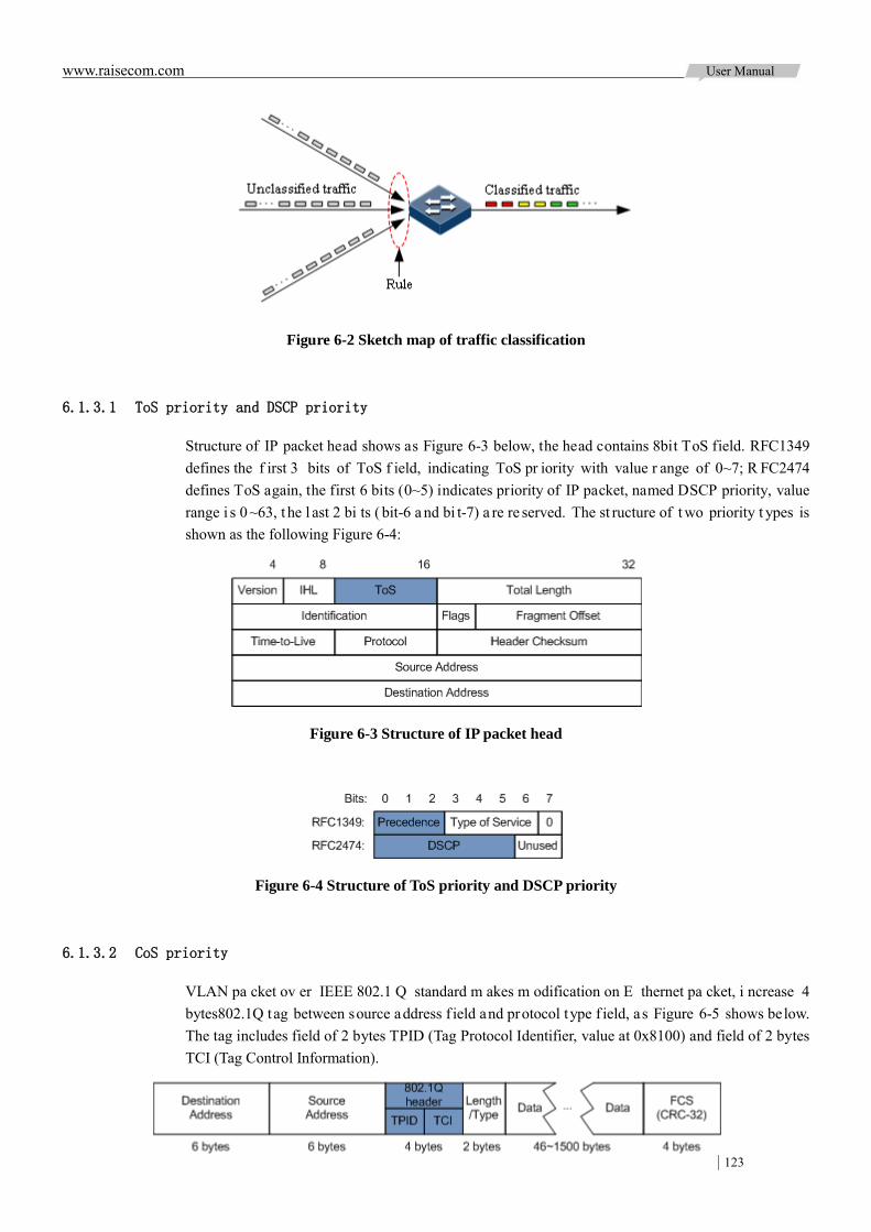
www.raisecom.com User Manual
123
Figure 6-2 Sketch map of traffic classification
6.1.3.1 ToS priority and DSCP priority
Structure of IP packet head shows as Figure 6-3 below, the head contains 8bit ToS field. RFC1349 defines the f irst 3 bits of ToS f ield, indicating ToS pr iority with value r ange of 0~7; R FC2474 defines ToS again, the first 6 bits (0~5) indicates priority of IP packet, named DSCP priority, value range i s 0~63, t he l ast 2 bi ts ( bit-6 a nd bi t-7) a re re served. The st ructure of t wo priority t ypes is shown as the following Figure 6-4:
Figure 6-3 Structure of IP packet head
Figure 6-4 Structure of ToS priority and DSCP priority
6.1.3.2 CoS priority
VLAN pa cket ov er IEEE 802.1 Q standard m akes m odification on E thernet pa cket, i ncrease 4 bytes802.1Q tag between source address f ield and protocol type f ield, as Figure 6-5 shows below. The tag includes field of 2 bytes TPID (Tag Protocol Identifier, value at 0x8100) and field of 2 bytes TCI (Tag Control Information).

www.raisecom.com User Manual
124
Figure 6-5 Structure of VLAN packets
CoS priority locates at the first 3 bits of TCI field, value range is 0~7, as Figure 6-6 shows below. It is available to guarantee service quality in layer-2 network.
Figure 6-6 Structure of CoS priority packets
6.1.4 Traffic policy Perform di fferent ope ration for di fferent pa ckets a fter classifying packets t raffic, the t raffic classification and operation binding form the traffic policy.
6.1.4.1 Rate limit
Rate limit is to control network traffic, by monitoring traffic rate enters network to discard overflow part a nd c ontrol t he e ntering t raffic in a r easonable r ange, t hus t o pr otect ne twork r esource a nd carrier interest.
ISCOM2924GF device is in support of rate limit at packet ingress direction over traffic policy.
6.1.4.2 Re-direction
Re-direction means to forward packets in the original corresponding relation between destination and interface, it forwards packet to assigned interface to implement policy routing.
ISCOM2924GF device supports forwarding ingress packets to assigned interface.
6.1.4.3 Re-mark
Re-mark means to set some priority fields in packet again and then classify packets according to self standard. Besides, downstream node i n ne twork c an pr ovide di verse Q oS s ervice a ccording t o re-marked information.
ISCOM2924GF device is in support of re-mark for below priority fields:
IP packets ToS priority IP packets DSCP priority VLAN packets CoS priority
6.1.4.4 Traffic statistics
Traffic statistics is used for data messages statistics of specified service traffic, which is the number of messages and bytes passed through matching traffic classification or discarded.
Traffic statistics itself is not QoS control measure, but can be used in combination with other QoS

www.raisecom.com User Manual
125
actions to improve the security of network and messages.
6.1.5 Priority mapping When packets enter device, priority mapping function sends them to queues with different internal priority i n a ccordance w ith m apping r elationship f rom e xternal t o i nternal, t hus t he pa ckets c an perform queue schedule at packets egress direction.
Note: Internal pr iority is a kind of internal pr iority device distributed to packets, corresponding to interface queue No. Packets with bigger internal priority value will be processed precedent.
ISCOM2924GF device supports DSCP priority over IP packets or CoS priority over VLAN packets to perform priority mapping.
By default, the mapping relationship among ISCOM2924GF device internal priority, DSCP priority and CoS priority is shown in the table 6-1 below:
Table 6-1 Mapping relationship of internal priority, DSCP priority, CoS priority
Internal 0 1 2 3 4 5 6 7
DSCP 0~7 8~15 16~23 24~31 32~39 40~47 48~55 56~63
CoS 0 1 2 3 4 5 6 7
6.1.6 Queue schedule Queue schedule i s necessary when there i s i ntermittent congestion in ne twork and de lay sensitive services require higher QoS service than non-sensitive services.
Queue s chedule adopts different s chedule a lgorithm t o t ransport pa ckets f low i n que ue. ISCOM2924GF de vice is in s upport of SP ( Strict-Priority), W RR (Weight R ound R obin), DRR (Deficit Round Robin), SP+WRR and SP+DRR algorithm to solve network flow problem and have different influences on distribution, delay, and jitter of bandwidth resource:
SP: t o s chedule s trictly a ccording t o que ue pr iority order. Lower pr iority queue cannot perform schedule unt il the packets in higher priority queue a ll f inished schedule, as Figure 6-7 shows below.
Figure 6-7 Sketch map of SP schedule

www.raisecom.com User Manual
126
WRR: on basis of round schedule each queue according to queue priority, schedule packets in various queues according to weight of each queue, as Figure 6-8 shows below.
Figure 6-8 Sketch map of WRR schedule
DRR: on basis of round schedule each queue according to queue priority, schedule packets in each queue according to weight of each queue. Besides, lending the redundant bandwidth of a queue in one schedule to other queue, in the later schedule, the queue borrowed bandwidth will return it back, as Figure 6-9 shows below.
Figure 6-9 Sketch map of DRR schedule
SP+WRR: di viding que ues on i nterface i nto t wo gr oups, us er c an assign some que ues perform SP schedule and other queues perform WRR schedule.
SP+DRR: dividing queues on interface into two groups, user can assign some queues perform SP schedule and other queues perform DRR schedule.
6.1.7 Rate limit over interface and VLAN ISCOM2924GF not onl y s upports r ate lim it ov er tr affic pol icy but a lso supports r ate lim it ov er interface and VLAN I D. Similar t o rate l imit over t raffic pol icy, device di scards the exceeding traffics.

www.raisecom.com User Manual
127
6.2 Configure priority trust
6.2.1 Preparation for configuration 6.2.1.1 Networking situation
User c an c hoose pr iority for t rusted pa ckets f rom ups tream de vice, unt rusted pr iority pa ckets a re processed by traffic classification and traffic policy. After configuring priority trust, device operates packets according to their priorities and provides related service.
6.2.1.2 Preconditions
N/A
6.2.2 Default configuration of priority trust The default configuration of priority trust is as below:
Function Default value
Global QoS function status Enable
Interface trust priority type Trust CoS priority
6.2.3 Configure interface priority trust Please configure interface priority trust for the device as below.
Step Configuration Description
1 Raisecom#config Enter global configuration mode.
2 Raisecom(config)#mls qos enable Global enable QoS function.
By default, the device enables global QoS function.
The command mls qos disable can disable the function.
3 Raisecom(config)#interface port port-id
Enter physical layer interface configuration mode.
4 Raisecom(config-port)#mls qos trust { cos | dscp }
Configure interface trust priority type.
By default, interface trusts CoS priority.
6.2.4 Checking configuration Check the result by the commands below after configuration:
No. Item Description
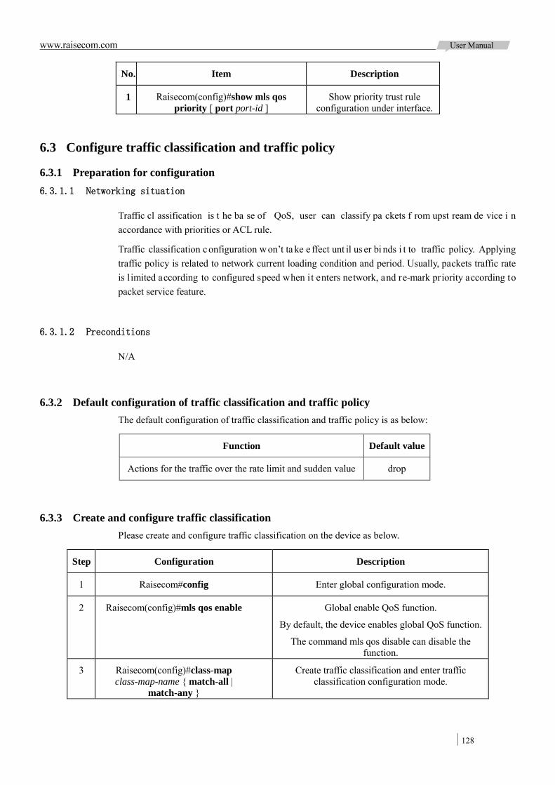
www.raisecom.com User Manual
128
No. Item Description
1 Raisecom(config)#show mls qos priority [ port port-id ]
Show priority trust rule configuration under interface.
6.3 Configure traffic classification and traffic policy
6.3.1 Preparation for configuration 6.3.1.1 Networking situation
Traffic cl assification is t he ba se of QoS, user can classify pa ckets f rom upst ream de vice i n accordance with priorities or ACL rule.
Traffic classification c onfiguration w on’t ta ke e ffect unt il us er bi nds i t to traffic policy. Applying traffic policy is related to network current loading condition and period. Usually, packets traffic rate is l imited according to configured speed when it enters network, and re-mark priority according to packet service feature.
6.3.1.2 Preconditions
N/A
6.3.2 Default configuration of traffic classification and traffic policy The default configuration of traffic classification and traffic policy is as below:
Function Default value
Actions for the traffic over the rate limit and sudden value drop
6.3.3 Create and configure traffic classification Please create and configure traffic classification on the device as below.
Step Configuration Description
1 Raisecom#config Enter global configuration mode.
2 Raisecom(config)#mls qos enable Global enable QoS function.
By default, the device enables global QoS function.
The command mls qos disable can disable the function.
3 Raisecom(config)#class-map class-map-name { match-all |
match-any }
Create traffic classification and enter traffic classification configuration mode.
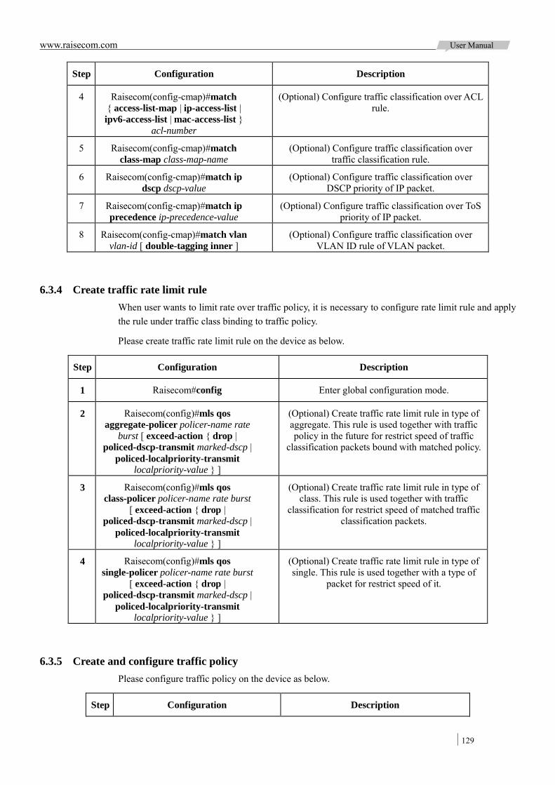
www.raisecom.com User Manual
129
Step Configuration Description
4 Raisecom(config-cmap)#match { access-list-map | ip-access-list | ipv6-access-list | mac-access-list }
acl-number
(Optional) Configure traffic classification over ACL rule.
5 Raisecom(config-cmap)#match class-map class-map-name
(Optional) Configure traffic classification over traffic classification rule.
6 Raisecom(config-cmap)#match ip dscp dscp-value
(Optional) Configure traffic classification over DSCP priority of IP packet.
7 Raisecom(config-cmap)#match ip precedence ip-precedence-value
(Optional) Configure traffic classification over ToS priority of IP packet.
8 Raisecom(config-cmap)#match vlan vlan-id [ double-tagging inner ]
(Optional) Configure traffic classification over VLAN ID rule of VLAN packet.
6.3.4 Create traffic rate limit rule When user wants to limit rate over traffic policy, it is necessary to configure rate limit rule and apply the rule under traffic class binding to traffic policy.
Please create traffic rate limit rule on the device as below.
Step Configuration Description
1 Raisecom#config Enter global configuration mode.
2 Raisecom(config)#mls qos aggregate-policer policer-name rate
burst [ exceed-action { drop | policed-dscp-transmit marked-dscp |
policed-localpriority-transmit localpriority-value } ]
(Optional) Create traffic rate limit rule in type of aggregate. This rule is used together with traffic policy in the future for restrict speed of traffic
classification packets bound with matched policy.
3 Raisecom(config)#mls qos class-policer policer-name rate burst
[ exceed-action { drop | policed-dscp-transmit marked-dscp |
policed-localpriority-transmit localpriority-value } ]
(Optional) Create traffic rate limit rule in type of class. This rule is used together with traffic
classification for restrict speed of matched traffic classification packets.
4 Raisecom(config)#mls qos single-policer policer-name rate burst
[ exceed-action { drop | policed-dscp-transmit marked-dscp |
policed-localpriority-transmit localpriority-value } ]
(Optional) Create traffic rate limit rule in type of single. This rule is used together with a type of
packet for restrict speed of it.
6.3.5 Create and configure traffic policy Please configure traffic policy on the device as below.
Step Configuration Description

www.raisecom.com User Manual
130
Step Configuration Description
1 Raisecom#config Enter global configuration mode.
2 Raisecom(config)#policy-map policy-map-name
Create traffic policy and enter traffic policy configuration mode.
3 Raisecom(config-pmap)#description string
(Optional) Configure description for traffic policy.
4 Raisecom(config-pmap)#class-map class-map-name
Bind traffic classification into traffic policy; only apply policy for packets match with
traffic class.
Note: At least one rule type is necessary for binding traffic class for policy, otherwise
cannot bind successfully.
5 Raisecom(config-pmap-c)#police policer-name
(Optional) Configure rate limit rule under traffic class to form rate limit policy.
6 Raisecom(config-pmap-c)#redirect-to port port-id
(Optional) Configure re-direct rule under traffic class, forwarding classified packets
from assigned interface.
7 Raisecom(config-pmap-c)#set { cos cos-value | ip dscp ip-dscp-value | ip
precedence ip-precedence-value | vlan vlan-id }
(Optional) Configure re-mark rule under traffic class, modify packet ToS, DSCP, CoS
or VLAN ID of matched traffic class.
8 Raisecom(config-pmap-c)#statistics enable
(Optional) Configure traffic statistic rule under traffic class, statistic packets for
matched traffic class.
9 Raisecom(config-pmap-c)#quit
Raisecom(config-pmap)#quit
Raisecom(config)#service-policy policy-name { egress port-id | ingress
port-id [ egress port-id ]}
Bind the configured traffic policy to interface.
6.3.6 Checking configuration Check the result by the commands below after configuration:
No. Item Description
1 Raisecom(config)#show mls qos Show QoS configuration of assigned interface.
2 Raisecom(config)#show class-map [ class-map-name ]
Show assigned traffic classification rule.
3 Raisecom(config)#show mls qos policer [ policer-name | aggregate-policer |
class-policer | single-policer ]
Show assigned rate limit rule.
4 Raisecom(config)#show policy-map [ policy-map-name [ class class-map-name ]
| class class-map-name | port port-id ]
Show assigned traffic policy configuration.
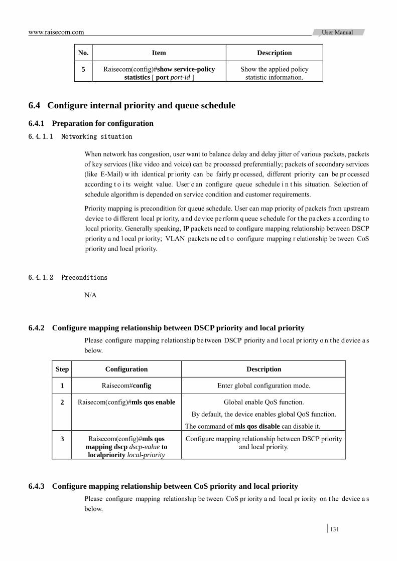
www.raisecom.com User Manual
131
No. Item Description
5 Raisecom(config)#show service-policy statistics [ port port-id ]
Show the applied policy statistic information.
6.4 Configure internal priority and queue schedule
6.4.1 Preparation for configuration 6.4.1.1 Networking situation
When network has congestion, user want to balance delay and delay jitter of various packets, packets of key services (like video and voice) can be processed preferentially; packets of secondary services (like E-Mail) w ith identical pr iority can be fairly pr ocessed, different priority can be pr ocessed according t o i ts weight value. User c an configure queue schedule i n t his situation. Selection of schedule algorithm is depended on service condition and customer requirements.
Priority mapping is precondition for queue schedule. User can map priority of packets from upstream device to di fferent local pr iority, and device pe rform q ueue schedule for t he packets a ccording to local priority. Generally speaking, IP packets need to configure mapping relationship between DSCP priority a nd l ocal pr iority; VLAN packets ne ed t o configure mapping r elationship be tween CoS priority and local priority.
6.4.1.2 Preconditions
N/A
6.4.2 Configure mapping relationship between DSCP priority and local priority Please configure mapping r elationship be tween DSCP priority a nd l ocal pr iority o n t he d evice a s below.
Step Configuration Description
1 Raisecom#config Enter global configuration mode.
2 Raisecom(config)#mls qos enable Global enable QoS function.
By default, the device enables global QoS function.
The command of mls qos disable can disable it.
3 Raisecom(config)#mls qos mapping dscp dscp-value to localpriority local-priority
Configure mapping relationship between DSCP priority and local priority.
6.4.3 Configure mapping relationship between CoS priority and local priority Please configure mapping relationship be tween CoS pr iority a nd local pr iority on t he device a s below.
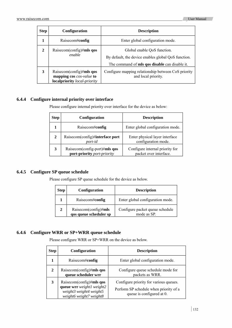
www.raisecom.com User Manual
132
Step Configuration Description
1 Raisecom#config Enter global configuration mode.
2 Raisecom(config)#mls qos enable
Global enable QoS function.
By default, the device enables global QoS function.
The command of mls qos disable can disable it.
3 Raisecom(config)#mls qos mapping cos cos-value to localpriority local-priority
Configure mapping relationship between CoS priority and local priority.
6.4.4 Configure internal priority over interface Please configure internal priority over interface for the device as below:
Step Configuration Description
1 Raisecom#config Enter global configuration mode.
2 Raisecom(config)#interface port port-id
Enter physical layer interface configuration mode.
3 Raisecom(config-port)#mls qos port-priority port-priority
Configure internal priority for packet over interface.
6.4.5 Configure SP queue schedule Please configure SP queue schedule for the device as below.
Step Configuration Description
1 Raisecom#config Enter global configuration mode.
2 Raisecom(config)#mls qos queue scheduler sp
Configure packet queue schedule mode as SP.
6.4.6 Configure WRR or SP+WRR queue schedule Please configure WRR or SP+WRR on the device as below.
Step Configuration Description
1 Raisecom#config Enter global configuration mode.
2 Raisecom(config)#mls qos queue scheduler wrr
Configure queue schedule mode for packets as WRR.
3 Raisecom(config)#mls qos queue wrr weight1 weight2
weight3 weight4 weight5 weight6 weight7 weight8
Configure priority for various queues.
Perform SP schedule when priority of a queue is configured at 0.

www.raisecom.com User Manual
133
6.4.7 Configure DRR or SP+DRR queue schedule Please configure DRR or SP+DRR on the device as below.
Step Configuration Description
1 Raisecom#config Enter global configuration mode.
2 Raisecom(config)#mls qos queue scheduler drr
Configure queue schedule mode for packets as DRR.
3 Raisecom(config)#mls qos queue drr weight1 weight2
weight3 weight4 weight5 weight6 weight7 weight8
Configure priority for various queues.
Perform SP schedule when priority of a queue is configured at 0.
6.4.8 Checking configuration Check the result by the commands below after configuration:
No. Item Description
1 Raisecom#show mls qos mapping [ cos | dscp | localpriority ]
Show mapping relationship configuration for assigned priority.
2 Raisecom(config)#show mls qos queue Show queue schedule configuration.
6.5 Configure traffic rate limit over interface and VLAN
6.5.1 Preparation for configuration 6.5.1.1 Networking situation
When ne twork h as c ongestion, us er c an configure rate li mit o ver int erface or V LAN if w ant to restrict burst traffic flow at an interface or a VLAN to make it transports in a well-proportioned rate, so as to remove network congestion.
6.5.1.2 Preconditions
Related VLAN must be created before configuring rate limit over VLAN or QinQ.
6.5.2 Configure traffic rate limit over interface Please configure rate limit over interface on the device as below.
Step Configuration Description
1 Raisecom#config Enter global configuration mode.
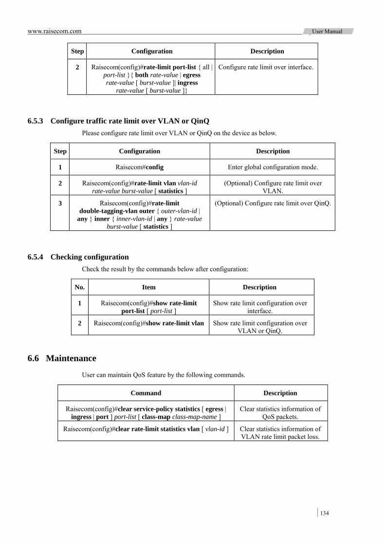
www.raisecom.com User Manual
134
Step Configuration Description
2 Raisecom(config)#rate-limit port-list { all | port-list }{ both rate-value | egress rate-value [ burst-value ]| ingress
rate-value [ burst-value ]}
Configure rate limit over interface.
6.5.3 Configure traffic rate limit over VLAN or QinQ Please configure rate limit over VLAN or QinQ on the device as below.
Step Configuration Description
1 Raisecom#config Enter global configuration mode.
2 Raisecom(config)#rate-limit vlan vlan-id rate-value burst-value [ statistics ]
(Optional) Configure rate limit over VLAN.
3 Raisecom(config)#rate-limit double-tagging-vlan outer { outer-vlan-id |
any } inner { inner-vlan-id | any } rate-value burst-value [ statistics ]
(Optional) Configure rate limit over QinQ.
6.5.4 Checking configuration Check the result by the commands below after configuration:
No. Item Description
1 Raisecom(config)#show rate-limit port-list [ port-list ]
Show rate limit configuration over interface.
2 Raisecom(config)#show rate-limit vlan Show rate limit configuration over VLAN or QinQ.
6.6 Maintenance
User can maintain QoS feature by the following commands.
Command Description
Raisecom(config)#clear service-policy statistics [ egress | ingress | port ] port-list [ class-map class-map-name ]
Clear statistics information of QoS packets.
Raisecom(config)#clear rate-limit statistics vlan [ vlan-id ] Clear statistics information of VLAN rate limit packet loss.
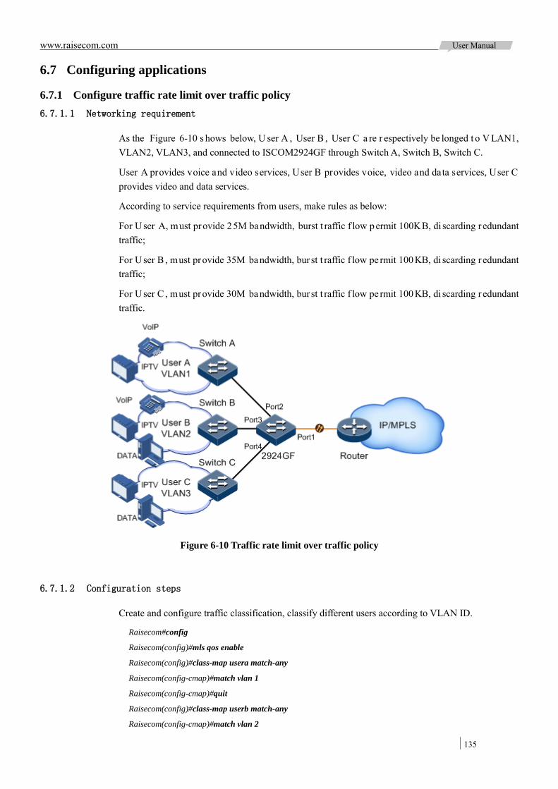
www.raisecom.com User Manual
135
6.7 Configuring applications
6.7.1 Configure traffic rate limit over traffic policy 6.7.1.1 Networking requirement
As the Figure 6-10 s hows below, U ser A , User B , User C a re r espectively be longed t o V LAN1, VLAN2, VLAN3, and connected to ISCOM2924GF through Switch A, Switch B, Switch C.
User A provides voice and video services, User B provides voice, video and data services, User C provides video and data services.
According to service requirements from users, make rules as below:
For U ser A, must provide 25M bandwidth, burst t raffic f low permit 100KB, di scarding r edundant traffic;
For U ser B , must provide 35M bandwidth, bur st t raffic f low pe rmit 100 KB, di scarding r edundant traffic;
For U ser C , must provide 30M bandwidth, bur st t raffic f low pe rmit 100 KB, di scarding r edundant traffic.
Figure 6-10 Traffic rate limit over traffic policy
6.7.1.2 Configuration steps
Create and configure traffic classification, classify different users according to VLAN ID.
Raisecom#config
Raisecom(config)#mls qos enable
Raisecom(config)#class-map usera match-any
Raisecom(config-cmap)#match vlan 1
Raisecom(config-cmap)#quit
Raisecom(config)#class-map userb match-any
Raisecom(config-cmap)#match vlan 2

www.raisecom.com User Manual
136
Raisecom(config-cmap)#quit
Raisecom(config)#class-map userc match-any
Raisecom(config-cmap)#match vlan 3
Raisecom(config-cmap)#quit
Create traffic rate limit rule.
Raisecom(config)#mls qos single-policer usera 25000 100 exceed-action drop
Raisecom(config)#mls qos single-policer userb 35000 100 exceed-action drop
Raisecom(config)#mls qos single-policer userc 30000 100 exceed-action drop
Create and configure traffic policy.
Raisecom(config)#policy-map usera
Raisecom(config-pmap)#class-map usera
Raisecom(config-pmap-c)#police usera
Raisecom(config-pmap-c)#quit
Raisecom(config-pmap)#quit
Raisecom(config)#service-policy usera ingress 2
Raisecom(config)#policy-map userb
Raisecom(config-pmap)#class-map userb
Raisecom(config-pmap-c)#police userb
Raisecom(config-pmap-c)#quit
Raisecom(config-pmap)#quit
Raisecom(config)#service-policy userb ingress 3
Raisecom(config)#policy-map userc
Raisecom(config-pmap)#class-map userc
Raisecom(config-pmap-c)#police userc
Raisecom(config-pmap-c)#quit
Raisecom(config-pmap)#quit
Raisecom(config)#service-policy userc ingress 4
6.7.1.3 Show result
Show traffic classification configuration by the command of show class-map.
Raisecom#show class-map usera
Class Map match-any usera (id 0)
Match vlan 1
Raisecom#show class-map userb
Class Map match-any userb (id 1)
Match vlan 2
Raisecom#show class-map userc
Class Map match-any userb (id 2)
Match vlan 3
Show rate limit rule configuration by the command of show mls qos policer.
Raisecom(config)#show mls qos policer
single-policer usera 25000

www.raisecom.com User Manual
137
100
exceed-action drop
Used by policy map usera
single-policer userb 35000
100
exceed-action drop
Used by policy map userb
single-policer userc 30000
100
exceed-action drop
Used by policy map userc
Show traffic policy configuration by the command of show policy-map.
Raisecom(config)#show policy-map
Policy Map usera
Class usera
police usera
Policy Map userb
Class userb
police userb
Policy Map userc
Class userc
police userc
6.7.2 Configure queue schedule application 6.7.2.1 Networking requirement
As Figure 6-11 shows below, User A provides voice and video services, User B provides voice, video and data services, User C provides video and data services.
CoS priority of voice service is 5, CoS priority of video service is 4, CoS priority of data service is 2. The internal priorities for these three kinds service are respectively 6, 5, and 2.
Make below rules for different service type:
For voice service, need to perform SP schedule, make sure this part of traffic passes preferentially;
For video service, need to perform WRR schedule, weighted at 50;
For data service, need to perform WRR schedule, weighted at 20;
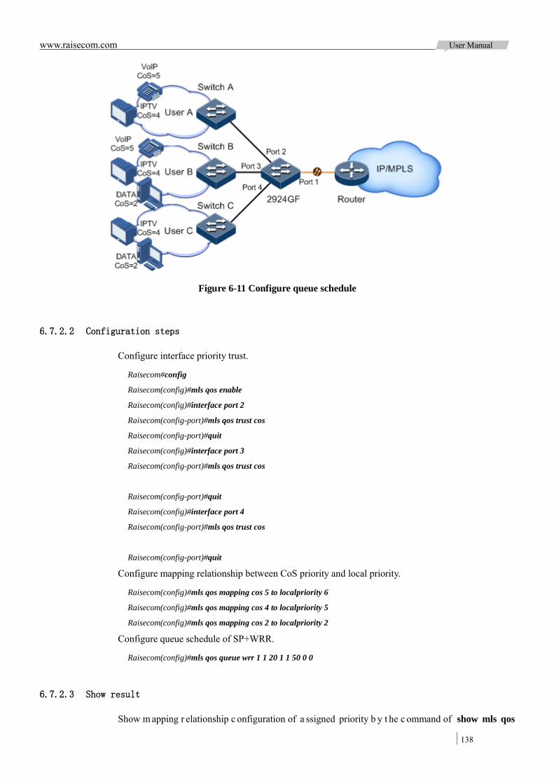
www.raisecom.com User Manual
138
Figure 6-11 Configure queue schedule
6.7.2.2 Configuration steps
Configure interface priority trust.
Raisecom#config
Raisecom(config)#mls qos enable
Raisecom(config)#interface port 2
Raisecom(config-port)#mls qos trust cos
Raisecom(config-port)#quit
Raisecom(config)#interface port 3
Raisecom(config-port)#mls qos trust cos
Raisecom(config-port)#quit
Raisecom(config)#interface port 4
Raisecom(config-port)#mls qos trust cos
Raisecom(config-port)#quit
Configure mapping relationship between CoS priority and local priority.
Raisecom(config)#mls qos mapping cos 5 to localpriority 6
Raisecom(config)#mls qos mapping cos 4 to localpriority 5
Raisecom(config)#mls qos mapping cos 2 to localpriority 2
Configure queue schedule of SP+WRR.
Raisecom(config)#mls qos queue wrr 1 1 20 1 1 50 0 0
6.7.2.3 Show result
Show m apping r elationship c onfiguration of a ssigned priority b y t he c ommand of show mls qos
www.raisecom.com User Manual
139
mapping
Raisecom(config)#show mls qos mapping cos
CoS-LocalPriority Mapping:
CoS: 0 1 2 3 4 5 6 7
--------------------------------------------------
LocalPriority: 0 1 2 3 5 6 6 7
Show queue schedule configuration by the command of show mls qos queue.
Raisecom(config)#show mls qos queue
Queue Weight(WRR)
-------------------------
1 1
2 1
3 20
4 1
5 1
6 50
7 0
8 0
Queue Weight(DRR)
-------------------------
1 1
2 1
3 1
4 1
5 1
6 1
7 1
8 1
6.7.3 Configure traffic rate limit over interface application 6.7.3.1 Networking requirement
As the Figure 6-12 shows below, User A, User B, User C are respectively connected to Switch A, Switch B, Switch C and ISCOM2924GF.
User A provides voice and video services, User B provides voice, video and data services, User C provides video and data services.
According to service requirements from users, make rules as below:
For U ser A, must p rovide 25M bandwidth, burst t raffic f low pe rmit 100KB, di scarding r edundant traffic;
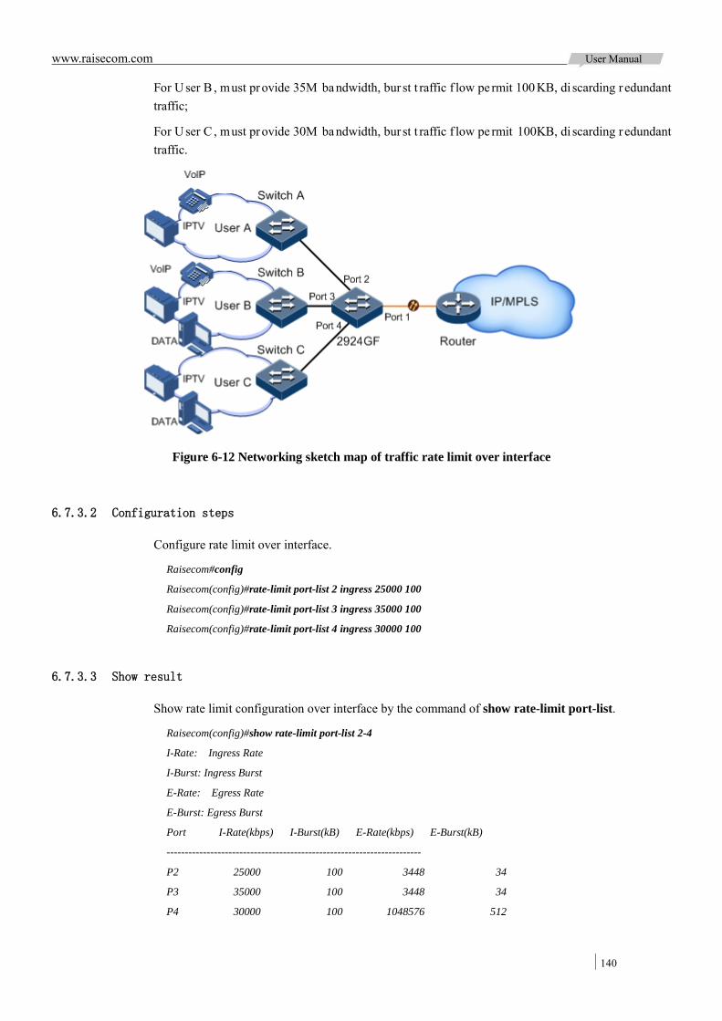
www.raisecom.com User Manual
140
For U ser B , must provide 35M bandwidth, bur st t raffic f low pe rmit 100 KB, di scarding r edundant traffic;
For U ser C , must provide 30M bandwidth, bur st t raffic f low pe rmit 100KB, di scarding r edundant traffic.
Figure 6-12 Networking sketch map of traffic rate limit over interface
6.7.3.2 Configuration steps
Configure rate limit over interface.
Raisecom#config
Raisecom(config)#rate-limit port-list 2 ingress 25000 100
Raisecom(config)#rate-limit port-list 3 ingress 35000 100
Raisecom(config)#rate-limit port-list 4 ingress 30000 100
6.7.3.3 Show result
Show rate limit configuration over interface by the command of show rate-limit port-list.
Raisecom(config)#show rate-limit port-list 2-4
I-Rate: Ingress Rate
I-Burst: Ingress Burst
E-Rate: Egress Rate
E-Burst: Egress Burst
Port I-Rate(kbps) I-Burst(kB) E-Rate(kbps) E-Burst(kB)
----------------------------------------------------------------------
P2 25000 100 3448 34
P3 35000 100 3448 34
P4 30000 100 1048576 512
www.raisecom.com User Manual
141
Chapter 7 Multicast
This c hapter i ntroduces b asic pr inciple a nd c onfiguration of m ulticast a nd provides r elated configuration applications.
Overview Configure IGMP foundation Configure IGMP Snooping Configure IGMP MVR Configure IGMP Proxy Maintenance Configuring applications
7.1 Overview
7.1.1 Multicast overview With t he c ontinuous development of Internet ne twork, the various interacting network data, v oice and video will become more and more; the other hand, the emerging e-commerce, online meetings, online a uctions, v ideo on d emand, di stance l earning a nd ot her s ervices also rise gradually. These services come up w ith higher requirements for ne twork bandwidth, information security and pa id. Traditional unicast and broadcast cannot meet these requirements well, while multicast has met them timely.
Multicast is a poi nt to multipoint data transmission method. The method can effectively solve the single point sending and multipoint receiving problems. During the network packet transmission, it can save network resources and improve information security.
7.1.1.1 Comparison among unicast, broadcast and multicast
Multicast is a kind of packets transmission which is parallel with unicast and broadcast.
Unicast: T he s ystem e stablished a data transmission path f or e ach us er w ho ne eds t he information, a nd s ent s eparate c opy i nformation f or them. Through unicast, t he amount o f information transmitted over the network is proportional to the number of user, so when the number of users becomes huge, there will be more identical information in network. At this point, bandwidth will become an important bottleneck, and unicast will not be conducive to large-scale information transmission.
Broadcast: The system sends information to all users, whether they need or not, any user will receive it. Through broadcast, the information source delivers information to all users in the network segment, which made the information security and paid s ervice lose gua rantee. In addition, w hen the num ber of us ers w ho re quires this kind of information decreases, the utilization of network resources will be very low, the bandwidth will be wasted seriously.
Multicast: When some users in the network need specific information, the sender only sends one piece of information, then the transmitted information can be reproduced and distributed in fork junction as far as possible.
As shown in the Figure 7-1, assume that User B and User C need information, you can use multicast
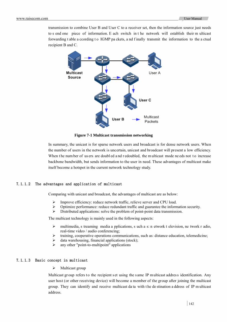
www.raisecom.com User Manual
142
transmission to combine User B and User C to a receiver set, then the information source just needs to s end one piece of information. E ach switch in t he network will establish their m ulticast forwarding t able a ccording t o IGMP pa ckets, a nd f inally transmit the information to the a ctual recipient B and C.
Figure 7-1 Multicast transmission networking
In summary, the unicast is for sparse network users and broadcast is for dense network users. When the number of users in the network is uncertain, unicast and broadcast will present a low efficiency. When t he num ber of us ers are doubl ed a nd r edoubled, the m ulticast mode ne eds not t o increase backbone bandwidth, but sends information to the user in need. These advantages of multicast make itself become a hotspot in the current network technology study.
7.1.1.2 The advantages and application of multicast
Comparing with unicast and broadcast, the advantages of multicast are as below:
Improve efficiency: reduce network traffic, relieve server and CPU load. Optimize performance: reduce redundant traffic and guarantee the information security. Distributed applications: solve the problem of point-point data transmission.
The multicast technology is mainly used in the following aspects:
multimedia, s treaming media a pplications, s uch a s: n etwork t elevision, ne twork r adio, real-time video / audio conferencing;
training, cooperative operations communications, such as: distance education, telemedicine; data warehousing, financial applications (stock); any other "point-to-multipoint" applications
7.1.1.3 Basic concept in multicast
Multicast group
Multicast gr oup refers t o the recipient s et using the s ame IP multicast addres s identification. Any user host (or other receiving device) will become a member of the group after joining the multicast group. They can identify and receive multicast da ta with t he de stination a ddress of IP m ulticast address.
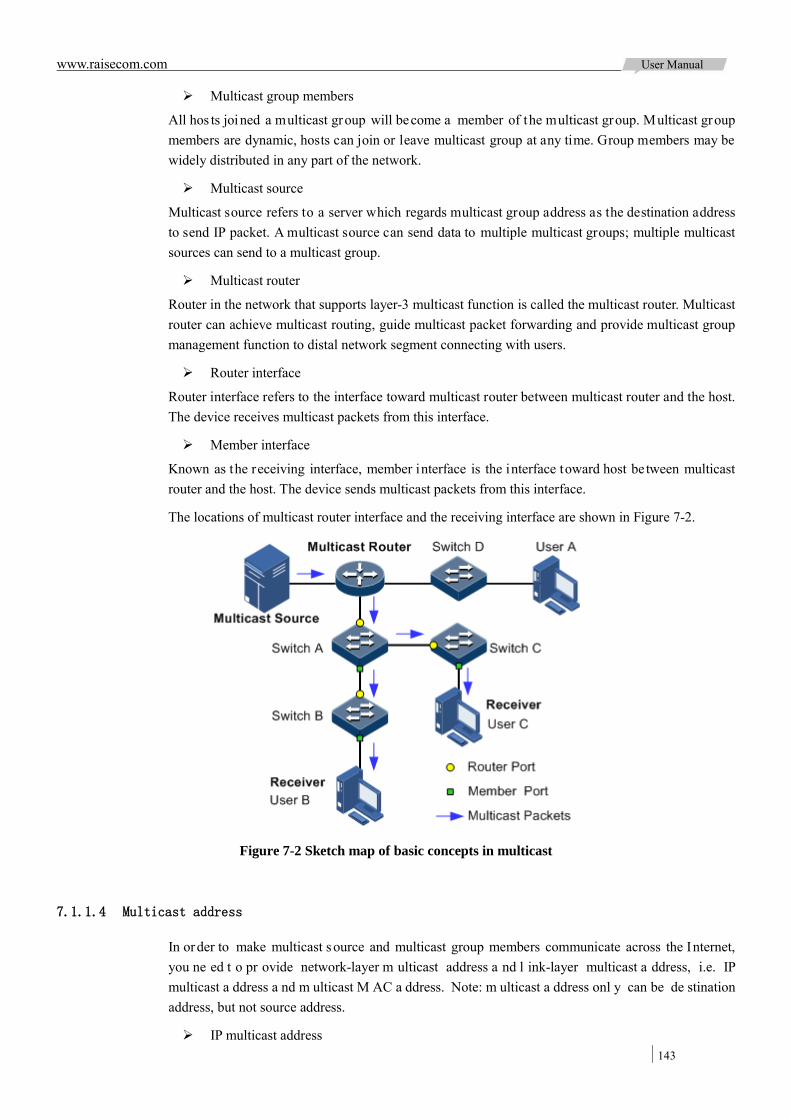
www.raisecom.com User Manual
143
Multicast group members
All hos ts joined a multicast group will become a member of the multicast group. Multicast group members are dynamic, hosts can join or leave multicast group at any time. Group members may be widely distributed in any part of the network.
Multicast source
Multicast source refers to a server which regards multicast group address as the destination address to send IP packet. A multicast source can send data to multiple multicast groups; multiple multicast sources can send to a multicast group.
Multicast router
Router in the network that supports layer-3 multicast function is called the multicast router. Multicast router can achieve multicast routing, guide multicast packet forwarding and provide multicast group management function to distal network segment connecting with users.
Router interface
Router interface refers to the interface toward multicast router between multicast router and the host. The device receives multicast packets from this interface.
Member interface
Known as the receiving interface, member interface is the interface toward host between multicast router and the host. The device sends multicast packets from this interface.
The locations of multicast router interface and the receiving interface are shown in Figure 7-2.
Figure 7-2 Sketch map of basic concepts in multicast
7.1.1.4 Multicast address
In order to make multicast s ource and multicast group members communicate across the Internet, you ne ed t o pr ovide network-layer m ulticast address a nd l ink-layer multicast a ddress, i.e. IP multicast a ddress a nd m ulticast M AC a ddress. Note: m ulticast a ddress onl y can be de stination address, but not source address.
IP multicast address
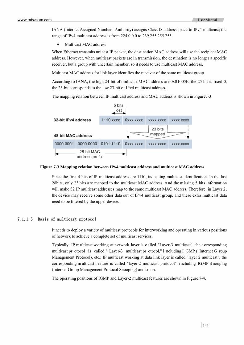
www.raisecom.com User Manual
144
IANA (Internet Assigned Numbers Authority) assigns Class D address space to IPv4 multicast; the range of IPv4 multicast address is from 224.0.0.0 to 239.255.255.255.
Multicast MAC address
When Ethernet transmits unicast IP packet, the destination MAC address will use the recipient MAC address. However, when multicast packets are in transmission, the destination is no longer a specific receiver, but a group with uncertain member, so it needs to use multicast MAC address.
Multicast MAC address for link layer identifies the receiver of the same multicast group.
According to IANA, the high 24-bit of multicast MAC address are 0x01005E, the 25-bit is fixed 0, the 23-bit corresponds to the low 23-bit of IPv4 multicast address.
The mapping relation between IP multicast address and MAC address is shown in Figure7-3
Figure 7-3 Mapping relation between IPv4 multicast address and multicast MAC address
Since the first 4 bits of IP multicast address are 1110, indicating multicast identification. In the last 28bits, only 23 bits are mapped to the multicast MAC address. And the missing 5 bits information will make 32 IP multicast addresses map to the same multicast MAC address. Therefore, in Layer 2, the device may receive some other data out of IPv4 multicast group, and these extra multicast data need to be filtered by the upper device.
7.1.1.5 Basis of multicast protocol
It needs to deploy a variety of multicast protocols for interworking and operating in various positions of network to achieve a complete set of multicast services.
Typically, IP m ulticast w orking at n etwork layer is c alled "Layer-3 multicast", t he c orresponding multicast pr otocol is called " Layer-3 multicast pr otocol," i ncluding I GMP ( Internet G roup Management Protocol), etc.; IP multicast working at data link layer is called "layer 2 multicast", the corresponding m ulticast f eature is called "layer-2 multicast protocol", i ncluding IGMP S nooping (Internet Group Management Protocol Snooping) and so on.
The operating positions of IGMP and Layer-2 multicast features are shown in Figure 7-4.

www.raisecom.com User Manual
145
Figure 7-4 The operating positions of IGMP and Layer-2 multicast features
IGMP i s t he pr otocol r esponsible f or I Pv4 multicast member management in TCP / IP protocol family. IGMP r uns between multicast r outer a nd hos t, de fines t he establishment a nd maintenance mechanism of multicast gr oup m embership be tween host and multicast r outer. IGMP d oes not contain the transmission and maintenance of group membership between multicast routers, which is completed by multicast routing protocol.
IGMP manages group members by IGMP messages interaction between host and multicast router. IGMP messages are encapsulated in IP messages, including Query messages, Report messages and Leave messages. The basic functions of IGMP are:
Host sends Report messages joining multicast group, sends Leave messages leaving multicast group, and automatically decides which multicast group messages to receive.
The multicast rout er se nds Query messages periodically and receives Report messages and Leave messages from hosts to understand the multicast group members in connected network segment. The multicast data will be forwarded to the network segment if there are multicast group members; not forward if no multicast group members.
Up to now, IGMP has three versions: IGMPv1 version, IGMPv2 version and IGMPv3 version, the new version is fully compatible with old version. Currently the most widely used version is IGMPv2, while Leave messages only apply to IGMPv2 and IGMPv3.
Layer-2 multicast manages a nd c ontrols multicast gr oups by monitoring a nd a nalyzing IGMP messages be tween hosts a nd multicast r outers as s o to achieve multicast data f orwarding a nd suppress multicast data diffusion in layer-2 network.
7.1.1.6 The supported multicast performance
The device is in support of the following multicast features:
Basic function of IGMP IGMP Snooping IGMP MVR IGMP Proxy (IGMP Proxy) IGMP filtering
Note:
The functions of IGMP Snooping and IGMP MVR on ISCOM2924GF device can be enabled simultaneously.
ISCOM2924GF device is in support of IGMPv1and IGMPv2 simultaneously.

www.raisecom.com User Manual
146
7.1.2 Basic functions of IGMP The basic functions of IGMP are shown below:
Assign multicast router interface; Enable instant-leaving function; Set multicast forwarding entries and router interface aging time; Enable IGMP ring network forwarding function.
The basic function of IGMP provides Layer-2 multicast common features, which can be used when the device enables IGMP Snooping or IGMP MVR function.
Note: The basic function configuration is valid to IGMP Snooping or IGMP MVR simultaneously.
The concepts description related to IGMP basic functions is as below:
Multicast router interface
The r outer i nterface can be l earnt dynamically (need t o e nable multicast routing protocol on multicast routers, learn by IGMP query messages) on layer-2 multicast switch, or set manually so as to forward downstream multicast report and leave messages to the router interface.
Router interface learnt dynamically has aging time, while the router interface configured manually will not be aged.
Aging time
Set the aging time applying to both of multicast forwarding entry and router interface.
On layer-2 switch running multicast function, every router interface learnt dynamically will enable a timer; the timer timeout is "IGMP Snooping aging time." The router interface will be deleted without receiving IGMP Query messages at aging time; Update timeout for router interface when receiving IGMP Query messages.
Each multicast forwarding entry will enable a timer, that is, the aging time of multicast member; the timer tim eout is "IGMP S nooping a ging t ime". The m ulticast member w ill be deleted without receiving IGMP Report messages at aging time; Update timeout for multicast forwarding entry when receiving IGMP Report messages.
Instant-leaving function
On layer-2 s witch r unning m ulticast function, us er w ill not de lete t he c orresponding multicast forwarding entry immediately, but wait until the entry is aged when sending Leave messages. Enable this function to delete the corresponding multicast forwarding entry quickly when there are a large number of downstream users and adding leaving is more frequent.
Note: Instant-leaving function only applies to IGMP v2/v3 versions.
IGMP ring network forwarding function
On layer-2 switch running multicast function, t he IGMP r ing ne twork forwarding function can be enabled to any type of interfaces.
Enabling IGMP ring network forwarding can achieve multicast backup protection in r ing network, make the m ulticast service m ore stable, and prevent l ink failure from causing multicast s ervice failure.
IGMP ring network forwarding function applies to Ethernet ring, STP / RSTP / MSTP ring and G.8032 ring, etc.
www.raisecom.com User Manual
147
7.1.3 IGMP Snooping IGMP S nooping ( Internet G roup M anagement Protocol S nooping) i s m ulticast c onstraining mechanism r unning on L ayer-2 devices, us ed for m ulticast gr oup m anagement a nd c ontrol and achieve layer-2 multicast.
IGMP S nooping a llows t he switch t o monitor IGMP session between hos ts and multicast r outers. When monitoring a group of IGMP Report from host, the switch will add host-located interface to the f orwarding e ntry of t his gr oup; similarly, w hen f orwarding entry arriving at aging t ime, the switch will delete host-located interface from forwarding entry.
IGMP Snooping forwards multicast da ta by layer-2 multicast forwarding entry. When receiving multicast da ta, the switch will forward them directly according to the corresponding receiver interface of multicast f orwarding e ntry, but not f lood t o a ll i nterfaces, so as to save the switch bandwidth effectively.
IGMP Snooping establishes layer-2 multicast forwarding entry, which can be learnt dynamically or configured manually.
Currently, the switch is in support of up to 1024 layer-2 multicast forwarding entries.
7.1.4 IGMP MVR IGMP MVR (Multicast VLAN Registration) is multicast constraining mechanism running on layer-2 devices, used for multicast group management and control and achieve layer-2 multicast.
IGMP MVR adds member interfaces belonging to different user VLAN in switch to multicast VLAN by configuring multicast VLAN and makes different VLAN user uses one common multicast VLAN, then the multicast data will be transmitted only in one multicast VLAN without copying one for each user VLAN, t hus s aving b andwidth. At the s ame t ime, multicast V LAN and us er V LAN ar e completely isolated which also increases the security.
Both IGMP MVR and IGMP Snooping can achieve layer-2 multicast, but the difference is: Multicast VLAN in IGMP Snooping is the same with user VLAN, while multicast VLAN in IGMP MVR can be different with user VLAN.
Note: One switch can configure up t o 10 multicast VLAN, at least one multicast VLAN and group addresses. The supported maximum number of multicast groups is 1024.
7.1.5 IGMP Proxy IGMP Proxy is an IGMP protocol proxy mechanism. It is used for assisting IGMP to manage and control multicast group. IGMP Proxy will terminate IGMP packets; It can proxy host function and also proxy multicast router functions for t he next agent. E nable Layer 2 ne twork device of I GMP Proxy feature, there are two identities:
On t he us er s ide, i t i s a query bui lder a nd un dertakes t he r ole of Server, s ending Query packets and periodically checking user information, and dealing with the Report and Leave packets from user.
On the network routing s ide, i t i s a hos t and unde rtakes the role of C lient, r esponding the multicast r outer Q uery pa cket and s ending Report an d Leave pa ckets. It s ends the us er information to the network when they are in need.
The proxy mechanism can control and access user information effectively, at the same time, reducing
www.raisecom.com User Manual
148
the ne twork s ide pr otocol packet a nd n etwork l oad. IGMP Proxy e stablishes multicast pa cket forwarding list by intercepting IGMP packet between the user and the multicast routers.
7.1.6 IGMP filtering In or der t o c ontrol us er a ccess, y ou c an s et IGMP f iltering. I GMP f iltering contains acces sible multicast group scope limited by filter template and the maximum number of groups:
IGMP filtering template
To e nsure i nformation s ecurity, t he a dministrator ne eds t o l imit t he multicast us ers, s uch a s what multicast data are allowed to receive and what are not.
Configure IGMP Profile filtering template to control the interface. One IGMP Profile can be set one or more multicast group access control restrictions and access the multicast group according to the restriction rules ( permit and deny). If a r ejected IGMP P rofile filtering template is applied to the interface, the interface will discard the IGMP report message from this group directly once receiving it and doesn’t allow receiving this group of multicast data.
IGMP filtering template can be configured on interface or "interface + VLAN".
IGMP Profile only applies to dynamic multicast groups, but not static ones.
Limit to the maximum number of multicast group
The maximum al lowed adding number of multicast group and the maximum group limitation rule can be set on interface or "interface + VLAN”.
The maximum group limitation rule sets the actions for reaching the maximum number of multicast group users added, which can be no l onger allowing user adding groups, or covering the or iginal adding group.
Note: IGMP filtering is generally used with IGMP Snooping/IGMP MVR.
7.2 Configure IGMP foundation
7.2.1 Configure basic function of IGMP Please configure basic function of IGMP for the device as below
Step Configuration Description
1 Raisecom#config Enter global configuration mode.
2 Raisecom(config)#igmp mrouter vlan vlan-id { interface-type interface-number }
(Optional) Configure multicast routing interface
3 Raisecom(config)#igmp immediate-leave { interface-type interface-number } [ vlan
vlan-list ]
(Optional) Configure interface or the immediate-leave function of “interface + VLAN”.
4 Raisecom(config)#igmp timeout { period | infinite }
(Optional) Configure the aging time for multicast forwarding table entry.
The aging time set by this command is valid to all dynamic learning router interface and multicast
forwarding table entries.
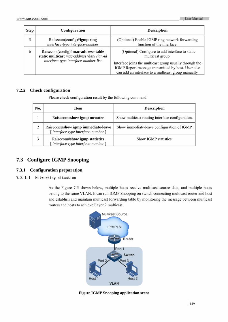
www.raisecom.com User Manual
149
Step Configuration Description
5 Raisecom(config)#igmp ring interface-type interface-number
(Optional) Enable IGMP ring network forwarding function of the interface.
6 Raisecom(config)#mac-address-table static multicast mac-address vlan vlan-id
interface-type interface-number-list
(Optional) Configure to add interface to static multicast group.
Interface joins the multicast group usually through the IGMP Report message transmitted by host. User also can add an interface to a multicast group manually.
7.2.2 Check configuration Please check configuration result by the following command:
No. Item Description
1 Raisecom#show igmp mrouter Show multicast routing interface configuration.
2 Raisecom#show igmp immediate-leave [ interface-type interface-number ]
Show immediate-leave configuration of IGMP.
3 Raisecom#show igmp statistics [ interface-type interface-number ]
Show IGMP statistics.
7.3 Configure IGMP Snooping
7.3.1 Configuration preparation 7.3.1.1 Networking situation
As the Figure 7-5 shows below, multiple hosts receive multicast source data, and multiple hosts belong to the same VLAN. It can run IGMP Snooping on switch connecting multicast router and host and establish and maintain multicast forwarding table by monitoring the message between multicast routers and hosts to achieve Layer 2 multicast.
Figure IGMP Snooping application scene

www.raisecom.com User Manual
150
7.3.1.2 Precondition
Before c onfiguring I GMP Snooping, you s hould create t he V LAN a nd j oin t he c orresponding interface to VLAN.
7.3.2 Default configuration of IGMP Snooping The default configuration of IGMP Snooping is as below:
Function Default value
Global IGMP Snooping status Disable
VLAN IGMP Snooping status Disable
7.3.3 Configure IGMP Snooping function Please configure IGMP Snooping function as below:
Step Configuration Description
1 Raisecom#config Enter global configuration mode
2 Raisecom(config)#igmp snooping Enable global IGMP Snooping.
3 Raisecom(config)#igmp snooping vlan vlan-list
Enable VLAN IGMP Snooping.
4 Raisecom(config)#mac-address-table static multicast mac-address vlan
vlan-id interface-type interface-number-list
(Optional) Configure static multicast forwarding table.
Interface joins the multicast group usually through the IGMP Report message
transmitted by host. User also can add an interface to a multicast group manually.
7.3.4 Check configuration Please check configuration result by the following command:
No. Item Description
1 Raisecom#show igmp snooping [ vlan vlan-list ] Show IGMP Snooping configuration.
2 Raisecom#show igmp snooping member [ interface-type interface-number | vlan vlan-id ]
Show IGMP Snooping multicast group member configuration.
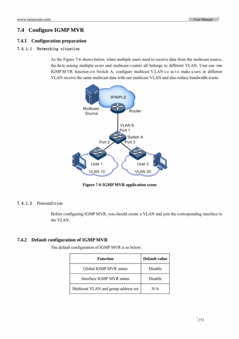
www.raisecom.com User Manual
151
7.4 Configure IGMP MVR
7.4.1 Configuration preparation 7.4.1.1 Networking situation
As the Figure 7-6 shows below, when multiple users need to receive data from the multicast source, the da ta among multiple us ers and multicast r outers all belongs to different VLAN. User can run IGMP M VR function o n Switch A, configure multicast V LAN s o as t o make u sers in different VLAN receive the same multicast data with one multicast VLAN and also reduce bandwidth waste.
Figure 7-6 IGMP MVR application scene
7.4.1.2 Precondition
Before configuring IGMP MVR, you should create a VLAN and join the corresponding interface to the VLAN.
7.4.2 Default configuration of IGMP MVR The default configuration of IGMP MVR is as below:
Function Default value
Global IGMP MVR status Disable
Interface IGMP MVR status Disable
Multicast VLAN and group address set N/A

www.raisecom.com User Manual
152
7.4.3 Configure IGMP MVR function Please configure IGMP MVR function as below:
Step Configuration Description
1 Raisecom#config Enter global configuration mode
2 Raisecom(config)#igmp mvr Enable global IGMP MVR function.
3 Raisecom(config)#igmp mvr interface-type interface-number
Enable interface IGMP MVR function.
4 Raisecom(config)#igmp mvr mcast-vlan vlan-id group { start-ip-address
[ end-ip-address ] | any }
Configure multicast VLAN IP address.
Note: After enabling IGMP MVR, the device needs to configure multicast VLAN and binding group address set, do nothing to Report message if the receiving IGMP
Report message doesn’t belong to any VLAN IP address set, user cannot demand
to multicast traffic.
5 Raisecom(config)#mac-address-table static multicast mac-address vlan vlan-id
interface-type interface-number-list
(Optional) Configure static multicast forwarding table.
Interface joins the multicast group usually through the IGMP Report message
transmitted by host. User also can add an interface to a multicast group manually.
7.4.4 Check configuration Please check configuration result by the following command:
No. Item Description
1 Raisecom#show igmp mvr[ interface-type interface-number ]
View IGMP MVR configuration.
2 Raisecom#show igmp mvr member [ interface-type interface-number |
user-vlan vlan-id ]
View IGMP MVR multicast group members information.
3 Raisecom# show igmp mvr vlan-group [ mcast-vlan vlan-id ]
View multicast VLAN and group address set.
7.5 Configure IGMP Proxy
7.5.1 Configuration preparation 7.5.1.1 Networking situation
There are multiple hosts or multiple user subnets in a large-scale multicast protocols application network. Configure IGMP pr oxy on switch which connects w ith multicast r outer and h ost t o intercept the IGMP packets and reduce network burden.
IGMP P roxy can reduce t he configuration a nd management w ork of multicast r outers to users subnets, at the same time, achieve the multicast connection of customer subnet.

www.raisecom.com User Manual
153
IGMP Proxy function is generally used with IGMP Snooping or IGMP MVR.
7.5.1.2 Precondition
Before configuring IGMP Proxy, you should create VLAN and join the corresponding interface to the VLAN.
7.5.2 Default configuration of IGMP Proxy The default configuration of IGMP Proxy is as below:
Function Default value
IGMP Proxy status Disable
IGMP message suppression function Disable
IGMP querier function Disable
IGMP querier and source IP address of IGMP Proxy transmission message
Use the IP address of IP interface 0, or use 0.0.0.0 if the IP interface 0 hasn’t be configured.
IGMP query interval 60s
The maximum response time of Query transmission message
10s
The Query transmission interval of final member
1s
7.5.3 Configure IGMP Proxy function Please configure IGMP Proxy function as below:
Step Configuration Description
1 Raisecom#config Enter global configuration mode
2 Raisecom(config)#igmp proxy Enable IGMP Proxy function
3 Raisecom(config)#igmp proxy suppression
Enable IGMP packet suppression function.
4 Raisecom(config)#igmp proxy querier Enable IGMP querier function
5 Raisecom(config)#igmp proxy source-ip ip-address
(Optional) Configure source IP address of query packet sent by IGMP Proxy querier.
6 Raisecom(config)#igmp proxy query-interval seconds
(Optional) Configure IGMP query interval.
7 Raisecom(config)#igmp proxy query-max-response-time period
(Optional) Configure the maximum response time of Query packet.
8 Raisecom(config)#igmp proxy last-member-query period
(Optional) Configure the Query transmission interval of final member.
Note:

www.raisecom.com User Manual
154
Configure IGMP P roxy if it isn’t ena bled: set source I P address, t he que ry interval, the maximum response t ime of Query packet transmission, Query transmission interval of f inal member, once MVR Proxy is started, the configuration takes effect immediately.
IGMP Proxy function can be started when enabling IGMP Snooping or IGMP MVR.
7.5.4 Check configuration Please check configuration result by the following command:
No. Item Description
1 Raisecom#show igmp proxy View IGMP Proxy configuration information
7.6 Configure IGMP filtering
7.6.1 Configuration preparation 7.6.1.1 Networking situation
The di fferent us ers in the s ame multicast group receive different multicast requirements a nd permissions, allow configuring filter rule on switch which connects multicast router and user host so as to restrict multicast users. It also can set the maximum number of multicast group allowing user joining. IGMP Proxy function is generally used with IGMP Snooping or IGMP MVR.
7.6.1.2 Precondition
Before configuring IGMP filtering, you should create VLAN and join the corresponding interface to the VLAN.
7.6.2 Default configuration of IGMP filtering The default configuration of IGMP filtering is as below:
Function Default value
Global IGMP filtering Disable
IGMP filtering template Profile N/A
IGMP filtering template action Refuse
IGMP filtering under interface No maximum group limitation, the largest group action is drop, no application filter template
IGMP filtering under “interface + VLAN” No maximum group limitation, the largest group action is drop, no application filter template
7.6.3 Configure to enable global IGMP filtering Please configure to enable global IGMP filtering as below:

www.raisecom.com User Manual
155
Step Configuration Description
1 Raisecom#config Enter global configuration mode
2 Raisecom(config)#igmp filter Enable global IGMP filtering
Note: When configuring IGMP filtering template or the maximum group limitation, please use the command igmp filter to enable global IGMP filtering at first.
7.6.4 Configure IGMP filtering template IGMP filtering template can be used to interface or “interface + VLAN”.
Please configure IGMP filtering template as below:
Step Configuration Description
1 Raisecom#config Enter global configuration mode
2 Raisecom(config)#igmp filter profile profile-number
Create Profile and enter Profile configuration mode.
3 Raisecom(config-igmp-profile)#permit | deny
(Optional) Configure IGMP Profile action.
4 Raisecom(config-igmp-profile)#range range-id start-ip-address [ end-ip-address ]
Configure to control IP multicast address access and range.
5 Raisecom(config-igmp-profile)#exit
Raisecom(config)#interface interface-type interface-number
Enter physical layer interface configuration mode or aggregation group configuration mode.
6 Raisecom(config-port)#igmp filter profile profile-number [ vlan vlan-list ]
Configure IGMP Profile filtering template to physical interface or “interface + VLAN”.
Raisecom(config-aggregator)#igmp filter profile profile-number [ vlan vlan-list ]
Configure IGMP Profile filtering template to aggregation group interface or “interface + VLAN”.
Note: Perform the command of igmp filter profile profile-number in interface configuration mode to make the created IGMP Profile apply to the specified interface. One IGMP Profile can be applied to multiple interfaces, but each interface can have only one IGMP Profile.
7.6.5 Configure the maximum multicast group number restriction User can add the maximum multicast group number restriction applied to interface or “interface + VLAN”.
Please take the following configuration to the device:
Step Configuration Description
1 Raisecom#config Enter global configuration mode
2 Raisecom(config)#interface interface-type interface-number
Enter physical layer interface configuration mode or aggregation group configuration mode.
3 Raisecom(config-port)#igmp filter max-groups group-number [ vlan
vlan-list ]
Configure the maximum multicast group number restriction to physical interface or “interface +
VLAN”.

www.raisecom.com User Manual
156
Step Configuration Description
Raisecom(config-aggregator)#igmp filter max-groups group-number
[ vlan vlan-list ]
Configure the maximum multicast group number restriction to aggregation group interface or
“interface + VLAN”.
4 Raisecom(config-port)#igmp filter max-groups action { drop | replace } [ vlan vlan-list ]
(Optional) Configure the action over maximum multicast group number restriction in physical
interface or “interface + VLAN”.
Raisecom(config-aggregator)#igmp filter max-groups action { drop |
replace } [ vlan vlan-list ]
(Optional) Configure the action over maximum multicast group number restriction in aggregation
group interface or “interface + VLAN”.
7.6.6 Check configuration Please check configuration result by the following command:
No. Item Description
1 Raisecom#show igmp filter [interface| interface-type interface-number [vlan vlan-id ] ]
View IGMP filtering configuration.
2 Raisecom#show igmp filter profile [ profile-number ]
View IGMP Profile information.
7.7 Maintenance
Users can maintain multicast features operation and configuration by the following command.
Command Description
Raisecom(config)#clear igmp statistics [ interface-type interface-number ]
Clear IGMP statistic information
Raisecom(config)#no igmp member [ interface-type interface-number ]
Delete specified multicast forwarding table entry.
7.8 Configuration application
7.8.1 Configure IGMP Snooping and IGMP Proxy application 7.8.1.1 Network requirements
As Shown in Figure 7-7, the switch interface Port 1 connects with multicast router; interface Port 2 and Port 3 connects users. All multicast users belong to the same VLAN10; It is needed to configure IGMP Snooping on the switch to receive multicast data with the address 234.5.6.7.
Enable the IGMP P roxy function on switch to r educe communication between the hosts and multicast routers and achieve multicast function.
When the P C and set-top box a dd i nto t he s ame m ulticast gr oup, t he s witch r eceives t wo I GMP Report messages and only sends one of them to multicast router. The IGMP Query message sent by multicast will no longer forward downstream, but transmit IGMP Query message
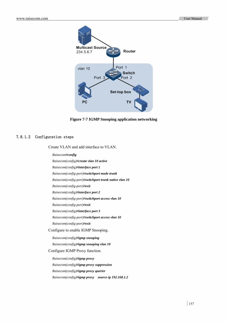
www.raisecom.com User Manual
157
Figure 7-7 IGMP Snooping application networking
7.8.1.2 Configuration steps
Create VLAN and add interface to VLAN.
Raisecom#config
Raisecom(config)#create vlan 10 active
Raisecom(config)#interface port 1
Raisecom(config-port)#switchport mode trunk
Raisecom(config-port)#switchport trunk native vlan 10
Raisecom(config-port)#exit
Raisecom(config)#interface port 2
Raisecom(config-port)#switchport access vlan 10
Raisecom(config-port)#exit
Raisecom(config)#interface port 3
Raisecom(config-port)#switchport access vlan 10
Raisecom(config-port)#exit
Configure to enable IGMP Snooping.
Raisecom(config)#igmp snooping
Raisecom(config)#igmp snooping vlan 10
Configure IGMP Proxy function.
Raisecom(config)#igmp proxy
Raisecom(config)#igmp proxy suppression
Raisecom(config)#igmp proxy querier
Raisecom(config)#igmp proxy source-ip 192.168.1.2
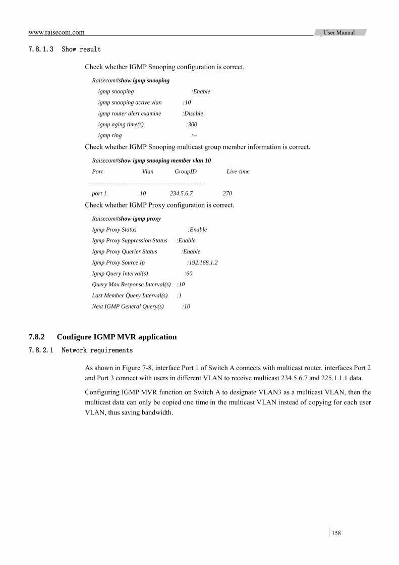
www.raisecom.com User Manual
158
7.8.1.3 Show result
Check whether IGMP Snooping configuration is correct.
Raisecom#show igmp snooping
igmp snooping :Enable
igmp snooping active vlan :10
igmp router alert examine :Disable
igmp aging time(s) :300
igmp ring :--
Check whether IGMP Snooping multicast group member information is correct.
Raisecom#show igmp snooping member vlan 10
Port Vlan GroupID Live-time
-------------------------------------------------------
port 1 10 234.5.6.7 270
Check whether IGMP Proxy configuration is correct.
Raisecom#show igmp proxy
Igmp Proxy Status :Enable
Igmp Proxy Suppression Status :Enable
Igmp Proxy Querier Status :Enable
Igmp Proxy Source Ip :192.168.1.2
Igmp Query Interval(s) :60
Query Max Response Interval(s) :10
Last Member Query Interval(s) :1
Next IGMP General Query(s) :10
7.8.2 Configure IGMP MVR application 7.8.2.1 Network requirements
As shown in Figure 7-8, interface Port 1 of Switch A connects with multicast router, interfaces Port 2 and Port 3 connect with users in different VLAN to receive multicast 234.5.6.7 and 225.1.1.1 data.
Configuring IGMP MVR function on Switch A to designate VLAN3 as a multicast VLAN, then the multicast data can only be copied one time in the multicast VLAN instead of copying for each user VLAN, thus saving bandwidth.

www.raisecom.com User Manual
159
Figure 7-8 IGMP MVR application networking
7.8.2.2 Configuration steps
Create VLAN on Switch A and add the interface into it.
Raisecom(config)#config
Raisecom(config)#creat vlan 3,12,13 active
Raisecom(config)#interface port 1
Raisecom(config-port)#switchport mode trunk
Raisecom(config-port)#switchport trunk native vlan 3
Raisecom(config-port)#switchport trunk untagged vlan 12,13
Raisecom(config-port)#exit
Raisecom(config)#interface port 2
Raisecom(config-port)#switchport mode trunk
Raisecom(config-port)#switchport trunk native vlan 12
Raisecom(config-port)#switchport trunk untagged vlan 3
Raisecom(config-port)#exit
Raisecom(config)#interface port 3
Raisecom(config-port)#switchport mode trunk
Raisecom(config-port)#switchport trunk native vlan 13
Raisecom(config-port)#switchport trunk untagged vlan 3
Raisecom(config-port)#exit
Configure IGMP MVR function on Switch A.
Raisecom(config)#igmp mvr
Raisecom(config)#igmp mvr port 2,3
Raisecom(config)#igmp mvr mcast-vlan 3 group 234.5.6.7
Raisecom(config)#igmp mvr mcast-vlan 3 group 225.1.1.1
www.raisecom.com User Manual
160
7.8.2.3 Show result
Check whether the IGMP MVR configuration configuration is correct.
Raisecom#show igmp mvr
igmp mvr running :Enable
igmp mvr port :port-list 2-3
igmp mvr multicast vlan(ref) :3(2)
igmp router alert examine :Disable
igmp aging time(s) :300
igmp ring :--
Check whether the multicast VLAN and group address information are correct.
Raisecom#show igmp mvr vlan-group
mcast-vlan start-group end-group
-------------------------------------------
3 225.1.1.1 225.1.1.1
3 234.5.6.7 234.5.6.7
7.8.3 Configure IGMP filtering example under the interface 7.8.3.1 Network requirements
Enable IGMP filtering on switch, add interface filter rule to restrict multicast user.
As shown in Figure 7-9, create IGMP filtering rules Profile 1, set address range between 234.5.6.7 and 234.5.6.10, the action is in green light. According to IGMP filtering rules under the interface Port 2, set-top box can join the multicast group 234.5.6.7, but not the multicast group 234.5.6.11; Port 3 hasn’t enabled filtering rule and PC can the multicast group 234.5.6.11.
Set the maximum gr oup l imitation to interface Port 2, a fter a dding s et-top boxe s 234.5. 6.7, a dd 234.5.6.8 and quit the previous 234.5.6.7 multicast group.
As Figure 7-9 shows, use IGMP MVR function to provide multicast service.
Figure 7-9 IGMP filtering networking

www.raisecom.com User Manual
161
7.8.3.2 Configuration steps
Create VLAN and add the interface into it.
Raisecom#config
Raisecom(config)#creat vlan 3,12,13 active
Raisecom(config)#interface port 1
Raisecom(config-port)#switchport mode trunk
Raisecom(config-port)#switchport trunk native vlan 3
Raisecom(config-port)#switchport trunk untagged vlan 12,13
Raisecom(config-port)#exit
Raisecom(config)#interface port 2
Raisecom(config-port)#switchport mode trunk
Raisecom(config-port)#switchport trunk native vlan 12
Raisecom(config-port)#switchport trunk untagged vlan 3
Raisecom(config-port)#exit
Raisecom(config)#interface port 3
Raisecom(config-port)#switchport mode trunk
Raisecom(config-port)#switchport trunk native vlan 13
Raisecom(config-port)#switchport trunk untagged vlan 3
Raisecom(config-port)#exit
Configure IGMP MVR function.
Raisecom(config)#igmp mvr
Raisecom(config)#igmp mvr port 2,3
Raisecom(config)#igmp mvr mcast-vlan 3 group any
Configure IGMP filtering template.
Raisecom(config)#igmp filter profile 1
Raisecom(config-igmp-profile)#permit
Raisecom(config-igmp-profile)#range 1 234.5.6.7 234.5.6.10
Raisecom(config-igmp-profile)#exit
Configure IGMP filtering template to set-top box.
Raisecom(config)#igmp filter
Raisecom(config)#interface port 2
Raisecom(config-port)#igmp filter profile 1
Configure the maximum group number limitation for set-top box interface.
Raisecom(config-port)#igmp filter max-groups 1
Raisecom(config-port)#igmp filter max-groups action replace
7.8.3.3 Show result
Check whether the IGMP filtering configuration is correct.
Raisecom#show igmp filter port 2

www.raisecom.com User Manual
162
IGMP profile: 1
MaxGroup: 1
Currentgroup: 0
action: replace
7.8.4 Configure ring network multicast application example 7.8.4.1 Network requirements
Configure IGMP r ing forwarding function on s ingle E thernet r ing to make multicast service more stable and prevent multicast service from disrupting by some failure links.
As shown in Figure 7-10, Port 1 and Port 2 of Switch A, Port 2 and Port 3 of Switch B, Port 2 and Port 4 of Switch C constitute an physical ring, multicast traffic input from Port 1 of Switch B. The user who need multicast stream goes through Port 5 and Port 6 interfaces of Switch C. By doing this, whichever links fail in the Switch, it will not affect customer’s on-demand multicast stream.
When using single Ethernet ring to provide multicast services, you can adopt IGMP MVR or IGMP Snooping function to receive the multicast stream.
Take STP providing ring network detection and IGMP Snooping providing multicast function for an example:
Figure 7-10 Ring network multicast application networking
7.8.4.2 Configuration steps
Enable STP function, create VLAN and add interface into the VLAN.
Configure Switch A
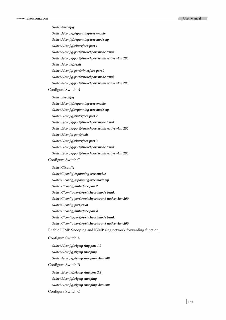
www.raisecom.com User Manual
163
SwitchA#config
SwitchA(config)#spanning-tree enable
SwitchA(config)#spanning-tree mode stp
SwitchA(config)#interface port 1
SwitchA(config-port)#switchport mode trunk
SwitchA(config-port)#switchport trunk native vlan 200
SwitchA(config)#exit
SwitchA(config-port)#interface port 2
SwitchA(config-port)#switchport mode trunk
SwitchA(config-port)#switchport trunk native vlan 200
Configura Switch B
SwitchB#config
SwitchB(config)#spanning-tree enable
SwitchB(config)#spanning-tree mode stp
SwitchB(config)#interface port 2
SwitchB(config-port)#switchport mode trunk
SwitchB(config-port)#switchport trunk native vlan 200
SwitchB(config-port)#exit
SwitchB(config)#interface port 3
SwitchB(config-port)#switchport mode trunk
SwitchB(config-port)#switchport trunk native vlan 200
Configura Switch C
SwitchC#config
SwitchC(config)#spanning-tree enable
SwitchC(config)#spanning-tree mode stp
SwitchC(config)#interface port 2
SwitchC(config-port)#switchport mode trunk
SwitchC(config-port)#switchport trunk native vlan 200
SwitchC(config-port)#exit
SwitchC(config)#interface port 4
SwitchC(config-port)#switchport mode trunk
SwitchC(config-port)#switchport trunk native vlan 200
Enable IGMP Snooping and IGMP ring network forwarding function.
Configure Switch A
SwitchA(config)#igmp ring port 1,2
SwitchA(config)#igmp snooping
SwitchA(config)#igmp snooping vlan 200
Configura Switch B
SwitchB(config)#igmp ring port 2,3
SwitchB(config)#igmp snooping
SwitchB(config)#igmp snooping vlan 200
Configura Switch C

www.raisecom.com User Manual
164
SwitchC(config)#igmp ring port 2,4
SwitchC(config)#igmp snooping
SwitchC(config)#igmp snooping vlan 200
7.8.4.3 Show result
Disconnect any one link in ring link to check whether the multicast traffic can be reveived normally.
www.raisecom.com User Manual
165
Chapter 8 Security
This c hapter i ntroduces b asic pr inciple a nd c onfiguration of s ecurity a nd pr ovides r elated configuration applications.
Overview ACL RADIUS TACACS+ Storm Control Maintenance Configuring applications
8.1 Overview
Network application is getting more and more popular with the continuous development of Internet. More and more enterprises speed up its development by using network. To ensure data and resource security in open network environemtn become more and more important. Besides, some user access network unconsciously but cause damage to network also lead device performance degrade or even cause abnormal.
To d eploy a ccess c ontrol, user a uthentication, e tc. s ecurity t echnology c an effectively i mprove network and device security.
8.1.1 ACL ACL (Access Control List) is a set of ordered rules, which can control the device to receive or refuse to some data message.
User needs to configure rules in network to control illegal packets influent network perofmrnace and decide packets allowed passing. These rules are defined by ACL.
ACL is a series of rule composed by permit | deny sentences. The rules are described according to source a ddress, destination a ddress, por t I D of da ta pa ckets. Device j udges r eceiving or r ejecting packets according to the rules.
8.1.2 RADIUS RADIUS (Remote Authentication Dial I n User S ervice) i s a kind of s tandard communication protocol t hat authenticate r emote acces s users intensively. RADIUS uses UDP a s t he t ransmission protocol (port 1812 and port 1813) which has a good instantaneity; at the same time, RADIUS is in support of retransmission mechanism and standby server mechanism which has a good reliability.
www.raisecom.com User Manual
166
8.1.2.1 RADIUS authentication function
RADIUS adopts c lient/server m ode, network access de vice i s us ed as cl ient of RADIUS server. RADIUS server receives user connecting requests and authenticates users, then reply configuration information to all clients for providing services. Control user access device and network and improve network security.
Communication between client and RADIUS server is authenticated by sharing key, which won’t be transmitted on network. Besides, all user directions need to be encrypted when transmitting between client device and RADIUS server to ensure security.
8.1.2.2 RADIUS accounting function
RADIUS accounting function i s used to authenticate user through RADIUS. User sends a starting account packets to RADIUS accrounting server when log in, according to the accounting policy to send update packet to RADIUS server; when log off, send stopping account packet to RADIUS accounting server, the packet includes user online time. RADIUS accounting server can record the access time and operations for each user by the packets.
8.1.3 TACACS+ TACACS+ (Terminal Access Controller Access Control System) i s a ki nd of ne twork a ccess authentication protocol similar to RADIUS. The differences between them are:
TACACS+ uses TCP port, which has higher transmission reliability compared with UPD port used by RADIUS.
TACACS+ encrypts the holistic of packets except the standard head of TACACS+, and there is an area to show whether the data packets are encrypted in the head of packet. Compared to RADIUS user password encryption, the TACACS+ is much safer.
TACACS+ authentication function is separated from authorization and accounting functions; it is more flexible in deployment.
In a w ord, TACACS+ is s afer a nd more r eliable than R ADIUS, but RADIUS is used w ider i n network as an open protocol.
8.1.4 Storm suppression In most layer-2 network application, unicast traffic flow is much bigger than broadcast traffic flow. If customer doesn’t control broadcast flow, broadcast storm may generate and occupies large amount of network bandwidth. Broadcast storm can degrade network performance and influence forwarding of unicast packets or even lead communication halt.
Restricting broadcast traffic flow generated from network on layer-2 device can suppress broadcast storm and ensure common unicast forwarding normally.
The storm suppression allows the interface to f ilter broadcast packet in the network. Enable s torm suppression, when the interface r eceiving broadcast messages are accumulated to a pr edetermined threshold, the interface will discard broadcast packets automatically. The broadcast packets will be broadcast normally to the other switch interfaces if this function is not enabled or broadcast packets are not accumulated to a threshold.

www.raisecom.com User Manual
167
8.2 Configure ACL
8.2.1 Preparation for configuration 8.2.1.1 Networking situation
ACL can help network device to recognize filter objects. The device recognizes special objects and then permit or denay packets passing according to the configured policy.
ACL includes the below types:
IP ACL: make classification rule according to source or destination address taken by packets IP head, port ID used by TCP or UDP, etc. attributes.
IPv6 A CL: m ake c lassification r ule a ccording t o s ource or de stination address t aken by packets IPv6 head, tag value, etc. attributes.
MAC A CL: make c lassification r ule a ccording t o s ource M AC a ddress, de stination M AC address, layer-2 protocol type taken by packets layer-2 frame head, etc. attributes.
MAP ACL: MAP ACL can define more protocols and more detailed protocol fields than IP ACL and MAC ACL, also can match any bytes in the former 64 bytes of layer-2 data frame according to user’s definition.
There are 4 kinds of ACL application according to difference of application environment: ACL over the whole device, over interface, over flow from ingress port to egress port and over VLAN.
8.2.1.2 Preconditions
N/A
8.2.2 Default configuration of ACL The default configuration of ACL is as below:
Function Default value
Function status of device filter Disable
MAC address matching rules Mismatch
CoS valuematching rules Mismatch
Ethernet frame type matching rules Mismatch
ARP protocol type matching rules Mismatch
ARP message and MAC/IP address matching rules Mismatch
IP message matching rules Mismatch
TCP message matching rules Mismatch
UDP message matching rules Mismatch
IGMP message type matching rules Mismatch

www.raisecom.com User Manual
168
Function Default value
IPv6 message matching rules Mismatch
8.2.3 Configure IP ACL Please configure IP ACL for the device as below.
Step Configuration Description
1 Raisecom#config Enter global configuration mode.
2 Raisecom(config)#ip-access-list acl-number { deny | permit } { protocol-id | icmp | igmp |
ip } { source-ip-address ip-mask | any } { destination-ip-address ip-mask | any }
Confiugre IP ACL.
Raisecom(config)#ip-access-list acl-number { deny | permit } { tcp | udp }
{ source-ip-address ip-mask | any } [ source-protocol-port ] { destination-ip-address
ip-mask | any } [ destination-protocol-port ]
8.2.4 Configure IPv6 ACL Please configure IPv6 ACL for the device as below.
Step Configuration Description
1 Raisecom#config Enter global configuration mode.
2 Raisecom(config)#ipv6-access-list acl-number { deny | permit } { next-header-value | icmpv6 | ipv6 | tcp | udp } [ traffic-class class-id ] [ flow-label label-id ]
{ source-ipv6-address/mask | any } { destination-ipv6-address/mask | any }
Confiugre IPv6 ACL.
8.2.5 Configure MAC ACL Please configure MAC ACL for the device as below.
Step Configuration Description
1 Raisecom#config Enter global configuration mode.
2 Raisecom(config)#mac-access-list acl-number { deny | permit } [ protocol-id | arp | ip | rarp |
any ] { source-mac-address mask | any} { destination-mac-address mask | any }
Confiugre MAC ACL.

www.raisecom.com User Manual
169
8.2.6 Configure MAP ACL Please configure MAP ACL for the device as below.
Step Configuration Description
1 Raisecom#config Enter global configuration mode.
2 Raisecom(config)#access-list-map acl-number { deny | permit }
Create M AP A CL list a nd e nter ACLMAP configuration mode.
3 Raisecom(config-aclmap)#match mac { destination | source } mac-address mask
(Optional) Define m atch rule f or sour ce or destination MAC a ddress. By default, don’t match MAC address.
4 Raisecom(config-aclmap)#match cos cos-value (Optional) Define match rule f or Cos value. By default, don’t match Cos value.
5 Raisecom(config-aclmap)#match ethertype ethertype [ ethertype-mask ]
(Optional) Define m atch rule for Ethernet frame type. By default, don’t match Ethernet frame t ype. Both ethertype and ethertype-mask are he x-decimal di gitals in format of HHHH.
6 Raisecom(config-aclmap)#match { arp | eapol | flowcontrol | icmpv6 | ip | ipv6 | loopback |
mpls | mpls-mcast | pppoe | pppoedisc | slowprotocol | x25 | x75 }
(Optional) Define match rule for upper layer protocol t ype car ried by l aryer-2 packets head.
7 Raisecom(config-aclmap)#match arp opcode { request | reply }
(Optional) Define m atch r ule f or ARP protocol t ype ( reply pa cket/request pa cket). By default, don’t match ARP protocol type.
8 Raisecom(config-aclmap)#match arp { sender-mac | target-mac } mac-address
(Optional) Define m atch rule for MA C address of ARP packet. By de fault, do n’t match MAC address for ARP packet.
9 Raisecom(config-aclmap)#match arp { sender-ip | target-ip } ip-address [ ip-mask ]
(Optional) Define m atch rule f or IP addres s of ARP packet. By de fault, don ’t m atch IP address of ARP packet.
10 Raisecom(config-aclmap)#match ip { destination-address | source-address }
ip-address [ ip-mask ]
(Optional) Define m atch rule f or sour ce or destination IP address. By default, don’t match IP address.
11 Raisecom(config-aclmap)#match ip precedence { precedence-value | routine |
priority | immediate | flash | flash-override | critical | internet | network }
(Optional) Define m atch rule f or IP packet priority. By de fault, don ’t m atch IP packet priority.
12 Raisecom(config-aclmap)#match ip tos { tos-value | normal | min-monetary-cost |
min-delay | max-reliability | max-throughput }
(Optional) Define match r ule for ToS value of IP packet priority. By default, don’t match ToS value of IP packet priority.
13 Raisecom(config-aclmap)#match ip dscp { dscp-value | af11 | af12 | af13 | af21 | af22 |
af23 | af31 | af32 | af33 | af41 | af42 | af43 | cs1 | cs2 | cs3 | cs4 | cs5 | cs6 | cs7 | ef | default }
(Optional) Define match rule for DSCP value of IP packet. By default, don’t match DSCP value of IP packet.
14 Raisecom(config-aclmap)#match ip protocol { protocol-id | ahp | esp | gre | icmp | igmp |
igrp | ipinip | ospf | pcp | pim | tcp | udp }
(Optional) Define m atch r ule f or pr otocol value of IP packet. By default, don’t match.

www.raisecom.com User Manual
170
Step Configuration Description
15 Raisecom(config-aclmap)#match ip tcp {destination-port|source-port} {port-id
|bgp|domain|echo|exec|finger|ftp| ftp-data| gopher|hostname|ident|irc|klogin| kshell| login| lpd|nntp|pim-auto-rp|pop2|pop3|smtp |sunrpc| syslog|tacacs|talk|telnet|time|uucp|whois|www}
(Optional) Define m atch r ule f or por t ID o f TCP packet. By default, don’t match port ID of TCP packet.
16 Raisecom(config-aclmap)#match ip tcp { ack | fin | psh | rst | syn | urg }
(Optional) Define m atch rule f or TCP protocol t ag. By de fault, don ’t m atch TCP protocol tag.
17 Raisecom(config-aclmap)#match ip udp {destination-port | source-port}
{port-id|biff|bootpc|bootps|domain | echo|mobile-ip|netbios-dgm|netbios-ns |
netbios-ss|ntp|pim-auto-rp|rip|snmp|snmptrap |sunrpc|syslog|tacacs|talk|tftp|time|who}
(Optional) Define m atch rule f or po rt ID o f UDP packet. By default, don’t match port ID of UDP packet.
18 Raisecom(config-aclmap)#match ip icmp icmp-type-id [ icmp-code ]
(Optional) Define m atch rule for m essage type of ICMP packet. By default, don’t match message type of ICMP packet.
19 Raisecom(config-aclmap)#match ip igmp {igmp-type-id|dvmrp| query|leave-v2|
report-v1|report-v2|report-v3 | pim-v1}
(Optional) Define m atch rule for m essage type of IGMP packet. By de fault, don ’t match message type of IGMP packet.
20 Raisecom(config-aclmap)#match ipv6 { destination-address | source-address }
ipv6-address/mask
(Optional) Define m atch rule f or sour ce or destination a ddress of IPv6 packet. By default, don’t match source or destination address of IPv6 packet.
21 Raisecom(config-aclmap)#match ipv6 flow-label label-id
(Optional) Define match rule for flow tag of IPv6 packet. By default, don’t match flow tag of IPv6 packet.
22 Raisecom(config-aclmap)#match ipv6 protocol protocol-id
(Optional) Define m atch r ule f or pr otocol value of IPv6 packet. By default, don’t match protocol value of IPv6 packet.
23 Raisecom(config-aclmap)#match ipv6 traffic-class class-id
(Optional) Define m atch rule for f low classification of IPv6 packet. By de fault, don’t m atch flow c lassification of IPv6 packet.
24 Raisecom(config-aclmap)#match user-define rule-string rule-mask offset
(Optional) Confiugre m atch r ule f or user-defined f ield, that is, two parameters of rule mask and offset take an y b yte f rom the former 64 b ytes of da ta f rame, t hen comparing with user-defined rule to filter out matched data frame for processing.
For e xample, if w ant to f ilter a ll T CP packets, user can defines t he r ule as “06”, rule mask is “EF”, offset is 27, the rule mask and of fset v alue w ork t ogether t o f ilter out content of T CP pr otocol I D f ield, then comparing with rule and match with all TCP packets.
Note: Rule must be even number of he x digital, offset inc ludes f ield 802.1q V LAN Tag, make the device receives untag packets.
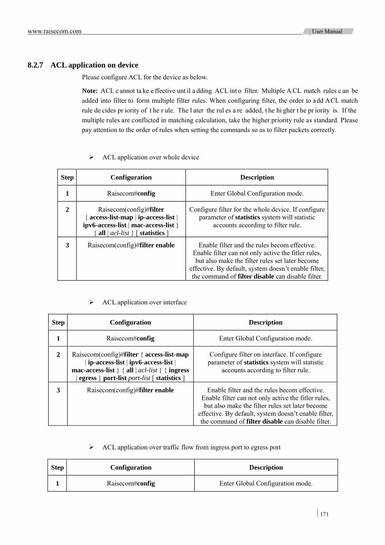
www.raisecom.com User Manual
171
8.2.7 ACL application on device Please configure ACL for the device as below.
Note: ACL c annot ta ke e ffective unt il a dding ACL int o filter. Multiple A CL match rules c an be added into filter to form multiple filter rules. When configuring filter, the order to add ACL match rule de cides pr iority of t he r ule. The l ater the rul es a re added, t he hi gher t he pr iority is. If the multiple rules are conflicted in matching calculation, take the higher priority rule as standard. Please pay attention to the order of rules when setting the commands so as to filter packets correctly.
ACL application over whole device
Step Configuration Description
1 Raisecom#config Enter Global Configuration mode.
2 Raisecom(config)#filter { access-list-map | ip-access-list | ipv6-access-list | mac-access-list }
{ all | acl-list } [ statistics ]
Configure filter for the whole device. If configure parameter of statistics system will statistic
accounts according to filter rule.
3 Raisecom(config)#filter enable Enable filter and the rules becom effective. Enable filter can not only active the fitler rules, but also make the filter rules set later become
effective. By default, system doesn’t enable filter, the command of filter disable can disable filter.
ACL application over interface
Step Configuration Description
1 Raisecom#config Enter Global Configuration mode.
2 Raisecom(config)#filter { access-list-map | ip-access-list | ipv6-access-list |
mac-access-list } { all | acl-list } { ingress | egress } port-list port-list [ statistics ]
Configure filter on interface. If configure parameter of statistics system will statistic
accounts according to filter rule.
3 Raisecom(config)#filter enable Enable filter and the rules becom effective. Enable filter can not only active the fitler rules, but also make the filter rules set later become
effective. By default, system doesn’t enable filter, the command of filter disable can disable filter.
ACL application over traffic flow from ingress port to egress port
Step Configuration Description
1 Raisecom#config Enter Global Configuration mode.
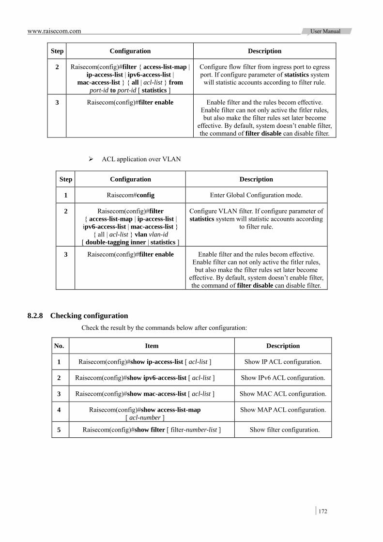
www.raisecom.com User Manual
172
Step Configuration Description
2 Raisecom(config)#filter { access-list-map | ip-access-list | ipv6-access-list |
mac-access-list } { all | acl-list } from port-id to port-id [ statistics ]
Configure flow filter from ingress port to egress port. If configure parameter of statistics system will statistic accounts according to filter rule.
3 Raisecom(config)#filter enable Enable filter and the rules becom effective. Enable filter can not only active the fitler rules, but also make the filter rules set later become
effective. By default, system doesn’t enable filter, the command of filter disable can disable filter.
ACL application over VLAN
Step Configuration Description
1 Raisecom#config Enter Global Configuration mode.
2 Raisecom(config)#filter { access-list-map | ip-access-list | ipv6-access-list | mac-access-list }
{ all | acl-list } vlan vlan-id [ double-tagging inner | statistics ]
Configure VLAN filter. If configure parameter of statistics system will statistic accounts according
to filter rule.
3 Raisecom(config)#filter enable Enable filter and the rules becom effective. Enable filter can not only active the fitler rules, but also make the filter rules set later become
effective. By default, system doesn’t enable filter, the command of filter disable can disable filter.
8.2.8 Checking configuration Check the result by the commands below after configuration:
No. Item Description
1 Raisecom(config)#show ip-access-list [ acl-list ] Show IP ACL configuration.
2 Raisecom(config)#show ipv6-access-list [ acl-list ] Show IPv6 ACL configuration.
3 Raisecom(config)#show mac-access-list [ acl-list ] Show MAC ACL configuration.
4 Raisecom(config)#show access-list-map [ acl-number ]
Show MAP ACL configuration.
5 Raisecom(config)#show filter [ filter-number-list ] Show filter configuration.
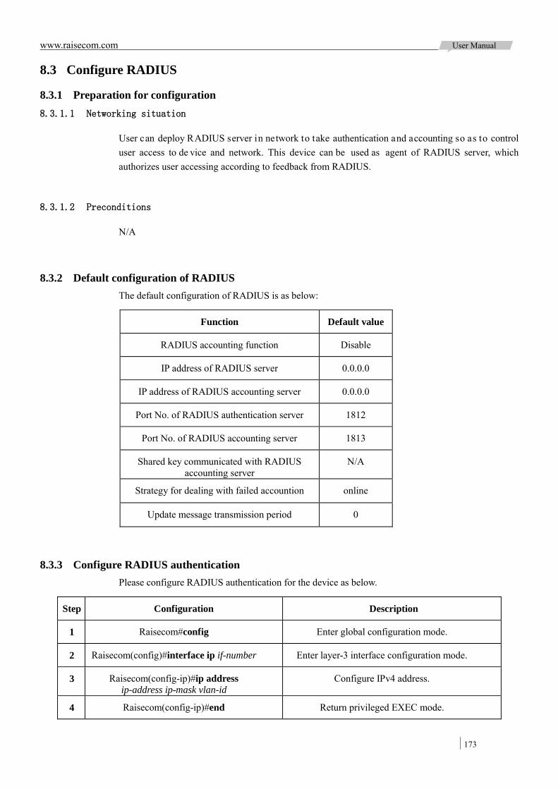
www.raisecom.com User Manual
173
8.3 Configure RADIUS
8.3.1 Preparation for configuration 8.3.1.1 Networking situation
User can deploy RADIUS server in network to take authentication and accounting so as to control user access to de vice and network. This device can be used as agent of RADIUS server, which authorizes user accessing according to feedback from RADIUS.
8.3.1.2 Preconditions
N/A
8.3.2 Default configuration of RADIUS The default configuration of RADIUS is as below:
Function Default value
RADIUS accounting function Disable
IP address of RADIUS server 0.0.0.0
IP address of RADIUS accounting server 0.0.0.0
Port No. of RADIUS authentication server 1812
Port No. of RADIUS accounting server 1813
Shared key communicated with RADIUS accounting server
N/A
Strategy for dealing with failed accountion online
Update message transmission period 0
8.3.3 Configure RADIUS authentication Please configure RADIUS authentication for the device as below.
Step Configuration Description
1 Raisecom#config Enter global configuration mode.
2 Raisecom(config)#interface ip if-number Enter layer-3 interface configuration mode.
3 Raisecom(config-ip)#ip address ip-address ip-mask vlan-id
Configure IPv4 address.
4 Raisecom(config-ip)#end Return privileged EXEC mode.
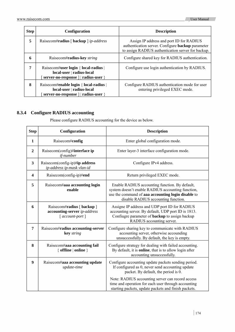
www.raisecom.com User Manual
174
Step Configuration Description
5 Raisecom#radius [ backup ] ip-address Assign IP address and port ID for RADIUS authentication server. Configure backup parameter to assign RADIUS authentication server for backup.
6 Raisecom#radius-key string Configure shared key for RADIUS authentication.
7 Raisecom#user login { local-radius | local-user | radius-local
[ server-no-response ] | radius-user }
Configure use login authentication by RADIUS.
8 Raisecom#enable login { local-radius | local-user | radius-local
[ server-no-response ] | radius-user }
Configure RADIUS authentication mode for user entering privileged EXEC mode.
8.3.4 Configure RADIUS accounting Please configure RADIUS accounting for the device as below.
Step Configuration Description
1 Raisecom#config Enter global configuration mode.
2 Raisecom(config)#interface ip if-number
Enter layer-3 interface configuration mode.
3 Raisecom(config-ip)#ip address ip-address ip-mask vlan-id
Configure IPv4 address.
4 Raisecom(config-ip)#end Return privileged EXEC mode.
5 Raisecom#aaa accounting login enable
Enable RADIUS accounting function. By default, system doesn’t enable RADIUS accounting function, use the command of aaa accounting login disable to
disable RADIUS accounting function.
6 Raisecom#radius [ backup ] accounting-server ip-address
[ account-port ]
Assigne IP address and UDP port ID for RADIUS accounting server. By default, UDP port ID is 1813.
Confiugre parameter of backup to assign backup RADIUS accounting server.
7 Raisecom#radius accounting-server key string
Configure sharing key to communicate with RADIUS accounting server, otherwise accounding
unsuccessfully. By default, the key is empty.
8 Raisecom#aaa accounting fail { offline | online }
Configure strategy for dealing with failed accounting. By default, it is online, that is to allow login after
accounting unsuccessfully.
9 Raisecom#aaa accounting update update-time
Configure accounting update packets sending period. If configured as 0, never send accounting update
packet. By default, the period is 0.
Note: RADIUS accounting server can record access time and operation for each user through accounting starting packets, update packets and finish packets.
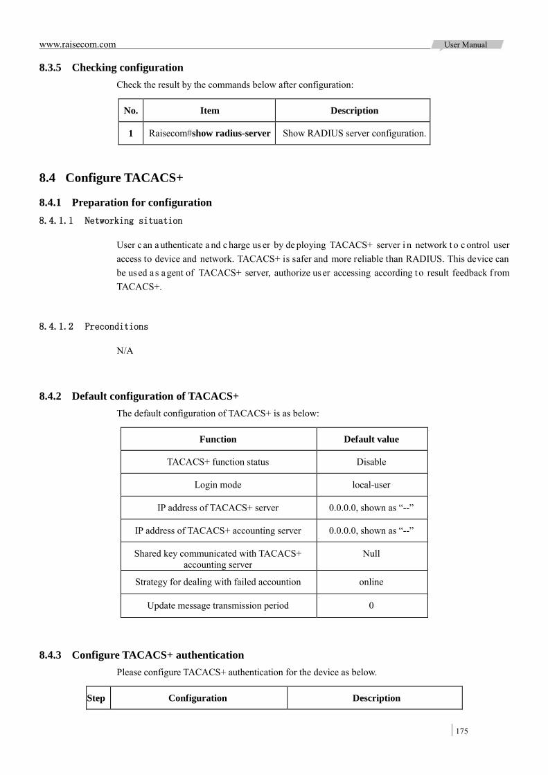
www.raisecom.com User Manual
175
8.3.5 Checking configuration Check the result by the commands below after configuration:
No. Item Description
1 Raisecom#show radius-server Show RADIUS server configuration.
8.4 Configure TACACS+
8.4.1 Preparation for configuration 8.4.1.1 Networking situation
User c an a uthenticate a nd c harge us er by de ploying TACACS+ server i n network t o c ontrol user access to device and network. TACACS+ is safer and more reliable than RADIUS. This device can be used a s agent of TACACS+ server, authorize user accessing according to result feedback f rom TACACS+.
8.4.1.2 Preconditions
N/A
8.4.2 Default configuration of TACACS+ The default configuration of TACACS+ is as below:
Function Default value
TACACS+ function status Disable
Login mode local-user
IP address of TACACS+ server 0.0.0.0, shown as “--”
IP address of TACACS+ accounting server 0.0.0.0, shown as “--”
Shared key communicated with TACACS+ accounting server
Null
Strategy for dealing with failed accountion online
Update message transmission period 0
8.4.3 Configure TACACS+ authentication Please configure TACACS+ authentication for the device as below.
Step Configuration Description
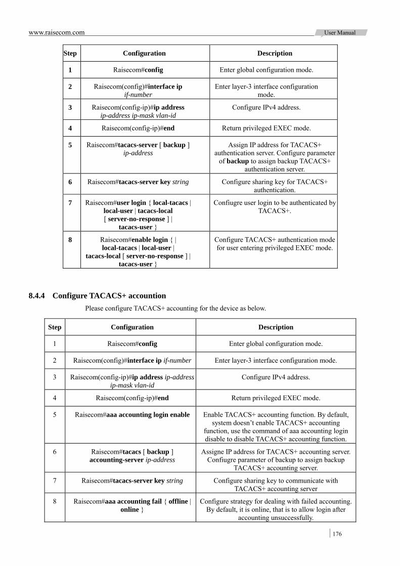
www.raisecom.com User Manual
176
Step Configuration Description
1 Raisecom#config Enter global configuration mode.
2 Raisecom(config)#interface ip if-number
Enter layer-3 interface configuration mode.
3 Raisecom(config-ip)#ip address ip-address ip-mask vlan-id
Configure IPv4 address.
4 Raisecom(config-ip)#end Return privileged EXEC mode.
5 Raisecom#tacacs-server [ backup ] ip-address
Assign IP address for TACACS+ authentication server. Configure parameter
of backup to assign backup TACACS+ authentication server.
6 Raisecom#tacacs-server key string Configure sharing key for TACACS+ authentication.
7 Raisecom#user login { local-tacacs | local-user | tacacs-local [ server-no-response ] |
tacacs-user }
Confiugre user login to be authenticated by TACACS+.
8 Raisecom#enable login { | local-tacacs | local-user |
tacacs-local [ server-no-response ] | tacacs-user }
Configure TACACS+ authentication mode for user entering privileged EXEC mode.
8.4.4 Configure TACACS+ accountion Please configure TACACS+ accounting for the device as below.
Step Configuration Description
1 Raisecom#config Enter global configuration mode.
2 Raisecom(config)#interface ip if-number Enter layer-3 interface configuration mode.
3 Raisecom(config-ip)#ip address ip-address ip-mask vlan-id
Configure IPv4 address.
4 Raisecom(config-ip)#end Return privileged EXEC mode.
5 Raisecom#aaa accounting login enable Enable TACACS+ accounting function. By default, system doesn’t enable TACACS+ accounting
function, use the command of aaa accounting login disable to disable TACACS+ accounting function.
6 Raisecom#tacacs [ backup ] accounting-server ip-address
Assigne IP address for TACACS+ accounting server. Confiugre parameter of backup to assign backup
TACACS+ accounting server.
7 Raisecom#tacacs-server key string Configure sharing key to communicate with TACACS+ accounting server
8 Raisecom#aaa accounting fail { offline | online }
Configure strategy for dealing with failed accounting. By default, it is online, that is to allow login after
accounting unsuccessfully.

www.raisecom.com User Manual
177
Step Configuration Description
9 Raisecom#aaa accounting update period Configure to update accounting packets transmission period. If configured as 0, never send accounting
update packet. By default, the period is 0.
8.4.5 Checking configuration Check the result by the commands below after configuration:
No. Item Description
1 Raisecom#show tacacs-server Show TACACS+ server configuration.
2 Raisecom#show radius-server Show TACACS+ accounting configuration.
Note: Use the command of show radius-server to check TACACS+ and
RADIUS accountiong configuration. By default the authentication information is RADIUS authentication configuration.
8.5 Configure storm suppression
8.5.1 Preparation for configuration 8.5.1.1 Networking situation
Configure storm suppression in layer-2 network can control the broadcast storm when the broadcast packets increasing in network and then ensure unicast be forwarded normally.
The f ollowing f lows m ay c ause br oadcast f low, us er needs t o s et r ate l imit on l ayer-2 device f or themre spectively:
Unknown uni cast flow: de stination MAC is unicast f low not existing in MAC table, broadcast this flow on layer-2 device.
Multicast flow: destination MAC is multicast flow, broadcast this flow on layer-2 device. Broadcast flow: destination MAC is broadcast flow, broadcast this flow on layer-2 device.
8.5.1.2 Preconditions
Connect interfaces and configure physical pa rameters f or i nterface be fore con figuring s torm suppression and make physical interface is Up.
8.5.2 Default configuration of storm suppression The default configuration of storm suppression is as below:
Function Default value
Storm suppression status of broadcast flow Enable
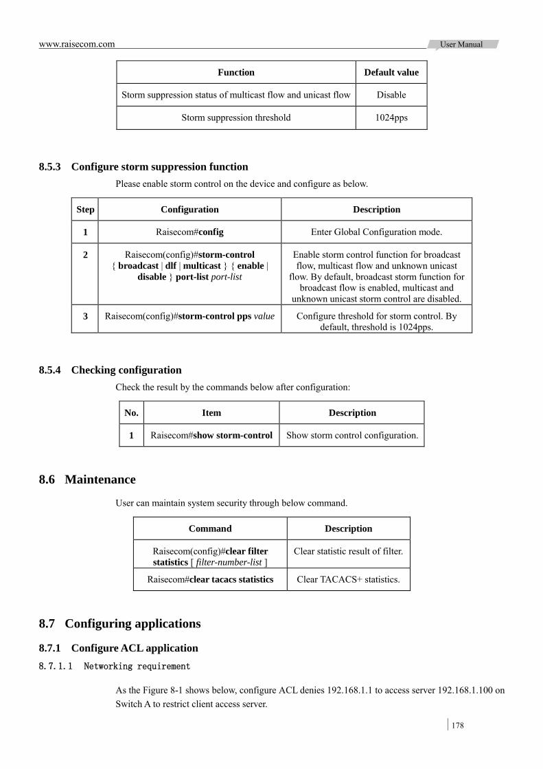
www.raisecom.com User Manual
178
Function Default value
Storm suppression status of multicast flow and unicast flow Disable
Storm suppression threshold 1024pps
8.5.3 Configure storm suppression function Please enable storm control on the device and configure as below.
Step Configuration Description
1 Raisecom#config Enter Global Configuration mode.
2 Raisecom(config)#storm-control { broadcast | dlf | multicast } { enable |
disable } port-list port-list
Enable storm control function for broadcast flow, multicast flow and unknown unicast
flow. By default, broadcast storm function for broadcast flow is enabled, multicast and
unknown unicast storm control are disabled.
3 Raisecom(config)#storm-control pps value Configure threshold for storm control. By default, threshold is 1024pps.
8.5.4 Checking configuration Check the result by the commands below after configuration:
No. Item Description
1 Raisecom#show storm-control Show storm control configuration.
8.6 Maintenance
User can maintain system security through below command.
Command Description
Raisecom(config)#clear filter statistics [ filter-number-list ]
Clear statistic result of filter.
Raisecom#clear tacacs statistics Clear TACACS+ statistics.
8.7 Configuring applications
8.7.1 Configure ACL application 8.7.1.1 Networking requirement
As the Figure 8-1 shows below, configure ACL denies 192.168.1.1 to access server 192.168.1.100 on Switch A to restrict client access server.
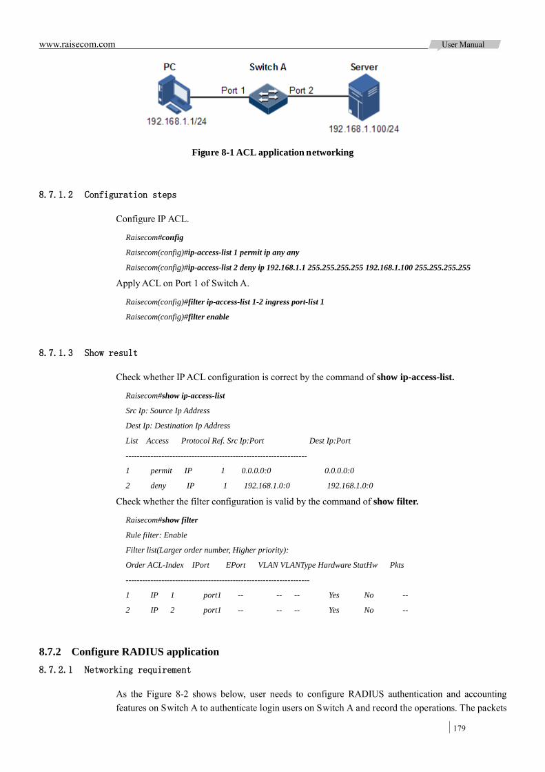
www.raisecom.com User Manual
179
Figure 8-1 ACL application networking
8.7.1.2 Configuration steps
Configure IP ACL.
Raisecom#config
Raisecom(config)#ip-access-list 1 permit ip any any
Raisecom(config)#ip-access-list 2 deny ip 192.168.1.1 255.255.255.255 192.168.1.100 255.255.255.255
Apply ACL on Port 1 of Switch A.
Raisecom(config)#filter ip-access-list 1-2 ingress port-list 1
Raisecom(config)#filter enable
8.7.1.3 Show result
Check whether IP ACL configuration is correct by the command of show ip-access-list.
Raisecom#show ip-access-list
Src Ip: Source Ip Address
Dest Ip: Destination Ip Address
List Access Protocol Ref. Src Ip:Port Dest Ip:Port
------------------------------------------------------------------
1 permit IP 1 0.0.0.0:0 0.0.0.0:0
2 deny IP 1 192.168.1.0:0 192.168.1.0:0
Check whether the filter configuration is valid by the command of show filter.
Raisecom#show filter
Rule filter: Enable
Filter list(Larger order number, Higher priority):
Order ACL-Index IPort EPort VLAN VLANType Hardware StatHw Pkts
-------------------------------------------------------------------
1 IP 1 port1 -- -- -- Yes No --
2 IP 2 port1 -- -- -- Yes No --
8.7.2 Configure RADIUS application 8.7.2.1 Networking requirement
As the Figure 8-2 shows below, user needs to configure RADIUS authentication and accounting features on Switch A to authenticate login users on Switch A and record the operations. The packets

www.raisecom.com User Manual
180
update transmitting interval is 2 minutes. User will be offline if the accounting fails.
Figure 8-2 RADIUS application networking
8.7.2.2 Configuration steps
Configure user login authentication through RADIUS.
Raisecom#radius 192.168.1.1
Raisecom#radius-key raisecom
Raisecom#user login radius-user
Raisecom#enable login local-radius
Configure user login accounting through RADIUS.
Raisecom#aaa accounting login enable
Raisecom#radius accounting-server 192.168.1.1
Raisecom#radius accounting-server key raisecom
Raisecom#aaa accounting fail offline
Raisecom#aaa accounting update 2
8.7.2.3 Show result
Show RADIUS configuration by the command of show radius-server.
Raisecom#show radius-server
Authentication server IP: 192.168.1.1 port:1812
Backup authentication server IP:0.0.0.0 port:1812
Authentication server key: raisecom
Accounting server IP: 192.168.1.1 port:1813
Backup accounting server IP: 0.0.0.0 port:1813
Accounting server key: raisecom
Accounting login: enable
Update interval: 2
Accounting fail policy: offline
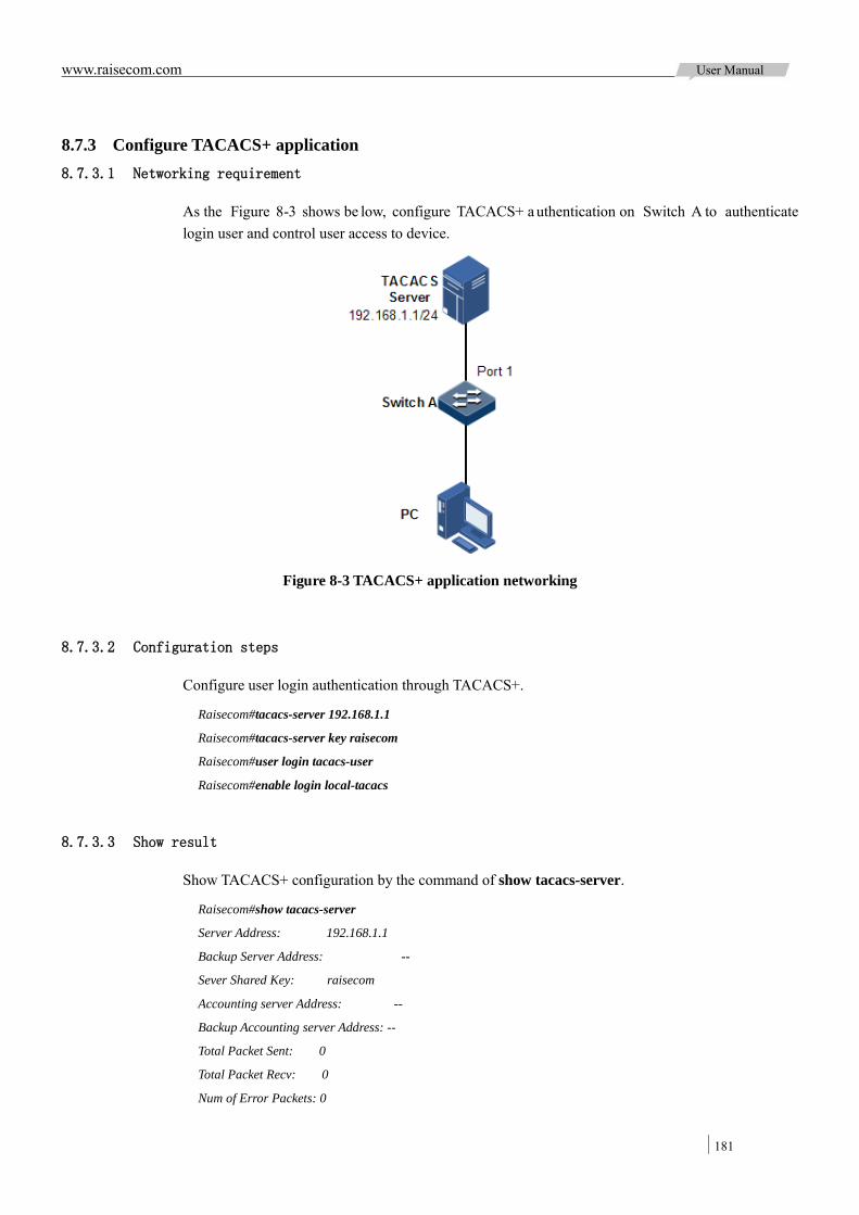
www.raisecom.com User Manual
181
8.7.3 Configure TACACS+ application 8.7.3.1 Networking requirement
As the Figure 8-3 shows be low, configure TACACS+ a uthentication on Switch A to authenticate login user and control user access to device.
Figure 8-3 TACACS+ application networking
8.7.3.2 Configuration steps
Configure user login authentication through TACACS+.
Raisecom#tacacs-server 192.168.1.1
Raisecom#tacacs-server key raisecom
Raisecom#user login tacacs-user
Raisecom#enable login local-tacacs
8.7.3.3 Show result
Show TACACS+ configuration by the command of show tacacs-server.
Raisecom#show tacacs-server
Server Address: 192.168.1.1
Backup Server Address: --
Sever Shared Key: raisecom
Accounting server Address: --
Backup Accounting server Address: --
Total Packet Sent: 0
Total Packet Recv: 0
Num of Error Packets: 0

www.raisecom.com User Manual
182
8.7.4 Configure storm suppressionapplication 8.7.4.1 Networking requirement
As the Figure 8-4 shows below, to restrict influence on Switch A caused by broadcast s torm, user needs to configure storm suppression feature on Switch A to control broadcast packets and unknown unicast packets, threshold is 2000pps.
Figure 8-4 Storm suppression application networking
8.7.4.2 Configuration steps
Configure storm control function on Switch A.
Raisecom#config
Raisecom(config)#storm-control broadcast enable port-list 1-2
Raisecom(config)#storm-control dlf enable port-list 1-2
Raisecom(config)#storm-control pps 2000
8.7.4.3 Show result
Show storm control configuration by the command of show storm-control.
Raisecom#show storm-control
Threshold: 2000 pps
Interface Broadcast Multicast Unicast
-----------------------------------------------------------
port1 Enable Disable Enable
port2 Enable Disable Enable
port3 Enable Disable Disable
port4 Enable Disable Disable
port5 Enable Disable Disable
port6 Enable Disable Disable
……
www.raisecom.com User Manual
183
Chapter 9 Reliability
This chapter introduces basic principle and configuration of network reliability and provides related configuration applications.
Overview Configure link aggregation Configure interface backup ELPS ERPS Configure Ethernet ring Maintenance Configuring applications
9.1 Overview
Ethernet is becoming more and more widely used for its simple structure, high-efficient and cost-effective f eatures. One of t he i mportant reasons to restrict Ethernet ap plication in telecommunication is the tr aditional E thernet r eliability. Packeting services ar e pr esented in burst mode usually; it is difficult to ensure invariable traffic. As two features of Ethernet, statistic TDM and a ddress l earning s ystem pr ovide e fficient a nd f lexible ba ndwidth a nd m eanwhile i mport incertitude for service bandwidth and path.
In order to improve Ethernet reliability and meet demands of telecommunication network, customer can deploy special reliability technology in Ethernet.
9.1.1 Link aggregation Link aggregation function is t o aggregate s everal ph ysical E thernet i nterface together and make a trunk group by logically, and consider the several physical l inks in one trunk group as one logical link. This f unction r ealizes f low l oad s haring among m ember i nterfaces in a t runk gr oup, t hen improve link reliability among devices and increase bandwidth without upgrading hardware.
The device is in support of two link aggregation modes:
Manual aggregation mode
This mode is to add several physical interface into a Trunk group and make up a logical interface. The link under one logical link can realize load sharing. This mode is not convenient for watch link aggregation interface status.
Static LACP aggregation mode
LACP (Link A ggregation C ontrol Protocol) pr otocol is ba sed on IEEE802.3ad recommendation. LACP exchanges information with peer through LACPDU (Link Aggregation Control Protocol Data Unit). After enabling LACP of a interface, it notifies the peer its own LACP priority, system MAC, interface LACP priority, port ID and operation Key via sending LACPDU.

www.raisecom.com User Manual
184
The pe er r eceives L ACPDU and com pares i nformation with other interfaces received, c hoosing interface in Selected status. The interfaces at both ends be come consi stent i n Selected status. The operation Key performs aggregation and control on t he automatical generated configuration group according to the interface configuration (speed, duplex mode, Up/Down status, basic configuration information, etc.).
The m ain difference be tween static LACP aggregation a nd m anual a ggregation is: s tatic LACP aggregation mode has standby l ink, while a ll t he member interfaces of manual aggregation a re in forwarding status and share loading flow.
Link aggregation is the most widely used and simplest function in Ethernet reliability technology.
9.1.2 Interface backup Double-upstream networking is one of the most commonly used application networks, which often blocks redundant l inks through the Spanning Tree Protocol for backup. Although this solution can meet customer redundancy backup demand in function, it cannot achieve the requirements of many users in performance. Even with the rapid migration of Rapid Spanning Tree Protocol, it can only get a second level convergence, which is a very bad performance parameter for high-end Ethernet switch used in carrier-class network core.
RAISECOM proprietary interface backup solution aims a t double-upstream networking to achieve the redundancy backup of master standby link and rapid migration. The program is tailor-made for double-upstream networking, which not onl y ensures the performance, b ut also simplifies the configuration.
Interface ba ckup function is the ot her solution for STP pr otocol. Users can configure i nterface manually to achieve the basic l ink redundancy when disabling STP function. If the switch enables STP, the interface backup function will be disabled because STP already provides similar function.
Interface backup function can be achieved by setting interface backup group, which contains a pair of interfaces, one is master interface and the other is standby interface. The master interface located link is called master link, while the standby interface located link is called standby link. The member interface in interface backup group is in support of physical interface and link aggregation group, but not layer-3 interface.
In the interface backup group, when one interface is in forwarding (Up) s tate, the other will be in standby (Standby) state. Any time, only one in two interfaces is in the forwarding state. The interface in standby state will change to forwarding state to maintain the normal link when there is link failure in forwarding state interface.

www.raisecom.com User Manual
185
Figure 9-1 Interface backup networking
Interface backup principle is shown in Figure 9-1. Port 1 and Port 2 on Switch A are connected with the upstream switches respectively, the interface forwarding state is as follows:
In normal state, Port 1 on Switch A is master interface, Port 2 is standby interface, Port 1 and upstream switch forward messages, while Port 2 and the upstream switch not.
When there is link failure between Port 1 and upstream switch, the standby interface Port 2 and upstream switch forward messages.
When the Port 1 link failure is recovered and kept for a period of time (restore delay), Port 1 will change to forwarding state, Port 2 becomes standby state.
The switch will send a Trap to report ne twork management system when the master interface and standby interface switch with each other.
9.1.2.1 Interface backup over VLAN
Interface backup can be used on VLAN to make the two interfaces forward concurrently on different VLAN. In Figure 9 -2, interface ba ckup function over V LAN i s achi eved by cr eating VLAN and adding interface to it.
Figure 9-2 Sketch map of Interface backup over VLAN
Figure 9-2 Sketch map of Interface backup over VLAN
In different VLAN, the interface forwarding state is as follows:

www.raisecom.com User Manual
186
Under norm al circumstances, configure S witch A i n VLAN 10 0~VLAN 150, P ort 1 as master interface, Port 2 as standby interface; in VLAN 151 ~VLAN 200, P ort 2 is m aster interface, Port 1 is standby interface. Then, Port 1 forwards traffic in VLAN 100~VLAN 150, Port 2 forwards traffic in VLAN 151~VLAN 200.
When Port 1 has link failure, Port 2 is re sponsible for for warding traffic in VLAN 100~VLAN 200.
When Port 1 recovers normal and keeps for a period of time (restore delay), Port 1 forwards traffic in VLAN 100~VLAN 150, Port 2 forwards traffic in VLAN 151~VLAN 200.
Using this method, interface backup over VLAN can be used for load balancing. At the same time, this application doesn’t depend on the uplink switch configuration and is easy for user to operate.
9.1.3 ELPS ELPS (Ethernet Linear Protection Switching) is an APS (Automatic Protection Switching) protocol over IT U-T G.8031 r ecommendation. It is a n end-to-end protection t echnology us ed to protect an Ethernet connection.
ELPS de ploys pr otection r esources f or w orking r esources, l ike pa th a nd ba ndwidth, e tc. E LPS technology takes a simple and fast predictable mode to realize network resource switching, easier for carrier to program network more efficiently and know network active status.
9.1.4 ERPS ERPS (Ethernet Ring Protection Switching) is an APS protocol over ITU-T G.8032 recommendation. It is special used in Ethernet ring link protocol. Generally, ERPS can avoid broadcast storm caused by data loopback. When Ethernet has loop or device malfault, ERPS can switch the link to backup link and ensure service restore quickly.
ERPS t akes t he s pcial VLAN i n r ing ne twork t o t ransmit r ing ne twork c ontrol i nformation a nd meanwhile, combining with the topology feature of ring network to discover network fault quickly and enable backup link to restore service fast.
9.1.5 Ethernet ring With the development of Ethernet to the MAN, voice, video and multicast service has come up with higher re quirements to the E thernet r edundancy protection a nd fault r ecovery t ime. The fault recovery convergence time of original STP mechanism is in the second level, which is far to meet the fault recovery time requirements of MAN.
Ethernet ring technology is RAISECOM independent research and development protocol, which can ensure that there is data loop in Ethernet by blocking some interface on the ring. Ethernet ring solves the problems of weak protection to traditional data network and long time to fault recovery, which, in theory, can provide 50ms rapid protection features.
Shown in Figure 9-3, blocked interface node is the master node, other nodes are transmission nodes. The master node generates by election. Each node can specify one loop interface as the first interface, the other as the second interface. The master node usually sends Hello messages periodically from the f irst int erface and receives Hello message s ent by i tself in t he s econd i nterface unde r t he circumstance of complete Ethernet ring. Then the master node w ill block the f irst int erface immediately to ensure there is no l oop when the ring network is in a complete s tate. For the other

www.raisecom.com User Manual
187
nodes on t he Ethernet r ing, the f irst interface No. and the second interface No. play the same role basically.
Ethernet ring generates master node by the election, so each node needs to collect device information on Ethernet ring, only the right collection leads to correct election. Topology collection is completed by Hello messages, which contain all nodes information the node collected from the other interface. The normal state of Ethernet ring is shown in Figure 9-3.
Figure 9-3 Sketch map of Ethernet ring in normal status
According to the interface state of node ring, the ring node state can be divided into three types:
Down: At least one of the two Ethernet ring interfaces is Down; Block: At least one of the two Ethernet ring interfaces is Block; Two-Forwarding: Both Ethernet ring interfaces are Forwarding.
The election rules of master node are as follows:
In all nodes on t he ring, node with Down state is prior for master node, followed by Block and Two-Forward.
If the nodes are in the same state, the node with high-priority Bridge is master node. If the nodes have the same state and priority, the node with large Mac is master node.
Interface Block rules:
If the node is not master node, the two interfaces are Forwarding. If the node is master node, then one of two interfaces is Block, the other is Forwarding. Rules
are as follows: Interface with Down link is prior for Block; Both interfaces are Down, the Block is the first interface; Both interfaces are Up, the Block is the first interface;
The Ethernet ring link failure is shown in Figure 9-4.
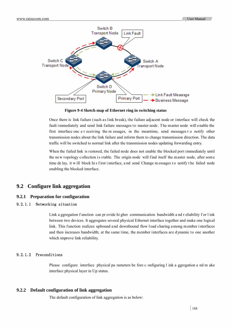
www.raisecom.com User Manual
188
Figure 9-4 Sketch map of Ethernet ring in switching status
Once there is link failure (such as link break), the failure adjacent node or interface will check the fault immediately and send link failure messages to master node. The master node will enable the first interface onc e r eceiving the m essages, in the meantime, send messages t o notify other transmission nodes about the link failure and inform them to change transmission direction. The data traffic will be switched to normal link after the transmission nodes updating forwarding entry.
When the failed link is restored, the failed node does not enable the blocked port immediately until the new topology collection i s s table. The origin node will f ind itself the master node, after some time de lay, it w ill block hi s f irst i nterface, a nd send Change m essages t o notify t he failed node enabling the blocked interface.
9.2 Configure link aggregation
9.2.1 Preparation for configuration 9.2.1.1 Networking situation
Link a ggregation f unction can pr ovide hi gher communication bandwidth a nd r eliability f or l ink between two devices. It aggregates several physical Ethernet interface together and make one logical link. This f unction realizes upbound and downbound flow l oad s haring a mong member i nterfaces and then increases bandwidth; at the same time, the member interfaces are dynamic to one another which improve link reliability.
9.2.1.2 Preconditions
Please configure interface physical pa rameters be fore c onfiguring l ink a ggregation a nd m ake interface physical layer in Up status.
9.2.2 Default configuration of link aggregation The default configuration of link aggregation is as below:
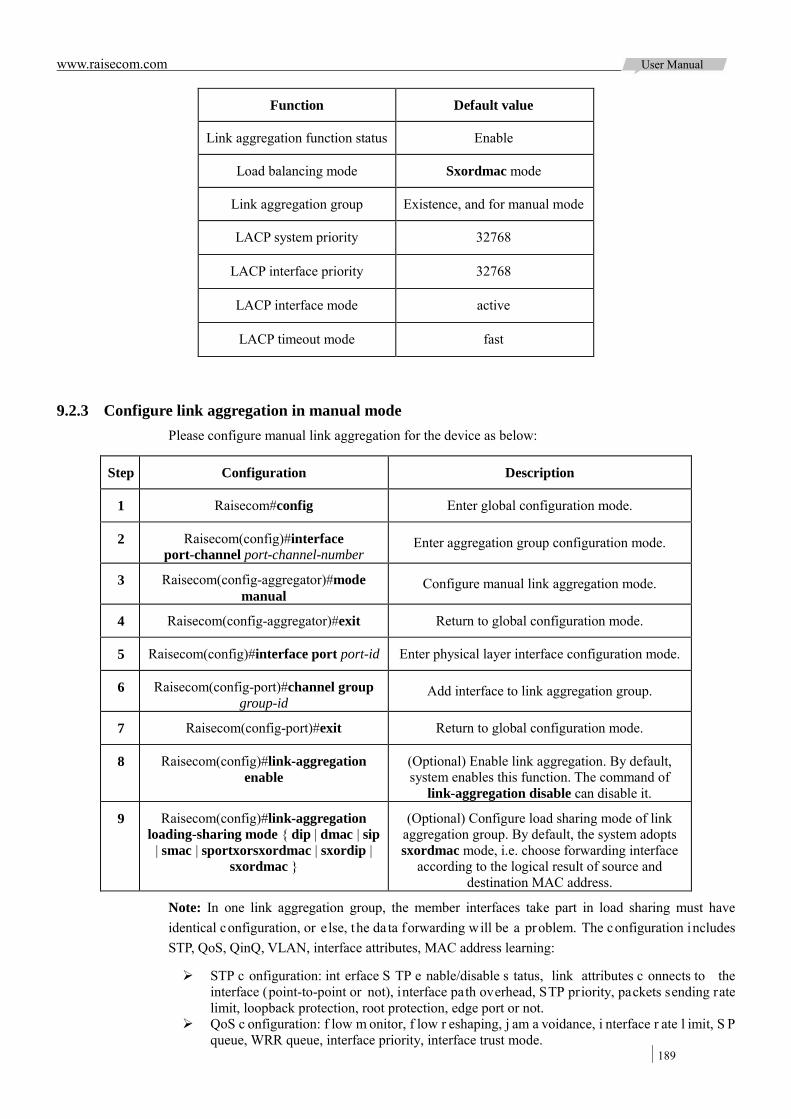
www.raisecom.com User Manual
189
Function Default value
Link aggregation function status Enable
Load balancing mode Sxordmac mode
Link aggregation group Existence, and for manual mode
LACP system priority 32768
LACP interface priority 32768
LACP interface mode active
LACP timeout mode fast
9.2.3 Configure link aggregation in manual mode Please configure manual link aggregation for the device as below:
Step Configuration Description
1 Raisecom#config Enter global configuration mode.
2 Raisecom(config)#interface port-channel port-channel-number
Enter aggregation group configuration mode.
3 Raisecom(config-aggregator)#mode manual
Configure manual link aggregation mode.
4 Raisecom(config-aggregator)#exit Return to global configuration mode.
5 Raisecom(config)#interface port port-id Enter physical layer interface configuration mode.
6 Raisecom(config-port)#channel group group-id
Add interface to link aggregation group.
7 Raisecom(config-port)#exit Return to global configuration mode.
8 Raisecom(config)#link-aggregation enable
(Optional) Enable link aggregation. By default, system enables this function. The command of
link-aggregation disable can disable it.
9 Raisecom(config)#link-aggregation loading-sharing mode { dip | dmac | sip
| smac | sportxorsxordmac | sxordip | sxordmac }
(Optional) Configure load sharing mode of link aggregation group. By default, the system adopts sxordmac mode, i.e. choose forwarding interface
according to the logical result of source and destination MAC address.
Note: In one link aggregation group, the member interfaces take part in load sharing must have identical configuration, or e lse, the da ta forwarding will be a problem. The configuration includes STP, QoS, QinQ, VLAN, interface attributes, MAC address learning:
STP c onfiguration: int erface S TP e nable/disable s tatus, link attributes c onnects to the interface (point-to-point or not), interface path overhead, STP priority, packets sending rate limit, loopback protection, root protection, edge port or not.
QoS c onfiguration: f low m onitor, f low r eshaping, j am a voidance, i nterface r ate l imit, S P queue, WRR queue, interface priority, interface trust mode.

www.raisecom.com User Manual
190
QinQ configuration: interface QinQ enable/disable status, added outer VLAN Tag, policy for adding outer VLAN Tag by different inner VLANID.
VLAN c onfiguration: i nterface pe rmitting V LAN, de fault V LAN I D, i nterface l ink t ype (Trunk, Hybrid, A ccess), s ub-net VL AN configuration, V LAN packets w ith T ag configuration or not.
Interface at tributes conf iguration: i nterface i s adde d into i solation gr oup or not , i nterface speed, duplex mode, link up.down status.
MAC a ddress l earning c onfiguration: M AC a ddress l earning e nable/disable, i nterface w ith max. Learning MAC address number limit or not, MAC address table can control forwarding when it is full.
9.2.4 Configure static LACP link aggregation Please configure static LACP link aggregation for the device as below:
Step Configuration Description
1 Raisecom#config Enter global configuration mode.
2 Raisecom(config)#lacp system-priority system-priority
(Optional) Configure system LACP pr iority. The higher pr iority e nd i s a ctive e nd. L ACP c hooses active and backup interfaces according to the active end c onfiguration. The s maller t he num ber i s, the higher t he pr iority i s. By default, system LACP priority is 32768. The smaller system MAC address device will be chosen as active end if devices system LACP priorities are identical.
3 Raisecom(config)#lacp timeout { fast | slow }
(Optional) Configure LACP timeout mode.
4 Raisecom(config)#interface port-channel port-channel-number Enter link aggregation group configuration mode.
5 Raisecom(config-aggregator)#mode lacp-static Configure static LACP link aggregation group.
6 Raisecom(config-aggregator)#{ max-active | min-active } links number
(Optional) Configure max. or m in. a ctive l inks number for LACP link aggregation group.
7 Raisecom(config-aggregator)#exit Return to global configuration mode.
8 Raisecom(config)#interface port port-id Enter physical layer interface configuration mode.
9 Raisecom(config-port)#channel group group-id
Add member interfaces into LACP link aggregation group.
10 Raisecom(config-port)#lacp port-priority port-priority
(Optional) Configure interface LACP priority. The priority inf luents de fault int erface s election for LACP. By default, system LACP priority is 32768.
11 Raisecom(config-port)#lacp mode { active | passive }
(Optional) Configure LACP m ode f or m ember interface. By de fault i s i n act ive mode. LACP connection will fail when both ends of a link are in passive mode.
12 Raisecom(config-port)#exit Return to global configuration mode.
13 Raisecom(config)#link-aggregation enable
(Optional) Enable link aggregation. By default, It is enabled. The c ommand of link-aggregation disable can disable this function.

www.raisecom.com User Manual
191
Note:
Interface in s tatic LACP l ink a ggregation gr oup can b e i n a ctive or s tandby s tatus. Both active interface and standby i nterface can receive/transmit LACP p ackets, but s tandby interface cannot forward client packets.
System chooses default interface in the order of neighbor discover, interface maximum speed, interface highest LACP pr iority, interface minimum ID. The interface is in active s tatus by default, the interface with identical speed, identical peer and identical device operation key is also in active status; other interfaces are in standby status.
9.2.5 Checking configuration Check the result by the commands below after configuration:
No. Item Description
1 Raisecom#show lacp internal [ detail ]
Show loc al s ystem LACP int erface s tatus, mark, interface priority, management key, operation key and status of interface status machine.
2 Raisecom#show lacp neighbor[ detail ]
Show ne ighbor LACP information, i ncluding mark, interface priority, device ID, Age, operation key value, interface ID and status of interface status machine.
3 Raisecom#show lacp statistics [ port-list
port-list ]
Show i nterface LACP statistic inf ormation, including total receiving a nd t ransmitting number L ACP pa ckets, r eceiving and t ransmitting num ber o f M arker pa ckets, r eceiving a nd transmitting number of Marker Response packets, as well as error packets.
4 Raisecom#show lacp sys-id
Show gl obal e nable c ondition of loc al s ystem LACP, de vice ID, including system LACP priority and system MAC address.
5 Raisecom#show link-aggregation
Show c urrent s ystem link a ggregation e nable/disable, link aggregation load sharing mode, group member interface set by all c urrent link aggregation groups and current effective member interfaces.
Note: Current ef fective member interface i ndicates t he interface list in Up status in group member interfaces.
9.3 Configure interface backup
9.3.1 Preparation for configuration 9.3.1.1 Networking situation
Configure interface backup function to achieve the redundancy backup and quick switch of master and s tandby l inks w hen di sabling S TP f unction.It a lso c an a chieve t he l oad balancing b etween interfaces by interface backup over VLAN.
Compared with STP function, interface backup ensures the fast millisecond switching and simplifies the configuration.

www.raisecom.com User Manual
192
9.3.1.2 Preconditions
Finish the following tasks before configuring interface backup:
Create VLAN Add interface to VLAN Disable STP function
9.3.2 Default configuration of interface backup The default configuration of interface backup is as below:
Function Default value
Interface backup group N/A
Recovery time 15s
Recovery mode Interface connection mode (port-up)
9.3.3 Configure the basic function of interface backup Please configure the basic function of interface backup as below:
Step Configuration Description
1 Raisecom#config Enter global configuration mode.
2 Raisecom(config)#interface interface-type primary-interface-number
Enter physical layer interface configuration mode or aggregation group configuration mode.
3 Raisecom(config-port)#switchport backup interface-type
backup-interface-number [ vlanlist vlan-list ]
Configure interface backup group.
Configure interface backup-interface-number as standby interface, while
primary-interface-number as master interface on VLAN list.
If configure interface backup group not assigningVLAN list, the default VLAN range is
1~4049.
Raisecom(config-aggregator)#switchport backup interface-type
backup-interface-number [ vlanlist vlan-list ]
4 Raisecom(config-port)#exit Return global configuration mode.
Raisecom(config-aggregator)#exit
5 Raisecom(config)#switchport backup restore-delay period
(Optional) Configure fault recovery delay time.
6 Raisecom(config)#switchport backup restore-mode { disable |
neighbor-discover | port-up }
(Optional) Configure recovery mode.
Note:
In one interface backup group, on interface cannot be master interface and standby interface at the same time.
On t he s ame VLAN, one i nterface/link a ggregation gr oup c annot be a m ember of bot h
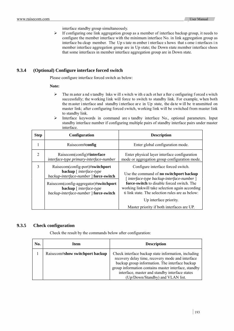
www.raisecom.com User Manual
193
interface standby group simultaneously. If configuring one link aggregation group as a member of interface backup group, it needs to
configure the member interface with the minimum interface No. in link aggregation group as interface ba ckup member. The Up s tate m ember i nterface s hows that s ome i nterfaces i n member interface aggregation group are in Up state; the Down state member interface shoes that some interfaces in member interface aggregation group are in Down state.
9.3.4 (Optional) Configure interface forced switch Please configure interface forced switch as below:
Note:
The m aster a nd s tandby lnks w ill s witch w ith e ach ot her a fter c onfiguring f orced s witch successfully; the working link will force to switch to standby link. For example, when both the m aster i nterface and standby i nterface ar e in Up state, the da te w ill be tr ansmitted on master link; after configuring forced switch, working link will be switched from master link to standby link.
Interface keywords in command are s tandby interface No., optional parameters. Input standby interface number if configuring multiple pairs of standby interface pairs under master interface.
Step Configuration Description
1 Raisecom#config Enter global configuration mode.
2 Raisecom(config)#interface interface-type primary-interface-number
Enter physical layer interface configuration mode or aggregation group configuration mode.
3 Raisecom(config-port)#switchport backup [ interface-type
backup-interface-number ] force-switch
Configure interface forced switch.
Use the command of no switchport backup [ interface-type backup-interface-number ] force-switch to disable forced switch. The
working linkwill take selection again according ti link state. The selection rules are as below:
Up interface priority.
Master priority if both interfaces are UP.
Raisecom(config-aggregator)#switchport backup [ interface-type
backup-interface-number ] force-switch
9.3.5 Check configuration Check the result by the commands below after configuration:
No. Item Description
1 Raisecom#show switchport backup Check interface backup state information, including recovery delay time, recovery mode and interface backup group information. The interface backup
group information contains master interface, standby interface, master and standby interface states
(Up/Down/Standby) and VLAN list.
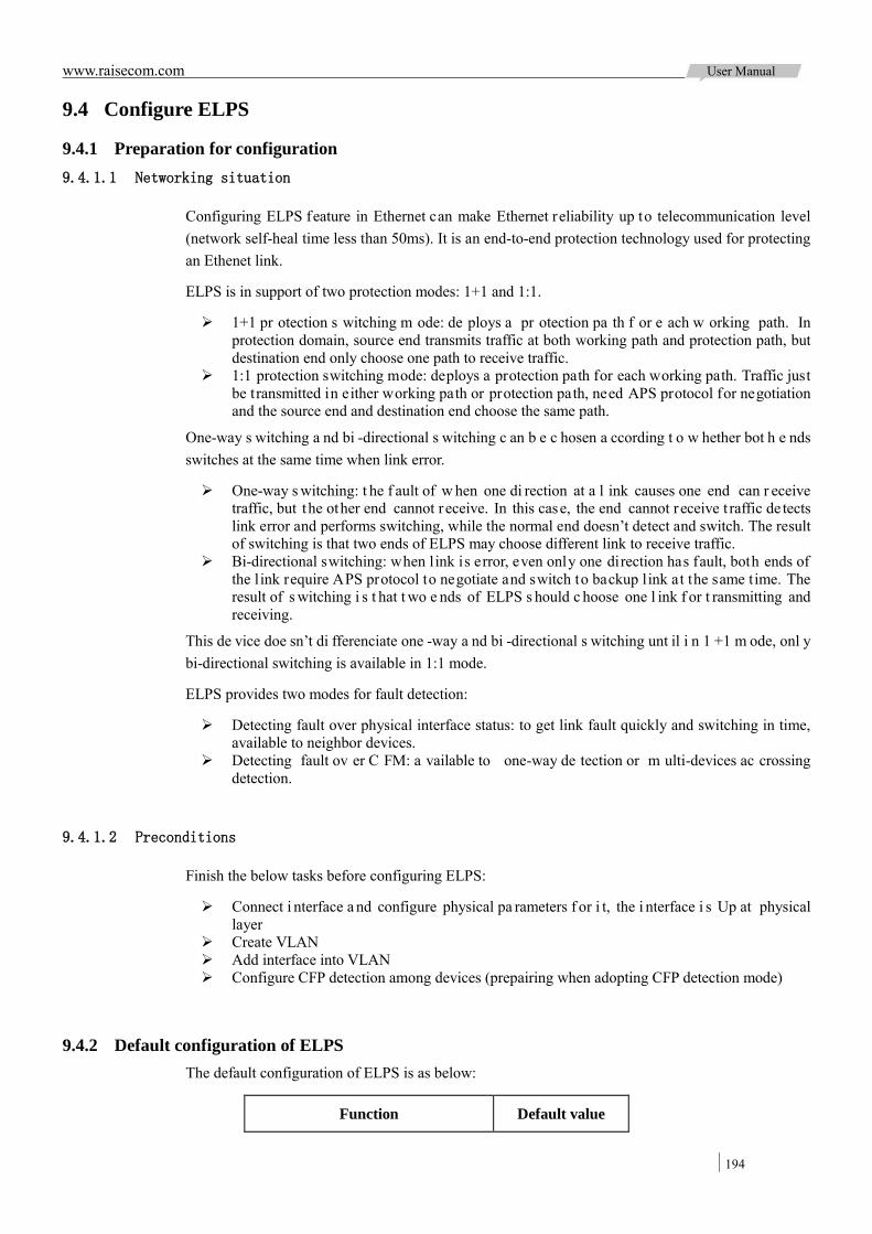
www.raisecom.com User Manual
194
9.4 Configure ELPS
9.4.1 Preparation for configuration 9.4.1.1 Networking situation
Configuring ELPS feature in Ethernet can make Ethernet reliability up to telecommunication level (network self-heal time less than 50ms). It is an end-to-end protection technology used for protecting an Ethenet link.
ELPS is in support of two protection modes: 1+1 and 1:1.
1+1 pr otection s witching m ode: de ploys a pr otection pa th f or e ach w orking path. In protection domain, source end transmits traffic at both working path and protection path, but destination end only choose one path to receive traffic.
1:1 protection switching mode: deploys a protection path for each working path. Traffic just be transmitted in either working path or protection path, need APS protocol for negotiation and the source end and destination end choose the same path.
One-way s witching a nd bi -directional s witching c an b e c hosen a ccording t o w hether bot h e nds switches at the same time when link error.
One-way s witching: t he f ault of w hen one di rection at a l ink causes one end can r eceive traffic, but the other end cannot receive. In this case, the end cannot receive t raffic de tects link error and performs switching, while the normal end doesn’t detect and switch. The result of switching is that two ends of ELPS may choose different link to receive traffic.
Bi-directional switching: when link is error, even only one direction has fault, both ends of the link require APS protocol to negotiate and switch to backup link at the same time. The result of s witching i s t hat t wo e nds of ELPS s hould c hoose one l ink f or t ransmitting and receiving.
This de vice doe sn’t di fferenciate one -way a nd bi -directional s witching unt il i n 1 +1 m ode, onl y bi-directional switching is available in 1:1 mode.
ELPS provides two modes for fault detection:
Detecting fault over physical interface status: to get link fault quickly and switching in time, available to neighbor devices.
Detecting fault ov er C FM: a vailable to one-way de tection or m ulti-devices ac crossing detection.
9.4.1.2 Preconditions
Finish the below tasks before configuring ELPS:
Connect i nterface a nd configure physical pa rameters f or i t, the i nterface i s Up at physical layer
Create VLAN Add interface into VLAN Configure CFP detection among devices (prepairing when adopting CFP detection mode)
9.4.2 Default configuration of ELPS The default configuration of ELPS is as below:
Function Default value

www.raisecom.com User Manual
195
Function Default value
Protection group mode revertive mode
WTR timer 5min
HOLDOFF timer 0
ELPS failure information reports to network management system status
Enable
Failure detection method Physical link
9.4.3 Create protection line Please enable ELPS on the device as below:
Step Configuration Description
1 Raisecom#config Enter global configuration mode.
2 Raisecom(config)#ethernet line-protection line-id working
{ port port-id | port-channel port-channel-number } vlan-list
protection { port port-id | port-channel port-channel-number }
vlan-list { one-plus-one-bi | one-plus-one-uni | one-to-one } [ non-revertive ] [ protocol-vlan
vlan-id ]
Create ELPS pr otection l ine and configure protection m ode. The pr otection gr oup be comes non-revertive mode i f configure the pa rameter of non-revertive. In r evertive m ode, w hen w orking line f ault r ecover, traffic switches ba ck t o w orking line from protection line; it doesn’t switch back if in non-revertive mode. By default, protection group is in revertive mode.
3 Raisecom(config)#ethernet line-protection line-id name string
(Optional) Configure ELPS protection line name.
4 Raisecom(config)#ethernet line-protection line-id wtr-timer
wtr-timer
(Optional) Configure WTR timer. In revertive mode, traffic waits WT R t imer ov ertime t o recover t o working link after its fault restore. By default, WTR timer value is 5 minutes.
Note: I t is be tter to configure WTR tim er a t tw o ends c onsistent, or e lse f ast s witching i n 5 0ms cannot be ensured.
5 Raisecom(config)#ethernet line-protection line-id hold-off-timer
hold-off-timer
(Optional) Configure HOLDOFF timer. After configuring HOLDOFF timer, system delays process fault time when working link is error, that is to say, it switches to protection link after a delay time to avoid f requent s witch c aused by working l ink change. By default, HOLDOFF timer is 0.
Note: HOLDOFF t imer configures i n large v alue will i nfluence 50m s s witching pe rformance, i t i s recommended to use defaulted value 0.
6 Raisecom(config)#ethernet line-protection trap enable
(Optional) Enable ELPS fault information reports to NMS. It i s di sabled by de fault. The c ommand of ethernet port-protection trap disable can di sable this function.

www.raisecom.com User Manual
196
9.4.4 Configure ELPS fault detection mode Please configure ELPS for the device as below.
Step Configuration Description
1 Raisecom#config Enter global configuration mode.
2 Raisecom(config)#ethernet line-protection line-id { working | protection } failure-detect
physical-link
Configure physical l ink de tection m ode f or working path and protection path. By default is is physical link detection mode.
Raisecom(config)#ethernet line-protection line-id { working | protection } failure-detect cc
[ md md-name ] ma ma-name level level mep LocalMepid RemoteMepid
Configure CC de tection m ode f or w orking path and protection path. The fault detection mode takes effective after user finishes CFM related configuration.
Raisecom(config)#ethernet line-protection line-id { working | protection } failure-detect
physical-link-or-cc [ md md-name ] ma ma-name level level mep LocalMepid RemoteMepid
Configure physical link or C C de tection mode f or w orking l ink or pr otection l ink. Any f ault of physical link or CC w ill be reported. The f ault de tection m ode t akes effective a fter us er fi nishes C FM re lated configuration.
Note: The working path and protection path can configure different fault de tection mode, but it is better to keep their configuration consistent.
9.4.5 (Optional) Configure ELPS switching control Please configure ELPS for the device as below.
Step Configuration Description
1 Raisecom#config Enter Global Configuration mode.
2 Raisecom(config)#ethernet line-protection line-id lockout
Lock out protection switch. Traffic won’t switch to protection link even if working link is fault.
3 Raisecom(config)#ethernet line-protection line-id force-switch
Switching traffic to protection link from working link by force.
4 Raisecom(config)#ethernet line-protection line-id manual-switch
Switching traffic to protection link from working link by manual, priority of this command is lower
than force switch and auto-switch.
5 Raisecom(config)#ethernet line-protection line-id
manual-switch-to-work
Traffic switches back to working link from protection link in non-revertive mode.
6 Raisecom(config)#clear ethernet line-protection line-id end-to-end
command
Clear end-to-end switch control commands, including commands of lockout, force-switch, manual-switch and manual-switch-to-work.
Note: By de fault, traffic will s witch t o pr otection l ink when w orking l ink i s f ault. Thus E LPS is needed in some special conditions.
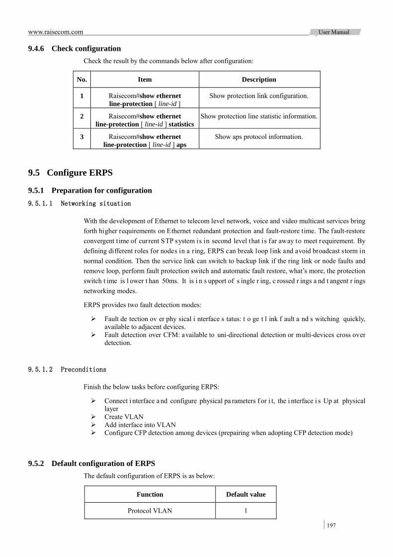
www.raisecom.com User Manual
197
9.4.6 Check configuration Check the result by the commands below after configuration:
No. Item Description
1 Raisecom#show ethernet line-protection [ line-id ]
Show protection link configuration.
2 Raisecom#show ethernet line-protection [ line-id ] statistics
Show protection line statistic information.
3 Raisecom#show ethernet line-protection [ line-id ] aps
Show aps protocol information.
9.5 Configure ERPS
9.5.1 Preparation for configuration 9.5.1.1 Networking situation
With the development of Ethernet to telecom level network, voice and video multicast services bring forth higher requirements on Ethernet redundant protection and fault-restore time. The fault-restore convergent t ime of current STP system is in second level that is far away to meet requirement. By defining different roles for nodes in a ring, ERPS can break loop link and avoid broadcast storm in normal condition. Then the service link can switch to backup link if the ring link or node faults and remove loop, perform fault protection switch and automatic fault restore, what’s more, the protection switch t ime is l ower t han 50ms. It is i n s upport of s ingle r ing, c rossed r ings a nd t angent r ings networking modes.
ERPS provides two fault detection modes:
Fault de tection ov er phy sical i nterface s tatus: t o ge t l ink f ault a nd s witching quickly, available to adjacent devices.
Fault detection over CFM: available to uni-directional detection or multi-devices cross over detection.
9.5.1.2 Preconditions
Finish the below tasks before configuring ERPS:
Connect i nterface a nd configure physical pa rameters f or i t, the i nterface i s Up at physical layer
Create VLAN Add interface into VLAN Configure CFP detection among devices (prepairing when adopting CFP detection mode)
9.5.2 Default configuration of ERPS The default configuration of ERPS is as below:
Function Default value
Protocol VLAN 1
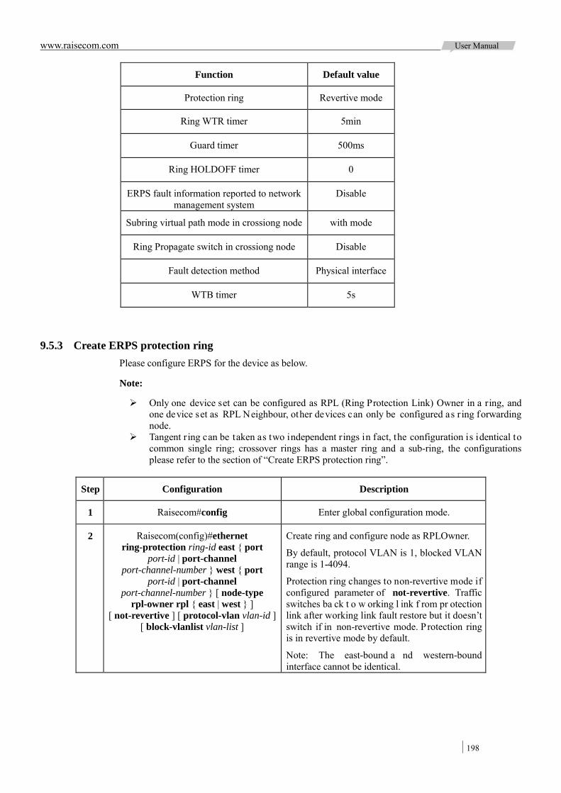
www.raisecom.com User Manual
198
Function Default value
Protection ring Revertive mode
Ring WTR timer 5min
Guard timer 500ms
Ring HOLDOFF timer 0
ERPS fault information reported to network management system
Disable
Subring virtual path mode in crossiong node with mode
Ring Propagate switch in crossiong node Disable
Fault detection method Physical interface
WTB timer 5s
9.5.3 Create ERPS protection ring Please configure ERPS for the device as below.
Note:
Only one device set can be configured as RPL (Ring Protection Link) Owner in a ring, and one device set as RPL Neighbour, other devices can only be configured as r ing forwarding node.
Tangent ring can be taken as two independent rings in fact, the configuration is identical to common single ring; crossover rings has a master ring and a sub-ring, the configurations please refer to the section of “Create ERPS protection ring”.
Step Configuration Description
1 Raisecom#config Enter global configuration mode.
2 Raisecom(config)#ethernet ring-protection ring-id east { port
port-id | port-channel port-channel-number } west { port
port-id | port-channel port-channel-number } [ node-type
rpl-owner rpl { east | west } ] [ not-revertive ] [ protocol-vlan vlan-id ]
[ block-vlanlist vlan-list ]
Create ring and configure node as RPLOwner.
By default, protocol VLAN is 1, blocked VLAN range is 1-4094.
Protection ring changes to non-revertive mode if configured parameter of not-revertive. Traffic switches ba ck t o w orking l ink f rom pr otection link after working link fault restore but it doesn’t switch if in non-revertive mode. Protection ring is in revertive mode by default.
Note: The east-bound a nd western-bound interface cannot be identical.

www.raisecom.com User Manual
199
Step Configuration Description
Raisecom(config)#ethernet ring-protection ring-id east { port
port-id | port-channel port-channel-number } west { port
port-id | port-channel port-channel-number } node-type rpl-neighbour rpl { east| west }
[ not-revertive ] [ protocol-vlan vlan-id ] [ block-vlanlist vlan-list ]
Create ring and configure node as RPL
Neighbour.
Raisecom(config)#ethernet ring-protection ring-id east { port
port-id | port-channel port-channel-number } west { port
port-id | port-channel port-channel-number } [ not-revertive ] [ protocol-vlan vlan-id ] [ block-vlanlist
vlan-list ]
Create ring and configure node as ring forwarding node.
3 Raisecom(config)#ethernet ring-protection ring-id name string
(Optional) Configure ring name. The length of
name cannot exceed 32 strings.
4 Raisecom(config)#ethernet ring-protection ring-id version { 1 | 2 }
(Optional) Configure protocol version. All nodes in one r ing m ust be c onsistent, v ersion 1 differenciate r ing v ia pr otocol VLAN, s o different r ings ne ed configure different protocol VLAN, and so do version 2. By default, using protocol version 1.
5 Raisecom(config)#ethernet ring-protection ring-id guard-time
guard-time
(Optional) D uring f ault nod e r estore t ime, a fter configuring Guard timer it doesn’t deal with APS protocol pa ckets. In s ome bi g r ing ne twork, restore node fault immediately may receive fault notice from neighbor node and cause link Down. Configure ring Guard timer can solve t his problem.
6 Raisecom(config)#ethernet ring-protection ring-id wtr-time
wtr-time
(Optional) Configure ring WTR tim er. In revertive mode, waiting WTR tim er ti meout to switch ba ck w orking l ink when w orking l ink restore from fault. By default, WTR timer values 5 minutes.
7 Raisecom(config)#ethernet ring-protection ring-id holdeoff-time
holdoff-time
(Optional) System delays fault report time when working l ink f aults a fter c onfiguring r ing HOLDOFF t imer. It c an a void w orking l ink switching f requently. By default, H OLDOFF timer is 0.
Note: 50ms s witching pe rformance w ill be affected by HOLDOFF timer v alue if i t is too bigger, so it is 0 by default 0.
8 Raisecom(config)#ethernet ring-protection trap enable
(Optional) Enable ERPS fault information report to NMS. Disable by default. Us the command of ethernet ring-protection trap disable to disable this function.

www.raisecom.com User Manual
200
9.5.4 (Optional) Create ERPS protection sub-ring Note:
Only the crossover rings network contains master ring and sub-ring. The master ring configuration is identical to the configuration of single ring or tangent ring;
please refer to the section of “Create ERPS protection ring” for details. Un-crossed node on s ub-ring is i dentical t o c onfiguration of s ingle ring or t angent ring;
please refer to the section of “Create ERPS protection ring” for details.
Please configure ERPS crossover rings for devices as below.
Step Configuration Description
1 Raisecom#config Enter global configuration mode.
2 Raisecom(config)#ethernet ring-protection ring-id { east | west } { port port-id | port-channel
port-channel-number } node-type rpl-owner [ not-revertive ] [ protocol-vlan vlan-id ]
[ block-vlanlist vlan-list ]
Create sub-ring and configure node as RPLOwner on crossover node.
By default, protocol VLAN is 1, blocked VLAN range is 1-4094.
Protection r ing c hanges t o no n-revertive mode if configured parameter of not-revertive. Traffic switches ba ck t o w orking l ink f rom pr otection l ink after working link fault restore but it doesn’t switch if in non -revertive mode. P rotection r ing i s i n r evertive mode by default.
Note: T he link be tween t wo crossover nodes i n crossover r ings be longs to m aster r ing, so either east-bound or w ester-bound i nterface c an be configured for sub-ring.
Raisecom(config)#ethernet ring-protection ring-id { east | west } { port port-id | port-channel
port-channel-number } node-type rpl-neighbour [ not-revertive ] [ protocol-vlan vlan-id ]
[ block-vlanlist vlan-list ]
Create sub-ring and configure node as RPL Neighbour on crossover nodes.
Raisecom(config)#ethernet ring-protection ring-id { east | west } { port port-id | port-channel
port-channel-number } [ not-revertive ] [ protocol-vlan vlan-id ] [ block-vlanlist vlan-list ]
Create sub-ring and configure node as ring forwarding node on crossover nodes.
3 Raisecom(config)#ethernet ring-protection ring-id raps-vc { with | without }
(Optional) Configure sub-ring virtual path mode on crossover node. Protocol packets transmitting in
sub-ring is different from master ring, including with mode and without mode:
with: sub-ring protocol packets transmitted by master ring.
without: sub-ring protocol packets transmitted by sub-ring protocol VLAN, so the blocked VLAN list should not include protocol VLAN. By default, sub-ring virtual path uses with. Configuration mode of two crossover nodes must be consistent.
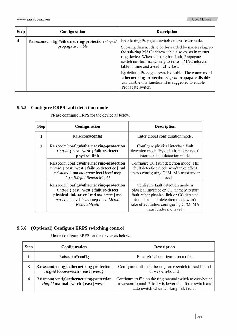
www.raisecom.com User Manual
201
Step Configuration Description
4 Raisecom(config)#ethernet ring-protection ring-id propagate enable
Enable ring Propagate switch on crossover node. Sub-ring data needs to be forwarded by master ring, so the sub-ring MAC address table also exists in master ring device. When sub-ring has fault, Propagate switch notifies master ring to refresh MAC address table in time and avoid traffic lost. By default, Propagate switch disable. The commandof ethernet ring-protection ring-id propagate disable can disable this function. It is suggested to enable Propagate switch.
9.5.5 Configure ERPS fault detection mode Please configure ERPS for the device as below.
Step Configuration Description
1 Raisecom#config Enter global configuration mode.
2 Raisecom(config)#ethernet ring-protection ring-id { east | west } failure-detect
physical-link
Configure physical interface fault detection mode. By default, it is physical
interface fault detection mode.
Raisecom(config)#ethernet ring-protection ring-id { east | west } failure-detect cc [ md
md-name ] ma ma-name level level mep LocalMepid RemoteMepid
Configure CC fault detection mode. The fault detection mode won’t take effect
unless configuring CFM. MA must under md level.
Raisecom(config)#ethernet ring-protection ring-id { east | west } failure-detect
physical-link-or-cc [ md md-name ] ma ma-name level level mep LocalMepid
RemoteMepid
Configure fault detection mode as physical interface or CC. namely, report fault either physical link or CC detected
fault. The fault detection mode won’t take effect unless configuring CFM. MA
must under md level.
9.5.6 (Optional) Configure ERPS switching control Please configure ERPS for the device as below.
Step Configuration Description
1 Raisecom#config Enter global configuration mode.
3 Raisecom(config)#ethernet ring-protection ring-id force-switch { east | west }
Configure traffic on the ring force switch to east-bound or western-bound.
4 Raisecom(config)#ethernet ring-protection ring-id manual-switch { east | west }
Configure traffic on the ring manual switch to east-bound or western-bound. Priority is lower than force switch and
auto-switch when working link faults.
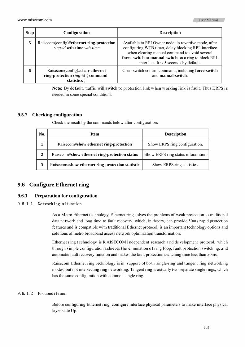
www.raisecom.com User Manual
202
Step Configuration Description
5 Raisecom(config)#ethernet ring-protection ring-id wtb-time wtb-time
Available to RPLOwner node, in revertive mode, after configuring WTB timer, delay blocking RPL interface
when clearing manual command to avoid several force-switch or manual-switch on a ring to block RPL
interface. It is 5 seconds by default.
6 Raisecom(config)#clear ethernet ring-protection ring-id { command |
statistics }
Clear switch control command, including force-switch and manual-switch.
Note: By de fault, traffic will s witch t o pr otection l ink w hen w orking l ink i s f ault. Thus E RPS i s needed in some special conditions.
9.5.7 Checking configuration Check the result by the commands below after configuration:
No. Item Description
1 Raisecom#show ethernet ring-protection Show ERPS ring configuration.
2 Raisecom#show ethernet ring-protection status Show ERPS ring status inforamtion.
3 Raisecom#show ethernet ring-protection statistic Show ERPS ring statistics.
9.6 Configure Ethernet ring
9.6.1 Preparation for configuration 9.6.1.1 Networking situation
As a Metro Ethernet technology, Ethernet ring solves the problems of weak protection to traditional data network and long time to fault recovery, which, in theory, can provide 50ms rapid protection features and is compatible with traditional Ethernet protocol, is an important technology options and solutions of metro broadband access network optimization transformation.
Ethernet r ing t echnology is R AISECOM i ndependent research a nd de velopment protocol, which through s imple configuration achieves the elimination of r ing loop, fault protection switching, and automatic fault recovery function and makes the fault protection switching time less than 50ms.
Raisecom Ethernet r ing t echnology is in support of bo th single-ring and t angent ring networking modes, but not intersecting ring networking. Tangent ring is actually two separate single rings, which has the same configuration with common single ring.
9.6.1.2 Preconditions
Before configuring Ethernet ring, configure interface physical parameters to make interface physical layer state Up.

www.raisecom.com User Manual
203
9.6.2 Default configuration of Ethernet ring The default configuration of Ethernet ring is as below:
Function Default value
Ethernet ring function status Disable
Hello messages transmitting time 1s
Fault recovery delay time 5s
Bridge priority 1
Ring interface aging time 15s
Ring protocol messages VLAN 2
9.6.3 Create Ethernet ring Please create Ethernet ring as below:
Step Configuration Description
1 Raisecom#config Enter global configuration mode.
2 Raisecom(config)#interface interface-type primary-interface-number
Enter physical layer interface configuration mode.this interface is the first interface of ring node.
3 Raisecom(config-port)#ethernet ring ring-id interface-type sencondary-interface-number
Create ring and configure corresponding ring interface. This interface is the second interface of
ring node.
4 Raisecom(config-port)#exit
Raisecom(config)#ethernet ring ring-id enable
Enable Ethernet ring function.
9.6.4 Configure basic function of ring Note:
For al l devices in the same ring, suggest configure the fault recovery t ime, Hello messages interval. Ring protocol VLAN and Ring interface aging time separately for the same value.
Interface aging time must be greater than 2 times Hello time.
Please configure the basic function of ring on the device as below:
1 Raisecom#config Enter global configuration mode.
2 Raisecom(config)#ethernet ring ring-id hello-time hello-time
(Optional) Configure Hello messages transmitting time for Ethernet ring. By default, the messages sending
interval is 1s.
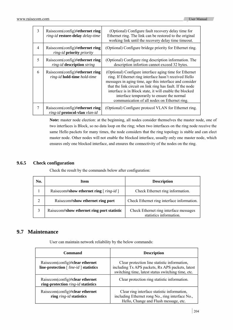
www.raisecom.com User Manual
204
3 Raisecom(config)#ethernet ring ring-id restore-delay delay-time
(Optional) Configure fault recovery delay time for Ethernet ring. The link can be restored to the original working link until the recovery delay time timeout.
4 Raisecom(config)#ethernet ring ring-id priority priority
(Optional) Configure bridege priority for Ethernet ring.
5 Raisecom(config)#ethernet ring ring-id description string
(Optional) Configure ring description information. The description infortion cannot exceed 32 bytes.
6 Raisecom(config)#ethernet ring ring-id hold-time hold-time
(Optional) Configure interface aging time for Ethernet ring. If Ethernet ring interface hasn’t received Hello
messages in aging time, age this interface and consider that the link circuit on link ring has fault. If the node interface is in Block state, it will enable the blocked
interface temporarily to ensure the normal communication of all nodes on Ethernet ring.
7 Raisecom(config)#ethernet ring ring-id protocol-vlan vlan-id
(Optional) Configure protocol VLAN for Ethernet ring.
Note: master node election: at the beginning, all nodes consider themselves the master node, one of two interfaces is Block, so no data loop on the ring; when two interfaces on the ring node receive the same Hello packets for many times, the node considers that the ring topology is stable and can elect master node. Other nodes will not enable the blocked interface, usually only one master node, which ensures only one blocked interface, and ensures the connectivity of the nodes on the ring.
9.6.5 Check configuration Check the result by the commands below after configuration:
No. Item Description
1 Raisecom#show ethernet ring [ ring-id ] Check Ethernet ring information.
2 Raisecom#show ethernet ring port Check Ethernet ring interface information.
3 Raisecom#show ethernet ring port statistic Check Ethernet ring interface messages statistics information.
9.7 Maintenance
User can maintain network reliability by the below commands:
Command Description
Raisecom(config)#clear ethernet line-protection [ line-id ] statistics
Clear protection line statistic information, including Tx APS packets, Rx APS packets, latest switching time, latest status switching time, etc.
Raisecom(config)#clear ethernet ring-protection ring-id statistics
Clear protection ring statistic information.
Raisecom(config)#clear ethernet ring ring-id statistics
Clear ring interface statistic information, including Ethernet rong No., ring interface No.,
Hello, Change and Flush message, etc.
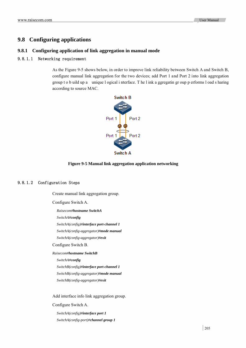
www.raisecom.com User Manual
205
9.8 Configuring applications
9.8.1 Configuring application of link aggregation in manual mode 9.8.1.1 Networking requirement
As the Figure 9-5 shows below, in order to improve link reliability between Switch A and Switch B, configure manual link aggregation for the two devices; add Port 1 and Port 2 into link aggregation group t o b uild up a unique l ogical i nterface. T he l ink a ggregatin gr oup p erforms l oad s haring according to source MAC.
Figure 9-5 Manual link aggregation application networking
9.8.1.2 Configuration Steps
Create manual link aggregation group.
Configure Switch A.
Raisecom#hostname SwitchA
SwitchA#config
SwitchA(config)#interface port-channel 1
SwitchA(config-aggregator)#mode manual
SwitchA(config-aggregator)#exit
Configure Switch B.
Raisecom#hostname SwitchB
SwitchA#config
SwitchB(config)#interface port-channel 1
SwitchB(config-aggregator)#mode manual
SwitchB(config-aggregator)#exit
Add interface info link aggregation group.
Configure Switch A.
SwitchA(config)#interface port 1
SwitchA(config-port)#channel group 1
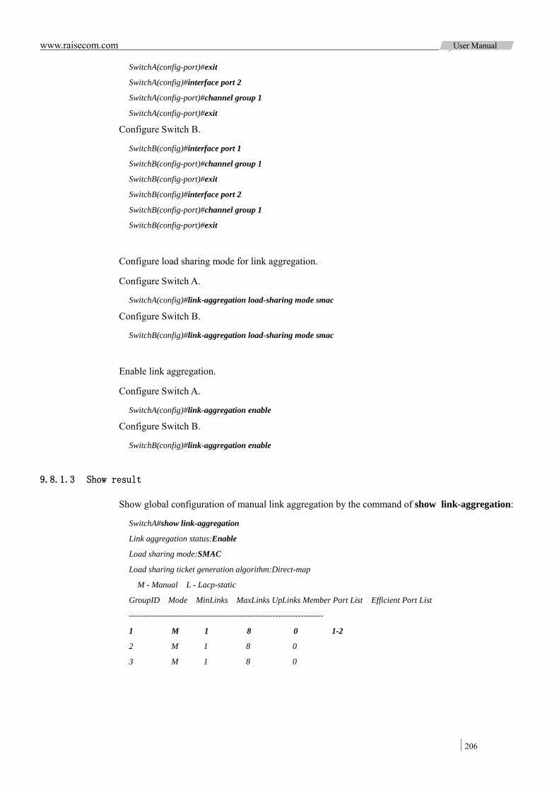
www.raisecom.com User Manual
206
SwitchA(config-port)#exit
SwitchA(config)#interface port 2
SwitchA(config-port)#channel group 1
SwitchA(config-port)#exit
Configure Switch B.
SwitchB(config)#interface port 1
SwitchB(config-port)#channel group 1
SwitchB(config-port)#exit
SwitchB(config)#interface port 2
SwitchB(config-port)#channel group 1
SwitchB(config-port)#exit
Configure load sharing mode for link aggregation.
Configure Switch A.
SwitchA(config)#link-aggregation load-sharing mode smac
Configure Switch B.
SwitchB(config)#link-aggregation load-sharing mode smac
Enable link aggregation.
Configure Switch A.
SwitchA(config)#link-aggregation enable
Configure Switch B.
SwitchB(config)#link-aggregation enable
9.8.1.3 Show result
Show global configuration of manual link aggregation by the command of show link-aggregation:
SwitchA#show link-aggregation
Link aggregation status:Enable
Load sharing mode:SMAC
Load sharing ticket generation algorithm:Direct-map
M - Manual L - Lacp-static
GroupID Mode MinLinks MaxLinks UpLinks Member Port List Efficient Port List
---------------------------------------------------------------------
1 M 1 8 0 1-2
2 M 1 8 0
3 M 1 8 0
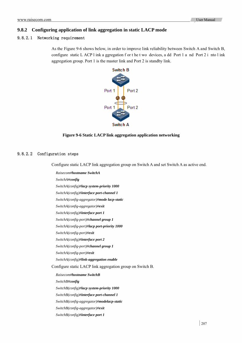
www.raisecom.com User Manual
207
9.8.2 Configuring application of link aggregation in static LACP mode 9.8.2.1 Networking requirement
As the Figure 9-6 shows below, in order to improve link reliability between Switch A and Switch B, configure static L ACP l ink a ggregation f or t he t wo devices, a dd Port 1 a nd Port 2 i nto l ink aggregation group. Port 1 is the master link and Port 2 is standby link.
Figure 9-6 Static LACP link aggregation application networking
9.8.2.2 Configuration steps
Configure static LACP link aggregation group on Switch A and set Switch A as active end.
Raisecom#hostname SwitchA
SwitchA#config
SwitchA(config)#lacp system-priority 1000
SwitchA(config)#interface port-channel 1
SwitchA(config-aggregator)#mode lacp-static
SwitchA(config-aggregator)#exit
SwitchA(config)#interface port 1
SwitchA(config-port)#channel group 1
SwitchA(config-port)#lacp port-priority 1000
SwitchA(config-port)#exit
SwitchA(config)#interface port 2
SwitchA(config-port)#channel group 1
SwitchA(config-port)#exit
SwitchA(config)#link-aggregation enable
Configure static LACP link aggregation group on Switch B.
Raisecom#hostname SwitchB
SwitchB#config
SwitchB(config)#lacp system-priority 1000
SwitchB(config)#interface port-channel 1
SwitchB(config-aggregator)#modelacp-static
SwitchB(config-aggregator)#exit
SwitchB(config)#interface port 1

www.raisecom.com User Manual
208
SwitchB(config-port)#channel group 1
SwitchB(config-port)#exit
SwitchB(config)#interface port 2
SwitchB(config-port)#channel group 1
SwitchB(config-port)#exit
SwitchB(config)#link-aggregation enable
9.8.2.3 Show result
Show static LACP link aggregation global configuration on Switch A by the command of show
link-aggregation:
Raisecom#show link-aggregation
Link aggregation status:Enable
Load sharing mode:SXORDMAC
Load sharing ticket generation algorithm:Direct-map
M - Manual L - Lacp-static
GroupID Mode MinLinks MaxLinks UpLinks Member Port List Efficient Port List
---------------------------------------------------------------------
1 L 1 8 0 1-2
2 M 1 8 0
3 M 1 8 0
4 M 1 8 0
5 M 1 8 0
6 M 1 8 0
7 M 1 8 0
8 M 1 8 0
Show peer system LACP interface s tatus, mark, interface pr iority, management key, operation key and status of interface status machine on Switch A by the command of show lacp internal:
Raisecom(config)#show lacp internal
Flags:
S - Device is requesting Slow LACPDUs F - Device is requesting Fast LACPDUs
A - Device in Active mode P - Device in Passive mode
Interface State Flag Port-Priority Admin-key Oper-key Port-State
-------------------------------------------------------------------------
P1 active SA 1000 1 1 0x45
P2 standby SA 32768 1 1 0x45
Show peer system LACP interface s tatus, mark, interface pr iority, management ke y, operation key and status of interface status machine on Switch A by the command of show lacp neighbor.
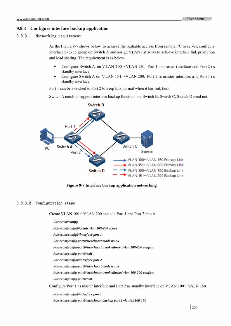
www.raisecom.com User Manual
209
9.8.3 Configure interface backup application 9.8.3.1 Networking requirement
As the Figure 9-7 shows below, to achieve the realiable accress from remote PC to server, configure interface backup group on Switch A and assign VLAN list so as to achieve interface link protection and load sharing. The requirement is as below:
Configure Switch A on V LAN 100~VLAN 150, Port 1 i s m aster i nterface a nd P ort 2 i s standby interface.
Configure S witch A on V LAN 151~VLAN 200, Port 2 i s master interface, a nd Port 1 i s standby interface.
Port 1 can be switched to Port 2 to keep link normal when it has link fault.
Switch A needs to support interface backup function, but Switch B, Switch C, Switch D need not.
Figure 9-7 Interface backup application networking
9.8.3.2 Configuration steps
Create VLAN 100~VLAN 200 and add Port 1 and Port 2 into it.
Raisecom#config
Raisecom(config)#create vlan 100-200 active
Raisecom(config)#interface port 1
Raisecom(config-port)#switchport mode trunk
Raisecom(config-port)#switchport trunk allowed vlan 100-200 confirm
Raisecom(config-port)#exit
Raisecom(config)#interface port 2
Raisecom(config-port)#switchport mode trunk
Raisecom(config-port)#switchport trunk allowed vlan 100-200 confirm
Raisecom(config-port)#exit
Configure Port 1 as master interface and Port 2 as standby interface on VLAN 100~VALN 150.
Raisecom(config)#interface port 1
Raisecom(config-port)#switchport backup port 2 vlanlist 100-150

www.raisecom.com User Manual
210
Raisecom(config-port)#exit
Configure Port 2 as master interface and Port 1 as standby interface on VLAN 151~VALN 200.
Raisecom(config)#interface port 2
Raisecom(config-port)#switchport backup port 1 vlanlist 151-200
9.8.3.3 Show result
Check i nterface ba ckup s tatus i nformation i n c onditions of normal l ink s tatus a nd l ink fault separately by the command of show switchport backup.
When the link of Port 1 and Port 2 is Up, Port 1 forwards traffics on VLAN 100~VALN 1 50, while Port 2 forwards traffics on VLAN 151~VALN 200.
Raisecom#show switchport backup
Restore delay: 15s.
Restore mode: port-up.
Active Port(State) Backup Port(State) Vlanlist
---------------------------------------------------------
port1 (Up) port2 (Standby) 100-150
port2 (Up) port1 (Standby) 151-200
Break the link simulation fault between Switch A and Switch B manually, then the status of Port 1 will become Down, Port 2 will forward traffics on VLAN 100~VALN 200.
Raisecom#show switchport backup
Restore delay: 15s
Restore mode: port-up
Active Port(State) Backup Port(State) Vlanlist
-----------------------------------------------------------------
port1 (Down) port2 (Up) 100-150
port2 (Up) port1 (Down) 150-200
When Port1 recovers t o Up st atus for 15s (re cover de lay), Port 1 will forward traffics on VLAN 100~VALN 150, and Port 2 on VLAN 151~VALN 200.
9.8.4 Configuring application of ELPS protection in 1:1 mode 9.8.4.1 Networking requirement
As the Figure 9-8 shows below, in order to improve link reliability between Switch A and Switch B, configure 1:1 ELPS on the two devices and detect fault over physical interface status. Port 1 and Port 2 set in VLAN range 100~200.
Figure 9-8 Networking sketch map of 1:1 ELPS application
www.raisecom.com User Manual
211
9.8.4.2 Configuration steps
Create VLAN 100~VLAN 200 and add interface into VLAN 100~VLAN 200.
Configure Switch A.
Raisecom#hostname SwitchA
SwitchA#config
SwitchA(config)#create vlan 100-200 active
SwitchA(config)#interface port 1
SwitchA(config-port)#switchport mode trunk
SwitchA(config-port)#switchport trunk allowed vlan 100-200 confirm
SwitchA(config-port)#exit
SwitchA(config)#interface port 2
SwitchA(config-port)#switchport mode trunk
SwitchA(config-port)#switchport trunk allowed vlan 100-200 confirm
SwitchA(config-port)#exit
Configure Switch B.
Raisecom#hostname SwitchB
SwitchB#config
SwitchB(config)#create vlan 100-200 active
SwitchB(config)#interface port 1
SwitchB(config-port)#switchport mode trunk
SwitchB(config-port)#switchport trunk allowed vlan 100-200 confirm
SwitchB(config-port)#exit
SwitchB(config)#interface port 2
SwitchB(config-port)#switchport mode trunk
SwitchB(config-port)#switchport trunk allowed vlan 100-200 confirm
SwitchB(config-port)#exit
create 1:1 mode ELPS protection line.
Configure Switch A.
SwitchA(config)#ethernet line-protection 1 working port 1 100-200 protection port 2 100-200 one-to-one
Configure Switch B.
SwitchB(config)#ethernet line-protection 1 working port 1 100-200 protection port 2 100-200 one-to-one
Configure fault detection mode.
Configure Switch A.
SwitchA(config)#ethernet line-protection 1 working failure-detect physical-link
SwitchA(config)#ethernet line-protection 1 protection failure-detect physical-link
Configure Switch B.
SwitchB(config)#ethernet line-protection 1 working failure-detect physical-link
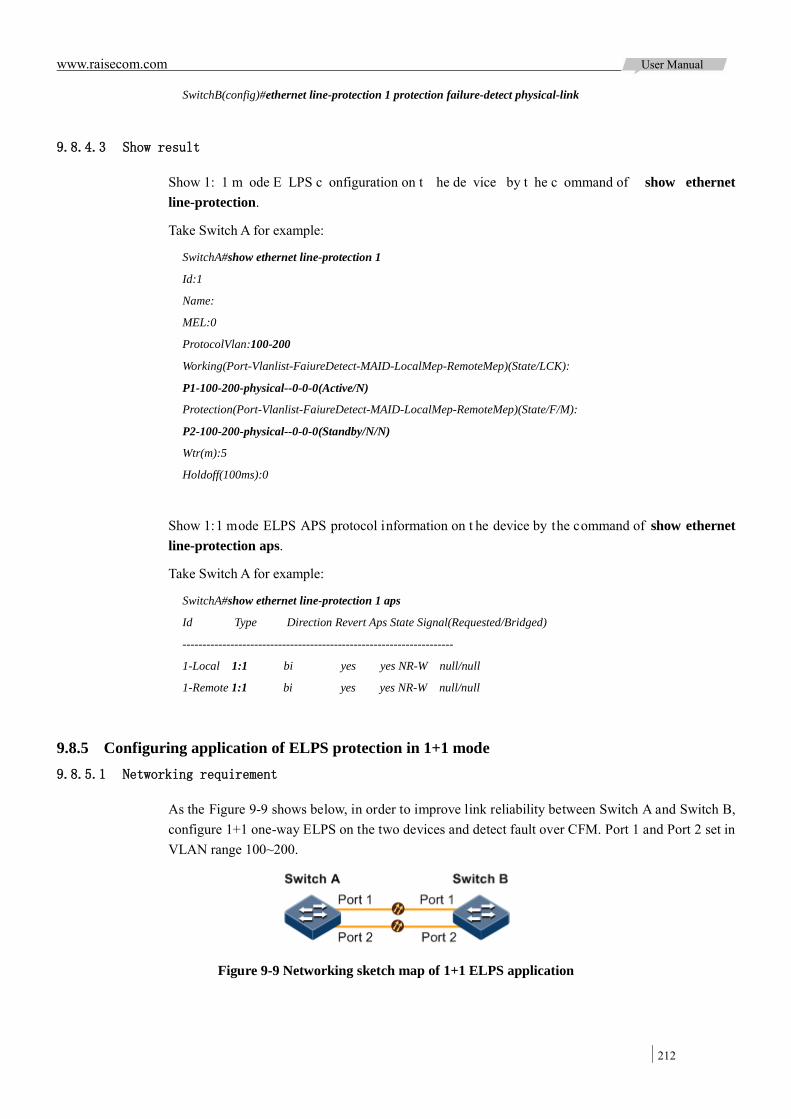
www.raisecom.com User Manual
212
SwitchB(config)#ethernet line-protection 1 protection failure-detect physical-link
9.8.4.3 Show result
Show 1: 1 m ode E LPS c onfiguration on t he de vice by t he c ommand of show ethernet line-protection.
Take Switch A for example:
SwitchA#show ethernet line-protection 1
Id:1
Name:
MEL:0
ProtocolVlan:100-200
Working(Port-Vlanlist-FaiureDetect-MAID-LocalMep-RemoteMep)(State/LCK):
P1-100-200-physical--0-0-0(Active/N)
Protection(Port-Vlanlist-FaiureDetect-MAID-LocalMep-RemoteMep)(State/F/M):
P2-100-200-physical--0-0-0(Standby/N/N)
Wtr(m):5
Holdoff(100ms):0
Show 1:1 mode ELPS APS protocol information on t he device by the command of show ethernet line-protection aps.
Take Switch A for example:
SwitchA#show ethernet line-protection 1 aps
Id Type Direction Revert Aps State Signal(Requested/Bridged)
--------------------------------------------------------------------
1-Local 1:1 bi yes yes NR-W null/null
1-Remote 1:1 bi yes yes NR-W null/null
9.8.5 Configuring application of ELPS protection in 1+1 mode 9.8.5.1 Networking requirement
As the Figure 9-9 shows below, in order to improve link reliability between Switch A and Switch B, configure 1+1 one-way ELPS on the two devices and detect fault over CFM. Port 1 and Port 2 set in VLAN range 100~200.
Figure 9-9 Networking sketch map of 1+1 ELPS application
www.raisecom.com User Manual
213
9.8.5.2 Configuration steps
Create VLAN 100~VLAN 200 and add interface into VLAN 100~VLAN 200.
Configure Switch A.
Raisecom#hostname SwitchA
SwitchA#config
SwitchA(config)#create vlan 100-200 active
SwitchA(config)#interface port 1
SwitchA(config-port)#switchport mode trunk
SwitchA(config-port)#switchport trunk allowed vlan 100-200 confirm
SwitchA(config-port)#exit
SwitchA(config)#interface port 2
SwitchA(config-port)#switchport mode trunk
SwitchA(config-port)#switchport trunk allowed vlan 100-200 confirm
SwitchA(config-port)#exit
Configure Switch B.
Raisecom#hostname SwitchB
SwitchB#config
SwitchB(config)#create vlan 100-200 active
SwitchB(config)#interface port 1
SwitchB(config-port)#switchport mode trunk
SwitchB(config-port)#switchport trunk allowed vlan 100-200 confirm
SwitchB(config-port)#exit
SwitchB(config)#interface port 2
SwitchB(config-port)#switchport mode trunk
SwitchB(config-port)#switchport trunk allowed vlan 100-200 confirm
SwitchB(config-port)#exit
Configure CFM.
Configure Switch A.
SwitchA(config)#ethernet cfm domain md-name md1 level 7
SwitchA(config)#service ma1 level 7
SwitchA(config-service)#service vlan-list 100
SwitchA(config-service)#service mep down mpid 1 port 1
SwitchA(config-service)#service mep down mpid 2 port 2
SwitchA(config-service)#service remote-mep 3
SwitchA(config-service)#service remote-mep 4
SwitchA(config-service)#service cc enable mep 1
SwitchA(config-service)#service cc enable mep 2
SwitchA(config-service)#exit
SwitchA(config)#ethernet cfm enable
Configure Switch B.
www.raisecom.com User Manual
214
SwitchB(config)#ethernet cfm domain md-name md1 level 7
SwitchB(config)#service ma1 level 7
SwitchB(config-service)#service vlan-list 100
SwitchB(config-service)#service mep down mpid 3 port 1
SwitchB(config-service)#service mep down mpid 4 port 2
SwitchB(config-service)#service remote-mep 1
SwitchB(config-service)#service remote-mep 2
SwitchB(config-service)#service cc enable mep 3
SwitchB(config-service)#service cc enable mep 4
SwitchB(config-service)#exit
SwitchB(config)#ethernet cfm enable
Create 1+1 mode one-way ELPS protection line.
Configure Switch A.
SwitchA(config)#ethernet line-protection 1 working port 1 100-200 protection port 2 100-200 one-plus-one-uni
Configure Switch B.
SwitchB(config)#ethernet line-protection 1 working port 1 100-200 protection port 2 100-200 one-plus-one-uni
Configure fault detection mode.
Configure Switch A.
SwitchA(config)#ethernet line-protection 1 working failure-detect cc md md1 ma ma1 level 7 mep 1 3
SwitchA(config)#ethernet line-protection 1 protection failure-detect cc md md1 ma ma1 level 7 mep 2 4
Configure Switch B.
SwitchB(config)#ethernet line-protection 1 working failure-detect cc md md1 ma ma1 level 7 mep 3 1
SwitchB(config)#ethernet line-protection 1 protection failure-detect cc md md1 ma ma1 level 7 mep 4 2
9.8.5.3 Show result
Show 1+ 1 m ode E LPS configuration on the de vice by the c ommand of show ethernet line-protection.
Take Switch A for example:
SwitchA#show ethernet line-protection 1
Id:1
Name:
ProtocolVlan:100-200
Working(Port-Vlanlist-FaiureDetect-MAID-LocalMep-RemoteMep)(State/LCK):
Port1-100-200-cc-md1ma1-7-1-3(Active/N)
Protection(Port-Vlanlist-FaiureDetect-MAID-LocalMep-RemoteMep)(State/F/M):
Port2-100-200-cc-md1ma1-7-2-4(Standby/N/N)
Wtr(m):5
Holdoff(100ms):0

www.raisecom.com User Manual
215
Show 1+1 mode ELPS APS protocol information on t he device by the command of show ethernet line-protection aps.
Take Switch A for example:
SwitchA#show ethernet line-protection 1 aps
Id Type Direction Revert Aps State Signal(Requested/Bridged)
--------------------------------------------------------------------
1-Local 1+1 uni yes yes NR-W null/normal
9.8.6 Configuring application of single ring ERPS protection 9.8.6.1 Networking requirement
As the Figure 9-10 shows below, in order to improve Ethernet reliability, the four devices Switch A, Switch B, Switch C and Switch D build up an ERPS single ring.
Switch A device i s R PLOwner, Switch B i s R PLNeighbour; the RPL link between Switch A a nd Switch B is blocked.
The fault detection mode between Switch A and Switch D is physical-link-or-cc, other l inks adopt default fault detection mode (physical-link).
By default, VLAN is 1, and the congested VLAN range is 1~4094.
Figure 9-10 Single ring ERPS application networking
9.8.6.2 Configuration steps
Add interface into VLAN 1~VLAN 4094.
Configure Switch A.
Raisecom#hostname SwitchA
SwitchA#config
SwitchA(config)#interface port 1
SwitchA(config-port)#switchport mode trunk
SwitchA(config-port)#exit
SwitchA(config)#interface port 2
www.raisecom.com User Manual
216
SwitchA(config-port)#switchport mode trunk
SwitchA(config-port)#exit
Configure Switch B.
Raisecom#hostname SwitchB
SwitchB#config
SwitchB(config)#interface port 1
SwitchB(config-port)#switchport mode trunk
SwitchB(config-port)#exit
SwitchB(config)#interface port 2
SwitchB(config-port)#switchport mode trunk
SwitchB(config-port)#exit
Configure Switch C.
Raisecom#hostname SwitchC
SwitchC#config
SwitchC(config)#interface port 1
SwitchC(config-port)#switchport mode trunk
SwitchC(config-port)#exit
SwitchC(config)#interface port 2
SwitchC(config-port)#switchport mode trunk
SwitchC(config-port)#exit
Configure Switch D.
Raisecom#hostname SwitchD
SwitchD#config
SwitchD(config)#interface port 1
SwitchD(config-port)#switchport mode trunk
SwitchD(config-port)#exit
SwitchD(config)#interface port 2
SwitchD(config-port)#switchport mode trunk
SwitchD(config-port)#exit
Configure CFM.
Configure Switch A.
SwitchA(config)#ethernet cfm domain md-name md1 level 7
SwitchA(config)#service ma1 level 7
SwitchA(config-service)#service vlan-list 1
SwitchA(config-service)#service mep down mpid 1 port 2
SwitchA(config-service)#service remote-mep 2
SwitchA(config-service)#service cc enable mep 1
SwitchA(config-service)#exit
SwitchA(config)#ethernet cfm enable
Configure Switch D.
SwitchD(config)#ethernet cfm domain md-name md1 level 7

www.raisecom.com User Manual
217
SwitchD(config)#service ma1 level 7
SwitchD(config-service)#service vlan-list 1
SwitchD(config-service)#service mep down mpid 2 port 1
SwitchD(config-service)#service remote-mep 1
SwitchD(config-service)#service cc enable mep 2
SwitchD(config-service)#exit
SwitchD(config)#ethernet cfm enable
Create ERPS protection ring.
Configure Switch A.
SwitchA(config)#ethernet ring-protection 1 east port 1 west port 2 node-type rpl-owner rpl east
Configure Switch B.
SwitchB(config)#ethernet ring-protection 1 east port 1 west port 2 node-type rpl-neighbour rpl west
Configure Switch C.
SwitchC(config)#ethernet ring-protection 1 east port 1 west port 2
Configure Switch D.
SwitchD(config)#ethernet ring-protection 1 east port 1 west port 2
Configure fault detection mode.
Configure Switch A.
SwitchA(config)#ethernet ring-protection 1 west failure-detect physical-link-or-cc md md1 ma ma1 level 7 mep 1 2
Configure Switch D.
SwitchD(config)#ethernet ring-protection 1 east failure-detect physical-link-or-cc md md1 ma ma1 level 7 mep 2 1
9.8.6.3 Show result
Check i f E RPS protection ring is ef fective on the de vice b y t he command of show ethernet ring-protection status.
Take Switch A for example, RPL link is congested to avoid loopback:
SwitchA#show ethernet ring-protection status
Id/Name Status Last Occur(ago) East-State West-State sc Traffic-vlanlist
---------------------------------------------------------------------
1 idle 0 day 0:0:50:750 block forwarding 1 1-4094
Cut off link between Switch B and Switch C by manual to simulate fault, execute command to show ERPS protection ring status on Switch A again, RPL link switches to forwarding status.
SwitchA#show ethernet ring-protection status
Id/Name Status Last Occur(ago) East-State West-State sc Traffic-vlanlist
-------------------------------------------------------------------
1 Protection 0 day 0:0:55:950 forwarding forwarding 1 1-4094
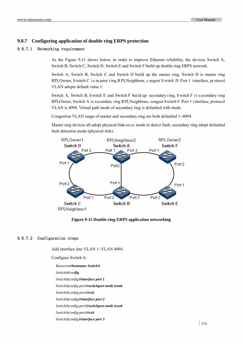
www.raisecom.com User Manual
218
9.8.7 Configuring application of double ring ERPS protection 9.8.7.1 Networking requirement
As the Figure 9-11 shows below, in order to improve Ethernet reliability, the devices Switch A, Switch B, Switch C, Switch D, Switch E and Switch F build up double ring ERPS network.
Switch A, Switch B, Switch C and Switch D build up the master ring, Switch D is master ring RPLOwner, S witch C i s m aster r ing R PLNeighbour, c ongest S witch D Port 1 i nterface, pr otocol VLAN adopts default value 1.
Switch A, Switch B, S witch E and Switch F bui ld up secondary r ing, S witch F i s s econdary r ing RPLOwner, Switch A is secondary ring RPLNeighbour, congest Switch F Port 1 i nterface, protocol VLAN is 4094. Virtual path mode of secondary ring is defaulted with mode.
Congestion VLAN range of master and secondary ring are both defaulted 1~4094.
Master ring devices all adopt physical-link-or-cc mode to detect fault, secondary ring adopt defaulted fault detection mode (physical-link).
Figure 9-11 Double-ring ERPS application networking
9.8.7.2 Configuration steps
Add interface into VLAN 1~VLAN 4094.
Configure Switch A.
Raisecom#hostname SwitchA
SwitchA#config
SwitchA(config)#interface port 1
SwitchA(config-port)#switchport mode trunk
SwitchA(config-port)#exit
SwitchA(config)#interface port 2
SwitchA(config-port)#switchport mode trunk
SwitchA(config-port)#exit
SwitchA(config)#interface port 3
www.raisecom.com User Manual
219
SwitchA(config-port)#switchport mode trunk
SwitchA(config-port)#exit
Configure Switch B.
Raisecom#hostname SwitchB
SwitchB#config
SwitchB(config)#interface port 1
SwitchB(config-port)#switchport mode trunk
SwitchB(config-port)#exit
SwitchB(config)#interface port 2
SwitchB(config-port)#switchport mode trunk
SwitchB(config-port)#exit
SwitchB(config)#interface port 3
SwitchB(config-port)#switchport mode trunk
SwitchB(config-port)#exit
Configure Switch C.
Raisecom#hostname SwitchC
SwitchC#config
SwitchC(config)#interface port 1
SwitchC(config-port)#switchport mode trunk
SwitchC(config-port)#exit
SwitchC(config)#interface port 2
SwitchC(config-port)#switchport mode trunk
SwitchC(config-port)#exit
Configure Switch D.
Raisecom#hostname SwitchD
SwitchD#config
SwitchD(config)#interface port 1
SwitchD(config-port)#switchport mode trunk
SwitchD(config-port)#exit
SwitchD(config)#interface port 2
SwitchD(config-port)#switchport mode trunk
SwitchD(config-port)#exit
Configure Switch E.
Raisecom#hostname SwitchE
SwitchE#config
SwitchE(config)#interface port 1
SwitchE(config-port)#switchport mode trunk
SwitchE(config-port)#exit
SwitchE(config)#interface port 2
SwitchE(config-port)#switchport mode trunk
SwitchE(config-port)#exit
Configure Switch F.
Raisecom#hostname SwitchF

www.raisecom.com User Manual
220
SwitchF#config
SwitchF(config)#interface port 1
SwitchF(config-port)#switchport mode trunk
SwitchF(config-port)#exit
SwitchF(config)#interface port 2
SwitchF(config-port)#switchport mode trunk
SwitchF(config-port)#exit
Configure master ring CFM detection.
Configure Switch A.
SwitchA(config)#ethernet cfm domain md-name md1 level 7
SwitchA(config)#service ma1 level 7
SwitchA(config-service)#service vlan-list 1
SwitchA(config-service)#service mep down mpid 1 port 1
SwitchA(config-service)#service mep down mpid 2 port 2
SwitchA(config-service)#service cc enable mep 1
SwitchA(config-service)#service cc enable mep 2
SwitchA(config-service)#exit
SwitchA(config)#ethernet cfm enable
Configure Switch B.
SwitchB(config)#ethernet cfm domain md-name md1 level 7
SwitchB(config)#service ma1 level 7
SwitchB(config-service)#service vlan-list 1
SwitchB(config-service)#service mep down mpid 3 port 1
SwitchB(config-service)#service mep down mpid 4 port 2
SwitchB(config-service)#service cc enable mep 3
SwitchB(config-service)#service cc enable mep 4
SwitchB(config-service)#exit
SwitchB(config)#ethernet cfm enable
Configure Switch C.
SwitchC(config)#ethernet cfm domain md-name md1 level 7
SwitchC(config)#service ma1 level 7
SwitchC(config-service)#service vlan-list 1
SwitchC(config-service)#service mep down mpid 5 port 1
SwitchC(config-service)#service mep down mpid 6 port 2
SwitchC(config-service)#service cc enable mep 5
SwitchC(config-service)#service cc enable mep 6
SwitchC(config-service)#exit
SwitchC(config)#ethernet cfm enable
Configure Switch D.
SwitchD(config)#ethernet cfm domain md-name md1 level 7
SwitchD(config)#service ma1 level 7

www.raisecom.com User Manual
221
SwitchD(config-service)#service vlan-list 1
SwitchD(config-service)#service mep down mpid 7 port 1
SwitchD(config-service)#service mep down mpid 8 port 2
SwitchD(config-service)#service cc enable mep 7
SwitchD(config-service)#service cc enable mep 8
SwitchD(config-service)#exit
SwitchD(config)#ethernet cfm enable
Create master ring for ERPS protection.
Configure Switch A.
SwitchA(config)#ethernet ring-protection 1 east port 1 west port 2
Configure Switch B.
SwitchB(config)#ethernet ring-protection 1 east port 1 west port 2
Configure Switch C.
SwitchC(config)#ethernet ring-protection 1 east port 1 west port 2 node-type rpl-neighbour rpl west
Configure Switch D.
SwitchD(config)#ethernet ring-protection 1 east port 1 west port 2 node-type rpl-owner rpl east
Configure fault detection mode for master ring.
Configure Switch A.
SwitchA(config)#ethernet ring-protection 1 east failure-detect physical-link-or-cc md md1 ma ma1 level 7 mep 1 8
SwitchA(config)#ethernet ring-protection 1 west failure-detect physical-link-or-cc md md1 ma ma1 level 7 mep 2 3
Configure Switch B.
SwitchB(config)#ethernet ring-protection 1 east failure-detect physical-link-or-cc md md1 ma ma1 level 7 mep 3 2
SwitchB(config)#ethernet ring-protection 1 west failure-detect physical-link-or-cc md md1 ma ma1 level 7 mep 4 5
Configure Switch C.
SwitchC(config)#ethernet ring-protection 1 east failure-detect physical-link-or-cc md md1 ma ma1 level 7 mep 5 4
SwitchC(config)#ethernet ring-protection 1 west failure-detect physical-link-or-cc md md1 ma ma1 level 7 mep 6 7
Configure Switch D.
SwitchD(config)#ethernet ring-protection 1 east failure-detect physical-link-or-cc md md1 ma ma1 level 7 mep 7 6
SwitchD(config)#ethernet ring-protection 1 west failure-detect physical-link-or-cc md md1 ma ma1 level 7 mep 8 1
Configure sub-ring for ERPS protection ring.
Configure Switch A.
SwitchA(config)#ethernet ring-protection 2 east port 3 node-type rpl-neighbour protocol-vlan 4094

www.raisecom.com User Manual
222
SwitchA(config)#ethernet ring-protection 2 propagate enable
Configure Switch B.
SwitchB(config)#ethernet ring-protection 2 east port 3 protocol-vlan 4094
SwitchB(config)#ethernet ring-protection 2 propagate enable
Configure Switch E.
SwitchE(config)#ethernet ring-protection 2 east port 1 west port 2 protocol-vlan 4094
Configure Switch F.
SwitchF(config)#ethernet ring-protection 2 east port 1 west port 2 node-type rpl-owner rpl east protocol-vlan 4094
9.8.7.3 Show result
Check i f E RPS protection ring i s e ffective on t he de vice b y t he c ommand of show ethernet ring-protection status.
Execute the command on Switch A, Switch D and Switch F r espectively, the r esult w ill s how a s below if configure successfully.
SwitchA#show ethernet ring-protection status
Id/Name Status Last Occur(ago) East-State West-State sc Traffic-vlanlist
-------------------------------------------------------------------------
1 idle 0 day 0:0:50:750 forwarding forwarding 1 1-4094
Id/Name Status Last Occur(ago) East-State West-State sc Traffic-vlanlist
-------------------------------------------------------------------------
2 idle 0 day 0:0:50:750 forwarding forwarding 1 1-4094
SwitchD#show ethernet ring-protection status
Id/Name Status Last Occur(ago) East-State West-State sc Traffic-vlanlist
-------------------------------------------------------------------------
1 idle 0 day 0:0:50:750 block forwarding 1 1-4094
SwitchF#show ethernet ring-protection status
Id/Name Status Last Occur(ago) East-State West-State sc Traffic-vlanlist
-------------------------------------------------------------------------
2 idle 0 day 0:0:50:750 block forwarding 1 1-4094
9.8.8 Configure Ethernet ring application 9.8.8.1 Networking requirement
As t he F igure 9 -12 s hows be low, t o i mprove t he r eliability of E thernet, t he S witch A , S witch B, Switch C, Switch D have constituted an Ethernet single ring Ring 1.
The figure shows that the four devices are added to Ring 1 interface. MAC addresses are Switch A (000E.5E00.000A), Switch B (000E.5E00.000B), Switch C (000E.5E00.000C), Switch D (000E.5E00.000D).

www.raisecom.com User Manual
223
The status and priority of four nodes are the same, Mac address of Switch D is biggest, and therefore, Switch D is the master node of Ethernet ring.
Figure 9-12 Ethernet ring application networking
9.8.8.2 Configuration steps
Configure Switch A.
Raisecom#hostname SwitchA
SwitchA#config
SwitchA(config)#interface port 1
SwitchA(config-port)#ethernet ring 1 port 2
SwitchA(config-port)#exit
SwitchA(config)#ethernet ring 1 enable
Switch Switch B, Switch C, and Swtch C, please take Switch A configuration for reference.
9.8.8.3 Show result
Check Ethernet ring configuration by the command of show ethernet ring.
Take Switch D for example, when the loop is normal, the first ring interface of master node Switch D: Port 1 Block clears data loop.
SwitchD#show ethernet ring
Ethernet Ring Upstream PortList:--
Ethernet Ring 1:
Ring Admin: Enable
Ring State: Enclosed
Bridge State: Block
Ring state duration: 0 days, 3 hours, 30 minutes, 15 seconds
Bridge Priority: 1
Bridge MAC: 000E.5E00.000D
Ring DB State: Block
Ring DB Priority: 1
Ring DB: 000E.5E00.000D

www.raisecom.com User Manual
224
Hello Time: 1
Restore delay: 5
Hold Time: 15
Protocol Vlan: 2
Break l ink s imulation f ault be tween S witch A a nd S witch B m anually, P ort 1 of S witch D w ill change i ts s tatus f rom B lock t o F orwarding, Port 1 of S witch B w ill c hange i ts status fr om Forwarding to Block. Check Ethernet ring status again.
SwitchD#show ethernet ring
Ethernet Ring Upstream-Group:1
Ethernet Ring 1:
Ring Admin: Enable
Ring State: Unenclosed
Bridge State: Two-Forward
Ring state duration: 0 days, 3 hours, 30 minutes, 15 seconds
Bridge Priority: 1
Bridge MAC: 000E.5E00.000D
Ring DB State: Block
Ring DB Priority: 1
Ring DB: 000E.5E00.000B
Hello Time: 1
Restore delay: 15
Hold Time: 15
Protocol Vlan: 2
www.raisecom.com User Manual
225
Chapter 10 OAM
This chapter introduces basic principle and configuration of OAM and provides related configuration applications.
Overview EFM CFM SLA E-LMI Maintenance Configuring applications
10.1 Overview
10.1.1 OAM overview Ethernet i s de signed for LAN initially; the OAM (Operation, Administration and Management) i s weak for its small scale and possesses administrative system of NE level. With the wider application of E thernet i n t elecom ne twork, t he l ink l ength a nd network s cal become bi gger a nd bi gger, i t demands an efficient management and maintenance system in telecom network.
To confirm connectivity of Ethernet virtual connection, detecting, confirming and locating fault from Ethernet layer, as well as balance network utility and network performance, then providing service according S LA (Service Level Agreement) i mplementing OAM o n E thernet has becoming a inevitable developing trend.
Ethernet OAM is graded to achieve, as shown in Figure 10-1, it is generally divided into two levels:
Link level Ethernet OAM: mostly used to the Ethernet physical link between PE (P rovider Edge) and CE (Customer Edge) (i.e.: the last mile) to monitor the link status between users network and and operators network. The typical protocol is EFM (Ethernet in the First Mile) OAM protocol.
Service-class Ethernet OAM: mostly used to network access convergence l ayer to monitor the e ntire ne twork connectivity, position network connectivity fault, and monitor link performance. The typical protocol is CFM (Connectivity Fault Management) OAM protocol.

www.raisecom.com User Manual
226
Figure 10-1 Sketch map of OAM level
10.1.2 EFM Complied with IEEE 8802.3ah protocol, EFM is a kind of Ethernet OAM technology in link level, which provides link connectivity detection function, link fault monitoring function, and remote fault notification function, etc to the link between two straight-connection devices.
"The last mile" in EFM refers t o the connection f rom telecommunications carrier t o the users. Its goal is to promote the widely used Ethernet technology to the telecommunications access network market, which can significantly improve network performance and reduce device and operating costs. EFM is mainly used for user access network edge Ethernet link.
Switch device provides the IEEE 802.3ah standard EFM function.
10.1.3 CFM CFM is a kind of Ethernet OAM technology in network level, implementing end-to-end connectivity fault de tection, f ault n otification, j udgement a nd l ocation f unctions. It is us ed t o diagnose f ault actively for EVC (Ethernet Virtual Connection) and provide c ost-effective ne twork maintenance solution via fault management function and improve network maintenance.
The s witch provides CFM function which is compatible w ith IEEE 802.1ag and ITU-T Y.1731 recommendations.

www.raisecom.com User Manual
227
CFM is made from below components:
MD
MD (Maintenance D omain, al so cal led MEG, Maintenance E ntity Group) is a network that runs CFM f unction. It de fines ne twork r ange f or OAM m anagement. M D ha s l evel pr operty w ith 8 different levels (level 0 to level 7), the bigger the number is, the higher the level is, and the larger the corresponding range is. Protocol packets of lower level MD will be discarded after entering higher level MD; while higher level MD packets can transmit through lower level MD. In one VLAN range, different MD can be adjacent, embedded, but not crossed.
As the Figure 10-2 shows below, MD2 is contained in MD1. MD1 packets need to transmit through MD2. Confiure MD1 level as 6, and MD2 level as 3. Then MD1 packets can t ravel through MD2 and implement connectivity fault management to the whole MD1, but MD2 packets won’t di ffuse into MD1. MD2 is server layer and MD1 is client layer.
Figure 10-2 Sketch map of different MD levels
Service instance
Service Instance also called MA (Maintenance Association) is part of MD. One MD can be divided into one or multiple service instances. One service instance corresponds to one service, mapping to one VLAN group; VLAN of different service instances cannot cross. Though service instance can map to multiple VLAN, one instance can use one VLAN for transmitting or receiving OAM packets. This VLAN is master VLAN of the intance.
MEP
As the Figure 10-3 shows below, MEP (Maintenance associations End Point) is edge node of service intance. MEP can transmit and deal with CFM packets, instance that MEP located and MD decide the VLAN and level for MEP packets transmission and reception
MEP on a ny de vice r unning C FM i n ne twork i s c alled l ocal MEP; MEP on ot her de vices i n t his instance is called RMEP (Remote Maintenance association End Point).
One i nstance can configure multiple MEP; packets s ent by M EP i n one i nstance t ake i dentical S-VLAN TAG, priority and C-VLAN TAG. MEP can receive OAM packets sent by other MEP in the instance, stop packets with the same level or lower than its own level and transmit packets higher than its own level.
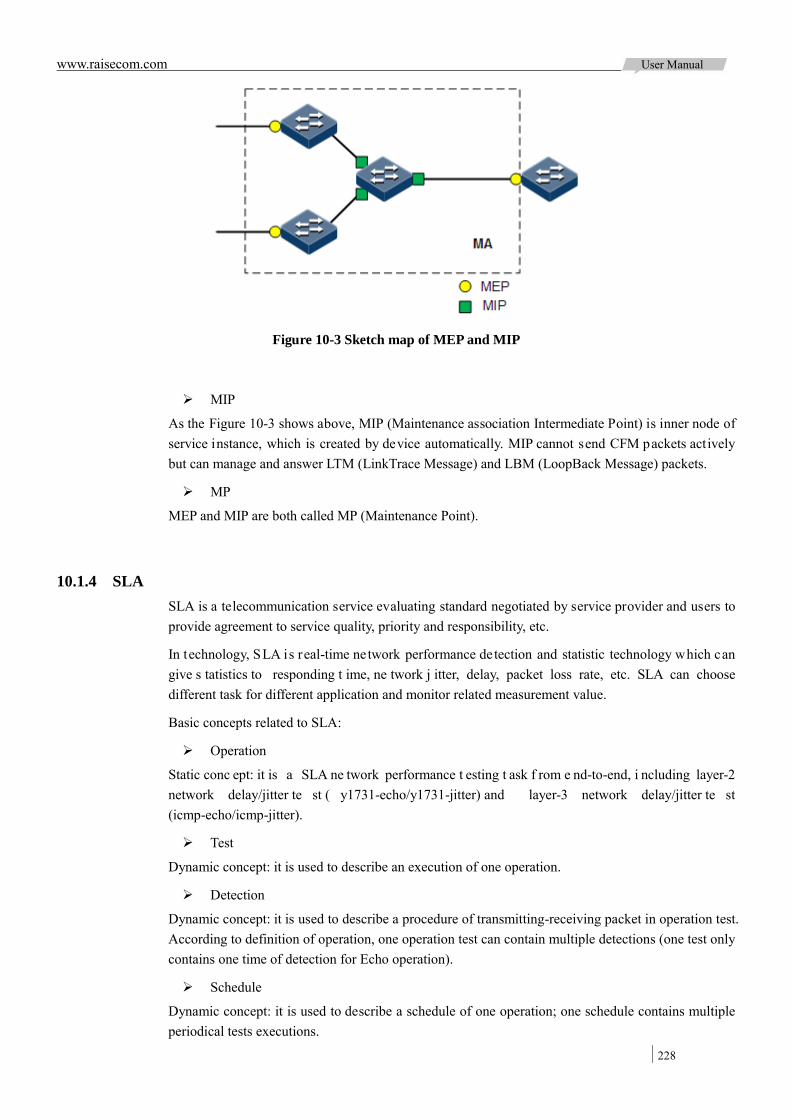
www.raisecom.com User Manual
228
Figure 10-3 Sketch map of MEP and MIP
MIP
As the Figure 10-3 shows above, MIP (Maintenance association Intermediate Point) is inner node of service instance, which is created by device automatically. MIP cannot send CFM packets actively but can manage and answer LTM (LinkTrace Message) and LBM (LoopBack Message) packets.
MP
MEP and MIP are both called MP (Maintenance Point).
10.1.4 SLA SLA is a telecommunication service evaluating standard negotiated by service provider and users to provide agreement to service quality, priority and responsibility, etc.
In technology, SLA is real-time network performance detection and statistic technology which can give s tatistics to responding t ime, ne twork j itter, delay, packet loss rate, etc. SLA can choose different task for different application and monitor related measurement value.
Basic concepts related to SLA:
Operation
Static conc ept: it is a SLA ne twork performance t esting t ask f rom e nd-to-end, i ncluding layer-2 network delay/jitter te st ( y1731-echo/y1731-jitter) and layer-3 network delay/jitter te st (icmp-echo/icmp-jitter).
Test
Dynamic concept: it is used to describe an execution of one operation.
Detection
Dynamic concept: it is used to describe a procedure of transmitting-receiving packet in operation test. According to definition of operation, one operation test can contain multiple detections (one test only contains one time of detection for Echo operation).
Schedule
Dynamic concept: it is used to describe a schedule of one operation; one schedule contains multiple periodical tests executions.

www.raisecom.com User Manual
229
10.1.5 E-LMI Refering to Frame Relay Local Management Interface Specification, MEF (Metro Ethernet Forum) defines t he E thernet L ocal M anagement I nterface. E -LMI i s the O AM pr otocol to locate in UNI (User-Network Interface), mainly used between CE and PE devices.
E-LMI enables service providers to configure CE automatically according to purchased services. By E-LMI, CE can automatically r eceive mapping information from us er VLAN t o EVC and the corresponding bandwidth and QoS settings. E-LMI CE device auto-configuration function not only reduces the w ork of the services establishment, but also the coordination work between service providers and enterprises users. As a result, enterprise users needn’t to know the configuration of CE devices; service pr ovider w ill t ake t he i ntegrateconfiguration a nd m anagement w hich r educes the risk of human errors.
In addition, E-LMI also provides the EVC status information to CE device. Once the EVC fails (such as PE uses CFM to provide fault detection function for EVC), PE will notify the CE device to access side route for switching.
The deployment location of E-LMI in the network is shown in Figure 10-4:
Figure 10-4 E-LMI location in network
10.2 EFM
10.2.1 Preparation for configuration 10.2.1.1 Networking situation
Deploy E FM feature be tween s traight t hrough connected devices can efficiently improve E thernet link management and maintenance capability and ensure network running stable.
10.2.1.2 Preconditions
Before configuring EFM, users have to connect interface and configure physical pa rameters for it, the interface is Up at physical layer.
10.2.2 Default configuration of EFM The default configuration of EFM is as below:
Function Default value

www.raisecom.com User Manual
230
Function Default value
Working mode of EFM Passive
Message transmission interval 10×100ms
Link timeout time 5s
OAM function status Disable
Alarm function statusof peer OAM event Disable
Remote loopback status of EFM Respond
Monitoring window of error frame event 1s
Monitoring threshold of error frame event 1 error frame
Monitoring window for statistic event of link error frame seconds
60s
Monitoring threshold for statistic event of link error frame seconds
1s
Monitoring window for statistic event of error code 100ms
Monitoring threshold for statistic event of error code 1s
Fault indication function status Enable
Alarm function for Local OAM event Disable
10.2.3 Basic functions of EFM Please configure EFM on the device as below:
Step Configuration Description
1 Raisecom#config Enter global configuration mode.
2 Raisecom(config)#interface port port-id
Enter physical layer interface configuration mode.
3 Raisecom(config-port)#oam { active | passive }
Configure work mode for EFM. In active mode, starting OAM peer discover process actively, not supporting no answer to remote loopback command and no answer to variable obtain request functions; don’t start OAM peer
discover process in passive mode, not in support of sending remote loopback command and sending variable obtain
request functions. By default, device is in passive mode. At least one end is active mode when configuring, otherwise
the link detection cannot perform.

www.raisecom.com User Manual
231
Step Configuration Description
4 Raisecom(config-port)#exit
Raisecom(config)#oam send-period period-number
(Optional) OAM link sends INFO packets to each other timing, use this command to set packets sending interval
and control link communication period. The unit is 100ms.
By default, sending interval is 10 (10×100ms).
5 Raisecom(config)#oam timeout period-number
(Optional) Configure OAM link timeout time.
OAM link is broken if both ends devices of OAM link haven’t receive OAM packets over timeout time.
By default, time for link timeout is 5s.
6 Raisecom(config)#interface port port-id
Enter physical layer interface configuration mode.
7 Raisecom(config-port)#oam enable Enable interface OAM function. By default, OAM disable. The command of oam disable can disable interface OAM.
10.2.4 Active functions of EFM Please configure EFM active function for the device as below.
Note: EFM active function must be configured when the device is in active mode.
10.2.4.1 (Optional) Startup EFM remote loop function
Step Configuration Description
1 Raisecom#config Enter global configuration mode.
2 Raisecom(config)#interface port port-id
Enter physical layer interface configuration mode.
3 Raisecom(config-port)#oam remote-loopback
Configure interface to start EFM remote loopback function. Remote loopback function can only be started after EFM connection and
must be configured in active mode device.
4 Raisecom(config-port)#no oam remote-loopback
(Optional) Disable remote loopback function. Disable remote loopback function in time after
finish detection.
Note:
Perform loopback detection periodically can discover network fault in time. By loopback detection in network sections can locate exact fault area and help users remove fault.
In link loopback status, the device loopback all packets except OAM packets received by link to peer device, user data packets cannot forwarded normally. Please disable this function in time when doesn’t need detection.
10.2.4.2 (Optional) Configure peer OAM event trap function
Step Configuration Description
1 Raisecom#config Enter global configuration mode.

www.raisecom.com User Manual
232
Step Configuration Description
2 Raisecom(config)#interface port port-id
Enter physical layer interface configuration mode.
3 Raisecom(config-port)#oam peer event trap enable
Enable peer OAM event trap function, link monitor event can be reported to NMS center in time. By default, device doesn’t report trap to NMS center through SNMP TRAP when receiving peer link
monitor event. User can use the command of oam peer event trap disable to disable this function.
10.2.4.3 (Optional) Check current variable value of peer
Please configure OAM link monitor for the device as below.
Step Configuration Description
1 Raisecom#show oam peer [link-statistic | oam-info ] port-list
port-list
Get peer device OAM information or interface statistic variable value.
Note: By ge tting c urrent variable value of pe er de vice to get s tatus of c urrent l ink. IEEE802.3 Clause30 defines and explains supporting OAM ge tting variable and i ts denotation in details. The variable t akes Object as t he m aximum di vision, e ach obj ect c ontains Package a nd Attribute. A package contains several attributes. Attribute is the minimum unit of variable. When OAM variable getting, i t defines object, package, brach and leaf description of a ttributes by Clause30 to describe requesting object, and the branch and leaf are followed by variable value to denote object responds variable r equest. The de vice i s i n s upport of OAM inf ormation and interface s tatistics f or obj ect variable getting.
Peer variable getting cannot realize until building up EFM connection.
10.2.5 Passive functions of EFM Please configure EFM passive function for the device as below.
Note: EFM passive function can be configured regardless the device is in active or passive mode.
10.2.5.1 (Optional) Configure device related EFM remote loopback
Step Configuration Description
1 Raisecom#config Enter global configuration mode.
2 Raisecom(config)#interface port port-id
Enter physical layer interface configuration mode.
3 Raisecom(config-port)#oam loopback { ignore | process }
Configure ignore or process EFM remote loopback. By default, the device processes EFM
remote loopback.
Note: Peer EFM remote loopback function won’t take effect until remote loopback process function

www.raisecom.com User Manual
233
is configured at local.
10.2.5.2 (Optional) Configure OAM link monitor function
Step Configuration Description
1 Raisecom#config Enter global configuration mode.
2 Raisecom(config)#interface port port-id
Enter physical layer interface configuration mode.
3 Raisecom(config-port)#oam errored-frame window window
threshold threshold
Configure error frame monitor window and threshold. By default, monitor window is 1
second, threshold is 1 error frame.
4 Raisecom(config-port)#oam errored-frame-period window
window threshold threshold
Configure error frame period event monitor window and threshold. By default, monitor
window is 100 ms, threshold is 1 error frame.
5 Raisecom(config-port)#oam errored-frame-seconds window
window threshold threshold
Configure link error frame seconds windown and threshold. By default, monitor window is
60 seconds, threshold is 1 second.
6 Raisecom(config-port)#oam errored-symbol-period window
window threshold threshold
Configure error code window and threshold. By default, monitor window is 100ms,
threshold is 1 second.
Note:
OAM link m onitor is us ed t o de tect a nd r eport l ink error i n di fferent c ondition. When detection link has fault, device notifies peer the error generated time, windown and threshold setting, etc. by OAM event, the peer receives event not ification and report NMS center via SNMP Trap. Besides, local device can direct report event to NMS center via SNMP Trap.
By default, system has default value for error generated time, windown and threshold setting.
10.2.5.3 (Optional) Configure OAM fault indication function
Step Configuration Description
1 Raisecom#config Enter global configuration mode.
2 Raisecom(config)#interface port port-id
Enter physical layer interface configuration mode.
3 Raisecom(config-port)#oam notify { critical-event |
dying-gasp | errored-frame | errored-frame-period | errored-frame-seconds | errored-symbol-period }
{ disable | enable }
Configure OAM fault indication system, used to notify peer device that local device is abnormal. The device can notify peer faults of link-fault, dying-gasp and critical-event. By
default, device fault indication is enabled. When fault happens, device notifies peer through OAM immediately.
Except link-fault must notify peer, dying-gasp and critical-event can be disabled by this command.
10.2.5.4 (Optional) Configure local OAM event trap function
Step Configuration Description

www.raisecom.com User Manual
234
Step Configuration Description
1 Raisecom#config Enter global configuration mode.
2 Raisecom(config)#interface port port-id
Enter physical layer interface configuration mode.
3 Raisecom(config-port)#oam event trap enable
Enable local OAM event trap function, link monitor event can be reported to NMS center in time. By
default, device won’t report NMS center by SNMP Trap. The command of oam event trap disable can
disable it.
10.2.6 Checking configuration Check the result by the commands below after configuration:
No. Item Description
1 Raisecom#show oam [ port-list port-list ]
Show basic configuration of EFM.
2 Raisecom#show oam loopback [ port-list port-list ]
Show EFM remote loopback configuration.
3 Raisecom#show oam notify [ port-list port-list ]
Show OAM link monitor and fault indication configuration.
4 Raisecom#show oam statistics [ port-list port-list ]
Show OAM statistic information.
5 Raisecom#show oam trap [ port-list port-list ]
Show OAM event trap configuration.
6 Raisecom#show oam event [ port-list port-list ] [ critical ]
Shoe serious interface detection fault information of local device.
7 Raisecom#show oam peer event [ port-list port-list ]
[ critical ]
Show serious peer transmission fault information to the interface.
10.3 CFM
10.3.1 Preparation for configuration 10.3.1.1 Networking situation
To develop Ethernet technology application in telecommunication network, Ethernet needs to realize service level identical to telecommunication transmission network. CFM provides full OAM tool to telecommunication Ethernet to solve this problem.
CFM provides the below OAM functions:
Fault detection function
Fault detection function refers to use CC (Continuity Check) protocol to detect the connectivity of Ethernrt v irtual ne twork and confirm the MP connection s tatus. This function i s r ealized by MEP sending CCM (Continuity Check Message) periodically, other MEP in one service instance receives
www.raisecom.com User Manual
235
packet to confirm the status of RMEP. The device fault or link configuration error may make MEP cannot fail to receive and process CCM from RMEP. If MEP hasn’t recived remote CCM packet in 3.5 CCM intervals, the link is considered to be fault, system will send fault trap according to alarm priority configuration.
Fault acknowledgement function
Using L B ( LoopBack), this f unction c onfirms connectivity be tween t wo M P by s ending L BM (LoopBack Message) from source MEP and answering LBR (LoopBack Reply) by destination MP. Source MEP sends LBM to MP for fault acknowledgement; the MP receives LBR and sends a LBR to source ME P. I f the source ME P can receive LBR, the pa th is connective; if sou rce ME P can’t receive LBR, the path is not connective.
Fault location function
Using LT, this function sends LTM (LinkTrace Message) to destination MP by source MEP, each MP device on LTM transmitting path will answer LTR ( LinkTrace Reply) to source MEP, and then the efficient LTR and LTM fault location point can be recorded.
Alarm indication signal function (AIS, Alarm Indication Signal)
This function is used to stop alarm when detected fault at server layer (sub-layer). MEP (including server MEP) sends AIS frame to client MD when detected fault. ETH-AIS frame is transmitted on MEP (or server MEP). When receiving AIS frame, it doesn’t contain peer MEP information of fault, the M EP must inhi bit a ll pe er M EP tr ap regardless of the c onnectivity s tatus. It can inhibit c lient alarm information through AIS function to make the network easier to manage and maintain when server layer has fault.
Ethernet signal lock function (LCK, Lock)
This function is used to notify management lock for server layer (sub-layer) MEP and the followed data service t raffic halt. The service t raffic is sent for MEP expected to receive t raffic. Then MEP receives ETH-LCK frame can identify it is fault or management lock of server layer MEP. Lock is OAM f unction a ccording t o r equirement, a t ypical a pplication of M EP l ock i s w hen pe rforming diagnostic test when service halts.
Anyway, CFM implements end-to-end service OAM technology, reducing service provider operation cost and improve competion.
10.3.1.2 Preconditions
Finish below tasks before configuring CFM:
Connect i nterface a nd configure physical pa rameters f or i t, the i nterface i s Up at physical layer
Create VLAN Add interface into VLAN
10.3.2 Default configuration of CFM The default configuration of CFM is as below:
Function Default value
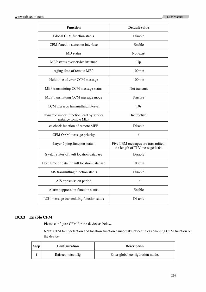
www.raisecom.com User Manual
236
Function Default value
Global CFM function status Disable
CFM function status on interface Enable
MD status Not exist
MEP status overservice instance Up
Aging time of remote MEP 100min
Hold time of error CCM message 100min
MEP transmitting CCM message status Not transmit
MEP transmitting CCM message mode Passive
CCM message transmitting interval 10s
Dynamic import function leart by service instance romote MEP
Ineffective
cc check function of remote MEP Disable
CFM OAM message priority 6
Layer-2 ping function status Five LBM messages are transmitted; the length of TLV message is 64.
Switch status of fault location database Disable
Hold time of data in fault location database 100min
AIS transmitting function status Disable
AIS transmission period 1s
Alarm suppression function status Enable
LCK message transmitting function statis Disable
10.3.3 Enable CFM Please configure CFM for the device as below.
Note: CFM fault detection and location function cannot take effect unless enabling CFM function on the device.
Step Configuration Description
1 Raisecom#config Enter global configuration mode.

www.raisecom.com User Manual
237
Step Configuration Description
2 Raisecom(config)#ethernet cfm enable
Enable global CFM function. By default, CFM is not enabled globally; the command of ethernet cfm
disable can disable it.
3 Raisecom(config)#interface port port-id
Enter physical layer interface configuration mode.
4 Raisecom(config-port)#ethernet cfm enable
Enable CFM function on interface. By default, interface enables CFM function. The command of ethernet cfm disable can disable it. The interface
cannot receive/transmit CFM packets after disabled.
10.3.4 Basic functions of CFM Please configure CFM for the device as below.
Step Configuration Description
1 Raisecom#config Enter global configuration mode.
2 Raisecom(config)#ethernet cfm domain [ md-name
domain-name ] level level
Create maintain domain. Use the pa rameter md-name to assign name for MD in 802.1ag style. MA and CCM packets u nder M D a re b oth i n 80 2.1ag s tyle; don ’t assign name, the MD is in Y.1731 style, MA and CCM packets under this MD are both in Y.1731 style. If user assigns na me f or MD , the na me m ust be uni que i n global, or else MD configuration will be failure.
Note: L evel of specified MD m ust be different; other wise MD configuration will fail.
3 Raisecom(config)#service cisid level level
Create service instance and enter instance configuration mode. ( MD name, s ervice instance name) character string i s uni que i n gl obal range. If se rvice instance existed, this c ommand will di rect le ad to service instance configuration mode.
4 Raisecom(config-service)#service vlan-list vlan-list [ primary-vlan
vlan-id ]
Configure service application VLAN map.
VLAN list pe rmits a t most 32 VLAN. The smallest VLAN w ill be t aken as pr imary V LAN of s ervice instance. All M EP in service ins tance tr ansmit a nd receive packets through primary VLAN.
Note: Since using primary V LAN t o t ransmit a nd receive pa ckets, all of ot her V LAN i n the l ist ar e mapped t o pr imary V LAN. This logical V LAN mapping r elationship i s globally; VLAN m apping relationship of di fferent le vel c an be ide ntical but cannot c ross. For e xample: i nstance 1 m apping t o VLAN 10-20, instance 2 mapping to VLAN 15-30, the configuration i s i llegal b ecause V LAN 15 -20 is overlopped.
5 Raisecom(config-service)#service mep [ up | down ] mpid mep-id
port port-id
Configure MEP over service instance. Service instance must map to VLAN when configuring this kind MEP. By de fault, M EP i s Up, that is to detect the f ault in interface uplink direction.
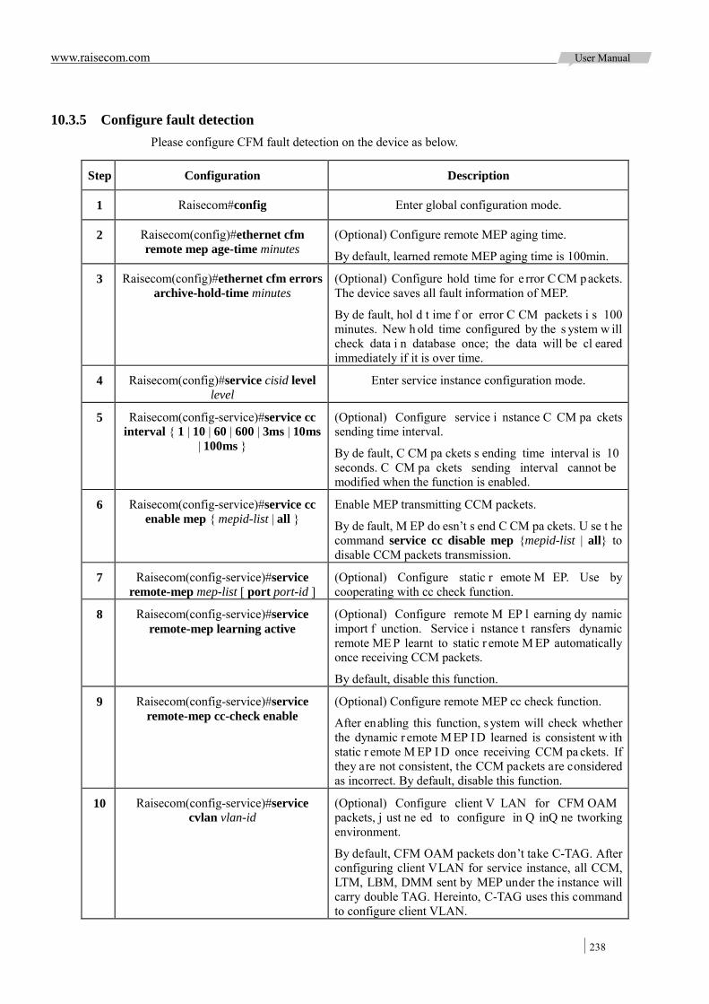
www.raisecom.com User Manual
238
10.3.5 Configure fault detection Please configure CFM fault detection on the device as below.
Step Configuration Description
1 Raisecom#config Enter global configuration mode.
2 Raisecom(config)#ethernet cfm remote mep age-time minutes
(Optional) Configure remote MEP aging time.
By default, learned remote MEP aging time is 100min.
3 Raisecom(config)#ethernet cfm errors archive-hold-time minutes
(Optional) Configure hold time for e rror C CM packets. The device saves all fault information of MEP.
By de fault, hol d t ime f or error C CM packets i s 100 minutes. New h old time configured by the s ystem w ill check data i n database once; the data will be cl eared immediately if it is over time.
4 Raisecom(config)#service cisid level level
Enter service instance configuration mode.
5 Raisecom(config-service)#service cc interval { 1 | 10 | 60 | 600 | 3ms | 10ms
| 100ms }
(Optional) Configure service i nstance C CM pa ckets sending time interval.
By de fault, C CM pa ckets s ending time interval is 10 seconds. C CM pa ckets sending interval cannot be modified when the function is enabled.
6 Raisecom(config-service)#service cc enable mep { mepid-list | all }
Enable MEP transmitting CCM packets.
By de fault, M EP do esn’t s end C CM pa ckets. U se t he command service cc disable mep {mepid-list | all} to disable CCM packets transmission.
7 Raisecom(config-service)#service remote-mep mep-list [ port port-id ]
(Optional) Configure static r emote M EP. Use by cooperating with cc check function.
8 Raisecom(config-service)#service remote-mep learning active
(Optional) Configure remote M EP l earning dy namic import f unction. Service i nstance t ransfers dynamic remote ME P learnt to static r emote M EP automatically once receiving CCM packets.
By default, disable this function.
9 Raisecom(config-service)#service remote-mep cc-check enable
(Optional) Configure remote MEP cc check function.
After enabling this function, system will check whether the dynamic r emote M EP ID learned is consistent w ith static r emote M EP I D once receiving CCM pa ckets. If they are not consistent, the CCM packets are considered as incorrect. By default, disable this function.
10 Raisecom(config-service)#service cvlan vlan-id
(Optional) Configure client V LAN for CFM OAM packets, j ust ne ed to configure in Q inQ ne tworking environment.
By default, CFM OAM packets don’t take C-TAG. After configuring client VLAN for service instance, all CCM, LTM, LBM, DMM sent by MEP under the instance will carry double TAG. Hereinto, C-TAG uses this command to configure client VLAN.

www.raisecom.com User Manual
239
Step Configuration Description
11 Raisecom(config-service)#service priority priority
(Optional) Configure CFM OAM packets priority.
After configuring packets priority, all CCM, LBM, LTM, DMM sent by MEP use assigned priority.
By default, packet priority is 6.
12 Raisecom(config-service)#snmp-server trap cfm { all | ccmerr | macremerr |
none | remerr | xcon } mep { all | mep-list }
(Optional) Configure CFM permitting sending fault trap type. C C f unction of CFM can detect f ault i n 5 l evels, they are from high to low: level 5-cross connection, level 4-CCM error, level 3-remote MEP loss, level 2-interface status fault, level 1-RDI. By default, it is macremerr, namely permiting fault trap on level 2-5.
Note:
When CFM detected fault, identical level or lower level fault won’t generate trap again before removing fault;
Wait f or 10s unt il the f ault s tatus is c leared a fter removing CFM fault.
10.3.6 Configure fault acknowledgement Please configure CFM fault acknowledgement for the device as below.
Step Configuration Description
1 Raisecom#config Enter global configuration mode.
2 Raisecom(config)#service cisid level level
Enter service instance configuration mode.
3 Raisecom(config-service)#ping { mac-address | mep rmep-id }
[ count count ] [ size size ] [ source mep-id ]
Execute layer-2 ping function for fault acknowledgement.
By default, five LBM messages will be transmitted; the length of TLV message is 64; they will search an available
source MEP by automation.
CFM needs to find destination MEP MAC address by mep-id to execute ping operation if the specified destination mep-id performs layer-2 ping operation. Source MEP will
save remote MEP idata information in remote MEP database after discovering and stabilizing remote MEP. The remote
MEP MAC address can be found from remote MEP database according to mep-id.
Note:
Make s ure gl obal C FM f unction e nable be fore executing t his c ommand, ot herwise t he command will be executed unsuccessfully;
If there is no MEP configured in service instance, ping unsuccessfully because of fail to find source MEP;
If assigned source MEP is invalid, ping unsuccessfully. For example, assigned source MEP is not existing or CFM of the source MEP interface is disabled;
If assigning destination MEPID to perform ping operation, ping unsuccessfully when fail to find destination MEP MAC address according to MEPID;
Operation will f ail if ot her us ers a re us ing t he a ssigned s ource M EP t o pe rform ping operation.
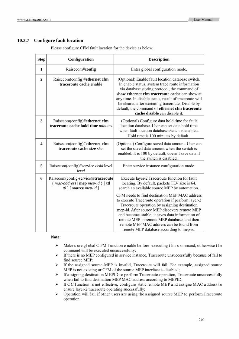
www.raisecom.com User Manual
240
10.3.7 Configure fault location Please configure CFM fault location for the device as below.
Step Configuration Description
1 Raisecom#config Enter global configuration mode.
2 Raisecom(config)#ethernet cfm traceroute cache enable
(Optional) Enable fault location database switch. In enable status, system trace route information via database storing protocol, the command of
show ethernet cfm traceroute cache can show at any time. In disable status, result of traceroute will be cleared after executing traceroute. Disable by
default, the command of ethernet cfm traceroute cache disable can disable it.
3 Raisecom(config)#ethernet cfm traceroute cache hold-time minutes
(Optional) Configure data hold time for fault location database. User can set data hold time
when fault location database switch is enabled. Hold time is 100 minutes by default.
4 Raisecom(config)#ethernet cfm traceroute cache size size
(Optional) Configure saved data amount. User can set the saved data amount when the switch is
enabled. It is 100 by default; doesn’t save data if the switch is disabled.
5 Raisecom(config)#service cisid level level
Enter service instance configuration mode.
6 Raisecom(config-service)#traceroute { mac-address | mep mep-id } [ ttl
ttl ] [ source mep-id ]
Execute layer-2 Traceroute function for fault locating. By default, packets TLV size is 64,
search an available source MEP by automation.
CFM needs to find destination MEP MAC address to execute Traceroute operation if perform layer-2
Traceroute operation by assigning destination mep-id. After source MEP discovers remote MEP and becomes stable, it saves data information of remote MEP in remote MEP database, and then remote MEP MAC address can be found from
remote MEP database according to mep-id.
Note:
Make s ure gl obal C FM f unction e nable be fore executing t his c ommand, ot herwise t he command will be executed unsuccessfully;
If there is no MEP configured in service instance, Traceroute unsuccessfully because of fail to find source MEP;
If the assigned source MEP is invalid, Traceroute will fail. For example, assigned source MEP is not existing or CFM of the source MEP interface is disabled;
If assigning destination MEPID to perform Traceroute operation, Traceroute unsuccessfully when fail to find destination MEP MAC address according to MEPID;
If C C f unction i s not e ffective, configure static re mote ME P a nd a ssigne MAC a ddress t o ensure layer-2 traceroute operating successfully;
Operation will fail if other users are using the assigned source MEP to perform Traceroute operation.

www.raisecom.com User Manual
241
10.3.8 Configure AIS function Please configure CFM AID for the device as below.
Configure server layer devices as below:
Step Configuration Description
1 Raisecom#config Enter Global Configuration mode.
2 Raisecom(config)#service cisid level level
Enter service instance configuration mode..
3 Raisecom(config-service)#service ais enable
Enable AIS sending function. By deault, system doesn’t enable LCK function. The command of service ais
disable can disable it.
4 Raisecom(config-service)#service ais period { 1 | 60 }
Configure AIS sending period. By default, sending period is 1 second.
5 Raisecom(config-service)#service ais level level
Configure AIS level being sent to client MD.
Configure client layer devices as below:
Step Configuration Description
1 Raisecom#config Enter Global Configuration mode.
2 Raisecom(config)#service cisid level level Enter service instance configuration mode.
3 Raisecom(config-service)#service suppress-alarms enable mep { all |
mep-list }
Enable alarm control function. By default, this function is enabled. The command of
service suppress-alarms disable mep mep-list can disable it.
10.3.9 Configure Ethernet signal lockout function Please configure CFM Ethernet lock function for the device as below.
Configure server layer devices as below:
Step Configuration Description
1 Raisecom#config Enter global configuration mode.
2 Raisecom(config)#service cisid level level
Enter service instance configuration mode.
3 Raisecom(config-service)#service lck start mep { all | mep-list }
Enable LCK packets sending function. By deault, system doesn’t enable LCK
function. The command of service lck stop mep mep-list can disable it.
4 Raisecom(config-service)#service lck period { 1 | 60 }
Configure LCK packets sending period. By default, sending period is 1 second.
5 Raisecom(config-service)#service lck level level
Configure LCK level sent to client MD.

www.raisecom.com User Manual
242
Configure client layer devices as below:
Step Configuration Description
1 Raisecom#config Enter global configuration mode.
2 Raisecom(config)#service cisid level level
Enter service instance configuration mode.
3 Raisecom(config-service)#service suppress-alarms enable mep
{ all | mep-list }
Enable alarm control function. By default, this function is enabled. The command of service suppress-alarms disable mep mep-list can
disable it.
10.3.10 Checking configuration Check the result by the commands below after configuration:
Step Configuration Description
1 Raisecom#show ethernet cfm Show CFM global configuration.
2 Raisecom#show ethernet cfm domain [ level level ] Show MD and service instance configuration.
3 Raisecom#show ethernet cfm errors [ level level ] Shoe error CCM database information.
4 Raisecom#show ethernet cfm lck [ level level ] Show Ethernet lockout signal.
5 Raisecom#show ethernet cfm local-mp [ interface port port-id | level level ]
Show local MEP configuration.
6 Raisecom#show ethernet cfm remote-mep [ static [ level level ] ]
Show static remote MEP information.
7 Raisecom#show ethernet cfm remote-mep [ level level [ service name [ mpid local-mep-id ] ] ]
Show remote MEP discovery information.
8 Raisecom#show ethernet cfm suppress-alarms [ level level ]
Show CCM alarm suppression function configuration.
9 Raisecom#show ethernet cfm traceroute-cache Show fault location database traceroute information.
10.4 SLA
10.4.1 Preparation for configuration 10.4.1.1 Networking situation
Carrier and customer sign SLA protocol to guarantee users can enjoy certain quality network service. To perform SLA protocol effectively, carrier needs to deploy SLA feature test performance on device and the test result is evidence to ensure user’s performance.
SLA feature chooses two testing node, configure SLA operation on one node and schedule executing
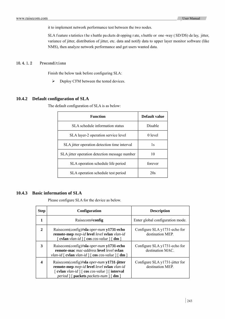
www.raisecom.com User Manual
243
it to implement network performance test between the two nodes.
SLA f eature s tatistics t he s huttle pa ckets dr opping r ate, s huttle or one -way ( SD/DS) de lay, jitter, variance of jitter, distribution of jitter, etc. data and notify data to upper layer monitor software (like NMS), then analyze network performance and get users wanted data.
10.4.1.2 Preconditions
Finish the below task before configuring SLA:
Deploy CFM between the tested devices.
10.4.2 Default configuration of SLA The default configuration of SLA is as below:
Function Default value
SLA schedule information status Disable
SLA layer-2 operation service level 0 level
SLA jitter operation detection time interval 1s
SLA jitter operation detection message number 10
SLA operation schedule life period forever
SLA operation schedule test period 20s
10.4.3 Basic information of SLA Please configure SLA for the device as below.
Step Configuration Description
1 Raisecom#config Enter global configuration mode.
2 Raisecom(config)#sla oper-num y1731-echo remote-mep mep-id level level svlan vlan-id
[ cvlan vlan-id ] [ cos cos-value ] [ dm ]
Configure SLA y1731-echo for destination MEP.
3 Raisecom(config)#sla oper-num y1731-echo remote-mac mac-address level level svlan
vlan-id [ cvlan vlan-id ] [ cos cos-value ] [ dm ]
Configure SLA y1731-echo for destination MAC.
4 Raisecom(config)#sla oper-num y1731-jitter remote-mep mep-id level level svlan vlan-id [ cvlan vlan-id ] [ cos cos-value ] [ interval
period ] [ packets packets-num ] [ dm ]
Configure SLA y1731-jitter for destination MEP.

www.raisecom.com User Manual
244
Step Configuration Description
5 Raisecom(config)#sla oper-num y1731-jitter remote-mac mac-address level level svlan
vlan-id [ cvlan vlan-id ] [ cos cos-value ] [ interval period ] [ packets packets-num ] [ dm ]
Configure SLA y1731-jitter for destination MAC.
6 Raisecom(config)#sla oper-num icmp-echo dest-ipaddr ip-address [ dscp dscp-value ]
Configure basic information for SLA icmp-echo.
7 Raisecom(config)#sla oper-num icmp-jitter dest-ipaddr ip-address [ dscp dscp-value ] [ interval period ] [ packets packets-num ]
Configure basic information for SLA icmp-jitter.
8 Raisecom(config)#sla y1731-echo quick-input [ level level ] [ svlan vlan-id ] [ dm ]
Create y1731-echo quickly.
9 Raisecom(config)#sla y1731-jitter quick-input [ level level] [ svlan vlan-id ] [ dm ]
Create y1731-jitter quickly.
Note:
After c onfiguring basic information for on e o peration ( differed by ope ration I D), i t i s no t allowed to modify or configure again. That is to say, delete the operation at first if user wants to configure it again.
SLA supports a t m ost 100 operations s chedule a t one time up t o 100 pi eces, b ut w ait a schedule to finish (reach schedule life time or stop schedule) before schedule again or modify schedule information.
10.4.4 Configure SLA schedule information and enable schedule Please configure SLA for the device as below.
Step Configuration Description
1 Raisecom#config Enter global configuration mode.
2 Raisecom(config)#sla schedule oper-num [ life { forever |
life-time } ] [ period period ]
Configure SLA schedule information, enable SLA operation schedule. By
default, disable schedule.
10.4.5 Check configuration Check the result by the commands below after configuration:
No. Item Description
1 Raisecom#show sla { all | oper-num } configuration
Show SLA configuration.
2 Raisecom#show sla { all | oper-num } result
Show the latest operation test information.
3 Raisecom#show sla { all | oper-num } statistic
Show operation schedule statistics. One operation (differed by operation ID) possesses
5 groups of statistics at most, if over 5, the oldest statistics (from the schedule starting
time) will get aged if over 5 groups.

www.raisecom.com User Manual
245
10.5 E-LMI
10.5.1 Preparation for configuration 10.5.1.1 Networking situation
By E -LMI, PE can s end t he m apping i nformation from VLAN to EVC to CE and achieve t he automatic configuration function of CE d evice. This not onl y reduces the work of t he business establishment, but also the coordination work between service providers and enterprise users. As a result, enterprise users needn’t to know the configuration of CE devices; service provider will take the integrateconfiguration and management which reduces the risk of human errors.
Cooperating w ith O AM pr otocol ( such a s C FM pr otocol), E -LMI can give f eedback of the EV C status inf ormation in service pr ovider ne twork t o C E de vice timely. Once the E VC f ails, PE will notify the CE device to access side route for switching.
10.5.1.2 Preconditions
Finish the following tasks before configuring E-LMI:
Connect interface and configure the interface physical pa rameters, make the physical l ayer status of interface Up;
Configure the physical layrer interface between PE and CE for Trunk mode. Configure CFM between PE devices.
10.5.2 Default configuration of E-LMI The default configuration of E-LMI is as below:
Function Default value
Global E-LMI function status Enable
Interface E-LMI function status Disable
Working mode of the device pe
Trap switch status Close
EVCmessage notification mode asyn
Value of T391 timer 10s
Value of T392 timer 15s
T392 timer function status Enable
Value of N391counter 360
Value of N393counter 4

www.raisecom.com User Manual
246
10.5.3 Configure E-LMI function for PE device Please configure E-LMI function for PE device as below:
Enable E-LMI function
Step Configuration Description
1 Raisecom#config Enter global configuration mode.
2 Raisecom(config)#ethernet lmi enable
Globally enable E-LMIfunction. The command of ethernet lmi disable can disable this function.
3 Raisecom(config)#ethernet lmi trap { enable | disable }
(Optional) Configure Trap switch.
4 Raisecom(config)#ethernet lmi pe Configure the device as PE.
5 Raisecom(config)#interface port port-id
Enter physical layer interface configuration mode.
6 Raisecom(config-port)#ethernet lmi enable
(Optional) Enable E-LMI function on interface. The command of ethernet lmi disable can disable
this function.
7 Raisecom(config-port)#ethernet lmi t392 enable
(Optional) Enable E-LMI T392 timer function on interface. The command of ethernet lmi t392
disable can disable this function.
8 Raisecom(config-port)#ethernet lmi t392 value
(Optional) Configure the value for T392 timer.
Note: The value of T392 timer must be greater than the value for T391 timer of the corresping CE
device.
9 Raisecom(config-port)#ethernet lmi n393 value
(Optional) Configure the value of N393 counter for PE device.
Configure EVC
Step Configuration Description
1 Raisecom#config Enter global configuration mode.
2 Raisecom(config)#ethernet lmi evc evc-number evc-name
Create EVC and enter EVC configuration mode.
3 Raisecom(config-evc)#oam-protocol cfm svlan vlan-id level level
Bind EVC and CFM.
The binding CFM service instance must be existed and MEP is Up.
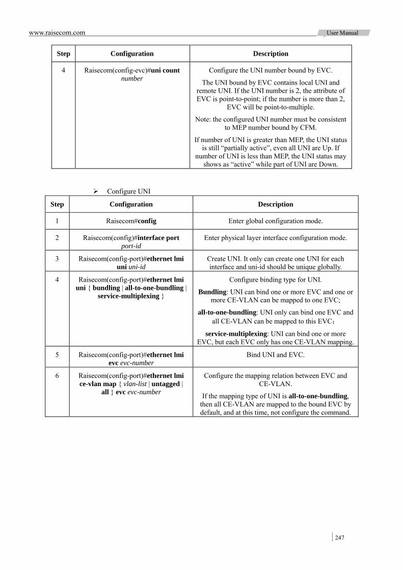
www.raisecom.com User Manual
247
Step Configuration Description
4 Raisecom(config-evc)#uni count number
Configure the UNI number bound by EVC.
The UNI bound by EVC contains local UNI and remote UNI. If the UNI number is 2, the attribute of EVC is point-to-point; if the number is more than 2,
EVC will be point-to-multiple.
Note: the configured UNI number must be consistent to MEP number bound by CFM.
If number of UNI is greater than MEP, the UNI status is still “partially active”, even all UNI are Up. If
number of UNI is less than MEP, the UNI status may shows as “active” while part of UNI are Down.
Configure UNI
Step Configuration Description
1 Raisecom#config Enter global configuration mode.
2 Raisecom(config)#interface port port-id
Enter physical layer interface configuration mode.
3 Raisecom(config-port)#ethernet lmi uni uni-id
Create UNI. It only can create one UNI for each interface and uni-id should be unique globally.
4 Raisecom(config-port)#ethernet lmi uni { bundling | all-to-one-bundling |
service-multiplexing }
Configure binding type for UNI.
Bundling: UNI can bind one or more EVC and one or more CE-VLAN can be mapped to one EVC;
all-to-one-bundling: UNI only can bind one EVC and all CE-VLAN can be mapped to this EVC;
service-multiplexing: UNI can bind one or more EVC, but each EVC only has one CE-VLAN mapping.
5 Raisecom(config-port)#ethernet lmi evc evc-number
Bind UNI and EVC.
6 Raisecom(config-port)#ethernet lmi ce-vlan map { vlan-list | untagged |
all } evc evc-number
Configure the mapping relation between EVC and CE-VLAN.
If the mapping type of UNI is all-to-one-bundling, then all CE-VLAN are mapped to the bound EVC by default, and at this time, not configure the command.
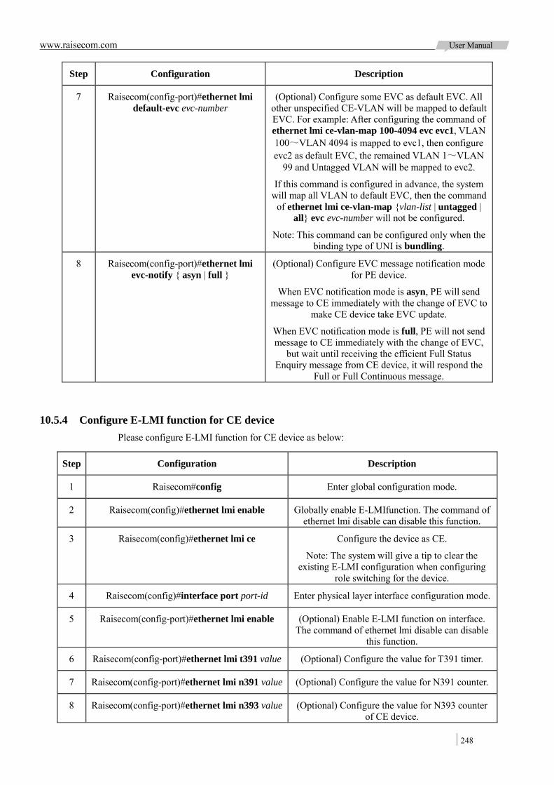
www.raisecom.com User Manual
248
Step Configuration Description
7 Raisecom(config-port)#ethernet lmi default-evc evc-number
(Optional) Configure some EVC as default EVC. All other unspecified CE-VLAN will be mapped to default EVC. For example: After configuring the command of ethernet lmi ce-vlan-map 100-4094 evc evc1, VLAN 100~VLAN 4094 is mapped to evc1, then configure evc2 as default EVC, the remained VLAN 1~VLAN
99 and Untagged VLAN will be mapped to evc2.
If this command is configured in advance, the system will map all VLAN to default EVC, then the command
of ethernet lmi ce-vlan-map {vlan-list | untagged | all} evc evc-number will not be configured.
Note: This command can be configured only when the binding type of UNI is bundling.
8 Raisecom(config-port)#ethernet lmi evc-notify { asyn | full }
(Optional) Configure EVC message notification mode for PE device.
When EVC notification mode is asyn, PE will send message to CE immediately with the change of EVC to
make CE device take EVC update.
When EVC notification mode is full, PE will not send message to CE immediately with the change of EVC,
but wait until receiving the efficient Full Status Enquiry message from CE device, it will respond the
Full or Full Continuous message.
10.5.4 Configure E-LMI function for CE device Please configure E-LMI function for CE device as below:
Step Configuration Description
1 Raisecom#config Enter global configuration mode.
2 Raisecom(config)#ethernet lmi enable Globally enable E-LMIfunction. The command of ethernet lmi disable can disable this function.
3 Raisecom(config)#ethernet lmi ce Configure the device as CE.
Note: The system will give a tip to clear the existing E-LMI configuration when configuring
role switching for the device.
4 Raisecom(config)#interface port port-id Enter physical layer interface configuration mode.
5 Raisecom(config-port)#ethernet lmi enable (Optional) Enable E-LMI function on interface. The command of ethernet lmi disable can disable
this function.
6 Raisecom(config-port)#ethernet lmi t391 value (Optional) Configure the value for T391 timer.
7 Raisecom(config-port)#ethernet lmi n391 value (Optional) Configure the value for N391 counter.
8 Raisecom(config-port)#ethernet lmi n393 value (Optional) Configure the value for N393 counter of CE device.

www.raisecom.com User Manual
249
10.5.5 Check configuration Check the result by the commands below after configuration:
No. Item Description
1 Raisecom#show ethernet lmi config port-list { all | port-list }
Show E-LMI configuration of interface.
2 Raisecom#show ethernet lmi statistics port-list { all | port-list }
Show E-LMI statistics of interface.
3 Raisecom#show ethernet lmi uni port-list { all | port-list }
Show UNI configuration.
4 Raisecom#show ethernet lmi evc evc-number
Show EVC status.
5 Raisecom#show ethernet lmi evc map port-list { all | port-list }
Show the mapping information between EVC and CE-VLAN.
6 Raisecom#show ethernet lmi evc map oam Show OAM protocol information mapped by EVC.
10.6 Maintenance
User can maintain OAM features by the below commands.
Command Description
Raisecom(config-port)#clear oam statistics Clear EFM OAM interface link statistics.
Raisecom(config)#clear ethernet cfm errors [ level level ]
Clear CCM error database information.
Raisecom(config)#clear ethernet cfm remote-mep [ level level ]
Clear remote MEP.
Raisecom(config)#clear ethernet cfm traceroute-cache
Clear traceroute cache database.
Raisecom(config)#clear ethernet lmi statistics port-list { all | port-list }
Clear interface E-LMI statistics.
10.7 Configuring applications
10.7.1 Application of EFM 10.7.1.1 Networking requirement
As the Figure 10-5 s hows be low, de ploy E FM f eature on de vice t o i mprove E thernet l ink management and maintenance capability between Switch A and Switch B. Switch A is act ive end, Switch B is passive end. Deploy OAM event trap function on Switch A.
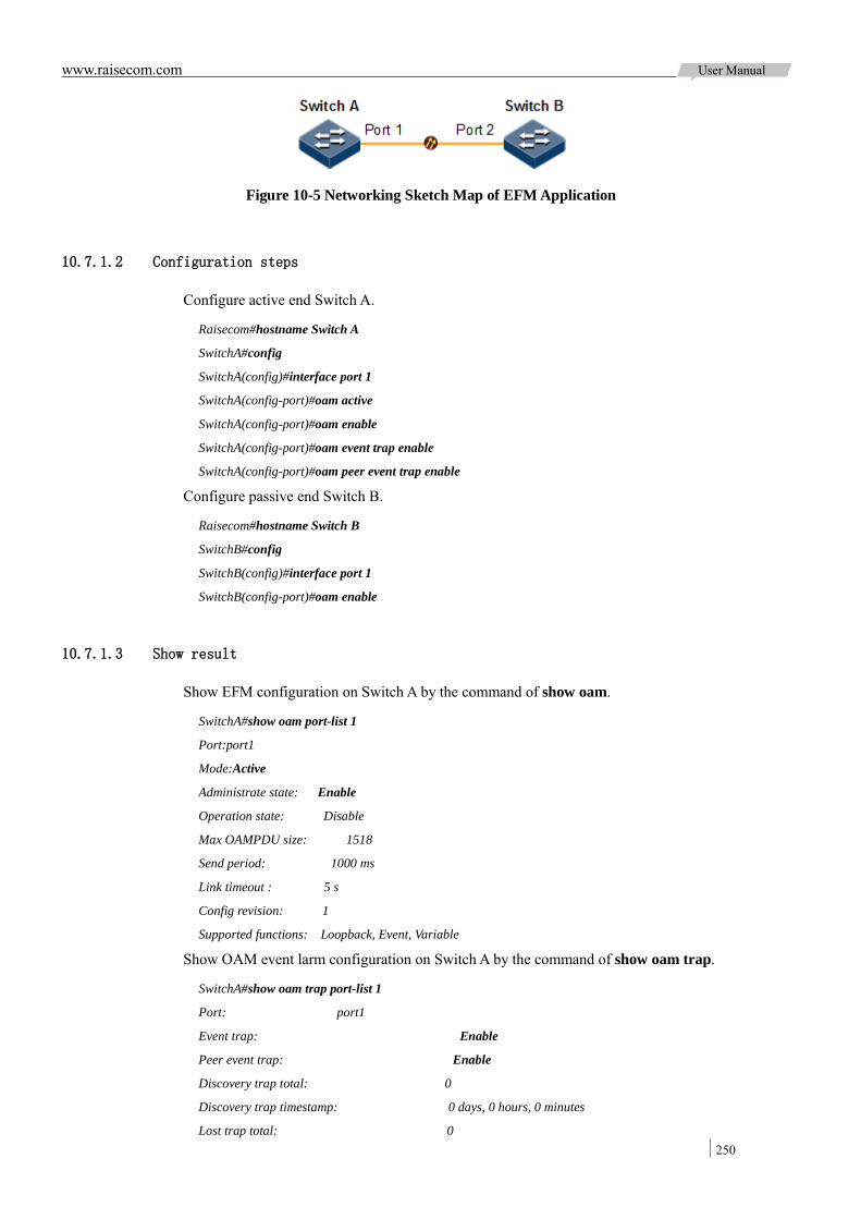
www.raisecom.com User Manual
250
Figure 10-5 Networking Sketch Map of EFM Application
10.7.1.2 Configuration steps
Configure active end Switch A.
Raisecom#hostname Switch A
SwitchA#config
SwitchA(config)#interface port 1
SwitchA(config-port)#oam active
SwitchA(config-port)#oam enable
SwitchA(config-port)#oam event trap enable
SwitchA(config-port)#oam peer event trap enable
Configure passive end Switch B.
Raisecom#hostname Switch B
SwitchB#config
SwitchB(config)#interface port 1
SwitchB(config-port)#oam enable
10.7.1.3 Show result
Show EFM configuration on Switch A by the command of show oam.
SwitchA#show oam port-list 1
Port:port1
Mode:Active
Administrate state: Enable
Operation state: Disable
Max OAMPDU size: 1518
Send period: 1000 ms
Link timeout : 5 s
Config revision: 1
Supported functions: Loopback, Event, Variable
Show OAM event larm configuration on Switch A by the command of show oam trap.
SwitchA#show oam trap port-list 1
Port: port1
Event trap: Enable
Peer event trap: Enable
Discovery trap total: 0
Discovery trap timestamp: 0 days, 0 hours, 0 minutes
Lost trap total: 0

www.raisecom.com User Manual
251
Lost trap timestamp: 0 days, 0 hours, 0 minutes
10.7.2 Application of CFM 10.7.2.1 Networking requirement
As t he Figure 10-6 shows below, users communicate w ith server through t he ne twork bui ldup by Switch A, Switch B a nd Switch C. To make E thernet l ink between server and user ge t telecommunication service l evel, user can deploy C FM f eature on Switch device t o realize act ive fault detection, acknowledgement and location. Switch A and Switch C are MEP, Switch B is M IP, detecting Ethernet fault from Switch A Port 1 to Switch C Port 2, maintenance domain level is 3.
Figure 10-6 Networking Sketch Map of CFM Application
10.7.2.2 Configuration steps
Configure interface adding into VLAN.
Configure Switch A.
Raisecom#hostname SwitchA
SwitchA#config
SwitchA(config)#create vlan 100 active
SwitchA(config)#interface port 1
SwitchA(config-port)#switchport access vlan 100
SwitchA(config-port)#exit
SwitchA(config)#interface port 2
SwitchA(config-port)#switchport mode trunk
SwitchA(config-port)#exit
Configure Switch B.
Raisecom#hostname SwitchB
SwitchB#config
SwitchB(config)#interface port 1
SwitchB(config-port)#switchport mode trunk
SwitchB(config-port)#exit

www.raisecom.com User Manual
252
SwitchB(config)#interface port 2
SwitchB(config-port)#switchport mode trunk
SwitchB(config-port)#exit
Configure Switch C.
Raisecom#hostname SwitchC
SwitchC#config
SwitchC(config)#create vlan 100 active
SwitchC(config)#interface port 2
SwitchC(config-port)#switch access vlan 100
SwitchC(config-port)#exit
SwitchC(config)#interface port 1
SwitchC(config-port)#switchport mode trunk
SwitchC(config-port)#exit
Configure CFM fault detection function.
Configure Switch A.
SwitchA(config)#ethernet cfm domain level 3
SwitchA(config)#service ma1 level 3
SwitchA(config-service)#service vlan-list 100
SwitchA(config-service)#service mep up mpid 301 port 1
SwitchA(config-service)#service remote-mep 302
SwitchA(config-service)#service cc enable mep all
SwitchA(config-service)#exit
SwitchA(config)#ethernet cfm enable
Configure Switch B.
SwitchB(config)#ethernet cfm domain level 3
SwitchB(config)#service ma1 level 3
SwitchB(config-service)#service vlan-list 100
SwitchB(config-service)#exit
SwitchB(config)#ethernet cfm enable
Configure Switch C.
SwitchC(config)#ethernet cfm domain level 3
SwitchC(config)#service ma1 level 3
SwitchC(config-service)#service vlan-list 100
SwitchC(config-service)#service mep up mpid 302 port 2
SwitchC(config-service)#service remote mep 301
SwitchC(config-service)#service cc enable mep all
SwitchC(config-service)#exit
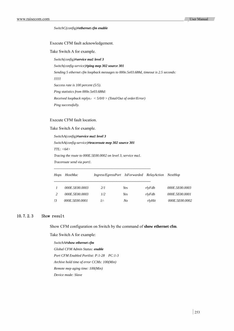
www.raisecom.com User Manual
253
SwitchC(config)#ethernet cfm enable
Execute CFM fault acknowledgement.
Take Switch A for example.
Switch(config)#service ma1 level 3
Switch(config-service)#ping mep 302 source 301
Sending 5 ethernet cfm loopback messages to 000e.5e03.688d, timeout is 2.5 seconds:
!!!!!
Success rate is 100 percent (5/5).
Ping statistics from 000e.5e03.688d:
Received loopback replys:< 5/0/0 > (Total/Out of order/Error)
Ping successfully.
Execute CFM fault location.
Take Switch A for example.
SwitchA(config)#service ma1 level 3
SwitchA(config-service)#traceroute mep 302 source 301
TTL: <64>
Tracing the route to 000E.5E00.0002 on level 3, service ma1.
Traceroute send via port1.
----------------------------------------------------------------------------------
Hops HostMac Ingress/EgressPort IsForwarded RelayAction NextHop
----------------------------------------------------------------------------------
1 000E.5E00.0003 2/1 Yes rlyFdb 000E.5E00.0003
2 000E.5E00.0003 1/2 Yes rlyFdb 000E.5E00.0001
!3 000E.5E00.0001 1/- No rlyHit 000E.5E00.0002
10.7.2.3 Show result
Show CFM configuration on Switch by the command of show ethernet cfm.
Take Switch A for example:
SwitchA#show ethernet cfm
Global CFM Admin Status: enable
Port CFM Enabled Portlist: P:1-28 PC:1-3
Archive hold time of error CCMs: 100(Min)
Remote mep aging time: 100(Min)
Device mode: Slave
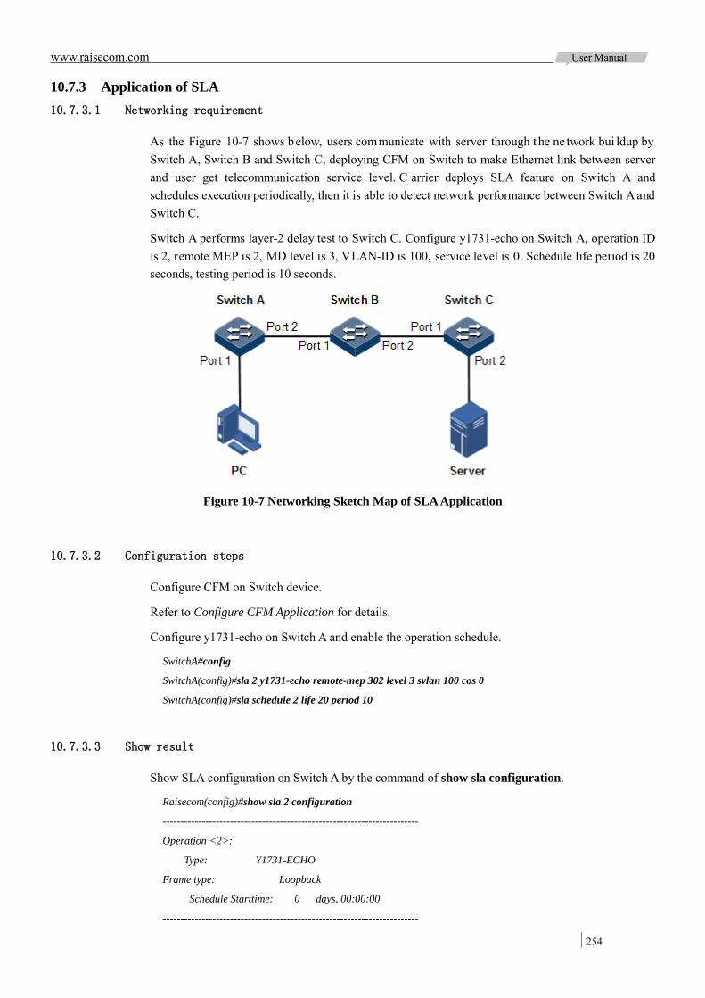
www.raisecom.com User Manual
254
10.7.3 Application of SLA 10.7.3.1 Networking requirement
As the Figure 10-7 shows below, users communicate with server through t he ne twork bui ldup by Switch A, Switch B and Switch C, deploying CFM on Switch to make Ethernet link between server and user get telecommunication service level. C arrier deploys SLA feature on Switch A and schedules execution periodically, then it is able to detect network performance between Switch A and Switch C.
Switch A performs layer-2 delay test to Switch C. Configure y1731-echo on Switch A, operation ID is 2, remote MEP is 2, MD level is 3, VLAN-ID is 100, service level is 0. Schedule life period is 20 seconds, testing period is 10 seconds.
Figure 10-7 Networking Sketch Map of SLA Application
10.7.3.2 Configuration steps
Configure CFM on Switch device.
Refer to Configure CFM Application for details.
Configure y1731-echo on Switch A and enable the operation schedule.
SwitchA#config
SwitchA(config)#sla 2 y1731-echo remote-mep 302 level 3 svlan 100 cos 0
SwitchA(config)#sla schedule 2 life 20 period 10
10.7.3.3 Show result
Show SLA configuration on Switch A by the command of show sla configuration.
Raisecom(config)#show sla 2 configuration
------------------------------------------------------------------------
Operation <2>:
Type: Y1731-ECHO
Frame type: Loopback
Schedule Starttime: 0 days, 00:00:00
------------------------------------------------------------------------
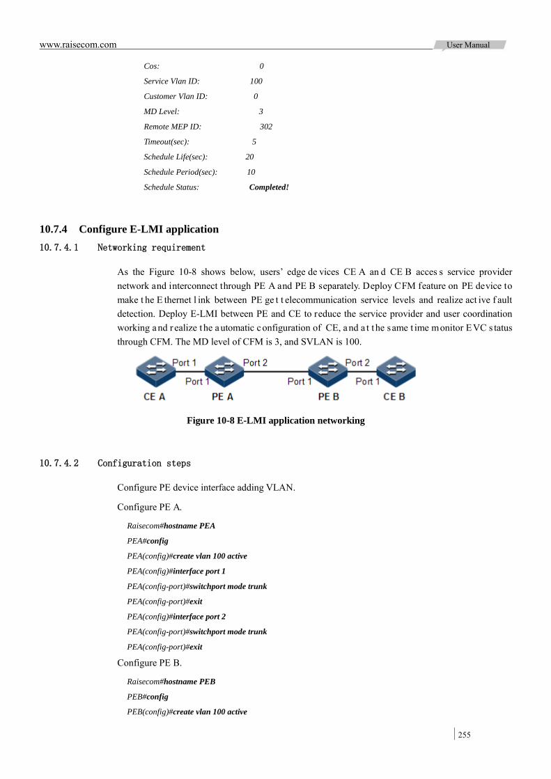
www.raisecom.com User Manual
255
Cos: 0
Service Vlan ID: 100
Customer Vlan ID: 0
MD Level: 3
Remote MEP ID: 302
Timeout(sec): 5
Schedule Life(sec): 20
Schedule Period(sec): 10
Schedule Status: Completed!
10.7.4 Configure E-LMI application 10.7.4.1 Networking requirement
As the Figure 10-8 shows below, users’ edge de vices CE A an d CE B acces s service provider network and interconnect through PE A and PE B separately. Deploy CFM feature on PE device to make t he E thernet l ink between PE ge t t elecommunication service levels and realize act ive f ault detection. Deploy E-LMI between PE and CE to reduce the service provider and user coordination working and r ealize the automatic configuration of CE, and a t t he same t ime monitor EVC s tatus through CFM. The MD level of CFM is 3, and SVLAN is 100.
Figure 10-8 E-LMI application networking
10.7.4.2 Configuration steps
Configure PE device interface adding VLAN.
Configure PE A.
Raisecom#hostname PEA
PEA#config
PEA(config)#create vlan 100 active
PEA(config)#interface port 1
PEA(config-port)#switchport mode trunk
PEA(config-port)#exit
PEA(config)#interface port 2
PEA(config-port)#switchport mode trunk
PEA(config-port)#exit
Configure PE B.
Raisecom#hostname PEB
PEB#config
PEB(config)#create vlan 100 active

www.raisecom.com User Manual
256
PEB(config)#interface port 1
PEB(config-port)#switchport mode trunk
PEB(config-port)#exit
PEB(config)#interface port 2
PEB(config-port)#switchport mode trunk
PEB(config-port)#exit
Configure CFM fault detection function.
Configure PE A.
PEA(config)#ethernet cfm domain level 3
PEA(config)#service ma1 level 3
PEA(config-service)#service vlan-list 100
PEA(config-service)#service mep up mpid 301 port 1
PEA(config-service)#service remote-mep 302
PEA(config-service)#service cc enable mep all
PEA(config-service)#exit
PEA(config)#ethernet cfm enable
Configure PE B.
PEB(config)#ethernet cfm domain level 3
PEB(config)#service ma1 level 3
PEB(config-service)#service vlan-list 100
PEB(config-service)#service mep up mpid 302 port 2
PEB(config-service)#service remote-mep 301
PEB(config-service)#service cc enable mep all
PEB(config-service)#exit
PEB(config)#ethernet cfm enable
Configure E-LMI function of PE device.
Configure PE A.
PEA(config)#ethernet lmi enable
PEA(config)#ethernet lmi pe
PEA(config)#ethernet lmi evc 1 evc1
PEA(config-evc)#oam-protocol cfm svlan 100 level 3
PEA(config-evc)#exit
PEA(config)#interface port 1
PEA(config-port)#ethernet lmi uni uni1
PEA(config-port)#ethernet lmi uni bundling
PEA(config-port)#ethernet lmi evc 1
PEA(config-port)#ethernet lmi ce-vlan map 100 evc 1
PEA(config-port)#exit
Configure PE B.
PEB(config)#ethernet lmi enable

www.raisecom.com User Manual
257
PEB(config)#ethernet lmi pe
PEB(config)#ethernet lmi evc 1 evc1
PEB(config-evc)#oam-protocol cfm svlan 100 level 3
PEB(config-evc)#exit
PEB(config)#interface port 2
PEB(config-port)#ethernet lmi uni uni1
PEB(config-port)#ethernet lmi uni bundling
PEB(config-port)#ethernet lmi evc 1
PEB(config-port)#ethernet lmi ce-vlan map 100 evc 1
PEB(config-port)#exit
Execute E-LMI function on CE device.
Configure CE A.
Raisecom#hostname CEA
CEA#config
CEA(config)#ethernet lmi enable
CEA(config)#ethernet lmi ce
Configure CE B.
Raisecom#hostname CEB
CEB#config
CEB(config)#ethernet lmi enable
CEB(config)#ethernet lmi ce
10.7.4.3 Show result
Check whether E-LMI configuration is correct on PE device by the command of show ethernet lmi config port-list port-list.
Take PE A as example.
PEA#show ethernet lmi config port-list 1
E-LMI Global Enable Status: Enable (default is disabled)
TrapEnable: Enable (default is enabled)
Mode: PE (default is PE)
-------------------------------------------------------------------------
E-LMI Interface client1 configuration:
E-LMI Interface Enable status: Enable (default is enabled)
Max EVC number: 64
N393: 4 (default is 4)
Notify Type: Aysn (default is Aysn)
T392 Enable Status: Enable (default is enabled)
T392: 15s (default is 15s)
Check whether the VLAN configuration is learnt correctly on CE device by the command of show

www.raisecom.com User Manual
258
vlan.
Take CE A as example.
CEA#show vlan
Switch Mode: --
VLAN Name State Status Priority Member-Ports
---------------------------------------------------------------
1 Default active static -- 1-6
100 VLAN0100 active static -- 3
www.raisecom.com User Manual
259
Chapter 11 System Management
This c hapter i ntroduces basic pr inciple a nd c onfiguration of s ystem management a nd pr ovides related configuration applications.
Overview SNMP KeepAlive RMON Cluster management LLDP Expanded OAM SFP digital diagnostics System LOG Alarm management Hardware environment detection Fan monitor CPU monitor Check device information Ping Traceroute Maintenance Configuring applications
11.1 Overview
11.1.1 SNMP SNMP ( Simple N etwork Management P rotocol) i s a dvanced by IETF (Internet E ngineering Task Force) f or s olving m anagement pr oblem of ne twork de vices i n I nternet. S NMP l ets r emote management for network devices supporting this protocol through one NMS (Network Management System) possible, including monitor network status, modify network device configuration, receiving network event alarm, etc. It is the widest applied network management protocol in TCP/IP network.
11.1.1.1 Working system
SNMP is separated into two parts: Agent and NMS. The Agent and NMS communicate by SNMP packets being sent through UDP. The working system of SNMP is shown in the Figure 11-1:
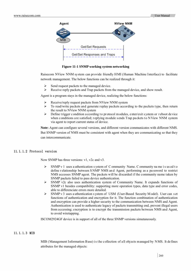
www.raisecom.com User Manual
260
Figure 11-1 SNMP working system networking
Raisecom NView NNM system can provide friendly HMI (Human Machine Interface) to facilitate network management. The below functions can be realized through it:
Send request packets to the managed device. Receive reply packets and Trap packets from the managed device, and show result.
Agent is a program stays in the managed device, realizing the below functions:
Receive/reply request packets from NView NNM system To read/write packets and generate replay packets according to the packets type, then return
the result to NView NNM system Define t rigger condition according to protocol modules, enter/exit s ystem or r eboot device
when conditions a re satisfied; replying module sends Trap packets to NView NNM system via agent to report current status of device.
Note: Agent can configure several versions, and different version communicates with different NMS. But SNMP version of NMS must be consistent with agent when they are communicating so that they can intercommunicate.
11.1.1.2 Protocol version
Now SNMP has three versions: v1, v2c and v3.
SNMP v 1 uses a uthentication s ystem of C ommunity Name. C ommunity na me i s us ed t o define r elationship between S NMP NMS an d Agent, performing as a pa ssword to restrict NMS accesses SNMP agent. The packets will be discarded if the community name taken by SNMP packets failed to pass device authentication.
SNMP v2c also uses authentication system of Community Name. It expands functions of SNMP v1 besides compatibility: supporting more operation types, data type and error codes, able to differenciate errors more detailed.
SNMP v 3 uses a uthentication s ystem of USM (User-Based Security M odel). User can s et functions of authentication and encryption for it. The function combination of authentication and encryption can provide a higher security to the communication between NMS and Agent. Authentication is used to authenticate legacy of packets transmitting end, prevent illegal users from accessing; encryption is to encrypt the transmission packets between NMS and Agent, to avoid wiretapping.
ISCOM2924GF device is in support of all of the three SNMP versions simutaneously.
11.1.1.3 MIB
MIB (Management Information Base) i s the collection of a ll objects managed by NMS. It de fines attributes for the managed objects:

www.raisecom.com User Manual
261
Name Access right Data type
The device-related statistic contents can be reached by accessing data items. Each proxy has its own MIB. MIB can be taken as an interface between NMS and Agent, through which NMS can read/write every managed object in Agent to manage and monitor the device.
MIB store information in a tree structure, its root is on the top, without name. Nodes of the tree are the managed objects, which take a uniquely pa th s tarting f rom root (OID) for identication. SNMP protocol packets can access network devices by checking the nodes in MIB tree directory.
ISCOM2924GF is in support of standard MIB and Raisecom customized MIB.
11.1.2 KeepAlive KeepAlive packet is a ki nd of keepAlive mechanism running i n HDLC ( High-Level D ata Link Control) l ink l ayer pr otocol. The de vice w ill s end a KeepAlive pa cket to c onfirm w hether the opposite side is online every several seconds so as to realize neighbor detection mechanism.
Trap is the unrequested information sent by the device actively to NMS, used to report some urgent and important events.
Switch s ends K eepAlive Trap pockers act ively which includes the basic inf ormation of s witch (device name, device OID, MAC address and IP address). Network management synchronizes device information by IP to make the NMS di scover ne twork segment in a shour t ime, improve working efficiency and reduce working load of administrators.
11.1.3 RMON RMON (Remote Network Monitoring) is a standard stipulated by IETF (Internet Engineering Task Force) for network data monitoring through different network Agent and NMS.
RMON is achieved based on SNMP architecture, including the network management center and the Agent running on network devices. On the foundation of SNMP, increase the subnet traffic, statistics, and analysis to achieve the monitoring to one network segment and the whole network, while SNMP only can monitor the partial information of a s ingle device and it is difficult for i t to monitor one network segment.
RMON Ag ent is c ommonly r eferred t o a s the pr obe pr ogram; R MON Probe can take the communication s ubnet s tatistics a nd pe rformance a nalysis. W henever it finds network f ailure, RMON Probe can report network management center, and describes the capture information under unusual ci rcumstances so t hat the ne twork management cent er doesn’t ne ed t o pol l the de vice constantly. Compared with SNMP, RMON can monitor remote de vices more act ively and more effectively, ne twork administrators c an t rack the ne twork, network segment or de vice malfunction more quickly. T his a pproach r educes t he data traffics be tween network m anagement cent er and Agent, makes it pos sible to manage l arge ne tworks simply and pow erfully, and m akes up the limitations of SNMP in growing distributed Internet.
RMON Probe data collection methods:
Distributed RMON. Network management center obtains network management information and controls network resources directly from RMON Probe through dedicated RMON Probe collection data.
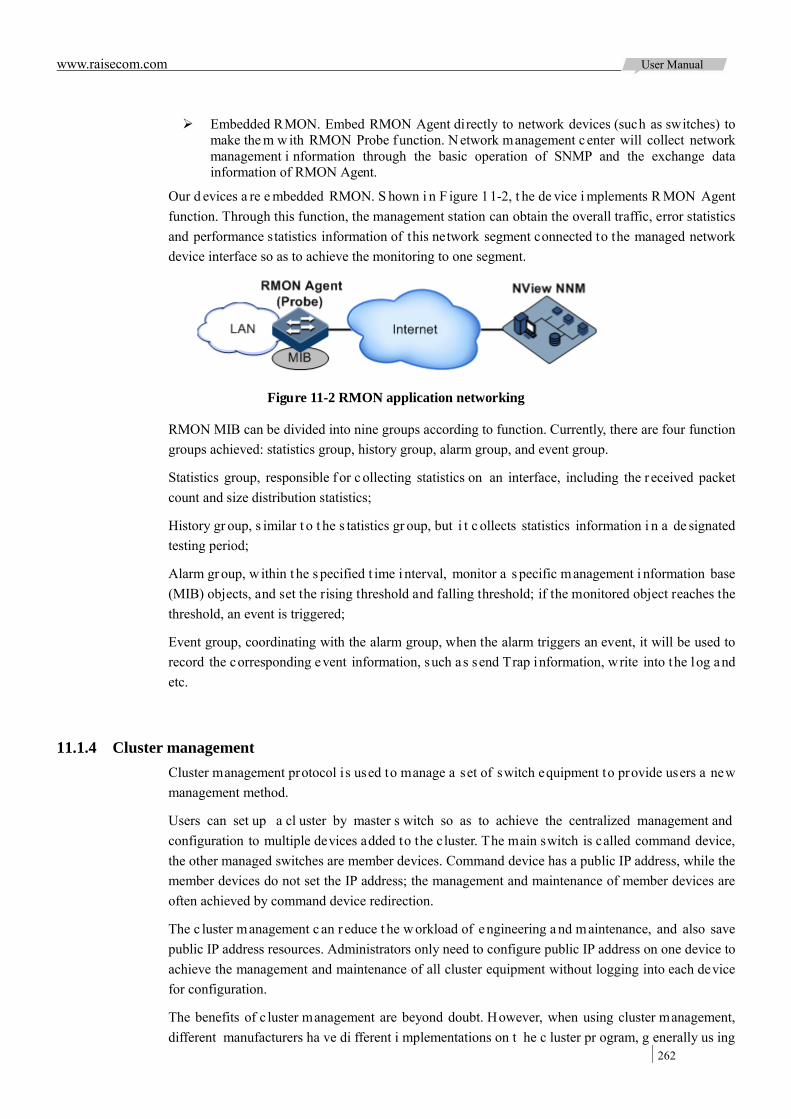
www.raisecom.com User Manual
262
Embedded RMON. Embed RMON Agent directly to network devices (such as switches) to make the m w ith RMON Probe function. N etwork management center will collect network management i nformation through the basic operation of SNMP and the exchange data information of RMON Agent.
Our d evices a re e mbedded RMON. S hown i n F igure 11-2, t he de vice i mplements R MON Agent function. Through this function, the management station can obtain the overall traffic, error statistics and performance statistics information of this network segment connected to the managed network device interface so as to achieve the monitoring to one segment.
Figure 11-2 RMON application networking
RMON MIB can be divided into nine groups according to function. Currently, there are four function groups achieved: statistics group, history group, alarm group, and event group.
Statistics group, responsible f or c ollecting statistics on an interface, including the r eceived packet count and size distribution statistics;
History gr oup, s imilar t o t he s tatistics gr oup, but i t c ollects statistics information i n a de signated testing period;
Alarm gr oup, w ithin t he s pecified t ime i nterval, monitor a s pecific management i nformation base (MIB) objects, and set the rising threshold and falling threshold; if the monitored object reaches the threshold, an event is triggered;
Event group, coordinating with the alarm group, when the alarm triggers an event, it will be used to record the corresponding event information, such as send Trap information, write into the log and etc.
11.1.4 Cluster management Cluster management protocol is used to manage a set of switch equipment to provide users a new management method.
Users can set up a cl uster by master s witch so as to achieve the centralized management and configuration to multiple devices added to the cluster. The main switch is called command device, the other managed switches are member devices. Command device has a public IP address, while the member devices do not set the IP address; the management and maintenance of member devices are often achieved by command device redirection.
The c luster management c an r educe t he w orkload of engineering a nd maintenance, and also save public IP address resources. Administrators only need to configure public IP address on one device to achieve the management and maintenance of all cluster equipment without logging into each device for configuration.
The benefits of c luster management are beyond doubt. However, when using cluster management, different manufacturers ha ve di fferent i mplementations on t he c luster pr ogram, g enerally us ing
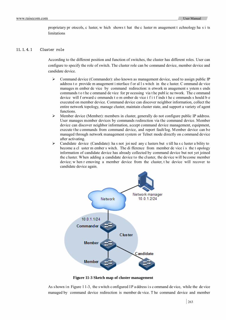
www.raisecom.com User Manual
263
proprietary pr otocols, c luster, w hich shows t hat the c luster m anagement t echnology ha s i ts limitations
11.1.4.1 Cluster role
According to the different position and function of switches, the cluster has different roles. User can configure to specify the role of switch. The cluster role can be command device, member device and candidate device.
Command device (Commander): also known as management device, used to assign public IP address t o provide m anagement i nterface f or al l s witch in the c luster. C ommand de vice manages m ember de vice by command redirection: n etwork m anagement s ystem s ends commands t o t he c ommand de vice for pr ocessing via t he publ ic ne twork. The c ommand device will f orward c ommands t o m ember de vice i f i t f inds t he c ommands s hould b e executed on member device. Command device can discover neighbor information, collect the entire network topology, manage cluster, maintain cluster state, and support a variety of agent functions.
Member device (Member): members in cluster, generally do not configure public IP address. User manages member devices by commands redirection via the command device. Member device can discover neighbor information, accept command device management, equipment, execute t he commands from command device, and report fault/log. Member device can be managed through network management system or Telnet mode directly on c ommand device after activating.
Candidate device (Candidate): ha s not joi ned any c lusters but s till ha s c luster a bility to become a cl uster m ember s witch. The di fference from member de vice i s the t opology information of candidate device has already collected by command device but not yet joined the c luster. When adding a candidate device to the cluster, the device will become member device; w hen r emoving a member device from the cluster, t he device will recover to candidate device again.
Figure 11-3 Sketch map of cluster management
As s hown i n Figure 11-3, the s witch c onfigured I P a ddress i s c ommand de vice, while the de vice managed by command device redirection is member de vice. T he command device and member
www.raisecom.com User Manual
264
device can form a cluster. The device not joined cluster but still had cluster ability is candidate device.
11.1.4.2 Working principle of cluster
Cluster management mainly contains three protocols:
RNDP (Raisecom Neighbor Discover Protocol) is responsible for the neighbor discovery and information gathering of devices.
RTDP (Raisecom Topology Discover Protocol) is responsible for the entire network topology information collection and processing.
RCMP ( Raisecom C luster M anagement P rotocol) m ainly configures t o add, activate, and delete cluster members.
RTDP and RCMP protocols take communication in the cluster VLAN. So, if there are devices not supporting RAISECOM cl uster m anagement function between the t wo devices f or cl uster management, you ne ed t o c onfigure t he c luster VLAN to e nsure t he nor mal c ommunication of RCMP and RTDP protocols.
Each cluster must specify a com mand device. After command device is specified, command device can di scover and determine candidate de vice through neighbor discovery and topology gathering protocol. Users can add candidate device to the cluster by corresponding configuration.
Candidate de vice will become m ember device af ter addi ng to cluster. If you w ant to m anage t he device through cluster management function, you must activate the switch, or configure auto-active function on switch.
11.1.5 LLDP As the growing of network scale and the i ncreasing of network devices, ne twork t opology is becoming m ore c omplex a nd network m anagement is become pa rticularly i mportant. T o t rack changes i n network t opology information, m any ne twork management s oftware has a dopted the "automatic di scovery" f unction, but m ost ne twork m anagement s oftware only can analyze t he network layer topology without determining by which i nterface other devices connected t o other devices.
LLDP ( Link Layer D iscovery P rotocol) is a link la yer di scovery pr otocol de fined by t he I EEE 802.1AB. Network m anagement s ystem c an m aster l ayer-2 network t opology a nd t he c hanges quickly by the protocol.
LLDP or ganizes the l ocal device i nformation to di fferent T LV ( Type Length V alue uni t), a nd encapsulates t hem in LLDPDU ( Link Layer D iscovery P rotocol Data U nit) to s end to direct- connected neighbors. Meanwhile, LLDP will save the information from neighbors with the standard MIB ( Management Information Base) f or m anagement s ystem to inquiry and judge links communication status.
11.1.5.1 Basic concept
LLDP messages: Ethernet messages encapsulated LLDPDU in data unit.
LLDPDU: da ta uni t of LLDP message. Before the c omposition of L LDPDU, the de vice w ill

www.raisecom.com User Manual
265
encapsulate local information to TLV, and a number of TLV will combine into one LLDPDU, which encapsulated in the Ethernet data part will be transmitted.
Shown in Figure 11-4, LLDPDU is formed by a number of TLV, which contains four mandatory TLV and a number of optional TLV.
Figure 11-4 LLDPDU structure chart
TLV: uni t c ombining LLDPDU, which r efers t o t he unit de scribing t he object type, l ength a nd information.
TLV st ructure is shown i n F igure 1 1-5: each TLV r epresents a piece of local i nformation. For example, t he device ID and interface ID are corresponded to Chassis ID TLV and Por t ID TLV separately.
Figure 11-5 Basic TLV structure chart
TLV types are shown in Table 11-1, currently, it only uses the type of 0~8.
Table 11-1 TLV types:
TLV type Description Compulsory or not
0 End Of LLDPDU: means LLDP messages end. Compulsory
1 Chassis Id: MAC address of sending device. Compulsory
2 Port Id: sending side interface of LLDP messages Compulsory
3 Time To Live: aging time of local device information on neighbour device.
Compulsory
4 Port Description: description of Ethernet interface Optional
5 System Name Optional
6 System Description Optional
7 System Capabilities: main function of system and the used function
Optional
8 Management Address Optional
11.1.5.2 Working principle of LLDP
LLDP i s a point-to-point one -way di stribution protocol, which sends LLDP messages periodically
www.raisecom.com User Manual
266
from l ocal de vice t o oppo site de vice (or se nd LLDP messages w hen there i s cha nge in local information) to notify the link state to opposite device.
The data traffic is as follows:
When sending, the de vice obtains system information r equired by the selected TLV, and obtains configuration information from LLDP MIB, generates TLV, constitutes LLDPDU, encapsulates to LLDP messages and sends them to opposite device.
After r eceiving LLDP messages, oppos ite de vice w ill a nalyze a ll the T LV information. If there i s c hange, t he oppos ite de vice w ill upda te t he i nformation to LLDP neighbors M IB table and inform NMS.
The aging time TTL (Time to live) of local device information in the neighbor node can be adjusted by modifying t he pa rameter values of aging coefficient, s ends LLDP messages t o ne ighbor node , after r eceiving LLDP messages, ne ighbor no de will adjust the a ging time of its neighbor n odes (sending side) information. Aging time formula, TTL = Min {65535, (interval × hold-multiplier)}:
Interval indicates the time period to send LLDP messages from neighbor node. Hold-multiplier refers to the aging coefficient of device information in neighbor node.
11.1.6 Optical module digital diagnostics Optical m odule digital d iagnostics function on de vice i s i n s upport of SFP ( Small Form-factor Pluggables), and 10 GE SFP + diagnosis.
Optical m odule digital di agnostics function provides a performance m onitoring method. Network administrator analyzes the monitor data provided by SFP to predict the age of transceiver, isolates system fault and authenticates modules compatibility during installation.
Optical module digital diagnostics function can monitor the following performance parameters:
Module temperature Inner supply voltage Transmitting offset current Transmitting optical power Receiving optical power
When the pe rformance parameters r each alarm t hreshold or s tatus i nformation changes, the corresponding Trap alarm will be generated.
11.1.7 System Log System Log means the device records system information and debug information, etc. in the form of log and outputs them to assigned destination. When the device has fault, the system log will take it easy for user to check and locate fault.
System information and some debug outputs of ISCOM2924GF will be sent to system log. System log sends the information t o di fferent de stination according to user configuration. The system log destinations are as below:
Console: output log information to local Console through Console interface Log host: output log information to log host in log file format Monitor: output log information to monitor, such as Telnet terminal File: output log information to device Flash in log file format Buffer: output log information to buffer
Format of system log:
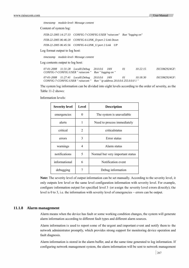
www.raisecom.com User Manual
267
timestamp module-level- Message content
Content of system log:
FEB-22-2005 14:27:33 CONFIG-7-CONFIG:USER "raisecom" Run "logging on"
FEB-22-2005 06:46:20 CONFIG-6-LINK_D:port 2 Link Down
FEB-22-2005 06:45:56 CONFIG-6-LINK_U:port 2 Link UP
Log format output to log host:
timestamp module-level- Message content
Log contents output to log host:
07-01-2008 11:31:28 Local0.Debug 20.0.0.6 JAN 01 10:22:15 ISCOM2924GF: CONFIG-7-CONFIG:USER " raisecom " Run " logging on "
07-01-2008 11:27:41 Local0.Debug 20.0.0.6 JAN 01 10:18:30 ISCOM2924GF: CONFIG-7-CONFIG:USER " raisecom " Run " ip address 20.0.0.6 255.0.0.0 1 "
The system log information can be divided into eight levels according to the order of severity, as the Table 11-2 shows:
Information levels:
Severity level Level Description
emergencies 0 The system is unavailable
alerts 1 Need to process immediately
critical 2 criticalstatus
errors 3 Error status
warnings 4 Alarm status
notifications 5 Normal but very important status
informational 6 Notification event
debugging 7 Debug information
Note: The severity level of output information can be set manually. According to the severity level, it only outputs low level or the same level configuration information with severity level. For example, configure information output for specified level 3 (or assign the severity l evel e rrors di rectly); the level is 0 to 3, i.e. the information with severity level of emergencies ~ errors can be output.
11.1.8 Alarm management Alarm means when the device has fault or some working condition changes, the system will generate alarm information according to different fault types and different alarm sources.
Alarm information is used to report some of the urgent and important event and notify them to the network administrator promptly, which provides strong support for monitoring device operation and fault diagnosis.
Alarm information is stored in the alarm buffer, and at the same time generated to log information. If configuring network management system, the alarm information will be sent to network management

www.raisecom.com User Manual
268
system through SNMP (Simple Network Management Protocol). The information sent to the network management system is called Trap information.
11.1.8.1 Classification of alarm information
The alarm information can be divided into three types according to alarm natures:
Fault alarm: refers t o the alarm for so me hardware fault or some abnormal important functions, such as interface status down alarm;
Recovery alarm: re fers to the al arm for de vice failure or a bnormal function r eturning to normal, such as interface status up alarm;
Event alarm: refers to the alarm indicating the prompted fault and recovery unmatched, such as Ping probe failure alarm.
The alarm information can be divided into five types according to alarm functions:
Communication alarm: refers t o the alarms r elated to the processing of i nformation transmission, i ncluding the c ommunication f ault between ne twork e lements, network elements and network management systems or NMS and NMS.
Service quality alarm: refers to the alarms caused by service quality degradation, including congestion, performance decline, high resource utilization rate, and the bandwidth reducing.
Processing error alarm: refers t o the al arms caused by software or pr ocessing errors, including s oftware e rrors, m emory ov erflow, v ersion mismatching, and t he a bnormal program aborts.
Environmental a larm: refers t o the al arms caus ed by equipment l ocation-related pr oblems, including the environment temperature, humidity, ventilation and other abnormal working conditions.
Device alarm: refers to the alarms caused by physical resource failure, including power, fan, processor, clock, input / output interfaces and other hardware devices.
11.1.8.2 Output of alarm information
There are three alarm information output modes:
Alarm buffer: record in tabular form, including the current alarm table and history alarm table. Current alarm table, recording alarm information which doesn’t be cleared or restored. History alarm table, recording the cleared and auto-restored alarm information.
Log: alarm information is generated to system log when recorded in alarm buffer, and stored in t he a larm l og buf fer. By de fault, a larm inf ormation will generate to system l og automatically. User can suppress the generation of the system log manually.
Trap Information: alarm information sent to network management system when configuring network management system.
Alarm will be broadcast a ccording t o t he various t erminals of t he de vice c onfiguration, i ncluding command-line terminal and network management system.
Alarm information log output with the beginning of symbol "#", the output format is:
# Index TimeStamp HostName ModuleName / Severity / name: Arise From Description
The field description is shown in Table 11-3.
Table 11-3 Alarm information field description
Field Description
Index Alarm index

www.raisecom.com User Manual
269
Field Description
TimeStamp Alarm time
HostName Alarm host name
ModuleName Alarm module name
Severity Alarm severity level
name Alarm name
Arise From Description Alarm description
11.1.8.3 Level of alarm information
The alarm level is used to identify the severity degree of an alarm. The level is defined in Table 11-4.
Table 11-4 Alarm level definition
Level Description Corresponding Syslog
Critical (3) This alarm has affected system services and requires immediate troubleshooting. Restore the device or source immediately if they are completely unavailable, even it
is not during working time.
1 (Alert)
Major (4) This alarm has affected the service quality and requires immediate troubleshooting. Restore the device or source
service quality if they decline; or take measures immediately during working hours to restore all
performances.
2 (Critical)
Minor (5) This alarm hasn’t influenced the existing service yet, which needs further observation and take measures at
appropriate time so as to avoid more serious fault.
3 (Error)
Warning (6) This alarm will not affect the current service, but maybe the potential error will affect the service, so it can be
considered as needing to take measures.
4 (Warning)
Indeterminate (2) Uncertain alarm level, usually the event alarm. 5 (Notice)
Cleared (1) This alarm shows to clear one or more reported alarms. 5 (Notice)
11.1.8.4 Alarm-related concepts
Introduction of alarm related concepts:
Alarm suppression
The device only records root-cause alarm, but not incidental alarm when enabling alarm suppression. For example, the generation of alarm A will inevitably produce alarm B, then alarm B is suppressed and doe sn’t appe ar i n alarm buffer and r ecord l og information when e nabling a larm s uppression. Enabling alarm suppression can reduce the number of alarms effectively.
www.raisecom.com User Manual
270
The root-cause alarm and all other incidental alarms will be recorded on device when disabling alarm suppression.
Alarm Auto-reporting
Auto-reporting refers to the a larm w ill be r eported t o network m anagement s ystem automatically with i ts ge neration a nd ne edn’t initiate inqui ries or s ynchronization. User can set auto-reporting function to a larms generated f rom s ome property module ( alarm source), s ome interface ( alarm source), and the specified property module in the specified interface.
Note: Alarm Source: refers to the alarm ent ities generated related alarms, such as interface, alarm module (in support of alarm features) and so on.
Alarm monitoring
Alarm monitoring is used to deal with each module alarms:
The alarm module will receive alarms generated by each module when enabling alarm monitoring function, and deal with them according to the configuration of alarm module, such as record alarm in alarm buffer, and record system logs, etc;
The a larm m odule w ill di scard t he a larm ge nerated by t he m odule without follow-up treatment when disabling alarm monitoring function and the alarms will not be recorded on the device.
User can take alarm monitoring to some property module, some interface or the specified property module in the specified interface.
Alarm reverse mode
Alarm reverse refers t o the de vice will r eport t he i nformation oppos ite t o a ctual s tatus w hen recording alarm information, or report the a larm when there is no alarm information. Not report if there is alarm information.
Currently, t he de vice is only in support of reverse mode configuration of the i nterface. There a re three reverse modes to be set; the specific definitions are as follows:
No reverse mode
Device alarm is reported normally.
Manual reverse mode
Set the alarm reverse mode of an interface as manual reverse mode, then no matter what the current alarm state is, the reported alarm state of the interface will be changed opposite to the actual alarm state immediately, that is to say, not report when there are alarms, report when there aren’t alarms actually. The interface will maintain the opposite alarm state regardless of the alarm state changes before the alarm reverse state being restored to non-reverse mode.
Auto-reverse mode
Set the alarm re verse mode as aut o-reverse m ode. If t he i nterface hasn’t actual r everse al arm currently, the setting will return fail; if the interface has actual reverse alarm, the setting is success and enter reverse m ode, i.e. t he i nterface r eported alarm s tatus is changed oppos ite t o t he actual alarm s tatus immediately. After the alarm is f inished, the enabling s tate of interface alarm reverse will e nds automatically and cha nges to no n-reverse al arm mode so that t he al arm s tate can be reported normally in next alarm.
Alarm delay
Alarm delay refers to the device will record alarms and report alarms to NMS after a delay time but not immediately when alarms generate. Both recording delay time and reporting delay time are the

www.raisecom.com User Manual
271
same.
By default, the device alarm is reported once generating (0s), which is instant reporting; clear alarm once it ends (0s), which is instant clearing.
Alarm storage mode
Alarm storage mode refers t o how t o record new ge nerated alarms w hen the a larm buf fer i s f ull. There are two ways:
Stop: stop mode, when the alarm buffer is full, new generated alarms will be discarded without recording.
Loop: wrapping mode, when the alarm buffer is full, the new generated al arms will replace old alarm information and take rolling records.
Use configured storage m ode t o deal with new generated alarm information w hen the al arm information in device alarm table is full.
Alarm clear
Clear the current alarm, which i s delete the current alarm from current alarm table. T he cleared alarms will enter history alarm table.
Check alarm
Administrators can check alarms directly on t he device, monitor alarm information. If the device is configured network management system, they can monitor on the network management system.
11.1.9 Hardware environment monitoring Hardware environment m onitoring mainly r efers t o m onitor t he r unning e nvironment of ISCOM2924GF device. The monitoring alarm events include:
Power state alarm Temperature beyond threshold alarm Voltage beyond threshold alarms Abnormal interface status alarm
There are s everal w ays to notify the us er when an al arm is generated. The alarm event out put methods are as follows:
Record device hardware environmental monitoring alarm buffer; Output Syslog system log; Send Trap to network management center.
User can take appropriate measures to prevent failure when alarm events happen.
11.1.9.1 Alarm event
Power monitoring alarm
There are two power status alarms specifically:
Abnormal supply voltage alarm
The al arm ge nerates w hen the p ower v oltage is over or be low 20% of t he predetermined v oltage value 12V, on the contrary, alarm will also generates when voltage restore the normal value. This alarm event is in support of recording hardware monitoring alarm table, Trap and Syslog output.
Power state change alarm
www.raisecom.com User Manual
272
Power state change refers to the power present changes to power absent, or power absent changes to power present state. ISCOM2924GF device is in support of dual power supplies, so the power state change alarm can be divides into one power state of two powers changes and device power-down.
One power state of dual powers changes: the alarm event will inform user the state of power 1/2 changes, which is in support of recording hardware monitoring alarm table, Trap and Syslog output.
Device power-down: Both powers are down, that is to say, both powers are changed to absent state, which is only support of Syslog output.
Temperature beyond threshold alarm
The device is in support of temperature beyond threshold alarm event, when the current temperature is lower than low temperature threshold, the low temperature alarm event will generate, which is in support of recording hardware monitoring alarm table, Trap and Syslog output.
When the device current temperature is higher than high temperature threshold, the high temperature alarm event w ill generate, which i s a lso in support of recording hardware monitoring a larm table, Trap and Syslog output.
Voltage beyond threshold alarm
The device is in support of voltage beyond threshold alarm event, when the current voltage is lower than low v oltage threshold, the low v oltage a larm e vent w ill ge nerate, w hich is in support of recording hardware monitoring alarm table, Trap and Syslog output.
When the device current voltage is higher than high voltage threshold, the high voltage alarm event will ge nerate, w hich i s a lso i n support of r ecording h ardware m onitoring a larm t able, T rap a nd Syslog output.
Note: the device only monitor 3.3V master chip voltage.
Interface status alarm
Each interface has three alarm events:
Interface link-fault alarm: link failure alarm refers to the peer link signal loss. The alarm event only aims at optical port, but not power port.
Interface link-down alarm: interface status Down alarm. Interface not-forwarding alarm: The interface will change to non-forwarding state under
all VLAN.
All three alarm events are in support of recording hardware monitoring alarm table, Trap and Syslog output.
11.1.9.2 Alarm output mode
Hardware environment monitoring alarm output modes are as below:
Hardware environment monitoring a larm buf fer out put, which is r ecorded to the ha rdware environment monitoring alarm table The hardware environment monitoring alarm table, recording current alarm information
which hasn’t been cleared and restored. The hardware e nvironment monitoring history a larm table, r ecording c urrent, restored
and manually cleared alarm information.
Hardware e nvironmental monitoring alarm information can be recorded in the cu rrent hardware environment monitoring a larm table and ha rdware environment m onitoring history alarm t able automatically without configuring manually.

www.raisecom.com User Manual
273
Trap output
Alarm information is output to network management center in Trap mode.
Trap output has global switch and all monitored alarm events still have their own Trap alarm output switches. When enabling the global switch and monitored alarm events switches simultaneously, the alarm will generate Trap output.
The contents of Trap information are shown in Table 11-5.
Table 11-5 Trap description
Field Description
Alarm status Asserted (current alarm)
Cleared (alarm recovery)
Clearall (clear all alarm information)
Alarm source Device (global alarm)
Interface number (interface status alarm)
Timestamp Alarm time, in the form of absolute time
Alarm event type dev-power-down (power-down alarm)
power-abnormal (power-abnormal alarm, one of two powers is power down.)
high-temperature (high-temperature alarm)
low-temperature (low-temperature alarm)
high-volt (high-voltage alarm)
low-volt (low-voltage alarm)
link-down (interface LinkDown alarm)
not-forwarding (interface Not-Forwarding alarm)
link-falut (interface LinkFault alarm)
all-alarm (clear all alarm information) Syslog output
Record alarm information to Syslog.
Syslog output has global s witch and all monitored alarm events still have the ir o wn Syslog alarm output s witches. When e nabling t he gl obal s witch a nd monitored alarm ev ents s witches simultaneously, the alarm will generate Syslog output.
Syslog contents are shown in Table 11-6.
Table 11-6 Syslog information description
Field Description
Facility The module name generating alarm, the hardware environment monitoring module is fixed as alarm.
Severity Level, Please see table 11-2 for the same system log difined levels.
Mnemonics Alarm event type, please see table 11-5 for the detailed type deacription.
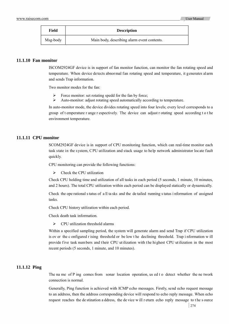
www.raisecom.com User Manual
274
Field Description
Msg-body Main body, describing alarm event contents.
11.1.10 Fan monitor ISCOM2924GF device is in support of fan monitor function, can monitor the fan rotating speed and temperature. When device detects abnormal fan rotating speed and temperature, it generates alarm and sends Trap information.
Two monitor modes for the fan:
Force monitor: set rotating spedd for the fan by force; Auto-monitor: adjust rotating speed automatically according to temperature.
In auto-monitor mode, the device divides rotating speed into four levels; every level corresponds to a group of t emperature r ange r espectively. The device can adjust r otating speed according t o t he environment temperature.
11.1.11 CPU monitor SCOM2924GF device is in support of CPU monitoring function, which can real-time monitor each task state in the system, CPU utilization and stack usage to help network administrator locate fault quickly.
CPU monitoring can provide the following functions:
Check the CPU utilization
Check CPU holding time and utilization of all tasks in each period (5 seconds, 1 minute, 10 minutes, and 2 hours). The total CPU utilization within each period can be displayed statically or dynamically.
Check the ope rational s tatus of a ll ta sks and the de tailed running s tatus i nformation of assigned tasks.
Check CPU history utilization within each period.
Check death task information.
CPU utilization threshold alarms
Within a specified sampling period, the system will generate alarm and send Trap if CPU utilization is ov er the c onfigured r ising threshold or be low t he declining threshold. Trap i nformation w ill provide f ive task numbers and t heir CPU ut ilization with t he hi ghest CPU ut ilization in the most recent periods (5 seconds, 1 minute, and 10 minutes).
11.1.12 Ping The na me of P ing comes from sonar location operation, us ed t o detect whether the ne twork connection is normal.
Generally, Ping function is achieved with ICMP echo messages. Firstly, send echo request message to an address, then the address corresponding device will respond to echo reply message. When echo request reaches the de stination a ddress, the de vice w ill r eturn echo reply message to t he s ource

www.raisecom.com User Manual
275
address in an effective time to show the destination is reachable. If not receiving echo reply within the effective time, the sending end will display timeout, which means the destination is unreachable.
Ping function principle is shown in Figure 11-6.
Figure 11-6 Ping function achieving principle network
11.1.13 Traceroute Same to P ing, Traceroute i s a commonly used maintenance method in network m anagement. Traceroute function is often used to test the network nodes of messages from sender to destination, detect whether the network connection is reachable and analyze network fault.
The implementation process of Traceroute is as follows:
First, send a piece of TTL1 sniffer message (UDP port number of message is unavailable to any application programs in destination side).
TTL deducts 1 when reaching the first hop; because the TTL value is 0, in the first hop, the device returns an ICMP timeout message, indicating that this message cannot be sent.
The sending host will add 1 to TTL and resend this message. Because TTL value was reduced to 0 in the second hop, the device will return an ICMP
timeout message, indicating that this message cannot be sent.
The above steps will continue until the messages reach destination host, which will not return ICMP timeout message. Because the port number of destination host hasn’t be used, destination host will send port unreachable message and finish the test. Thus, the sending host can record the source address of each ICMP TTL t imeout message, and analyze the pa th to destination according to the response message. Traceroute function principle is shown in Figure 11-7.

www.raisecom.com User Manual
276
Figure 11-7 Traceroute function achieving principle networking
11.2 SNMP
11.2.1 Preparation for configuration 11.2.1.1 Networking situation
When us er needs t o l og o n ISCOM2924GF device t hrough N MS, pl ease configure SNMP basic functions for ISCOM2924GF in advance.
11.2.1.2 Preconditions
Finish below tasks before configuring SNMP:
Configure SNMP interface IP address. Configure routing pr otocol, a nd m ake s ure r outing be tween ISCOM2924GF and N MS is
available.
11.2.2 Default configuration of SNMP The default configuration of SNMP is as below:
Function Default value
SNMP view By default: system, internet view
SNMP community By default: public, private community
Index CommunityName ViewName Permission
1 public internet r o
2 private internet r w
SNMP access group By default: initialnone, initial group
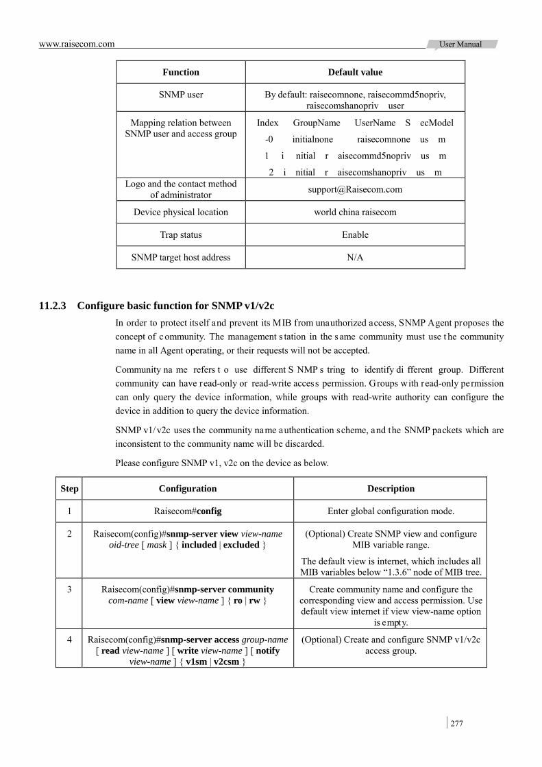
www.raisecom.com User Manual
277
Function Default value
SNMP user By default: raisecomnone, raisecommd5nopriv, raisecomshanopriv user
Mapping relation between SNMP user and access group
Index GroupName UserName S ecModel
-0 initialnone raisecomnone us m
1 i nitial r aisecommd5nopriv us m
2 i nitial r aisecomshanopriv us m Logo and the contact method
of administrator [email protected]
Device physical location world china raisecom
Trap status Enable
SNMP target host address N/A
11.2.3 Configure basic function for SNMP v1/v2c In order to protect itself and prevent its MIB from unauthorized access, SNMP Agent proposes the concept of community. The management s tation in the s ame community must use t he community name in all Agent operating, or their requests will not be accepted.
Community na me refers t o use different S NMP s tring to identify di fferent group. Different community can have read-only or read-write access permission. Groups with read-only permission can only query the device information, while groups with read-write authority can configure the device in addition to query the device information.
SNMP v1/v2c uses the community name authentication scheme, and the SNMP packets which are inconsistent to the community name will be discarded.
Please configure SNMP v1, v2c on the device as below.
Step Configuration Description
1 Raisecom#config Enter global configuration mode.
2 Raisecom(config)#snmp-server view view-name oid-tree [ mask ] { included | excluded }
(Optional) Create SNMP view and configure MIB variable range.
The default view is internet, which includes all MIB variables below “1.3.6” node of MIB tree.
3 Raisecom(config)#snmp-server community com-name [ view view-name ] { ro | rw }
Create community name and configure the corresponding view and access permission. Use default view internet if view view-name option
is empty.
4 Raisecom(config)#snmp-server access group-name [ read view-name ] [ write view-name ] [ notify
view-name ] { v1sm | v2csm }
(Optional) Create and configure SNMP v1/v2c access group.
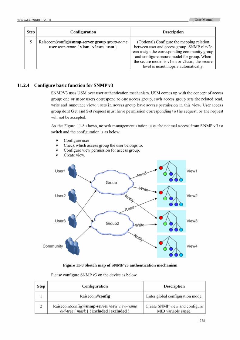
www.raisecom.com User Manual
278
Step Configuration Description
5 Raisecom(config)#snmp-server group group-name user user-name { v1sm | v2csm | usm }
(Optional) Configure the mapping relation between user and access group. SNMP v1/v2c can assign the corresponding community group
and configure secure model for group. When the secure model is v1sm or v2csm, the secure
level is noauthnopriv automatically.
11.2.4 Configure basic function for SNMP v3 SNMPV3 uses USM over user authentication mechanism. USM comes up with the concept of access group: one or more users correspond to one access group, each access group sets the related read, write and announce v iew; u sers i n access group have acces s pe rmission in this view. User acces s group dent Get and Set request must have permission corresponding to the request, or the request will not be accepted.
As the Figure 11-8 s hows, ne twrk management s tation us es t he nor mal a ccess f rom S NMP v3 t o switch and the configuration is as below:
Configure user Check which access group the user belongs to. Configure view permission for access group. Create view.
Figure 11-8 Sketch map of SNMP v3 authentication mechanism
Please configure SNMP v3 on the device as below.
Step Configuration Description
1 Raisecom#config Enter global configuration mode.
2 Raisecom(config)#snmp-server view view-name oid-tree [ mask ] { included | excluded }
Create SNMP view and configure MIB variable range.

www.raisecom.com User Manual
279
Step Configuration Description
3 Raisecom(config)#snmp-server user user-name [ remote engine-id ] authentication { md5 | sha }
authpassword
Create user and configure authentication mode.
4 Raisecom(config)#snmp-server access group-name [ read view-name ] [ write view-name ] [ notify
view-name ] [ context context-name { exact | prefix } ] usm { noauthnopriv | authnopriv }
Create and configure SNMP v3 access group.
5 Raisecom(config)#snmp-server group group-name user user-name { v1sm | v2csm | usm }
Configure the mapping relation between user and access group.
11.2.5 Configure other information of SNMP Configure other information of SNMP, including:
Logo and contact method of administrators Physical location of switch
All SNMP v1, v2c and v3 are in support of the above configuration.
Please configure other information of SNMP on the device as below.
Step Configuration Description
1 Raisecom#config Enter global configuration mode.
2 Raisecom(config)#snmp-server contact contact
(Optional) Configure logo and contact method of administrators.
Note: Foe example: use E-mail as logo and contact method of administrators.
3 Raisecom(config)#snmp-server location location
(Optional) assign the physical location of device.
11.2.6 Configure Trap Note: Except for target host configuration, Trap configuration of SNMP v1, v2c and v3 are identical.
Trap means the device sends unrequested information to NMS automatically, which is used to report some critical events.
Finish the following tasks befoce configuring Trap function:
Configure SNMP basic function. SNMP v1 and v2c versions need to configure community name; SNMP v3 needs to configure username and SNMP view.
Configure routing pr otocol, a nd m ake s ure r outing be tween ISCOM2924GF and N MS is available.
Please configure SNMP Trap on the device as below.
Step Configuration Description
1 Raisecom#config Enter global configuration mode.
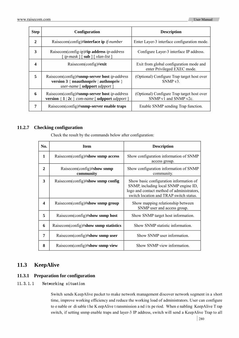
www.raisecom.com User Manual
280
Step Configuration Description
2 Raisecom(config)#interface ip if-number Enter Layer-3 interface configuration mode.
3 Raisecom(config-ip)#ip address ip-address [ ip-mask ] [ sub ] [ vlan-list ]
Configure Layer-3 interface IP address.
4 Raisecom(config)#exit Exit from global configuration mode and enter Privileged EXEC mode.
5 Raisecom(config)#snmp-server host ip-address version 3 { noauthnopriv | authnopriv }
user-name [ udpport udpport ]
(Optional) Configure Trap target host over SNMP v3.
6 Raisecom(config)#snmp-server host ip-address version { 1 | 2c } com-name [ udpport udpport ]
(Optional) Configure Trap target host over SNMP v1 and SNMP v2c.
7 Raisecom(config)#snmp-server enable traps Enable SNMP sending Trap function.
11.2.7 Checking configuration Check the result by the commands below after configuration:
No. Item Description
1 Raisecom(config)#show snmp access Show configuration information of SNMP access group.
2 Raisecom(config)#show snmp community
Show configuration information of SNMP community.
3 Raisecom(config)#show snmp config Show basic configuration information of SNMP, including local SNMP engine ID,
logo and contact method of administrators, switch location and TRAP switch status.
4 Raisecom(config)#show snmp group Show mapping relationship between SNMP user and access group.
5 Raisecom(config)#show snmp host Show SNMP target host information.
6 Raisecom(config)#show snmp statistics Show SNMP statistic information.
7 Raisecom(config)#show snmp user Show SNMP user information.
8 Raisecom(config)#show snmp view Show SNMP view information.
11.3 KeepAlive
11.3.1 Preparation for configuration 11.3.1.1 Networking situation
Switch sends KeepAlive packet to make network management discover network segment in a short time, improve working efficiency and reduce the working load of administrators. User can configure to e nable or di sable t he K eepAlive t ransmission a nd i ts pe riod. When e nabling KeepAlive T rap switch, if setting snmp enable traps and layer-3 IP address, switch will send a KeepAlive Trap to all

www.raisecom.com User Manual
281
target hosts with Bridge Trap every KeepAlive Trap Interval.
11.3.1.2 Preconditions
Configure SNMP interface IP address. Configure basic function of SNMP: SNMP v1 and v2c versions need to configure community
name; SNMP v3 needs to configure username and SNMP view. Configure routing pr otocol, a nd m ake s ure r outing be tween ISCOM2924GF and N MS is
available.
11.3.2 Defaut configuration of KeepAlive The default configuration of KeepAlive is as below:
Function Default value
KeepAlive Trap function status Disable
KeepAlive Trap period 300s
11.3.3 Configure KeepAlive function Please configure KeepAlive function as below:
Step Configuration Description
1 Raisecom#config Enter global configuration mode.
2 Raisecom(config)#snmp-server keepalive-trap enable
Enable to send KeepAlive Trap. By default, disable to send KeepAlive Trap packet. The command of snmp-server keepalive-trap
disable can disable this function.
3 Raisecom(config)#snmp-server keepalive-trap interval period
(Optional) Configure KeepAlive Trap transmission period.
Note: To avoid multiple de vices s ending KeepAlive Trap in the s ame t ime according to the s ame period and causing heavy network management load, the real transmission period of KeepAlive Trap is timed as period+5s random transmission.
11.3.4 Check configuration Check the result by the commands below after configuration:
No. Item Description
1 Raisecom#show keepalive Show KeepAlive configuration.

www.raisecom.com User Manual
282
11.4 RMON
11.4.1 Preparation for configuration 11.4.1.1 Networking situation
RMON can help user monitor network and statistic traffic flow.
RMON is a more efficient monitoring method than SNMP. User just needs to assign alarm threshold, device over t hreshold w ill s end trap information without variable information, which r educes communication amount between management device and managed device management and provides simple and efficient management to network.
11.4.1.2 Preconditions
Link between device and NMS is available.
11.4.2 Default configuration of RMON The default configuration of RMON is as below:
Function Default value
Statistics group Enable all interfaces statistics function (including layer-3 interface and physical interface)
History statistics group Disable
Alarm group N/A
Event group N/A
11.4.3 Configure RMON statistics function RMON s tatistics function can set the int erface s tatistics, including interface sending and receiving packet, too small or too large packets, conflict, cyclic redundancy check and error count, packet loss, length of received packet, fragment, broadcast, multicast, and unicast news, etc.
Please configure RMON statistics function on the device as below.
Step Configuration Description
1 Raisecom#config Enter global configuration mode.
2 Raisecom(config)#rmon statistics { ip if-number | port-list port-list }
[ owner owner-name ]
Enable interface RMON statistics function and configure related parameters.
By default, enable all interfaces RMON statistic function. The command of no
rmon statistics can disable this function.
Note: When using the command of no rmon statistics to disable interface statistics function, user cannot continue to obtain the interface statistics, but the interface still can take data statistics.
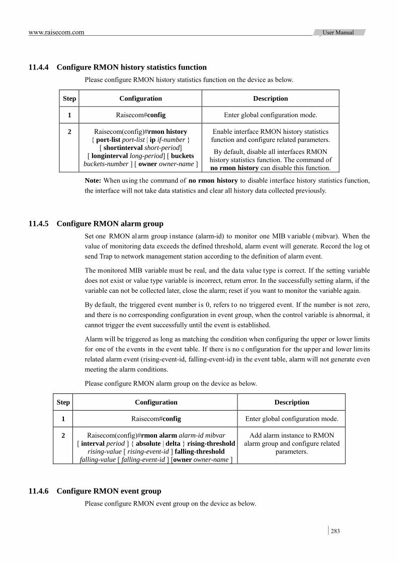
www.raisecom.com User Manual
283
11.4.4 Configure RMON history statistics function Please configure RMON history statistics function on the device as below.
Step Configuration Description
1 Raisecom#config Enter global configuration mode.
2 Raisecom(config)#rmon history { port-list port-list | ip if-number }
[ shortinterval short-period] [ longinterval long-period] [ buckets
buckets-number ] [ owner owner-name ]
Enable interface RMON history statistics function and configure related parameters.
By default, disable all interfaces RMON history statistics function. The command of no rmon history can disable this function.
Note: When using the command of no rmon history to disable interface history statistics function, the interface will not take data statistics and clear all history data collected previously.
11.4.5 Configure RMON alarm group Set one RMON alarm group instance (alarm-id) to monitor one MIB variable (mibvar). When the value of monitoring data exceeds the defined threshold, alarm event will generate. Record the log ot send Trap to network management station according to the definition of alarm event.
The monitored MIB variable must be real, and the data value type is correct. If the setting variable does not exist or value type variable is incorrect, return error. In the successfully setting alarm, if the variable can not be collected later, close the alarm; reset if you want to monitor the variable again.
By default, the triggered event number is 0, refers to no triggered event. If the number is not zero, and there is no corresponding configuration in event group, when the control variable is abnormal, it cannot trigger the event successfully until the event is established.
Alarm will be triggered as long as matching the condition when configuring the upper or lower limits for one of the events in the event table. If there is no c onfiguration for the upper and lower limits related alarm event (rising-event-id, falling-event-id) in the event table, alarm will not generate even meeting the alarm conditions.
Please configure RMON alarm group on the device as below.
Step Configuration Description
1 Raisecom#config Enter global configuration mode.
2 Raisecom(config)#rmon alarm alarm-id mibvar [ interval period ] { absolute | delta } rising-threshold
rising-value [ rising-event-id ] falling-threshold falling-value [ falling-event-id ] [owner owner-name ]
Add alarm instance to RMON alarm group and configure related
parameters.
11.4.6 Configure RMON event group Please configure RMON event group on the device as below.
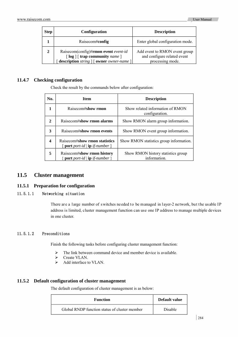
www.raisecom.com User Manual
284
Step Configuration Description
1 Raisecom#config Enter global configuration mode.
2 Raisecom(config)#rmon event event-id [ log ] [ trap community name ]
[ description string ] [ owner owner-name ]
Add event to RMON event group and configure related event
processing mode.
11.4.7 Checking configuration Check the result by the commands below after configuration:
No. Item Description
1 Raisecom#show rmon Show related information of RMON configuration.
2 Raisecom#show rmon alarms Show RMON alarm group information.
3 Raisecom#show rmon events Show RMON event group information.
4 Raisecom#show rmon statistics [ port port-id | ip if-number ]
Show RMON statistics group information.
5 Raisecom#show rmon history { port port-id | ip if-number }
Show RMON history statistics group information.
11.5 Cluster management
11.5.1 Preparation for configuration 11.5.1.1 Networking situation
There are a large number of switches needed to be managed in layer-2 ne twork, but the usable IP address is limited, cluster management function can use one IP address to manage multiple devices in one cluster.
11.5.1.2 Preconditions
Finish the following tasks before configuring cluster management function:
The link between command device and member device is available. Create VLAN. Add interface to VLAN.
11.5.2 Default configuration of cluster management The default configuration of cluster management is as below:
Function Default value
Global RNDP function status of cluster member Disable

www.raisecom.com User Manual
285
Function Default value
Interface RNDP function status of cluster member Enable
RTDP collection function status of cluster member Disable
The maximum collection range for cluster member RTDP 16 jumpers
Cluster management function status of command device Disable
The maximum member number of command device cluster management
128
Auto-active function status of candidate device Disable
MAC address of command device with candidate device auto-active function
0000.0000.0000
11.5.3 Configure RNDP function Please configure RNDP function on the device as below:
Step Configuration Description
1 Raisecom#config Enter global configuration mode.
2 Raisecom(config)#rndp enable (Optional) Enable global RNDP function.
3 Raisecom(config)#interface port port-id Enter physical layer interface configuration mode.
4 Raisecom(config-port)#rndp enable (Optional) Enable interface RNDP function.
11.5.4 Configure RTDP function Note: When configuring cluster VLAN, if the device is command device or member device, due to the cluster device has already confirmed cluster VLAN, then cluster VLAN configuration will lead to conflict and failure, exit cluster and configure successfully.
Please configure RTDP function on the device as below:
Step Configuration Description
1 Raisecom#config Enter global configuration mode.
2 Raisecom(config)#rtdp enable Enable global RTDP function.
3 Raisecom(config)#rtdp max-hop max-hop
(Optional) Configuration the maximum collectionrange for RTDP.
4 Raisecom(config)#cluster vlan vlan-id port-list port-list
(Optional) Configure cluster VLAN and interfacelist. The VLAN used by cluster
protocol packet communication has limited the range of cluster management.
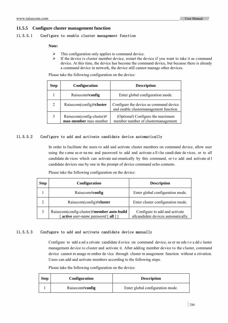
www.raisecom.com User Manual
286
11.5.5 Configure cluster management function 11.5.5.1 Configure to enable cluster management function
Note:
This configuration only applies to command device. If the device is cluster member device, restart the device if you want to take it as command
device. At this time, the device has become the command device, but because there is already a command device in network, the device still cannot manage other devices.
Please take the following configuration on the device:
Step Configuration Description
1 Raisecom#config Enter global configuration mode.
2 Raisecom(config)#cluster Configure the device as command device and enable clustermanagement function.
3 Raisecom(config-cluster)#max-member max-number
(Optional) Configure the maximum member number of clustermanagement.
11.5.5.2 Configure to add and activate candidate device automatically
In order to facilitate the users to add and activate cluster members on command device, allow user using the s ame us er na me and password to add and activate a ll t he candi date de vices, or to all candidate de vices which can activate aut omatically by this command, or t o add and activate al l candidate devices one by one in the prompt of device command echo contents.
Please take the following configuration on the device:
Step Configuration Description
1 Raisecom#config Enter global configuration mode.
2 Raisecom(config)#cluster Enter cluster configuration mode.
3 Raisecom(config-cluster)#member auto-build [ active user-name password [ all ] ]
Configure to add and activate allcandidate devices automatically.
11.5.5.3 Confugure to add and activate candidate device manually
Configure to add a nd a ctivate candidate d evice on command device, us er ne eds t o a dd c luster management device to cluster and activate it. After adding member device to the cluster, command device cannot m anage m ember de vice through cluster m anagement function without a ctivation. Users can add and activate members according to the following steps.
Please take the following configuration on the device:
Step Configuration Description
1 Raisecom#config Enter global configuration mode.

www.raisecom.com User Manual
287
Step Configuration Description
2 Raisecom(config)#cluster Enable cluster management function and enter cluster configuration mode.
3 Raisecom(config-cluster)#member mac-address active [ user-name
password ]
Configure to add candidate device to cluster and activate it. The command of no member
{all | mac-address} can delete all or specified cluster members. The command of member {all | mac-address} suspend can suspend all or specified cluster members.
11.5.5.4 Configure auto-active function
User must set MAC address for auto-active subordinated command device after setting auto-active function on candidate de vice, and t hen the candidate d evice can be act ivated automatically b y i ts subordinated command device if the command device is configured to add and activate all candidate members to cluster automatically when connecting the device to network.
Please take the following configuration on the device:
Step Configuration Description
1 Raisecom#config Enter global configuration mode.
2 Raisecom(config)#cluster-autoactive (Optional) Enable auto-active function.
3 Raisecom(config)#cluster-autoactive commander-mac mac-address
(Optional) Assign MAC address for auto-active command device.
11.5.5.5 Configure remote access member device
In c luster c onfiguration mode, us er can t ake r emote m anagement t o activated member de vices on command device. User can login activated cluster members according to the following steps.
Please take the following configuration on the device:
Step Configuration Description
1 Raisecom#config Enter global configuration mode.
2 Raisecom(config)#cluster Enter cluster configuration mode.
3 Raisecom(config-cluster)#rcommand { hostname [ mac-address ] | mac-address }
Login cluster member device.
11.5.6 Check configuration Check the result by the commands below after configuration:
No. Item Description
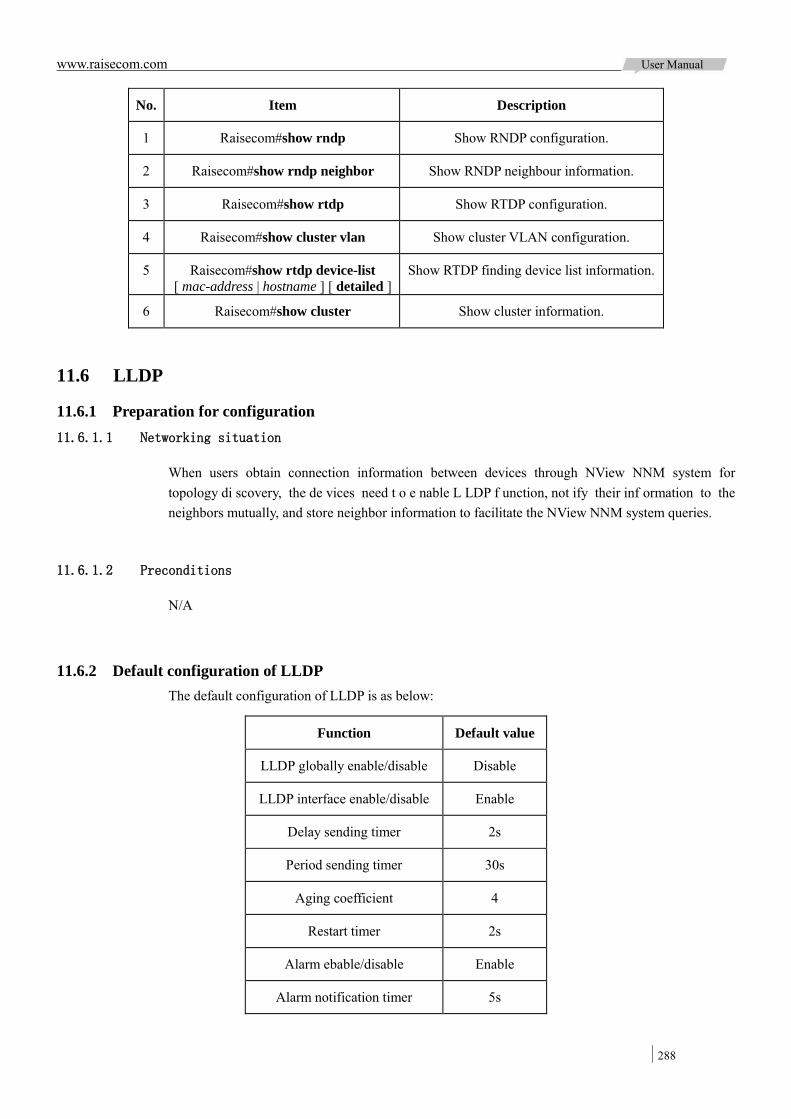
www.raisecom.com User Manual
288
No. Item Description
1 Raisecom#show rndp Show RNDP configuration.
2 Raisecom#show rndp neighbor Show RNDP neighbour information.
3 Raisecom#show rtdp Show RTDP configuration.
4 Raisecom#show cluster vlan Show cluster VLAN configuration.
5 Raisecom#show rtdp device-list [ mac-address | hostname ] [ detailed ]
Show RTDP finding device list information.
6 Raisecom#show cluster Show cluster information.
11.6 LLDP
11.6.1 Preparation for configuration 11.6.1.1 Networking situation
When users obtain connection information between devices through NView NNM system for topology di scovery, the de vices need t o e nable L LDP f unction, not ify their inf ormation to the neighbors mutually, and store neighbor information to facilitate the NView NNM system queries.
11.6.1.2 Preconditions
N/A
11.6.2 Default configuration of LLDP The default configuration of LLDP is as below:
Function Default value
LLDP globally enable/disable Disable
LLDP interface enable/disable Enable
Delay sending timer 2s
Period sending timer 30s
Aging coefficient 4
Restart timer 2s
Alarm ebable/disable Enable
Alarm notification timer 5s
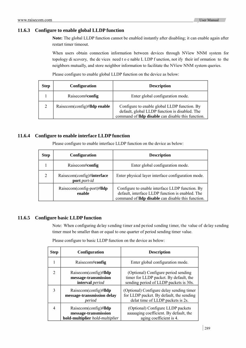
www.raisecom.com User Manual
289
11.6.3 Configure to enable global LLDP function Note: The global LLDP function cannot be enabled instantly after disabling; it can enable again after restart timer timeout.
When users obtain connection information between devices through NView NNM system for topology di scovery, the de vices need t o e nable L LDP f unction, not ify their inf ormation to the neighbors mutually, and store neighbor information to facilitate the NView NNM system queries.
Please configure to enable global LLDP function on the device as below:
Step Configuration Description
1 Raisecom#config Enter global configuration mode.
2 Raisecom(config)#lldp enable Configure to enable global LLDP function. By default, global LLDP function is disabled. The
command of lldp disable can disable this function.
11.6.4 Configure to enable interface LLDP function Please configure to enable interface LLDP function on the device as below:
Step Configuration Description
1 Raisecom#config Enter global configuration mode.
2 Raisecom(config)#interface port port-id
Enter physical layer interface configuration mode.
Raisecom(config-port)#lldp enable
Configure to enable interface LLDP function. By default, interface LLDP function is enabled. The
command of lldp disable can disable this function.
11.6.5 Configure basic LLDP function Note: When configuring delay sending t imer and period sending t imer, the value of delay sending timer must be smaller than or equal to one quarter of period sending timer value.
Please configure to basic LLDP function on the device as below:
Step Configuration Description
1 Raisecom#config Enter global configuration mode.
2 Raisecom(config)#lldp message-transmission
interval period
(Optional) Configure period sending timer for LLDP packet. By default, the sending period of LLDP packets is 30s.
3 Raisecom(config)#lldp message-transmission delay
period
(Optional) Configure delay sending timer for LLDP packet. By default, the sending
delat time of LLDP packets is 2s.
4 Raisecom(config)#lldp message-transmission
hold-multiplier hold-multiplier
(Optional) Configure LLDP packets aaaaaging coefficient. By default, the
aging coefficient is 4.

www.raisecom.com User Manual
290
Step Configuration Description
5 Raisecom(config)#lldp restart-delay period
(Optional) Configure restart timer. The device can enable global LLDP function again after restart time when disabling global LLDP function. By default, the
restart time is 2s.
11.6.6 Configure LLDP alarm function Enable LLDP alarm notification function to send topology information update alarm to Nview NNM system when the network changes.
Please configure LLDP alarm function on the device as below:
Step Configuration Description
1 Raisecom#config Enter global configuration mode.
2 Raisecom(config)#snmp-server lldp-trap enable
Enable LLDP alarm function.
3 Raisecom(config)#lldp trap-interval period
(Optional) Configure LLDP alarm Trap period sending timer. By default, The LLDP alarm Trap
sending period is 5s.
11.6.7 Check configuration Check the result by the commands below after configuration:
No. Item Description
1 Raisecom#show lldp local config Show LLDP local configuration.
2 Raisecom#show lldp local system-data [ port port-id ]
Show LLDP local system information.
3 Raisecom#show lldp remote [ port port-id ][ detail ]
Show LLDP neighbor information.
4 Raisecom#show lldp statistic [ port port-id ]
Show LLDP packet statistics information.
11.7 Optical module digital diagnostics
11.7.1 Preparation for configuration 11.7.1.1 Networking situation
Fault di agnostics f unction of opt ical m odule pr ovides a detection m ethod to SFP pe rformation parameters; user can predict t he s ervice l ife of opt ical m odule, isolate s ystem f ault and check its compatibility during installation through analyzing the monitoring data.
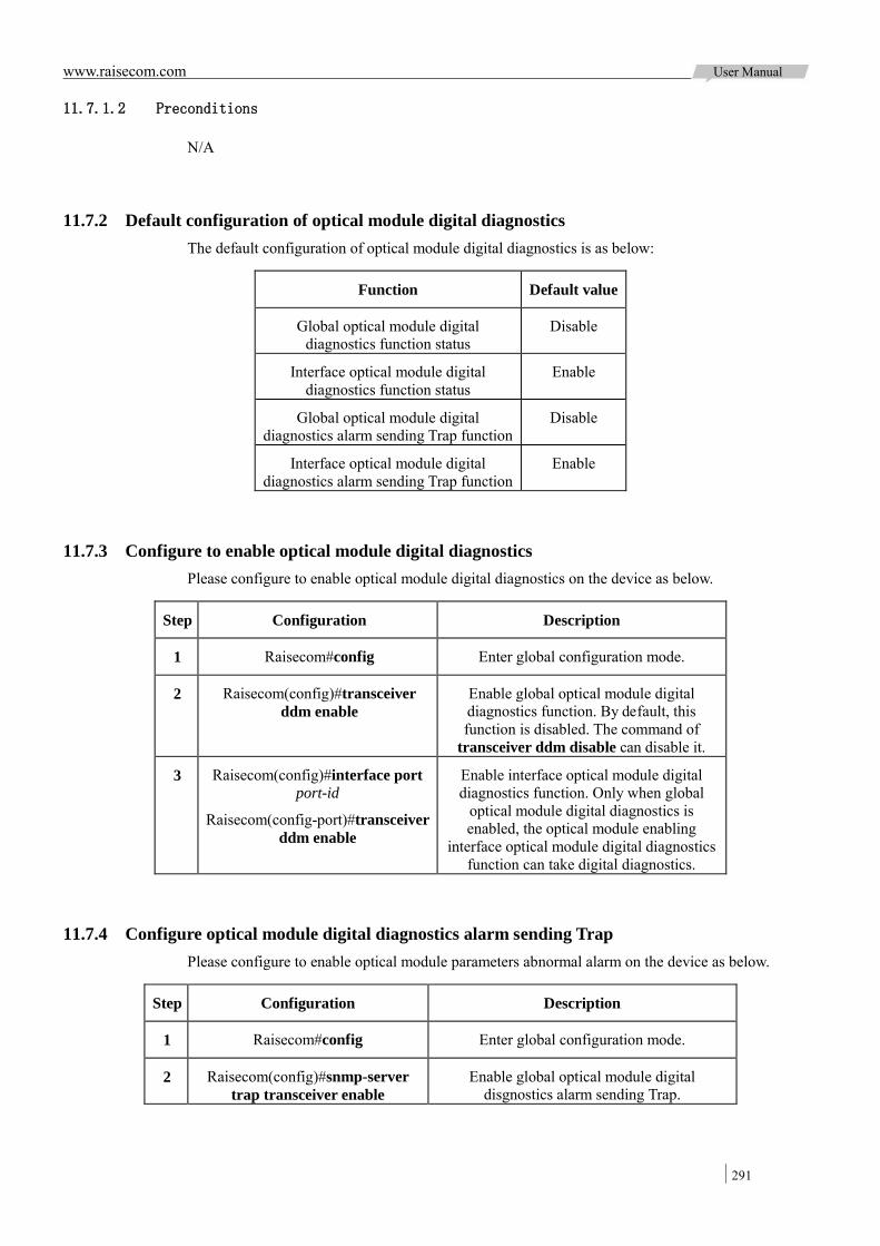
www.raisecom.com User Manual
291
11.7.1.2 Preconditions
N/A
11.7.2 Default configuration of optical module digital diagnostics The default configuration of optical module digital diagnostics is as below:
Function Default value
Global optical module digital diagnostics function status
Disable
Interface optical module digital diagnostics function status
Enable
Global optical module digital diagnostics alarm sending Trap function
Disable
Interface optical module digital diagnostics alarm sending Trap function
Enable
11.7.3 Configure to enable optical module digital diagnostics Please configure to enable optical module digital diagnostics on the device as below.
Step Configuration Description
1 Raisecom#config Enter global configuration mode.
2 Raisecom(config)#transceiver ddm enable
Enable global optical module digital diagnostics function. By default, this function is disabled. The command of
transceiver ddm disable can disable it.
3 Raisecom(config)#interface port port-id
Raisecom(config-port)#transceiver ddm enable
Enable interface optical module digital diagnostics function. Only when global
optical module digital diagnostics is enabled, the optical module enabling
interface optical module digital diagnostics function can take digital diagnostics.
11.7.4 Configure optical module digital diagnostics alarm sending Trap Please configure to enable optical module parameters abnormal alarm on the device as below.
Step Configuration Description
1 Raisecom#config Enter global configuration mode.
2 Raisecom(config)#snmp-server trap transceiver enable
Enable global optical module digital disgnostics alarm sending Trap.
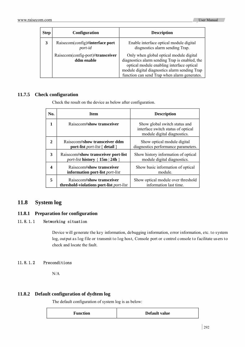
www.raisecom.com User Manual
292
Step Configuration Description
3 Raisecom(config)#interface port port-id
Raisecom(config-port)#transceiver ddm enable
Enable interface optical module digital disgnostics alarm sending Trap.
Only when global optical module digital diagnostics alarm sending Trap is enabled, the
optical module enabling interface optical module digital diagnostics alarm sending Trap function can send Trap when alarm generates.
11.7.5 Check configuration Check the result on the device as below after configuration.
No. Item Description
1 Raisecom#show transceiver Show global switch status and interface switch status of optical
module digital diagnostics.
2 Raisecom#show transceiver ddm port-list port-list [ detail ]
Show optical module digital diagnostics performance parameters.
3 Raisecom#show transceiver port-list port-list history { 15m | 24h }
Show history information of optical module digital diagnostics.
4 Raisecom#show transceiver information port-list port-list
Show basic information of optical module.
5 Raisecom#show transceiver threshold-violations port-list port-list
Show optical module over threshold information last time.
11.8 System log
11.8.1 Preparation for configuration 11.8.1.1 Networking situation
Device will generate the key information, debugging information, error information, etc. to system log, output as log f ile or t ransmit to log host, Console port or control console to facilitate users to check and locate the fault.
11.8.1.2 Preconditions
N/A
11.8.2 Default configuration of dydtem log The default configuration of system log is as below:
Function Default value
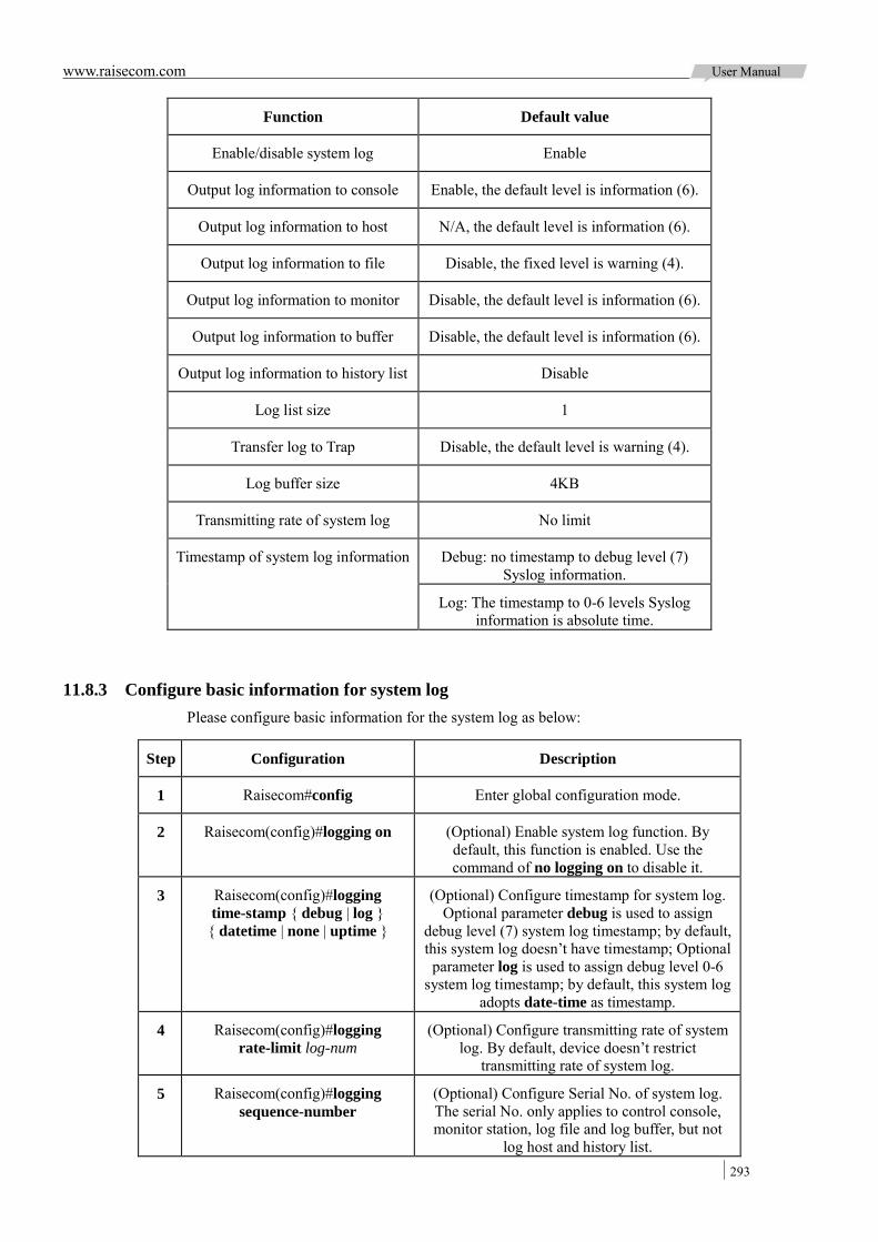
www.raisecom.com User Manual
293
Function Default value
Enable/disable system log Enable
Output log information to console Enable, the default level is information (6).
Output log information to host N/A, the default level is information (6).
Output log information to file Disable, the fixed level is warning (4).
Output log information to monitor Disable, the default level is information (6).
Output log information to buffer Disable, the default level is information (6).
Output log information to history list Disable
Log list size 1
Transfer log to Trap Disable, the default level is warning (4).
Log buffer size 4KB
Transmitting rate of system log No limit
Timestamp of system log information Debug: no timestamp to debug level (7) Syslog information.
Log: The timestamp to 0-6 levels Syslog information is absolute time.
11.8.3 Configure basic information for system log Please configure basic information for the system log as below:
Step Configuration Description
1 Raisecom#config Enter global configuration mode.
2 Raisecom(config)#logging on (Optional) Enable system log function. By default, this function is enabled. Use the command of no logging on to disable it.
3 Raisecom(config)#logging time-stamp { debug | log } { datetime | none | uptime }
(Optional) Configure timestamp for system log. Optional parameter debug is used to assign
debug level (7) system log timestamp; by default, this system log doesn’t have timestamp; Optional parameter log is used to assign debug level 0-6
system log timestamp; by default, this system log adopts date-time as timestamp.
4 Raisecom(config)#logging rate-limit log-num
(Optional) Configure transmitting rate of system log. By default, device doesn’t restrict
transmitting rate of system log.
5 Raisecom(config)#logging sequence-number
(Optional) Configure Serial No. of system log. The serial No. only applies to control console, monitor station, log file and log buffer, but not
log host and history list.

www.raisecom.com User Manual
294
Step Configuration Description
6 Raisecom(config)#logging discriminator
distriminator-number { facility | mnemonics | msg-body } { drops
| includes | none } key
(Optional) Create and configure system log filter. The filter can filter output log from control
console, monitor station, log file and log buffer.
11.8.4 Configure system log output Please configure system log output on the device as below.
Step Configuration Description
1 Raisecom#config Enter global configuration mode.
2 Raisecom(config)#logging console [ log-level | alerts | critical | debugging | emergencies | errors
| informational | notifications | warnings | distriminator distriminator-number ]
(Optional) Configure system log output direction as Console.
3 Raisecom(config)#logging host ip-address [ log-level | alerts | critical | debugging |
emergencies | errors | informational | notifications | warnings | distriminator distriminator-number ]
(Optional) Configure system log output direction as log host. It can configure 10
log hosts at most.
Raisecom(config)#logging facility { alert | audit | | auth | clock | cron | daemon | ftp | kern | local0 | local1 | local2 | local3 | local4 | local5 | local6 |
local7 | lpr | mail | news | ntp | sercurity | syslog | user | uucp }
(Optional) Configure log information facility field sent to log host. The
precondition is system has created log host, or the configuration will fail. This configuration applies to all log hosts on
the device.
4 Raisecom(config)#logging monitor [ log-level | alerts | critical | debugging | emergencies | errors |
informational | notifications | warnings | distriminator distriminator-number ]
(Optional) Configure system log output direction as monitor.
5 Raisecom(config)#logging file [ discriminator discriminateor-number ]
(Optional) Configure system log output direction as Flash. The heavy level is
fixed as warning (4), not allow configuring.
6 Raisecom(config)#logging buffered [ log-level | alerts | critical | debugging | emergencies | errors
| informational | notifications | warnings | distriminator distriminator-number ]
(Optional) Configure log buffer size.
Raisecom(config)#logging buffered size size (Optional) Configure system log output direction as history list.
The output information is transferred to Trap level.
7 Raisecom(config)#logging history (Optional) Configure system log output direction as buffer.
Raisecom(config)#logging history size size (Optional) Configure log history list size.
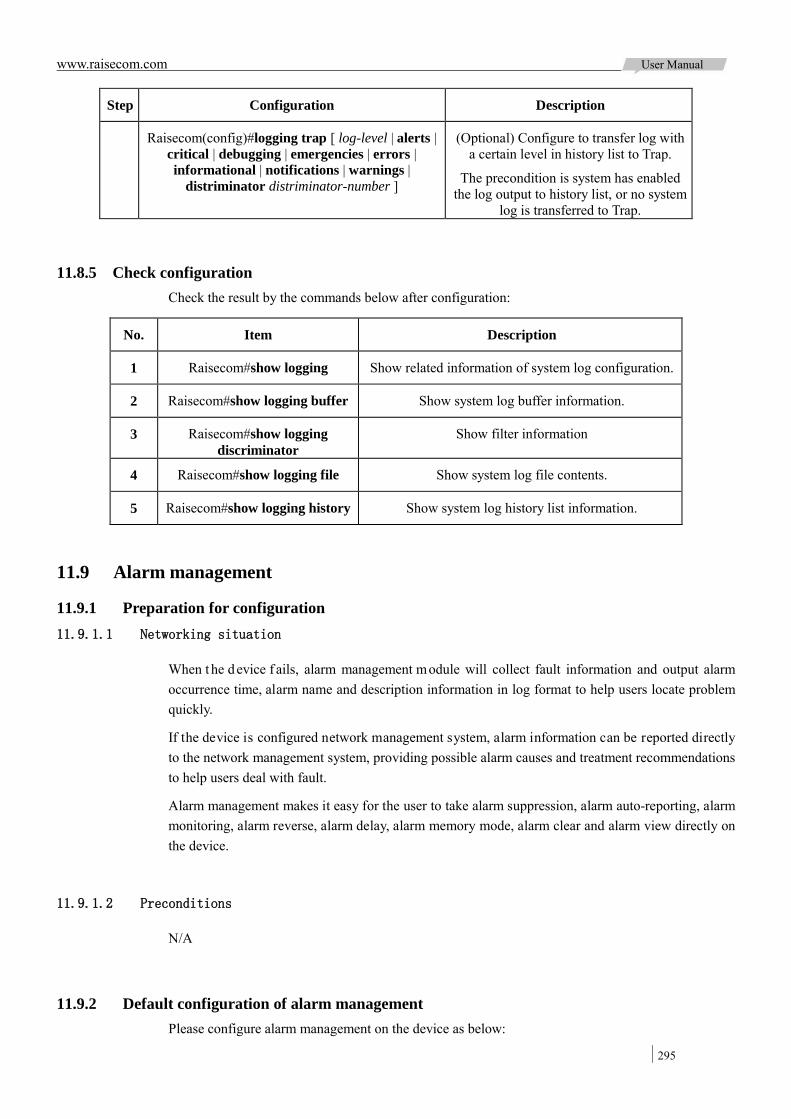
www.raisecom.com User Manual
295
Step Configuration Description
Raisecom(config)#logging trap [ log-level | alerts | critical | debugging | emergencies | errors | informational | notifications | warnings |
distriminator distriminator-number ]
(Optional) Configure to transfer log with a certain level in history list to Trap.
The precondition is system has enabled the log output to history list, or no system
log is transferred to Trap.
11.8.5 Check configuration Check the result by the commands below after configuration:
No. Item Description
1 Raisecom#show logging Show related information of system log configuration.
2 Raisecom#show logging buffer Show system log buffer information.
3 Raisecom#show logging discriminator
Show filter information
4 Raisecom#show logging file Show system log file contents.
5 Raisecom#show logging history Show system log history list information.
11.9 Alarm management
11.9.1 Preparation for configuration 11.9.1.1 Networking situation
When t he d evice f ails, alarm management module will collect fault information and output alarm occurrence time, alarm name and description information in log format to help users locate problem quickly.
If the device is configured network management system, alarm information can be reported directly to the network management system, providing possible alarm causes and treatment recommendations to help users deal with fault.
Alarm management makes it easy for the user to take alarm suppression, alarm auto-reporting, alarm monitoring, alarm reverse, alarm delay, alarm memory mode, alarm clear and alarm view directly on the device.
11.9.1.2 Preconditions
N/A
11.9.2 Default configuration of alarm management Please configure alarm management on the device as below:
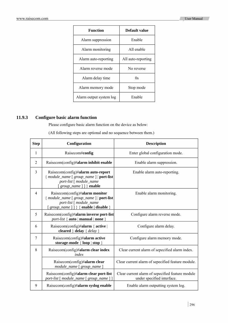
www.raisecom.com User Manual
296
Function Default value
Alarm suppression Enable
Alarm monitoring All enable
Alarm auto-reporting All auto-reporting
Alarm reverse mode No reverse
Alarm delay time 0s
Alarm memory mode Stop mode
Alarm output system log Enable
11.9.3 Configure basic alarm function Please configure basic alarm function on the device as below:
(All following steps are optional and no sequence between them.)
Step Configuration Description
1 Raisecom#config Enter global configuration mode.
2 Raisecom(config)#alarm inhibit enable Enable alarm suppression.
3 Raisecom(config)#alarm auto-report { module_name [ group_name ] | port-list
port-list [ module_name [ group_name ] ] } enable
Enable alarm auto-reporting.
4 Raisecom(config)#alarm monitor { module_name [ group_name ] | port-list
port-list [ module_name [ group_name ] ] } { enable | disable }
Enable alarm monitoring.
5 Raisecom(config)#alarm inverse port-list port-list { auto | manual | none }
Configure alarm reverse mode.
6 Raisecom(config)#alarm { active | cleared } delay { delay }
Configure alarm delay.
7 Raisecom(config)#alarm active storage-mode { loop | stop }
Configure alarm memory mode.
8 Raisecom(config)#alarm clear index index
Clear current alarm of sepecified alarm index.
Raisecom(config)#alarm clear module_name [ group_name ]
Clear current alarm of sepecified feature module.
Raisecom(config)#alarm clear port-list port-list [ module_name [ group_name ] ]
Clear current alarm of sepecified feature module under specified interface.
9 Raisecom(config)#alarm syslog enable Enable alarm outputting system log.
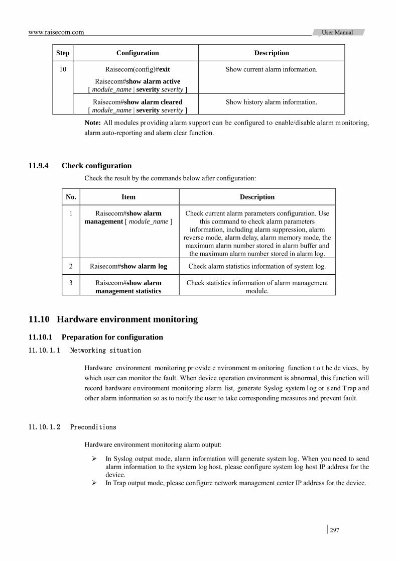
www.raisecom.com User Manual
297
Step Configuration Description
10 Raisecom(config)#exit
Raisecom#show alarm active [ module_name | severity severity ]
Show current alarm information.
Raisecom#show alarm cleared [ module_name | severity severity ]
Show history alarm information.
Note: All modules providing alarm support can be configured to enable/disable a larm monitoring, alarm auto-reporting and alarm clear function.
11.9.4 Check configuration Check the result by the commands below after configuration:
No. Item Description
1 Raisecom#show alarm management [ module_name ]
Check current alarm parameters configuration. Use this command to check alarm parameters
information, including alarm suppression, alarm reverse mode, alarm delay, alarm memory mode, the maximum alarm number stored in alarm buffer and
the maximum alarm number stored in alarm log.
2 Raisecom#show alarm log Check alarm statistics information of system log.
3 Raisecom#show alarm management statistics
Check statistics information of alarm management module.
11.10 Hardware environment monitoring
11.10.1 Preparation for configuration 11.10.1.1 Networking situation
Hardware environment monitoring pr ovide e nvironment m onitoring function t o t he de vices, by which user can monitor the fault. When device operation environment is abnormal, this function will record hardware environment monitoring alarm list, generate Syslog system log or s end Trap and other alarm information so as to notify the user to take corresponding measures and prevent fault.
11.10.1.2 Preconditions
Hardware environment monitoring alarm output:
In Syslog output mode, alarm information will generate system log. When you need to send alarm information to the system log host, please configure system log host IP address for the device.
In Trap output mode, please configure network management center IP address for the device.

www.raisecom.com User Manual
298
11.10.2 Default configuration of hardware environment monitoring The default configuration of hardware environment monitoring is as below:
Function Default value
Global hardware environment monitoringalarm Syslog output
Disable
Global hardware environment monitoringalarm Trap output
Disable
Power down event alarm Enable Trap output function
Enable Syslog system log output function Temperature alarm output
Voltage alarm output
Interface link-down event alarm output
Interface link-fault event alarm Disable Trap output function
Disable Syslog system log output function Interface not-forwarding event alarm output
High temperature alarm threshold 60ºC
Low temperature alarm threshold 20ºC
High voltage threshold 3450mV
Low voltage threshold 3150mV
11.10.3 Configure to enable global hardware environment monitoring Please take the following configuration on the device:
Step Configuration Description
1 Raisecom#config Enter global configuration mode.
2 Raisecom(config)#logging alarm (Optional) Configure to enable global hardware environment monitoring alarm Syslog output.
3 Raisecom(config)#snmp-server alarm-trap enable
(Optional) Configure to enable global hardware environment monitoring alarm Trap output.
Note:
When enabling global ha rdware environment monitoring a larm S yslog output, a larm e vent can generate syslog only when Syslog output under alarm event is also enabled.
When e nabling gl obal ha rdware e nvironment monitoring a larm s ending T rap, a larm e vent can send Trap only when Trap output under alarm event is also enabled.
11.10.4 Configure power monitoring alarm Please take the following configuration on the device:

www.raisecom.com User Manual
299
Step Configuration Description
1 Raisecom#config Enter global configuration mode.
2 Raisecom(config)#alarm power-supply { notifies | syslog }
Enable power monitoring alarm output and configure power monitoring alarm output mode.
11.10.5 Configure temperature monitoring alarm Please take the following configuration on the device:
Step Configuration Description
1 Raisecom#config Enter global configuration mode.
2 Raisecom(config)#alarm temperature { high high-value | low low-value | notifies | syslog }
Enable temperature alarm output and configure temperature alarm output mode or temperature
alarm threshold.
High temperature threshold high-value must be higher than low temperature threshold low-value.
Low temperature threshold low-value must be lower than high temperature threshold high-value.
11.10.6 Configure voltage monitoring alarm Please take the following configuration on the device:
Step Configuration Description
1 Raisecom#config Enter global configuration mode.
2 Raisecom(config)#alarm voltage { high high-value | low low-value
| notifies | syslog }
Enable voltage alarm output and configure voltage alarm output
mode or voltage alarm threshold.
Note: the device is only in support of 3.3V master chip voltage.
11.10.7 Configure interface status monitoring alarm Please take the following configuration on the device:
Step Configuration Description
1 Raisecom#config Enter global configuration mode.
2 Raisecom(config)#alarm port { link-down | link-fault |
not-forwarding } { notifies | syslog } port-list port-list
Enable interface status alarm output and configure interface status alarm output mode.

www.raisecom.com User Manual
300
11.10.8 Clear all hareware environments monitoring alarm event manually Please take the following configuration on the device:
Step Configuration Description
1 Raisecom#config Enter global configuration mode.
2 Raisecom(config)#clear alarm Configure to clear alarm manually.
Execute this command to clear all alarm information in current alarm list and generate an all-alarm type
alarm information in history alarm list.
If enabling global sending Trap, the all-alarm alarm infoemation will be output in Trap mode; if enabling global Syslog, the all-alarm alarm information will
be output in Syslog mode.
11.10.9 Check configuration Check the result by the commands below after configuration:
No. Item Description
1 Raisecom#show alarm Show global hardware environment monitoring alarm configuration.
Use this command to check hardware environment monitoring information, including
global alarm Syslog output, global sending Trap, power down alarm, temperature alarm
and voltage alarm.
2 Raisecom#show alarm port-list port-list Show interface status alarm information.
3 Raisecom#show alarm currrent Show current alarm information of hardware environment monitoring.
4 Raisecom#show alarm history Show history alarm information of hardware environment monitoring.
5 Raisecom#show environment [ power | temperature | voltage ]
Show the current power, temperature, voltage alarm and the current environment information.
6 Raisecom#show power-card Show power type and serial No. of the device.
11.11 Fan monitor
11.11.1 Preparation for configuration 11.11.1.1 Networking situation
When putting I SCOM2924GF in very hot environment, t he high temperature may influent he at exhausting performance of the device, then configure fan monitor function to make the device adjust temperature automatically according t o e nvironment t emperature a nd m aintain nor mal r unning of device.

www.raisecom.com User Manual
301
11.11.1.2 Preconditions
N/A
11.11.2 Configure fan monitor function Please configure fan monitor function on the device as below.
Step Configuration Description
1 Raisecom#config Enter global configuration mode.
2 Raisecom(config)#fan-monitor mode { auto | enforce }
Configure monitor mode for fan rotate speed. By default, fan monitor mode is auto.
3 Raisecom(config)#fan-monitor enforce level level (Optional) Configure fan rotate speed in force monitor mode.
4 Raisecom(config)#fan-monitor temperature-scale temperature1 temperature2 temperature3
(Optional) configure temperature range corresponding to different rotate scale in
auto monitor mode.
11.11.3 Check configuration Check the result by the commands below after configuration:
No. Item Description
1 Raisecom#show fan-monitor information Show related information of fan monitor configuration.
2 Raisecom#show fan-monitor status Show current fan status information.
11.12 CPU monitor
11.12.1 Preparation for configuration 11.12.1.1 Networking situation
CPU monitor can give real-time monitoring to task state, CPU utilization rate and stack usage in the system, provide CPU ut ilization rate threshold alarm, detect and eliminate hidden dangers, or help administrator for fault location.
11.12.1.2 Preconditions
Finish the following task before configuring CPU monitor:
When the CPU monitor alarm information needs to be output in Trap mode, configure Trap output target host address on the device, which is IP address of network management center.

www.raisecom.com User Manual
302
11.12.2 Defaut configuration of CPU monitor The default configuration of CPU monitor is as below:
Function Default value
CPU utilization rate alarm Trap output Disable
Upper threshold of CPU utilization rate alarm 100%
Lower threshold of CPU utilization rate alarm 1%
Sampling period of CPU utilization rate 60s
11.12.3 Check CPU monitor information Please configure the CPU monitor on the device as below:
Step Configuration Description
1 Raisecom#show cpu-utilization [ dynamic | history { 10min | 1min | 2hour | 5sec } ]
Check CPU utilization rate.
2 Raisecom#show process [ dead | sorted { normal-priority | process-name } | taskname ]
Check task status.
3 Raisecom#show process cpu [ sorted [ 10min | 1min | 5sec | invoked ] ]
Check CPU utilization rate of all tasks.
11.12.4 Configure CPU monitor alarm Please configure the CPU monitor alarm on the device as below:
Step Configuration Description
1 Raisecom#config Enter global configuration mode.
2 Raisecom(config)#snmp-server traps enable cpu-threshold
Enable CPU threshold alarm sending Trap.
3 Raisecom(config)#cpu rising-threshold
rising-threshold-value [ falling-threshold
falling-threshold-value ] [ interval interval-value ]
(Optional) Configure upper threshold, lower threshold and sampling time interval for CPU alarm. The upper
threshold must be greater than lower threshold.
After enabling CPU threshold alarm sending Trap. In specified sampling period, the system will send alarm Trap automatically when the CPU utilization rate is
over upper threshold or below lower threshold.
11.12.5 Check configuration Check the result by the commands below after configuration:
No. Item Description

www.raisecom.com User Manual
303
No. Item Description
1 Raisecom#show cpu-utilization Check CPU utilization and related configuration information.
11.13 Check device information
Please configure the device as below:
Step Configuration Description
1 Raisecom#show version Check the device version.
2 Raisecom#show running-config Check the current configuration file.
3 Raisecom#show clock Check system time.
4 Raisecom#show environment [ power | temperature | voltage ]
Check the current power, temperature, and voltage.
5 Raisecom#show power-card Check the power type and serial No.
11.14 Ping
Please configure Ping function on the device as below:
Step Configuration Description
1 Raisecom#ping ip-address [ count count ] [ size size ] [ waittime period]
(Optional) Test IPv4 network connection by the command of Ping.
2 Raisecom#ping ipv6 ipv6-address [ count count ] [ size size ] [ waittime period ]
(Optional) Test IPv6 network connection by the command of Ping.
Note: The device c annot perform ot her operations in the pr ocess of Ping. It can perform other operations only when Ping is finished or break off Ping through "ctrl + c".
11.15 Traceroute
Configure the IP address an d default ga teway f or ISCOM2924GF de vice be fore us ing Traceroute function.
Please configure Traceroute function on the device as below:
Step Configuration Description
1 Raisecom#config Enter global configuration mode.
2 Raisecom(config)#interface ip if-number Enter layer-3 interface configuration mode.
3 Raisecom(config-ip)#ip address ip-address [ ip-mask ] vlan-id
Configure interface IP address.
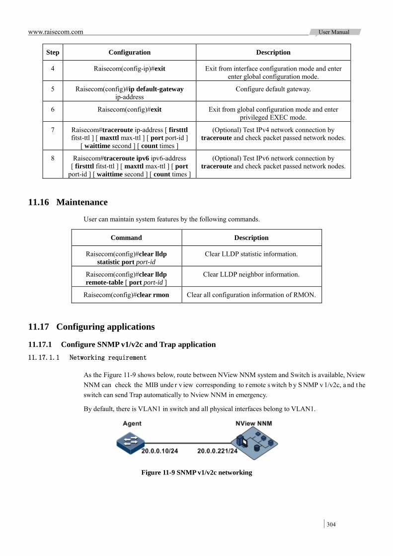
www.raisecom.com User Manual
304
Step Configuration Description
4 Raisecom(config-ip)#exit Exit from interface configuration mode and enter enter global configuration mode.
5 Raisecom(config)#ip default-gateway ip-address
Configure default gateway.
6 Raisecom(config)#exit Exit from global configuration mode and enter privileged EXEC mode.
7 Raisecom#traceroute ip-address [ firstttl fitst-ttl ] [ maxttl max-ttl ] [ port port-id ]
[ waittime second ] [ count times ]
(Optional) Test IPv4 network connection by traceroute and check packet passed network nodes.
8 Raisecom#traceroute ipv6 ipv6-address [ firstttl fitst-ttl ] [ maxttl max-ttl ] [ port
port-id ] [ waittime second ] [ count times ]
(Optional) Test IPv6 network connection by traceroute and check packet passed network nodes.
11.16 Maintenance
User can maintain system features by the following commands.
Command Description
Raisecom(config)#clear lldp statistic port port-id
Clear LLDP statistic information.
Raisecom(config)#clear lldp remote-table [ port port-id ]
Clear LLDP neighbor information.
Raisecom(config)#clear rmon Clear all configuration information of RMON.
11.17 Configuring applications
11.17.1 Configure SNMP v1/v2c and Trap application 11.17.1.1 Networking requirement
As the Figure 11-9 shows below, route between NView NNM system and Switch is available, Nview NNM can check the MIB unde r v iew corresponding to r emote s witch b y S NMP v 1/v2c, a nd t he switch can send Trap automatically to Nview NNM in emergency.
By default, there is VLAN1 in switch and all physical interfaces belong to VLAN1.
Figure 11-9 SNMP v1/v2c networking

www.raisecom.com User Manual
305
11.17.1.2 Configuration steps
Configure IP address for Switch.
Raisecom#config
Raisecom(config)#interface ip 0
Raisecom(config-ip)#ip address 20.0.0.10 255.255.255.0 1
Raisecom(config-ip)#exit
Configure SNMP v1/v2c view.
Raisecom(config)#snmp-server view mib2 1.3.6.1.2.1 included
Configure SNMP v1/v2c community.
Raisecom(config)#snmp-server community raisecom view mib2 ro
Configure Trap alarm.
Raisecom(config)#snmp-server enable traps
Raisecom(config)#snmp-server host 20.0.0.221 version 2c raisecom
11.17.1.3 Show result
Check IP address configuration by show interface ip.
Raisecom#show interface ip
IF Address NetMask Source Catagory
----------------------------------------------------------
0 20.0.0.10 255.255.255.0 assigned primary
Check view configuration by show snmp view.
Raisecom(config)#show snmp view
Index: 0
View Name: mib2
OID Tree: 1.3.6.1.2.1
Mask: --
Type: include
…
Check community configuration by show snmp-server community.
Raisecom#show snmp community
Index Community Name View Name Permission
------------------------------------------------------------
1 private internet rw
2 public internet ro
3 raisecom mib2 ro
Check target host configuration by show snmp host.
Raisecom#show snmp host
Index: 0
IP family: IPv4
IP address: 20.0.0.221
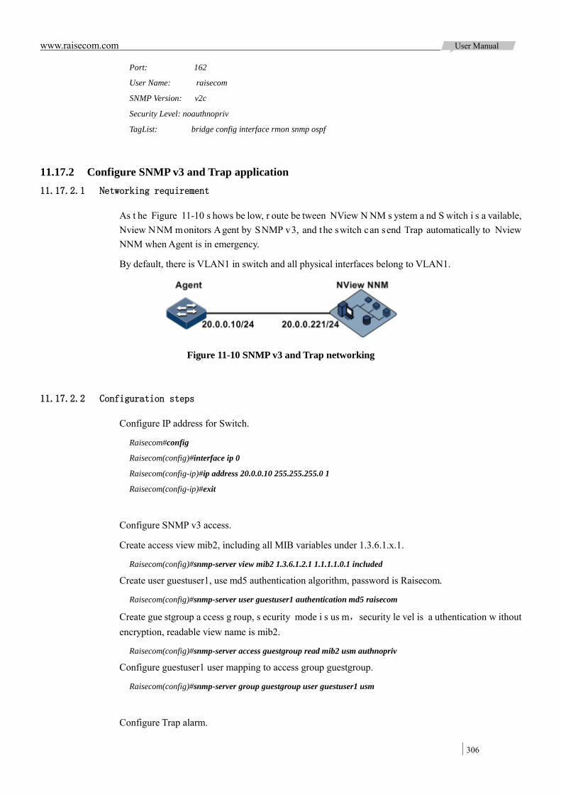
www.raisecom.com User Manual
306
Port: 162
User Name: raisecom
SNMP Version: v2c
Security Level: noauthnopriv
TagList: bridge config interface rmon snmp ospf
11.17.2 Configure SNMP v3 and Trap application 11.17.2.1 Networking requirement
As t he Figure 11-10 s hows be low, r oute be tween NView N NM s ystem a nd S witch i s a vailable, Nview NNM monitors Agent by SNMP v3, and the switch can send Trap automatically to Nview NNM when Agent is in emergency.
By default, there is VLAN1 in switch and all physical interfaces belong to VLAN1.
Figure 11-10 SNMP v3 and Trap networking
11.17.2.2 Configuration steps
Configure IP address for Switch.
Raisecom#config
Raisecom(config)#interface ip 0
Raisecom(config-ip)#ip address 20.0.0.10 255.255.255.0 1
Raisecom(config-ip)#exit
Configure SNMP v3 access.
Create access view mib2, including all MIB variables under 1.3.6.1.x.1.
Raisecom(config)#snmp-server view mib2 1.3.6.1.2.1 1.1.1.1.0.1 included
Create user guestuser1, use md5 authentication algorithm, password is Raisecom.
Raisecom(config)#snmp-server user guestuser1 authentication md5 raisecom
Create gue stgroup a ccess g roup, s ecurity mode i s us m,security le vel is a uthentication w ithout encryption, readable view name is mib2.
Raisecom(config)#snmp-server access guestgroup read mib2 usm authnopriv
Configure guestuser1 user mapping to access group guestgroup.
Raisecom(config)#snmp-server group guestgroup user guestuser1 usm
Configure Trap alarm.

www.raisecom.com User Manual
307
Raisecom(config)#snmp-server enable traps
Raisecom(config)#snmp-server host 20.0.0.221 version 3 authnopriv guestuser1
11.17.2.3 Show result
Check SNMP access group configuration by show snmp access.
Raisecom#show snmp access
…
Index: 1
Group: guestgroup
Security Model: usm
Security Level: authnopriv
Context Prefix: --
Context Match: exact
Read View: mib2
Write View: --
Notify View: internet
…
Check the mapping relationship configuration between user and access group by show snmp group.
Raisecom#show snmp group
Index GroupName UserName SecModel
-----------------------------------------------------------
0 initialnone none usm
1 initial md5nopriv usm
2 initial shanopriv usm
3 guestgroup guestuser1 usm
Check Trap target host configuration by show snmp host.
Raisecom#show snmp host
Index: 0
IP family: IPv4
IP address: 20.0.0.221
Port: 162
User Name: guestuser1
SNMP Version: v3
Security Level: authnopriv
TagList: bridge config interface rmon snmp ospf
11.17.3 Configure KeepAlive application 11.17.3.1 Networking requirement
As the Figure 11-11 shows below, the IP address of switch is 192.168.1.2, Trap target host address of SNMPv2c is 1 92.168.1.1, read a nd w rite c ommunity na me i s publ ic, S NMP v ersion i s v 2c. Configure time interval sending KeepAlive Trap from switch to SNMP network management station
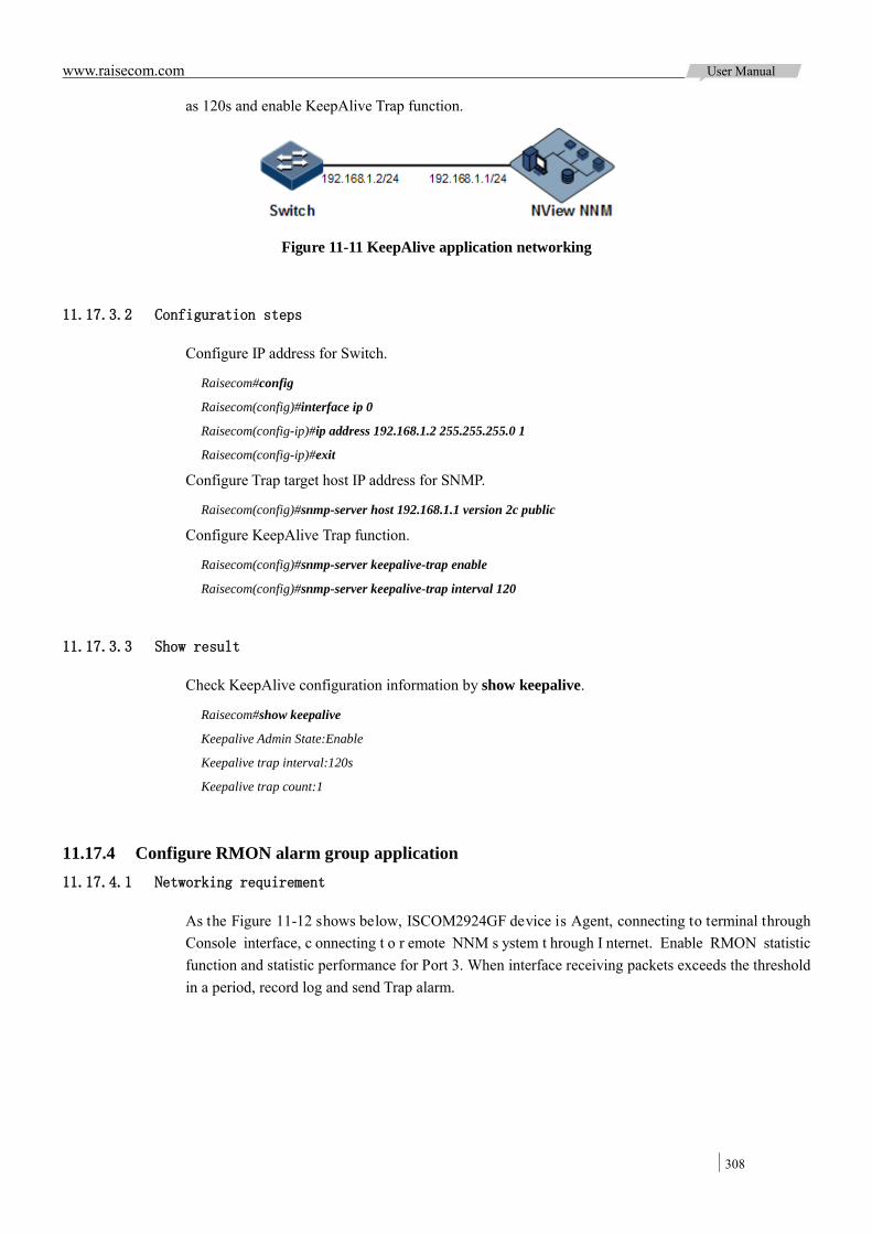
www.raisecom.com User Manual
308
as 120s and enable KeepAlive Trap function.
Figure 11-11 KeepAlive application networking
11.17.3.2 Configuration steps
Configure IP address for Switch.
Raisecom#config
Raisecom(config)#interface ip 0
Raisecom(config-ip)#ip address 192.168.1.2 255.255.255.0 1
Raisecom(config-ip)#exit
Configure Trap target host IP address for SNMP.
Raisecom(config)#snmp-server host 192.168.1.1 version 2c public
Configure KeepAlive Trap function.
Raisecom(config)#snmp-server keepalive-trap enable
Raisecom(config)#snmp-server keepalive-trap interval 120
11.17.3.3 Show result
Check KeepAlive configuration information by show keepalive.
Raisecom#show keepalive
Keepalive Admin State:Enable
Keepalive trap interval:120s
Keepalive trap count:1
11.17.4 Configure RMON alarm group application 11.17.4.1 Networking requirement
As the Figure 11-12 shows below, ISCOM2924GF device is Agent, connecting to terminal through Console interface, c onnecting t o r emote NNM s ystem t hrough I nternet. Enable RMON statistic function and statistic performance for Port 3. When interface receiving packets exceeds the threshold in a period, record log and send Trap alarm.

www.raisecom.com User Manual
309
Figure 11-12 RMON application networking
11.17.4.2 Configuration steps
Create e vent w ith index I D 10, us ed t o r ecord a nd s end l og information with description s tring High-ifOutErrors, the owner of log information is system.
Raisecom#config
Raisecom(config)#rmon event 1 log description High-ifOutErrors owner system
Create a larm i tem w ith i ndex I D 1 0, used t o m onitor M IB variables 1.3.6.1.2.1.2.2.1.20.1, c heck every 20 seconds, if the variable increases over 15, the Trap alarm is triggered, the owner of alarm information is also system.
Raisecom(config)#rmon alarm 10 1.3.6.1.2.1.2.2.1.20.1 interval 20 delta rising-threshold 15 1 falling-threshold 0 owner system
11.17.4.3 Show result
Check w hether t here i s e vent gr oup i nformation on t he de vice by t he c ommand of show rmon alarms.
Raisecom#show rmon alarms
Alarm 10 is active, owned by system
Monitors 1.3.6.1.2.1.2.2.1.20.1 every 20 seconds
Taking delta samples, last value was 0
Rising threshold is 15, assigned to event 1
Falling threshold is 0, assigned to event 0
On startup enable rising and falling alarm
Check w hether t here i s a larm gr oup i nformation on t he de vice by the c ommand of show rmon events.
Raisecom#show rmon events
Event 1 is active, owned by system
Event generated at 0:0:0
Send TRAP when event is fired.
When alarm event is triggered, user can also check related information by alarm management part of NNM system.

www.raisecom.com User Manual
310
11.17.5 Configure cluster management and realize remote access 11.17.5.1 Networking requirement
A lot of devices in layer-2 network need to be managed, but current IP address resource in public network is limited. User wants to use one device to manage other device.
Cluster management function can us e one IP ad dress t o manage m upltiple devices i n a cl uster. Manage all member devices in cluster through command device and remote log in member device for configuration and maintenance.
As the Figure 11-13 shows below, Switch A is command device, MAC address is 000e.5e03.5318; Switch B an d Switch C is cl uster m ember de vice, M AC ad dress i s 000E.5EBD.5951 and 000E.5E03.023C separately. Configure cluster management function to realize remote management and maintenance from Switch A log onto Switch B and Switch C.
Figure 11-13 Cluster management networking
11.17.5.2 Configuration steps
Switch A is command device, take the following configuration on Switch A.
Configure global and interface enabling RNDP function.
Raisecom#hostname SwitchA
SwitchA#config
SwitchA(config)#rndp enable
SwitchA(config)#interface range 1-2
SwitchA(config-range)#rndp enable
SwitchA(config-range)#exit
Configure to enable RTDP function.
SwitchA(config)#rtdp enable
Configure to start auto-active function.

www.raisecom.com User Manual
311
SwitchA(config)#cluster-autoactive
Assign itself for command device and start cluster management function.
SwitchA(config)#cluster
Configure auto-build and activate all candidate devices.
SwitchA(config-cluster)#member auto-build active raisecom raisecom all
SwitchA(config-cluster)#exit
Configure to enable RNDP and RTDP function on Switch B, and enable auto-active function, assign MAC address for auto-active command device.
Raisecom#hostname SwitchB
SwitchB#config
SwitchB(config)#rndp enable
SwitchB(config)#interface port 3
SwitchB(config-port)#rndp enable
SwitchB(config-port)#exit
SwitchB(config)#rtdp enable
SwitchB(config)#cluster-autoactive
SwitchB(config)#cluster-autoactive commander-mac 000e.5e03.5318
Configure to enable RNDP and RTDP function on Switch C, and enable auto-active function, assign MAC address for auto-active command device.
Raisecom#hostname SwitchC
SwitchC#config
SwitchC(config)#rndp enable
SwitchC(config)#interface port 3
SwitchC(config-port)#rndp enable
SwitchC(config-port)#exit
SwitchC(config)#rtdp enable
SwitchC(config)#cluster-autoactive
SwitchC(config)#cluster-autoactive commander-mac 000e.5e03.5318
Log in Switch B on Switch A.
SwitchA#config
SwitchA(config)#cluster
SwitchA(config-cluster)#rcommand SwitchB
Login: raisecom
Password:
SwitchB>
Log in Switch C on Switch A.
SwitchA#config
www.raisecom.com User Manual
312
SwitchA(config)#cluster
SwitchA(config-cluster)#rcommand SwitchC
Login: raisecom
Password:
SwitchC>
11.17.5.3 Show result
Check cluster information on Switch A by show cluster.
SwitchA#show cluster
Identity:Commander
Current member number:2
Max member number:128
Check cluster member information on Switch A by show cluster.
SwitchA#show cluster member
MAC Address Operation State Hostname
-----------------------------------------------------
000E.5EBD.5951 Up Active SwitchB
000E.5E03.023C Up Active SwitchC
Check cluster configuration information on Switch B by show cluster.
SwitchB#show cluster
Identity:Member
Autoactive:ON
Autoactive commander mac:000e.5e03.5318
Commander mac:000e.5e03.5318
Check cluster information on Switch C; please take cluster information on Switch B for reference.
11.17.6 Configure LLDP function application 11.17.6.1 Networking requirement
As the Figure 11-14 shows below, switch is c onnected t o Nview N NM; enable LLDP be tween Switch A and Switch B, query layer-2 link change through Nview NNM system. The neighbor aging, new neighbor and neighbor i nformation changes w ill be reported LLDP a larm to N View NNM system.
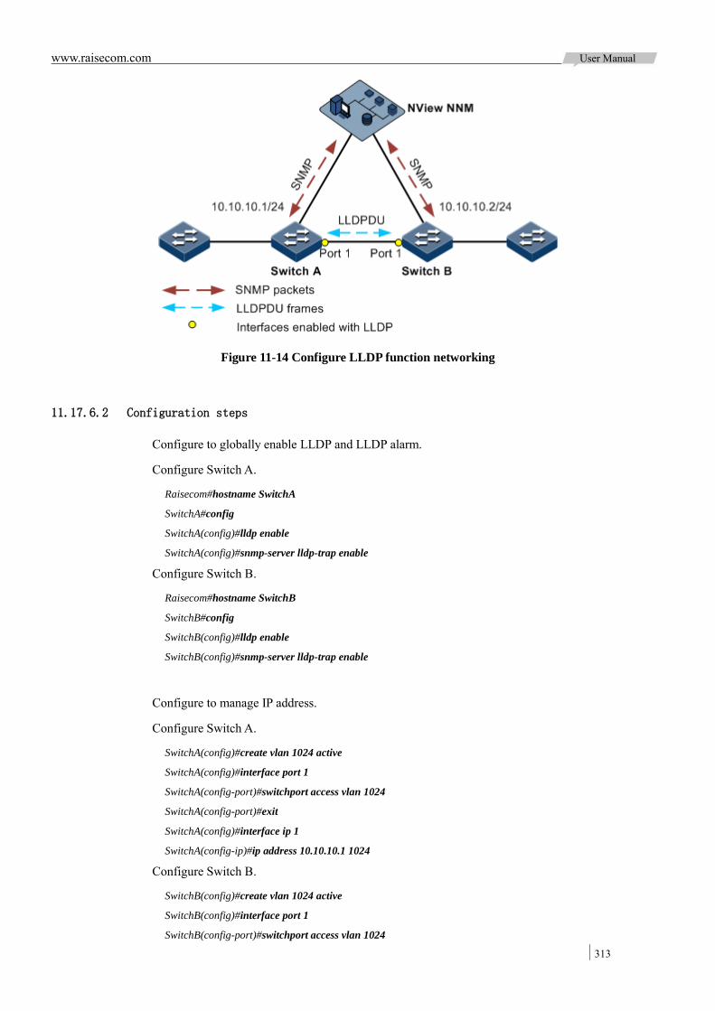
www.raisecom.com User Manual
313
Figure 11-14 Configure LLDP function networking
11.17.6.2 Configuration steps
Configure to globally enable LLDP and LLDP alarm.
Configure Switch A.
Raisecom#hostname SwitchA
SwitchA#config
SwitchA(config)#lldp enable
SwitchA(config)#snmp-server lldp-trap enable
Configure Switch B.
Raisecom#hostname SwitchB
SwitchB#config
SwitchB(config)#lldp enable
SwitchB(config)#snmp-server lldp-trap enable
Configure to manage IP address.
Configure Switch A.
SwitchA(config)#create vlan 1024 active
SwitchA(config)#interface port 1
SwitchA(config-port)#switchport access vlan 1024
SwitchA(config-port)#exit
SwitchA(config)#interface ip 1
SwitchA(config-ip)#ip address 10.10.10.1 1024
Configure Switch B.
SwitchB(config)#create vlan 1024 active
SwitchB(config)#interface port 1
SwitchB(config-port)#switchport access vlan 1024

www.raisecom.com User Manual
314
SwitchB(config)#interface ip 1
SwitchB(config-ip)#ip address 10.10.10.2 1024
Configure LLDP attributes.
Configure Switch A.
SwitchA(config)#lldp message-transmission interval 60
SwitchA(config)#lldp message-transmission delay 9
SwitchA(config)#lldp trap-interval 10
Configure Switch B.
SwitchB(config)#lldp message-transmission interval 60
SwitchB(config)#lldp message-transmission delay 9
SwitchB(config)#lldp trap-interval 10
11.17.6.3 Show result
Check the local configuration by show lldp local config.
SwitchA#show lldp local config
System configuration:
-------------------------------------------------------------------------
LLDP enable status: enable (default is disabled)
LLDP enable ports: 1-28
LldpMsgTxInterval: 60 (default is 30s)
LldpMsgTxHoldMultiplier: 4 (default is 4)
LldpReinitDelay: 2 (default is 2s)
LldpTxDelay: 2 (default is 2s)
LldpNotificationInterval: 5 (default is 5s)
LldpNotificationEnable: enable (default is enabled)
LldpNotificationEnable: enable(default is enabled)
The destination mac address of LLDPDU: (default is 0180.c200.000e)
-------------------------------------------------------------
port1 : destination-mac:0180.C200.000E
port2 : destination-mac:0180.C200.000E
port3 : destination-mac:0180.C200.000E
……
SwitchB#show lldp local config
System configuration:
-------------------------------------------------------------------------
LLDP enable status: enable (default is disabled)
LLDP enable ports: 1
LldpMsgTxInterval: 60 (default is 30s)
LldpMsgTxHoldMultiplier: 4 (default is 4)
LldpReinitDelay: 2 (default is 2s)
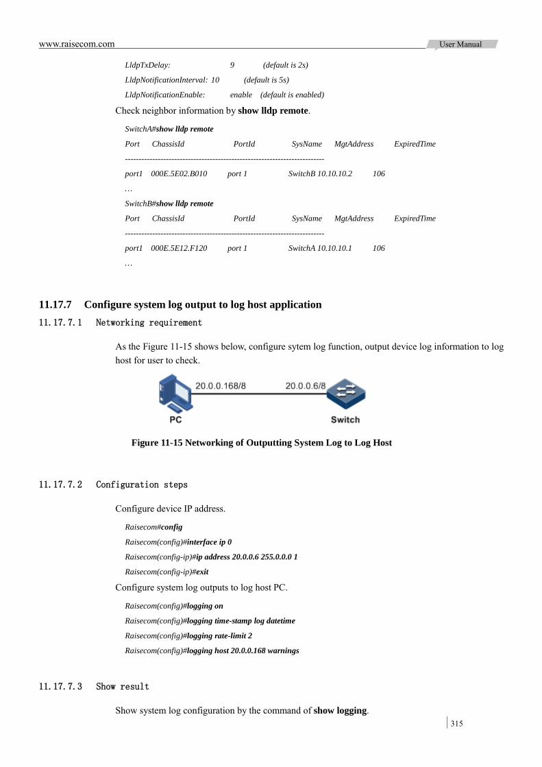
www.raisecom.com User Manual
315
LldpTxDelay: 9 (default is 2s)
LldpNotificationInterval: 10 (default is 5s)
LldpNotificationEnable: enable (default is enabled)
Check neighbor information by show lldp remote.
SwitchA#show lldp remote
Port ChassisId PortId SysName MgtAddress ExpiredTime
-------------------------------------------------------------------------
port1 000E.5E02.B010 port 1 SwitchB 10.10.10.2 106
…
SwitchB#show lldp remote
Port ChassisId PortId SysName MgtAddress ExpiredTime
-------------------------------------------------------------------------
port1 000E.5E12.F120 port 1 SwitchA 10.10.10.1 106
…
11.17.7 Configure system log output to log host application 11.17.7.1 Networking requirement
As the Figure 11-15 shows below, configure sytem log function, output device log information to log host for user to check.
Figure 11-15 Networking of Outputting System Log to Log Host
11.17.7.2 Configuration steps
Configure device IP address.
Raisecom#config
Raisecom(config)#interface ip 0
Raisecom(config-ip)#ip address 20.0.0.6 255.0.0.0 1
Raisecom(config-ip)#exit
Configure system log outputs to log host PC.
Raisecom(config)#logging on
Raisecom(config)#logging time-stamp log datetime
Raisecom(config)#logging rate-limit 2
Raisecom(config)#logging host 20.0.0.168 warnings
11.17.7.3 Show result
Show system log configuration by the command of show logging.
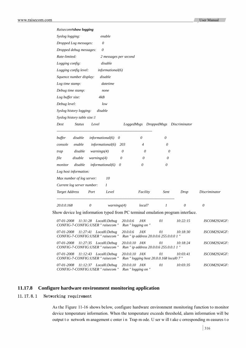
www.raisecom.com User Manual
316
Raisecom#show logging
Syslog logging: enable
Dropped Log messages: 0
Dropped debug messages: 0
Rate-limited: 2 messages per second
Logging config: disable
Logging config level: informational(6)
Squence number display: disable
Log time stamp: datetime
Debug time stamp: none
Log buffer size: 4kB
Debug level: low
Syslog history logging: disable
Syslog history table size:1
Dest Status Level LoggedMsgs DroppedMsgs Discriminator
-----------------------------------------------------------------------------
buffer disable informational(6) 0 0 0
console enable informational(6) 203 4 0
trap disable warnings(4) 0 0 0
file disable warnings(4) 0 0 0
monitor disable informational(6) 0 0 0
Log host information:
Max number of log server: 10
Current log server number: 1
Target Address Port Level Facility Sent Drop Discriminator
-----------------------------------------------------------------------------------------------
20.0.0.168 0 warnings(4) local7 1 0 0
Show device log information typed from PC terminal emulation program interface.
07-01-2008 11:31:28 Local0.Debug 20.0.0.6 JAN 01 10:22:15 ISCOM2924GF: CONFIG-7-CONFIG:USER " raisecom " Run " logging on "
07-01-2008 11:27:41 Local0.Debug 20.0.0.6 JAN 01 10:18:30 ISCOM2924GF: CONFIG-7-CONFIG:USER " raisecom " Run " ip address 20.0.0.6 255.0.0.0 1 "
07-01-2008 11:27:35 Local0.Debug 20.0.0.10 JAN 01 10:18:24 ISCOM2924GF: CONFIG-7-CONFIG:USER " raisecom " Run " ip address 20.0.0.6 255.0.0.1 1 "
07-01-2008 11:12:43 Local0.Debug 20.0.0.10 JAN 01 10:03:41 ISCOM2924GF: CONFIG-7-CONFIG:USER " raisecom " Run " logging host 20.0.0.168 local0 7 "
07-01-2008 11:12:37 Local0.Debug 20.0.0.10 JAN 01 10:03:35 ISCOM2924GF: CONFIG-7-CONFIG:USER " raisecom " Run " logging on "
11.17.8 Configure hardware environment monitoring application 11.17.8.1 Networking requirement
As the Figure 11-16 shows below, configure hardware environment monitoring function to monitor device temperature information. When the temperature exceeds threshold, alarm information will be output t o network m anagement c enter i n Trap m ode. U ser w ill t ake c orresponding m easures t o

www.raisecom.com User Manual
317
prevent fault.
Figure 11-16 Hardware environment monitoring application networking
11.17.8.2 Configuration steps
Configure device IP address.
Raisecom#config
Raisecom(config)#interface ip 0
Raisecom(config-ip)#ip address 20.0.0.6 255.255.255.0 1
Raisecom(config-ip)#exit
Configure device to send Trap.
Raisecom(config)#snmp-server enable traps
Raisecom(config)#snmp-server host 20.0.0.1 version 2c public
Enable global hardware environment monitoring alarm sending Trap.
Raisecom(config)#snmp-server alarm-trap enable
Configure temperature monitoring function for the device.
Raisecom(config)#alarm temperature notifies
Raisecom(config)#alarm temperature high 50
Raisecom(config)#alarm temperature low 20
11.17.8.3 Show result
Check device sending Trap configuration by show snmp config.
Raisecom#show snmp config
Contact information: [email protected]
Device location : World China Raisecom
SNMP trap status: enable
SNMP engine ID: 800022B603000E5E156789
Check Trap target host configuration by show snmp host.
Raisecom#show snmp host
Index: 0
IP family: IPv4
IP address: 20.0.0.1
Port: 162
User Name: public
SNMP Version: v2c
Security Level: noauthnopriv

www.raisecom.com User Manual
318
TagList: bridge config interface rmon snmp ospf
Check device hardware environment monitoring alarm configuration by show alarm.
Raisecom#show alarm
Traps alarm: Enabled
Logging alarm: Disabled
Power Supply
Notifies: Disabled
Syslog: Enabled
Temperature
High threshold(Celsius): 50
Low threshold(Celsius): 20
Notifies: Enabled
Syslog: Enabled
Voltage
High threshold: 3450mV
Low threshold: 3150mV
Notifies: Disabled
Syslog: Disabled
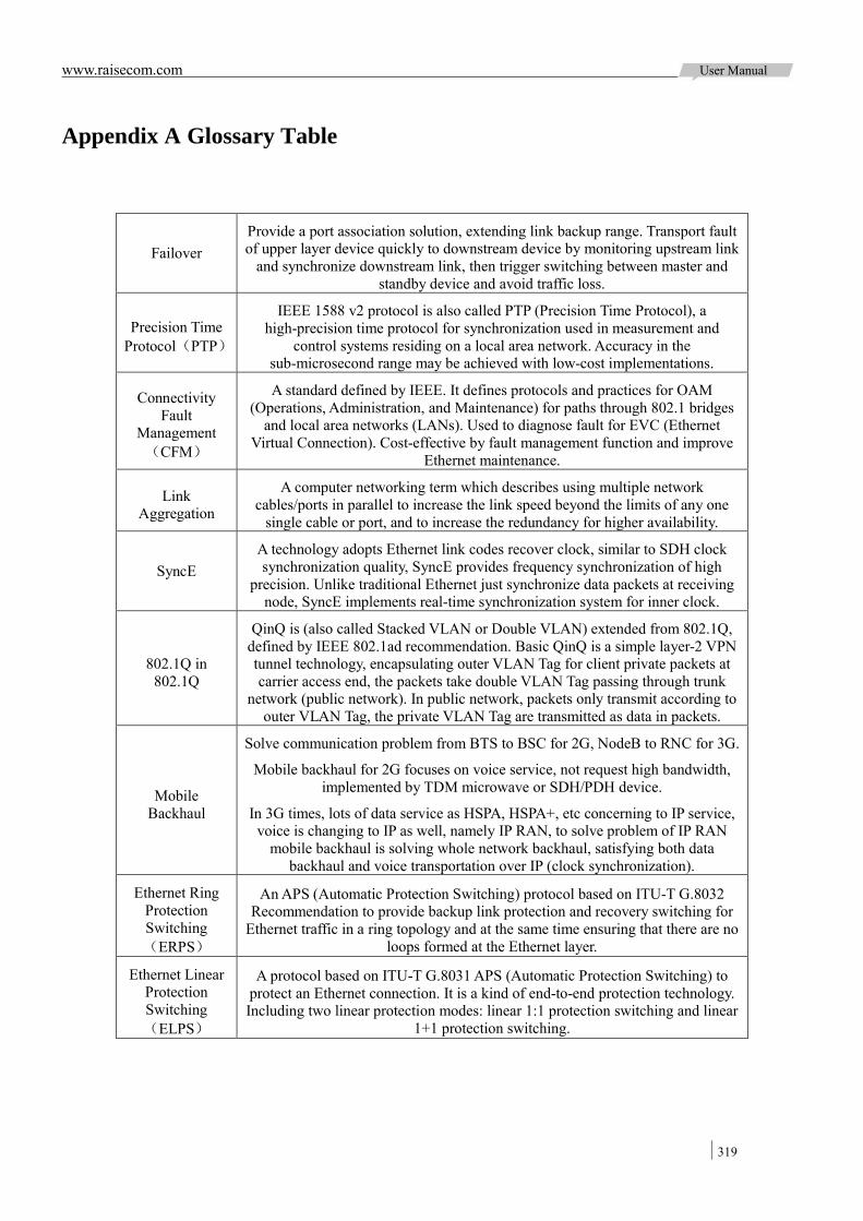
www.raisecom.com User Manual
319
Appendix A Glossary Table
Failover Provide a port association solution, extending link backup range. Transport fault of upper layer device quickly to downstream device by monitoring upstream link
and synchronize downstream link, then trigger switching between master and standby device and avoid traffic loss.
Precision Time Protocol(PTP)
IEEE 1588 v2 protocol is also called PTP (Precision Time Protocol), a high-precision time protocol for synchronization used in measurement and
control systems residing on a local area network. Accuracy in the sub-microsecond range may be achieved with low-cost implementations.
Connectivity Fault
Management(CFM)
A standard defined by IEEE. It defines protocols and practices for OAM (Operations, Administration, and Maintenance) for paths through 802.1 bridges
and local area networks (LANs). Used to diagnose fault for EVC (Ethernet Virtual Connection). Cost-effective by fault management function and improve
Ethernet maintenance.
Link Aggregation
A computer networking term which describes using multiple network cables/ports in parallel to increase the link speed beyond the limits of any one
single cable or port, and to increase the redundancy for higher availability.
SyncE A technology adopts Ethernet link codes recover clock, similar to SDH clock synchronization quality, SyncE provides frequency synchronization of high
precision. Unlike traditional Ethernet just synchronize data packets at receiving node, SyncE implements real-time synchronization system for inner clock.
802.1Q in 802.1Q
QinQ is (also called Stacked VLAN or Double VLAN) extended from 802.1Q, defined by IEEE 802.1ad recommendation. Basic QinQ is a simple layer-2 VPN tunnel technology, encapsulating outer VLAN Tag for client private packets at carrier access end, the packets take double VLAN Tag passing through trunk
network (public network). In public network, packets only transmit according to outer VLAN Tag, the private VLAN Tag are transmitted as data in packets.
Mobile Backhaul
Solve communication problem from BTS to BSC for 2G, NodeB to RNC for 3G.
Mobile backhaul for 2G focuses on voice service, not request high bandwidth, implemented by TDM microwave or SDH/PDH device.
In 3G times, lots of data service as HSPA, HSPA+, etc concerning to IP service, voice is changing to IP as well, namely IP RAN, to solve problem of IP RAN
mobile backhaul is solving whole network backhaul, satisfying both data backhaul and voice transportation over IP (clock synchronization).
Ethernet Ring Protection Switching(ERPS)
An APS (Automatic Protection Switching) protocol based on ITU-T G.8032 Recommendation to provide backup link protection and recovery switching for
Ethernet traffic in a ring topology and at the same time ensuring that there are no loops formed at the Ethernet layer.
Ethernet Linear Protection Switching(ELPS)
A protocol based on ITU-T G.8031 APS (Automatic Protection Switching) to protect an Ethernet connection. It is a kind of end-to-end protection technology. Including two linear protection modes: linear 1:1 protection switching and linear
1+1 protection switching.
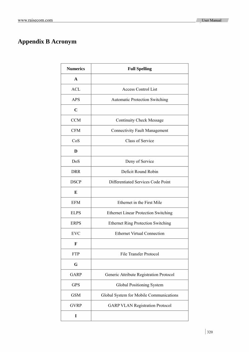
www.raisecom.com User Manual
320
Appendix B Acronym
Numerics Full Spelling
A
ACL Access Control List
APS Automatic Protection Switching
C
CCM Continuity Check Message
CFM Connectivity Fault Management
CoS Class of Service
D
DoS Deny of Service
DRR Deficit Round Robin
DSCP Differentiated Services Code Point
E
EFM Ethernet in the First Mile
ELPS Ethernet Linear Protection Switching
ERPS Ethernet Ring Protection Switching
EVC Ethernet Virtual Connection
F
FTP File Transfer Protocol
G
GARP Generic Attribute Registration Protocol
GPS Global Positioning System
GSM Global System for Mobile Communications
GVRP GARP VLAN Registration Protocol
I
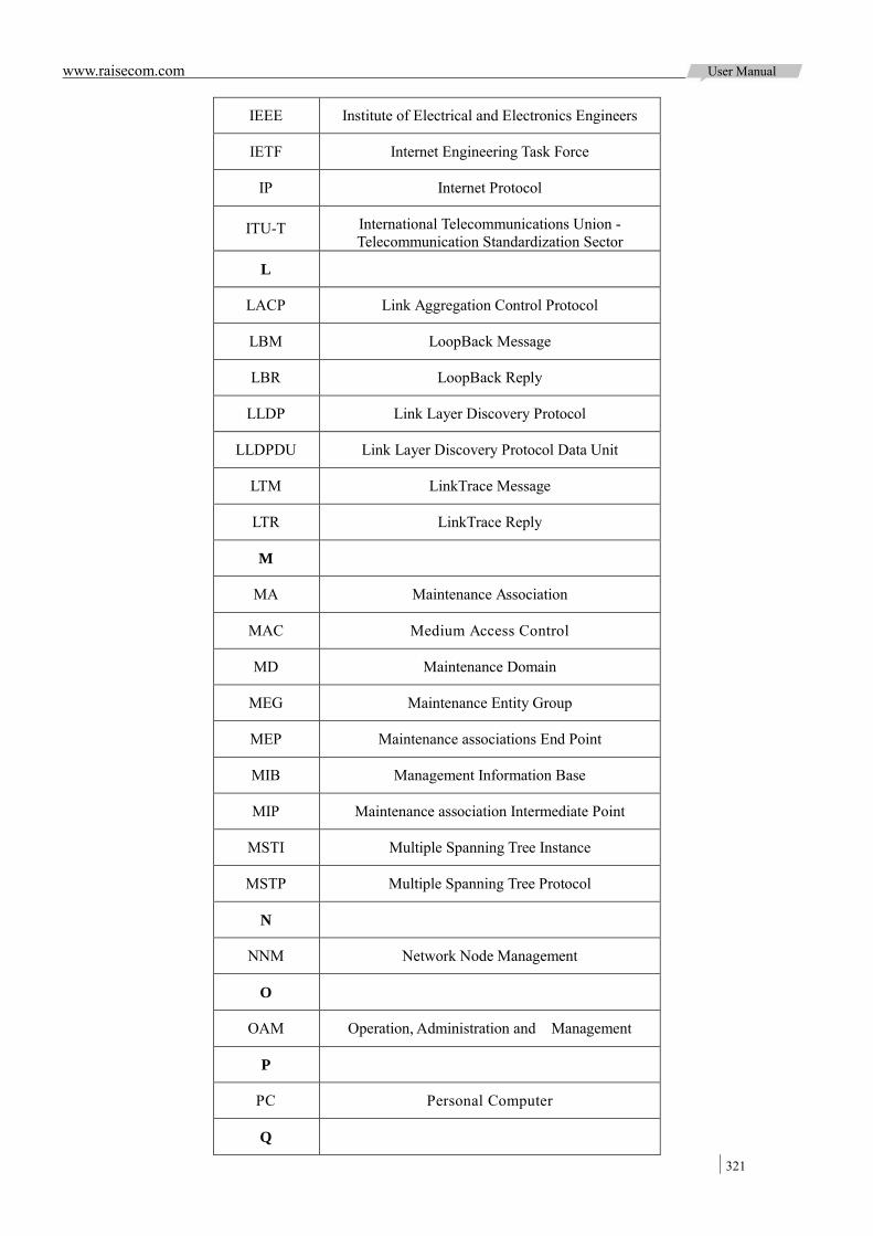
www.raisecom.com User Manual
321
IEEE Institute of Electrical and Electronics Engineers
IETF Internet Engineering Task Force
IP Internet Protocol
ITU-T International Telecommunications Union - Telecommunication Standardization Sector
L
LACP Link Aggregation Control Protocol
LBM LoopBack Message
LBR LoopBack Reply
LLDP Link Layer Discovery Protocol
LLDPDU Link Layer Discovery Protocol Data Unit
LTM LinkTrace Message
LTR LinkTrace Reply
M
MA Maintenance Association
MAC Medium Access Control
MD Maintenance Domain
MEG Maintenance Entity Group
MEP Maintenance associations End Point
MIB Management Information Base
MIP Maintenance association Intermediate Point
MSTI Multiple Spanning Tree Instance
MSTP Multiple Spanning Tree Protocol
N
NNM Network Node Management
O
OAM Operation, Administration and Management
P
PC Personal Computer
Q
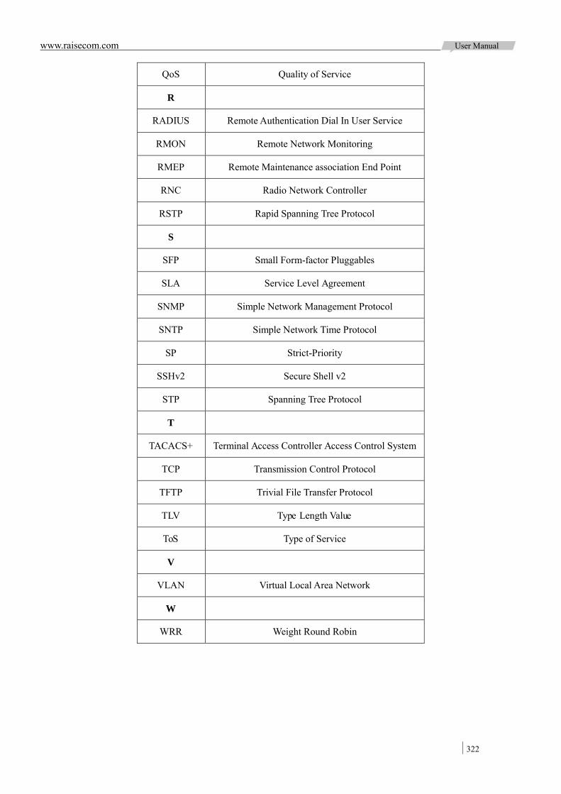
www.raisecom.com User Manual
322
QoS Quality of Service
R
RADIUS Remote Authentication Dial In User Service
RMON Remote Network Monitoring
RMEP Remote Maintenance association End Point
RNC Radio Network Controller
RSTP Rapid Spanning Tree Protocol
S
SFP Small Form-factor Pluggables
SLA Service Level Agreement
SNMP Simple Network Management Protocol
SNTP Simple Network Time Protocol
SP Strict-Priority
SSHv2 Secure Shell v2
STP Spanning Tree Protocol
T
TACACS+ Terminal Access Controller Access Control System
TCP Transmission Control Protocol
TFTP Trivial File Transfer Protocol
TLV Type Length Value
ToS Type of Service
V
VLAN Virtual Local Area Network
W
WRR Weight Round Robin

Address: Building 2, No. 28 of the Shangdi 6th Street, Haidian District, Beijing. Postcode: 100085 Tel: +86-10-82883305 Fax: +86-10-82883056 Email: [email protected] http://www.raisecom.com