Configuration Guide (NAS) - Veritas SORT
338
Symantec FileStore N8300 (Software Release 5.7) Clustered NAS Storage System V200R001 Configuration Guide (NAS) Issue 01 Date 2011-8-30 Symantec Corporation
-
Upload
khangminh22 -
Category
Documents
-
view
1 -
download
0
Transcript of Configuration Guide (NAS) - Veritas SORT

Symantec FileStore N8300 (Software Release 5.7) Clustered NASStorage System
V200R001
Configuration Guide (NAS)
Issue 01
Date 2011-8-30
Symantec Corporation

Symantec provides customers with comprehensive technical support and service. For any assistance, pleasecontact our local office or company headquarters.
Symantec CorporationAddress: 350 Ellis St, Mountain View CA 94043
Website: http://www.symantec.com
Copyright © Symantec Corporation. 2011. All rights reserved.No part of this document may be reproduced or transmitted in any form or by any means without prior writtenconsent of Symantec Corporation. Trademarks and Permissions
and other Symantec trademarks are trademarks of Symantec Corporation.All other trademarks and trade names mentioned in this document are the property of their respective holders. NoticeThe purchased products, services and features are stipulated by the contract made between Symantec andthe customer. All or part of the products, services and features described in this document may not be withinthe purchase scope or the usage scope. Unless otherwise specified in the contract, all statements, information,and recommendations in this document are provided "AS IS" without warranties, guarantees or representationsof any kind, either express or implied.
The information in this document is subject to change without notice. Every effort has been made in thepreparation of this document to ensure accuracy of the contents, but all statements, information, andrecommendations in this document do not constitute a warranty of any kind, express or implied.
Symantec Corporation

Contents
1 Configuration Process of NAS Service..................................................................................1-1
2 Checking Before Configuring the NAS Service...................................................................2-12.1 Check the Hardware Installation.....................................................................................................................2-22.2 Check the Network Connection Status............................................................................................................2-2
3 Creating a File System...............................................................................................................3-13.1 Configuring Storage Units..............................................................................................................................3-2
3.1.1 Configuration Process............................................................................................................................3-23.1.2 Creating a RAID Group.........................................................................................................................3-33.1.3 Setting a Hot Spare Disk........................................................................................................................3-73.1.4 Creating LUNs for Coordinator Disks...................................................................................................3-73.1.5 Creating LUNs for Data Disk...............................................................................................................3-103.1.6 Creating a Host Group..........................................................................................................................3-123.1.7 Creating a Host.....................................................................................................................................3-133.1.8 Adding an Initiator to the Host.............................................................................................................3-143.1.9 Mapping a LUN to a Host Group.........................................................................................................3-153.1.10 Scanning Disk Media.........................................................................................................................3-163.1.11 Configuring I/O Fencing....................................................................................................................3-17
3.2 Checking the System Status..........................................................................................................................3-193.2.1 Configuration Process..........................................................................................................................3-193.2.2 Checking the Running Status of Each Cluster Node............................................................................3-193.2.3 Checking the Status of Service Network Ports....................................................................................3-20
3.3 Configuring a File System.............................................................................................................................3-203.3.1 Configuration Process..........................................................................................................................3-213.3.2 Creating a Pool.....................................................................................................................................3-213.3.3 Creating a File System.........................................................................................................................3-223.3.4 Creating a Local User...........................................................................................................................3-243.3.5 Creating a Local Group........................................................................................................................3-253.3.6 Configuring a User/Group Quota (Optional).......................................................................................3-26
4 Sharing a File System................................................................................................................4-14.1 Configuring a CIFS Share In a Non-Domain Environment............................................................................4-3
4.1.1 About Configuring a CIFS Share in a Non-Domain Environment........................................................4-34.1.2 Configuring a CIFS Normal Share in a Non-Domain Environment......................................................4-4
Symantec FileStore N8300 (Software Release 5.7)Configuration Guide (NAS) Contents
Issue 01 (2011-8-30) Symantec Corporation i

4.1.3 Configuring a CIFS Homedir Share in a Non-Domain Environment....................................................4-84.2 Configuring an NFS Share in a Non-Domain Environment.........................................................................4-13
4.2.1 About Configuring an NFS Share in a Non-Domain Environment.....................................................4-134.2.2 Configuration Process..........................................................................................................................4-144.2.3 Creating an NFS Share.........................................................................................................................4-144.2.4 Accessing the NFS Share.....................................................................................................................4-15
4.3 Configuring a CIFS Share in AD Domain....................................................................................................4-184.3.1 About Configuring a CIFS Share in AD Domain................................................................................4-184.3.2 Configuration Process..........................................................................................................................4-194.3.3 Configuring an NTP Server..................................................................................................................4-204.3.4 Configuring a DNS Server (Optional).................................................................................................4-224.3.5 Configuring an AD Domain Controller...............................................................................................4-394.3.6 Establishing a Connection in the AD Domain.....................................................................................4-66
4.4 Configuring an NFS Share in LDAP Environment.......................................................................................4-704.4.1 About Configuring an NFS Share in LDAP Environment...................................................................4-714.4.2 Configuration Process..........................................................................................................................4-744.4.3 Constructing an LDAP Domain...........................................................................................................4-754.4.4 Adding the N8300 to an LDAP Domain..............................................................................................4-77
4.5 Configuring an NFS Share in NIS Environment...........................................................................................4-814.5.1 About Configuring an NFS Share in NIS Environment.......................................................................4-814.5.2 Configuration Procedure......................................................................................................................4-864.5.3 Constructing an NIS Domain...............................................................................................................4-874.5.4 Configuring the N8300 to Add It to an NIS Domain...........................................................................4-87
5 Configuring Value-Added Service.........................................................................................5-15.1 Configuring the FTP........................................................................................................................................5-4
5.1.1 About Configuring the FTP....................................................................................................................5-45.1.2 Configuration Process............................................................................................................................5-65.1.3 Configuring the N8300 as the FTP Server.............................................................................................5-75.1.4 Accessing the FTP Service.....................................................................................................................5-95.1.5 Managing the FTP Service (Optional).................................................................................................5-10
5.2 Configuring the HTTP..................................................................................................................................5-125.2.1 About Configuring the HTTP..............................................................................................................5-125.2.2 Configuration Process..........................................................................................................................5-135.2.3 Configuring the N8300 as the HTTP Server........................................................................................5-145.2.4 Managing the HTTP Service (Optional)..............................................................................................5-16
5.3 Configuring File System Replication............................................................................................................5-185.3.1 About Configuring the Replication......................................................................................................5-185.3.2 Configuring Replication for a File System..........................................................................................5-19
5.4 Configuring Backup Through NDMP...........................................................................................................5-235.4.1 About Configuring Backup Through NDMP.......................................................................................5-245.4.2 Configuration Process..........................................................................................................................5-255.4.3 Establishing the NDMP Backup Environment.....................................................................................5-26
ContentsSymantec FileStore N8300 (Software Release 5.7)
Configuration Guide (NAS)
ii Symantec Corporation Issue 01 (2011-8-30)

5.4.4 Establishing a Connection....................................................................................................................5-515.4.5 Backing Up Data..................................................................................................................................5-535.4.6 Restoring Data (Optional)....................................................................................................................5-55
5.5 Configuring Backup through the Embedded NetBackup Client...................................................................5-595.5.1 About Configuring Backup through the Embedded NetBackup Client..............................................5-605.5.2 Configuration Process..........................................................................................................................5-615.5.3 Configuring Backup Servers................................................................................................................5-625.5.4 Establishing a Connection....................................................................................................................5-935.5.5 Backing Up Data..................................................................................................................................5-945.5.6 Restoring Data (Optional)..................................................................................................................5-112
5.6 Configuring File System Snapshot..............................................................................................................5-1215.6.1 About Configuring File System Snapshot..........................................................................................5-1225.6.2 Configuration Process........................................................................................................................5-1225.6.3 Creating File System Snapshot..........................................................................................................5-1235.6.4 Managing the Snapshot Quota...........................................................................................................5-1255.6.5 Configuring the Snapshot Share (Optional).......................................................................................5-1265.6.6 Snapshot Recovery.............................................................................................................................5-128
5.7 Configuring File System Mirroring.............................................................................................................5-1285.7.1 About Configuring File System Mirroring.........................................................................................5-1295.7.2 Configuration Process........................................................................................................................5-1295.7.3 Adding a Mirror.................................................................................................................................5-1305.7.4 Configuring a File System to Be Shared (Optional)..........................................................................5-131
5.8 Configuring DST.........................................................................................................................................5-1315.8.1 About Configuring DST.....................................................................................................................5-1325.8.2 Configuration Process........................................................................................................................5-1335.8.3 Creating Secondary-Tier Storage.......................................................................................................5-1335.8.4 Setting a DST Policy..........................................................................................................................5-135
6 Configuring the Alarm Notification Function.....................................................................6-16.1 Configuring an Alarm Email...........................................................................................................................6-2
6.1.1 About Configuring the Alarm Email......................................................................................................6-26.1.2 Configuration Process............................................................................................................................6-36.1.3 Confirming the Information of Email Server.........................................................................................6-46.1.4 Configuring the Email Service for the N8300.......................................................................................6-4
6.2 Configuring SNMP.........................................................................................................................................6-66.2.1 About Configuring SNMP.....................................................................................................................6-66.2.2 Configuration Process............................................................................................................................6-66.2.3 Confirming SNMP Server......................................................................................................................6-76.2.4 Configuring the SNMP Service..............................................................................................................6-8
6.3 Configuring the Syslog System ......................................................................................................................6-96.3.1 About Configuring the Syslog System ................................................................................................6-106.3.2 Configuration Process..........................................................................................................................6-106.3.3 Configuring a Syslog Server................................................................................................................6-11
Symantec FileStore N8300 (Software Release 5.7)Configuration Guide (NAS) Contents
Issue 01 (2011-8-30) Symantec Corporation iii

6.3.4 Configuring the Syslog Service for the N8300....................................................................................6-13
7 Common Information Query...................................................................................................7-17.1 Quick Reference for Information Query.........................................................................................................7-27.2 Querying System Management Information...................................................................................................7-3
7.2.1 Querying Performance Statistics............................................................................................................7-47.2.2 Querying the System Time Information.................................................................................................7-57.2.3 Querying System Time Zone Information.............................................................................................7-5
7.3 Querying Event Management Information......................................................................................................7-67.3.1 Querying Fault Information................................................................................................................... 7-67.3.2 Querying Events Information ................................................................................................................7-7
7.4 Querying Device Management Information....................................................................................................7-87.4.1 Querying Node Information for a Clustered NAS Engine.....................................................................7-87.4.2 Querying Data Disk Information for a Clustered NAS Engine..............................................................7-97.4.3 Querying Pool Information for a Clustered NAS Engine......................................................................7-97.4.4 Querying File System Information for a Clustered NAS Engine...........................................................7-97.4.5 Querying the Share Service Information for a Clustered NAS Engine................................................7-107.4.6 Querying Information About a Storage Unit Controller Enclosure.....................................................7-107.4.7 Querying FC Port Information.............................................................................................................7-117.4.8 Querying Information About a SAS Host Port for a Storage Unit.......................................................7-127.4.9 Querying Information About the Management Network Port for a Storage Unit................................7-127.4.10 Querying Information About a Serial Port for a Storage Unit...........................................................7-137.4.11 Querying Information About the Power Supply for a Storage Unit..................................................7-137.4.12 Querying Information About a Battery for a Storage Unit................................................................7-137.4.13 Querying Information About a Fan for a Storage Unit......................................................................7-147.4.14 Querying Information About a Hard Disk for the Storage Unit.........................................................7-147.4.15 Querying RAID Group Information...................................................................................................7-14
7.5 Querying the Service Management Information...........................................................................................7-157.5.1 Querying Information About the Cluster IP Address...........................................................................7-167.5.2 Querying DNS Service Information.....................................................................................................7-167.5.3 Querying NIS Service Information......................................................................................................7-177.5.4 Querying LDAP Service Information..................................................................................................7-177.5.5 Querying NSSwitch Service Information............................................................................................7-177.5.6 Querying Route Information................................................................................................................7-187.5.7 Querying Backup Information.............................................................................................................7-187.5.8 Querying FTP Service Information......................................................................................................7-187.5.9 Querying Information About the Secondary Tier Storage of the File System ....................................7-197.5.10 Querying Information About the Storage Tiering Policy of a File System........................................7-197.5.11 Querying Information About a Storage Tiering Schedule of a File System......................................7-197.5.12 Querying Mirror Information for a File System.................................................................................7-207.5.13 Querying Snapshot Information for a File System.............................................................................7-207.5.14 Querying Quota Information for a File System.................................................................................7-207.5.15 Querying CIFS Share Information.....................................................................................................7-20
ContentsSymantec FileStore N8300 (Software Release 5.7)
Configuration Guide (NAS)
iv Symantec Corporation Issue 01 (2011-8-30)

7.5.16 Querying Information About a Virtual IP Address of the CIFS Share..............................................7-217.5.17 Querying NFS Share Information......................................................................................................7-217.5.18 Querying Information About a LUN for a Storage Unit....................................................................7-217.5.19 Querying Information About the Host Groups for a Storage Unit.....................................................7-227.5.20 Querying Information About the Host for a Storage Unit.................................................................7-227.5.21 Querying Information About the Initiator for a Storage Unit............................................................7-227.5.22 Querying Information About the LUN Mapping for a Storage Unit.................................................7-23
7.6 Querying the User Management Information...............................................................................................7-237.6.1 Querying the User Information............................................................................................................7-23
8 Related Operations....................................................................................................................8-18.1 ISM-related Operations...................................................................................................................................8-2
8.1.1 Logging In to the ISM............................................................................................................................8-28.1.2 Discovering a Device.............................................................................................................................8-28.1.3 Exiting the ISM......................................................................................................................................8-4
8.2 CLI-related Operations....................................................................................................................................8-48.2.1 Logging In to the CLI.............................................................................................................................8-48.2.2 Logging Out of the CLI..........................................................................................................................8-6
8.3 Exporting the Configuration File of Engine....................................................................................................8-68.4 Operations Related to Initializing an Engine..................................................................................................8-7
8.4.1 Adding a Node.......................................................................................................................................8-78.4.2 Removing a Node...................................................................................................................................8-88.4.3 Rebooting a Node...................................................................................................................................8-88.4.4 Powering Off a Node..............................................................................................................................8-98.4.5 Setting a Time Zone...............................................................................................................................8-9
A Parameter Description.............................................................................................................A-1A.1 Parameter Description of Creating a RAID Group.......................................................................................A-2A.2 Parameter Description of Creating a LUN....................................................................................................A-3A.3 Parameter Description of Creating a Host Group..........................................................................................A-6A.4 Parameter Description of Creating a File System.........................................................................................A-7A.5 Parameter Description of Configuring Quota................................................................................................A-9A.6 Parameter Description of Exporting the Configuration File of Engine.......................................................A-10A.7 Parameter Description of Modifying CIFS Normal Share Options............................................................A-11A.8 Parameter Description of Configuring CIFS Share Global Settings...........................................................A-12A.9 Parameter Description of Modifying NFS Share Options...........................................................................A-13
Symantec FileStore N8300 (Software Release 5.7)Configuration Guide (NAS) Contents
Issue 01 (2011-8-30) Symantec Corporation v


Figures
Figure 1-1 Overall configuration process.............................................................................................................1-1Figure 3-1 Procedure for configuring storage unit...............................................................................................3-3Figure 3-2 Procedure for checking the system status.........................................................................................3-19Figure 3-3 Procedure for configuring a file system............................................................................................3-21Figure 4-1 Flowchart of configuring a CIFS normal share in a non-domain environment..................................4-4Figure 4-2 Flowchart of configuring a CIFS homedir Share in a non-domain environment...............................4-9Figure 4-3 Flowchart of configuring the NFS share in a non-domain environment..........................................4-14Figure 4-4 Typical networking in AD domain...................................................................................................4-19Figure 4-5 Flowchart of configuring a CIFS share in AD domain....................................................................4-20Figure 4-6 Registry Editor dialog box..............................................................................................................4-21Figure 4-7 Configure Your Server Wizard dialog box...................................................................................4-23Figure 4-8 Preparation steps before configuring a server..................................................................................4-23Figure 4-9 Selecting a server role.......................................................................................................................4-24Figure 4-10 Server confirmation interface.........................................................................................................4-25Figure 4-11 Configure a DNS Server Wizard 1..............................................................................................4-25Figure 4-12 Configure a DNS Server Wizard 2..............................................................................................4-26Figure 4-13 Configure a DNS Server Wizard 3..............................................................................................4-27Figure 4-14 New Zone Wizard 1......................................................................................................................4-28Figure 4-15 New Zone Wizard 2......................................................................................................................4-29Figure 4-16 Configure a DNS Server Wizard 4..............................................................................................4-29Figure 4-17 Configure a DNS Server Wizard 5..............................................................................................4-30Figure 4-18 Add client.......................................................................................................................................4-31Figure 4-19 Add ADS........................................................................................................................................4-31Figure 4-20 Creating a reverse lookup zone.......................................................................................................4-32Figure 4-21 Creating a reverse lookup zone interface 1.....................................................................................4-32Figure 4-22 Creating a reverse lookup zone interface 2.....................................................................................4-33Figure 4-23 Creating a reverse lookup zone interface 3.....................................................................................4-34Figure 4-24 Creating a reverse lookup zone interface 4.....................................................................................4-35Figure 4-25 Creating a reverse lookup zone interface 5.....................................................................................4-36Figure 4-26 Creating a reverse lookup zone interface 6.....................................................................................4-37Figure 4-27 Creating a pointer in the reverse lookup zone................................................................................4-37Figure 4-28 New Resource Record dialog box.................................................................................................4-38Figure 4-29 Command interface.........................................................................................................................4-39
Symantec FileStore N8300 (Software Release 5.7)Configuration Guide (NAS) Figures
Issue 01 (2011-8-30) Symantec Corporation vii

Figure 4-30 Configure Your Server Wizard window.....................................................................................4-40Figure 4-31 Preliminary steps............................................................................................................................4-41Figure 4-32 Server role configuration................................................................................................................4-42Figure 4-33 Active Directory Installation Wizard..............................................................................................4-43Figure 4-34 Operating System Compatibility.................................................................................................4-43Figure 4-35 Domain Controller Type..............................................................................................................4-44Figure 4-36 Create New Domain......................................................................................................................4-45Figure 4-37 New Domain Name.......................................................................................................................4-46Figure 4-38 NetBIOS Domain Name.................................................................................................................4-47Figure 4-39 Database and Log Folders...........................................................................................................4-48Figure 4-40 Shared System Volume................................................................................................................4-49Figure 4-41 Permissions....................................................................................................................................4-49Figure 4-42 Directory Services Restore Mode Administrator Password.....................................................4-50Figure 4-43 Reviewing and confirming the configured options........................................................................4-51Figure 4-44 Configuring Active Directory.........................................................................................................4-51Figure 4-45 Completing the Active Directory Installation Wizard..............................................................4-52Figure 4-46 Setting a DNS server......................................................................................................................4-53Figure 4-47 Installation wizard..........................................................................................................................4-54Figure 4-48 Operating System Compatibility.................................................................................................4-54Figure 4-49 Domain Controller Type..............................................................................................................4-55Figure 4-50 Setting the network username and password..................................................................................4-56Figure 4-51 Additional Domain Controller....................................................................................................4-57Figure 4-52 Database and Log Folders...........................................................................................................4-58Figure 4-53 Shared System Volume................................................................................................................4-59Figure 4-54 Directory Services Restore Mode Administrator Password.....................................................4-60Figure 4-55 Reviewing selected options............................................................................................................4-61Figure 4-56 Completing the Active Directory Installation Wizard..............................................................4-62Figure 4-57 DNS Management window...........................................................................................................4-63Figure 4-58 CLI for checking the SVR..............................................................................................................4-63Figure 4-59 Checking the AD database file.......................................................................................................4-64Figure 4-60 Checking the SYSVOL folder.......................................................................................................4-65Figure 4-61 Event viewer...................................................................................................................................4-65Figure 4-62 typical networking modes in an LDAP domain.............................................................................4-74Figure 4-63 Flowchart of configuring an NFS share in LDAP environment.....................................................4-75Figure 4-64 Hierarchy planning diagram of LDAP domains.............................................................................4-76Figure 4-65 Typical networking configuration in an NIS domain.....................................................................4-85Figure 4-66 Flowchart of configuring an NFS share in NIS environment.........................................................4-86Figure 5-1 FTP service configuration flowchart..................................................................................................5-7Figure 5-2 HTTP service configuration flowchart.............................................................................................5-14Figure 5-3 A point-to-point disaster recovery application.................................................................................5-19Figure 5-4 Flowchart of configuring NDMP backup.........................................................................................5-26Figure 5-5 Installing Symantec NetBackup for NDMP.....................................................................................5-28
FiguresSymantec FileStore N8300 (Software Release 5.7)
Configuration Guide (NAS)
viii Symantec Corporation Issue 01 (2011-8-30)

Figure 5-6 Installing Symantec NetBackup Add-On.........................................................................................5-28Figure 5-7 Choosing to install Symantec NetBackup for NDMP......................................................................5-29Figure 5-8 Confirming to install Symantec NetBackup for NDMP...................................................................5-29Figure 5-9 Successful installation of Symantec NetBackup for NDMP............................................................5-29Figure 5-10 Creating a host in a forward lookup zone.......................................................................................5-30Figure 5-11 Adding a Symantec NetBackup server...........................................................................................5-31Figure 5-12 Specifying the N8300 as the backup client host.............................................................................5-32Figure 5-13 Creating a reverse lookup zone.......................................................................................................5-33Figure 5-14 New Zone Wizard window...........................................................................................................5-34Figure 5-15 Dynamic Update dialog box.........................................................................................................5-35Figure 5-16 Reviewing configuration items of the new reverse lookup zone....................................................5-36Figure 5-17 Media and Device Management dialog box................................................................................5-37Figure 5-18 Entering the NDMP host name.......................................................................................................5-37Figure 5-19 Entering the user name and password............................................................................................5-38Figure 5-20 NDMP host list...............................................................................................................................5-38Figure 5-21 Starting the device configuration wizard........................................................................................5-39Figure 5-22 Device Configuration Wizard window........................................................................................5-40Figure 5-23 Finishing configuration in the device configuration wizard...........................................................5-41Figure 5-24 Selecting to inventory robots..........................................................................................................5-42Figure 5-25 Robot Inventory dialog box..........................................................................................................5-43Figure 5-26 Robot Inventory dialog box..........................................................................................................5-44Figure 5-27 Choosing New Storage Unit..........................................................................................................5-45Figure 5-28 New Storage Unit dialog box........................................................................................................5-46Figure 5-29 Choosing New Policy.....................................................................................................................5-47Figure 5-30 Add a New Policy dialog box........................................................................................................5-47Figure 5-31 Change Policy dialog box..............................................................................................................5-48Figure 5-32 Adding a new schedule...................................................................................................................5-49Figure 5-33 Modifying attributes of the schedule..............................................................................................5-49Figure 5-34 Setting the schedule........................................................................................................................5-50Figure 5-35 Setting the client.............................................................................................................................5-50Figure 5-36 Add Backup Selection dialog box................................................................................................5-51Figure 5-37 Choosing Manual Backup............................................................................................................5-53Figure 5-38 Selecting hosts to be backed up......................................................................................................5-54Figure 5-39 Activity Monitor dialog box.........................................................................................................5-54Figure 5-40 Selecting Restore Files..................................................................................................................5-55Figure 5-41 Selecting the Symantec NetBackup master server.........................................................................5-56Figure 5-42 Selecting the directory or file to be restored...................................................................................5-57Figure 5-43 Selecting the destination.................................................................................................................5-58Figure 5-44 View Progress dialog box..............................................................................................................5-59Figure 5-45 Viewing the restoration progress....................................................................................................5-59Figure 5-46 Typical networking of a NetBackup backup environment.............................................................5-60Figure 5-47 Flowchart of configuring backup through the embedded NetBackup Client of the N8300...........5-62
Symantec FileStore N8300 (Software Release 5.7)Configuration Guide (NAS) Figures
Issue 01 (2011-8-30) Symantec Corporation ix

Figure 5-48 Initial browse interface...................................................................................................................5-63Figure 5-49 Selecting an installation object.......................................................................................................5-64Figure 5-50 Welcome interface..........................................................................................................................5-65Figure 5-51 License interface.............................................................................................................................5-66Figure 5-52 Install Choice interface..................................................................................................................5-67Figure 5-53 Licensing interface..........................................................................................................................5-68Figure 5-54 System Names interface.................................................................................................................5-69Figure 5-55 EMM Server interface....................................................................................................................5-70Figure 5-56 Install interface...............................................................................................................................5-71Figure 5-57 Completion interface......................................................................................................................5-72Figure 5-58 Selecting the server wizard.............................................................................................................5-73Figure 5-59 Server wizard interface...................................................................................................................5-74Figure 5-60 Preparation steps before configuring a server................................................................................5-74Figure 5-61 Selecting a server role.....................................................................................................................5-75Figure 5-62 Server confirmation interface.........................................................................................................5-76Figure 5-63 DNS configuration wizard..............................................................................................................5-77Figure 5-64 DNS configuration wizard..............................................................................................................5-78Figure 5-65 DNS configuration wizard..............................................................................................................5-79Figure 5-66 DNS configuration wizard..............................................................................................................5-80Figure 5-67 DNS configuration wizard..............................................................................................................5-81Figure 5-68 DNS configuration wizard..............................................................................................................5-82Figure 5-69 Selecting a DNS server...................................................................................................................5-83Figure 5-70 Host creation window 1..................................................................................................................5-84Figure 5-71 Host creation window 2..................................................................................................................5-84Figure 5-72 Creating a reverse lookup zone.......................................................................................................5-85Figure 5-73 Creating a reverse lookup zone interface 1.....................................................................................5-86Figure 5-74 Creating a reverse lookup zone interface 2.....................................................................................5-87Figure 5-75 Creating a reverse lookup zone interface 3.....................................................................................5-88Figure 5-76 Creating a reverse lookup zone interface 4.....................................................................................5-89Figure 5-77 Creating a reverse lookup zone interface 5.....................................................................................5-90Figure 5-78 Creating a reverse lookup zone interface 6.....................................................................................5-91Figure 5-79 Creating a pointer in the reverse lookup zone................................................................................5-91Figure 5-80 New Resource Record dialog box.................................................................................................5-92Figure 5-81 Command interface.........................................................................................................................5-93Figure 5-82 Creating a new storage unit............................................................................................................5-94Figure 5-83 New Storage Unit dialog box........................................................................................................5-95Figure 5-84 Method of creating a backup policy (1)..........................................................................................5-97Figure 5-85 Method of creating a backup policy (2)..........................................................................................5-97Figure 5-86 Naming a backup policy.................................................................................................................5-98Figure 5-87 Setting attributes for the backup policy..........................................................................................5-99Figure 5-88 Setting attributes for the backup policy........................................................................................5-103Figure 5-89 Creating a new schedule...............................................................................................................5-104
FiguresSymantec FileStore N8300 (Software Release 5.7)
Configuration Guide (NAS)
x Symantec Corporation Issue 01 (2011-8-30)

Figure 5-90 Setting the schedule attributes......................................................................................................5-105Figure 5-91 Setting the start and end time of the schedule..............................................................................5-106Figure 5-92 Setting the exclude dates for the schedule....................................................................................5-106Figure 5-93 Completing setting the schedule...................................................................................................5-107Figure 5-94 Setting the clients..........................................................................................................................5-108Figure 5-95 Setting backup options..................................................................................................................5-109Figure 5-96 Selecting the files to be backed up...............................................................................................5-110Figure 5-97 Selecting manual backup..............................................................................................................5-111Figure 5-98 Checking backup jobs...................................................................................................................5-111Figure 5-99 Backup job information................................................................................................................5-112Figure 5-100 Backup, Archive, and Restore dialog box...............................................................................5-113Figure 5-101 Selecting NetBackup client properties........................................................................................5-114Figure 5-102 Checking the client name...........................................................................................................5-115Figure 5-103 Specifying NetBackup machines and policy type......................................................................5-115Figure 5-104 Checking the backup server, client, and restore policy type......................................................5-116Figure 5-105 Selecting files and folders to restore...........................................................................................5-116Figure 5-106 Select the file to be restored........................................................................................................5-117Figure 5-107 Starting the restore......................................................................................................................5-118Figure 5-108 Restore Marked Files dialog box.............................................................................................5-119Figure 5-109 Checking the details about a restoring job..................................................................................5-120Figure 5-110 Details about a restoring job.......................................................................................................5-121Figure 5-111 Flowchart of configuring a file system snapshot........................................................................5-123Figure 5-112 Flowchart of configuring file system mirror..............................................................................5-130Figure 5-113 a typical DST networking scenario.............................................................................................5-133Figure 5-114 Flowchart of configuring the DST..............................................................................................5-133Figure 6-1 typical networking scenario for configuration alarm email notifications...........................................6-3Figure 6-2 Flowchart of configuring the alarm email..........................................................................................6-4Figure 6-3 Flowchart of configuring the SNMP..................................................................................................6-7Figure 6-4 Example interface for accessing the GUI...........................................................................................6-8Figure 6-5 Ethereal: Capture Options dialog box............................................................................................ 6-8Figure 6-6 Typical Networking Modes for Syslog............................................................................................6-10Figure 6-7 Flowchart of configuring the syslog.................................................................................................6-11Figure 6-8 Syslog.conf.......................................................................................................................................6-12Figure 6-9 Syslog...............................................................................................................................................6-13Figure 8-1 SSH login interface.............................................................................................................................8-5Figure 8-2 Enter Authentication Response dialog box.....................................................................................8-5
Symantec FileStore N8300 (Software Release 5.7)Configuration Guide (NAS) Figures
Issue 01 (2011-8-30) Symantec Corporation xi


Tables
Table 3-1 RAID level comparison........................................................................................................................3-4Table 4-1 Description of parameters in the Homedir Quota Management dialog box...................................4-11Table 4-2 Parameter description.........................................................................................................................4-69Table 4-3 Network parameters...........................................................................................................................4-75Table 4-4 Hierarchy planning description of LDAP domains............................................................................4-76Table 4-5 Information about files on the NIS server..........................................................................................4-82Table 4-6 Configuration files.............................................................................................................................4-82Table 4-7 Main services.....................................................................................................................................4-83Table 4-8 Related commands.............................................................................................................................4-83Table 4-9 Configuration files for the NIS client.................................................................................................4-83Table 4-10 Main commands on the NIS client...................................................................................................4-84Table 4-11 Components that need to be installed on the NIS server.................................................................4-85Table 4-12 components that need to be installed on the NIS client...................................................................4-86Table 4-13 Network parameters.........................................................................................................................4-87Table 5-1 Description of value-added services....................................................................................................5-1Table 5-2 Description of parameters in the Sessions tab...................................................................................5-10Table 5-3 Description of parameters in the Statistics tab..................................................................................5-11Table 5-4 Hardware and operating systems that NetBackup for NDMP supports.............................................5-25Table 5-5 List of OSs and hardware types supported by Symantec NetBackup for NDMP..............................5-27Table 5-6 Composition of a backup policy........................................................................................................5-61Table 5-7 Description of the parameters in the New Storage Unit dialog box.................................................5-95Table 5-8 Parameter description.........................................................................................................................5-99Table 5-9 Type..................................................................................................................................................5-101Table 5-10 Parameter description.....................................................................................................................5-105Table 5-11 Flowchart for configuring the snapshot share................................................................................5-127Table 5-12 Two modes of cross-array mirroring..............................................................................................5-129Table 5-13 Flowchart for configuring a file system to be shared.....................................................................5-131Table 5-14 DST storage modes........................................................................................................................5-132Table 7-1 Quick reference for common query operations....................................................................................7-2Table 7-2 Description of the performance items for the engine node..................................................................7-4Table 7-3 Description of the performance items of the storage unit....................................................................7-5Table 7-4 Event parameters..................................................................................................................................7-6Table 7-5 Event parameters..................................................................................................................................7-7
Symantec FileStore N8300 (Software Release 5.7)Configuration Guide (NAS) Tables
Issue 01 (2011-8-30) Symantec Corporation xiii

Table 7-6 Parameters of the SAS host port........................................................................................................7-12Table 8-1 descriptions of parameters in the Export Configuration File dialog box..........................................8-6Table A-1 Advanced information........................................................................................................................A-5Table A-2 Parameter Description........................................................................................................................A-7
TablesSymantec FileStore N8300 (Software Release 5.7)
Configuration Guide (NAS)
xiv Symantec Corporation Issue 01 (2011-8-30)

1 Configuration Process of NAS Service
This section describes the overall configuration process for the NAS service, and you can learnthe provided configuration functions through the flow chart.
You can learn the configuration operations that need to be performed when using the NASservice. Figure 1-1 shows the overall configuration process.
Figure 1-1 Overall configuration process
Start
Checking Before the Configuration
Creating a File System
Sharing a File System
Configuring Value-Added Service
Configuring the FTP
Configuring the HTTP
Configuring File System Replication
Configuring Backup Through the NDMP
Configuring Backup Through Embedded NetBackup Client
Configuring File System Snapshot
Configuring the Alarm Notification Function
Configuring an Alarm Email
Configuring SNMP
Configuring the Syslog System End
Required parent itemNote: Optional
parent itemOptional child item
Configuring File System Mirroring
Configuring DST
Configuring a CIFS Share In a Non-Domain Environment
Configuring an NFS Share in a Non-Domain Environment
Configuring a CIFS Share in AD Domain
Configuring an NFS Share in the LDAP
Configuring an NFS Share in NIS Evironment
Symantec FileStore N8300 (Software Release 5.7)Configuration Guide (NAS) 1 Configuration Process of NAS Service
Issue 01 (2011-8-30) Symantec Corporation 1-1


2 Checking Before Configuring the NASService
About This Chapter
Before configuring the N8300, check hardware installation and network connection status.
2.1 Check the Hardware InstallationCheck the N8300 hardware installation, including cable connections and device indicator status.
2.2 Check the Network Connection StatusAfter the hardware installation is complete, check the network connection status.
Symantec FileStore N8300 (Software Release 5.7)Configuration Guide (NAS) 2 Checking Before Configuring the NAS Service
Issue 01 (2011-8-30) Symantec Corporation 2-1
2.1 Check the Hardware InstallationCheck the N8300 hardware installation, including cable connections and device indicator status.
For details on how to check the N8300 hardware installation, see the N8300 Series ClusteredNAS Storage System Installation Guide.
2.2 Check the Network Connection StatusAfter the hardware installation is complete, check the network connection status.
Log in to the ISM to check whether the clustered NAS engine and storage unit were discoveredsuccessfully; for details, please see 8.1 ISM-related Operations.
NOTE
If discovering the clustered NAS engine or discovering the storage unit fails, it indicates that the initialconfiguration of storage integration is wrong. In this case, contact technical support engineers.
2 Checking Before Configuring the NAS ServiceSymantec FileStore N8300 (Software Release 5.7)
Configuration Guide (NAS)
2-2 Symantec Corporation Issue 01 (2011-8-30)

3 Creating a File System
About This Chapter
This section explains how to create a file system by using the storage space. This step is theprecondition for configuring the NAS service.
Creating a file system includes the following steps:
1. Configure the storage space on the hard disks, that is, configure the storage unit, so that theN8300 engine can use the storage space. For details, see 3.1 Configuring Storage Units.
2. Before you configure the NAS service, you need to check system status. For details, see3.2 Checking the System Status.
3. Configure the file system. For details, see 3.3 Configuring a File System.
3.1 Configuring Storage UnitsThis chapter explains how to configure a storage unit. Configuring the storage unit is theprecondition for other configurations. A storage unit can be identified by the NAS as a LUNonly after the LUN is created.
3.2 Checking the System StatusThis section describes how to check the system status, including checking the running status ofeach cluster node, and checking the status of the service port.
3.3 Configuring a File SystemThis section describes how to configure a file system, including creating a pool, creating a filesystem, configuring the local user and group (optional), and configuring a user/group quota.
Symantec FileStore N8300 (Software Release 5.7)Configuration Guide (NAS) 3 Creating a File System
Issue 01 (2011-8-30) Symantec Corporation 3-1
3.1 Configuring Storage UnitsThis chapter explains how to configure a storage unit. Configuring the storage unit is theprecondition for other configurations. A storage unit can be identified by the NAS as a LUNonly after the LUN is created.
3.1.1 Configuration ProcessYou can learn the operations about configuring storage unit through the flow chart.
3.1.2 Creating a RAID GroupThrough this operation, you can create a RAID group. For a new system, you need to create aRAID group first. Storage units support RAID 0, RAID 1, RAID 5, RAID 6, RAID 50, andRAID 10. You can create different RAID levels as required.
3.1.3 Setting a Hot Spare DiskThrough this operation, you can change a free disk to a hot spare disk.
3.1.4 Creating LUNs for Coordinator DisksThis section describes how to create LUNs for coordinator disks. Before creating LUNs for datadisks, create LUNs for coordinator disks first. To make the I/O Fencing available in the cluster,you need to create three LUNs to serve as coordinator disks.
3.1.5 Creating LUNs for Data DiskIn a new file system, you need to create a LUN first after creating RAID groups.
3.1.6 Creating a Host GroupThis section describes how to create a host group. Host Group is a group of hosts. All hosts ina host group can share the same LUN. By setting the engine to a host group, you can implementunified management of hosts at the same type.
3.1.7 Creating a HostThis section describes how to create hosts in a host group. The host here is virtually created for the convenience of management. The virtual hostcorresponds to a physical application server only when ports are added to this host.
3.1.8 Adding an Initiator to the HostThis section describes how to add an initiator to the engine. The virtual host is consistent withthe physical one, and the application can use the LUN provided by the storage device only afterthe initiator is configured.
3.1.9 Mapping a LUN to a Host GroupBy using this operation, you can map a LUN to a specified host group.
3.1.10 Scanning Disk MediaThis section describes how to scan disks. This operation applies to both coordinator disks anddata disks. It also refreshes information about data disks that consist of LUNs.
3.1.11 Configuring I/O FencingThis section describes how to configure I/O fencing.
3.1.1 Configuration ProcessYou can learn the operations about configuring storage unit through the flow chart.
Figure 3-1 shows the procedure for configuring storage unit.
3 Creating a File SystemSymantec FileStore N8300 (Software Release 5.7)
Configuration Guide (NAS)
3-2 Symantec Corporation Issue 01 (2011-8-30)

Figure 3-1 Procedure for configuring storage unit
Start
End
Creating LUNs for Data Disk
Configuring I/O Fencing
2. Configuring a Storage Unit
Related to the Host
Creating a RAID Group
Setting a Hot Spare Disk
Creating LUNs for Coordinator Disks
Creating a Host Group
Creating a Host
Mapping a LUN to a Host Group
Scanning Disk Media
1. Configuring a Storage Unit
Related to the LUN
3. Preparation for Creating File
System
Required child item
Optional child itemNote:
Adding an Initiator to the Host
3.1.2 Creating a RAID GroupThrough this operation, you can create a RAID group. For a new system, you need to create aRAID group first. Storage units support RAID 0, RAID 1, RAID 5, RAID 6, RAID 50, andRAID 10. You can create different RAID levels as required.
Prerequisite
The storage device has free disks for creating RAID groups.
Symantec FileStore N8300 (Software Release 5.7)Configuration Guide (NAS) 3 Creating a File System
Issue 01 (2011-8-30) Symantec Corporation 3-3

Precautionsl Guests cannot create a RAID group.
l There are adequate free disks in the system. Each RAID group has at most 24 disks.
l A RAID 0 group requires at least one free disks.
l A RAID 1 group requires at least two free disks.
l A RAID 5 group requires at least three free disks.
l A RAID 6 group requires at least four free disks.
l A RAID 10 group requires at least four free disks.
l A RAID 50 group requires at least six free disks.
l The hard disks in slots 0 through 3 of the controller enclosure are system coffer disks thatsave valuable system data. Do not randomly insert or remove the hard disks, nor alter thesequence of the hard disks in the coffer; otherwise the system data may be damaged.
l Do not randomly insert or remove hard disks in other slots; otherwise system data loss mayoccur.
l The types of coffer disks must be the same.
l The disk in either slot 0 or slot 1 must be present, and the disk in either slot 2 or slot 3 mustbe present.
Procedure
Step 1 Go to the Create RAID Group dialog box.1. On the main interface of the ISM, choose Clustered NAS Storage System > Storage
Resources > RAID Groups in the navigation tree.2. In the function pane, click Create.
The Create RAID Group dialog box is displayed.
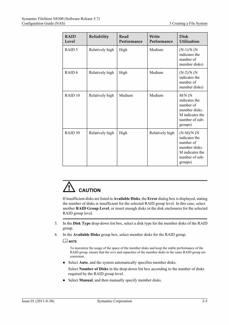
Step 2 Configure RAID group settings.1. In the Name text box, enter the RAID group name.2. In the Level drop-down box, select the RAID group level.
Consider reliability, performance, and disk utilization when selecting RAID levels. Table3-1 lists the comparison of different RAID levels.
Table 3-1 RAID level comparison
RAIDLevel
Reliability ReadPerformance
WritePerformance
DiskUtilization
RAID 0 Low High High 100%
RAID 1 High Low Low 1/N (N indicatesthe number ofmember disks)
RAID 3 Relatively high High Low (N-1)/N (Nindicates thenumber ofmember disks)
3 Creating a File SystemSymantec FileStore N8300 (Software Release 5.7)
Configuration Guide (NAS)
3-4 Symantec Corporation Issue 01 (2011-8-30)
RAIDLevel
Reliability ReadPerformance
WritePerformance
DiskUtilization
RAID 5 Relatively high High Medium (N-1)/N (Nindicates thenumber ofmember disks)
RAID 6 Relatively high High Medium (N-2)/N (Nindicates thenumber ofmember disks)
RAID 10 Relatively high Medium Medium M/N (Nindicates thenumber ofmember disks.M indicates thenumber of sub-groups)
RAID 50 Relatively high High Relatively high (N-M)/N (Nindicates thenumber ofmember disks.M indicates thenumber of sub-groups)
CAUTIONIf insufficient disks are listed in Available Disks, the Error dialog box is displayed, statingthe number of disks is insufficient for the selected RAID group level. In this case, selectanother RAID Group Level, or insert enough disks in the disk enclosures for the selectedRAID group level.
3. In the Disk Type drop-down list box, select a disk type for the member disks of the RAIDgroup.
4. In the Available Disks group box, select member disks for the RAID group.
NOTE
To maximize the usage of the space of the member disks and keep the stable performance of theRAID group, ensure that the revs and capacities of the member disks in the same RAID group areconsistent.
l Select Auto, and the system automatically specifies member disks.Select Number of Disks in the drop-down list box according to the number of disksrequired by the RAID group level.
l Select Manual, and then manually specify member disks.
Symantec FileStore N8300 (Software Release 5.7)Configuration Guide (NAS) 3 Creating a File System
Issue 01 (2011-8-30) Symantec Corporation 3-5

Select member disks in Available Disk according to the number of disks required bythe selected RAID level. Use member disks of the same capacity to increase the diskutilization.
5. (Optional) Select Sub-Group Disks in the drop-down list box for RAID 10 and RAID 50.
NOTE
The value of the Sub-Group Disks in the drop-down list box is valid only after the RAID groupmember disks are specified, and varies according to the number of the RAID group member disks.
l For RAID 10, Sub-Group Disks indicates the number of hard disks in each RAID 1sub-group in a RAID 10 group. The value of Sub-Group Disks must be no less than 2,and can exactly divide the total number of member disks in the RAID group.
l For RAID 50, Sub-Group Disks indicates the number of hard disks in each RAID 5sub-group in a RAID 50 group. The value of Sub-Group Disks must be no less than 3,and can exactly divide the total number of member disks in the RAID group.
Step 3 Click OK.Continue by following the instructed prompts.
l If the disk type of hot spare disks are different from that of the RAID group member disks,the Info dialog box displays, indicating that you need to create hot spare disks. ClickContinue to complete creating RAID group according to the ISM wizard, and then to createhot spare disks for the storage system.
l If hot spare disks in the storage system, the Info dialog box is displayed , prompting to createmore RAID groups.
– To create more RAID groups, click Continue. The Create RAID Group dialog box isdisplayed.
– To exit the Prompt dialog box, click Finish. You have successfully created a RAIDgroup.
For details on the relevant parameters of a RAID group, see A.1 Parameter Description ofCreating a RAID Group.
----End
Result
View the details about the created RAID group using the following steps.
1. Choose Clustered NAS Storage System > Storage Resources > RAID Groups in thenavigation tree.
2. Select the newly-created RAID group in the function pane.
3. View the details about the RAID group in the Detail pane below.
Follow-up Procedurel Create hot spare disks to ensure that the data on a member disk of the RAID group can be
stored on another free disk when a member disk fails. For details on creating hot-sparedisks, see 3.1.3 Setting a Hot Spare Disk.
l 3.1.1 Configuration Process shows the relevant operations about configuring storageunits. The next step is 3.1.3 Setting a Hot Spare Disk.
3 Creating a File SystemSymantec FileStore N8300 (Software Release 5.7)
Configuration Guide (NAS)
3-6 Symantec Corporation Issue 01 (2011-8-30)
3.1.3 Setting a Hot Spare DiskThrough this operation, you can change a free disk to a hot spare disk.
PrerequisiteThe free disk exists in the system.
CAUTIONl In addition, do not use a coffer disk as a hot spare disk.
l The physical type of the hot spare disk must be the same as that of the disk in the owningRAID group.
ProcedureStep 1 In the navigation tree, choose Clustered NAS Storage System > Device Info.
Step 2 Expand Device Info and choose storage unite, click Disks.
Step 3 In the function pane, select the free disk that is changed to a hot spare disk and then choose HotSpare Disk > Set Hot Spare Disk.The Result dialog box is displayed.
Step 4 Click Close.
----End
ResultYou have successfully created a hot spare disk. The Running Status of the hot spare disk haschanged to Free Hot Spare Disk. In case of a RAID group failure due to a faulty member disk,the hot spare disk will now take over the data stored on the faulty member disk to ensure normaloperation of the RAID group. In this case, the Running Status of the hot spare disk changes toUsed hot spare disk.
Follow-up Procedure3.1.1 Configuration Process shows how to configure storage units.l The previous step is 3.1.2 Creating a RAID Group.
l The next step is 3.1.4 Creating LUNs for Coordinator Disks.
3.1.4 Creating LUNs for Coordinator DisksThis section describes how to create LUNs for coordinator disks. Before creating LUNs for datadisks, create LUNs for coordinator disks first. To make the I/O Fencing available in the cluster,you need to create three LUNs to serve as coordinator disks.
PrerequisiteA RAID group is already created.
Symantec FileStore N8300 (Software Release 5.7)Configuration Guide (NAS) 3 Creating a File System
Issue 01 (2011-8-30) Symantec Corporation 3-7

Contextl You are recommended to select a LUN of over 100 MB capacity to serve as a coordinator
disk.l You are recommended to create the three LUNs for coordinator disks in different RAID
groups.l A LUN that serves as a coordinator disk cannot be used to create a file system.
Procedure
Step 1 Go to the Create LUN dialog box.1. In the navigation tree, choose Clustered NAS Storage System > Storage Resources >
RAID Groups.2. In the function pane, select the RAID group where you want to create a LUN, and then
choose LUN > Create.The Create LUN dialog box is displayed.
For details on the relevant parameters of a LUN, see A.2 Parameter Description ofCreating a LUN.
NOTE
You need to go through the procedure for creating a LUN three times in different RAID groups.Create one LUN of over 100 MB capacity each time.
CAUTIONYou need to name LUNs for Coordinator Disks specially.
Step 2 Set basic parameters of the LUN.1. In the Name text box, enter a name for the LUN.
When LUNs are created in batches, the storage system automatically adds an underscoreand a sequential number after the entered LUN name to separate the LUNs from oneanother. For example, when two LUNs are created, enter lun in the Name text box. Thenames of the two LUNs are lun_1 and lun_2.
2. Set the number and the capacity of the LUN.l If using the available capacity of the RAID group as the LUN capacity, select the Use
available capacity check box.
NOTE
The space to be used for LUNs must be contiguous. That is, the capacity can be used for a singleLUN is less than the available capacity of the RAID group which minus the capacity of the createdLUNs.
l If the LUN capacity has been planned, select the number and capacity of LUNs asrequired.
a. Enter the number of LUNs to be created in batches in the Number text box.This storage system supports the ability to create 1 to 100 LUNs in a batch.
b. Set the capacity of the LUN.
3 Creating a File SystemSymantec FileStore N8300 (Software Release 5.7)
Configuration Guide (NAS)
3-8 Symantec Corporation Issue 01 (2011-8-30)

The actual LUN capacity is the capacity entered in the Capacity plus the capacityselected in the second drop-down list box after Capacity. For example, enter 10in the Capacity text box, select MB, then select 512 KB in the second drop-downlist box. The capacity of the LUN is 10.5 MB.
3. In the Stripe Depth (KB) drop-down list box, select a stripe depth for the LUN.
NOTE
This parameter cannot be modified after configuring. Before creating LUN, plan the stripe depth.
Stripe depth: the number of blocks in a stripe of a storage device that adopts striped datamapping. Stripe depth also refers to the number of consecutively-addressed virtual blocksthat are mapped to consecutively-addressed disk blocks on a single member disk of a storagedevice. Adopt a proper stripe depth according to specific application scenarios.
l If the storage system is used for storing a large amount of sequential data, such as mediadata, a larger stripe depth (64 KB) is recommended.
l If the storage system is used for storing a large amount of random data, such as thetransaction processing data, a smaller stripe depth (32 KB) is recommended.
4. In the Owning Controller drop-down list box, select an owning controller for the LUN.
An owning controller on a LUN processes all the host I/O requests on the LUN to ensuredata consistency.
NOTE
l When two controllers are configured for the storage system, specify the LUNs belonging todifferent RAID groups in the storage system to different controllers to ensure load balancingbetween controller A and controller B.
l For the LUNs in the same RAID group, selecting the same owning controller is recommended.
Step 3 (Optional) Set the advanced properties for the LUN.The advanced properties of the LUN include the prefetch strategy and the write strategy.l Prefetch strategy: how the data is read from the disk after the application server sends the
read I/O request.l Write strategy: how the data is written on the disk after the application server sends the write
I/O request.1. Click Advanced.
The Advanced dialog box is displayed.2. Set the prefetch strategy for the LUN in the Prefetch Strategy pane.
The value of Prefetch Strategy can be None, Intelligent, Constant, or Variable.
NOTE
For random read services, the system performance is declined if the cache prefetch strategy is enabled.Therefore, it is recommended to set this parameter as None.
3. Set the write strategy for the LUN in the Write Strategy group box.The value of Write Strategy can be Write Through, Write Back; Mirroring, WriteBack; Not Mirroring, Write Back Mandatory; Mirroring or Write Back Mandatory;Not Mirroring.l In write through mode, the host writes data to the cache first and then onto the hard
disks. After that, the storage system sends the write success command to the host. Inwrite back mode, the host writes data to the cache, and then the storage system sendsthe write success command to the host.
Symantec FileStore N8300 (Software Release 5.7)Configuration Guide (NAS) 3 Creating a File System
Issue 01 (2011-8-30) Symantec Corporation 3-9

l Mirroring refers to simultaneously writing the data to the local cache and remote cache.Not mirroring refers to writing the data only to the local cache.
4. Click OK.The Create LUN dialog box is displayed.
Step 4 Click OK.The Result dialog box is displayed.
Step 5 Click Close.Creating LUNs is complete.
----End
ResultView the details of the created LUN using the following steps.
1. Choose Clustered NAS Storage System > Storage Resources > LUN in the navigationtree.
2. Select the newly-created LUN in the function pane.3. View the details about the LUN in the Detail pane below.
Follow-up Procedure3.1.1 Configuration Process shows how to configure storage units.l The previous step is 3.1.3 Setting a Hot Spare Disk.
l The next step is 3.1.5 Creating LUNs for Data Disk.
3.1.5 Creating LUNs for Data DiskIn a new file system, you need to create a LUN first after creating RAID groups.
PrerequisiteThe RAID group exists on the ISM client.
ProcedureStep 1 Go to the Create LUN dialog box.
1. In the navigation tree, choose Clustered NAS Storage System > Storage Resources >RAID Groups.
2. In the function pane, select the RAID group where you want to create a LUN, and thenchoose LUN > Create.The Create LUN dialog box is displayed.
For details on the relevant parameters of a LUN, see A.2 Parameter Description ofCreating a LUN.
Step 2 Set basic parameters of the LUN.1. In the Name text box, enter a name for the LUN.
When LUNs are created in batches, the storage system automatically adds an underscoreand a sequential number after the entered LUN name to separate the LUNs from one
3 Creating a File SystemSymantec FileStore N8300 (Software Release 5.7)
Configuration Guide (NAS)
3-10 Symantec Corporation Issue 01 (2011-8-30)

another. For example, when two LUNs are created, enter lun in the Name text box. Thenames of the two LUNs are lun_1 and lun_2.
2. Set the number and the capacity of the LUN.l If using the available capacity of the RAID group as the LUN capacity, select the Use
available capacity check box.
NOTE
The space to be used for LUNs must be contiguous. That is, the capacity can be used for a singleLUN is less than the available capacity of the RAID group which minus the capacity of the createdLUNs.
l If the LUN capacity has been planned, select the number and capacity of LUNs asrequired.
a. Enter the number of LUNs to be created in batches in the Number text box.This storage system supports the ability to create 1 to 100 LUNs in a batch.
b. Set the capacity of the LUN.The actual LUN capacity is the capacity entered in the Capacity plus the capacityselected in the second drop-down list box after Capacity. For example, enter 10in the Capacity text box, select MB, then select 512 KB in the second drop-downlist box. The capacity of the LUN is 10.5 MB.
3. In the Stripe Depth (KB) drop-down list box, select a stripe depth for the LUN.
NOTE
This parameter cannot be modified after configuring. Before creating LUN, plan the stripe depth.
Stripe depth: the number of blocks in a stripe of a storage device that adopts striped datamapping. Stripe depth also refers to the number of consecutively-addressed virtual blocksthat are mapped to consecutively-addressed disk blocks on a single member disk of a storagedevice. Adopt a proper stripe depth according to specific application scenarios.
l If the storage system is used for storing a large amount of sequential data, such as mediadata, a larger stripe depth (64 KB) is recommended.
l If the storage system is used for storing a large amount of random data, such as thetransaction processing data, a smaller stripe depth (32 KB) is recommended.
4. In the Owning Controller drop-down list box, select an owning controller for the LUN.
An owning controller on a LUN processes all the host I/O requests on the LUN to ensuredata consistency.
NOTE
l When two controllers are configured for the storage system, specify the LUNs belonging todifferent RAID groups in the storage system to different controllers to ensure load balancingbetween controller A and controller B.
l For the LUNs in the same RAID group, selecting the same owning controller is recommended.
Step 3 (Optional) Set the advanced properties for the LUN.The advanced properties of the LUN include the prefetch strategy and the write strategy.l Prefetch strategy: how the data is read from the disk after the application server sends the
read I/O request.l Write strategy: how the data is written on the disk after the application server sends the write
I/O request.1. Click Advanced.
Symantec FileStore N8300 (Software Release 5.7)Configuration Guide (NAS) 3 Creating a File System
Issue 01 (2011-8-30) Symantec Corporation 3-11

The Advanced dialog box is displayed.
2. Set the prefetch strategy for the LUN in the Prefetch Strategy pane.The value of Prefetch Strategy can be None, Intelligent, Constant, or Variable.
NOTE
For random read services, the system performance is declined if the cache prefetch strategy is enabled.Therefore, it is recommended to set this parameter as None.
3. Set the write strategy for the LUN in the Write Strategy group box.The value of Write Strategy can be Write Through, Write Back; Mirroring, WriteBack; Not Mirroring, Write Back Mandatory; Mirroring or Write Back Mandatory;Not Mirroring.
l In write through mode, the host writes data to the cache first and then onto the harddisks. After that, the storage system sends the write success command to the host. Inwrite back mode, the host writes data to the cache, and then the storage system sendsthe write success command to the host.
l Mirroring refers to simultaneously writing the data to the local cache and remote cache.Not mirroring refers to writing the data only to the local cache.
4. Click OK.The Create LUN dialog box is displayed.
Step 4 Click OK.The Result dialog box is displayed.
Step 5 Click Close.Creating LUNs is complete.
----End
Result
View the details of the created LUN using the following steps.
1. Choose Clustered NAS Storage System > Storage Resources > LUN in the navigationtree.
2. Select the newly-created LUN in the function pane.
3. View the details about the LUN in the Detail pane below.
Follow-up Procedure
3.1.1 Configuration Process shows how to configure storage units.
l The previous step is 3.1.4 Creating LUNs for Coordinator Disks.
l The next step is 3.1.6 Creating a Host Group.
3.1.6 Creating a Host GroupThis section describes how to create a host group. Host Group is a group of hosts. All hosts ina host group can share the same LUN. By setting the engine to a host group, you can implementunified management of hosts at the same type.
3 Creating a File SystemSymantec FileStore N8300 (Software Release 5.7)
Configuration Guide (NAS)
3-12 Symantec Corporation Issue 01 (2011-8-30)

Procedure
Step 1 Go to the Create Host Group dialog box.1. In the navigation tree, choose Mappings > Host Groups.2. In the function pane, click Create.
The Create Host Group is displayed.
Step 2 Enter the parameters of the host group in the Create Host Group dialog box.1. In the Host Group Name text box, enter the host group name.2. Select the Linux of the host group from the OS drop-down list box.
Step 3 Click OK.The Info dialog box is displayed, indicating the result of creating a host group.l If the creation a host group is successful, the details about the host group can be viewed in
the host group list.l If the creation of a host group fails, go back to the previous step and modify the configuration
according to the error information.l For details on the relevant parameters of creating a host group, see A.3 Parameter
Description of Creating a Host Group.
Step 4 Click OK.
----End
Result
View the details about the created host group using the following steps.
1. Choose Mappings > Host Groups in the navigation tree.2. Select the group of the created host.3. Click the Host Groups tab on the lower part of the function pane, and check whether the
created host exists.
Follow-up Procedure
3.1.1 Configuration Process shows how to configure storage units.l The previous step is 3.1.5 Creating LUNs for Data Disk.
l The next step is 3.1.7 Creating a Host.
3.1.7 Creating a HostThis section describes how to create hosts in a host group. The host here is virtually created for the convenience of management. The virtual hostcorresponds to a physical application server only when ports are added to this host.
Prerequisitel The host group in which hosts are to be created exists.
l The OS type of the created host must be consistent with that of the host group.
Symantec FileStore N8300 (Software Release 5.7)Configuration Guide (NAS) 3 Creating a File System
Issue 01 (2011-8-30) Symantec Corporation 3-13

Context"Host" and "host group" mentioned in this section are virtual concepts. A host group correspondsto a cluster, and a host corresponds to an engine node.
Procedure
Step 1 Go to the Create Hosts dialog box.1. In the navigation tree, choose Mappings > Hosts.2. In the function pane, click Create.
The Create Hosts dialog box is displayed.
Step 2 Configure the host in the Create Hosts dialog box.1. Select the host group that the host belongs to in the Host Group Name drop-down list box.
The OS type of the selected host group is displayed.2. Enter the host name in the Host Name text box.
Step 3 Click OK.The result of creating a host is displayed.l If the creation of the host is successful, the details about the host can be viewed in the function
pane.l If the creation of the host fails, go back to the previous step and modify the configuration
according to the error information.
----End
ResultView the details about the created host using the following steps.
1. Choose Mappings > Host Groups in the navigation tree.2. Select the group of the created host.3. Click the Hosts tab on the lower part of the function pane, and check whether the created
host exists.
Follow-up Procedure3.1.1 Configuration Process shows how to configure storage units.l The previous step is 3.1.6 Creating a Host Group.
l The next step is 3.1.8 Adding an Initiator to the Host.
3.1.8 Adding an Initiator to the HostThis section describes how to add an initiator to the engine. The virtual host is consistent withthe physical one, and the application can use the LUN provided by the storage device only afterthe initiator is configured.
PrerequisiteThe storage device has free initiators.
3 Creating a File SystemSymantec FileStore N8300 (Software Release 5.7)
Configuration Guide (NAS)
3-14 Symantec Corporation Issue 01 (2011-8-30)

ContextBefore adding an initiator to an engine node, check that the initiators belongs to a host. You cando the check by comparing whether the initiator identifier is consistent with the node HBAinformation.
NOTEIn the navigation tree, choose Clustered NAS Storage System > Device Info > NAS Engine, and clickthe HBAs tab in the function pane where you can view the HBA information.
Procedure
Step 1 Go to Initiator Configuration dialog box.1. On the main interface of the ISM, choose Clustered NAS Storage System > Mapping >
Hosts in the navigation tree.2. In the function pane, click Config Initiator.
The Initiator Configuration dialog box is displayed.
Step 2 Add an Initiator to the Host.1. Click Add....
the Add dialog box is displayed.2. Select the initiator to be added.3. Click OK.
The Result dialog box is displayed.4. Click Close.
----End
ResultView the details about the initiators by following these steps.
1. Choose Mappings > Hosts in the navigation tree.2. Select the host for which the initiator is added.3. Click the Initiators tab on the lower part of the function pane, and check whether the added
initiator exists.
Follow-up Procedure3.1.1 Configuration Process shows how to configure storage units.l The previous step is 3.1.7 Creating a Host.
l The next step is 3.1.8 Adding an Initiator to the Host.
3.1.9 Mapping a LUN to a Host GroupBy using this operation, you can map a LUN to a specified host group.
PrerequisiteThere is an existing LUN that is not mapped to a host or host group.
Symantec FileStore N8300 (Software Release 5.7)Configuration Guide (NAS) 3 Creating a File System
Issue 01 (2011-8-30) Symantec Corporation 3-15

Precautionsl A LUN cannot be mapped to a host in the default host group, but can be mapped to the
default host group.l A guest cannot map LUNs to a specified host group.
Procedure
Step 1 Go to the Mapping to Host Group dialog box.1. On the main interface of the ISM, choose Clustered NAS Storage System > Storage
Resources > LUNs in the navigation tree.2. Select the LUN to be mapped to a host group.
NOTE
You can click the Details tab to check whether a LUN has already been mapped.
3. Choose Add Mapping > Map to Host Group.The Mapping to Host Group dialog box is displayed.
Step 2 Add mapping to host group.1. In the Select Host Group group box, select the host group to which the LUN is mapped.2. In the Host LUN ID list box, select the LUN ID from the dropdown list.3. Click OK.
The Result dialog box is displayed.4. Click Close.
----End
ResultView the details about the added LUN mapping using the following steps.
1. Choose Mappings > Host Groups in the navigation tree.2. Select the host group o that is added with the LUN mapping in the function pane.3. Click Mapped LUNs tab on the lower part of the function pane to view the added LUN
mapping.
Follow-up Procedure3.1.1 Configuration Process shows how to configure storage units.l The previous step is 3.1.7 Creating a Host.
l The next step is 3.1.10 Scanning Disk Media.
3.1.10 Scanning Disk MediaThis section describes how to scan disks. This operation applies to both coordinator disks anddata disks. It also refreshes information about data disks that consist of LUNs.
Prerequisitel The N8300 is properly powered on and indicators are in normal states.
3 Creating a File SystemSymantec FileStore N8300 (Software Release 5.7)
Configuration Guide (NAS)
3-16 Symantec Corporation Issue 01 (2011-8-30)

Contextl Scanning disks takes three to five minutes.l Scanning disks occupies system resources, driving down the system performance.
CAUTIONDo not scan disks during busy hours; otherwise business interruptions may occur.
ProcedureStep 1 On the main interface of the ISM, choose Clustered NAS Storage System > Storage
Resources > Data Disks in the navigation tree.
Step 2 In the function pane, click Scanbus.The Warning dialog box is displayed.
Step 3 After confirming the warning information, select “I have read the warning message carefully.”and then click OK.
Step 4 Wail until the Result dialog box is displayed. Then click Close.
----End
ResultView the details about the data disks by following these steps.
1. Choose Storage Resources > Data Disks.2. View the details about the data disks in function pane.
Follow-up Procedure3.1.1 Configuration Process shows how to configure storage units.l The previous step is 3.1.9 Mapping a LUN to a Host Group.l The next step is 3.1.11 Configuring I/O Fencing.
3.1.11 Configuring I/O FencingThis section describes how to configure I/O fencing.
Prerequisitel The N8300 is properly powered on and indicators are in normal states.l Go to the CLI management mode. For details, see Log In to the CLI. Go to the report sub
menu. Run the showevent command to view the alarm information, and determine whetherthe N8300 is working normally based on the information.
l The LUNs for coordinate disks are created.
ContextTo configure I/O fencing, log in to the cluster from a physical IP address rather than the consoleIP address. For details about how to query the physical IP address, see 7.5.1 Querying
Symantec FileStore N8300 (Software Release 5.7)Configuration Guide (NAS) 3 Creating a File System
Issue 01 (2011-8-30) Symantec Corporation 3-17

Information About the Cluster IP Address. This physical IP address must be on the sameengine node with the console IP address. The default user name and password are bothmaster.
I/O fencing requires three independent LUNs from one disk array to serve as coordinator disks.So, you need to create three LUNs (each has a capacity 100 MB in the storage unit). The threeLUNs cannot be used to create a file system.
CAUTIONDo not randomly delete the three LUNs that serve as coordinator disks; otherwise, the clustermay not restart normally.
Procedure
Step 1 Check the status of the coordinator disks (size and quantity).
Step 2 Enable the I/O Fencing function of the N8300.N8000.Storage> fencing on huawei-s5500-0_2,huawei-s5500-0_3,huawei-s5500-0_4
NOTE
Enabling the I/O fencing function takes a long time.
huawei-s5500-0_2, huawei-s5500-0_3, huawei-s5500-0_4 is the coordinator disk names discoveredduring disk scanning.
You can determine the coordinator disk according to the disk size.
l If only three 100 MB disks are found after the scanning, they are coordinator disks.
l If there are more than three 100 MB disks, you can run the disk list detail command to check the lasttwo digits of Serial Number of the disks. If the digits correspond to the LUN ID of the createdcoordinator disk, the disk is a coordinator disk.
NOTE
Serial Number is a hexadecimal disk serial number.
Step 3 View the I/O fencing status of the N8300 and make sure that the function is enabled and workingnormally.N8000.Storage > fencing statusIO Fencing Status=================EnabledDisk Name Coord Flag On============== ==============huawei-s5500_2 Yeshuawei-s5500_3 Yeshuawei-s5500_4 Yes
NOTE
To replace an I/O Fencing coordinator disk, run the fencing replace src_disk dest_disk command. Beforerunning the fencing replace src_disk dest_disk command, do make sure that the quantity of disks to bereplaced equals that of the replacement disks. Run fencing off first and then fencing on.
----End
3 Creating a File SystemSymantec FileStore N8300 (Software Release 5.7)
Configuration Guide (NAS)
3-18 Symantec Corporation Issue 01 (2011-8-30)

3.2 Checking the System StatusThis section describes how to check the system status, including checking the running status ofeach cluster node, and checking the status of the service port.
3.2.1 Configuration ProcessYou can learn the operations about checking the system status through the flow chart.
3.2.2 Checking the Running Status of Each Cluster NodeThis section describes how to check the running status of nodes in the cluster. From the runningstatus, you can judge whether the primary and secondary nodes are online.
3.2.3 Checking the Status of Service Network PortsThis section describes how to check the status of service network ports. By checking thecorresponding physical IP address and virtual IP address of a service network port, you can judgewhether the service network port works normally.
3.2.1 Configuration ProcessYou can learn the operations about checking the system status through the flow chart.
Figure 3-2 shows the procedure for checking the system status.
Figure 3-2 Procedure for checking the system status
Start
End
Checking the Status of Service Network Ports
Checking the Running Status of Each Cluster
Node
Required child item
Optional child itemNote:
3.2.2 Checking the Running Status of Each Cluster NodeThis section describes how to check the running status of nodes in the cluster. From the runningstatus, you can judge whether the primary and secondary nodes are online.
Procedure
Step 1 On the main interface of the ISM, choose Clustered NAS Storage System > Device Info in thenavigation tree.
Step 2 Expand Device Info and choose NAS engine.
Symantec FileStore N8300 (Software Release 5.7)Configuration Guide (NAS) 3 Creating a File System
Issue 01 (2011-8-30) Symantec Corporation 3-19

Step 3 Check the running status of the nodes in the function pane.
----End
3.2.3 Checking the Status of Service Network PortsThis section describes how to check the status of service network ports. By checking thecorresponding physical IP address and virtual IP address of a service network port, you can judgewhether the service network port works normally.
ContextWhen the cluster status is normal, check the IP address and virtual IP address of a service networkport for whether the network port works normally.
Procedure
Step 1 On the main interface of the ISM, choose Clustered NAS Storage System > Device Info in thenavigation tree.
Step 2 Expand Device Info and choose NAS engine.
Step 3 In the function pane, click the IP Address tab.
Step 4 Check whether each service network port can be pinged through.The method is as follows: On a client that is in the same network segment as the service networkports, ping the physical network ports and virtual network ports in the cluster one by one tocheck their connectivity.
Step 5 Check whether virtual network ports are evenly distributed on the nodes.If yes, the ports are in normal states, and vice versa.
----End
3.3 Configuring a File SystemThis section describes how to configure a file system, including creating a pool, creating a filesystem, configuring the local user and group (optional), and configuring a user/group quota.
3.3.1 Configuration ProcessYou can learn the operations about configuring a file system through the flow chart.
3.3.2 Creating a PoolThis section describes how to create a pool, which is used for creating a file system.
3.3.3 Creating a File SystemThis section describes how to create a file system. By creating a file system, you can share storageresources of the N8300 as file directories.
3.3.4 Creating a Local UserThrough this operation, you can create a local user.
3.3.5 Creating a Local GroupThrough this operation, you can create a local group.
3.3.6 Configuring a User/Group Quota (Optional)
3 Creating a File SystemSymantec FileStore N8300 (Software Release 5.7)
Configuration Guide (NAS)
3-20 Symantec Corporation Issue 01 (2011-8-30)

This section describes how to configure a user/group quota. By using this operation, you cancontrol the usage of space and the number of file systems for different users/groups.
3.3.1 Configuration ProcessYou can learn the operations about configuring a file system through the flow chart.
Figure 3-3 shows the procedure for configuring a file system.
Figure 3-3 Procedure for configuring a file system
Start
End
Creating a File System
Creating a Pool
Creating a Local User
Creating a Local Group
Configuring a User/Group Quota (Optional)
1. Creating File System
2. Managing User or Group
Required child item
Optional child itemNote:
3.3.2 Creating a PoolThis section describes how to create a pool, which is used for creating a file system.
Prerequisitel Before creating a file system, configure the I/O fencing function to ensure data consistency
between nodes upon a split brain condition. For details on how to configure I/O fencing,see 3.1.11 Configuring I/O Fencing.
l Data disks in use cannot be used to create a pool. To check for unused data disks in thesystem, scan data disks. For details, see 3.1.10 Scanning Disk Media.
l Quorum disks cannot be used to create a pool.
Context
A pool is a group of data disks. It is used to create a file system or expand the storage capacity.
Symantec FileStore N8300 (Software Release 5.7)Configuration Guide (NAS) 3 Creating a File System
Issue 01 (2011-8-30) Symantec Corporation 3-21

Procedure
Step 1 Go to the Create Pool dialog box.1. On the main interface of the ISM, choose Clustered NAS Storage System > Storage
Resources > Pools in the navigation tree.2. In the function pane, click Create.
The Create Pool dialog box is displayed.
NOTE
l The pool name must be unique.
l Data disks must exist in the Create Pool dialog box.
Step 2 Configure the pool.1. Enter the pool name in the Pool Name.2. Select the member data disks of the pool.3. Click OK.
The Result dialog box is displayed.4. Click Close.
----End
ResultView the details about the created host using the following steps.
1. Choose Storage Resources > Pools in the navigation tree.2. View the details about the created pools in function pane.
Follow-up Procedure3.3.1 Configuration Process shows how to configure a file system.l The next step is 3.3.3 Creating a File System.
3.3.3 Creating a File SystemThis section describes how to create a file system. By creating a file system, you can share storageresources of the N8300 as file directories.
Precautionsl The name of the file system must be unique.
l The capacity of the new file system cannot be larger than that of the specified storage poolor that provided by the data disk.
Procedure
Step 1 Go to the Create File System dialog box.1. On the main interface of the ISM, choose Clustered NAS Storage System > Storage
Resources > Pools in the navigation tree.2. In the function pane, click Create File System.
3 Creating a File SystemSymantec FileStore N8300 (Software Release 5.7)
Configuration Guide (NAS)
3-22 Symantec Corporation Issue 01 (2011-8-30)
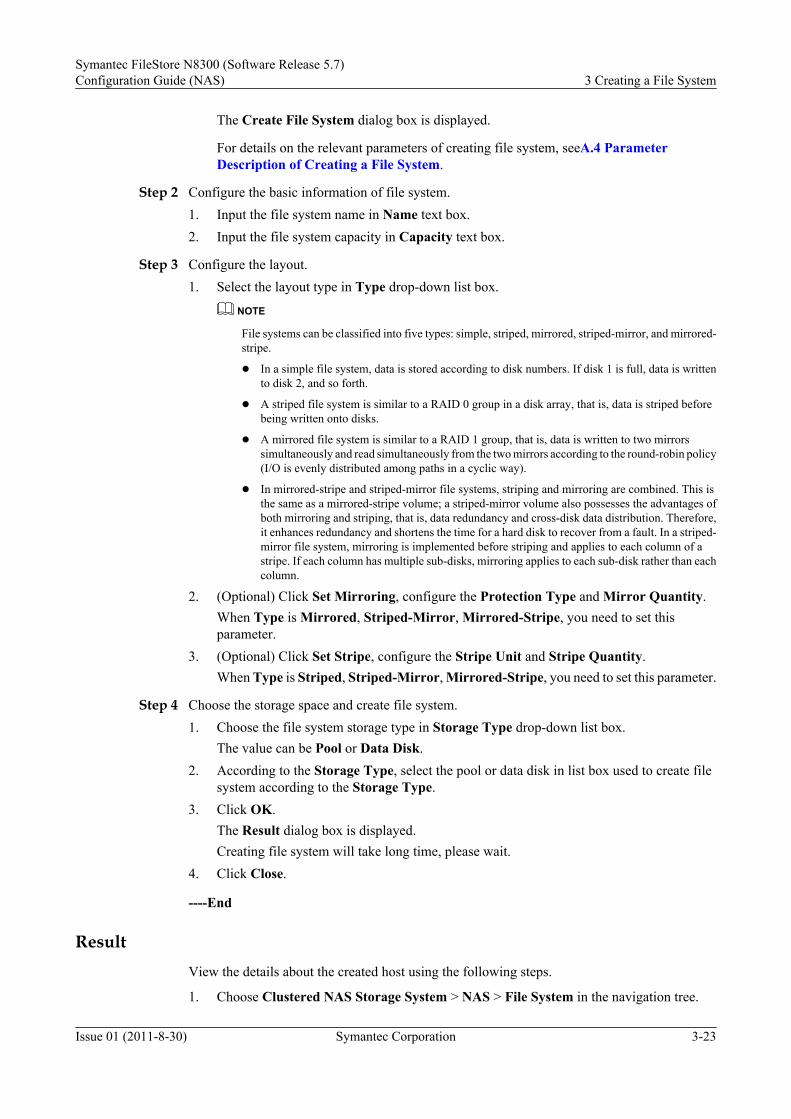
The Create File System dialog box is displayed.
For details on the relevant parameters of creating file system, seeA.4 ParameterDescription of Creating a File System.
Step 2 Configure the basic information of file system.1. Input the file system name in Name text box.2. Input the file system capacity in Capacity text box.
Step 3 Configure the layout.1. Select the layout type in Type drop-down list box.
NOTE
File systems can be classified into five types: simple, striped, mirrored, striped-mirror, and mirrored-stripe.
l In a simple file system, data is stored according to disk numbers. If disk 1 is full, data is writtento disk 2, and so forth.
l A striped file system is similar to a RAID 0 group in a disk array, that is, data is striped beforebeing written onto disks.
l A mirrored file system is similar to a RAID 1 group, that is, data is written to two mirrorssimultaneously and read simultaneously from the two mirrors according to the round-robin policy(I/O is evenly distributed among paths in a cyclic way).
l In mirrored-stripe and striped-mirror file systems, striping and mirroring are combined. This isthe same as a mirrored-stripe volume; a striped-mirror volume also possesses the advantages ofboth mirroring and striping, that is, data redundancy and cross-disk data distribution. Therefore,it enhances redundancy and shortens the time for a hard disk to recover from a fault. In a striped-mirror file system, mirroring is implemented before striping and applies to each column of astripe. If each column has multiple sub-disks, mirroring applies to each sub-disk rather than eachcolumn.
2. (Optional) Click Set Mirroring, configure the Protection Type and Mirror Quantity.When Type is Mirrored, Striped-Mirror, Mirrored-Stripe, you need to set thisparameter.
3. (Optional) Click Set Stripe, configure the Stripe Unit and Stripe Quantity.When Type is Striped, Striped-Mirror, Mirrored-Stripe, you need to set this parameter.
Step 4 Choose the storage space and create file system.1. Choose the file system storage type in Storage Type drop-down list box.
The value can be Pool or Data Disk.2. According to the Storage Type, select the pool or data disk in list box used to create file
system according to the Storage Type.3. Click OK.
The Result dialog box is displayed.Creating file system will take long time, please wait.
4. Click Close.
----End
ResultView the details about the created host using the following steps.
1. Choose Clustered NAS Storage System > NAS > File System in the navigation tree.
Symantec FileStore N8300 (Software Release 5.7)Configuration Guide (NAS) 3 Creating a File System
Issue 01 (2011-8-30) Symantec Corporation 3-23

2. Select the File System need to view.
3. View the details about the created file system.
Follow-up Procedure
3.3.1 Configuration Process shows how to configure a file system.
l The previous step is 3.3.2 Creating a Pool.
l The next step is 3.3.4 Creating a Local User.
3.3.4 Creating a Local UserThrough this operation, you can create a local user.
Precaution
The local user name cannot contain upper-case letters.
Procedure
Step 1 Go to Local Users and Groups Management dialog box.
1. On the main interface of the ISM, choose Clustered NAS Storage System > Settings inthe navigation tree.
2. In the function pane, click Local Users and Groups Management.The Local Users and Groups Management dialog box is displayed.
Step 2 Create local user.
1. Click the Local User tab.
2. Click Create.The Create Local User dialog box is displayed.
3. Enter a new user name in the User text box.
4. Enter password in the New Password text box.
5. Enter password again in the Confirm Password text box.
6. Click OK.The Result dialog box is displayed.
7. Click Close.
Step 3 Enter a new user name in the User text box.
Step 4 Enter password in the New Password text box.
Step 5 Enter password again in the Confirm Password text box.
Step 6 Click OK.The Result dialog box is displayed.
Step 7 Click Close.
----End
3 Creating a File SystemSymantec FileStore N8300 (Software Release 5.7)
Configuration Guide (NAS)
3-24 Symantec Corporation Issue 01 (2011-8-30)

Result
View the details about the created local user using the following steps.
1. Choose Clustered NAS Storage System > Settings in the navigation tree.2. In the function pane, click Local Users and Groups Management.3. Click the Local User tab.4. View the details about the created local user in User list box.
Follow-up Procedure
3.3.1 Configuration Process shows how to configure a file system.l The previous step is 3.3.3 Creating a File System.
l The next step is 3.3.5 Creating a Local Group.
3.3.5 Creating a Local GroupThrough this operation, you can create a local group.
Procedure
Step 1 Go to the Local Users and Groups Management dialog box.1. On the main interface of the ISM, choose Clustered NAS Storage System > Settings in
the navigation tree.2. In the function pane, click Local Users and Groups Management.
The Local Users and Groups Management dialog box is displayed.
Step 2 Create local group.1. Click the Local Group tab.2. Click Create.
The Create Group dialog box is displayed.3. Enter a new group name in the Group Name text box.4. Choose a user in the Select User box.5. Click OK.
The Result dialog box is displayed.6. Click Close.
----End
Result
View the details about the created local user using the following steps.
1. Choose Clustered NAS Storage System > Settings in the navigation tree.2. In the function pane, click Local Users and Groups Management.3. Click the Local Group tab.4. View the details about the created local user in Group Name list box.
Symantec FileStore N8300 (Software Release 5.7)Configuration Guide (NAS) 3 Creating a File System
Issue 01 (2011-8-30) Symantec Corporation 3-25

Follow-up Procedure3.3.1 Configuration Process shows how to configure a file system.l The previous step is 3.3.4 Creating a Local User.
l The next step is 3.3.6 Configuring a User/Group Quota (Optional).
3.3.6 Configuring a User/Group Quota (Optional)This section describes how to configure a user/group quota. By using this operation, you cancontrol the usage of space and the number of file systems for different users/groups.
NoteThe user quota or group quota cannot exceed the total capacity of the file system.
When the file system space usage exceeds the quota, you need to delete files to release the space.Wait three minutes after deleting the files and then create new files.
Procedure
Step 1 Enable user/group quota.1. On the main interface of the ISM, choose Clustered NAS Storage System > NAS > File
System in the navigation tree.2. Select the file system and click Quota.
The Quota dialog box is displayed.3. Click Enable.
Step 2 Go to the Add File System Quota dialog box.1. Click User/Group Quota tab.2. Click Add.
The Add File System Quota dialog box is displayed.
Step 3 Set the user or group need to configure quota.1. Choose Local User or Domain User in User Type drop-down list box.
When N8300 use domain authentication, you need to choose Domain User.2. Choose User or Quota Type in Quota Type group box.
Step 4 Set the quota related parameter.
For details on the relevant parameters of quota, see A.5 Parameter Description of ConfiguringQuota.
1. (Optional) Enter the file space soft quota in File Space Soft Quota text box, the unit canbe MB, GB or TB.
2. (Optional) Enter the file space hard quota in File Space Hard Quota text box, the unit canbe MB, GB or TB.
3. (Optional) Enter the Inode number soft quota in Inode Number Soft Quota text box.4. (Optional) Enter the Inode number hard quota in Inode Number Hard Quota text box.5. Click OK.
The Result dialog box is displayed.
3 Creating a File SystemSymantec FileStore N8300 (Software Release 5.7)
Configuration Guide (NAS)
3-26 Symantec Corporation Issue 01 (2011-8-30)

6. Click Close.
----End
ResultView the details about the created host using the following steps.
1. Choose Clustered NAS Storage System > NAS > File System in the navigation tree.2. In function pane, select the file system need to view quota information, click Quota.3. Click User/Group Quota tab.4. View the quota information in list box.
Follow-up Procedure3.3.1 Configuration Process shows how to configure a file system.l The previous step is 3.3.5 Creating a Local Group.
Symantec FileStore N8300 (Software Release 5.7)Configuration Guide (NAS) 3 Creating a File System
Issue 01 (2011-8-30) Symantec Corporation 3-27


4 Sharing a File System
About This Chapter
This section describes how to share a file system. After the file system is created, you can shareit in different modes.
The N8300 provides the following file system sharing modes:
1. For how to configure a CIFS share in the non-domain environment, see 4.1 Configuringa CIFS Share In a Non-Domain Environment.
2. For how to configure an NFS share in the non-domain environment, see 4.2 Configuringan NFS Share in a Non-Domain Environment.
3. For how to configure a CIFS share in the AD domain environment, see 4.3 Configuring aCIFS Share in AD Domain.
4. For how to configure an NFS share in the LDAP domain environment, see 4.4 Configuringan NFS Share in LDAP Environment.
5. For how to configure an NFS share in the NIS domain environment, see 4.5 Configuringan NFS Share in NIS Environment.
4.1 Configuring a CIFS Share In a Non-Domain EnvironmentCommon Internet File System (CIFS) is the mainstream file system for sharing betweenheterogeneous platforms. It is used for Windows environments. Configuring a CIFS share in anon-domain environment refers to configuring the CIFS normal share and CIFS homedir sharein the environment.
4.2 Configuring an NFS Share in a Non-Domain EnvironmentNetwork File System (NFS). Through NFS, users and programs can access files in a remotesystem similar to accessing local files. NFS enables each node (computer) to utilize networkresources as easily as local resources.
4.3 Configuring a CIFS Share in AD DomainActive Directory (AD) is a directory service for Windows Standard Server, Windows EnterpriseServer, and Windows Datacenter Server. Storing information related to network objects, ADenables the administrator and users to easily find and use the information.
4.4 Configuring an NFS Share in LDAP Environment
Symantec FileStore N8300 (Software Release 5.7)Configuration Guide (NAS) 4 Sharing a File System
Issue 01 (2011-8-30) Symantec Corporation 4-1

The N8300 uses Lightweight Directory Access Protocol (LDAP) for access control, that is, onlyspecified hosts can be mounted with NFS share. LDAP-based access control is mainly used foran NFS share environment.
4.5 Configuring an NFS Share in NIS EnvironmentNetwork Information Service (NIS), implemented in a NIS server, is used as an authenticationauthority. When a user logs into the N8300 , NIS enables Linux to compare the account/passwordentered by a user with the account/password stored on the NIS server. The NIS server also storesmany other types of information.
4 Sharing a File SystemSymantec FileStore N8300 (Software Release 5.7)
Configuration Guide (NAS)
4-2 Symantec Corporation Issue 01 (2011-8-30)

4.1 Configuring a CIFS Share In a Non-DomainEnvironment
Common Internet File System (CIFS) is the mainstream file system for sharing betweenheterogeneous platforms. It is used for Windows environments. Configuring a CIFS share in anon-domain environment refers to configuring the CIFS normal share and CIFS homedir sharein the environment.
4.1.1 About Configuring a CIFS Share in a Non-Domain EnvironmentThe CIFS share provided by the N8300 is used for Windows clients in a non-domain environmentor an AD domain. The CIFS share is used to share network files. It enables users to access fileson the server through Windows clients.
4.1.2 Configuring a CIFS Normal Share in a Non-Domain EnvironmentThis section describes how to configure the CIFS normal share in a non-domain environment.Through this operation, all users can access the shared directory.
4.1.3 Configuring a CIFS Homedir Share in a Non-Domain EnvironmentThis section describes how to configure the CIFS homedir share in a non-domain environment.Through this operation, different users can access the user group directory. Compared with theCIFS normal share, the CIFS homedir share does not allow all users to access the same shareddirectory.
4.1.1 About Configuring a CIFS Share in a Non-DomainEnvironment
The CIFS share provided by the N8300 is used for Windows clients in a non-domain environmentor an AD domain. The CIFS share is used to share network files. It enables users to access fileson the server through Windows clients.
Basic Concepts
Some basic concepts about the CIFS share provided by the N8300 are described as follows:
l CIFS
Common Internet File System (CIFS) is the mainstream file system for sharing betweenheterogeneous platforms. Developed by Microsoft, CIFS is mainly used for NT/Windowsenvironments. Running over TCP/IP, CIFS enables Windows-based computers "see"UNIX—based computers in network.
l CIFS share authentication modes
CIFS share authentication offers only one permission for access to shared files and twouser authentication modes: user and Active directory Server (ADS).
User: Local user authentication. User names and corresponding passwords are stored in theN8300. No other server is needed.
ADS: Active Directory Server. The AD domain controller is responsible for userauthentication. All members in the AD domain are allowed to access the shared files.
l CIFS normal share
Symantec FileStore N8300 (Software Release 5.7)Configuration Guide (NAS) 4 Sharing a File System
Issue 01 (2011-8-30) Symantec Corporation 4-3

The CIFS normal share means that the file system is shared as a directory and all users canaccess the directory.
l CIFS homedir share
The CIFS homedir share refers to that each user owns an independent user group whichhas the same name with the user. Each user can only access the corresponding user groupdirectory.
NOTE
The main difference between the CIFS homedir share and CIFS normal share is that whether different usershave different shared directories.
Principles for Configuring the CIFS Sharel The CIFS share provided by the N8300 is mainly used for Windows clients.
l If you do not need to limit permissions for the shared directory, configure the CIFS normalshare. However, if you want to allow only specified users to access the shared directory,configure the CIFS homedir share.
4.1.2 Configuring a CIFS Normal Share in a Non-DomainEnvironment
This section describes how to configure the CIFS normal share in a non-domain environment.Through this operation, all users can access the shared directory.
Procedure for Configuring a CIFS Normal Share in a Non-Domain Environment
The CIFS normal share allows all users to access the shared directory.
Figure 4-1 shows the flowchart of configuring a CIFS normal share in a non-domainenvironment.
Figure 4-1 Flowchart of configuring a CIFS normal share in a non-domain environment
Start
End
Accessing the CIFS Normal in User Mode
Creating a Normal Share
Global Configuration
Required child item
Optional child itemNote:
4 Sharing a File SystemSymantec FileStore N8300 (Software Release 5.7)
Configuration Guide (NAS)
4-4 Symantec Corporation Issue 01 (2011-8-30)

Creating a CIFS Normal ShareThis section describes how to create a CIFS normal share. A CIFS normal share enables all usersto access the shared file systems.
PrerequisiteThe specified file system must be online and must not be shared.
Precautionl You can not configure remote complication for a specified file system which has set the
paramter full_acl in CLI. For details of full_acl, please see the description for share addcommand in N8300 Series Clustered NAS Storage System Command Reference.
l You can not set the attribute full_acl for a specified shared file system after configuringthe remote replication.
Procedure
Step 1 Go to the Create CIFS Normal Share dialog box.1. On the main interface of the ISM, choose Clustered NAS Storage System > NAS
Services > CIFS in the navigation tree.2. In the function pane, choose Normal Share > Create.
The Create CIFS Normal Share dialog box is displayed.
Step 2 Configure basic information of CIFS Normal share.1. In the Share Name text box, enter a share name.2. Select the file system where you want to create the CIFS share.
Step 3 Modify the CIFS Normal share options.1. Click Modify....
The Modify Options dialog box is displayed.2. Modify CIFS Normal share options.
For details on the relevant parameters of creating CIFS Normal share, seeA.7 ParameterDescription of Modifying CIFS Normal Share Options.
3. Click OK.
Step 4 Confirm the configuration information and finish creating CIFS Normal share.1. Click OK.
The Result dialog box is displayed.2. Click Close.
Step 5 Enable the CIFS service.1. On the main interface of the ISM, choose Clustered NAS Storage System > NAS
Services > CIFS in the navigation tree.2. In the function pane, click CIFS Service.
The CIFS Service dialog box is displayed.3. Click Enable.
Symantec FileStore N8300 (Software Release 5.7)Configuration Guide (NAS) 4 Sharing a File System
Issue 01 (2011-8-30) Symantec Corporation 4-5

If you need to restart the CIFS service, click Disable in the CIFS Service dialog box, andthen click Enable.
CAUTIONRestarting the CIFS service interrupts the services running on the file system. Therefore,restart the CIFS service when the system is idle.
----End
ResultView the details about the created file system using the following steps.
1. Choose Clustered NAS Storage System > NAS > CIFS in the navigation tree.2. Select the File System need to view.3. View the details about the created file system in Details tab and Directories tab.
Follow-up ProcedureProcedure for Configuring a CIFS Normal Share in a Non-Domain Environment showshow to configure a CIFS Normal share in a Non-Domain Environment.l The next step is Global Configuration.
Global ConfigurationThis section describes how to configure global parameters.
Procedure
Step 1 Go to the Global Settings dialog box.1. On the main interface of the ISM, choose Clustered NAS Storage System > NAS
Services > CIFS in the navigation tree.2. In function pane, click Global Settings.
The Global Settings dialog box is displayed.
Step 2 Configuration global settings.
For details on the relevant parameters of global settings, see A.8 Parameter Description ofConfiguring CIFS Share Global Settings.
1. Select user in Security Mode drop-down list box.2. Click OK.
The Result dialog box is displayed.3. Click Close.
Step 3 Restart CIFS service.1. On the main interface of the ISM, choose Clustered NAS Storage System > NAS
Services > CIFS in the navigation tree.
4 Sharing a File SystemSymantec FileStore N8300 (Software Release 5.7)
Configuration Guide (NAS)
4-6 Symantec Corporation Issue 01 (2011-8-30)

2. In function pane, click CIFS Service.The CIFS Service dialog box is displayed.
3. Click Disable, then click Enable.
----End
ResultView the CIFS share global settings using the following steps.
1. Choose Clustered NAS Storage System > NAS > CIFS in the navigation tree.2. In the function pane, click Global Settings.
Follow-up ProcedureProcedure for Configuring a CIFS Normal Share in a Non-Domain Environment showshow to configure a CIFS Normal share in a Non-Domain Environment.l The previous step is Creating a CIFS Normal Share.
l The next step is Accessing the CIFS Normal Share in User Mode.
Accessing the CIFS Normal Share in User ModeThis section describes how to access the CIFS normal share in user mode. Through this operation,the user can access the shared file system in the non-domain environment.
ContextFor differences between CIFS normal and CIFS homedir shares, see 4.1.1 About Configuringa CIFS Share in a Non-Domain Environment.
Procedure
Step 1 In the Windows OS, choose Start > Run.The Run dialog box is displayed. Enter the virtual IP address of the CIFS normal share you needto accesse.For details on query the virtual IP address of the CIFS normal share, see 7.5.16 QueryingInformation About a Virtual IP Address of the CIFS Share.
Step 2 Click OK.You can see all the CIFS normal share folder.
Step 3 Double click the folder you need to access.The Connect to... dialog box is displayed.
Step 4 In the Connect to... dialog box, enter the username and password and click OK.
Symantec FileStore N8300 (Software Release 5.7)Configuration Guide (NAS) 4 Sharing a File System
Issue 01 (2011-8-30) Symantec Corporation 4-7

NOTE
If the Connect to... dialog box is not displayed after clicking OK in the Run dialog box, re-enable theCIFS service. Then wait until this operation is valid. For details, see Creating a CIFS Normal Share step7.
CAUTIONRestarting the CIFS service interrupts the services running on the file system. Therefore, restart the CIFSservice when the system is idle.
Step 5 Then, you can access the shared files system fs1 in the share directory.
NOTE
If you cannot access the file system, re-set the local username and password. For details, see 3.3.4 Creatinga Local User. Re-enable the share service and wait until this operation is valid. For details, see Creatinga CIFS Normal Share step 7.
CAUTIONRestarting the CIFS service interrupts the services running on the file system. Therefore, restart the CIFSservice when the system is idle.
----End
4.1.3 Configuring a CIFS Homedir Share in a Non-DomainEnvironment
This section describes how to configure the CIFS homedir share in a non-domain environment.Through this operation, different users can access the user group directory. Compared with theCIFS normal share, the CIFS homedir share does not allow all users to access the same shareddirectory.
Configuring a CIFS Homedir Share in a Non-Domain EnvironmentThe CIFS homedir share only allows each user to access the corresponding user group directory.Directories of different users are logically separate.
For the differences between the CIFS normal and CIFS homedir, see 4.1.1 About Configuringa CIFS Share in a Non-Domain Environment.
Figure 4-2 shows the flowchart of configuring a CIFS homedir in a non-domain environment.
4 Sharing a File SystemSymantec FileStore N8300 (Software Release 5.7)
Configuration Guide (NAS)
4-8 Symantec Corporation Issue 01 (2011-8-30)

Figure 4-2 Flowchart of configuring a CIFS homedir Share in a non-domain environment
Start
End
Accessing the CIFS Homedir Share in User
Mode
Adding a Homedir Share
Global Configuration
Adding a Quota
Required child item
Optional child itemNote:
Adding a Homedir Share
Through this operation, you can add a homedir share file system.
Prerequisite
The specified file system is online, and is not shared.
Procedure
Step 1 Go to the CIFS Homedir Share Management dialog box
1. On the main interface of the ISM, choose Clustered NAS Storage System > NASServices > CIFS in the navigation tree.
2. In the function pane, click Homedir Share.The CIFS Homedir Share Management dialog box is displayed.
Step 2 Create CIFS Homedir share.
1. Click Add.The Add File System dialog box is displayed.
2. Select the file system that you want to set for the homedir share.
3. Click OK.The Result dialog box is displayed
4. Click Close.
Step 3 Restart CIFS service.
Symantec FileStore N8300 (Software Release 5.7)Configuration Guide (NAS) 4 Sharing a File System
Issue 01 (2011-8-30) Symantec Corporation 4-9

CAUTIONRestarting the CIFS service interrupts the services running on the file system. Therefore, restartthe CIFS service during idle hours.
1. On the main interface of the ISM, choose Clustered NAS Storage System > NASServices > CIFS in the navigation tree.
2. In function pane, click CIFS Service.The CIFS Service dialog box is displayed.
3. Click Disable, then click Enable.
----End
Result
View the CIFS share global settings using the following steps.
1. Choose Clustered NAS Storage System > NAS > CIFS in the navigation tree.
2. In the function pane, click CIFS Homedir Share Management.
3. In CIFS Homedir Share Management dialog box, you can view the file systeminformation of CIFS Homedir share in Shared File Systems tab.
Follow-up Procedure
Configuring a CIFS Homedir Share in a Non-Domain Environment shows how to configurea CIFS Homedir share in a Non-Domain Environment.
l The next step is Global Configuration.
Global Configuration
This section describes how to configure global parameters.
CAUTIONAfter the homedir service is modified, the system prompts to restart the CIFS service. Restartingthe CIFS service interrupts the services running on the current file system. Therefore, restart theCIFS service when the system is idle.
For details on how to configure global parameters, see Global Configuration.
Adding a User Quota
This section describes how to configure a user quota. This operation only applies to the CIFShomedir share. Both the quota and quota status need to be configured. Through this operation,you can control the usage of space and the number of file systems for users from different groups.
4 Sharing a File SystemSymantec FileStore N8300 (Software Release 5.7)
Configuration Guide (NAS)
4-10 Symantec Corporation Issue 01 (2011-8-30)

PrerequisiteNOTE
After the homedir configuration is changed, you are prompted to restart the CIFS service, which interruptsthe work of the current file system. Therefore, change the homedir share configuration during idle hours.
Precautionsl The added user quota or group quota cannot exceed the total capacity of the file system.
l You need to use an existing local user name. In addition, in Global Settings, the SecureMode for the local user is user. For details on creating a local user, see 3.3.4 Creating aLocal User and 3.3.5 Creating a Local Group
l When the homedir share contains multiple file systems, the maximum quota or global quotafor each user or global quota cannot exceed the capacity of the smallest file system.
l The homedir service uses all the virtual IP addresses, and the upper limit on the number ofvirtual IP addresses is 42. Therefore, ensure that the number of bonded virtual IP addressesis within the limit before configuring the homedir service.
l When the homedir share contains multiple file systems, the maximum value among userquotas and the global quota cannot exceed the capacity of the smallest file system.
l Before applying the new settings, clear the quota information from the previous file system.
Procedure
Step 1 On the main interface of the ISM, choose Clustered NAS Storage System > NAS Services >CIFS in the navigation tree.
Step 2 In the function pane, click Homedir Quota.The Homedir Quota Management dialog box is displayed.
Step 3 Click the User/Group Quota tab.
Step 4 Click Add.The Add CIFS Homedir Quota dialog box is displayed.
Step 5 Choose the Domain User or Local User in the User Type drop-down list.
Step 6 Choose the User or Group in the Quota Type drop-down list.
Step 7 Choose the user name or group name in drop-down list.
Step 8 Set the quota parameters in the Add CIFS Homedir Quota dialog box. For descriptions of theparameters, see Table 4-1.
Table 4-1 Description of parameters in the Homedir Quota Management dialog box
Parameter
Description
File SpaceSoft Quota
Indicates that the exceeded space can still be used within a certain period of timewhen the space quota exceeds the preset value. In other words, the space quotacan exceed the preset value before the expiration date arrives.NOTE
The soft quota takes effect 7 days after the quota restriction is triggered.
Symantec FileStore N8300 (Software Release 5.7)Configuration Guide (NAS) 4 Sharing a File System
Issue 01 (2011-8-30) Symantec Corporation 4-11

Parameter
Description
File SpaceHardQuota
Indicates that once the space quota exceeds the preset value, the exceeded spacecannot be used.
FileQuantitySoft Quota
Indicates that the excessive files can still be used within a certain period of timewhen the quantity quota exceeds the preset value. In other words, the quantityquota can exceed the reset value before the expiration date arrives.NOTE
The soft quota takes effect 7 days after the quota restriction is triggered.
FileQuantityHardQuota
Indicates that once the quantity quota exceeds the preset value, the excessivefiles cannot be used.
Step 9 Click OK.The Result dialog box is displayed.
Step 10 Click Close.
Step 11 After the quota is configured, if the quota status is Disable, you need to click Enable in theHomedir Quota Management dialog box to enable the user quota or group quota.
----End
Accessing the CIFS Homedir Share in User Mode
This section describes how to access the CIFS homedir share in user mode. If access to the CIFShomedir share in user mode is enabled, each user can access the shared directory of thecorresponding group in a non-domain environment.
Context
For the differences between CIFS normal shares and CIFS homedir shares, see 4.1.1 AboutConfiguring a CIFS Share in a Non-Domain Environment.
Procedure
Step 1 In the Windows OS, choose Start > Run.The Run dialog box is displayed. Enter the service IP address of the N8300.
NOTE
Input as format as \\**.**.**.**\test in Run dialog box when the file system both set homedir share andnormal share. It contains N8300 service IP and user name.
Step 2 Click OK.The Connect to... dialog box is displayed.
Step 3 In the Connect to... dialog box, enter the username and password and click OK.
4 Sharing a File SystemSymantec FileStore N8300 (Software Release 5.7)
Configuration Guide (NAS)
4-12 Symantec Corporation Issue 01 (2011-8-30)

Step 4 After successful authentication, you can access the shared directory. If you access the N8300 asuser test, the N8300 automatically creates a directory named test (same as the username). Youcan only perform operations in the test directory.
----End
4.2 Configuring an NFS Share in a Non-DomainEnvironment
Network File System (NFS). Through NFS, users and programs can access files in a remotesystem similar to accessing local files. NFS enables each node (computer) to utilize networkresources as easily as local resources.
4.2.1 About Configuring an NFS Share in a Non-Domain EnvironmentNFS is mainly used for file sharing of operating systems, such as UNIX, Linux, AIX, and HP-UNIX. Through NFS, users and programs can access files in a remote system similar to accessinglocal files. NFS enables each node (computer) to utilize network resources as easily as localresources. NFS allows you to share and remotely access network files in environmentscontaining different types of computers, operating systems, network architectures, and transferprotocols.
4.2.2 Configuration ProcessYou can learn the operations about configuring NFS share in a non-domain environment throughthe flow chart.
4.2.3 Creating an NFS ShareThis section describes how to create an NFS share. After creating an NFS share, clients that haveUNIX, Linux, AIX, or HP-UNIX can access the shared file system.
4.2.4 Accessing the NFS ShareThis section describes how to access the NFS share from different clients, including SUSE andRedHat clients, HP-UNIX and SUN Solaris clients, IBM AIX clients, and Mac OS clients.
4.2.1 About Configuring an NFS Share in a Non-DomainEnvironment
NFS is mainly used for file sharing of operating systems, such as UNIX, Linux, AIX, and HP-UNIX. Through NFS, users and programs can access files in a remote system similar to accessinglocal files. NFS enables each node (computer) to utilize network resources as easily as localresources. NFS allows you to share and remotely access network files in environmentscontaining different types of computers, operating systems, network architectures, and transferprotocols.
Employing the client/server architecture, NFS consists of a client program and a server program.The server program enables other computers to access the file system. This process is called"output." When accessing shared file systems, the NFS client program "transfers" them out fromthe NFS server. The NFS protocol allows you to access and share files, and communicatebetween servers and clients. In this way, clients can remotely access data stored on storagedevices.
Symantec FileStore N8300 (Software Release 5.7)Configuration Guide (NAS) 4 Sharing a File System
Issue 01 (2011-8-30) Symantec Corporation 4-13

4.2.2 Configuration ProcessYou can learn the operations about configuring NFS share in a non-domain environment throughthe flow chart.
Figure 4-3 shows the flowchart of configuring the NFS share in a non-domain environment.
Figure 4-3 Flowchart of configuring the NFS share in a non-domain environment
Start
End
Creating an NFS Share
Accessing the NFS Share
Required child item
Optional child itemNote:
4.2.3 Creating an NFS ShareThis section describes how to create an NFS share. After creating an NFS share, clients that haveUNIX, Linux, AIX, or HP-UNIX can access the shared file system.
PrerequisiteThe specified file system must be online and the file system must not be shared.
If the file system is configured CIFS share , then it only can be configured read-only permissionof NFS share.
If the file system is configured NFS share , then it only can be configured read-only permissionof CIFS share.
Procedure
Step 1 Go to the Create NFS Share dialog box.1. On the main interface of the ISM, choose Clustered NAS Storage System > NAS
Services > NFS in the navigation tree.2. In the function pane, click Create.
The Create NFS Share dialog box is displayed.
Step 2 Create NFS share.1. In the Select File System list box, select the file system where you want to create the NFS
share.2. Click Modify....
The Modify Options dialog box is displayed.3. Set NFS share options.
4 Sharing a File SystemSymantec FileStore N8300 (Software Release 5.7)
Configuration Guide (NAS)
4-14 Symantec Corporation Issue 01 (2011-8-30)

For details on the relevant parameters of setting NFS share options, see A.9 ParameterDescription of Modifying NFS Share Options.
4. Click OK to go back to the Create NFS Share dialog box.
5. Choose the client that can access NFS share in Clients group box.
l Choose All clients, all clients can access this NFS share.
l Choose Host and enter the IP address in text box, the host with this IP address can accessthis NFS share.
l Choose Work Group and enter the group name in text box, the host belong to netgroupin LDAP domain or NIS domain can access this NFS share.
6. Click OK.The Result dialog box is displayed.
7. Click Close.
----End
Result
View the details about the created file system using the following steps.
1. Choose Clustered NAS Storage System > NAS > NFS in the navigation tree.
2. Select the NFS share need to view.
3. View NFS related information in Details tab, view client information in Clients tab.
Follow-up Procedure
4.2.2 Configuration Process shows how to configure an NFS Share in a Non-DomainEnvironment.
l The next step is 4.2.4 Accessing the NFS Share.
4.2.4 Accessing the NFS ShareThis section describes how to access the NFS share from different clients, including SUSE andRedHat clients, HP-UNIX and SUN Solaris clients, IBM AIX clients, and Mac OS clients.
Enabling the NFS service
Step 1 In the navigation tree on the ISM main interface, choose Clustered NAS Storage System >NAS Services > NFS.
Step 2 In the function pane, click NFS Service.The NFS Service dialog box is displayed.
Step 3 Click Enable to enable the NFS service.The Result dialog box is displayed.
Step 4 Click Close.
----End
Symantec FileStore N8300 (Software Release 5.7)Configuration Guide (NAS) 4 Sharing a File System
Issue 01 (2011-8-30) Symantec Corporation 4-15

SUSE and RedHat ClientsStep 1 Log in to the client as user root.
Step 2 Run the showmount command to view all the shared files on the N8300 NFS server.#showmount –e 192.168.28.39Export list for 192.168.28.39/vx/nfstest *#
NOTE
192.168.28.39 is the service IP address of the N8300./vx/nfstest is the NFS share file system for the N8300.
Step 3 Run the mount command to mount the remote file system.mount –t nfs 192.168.28.39:/vx/nfstest /mnt
NOTE
You can enter -o timeo=10 after the mount command to set the NFS server retry time.
Step 4 Check whether the shared file system of the remote Linux system is mounted to the local filesystem. If the N8300 shared file system is displayed on the screen, it indicates that the remoteLinux shared file system is successfully mounted on the local file system. In this case, the clientis mounted with the remote N8300 shared file system.#mount192.168.28.39:/vx/fs_sim on /mnt type nfs (rw,addr=192.168.28.39)
----End
HP-UNIX and SUN Solaris ClientsStep 1 Log in to the client as user root.
Step 2 Run the showmount command to view all the shared files on the N8300 NFS server.#showmount –e 192.168.28.39Export list for 192.168.28.39/vx/nfstest *#
NOTE
192.168.28.39 is the service IP address of the N8300./vx/nfstest is the NFS share file system of the N8300.
Step 3 Run the mount command to mount the remote file system.mount –f nfs -o vers=3,proto=tcp 192.168.28.39:/vx/nfstest /mnt
NOTE
-f nfs is the default option. You can also choose not to enter it.For Vers, select option 2 or option 3.For Proto, select tcp or udp.
Step 4 Check whether the shared file system of the remote Linux system is mounted to the local filesystem. If the N8300 shared file system is displayed on the screen, it indicates that the remoteLinux shared file system is mounted to the local file system. In this case, the client is mountedwith the remote N8300 shared file system successfully.#mount192.168.28.39:/vx/fs_sim on /mnt type nfs (rw,addr=192.168.28.39)
----End
4 Sharing a File SystemSymantec FileStore N8300 (Software Release 5.7)
Configuration Guide (NAS)
4-16 Symantec Corporation Issue 01 (2011-8-30)

IBM AIX Clients
Step 1 Log in to the client as user root.
Step 2 Run the showmount command to view all the shared files on the N8300 NFS server.#showmount –e 192.168.28.39Export list for 192.168.28.39/vx/nfstest *#
NOTE
192.168.28.39 is the service IP address of the N8300.
/vx/nfstest is the NFS share file system of the N8300.
Step 3 Run the mount command to mount the remote file system.mount 192.168.28.39:/vx/nfstest /mntmount: 1831-008 giving up on:192.168.28.39:/vx/nfstest Vmount: Operation not permitted.#
NOTE
After the mount command is run, the Linux NFS share might fail to mount to the AIX client and the systemprompts that the permission does not match. The reason is that the AIX client does not match the defaultNFS port of the Linux. Run the following command to solve this problem.#nfso –o nfs_use_reserved_ports=1Setting nfs_use_reserved_ports to 1
Step 4 Check whether the shared file system of the remote Linux system is mounted to the local filesystem. If the N8300 shared file system is displayed on the screen, it indicates that the remoteLinux shared file system is mounted to the local file system. In this case, the client is mountedwith the remote N8300 shared file system successfully.#mount192.168.28.39:/vx/fs_sim on /mnt type nfs (rw,addr=192.168.28.39)
----End
Mac OS Clients
Step 1 Run the showmount command to view all the shared files on the N8300 NFS server.Volumes root# showmount -e 192.168.65.200Exports list on 192.168.65.200:/vx/fs_1 *
Step 2 Run the mount command to mount the remote file system.Volumes root# sudo /sbin/mount_nfs -P 192.168.65.200:/vx/fs_1 /Volumes/mount1
Step 3 Check whether the shared file system of the remote Linux system is mounted to the local filesystem. If the N8300 shared file system is displayed on the screen, it indicates that the remoteLinux shared file system is mounted to the local file system. In this case, the client is mountedwith the remote N8300 shared file system successfully.Volumes root# mount/dev/disk0s2 on / (hfs, local, journaled)devfs on /dev (devfs, local)fdesc on /dev (fdesc, union)map -hosts on /net (autofs, automounted)map auto_home on /home (autofs, automounted)192.168.65.200:/vx/fs_1 on /Volumes/mount1 (nfs)
----End
Symantec FileStore N8300 (Software Release 5.7)Configuration Guide (NAS) 4 Sharing a File System
Issue 01 (2011-8-30) Symantec Corporation 4-17

4.3 Configuring a CIFS Share in AD DomainActive Directory (AD) is a directory service for Windows Standard Server, Windows EnterpriseServer, and Windows Datacenter Server. Storing information related to network objects, ADenables the administrator and users to easily find and use the information.
4.3.1 About Configuring a CIFS Share in AD DomainThe N8300 joins an Active Directory (AD) domain as a client of the AD domain controller. TheAD domain controller authenticates all domain users who access the N8300.
4.3.2 Configuration ProcessYou can learn the operations about configuring a CIFS share in AD domain through the flowchart.
4.3.3 Configuring an NTP ServerThis section describes how to configure a Network Time Protocol (NTP) server.
4.3.4 Configuring a DNS Server (Optional)This section describes how to configure a DNS server. The domain controller registers itselfwith the DNS server; so that other computers can find the domain controller through the DNSserver.
4.3.5 Configuring an AD Domain ControllerThis section describes how to configure an AD controller. Build an AD domain by configuringan AD domain controller. Add the N8300 to the domain to serve as a client.
4.3.6 Establishing a Connection in the AD DomainThis section describes how to establish a connection in the AD domain. After a connection isestablish in the AD domain, the N8300 is added to the domain as a client. All permissions areconfigured and authenticated by the domain server.
4.3.1 About Configuring a CIFS Share in AD DomainThe N8300 joins an Active Directory (AD) domain as a client of the AD domain controller. TheAD domain controller authenticates all domain users who access the N8300.
Basic ConceptsBasic concepts about an AD domain are described as follows:
l ADAD is a directory service for Windows Standard Server, Windows Enterprise Server, andWindows Datacenter Server. AD stores information about network objects thatadministrator and users can easily query and use. AD uses a tiered data storage mode andhierarchically organizes directory information.
l DNSA domain name service server (DNS server) stores the domain names and correspondingIP addresses of all the hosts on the network and converts domain names to IP addresses.As the server in client/server mode, a DNS server can be a main server or forwarding server.The process of mapping a domain name to the corresponding IP address is called domainname resolution. When a user enters a DNS name in an application, DNS converts the nameto the corresponding format, such as an IP address.
4 Sharing a File SystemSymantec FileStore N8300 (Software Release 5.7)
Configuration Guide (NAS)
4-18 Symantec Corporation Issue 01 (2011-8-30)

l Domain
A domain is the unique security boundary of the computer network of Windows NT orWindows 2000. AD consists of one or multiple domains. For a stand-alone station, a domainrefers to a computer. The domain can be expanded to different physical locations. Eachdomain has its security policies and security relationships with other domains.
Typical Networking Modes
Storing information related to network objects, the AD enables the administrator and users toeasily find and use the information. It stores data in a structured way, and organizes the directoryinformation logically on this basis.
Figure 4-4 shows a typical networking scenario in an AD domain.
Figure 4-4 Typical networking in AD domain
AD Client
……
AD Mater Server
Clustered NAS Storage System
AD Client AD Client
AD Slave Server
LAN
4.3.2 Configuration ProcessYou can learn the operations about configuring a CIFS share in AD domain through the flowchart.
Figure 4-5 shows the flowchart of configuring the CIFS share in an AD domain.
Symantec FileStore N8300 (Software Release 5.7)Configuration Guide (NAS) 4 Sharing a File System
Issue 01 (2011-8-30) Symantec Corporation 4-19

Figure 4-5 Flowchart of configuring a CIFS share in AD domain
Start
End
Configuring an NTP Server
Configuring a Primary AD Domain Controller
Exporting the Configuration File of
Engine
Configuring a DNS Server
Checking the AD Status
Establishing the Connection Between the
N8300 and the NTP
Establishing the Connection Between the
N8300 and the DNS
Establishing the Connection Between the
N8300 and the AD Domain Controller
Creating a CIFS Share in AD Domain
1. Configuring Network
Environment
2. Configuring AD Domain Controller
3. Establishing the Connection
4.Creating the CIFS Share
5. Backup the Configuration
File
Configuring a Secondary AD Domain Controller
Required child item
Optional child itemNote:
4.3.3 Configuring an NTP ServerThis section describes how to configure a Network Time Protocol (NTP) server.
4 Sharing a File SystemSymantec FileStore N8300 (Software Release 5.7)
Configuration Guide (NAS)
4-20 Symantec Corporation Issue 01 (2011-8-30)
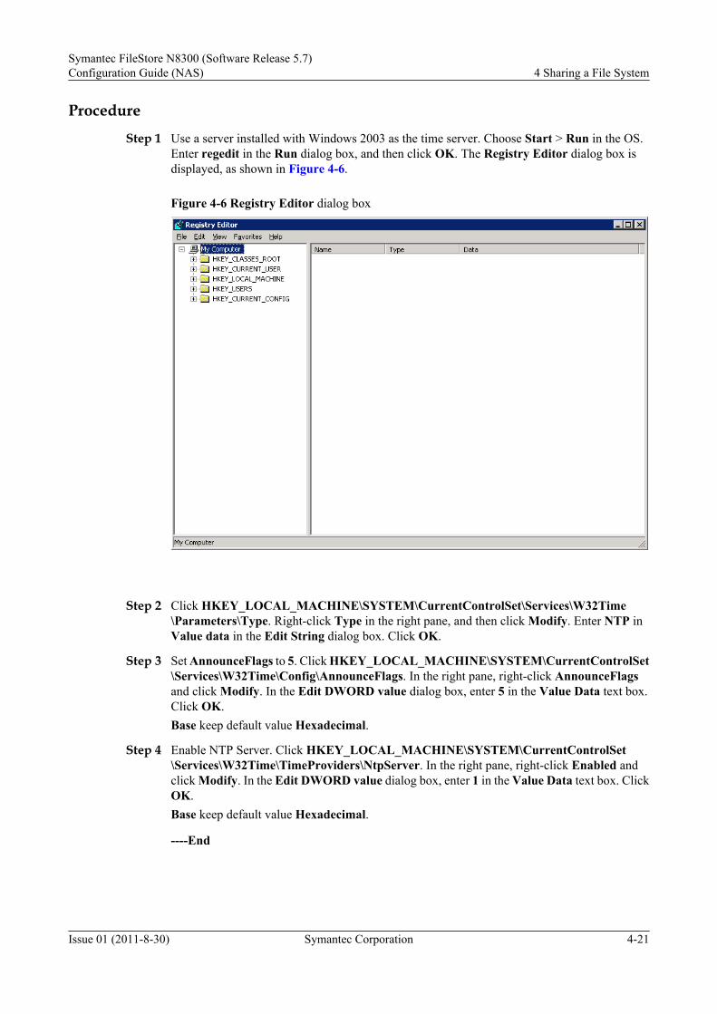
Procedure
Step 1 Use a server installed with Windows 2003 as the time server. Choose Start > Run in the OS.Enter regedit in the Run dialog box, and then click OK. The Registry Editor dialog box isdisplayed, as shown in Figure 4-6.
Figure 4-6 Registry Editor dialog box
Step 2 Click HKEY_LOCAL_MACHINE\SYSTEM\CurrentControlSet\Services\W32Time\Parameters\Type. Right-click Type in the right pane, and then click Modify. Enter NTP inValue data in the Edit String dialog box. Click OK.
Step 3 Set AnnounceFlags to 5. Click HKEY_LOCAL_MACHINE\SYSTEM\CurrentControlSet\Services\W32Time\Config\AnnounceFlags. In the right pane, right-click AnnounceFlagsand click Modify. In the Edit DWORD value dialog box, enter 5 in the Value Data text box.Click OK.Base keep default value Hexadecimal.
Step 4 Enable NTP Server. Click HKEY_LOCAL_MACHINE\SYSTEM\CurrentControlSet\Services\W32Time\TimeProviders\NtpServer. In the right pane, right-click Enabled andclick Modify. In the Edit DWORD value dialog box, enter 1 in the Value Data text box. ClickOK.Base keep default value Hexadecimal.
----End
Symantec FileStore N8300 (Software Release 5.7)Configuration Guide (NAS) 4 Sharing a File System
Issue 01 (2011-8-30) Symantec Corporation 4-21

4.3.4 Configuring a DNS Server (Optional)This section describes how to configure a DNS server. The domain controller registers itselfwith the DNS server; so that other computers can find the domain controller through the DNSserver.
PrerequisiteA DNS server must support local service (SRV) resource records. It is better if the DNS serversimultaneously supports dynamic updates, incremental zone transfer, and fast zone transfer.
ContextA DNS server can be configured in the following two ways:
l When an independent server or member server is upgraded to the domain controller,Microsoft DNS Server is automatically installed on the server. Meanwhile, a zone thatsupports AD domains is created on the DNS server.
l If the existing DNS server is used or another DNS server is installed, create a zone thatsupports AD domains on the DNS server.
Procedure
Step 1 On the Windows Server 2003 Enterprise Edition SP2 system that is to be an independent serveror member server, choose Start > Administrative Tools > Configure Your Server Wizard tostart the server installation wizard.
Step 2 Click Next in the Configure Your Server Wizard window. Finish the preparation workaccording to the prompt messages. Then click Next, as shown in Figure 4-7.
4 Sharing a File SystemSymantec FileStore N8300 (Software Release 5.7)
Configuration Guide (NAS)
4-22 Symantec Corporation Issue 01 (2011-8-30)

Figure 4-7 Configure Your Server Wizard dialog box
Figure 4-8 Preparation steps before configuring a server
Symantec FileStore N8300 (Software Release 5.7)Configuration Guide (NAS) 4 Sharing a File System
Issue 01 (2011-8-30) Symantec Corporation 4-23

Step 3 In the Server Role drop-down list, select DNS Server and click Next, as shown in Figure4-9.
Figure 4-9 Selecting a server role
Step 4 Confirm the selection and click Next. The Configure a DNS Server Wizard window isdisplayed. Then click Next, as shown in Figure 4-10.
4 Sharing a File SystemSymantec FileStore N8300 (Software Release 5.7)
Configuration Guide (NAS)
4-24 Symantec Corporation Issue 01 (2011-8-30)

Figure 4-10 Server confirmation interface
Figure 4-11 Configure a DNS Server Wizard 1
Symantec FileStore N8300 (Software Release 5.7)Configuration Guide (NAS) 4 Sharing a File System
Issue 01 (2011-8-30) Symantec Corporation 4-25

Step 5 Select a lookup zone type. The forward lookup zone is the default option. You can manuallyconfigure the lookup zone type after configuring DNS, as shown in Figure 4-12.
Figure 4-12 Configure a DNS Server Wizard 2
Step 6 Select This server maintains the zone to create a primary forward lookup zone, as shown inFigure 4-13.
4 Sharing a File SystemSymantec FileStore N8300 (Software Release 5.7)
Configuration Guide (NAS)
4-26 Symantec Corporation Issue 01 (2011-8-30)

Figure 4-13 Configure a DNS Server Wizard 3
Step 7 Enter a zone name (hs.com is used as an example), as shown in Figure 4-14.
Symantec FileStore N8300 (Software Release 5.7)Configuration Guide (NAS) 4 Sharing a File System
Issue 01 (2011-8-30) Symantec Corporation 4-27

Figure 4-14 New Zone Wizard 1
Step 8 You can choose to allow only secure dynamic updates, allow both non-secure and securedynamic updates, or do not allow dynamic updates, as shown in Figure 4-15.
4 Sharing a File SystemSymantec FileStore N8300 (Software Release 5.7)
Configuration Guide (NAS)
4-28 Symantec Corporation Issue 01 (2011-8-30)

Figure 4-15 New Zone Wizard 2
Figure 4-16 Configure a DNS Server Wizard 4
Symantec FileStore N8300 (Software Release 5.7)Configuration Guide (NAS) 4 Sharing a File System
Issue 01 (2011-8-30) Symantec Corporation 4-29

Step 9 Confirm the previous DNS settings and click Finish, as shown in Figure 4-17.
Figure 4-17 Configure a DNS Server Wizard 5
Step 10 Choose Start > Administrative Tools > DNS to enter DNS management interface.
Step 11 On DNS management interface, choose Forward Lookup Zones > hs.com > New Host to adda host, as shown in Figure 4-18 and Figure 4-19.
Add the N8300 as the client. sfstest is the virtual name of the client and 129.62.26.101 is the IPaddress of the client.
4 Sharing a File SystemSymantec FileStore N8300 (Software Release 5.7)
Configuration Guide (NAS)
4-30 Symantec Corporation Issue 01 (2011-8-30)

Figure 4-18 Add client
Repeat the same steps to add the ADS. client13 is the name of the ADS. 129.62.26.233 is theIP address of the ADS.
Figure 4-19 Add ADS
Step 12 On DNS management interface, choose Reverse Lookup Zones > New Zone, as shown inFigure 4-20.
Symantec FileStore N8300 (Software Release 5.7)Configuration Guide (NAS) 4 Sharing a File System
Issue 01 (2011-8-30) Symantec Corporation 4-31

Figure 4-20 Creating a reverse lookup zone
1. On the New Zone Wizard interface, click Next, as shown in Figure 4-21.
Figure 4-21 Creating a reverse lookup zone interface 1
4 Sharing a File SystemSymantec FileStore N8300 (Software Release 5.7)
Configuration Guide (NAS)
4-32 Symantec Corporation Issue 01 (2011-8-30)

2. Figure 4-22 shows the second step for creating a reserve lookup zone.
Figure 4-22 Creating a reverse lookup zone interface 2
3. Figure 4-23 shows the third step for creating a reserve lookup zone.
Symantec FileStore N8300 (Software Release 5.7)Configuration Guide (NAS) 4 Sharing a File System
Issue 01 (2011-8-30) Symantec Corporation 4-33

Figure 4-23 Creating a reverse lookup zone interface 3
4. The fourth step for creating a reserve lookup zone is to enter the network ID 129.62.26,
which is in the network segment where the IP addresses of the NBU server and backupclient are, as shown in Figure 4-24.
4 Sharing a File SystemSymantec FileStore N8300 (Software Release 5.7)
Configuration Guide (NAS)
4-34 Symantec Corporation Issue 01 (2011-8-30)

Figure 4-24 Creating a reverse lookup zone interface 4
5. Figure 4-25 shows the fifth step for creating a reserve lookup zone.
Symantec FileStore N8300 (Software Release 5.7)Configuration Guide (NAS) 4 Sharing a File System
Issue 01 (2011-8-30) Symantec Corporation 4-35

Figure 4-25 Creating a reverse lookup zone interface 5
6. The sixth step for creating a reserve lookup zone is to confirm the settings and click
Finish, as shown in Figure 4-26.
4 Sharing a File SystemSymantec FileStore N8300 (Software Release 5.7)
Configuration Guide (NAS)
4-36 Symantec Corporation Issue 01 (2011-8-30)

Figure 4-26 Creating a reverse lookup zone interface 6
Step 13 In the reverse lookup zone, create a pointer (PTR), as shown in Figure 4-27 and Figure 4-28.
Figure 4-27 Creating a pointer in the reverse lookup zone
Symantec FileStore N8300 (Software Release 5.7)Configuration Guide (NAS) 4 Sharing a File System
Issue 01 (2011-8-30) Symantec Corporation 4-37

Figure 4-28 New Resource Record dialog box
Host IP number 101 corresponds to host sfstest. Repeat the previous steps to add client13.
Step 14 Check whether DNS is successfully configured. Choose Start > Run. Run the pingsfstest.hs.com and ping client13.hs.com commands. If they can be pinged through, DNS issuccessfully configured, as shown in Figure 4-29.
4 Sharing a File SystemSymantec FileStore N8300 (Software Release 5.7)
Configuration Guide (NAS)
4-38 Symantec Corporation Issue 01 (2011-8-30)

Figure 4-29 Command interface
----End
4.3.5 Configuring an AD Domain ControllerThis section describes how to configure an AD controller. Build an AD domain by configuringan AD domain controller. Add the N8300 to the domain to serve as a client.
Configuring a Primary AD Domain ControllerThis section describes how to configure a primary AD domain controller. The N8300 is addedto the domain as a client. All permissions are configured and authenticated by the domain server.
Prerequisitel The DNS domain name is already set.
l A DNS server is already set.
l Enough disk space is reserved.
l At least one NTFS disk partition is ready.
Procedure
Step 1 On the Windows Server 2003 Enterprise Edition SP2 that is to be an independent server ormember server, choose start > Run. Enter dcpromo to open the Active Directory installationwizard, as shown in .Figure 4-30.
Symantec FileStore N8300 (Software Release 5.7)Configuration Guide (NAS) 4 Sharing a File System
Issue 01 (2011-8-30) Symantec Corporation 4-39

Figure 4-30 Configure Your Server Wizard window
Step 2 Click Next to go to the preliminary steps, as shown in Figure 4-31.
4 Sharing a File SystemSymantec FileStore N8300 (Software Release 5.7)
Configuration Guide (NAS)
4-40 Symantec Corporation Issue 01 (2011-8-30)

Figure 4-31 Preliminary steps
Step 3 Click Next. A warning message is displayed, indicating that the server has no networkconnection. Before configuring the server, make sure that it is connected to the network.
Step 4 Select Domain Controller (Active Directory) in the dialog box shown in Figure 4-32. ClickNext to start configuring the AD domain controller.
Symantec FileStore N8300 (Software Release 5.7)Configuration Guide (NAS) 4 Sharing a File System
Issue 01 (2011-8-30) Symantec Corporation 4-41

Figure 4-32 Server role configuration
Step 5 Click Next in the dialog box shown in Figure 4-33.
4 Sharing a File SystemSymantec FileStore N8300 (Software Release 5.7)
Configuration Guide (NAS)
4-42 Symantec Corporation Issue 01 (2011-8-30)

Figure 4-33 Active Directory Installation Wizard
Step 6 Click Next in the dialog box shown in Figure 4-34.
Figure 4-34 Operating System Compatibility
Symantec FileStore N8300 (Software Release 5.7)Configuration Guide (NAS) 4 Sharing a File System
Issue 01 (2011-8-30) Symantec Corporation 4-43

Step 7 Select the type of the domain controller to be created. Select a new domain controller, and thenclick Next, as shown in Figure 4-35.
Figure 4-35 Domain Controller Type
Step 8 Select Domain in a new forest, and then click Next, as shown in Figure 4-36.
4 Sharing a File SystemSymantec FileStore N8300 (Software Release 5.7)
Configuration Guide (NAS)
4-44 Symantec Corporation Issue 01 (2011-8-30)

Figure 4-36 Create New Domain
Step 9 In the dialog box shown in Figure 4-37, enter a domain name that complies with DNS format(hstest.com for example). Then the wizard checks whether the name already exists on thenetwork. If yes, the wizard requires you to enter a new domain name.
Symantec FileStore N8300 (Software Release 5.7)Configuration Guide (NAS) 4 Sharing a File System
Issue 01 (2011-8-30) Symantec Corporation 4-45

Figure 4-37 New Domain Name
Step 10 Set the NetBIOS domain name. In the dialog box shown in Figure 4-38, enter a domain namethat complies with the NetBIOS format, so that Windows 95 and Windows NT computers, whichdo not support DNS, can access resources in the domain through the NetBIOS.
NOTE
By default, this domain name is the first half of DNS domain name. For example, if DNS domain name ishstest.com, the NetBIOS domain name is HSTEST. If the name already exists on the network, the wizardautomatically changes it. This name should not contain more than 15 characters and can be changed.
4 Sharing a File SystemSymantec FileStore N8300 (Software Release 5.7)
Configuration Guide (NAS)
4-46 Symantec Corporation Issue 01 (2011-8-30)

Figure 4-38 NetBIOS Domain Name
Step 11 Select folders for storing the AD database and log file, and then click Next, as shown in Figure4-39.
Symantec FileStore N8300 (Software Release 5.7)Configuration Guide (NAS) 4 Sharing a File System
Issue 01 (2011-8-30) Symantec Corporation 4-47

Figure 4-39 Database and Log Folders
Step 12 Select a folder for storing SYSVOL (SYSVOL can only sit in an NTFS-formated disk partition).Click Next, as shown in Figure 4-40.
4 Sharing a File SystemSymantec FileStore N8300 (Software Release 5.7)
Configuration Guide (NAS)
4-48 Symantec Corporation Issue 01 (2011-8-30)

Figure 4-40 Shared System Volume
Step 13 Select the default permissions for users and groups, as shown in Figure 4-41. Select Permissionscompatible only with Windows 2000 and Windows Server 2003 operating systems, and thenclick Next.
Figure 4-41 Permissions
Symantec FileStore N8300 (Software Release 5.7)Configuration Guide (NAS) 4 Sharing a File System
Issue 01 (2011-8-30) Symantec Corporation 4-49

Step 14 Set the administrator password for the directory services restore mode, as shown in Figure4-42. Then click Next.
NOTE
The directory services restore mode is a safe mode in which the AD database can be restored. To enter thismode, press the F8 key when the system is starting, and enter the password set in this step.
Figure 4-42 Directory Services Restore Mode Administrator Password
Step 15 Review and confirm your previous settings, as shown in Figure 4-43. Click Next to configureAD, as shown in Figure 4-44.
4 Sharing a File SystemSymantec FileStore N8300 (Software Release 5.7)
Configuration Guide (NAS)
4-50 Symantec Corporation Issue 01 (2011-8-30)

Figure 4-43 Reviewing and confirming the configured options
Figure 4-44 Configuring Active Directory
Symantec FileStore N8300 (Software Release 5.7)Configuration Guide (NAS) 4 Sharing a File System
Issue 01 (2011-8-30) Symantec Corporation 4-51

Step 16 After the configuration is complete, click Finish to restart the system, as shown in Figure4-45.
Figure 4-45 Completing the Active Directory Installation Wizard
----End
Configuring a Secondary AD Domain Controller (Optional)This section describes how to configure a secondary AD domain controller. A secondary ADdomain controller shares the workload of the primary controller and enables fault tolerance.
ContextConfiguring multiple domain controllers:l Shortens the duration of a user login process. Because multiple domain controllers share
the work of authenticating user names and passwords, users can log in to the system morequickly.
l Enables fault tolerance. Even if one domain controller becomes faulty, other domaincontrollers take over its work, so that users can still log in to the system.
Procedure
Step 1 Click Start > Control Panel. Double-click the Network and Dial-up Connections icon. In theNetwork Connections window, double-click Local Area Connection, and then click
4 Sharing a File SystemSymantec FileStore N8300 (Software Release 5.7)
Configuration Guide (NAS)
4-52 Symantec Corporation Issue 01 (2011-8-30)

Properties in the dialog box. The Local Area Connection Properties window is displayed.Click Internet Protocol (TCP/IP), and the Internet Protocol (TCP/IP) Properties dialog boxis displayed, as shown in Figure 4-46.
Figure 4-46 Setting a DNS server
Step 2 In the Internet Protocol (TCP/IP) Properties dialog box, enter the IP address of DNS serverin Preferred DNS server.
NOTE
Perform this step first, so that this computer can find other domain controllers through DNS server. Afterbeing configured as a domain controller, this computer must register itself with DNS server, so that othercomputers can find it through DNS server.
Step 3 Choose Start > Run. The Run dialog box is displayed. Enter dcpromo to start the ActiveDirectory installation wizard.
Step 4 Click Next in the dialog box shown in Figure 4-47.
Symantec FileStore N8300 (Software Release 5.7)Configuration Guide (NAS) 4 Sharing a File System
Issue 01 (2011-8-30) Symantec Corporation 4-53

Figure 4-47 Installation wizard
Step 5 Click Next in the window shown in Figure 4-48.
Figure 4-48 Operating System Compatibility
4 Sharing a File SystemSymantec FileStore N8300 (Software Release 5.7)
Configuration Guide (NAS)
4-54 Symantec Corporation Issue 01 (2011-8-30)

Step 6 Select Additional domain controller for an existing domain, as shown in Figure 4-49.
CAUTIONOnce this computer is configured as an additional domain controller, all the accounts and keysin the computer will be deleted. As a result, data encrypted before cannot be read. Therefore,decrypt the encrypted data before performing this step.
Figure 4-49 Domain Controller Type
Step 7 Check whether DNS server IP address of this computer is already specified, and then clickNext.
Step 8 Enter the username and password for the domain controller, as shown in Figure 4-50.
Symantec FileStore N8300 (Software Release 5.7)Configuration Guide (NAS) 4 Sharing a File System
Issue 01 (2011-8-30) Symantec Corporation 4-55

Figure 4-50 Setting the network username and password
Step 9 Set the name of the domain where the domain controller belongs and click Next, as shown inFigure 4-51.
4 Sharing a File SystemSymantec FileStore N8300 (Software Release 5.7)
Configuration Guide (NAS)
4-56 Symantec Corporation Issue 01 (2011-8-30)

Figure 4-51 Additional Domain Controller
Step 10 Select folders for storing the AD database and log file, and then click Next, as shown in Figure4-52.
Symantec FileStore N8300 (Software Release 5.7)Configuration Guide (NAS) 4 Sharing a File System
Issue 01 (2011-8-30) Symantec Corporation 4-57

Figure 4-52 Database and Log Folders
Step 11 Select a folder for storing SYSVOL (SYSVOL can only sit in an NTFS-formated disk partition),as shown in Figure 4-53. Click Next.
4 Sharing a File SystemSymantec FileStore N8300 (Software Release 5.7)
Configuration Guide (NAS)
4-58 Symantec Corporation Issue 01 (2011-8-30)

Figure 4-53 Shared System Volume
Step 12 Set the administrator password for the directory services restore mode, as shown in Figure4-54. Then click Next.
NOTE
The directory services restore mode is a safe mode in which the AD database can be restored. To enter thismode, press the F8 key when the system is starting, and enter the password set in this step.
Symantec FileStore N8300 (Software Release 5.7)Configuration Guide (NAS) 4 Sharing a File System
Issue 01 (2011-8-30) Symantec Corporation 4-59

Figure 4-54 Directory Services Restore Mode Administrator Password
Step 13 Make sure that the contents of Summary in the dialog box shown in Figure 4-55 are correct.Then click Next.
4 Sharing a File SystemSymantec FileStore N8300 (Software Release 5.7)
Configuration Guide (NAS)
4-60 Symantec Corporation Issue 01 (2011-8-30)

Figure 4-55 Reviewing selected options
Step 14 After the configuration is complete, click Finish to restart the system, as shown in Figure4-56.
Symantec FileStore N8300 (Software Release 5.7)Configuration Guide (NAS) 4 Sharing a File System
Issue 01 (2011-8-30) Symantec Corporation 4-61

Figure 4-56 Completing the Active Directory Installation Wizard
----End
Checking the AD StatusAfter the AD installation is complete, check whether the SRV record, SYSVOL folder, and ADdatabase file of the DNS were created normally.
Procedure
Step 1 Check whether the records on DNS server are complete.1. Check the host name and IP address. Check whether the domain controller has registered
its host name and IP address with DNS server. On DNS server, choose Start >Administrative Tool > DNS, as shown in Figure 4-57. There should be a zone namedhstest.com, so that members in the hstest.com domain can register data with this zone.Check whether Figure 4-57 contains the following folders: _msdcs, _sites, _tcp, and_udp.
4 Sharing a File SystemSymantec FileStore N8300 (Software Release 5.7)
Configuration Guide (NAS)
4-62 Symantec Corporation Issue 01 (2011-8-30)

Figure 4-57 DNS Management window
2. Check the SRV record with the NSLOOKUP program. Choose Start > Run. Enter cmdin the dialog box. Run nslookup using the CLI. Enter the set type=srv command. As shownin Figure 4-58, enter _ldap._tcp.dc._msdcs.hstest.com. You can see that two domaincontrollers have successfully registered their LDAP server role information with DNSserver.
Figure 4-58 CLI for checking the SVR
Symantec FileStore N8300 (Software Release 5.7)Configuration Guide (NAS) 4 Sharing a File System
Issue 01 (2011-8-30) Symantec Corporation 4-63

Step 2 Check the Active Directory database file and the SYSVOL folder.1. By default, the AD database file and the log file are stored in C:\WINDOWS\NTDS.
Choose Start > Run, and enter %systemroot%\NTDS to check whether the folder andfiles are created correctly. As shown in Figure 4-59, ntds.dit is the database file,and .log is the log file.
Figure 4-59 Checking the AD database file
2. By default, SYSVOL is created in C:\WINDOWS\SYSVOL. Choose Start > Run, and
then enter %systemroot%\SYSVOL in the dialog box. As shown in Figure 4-60,SYSVOL has four subfolders, among which sysvol is shared.
4 Sharing a File SystemSymantec FileStore N8300 (Software Release 5.7)
Configuration Guide (NAS)
4-64 Symantec Corporation Issue 01 (2011-8-30)

Figure 4-60 Checking the SYSVOL folder
Step 3 Check the log file with the Event Viewer for any problems related to AD. Choose Start >Administrative Tool > Event Viewer, as shown in Figure 4-61. You need to check the fourlog files: System, Directory Servies, DNS Server, and File Replication Service.
Figure 4-61 Event viewer
Symantec FileStore N8300 (Software Release 5.7)Configuration Guide (NAS) 4 Sharing a File System
Issue 01 (2011-8-30) Symantec Corporation 4-65

----End
4.3.6 Establishing a Connection in the AD DomainThis section describes how to establish a connection in the AD domain. After a connection isestablish in the AD domain, the N8300 is added to the domain as a client. All permissions areconfigured and authenticated by the domain server.
Establishing the Connection Between the N8300 and the NTP Server
This section describes how to establish the connection between the N8300 and the NTP server.As the client of the NTP server, the N8300 actively synchronizes its time with that of the NTPserver.
Prerequisite
The NTP server has already been configured.
Procedure
Step 1 Log in to the CLI as user master. Go to the system interface. On the N8300, you can enable/disable the NTP client, specify the NTP server address, and display the NTP information.N8000.System> ntp disable --disable NTP on all the nodesenable --enable NTP on all the nodesservername --set the NTP servername on all the nodesshow --display status of NTP and servername
Step 2 Set the IP address of the NTP server.N8000.System> ntp servername 129.62.62.188 Setting NTP server = 129.62.62.188.Done.
Step 3 View the configuration information.N8000.System> ntp showStatus : EnabledServer Name: 129.62.62.188
NOTE
If the NTP service status is Enable, run ntp disable to disable the service first, and then run ntp enableto enable the service. If the NTP service status is disable, run ntp enable directly to enable the service.
Step 4 Check whether the time on the N8300 is already synchronized with that on the NTP server.N8000.System> clock showWed Sep 9 17:26:30 CST 2009
----End
Establishing the Connection Between the N8300 and DNS (Optional)
This section describes how to establish the connection between the N8300 and DNS server. Afterbeing connected to the DNS server, the N8300 can find the domain controller through DNSserver.
4 Sharing a File SystemSymantec FileStore N8300 (Software Release 5.7)
Configuration Guide (NAS)
4-66 Symantec Corporation Issue 01 (2011-8-30)

PrerequisiteThe DNS server has already been configured.
Procedure
Step 1 On the ISM main interface, choose Clustered NAS Storage System > Device Info in thenavigation tree.
Step 2 Expand Device Info and choose NAS engine.
Step 3 In the function pane, choose Network > DNS Management.The DNS Management dialog box is displayed.
Step 4 In the DNS Management dialog box, check DNS status.If the status is Disabled, click Enable to enable DNS.
Step 5 In the DNS Management dialog box, enter the domain name (for example, hstest.com) in theDomain Name field.
Step 6 In the DNS Management dialog box, click Add.The Add Server dialog box is displayed.
Step 7 Enter the IP address of the current DNS server in the Name Server field.
Step 8 Click OK.
----End
Establishing the Connection Between the N8300 and the AD Domain ControllerThis section describes how to establish the connection between the N8300 and the AD domaincontroller. After the N8300 is connected to the AD domain controller, all the permissionsallocation and authentication are completed by the domain controller.
PrerequisiteThe AD domain controller has already been configured.
Procedure
Step 1 On the ISM main interface, choose Clustered NAS Storage System > NAS Services > CIFSin the navigation tree.
Step 2 In the function pane, click Global Settings.The Global Settings dialog box is displayed.
Step 3 In the Global Settings dialog box, set Security Mode to ads.
Symantec FileStore N8300 (Software Release 5.7)Configuration Guide (NAS) 4 Sharing a File System
Issue 01 (2011-8-30) Symantec Corporation 4-67

NOTE
The following parameters are valid only when Security Mode is set to ads.
l Domain: domain name of the server.
l Domain User: user in the AD domain.
l Domain Controller: IP address or host name of the AD domain.
During the user authentication when a client in the AD domain accesses the CIFS sharing, enter the username in the format of “domainname\name”.
The local user name cannot contain upper-case letters.
Step 4 Click OK.The connection between the N8300 and the AD domain controller is established.
----End
Follow-up Procedure
After all the global parameters are configured, you must restart the CIFS service.
CAUTIONRestarting the CIFS service interrupts the services running on the file system. Therefore, restartthe CIFS service in idle hours.
For details, see Creating a CIFS Normal Share step 7.
Creating a CIFS Share in AD Domain
This section describes how to create a CIFS share in AD domain. Creating a CIFS share refersto creating a CIFS normal share and creating a CIFS homedir share.
Creating a CIFS Normal Share in AD Domain
Step 1 On the main interface of ISM, choose Clustered NAS Storage System > NAS Services >CIFS in the navigation tree.
Step 2 In the function pane, choose Normal Share > Create.The Create CIFS Normal Share dialog box is displayed.
Step 3 Select the file system where the CIFS share is to be created. In the Share Name text box, entera share name.
Step 4 To set share options, click Modify....The Modify Options dialog box is displayed.
Step 5 In the Modify Options dialog box, enter parameters. For details on the parameter description,see Table 4-2. Click OK to return to the Create CIFS Normal Share dialog box.
4 Sharing a File SystemSymantec FileStore N8300 (Software Release 5.7)
Configuration Guide (NAS)
4-68 Symantec Corporation Issue 01 (2011-8-30)

Table 4-2 Parameter description
Name Description
Owner There are some operations which require Owner privileges. In AD domain, thevalue of Owner is AD domain controller administrator account.
Group There are some operations which require Group privileges
RW Read/write mode for the shared file system. The value can be ro or rw.NOTE
If the permission to the file system is set to rw in the NFS share, the permission to the filesystem can only be set to ro in the CIFS share.
Guest Indicates whether to enter the password before you access the shared filesystem. The value can be noguest or guest.
Lock Mode Indicates whether data cache is allowed in the shared file system. The valuecan be oplocks or nooplock.
Allocatevirtual IPaddressautomatically
The virtual IP address is automatically allocated by the system.
Virtual IPAddress
Indicates the virtual IP address which need to configure manually.NOTE
If you choose Allocate virtual IP address automatically, the virtual IP address can notbe configured manually.
Step 6 In the Create CIFS Normal Share dialog box, click OK. The Result dialog box is displayed.Then click Close.
Step 7 Under CIFS of the navigation tree, check the created CIFS normal share. Click CIFS Service.The CIFS Service dialog box is displayed. Click Enable to enable the CIFS service.
If you need to restart CIFS service,click Disable in the CIFS Service dialog box, then clickEnable and input the password for administrator account of AD domain controller. WhenStatus is Online, restart CIFS service finished.
CAUTIONRestarting the CIFS service interrupts the services running on the file system. Therefore, restartthe CIFS service when the system is idle.
----End
Creating a CIFS Homedir Share in AD Domain
Step 1 On the main interface of the ISM, choose Clustered NAS Storage System > NAS Services >CIFS in the navigation tree.
Symantec FileStore N8300 (Software Release 5.7)Configuration Guide (NAS) 4 Sharing a File System
Issue 01 (2011-8-30) Symantec Corporation 4-69

Step 2 In the function pane, click Homedir Share.The CIFS Homedir Share Management dialog box is displayed.
Step 3 Click Add.The Add File System dialog box is displayed.
Step 4 Select the file system whose homedir share is to be set.
Step 5 Click OK.The Result dialog box is displayed
Step 6 Click Close.
Step 7 Under CIFS of the navigation tree, check the created CIFS share. Click CIFS Service. TheCIFS Service dialog box is displayed. Click Enable to enable the CIFS service.
If you need to restart CIFS service,click Disable in the CIFS Service dialog box, then clickEnable and input the password for administrator account of AD domain controller. WhenStatus is Online, restart CIFS service finished.
CAUTIONRestarting the CIFS service interrupts the services running on the file system. Therefore, restartthe CIFS service when the system is idle.
----End
4.4 Configuring an NFS Share in LDAP EnvironmentThe N8300 uses Lightweight Directory Access Protocol (LDAP) for access control, that is, onlyspecified hosts can be mounted with NFS share. LDAP-based access control is mainly used foran NFS share environment.
4.4.1 About Configuring an NFS Share in LDAP EnvironmentThe N8300 uses LDAP for access control, that is, only specified hosts can be mounted with NFSshare. LDAP-based access control is mainly used for an NFS sharing environment. As the LDAPclient, the N8300 needs to be configured with IP address information of the server to establishthe connection with the LDAP server.
4.4.2 Configuration ProcessYou can learn the operations about configuring an NFS share in LDAP environment throughthe flow chart.
4.4.3 Constructing an LDAP DomainConstructing an LDAP domain consists of two parts, namely, configuring a Linux host as theLDAP server and configuring the to-be-added Linux hosts as LDAP clients.
4.4.4 Adding the N8300 to an LDAP DomainThis chapter explains how to configure and add the N8300 to an LDAP domain. After addingthe N8300 to an LDAP domain, users will be authenticated by the LDAP server when theyattempt to access NFS shares. To apply the N8300 to a running LDAP domain, you can simplyimplement the configuration described in this chapter.
4 Sharing a File SystemSymantec FileStore N8300 (Software Release 5.7)
Configuration Guide (NAS)
4-70 Symantec Corporation Issue 01 (2011-8-30)

4.4.1 About Configuring an NFS Share in LDAP EnvironmentThe N8300 uses LDAP for access control, that is, only specified hosts can be mounted with NFSshare. LDAP-based access control is mainly used for an NFS sharing environment. As the LDAPclient, the N8300 needs to be configured with IP address information of the server to establishthe connection with the LDAP server.
Basic Conceptsl LDAP
Lightweight Directory Access Protocol (LDAP) is based on X.500 and supports TCP/IP.The LDAP server maintains a table containing directory information about current usageof storage resources, such as information about resource allocation and usage of each user/user group and permission information. The server also converts a logical file name to aphysical file location. In addition, based on current directory information, the LDAP serverprovides directory services, for example, searches based on resource properties.
l Application Scenarios of LDAP Data StorageThe LDAP directory stores data in files. To improve performance, LDAP uses an index-based file database rather than using a relational database. In addition, the read operationis optimized after redesign. LDAP is not optimal for data storage involving frequent writeoperations. Unlike a relational database, an index-based file database does not contain alarge number of functions. An index-based file database provides query services, and theratio of query operations (read operations) to modification operations (read-writeoperations) is usually larger than 10:1. The LDAP directory is most useful for storing thefollowing types of data (data that read from different locations but that does not requirefrequent updates).
l LDAP Storage RulesThe structure of the LDAP directory is as follows:Root of the LDAP directory dc=company_name,dc=com,dc=cn (base DN) / \ ou solutions backup / \ user ldapuser N8000user
The top of the LDAP directory is the root, namely, the base distinguished name (DN). DNsare usually in one of the following formats:– Format based on X.500: DN:o="******.com", c=cn
– Format based on Internet address: DN:o=******.com
– Format based on different parts of the DNS domain name:dc=******,dc=com The thirdformat is commonly used.
In the root directory, data needs to be divided logically. Most LDAP directories useorganization units (OUs) to separate data logically. In X.500, OUs represent departmentsof an enterprise, for example, the sales department and the finance department. Currently,the naming rule ou= is still used, but it is divided into several categories, includingou=people, ou=groups, and ou=devices. The lower-level OUs sometimes are furtherdivided. The following is an example of an LDAP directory tree (entries are not listed):
dc=company_name, dc=com ou=storage ou=solutions ou=optimizatioin ou=OSM
Symantec FileStore N8300 (Software Release 5.7)Configuration Guide (NAS) 4 Sharing a File System
Issue 01 (2011-8-30) Symantec Corporation 4-71

An LDAP record is called an entry, namely, a directory entry. An entry consists of thefollowing information:
# ldapuser, solutions, company_name.com dn: cn=ldapuser,ou=solutions,dc=company_name,dc=comobjectClass: inetOrgPerson mail: ldapuser@company_name.com userPassword:: cGFzc3dvcmQ= uid: ldapuser sn: ldapuser cn: ldapuser Each entry has a DN. An entry is a set of DN attributes. Attributes consist of a type andmultiple values. The type specifies the value restrictions and the comparison rules of thistype of data. In LDAP, syntax is used to represent attribute value restrictions andcomparison rules. The DN leaf is called RDN. For example, in dn:cn=ldapuser,ou=solutions, dc=companyname, dc=com, ldapuser is RDN which is uniquein an OU.
l LDIF File FormatLDAP Interchange Format (LDIF) is the standard text file format for storing LDAPconfiguration information and directory contents. It facilitates reading, writing, and otheroperations.LDIF files are usually used for importing record information or changing recordinformation in the directory. Data is organized in the LDAP schema format, and data goesthrough a schema check. If unqualified formats are found during a check, an error messageis reported. An LDIF file is shown as follows:
# extended LDIF# LDAPv3# base <dc=company_name,dc=com> with scope sub# filter: (objectClass=*)# requesting: ALL# company_name.comdn: dc=company_name,dc=comdc: company_nameobjectClass: domain
NOTELines started with "#" are the commentary lines. The content to the left of a colon is the property type,and content to the right is the property value. One property may have multiple values.
l LDAP EntryOne LDAP record is a directory entry.– objectClass
In LDAP, each record must contain the objectClass attribute, and this attribute musthave at least one value. Each value is used as an LDAP record of the data storagetemplate. The template contains multiple mandatory attributes (values that have beenassigned) and optional attributes in a record. As shown in the preceding sample LDIFfile, the value of objectClass is domain.
– AttributeThe Attribute class is similar to a variable in a programming language. This class hasvalues and is like a container that contains the same type of information. The governmentdeclares commonly-used attributes. The user can also define new attributes. The nameof each attribute must be unique. objectClass is also an attribute. objectClass containsother attributes and itself. Common attributes include objectClass, dc, ou, cn, c, mail,telephoneNumber, sn, and uid.
– Schema
4 Sharing a File SystemSymantec FileStore N8300 (Software Release 5.7)
Configuration Guide (NAS)
4-72 Symantec Corporation Issue 01 (2011-8-30)

Schema is a type definition mechanism. Each type is defined to objectClass.objectClass defines the mandatory, optional attributes, and other restrictions of an entryinstance of objectClass. Similar to the object-oriented programming language,objectClass supports inheritance, and all objectClass belongs to top. Because topdefines the mandatory attribute objectClass, each entry instance has this attribute.InetOrgPerson, OrganizationalUnit, Organization are the common objectClass.
l LDAP Basic Operations
– Interactions
The LDAP client and the LDAP server interact with each other as follows:
1. The LDAP client sends a connection request for establishing a session with theLDAP server. When a session is established, the client needs to specify the userfor access. After that, the user can access the directory information from the server.
2. The LDAP client sends the commands for querying, creating, updating, deleting,moving, and comparing directory entries.
3. The LDAP client ends the session.
– Query Operations
LDAP operations are classified into three types: query, update, and authentication. Thequery operation is complex. The user needs to specify the start point, query depth,conditions, and properties returned in the directory entries.
The start point for queries is specified through the base DN. The query depth, namely,the query scope, includes baseObject, singleLevel, and wholeSubtree. If the type isbaseObject, only the directory entry specified through the base DN is queried. If thetype is singleLevel, only the direct subnodes of the base DN is queried. If the type iswholeSubtree, all subnodes of the base DN and the base DN are queried.
In the following example, all directory entries of the base DN (dc=******,dc=com) arequeried:
#ldapsearch -H ldap://10.147.105.84:389/ -x -D "cn=ldapuser,ou=solutions,dc=company_name,dc=com" -w password –b "dc=company_name,dc=com" "(objectClass=*)"
– Update Operations
LDAP defines the following update operations:
– add
Use this operation to add a new entry to the directory tree.
– delete
Use this operation to delete a directory entry. Only leaf nodes can be deleted.Deleting an alias does not affect the referenced node.
– modify
Use this operation to modify attributes of directory entries, including adding anddeleting attributes.
– modify DN
Use this operation to move the directory tree.
– Authentication Operations
LDAP defines the following authentication operations:
– bind
Symantec FileStore N8300 (Software Release 5.7)Configuration Guide (NAS) 4 Sharing a File System
Issue 01 (2011-8-30) Symantec Corporation 4-73

Use this operation to establish a session between the LDAP client and the LDAPserver.
– unbindUse this operation to end the session.
– abandonUse this operation to cancel the previous operation.
Typical Networking ModesFigure 4-62 shows the typical networking modes in an LDAP domain.
Figure 4-62 typical networking modes in an LDAP domain
LDAP client
...
LDAP server
Clustered NAS Storage System
LDAP client LDAP client
LAN
4.4.2 Configuration ProcessYou can learn the operations about configuring an NFS share in LDAP environment throughthe flow chart.
Figure 4-63 shows the flowchart of configuring the NFS share in an LDAP environment.
4 Sharing a File SystemSymantec FileStore N8300 (Software Release 5.7)
Configuration Guide (NAS)
4-74 Symantec Corporation Issue 01 (2011-8-30)

Figure 4-63 Flowchart of configuring an NFS share in LDAP environment
Start
End
Configuring the NSSwitch
Configuring the N8300 to Add It to an LDAP Domain
Verifying the N8300 Entry to an LDAP Domain
1.LDAP Domain Configuration
2.Add N8300 to an LDAP Domain
Constructing an LDAP Domain
If LDAP domain have not constructed, you need finish LDAP domain construction.
Required child item
Optional child itemNote:
4.4.3 Constructing an LDAP DomainConstructing an LDAP domain consists of two parts, namely, configuring a Linux host as theLDAP server and configuring the to-be-added Linux hosts as LDAP clients.
For details about constructiong an LDAP domain and the application of LDAP domain, pleasesee N8300 Clustered NAS Storage System LDAP Domain Configuration.
For example, if LDAP domain constructed, to apply the N8300 to a running LDAP domain, youcan simply implement the configuration described in this chapter.
Table 4-3 lists the network parameters for constructing an LDAP domain.
Table 4-3 Network parameters
Item IP Address Description
LDAP server 129.22.17.191 The host name is linux-ldap.
LDAP client 129.22.17.192 The host name is linux-client.
N8300 129.22.211.20 Deploying the N8300 in an LDAP domain isactually adding it to the domain as an LDAP client.
Figure 4-64 shows an example of planning LDAP domains for N8300 applications.
Symantec FileStore N8300 (Software Release 5.7)Configuration Guide (NAS) 4 Sharing a File System
Issue 01 (2011-8-30) Symantec Corporation 4-75

Figure 4-64 Hierarchy planning diagram of LDAP domains
company.com
users groups netgroups
ldapuser
client
ldapgroup sfsusers
cfsusers
NOTE
Table 4-4 lists the description for the items in Figure 4-64.
Table 4-4 Hierarchy planning description of LDAP domains
Item Description Base DN
company.com Name of the created LDAP domain. dn: dc=company,dc=com
users Organizational unit that has two usermembers (ldapuser and client).
dn: ou=users,dc=company,dc=com
groups Organizational unit that has a groupmember (ldapgroup).
dn: ou=groups,dc=company,dc=com
netgroups Organizational unit that has twonetgroup members (sfsusers andcfsusers).
dn:ou=netgroups,dc=company,dc=com
ldapuser User owned by the usersorganizational unit.
dn:cn=ldapuser,ou=users,dc=company,dc=com
client User owned by the usersorganizational unit.
dn:cn=client,ou=users,dc=company,dc=com
ldapgroup Group owned by the ldapgrouporganizational unit.
dn:cn=ldapgroup,ou=users,dc=company,dc=com
sfsusers Network group owned by thenetgroups organizational unit.
dn:cn=sfsusers,ou=users,dc=company,dc=com
cfsusers Network group owned by thenetgroups organizational unit.
dn:cn=cfsusers,ou=users,dc=company,dc=com
4 Sharing a File SystemSymantec FileStore N8300 (Software Release 5.7)
Configuration Guide (NAS)
4-76 Symantec Corporation Issue 01 (2011-8-30)

4.4.4 Adding the N8300 to an LDAP DomainThis chapter explains how to configure and add the N8300 to an LDAP domain. After addingthe N8300 to an LDAP domain, users will be authenticated by the LDAP server when theyattempt to access NFS shares. To apply the N8300 to a running LDAP domain, you can simplyimplement the configuration described in this chapter.
Configuring the NSSwitch
Before adding the N8300 to an LDAP domain, you need to configure the Name Service Switch(the NSSwitch for short) function. In N8300 applications, the NSSwitch function provides themeans of retrieving authentication information, and defines the retrieval sequence when usingthose means.
Context
Configuring the NSSwitch is actually to modify the NSSwitch.conf file in Linux. To do this,complete the following configuration procedures on the ISM. When you attempt to deploy theN8300 in an LDAP domain by configuring the NSSwitch, the LDAP client needs to retrieveauthentication information through the LDAP server when mounting NFS shares on theN8300.
Procedure
Step 1 Access the NSSwitch Management dialog box.1. In the ISM navigation tree, choose Clustered NAS Storage System > Device
Information.2. Expand the Device Information node and select the NAS engine to be configured.3. In the function pane, choose Network Management > NSSwitch Management.
The NSSwitch Management dialog box is displayed.
Step 2 Configure the service search sequence.1. Click Settings....
The Settings dialog box is displayed.2. Choose Group from the Option drop-down list.3. Set the addressing sequence as files, ldap, nis, winbind.4. Click OK.
The Result dialog box is displayed.5. Click Close to return to the NSSwitch Management dialog box.6. Click Settings....
The Settings dialog box is displayed.7. Choose Host from the Option drop-down list.8. Set the addressing sequence as files, nis, dns.9. Click OK.
The Result dialog box is displayed.10. Click Close to return to the NSSwitch Management dialog box.
Symantec FileStore N8300 (Software Release 5.7)Configuration Guide (NAS) 4 Sharing a File System
Issue 01 (2011-8-30) Symantec Corporation 4-77

11. Click Settings....The Settings dialog box is displayed.
12. Choose Netgroup from the Option drop-down list.13. Set the addressing sequence as ldap, nis.14. Click OK.
The Result dialog box is displayed.15. Click Settings....
The Settings dialog box is displayed.16. Choose Password from the Option drop-down list.17. Set the addressing sequence as files, ldap, winbind, nis.18. Click OK.
The Result dialog box is displayed.19. Click Close to return to the NSSwitch Management dialog box.20. Click Settings....
The Settings dialog box is displayed.21. Choose Shadow from the Option drop-down list.22. Set the addressing sequence as files, ldap, winbind, nis.23. Click OK.
The Result dialog box is displayed.24. Click Close to return to the NSSwitch Management dialog box.25. Click Close to exit the NSSwitch Management dialog box.
----End
ResultLDAP authentication can be enabled after adding the N8300 to the LDAP domain by goingthrough the preceding NSSwitch configuration procedure.
Configuring the N8300 to Add It to an LDAP DomainAdd the N8300 to an LDAP domain by completing the N8300 configuration.
PrerequisiteAn LDAP domain is constructed.
Procedure
Step 1 Access the LDAP Management dialog box.1. In the ISM navigation tree, choose Clustered NAS Storage System > Device
Information.2. Expand the Device Information node and select the NAS engine to be configured.3. In the function pane, choose Network Management > LDAP Management.
The LDAP Management dialog box is displayed.
4 Sharing a File SystemSymantec FileStore N8300 (Software Release 5.7)
Configuration Guide (NAS)
4-78 Symantec Corporation Issue 01 (2011-8-30)

Step 2 Configure common LDAP parameters.
1. Click Settings... in the LDAP Management dialog box.The LDAP Configure dialog box is displayed.
2. Click the Common tab.
3. Enter the permission hierarchy information for the server end based on the relevantinformation transferred to the LDAP server.
l Enter the IP address of the LDAP server in the Server text box: 129.22.17.191, forexample.
l Leave the Port text box as its default 389.
l Enter the Base DN configured on the LDAP server in the Base DN text box:dc=company,dc=com, for example.
l Enter the Users Base DN configured on the LDAP server in the Users Base DN textbox: ou=users,dc=company,dc=com, for example.
l Enter the Groups Base DN configured on the LDAP server in the Groups Base DN textbox: ou=groups,dc=company,dc=com, for example.
l Enter the NetGroups Base DN configured on the LDAP server in the NetGroups BaseDN text box: ou=netgroups,dc=company,dc=com, for example.
4. Click OK after completing the common configuration.The Result dialog box is displayed.
5. Click Close to return to the LDAP Management dialog box.
Step 3 Configure LDAP security parameters.
1. Click Settings... in the LDAP Management dialog box.The LDAP Configure dialog box is displayed.
2. Click the Security tab.
NOTE
You can leave all security parameters as their defaults for common authentication applications.
3. Click OK after completing the security configuration.
4. Click Close to return to the LDAP Management dialog box.
Step 4 Enable the LDAP service.
1. In the LDAP Management dialog box, click Enable in the LDAP Service group box.The Result dialog box is displayed.
2. Click Close to return to the LDAP Management dialog box.
Step 5 Click Close to exit the LDAP Management dialog box.
----End
Result
The N8300 is added to the LDAP domain after completing the N8300 configuration. In thiscondition, you can query and verify the hierarchy information about users, groups, and netgroupsin the LDAP domain by clicking Query in the Query group box from the LDAPManagement dialog box.
Symantec FileStore N8300 (Software Release 5.7)Configuration Guide (NAS) 4 Sharing a File System
Issue 01 (2011-8-30) Symantec Corporation 4-79

Verifying the N8300 Entry to an LDAP DomainThis section explains how to check whether the N8300 is successfully added to an LDAP domainby going through the process of authenticating the users who attempt to access NFS shares usingthe LDAP server.
PrerequisiteFile systems are created.
LDAP server configuration, LDAP client configuration, and N8300 configuration are allcompleted.
ContextIf the N8300 is successfully added to an LDAP domain, Linux clients in the domain can mountNFS shares on the N8300, whereas other clients outside the domain cannot fulfill that becauseof permission restriction.
Procedure
Step 1 Configure an NFS share on the N8300, and share the fs1 file system with the sfsuers netgroup.1. In the ISM navigation tree, choose Clustered NAS Storage System > NAS Service > NFS
Share.2. In the function pane, click Create.
The Create NFS Share dialog box is displayed.3. Choose the created fs1 file system in the Select a File System list box.4. Select Workgroup in the Clients group box, and enter a workgroup name such as
sfsusers.5. Click OK.
The Result dialog box is displayed.6. Click Close.
Step 2 Mount the NFS share through the Linux client owned by the sfsusers workgroup in the LDAPdomain.1. Run the mount -t nfs 129.22.211.20:/vx/fs1 /mnt command on the Linux client to mount
the NFS share.129.22.211.20 stands for the service IP address of the N8300, /vx/fs1 stands for the sharedNFS file system created by the N8300, and /mnt stands for the shared folder mounted bythe client.linux-client:~ # mount -t nfs 129.22.211.20:/vx/fs1 /mnt
2. Run the mount command to view the mounted share.linux-client:~ # mount129.22.211.20:/vx/fs1 on /mnt type nfs (ro,addr=129.22.211.20)The NFS share on the N8300 is successfully mounted to the Linux client owned by thesfsusers workgroup in the LDAP domain, as shown above.
Step 3 Run the mount -t nfs 129.22.211.20:/vx/fs1 /mnt command on the Linux client that is outsidethe LDAP domain to mount the NFS share.129.22.211.20 stands for the service IP address of the N8300, /vx/fs1 stands for the shared NFSfile system created by the N8300, and /mnt stands for the shared folder mounted by the client.
4 Sharing a File SystemSymantec FileStore N8300 (Software Release 5.7)
Configuration Guide (NAS)
4-80 Symantec Corporation Issue 01 (2011-8-30)

linux-OtherClient:~ # mount -t nfs 129.22.211.20:/vx/fs1 /mntmount: 129.22.211.20:/vx/fs1 failed, reason given by server: Permission deniedThe Linux client outside the LDAP domain is unauthorized to mount the NFS share on theN8300, as shown above.
----End
Result
A specified NFS share can be mounted by the Linux client in the LDAP domain. That means,the N8300 is successfully deployed in the LDAP domain and the LDAP server can authenticateusers for NFS shares, ensuring that N8300 NFS shares are accessible only to certain hosts in theLDAP domain.
4.5 Configuring an NFS Share in NIS EnvironmentNetwork Information Service (NIS), implemented in a NIS server, is used as an authenticationauthority. When a user logs into the N8300 , NIS enables Linux to compare the account/passwordentered by a user with the account/password stored on the NIS server. The NIS server also storesmany other types of information.
4.5.1 About Configuring an NFS Share in NIS EnvironmentIt is quite troublesome to set identical account and password for each host in a large networkdomain with multiple Linux hosts. If there is a NIS master server that manages accounts andpasswords of all hosts in the domain, it can provide any other host with the corresponding useraccount and password when a user logs in. Therefore, the administrator adds, modifies, anddeletes user information only on the master server. In this way, the master server makes theprocedure for setting user accounts and passwords no longer repetitive, facilitating management.The NIS server is such a master server.
4.5.2 Configuration Procedureou can learn the operations about configuring an NFS share in NIS environment through theflow chart.
4.5.3 Constructing an NIS DomainNConstructing an NIS domain consists of two parts, namely, configuring a Linux host as theNIS server and configuring other Linux hosts to be added to the domain as NIS clients.
4.5.4 Configuring the N8300 to Add It to an NIS DomainThis chapter explains how to add the N8300 to an NIS domain. After adding the N8300 to theNIS domain, users will be authenticated by the NIS server when they attempt to access NFSshares.
4.5.1 About Configuring an NFS Share in NIS EnvironmentIt is quite troublesome to set identical account and password for each host in a large networkdomain with multiple Linux hosts. If there is a NIS master server that manages accounts andpasswords of all hosts in the domain, it can provide any other host with the corresponding useraccount and password when a user logs in. Therefore, the administrator adds, modifies, anddeletes user information only on the master server. In this way, the master server makes theprocedure for setting user accounts and passwords no longer repetitive, facilitating management.The NIS server is such a master server.
Symantec FileStore N8300 (Software Release 5.7)Configuration Guide (NAS) 4 Sharing a File System
Issue 01 (2011-8-30) Symantec Corporation 4-81

Basic Conceptsl NIS
NIS (old name: Sun Yellow Pages, for short, YP) offers the yellow page functions for userauthentication. When a user logs in to the N8300, NIS enables Linux to compare theaccounts and passwords entered by the user with those stored on the NIS host. The NISserver also stores many other types of information.
l File Structure of the NIS Server
– Information About Files on the NIS Server
Table 4-5 lists information about files on the NIS server.
Table 4-5 Information about files on the NIS server
File Name Content
/etc/passwd User accounts, user identification (UID), group identification(GID), home directory, and login shell.
/etc/group Mapping between groups and GIDs as well as the members in thegroups.
/etc/hosts Mapping between host names and IP addresses.
/etc/services Mapping between daemons and port numbers.
/etc/protocols Basic TCP/IP encapsulation protocols, such as the TransmissionControl Protocol (TCP), User Datagram Protocol (UDP), andInternet Control Message Protocol (ICMP).
/etc/netgroup Definition and use of network groups.
/etc/rpc Information about the remote procedure call (RPC) server.
/var/yp/ypservers
Information database for the NIS server.
– NIS Server Structure
The NIS server include configuration files, main services, and related commands.
Table 4-6 lists the configuration files.
Table 4-6 Configuration files
ConfigurationFile Content
/etc/ypserv.conf Key configuration file under /etc that specifies the loginpermission to the NIS client.
/etc/hosts File under /etc that contains the mapping between IP addressesand host names.
/etc/netgroup File under /etc and it specifies trusted host groups.
4 Sharing a File SystemSymantec FileStore N8300 (Software Release 5.7)
Configuration Guide (NAS)
4-82 Symantec Corporation Issue 01 (2011-8-30)

ConfigurationFile Content
/var/yp/Makefile
File under /var/yp that relates to the setup of an informationdatabase.
Table 4-7 lists the main services.
Table 4-7 Main services
Service Function
/usr/sbin/ypserv Major service provided by the NIS server.
/usr/sbin/rpc.ypxfrd
Service that contributes to the transmission of an informationdatabase between the master server and the slave server.
/usr/sbin/rpc.yppasswdd
This service allows you to directly change the password of theNIS server after logging into the NIS client.
/var/yp/Makefile
This service is under /var/yp and it relates to the setup of aninformation database.
Table 4-8 lists the related commands.
Table 4-8 Related commands
Command Function
/usr/sbin/yppush
Command used by the NIS master server to transfer aninformation database to the slave NIS server.
/usr/lib/yp/ypinit
Command used to set up an information database.
/usr/lib/yp/ypxfr
Command used to transfer an information database.
l Configuration files on the NIS Client
Table 4-9 lists the configuration files on the NIS client.
Table 4-9 Configuration files for the NIS client
Configuration File Function
/etc/hosts Configuration file under /etc and thatcontains the mapping between IP addressesand host names.
Symantec FileStore N8300 (Software Release 5.7)Configuration Guide (NAS) 4 Sharing a File System
Issue 01 (2011-8-30) Symantec Corporation 4-83

Configuration File Function
/etc/yp.conf Main configuration file of the ypbindservice under /etc and it contains theconfiguration about the NIS server.
/etc/nsswitch.conf An important configuration file under /etcthat specifies the order of queryinginformation such as accounts andpasswords.
Table 4-10 lists the main commands for the NIS client.
Table 4-10 Main commands on the NIS client
Command Function
/usr/bin/yppasswd Changes the password of the client user onthe NIS server.
/usr/bin/ypchsh Changes the default login shell of the clientuser.
/usr/bin/ypchfn Changes the finger information about theclient user.
Typical NetworkingOnce the NIS client is configured, the N8300 provides all the NIS functions, and supportsnetgroup-based permissions for sharing NFS file systems.
Figure 4-65 shows a typical networking configuration in an NIS domain.
4 Sharing a File SystemSymantec FileStore N8300 (Software Release 5.7)
Configuration Guide (NAS)
4-84 Symantec Corporation Issue 01 (2011-8-30)

Figure 4-65 Typical networking configuration in an NIS domain
NIS Client
……
NIS Server
Clustered NAS Storage System
NIS Client NIS Client
LAN
RequirementsThe NIS server uses the RPC protocol, and serves as a client. Table 4-11 shows the componentsinstalled on the NIS server.
Table 4-11 Components that need to be installed on the NIS server
Component Function
yp-tools Allows you to query the commands of the NISserver.
ypbind Serves as the service process of the NISclient.
ypserv Serves as the service process of the NISserver.
portmap Provides the RPC service.
Symantec FileStore N8300 (Software Release 5.7)Configuration Guide (NAS) 4 Sharing a File System
Issue 01 (2011-8-30) Symantec Corporation 4-85

TIP
You can run the rpm-qa command to check whether the components have been installed. The querycommands are as follows:
nis-server:~ # rpm -qa|grep ^yp ypserv-2.19-13.2 ypbind-1.19.1-14.4 yp-tools-2.9-16.2 nis-server:~ # rpm -qa|grep ^port portmap-5beta-749.10 Normally, the yp-tools, ypbind, and portmap are installed automatically, but the ypserv may not be installed.To check whether the ypserv is installed, run yast and choose Network Services and navigate to NISServer. If the ypserv is not installed, the system gives you a prompt.
Table 4-12 lists the components that need to be installed on the NIS client.
Table 4-12 components that need to be installed on the NIS client
Components Function
yp-tools Allows you to query the commands of the NISserver.
ypbind Serves as the service process of the NISclient.
4.5.2 Configuration Procedureou can learn the operations about configuring an NFS share in NIS environment through theflow chart.
Figure 4-66 shows the flowchart of configuring the NFS share in an NIS environment.
Figure 4-66 Flowchart of configuring an NFS share in NIS environment
Start
End
Configuring the NSSwitch
Configuring the N8300 to Add It to an NIS Domain
Verifying the N8300 Entry to an NIS Domain
1.NIS Domain Configuration
2.Add N8300 to an NIS Domain
Constructing an NIS Domain
If NIS domain have not constructed, you need finish
NIS domain construction.
Required child item
Optional child itemNote:
4 Sharing a File SystemSymantec FileStore N8300 (Software Release 5.7)
Configuration Guide (NAS)
4-86 Symantec Corporation Issue 01 (2011-8-30)

4.5.3 Constructing an NIS DomainNConstructing an NIS domain consists of two parts, namely, configuring a Linux host as theNIS server and configuring other Linux hosts to be added to the domain as NIS clients.
For details about constructiong an NIS domain and the application of NIS domain, please seeN8300 Clustered NAS Storage System NIS Domain Configuration.
For example, if NIS domain constructed, to apply the N8300 to a running NIS domain, you cansimply implement the configuration described in this chapter.
Table 4-13 lists the network parameters for constructing an NIS domain.
Table 4-13 Network parameters
Item IP Address Description
NIS server 129.23.190.222
The host name is linux-nis.
NIS client 129.23.190.123
The host name is linux-client.
N8300 129.23.124.90 Deploying the N8300 in an NIS domain is actuallyadding it to the domain as an NIS client.
The NIS domain information in this chapter:l NIS domain name: site
l NIS domain netgroup: nisgroup1(129.23.190.123,user123456,site)In the format of "group name (host name/IP address, user name, domain name)" to createthe netgroup for the NIS clients in the NIS domain.
4.5.4 Configuring the N8300 to Add It to an NIS DomainThis chapter explains how to add the N8300 to an NIS domain. After adding the N8300 to theNIS domain, users will be authenticated by the NIS server when they attempt to access NFSshares.
Configuring the NSSwitchBefore adding the N8300 to an NIS domain, you need to configure the Name Service Switch(the NSSwitch for short) function. In N8300 applications, the NSSwitch function provides themeans of retrieving authentication information, and defines the retrieval sequence when usingthose means.
ContextConfiguring the NSSwitch is actually to modify the NSSwitch.conf file in Linux. To do this,complete the following configuration procedures on the ISM. When you attempt to deploy the
Symantec FileStore N8300 (Software Release 5.7)Configuration Guide (NAS) 4 Sharing a File System
Issue 01 (2011-8-30) Symantec Corporation 4-87

N8300 in an NIS domain by configuring the NSSwitch, the NIS client needs to retrieveauthentication information through the NIS server when mounting NFS shares on the N8300.
Procedure
Step 1 Access the NSSwitch Management dialog box.1. In the ISM navigation tree, choose Clustered NAS Storage System > Device
Information.2. Expand the Device Information node and select the NAS engine to be configured.3. In the function pane, choose Network Management > NSSwitch Management.
The NSSwitch Management dialog box is displayed.
Step 2 Configure the service search sequence.1. Click Settings....
The Settings dialog box is displayed.2. Choose Group from the Option drop-down list.3. Set the addressing sequence as files, NIS, nis, winbind.4. Click OK.
The Result dialog box is displayed.5. Click Close to return to the NSSwitch Management dialog box.6. Click Settings....
The Settings dialog box is displayed.7. Choose Host from the Option drop-down list.8. Set the addressing sequence as files, nis, dns.9. Click OK.
The Result dialog box is displayed.10. Click Close to return to the NSSwitch Management dialog box.11. Click Settings....
The Settings dialog box is displayed.12. Choose Netgroup from the Option drop-down list.13. Set the addressing sequence as NIS, nis.14. Click OK.
The Result dialog box is displayed.15. Click Settings....
The Settings dialog box is displayed.16. Choose Password from the Option drop-down list.17. Set the addressing sequence as files, NIS, winbind, nis.18. Click OK.
The Result dialog box is displayed.19. Click Close to return to the NSSwitch Management dialog box.20. Click Settings....
The Settings dialog box is displayed.21. Choose Shadow from the Option drop-down list.
4 Sharing a File SystemSymantec FileStore N8300 (Software Release 5.7)
Configuration Guide (NAS)
4-88 Symantec Corporation Issue 01 (2011-8-30)

22. Set the addressing sequence as files, NIS, winbind, nis.
23. Click OK.The Result dialog box is displayed.
24. Click Close to return to the NSSwitch Management dialog box.
25. Click Close to exit the NSSwitch Management dialog box.
----End
Result
NIS authentication can be enabled after adding the N8300 to the NIS domain by going throughthe preceding NSSwitch configuration procedure.
Configuring the N8300 to Add It to an NIS Domain
Add the N8300 to an NIS domain by completing the N8300 configuration.
Prerequisite
An NIS domain is constructed.
Procedure
Step 1 Go to the NIS Management dialog box.
1. In the ISM navigation tree, choose Clustered NAS Storage System > DeviceInformation.
2. Expand the Device Information node and select the NAS engine to be configured.
3. In the function pane, choose Network Management > NIS Management.The NIS Management dialog box is displayed.
Step 2 Configure NIS domain parameters.
1. Enter a name for the NIS domain in the Domain Name text box.This section uses the previously configured site as the domain name.
2. Enter the IP address of the NIS server in the Server Name text box.This section uses the previously configured 129.23.190.222 as the IP address of the NISserver.
3. Click Apply.The Result dialog box is displayed.
4. Click Close.
Step 3 Enable the NIS service.
1. Click Enable in the NIS Status group box.The Result dialog box is displayed.
2. Click Close.
----End
Symantec FileStore N8300 (Software Release 5.7)Configuration Guide (NAS) 4 Sharing a File System
Issue 01 (2011-8-30) Symantec Corporation 4-89

ResultThe N8300 is added to the NIS domain after the N8300 configuration is complete.
Verifying the N8300 Entry to an NIS DomainAfter adding the N8300 to an NIS domain, you can use the NIS server to authenticate the userswho attempt to access NFS shares. This section explains how to check whether the N8300 issuccessfully added to an NIS domain by going through the process of accessing NFS shares byan NIS client.
PrerequisiteFile systems are created.
NIS server configuration, NIS client configuration, and N8300 configuration are completed.
ContextIf the N8300 is successfully added to an NIS domain, Linux clients in the domain can mountNFS shares on the N8300, while other clients outside the domain cannot fulfill that due topermission restriction.
Procedure
Step 1 Configure an NFS share on the N8300, and share the fs1 file system with the nisgroup1 netgroup.1. In the ISM navigation tree, choose Clustered NAS Storage System > NAS Service > NFS
Share.2. In the function pane, click Create.
The Create NFS Share dialog box is displayed.3. Choose the created fs1 file system in the Select a File System list box.4. Select Workgroup in the Clients group box, and enter a workgroup name such as
nisgroup1.5. Click OK.
The Result dialog box is displayed.6. Click Close.
Step 2 Mount the NFS share through the Linux client owned by the nisgroup1 workgroup in the NISdomain.1. Run the mount -t nfs 129.23.124.90:/vx/fs1 /mnt command on the Linux client to mount
the NFS share.129.23.124.90 stands for the service IP address of the N8300, /vx/fs1 stands for the sharedNFS file system created by the N8300, and /mnt stands for the shared folder mounted bythe client.linux-client:~ # mount -t nfs 129.23.124.90:/vx/fs1 /mnt
2. Run the mount command to view the mounted share.linux-client:~ # mount129.23.124.90:/vx/fs1 on /mnt type nfs (ro,addr=129.23.124.90)The NFS share on the N8300 is successfully mounted to the Linux client owned by thenisgroup1 workgroup in the NIS domain, as shown above.
4 Sharing a File SystemSymantec FileStore N8300 (Software Release 5.7)
Configuration Guide (NAS)
4-90 Symantec Corporation Issue 01 (2011-8-30)

Step 3 Run the mount -t nfs 129.23.124.90:/vx/fs1 /mnt command on the Linux client that is outsidethe NIS domain to mount the NFS share.129.23.124.90 stands for the service IP address of the N8300, /vx/fs1 stands for the shared NFSfile system created by the N8300, and /mnt stands for the shared folder mounted by the client.linux-OtherClient:~ # mount -t nfs 129.23.124.90:/vx/fs1 /mntmount: 129.23.124.90:/vx/fs1 failed, reason given by server: Permission deniedThe Linux client outside the NIS domain is unauthorized to mount the NFS share on theN8300, as shown above.
----End
ResultA specified NFS share can be mounted by the Linux client in the NIS domain. That means, theN8300 is successfully deployed in the NIS domain and the NIS server can authenticate users forNFS shares, ensuring that N8300 NFS shares are accessible only to certain hosts in the NISdomain.
Symantec FileStore N8300 (Software Release 5.7)Configuration Guide (NAS) 4 Sharing a File System
Issue 01 (2011-8-30) Symantec Corporation 4-91


5 Configuring Value-Added Service
About This Chapter
After file systems are created, you can configure the value-added services as required.
Table 5-1 lists the description of value-added services.
Table 5-1 Description of value-added services
Name of value-addedservice
Description of value-added service
5.1 Configuring the FTP Transfer over FTP can be carried out between differentoperating systems (OSs), that is, files can be transferredbetween two hosts that use different file structure andcharacter sets.
5.2 Configuring the HTTP The Hypertext Transfer Protocol (HTTP) is a most widelyapplied Internet protocol. All World Wide Web (WWW)files must comply with this protocol standard. The HTTPwas originally designed as a method for publishing andreceiving Hypertext Markup Language (HTML) pages.
5.3 Configuring File SystemReplication
The file system replication feature allows users to define thepolicy for periodic replication of the file system of the localN8300 to a remote N8300. The feature is also applicable tocontent sharing and replication. Its typical applicationscenario is point-to-point disaster recovery.
5.4 Configuring BackupThrough NDMP
NDMP is an open protocol for data backup/recovery onNAS devices. Backup/recovery over NDMP refers tocopying I/O data of files from the file system to the backupdevice through a universal interface in a heterogeneous orhomogeneous environment.
Symantec FileStore N8300 (Software Release 5.7)Configuration Guide (NAS) 5 Configuring Value-Added Service
Issue 01 (2011-8-30) Symantec Corporation 5-1

Name of value-addedservice
Description of value-added service
5.5 Configuring Backupthrough the EmbeddedNetBackup Client
The Veritas NetBackup offers data protection for a datacenter that employs Windows NT/2000, UNIX, or Netware.It lets users manage all backup and recovery jobs on flexiblegraphic interfaces and empowers enterprises to formulatecontinuous backup policies.
5.6 Configuring File SystemSnapshot
A file system snapshot is a frozen image of the N8300clustered file permanent at a specified point in time. The filesystem snapshot feature generates a fully available copy ofthe source data instantaneously. If the source LUN databecomes unusable due to viruses or maloperation, the copyof data is used to recover the source LUN data through arollback.
5.7 Configuring File SystemMirroring
File system mirroring is a process of producing mirrors ofone file system on two or more disks or disk subsystems.When one mirror becomes faulty, another mirror stillsupports the services. In this way, full data redundancy isachieved.
5.8 Configuring DST Dynamic storage tiering means that according to the presetstorage policy, the seldom-accessed data is stored on thecheap storage media while the frequently-accessed data (hotdata) is stored on the high-performance storage media. Theuser is allowed to control the data migration rules byformulating the optimal storage policy based on factorssuch as data access frequency, retention period, andrequirements on capacity or performance. In addition, DSTlowers maintenance and management cost while improvingutilization of storage resources.
5.1 Configuring the FTPTransfer over FTP can be carried out between different operation systems. Files can betransferred between two hosts that use different file structures and character sets.
5.2 Configuring the HTTPThe Hypertext Transfer Protocol (HTTP) is the most widely used Internet protocol. All WorldWide Web (WWW) files must comply with this protocol. The HTTP was originally designedas a method for publishing and receiving Hypertext Markup Language (HTML) pages.
5.3 Configuring File System ReplicationThe file system replication service allows users to define the policy for periodic replication ofthe file system for the local N8300 to a remote N8300. The feature is also applicable to contentsharing and replication. Its typical application scenario is point-to-point disaster recovery.
5.4 Configuring Backup Through NDMPNDMP is an open protocol for data backup and recovery on NAS devices. Backing up andrecovering data over NDMP involves copying I/O data in files from the file system to the backupdevice through a universal interface.
5.5 Configuring Backup through the Embedded NetBackup Client
5 Configuring Value-Added ServiceSymantec FileStore N8300 (Software Release 5.7)
Configuration Guide (NAS)
5-2 Symantec Corporation Issue 01 (2011-8-30)

The Veritas NetBackup offers data protection for a data center that employees Windows NT/2000, UNIX, or Netware. It let users manage all backup and restoration jobs on flexible graphicinterfaces and empowers enterprises to formulate continuous backup policies.
5.6 Configuring File System SnapshotA file system snapshot is a permanent image of the N8300 at a specified point in time. The filesystem snapshot provides an online backup mechanism. By identifying and maintaining the filesystem blocks changed since the last snapshot is taken or changed since the replicationtechnology is adopted, the file system snapshot can minimize the I/O expenses.
5.7 Configuring File System MirroringFile system mirroring is a process of producing mirrors of one file system on two or more disksor disk subsystems. When one mirror becomes faulty, another mirror still support the services.In this way, full data redundancy is achieved.
5.8 Configuring DSTDynamic Storage Tiering (DST), based on the specified storage policy, allows seldom accesseddata (cold data) to be stored on cost-efficient storage media while frequently accessed data (hotdata) can be stored on high-performance storage media.
Symantec FileStore N8300 (Software Release 5.7)Configuration Guide (NAS) 5 Configuring Value-Added Service
Issue 01 (2011-8-30) Symantec Corporation 5-3

5.1 Configuring the FTPTransfer over FTP can be carried out between different operation systems. Files can betransferred between two hosts that use different file structures and character sets.
5.1.1 About Configuring the FTPTransfer over FTP can be carried out between different operation systems. Files can betransferred between two hosts that use different file structure and character sets. The N8300provides FTP services for anonymous users. Furthermore, the N8300 implements FTP usermanagement and resource management, such as server bandwidth management.
5.1.2 Configuration ProcessYou can learn the operations about configuring the FTP service through the flow chart.
5.1.3 Configuring the N8300 as the FTP ServerThis section describes how to configure the N8300 as the FTP server. After configuring the FTPserver on the N8300, the N8300 provides clients with FTP services, including managing FTPusers.
5.1.4 Accessing the FTP ServiceThe N8300 provides anonymous users with FTP read-only access and provides local users withFTP read-only or read-write access. A user can access the specified FTP directory using aWindows or Linux client over FTP.
5.1.5 Managing the FTP Service (Optional)This section describes how to manage the FTP service. FTP service management enables usersto obtain more function configuration items, makes configurations more flexible, and facilitatesserver maintenance.
5.1.1 About Configuring the FTPTransfer over FTP can be carried out between different operation systems. Files can betransferred between two hosts that use different file structure and character sets. The N8300provides FTP services for anonymous users. Furthermore, the N8300 implements FTP usermanagement and resource management, such as server bandwidth management.
Basic Concepts
Some basic concepts about FTP are described as follows:
l FTP
FTP transfer can be used for transferring a complete file from one host to another with adifferent OS, file structures, and character sets.
Two TCP connections are used for transferring files over FTP:
– Control connection
The control connection is established in the client/server mode. The server opens thepublic FTP port 21 with the passive mode and waits for the connection of the client.While the client opens the public FTP port 21 with the active mode, and sends the requestto establish the connection.
5 Configuring Value-Added ServiceSymantec FileStore N8300 (Software Release 5.7)
Configuration Guide (NAS)
5-4 Symantec Corporation Issue 01 (2011-8-30)

The control connection is always waiting for the communication between the client andthe server. It sends the commands from the client to the server and the responses fromthe server to the client.
– Data connectionThe data connection ends of the server use port 20. The server opens the data connectionsactively, and usually closes them actively. But when the client is sending files to theserver in stream, the data connection needs to be closed by the client.The transferring mode of the FTP is stream mode. The end of the file is identified byclosing the data connection. So the transmission of every file and every directory listall need to establish a brand-new data connection. A data connection is created when afile is transferred between the client and the server.
l File Transfer– File Type
1. ASCII (American Standard Code for Information Interchange) filesText files are transferred in ASCII format. The sender transforms the local filesinto ASCII files, while the receiver transforms them from ASCII files into theoriginal local files.
2. EBCDIC (Extended Binary Coded Decimal Interchange Code) filesThe transmission asks that the two ends should all be the EBCDIC systems.
3. Binary filesThe files are transferred in a sequential bit stream. This is usually used intransferring image files or program files.
4. Local filesThis file type is used to transfer the binary files between hosts, which have differentbyte sizes. The sender decides the byte size for transferring the files.
– File Structure
1. Byte streamThe files are deemed to a byte stream.
2. Record structureThis file structure is only used by text file (the ASCII files or the EBCDIC files).
3. Page structureThe transferring unit is one page. Every page is transferred with a page number,so that the receiver can store the pages randomly.
– Transfer Mode
1. Stream modeThe files are transferred using byte stream. The sender closes the data connectionif the file structure is a byte stream. If the file is in record structure, there are specialtwo-byte sequence codes to identify the end of the record and the end of the file.
2. Block modeThe files are transferred as series of blocks. Every block has one or many headbytes.
3. Compression modeThis mode compresses the same bytes.
Symantec FileStore N8300 (Software Release 5.7)Configuration Guide (NAS) 5 Configuring Value-Added Service
Issue 01 (2011-8-30) Symantec Corporation 5-5

– PORT command
The PORT command is used to enable the port. The command format is the following:PORT a, b, c, d, e, f, where a, b, c, d represent the decimal IP address separated by dots.e, f are two decimal numbers, representing the port number (calculated by the formula: e x256 + f).
NOTEFor example, in PORT 192,168,150,80,14,178, 192,168,150,80 stands for the IP address 192.168.150.80,and 14,178 stands for the port number 3762 (14 x 256 + 178 = 3762).
Requirementsl When the N8300 is used as an FTP server, it provides one-node mode. That is, only one
node in the cluster provides the FTP service at one time. When this node is shut down, theFTP service may not failover with the other services. But when the original node isrecovered, resuming broken transfer is supported.
l The FTP service of the N8300 provides read-only access permissions for anonymous usersand read-write access permission for FTP users. You can manage delete access permissionthough global anti-deletion configuration. Users can access the specified directory usingFTP. If the specified directory is already shared as NFS or CIFS , it can also be accessed.
l When the file system is accessed using FTP, the max number of connections is 2000 , themaximum reading bandwidth is 400 MB/s the max writing bandwidth is 200MB/s and themax connection per IP address is 99.
l The number of files allowed in an FTP shared directory cannot exceed 100,000.
5.1.2 Configuration ProcessYou can learn the operations about configuring the FTP service through the flow chart.
Figure 5-1 shows the procedure for configuring the FTP service.
5 Configuring Value-Added ServiceSymantec FileStore N8300 (Software Release 5.7)
Configuration Guide (NAS)
5-6 Symantec Corporation Issue 01 (2011-8-30)

Figure 5-1 FTP service configuration flowchart
Start
End
Managing the FTP Service
1. Configuring the N8300 as the
FTP Server
3. Managing the FTP Service
Creating an FTP User
Accessing the FTP Service
Managing a Session
FTP Global Settings
2. Accessing the Service
Required child item
Optional child itemNote:
5.1.3 Configuring the N8300 as the FTP ServerThis section describes how to configure the N8300 as the FTP server. After configuring the FTPserver on the N8300, the N8300 provides clients with FTP services, including managing FTPusers.
Creating an FTP User (Optional)
This section describes how to create an FTP user. After creating FTP users, you can manageFTP users and their permissions, which helps to keep the FTP server secure.
Context
The N8300 provides local users with FTP read or read/write service. Windows or Linux userscan access specified FTP directories.
Procedure
Step 1 Go to the Create FTP User dialog box.
1. On the main interface of the ISM, choose Clustered NAS Storage System > NASServices > FTP in the navigation tree.
2. In the function pane, click Create.The Create FTP User dialog box is displayed.
Symantec FileStore N8300 (Software Release 5.7)Configuration Guide (NAS) 5 Configuring Value-Added Service
Issue 01 (2011-8-30) Symantec Corporation 5-7

NOTE
This is an optional step. If you do not need to create a self-definable user, you can access the sharedfile system as an anonymous user (the main directory for anonymous users cannot be /vx/) when theFTP service is enabled.
Permissions for a self-definable user can be read-only or read/write. The default uploading bandwidthis 30 MB/s, and the default downloading bandwidth is 60 MB/s.
The main directory is the selected file system, and the sub-directory is a file folder under the maindirectory.
Step 2 Configure the basic information of FTP user.1. Enter the FTP user name in User Name text box.2. Enter the FTP user password in Password dialog box.3. Enter the FTP user password again in Confirm Password text box.4. Select the permission of FTP user in RW drop-down list box. The value can be ro or rw.
Step 3 Configure the FTP directory.1. Select the file system need to be shared by FTP in Main Directory2. Select the check box in front of Sub Directory if you need set the sub directory, and enter
the path of sub directory in text box.3. Click OK.
The Result dialog box is displayed.4. Click Close.
----End
ResultView the details about the created file system using the following steps.
1. Choose Clustered NAS Storage System > NAS > FTP in the navigation tree.2. Select the FTP user need to view.3. View the details about the created FTP user in Detail tab.
Follow-up Procedure5.1.2 Configuration Process shows how to configure the FTP.l The next step is Managing the FTP Service (Optional).
Managing the FTP Service (Optional)This section describes how to manage the status of the FTP service. The N8300 can enable ordisable the FTP service using the FTP Service Management dialog.
Procedure
Step 1 Go to the FTP Service dialog box.1. On the main interface of the ISM, choose Clustered NAS Storage System > NAS
Services > FTP in the navigation tree.2. In the function pane, click FTP Service.
5 Configuring Value-Added ServiceSymantec FileStore N8300 (Software Release 5.7)
Configuration Guide (NAS)
5-8 Symantec Corporation Issue 01 (2011-8-30)

The FTP Service dialog box is displayed.
Step 2 Enable or disable the FTP service.l If the FTP service status is offline, click Enable to enable FTP service.
l If the FTP service status is online, click Disable to disable FTP service.
Step 3 Click Close.
----End
Result
View the details about the created file system using the following steps.
1. Choose Clustered NAS Storage System > NAS > FTP in the navigation tree.2. In the function pane, click FTP Service.3. View current FTP service status in Node Service Status group box of FTP Service dialog
box.
Follow-up Procedure
5.1.2 Configuration Process shows how to configure the FTP.l The previous step is Creating an FTP User (Optional).
l The next step is 5.1.4 Accessing the FTP Service.
5.1.4 Accessing the FTP ServiceThe N8300 provides anonymous users with FTP read-only access and provides local users withFTP read-only or read-write access. A user can access the specified FTP directory using aWindows or Linux client over FTP.
Accessing the FTP Server on a Linux Client
Step 1 Access the FTP server on the Linux client over FTP.
Client_02:~ # ftp 192.168.34.100Connected to 192.168.34.100.220-Welcome to Pure-FTPd.220-You are user number 1 of 2000 allowed.220-IPv6 connections are also welcome on this server.220 You will be disconnected after 15 minutes of inactivity.Name (192.168.34.100:support): yang3331 User yang3 OK. Password requiredPassword:230-Your bandwidth usage is restricted230-User yang3 has group access to: 49 230 OK. Current directory is /Remote system type is UNIX.Using binary mode to transfer files.ftp>
According to the prompt message displayed while logging in to the FTP server, you need tocheck whether the number of connections exceeds the set maximum number. The systemprompts the maximum idle time. When the idle time exceeds the threshold, the N8300automatically disconnects from the client.
Symantec FileStore N8300 (Software Release 5.7)Configuration Guide (NAS) 5 Configuring Value-Added Service
Issue 01 (2011-8-30) Symantec Corporation 5-9

In this example, the FTP user name is yang3. After entering the correct password, the user canread and write data in the specified default directory. For an anonymous user, the password isempty by default. After login, the anonymous user can read data in the specified directory.
----End
Accessing the FTP Server on a Windows Client
Step 1 Use the dedicated FTP client tool FlashFXP to connect the virtual IP address of the N8300. Enterthe user name and password, and then you can access the contents in the main directory of theself-definable user. For an anonymous user, the password is empty by default. After login, theanonymous user can read data in the specified directory.
NOTE
It is recommended that you use a dedicated FTP client tool, such as FlashFXP or FileZilla, when using theFTP service on a Windows client.
Do not use a non-standard FTP client tool (for example, Internet Explorer) to access an FTP directory.
----End
5.1.5 Managing the FTP Service (Optional)This section describes how to manage the FTP service. FTP service management enables usersto obtain more function configuration items, makes configurations more flexible, and facilitatesserver maintenance.
Managing a Session (Optional)This section describes how to manage a session.
ContextWhen the client accesses the shared file system of the N8300 through the FTP, a session iscreated. To manage the session, do the following:
Procedure
Step 1 Go to the Session dialog box.1. On the main interface of the ISM, choose Clustered NAS Storage System > NAS
Services > FTP in the navigation tree.2. In the function pane, click Session.
The Session dialog box is displayed.
Step 2 View the session information.1. In the Session dialog box, check the session status in the Sessions tab. For details, seeTable
5-2.
Table 5-2 Description of parameters in the Sessions tab
Parameter Description
Session ID This parameter indicates the ID for a session.
5 Configuring Value-Added ServiceSymantec FileStore N8300 (Software Release 5.7)
Configuration Guide (NAS)
5-10 Symantec Corporation Issue 01 (2011-8-30)

Parameter Description
User Name This parameter indicates the name of a user that generates thesession.
Client IP address This parameter indicates the IP address of a current session user.
Server IP address This parameter indicates the IP address of a current sessionserver.
Current OperationStatus
This parameter indicates the current operation status of thesession, such as, uploading.
Currently AccessedFile
This parameter indicates the file that is currently being accessed.
2. Click the Statistics tab to check the distribution of the current sessions on each node. For
details, seeTable 5-3.
Table 5-3 Description of parameters in the Statistics tab
Parameter Description
Node This parameter indicates the name of the node where the currentsession resides.
Number of Sessions This parameter indicates the number of sessions that aregenerated on each node.
3. Click Close.
----End
FTP Global SettingsThis section describes how to set global settings.
Procedure
Step 1 Go to the Global Settings dialog box.1. On the main interface of the ISM, choose Clustered NAS Storage System > NAS
Services > FTP in the navigation tree.2. In the function pane, click Global Settings.
The Global Settings dialog box is displayed.
Symantec FileStore N8300 (Software Release 5.7)Configuration Guide (NAS) 5 Configuring Value-Added Service
Issue 01 (2011-8-30) Symantec Corporation 5-11

CAUTIONThe default login directory for anonymous users cannot be /vx/. Change the directory beforeusing the service; otherwise, Allow Connection from Anonymous Users or not cannotbe set to Yes.
Step 2 Set global settings.1. Select the item need to modify in Item List list box.2. Click Setting to modify the settings.
Step 3 After the global FTP parameters are changed, the FTP service needs to be restarted so that theytake effect. You need to disable the FTP service before restarting it. Then enable it again. Fordetails, see Managing the FTP Service (Optional).
----End
ResultAfter the global FTP parameters are changed, view the details about the FTP global settingsusing the following steps.
1. On the main interface of the ISM, choose Clustered NAS Storage System > NASServices > FTP in the navigation tree.
2. In the function pane, click Global Settings.3. The modified global configuration is displayed in the New Value column.
5.2 Configuring the HTTPThe Hypertext Transfer Protocol (HTTP) is the most widely used Internet protocol. All WorldWide Web (WWW) files must comply with this protocol. The HTTP was originally designedas a method for publishing and receiving Hypertext Markup Language (HTML) pages.
5.2.1 About Configuring the HTTPHTTP is primarily used for transferring hpertext from the server to the local browser. TheN8300 allows you to access files system using the HTTP.
5.2.2 Configuration ProcessYou can learn the operations about configuring the HTTP service through the flow chart.
5.2.3 Configuring the N8300 as the HTTP ServerTo configure the HTTP service, configure the N8300 as the HTTP server first.
5.2.4 Managing the HTTP Service (Optional)This section describes how to manage the HTTP service. HTTP service management enablesusers to obtain more function configuration items, makes configurations more flexible, andfacilitates server maintenance.
5.2.1 About Configuring the HTTPHTTP is primarily used for transferring hpertext from the server to the local browser. TheN8300 allows you to access files system using the HTTP.
5 Configuring Value-Added ServiceSymantec FileStore N8300 (Software Release 5.7)
Configuration Guide (NAS)
5-12 Symantec Corporation Issue 01 (2011-8-30)

Basic ConceptsBasic concepts about configuring HTTP are described as follows:
l HTTPThe HTTP is a standard for requests and responses between a client and a server. Allinformation on Web servers over the Internet is hypertext information, so the HTTP isnecessary for clients to access hypertext information. The HTTP contains commands andthe transferred information. Besides Web access, HTTP can be used for communicatingbetween application systems on the Internet/Intranet.
l HTTP root directoryThe HTTP root directory is a visible root directory of the main document tree on thenetwork. When the http alias command is not used, a client accesses resources in the rootdirectory if the URL is not used.
l HTTP aliasAn alias of a static resource on a Web server. When a directory in a file system is mappedto an alias, the client uses the alias as a part of the URL; so that users can access contentsin the directory rapidly and conveniently.
Requirementsl When the client downloads a file larger than 2 GB through the HTTP service of the
N8300, the professional download tool is recommended.l The HTTP service identifies only UTF-8 Chinese characters. Therefore, you must use the
CIFS service that supports UTF-8 to upload files with Chinese names for the HTTP service.
5.2.2 Configuration ProcessYou can learn the operations about configuring the HTTP service through the flow chart.
Figure 5-2 shows the procedure for configuring the HTTP service.
Symantec FileStore N8300 (Software Release 5.7)Configuration Guide (NAS) 5 Configuring Value-Added Service
Issue 01 (2011-8-30) Symantec Corporation 5-13

Figure 5-2 HTTP service configuration flowchart
Start
End
Configuring the HTTP Root Directory
Enabling the HTTP Service
1. Configuring the N8300 as the
HTTP Server
2. Managing the HTTP Service Session Statistic
HTTP Service Management
Creating an Alias
Required child item
Optional child itemNote:
5.2.3 Configuring the N8300 as the HTTP ServerTo configure the HTTP service, configure the N8300 as the HTTP server first.
Configuring the HTTP Root DirectoryThis section describes how to configure the HTTP root directory.
ContextIf a client does not use an HTTP alias when accessing an HTTP share, it accesses resources inthe current HTTP root directory.
Procedure
Step 1 Go to the HTTP Root Directory Configuration dialog box1. In the navigation tree on the ISM main interface, choose Clustered NAS Storage
System > NAS Services > HTTP.2. In the function pane, click Root Directory.
The HTTP Root Directory Configuration dialog box is displayed.
Step 2 Configure the HTTP root directory.1. Select the check box in front of Modify.2. Select the file system that requires the HTTP service from the Directory Settings list box.
5 Configuring Value-Added ServiceSymantec FileStore N8300 (Software Release 5.7)
Configuration Guide (NAS)
5-14 Symantec Corporation Issue 01 (2011-8-30)

3. Select the check box before Sub Directory.4. In the Sub Directory text box, enter the sub directory.5. Click OK.
The Result dialog box is displayed.6. Click Close.
----End
Result
View the details about the HTTP root directory using the following steps.
1. In the navigation tree on the ISM main interface, choose Clustered NAS StorageSystem > NAS Services > HTTP.
2. In the function pane, select the HTTP root directory need to view.3. View the informantion in Details tab.
Follow-up Procedure
5.2.2 Configuration Process shows how to configure file system snapshot.l The next step is Enabling the HTTP Service.
Enabling the HTTP Service
This section describes how to enable the HTTP service. Before you use the HTTP service, youneed to enable the service first.
Procedure
Step 1 Go to the HTTP Service dialog box.1. In the navigation tree on the ISM main interface, choose Clustered NAS Storage
System > NAS Services > HTTP.2. In the function pane, click HTTP Services.
The HTTP Services dialog box is displayed.
Step 2 Enable the HTTP service.1. Click Enable to enable the service.
----End
Result
View the current HTTP service status using the following steps.
1. In the navigation tree on the ISM main interface, choose Clustered NAS StorageSystem > NAS Services > HTTP.
2. In the function pane, click HTTP Services.3. View the current HTTP service status in System Service Status Configurationgroup box.4. View the HTTP service on each node in Node Service Status.
Symantec FileStore N8300 (Software Release 5.7)Configuration Guide (NAS) 5 Configuring Value-Added Service
Issue 01 (2011-8-30) Symantec Corporation 5-15

Follow-up Procedure
5.2.2 Configuration Process shows how to configure the HTTP.l The previous step is Configuring the HTTP Root Directory.
l The next step is Creating an Alias.
5.2.4 Managing the HTTP Service (Optional)This section describes how to manage the HTTP service. HTTP service management enablesusers to obtain more function configuration items, makes configurations more flexible, andfacilitates server maintenance.
Creating an Alias
If a client uses an HTTP alias when accessing an HTTP share, it accesses resources in the HTTPdirectory that maps to the alias.
Procedure
Step 1 Go to the Greate HTTP Alias dialog box.1. In the navigation tree on the ISM main interface, choose Clustered NAS Storage
System > NAS Services > HTTP.2. In the function pane, click Create.
The Create HTTP Alias dialog box is displayed.
Step 2 Create an alias.1. In the Alias text box, enter the HTTP alias.
NOTE
An HTTP alias contains 2 to 31 characters and starts with a slash (/).
2. In the Directory Settings list box, select the file system to which the directory mapped tothe alias belongs.
3. Select the check box before Sub Directory.4. enter the name of the directory to which the alias is mapped to in the Sub Directory text
box.5. Click OK.
The Result dialog box is displayed.6. Click Close.
----End
Result
View the details about the HTTP alias using the following steps.
1. In the navigation tree on the ISM main interface, choose Clustered NAS StorageSystem > NAS Services > HTTP.
2. In function pane, view the HTTP alias and the file system shared by HTTP.
5 Configuring Value-Added ServiceSymantec FileStore N8300 (Software Release 5.7)
Configuration Guide (NAS)
5-16 Symantec Corporation Issue 01 (2011-8-30)

Follow-up Procedure
5.2.2 Configuration Process shows how to configure the HTTP.l If you need view the session statistics, seeSession Statistics.
l If you need manage HTTP services, seeHTTP Service Management.
Session Statistics
This section describes how to view session statistics.
Procedure
Step 1 In the navigation tree on the ISM main interface, choose Clustered NAS Storage System >NAS Services > HTTP.
Step 2 In the function pane, click Session.The Session dialog box is displayed.
Step 3 In the Session dialog box, you can view the current number of sessions.
----End
Follow-up Procedure
5.2.2 Configuration Process shows how to configure the HTTP.l If you need to create alias, seeCreating an Alias.
l If you need manage HTTP services, seeHTTP Service Management.
HTTP Service Management
Using the HTTP Service dialog, you can enable or disable the HTTP service.
Procedure
Step 1 In the navigation tree on the ISM main interface, choose Clustered NAS Storage System >NAS Services > HTTP.
Step 2 In the function pane, click HTTP Service.The HTTP Service dialog box is displayed.
Step 3 In the System Service Status group box, you can change the HTTP service status by clickingEnable or Disable.
----End
Follow-up Procedure
5.2.2 Configuration Process shows how to configure the HTTP.l If you need create alias, seeCreating an Alias.
l If you need view session statistics, seeSession Statistics.
Symantec FileStore N8300 (Software Release 5.7)Configuration Guide (NAS) 5 Configuring Value-Added Service
Issue 01 (2011-8-30) Symantec Corporation 5-17

5.3 Configuring File System ReplicationThe file system replication service allows users to define the policy for periodic replication ofthe file system for the local N8300 to a remote N8300. The feature is also applicable to contentsharing and replication. Its typical application scenario is point-to-point disaster recovery.
5.3.1 About Configuring the ReplicationThe replication function of the N8300 is primarily used for point-to-point disaster recovery. Thereplication function copies data of the production N8300 to the corresponding offline N8300.When the local N8300 is faulty, the offline N8300 provides read-only services.
5.3.2 Configuring Replication for a File SystemThis section describes how to create replication for a file system.
5.3.1 About Configuring the ReplicationThe replication function of the N8300 is primarily used for point-to-point disaster recovery. Thereplication function copies data of the production N8300 to the corresponding offline N8300.When the local N8300 is faulty, the offline N8300 provides read-only services.
Basic Conceptsl File System Replication
File system replication refers to a periodic replication of a file system of the local N8300to a remote N8300 according to a user-defined policy. File system replication ensures datasharing, replication, and distribution, and effectively prevents disastrous consequencescaused by damage to physical devices.File system replication allows users to define the policy for periodically replicating a filesystem for the local N8300 to a remote N8300. This function can be applied in contentsharing and replication.
l Source SystemThe N8300 where the source file system is.
l Destination SystemThe N8300 where the target file system is.
l Point-to-Point Disaster RecoveryPoint-to-point disaster recovery refers to replicating data in the online production systemto an offline system. The offline system can provide read-only service at any time. It canalso be used for data recovery after data in the production system is lost. Replication canbe implemented over WAN/LAN.
Typical NetworkingFigure 5-3 shows a typical networking scenario.
5 Configuring Value-Added ServiceSymantec FileStore N8300 (Software Release 5.7)
Configuration Guide (NAS)
5-18 Symantec Corporation Issue 01 (2011-8-30)

Figure 5-3 A point-to-point disaster recovery application
Backup medium
Clients. . .
IP Network
IP Network
Remote N8300
Local N8300
FC Network
RequirementsTwo sets of N8300 devices are required for replication. The configuration steps in this documentare based on two sets of N8300 devices. The source system is the replication source and thedestination system is the replication destination.
5.3.2 Configuring Replication for a File SystemThis section describes how to create replication for a file system.
PrerequisiteTwo sets of N8300 devices are required for replication.
The configuration steps in this document are based on two sets of N8300 devices. The sourcesystem is the replication source and the destination system is the replication destination.
ContextThe replication function of the N8300 is based on file changes, that is, the replication moduleonly replicates the changed data in the source system to the destination system. This savesnetwork bandwidth and storage space, and also shortens the replication time.
The replication function of the N8300 is built on the File Change Logs (FCLs) and checkpoints,and is realized through the following three modules:l Data generation module: Obtains the changed data in the source system.
l Data transfer module: Transfers the changed data in the source system to the destinationsystem.
Symantec FileStore N8300 (Software Release 5.7)Configuration Guide (NAS) 5 Configuring Value-Added Service
Issue 01 (2011-8-30) Symantec Corporation 5-19

l File change capture module: Identifies the changed data in the source system.
When a replication job is enabled, the file change capture module in the source system startsidentifying the file changes. Based on the file changes, the data transfers to the destination systemby the data transfer module. Then the latest data is synchronized to the destination file system.
Precautionsl The configurations and operations related to file system snapshot cannot be performed in
the target file system for remote replication.l It is recommended to perform the snapshot or remote replication tasks of different file
systems in different time periods.l Some of the file attributes may change after performing remote replication, such as change
time.l You can not configure remote complication for a specified CIFS shared file system which
has set the paramter full_acl in CLI. For details of full_acl, please see the description forshare add command in N8300 Series Clustered NAS Storage System CommandReference.
l You can not set the attribute full_acl for a specified CIFS shared file system afterconfiguring the remote replication.
Procedure
Step 1 Bind a replication virtual IP address (replication IP address for short).The replication IP address is required to be bound respectively on the source system anddestination system. The procedure for binding the replication IP address (through the ISM) inthe source system is the same as that in the destination system.1. In the navigation tree on the ISM main interface, choose Clustered NAS Storage
System > NAS Services > Replication.2. In the function pane, click Remote Link.
The Remote Link dialog box is displayed.
NOTE
Bind a replication IP address respectively in the local cluster and remote cluster. A remote IP addressmust meet the following requirements:
l A replication IP address to be bound must be available (not being used by the cluster).
l The replication IP of the local cluster must be able to connect to the remote cluster.
A replication IP address is in the OFFLINE state after being bound. It enters the ONLINE statewhen the replication service is started.
3. Click Bind... in the Replication IP Address group box.Then the Bind Replication IP Address dialog box is displayed.
4. Enter the replication IP address, and then click OK.The Result dialog box is displayed.
5. Click Close.6. Do the same in the destination system.
Step 2 Start the replication service.Start the replication service respectively in the source system and destination system.1. In the Remote link dialog box, click Start in the Replication Service Status group box.
5 Configuring Value-Added ServiceSymantec FileStore N8300 (Software Release 5.7)
Configuration Guide (NAS)
5-20 Symantec Corporation Issue 01 (2011-8-30)

2. Do the same in the destination system.
Step 3 Export the key file for the local cluster.Export the authentication information and save the information in a key file in the source systemand destination system.1. In the Remote link dialog box, select the scp protocol in the Export Key group box.2. Enter the export path in the Path text box. The entered path must comply with the prompted
format //userName@cluster ip:/path of key/key file name.For example //[email protected]:/home/support/s_rep. 129.62.38.60 is the consoleIP address of the source system.
3. Enter the password of the user name in the Password text box.For example, the default password of user support is symantec.
4. Click Export to export the key file of the source system to the specified directory.The Result dialog box is displayed.For example, export the key file of the source system to the /home/support directory ofthe local cluster.
5. Click Close.6. Do the same in the destination system.
Step 4 Import the key file of the peer cluster.In each N8300 NAS system, import the key file of the other system.1. In the Remote link dialog box, select the scp protocol in the Import Key group box.2. Enter the export path in the Path text box. The entered path must comply with the prompted
format //userName@cluster ip:/path of key/key file name.For example //[email protected]:/home/support/s_rep. 129.62.21.60 is the consoleIP address of the destination system.
3. Enter the password of the user name in the Password text box.For example, the default password of user support is symantec.
4. Click Import to import the key file of the destination system to the specified directory.The Result dialog box is displayed.For example, import the key file of the destination system to the /home/support directoryof the local cluster.
5. Click Close.6. Do the same in the other cluster.
Step 5 Perform the authentication and name the link.
NOTE
After the key file of each cluster is imported to the other cluster, you can view that a link without a nameis established in the link list. In this case, you need to authenticate and name the link in either system.
1. In the Remote Links list box, select the link to be authenticated, and then clickAuthority.The Authenticate Remote Link dialog box is displayed.
2. Enter the link name, for example, rep_link, and then click OK.
NOTE
Perform the operation only in the destination cluster. After the operation succeeds, you can view thelink name in both the source system and the destination system.
Symantec FileStore N8300 (Software Release 5.7)Configuration Guide (NAS) 5 Configuring Value-Added Service
Issue 01 (2011-8-30) Symantec Corporation 5-21

Step 6 Check the link.After the link is configured, you need to check that the link works correctly.1. Click Check in the Remote link dialog box.
You can perform the following steps only when the link check result is normal. Performthe following steps only in the source system.
2. Click Close to exit the Remote link dialog box.
Step 7 Create a replication unit.Create a replication unit in the source system according to the replication source and destination.1. In the navigation tree on the ISM main interface, choose Clustered NAS Storage
System > NAS Services > Replication.2. In the function pane, click Replication Unit.
The Replication Unit dialog box is displayed.3. Click Create....
The Create Replication Unit dialog box is displayed.4. Enter the replication unit name and select the corresponding file system.
NOTE
The file system corresponding to the created replication unit must exist in the system. For example,the source system has two replication units, local_repunit and remote_repunit, which correspond tofs1 and fs2. In this case, file systems fs1 and fs2 must exist in the source systems.
Step 8 Create a replication schedule.You can create a replication schedule to schedule replication jobs.1. In the navigation tree on the ISM main interface, choose Clustered NAS Storage
System > NAS Services > Replication.2. In the function pane, click Schedule.
The Schedule dialog box is displayed.3. Click Create....
The Create Schedule dialog box is displayed.4. Enter the schedule name, and select Timing or Period.5. Click OK.
The Result dialog box is displayed.6. Click Close.
Step 9 Create a remote replication job.After you create a replication unit and replication schedule, you can create a replication job.1. In the navigation tree on the ISM main interface, choose Clustered NAS Storage
System > NAS Services > Replication.2. In the function pane, click Create.
The Create Replication Job: Check Conditions dialog box is displayed.3. Click Next.
The Create Replication Job: Set Parameters dialog box is displayed.4. In the Name text box, enter the name of the replication job.5. Select a replication unit from the Source drop-down list box.
You can also click Create... on the right to create a new replication unit.
5 Configuring Value-Added ServiceSymantec FileStore N8300 (Software Release 5.7)
Configuration Guide (NAS)
5-22 Symantec Corporation Issue 01 (2011-8-30)

6. Select a destination replication unit from the Destination drop-down list box.You can also click Create... on the right, specify a unique replication unit in the displayedCreate Replication Unit dialog box, and then select a file system .
7. Select a link from the Link drop-down list box.You can also click Create... on the right to create a new link.
8. Select Schedule, and then select a schedule from the drop-down list box on the right.You can also click Create... on the right to create a new schedule.
9. You can also click Create... on the right to create a new schedule.10. Click Complete.11. Click OK.
Step 10 Enable the created replication job.After being created, a replication job is disabled by default. You need to enable the job.1. In the navigation tree on the ISM main interface, choose Clustered NAS Storage
System > NAS Services > Replication.2. In the function pane, choose Job > Enable.3. Click OK in the displayed dialog box.
The Result dialog box is displayed.4. Click Close.
----End
5.4 Configuring Backup Through NDMPNDMP is an open protocol for data backup and recovery on NAS devices. Backing up andrecovering data over NDMP involves copying I/O data in files from the file system to the backupdevice through a universal interface.
5.4.1 About Configuring Backup Through NDMPNDMP is an open protocol for data backu and recovery on NAS devices. Backing up andrecovering data over NDMP involves copying I/O data in files from the file system to the backupdevice through a universal interface.
5.4.2 Configuration ProcessYou can learn the operations about configuring NDMP backup through the flow chart.
5.4.3 Establishing the NDMP Backup EnvironmentThis section describes how to establish the NDMP backup environment. Include theconfiguration of master server, backup media and DNS.
5.4.4 Establishing a ConnectionThe connections between the N8300 and the NDMP server and the DNS server form a backupnetwork. You can only transfer the backup control flow and data flow over the backup network.
5.4.5 Backing Up DataThis section describes how to back up data through the NDMP server.
5.4.6 Restoring Data (Optional)This section describes how to restore data. If an NDMP host performed backup operations, anadministrator can restore files to that host using the NetBackup server's Backup, Archive, andRestore window.
Symantec FileStore N8300 (Software Release 5.7)Configuration Guide (NAS) 5 Configuring Value-Added Service
Issue 01 (2011-8-30) Symantec Corporation 5-23

5.4.1 About Configuring Backup Through NDMPNDMP is an open protocol for data backu and recovery on NAS devices. Backing up andrecovering data over NDMP involves copying I/O data in files from the file system to the backupdevice through a universal interface.
NDMP divides the control and data flows for backup and restoration operations into independentsessions. This can flexibly configure the environment for protecting the data of the NetworkAppliance Filer data. Independent sessions can be started from different positions and guidedto different positions, and thus you flexibly design the topology based on NDMP.
Basic ConceptsSome basic concepts about Configuring Backup Through the NDMP include:
l NDMPNhe Network Data Management Protocol (NDMP) is jointly developed by NetworkAppliance Corporation and Legato System for NAS-based disaster recovery and backup.NDMP is an open protocol designed to perform backup and recovery. Through the protocol,NDMP-compliant backup applications can control data backup and restoration on anyNDMP host that runs the NDMP Server application.NDMP uses the client/server architecture as follows:– The Symantec NetBackup master server or media server that is installed with the
Symantec NetBackup for NDMP is called Symantec NetBackup for NDMP server.– The host where the NDMP server application program resides is an NDMP host
(corresponding to the N8300s).– The Symantec NetBackup software is the client of the NDMP server application
program. With Symantec NetBackup for NDMP allows, the Symantec NetBackup isthe NDMP client. On the other side, the NDMP host serves as the Symantec NetBackupclient.
l Symantec NetBackup for NDMPSymantec NetBackup for NDMP is an optional application. With NetBackup for NDMP,the NetBackup application uses the NDMP protocol to initialize and control the backupand restoration of mounted network NAS systems. By default, Symantec NetBackup 6.5for Windows contains Symantec NetBackup for NDMP, while Symantec NetBackup forLinux does not. A license is required for Symantec NetBackup for NDMP.The Symantec NetBackup protects data center data using Windows NT/2000, UNIX, orNetware. Symantec NetBackup provides a graphical interface that allows users to manageall backup and restoration jobs. Enterprises can implement continuous backup policies withSymantec Netbackup. Symantec NetBackup supports Oracle, Microsoft SQL Server,Sybase, Informix, DB2, Microsoft Exchange, SAP R/3, and Lotus Notes. It also supportsmost common file and server formats.
l Types of NDMP BackupThe NDMP client (Symantec NetBackup) sends commands to the NDMP host. Thosecommands control the NDMP server application that backs up and restores data on the host.When you use NetBackup to back up data on the host, choose one of the following backupmodes:
NOTE
The N8300 can only back up data to a remote NDMP. A remote NDMP is the media manager deviceon the NetBackup server.
5 Configuring Value-Added ServiceSymantec FileStore N8300 (Software Release 5.7)
Configuration Guide (NAS)
5-24 Symantec Corporation Issue 01 (2011-8-30)

– Local NDMP BackupSymantec NetBackup for NDMP starts the backup. The NDMP host disks transmit datato a storage device mounted on the same host, or to an available device in the storagearea network (SAN).
– Three-way NDMP BackupSymantec NetBackup for NDMP starts the backup. The NDMP host transmits data toa storage device on another NDMP host mounted on the same LAN, or to an availablestorage device on the SAN.
– Backup to the Media Manager Storage Device (Remote NDMP)The NDMP host transmits data to an available media manager storage device that iseither mounted on the Symantec NetBackup media server or mounted on the SAN. Aremote NDMP backup is also a type of three-way backup and restoration.
RequirementsTable 5-4 lists the hardware and operating systems that NetBackup for NDMP supports.
Table 5-4 Hardware and operating systems that NetBackup for NDMP supports
Hardware Type OS
HP PA-RISC HP-UX
IBM AIX
Intel Pentium Windows
Intel x86 Linux
SPARC Solaris
5.4.2 Configuration ProcessYou can learn the operations about configuring NDMP backup through the flow chart.
Figure 5-4 shows the flowchart of configuring NDMP backup.
Symantec FileStore N8300 (Software Release 5.7)Configuration Guide (NAS) 5 Configuring Value-Added Service
Issue 01 (2011-8-30) Symantec Corporation 5-25

Figure 5-4 Flowchart of configuring NDMP backup
Start
End
Building the NDMP Backup Environment
Establishing the Connection Between the N8300 and NDMP Server
Establishing the Connection Between the N8300 and DNS Server
Exporting the Configuration File of
Engine
Backing Up Data
Restoring Data
1. Building Backup
Environment
2. Establishing the Connection
4. Backup the Configuration
File
3.Backing up and Restoring
Required child item
Optional child itemNote:
5.4.3 Establishing the NDMP Backup EnvironmentThis section describes how to establish the NDMP backup environment. Include theconfiguration of master server, backup media and DNS.
Prerequisite
The NBU has already been installed on the master server.
Context
Establishing the NDMP backup environment include the configuration of master server, backupmedia and DNS.
l On the master server, for details on how to install Symantec NetBackup for NDMP, seethe Symantec NetBackup_AdminGuide_NDMP. Symantec NetBackup for NDMP requiresa license. You can choose help > license keys... from the menu on the Symantec NetBackupconsole to check whether Symantec NetBackup for NDMP is supported.On Windows,Symantec NetBackup for NDMP is installed during the NetBackup installation. On UNIX,you need to install NetBackup for NDMP separately. For installation instructions, see Step1 in the NetBackup for NDMP installation instructions.
5 Configuring Value-Added ServiceSymantec FileStore N8300 (Software Release 5.7)
Configuration Guide (NAS)
5-26 Symantec Corporation Issue 01 (2011-8-30)

l For details on configuring backup media, see related configuration guide according to thebackup media you choose.
l For details on configuring DNS, see 4.3.4 Configuring a DNS Server (Optional).
The master server/media server of Symantec NetBackup for NDMP must be installed withSymantec NetBackup 6.0 or a later version.
Table 5-5 List of OSs and hardware types supported by Symantec NetBackup for NDMP
Hardware Type OS
HP PA-RISC HP-UX
IBM AIX
Intel Pentium Windows
Intel x86 Linux
SPARC Solaris
This section uses configuring NDMP in Linux as an example, supposing the environment is asfollows:l Name of Symantec NetBackup for NDMP server: NDMP-Server
l IP address of Symantec NetBackup for NDMP server: 172.24.100.188
l Backup client (N8300) name: N8000
l Backup IP address of the N8300: 172.24.100.50
l Number of N8300 nodes: 2
Procedure
Step 1 Install the Symantec NetBackup for NDMP ingredient on the master server.This section uses a SUSE 10 installation as an example. Make sure that you are using NetBackupversion 6.X or later before you install NetBackup for NDMP.
1. Run the CD, or run the install script in the directory after the ISO file is mounted, as shownin Figure 5-5.
Symantec FileStore N8300 (Software Release 5.7)Configuration Guide (NAS) 5 Configuring Value-Added Service
Issue 01 (2011-8-30) Symantec Corporation 5-27

Figure 5-5 Installing Symantec NetBackup for NDMP
2. In Installation Options, choose 1 Symantec NetBackup Add-On Product Software. The
system installs the Symantec NetBackup Add-On, as shown in Figure 5-6.
Figure 5-6 Installing Symantec NetBackup Add-On
3. In Symantec NetBackup Add-On Product Installation, select 5) Symantec NetBackup
for NDMP. At the prompt for choosing an option, Enter q. The system installs NetBackupfor NDMP.
5 Configuring Value-Added ServiceSymantec FileStore N8300 (Software Release 5.7)
Configuration Guide (NAS)
5-28 Symantec Corporation Issue 01 (2011-8-30)

Figure 5-7 Choosing to install Symantec NetBackup for NDMP
4. Enter y or press Enter to confirm that the correct product is selected for the installation, asshown in Figure 5-8.
Figure 5-8 Confirming to install Symantec NetBackup for NDMP
5. Enter y or press Enter to confirm that you want to proceed with the installation, as shownin Figure 5-9.. Press Enter after you see the success message.
Figure 5-9 Successful installation of Symantec NetBackup for NDMP
Step 2 Add DNS forward lookup and reverse lookup records on the DNS.
Symantec FileStore N8300 (Software Release 5.7)Configuration Guide (NAS) 5 Configuring Value-Added Service
Issue 01 (2011-8-30) Symantec Corporation 5-29

NOTEBefore performing the operation, check if DNS is installed in the Windows Server environment. If the DNSis not installed, see 4.3.4 Configuring a DNS Server (Optional).
1. Launch the DNS management interface by choosing Start > Administrative Tools >DNS .
2. In the navigation tree, expand Forward Lookup Zones, right-click testzone.com, and thenchoose New Host(A)... in the drop-down list box, as shown in Figure 5-10.
Figure 5-10 Creating a host in a forward lookup zone
3. Add a Symantec NetBackup server in New Host dialog box, as shown in Figure 5-11.
5 Configuring Value-Added ServiceSymantec FileStore N8300 (Software Release 5.7)
Configuration Guide (NAS)
5-30 Symantec Corporation Issue 01 (2011-8-30)

Figure 5-11 Adding a Symantec NetBackup server
NOTE
NDMP-Server is the name of the Symantec NetBackup server, and 172.24.100.188 is the IP addressof the Symantec NetBackup Server.
4. Specify the N8300 as the backup client host, as shown in Figure 5-12.
Symantec FileStore N8300 (Software Release 5.7)Configuration Guide (NAS) 5 Configuring Value-Added Service
Issue 01 (2011-8-30) Symantec Corporation 5-31

Figure 5-12 Specifying the N8300 as the backup client host
NOTE
N8000 is the name of the backup client, and 172.24.100.50 is the dedicated virtual IP address forbackup.
Step 3 In the navigation tree, right-click Reverse Lookup Zones, and choose New Zone from theshortcut menu to add a reverse lookup zone.
1. Create a reserve lookup zone, as shown in Figure 5-13.
5 Configuring Value-Added ServiceSymantec FileStore N8300 (Software Release 5.7)
Configuration Guide (NAS)
5-32 Symantec Corporation Issue 01 (2011-8-30)

Figure 5-13 Creating a reverse lookup zone
2. In the New Zone Wizard window, accept the default settings, and click Next. Select
Network ID, and then enter 172.24.100. The NetBackup server is in the same segment asthe backup client (N8300), as shown in Figure 5-14.
Symantec FileStore N8300 (Software Release 5.7)Configuration Guide (NAS) 5 Configuring Value-Added Service
Issue 01 (2011-8-30) Symantec Corporation 5-33

Figure 5-14 New Zone Wizard window
3. In the Dynamic Update dialog box, select Do not allow dynamic updates, as shown in
Figure 5-15.
5 Configuring Value-Added ServiceSymantec FileStore N8300 (Software Release 5.7)
Configuration Guide (NAS)
5-34 Symantec Corporation Issue 01 (2011-8-30)

Figure 5-15 Dynamic Update dialog box
4. Review the configuration settings of the new reverse lookup zone, and then click Finish,
as shown in Figure 5-16.
Symantec FileStore N8300 (Software Release 5.7)Configuration Guide (NAS) 5 Configuring Value-Added Service
Issue 01 (2011-8-30) Symantec Corporation 5-35

Figure 5-16 Reviewing configuration items of the new reverse lookup zone
Step 4 Check whether the DNS is successfully configured on the DNS.Choose Start > Run, and then ping the servers. Enter the following:ping NDMP-Server.testzone.com
ping N8000.testzone.com
If you can ping the servers, the configuration is successful.
Step 5 Authorize the NetBackup Server to access the backup NDMP host on the master server.
1. In the navigation tree, expand Media and Device Management, right-click Credentials,and choose New NDMP Hosts from the shortcut menu. The NDMP Host name dialogbox is displayed, as shown in Figure 5-17.
5 Configuring Value-Added ServiceSymantec FileStore N8300 (Software Release 5.7)
Configuration Guide (NAS)
5-36 Symantec Corporation Issue 01 (2011-8-30)

Figure 5-17 Media and Device Management dialog box
2. In the Media and Device Management dialog box, enter the name of the NDMP host you
want to authorize. As shown in Figure 5-18, the name should correspond to the virtualname you configured in the N8300 node's backup mode. For detail on configuration ofN8300, seeEstablishing the Connection Between the N8300 and NDMP Server
Figure 5-18 Entering the NDMP host name
3. In the New NDMP Host dialog box, select the authorization mode, and enter the user name
and password, as shown in Figure 5-19.
Symantec FileStore N8300 (Software Release 5.7)Configuration Guide (NAS) 5 Configuring Value-Added Service
Issue 01 (2011-8-30) Symantec Corporation 5-37

Figure 5-19 Entering the user name and password
4. Click OK. The NDMP host is created successfully, as shown in Figure 5-20.
Figure 5-20 NDMP host list
5 Configuring Value-Added ServiceSymantec FileStore N8300 (Software Release 5.7)
Configuration Guide (NAS)
5-38 Symantec Corporation Issue 01 (2011-8-30)

Step 6 Configure the drive and robot with the Netbackup device configuration wizard on the masterserver.
1. In the navigation tree, select the NDMP server to be configured. Click Configure StorageDevices in the function pane to start the device configuration wizard, as shown in Figure5-21.
Figure 5-21 Starting the device configuration wizard
2. Follow the prompts in the Device Configuration Wizard, as shown in Figure 5-22.
Symantec FileStore N8300 (Software Release 5.7)Configuration Guide (NAS) 5 Configuring Value-Added Service
Issue 01 (2011-8-30) Symantec Corporation 5-39

Figure 5-22 Device Configuration Wizard window
3. Click Finish, as shown in Figure 5-23.
5 Configuring Value-Added ServiceSymantec FileStore N8300 (Software Release 5.7)
Configuration Guide (NAS)
5-40 Symantec Corporation Issue 01 (2011-8-30)

Figure 5-23 Finishing configuration in the device configuration wizard
Step 7 Inventory the drive libraries corresponding to the robots on the master server.
1. In the navigation tree, click Media and Device Management and then Devices; right-clickRobot; and choose Inventory Robot from the shortcut menu, as shown in Figure 5-24.
Symantec FileStore N8300 (Software Release 5.7)Configuration Guide (NAS) 5 Configuring Value-Added Service
Issue 01 (2011-8-30) Symantec Corporation 5-41

Figure 5-24 Selecting to inventory robots
2. In the Robot Inverntory dialog box, click start to enable the service, as shown in Figure
5-25.
5 Configuring Value-Added ServiceSymantec FileStore N8300 (Software Release 5.7)
Configuration Guide (NAS)
5-42 Symantec Corporation Issue 01 (2011-8-30)

Figure 5-25 Robot Inventory dialog box
3. Figure 5-26 shows the dialog box after the service is enabled.
Symantec FileStore N8300 (Software Release 5.7)Configuration Guide (NAS) 5 Configuring Value-Added Service
Issue 01 (2011-8-30) Symantec Corporation 5-43

Figure 5-26 Robot Inventory dialog box
Step 8 Create a media manager storage unit on the master server.
1. In the navigation tree, click Symantec NetBackup Management and then Storage; right-click Storage Unit; and choose New Storage Unit from the shortcut menu, as shown inFigure 5-27.
5 Configuring Value-Added ServiceSymantec FileStore N8300 (Software Release 5.7)
Configuration Guide (NAS)
5-44 Symantec Corporation Issue 01 (2011-8-30)

Figure 5-27 Choosing New Storage Unit
2. In the Storage_unit name dialog box, enter the storage unit name in the Storage unit
name field, as shown in Figure 5-28.
Symantec FileStore N8300 (Software Release 5.7)Configuration Guide (NAS) 5 Configuring Value-Added Service
Issue 01 (2011-8-30) Symantec Corporation 5-45

Figure 5-28 New Storage Unit dialog box
Step 9 Create an NDMP policy on the master server.
1. In the navigation tree, choose Symantec NetBackup Management > Policies. Right-clickSummary of All Policies in the function pane, and choose New Policy... from the shortcutmenu, as shown in Figure 5-29.
5 Configuring Value-Added ServiceSymantec FileStore N8300 (Software Release 5.7)
Configuration Guide (NAS)
5-46 Symantec Corporation Issue 01 (2011-8-30)

Figure 5-29 Choosing New Policy
2. Enter the policy name in the Add a New Policy dialog box, as shown in Figure 5-30.
Figure 5-30 Add a New Policy dialog box
3. In the Change Policy dialog box, click the Attributes tab. Select NDMP from the Policytype drop-down list, as shown in Figure 5-31.
Symantec FileStore N8300 (Software Release 5.7)Configuration Guide (NAS) 5 Configuring Value-Added Service
Issue 01 (2011-8-30) Symantec Corporation 5-47

Figure 5-31 Change Policy dialog box
NOTE
The policy type must be NDMP.
4. To add a new schedule, click the Schedules tab, and then click New, as shown in Figure5-32.
5 Configuring Value-Added ServiceSymantec FileStore N8300 (Software Release 5.7)
Configuration Guide (NAS)
5-48 Symantec Corporation Issue 01 (2011-8-30)

Figure 5-32 Adding a new schedule
5. Review the information in the Attributes tab, as shown in Figure 5-33.
Figure 5-33 Modifying attributes of the schedule
Symantec FileStore N8300 (Software Release 5.7)Configuration Guide (NAS) 5 Configuring Value-Added Service
Issue 01 (2011-8-30) Symantec Corporation 5-49

6. Select Start Windows tab and set the schedule, as shown in Figure 5-34.
Figure 5-34 Setting the schedule
7. Select the Clients tab in Figure 5-32 to add the client .
The client is the N8300. Enter the N8300 virtual name in the Client name field, and selectLinux, SuSE2.6 from the Hardware and operating system drop-down list, as shown inFigure 5-35.
Figure 5-35 Setting the client
8. Click the Backup Selections tab. In the Add Backup Selection dialog box, click Add to
select the files you want to back up, as shown in Figure 5-36.
5 Configuring Value-Added ServiceSymantec FileStore N8300 (Software Release 5.7)
Configuration Guide (NAS)
5-50 Symantec Corporation Issue 01 (2011-8-30)

Figure 5-36 Add Backup Selection dialog box
NOTEYou can only select existing file systems on the N8300 here. Currently, the N8300 does not supportbackup of files on local disks. After configuration of the NDMP server is complete, you can selectfiles to be replicated in the Add Backup Selection dialog box. For details on how to perform abackup, see 5.4.3 Establishing the NDMP Backup Environment.
----End
5.4.4 Establishing a ConnectionThe connections between the N8300 and the NDMP server and the DNS server form a backupnetwork. You can only transfer the backup control flow and data flow over the backup network.
Establishing the Connection Between the N8300 and NDMP ServerThis section describes how to establish the connection between the N8300 and an NDMP server.
PrerequisiteThe NDMP server is already configured. The network connection between the N8300 and theNDMP server is normal.
Procedure
Step 1 Modify the Hosts file.
Log in to the node as the support user. Modify the hosts files on each node, and associate theIP address with the NetBackup server and the media server.
Symantec FileStore N8300 (Software Release 5.7)Configuration Guide (NAS) 5 Configuring Value-Added Service
Issue 01 (2011-8-30) Symantec Corporation 5-51

NOTE
In the hosts file, associate the NetBackup server name with the IP address.
In the hosts file of the Sfsndmp_02 node, aassociate the NetBackup server name with the IP address.Sfsndmp_01:~ # vi /etc/hosts## hosts This file describes a number of hostname-to-address# mappings for the TCP/IP subsystem. It is mostly# used at boot time, when no name servers are running.# On small systems, this file can be used instead of a# "named" name server.# Syntax:## IP-Address Full-Qualified-Hostname Short-Hostname#127.0.0.1 localhost# special IPv6 addresses::1 localhost ipv6-localhost ipv6-loopbackfe00::0 ipv6-localnetff00::0 ipv6-mcastprefixff02::1 ipv6-allnodesff02::2 ipv6-allroutersff02::3 ipv6-allhosts172.18.119.139 sfsndmp_1172.24.100.188 SpecSfs-2
Step 2 Set the node NDMP information. Log in to the cluster as the master user, and then go to thebackup mode. Set the virtual IP address and virtual client name of the N8300 node to be backedup.1. Set virtual-ip. Enter the following:
xml.Backup> virtual-ip 172.24.100.105OK Completed
2. Set virtual-name. Enter the following:xml.Backup> virtual-name ndmpOK Completed
3. View the default NDMP policy.xml.Backup> ndmp showenv Overwrite policy: Rename oldFailure Resilient: yesRestore DST policies: noRecursive restore: yesUpdate dumpdates: yesSend history: noUse snapshot: yesBackup method: fclMasquerade as EMC: noOK Completed
4. Set the NDMP policy. Enter the following:ndmp setenv
----End
Establishing the Connection Between the N8300 and DNS Server (Optional)This section describes how to establish the connection between the N8300 and a DNS server.
ContextThis section describes how to establish the connection between the N8300 and a DNS server.For details, see Establishing the Connection Between the N8300 and DNS (Optional).
5 Configuring Value-Added ServiceSymantec FileStore N8300 (Software Release 5.7)
Configuration Guide (NAS)
5-52 Symantec Corporation Issue 01 (2011-8-30)

5.4.5 Backing Up DataThis section describes how to back up data through the NDMP server.
Procedure
Step 1 In the navigation tree, choose Symantec NetBackup Management > Policies. In the right pane,right-click the name of the policy to be executed, and choose Manual Backup from the shortcutmenu, as shown in Figure 5-37.
Figure 5-37 Choosing Manual Backup
Step 2 In the Manual Backup dialog box, select a schedule, and then select the client (NDMP host) tobe backed up, as shown in Figure 5-38.
If no schedule is selected, Symantec NetBackup uses the schedule with the highest reservationlevel. If no client is selected, Symantec NetBackup backs up all configured NDMP hosts.
Symantec FileStore N8300 (Software Release 5.7)Configuration Guide (NAS) 5 Configuring Value-Added Service
Issue 01 (2011-8-30) Symantec Corporation 5-53

Figure 5-38 Selecting hosts to be backed up
Step 3 Click OK to start the backup. You can view the execution result in the Activity Monitor, asshown in Figure 5-39.
Figure 5-39 Activity Monitor dialog box
----End
5 Configuring Value-Added ServiceSymantec FileStore N8300 (Software Release 5.7)
Configuration Guide (NAS)
5-54 Symantec Corporation Issue 01 (2011-8-30)

5.4.6 Restoring Data (Optional)This section describes how to restore data. If an NDMP host performed backup operations, anadministrator can restore files to that host using the NetBackup server's Backup, Archive, andRestore window.
ContextThis section uses restoring files in the ndmp_fs file system of the N8300 as an example. Toverify a NetBackup restoration operations, log in to the N8300 to delete files in the ndmp_fsfile system before you perform a restoration operation.
Procedure
Step 1 In the navigation tree, select Backup, Archive, and Restore, and click the Restore Files in theright pane, as shown in Figure 5-40.
Figure 5-40 Selecting Restore Files
Step 2 Click Specify Symantec NetBackup Machines and Policy Type, as shown in Figure 5-41.
NOTE
Select the NetBackup master server from the Server to use for backups and restores drop-down list. If thereare multiple master servers, select the master server that contains the policy for the host you want to restore.Select NDMP from the Policy type for restores drop-down list.
Symantec FileStore N8300 (Software Release 5.7)Configuration Guide (NAS) 5 Configuring Value-Added Service
Issue 01 (2011-8-30) Symantec Corporation 5-55

Figure 5-41 Selecting the Symantec NetBackup master server
Step 3 Click OK, and select the directory or file to be restored, and click Restore, as shown in Figure5-42.
5 Configuring Value-Added ServiceSymantec FileStore N8300 (Software Release 5.7)
Configuration Guide (NAS)
5-56 Symantec Corporation Issue 01 (2011-8-30)

Figure 5-42 Selecting the directory or file to be restored
Step 4 In the Restore Marked Files dialog box, select the destination, and click Start Restore, asshown in Figure 5-43.
Symantec FileStore N8300 (Software Release 5.7)Configuration Guide (NAS) 5 Configuring Value-Added Service
Issue 01 (2011-8-30) Symantec Corporation 5-57

Figure 5-43 Selecting the destination
Step 5 When you are asked if you want to view the progress of the restore operation, click Yes, asshown in Figure 5-44.
5 Configuring Value-Added ServiceSymantec FileStore N8300 (Software Release 5.7)
Configuration Guide (NAS)
5-58 Symantec Corporation Issue 01 (2011-8-30)

Figure 5-44 View Progress dialog box
Figure 5-45 Viewing the restoration progress
Step 6 Verify that the files in the N8300 ndmp_fs file system are restored successfully.
----End
5.5 Configuring Backup through the Embedded NetBackupClient
The Veritas NetBackup offers data protection for a data center that employees Windows NT/2000, UNIX, or Netware. It let users manage all backup and restoration jobs on flexible graphicinterfaces and empowers enterprises to formulate continuous backup policies.
5.5.1 About Configuring Backup through the Embedded NetBackup Client
Symantec FileStore N8300 (Software Release 5.7)Configuration Guide (NAS) 5 Configuring Value-Added Service
Issue 01 (2011-8-30) Symantec Corporation 5-59

Veritas NetBackup (NBU) is a piece of enterprise-level backup management software that haspowerful functions. It provides a complete data protection mechanism and protects all kinds ofdata in an enterprise, namely, from the data of work groups to that on enterprise-level servers.
5.5.2 Configuration ProcessYou can learn the operations about configuring backup through the embedded NetBackup Clientof the N8300 through the flow chart.
5.5.3 Configuring Backup ServersThis section describes how to configure backup servers, including a master server, a mediaserver, and a DNS server.
5.5.4 Establishing a ConnectionThis section describes how to establish connections between the N8300 and the master server,media server, and DNS server.
5.5.5 Backing Up DataThis section describes how to back up data, including setting a backup policy and fulfilling databackup and data recovery.
5.5.6 Restoring Data (Optional)This section describes how to restore data.
5.5.1 About Configuring Backup through the EmbeddedNetBackup Client
Veritas NetBackup (NBU) is a piece of enterprise-level backup management software that haspowerful functions. It provides a complete data protection mechanism and protects all kinds ofdata in an enterprise, namely, from the data of work groups to that on enterprise-level servers.
Typical Networking ModesFigure 5-46 shows the typical networking. The N8300 serves as the backup client in the backupenvironment. The control flow and the data flow go through the N8300 to the backup server,and finally reach the storage media. The backup networking is comparatively simple.
Figure 5-46 Typical networking of a NetBackup backup environment
WANNBUMaster&Media Server
Backup medium
Windows/Linux Clients
. . .
DNS Server
N8300
5 Configuring Value-Added ServiceSymantec FileStore N8300 (Software Release 5.7)
Configuration Guide (NAS)
5-60 Symantec Corporation Issue 01 (2011-8-30)

Backup PolicyA backup policy consists of four parts, as shown in Table 5-6.
Table 5-6 Composition of a backup policy
Part Description
Attributes Whether the policy is activePolicy typeTask priorityStorage unit and volume pool
Schedules For automatic backup, the backup schedules of all the applicable clientsof the policy are listed.For manual backup or archiving, the proper time for submitting relatedtasks is given.
Clients All the applicable clients of the policy are listed.
Back Selections For automatic backup, files or folders to be backed up are listed.For manual backup, nothing is listed because the files and folders to bebacked up are selected by users.
Limitationsl If no DNS server is used, the NetBackup Client can convert the NetBackup server name to
the Corresponding IP address only when the hosts file on each node of the N8300 ismodified.
l The backup IP address of the N8300 cannot conflict with the service IP address and isrecommended to set in the same network segment as the service IP address.
5.5.2 Configuration ProcessYou can learn the operations about configuring backup through the embedded NetBackup Clientof the N8300 through the flow chart.
Figure 5-47 shows the flowchart of configuring backup through the embedded NetBackup Clientof the N8300.
Symantec FileStore N8300 (Software Release 5.7)Configuration Guide (NAS) 5 Configuring Value-Added Service
Issue 01 (2011-8-30) Symantec Corporation 5-61

Figure 5-47 Flowchart of configuring backup through the embedded NetBackup Client of theN8300
Start
End
Configuring the Master/Media Server
Exporting the Configuration File of
Engine
Restoring Data
1. Building Backup
Environment
2. Establishing the Connection
5. Backup Configuration
File
3. Backing up Data
Configuring a DNS
Establishing Connection Between the N8300 and
Master/Media Server
Setting a Backup Policy
Implementing Data Backup
4. Restoring Data
Establishing Connection Between the N8300 and
DNS Server
Required child item
Optional child itemNote:
5.5.3 Configuring Backup ServersThis section describes how to configure backup servers, including a master server, a mediaserver, and a DNS server.
Configuring the Master/Media ServerThis section describes how to configure the master/media server.
PrerequisiteIf the DNS is not used, add the host names and corresponding addresses of all the servers to thehosts file on the client that is installed with the NBU and add the host names and correspondingaddress of the all the clients to the hosts file on the server.
5 Configuring Value-Added ServiceSymantec FileStore N8300 (Software Release 5.7)
Configuration Guide (NAS)
5-62 Symantec Corporation Issue 01 (2011-8-30)

ContextThe NBU can be installed in different OS. The installation procedure is identical. This documentuses the Windows OS as an example.
Procedure
Step 1 Log in to the computer where the NBU is to be installed as an administrator.
Step 2 Insert the NBU installation CD-ROM into the drive.
Step 3 In the initial browse interface, click NetBackup Installation, as shown in Figure 5-48.
Figure 5-48 Initial browse interface
Step 4 In the pop-up interface displayed in Figure 5-49, select Install Server Software.
Symantec FileStore N8300 (Software Release 5.7)Configuration Guide (NAS) 5 Configuring Value-Added Service
Issue 01 (2011-8-30) Symantec Corporation 5-63

Figure 5-49 Selecting an installation object
Step 5 In the interface displayed in Figure 5-50, click next.
5 Configuring Value-Added ServiceSymantec FileStore N8300 (Software Release 5.7)
Configuration Guide (NAS)
5-64 Symantec Corporation Issue 01 (2011-8-30)

Figure 5-50 Welcome interface
Step 6 In the interface displayed in Figure 5-51, select I accept the terms of the license agreementand click next.
Symantec FileStore N8300 (Software Release 5.7)Configuration Guide (NAS) 5 Configuring Value-Added Service
Issue 01 (2011-8-30) Symantec Corporation 5-65

Figure 5-51 License interface
Step 7 In the interface displayed in Figure 5-52, select Install to this computer only. Then, you canselect either Typical or Custom. Here, keep the default option and click next.
5 Configuring Value-Added ServiceSymantec FileStore N8300 (Software Release 5.7)
Configuration Guide (NAS)
5-66 Symantec Corporation Issue 01 (2011-8-30)

Figure 5-52 Install Choice interface
Step 8 In the NetBackup License Key and Server Type interface displayed in Figure 5-53, enter thelicense key in License key and click NetBackup Master Server.
Symantec FileStore N8300 (Software Release 5.7)Configuration Guide (NAS) 5 Configuring Value-Added Service
Issue 01 (2011-8-30) Symantec Corporation 5-67

Figure 5-53 Licensing interface
NOTE
To install the media server, click NetBackup Media Server. The difference between installing the mediaserver and installing backup server is that when install the media server, the NetBackup System namewindow contains Media Server Name, which is used for naming the media server. In the NetBackupSystem name window, specify the backup server for which the media server is configured.
Step 9 In the interface displayed in Figure 5-54, enter a name in Master Server in NetBackup SystemNames and select either to install the LiveUpdate agent or enter the LiveUpdate path. Here, keepthe default options.
5 Configuring Value-Added ServiceSymantec FileStore N8300 (Software Release 5.7)
Configuration Guide (NAS)
5-68 Symantec Corporation Issue 01 (2011-8-30)

Figure 5-54 System Names interface
NOTE
The default value of Master Server Name is the name of the host where the NBU is installed.
Step 10 In the NetBackup Enterprise Media Manager interface displayed in Figure 5-55, set the namefor the Media Server where the EMM can be installed. Although the EMM can be installed onthe Media Server, you are recommended to install it on the Master Server. Here, keep the defaultoption.
Symantec FileStore N8300 (Software Release 5.7)Configuration Guide (NAS) 5 Configuring Value-Added Service
Issue 01 (2011-8-30) Symantec Corporation 5-69

Figure 5-55 EMM Server interface
Step 11 In the Install the Program window, click Install, as shown in Figure 5-56.
5 Configuring Value-Added ServiceSymantec FileStore N8300 (Software Release 5.7)
Configuration Guide (NAS)
5-70 Symantec Corporation Issue 01 (2011-8-30)

Figure 5-56 Install interface
Step 12 In the interface displayed in Figure 5-57, click Finish in the Installation Complete window.Installing the NBU and configuring the Master/Media Server are complete.
Symantec FileStore N8300 (Software Release 5.7)Configuration Guide (NAS) 5 Configuring Value-Added Service
Issue 01 (2011-8-30) Symantec Corporation 5-71

Figure 5-57 Completion interface
----End
Configuring a DNS (Optional)This section describes how to configure a DNS.
ContextThe N8300 integrates the NBU client. If the DNS is not used, the NBU client can resolve the IPaddress of the server according to the server name only when the host file on each node of theN8300 is modified.
The backup IP address of the N8300 cannot conflict with the service IP address and isrecommended to be set in the same network segment as the service IP address.
Procedure
Step 1 On the Windows Server 2003 computer that is to be an independent server or member server,choose Start > Administrative Tools > Configure Your Server Wizard to start the serverinstallation wizard, as shown in Figure 5-58.
5 Configuring Value-Added ServiceSymantec FileStore N8300 (Software Release 5.7)
Configuration Guide (NAS)
5-72 Symantec Corporation Issue 01 (2011-8-30)
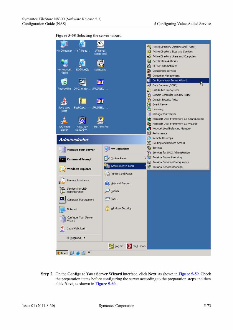
Figure 5-58 Selecting the server wizard
Step 2 On the Configure Your Server Wizard interface, click Next, as shown in Figure 5-59. Checkthe preparation items before configuring the server according to the preparation steps and thenclick Next, as shown in Figure 5-60.
Symantec FileStore N8300 (Software Release 5.7)Configuration Guide (NAS) 5 Configuring Value-Added Service
Issue 01 (2011-8-30) Symantec Corporation 5-73

Figure 5-59 Server wizard interface
Figure 5-60 Preparation steps before configuring a server
5 Configuring Value-Added ServiceSymantec FileStore N8300 (Software Release 5.7)
Configuration Guide (NAS)
5-74 Symantec Corporation Issue 01 (2011-8-30)

Step 3 In the Server Role drop-down list, select DNS Server and click Next, as shown in Figure5-61.
Figure 5-61 Selecting a server role
Step 4 As shown in Figure 5-62, confirm the selection and click Next. The Configure a DNS ServerWizard interface is displayed, as shown in Figure 5-63. Then click Next.
Symantec FileStore N8300 (Software Release 5.7)Configuration Guide (NAS) 5 Configuring Value-Added Service
Issue 01 (2011-8-30) Symantec Corporation 5-75

Figure 5-62 Server confirmation interface
5 Configuring Value-Added ServiceSymantec FileStore N8300 (Software Release 5.7)
Configuration Guide (NAS)
5-76 Symantec Corporation Issue 01 (2011-8-30)

Figure 5-63 DNS configuration wizard
Step 5 Choose the lookup zone type. The forward lookup zone is the default option. To build the NBUbackup environment, you can create either a forward lookup zone or a reverse lookup zone. Youcan manually configure the lookup zone type after configuring the DNS, as shown in Figure5-64.
Symantec FileStore N8300 (Software Release 5.7)Configuration Guide (NAS) 5 Configuring Value-Added Service
Issue 01 (2011-8-30) Symantec Corporation 5-77

Figure 5-64 DNS configuration wizard
Step 6 Choose This server maintains the zone to create a primary forward lookup zone, as shown inFigure 5-65.
5 Configuring Value-Added ServiceSymantec FileStore N8300 (Software Release 5.7)
Configuration Guide (NAS)
5-78 Symantec Corporation Issue 01 (2011-8-30)

Figure 5-65 DNS configuration wizard
Step 7 Enter a zone name. Here, use hs.com as an example, as shown in Figure 5-66.
Symantec FileStore N8300 (Software Release 5.7)Configuration Guide (NAS) 5 Configuring Value-Added Service
Issue 01 (2011-8-30) Symantec Corporation 5-79

Figure 5-66 DNS configuration wizard
Step 8 You can choose to allow only secure dynamic updates, allow both nonsecure and secure dynamicupdates, or not to allow dynamic updates, as shown in Figure 5-67.
5 Configuring Value-Added ServiceSymantec FileStore N8300 (Software Release 5.7)
Configuration Guide (NAS)
5-80 Symantec Corporation Issue 01 (2011-8-30)

Figure 5-67 DNS configuration wizard
Step 9 Confirm the previous DNS settings and click Finish, as shown in Figure 5-68.
Symantec FileStore N8300 (Software Release 5.7)Configuration Guide (NAS) 5 Configuring Value-Added Service
Issue 01 (2011-8-30) Symantec Corporation 5-81

Figure 5-68 DNS configuration wizard
Step 10 Choose Start > Administrative Tools > DNS to enter the DNS management interface, as shownin Figure 5-69.
5 Configuring Value-Added ServiceSymantec FileStore N8300 (Software Release 5.7)
Configuration Guide (NAS)
5-82 Symantec Corporation Issue 01 (2011-8-30)

Figure 5-69 Selecting a DNS server
Step 11 On the DNS management interface, choose Forward Lookup Zones > hs.com > New Host toadd a host, as shown in Figure 5-70 and Figure 5-71.
Symantec FileStore N8300 (Software Release 5.7)Configuration Guide (NAS) 5 Configuring Value-Added Service
Issue 01 (2011-8-30) Symantec Corporation 5-83

Figure 5-70 Host creation window 1
Add the N8300 as the backup client. sfstest is the virtual name of the backup client and129.62.26.101 is the IP address of the backup client.
Figure 5-71 Host creation window 2
Repeat the same steps to add the NBU server. client13 is the name of the NBU server.129.62.26.233 is the IP address of the NBU server.
5 Configuring Value-Added ServiceSymantec FileStore N8300 (Software Release 5.7)
Configuration Guide (NAS)
5-84 Symantec Corporation Issue 01 (2011-8-30)
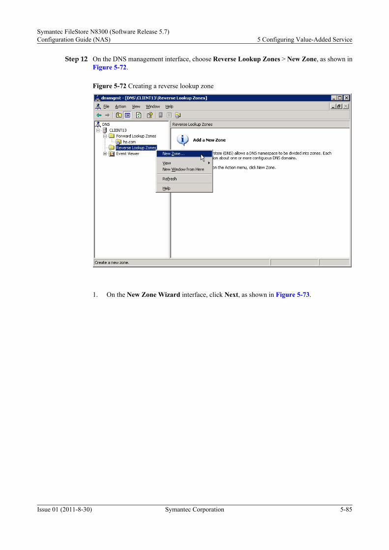
Step 12 On the DNS management interface, choose Reverse Lookup Zones > New Zone, as shown inFigure 5-72.
Figure 5-72 Creating a reverse lookup zone
1. On the New Zone Wizard interface, click Next, as shown in Figure 5-73.
Symantec FileStore N8300 (Software Release 5.7)Configuration Guide (NAS) 5 Configuring Value-Added Service
Issue 01 (2011-8-30) Symantec Corporation 5-85

Figure 5-73 Creating a reverse lookup zone interface 1
2. Figure 5-74 shows the second step to create a reserve lookup zone.
5 Configuring Value-Added ServiceSymantec FileStore N8300 (Software Release 5.7)
Configuration Guide (NAS)
5-86 Symantec Corporation Issue 01 (2011-8-30)

Figure 5-74 Creating a reverse lookup zone interface 2
3. Figure 5-75 shows the third step to create a reserve lookup zone.
Symantec FileStore N8300 (Software Release 5.7)Configuration Guide (NAS) 5 Configuring Value-Added Service
Issue 01 (2011-8-30) Symantec Corporation 5-87

Figure 5-75 Creating a reverse lookup zone interface 3
4. The fourth step to create a reserve lookup zone is to enter the network ID 129.62.26, which
is in the network segment where the IP addresses of the NBU server and backup client are,as shown in Figure 5-76.
5 Configuring Value-Added ServiceSymantec FileStore N8300 (Software Release 5.7)
Configuration Guide (NAS)
5-88 Symantec Corporation Issue 01 (2011-8-30)

Figure 5-76 Creating a reverse lookup zone interface 4
5. Figure 5-77 shows the fifth step to create a reserve lookup zone.
Symantec FileStore N8300 (Software Release 5.7)Configuration Guide (NAS) 5 Configuring Value-Added Service
Issue 01 (2011-8-30) Symantec Corporation 5-89

Figure 5-77 Creating a reverse lookup zone interface 5
6. The sixth step to create a reserve lookup zone is to confirm the settings and click Finish,
as shown in Figure 5-78.
5 Configuring Value-Added ServiceSymantec FileStore N8300 (Software Release 5.7)
Configuration Guide (NAS)
5-90 Symantec Corporation Issue 01 (2011-8-30)

Figure 5-78 Creating a reverse lookup zone interface 6
Step 13 In the reverse lookup zone, create a pointer (PTR), as shown in Figure 5-79 and Figure 5-80.
Figure 5-79 Creating a pointer in the reverse lookup zone
Symantec FileStore N8300 (Software Release 5.7)Configuration Guide (NAS) 5 Configuring Value-Added Service
Issue 01 (2011-8-30) Symantec Corporation 5-91

Figure 5-80 New Resource Record dialog box
Host IP number 101 corresponds to host sfstest. Repeat the previous steps to add client13.
Step 14 Check whether the DNS is successfully configured. Choose Start > Run. Run the pingsfstest.hs.com and ping client13.hs.com commands. If they can be pinged through, the DNS issuccessfully configured, as shown in Figure 5-81.
5 Configuring Value-Added ServiceSymantec FileStore N8300 (Software Release 5.7)
Configuration Guide (NAS)
5-92 Symantec Corporation Issue 01 (2011-8-30)

Figure 5-81 Command interface
----End
5.5.4 Establishing a ConnectionThis section describes how to establish connections between the N8300 and the master server,media server, and DNS server.
Establishing Connection Between the N8300 and Master/Media Server
This section describes how to establish the connection between the N8300 and the master/mediaserver.
Procedure
Step 1 On the main interface of the ISM, choose Clustered NAS Storage System > ConfigurationAssistant in the navigation tree.
Step 2 In the function pane, click Backup Management.The Backup Management dialog box is displayed.
Step 3 Configure the client. In the Backup Management dialog box, click Client Config....The Set Backup Clientdialog box is displayed.
NOTE
The IP address of the N8300 on the client is a virtual one and is specially used for the backup service. ThisIP address should be in the same network segment as other IP addresses and has not been used.
The client name is used for the NBU master server to identify the N8300 as a backup client.
Step 4 In the Set Backup Client dialog box, enter the IP Address and Name of the N8300,
Step 5 Set servers. In the Backup Management dialog box, click Media Server....Set names for the NBU master server and EMM server.
Symantec FileStore N8300 (Software Release 5.7)Configuration Guide (NAS) 5 Configuring Value-Added Service
Issue 01 (2011-8-30) Symantec Corporation 5-93

Step 6 Click Add... to add multiple media servers.
Step 7 In the Backup Management dialog box, click Enable to enable the backup server.
----End
Establishing Connection Between the N8300 and DNS Server (Optional)This section describes how to establish the connection between the N8300 and the DNS server.
ContextFor details on how to how to establish the connection between the N8300 and the DNS server,see Establishing the Connection Between the N8300 and DNS (Optional).
5.5.5 Backing Up DataThis section describes how to back up data, including setting a backup policy and fulfilling databackup and data recovery.
Setting a Backup PolicyThis section describes how to set a backup policy.
PrerequisiteAt least one file system is created in the N8300 that serves as the NBU backup client.
ProcedureStep 1 Set storage units. Click Storage Units > New Storage Unit, as shown in Figure 5-82.
Figure 5-82 Creating a new storage unit
5 Configuring Value-Added ServiceSymantec FileStore N8300 (Software Release 5.7)
Configuration Guide (NAS)
5-94 Symantec Corporation Issue 01 (2011-8-30)

Step 2 In the New Storage Unit dialog box, set fstest as the name of a storage unit.
Figure 5-83 New Storage Unit dialog box
Table 5-7 Description of the parameters in the New Storage Unit dialog box
Name Description
On demand only If this option is selected, the storage unit only applies to the specifiedpolicy and schedule. If this option is not selected, the storage unitapplies to all polices and schedules.
Media server Name of a specified media server.
Symantec FileStore N8300 (Software Release 5.7)Configuration Guide (NAS) 5 Configuring Value-Added Service
Issue 01 (2011-8-30) Symantec Corporation 5-95

Name Description
Absolute pathname todirectory
Absolute path of a specified backup storage unit.
Disk type There are three disk types: BasicDiskNearStoreSnapVault.BasicDisk is used for basic disks.NearStore is used for NAS. This option is available only whenNetBackup Disk Optimization Option is enabled.SnapVault is used for NAS. This option is available only whenNetBackup Advanced Client is enabled.
Enable TemporaryStaging Area
Enables the storage unit to be a temporary staging area.
High water mark When the high water mark is reached, the NBU considers the spaceof the disk storage unit to be full.
Low water mark Low water mark collaborates with Enable Temporary StagingArea. When the space of the storage unit reaches the low water mark,the NBU is to copy the image to the final destination according to itsstaging schedule.
Maximum concurrentjobs
Maximum number of backups sent by the NBU to the disk each time.If the maximum number of concurrent jogs is set to zero, the storageunit is disabled.
Step 3 Set Policies. In the navigation tree shown in Figure 5-84, click Policies. On the menu bar, chooseActions > New > New Policy; or right-click Policies and choose New Policy, as shown inFigure 5-84 and Figure 5-85.
5 Configuring Value-Added ServiceSymantec FileStore N8300 (Software Release 5.7)
Configuration Guide (NAS)
5-96 Symantec Corporation Issue 01 (2011-8-30)

Figure 5-84 Method of creating a backup policy (1)
Figure 5-85 Method of creating a backup policy (2)
Symantec FileStore N8300 (Software Release 5.7)Configuration Guide (NAS) 5 Configuring Value-Added Service
Issue 01 (2011-8-30) Symantec Corporation 5-97

Step 4 In the Add a New Policy dialog box, enter the policy name test, as shown in Figure 5-86. ClickOK.
Figure 5-86 Naming a backup policy
Step 5 In the dialog box shown in Figure 5-87, set attributes, schedules, clients, and backup selections.
5 Configuring Value-Added ServiceSymantec FileStore N8300 (Software Release 5.7)
Configuration Guide (NAS)
5-98 Symantec Corporation Issue 01 (2011-8-30)

Figure 5-87 Setting attributes for the backup policy
Table 5-8 Parameter description
Name Description
Policy type Specifies the client types included in the policy; in certain conditions,specifies the types of backup that can be performed on the client. Forthe policy types, see Table 5-9.
Symantec FileStore N8300 (Software Release 5.7)Configuration Guide (NAS) 5 Configuring Value-Added Service
Issue 01 (2011-8-30) Symantec Corporation 5-99

Name Description
Cross Mount Point If this option is selected, other file systems in a file system that is onthe UNIX Client are to be backed up.
Compression If this option is selected, the data is to be compressed before it istransferred to the Server.
Policy Priority Controls the backup order. The job with higher priority is backed upfirst.
Policy Storage Unit Default storage unit of the backup based on the policy. Select a policystorage unit from the drop-down list box. If Any Available is chosen,the NBU tries to storage data onto the locally-mounted storage unit.If no local drive is found, the NBU searches for the available storageunits in alphabetical order.
Policy Volume Pool Default volume pool of the backup based on the policy.
Take CheckpointsEvery
Instructs the NBU whether to create checkpoints according to thespecified frequency when performing the backup based on the policy.Creating checkpoints during the backup is very useful. If this optionis not selected, the failed backup job based on the policy will have torestart all over again. If this option is selected, the NBU will retry thefailed backup job from the latest checkpoint rather than restart thewhole backup job.
Limit Jobs Per Policy Limits the number of concurrent jobs under this policy.
Job Priority Specifies the priority assigned to the backup jobs. When the drive isenabled, the NBU starts to back up the data on the first client withthe highest priority.
Go Into Effect at The policy is available only when this option is selected.
Backup NetworkDrives
Only applies to certain policy types.
Collect True ImageRestore Information
Only applies to certain policy types. Once this option is selected, theNBU starts collecting the necessary information for restoring thedirectory. The information has been included in the contents whenthe user chooses incremental backup (or full backup) to be restored.The files deleted before the selected backup starts cannot be restored.Otherwise, according to the incremental backup feature, all backedup files since the last full backup and the files deleted in a certainpoint in time during this period of time will be restored.
Allow Multiple DataStream
Enables the NBU to divide automatic backup jobs of each client intomultiple jobs according to the commands or script/template (databasepolicy type) in the backup selection list. Each job only perform a partof backups in the backup selection list. Jobs are distributed indifferent data streams and can be concurrently performed.
Keyword Phrase Phrase by which the NBU is related to all backups or archives. Theclient can only list or restore the backups associated with this phrase.
5 Configuring Value-Added ServiceSymantec FileStore N8300 (Software Release 5.7)
Configuration Guide (NAS)
5-100 Symantec Corporation Issue 01 (2011-8-30)

Table 5-9 Type
Name Meaning
AFS Used only when the AFS file system on the client needs to be backedup.
DataStore A reserved policy type and used only when Varitas or other partnersprovide an agent for the new application or database.
DataTools-SQL -BackTrack
Used only when clients that run NetBackup for DataTools-SQL-BackTrack exist.
DB2 Used only when clients that run NetBackup for DB2 exist.
FlashBackup Only applies to NetBackup Enterprise Server: Used only when clientsthat run NetBackup FlashBackup in UNIX exists. This policy isavailable only when the NetBackup Advanced Client is installed.
FlashBackup-Windows
Only applies to NetBackup Enterprise Server: Used only when clientsthat run NetBackup FlashBackup in Windows exists. This policy isavailable only when the NetBackup Advanced Client is installed.
Informix-On-Bar Used only when clients that run NetBackup for Informix exist.
Lotus-Notes Used only when clients that run NetBackup for Lotus Notes exist.
MS-Exchange-Server
Used only when clients that run NetBackup for MS-Exchange exist.
MS-SharePoint Used for setting a policy for NetBackup for SharePoint Portal Server.
MS-SQL-Server Used only when clients that run NetBackup for MS-SQL Server exist.
MS-Windows-NT Used only when the clients in Windows 2000, Windows XP,Windows Server 2003, and/or NetBackup 5.x NT exist.
NBU-Catalog Used for backing up catalogs. The catalog can be backed up whileother services are running.
NDMP Used only when clients that run NetBackup for NDMP exist. Thispolicy is available only when NetBackup NDMP is installed andlicensed.
NetWare Used only when NetBackup Novell NetWare (MicrosoftWindowsinterface is used in this version) exists.
Oracle Used only when clients that run NetBackup for Oracle exist.
SAP Used only when clients that run NetBackup for SAP exist.
Split-Mirror Only applies to NetBackup Enterprise Server: Used only when clientsthat run NetBackup for EMC exists.
Symantec FileStore N8300 (Software Release 5.7)Configuration Guide (NAS) 5 Configuring Value-Added Service
Issue 01 (2011-8-30) Symantec Corporation 5-101

Name Meaning
Standard Used only when the following client combinations are involved:1. UNIX client (including Mac OS X client); specified clients (such
as Oracle) are excluded.2. Clients with NetBackup Novell NetWare that is the target version
of the NBU.
Sybase Used only when clients that run NetBackup for Sybase exist.
CAUTIONTo use CheckPoint Restart for backup, restore, and synthetic backup, or use Bare MetalRestore to Collect Disaster Recover Information for Bare Metal Restore, you must chooseStandard or MS-Windows-NT.
Step 6 Set the Attributes tab page, as shown in Figure 5-88.
5 Configuring Value-Added ServiceSymantec FileStore N8300 (Software Release 5.7)
Configuration Guide (NAS)
5-102 Symantec Corporation Issue 01 (2011-8-30)

Figure 5-88 Setting attributes for the backup policy
Step 7 In the Schedules tag page, click New..., as shown in Figure 5-89
Symantec FileStore N8300 (Software Release 5.7)Configuration Guide (NAS) 5 Configuring Value-Added Service
Issue 01 (2011-8-30) Symantec Corporation 5-103

Figure 5-89 Creating a new schedule
Step 8 Set Attributes for the Schedules, as shown in Figure 5-90.
5 Configuring Value-Added ServiceSymantec FileStore N8300 (Software Release 5.7)
Configuration Guide (NAS)
5-104 Symantec Corporation Issue 01 (2011-8-30)

Figure 5-90 Setting the schedule attributes
Table 5-10 Parameter description
Parameter Description
Type of Backup Backup typeFull backup, differential-incremental backup,cumulative-incremental backup, userbackup, and user archive.
Retention Period Specifies the duration for the backup.
Frequency Specifies how frequently is the scheduleperformed.
Step 9 Set Start window for the Schedules, as shown in Figure 5-91.
Symantec FileStore N8300 (Software Release 5.7)Configuration Guide (NAS) 5 Configuring Value-Added Service
Issue 01 (2011-8-30) Symantec Corporation 5-105

Figure 5-91 Setting the start and end time of the schedule
Step 10 Set Exclude Dates by choosing the date when backup is not performed, as shown in Figure5-92. Then, click OK, as shown in Figure 5-93.
Figure 5-92 Setting the exclude dates for the schedule
5 Configuring Value-Added ServiceSymantec FileStore N8300 (Software Release 5.7)
Configuration Guide (NAS)
5-106 Symantec Corporation Issue 01 (2011-8-30)

Figure 5-93 Completing setting the schedule
Step 11 Setting the Clients tab page, as shown in Figure 5-94.
Symantec FileStore N8300 (Software Release 5.7)Configuration Guide (NAS) 5 Configuring Value-Added Service
Issue 01 (2011-8-30) Symantec Corporation 5-107

Figure 5-94 Setting the clients
Step 12 In the Backup Selections tab page, set the file to be backed up, as shown in Figure 5-95. ClickNew and then the folder icon on the right of Backup Selections. Browse is displayed, as shownin Figure 5-96. select the files to be backed up or click New to add the files to be backed up (thefiles should have the same backup policy).
5 Configuring Value-Added ServiceSymantec FileStore N8300 (Software Release 5.7)
Configuration Guide (NAS)
5-108 Symantec Corporation Issue 01 (2011-8-30)

Figure 5-95 Setting backup options
Symantec FileStore N8300 (Software Release 5.7)Configuration Guide (NAS) 5 Configuring Value-Added Service
Issue 01 (2011-8-30) Symantec Corporation 5-109

Figure 5-96 Selecting the files to be backed up
----End
Implementing Data BackupThis section describes how to implement data backup.
ContextAfter a policy is created, the NBU automatically starts the backup service. You can also startthe backup service manually.
Procedure
Step 1 Right-click the policy name and select Manual Backup, as shown in Figure 5-97.
5 Configuring Value-Added ServiceSymantec FileStore N8300 (Software Release 5.7)
Configuration Guide (NAS)
5-110 Symantec Corporation Issue 01 (2011-8-30)

Figure 5-97 Selecting manual backup
Step 2 The Activity Monitor dialog box is displayed. Right-click the running job and chooseDetails, as shown in Figure 5-98.
Figure 5-98 Checking backup jobs
Symantec FileStore N8300 (Software Release 5.7)Configuration Guide (NAS) 5 Configuring Value-Added Service
Issue 01 (2011-8-30) Symantec Corporation 5-111

Step 3 In the Job Details dialog box, click the Job Overview tab and the Detailed Status tab fordetailed backup information, as shown in Figure 5-99.
Figure 5-99 Backup job information
----End
5.5.6 Restoring Data (Optional)This section describes how to restore data.
Procedure
Step 1 On the menu bar of NetBackup Administration Console, choose File > Backup, archive, andrestore, as shown in Figure 5-100.
5 Configuring Value-Added ServiceSymantec FileStore N8300 (Software Release 5.7)
Configuration Guide (NAS)
5-112 Symantec Corporation Issue 01 (2011-8-30)

Figure 5-100 Backup, Archive, and Restore dialog box
Step 2 In the Backup, Archive, and Restore window, choose File > NetBackup Client Properties,as shown in Figure 5-101.
Symantec FileStore N8300 (Software Release 5.7)Configuration Guide (NAS) 5 Configuring Value-Added Service
Issue 01 (2011-8-30) Symantec Corporation 5-113

Figure 5-101 Selecting NetBackup client properties
Step 3 In the NetBackup Client Properties dialog box, select the General tab and enter a client namein the Client name text box. as shown in Figure 5-102.
5 Configuring Value-Added ServiceSymantec FileStore N8300 (Software Release 5.7)
Configuration Guide (NAS)
5-114 Symantec Corporation Issue 01 (2011-8-30)

Figure 5-102 Checking the client name
Step 4 On the menu bar of Backup, Archive, and Restore, choose File > Specify NetBackupMachines and Policy Type…, as shown in Figure 5-103.
Figure 5-103 Specifying NetBackup machines and policy type
Symantec FileStore N8300 (Software Release 5.7)Configuration Guide (NAS) 5 Configuring Value-Added Service
Issue 01 (2011-8-30) Symantec Corporation 5-115

Step 5 In the Specify NetBackup Machines and Policy Type dialog box, set the server name, nameof the client to be restored, and restore policy type, as shown in Figure 5-104.
Figure 5-104 Checking the backup server, client, and restore policy type
Step 6 In the Backup, Archive, and Restore window, choose File > Select Files and Folders toRestore... > from Normal Backup..., as shown in Figure 5-105.
Figure 5-105 Selecting files and folders to restore
5 Configuring Value-Added ServiceSymantec FileStore N8300 (Software Release 5.7)
Configuration Guide (NAS)
5-116 Symantec Corporation Issue 01 (2011-8-30)

Step 7 In the Backup, Archive, and Restore-Netbackup window, specify the file to be restored, asshown in Figure 5-106.
Figure 5-106 Select the file to be restored
Step 8 In the window shown in Figure 5-107, choose Action > Restore....
Symantec FileStore N8300 (Software Release 5.7)Configuration Guide (NAS) 5 Configuring Value-Added Service
Issue 01 (2011-8-30) Symantec Corporation 5-117

Figure 5-107 Starting the restore
Step 9 In the Restore Marked Files dialog box, select the restore location and restore item, as shownin Figure 5-108. Then click Start Restore.
5 Configuring Value-Added ServiceSymantec FileStore N8300 (Software Release 5.7)
Configuration Guide (NAS)
5-118 Symantec Corporation Issue 01 (2011-8-30)

Figure 5-108 Restore Marked Files dialog box
Step 10 In the navigation tree of the Activity Monitor window, click Activity Monitor, as shown inFigure 5-109. Right-click a restoring job on the right corner and select Details to check thedetails about the job, as shown in Figure 5-110.
Symantec FileStore N8300 (Software Release 5.7)Configuration Guide (NAS) 5 Configuring Value-Added Service
Issue 01 (2011-8-30) Symantec Corporation 5-119

Figure 5-109 Checking the details about a restoring job
5 Configuring Value-Added ServiceSymantec FileStore N8300 (Software Release 5.7)
Configuration Guide (NAS)
5-120 Symantec Corporation Issue 01 (2011-8-30)

Figure 5-110 Details about a restoring job
----End
5.6 Configuring File System SnapshotA file system snapshot is a permanent image of the N8300 at a specified point in time. The filesystem snapshot provides an online backup mechanism. By identifying and maintaining the filesystem blocks changed since the last snapshot is taken or changed since the replicationtechnology is adopted, the file system snapshot can minimize the I/O expenses.
5.6.1 About Configuring File System SnapshotThe file system snapshot function provided by the N8300 enhances data security and reliability,and enables storage devices to generate recovery points frequently and flexibly for quick datarecovery.
5.6.2 Configuration ProcessYou can learn the operations about configuring file system snapshot through the flow chart.
5.6.3 Creating File System SnapshotThis section describes how to create a file system snapshot in manual or auto mode.
5.6.4 Managing the Snapshot QuotaThrough this operation, you can manage the snapshot quota.
Symantec FileStore N8300 (Software Release 5.7)Configuration Guide (NAS) 5 Configuring Value-Added Service
Issue 01 (2011-8-30) Symantec Corporation 5-121

5.6.5 Configuring the Snapshot Share (Optional)This section describes how to configure the snapshot share.
5.6.6 Snapshot RecoveryThrough this operation, you can recover file system through the snapshot.
5.6.1 About Configuring File System SnapshotThe file system snapshot function provided by the N8300 enhances data security and reliability,and enables storage devices to generate recovery points frequently and flexibly for quick datarecovery.
Basic ConceptsBasic concepts about configuring the file system snapshot are described as follows:
l File system snapshotA file system snapshot is a precise image of an online file system captured at a point intime. It is a quick backup mechanism.The N8300 provides automatic and manual file system snapshots. You can create a snapshotfor an N8300 file system on any node and perform backup and restoration on this node.
l Performance of the file system snapshotThe file system snapshot provides optimal snapshot performance but compromises on theperformance of writing data onto the file system. The throughput of reading a file systemsnapshot is nearly equal to that of reading a standard VxFS file system. Usually, the filesystem snapshot function does not affect the time for reading data from the file system butdoubles or triples the time for writing data to the file system. This is because you can writethe new data onto the file system only after you read the old data first and write it onto thesnapshot.
l Quota of the File System SnapshotThe quota of the file system snapshot is set to control the usage of files and data blocks ofthe file system. You can allocate the quota of files and data blocks to each user or group.
NOTE
The snapshot quota cannot be larger than the capacity of the file system.
Work PrinciplesIn the N8300, the file system snapshot is created based on the copy on first write mechanism.The implementation procedure is as follows:
1. The file system is in the stable state and all data is written on the hard disk.2. The snapshot tool freezes the file system (main file set) and prevents all I/O requests to the
file system instantly. Then it creates a file system snapshot without any data.3. The created file system snapshot is initialized. This snapshot points to the block mirror of
the main file set.4. Retract the prevention of I/O requests.
5.6.2 Configuration ProcessYou can learn the operations about configuring file system snapshot through the flow chart.
Figure 5-111 shows the flowchart of configuring file system snapshot.
5 Configuring Value-Added ServiceSymantec FileStore N8300 (Software Release 5.7)
Configuration Guide (NAS)
5-122 Symantec Corporation Issue 01 (2011-8-30)

Figure 5-111 Flowchart of configuring a file system snapshot
Start
End
Creating a Snapshot
Snapshot Recovery
1. Creating a File System Snapshot
2. Managing the Snapshot
4. Snapshot Recovery
Sharing the Snapshot
Creating a Schedule Policy
Managing the Snapshot Quota
3. Sharing the Snapshot
Required child item
Optional child itemNote:
5.6.3 Creating File System SnapshotThis section describes how to create a file system snapshot in manual or auto mode.
The preconditions for creating a file system snapshot include:l One or more file systems are created.
l The file system where a snapshot is to be created has sufficient capacity.
l The file system where a snapshot is to be created has snapshots but the capacities of thesnapshots do not reach the snapshot quota.
Creating a Snapshot
Through this operation, you can create a snapshot.
Prerequisite
The specified file system must be in the online status.
Procedure
Step 1 Go to the Manage Snapshot dialog box.1. On the main interface of the ISM, choose Clustered NAS Storage System > NAS
Services > File Systems in the navigation tree.2. In the function pane, select the file system where the snapshot is to be created.
Symantec FileStore N8300 (Software Release 5.7)Configuration Guide (NAS) 5 Configuring Value-Added Service
Issue 01 (2011-8-30) Symantec Corporation 5-123

3. Choose Snapshot > Manage Snapshot.The Manage Snapshot dialog box is displayed.
Step 2 Create a snapshot.
1. Click Create to manually create a snapshot.The Create Snapshot dialog box is displayed.
2. Enter the snapshot name in Snapshot text box.
3. Set whether the snapshot is removable
NOTE
When Removable is set to Yes, if the storage space is insufficient, the snapshot is automaticallydeleted. Therefore, set Removable to No when creating a snapshot for the key service.
4. Click OK.The Result dialog box is displayed.
5. Click Close.
----End
Result
View the details about the snapshot using the following steps.
1. On the main interface of the ISM, choose Clustered NAS Storage System > NASServices > File Systems in the navigation tree.
2. In the function pane, select the file system where the snapshot is to be created.
3. Choose Snapshot > Manage Snapshot.
4. View the snapshot information in Manage Snapshot dialog box Snapshot list tab.
Follow-up Procedure
5.6.2 Configuration Process shows how to configure the file system snapshot.
l The next step is Creating a Schedule Policy.
Creating a Schedule Policy
This section describes how to automatically create a file system snapshot.
Context
A snapshot can be quickly created. After the snapshot is automatically created, the status of thesnapshot becomes offline. To automatically create the snapshot for the N8300 means that asnapshot can be created according to the specified periodical policy.
Precautions
It is recommended to perform the snapshot or remote replication tasks of different file systemsin different time periods.
5 Configuring Value-Added ServiceSymantec FileStore N8300 (Software Release 5.7)
Configuration Guide (NAS)
5-124 Symantec Corporation Issue 01 (2011-8-30)

Procedure
Step 1 Go to the Manage Snapshot dialog box.1. On the main interface of the ISM, choose Clustered NAS Storage System > NAS
Services > File Systems in the navigation tree.2. In the function pane, select the file system where the snapshot is to be created.3. Choose Snapshot > Manage Snapshot.
The Manage Snapshot dialog box is displayed.
Step 2 Create schedule policy.1. Select the Schedule Policy tab.2. In the Schedule group box, click Create to create a schedule policy.
The Create Schedule dialog box is displayed.3. Enter the schedule name in Schedule Name text box.4. Enter the max quantity of snapshot in Max Snapshots.5. You can set the policy is Timing or Period.
NOTE
Set the Timing to perform the tiering strategy at a specified time.
Set the Period to periodically perform the tiering strategy according to the specified schedule.
6. Click OK.The Result dialog box is displayed.
7. Click Close.
----End
Result
View the created schedule policy and created snapshot using the following steps.
1. On the main interface of the ISM, choose Clustered NAS Storage System > NASServices > File Systems in the navigation tree.
2. In the function pane, select the file system where the snapshot is to be created.3. Choose Snapshot > Manage Snapshot.4. Select the Schedule Policy tab in Manage Snapshot dialog box.5. View the snapshot schedule policy in Schedule group box.6. View the created timing snapshots in Timing snapshot list box.
Follow-up Procedure
5.6.2 Configuration Process shows how to configure file system snapshot.l The previous step is Creating a Snapshot.
l The next step is 5.6.4 Managing the Snapshot Quota.
5.6.4 Managing the Snapshot QuotaThrough this operation, you can manage the snapshot quota.
Symantec FileStore N8300 (Software Release 5.7)Configuration Guide (NAS) 5 Configuring Value-Added Service
Issue 01 (2011-8-30) Symantec Corporation 5-125

Precautions
The snapshot quota cannot be greater than the capacity of the file system.
Procedure
Step 1 Go to the Set Snapshot Quota dialog box.1. On the main interface of the ISM, choose Clustered NAS Storage System > NAS
Services > File Systems in the navigation tree.2. In the function pane, Select the file system that needs to manage the snapshot quota.3. Choose Snapshot > Set Snapshot Quota.
The Set Snapshot Quota dialog box is displayed.
Step 2 Set the snapshot quota.
NOTE
l The snapshot quota indicates the maximum storage space that is dynamically provided by the filesystem. All the snapshots of this file system share this storage space.
l The snapshot quota cannot be larger than the capacity of the file system.
1. Enter the quota in Quota text box, the value can be MB, GB or TB.2. If the current quota status is Disable, click Enable. If the current quota status is Enable,
ignore this step.3. Click OK.
The Result dialog box is displayed.4. Click Close.
----End
Result
View the file system snapshot quota using the following steps.
1. On the main interface of the ISM, choose Clustered NAS Storage System > NASServices > File Systems in the navigation tree.
2. In the function pane, Select the file system that needs to manage the snapshot quota.3. Choose Snapshot > Set Snapshot Quota.4. View snapshot quota in Set Snapshot Quota dialog box.
Follow-up Procedure
5.6.2 Configuration Process shows how to configure file system snapshot.l The previous step is Creating a Schedule Policy.
l The next step is 5.6.5 Configuring the Snapshot Share (Optional).
5.6.5 Configuring the Snapshot Share (Optional)This section describes how to configure the snapshot share.
Table 5-11 shows the flowchart for configuring the snapshot share.
5 Configuring Value-Added ServiceSymantec FileStore N8300 (Software Release 5.7)
Configuration Guide (NAS)
5-126 Symantec Corporation Issue 01 (2011-8-30)

Table 5-11 Flowchart for configuring the snapshot share
Option 1:Sharing thesnapshotthrough theCIFS
Sub-option 1: Share the snapshot through the CIFS normal in the non-domainenvironment.NOTE
l For details, see Configuring the CIFS Normal Share in the Non-DomainEnvironment.
l The operations of sharing snapshots and files systems are identical. The differenceleads in the shared objects. The previous ones are the snapshots while the latter onesare the file systems.
Sub-option 2: Share the snapshot through the CIFS homedir in the non-domainenvironment.NOTE
l For details, see Configuring the CIFS Homedir Share in the Non-DomainEnvironment.
l The operations of sharing snapshots and files systems are identical. The differenceleads in the shared objects. The previous ones are the snapshots while the latter onesare the file systems.
Sub-option 3: Share the snapshot through the CIFS in the AD domain.NOTE
l For details, see 4.3.2 Configuration Process.
l The operations of sharing snapshots and files systems are identical. The differenceleads in the shared objects. The previous ones are the snapshots while the latter onesare the file systems.
Option 2:Sharing thesnapshotthrough theNFS
Sub-option 1: Share the snapshot through the NFS in the non-domainenvironment.NOTE
l For details, see 4.2 Configuring an NFS Share in a Non-Domain Environment.
l The operations of sharing snapshots and files systems are identical. The differenceleads in the shared objects. The previous ones are the snapshots while the latter onesare the file systems.
Sub-option 2: Share the snapshot through the NFS in the LDAP.NOTE
l For details, see 4.4.2 Configuration Process.
l The operations of sharing snapshots and files systems are identical. The differenceleads in the shared objects. The previous ones are the snapshots while the latter onesare the file systems.
Sub-option 3: Share the snapshot through the NFS in the NIS.NOTE
l For details, see 4.5.2 Configuration Procedure.
l The operations of sharing snapshots and files systems are identical. The differenceleads in the shared objects. The previous ones are the snapshots while the latter onesare the file systems.
Symantec FileStore N8300 (Software Release 5.7)Configuration Guide (NAS) 5 Configuring Value-Added Service
Issue 01 (2011-8-30) Symantec Corporation 5-127

5.6.6 Snapshot RecoveryThrough this operation, you can recover file system through the snapshot.
Prerequisitel The snapshot is set to the Offline state.
l The file system is not shared.
Procedure
Step 1 Go to the Manage Snapshot dialog box.1. In the navigation tree, choose Clustered NAS Storage System > NAS Services > File
System.2. In the function pane, select the file system that needs to perform the snapshot.3. Choose Snapshot > Manage Snapshot.
The Manage Snapshot dialog box is displayed.
Step 2 Recover file system through the snapshot.1. Select the snapshot that is used to recover the file system.2. If the snapshot is in the Online status, click Set Offline to set the snapshot to Offline. If
the snapshot is in the Offline status, ignore this step.3. Click Recover.
The Warning dialog box is displayed.4. Read carefully the contents in the Warning dialog box and select the check box before "I
have read the warning message carefully.".5. Click OK.
The Result dialog box is displayed.6. Click Close.
----End
Follow-up Procedure5.6.2 Configuration Process shows how to configure file system snapshot.l The previous step is 5.6.5 Configuring the Snapshot Share (Optional).
5.7 Configuring File System MirroringFile system mirroring is a process of producing mirrors of one file system on two or more disksor disk subsystems. When one mirror becomes faulty, another mirror still support the services.In this way, full data redundancy is achieved.
5.7.1 About Configuring File System MirroringFile system mirroring is a process of producing mirrors of one file system on two or more disksor disk subsystems. When one mirror becomes faulty, another mirror still support the services.In this way, full data redundancy is achieved.
5.7.2 Configuration Process
5 Configuring Value-Added ServiceSymantec FileStore N8300 (Software Release 5.7)
Configuration Guide (NAS)
5-128 Symantec Corporation Issue 01 (2011-8-30)

You can learn the operations about configuring file system mirror through the flow chart.
5.7.3 Adding a MirrorThrough this operation, you can add a mirror.
5.7.4 Configuring a File System to Be Shared (Optional)This section describes how to configure a file system to be shared.
5.7.1 About Configuring File System MirroringFile system mirroring is a process of producing mirrors of one file system on two or more disksor disk subsystems. When one mirror becomes faulty, another mirror still support the services.In this way, full data redundancy is achieved.
Basic Concepts
Some basic concepts about configuring the file system mirroringare described as follows:
l File System Mirroring
File system mirroring is a process of producing mirrors of one file system on two or moredisks or disk subsystems.
N8300 support multiple file system mirroring.
l Local Mirroring
The same data is respectively written onto the working disk and mirror disk of the samearray. When the working disk is faulty, the system automatically reads data from the mirrordisk, realizing optimal data protection.
l Cross-Array Mirroring
he same data is written onto hard disks of multiple arrays respectively to form multiplemirrors. When one mirror becomes faulty, another mirror still supports services. In thisway, full data redundancy is achieved.
Table 5-12 Two modes of cross-array mirroring
Type Application Scenario
Mirrored The same data is written onto hard disks of multiple arrayswhile it is written onto the file system. When data on one arrayis faulty, it can be immediately restored from another array.
Mirror-stripped Mirror-based stripe. It combines the advantages of stripingand mirroring, that is, data mirror redundancy and cross-diskdata distribution. Therefore, it can enhance redundancyperformance and shorten the recovery time after a hard diskis faulty.
5.7.2 Configuration ProcessYou can learn the operations about configuring file system mirror through the flow chart.
Figure 5-112 shows the flowchart of configuring file system mirror.
Symantec FileStore N8300 (Software Release 5.7)Configuration Guide (NAS) 5 Configuring Value-Added Service
Issue 01 (2011-8-30) Symantec Corporation 5-129

Figure 5-112 Flowchart of configuring file system mirror
Start
End
Adding a Mirror
Configuring a File System to Be Shared
Required child item
Optional child itemNote:
5.7.3 Adding a MirrorThrough this operation, you can add a mirror.
Precautions
The capacity of the storage pool or data disk specified when you add a mirror must be largerthan that of the original file system.
Procedure
Step 1 Go to the Mirror dialog box.1. On the main interface of the ISM, choose Clustered NAS Storage System > NAS
Services > File System in the navigation tree.2. In the function pane, select the file system that needs to add a mirror.3. Click Mirror.
The Mirror dialog box is displayed.
Step 2 Add a mirror.1. Select the storage tier.
If this file system created second tier, you can add mirror for second tier.2. Click Add.
The Add Mirror dialog box is displayed.3. Select Storage Tier.4. Select Storage Type, The value can be Pool or Data Disk.5. Select Protection Type, The value can be Pool or Data Disk.6. Select the pool or data disk in Storage Resources list box7. Click OK.
The Result dialog box is displayed.8. Click Close.
----End
5 Configuring Value-Added ServiceSymantec FileStore N8300 (Software Release 5.7)
Configuration Guide (NAS)
5-130 Symantec Corporation Issue 01 (2011-8-30)

ResultView the details about the mirror using the following steps.
1. On the main interface of the ISM, choose Clustered NAS Storage System > NASServices > File System in the navigation tree.
2. In the function pane, select the file system that needs to add a mirror.3. View the mirror information of the file system in Mirror tab
Follow-up Procedure5.7.2 Configuration Process shows how to configure the file system mirroring.l The next step is 5.7.4 Configuring a File System to Be Shared (Optional).
5.7.4 Configuring a File System to Be Shared (Optional)This section describes how to configure a file system to be shared.
Table 5-13 shows the flowchart for configuring a file system to be shared.
Table 5-13 Flowchart for configuring a file system to be shared
Option 1:Sharing afile systemin CIFSshare mode
Sub-option 1: Configuring the CIFS Normal Share in a Non-DomainEnvironment
Sub-option 2: Configuring the CIFS Homedir Share in a Non-DomainEnvironment
Sub-option 3: configuring the CIFS share in the AD domainFor details, see Configuring the CIFS Normal Share in the Non-DomainEnvironment.
Option 2:Sharing afile systemin NFSshare mode
Sub-option 1: Configuring the NFS Share in a Non-Domain Environment
Sub-option 2: Configuring the NFS share in the LDAP environmentFor details, see 4.4.2 Configuration Process.
Sub-option 3: Configuring the NFS share in the NIS environmentFor details, see 4.5.2 Configuration Procedure.
5.8 Configuring DSTDynamic Storage Tiering (DST), based on the specified storage policy, allows seldom accesseddata (cold data) to be stored on cost-efficient storage media while frequently accessed data (hotdata) can be stored on high-performance storage media.
5.8.1 About Configuring DSTDynamic Storage Tiering (DST), based on the specified storage policy, allows seldom accesseddata (cold data) to be stored on cost-efficient storage media while frequently accessed data (hotdata) can be stored on high-performance storage media.
5.8.2 Configuration Process
Symantec FileStore N8300 (Software Release 5.7)Configuration Guide (NAS) 5 Configuring Value-Added Service
Issue 01 (2011-8-30) Symantec Corporation 5-131

You can learn the operations about configuring the DST through the flow chart.5.8.3 Creating Secondary-Tier StorageThrough this operation, you can create the secondary-tier storage.5.8.4 Setting a DST PolicyThis section describes how to set a DST policy. You can migrate files according to the DSTpolicy you set.
5.8.1 About Configuring DSTDynamic Storage Tiering (DST), based on the specified storage policy, allows seldom accesseddata (cold data) to be stored on cost-efficient storage media while frequently accessed data (hotdata) can be stored on high-performance storage media.
Basic Conceptsl DST
According to the DST policy, cold data is migrated to the cost-efficient storage units whilehot data is still stored on high-performance storage units. The migration process isautomatic and transparent. When the data on the nearline storage units becomes hot data,the data is migrated to high-performance storage units. In this way, I/O performance of theservice host is enhanced.
l DST Storage ModesDST storage modes cover primary-tier to secondary-tier storage and secondary-tier toprimary-tier storage.Table 5-14 lists the two DST storage modes.
Table 5-14 DST storage modes
Type Application Scenario
Storage Tiering fromPrimary Tier toSecondary Tier
Data is stored on the primary-tier storage units first. Filteredaccording to a time policy, data that is not accessed for a longtime, or that is written to the primary-tier storage unit isautomatically migrated to the secondary tier.
Storage Tiering fromSecondary Tier toPrimary Tier
Data is stored on the secondary-tier storage units first. Aftera specified period of time, the N8300 calculates the accessfrequency of data and migrates the data that is frequentlyaccessed to the primary-tier storage units.
RequirementsIt is recommended that you configure two sets of storage units when using DST. Configure oneset of storage units with FC disks and SATA disks, and the other set configure with SAS disksand SATA disks.
To ensure the data migration rate of hierarchical storage, it is better to restrict the number offiles in a single file system directory to less than 100,000.
Typical Networking ModesBy using the DST feature, cold data is migrated to the cost-efficient storage units, but theavailability of the cold data is maintained. This enables the service host to access the migrated
5 Configuring Value-Added ServiceSymantec FileStore N8300 (Software Release 5.7)
Configuration Guide (NAS)
5-132 Symantec Corporation Issue 01 (2011-8-30)

data on the secondary-tier storage at any time; meanwhile, hot data is stored on the primary-tierstorage units with high performance. In this way, the I/O performance of the service host isenhanced.
Figure 5-113 shows a typical DST networking scenario.
Figure 5-113 a typical DST networking scenario
FC/SASDisks
SATADisks
Hot data is stored on the primary-tier storage units
Cold data is migrated to the cheap storage units
5.8.2 Configuration ProcessYou can learn the operations about configuring the DST through the flow chart.
Figure 5-114 shows the flowchart of configuring the DST.
Figure 5-114 Flowchart of configuring the DST
Start
End
Creating Secondary-Tier Storage
Setting a DST Policy
Required child item
Optional child itemNote:
5.8.3 Creating Secondary-Tier StorageThrough this operation, you can create the secondary-tier storage.
Symantec FileStore N8300 (Software Release 5.7)Configuration Guide (NAS) 5 Configuring Value-Added Service
Issue 01 (2011-8-30) Symantec Corporation 5-133

Prerequisitel The specified file system must be in the online status.
l No secondary-tier storage exists in the specified file system.
Precautions
The capacity of the secondary-tier storage cannot be larger than that of the specified storage poolor that of the data disk.
Procedure
Step 1 Go to the configuration wizard of creating secondary-tier storage.1. On the main interface of the ISM, choose Clustered NAS Storage System > NAS
Services > File Systems in the navigation tree.2. In the function pane, select the file system need to create secondary-tier storage.3. Click Storage Tiering > Create Secondary Tier.
The Create Secondary Tier Step 4-1: Confirm File System dialog box is displayed.
Step 2 Create secondary-tier storage follow the configuration wizard.1. Confirm the file system name need to create secondary-tier storage, and clickNext.
The Create Secondary Tier Step 4-2: Capacity Setting dialog box is displayed.
NOTE
The secondary-tier storage is usually created on the cost-efficient storage media, such as SATA diskswhile the primary-tier storage is usually created on the high-performance and expansive storagemedia, such as FC disks.
The spaces for the primary-tier storage and secondary-tier storage can be different.
2. Set Capacity, Storage Type, then select the pool to create secondary-tier storage (if thestorage type is the data disk, choose Data Disk), click Next.The Create Secondary Tier Step 4-3: Layout Setting dialog box is displayed.
3. Set layout, for details about the layout parameters, see A.4 Parameter Description ofCreating a File System, then click Next.The Create Secondary Tier Step 4-4: Confirm Configuration Information dialog boxis displayed.
4. Click Finish.The Result dialog box is displayed.
5. Click Close.
----End
Result
View the details about the secondary tier storage using the following steps.
1. On the main interface of the ISM, choose Clustered NAS Storage System > NASServices > File Systems in the navigation tree.
2. In the function pane, select the file system need to create secondary-tier storage.3. View the secondary-tier storage information in Secondary-Tier tab.
5 Configuring Value-Added ServiceSymantec FileStore N8300 (Software Release 5.7)
Configuration Guide (NAS)
5-134 Symantec Corporation Issue 01 (2011-8-30)

Follow-up Procedure5.8.2 Configuration Process shows how to configure DST.l The next step is 5.8.4 Setting a DST Policy.
5.8.4 Setting a DST PolicyThis section describes how to set a DST policy. You can migrate files according to the DSTpolicy you set.
PrerequisiteA file system with tiered storage is created.
Procedure
Step 1 Go to the Policy Management dialog box.1. On the main interface of the ISM, choose Clustered NAS Storage System > NAS
Services > File Systems in the navigation tree.2. In function pane, select the file system where you want to set the DST policy.3. Choose Storage Tiering > Policy Management.
The Policy Management dialog box is displayed.
Step 2 Create schedule.The DST schedule determine when execute the policy.1. Select the file system where you want to set the DST policy.2. Click Create Schedule.
The Create Schedule dialog box is displayed.3. Choose the schedule type, the value can be Timing or Period.
NOTE
In the Create Schedule dialog box, you can create a schedule using either Timing or Period modes.
l Timing: In this mode, you can execute the DST policy at a specific time each day, at a specifictime on a certain day of each week, or at a specific time on a certain day of a certain month, orevery other month.
l Period: In this mode, you can execute the DST policy every 15 minutes, 30 minutes, 45 minutes,or every other hour. The hour value can be set from 1 to 23.
4. Click OK.The Result dialog box is dispayed.
5. Click Close.
Step 3 Configure policy.The DST policy determine condition of file migration.
Symantec FileStore N8300 (Software Release 5.7)Configuration Guide (NAS) 5 Configuring Value-Added Service
Issue 01 (2011-8-30) Symantec Corporation 5-135

NOTE
In the Modify Policy dialog box, the default values of Set Days, Minimum Access Popularity, and Period(days) are 30, 5, and 3. The default values indicate that if the file on the primary tier is not accessed for 30days, the files are to be migrated to the secondary tier. If the file on the secondary tier is accessed morethan five times every three days, the file will be migrated to the primary tier.
For the Create on field, if Primary Tier is selected, data is stored on the primary tier first. The file whoseaccess popularity value is less than the maximum access popularity value within the specified time will bemigrated to the secondary-tier storage units. This policy provides for storage tiering from a primary tier toa secondary tier.
In the Create on field, if Secondary Tier is selected, data is stored on the secondary-tier storage units first.The file whose access popularity value is larger than the maximum access popularity value within thespecified time will be migrated to the primary-tier storage units. This policy provides storage tiering fromthe secondary tier to the primary tier.
CAUTIONDo not set the values for the Minimum Access Popularity and Period (days) to 1.The I/O operations generated while creating a file system are captured in the access popularity.
1. In the Storage Tiering Policy group box, click Modify Policy.The Modify Policy dialog box is displayed.
2. Choose Primary Tier in Policy group box.3. Enter the days in Set Days text box.4. Set access popularity, include Minimum Access Popularity and Period(days).5. Click OK.
The Result dialog box is displayed.6. Click Close.
----End
ResultView the details about the DST schedule and policy using the following steps.
1. On the main interface of the ISM, choose Clustered NAS Storage System > NASServices > File Systems in the navigation tree.
2. In function pane, select the file system where you want to set the DST policy.3. Choose Storage Tiering > Policy Management.4. View the details about the DST schedule and policy in Policy Management dialog box.
Follow-up ProcedureYou can execute the DST policy automatically (according to the schedule) or manually. If youdecide to execute the policy manually, click Execute Policy in the Policy Management dialogbox. Verify that the file migration occurred between the primary tier and the secondary tier.
5.8.2 Configuration Process shows how to configure DST.l The previous step is 5.8.3 Creating Secondary-Tier Storage.
5 Configuring Value-Added ServiceSymantec FileStore N8300 (Software Release 5.7)
Configuration Guide (NAS)
5-136 Symantec Corporation Issue 01 (2011-8-30)

6 Configuring the Alarm NotificationFunction
About This Chapter
Through the alarm notification function, you can collect alarm or log information generated onthe N8300 in real-time, facilitating cluster management.
6.1 Configuring an Alarm EmailAfter an alarm email is configured, the alarms generated on the N8300 are sent to the networkadministrator in real-time.
6.2 Configuring SNMPThe Simple Network Management Protocol (SNMP) is an application layer protocol thatspecifies how to transfer management messages between the Network Management System(NMS) and the agent.
6.3 Configuring the Syslog SystemAs a traditional log system, syslog continues to serve as a main application system. In an actualapplication environment, syslog is the log system that is easiest to obtain in the UNIX OS. Byconfiguring syslog, you can collect the necessary log information about the N8300.
Symantec FileStore N8300 (Software Release 5.7)Configuration Guide (NAS) 6 Configuring the Alarm Notification Function
Issue 01 (2011-8-30) Symantec Corporation 6-1

6.1 Configuring an Alarm EmailAfter an alarm email is configured, the alarms generated on the N8300 are sent to the networkadministrator in real-time.
6.1.1 About Configuring the Alarm EmailThe N8300 supports sending alarms to the network administrator through email notifications inreal-time.
6.1.2 Configuration ProcessYou can learn the operations about configuring the alarm email through the flow chart.
6.1.3 Confirming the Information of Email ServerYou need to confirm the information on the email server prior to confiugring the email servicefor the N8300.
6.1.4 Configuring the Email Service for the N8300After the email service is configured for the N8300, the alarm information generated on theN8300 can be sent to the network administrator using the email server in real-time.
6.1.1 About Configuring the Alarm EmailThe N8300 supports sending alarms to the network administrator through email notifications inreal-time.
Typical Networking ModesFigure 6-1 shows a typical networking scenario for configuration alarm email notifications.
6 Configuring the Alarm Notification FunctionSymantec FileStore N8300 (Software Release 5.7)
Configuration Guide (NAS)
6-2 Symantec Corporation Issue 01 (2011-8-30)

Figure 6-1 typical networking scenario for configuration alarm email notifications
LANLAN
Clustered NAS Storage System
Client
Email server
Application ScenariosAfter the N8300 is configured with email alarm notifications, alarms can be sent to the networkadministrator through emails in real-time, which enables the network administrator to manageand maintain the N8300 in time.
6.1.2 Configuration ProcessYou can learn the operations about configuring the alarm email through the flow chart.
Figure 6-2 shows the flowchart of configuring the alarm email.
Symantec FileStore N8300 (Software Release 5.7)Configuration Guide (NAS) 6 Configuring the Alarm Notification Function
Issue 01 (2011-8-30) Symantec Corporation 6-3

Figure 6-2 Flowchart of configuring the alarm email
Start
End
Confirming the Information of Email
Server
Configuring the Email Service of the N8300
Required child item
Optional child itemNote:
6.1.3 Confirming the Information of Email ServerYou need to confirm the information on the email server prior to confiugring the email servicefor the N8300.
NOTEYou need confirm the address and user name of the email server before configuring the emailservice in N8300.
6.1.4 Configuring the Email Service for the N8300After the email service is configured for the N8300, the alarm information generated on theN8300 can be sent to the network administrator using the email server in real-time.
PrerequisiteThe email server has been configured.
Procedure
Step 1 In the navigation tree, choose Clustered NAS Storage System > Settings.
Step 2 In the operation area, select Event Notification Settings.The Event Notification Settings dialog box is displayed.
Step 3 Click the Email Notification tab.
Step 4 Select the Enable check box.
Step 5 Set parameters. The parameters are described as follows:
Parameter Description Setting
Level Setting The alarm level. The value can beCritical, Major, or Warning
Example:Major.
6 Configuring the Alarm Notification FunctionSymantec FileStore N8300 (Software Release 5.7)
Configuration Guide (NAS)
6-4 Symantec Corporation Issue 01 (2011-8-30)

Parameter Description Setting
Sender Email The email address of the sender. Example:[email protected]
SMTP Server The IP address of the Simple MailTransfer Protocol (SMTP) server. AnSMTP server is an email server thatcomplies with the SMTP. The emails withalarm information can be sent to the mailbox of the receiver through the SMTPserver.
Note:Configure the SMTPserver in the standard modeof the SMTP server.Example:172.24.1.82172.26.2.60
SMTP Serverrequires accountauthentication
Whether the SMTP server requires IDauthentication of the sender. If the SMTPserver requires ID authenticationcheck box is not selected, Account andPassword cannot be edited.
Example:If ID authentication isrequired, select the checkbox; otherwise, do notselect it.
Account The SMTP account of the sender. Whenthe sender sends emails with alarminformation through the SMTP server, theSMTP server requires the sender to enterthe SMTP account and password to verifythe identity of the sender.
Note:The value cannot be null.Example:testuser
Password The password of the SMTP account of thesender. When the sender sends emailswith alarm information through theSMTP server, the SMTP server requiresthe sender to enter the SMTP account andpassword to verify the identity of thesender.
Example:aJ1p23dySQ
Receiver Email The email address of the receiver. Whenentering multiple receiver addresses,separate these addresses with semicolons.You can enter a maximum of 255characters (including the semicolons) atone time. Click Add. The receiver emailaddresses are added to the Email List listbox.
Example:[email protected];[email protected]
Email Address Information about receivers' emails.Select an email address and click Delete.The email address is deleted from the list.
Example:[email protected]@163.com
Step 6 Click OK. The Result dialog box is displayed.
Step 7 Click Close.
----End
Symantec FileStore N8300 (Software Release 5.7)Configuration Guide (NAS) 6 Configuring the Alarm Notification Function
Issue 01 (2011-8-30) Symantec Corporation 6-5

6.2 Configuring SNMPThe Simple Network Management Protocol (SNMP) is an application layer protocol thatspecifies how to transfer management messages between the Network Management System(NMS) and the agent.
6.2.1 About Configuring SNMPThis section provides background information for configuring SNMP.
6.2.2 Configuration ProcessYou can learn the operations about configuring the SNMP through the flow chart.
6.2.3 Confirming SNMP ServerThis section describes how to confirm SNMP server.
6.2.4 Configuring the SNMP ServiceAs the SNMP client, the N8300 needs to be configured with the SNMP service to build aconnection with the SNMP server.
6.2.1 About Configuring SNMPThis section provides background information for configuring SNMP.
SNMP has the following features:
l Allows network administrators to manage the network. Network administrators can searchor modify information, and can perform fault analysis, capacity planning, and reportgeneration.
l Includes the User Datagram Protocol (UDP) supported by most products.
l Enables data collection based on polling. A network administrator can specify intervals forcollecting data for assessing network performance, performance of network segments, andoperations.
6.2.2 Configuration ProcessYou can learn the operations about configuring the SNMP through the flow chart.
Figure 6-3 shows the flowchart of configuring the SNMP.
6 Configuring the Alarm Notification FunctionSymantec FileStore N8300 (Software Release 5.7)
Configuration Guide (NAS)
6-6 Symantec Corporation Issue 01 (2011-8-30)

Figure 6-3 Flowchart of configuring the SNMP
Start
End
Confirming SNMP Server
Configuring the SNMP Service
Required child item
Optional child itemNote:
6.2.3 Confirming SNMP ServerThis section describes how to confirm SNMP server.
PrerequisiteThe server of the SUSE9 SP3 is used as an example. Ensure that the system can access the GUI.
This section describes how to confirm SNMP server. The configuration of SNMP server mustbe completed.
Procedure
Step 1 Run the ethereal command. The capture packet tool is displayed, as shown in Figure 6-4.
NOTEYou cannot use SSH or other remote login tools to access the GUI. Use a local Linux system, or use a toolsuch as X-manager, for example, for accessing the GUI.
Symantec FileStore N8300 (Software Release 5.7)Configuration Guide (NAS) 6 Configuring the Alarm Notification Function
Issue 01 (2011-8-30) Symantec Corporation 6-7

Figure 6-4 Example interface for accessing the GUI
Step 2 On the menu bar of the displayed interface, choose Capture > Options. The Ethereal:CaptureOptions dialog box is displayed, as shown in Figure 6-5.
Figure 6-5 Ethereal: Capture Options dialog box
Step 3 In the Capture Filter text box, enter the port used for capturing packets and the adopted protocol.Ports 161 and 162 are used for SNMP.You can select the NIC in the Interface drop-down list box. If the SNMP server has multiplenetwork ports and each network port is allocated with an IP address, you can capture the requireddata packet only when you select a corresponding network port.
Step 4 Click Start to start capturing packets. If an alarm email notification is generated on theN8300, the capture packet tool captures the alarm data packet.
----End
6.2.4 Configuring the SNMP ServiceAs the SNMP client, the N8300 needs to be configured with the SNMP service to build aconnection with the SNMP server.
Prerequisite
The SNMP server must be pre-configured.
6 Configuring the Alarm Notification FunctionSymantec FileStore N8300 (Software Release 5.7)
Configuration Guide (NAS)
6-8 Symantec Corporation Issue 01 (2011-8-30)

Procedure
Step 1 Log in to the CLI. For details on how to log in to the CLI, see Logging In to the CLI.
************************************************************ N8000 Clustered NAS Storage System ** ** ** Warning: Authorized Access Only ************************************************************
5.6 ENTERPRISE EDITION (Mon Nov 29 07:36:02 2010), Installed on Sun Dec 19 16:16:41 GMT-12 2010Welcome, master (Master). Today's date is Tue Jan 8 13:00:29 GMT-12 2036.N8000test>
Step 2 Go to the report mode.N8000test> reportEntering report mode...N8000test.Report>
Step 3 Set the IP address of the SNMP server.N8000test.Report> snmp add 10.210.131.188OK Completed
Step 4 Set the filtering conditions.N8000test.Report> snmp set filter allOK CompletedThis parameter option include network, storage, all. Default is all.
Step 5 Set the security level.N8000test.Report> snmp set severity alertOK CompletedSecurity level include emerg, alert, crit, err, warning, notice, info, debug. For details ofsecurity level, please see N8300 Series Clustered NAS Storage System Command Reference.
----End
6.3 Configuring the Syslog SystemAs a traditional log system, syslog continues to serve as a main application system. In an actualapplication environment, syslog is the log system that is easiest to obtain in the UNIX OS. Byconfiguring syslog, you can collect the necessary log information about the N8300.
6.3.1 About Configuring the Syslog SystemSyslog is a standard for logging program messages. It is primarily used for recording informationgenerated by the UNIX kernel and by system programs in text mode.
6.3.2 Configuration ProcessYou can learn the operations about configuring the syslog through the flow chart.
6.3.3 Configuring a Syslog ServerThis section describes how to configure a syslog server.
6.3.4 Configuring the Syslog Service for the N8300This section describes how to configure the syslog service for the N8300.
Symantec FileStore N8300 (Software Release 5.7)Configuration Guide (NAS) 6 Configuring the Alarm Notification Function
Issue 01 (2011-8-30) Symantec Corporation 6-9

6.3.1 About Configuring the Syslog SystemSyslog is a standard for logging program messages. It is primarily used for recording informationgenerated by the UNIX kernel and by system programs in text mode.
Typical Networking ModesTypical Networking Modes for Syslog. As shown in Figure 6-6.
Figure 6-6 Typical Networking Modes for Syslog
LANLAN
Clustered NAS Storage System
Client
Syslog Server
Application ScenariosThe UNIX kernel and some system programs sometimes generate errors or alarms.Informationabout the errors and alarms is written to a file for subsequent checks. The tracking and recordingprocess is completed through syslog. Upon collecting the information, the syslog client sendsthe information to the syslog server. The syslog server enables the syslog watchdog functionand records the information in text mode according to pre-set rules.
6.3.2 Configuration ProcessYou can learn the operations about configuring the syslog through the flow chart.
6 Configuring the Alarm Notification FunctionSymantec FileStore N8300 (Software Release 5.7)
Configuration Guide (NAS)
6-10 Symantec Corporation Issue 01 (2011-8-30)

Figure 6-7 shows the flowchart of configuring the syslog.
Figure 6-7 Flowchart of configuring the syslog
Start
End
Configuring a Syslog Server
Configuring the Syslog Service of the N8000
Required child item
Optional child itemNote:
6.3.3 Configuring a Syslog ServerThis section describes how to configure a syslog server.
ContextThe syslog server is configured on the SUSE 9.
Syslog configuration refers to configuring the /etc/syslog.conf and /etc/sysconfig/syslog files.
Procedure
Step 1 Configure the /etc/syslog.conf file.1. Create a file dedicated to collecting the log information from the N8300. For example, input
touch /var/log/iixx to create the /var/log/iixx file for collecting all log information with aspecified alarm level.
2. Configure the /etc/syslog.conf file.
Figure 6-8 shows the content in the /etc/syslog.conf file of the syslog server. Run thefollowing command to send all log information with the specified alert level to the /var/log/iixx file.
Symantec FileStore N8300 (Software Release 5.7)Configuration Guide (NAS) 6 Configuring the Alarm Notification Function
Issue 01 (2011-8-30) Symantec Corporation 6-11

*.=alert/var/log/iixx
Figure 6-8 Syslog.conf
3. Save the configuration file and run the following commands to restart the syslog services.
ldapserver:~# /etc/init.d/syslog restartshutting down syslog servicesstarting syslog services
Step 2 Configure the /etc/sysconfig/syslog file.1. The syslog server can receive log information outside the N8300 only when the /etc/
sysconfig/syslog file is configured. Figure 6-9 shows the default content in the /etc/sysconfig/syslog file.
6 Configuring the Alarm Notification FunctionSymantec FileStore N8300 (Software Release 5.7)
Configuration Guide (NAS)
6-12 Symantec Corporation Issue 01 (2011-8-30)

Figure 6-9 Syslog
2. Run the vi /etc/sysconfig/syslog command to add the parameter -r to
SYSLOGD_PARAMS, which becomes SYSLOGD_PARAMS="-r".3. Save the configuration. You have now enabled receiving log information outside of the
N8300. After the configuration, you must run the following commands to restart the syslogservices.ldapserver:~# /etc/init.d/syslog restartshutting down syslog servicesstarting syslog services
----End
6.3.4 Configuring the Syslog Service for the N8300This section describes how to configure the syslog service for the N8300.
Symantec FileStore N8300 (Software Release 5.7)Configuration Guide (NAS) 6 Configuring the Alarm Notification Function
Issue 01 (2011-8-30) Symantec Corporation 6-13

Procedure
Step 1 On the main interface of the ISM, choose Clustered NAS Storage System > Settings in thenavigation tree.
Step 2 In the System Monitor group box of the function pane, click Syslog Server IP AddressManagement.The Syslog Server IP Address Management dialog box is displayed.
Step 3 In the Syslog Server IP Address Management dialog box, click Add.The Add Syslog Server IP Address dialog box is displayed.
Step 4 In the Add Syslog Server IP Address dialog box, enter the IP address of the syslog server andclick OK.The Information dialog box stating "Operation Succeeded" is displayed.
Step 5 In the Syslog Server IP Address Management dialog box, click Settings....The Set Filter or Severity dialog box is displayed.
NOTE
l In the Filter drop-down list box, you can select either All, Network, or Storage. All includes networkalarm information and storage alarm information. You can also add network alarm information orstorage alarm information respectively.
l In the Severity drop-down list box, you can select Event, Critical, Major, Minor, or Warning. Aftersetting the severity level, syslog reports alarm information with the corresponding alarm severity.
Step 6 Click OK.
----End
6 Configuring the Alarm Notification FunctionSymantec FileStore N8300 (Software Release 5.7)
Configuration Guide (NAS)
6-14 Symantec Corporation Issue 01 (2011-8-30)

7 Common Information Query
About This Chapter
You can query some related information using this chapter.
7.1 Quick Reference for Information QueryThe quick reference covers common query operations.
7.2 Querying System Management InformationThis section describes how to query system management information.
7.3 Querying Event Management InformationThis section describes how to query for event management information.
7.4 Querying Device Management InformationThis section describes how to query for device management information.
7.5 Querying the Service Management InformationThis section describes how to query for service management information.
7.6 Querying the User Management InformationThis section describes how to query for user management information.
Symantec FileStore N8300 (Software Release 5.7)Configuration Guide (NAS) 7 Common Information Query
Issue 01 (2011-8-30) Symantec Corporation 7-1

7.1 Quick Reference for Information QueryThe quick reference covers common query operations.
Table 7-1 lists the common query operations.
Table 7-1 Quick reference for common query operations
Type Name
Queryingsystemmanagementinformation
7.2.1 Querying Performance Statistics
7.2.2 Querying the System Time Information
7.2.3 Querying System Time Zone Information
Querying eventmanagementinformation
7.3.1 Querying Fault Information
7.3.2 Querying Events Information
Queryingdevicemanagementinformation
7.4.1 Querying Node Information for a Clustered NAS Engine
7.4.2 Querying Data Disk Information for a Clustered NAS Engine
7.4.3 Querying Pool Information for a Clustered NAS Engine
7.4.4 Querying File System Information for a Clustered NAS Engine
7.4.5 Querying the Share Service Information for a Clustered NASEngine
7.4.6 Querying Information About a Storage Unit ControllerEnclosure
7.4.7 Querying FC Port Information
7.4.8 Querying Information About a SAS Host Port for a Storage Unit
7.4.9 Querying Information About the Management Network Port fora Storage Unit
7.4.10 Querying Information About a Serial Port for a Storage Unit
7.4.11 Querying Information About the Power Supply for a StorageUnit
7.4.12 Querying Information About a Battery for a Storage Unit
7.4.13 Querying Information About a Fan for a Storage Unit
7.4.14 Querying Information About a Hard Disk for the Storage Unit
7.4.15 Querying RAID Group Information
Queryingservice
7.5.1 Querying Information About the Cluster IP Address
7.5.2 Querying DNS Service Information
7 Common Information QuerySymantec FileStore N8300 (Software Release 5.7)
Configuration Guide (NAS)
7-2 Symantec Corporation Issue 01 (2011-8-30)

Type Name
managementinformation
7.5.3 Querying NIS Service Information
7.5.4 Querying LDAP Service Information
7.5.5 Querying NSSwitch Service Information
7.5.6 Querying Route Information
7.5.7 Querying Backup Information
7.5.8 Querying FTP Service Information
7.5.9 Querying Information About the Secondary Tier Storage of theFile System
7.5.10 Querying Information About the Storage Tiering Policy of a FileSystem
7.5.11 Querying Information About a Storage Tiering Schedule of aFile System
7.5.12 Querying Mirror Information for a File System
7.5.13 Querying Snapshot Information for a File System
7.5.14 Querying Quota Information for a File System
7.5.15 Querying CIFS Share Information
7.5.16 Querying Information About a Virtual IP Address of the CIFSShare
7.5.17 Querying NFS Share Information
7.5.18 Querying Information About a LUN for a Storage Unit
7.5.19 Querying Information About the Host Groups for a StorageUnit
7.5.20 Querying Information About the Host for a Storage Unit
7.5.21 Querying Information About the Initiator for a Storage Unit
7.5.22 Querying Information About the LUN Mapping for a StorageUnit
Querying usermanagementinformation
7.6.1 Querying the User Information
7.2 Querying System Management InformationThis section describes how to query system management information.
7.2.1 Querying Performance Statistics
Symantec FileStore N8300 (Software Release 5.7)Configuration Guide (NAS) 7 Common Information Query
Issue 01 (2011-8-30) Symantec Corporation 7-3

This section describes how to query performance statistics.
7.2.2 Querying the System Time InformationThis section describes how to query for system time information.
7.2.3 Querying System Time Zone InformationThis section describes how to query for system time zone information.
7.2.1 Querying Performance StatisticsThis section describes how to query performance statistics.
PrerequisiteThe performance monitoring switch is in the ON state.
ProcedureStep 1 On the main menu, choose Performance > Performance Monitoring....
NOTE
Before starting the performance monitoring function, ensure that the performance monitoring switch is inthe ON state. Set the performance monitoring switch to ON during the Performance > Set PerformanceMonitoring Switch....For details on the performance monitoring items and descriptions of the engine node and storage unit, seeTable 7-2 and Table 7-3.
Table 7-2 Description of the performance items for the engine node
Item Description
Device Name Discovered cluster in the system.
Object Type The value can be CPU, Power Supply, CPU Core, Node, Fan Enclosure.
Object List Object on which performance statistics are to be performed.
Data Type Data types of different objects. Note the following when setting thisparameter:l When the Object Type is CPU, the Data Type is Operating
Temperature.l When the Object Type is Power Supply,the Data Type is Power
Consumption.l When the Object Type is CPU Core,the Data Type is CPU Usage.
l When the Object Type is Node,the Data Type can be CPU Usage,Memory Usage, Swap Usage, Network Read Traffic, Network WriteTraffic, Network Inbound Packages, Network Outbound Packages,Power Consumption.
l When the Object Type is Fan Enclosure, the Data Type is OperatingTemperature.
StatisticsPeriod
Period for performing the performance statistics.The value can be Minute, Half Hour, Day, Month, Year.
7 Common Information QuerySymantec FileStore N8300 (Software Release 5.7)
Configuration Guide (NAS)
7-4 Symantec Corporation Issue 01 (2011-8-30)

Table 7-3 Description of the performance items of the storage unit
Item Description
Device Name Discovered storage unit in the system.
Object Type Type of the object on which performance statistics are to be performed. Thevalue can be LUN, Link, Front-End Host Port.
Object List Object on which performance statistics is to carried out in different objecttypes.
Data Type Data types of different objects. Note the following when setting thisparameter:l When the Object Type is Front-End Host Port,the Data Type can be
Average Latency, Max Latency, Max IOPS, Current IOPS, MaxBandwidth, Current Bandwidth, Write IO Traffic, or Read IOTraffic.
l When the Object Type is LUN, the Data Type can be Total IO Count,Read IO Ratio, Write IO Ratio, Current Bandwidth, MaxBandwidth, Current IOPS, Max IOPS, Cache Hit.
l When the Object Type is Link, the Data Type can be Max Latency,Average Latency, Max Bandwidth, Current Bandwidth, Max IOPS,Current IOPS, Write IO Ratio, Read IO Ratio.
StatisticsPeriod
Period for performing the performance statistics. The value can be Minute,Half Hour, Day, or Month.
----End
7.2.2 Querying the System Time InformationThis section describes how to query for system time information.
Procedure
Step 1 On the main interface of the ISM, choose Clustered NAS Storage System > Device Info in thenavigation tree.
Step 2 Expand Device Info and choose NAS engine.
Step 3 In the function pane, click System.The System dialog box is displayed.
Step 4 In the System dialog box, click the Set Time tab to set the system time.
----End
7.2.3 Querying System Time Zone InformationThis section describes how to query for system time zone information.
Symantec FileStore N8300 (Software Release 5.7)Configuration Guide (NAS) 7 Common Information Query
Issue 01 (2011-8-30) Symantec Corporation 7-5

Procedure
Step 1 On the main interface of the ISM, choose Clustered NAS Storage System > Device Info in thenavigation tree.
Step 2 Expand Device Info and choose NAS engine.
Step 3 In the function pane, click System.The System dialog box is displayed.
Step 4 In the System dialog box, click Time Zone Settin....The Time Zone Setting dialog box is displayed.
Step 5 In the Time Zone Setting dialog box, view the information about the time zone for the currentsystem.
----End
7.3 Querying Event Management InformationThis section describes how to query for event management information.
7.3.1 Querying Fault InformationThis section describes how to query for faults information.
7.3.2 Querying Events InformationThis section describes how to query for faults information .
7.3.1 Querying Fault InformationThis section describes how to query for faults information.
Procedure
Step 1 In the menu bar, choose Event > Event Management....The Event Management dialog box is displayed.
Step 2 In the Event Management dialog box, choose the Faults tab. Select the device for which alarminformation you want to check.
Step 3 Click View in Details to view the detailed description and handling methods for the fault whenfaults exist. For details on the related parameters, see Table 7-4.
Table 7-4 Event parameters
Parameter Description
Level Severity of a fault is displayed by icons.
l indicates Critical.
l indicates Major.
l indicates Warning.
7 Common Information QuerySymantec FileStore N8300 (Software Release 5.7)
Configuration Guide (NAS)
7-6 Symantec Corporation Issue 01 (2011-8-30)

Parameter Description
Source The source for fault.
ID ID of the fault. An ID only identifies one piece of fault information.
Description Simple description of the fault.
Occurred At Time when the fault occurred.
Details Details for the fault.
----End
7.3.2 Querying Events InformationThis section describes how to query for faults information .
Procedure
Step 1 In the menu bar, choose Event > Event Management....The Event Management dialog box is displayed.
Step 2 In the Event Management dialog box, choose the Events tab. Select the device for which eventinformation you want to check, and click query.
Step 3 Click View in Details to view the detailed description and handling methods for the events whenevents exist. For details on the related parameters, see Table 7-5.
Table 7-5 Event parameters
Parameter Description
Level Severity of a fault is displayed by icons.
l indicates Critical.
l indicates Major.
l indicates Warning.
l indicates Info
Source The source for the event.
ID ID of an event. An ID only identifies one piece of event information.
Description Simple description of the event.
Occurred At Time when the event occurred.
Recovered At Time when the event was removed.
Details Details for the event.
----End
Symantec FileStore N8300 (Software Release 5.7)Configuration Guide (NAS) 7 Common Information Query
Issue 01 (2011-8-30) Symantec Corporation 7-7

7.4 Querying Device Management InformationThis section describes how to query for device management information.
7.4.1 Querying Node Information for a Clustered NAS EngineThis section describes how to query for node information for a clustered NAS engine.
7.4.2 Querying Data Disk Information for a Clustered NAS EngineThis section describes how to query for data disk information for a clustered NAS engine.
7.4.3 Querying Pool Information for a Clustered NAS EngineThis section describes how to query for pool information for a clustered NAS engine.
7.4.4 Querying File System Information for a Clustered NAS EngineThis section describes how to query for file system information for a clustered NAS engine.
7.4.5 Querying the Share Service Information for a Clustered NAS EngineThis section describes how to query for share service information for a clustered NAS engine.
7.4.6 Querying Information About a Storage Unit Controller EnclosureThis section describes how to query for information about a storage unit controller enclosure.
7.4.7 Querying FC Port InformationThrough this operation, you can Query the information on FC port.
7.4.8 Querying Information About a SAS Host Port for a Storage UnitThis section describes how to query for information for a SAS host port for a storage unit.
7.4.9 Querying Information About the Management Network Port for a Storage UnitThis section describes how to query for information about the management network port for astorage unit.
7.4.10 Querying Information About a Serial Port for a Storage UnitThis section describes how to query for information about a serial port for a storage unit.
7.4.11 Querying Information About the Power Supply for a Storage UnitThis section describes how to query for information about the power supply for a storage unit.
7.4.12 Querying Information About a Battery for a Storage UnitThis section describes how to query for information about the battery for a storage unit.
7.4.13 Querying Information About a Fan for a Storage UnitThis section describes how to query for information about a fan for a storage unit.
7.4.14 Querying Information About a Hard Disk for the Storage UnitThis section describes how to query for information about a hard disk for the storage unit.
7.4.15 Querying RAID Group InformationThis section describes how to query for RAID group information.
7.4.1 Querying Node Information for a Clustered NAS EngineThis section describes how to query for node information for a clustered NAS engine.
7 Common Information QuerySymantec FileStore N8300 (Software Release 5.7)
Configuration Guide (NAS)
7-8 Symantec Corporation Issue 01 (2011-8-30)

Procedure
Step 1 On the main interface of the ISM, choose Clustered NAS Storage System > Device Info in thenavigation tree.
Step 2 Expand Device Info and choose NAS Engine.
Step 3 In the function pane, query for node information for the clustered NAS engine. Select the nodeto be queried.l Choose the IP Address tab to query for IP address information.
l Choose the Links tab to query for link information.
l Choose the HBAs tab to query for HBA information.
l Choose the Hardware Information tab to query for Hardware information.
----End
7.4.2 Querying Data Disk Information for a Clustered NAS EngineThis section describes how to query for data disk information for a clustered NAS engine.
Procedure
Step 1 On the main interface of the ISM, choose Clustered NAS Storage System > StorageResources > Data Disks in the navigation tree.
Step 2 In the function pane, query for data disk information for the clustered NAS engine. Select thedata disk to be queried. Click the Connection Status tab to query for the status of the connectionbetween the data disk and the engine node. Click the Paths tab to query for the status of the pathbetween the data disk and the engine node.
----End
7.4.3 Querying Pool Information for a Clustered NAS EngineThis section describes how to query for pool information for a clustered NAS engine.
Procedure
Step 1 On the main interface of the ISM, choose Clustered NAS Storage System > StorageSources > Pools in the navigation tree.
Step 2 In the function pane, query for pool information for the clustered NAS engine. Select the poolto be queried.l Choose the Data Disks tab to query for information about data disks in the pool.
l Choose the File Systems tab to query for information about file systems created in the pool.
----End
7.4.4 Querying File System Information for a Clustered NAS EngineThis section describes how to query for file system information for a clustered NAS engine.
Symantec FileStore N8300 (Software Release 5.7)Configuration Guide (NAS) 7 Common Information Query
Issue 01 (2011-8-30) Symantec Corporation 7-9

Procedure
Step 1 On the main interface of the ISM, choose Clustered NAS Storage System > NAS Services >File Systems in the navigation tree.
Step 2 In the function pane, query for file system information for the clustered NAS engine. Select thefile system to be queried.l Choose the Details tab to query for detailed information about the file system.
l Choose the Snapshots tab to query for information about the snapshot for the file system.
l Choose the Mirrors tab, query for information about the mirror for the file system.
l Choose the Primary Tier tab, query for information about the primary tier storage for thefile system.
l Choose the Secondary Tier tab, query for information about the secondary tier storage ofthe file system.
----End
7.4.5 Querying the Share Service Information for a Clustered NASEngine
This section describes how to query for share service information for a clustered NAS engine.
Procedure
Step 1 On the main interface of the ISM, choose Clustered NAS Storage System > NAS Services inthe navigation tree.
Step 2 In the CIFS and NFS group boxes of the function pane, check the CIFS and NFS share serviceinformation respectively.
----End
7.4.6 Querying Information About a Storage Unit ControllerEnclosure
This section describes how to query for information about a storage unit controller enclosure.
Procedure
Step 1 In the navigation tree, choose Clustered NAS Storage System > Device Info.
Step 2 Expand Device Info and choose storage unite, click Enclosure.
Step 3 In the function pane, query for information about the storage unit controller enclosure. Selectthe controller enclosure that you want to query.l Choose the Details tab to query for enclosure information details.
l Choose the Controllers tab to query for controller information.
l Choose the Disks tab to query for information about the hard disks in the controller enclosure.
l Choose the Environment Info tab to query for environment information.
----End
7 Common Information QuerySymantec FileStore N8300 (Software Release 5.7)
Configuration Guide (NAS)
7-10 Symantec Corporation Issue 01 (2011-8-30)

7.4.7 Querying FC Port InformationThrough this operation, you can Query the information on FC port.
PrerequisiteThe FC port module is installed on the controller.
Procedure
Step 1 In the navigation tree, choose Clustered NAS Storage System > Device Info.
Step 2 Expand Device Info and choose storage unite, click Ports.
Step 3 In the function pane, select the FC port whose information is to be viewed.
Step 4 In the below part of the function pane, view the information on the FC port. The parameters aredescribed as follows:
Parameter Description Setting
Controller ID This paramter indicates the number of a controllerwhere the FC port module is located.
[Example]A
ID This paramter indicates the number of an FC port. [Example]10
WWN This parameter indicates the unique identifier of aport.
[Example]2200001882f315e9
Health Status This parameter indicates the health status of an FCport.l Normal: indicates that the FC port functions
normally and all the parameters are set correctly.l Unknown: indicates that the system cannot
report the health status of an FC port.
[Example]Normal
Running Status This parameter indicates the running status of anFC port: Online or Offline.
[Example]Online
ConfigurationRate (Gbps)
This parameter indicates the data transfer rate ofthe FC port. The value can be Auto-Adapt, 1Gbps, 2 Gbps, and 4 Gbps. Auto-Adapt indicatesthat the rate of the port is determined throughnegotiation.
[Example]2 Gbps
Running Rate(Gbps)
This parameter indicates the actual running rate ofan FC port. The value can be 1 Gbps, 2 Gbps, and4 Gbps.
[Example]2 Gbps
Symantec FileStore N8300 (Software Release 5.7)Configuration Guide (NAS) 7 Common Information Query
Issue 01 (2011-8-30) Symantec Corporation 7-11

Parameter Description Setting
Config Mode This parameter indicates the networking mode ofan FC port. The value can be Fabric, PublicLoop, Point to Point, and Auto. Auto indicatesthat the mode of the port is determined throughnegotiation.
[Example]Public Loop
Running Mode This parameter indicates the actual running modeof an FC port. The value can be Fabric, PublicLoop, or Point to Point.
[Example]Public Loop
----End
7.4.8 Querying Information About a SAS Host Port for a StorageUnit
This section describes how to query for information for a SAS host port for a storage unit.
Procedure
Step 1 In the navigation tree, choose Clustered NAS Storage System > Device Info.
Step 2 Expand Device Info and choose storage unite, click Controllers.
Step 3 In the function pane, select the controller whose SAS host port is to be queried. Click the SASHost Ports tab, and query for information about the SAS host port.
Step 4 View the information about the SAS host port. For details on the related parameters, see Table7-6.
Table 7-6 Parameters of the SAS host port
Parameter Description
Port ID ID for the SAS host port.
WWN WWN for the SAS host port.
Health Status Function and running parameter performance of the SAS host port.
Running Status Running status for the SAS host port. The value can be Online orOffline.
----End
7.4.9 Querying Information About the Management Network Portfor a Storage Unit
This section describes how to query for information about the management network port for astorage unit.
7 Common Information QuerySymantec FileStore N8300 (Software Release 5.7)
Configuration Guide (NAS)
7-12 Symantec Corporation Issue 01 (2011-8-30)

Procedure
Step 1 In the navigation tree, choose Clustered NAS Storage System > Device Info.
Step 2 Expand Device Info and choose storage unite.
Step 3 In the physical view, click the icon . The Management Network Port Properties dialog boxis displayed.
NOTE
A storage device is configured with two management network ports. You can query for managementnetwork port properties for controller A and controller B. Click the icon on the left, the managementnetwork port properties for controller A are displayed. Click the icon on the right, the managementnetwork port properties for controller B are displayed.
Step 4 The Management Network Port Properties dialog box shows the properties for themanagement network ports.
----End
7.4.10 Querying Information About a Serial Port for a Storage UnitThis section describes how to query for information about a serial port for a storage unit.
Procedure
Step 1 In the navigation tree, choose Clustered NAS Storage System > Device Info.
Step 2 Expand Device Info and choose storage unite.
Step 3 In the physical view, click the icon . The Serial Port Properties dialog box is displayed.
Step 4 The Management Network Port Properties dialog box shows the properties for the serial port.
----End
7.4.11 Querying Information About the Power Supply for a StorageUnit
This section describes how to query for information about the power supply for a storage unit.
Procedure
Step 1 In the navigation tree, choose Clustered NAS Storage System > Device Info.
Step 2 Expand Device Info and choose storage unite.
Step 3 In the physical view, click the icon . The Power Properties dialog box is displayed.
Step 4 The Power Properties dialog box shows the properties for the power supply.
----End
7.4.12 Querying Information About a Battery for a Storage UnitThis section describes how to query for information about the battery for a storage unit.
Symantec FileStore N8300 (Software Release 5.7)Configuration Guide (NAS) 7 Common Information Query
Issue 01 (2011-8-30) Symantec Corporation 7-13

Procedure
Step 1 In the navigation tree, choose Clustered NAS Storage System > Device Info.
Step 2 Expand Device Info and choose storage unite.
Step 3 In the physical view, click the icon . The Battery Properties dialog box is displayed.
Step 4 The Battery Properties dialog box shows the properties for the battery.
----End
7.4.13 Querying Information About a Fan for a Storage UnitThis section describes how to query for information about a fan for a storage unit.
Procedure
Step 1 In the navigation tree, choose Clustered NAS Storage System > Device Info.
Step 2 Expand Device Info and choose storage unite.
Step 3 In the physical view, click the icon . The Fan Group Properties dialogbox is displayed.
Step 4 The Fan Group Properties dialog box shows the properties for the fan group.
----End
7.4.14 Querying Information About a Hard Disk for the StorageUnit
This section describes how to query for information about a hard disk for the storage unit.
Procedure
Step 1 In the navigation tree, choose Clustered NAS Storage System > Device Info.
Step 2 Expand Device Info and choose storage unite.
Step 3 In the physical view, click the icon . The Disk Properties dialog box isdisplayed.
Step 4 The Disk Properties dialog box shows the properties for the hard disk.
----End
7.4.15 Querying RAID Group InformationThis section describes how to query for RAID group information.
7 Common Information QuerySymantec FileStore N8300 (Software Release 5.7)
Configuration Guide (NAS)
7-14 Symantec Corporation Issue 01 (2011-8-30)

Procedure
Step 1 On the main interface of the ISM, choose Clustered NAS Storage System > StorageResources > RAID Groups in the navigation tree.
Step 2 In the function pane, query for RAID group information. Select the RAID group to be queried.l Choose the Details tab, and query for information about the RAID group.
l Choose the LUNs tab, and query for information about the LUN to which the RAID groupbelongs.
l Choose the Disks tab, and query for information about the hard disks that comprise the RAIDgroup.
----End
7.5 Querying the Service Management InformationThis section describes how to query for service management information.
7.5.1 Querying Information About the Cluster IP AddressThis section describes how to query for information about the cluster IP address.
7.5.2 Querying DNS Service InformationThis section describes how to query for DNS service information.
7.5.3 Querying NIS Service InformationThis section describes how to query for NIS service information.
7.5.4 Querying LDAP Service InformationThis section describes how to query for LDAP service information.
7.5.5 Querying NSSwitch Service InformationThis section describes how to query for NSSwitch service information.
7.5.6 Querying Route InformationThis section describes how to query for route information.
7.5.7 Querying Backup InformationThis section describes how to query for backup information.
7.5.8 Querying FTP Service InformationThis section describes how to query for FTP service information.
7.5.9 Querying Information About the Secondary Tier Storage of the File SystemThis section describes how to query for information about the secondary tier storage for a filesystem.
7.5.10 Querying Information About the Storage Tiering Policy of a File SystemThis section describes how to query for information about the storage tiering policy for a filesystem.
7.5.11 Querying Information About a Storage Tiering Schedule of a File SystemThis section describes how to query for information about a storage tiering schedule of a filesystem.
7.5.12 Querying Mirror Information for a File SystemThis section describes how to query for mirror information for a file system.
Symantec FileStore N8300 (Software Release 5.7)Configuration Guide (NAS) 7 Common Information Query
Issue 01 (2011-8-30) Symantec Corporation 7-15

7.5.13 Querying Snapshot Information for a File SystemThis section describes how to query for snapshot information for a file system.
7.5.14 Querying Quota Information for a File SystemThis section describes how to query for quota information for a file system.
7.5.15 Querying CIFS Share InformationThis section describes how to query for CIFS share information.
7.5.16 Querying Information About a Virtual IP Address of the CIFS ShareThis section describes how to query for information about a virtual IP address for a CIFS share.
7.5.17 Querying NFS Share InformationThis section describes how to query for NFS share information.
7.5.18 Querying Information About a LUN for a Storage UnitThis section describes how to query for information about a LUN for a storage unit.
7.5.19 Querying Information About the Host Groups for a Storage UnitThis section describes how to query for information about the host groups for a storage unit.
7.5.20 Querying Information About the Host for a Storage UnitThis section describes how to query for information about the host for a storage unit.
7.5.21 Querying Information About the Initiator for a Storage UnitThis section describes how to query for information about the initiator for a storage unit.
7.5.22 Querying Information About the LUN Mapping for a Storage UnitThis section describes how to query for information about the LUN mapping for a storage unit.
7.5.1 Querying Information About the Cluster IP AddressThis section describes how to query for information about the cluster IP address.
Procedure
Step 1 In the navigation tree, choose Clustered NAS Storage System > Device Info.
Step 2 Expand Device Info and choose NAS engine.
Step 3 In the function pane, click the IP Address tab to query for information about a cluster IP address.
----End
7.5.2 Querying DNS Service InformationThis section describes how to query for DNS service information.
Procedure
Step 1 In the navigation tree, choose Clustered NAS Storage System > Device Info.
Step 2 Expand Device Info and choose NAS engine.
Step 3 In the function pane, choose Network > DNS Management.The DNS Management dialog box is displayed.
7 Common Information QuerySymantec FileStore N8300 (Software Release 5.7)
Configuration Guide (NAS)
7-16 Symantec Corporation Issue 01 (2011-8-30)

Step 4 In the Servers group box of the DNS Management dialog box, query for DNS serverinformation.
----End
7.5.3 Querying NIS Service InformationThis section describes how to query for NIS service information.
Procedure
Step 1 In the navigation tree, choose Clustered NAS Storage System > Device Info.
Step 2 Expand Device Info and choose NAS engine.
Step 3 In the function pane, choose Network > NIS Management.The NIS Management dialog box is displayed.
Step 4 In the NIS Management dialog box, query for NIS service information.
----End
7.5.4 Querying LDAP Service InformationThis section describes how to query for LDAP service information.
Procedure
Step 1 In the navigation tree, choose Clustered NAS Storage System > Device Info.
Step 2 Expand Device Info and choose NAS engine.
Step 3 In the function pane, choose Network > LDAP Management.The LDAP Management dialog box is displayed.
Step 4 After enabling the LDAP service, click Query....The Query Information dialog box is displayed.l Click the Users tab to query for user information.
l Click the Groups tab to query for group information.
l Click the Netgroups tab to query for network group information.
----End
7.5.5 Querying NSSwitch Service InformationThis section describes how to query for NSSwitch service information.
Procedure
Step 1 In the navigation tree, choose Clustered NAS Storage System > Device Info.
Step 2 Expand Device Info and choose NAS engine.
Step 3 In the function pane, choose Network > NSSwitch Management.
Symantec FileStore N8300 (Software Release 5.7)Configuration Guide (NAS) 7 Common Information Query
Issue 01 (2011-8-30) Symantec Corporation 7-17

The NSSwitch Management dialog box is displayed.
Step 4 In the NSSwitch Management dialog box, query for NIS service information.
----End
7.5.6 Querying Route InformationThis section describes how to query for route information.
Procedure
Step 1 In the navigation tree, choose Clustered NAS Storage System > Device Info.
Step 2 Expand Device Info and choose NAS engine.
Step 3 In the function pane, choose Network > Route Management.The Route Management dialog box is displayed.
Step 4 In the Route Table group box of the Route Management dialog box, query for routeinformation.
----End
7.5.7 Querying Backup InformationThis section describes how to query for backup information.
Procedure
Step 1 On the main interface of the ISM, choose Clustered NAS Storage System > ConfigurationAssistant in the navigation tree.
Step 2 In the NAS Services group box of the function pane, click Backup Management.The Backup Management dialog box is displayed.
Step 3 In the Backup Management dialog box, query for current backup information.
----End
7.5.8 Querying FTP Service InformationThis section describes how to query for FTP service information.
Procedure
Step 1 On the main interface of the ISM, choose Clustered NAS Storage System > NAS Services >FTP in the navigation tree.
Step 2 In the function pane, query for FTP service information.l Choose the Details tab to query for FTP service information.
l Choose the Owning File System tab to query for information about file system where thefile system is that contains the FTP main directory.
----End
7 Common Information QuerySymantec FileStore N8300 (Software Release 5.7)
Configuration Guide (NAS)
7-18 Symantec Corporation Issue 01 (2011-8-30)

7.5.9 Querying Information About the Secondary Tier Storage ofthe File System
This section describes how to query for information about the secondary tier storage for a filesystem.
Procedure
Step 1 On the main interface of the ISM, choose Clustered NAS Storage System > NAS Services >File Systems in the navigation tree.
Step 2 In the function pane, select the file system to be queried, and choose the Secondary Tier tab.
Step 3 In the Secondary Tier group box, query for information about the secondary tier storage of thefile system.
----End
7.5.10 Querying Information About the Storage Tiering Policy of aFile System
This section describes how to query for information about the storage tiering policy for a filesystem.
Procedure
Step 1 On the main interface of the ISM, choose Clustered NAS Storage System > NAS Services >File Systems in the navigation tree.
Step 2 In the function pane, select the file system whose storage tiering policy is to be queried. ChooseStorage Tiering > Policy Management.
Step 3 The Policy Management dialog box is displayed.
Step 4 In the Policy Management dialog box, select the file system to be queried. In the StorageTiering Policy group box, query for storage tiering policy for the selected file system.
----End
7.5.11 Querying Information About a Storage Tiering Schedule ofa File System
This section describes how to query for information about a storage tiering schedule of a filesystem.
Procedure
Step 1 On the main interface of the ISM, choose Clustered NAS Storage System > NAS Services >File Systems in the navigation tree.
Step 2 In the function pane, select the file system whose storage tiering policy is to be queried. ChooseStorage Tiering > Policy Management.
Step 3 The Policy Management dialog box is displayed.
Symantec FileStore N8300 (Software Release 5.7)Configuration Guide (NAS) 7 Common Information Query
Issue 01 (2011-8-30) Symantec Corporation 7-19

Step 4 In the Policy Management dialog box, select the file system to be queried. In the Schedulegroup box, query for information about the storage tiering schedule of the selected file system.
----End
7.5.12 Querying Mirror Information for a File SystemThis section describes how to query for mirror information for a file system.
Procedure
Step 1 On the main interface of the ISM, choose Clustered NAS Storage System > NAS Services >File Systems in the navigation tree.
Step 2 In the function pane, select the file system to be queried, and choose the Mirrors tab to queryfor mirror information for the selected file system.
----End
7.5.13 Querying Snapshot Information for a File SystemThis section describes how to query for snapshot information for a file system.
Procedure
Step 1 On the main interface of the ISM, choose Clustered NAS Storage System > NAS Services >File Systems in the navigation tree.
Step 2 In the function pane, select the file system to be queried, and choose the Snapshot tab to queryfor snapshot information for the selected file system.
----End
7.5.14 Querying Quota Information for a File SystemThis section describes how to query for quota information for a file system.
Procedure
Step 1 On the main interface of the ISM, choose Clustered NAS Storage System > NAS Services >File Systems in the navigation tree.
Step 2 In the function pane, click Quota.The Quota dialog box is displayed, showing quota information for the file system.
----End
7.5.15 Querying CIFS Share InformationThis section describes how to query for CIFS share information.
7 Common Information QuerySymantec FileStore N8300 (Software Release 5.7)
Configuration Guide (NAS)
7-20 Symantec Corporation Issue 01 (2011-8-30)

Procedure
Step 1 On the main interface of the ISM, choose Clustered NAS Storage System > NAS Services >CIFS in the navigation tree.
Step 2 In the function pane, select the CIFS share to be queried.l Choose the Details tab to query for detailed information about the CIFS share.
l Choose the Directories tab to query for share information about the CIFS share.
----End
7.5.16 Querying Information About a Virtual IP Address of the CIFSShare
This section describes how to query for information about a virtual IP address for a CIFS share.
Procedure
Step 1 On the main interface of the ISM, choose Clustered NAS Storage System > NAS Service >CIFS in the navigation tree.
Step 2 In the function pane, select the CIFS share to be queried. Choose the Directories tab to queryfor virtual IP address for the selected CIFS share.
----End
7.5.17 Querying NFS Share InformationThis section describes how to query for NFS share information.
Procedure
Step 1 On the main interface of the ISM, choose Clustered NAS Storage System > NAS Services >NFS in the navigation tree.
Step 2 In the function pane, select the NFS share to be queried and do the following:l Choose the Details tab to query for detailed information about the NFS share.
l Choose the Clients tab to query for information about Clients.
----End
7.5.18 Querying Information About a LUN for a Storage UnitThis section describes how to query for information about a LUN for a storage unit.
Procedure
Step 1 On the main interface of the ISM, choose Clustered NAS Storage System > StorageResources > LUNs in the navigation tree.
Step 2 In the function pane, select the LUN to be queried and choose the Details tab to query forinformation about the selected LUN.
----End
Symantec FileStore N8300 (Software Release 5.7)Configuration Guide (NAS) 7 Common Information Query
Issue 01 (2011-8-30) Symantec Corporation 7-21

7.5.19 Querying Information About the Host Groups for a StorageUnit
This section describes how to query for information about the host groups for a storage unit.
Procedure
Step 1 On the main interface of the ISM, choose Clustered NAS Storage System > Mapping > HostGroups in the navigation tree.
Step 2 In the function pane, query for host group information. Select a host group to be queried.l Choose the Details tab to query for details about host group you choose.
l Choose the Mapped LUNs tab to query for the LUN that is to be mapped to the host group.
l Choose the Mapped Snapshots tab to query for the virtual snapshot that is to be mapped tothe host group.
l Choose the Hosts tab to query for the hosts included in the selected host group.
l Choose the Command Devices tab to query for information about the command device ofthe selected host group.
----End
7.5.20 Querying Information About the Host for a Storage UnitThis section describes how to query for information about the host for a storage unit.
Procedure
Step 1 On the main interface of the ISM, choose Clustered NAS Storage System > Mapping >Hosts in the navigation tree.
Step 2 In the function pane, query for host information. Select the host to be queried.l Choose the Details tab to query for the details about host you choose.
l Choose the Mapped LUNs tab to query for the LUN that is to be mapped to the host.
l Choose the Mapped Snapshots tab to query for the virtual snapshot that is to be mapped tothe host.
l Choose the Initiators tab to query for information about the initiator of the selected host.
l Choose the Command Devices tab to query for information about the command device ofthe selected host.
----End
7.5.21 Querying Information About the Initiator for a Storage UnitThis section describes how to query for information about the initiator for a storage unit.
Procedure
Step 1 On the main interface of the ISM, choose Clustered NAS Storage System > Mapping >Initiators in the navigation tree.
7 Common Information QuerySymantec FileStore N8300 (Software Release 5.7)
Configuration Guide (NAS)
7-22 Symantec Corporation Issue 01 (2011-8-30)

Step 2 In the function pane, query for information about the initiator of the storage unit.
----End
7.5.22 Querying Information About the LUN Mapping for a StorageUnit
This section describes how to query for information about the LUN mapping for a storage unit.
Procedure
Step 1 On the main interface of the ISM, choose Clustered NAS Storage System > Mapping in thenavigation tree.
Step 2 In the function pane, query for information about the LUN mapping of the storage unit.
----End
7.6 Querying the User Management InformationThis section describes how to query for user management information.
7.6.1 Querying the User InformationThis section describes how to query for user information.
7.6.1 Querying the User InformationThis section describes how to query for user information.
Procedure
Step 1 On the main interface of the ISM, choose Clustered NAS Storage System > Settings in thenavigation tree.
Step 2 In the System Configuration group box of the function pane, click User Management.The User Management dialog box is displayed. In the User Management dialog box, queryfor user information.
----End
Symantec FileStore N8300 (Software Release 5.7)Configuration Guide (NAS) 7 Common Information Query
Issue 01 (2011-8-30) Symantec Corporation 7-23


8 Related Operations
About This Chapter
8.1 ISM-related OperationsThis section describes the ISM-related operations.
8.2 CLI-related OperationsThis section describes the CLI-related operations.
8.3 Exporting the Configuration File of EngineThrough this operation, you can export a configuration file.
8.4 Operations Related to Initializing an EngineThis section describes operations related to initializing an engine.
Symantec FileStore N8300 (Software Release 5.7)Configuration Guide (NAS) 8 Related Operations
Issue 01 (2011-8-30) Symantec Corporation 8-1

8.1 ISM-related OperationsThis section describes the ISM-related operations.
8.1.1 Logging In to the ISMAfter starting the ISM, you can log in to the ISM to manage and maintain the devices.
8.1.2 Discovering a DeviceYou can discover a device according to your needs, which is the prerequisite for managementoperations.
8.1.3 Exiting the ISMYou can exit the ISM.
8.1.1 Logging In to the ISMAfter starting the ISM, you can log in to the ISM to manage and maintain the devices.
Procedure
1. Double-click to start ISM. The Select Language dialog box is displayed.
2. In the Language drop-down list box, select Chinese or English.
3. Click OK to enter the ISM interface.
8.1.2 Discovering a DeviceYou can discover a device according to your needs, which is the prerequisite for managementoperations.
Procedure1. On the menu bar, choose System > Discover Device..., the Discover Device dialog box is
displayed.
2. The following table lists the parameters on the New Discover tab page.
ParameterName
Parameter Description Setting
User Name Specifies the user name of the deviceto be discovered.
Value range:The user name contains 4to 32 DBC-case letters,DBC-case numbers,hyphens and/orunderscores, and must startwith a letter or underscore.Example:master
8 Related OperationsSymantec FileStore N8300 (Software Release 5.7)
Configuration Guide (NAS)
8-2 Symantec Corporation Issue 01 (2011-8-30)

ParameterName
Parameter Description Setting
Password Specifies the password of the deviceto be discovered.
Value range:The password contains 6 to16 characters.Example:master
Device Type Specifies the type of the device to bediscovered: N8000.
Example:N8000
Specify IPAddress
Indicates that the device is discoveredthrough the specified IP address of thedevice management network port.NOTE
When Device Type is Clustered NASEngine, only Specify IP Address isavailable.
Value range:The value of the first fieldranges from 1 to 233. Thevalues of the other fieldsrange from 0 to 255.Example:129.62.25.11
Specify IPSegment
Indicates that the device is discoveredthrough the specified IP addresssegment of the device managementnetwork port.From IP Address: Specifies the startIP address of the IP address segment.To IP Address: Specifies the end IPaddress of the IP address segment.NOTE
The value of From IP Address must besmaller than or equal to that of To IPAddress. The method for comparingthese two IP addresses is: The IP addresswhose first field is greater is considered asgreater. If the first fields of the two IPaddresses are the same, compare thesecond fields; the IP address whosesecond field is greater is considered asgreater. If the second fields of the two IPaddresses are the same, compare the thirdfields, and the like.
Value range:
The value of the first fieldranges from 1 to 233. Thevalues of the other fieldsrange from 0 to 255.
Example:
From IP Address:129.62.25.10
To IP Address:129.62.25.90CAUTION
Specify IP Segment refersto the IP address segment inthe subnet in which thecurrent client resides. Whenthe ISM server uses Linux, arouter must be added todiscover a device in the samesubnet.
Local Sub-network
Indicates that the device is discoveredin the subnet in which the clientresides.
Example:Select Local Sub-network.CAUTION
When the ISM server usesLinux, a router must beadded to discover a device inthe same subnet.
3. Click OK, and the discovered device is displayed as a tree node in the navigation tree.
Symantec FileStore N8300 (Software Release 5.7)Configuration Guide (NAS) 8 Related Operations
Issue 01 (2011-8-30) Symantec Corporation 8-3

NOTE
l If you have never logged in to the ISM before, Rediscover is empty.
l If you select the device in Rediscover and log in to the ISM, the system connects the selected deviceautomatically according to the device IP address, user name, and password in the historyconfiguration file, and the discovered device is displayed as a tree node in the navigation tree.
8.1.3 Exiting the ISMYou can exit the ISM.
Procedure1. On the menu bar, choose System > Exit, and the Logout Confirmation dialog box is
displayed.2. Click OK to log out of the ISM.
NOTE
You can also click in the upper right corner of the interface to log out of the ISM.
8.2 CLI-related OperationsThis section describes the CLI-related operations.
8.2.1 Logging In to the CLIThis section describes how to log in to the CLI. You can manage and maintain the N8300 usingthe CLI.
8.2.2 Logging Out of the CLIThis section describes how to log out of the CLI.
8.2.1 Logging In to the CLIThis section describes how to log in to the CLI. You can manage and maintain the N8300 usingthe CLI.
PrerequisiteYou have installed the SSH login tool.
Procedure
Step 1 Run the SSH login tool, as shown in Figure 8-1.
8 Related OperationsSymantec FileStore N8300 (Software Release 5.7)
Configuration Guide (NAS)
8-4 Symantec Corporation Issue 01 (2011-8-30)

Figure 8-1 SSH login interface
Step 2 Click Quick Connect. The Connect to Remote Host dialog box is displayed. Enter the consoleIP address and username for the N8300. The default username is master. Click Connect andthe Enter Authentication Response dialog box is displayed, as shown in Figure 8-2.
Figure 8-2 Enter Authentication Response dialog box
Step 3 In the Enter Authentication Response dialog box, enter the default password master. ClickOK and then the following interface is displayed.Last login: Wed Sep 23 15:08:04 2009 from 10.210.131.254
************************************************************ N8000 Clustered NAS Storage System * * ** ** Warning: Authorized Access Only ************************************************************
5.5.0.0.0 (Tue Aug 4 11:27:34 2009), Installed on Sat Aug 8 09:57:40 CST 2009Welcome, master (Master). Today's date is Wed Sep 23 15:26:12 CST 2009.xml>
----End
Symantec FileStore N8300 (Software Release 5.7)Configuration Guide (NAS) 8 Related Operations
Issue 01 (2011-8-30) Symantec Corporation 8-5

8.2.2 Logging Out of the CLIThis section describes how to log out of the CLI.
PrerequisiteThe master user is logged in to the CLI.
Procedure
Step 1 Run the logout command to log out of the CLI, as shown in the following interface.N8000test> logout
Connection closed by foreign host
----End
8.3 Exporting the Configuration File of EngineThrough this operation, you can export a configuration file.
Procedure
Step 1 On the main interface of the ISM, choose Clustered NAS Storage System > Device Info in thenavigation tree.
Step 2 Click the icon to enter the device information interface.
Step 3 In the function pane, click System.The System dialog box is displayed.
Step 4 Click the Config File Management tab.
Step 5 Click Export....The Export Configuration File dialog box is displayed.
Step 6 Set parameters. The parameters are described in Table 8-1:
Table 8-1 descriptions of parameters in the Export Configuration File dialog box
Parameter Description Setting
File Name This parameter indicates the nameof the configuration file that issaved in the local server.
Example:file_config
Protocol Type This parameter indicates the typeof protocol used when theconfiguration file is exported. Thevalue can be ftp or scp.
Example:scp
Host Name This parameter indicates the nameof the server or the IP address forthe server.
Example:192.168.248.80
8 Related OperationsSymantec FileStore N8300 (Software Release 5.7)
Configuration Guide (NAS)
8-6 Symantec Corporation Issue 01 (2011-8-30)

Parameter Description Setting
File Path This parameter indicates the pathwhere the configuration file issaved.
Example:/var
User Name This parameter indicates the username for the server.
Example:support
Password This parameter indicates thepassword for the server.
Example:123456
Remote Address This parameter indicates theremote address by which theconfiguration file is saved.NOTE
This parameter depends on ProtocolType, Server Name, File Path, andUser Name.
Example:scp://[email protected]:/varftp://[email protected]/var
Step 7 Click OK.The Information dialog box is displayed.
Step 8 Click OK.
----End
8.4 Operations Related to Initializing an EngineThis section describes operations related to initializing an engine.
8.4.1 Adding a NodeThrough this operation, you can add a node to the cluster.
8.4.2 Removing a NodeThrough this operation, you can remove a node.
8.4.3 Rebooting a NodeThrough this operation, you can reboot a node.
8.4.4 Powering Off a NodeThrough this operation, you can power off a node.
8.4.5 Setting a Time ZoneThrough this operation, you can set the time zone of the system.
8.4.1 Adding a NodeThrough this operation, you can add a node to the cluster.
Prerequisitel The cluster management software is installed on the specified node.
Symantec FileStore N8300 (Software Release 5.7)Configuration Guide (NAS) 8 Related Operations
Issue 01 (2011-8-30) Symantec Corporation 8-7

l The specified node is in the INSTALLED status.
Procedure
Step 1 Go to the Add Node dialog box.1. On the main interface of the ISM, choose Clustered NAS Storage System > Device
Info in the navigation tree.
2. Click the icon to enter the device information interface.3. In the function pane, click Cluster > Add Node.
The Add Node dialog box is displayed.
Step 2 Add node.1. In the Installed Node list box, select the node to be added.2. Click OK.
The Result dialog box is displayed.3. Click Close.
----End
8.4.2 Removing a NodeThrough this operation, you can remove a node.
Procedure
Step 1 In the navigation tree, choose Clustered NAS Storage System > Device Info. Click the icon
to enter the device information interface.
Step 2 In the function pane, select the cluster that is to be deleted a node.
Step 3 Choose Cluster > Remove. The Warning dialog box is displayed.
Step 4 Read carefully the contents in the Warning dialog box and select the check box before "I haveread the warning message carefully.".
Step 5 Click OK. The Result dialog box is displayed.
Step 6 Click Close.
----End
NOTE
l If the node is not in the Online status, this node is deleted permanently. Therefore, if you want to addthis deleted node to the cluster again, you need to reinstallation.
l After the node is removed from the cluster, the IP address of the original node can be used in anothernode or a new node of the cluster.
8.4.3 Rebooting a NodeThrough this operation, you can reboot a node.
8 Related OperationsSymantec FileStore N8300 (Software Release 5.7)
Configuration Guide (NAS)
8-8 Symantec Corporation Issue 01 (2011-8-30)

Procedure
Step 1 In the navigation tree, choose Clustered NAS Storage System > Device Info. Click the icon
to enter the device information interface.
Step 2 In the function pane, select the node to be rebooted.
Step 3 Click Cluster > Reboot. The Warning dialog box is displayed.
Step 4 Read carefully the contents in the Warning dialog box and select the check box before "I haveread the warning message carefully.".
Step 5 Click OK. The Result dialog box is displayed.
Step 6 Click Close.
----End
8.4.4 Powering Off a NodeThrough this operation, you can power off a node.
Precautions
After the node is powered off, you need to power it on manually.
Procedure
Step 1 In the navigation tree, choose Clustered NAS Storage System > Device Info. Click the icon
to enter the device information interface.
Step 2 In the function pane, select a node that is to be powered off.
Step 3 Choose Cluster > Shutdown. The Warning dialog box is displayed.
Step 4 Read carefully the contents in the Warning dialog box and select the check box before "I haveread the warning message carefully.".
Step 5 Click OK. The Result dialog box is displayed.
Step 6 Click Close.
----End
8.4.5 Setting a Time ZoneThrough this operation, you can set the time zone of the system.
Precautions
To ensure data consistency, do not adjust the value of the time zone when the system is running.
Symantec FileStore N8300 (Software Release 5.7)Configuration Guide (NAS) 8 Related Operations
Issue 01 (2011-8-30) Symantec Corporation 8-9

Procedure1. In the navigation tree, choose Clustered NAS Storage System > Device Info. Click the
icon to enter the device information interface.2. In the function pane, click System.3. The System dialog box is displayed.4. Select the Set Time tab.5. Click Time Zone Setting. The Time Zone Setting dialog box is displayed.6. In the Time Zones drop-down list box, select a time zone.7. Click OK.
8 Related OperationsSymantec FileStore N8300 (Software Release 5.7)
Configuration Guide (NAS)
8-10 Symantec Corporation Issue 01 (2011-8-30)

A Parameter Description
When configuring basic services or value-added services on the N8300, refer to relevantparameter descriptions provided in this chapter.
A.1 Parameter Description of Creating a RAID Grouphen creating a RAID group, set relevant parameters based on the descriptions provided in thissection.
A.2 Parameter Description of Creating a LUNWhen creating a LUN, set relevant parameters based on the descriptions provided in this section.
A.3 Parameter Description of Creating a Host GroupWhen creating a host group, set related parameters based on the descriptions provided in thissection.
A.4 Parameter Description of Creating a File SystemWhen creating a file system, set relevant parameters based on the descriptions provided in thissection.
A.5 Parameter Description of Configuring QuotaWhen configuring quota, set relevant parameters based on the descriptions provided in thissection.
A.6 Parameter Description of Exporting the Configuration File of EngineWhen exporting the configuration file of engine , set relevant parameters based on thedescriptions provided in this section.
A.7 Parameter Description of Modifying CIFS Normal Share OptionsWhen modifying CIFS Normal share options, set relevant parameters based on the descriptionsprovided in this section.
A.8 Parameter Description of Configuring CIFS Share Global SettingsWhen configure CIFS share global settings, set relevant parameters based on the descriptionsprovided in this section.
A.9 Parameter Description of Modifying NFS Share OptionsWhen modifying NFS share options, set relevant parameters based on the descriptions providedin this section.
Symantec FileStore N8300 (Software Release 5.7)Configuration Guide (NAS) A Parameter Description
Issue 01 (2011-8-30) Symantec Corporation A-1
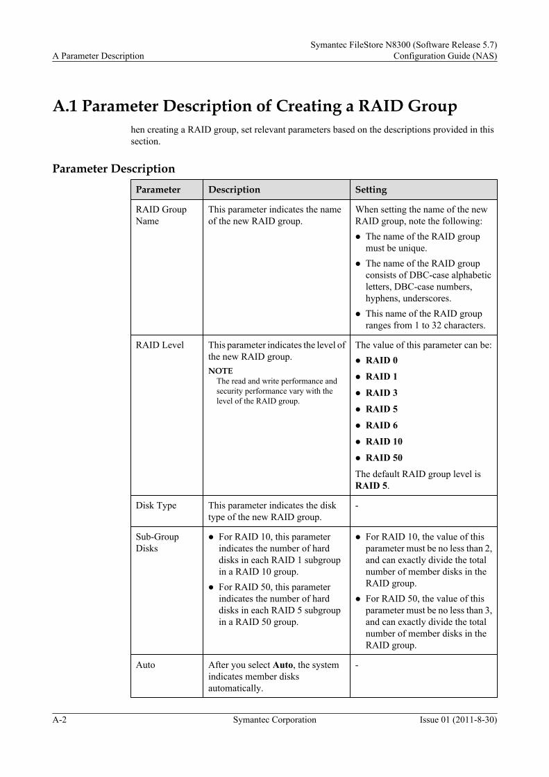
A.1 Parameter Description of Creating a RAID Grouphen creating a RAID group, set relevant parameters based on the descriptions provided in thissection.
Parameter DescriptionParameter Description Setting
RAID GroupName
This parameter indicates the nameof the new RAID group.
When setting the name of the newRAID group, note the following:l The name of the RAID group
must be unique.l The name of the RAID group
consists of DBC-case alphabeticletters, DBC-case numbers,hyphens, underscores.
l This name of the RAID groupranges from 1 to 32 characters.
RAID Level This parameter indicates the level ofthe new RAID group.NOTE
The read and write performance andsecurity performance vary with thelevel of the RAID group.
The value of this parameter can be:l RAID 0
l RAID 1
l RAID 3
l RAID 5
l RAID 6
l RAID 10
l RAID 50
The default RAID group level isRAID 5.
Disk Type This parameter indicates the disktype of the new RAID group.
-
Sub-GroupDisks
l For RAID 10, this parameterindicates the number of harddisks in each RAID 1 subgroupin a RAID 10 group.
l For RAID 50, this parameterindicates the number of harddisks in each RAID 5 subgroupin a RAID 50 group.
l For RAID 10, the value of thisparameter must be no less than 2,and can exactly divide the totalnumber of member disks in theRAID group.
l For RAID 50, the value of thisparameter must be no less than 3,and can exactly divide the totalnumber of member disks in theRAID group.
Auto After you select Auto, the systemindicates member disksautomatically.
-
A Parameter DescriptionSymantec FileStore N8300 (Software Release 5.7)
Configuration Guide (NAS)
A-2 Symantec Corporation Issue 01 (2011-8-30)

Parameter Description Setting
Manual If you select Manual, specify themember disks of the RAID group inthe free disk list.
-
Number ofDisks
This parameter indicates thenumber of the specified numberdisk. This parameter is availableonly when Manual is selected.
-
RemainingDisks
This parameter indicates thenumber of unused disks.
-
Selected Disks This parameter indicates thenumber of disks in the RAID group.
-
Total Capacity(GB)
This parameter indicates thecapacity of the selected disks.The capacity of a RAID group is thetotal capacity of all member disks.
-
A.2 Parameter Description of Creating a LUNWhen creating a LUN, set relevant parameters based on the descriptions provided in this section.
Parameter DescriptionParameter Description Setting
RAID GroupName
This parameter indicates the RAIDgroup whose LUN is to be created.
Select the created RAID groupfrom the drop-down list box.NOTE
If the RAID group that the plannedLUN belongs to is not in the drop-down list box, click Create RAIDGroup to create a new RAID group.
AvailableCapacity(GB)
This parameter indicates the capacityof the RAID group.NOTE
The capacity of the created LUN cannot belarger than the capacity of the RAID groupthat the created LUN belongs to.
-
RAID GroupLevel
This parameter indicates the RAIDgroup level whose LUN is to becreated.
-
Number This parameter indicates the number ofLUNs created in batches.
The value ranges from 1 to 100.
Symantec FileStore N8300 (Software Release 5.7)Configuration Guide (NAS) A Parameter Description
Issue 01 (2011-8-30) Symantec Corporation A-3

Parameter Description Setting
Name This parameter indicates the name ofthe LUN.
When setting the name of the LUN,note the following:l The name of each LUN must be
unique in the storage system.l The name of the LUN consists of
DBC-case alphabetic letters,DBC-case numbers,underscores or hyphens, and itcontains 1 to 32 characters.
Capacity This parameter indicates the capacityof the new LUNs.
When setting this parameter, notethe following:l The value entered in the first text
box after Capacity must be aninteger.
l The maximum capacity of aLUN is the available capacity ofthe RAID group.
l Select 0 MB or 512 MB from thesecond drop-down list box afterCapacity.
The unit of the capacity can be MB,GB, TB, or KB.
Stripe Depth(KB)
This parameter indicates the stripedepth of a LUN.NOTE
The stripe depth affects the I/Operformance of the storage device.Therefore, select the stripe depthappropriately according to differentapplication scenarios.
l If the storage system is used for storinga large number of sequential data, alarger stripe depth (64 KB) isrecommended.
l If the storage system is used for storinga large number of random data, asmaller stripe depth (32 KB) isrecommended.
The value of the stripe depth can be4 KB, 8 KB, 16 KB, 32 KB, 64KB, 128 KB, 256 KB, or 512 KB.The default value of the stripe depthis 64 KB.The unit of the stripe depth is KB.NOTE
This parameter cannot be modifiedafter configuration. Before creating aLUN, plan the stripe depth.
OwningController
This parameter indicates the owningcontroller on which the LUN is to becreated. To ensure data consistency,the owning controller has precedenceto handle all the host I/O requests of theLUN.
The value of this parameter can be:l Controller A
l Controller B
l Auto Selected
A Parameter DescriptionSymantec FileStore N8300 (Software Release 5.7)
Configuration Guide (NAS)
A-4 Symantec Corporation Issue 01 (2011-8-30)

Table A-1 Advanced information
Parameter Description Setting
PrefetchStrategy
This parameter indicates the methodto read the data on a LUN. When thestorage system reads the data on theLUN, the storage system sends thedata from the disk to the cache inadvance according to the configuredpolicy.NOTE
If you are familiar with the applicationscenarios of the storage device, you canuse the fixed prefetch or variable prefetchstrategy according to the actual condition.Otherwise, the intelligent prefetch isrecommended.
l Constant Prefetch Value is suitable forthe sequential read applications thathave a fixed size. For example, in themulti-user streaming media video ondemand (VOD) application, thestreaming media files on the servershave the same code stream.
l Variable Prefetch Multiple is suitablefor the sequential read applicationsthat have an unfixed size, or for themulti-user concurrent readapplications whose pre-read amountcannot be determined and cannot beset by fixed prefetch amount. Forexample, in the multi-user streamingmedia VOD application, thestreaming media files on the servershave different code streams.
l Intelligent Prefetch is suitable forsingle-stream read applications andfor the read applications that cannot bedetermined sequential or random, forexample, read and write of files.
l None is suitable for the random readapplications or for the applicationsthat are already set with a prefetchstrategy, for example, databaseapplications.
The value of the prefetch strategy canbe:l None
The storage system reads the dataaccording to the prefetch lengthspecified in the I/O request, that is,the prefetch strategy is notadopted. This setting is suitable forrandom read applications or forapplications that are already setwith a prefetch strategy, such asdatabase applications. If a prefetchstrategy is not used, the readperformance is degraded. Usingintelligent prefetch strategy isrecommended. Fixed prefetch oralterable prefetch strategies can beused with application scenariosinvolving large amounts ofsequential data.
l IntelligentThe system software controls theprefetch amount by calculating theproper value. In the Intelligentprefetch mode, the storage systemprefetches the data at the end of thechunk where the host requestresides.
l Constant Prefetch ValueWhen a storage system reads dataon a LUN, it reads the data from thecache according to a constantprefetch length rather than theprefetch length specified in the I/Orequest.
l Variable Prefetch MultipleWhen a storage system reads thedata on a LUN, it reads the datafrom the cache according to themultiples of the prefetch lengthspecified in the I/O request.
Symantec FileStore N8300 (Software Release 5.7)Configuration Guide (NAS) A Parameter Description
Issue 01 (2011-8-30) Symantec Corporation A-5

Parameter Description Setting
WriteStrategy
This parameter indicates the methodby which data is written on a LUN.NOTE
The Write Back strategy is availableonly in the dual-controller status.
The value of this parameter can be:l Write Through
Data is directly written into thedisk. The disk is accessed in eachwrite operation and has a lowperformance but high reliability.
l Write Back, MirroringData is written into the localmemory and the peer memory atthe same time. The performanceand reliability are high.
l Write Back, No MirroringData is written only into the localmemory. The performance is highand the reliability is medium.
l Write Back Mandatory, MirroringWhen the storage systemencounters certain faults, forexample, a single-power fault orsingle-fan fault, for example, thedata is not written to the disk butwritten to the local cache and thepeer cache at the same time.
l Write Back Mandatory, NoMirroringWhen the storage systemencounters certain faults, a single-power fault and single-fan fault,for example, the data is not writtento the disk but written to the localcache.
A.3 Parameter Description of Creating a Host GroupWhen creating a host group, set related parameters based on the descriptions provided in thissection.
A Parameter DescriptionSymantec FileStore N8300 (Software Release 5.7)
Configuration Guide (NAS)
A-6 Symantec Corporation Issue 01 (2011-8-30)

Parameter DescriptionParameter Description
Setting
HostGroupName
This parameter indicates the name of thenew host group.
When setting the name of the new hostgroup, note the following:l The name of a host group must be
unique.l The name of a host group consists of
DBC-case alphabetic letters, DBC-case numbers, hyphens orunderscores, and cannot start withhyphens.
l This name of a host group ranges from1 to 32 characters.
OperationSystemType
This parameter indicates the OS type ofthe hosts in the host group.
The value of this parameter can be:l Windows contains Windows 2003,
Windows XP, and so on.l Linux contains Red Hat, SUSE, and
so on.l Solaris
l HP-UX
l AIX
l XenServer
l Mac OS X
A.4 Parameter Description of Creating a File SystemWhen creating a file system, set relevant parameters based on the descriptions provided in thissection.
Table A-2 Parameter Description
Parameter Description Setting
Name This parameter indicates the name of the new filesystem.NOTE
The file name must be unique, consisting of characterstrings only.
Example:fs_01
Symantec FileStore N8300 (Software Release 5.7)Configuration Guide (NAS) A Parameter Description
Issue 01 (2011-8-30) Symantec Corporation A-7

Parameter Description Setting
Capacity This parameter indicates the capacity of the newfile system.NOTE
The capacity of the new file system cannot be larger thanthat of the specified storage pool or that provided by thedata disk.
Example:10 GB
Layout This parameter indicates the layout of the new filesystem. The value can be Simple, Striped,Mirrored, Striped-Mirror, and Mirrored-Striped.NOTE
l If Layout is Striped, the number of data disksselected or the number of data disks in the storagepool must be no smaller than Stripe Quantity.
l If Layout is Striped-Mirror, Mirror Quantitydepends on Protection Type. If Protection Type isPool, the number of pools selected must be nosmaller than Mirror Quantity. If Protection Type isData Disk, the number of data disks selected or thenumber of data disks in the storage pool must be nosmaller than Mirror Quantity.
l If Layout is Mirrored-Stripe, Mirror Quantitydepends on Protection Type. If Protection Type isPool, the number of pools selected must be nosmaller than Mirror Quantity. If Protection Typeis Data Disk, the number of data disks selected orthe number of data disks in the pool must be nosmaller than the product of Stripe Quantity andMirror Quantity. When the file system issuccessfully created, one mirror exists in the systemby default.
l If Layout is Striped-Mirror, Mirror Quantitydepends on Protection. If Protection Type is Pool,the number of pools selected must be no smaller thanMirror Quantity If Protection is Data Disk, thenumber of data disks selected or the number of datadisks in the pool must be no smaller than the productof Stripe Quantity and Mirror Quantity.
l Striped-mirror and Mirrored-Stripe ensure theredundancy of the files and shorten the recovery timeif a disk failure occurs.
Example:Mirrored
Protection Type This parameter indicates the protection type of thenew file system. The value can be Pool or DataDisk.NOTE
l The default value is Data Disk.
l Prerequisite: The value of Layout is Mirrored,Striped-Mirror, or Mirrored-Stripe.
Example:Data Disk
A Parameter DescriptionSymantec FileStore N8300 (Software Release 5.7)
Configuration Guide (NAS)
A-8 Symantec Corporation Issue 01 (2011-8-30)

Parameter Description Setting
Mirror Quantity This parameter indicates the number of mirrors ofthe new file system.NOTE
l The value of Mirror Quantity must be a positiveinteger that is larger than 1
l Prerequisite: The value of Layout is Mirrored,Striped-Mirror, or Mirrored-Stripe.
Example:2
Stripe Unit This parameter indicates the stripe unit of the newfile system. The value can be 128 KB, 256 KB,512 KB, 1 MB, or 2 MB.NOTE
l The value of Stripe Unit must be smaller than thecapacity of the specified file system.
l The value of Stripe Unit must be smaller than thecapacity of the specified data disk or storage pool.
l Prerequisite: The value of Layout is Striped,Striped-Mirror, or Mirrored-Stripe.
Example:512 KB
Stripe Quantity This parameter indicates the number of stripes ofthe new file system.NOTE
l The value of Stripe Quantity must be a positiveinteger that is larger than 1
l Prerequisite: The value of Layout is Striped,Striped-Mirror, or Mirrored-Stripe.
Example:2
Storage Type This parameter indicates the storage type of thenew file system. The value can be Pool or DataDisk.
Example:Pool
A.5 Parameter Description of Configuring QuotaWhen configuring quota, set relevant parameters based on the descriptions provided in thissection.
Parameter DescriptionParameter
Description
File SpaceSoft Quota
Indicates that the exceeded space can still be used within a certain period of timewhen the space quota exceeds the preset value. In other words, the space quotacan exceed the preset value before the expiration date arrives.NOTE
The soft quota takes effect 7 days after the quota restriction is triggered.
Symantec FileStore N8300 (Software Release 5.7)Configuration Guide (NAS) A Parameter Description
Issue 01 (2011-8-30) Symantec Corporation A-9

Parameter
Description
File SpaceHardQuota
Indicates that once the space quota exceeds the preset value, the exceeded spacecannot be used.
FileQuantitySoft Quota
Indicates that the excessive files can still be used within a certain period of timewhen the quantity quota exceeds the preset value. In other words, the quantityquota can exceed the reset value before the expiration date arrives.NOTE
The soft quota takes effect 7 days after the quota restriction is triggered.
FileQuantityHardQuota
Indicates that once the quantity quota exceeds the preset value, the excessivefiles cannot be used.
A.6 Parameter Description of Exporting the ConfigurationFile of Engine
When exporting the configuration file of engine , set relevant parameters based on thedescriptions provided in this section.
Parameter DescriptionParameter Description Setting
File Name This parameter indicates the nameof the configuration file that issaved in the local server.
Example:file_config
Protocol Type This parameter indicates the typeof protocol used when theconfiguration file is exported. Thevalue can be ftp or scp.
Example:scp
Host Name This parameter indicates the nameof the server or the IP address forthe server.
Example:192.168.248.80
File Path This parameter indicates the pathwhere the configuration file issaved.
Example:/var
User Name This parameter indicates the username for the server.
Example:support
Password This parameter indicates thepassword for the server.
Example:123456
A Parameter DescriptionSymantec FileStore N8300 (Software Release 5.7)
Configuration Guide (NAS)
A-10 Symantec Corporation Issue 01 (2011-8-30)

Parameter Description Setting
Remote Address This parameter indicates theremote address by which theconfiguration file is saved.NOTE
This parameter depends on ProtocolType, Server Name, File Path, andUser Name.
Example:scp://[email protected]:/varftp://[email protected]/var
A.7 Parameter Description of Modifying CIFS NormalShare Options
When modifying CIFS Normal share options, set relevant parameters based on the descriptionsprovided in this section.
Parameter DescriptionParameter Description Setting
Owner There are some operations which require ownerprivileges.
Example:host1
Group There are some operations which require the groupprivileges.
Example:group1
RW Read/write mode for the shared file system. The valuecan be ro or rw.NOTE
If the permission to the file system is set to rw in the NFS share,the permission to the file system can only be set to ro in theCIFS share.
Example:rw
Guest Indicates whether to enter the password before youaccess the shared file system. The value can benoguest or guest.Default value is yes.
Example:noguest
Lock Mode Indicates whether data cache is allowed in the shared filesystem. The value can be oplocks or nooplock.Default value is oplocks.
Example:Oplock
Allocate virtualIP addressautomatically
The virtual IP address is automatically allocated by thesystem.
Example:-
Virtual IPAddress
Indicates the virtual IP address which need to configuremanually.NOTE
If you choose Allocate virtual IP address automatically, thevirtual IP address can not be configured manually.
Example:127.0.0.1
Symantec FileStore N8300 (Software Release 5.7)Configuration Guide (NAS) A Parameter Description
Issue 01 (2011-8-30) Symantec Corporation A-11

A.8 Parameter Description of Configuring CIFS ShareGlobal Settings
When configure CIFS share global settings, set relevant parameters based on the descriptionsprovided in this section.
Parameter Description
Parameter Description ParameterSetting
ClusteringMode
Determines that the CIFS share is enabled on a single nodeor in the entire cluster.l Normal: The CIFS share is enabled on a single node.
l Cluster: The CIFS share is enabled in the entire cluster.
ExampleCluster
NTLM Indicates whether to allow the NTLM authenticationprotocol. The value can be:l Yes: The NTLM authentication protocol is allowed.
l No: The NTLM authentication protocol is not allowed.NOTE
NTLM authentication only applies to Windows NT users.
ExampleYes
AllowTrustedDomain
Indicates whether the N8300 supports a multi-domainenvironment. The value can be:l Yes: A multi-domain environment is supported.
l No: A multi-domain environment is not supported.NOTE
If the value of Security Mode is user, this parameter cannot be setto Yes.
ExampleYes
SecurityMode
Domain type. The value can be user、domain and ads. Exampleuser
IdmapBackend
Indicates switch modes between different operating systems.The value can be:l RID: Indicates that to save the information about the local
user or group, you need to set Allow Trusted Domain toNo first. The default value of this parameter ranges from10,000 to 100,000.
l LDAP: Indicates that the information about the local useror group is saved in the LDAP server.
ExampleRID
Domain Domain name of a server.NOTE
This parameter is valid only when Security Mode is ads ordomain.
Examplehs.com
A Parameter DescriptionSymantec FileStore N8300 (Software Release 5.7)
Configuration Guide (NAS)
A-12 Symantec Corporation Issue 01 (2011-8-30)

Parameter Description ParameterSetting
DomainUser
Domain user name. Exampleadministrator
DomainContrlloer
IP address of a server.NOTE
l If the AD controller serves as a domain controller, use the IPaddress or DNS name as the server name.
l If the Windows NT4.0 Domain Controller serves as a domaincontroller, the value of Security Mode must be domain. Inaddition, the server name can only be the NetBIOS name.
Example127.0.0.1
A.9 Parameter Description of Modifying NFS ShareOptions
When modifying NFS share options, set relevant parameters based on the descriptions providedin this section.
Parameter DescriptionParameter
Description Setting
RW Read/write mode of the shared file system. The value can be ro or rw.NOTE
If the permission on the file system is already set to rw in the CIFS share, thepermission to the file system can only be set to ro in the NFS share.
Example:ro
Synchronization
This parameter indicates the synchronization mode of the share filesystem. The value can be sync or async.NOTE
l When the value is sync, all data is written onto the share upon receiving therequest.
l When the value is async, the NFS responds to the request before the data iswritten the share.
Example:Sync
Secure
This parameter indicates whether the share file system allows secureaccess. The value can be yes or no.NOTE
l When the value is yes, the NFS reads or writes data through the TCP/IP securityport numbered below 1024.
l When the value is no, the NFS reads or writes data through the port numberedabove 1024.
Example:Yes
Symantec FileStore N8300 (Software Release 5.7)Configuration Guide (NAS) A Parameter Description
Issue 01 (2011-8-30) Symantec Corporation A-13

Parameter
Description Setting
Root_Squash
Indicates whether the shared file system allows root authority. The valuecan be yes or no.NOTE
If the value of this parameter is yes, the client have root authority when accessingthe shared directory. You are recommended to set this parameter to no.
Example:No
Wdelay
This parameter indicates whether the share file system allows the delayin writing data to disk. The value can be yes or no.NOTE
l When the value is yes, data should be written in group when more than one userintend to write data onto the NFS directory.
l When the value is no, data is immediately written when more than one userintend to write data onto the NFS directory.
Example:No
A Parameter DescriptionSymantec FileStore N8300 (Software Release 5.7)
Configuration Guide (NAS)
A-14 Symantec Corporation Issue 01 (2011-8-30)