Oracle® MICROS Simphony - Configuration Guide
601
Oracle® MICROS Simphony Configuration Guide Release 19.1 F15052-29 June 2022
-
Upload
khangminh22 -
Category
Documents
-
view
1 -
download
0
Transcript of Oracle® MICROS Simphony - Configuration Guide
Oracle® MICROS SimphonyConfiguration Guide
Release 19.1F15052-29June 2022
Oracle MICROS Simphony Configuration Guide, Release 19.1
F15052-29
Copyright © 2010, 2022, Oracle and/or its affiliates.
This software and related documentation are provided under a license agreement containing restrictions onuse and disclosure and are protected by intellectual property laws. Except as expressly permitted in yourlicense agreement or allowed by law, you may not use, copy, reproduce, translate, broadcast, modify, license,transmit, distribute, exhibit, perform, publish, or display any part, in any form, or by any means. Reverseengineering, disassembly, or decompilation of this software, unless required by law for interoperability, isprohibited.
The information contained herein is subject to change without notice and is not warranted to be error-free. Ifyou find any errors, please report them to us in writing.
If this is software or related documentation that is delivered to the U.S. Government or anyone licensing it onbehalf of the U.S. Government, then the following notice is applicable:
U.S. GOVERNMENT END USERS: Oracle programs (including any operating system, integrated software,any programs embedded, installed or activated on delivered hardware, and modifications of such programs)and Oracle computer documentation or other Oracle data delivered to or accessed by U.S. Government endusers are "commercial computer software" or "commercial computer software documentation" pursuant to theapplicable Federal Acquisition Regulation and agency-specific supplemental regulations. As such, the use,reproduction, duplication, release, display, disclosure, modification, preparation of derivative works, and/oradaptation of i) Oracle programs (including any operating system, integrated software, any programsembedded, installed or activated on delivered hardware, and modifications of such programs), ii) Oraclecomputer documentation and/or iii) other Oracle data, is subject to the rights and limitations specified in thelicense contained in the applicable contract. The terms governing the U.S. Government’s use of Oracle cloudservices are defined by the applicable contract for such services. No other rights are granted to the U.S.Government.
This software or hardware is developed for general use in a variety of information management applications.It is not developed or intended for use in any inherently dangerous applications, including applications thatmay create a risk of personal injury. If you use this software or hardware in dangerous applications, then youshall be responsible to take all appropriate fail-safe, backup, redundancy, and other measures to ensure itssafe use. Oracle Corporation and its affiliates disclaim any liability for any damages caused by use of thissoftware or hardware in dangerous applications.
Oracle, Java, and MySQL are registered trademarks of Oracle and/or its affiliates. Other names may betrademarks of their respective owners.
Intel and Intel Inside are trademarks or registered trademarks of Intel Corporation. All SPARC trademarks areused under license and are trademarks or registered trademarks of SPARC International, Inc. AMD, Epyc,and the AMD logo are trademarks or registered trademarks of Advanced Micro Devices. UNIX is a registeredtrademark of The Open Group.
This software or hardware and documentation may provide access to or information about content, products,and services from third parties. Oracle Corporation and its affiliates are not responsible for and expresslydisclaim all warranties of any kind with respect to third-party content, products, and services unless otherwiseset forth in an applicable agreement between you and Oracle. Oracle Corporation and its affiliates will not beresponsible for any loss, costs, or damages incurred due to your access to or use of third-party content,products, or services, except as set forth in an applicable agreement between you and Oracle.

Contents
Preface
1 Introduction to Simphony
EMC Basics 1-1
2 Getting Started
3 Enterprise
Inheritance and Overrides 3-1
Distribution 3-2
Configuring Distribution Privileges 3-3
Distributing Properties and Revenue Centers 3-4
Distributing Records 3-5
Distribution Based on Source, Destination, and Selected Options 3-6
Configuring Permissions for the EMC 3-7
4 Cloning Simphony Database Configurations
Extracting Data from the Source Environment 4-2
Uploading Data to the Target Environment 4-2
Post-Uploading Cloned Data Instructions 4-3
5 Log File Management
Modifying the Default Log Archive Purge Settings for Application Services 5-2
Enabling Log Archiving for Workstations 5-2
6 Properties
Adding a Property 6-1
iii

Adding a Revenue Center 6-2
Revenue Center Groups 6-3
Configuring a Revenue Center Group 6-3
7 Zones
Creating Zones 7-7
8 POS Workstations
Workstation Tasks 8-1
Adding a Workstation 8-1
Configuring Workstation Transaction Settings 8-4
Setting Offline Transaction Posting Time 8-4
Configuring Workstation Security 8-5
Changing the Appearance of Workstations 8-6
Configuring the Magnetic Stripe Reader on the Oracle MICROS Tablet 720 8-6
Configuring the Barcode Scanner on the Oracle MICROS Tablet 720 8-7
Allowing Employees to Install and Authenticate POS Clients and Service Hosts 8-7
Using the Simphony POS Client and Mobile Solution Application on One Device 8-7
Configuring the Close Application Button 8-8
POS Clients Running Android Mobile Operating System 8-8
Android Functionality Support 8-8
Android Network Requirements 8-9
Android Payments 8-9
Workaround for Android Lollipop 5.0.2 and 5.1 8-9
Configuring the Android Device as a Workstation 8-9
Configuring an Android Workstation 8-10
Viewing and Editing Simphony Android Files 8-10
Wireless Signal Strength Threshold 8-11
Configuring Wireless Signal Strength Control Permissions 8-11
Configuring the Wireless Signal Strength Threshold for Tablet Devices 8-11
Configuring an Alpha-Numeric Keyboard 8-12
9 Language Settings and Translation
Language Translation Configuration Tasks 9-1
Configuring Translation Privileges 9-2
Configuring Languages 9-2
Configuring Workstation Translations 9-3
Configuring the EMC Translation Files 9-7
Translating Menu Item Records 9-7
iv
EMC Record Translation 9-8
Translating Touchscreen Buttons 9-8
Setting Languages for the Property 9-8
Setting the Default Language for Employees 9-9
Setting the Default Language for a Workstation 9-9
Configuring Screen Language Buttons 9-9
Multiple Languages on Guest Checks and Customer Receipts 9-10
Printing a Secondary Language on Guest Checks and Customer Receipts 9-10
Configuring Right to Left Reading Languages 9-11
Creating a Print Language List Button 9-11
Creating Print Language Buttons 9-12
Copying Translations from One Language to Another 9-12
Exporting a Translation File 9-12
10
Privacy and Personal Data Management
Configuring Consent Messages 10-1
Withdrawing Consent 10-2
Removing Personal Data from Simphony 10-2
11
Employees and Privileges
Creating Employee Roles 11-1
Creating Employee Classes 11-2
Adding an Employee 11-4
Deleting an Employee 11-4
Changing Employee Information 11-5
Configuring Employee Shifts 11-8
Configuring Employee Breaks 11-11
Clock-In and Clock-Out Cycles 11-11
Setting Clock-In and Clock-Out Cycles 11-11
Job Codes 11-12
Configuring Job Codes 11-12
Declaring Tips 11-13
Configuring Tip Tracking and Reporting 11-13
Configuring Tip Track Buttons 11-15
12
Payments and Currency
Types of Payment 12-1
Configuring Currency 12-1
Configuring Base Currency and Alternate Currency 12-2
v

Configuring Currency Conversions 12-2
Configuring the Cash Tender 12-3
Adding Payment Keys to the Transaction Page 12-6
The Oracle Payment Interface (OPI) 12-7
OPI Architecture 12-7
Configuring the OPI Driver 12-9
Configuring the OPI Payment Module 12-10
Configuring the Default Payment Tender for OPI 12-10
Creating Credit Card Payment Buttons 12-11
Updating Credit Card Preambles for OPI 12-11
Configuring the OPI and SPI to Settle Transactions Automatically 12-12
Configuring the OPI and SPI to Settle Transactions Manually 12-13
Credit Card Preambles for OPI 12-13
The Simphony Payment Interface (SPI) 12-14
SPI Architecture 12-14
Payment Driver vs. Workstation Settings 12-19
OPI Users 12-19
Pay@Table 12-19
Check Sharing 12-20
Configuring the SPI Payment Driver 12-20
Configuring Mail Order Telephone Order (MOTO) 12-22
OPERA Self Pay 12-23
Configuring a Credit Card Tender 12-23
Credit Card Preamble 12-24
Configuring Standard Credit Card Preambles 12-24
List of Standard Credit Card Preambles for the U.S. 12-24
Configuring Credit Card Authorization to Print Merchant Vouchers and Customer Receipts 12-25
Configuring Credit Card Voucher Headers and Trailers 12-26
Configuring the Room Charge Tender 12-26
Configuring the OPERA PMS Payment Driver 12-26
Configuring the Loadable PMS Payment Module 12-28
Configuring the OPERA Self Pay Button 12-28
Configuring Email Receipts 12-29
Configuring a Tender with Charged Tips 12-30
Autosequence Events 12-31
Configuring Autosequence Events 12-31
Configuring the Autosequence Event Schedule 12-32
Removing Legacy Credit Card Drivers 12-32
vi

13
Taxes
Tax Rates and Tax Classes 13-2
Configuring Tax Rates and Classes 13-2
Tax Parameters 13-3
Configuring Tax Parameters 13-5
Tax Labels 13-6
Configuring Tax Labels 13-6
Serving Periods 13-6
Configuring a Serving Period 13-6
Order Types 13-7
Configuring Order Types 13-9
Configuring Order Types as Subtotal Keys 13-10
Configuring Touchscreen Buttons for Order Types 13-11
Printing Tax Rate Per Item 13-11
Configuring Tax Rates Per Item to Print on Guest Check, Customer Receipt and Journal 13-12
Configuring Workstation Number and Transaction Number to Print on Guest Check,Customer Receipt, and Journal 13-12
Surcharges 13-13
Configuring Surcharges 13-13
Configuring the Menu Item Tax Class Override 13-14
Configuring Options for Australia GST Requirements 13-15
14
Discounts
Manual Discounts 14-1
Automatic Discounts 14-2
Automatic Discount Rules 14-2
Awarding Algorithms 14-4
Discount Award Types 14-6
Discount Exclusivity 14-7
Simple Exclusivity 14-8
Group Exclusivity 14-9
Menu Item Groups 14-10
Configuring Menu Item Groups 14-10
Configuring Discount Privileges 14-11
Configuring Discounts 14-12
Configuring Effectivity Groups 14-17
Automatic Discounts with Decimal Quantity Menu Items 14-18
Amount Off Examples 14-18
Amount Substitution Examples 14-19
Configuring Decimal Quantity Menu Items 14-20
vii

Configuring an Item Price Substitution Discount 14-20
Configuring a Quantity Threshold Discount 14-21
Configuring a Total Price Threshold Discount 14-22
Configuring a Combination Pricing Discount 14-23
Configuring a Sales Price Discount 14-24
Discounts With Condiments 14-24
Configuring Condiments as Discount Triggers 14-25
Configuring Discounts for Parent Menu Items in a Menu Item Class 14-25
Configuring a Condiment as the Discount Award 14-25
Creating the Discount Button 14-27
15
Service Charges
Configuring Service Charges 15-1
Creating Service Charge Buttons 15-5
Menu Item Fees 15-6
Configuring Menu Item Fees 15-6
16
Menu Items
Configuring Menu Items 16-1
Adding and Disabling Menu Items 16-3
Configuring Employee Privileges to Edit Menu Item Definitions and Prices 16-3
Configuring Employee Privileges for Menu Item Availability Adjustments 16-4
Configuring Menu Item Availability for Multiple Definitions at the Workstation 16-5
Adding the Menu Item Availability Key to the Transaction Page 16-5
Adding Menu Item Keys to the Transaction Page 16-5
Adding the Edit Menu Item Key to the Transaction Page 16-6
Repeatable Menu Items 16-6
Configuring Menu Items to be Repeatable 16-6
Configuring a Repeat Round Button 16-7
Menu Item Distribution 16-7
Distributing Menu Items 16-7
Searching and Filtering Menu Items 16-9
17
Categorizing Menu Items into Groups
Configuring Major Groups 17-1
Configuring Family Groups 17-1
viii

18
Menu Item Master Records
Configuring Master Records for Menu Items 18-1
19
Menu Item Search and Report
Generating the Module Reference Report 19-1
20
Menu Item Classes
Configuring Menu Item Classes 20-1
Print Groups 20-9
Configuring Print Groups for Menu Item Classes 20-9
21
Menu Item Definitions
Adding Menu Item Definition Records to Multiple Menu Item Masters 21-1
Adding Menu Item Definition Records to a Single Menu Item Master 21-2
Configuring Menu Item Definitions 21-3
Allowing Users to Override Restricted Menu Item Ranges 21-6
22
Menu Item Prices
Configuring Menu Item Prices 22-2
Configuring Menu Item Prices for Multiple Definitions 22-3
23
Menu Levels
Setting Main, Sub, and Custom Menu Levels 23-3
Setting the Default Main and Sub Levels for Serving Periods 23-4
Configuring Auto Menu Levels 23-4
Setting the Default Menu Levels for a Revenue Center 23-4
Configuring Active Menu Levels for Menu Item Definitions and Prices 23-5
24
Sales Itemizers
Configuring Sales Itemizers 24-1
25
Screen Look Up (SLU)
Configuring Screen Look Ups for Menu Items 25-1
Configuring Screen Look Ups for Discounts 25-3
ix

Configuring Screen Look Ups for Service Charges 25-3
Configuring Menu Item Screen Look Ups by Family Group 25-4
Configuring Menu Item Screen Look Ups by Major Group 25-4
Configuring Menu Item Screen Look Ups by Menu Item Master Group 25-4
Configuring Screen Look Ups for Custom Reports 25-5
Configuring Screen Look Ups for Open Checks 25-5
26
Number Look Up (NLU)
Configuring Number Look Ups for Discounts 26-1
Configuring Number Look Ups for Service Charges 26-1
Configuring Number Look Ups for Tender/Media Records 26-2
Configuring Number Look Ups for Main and Sub Levels 26-2
Configuring Number Lookups for Menu Items 26-3
Configuring NLU Groups 26-3
27
Weighed Menu Items
Configuring a Weighed Menu Item 27-1
Setting the Tare Weight for a Menu Item 27-1
28
Menu Item Waste
Allowing Employees to Begin Waste Checks and Run Waste Reports 28-2
Configuring Waste Reasons 28-2
Configuring Waste Receipt Headers and Trailers 28-2
Hiding Price Details on Waste Checks 28-3
Creating the Declare Waste Button 28-3
29
Menu Item Refills
Allowing Employees to Refill Menu Items 29-1
Making Menu Items Refillable and Configuring the Refill Limit 29-1
Adding Refill Buttons 29-1
30
Condiments
Condiment Groups and Condiment Sets 30-1
Configuring Condiment Groups 30-2
Creating Menu Item Classes for Condiment Groups 30-2
Creating Menu Item Master Records for Condiments 30-3
Configuring Condiment Sets 30-3
x

Assigning Condiments to Parent Menu Item Classes 30-4
Assigning Default Condiments to Parent Menu Items 30-7
Condiment Prefixes 30-7
Creating Condiment Prefix Menu Items 30-7
Creating Menu Item Classes for Prefixes 30-8
Using Condiment Prefixes with Menu Item Classes 30-9
Disabling Condiment Prefixes 30-9
Configuring Touchscreen Buttons for Condiment Prefixes 30-9
Setting Condiment Appearance 30-9
Popup Condiment Orderer 30-10
Configuring a Popup Condiment Orderer Page 30-11
Configuring a Revenue Center to Use the Popup Condiment Orderer 30-12
Configuring Menu Items Linked to Classes to Use the Popup Condiment Orderer 30-12
31
Combo and Fixed Price Meals
Combo Meal Group Pricing 31-1
Placeholder Menu Items in Combo Meals 31-3
Creating Combo Meal Groups 31-3
Creating Combo Meals 31-6
Configuring Additional Combo Meal Settings 31-9
Creating Combo Meal Pages 31-10
Configuring a Smart Key to Show Menu Level Buttons 31-11
Combo Meal Function Keys 31-13
32
Guest Checks
Configuring Guest Check Numbers 32-1
Configuring Guest Check Headers and Trailers 32-1
Creating a Service Total to End the Current Service Round of Checks 32-2
Adding a Service Total Key to the Transaction Page 32-3
Configuring Open Checks on Revenue Centers to Automatically Cancel 32-3
Fast Transactions 32-4
Configuring Fast Transactions 32-4
Full Seat Checks 32-5
Configuring a Print Full Seat Check Service Total 32-5
Creating a Full Seat Check Button 32-6
Splitting Off an Item 32-6
Configuring a Split Off Item Button 32-7
Conversational Ordering 32-8
Creating Menu Item Master Groups for Conversational Ordering 32-8
xi

Configuring Menu Level Sets for Conversational Ordering 32-8
Configuring Menu Item Classes for Conversational Ordering 32-9
Configuring Menu Items for Conversational Ordering 32-10
Creating Buttons for Conversational Ordering 32-11
Configuring Employee Privileges for Automatic Check Firing 32-12
Configuring Automatic Check Firing 32-12
Configuring Employee Privileges for Check Re-firing 32-14
Configuring the Check Re-fire Button 32-14
Suspend and Resume 32-15
Configuring Suspend and Resume 32-15
Creating a Suspend and Resume Button 32-15
Setting the Employee Auto Sign Out Period 32-16
Follow Me 32-16
Configuring Follow Me Checks 32-16
Order Handling on Open Checks 32-17
Holding and Sending Items to Order Devices 32-17
Configuring Send and Stay 32-18
Setting the Hold and Fire Option 32-18
Setting the Hold and Fire Tender Notification 32-18
Setting a Reminder for Items on Hold 32-18
Configuring Checks with Items on Hold to End Current Service Round 32-19
Configuring Check Handling For Closing Checks With Held Items 32-20
Configuring Item Hold Buttons 32-20
Configuring the Fire Now Button 32-21
Team Service 32-21
Reports and Totals Posting for Team Checks 32-21
Enabling Team Service 32-22
Configuring Team Service Privileges 32-22
Configuring Revenue Centers to Delete Service Teams at the Start of Day 32-23
Adding Team Service Buttons 32-24
Closed Guest Check Operations 32-24
Configuring Closed Check Settings 32-24
Allowing Employees to Adjust Closed Checks 32-25
Allowing Employees to Reopen and Edit a Closed Check 32-26
Allowing Employees to Reprint Closed Checks 32-27
Allowing Employees to Manually Replay Checks Through the Workstation 32-28
Check Add/Transfer 32-29
Allowing Employees to Add or Transfer Checks 32-29
Configuring the Add/Transfer Revenue Centers 32-29
Configuring Add/Transfer Buttons 32-29
Seat Filtering and Memo Checks 32-30
xii

Configuring Memo Check Printing 32-33
Configuring Service Charges for Seat Filtering 32-34
Configuring Seat Filter Management Buttons 32-34
33
Workstation Touchscreen Pages
Page Design 33-1
Assigning Default Touchscreen Pages 33-2
Configuring Function Keys 33-2
Configuring Macros 33-3
34
Rental Deposits
Configuring Deposits as a Menu Item 34-1
Configuring Deposits as a Service Charge 34-1
Configuring Rental Deposit Buttons 34-2
35
Resetting Daily Totals
Start of Day 35-1
Start of Day Business Rules 35-1
Start of Day with Offline Workstations or Server 35-2
Configuring Start of Day 35-2
36
Updating POS Client Configuration
Setting the Database Update Frequency 36-1
37
Clearing Totals
Running the Clear Totals Operation 37-1
38
Check and Posting Service (CAPS)
CAPS Configuration Methods 38-1
CAPS Supported Software and Hardware 38-2
CAPS Configuration Tool 38-2
Prerequisite Products for CAPS 38-3
Tasks to Set Up CAPS as a Web Service on Microsoft Internet Information Services(IIS) 38-3
Configuring CAPS on Microsoft IIS with Oracle Database on Enterprise Server 38-4
Configuring CAPS Access 38-4
xiii

Configuring the Service Host for CAPS in EMC 38-4
Configuring CAPS with an Oracle Database 38-5
Configuring CAPS on Microsoft IIS 38-6
Configuring CAPS on Microsoft IIS with Oracle Database on Remote Service Host 38-6
Configuring CAPS Access 38-6
Configuring the Service Host for CAPS in EMC 38-7
Preparing the Server to Configure CAPS 38-7
Scheduling and Viewing Device Information 38-8
Device Information Needs Attention State 38-9
Configuring CAPS with an Oracle Database 38-11
Configuring CAPS on Microsoft IIS 38-12
Upgrading Microsoft IIS CAPS 38-12
Upgrading Microsoft IIS CAPS on Enterprise Server 38-12
Upgrading Microsoft IIS CAPS on Remote Service Host 38-13
Configuring CAPS as a Windows Service with an Oracle Database 38-13
Configuring CAPS Access 38-13
Configuring the Service Host for CAPS in EMC 38-14
Preparing the Server to Configure CAPS 38-15
Scheduling and Viewing Device Information 38-15
Device Information Needs Attention State 38-17
Configuring CAPS with an Oracle Database 38-19
Copying the Database Settings 38-19
Starting the CAPS Service 38-20
Optional CAPS Configuration Tasks 38-20
CAPS Optimization for High Loads 38-20
CAL Installation Prerequisites for a Workstation without the POS Interface (CAPS OnlyWorkstation) 38-20
Configuring the Deployment Schedule to Install CAL on a Workstation without thePOS Interface 38-20
Installing CAL on a Workstation without the POS Interface 38-21
Configuring the Show Database Provider Button 38-24
Encrypting Database Credentials 38-24
Verifying CAPS Installation 38-25
Configuring IIS Application Pool Settings 38-25
Configuring Recycle Settings for the IIS Application Pool 38-25
Restarting Microsoft IIS CAPS 38-25
39
Printers
Print Controller 39-1
Roll Printer 39-2
Slip Printer 39-2
xiv

Internet Protocol (IP) Printer 39-2
Bluetooth Printer 39-2
Printer Groups 39-2
Configuring a Printer 39-3
Creating, Editing, and Removing Printer Groups 39-7
Configuring the Change Default Printer Destination Button 39-8
Configuring a Printer Order Device 39-8
Secondary Printing 39-11
Configuring Secondary Printing 39-12
Printer DIP and Memory Switch Settings 39-13
Epson Printer Setup for IDN Module 39-13
Printer DIP Switch/Memory Switch Setting when using UB-IDN (IDN02) Interface 39-14
Printer DIP Switch/Memory Switch Setting when using UB-IDML (IDNML02) Interface 39-15
Printer DIP Switch/Memory Switch Setting when using UB-E02 (E03) Interface 39-17
Printer DIP Switch/Memory Switch Setting when using UB-EML Interface 39-18
Printer DIP Switch/Memory Switch Setting when using UB-EML02 Interface 39-20
DIP Switch Definitions 39-21
40
Logo Printing
Uploading a Logo to Simphony 40-1
Assigning a Logo to Guest Checks and Customer Receipts 40-2
41
Banquet Guest Check Printing
Configuring Employee Privileges for Banquet Guest Check Printing 41-2
Configuring Banquet Guest Check Buttons and Prompts 41-4
Adding a Banquet Guest Check Printer and Various Print Settings 41-16
Creating and Printing Banquet Guest Checks From a POS Workstation 41-21
42
Configuring Pre-Production Chits to Output to Remote Printers
Configuring Print Classes for Pre-Production Chits 42-1
Configuring Tender/Media - Service Total Records for Pre-Production Chits 42-1
Configuring Menu Item Classes for Pre-Production Chits 42-2
Configuring a Page Design Button for Pre-Production Chits 42-3
Example of a Pre-Production Chit 42-4
43
Peripheral Devices
Cash Drawer Assignment and Unassignment 43-1
Configuring a Cash Drawer 43-2
xv

Coin Dispenser 43-5
Configuring a Coin Dispenser 43-5
Magnetic Stripe Reader 43-6
Installing the MSR Sleeve for Oracle MICROS Tablet E-Series 8-Inch and 11-Inch Devices 43-6
Configuring a Magnetic Stripe Reader 43-7
Testing the MSR Sleeve for Oracle MICROS Tablet E-Series 8-Inch and 11-Inch Devices 43-8
Barcode Reader Setup Methods 43-8
Configuring a Barcode Reader Using the Barcodes Module Method 43-9
Configuring the 1D/2D Imager Scanner 43-10
Fingerprint Scanning 43-11
Configuring the Biometrics CAL Package Deployment 43-12
Configuring Employee Privileges for the Fingerprint Reader 43-12
Configuring the Touchscreen Home or Sign In Page to Assign Employee PersonalIdentification Number (PIN) 43-13
Configuring the Workstation Employee Fingerprint Sign In Options 43-13
Scanning a Fingerprint 43-13
Configuring a Scale 43-14
Sales Recording Module (SRM) 43-15
Enabling SRM for a Property 43-15
Configuring SRM Payment Types for Tenders 43-15
Enabling SRM for Printers 43-16
Configuring the Quebec SRM Control Button 43-16
Allowing Employees to Enable and Disable SRM from the Workstation 43-17
44
Reporting
Allowing Employees to Run Reports 44-1
List of Workstation PMC Reports 44-1
Closed Check Report Codes 44-3
Configuring Employee Privileges for Oracle Hospitality Reporting and Analytics 44-5
Configuring the Log Files for Oracle Hospitality Reporting and Analytics 44-5
Viewing Move History Logs 44-6
Configuring Data Retention Limits 44-7
45
Auditing
Using the Audit Trail 45-1
Using Audit This Record 45-3
xvi

46
Importing and Exporting Data
Configuring the Import/Export Service Privileges 46-1
Configuring the Import/Export Service 46-2
Configuring Task Schedules for Export Reliability 46-3
Increasing the Import File Size 46-3
Import/Export Service Components 46-4
47
Loyalty and Gift Card Interfaces and Drivers
Loyalty and Stored Value Configuration Prerequisites 47-1
Loyalty Configuration Tasks 47-2
Configuring Loyalty and Stored Value Privileges 47-2
Setting Loyalty Options 47-6
Configuring the Loyalty Driver 47-7
Configuring the Loyalty Module 47-8
Stored Value Configuration Tasks 47-9
Setting Stored Value Options 47-10
Configuring the Stored Value Driver 47-11
Configuring the Stored Value Module 47-12
Creating Loyalty and Stored Value Buttons 47-13
Voiding Points on a Re-opened Check 47-16
XProcessor Extension Application Migration 47-16
48
Events
Configuring Event Privileges and Permissions 48-1
Specifying Ad Hoc Reports 48-2
Enabling Events 48-3
Configuring Event Types and Sub Types 48-3
Creating an Event 48-4
Configuring an Event Area 48-5
Linking Events 48-5
Breaking Linked Events 48-6
Cancelling an Event 48-6
Configuring Event Information to Print on Checks and Receipts 48-7
Creating Task Schedules 48-7
Configuring the Event Status Bar 48-9
Configuring the Event Buttons 48-10
Event Information in Reporting and Analytics Reports 48-10
xvii

49
Dining Room Tables and Seating
Standard and Enhanced Table Management 49-1
Configuring the Standard Table Management Interface 49-1
Creating Standard Dining Tables 49-3
Configuring the Standard Dining Table Status Set 49-3
Table Management 49-4
Reservation List 49-4
Wait List 49-5
Table Management, Reservation, and Wait List Configuration Prerequisites 49-5
Configuring Table Management Privileges 49-5
Configuring Reservation Privileges 49-7
Configuring Wait List Privileges 49-8
Configuring Servers for Table Management 49-9
Configuring Properties for Table Management 49-9
Configuring Custom Images for Table Management 49-9
Configuring KDS or Dining Course Colors and Images for Table Management 49-10
Configuring Dining Course Pacing 49-10
Configuring the Service Total Tender for Table Management 49-11
Enhanced Dining Tables 49-11
Setting Dining Table Classes 49-11
Setting Enhanced Dining Table Attributes 49-12
Configuring Enhanced Dining Tables 49-13
Setting Table Decorator Images 49-14
Configuring Server and Table Availability 49-16
Setting Table Management Options 49-16
Configuring Table Suggestion Factors 49-18
Table Management Alerts 49-19
Configuring Alerts 49-20
Table Management Sections 49-20
Configuring Sections 49-20
Creating the Touchscreen Reservation List 49-21
Creating the Touchscreen Wait List 49-23
Touchscreen Page Table Management Tasks 49-25
Host Command Area 49-26
Configuring the Host Command Area 49-26
Dining Table Status 49-26
Configuring the Dining Table Status 49-27
Employee Lines 49-28
Configuring Employee Lines 49-28
Section Layout 49-29
xviii

Creating a Section Layout 49-30
Creating Enhanced Dining Tables 49-30
Setting Table Management Functions in Check Detail 49-30
Creating the Employee Section Assignment Report Button 49-31
Configuring Table Cancellation Reasons 49-31
Setting Reservation Timing Parameters 49-32
Setting Wait List Timing Parameters 49-33
Reservation Periods 49-34
Configuring Effectivity 49-34
Configuring Acceptance Limits 49-35
Configuring Occupancy Limits 49-36
Configuring Seating Limits 49-36
Configuring Target Turn Times 49-37
Table Management Configuration Levels 49-38
Reservation Configuration Levels 49-39
Wait List Configuration Levels 49-39
50
Enterprise Cash Management
Configuring Data Retention Limits 50-1
Specifying Ad Hoc Reports 50-1
Configuring ECM Privileges and Permissions 50-2
Allowing Users to View Blind Totals 50-8
Allowing Assigned Receptacle Access and Counts 50-9
Configuring Accounting Methods for Users 50-9
Allowing Users to Override Employee Class Options 50-10
Tracking Tender Transaction Items 50-10
Tracking Service Charge Transactions 50-11
Tracking Discount Transactions 50-11
Creating, Editing, and Deleting Cash Management Reasons 50-11
Cash Management Classes 50-12
Adding Transaction Items 50-12
Adding Counting Units 50-13
Cash Pull Threshold Set 50-14
Creating, Editing, and Deleting a Cash Pull Threshold Set 50-14
Cash Count Threshold Set 50-15
Creating, Editing, and Deleting a Cash Count Threshold Set 50-15
PAR Level Set 50-16
Creating, Editing, and Deleting a PAR Level Set 50-16
Count Sheet 50-16
Creating, Editing, and Deleting a Count Sheet 50-17
xix

Creating, Editing, and Deleting an Account 50-19
Creating, Editing, and Deleting a Vendor 50-19
Creating and Editing a Template 50-20
Creating, Editing, and Deactivating Receptacles 50-23
Setting Cash Management Parameters 50-23
Creating Cash Management Touchscreens and Dashboard 50-28
Configuring a Smart Key on a Workstation 50-33
Configuring a Till Through Extensibility 50-34
Configuring a Bank Deposit Reference Through Extensibility 50-34
ECM Reporting 50-34
Enabling Reports in Enterprise Back Office 50-34
ECM Enterprise Information in Reporting and Analytics Reports 50-35
ECM Property Reports 50-36
ECM Workstation Hardware 50-37
ECM Configuration Levels 50-38
51
Engagement Cloud Service
System Requirements and Supported Devices 51-1
Security Precautions 51-1
Assigning Privileges for Engagement Administrative Users 51-2
Language Translation Tasks 51-2
Adding a New Language to Hub and Welcome Pages 51-3
Adding a Language to the EMCWeb File 51-3
Adding a Language File to the Engagement Configuration Application Server 51-4
Setting Multiple Languages 51-4
Engagement Manager Procedures 51-4
Adding Engagement Manager Procedure Tiles to the Hub Page 51-5
Editing the Check Header and Trailer 51-5
Editing Bulk Menu Item Prices 51-6
Adding an Employee From a Template 51-6
Deactivating an Employee 51-7
Adding a New Menu Item Using an Existing Menu Item as a Template 51-8
Adding Images to Menu Items 51-8
Adding or Changing an Employee’s Profile Image 51-8
Creating Pages for Engagement Users 51-9
Modifying Pages for Engagement Users 51-9
Assigning Logos and Colors to Pages 51-9
Assigning Default Welcome and Hub Pages 51-10
Widgets 51-10
The IP Camera Widget 51-11
xx

Adding and Moving Widgets 51-11
Creating Tiles (Adding Widgets to a Page) 51-12
Adding Command Buttons 51-14
Configuring Widget Timing Values 51-14
List of Widgets 51-15
Viewing the Maximum Data Limit for Hosted Engagement Server 51-18
52
Extension Applications
Configuring Extension Application Privileges 52-1
Enabling Extension Applications 52-1
53
Transaction Services
Configuring the Transaction Services Workstation Client 53-1
Configuring the Transaction Services Default Employee 53-2
Order Information Service 53-2
Activating the Extension Application for Order Information Service 53-3
Configuring Touchscreen Order Information Service Buttons 53-3
Order Information Service Functions and Extensibility Arguments 53-5
54
Cruise Ship Time Zone and Business Day Settings
Changing the Time Zone 54-1
Start of Business Day 54-1
Configuring Start of Day 54-2
Workstation Control Privileges 54-3
Configuring Workstation Control Privileges 54-3
55
Interfaces with Simphony
Configuring a Rear Marketing Display (RMD) 55-1
OPERA PMS Enhanced Interface Features and Requirements 55-5
Inserting the Extension Application Files for OPERA 55-6
Configuring OPERA Content Information 55-9
Content Text Settings for the OPERA PMS 55-10
Configuring the OPERA PMS Interface 55-13
Enabling the OPERA PMS Interface for a Revenue Center 55-16
Adding the Tender/Media Data Extension for OPERA 55-17
Configuring the Tender Media for OPERA 55-18
Configuring the Room Charge Buttons for the OPERA PMS 55-20
xxi

Updating the SIM OPERA Interface to a Newer Version 55-22
56
Accessibility
Enabling High Contrast Visibility Settings 56-1
Navigating the Home Page Using Keystrokes 56-1
Keyboard Shortcuts 56-2
xxii

Preface
Oracle MICROS Simphony is a cloud-based Point-of-Sale (POS) solution that providesbusiness management capabilities using a single tool with vast integration capabilities toproperty management systems, paperless kitchen display systems, credit card interfaces,and reporting applications.
Purpose
This Configuration Guide provides instructions to set up Simphony release 19.1.
Audience
This document is intended for system administrators of Oracle MICROS Simphony release19.1.
Customer Support
To contact Oracle Customer Support, access My Oracle Support at the following URL:
https://support.oracle.com
When contacting Customer Support, please provide the following:
• Product version and program/module name
• Functional and technical description of the problem (include business impact)
• Detailed step-by-step instructions to re-create
• Exact error message received and any associated log files
• Screen shots of each step you take
Documentation
Product documentation is available on the Oracle Help Center at https://docs.oracle.com/en/industries/food-beverage/pos.html.
Simphony eLearning
The Simphony Learning Subscription provides additional product knowledge throughinteractive training, guided video tours, and helpful knowledge checks. After exploring thedocumentation library, use your Oracle Single Sign On to check out the Simphony learningopportunities at Hospitality Learning Subscriptions.
xxiii

Revision History
Date Description of Change
January 2020 • Initial publication.• Updated Fingerprint Scanning in
Chapter 42: Peripheral Devices toinclude information on how the systemprocesses fingerprint data.
• Updated Chapter 8: POS Workstations(updated the Android Payments topicto include OPI/SPI as supporteddrivers).
February 2020 Updated Chapter 4: Uploading Data to theTarget Environment
March 2020 Updated Chapter 32: Guest Checks for theConfiguring Team Service Privileges sub-topic
May 2020 Updated the following sections in Chapter12: Payments and Currency:• OPERA Self Pay• Configuring the Room Charge Tender• Configuring the OPERA PMS Payment
DriverUpdated Configuring Menu ItemDefinitions in Chapter 21: Menu ItemDefinitions.Updated Chapter 40: Logo Printing toindicate that you can configure a check toprint more than one logo.Updated Fingerprint Scanning in Chapter42: Peripheral Devices to include biometricdata storage in Employee table, andqueries.
June 2020 Added Configuring Alpha-NumericKeyboard in Chapter 8: POS Workstations.Updated Configuring WorkstationTranslations in Chapter 9: LanguageSettings and Translation.Merged Configuring POS Core and PaymentTranslations to Configuring WorkstationTranslations in Chapter 9: LanguageSettings and Translation.Removed the following sections fromChapter 38: Check and Posting Service(CAPS):• Configuring CAPS on Microsoft IIS with
SQL Server Database on EnterpriseServer
• Configuring CAPS on Microsoft IIS withSQL Server Database on RemoteService Host
• Configuring CAPS as a WindowsService with a Microsoft SQL Database
Preface
xxiv

Date Description of Change
July 2020 Updated OPERA Self Pay in Chapter 12:Payments and Currency.
October 2020 Updated Configuring Family Groups inChapter 17: Categorizing Menu Items intoGroups.Updated Configuring Service Charges(regarding Tips Paid Tender/Media) inChapter 15: Service Charges.
November 2020 Updated Surcharges in Chapter 13: Taxes.Updated Follow Me in Chapter 32: GuestChecks.Updated Configuring Employee Privilegesfor Oracle Hospitality Reporting andAnalytics in Chapter 43: Reporting.
February 2021 Updated the following topics in Chapter 42:Peripheral Devices:• Updated the Configuring a Barcode
Reader Using the Barcodes ModuleMethod topic.
• Removed the Configuring a BarcodeReader Using the Number Lookup(NLU) Method topic.
Updated Enabling Log Archiving forWorkstations in the Log File Managementchapter.
March 2021 Added the Configuring a Rear MarketingDisplay (RMD) topic to the Interfaces withSimphony chapter.
April 2021 Updated the Configuring the Room ChargeTender topic in the Payments and Currencychapter.
May 2021 Updated Cloning Simphony DatabaseConfigurations.Updated Configuring Effectivity Groups inthe Discounts chapter.Updated the following topics in the Taxeschapter.• Taxes (Updated the Tax Methods table
in the U.S. Inclusive Tax row)• Configuring a Serving Period• Configuring Order TypesUpdated Configuring Closed Check Settingsin the Guest Checks chapter.Added the following topics to the Checkand Posting Service (CAPS) chapter:• Scheduling and Viewing Device
Information• Device Information Needs Attention
State
Preface
xxv

Date Description of Change
June 2021 • Updated Slip Printer in the Printerschapter.
• Added the Configuring Open Checks onRevenue Centers to AutomaticallyCancel topic to the Guest Checkschapter.
September 2021 Updated Order Types in the Taxes chapter.
October 2021 • Added Removing Legacy Credit CardDrivers topic in Payments chapter.
• Updated List of Workstation PMCReports, and added Closed CheckReport Codes to the Reporting chapter.
• Updated Configuring Options forAustralia GST Requirements in theTaxes chapter.
November 2021 Added the CAPS Optimization for HighLoads topic in the Check and PostingService (CAPS) chapter.
January 2022 Added the Banquet Guest Check Printingchapter.
March 2022 Added the Post-Uploading Cloned DataInstructions topic to the Cloning SimphonyDatabase Configurations chapter.Updated the CAPS Optimization for HighLoads topic in the Check and PostingService (CAPS) chapter.
April 2022 Updated the following topics in the Loyaltyand Gift Card Interfaces and Driverschapter:• Setting Loyalty Options• Setting Stored Value Options
May 2022 Updated Configuring Mail Order TelephoneOrder (MOTO) in the Payments andCurrency chapter.Updated Configuring Menu Item Prices inthe Menu Item Prices chapter.
June 2022 Updated CAPS Configuration Methods inthe Check and Posting Service (CAPS)chapter by restoring Microsoft SQL Serverreferences.
Preface
xxvi

1Introduction to Simphony
Oracle Hospitality Simphony is an Enterprise-class Point-of-Sale (POS) software product.Simphony can be hosted in the Oracle Cloud Hosting Center, self hosted at multipleproperties or at a customer’s data center. Simphony can support multiple or single propertyconfigurations.
Administrators can configure Simphony using the Enterprise Management Console (EMC)tool. This application allows you to set up the Enterprise, properties, revenue centers, andzones from a PC that has access to the central server.
Simphony interacts with the following devices and solutions:
• Peripheral Devices, such as cash drawers, magnetic stripe readers, and barcode readers
• Printers and Order Devices, such as a Kitchen Display System (KDS)
• Credit Card Drivers
• Loyalty and Gift Card Interfaces and Drivers
• Oracle Hospitality Reporting and Analytics
• Oracle Hospitality OPERA 5 Hotel Property Systems
EMC BasicsThis section describes the basic functions in EMC. For information about accessing the EMCafter a fresh installation or upgrade, see the Oracle Hospitality Simphony Post-Installation orUpgrade Guide, specifically the EMC Access Security chapter.
EMC Configuration Hierarchy
The Simphony EMC has three areas that allow you to choose where to define certaindefinitions and records in the EMC’s hierarchy tree. In EMC, modules are configured (in orderfrom highest to lowest) on the enterprise, property, or revenue center levels. See Enterprisefor more information on EMC levels.
An employee’s assigned role determines whether users have full or partial access to specificmodules on certain levels. See Employees and Privileges for more information on employeeroles
EMC Home Page
When you log in, EMC defaults to the Home Page. The Home Page shows a navigation treein the Locations pane based on the EMC levels. Modules appear to the right of the Locationspane and filters based on the location you select from the navigation tree.
You can use the filters below the Locations pane to easily search for properties, revenuecenters, and zones within a large enterprise.
1-1

Figure 1-1 EMC Home Page Filters
• Filter: Enter the name of a property, revenue center or zone to filter the navigationtree.
• Coll: Click to collapse the navigation tree. If the navigation tree is collapsed whenfiltering, the search returns the top most level. For example, when you search for arevenue center, the navigation tree shows the property to which it belongs.
• Exp: Click to expand the navigation tree.
• Show all zones: Select to shows zones in the navigation tree and to includezones in your search.
• #: Select to show the object number in front of properties, revenue centers, andzones in the navigation tree.
EMC remembers each users state at the time of exit. Therefore, the next time you login, the EMC Home Page defaults to the location that was last viewed by you whenEMC was closed.
Table View and Form View
Table view and form view are two views used to show information within modules.
Most modules open to table view, which is a grid view showing all records sorted byobject number. Typically, the first two columns are the object number and name of therecord. Table view is generally used when making bulk changes. When a record ischanged, table view highlights the record in yellow.
Form view shows the same content that is available in table view, but for a singlerecord. Depending on the data, sometimes form view shows more information thantable view. For example, the Employee Roles module, which contains only objectnumber and name in table view, contains several configurable tabs in form view. Formview includes a navigation bar that shows the object number and name of each recordavailable, making record-to-record navigation easier. To navigate to a specific record,simply select the record within the navigation bar and the corresponding form viewtabs populate with the selected record’s information.
Three methods are available for switching between table view and form view:
• Click the Toggle Table/Form View icon on the EMC toolbar.
• While in table view, double-click the Object Number column to open form view.
• While in form view, double-click the object number/name in the navigation bar toopen table view.
Chapter 1EMC Basics
1-2

Module Record Filters
By default, most modules in EMC show all of the available records when opened. You canremove unwanted records from view using the filters available in table view. The filtersappear above the table and is set to Show All Records.
Figure 1-2 EMC Filter Section in Table View
When records are filtered,
• Form view shows only the records that appear in table view. While in form view, thenavigation buttons (next, previous, first, and last) change to only the records that appearin table view.
• The Option Bit Comparison Dialog shows only the records that appear in table view.
The Menu Item Maintenance module provides additional filters for streamlining the records.See Searching and Filtering Menu Items for more information.
Sorting Records
In EMC, you can sort records presented in tables by one of the columns. By default, recordsare sorted by object number. To sort by another column, click the column header.
EMC Toolbar
EMC uses common controls that are familiar to most users. For example, the top of thescreen includes a menu bar with the standard File, Edit, and View options. Additionally, anumber of navigational icons are available on the toolbar.
The following table describes the icons on the EMC toolbar. You can also access thefunctions performed by these icons within the menu bar.
Table 1-1 EMC Toolbar Icons
ToolbarIcon
Name Function Available inTable View?
Available inForm View?
Refresh Performs a refresh of the data in thecurrent module.
Yes Yes
Close Closes the currently active module. Yes Yes
Close All Closes all open modules. Yes Yes
LocationSelector
Opens the current module in anotherproperty or revenue center. This iconis enabled only if you open a modulefrom the property or revenue centerlevel.
Yes Yes
Chapter 1EMC Basics
1-3

Table 1-1 (Cont.) EMC Toolbar Icons
ToolbarIcon
Name Function Available inTable View?
Available inForm View?
LanguageTranslation
Opens the EMC Record Translationdialog. This icon is enabled only whenthe current GUI control is atranslatable text field.
Yes Yes
Print Opens a dialog that allows you to printrecords from table view.
Yes No
Save Saves changes to records in thecurrently active module. This icon isenabled only when changes have aremade to the current module.When you insert a new record to amodule, Simphony automaticallysaves that record. To invoke this icon,you must make initial entries ormodify an existing record entry.
Yes Yes
Save All Saves changes to records in all openmodules. This icon is enabled onlywhen any open module has its recordschange.
Yes Yes
Insert Adds a new record to the module. Thisicon is enabled only when the currentmodule supports the Insertfunctionality and only when thelogged-in user has Employee Rolepermissions to add new records to themodule.
Yes Yes
Delete Deletes records. This icon is enabledonly when the current modulesupports the Delete functionality, andonly when the logged-in user hasEmployee Role permissions to deleterecords from the module.
Yes Yes
Distribute Distributes records. This icon isenabled only when the EMC user isassociated with an Enterprise Rolewith the option Distribute enabled,and only when the current modulesupports distribution.
Yes Yes
Copy Record(s) Copies records while in table view. Yes No
Chapter 1EMC Basics
1-4

Table 1-1 (Cont.) EMC Toolbar Icons
ToolbarIcon
Name Function Available inTable View?
Available inForm View?
Undo/Redo Performs the undo/reload function.You cannot undo the addition ordeletion of a record. EMC uses arecord-level undo, where all changesto a single record are undone. Youcannot undo a previous changebecause the flow and layout of EMCmake this an impractical option. Thestandard Ctrl+Z functionality doesexist to undo changes to a text field.In Employee Maintenance and MenuItem Maintenance, undo is availablethrough the right-click menu only.
Yes Yes
Paste Record(s) Pastes records while in table view. Yes No
Toggle Table/Form View
Switches the current module betweentable view and form view.
Yes Yes
First Record Navigates to the first record in themodule.
No Yes
PreviousRecord
Navigates to the previous visiblerecord in the module.
No Yes
Next Record Navigate to the next record. No Yes
Last Record Navigates to the last record in themodule.
No Yes
Go To Opens a dialog that allows you to typean object number and navigate to thespecified record.
Yes Yes
Find Opens a dialog that allow you to find arecord based on text comparison inany column.
Yes No
Go To Previous In some modules, go to links areprovided to quickly open othermodules. For example, the Job Codesmodule includes a go to link to openthe Employee Classes module. Afterclicking a go to link, this icon isenabled. When clicked, it closes themodule that you were navigated to(for example, Employee Classes) andreturns you to the module from whichthe link was pressed (for example, JobCode).
N/A N/A
Navigation Bar Switches the visibility of thenavigation bar in form view.
No Yes
Chapter 1EMC Basics
1-5

2Getting Started
This chapter provides a high-level overview of Simphony configuration.
Table 2-1 Getting Started
I Want To Go To
Configure the business start of day Resetting Daily Totals
Add properties Adding a Property
Configure languages Adding a Language
Configure currencies Payment and Currency
Add revenue centers Adding a Revenue Center
Add employees Employees and Privileges
Add menu items Menu Items
Add condiments to menu items Condiments
Create combo meals Combo and Fixed Price Meals
Configure menu levels Menu Levels
Configure service charges Service Charges
Configure taxes Taxes
Configure discounts Discounts
Configure guest checks and receipts Guest Checks
Add workstations POS Workstations
Configure workstation touchscreens Workstation Touchscreen Pages
Configure Kitchen Display Systems Oracle Hospitality Simphony KDS Configurationand User Guide
Configure printers Printers
Configure cash drawers, coin dispenses,barcode scanners, and other peripheraldevices
Peripheral Devices
2-1

3Enterprise
The term Enterprise refers to the company’s business operations managed by Simphony.Simphony supports multiple properties, and administrators can configure each propertyindividually. Simphony allows these properties to report centrally to a single database.
Configuration flexibility accommodates differences between properties and revenue centers.In an Enterprise, the EMC configuration hierarchy is important to the administrator. Somemodule components are configured at the Enterprise and are then used in various propertiesand revenue centers.
The EMC level refers to the location where an EMC module is configured. In the EMC, youcan configure modules for the Enterprise, property, revenue center, and zone levels based onthe information you are configuring. For example, employee roles are set at the Enterpriselevel because typically a company keeps privileges the same throughout the Enterprise (forexample, all bartenders have the same privileges). Tax rates are set at the property levelbecause a property in Chicago uses different tax rates than a property in Dallas. Orderdevices are set at the revenue center level for a particular restaurant.
The following figure depicts the Enterprise with two properties. One property has two revenuecenters (they might be a restaurant and bar), while the other property has one revenuecenter.
Figure 3-1 Enterprise Hierarchy Organization Levels
Inheritance and OverridesWhen configuration elements that are the same throughout an Enterprise, inheritance allowsyou to configure the elements once and use them throughout the properties and revenuecenters. When an operation differs at the property or revenue center levels, override allowsyou to break away from the ancestry.
When you configure a module at the Enterprise level, the property and revenue center levelsinherit the module settings. If you want the property or revenue center to have a different
3-1

configuration than the Enterprise level, you can override the inheritance at the propertyand revenue center levels. For example, you can configure menu items at theEnterprise level, and override the menu items for a property by changing theconfiguration at the property level.
Some EMC modules show the Zone/Location or Tab and Inheritance Type columns.The Zone/Location column shows the zone or the location (Enterprise, property, orrevenue center) of each record. The Inheritance Type column indicates the type ofinheritance for each record:
• Defined Here, No Override: This status indicates the record is defined in thelocation of the module that is open. The record does not override another record. Itis possible that another record overrides this record. (EMC is not aware of recordsbelow the current location.)
• Inherited: This status indicates the record is defined in another location, and it isinherited in the current module and location.
• Defined Here, Overriding: This status indicates the record is defined in thelocation of the module that is open. The record overrides another record from ahigher location.
Additionally, in Menu Item Maintenance, the Override Indicator column shows visualmarkers denoting the overriding level hierarchy (where an item is configured) fordefinitions on the Enterprise:
• Up arrow (↑): Indicates that there is a definition above the current level in thehierarchy.
• Down arrow (↓): Indicates that it is overridden below in the hierarchy.
• Plus sign (+): Indicates that there is a definition at another unit, which can be apeer to the current level or a different zone, which is not above or below thecurrent unit in the hierarchy.
You need to change a record from the location in which it is inherited. If the changeonly applies to a particular location (such as the Bar revenue center), you can overridethe record. You cannot edit an inherited record from a child hierarchy. When overridesexist for a record, the lowest record location applies.
The Override Indicator column is calculated only when the Map Menu Item Overrideoption is set on the search panel.
DistributionDistribution is an EMC function that enables you to copy records between propertiesand revenue centers. You can configure records once within the EMC and distributethe records throughout the enterprise to multiple properties and revenue centerswithout having to create a record multiple times.
Remote Distribution
Remote distribution enables you to distribute data between two different Simphonysystems. Remote distribution is database independent; therefore, you can distributefrom a Microsoft SQL database into an Oracle Database and conversely, from anOracle Database into a Microsoft SQL database. Remote distribution is specificallydesigned for the following two scenarios:
Chapter 3Distribution
3-2

• Moving data from a testing system into a production system. This allows testing in a pre-production environment before moving to production.
• Distributing a new revenue center into the production system.
The Importance of Object Numbers
When records are distributed from one location to another, the object number stays the same.Therefore, it is important to configure properties and revenue centers consistently. Forexample, if object number 11 is Room Charge in one property, it must be Room Charge in allproperties. Consider the following sample serving period configuration in revenue center 4:
• Object Number: 1
• Default Transaction Page: 41
When distributing this record to revenue center 8, it is created with the object number 1, andthere are two possibilities for the default transaction page:
• If transaction page object number 41 exists in revenue center 8, the serving period'sdefault screen is set to 41.
• If transaction page object number 41 does not exist in revenue center 8, the defaultscreen is set to 0. This is the standard functionality for all types of distributed records. Ifthe referencing object number does not exist, the value is set to 0.
Configuring Distribution Privileges1. Select the Enterprise level, click Configuration, and then click Roles.
2. Double-click the role type, click the Actions tab, and then select the appropriateprivileges:
Table 3-1 Distribution Privileges
Privilege Name Allows the Employee to ...
Distribute Use the EMC Distribute function.
Remote Distribute Out Move data from one revenue center toanother revenue center or from oneproperty to another property between twodifferent Simphony systems. Select thisoption to allow employees associated withthis role to remote distribute from thisSimphony system out to another Simphonysystem.Employees need login credentials withpermissions on the receiving Simphonysystem to Remote Distribute In.
Chapter 3Distribution
3-3

Table 3-1 (Cont.) Distribution Privileges
Privilege Name Allows the Employee to ...
Remote Distribute In Move data from one revenue center toanother revenue center or from oneproperty to another property between twodifferent Simphony systems. Select thisoption to allow employees associated withthis role to remote distribute from anotherSimphony system into this Simphonysystem.Employees need Remote Distribute Outpermissions on the other system todistribute in.
3. Click Save.
Distributing Properties and Revenue Centers1. To distribute a property:
a. Select the Enterprise, click Setup, and then click Properties.
b. Select the source property record.
2. To distribute a revenue center:
a. Select the property, click Setup, and then click RVC Configuration.
b. Select the source revenue center record.
3. To distribute within the same Simphony system, in the EMC toolbar, click Edit, andthen click Distribute.
4. To remotely distribute between Simphony systems:
a. In the EMC toolbar, click Edit, and then click Remote Distribute.
b. Enter or select the Server or the IP address of the destination Simphonysystem.
c. Enter the user credentials for the destination system in the User andPassword fields respectively, and then click OK to log on to the system.
5. From the Destination pane, select the destination properties or revenue centers.
6. From the Modules To Copy pane, select the modules to distribute.
7. Select the appropriate options:
The following table lists the distribution options and indicates whether the optionsare applicable for property distribution or revenue center distribution. See Distribution Based on Source, Destination, and Selected Options for moreinformation on how Simphony distributes records based on the source record,destination record, and the configuration of options Distribute inherited recordsand If destination record is inherited, create override.
Chapter 3Distribution
3-4

Table 3-2 Property and Revenue Center Distribution Options
Option Description Property RVC
Create Clone Select this option to copy IP addresses ofworkstations and KDS displays and todistribute all revenue centers and createnew revenue centers.Selecting this option also enables theDistribute RVCs and Copy IP Addressesoptions.
Yes No
Distribute RVCs Select this option to distribute revenuecenters, including all modules, in addition todistributing the selected modules for theproperty, if revenue centers exist in bothproperties. Existing records are overwrittenand new records are created.Selecting Create Clone automaticallyenables this option.
Yes No
Create RVCs If remote distributing, select this option tocreate revenue centers in the destinationproperties, if they do not exist.This option only becomes active when youselect Distribute RVC.
Yes No
Copy IP Addresses Select this option to copy IP addresses of thesource record to the destination record. Thisoption applies only to modules where therecords include an IP address (for example,workstations and KDS displays).Selecting Create Clone automaticallyenables this option.
Yes No
Distributeinherited records
Select to distribute all records (defined andinherited) to the destination property.Deselect to distribute only records definedat the source property.
Yes Yes
If destinationrecord isinherited, createoverride
Select to override inherited definitionrecords in the destination property. Deselectto keep inherited records unchanged.
Yes Yes
Distribute DataExtension if theyExist
Select to distribute any existing dataextension values. The source anddestination data extension property recordmust match
Yes Yes
8. Click OK.
Distributing RecordsThis procedure is applicable for most modules in the EMC. Some modules, such as MenuItem Maintenance, contain module-specific distribution dialog boxes. See Distributing MenuItems for more information.
1. Navigate to the module that you want to distribute.
2. To distribute records within the same Simphony system, in the EMC toolbar, click Edit,and then click Distribute.
Chapter 3Distribution
3-5

3. To remotely distribute records between Simphony systems:
a. In the EMC toolbar, click Edit, and then click Remote Distribute.
b. Enter or select the Server or the IP address of the destination Simphonysystem.
c. Enter the user credentials for the destination system in the User andPassword fields respectively, and then click OK to log on to the system.
4. From the Record Selection pane, select the records to distribute:
• All Records: Select to copy all records from the source to the destination.
• Selected Records: Select to distribute only the selected records.
• Specify Records: Select to enter a list or range of records to distribute, andthen enter the record numbers or ranges in the text box below separated by acomma. For example, 3-7, 9-20, 21-30.
5. From the Options pane, select the appropriate options:
See Distribution Based on Source, Destination, and Selected Options for moreinformation on how Simphony distributes records based on the source record,destination record, and the configuration of options Distribute inherited recordsand If destination record is inherited, create override.
• Overwrite records if they exist: Select to overwrite existing records in thedestination location. If the destination record is inherited, it is not overwritten.
• Create records if they do not exist: Select to create new records in thedestination location.
• Distribute inherited records: Select to distribute all records (defined andinherited) to the destination property. Deselect to distribute only recordsdefined at the source property. This option only appears if the module supportsinheritance and override.
• If destination record is inherited, create override: Select to overrideinherited definition records in the destination property. Deselect to keepinherited records unchanged. This option only appears if the module supportsinheritance and override.
• Distribute Data Extension if they Exist: Select to distribute any existing dataextension values. The source and destination data extension property recordmust match.
6. From the Destination pane, select one or more destinations for the records.
7. Click OK.
Once distribution completes, a Distribution Report appears showing all recordsthat were created, overwritten, and any errors encountered. You can save thisreport by clicking Save to Disk.
Distribution Based on Source, Destination, and Selected OptionsThe following table describes how records are distributed based on the source record,destination record, and the selected distribution options.
Chapter 3Distribution
3-6

Table 3-3 Distribution Based on Source, Destination, And Selected Options
Record SourceType
RecordDestination Type
Option DistributeInherited Records
Option IfDestinationRecord isInherited, CreateOverride
DestinationRecord Created?
Inherited Inherited Selected Selected Yes
Inherited Inherited Selected Deselected No
Inherited Inherited Deselected Selected No
Inherited Inherited Deselected Deselected No
Inherited Defined Selected N/A Yes
Inherited Defined Deselected N/A No
Defined Inherited Selected Selected Yes
Defined Inherited Selected Deselected No
Defined Inherited Deselected Selected Yes
Defined Inherited Deselected Deselected No
Defined Defined Selected N/A Yes
Defined Defined Deselected N/A Yes
Configuring Permissions for the EMCYou can set user permissions for the EMC modules. The privileges define the actions whichusers linked to the role can perform throughout EMC.
1. Select the Enterprise level, click Configuration, and then click Roles.
2. Double-click the record of the role for which to set user permissions (for example,administrator, manager or server).
3. Click the EMC Modules tab.
4. Select the appropriate module permission options for the user role. You can grant userpermissions for the following module actions:
• View: Open and view a module. If you allow a user to Edit, Add, or Delete, you mustalso grant View access (otherwise the user cannot open the module).
• Edit: Update fields or records within a module.
• Add: Add records to a module.
• Delete: Delete records from a module.
• Add Override: Override records within a module.
• Allow Duplicate Obj#: Add menu item records where existing records with the samenumber exist elsewhere in the Enterprise.
• Allow Duplicate Name: Add records where existing records with the same nameexist elsewhere in the Enterprise.
To grant access for all module actions, select All Modules from the Global Accesssection for each action. The All Modules option allows you to easily configure allpermissions for the user for every module without individually selecting each option.
Chapter 3Configuring Permissions for the EMC
3-7

Selecting All Modules also allows the user to access new modules that becomeavailable in future Simphony versions. Oracle Hospitality recommends granting AllModules permission for an administrator role.
5. Click the Actions tab.
6. Select the appropriate action permissions for the role.
To grant access to perform all actions, select All Actions from the Global Accesssection. Selecting All Actions also allows the user to perform new actions thatbecome available in future Simphony versions. Oracle Hospitality recommendsgranting All Actions permission for an administrator type of role.
7. Click Save.
Chapter 3Configuring Permissions for the EMC
3-8

4Cloning Simphony Database Configurations
Starting with Simphony 18.2.2, you can clone an existing Simphony database configuration toquickly set up a new database. Cloning a database configuration consists of extracting datafrom a source environment and then uploading that data to the new target environment.Roles are not deleted during the cloning process, preserving existing users, so they cancontinue to log onto the system.
To clone a database configuration, you need the EMC logon credentials for both the sourceand new target environments.
Note:
The Shell DB Clone tool only supports Oracle-to-Oracle Database solutions. Thetool is not supported for use with Microsoft SQL Server database installations.
How it Works
Data Extraction
• Data extraction from the source database only extracts configuration and definitionrelated data. It does not extract any Payment Card Industry (PCI) data (where cardholderdata includes any information that could be used to identify the individual) or transactionaldata.
• Data extraction only partially occurs for employee related data. See the Post-UploadingCloned Data Instructions section for more information.
• A validation check is run against each extracted table for a row count of one million ormore. If the detected row count is greater than one million records, the extraction processstops and users are prompted to confirm continuing with the data extraction. This ismeant as a safe-guard to ensure the data extraction is occurring from the correctdatabase.
• The Shell DB Clone tool is not designed to serve as a database backup strategy. Only alimited amount of data/configuration items are extracted which does not fulfill an entiredatabase backup.
Uploading Data
• During the data upload process, the application first checks to ensure users are notuploading data into an organization running live transactions.
• The Shell DB Clone tool detects any existing configuration related data and generates awarning message to users which indicates the cloned data upload process deletes anycurrently existing configuration records (as listed on the validation check window).
4-1

Figure 4-1 Uploading Data Validation Check
Note:
You can proceed with uploading cloned data despite the warningmessage by clicking the Erase Data & Proceed button, but be awarethe cloned data upload does not merge data, rather it only inserts cloneddata.
Extracting Data from the Source Environment
1. Log in to the source environment.
2. Click Clone Config on the toolbar.
3. Click Create Configuration Export File.
4. In the Extract and Download window, click Download Link to download the dataZIP file.
5. Log out of the clone configuration tool.
Uploading Data to the Target Environment1. Log in to the new target environment.
2. Click Clone Config on the toolbar.
3. Drag and drop the data ZIP file to the Import Configuration window or click the linkto upload the file. Do not unzip the data ZIP file first.
Chapter 4Extracting Data from the Source Environment
4-2

4. Click Import Configuration File.
5. After the upload is complete, verify the configuration settings in the new environment.
If the upload fails, review the error messages returned by the clone tool, and then try theupload again.
If configuration data exists in the target environment, the clone tool detects the dataduring the upload. To overwrite the existing data with the data you are uploading, clickErase Data & Proceed.
Post-Uploading Cloned Data InstructionsOnce you have successfully uploaded cloned data, you need to access the EMC for the newenvironment and perform the following:
Employee Configuration
Most personal information data contained in employee records is not cloned during the dataextraction process. Your new environment now contains only partial employee records whichcan be used to log on to the EMC (for example, as the default user). Users need to configureemployee information such as their first and last name, password, email address, and enabletheir access to generate Reporting and Analytics reports, and so on.
See the Oracle MICROS Simphony Configuration Guide, specifically the Employees andPrivileges chapter and the Configuring Employee Privileges for Oracle HospitalityReporting and Analytics topic in the Reporting chapter for more information.
Reporting and Analytics Integration
Reporting and Analytics configuration data is not cloned. Users need to map all associatedproperties and revenue centers to the Reporting and Analytics environment.
See the Oracle MICROS Simphony Installation Guide, specifically the Post-InstallationTasks chapter, and the Connecting Reporting and Analytics to Simphony topic for moreinformation.
Workstation Configuration
Existing workstations are erased during the cloning process. Workstations for the targetedlocation need to be updated with their correct host names, subnet masks, and defaultgateways.
See the Oracle MICROS Simphony Configuration Guide, specifically the POS Workstationschapter for more information.
CAL Package Configuration
CAL packages are not cloned. As with standard operations, you need to assign CALpackages to the workstations. After this is complete, workstations with updated CALpackages can begin to process transactions.
See the Oracle MICROS Simphony Client Deployment Guide for more information.
Chapter 4Post-Uploading Cloned Data Instructions
4-3

5Log File Management
Built-in log archiving capabilities are included with Simphony version 2.8 and later. Ratherthan deleting the oldest log file when a log reaches its maximum size, Simphony compressesthe oldest log file up to two percent of its original size and then stores it in an AutoArchivefolder, which is located in the same directory as the original logs. This reduces the disk spaceconsumed by the log files and allows you to keep the files for a longer period of time. Forexample, if the maximum file size for a single log file is 1 MB and the total amount of diskspace (log size) that can be used by all log files is 10 MB or 10 logs, when the applicationgenerates the eleventh log, it compresses the oldest log file and moves it to the AutoArchivefolder.
Simphony names the archived files after the log files and includes the date and time ofcompression. You can easily search the log files for a particular date. For example, if the logfile is Log_PEPPER_172.txt, the archived file isLog_Pepper_172.DateOfCreation_TimeOfCreation.zip.
Simphony purges archived log files only when one of the following configured thresholds ismet:
Table 5-1 Log Archive Purge Thresholds
Purge Threshold Description
LogArchiver.MinDiskUsedPercent This threshold defines the free disk space threshold.When the free disk space falls below the configuredpercentage, Simphony purges the archived files.The minimum disk space is set to 10% by default.
LogArchiver.MaxDiskUsedMB This threshold defines the maximum size for thearchived files. When the total size of all the archivesexceeds the configured amount, Simphony purges thearchived files.The size is set to 100 MB by default.
LogArchiver.DaysToKeeep This threshold defines the number of days to keep thearchived logs before purging.The number of days to keep is set to 21 days by default.
The ArchiveHistory.txt file, which resides in the original log directory, tracks log archivingoperations. When this file reaches 20 KB, Simphony renames it toArchiveHistory.previous.txt. Simphony retains only one ArchiveHistory.previous.txt file at atime.
Log archiving is active by default for application servers and services, while it is deactivatedby default for workstation services due to the constrained disk space of workstations.
5-1

Modifying the Default Log Archive Purge Settings forApplication Services
To modify the default archive purge settings, you need to add entries to fourapplication service configuration files. The following table lists the configuration files forthe application services and their locations:
Table 5-2 Application Services Configuration Files
Application Service Configuration File Name Location
EGateway Service Web.config [DriveLetter]:\MICROS\Simphony2\EGatewayService
Data Transfer Service(DTS)
DataTransfeService.exe.config
[DriveLetter]:\MICROS\Simphony2\DataTransfeService
Direct Posting Service(DPS)
DirectPostingService.exe.config
[DriveLetter]:\MICROS\Simphony2\DirectPostingService
Sequencer Service SequencerService.exe.config
[DriveLetter]:\MICROS\Simphony2\SequencerService
1. Browse to the file location and open the configuration file.
2. Add the following entries:
• To turn off log archiving, add <add key="LogArchiver.Enabled"value="false" />.
• To change the free disk space threshold, add <addkey="LogArchiver.MinDiskUsed-Percent"value="MinDiskUsedPercent" />.
• To change the maximum size for the archived files, add <addkey="LogArchiver.MaxDiskUsedMB" value="MaxDiskUsedMB" />.
• To change the number of days to keep the archived logs, add <addkey="LogArchiver.DaysToKeep" value="DaystoKeep" />.
3. Repeat Steps 1 and 2 for each configuration file listed in the table.
Enabling Log Archiving for WorkstationsWorkstations keep 10 logs by default. In some cases, it is necessary to retain the logsfor a longer period of time. This is accomplished by enabling the Log Archivingsettings on each workstation where needed.
Once enabled, an additional folder in the EGatewayLog folder named AutoArchive iscreated. The logs that are rotated out of the EgatewayLog folder are then zipped andplaced in the AutoArchive folder.
Chapter 5Modifying the Default Log Archive Purge Settings for Application Services
5-2
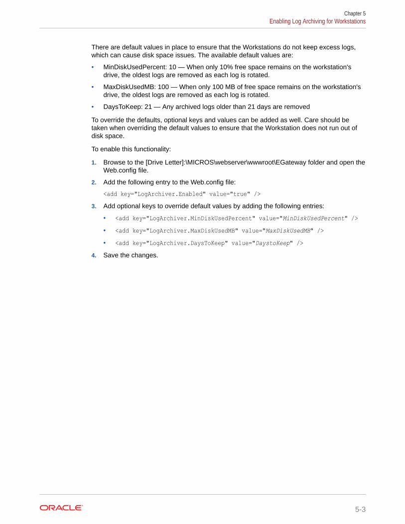
There are default values in place to ensure that the Workstations do not keep excess logs,which can cause disk space issues. The available default values are:
• MinDiskUsedPercent: 10 — When only 10% free space remains on the workstation'sdrive, the oldest logs are removed as each log is rotated.
• MaxDiskUsedMB: 100 — When only 100 MB of free space remains on the workstation'sdrive, the oldest logs are removed as each log is rotated.
• DaysToKeep: 21 — Any archived logs older than 21 days are removed
To override the defaults, optional keys and values can be added as well. Care should betaken when overriding the default values to ensure that the Workstation does not run out ofdisk space.
To enable this functionality:
1. Browse to the [Drive Letter]:\MICROS\webserver\wwwroot\EGateway folder and open theWeb.config file.
2. Add the following entry to the Web.config file:
<add key="LogArchiver.Enabled" value="true" />3. Add optional keys to override default values by adding the following entries:
• <add key="LogArchiver.MinDiskUsedPercent" value="MinDiskUsedPercent" />• <add key="LogArchiver.MaxDiskUsedMB" value="MaxDiskUsedMB" />• <add key="LogArchiver.DaysToKeep" value="DaystoKeep" />
4. Save the changes.
Chapter 5Enabling Log Archiving for Workstations
5-3

6Properties
A property is a place of business. A property can have one or more revenue centers within aconfined geographic location. For example, a hotel property can have three revenue centers(restaurant, bar, and gift shop), and a shopping mall can have several restaurant revenuecenters. Both properties can belong to the same Simphony Enterprise, but each property hasseparate sales figures, tax information, and other configuration specific to the location.
Adding a Property1. Select the Enterprise level, click Setup, and then click Properties.
2. Click the Insert icon ( ) on the toolbar.
3. In the Add Property dialog, enter the Property Number and Property Name.
4. Select 2 - Extensible Clients and Architecture from the Simphony Platform drop-down list.
5. Select the Time Zone for the property location.
6. Select the location configured in the reporting database from the Report Location drop-down list. The Oracle Hospitality Reporting and Analytics database determines thelocations that appear in the list.
a. To add a new location, click the New button, and then enter the appropriateinformation. An administrator must then add the information to the Reporting andAnalytics property list in order to run reports.
b. To change an existing location, click the Edit button, and then enter the appropriateinformation.
7. (Optional) To copy information from a property template, in the Source Property section,select Copy from source property. The hierarchy panel and Modules To Copy fieldsbecome active.
a. In the hierarchy panel, select the property to use as the source property.
b. In the Modules to Copy section, select the modules you want to copy from the sourceproperty. To automatically select all modules, click the Select All Modules link.
c. (Optional) To copy the Internet Protocol (IP) addresses of workstations and kitchendisplay system (KDS) displays, and to create new revenue centers, select CreateClone. Selecting this option essentially selects the next two options (described inSteps 7-d and 7-e).
d. (Optional) To create new revenue centers for the property based on the existingrevenue centers in the template property, select Create RVCs.
e. (Optional) To copy the IP addresses of workstations and KDS displays from thesource property to the destination property, select Copy IP Addresses. Use thisoption when properties are segmented on their own networks and IP addressconflicts do not occur.
6-1

f. (Optional) To distribute all records (defined and inherited) from the sourceproperty to the destination property, select Distribute inherited records.Deselect this option to distribute only records defined at the source property tothe destination property.
g. (Optional) To create an override record in the destination property when aninherited definition exists, select If destination record is inherited, createoverride.
h. (Optional) To distribute data extension values, select Distribute DataExtensions if they exist.
8. Click OK to copy the records from the source template property to the newproperty.
9. Click Save.
10. To delete a property:
a. Close all open checks and transactions.
b. Delete all associated revenue centers.
c. Delete the property.
Adding a Revenue Center1. Select the property, click Setup, and then click RVC Configuration.
2. Insert a record.
3. From the Add Revenue Center dialog, enter the RVC Number and the RVCName.
4. (Optional) To copy information from an existing revenue center, select Copy fromsource Revenue Center from the Source Revenue Center section. The hierarchypanel and Modules To Copy fields become active.
a. From the hierarchy panel, select the revenue center to use as the sourcerevenue center.
b. From the Modules to Copy section, select the modules you want to copy fromthe source revenue center. To automatically select all modules, click theSelect All Modules link.
c. (Optional) Select Distribute inherited records to distribute all records(defined and inherited) from the source revenue center to the new revenuecenter. Deselect this option to distribute only records defined at the sourcerevenue center to the new revenue center.
d. (Optional) Select If desination record is inherited, create override to createan override record in the new revenue center when an inherited definitionexists.
e. (Optional) Select Distribute Data Extensions if they exist to distribute dataextension values if they exist.
5. Click OK to copy the records from the source template revenue center to the newrevenue center.
6. From the RVC Configuration module table view, select the following options asapplicable for the new revenue center:
Chapter 6Adding a Revenue Center
6-2

• LDS Active: Select this option if the revenue center uses a Liquor DispensingSystem (LDS), which is a third-party system used for pouring and tracking liquor andbeverages, as well as mixed drinks.
• KDS Controller: Select the KDS Controller to control the kitchen display system(KDS) order devices in the revenue center.
7. Click Save.
Revenue Center GroupsYou can create a revenue center group for use when a property hosts an event that occurs inmultiple revenue centers. For example, a baseball game takes place in every revenue centerat a stadium. When you create the event, you can associate it with the revenue center grouprather than selecting each revenue center individually.
Revenue center groups are also useful when multiple revenue centers use the same kitchenor bar to prepare menu items. You can set a Menu Item Availability record for a revenuecenter group.
Configuring a Revenue Center Group1. Select the property, click Setup, and then click Revenue Center Groups.
2. Insert a new record or select an existing record, and then double-click the record to openit.
3. Select the revenue centers to include in the revenue center group.
4. Click Save.
Chapter 6Revenue Center Groups
6-3

7Zones
Zones are custom hierarchies within the Enterprise. You can use zones to group similaraspects of an Enterprise together to manage configuration tasks with minimum effort and toeliminate duplicate configuration. For example, you can categorize:
• Taxes by country, state, county, and city
• Prices by region, tier, and property
• Menu item maintenance by item groups (food, beverage, retail), price tiers, and stores
Zones assist in managing definitions and records in a more streamlined manner. Simphony’sInheritance and Override feature enables you to configure definition records on the Enterpriselevel, and they are inherited throughout the system. If there are unique circumstances wherea particular definition must be different from an inherited record, you can override that recordat the zone, property, or revenue center level. Inheritance and Override contains moreinformation.
For example, you can create a country zone for the Enterprise, create sub-zones (childzones) for each country, and then create or override the records from the relevant level asillustrated in the following figure. This figure shows a sample zone hierarchy for a singlerecord group, where the existence of records is denoted in blue and inheritance is denoted ingray.
7-1

Figure 7-1 Sample Zone Configuration
A single revenue center or property can belong to multiple zones, and a single zonecan contain an unlimited number of sub-zones. Zones with meaningful names providea clear overview of the structure. Configuring zones effectively:
• Allows privileged users to view and navigate the entire Enterprise from within theEMC in a more logical manner
• Creates a big picture that shows which locations might be affected by potentialchanges or updates
• Saves time with definition handling and updates throughout the system
• Controls definition distribution to POS clients
Record Priority within Multiple Zone Configurations
If a property or revenue center exists in multiple zones, Simphony uses the definitionrecord which is closest to the hierarchy when determining which record to use for aspecific object number. For example, in the following figure, the Enterprise depictedhas two separate zone hierarchies. The Country zone has two sub-zones: UnitedStates and Canada. The second zone, Concepts, also has two sub-zones:Restaurants and Retail. Both zone hierarchies have revenue centers in common.
Chapter 7
7-2

Imagine that a discount record is defined in the Enterprise, and the four sub-zones (UnitedStates, Canada, Restaurants, and Retail) override this discount record, which is theninherited by their properties and revenue centers respectively. The existence of the record isdenoted in blue and inheritance is denoted in gray.
Figure 7-2 Sample Configuration of a Single Record Definition
Chapter 7
7-3

Because the revenue centers are closer to the definition record in the Concepts zone(RVC 1-1 is only one level away from Restaurants while it is two levels away fromUnited States), the Concepts zone record wins.
Consider the following sample configuration for multiple discount records:
Figure 7-3 Sample Configuration of Multiple Record Definitions
Given the configuration in the above image, Simphony uses the following discountrecords for Property 1:
• Record 1 defined in Property 1
• Record 2 defined in the United States zone
• Record 3 defined in the Unites States zone
• Record 4 defined in the Enterprise
• Record 5 defined in Property 1
Record Collisions
Record collisions occur when a property or revenue center has two competing winningrecords that are the same number of levels away from the hierarchy. For example, inthe following figure, RVC 4-2 is one level away from Property 4 and Retails, both ofwhich have overriding record definitions.
Chapter 7
7-4

Figure 7-4 Sample Zone Configuration with Record Collision
While EMC prevents you from manually creating a competing record, such situations canarise when moving revenue centers and zones, or when using the Import/Export Service. Insuch instances, EMC detects the error and prevents you from opening the modulecorresponding to the definition record until the conflict is resolved.
Chapter 7
7-5
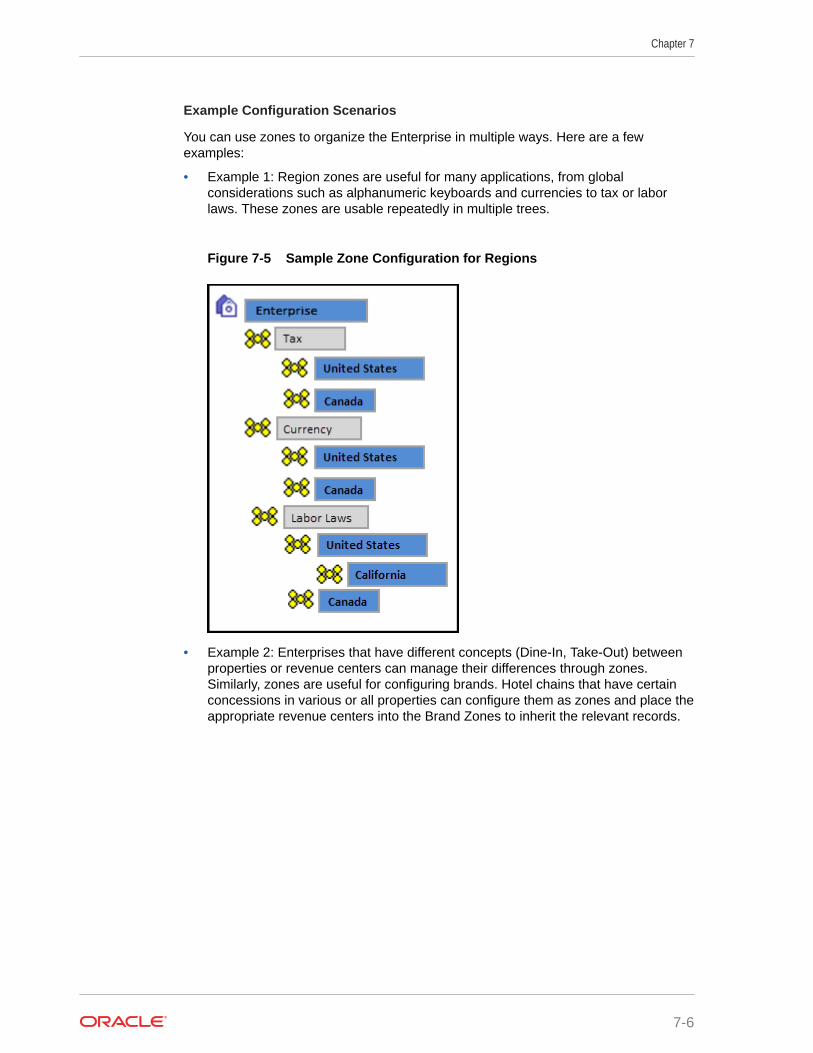
Example Configuration Scenarios
You can use zones to organize the Enterprise in multiple ways. Here are a fewexamples:
• Example 1: Region zones are useful for many applications, from globalconsiderations such as alphanumeric keyboards and currencies to tax or laborlaws. These zones are usable repeatedly in multiple trees.
Figure 7-5 Sample Zone Configuration for Regions
• Example 2: Enterprises that have different concepts (Dine-In, Take-Out) betweenproperties or revenue centers can manage their differences through zones.Similarly, zones are useful for configuring brands. Hotel chains that have certainconcessions in various or all properties can configure them as zones and place theappropriate revenue centers into the Brand Zones to inherit the relevant records.
Chapter 7
7-6

Figure 7-6 Sample Zone Configuration for Brands
Reporting and Analytics Posting
Reporting and Analytics is zone independent. Transactions post to the actual location wherethe transaction originated. For example, if a menu item definition record originated in theRetail zone, it posts under the revenue center that inherited the record from the zone at thetime of the transaction. If you create an overriding record later in the same revenue centerand another transaction is posted for the same menu item, Reporting and Analytics shows asif the price change was made for the same menu item.
Creating Zones1. Select the Enterprise, click Setup, and then click Zone Configuration.
2. In the Zone Configuration pane on the left, right-click Enterprise, and then select theappropriate option:
• Add Zone: Select to create only a single zone.
• Add Multiple Zones: Select to create more then one zone simultaneously.
3. In the Add Zones to Enterprise dialog, enter the Name and Object Number for eachzone, and then click OK.
Enter a meaningful name, such as a description of what modules are defined in the zone,to provide a clear overview of the structure.
Chapter 7Creating Zones
7-7
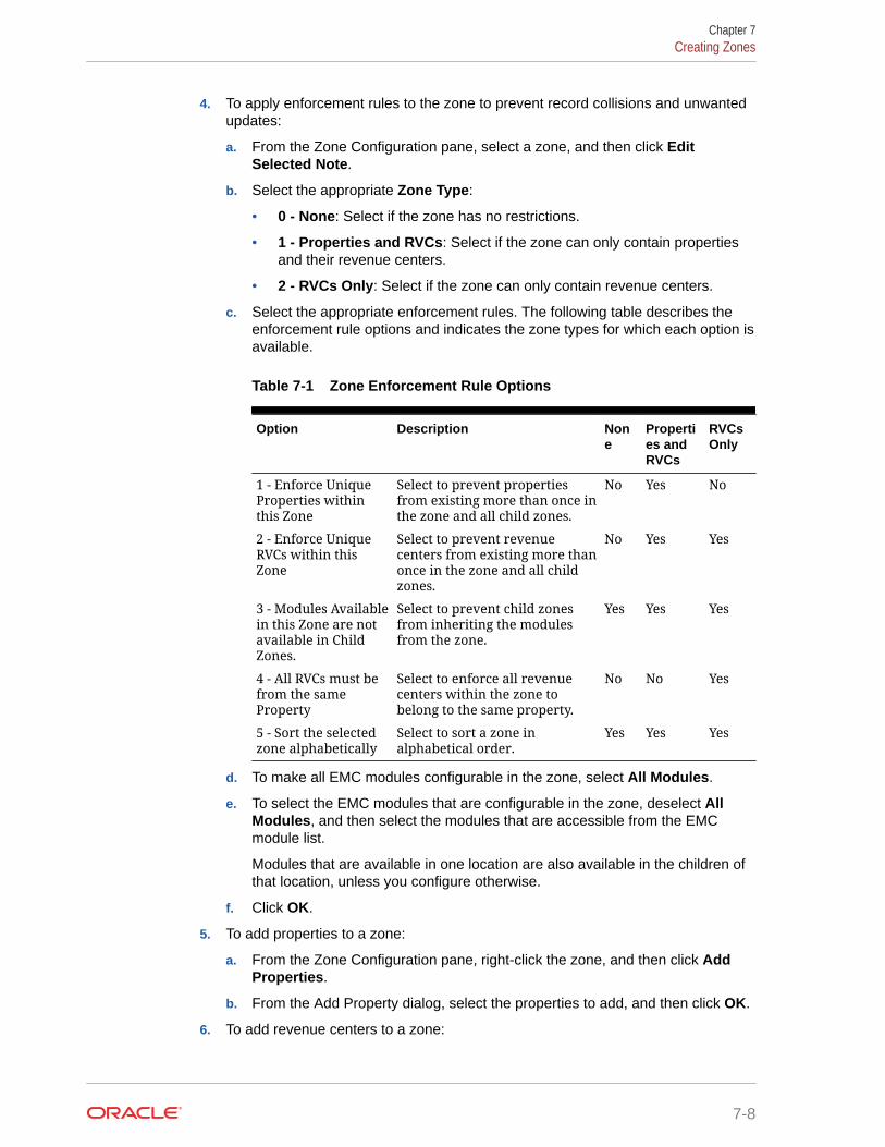
4. To apply enforcement rules to the zone to prevent record collisions and unwantedupdates:
a. From the Zone Configuration pane, select a zone, and then click EditSelected Note.
b. Select the appropriate Zone Type:
• 0 - None: Select if the zone has no restrictions.
• 1 - Properties and RVCs: Select if the zone can only contain propertiesand their revenue centers.
• 2 - RVCs Only: Select if the zone can only contain revenue centers.
c. Select the appropriate enforcement rules. The following table describes theenforcement rule options and indicates the zone types for which each option isavailable.
Table 7-1 Zone Enforcement Rule Options
Option Description None
Properties andRVCs
RVCsOnly
1 - Enforce UniqueProperties withinthis Zone
Select to prevent propertiesfrom existing more than once inthe zone and all child zones.
No Yes No
2 - Enforce UniqueRVCs within thisZone
Select to prevent revenuecenters from existing more thanonce in the zone and all childzones.
No Yes Yes
3 - Modules Availablein this Zone are notavailable in ChildZones.
Select to prevent child zonesfrom inheriting the modulesfrom the zone.
Yes Yes Yes
4 - All RVCs must befrom the sameProperty
Select to enforce all revenuecenters within the zone tobelong to the same property.
No No Yes
5 - Sort the selectedzone alphabetically
Select to sort a zone inalphabetical order.
Yes Yes Yes
d. To make all EMC modules configurable in the zone, select All Modules.
e. To select the EMC modules that are configurable in the zone, deselect AllModules, and then select the modules that are accessible from the EMCmodule list.
Modules that are available in one location are also available in the children ofthat location, unless you configure otherwise.
f. Click OK.
5. To add properties to a zone:
a. From the Zone Configuration pane, right-click the zone, and then click AddProperties.
b. From the Add Property dialog, select the properties to add, and then click OK.
6. To add revenue centers to a zone:
Chapter 7Creating Zones
7-8

a. From the Zone Configuration pane, right-click the zone, and then click Add RevenueCenters.
b. From the Add RVC dialog, select the property to which the revenue centers belongs,and then select the revenue centers from the list.
c. Click OK.
7. To apply enforcement rules to the properties or revenue centers in the zone:
a. From the Zone Configuration pane, select a property or revenue center, and thenclick Edit Selected Node.
b. Select the appropriate enforcement rules and configurable EMC modules. Refer tothe Zone Enforcement Rule Options table in Step 4 for more information on theenforcement rules.
8. Click OK.
Chapter 7Creating Zones
7-9

8POS Workstations
A workstation is a device used by managers, servers, bartenders, hosts, and cashiers at aproperty to perform various functions, such as creating guest checks, adding menu items,applying discounts and service charges, and paying a check. Examples of POS workstationsinclude the Oracle MICROS Workstation 6 Series and the Workstation 5a.
Workstation TasksAdding a workstation consists of completing the following tasks:
• Adding a workstation
• Configuring workstation transaction settings
• Setting offline transaction posting time
• Configuring workstation security
• (Optional) Configuring an Android mobile device as a workstation
Adding a Workstation1. Select the property, click Setup, and then click Workstations.
2. Insert a record for the workstation, enter the name, and then click OK.
3. Double-click the new workstation record.
4. On the General tab, enter information in the following fields:
Table 8-1 General Workstation Settings
Field Description
Type Select the type of workstation from the drop-down list:• 1 - Mobile MICROS: Mobile devices• 2 - Workstation Client: Workstations, virtual
machines, and Android tabletsSelect this option for the Oracle MICROS Workstation 6Series and the Oracle MICROS Tablet 700 Series.
• 3 - POSAPI Client: Simphony Transaction Services orPay@Table
• 6 - MICROS Tablet Client: Oracle MICROS Tablet E-SeriesSelect this option for the Oracle MICROS Tablet E-Series 11-inch.
Language Select the default language of the workstation. This is thelanguage that appears on the workstation’s Sign On screen.If an employee has a different default language set, theemployee sees their default language after signing in to theworkstation.
8-1

Table 8-1 (Cont.) General Workstation Settings
Field Description
Resolution Cols Enter the number of Resolution Columns for theworkstation’s display. The default value is 0 (zero).
Resolution Rows Enter the number of Resolution Rows for the workstation’sdisplay. The default value is 0 (zero).
Log Verbosity Select the logging verbosity for the workstation. Select 0(zero) for minimal logging. Higher log verbosity providesmore information in the log file, which may be helpful introubleshooting issues.
(Optional) Workstation Class Select a Workstation Class to allow similar workstations tobe grouped together and to share certain pageconfiguration settings.
Database Update Frequency Enter the number of seconds for the workstation to receivechanges. The default value is 1800 seconds (30 minutes).The value in this field overrides the Property Parameter’sDatabase Update Frequency setting.
Check Inactivity Timeout Enter the number of seconds before the workstation showsthe message (Do you need more time?), prompting theworkstation operator to cancel the transaction. When youenter 0 (zero), the message does not appear.When you select Enable Follow Me from the RVCParameters module, the check is automatically suspendedrather than cancelled.
Check Inactivity DialogTimeout
Enter the number of seconds that the workstation showsthe Inactivity dialog before automatically cancelling thetransaction. This field is unavailable when you set theCheck Inactivity Timeout value to 0 (zero).
Report Timeout Enter the number of seconds the workstation waits for aresponse before showing a communication failure notice.
Address / Host Name Enter the IP address or host name of the Oracle HospitalitySimphony Service Host where the workstation applicationruns.
Subnet Mask Enter the subnet mask of the Service Host where theworkstation application runs.
Default Gateway Enter the default gateway of the Service Host where theworkstation application runs.
Is Connectionless Select this option to have the Service Host open and close anew connection for each web service call. This preventsthe workstation from reaching the maximum number ofweb connections allowed, although the connectionbecomes slightly slower.
Chapter 8Adding a Workstation
8-2

Table 8-1 (Cont.) General Workstation Settings
Field Description
Is Windows Service Select this option to allow the Service Host to start as aWindows service. The Service Host service starts onMicrosoft Windows startup with other Microsoft Windowsservices. The POS client starts only when the workstationoperator signs on to the operating system.If you select this option, you need to change the ports ofthe services being run (for example, Check and PostingService (CAPS) and Oracle Hospitality Simphony KitchenDisplay System (KDS) Controller) in addition to the POSclient. Use the EMC modules to change the ports.If a non-POS client is required to run on the Service Host, itmust run on a different port than the workstation port.You can also set the Service Host to run as a MicrosoftWindows service from the Service Host module (ratherthan from the Workstations module). If you set this optionin the Service Host module, you do not need to change theports of the services being run as the device is not intendedto run the POS client.
5. Click the Printers tab.
6. Click the Select link next to each printer type that you need to configure, select theprinter, and then click OK.
7. Click the Revenue Centers tab.
8. Select the revenue centers for the workstation. You must select at least one revenuecenter.
9. Click Save.
10. When adding or removing workstations, you need to edit the system’s license count usingthe following steps:
a. Select the Enterprise level, click Setup, and then click Enterprise Parameters.
b. Click the License Configuration tab.
c. Click Configure adjacent to Workstations Client License Count.
d. To add a license count (for the first time), select I would like to set the licensecount to X, making the new license count X.
e. To append licenses to an existing license count, select I would like to add X to thecurrent license count, making the new license count Y.
f. Enter the number of client licenses purchased.
g. (Optional) Enter additional details regarding the purchased license in EnterReference Information for the License Count Change, and then click OK.
h. Repeat Steps 10-c through 10-g for Transaction Service Client License Count,and KDS Client License Count.
i. Click Save, and then click Yes to agree to the license.
j. To perform a side by side comparison of the number of purchased licenses againstthe number of configured clients, click View adjacent to the Properties, RevenueCenters, Concessions Terminals, Workstation Client License Count, TransactionServices Client License Count, or KDS Client License Count labels.
Chapter 8Adding a Workstation
8-3

Configuring Workstation Transaction Settings1. Select the property, click Setup, and then click Workstations.
2. Double-click the workstation record to open it.
3. Click the Transactions tab, and then enter information in the following fields:
Table 8-2 Workstation Transaction Settings
Field Description
Minimum Check Number Enter the minimum guest check number to use:• When the workstation is in offline mode• When the workstation is used in revenue
centers without the RVC Parameters option UseRevenue Center Check Numbers. In theserevenue centers, each workstation determinesits own check number range.
Maximum Check Number Enter the maximum guest check number to use:• When the workstation is in offline mode• When the workstation is used in revenue
centers without the RVC Parameters option UseRevenue Center Check Numbers. In theserevenue centers, each workstation determinesits own check number range.
(Optional) Default Order Type Select the default active order type for theworkstation (for example, Dine In, Take Out, orDrive Thru).
Barcode Format Set Select the barcode format for the workstation toread barcodes of various lengths.
Cashier Link Select the cashier record to link to the workstation.This provides a link to tracking totals for Tender/Media information.This field is available only when you select 8 - On =Link Cashier Totals to WS; OFF = Link toOperator from the Workstations module(Optionstab, and then the Offline/Misc subtab).
Merchant Group Select the merchant group for the workstation, orselect 0 - Use RVC Setting to use the settings fromthe revenue center in which the transaction occurs.If multiple revenue centers exist, each revenuecenter may route payment information to adifferent bank. These banks can be grouped intomerchant groups.
Thai Tax Rd Number If applicable, enter the number to print on Thai Taxtrailers.
4. Click Save.
Setting Offline Transaction Posting TimeWhen a property or its workstations are unable to communicate with the database foran extended period of time, transactions do not post. You can determine whether
Chapter 8Configuring Workstation Transaction Settings
8-4

offline transactions post using the current time or the transaction time once communicationresumes.
1. Select the property, click Setup, and then click Property Parameters.
2. Click the Options tab.
3. To allow offline checks to post to the database (when communication with the Check andPosting server is re-established) with the actual time of the transaction, select 6 - PostOffline Transactions with Actual Transaction Time. Deselect this option to allow offlinechecks to post with the time that the check is uploaded into the database.
4. Click Save.
Configuring Workstation Security1. Select the property, click Setup, and then click Workstations.
2. Double-click the workstation record to open it.
3. Click the Options tab, and then click the Display/Security subtab.
4. Select the appropriate options:
Table 8-3 Workstation Security Options
Security Option Description
Mag Card Entry Required forEmployee ID
Select this option to require all employeeidentification (ID) entries at the workstation to usea magnetic employee identification card (forexample, to sign on and authorize privilegedoperations). When you select this option, theworkstation does not accept an employee IDnumber entered through the keyboard ortouchscreen. Deselect this option to allowemployee ID entery by either a magnetic card orby the keyboard or touchscreen.
Disable Employee Auto Sign Out Select this option to if you do not want to use theAutomatic Operator Popup Interval set in theRVC Parameters module. Deselect this option tosign out workstation operators after theAutomatic Operator Popup Interval is reached.
Use Alternate ID for Sign-in Select this option to allow workstation operators tosign on using a four-digit alternate ID numberrather than a ten-digit employee ID number.
Fingerprint Scan Required forEmployee ID
Select this option to require all employee IDentries at the workstation to scan a fingerprint.When you select this option, the workstation doesnot accept an employee ID number enteredthrough the keyboard or touchscreen.
Employee ID or Fingerprint ScanRequired for Employee ID
Select this option to require all employee IDentries at the workstation to scan a fingerprint orenter an employee ID through the keyboard ortouchscreen. When you select this option, theworkstation only accepts an employee ID numberentered through the keyboard or touchscreen, orfingerprint scan.
Chapter 8Configuring Workstation Security
8-5

Table 8-3 (Cont.) Workstation Security Options
Security Option Description
Employee ID and Fingerprint ScanRequired for Employee ID
Select this option to require all employee IDentries at the workstation to scan a fingerprint andenter an employee ID through the keyboard ortouchscreen. When you select this option, theworkstation only accepts an employee ID numberentered through the keyboard or touchscreen andfingerprint scan.
Mag Card or Fingerprint ScanRequired for Employee ID
Select this option to require all employee IDentries at the workstation to scan a fingerprint orswipe a magnetic card. When you select thisoption, the workstation only accepts either amagnetic card swipe or fingerprint scan.
Mag Card and Fingerprint ScanRequired for Employee ID
Select this option to require all employee IDentries at the workstation to scan a fingerprint andswipe a magnetic card. When you select thisoption, the workstation accepts only a magneticcard swipe and fingerprint scan.
5. Click Save.
Changing the Appearance of Workstations1. Select the Enterprise, property, or zone, click Configuration, and then click
Theme Assignment.
2. Change the following settings:
• Default Theme: Select the default theme for the workstations.
• Default Palette: If you selected Edge as the Default Theme, select the colorpalette for the theme.
3. Click Save.
Configuring the Magnetic Stripe Reader on the OracleMICROS Tablet 720
The Oracle MICROS Tablet 720 comes with a built-in OPOS Mag Stripe Reader(MSR).
1. In EMC, select Property, Setup, Hardware/Interfaces, Workstations, and thenDevices.
2. In the Peripheral Device Configuration section, click Add.
3. For Select Peripheral Device Type, select OPOS Mag Stripe Reader.
4. For Configuration, enter IDTECH_SECUREMAG_USBHID.
5. Click OK, and then Save.
The Oracle MICROS Tablet 720 Setup Guide contains more information on setting upand using the Tablet 720.
Chapter 8Changing the Appearance of Workstations
8-6

Configuring the Barcode Scanner on the Oracle MICROS Tablet720
The Oracle MICROS Tablet 720 comes with a built-in OPOS Barcode Scanner.
1. In EMC, select Property, Setup, Hardware/Interfaces, Workstations, and thenDevices.
2. In the Peripheral Device Configuration section, click Add.
3. For Select Peripheral Device Type, select OPOS Barcode Reader.
4. For Configuration, enter Honeywell.
5. Click OK, and then Save.
The Oracle MICROS Tablet 720 Setup Guide contains more information on setting up andusing the Tablet 720.
Allowing Employees to Install and Authenticate POS Clients andService Hosts
In Simphony release 19.1, you must allow administrator employees to download software,install, and authenticate clients and service hosts using CAL version 145. After granting thisprivilege, employees can use their credentials to configure POS clients. In addition, the UserSecurity Credentials configured in the Property Parameters module become inactive.
1. Select the Enterprise, click Configuration, and then click Roles.
2. Double-click an employee role.
3. Click the Operations tab, click the Miscellaneous subtab , and then select 10065 -Download Software, Install and Authenticate Clients and Service Hosts Using CAL.
4. Click Save.
Using the Simphony POS Client and Mobile Solution Applicationon One Device
Your organization can run Mobile Solution 18.1 (used with Oracle Hospitality InventoryManagement and Oracle Hospitality Materials Control) on a Simphony tablet device. To shareapplications on the device, you need to configure a button (using the Page Design module inthe EMC) that closes the Simphony POS client on the device. (Minimizing Simphony does notrelease the scanner.)
After configuring the Close Application function button:
• When the device is powered on, the Simphony POS client starts automatically.
• The workstation operator must click the Close Application button to stop the SimphonyPOS client.
• The workstation operator must manually start the Mobile Solution application.
• After using Mobile Solution, the workstation operator must stop it.
Chapter 8Configuring the Barcode Scanner on the Oracle MICROS Tablet 720
8-7

• The workstation operator must manually start the Simphony POS client.
Configuring the Close Application ButtonTo configure a button that closes Simphony on the workstation:
1. Select the Enterprise, property, revenue center, or zone, click Configuration, andthen click Page Design.
2. Open the page on which to place the close application button.
3. On the Edit tab, select the page area in which to define the button.
4. Click Button to add a button.
5. From the Type drop-down list, select Function.
6. Click the black arrow beneath the Type drop-down list.
7. In the Name field, enter close, select Close Application in the Results section,and then click OK.
8. On the General subtab, click the Generate Legend link.
9. Position and size the button on the page. Use the Style arrow to change the color.
10. Click Save.
POS Clients Running Android Mobile Operating SystemYou can run Simphony release 2.7 and later on devices that have the Android mobileoperating system. The Simphony POS client operates in a similar way on an Androidmobile device and a Microsoft Windows device. You can configure the POS clientusing the EMC.
Oracle recommends using one revenue center per Android device, and a maximum of10,000 menu item definitions.
The UI is the same on all devices and workstations. Android devices have specialrequirements to consider, including deployment method, configuration requirements,and the procurement process.
The Oracle Food and Beverage Compatibility Matrix contains more information aboutsupported POS client operating systems.
Android Functionality SupportNote the following functionality limitations when using Simphony on an Android device:
• Simphony does not support remote access to the Android desktop for certifiedsupport applications (for example, Bomgar, Remote Desktop Protocol (RDP), andso on).
• Android devices only operate the Simphony POS client application and cannothost shared services that other devices might access.
• Android devices do not support the Check and Posting Service (CAPS). Therefore,the property must use at least one device with a Microsoft operating system inaddition to the Android device. Oracle Hospitality recommends that this device be
Chapter 8Configuring the Close Application Button
8-8

an Oracle MICROS Workstation 5a (POSReady) or Oracle MICROS PC Workstation2015.
Android Network RequirementsAndroid devices are connected wirelessly to Simphony using an 802.11x network. Therefore,it is vital that the property have a high quality wireless network. Spotty Wi-Fi coverage causesapplication performance issues with check sharing and posting, as well as bouncing betweenonline and offline states with the services on property (for example, check and posting,printing and kitchen display) and the Enterprise, which impacts the ability to receive databaseupdates.
You must configure the Android device to use a wireless local area network (WLAN) withconnectivity to the local area network (LAN) used by the Check and Posting Service andother Simphony POS clients with which they might share checks. Simphony does not supportthe use of a 3G or 4G connection through a telecommunications provider back to these localdevices.
Oracle Hospitality recommends that you configure Android devices to use a static InternetProtocol (IP) address. Simphony does not support the use of Dynamic Host ConfigurationProtocol (DHCP) assigned addresses unless you define a DHCP reservation.
Android PaymentsThe Android clients support credit card processing and other forms of electronic payments.
The following drivers are supported with the Android mobile operating system:
• OPI/SPI
The loadable Stored Value and Loyalty modules support Android clients, and are used withOracle Hospitality Gift and Loyalty and with FreedomPay. The Xprocessor ExtensionApplication, which is used for third party gift cards such as Givex, does not support Androiddevices.
Workaround for Android Lollipop 5.0.2 and 5.1Devices running the Android version Lollipop (5.0.2 and 5.1) mobile operating system do notrender the WebView drop-down lists properly. To resolve this issue, update the AndroidWebView Component.
1. Open the Play Store app on the Android device.
2. Search for, and then select the Android System WebView app by Google.
3. Tap Update.
Configuring the Android Device as a WorkstationPerform the following steps before installing Simphony software.
1. Configure the Android device to be a member of the POS network using a static InternetProtocol (IP) address.
2. Install antivirus software on the device.
3. Turn off Trusted Sources on the device. See the manufacturer instructions for details.
Chapter 8Android Network Requirements
8-9

4. If you are using a Bluetooth printer, pair it with the device. See the manufacturerinstructions for details.
Configuring an Android Workstation1. (Optional) If you are using a Bluetooth printer with the Android device, set the
printer from the Printers module. Configuring a Printer contains more informationabout setting up the printer.
2. Select the property, click Setup, and then click Workstations.
3. Insert a new workstation record.
4. Double-click the record to open it in form view.
5. Enter information in the workstation configuration fields, and set the Type as 2 -Workstation Client.
If you are configuring a Motorola MC40 device, set the Type as 1 - Mobile.
6. Enter the Internet Protocol (IP) address or host name of the Service Host wherethe workstation application runs in the Address/Host Name field.
7. Click the Options tab, and then click the Display/Security subtab.
8. Select 39 - Floating Tablet.
9. (Optional) If you are using a Bluetooth printer, click the Printers tab, and thenselect the printer.
10. Click the Revenue Centers tab, and then assign the device to a revenue center.
11. Click Save.
12. To install the Simphony Service Host on an Android Device, see the OracleHospitality Simphony Client Deployment Guide.
Viewing and Editing Simphony Android FilesAfter installing Simphony on an Android device, you can use the ConfigurationManagement Tool to view and edit certain files.
1. Launch the Simphony application on the Android device.
2. After the application loads, perform the following task on the Android device: Onevent (left swipe + right swipe + left swipe + tap + tap).
3. Enter the code based on the six-digit number shown at the top, and then tap SignIn. The Management Tool Home screen appears.
4. The following table lists the options and actions you can perform.
Table 8-4 Simphony Android Files
Option Action
View web.config.txt Tap to view and edit the web.config.txtfile
View config32.web Tap to view and edit the config32.web file
View Log Tap to view the EGateway Log
Chapter 8Configuring an Android Workstation
8-10

Table 8-4 (Cont.) Simphony Android Files
Option Action
View LogZone Tap to view theLogZone_LoadHandlers.txt file, which isnot editable
Ping Server Tap to view the Server Name or IPAddress
Delete DataStore Tap to delete the DataStore database fileand restart the application on the device
Copy DataStore Tap to copy the DataStore database filewithin the device
Wireless Signal Strength ThresholdWireless devices occasionally behave unpredictably or inconsistently due to weak wirelesssignal strength or a flickering network, leaving the device in a state that is not consistentlyonline or offline. To handle unstable network environments, you can configure the wirelessnetwork signal strength at which devices automatically go offline. Configure the wirelesssignal strength threshold for workstations that use a wireless network (tablet devices runningthe Microsoft Windows and Android mobile operating systems). Some devices may have bothcable and wireless network connections; when docked, the device can use both networktypes. Disable this wireless signal strength feature when docking a device with a cable(wired) network.
You can define the wireless threshold settings from the following EMC modules:
• Property Parameters: The values are set at the property.
• Workstations: The workstation inherits the values from the property, unless overriddenhere.
Configuring Wireless Signal Strength Control Permissions1. Select the Enterprise level, click Configuration, and then click Roles.
2. Double-click the role type record (for example, administrator, manager or server).
3. Click the Actions tab, and then click the Hardware subtab.
4. Select the Wireless Monitor option.
5. Click Save.
Configuring the Wireless Signal Strength Threshold for TabletDevices
1. Perform one of the following, depending on which level you want to configure or override:
• To configure at the property level, select the property, click Setup, and then clickProperty Parameters.
• To override at the workstation, select the property, click Setup, and then clickWorkstations.
Chapter 8Wireless Signal Strength Threshold
8-11

2. On the General tab, in the Wireless Signal Strength Control section, enterinformation in the following fields:
• Offline Threshold: Enter a number between 0 and 99 to represent the signalstrength percentage at which devices go offline. Devices will go offline whenthe signal strength is at or below this percentage value. For example, if theOffline Threshold is set to 90 (90%), and the device’s current signal is 89%,the device will go offline. When the signal is detected above 90%, the devicereconnects online.
• Reconnect Threshold: Enter a number between 0 and 99 to represent thesignal strength percentage at which devices recover online after being in anoffline state. Devices will go online when the signal strength is at or above thispercentage value. For example, if the Reconnect Threshold is set to 80, andthe device’s signal strength is 85%, the device will go online.
These values appear in a status bar on the POS client workstation.
3. Click Save.
Configuring an Alpha-Numeric KeyboardThe following steps describe how to configure an Alpha-Numeric Keyboard in EMC:
1. In Enterprise Management Console, select the property, click the Setup tab, andthen click Alpha-Numeric Keyboard under the Custom Content section.
2. Insert a new record. Choose Regular Alpha-Numeric or Small Screen Alpha-Numeric from the template record drop down menu.
3. Add a name for the record, and then click OK.
4. In the list view, set the desired language from the Language drop down menu.
5. Click the Options button, and then ensure that the Default keyboard for thislanguage option is enabled.
6. Double-click the record to enter page design view.
7. In page design, add the necessary buttons for the workstation. Ensure that thePopup Alpha Numeric Keyboard button is added. In addition to this, add aCancel button to be able to exit in the workstation.
8. Click the Save icon to complete.
Chapter 8Configuring an Alpha-Numeric Keyboard
8-12

9Language Settings and Translation
Simphony allows you to translate the user interface to the local language and to maintaintranslation files for the EMC. You can configure up to four languages to appear onworkstations, guest checks, and customer receipts. When a new language is configured for aproperty, all POS workstation clients must receive the new database updates and mustrestart prior to the changes becoming active. When the Translation CAL package is loaded,the POS workstation clients, including the CAPS workstation, need to be restarted uponreceiving the language translation files.
Simphony upgrades earlier versions of translation files to later versions, and translates alllanguages defined in the system. You cannot translate core translation files as they aremanaged internally.
Configuring languages allows strings that have been translated to be presented to the userbased on their language setting. You must manually translate menu items, touchscreenbuttons, and user-defined strings in the EMC.
Adding Languages contains a list of all supported languages in Simphony.
Language Translation Configuration TasksConfiguring language translation in Simphony consists of completing the following tasks:
Table 9-1 Overview of Configuring Languages
Task Go To
Set the Translation Privileges Configuring Translation Privileges
Create an Enterprise language entry Adding a Language
Load translation file • Loading Workstation Translations• Setting Languages in the EMC
Translate definition data • Translating Menu Item Records• Translating EMC Records• Translating Touchscreen Buttons
Set languages for the property Setting Languages for the Property
Assign languages to employees Associating Languages to Employees
Set the default language for a workstation Setting the Default Language for a Workstation
(Optional) Configure Simphony to print asecondary language on guest checks andcustomer receipts
Multiple Languages on Guest Checks andCustomer Receipts
(Optional) Create touchscreen button to switchbetween languages on workstations
Configuring Screen Language Buttons
9-1

Configuring Translation PrivilegesTo enable privileges so that users can modify, import, or configure translations,perform the following steps:
1. Select the Enterprise, click Configuration, and then click Roles.
2. Double-click the role type, click the Actions tab, and then select the appropriateprivileges:
Table 9-2 Translation Privilege Settings
Privilege Name Allows the Employee to... Recommended Roles
EMC Text Translations Import and modify theEMC related text files
Property expert
Workstation TextTranslations
Import and modifyworkstation related textfiles
Property expert
3. Click Save.
Configuring LanguagesConfiguring languages as described in this procedure changes the user interfacemessage language on workstations, and in the EMC for text labels, options, help text,and error messages. You must manually change the language for EMC records, menuitems, and touchscreen buttons.
1. Select the Enterprise, click Setup, and then click Languages.
2. Insert a record and enter a name (for example, Spanish).
3. Double-click the record to open it.
4. On the General tab, select the language from the Keyboard Type drop-down list.
5. On the Printing tab, set the following options (if needed):
• Print Custom Numerals: Select this option to print numerals defined in theCustom Numerals field on the General tab.
• Asian Characters: Select this option for languages such as Chinese,Japanese, Thai, and Korean where characters are picture-based. When youselect this option, characters print double-wide to make them more readable.The order device printer also prints the characters double-wide to maximizereadability.
• Mapping Font: By default, this option is set to Amap. Select Vmap for Thai.
6. Click the Miscellaneous tab.
7. Select the language from the Locale String drop-down list. The following tablelists all supported languages in Simphony.
Chapter 9Configuring Translation Privileges
9-2

Table 9-3 Supported Language Settings
Language Locale String Local ID Language Culture
Arabic Arabic-SaudiArabia Arabic (Saudi Arabia) ar-SA
Chinese (Simplified) chinese-simplified Chinese (People'sRepublic of China)
zh-CHS
Chinese (Traditional) chinese-traditional Chinese (Taiwan) zh-CHT
Danish danish Danish (Denmark) da-DK
Dutch dutch Dutch (Netherlands) nl-NL
English english-us English (UnitedStates)
en-US
Finnish finnish Finnish (Finland) fi-FI
French french France (France) fr-FR
German german German (Germany) de-DE
Italian italian Italian (Italy) it-IT
Japanese japanese Japanese (Japan) ja-JP
Korean korean Korean (Korea) ko-KR
Norwegian norwegian Norwegian (Norway) nb-NO
Portuguese (Brazil) portuguese Portuguese (Brazil) pt-BR
Portuguese (Portugal) portuguese Portuguese (Portugal) pt-PT
Russian russian Russian (Russia) ru-RU
Spanish spanish Spanish (Spain) es-ES
Swedish swedish Swedish (Sweden) sv-SE
Thai chinese Thai (Thailand) th-TH
Turkish turkish Turkish (Turkey) tr-TR
See http://msdn.microsoft.com/en-us/library/ee825488(v=cs.20) for a detailed list oflanguage codes.
8. Select the Local ID from the drop-down list, and then enter the Language Culturecorresponding to the language.
9. Click Save.
10. To configure translated text files for the workstation, see Configuring WorkstationTranslation Files.
11. To configure translated text files for the EMC, see Configuring the EMC Translation Files
Configuring Workstation TranslationsConfiguring Translations for Required Files
The following file types require translation configuration:
• OPS Text
• POS Core Text
• Payment Cash
Chapter 9Configuring Workstation Translations
9-3

To configure translated text files for required files:
1. Select the Enterprise, click Setup, and then click Languages.
2. Double-click the appropriate language record to open it.
3. Click the General tab, and apply the appropriate language abbreviation in the TextFile Name field. Refer to the table of standard language abbreviations below thesesteps as an example.
Figure 9-1 General Tab
4. Click Save to complete. If you are using an Android client or a non-standardlanguage (e.g. any language other than the 20 standard languages that areincluded with Simphony), proceed to the following steps.
5. Click the Text Files tab.
Figure 9-2 Text Files Tab
Chapter 9Configuring Workstation Translations
9-4

6. Click the Add link in the Text File Configurations section, and then select the desiredfile type from the File Type drop-down list.
7. Click the Edit link, and then click the Import from a file link.
8. Browse to the [Drive Letter]:\MICROS\Simphony2\Tools\Translationsfolder, and then select the file corresponding to your language. Use following sampleGerman translation text file names as an example:
a. For an OPS Text file, select OpsText_de.xml to translate to German.
b. For a POS Core Text file, select PosCoreText_de.xml to translate to German.
c. For a MICROS Payment Cash file, select MicrosPaymentCash_de.xml totranslate to German.
9. Click Open, click OK, and then click Save.
Note:
Text files uploaded to EMC are available to use for all client types.
Table 9-4 Sample Translation Files and Used Abbreviations for Language Settings
Language Sample OpsText Filename Abbreviation
English OpsText.xml No Abbreviation
German OpsText_de.xml de
Spanish OpsText_es.xml es
Italian OpsText_it.xml it
French OpsText_fr.xml fr
Danish OpsText_da.xml da
Dutch OpsText_nl.xml nl
Arabic OpsText_ar.xml ar
Portuguese OpsText_pt.xml pt
Finnish OpsText_fi.xml fi
Japanese OpsText_ja.xml ja
Korean OpsText_ko.xml ko
Norwegian OpsText_no.xml no
Portuguese (Brazil) OpsText_pt_BR.xml pt_BR
Russian OpsText_ru.xml ru
Swedish OpsText_sv.xml sv
Thai OpsText_th.xml th
Turkish OpsText_tr.xml tr
Chinese (Simplified) OpsText_zh_CN.xml zh_CH
Chinese (Traditional) OpsText_zh_TW.xml zh_TW
Configuring Translations for Custom Files
The following steps are required only for Android clients and non-standard language users.
Chapter 9Configuring Workstation Translations
9-5

In addition to configuring the required translated files for POS client workstations andthe Enterprise Management Console, you can also configure the translated text for thefollowing custom files:
• Micros.Payment.LoadableCreditCardModule
• Micros.Payment.LoadablePmsModule
• LoyaltyCommandModule.dll
• StoredValueCommandModule.dll
To configure translated text files for custom files:
1. Select the Enterprise, click Setup, and then click Languages.
2. Double-click the appropriate language record to open it.
3. Click the General tab and set the language abbreviation. Refer to Step 3 from theprevious section, if you have not set your language abbreviation.
4. Click the Text Files tab.
5. Click the Add link in the Text File Configurations section, and then select 0 –Custom from the File Type drop-down list.
6. Click the Edit link, and then click the Import from a file link. For standardlanguage users, Simphony's preset translation files are automatically sent throughthe Service Host Download package.
7. Browse to the [Drive Letter]:\MICROS\Simphony2\Tools\Translationfolder, and then select the desired custom text file corresponding to your language.
For example, if you are adding a translation text file forStoredValueCommandModule.dll, browse to that folder in the Translations folder,and select the desired language. Use following sample German translation text filename as an example:
• StoredValueCommandModule.dll_de.xml8. Click Open, and then click OK.
9. Repeat Steps 3 through 5 for each custom file.
10. Click Save.
Configuring Translation Files for Non-Standard Languages
The following steps apply to users who need to create a translation file for a non-standard language (e.g. any language other than the 20 standard languages that areincluded with Simphony).
1. Select the Enterprise, click Setup, and then click Languages.
2. Create a custom language record by clicking the Add icon in the toolbar. Click OKto save the custom language record.
3. Click the General tab and set the language abbreviation in the Text File Namefield. Refer to this site and find the appropriate language abbreviation in the ISO639–1 column.
4. Click the Translation tab and select the desired Text File Type.
5. In the Translated Text column of the Text Elements section, manually translateeach text element listed in the desired language. For example, if the non-standardlanguage is Czech, manually translate each text element to its Czech equivalent.
Chapter 9Configuring Workstation Translations
9-6
6. After translating each text element, click Export to a File in the Text File section. Thecustom text file name is automatically generated from the text in the Text File Name fieldof the General tab. For example, when setting up a translation file for OPS Text in Czech,the file name displays as OpsText_cz.xml if the abbreviation was set to cz.
7. Navigate to the appropriate text file type folder, click Save, and then click OK.
8. The non-standard language translation file is now available for use when adding andimporting in the Text Files tab.
Configuring the EMC Translation FilesWhen you add a new language or after the Simphony Cloud Service has been upgraded, youneed to import the translation files for each local language you want to use or that you haveconfigured.
To configure translated text files for the EMC:
1. Select the Enterprise, click Setup, and then click Languages.
2. Double-click the language record to open it.
3. Click the Translation tab.
4. To access a standard translation file:
a. In the Type drop-down list, select EMC Text.
b. Click Import Standard Translation.
c. In the Select translation field, select the EMC Text file corresponding to the standardlanguage, and then click OK.
For example, select EMCText_de.xml for German.
If you do not import a standard translation file, the system will use the default English(EMCText.xml). The default English text file does not appear in the list.
d. The Import Summary Report shows the number of fields that were successfullyimported from the application server. Click the Exit button.
The translated fields are listed in the Text Elements section of the Translation tab.
5. To manually import a translation file for each language used:
a. In the Type drop-down list, select EMC Text.
b. Click Import from a File.
c. Browse to the [Drive Letter]:\MICROS\Simphony2\EmcClient folder, select thelanguage translation text file, and then click Open.
d. Click Yes in the Translation dialog to proceed.
e. The Import Summary Report shows the number of fields that were successfullyimported from the application server. Click the Exit button.
The translated fields are listed in the Text Elements section of the Translation tab.
6. Click Save.
Translating Menu Item Records1. Select the Enterprise, property, revenue center, or zone, click Configuration, and then
click Menu Item Maintenance.
Chapter 9Configuring the EMC Translation Files
9-7
2. Use the filters to search for the items to translate, and then click Search.
3. To translate menu item master records, enter the translated text in the relevantlanguage column on the Master Records tab.
For example, to translate master records to Spanish, enter the translated text inthe Name - Spanish column. Master records show a separate column for eachlanguage configured in the Enterprise.
4. To translate menu item definitions, click the Definition Records tab, and thenenter the translated text in the relevant language column.
Definition records show two extra columns per language, First - [LanguageName] and Second - [Language Name], to allow translations for the first nameand second name of each definition.
5. Click Save.
EMC Record TranslationIn the EMC, you can translate the name of any record into multiple languages usingthe Text Translation dialog. This dialog is invoked by the Language Translation icon
( ) on the toolbar (or using the shortcut key F8). The Language Translation icononly becomes active when a translatable text field or a translatable table view cell isactive in the module. This icon is dimmed if:
• Only one language exists in the Enterprise
• You do not have Edit access for the selected module
Translated text saves when the record itself is saved. Therefore, if you perform anundo operation on a record, record translations are also reverted.
Translating Touchscreen Buttons1. Select the Enterprise, property, revenue center, or zone, click Configuration, and
then click Page Design.
2. Open the page to translate, and then on the Edit tab, click the Translate current
item legend ( ) icon.
3. In the Edit Content Area Translated Text dialog, enter the translation for eachbutton in the relevant language column.
The dialog shows a separate column for each language assigned to the currentproperty in Property Parameters. Each row in the grid represents a singletouchscreen button.
4. Click Save.
Setting Languages for the PropertyYou can specify four languages that are available to be used in the property.Workstation operators can then switch between the four different languages on the fly,independent from the employee language settings. For example, if an employee has adifferent language assigned that what is configured for the property, the workstation
Chapter 9EMC Record Translation
9-8

operator will be prompted to select any of the available languages of the property upon firstsigning in to the workstation.
After configuring languages for a property, all POS workstation clients must receive the newdatabase updates and must be restarted prior to the changes becoming active.
To configure the screen languages for the property:
1. Select the property, click Setup, and then click Property Parameters.
2. On the General tab, select the default language from the Language 1 drop-down list.
3. (Optional) From the Language 2 through Language 4 drop-down lists, select thesecondary languages.
4. Click Save.
Setting the Default Language for EmployeesYou can configure the default language for employees, which appears on the following:
• POS Operations UI for the logged in workstation operator
• Workstation messages and prompts not configurable in the EMC
• PMC labels and ad hoc reports
1. Select the Enterprise, property, revenue center, or zone, click Configuration, and thenclick Employee Maintenance.
2. Double-click an employee record to open it, change the default Language of theemployee, and then click Save.
3. Repeat Step 2 for all employees.
Setting the Default Language for a WorkstationYou can configure the language that appears on the POS UI Sign-In page.
Employees with a different language configured see their default language after signing in tothe workstation.
The CAPS workstation requires the translation files, so the ad hoc reports for the workstationoperator who is signed in show the report in the his or her assigned language.
1. Select the property, click Setup, and then click Workstations.
2. Double-click a workstation record to open it.
3. On the General tab, select the Language to appear on the workstation device, and thenclick Save.
4. Repeat Steps 2 and 3 for all workstations.
Configuring Screen Language ButtonsIf more than one language is configured, you can create touchscreen buttons to allowworkstation operators to switch between the languages.
1. Select the Enterprise, property, revenue center, or zone, click Configuration, and thenclick Page Design.
Chapter 9Setting the Default Language for Employees
9-9

2. Open the Front of House page on which to place the language buttons, and thenon the Edit tab, select the page area in which to define the buttons.
3. Click Button, and then on the General subtab, select Function from the Typedrop-down list.
4. Click the black arrow directly beneath the Type drop-down list, and then selectMulti Language from the Type pane.
5. To allow workstation operators to select the preferred language from a list, selectScreen Language List, and then click OK.
6. To configure separate touchscreen buttons for each language configured for theproperty, select Screen Language 1, and then click OK.
Screen Language 1 shows the descriptors for the default language.
7. Enter a Legend for the button, and then position and size the button on the page.
8. If you are creating separate buttons for each language, repeat Steps 3 through 7and configure buttons for the following:
• Screen Language 2: Shows the descriptors for the second language definedin the system.
• Screen Language 3: Shows the descriptors for the third language defined inthe system.
• Screen Language 4: Shows the descriptors for the fourth language defined inthe system.
9. Click Save.
Multiple Languages on Guest Checks and CustomerReceipts
You can show guest check detail and print a customer receipt showing both primaryand secondary languages configured for the property. For example, English and Arabiccan appear on the guest check detail area of the POS client and print on the customerreceipt. When configured, all areas of the check show both languages, except thecheck number, table number and employee name and number. These fields print inthe primary language.
Simphony version 2.7 and later supports printing custom numerals on a customerreceipt (not in the check detail area of the POS client). For example, Arabic digits canprint on the customer receipt rather than Latin digits.
Printing a Secondary Language on Guest Checks and CustomerReceipts
To configure Simphony to print menu items in an alternate language beneath thedefault language on guest checks and customer receipts:
1. Select the property, click Setup, and then click Property Parameters.
2. On the General tab, select a language from the Select Secondary PrintLanguage drop-down list. Select 0 - None to print only the default language.
3. Click Save.
Chapter 9Multiple Languages on Guest Checks and Customer Receipts
9-10

4. Select the Enterprise, property, revenue center, or zone, click Setup, and then clickFormat Parameters.
5. Click the Options tab.
6. Select 52 - Print Secondary Language on Guest Checks/Customer Receipt.
7. Click Save.
Configuring Right to Left Reading LanguagesTo show guest check detail and print customer receipts and guest checks in the right to leftorientation configured for a language, set the following:
• Enterprise Language
• Workstation Language
• Secondary Print Language
1. Select the Enterprise level, click Setup, and then click Languages.
2. Double-click the language record to open it.
3. To show the check detail area and customer receipt on the POS client and print in right-to-left orientation, select Right-To-Left.
4. To print Hebrew characters in the correct order, select Reverse Word.
5. Click Save.
6. Select the property, click Setup, and then click Workstations.
7. From the Language drop-down list, select the language to appear on the workstation.
You can override the default language on the workstation for specific employees usingthe Employee Maintenance module. Employees with a different language configured inEmployee Maintenance see that language after signing on to the workstation.
8. Click Save.
9. Select the property, click Setup, and then click Property Parameters.
10. From the Language 1 and Language 2 drop-down lists, select the primary andsecondary languages.
11. From the Select Secondary Print Language drop-down list, select the language.
To print only the default language, select 0 - None. When printing multiple languages, theapplication prints item names in the order configured for the property.
12. Click Save.
13. Select the Enterprise, property, revenue center, or zone, click Setup, and then clickFormat Parameters.
14. Click the Options tab, and then select 52 - Print Secondary Language on GuestChecks/Customer Receipt.
15. Click Save.
Creating a Print Language List ButtonWhen printing multiple languages, you can have each workstation operator select thelanguage from a list in the POS client using the Print Language List button.
Chapter 9Multiple Languages on Guest Checks and Customer Receipts
9-11

1. Select the Enterprise, property, revenue center, or zone, click Configuration, andthen click Page Design.
2. Add a button to the appropriate screen with the function Print Language List.
3. Click Save.
Creating Print Language ButtonsThe Print Language function allows the workstation operator to select a specificlanguage. For example, if the secondary language is Arabic, the Print Language 2button prints the customer receipt in Arabic. Follow these steps to create one or morePrint Language buttons.
1. Select the Enterprise, property, revenue center, or zone, click Configuration, andthen click Page Design.
2. Add a button to the appropriate screen with the function Print Language 2.Depending on the number of languages, you can create other Print Languagebuttons (for example, Print Language 3 and Print Language 4).
3. Click Save.
Copying Translations from One Language to Another1. Select the Enterprise, click Setup, and then click Languages.
2. Double-click the appropriate language record to open it, and then click theTranslations tab.
3. To copy all translations from another language, click Copy All Translations,select the language from which to copy, and then click OK.
4. To copy the translations for selected elements:
a. From the Text Element section, select the relevant records, and then clickCopy Selected Translations.
b. Select the language from which to copy, and then click OK.
5. Click Save.
Exporting a Translation FileAfter you modify a language file, you can export it and then import it into anothersystem.
1. Select the Enterprise, click Setup, and then click Languages.
2. Double-click the appropriate language record to open it, and then click theTranslations tab.
3. Click Export to a File, and then browse to the desired local directory and save thefile.
The default file name appends the language to the end. For example, if thelanguage is French, the exported default file name is OPSText_French.
Chapter 9Copying Translations from One Language to Another
9-12

10Privacy and Personal Data Management
Before entering and storing the personal information of an employee in the system, consentmust first be obtained. Consent can be denied, which stops you from entering a newemployee record. You can enable or disable the prompt of the consent message. The promptof the consent message applies for the Enterprise.
The consent notification message for an employee appears in the EMC at the Enterpriselevel when creating a new employee. If consent is granted, the personal information isentered in the Employee Maintenance module and stored in the application database.
The Audit Trail tracks and logs the user name of whomever is currently logged in (either inthe EMC or workstation), and responds to the consent request for employees. Audit Trailcontains more information.
Configuring Consent Messages1. Select the Enterprise level, click Setup, and then click Enterprise Parameters.
2. Click the Data Privacy tab.
3. Enter or paste the consent message for employees in the Capture Consent Messagetext box, and then click Save.
The character limit for consent messages is unlimited. The default language is Englishand you must first enter the consent message in English. You can then enter themessage in multiple languages (depending on the languages configured in theLanguages module). The language tabs that appear are those configured for theEnterprise.
4. To enable the consent prompt, select Enable Consent Capture.
If Enable Consent Capture is enabled, when an administrator adds a new employee,the configured consent message prompt appears in the administrator’s language. Theconsent must be accepted to add a new employee. If consent is denied, the employeerecord cannot be created nor saved.
5. To disable the consent prompt, select Disable Consent Capture. The Capture ConsentMessage text box, and the No Of Days to keep Employee PII Data fields also becomeinactive.
6. In the No Of Days to keep Employee PII Data field, enter the number of days after anemployee withdraws consent when the system de-identifies the employee’s PII data. De-identifying deletes a person’s personal data from the system.
Removing Personal Data from Simphony contains more information about configuring de-identification.
7. Click Save.
8. If prompted with a consent message for bulk updates for existing employees, click OK.
To deny the bulk updates for existing employees, click Cancel. The data is not saved.
9. To edit the consent message:
10-1

a. Modify the message text, and then click Save.
If you modify the consent message, you are prompted with the option to triggerre-capturing of consent from users.
b. To present the updated consent message to all employees and requirerecapture of consent when employees log in to EMC, the workstation, theEngagement Cloud Service, or the Simphony Web Portal, click OK.
c. On the Consent status updated successfully dialog, click OK.
The Employee Maintenance module shows all employee records and the IsConsented option is unchecked for everyone. After an employee logs in andagrees to the modified consent message, the Is Consented option becomeschecked.
Withdrawing ConsentBefore withdrawing an employee’s consent, you must ensure that:
• Enable Consent Capture is selected in the Enterprise Parameters module. Configuring Consent Messages contains more information.
• The employee is in a deleted state. Deleting an Employee contains moreinformation.
If an employee has withdrawn consent, they can be reactivated if the employeepersonal information has not been removed from Simphony. Consent must be askedagain upon reactivation. See Removing Personal Data from Simphony for moreinformation about de-identification.
1. Select the Enterprise, property, or revenue center, click Configuration, and thenclick Employee Maintenance.
2. Select View Deleted Employees, and then click the Search button to locate theemployee record.
3. Right-click the employee record, and select Withdraw Consent.
4. In the Withdraw Consent confirmation dialog, click Yes. The employee’s consentstatus is removed.
5. Click Save.
Removing Personal Data from SimphonyWhen you de-identify someone, their personal data is deleted from Simphony. Theemployee who withdrew consent in the system will have their records de-identifiedafter a configured number of days. Simphony automatically runs a DTS job on aperiodic basis to check for records eligible for de-identification; the default is every 12hours.
After an employee has been de-identified, the employee cannot be reactivated.
1. To configure automated de-identification:
a. Select the Enterprise level, click Setup, and then click EnterpriseParameters.
b. Click the Miscellaneous tab.
Chapter 10Withdrawing Consent
10-2

c. In the DTS Jobs section, enter the Interval for the Withdraw Employee Consentjob. This is the number of minutes between jobs. For example, if you enter 1, theDTS job runs every minute.
d. Click Save.
2. To manually de-identify an employee without using the DTS job:
a. Select the Enterprise, property, or revenue center, click Configuration, and then clickEmployee Maintenance.
b. Search for the employee record with the View Deleted Employees option selected inthe Search/Table View pane.
c. Right-click the employee record, and then select De-identify Now.
d. In the De-Identify Now confirmation dialog, click Yes. The employee’s PII data is de-identified with a standard template.
Chapter 10Removing Personal Data from Simphony
10-3

11Employees and Privileges
If you are using Oracle Hospitality Labor Management, you need to add employees usingLabor Management. The Oracle Hospitality Labor Management Cloud Service FeatureReference Manual, located at the Oracle Help Center, contains information about addingemployees in Labor Management. The initial employee information is sent from LaborManagement to Simphony. To change the role for an existing employee, use the SimphonyEMC.
In Simphony, privileges determine the activities an employee can perform, the EMC modulesavailable to the employee, and the types of transactions the employee can process. You canconfigure privileges by the job role (for example, host, server, bartender, cashier, manager).
Creating Employee Roles1. Select the Enterprise level, click Configuration, and then click Roles.
2. Insert a record for the type of role (for example, host, bartender, server, manager, oradministrator), and then click OK.
3. Double-click the role type.
4. On the General tab, select the role security from the Level drop-down list.
Level 0 (zero) has greater privileges than level 9. The value in this field prevents EMCusers from creating employee records with greater privileges than the administrator isgranted. The following table describes typical levels for various types of roles. Gapsappear to allow flexibility for other types of roles that are not listed.
Table 11-1 Role Security Levels
Level Type of Role
0 System Administrator
1 Enterprise Level Administrator
2
3
4 Property Level Administrator
5
6 Property Floor Manager
7
8 Bartender, Cashier, Server
9
5. Click the EMC Modules tab.
6. For each EMC module listed in the File column, select one or more of the followingprivileges:
11-1

• View: Selecting this option grants access to view a module. You must selectView so that employees in the role can open the module.
• Edit: Selecting this option allows employees in the role to update fields orrecords within a module.
• Add: Selecting this option allows employees in the role to add records to amodule.
• Delete: Selecting this option allows employees in the role to delete recordsfrom a module.
• Add Override: Selecting this option allows employees in the role to overriderecords in a module.
• Allow Duplicate Obj#: Selecting this option allows employees in the role toadd menu item records where existing records with the same number existelsewhere in the Enterprise.
• Allow Duplicate Name: Selecting this option allows employees in the role toadd records where existing records with the same name exist elsewhere in theEnterprise.
• To easily configure a role to View, Edit, Add, Delete, or Add Override for everymodule without individually selecting each option, right-click a column headingand select Set All.
7. Click the Actions tab.
8. Select Enable for the appropriate EMC tasks listed in the Action column.
To activate a role for every module without individually selecting each option, right-click the Enable heading, and then select Set All.
9. Click Save.
Creating Employee ClassesYou can set collective options for a group of similar employee roles using an EmployeeClass. Each employee must belong to an Employee Class to perform workstationoperations.
1. Select the property, click Configuration, and then click Employee Classes.
2. Insert a record for a group of employees (for example, server, bartender, or host),and then double-click the record to open it.
3. On the General tab, set information for the fields as described in the followingtable:
Table 11-2 Employee Class Settings
Field Description
#Hours/Day Before OT Enter the number of regular hours thatemployees in the Employee Class canwork in a single day before being paid atthe overtime rate.
Chapter 11Creating Employee Classes
11-2

Table 11-2 (Cont.) Employee Class Settings
Field Description
#Hours/Period Before OT Enter the number of regular hours thatemployees in the Employee Class canwork in a single pay period before beingpaid at the overtime rate.
ISL Options Select the ISL Employee Options toallow employees in the Employee Class toexecute Interface Script Language (ISL)scripts.ISL is the Oracle Hospitality proprietaryinterpreted language used to create smallprograms called scripts. The ISL optionsact like a transaction privilege level in anISL script. ISL scripts can be written toinclude variables that check for thepresence of these privileges for theemployee who is running the script. Ifthe employee is not a member of anEmployee Class that has the necessaryISL employee option set, the script doesnot execute, and a privilege promptappears.
Default Trans TS Select the default touchscreen thatappears when members of the EmployeeClass sign on to a workstation.
MMH Default Trans TS Select the default touchscreen thatappears when members of the EmployeeClass sign on to a Mobile MICROS device.
Pickup/Add/Xfer SLU Style Select a touchscreen style thatworkstation operators can use whenadding and transferring checks with theAdd/Transfer Check Screen Lookup(SLU) function key.
View Screen/Style Names for RVC Select this option to view the screennames and styles set in the revenuecenters.
4. Click the Operator Options tab.
5. For each revenue center listed, from the Operator Type drop-down list, select the guestcheck printing method for workstation operators assigned to the Employee Class.
• By Round: Select this option to print a guest check at the end of each service round,showing only the changes posted to the service round.
• On Demand: Select this option to print a buffered guest check after performing aService Total or tender set to print an on demand check.
• Temp On Demand: Select this option to print a guest check on demand (in a byround manner).
• Special By Round: Select this option to print a guest check on demand for all roundsexcept the first round of a check. The first round always prints. Subsequent servicerounds print if the Service Total is set to print an on demand check.
6. For each revenue center listed, select the appropriate Options for workstation operatorsassigned to the Employee Class, and then click OK.
Chapter 11Creating Employee Classes
11-3

Using a Server Employee Class as an example, you can require all servers in arevenue center to enter the number of guests when beginning new checks and toenter table numbers.
7. Click Save.
Adding an EmployeeYou must have the Enterprise level permission Add Employees to add an employeerecord from a template.
1. Select the Enterprise, property, or revenue center, click Configuration, and thenclick Employee Maintenance.
2. Click the Insert Record icon from the toolbar. The Add Employees dialog appears.
3. From the Select a task to perform drop-down list, select Add Employee Recordfrom Template.
Using a template simplifies the process of adding employees.
4. Click the Select link next to the Employee To Copy field.
5. From the Select Employee dialog, select a template employee record, and thenclick OK.
6. Enter employee information in the following fields, and then click OK.
• First and Last Name
• (Optional) Check Name: Enter the employee name to appear on guest checks(for example, Sally S).
• (Optional) ID: Enter the employee identification number.
• Record Number: The next available record number appears by default.
• Property # and Name: The property where the employee works.
• RVC # and Name: The revenue center (RVC) where the employee works.
7. Click Yes in the Add Employee confirmation dialog.
8. If prompted with the employee consent message, click OK to accept consent andsave the new employee record.
Click Cancel to deny consent. The Warning Data Privacy Declined dialog appears.If you click OK, the employee record is not created nor saved.
When employee consent capture is enabled, the consent must be accepted to adda new employee.
9. To add another employee:
a. Click Yes on the Item Added Successfully dialog (prompt to add anotheremployee), and then repeat Steps 6 through 8
b. When you are finished adding employees, click No.
10. Click Save.
Deleting an EmployeeYou must have the Enterprise level permission called Delete Employees to remove anemployee record.
Chapter 11Adding an Employee
11-4

1. Select the Enterprise, property, or revenue center, click Configuration, and then clickEmployee Maintenance.
2. Search for the employee record.
3. Right-click the employee record, and then select Delete.
4. From the Delete Employee Records dialog, click Yes to confirm.
5. To view a list of all deleted employees in the search area, select View DeletedEmployees, and then click Search.
6. To reactivate a deleted employee, right-click the employee record, select Reactivate, andthen click Yes to confirm.
After an employee has been de-identified, the employee cannot be reactivated becausethe employee’s personally identifiable information has been deleted from Simphony andcannot be reconstructed. Removing Personal Data from Simphony contains moreinformation about de-identification.
7. If you are an administrator and want to permanently delete an employee, right-click theemployee record, select Permanently Delete, and then click Yes on the prompts toconfirm.
You cannot permanently delete an employee who is not marked Is Deleted and who hasassociated sales or timecard records in the Oracle Hospitality Reporting and Analyticsdatabase. Employees are mapped between the Simphony and Reporting and Analyticsdatabases using the object number from the EMC. Consider the following example:
• Employee 12345, Ted Davis, has $500 in sales
• Employee 12345 is deleted from the database
• If the EMC allowed this employee to be permanently deleted, a new employee, MarySmith, could be added at employee record 12345 and the new employee wouldessentially start with $500 in sales
Thus, the two-step employee deletion process preserves the object number between thetwo databases. Because of this potential scenario, object numbers are not reusable. Ifemployee 12345 shows as Is Deleted in the database, you cannot create a newemployee record using number 12345.
8. Click Save.
9. To withdraw an employee’s consent, see Withdrawing Consent.
Changing Employee InformationYou must have the Enterprise level permission Edit Employees to change an employeerecord.
1. Select the Enterprise, property, or revenue center, click Configuration, and then clickEmployee Maintenance.
2. Search for the employee record using the Search Criteria fields to limit the results, andthen click Search. Depending on the hierarchy level at which you opened the EmployeeMaintenance module (Enterprise, property, or revenue center), the resulting list ofemployee records appears in one of the following tabs located near the lower area of thescreen:
• Employee Records – Enterprise level
• Property Employee Records – Property level
Chapter 11Changing Employee Information
11-5

• Operator Records – Revenue Center level
3. Make changes in either table view or form view. To make changes in form view,double-click the object number of the employee record.
4. Change any of the information in the active fields. The following tables list thetypes of information you can change for each hierarchy level.
Table 11-3 Employee Records Information
Subtab Type of Information
General Allows you to change basic informationabout the employee, including name,language, identification numbers, level,group, email address, and EMC logincredentials.
Note:
The Employee Access Level isnot manageable from EMCwhen Labor Management is inuse. When the EmployeeAccess Level is changed inLabor Management, it issubsequently updated inSimphony.
Roles Allows you to change the employee’srole.
Chapter 11Changing Employee Information
11-6
Table 11-3 (Cont.) Employee Records Information
Subtab Type of Information
Reporting In previous versions, this tab allowedyou to change an employee’s logoncredentials for Oracle HospitalityReporting and Analytics ( R&A).
Note:
Beginning with the Simphony19.1.2 release, when integratedwith R&A version 20.1,Reporting User creation is nolonger possible from theSimphony EMC because theEmployee records Reportingsubtab has been disabled.Moving forward, ReportingUsers are only able to becreated from the R&A version20.1 application. It is stillpossible to add Reporting Usersfrom Simphony when it isassociated with R&A version9.1.
See the Enterprise Back Office 20.1documentation, specifically theReporting and Analytics User Guide’s Adding Users section for moreinformation about adding users fromR&A.
References Shows the locations where the employeeis being referenced (excludingworkstations).
Table 11-4 Property Employee Records Information
Subtab Type of Information
General The General subtab allows you to changebasic information about the employee,including name, employee class, revenuecenter, check name, email address, andclock-in options.
Job Codes The Job Codes subtab shows the job codeassigned to the employee in the property.You can change the Regular and OvertimePay Rates for each job code.
Chapter 11Changing Employee Information
11-7

Table 11-4 (Cont.) Property Employee Records Information
Subtab Type of Information
Operators The Operators sub tab shows each revenuecenter in the property where the employeehas an operator record. You can change theCash Drawer, Table Count, TMS Color, andServer Efficiency. You can also selectwhether to use the Employee Class optionsor set options at the operator level.
Table 11-5 Operator Records Information
Subtab Type of Information
General The General subtab allows you tochange basic information about theemployee, including name, employeeclass, revenue center, and clock-inoptions.
Job Codes The Job Codes subtab shows the job codeassigned to the employee in the property.You can change the Regular andOvertime Pay Rates for each job code.
Operators The Operations subtab shows eachrevenue center in the property where theemployee has an operator record. Youcan change the Cash Drawer, TableCount, TMS Color, and ServerEfficiency. You can also select whether touse the Employee Class options or setoptions at the operator level.
5. Click Save.
Configuring Employee ShiftsA shift is the period of time that an employee is scheduled to work. Employees canvolunteer or are scheduled to work more than one shift. Simphony provides the abilityto post employee or cashier totals to shifts to account for the multiple shifts workedduring a single business day.
1. Select the Enterprise, property, revenue center, or zone, click Setup, and thenclick Control Parameters.
2. Click the Options tab, and then select the appropriate shift options.
Chapter 11Configuring Employee Shifts
11-8

Table 11-6 Shift Options
Option Description
49 - Enable Shift Tracking Select this option to activate shift reporting,segregating employee, employee tip, andcashier financial totals by shift. Deselect thisoption to accumulate employee, employeetip, and cashier totals in a single total set.When you deselect this option, thesubsequent shift-related options aredimmed.
50 - Increment Cashier Shift when ClockingOut
Select this option to increment the shift forthe cashier associated with the employeeclocking out (except when clocking out onbreak). Deselect this option to have the shiftfor the cashier associated with the employeeremain the same.
51 - Increment Cashier Shift when ClockingIn
Select this option to increment the shift forthe cashier associated with the employeeclocking in (except when returning frombreak). Deselect this option to have the shiftfor the cashier associated with the employeeremain the same.
52 - Increment Cashier Shift when ChangingJob
Select this option to increment the shift forthe cashier associated with the employeewhen they clock in with a different job. Thisclock in occurs automatically when theemployee signs on to a workstation with adifferent revenue center than the job inwhich they are currently clocked in. Deselectthis option to have the shift for the cashierassociated with the employee remain thesame during this clock in cycle.
53 - Increment Cashier Shift when ChangingRevenue Center
Select this option to increment the shift forthe cashier associated with the employeewhen signing on to a different revenuecenter. Deselect this option to have the shiftfor the cashier associated with the employeeremain the same when signing on to adifferent revenue center.
54 - Prompt before incrementing CashierShift
Select this option to prompt the employee toincrement the shift for the cashierassociated with the employee when the shiftis set to increment upon clocking in or out,changing jobs, or changing revenue centers.Deselect this option so that no promptingoccurs when the cashier shift is set toincrement through one of those methods.
55 - Prompt to Increment Cashier Shift afterShift Report
Select this option to prompt the workstationoperator to increment the cashier shift whena Cashier Shift Report is generated with ashift scope. Deselect this option so that noprompting occurs and the cashier shift doesnot increment.
Chapter 11Configuring Employee Shifts
11-9

Table 11-6 (Cont.) Shift Options
Option Description
56 - Increment Employee Shift whenClocking Out
Select this option to increment the shift forthe employee upon clocking out (except onbreak). Deselect this option to have the shiftfor the employee remain the same.
57 – Increment Employee Shift whenClocking In
Select this option to increment the shift forthe employee upon clocking in (except whenreturning from break). Deselect this optionto have the shift for the employee remainthe same.
58 - Increment Employee Shift whenChanging Job
Select this option to increment the shift forthe employee when clocking in with adifferent job. This clock in occursautomatically when the employee signs onto a workstation with a different revenuecenter than the job in which they arecurrently clocked in. Deselect this option tohave the shift for the employee remain thesame during this clock in cycle.
59 - Increment Employee Shift whenChanging Revenue Center
Select this option to increment the employeeshift when signing in to a different revenuecenter. Deselect this option to have theemployee shift remain the same whensigning in to a different revenue center.
60 - Prompt to Increment Employee Shiftafter Shift Report
Select this option to prompt the workstationoperator to increment the employee shiftwhen an Employee Shift Report is generatedwith a shift scope. Deselect this option to setno prompting and leave the employee shiftthe same.
61 - Prompt before incrementing EmployeeShift
Select this option to prompt the workstationoperator to increment the employee shiftwhen the shift is set to increment uponclocking in or out, changing jobs, orchanging revenue centers. Deselect thisoption to set no prompting when theemployee shift is set to increment throughone of those methods.
3. Click Save.
4. Select the revenue center, click Setup, and then click RVC Parameters.
5. Click the Calendar tab.
6. From the Shift Incrementing Options section, select the following options if you donot want Employee or Cashier Financial Shifts to reset with the start of businessday:
• Do not reset Employee Financial Shifts with the start of each businessday
• Do not reset Cashier Financial Shifts with the start of each business day
7. Click Save.
Chapter 11Configuring Employee Shifts
11-10

Configuring Employee BreaksA break is a rest period for hourly workers, such as a lunch break. Breaks can be either paidor unpaid and you can set time limits for breaks. Some jurisdictions legislate break lengthrequirements for minor employees.
1. Select the property, click Setup, and then click Property Parameters.
2. Click the Timekeeping tab, and then enter values in the following fields:
• Minor Unpaid Break Minimum Length: If applicable, enter the minimum number ofminutes allowed for unpaid breaks taken by a minor employee.
• Minor Unpaid Break Maximum Length: If applicable, enter the maximum number ofminutes allowed for unpaid breaks taken by a minor employee.
• Minor Paid Break Minimum Length: If applicable, enter the minimum number ofminutes allowed for paid breaks taken by a minor employee.
• Minor Paid Break Maximum Length: If applicable, enter the maximum number ofminutes allowed for paid breaks taken by a minor employee.
• Regular Unpaid Break Minimum Length: Enter the minimum number of minutesallowed for an unpaid break taken by a regular employee.
• Regular Unpaid Break Maximum Length: Enter the maximum number of minutesallowed for an unpaid break taken by a regular employee.
• Regular Paid Break Minimum Length: Enter the minimum number of minutesallowed for a paid break taken by a regular employee.
• Regular Paid Break Maximum Length: Enter the maximum number of minutesallowed for a paid break taken by a regular employee.
3. Click Save.
Clock-In and Clock-Out CyclesA clock-in cycle for a workstation operator includes one clock in and the subsequent clockout. Clock-in cycles are sequentially numbered from the start of the current payroll period tothe current date on employee time cards and labor detail reports. If breaks are not in use, acycle is the equivalent of a work shift.
A clock-in cycle includes the day, date, and time of the entry and the Job Code under whichthe employee clocks in.
Setting Clock-In and Clock-Out Cycles1. Select the Enterprise, property, or revenue center, click Configuration, and then click
Employee Maintenance.
2. Search for the property employee record.
3. Select the Employee Records tab near the lower part of the screen, and then double-click the object number of the appropriate record.
4. If the ID field is blank, enter the employee identification number.
5. Click the Search/Table View tab.
Chapter 11Configuring Employee Breaks
11-11

6. Click the Property Employee Records tab near the lower part of the screen, andthen double-click the object number of the appropriate record.
7. Click the Job Codes tab and add a job code for the role if it does not exist.
Employees who clock in require a job code. Employees without a job codeassigned typically do not need to clock in (such as tax exempt employees). If anemployee has more than one job code assigned (for example, bartender andserver), the workstation prompts the employee to select a job code when clockingin.
8. Click Save.
9. Select the Enterprise level, click Configuration, and then click Roles.
10. Select the role type, click the Operations tab, and then click the Timekeepingsubtab.
11. From the Job Rate Options section, select the appropriate Clock in at Rateoptions for employees associated with the role. Each rate number refers to a payrate that is assigned for the employee record.
12. Click Save.
Job CodesA Job Code identifies a category of labor group (for example, Server, Bartender,Cashier, Manager) for timekeeping. Job codes:
• Link hourly employees to specific pay rates upon clock in
• Group labor hours and costs into job categories on reports
Configuring Job Codes1. Select the property, click Configuration, and then click Job Codes.
2. Insert a new job code record with the appropriate name (for example, Server,Bartender, or Manager), and then double-click it to open.
3. Select the Employee Role from the drop-down list to associate with the job code.
If you select 0 - None, the employee receives privileges based on the roles set inthe Employee Maintenance module.
This setting is ideal for an employee who has two job codes (for example, Serverand Bartender). The privileges associated with this employee role are active forthe duration of the clock-in cycle.
4. Select the Employee Class from the drop-down list.
If you select 0 - None, the employee uses the Employee Class set in theEmployee Maintenance module.
The employee is assigned to this employee class for the duration of the clock-incycle.
5. Select the Revenue Center in which the job code is available.
To make the job code available in all revenue centers, select 0 - None.
6. Enter the Report Group for the job code.
Chapter 11Job Codes
11-12

The labor reports sort and calculate subtotals by the Report Group. If you set the ReportGroup to 0 (zero), the job code does not appear on job code reports.
7. Select the appropriate options as described in the following table:
Table 11-7 Job Code Options
Option Description
1 - Prompt for Direct Tips beforeClocking Out
Select this option to prompt employees who areclocked in under the job code to declare theamount of direct tips received (tips givendirectly from the customer to the employee)when clocking out.
2 - Prompt for Indirect Tips beforeClocking Out
Select this option to prompt employees who areclocked in under the job code to declare theamount of indirect tips received (tips given fromone employee to another) when clocking out.
3 - Cannot Clock Out with Open Checks Select this option to prevent employees clockedin under the job code from clocking out whilethey have open guest checks.You can override this setting for employees thathave the Clock Out with Open Checksprivilege.
4 - Use Scheduled Time if EmployeeClocks in Early
Select this option to use the employee’sscheduled clock-in time for labor calculations ifthe employee clocks in earlier than scheduled.
5 - Prompt for Clock In Revenue Center Select this option to allow employees to selectthe revenue center when clocking in.
8. Click Save.
Declaring TipsTip declaration is a generic term that applies to direct tips and indirect tips.
Tip Track is a Simphony feature that involves declaration of indirect tips. Servers can use TipTrack to:
• Share tips with other employees
• Edit tip-outs
• Claim tips from other employees
Managers can use Tip Track to:
• Grant tip-out privileges
• Generate tip-out transaction reports
Configuring Tip Tracking and Reporting1. Select the Enterprise level, click Configuration, and then click Roles.
2. Select the type of role (for example, server or bartender).
Chapter 11Declaring Tips
11-13

3. Click the Operations tab, and then select the appropriate options as described inthe following table:
Table 11-8 Tip Tracking and Reporting Privileges
Option Number Privilege Name Allow the Employeeto...
RecommendedRole
65 Authorize/Use the[Direct Tips] and[Indirect Tips] Keys
Use the Direct Tipsand Indirect Tipsfunction keys todeclare cash tipsreceived, and toauthorize others todo so
Server
66 Authorize/Use the[Direct Tips] and[Indirect Tips] Keysfor AnotherEmployee
Use the Direct Tipsand Indirect Tipskeys to declare cashtips received byanother employee,and to authorizeothers to do so
Manager
187 Authorize/Performthe Pay Tip Out ToOthers Keys
Give cash tips toothers, and toauthorize non-privilege employeesto do so
Server
188 Claim Tips FromOther Employee
Receive a tip fromanother employee
Server
189 Authorize/PerformEdit Of Any TipOuts
Edit cash tips givento other employees,and to authorizenon-privilegeemployees to do so
Manager
195 Allow Edit of MyTip Out
Edit tip outs Server
303 Authorize/Performa zero Direct Tip
Enter a $0 direct tipwithout requiringauthorization to doso when clockingout
Manager
31010 Run Employee TipReport
Run the EmployeeTip Report
Manager
31045 Run Employee TipTrack Report
Run the EmployeeTip Track Report
Manager
4. Click Save.
5. Select the revenue center, click Setup, and then click RVC Parameters.
6. Click the Options tab.
7. To print a validation receipt when a tip-out or tip edit operation occurs, select 7 -Validate Employee Direct/Indirect Tips Declared Transactions.
8. Assign a validation printer at the property level:
a. Select the property, click Setup, and then click Workstations.
Chapter 11Configuring Tip Tracking and Reporting
11-14

b. Click the Printers tab.
c. Select a Validation Printer, and then click OK.
d. Click Save.
Configuring Tip Track Buttons1. Select the Enterprise, property, revenue center, or zone, click Configuration, and then
click Page Design.
2. Open the page on which to place tip track buttons.
3. On the Edit tab, select the page area in which to define the tip track functions.
4. Click Button.
5. On the General subtab, enter the button name Tip Track Tip Out in the Legend field.
6. Select Function from the Type drop-down list.
7. Click the black arrow directly beneath the Type drop-down list, select Tips from the Typesection, select Tip Track Tip Out from the Results section, and then click OK.
8. Repeat Steps 3 through 7 to create the following buttons:
• Tip Track Edit My Tips
• Tip Track Edit
9. Click Save.
Chapter 11Configuring Tip Track Buttons
11-15

12Payments and Currency
Guests pay guest checks with various types of payments or tenders, ranging from paper toplastic to digital.
Types of PaymentPayments reduce the balance of the guest check, and can include the types listed in thefollowing table:
Table 12-1 Payment Types
Payment Type More Information
Cash Configuring the Cash Tender
Credit Cards The Oracle Payment Interface (OPI)
The Simphony Payment Interface (SPI)
Gift Cards Stored Value Configuration Tasks
Pay at the Table Pay@Table
Hotel Room Charge Configuring the Room Tender
Configuring CurrencyYou can configure the types of currencies in circulation for exchange at workstations (forexample US Dollars, Canadian Dollars, Euros, Pounds Sterling, Pesos, or Yen).
1. Select the Enterprise, property, or zone, click Setup, and then click Currency.
2. Insert a record, enter the name (for example, US Dollars), and then click OK.
3. Double-click the record to open it.
4. Enter the Abbreviation for the currency (for example, USD).
5. Enter the Symbol for the currency record (for example, $).
6. Select the Number of Digits from the drop-down list.
This is the number of digits after the decimal point that the currency allows.
7. Enter the Smallest Bill Amount for the currency (for example, 1).
8. Select 1 - On = Print Symbol After Total; Off = Print Symbol Before Total to print thecurrency’s symbol after the amount due on guest checks and customer receipts. Deselectthis option to print the currency’s symbol before the amount due.
9. Select 5 - Use Thousands Separator Character to use the thousands separator(comma as in the example 1,000) when numbers are printed.
10. Click Save.
11. Repeat Steps 2 through 10 for each currency payment allowed.
12-1

Configuring Base Currency and Alternate Currency1. Select the Enterprise, property, or zone, click Setup, and then click Currency
Parameters.
2. Select the Base Currency from the drop-down list. This is the primary currency forthe location.
Oracle recommends setting the base currency once during initial configuration of aproperty, prior to opening guest checks. When you change the base currency afteropening checks, the EMC prompts you for verification twice.
3. (Optional) Select the Alternate Currency from the drop-down list.
This is the other currency used at the location. For example, a property locatednear Niagara Falls might set US Dollars as the base currency and acceptCanadian Dollars as the alternate currency.
4. To use rounding, select 4 - Round Currency. Selecting this option activates thesubsequent options. Select the appropriate options to round the amount due:
• 5 - ON = Round to Nearest 0; OFF = Round to Nearest 5: Select this optionto round currency amounts to the nearest 0 (for example, 163.336 rounds to163.340). Deselect this option to round currency amounts to the nearest 5 (forexample, 163.336 rounds to 163.335).
• 6 - ON = Round to Second-Least Significant Digit; OFF = Round to LeastSignificant Digit: Select this option to round currency amounts based on thesecond least significant digit (for example, in 100.45, the second leastsignificant digit is 4). Deselect this option to round currency amounts based onthe least significant digit (for example, in 100.45, the least significant digit is 5).
5. Click Save.
6. Select the Enterprise, property or zone, click Setup, and then click CurrencyAvailability.
7. If you selected the Enterprise level, for each record, select the non-base currency(foreign or alternate currency) for conversion in the Currency field.
8. Select the appropriate alternate currency options:
• 2 - Issue Change In Other Currency: Select this option to issue change froma currency conversion in the currency. Deselect this option to issue changeonly in the base currency.
• 3 - Prompt For Issuing Change: Select this option to ask the workstationoperator with a Yes/No prompt whether change is required in the alternatecurrency. Deselect this option to issue change only in the base currencywithout prompting.
• Select options 4, 5, and 6 as appropriate for the alternate currency. Theseoptions are described in Step 4.
9. Click Save.
Configuring Currency ConversionsYou can configure the manner in which one currency rate converts to another currencyrate. Typically, currency conversion rates are set at the Enterprise level, and each
Chapter 12Configuring Base Currency and Alternate Currency
12-2

property receives the same conversion. If one location has a slightly different conversion ratefor the same two currencies, you can set the currency conversion at the zone (for example, aEuro-to-US Dollar conversion might be standard for the Enterprise level, while an airportproperty has a different rate).
1. Select the Enterprise, property or zone, click Setup, and then click CurrencyConversions.
2. Insert a record. Each record contains two currencies: a Currency and a ConversionCurrency.
3. Click the ellipsis point (...) button from the Currency column, select the currency, andthen click OK.
This field, divided by the Rate, determines the number of Conversion Currency records.
4. Click the ellipsis point (...) button from the Conversion Currency column, select theconversion currency, and then click OK. You must select a different currency than theselection in the Currency field. That is, the Currency and Conversion Currency fieldscannot contain the same values.
This field, multiplied by the Rate, determines the number of Currency records.
5. Enter the conversion Rate.
The Rate determines how Simphony calculates the Currency and Conversion Currency.The Conversion and Conversion Reverse fields calculate automatically to show additionalinformation about the record.
6. Click Save.
Configuring the Cash TenderYou must configure a cash tender to allow guests to pay the check with cash.
1. Select the Enterprise, property, or revenue center, click Setup, and then click Payments.
2. Insert a record, enter Cash as the name, and then click OK.
3. Double-click the record to open it.
4. On the General tab, click the Import from a file link.
5. Browse to [Drive Letter]:\MICROS\Simphony2\EgatewayService\handlers, selectMicros.Payment.Cash.dll, and then click Open.
6. Click the Configuration tab, and then click the Module Configuration subtab.
7. Enter information in the following fields:
Table 12-2 Module Configuration Fields
Field Description
Module ID Enter MicrosCashPaymentModule.
Description Enter a description for the payment driver (forexample, MICROS Cash Payment Module).
Do Not Batch Select False.
Chapter 12Configuring the Cash Tender
12-3

Table 12-2 (Cont.) Module Configuration Fields
Field Description
Run As Service Select either True or False to indicate whether torun the MICROS Cash Payment Module as aService Host service. Select False to run the cashmodule directly on the POS client.
Show Change Due Dialog Select True to show the Change Due dialog on thePOS client.
8. Click Save.
9. Select the Enterprise or property, click Configuration, and then click Tender/Media.
10. Insert a record, name it Cash, and then click OK.
11. Double-click the Cash record to open it.
12. On the General tab, select 1 - Payment from the Key Type drop-down list.
13. Click the Options tab, and then click the Printing Options subtab.
14. Select 8 - Print Customer Receipt and 21 - Print Summary Totals.
15. Select the Ops Behavior subtab, and then select the appropriate options asdescribed in the following table:
Table 12-3 Amount Options
Option Description
2 - Amount Required Select this option to require an amount whenusing the cash tender. If the workstationoperator presses the cash tender button at thePOS client without entering an amount, the POSclient prompts to enter the tender amount.If you deselect option 2 and select option 3, thetender is used for 0.00, unless the workstationoperator enters an amount before pressing thetender key.
3 - Assume Paid in Full Select this option to record the exact amountdue as the entry. You must also deselect option2. If you deselect both options 2 and 3, thesystem records 0.00 as the entry.
4 - Use with Currency Conversion Select this option to post payment amountsentered through a currency key to the cashpayment key.
37 - Partial Tender Not Allowed Select this option to prevent the cash tenderfrom being used to partially tender atransaction.
Chapter 12Configuring the Cash Tender
12-4

Table 12-3 (Cont.) Amount Options
Option Description
53 - Round Tender to Next HighestDollar
Select this option to round the cash tender up tothe next highest whole number dollar amount.Options 53, 3, and 56 work together; to enableoption 53, you must also select options 3 and 56.In addition, option 2 must be deselected. In thisscenario, the Change Due will always be 0.00and the rounding value will show thedifference.In Page Design, you must configure thePayment Type as Cash:Cash and the Functionas Default in the Payment Configuration dialogwhen configuring the Cash payment tenderbutton.Partial tenders are allowed when AmountOptions 3, 53, and 56 are enabled, when thePayment Type is Cash:Cash and the Functionis # (DollarUp) in the Payment Configurationdialog when configuring the payment tenderbutton in Page Design. Partial Tenders are notallowed when option 37 is enabled. (Themessage “Tender must be made in full” willappear when option 37 is enabled).Adding Payment Keys to the Transaction Pagecontains more information.
56 - Round Change Due Select this option to accept payments for theexact amount and to round change due.Selecting option 56 overrides option 87.
87 - Rounded Payments andChange
Select this option to round change due resultingfrom an overtender.
88 - Round Payments and ChangeTo the Nearest 0
Select this option to round the payment total orchange due to the nearest 0 or 10.You must also select one of the followingoptions:• 56• 87If you select option 88, the least significantdecimal digit is rounded to 0 or 10. Deselectoption 88 to round the least significant decimaldigit to 0 or 5.Tender/Media Amount Options 53 and 88 aremutually exclusive; you cannot select both.
Chapter 12Configuring the Cash Tender
12-5

Table 12-3 (Cont.) Amount Options
Option Description
96 - Round To Second LeastSignificant Digit
Select this option to round the payment total orchange due to the nearest .50 or 1.00.You must also select one of the followingoptions:• 56• 87If you select option 88, the payment total andchange due are rounded to the nearest 0. Withoption 96 enabled, it is rounded to thenearest .00.If you deselect option 88, the payment total andchange due are rounded to the nearest 0 or 5.With option 96 enabled, it is rounded to thenearest .00 or .50.
97 - Round Change Due Down Select this option to round change due downwhen the unrounded change is exactly half ofthe rounding number. For example if thepayment given is .25 greater than the amountdue, and rounding is to the nearest .50, thechange due will be 0 instead of .50.Select option 97 to round the change due down.Deselect option 97 to round the change due up.
16. Click Save.
Adding Payment Keys to the Transaction PageYou can create payment keys for each type of payment tender (for example, Cash,Auth, Auth and Pay, Final Authorization, and Split Tender).
1. Select the Enterprise, property, revenue center, or zone, click Configuration, andthen click Page Design.
2. Open the Front of House page (typically the Transaction page) on which to placethe payment buttons.
3. On the Edit tab, select the page area in which to define the payment buttons.
4. Click Button to add a button.
5. On the General subtab, enter the button name in the Legend field.
6. From the Type drop-down list, select Payment Tenders.
7. Click the black arrow beneath the Type drop-down list.
8. Select the tender payment type, and then click OK.
9. From the Payment Configuration dialog, select the Payment Type, and then clickOK.
10. Position and size the button on the page. Use the Style arrow to change the color.
11. Click Save.
Chapter 12Adding Payment Keys to the Transaction Page
12-6

The Oracle Payment Interface (OPI)The Oracle Payment Interface (OPI) simplifies credit card payment configuration by enablingSimphony to communicate with payment service providers (PSPs) that provide credit cardprocessing using a single payment driver. In addition the OPI:
• Enhances security by not handling or storing card holder or sensitive authentication datain Simphony or OPI. PSPs process card data and provide a token to Simphony.
• Eliminates credit card batch processing in Simphony by automating end-of-daysettlement for credit card transactions through the OPI.
Before performing an installation or upgrade, ensure that you install or upgrade to OPIversion 6.2, including the latest patch.
See My Oracle Support (MOS) at https://support.oracle.com/ to access the latest OPIpayment drivers.
OPI ArchitectureIn the Simphony implementation, an OPI server is installed on-premise and processespayment requests between the Simphony POS clients and the PSP. The PSP provides thePIN Entry Devices (PEDs) that read and process credit card data, and then communicatewith the PSP Host on the Cloud. The PEDs can be connected directly to the POS clients(usually via serial, USB, or Bluetooth connection) or they can be network devices.
OPI supports two modes:
• Terminal Mode
• Middleware Mode
In Terminal mode, the OPI Datastore database contains a table with a one-to-one mapping ofPOS client to PED. A payment request from a POS client is directed to the correct PED. InMiddleware mode, the PSP provides an application, called middleware, that handles themapping of a POS client to a PED. The OPI server directs all payment requests to themiddleware application, which then routes the request to the appropriate PED. In eithermode, neither the OPI server nor Simphony come in contact with credit card data. Sensitivedata is handled strictly between the PED or middleware and the PSP Host. OPI receives andstores tokens and voucher printing instructions from the PSP, and passes the voucher data toSimphony, leaving Simphony and the OPI server out of PA-DSS scope.
Chapter 12The Oracle Payment Interface (OPI)
12-7

Figure 12-1 Terminal Mode Architecture
Chapter 12OPI Architecture
12-8
Figure 12-2 Middleware Mode Architecture
Configuring the OPI DriverIf the property sends transactions to multiple Merchant IDs, create the OPI driver record inthe property with the Merchant ID that is used by a majority of the revenue centers, and thenoverride the driver records of the revenue centers that route transactions to other MerchantIDs.
1. Select the Enterprise, property, or revenue center, click Setup, and then click PaymentDrivers.
2. Insert a new Payment Driver record named OPI, and then double-click the record to openit.
3. On the General tab, select 3 - DLL or 26 - Secure DLL Configuration as the ContentType, click Import from a file, browse to [Drive
Chapter 12Configuring the OPI Driver
12-9

Letter]:\MICROS\Simphony2\EgatewayService\handlers\OPIPayment.dll, and then click Open.
4. On the Configurations subtab, enter information in the following fields:
• Display Name: Enter a display name for the driver (for example, OPI).
• Merchant Number: Enter the Merchant ID.
• Primary Host: Enter the URL for the OPI gateway.
• Host Timeout: Enter the timeout value in seconds. The default timeout valueis 180 seconds.
• Pass Phrase: Enter a passphrase for authentication.
5. Click Save.
Configuring the OPI Payment Module1. Select the Enterprise, property, revenue center, or zone, click Setup, and then
click Payments.
2. Insert a new record for the OPI, and then double-click to open it.
3. Click Import from a file, browse to [Drive letter]\MICROS\Simphony2\EgatewayService\handlers\Micros.Payment.LoadableCreditCardModule.dll, and then click Open.
4. Select the OPI Driver from the drop-down list.
5. Select the Device from the drop-down list.
6. Select 3 - DLL from the Content Type drop-down list.
7. On the Configuration subtab, modify the settings as required. Obtain theconfiguration information from the credit card processor.
To enable Incremental Authorizations, select True. By default, IncrementalAuthorizations is disabled (False). You must use the native Oracle PaymentInterface (OPI) payment drivers and the payment service provider must supportIncremental Authorizations.
8. Click Save.
Configuring the Default Payment Tender for OPI1. Create a credit card tender for the OPI. See Configuring a Credit Card Tender for
instructions.
Give the tender a general name such as OPIDefault.
2. Select the Enterprise, property, revenue center, or zone, click Setup, and thenclick Tender Parameters.
3. On the Configuration tab, select the credit card tender that you created for the OPIas the Default Payment Card Tender.
4. Click Save.
5. Create a button for the default OPI tender. See Creating Credit Card PaymentButtons for instructions.
Chapter 12Configuring the OPI Payment Module
12-10

Creating Credit Card Payment ButtonsOracle recommends that you create payment card buttons on a page for the credit cardfunctions.
1. Select the Enterprise, property, revenue center, or zone, click Configuration, and thenclick Page Design.
2. Open the page on which to place credit card buttons.
3. On the Edit tab, select the page area in which to define the credit card functions (typicallythe payment area).
4. Click Payments.
5. On the General subtab, select Payment Tenders from the Type drop-down list.
6. Click the black arrow beneath the Type drop-down list.
7. From the Select Tender/Media Payment dialog, select the payment tender, and then clickOK.
Select None to use all types of credit cards.
8. From the Payment Configuration dialog, select CreditDebit:Loadable from the PaymentType drop-down list.
9. Select the appropriate function key from the Functions drop-down list, and then clickOK:
• CreditAuthOnly: This function sends a request to the cardholder’s bank to authorizeavailable funds and place a hold on those funds for sale. The account is not charged.This function is used in Table Service to obtain authorization of payment.
• CreditAuthAndPay: This function authorizes funds available and completes the sale.This function is used in Quick Service to apply payment and close a check.
• InitialAuthorization: This function sends a request to the cardholder’s bank toauthorize available funds and place a hold on those funds for sale. The account isnot charged. This function is used in Table Service to obtain authorization of paymentfor a large party or with bar tabs where additional charges may be incurred.
• ManualAuthorization: When connection to the credit card processor is unavailable,this function allows the workstation operator to manually enter the authorization code(obtained by phoning the credit card processor).
10. Position and size the button on the page. Use the Style arrow to change the color.
11. In the Legend field, enter the button name.
12. Repeat Steps 7 through 11 for each type of payment tender.
13. Click Save.
Updating Credit Card Preambles for OPI1. Click the Enterprise or property, click Configuration, and then click Tender/Media.
2. Double-click a credit card tender type to open it, click the Options tab, and then click theCredit Card Options subtab.
Chapter 12Creating Credit Card Payment Buttons
12-11

3. In the Preambles section, if standard credit card preambles are defined, select thepreamble records, and then click Delete.
You must delete all preexisting standard credit card preambles.
4. Click Add, and then configure the Start preamble and the Length based on thecard payment type.
See Credit Card Preambles for OPI for a list of preambles for commonly used cardtypes.
5. Click Save.
6. Repeat Steps 2 through 5 for other credit card payment types.
Configuring the OPI and SPI to Settle TransactionsAutomatically
You can configure the OPI or SPI settlement to run automatically at a recurring dayand time. The settlement occurs at the Coordinated Universal Time (UTC) standard.Here are a few configuration examples:
Workstation Time Zone: Eastern
Recurrence Time: 15:00
Configuration 1 (There is no conversion to UTC in this case)
• Time Zone: 0 - Local Time Zone
• Time Settlement Occurs: 15:00
Any event with a Time Zone is converted to UTC. This is best illustrated withConfiguration 2.
Configuration 2
• Time Zone: 35 - Eastern Time Zone (UTC - 5) (Daylight Savings Time is active)
• UTC Time Settlement Will Occur: 19:00
Configuration 3
• Time Zone: 260 - Brisbane (UTC + 10)
• UTC Time Settlement Will Occur: 05:00 Tomorrow
1. Select the Enterprise or property, click Configuration, and then click TaskSchedules.
2. Insert a new record for the OPI or SPI EOD, and then double-click the record toopen it.
3. On the General tab, in the Service Type drop-down list, select 8 - Check andPosting, and then select 5 - EOD Settlement as the Task Type.
4. In the Schedule Type drop-down list, select 4 - Recurring - Daily, and then selectEnabled in the Duration section.
5. Select the Start date, and then click No end date.
6. Click the Recurrence tab.
Chapter 12Configuring the OPI and SPI to Settle Transactions Automatically
12-12

7. To set the SOD settlement:
a. In the Daily Frequency section, select Occurs once at.
b. Schedule the EOD settlement to execute at the same time SOD runs on the property.
8. To set the EOD settlement:
a. In the Daily section, enter 1 in the Every xx day(s) field.
b. In the Daily Frequency section, select Occurs every and schedule the EOD batchsettlement time to execute.
9. Click Save.
Configuring the OPI and SPI to Settle Transactions ManuallyIf credit card settlement fails, you can enable workstation operators to manually perform theEOD OPI or SPI settlement through the workstation.
1. Select the Enterprise, property, revenue center, or zone, click Configuration, and thenclick Page Design.
2. Double-click the transaction page on which you want the button to appear on theworkstation, and insert a new button.
3. On the General tab, select Payment Tenders as the Type, click the right arrow directlybeneath the Type drop-down list, select the 0–None payment record, and then click OK.
4. On the Payment Configuration dialog, select CreditDebit:Loadable from the PaymentType drop-down list.
5. In the Argument drop-down list, select CreditDebit:Loadable ManualEODSettlement,and then click OK.
6. Enter a Legend for the button (for example, OPI EOD or SPI EOD), and then click Save.
Credit Card Preambles for OPIThe following table lists the credit card preambles for OPI.
Table 12-4 Credit Card Preambles for OPI
Card Type Start Length
Visa 0* 1
Visa PIN Credit 12* 2
Visa Electron 17* 2
Visa Debit 18* 2
VPAY 20* 2
MasterCard 1* 1
MasterC Debit 24* 2
MasterCard PIN Credit 13* 2
American Express 2* 1
Discover 26* 2
Diners 3* 1
Chapter 12Configuring the OPI and SPI to Settle Transactions Manually
12-13

Table 12-4 (Cont.) Credit Card Preambles for OPI
Card Type Start Length
JCB 4* 1
SVC 7* 1
Maestro 19* 2
Gift Card 8* 1
Points 9* 1
CUP 10* 2
CUP Debit 14* 2
Debit 11* 2
Interac 15* 2
UKDM/Switch 16 1
VPAY 20* 2
Alliance 21* 2
ecChip 22* 2
GiroCard 23* 2
Bank Card 25* 2
PayPal 27* 2
The Simphony Payment Interface (SPI)The SPI is a resilient version of the OPI. It is part of the Simphony client applicationand formats the individual messages for the PSP (terminal or middleware) andprocesses the responses for the client directly. This eliminates the need for the OPIserver and avoids traffic over the LAN on POS clients that have a PIN Entry Device(PED) attached.
SPI ArchitectureWith the exception of Pay@Table, there is no longer a need for the OPI server. Thebusiness logic and communication layer that with the OPI are handled by the OPIserver are included in the SPI, which is a component of the Simphony clientapplication. If a POS client has a PED attached, it is possible to be completelyindependent of the LAN for payment processing.
The SPI can be deployed using one of the following connection methods: Terminalmode or Middleware mode. Talk to your PSP to identify the mode(s) which areavailable and best suited to your environment.
Terminal Mode
POS Clients With Attached PEDs
In the ideal scenario, Simphony POS clients (typically Win32 or Win64) are eachattached to a PED. This setup eliminates the need for a LAN connection.
Chapter 12The Simphony Payment Interface (SPI)
12-14

Figure 12-3 POS Clients With Attached PEDs
The process for a credit card transaction follows these steps (as illustrated in the followingfigure):
Figure 12-4 Terminal Mode Architecture With Attached PED
Chapter 12SPI Architecture
12-15

1. POS Operations sends a payment request to the PED, addressing it aslocalhost:port.
2. The PED communicates with the PSP Host and returns the token and voucherprinting instructions to POS Operations.
3. The token and other transaction details are saved in the Datastore on the POSclient.
This scenario is independent of both the LAN and the OPI server.
POS Clients Without Attached PEDs
POS clients, such as tablets and Android devices, may not have PED devices directlyattached. However, PSPs offer network-capable PEDs that can be used.
Figure 12-5 POS Clients Without Attached PEDs
The process for a credit card transaction follows these steps (as illustrated in thefollowing figure):
Chapter 12SPI Architecture
12-16

Figure 12-6 Terminal Mode Architecture Without Attached PED
1. POS Operations sends a payment request to the PED over the network, addressing itwith its IP address:port.
2. The PED communicates with the PSP Host and returns the token and voucher printinginstructions to POS Operations.
3. The token and other transaction details are saved in the Datastore on the POS client.
This scenario depends on a LAN connection and is vulnerable to network failure to the PED,but does not require an OPI server.
Middleware Mode
POS Clients With or Without Attached PEDs
The PSP provides an application, called middleware, which handles the mapping of a POSclient to a PED.
Chapter 12SPI Architecture
12-17

The process for a credit card transaction follows these steps (as illustrated in thefollowing figure):
Figure 12-7 Middleware Mode Architecture With or Without Attached PED
1. POS Operations sends a payment request to the IP address where themiddleware application is configured.
2. The middleware application passes the request to the appropriate PED.
3. The PED communicates with the PSP Host and returns the token and voucherprinting instructions to POS Operations.
4. The token and other transaction details are saved in the Datastore on the POSclient.
This scenario depends on a LAN connection and is vulnerable to network failure to thePED, but does not require an OPI server.
Chapter 12SPI Architecture
12-18

Payment Driver vs. Workstation SettingsYou must configure SPI as a payment driver. You can configure the SPI driver at theEnterprise, zone, property, and revenue center levels in the Payment Drivers module, andyou can override the SPI configuration to set client specific values at the workstation level inthe Workstations module. Workstation settings override Payment Driver settings in case ofconflict. If workstation settings are present, but the driver is not SPI, workstation settings areignored.
One example where workstation device settings are required when a property or revenuecenter has a mix of Windows clients that have PEDs directly attached, and Android clientsthat are paired with network PEDs in Terminal mode:
• For the Windows clients, entering http://localhost:port in the Primary Host of thePayment Driver module is sufficient as each PED communicates with the client on thelocal host IP address.
• For the Android clients, it is necessary to enter each PED’s IP address individually. AnSPI device is added for each Android client, and the only setting entered is the pairedPED’s actual URL. When the Android client attempts to process a credit card transaction,the device setting URL will override the Payment Driver setting, and it will communicatewith its own paired PED. If this environment is a middleware mode, this configuration isnot necessary. In that case, the URL in the Payment Driver points to the middleware host,which in turn looks up the paired PED for the requesting client, and passes the requeston.
SPI supports TLS 1.2 with two-way authentication, where server and client exchangecertificates. The PSP is responsible for issuing certificates. Another scenario in whichworkstation devices have to be used for each client is HTTPS with two-way authenticationwhen client certificates are to be issued for each client individually. In that case, the PaymentDriver settings reflect the security settings as HTTPS with Certificate Validation, and theServer Certificate’s public key file will be loaded. For each client, a workstation SPI device iscreated, and the client’s certificate with password is loaded.
OPI UsersIf you are currently using the Oracle Payment Interface (OPI), you will not experiencechanges as the system can run SPI and OPI together at the same property. OPI transactiondata remains in the OPI database. If an Enterprise is currently using OPI, you can create anoverride record at a property or revenue center to configure it to use SPI, while otherproperties or revenue centers remain on OPI. Only a few settings that were configured on theOPI server are now configured in EMC. If required, client-specific settings (such as the PED’sIP address or client certificates) can be set at each workstation by configuring an SPI device.
The OPI and SPI use the same OPIPayment.dll file.
Pay@TablePay@Table is supported by both OPI and SPI. Pay@Table devices continue to connect to theOPI server and use Transaction Services to close the check. The architecture andconfiguration remains the same. These devices are supported with a LAN connection, but notduring LAN failure. If the LAN connection is not available, Pay@Table devices are dependenton the OPI server.
Chapter 12Payment Driver vs. Workstation Settings
12-19

Check SharingThe SPI supports check sharing if this feature is also supported by the primary serviceprovider.
Configuring the SPI Payment DriverTo add the SPI driver for the first time, or to update an existing property, revenuecenter, or zone from OPI to using SPI:
1. Select the Enterprise, property, or revenue center, click Setup, and then clickPayment Drivers.
If multiple properties exist and you are configuring one property or revenue centerto use SPI, select the property or revenue center that will use SPI.
2. Insert a new Payment Driver record named SPI, and then double-click the recordto open it.
3. On the General tab, select 26 - Secure DLL Configuration as the Content Type,click Import from a file, browse to [DriveLetter]:\MICROS\Simphony2\EgatewayService\handlers\OPIPayment.dll, andthen click Open.
4. On the Configuration subtab, enter information in the following fields:
Table 12-5 Configuration Fields
Field Description
Description Enter a description for the driver (for example,SPI).
Display Name Enter a display name for the driver (for example,SPI).
Currency Code Enter or verify the existing ISO numeric three-digitcurrency code for the country. (This value can onlybe set when SPI Interface = True.)
Enable Quick Chip Set the value to True when using the quick chipfeature. (This value can only be set when SPIInterface = True.)Ensure that your PSP supports quick chip beforeyou enable this feature. Quick chip lets the guestswipe or dip a credit card at the beginning of a fasttransaction while the workstation operator entersthe menu items.The system must allow fast transactions byenabling option 15 - Allow Fast Transactions inthe RVC Parameters module.
Merchant Number Enter the Merchant ID.
Host Timeout Enter the timeout value in seconds. This is theamount of time that the host waits for a responsefrom the PSP. The default timeout value is 180seconds.
Chapter 12Check Sharing
12-20

Table 12-5 (Cont.) Configuration Fields
Field Description
Pass Phrase Leave this field blank for SPI.
Primary Host Enter the URL for the PSP endpoint.For example, in Terminal Mode this is http://PEDIPAddress:Port. In Middleware Mode, this ishttp://MiddlewareIPAddress:Port. If the IPaddress for each PED is different (network/wirelessPEDs in Terminal mode), you need to createworkstation devices to enter each POS client’sPED’s IP address individually.If the Security Settings use HTTPS, ensure that thePrimary Host field shows https. This is based onthe Security settings below.
SPI Interface Set the value to True when using the SPI driver.This is helpful in preparation for an upgrade orswitch from OPI to SPI, when you have a propertywith many POS clients that each require acertificate. While the property is still operating onOPI and the payment driver remains set to SPIInterface = False, each client SPI device can becreated and certificates loaded. As long as thepayment driver is not set to SPI, the device recordis ignored. When the property is ready to switch toSPI, you simply need to set the SPI Interface toTrue.
Validate XML Message AgainstSchema
To validate the format of existing messages that aresent to the PSP against the schema, set the value toTrue. (This value can only be set when SPIInterface = True.)
Chapter 12Configuring the SPI Payment Driver
12-21

Table 12-5 (Cont.) Configuration Fields
Field Description
Security You can load the certificate into the payment driveror the workstation device, depending on thecommunication method and connection betweenthe POS client and the PED. The certificates areinstalled on the POS clients as part of the DBSyncprocess.• Security Settings: Select the appropriate
option:– Use Http Only– Use Https with No Certificate Validation– Use Https with Certificate Validation
(one- or two-way authentication)* For one-way authentication, the PSP
provides the private key for the servercertificates, which must be distributedto all POS clients.
* For two-way authentication, the clientcertificates with passwords are alsoissued by the PSP for each SimphonyPOS client.
• Load Server Certificate: Click the ellipsisbutton, select the server certificate, and thenclick Open.
• Load Client Certificate: Click the ellipsisbutton, select the client certificate, enter thepassword when prompted, and then clickOpen.
• Delete Certificates: To delete a certificate,select Do Not Delete, Delete All Certificates,Delete Server Certificate, or Delete ClientCertificate. Confirm with Yes or No.
The Oracle Hospitality Simphony Security Guidecontains more information about the certificates.
5. Click Save.
Configuring Mail Order Telephone Order (MOTO)You need to create the MOTO button on a page, allowing workstation operators to usethe MOTO feature with SPI.
1. Select the Enterprise, property, revenue center, or zone, click Configuration, andthen click Page Design.
2. Double-click the transaction page on which you want the MOTO button to appearon the workstation, and insert a new button.
3. On the General tab, select Payment Tenders as the Type, click the right arrowdirectly beneath the Type drop-down list, select the 0 - None payment record, andthen click OK.
4. On the Payment Configuration dialog, select CreditDebit:Loadable from thePayment Type drop-down list.
5. In the Function drop-down list, select CreditAuthAndPay or CreditAuthOnly.
Chapter 12Configuring Mail Order Telephone Order (MOTO)
12-22

6. In the Argument field, enter MOTO, and then click OK.
7. Enter a Legend for the button (for example, MOTO Sale or MOTO Auth), and then clickSave.
OPERA Self PayThis section describes the process in which a guest can charge items to their room using atablet or other guest-facing device, and an overview for setting up OPERA Self Pay featuresfor Simphony.
This feature lets the guest charge their transaction to their guest room using a self-servicedevice such as a kiosk, tablet, or other device that is presented to them at the end of theirmeal or upon delivery of their in-room dining. The guest can perform the following tasks viathe OPERA Self Pay screens:
• View the check
• Add a tip or change the tip value
• Select a different language
• Charge entire check to a room account
• Enter a room number and guest last name
• Sign the check with electronic signature
• Enter a valid email address and receive a receipt electronically through email
When a guest charges payment to a room account, Simphony posts the total payment to theOPERA property management system (PMS). The front desk manager can view the paymentand signature from OPERA Self Pay in:
• Oracle Hospitality Reporting and Analytics using the Check Query and Audit and Analysisportlets
• Oracle Hospitality Simphony Reports
• OPERA 5.6.1.0 or later and OPERA Cloud 20.2.0.0 or later
Check images, including captured electronic signatures, are available through the OracleHospitality Reporting and Analytics Check Query and Audit and Analysis portlets, OPERA5.6.1.0 or later, and OPERA Cloud 20.2.0.0 or later.
Complete the following tasks to set up the OPERA Self Pay feature.
• Configure the Tenders
• Configure the Payment Drivers
• Configure the Payment Modules
• Create buttons for the POS Client
• Configure Email Receipts
• Configure Languages
Configuring a Credit Card Tender1. Select the Enterprise or property, click Configuration, and then click Tender/Media.
Chapter 12OPERA Self Pay
12-23

2. Insert a record and name it based on the credit card company (for example, Visaor MasterCard).
3. Double-click the credit card record to open it.
4. On the General tab, select 1 - Payment from the Key Type drop-down list.
5. Click the Options tab, and then click the Printing Options subtab.
6. Select 8 - Print Customer Receipt and 21 - Print Summary Totals.
7. Click the Ops Behavior subtab.
8. Select 3 - Assume Paid in Full.
9. Click Save.
Credit Card PreambleA credit card preamble—sometimes called a credit card prefix, issuer identificationnumber (IIN), or bank identification number (BIN)—is a digit or series of digits at thebeginning of a credit card number that identifies the type of card or company thatissued the card.
Adhere to the following rules for governing a valid credit card preamble:
• The Start and End preambles must end with an asterisk (*) (for example, 304*).
• The number of digits in the Start and End fields must be the same.
• The number of digits in the Start and End fields cannot exceed the Lengthdefined.
• The value of the End field must be greater than the value of the Start field.
Configuring Standard Credit Card Preambles1. Select the Enterprise or property, click Configuration, and then click Tender/
Media.
2. Double-click a credit card tender to open it, click the Options tab, and then clickthe Credit Card Options subtab.
3. In the Preambles section, click Add, and then enter the Start, End, and Lengthfor the preamble.
If the preamble record defines a range such as 3050 to 3090, the Start fieldrepresents the begin range, which is 3050*, and the End field represents the endrange, which is 3090*.
See List of Standard Preambles for the U.S for a list of standard credit cardpreamble ranges for different card types.
4. To add another preamble for the card, Repeat Step 3.
5. Click Save.
List of Standard Credit Card Preambles for the U.S.The values listed in the following table apply to all US sites. Additional types areaccepted in other countries. Contact the local processor for the specific list. Preambles
Chapter 12Credit Card Preamble
12-24

also change as card providers are bought out (for instance, Discover purchased Diner’s Club)and should be updated regularly.
Table 12-6 List of Standard U.S. Credit Card Preambles
Card Type Start End Length
Visa 40000000* 49999999* 16
MasterCard 51000000*222100*
55999999*272099*
1616
American Express 34000000*37000000*
34999999*37999999*
1615
Diners Club 36000000*38000000*30000000*30950000*
36999999*39999999*30599999*30959999*
14161616
JCB 35280000* 35899999* 16
Discover 60110000*60112000*60117400*60117700*60118600*64400000*
60110999*60114999*60117499*60117999*60119999*65999999*
161616161616
Discover (CUP) 62212600*62400000*62820000*
62292599*62699999*62889999*
161616
Configuring Credit Card Authorization to Print MerchantVouchers and Customer Receipts
You can configure the printing of credit card vouchers when workstation operators press theCredit Card Authorization function key on the POS client. Complete the steps below toallow the following items to print:
• Merchant voucher (for cardholder signature)
• Customer receipt
Confirm the cardholder signature verification with your Payment Service Processor (PSP)before configuring Quick Service Limits. Cardholder signature verification prompts are forcedby the PSP, and may appear for every transaction, even if the property is configured to notprint merchant vouchers below a certain amount. This could leave a property in a situationwhere no signature is present, but the workstation operator is prompted to verify it.
1. Select the Enterprise or property, click Configuration, and then click Tender/Media.
2. Click the Printing Options tab, and then select the following options:
• 8 - Print Customer Receipt
• 54 - Print 2 Guest Checks/Receipts
3. Click Save.
Chapter 12Configuring Credit Card Authorization to Print Merchant Vouchers and Customer Receipts
12-25

4. Repeat Steps 1 through 3 for each credit card tender record.
If multiple properties exist and each property has different credit card tenders (notinherited from the Enterprise), you will need to configure the printing optionsseparately for each property.
5. Select the revenue center, click Setup, and then click RVC Parameters.
6. Click the CA/EDC tab (Credit Card Authorization/Electronic Draft Capture), andthen select 7 - Print Two Credit Card Vouchers.
7. Click Save.
Configuring Credit Card Voucher Headers and TrailersCredit card headers and trailers are leading and trailing lines that print on credit cardvouchers.
1. Select the Enterprise or revenue center, click Descriptors, and then click eitherCredit Card Headers or Credit Card Trailers.
2. In the Text column, enter the text to appear on the header or trailer in the rows.
3. To insert a logo for the header or trailer, select a check box from the Use Logocolumn, and then select a logo using the ellipsis point (...) button in the Logocolumn.
Logo Printing contains more information about setting a header or trailer line toprint logos rather than text.
4. Click Save.
Configuring the Room Charge TenderConfigure a room charge tender for guests to charge meals to a hotel room usingOracle Hospitality OPERA.
1. Select the Enterprise or property, click Configuration, and then click Tender/Media.
2. Insert a record and name it OPERA Room Charge.
3. Double-click the OPERA Room Charge record to open it.
4. On the General tab, select 1 - Payment from the Key Type drop-down list.
5. Click the Options tab, and then click the Interface Options subtab.
6. Configure settings on the subtab as follows:
• Click the Interface Link drop-down and select 0 - None.
• Select 38 - Use ISL TMED Procedure Instead of PMS Interface.
• Select 39 - Reverse PMS Itemizers On VOID Postings.
7. Click Save.
Configuring the OPERA PMS Payment DriverTo configure the Oracle Hospitality OPERA 5 Hotel Property Systems payment driver:
Chapter 12Configuring Credit Card Voucher Headers and Trailers
12-26

1. Select the Enterprise, property, or revenue center, click Setup, and then click PaymentDrivers.
2. Insert a record, enter OPERA PMS Driver as the name, and then click OK.
3. Double-click the record to open it.
4. On the General tab, click the Import from a file link.
5. Browse to [Drive Letter]:\MICROS\Simphony2\EgatewayService\handlers, selectOperaWSPayment.dll, and then click Open.
6. Click the Configuration tab.
7. From the Assembly/Class section, enter information in the following fields:
Table 12-7 Assembly/Class Fields
Field Description
Description Enter a description for the payment driver (forexample, PMS posting driver for OPERA).
Display Name Enter the name of the PMS driver (for example,OPERAPMS). This value appears in the Driver drop-down list.
Driver ID Enter OPERAPMS.
8. From the Opera Interface Properties section, enter information in the following fields:
Table 12-8 Opera Interface Properties Fields
Field Description
Connection String For Opera Cloud, enter CLOUD.For Opera version 5, enter the connection stringprovided. It will look similar to jdbc / abcde.
Interface ID Enter the OPERA interface ID.
Opera Tender Number Enter the Tender/Media object number mapped forthe Room Charge.
Password Enter the password.
Posting Format Select one of the following:• Encoded: Select to post to OPERA with encoded
format in the XML request. The Encodedformat is used for backward compatibility. Usethis format with OPERA version 5.0.04.
• Literal or Empty (by default): Select to post toOPERA with plain text format. The room chargewill post to OPERA with Literal format in theXML request. Use this format with OPERAversion 5.0.05.
Resort Enter the name of the property using OPERA.
UserName Enter the user name.
Web Service Enter the URL of the OPERA Web Service.
9. Click Save.
Chapter 12Configuring the OPERA PMS Payment Driver
12-27
Configuring the Loadable PMS Payment ModuleConfigure a property management system (PMS) payment module for guests tocharge meals to a hotel room using Oracle Hospitality OPERA version 5.0.04.01 andlater.
1. Select the Enterprise, property, revenue center, or zone, click Setup, and thenclick Payments.
2. Insert a record and name it LoadablePMS.
3. Double-click the LoadablePMS record to open it.
4. Click the Import from a file link.
5. Browse to [DriveLetter]:\MICROS\Simphony2\EgatewayService\handlers\Micros.Payment.LoadablePmsModule.dll, and then click Open.
6. Click the Configuration subtab.
7. Select the Module Functions section.
8. Enter the Configuration Number for the Room Charge tender record.
9. Select Payment as the Configuration Type.
10. Click Save.
Configuring the OPERA Self Pay ButtonOPERA Self Pay utilizes the Loadable PMS Payment Module to perform a roomcharge from the Simphony POS client to the OPERA Property Management System.To configure the OPERA Self Pay button within the Simphony EMC:
1. Select the Enterprise, Property, Revenue Center, or Zone, click Configuration,and then click Page Design.
2. Open the page on which to place the OPERA Self Pay button.
3. On the Edit tab, select the page area in which to define the OPERA Self Payfunctions (typically the payment area).
4. Click Button.
5. On the General subtab, enter the button name in the Legend field.
6. Select Function from the Type drop-down list.
7. Click the black arrow directly beneath the Type drop-down list, and then selectOPERA Self Pay.
8. Highlight the OPERA Self Pay button.
9. Click the OPERA Self Pay Configuration button. The following steps areoptional:
a. Select Exit Opera Self Pay Without ID Prompt when OPERA Self Pay isused on a guest-facing device (such as a kiosk). This allows for the guest toexit to the order screen without employee intervention.
Chapter 12Configuring the Loadable PMS Payment Module
12-28

b. Select Hide Email Prompt Screen so that the UI does not ask for a guest’s e-mailaddress. If this option is disabled, the option to enter an email address appears forthe guest.
c. Select Enable Tip Screen, and then enter the Default Tip Percent value between0–99. This tip percentage value is shown to the guest.
10. In the Select Payment Methods section, select Opera as the payment type fromtheType drop-down list.
11. Click the Edit... link in the Command column.
12. From the Payment Configuration dialog window, select the appropriate payment methodfrom the Functions drop-down list.
13. Select the Loadable PMS Driver Payment command —Other1:LoadablePms— from thePayment Type drop-down list, and then click OK.
Table 12-9 OPERA Self Pay Payment Methods
Type Command
Opera Other1:LoadablePms: Loadable propertymanagement system driver for roomcharges
14. In the Style section, click the arrow to change the color of the button.
15. Position and size the button to the desired area and dimension on the page.
16. Click Save.
Configuring Email Receipts1. Select the property, click Setup, and then click Property Parameters.
2. On the General tab, click the Primary SMTP Server subtab.
3. Enter information in the fields as described in the following table:
Table 12-10 Email Receipt Fields
Field Description
Server Enter the email server or service to use.Click Select to choose from the SMTP Serverlist of commonly used mail servers (forexample, Outlook, Gmail, or Yahoo).
Port Enter the port number for the SMTP emailserver. A default port of 587 works for mostSMTP servers.
SSL Select this option to require secure Internetcommunication.
User Name Enter the user name of the email addressthat will send receipts.
Password, Confirm Password Enter the password associated with theemail user name.
Chapter 12Configuring Email Receipts
12-29

Table 12-10 (Cont.) Email Receipt Fields
Field Description
Source Email Enter the full email address to appear as thesender in the emailed receipt. Depending onthe SMTP server, this may not create a copyof emails sent.
Name Enter the business name or sender name toappear along with the email in the senderfield. Depending on the SMTP server, thisvalue may or may not appear in the sentemail (for example, Username = jsmithName = John could appear as:John<[email protected]>).
BCC List Enter the email addresses to receive a blindcarbon copy of the email receipt that is sentto the guest. Oracle recommends that youlist the source email in the BCC field so youcan resend copies of email receipts later ifnecessary.
4. Click the Send Test Email button to send a test email receipt message to thesource email address. A confirmation appears after the email is successfully sent.
5. Click the Backup SMTP Server subtab.
6. Configure the Backup SMTP Server with the same settings as the Primary SMTPServer or an alternate server from which to send emails in the event the primaryserver becomes unavailable.
7. Click the Text Formatting subtab, and then enter information in the followingfields:
• Email Subject: Enter text in rich text format to appear as the subject line ofemail receipts.
• Email Body: Enter text in rich text format to appear as the body of emailreceipts. You must include @@Check in the body in order to send a copy ofthe receipt.
8. Click the HTML Formatting subtab, and then enter information in the followingfields:
• Email Subject: Enter text in HTML format as the subject line of email receipts.
• Email Body: Enter text in HTML format as the body of email receipts. Youmust include @@Check in the body in order to send a copy of the receipt.
9. Select the Send Html Email check box to dim the Text Formatting tab and sendonly the HTML format. Deselect this option to dim the HTML Formatting tab andsend only the text formatted email.
10. Click Save.
Configuring a Tender with Charged TipsA charged tip is a gratuity credited to a server by adding it to a charge slip, such as acredit charge slip or room charge slip. Thus, like the meal, the tip is “charged” to acredit card or room account. A charged tip is credited to the check operator.
Chapter 12Configuring a Tender with Charged Tips
12-30

1. Select the Enterprise or property, click Configuration, and then click Tender/Media.
2. Double-click a credit card tender record to open it (for example, Visa or OPERA RoomCharge).
3. Click the Ops Behavior subtab.
4. Select the following options:.
• 9 - Charged Tip Required
• 10 - Post to Gross Receipts on Tip Reports
Disabling 10 causes service charges to post to gross receipts as a negative amounton tip reports.
• 11 - Post Amount to Charged Receipts on Tip Reports
5. Click Save.
6. Select the Enterprise, property, or zone, click Configuration, and then click ServiceCharges.
7. Double-click a service charge record to open it
8. In the Service Charge options section, select 3 - Post to Charged Tips Total on TipReports.
Configuring Service Charges contains more information about option 3.
9. Click Save.
Autosequence EventsYou can set up automatic event tasks, such as running Start of Day (SOD) and nightly creditcard batching, using the PC Autosequence feature. After you create an automatic event, youcan schedule it to run repeatedly at specific frequencies or time intervals.
To set up an automatic event, you must configure the Autosequence Event and theAutosequence Event Schedule.
Configuring Autosequence Events1. Select the Enterprise level, click Configuration, and then click PC Autosequences.
2. Insert a record for the autosequence event (for example, Nightly Batch). If theautosequence event record exists, skip this step.
3. Double-click the record to open it.
4. On the General tab, select each Property to include in the autosequence event run.
5. (Optional) Select the employee group that is allowed to run the autosequence event fromthe Privilege Group drop-down list.
6. (Optional) To restrict execution of the autosequence event, click the Add link from theParameters section, and then add optional parameters.
7. Click the Steps tab.
8. Beneath the Steps section, click the Add link to add the first step of the autosequenceevent.
9. From the Step Parameters section, select the Step Type from the drop-down list.
Chapter 12Autosequence Events
12-31

10. Repeat Steps 9 and 10 to add each step required to run the autosequence event.
11. Select the outcome for each step:
• Step on Success: Select the step number to occur next if a step succeeds.For example, after Step 1 runs successfully, proceed to Step 2.
• Step on Failure: Select the step number to occur next if a step fails. Forexample, if Step 1 fails, do no proceed with any steps.
12. Click Save.
Configuring the Autosequence Event Schedule1. Select the Enterprise level, click Configuration, and then click PC Autosequence
Schedules.
2. Insert a record for the autosequence schedule (for example, Nightly Batch). If theautosequence schedule record exists, skip this step.
3. Double-click the record to open it.
4. On the General tab, enter information in the following fields:
Table 12-11 General Settings Fields
Field Description
Autosequence Select the autosequence event from thedrop-down list.
Server Name Enter the name of the server located atthe Enterprise level or Hosting Center.
Time Zone Select the time zone of the Enterpriselevel or Hosting Center.
Schedule Type Select the frequency for theautosequence event.
Duration Select Enabled for the autosequenceevent to run.Select the Start and End dates for theautosequence event.
5. Click the Recurrence tab.
6. From the Daily section, enter the number of days for the autosequence event toreoccur. For example, to run the event daily, set this value to Every 1 day(s).
7. From the Daily Frequency section, set the time or times for the autosequenceevent to run.
8. Click Save.
Removing Legacy Credit Card DriversThe following steps describe how to remove legacy credit card drivers from EMC, inorder to allow for upgrading from older versions of Simphony. Oracle Food & Beverageprovides an Upgrade Eligibility tool for customers that need to remove legacy creditcard drivers.
Chapter 12Configuring the Autosequence Event Schedule
12-32

1. On the client system file explorer, navigate to the Handlers directory, and run theUpgradeEligibilityCheck.exe utility.
2. After the utility finishes checking, it notifies you that there are configuration settings thatare preventing an upgrade. Navigate to the UpgradeEligibilityCheck.log in theHandlers directory and open the file to view the list of detected settings.
3. Make note of the listed legacy payment drivers (and their property/enterprise locations inEMC) in the log file that are preventing the upgrade.
4. In EMC, at the enterprise or property level, navigate to the Setup tab and then clickPayment Drivers.
5. Select the payment driver record(s) that need to be deleted, and then click the Deleteicon button.
6. Run the UpgradeEligibilityCheck.exe utility to verify that there are no additionalpayment drivers to delete.
Chapter 12Removing Legacy Credit Card Drivers
12-33

13Taxes
A tax is a sum of money imposed by a government, levied upon prepared food andbeverages sold in a restaurant. The following table explains the Simphony methods oftaxation:
Table 13-1 Tax Methods
Tax Method Description
Value Added Tax (VAT) A VAT is a form of sales tax used in some countries. VAT is aninclusive tax, which means the tax is included in the menuitem price. The global tax type can be set as European orUnited States. A VAT is calculated differently, depending onthe global setting. In Europe, only inclusive type tax iscalculated. In the United States, inclusive type tax and add-ontype tax can be used at the same time.VAT inclusive taxes are broken out from sales totals onfinancial related reports (for example, Revenue CenterFinancial Report or System Financial Report), with theinclusive tax reflected in the Tax Collected totals field.If your property uses VAT, the following Reporting andAnalytics templates can be applied for the Open/Closed Checkreports:• EAME_MMRevCtrOpenChecks_VAT• EAME_MMRevCtrClosedChecks_VAT
U.S. Inclusive Tax U.S. inclusive tax uses the item price and a percent value tocalculate the tax amount. The tax is then included in the priceof each menu item added to the bill. For example, if the taxrate is 5% and the item price is $5.00, the inclusive tax methodcalculates by the formula: $5.00/(1+5%) = $4.76. The total costfor the customer remains $5.00, but the net sales price is $4.76and the tax is $0.24. If U.S. inclusive tax is used, only oneinclusive tax rate can be applied to a menu item.U.S. inclusive taxes do not appear on the Open Check Reportin Reporting and Analytics, and do not print on Open/ClosedCheck reports.Additionally, inclusive taxes are broken out from net salestotals on financial related reports (for example, RevenueCenter Financial Report or System Financial Report), with theinclusive tax reflected in the Tax Collected totals field.
Add-on Tax Add-on tax uses the item price to calculate tax, which is thenadded to the bill. For example, if the tax rate is 5% and theitem is $5.00, the application calculates 5% of $5.00,posting $0.25 tax to the check and making the total dueof $5.25.
Breakpoint or Threshold Tax Breakpoints establish the points at which an increase of onecent in sales increases tax by one cent. For example, abreakpoint tax might be one percent for sales from zero totwenty cents and then two percent from twenty-one to fortycents. Twenty cents would be the breakpoint for this tax.
13-1

Tax Rates and Tax ClassesSimphony uses tax rates and tax classes to assign taxes to menu items, discounts,and service charges.
A tax rate is the percentage at which taxes are paid to a government. In somejurisdictions, multiple tax rates apply. Usually these tax rates must be calculatedseparately for accounting purposes (allowing each jurisdictional government to collectthe appropriate tax amount).
A tax class is a collection of tax rates. Tax classes determine the tax rates that apply tomenu items and service charges, and which tax rates can be reduced by discounts.Consider the following example: 2% City Tax Rate + 4% State Tax Rate = 6%Sales Tax (tax class which contains two tax rates). In this example, both thecity and state tax rates are active for the Sales tax class. The total sales tax is 6%. Bygrouping multiple tax rates into a single tax class, you can view a record named SalesTax.
You can associate a tax class with the following types of records:
• Menu Item Class: All menu item definitions in the menu item class are taxed usingthe tax class.
• Discount: When you assign a tax class to a discount, the taxes linked to the taxclass are recalculated when the discount is applied using the reduced taxablesales value.
• Service Charge: Some types of service charges are taxed, such as banquet androom service transactions.
For server convenience, bars often use inclusive taxes. In some properties withmultiple revenue centers, it is common that a bar revenue center uses inclusive taxeswhile a restaurant revenue center uses add-on taxes, even though both revenuecenters serve the same items. In this scenario, the configuration of a Liquor tax classmight be:
• Inclusive tax rate – 5%
• Add-on tax rate – 5%
Using this scenario, you can set either order types or serving periods to have theappropriate tax rates in the revenue centers. The following table shows an exampleconfiguration using Order Types:
Table 13-2 Example of Inclusive Tax with Multiple Revenue Centers
Revenue Center Order Type Tax Configuration
Bar • Inclusive tax rate enabled• Add-on tax rate disabled
Restaurant • Inclusive tax rate disabled• Add-on tax rate enabled
Configuring Tax Rates and Classes1. Select the Enterprise, property, or zone, click Setup, and then click Tax Rates.
Chapter 13Tax Rates and Tax Classes
13-2

2. Locate the appropriate tax rate. There are 64 active tax rates.
3. Select the tax rate type from the Type drop-down list. The following table describes thetax types:
Table 13-3 Tax Types
Type Description
0 - Disabled Tax Rate Select this option if the tax rate is not used.
1 - Add On, Breakpoint Select this option to calculate the add-on taxusing the Breakpoint method.
2 - Add On, Percentage Select this option to calculate the add-on taxusing the tax percentage rate.
3 - Included, Percentage Select this option to calculate the inclusivetax using the tax percentage rate todetermine what portion of the sales price isthe tax. The inclusive tax applies differentlydepending on the global VAT (European orUnited States).Because the tax is included in the price, thetax is backed out of gross sales on reports.
4 - Surcharge Select this option to calculate surcharges foritems.
4. Click Save.
5. Select the Enterprise, property, or zone, click Setup, and then click Tax Classes.
6. Insert a tax class record with the appropriate name (for example, Soda Tax, Liquor Tax,or Surcharge).
7. From the Taxes Enabled field, select the applicable tax rates, and then click OK. The taxrates you select are active for the tax class.
8. Click Save.
Tax ParametersThe Tax Parameters module enables you to configure options related to taxes. You canconfigure the Tax Parameters module at the property, zone, or revenue center levels. Configuring Tax Parameters contains more information.
The following tables list all tax parameter options.
Table 13-4 Tax Parameters International Options
International Options Description
1 – ON = Apply Tax as Add-On; OFF = Apply Taxas VAT
Select this option to treat taxes as add-on.Deselect this option to treat taxes as a valueadded tax (VAT). If you enable VAT, all tax ratesin use must be type Included, Percentage.
Chapter 13Tax Parameters
13-3

Table 13-4 (Cont.) Tax Parameters International Options
International Options Description
3 - Print Tax Itemizers Select this option to print tax itemizers onguest checks and receipts. An itemizer isconsidered a bucket that holds the sale amountof all items taxed at a specific rate. At the endof a transaction, the tax is applied to thesubtotal of all items in the bucket. Menu ItemClasses are linked to Tax Classes, which inturn, are linked to Tax Rates 1-64. When youlink to a tax rate, you are creating an itemizerbucket for that item.You must enable this option for Philippine tax.
4 - Enable Canadian GST Select this option to enable Canadian Goodsand Services Tax (GST).
6 - Enable Thailand Tax Printing Select this option to enable Thai tax options.
13 - Truncate Inclusive Taxes This option applies to all inclusive taxcalculations. It determines whether theinclusive tax amount that is calculated isrounded or truncated. For example, if acurrency has two decimal places and the taxcalculated is 12.005, the rounded tax is 12.01,but the truncated tax is 12.00.
14 - Print Item Inclusive Tax Total If the check contains items with inclusivetaxes, this option enables the total inclusivetax to print on the guest check. The line printsaccording to Tax Parameters option 4 - PrintInclusive Tax Totals when 0.00. The inclusivetax amount is the sum of the inclusive taxesfor each item on the check. You must alsoselect Tender/Media Printing Options 21 -Print Summary Totals and 24 - PrintInclusive Tax or VAT Lines on Check orReceipt for the inclusive tax totals to print.
15 - Print Check Inclusive Tax Total If the check contains items with inclusivetaxes, this option enables the total inclusivetax to print on the guest check. The line printsaccording to Tax Parameters option 4 - PrintInclusive Tax Totals when 0.00. The inclusivetax amount is calculated on the total sales foreach tax rate. You must also select Tender/Media Printing Options 21 - Print SummaryTotals and 24 - Print Inclusive Tax or VATLines on Check or Receipt for the inclusivetax totals to print.
16 - Print Tax Rate per item Select to print the applied tax rates for eachmenu item on guest checks, customer receipts,and the journal.
17 - Enable Tax Labels Select to consolidate tax reporting informationbased on the defined Tax Labels configuredunder Tax Rates.
Chapter 13Tax Parameters
13-4

Table 13-5 Tax Parameters Options
Options Description
1 - Do Not Include Tax in Totals on Tip Reports Select this option to prevent a transaction'scalculated tax amount from posting to thegross receipts and charged receipts totals ontip reports.
2 - Require a Reference Entry with TaxExemptions
Select this option to require workstationoperators to enter a reference entry whenusing an exempt tax function key.
3 - Print Inclusive Tax Lines Before SummaryTotals
Select this option to print inclusive tax totalbefore summary totals on guest checks andcustomer receipts.
4 - Print Inclusive Tax Totals when 0.00 Select this option to print inclusive totals onguest checks and customer receipts even if thecalculated tax due is 0.00.
5 - Print Consolidated VAT Line on Checks andCustomer Receipts
Select this option to print a consolidated VATline. If you use this option in conjunction withindividual VAT line printing, the consolidatedline prints last.
6 - Print VAT Net Totals on Guest Checks andCustomer Receipts
Select this option to print a VAT Net Totals lineon guest checks and customer receipts.
7 - Print Tax Exempt Voucher Select this option to print a voucher when anytax is exempted. The voucher prints when atax exempt function key or a tender exemptstax. The voucher prints at the validationprinter designated for the workstation.Deselect this option to suppress printing of atax exempt voucher.
8 - Post Taxable Sales When the Tax Rate isZero
Select this option to have taxable sales post tothe TAX_DAILY_TOTAL table in Reporting andAnalytics when the tax rate is set to 0.00%. Thetaxable amounts can be used for reportingeven though there are no applied taxes.Deselect this option so that taxable sales doNOT post to Reporting and Analytics when thetax rate is set to 0.00%.
Configuring Tax ParametersTax Parameters contains a list of all tax parameter options.
1. Select the property, zone, or revenue center, click the Setup tab, and then click TaxParameters.
2. Click the International Options tab, enable the appropriate options, and then click Save.
3. Click the Options tab, enable the appropriate options, and then click Save.
4. To set printing lines for the appropriate tax rates, select the VAT Options, and then clickSave.
Chapter 13Configuring Tax Parameters
13-5

Tax LabelsSetting tax labels allows you to perform the following actions:
• Define up to two tax labels and associate each of them with a specific tax rate
• Associate multiple tax rates with the same tax labels
• Associate a blank tax label with tax exempt items (considered non-value-addedtax (VAT))
Configuring Tax Labels1. Select the Enterprise, property, revenue center, or zone, click Setup, and then
click Tax Parameters.
2. Click the International Options tab.
3. Select 17 - Enable Tax Labels.
4. Click the Options tab.
5. To post items with a 0% tax rate, select 8 - Post Taxable Sales when Tax Rate isZero.
6. Click Save.
Serving PeriodsA serving period is a time period during the business day in one revenue center. Thefollowing examples illustrate serving periods:
• Breakfast (5:00 a.m. to 11:00 a.m.)
• Lunch (11:00 a.m. to 5:00 p.m.)
• Dinner (5:00 p.m. to 10:00 p.m.)
You can run sales reports for serving periods, include the active serving period ininterface posting messages, and use serving periods to determine the defaulttransaction screen.
Configuring a Serving Period1. Select the revenue center, click Configuration, and then click Serving Periods.
2. Insert a record and enter the serving period name.
The name is used in Serving Period Reports and is also available as an indicatoron the POS client.
3. Select the serving period Start Time and the End Time. If the serving period lastsall day, use the same start and end times.
4. In the Table Count field, enter the number of tables available during the servingperiod.
5. Select the days of the week when the serving period is active.
6. (Optional) Select the Default Main Level to use when the serving period is active.
Chapter 13Tax Labels
13-6

The values available in the Default Main Level and the Default Sub Level fields are setin the RVC Parameters module. Setting the Default Menu Levels for a Revenue Centercontains more information.
Menu Levels contains more information about Menu Level Hierarchy.
7. Select the Default Sub Level to use when the serving period is active.
8. Click the Taxes tab.
9. Select the tax rates to use when the serving period is active.
10. Click Save.
Order TypesAn order type is a sales category, such as Dine In or Take Out. You can set up to eight ordertypes for each location. Order types control active tax rates for a transaction and help toreduce theft in fast transaction environments. You can specify order types at three differentlevels of a transaction, as described in the following table: Transaction, Check, and MenuItem.
Table 13-6 Order Types
Order Type Description
Transaction Order Type This is the order type of the current round. If the workstationoperator changes the transaction order type, the order type ofall menu items in the current round changes to the selectedorder type while the order type of the check remainsunaffected. A reference entry with the name of the changedorder type appears at the top of the menu items.
Check Order Type The active check order type appears in the check detail header.When option 16 - Post to Check Order Type is enabled (in theRVC Parameters module Posting options), and the menu itemorder type is different from the active check order type, menuitem sales post to the check order type on financial reports,even if the Menu Item Order Type function is used and willresult in a different order type.When option 16 - Post to Check Order Type is disabled, andthe menu item order type is different from the active checkorder type, menu item sales post to the menu item order typeon financial reports.For example, a Dine In guest wants to take a dessert home, sothe server changes the dessert item’s order type to Take Out.Doing so may have tax rate implications, as well as notifyingthe prep station to package the dessert for carry out. In thisinstance, if option 16 is disabled, the dessert posts to the TakeOut order type totals on the financial reports.
Chapter 13Order Types
13-7

Table 13-6 (Cont.) Order Types
Order Type Description
Menu Item Order Type This is the order type of the menu item and also affects thecondiments of the menu item. The workstation operator canchange the order type of an entire combo meal or selecteditems in a combo meal. A reference entry appears with thename of the order type beneath the menu item to which thechange was made. If the workstation operator consolidatesmenu items, changing the menu item order type affects allconsolidated items. When the workstation operator changes acondiment order type, it applies to the parent menu item.Review the Check Order Type information (in the row directlyabove) for information about how Posting option 16 - Post toCheck Order Type in the RVC Parameters module affectsorder types and their reporting totals.
Order Type Subtotal Security Option
In a fast transaction environment, you can increase security and reduce theft byrestricting the workstation operators’ ability to perform voids and cancel transactions,while still allowing operators to perform legitimate error corrections. Simphony allowsyou to suppress the check total on the workstation until the workstation operatorpresses an order type key that functions as a subtotal. The following table describesthe type of theft that can be prevented using the subtotal security.
Chapter 13Order Types
13-8

Table 13-7 Subtotal Restriction Scenarios
No Order Type Subtotal Keys Using Order Type Subtotal Keys
• Workstation operator begins transaction.• Customer orders hamburger and soda.• Workstation operator sees the total
as $4.78 and requests the payment amountfrom the customer.
• The customer gives $4.78 in cash.• Workstation operator pockets the cash and
voids the items or cancels the transaction.
• Workstation operator begins transaction.• Customer orders hamburger and soda.• Workstation operator does not see the
total amount due, and must press one ofthe Order Type function keys to view thesubtotal.
• The customer gives $4.78 in cash.• Workstation operator cannot void items or
cancel the transaction after pressing theOrder Type key. After pressing the OrderType key, the items ordered areconsidered previous-round items forvoiding purposes. Typically, onlymanagers can perform previous-roundvoids.If the workstation operator adds anothermenu item after pressing the Order Typekey, the Summary Totals are hidden untilan Order Type is declared again. Theworkstation operator can perform errorcorrections on items that were orderedsince the Order Type key was pressed, butcannot perform error corrections on itemsbefore the Order Type declaration.
Configuring Order Types1. Select the Enterprise, property, or zone, click Descriptors, and then click Order Types.
2. In the Text field, enter an order type for each record (for example, Dine In, Take Out,Drive Thru).
3. Click Save.
4. Select the Enterprise, property, revenue center, or zone, click Setup, and then clickOrder Type Parameters.
5. For each order type record, select the appropriate options as described in the followingtable:
Table 13-8 Order Type Options
Option Description
1 - Print on Customer Receipt andGuest Check
Select this option to print the order type name oncustomer receipts and guest checks.
2 - Print on Order Printer Select this option to print the order type name onorder printers.
4 - Do Not Post Transactions to TipReport Totals
Select this option to exclude sales for the order typefrom Tip Report Totals.
Chapter 13Configuring Order Types
13-9

Table 13-8 (Cont.) Order Type Options
Option Description
5 - Perform Auto Combo Recognition Select this option to have workstationsautomatically perform auto combo recognitionwhen the workstation operator changes theworkstation to the order type.
6 - Transaction Cancel Default Select this option when starting orders without anorder type.When a workstation operator begins a transactionand cancels it before selecting an order type, thePOS client requires the workstation operator toassociate the check with an order type for postingpurposes. The POS client finds the first order typethat has this option selected and uses it.Deselect this option to have the POS client use thefirst order type record in the list to associate withthe check.
8 - Enable Routing Order by OrderType
Select this option to control order routing by theorder type.
9 - KDS Allow Item Print on Item AllPrep Done
See Printing Runner Chits by Order Type in theOracle Hospitality Simphony KDS Configuration andUser Guide for more information.
10 - Suppress Dining Course See Suppressing Dining Courses from Orders in theOracle Hospitality Simphony KDS Configuration andUser Guide for more information.
11 - Exempt Inclusive Tax Select this option to exempt the inclusive tax fortake away order types.
6. Click the ellipsis point (...) button in the Tax Mask column, select the tax rates forthe order type, and then click OK.
7. Select Active for each order type that you want to activate.
8. Click Save.
9. Select the revenue center, click Setup, and then click RVC Parameters.
10. (Optional) Select the Default Order Type from the drop-down list. This is the ordertype that is active when a workstation operator begins a check.
11. Click Save.
12. To override the default order type setting for a workstation:
a. Select the property, click Setup, and then click Workstations.
b. Click the Transactions tab.
c. Select the Default Order Type from the drop-down list.
d. Click Save.
Configuring Order Types as Subtotal KeysYou can allow the Order Type keys in the revenue center to act as Subtotal keys. Afterpressing the Order Type key, the items ordered are considered previous-round itemsfor voiding purposes. This is a security option to prevent fast transaction operatorsfrom voiding items after viewing the check subtotal.
Chapter 13Configuring Order Types as Subtotal Keys
13-10

1. Select the Enterprise, property, or revenue center, click Setup, and then click ControlParameters.
2. Click the Options tab.
3. If you do not want summary totals (subtotal, tax, amount due, and change due) to appearon the workstation until the workstation operator presses an Order Type key, select 8 -Display Summary Totals Only After Order Type Declared.
4. Click Save.
Configuring Touchscreen Buttons for Order Types1. Select the Enterprise, property, revenue center, or zone, click Configuration, and then
click Page Design.
2. Open the page on which to place the order type buttons, and then on the Edit tab, selectthe page area in which to define the buttons.
3. Click Button.
4. To configure a menu item order type button:
a. On the General subtab, select Menu Item Order Type from the Type drop-down list
b. Click the black arrow directly beneath the Type drop-down list, select an order typefrom the list, and then click OK.
5. To configure a transaction order type button:
a. On the General subtab, select Transaction Order Type from the Type drop-down list
b. Click the black arrow directly beneath the Type drop-down list, select an order typefrom the list, and then click OK.
6. To configure a check order type button:
a. On the General subtab, select Order Type from the Type drop-down list
b. Click the black arrow directly beneath the Type drop-down list, select an order typefrom the list, and then click OK.
7. Enter a Legend for the button, and then position and size the button on the page.
8. Click Save.
9. Repeat Steps 3 through 8 to configure more order type buttons.
Printing Tax Rate Per ItemYou can configure a menu item’s tax rate to print on guest checks and customer receipts, andin the journal. The following diagram illustrates a sample customer receipt printed with the taxrates for each menu item, workstation number and transaction number.
Chapter 13Configuring Touchscreen Buttons for Order Types
13-11

Figure 13-1 Sample Guest Check with Tax Rates
Configuring Tax Rates Per Item to Print on Guest Check,Customer Receipt and Journal
1. Select the Enterprise, property, revenue center, or zone, click Setup, and thenclick Tax Parameters.
2. Click the International Options tab.
3. Select 16 - Print Tax Rate per item to print tax rates associated with the menuitem class on the guest checks and customer receipts. Deselect this option if youdo not want the tax rates to print on the guest check, customer receipt, or journal.
For example, the line item for a Grilled Cheese Sandwich on the printed checkappears as follows:
1 Grilled Cheese 5.99 T2 T4
The guest check and customer receipt indicate the tax rate applied to each item.The T2 and T4 shown after the item’s price indicate that tax rates 2 and 4 wereapplied to a Grilled Cheese.
4. Click Save.
Configuring Workstation Number and Transaction Numberto Print on Guest Check, Customer Receipt, and Journal
1. Select the Enterprise, property, revenue center, or zone, click Setup, and thenclick Format Parameters.
2. Click the Options tab.
3. Select the appropriate workstation and transaction options.
• 54 - Print Workstation Number: Select this option to print the workstationnumber on the header of guest checks and customer receipts, and in thejournal.
Chapter 13Configuring Tax Rates Per Item to Print on Guest Check, Customer Receipt and Journal
13-12

• 55 - Print Transaction Number: Select this option to print the transaction number onthe header of guest checks and customer receipts, and in the journal. The journalheader does not contain the legacy transaction number (labeled TRN).
4. Click Save.
SurchargesA surcharge is a preset tax amount that is applied to a menu item. For example, some citiescharge a sugar tax for beverages that contain added sugar, such as carbonated soft drinks,sports drinks, and energy drinks.
Configuring Surcharges1. Create a surcharge tax rate:
a. Select the Enterprise, property, or zone, click Setup, and then click Tax Rates.
b. Insert a record and name it for the surcharge.
c. Select the 4 - Surcharge tax rate type from the Type drop-down list.
d. Click Save.
2. Create a surcharge tax class:
a. Select the Enterprise, property, or zone, click Setup, and then click Tax Classes.
b. Insert a tax class record and name it for the surcharge.
c. From the Taxes Enabled field, select the surcharge tax rate, and then click OK.
d. Click Save.
3. Configure the Tax Mask:
a. Select the Enterprise, property, revenue center, or zone, click Setup, and then clickOrder Type Parameters.
b. Click the ellipsis point (...) button in the Tax Mask column, select the surcharge taxrate for the order type, and then click OK.
c. Ensure that Active is enabled for the order type with the surcharge tax rate.
d. Click Save.
4. Configure the serving period for the tax rate:
a. Select the revenue center, click Configuration, and then click Serving Periods.
b. Insert a record and enter the serving period name, or select an existing servingperiod.
c. On the Taxes tab, select the surcharge tax rate
d. Click Save.
5. Change the Menu Item Class to the surcharge tax class:
a. Select the Enterprise, property, revenue center, or zone, click Configuration, andthen click Menu Item Classes.
b. Double-click the menu item class.
c. On the General tab, select the surcharge tax class from the Tax Class drop-downlist.
Chapter 13Surcharges
13-13

d. Click Save.
6. Configure the surcharge for the Menu Item Definition record:
a. Select the Enterprise, property, revenue center, or zone, click Configuration,and then click Menu Item Maintenance.
b. Double-click the menu item master record corresponding to the definition toopen it.
c. Click the General tab, and then enter the surcharge for the menu item in theSurcharge field.
d. Click Save.
Configuring the Menu Item Tax Class Override1. Select the Enterprise, property, or zone, click Configuration, and then click Menu
Item Groups.
2. Insert a record and name it for the tax class override.
3. Double-click the record to open it.
4. Select 2 - Tax Override from the Group Type drop-down list in the Group TypeConfiguration section.
5. Enter the Threshold Quantity.
• The base tax class setting is applied if the quantity of an ordered menu item isbelow the designated threshold value.
• You can use the Menu Item Definition Quantity field to contribute (or add to)to the Menu Item Group module’s Threshold Quantity value. Once theThreshold Quantity setting has been reached or exceeded, the previous basetax class setting is overridden by the tax class assigned to the Menu ItemGroup record. See Configuring Menu Item Definitions for more information.
• For Add-on taxes, the overall price of an item changes when the threshold ismet or exceeded.
• For Inclusive taxes, only the tax rate changes when the threshold is met orexceeded.
6. From the Tax Class Override drop-down list, select the desired tax class override.
You can use the lookup function for tax class override, which opens the TaxClasses module.
Tax Rates and Tax Classes contains more information.
7. You must add all menu items to a specific Menu Item Group to which you want toapply a tax class override. In the Include section, click Add to assign menu items(or range of items) that you want to be able to apply to this particular tax classoverride.
8. Select information for the fields described in the following table:
Chapter 13Configuring the Menu Item Tax Class Override
13-14

Table 13-9 Include Fields
Field Description
Type Select 4 - By Menu Item.This the only option that is applicable as anincluded item for tax class override. Anerror message appears if you select familygroup or major group.
Start # Click in this field, and then enter the startitem.
End # Do not enter anything in this field.
See Items and Select Click the link, select the item or item rangein the See Items and Select dialog, and thenclick OK.
Range Items selected in See Items and Selectappear in this field.
9. If a menu item or menu item range was entered in error or is no longer needed, select therow, and then click Delete.
10. Repeat Steps 7 through 9 as needed.
11. Click Save.
Configuring Options for Australia GST RequirementsThe following options must be configured in EMC in accordance with the Australia Goods andServices Tax requirements:
• 1 - On = Apply Tax as Add-On; Off = Apply Tax as VAT
• 78 - Forgive Inclusive Tax
• 11 - Exempt Inclusive Tax
• 61 - Show Asterisk
1. To configure the Tax Parameter option 1:
a. Select the Enterprise, property, or revenue center, click Setup, and then click TaxParameters.
b. Click the International Options tab.
c. Enable option 1 - On = Apply Tax as Add-On; Off = Apply Tax as VAT.
d. Click Save.
2. To configure Menu Item Classes option 78:
a. Select the Enterprise, property, or revenue center, click Configuration, and then clickMenu Item Classes.
b. Double-click the record to open it.
c. On the General tab, select a previously configured tax class from the Tax Classdrop-down list.
d. Click the Options tab, and then select option 78 - Forgive Inclusive Tax.
e. Click Save.
Chapter 13Configuring Options for Australia GST Requirements
13-15

3. To configure Order Type option 11:
a. Select the Enterprise, property, or revenue center, click Setup, and then clickOrder Type Parameters.
b. Locate the Take Away order type record, click the ellipsis point (...) button inthe Options column, select 11 - Exempt Inclusive Tax, and then click OK.
c. Click Save.
4. To configure the Print Outputs and option 61:
a. Select the Enterprise, property, or revenue center, click Setup, and then clickFormat Parameters.
b. Click the Configuration tab.
c. In the Print Output section, enter the Print Tax Invoice after Sales Thresholdand the Print Customer Information after Sales Threshold.
d. Enter the customer name and/or business number in the Customer/TradeIdentity Label field.
Per Australia GST requirements, this label must be present on a bill after themaximum threshold is met. This information is never stored, and the label canbe changed.
e. Click the Options tab.
f. Select 61 - Show Asterisk ( * ) indicator for Menu Item where InclusiveTax was forgiven on screen.
g. Click Save.
Chapter 13Configuring Options for Australia GST Requirements
13-16

14Discounts
You can activate a discount using the methods described in the following table:
Table 14-1 Discount Methods
Discount Method Description
Manual A workstation operator manually applies a discount to acheck by pressing a discount key. This is a traditionaldiscount method.
Automatic Simphony applies an automatic discount when atransaction meets certain criteria. As a workstationoperator adds menu items to the guest check, Simphonydetects items that trigger a discount, and then appliesthe discount to the check.
Coupon A coupon is an automatic discount with one difference:the workstation operator must first apply the discount(coupon) to the guest check.Coupon discounts do not require trigger menu items onthe transaction when entering the coupon. The coupondiscounts the check if trigger menu items are addedbefore or after the coupon is entered. The coupon isapplied only when the menu items are ordered and it isnot excluded by the presence of a better deal.
Combination Pricing A combination pricing discount charges a single pricefor multiple items when they appear on a check at thesame time. Restaurants use this type of discount incombo meal scenarios such as Burger, Fries, and Sodaare $3.25. Configuring a Combination Pricing Discountcontains instructions to set up combination pricingdiscounts.
Manual DiscountsWorkstation operators can manually apply a discount to a transaction. You can configuremanual discounts as:
• Subtotal discounts
• Item discounts
Subtotal Discounts
All discounts are subtotal discounts by default. That is, the discount applies to all items on acheck that belongs to a menu item group or itemizer group affected by the discount. Subtotaldiscounts are item discounts that apply to multiple items. The amount of a subtotal discount isallotted to all items to which the discount applies. For example, a $3.00 discount that appliesto two items will discount each item by $1.50. Workstation operators can add a subtotaldiscount any time during the transaction, and the subtotal discount is applied to all trigger
14-1

items that are already on the check. New items added after applying the discount arenot discounted.
Item Discounts
An item discount applies to only one item. Item discounts apply to any menu item thatbelongs to a Menu Item Class with option 7 - Item Discounts May Be Applied tothese Menu Items set. Discount Itemizers and Menu Item Groups are not applicablefor item discounts. Workstation operators must add an item discount immediately afteradding the menu item to discount.
Automatic DiscountsThe workstation automatically applies discounts to a guest check based on conditionswithin the transaction and without workstation operator interaction. For example, aproperty may run a promotional sale: buy one DVD and receive one CD for free. In thissituation, whenever both a CD and a DVD appear on a single transaction, a 100%discount applies to the CD. There are several automatic discount types. This scenariois just one example of an automatic discount configuration.
Automatic discounts and coupon discounts use the following Menu Item Groups todetermine which items receive a discount:
• Trigger Menu Item Group: Trigger menu items are the menu items that trigger adiscount award. A Trigger Menu Item Group contains at least one item thatinitiates a discount. For example, in a Buy a DVD, get a CD example, the DVD isin the Trigger Menu Item Group. When a workstation operator adds the minimumquantity of items (1) from this menu item group (DVD), items from the Award MenuItem Group are discounted based on the award configuration for the discount.
• Award Menu Item Group: The Award Menu Item Group is the Menu Item Group tobe used as the award group. An Award Menu Item Group contains at least oneitem to receive a discount. For example, in the Buy a DVD, get a CD example, theCD is in the Award Menu Item Group. When a workstation operator adds theminimum quantity of items from the Trigger Menu Item Group, items from thisAward Menu Item Group are discounted based on the award configuration for thediscount. As another example, in a Buy-One-Get-One scenario, such as Buy oneDVD and get one CD for 50% off, set the Award Menu Item Group to CDs and thePercent Off to 50.
A menu item can be in both the trigger and award groups.
Simphony uses several other factors to determine the automatic discount amount:
• Automatic Discount Rules
• Awarding Algorithms
• Discount Award Types
• Discount Exclusivity
Automatic Discount RulesVarious algorithms (known as Automatic Discount Rules) determine how Simphonycalculates a discount. The following table explains the Automatic Discount Rules:
Chapter 14Automatic Discounts
14-2

Table 14-2 Automatic Discount Rules
Automatic Discount Rule Description
Item Price Substitution The discount is applied when the Minimum Quantityhas been satisfied. If the Minimum Quantity is not met,the normal item price applies. When the MinimumQuantity is set to 1, the Max Count is equal to thenumber of items awarded. When the MinimumQuantity is set to a value greater than 1, the Max Countfield applies to groups of awarded menu items. Whenset, the Max Count field affects which items get thereward. A value of 0 indicates that the discount appliesto an unlimited number of items.This discount rule is used in scenarios such as:• All Beverages are half-price on Tuesday• If you order three or more hamburgers, they are
20% off• Candy bars are 10% off• Candy bars are 50 cents off• Candy bars are $1 eachThe Item Price Substitution discount rule is morecomplex than the Sales Price rule.
Quantity Threshold Use a Quantity Threshold discount when the number ofitems added triggers a discount, and the awarded itemsare different than the trigger items. The discount isapplied when the Minimum Quantity has beensatisfied. When the workstation operator adds theconfigured number of items from the Trigger MenuItem Group, the discount award is applied. Forexample, to configure a scenario where every threeshirts purchased awards a free tie, set the MinimumQuantity value to 3, the Trigger Menu Item Group asthe Shirt group, the Award Menu Item Group as the Tiegroup, and the Award Count to 1.This discount rule can be used for Buy-One-Get-Onescenarios, such as Buy one DVD and get one CD for 50%off, or Buy two entrees and a dessert is free.
Total Price Threshold Use a Total Price Threshold discount when the totalprice of items triggers a discount. This discount issimilar in operation to Quantity Threshold, except thatTotal Price Threshold looks at the total price of thetrigger items rather than the quantity of items on thetransaction.This discount rule is used for scenarios such as 15% offall purchases of $200 or more.
Combination Pricing Use a Combination Pricing discount to include eachcombo item to apply the discount. Workstationoperators must add at least two of an item before adiscount can be applied.This discount rule is used for combination meals, suchas when a hamburger, fries, and soda are applied onone check, charge $4.00.
Chapter 14Automatic Discount Rules
14-3

Table 14-2 (Cont.) Automatic Discount Rules
Automatic Discount Rule Description
Sales Price This discount rule is similar to Item Price Substitution,but it is easier to configure. Sales Price discounts haveno Minimum Quantity or Max Count associated,always apply before another discount, and cannot bereplaced by a better deal.Use this discount rule for All hamburgers are $2.00 onWednesdays, without configuring Minimum Quantityof trigger items or Max Count per check.
Awarding AlgorithmsThe better deal always wins with automatic discounts. For example, if you set bothBuy One DVD Get One CD For Free and Buy One DVD Get One Car For Free, theapplication discounts the price of the car to $0.00 because this is a better deal thanreceiving a CD for $0.00.
When using automatic discounts, Simphony detects the presence of discountablemenu items on a transaction, and then performs algorithms to determine whichdiscounts are applied and which items receive a discount. The following two types ofalgorithms determine the discount:
Chapter 14Awarding Algorithms
14-4

Table 14-3 Awarding Algorithms
Awarding Algorithm Description
Best Deal for Customer If two discounts can be applied to a check and one yieldsa higher discounted amount, that discount is said to givethe best deal. If two discounts can be applied to a check,and the order in which they are applied yields adifferent amount, the ordering which gives the customerthe highest discount is said to give the best deal.Each automatic discount type provides the best deal forthe customer, which means that the workstation scansall menu items and determines the largest discount toapply. In this example, a common best deal scenario isdescribed as follows:• A combo discount is configured so any Pants-and-
Shirt purchase is $30.• If a customer orders a $25 pair of pants and a $20
shirt, the discount is $15:– $25 for a pair of pants, $20 for a shirt = $45– The combination price is $30, so the discount
is $15.• If the customer then orders a $25 shirt, the discount
recalculates:– $25 for a pair of pants, $25 for a shirt = $50– The combination price is $30, so the discount
is $20.In this example, the higher-priced shirt is discounted, sothe customer receives a total discount of $20 instead ofjust $15. This is the calculation for all automaticdiscounts and you cannot configure it (except forQuantity Threshold Discounts). By default, the POS clientconsiders all menu items on the check and all discountsthat can apply, and creates the largest discount possiblefor the customer.
Best Deal for Merchant You can configure Quantity Threshold Discounts toprovide the best deal for the merchant, which meansthat the customer receives the lowest possible discount.Some jurisdictions require this configuration.
Chapter 14Awarding Algorithms
14-5

Figure 14-1 Examples of Best Deals for Merchant and Customer
Consider this discount: Buy one entree and get a second (of equal or lesser value) for50% off. The examples show the different calculations of the discount based on thebest deal configuration.
• In Example 1, the Filet is the most expensive item, so it is the trigger. The ChickenDinner is more expensive than the Spaghetti, so it is discounted by 50%. The totaldiscount is $7.50.
• In Example 2, the Filet is the most expensive item, so it is the trigger. TheSpaghetti is the least expensive entree, so it is discounted by 50%. The totaldiscount is $5.00.
Discount Award TypesAn award type identifies the discount that customers receive. The following tabledescribes the three discount award types in Simphony.
Table 14-4 Award Types
Award Type Description
Percent Off This award type is used when all menu items in theTrigger Menu Item Group (Item Price Substitutiondiscounts) or in the Award Menu Item Group(Threshold discounts) are to receive a percentdiscount. You can use the Percent Off award type fordiscounts such as All sodas are 50% off on Tuesdaysor Get 15% off all shirts for purchases of $80 ormore.Simphony calculates this type of award as a percentof the sales total. For example, if the item is $10.00and the discount is 20%, the discount amountis $2.00. The amount owed is reduced to $8.00.
Chapter 14Discount Award Types
14-6

Table 14-4 (Cont.) Award Types
Award Type Description
Amount Off This award type is used when all items in theTrigger Menu Item Group (Item Price Substitutiondiscounts) or in the Award Menu Item Group(Threshold discounts) are to receive a flat amountdiscount. You can use the Amount Off award typefor discounts such as All sodas are $1.00 off onTuesdays or Save $25 on shirts for purchases of $150or more on pants.Simphony calculates this type of award as a fractionof the sales total. The discount awarded cannot begreater than the Amount Off value. The Amount Offis subtracted from the item’s price. For example, ifthe item is $10.00 and the Amount Off is $3.00, thediscount amount is $3.00. The amount owed is $7.00.Items are not discounted below 0.00; if an item’sprice is $5.00 and the Amount Off is set to $9.00, theamount owed is $0.00.Amount Off Examples contains more complexexamples of the Amount Off award type.
Amount Substitution This award type is used when all items in theTrigger Menu Item Group (Item Price Substitutiondiscounts) or in the Award Menu Item Group(Threshold discounts) are to be charged a fixedamount. You can use the Amount Substitutionaward for discounts such as All sodas are $2.00 onTuesdays or Buy $80 of shirts and receive up to 3pairs of pants for $15.00 each.The amount is substituted for the original price ofthe item. For example, if the item is $10.00 and theamount substitution is $5.99, the discounted item’sprice is $5.99. Calculations do not change withwhole numbers. For decimal values, Simphonycalculates what percent of the parent item theoriginal substitution price was, and applies thatpercent discount to the new decimal quantity.Amount Substitution contains more complexexamples of the Amount Substitution award type.
Discount ExclusivityExclusivity stops all discounts from applying to a check at once. Discount exclusivity controlshow multiple discounts interact with each other. You can configure discounts to be exclusiveto the following:
• Per transaction
• Per menu item
• Based on workstation operator-defined groups
In short, discount exclusivity stops discounts from applying multiple times to the same items.
Discount exclusivity applies in these situations:
Chapter 14Discount Exclusivity
14-7

• A senior citizen discount coupon cannot be used at the same time as a 25% off allitems discount.
• A Buy One Get One Free discount cannot be applied to a transaction that also hasa Buy $100, Get 25% Off Discount.
• The customer's 10% coupon cannot be applied to items that receive the HappyHour discount.
You can configure two types of discount exclusivity: simple exclusivity and groupexclusivity. Simple exclusivity is easier to use and configure. Group exclusivity yieldsgreater flexibility, but at the price of complexity. Simple Exclusivity and GroupExclusivity contain more information about these types of discount exclusivity.
Automatic discounts always recalculate after the workstation operator adds orremoves an item from a guest check. Because of this, automatic discounts are alwaysapplied after manual discounts. Consider the following example:
• The revenue center is configured with automatic discounts enabled in the RVCParameters module.
• One automatic discount is active: all food is 10% off.
• A manual discount is configured, and it allows the 10% off all food discount to beon the check at the same time as the manual discount.
• The operator orders $20 of food.
• The automatic discount applies on the check for $2.
If the workstation operator then adds a manual discount for $5.00 off, the discountchanges:
• All automatic discounts are removed (this occurs internally on the workstation butis listed here to explain the logic)
• The check's total is $15.00 ($20.00 minus the $5.00 manual discount)
• The 10% automatic discount is applied for $1.50, taking the check's total to $13.50
Because of the scenario described here, it is not possible to get a better deal whencombining automatic and manual discounts. Either the discounts can both be on thecheck (as in this example) or the manual discount is not allowed (if the automaticdiscount is exclusive to the manual discount). Thus, to use manual discounts andautomatic discounts in the same environment, configure the discounts that wouldnormally be manual as automatic coupon discounts, which follow the best deal rules ofthe Discount Engine. See Understanding Awarding Algorithms for more information.
Configuring Discounts contains more information about setting the Simple ItemExclusivity and Simple Transaction Exclusivity options.
Simple ExclusivityThe following three discount options apply to simple exclusivity in the Discountsmodule:
Chapter 14Simple Exclusivity
14-8

Table 14-5 Simple Exclusivity Options
Option Description
9 - Simple Item Exclusivity When you select this option, only this discount can be appliedto a menu item. This prevents individual items from beingdiscounted more than once. Deselecting this option causes theExclusivity Group settings to determine how this discountinteracts with other discounts. If other discounts that arebetter deals can apply to the item or transaction, the betterdeal discounts apply.
23 - Simple TransactionExclusivity
When you select this option, only this discount can be appliedto a single check. This prevents the check from beingdiscounted more than once. Deselecting this option causes theExclusivity Group settings to determine how this discountinteracts with other discounts. If other discounts that arebetter deals can apply to the item or transaction, the betterdeal discounts apply.
24 - Discount is Final When you select this option, no additional discounts can beapplied to the transaction after this discount posts. (Thisoption works in automatic discount transactions only.)
Group ExclusivityGroup exclusivity lets you configure the manner in which discounts interact. When twodiscounts are exclusive to each other, it means that only one discount applies. Thisexclusiveness can apply either per transaction or per menu item:
• If two discounts are transaction exclusive to each other, only one can be applied to thesame transaction. The discount that provides the best deal is applied to the check.
• If two discounts are item exclusive to each other, only one can be applied to a specificmenu item. Two discounts that are item exclusive can both be present on a transaction,but only applied to different menu items. Again, the discount that provides the best deal isapplied to the item.
Table 14-6 Transaction Exclusivity
Discount In Exclusivity Group 1 In Exclusivity Group 2
A Yes Yes
B Yes No
C No Yes
D No No
Given the configuration shown in the Transaction Exclusivity table, the following occurs:
• Discounts A and B cannot appear on the same transaction because they both belong tothe first group.
• Discounts A and C cannot appear on the same transaction because they both belong tothe second group.
• Discounts B and C can appear on the same transaction because they do not belong tothe same groups.
Chapter 14Group Exclusivity
14-9

• Discount D can appear on any transaction with A, B, and C because it does notbelong to any group.
The Transaction Exclusivity example shows a configuration with only two groups. Thecombinations become more complex (yet more flexible) when using all 32 groups inthe property.
Table 14-7 Item Exclusivity
Discount In Exclusivity Group 1 Menu Items Affected byDiscount
A Yes x, y
B Yes x
C No y
Given the configuration shown in the Item Exclusivity table, the following occurs:
• Menu Item x is discounted by A or B, but not both. Discounts A and B areexclusive to each other.
• Menu Item y is discounted by A and C. These discounts are not exclusive to eachother, so they may both discount the same items.
Menu Item GroupsEach record in a menu item group specifies the menu items it represents. Within theMenu Item Group module, you can assign menu items based on major groups, familygroups, or by menu item object number or range. Each menu item group can have acombination of major groups, family groups, and so on. You can configure menu itemgroups to include and exclude major groups, family groups, and so on.
Examples of menu item groups are:
• All menu items in major group Liquor
• All menu items in major group Liquor, but not Bottles of Wine in family group 6
• All menu items in family groups Cold Appetizers, Warm Appetizers, and Soups
• All menu items with object numbers in the range 4000-4999, 14000-14999, andmajor group Non-liquor
• All menu items with object numbers in the range 5000-10000, except those in6500-6600
Configuring Menu Item Groups1. Select the Enterprise, property, or zone, click Configuration, and then click Menu
Item Groups.
2. Insert a menu item group record, and then double-click it to open.
3. Click Add near one of the following areas:
• Include: You can add the menu item groups to include in the discount here
• Exclude: You can add the menu item groups to exclude from the discount here
4. Select information for the fields described in the following table:
Chapter 14Menu Item Groups
14-10

Table 14-8 Include and Exclude Fields
Field Description
Type Select the grouping to include or exclude:• 0 - None• 1 - All• 2 - By Major Group• 3 - By Family Group• 4 - By Menu Item
Start # Click in this field, and then select the start item.
End # Do not enter anything in this field.
See Items and Select Click the link and then select the menu items to be thetrigger. This item appears in the End # field.
Range The items you selected in the See Items and Select dialogappear in this field.
Override Price Amount/Percentage (Include only)
If you want a discount to apply to menu items differently,use this field. For example, you can set discounts for SweetPotato Fries to 15% and Pub Fries to 20%.To use this field with automatic discounts, you must selectthe Use Price in MI Group Detail option from theDiscounts module Auto subtab. You can set amount off,percent off, or amount substitution, based on the discountconfiguration. For example, enter 10.00 to indicate 10% off(not 0.10). The Use Price in MI Group Detail option doesnot function with combination pricing discounts.
5. Click Save.
Configuring Discount Privileges1. Select the Enterprise level, click Configuration, and then click Roles.
2. Select the role type, click the Operations tab, and then click the Voids/Returns subtab.
3. Select the following options to allow employees to void discounts in a previous round andon closed checks:
• 27 - Authorize/Perform Void of Discounts from a Previous Round
• 70 - Authorize/Perform Void of Discounts on Closed Checks
4. Click the Transactions subtab.
5. Select the options that apply to discounts:
• 20 - Post Discounts to Checks Belonging to Another Operator
• 52 - Authorize/Perform Posting of Discounts in Priv Group 1
• 53 - Authorize/Perform Posting of Discounts in Priv Group 2
• 54 - Authorize/Perform Posting of Discounts in Priv Group 3
• 98 - Authorize/Perform Employee Meal Discount Override for Non-ScheduledEmployees
• 282 - Authorize/Perform Minimum Amount Threshold Override
6. Click Save.
Chapter 14Configuring Discount Privileges
14-11

Configuring Discounts1. Select the Enterprise, property, or zone, click Configuration, and then click
Discounts.
2. Insert a record for a discount or double-click a record to select it.
3. On the General tab, select the type of discount from the Activation Type drop-down list:
• 0 - Manual (Manually entered and applied)
• 1 - Automatic (Automatically applied, operator cannot enter)
• 2 - Coupon (Automatically applied, operator must enter)
4. (Optional) Enter the minimum menu item subtotal required on a check to apply thediscount in the Min Amount field.
5. To configure a manual discount, enter the following information. Otherwise, skipthis step.
a. To use a percent discount, enter the percentage in the Percent field.
b. If configuring an open-priced discount, enter the maximum amount allowed forthe discount in the Max Amount field.
c. If configuring a preset amount discount, enter the amount of the discount inthe Amount field.
This field works with options 7 - Limit Discount to Value in Amount Fieldand 8 - If No Amount is Entered, Use the Full Discountable Amount.
d. From the Trigger MI Group drop-down list, select the menu item group thattriggers the discount.
This is an alternative and preferred method to using discount itemizers. Thediscount applies to only those qualifying menu items based on the selectedTrigger MI Group, Trigger Condiment Group, and other discountconfigurations.
6. To make the discount available to the workstation operator, select Enabled.
You can turn off temporary discounts by deselecting Enabled.
7. Select the Tax Class to use for the discount.
8. Select a Privilege Group to restrict the discount to only employees who are linkedto the same privilege group. Set the Privilege Group to 0 to allow all employeesto use the discount.
9. Select the method to determine how condiment menu items are discounted fromthe Condiment Discountability drop-down list.
If you select 0 - Use MI Class Option, the discounts only apply to parent itemsunless you enable the Menu Item Class option 55 - Discounts Apply to PricedCondiments.
10. Select the Report Group to associate with the discount.
Report groups are subcategories that allow reports to show similar discountsgrouped together. You can set report groups from the Report Groups module, inthe Reporting section of the Property tab.
Chapter 14Configuring Discounts
14-12

11. Select the appropriate options for the discount. The following table describes the optionsand indicates the Activation Types (Manual, Automatic, Coupon) that are available foreach option.
Table 14-9 Discount Options
Option Description Manual Automatic Coupon
1 - ON = Open;OFF = Preset
Select this option to make thediscount open. The workstationprompts the workstation operator toenter the amount or percentage.Deselect this option to use a presetamount or preset percentage for thediscount.
Yes No Yes
2 - ON = Amount;OFF =Percentage
Select this option to make thediscount an amount. Deselect thisoption to make the discount apercentage.
Yes No No
3 - This is anItem Discount
Select this option to calculate thediscount based on the price of thelast menu item entered. Deselect thisoption to calculate the discountbased on the discountabletransaction subtotal.For automatic discounts, this optioncontrols the discount sorting andconsolidation on a check. When set,each item in the Menu Item AwardGroup shows the discounted amounton customer receipts and on the POSclient. When deselected, all items inthe Menu Item Award Group show acombined discounted amount as oneentry.
Yes Yes Yes
4 - EmployeeMeal
Select this option to set the discountas an Employee Discount. The POSclient prompts the workstationoperator to enter the employeenumber or ID of the employeereceiving the discount.
Yes No Yes
5 - ReferenceEntry Required
Select this option to require theworkstation operator to enter aname or number when using thediscount.
Yes No Yes
6 - ValidationRequired
Select this option to print avalidation chit when the discount isapplied.
Yes No Yes
7 - LimitDiscount toValue in AmountField
Select this option to limit the amountof a discount. Enter an amount in theMax Amount field, which representsthe highest discount possible whensetting this option.
Yes No Yes
Chapter 14Configuring Discounts
14-13

Table 14-9 (Cont.) Discount Options
Option Description Manual Automatic Coupon
8 - If No Amountis Entered, Usethe FullDiscountableAmount
Select this option to control the openamount discount calculation if theworkstation operator does not enteran amount before pressing theDiscount button. In short, this optionallows you to set a discount as:• A 100% discount (if the
workstation operator does notenter an amount before selectingthe Discount button)
• An open amount discount (if theworkstation operator enters anamount before selecting theDiscount button)
You must select option 2 - ON =Amount; OFF = Percentage toactivate this option.
Yes No No
9 - Simple ItemExclusivity
Select this option to apply thediscount to only one menu item. Thissetting imposes a limit of onediscount per item and preventsindividual items from receiving adiscount more than once.Deselect this option to have theExclusivity tab settings determinehow the discount interacts withother discounts.
Yes Yes Yes
10 - TenderRequired (Onlyfor SubtotalDiscounts)
Select this option to requireworkstation operators to tender thetransaction after applying a subtotaldiscount. You must also deselectoption 3 - This is an Item Discount.
Yes No No
11 - Affects AutoService Charge(Only SubtotalDiscounts)
Select this option to apply thediscount to Menu Item Itemizers thatallow Auto Service Charges. Thisresults in an adjusted Auto ServiceCharge value based on the Itemizersdiscounted. Deselect to keep the AutoService Charge unchanged.
Yes No No
14 - Do NotAllow SubtotalDiscount WhileSeat Filter isActive
Select this option to disallow subtotaldiscounts while seat filtering isactive. Deselect for item discounts orwhen not using seat handling.
Yes No No
23 - SimpleTransactionExclusivity
Select this option to have thediscount apply to a singletransaction. This setting prevents thetransaction from receiving adiscount more than once.
Yes Yes Yes
Chapter 14Configuring Discounts
14-14

Table 14-9 (Cont.) Discount Options
Option Description Manual Automatic Coupon
24 - Discount isFinal
Select this option to preventworkstation operators from applyingadditional discounts to thetransaction after the discount isposted.
No Yes No
25 - DiscountCombo MealGroup Items
Select this option to discount combogroup menu items when the AllowDiscounts option is set for thecombo group.
Yes Yes No
28 - Apply toReturned orDirect-VoidedMenu Items
Select this option to allow thediscount to be applied to returnedand voided items.
No Yes Yes
29 - Menu itemto use checkopen time
Select this option to have a menuitem use the check’s open time(instead of using the current time) todetermine effectivity of the discount.
Yes Yes Yes
30 - Selectedmenu item toinclude parentmenu item indiscount
Select this option to include a parentmenu item in the discount when theworkstation operator selects a childmenu item for the discount.
Yes Yes Yes
31 - NetAutomaticService ChargeItemizer
Select this option to post the netvalue of the menu item to theAutomatic Service Charge Itemizer,reducing the Automatic ServiceCharge after the discount is applied.This option is available when you setoption 3 - This is an Item Discount(above) and option 12 - Add toAutomatic Service Charge Itemizerfrom the Menu Item Classes module.
No Yes Yes
32 - LimitDiscount valueto value ofDiscountableItem
Select this option to limit thediscountable amount to the item oraward when the Amount Off exceedsthe item or award. For example, ifthe Amount Off is $5.00 and the itemor award is $4.00, the discount islimited to $4.00.
Yes Yes No
33 - CashManagementTransaction Item
Select this option to include thediscount in Enterprise CashManagement (ECM) tracking andreports.
Yes No Yes
12. Click the RVC Type tab.
13. Select the revenue centers that can have the discount available.
14. Click the Menu Levels tab.
15. In the Menu Level Configuration section, select the Active On Main Levels and ActiveOn Sub Levels on which the discount is active.
16. In the Main Level Popup and Sub Level Popup sections, select Transaction Default toreturn the transaction to the default Main Level or Sub Level after the discount is pressed,
Chapter 14Configuring Discounts
14-15

select 0 - Stay Down to keep the current transaction levels, or select one of thelevels 1-8 to become active. Deselect Transaction Default to make the otherlevels active for selection.
17. (Optional) If you are using NLUs or SLUs, click the NLU/SLU tab.
18. (Optional) Enter the unique NLU number for the discount (0 to 255).
19. (Optional) Select a screen lookup key for the discount from the SLU drop-downlist.
The SLU is configured by selecting the Enterprise or property, clickingDescriptors, and then clicking Discounts.
20. (Optional) From the MMH SLU drop-down list, select a Mobile MICROS screenlookup key for the discount.
21. (Optional) From the Icon drop-down list, select an icon to assign to the discountkey.
22. Click the Effectivity tab.
23. Select the dates, days, and times for the discount to be in effect.
24. To configure manual discount printing output, click the Output tab, and then selectthe order devices that will show the discount. Otherwise, skip this step.
Automatic Discounts and Coupons are excluded from Order Device output.
25. Click the Effectivity Groups tab.
Effectivity groups allow you to configure and package promotions so that the menuitems and their discounts are only available for a fixed period of time. If effectivitygroups do not exist, you must create one or more in the Effectivity Groups module. Configuring Effectivity Groups contains more information.
26. Click the Add Effectivity Record link.
27. Click the Select link adjacent to Effectivity Group, select the effectivity group,and then click OK twice. The new effectivity record shows the discount name,Effectivity Status (for example, Active or Future), Date Start, and Date End.
28. Click Save.
29. To set an automatic discount to apply to a revenue center:
a. Select the revenue center, click Setup, and then click RVC Parameters.
b. Click the Options tab.
c. Select 48 - Enable Automatic Discounts by Default. If you do not select thisoption, workstation operators must activate automatic discounts pertransaction using one of the following function keys:
• 655 - Auto Discount Toggle: Switch the automatic discounts for thetransaction
• 656 - Auto Discount Apply: Apply all discounts possible
• 657 - Auto Discount Remove: Remove all discounts from the transaction
Examples of the types of discounts that are available with this option include:
• All appetizers are 25% off
• All domestic beers are $3.00 during Happy Hour
• Buy an appetizer, get another one for 50% off
Chapter 14Configuring Discounts
14-16

• Buy an entrée, get $2.00 off a dessert
d. Click Save.
30. To configure an Item Price Substitution Discount, see Configuring an Item PriceSubstitution Discount.
31. To configure a Quantity Threshold Discount, see Configuring a Quantity ThresholdDiscount.
32. To configure a Total Price Threshold Discount, see Configuring a Total Price ThresholdDiscount.
33. To configure a Combination Pricing Discount, see Configuring a Combination PricingDiscount.
34. To configure a Sales Price Discount, see Configuring a Sales Price Discount.
Configuring Effectivity GroupsYou can assign discounts, menu item prices, and reservation periods to an effectivity group.Effectivity groups let you configure and package promotions and reservation times. Forexample, you can make menu items or discounts available for a fixed period of time.
1. Select the Enterprise, property, revenue center, or zone, click Configuration, and thenclick Effectivity Groups.
2. Insert a record for the effectivity group, enter a descriptive name, and then click OK.
3. Double-click the record to open it.
4. Click the Add link, and then select the Start Time and the End Time from the calendar.
5. Click Save.
6. After creating the Effectivity Group, you need to associate the Effectivity Group with oneof the following types of records to make it active:
• Tender/Media
• Menu Item Price
• Discount
• Combo Group Detail Price
• Service Charge
• Tax
• Page Content Area
You can make the association in the record type. For example, to associate a Tender/Media record with the Effectivity Group, click the Tender/Media module, and then clickthe Effectivity tab.
Note:
Valid Property effectivity date settings take precedence over enterpriseeffectivity date settings. If no valid effectivity dates are configured for a property,then valid enterprise effectivity dates are then used by the system.
Chapter 14Configuring Effectivity Groups
14-17

Automatic Discounts with Decimal Quantity Menu ItemsSimphony ignores decimal quantity menu items with automatic discounts and appliesthe discount for the closest whole number. For example:
• 1 Cherry Pie = $20.00
• 1.5 Cherry Pies = $30.00
• If you add a menu item to the check with a quantity less than 1, Simphony doesnot apply the automatic discount.
• If you add a menu item to the check with a discount and then split the check, thediscount no longer applies to either check.
The following automatic discount rules ignore decimal quantities when ordering:
• Quantity Threshold
• Combination Pricing
The discount engine ignores menu items added with a quantity less than 1 (forexample .5 cup of yogurt). Understanding Automatic Discount Rules contains moreinformation about Quantity Threshold and Combination Pricing.
Amount Off Examples contains examples of the Amount Off award type.
Amount Substitution contains examples of the Amount Substitution award type.
Amount Off ExamplesThis section provides examples of the Amount Off discount award type.
Example 1: Whole Number Quantity Item
• 1 Salad: $10.00
• Amount Off: $2.00
• Award Percent = Amount Off ($2.00) / Item Base Price ($10.00) = .20
• Discount = Discountable Total ($10.00) x Award Percent (.20) = $2.00
Because the Discountable Total is greater than or equal to the base price, thecustomer receives the Amount Off.
Example 2: Decimal Number Quantity Item
• .5 Salad: $5.00
• Amount Off: $2.00
• Award Percent = Amount Off ($2.00) / Item Base Price ($10.00) = .20
• Discount = Discountable Total ($5.00) x Award Percent (.20) = $1.00
When the Discountable Total is less than the base price, the customer receives thediscount based on the Award Percent calculation.
Example 3: Decimal Number Quantity Item with Condiment
• .5 Salad: $5.00
Chapter 14Automatic Discounts with Decimal Quantity Menu Items
14-18
• 1 Chicken: $5.00
• Discountable Total = $10.00
• Discount = Discountable Total ($10.00) x Award Percent (.20) = $2.00
Because the Discountable Total is greater than or equal to the base price, the customerreceives the Amount Off.
Amount Substitution ExamplesThis section provides examples of the Amount Substitution discount award type.
Example 4: Whole Number Quantity Item
• 1 Salad: $10.00
• Amount Substitution: $9.00 (discounted $1.00)
• Award Percent = Amount Substitution ($9.00) / Item Base Price ($10.00) = .90
• Discount = ($10.00) - Amount Substitution ($9.00) = $1.00
When dealing with whole number quantity menu items, the customer always pays theAmount Substitution. If the customer orders items totaling $100, they pay only $9.00.
Example 5: Decimal Number Quantity Item
• .5 Salad: $5.00
• Amount Substitution: $9.00 (discounted $1.00 from parent item base price)
• Award Percent = Amount Substitution ($9.00) / Item Base Price ($10.00) = .90
• Discount = (Current Sales Total – (Current Sales x Award Percent) = $5.00 – ($5.00x .90) = $5.00 – $4.50 = $.50
Example 6: Decimal Number Quantity Item, More Condiments Than Parent Items
• The Award Percent for Amount Substitution is based on the parent item base price, notthe total price of each item plus condiments.
• The Discount Calculation only applies when the menu item plus condiments are less thanthe base price amount of the parent item.
OrderNumber
Items Price AwardPercent
DiscountCalculation
DiscountAmount
CustomerPays
1 1 Salad $10.00 ($9.00) /($10.00)= .90
($25.00– $9.00)
$16.00 $9.00
1 Chicken $5.00
1 Steak $5.00
1 Steak(This extracondimentis added tothe firstmenu item.)
$5.00
2 1 Salad $10.00 ($9.00) /($10.00)= .90
($25.00– $9.00)
$11.00 $9.00
1 Chicken $5.00
Chapter 14Amount Substitution Examples
14-19

OrderNumber
Items Price AwardPercent
DiscountCalculation
DiscountAmount
CustomerPays
1 Steak $5.00
3 1 Salad $10.00 ($9.00) /($10.00)= .90
($17.50– $9.00)
$8.50 $9.00
1 Chicken $2.50
1 Steak $5.00
4 .5 Salad $5.00 ($9.00) /($10.00)= .90
($10.00– $9.00)
$1.00 $9.00
1 Steak $5.00
Configuring Decimal Quantity Menu Items1. Select the Enterprise, property, or revenue center, click Configuration, and then
click Menu Item Classes.
2. Double-click the menu item class record to open it.
3. (Optional) On the General tab, select 2 - Decimal/fraction allowed, round salescount up from the Count Entry drop-down list.
4. Click Save.
Configuring an Item Price Substitution Discount1. Select the Enterprise, property, or zone, click Configuration, and then click
Discounts.
2. Double-click an automatic discount record to open it.
3. On the Auto tab, select 1 - Item Price Substitution from the Automatic(Automatically applied, operator cannot enter) drop-down list.
4. (Optional) Enter a Priority for the discount.
Priority determines the order in which discounts are calculated. By default, thisfield is blank (0) for all discounts, meaning that discounts are calculated at thesame time. If you enter a priority, the workstation calculates all discounts in priority1, then in priority 2, and so on. Priority zero (0) discounts are calculated last. Thepriority field allows Simphony to calculate discounts more efficiently.
5. In the Trigger section, configure a trigger to invoke the discount:
• Trigger MI Group: Select the menu item groups that will trigger the discountaward.
• Trigger Condiment Group: Select the condiment menu item groups to use asthe trigger for the discount, if any. For example, If customers can get a bagelfor $0.50 when they add cream cheese to any bagel, cream cheese is thetrigger condiment and bagel is the trigger menu item for the $0.50 discount.
• Minimum Quantity: Enter the number of items that customers must orderfrom the corresponding trigger menu group before applying the discountaward.
6. In the Awards section, configure the discount amount:
Chapter 14Configuring Decimal Quantity Menu Items
14-20

• Percentage Off: If this is a percent discount, enter the percentage to discount fromeach item in the Trigger MI Group.
• Amount Off: If this is an amount discount, enter the amount to discount from eachitem in the Trigger MI Group.
• Amount Substitution: If this is an amount substitution discount, enter the price tocharge for each item in the Trigger MI Group.
• Max Count: Enter the maximum number of discounts that can be applied to a singlecheck when option 23 - Simple Transaction Exclusivity is enabled for this discount.If set to zero (0), the maximum count is unlimited.
For example, if the discount is $5.00 off every appetizer with a limit of 3 appetizersper check, set this field to 3. Then, if seven appetizers are ordered, the three mostexpensive appetizers are discounted while the other four appetizers are charged theregular price.
7. If you configured a Percent Off discount, click the General tab, and then enter themaximum amount allowed for the discount in the Max Amount field.
8. Click Save.
Configuring a Quantity Threshold Discount1. Select the Enterprise, property, or zone, click Configuration, and then click Discounts.
2. Double-click an automatic discount record to open it.
3. Click the Auto tab, and then select 2 - Quantity Threshold from the Automatic(Automatically applied, operator cannot enter) drop-down list.
4. Select the appropriate Awarding Algorithm:
• 1 - Best Deal for Customer: Select to apply the best possible deal (highest discountamount) to the check. Oracle recommends using this setting unless specific businessneeds are required at the property.
• 2 - Best Deal for Merchant: Select to apply the smallest discount amount to thecheck. This option is intended for properties with specific needs and configurations.
5. (Optional) Enter a Priority for the discount.
Priority determines the order in which discounts are calculated. By default, this field isblank (0) for all discounts, meaning that discounts are calculated at the same time. If youenter a priority, the workstation calculates all discounts in priority 1, then in priority 2, andso on. Priority zero (0) discounts are calculated last. The priority field allows Simphony tocalculate discounts more efficiently.
6. Enter the maximum number of times the coupon discount can be entered on a check inthe Max Count Per Check field.
7. To use promotion prices that appear in the Menu Item Groups module for the discountedmenu item, select Use Price in MI Group Detail.
8. In the Trigger section, configure up to eight unique triggers to invoke the discount. Youmust configure the triggers in sequential order.
• Trigger MI Group: Select the menu item groups that will trigger the discount award.
• Trigger Condiment Group: Select the condiment menu item groups to use as thetrigger for the discount, if any. For example, If customers can get a bagel for $0.50
Chapter 14Configuring a Quantity Threshold Discount
14-21

when they add cream cheese to any bagel, cream cheese is the triggercondiment and bagel is the trigger menu item for the $0.50 discount.
• Quantity: Enter the number of items that customers must order from thecorresponding trigger menu group before applying the discount award.
• Minimum Quantity: Enter the number of items that customers must orderfrom the corresponding trigger menu group before applying the discountaward.
9. In the Awards section, configure up to eight rewards for the discount:
• Award MI Group: Select the menu item groups to use as the award groupwhen the minimum quantity of items from the Trigger MI Group is ordered.
• Award Type: Select the discount type.
• Percentage Off: If this is a percent discount, enter the percentage to discountfrom each item in the Award MI Group.
• Amount Off: If this is an amount discount, enter the amount to discount fromeach item in the Award MI Group.
• Amount Substitution: If this is an amount substitution discount, enter theprice to charge for each item in the Award MI Group.
• Award Count: Enter the number of award items that are allowed once theTrigger MI Group's Minimum quantity is reached. For example, if this is a BuyThree Coffees and Get Two Donuts at 50% off discount, set this field to 2.
• Max Count: Enter the maximum number of award items that can bediscounted on a single check. If set to zero (0), the maximum count isunlimited.
• Allow award of higher priced item: Select to allow a discount to be appliedwhen the trigger item price is lower than the award item price.
10. If you configured a Percent Off discount, click the General tab, and then enter themaximum amount allowed for the discount in the Max Amount field.
11. Click Save.
Configuring a Total Price Threshold Discount1. Select the Enterprise, property, or zone, click Configuration, and then click
Discounts.
2. Double-click an automatic discount record to open it.
3. Click the Auto tab, and then select 3 - Total Price Threshold from the Automatic(Automatically applied, operator cannot enter) drop-down list.
4. (Optional) Enter a Priority for the discount.
Priority determines the order in which discounts are calculated. By default, thisfield is blank (0) for all discounts, meaning that discounts are calculated at thesame time. If you enter a priority, the workstation calculates all discounts in priority1, then in priority 2, and so on. Priority zero (0) discounts are calculated last. Thepriority field allows Simphony to calculate discounts more efficiently.
5. To use promotion prices that appear in the Menu Item Groups module for thediscounted menu item, select Use Price in MI Group Detail.
Chapter 14Configuring a Total Price Threshold Discount
14-22

6. In the Trigger section, configure up to eight unique triggers to invoke the discount. Youmust configure the triggers in sequential order.
• Trigger MI Group: Select the menu item groups that will trigger the discount award.When the total amount of all items on a check exceeds the amount configured for thetrigger group, the discount will be applied to all items in the Award Menu Item Group.
• Trigger Condiment Group: Select the condiment menu item groups to use as thetrigger for the discount, if any. For example, If customers can get a bagel for $0.50when they add cream cheese to any bagel, cream cheese is the trigger condimentand bagel is the trigger menu item for the $0.50 discount.
• Total: Enter the total amount of corresponding trigger menu item group itemscustomers must order before applying the discount (that is, to activate the AwardMenu Item Group). For example, if you are giving 15% off all shirts for a purchaseof $80 or more, enter 80.00 in this field.
7. In the Awards section, configure up to eight rewards for the discount:
• Award MI Group: Select the menu item groups to use as the award group when thetotal amount of all items on a check exceeds the Total configured for the Trigger MIGroup.
• Award Type: Select the discount type.
• Percentage Off: If this is a percent discount, enter the percentage to discount fromeach item in the Award MI Group.
• Amount Off: If this is an amount discount, enter the amount to discount from eachitem in the Award MI Group.
• Amount Substitution: If this is an amount substitution discount, enter the price tocharge for each item in the Award MI Group.
• Max Count: Enter the maximum number of award items that can be discounted on asingle check. If set to zero (0), the maximum count is unlimited.
8. If you configured a Percent Off discount, click the General tab, and then enter themaximum amount allowed for the discount in the Max Amount field.
9. Click Save.
Configuring a Combination Pricing Discount1. Select the Enterprise, property, or zone, click Configuration, and then click Discounts.
2. Double-click an automatic discount record to open it.
3. On the Auto tab, select 4 - Combination Pricing from the Automatic (Automaticallyapplied, operator cannot enter) drop-down list.
4. (Optional) Enter a Priority for the discount.
Priority determines the order in which discounts are calculated. By default, this field isblank (0) for all discounts, meaning that discounts are calculated at the same time. If youenter a priority, the workstation calculates all discounts in priority 1, then in priority 2, andso on. Priority zero (0) discounts are calculated last. The priority field allows Simphony tocalculate discounts more efficiently.
5. If you are configuring an automatic coupon discount with combination pricing, enter themaximum number of times the coupon discount can be entered on a check in the MaxCount Per Check field. Enter a value of 0 to allow the discount to be added an unlimitedamount of times to the same check.
Chapter 14Configuring a Combination Pricing Discount
14-23

This field is active only for automatic discounts with the Activation Type of 2 -Coupon (Automatically applied, operator must enter).
6. In the Trigger section, select up to eight unique Trigger MI Groups that invoke thediscount. You must configure the triggers in sequential order.
7. Enter the price to charge for this combo meal in the Amount Substitution field.
8. Enter the maximum number of combo meals that customers can order per checkin the Max Count field.
In general, the Max Count field is set to 0 to allow an unlimited amount of combomeals on a single check
9. Click Save.
Configuring a Sales Price Discount1. Select the Enterprise, property, or zone, click Configuration, and then click
Discounts.
2. Double-click an automatic discount record to open it.
3. On the Auto tab, select 5- Sales Price from the Automatic (Automaticallyapplied, operator cannot enter) drop-down list.
4. Select the menu item groups that will trigger the discount from the Trigger MIGroup drop-down list, and then select the condiment menu item groups to use asthe trigger for the discount, if any from the Trigger Condiment Group drop-downlist.
For example, if customers can get a bagel for $0.50 when they add cream cheeseto any bagel, cream cheese is the trigger condiment and bagel is the trigger menuitem for the $0.50 discount.
5. Select discount type, and then enter the discount amount:
• Percentage Off: If this is a percent discount, enter the percentage to discountfrom each item in the menu group.
• Amount Off: If this is an amount discount, enter the amount to discount fromeach item in the menu group.
• Amount Substitution: If this is an amount substitution discount, enter theprice to charge for each item in the menu group.
6. If you configured a Percent Off discount, click the General tab, and then enter themaximum amount allowed for the discount in the Max Amount field.
7. Click Save.
Discounts With CondimentsYou can apply manual, automatic, and coupon discounts to a check when a condimentitem is present on the check. A workstation operator can manually apply a discount byselecting the condiment item. For example, configure a bagel to be a parent menuitem and configure the condiment, such as cream cheese, to trigger a 5% discount. Asa result, when the workstation operator enters the customer order for a bagel withcream cheese, the system applies the discount after the workstation operator selectscream cheese.
Chapter 14Configuring a Sales Price Discount
14-24

Place condiments in trigger menu item groups to have Simphony apply automatic andcoupon discounts.
Complete the following tasks to apply discounts when condiments are present:
• Specify the condiment to be the trigger
• Set the discount to apply to the parent menu item, condiment, or both
• Set up the discount for a condiment
• Create a discount button to appear on the workstation page
Configuring Condiments as Discount Triggers1. Select the Enterprise, property, or zone, click Configuration, and then click Menu Item
Groups.
2. Create a menu item group record and then double-click it to open.
3. Click Add near the Include area.
4. Select information for the fields described in the following table:
Table 14-10 Include Fields
Field Description
Type Select 4 - By Menu Item.
Start # Click in this field, and select the start number.
End # Click in this field, but do not enter a value.
See Items and Select Click the link and then select the condiment to actas the discount trigger. This condiment appears inthe End # field.
5. Click Save.
Configuring Discounts for Parent Menu Items in a Menu ItemClass
1. Select the Enterprise, property, or zone, click Configuration, and then click Menu ItemClasses.
2. Double-click a menu item class record.
3. Click the Options tab.
4. To allow both parent and condiment items to receive the discount, select 55 - DiscountsApply to Priced Condiments (parent items only). Deselect option 55 to have only theparent item receive the discount.
5. Click Save.
Configuring a Condiment as the Discount Award1. Select the Enterprise, property, or zone, click Configuration, and then click Discounts.
Chapter 14Configuring Condiments as Discount Triggers
14-25

2. Create the discount record and then double-click it.
3. On the General tab, enter the fields as described in the following table:
Table 14-11 Discount Fields
Field Description
Activation Type Select the type of discount:• 0 - Manual (Manually entered and applied)• 1 - Automatic (Automatically applied, operator
cannot enter)• 2 - Coupon (Automatically applied, operator
must enter)
Percent Enter the discount percentage to use a percentdiscount.
Max Amount Enter the maximum amount allowed for the discountto use an amount discount.
Enabled Select this option to make the discount available to theworkstation operator. (If you configure a temporarydiscount, you can quickly turn it off.)
Condiment Discountability Select the discount method for condiment menu items:• 0 - Use MI Class Option: You must also select
Menu Item Class option 55 - Discounts Apply toPriced Condiments (parent items only).
• 1 - Parent Items Only: Selecting this optionapplies the discount only to the parent menu item.
• 2 - Condiment Items Only: Selecting this optionapplies the discount to the trigger condiment andto all condiments associated with the check.
• 3 - Parent and Highlighted Condiment Items:This option is available only for manual discounts.
• 4 - Parent and All Condiment Items: Selectingthis option applies the discount to the parentmenu item and to all condiments associated withthe check.
Trigger MI Group Select the menu item group to trigger the discountaward. When a workstation operator adds theminimum quantity of items from this menu itemgroup, the items are discounted based on the awardconfiguration for this discount.When you select 0 - Use Discount Itemizers, the onlyoptions available for the Trigger Condiment Group are0 - None and all available condiment groupspreviously created.
Trigger Condiment Group Select the Condiment Menu Item Group to use as thetrigger for the discount.This field is dimmed when the Trigger MI Group is setto 0 - Use Discount Itemizers.This is an alternative method to using discountitemizers. The discount applies to only qualifyingmenu items based on the selected Trigger Menu ItemGroup, Trigger Condiment Group, and otherdiscount configuration.
Chapter 14Configuring a Condiment as the Discount Award
14-26

Table 14-11 (Cont.) Discount Fields
Field Description
Options Select 25 - Discount Combo Meal Group Items todiscount combo group menu items. You must alsoselect option 1 - Allow Discounts from the ComboMeal Groups module.
4. On the Effectivity tab, select the days on which the application applies the discount.
5. On the RVC Type tab, select the revenue centers that can use this discount.
6. On the Menu Levels tab, in the Menu Level Configuration section, select all options forActive On Main Levels and Active On Sub Levels.
7. On the Output tab, select the following options:
• Print on Customer Receipt
• Print on Journal
• Print on Guest Check
8. Click Save.
Creating the Discount Button1. Select the Enterprise, property, or zone, click Configuration, and then click Page
Design.
2. Open the page on which to place the discount button.
3. Click the Edit tab, and then select the page area in which to define the button.
4. Click Button, and then on the General subtab, select Discount from the Type drop-downlist.
5. Click the black arrow directly beneath the Type drop-down list, select the discount, andthen click OK.
6. Enter a Legend for the button, position and size the button on the page, and then clickSave.
Chapter 14Creating the Discount Button
14-27

15Service Charges
A service charge is the amount added to a sales transaction for a service rendered and isposted to one of the following parties:
• The person or people providing the service (for example, a server or bartender, or a teamof servers)
• The House or the establishment providing the service
You can configure the following types of service charges:
• Service changes that report as Tips on employee tip reports
• Service changes that report as Service Charges on employee tip reports
• Service changes that are paid to the House
• Non-revenue service charges
• Gift certificates sold
Configuring Service Charges1. Select the Enterprise, property, or zone, click Configuration, and then click Service
Charges.
2. Insert the service charge record, and then double-click it.
3. On the General Settings tab, enter information in the fields as described in the followingtable:
Table 15-1 General Settings Fields
Field Description
Percent Enter the service charge percentage. This field becomesavailable only when you deselect option 2 - ON =Amount; OFF = Percentage.
Amount Enter the service charge amount. This field becomesavailable only when you select option 2 - ON =Amount; OFF = Percentage.
Tips Paid Tender/Media To link the service charge to a Tips Paid Tender/Media,select the Pickup configured as Tips Paid from thedrop-down list.When a service charge linked to a Tips Paid Tender/Media is added to a check, it automatically posts to TipsPaid.Automatically posted Tips Paid occur as a part of a salestransaction and therefore are not included in non-salestransaction reports.
15-1
Table 15-1 (Cont.) General Settings Fields
Field Description
HALO Enter the High Amount Lock Out (HALO) value for theservice charge. This setting limits the amountworkstation operators can enter for the service charge.To exceed this limit, the workstation operator musthave the Authorize/Perform Over HALO Amounts onService Charge Keys option set for the employee role.When you set the value to 0, there is no HALO for theservice charge.This field does not apply to automatic service charges.
Tax Class To apply a tax class to the service charge, select a TaxClass from the drop-down list.
Privilege Group Select a Privilege Group to restrict use of this servicecharge to employees who are linked to the sameprivilege group. You can set the field to 0 to allow allemployees to use the service charge.
Percent to Tips Paid Enter the percentage of a charged tip that posts to theTips Paid Tender/Media.
Report Group Select the report group to which this service chargerecord belongs.Report groups are subcategories that allow reports toshow similar service charges grouped and subtotaledtogether. You can configure report groups from theReport Groups module, in the Reporting section of theProperty tab.
4. Select the Service Charge options as described in the following table:
Table 15-2 Service Charge Options
Option Description
1 - ON = Open; OFF = Preset Select this option to make the service charge anopen service charge, prompting the workstationoperator for the amount or percentage. Deselectthis option to use a preset amount or presetpercentage for the service charge.
2 - ON = Amount; OFF =Percentage
Select this option to make the service charge anamount service charge. Deselect this option tomake the service charge a percentage servicecharge.
Chapter 15Configuring Service Charges
15-2

Table 15-2 (Cont.) Service Charge Options
Option Description
3 - Post to Charged Tips Totalon Tip Reports
Select this option to post the service charge to theDirect Charged Tips total. This option recordscharged tips that employees receive directly fromcustomers. If you select this option, workstationoperators who use it must also enter a chargepayment using a tender with Tender/Media optionPost to Charged Receipts on Tip Reports set.Select either 3 - Post to Charged Tips Total on TipReports or 11 - Do Not Post to Gross Receipts, butnot both.Select either 3 - Post to Charged Tips Total on TipReports or 4 - Post to Service Charges Total onTip Reports, but not both.
4 - Post to Service Charges Totalon Tip Reports
Select this option to post the service charge to theService Charges total, but not the Total Tips or theGross F&B Receipts total. Deselect this option topost the service charge to the Gross Food andBeverage Receipts, but not to the Service Chargestotal. The Service Charges total on tip reports meetsthe reporting requirements of United States IRSForm 8027, which states that this total should equalall tips that are paid to the employee as wages, andare less than 10% of the transaction total.Select either 3 - Post to Charged Tips Total on TipReports or 4 - Post to Service Charges Total onTip Reports, but not both.
5 - Reference Entry Required Select this option to require the workstationoperator to enter an alphanumeric reference entrywhen using the service charge.
6 - Validation Required Select this option to print a validation chit whenthe workstation operator uses the service charge.
7 - Non-Revenue ServiceCharge (No Post to Sales)
Select this option to create a service charge thatdoes not post to Simphony sales totals. (A trackinggroup total can track this amount if necessary.)This option is often used to create a service chargefor gift certificate sales as the customer can pay forthe gift certificate with a credit card. When youselect this option, you must configure the servicecharge as an amount service charge. A non-revenue service charge cannot post to a check thatcontains menu items. If a cashier link is requiredfor tendering, a cashier link is also required forposting a non-revenue service charge. When usingthis option, deselect options 3 and 4.
8 - Taiwanese Paid Out Select this option to create a service charge that isused to record the repayment of cash from aTaiwanese paid out.
9 - Reset Itemizer(s) Select this option to reset service charge itemizers.When set, service charges can only apply once tomenu items that post to the same service chargeitemizers. Deselecting this option allows multipleservice charges to apply to the same service chargeitemizers.
Chapter 15Configuring Service Charges
15-3

Table 15-2 (Cont.) Service Charge Options
Option Description
10 - Service Charge Adds toGuest Count
Select this option to increment the transaction’sguest count by one every time the service chargeapplies to the transaction. This option is often usedfor non-revenue service charges that apply ascover charges. Selecting the RVC Parameter option8 - Use Number of Seats for Guest Countoverrides the setting of this option. When theworkstation operator presses the Number ofGuests key during a transaction, the guest countno longer increments when the service chargeapplies to the transaction. The workstationoperator must maintain the guest count manuallyfrom that point.
11 - Do Not Post to GrossReceipts
Select this option to prevent checks with thisservice charge from posting to gross F&B receiptson tip reports. This is intended for service chargesthat meet the United States Internal RevenueService’s definition of non-allocable receipts (asdefined in the IRS Instructions for Form 8027).Deselecting this option allows the service charge topost to gross F&B receipts on the tip reports.Select either 3 - Post to Charged Tips Total on TipReports or 11 - Do Not Post to Gross Receipts, butnot both.
12 - Item is Shareable Select this option to share the item between two ormore seats or two or more checks when usingTouchEdit or TouchSplit.
13 - Cash Tips Select this option to add the Direct Cash Tips totalon the tip reports. Selecting option 3 - Post toCharged Tips Total on Tip Reports or 4 - Post toService Charges Total on Tip Reports overridesthis option. This option is used in a cashierenvironment where the guest leaves the table andpays the check directly with a cashier. Whenpaying the bill, the guest indicates to the cashier togive the change to the server. After receivingpayment, the cashier can post a value to a Cash TipService Charge. This Cash Tip Service Charge poststo the employee’s Direct Cash Tips total on theEmployee Tip Report.
14 - Service Charge Used ForStored Value Transactions
Select this option if the service charge is used forstored value transactions.
17 - Use Floor Amount(Automatic Service ChargesOnly)
Select this option to require a minimum value forthe automatic service charge. Then enter theminimum floor amount in the Amount field, whichis only active for percentage service charges whenyou select option 17. This option only applies to theservice charge in revenue centers where it is usedas an automatic service charge.
Chapter 15Configuring Service Charges
15-4

Table 15-2 (Cont.) Service Charge Options
Option Description
18 - Gift Certificate Sold Select this option to create a service charge thatcan be paid without posting to sales totals. (Atracking group total can track the amount ifnecessary.) This option is similar to 7 - Non-Revenue Service Charge, except that menu itemscan be present on the check in addition to theservice charge. When you select this option, youmust configure the service charge as an amount. Ifa tender requires a cashier link, posting a non-revenue service charge also requires a cashier link.Selecting this option dims option 7.
22 - Add to Checks Begun/PaidCount if Non-Revenue
This option applies to the service charge if it isconfigured as non-revenue (option 7 is set).Selecting this option increases the checks begun orpaid count on reports when the non-revenueservice charge applies to a transaction. Deselectingthis option results in no change to the checksbegun or paid count.
23 - Rental Deposit Select this option to use the service charge as arental deposit. Rental deposits work with thedeposit handling feature and are necessary toapply a deposit to a check. Service charges withthis option set may be non-revenue servicecharges. However, unlike traditional non-revenueservice charges, a check may contain more thanone rental deposit service charge.
26 - Configure as Banquet Tip Select this option to include the amount of theservice charge transaction in the Tip SummaryTotal of the banquet check.
27 - Configure as Banquet Fee Select this option to include the amount of theservice charge transaction in the Fees SummaryTotal based upon the selected service charge on thebanquet check.
28 - Cash ManagementTransaction Item
Select this option to include the service charge inCash Management tracking and reporting.
30 - Prorate Service Charges toMenu Items
Select this option to prorate the service chargebased on the value of the menu items. Thisoverrides the requirement for the minimum guestcount for a memo check, if the minimum guestcount requirement is met for the entire check.
5. Click Save.
Creating Service Charge Buttons1. Select the Enterprise, property, revenue center, or zone, click Configuration, and then
click Page Design.
2. Open the page (typically the Transaction page) on which to place the Service Chargebuttons.
3. On the Edit tab, select the page area in which to define the Service Charge buttons.
Chapter 15Creating Service Charge Buttons
15-5

4. Click Button to add a button, and then on the General subtab, select ServiceCharge from the Type drop-down list.
5. Click the black arrow directly beneath the Type drop-down list, select the servicecharge, and then click OK.
6. Enter a Legend for the button.
7. Position and size the button on the page. Use the Style arrow to change the color.
8. Click Save.
Menu Item FeesYou can apply one or more menu item service charge fees (for example, a bottledeposit and a recycling fee), which are combined as a service charge group, to amenu item. When the workstation operator adds a menu item (for example, bottledsoda) that is associated with a service charge group, Simphony adds the menu itemfees to the guest check under the service charge group. Auditors can track therevenue from specific menu item fees, such as a recycling fee.
Configuring Menu Item Fees1. Select the Enterprise, property, revenue center, or zone, click Configuration, and
then click Service Charge Groups.
2. Insert a new service charge group or double-click the existing service chargegroup record.
3. Add or remove service charges to be included with this service charge group usingthe Add and Delete links.
4. Click Save.
5. Select the Enterprise, property, revenue center, or zone, click Configuration, andthen click Menu Item Classes.
6. Double-click the menu item class record.
7. On the General tab, select the Service Charge Group from the drop-down list toapply to the menu item class record.
8. Click Save.
9. Select the Enterprise level, click Configuration, and then click Roles.
10. Select the role, click the Operations tab, and then click the Voids/Returnssubtab.
11. Select Authorize/Perform Void of Fees.
12. Click Save.
13. Select the Enterprise, property, or revenue center, click Configuration, and thenclick Page Design.
14. Add the Display/Hide Menu Item Fees function key.
Workstation operators use the Display/Hide Menu Item Fees function key toshow or hide menu item fees on the workstation.
15. Click Save.
Chapter 15Menu Item Fees
15-6

16Menu Items
A menu item is the foundation of transactions. Anything ordered is a menu item. Inrestaurants, food and drinks are menu items. In retail stores, shirts and hats are alsoconsidered menu items. Therefore, any item being sold is a menu item.
Oracle recommends configuring menu items in the following order:
Figure 16-1 Sequence for Configuring Menu Items
Configuring Menu Items1. Select the Enterprise, property, revenue center, or zone, click Configuration, and then
click Menu Item Classes.
2. Double-click a menu item class.
3. To allow the main level of the transaction to change to another level when a workstationoperator orders a menu item from this class, select a new Main Level Popup.
4. To allow the sub level of the transaction to change to another level when a workstationoperator orders a menu item from this class, select a new Sub Level Popup.
5. To allow the transaction to return to the default main level after a workstation operatororders a menu item from this class, select Main Level Default.
6. To allow the transaction to return to the default sub level after a workstation operatororders a menu item from this class, select Sub Level Default.
7. Click the Options tab, and then select the appropriate options:
16-1

Table 16-1 Menu Item Options
Option Description
10 - ON = Use Sub Level Pricing; OFF =Use Main Level Pricing
Select this option for an item withmultiple price definitions, to have theworkstation use sub level pricing for themenu item class.
26 - Keep Main Level With RepeatRounds
Select this option to have the items in theclass use the same main menu level thatwas in effect during the most recentservice round when ordered using theRepeat Round touchscreen button.
27 - Keep Sub Level With Repeat Rounds Select this option to have the items in theclass use the same sub menu level thatwas in effect during the most recentservice round when ordered using theRepeat Round touchscreen button.
28 - Print Main Level Prefix and Suffix Select this option to show the main menulevel prefixes or suffixes on the checkdetail area and print on guest checks andorder receipts.
29 - Print Sub Level Prefix and Suffix Select this option to show the sub menulevel prefixes or suffixes on the checkdetail area and print on guest checks andcustomer receipts.Prefixes and suffixes are often used toshow the size of a menu item (forexample, small or large soda). It isrecommended to enable this option socustomers understand why differentcharges are applied to the same menuitem. For example, a Large Soda is $2.50,and a Small Soda is $1.50. When thisoption is deselected, the guest check ororder receipt shows two entries for Soda:one Soda for $2.50 and another Sodafor $1.50. If prefixes are printing, thecustomer understands that the Lrg Sodais $2.50 and the Sm Soda is $1.50.
52 - Prompt to begin another item if thisitem is incomplete
Select this option to prompt workstationoperators to move to the next itembefore completing a menu item order. Touse option 52, you must deselect option51 - Item must be complete beforebeginning another item. Option 52 isnot used with required condiments.
69 - Prompt to lookup menu itemdefinition based on current menu levels(Repeat Rounds)
Select this option to prompt workstationoperators to run a menu item definitionlookup based on the current active menulevels when a repeatable menu item isunavailable.You must also select options 26 - KeepMain Level With Repeat Rounds and 27- Keep Sub Level With Repeat Rounds.
8. Click Save.
Chapter 16Configuring Menu Items
16-2

Adding and Disabling Menu ItemsAdding a menu item is a different process than adding records in other EMC modules. Youcan add master records, definition records, and price records at the same time for theEnterprise from the Menu Item Maintenance module. These instructions explain how to addmenu item master records with definition and price records. For information about addingmasters, definitions, and prices individually, see the appropriate section:
• Configuring Master Records for Menu Items
• Configuring Menu Item Definitions
• Configuring Menu Item Prices
1. To add menu items from the EMC, select the Enterprise, property, revenue center, orzone, click Configuration, and then click Menu Item Maintenance.
2. Insert a record.
3. If you opened Menu Item Maintenance at the revenue center level, from the Select atask to perform drop-down list, select Add Master Record from Template.
4. Click Select adjacent to the Master to Copy field, and then select a template record.
5. Enter the Name of the new menu item.
6. Enter the Record Number of the item. By default, this field shows the next availablerecord number after the selected record to copy.
7. If you selected Add Master Record from Template, select Copy Menu Item Names tocopy all existing primary and foreign names, including Long Descriptors, from the originalmenu item to the new menu item.
8. If the menu item is priced the same for the entire Enterprise or property, select Use thesame price for all records, and then enter the price in the text box next to the option.
9. If the menu item has more than one definition and price, select Configure PricesIndividually, enter the price for the first definition in the Price column, and then click OKto add the menu item.
10. To add another menu item, click Yes when prompted, and repeat Steps 4 through 9.
11. When you have finished adding items, click No.
12. Click Save.
13. To disable a menu item, select the Enterprise, property, revenue center, or zone, clickConfiguration, and then click Menu Item Maintenance.
14. Double-click the menu item to disable.
15. Click the General tab, and then deselect all main and sub levels from the Menu LevelAvailability section.
16. Click Save.
Configuring Employee Privileges to Edit Menu Item Definitionsand Prices
In the EMC, you must grant employees permission to edit menu item definitions and prices.The permissions enable workstation operators to change menu item definitions and prices at
Chapter 16Adding and Disabling Menu Items
16-3

the property level from the workstation using the Edit Menu Item function key. TheOracle Hospitality Simphony Manager User Guide contains more information onAdjusting Menu Item Definitions.
Users cannot edit a menu item that is defined at the Enterprise or zone levels; userswith the appropriate privileges can edit a menu item that is defined at the propertylevel.
1. Select the Enterprise level, click Configuration, and then click Roles.
2. Select the role type, click the Operations tab, and then click the PMC Proceduressub-tab.
3. Select options 30020 - View Menu Items to enable employees to access menuitems from the workstation, 30021 - Edit Menu Item Definitions to enableemployees to edit menu item definitions from the workstation, and 30022 - EditMenu Item Prices to enable employees to edit menu item prices from theworkstation.
4. Click the PMC General/Reports sub-tab.
5. Select 30001 - Run PMC to allow employees associated with the role to launchthe PMC on the workstation using Function Key 300, Launch PMC.
6. Click Save.
Configuring Employee Privileges for Menu Item AvailabilityAdjustments
In the EMC, you must grant employees permission to adjust the availability of menuitems. The permission enables workstation operators to change menu item availabilityat the workstation using the Menu Item Availability function key. The Oracle HospitalitySimphony Manager User Guide contains more information on Adjusting Menu ItemAvailability.
1. Select the Enterprise level, click Configuration, and then click Roles.
2. Select the role type, click the Operations tab, and then click the PMC Proceduressub-tab.
3. Select options 30020 - View Menu Items to enable employees to access menuitems from the workstation, and 30023 - Change Menu Item Availability toenable employees associated with the role to adjust the availability of menu itemsfrom the workstation.
4. Click the PMC General/Reports sub-tab.
5. Select 30001 - Run PMC to allow employees associated with the role to launchthe PMC on the workstation using Function Key 300, Launch PMC.
6. Click Save.
Chapter 16Configuring Employee Privileges for Menu Item Availability Adjustments
16-4

Configuring Menu Item Availability for Multiple Definitions at theWorkstation
By default, the Menu Item Availability function key only allows workstation operators toadjust the availability of the first menu item definition. To allow workstation operators to editall definitions of an item from the workstation:
1. Select the revenue center, click Setup, and then click RVC Parameters.
2. Click the Options tab, and then select 66 - Manage Menu Item Availability/Out of Itemfor each Menu Item Definition.
3. Click Save.
Adding the Menu Item Availability Key to the Transaction Page1. Select the Enterprise, property, revenue center, or zone, click Configuration, and then
click Page Design.
2. Open the page (typically the Transaction page) on which to place the menu itemavailability function key.
3. On the Edit tab, select the page area in which to define the menu item availabilityfunction key.
4. Click Button.
5. On the General subtab, enter the key name in the Legend field.
6. From the Type drop-down list, select Function.
7. Click the black arrow beneath the Type drop-down list.
8. Select Menu Item in the Filter list, select Menu Item Availability in the Results list, andthen click OK.
9. Position and size the button on the page. Use the Style arrow to change the color.
10. Click Save.
Adding Menu Item Keys to the Transaction Page1. Select the Enterprise, property, revenue center, or zone, click Configuration, and then
click Page Design.
2. Open the page (typically the Transaction page) on which to place the menu item buttons.
3. On the Edit tab, select the page area in which to define the menu item buttons.
4. Click Button to add a button.
5. On the General subtab, enter the button name in the Legend field.
6. From the Type drop-down list, select Menu Item.
7. Click the black arrow beneath the Type drop-down list.
8. Select the menu item, and then click OK.
9. From the Menu Item Display Name drop-down list, select the appearance for the menuitem name.
Chapter 16Configuring Menu Item Availability for Multiple Definitions at the Workstation
16-5

10. Position and size the button on the page. Use the Style arrow to change the color.
11. Click Save.
12. Repeat Steps 4 through 11 to create keys for each menu item.
Adding the Edit Menu Item Key to the Transaction Page1. Select the Enterprise, property, revenue center, or zone, click Configuration, and
then click Page Design.
2. Open the page (typically the Transaction page) on which to place the menu itembuttons.
3. On the Edit tab, select the page area in which to define the menu item buttons.
4. Click Button.
5. On the General subtab, enter the button name in the Legend field.
6. From the Type drop-down list, select Menu Item.
7. Click the black arrow beneath the Type drop-down list.
8. Select Menu Item in the Filter list, select Edit Menu Item in the Results list, andthen click OK.
9. Position and size the button on the page. Use the Style arrow to change the color.
10. Click Save.
Repeatable Menu ItemsRepeat Round allows workstation operators to order several items (typically beveragesor fixed price meal items) from the previous round of a guest check to the currentround using a single button. Repeat Round is used when customers re-order the samemenu items for another round. For example, a group of 10 people at the bar ordered10 beverages. After drinking the beverages, they ordered another round. Rather thanentering all 10 drinks again, the bartender presses the Repeat Round function key toquickly re-enter the beverage order.
If a menu item is set to check for availability, the Repeat Round function inquires andupdates this status. If the availability of an item is exceeded, the entire Repeat Roundprocess stops.
The following menu item types are not repeatable:
• Weighed menu items
• Combo meals
• Voided and returned menu items
• Menu items that are programmed to allow a decimal amount entry
Configuring Menu Items to be Repeatable1. Select the Enterprise, property, revenue center, or zone, click Configuration, and
then click Menu Item Classes.
2. Double-click a menu item class record to open it.
Chapter 16Adding the Edit Menu Item Key to the Transaction Page
16-6

3. Click the Options tab, and then configure the following settings: .
• 25 - Use with Repeat Round Key: Select if menu items in this class can be repostedon guest checks using the Repeat Round key. For an item to be repeatable, you mustmake all associated condiments repeatable. Else, the parent menu item does notrepeat when the Repeat Round key is used.
• 26 - Keep Main Level With Repeat Rounds: Select for items in this class to use thesame Main Menu Level that was in effect during the most recent service round whenordered using the Repeat Round key. Deselect to use current menu levels. Forexample, you can use a Main Level with Happy Hour prices, where Happy Hour endsat 7:00 pm. In this example, if you keep the Main Level, you will have an ExtendedHappy Hour.
• 27 - Keep Sub Level with Repeat Round: Select for items in this class to use thesame Sub Menu Level that was in effect during the most recent service round whenordered using the Repeat Round key. Deselect to use current menu levels. You canuse a Sub Level for menu item sizing. If a pitcher of draft beer is ordered and servicetotaled, the Repeat Round key repeats the pitcher if this option is selected, butrepeats only a pint of draft beer if deselected.
• 69 - Prompt to lookup menu item definition based on current menu levels(Repeat Rounds): Select to prompt the workstation operator to look up a menu itemdefinition based on the current menu levels when a repeatable menu item isunavailable. You must also select options 26 - Keep Main Level With RepeatRounds and 27 - Keep Sub Level With Repeat Rounds.
4. Click Save.
Configuring a Repeat Round Button1. Select the Enterprise, property, revenue center, or zone, click Configuration, and then
click Page Design.
2. Open the page on which to place the Repeat Round button.
3. Click the Edit tab, and then select the page area in which to define the button.
4. Click Button, and then on the General subtab, select Function from the Type drop-down list.
5. Click the black arrow directly beneath the Type drop-down list, select Transaction fromthe Type pane, and then select Repeat Round.
6. Enter a Legend for the button (for example, Repeat Round), position and size thebutton on the page, and then click Save.
Menu Item DistributionMenu Item Distribution is the method of distributing menu item records in the Menu ItemMaintenance module. Because the Menu Item Maintenance module allows the configurationof multiple record types (Menu Item Masters, Menu Item Definitions, and Menu Item Prices),the Menu Item Distribution dialog differs from the dialogs that appear in other modules.
Distributing Menu Items1. Select the Enterprise, property, revenue center, or zone, click the Configuration tab, and
then click Menu Item Maintenance.
Chapter 16Configuring a Repeat Round Button
16-7

2. To distribute a specific set of records, use the filters to search for the items todistribute, and then select the records.
3. Click Edit on the EMC toolbar, and then select Distribute.
4. From the Destination pane, select the locations to which to distribute.
5. From the Record Type pane, select the attributes to distribute:
• Masters: Select to distribute menu item masters.
• Definitions: Select to distribute menu item definitions.
• Prices: Select to distribute menu item prices.
6. From the Record Selection pane, select the records to distribute:
• All Records: Select to copy all records from the source to the destinationrevenue center or property.
• Selected Records: Select to distribute only the selected records. Whendistributing definitions and prices, all records for the object number aredistributed. For example, if you choose to distribute definition number 1000,sequence #3, all definitions for number 1000 are distributed, not onlysequence #3.
• Specify Records: Select to enter a list or range of records to distribute, andthen enter the record numbers in the text box below.
7. From the Options pane, select the appropriate options:
• Overwrite records if they exist: Select to overwrite existing records in thedestination location. If the destination record is inherited, it is not overwritten.
• Create records if they do not exist: Select to create new records in thedestination location.
• Distribute inherited records: Select to distribute all records (defined andinherited) to the destination property. Deselect to distribute only recordsdefined at the source property.
• If destination record is inherited, create override: Select to overrideinherited definition records in the destination property. Deselect to keepinherited records unchanged.
• Distribute Data Extensions if they exist: Select to distribute data extensionvalues, if existing. The source and destination data extension property recordsmust match. Deselect to prevent data extension values from distributing
• Create Masters for Definitions: Select to create new Menu Item Masterrecords for distributed Menu Item Definition records in the destination location,if they do not currently exist. This option is only available when Definitions arebeing distributed without Master records. It is recommended to select thisoption if distributing menu items between revenue centers in differentproperties.
8. Click OK.
Once distribution completes, a Distribution Report appears showing all recordsthat were created, overwritten, and any errors encountered. You can save thisreport by clicking Save to Disk.
Chapter 16Distributing Menu Items
16-8
Searching and Filtering Menu ItemsThe Menu Item Maintenance module allows you to search for menu items. Typically severalthousand menu item records are likely to exist. Searching and filtering allows you to work withonly the desired menu item records. By default, no items appear in table view.
1. Select the Enterprise, property, revenue center, or zone, click Configuration, and thenclick Menu Item Maintenance.
2. To view all records, click Search without entering search criteria.
Depending on the number of menu items, this step may take several minutes.
3. To view specific menu item records, enter information in the relevant search fields, andthen click Search:
• Record Type: Select the type of record to find (Menu Item Master, Menu ItemDefinition, or Menu Item Price). When both a Menu Item Master and a revenuecenter are selected, Simphony returns only master records with definitions in theselected revenue center.
• Name Search: Enter the menu item name (partial or full) to search. Only recordscontaining the text in the name field for the specified language are returned. MenuItem Definition and Price searches will look for the text in either the Name 1 or Name2 fields. Entering Shrimp Cocktail returns the specific record; a family group searchon Appetizers returns results more quickly.
• Major Group: Enter a major group number or a range of major group numbers toinclude in the search.
• Family Group: Enter a family group number or a range of family group numbers toinclude in the search.
• Master Group: Enter a menu item master group number or a range of master groupnumbers to include in the search.
• Object Number or Range: Enter an object number or range of object numbers toinclude in the search.
• Show Master w/Defs Only: Select to show only menu item master records thatcontain one or more definitions for this zone or property. Deselect to show all menuitem master records for this level or above.
• Map Menu Item Overrides: Select to show the Menu Item Override indicator, whichallows you to see other locations in the Enterprise where the item is configured.Deselect to exclude the Menu Item Override indicator. As the system needs to checkthe entire enterprise for the menu item, the search results will take longer togenerate. Therefore, set this option only when there is a specific need to see thisinformation.
• Class: Enter a menu item class or range of menu item classes to include in thesearch when querying menu item definitions or menu item prices.
• SLU: Enter a SLU or range of SLUs to include in the search when querying menuitem definitions or menu item prices.
• Sales Itemizer: Enter a sales itemizer or range of sales itemizers to include in thesearch when querying menu item definitions or menu item prices.
Chapter 16Searching and Filtering Menu Items
16-9

17Categorizing Menu Items into Groups
Both major groups and family groups categorize menu items and sales. Every menu itembelongs to a major group and to a family group.
A major group is a basic category of a menu item, such as Food or Liquor. For example, youcan configure major groups to represent revenue centers so that an accountant can seesales figures for a tenant.
A family group is a category of menu items.
Configuring Major Groups1. Select the Enterprise, property, or zone, click Configuration, and then click Major
Groups.
2. Insert a new record, and then enter a name for the major group (for example, Food).
3. Enter a number other than 0 (zero) in the Report Group field.
For example, you can enter 1 for the Food major group and enter 2 for the Liquor majorgroup. When you enter 0 (zero), the menu item does not appear on the Menu ItemReport.
4. Click Save.
Configuring Family Groups1. Select the Enterprise, property, or zone, click Configuration, and then click Family
Groups.
2. Insert a new record, and then enter a name for the family group (for example,Appetizers).
3. Enter a number other than 0 (zero) in the Report Group field.
For example, you can enter 1 for all family groups associated with Food and enter 2 forall family groups associated with Liquor. When you enter 0 (zero), the menu item doesnot appear on the Menu Item Report.
4. (Optional) Select the Parent Major Group to which the new family group belongs.
Note:
Assigning a Parent Major Group to a Family Group provides a filtering ofchoices when assigning a family group to a Menu Item Master record, whereonly the family groups belonging to the assigned Major Group appear in thedrop-down list. This is useful when there are a large number of family groupsconfigured, or to prevent assigning a family group which is not associated witha major group.
17-1

5. Click Save.
Chapter 17Configuring Family Groups
17-2

18Menu Item Master Records
A menu item master record is configured at the Enterprise level and is inherited by allproperties. This record resides at the top of the menu item hierarchy, and its primary purposeis to appear in reports. A menu item master:
• Does not appear on workstation touchscreens
• Does not have a price
A menu item can have only one menu item master per property (for example, one ShrimpCocktail master record exists).
Configuring Master Records for Menu ItemsYou can add master records for menu items, along with menu item definitions and prices,using a template record. If you are creating a new property and there are no template recordsto use, at first you can add only a menu item master record, and then add menu itemdefinition and price records later.
If a menu item name includes the special characters, $#$, they are replaced with the objectnumber of the record being created. For example, if the name is My Record $#$ and is beinginserted into object number 4, the new record is created as My Record 4.
1. Select the Enterprise level, click Configuration, and then click Menu Item Maintenance.
2. Click Insert on the toolbar.
3. To add a master record using a template:
a. From the Select a task to perform drop-down list, select Add Master Record fromTemplate, and then select the menu item to use as the template from Master toCopy.
b. Enter the Name of the new menu item, select the Report Master, and then enter theRecord Number for the menu item master record.
c. To copy all menu item names from the original menu item template, select CopyMenu Item Name.
d. To modify the prices of each menu item definition, select Configure PricesIndividually, and then enter the price for each definition in the table.
This is the default setting. This option is used for menu items that do not use thesame price in every revenue center. That is, multiple price records exist in a singlerevenue center for a single definition. If the Price Level field in the table is blank, therecord has no price (it is probably a condiment), and no price will be created.
e. To define a single price for all menu item definitions, select Use same price for allrecords, and then enter the price in the adjacent field.
This option is used for menu items that are priced the same system-wide. It creates amenu item with the same price for every definition and price record. If the Price Levelfield in the table is blank, the record has no price (it is probably a condiment), and noprice will be created. You can modify the price of a definition at any time.
18-1

4. To add a master record without a template:
a. From the Select a task to perform drop-down list, select Add Master RecordWithout a Template, and then enter the Name of the new menu item.
b. Select a Major Group and a Family Group for the menu item.
c. Enter a Report Group number between 1 and 99 for the menu item.
Menu Item Reports sort and list subtotals by Report Group. When the ReportGroup number is 0 (zero), the menu item does not show on Menu ItemReports.
d. Select the appropriate value for the object number:
• To insert the menu item in the next available position, select NextAvailable Position.
• To define the record number or range for the new menu item record orrecords, select Record Number Or Range, and then enter the recordnumbers or ranges.
• To insert the menu item at the next available record number after thecurrently selected record, select After currently selected record. Forexample, if you have record #50 selected and records 51 through 53 alsoexist, the new men item is created in record #54.
5. Click OK.
6. (Optional) Select the Master Group for the Menu Item Master record.
A Menu Item Master Group is a collection of Menu Item Masters. The group isused for conversational ordering to allow the menu item master to be switchedbased on levels or other conditions.
7. Double-click the new master record to open it.
8. Click the Production Item tab, click Add and then, configure the followingsettings:
• Production Item Name: Select the name of the production item. You can addmore than one distinct production item.
• Production Item Count: Enter the number of portions required to completethe menu item. The count must be between 1000.00 and 0.00. For example, ahamburger would require a single hamburger patty, while a double-cheeseburger would required 2 patties. You can enter half, quarter, and so on.
9. Click Save.
Chapter 18Configuring Master Records for Menu Items
18-2

19Menu Item Search and Report
To prevent the addition of unnecessary menu item records, privileged users can run theModule Reference Report to search and review the system for existing menu item names orrecord numbers (or range of record numbers). This report shows the location of items andoverrides throughout the Enterprise. The report appears in two views: tree view and text view.
Generating the Module Reference Report1. Select the Enterprise level, click the Tasks tab, and then click Module Reference
Report.
2. Select the appropriate Report Type:
• By Name: Select to search for menu items by name.
• By Number: Select to search for menu items by record number.
3. Click Select Items for Report, select the menu item names or numbers to include in thesearch, and then click OK.
Select multiple menu items by pressing the CTRL or SHIFT key while selecting an item.You can select a maximum of 50 items at a time.
4. Click Run Report by Name or Run Report by Number to generate the report.
5. To print the report, click the Text View tab, and then click Print.
6. To save the report as a text file, click the Text View tab, click Save as Text File, and thenenter the file name and browse to the location to save the file.
19-1

20Menu Item Classes
A menu item class consists of a set of options that apply to similar menu items in a revenuecenter. A menu item class specifies information, including:
• The tax class associated with the menu items
• The two types of menu items: Regular and Condiments
• Active menu levels after ordering an item from the class
• The order devices to which the items output
You can configure similar menu items into a class rather than individually setting each menuitem’s order device output or condiment settings. For example, the menu items Cola, DietCola, and Root Beer all share the following characteristics:
• Receive the same tax rates
• Do not require condiments
• Output to the same order device
Therefore, you can create one menu item class called Soda and make all soda menu items apart of this class.
Configuring Menu Item ClassesFor information about configuring menu item classes for condiments and fixed price meals,see Creating Menu Item Classes for Condiment Groups.
1. Select the Enterprise, property, revenue center, or zone, click Configuration, and thenclick Menu Item Classes.
2. Insert a new record, and then enter a name for the new menu item class.
3. Double-click the new menu item class.
4. On the General tab, configure the appropriate settings:
Table 20-1 General Menu Item Class Fields
Field Description
Tax Class Select the tax class to apply to the menu itemclass. To leave the tax class blank, select 0 -None.Tax Rates and Tax Classes contains moreinformation about tax classes.
Main Level Popup Select the Main Level of the transaction thatbecomes active after ordering a menu itemfrom the menu item class.
20-1

Table 20-1 (Cont.) General Menu Item Class Fields
Field Description
Sub Level Popup Select the Sub Level of the transaction thatbecomes active after ordering a menu itemfrom the menu item class.
Privilege Group Select a Privilege Group number to restrictthe use of menu items in the menu itemclass to employees who are linked to thesame Privilege Group.To enable all employees to order items in themenu item class, select 0 (zero).
Sales Itemizer Select the Sales Itemizer that is associatedwith this Menu Item Class.The Sales Itemizer is often used for interface(Property Management System) purposes, orto replace the Subtotal on printed guestchecks and customer receipts. You can eithersee the Subtotal, or Food, Liquor, Beer, andWine.
Discount Itemizer Select the discount itemizer to determinewhich discounts can apply to specific menuitems.
Srv Chrg Itemizer Select the Service Charge Itemizer that isassociated with this Menu item Class. TheService Charge Itemizer is used to determinewhich Service Charges can be applied tospecific menu items. Note that the automaticservice charge is unaffected by this setting;only Menu Item Class Option 12 - Add toAutomatic Service Charge Itemizer affectsthe Automatic Service Charge posting.
HALO Enter the High Amount Lock Out (HALO)value for menu items in this Menu ItemClass. This field represents the total dollaramount of the items that are being ordered,and it is often used for Open Priced menuitems. For example, if this field is set to 50,the operator is prompted to confirm items inthis class if they exceed 50.00. Note that theentered value must contain all zeroes exceptfor the first digit. Valid values are: 2, 20, 200,2000. Invalid values are 45, 450, 405.HALO is also often used for preset pricedmenu items to safeguard against erroneousentry. For example, the price of Coffeeis $1.00. A workstation operator could post 1Coffee, 5 Coffees or 10 Coffees if someone isgetting coffee for their entire office. It isunlikely that someone would order 100Coffees ($100). It is likely that someoneordering 10 Coffees inadvertently presses anextra 0 when entering the quantity.
Chapter 20Configuring Menu Item Classes
20-2
Table 20-1 (Cont.) General Menu Item Class Fields
Field Description
Pricing Calculation Select the calculation method to use forpricing menu items in the class.• To base the price on the amount
entered, select 0 - Based on enteredcount
• To base the price on the rounded upcount, select 1 - Based on sales countwhen sales rounded up.
Count Display Select the manner in which the amountappears for a decimal item on theworkstation and printers.• 0 - Show entered amount• 1 - Show sales count amount with
entered count as referenceThe count for an item can be entered asa decimal. There are two counts kept foran item; the entered amount, and thesales count. The sales count is alwaysthe entered amount if the enteredamount is a whole number. If theentered amount is not a whole numberthen the sales count is the enteredamount, only rounded up. For example,if a user enters 1.5, then the enteredamount is 1.5 and the sales count is 2.This field determines whether theentered amount or the sales countappears on workstations and printers.
Count Entry Select the manner in which workstationoperators can enter the sales count of anitem in the class.
Print Group Enter the Print Group (1-99). The sortingmechanism uses this value for receiptprinting, check detail, and order outputdevices. When the items are set to usegroups for sorting, the items appear fromlowest group number to highest.
Print Class Select the print class for the menu item class.If the Condiment Prefix Type is set toanything except 0 - Not a Prefix, prefixcondiments follow the same print classsetting chosen for the condiment with whichthey are associated.
KDS Highlight Scheme Select the KDS Highlight Scheme color todisplay menu items on the KDS.
Condiment Prefix Type Select the prefix type associated with thecondiment type.
Chapter 20Configuring Menu Item Classes
20-3

Table 20-1 (Cont.) General Menu Item Class Fields
Field Description
Next Page/Panel Select a Page or Panel that the order screenswitches to after a menu item associatedwith this class is ordered.• Page: From the drop-down list, select
the next screen to which theworkstation user is directed.
• Panel: If you select a tabbed template,this area specifies which tab to navigateto after pressing the button.
To use the Next Page functionality in theMenu Item Classes module, Oraclerecommends that you configure a Sales SLUscreen in the Page Design module, and thenselect this newly created SLU page from thePage drop-down list and Save.Ensure that menu items are assigned theproper SLU from the Menu Item Definitionrecord; this allows workstation operators toadd the menu item from the SLU page.To enable a hard-coded menu item key tonavigate to another page, configure the NextPage/Panel fields for the actual menu itemkey in the Page Design module.
Maximum Refill Count Enter the maximum number of refillsallowed (up to 99).
Refill Descriptor Enter the optional label to identify refillitems when printed on order chits (up to 12characters).
Service Charge Group Select the Service Charge Group to apply tothis Menu Item Class. Select 0 - None for noservice charge.
Pre-Production Chit Print Class Select a Print Class to print pre-productionchits to remote printers for the menu itemsassigned to this Menu Item Class. Remotepre-production chit printers are assigned inthe Print Classes module.See Configuring Pre-Production Chits toOutput to Remote Printers for more setupinformation.
5. Click the Options tab, and then select the appropriate options.
Table 20-2 Menu Item Class Options
Option Description
1 - ON = Open-Priced Menu Items; OFF =Preset Menu Items
Select this option to require workstationoperators to enter a price when adding amenu item in the class. Deselect thisoption if you are using preset prices.
Chapter 20Configuring Menu Item Classes
20-4

Table 20-2 (Cont.) Menu Item Class Options
Option Description
3 - Negative Priced Menu Items Select this option to have menu items inthis class post a negative price. Thisoption causes a minus sign (-) to appearbefore the price.
4 - Increment Seat Number With Sale ofthese Menu Items
Select this option to increase the seatnumber each time a workstationoperator adds a menu item in the class.This feature is not available when seatfiltering is active.
5 - Reference Entry Required Select this option to require workstationoperators to enter a reference entrywhen adding menu items in the class.The text that is entered outputs to orderdevices, checks, receipts, and journals.
6 - Validation Required Select this option to print a validationchit at the validation printer designatedin the Workstation module.
7 - Item Discounts May Be Applied tothese Menu Items
Select this option to allow menu items inthe class to be discounted with an itemdiscount (manual discount only).
8 - Allow Menu Items in this Class to beNon-Priced
Select this option to allow menu items inthe class to be non-priced. Whenselected, priced menu items in this classpost a sales and count total whenordered, and appear on reports; non-priced items do not post a sales countand do not appear on reports.Priced menu items do not require anentry on the Menu Item Price form.
10 - ON = Use Sub Level Pricing; OFF =Use Main Level Pricing
Select this option to apply Sub Levelpricing to menu items assigned to themenu item class.
11 - Add to Guest Count Select this option to increase the guestcount each time a workstation operatoradds menu items that are assigned to theclass. When this option is selected andthe Guest Count field is set to 0,Simphony increments the guest count inthe transaction by one.If a workstation operator uses theNumber of Guests function key during atransaction, the guest count no longerincrements when menu items in the classare added to the check.Revenue Center Parameters option 8 -Use Number of Seats for Guest Countoverrides this option.
Chapter 20Configuring Menu Item Classes
20-5

Table 20-2 (Cont.) Menu Item Class Options
Option Description
12 - Add to Automatic Service ChargeItemizer
Select this option to add sales of themenu items in this class to the AutomaticService Charge itemizer. Automaticservice charges apply to all menu itemsassociated with Menu Item Classes wherethis option is enabled.
13 - Print Price on Order Chit Select this option to print the menu itemprice on order devices. This option istypically used with open-priced menuitems. Order Devices option WrapCondiments overrides this option.
14 - Do Not Put in Transaction Detail Select this option to prevent zero-pricedor non-priced menu items in the classfrom printing, appearing, or posting.
17 - Print Name 1 and Name 2 on Checks Select this option to print the First Nameand the Second Name (from the MenuItem's Definition record) of all menuitems associated with the class on guestchecks. For example, with wine menuitems, the First Name shows the name ofthe wine, while the Second Name showsthe Bin Number and the type of wine.
18 - Print Name 2 on Order Outputinstead of Name 1
Select this option to print the SecondName, if defined, of menu itemsassociated with this class on orderdevices. If a Second Name is not defined,the First Name is used.Order Devices option 11 - Print BothMenu Item Names overrides this option.
19 - Use Name 2 on Touchscreens insteadof Name 1
Select this option to show the SecondName, if defined, of menu items in thisclass on touchscreen keys. If a SecondName is not defined, the First Name isused. This applies to names shown onMenu Item and Condiment SLU’s, but notto Direct Access keys.
24 - LDS Items (International LDS Only) Select this option if all menu items in thisclass can be ordered using anInternational Liquor Dispensing System(ILDS). Deselect if using a NorthAmerican Dispensing System (NALDS).
35 - Fixed Price Meal Select this option to indicate all menuitems in the class are the priced (parent)portion of a fixed price meal.
38 - Item is Shareable Select this option to allow menu items inthe class to be shared between two ormore seats, or two or more checks.
39 - Retail Item Select this option to designate all menuitems in this class as retail items. Retailitems do not post to Gross Food andBeverage receipts.
Chapter 20Configuring Menu Item Classes
20-6

Table 20-2 (Cont.) Menu Item Class Options
Option Description
41 - Consolidate Menu Items withCondiments on Order Output
Select this option to consolidate parentmenu items on Order Device Output, andthen to print each condiment with itsseat number to which the condimentapplies. (The Order Device option, PrintSeat Numbers with Individual Itemsmust be enabled). For example, if thisoption is enabled, and an operator ordersChicken Wings with condiments ‘Extra’and ‘Sauce’ on Seat 1, and Chicken Wingswith condiments ‘Without’ and ‘BleuCheese’ on Seat 2, then the Order DeviceOutput shows the following:Seat 1,2: Chicken WingsS1 ExtraS1 SauceS2 WithoutS2 Bleu Cheese
43 - Include in CRM/TMS Check DetailStatus Update
Select this option to indicate whether amenu item associated with this class issent to TMS with the check detail statusmessage.
45 - Use KDS/Dining Course Number Select this option to use KDS/DiningCoursing with the menu item class.
62 - Count Menu Item Select this option to allow the menu itemcount to appear on the KDS or at thebottom of the requisition chit from alocal or remote printer. To use the Countmenu item feature with a KDS, assign aKDS Chit Layout Style containing a menuitem count element (for example, #301 -Chit-Std-DOM ). You must also select theOrder Devices KDS option 11 - DisplayMenu Item Count for the order device.To be counted, you must send a menuitem to at least one KDS Display.This feature informs the expediter orbagger of how many items go into thebag for carry-out or quick service orders.
66 - Print Name 3 on Order Outputinstead of Name 1
Select this option to print the menu itemdefinition’s Third Name, if defined, onorder devices for all menu items in thisclass. If a Third Name is not defined, theFirst Name is used.Menu Item Classes option 18 - PrintName 2 on Order Output instead ofName 1 and Order Devices option 11 -Print Both Menu Item Names overridesthis option.
Chapter 20Configuring Menu Item Classes
20-7

Table 20-2 (Cont.) Menu Item Class Options
Option Description
68 - Print Name 3 on Checks Select this option to print the menu itemdefinition’s Third Name, if defined, onguest checks for menu items in this class.17 - Print Name 1 and Name 2 onChecks overrides this option.
70 - Use Name 2 on OCB instead of Name1
Select this option to show the menu itemdefinition's Second Name, if defined, onan Order Confirmation Board (OCB). If aSecond Name is not defined, the FirstName is used.
74 - Prevent Menu Items from Being Held Select this option to prevent menu itemsbelonging to this menu item class frombeing held.
75 - KDS Sort Priority Above Normal See Prioritizing Menu Item Classes onKDS Displays in the Oracle HospitalitySimphony KDS Configuration and UserGuide for more information.
76 - Post Sales Count To KDS Reports Select this option to add the menu itemcount to the Menu Item Count totals onKDS reports.
77 - Only allow condiments with anactive price record
Select this option to have condimentitems with an active effectivity pricerecord appear in SLUs. When theeffectivity record is expired or has afuture date, the condiments are notavailable in SLUs.You must also disable option 8 - AllowMenu Items in this Class to be Non-Priced.
78 - Forgive Inclusive Tax Select this option to forgive the inclusivetax for the Menu Item Class.
79 - Do not print unpriced condiments onGuest Checks
Select this option to prevent unpricedcondiments from printing on guestchecks and customer receipts.Option 79 applies to the menu itemcondiments. For example, if there is nocharge for lettuce on a sandwich, you canconfigure this condiment to not print. Ifthere is a charge for avocado on asandwich, you can configure thiscondiment to print.You must also select 65 - SupportEnhanced Prefix Mode (Parent Only)for the main menu item (such as ahamburger or chicken sandwich) thatcan be modified with condiments. UsingCondiment Prefixes with Menu Item Classescontains more information about option65.
Chapter 20Configuring Menu Item Classes
20-8

Table 20-2 (Cont.) Menu Item Class Options
Option Description
80 - Override do not print unpricedcondiments on Guest Checks
Select this option to have condimentswith the condiment prefix always printon guest checks and customer receipts.Option 80 is the override of option 79 forthe unpriced condiments. If you areusing condiment prefixes (for example,extra mayo), apply this option to thecondiment prefix menu item class.
6. Click Save.
Print GroupsPrint groups are user-defined values used to sort menu items. Print groups control sorting onvarious types of print jobs including order chits, guest checks, and customer receipts;however, it is most commonly used for order device output. You can use print groups to:
• Sort by preparation time (items that take longer are sorted first)
• Sort by meal course (appetizers before entrees)
• Sort specific condiments last
• Change the print group of parent menu items
Print groups are programmed for a menu item class; new menu item class records arecreated with a default value of 1.
Configuring Print Groups for Menu Item Classes1. Select the Enterprise, property, revenue center, or zone, click Configuration, and then
click Menu Item Classes.
2. Double-click a menu item class to open it.
3. On the General tab, select a Print Group for the class.
When the items are set to use print groups for sorting, the items appear from lowestgroup number to highest.
4. Click Save.
Chapter 20Print Groups
20-9

21Menu Item Definitions
Menu item definitions define the menu items available within the revenue center, including:
• Screen look up (SLU) on which the menu item appears
• Menu item class to which it belongs
• Menu levels where the item is active
• Name of the item that appears on guest checks, customer receipts, order receipts, andjournals
Menu item definitions are the records that customers can order. Menu item definitions appearon touchscreens and print on order chits, guest checks, and customer receipts. A menu itemcan have up to 64 menu item definitions in a revenue center for a single menu item master.The following figure shows the relationship between the menu item master and menu itemdefinitions.
When customers order menu items (configured as menu item definitions), the sale count ofthe menu item master increases. This is the purpose of the menu item master record. Onlyone instance of the item needs to exist in a property, but multiple menu item definitions allowthis master record to behave differently.
You can create new definitions based on an existing menu item or without using an item. Youcan add menu item definitions to existing menu item master records from both table and formview.
Adding Menu Item Definition Records to Multiple Menu ItemMasters
1. Select the Enterprise, property, revenue center, or zone, click Configuration, and thenclick Menu Item Maintenance.
2. Click Insert.
3. From the Select a task to perform drop-down list, select Add Definition to Masters.
The drop-down list shows valid choices based on your location within the application andyour privilege levels.
21-1

4. To add definitions to a menu item master record, select the menu item masterrecord from the master record list.
5. To add definitions to multiple menu item master records, select one of the followingfrom the Range Type drop-down list:
a. Record Number or Range: Select this option if the menu item master recordsto receive the definitions are not in sequential order, and then enter individualrecord numbers or ranges (for example, 3, 5, 6-12).
b. Select Range: Select this option if the menu item master records to receivethe definitions are in sequential order, and then select the begin and enditems.
6. Select one of the following methods to create the new definitions:
• Use Template: Select this option to use an existing definition record as atemplate for creating the new definitions, and then select the menu itemdefinition record to use as the template from the Template Definition field.
• Menu Item Class: Select the menu item class, and then click OK to createnew definitions from scratch (without a template).
7. Select the definitions to create for the master records from the Definitions to Addlist.
Up to 64 definitions can exist for one master record in one zone. Simphonyignores requests to create a definition sequence for a master, if it already exists.
8. If you are using a template and you want the new definitions to inherit pricerecords, from the Insert Price Records drop-down list, select Inherit Prices fromTemplate.
9. To add new price records for the new menu item definitions:
a. From the Insert Price Records drop-down list, select Specify Prices.
b. Select the Number of Price Records to create for the definitions.
c. Enter the Price for the definitions.
Typically, you use Specify Prices when the new definitions each have only oneprice record.
10. Click OK to confirm.
11. Configure the definitions. See Configuring Menu Item Definitions for instructions.
Adding Menu Item Definition Records to a Single Menu ItemMaster
1. Select the Enterprise, property, revenue center, or zone, click Configuration, andthen click Menu Item Maintenance.
2. Double-click a master record to open it.
3. Click the Insert icon on the toolbar.
4. From the Select a task to perform drop-down list, select Add DefinitionRecords to this Master.
The Master field shows the Menu Item Master to receive the new definitionrecords.
Chapter 21Adding Menu Item Definition Records to a Single Menu Item Master
21-2

5. From the Definitions to Add list, select the number of definitions to created for themaster.
Up to 64 definitions can exist for one master record. Simphony ignores requests to createdefinitions greater than sequence number 64.
6. If the master record already has definitions configured, select an existing menu itemdefinition to use as a template for the new definition record from the Use Template drop-down list.
7. To add price records when creating the definition:
a. Select Insert Price Records.
b. If you are not using a definition template, select the Number of Price Records tocreate for the definition, and then enter the default Price for the new price records.
If using a definition template, Simphony copies the price records from the templaterecord.
8. Click OK to confirm.
9. Configure the definitions. See Configuring Menu Item Definitions for instructions.
Configuring Menu Item DefinitionsThe Major and Family Groups assigned to the corresponding Master are shown here forreference and are generally used for filtering purposes.
1. Select the Enterprise, property, revenue center, or zone, click Configuration, and thenclick Menu Item Maintenance.
2. Double-click the menu item master record corresponding to the definition to open it.
3. Click the General tab, and then configure information for the fields described in thefollowing table:
Table 21-1 Menu Item Definition Fields
Field Description
Def Sequence # If more than one definition exists for this item,select the Menu Item (MI) Definition number tochange to another definition of this item.For example, a Vodka menu item can have twodefinitions: one appears on a SLU and prompts fora modifier; and another as the item that isprompted for, for instance, if a Martini requires thetype of Vodka. The definition sequence number isthe number of the definition in the revenue centerfor the master record. Up to 64 definitions can existin one revenue center for a single Menu ItemMaster record.
(Optional) First Name Enter the name for the MI Definition, whichappears on the workstation, KDS Displays, guestchecks, customer receipts, and order device output.
Chapter 21Configuring Menu Item Definitions
21-3

Table 21-1 (Cont.) Menu Item Definition Fields
Field Description
(Optional) Second Name Enter an alternate second name for the menu itemto use on touchscreen keys or order device outputdepending on Menu Item Classes options 18 - PrintName 2 on Order Output instead of Name 1 and19 - Use Name 2 on Touchscreens instead ofName 1. Leave this field blank to use the FirstName by default.The output to order device printers appears doublewide, showing fewer characters than single wideoutput. Oracle recommends enabling option 18 -Print Name 2 on Order Output instead of Name1, because only 12 characters print to order devices,but 16 are allowed as the Definition Name.Second Name is sometimes used when the kitchenstaff does not use the native language. This field isalso used when Order Devices option 11 - PrintBoth Menu Item Names is set for a wine orderdevice. This allows the First Name of the wine,while the Second Name represents the Bin numberand type of wine.
(Optional) Third Name Enter the third name for a definition to use forsearch operations with the Order Menu Item ByName 3 function key.
(Optional) Long Descriptor Enter the descriptor to print on guest checks andreceipts, below the menu item and price.
Menu Item Class Select the Menu Item Class to assign to thisdefinition.
Print Class Override Select the Print Class for the menu item definitionto override its menu item class setting. Select option0 to use the menu item class setting.
KDS Prep Time Minutes SecondsNegative
Enter the time it takes to prepare the menu item, inMinutes or Seconds.If the item has a negative prep time (for example, acondiment that changer the item’s prep time), selectthe Negative check box.
SLU through SLU 8 Select the relevant SLU numbers.
SLU Sort Priority If you are using SLUs, enter a SLU sort prioritynumber (between 1-99) for the menu item.Use this field when Touchscreen Style option SortScreen Using Menu Item Sort Priorities is set.When configured, menu items with Sort Priority 1appear on the screen first, followed by menu itemswith Sort priority 2, and so on up to Sort Priority 99,and then finally Sort Priority 0 items.
(Optional) NLU Group Select the number of the NLU Group to assign tothis menu item.
(Optional) NLU Number Enter the NLU number for the menu item. Up to 12digits are allowed.
Chapter 21Configuring Menu Item Definitions
21-4

Table 21-1 (Cont.) Menu Item Definition Fields
Field Description
Main Level Select the Main Levels on which the definition isactive (for example, you can use this field for menuitem sizes, such as Small, Medium and Large, or forserving periods, such as Happy Hour).Click All to make the definition active on all MainLevels. Click None to deselect all Main Levels.
Sub Level Select the Sub Levels on which the definition isactive.Click All to make the definition active on all SubLevels. Click None to deselect all Sub Levels.
Prefix Level Override Select to allow the condiment prefix to override theprice level of the item it modifies. You must select65 - Support Enhanced Prefix Mode (ParentOnly) in the Menu Item Class module.
(Optional) Surcharge Enter the surcharge for the menu item, if 4 -Surcharge is enabled in the Tax Rates module.
Tare Weight Enter the weight of the empty package for an itemthat is sold by weight (for example, the weight ofthe salad container at a salad bar, where salad issold by weight).The Tare Weight should not be more accurate thanyour scale can measure so that the application doesnot round. For kilograms this is to the thousandth0.000, for pounds the hundredth 0.00, and forounces the tenth 0.0.
Guest Count Enter the guest count for the menu item toincrement the check guest count when added. Forexample, if a catering order consists of 2 CateringAppetizer Platters, each representing 10 guests asdefined here, the guest count on the check will be20. You must select 11 - Add to Guest Count in theMenu Item Class module.This value does not affect the guest count when 8 -Use Number of Seats for Guest Count is set in theRevenue Center Parameters module. If theworkstation operator presses the Number ofGuests key during a transaction, the guest count nolonger increments when menu items are added tothe check.
(Optional) Quantity For some menu items, you might want to assign aquantity (greater than one) to a single MI Definitionrecord. For example, you could have one MIDefinition record for ½ Dozen Donuts (whoseassigned Quantity setting is 6). The default value ofthe Quantity field is one (1).The Quantity field is accessible from a MIDefinition record and then switching to Table view.The MI Definition Quantity field also links to andenhances the Menu Item Tax Class Overridefeature. Configuring the Menu Item Tax Class Overridecontains more information about menu item taxclass overriding.
Chapter 21Configuring Menu Item Definitions
21-5

4. Click Save.
Allowing Users to Override Restricted Menu Item RangesYou can allow users to add, edit, and delete menu item master records, definitions,and prices for menu item object numbers that are set as restricted in the Propertiesmodule.
1. Select the Enterprise level, click Configuration, and then click Roles.
2. Double-click an employee role.
3. Click the EMC Modules tab.
4. From the Menu Items section, select the Edit privilege option for Menu ItemMaster Restriction.
5. Click Save.
Chapter 21Allowing Users to Override Restricted Menu Item Ranges
21-6

22Menu Item Prices
A menu item price is the amount charged for the sale of a menu item. In Simphony, menuitem prices are configured per menu item definition. Typically a menu item definition has oneprice. However, in some cases a definition has multiple prices (for example, separate pricesfor a small, medium, and large soda), or no price (common for condiments).
When multiple prices are active for the current Main or Sub Level, the workstation searchesthe prices assigned to the definition starting with price sequence number 1, then pricesequence number 2, and so on. The workstation adds the first price that meets the activelevel to the check. For example, based on the configuration described in the following table,the item price is $8.00 when ordered on menu level 7, and $4.00 when ordered at any otherlevel. The workstation’s logic is:
• The current level of the transaction is level 5.
• Price number 1 for the item is active on level 7. Continue to the next price.
• Price number 2 for the item is active on level 0. This represents any level. The itemis $4.00.
Table 22-1 Correct Menu Prices and Levels
Price Sequence Number Price Level
1 8.00 7 - Double
2 4.00 0 - All Levels
When configuring multiple prices, you must always configure the 0 - All Levels price level asthe last price sequence number for the definition. For example, in the following table, theconfigurations in the previous table are reversed.
Table 22-2 Incorrect Menu Prices and Levels
Price Sequence Number Price Level
1 4.00 0 - All Levels
2 8.00 7 - Double
The workstation’s logic is:
• The current level of the transaction is level 7.
• Price number 1 for the item is active on level 0; this includes all levels. The item is $4.00.
The item price $8.00 never becomes active because the 0 - All Levels price level is set as thefirst price sequence for the definition.
22-1

Configuring Menu Item Prices1. Select the Enterprise, property, revenue center, or zone, click Configuration, and
then click Menu Item Maintenance.
2. Click Search to show all menu items, and then double-click a menu item masterrecord.
3. Click Prices, and then click the Insert button on the toolbar.
4. From the Prices to Add field, select Price Sequence #1, enter the Default Pricefor the menu item, and then click OK.
5. Configure the price record. The following table describes the price record fields:
Table 22-3 Price Record Configuration Fields
Field Description
Price Enter the menu item price amount.
(Optional) Prep Cost Enter the menu item prep cost.This field is grayed out for propertiesthat have Inventory Managementenabled.
Tax Class Override To allow the menu item price to use adifferent tax class than the tax classconfigured for the menu item definition,select a new tax class from the list.If you select 0 - None, the price uses thetax class configured for the menu itemclass associated with the menu itemdefinition.
Service Charge Group If the price includes a service charge,select a service charge group from thelist.
Active on Level Select the main or sub menu level inwhich this price becomes active.Select 0 - All Levels to make the priceactive for all menu levels.
Options If the price applies for the item whenordered as a course for a fixed pricemeal, select 1 - Price for Fixed PriceMeal Course.If the price applies when the item isordered as a course for a fixed pricemeal as well as when ordered as anormal menu item entry, select 2 - Pricefor Fixed Price Meal Course andRegular Menu Item.
Effectivity Group To make the price active at a specific dateand time, select the correspondingeffectivity group from the list.
6. Click Save.
7. Repeat Steps 3 through 6 to add price definitions for the menu item.
Chapter 22Configuring Menu Item Prices
22-2

Configuring Menu Item Prices for Multiple DefinitionsYou can define price records for multiple menu item definitions simultaneously.
1. Select the Enterprise, property, revenue center, or zone, click Configuration, and thenclick Menu Item Maintenance.
2. (Optional) In table view, click the Definition Records tab, and then select the definitionsfor which to add the new price records.
This is the most common method of adding prices to definitions.
3. Click Insert on the toolbar.
4. From the Select a task to perform drop-down list, select Add Prices to Definitions.
5. To insert the new price records to the definitions you selected in Step 2, select SelectedRecords from the Range Type drop-down list.
This is the default setting if Menu Item Definitions are active in table view and youselected at least one menu item definition before accessing the Add Menu Items dialog.The selected records show beneath the Range Type drop-down list.
6. To insert the new price records into a range of menu item definitions:
a. Select Select Range from the Range Type drop-down list.
b. Select the first and last definition records to receive the new prices from the BeginRange and the End Range fields respectively.
7. From the Prices to Add list, select the price sequences to add for each menu itemdefinition selected, and then enter the Price.
Simphony ignores requests to create the same price sequence for a definition multipletimes and requests to create prices greater than sequence number 8. For example, if adefinition already has six prices and you choose to add three prices, Simphony does notcreate price 9.
8. Select the Menu Level in which the new price records become active, and then click OK.
Prices are active on either the sub level or the main level, as dictated by the Menu ItemDefinition's class.
Chapter 22Configuring Menu Item Prices for Multiple Definitions
22-3

23Menu Levels
Simphony uses menu levels to:
• Determine which sales items (Menu Items, Discounts, Service Charges, Tender/Medias)are available in a transaction.
• Allow different prices for one menu item.
A main menu level and a sub menu level are always active. You can determine which levelsare active by default (using the menu level hierarchy) and allow workstation operators tochange the levels during a transaction using a function key or menu level pop-ups. You canalso configure the status bar in the upper or lower area of the workstation to show main andsub level names that are active.
Auto Menu Level
You can set the main menu level, sub menu level, or both to change automatically at aspecific time of day. This configuration is called auto menu level, and controls the availabilityof sales detail items. For example, a revenue center can offer an Early Bird Special (Burgersare $5.00) every weekday from 3:00 p.m. to 6:00 p.m. For the Early Bird Special toautomatically occur, you can set an auto menu level from 3:00 p.m. to 6:00 p.m. Mondaythrough Friday. Set menu item definitions with multiple prices accordingly (one price for theEarly Bird level and another general price).
If you configure auto menu levels to overlap, menu levels become active based on the orderin which you set the auto menu levels. After the workstation determines that one level isactive, it does not look at the other auto menu levels. Therefore, you must pay specialattention when configuring multiple auto menu levels that occur on the same days at thesame times.
According to the configuration in the following table, at 3:00 p.m. the main level become 2 -Early Bird, and at 4:00 p.m. the main level becomes 3 - Free Drinks. This occurs because theFree Drinks level is set at auto level 1, and starts after Early Bird, which is set at auto level 2.
Table 23-1 Example of Correct Auto Menu Levels
Number
Main Level Start Time End Time Days Active
1 3 - Free Drinks 16:00 17:00 Monday–Friday
2 2 - Early Bird 15:00 18:00 Monday–Friday
The workstation’s logic for these two menu levels is explained in the following table.
Table 23-2 Workstation Logic
Time Logic
15:00 Is auto level 1 active? NoIs auto level 2 active? Yes. Active main level is 2 - Early Bird
23-1

Table 23-2 (Cont.) Workstation Logic
Time Logic
16:00 Is auto level 1 active? Yes. Active level is 3 - Free Drinks
17:00 Is auto level 1 active? NoIs auto level 2 active? Yes. Active main level is 2 - Early Bird
18:00 Is auto level 1 active? NoIs auto level 2 active? NoThe main level is 1 - Regular, which is the default menu levelfor the revenue center
Menu Level Hierarchy
The following menu level hierarchy determines which setting controls the defaulttransaction menu levels:
Table 23-3 Menu Level Hierarchy
Number
Enterprise Management Console (EMC)Configuration
Description
1 Serving Periods If the active serving period has a mainor sub level that is not 0, that is theactive main or sub level.
2 Auto Menu Levels table If the time of day falls during an activeauto menu level, the main or sub levelthat is specified for that auto menulevel is the active level.
3 Transaction Menu Level Defaults If the main or sub level set in the RVCParameters module is not 0, that is theactive main or sub level.
4 Main 1 and sub 1 are always defaults If the other hierarchy rules have notbeen met, the workstation defaults tomain level 1 and sub level 1.
Menu Level Configuration Tasks
Setting up menu levels consists of completing the following tasks:
• Set up main, sub, and custom menu levels
• Configure the default main and sub levels for serving periods
• Configure auto menu levels
• Configure the default menu levels for a revenue center
• Configure the active menu levels for menu item definitions, prices, discounts,service charges, and Tender/Media
• Configure the functionality of menu items at the workstation
Chapter 23
23-2

Setting Main, Sub, and Custom Menu Levels1. Select the Enterprise, property, revenue center, or zone, click Configuration, and then
click Menu Level Sets.
The Type column specifies whether the Menu Level Set refers to the Main Levels, theSub Levels, or to the levels defined within the record. Main Levels and Sub Levels arenot configured in this module. However, you can create an entry for the entire Main LevelSet and Sub Level Set in this module; this allows you to configure the Options andDefault Master Group fields for Main and Sub levels.
2. To create a custom menu level, insert a new record, and then enter a custom level setname.
3. To define main menu levels, double-click Main.
4. To define sub menu levels, double-click Sub.
5. To define menu levels for a custom level set, double-click the new custom level that youcreated in Step 2.
6. Select the appropriate options:
a. To change the menu level to the default level when the workstation operator pressesa touchscreen button corresponding to any menu level in this menu level set again,select 1 - Pressing level key again reverts to default level.
b. If the menu level set is bound to a Default Master Group and you want the POS clientto switch the active parent menu item when the active menu level changes, select 2 -Bound to parent.
7. (Optional) Select the Default Master Group for the menu level set.
This field is used for conversational ordering. If a Default Master Group is assigned, whena Menu Level in this group is pressed, Simphony determines which item from theselected Menu Item Group (if any) to apply to the check.
8. In the Menu Level Entries section, define the menu levels.
You can use Menu Levels to specify menu item sizes, such as Small, Medium, andLarge, and serving periods, such as Happy Hour.
9. (Optional) Enter the Prefix or Suffix for each menu level to show on the check detailarea and print on guest checks and customer receipts.
10. To define a menu level as the default level for the menu level set:
a. In the Options column, click the ellipsis point (...) button adjacent to the default menulevel.
b. Select 1 - Default, and then click OK.
11. To define a menu level as an anonymous level for the menu level set:
a. In the Options column, click the ellipsis point (...) button adjacent to the anonymousmenu level.
b. Select 2 - Anonymous, and then click OK.
The Default and Anonymous menu levels are generic, and are typically used with $0.00priced menu item definitions that have names such as [SIZE] Hot Drink or [TEMP] Drink.
12. Click Save.
Chapter 23Setting Main, Sub, and Custom Menu Levels
23-3

Setting the Default Main and Sub Levels for Serving Periods1. Select the revenue center, click Configuration, and then click Serving Periods.
2. Double-click a serving period record.
3. On the General tab, select the Default Main Level, and then select the DefaultSub Level.
4. Click Save.
Configuring Auto Menu Levels1. Select the Enterprise, property, revenue center, or zone, click Configuration, and
then click Auto Menu Levels.
2. In the Start column, enter the time at which the menu level becomes active.
3. In the End column, enter the time at which the menu level becomes inactive.
4. Select the Main Level, and then select the Sub Level.
5. Click the ellipsis point (...) button from the Options column.
6. Select 1 - This Entry is Active, and then select one or more of the followingoptions that correspond with the days that the menu level becomes active:
• 2 - Active On Sunday
• 3 - Active On Monday
• 4 - Active On Tuesday
• 5 - Active On Wednesday
• 6 - Active On Thursday
• 7 - Active On Friday
• 8 - Active On Saturday
7. Click Save.
Setting the Default Menu Levels for a Revenue Center1. Select the revenue center, click Setup, and then click RVC Parameters.
2. On the General tab, select the Default Main Level, and then select the DefaultSub Level.
The values configured in the Default Main Level and the Default Sub Level fieldsare available in the Serving Periods module. Configuring a Serving Periodcontains more information.
3. Click the Options tab, and then set the main and sub menu levels as follows:
• To set the workstation to remain at the current main menu level aftercompleting a transaction, select 23 - Retain Current Main Level after aTransaction.
• To set the workstation to remain at the current sub menu level after completinga transaction, select 24 - Retain Current Sub Level after a Transaction.
Chapter 23Setting the Default Main and Sub Levels for Serving Periods
23-4

4. Click Save.
Configuring Active Menu Levels for Menu Item Definitions andPrices
1. Select the Enterprise, property, revenue center, or zone, click Configuration, and thenclick Menu Item Maintenance.
2. Search for and then double-click a menu item master record.
3. If the menu item has multiple definitions, select a definition, and then click the Generaltab.
4. From the Menu Level Availability section, select the active main and sub levels for theitem.
5. To set the menu item definition as active on all menu levels, click All.
6. To set the menu item definition as active on a custom menu level:
a. Click Menu Levels Tab, select a Menu Level Set, and then select the menu levels.
b. To set the definition as active on all custom levels, select Active on All Levels.
7. If the menu item has multiple price records click Prices, and then select the Active MenuLevel for each price definition.
When menu items are assigned to a class which uses sub level pricing (Menu Item Classoption 10 - ON = Use Sub Level Pricing; OFF = Use Main Level Pricing is set),Simphony lists sub levels.
8. Click Save.
Chapter 23Configuring Active Menu Levels for Menu Item Definitions and Prices
23-5

24Sales Itemizers
Sales itemizers are used with PMS postings and other third-party interfaces. When theworkstation operator adds items to a check, Simphony maintains various subtotals, known asitemizers, in the background. An itemizer is a bucket where totals accumulate. Simphonyuses sales itemizers to separate menu item sales into categories such as food, beverage,and merchandise. You can configure up to 16 sales itemizers, which can output in theSummary Totals section of a guest check or customer receipt in lieu of the Subtotal.
Configuring Sales Itemizers1. Select the Enterprise level, click Descriptors, and then click Sales Itemizers.
2. In the Text column, enter the names for each descriptor.
3. Click Save.
24-1

25Screen Look Up (SLU)
A screen look up (SLU) is a touchscreen button that gives workstation operators access to alist of items, except the workstation shows each item in the list as a separate touchscreenbutton. For example, the Open Check SLU shows separate touchscreen buttons for eachopen check within the revenue center. When a workstation operator presses a menu itemSLU (for example, appetizers), the workstation shows all menu items belonging to that SLU.Typically menu item buttons are not added directly to a touchscreen, but instead menu itemsare usually linked to SLUs.
You can configure screen look ups for the following items:
• Menu Items
• Discounts
• Service Charges
• Family Groups
• Major Groups
• Custom Reports
• Open Checks
Configuring Screen Look Ups for Menu ItemsYou can assign each menu item definition to a maximum of 8 different SLUs in table view ofthe Menu Item Maintenance module. Assigning multiple SLUs to a menu item allows flexibilityin building POS client pages that are customized to use dine in, take away, and carry out, andshows the menu items supported by the order type.
1. Select the Enterprise, property, revenue center, or zone, click Descriptors, and then clickMenu Item.
2. Insert a new record, enter a name for the menu item screen look up (for example,Breakfast) in the Record Name field, and then click OK.
3. Repeat Step 2 to add more SLUs, and then click Save.
4. Select the Enterprise, property, revenue center, or zone, click Configuration, and thenclick Menu Item Maintenance.
5. To assign a SLU, click the ellipsis point (...) button adjacent to the menu item First Name,select the SLU, and then click OK.
To assign another SLU to the menu item, select the SLU from the SLU 2 column. You canassign up to 8 SLUs per menu item. Duplicate SLUs do not appear on the sameworkstation page.
6. (Optional) To assign a SLU sort priority:
a. Double-click a menu item, and then click General.
b. Select the relevant SLU from the Touchscreen Properties section.
Use the SLU 2, SLU 3, and so on for multiple SLUs.
25-1

c. Enter a SLU Sort Priority (between 1-99) for the menu item.
Use this field when Page Design Layout option, Use Sort Priority, is enabledfrom the Screen Lookup settings. When configured, menu items with SortPriority 1 appear on the screen first, followed by menu items with Sort priority2, and so on up to Sort Priority 99, and then finally Sort Priority 0 items.
Figure 25-1 Page Design Screen Lookup (SLU) Layout Settings
7. Select the Enterprise, property, revenue center, or zone, click Configuration, andthen click Page Design.
8. Double-click the transaction page on which you want the screen look up to appearon the workstation.
9. Click Other in the Page Design toolbar, and then click Sales SLU.
10. Select Menu Item from the Type drop-down list, select SLU as the Property, andthen select the menu item screen lookup as the Value.
11. Select the Menu Item Display Name, and then click Save.
12. If the revenue center uses hand held POS client devices:
a. Select Dynamic SLU as the Property, and then select a menu item screenlook up group as the SLU Value.
Chapter 25Configuring Screen Look Ups for Menu Items
25-2

b. Enter a non-zero value for the Visual State(s).
The application uses the Visual State value to link menu item screen look ups withtheir corresponding Visual State buttons, which workstation operators use to changethe menu items that appear in the Dynamic SLU.
c. To add more screen look ups to the Dynamic SLU, click Add.
d. Select the Menu Item Display Name, and then click Save.
e. Insert buttons for each screen look up that you added to the Dynamic SLU.
For example, if you added five screen look up groups to the Dynamic SLU, insert fivebuttons.
f. Select Function from the Type drop-down list, and then select Visual State from theFunction list.
g. In the Arguments field, enter the Visual State value that you assigned to a screenlook up group in Step 12-b.
h. Click Save.
Configuring Screen Look Ups for Discounts1. Select the Enterprise, property, or zone, click Descriptors, and then click Discount.
2. Enter names for discount screen look up groups in the Text column, and then click Save.
3. Select the Enterprise property, or zone, click Configuration, and then click Discounts.
4. Double-click a record, and then click NLU/SLU.
5. Select the relevant SLU for the discount, and then click Save.
6. Repeat Steps 3 through 5 for all discounts to appear in screen lookups.
7. Select the Enterprise, property, revenue center, or zone, click Configuration, and thenclick Page Design.
8. Double-click the transaction page on which you want the screen look up to appear on theworkstation.
9. Click Other in the Page Design toolbar, and then click Sales SLU.
10. Select Discount from the Type drop-down list, and then select the discount screenlookup from the Value drop-down list.
11. Click Save.
Configuring Screen Look Ups for Service Charges1. Select the Enterprise property, or zone, click Descriptors, and then click Service
Charge.
2. Enter names for service charge screen look ups in the Text column.
3. Click Save.
4. Select the Enterprise property, or zone, click Configuration, and then click ServiceCharges.
5. Double-click a record, and then click NLU/SLU.
6. Select the relevant SLU for the service charge.
Chapter 25Configuring Screen Look Ups for Discounts
25-3

7. Click Save.
8. Repeat Steps 4 through 7 for all service charges to appear in screen lookups.
9. Select the Enterprise, property, revenue center, or zone, click Configuration and,and then click Page Design.
10. Double-click the transaction page on which you want the screen look up to appearon the workstation.
11. Click Other in the Page Design toolbar, and then click Sales SLU.
12. Select Service Charge from the Type drop-down list, and then select the servicecharge screen lookup as the Value.
13. Click Save.
Configuring Menu Item Screen Look Ups by Family Group1. Select the Enterprise, property, revenue center, or zone, click Configuration, and
then click Page Design.
2. Double-click the transaction page on which you want the screen look up to appearon the workstation.
3. Click Other in the Page Design toolbar, and then click Sales SLU.
4. Select Menu Item from the Type drop-down list, select Family Group as theProperty, and then select the family group to show in the screen look up as theValue.
5. Select the Menu Item Display Name.
6. Click Save.
Configuring Menu Item Screen Look Ups by Major Group1. Select the Enterprise, property, revenue center, or zone, click Configuration, and
then click Page Design.
2. Double-click the transaction page on which you want the screen look up to appearon the workstation.
3. Click Other in the Page Design toolbar, and then click Sales SLU.
4. Select Menu Item from the Type drop-down list, select Major Group as theProperty, and then select the major group to show in the screen look up as theValue.
5. Select the Menu Item Display Name.
6. Click Save.
Configuring Menu Item Screen Look Ups by Menu ItemMaster Group
You can assign a Menu Item Master Group to a SLU, which is applied to a workstationpage. This feature is useful with conversational ordering as it enables easy addition tothe page without hard coding individual menu items on the page. The systemautomatically generates the Master Group SLU button on the page.
Chapter 25Configuring Menu Item Screen Look Ups by Family Group
25-4

1. Select the Enterprise, property, revenue center, or zone, click Descriptors, and then clickMenu Item Master Group SLU Names.
2. Enter names for menu item master group screen look ups in the Text column.
3. Click Save.
4. Select the Enterprise, property, or zone, click Configuration, and then click Menu ItemMaster Groups.
5. Select the SLU assignment for each Menu Item Master Group.
You can assign a maximum of 32 Menu Item Master Group SLUs.
6. Click Save.
7. Select the Enterprise, property, revenue center, or zone, click Configuration and, andthen click Page Design.
8. Double-click the transaction page on which you want the screen look up to appear on theworkstation.
9. Click Other in the Page Design toolbar, and then click Sales SLU.
10. Select Master Group from the Type drop-down list, select SLU as the Property, andthen select the menu item master group to show in the screen look up as the Value.
The Value drop-down list shows the menu item master group screen look up names thatyou created in Step 2.
11. Select the Menu Item Display Name.
12. Click Save.
Configuring Screen Look Ups for Custom Reports1. Select the Enterprise, property, revenue center, or zone, click Configuration, and then
click Page Design.
2. Double-click the transaction page on which you want the screen look up to appear on theworkstation.
3. Click Other in the Page Design toolbar, and then click Sales SLU.
4. Select Custom Report from the Type drop-down list.
5. Click Save.
Configuring Screen Look Ups for Open Checks1. Select the Enterprise, property, revenue center, or zone, click Configuration, and then
click Page Design.
2. Double-click the transaction page on which you want the screen look up to appear on theworkstation.
3. Click Other in the Page Design toolbar, and then click Check SLU.
4. In the Show Checks For drop-down list, select one of the following:
• All Employees: Select this option to set the SLU to show open checks belonging toall employees.
• Currently Signed In Employee: Select this option to set the SLU to show openchecks belonging to only the employee who is signed in.
Chapter 25Configuring Screen Look Ups for Custom Reports
25-5

5. Select the type of open checks to appear on the SLU:
Table 25-1 Open Check Options
Open Check SLU Option Description
All Checks Select this option to show all openchecks.
Autofire Checks Only Select this option to show only openchecks that are configured to send toorder devices at a preset time.
All Except Autofire Checks Select this option to hide open checksthat are configured to send to orderdevices at a preset time.
Checks with Held Items Only Select this option to show only openchecks with items on hold.
All Except Checks with Held Items Select this option to hide checks withitems on hold.
All Except Autofire and Checks with HeldItems
Select this option to hide open checkswith items on hold and checks that areconfigured to send to order devices at apreset time.
Autofire Checks with Held Items Only Select this option to show only openchecks that are configured to send toorder devices at a predefined time andhave items on hold.
6. In the Sort Order drop-down list, select the primary sort criteria for the SLU.Selecting a Sort Order option in the Page Design module simplifies SLU sortingconfiguration in the EMC.
Table 25-2 Open Check Sort Order Options
Open Check SLU Sort Order Option Description
Check Open Time Select this option to show open checks inthe order in which they are created(opened) in the check SLU. The earliesttime is shown first. This option is thedefault sort order.
Table Name Select this option to sort open checksstarted with a table name or number inalphanumeric order in the check SLU.Checks without table names or numbersappear first before table name/numberchecks.
Chapter 25Configuring Screen Look Ups for Open Checks
25-6

Table 25-2 (Cont.) Open Check Sort Order Options
Open Check SLU Sort Order Option Description
Service Total Time Select this option to sort open checks inthe order in which they are servicetotaled. The earliest service total time isshown first.This is useful for drive thru operationswhere checks are ordered in the samesequence as cars entering the drive thru.Workstation operators are able to pickup checks quickly and service guestsefficiently with their drive thru orders.
Sort Order Overrides:
When options 65 - Sort Check SLU by Table Name (in the RVC Parameters module) or23 - Sort Check SLU by Table Name (in the Employee Classes module or the EmployeeMaintenance module (Operator Records tab)) are enabled, these options override thecheck SLU Sort Order set here in the Page Design module (described in the precedingtable). When options 65 or 23 are enabled, the Page Design setting is the secondary sortorder when no table name/number is used.
Sort Order Exceptions:
• When Table Name sort order is enabled, checks using a Check Name (ID), wherethe name or ID is a customer reference, are shown first in the Check SLU inalphabetical order so they can be easily identified.
• Autofire (future) checks are listed at the end of the check SLU, irrespective of the sortorder setting, and follow regular checks chronologically sorted by scheduled fire date/time.
7. To show only open checks that belong to specific order types (for example, Dine-in orTake Out), select one or more Order Types, and then click Add.
8. Click Save.
Chapter 25Configuring Screen Look Ups for Open Checks
25-7

26Number Look Up (NLU)
A number look up (NLU) is a touchscreen button that allows workstation operators to accessa numbered list of items. The workstation operator can select one of the following items orenter the relevant NLU number to apply the item to the transaction:
• Discounts
• Main Levels
• Menu Items
• Service Charges
• Sub Levels
• Tender/Media
To show an item in NLU, you must configure a valid NLU number greater than zero (0) for theitem. You can intentionally assign duplicate NLU numbers. If this occurs, the workstationapplies the lowest numbered record (by object number) to the check. When showingdiscounts, service charges, and tender/media records, the workstation takes the active menulevel of the transaction into consideration. For example, Chardonnay has 3 definitions used:4-ounce pour (small), 6-ounce pour (medium), and carafe (large). All three definitions areconfigured with NLU 23. The workstation operator selects the Small, Medium, or Large MenuLevel and the 23 menu item NLU to get the desired Chardonnay.
Configuring Number Look Ups for Discounts1. Select the Enterprise or property, click Configuration, and then click Discounts.
2. Double-click a record, and then click NLU/SLU.
3. Enter a unique NLU number for the discount.
You can enter a value between 1 and 255.
4. Click Save.
5. Repeat Steps 2 through 4 for all discounts to appear in the number look up.
6. Select the Enterprise, property, revenue center, or zone, click Configuration, and thenclick Page Design.
7. Double-click the transaction page on which you want the number look up to appear onthe workstation.
8. Insert a new button, select Function from the Type drop-down list, select Discount NLUfrom the Function list, and then click OK.
9. Click Save.
Configuring Number Look Ups for Service Charges1. Select the Enterprise or property, click Configuration, and then click Service Charges.
26-1

2. Double-click a record, and then click NLU/SLU.
3. Enter a unique NLU number for the service charge.
You can enter a value between 1 and 255.
4. Click Save.
5. Repeat Steps 2 through 4 for all service charges to appear in the number look up.
6. Select the Enterprise, property, revenue center, or zone, click Configuration, andthen click Page Design.
7. Double-click the transaction page on which you want the number look up toappear on the workstation.
8. Insert a new button, select Function from the Type drop-down list, select ServiceCharge NLU from the Function list, and then click OK.
9. Click Save.
Configuring Number Look Ups for Tender/Media Records1. Select the Enterprise or property, click Configuration, and then click Tender/
Media.
2. Double-click a record.
3. Enter a unique NLU number for the tender/media record.
You can enter a value between 1 and 255.
4. Click Save.
5. Repeat Steps 2 through 4 for all tender/media records to appear in the numberlook up.
6. Select the Enterprise, property, revenue center, or zone, click Configuration, andthen click Page Design.
7. Double-click the transaction page on which you want the number look up toappear on the workstation.
8. Insert a new button, select Function from the Type drop-down list, select Tender/Media NLU from the Function list, and then click OK.
9. Click Save.
Configuring Number Look Ups for Main and Sub Levels1. Select the Enterprise, property, revenue center, or zone, click Configuration, and
then click Page Design.
2. Double-click the transaction page on which you want the number look up toappear on the workstation.
3. Insert a new button, select Function from the Type drop-down list, select eitherMain Level NLU or Sub Level NLU from the Function list, and then click OK.
4. Click Save.
Chapter 26Configuring Number Look Ups for Tender/Media Records
26-2

Configuring Number Lookups for Menu Items1. Select the Enterprise, property, revenue center, or zone, click Configuration, and then
click Menu Item Maintenance.
2. Double-click a menu item, and then click the General tab.
3. Select the relevant NLU Group from the Number Lookup Properties section.
4. Enter a unique NLU Number for the discount. Up to 12 digits are allowed
5. Click Save.
6. Repeat Steps 2 through 5 for all menu items to appear in the number look up.
7. Select the Enterprise, property, revenue center, or zone, click Configuration, and thenclick Page Design.
8. Double-click the transaction page on which you want the number look up to appear onthe workstation.
9. Insert a new button, select Function from the Type drop-down list, select Menu ItemNLU from the Function list, and then click OK.
10. Click Save.
Configuring NLU GroupsAn NLU Group contains menu items that workstation operators can scan with a barcodescanner to look up items.
1. Select the Enterprise, property, revenue center, or zone, click Descriptors, and then clickNLU Names.
2. In the Text field, enter the NLU Group name (for example, Barcode Items).
You can configure up to 32 NLU Groups.
3. Click Save.
4. Select the Enterprise, property, revenue center, or zone, click Configuration, and thenclick Menu Item Maintenance.
5. Select a menu item record (for example, potato chips).
6. Select the NLU Group to associate with the menu item.
7. Enter the NLU number or barcode value in the NLU Number field.
8. Repeat Steps 5 through 7 for each menu item that associates with an NLU Group.
9. Click Save.
Chapter 26Configuring Number Lookups for Menu Items
26-3
27Weighed Menu Items
A weighed menu item is measured in ounces, pounds, or kilograms and is priced per unit ofmeasurement (for example, lobster is sold by the pound). You can measure the weightmanually or automatically. The workstation calculates the price regardless of the weight entrymethod.
• Manual: The workstation operator is prompted to enter the weight of the item if the scaleis not connected.
• Automatic: A scale attached to a workstation can automatically calculate the weight of theitem.
Tare weight is the weight of a container or wrapper that is deducted from the gross weight toobtain the net weight. For example, in a restaurant with a salad bar where salad is sold byweight, the customer should not be charged for the weight of the container. To prevent this, atare weight is configured for the salad menu item, and the weight of the salad’s container isautomatically subtracted from the weight of the salad.
The weight and tare weight (if set) appear for a weighed menu item on guest checks andcustomer receipts. The weight formatting meets the United States Department of AgricultureWeights and Measures requirements for scale certification. The weight is determined by theUnit of Measure (UOM) as follows:
• Kilograms: 0.000
• Pounds: 0.00
• Ounces: 0.0
The UOM must match in the Enterprise Management Console (EMC) configuration and onthe scale setting. For example, the scale must measure in ounces and EMC must be set touse ounces.
Configuring a Weighed Menu ItemThere are two methods of configuring a weighed menu item. You can use one of thefollowing:
1. Assign the menu item to a menu item class that has option 15 - Weighed Items set.
2. Configure a Tare Weight for the menu item definition. See Setting the Tare Weight for aMenu Item for more information.
Setting the Tare Weight for a Menu Item1. Select the Enterprise, property, revenue center, or zone, click Configuration, and then
click Menu Item Maintenance.
2. Click Search to show all menu items, and then double-click a menu item master record.
3. Click the Definition Records tab in the lower area of the screen.
27-1

4. In the Tare Weight field, enter the weight of the empty package for an item that issold by weight (for example, the weight of the salad container at a salad bar,where salad is sold by weight).
The Tare Weight should not be more accurate than your scale can measure sothat the application does not round. For kilograms this is to the thousandth 0.000,for pounds the hundredth 0.00, and for ounces the tenth 0.0.
5. Click Save.
6. Select the Enterprise, property, revenue center, or zone, click Setup, and thenclick Control Parameters.
7. Click the Options tab, and then select 13 - Convert Weight to System Unit ofMeasure.
You must set this option in the United States to comply with the Department ofAgriculture Weights and Measure requirements. Setting this option allows the POSclient to convert the item weight to the property’s UOM if the UOM received from ascale does not correspond to the UOM set from the Property Parameters module.
8. Click Save.
Chapter 27Setting the Tare Weight for a Menu Item
27-2

28Menu Item Waste
Menu Item Waste describes menu items that are not sold to customers due to reasons suchas spillage, spoilage and quality standards. Menu Item Waste also includes menu items thatare donated (for example, to soup kitchens, employee parties, or used for photo shoots).There are three main characteristics of a menu item waste check:
• Does not post to sales
• Deplete inventory
• Service Total and Print functions close a waste check
When menu item waste occurs, authorized workstation operators can begin a menu itemwaste check and then enter menu items to waste or donate. Managers can generate wastereports by revenue center, menu item, employee, and waste reason. Depending on thereasons for waste, managers can take action to reduce inventory loss. You can differentiatewaste checks from other checks in the Employee Journal Report and the Check JournalReport by the Waste Check banner on the check header.
The following table lists the functional differences between menu item waste checks andguest checks.
Table 28-1 Differences Between Waste Checks and Guest Checks
Function Menu Item Waste Checks Guest Checks
Kitchen Display Systems (KDS)or screen lookups display thecheck
No Yes
Reopen a closed check No Yes
Apply discounts No Yes
Apply taxes No Yes
Apply service charges No Yes
Apply guest count No Yes
Return item No Yes
Edit seat No Yes
Split check No Yes
Gift card or credit cardoperations
No Yes
Send and Stay No Yes
Hold and Fire No Yes
Transaction void No Yes
Transaction return No Yes
Menu item availability No Yes
Complete the following tasks to configure the Menu Item Waste feature:
28-1
• Configure employee privileges to begin waste checks and run waste check reports
• Define reasons for menu items declared as waste
• Configure waste receipt headers and trailers
• (Optional) Hide price details on waste checks
• Add a Declare Waste button to the touchscreen page
Allowing Employees to Begin Waste Checks and Run WasteReports
1. Select the Enterprise level, click Configuration, and then click Roles.
2. Select the role type, and then click the Operations tab.
3. To allow employees associated with this role to begin waste checks and toauthorize other employees to begin waste checks, select 263 - Authorize/BeginMenu Item Waste Check.
4. Select the appropriate report privileges as described in the following table:
Table 28-2 Menu Item Waste Report Privileges
Privilege Name Allows the Employee to ...
31062 - Run Employee Waste Report Run the Employee Waste Report from theworkstation.
31063 - Run Menu Item Waste Report Run the Menu Item Waste Report fromthe workstation.
31064 - Run Waste Summary Report Run the Waste Summary Report from theworkstation.
31065 - Run Waste Detail Report Run the Waste Detail Report from theworkstation.
5. Click Save.
Configuring Waste Reasons1. Select the Enterprise level, click Descriptors, and then click Void/Return/Waste
Reasons.
2. To add a new waste reason, enter a waste reason in an empty row of the Textcolumn, and then select 2 - Use for Waste in the Options column.
3. To use an existing void or return reason as a waste reason, select 2 - Use forWaste in the Options column adjacent to the void or return reason.
The options work independently of each other; you can set one, both, or none.
4. Click Save.
Configuring Waste Receipt Headers and TrailersWhen you post a waste check, the guest check printer assigned to the workstationprints a waste receipt.
Chapter 28Allowing Employees to Begin Waste Checks and Run Waste Reports
28-2

1. Select the Enterprise level, and then click Descriptors.
2. Select one of the following options, depending on whether you want to configure receiptheaders or trailers:
• Waste Receipt Headers
• Waste Receipt Trailers
3. Perform one of the following actions:
• Enter text for the header or trailer in the rows of the Text column.
• Select a check box in the Use Logo column, and then select a logo using the ellipsispoint (...) button in the Logo column.
4. Click Save.
Hiding Price Details on Waste ChecksA waste check measures the cost of wasted inventory as opposed to a guest check thatposts the prices of menu items to the sales totals.
Complete these steps if you do not want to show prices of waste menu items in the checkdetail area of the workstation screen or print prices on waste receipts.
1. Select the Enterprise level, click Setup, and then click Format Parameters.
2. Click the Options tab, and then select 56 - Do not display/print price for Waste.
3. Click Save.
Creating the Declare Waste ButtonTo declare waste, you need to add the Declare Waste function key to a page.
1. Select the Enterprise, property, or revenue center, click Configuration, and then clickPage Design.
2. Open the Front of House page on which to place the Declare Waste button.
3. On the Edit tab, select the page area in which to define the Declare Waste button.
4. Click Button to add a button.
5. On the General subtab, enter the button name in the Legend field.
6. Select Function from the Type drop-down list.
7. Click the black arrow directly beneath the Type drop-down list, and then select DeclareWaste.
8. Highlight the Declare Waste button.
9. Position and size the button on the page. Use the Style arrow to change the color.
10. Click Save.
Chapter 28Hiding Price Details on Waste Checks
28-3

29Menu Item Refills
Refills is a function that provides workstation operators the ability to reorder menu items fromthe previous round of a check to the current round, free of charge. It is ideal for occasionssuch as an all-you-can-eat buffet where customers can reorder menu items for free until therefill limit of the menu item is reached.
When a menu item with a condiment is refilled, the condiment retains its cost for therestaurant, while the sales price of the parent menu item shows a zero amount.
To control costs, only one refill is enabld for each parent menu item per service round.
Allowing Employees to Refill Menu Items1. Select the Enterprise level, click Configuration, and then click Roles.
2. Double-click the role type record (for example, administrator, manager or server).
3. Click the Operations tab, click the Transactions subtab, and then select 186 - PerformMenu Item Refills.
4. Click Save.
Making Menu Items Refillable and Configuring the Refill Limit1. Select the Enterprise, property, revenue center, or zone, click Configuration, and then
click Menu Item Classes.
2. Double-click a menu item class to open it.
3. Click the Options tab, and then select 72 - Enable Refill.
4. Click the General tab, and then enter maximum number of refills customers can order inthe Maximum Refill Count field. The maximum refill count is 99.
5. Enter a label (for example, Refill) to identify refill items on printed order chits in theRefill Descriptor field. Up to 12 characters are allowed.
6. Click Save.
7. Repeat Steps 2 through 6 for all menu item classes that are refillable.
Adding Refill ButtonsIn order for workstation operators to initiate refills for customers, you must configuretouchscreen buttons for the refill function. There are two types of refill functions.
1. Select the Enterprise, property, revenue center, or zone, click Configuration, and thenclick Page Design.
2. Open the page on which to place the refill buttons.
3. On the Edit tab, select the page area in which to define the buttons.
29-1

4. Click Button, and then on the General subtab, select Function from the Typedrop-down list.
5. Click the black arrow directly beneath the Type drop-down list, and then selectTransaction from the Type pane.
6. Select one of the following function keys, and then click OK:
• Refill Auto: Shows a list of refillable items on the check for selection.
• Refill Interactive: Refills only the parent menu item and allows theworkstation operator to select required and allowed condiments as necessary.Only one menu item is refillable at a time using this function.
7. Enter a Legend for the button (for example, Refill), and then position and sizethe button on the page.
8. Repeat Steps 4 through 7 and create a button for the remaining Refill function.
9. Click Save.
Chapter 29Adding Refill Buttons
29-2

30Condiments
Condiments typically provide details to the cook preparing the menu item, such as a raresteak and salad dressing. Other examples of condiments include tomatoes, onions, andpickles. In Simphony, enhanced condiment prefixes include the words extra, add, substitute,and without.
Setting up condiments consists of completing the tasks listed in the following table:
Table 30-1 Condiment Configuration Tasks
Task More Information
Create condiment groups Configuring Condiment Groups
Create menu item classes for the condimentgroups
Creating Menu Item Classes for Condiment Groups
Create menu item master records forcondiments and assign to condiment classes
Creating Menu Item Master Records forCondiments
Create condiment sets and assign condiments Configuring Condiment Sets
Assign condiments to parent menu itemclasses
Assigning Condiments to Parent Menu ItemClasses
Assign default condiments to parent menuitems
Assigning Default Condiments to Parent MenuItems
Create condiment prefixes Configuring Condiment Prefixes
Configure additional settings for condimentappearance on workstations, guest checks,and customer receipts
Setting Condiment Appearance
Condiment Groups and Condiment SetsA condiment set defines the condiments that accompany the parent menu item. For example,a condiment set for a bacon cheeseburger includes the following condiments:
• Bacon
• Cheddar Cheese
• Mayonnaise
• Lettuce
• Ketchup
A condiment group defines the category to which a condiment set belongs and dictates itsbehavior.
30-1

Configuring Condiment Groups1. Select the Enterprise, property, revenue center, or zone, click Descriptors, and
then click Condiment Group Names.
2. Enter condiment group names (for example, Meat Group or Cheese Group) in theText field.
3. Click Save.
Creating Menu Item Classes for Condiment Groups1. Select the Enterprise, property, revenue center, or zone, click Configuration, and
then click Menu Item Classes
2. Insert a new record, enter the class name, and double-click the new record.
3. On the General tab, select the Condiment Order Type from the drop-down list.
This setting describes how the condiment is added to a check when it is ordered:
• 0 - Add: Select to create a new item on the check even if it already exists forthat parent.
• 1 - Increment: Select to add the item if it does not exist for the parent orincrements an existing one.
• 2 - Replace In Condiment Group: Select to remove any items that exist inthe item’s member condiment group before adding it (this simulates a radiobutton effect).
• 3 - Replace In Master Group: Select to remove any items that exist in theitem’s master group are before adding it.
• 4 - Toggle: Select to toggle the item on and off.
4. Click the Options tab, and then select 2 - ON = Condiment Menu Items; OFF =Regular Menu Items.
When you select this option, Simphony updates the Type column in table view toCondiment for this menu item class. For a menu item to be a condiment, it mustbelong to a class where at least one Member Condiment Group is enabled.
5. To set no charge for the condiments in this class, select 8 - Allow Menu Items inthis Class to be Non-Priced.
To prevent a condiment from printing on the guest check and customer receipt if itdoes not have an associated price, see Configuring Menu Item Classes,specifically options 79 - Do not print unpriced condiments on Guest Checksand 80 - Override do not print unpriced condiments on Guest Checks.
6. To set each condiment in this class to print to a specific order device, select 22 -ON = Use Own Output Link; OFF = Use Parent's (Condiments Only).
By default, the ideal setup of a condiment group class is to keep this optiondeselected and to select all order devices as the output. This ensures that thecondiment always follows the parent item to its order devices. This option does notapply to Condiment Prefixes.
7. To override order device programming of the parent menu item, select 58 -Condiment order device programming overrides that of parent.
Chapter 30Configuring Condiment Groups
30-2

When this option is selected, order devices configured for the condiments class overridethe order devices defined for parent menu items. Use this option in a situation where amenu item is sent to a different order device when a specific condiment is added. Forexample, a Muffin served at room temperature outputs to the Pantry Order Device. Warmis set to output to the Hot Order Device. When the Condiment Warm with this option setis added to the Menu Item Muffin, the Muffin will use the Order Device output of theWarm Condiment and go to the Hot Order Device instead of the usual Pantry. This optiondoes not function if the menu item is a Condiment Prefix.
8. Click the Condiment Groups tab, and then select the Member Condiment Groups forthe class.
For example, if the condiment class is Deli Meat Class, select Meat Group from theMember Condiment Groups list.
9. Click Save.
10. Repeat Steps 2 through 9 to create menu item classes for all condiment groups.
Creating Menu Item Master Records for Condiments1. Select the Enterprise, property, revenue center, or zone, click Configuration, and then
click Menu Item Maintenance.
2. Insert a new record, and then enter the condiment name (for example, Ham).
3. Search for and then double-click the new record
4. Insert a definition record, and then click the General subtab.
5. From the Name and Class section, select the Menu Item Class for the condiment.
6. To set a priced condiment:
a. Click the Prices subtab, insert a price definition, and then enter the Price for thecondiment.
b. To set the price to become active at a specific menu level, select Active On Level,and then select the level.
7. Click Save.
8. Repeat Steps 2 through 6 to create menu item master records for all condiments.
Configuring Condiment Sets1. Select the Enterprise, property, revenue center, or zone, click Configuration, and then
click Condiment Sets.
2. Insert a new record, enter a name for the condiment group, and then double-click thenew record.
3. Click Add from the Condiments section.
4. From the Menu Item column, click the ellipsis point (...) button, select a condiment fromthe list, and then click OK.
5. Enter the number of condiments that accompany the condiment group in the DefaultCount field.
For example, if the condiment is a slice of cheddar cheese and you enter number 2 asthe default count, 2 slices of cheddar cheese accompany the condiment.
Chapter 30Creating Menu Item Master Records for Condiments
30-3

6. In the Sort Order field, enter the order in which the workstation shows thecondiment on screen.
7. If you want the condiment to remain in the order when the workstation operatorchanges a menu item to plain (for example, when a workstation operator changesthe order to a plain bacon cheeseburger, the bacon and the cheese are notremoved), click the ellipsis point (...) button from the Options column, select 1 -Persist On Plain, and then click OK.
8. Enter the Menu Item Definition Sequence number that coincides with thiscondiment.
The Menu Item Definition Sequence number helps workstation operators switchbetween condiments. For example, the cheeseburger has two menu itemdefinitions. If the customer orders definition 1, the cheeseburger should havecheddar cheese and if the customer orders definition 2, the cheeseburger shouldhave mozzarella cheese. When configuring the condiment group for thecheeseburger, you must enter 1 as the Menu Item Definition Sequence for thecondiment cheddar cheese and 2 as the Menu Item Definition Sequence for thecondiment mozzarella cheese.
9. Repeat Steps 3 through 8 to add more condiments to the condiment group.
10. Click Save.
Assigning Condiments to Parent Menu Item Classes1. Select the Enterprise, property, revenue center, or zone, click Configuration, and
then click Menu Item Classes.
2. Double-click a parent menu item class.
3. Click the Condiment Groups tab, and then select the appropriate RequiredCondiment Groups and Allowed Condiment Groups for the class.
For example, if the parent menu item class is Sandwich Class, the required andallowed condiment groups are listed in the following table:
Table 30-2 Examples of Required and Allowed Condiment Groups
Condiment Group Examples
Required Condiment Meat Group, Bread GroupEach Required Condiment Group that you selectappears on the Forced Condiments tab. From thereyou can enter the Minimum and Maximumamounts for each item.
Allowed Condiment Meat Group, Bread Group, Cheese Group, SauceGroup, and Veggie Group
4. (Optional) Click the Forced Condiments tab.
5. For each required condiment group, enter the Minimum and Maximum condimentcount required to complete the order.
For example, if you set the minimum condiment count for Veggie Group as 2, theworkstation operator must add two types of vegetables to complete the order.
Chapter 30Assigning Condiments to Parent Menu Item Classes
30-4

6. To limit the number of selections that workstation operators can add from a condimentgroup at a certain menu level, enter the Threshold 1 and Threshold 2 for each requiredcondiment group.
Typically, the menu level controls which price is used for a condiment. The thresholdvalues allow you to determine when the price of a condiment changes, based on thenumber of items selected.
7. Click the Options tab, and then select the appropriate options as described in thefollowing table:
Table 30-3 Condiment Menu Item Class Options
Option Description
9 - Condiment Changes Print Group of ParentMenu Item
Select this option to have the menu items inthis class use the print group of thecondiment.This is used to modify the parent menuitem's Order Device Sorting. For example,you can use the condiment As Entree tomodify an appetizer, forcing it to print andsort with other entrée menu items.If a parent menu item has severalcondiments with this option set, the lastcondiment for which this option is enableddetermines the parent’s print group. Themenu item cannot be a Condiment Prefix.
21 - Require Number of Condiments toMatch Number of Parent Items
Select this option to match the number of therequired condiments belonging to the menuitem class to the number of parent menuitems ordered.For example, if selected, when a workstationoperator orders 3 Steak Dinner, the operatoris prompted for the Meat Temperaturecondiment group three times. If this optionis deselected and a workstation operatororders 3 Steak Dinner, the operator isprompted for the Meat Temperaturecondiment only once, and the cook assumesthat all three steaks are to be prepared at thesame temperature.
23 - Add Condiment Price to the ParentItem's Price on Check Only
Select this option to have guest checks andcustomer receipts show the price ofcondiment added to the price of the menuitem it is modifying.For example, a Salad is $5.00, and BlueCheese dressing is $0.25. With option 23 set,the guest check and receipt show the priceas $5.25.This option does not apply to CondimentsPrefixes.
Chapter 30Assigning Condiments to Parent Menu Item Classes
30-5

Table 30-3 (Cont.) Condiment Menu Item Class Options
Option Description
30 - Sort Condiments by Print Group Select this option to sort condimentsaccording to their print group. Deselect toprint condiments in the order in which theywere ordered.For example, Prime Rib requires threecondiments: meat temperature, potato type,and salad dressing. In addition to theserequired condiments, which must beentered first, other condiments such as EndCut are ordered for this item. By configuringmenu item class print groups to anticipatethis situation, the meat temperature itemsare assigned to Print Group 1, the potatotype and salad dressing items are assignedto Print Group 4, and the End Cut item isassigned to Print Group 2. When the item isadded, the cook sees the condiments print inthis order: meat temperature, End Cut,potato type, and then salad dressing.Therefore, Simphony sorted the End Cutitem immediately after the meattemperature, making the order receipt morelogical to read.This option does not apply to CondimentPrefixes.
41 - Consolidate Menu Items withCondiments on Order Output
Select this option to have order devicesconsolidate items with condiments and printeach condiment with the seat number towhich the condiment applies.You must also select 6 - Print Seat Numberswith Individual Items from the OrderDevices module at the revenue center level.
42 - Consolidate Parents with MatchingCondiments on Order Output
Select this option to have order devicesconsolidate parent menu items withidentical condiments.
54 - Condiment entry/display relational toParent Item's quantity
Select to show the number of condiments foreach parent menu item. Deselect to add eachcondiment individually or by quantitywithout relation to the parent item’squantity. Use this option based on theordering process and flow of operations.For example, if set and there are 3 Burgers,when a workstation operator enters 2Cheese, each Burger will get 2 cheese for atotal of 6 Cheese. Because the condimentsare relational to the parent item’s quantity, itonly shows how many Cheese each Burgerwill get—in this example 2 for each Burger.If deselected, to order 2 Cheese for eachBurger, workstation operators must enter 6Cheese.
8. Click Save.
9. Repeat Steps 2 through 8 for all parent menu item classes.
Chapter 30Assigning Condiments to Parent Menu Item Classes
30-6

Assigning Default Condiments to Parent Menu ItemsDefault condiments are not supported with Transaction Services. If you are using TransactionServices, workstation operators need to add default condiments separately.
1. Select the Enterprise, property, revenue center, or zone, click Configuration, and thenclick Menu Item Maintenance.
2. Search for and double-click a parent menu item record.
3. Click the Default Condiments subtab, and then click Add.
4. Click the ellipsis point (...) button from the Condiment Set column, select the condimentset, and then click OK.
5. (Optional) Enter the sort group number for the condiment set in the Sort Group column.
All condiment sets appear in the workstation according to the Sort Group. Condimentsets in Sort Group 0 appear first, followed by 1, 2, and so on. Items that have the sameSort Group number appear as they are listed in the EMC.
6. To show the default condiments, click the ellipsis point (...) button from the Optionscolumn, and then select 1 - Display when in default state.
7. To always charge guests for the condiment count, select 2 - Charge for entire salescount, and then click OK.
For example, if a burger comes with 2 slices of cheese by default, the guest is chargedregardless of whether they order 1 or 2 slices of cheese on the burger. If you do notselect this option, guests are only charged when the condiment count exceeds the defaultcount.
8. Click Save.
Condiment PrefixesMany restaurants allow workstation operators to modify menu items, such as adding,removing, increasing and decreasing the number of condiments on the item. Workstationoperators can add prefixes (for example, No, Add, Extra) before the condiment on the guestcheck, order devices, and customer receipts. This provides helpful preparation instructions tothe kitchen staff and eliminates order confusion.
Condiment prefixes follow the same print class settings configured for the condiment to whichthey are associated.
Complete the following tasks to set up condiment prefixes:
• Create condiment prefix menu items
• Create menu item classes for the prefixes
• Activate and deactivate condiment prefixes
• Configure separate touchscreen buttons for condiment prefixes
Creating Condiment Prefix Menu Items1. Select the Enterprise, click Configuration, and then click Menu Item Maintenance.
2. Insert a new record and name it Prefixes.
Chapter 30Assigning Default Condiments to Parent Menu Items
30-7

3. Select the Prefixes header record and insert a new record. Enter the prefix (forexample, ADD) as the name for the new menu item record.
4. Double-click the record you created in Step 3, and then click Menu Levels Tab.
5. Select Active on All Levels.
6. Click Prices and insert a $0 priced record.
7. Click Save.
8. Repeat Steps 3 through 7 to create records for the remaining prefixes.
Creating Menu Item Classes for Prefixes1. Select the Enterprise level, click Descriptors, and then click Condiment Group
Names.
2. In the Text field, enter a group name to appear in the POS client for the condimentprefixes.
3. Click Save.
4. Select the Enterprise level, click Configuration, and then click Menu ItemClasses.
5. Insert a new record and name it after a prefix (for example, Add).
6. Double-click the new record.
7. On the General tab, select the Condiment Prefix Type that corresponds to theprefix menu item class that you created in Step 5:
• 1 - Description Prefix: Indicates that the prefix describes the condiment itmodifies more clearly (for example, Lite Mayo).
• 2 - No Prefix: Indicates the removal of the default condiment (for example, NoCheddar).
• 3 - Add Prefix: Indicates the addition of a non-default condiment (for example,Add American).
• 4 - Sub Prefix: Identifies the item as replacing a default condiment with asimilar condiment (for example, No American, Sub Cheddar).
• 5 - Plain Prefix: Works like a function key. When selected, all condiments areremoved from the check detail. If an item is re-added after being set to Plain,the workstation shows the items in the check detail, including default itemsthat are placed back on the menu item. Switching the Plain key is the same asselecting the Reset key.
• 6 - Reset Prefix: Resets the menu item to its original ordered state with nonon-default condiments ordered and all of the default condimentsautomatically ordered.
8. Click the Options tab, and then select 2 - ON = Condiment Menu Items; OFF =Regular Menu Items and 8 - Allow Menu Items in this Class to be Non-Priced.
9. Click the Condiments Group tab.
10. From the Member Condiment Groups section, select the condiment group that youcreated in Step 2.
11. Click Save.
Chapter 30Creating Menu Item Classes for Prefixes
30-8

12. Repeat Steps 5 through 11 to configure menu item classes for the remaining prefixes.
Using Condiment Prefixes with Menu Item Classes1. Select the Enterprise, property, revenue center, or zone, click Configuration, and then
click Menu Item Classes.
2. For all regular menu item classes, select 65 - Support Enhanced Prefix Mode (ParentOnly), and then click OK.
If you are not using condiment prefixes, do not select 65 - Support Enhanced PrefixMode (Parent Only).
3. Click Save.
Disabling Condiment PrefixesYou can disable condiment prefixes to prevent them from appearing in the Combo/CondimentOrderer.
1. Select the Enterprise level, click Configuration, and then click Menu Item Classes.
2. Double-click a regular menu item class with condiments.
3. Click the Condiments Group tab, and then change all Allowed Condiment Groups toRequired Condiment Groups.
4. From the Allowed Condiment Groups section, select the condiment group you created inthe section Creating Menu Items Classes for Prefixes.
5. Click the Forced Condiments tab, and then set the Minimum value for the previouslyenabled condiment groups to 0 (zero).
6. Repeat Steps 2 through 5 for all regular menu items with condiments.
7. Click Save.
Configuring Touchscreen Buttons for Condiment Prefixes1. Select the Enterprise, property, revenue center, or zone, click Configuration, and then
click Page Design.
2. Locate the Combo/Condiment Orderer and deselect Allowed.
3. Click Save.
4. Insert a new button on the transaction screen, select Menu Item as the button type, andthen select a prefix as the menu item (for example, ADD).
5. Enter or generate a legend for the button, and then click Save.
6. Repeat Steps 4 and 5 to configure touchscreen buttons for the remaining condimentprefixes.
Setting Condiment Appearance1. Select the Enterprise, property, or revenue center, click Setup, and then click Format
Parameters.
2. Click the Options tab, and then select the appropriate options:
Chapter 30Using Condiment Prefixes with Menu Item Classes
30-9

• To show as many condiments as possible printed together on each line ofguest checks and customer receipts, select 4 - Wrap Condiments on GuestChecks.
• To hide previous round condiments and show only the parent menu item whena workstation operator picks up a check, select 35 - Hide Previous RoundCondiments on Display.
• To set the check detail area to actively sort condiments while they are added,select 45 - Sort Current Round Condiments on Screen. Condiment sortingoccurs only when items are in different print groups and the parent allowscondiment sorting.
3. Click Save.
4. Select the Enterprise, property, or revenue center, click Setup, and then clickControl Parameters.
5. Click the Options tab, and then select the appropriate options:
• To show only condiments that workstation operators are allowed to add withthe parent menu item, select 37 - Enable Condiment Masking.
• To allow workstation operators to add condiments out of order (conversationalordering), select 44 - Permit Required Condiments To Be Entered Out OfOrder.
6. Click Save.
7. Select the revenue center, click Setup, and then click Order Devices.
8. Double-click a printer record, and then click the Options tab.
9. To print condiments in red font, select 10 - Print Condiments in Red (OverridesPrint Class Settings).
10. Click Save.
Popup Condiment OrdererThe Popup Condiment Orderer provides a screen workflow that automaticallyadvances the workstation operator through required condiments when adding menuitems.
The Popup Condiment Orderer resides in a template. The system creates a page(based on the template) that pops up for required condiments. When adding a menuitem (for example, Steak) that requires condiment selection to a transaction, the pagewith the template appears as a popup where the workstation operator can select therequired condiment groups (for example, meat temperature and sauce).
The workstation operator can also recall a Popup Condiment Orderer to modify therequired condiments of a previously ordered menu item. The workstation operator canselect the parent item or condiment in the check detail or select the Recall PopupCondiment Orderer function key (depending on configuration).
Unlike the regular Condiment Orderer, the Popup Condiment Orderer automaticallypops up and closes.
Complete the following tasks to set up the Popup Condiment Orderer:
• Configure a Popup Condiment Orderer page
• Configure a revenue center to use the Popup Condiment Orderer
Chapter 30Popup Condiment Orderer
30-10

• Configure a menu item class to use the Popup Condiment Orderer
Configuring a Popup Condiment Orderer Page1. Select the Enterprise, property, revenue center, or zone, click Configuration, and then
click Page Design.
2. Insert a record for Popup Condiment Orderer if it does not exist.
3. Double-click the record to open it.
4. Select Specify Template, and then select Popup Condiment Orderer from the InternalTemplates list.
The template is preset with a Condiment Orderer control and a Done button. You cannotdelete these elements from the template, nor can you copy elements to this template.The Popup Condiment Orderer template supports two key functions: Void andTransaction Cancel.
5. From the Popup Type drop-down list, select the location for the Popup CondimentOrderer on the page. (The Popup Types do not apply to POS clients running the Androidmobile operating system.)
• Full Screen
• Centered
• Next to Check Detail Area
• In Dynamic Content Area
6. Select Allow selection in check detail area to allow workstation operators to select thecurrent menu item and its condiments in the check detail area while the PopupCondiment Orderer is open.
7. Select Manually dismiss Condiment Orderer to have the Popup Condiment Ordererremain open after the workstation operator selects all required condiments. Theworkstation operator must use the Done button to close the Popup Condiment Orderer.
If you configure required condiment groups with a zero minimum count, select Manuallydismiss Condiment Orderer. Otherwise the Popup Condiment Orderer automaticallycloses because the application meets the minimum required count (zero) before theworkstation operator orders a condiment in the group.
8. (Optional) Change the page settings, such as layout and button styles. You cannot modifythe dimmed settings.
9. (Optional) Repeat Steps 2 through 8 to create additional Popup Condiment Ordererpages. The POS client requires one page for initial condiment selection and subsequentediting, although you can configure two pages.
When you designate Next Page/Panel for menu items (in menu item classes and onmenu item buttons), the POS client goes to the designated page or panel after the PopupCondiment Orderer closes (either manually or automatically).
10. Click Save.
Chapter 30Configuring a Popup Condiment Orderer Page
30-11

Configuring a Revenue Center to Use the Popup CondimentOrderer
1. Select the revenue center, click Setup, and then click RVC Parameters.
2. From the Default Condiment Ordering Popup drop-down list, select the defaultPopup Condiment Orderer Page to appear when the workstation operator adds amenu item with required condiments for the revenue center.
3. From the Default Condiment Editing Popup drop-down list, select the defaultPopup Condiment Orderer Page to appear when the workstation operator selectsa menu item with required condiments in the check detail area for the revenuecenter.
4. Click Save.
Configuring Menu Items Linked to Classes to Use the PopupCondiment Orderer
The Popup Condiment Orderer configuration in the Menu Item Classes moduleoverrides the revenue center configuration in the RVC Parameters module.
If you do not configure a revenue center or menu item class to use the PopupCondiment Orderer, the feature is turned off. You can use a mix of the settings. Forexample, you can set the revenue center to use the Popup Condiment Orderer, andset specific menu items to use the revenue center parameter, other menu items to usea different Popup Condiment Orderer, and some menu items with no popup.
1. Select the Enterprise, property, revenue center, or zone, click Configuration, andthen click Menu Item Classes.
2. Double-click the menu item class record.
3. From the Condiment Order Popup drop-down list, select the Popup CondimentOrderer Page to automatically appear when the workstation operator orders amenu item with required condiments:
If you want the menu item class to use the Default Condiment Ordering Popupassigned to the revenue center, select 0 - Use Revenue Center Parameter.
4. From the Condiment Edit Popup drop-down list, select the Popup CondimentOrderer Page to automatically appear when the workstation operator selects amenu item with required condiments in the check detail area:
If you want the menu item class to use the Default Condiment Editing Popupassigned to the revenue center, select 0 - Use Revenue Center Parameter.
To use gestures on transaction pages, set the Condiment Edit Popup to NoPopup for the menu item classes, and use the Recall Popup CondimentOrderer function key to modify previously ordered required condiments.
5. Click Save.
Chapter 30Configuring a Revenue Center to Use the Popup Condiment Orderer
30-12

31Combo and Fixed Price Meals
A combo meal consists of two or more menu items grouped together in combo meal groupsand sold to the customer for a single price. Quick service restaurants typically sell combomeals to increase business by packaging the most frequently requested menu combinations(for example, hamburger, fries, and a drink) and offering them for a lower price than à la carteitems.
A combo meal group allows you to configure the menu items within a group so that the POSclient knows which items to combine. Two typical combo meal groups are combo sides andcombo drinks. For example, you can configure a meal named Combo 1 with a primary menuitem called Combo Sandwiches and additional Combo Groups (such as Combo Drinks andCombo Side Items).
A fixed price meal (FPM) is a complete meal offered at a fixed price. For example, duringspecial occasions or holidays, restaurants sometimes serve multi-course meals with only afew menu item choices for each course, and charge a fixed total price.
There is no restriction on the number of FPMs or courses. The workstation operator canorder multiple meals on the same seat. The sides can default to a placeholder menu item thatthe workstation operator replaces in a later round. Placeholder menu items can be shown orhidden in the check detail area.
You can configure FPMs like combo meals. Creating Combo Meal Groups contains moreinformation about assembling required items for a FPM, and assigning alternate groups toallow guests to substitute items.
Combo Meal Group PricingYou can use many pricing scenarios for combo meal groups, as described in the followingexamples.
Pricing Combo Meal Groups Based on Side Items
You can price side items on the combo meal’s side items level instead of the pricing at thecombo meal groups items level. In some cases, this simplifies combo meal priceconfiguration. If you set prices in both places, the pricing on the combo meal groups itemlevel takes precedence. Consider the following examples:
• (Traditional Pricing) Combo Meal #1 Drink price $0.99
• (Traditional Pricing) Combo Meal #2 Drink price $1.09
• (Side Item Pricing) Milk (drink choice) price $1.50 (upcharge)
1 Combo Meal #1: Root Beer $0.99
1 Combo Meal #1: Milk $1.50
1 Combo Meal #2: Root Beer $1.09
31-1

Pricing Combo Meal Groups Based on Size
The following figure illustrates the configuration of a basic combo meal group usingdifferent sizes and associated prices. A combo meal group called Combo Drinkscontains the menu items Small Cola, Medium Cola and Large Cola. The Medium Colais the default drink for all applicable Order Types. The workstation operator does notneed to make a selection when adding the combo meal item using the workstation.The application automatically adds the Medium Cola as the default selection. (Aworkstation operator can modify this choice using the sizing or substitute functionkeys.) You can apply the prices of $1.00 for the Medium Cola and $2.00 for the LargeCola. To use combo meal sizing, set the Small Cola as the Size 1 Item, the MediumCola as the Size 2 Item and the Large Cola as the Size 3 Item. You must set Size 1-4Item settings for all sizable combo group items listed. To enable workstation operatorsto add or change combo meal item sizes, add buttons to the combo transaction pageusing the Page Design module.
Figure 31-1 Example of Pricing Based on Item Size
Pricing Combo Meal Groups Based on Menu Item Definition
The following figure shows another optional pricing convention. You can price anycombo meal menu item (for example, a Hamburger Combo to include all combo sideand drink items). Set the combo’s price in the menu item definition record (in the MenuItem Maintenance module), and deselect option 4 - Add Side Prices To Meal Price inthe Combo Meals module.
Chapter 31Combo Meal Group Pricing
31-2

Figure 31-2 Example of Pricing Based on Menu Item Definition
Another method is to lower the combo meal menu item price and then roll the price of thecombo sides and combo drink items into the price of the primary combo meal menu item.
Placeholder Menu Items in Combo MealsWhen ordering a combo meal, the guest might not know what they want for dessert whenplacing the initial appetizer and entrée for a combo meal. The workstation operator can post aplaceholder menu item to complete the combo meal, substituting it with the guest’s dessertchoice (made after the entrée is cleared and they are ready to order dessert). Placeholderitems stand in for unknown items until the workstation operator substitutes the placeholderitem with the actual menu item in a subsequent service round.
You need to configure a placeholder as a menu item (MI), including inserting a MI master, MIdefinition and a $0.00 price record. Additionally, assign a MI class to its MI definition file usingthe placeholder options. Then add the placeholder menu item to each desired combo mealgroup (for example, combo sides) so that Simphony shows the placeholder item on the ChildOrderer area of the page. When the workstation operator selects the placeholder item, itoccupies a place in the check to enable service total.
The workstation operator can substitute the placeholder menu item at any time prior toclosing the check. After substituting it with a valid item (as shown in the following figure), theworkstation operator cannot change the item back to a placeholder item. However, theworkstation operator can substitute with another valid item.
Creating Combo Meal GroupsYou need to configure the menu items that comprise a combo meal group. Then you canconfigure combo meals using two EMC modules: Combo Meal Groups and Combo Meals.Configure the Combo Meal Groups module first and then configure the Combo Mealsmodule.
1. Select the Enterprise, property, revenue center, or zone, click Configuration, and thenclick Combo Meal Groups.
2. Insert a record for a new combo meal group with the appropriate name, or double-clickan existing record.
Chapter 31Placeholder Menu Items in Combo Meals
31-3

3. Select the appropriate combo group configuration options:
• 1 - Allow Discounts: Select this option to apply discounts to items in thegroup. The discount being applied must have option 25 - Discount ComboMeal Group Items set from the Discounts module.
• 2 - Substitution Group items use this sides price: Select this option to setthe menu item price to the side’s combo meal price specified on the combomeal form. The price setting occurs when the workstation operator substitutesa combo meal side with a menu item from an alternate group. Deselect thisoption to set the menu item price in the alternate group.
4. (Optional) To enable substitution side items, add Alternate Groups using the Addlink.
• When Alternate Groups are present, workstation operators can substitutecombo side items with other combo meal groups. For example, the guestmight want to have an onion rings side item that is generally available inCombo Meal #2 with a Combo Meal #4. You can add a Combo Onion Ringsalternate group that enables menu item substitution with a Combo Fries group.Configuring alternate side groups enables the application to substitute theseside menu items. You must configure an Alternate Side button (using the PageDesign module) to substitute items in the POS client.
• If you are using Simphony version 2.7 MR3 or later, configure FPMs in theAlternate Groups field. For example, guests often substitute an appetizer orsalad for the entrée portion of an FPM and this field accommodates thesesubstitutions.
5. Click the Items tab to configure all menu items within a combo meal group.
• To have all of the combo meal side items sent to the order device of the parentitem, select 11 - Send to Combo Parent Order Devices. This enables anentrée that comes with two sides to print to the same order device.
For example, if you have a steak with mashed potatoes and broccoli, you cansend the steak, potatoes, and broccoli to the grill order device. Deselect option11 to send the steak and potatoes to the grill order device and the broccoli tothe pantry order device.
6. Click the Add and Delete links to add or remove menu items from the combo mealgroup.
7. Enter or select information in the following fields for each item:
Table 31-1 Combo Meal Group Fields
Field or Option Description
Primary Menu Item Select a menu item to be the primaryitem in the combo meal group.This field shows all menu item masterrecords that contain a definition in therevenue center.
Quantity Enter the number of times the menuitem is needed in the combo group (forexample, a combo meal has onehamburger).
Chapter 31Creating Combo Meal Groups
31-4

Table 31-1 (Cont.) Combo Meal Group Fields
Field or Option Description
1 - Default when no Order Type declared Select this option to make the selecteditem the default item for the combogroup without an Order Type.
2 - 9 Default for Order Types 1-8 Select these options to make the selecteditem the default item when Order Type 1(through 8) is active. Deselect theseoptions to have the workstation operatorselect an item to fulfill the combo mealrequirements.
10 - Autofill Select this option to change the quantityof the side item ordered to the number ofremaining items to complete the siderequirements when the workstationoperator orders one of the combo mealsand more than one remaining item isrequired.
Size 1-4 Items Select a menu item that substitutes forthe Primary Menu Item when using theCombo Size 1 through Size 4 functionkeys (set in Page Design under Type).This list shows all menu items assignedto the combo group after saving theitems. You cannot copy or paste combomeal groups in the EMC. The Size 1-4Items field populates only after you saveitems. For example, if you create a newcombo group and add the items Soda andLarge Soda, you must save these itemsbefore selecting either item in this field.
Size 1-4 Menu Levels Select a menu level that can affect theprice of the substituted Size 1-4 Items.
8. To set specific side items with a different price (upcharge), click the Prices subtab.
For example, Fries are priced at $0.00, but there is an extra charge of $1.25 when theguest orders Onion Rings.
9. Click the Add and Delete links to add or remove prices for each item. You can configureup to 8 prices for a single item.
Set the following fields when adding a price:
• Price: Enter the price to charge for the item.
• Prep Cost: Enter the à la carte price of the combo group item.
• Active On Level: Select the menu level on which the price is active.
• (Optional) Effectivity Group: Select the effectivity group for this price.
• (Optional) Date Start and Date End: Enter start and end dates.
10. Click Save.
Chapter 31Creating Combo Meal Groups
31-5

Creating Combo Meals1. Select the Enterprise, property, revenue center, or zone, click Configuration, and
then click Combo Meals.
2. Insert a record for a new combo meal, or double-click an existing record.
3. Click the Select link next to the Menu Item Master field, select the menu item thatrepresents the combo meal, and then click OK.
4. Click the ellipsis point button, select the Primary Combo Group, and then clickOK.
This is the combo meal group of the primary item for the combo meal. Forexample, if you have a Burger Combo, you might select a Burgers Combo MealGroup.
5. In the Priority field, enter the combo meal priority when workstation operatorspress the Auto Combo function key.
6. From the Auto Combo Algorithm drop-down list, select the setting for theapplication to use when the workstation operator creates a combo meal frommenu items already listed on a check. When the workstation operator presses theAuto Combo function key, the application uses one of the following options tocombine the combo meal items:
• 0 - First Deal Found: Select this option to have the application use andcombine the first items found.
• 1 - Best Deal for Customer: Select this option to combine the most expensiveitems as a combo meal.
• 2 - Best Deal for Merchant: Select this option to combine the least expensiveitems as a combo meal.
7. Select the appropriate options as described in the following table:
Table 31-2 Combo Meal Options
Option Description
1 - Disable Auto-Combo Recognition Select this option to prevent the combomeal from being considered when theworkstation operator presses the AutoCombo function key.
2 - Allow Auto-Combo in Previous Round Select this option to allow the combomeal to consider previous-round itemswhen the workstation operator pressesthe Auto Combo function key.
3 - Is Sized Combo Meal Select this option to allow the combomeal to use Combo Size Size 1-4 functionkeys, changing the size of the itemsordered.
4 - Add Side Prices To Meal Price Select this option to add the prices of themeal’s side items to the price of the mealon the Kitchen Display System (KDS)display and the customer receipt.
Chapter 31Creating Combo Meals
31-6

Table 31-2 (Cont.) Combo Meal Options
Option Description
5 - Only Print Priced Sides On GuestCheck
Select this option to prevent the meal’sside items from printing on the customerreceipt when they have no price, orwhen their price rolls into the price ofthe meal.
6 - No Charge For Condiments Select this option when addedcondiments (to the meal) are non-priced.
7 - No Bulk Order With Quantity Order Select this option to prompt theworkstation operator for each non-default side item per meal. This option isused when a workstation operator addsmore than one combo meal.Deselect this option to allow theworkstation operator to specify a countwhen ordering non-default side items.When you deselect this option, theapplication does not continue to the nextside item until all of the combo mealssatisfy the side items requirement.
8 - Allow Resizing of Individual Sides Select this option to allow theworkstation operator to change the sizeof one selected combo meal side item.Deselect this option to allow theworkstation operator to resize the entirecombo meal.
9 - Do Not Show With Combo MealChoices
If workstation operators can createmultiple combo meals from the existingmenu items listed on a check and youselect this option, a system-generated listof available choices does not include thecombo meal. This combo meal onlyappears in the list when no combo mealsare found.
10 - Keep Last Item Selected afterOrdering a New Meal
Select this option if you expectmodifications to the combo meal afteradding the last side, keeping the combomeal selected. This is particularly usefulif the last side is often modified.
Chapter 31Creating Combo Meals
31-7

Table 31-2 (Cont.) Combo Meal Options
Option Description
11 - Is Defined Combo Meal Select this option to allow the applicationto incorporate the meal items in thecombo as individual menu items in theAuto Combo On The Fly process.For example, you can configure a Donut6 combo meal and set option 11. When aguest orders a Donut 6 combo and thenadds one more donut, the option allowsthe application to handle the Donut 6combo as six individual donuts. The autocombo procedure creates an auto combomeal from the menu items added to thecheck in the current round and initiatesa Donut 7 combo instead of adding aseventh donut at full price. This resultsin a lower price for the customer.
8. To add a combo group:
a. Cick the Add link in the Combo Groups section.
b. Enter the Side Count.
c. Click the ellipsis pint button in the Side Item Group column, select the sideitems for the combo meal, and then click OK.
For example, if the combo meal is a Burger, Fries, and Soda, the side itemsinclude two Combo Meal Groups: Fries and Soda.
d. To include only the menu items that are active at the menu level in the combomeal group SLU list, select the default size for a combo meal side item usingthe Default Menu Level drop-down arrow.
The menu item’s active menu level needs to be configured in order to selectthe Default Menu Level. Configuring Active Menu Levels for Menu ItemDefinitions and Prices contains more information.
The menu level availability is configured for each individual item in the MenuItem Maintenance module. The Main Level Link must be selected in theMenu Item Maintenance module. Configuring Menu Item Definitions containsmore information.
A workstation operator can select the menu items that appear on the page byswitching between menu levels on the POS client. If the workstation operatoruses a main or sub level button while this side item is active, the Menu LevelChange dialog appears after adding the side item to the guest check.
Using the example shown in the following table, you can have the SLU showonly medium sized beverages by setting the side item’s Default Menu Levelto 3 in the Combo Meals module. Workstation operators can use the MenuLevel buttons to switch to the small and large size beverages. To have theSLU show all sizes of beverages in this example, set the Default Menu Levelto 1.
Chapter 31Creating Combo Meals
31-8

Table 31-3 Example of Menu Levels Used for Combo SLU Sizes
Number Default Menu Level
1 Small BeverageMedium BeverageLarge Beverage
2 Large Beverage
3 Medium Beverage
4 Small Beverage
e. To configure the SLU menu item sizes that appear on a workstation page, select theMenu Level.
Selecting the Menu Level reduces the number of items shown in a SLU, making iteasier for workstation operators to locate the right combination of menu items andsizes for a combo meal without scrolling through many lists. The list of items in theSLU changes based on the Menu Level. If there are no Menu Levels configured, allSLU items appear on the workstation.
9. Do not price items within the combo meal’s Combo Group Price field for combo sizemeals as this could cause issues with the Size 1-4 Items fields in the Combo MealGroups module. See Creating Combo Meal Groups for more information.
10. Click Save.
Configuring Additional Combo Meal SettingsYou can configure additional combo meal options in various EMC modules.
1. To prevent tendering with incomplete combo meals:
a. Select the Enterprise, property, or zone, click Configuration, and then click Tender/Media.
b. Double-click the tender media record.
c. Click the Options tab, and then click the Printing Options subtab.
d. To prevent the tender from being enabled when a meal is missing a side item, select85 - Not Allowed With Incomplete Meals.
e. Click Save.
2. To enable workstation operators to add incomplete combo meals and placeholder items:
a. Select the Enterprise level, click Configuration, and then click Roles.
b. Double-click the role record.
c. Click the Operations tab, and then click the Transactions subtab.
d. To enable workstation operators to add a parent item without a required condiment,select 161 - Allow Incomplete Item.
The parent menu item must have 59 - Allow Item Incomplete Based on Role setfrom the Menu Item Classes module.
e. To enable workstation operators to authorize or perform a service total or tender on atransaction with a placeholder item, select 164 - Authorize/Perform Service Total/Payment with Placeholder item.
Chapter 31Configuring Additional Combo Meal Settings
31-9

You must also set option 85 - Not Allowed With Incomplete Meals in theTender/Media module. Placeholder Menu Items in Combo Meals containsmore information.
f. Click Save.
3. To configure revenue center parameters for combo meals:
a. Select the revenue center, click Setup, and then click RVC Parameters.
b. Click the Options tab.
c. To enable the combo key to function with Auto Combo Meal recognition, select51 - Allow Auto Combo Meal Recognition with the "Combo" key.
d. To enable the Auto Combo Meal recognition to create combo meals frommenu items that were ordered in previous rounds, select 52 - Allow Creationof Combo Meals from Previous Round Menu Items.
e. To show a list of combo meal choices when the workstation operator attemptsto create meals from menu items already on the check, select 55 - ShowCombo Meal Choices.
f. To have the application create combo meals from the menu items added to thecheck in the current round, select 58 - Auto Combo Items On The Fly.
g. Click Save.
4. To configure menu item class options:
a. Select the Enterprise, property, revenue center, or zone, click Configuration,and then click Menu Item Classes.
b. Double-click the menu item class record.
c. Click the Options tab.
d. To indicate that all menu items in the class are the priced (parent) portion of aFixed Price Meal, select 35 - Fixed Price Meal.
If this option is not selected, the class is treated as a child (non-priced)component of a Fixed Price Meal. The system relies on the setting of theCourse Mask options to determine whether a menu item class is associatedwith a fixed price meal.
e. To enable the workstation operator to add a menu item without satisfying therequired condiment’s conditions, select 59 - Allow Item Incomplete BasedOn Role.
The role privilege 161 - Allow Incomplete Item must be set for theworkstation operator ordering a parent item with this menu item class.
f. If the menu item is a placeholder in a combo meal, select 60 - Placeholder.
g. To hide placeholder items from the check detail area, select 61 - NoPlaceholder Display.
h. Click Save.
Creating Combo Meal Pages1. Select the Enterprise, property, revenue center, or zone, click Configuration, and
then click Page Design.
Chapter 31Creating Combo Meal Pages
31-10
2. Open the page (typically the Transaction page) on which to place the combo meal keysand functions.
3. Click Button, and then create combo meal menu item keys on the Transaction page.
4. Click Other..., and then add a Condiment/Combo Orderer.
Add the Condiment/Combo Orderer to the same Transaction page as the combo menuitems and function keys to view the combo meals and substitute side items easier.
5. Select the Condiment/Combo Orderer, click the Data tab, and then select Display TitleBar.
The Display Title Bar on the POS client indicates when required combo meal sides orcondiments are not ordered.
6. Select Combo Meal Side to have the application generate and show combo meal sideitems.
7. (Optional) Create combo meal size keys (if needed). These keys enable switchingbetween sizes of combo meal items. You can name the combo size keys for an actualsize such as small, medium, or large, or Combo Size 1, Combo Size 2, and so on.
Figure 31-3 Combo Meal Size Key
8. Add the appropriate function keys to the Combo Meal Transaction page (for exampleCombo, Un-Combo, Auto Combo and Combo Multi-Selection).
Combo Meal Function Keys contains more information about each combo meal functionkey.
9. Configure keys for all individual menu items available (in particular combo groups).
10. Click Save.
Configuring a Smart Key to Show Menu Level ButtonsYou can configure a smart key that workstation operators use to change menu levels. Definea smart key on the page containing the Condiment/Combo Orderer and set the main and sublevel buttons for only small, medium, and large levels to appear when a combo side item witha default menu level is active. The buttons disappear from the page when the combo mealmoves to the next side item or is complete. The smart key is only active while adding acombo meal side with a default menu level.
Follow these steps to implement the smart key.
Chapter 31Configuring a Smart Key to Show Menu Level Buttons
31-11

1. Select the Enterprise, zone, property, or revenue center, click Configuration, andthen click Page Design.
2. Select the page that has the Condiment/Combo Orderer. This is typically theTransaction page that also has the combo menu items and function keys.
Creating Combo Meal Pages contains information about configuring theCondiment/Combo Orderer
3. On the Edit tab, click Button.
4. Enter information in the Page Design fields.
Table 31-4 Page Design Edit Fields
Field Entry
Legend Enter the name of the button (forexample, Smart Key).
Type Select Function from the drop-down list.
Sub Type Click the black arrow, and then selectSmart Key.
Auto Active Select this option to make the buttonautomatically active.
5. Click the Edit Smart Keys button.
6. Click Add.
7. Enter information in the fields as described in the following table for the Main Levelsmart key.
Table 31-5 Smart Key 1 Fields
Field Smart Key Entry
Condition Select Combo Side Default Level Activefrom the drop-down list.
Value Enter 1.
Legend Enter the name of the button (forexample, Small, Medium, or Large).
Type Select Main Menu Level from the drop-down list.
8. Click Add.
9. (Optional) Enter information in the fields as described in the following table for theSub Level smart key.
Table 31-6 Smart Key 2 Fields
Field Smart Key Entry
Condition Select Combo Side Default Level Activefrom the drop-down list.
Value Enter 2.
Legend Enter the name of the button.
Chapter 31Configuring a Smart Key to Show Menu Level Buttons
31-12

Table 31-6 (Cont.) Smart Key 2 Fields
Field Smart Key Entry
Type Select Sub Menu Level from the drop-down list.
10. Click Close.
11. Click Save.
Combo Meal Function KeysWorkstation operators can use the following function keys (if configured) with combo meals:
Table 31-7 Combo Meal Function Keys
Function Key Description
Auto Combo This key allows the workstation operator to create one ormore combo meals from existing menu items.
Combo This key changes the selected item or the last item on thecheck to a combo meal. The item must be a primary comboitem. For example, if the combo meal is a burger with friesand a drink, the burger item must be the highlighted itemor the last item ordered before pressing this key.
Combo Alternate Side This key allows the workstation operator to substitute acombo meal side with a selection from another combomeal group (for example, when a customer orders anappetizer instead of an entree in a combo meal).
Combo Bulk Order This key allows the workstation operator to order multiplecombo meals at a time. The workstation operator mustmeet each combo’s side item requirements before movingon to order the next combo’s side items.
Combo Multi Selection This key allows the workstation operator to select existingmenu items to combine into a combo meal. This functionshows the check detail in a window, which allows theworkstation operator to select individual items to make upthe combo meal. This gives the workstation operatorgreater control in determining what is included in thecombo meal.
Un-Combo This key separates an existing combo meal into individual àla carte items (non-combo pricing takes effect).
Type - Combo Order Size This key changes the order size before ordering the combomeal.
Type - Combo Size 1-4 These keys change the combo size after ordering the combomeal. Using these keys causes the workstation to resize theselected combo meal or combo meal side item to selectedsizes 1 through 4. If the workstation operator does notselect an item, the last item on the check is resized.
Chapter 31Combo Meal Function Keys
31-13

32Guest Checks
A guest check contains a record of all sales on the check, from the guest’s initial menu itemto final payment.
Configuring Guest Check NumbersThe guest check number can be between 1 and 99999999 (an eight-digit number). Generallycheck numbers are created in sequential order. If a workstation operator begins checknumber 10000007, the next check number for the revenue center is 10000008. Checknumbers are maintained at the revenue center.
If the property has multiple revenue centers and wants to keep unique check numbers foreach revenue center, you can assign an exclusive range or check numbers per revenuecenter. For example, Revenue Center 1 could have checks from 1000 to 1999 and RevenueCenter 2 could have checks from 2000 to 2999.
1. Select the revenue center, click Setup, and then click RVC Parameters.
2. To set guest check numbers to generate automatically, enter the Min Guest Check # andthe Max Guest Check # on the General tab.
When Simphony generates check numbers automatically, after reaching the Max GuestCheck # value, the next check number is the Min Guest Check # value.
3. To enable workstation operators to manually assign guest check numbers, click theOptions tab, and then select 1 - Operator Assigns Check Numbers.
This option is used at properties that have guest checks with pre-printed numbers.
4. Click Save.
Configuring Guest Check Headers and TrailersGuest check headers and trailers are leading and trailing lines that print on guest checks.Typically, the header lines include the name of the property or revenue center and address.The trailer lines generally show gratitude or promotional information about upcoming events.At hotels, guest check trailers are often configured to show room charge information for thecustomer to complete. You can also set a header or trailer line to print logos rather than text.
Headers print automatically on guest checks. You must set trailers to print per tender/mediarecord.
1. Select the Enterprise, property, revenue center, or zone, click Descriptors, and then clickeither Guest Check Headers or Guest Check Trailers.
2. For each row, enter information in the following fields:
• Text: Enter the text to appear on the header or trailer.
• (Optional) Use Logo: Select this option to print a logo rather than text on the guestcheck header or trailer.
• (Optional) Logo: If you selected Use Logo, select an image.
32-1
3. Click Save.
4. To configure trailers to print for each tender media record, select the Enterprise,property or zone, click Configuration, and then click Tender/Media.
5. Double-click the tender record.
6. Click the Options tab, and then click the Printing Options subtab.
7. Set the appropriate options as described in the following table:
Table 32-1 Trailer Printing Options for a Tender Record
Option Description
20 - Print Sales Itemizers Select this option to print the salesitemizer lines on guest checks, customerreceipts, and memo checks whenworkstation operators use the tenderrecord. Deselect this option to suppressprinting of the sales itemizers.
21 - Print Summary Totals Select this option to print the summarytotals (subtotal, tax, amount due, andchange due) on guest checks, customerreceipts, and memo checks whenworkstation operators press the key.Deselect this option to suppress printingof the summary totals.
22 - Print Check Trailer Select this option to print the guest checktrailer lines at the end of the guest check.
28 - Print Guest Check Trailer on FastTransaction Customer Receipt
Select this option to print the guest checktrailer on the customer receipt whenworkstation operators use the tender toclose a fast transaction. Deselect thisoption to prevent the trailer fromprinting on customer receipts.
8. Click Save.
Creating a Service Total to End the Current Service Roundof Checks
You can configure the following two types of service totals. Both types are used to endthe current service round of guest checks:
• Service totals that send menu items to order devices, end the current serviceround, and post totals
• Service totals that send menu items to order devices, end the current serviceround, post totals, and print to order devices
1. To have the service total send menu items to order devices:
a. Select the Enterprise or property, click Configuration, and then click Tender/Media.
b. Insert a new record, enter a name for the new tender record (for example,Send), and then double-click the new tender record.
Chapter 32Creating a Service Total to End the Current Service Round of Checks
32-2

c. From the Key Type drop-down list, select Service Total.
d. Click Menu Levels, and then select the Main and Sub Levels on which the servicetotal is active.
e. Click Save.
2. To have the service total send menu items to order devices and print the guest check:a. Select the Enterprise or property, click Configuration and Tender/Media.
b. Insert a new record, enter a name for the new tender record (for example, Print), anddouble-click the new tender record.
c. From the Key Type drop-down list, select Service Total.
d. Click Options and then click Printing Options.
e. Select 23 - Print Check on Demand.
f. Click Menu Levels and select the Main and Sub Levels on which the service total isactive.
g. Click Save.
Adding a Service Total Key to the Transaction Page1. Select the Enterprise, property, revenue center, or zone, click Configuration, and then
click Page Design.
2. Open the page (typically the Transaction page) on which to place the Service Totalfunction key.
3. On the Edit tab, select the page area in which to define the Service Total key.
4. Click Button.
5. On the General subtab, enter the function key name (for example, Service Total or Sendand Stay (if you are using Send and Stay functionality)) in the Legend field.
6. From the Type drop-down list, select Tender/Media.
7. Click the black arrow beneath the Type drop-down list.
8. Select the Service Total tender, and then click OK.
9. Position and size the button on the page. Use the Style arrow to change the color.
10. Click Save.
Configuring Open Checks on Revenue Centers to AutomaticallyCancel
You can configure a revenue center (RVC) to automatically cancel any open checks whichhave not already been cancelled (voided) or tendered by configuring the Purge OrderThreshold (in Minutes) field. Some customers wish to have all currently open checkscancelled prior to running their Start of Day (SOD) daily system reset. This setting is disabledby default with a zero setting. The minimum number of minutes for this field is 30. By default,point-of-sales (POS) Operations scans for all open checks every 5 minutes.
Essentially, enabling this functionality means no carried-over totals are generated on financialreports for these RVC’s upon the completion of the daily SOD autosequence. All EMCconfigurations for this functionality are tracked by the Audit Trail module.
Chapter 32Adding a Service Total Key to the Transaction Page
32-3
To enable access privileges to configure this functionality, you must be assigned Viewand Edit employee privileges (using the Roles module) for accessing the RVCParameters module.
See the Employees and Privileges chapter for more information about configuringemployee roles and EMC access privileges.
To configure the Purge Order Threshold (in Minutes) setting in EMC:
1. Access the EMC, select the revenue center, click Setup, and then click RVCParameters.
2. From the General tab, enter a time value in the Purge Order Threshold (inMinutes) field and Save.
Fast TransactionsA Fast Transaction is a transaction that is started by selecting a menu item orscanning a barcode to post a menu item rather than selecting a Begin Check functionkey. Workstation operators can quickly start transactions by pressing a menu item keyor scanning an item. Fast transactions are used in quick service or retail environmentswhere a workstation operator begins transactions repeatedly, and rarely assignscustomers to a specific table or check number.
Configuring Fast Transactions1. Select the revenue center, click Setup, and then click RVC Parameters.
2. Click the Options tab, and then select 15 - Allow Fast Transactions.
3. To prevent customer receipts from automatically printing after each fasttransaction, select 9 - On Demand Customer Receipts.
4. Click Save.
5. Select the Enterprise, property, revenue center, or zone, click Setup, and thenclick Format Parameters.
6. Click the Options tab.
7. To print the check number at the bottom of the customer receipt to be used as anorder number, select 21 - Print order number at bottom of Receipts.
8. Click Save.
9. Select the Enterprise, property, or zone, click Configuration, and then clickTender/Media.
10. Double-click the tender record.
11. Click the Options tab, and then click the Printing Options subtab.
12. To print the guest check trailer on the customer receipt when a workstationoperator uses the tender to close a fast transaction, select 28 - Print GuestCheck Trailer on Fast Transaction Customer Receipt.
13. Click Save.
Chapter 32Fast Transactions
32-4

Full Seat ChecksA full seat check shows each seat’s menu items with the subtotal separated by the seatheader. Unlike a seat check, each full seat check includes a check header, a check trailer,and a paper cut.
Figure 32-1 Example of Full Seat Check
Configuring a Print Full Seat Check Service Total1. Select the Enterprise or property, click Configuration, and then click Tender/Media.
2. Add a new record, and then double-click it to open in form view.
3. Select 2 - Service Total from the Key Type drop-down list.
4. Click the Options tab, and then click the Printing Options subtab.
5. Select 16 - Print Full Seat Check.
If you also select 14 - Print Seat Check, option 16 overrides option 14.
6. Select 21 - Print Summary Totals.
7. Click the Menu Levels tab, and then select the Main and Sub Level on which the PrintFull Seat Check Service Total is available.
8. Click Save.
9. Add a touchscreen button for the tender/media record that you created in Step 2. Creating a Full Seat Check Button contains more information about configuring thetouchscreen button.
Chapter 32Full Seat Checks
32-5

Creating a Full Seat Check Button1. Select the Enterprise, property, revenue center, or zone, click Configuration, and
then click Page Design.
2. Open the page on which to place the Full Seat Check button.
3. On the Edit tab, select the page area in which to define the Full Seat Checkbutton.
4. Click Button to add a button.
5. On the General subtab, enter the button name in the Legend field.
6. Select Tender/Media from the Type drop-down list.
7. Click the black arrow directly beneath the Type drop-down list, and then selectFull Seat Check.
8. Highlight the Full Seat Check button.
9. Position and size the button on the page. Use the Style arrow to change the color.
10. Click Save.
Splitting Off an ItemA Split Off Item is a function key that enables workstation operators to separate (split)one or more items from a multiple quantity menu item entry so that it can be modifiedindependently from the original item.
For example, a guest orders 3 burgers with 2 pieces of cheese and bacon. The guestthen later requests to add ketchup to one burger. The workstation operator uses SplitOff Item to separate one of the burgers and adds ketchup to it.
Chapter 32Creating a Full Seat Check Button
32-6
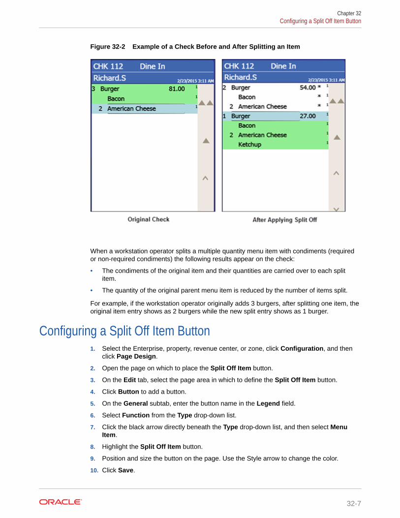
Figure 32-2 Example of a Check Before and After Splitting an Item
When a workstation operator splits a multiple quantity menu item with condiments (requiredor non-required condiments) the following results appear on the check:
• The condiments of the original item and their quantities are carried over to each splititem.
• The quantity of the original parent menu item is reduced by the number of items split.
For example, if the workstation operator originally adds 3 burgers, after splitting one item, theoriginal item entry shows as 2 burgers while the new split entry shows as 1 burger.
Configuring a Split Off Item Button1. Select the Enterprise, property, revenue center, or zone, click Configuration, and then
click Page Design.
2. Open the page on which to place the Split Off Item button.
3. On the Edit tab, select the page area in which to define the Split Off Item button.
4. Click Button to add a button.
5. On the General subtab, enter the button name in the Legend field.
6. Select Function from the Type drop-down list.
7. Click the black arrow directly beneath the Type drop-down list, and then select MenuItem.
8. Highlight the Split Off Item button.
9. Position and size the button on the page. Use the Style arrow to change the color.
10. Click Save.
Chapter 32Configuring a Split Off Item Button
32-7

Conversational OrderingConversational ordering allows workstation operators to add specially configuredmenu items for guests who order these items in no particular sequence. For example,in a coffee shop, the workstation operator requires the following items:
• Drink Type (Espresso, Latte, Mocha, Tea)
• Drink Size (Small, Medium, Large)
• Drink Temperature (Hot, Iced)
• Condiments or Modifiers (Whipped Cream, Cinnamon, Skim Milk)
When using conversational ordering, the workstation operator adds the order as aguest states items (for example, an iced mocha, medium size, with whipped cream),improving Speed of Service (SOS), ease of ordering for guests, and overall orderaccuracy.
Setting up conversational ordering consists of completing the following tasks:
• Creating Menu Item Master Groups
• Configuring Menu Level Sets
• Configuring Menu Item Classes
• Setting Menu Items
• Creating Front of House Buttons
Creating Menu Item Master Groups for ConversationalOrdering
1. Select the Enterprise, property, or zone, click Configuration, and then click MenuItem Master Groups.
2. Insert a new Menu Item Master Group.
In the coffee shop example, you could create the following groups: Espresso,Latte, Mocha, and Americano.
3. Click Save.
Configuring Menu Level Sets for Conversational Ordering1. Select the Enterprise, property, revenue center, or zone, click Configuration, and
then click Menu Level Sets.
2. Insert a new Menu Level Set.
In the coffee shop example, you could create Size and Temperature Menu LevelSets.
3. Select the Default Master Group for each Menu Level Set.
In the coffee shop example, you could select Drinks as the Default Master Group.When a workstation operators selects a Menu Level in this group, Simphonydetermines which item of the selected Menu Item Group to apply to the check.
Chapter 32Conversational Ordering
32-8

4. Double-click a Menu Level Set to open it in form view.
5. From the General section, select 2 - Bound to parent to bind the Menu Item MasterGroup (for example, Drinks) to the custom Menu Levels (for example, Size andTemperature).
When a guest initially orders a drink by either Size or Temperature, those menu items linkto the Menu Item Master Group, which also link to Anonymous Menu Level EntryOptions. This enables the workstation operator to add items in the exact order that theguest states or orders them.
6. From the Menu Level Entries section, click Add.
7. Enter menu level names for the Menu Level Set (for example, you could add Small,Medium, and Large Menu Level Entries to the Size Menu Level Set).
8. For each Menu Level Entry, select the Default and Anonymous options.
Selecting these options enable the menu level sets to serve as temporary $0.00placeholders for menu items when guests order them out of sequence.
9. Click Save.
Configuring Menu Item Classes for Conversational Ordering1. Select the Enterprise, property, revenue center, or zone, click Configuration, and then
click Menu Item Classes.
2. Insert a new Menu Item Class record.
• For each menu item that a guest can order through Conversational Ordering, createat least two Menu Item Classes to accommodate the guest in ordering the samemenu item in different ways. In the coffee shop example, each coffee type might havetwo classes: Latte Anonymous and Latte Defined. Create the Anonymous class first.
• Create a generic Menu Item Class to assign only to Menu Item Definitions thatare $0.00 priced menu items. In the coffee shop example, the Menu Item Class DrinkAnonymous can be used for Menu Item Definitions such as {SIZE} Large Drink or{TEMP} Hot Drink. This Menu Item Class is assigned to the Default Master Groupnamed Drinks.
3. Double-click a Menu Item Class to open it in form view.
4. From the General tab, select 2 - Replace in Condiment Group from the CondimentOrder Type drop-down list.
Setting this option replaces the previously selected condiment with the latest condimentchoice when the workstation operator selects condiments. If you set the Incrementoption, a priced condiment can be added to a transaction, such as a shot of espresso.
5. (Optional) Select the default parent to order from the Default Master Group drop-downlist.
In conversational ordering you can assign a default parent item to a condiment so thatwhen the condiment is ordered without an existing parent, Simphony orders thecondiment's default parent. For example, the condiment American Cheese has Burger asits default parent. If the workstation operator orders American Cheese and there is nocurrent parent, Simphony orders the Burger automatically and the American Cheeseappears as a condiment on the burger.
Set this field only for condiments; it is meaningless for parent items.
6. Click the Options tab.
Chapter 32Configuring Menu Item Classes for Conversational Ordering
32-9

7. For each Menu Item Class with Anonymous in the name, select the followingoptions:
• 8 - Allow Menu Items in this Class to be Non-Priced
• 49 - Participates in Menu Item Master Switching
• 50 - Anonymous Menu Item
8. For each Menu Item Class with Defined in the name, select the following options:
• 8 - Allow Menu Items in this Class to be Non-Priced
• 49 - Participates in Menu Item Master Switching
9. For the generic Menu Item Class, select the following options:
• 8 - Allow Menu Items in this Class to be Non-Priced
• 49 - Participates in Menu Item Master Switching
• 50 - Anonymous Menu Item
10. Click the Condiment Groups tab.
11. For each Menu Item Class, select the appropriate condiment groups:
• Required Condiment Groups: These condiment groups must be enteredwhen a workstation operator adds menu items in this class.
• Allowed Condiment Groups: These condiment groups are allowed to beentered as condiments for menu items in this class.
• Member Condiment Groups: These condiment groups consist of menu itemsin this class.
12. Click Save.
Configuring Menu Items for Conversational Ordering1. Select the Enterprise, property, revenue center, or zone, click Configuration, and
then click Menu Item Maintenance.
2. Insert a menu item master record for each menu item (including condiments) thatcan be ordered using conversational ordering. You need to account for all potentialordering combinations a guest might use. Use braces {} to surround the genericvariables such as {SIZE} and {TEMP}.
In the coffee shop example shown in the following figure, you might have recordsfor {SIZE} {TEMP} Drink, {SIZE} Hot Drink, and so on.
Chapter 32Configuring Menu Items for Conversational Ordering
32-10

Figure 32-3 Menu Item Master Records for Conversationally Ordered Items
3. Select the Major Group, the Family Group, and the Master Group.
4. Click the Definition Records tab in the lower area of the page.
5. Set the following for each record:
• Menu Item Class
• Menu Item Price
• Menu Level Availability
• Default Condiments
6. Click Save.
Creating Buttons for Conversational Ordering1. Select the Enterprise, property, revenue center, or zone, click Configuration, and then
click Page Design.
2. Open the page on which to place menu item master buttons.
3. On the Edit tab, select the page area in which to define the menu items (includingcondiments) (typically the transaction area).
Chapter 32Creating Buttons for Conversational Ordering
32-11

4. Click Button to add a button.
5. On the General subtab, select the appropriate function from the Type drop-downlist.
6. Click the black arrow beneath the Type drop-down list.
7. Position and size the button on the page. Use the Style arrow to change the color.
8. In the Legend field, enter the button name.
9. Click Save.
10. Repeat these steps to create buttons for each of the menu item master names.
Configuring Employee Privileges for Automatic Check Firing1. Select the Enterprise level, click Configuration, and then click Roles.
2. Double-click an employee role, click the Operations tab, and then click the GuestChecks subtab.
3. Select the appropriate privileges. The following table describes the privilegescorresponding to automatic check firing.
Table 32-2 Employee Guest Check Privileges for Automatic Check Firing
Privilege Description
183 - Begin Autofire Check using [BeginAutofire Check] Key
Select this option to allow employees inthis role to create checks with orders thatautomatically fire at a preset time usingthe Begin Autofire Check function key.
184 - Authorize/Perform Pickup ofAutofire Check Belonging to AnotherOperator
Select this option to allow employees inthis role to pick up and edit checks withorders that fire at a preset time fromother employees.
185 - Authorize/Perform Edit of AutofireDate/Time
Select this option to allow employees inthis role to modify the date and time thatorders are set to automatically fire.
4. To allow employees in this role to generate the Autofire Open Check Report fromthe workstation, click the Ad Hoc Reports subtab, and then select 31030 - RunAutofire Open Check Report.
5. Click Save.
Configuring Automatic Check Firing1. Select the revenue center, click Setup, and then click RVC Parameters.
2. Click the Autofire tab, and then configure the fields as described in the followingtable:
Chapter 32Configuring Employee Privileges for Automatic Check Firing
32-12

Table 32-3 Automatic Check Firing Fields
Fields and Options Description
(Optional) Autofire Employee To allow a specific employee to become theowner of all checks, including those placedusing Transaction Services after the ordersfire, select a workstation operator, and thenclick OK.• If you select an Autofire Employee, all
sales totals post to the designatedworkstation operator and the checksappear under the Autofire Employee inthe Open Check Report.
• If you do not select an AutofireEmployee, the check operator remainsthe owner of the check after the orderfires.
Autofire Workstation Select the workstation from which theorders fire and print. The application usesthis value to determine the order outputdevices and workstation printers to usewhen an order fires.
Default Autofire Tender/Media Select a service total that workstationoperators can use with Autofire.You can assign any service total. Oraclerecommends configuring a separate servicetotal for automatic order firing to allowworkstation operators to identify thedesignated touchscreen button. Creating aService Total to End the Current Round ofChecks contains information aboutconfiguring a service total.
Backup Autofire Delay (Mins) Enter the amount of time (in minutes) thatthe autofire workstation must try to fire theorders.After the Backup Autofire Delay timeelapses, if the autofire workstation isunsuccessful at firing the order, theworkstation at which the check wasoriginally created tries to fire the order. Ifboth workstations fail, a memo chit printsand a workstation operator must manuallyfire the order.
(Optional) Maximum Days Enter the maximum number of days forwhich workstation operators can scheduleorders to fire automatically.
(Optional) 1 - Print Autofire Memo at Time ofEntry
Select this option if you want a memo chit toprint when workstation operators createorders that fire automatically.
(Optional) 2 - Print Guest Check at Time ofAutofire
Select this option if you want a guest checkto print when an order automatically fires toorder devices.If you select this option, guest checks print atthe guest check printer assigned to theautofire workstation.
Chapter 32Configuring Automatic Check Firing
32-13

Table 32-3 (Cont.) Automatic Check Firing Fields
Fields and Options Description
3 - Enable Autofire in this Revenue Center Select this option to allow the revenuecenter to create orders that fireautomatically.If you are using DOM, do not enable Autofireor hold and fire.
3. Click Save.
4. Select the Enterprise, property, revenue center, or zone, click Descriptors, andthen click Autofire Check Offline Header.
5. From the Text column, enter the header lines to print on memo chits when ordersfail to fire automatically.
6. To add a logo to the header, select Use Logo, click the ellipsis point (...) buttonfrom the Logo column, select the logo from the list, and then click OK.
7. Click Save.
8. Select the Enterprise, property, revenue center, or zone, click Configuration, andthen click Page Design.
9. Insert a new button on the transaction page, select Function from the Type drop-down list, and then select Begin Autofire Check from the Function list.
10. Click Save.
Configuring Employee Privileges for Check Re-firing1. Select the Enterprise level, click Configuration, and then click Roles.
2. Double-click an employee role, click the Operations tab, and then click theTransaction subtab.
3. To allow employees in this role to re-fire items in a previous round, select 293 -Authorize/perform re-fire Menu item.
4. Click Save.
Configuring the Check Re-fire Button1. Select the Enterprise, property, revenue center, or zone, click Configuration, and
then click Page Design.
2. Open the transaction page on which to place the Re-fire button.
3. On the Edit tab, select the page area in which to define the Re-fire button.
4. Click Button.
5. On the General subtab, enter the button name (for example, Re-fire PendingChecks) in the Legend field.
6. Select Function from the Type drop-down list.
7. Click the black arrow directly beneath the Type drop-down list, select Re-fire, andthen click OK.
8. Position and size the button on the page. Use the Style arrow to change the color.
Chapter 32Configuring Employee Privileges for Check Re-firing
32-14

9. Click Save.
Suspend and ResumeWith the Suspend and Resume feature, workstation operators can:
• Suspend a check started by another employee, and sign on to the workstation.
• Suspend a check when the workstation automatically signs off an employee.
• Suspend a check using a Service Total key.
When suspended, the check is stored in the memory until a workstation operator resumes itby signing on to a workstation.
Configuring Suspend and Resume1. Select the revenue center, click Setup, and then click RVC Parameters.
2. Click the Options tab, and then select 60 - Enable Suspend/Resume.
3. Click Save.
4. Select the Enterprise, property, or zone, click Configuration, and then click Tender/Media.
5. Insert a record with the tender name.
6. Double-click the tender record.
7. On the General tab, select 2 - Service Total from the Key Type drop-down list.
8. Click the Options tab, and then click the Ops Behavior subtab.
9. Select 74 - Suspend Order.
10. Click Save.
11. Select the Enterprise, property, revenue center, or zone, click Setup, and then clickTender Parameters.
12. Click the Configuration tab.
13. To configure a default Suspend Order tender, in the Default Suspend Order Tenderdrop-down list, select the suspend order tender.
A default Suspend Order tender is needed for certain suspend scenarios, such as when aworkstation operator is auto-signed out or when another operator signs in.
14. Click Save.
Creating a Suspend and Resume ButtonTo allow workstation operators to manually suspend a check, you need to add a buttonassigned to the service total tender record.
1. Select the Enterprise, property, revenue center, or zone, click Configuration, and thenclick Page Design.
2. Open the page on which to place the Suspend/Resume button.
3. On the Edit tab, select the page area in which to define the Suspend/Resume button.
Chapter 32Suspend and Resume
32-15

4. Click Button.
5. On the General subtab, enter the button name in the Legend field.
6. Select Tender/Media from the Type drop-down list.
7. Click the black arrow directly beneath the Type drop-down list, select the tenderyou created for the suspend and resume service total, and then click OK.
8. Position and size the button on the page. Use the Style arrow to change the color.
9. Click Save.
Setting the Employee Auto Sign Out PeriodTo automatically suspend a check and sign out an employee, you need to define theautomatic operator popup interval.
1. Select the Enterprise, property, revenue center, or zone, click Setup, and thenclick Control Parameters.
2. Click the Configuration tab.
3. In the Automatic Operator "Popup" Interval (min:sec) field, enter the amount oftime (in minutes and seconds) that the workstation waits before signing out aninactive popup workstation operator.
4. Click Save.
Follow MeFollow Me extends the functionality of the suspend and resume feature in Simphony.Follow Me allows workstation operators to use suspended checks across workstationsin the same revenue center. This feature increases speed of service in a pub or fastcasual restaurant environment.
For example, a pub may have three workstations and up to twelve bartenders workingsimultaneously. Each bartender can sign on and sign off at any workstation. Abartender can begin a check on workstation 1, prepare a drink, suspend the check (viaidle timeout, manual suspend, or other employee sign on), and then sign on toworkstation 2 to resume the check. The check is automatically resumed on workstation2. Any menu items, discounts, and service charges that were added on workstation 1appear on workstation 2. A check can be open on only one workstation at a time.
The journal logs the suspend and resume history of each check and lists theworkstation on which the suspend and resume transaction was performed.
Configuring Follow Me Checks1. Select the revenue center, click Setup, and then click RVC Parameters.
2. Click the Options tab, and then select 68 - Enable Follow Me.
When you set Follow Me, option 60 - Enable Suspend/Resume dims, and viceversa. You cannot select both Follow Me and Suspend/Resume; they are mutuallyexclusive. When you set Follow Me, each workstation in the revenue centerparticipates in the Follow Me operation.
3. Select the property, click Setup, and then click Workstations.
Chapter 32Setting the Employee Auto Sign Out Period
32-16

4. On the General tab, enter information in the fields as described in the following table:
Table 32-4 Workstation Timeout Settings
Timeout Setting Description
Check Inactivity Timeout Enter the number of seconds that theworkstation waits before prompting theworkstation operator to cancel a transaction.If you set this value to 0 (zero), the Canceldialog does not appear.If you select 68 - Enable Follow Me from theRVC Parameters module, the guest check isautomatically suspended rather thancancelled.
Check Inactivity Dialog Timeout Enter the number of seconds that theworkstation shows the Do you need moretime? Inactivity dialog before automaticallycancelling the transaction. If you set thisvalue to 0 (zero), the Cancel dialog does notappear.
5. Click Save.
Order Handling on Open ChecksThis section describes how to configure the following Simphony features:
• Send and Stay: Send orders to order devices (such as remote printers or a KitchenDisplay System (KDS)) when performing a Service Total while the guest check remainsopen
• Timed Fire: Manually or automatically send items on a guest check to order devices ingroups over a period of time at preset times
Holding and Sending Items to Order DevicesThe following table describes how to configure the workstation to hold and send menu itemson open guest checks to order devices.
Table 32-5 Configure Workstations to Hold Items on Guest Checks
Task More Information
Enable option to hold items on guest checksand add touchscreen buttons
Setting the Hold and Fire Option
Enable workstation notifications for heldmenu items when tendering
Setting the Hold and Fire Tender Notification
Configure workstations to remindworkstation operators of checks with itemson hold after signing into the workstation
Setting a Reminder for Items on Hold
Configure guest checks with items on hold toend current service round and addtouchscreen buttons
Setting Checks with Items on Hold to End CurrentService Round
Chapter 32Order Handling on Open Checks
32-17

Table 32-5 (Cont.) Configure Workstations to Hold Items on Guest Checks
Task More Information
Configure how to handle items on hold whenclosing checks
Setting Check Handling with Items on Hold whenClosing Checks
(Optional) Configure Check Screen Look Up(SLU) to display checks with only held items
Configuring Check Screen Lookup (SLU) to ShowChecks with only Held Items
Configuring Send and StayFollow these instructions to configure the Service Total to send items to be preparedwhile the check remains open.
1. Select the property, click Configuration, and then click Tender/Media.
2. Insert a Service Total record if it does not exist.
3. Double-click the record to open it.
4. On the General tab, select 2 - Service Total from the Key Type drop-down list.
5. Click the Options tab, and then click the Ops Behavior subtab.
6. Select 95 - Send Order.
7. Click Save.
8. Add a touchscreen button for the tender/media record that you created in Step 2. Adding a Service Total Key to the Transaction Page contains more informationabout configuring a service total touchscreen button.
Setting the Hold and Fire Option1. Select the revenue center, click Setup, and then click RVC Parameters.
2. Click the Options tab, and then select 70 - Enable Hold and Fire.
Do not enable hold and fire if you are using DOM.
3. Click Save.
Setting the Hold and Fire Tender Notification1. Select the revenue center, click Setup, and then click Control Parameters.
2. Click the Options tab, and then select 66 - Enable Hold and Fire Final TenderNotification.
This notification indicates that unfired menu items are on a check during the finaltender process.
3. Click Save.
Setting a Reminder for Items on Hold1. Select the Enterprise level, click Setup, and then click Control Parameters.
Chapter 32Configuring Send and Stay
32-18

2. Click the Configuration tab.
3. In the Confirm Threshold Period for Items on Hold (minutes) field, enter the time thatelapses before notifying workstation operators of checks with items on hold.
If you set the Confirm Threshold Period for Items on Hold (minutes) to 0, theworkstation shows a reminder each time a workstation operator signs on to theworkstation.
4. Click Save.
Configuring Checks with Items on Hold to End Current ServiceRound
1. Select the property, click Configuration, and then click Tender/Media.
2. Insert a new record and name it Hold Order.
3. Double-click the new tender to open it.
4. On the General tab, select 2 - Service Total from the Key Type drop-down list.
5. Click the Options tab, and then click the Ops Behavior subtab.
6. Select 2- Hold Order from the Hold Type drop-down list. The Hold Type is used withHold and Fire to establish the order device output instructions for menu items on theguest check. The following options are available.
• 0 - Fire Order: Sends all menu items, including items on hold, to order devices. Itemsthat you configure to send at a preset time are exempt from this service total type.
• 1- Keep Held Status: Sends all items to the order device except those on hold.
• 2- Hold Order: Holds the entire guest check.
7. Click Save.
8. Repeat Steps 2 through 7 and configure service totals for Fire Order and Keep HeldStatus.
9. Select the Enterprise, property, revenue center, or zone, click Configuration, and thenclick Page Design.
10. Open the Front of House touchscreen page (typically the Transaction page) on which toplace the service total buttons.
11. On the Edit tab, select the page area in which to define buttons, and then click Button.
12. On the General subtab, select Tender/Media from the Type drop-down list.
13. Click the black arrow directly beneath the Type drop-down list, select Hold Order, andthen click OK.
14. Position and size the button on the page, and then click Save.
15. Repeat Steps 11 through 14 and add touchscreen buttons for the Fire Order and KeepHeld Status service total keys.
Chapter 32Configuring Checks with Items on Hold to End Current Service Round
32-19

Configuring Check Handling For Closing Checks With HeldItems
1. Select the property, click Configuration, and then click Tender/Media.
2. Double-click a Service Total tender record to open it.
3. Click the Options tab, and then click the Ops Behavior subtab.
4. In the Tender Media Hold Types section, select a Hold Type for each type ofService Total tender used when making a payment and closing a guest check. Thefollowing table describes the Hold Types and their affect on the workstationmessages.
Table 32-6 Hold Types and Workstation Messages
Hold Type Workstation Message When Closing a Check withItems on Hold
0 - Fire Order Select this option to send all items on hold to theorder devices. This is the default Hold Type.
1 - Keep Held Status Select this option to show a message asking theworkstation operator whether to send the items onhold to the order devices or to close the checkwithout sending the items.
2 - Hold Order Select this option to show a message asking theworkstation operator whether to send the items onhold to the order devices or to close the checkwithout sending the items.
5. Click Save.
Configuring Item Hold ButtonsTo allow workstation operators to hold items on a check without sending to orderdevices, you need to add buttons to the touchscreen page.
1. Select the Enterprise, property, revenue center, or zone, click Configuration, andthen click Page Design.
2. Open the page on which to place the buttons, and then on the Edit tab, select thepage area in which to define the buttons.
3. Click Button, and then on the General subtab, select Function from the Typedrop-down list.
4. Click the black arrow directly beneath the Type drop-down list, select Transactionfrom the Type pane, and then select one of the following functions:
• Hold: Holds the menu items selected in the check detail area.
• Hold Transaction: Holds every successive menu item added to the checkduring the current round.
• Timed Fire Menu Item: Holds selected items or an entire check until apredefined time.
Chapter 32Configuring Check Handling For Closing Checks With Held Items
32-20
• View Fire Times: Shows the time each menu item is configured to send to orderdevices
5. Click OK, enter a Legend for the button, and then position and size the button on thepage.
6. Repeat Steps 3 through 5 and configure buttons for the remaining hold functions in Step4, and then click Save.
Configuring the Fire Now ButtonTo allow workstation operators to fire items on a check from the current service round to orderdevices, you need to add a Fire Now button to the touchscreen page.
1. Select the Enterprise, property, revenue center, or zone, click Configuration, and thenclick Page Design.
2. Open the page on which to place the button, and then on the Edit tab, select the pagearea in which to define the button (for example, a menu item selection page).
3. Click Button, and then on the General subtab, select Function from the Type drop-down list.
4. Click the black arrow directly beneath the Type drop-down list, select Fire Now from theType pane, and then select the Service Total configured as the Fire Now Service Total.
5. Click OK, enter a Legend for the button (for example, Fire Now), and then position andsize the button on the page. The selected Tender Media’s number appears in theArguments field for the Fire Now function.
6. Click Save.
Team ServiceTeam Service allows assignment of more than one service personnel to a check. A team ofservice personnel can work together when there is a large party requiring more than oneserver. In some environments (usually high-end fine dining establishments), Team Service isused exclusively, regardless of the party size.
Tip and receipt totals are divided equally on the Employee Tip Report among all teammembers when a team check is closed. This allows resulting pay out of tips or servicecharges to be paid equally among the team members. As the Employee Tip Report is usedfor income reporting purposes for tax authorities, tax liabilities are shared equally amongteam members. See Reports and Totals Posting for Team Checks for more information.
Team members can access checks where they are assigned as part of the team, even if theyare not the check owner. This is independent of Role option 18 - Authorize/Perform Pickupof a Check Belonging to Another Operator.
Reports and Totals Posting for Team ChecksTeam Service only affects Employee Tip Report totals. The Employee Financial Report is notimpacted. When a team check is closed, all totals post as usual to the Employee FinancialReport of the check operator. Totals posted to the Employee Tip Report are distributedequally among all members of the team.
The following table shows an example result from totals posting of a team check with threeteam members. Totals post only to the Employee Financial Report of the check owner
Chapter 32Configuring the Fire Now Button
32-21

(Employee 1) while totals are distributed equally among all team members on theEmployee Tip Report.
Table 32-7 Sample Totals Posting for Team Checks
Report Name Total Employee 1 Employee 2 Employee 3
EmployeeFinancial
Net Sales $ 3000.00 $ 0 $ 0
EmployeeFinancial
Charge Tips $ 300.00 $ 0 $ 0
Employee TipReport
Gross Receipts $ 1000.00 $ 1000.00 $ 1000.00
Employee TipReport
Charge Tips $ 100.00 $ 100.00 $ 100.00
Totals posted to the Employee Tip Report outside of a team check, such as those fromregular guest checks or employee tip declarations, are posted in the normal manner.
This reporting is visible in both Ad Hoc Reports available at the workstation and inReporting and Analytics Reports.
Enabling Team Service1. Select the Enterprise, property, revenue center, or zone, click Setup, and then
click Format Parameters.
2. Click the Options tab, and then select 29 - Enable Team Service.
3. To print the names of all team members on guest checks, select 41 - Print TeamMember Names on Guest Check.
4. Click Save.
Configuring Team Service Privileges1. Select the Enterprise, click Configuration, and then click Roles.
2. Double-click the role type, click the Operations tab, and then click theMiscellaneous subtab.
3. Select the appropriate privileges. The following table summarizes the privilegesassociated with Team Service and the recommended roles to have the privilegeset:
Table 32-8 Team Service Privileges
Option Number Privilege Name Allows the Employee to ...
190 Authorize/Create Team Create a team and addinitial team members to it,and to authorize others todo so.
191 Authorize/Add or DeleteTeam Member to a Team
Add or delete members toan existing team, and toauthorize others to do so.
Chapter 32Enabling Team Service
32-22

Table 32-8 (Cont.) Team Service Privileges
Option Number Privilege Name Allows the Employee to ...
192 Authorize/Delete a Team Delete an existing team,and to authorize others todo so.
1937
Print a list of TeamsValidate Employee Direct/Indirect Tips DeclaredTransaction
Print a team list showingthe name of the team andall assigned members, andto authorize others to doso.To actually print a teammember list, you are alsorequired to enable arevenue center leveloption. Access the EMC,select the Revenue Centerwhere the team memberswere assigned, click theRVC Configuration tab,under the GeneralOptions section, enableoption 7–ValidateEmployee Direct/IndirectTips DeclaredTransaction, and thenSave. Repeat this step foreach revenue center asneeded.
196 Available as Team ServiceTeam Member
Appear in selection listswhen assigning teammember.
4. Click Save.
Configuring Revenue Centers to Delete Service Teams at theStart of Day
You can configure Simphony to automatically remove all teams on a daily basis for locationsthat use Team Service as a standard of operation. As team members usually change eachday based on employee scheduling and availability, this allows managers to create newteams each day without having to edit or delete previous teams.
1. Select the Enterprise or property, click Configuration, and then click Task Schedules.
2. Insert a new record, and then double-click the record to open it.
3. On the General tab, select 7 - Workstation as the Service Type, and then select 3 -Reset Team Service as the Task Type.
4. Select 4 - Recurring - Daily as the Schedule Type, select Enabled, and then select theStart Date.
5. Click the Recurrence tab.
6. In the Daily Frequency section, set the time at which to run the task, and then click Save.
Chapter 32Configuring Revenue Centers to Delete Service Teams at the Start of Day
32-23

7. Repeat Steps 2 through 6 to create another task, but change the Service Type to8 - Check and Posting.
Adding Team Service Buttons1. Select the Enterprise, property, revenue center, or zone, click Configuration, and
then click Page Design.
2. Open the page on which to place the Team Service buttons, and then on the Edittab, select the page area in which to define the buttons.
3. Click Button, and then on the General subtab, select Function from the Typedrop-down list.
4. Click the black arrow directly beneath the Type drop-down list, and then selectCheck Begin Pickup from the Type pane.
5. Select Begin Team Check, and then click OK.
The Begin Team Check key allows workstation operators to start a team check. Ifthe workstation operator is a member of multiple teams, the workstation shows alist of teams.
6. Enter a Legend for the button (for example, Begin Team Check), and thenposition and size the button on the page.
7. Click Save.
8. Repeat Steps 3 through 7 and add buttons for the following functions:
• Create Team Members or Add Team to Check: Creates, edits, or deletes ateam; adds a team to a check; and prints a team list.
• Edit Team: Shows team information and allows member editing.
• Remove Team from Check: Removes the team from a check.
Closed Guest Check OperationsAfter a check is closed, you can allow workstation operators to perform theseoperations:
• Adjust Closed Check: Change or add a tip, tender, or guest count to a closedcheck without reopening it.
• Reopen Closed Check: Reopen the check and use as a regular guest check. Allmenu items from the check are considered previous-round items.
• Reprint Closed Check: Reprint checks for a closed transaction in the current orprevious business dates.
• Reprint Previous Closed Check: Reprint a receipt for the last closed check.
Configuring Closed Check Settings1. Select the Enterprise, property, revenue center, or zone, click Setup, and then
click Control Parameters.
2. Click the Configuration tab, and then enter information in the following fields:
Chapter 32Adding Team Service Buttons
32-24

• Number of Days to Adjust Closed Checks: Enter the number of days (0-999) aprivileged employee can adjust closed checks. Enter 0 to allow the adjustment for thecurrent business day only.
• Number of Days to Reopen/Reprint Closed Check from Previous Business Day:Enter the number of days (0-999) a privileged employee can reopen or reprint closedchecks. Enter 0 to allow checks from the current business day only to be reopened orreprinted.
3. To allow privileged operators to service total reopened checks, click the Options tab, andthen select 31 - Allow Service Total of Closed Checks.
4. Click Save.
5. To retain the original guest check number when reopened:
a. Select the revenue center, click Setup, and then click RVC Parameters.
b. Click the Options tab, and then select 37 - Keep The Same Check Number When aCheck is Reopened.
If deselected, Simphony assigns a new guest check number to the check whenreopened.
c. Click Save.
6. To configure reprinting of closed checks:
a. Select the Enterprise or property, click Configuration, and then click Tender/Media.
b. Insert a Service Total tender record if it does not exist.
c. Double-click the Service Total record to open it.
d. On the General tab, select 2 - Service Total as the Key Type.
e. Click the Options tab, and then click the Printing Options subtab.
f. Select 19 - Reprint Check.
Setting option 19 does not print an exact copy of the receipt unless the printingoptions are the same as the original tender.
You can enable other options to include elements of the check, such as 21 - PrintSummary Totals or 22 - Print Check Trailer, but selecting these options is notrequired.
g. Click Save.
h. Select the Enterprise, property, revenue center, or zone, click Setup, and then clickTender Parameters.
i. Click the Configuration tab, and then in the Default Reprint Check Tender/Mediadrop-down list, select the Service Total tender from step 6-b.
j. Click Save.
Allowing Employees to Adjust Closed Checks1. Select the Enterprise level, click Configuration, and then click Roles.
2. Double-click the role type, click the Operations tab, click the Guest Checks subtab, andthen select the appropriate options:
• 67 - Authorize/Perform Adjust Closed Check: Select to allow employees with thisrole to use the Adjust Closed Check function key, and to authorize others to do so. A
Chapter 32Allowing Employees to Adjust Closed Checks
32-25

closed check adjustment allows the user (if privileged to void Tender/Mediafrom a previous round) to adjust the tender/media, charge tip, or the number ofguests on a closed check.
• 133 - Auth/Perform Adjust Closed Check from Previous Business Days:Select to allow employees with this role to adjust closed checks from previousbusiness days.
3. Click Save.
4. Select the Enterprise, property, revenue center, or zone, click Configuration, andthen click Page Design.
5. Open the page on which to place the Adjust Closed Check buttons.
6. On the Edit tab, select the page area in which to define the buttons.
7. Click Button, and then on the General subtab, select Function from the Typedrop-down list.
8. Click the black arrow directly beneath the Type drop-down list, and then selectCheck Begin Pickup from the Type pane.
9. Select the appropriate function key, and then click OK.
• Adjust Closed Check: Prompts for the check number of the closed check toadjust.
• Adjust Closed Check From List: Prompts to select a closed check to adjustfrom a list of checks for the current business day.
When adjusting a check using either function key, workstation operators can edittenders, charge tips, and the number of guests on the check, but the check itself isnot reopened.
10. Enter a Legend for the button, and then position and size the button on the page.
11. (Optional) Repeat Steps 7 through 10 and configure a button for the remainingAdjust Closed Check function in Step 9, and then click Save.
Allowing Employees to Reopen and Edit a Closed Check1. Select the Enterprise level, click Configuration, and then click Roles.
2. Double-click the role type, click the Operations tab, click the Guest Checkssubtab, and then select the appropriate options:
• 68 - Authorize/Perform Reopen Closed Check: Select to allow employeeswith this role to use the Reopen Closed Check key, and to authorize others todo so.
• 134 - Auth/Perform Reopen Closed Check from Previous Business Days:Select to allow employees with this role to reopen closed checks from previousbusiness days.
3. Click the Voids/Returns subtab, and then select the appropriate options:
• 69 - Authorize/Perform Void of Menu Items on Closed Checks: Select toallow employees with this role to void menu items from closed checks afterthey have been reopened, and to authorize others to do so. You must alsoselect Roles option 25 - Authorize/Perform Void of Menu Items from aPrevious Round.
Chapter 32Allowing Employees to Reopen and Edit a Closed Check
32-26

• 70 - Authorize/Perform Void of Discounts on Closed Checks: Select to allowemployees with this role to void discounts from closed checks after they have beenreopened, and to authorize others to do so. You must also select Roles option 27 -Authorize/Perform Void of Discounts from a Previous Round.
• 71 - Authorize/Perform Void of Service Charges on Closed Checks: Select toallow employees with this role to void service charges from closed checks after theyhave been reopened, and to authorize others to do so. You must also select Rolesoption 28 - Authorize/Perform Void of Service Charges from a Previous Round.
4. Click Save.
5. Select the Enterprise, property, revenue center, or zone, click Configuration, and thenclick Page Design.
6. Open the page on which to place the Reopen Closed Check buttons.
7. On the Edit tab, select the page area in which to define the buttons.
8. Click Button, and then on the General subtab, select Function from the Type drop-down list.
9. Click the black arrow directly beneath the Type drop-down list, and then select CheckBegin Pickup from the Type pane.
10. Select the appropriate function key, and then click OK.
• Reopen Closed Check: Prompts for the check number of the closed check toreopen.
• Reopen Closed Check From List: Reopens the closed checks selected from a listof closed checks available on the current workstation.
11. Enter a Legend for the button, and then position and size the button on the page.
12. Repeat Steps 8 through 11 to create a button for the remaining Reopen Closed Checkfunction in Step 10, and then click Save.
Allowing Employees to Reprint Closed Checks1. Select the Enterprise level, click Configuration, and then click Roles.
2. Double-click the role type, click the Operations tab, click the Printing subtab, and thenselect the appropriate options:
Table 32-9 Check Reprinting Options
Option Description
23 - Authorize/Perform UnlimitedReprinting/Printing of a Check
Select to allow employees associated withthis role to perform two functions:
a. Allow On-Demand operators to printmore guest checks than the maximumnumber allowed.
b. Allow By-Round operators to use theReprint Closed Check key.
Selecting this option also allows employeesto grant authorization to others for thesefunctions.
Chapter 32Allowing Employees to Reprint Closed Checks
32-27

Table 32-9 (Cont.) Check Reprinting Options
Option Description
24 - Authorize/Perform Reprinting of ClosedChecks
Select to allow employees with this role toreprint a closed guest checks and toauthorize others to do so.
3. Click Save.
4. Select the Enterprise, property, revenue center, or zone, click Configuration, andthen click Page Design.
5. Open the Front of House page on which to place the Reprint Closed Checkbuttons.
6. On the Edit tab, select the page area in which to define button.
7. Click Button, and then on the General subtab, select Function from the Typedrop-down list.
8. Click the black arrow directly beneath the Type drop-down list, and then selectPrint from the Type pane.
9. Select Reprint Closed Check, and then click OK.
When this function key is used, the Default Reprint Check Tender assigned inTender Parameters is used to print the check.
10. Enter a Legend for the button, and then position and size the button on the page.
11. Repeat steps 7 through 10 to create a Reprint Previous Closed Check button.
This function key is used to reprint a receipt for the last closed check.
12. Click Save.
Allowing Employees to Manually Replay Checks Throughthe Workstation
Beginning with Simphony version 2.9.2, you must grant employees permission tomanually replay offline checks through the Property Management Console (PMC), if anoffline POS workstation fails to automatically replay its checks before reconnectingonline.
1. Select the Enterprise level, click Configuration, and then click Roles.
2. Double-click the role type record (for example, administrator or manager).
3. Click the Operations tab, and then click the PMC General/Reports subtab.
4. Select 30001 - Run PMC to allow employees associated with this role to launchthe PMC on workstations using the Launch PMC function key.
5. Click the PMC Procedures subtab, and then select 30069 - Replay Checks fromthe Other Procedure Options section.
6. Click Save.
Chapter 32Allowing Employees to Manually Replay Checks Through the Workstation
32-28

Check Add/TransferTransferring checks is a procedure that changes ownership of a guest check. Simphonyenables privileged workstation operators to transfer checks from another server tothemselves by employee number or by employee ID number. Guest checks may also betransferred across Revenue Centers. The Transfer Checks function only transfers theownership of the guest check; it does not transfer the check’s sales totals for reportingpurposes.
Add Check means to combine two checks together while in a transaction.
Allowing Employees to Add or Transfer Checks1. Select the Enterprise level, click Configuration, and then click Roles.
2. Double-click the role type record (for example, administrator, manager or server).
3. Click the Operations tab, and then click the Guest Checks subtab.
4. Select the appropriate permission options for the user role:
• 45 - Authorize Transfer of Checks in the Same Revenue Center: Select to allowemployees with this role to transfer checks from another operator within the samerevenue center, and to authorize others to do so.
• 46 - Authorize Transfer of Checks Between Revenue Centers: Select to allowemployees with this role to transfer checks from another revenue center, and toauthorize others to do so.
• 47 - Authorize Adding of Checks in the Same Revenue Center: Select to allowemployees with this role to add checks (to be in a check, and add another check to it)within a revenue center, and to authorize others to do so.
• 48 - Authorize Adding of Checks Between Revenue Centers: Select to allowemployees with this role to add checks (to be in a check, and add another check to it)from another revenue center, and to authorize others to do so.
5. Click Save.
Configuring the Add/Transfer Revenue Centers1. Select the revenue center, click Setup, and then click RVC Parameters.
2. On the General tab, scroll down to the Add/Transfer Revenue Center section, and thenselect up to eight revenue centers from which checks can be transferred into this revenuecenter.
3. Click Save.
4. Repeat Steps 1 through 3 for all revenue centers in the property.
Configuring Add/Transfer Buttons1. Select the Enterprise, property, revenue center, or zone, click Configuration, and then
click Page Design.
2. Open the page on which to place the Add/Transfer buttons.
Chapter 32Check Add/Transfer
32-29

3. Click the Edit tab, and then select the page area in which to define the buttons.
4. Click Button, and then on the General subtab, select Function from the Typedrop-down list.
5. Click the black arrow directly beneath the Type drop-down list, select Check Addfrom the Type pane.
6. Select one of the following function keys, and then click OK:
• Add/Transfer by Number: Adds or transfers a check within the same revenuecenter using the check number entered.
• Add/Transfer Check by Number RVC Index: Adds or transfers a check(using the check number) from the revenue center specified in the Index field.The Index field points to one of the eight revenue centers configured in theAdd/Transfer section of the RVC Parameters module.
• Add/Transfer Check by Number Prompt RVC: Adds or transfers a check(using the check number) from one of the eight add/transfer revenue centersconfigured in the RVC Parameters module.
• Add/Transfer Check by Table: Adds or transfers a check within a revenuecenter. The workstation client prompts for the table number or table ID of thecheck to be added or transferred.
• Add/Transfer Check by Table RVC Index: Adds or transfers a check (usingthe table number or table ID) from the revenue center specified in the Indexfield. The Index field points to one of the eight revenue centers configured inthe add/transfer section of the RVC Parameters module.
• Add/Transfer Check by Table Prompt RVC: Adds or transfers a check (usingthe table number or table ID) from one of the eight add/transfer revenuecenters configured in the RVC Parameters module.
• Add/Transfer Check From List Prompt RVC: Prompts users for the revenuecenter, and then shows all open checks that can be added or transferred fromothers within the specified revenue center.
• Add/Transfer Check From List RVC Index: Shows all open checks in therevenue center (specified by the Index field) that can be added or transferredfrom others. The Index field points to one of the eight revenue centersconfigured in the Add/Transfer section of the RVC Parameters module.
• Add/Transfer Check SLU: Shows a list of checks that can be added ortransferred from other workstation operators on the Open Check SLU.
7. Enter a Legend for the button, and then position and size the button on the page.
8. Repeat Steps 4 through 7 to create buttons as needed for the remaining Add/Transfer functions in Step 6.
9. Click Save.
Seat Filtering and Memo ChecksYou can configure check filtering by one or more seat numbers, allow workstationoperators to apply a tender only for the detail and summary totals associated with theseat, and if required, allow workstation operators to create a check for the filteredseats. This enables workstation operators to:
• Review check detail posting to facilitate the delivery of meals to the proper guest
Chapter 32Seat Filtering and Memo Checks
32-30

• Print checks for one or more seats, or for groups of seats in a large party without creatingseparate checks
For example, a party of four arrives at the restaurant. A workstation operator begins a checkfor the table, assigning a seat number to each order. When the party has completed thedining experience, guests at seats 1 and 2 want to pay and leave before the guests at seats 3and 4. The workstation operator can:
1. Filter the check by seats 1 and 2.
2. Apply a tender and close the check for the filtered seats.
3. If configured, print a memo check.
4. Close the check by tendering the remaining seats.
After applying a tender to a filtered check, items belonging to the filtered seat or seats areremoved from the primary guest check.
The check for the filtered seats is referred to as a memo check. After closing a memo check,depending on the configuration, the active seat in the filter increments to the next seatnumber, and menu items associated with that seat appear in the check detail area. A memotendered check contains the same information as the primary check when closed, such asservice team details, event details, and suite owner details.
Workstation operators can identify memo checks on the Check Journal Report by the MEMOCHECK banner on the check header and in ad-hoc reports, as well as on the printed check.
Figure 32-4 Sample Check Filtered by Seats
Chapter 32Seat Filtering and Memo Checks
32-31
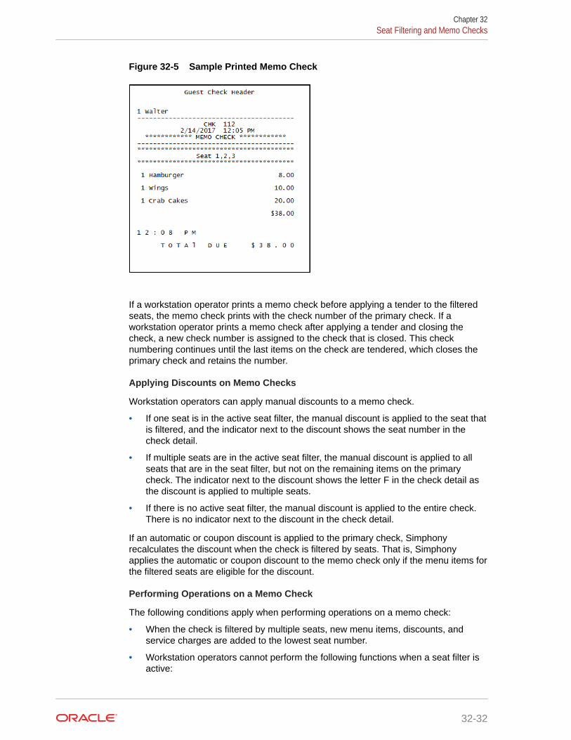
Figure 32-5 Sample Printed Memo Check
If a workstation operator prints a memo check before applying a tender to the filteredseats, the memo check prints with the check number of the primary check. If aworkstation operator prints a memo check after applying a tender and closing thecheck, a new check number is assigned to the check that is closed. This checknumbering continues until the last items on the check are tendered, which closes theprimary check and retains the number.
Applying Discounts on Memo Checks
Workstation operators can apply manual discounts to a memo check.
• If one seat is in the active seat filter, the manual discount is applied to the seat thatis filtered, and the indicator next to the discount shows the seat number in thecheck detail.
• If multiple seats are in the active seat filter, the manual discount is applied to allseats that are in the seat filter, but not on the remaining items on the primarycheck. The indicator next to the discount shows the letter F in the check detail asthe discount is applied to multiple seats.
• If there is no active seat filter, the manual discount is applied to the entire check.There is no indicator next to the discount in the check detail.
If an automatic or coupon discount is applied to the primary check, Simphonyrecalculates the discount when the check is filtered by seats. That is, Simphonyapplies the automatic or coupon discount to the memo check only if the menu items forthe filtered seats are eligible for the discount.
Performing Operations on a Memo Check
The following conditions apply when performing operations on a memo check:
• When the check is filtered by multiple seats, new menu items, discounts, andservice charges are added to the lowest seat number.
• Workstation operators cannot perform the following functions when a seat filter isactive:
Chapter 32Seat Filtering and Memo Checks
32-32

– Fire Now
– Next #/Next Seat
– Touch Split
– Begin Check
– Pick Up Check
– Transfer Check
• Simphony supports assigning up to 65 seats to a check.
Performing Memo Tenders When Using a Kitchen Display System (KDS)
The following conditions apply to the KDS when performing a memo tender:
• KDS Reports and report drill downs do not account for memo tendered or split checks incheck counts, timings, and check detail.
• Check modifications such as adding new menu items to a check, adding or editingcondiments, and the voiding of existing menu items are not allowed when the followingDynamic Order Mode (DOM) types are enabled:
– Fire on Fly
– Fire on Next
– Fire on Tender
Configuring Memo Check Printing1. Select the Enterprise or property, click Configuration, and then click Tender/ Media.
2. Insert a new record, name it Print Memo Check, and then click OK.
3. Double-click the Print Memo Check record to open it.
4. From the Key Type drop-down list, select 2 - Service Total.
5. Click the Options tab, click the Printing Options subtab, and then select the followingoptions:
• 13 - Print Memo Check: Select to allow this key to print memo checks.
• (Optional) 15 - Increment Active Seat # after Memo Check Print: Select toincrement the active seat number on the seat filter or active memo check number tothe next number each time this key is used to print. This allows workstation operatorsto, in succession, generate Memo Checks or to apply Memo Tenders. When thisoption is selected, pop-up operators remain signed in when the seat filter is reset.Deselect to reset the seat filter when this key is used to print.
Select 13 and (optionally) 15 for all tender medias that can be used for Memo Tendering.
6. Click Save.
7. Select the Enterprise, property, revenue center, or zone, click Configuration, and thenclick Page Design.
8. Open the page on which to place the memo check button.
9. On the Edit tab, select the page area in which to define the buttons.
10. Click Button, and then on the General subtab, select Tender/Media from the Type drop-down list.
Chapter 32Configuring Memo Check Printing
32-33

11. Click the black arrow beneath the Type drop-down list, select Print Memo Checkfrom the list and then click OK.
12. Enter a Legend for the button (for example, Print Memo Check), and then positionand size the button on the page.
13. Click Save.
14. (Optional) To prompt for the guest count for memo checks:
a. Select the Enterprise, property, revenue center, or zone, click the Setup tab,and then click Control Parameters.
b. Click the Options tab, and then select 9 - Prompt for Guest Count whenSplit Check.
Configuring Service Charges for Seat FilteringWhen a check is filtered by seats, automatic service charges prorate based on theactive menu items. Manual service charges do not prorate when seat filtering is active.Instead, the manual service charge is added to the last memo check that is closed forthe table. To set manual service charges to prorate based on the filtered seats:
1. Select the Enterprise, property, or zone, click Configuration, and then clickService Charges.
2. Insert a record for either an automatic or a manual amount service charge withprorate option, or double-click an existing automatic or manual service chargerecord to open it.
3. On the General tab, select option 2 - On = Amount; Off = Percentage, and thenenter the service charge value in the Amount field under General Settings.
4. If required for your country, select the Tax Class from the drop-down list.
5. Select option 30 - Prorate Service Charges to Menu Items.
When selected, the service charge prorates based on the value of the menu itemsin the filtered seats. This overrides the requirement for the minimum number ofguest count for a memo check, if the minimum guest count requirement is met forthe entire check.
6. If you are configuring a manual amount service charge with prorate option,complete the following substeps to prorate to all menu items with correspondingservice charge itemizers:
a. Click the Itemizers tab, and then select all service charge itemizers.
b. Click the Menu Levels tab, and then select the appropriate Main and SubLevels.
7. Click the Output tab, and then select Print on Customer Receipt, Print onJournal, and Print on Guest Check.
8. Click Save.
Configuring Seat Filter Management Buttons1. Select the Enterprise, property, revenue center, or zone, click Configuration, and
then click Page Design.
2. Open the page on which to place the memo check button.
Chapter 32Configuring Service Charges for Seat Filtering
32-34

3. On the Edit tab, select the page area in which to define the buttons.
4. Click Button, and then on the General subtab, select Function from the Type drop-downlist.
5. Click the black arrow beneath the Type drop-down list, and then select Guest Seat fromthe Type pane.
6. Select one of the following function keys, and then click OK:
• Manage Seat Filter: A pop-up screen appears showing all available seats on theguest check, and lets you add or remove seats interactively from the seat filter.
• Add to Seat Filter: Prompts you for a seat number that is to be filtered (if no seatfilter is active), or adds the seat number to an active seat filter.
• Remove From Seat Filter: Prompts you for the seat number that you want toremove from the current seat filter.
• Clear Seat Filter: Removes all seats from the current seat filter.
• Edit Seat: Allows you to change the seat number of previously ordered menu items.
7. Enter a Legend for the button, and then position and size the button on the page.
8. Repeat Steps 3 through 6 and create buttons for the remaining functions in Step 6.
9. Click Save.
Chapter 32Configuring Seat Filter Management Buttons
32-35

33Workstation Touchscreen Pages
A touchscreen page is a defined layout of functions and buttons that you configure in theEMC. The touchscreen page appears on the workstation, allowing workstation operators toperform operations and transactions on the POS client.
Page templates allow you to customize a workstation touchscreen page in various ways.Page templates are categorized into the following types:
• Classic templates: These templates are similar to Simphony First Edition touchscreentemplates
• Blank templates: These templates are used for customized pages or a Sign On page
• Tabbed templates: These templates are used for Sign On and Transaction pages
Tabbed templates allow the greatest functionality. With a tabbed template, you can configuremultiple tabs on the page. Approximately 50 tabs and subtabs can appear on a page, andeach tab and subtab contain up to 50 buttons. Having a large number of buttons on a singlepage allows you to configure a small number of pages for a revenue center. A tab is used fornavigation. Navigation on a page is consistent from page to page (navigation bar andsubtabs).
Pages can contain buttons and more sophisticated content, such as dining tables, ScreenLookups (SLUs), numeric entry areas, and background panels for highlighted groups ofcontrols. All buttons performs a function.
The content appearing on a page can be dynamic based on the menu levels, serving period,employee class, or other criteria. For example, you can show a Manager Functions tab only ifthe manager is assigned to one of three manager employee classes.
When editing pages from the Page Design module, what-you-see-is-what-you-get.
Page DesignA touchscreen page is a defined layout of functions and buttons that you configure in theEMC. The touchscreen page appears on the workstation, allowing workstation operators toperform operations and transactions on the POS client.
Page templates allow you to customize a workstation touchscreen page in various ways.Page templates are categorized into the following types:
• Classic templates: These templates are similar to Simphony First Edition touchscreentemplates
• Blank templates: These templates are used for customized pages or a Sign On page
• Tabbed templates: These templates are used for Sign On and Transaction pages
Tabbed templates allow the greatest functionality. With a tabbed template, you can configuremultiple tabs on the page. Approximately 50 tabs and subtabs can appear on a page, andeach tab and subtab contain up to 50 buttons. Having a large number of buttons on a singlepage allows you to configure a small number of pages for a revenue center. A tab is used for
33-1

navigation. Navigation on a page is consistent from page to page (navigation bar andsubtabs).
Pages can contain buttons and more sophisticated content, such as dining tables,Screen Lookups (SLUs), numeric entry areas, and background panels for highlightedgroups of controls. All buttons performs a function.
The content appearing on a page can be dynamic based on the menu levels, servingperiod, employee class, or other criteria. For example, you can show a ManagerFunctions tab only if the manager is assigned to one of three manager employeeclasses.
When editing pages from the Page Design module, what-you-see-is-what-you-get.
Assigning Default Touchscreen Pages1. Select the Enterprise, property, revenue center, or zone, click Configuration, and
then click Page Assignment.
2. Click the Configuration tab, and then configure the following settings:
• Default Sign In Page: Select the page to show when workstation operatorsare not signed on to a workstation.
• Default Transaction Page: Select the page to show for workstation operatorswho sign on to this location when a transaction page is not defined (throughoperator, Employee Class, and so on).
• Default Training Page: Select the page to show for workstation operators intraining mode. If you select 0 - None, employees in training mode see thedefault touchscreen based on the touchscreen hierarchy.
3. Click Save.
Configuring Function KeysFunction keys allow workstation operators to perform a variety of tasks, such asbeginning a guest check, opening a cash drawer, authorizing a credit card, transferringchecks, printing customer receipts, and many other operations.
1. Select the Enterprise, property, revenue center, or zone, click Configuration, andthen click Page Design.
2. Open the page on which to place a function key.
3. On the Edit tab, select the page area in which to define the function key.
4. Click Button.
5. On the General subtab, enter the key name in the Legend field.
6. From the Type drop-down list, select Function.
7. Click the black arrow beneath the Type drop-down list.
8. Select the appropriate function, and then click OK.
9. Position and size the button on the page. Use the Style arrow to change the color.
10. Click Save.
Chapter 33Assigning Default Touchscreen Pages
33-2

Configuring MacrosA macro is a button that, when pressed, executes a series of commands. Macros save timewhen workstation operators frequently enter certain sequences or keystrokes. You can setmacros to include menu items, service charges, discounts, tenders, function keys,alphanumeric keys, or a link to another macro.
1. Select the Enterprise, property, revenue center, or zone, click Configuration, and thenclick Page Design.
2. Open the page on which to place the macro button.
3. On the Edit tab, select the page area in which to define the macro button.
4. Click Button to add a button.
5. On the General subtab, enter the button name in the Legend field.
6. From the Type drop-down list, select Function.
7. Click the black arrow directly beneath the Type drop-down list, select the Macro function,and then click OK.
8. Click the Edit Macro Keys button, and then add the appropriate steps in the propersequence.
9. Highlight the macro button.
10. Position and size the button on the page. Use the Style arrow to change the color.
11. Click Save.
Chapter 33Configuring Macros
33-3

34Rental Deposits
Rental deposits are used in Simphony to record advance payments on scheduled events,such as banquets, parties, room rentals, or as a security deposit on loaned items, such asbowling shoes. The Rental Deposits feature allows workstation operators to accept, apply,record, report, and refund rental deposits taken at the POS client.
A rental deposit can be a menu item or a non-revenue service charge. Unlike traditional non-revenue service charges, a check can contain more than one rental deposit.
Automatic discounts are not applied to rental menu items as the discount amount can changewhen other items are added to the check.
Configuring Deposits as a Menu Item1. Select the Enterprise, property, revenue center, or zone, click Configuration, and then
click Menu Item Classes.
2. Insert a new record for the rental item (for example, Bike Rental or Bowling Shoes).
3. Double-click the new record to open it, and then click the Options tab.
4. Select 64 - Rental Deposit, and then click Save.
Enabling this option makes all menu items assigned to this class Rental Deposits. Youcan use this option with the Deposit Handling feature to apply a deposit to a check.
5. Select the Enterprise, property, revenue center, or zone, click Configuration, and thenclick Menu Item Maintenance.
6. Insert a new record and name it the same as the rental item.
7. Double-click the new record to open it, insert a definition record, and then click theGeneral tab.
8. From Menu Item Class, select the class that you created in Step 2, and then click Save.
9. Select the revenue center, click Setup, and then click RVC Parameters.
10. On the General tab, select the rental item that you created in Step 6 from the DepositForfeit Return Item (Menu Item) drop-down list, and then click Save.
11. Add a button for the rental item to the workstation Transaction page. See Adding MenuItem Keys to the Transaction Page for instructions.
Configuring Deposits as a Service Charge1. Select the Enterprise, property, revenue center, or zone, click Configuration, and then
click Menu Item Classes.
2. Insert a new record for the rental service charge (for example, Banquet Service Chargeor Conference Room Rental Service Charge).
3. Double-click the new record to open it, and then click the Options tab.
4. Select 64 - Rental Deposit, and then click Save.
34-1

5. Select the Enterprise or property, click Configuration, and then click ServiceCharges.
6. Insert a new record and name it the same as the rental service charge.
7. Double-click the new record to open it.
8. On the General tab, select 23 - Rental Deposit, and then configure the followingsettings:
• 1 - On = Open; Off = Preset: Select to make the rental deposit service chargean open service charge, prompting workstation operators for the amount orpercentage. Deselect to use a preset amount or preset percentage for therental deposit service charge.
• 2 - On = Amount; Off = Percentage: Select to make the rental depositservice charge an amount service charge. Deselect to make the rental depositservice charge a percentage service charge.
9. Click Save.
10. Select the revenue center, click Setup, and then click RVC Parameters.
11. Click the Options tab, and then select 67 - Use Service Charge as DepositForfeit Return Item.
12. Click the General tab, and then select the service charge that you created in Step6 from the Deposit Forfeit Return Item (Service Charge) drop-down list.
13. Click Save.
Configuring Rental Deposit Buttons1. Select the Enterprise, property, revenue center, or zone, click Configuration, and
then click Page Design.
2. Open the page on which to place the Rental Deposit buttons.
3. Click the Edit tab, and then select the page area in which to define the buttons.
4. Click Button, and then on the General subtab, select Function from the Typedrop-down list.
5. Click the black arrow directly beneath the Type drop-down list, select Transactionfrom the Type pane.
6. Select one of the following function keys, and then click OK:
• Apply Deposit: Applies a deposit to an active guest check containing a rentaldeposit.
• Edit Deposit: Modifies information for the current or future rounds for adeposit in the check detail area.
• Show Deposit: Refunds a deposit on a closed check, or prints a depositreport for all deposits or a selected deposit.
7. Enter a Legend for the button, and then position and size the button on the page.
8. Repeat Steps 4 through 7 and create buttons for the remaining Rental Depositfunctions in Step 6.
9. Click Save.
Chapter 34Configuring Rental Deposit Buttons
34-2

10. If you configured a deposit as a service charge, add a button for the Deposits servicecharge to the transaction page. Creating Service Charge Buttons contains instructions.
Chapter 34Configuring Rental Deposit Buttons
34-3

35Resetting Daily Totals
A business day refers to the beginning and end times of a day of business. A business daycan have any begin time, but typically a business day starts in the early morning hours duringa slow or closed period of operations (for example, 3:00 a.m. or 4:00 a.m.). A calendar dayalways begins at 12:00 a.m.
To reset daily check and employee totals, a property or revenue center must start a newbusiness day.
Start of DayStart of Day (SOD) is the process that begins a new business day at a property. The SODcan be set to run automatically or manually.
When the time of day occurs that a new business day is automatically configured to start (forexample, at 4:00 a.m. each day), the following actions occur in the order listed:
• Simphony increases the Business Day and updates the status of checks and employees.
• The PC Autosequence runs, and typically performs the following actions:
– Batches and settles credit cards
– Runs custom applications for a property
• After the SOD Asequence completes, Simphony checks to see whether it is time to runother autosequences (such as Start of Week Autosequence, Start of Pay PeriodAutosequence, and so on).
Many properties like to start a new business day manually at their own time (after a nightauditor balances reports). Often these properties stop their Simphony and propertymanagement systems at the same time, roll to a new business day, and then bring thesystems back up. An administrator can manually run SOD in Simphony using an interactioncalled PC Autosequence (from the EMC) or by pressing a button on the workstation. WhenSOD begins manually, Simphony performs the same actions as if it were run automatically.The only difference is the method by which SOD begins.
Start of Day Business RulesSimphony has business rules to determine how and when a business day can begin, andwhich business day is beginning. The rules exist for both automatic and manual SOD.
When starting a new business day, the following rules apply:
• SOD cannot be run twice in 8 hours.
• SOD cannot be run twice between midnight and noon.
• SOD cannot be run twice between noon and midnight.
• When a business day is scheduled to run automatically, it is not possible to start thebusiness day manually with a PC Autosequence.
35-1
A business day is calculated based on noon (12:00 p.m.) to noon times.
• If SOD is run before noon, Simphony assumes the business day completed is forthe previous calendar day. (If SOD runs at 3:05 a.m. on the 17th, the 16th is thebusiness day that is closing, and the 17th is the business day being started.)
• If SOD is run after noon, Simphony assumes the business day completed is for thecurrent calendar day. (If SOD is run at 11:52 p.m. on the 17th, the 17th is thebusiness day that is closing, and the 18th is the business day being started.)
Start of Day with Offline Workstations or ServerWorkstations are aware of the business date configuration so that offline reports showrelevant information. Consider the following scenario:
• Every business day begins at 3:00 p.m.
• On Tuesday at approximately 11:00 a.m., a property loses communication with thedatabase (the property is in Yellow Mode).
• The site is offline until Friday afternoon.
In this situation, workstations run reports as if SOD occurred. For example, a reporttaken for today on Wednesday at 4:00 p.m, shows data from Wednesday at 3:00 a.m.(the time SOD would have occurred) to the current second when the report was taken.In addition, if days are configured for manual SOD, workstation reports assume thatthe business day begins 24 hours after the previous SOD occurred. In this situation, adialog box appears on workstations informing the manager that a new business dayhas begun.
Catch-Up mode increases the business day after the Simphony server goes offlineduring an automatically scheduled SOD time period. Consider the following scenario:
• SOD is set to run automatically at 4:00 a.m.
• At 2:00 a.m., the Simphony server experiences a power failure.
• At 6:00 a.m., the Simphony server is online again.
In Catch-Up mode, the SOD Autosequence does not start. With Catch-Up mode, thebusiness day still starts at 4:00 a.m. When Simphony comes online at 6:00 a.m., thePERIOD_INSTANCE table is populated with rows to indicate that the business daystarted. The rows do not show a 6:00 a.m. run time, however. Catch-Up mode knowsthat the application was supposed to have started at 4:00 a.m., so the rows arecreated with 4:00 a.m. as the start time. Simphony can catch-up from up to two missedautomatic start of days and make the appropriate PERIOD_INSTANCE entries.
Configuring Start of Day1. Select the Enterprise level, click Configuration, and then click Roles.
2. Select the role type (such as manager), click the Operations tab, and then clickthe PMC Procedures subtab.
3. Select the appropriate start of day role privileges:
• 30058 - Run Start of Day from OPS: Select this option to allow all employeeswith the role to increment the business date from the property’s Check andPosting Service (CAPS) workstation.
Chapter 35Start of Day with Offline Workstations or Server
35-2

• 30059 - Prevent Running SOD from OPS with Open Checks: Select this option sothat Start of Day (SOD) cannot run when open checks exist.
4. Click Save.
5. To allow a manager or administrator to manually run SOD from a workstation, select theEnterprise, property, or revenue center, click Configuration , and then click PageDesign. Otherwise, skip to Step 14.
6. Select the page on which to place the Start of Day button.
The Start of Day button allows a manager or administrator to manually run the Start ofDay on a workstation.
7. Add a Start of Day button:
a. In the Legend field, enter Run Start of Day.
b. From the Type drop-down list, select Function.
c. Click the arrow beneath the Type drop-down list, and then select Start of Day.
d. Position and size the new button on the page.
8. Click Save.
9. Select the property, click Setup, and then click Property Parameters.
10. Click the Options tab.
11. To allow a manager or administrator to manually run SOD from a workstation, select 48 -Run Start of Day from OPS.
12. Click the Calendar tab.
13. Select Run Manually for each day of the week.
14. In the Manual SOD Safety catch time field, set the time when the applicationautomatically increments the business date if someone forgets to manually run SOD.
The application checks to see whether SOD occurred within a 24-hour period for theselected property. This time is based on the time zone of the property.
15. Click Save.
16. Select the Enterprise level, click Configuration, and then click PC Autosequences.
17. Insert a PC Autosequence record and name it Increment Business Day.
18. Open the record, and then select the Allowed Properties to view the autosequence.
19. (Optional) Add Parameters as appropriate. For example, you can enter a propertynumber and exclude a revenue center number.
20. On the Steps tab, add a step, and then from the Step Type drop-down list, select 3 -Increment Business Date.
21. Click Save.
Chapter 35Configuring Start of Day
35-3

36Updating POS Client Configuration
You can establish the frequency with which database synchronization jobs run on theworkstations. By default, the workstations and Kitchen Display System (KDS) Controllers wait30 minutes to retrieve the latest updates from the database.
The Database Update Frequency setting exists in three EMC modules:
• Property Parameters
• Workstations
• KDS Controller
The Workstations module setting or KDS Controller module setting takes precedence overthe Property Parameters setting. If the workstation’s Database Update Frequency setting isgreater than the Property Parameters setting, the highest configured value within the entireWorkstations module for the property is used for the purge jobs event scheduling calculation.
Setting the Database Update Frequency1. Select the property, click Setup, and then click Property Parameters.
2. Click the Workstations tab.
3. In the Database Update Frequency field, enter the number of seconds that workstationsand KDS Controllers wait to retrieve the latest updates from the database.
4. Click Save.
5. To override this setting for the workstation, select the property, click Setup, and then clickWorkstations.
6. Double-click the workstation.
7. On the General tab, set the Database Update Frequency timeout value.
8. Click Save.
9. To override this setting for the KDS, select the property, click Setup, and then click KDSControllers.
10. Double-click the KDS record.
11. On the General tab, set the Database Update Frequency timeout value.
12. Click Save.
36-1

37Clearing Totals
If you have the appropriate privileges, you can purge unwanted transaction totalsaccumulated during testing and training periods prior to going live. Clearing totalsimmediately purges the totals for all of the designated property’s revenue centers from theEnterprise. You cannot clear totals for individual revenue centers.
The Clear Totals operation performs the following tasks:
• Immediately purges the property’s transaction totals and check related data on and priorto the selected business date from the Enterprise
• Initiates a request to run a purge job for the reporting database (Oracle HospitalityReporting and Analytics Advanced) totals
• Purges the MRequest Queues data
• Purges the Journal log file data
• (Optional) Purges Cash Management data
After the Clear Totals operation begins, two data purging events are scheduled to run for thefollowing purge jobs:
• Check and Posting Service (CAPS) Database: This event runs first based on theDatabase Update Frequency setting, plus an additional 30 minutes. When the scheduledtime is reached, the application purges the designated property’s CAPS database.
• Workstation DataStore Data: This event runs second based on the Database UpdateFrequency setting, plus an additional 45 minutes. When the scheduled time is reached,the application purges the DataStore data from the designated property’s workstations.
Running the Clear Totals OperationBefore clearing totals, you must batch and settle all credit card transactions dated prior to thespecified business date. You cannot clear totals when unbatched credit cards exist. Oraclerecommends that you generate and save all credit card related reports from either the EMCor Oracle Hospitality Reporting and Analytics for historical reference.
Time Zone synchronization between the Simphony application server and workstations isimportant for the Clear Totals operation to work correctly. The CAL keeps the time settings onSimphony clients in sync with the Simphony application server. Some devices do not useCAL for configuration, and these devices can become out of sync with the Simphonyapplication server. Therefore, before running the Clear Totals operation, ensure that the timesettings on non-CAL devices are set to match the Simphony application server’s time settingsas closely as possible.
1. Select the property, click Tasks, and then click Clear Totals.
2. Select the Business Date from the drop-down list.
3. Click Clear Totals. The Result window shows the status of each purged job.
4. Select the property, click Setup, and then click Workstations.
37-1

5. Look at the column named Totals Cleared Through, and verify that the date andtime appear in the column for each workstation at the property.
6. Double-click the Check and Posting Service (CAPS) workstation, and then clickthe Service Host tab.
7. Verify that the date and time appear in the Totals Cleared Through column forthe CAPS workstation.
EGateway log files show the date and time a Clear Totals operation was performed.
Chapter 37Running the Clear Totals Operation
37-2

38Check and Posting Service (CAPS)
The Check and Posting Service (CAPS) is a required service that runs on-premises at theproperty. CAPS acts as the bridge between the Enterprise and the property, providingresiliency and increasing system performance. As workstation operators perform transactionsand other operations on POS clients, CAPS stores the information and then posts in real-timeto the Enterprise. Each property must have CAPS configured because without it, informationoccurring on the POS clients does not post to the Enterprise.
In the event of a WAN outage, POS clients are largely unaffected as they continue to posttransactions to the on-premises CAPS. During a WAN outage, the Enterprise is inaccessibleto the property; changes made in EMC are not reflected on POS clients, and Reporting andAnalytics reports do not include the live transactions. Other systems and functions that relyon Enterprise connectivity are similarly impacted. When the WAN connection is restored,CAPS posts the information to the Enterprise.
CAPS also serves as the arbitrator of check sharing by maintaining a record of checkownership. This minimizes the likelihood of multiple POS clients having conflicting versions ofa check.
Some properties perform a large volume of transactions that overwhelm the POS clientworkload. For these environments, it may be necessary to run CAPS on a PC withsignificantly more computing resources and disk space. The information in this chapterexplains the variety of configuration methods for CAPS.
CAPS Configuration MethodsBeginning with Simphony version 2.9, you can run the CAPS web application on MicrosoftInternet Information Services (IIS) and also have the CAPS database reside on an Oracledatabase.
Running CAPS as a web service is an alternative method to running CAPS as a Windowsservice and a workstation-based service. In Simphony versions earlier than 2.9, CAPS runsonly on a Microsoft SQL Server database and the embedded Simphony Service Host Webkitweb server.
CAPS needs to be on-property regardless of which configuration fits the businessarchitecture. CAPS holds state information of checks and hence, the CAPS service must beon sticky sessions. The CAPS service cannot reside behind a load balancer.
You can run CAPS using one of the following types of configuration methods:
• CAPS Running on a POS Client Workstation (along with the POS client)
• CAPS Running on a POS Client Workstation (without the POS client)
• CAPS Running as a Windows Service with Oracle database
• CAPS Running as a Windows Service with Microsoft SQL Server database
• CAPS Running as a Web Service on Microsoft Internet Information Services (IIS) withOracle database
• CAPS Running as a Web Service on Microsoft IIS with Microsoft SQL Server database
38-1

Table 38-1 CAPS Configuration Methods
CAPS ConfigurationDetails
CAPS on a POSClient Workstation CAPS as a Windows
Service
CAPS as a WebService on Microsoft
IIS
CAPS Database Microsoft SQLExpress
Oracle DatabaseMicrosoft SQLServer
Oracle DatabaseMicrosoft SQLServer
CAPS Service Host POS client CAPS Only CAPS Only
Hardware All supported OracleMICROSworkstations
All supportedMicrosoft WindowsServers
All supportedMicrosoft WindowsServers
CAPS Supported Software and Hardware
Recommended Workstations for CAPS
• Oracle MICROS Workstation 610
• Oracle MICROS Workstation 620
• Oracle MICROS Workstation 650
• Oracle MICROS PC Workstation 2015 (Microsoft POSReady 7, MicrosoftWindows 7 Professional)
CAPS Supported Operating Systems
• Microsoft Windows Server 2012 R2
• Microsoft Windows 10 IoT Enterprise (formerly Industry)
• Microsoft Windows 8.1
• Microsoft Windows 7
• Microsoft POSReady 7
• Oracle Linux 7.6
CAPS Supported Databases
• Oracle Database 18c Standard Edition
• Oracle Database 12c Standard Edition
• MySQL 5.7 (Oracle Linux)
CAPS Configuration ToolTo facilitate CAPS configuration, you can use the CAPS Configuration Tool. The CAPSConfiguration Tool is packaged with the Simphony 18.1 release during an installationor upgrade, deploys on the Simphony server to the [Driveletter]:\MICROS\Simphony2\Tools folder, and is named CAPSConfigurator.
Chapter 38CAPS Supported Software and Hardware
38-2

If privileged to do so, when you click CAPSConfigurator, use your EMC logon credentials tosign on to the tool. The tool provides an option to upgrade CAPS to future versions ofSimphony, create the CAPS database schema on either an Oracle or Microsoft SQL Serverdatabase. The tool can also assist you in configuring the service on IIS, and finally, it canauthenticate CAPS on existing Services Hosts running instances of CAPS on IIS.
Figure 38-1 CAPS Configurator Tool
Configuring CAPS Access contains important information about enabling the privileges toaccess the CAPS Configuration Tool.
Prerequisite Products for CAPSThe following prerequisite products are required when using CAPS as a web service onMicrosoft Internet Information Services (IIS), unless otherwise noted.
• Simphony Release 2.9 or Later
• Database Platform (one of the following):
– Oracle Database 12c Server
– Oracle Database 12c Standard Edition
• Operating System Components:
– Microsoft IIS
– Microsoft .NET Framework 4.6.1
Tasks to Set Up CAPS as a Web Service on Microsoft Internet InformationServices (IIS)
Setting up CAPS as a web service consists of completing the following tasks:
Chapter 38Prerequisite Products for CAPS
38-3

• Allowing access to the CAPS Configuration Tool
• Enabling users to install and authenticate workstations
• Configuring the Service Host for CAPS in the EMC
• Installing CAPS database software
• Configuring the CAPS database
• Configuring the Service on Microsoft IIS
Configuring CAPS on Microsoft IIS with Oracle Database onEnterprise Server
The option to run CAPS on an Enterprise server is only available for licensedSimphony customers. The Simphony cloud services do not support this feature.
Configuring CAPS Access contains important information about enabling the privilegesto access the CAPS Configuration Tool.
Configuring CAPS Access1. Select the Enterprise level, click Configuration, and then click Roles.
2. Select the role type, click the Operations tab, and then click the Miscellaneoussubtab.
3. Select the following Miscellaneous options:
• 10061 - Allow Access to the IIS CAPS Configurator Tool
• 10065 - Download Software, Install and Authenticate Clients and ServiceHosts Using CAL
4. Click Save.
Note:
Before you perform an upgrade to Simphony 18.1 from Simphonyversions 2.9.x or 2.10, you need to ensure that the options describedabove are enabled before running the post-upgrade CAPS ConfigurationTool. Specifically, if option 10065 is disabled prior to the upgrade, afterthe upgrade, an error message appears during your login to the CAPSConfiguration Tool . If you click OK on the error message window, youcan log onto the CAPS Configuration Tool, but you cannot utilize theAuthenticate CAPS button (added to the CAPS Configuration Tool forthe Simphony 18.1 release).
Configuring the Service Host for CAPS in EMCFollow these steps to configure the Service Host for a hosted Enterprise withSimphony Premium Cloud Service users:
1. Select the Enterprise level, click Setup, and then click Service Hosts.
2. Insert a new Service Host record, and then double-click it to open in form view.
Chapter 38Configuring CAPS on Microsoft IIS with Oracle Database on Enterprise Server
38-4

3. In the Host Name field, enter the host name of the Simphony application server whereMicrosoft IIS is running.
4. Enter the Subnet Mask and the Default Gateway of the Enterprise server.
5. Click Save.
6. Select the property, click Setup, and then click Property Parameters.
7. Click the Workstations tab.
8. From the Service Hosts section, select the CAPS Service Host created in Step 1, andthen enter the Port number for CAPS configuration. For example, port number 8050.
This port is the unused port number and is different from the EGateway service port.
9. Click Save.
Configuring CAPS with an Oracle Database1. Run the ODP.NET_12CR2.bat under the current directory with administrator privileges
from a command prompt.
2. Navigate to the directory containing the CAPSConfigurator folder.
Depending on your configuration method, the path is one of the following:
• [Drive Letter]:\MICROS\Simphony2\Tools\CAPSConfigurator• [Drive
Letter]:\MICROS\Simphony\CAPSonIIS\Tools\CAPSConfigurator3. Double-click CAPSConfigurator, enter the server and port number of the EGateway, and
sign in using your EMC credentials. A list of Service Hosts appears.
4. Click the Service Host to configure.
5. Click CAPS Schema.
6. Enter the appropriate information in the CAPS Schema dialog, and then click Next.
• Database: Select the Oracle database type.
• Server: Enter the server name.
• Port: Enter the port number.
• Service name: Enter the service name.
• Admin User: Enter the administrative user name used to sign onto the Oracledatabase server, for example, the system user name. This user name cannot be aDBA user.
• Password: Enter the current user’s password to sign onto the Oracle databaseserver.
7. In the next CAPS Schema dialog, enter the User Name, Password, and ConfirmPassword to create a new database user for the CAPS database, and then click Next.
8. Click OK to confirm. A message indicates success.
The CAPS Schema dbsettings.xml is configured at one of the following directories(depending on your configuration):
• [Drive Letter]:\MICROS\Simphony2\IISCAPSServiceHost• [Drive Letter]:\MICROS\Simphony\IISCAPSServiceHost
Chapter 38Configuring CAPS on Microsoft IIS with Oracle Database on Enterprise Server
38-5

Configuring CAPS Access contains important information about enabling theprivileges to access the CAPS Configuration Tool.
Configuring CAPS on Microsoft IISIn the CAPS Configurator Tool, click Configure CAPS.
The CAPS Configurator Tool detects and configures the new Service Host. Uponsuccessful configuration, the configured check box in the UI is automatically selectedfor the configured Service Host. A browser opens with the configured CAPS URL.
CAPS is configured at [DriveLetter]:\MICROS\Simphony2\EgatewayService\IISCAPSServiceHost.
Configuring CAPS Access contains important information about enabling the privilegesto access the CAPS Configuration Tool.
Configuring CAPS on Microsoft IIS with Oracle Database onRemote Service Host
The CAPS service must run on the same server where the Oracle database isinstalled.
Configuring CAPS Access1. Select the Enterprise level, click Configuration, and then click Roles.
2. Select the role type, click the Operations tab, and then click the Miscellaneoussubtab.
3. Select the following Miscellaneous options:
• 10061 - Allow Access to the IIS CAPS Configurator Tool
• 10065 - Download Software, Install and Authenticate Clients and ServiceHosts Using CAL
4. Click Save.
Note:
Before you perform an upgrade to Simphony 18.1 from Simphonyversions 2.9.x or 2.10, you need to ensure that the options describedabove are enabled before running the post-upgrade CAPS ConfigurationTool. Specifically, if option 10065 is disabled prior to the upgrade, afterthe upgrade, an error message appears during your login to the CAPSConfiguration Tool . If you click OK on the error message window, youcan log onto the CAPS Configuration Tool, but you cannot utilize theAuthenticate CAPS button (added to the CAPS Configuration Tool forthe Simphony 18.1 release).
Chapter 38Configuring CAPS on Microsoft IIS with Oracle Database on Remote Service Host
38-6

Configuring the Service Host for CAPS in EMC1. To configure the Service Host for a hosted Enterprise with Simphony Standard Cloud
Service users:
a. Select the property level, click Setup, and then click Workstations.
b. Insert a new workstation record, and then double-click it to open in form view.
c. On the General tab, enter the host name of the remote server where CAPS will beconfigured in the Address/Host Name field.
d. Enter the Subnet Mask and the Default Gateway of the remote server where CAPSwill be configured.
e. If you are configuring CAPS as a Windows Service, select Is Windows Service.Otherwise, skip this step.
f. Click Save.
g. Click the Remove OPS From Service Host link, and then click Yes to confirm.
2. To configure the Service Host for a hosted Enterprise with Simphony Premium CloudService users:
a. Select the Enterprise level, click Setup, and then click Service Hosts.
b. Insert a new Service Host record, and then double-click it to open in form view.
c. In the Host Name field, enter the host name of the remote server where CAPS willbe configured.
d. Enter the Subnet Mask and the Default Gateway of the remote server.
e. If you are configuring CAPS as a Windows Service, select Is Windows Service.Otherwise, skip this step.
f. Click Save.
3. Select the property, click Setup, and then click Property Parameters.
4. Click the Workstations tab.
5. From the Service Hosts section, select the CAPS Service Host created in Step 1 or 2,and then enter the Port number for CAPS configuration.
This Port is the unused port number and is different from the Egateway service port.
6. Click Save.
Preparing the Server to Configure CAPS1. Ensure that the Server has the latest Microsoft Windows patches.
2. Turn on the Microsoft Windows features:
• Microsoft .NET Framework 3.5
• Microsoft IIS
3. Install Microsoft .NET Framework 4.6.1.
4. Install the Oracle Database 12c Server database.
a. Deselect the pluggable database option.
Chapter 38Configuring CAPS on Microsoft IIS with Oracle Database on Remote Service Host
38-7

b. Select the database admin user system account or equivalent.
5. In the EMC, configure the CAPSOnIIS CAL package for deployment to theRemote Service Host.
6. Install the CAL client on the Remote Service Host.
7. In the EMC, deploy the CAPSOnIIS CAL Package to the configured Service Host.
After completion, this package is available in the [DriveLetter]:\Micros\Simphony\CAPSonIIS folder.
8. If you are using Oracle Database 12c Release 2 for the CAPS database, completethe following steps:
a. Navigate to [DriveLetter]:\Micros\Simphony\CAPSOnIIS\Tools\ODP.NET_12CR2, andthen follow the instructions in the Readme.
b. Run the ODP.NET_12CR2.bat under the current directory with administratorprivileges from a command prompt.
During batch file execution, the status appears in the Command Promptwindow.
c. After successful execution of the batch file, close the Command Promptwindow.
Scheduling and Viewing Device InformationTo communicate workstation information, a core CAL package called DeviceInformation runs at each workstation and on CAPS running on a POS clientworkstation without the POS client. The Device Information CAL package is notneeded for Simphony release 19.1.2 as it is deployed automatically with the ServiceHost. However, the Device Information CAL package must be deployed for clients thatstill run on an earlier Simphony release (prior to 19.1.2), so the device information andmetrics can be sent to the enterprise for the older clients. The resulting deviceinformation status is propagated to the Service Host and to the property.
The Device Information module lets you schedule and view workstation metrics in theEMC at the Enterprise level. The device information allows administrators to detectpossible issues that could prevent a client from upgrading successfully. DeviceInformation Needs Attention State contains a list and description of the needs attentionworkstation state.
The detailed status of workstations and other CAL-enabled devices appears in theDevice Information module. After the CAL client is installed, the Device Informationmodule shows data if the following conditions are met:
• The CAL client is updated to Simphony release 19.1.2.
• The Device Information CAL package is deployed to the workstation, which showsthe status upon deployment.
1. To schedule the device information task:
a. Select the Enterprise level, click Configuration, and then click TaskSchedules.
b. Double-click the task schedule to open it in table view.
c. Select 8 - Device Information from the Task Type drop-down list.
Chapter 38Configuring CAPS on Microsoft IIS with Oracle Database on Remote Service Host
38-8

By default, the Device Information task is scheduled to run daily at 5:00 a.m. localtime. You can change this by clicking the Recurrence tab and changing the DailyFrequency occurrence options.
d. Ensure that the Task Data field shows DEVICE_INFORMATION_STATUS.
e. Click Save.
2. To view the workstation information after the device information task runs:
a. Select the Enterprise level, click Tasks, and then click Device Information.
The left pane shows a list of properties under Locations. If a property does not havethe Service Host, the middle and right panes are blank.
The middle pane shows a list of Service Hosts.
The right pane shows all device information, including CAL, Workstation Hardware,Security, and Simphony Software Information.
There are two statuses icons to indicate the device information status:
Table 38-2 Device Information Status Icons
Icon Icon Name Icon Status Description
No Issues The device informationmeets the requirementsand there are no issuesdetected.
Needs Attention The device informationdoes not meet therequirements. For example,the workstation devicemight need to be restartedfor operating systemupdates.
b. To limit the Service Hosts shown in the middle pane, select the filters for Status (All,No Issues, Need Attention), Name, Software Version, and CAL Version.
c. Click a Service Host to change the view in the right pane.
d. To expand and collapse the views in the right pane, click the individual green triangleicons, or click the Expand/Collapse All link in the upper right corner.
Device Information Needs Attention StateThe Device Information module checks the following settings for each workstation. The statusis available at the Enterprise level, and listed by property. The following table describes whatcauses the Needs Attention state.
Chapter 38Configuring CAPS on Microsoft IIS with Oracle Database on Remote Service Host
38-9
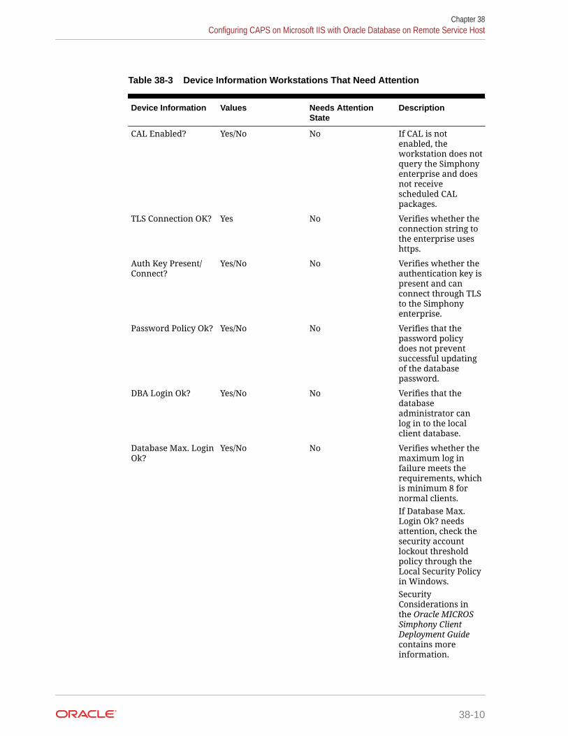
Table 38-3 Device Information Workstations That Need Attention
Device Information Values Needs AttentionState
Description
CAL Enabled? Yes/No No If CAL is notenabled, theworkstation does notquery the Simphonyenterprise and doesnot receivescheduled CALpackages.
TLS Connection OK? Yes No Verifies whether theconnection string tothe enterprise useshttps.
Auth Key Present/Connect?
Yes/No No Verifies whether theauthentication key ispresent and canconnect through TLSto the Simphonyenterprise.
Password Policy Ok? Yes/No No Verifies that thepassword policydoes not preventsuccessful updatingof the databasepassword.
DBA Login Ok? Yes/No No Verifies that thedatabaseadministrator canlog in to the localclient database.
Database Max. LoginOk?
Yes/No No Verifies whether themaximum log infailure meets therequirements, whichis minimum 8 fornormal clients.If Database Max.Login Ok? needsattention, check thesecurity accountlockout thresholdpolicy through theLocal Security Policyin Windows.SecurityConsiderations inthe Oracle MICROSSimphony ClientDeployment Guidecontains moreinformation.
Chapter 38Configuring CAPS on Microsoft IIS with Oracle Database on Remote Service Host
38-10

Table 38-3 (Cont.) Device Information Workstations That Need Attention
Device Information Values Needs AttentionState
Description
DB Pendingcredentials changes
Yes/No Yes Verifies whetherdatabase credentialchanges are pending,which require arestart.
Sufficient DiskSpace?
Yes/No No Verifies whether thedisk space fallsbelow the minimumof 1.5 GB free space.
OS pending reboot Yes/No Yes Test whether arestart is pendingbecause of aWindows update(Win32 devicesonly).
Directory Security Ok/No/NA No Test whether one ofthe followingdirectories are notaccessible:• %AppRoot%: Ok• %ALLUSERSPRO
FILE%: OkSecurityConsiderations inthe Oracle MICROSSimphony ClientDeployment Guidecontains moreinformation.
Configuring CAPS with an Oracle Database1. Run the ODP.NET_12CR2.bat under the current directory with administrator privileges
from a command prompt.
2. Navigate to the directory containing the CAPSConfigurator folder.
Depending on your configuration method, the path is one of the following:
• [Drive Letter]:\MICROS\Simphony2\Tools\CAPSConfigurator• [Drive
Letter]:\MICROS\Simphony\CAPSonIIS\Tools\CAPSConfigurator3. Double-click CAPSConfigurator, enter the server and port number of the EGateway, and
sign in using your EMC credentials. A list of Service Hosts appears.
4. Click the Service Host to configure.
5. Click CAPS Schema.
6. Enter the appropriate information in the CAPS Schema dialog, and then click Next.
• Database: Select the Oracle database type.
Chapter 38Configuring CAPS on Microsoft IIS with Oracle Database on Remote Service Host
38-11

• Server: Enter the server name.
• Port: Enter the port number.
• Service name: Enter the service name.
• Admin User: Enter the administrative user name used to sign onto the Oracledatabase server, for example, the system user name. This user name cannotbe a DBA user.
• Password: Enter the current user’s password to sign onto the Oracledatabase server.
7. In the next CAPS Schema dialog, enter the User Name, Password, and ConfirmPassword to create a new database user for the CAPS database, and then clickNext.
8. Click OK to confirm. A message indicates success.
The CAPS Schema dbsettings.xml is configured at one of the following directories(depending on your configuration):
• [Drive Letter]:\MICROS\Simphony2\IISCAPSServiceHost• [Drive Letter]:\MICROS\Simphony\IISCAPSServiceHostConfiguring CAPS Access contains important information about enabling theprivileges to access the CAPS Configuration Tool.
Configuring CAPS on Microsoft IISIn the CAPS Configurator Tool, click Configure CAPS.
The CAPS Configurator Tool detects and configures the new Service Host. Uponsuccessful configuration, the configured check box in the UI is automatically selectedfor the configured Service Host. A browser opens with the configured CAPS URL.
CAPS is configured at [DriveLetter]:\MICROS\Simphony2\EgatewayService\IISCAPSServiceHost.
Configuring CAPS Access contains important information about enabling the privilegesto access the CAPS Configuration Tool.
Upgrading Microsoft IIS CAPS
Upgrading Microsoft IIS CAPS on Enterprise Server1. Upgrade Simphony on the Enterprise server.
2. Browse to [DriveLetter]:\Micros\Simphony\Tools\CAPSConfigurator.
3. Double-click CAPSConfigurator, enter the server and port number of theEGateway, and sign in using your EMC credentials. A list of Service Hostsappears.
4. Select the Service Host configured on this server that needs to be upgraded.
5. Click Upgrade CAPS.
Chapter 38Upgrading Microsoft IIS CAPS
38-12

The CAPS Configurator Tool detects and configures the Service Host. Upon successfulconfiguration, the configured check box in the UI is automatically selected for theconfigured Service Host. A browser opens with the configured CAPS URL.
Configuring CAPS Access contains important information about enabling the privileges toaccess the CAPS Configuration Tool.
Upgrading Microsoft IIS CAPS on Remote Service Host1. Upgrade Simphony on the Enterprise server.
2. In the EMC, deploy the CAPSOnIIS CAL package to the configured Service Host.
3. Browse to [Driveletter]:\Micros\Simphony2\CAPSOnIIS\Tools\CAPSConfigurator on theremote server.
4. Double-click CAPSConfigurator, enter the server and port number of the EGateway, andsign in using your EMC credentials. A list of Service Hosts appears.
5. Select the Service Host configured on this server that needs to be upgraded.
6. Click Upgrade CAPS.
The CAPS Configurator Tool detects and configures the Service Host. Upon successfulconfiguration, the configured check box in the UI is automatically selected for theconfigured Service Host. A browser opens with the configured CAPS URL.
Configuring CAPS Access contains important information about enabling the privileges toaccess the CAPS Configuration Tool.
Configuring CAPS as a Windows Service with an OracleDatabase
CAPS must run on the same server where the Oracle database is installed. You can set upCAPS as a Windows service only on remote servers—not on the Enterprise server—for bothSimphony Premium Cloud Service and Simphony Standard Cloud Service users.
Configuring CAPS Access1. Select the Enterprise level, click Configuration, and then click Roles.
2. Select the role type, click the Operations tab, and then click the Miscellaneous subtab.
3. Select the following Miscellaneous options:
• 10061 - Allow Access to the IIS CAPS Configurator Tool
• 10065 - Download Software, Install and Authenticate Clients and Service HostsUsing CAL
4. Click Save.
Chapter 38Configuring CAPS as a Windows Service with an Oracle Database
38-13

Note:
Before you perform an upgrade to Simphony 18.1 from Simphonyversions 2.9.x or 2.10, you need to ensure that the options describedabove are enabled before running the post-upgrade CAPS ConfigurationTool. Specifically, if option 10065 is disabled prior to the upgrade, afterthe upgrade, an error message appears during your login to the CAPSConfiguration Tool . If you click OK on the error message window, youcan log onto the CAPS Configuration Tool, but you cannot utilize theAuthenticate CAPS button (added to the CAPS Configuration Tool forthe Simphony 18.1 release).
Configuring the Service Host for CAPS in EMC1. To configure the Service Host for a hosted Enterprise with Simphony Standard
Cloud Service users:
a. Select the property level, click Setup, and then click Workstations.
b. Insert a new workstation record, and then double-click it to open in form view.
c. On the General tab, enter the host name of the remote server where CAPSwill be configured in the Address/Host Name field.
d. Enter the Subnet Mask and the Default Gateway of the remote server whereCAPS will be configured.
e. If you are configuring CAPS as a Windows Service, select Is WindowsService. Otherwise, skip this step.
f. Click Save.
g. Click the Remove OPS From Service Host link, and then click Yes toconfirm.
2. To configure the Service Host for a hosted Enterprise with Simphony PremiumCloud Service users:
a. Select the Enterprise level, click Setup, and then click Service Hosts.
b. Insert a new Service Host record, and then double-click it to open in form view.
c. In the Host Name field, enter the host name of the remote server where CAPSwill be configured.
d. Enter the Subnet Mask and the Default Gateway of the remote server.
e. If you are configuring CAPS as a Windows Service, select Is WindowsService. Otherwise, skip this step.
f. Click Save.
3. Select the property, click Setup, and then click Property Parameters.
4. Click the Workstations tab.
5. From the Service Hosts section, select the CAPS Service Host created in Step 1or 2, and then enter the Port number for CAPS configuration.
This Port is the unused port number and is different from the Egateway serviceport.
Chapter 38Configuring CAPS as a Windows Service with an Oracle Database
38-14

6. Click Save.
Preparing the Server to Configure CAPS1. Ensure that the Server has the latest Microsoft Windows updates.
2. Turn on the Microsoft Windows features:
• Microsoft .NET Framework 3.5
• Microsoft IIS
3. Install Microsoft .NET Framework 4.6.1.
4. Install the Oracle 12c 32-bit client.
5. Install the Oracle Database 12c Server.
a. Deselect the pluggable database option.
b. Select the database admin user system account or equivalent.
6. From the EMC, configure the CAPSOnIIS CAL package for deployment to the RemoteService Host.
7. Set up the Service Host prerequisites for deployment to the Remote Service Host.
8. Set up the Service Host for deployment to the Remote Service Host.
9. Install the CAL client on the Remote Service Host.
10. From the EMC, deploy the CAPSOnIIS CAL Package to the configured Service Host.
11. If you are using Oracle Database 12c Release 2 for the CAPS database, complete thefollowing steps:
a. Navigate to [Drive Letter]:\Micros\Simphony\CAPSOnIIS\Tools\ODP.NET_12CR2,and then follow the instructions in the Readme.
b. Run the ODP.NET_12CR2.bat under the current directory with administratorprivileges from a command prompt.
During batch file execution, the status appears in the Command Prompt window.
c. After successful execution of the batch file, close the Command Prompt window.
12. Deploy the Service Host prerequisites CAL Package.
13. Deploy the Service Host CAL Package.
14. Stop the CAPS Service.
Scheduling and Viewing Device InformationTo communicate workstation information, a core CAL package called Device Information runsat each workstation and on CAPS running on a POS client workstation without the POSclient. The Device Information CAL package is not needed for Simphony release 19.1.2 as itis deployed automatically with the Service Host. However, the Device Information CALpackage must be deployed for clients that still run on an earlier Simphony release (prior to19.1.2), so the device information and metrics can be sent to the enterprise for the olderclients. The resulting device information status is propagated to the Service Host and to theproperty.
The Device Information module lets you schedule and view workstation metrics in the EMC atthe Enterprise level. The device information allows administrators to detect possible issues
Chapter 38Configuring CAPS as a Windows Service with an Oracle Database
38-15
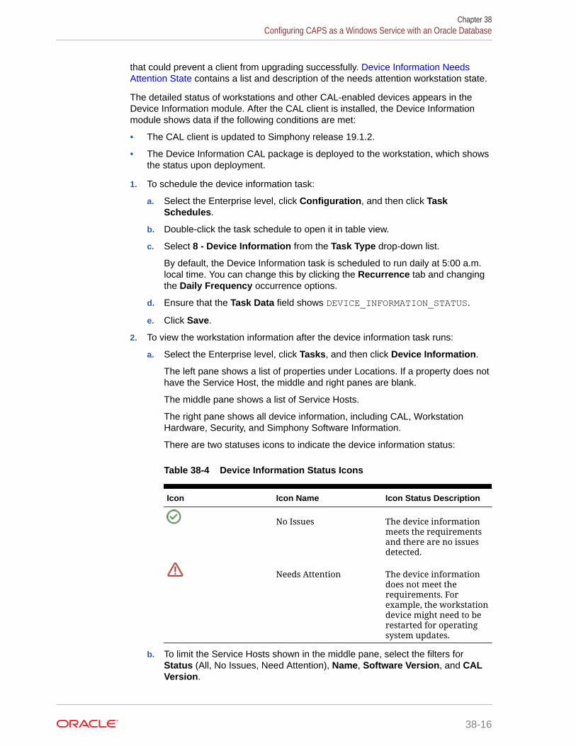
that could prevent a client from upgrading successfully. Device Information NeedsAttention State contains a list and description of the needs attention workstation state.
The detailed status of workstations and other CAL-enabled devices appears in theDevice Information module. After the CAL client is installed, the Device Informationmodule shows data if the following conditions are met:
• The CAL client is updated to Simphony release 19.1.2.
• The Device Information CAL package is deployed to the workstation, which showsthe status upon deployment.
1. To schedule the device information task:
a. Select the Enterprise level, click Configuration, and then click TaskSchedules.
b. Double-click the task schedule to open it in table view.
c. Select 8 - Device Information from the Task Type drop-down list.
By default, the Device Information task is scheduled to run daily at 5:00 a.m.local time. You can change this by clicking the Recurrence tab and changingthe Daily Frequency occurrence options.
d. Ensure that the Task Data field shows DEVICE_INFORMATION_STATUS.
e. Click Save.
2. To view the workstation information after the device information task runs:
a. Select the Enterprise level, click Tasks, and then click Device Information.
The left pane shows a list of properties under Locations. If a property does nothave the Service Host, the middle and right panes are blank.
The middle pane shows a list of Service Hosts.
The right pane shows all device information, including CAL, WorkstationHardware, Security, and Simphony Software Information.
There are two statuses icons to indicate the device information status:
Table 38-4 Device Information Status Icons
Icon Icon Name Icon Status Description
No Issues The device informationmeets the requirementsand there are no issuesdetected.
Needs Attention The device informationdoes not meet therequirements. Forexample, the workstationdevice might need to berestarted for operatingsystem updates.
b. To limit the Service Hosts shown in the middle pane, select the filters forStatus (All, No Issues, Need Attention), Name, Software Version, and CALVersion.
Chapter 38Configuring CAPS as a Windows Service with an Oracle Database
38-16

c. Click a Service Host to change the view in the right pane.
d. To expand and collapse the views in the right pane, click the individual green triangleicons, or click the Expand/Collapse All link in the upper right corner.
Device Information Needs Attention StateThe Device Information module checks the following settings for each workstation. The statusis available at the Enterprise level, and listed by property. The following table describes whatcauses the Needs Attention state.
Table 38-5 Device Information Workstations That Need Attention
Device Information Values Needs Attention State Description
CAL Enabled? Yes/No No If CAL is not enabled,the workstation doesnot query theSimphony enterpriseand does not receivescheduled CALpackages.
TLS Connection OK? Yes No Verifies whether theconnection string tothe enterprise useshttps.
Auth Key Present/Connect?
Yes/No No Verifies whether theauthentication key ispresent and canconnect through TLSto the Simphonyenterprise.
Password Policy Ok? Yes/No No Verifies that thepassword policy doesnot prevent successfulupdating of thedatabase password.
DBA Login Ok? Yes/No No Verifies that thedatabaseadministrator can login to the local clientdatabase.
Chapter 38Configuring CAPS as a Windows Service with an Oracle Database
38-17

Table 38-5 (Cont.) Device Information Workstations That Need Attention
Device Information Values Needs Attention State Description
Database Max. LoginOk?
Yes/No No Verifies whether themaximum log infailure meets therequirements, whichis minimum 8 fornormal clients.If Database Max. LoginOk? needs attention,check the securityaccount lockoutthreshold policythrough the LocalSecurity Policy inWindows.SecurityConsiderations in theOracle MICROSSimphony ClientDeployment Guidecontains moreinformation.
DB Pendingcredentials changes
Yes/No Yes Verifies whetherdatabase credentialchanges are pending,which require arestart.
Sufficient Disk Space? Yes/No No Verifies whether thedisk space falls belowthe minimum of 1.5GB free space.
OS pending reboot Yes/No Yes Test whether a restartis pending because ofa Windows update(Win32 devices only).
Directory Security Ok/No/NA No Test whether one ofthe followingdirectories are notaccessible:• %AppRoot%: Ok• %ALLUSERSPROFI
LE%: OkSecurityConsiderations in theOracle MICROSSimphony ClientDeployment Guidecontains moreinformation.
Chapter 38Configuring CAPS as a Windows Service with an Oracle Database
38-18

Configuring CAPS with an Oracle Database1. Run the ODP.NET_12CR2.bat under the current directory with administrator privileges
from a command prompt.
2. Navigate to the directory containing the CAPSConfigurator folder.
Depending on your configuration method, the path is one of the following:
• [Drive Letter]:\MICROS\Simphony2\Tools\CAPSConfigurator• [Drive
Letter]:\MICROS\Simphony\CAPSonIIS\Tools\CAPSConfigurator3. Double-click CAPSConfigurator, enter the server and port number of the EGateway, and
sign in using your EMC credentials. A list of Service Hosts appears.
4. Click the Service Host to configure.
5. Click CAPS Schema.
6. Enter the appropriate information in the CAPS Schema dialog, and then click Next.
• Database: Select the Oracle database type.
• Server: Enter the server name.
• Port: Enter the port number.
• Service name: Enter the service name.
• Admin User: Enter the administrative user name used to sign onto the Oracledatabase server, for example, the system user name. This user name cannot be aDBA user.
• Password: Enter the current user’s password to sign onto the Oracle databaseserver.
7. In the next CAPS Schema dialog, enter the User Name, Password, and ConfirmPassword to create a new database user for the CAPS database, and then click Next.
8. Click OK to confirm. A message indicates success.
The CAPS Schema dbsettings.xml is configured at one of the following directories(depending on your configuration):
• [Drive Letter]:\MICROS\Simphony2\IISCAPSServiceHost• [Drive Letter]:\MICROS\Simphony\IISCAPSServiceHostConfiguring CAPS Access contains important information about enabling the privileges toaccess the CAPS Configuration Tool.
Copying the Database SettingsCopy and replace the dbsettings.xml file from the CAPS_DIRECTORY_PATH (for example,copy from [Drive Letter]:\MICROS\Simphony\IISCAPSServiceHost to the [DriveLetter]:\Micros\Simphony2\WebServer\wwwroot\EGateway folder).
Chapter 38Configuring CAPS as a Windows Service with an Oracle Database
38-19

Starting the CAPS ServiceAfter the CAL process is complete, CAPS starts automatically. It may take severalseconds to create all tables and to synchronize data the first time.
Optional CAPS Configuration Tasks
CAPS Optimization for High LoadsTo handle high transaction CAPS environments, system administrators can enablethreaded posting. To enable threaded posting, modify the web.config.txt file located onthe CAPS machine.
For Simphony 19.x users, the following key needs to be manually entered in theappSettings section:
<add key="MaxMrequestPlaybackThreads" value="x" />In the syntax provided in the example above, x represents the number of threads.
The number of threads used depends on the volume of Mrequest messages. Also, thenumber of connections is derived from the number of threads. Under enough load, thevalue sets the upper limit of threads. There is a point when adding connectionsdecreases performance. As such, if you have a posting backlog on CAPS, it issuggested to use 1 thread for every 25 workstations.
CAL Installation Prerequisites for a Workstation without the POSInterface (CAPS Only Workstation)
Before installing CAL on a CAPS-only workstation, perform the following functions:
• Configure a service host for CAPS. See Configuring the Service Host for CAPS inEMC for instructions.
• Assign the employee privilege to download software, install and authenticateclients and Service Hosts using CAL.
Beginning with Simphony version 2.9.1 (which includes CAL version 139), usersmust have the employee privilege assigned to the appropriate role to successfullyauthenticate workstations, Android devices, and Kitchen Display Systems (KDS).After installing or upgrading to Simphony version 2.9.1 or later, you must assignthe privilege to a user’s role. When the Role option is set, employees can use theirEMC logon credentials when CAL’ing devices. See Allowing Employees to Installand Authenticate POS Clients and Service Hosts for instructions to assign theprivilege.
• Set the CAL deployment schedule. See Configuring the Deployment Schedule toInstall CAL on a POS Client Workstation without Ops for instructions.
Configuring the Deployment Schedule to Install CAL on a Workstation withoutthe POS Interface
1. Select the Enterprise, click Setup, and then click CAL Packages.
Chapter 38Optional CAPS Configuration Tasks
38-20

2. For Simphony version 2.9 and Simphony version 2.9.1:
a. If the CAPS workstation is running Microsoft Windows Embedded POSReady 2009,select Service Host Prereqs from the left pane.
b. If the CAPS workstation is running Microsoft Windows 7 or later, select Service HostPrereqs (SQL 2012) from the left pane.
3. For Simphony version 2.9.2, select Service Host Prereqs from the left pane for all POSclients.
4. Click the Deployment Schedule tab, and then click Add Deployment.
5. From the Deployment Type column, select 2 - Specific Service Host.
6. In the Service Host column, click the ellipsis (...) point button, select the CAPSworkstation, and then click OK.
7. In the Action To Take column, select 0 - Install, and then click Save.
8. Select Service Host from the left pane, and then repeat Steps 4 through 7.
Installing CAL on a Workstation without the POS Interface1. On the workstation, press Start, select All Programs, select Micros Client Application
Loader, and then select McrsCAL Config.
2. Decipher and enter the correct access code, and then press the Configure CAL button.
3. Enter the correct code based on the six-digit number shown at the top, and then pressNext.
4. In the Enter CAL Server dialog, select MICROS Simphony as the POS Type.
MICROS Simphony is used for both Simphony Standard and Premium Cloud Serviceenvironments.
5. Set the following values, and then press Next:
• Server Name: Leave this field blank.
• Server IP/URL: Leave this field blank.
• CAL Enabled: Select this option if it is not automatically set by default.
• Secure Connection: Select this option to use the Translation Layer Security (TLS)1.2 Encryption protocol. (If you are installing CAL version 139 or later, this option isset by default.)
• Server: Enter the CAPS server name.
• Port: Enter 443.
• Update: Click the Update button to automatically fill the Server Name and ServerIP/URL fields after the application server name is resolved and recognized. You arenow required to use an HTTPS secure connection in your Server URL.
6. If you are using Simphony version 2.9 (CAL version 138), skip to Step 8.
7. Beginning with Simphony version 2.9.1 and later, if you are installed on a SimphonyStandard or Premium Cloud Service environment, CAL prompts you to enter yourSimphony EMC logon credentials. Enter your User name and Password in the CALAuthentication dialog, and then press the Login button.
8. If the Enterprise has multiple properties, select the property from the Property Search andSelect dialog, and then press Next.
Chapter 38Optional CAPS Configuration Tasks
38-21

If the property does not appear in the list, enter the property name in the PropertyName field, and then press Search.
You do not see a property list if only one property is configured or if there aremultiple properties, but only one property is using workstations.
9. In the Select WS Identity dialog, select the Show Service Hosts option, select theappropriate service host from the available workstation list, and then press Save.Make sure the Service Host ID and Workstation ID populate. The workstationautomatically restarts several times when installing the CAL package.
Figure 38-2 Select Workstation Dialog
10. If you are using Simphony version 2.9 or Simphony version 2.9.2, after the CALprocess completes:
a. Browse to [Drive letter]:\MICROS\Simphony\webserver, and thenclick AuthenticationServer.
b. For Simphony version 2.9, enter the following details in the AuthenticationServer application:
• Client Service ID: Enter the Service ID for Check and Posting. You canfind the Service ID in the Workstations tab of the Property Parametersmodule.
Chapter 38Optional CAPS Configuration Tasks
38-22

• Installer Username: Enter the Install User Security Username configured inthe Security tab of the Property Parameters module. Contact your systemadministrator for assistance.
• Installer Password: Enter the Install User Security Password configured inthe Security tab of the Property Parameters module. Contact your systemadministrator for assistance.
Figure 38-3 Authentication Server Application for Simphony 2.9
c. For Simphony version 2.9.2 and later, enter the following details in the AuthenticationServer application:
• Service Host ID: The service host ID. This value is automatically populated.
• EMC Username: Enter your EMC user name.
• EMC Password: Enter your EMC password.
Chapter 38Optional CAPS Configuration Tasks
38-23

Figure 38-4 Authentication Server Application for Simphony 2.9.2
d. Click Authenticate.
e. Restart the workstation.
Configuring the Show Database Provider ButtonThe following steps are optional:
1. Select the Enterprise, property, revenue center, or zone, click Configuration, andthen click Page Design.
2. Double-click the page on which you want the Show Database Provider button toappear (typically the Sign In page).
3. Insert a new button.
4. On the General tab, select Function from the Type drop-down list, and then clickthe right arrow beneath the Type field.
5. On the left pane, in the Name field, enter Show Database Provider.
6. On the right pane, select Show Database Provider as the result, and then clickOK.
7. Click Generate Legend to set Show Database Provider as the button name.
8. Click Save.
Encrypting Database CredentialsThe following steps are optional:
1. Browse to [Drive Letter]:\MICROS\Simphony2\Tools\Crypt folder.
2. Run Crypt.exe.
Chapter 38Optional CAPS Configuration Tasks
38-24

3. Enter or copy the complete [CAPS HOSTED DIRECTORY]\DbSettings.xml path (forexample, [Drive Letter]:\MICROS\Simphony\IISCAPSServiceHost).
4. Click Read DB Settings.
5. Select CPServiceDB from the drop-down list.
6. Enter the password, and then click Encrypt Password.
Verifying CAPS InstallationThe following steps are optional:
1. Log in as the CAPS user on the Oracle database to verify the tables.
2. Verify the log files on the CAPS EGateway log and the workstation EGateway log folders.
3. Configure a new POS client workstation that points to CAPS from the PropertyParameters module (Workstations tab).
See Adding a Workstation for more information.
4. Click the Show Database Provider button, and then verify that CAPS DB: as Oracleappears.
5. Verify that the CAPS status is online.
6. Add a few test transactions from the workstation.
7. Verify that the transaction details post to the CHECKS table on the workstation datastoredatabase, the CAPS database, and the Simphony transaction database.
Configuring IIS Application Pool Settings
Configuring Recycle Settings for the IIS Application PoolFor instructions on configuring an application pool to recycle at a scheduled time, refer to theMicrosoft TechNet Library at https://technet.microsoft.com/en-us/. Ensure that the times youset do not coincide with the Start of Day (SOD) or periods of peak sales activity. If youconfigure the application pool to recycle at a scheduled time using the IIS Manager, considerthe following recycle settings for the IIS Application Pools.
• Set the Memory Based Maximums to less than half of the available server memory.
• Set the .NET Integration mode to Classic for the CAPS Application Pool.
• Set the Disable Overlapped Recycle setting to True for the CAPS Application Pool.
• Leave the Application Pool’s Pipeline mode settings on the default settings.
Restarting Microsoft IIS CAPSThe following steps are optional:
1. From Microsoft IIS Manager, recycle the CAPS application pool.
2. Click the configured IIS CAPS application under the website, and switch to Content View.
3. Right-click EGateway.asmx and select Browse. The new CAPS Egateway.asmx URLopens in the default internet browser.
Chapter 38Optional CAPS Configuration Tasks
38-25

39Printers
Printers and order devices are critical types of hardware that allow communication betweenthe Front of House and other areas of a restaurant, such as the kitchen and bar.
Print ControllerA Print Controller is a service that sends print jobs to a printer. Each POS client process hasa built-in Print Controller. A workstation typically acts as a Print Controller. When aworkstation operator performs an action that causes a guest check, order receipt, or otherprinting type to print, the POS client process does not communicate directly with the printerreceiving the print job. Instead, the POS client process sends a message to the PrintController (usually a workstation) that controls the printer. This Print Controller then receivesnotification that the print job succeeded or failed, and routes the success or failureinformation back to the workstation that sent the print job.
Ensure that employees in a revenue center know which workstations act as Print Controllersfor remote printers. This knowledge helps in troubleshooting printing problems.
Oracle Hospitality recommends that you have both a primary printer and a backup printer,and that primary and backup printers reside on two different Print Controllers. Thisconfiguration prevents a single point of failure from causing multiple remote printers to stopprinting.
A single Print Controller can control multiple printers. For example, one workstation cancontrol the following printers:
• Local printer that is physically attached to the workstation (used for guest checks andcustomer receipts)
• Hot food printer that is a remote Ethernet kitchen printer (used for order receipts)
In this configuration, if the workstation loses power or network connectivity, other workstationscannot print to either of these printers. This is generally not a problem because the print jobsprint to the backup printer as appropriate.
In another example, one workstation can control the following printers:
• Local printer that is physically attached to the workstation
• Hot food printer that is a remote Ethernet kitchen printer
• Cold food printer that is a remote Ethernet kitchen printer and backs up the hot foodprinter
Oracle Hospitality does not recommend this configuration. In this example, if the workstationloses power or network connectivity, other workstations cannot print to any of these printers.In this scenario, no order receipts print to the hot or cold printers in the kitchen. Kitchenoperations would likely be severely impacted.
39-1

Roll PrinterA roll printer uses a roll of paper as its source media. Thermal printers and impactprinters are two types of roll printers that you can use with Simphony.
Thermal Printer
A thermal printer does not use ink. Special thermal paper is provided for these printersto burn the text onto the paper. Thermal printers are primarily used as guest check andcustomer receipt printers. They are used infrequently in kitchens due to the heatreaction. Thermal printers are ideal in public areas as the printing operation is quiet.
Impact Printer
An impact printer is something of a retronym. All printers were impact printers prior tothe invention of the thermal printer. An impact printer is primarily used in kitchens toprint order receipts. Impact printers can print in black and red, and they can be usedwith two-ply paper.
Slip PrinterA slip printer does not contain paper. The workstation operator must add a piece (orslip) of paper per print job. Properties who use custom stationery (often containing acompany logo or other similar artwork) generally use slip printers for guest checks andcustomer receipts. Slip printers are also used for check endorsement printing. Theslips that are used by these printers are often called hard checks because they areusually made of card stock.
Slip printers are not supported when using Transaction Services.
Internet Protocol (IP) PrinterAn IP printer communicates with the Print Controller through a computer network thatuses the IP address for communication.
Bluetooth PrinterBluetooth printing refers to printing from an Oracle MICROS Tablet E-Series to awireless printer through the Bluetooth protocol.
There is a one-to-one relationship between a tablet and a Bluetooth printer. After youidentify and configure a Bluetooth printer and manually pair it with a specific OracleMICROS Tablet E-Series as the Print Controller Service Host, you cannot assignanother Oracle MICROS Tablet E-Series to the same Bluetooth printer.
Printer GroupsIf the property is large and has many printers disbursed over a wide area, you may findit useful to configure a limited list of printers that are selectable by workstationoperators. The workstation operator can select a printer that is nearby from the list atthe POS client (usually a mobile tablet device), and optionally set this printer as the
Chapter 39Roll Printer
39-2

default printer for future print jobs. When a workstation operator selects a default destinationprinter, the selection automatically resets at Start of Day.
A default printer group named All Destination Printers exists in the Printer Groups module.You cannot change this default printer group. If you do not create printer groups, all printerswith the option Destination Printer (set in the Printers module) belong to the All DestinationPrinters printer group. The All Destination Printers default printer group is useful forproperties that need only one group of destination printers.
Configuring a Printer1. Select the property, click Setup, and then click Printers.
2. Insert a printer record, name the printer, and then click OK.
3. Double-click the printer record to open it.
4. Select the Workstation from the drop-down list.
5. Select the Printer Type from the drop-down list.
Select Epson Bluetooth Printer for all Bluetooth printers.
6. If the roll printer is a thermal printer, select Thermal printer in the Printer Optionssection.
7. Enter the number of lines to advance the guest check or customer receipt after printingthe trailer text in the Trailing Line Feeds field.
The value in this field defaults to the recommended trailing line feeds for the printercommunication type, as listed in the following table. You can change the default value.
Table 39-1 Trailing Line Feeds per Printer Communication Type
Printer Communication Type Trailing Number of Lines
Bluetooth 1
Ethernet 1
Integrated Device Network (IDN) 1
Serial 6
OPOS 6
8. (Optional) To set the printer to print logos, select Enable Logo Printing. Simphony doesnot support logo printing on printers with multi-language cards.
When configuring Epson TM-P60 and TM-T88 Ethernet Thermal printers, configure thelogo to print in the center of the guest check or customer receipt by selecting the papersize of the printer from the Center Logo Using drop-down list.
• Epson TM-P60 Ethernet Thermal printers: Set the paper size to 2 1/4" (58mm)Paper.
• Epson TM-T88 Ethernet Thermal printers: Set the paper size to 3 1/8" (80mm)Paper.
Logo Printing contains more information about setting up logos to print on guest checksand customer receipts.
9. To allow the printer to be selectable by workstation operators (typically used with mobilePOS client devices), select Destination Printer.
Chapter 39Configuring a Printer
39-3

Bluetooth printers are not selectable.
10. Configure the appropriate values for the printer type. Specific fields become activebased on the printer type you selected.
The following table lists the printer types and indicates information for eachapplicable field. Enter or select information for the fields based on the printer youare configuring. Fields denoted as Not applicable are not needed for the printertype.
Table 39-2 Printer Configuration by Printer Type
Field Roll Printer Slip Printer IP Printer BluetoothPrinter
COM Port Select thecommunications port for theprinter.
Select thecommunications port for theprinter.
Not applicable Not applicable
Baud Rate Select the baudrate for theprinter.
Select the baudrate for theprinter.
Not applicable Not applicable
Parity Select theparity for theprinter.
Select theparity for theprinter.
Not applicable Not applicable
Data Bits Select the databits for theprinter.
Select the databits for theprinter.
Not applicable Not applicable
Stop Bits Select the stopbits for theprinter.
Select the stopbits for theprinter.
Not applicable Not applicable
PIN Not applicable Not applicable Not applicable Set the four-digit passkeythat must beentered intothe devicebefore printing.
ID Not applicable Not applicable Not applicable (Optional)Enter theBluetooth ID ofthe printer. Youcan leave thisfield blank toallowconfigurationfrom a mobiledevice whenusing differentprinters perevent.
Chapter 39Configuring a Printer
39-4

Table 39-2 (Cont.) Printer Configuration by Printer Type
Field Roll Printer Slip Printer IP Printer BluetoothPrinter
Number ofColumns
Not applicable Not applicable Not applicable This settingdetermines thereport width sothat guestchecks andreports printwith centeralignment. Bydefault, thewidth is set to32 columns.Select 40 forBixolon SPP-R300, SPP-R310,and R310iKBluetoothprinters.
Address Not applicable Not applicable Enter the IPaddress orhostname ofthe printer. Ifyou are usingthe printer forbanquetchecks, enterthe hostname.
Not applicable
Port Not applicable Not applicable Enter the portnumber for theIP printer.
Not applicable
11. Click Save.
12. Select the property, click Setup, and then click Workstations.
13. Double-click the workstation to open it.
14. Click the Printers tab.
15. Click the Select link to set the appropriate Printer for each type of print job. Click the Setfor All Destination Printers link to set the same printer for each type of print job.
The printer defined here (primary or backup) always appears in the Destination Printerslist on the POS client, even if you do not add it to the Destination Printer Group. Creating, Editing, and Removing Printer Groups contains more information.
Oracle Hospitality recommends that you assign the same printer model and format for thebackup printer to ensure that checks format properly on other printers.
16. Click the Select link and assign each printer type to a Destination Printer Group. Clickthe Set for All Destination Printers link to set the same printer type for all destinationprinter groups.
Selecting a Destination Printer Group overrides the printer selected for the printer type.
Printers with the option Selectable as Destination Printer set belong to a defaultDestination Printer Group called All Destination Printers.
Chapter 39Configuring a Printer
39-5
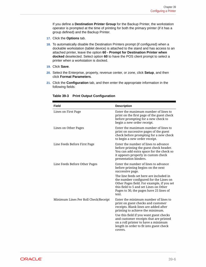
If you define a Destination Printer Group for the Backup Printer, the workstationoperator is prompted at the time of printing for both the primary printer (if it has agroup defined) and the Backup Printer.
17. Click the Options tab.
18. To automatically disable the Destination Printers prompt (if configured) when adockable workstation (tablet device) is attached to the stand and has access to anattached printer, leave the option 60 - Prompt for Destination Printer whendocked deselected. Select option 60 to have the POS client prompt to select aprinter when a workstation is docked.
19. Click Save.
20. Select the Enterprise, property, revenue center, or zone, click Setup, and thenclick Format Parameters.
21. Click the Configuration tab, and then enter the appropriate information in thefollowing fields:
Table 39-3 Print Output Configuration
Field Description
Lines on First Page Enter the maximum number of lines toprint on the first page of the guest checkbefore prompting for a new check tobegin a new order receipt.
Lines on Other Pages Enter the maximum number of lines toprint on successive pages of the guestcheck before prompting for a new checkto begin a new order receipt.
Line Feeds Before First Page Enter the number of lines to advancebefore printing the guest check header.You can add extra space for the check soit appears properly in custom checkpresentation binders.
Line Feeds Before Other Pages Enter the number of lines to advancebefore printing begins on the nextsuccessive page.The line feeds set here are included inthe number configured for the Lines onOther Pages field. For example, if you setthis field to 5 and set Lines on OtherPages to 30, the pages have 25 lines oftext.
Minimum Lines Per Roll Check/Receipt Enter the minimum number of lines toprint on guest checks and customerreceipts. Blank lines are added afterprinting to achieve the minimum.Use this field if you want guest checksand customer receipts that are printedon a roll printer to have a minimumlength in order to fit into guest checkcovers.
Chapter 39Configuring a Printer
39-6

Table 39-3 (Cont.) Print Output Configuration
Field Description
Number of Guest Check InformationLines
Enter the number of detail lines (0through 30) that can be entered in aSystem Interface Module (SIM) dialogbox.
Print Tax Invoice after Sales Threshold Enter the sales threshold needed to passfor a tax invoice to be printed for acustomer.
Print Customer Information after SalesThreshold
Enter the sales threshold needed to passfor customer information to be printedfor a customer.
Customer/Trade Identity Label Enter the label information to bepresented on the top of a bill after amaximum sales threshold is met. Thislabel is either a customer’s name(written in the field as Customer Name)or a Trade Identity Label.In the case of Australia Goods & ServicesTax requirements, the trade identitylabel for Australia is ABN. Thisinformation must be present on a billafter the maximum threshold is met. Theinformation is never stored, and thelabel can be changed.
22. Click the Options tab.
23. Select the appropriate printing options:
• 57 - Do Not Print Change/Payment Due in Double Wide: Select this option if youdo not want double-wide formatting on the Change Due line of a receipt or the TotalDue line of a check.
• 58 - Do Not Consolidate Current Round Items in Printed Guest Check: Selectthis option if you do not want to combine identical items which are ordered inmultiples in the current round when printing a receipt.
• 61 - Show Asterisk (*) indicator for Menu Item where Inclusive Tax was forgivenon screen: Select this option if you want to display an asterisk on the receipt toindicate that the inclusive tax was forgiven for a menu item.
24. Click Save.
Creating, Editing, and Removing Printer Groups1. Select the property, click Setup, and then click Printer Groups.
2. Insert a printer group record, name the printer group, and then click OK.
3. Double-click the printer group record to open it.
4. To add a printer to the printer group, click the Add link, click the ellipsis button, and thenselect the printer.
You can add any printer to any printer group, regardless of the Destination Printeroption setting. You can add one printer to multiple printer groups.
Chapter 39Creating, Editing, and Removing Printer Groups
39-7

5. Repeat Steps 1 through 4 for to create more printer groups and to add printers tothe groups.
6. To delete a printer from a printer group, select the printer, and then click the Deletelink.
7. Click Save.
8. To edit a printer group, highlight the record, change the values, and then clickSave.
9. To remove a printer group, highlight the record, and then click Delete on thetoolbar.
Configuring the Change Default Printer Destination ButtonYou need to create a button which allows workstation operators to set and reset thedefault printer selection.
1. Select the Enterprise, property, revenue center, or zone, click Configuration, andthen click Page Design.
2. Open the Front of House page on which to place the Change Default PrinterDestination button,
3. On the Edit tab, select the page area in which to define the button.
4. Click Button.
5. On the General subtab, enter the button name in the Legend field.
6. From the Type drop-down list, select Function.
7. Click the black arrow beneath the Type drop-down list, select Change DefaultPrinter Destination, and then click OK.
8. Position and size the button on the page. Use the Style arrow to change the color.
9. Click Save.
Configuring a Printer Order DeviceYou can configure order chits to send to a printer at the kitchen when checks areservice totalled on a workstation.
1. Select the revenue center, click Setup, and then click Order Devices.
2. Insert an order device record for the printer (for example, Kitchen Hot Printer), andthen double-click the record to open it.
3. On the General tab, select 1 - Remote from the Device Type drop-down list,select 0 - Printer from the Primary Device Type drop-down list, and then selectthe appropriate printer record from the Device drop-down list.
4. If you have a backup printer, select the Backup Device from the drop-down list.
5. From the Order Device Redirect drop-down list, select the printer order devicethat you created in Step 2.
6. From the Menu Item Printing drop-down list, select the items to route to this KDS:
• 0 - All Items: Select to route all menu items.
Chapter 39Configuring the Change Default Printer Destination Button
39-8

• 1 - Only Items with Condiments: Select to route only menu items with condiments.
• 2 - Only Items without Condiments: Select to route only menu items withoutcondiments.
7. From the Condiment Sort Type drop-down list, select how to sort the condiments on theorder chits. Condiment sorting only works if you have set Menu Item Classes option 30 -Sort Condiments by Print Group for the parent menu items.
• No condiment sorting: Select to list condiments in the order in which they areentered on the check by the workstation operator. Allowed condiments sort in theorder assigned in Condiment Sets, if configured.
• Sort allowed condiments: Select to sort only allowed condiments based on the printgroup. The sort order configured for allowed condiments in Condiment Sets isdiscarded. If required condiments are ordered in between allowed condiments, therequired condiments remain in the same position in which order they were ordered.
• Sort all condiments: Select to sort all condiments based on the print group,regardless of condiment type.
8. Configure the following Print Settings:
Table 39-4 Order Devices Printer Settings
Field Description
Max # Lines per Chit Enter the maximum number of lines (0 to99) to print on each page of an order chit.Oracle MICROS roll printers print 6 lines perinch.
Sort/Consolidation Method Select the parent menu item sort andconsolidation method for this order device.
Language Select the primary language for the orderdevice. This field only shows the languagesthat are assigned to the property in theProperty Parameters module.
Language 2 To print the output in a second language,select the secondary language.
Language 3 To print the output in a third language,select the third language.
Line Feeds Before Order Enter the number of lines to advance beforeprinting the order on order chits.
Line Feeds After Order Enter the number of lines to advance afterprinting the order on order chits.
9. Click the Options tab, and then select the appropriate printer options as described in thefollowing table:
Table 39-5 Order Devices Printer Options
Option Description
1 - On = Print Trans Emp Name and #; Off =Print Chk Emp Name and #
Select this option to print the employeename and number of the transactionoperator on the order chit. Deselect to printthe employee name and number of thecheck operator.
Chapter 39Configuring a Printer Order Device
39-9

Table 39-5 (Cont.) Order Devices Printer Options
Option Description
3 - Print Dopplebon Select this option to print a separate orderchit for each menu item in the currentservice round (dopplebon style). Deselect toprint one order chit for all menu items in thecurrent service round (the default printingstyle).
4 - Print Dopplebon Summary Select this option to print an order summarychit before printing an order's dopplebonorder chits. Deselect to suppress dopplebonsummary chit printing
6 - Print Seat Numbers with Individual Items Select this option to print seat numbers witheach individual menu item.If the order device is set to consolidate (Sort/Consolidate Method on the General tab), theseats print as a Seat Header above the detailitem.
7 - Print Revenue Center Name on Orders Select this option to print the revenue centername with each order sent to this orderdevice. The name prints in double-widecharacters. Deselect to suppress printing therevenue center name.
9 - On = Print void marker before Void; Off =Print Void in Red
Select this option to print a VV VOID VVline, in red or inverse, in front of voidedmenu items. Deselect to print voided itemsin red, without the VV Void VV line.
10 - Print Condiments in Red (OverridesPrint Class Settings)
Select this option to print condiments in redink or in inverse. Deselect to printcondiments in red/inverse or in black,depending on the Print Class Red/Blackoption setting.
11 - Print Both Menu Item Names Select this option to print both namesentered for a Menu Item Definition on theorder chit. Deselect to print only one name.When this option is deselected, the namethat prints is determined by the Menu ItemDefinition's Menu Item Class option PrintName 2 on Order Output Instead of Name1.
13 - Print Guest Check Info Lines BeforeHeader on Order Device
Select this option to print guest checkinformation lines before the order deviceheader.
14 - Print Guest Check Info Lines AfterHeader on Order Device
Select this option to print guest checkinformation lines after the order deviceheader.
15 - Print Guest Check Info Lines AfterTrailer on Order Device
Select this option to print guest checkinformation lines after the order devicetrailer.
16 - Print Secondary Items See Secondary Printing for more information.
21 - Exclude Voids Select this option if you do not want voids ofprevious round items to be sent to thekitchen.
Chapter 39Configuring a Printer Order Device
39-10

Table 39-5 (Cont.) Order Devices Printer Options
Option Description
22 - Intersperse Different Languages If you are printing in more than onelanguage, select this option to print themenu item in each language before printingany condiments. For example, the outputwill be menu item name in language 1,menu item name in language 2, 1stcondiment in language 1, 1st condiment inlanguage 2.
23 - Identify Combo Meals Select this option to print a flag to denotemenu items that are part of a combo meal. Ifprinting Asian characters, the information isprinted on the preceding line due to spacelimitations.
24 - Print Dining Course Header Select this option to print a dining courseheader and to group the menu items bydining course.
25 - Format Prefix On Separate Line Select this option to print the prefix on aseparate line above the condiment. Deselectto print the prefix on the same line as thecondiment that it modifies.
26 - Print Single Wide Select this option to print orders in single-width characters.This supports longer menu item names, buthas the drawback of not being as readablefrom a distance.
10. Click Save.
11. Select the property, click Setup, and then click Workstations.
12. Double-click the workstation record for which to assign the printer order device, and thenclick the Order Devices tab.
13. Select the printer order device from the Order Device Output list, and then click Save.
Secondary PrintingSecondary printing enables you to print menu items to additional printers as secondary items.A secondary item is one that is part of the same order, but prepared at another Prep Station.This allows the prep cook to know what other items accompany the dish. For example, ahouse salad is a primary item on the Cold Line, but a secondary item on the Hot Line. Whensecondary printing is enabled, the cook reading the chit from the Hot Printer sees the itemsnecessary for preparation at the Hot Line and also any items being prepared by other cooksthat were added to the check at the same time. This feature allows the kitchen to synchronizeorders for delivery. For example, pizza dip and chicken wings are programmed to print to theHot Printer, and house salad and mesclun mix are programmed to print to the Cold Printer. Ifthe cook who prepares the salads does not know that the chicken wings and pizza dip gowith the salad order, the cook might prepare the salads immediately. This can cause thesalads to get warm or wilt and possibly having to be remade.
Secondary items print in a smaller font at the bottom of the order chit.
Chapter 39Secondary Printing
39-11

Figure 39-1 Example Order Chit with Secondary Items
Configuring Secondary Printing1. Select the revenue center, click Setup, and then click Order Devices.
2. Double-click a printer order device record, and then click the Options tab.
3. Select the appropriate options that apply to secondary printing, and then clickSave:
• 16 - Print Secondary Items: Select this option to allow this order device toprint items sent from other printers as secondary items.
• 17 - Broadcast Secondary Print Jobs to All Printers: Select this option tosend all items programmed to print at this order device to other printers to printas secondary items. Items print only at other printers that have 16 - PrintSecondary Items enabled.
• 18 - Print Secondary Printer Header: Select this option to print the name ofthe printer from which the secondary items are being broadcasted.
• 19 - Print Secondary Items in Red: Select this option to print secondaryitems in red.
• 20 - Suppress Blank Lines Between Secondary Items: Select this option toremove extra line spacing between secondary items on order chits.
Chapter 39Configuring Secondary Printing
39-12

Printer DIP and Memory Switch SettingsThe following links explain the setup and configuration of DIP and memory switch settings:
Epson Printer Setup for IDN ModuleSetup the module DIP switches as follows:
Table 39-6 Printer ID
DEVICE # DS1 DS2 DS3 DS4
01 - - - ON*
02 - - ON -
03 - - ON ON
04 - ON - -
05 - ON - ON
06 - ON ON -
07 - ON ON ON
08 ON - - -
09 ON - - ON
10 ON - ON -
11 ON - ON ON
12 ON ON - -
13 ON ON - ON
14 ON ON ON -
15 ON ON ON ON
Table 39-7 Baud Rate
BAUD RATE DS5 DS6
9600 -* -*
19200 ON -
38400 - ON
*Factory Default
Chapter 39Printer DIP and Memory Switch Settings
39-13

Figure 39-2 Back of Printer and Module Faceplate
Set the annunciator to OFF by doing the following:
1. Make sure the printer is off.
2. Set the switches to the necessary parameters.
3. Turn the printer on. The Status sheet should subsequently print.
4. Turn the printer off. Set IDN switches back to their default setting.
Printer DIP Switch/Memory Switch Setting when using UB-IDN(IDN02) Interface
Table 39-8 TM-U200, TM-U220, TM-U2300
DIP SW 1 DIP SW 2
1–1 1–2 1–3 1–4 1–5 1–6 1–7 1–8 2–1 2–2 2–3 2–4 2–5 2–6 2–7 2–8
Chapter 39Printer DIP and Memory Switch Settings
39-14

Table 39-8 (Cont.) TM-U200, TM-U220, TM-U2300
DIP SW 1 DIP SW 2
x x OFF OFF OFF OFF OFF x ON* x x x x x x x
Table 39-9 TM-T88 Series
DIP SW 1 DIP SW 2
1–1 1–2 1–3 1–4 1–5 1–6 1–7 1–8 2–1 2–2 2–3 2–4 2–5 2–6 2–7 2–8x x OFF OFF OFF OFF ON OFF x x x x x x x x
Table 39-10 TM-T90, TM-L90 (Non-Peeler & Peeler)
DIP SW 1
1–1 1–2 1–3 1–4 1–5 1–6 1–7 1–8x ON OFF OFF OFF OFF ON OFF
Table 39-11 TM-T70
DIP SW 1 DIP SW 2
1–1 1–2 1–3 1–4 1–5 1–6 1–7 1–8 2–1 2–2 2–3 2–4 2–5 2–6 2–7 2–8x x OFF OFF OFF OFF ON OFF x x x x x x x x
Table 39-12 TM-T70II
No DIP SW or Memory SW change is necessary.Use GS (E command (Fn=11)) to set Serial Port Communication Parameters.
Table 39-13 Legend
OFF ON = Mandatory SettingOFF* ON* = Recommended Settingx = Don’t Care
Printer DIP Switch/Memory Switch Setting when using UB-IDML(IDNML02) Interface
Table 39-14 TM-U200A
DIP SW 1 DIP SW 2
1–1 1–2 1–3 1–4 1–5 1–6 1–7 1–8 2–1 2–2 2–3 2–4 2–5 2–6 2–7 2–8x ON x x x x x ON ON x x x x x x ON
Chapter 39Printer DIP and Memory Switch Settings
39-15

Table 39-15 TM-U200B/D
DIP SW 1 DIP SW 2
1–1 1–2 1–3 1–4 1–5 1–6 1–7 1–8 2–1 2–2 2–3 2–4 2–5 2–6 2–7 2–8x ON x x x x x ON ON x x ON x x x x
Table 39-16 TM-U220 A/B/D (STD)
DIP SW 1 DIP SW 2
1–1 1–2 1–3 1–4 1–5 1–6 1–7 1–8 2–1 2–2 2–3 2–4 2–5 2–6 2–7 2–8x ON x x x x x ON ON x x x x x x ON
Table 39-17 TM-U220 B/D (STD US), TM-U230
DIP SW 1 DIP SW 2
1–1 1–2 1–3 1–4 1–5 1–6 1–7 1–8 2–1 2–2 2–3 2–4 2–5 2–6 2–7 2–8x ON x x x x x ON ON x x ON x x x x
Table 39-18 TM-U230 with firmware x.xx RV-EMC
DIP SW 1 DIP SW 2
1–1 1–2 1–3 1–4 1–5 1–6 1–7 1–8 2–1 2–2 2–3 2–4 2–5 2–6 2–7 2–8OFF ON x x x x x ON ON x x ON x x x x
Table 39-19 TM-T88III/IV/V
DIP SW 1 DIP SW 2
1–1 1–2 1–3 1–4 1–5 1–6 1–7 1–8 2–1 2–2 2–3 2–4 2–5 2–6 2–7 2–8x x x x x x x x ON x x x x x x ON
Table 39-20 TM-T90, TM-L90 (Peeler & Non-Peeler) — DIP Switch
DIP SW 1
1–1 1–2 1–3 1–4 1–5 1–6 1–7 1–8x x x x x x x x
Table 39-21 TM-T90, TM-L90 (Peeler & Non-Peeler) — Memory Switch
Mem SW 1
1–1 1–2 1–3 1–4 1–5 1–6 1–7 1–8x x ON x x x x ON
Chapter 39Printer DIP and Memory Switch Settings
39-16

Table 39-22 TM-T70
DIP SW 1 DIP SW 2
1–1 1–2 1–3 1–4 1–5 1–6 1–7 1–8 2–1 2–2 2–3 2–4 2–5 2–6 2–7 2–8x x x x x x x x ON x x x x x x ON
Table 39-23 TM-T70II
No DIP SW or Memory SW change is necessary.
Table 39-24 Legend
OFF ON = Mandatory SettingOFF* ON* = Recommended Setting
x = Don’t Care
Printer DIP Switch/Memory Switch Setting when using UB-E02 (E03)Interface
Table 39-25 TM-U200A
DIP SW 1 DIP SW 2
1–1 1–2 1–3 1–4 1–5 1–6 1–7 1–8 2–1 2–2 2–3 2–4 2–5 2–6 2–7 2–8x x x x x x x x x x x x x x x ON
Table 39-26 TM-U200B/D
DIP SW 1 DIP SW 2
1–1 1–2 1–3 1–4 1–5 1–6 1–7 1–8 2–1 2–2 2–3 2–4 2–5 2–6 2–7 2–8x x x x x x x x x x x ON x x x x
Table 39-27 TM-U220 A/B/D (STD)
DIP SW 1 DIP SW 2
1–1 1–2 1–3 1–4 1–5 1–6 1–7 1–8 2–1 2–2 2–3 2–4 2–5 2–6 2–7 2–8x x x x x x x x x x x x x x x ON
Table 39-28 TM-U220 B/D (STD US), TM-U230
DIP SW 1 DIP SW 2
1–1 1–2 1–3 1–4 1–5 1–6 1–7 1–8 2–1 2–2 2–3 2–4 2–5 2–6 2–7 2–8x x x x x x x x x x x ON x x x x
Chapter 39Printer DIP and Memory Switch Settings
39-17

Table 39-29 TM-T88III/IV/V
DIP SW 1 DIP SW 2
1–1 1–2 1–3 1–4 1–5 1–6 1–7 1–8 2–1 2–2 2–3 2–4 2–5 2–6 2–7 2–8x x x x x x x x x x x x x x x ON
Table 39-30 TM-T90, TM-L90 (Peeler & Non-Peeler) — DIP Switch
DIP SW 1
1–1 1–2 1–3 1–4 1–5 1–6 1–7 1–8x x x x x x x x
Table 39-31 TM-T90, TML90 (Peeler & Non-Peeler) — Memory Switch
Mem SW 1
1–1 1–2 1–3 1–4 1–5 1–6 1–7 1–8x x x x x x x ON
Table 39-32 TM-T70
DIP SW 1 DIP SW 2
1–1 1–2 1–3 1–4 1–5 1–6 1–7 1–8 2–1 2–2 2–3 2–4 2–5 2–6 2–7 2–8x x x x x x x x x x x x x x x ON
Table 39-33 TM-T70II
No DIP SW or Memory SW change is necessary.
Table 39-34 Legend
OFF ON = Mandatory SettingOFF* ON* = Recommended Setting
x = Don’t Care
Printer DIP Switch/Memory Switch Setting when using UB-EMLInterface
Table 39-35 TM-U200A
DIP SW 1 DIP SW 2
1–1 1–2 1–3 1–4 1–5 1–6 1–7 1–8 2–1 2–2 2–3 2–4 2–5 2–6 2–7 2–8OFF ON x x x x x ON ON x OFF x ON OFF OFF ON
Chapter 39Printer DIP and Memory Switch Settings
39-18

Table 39-36 TM-U200B/D
DIP SW 1 DIP SW 2
1–1 1–2 1–3 1–4 1–5 1–6 1–7 1–8 2–1 2–2 2–3 2–4 2–5 2–6 2–7 2–8OFF ON x x x x x ON ON x OFF ON OFF OFF OFF x
Table 39-37 TM-U220 A/B/D (STD)
DIP SW 1 DIP SW 2
1–1 1–2 1–3 1–4 1–5 1–6 1–7 1–8 2–1 2–2 2–3 2–4 2–5 2–6 2–7 2–8OFF ON x x x x x ON ON x x OFF x OFF OFF ON
Table 39-38 TM-U220 B/D (STD US)
DIP SW 1 DIP SW 2
1–1 1–2 1–3 1–4 1–5 1–6 1–7 1–8 2–1 2–2 2–3 2–4 2–5 2–6 2–7 2–8OFF ON x x x x x ON ON x OFF ON x OFF x OFF
Table 39-39 TM-U230
DIP SW 1 DIP SW 2
1–1 1–2 1–3 1–4 1–5 1–6 1–7 1–8 2–1 2–2 2–3 2–4 2–5 2–6 2–7 2–8OFF ON x x x x x ON ON x OFF ON OFF OFF OFF x
Table 39-40 TM-T88III/IV/V
DIP SW 1 DIP SW 2
1–1 1–2 1–3 1–4 1–5 1–6 1–7 1–8 2–1 2–2 2–3 2–4 2–5 2–6 2–7 2–8OFF x x x x x x x ON OFF x x x OFF OFF ON
Table 39-41 TM-T90 — DIP Switch
DIP SW 1
1–1 1–2 1–3 1–4 1–5 1–6 1–7 1–8x x x x x x x x
Table 39-42 TM-T90 — Memory Switch 1
Mem SW 1
1–1 1–2 1–3 1–4 1–5 1–6 1–7 1–8x x x OFF x OFF OFF ON
Chapter 39Printer DIP and Memory Switch Settings
39-19

Table 39-43 Memory Switch 2
Mem SW 2
2–1 2–2 2–3 2–4 2–5 2–6 2–7 2–8ON x x x x x x x
Table 39-44 Memory Switch 8
Mem SW 8
8–1 8–2 8–3 8–4 8–5 8–6 8–7 8–8x x OFF x x x OFF OFF
Table 39-45 Legend
OFF ON = Mandatory SettingOFF* ON* = Recommended Setting
x = Don’t Care
Printer DIP Switch/Memory Switch Setting when using UB-EML02Interface
Table 39-46 TM-U220 A/B/D (STD)
DIP SW 1 DIP SW 2
1–1 1–2 1–3 1–4 1–5 1–6 1–7 1–8 2–1 2–2 2–3 2–4 2–5 2–6 2–7 2–8OFF ON x x x x x ON ON x x OFF x OFF OFF ON
Table 39-47 TM-U220 B/D (STD US)
DIP SW 1 DIP SW 2
1–1 1–2 1–3 1–4 1–5 1–6 1–7 1–8 2–1 2–2 2–3 2–4 2–5 2–6 2–7 2–8OFF ON x x x x x ON ON x OFF ON x OFF x OFF
Table 39-48 TM-T88IV/T88V
DIP SW 1 DIP SW 2
1–1 1–2 1–3 1–4 1–5 1–6 1–7 1–8 2–1 2–2 2–3 2–4 2–5 2–6 2–7 2–8OFF x x x x x x x ON OFF x x x OFF OFF ON
Table 39-49 TM-T90/L90 — DIP Switch 1
DIP SW 1
1–1 1–2 1–3 1–4 1–5 1–6 1–7 1–8x x x x x x x x
Chapter 39Printer DIP and Memory Switch Settings
39-20

Table 39-50 TM-T90/L90 — Memory Switch 1
Mem SW 1
1–1 1–2 1–3 1–4 1–5 1–6 1–7 1–8x x x OFF x OFF OFF ON
Table 39-51 TM-T90/L90 — Memory Switch 2
Mem SW 2
2–1 2–2 2–3 2–4 2–5 2–6 2–7 2–8ON x x x x x x x
Table 39-52 TM-T90/L90 — Memory Switch 8
Mem SW 8
8–1 8–2 8–3 8–4 8–5 8–6 8–7 8–8x x OFF x x x OFF OFF
Table 39-53 TM-T70
DIP SW 1 DIP SW 2
1–1 1–2 1–3 1–4 1–5 1–6 1–7 1–8 2–1 2–2 2–3 2–4 2–5 2–6 2–7 2–8OFF x x x x x x x ON OFF x x x OFF OFF ON
Table 39-54 TM-T70II — DIP Switch
No DIP Switch.
Table 39-55 TM-T70II — Memory Switch
Mem SW 1
1–1 1–2 1–3 1–4 1–5 1–6 1–7 1–8x x ON x OFF x x x
Table 39-56 Legend
OFF ON = Mandatory SettingOFF* ON* = Recommended Setting
x = Don’t Care
DIP Switch DefinitionsTM-U200A
1. RS-232 serial interface model
Chapter 39Printer DIP and Memory Switch Settings
39-21

Table 39-57 DIP Switch 1
Switch No. Function ON OFF DefaultSettings
1 Data reception error Ignored Prints “?” Off
2 Receive buffercapacity 40 bytes
ANK model:1000 bytes
Multilingualmodel: 512
bytes
Off
3 Handshaking XON/XOFF DTR/DSR Off
4 Word length 7 bit 8 bit Off
5 Parity check Yes No Off
6 Parity selection Even Odd Off
7 Baud rate selection 4800 bps 9600 bps Off
8 BUSY condition Receivebuffer-full
Off-lineReceive
buffer-fullOff
Table 39-58 DIP Switch 2
Switch No. Function ON OFF DefaultSettings
1
Selects number ofcharacters per line(cpl) 7x9 font / 9x9
font
42 cpl / 35 cpl 40 cpl / 33 cpl Off
2 For internal use only(*1) (Autocutter) Enabled Disabled On
3 For internal use only(*1) (Autocutter)
Asynchronous
Synchronouswith clock Off
4 Undefined – – Off
5For internal use only
(*1) (Semi-autoloading)
For type A For type B/D On
6For internal use only(*1) (Flash memory
rewriting)Enabled Disabled Off
7 Pin 6 reset signal Used Not used Off
8 Pin 25 reset signal Used Not used Off
2. Parallel interface model
Table 39-59 DIP Switch 1
Switch No. Function ON OFF DefaultSettings
1 Auto line feed Enabled Disabled Off
Chapter 39Printer DIP and Memory Switch Settings
39-22

Table 39-59 (Cont.) DIP Switch 1
Switch No. Function ON OFF DefaultSettings
2 Receive buffer 40 bytes – Off
3–7 Undefined – – Off
8 Busy condition Receivebuffer-full
Off-lineReceivebuffer-full
Off
Table 39-60 DIP Switch 2
Switch No. Function ON OFF DefaultSettings
1 Selects number ofcharacters per line (cpl)7x9 font / 9x9 font
42 cpl / 35 cpl 40 cpl / 33 cpl Off
2 For internal use only(*1) (Autocutter)
Enabled Disabled On
3 For internal use only(*1) (Interfacesynchronization)
Asynchronous Synchronouswith clock
Off
4 Undefined – – Off
5 For internal use only(*1) (semi-autoloading)
For Type A For type B/D On
6 For internal use only(*1) (Flash memoryrewriting)
Enabled Disabled Off
7 Undefined – – Off
8 Pin 31 reset signal Used Not Used On
TM-U200B/D
1. RS-232 serial interface model
Table 39-61 DIP Switch 1
Switch No. Function ON OFF Default B Default D
1 Data reception error Ignored Prints “?” Off Off
2 Receive buffercapacity 40 bytes
ANK model:1000 bytesMultilingualmodel: 512bytes
Off Off
3 Handshaking XON/XOFF DTR/DSR Off Off
4 Word length 7 bit 8 bit Off Off
5 Parity check Yes No Off Off
6 Parity selection Even Odd Off Off
7 Baud rate selection 4800 bps 9600 bps Off Off
Chapter 39Printer DIP and Memory Switch Settings
39-23

Table 39-61 (Cont.) DIP Switch 1
Switch No. Function ON OFF Default B Default D
8 BUSY condition Receivebuffer-full
Off-lineReceivebuffer-full
Off Off
Table 39-62 DIP Switch 2
Switch No. Function ON OFF Default B Default D
1 Selects number ofcharacters per line(cpl) 7x9 font / 9x9font
42 cpl / 35cpl
40 cpl / 33cpl
Off Off
2 For internal useonly (*1)(Autocutter)
Enabled Disabled On Off
3 Pin 6 reset signal Used Not used Off Off
4 Pin 25 reset signal Used Not used Off Off
5 For internal useonly (*1) (Semi-autoloading)
For type A For typeB/D
Off Off
6 For internal useonly (*1) (Flashmemoryrewriting)
Enabled Disabled Off Off
7 For internal useonly (*1) (Interfacesynchronization)
Asynchronous
Synchronous withclock
Off Off
8 Undefined – – Off Off
*1: Do not change the settings of DIP switches 2–2, 2–5, 2–6, and 2–7.
2. Parallel interface model
Table 39-63 DIP Switch 1
Switch No. Function ON OFF Default B Default D
1 Auto line feed Enabled Disabled Off Off
2 Receive buffer 40 bytes ANKModel:1000 bytesMultilingual mode: 512bytes
Off Off
3–7 Undefined – – Off Off
8 Busy condition Receivebuffer-full
Off-lineReceivebuffer-full
Off Off
Chapter 39Printer DIP and Memory Switch Settings
39-24

Table 39-64 DIP Switch 2
Switch No. Function ON OFF Default B Default D
1 Selects number ofcharacters per line(cpl) 7 x 9 / 9 x 9 font
42 cpl / 35cpl
40 cpl / 33cpl
Off Off
2 For internal use only(*1) (Autocutter)
Enabled Disabled On Off
3 Undefined – – Off Off
4 Pin 31 reset signal Used Not used On On
5 For internal use only(*1) (semi-autoloading)
For type A For type B/D Off Off
6 For internal use only(*1) (Flash memoryrewriting)
Enabled Disabled Off Off
7 For internal use only(*1) (Interfacesynchronization)
Asynchronous
Synchronous with clock
Off Off
8 Undefined – – Off Off
*1: Do not change the settings of DIP switches 2–2, 2–5, 2–6, and 2–7.
TM-U220A/B/D (STD)
1. Serial interface model
Table 39-65 DIP Switch 1
SwitchNo.
Function ON OFF Default A Default B Default D
1 Data receptionerror
Ignored Print “?” Off Off Off
2 Receive buffercapacity
40 bytes 4 KB Off Off Off
3 Handshaking XON/XOFF DTR/DSR Off Off Off
4 Word length 7 bits 8 bits Off Off Off
5 Parity check Yes No Off Off Off
6 Parity selection Even Odd Off Off Off
7 Transmissionspeed selection
4800 bps 9600 bps Off Off Off
8 BUSY condition Receivebuffer-full
OfflineReceivebuffer-full
Off Off Off
Chapter 39Printer DIP and Memory Switch Settings
39-25

Table 39-66 DIP Switch 2
SwitchNo.
Function ON OFF Default A Default B Default D
1 Selects numberof characters
per line (cpl) (*)
42 cpl / 35cpl
40 cpl / 33cpl
Off Off Off
2 Reserved(Autocutter)
Enabled Disabled On On Off
3 Undefined — – Off Off Off
4 Serialcommunication
set selection
Bymemoryswitch
By DIPswitch
Off Off Off
5 Undefined – — Off Off Off
6 Reserved (Flashmemory
rewriting)
Enabled Disabled Off Off Off
7 Pin 6 resetsignal
Used Not used Off Off Off
8 Pin 25 resetsignal
Used Not used Off Off Off
(*) Selection of dots between characters: On = 2 half dots, Off = 3 half dots
The number of characters per line in the Table indicates for the 76 mm-widthpaper.
2. Parallel interface model
Table 39-67 DIP Switch 1
SwitchNo.
Function ON OFF Default A Default B Default D
1 Auto line feed Enabled Disabled Off Off Off
2 Receive buffer 40 bytes 4KB Off Off Off
3 Undefined – – Off Off Off
4 Undefined – – Off Off Off
5 Undefined – – Off Off Off
6 Undefined – – Off Off Off
7 Undefined – – Off Off Off
8 BUSY condition Receivebuffer-full
OfflineReceivebuffer-full
Off Off Off
Chapter 39Printer DIP and Memory Switch Settings
39-26

Table 39-68 DIP Switch 2
Switch No. Function ON OFF Default A Default B Default D
1 Selects number ofcharacters perline (cpl) (*)
42 cpl / 35cpl
40 cpl / 33cpl
Off Off Off
2 Reserved(Autocutter)
Enabled Disabled On On Off
3 Undefined – – Off Off Off
4 Undefined – – Off Off Off
5 Undefined – – Off Off Off
6 Reserved (Flashmemoryrewriting)
Enabled Disabled Off Off Off
7 Undefined – – Off Off Off
8 Pin 31 reset signal Used Not used On On On
(*) Selection of dots between characters: On = 2 half dots, Off = 3 half dots.
The number of characters per line in the Table indicates for the 76 mm-width paper.
TM-U220B/D (US STD)
1. Serial interface model
Table 39-69 DIP Switch 1
Switch No. Function ON OFF Default B Default D
1 Printing mode Right side upprintingmode
Normalprintingmode
Off Off
2 Receive buffercapacity
40 bytes 4KB Off Off
3 Handshaking XON/XOFF DTR/DSR Off Off
4 Word length 7 bits 8 bits Off Off
5 Parity check Yes No Off Off
6 Parity selection Even Odd Off Off
7 Transmission speedselection
4800 bps 9600 bps Off Off
8 BUSY condition Receivebuffer-full
OfflineReceivebuffer-full
Off Off
Table 39-70 DIP Switch 2
Switch No. Function ON OFF Default B Default D
1 Selects number ofcharacters per line
(cpl) (*)
42 cpl / 35cpl
40 cpl / 33cpl
Off Off
Chapter 39Printer DIP and Memory Switch Settings
39-27

Table 39-70 (Cont.) DIP Switch 2
Switch No. Function ON OFF Default B Default D
2 Reserved(Autocutter)
Enabled Disabled On Off
3 Pin 6 reset signal Used Not used Off Off
4 Pin 25 reset signal Used Not used Off Off
5 Undefined – – Off Off
6 Reserved (Flashmemory rewriting)
Enabled Disabled Off Off
7 Undefined – – Off Off
8 Serialcommunication set
selection
By memoryswitch
By DIPswitch
Off Off
(*) Selection of dots between characters: On = 2 half dots, Off = 3 half dots.
The number of characters per line in the Table indicates for the 76 mm-widthpaper.
2. Parallel interface model
Table 39-71 DIP Switch 1
Switch No. Function ON OFF Default B Default D
1 Printing mode Right sideup printingmode
Normalprintingmode
Off Off
2 Receive buffer 40 bytes 4KB Off Off
3 Undefined – – Off Off
4 Undefined – – Off Off
5 Undefined – – Off Off
6 Undefined – – Off Off
7 Undefined – – Off Off
8 BUSY condition Receivebuffer-full
OfflineReceivebuffer-full
Off Off
Table 39-72 DIP Switch 2
Switch No. Function ON OFF Default B Default D
1 Selects number ofcharacters per line
(cpl) (*)
42 cpl / 35cpl
40 cpl / 33cpl
Off Off
2 Reserved(Autocutter)
Enabled Disabled On Off
3 Undefined – – Off Off
4 Pin 31 reset signal Used Not used On On
Chapter 39Printer DIP and Memory Switch Settings
39-28
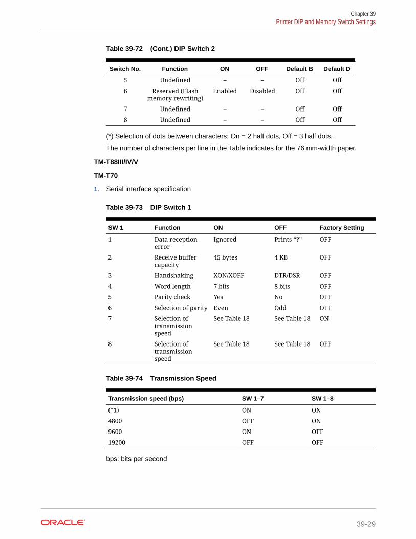
Table 39-72 (Cont.) DIP Switch 2
Switch No. Function ON OFF Default B Default D
5 Undefined – – Off Off
6 Reserved (Flashmemory rewriting)
Enabled Disabled Off Off
7 Undefined – – Off Off
8 Undefined – – Off Off
(*) Selection of dots between characters: On = 2 half dots, Off = 3 half dots.
The number of characters per line in the Table indicates for the 76 mm-width paper.
TM-T88III/IV/V
TM-T70
1. Serial interface specification
Table 39-73 DIP Switch 1
SW 1 Function ON OFF Factory Setting
1 Data receptionerror
Ignored Prints “?” OFF
2 Receive buffercapacity
45 bytes 4 KB OFF
3 Handshaking XON/XOFF DTR/DSR OFF
4 Word length 7 bits 8 bits OFF
5 Parity check Yes No OFF
6 Selection of parity Even Odd OFF
7 Selection oftransmissionspeed
See Table 18 See Table 18 ON
8 Selection oftransmissionspeed
See Table 18 See Table 18 OFF
Table 39-74 Transmission Speed
Transmission speed (bps) SW 1–7 SW 1–8
(*1) ON ON
4800 OFF ON
9600 ON OFF
19200 OFF OFF
bps: bits per second
Chapter 39Printer DIP and Memory Switch Settings
39-29

Table 39-75 DIP Switch 2
SW 2 Function ON OFF FactorySetting
1 Handshaking (Conditionor BUSY)
Receive bufferfull
OfflineReceive buffer-full
OFF
2 Reserved (Do notchange settings)
Fixed to OFF Fixed to OFF OFF
3 Selects print density See Table 20 See Table 20 OFF
4 Selects print density See Table 20 See Table 20 OFF
5 Setting the conditionsthat cancel the receivebuffer BUSY state (Thisfunction is effectivewhen the receive buffercapacity is set to 4 KB.)
Cancels the BUSYstate when theremainingcapacity of thereceive bufferreaches 138bytes.
Cancels the BUSYstate when theremainingcapacity of thereceive bufferreaches 256bytes.
OFF
6 Reserved (Do notchange settings)
Fixed to OFF Fixed to OFF OFF
7 I/F pin 6 reset signal Enabled Disabled OFF
8 I/F pin 25 reset signal Enabled Disabled OFF
Table 39-76 DIP Switch 2–3 and 2–4
Switch No. 3 Switch No. 4 Function
OFF OFF Print density (Standard)
ON OFF Print density (Medium)
OFF ON Print density (Dark)
ON ON Prohibited
2. Parallel interface specification
Table 39-77 DIP Switch 1
SW Function ON OFF FactorySetting
1 Auto line feed Alwaysenabled
Alwaysdisabled
OFF
2 Receive buffer capacity 45 bytes 4 KB OFF
3 Selects paper sensors tooutput paper-end signals(default value of ESC c 3)
Disabled Roll paper endsensorenabled; rollpaper near-end sensorenabled
OFF
4 Sets error signal Disabled Enabled OFF
5–8 Undefined – – OFF
Chapter 39Printer DIP and Memory Switch Settings
39-30

Table 39-78 DIP Switch 2
SW Function ON OFF FactorySetting
1 Handshaking (Conditionfor BUSY)
Receive buffer full OfflineReceive bufferfull
OFF
2 Reserved (Do not changesettings)
Fixed to OFF Fixed to OFF OFF
3 Selects print density See Table 23 See Table 23 OFF
4 Selects print density See Table 23 See Table 23 OFF
5 Setting the conditions thatcancel the receive bufferBUSY state (this functionis effective when thecapacity of the receivebuffer is set to 4 KB).
Cancels the BUSYstate when theremaining capacityof the receive bufferreaches 138 bytes.
Cancels the BUSYstate when theremainingcapacity of thereceive bufferreaches 256bytes.
OFF
6 Reserved (Do not changesettings)
Fixed to OFF Fixed to OFF OFF
7 Reserved (Do not changesettings)
Fixed to OFF Fixed to OFF OFF
8 Interface pin 31 resetsignal (Do not changesettings)
Fixed to ON Fixed to ON ON
Table 39-79 DIP Switch 2–3 and 2–4
3 4 Function
OFF OFF Print density (Standard)
ON OFF Print density (Medium)
OFF ON Print density (Dark)
ON ON Prohibited
TM-T70II
Table 39-80 Memory Switch 1
Memory Switch Function Setting Value — 48(OFF)
Setting Value — 49(ON)
Defaults
1–1 (Reserved) – – 48 (OFF)
1–2 Receive buffercapacity
4 KB 45 bytes 48 (OFF)
1–3 Condition for BUSY Receive buffer fullor offline
Receive buffer full 48 (OFF)
1–4 Data processing forreceiving error
Replaced with “?” Ignored 48 (OFF)
1–5 Automatic line feed Always disabled Always enabled 48 (OFF)
1–6 (Reserved) – – 48 (OFF)
Chapter 39Printer DIP and Memory Switch Settings
39-31

Table 39-80 (Cont.) Memory Switch 1
Memory Switch Function Setting Value — 48(OFF)
Setting Value — 49(ON)
Defaults
1–7 (Reserved) – – 48 (OFF)
1–8 (Reserved) – – 48 (OFF)
Table 39-81 Memory Switch 2
MemorySwitch
Function Setting Value —48 (OFF)
Setting Value — 49(ON)
Defaults
2–1 to 2–8 (Reserved) – – 48 (OFF)
Table 39-82 Memory Switch 3
MemorySwitch
Function Setting Value —48 (OFF)
Setting Value — 49(ON)
Defaults
3–1 to 3–8 (Reserved) – – 48 (OFF)
Table 39-83 Memory Switch 4
MemorySwitch
Function Setting Value —48 (OFF)
Setting Value — 49(ON)
Defaults
4–1 to 4–8 (Reserved) – – 48 (OFF)
Table 39-84 Memory Switch 5
MemorySwitch
Function Setting Value —48 (OFF)
Setting Value — 49(ON)
Defaults
5–1 Sets USB power-saving function *1
Enabled Disabled 48 (OFF)
5–2 Sets recoveryconditions fromreceive bufferBUSY (Enabledwhen the receivebuffer capacity isset to 4 KB)
Recovers when theremaining receivebuffer capacitybecomes 256 bytes
Recovers when theremaining receivebuffer capacitybecomes 138 bytes
48 (OFF)
5–3 Selects papersensors to outputpaper-end signals(default value ofESC c 3)
Roll paper endsensor enabled;roll paper near-end sensorenabled
Disabled 48 (OFF)
5–4 Sets error signal Enabled Disabled 48 (OFF)
5–5 (Reserved) – – 48 (OFF)
5–6 (Reserved) – – 48 (OFF)
5–7 (Reserved) – – 48 (OFF)
Chapter 39Printer DIP and Memory Switch Settings
39-32

Table 39-84 (Cont.) Memory Switch 5
MemorySwitch
Function Setting Value —48 (OFF)
Setting Value — 49(ON)
Defaults
5–8 (Reserved) – – 48 (OFF)
*1: Valid only when the USB interface communication condition is set to the vendor-definedclass and the system configuration is set so that the USB driver can support the USB power-saving function.
Function 11
Function 11 — Descriptions
• Sets the configuration item for the serial interface specified by a to the values specifiedby d.
a Configuration Item
1 Transmission speed
2 Parity
3 Handshaking
4 Bit length
• Transmission speed settings (a = 1)
d1...dk Transmission Speed
“2400” 2400 bps
“4800” 4800 bps
“9600” 9600 bps
“19200” 19200 bps
“38400” 38400 bps
“57600” 57600 bps
“115200” 115200 bps
• Parity settings (a =2)
Chapter 39Printer DIP and Memory Switch Settings
39-33

d1 Parity
48 None
49 Odd
50 Even
• Handshaking settings (a = 3)
d1 Handshaking
48 DTR/DSR control
49 XON/XOFF control
• Bit length settings (a = 4)
d1 Bit Length
55 7 bits
56 8 bits
Chapter 39Printer DIP and Memory Switch Settings
39-34

40Logo Printing
You can print the logo of your Enterprise, property, or revenue center on guest checks,customer receipts, and credit card vouchers. Simphony only supports monochrome bitmapimage files. Use Microsoft Paint to convert an image to a monochrome bitmap. Adhere to thefollowing rules governing the size of your logo:
• The image area must not exceed 98,304 pixels. (Keep in mind that a logo that is 512 x384 pixels exceeds 98,304 pixels.)
• The image width must not exceed 512 pixels.
• The image height must not exceed 384 pixels.
• The bitmap file must not exceed 8 kilobytes in size.
You can configure a check to print more than one logo. The printer loads one image at a timewhen printing the check. The time it takes to print a check depends on the number of imagesthe printer has to load.
Simphony does not support logo printing on:
• Printers with multi-language cards
• OPOS printers
Complete the following tasks to set up logo printing:
• Upload a logo to Simphony
• Assign a logo to guest checks, customer receipts, and credit card vouchers
• Set the printer to print the logo
• Ensure that the DIP settings for the printer's buffer are set to the higher value toaccommodate the logo's additional data
Printer DIP and Memory Switch Settings contains more information on DIP settings.
Uploading a Logo to Simphony1. Select the Enterprise level, click Configuration, and then click Print Logos.
2. Insert a new record, and then double-click it to open in form view.
3. Click Load Image.
4. Select the image, and then click Open to upload it to Simphony. After the logo uploads,an image preview appears.
5. Alternately, you can copy the image to your clipboard, and then click Paste Image toupload it to Simphony.
6. Click Save.
40-1

Assigning a Logo to Guest Checks and Customer Receipts1. Select the Enterprise, property, revenue center, or zone, click Descriptors, and
then click Guest Check Headers.
2. Select a check box in the Use Logo column.
If you select Use Logo for an existing record that has content in the Text column,that text no longer appears on printed guest checks and customer receipts.
3. Click the ellipsis point (...) button in the Logo column, select the image youuploaded, and then click OK.
4. Click Save.
5. To assign the logo to customer receipts and guest check trailers, repeat thesesteps, selecting the Guest Check Trailers and Customer Receipt Headersmodules in Step 1.
You must also select 28 - Print Guest Check Trailer on Fast TransactionCustomer Receipt for tender records from the Tender/Media options. If you do notset this option, trailers do not print on customer receipts when the tender is used toclose a fast transaction.
6. Click Save.
Chapter 40Assigning a Logo to Guest Checks and Customer Receipts
40-2

41Banquet Guest Check Printing
This chapter discusses the configuration and usage of the Banquet Guest Check Printingfeature.
A Banquet Guest Check is used to present a specially formatted guest check for customers.Even though it can be used anywhere, the banquet guest check is intended for use in abanquet environment. In this environment, there are additional components of informationwhich can be reflected on a guest check. Information such as the event name, address,contact information, name of the function room the event was held, names of the maitre’d andcatering sales manager, and the event’s serving period.
One format of the Banquet Guest Check is available, utilizing an 8.5 x 11 page output andprints on a custom page printer.
41-1

Figure 41-1 Example of a Printed Banquet Guest Check
Configuring Employee Privileges for Banquet Guest CheckPrinting
Operators must be assigned Role privileges to be allowed to configure and utilizeBanquet Guest Check printing functionality. To assign privileges to employees for thisfeature:
Chapter 41Configuring Employee Privileges for Banquet Guest Check Printing
41-2

To Configure the Role Option to Begin a Banquet Check By Prompt
Prerequisite: The operator already has access to a Begin Check By Prompt functiontouchscreen button.
1. Access the EMC and select the enterprise level, click the Configuration tab, and thenclick Roles.
2. Select or create an employee role and toggle to Form view.
3. Click the Operations tab, and then click the Guest Checks tab.
4. From the Add/Transfer/Pickup Options section, enable the 199 - Begin Check byPrompt option and Save.
5. Access and sign onto a point-of-sale (POS) workstation.
6. Press the Begin Check by Prompt button.
To Configure the Role Option to Edit a Banquet Check By Prompt
Prerequisite: The operator already has access to a Begin Check By Prompt functiontouchscreen button.
1. Access the EMC and select the enterprise level, click the Configuration tab, and thenclick Roles.
2. Select or create an employee role and toggle to Form view.
3. Click the Operations tab, and then click the Guest Checks tab.
4. From the Check Editing Options section, enable the 200 - Edit Check by Prompt optionand Save.
5. Access and sign onto a point-of-sale (POS) workstation.
6. Open a banquet check from the check listing.
7. Select a header and press the Edit Prompt button.
To Configure the Prompt for Authorization to Create a Banquet Check
Prerequisite: The operator already has access to a Begin Check By Prompt functiontouchscreen button.
If you want to require only privileged users to authorize beginning and printing banquetchecks:
1. Access the EMC and select the enterprise level, click the Configuration tab, and thenclick Roles.
2. From the Add/Transfer/Pickup Options section, disable the 199 - Begin Check byPrompt option for all non-privileged users roles and Save.
3. Access and sign onto a point-of-sale (POS) workstation.
4. Press the Begin Check by Prompt button.
5. Have a privileged user enter their authorization code to begin the check.
To Configure the Prompt for Authorization to Edit a Banquet Check
Prerequisite: The operator already has access to a Begin Check By Prompt functiontouchscreen button.
Chapter 41Configuring Employee Privileges for Banquet Guest Check Printing
41-3

If you want to require only privileged users to authorize editing and printing banquetchecks:
1. Access the EMC and select the enterprise level, click the Configuration tab, andthen click Roles.
2. From the Check Editing Options section, disable the 200 - Edit Check by Promptoption for all non-privileged users roles and Save.
3. Access and sign onto a point-of-sale (POS) workstation.
4. Open a banquet check from the check listing.
5. Select a header and press Edit Prompt.
6. Have a privileged user enter their authorization code to edit the check.
Configuring Banquet Guest Check Buttons and PromptsTo configure the Begin Banquet Guest Check for point-of-sale (POS) workstationtouchscreens:
1. Access the EMC and select the Enterprise, Property, Revenue Center, or Zone,click the Configuration tab, and then select Page Design.
2. You can configure an existing touchscreen or add a new one. Add a new button.
Figure 41-2 Page Design – Add Button
3. From the Type drop-down list, select Function, select the Begin Check ByPrompt function, and then click OK.
Chapter 41Configuring Banquet Guest Check Buttons and Prompts
41-4

Figure 41-3 Page Design – Begin Check By Prompt Function
4. Click the Configure Prompt Details button.
Figure 41-4 Page Design – Configure Prompt Details
Option 1 – Clicking the ‘No’ Button
1. Click No when prompted.
Chapter 41Configuring Banquet Guest Check Buttons and Prompts
41-5

Figure 41-5 Configure Prompt Details ‘No’ Response
2. From the Prompt Details section, configure the following:
a. From the Prompt Type field, select Configurable.
b. From the Dialog Type field, select a type from the drop-down list.
c. From the Prompt Category field, select BanquetPrompt.
d. From the Prompt Title field, select a title category from the drop-down list.
e. From the Prompt Text field, enter the appropriate text based on the PromptTitle setting.
f. From the Content Name field, enter a name for your banquet content.
g. Click the Add button, and then click Ok.
Figure 41-6 Configure Prompt Content Window - Prompt Details
Option 2 – Clicking the ‘Yes’ Button
1. A prompt asks you to choose the existing configuration prompt to set, or select theprompt content.
Chapter 41Configuring Banquet Guest Check Buttons and Prompts
41-6

Figure 41-7 Configure Prompt Details ‘Yes’ Response
• Selecting Yes displays a list of all the existing configuration file names in the Contenttable.
Figure 41-8 Select Existing Content Prompt
• As mentioned previously, selecting No allows you to set the prompts and save detailsin the Content table. Specify the name of the content.
2. As shown in Figure 5 above, configure the Prompt Type, Dialog Type, Prompt Category,Prompt Title, Prompt Text, Default Value, and then enter a Content Name. Click Add andOk.
Note:
The Optional check-box allows the prompt to bypass the next screen andallows the user to click OK.
• There are a number of options when configuring prompt content. Prompt Types can beConfigurable or Non-Configurable. Dialog Types include AlphaNumeric, Numeric, List,and by Date. Users must select from the following list of configurable prompt items thatcan be used for a Banquet Check:
– name="lblOrganization" >Organization
– name="lblAcct" >Acct
Chapter 41Configuring Banquet Guest Check Buttons and Prompts
41-7

– name="lblCustName" >Name
– name="lblCustAddress1" >Address Line 1
– name="lblCustAddress2" >Address Line 2
– name="lblCustCity" >City
– name="lblState" >State
– name="lblZip" >Zip
– name="lblDate" >Date
– name="lblTime" >Time
– name="lblEvent" >Event
– name="lblSalesperson" >Sales Person
– name="lblMaitred" >Maitre D'
– name="lblGuarantee" >Guarantee
Configurable Prompt Type
The example below illustrates a Configurable Prompt Type. When this type isconfigured, users are prompted to enter the requested information at the POSworkstation — in this case, a selection of function rooms.
Figure 41-9 Configure Prompt Content Window - Configurable Type
Non-Configurable Prompt Type
Non-Configurable prompts are not sent to users when beginning a Banquet Check.Regardless of the assigned Dialog Type (e.g., Alphanumeric, Numeric, List , or Date),users are not prompted to enter information.
Chapter 41Configuring Banquet Guest Check Buttons and Prompts
41-8

Figure 41-10 Configure Prompt Content Window - Non-Configurable Type
When configuring a Non-Configurable prompt, and a Default Value is entered, the value isprinted on the Banquet Check by default, without any prompts being sent to the user. Thefollowing example illustrates a List Dialog Type to provide a list of items — in this case, aselection of cities.
Figure 41-11 Non-Configurable Type - List Dialog Type
Chapter 41Configuring Banquet Guest Check Buttons and Prompts
41-9

When configuring a Non-Configurable prompt and the user does not enter a DefaultValue (leaves the setting blank), nothing is printed on the Banquet Check.
Figure 41-12 Non-Configurable Type - Blank Default Value Setting
Users may configure Non-Configurable prompts when certain data does not changeand remains static in a Banquet Check. For example, if the organization holding thebanquet is always the same, then it can be defined as a Non-Configurable prompt.
1. The details and content name added or selected is added as Arguments in thebutton properties panel.
Chapter 41Configuring Banquet Guest Check Buttons and Prompts
41-10

Figure 41-13 Page Design - Button Properties Panel
2. The configuration data for Banquet Check prompts is saved in the Content module as aString in the Content Type field, and is shown using XML format below.
Chapter 41Configuring Banquet Guest Check Buttons and Prompts
41-11

Figure 41-14 Property Level Content Module
Configuring a Banquet Check Add/Transfer by Number
The following steps illustrate how to transfer one Banquet Check to another.
1. Access the EMC, select a Revenue Center, click the Configuration tab, and thenclick Page Design.
2. Choose the touchscreen page to be edited and add a new button.
3. Select Function as the Type, select Add/Transfer by Number, click OK, andthen Save.
Figure 41-15 Page Design – Add/Transfer by Number Function
4. Access and sign onto a point-of-sale (POS) workstation.
Chapter 41Configuring Banquet Guest Check Buttons and Prompts
41-12

5. Begin a Banquet Check and ring up menu items. Note the check number and servicetotal.
6. Begin a second Banquet Check and ring menu items. Note the check number andservice total.
7. Pickup the first Banquet Check from the workstation Pick Up check list.
8. Press the Add/Transfer by Number button.
9. Enter the second Banquet Check number mentioned in step 6. The first check’s promptdata overwrites the second check’s prompt data when the checks are merged.
10. Press OK from the ‘Add Check’ screen. The second Banquet Check is transferred to thefirst one.
Configuring a Banquet Split Check
The following steps illustrate how to split a Banquet Check.
1. Access the EMC, select a Revenue Center, click the Configuration tab, and then clickPage Design.
2. Choose the touchscreen page to be edited and add a new button.
3. Select Function as the Type, select Touch Split, click OK, and then Save.
Figure 41-16 Page Design – Touch Split Function
4. Access and sign onto a point-of-sale (POS) workstation.
Chapter 41Configuring Banquet Guest Check Buttons and Prompts
41-13

5. Begin a Banquet Check, ring up some menu items, and then service total.
6. Pickup the first Banquet Check from the workstation Pick Up check list, and thenpress the Touch Split button.
7. Add a check, move some menu items from one check to another, and then pressSave.
8. Press Yes in response to the ‘Exit and save changes?’ prompt.
9. Press Yes in response to the ‘Print split checks?’ prompt. The Banquet Check issplit and the individual checks can be viewed in the open checks list. The firstcheck’s prompt data is copied to the second check when the checks are split.
Configuring RVC Table Names as Room Names
1. Access the EMC, select a Property, click the Configuration tab, click EmployeeClasses, and then select the Operator Options tab.
2. Enable the 1- Table Number Entry Required to Begin/Pickup Checks and 2-Number of Guest Entry Required for New Checks options, click OK, and thenSave.
Chapter 41Configuring Banquet Guest Check Buttons and Prompts
41-14

Figure 41-17 Employee Classes - Operator Options
3. Access the EMC, select a Revenue Center, click the Setup tab, and then select theTables module (under the RVC Configuration header).
4. Insert or click an available record, enter a room name, for example, Board Room, assigna Dining Table Class in the Class field, and then Save.
Chapter 41Configuring Banquet Guest Check Buttons and Prompts
41-15

Figure 41-18 Revenue Center Configuration - Tables Module
Adding a Banquet Guest Check Printer and Various PrintSettings
Configuring a Custom Page Printer
1. A Printer driver must be installed on the workstation.
2. Enter the hostname of the printer.
Figure 41-19 Add a Printer on the Workstation
Chapter 41Adding a Banquet Guest Check Printer and Various Print Settings
41-16

3. Access the EMC, select a Property, click the Setup tab, select the Printers module(under the Hardware/Interfaces header).
4. Configure a network banquet printer. For the Printer Type field, select Custom PagePrinter from the drop-down list.
Figure 41-20 EMC Printers Module
5. Enter the network printer name in the Name field and Save.
Note:
The Name field entry must be the physical printer’s name as seen on thenetwork and the Printer Host's IP address in the Printer Configuration section’sAddress field.
Figure 41-21 EMC Printers Module (continued)
Chapter 41Adding a Banquet Guest Check Printer and Various Print Settings
41-17

6. Access the EMC, select a Property, click the Setup tab, select the Workstationsmodule (under the Hardware/Interfaces header).
7. Choose the banquet printing workstation record and click the Printers tab.
8. Click Select, and from the drop-down list, choose the output printer in theBanquet Check Printer field (should be the Custom Page Printer type), click OK,and then Save.
Figure 41-22 Workstation Module - Assigning the Banquet Check Printer
Configuring a Tender Media Deposit
Users can post a Deposit Payment amount on a Banquet Check. If configured, thedeposit tender amount prints in a special location on the Banquet Check.
1. Access the EMC, select the Enterprise level, click the Configuration tab, selectthe Report Groups module (under the Reporting and Data header).
2. Insert a new record, name it, and then from the Type field, select Tender/Mediafrom the drop-down list.
Chapter 41Adding a Banquet Guest Check Printer and Various Print Settings
41-18

Figure 41-23 Report Groups Module
3. A Deposit Payment Tender is linked to a Report Group by enabling the 5 - Deposit Typeof Tender Media option. From the Options field, click the ellipsis (…) to open the ReportGroup Tender Media Options screen. Select option 5, click OK, and then Save.
4. Users can add an advance deposit payment against the Banquet Check by configuring anew payment tender.
Figure 41-24 Tender/Media - Advance Deposit Payment
Configuring Tender/Media Printing on Banquet Checks
To print a Banquet Check prior to finalizing the transaction, you can create a Tender/Mediarecord configured as a Service Total type. You can also use a Payment type to print aBanquet Check when the transaction is tendered or finalized.
Chapter 41Adding a Banquet Guest Check Printer and Various Print Settings
41-19

Figure 41-25 Tender/Media - Print Banquet Check Service Total
1. Before printing a Banquet Check, access the EMC, select the enterprise orproperty level, click the Configuration tab, select the Tender/Media module(under the Sales header).
2. Select the Printing Options tab, enable the 90 - Print Banquet Check option,and then Save.
Configuring Page Margins for Banquet Check Printing
1. Access the EMC, select a Property, click the Setup tab, select the Printersmodule (under the Hardware/Interfaces header).
2. Select the Banquet Check printer record.
3. Enter the values for the top, bottom, and left margins, and then Save.
Chapter 41Adding a Banquet Guest Check Printer and Various Print Settings
41-20

Figure 41-26 Formatting Banquet Check Page Margins
Creating and Printing Banquet Guest Checks From a POSWorkstation
Beginning a Banquet Check
Once EMC configuration is complete, you can now begin to generate banquet guest checksfrom a point-of-sales (POS) workstation.
1. After configuring a Begin Check By Prompt button in the EMC’s Page Design module,access a workstation and press the Begin Check By Prompt button.
Chapter 41Creating and Printing Banquet Guest Checks From a POS Workstation
41-21

Figure 41-27 Begin Check By Prompt
Note:
If a user cancels any one of the sequential Banquet Check prompts, theentire check/transaction is cancelled.
2. Add the Banquet Check’s header detail through prompts.
Chapter 41Creating and Printing Banquet Guest Checks From a POS Workstation
41-22

Figure 41-28 Banquet Check - Enter Name Window
3. Select the Room name. This step uses the EMC Tables module data to show a list ofroom names.
4. Select the Serving Period.
Figure 41-29 Banquet Check - Select Serving Period
Chapter 41Creating and Printing Banquet Guest Checks From a POS Workstation
41-23

5. The workstation’s Check Detail area displays the selected serving period.
Figure 41-30 Banquet Check - Shows Selected Serving Period
6. Select the header content in the Name field to edit. Press OK when finished.
Figure 41-31 Banquet Check - Edit the Header Content
Chapter 41Creating and Printing Banquet Guest Checks From a POS Workstation
41-24

7. The Check Detail area displays the newly entered header text.
Figure 41-32 Banquet Check - Edited Header Content
Utilizing Banquet Checks With Serving Periods
1. Log onto a POS workstation and press the Begin Check By Prompt button.
Figure 41-33 Banquet Check - Begin Check By Prompt
Chapter 41Creating and Printing Banquet Guest Checks From a POS Workstation
41-25

2. Enter the header prompt details and press OK to continue.
Figure 41-34 Banquet Check - Editing Header Prompt Details
3. Enter a table number and press Ok.
Chapter 41Creating and Printing Banquet Guest Checks From a POS Workstation
41-26

Figure 41-35 Begin Check - Enter Table Number
4. Enter the number of guests and press Ok.
Figure 41-36 Begin Check - Enter Guest Count
5. Select a serving period and press Ok.
Chapter 41Creating and Printing Banquet Guest Checks From a POS Workstation
41-27

Figure 41-37 Banquet Check - Select Serving Period
Configuring Check Printing Privileges
Printing of all checks, including Banquet Checks, requires privileges to be assigned toemployees Roles. Other EMC options also need to be enabled. To assign guest checkprinting privileges:
1. Access the EMC and the select the Enterprise level, click the Configuration tab,and then select Roles. Select the Role to be edited and toggle to Form view.
2. Click the Operations tab, click the Printing tab and enable the 23 - Authorize/Perform Unlimited Reprinting/Printing of a Check option.
3. To control how many checks may be printed by employees before requiringauthorization, access the EMC and select the Property or Revenue Center level.Click the Setup tab, and then click the Control Parameters module (under theParameters heading). Click the Configuration tab and from the Number ofChecks Printed Before Authorization field, enter a digit (from 0–99) to allowstaff to print Banquet Checks until the threshold limit is exceeded.
Chapter 41Creating and Printing Banquet Guest Checks From a POS Workstation
41-28

Figure 41-38 EMC Control Parameters - Number of Checks to Print BeforeAuthorization Setting
4. Access the EMC, select a Property, click the Configuration tab, and then click Tender/Media (under the Sales header).
5. Click the Options tab, click the Printing Options tab, and then enable the 23 - PrintCheck on Demand option and Save.
Chapter 41Creating and Printing Banquet Guest Checks From a POS Workstation
41-29

Figure 41-39 EMC Tender/Media Printing Options
6. Finally, each employee allowed to immediately print guest checks, needs to haveanother privilege assigned to them. This setting can be accessed from the EMC byselecting a Property, click the Configuration tab, click the Employee Classesmodule, and then click the Operator Options tab. From the Operator Type field,select 1 - On Demand from the drop-down list and Save.
Chapter 41Creating and Printing Banquet Guest Checks From a POS Workstation
41-30
42Configuring Pre-Production Chits to Output toRemote Printers
Kitchen or bar staff can preview orders and begin preparing items that require more prep orcooking time to assist in delivering orders more quickly. Pre-production printing allows serversto send certain menu items to remote printers prior to finalizing the current round.
Operationally, as workstation operators add menu items, they can select a Pre-ProductionChit (Tender/Media Service Total) button to send the pre-production items to remote printers.For easier recognition, pre-production chits are formatted differently than the output ofconventional order chits.
After an item is fired through pre-production chit printing, if the workstation operator adds asecond item and then selects pre-production chit printing again, the system only fires thesecond item. The first item does not trigger the re-fire of a pre-production chit.
Configuring Print Classes for Pre-Production ChitsTo configure and assign printers to a pre-production Print Class:
1. Select the Enterprise or property, click Configuration, and then click Print Classes.
2. Insert a new record and enter the name of the pre-production print class in the Namefield (for example, Print Pre-Production Chit).
3. Configure settings within the Options section as needed.
4. Select the Routing Group from the drop-down list in the Output section.
Typically, enabling the 0 - Use Order Devices routing group suffices for most pre-production chit printing tasks.
5. Enable the order devices that are to serve as a pre-production remote printers.
6. Click Save.
Configuring Tender/Media - Service Total Records for Pre-Production Chits
To configure Tender/Media - Service Total records for pre-production chit printing:
1. Select the Enterprise or property, click Configuration, and then click Tender Media.
2. Insert a new record, and enter the name of the pre-production service total record (forexample, Print Pre-Production Chit).
3. In the General Settings section, assign a Privilege Group that allows users to use thisservice total.
4. In the Key Type field, select 2 - Service Total from the drop-down list.
5. Configure the remainder of the General tab settings, and then click the Options tab.
42-1

6. Click the Printing Options tab, and then enable the 98 - Print Pre-ProductionChit option.
7. Click the Ops Behavior tab, and then select 2 - Hold Order as the Tender MediaHold Type from the drop-down list.
8. Configure the remainder of this service total record’s settings.
9. Click Save.
Configuring Menu Item Classes for Pre-Production ChitsYou need to determine which menu items to apply pre-production chit printing,navigate to each of these items’ assigned Menu Item Class, and assign the pre-production chit print class. To configure Menu Item Classes to generate pre-productionchits:
1. Select the Enterprise, property, or revenue center, click Configuration, and thenclick Menu Item Classes.
2. On the General tab, select the pre-production print class from the Pre-ProductionChit Print Class drop-down list.
Chapter 42Configuring Menu Item Classes for Pre-Production Chits
42-2

Figure 42-1 Menu Item Classes - Pre-Production Chit Print Class Setting
3. Click Save.
Configuring a Page Design Button for Pre-Production ChitsTo configure a workstation button to generate pre-production chit printing:
1. Select the Enterprise, property, or revenue center, click Configuration, and then clickPage Design.
2. On the order entry pages of your choice, add a new button and configure the followingfields:
a. Legend: Enter the button name.
b. Type: Select Tender/Media, and then select the Print Pre-Production Chit, Tender/Media - Service Total record.
Chapter 42Configuring a Page Design Button for Pre-Production Chits
42-3

Figure 42-2 Page Design - Workstation Button for Pre-Production ChitPrinting
3. Configure the remainder of the button’s settings.
4. Click Save.
Example of a Pre-Production ChitPre-Production chits are formatted differently than conventional order output to remoteprinters. The text * TO BE PREPARED * prints by default on each chit (with the OrderType showing directly beneath it), prior to the Dining Course name (if enabled), andthen the quantity ordered is printed adjacent to each ordered Menu Item.
If enabled, the Dining Course Name prints and also adheres to the Print Classessettings, whereby if the 4 - On = Red, Off = Black option is enabled, the DiningCourse name prints in red, and prints in black if disabled.
Here is an example of a Pre-Production Chit:
Chapter 42Example of a Pre-Production Chit
42-4

Figure 42-3 Example of a Pre-Production Chit
Chapter 42Example of a Pre-Production Chit
42-5

43Peripheral Devices
Peripheral devices connect with and relay information to or from Simphony. For example,common POS peripheral devices include magnetic card readers, cash drawers, coindispensers, printers, pole displays, and scales.
Cash Drawer Assignment and UnassignmentYou can assign a cash drawer in the following ways:
• By workstation
• By workstation operator
Giving multiple employees access to a single cash drawer is less secure than requiringemployees to be assigned to a cash drawer.
When you set the option Assign Cash Drawer By User Workstation from the Workstationsmodule, workstation operators can assign themselves to a cash drawer using the one of thefollowing function keys:
• 848 - Assign Cash Drawer
• 839 - Assign Cash Drawer 1
• 840 - Assign Cash Drawer 2
The following table compares these function keys:
Table 43-1 Assign Cash Drawer Function Key Comparison
848 - Assign Cash Drawer 839 - Assign Cash Drawer 1 and 840 - AssignCash Drawer 2
Assigns the drawer to the workstationoperator who is signed in.
Assigns the drawer to the workstationoperator who is signed in.
If two drawers are used with the workstation,Simphony assigns drawer 1 if both areunassigned. If drawer 1 is assigned, Simphonyassigns drawer 2, and vice-versa.
If two drawers are used with the workstation,these keys allow the workstation operator toselect the drawer he or she wants to assign. (Tooffer a choice, you must configure both keyson the touchscreen.)
Using this key opens the cash drawer. Using this key does not open the cash drawer.
If the cash drawer is unassigned, using this keyprompts the workstation operator to assign thecash drawer number.
If the cash drawer is unassigned, using this keyprompts the workstation operator to assign thecash drawer number, while the top of thescreen shows INACTIVE (no one is assigned).
43-1

Table 43-1 (Cont.) Assign Cash Drawer Function Key Comparison
848 - Assign Cash Drawer 839 - Assign Cash Drawer 1 and 840 - AssignCash Drawer 2
If a workstation operator attempts to assignthe drawer when another workstationoperator is already assigned, the followingerror message appears: All Cash DrawersCurrently Assigned.
If the workstation operator attempts to assignthe drawer when another workstationoperator is already assigned, no error messageappears. The top of the screen show NAME (ofthe person assigned to the drawer). Thus, oneperson may assign the drawer and overridethe workstation operator who is alreadyassigned.
All workstation operators can use this functionkey.
All workstation operators cannot use thisfunction key.
At the end of a shift, the workstation operatoror a privileged manager needs to unassign thedrawer to allow another workstation operatorto use the drawer.
At the end of a shift, it is not necessary tounassign the drawer because anotherworkstation operator may override theassigned workstation operator.
The 849 - Unassign Cash Drawer function key unassigns the drawer from theworkstation operator, regardless of whether the workstation operator assigned thedrawer using function 848 or 839/840. All workstation operators can always unassignthemselves from a drawer. You can prevent this by removing the Unassign CashDrawer function key from the touchscreen or restrict its access using a lockout macro.
Configuring a Cash Drawer1. Select the property, click Setup, and then click Workstations.
2. Double-click the workstation to be used with the cash drawer.
3. Click the Transactions tab.
4. Select the number of Cash Drawers (0, 1, or 2) that are physically installed at theworkstation.
5. In the Cash Drawer Beep Timeout field, enter the number of seconds the cashdrawer can be open before the workstation begins beeping. If you set this value to0 (zero), beeping does not occur.
6. In the Cash Drawer Notify Timeout field, enter the number of seconds the cashdrawer can be open before the workstation posts a message to the journal log file.If you set this value to 0 (zero), the message does not post to the journal log.
7. Click the Options tab, and then click the Hardware/Cash Drawer subtab.
8. Select the appropriate cash drawer options.
Chapter 43Configuring a Cash Drawer
43-2

Table 43-2 Cash Drawer Workstation Options
Option Description
Require Cash Drawer to be Closed BeforeNew Transaction
Select this option to require the workstationoperator to close the cash drawer beforebeginning a new transaction. Deselect thisoption to allow transactions to begin while acash drawer is open.
Assign Cash Drawer By User Workstation Select this option to allow workstationoperators to assign themselves to the cashdrawer using the one of the function keys(848 - Assign Cash Drawer, 839 - AssignCash Drawer 1, or 840 - Assign CashDrawer 2). Only the workstation operatorassigned to the drawer can open it.
Use Other Cash Drawer for Other Currency Select this option if two cash drawers are inuse for the workstation and one is dedicatedto foreign currency.
Require Cash Drawer Assignment to BeginTransaction
Select this option to require a workstationoperator to have a cash drawer assignedprior to beginning a transaction at theworkstation.
9. Click Save.
10. Select the Enterprise, property, revenue center, or zone, click Setup, and then clickControl Parameters.
11. Click the Options tab.
12. Select the appropriate cash drawer options.
Table 43-3 Cash Drawer Control Options
Option Description
23 - Open Drawer Only if Balance Due is 0.00 Select this option to prevent a tender/mediakey from opening the cash drawer unless thebalance due is $0.00. Deselect this option toallow a tender/media key to open the cashdrawer even if there is a balance due on thetransaction.If the transaction’s subtotal is $0.00 and youset 36 - Do Not Open Cash Drawer ifSubtotal is 0.00, the setting of option 23 isirrelevant.
Chapter 43Configuring a Cash Drawer
43-3

Table 43-3 (Cont.) Cash Drawer Control Options
Option Description
33 - Employee ID Required With [No Sale]Key
Select this option to prompt for the signed-onworkstation operator’s employee ID afterpressing the No Sale key. Deselect this optionto allow workstation operators to use the NoSale key any time a privileged employee issigned on.This feature is used by staydown operators(such as bartenders or sales clerks) whotypically walk away from the workstation,and by prompting for employee ID,mischievous persons cannot open thedrawer.
36 - Do Not Open Drawer if Subtotal is 0.00 Select this option to prevent the cash drawerfrom opening for transactions in which thesubtotal is $0.00. Deselect this option to allowthe cash drawer to open whenever aworkstation operator uses a tender/mediakey that is configured to open the drawer.
42 - Always Open Cash Drawer if ChangeDue
Select this option to allow the cash drawer toopen when there are no tenders on the checkthat should usually open the drawer. Thetransaction must have change due, and thecurrent tender must not be configured toopen the drawer.This option is typically used for Tender/Media records such as gift certificates, wherechange is issued only if the gift certificateexceeds the value of the transaction (thus,the drawer should be opened to issuechange), but the drawer remains closedwhen the gift certificate does not exceed thetransaction’s total.
65 - Allow open of Cash Drawer on ServiceCharge
Select this option to allow the cash drawer toopen for transactions where the servicecharge has a value greater than $0.00, butthe subtotal is $0.00.If you selected 36 - Do Not Open if Subtotalis $0.00, you must also select this option toallow the cash drawer to open for servicecharge only guest checks.
The cash drawer will always open when using the OpsCheckCashDrawerEventExtensibility function. When the Extensibility function OpsCheckCashDrawerEventrequests to open a cash drawer, the following cash drawer options are overridden:
• 23 - Open Drawer Only if Balance Due is 0.00
• 36 - Do Not Open Drawer if Subtotal is 0.00
• 42 - Always Open Cash Drawer if Change Due
• 65 - Allow open of Cash Drawer on Service Charge
13. Click Save.
14. Select the Enterprise, click Configuration, and then click Roles.
Chapter 43Configuring a Cash Drawer
43-4

15. Select the role type, click the Operations tab, and then click the Miscellaneous subtab.
16. Select the appropriate options for cash drawer privileges.
Table 43-4 Cash Drawer Privilege Options
Option Description
17 - Authorize/Perform unassignment ofcash drawer from others
Select this option to allow employees in theemployee class to use the Unassign CashDrawer function key to unassign cashdrawers from other workstation operators.Do not select this option for every employee;set it only for management employee classes.Setting this option allows workstationoperators in the employee class to usefunction keys 839 - Assign Cash Drawer 1and 840 - Assign Cash Drawer 2.
34 - Authorize Open Cash Drawer Using the[No Sale] Key
Select this option to allow employeesassociated with the role to open the cashdrawer outside of a transaction using the NoSale key, and to authorize non-privilegedemployees to do so.
88 - Authorize Cash Drawer Reconnection Select this option to allow employeesassociated with the role to authorize a cashdrawer cable reconnection on a workstation.
17. Click Save.
Coin DispenserA coin dispenser (sometimes called a coin changer) is a device attached to a workstation thatholds coins. A coin dispenser is not assigned to a workstation or server. When connected to aworkstation and configured, a cash tender sends commands to the coin dispenser todispense coins. The coin dispenser controls only the coin portion of a cash transaction. If thecustomer presents $20.00 to pay a $16.45 guest check, the coin dispenser automaticallydispenses $0.55, but the workstation operator must give the remaining $3.00 to the customer.
The coin dispenser hardware varies the coins that are dispensed to avoid depleting a singletype of coin. For example, if the device dispenses $0.55 three times in a row, it is probablethat both of the following combinations dispense at least once:
• 1 Quarter and 3 Dimes
• 2 Quarters and 1 Nickel
Configuring a Coin Dispenser1. Select the property, click Setup, and then click Workstations.
2. Double-click the workstation to open it in form view.
3. Click the Devices tab.
4. From the Peripheral Device Configuration section, click Add.
5. From the Select Peripheral Device Type drop-down list, select Coin Dispenser.
Chapter 43Coin Dispenser
43-5

6. Enter the COM Port, and then click OK.
7. Click Save.
8. On the workstation, allow the configuration change to download to the POS client.
9. Connect the coin dispenser’s serial cable to the appropriate COM port.
10. Restart the workstation.
11. If the workstation is a Win32 client, modify the device settings for the COM port tomatch the COM Port you set in Step 6.
Ensure that a workstation with an attached coin dispenser does not have a printeror other device configured for the same COM port as the coin dispenser. Havinganother device connected but not in use can cause problems with coin dispenseroperations.
12. Restart the workstation.
13. Verify that the coin dispenser is connected and ready for operation:
a. Sign on to the workstation as an employee with PMC privileges.
b. Launch PMC, and then click the Functions tab.
c. Click Device Diagnostics.
d. Click Dispense Change. The coin dispenser dispenses a penny whensuccessfully connected.
Magnetic Stripe ReaderWorkstation operators scan magnetic stripe cards using a magnetic stripe reader(MSR) attached to a workstation. Magnetic cards are commonly used as:
• Credit Cards
• Gift Cards
• Employee Identification Cards
Installing the MSR Sleeve for Oracle MICROS Tablet E-Series 8-Inch and 11-Inch Devices
The MSR sleeve for Oracle MICROS Tablet E-Series 8-inch and 11-inch devicessupports Transaction Vault Second Generation (TV2G) and data encryption.
Before installing the MSR sleeve driver for Oracle MICROS Tablet E-Series devices,ensure that the device has the following prerequisite requirements:
• Microsoft Windows 8.1 operating system
• Microsoft .NET Framework 4.0 or later
Contact Oracle Support to obtain the VeriFone E23x card reader driver before youbegin the following steps.
1. If a previous version of the driver exists, uninstall the old driver components beforeinstalling the new driver.
a. From the Control Panel, select Programs and Features.
Chapter 43Magnetic Stripe Reader
43-6

b. Uninstall the following components:
• E23x Driver Installer versions
• E23x OPOS DLL
• Microsoft POS for .NET 1.12
• OPOS Common Control Objects 1.13.001
2. Run the E23xDriverInstaller_1.2.0.exe file, and click Yes each time you are prompted.
3. Run the E23x_OPOS_DLL_Install_1.5.2.0.exe file, and click Yes each time you areprompted.
The driver and OPOS DLL installation configures a default OPOS device name for themagnetic stripe reader (MSR). Configure Simphony to use the exact name with the MSR.
Configuring a Magnetic Stripe Reader1. Select the property, click Setup, and then click Workstations.
2. Double-click the workstation to be used with the MSR.
3. Click the Options tab, and then click the Display/Security subtab.
4. Select the appropriate MSR options.
Table 43-5 MSR Workstation Options
Option Description
12 - Mag Card Entry Required for EmployeeID
Select this option to allow all employee IDentries at the workstation to be made byswiping a magnetic employee ID card. Theworkstation does not accept an employee IDnumber entered through the keyboard ortouchscreen.
50 - Mag Card or Fingerprint Scan Requiredfor Employee ID
Select this option to allow all employee IDentries at the workstation to be made using afingerprint scan or by swiping a magneticcard. That is, employees must swipe a card orscan a fingerprint.
51 - Mag Card and Fingerprint ScanRequired for Employee ID
Select this option to allow all employee IDentries at the workstation to be made using afingerprint scan and by swiping a magneticcard. That is, employees must both swipe acard and scan a fingerprint.
5. If you are using an encrypted MSR (for example, the MSR sleeve for Oracle MICROSTablet E-Series 8-inch and 11-inch devices with Transaction Vault Second Generation(TV2G)), complete the following steps:
a. Click the Hardware/Cash Drawer subtab.
b. Select 55 - Enable Encrypted Magnetic Stripe Reader Support.
After you select this option, you cannot turn it off. Before setting this option, ensurethat the credit card processor or gateway supports encryption functionality.
6. Click the Devices tab.
Chapter 43Configuring a Magnetic Stripe Reader
43-7

7. Click Add, and then select a magnetic stripe reader from the Select PeripheralDevice Type drop-down list.
8. Select the COM Port Settings (if necessary), and then click OK.
9. Click Save.
Testing the MSR Sleeve for Oracle MICROS Tablet E-Series8-Inch and 11-Inch Devices
You can test the MSR swiper functionality after you install the driver and configure theMSR.
1. Copy the e23xservice.exe and e23xD.dll files to the [Drive Letter]:\ProgramFiles\Verifone\E23xOPOS folder.
2. Close the ServiceHost application.
3. Run e23xservice.exe.
4. In the OPOS MSR section of the dialog box, select the following options:
• Open
• Claim
• Enable
• D. Ev (Data Events)
After each successful swipe attempt, the D. Ev option is deselected.
5. Swipe the magnetic card. If the card swipe was successful, a message appearswith the card data.
Barcode Reader Setup MethodsA barcode is an optical machine-readable representation of data. Barcodes are usedto quickly order items. Workstation operators scan barcodes using barcode scannersattached to workstations. When a barcode is scanned, the workstation softwareprocesses the data and matches it with a menu item configured in the Simphonydatabase.
The following two methods allow you to configure barcode menu item ordering:
• Use the Barcodes module from the EMC
• Use the number lookup (NLU) method
The following table outlines the differences between the two methods:
Table 43-6 Barcode Reader Setup Methods
Barcodes Module Method NLU Method
Greater configuration flexibility Less flexible configuration
More complex configuration Simplified configuration
Chapter 43Testing the MSR Sleeve for Oracle MICROS Tablet E-Series 8-Inch and 11-Inch Devices
43-8
Table 43-6 (Cont.) Barcode Reader Setup Methods
Barcodes Module Method NLU Method
Associate many different barcodes with thesame menu item (for example, pricingchewing gum items the same)
Not supported
Associate two different prices of onedefinition with different barcodes (forexample, small or large coffee)
Not supported
Allows up to 14-digit barcode Allows up to 12-digit barcode
Configuring a Barcode Reader Using the Barcodes ModuleMethod
1. Select the Enterprise, property, or revenue center click Configuration, and then clickBarcodes.
2. Insert a barcode record.
3. In the Barcode column, enter the numeric value that the barcode represents.
4. Click the ellipsis point (...) button in the Master column, select the master menu item tobe ordered when the barcode is entered, and then click OK.
5. In the Definition column, select the Menu Item Definition (belonging to the selectedMenu Item Master) to be ordered when the barcode is entered. If you select 0 - AllDefinitions, the workstation determines which definition to order at the time the barcodeis entered, based on active Menu Levels and other criteria.
This column is only active when you set the Menu Item Master column to a value otherthan 0 - None.
6. In the Price # column, select the Menu Item Price (belonging to the selected Menu ItemDefinition) to be ordered when the barcode is entered. If you select 0 - All Prices, theworkstation determines which price to order at the time the barcode is entered, based onactive Menu Levels and other criteria.
This column is only active when you set the Menu Item Definition column to a value otherthan 0 - All Definitions.
7. In the Alternate Price column, enter the price to charge for the item when the barcode isentered.
This value is used only when you set a value greater than 0.00; if the value is 0.00, theprice from the Menu Item Price record is used.
8. In the Alternate Prep Cost column, enter the prep cost to use for the item when it isordered by the barcode.
This value is used only when you set a value greater than 0.00; if the value is 0.00, theprep cost from the Menu Item Price record is used.
9. Click Save.
10. Select the Enterprise or property, click Setup, and then click Barcode Format Sets.
11. Insert a barcode format set record, and then double-click it.
Chapter 43Configuring a Barcode Reader Using the Barcodes Module Method
43-9

12. Click Add.
13. In the Input Length field, enter the number of digits in the scanned barcodes.
14. In the Returned Start field, enter the first digit to use in the numeric value toreturn.
15. In the Returned Length field, enter the number of digits to read as the numericvalue to return.
16. Click Save.
17. Select the property, click Setup, and then click Workstations.
18. Double-click the workstation to be used with the barcode reader.
19. Click the Transactions tab.
20. Select the Barcode Format Set for the workstation to use.
The Barcode Format Set determines how the workstation reads barcodes ofvarious lengths.
21. Click the Devices tab.
22. Click Add, and then select the barcode reader from the Select Peripheral DeviceType drop-down list.
23. Select the COM Port Settings (if necessary), and then click OK.
24. Click Save.
Configuring the 1D/2D Imager ScannerYou can configure the 1D/2D Imager Scanner for use with the Oracle MICROSWorkstation 6 Series and Oracle MICROS Compact Workstation 310.
1. Select the property, click Setup, and then click Workstations.
2. Double-click the workstation record to open it.
3. Click the Devices tab.
4. Click Add in the Peripheral Device Configuration section.
5. From the Select Peripheral Device Type drop-down list, select Generic BarcodeReader.
6. Under COM Port Settings, select the COM PORT.
The default COM Port setting is COM14.
To find the appropriate COM number, navigate to the workstation device managerand locate the COM number associated with the workstation.
7. Click Save.
8. After configuration in EMC, update the workstation.
9. Following the update, shut down the workstation, and then connect the scanner.
The workstation should always be turned off when connecting or disconnecting ascanner.
10. Restart the workstation.
11. Verify that the scanner is successfully initialized with the workstation.
Chapter 43Configuring the 1D/2D Imager Scanner
43-10

Fingerprint ScanningThis section describes fingerprint scanning. Fingerprint scanning provides greater security byverifying an employee’s identify. You can use an external USB fingerprint reader with thefollowing devices to scan fingerprints:
• Oracle MICROS Tablet E-Series
• Oracle MICROS Workstation 6 Series
• Oracle MICROS Workstation 5a
• Oracle MICROS PC Workstation 2015
• A PC running a Simphony client that is attached to the PC with a USB connection
You can require employees to scan fingerprints when performing the following operations:
• Signing in to a workstation
• Clocking in and out
• Authorizing privileged operations
Privileged employees can perform the following actions:
• Enroll themselves and other employees’ fingerprints in Simphony
• Register up to ten different fingers (in the event that employee digits becomeincapacitated (cut, removed, or bandaged))
At registration, the employee places a finger on the fingerprint reader. The reader scans thefingerprint and captures its characteristics (an array of pixels) as Fingerprint Image Data(FID). The reader then extracts fingerprint features as Fingerprint Minutiae Data (FMD) andcreates a data record that is stored in database tables in the cloud and in the POS clientswhere the employee signs in. At sign-in, the reader captures fingerprint data and then usesFMD records to search the local database for a match. If a match is found, the action isperformed (such as sign-in). The system does not store pictures, photographs, or images ofthe fingerprint. There is no way to reconstruct the fingerprint using the stored data.
Auditors can determine whether an employee performed an authorization using a fingerprintreader, manual entry, or magnetic card swipe.
Simphony does not store the fingerprint image. Simphony uses only a mathematicalidentification of the image. The data stored is similar to a hash of the fingerprint and cannotbe used to reconstruct the fingerprint. Collecting or enrolling employee fingerprints is aprivileged operation, typically requiring manager authorization. The data is protected at restand in transit within the Simphony application using the same approaches that all sensitivedata is protected. When an employee is deleted from the system, the stored fingerprint datafor that employee is also deleted. This applies to all storage at the enterprise and onpremise. In current versions, the timing of when an employee is deleted from the system isdetermined by when a privileged user manually deletes the employee record in EMC.
Biometric data is stored in the Employee table for the Enterprise database, CAPS database,and Datastore database. The following queries can be used to demonstrate that nofingerprint data is present:
• To show the count of employees with any biometric data:
SELECT count(*) AS "EMPLOYEES WITH BIOMETRIC DATA"
Chapter 43Fingerprint Scanning
43-11

FROM EMPLOYEE WHERE fingerprinttemplate1 IS NOT NULL or fingerprinttemplate2 IS NOT NULL or fingerprinttemplate3 IS NOT NULL or fingerprintnewtemplate1 IS NOT NULL or fingerprintnewtemplate2 IS NOT NULL or fingerprintnewtemplate3 IS NOT NULL;
• To show employee and fingerprint columns:
select FIRSTNAME, LASTNAME, FINGERPRINTTEMPLATE1, FINGERPRINTTEMPLATE2, FINGERPRINTTEMPLATE3, FINGERPRINTNEWTEMPLATE1, FINGERPRINTNEWTEMPLATE2, FINGERPRINTNEWTEMPLATE3 from EMPLOYEE;
Note:
– Neurotec templates are stored in FINGERPRINTTEMPLATE1,FINGERPRINTTEMPLATE2, FINGERPRINTTEMPLATE3
– UrU templates are stored in FINGERPRINTNEWTEMPLATE1,FINGERPRINTNEWTEMPLATE2, FINGERPRINTNEWTEMPLATE3
Configuring the Biometrics CAL Package Deployment1. Select the Enterprise level, click Setup, and then click CAL Packages.
2. Select Biometrics from the navigation tree.
3. Click the Deployment Schedules tab.
4. Click Add Deployment.
5. Select 1 - Property/Enterprise from the Deployment Type drop-down list.
6. Select 0 - Enterprise from the Property field.
7. Select 0 - Install from the Action to Take drop-down list.
8. Click Save.
Configuring Employee Privileges for the Fingerprint Reader1. Select the Enterprise level, click Configuration, and then click Roles.
2. Select the role type, click the Operations tab, and then click the PMC General/Reports subtab.
3. To allow employees associated with the role to open the Property ManagementConsole (PMC) using function key 300, select 30001 - Run PMC.
4. Click the PMC Procedures subtab.
5. Select 30055 - Assign Employee Fingerprint Scan and 30052 - AssignEmployee PIN.
6. Click Save.
Chapter 43Configuring the Biometrics CAL Package Deployment
43-12

Configuring the Touchscreen Home or Sign In Page to AssignEmployee Personal Identification Number (PIN)
1. Select the Enterprise, property, revenue center, or zone, click Configuration, and thenclick Page Design.
2. Open the Home or Sign In page.
3. On the Edit tab, click Button.
4. On the General subtab, enter Assign PIN in the Legend field.
5. Select Function from the Type drop-down list.
6. Click the black arrow directly beneath the Type drop-down list, and then select AssignEmployee PIN.
7. Position and size the button on the page. Use the Style arrow to change the color.
8. Click Save.
Configuring the Workstation Employee Fingerprint Sign InOptions
1. Select the property, click Setup, and then click Workstations.
2. Double-click the workstation to use with a fingerprint reader.
3. Click the Options tab.
4. Select the appropriate security options as described in the following table.
Table 43-7 Employee Security Options
Option Selecting This Option Requires That AllEmployees …
47 - Fingerprint Scan Required for EmployeeID
Scan a fingerprint.
48 - Employee ID or Fingerprint ScanRequired for Employee ID
Scan a fingerprint or enter the employee IDnumber.
49 - Employee ID and Fingerprint ScanRequired for Employee ID
Scan a fingerprint and enter the employeeID number.
50 - Mag Card or Fingerprint Scan Requiredfor Employee ID
Scan a fingerprint or swipe an employee IDcard.
51 - Mag Card and Fingerprint ScanRequired for Employee ID
Scan a fingerprint and swipe an employee IDcard.
5. Click Save.
Scanning a FingerprintYou can scan (also called enroll) a fingerprint using a workstation or from the EMC.
Chapter 43Configuring the Touchscreen Home or Sign In Page to Assign Employee Personal Identification Number (PIN)
43-13

If you upgrade Simphony to version 2.9.1 or later, you must deploy the Biometrics 5.0CAL package, and then re-enroll fingers with an Oracle MICROS or DigitalPersonafingerprint reader. To re-enroll, attach an Oracle MICROS or DigitalPersona fingerprintreader to the workstation, scan an already enrolled finger to sign on to the workstation,and then click OK at the prompt to re-enroll.
1. To scan (initially enroll) a fingerprint using a workstation:
a. Sign on to the workstation as an employee with the proper role privileges,using an employee ID.
b. Click the PMC button, and then click the Functions tab.
c. Click the Edit Employee PIN function.
d. Select the employee whose fingerprints need to be scanned.
e. Click the Enroll Fingerprint button.
f. Follow the prompts to enroll up to three fingers for one employee. Click Yes atthe prompt to scan the same finger four times, or click No to return to theSelect Employee dialog.
g. Place the finger to scan on the fingerprint reader, and then remove it when thescan is complete. Each finger is scanned four times. The scanner flasheswhile scanning and remains lit after the scan is complete. Repeat this step foreach finger.
2. To scan (initially enroll) a fingerprint using the EMC:
a. Select the Enterprise, property, or revenue center, click Configuration, andthen click Employee Maintenance.
b. Search for and select the employee record.
c. On the General subtab, click the Fingerprint Enrollment button.
d. Follow the prompts to enroll one or more fingerprints.
Configuring a ScaleA scale connects to the workstation and is used for menu items that are priced byweight (for example, salad bar). You can configure Simphony to calculate weight inounces, pounds, or kilograms.
1. Select the property, click Setup, and then click Workstations.
2. Double-click the workstation to open it in form view.
3. Click the Devices tab.
4. From the Peripheral Device Configuration section, click Add.
5. From the Select Peripheral Device Type drop-down list, select Scale (Serial).
6. Enter the COM Port to which the scale connects.
7. Select the following settings, and then click OK:
• Baud Rate: 9600
• Parity: E
• Data Bits: 7
• Stop Bits: 1
Chapter 43Configuring a Scale
43-14

8. (Optional) If you are using an Oracle MICROS Tablet E-Series, click the Display/Security subtab, and then deselect 39 - Floating tablet.
9. Click Save.
10. On the workstation, allow the configuration change to download to the POS client.
11. Connect the scale’s serial cable to the workstation’s serial COM port.
12. Connect the scale’s power cord to the outlet.
13. Restart the workstation.
14. Verify that the scale is connected and ready for operation:
a. Sign on to the workstation as an employee with PMC privileges.
b. Launch PMC, and then click the Functions tab.
c. Click Device Diagnostics.
d. Click Get Scale Weight.
e. Place a weighed menu item on the scale and add the menu item to a guest check.
Sales Recording Module (SRM)An SRM is a microcomputer designed to be connected to a cash register or POS system. Itrecords transaction information such as sales and tax data in a secure memory. After datatransmission begins, the SRM device sends the necessary information to a printer whichprints a customer receipt with a barcode and information about the restaurant. The SRM isused to produce reports such as a Periodic Sales Summary Report which containsinformation on sales and transactions carried out over a given period.
Restaurant owners who are also a Quebec Sales Tax (QST) registrant must producecustomer receipts using an SRM device and submit a receipt to the customer upon sale of ameal.
Enabling SRM for a Property1. Select the property, click Setup, and then click Property Parameters.
2. On the Options tab, select 38 - Enable Sales Recording Module, and then click Save.
Configuring SRM Payment Types for Tenders1. Select the Enterprise, property, revenue center, or zone, click Configuration, and then
click Tender/Media.
2. Double-click a Tender Media record to open it.
3. On the General tab, select the appropriate SRM Payment Type for the tender.
The SRM payment types are:
• 1 - ARG: Select this option for cash payments.
• 2 - CRE: Select this option for credit card payments.
• 3 - DEB: Select this option for Canadian debit card payments.
• 4 - AUT: Select this option for other payment types such as gift cards.
Chapter 43Sales Recording Module (SRM)
43-15

• 5 - PKG: Select this option for full payments where the check value posts to athird party system.
4. If you selected SRM payment type 5 - PKG, click the Options tab, click theTaxing Options subtab, and then click Select All to exempt all taxes from thetender.
If you do not exempt all taxes, they will post both to the SRM as well the third-partyapplication, resulting in duplicate tax entries.
5. Click the Options tab, click the Printing Options subtab, and then select thefollowing options:
• 8 - Print Customer Receipt
• 21 - Print Summary Totals
• 22 - Print Check Trailer
• 23 - Print Check on Demand
• 28 - Print Guest Check Trailer on Fast Transaction Customer Receipt
6. To have the tender print a special/duplicate receipt for the merchant, click theMiscellaneous Options subtab, and then select 84 - Quebec SRM Duplicate.
The printed receipt does not include a barcode. This option is used with theQuebec SRM Printer type.
When option 84 is enabled for the assigned Default Reprint Check Tender/Media, the system does not print barcodes on receipts for split checks.
7. Click Save.
8. Repeat Steps 2 through 7 for all tenders that you have configured.
Enabling SRM for Printers1. Select the property, click Setup, and then click Printers.
2. Double-click the record for a printer that has an SRM device attached, selectQuebec SRM Device, and then click Save.
3. Repeat Step 2 for all printers that have an SRM device.
Configuring the Quebec SRM Control ButtonYou can configure a touchscreen button to allow workstation operators to enable anddisable the SRM device locally through the POS client.
1. Select the Enterprise, property, revenue center, or zone, click Configuration, andthen click Page Design.
2. Double-click the page on which you want the button to appear on the workstation.
3. Insert a new button.
4. On the General tab, select Function as the Type, and then click the right arrowdirectly beneath the Type drop-down menu.
5. Select Fiscal from the Type pane, select Quebec SRM Control from the Resultspane, and then click OK.
6. Enter a Legend, and click Save.
Chapter 43Enabling SRM for Printers
43-16

Allowing Employees to Enable and Disable SRM from theWorkstation
1. Select the Enterprise level, click Configuration, and then click Roles.
2. Double-click the role type record (for example, administrator, manager or server).
3. Click the Operations tab, click the Miscellaneous sub-tab, scroll down to MiscellaneousOptions , and then select 162 - Authorize/Use Quebec SRM Control Function.
4. Click Save.
Chapter 43Allowing Employees to Enable and Disable SRM from the Workstation
43-17

44Reporting
Various Simphony reports are accessible from Oracle Hospitality Reporting and Analytics,and at the workstation. Reporting and Analytics reports provide access to Enterprise,property, zone, and revenue center information. Workstation reports provide access toproperty and revenue center totals. You can assign privileges to allow employees to runreports.
Allowing Employees to Run Reports1. Select the Enterprise level, click Configuration, and then click Roles.
2. Select the role type, click the Operations tab, and then click the PMC General/Reportssub-tab.
3. Select 30001 - Run PMC to allow employees associated with the role to launch theProperty Management Console (PMC) on the workstation using Function Key 300,Launch PMC.
4. Click the Ad Hoc Reports tab.
5. From the Report Options section, select the reports you want employees to run.
6. Click Save.
List of Workstation PMC ReportsAuthorized employees can run the following Property Management Console (PMC) reportswhen the workstation is in online mode:
Table 44-1 PMC Reports in Online Mode
Report Description
Financial Report Provides financial reporting for a property,revenue center, or employee.The Employee Financial Report is based on allsales-related entries, such as checks opened,menu items ordered, and the number andamount of service charges, discounts, andtenders applied. You can use this report tobalance the server’s bank, and to trackindividual performance.
Employee Open Check Report Provides a list of all open checks belonging toan employee at the time the report is taken.Checks appear in the following order:employee, property or revenue center, andevent.
44-1

Table 44-1 (Cont.) PMC Reports in Online Mode
Report Description
Employee Closed Check Report Provides a list of all checks that have beenclosed by an employee, including reopenedchecks that were closed again and checksclosed as memo checks. In addition, specialsymbols on the report indicate whether thecheck was transferred, re-opened, split, oradded. Checks appear in the following order:employee, property or revenue center, andevent.Closed Check Report Codes contains moreinformation on the status indicator codes forClosed Check Reports.
Employee Tip Report Provides a list of tippable sales in the form ofgross receipts from Food and Beverage, chargetips, service charges, tips paid, direct andindirect tip declaration, and percent of tips tosales.
Employee Labor Detail Report Provides an account of work performed byeach employee. The report includes the dates,times, and job rates of each clock-in and clock-out, the total hours of regular and overtimeworked at each job code, and the gross payearned.
Employee Labor Summary Report Provides a summary of the regular andovertime hours worked by each employee ateach of their assigned pay rates.
Cashier Financial Report Provides financial information for eachcashier, including tenders and tips paid.
Major Group Sales Report Provides sales totals for each major group.
Family Group Sales Report Provides sales totals for each family group.
Menu Item Summary Report Provides a list of all menu items.
Menu Item Sales Report Provides sales totals for each menu item.
Time Period Detail Report Shows each time period as a full report, with asimilar format to a system financial report(sales, check profiles, tracking group).
Time Period Summary Report Lists each time period with sales information.
Serving Period Financial Report Provides financial reporting by serving period.
Table Sales Report Provides sales totals for each table.
Clock-in Status Report Provides a list of employees who are currentlyclocked in or on a break.
Labor Availability Report Provides a count of all employees clocked in oron break as of the time the report is taken.
Job Code Report Summarizes all employee labor totals by jobcode.
Chapter 44List of Workstation PMC Reports
44-2

Table 44-1 (Cont.) PMC Reports in Online Mode
Report Description
Employee Autofire Open Check Report Provides a list of all checks that are scheduledfor autofire at the time the report is run.Checks appear by employee, property orrevenue center, and event, and sorted byscheduled date and time.
Employee Journal Report Provides a journal of all sales transactions by aspecific employee shown in a check detailarea.
Check Journal Report Provides a journal of all sales transactions in acheck detail area.
Tax Summary Report Provides a list of tax rates.
Authorized employees can run the following Property Management Console (PMC) reportswhen the workstation is in offline mode:
Table 44-2 PMC Reports in Offline Mode
Report Description
Offline Revenue Center Financial ReportOffline Employee Financial Report
Provides financial reporting for a revenuecenter or employee.The Employee Financial Report is based on allsales-related entries, such as checks opened,menu items ordered, and the number andamount of service charges, discounts, andtenders applied. You can use this report tobalance the server’s bank, and to trackindividual performance.
Offline Cashier Financial Report Provides financial information for eachcashier, including tenders and tips paid.
Offline Employee Open Check Report Provides a list of all open checks belonging toan employee at the time the report is taken.Checks appear in the following order:employee, revenue center, and event.Unlike the online version of this report, theoffline version functions only for a revenuecenter; it is not possible to take a report for theproperty.
Closed Check Report CodesThe Status Indicator field prints to the left of the check number and indicates how the checkwas closed. Several entries can apply to the same check, and they are printed in a string.The following table lists and describes the Status Indicators for Closed Check Report Codes.
Chapter 44List of Workstation PMC Reports
44-3

Table 44-3 Status Indicator Codes for Closed Check Report
Code Name Description
A Add The detail from this checkwas added to another check.
a Add The detail from this checkwas received from anothercheck.
C Canceled The check was re-openedand immediately closed,using the TransactionCancel key.
f Fast Transaction The check was createdduring a fast transaction.
j Adjusted The check was re-openedwith the Adjust ClosedCheck key, and the tenderor tip was adjusted.
R Re-opened This is the original checkthat was re-opened with theReopen Closed Check key.
r Re-opened This is the check that wascreated when re-opening acheck.
S Split This is the original checkbefore it was split.
s Split This is the check that wascreated when splitting acheck.
T Training This check was opened andclosed by a workstationoperator who was intraining mode.
X Transferred from check The detail from this checkwas added to another check,which is in a differentrevenue center. This symbolappears only if the transferwas between revenuecenters.
x Transferred to check The detail from this checkwas received from anothercheck in a different revenuecenter.
! Open on system This check was accessedwhile it was open on thesystem.
O Offline This check was createdoffline.
B Batched This check was batched.
Chapter 44List of Workstation PMC Reports
44-4

Configuring Employee Privileges for Oracle HospitalityReporting and Analytics
1. Select the Enterprise, property, or revenue center, click Configuration, and then clickEmployee Maintenance.
2. Search for the employee record.
3. Click the Employee Records tab near the lower area of the screen, and then double-click the object number of the appropriate record.
4. Click the Reporting tab to configure an employee’s settings as they pertain to logging into Reporting and Analytics.
Note:
Starting with the Simphony 19.1.2 patch release, when you install or upgrade toEnterprise Back Office version 20.1 (including Reporting and Analytics andMyLabor) in conjunction with installing or upgrading to Simphony version19.1.2, the Simphony EMC's Employee Maintenance, Reporting tab is nowdisabled. Going forward, new reporting users need to be added and configuredin R&A. Reporting access passwords are no longer synced between Simphonyand R&A.
If you still utilize Enterprise Back Office version 9.1, the Simphony EMC'sEmployee Maintenance, Reporting tab is still accessible and configurable asusual.
5. To grant the employee an active account in the Reporting and Analytics database, selectActive.
6. To make the employee a default user for all Reporting and Analytics employee recordsassociated with the same role, select Default User. This allows new employees inReporting and Analytics who share the same role to use the same settings as thisemployee.
7. From the Role drop-down list, select Workstation Report.
8. Click Save.
For users of R&A prior to the 20.1 release, the Oracle Hospitality Reporting and AnalyticsUser Guide, located at https://docs.oracle.com/cd/E80526_01/doc.91/e82050/toc.htm,contains information about enabling reports in Reporting and Analytics.
For users of R&A version 20.1, see the Enterprise Back Office 20.1 documentation,specifically the Add users content contained there, for more information about adding userportals to R&A.
Configuring the Log Files for Oracle Hospitality Reporting andAnalytics
1. Select the Enterprise level, click Setup, and then click Enterprise Parameters.
Chapter 44Configuring Employee Privileges for Oracle Hospitality Reporting and Analytics
44-5

2. Click the mymicros.net tab, and then enter the appropriate information. Thefollowing table describes the fields.
Table 44-4 Reporting and Analytics Settings
Field Description
Logs to Keep Enter the number of Data TransferService (DTS) logs to retain.
Error Files to Keep (days Enter the number of days the applicationretains error file logs.
Verbosity Select the Verbosity level for DTS logging.You should typically set this value toNormal. Set verbose logging toExtended or Super for troubleshootingas these elevated levels create large logfiles and slow performance.
mymicros.net Machine Name Enter the name of the Reporting andAnalytics server computer using theformat http://[YourReportingAndAnalyticsUrl].
Enterprise mylabor URL If DTS uses a different Internet Protocol(IP) address to connect to OracleHospitality Labor Management, enter theURL. Use the format http://[Name or IPaddress of the Reporting and Analyticsportal server].If you leave this field blank, DTS uses theReporting and Analytics machine nameto post Labor Management. Workstationsdo not use this URL.
Organization ID Do not change this value unlessinstructed by your Oracle representative.This field represents the Enterpriseorganization ID used for reporting toOracle Hospitality Reporting andAnalytics.
17 - Send selected translations toSimphony Reports
Select this option to send definitiontranslations to Simphony reports. Youmust also select the Send Translationsfor this Language to Simphony Reportsoption from the Language module foreach language to be sent to Simphonyreports.
3. Click Save.
The Oracle Hospitality Reporting and Analytics User Guide, located at http://docs.oracle.com/en/industries/hospitality/, contains information about enabling reportsin Reporting and Analytics.
Viewing Move History LogsDatabase administrators can use the EMC to verify Reporting and Analytics DailyAggregation and to review the Move History logs of the database. The self-serviceaccess to information in EMC eliminates the need to consult the Oracle Hospitality
Chapter 44Viewing Move History Logs
44-6

Simphony Data Transfer Service (DTS) log on the application server. Daily Aggregation islogged for each property and each business date.
This feature is compatible with Reporting and Analytics version 9.0 Patch 8 and later.
1. Select the Enterprise level, click Configuration, and then click PC Autosequences.
2. Double-click the Reporting and Analytics Daily Aggregation record to open it.
3. Click the Execution History tab, and then click Get History. The list of all Move HistoryLogs appears.
The Move History logs of the database are listed by date, along with details such as ID,Insert Date, Start Date, Finish Date, Property, and Complete Code (status). If theComplete Code shows Failed, the Reprocess button becomes active for a specificproperty and business date. You can click the Reprocess button to set a flag for the DTSto update the Reporting and Analytics Aggregation Service to process the record again.
4. To limit the information shown, select the Property, and the Date Range, and then clickthe Filter button.
The maximum date range is 7 days. If you do not select a date at the beginning (defaultstate), the system shows only yesterday and today’s dates.
5. Highlight a record in the Execution History section, and then click Show Details. TheExecution Detail section shows the date and time that the autosequence started andstopped and additional messages, such as property, location, and status (success orerror).
6. Click Save.
Configuring Data Retention LimitsDatabase administrators can set the length of time data (for example, ECM and Reportingand Analytics aggregation) remains present in the database at the Enterprise and propertylevels.
1. Select the Enterprise level, click Setup, and then click Enterprise Parameters.
2. Click the Miscellaneous tab.
3. To set data retention limits, in the Purging section, enter the Days To Keep for the PurgeType.
This is the number of days from the time a transaction is reported to the enterprise thatthe application retains it for use in reporting and auditing (for example, from 1 day to 999days). After the number of days to keep expires, a scheduled event purges the data. Bydefault, the purging jobs purge 1000 records per batch.
• To set ECM data retention, enter the number of days for ECM Transaction Detail.
• To change the PC Autosequences data retention, enter the number of days for thePcasequence Log.
Oracle recommends that you leave the default value set at 90 days, and that asubject matter expert change this setting if necessary. The Pcasequence Log PurgeType is available in Simphony version 2.10 and later and is compatible withReporting and Analytics version 9.0 Patch 8 and later.
4. Click Save.
Chapter 44Configuring Data Retention Limits
44-7

45Auditing
You can use the Audit Trail module to view additions, changes, and deletions made throughthe EMC and through PMC Procedures. In addition, the Audit Trail reports on successful andfailed logins to EMC, PMC Report takers, Key Manager activity, and Audit Trail purges.
In almost every module, you can audit an individual record or a group of similar records. Theresults usually show the record or records at a specific position. For example, consider thefollowing actions:
1. Add a Tender Media record at Object Number 1234.
2. Change the record’s name to Cash.
3. Delete the record.
4. Add a new record at Object Number 1234.
5. Change the record’s name to MasterCard.
After performing these steps, the Audit This Record results show all five of the changes (notjust the changes for steps 4 and 5). Although the first Tender Media record was deleted, it isconsidered “this record” for functional purposes. In short, all records at the same objectnumber are treated as “this record” and are included in the results.
Using the Audit TrailYou must have the privilege to access the audit trial at the Enterprise or property level. Whenan Audit Trail report is taken, the activity is logged to the Audit Trail. All Audit Trail Reportstaken are logged as an Enterprise level activity. You can use the Audit Trail two differentways: to view the history of a specific record or to perform a general search throughout theentire system.
1. Select the Enterprise or property, click Tasks, and then click Audit Trail.
2. To perform a quick search on the Search tab:
a. Select the timeframe from the All Changes In drop-down list.
b. Click the Run Quick Search button.
When you perform a quick search, the application ignores the values in the standardsearch fields.
3. To perform a standard search, enter or select information in the following fields, and thenclick the Search button.
45-1

Table 45-1 Audit Trail Standard Search Fields
Field Description
Application Select an application from the drop-down list.Depending on your selection, the Moduledrop-down list is active or dimmed. Forexample, when you select EMC, theModule drop-down list shows a list ofEMC modules.
Module Select a module from the drop-down list.This field is active only when theApplication selection allows a choice ofmodules.Depending on your selection, the ObjectNumbers field is active or dimmed. Forexample, when you select EMC from theApplication drop-down list andDiscounts from the Module drop-downlist, the Object Numbers field becomesactive.
(Optional) Object Numbers Enter an object number or range toretrieve results based on specific recordsonly. Leave this field blank to have theAudit Trail find all object numbers.
Operation Select an operation from the drop-downlist.This field is active based on acombination of the Application andModule selections.
Zone/Location Select a zone or location.When you open the Audit Trail from theEnterprise level, this field allows aselection of any property, zone, orrevenue centers. When you open theAudit Trail from the property level, thisfield allows a selection of revenuecenters within the property.
Employee Click the Select link, select an employee,and then click OK. When you select aspecific employee, only changes made bythat employee are included in the results.Click the Me link to include only thelogged-in employee.
Date Range Select the date range to use to query theAudit Trail.Select User-Defined to activate the Startand End fields.
(Optional) Start and End To narrow your query to a specific dateor date range, select the start and enddates and times.Select All Dates to include all dates inthe query.
Chapter 45Using the Audit Trail
45-2

Table 45-1 (Cont.) Audit Trail Standard Search Fields
Field Description
(Optional) Old/New Values Enter text for use in the query. This canbe useful in finding a specific change to arecord, such as when a Hamburger itemwas renamed to Cheeseburger.
Preserve Previous Results Select this option to merge the searchresults with the previous search results,instead of overwriting them. Deselectthis option to see only the results of themost recent search.
4. If the number of results that will be returned exceeds the pre-set thresholds for Audit Trailresults (for example, 10,000 records or more), the application prompts you to confirm theaction.
5. To view the search results for a quick search or a standard search, click the Results tab.
a. To save the results, click the Save to Disk button, select the directory, and then clickthe Save button.
b. To copy the results into another application (such as Notepad or email) withoutstoring the information, click the Formatted Results button, and then click the Copybutton.
6. To manually remove old records from the Audit Trail table in the database, click thePurge tab.
The Purge tab is visible only at the Enterprise level, and you must have the Purge AuditTrail privilege.
7. Select the date before which the records will be purged, and then click the Purge button.For example, if you select 9/1/2016, the application deletes all records from September 1,2016 and earlier.
Records are deleted based on the UTC date of the Audit Trail record.
In addition to this manually initiated purge, the Data Transfer Service (DTS) purges AuditTrail records automatically.
Using Audit This Record1. Select the Enterprise or property, and then open a module that contains at least one
record.
2. Highlight one or more records, right-click inside the first column, and then select eitherAudit This Record (single record) or Audit Selected Records (multiple records). TheAudit Record tab shows the information for the selected records.
Alternatively, from the EMC toolbar, click Edit, and then select Audit This Record.
3. To run specific queries on the selected record or records, click the Show AdvancedOptions link.
4. Use the same search parameters that are available in the Audit Trail module. See Usingthe Audit Trail for more information.
Chapter 45Using Audit This Record
45-3

46Importing and Exporting Data
The Simphony Import/Export Service allows you to:
• Import and export Simphony application data in a comma-separated values (CSV)format, to or from spreadsheet applications
• Import configuration data into the Simphony application database that can be called byexternal systems, such as a web service application programming interface (API)
• Export configuration data from Simphony that can be called by external systems, such asan on premise inventory management application
The main benefits of this service are:
• Allows you to load configuration data in bulk (for example, making a large number ofprice changes for menu items, which reduces the amount of time it takes to configuresystems)
• Allows third parties to integrate with customer databases (either self-hosted or hostedwithin an Oracle facility), without providing direct access to the application file server ordatabase
• Allows third parties to build custom interfaces
Configuring the Import/Export Service PrivilegesYou need to configure privileges to allow the appropriate employees to view and access theSimphony Import/Export service from the Simphony Web Portal (SWP).
1. Select the Enterprise level, click Configuration, and then click Roles.
2. Select the role, and then click the EMC Modules tab.
3. Scroll down to the Import/Export setting located within the File column under theEnterprise Modules section. The View setting controls the visibility of the Import/Exportservice on the SWP toolbar for staff assigned this role.
4. To enable visibility of the Import/Export service from the SWP, select the View checkboxand Save.
5. To hide the Import/Export service from the SWP, leave the View checkbox unselected.This is the default setting.
46-1

Figure 46-1 Role Configuration for Import/Export Access
Configuring the Import/Export ServiceBefore configuring the Import/Export Service, you must have the appropriate EMCEnterprise privileges assigned to you.
1. Select the Enterprise level, click Setup, and then click Enterprise Parameters.
2. Click the Import/Export tab.
3. Enter the appropriate values in the fields. The following table describes thesettings that you can configure for the Import/Export service.
Table 46-1 Import/Export Service Settings
Field Description
Root Path for Export/ImportFile Operations
If you are using Simphony version 2.9.1 or later,this field is disabled. Do not enter information inthis field.
Max No. of Records to CommitPer Batch
Enter the maximum number of records to commitper batch when importing. You can enter a valuefrom 1000 through 20000.If you change the default value, restart the OracleHospitality Simphony Data Request ProcessingService for the changes to take effect.
Import/Export API URL If you are using an API, enter the IP address of theimport/export API.
Simphony APP URL Enter the IP address for the Simphony Web Portal:https://[ServerName]/SimphonyApp.
Default Date Time Format Select the date and time format to use whenprocessing import and export requests.
4. Click Save.
Chapter 46Configuring the Import/Export Service
46-2

Configuring Task Schedules for Export ReliabilityWhen upgrading Simphony, the Dbupgrade automatically creates two tasks for ExportReliability: one for Workstation (WS) and one for Check and Posting (C&P), but only if thesetasks have never existed. The tasks are called ‘Daily WS Export Reliability with recurrence’and ‘Daily C&P Export Reliability with recurrence’. Default values are used for these tasks.
New organizations created after the upgrade require task schedules to be created manually.Schedules of an existing organization can be used as a template.
1. Select the Enterprise level, click Configuration, and then click Task Schedules.
2. Insert a new record for one of the following data export reliability tasks:
• Daily WS Export Reliability with recurrence
• Daily C&P Export Reliability with recurrence
3. Double-click the record to open it.
4. On the General tab, in the Service Type drop-down list, select one of the following,depending on the export reliability task created in Step 2:
• 7 - Workstation: Select this option for Daily WS Export Reliability with recurrence.
• 8 - Check and Posting: Select this option for Daily C&P Export Reliability withrecurrence.
5. Select 7 - Export Reliability as the Task Type.
6. The Task Data field must be blank. Changing important details of the scheduler (such asTask Data), results in the scheduler not running.
7. In the Duration (seconds) field, enter 120 seconds. This is the amount of time neededfor the task to run.
8. Click the Select link adjacent to the Time Zone field. Select the correct time zone fromthe list, and then click OK.
9. In the Schedule Type drop-down list, select the frequency to run the export reliabilitytasks as 4 - Recurring - Daily:
10. In the Duration section, click the Enabled check box, select a Start date of 1/1/2000 andselect No end date.
11. Click the Recurrence tab.
12. In the Daily Frequency section, select Occurs every, and enter:
• 45 minutes starting at 00:05 and ending at 23:10 for the Workstation task.
• 60 minutes starting at 00:15 and ending at 23:20 for the Check and Posting task.
13. Click Save.
14. Repeat Steps 1 through 13 to create the other Data Export Reliability task schedule.
Increasing the Import File SizeComplete these steps if the Enterprise requires you to import files larger than the default 4MBsize.
Chapter 46Configuring Task Schedules for Export Reliability
46-3

1. Browse to [Drive Letter]:\MICROS\Simphony2\SimphonyImportExport\WebApp\and open the Web.config file.
2. Add the following line within a comment:
<httpRuntime targetFramework="4.5" />3. Uncomment the following line:
<httpRuntime targetFramework="4.5" executionTimeout="240"maxRequestLength="10243"/>
4. Enter the maximum import file size for the maxRequestLength parameter inKilobits. By default, this value is set to 10 MB.
5. Save the changes.
Import/Export Service ComponentsThe Simphony Import/Export Service is comprised of four components, plus aMicrosoft Windows service. The following table lists the components and theircapabilities.
Table 46-2 Simphony Data Import/Export Service Components
Component Functionality
EGateway URL Provides access to the Simphony configurationfor self-hosted and Enterprise hosting centerenvironments.
Web Service (REST API) Assists developers with programmaticintegration and the development of third-partyapplication programming interfaces (API).
Web Service (SOAP API) The SOAP API has the same functionality as theREST API, except this web service is constructedusing the SOAP format rather than the RESTformat.
Simphony Web Portal (SWP) This web application enables you to:• Import and export data manually• Download and store data securely in a
database• Export data automatically using the
scheduler• Review the status of completed import and
export jobs• Access a Help page that provides additional
database and API detailsThe SWP is available for all users with SimphonyEMC logon credentials.
Oracle Hospitality Simphony DataRequest Processing Service (MicrosoftWindows Service)
This Microsoft Windows service runs as part ofthrottling and scheduling processes (rather thanon demand servicing requests).
Chapter 46Import/Export Service Components
46-4

47Loyalty and Gift Card Interfaces and Drivers
Oracle Hospitality Gift and Loyalty is a customer relationship management (CRM) applicationthat allows properties to manage point-based loyalty card programs and stored value cards(SVC) (also known as gift cards). Gift and Loyalty tracks customer activities (such asfrequency of visits, spending, and loyalty account balance) and reports the informationthrough Simphony’s enterprise reporting module. Simphony then sends this information toGift and Loyalty.
The following table lists common types of loyalty programs:
Table 47-1 Types of Loyalty Programs
Loyalty Program Description
Points earned per transaction or pervisit
An award given for X number of visits. The award couldbe a discount, coupon for future visit, or stored valueadded to the loyalty account for later redemption.
Points earned per dollar spent An award given for X dollars spent. The award could bea discount, coupon for future visit, or stored valueadded to the loyalty account for later redemption.
Discount card Each time the workstation operator swipes a card, thecheck receives an automatic discount. Restaurantstypically use discount cards to control employee mealdiscounts.
Category club card The customer earns points when ordering a specifictype of menu item (for example, burgers).
A stored value program allows a guest to establish a prepaid account to use for purchases ata property. The prepaid payment vehicle is a stored value card with an associated monetaryvalue. A gift card is an example of a stored value card containing a prepaid amount.
Loyalty and Stored Value Configuration PrerequisitesSimphony supports the Gift and Loyalty drivers only on Microsoft Windows CE and MicrosoftWindows 32-bit operating systems.
Complete the following tasks before configuring the Loyalty and Stored Value Interfaces andDrivers:
1. Install the latest Simphony release at the property.
2. Obtain access to the EMC within Simphony.
3. Configure unique Tender/Media and Discount records for loyalty transactions. Take noteof the record number and type as you need the values to post transactions for OracleHospitality Reporting and Analytics and third-party loyalty applications.
Reporting and Analytics and third-party loyalty applications use the configured SimphonyTender/Media and Discount records to post loyalty transactions to the guest check.
47-1

4. (Optional) If the property is using the XProcessor Extension Application for Giftand Loyalty, configure the Gift and Loyalty interface and XProcessor ExtensionApplication at the Enterprise level. Deploy each interface only to the correctlocations and clients. After you upgrade the appropriate clients to the latestSimphony release, see XProcessor Extension Application Migration forinstructions.
a. Leave the XProcessor installed at the Enterprise level until all clients havebeen upgraded to the latest Simphony release and are using the Gift andLoyalty interface.
b. Retrieve the data extension overrides for each property (such as URL, userid,user_password, and timeout_seconds). Take note of these settings as youneed this information to create the integrated Gift and Loyalty interface.
c. Take note of the current functions the site uses through XProcessor. You needthis information to create buttons for the Gift and Loyalty interface.
5. (Optional) If a third party developed a driver, use the driver configuration settingsprovided by the third party. Third-party drivers may have unique fields.
Loyalty Configuration TasksComplete the following tasks to set up the loyalty interface:
• Complete the configuration prerequisites
• Configure loyalty privileges
• Set loyalty options
• Configure the Loyalty driver
• Configure the Loyalty module
• Create Front of House loyalty buttons
• Allow workstation operators to void loyalty points issued on re-opened checks
• (If applicable) Migrate the XProcessor Extension Application
Configuring Loyalty and Stored Value Privileges1. Select the Enterprise level, click Configuration, and then click Roles.
2. Select the role type, click the Operations tab, and then click the Stored ValueCards subtab.
3. Select the appropriate options for the privileges. The following table summarizesthe privileges associated with Loyalty and Stored Value functionality.
Table 47-2 Loyalty and Stored Value Privileges
Section Option Number Privilege Name Select This Option toAllow Employees to...
Issue Functions 104 Authorize/PerformIssue Stored ValueFunction
Issue a stored valuecard
Chapter 47Loyalty Configuration Tasks
47-2

Table 47-2 (Cont.) Loyalty and Stored Value Privileges
Section Option Number Privilege Name Select This Option toAllow Employees to...
Issue Functions 105 Authorize/PerformVoid Issue StoredValue Entry
Void an issued card
Issue Functions 106 Authorize/PerformIssue Stored ValueBatch Function
Issue a batch of storedvalue cards
Issue Functions 107 Authorize/PerformVoid Issue StoredValue Batch Entry
Void a batch of storedvalue cards
Issue Functions 108 Authorize/PerformActivate Stored ValueFunction
Activate a stored valuecard
Issue Functions 109 Authorize/PerformVoid Activate StoredValue Entry
Void the activation of astored value card
Issue Functions 110 Authorize/PerformActivate Stored ValueBatch Function
Activate a batch ofstored value cards
Issue Functions 111 Authorize/PerformVoid Activate StoredValue Batch Entry
Void the activation of abatch of stored valuecards
Reload andRedeemFunctions
112 Authorize/PerformReload Stored ValueFunction
Reload (add credit) adollar amount to anexisting stored valuecard
Reload andRedeemFunctions
113 Authorize/PerformVoid Reload StoredValue Entry
Void a reloadtransaction
Reload andRedeemFunctions
114 Authorize/PerformRedeem AuthorizationStored Value Function
Perform a redemptionauthorization
Reload andRedeemFunctions
115 Authorize/PerformVoid RedeemAuthorization StoredValue Entry
Void a redemptionauthorization
Reload andRedeemFunctions
116 Authorize/PerformRedeem Stored ValueFunction
Perform a redemptiontransaction (acustomer makes apurchase using astored value card, andthe applicationdeducts a dollaramount from thecustomer’s account)
Reload andRedeemFunctions
117 Authorize/PerformVoid Redeem StoredValue Entry
Void a redemptiontransaction
Reload andRedeemFunctions
118 Authorize/PerformManual RedemptionStored Value Function
Perform a manualredemption
Chapter 47Configuring Loyalty and Stored Value Privileges
47-3

Table 47-2 (Cont.) Loyalty and Stored Value Privileges
Section Option Number Privilege Name Select This Option toAllow Employees to...
Reload andRedeemFunctions
119 Authorize/PerformVoid ManualRedemption StoredValue Entry
Void a manualredemptiontransaction
Point Functions 120 Authorize/PerformIssue Stored ValuePoints Function
Issue points to a storedvalue card
Point Functions 121 Authorize/PerformVoid Issue StoredValue Points Entry
Void the issued pointson a stored value card
Point Functions 122 Authorize/PerformRedeem Stored ValuePoints Function
Perform a pointsredemptiontransaction
Point Functions 123 Authorize/PerformVoid Redeem StoredValue Points Entry
Void a pointsredemptiontransaction
Other StoredValue CardOptions
103 Authorize/PerformManual Entry ofStored Value CardNumber
Manually enter thestored value cardaccount number
Other StoredValue CardOptions
124 Authorize/PerformStored Value Cash OutFunction
Debit some or all of theremaining balance ona stored value card
Other StoredValue CardOptions
179 Authorize/PerformVoid Stored Value CashOut Function
Void a cash outtransaction
Other StoredValue CardOptions
125 Authorize/PerformStored Value BalanceInquiry Function
Check a stored valuecard balance
Other StoredValue CardOptions
126 Authorize/PerformStored Value BalanceTransfer Function
Transfer the balancefrom one stored valuecard to another
Other StoredValue CardOptions
127 Authorize/PerformStored Value PointInquiry Function
Check a stored valuecard point balance
Other StoredValue CardOptions
128 Authorize/PerformStored Value ReportGeneration Function
Generate stored valuecard reports
Loyalty Options 166 Authorize/PerformLoyalty CouponInquiry
Request a list ofcoupons that areavailable for a loyaltyaccount
Loyalty Options 167 Authorize/PerformAccept Loyalty CouponFunction
Redeem a couponassociated with aloyalty account
LoyaltyOperations
168 Authorize/PerformVoid Accept LoyaltyCoupon Entry
Void the couponredemption
Chapter 47Configuring Loyalty and Stored Value Privileges
47-4

Table 47-2 (Cont.) Loyalty and Stored Value Privileges
Section Option Number Privilege Name Select This Option toAllow Employees to...
LoyaltyOperations
169 Authorize/PerformIssue Loyalty CouponFunction
Issue a coupon to aloyalty account
LoyaltyOperations
170 Authorize/PerformIssue Loyalty PointsFunction
Issue points to aloyalty account
LoyaltyOperations
171 Authorize/PerformVoid Issue LoyaltyPoints Entry
Void the point issuance
LoyaltyOperations
172 Authorize/PerformRedeem Loyalty PointsFunction
Accept or redeempoints to applytowards the balance ofa check
LoyaltyOperations
173 Authorize/PerformVoid Redeem LoyaltyPoints Entry
Void the pointsredemption
LoyaltyOperations
174 Authorize/PerformRedeem and IssueLoyalty PointsFunction
Redeem points andissue additional pointsto a loyalty account
LoyaltyOperations
175 Authorize/PerformVoid Redeem andIssue Loyalty PointsEntry
Void the pointsredemption andissuance
LoyaltyOperations
176 Authorize/PerformLoyalty BalanceInquiry Function
Request a pointsbalance for a loyaltyaccount
LoyaltyOperations
177 Authorize/PerformLoyalty Unique ItemInquiry Function
Request a list ofunique menu itemsthat were ordered on aprogram associatedwith a loyalty account
LoyaltyOperations
178 Authorize/PerformLoyalty BalanceTransfer Function
Transfer the pointsbalance associatedwith one loyaltyaccount number toanother loyaltyaccount
Chapter 47Configuring Loyalty and Stored Value Privileges
47-5

Table 47-2 (Cont.) Loyalty and Stored Value Privileges
Section Option Number Privilege Name Select This Option toAllow Employees to...
LoyaltyOperations
180 Authorize/PerformApply Loyalty Card toCheck
Use the OracleHospitality Gift andLoyalty operation thatapplies a card accountagainst the guestcheck. Depending onthe configuration inGift and Loyalty,setting this privilegecould trigger one ormore operations, suchas redeem points,apply coupons, redeema gift card, and issuepoints.
4. Click Save.
Setting Loyalty Options1. Select the Enterprise, property, or revenue center, click Configuration, and then
click Loyalty.
2. Insert a record, enter Loyalty as the name, and then click OK.
3. Double-click the record to open it.
4. Select the appropriate Loyalty Options as described in the following table.
Table 47-3 Loyalty Options
Option Description
1 - Support Offline Transactions Disable this option as loyalty transactions are notsupported in offline mode.
2 - Always Print Loyalty Results Enable this option to automatically print a chitafter each successful loyalty operation. Whenenabled, upon finalizing a transaction, themessage along with any POS Print Textconfigured for the transaction type automaticallyprints.
3 - Never Display Loyalty Results Enable this option to require the workstationoperator to touch the workstation in order toshow loyalty results. When enabled, no messageis generated. If the 2 - Always Print LoyaltyResults option is enabled, the loyalty results areprinted.
5 - Remove Loyalty Results PrintButton
Enable this option to hide the Print button fromthe loyalty results screen. When enabled, thegenerated message does not include the Wouldyou like to print? Yes or No prompt.Enable this option in conjunction with the 2 -Always Print Loyalty Results option.
Chapter 47Setting Loyalty Options
47-6

Table 47-3 (Cont.) Loyalty Options
Option Description
6 - Remove Guest Name LookupButton
Enable this option to hide the Guest NameLookup button from the account number entryscreen. This option deactivates the Guest NameLookup function.
7 - Remove Phone NumberLookup Button
Enable this option to hide the Phone NumberLookup button from the account number entryscreen. This option deactivates the PhoneNumber Lookup function.
5. Click Save.
Configuring the Loyalty Driver1. Select the Enterprise, property, or revenue center, click Setup, and then click Loyalty
Driver.
2. Insert a record and enter an appropriate gift and loyalty driver name.
3. Double-click the record to open it.
4. On the General tab, click the Import from a file link.
5. Browse to [Drive Letter]:\MICROS\Simphony2\EgatewayService\handlers, selectLoyaltyCommandModule.dll, and then click Open.
6. Click the Configuration tab.
7. From the Assembly/Class section, enter information in the following fields:
Table 47-4 Assembly/Class Fields
Field Description
Module ID Enter the module identification (for example,LoyaltyDriver).
Display Name Enter the name that should appear in Simphony Front ofHouse windows and dialogs (for example, [ProviderName] Loyalty).
Description Enter a description for the module (for example, LoyaltyDriver). Do not leave this field blank.
8. From the iCareDriver Properties section, enter information in the following fields:
Table 47-5 iCareDriver Properties Fields
Field Description
Certificate File If the property implemented a unique certificate file,specify the location of the certificate file on the localmachine.
Chapter 47Configuring the Loyalty Driver
47-7

Table 47-5 (Cont.) iCareDriver Properties Fields
Field Description
Communications Offline RetryCount
This value is the number of transactions that workstationoperators can complete offline before attempting anonline transaction. You cannot change the value in thisfield as it is based on the Tender Media or Service Chargerecords configured for offline use.
Communications TimeoutSeconds
You cannot change the value in this field as it is based onthe Tender Media or Service Charge records configuredfor offline use.
Log iCare Client Debug Data If the client is using Gift and Loyalty, indicate whetherthe application includes debug information in the log file.
Log iCare Client Message Data If the client is using Gift and Loyalty, indicate whetherthe application includes client messages in the log file.
Login Leave this field blank at the Enterprise level. This valueis set at the property level.
Password Leave this field blank at the Enterprise level. This valueis set at the property level.
Web Address Enter the path to Gift and Loyalty, including location,port number and service path. Use the following format:https://[GiftLoyaltyLocation]:[GiftLoyaltyPortNumber]/ws/services/StoredValueService.If the property is using a third-party payment providerapplication (rather than Gift and Loyalty), enter the pathto the third-party payment provider application. This canbe a Web address or a local path.
9. Click Save.
Configuring the Loyalty Module1. Select the Enterprise, property, or revenue center, click Setup, and then click
Loyalty Module.
2. Insert a record, enter LoyaltyModule as the name, and then click OK.
3. Double-click the record to open it.
4. On the General tab, click the Import from a file link.
5. Browse to [Drive Letter]:\MICROS\Simphony2\EgatewayService\handlers, selectLoyaltyCommandModule.dll, and then click Open.
6. Click the Configuration tab.
7. From the Assembly/Class section, enter information in the following fields:
• Module ID: Enter a value that identifies the module.
• Display Name: Enter the name to show in Simphony Front of House windowsand dialogs (for example, [Provider Name] Loyalty).
• Description: Enter a description of the loyalty module. Do not leave this fieldblank.
8. From the Common Properties section, enter information in the following fields:
Chapter 47Configuring the Loyalty Module
47-8

• Currency ISO Code: Enter the code (three alpha characters) that represents thecurrency being used (for example, USD).
See http://www.currency-iso.org/en/home/tables/table-a1.html for a list of CurrencyISO 4217 codes.
• Language ISO Code: Enter the code (two alpha characters) that represents thelanguage being used (for example, EN).
See http://www.loc.gov/standards/iso639-2/php/code_list.php for a list of LanguageISO 639-1 codes.
If the currency or language is different at the property, override these values at theproperty level.
9. From the Loyalty Module Properties section, enter information in the following fields:
• Account Number Maximum Length: Enter the maximum length of a loyalty accountnumber (up to 24 digits).
• Account Number Minimum Length: Enter the minimum length of a loyalty accountnumber (down to 7 digits).
• Cash Module Name: Enter the name of the cash module to use for redemptions (forexample, Cash:Cash).
10. Click Save.
11. Select the property, click Setup, and then click Loyalty Driver.
12. Double-click the gift and loyalty driver record to open it.
13. Click the Override This Record link, and then click Yes to confirm.
14. Click the Configuration tab.
15. From the iCare Driver Properties section, enter information in the following fields:
• Login: Enter the login for the property ID or the login for the provider.
• Password: Enter the password for the property ID or the provider.
16. Click Save.
Stored Value Configuration TasksComplete the following tasks to set up the stored value interface:
• Carry out the configuration prerequisites
• Configure stored value privileges
• Set stored value options
• Configure the Stored Value driver
• Configure the Stored Value module
• Create Front of House stored value buttons
• Allow workstation operators to void loyalty points issued on re-opened checks
• (If applicable) Migrate the XProcessor Extension Application
Chapter 47Stored Value Configuration Tasks
47-9

Setting Stored Value Options1. Select the Enterprise, property, or revenue center, click Configuration, and then
click Stored Value.
2. Insert a record, enter Stored Value as the name, and then click OK.
3. Double-click the record to open it.
4. Select the appropriate Stored Value Options. The following table describes theoptions.
Table 47-6 Stored Value Options
Option Description
1 - Support Offline Transactions For sites using Simphony Premium CloudService, enable this option to allowoffline stored value transactions.Stored value transactions are supportedin offline mode only for SimphonyPremium Cloud Service.
2 - Always Print Stored Value Results Enable this option to automatically printa chit after each successful stored valueoperation. When enabled, uponfinalizing a transaction, the messagealong with any POS Print Text configuredfor the transaction type automaticallyprints.
3 - Never Display Stored Value Results Enable this option to require theworkstation operator to tap theworkstation to show loyalty results.When enabled, no message is generated.If the 2 - Always Print Stored ValueResults option is enabled, the loyaltyresults are printed.
5 - Remove Stored Value Results PrintButton
Enable this option to hide the Printbutton from the stored value resultsscreen. When enabled, the generatedmessage does not include the Wouldyou like to print? Yes or Noprompt. Enable this option inconjunction with the 2 - Always PrintStored Value Results option.
6 - Remove Guest Name Lookup Button Enable this option to hide the GuestName Lookup button from the accountnumber entry screen. This optiondeactivates the Guest Name Lookupfunction.
7 - Remove Phone Number LookupButton
Enable this option to hide the PhoneNumber Lookup button from theaccount number entry screen. Thisoption deactivates the Phone NumberLookup function.
5. Click Save.
Chapter 47Setting Stored Value Options
47-10
Configuring the Stored Value Driver1. Select the Enterprise, property, or revenue center, click Setup, and then click Stored
Value Driver.
2. Insert a record, enter an appropriate stored value card driver name, and then click OK.
3. Double-click the record to open it.
4. On the General tab, click the Import from a file link.
5. Browse to [Drive Letter]:\MICROS\Simphony2\EgatewayService\handlers, selectStoredValueCommandModule.dll, and then click Open.
6. Click the Configuration tab.
7. From the Assembly/Class section, enter information in the following fields:
Table 47-7 Assembly/Class Fields
Field Description
Module ID Enter a value that identifies the module (for example,SVCDriver).
Display Name Enter the name to appear in Simphony Front ofHouse windows and dialogs (for example, [ProviderName] Stored Value).
Description Enter a description of the module (for example, SVCDriver). Do not leave this field blank.
8. From the iCareDriver Properties section, enter information in the following fields:
Table 47-8 iCareDriver Properties Fields
Field Description
Certificate File If the property implemented a unique certificate file,enter the location of the certificate file on the localmachine.
Communications Offline RetryCount
This value is the number of transactions thatworkstation operators can complete offline beforeattempting an online transaction. You cannot changethe value in this field as it is based on the TenderMedia or Service Charge records configured foroffline use.
Communications Timeout Seconds You cannot change the value in this field as it is basedon the Tender Media or Service Charge recordsconfigured for offline use.
Log iCare Client Debug Data If the client is using Gift and Loyalty, indicatewhether the application includes debug informationin the log file.
Log iCare Client Message Data If the client is using Gift and Loyalty, indicatewhether the application includes client messages inthe log file.
Login Leave this field blank at the Enterprise level. Thisvalue is set at the property level.
Chapter 47Configuring the Stored Value Driver
47-11

Table 47-8 (Cont.) iCareDriver Properties Fields
Field Description
Password Leave this field blank at the Enterprise level. Thisvalue is set at the property level.
Web Address Enter the path to Gift and Loyalty, including location,port number and service path. Use the followingformat: https:// [GiftLoyaltyLocation]:[GiftLoyaltyPortNumber]/ws/services/StoredValueService.If the property is using a third-party paymentprovider application (rather than Gift and Loyalty),enter the path to the third-party payment providerapplication. This can be a Web address or a localpath.
9. Click Save.
Configuring the Stored Value Module1. Select the Enterprise, property, or revenue center, click Setup, and then click
Stored Value Module.
2. Insert a record, enter SVCModule as the name, and then click OK
3. Double-click the record to open it.
4. On the General tab, click the Import from a file link.
5. Browse to [Drive Letter]:\MICROS\Simphony2\EgatewayService\handlers, selectStoredValueCommandModule.dll, and then click Open.
6. Click the Configuration tab.
7. From the Assembly/Class section, enter information in the following fields:
• Module ID: Enter the module identification.
• Display Name: Enter the name to appear in Simphony Front of Housewindows and dialogs.
• Description: Enter a description of the stored value module. Do not leave thisfield blank.
8. From the Common Properties section, enter information in the following fields:
• Currency ISO Code: Enter the code (three alpha characters) that representsthe currency being used (for example, USD).
See www.currency-iso.org/en/home/tables/table-a1.html for a list of CurrencyISO 4217 codes.
• Language ISO Code: Enter the code (two alpha characters) that representsthe language being used (for example, EN).
See www.loc.gov/standards/iso639-2/php/code_list.php for a list of LanguageISO 639–1 codes.
If the currency or language is different at the property, override these values at theproperty level.
Chapter 47Configuring the Stored Value Module
47-12
9. From the Stored Value Module Properties section, enter information in the followingfields:
• Account Number Maximum Length: Enter the maximum length of a stored valueaccount number (up to 24 digits).
• Account Number Minimum Length: Enter the minimum length of a stored valueaccount number (down to 7 digits).
• Cash Module Name: Enter the name of the cash module to use for redemptions (forexample, Cash:Cash).
• Max Card Activation Quantity: Enter the maximum number of stored value cardsthat can be activated with the Activate Multiple card operation.
• Max Card Issue Quantity
: Enter the maximum number of stored value cards that can be issued with theActivate Multiple card operation.
10. Click Save.
11. Select the property, click Setup, and then click Stored Value Driver.
12. Double-click the stored value card driver record to open it.
13. Click the Override This Record link, and then click Yes to confirm.
14. Click the Configuration tab.
15. From the iCare Driver Properties section, enter information in the following fields:
• Login: Enter the login for the property ID or the login for the provider.
• Password: Enter the password for the property ID or the provider.
16. Click Save.
Creating Loyalty and Stored Value ButtonsYou can create buttons on a page for the loyalty and stored value functions.
1. Select the Enterprise, property, or revenue center, click Configuration, and then clickPage Design.
2. Open the page on which to place loyalty and stored value buttons.
3. On the Edit tab, select the page area in which to define the loyalty and stored valuefunctions (typically the payment or function area).
4. Click Button.
5. On the General subtab, select the appropriate function from the Type drop-down list.
• Loyalty Function
• Stored Value Function
6. Click the black arrow beneath the Type drop-down list.
7. Select either iCare Loyalty or iCare Stored Value, and then click OK.
8. From the Loyalty or Stored Value Operation Selection dialog, select the appropriateModule Type (iCareLoyaltyModule or iCareSVCModule), select the appropriatefunction from the Functions drop-down list, and then click OK.
9. Position and size the button on the page. Use the Style arrow to change the color.
Chapter 47Creating Loyalty and Stored Value Buttons
47-13
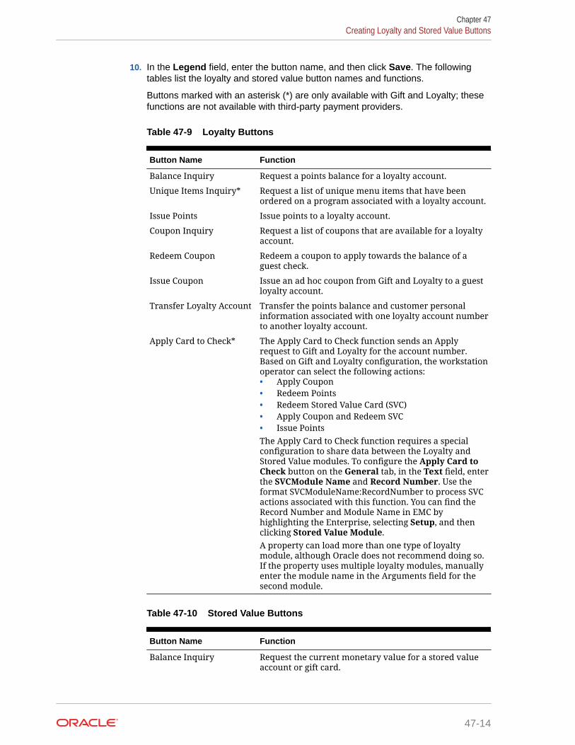
10. In the Legend field, enter the button name, and then click Save. The followingtables list the loyalty and stored value button names and functions.
Buttons marked with an asterisk (*) are only available with Gift and Loyalty; thesefunctions are not available with third-party payment providers.
Table 47-9 Loyalty Buttons
Button Name Function
Balance Inquiry Request a points balance for a loyalty account.
Unique Items Inquiry* Request a list of unique menu items that have beenordered on a program associated with a loyalty account.
Issue Points Issue points to a loyalty account.
Coupon Inquiry Request a list of coupons that are available for a loyaltyaccount.
Redeem Coupon Redeem a coupon to apply towards the balance of aguest check.
Issue Coupon Issue an ad hoc coupon from Gift and Loyalty to a guestloyalty account.
Transfer Loyalty Account Transfer the points balance and customer personalinformation associated with one loyalty account numberto another loyalty account.
Apply Card to Check* The Apply Card to Check function sends an Applyrequest to Gift and Loyalty for the account number.Based on Gift and Loyalty configuration, the workstationoperator can select the following actions:• Apply Coupon• Redeem Points• Redeem Stored Value Card (SVC)• Apply Coupon and Redeem SVC• Issue PointsThe Apply Card to Check function requires a specialconfiguration to share data between the Loyalty andStored Value modules. To configure the Apply Card toCheck button on the General tab, in the Text field, enterthe SVCModule Name and Record Number. Use theformat SVCModuleName:RecordNumber to process SVCactions associated with this function. You can find theRecord Number and Module Name in EMC byhighlighting the Enterprise, selecting Setup, and thenclicking Stored Value Module.A property can load more than one type of loyaltymodule, although Oracle does not recommend doing so.If the property uses multiple loyalty modules, manuallyenter the module name in the Arguments field for thesecond module.
Table 47-10 Stored Value Buttons
Button Name Function
Balance Inquiry Request the current monetary value for a stored valueaccount or gift card.
Chapter 47Creating Loyalty and Stored Value Buttons
47-14

Table 47-10 (Cont.) Stored Value Buttons
Button Name Function
Issue SVC Issue one stored value account number for a dollarvalue that is determined at the time of purchase.
Issue Multiple SVCs* Issue multiple stored value account numbers for a dollarvalue that is determined at the time of purchase.
Activate SVC Activate one stored value account. The applicationprompts the workstation operator to enter the pre-defined dollar value for validation.
Activate Multiple SVCs* Activate multiple stored value account numbers for adollar value that is determined at the time of purchase.The application prompts the workstation operator toenter the pre-defined dollar value for validation.
Reload Add funds to an existing stored value account.
Transfer Transfer the funds and customer personal information(if applicable) associated with one stored value accountto another stored value account.
Authorize Authorize a gift card for use as payment on a guestcheck.
Redeem Pay a guest check balance using a gift card.
Cash Out Obtain a cash payment for any remaining balance on astored value account.
Redeem SVC/Issue Points* The Redeem SVC/Issue Points function combines theRedeem SVC and Loyalty Issue Points functions. Theapplication prompts the workstation operator to redeema gift card, and then automatically issues points.The Redeem SVC/Issue Points function requires a specialconfiguration to share data between the Loyalty andStored Value modules. To configure the Redeem SVC/Issue Points button on the General tab, in the Textfield, enter the LoyaltyModule Name and RecordNumber. Use the formatLoyaltyModuleName:RecordNumber to process loyaltyactions associated with this function. You can find theRecord Number and Module Name in EMC byhighlighting the Enterprise level, clicking Setup, andthen clicking Loyalty Module.For SVC transactions, you can suppress a prompt forentry of the Total Amount Due by enabling Tender/Media option 3 - Assume Paid in Full, and by setting theText field of the Redeem button in the Page Designmodule to: RedeemAmountIsTotalDue.A property can load more than one type of stored valuemodule, although Oracle does not recommend doing so.If the property uses multiple stored value modules,manually enter the module name in the Arguments fieldfor the second module.
11. Repeat the preceding steps to create buttons for each of the loyalty and stored valuefunctions listed in the tables.
Chapter 47Creating Loyalty and Stored Value Buttons
47-15

Voiding Points on a Re-opened CheckTo allow workstation operators to void loyalty points issued on re-opened guestchecks, the check number must remain the same after reopening a check. By default,a guest check number increments each time a workstation operator re-opens thecheck, preventing the voiding of points due to check numbering mismatch.
1. Select the revenue center, click RVC Parameters, and then click Options.
2. Select 37 - Keep The Same Check Number When a Check is Reopened.
This allows a re-opened guest check to retain its original guest check number.When you deselect this option, Simphony assigns a re-opened guest check to anew check number.
3. Click Save.
XProcessor Extension Application MigrationYou can install the Loyalty driver for Gift and Loyalty Advanced at the property (inplace of the XProcessor Extension Application). Upgrade the POS clients to the latestSimphony release before completing the steps in this section.
1. Browse to the CAL server’s Microsoft Windows 32-bit or Microsoft Windows CEsubdirectory for Gift and Loyalty Advanced:
• CAL\Win32\ICareProcessor2.0 directory
• CAL\WinCE\ICareProcessor2.0 directory
2. Delete the ICareProcessor2.0 directory.
3. From the EMC, select the Enterprise level, click Setup, and then click CALPackages.
4. Delete the CAL Client package that was used to deploy the ICareProcessor2.0directory to the workstations.
5. Delete the following files from the disk:
• Micros.XProcessor.dll
• Micros.XProcessor.SVC.dll
• Micros.XProcessor.SVC.ICare.dll
6. Select the Enterprise, property, or revenue center, click Setup, and then clickExtension Application.
7. Delete the Extension Application for XProcessor.
8. Select the Enterprise, property, or revenue center, click Setup, and then clickPayments.
9. Delete the XProcessor Payment driver.
10. Select the Enterprise or property, click Configuration, and then click Tender/Media.
11. Delete XProcessor Close Check.
12. Delete the iCareSvcProcessor.icare.xml file.
Chapter 47Voiding Points on a Re-opened Check
47-16

13. Select the Enterprise level, click Configuration, and then click Data Extensions.
14. Delete the data extensions for each property.
15. Select the Enterprise, property, or revenue center, click Configuration, and then clickPage Design.
16. Double-click the page record containing Gift and Loyalty buttons to open it.
17. Delete all Gift and Loyalty buttons.
Depending on the property’s Gift and Loyalty configuration, additional menu items,discounts, service charges, or tenders may have been used. If these items are in use,leave these additional items and do not delete them.
18. If the property was using the Check Reprocessor service, remove the installed checkreprocessor files from the Enterprise Service Host as the Gift and Loyalty interface has itsown plug-ins.
19. Browse to the Handlers directory where the Check Reprocessor ran and open theChkReprocSvcHost.DLL.config file.
20. Delete the following tag:
<pluginAssembly displayname=”XProcessor Reprocessor”fullname=”Micros.XProcessor.SVC.dll, Version=0.0.0.0, Culture=neutral,PublicKeyToken=null” />Leave the tags <pluginAssemblies> and </pluginAssemblies>.
21. Delete the following files from the Handlers directory:
• Micros.XProcessor.Payment.dll
• Micros.Ops.Extensibility.dll
• Micros.XProcessor.dll
• Micros.XProcessor.SVC.dll
• Micros.XProcessor.SVC.iCare.dll
Chapter 47XProcessor Extension Application Migration
47-17

48Events
An event is a group of transactions that occur within a specific date and time range in one ormore revenue centers at a property. Examples of events include sporting events and games,banquets, weddings, and receptions. Setting an event allows you to accurately track salesand inventory, particularly when multiple events occur in a single business day (for example,a baseball double header).
You can configure events from the EMC, update event status and associate checks with aspecific event at the POS client, view various event reports in Reporting and Analytics, importand export event totals. You initiate events in the following ways:
• Automatically
• On a predefined schedule
• Through a call to an event service
• Using a function key on the workstation
Simphony retains all event information (including changes to events) for use in reporting andauditing.
Configuring Event Privileges and PermissionsYou can assign event privileges to employees.
1. Select the Enterprise level, click Configuration, and then click Roles.
2. Double-click the role type, and click the EMC Modules tab.
3. For each of the following event-related items listed in the File column, select theappropriate employee privileges (View, Edit, Add, and Delete):
• Event Types: This file controls the ability to view, change, create, and delete eventtypes and sub types.
• Event Areas: This file controls the ability to view, change, create, and delete eventareas.
• Event Definitions: This file controls the ability to view, change, create, and deleteevents.
Setting Employee Roles contains more information about setting employee privileges.
4. To set field level permissions, click the Fields tab.
5. Select Event Definitions from the EMC Modules list.
6. For Areas and Cancel Event, select the appropriate permissions from the Access drop-down list.
7. To set event check privileges, click the Operations tab, and then click the Transactionssubtab.
48-1

8. Select the appropriate options for the privileges. The following table summarizesthe check privileges associated with event functionality and the recommendedroles to have the privilege set.
Table 48-1 Event Check Privileges
Option Number Privilege Name Allow the Employeeto Authorize orPerform ...
RecommendedRoles
270 Authorize/Performassociation of anew check to anended event
Creating a newcheck and linking itto a closed or endedevent
Manager
271 Authorize/Performoverride of the"Event associationto a Check ismandatory" option(ControlParameters)
Beginning a checkwithout linking it toan event
Manager
9. Click the Miscellaneous subtab.
10. Select the appropriate options for the privileges. The following table summarizesthe workstation privileges associated with event functionality and therecommended roles to have the privilege set.
Table 48-2 Event Privileges
Option Number Privilege Name Allow the Employeeto Authorize orPerform ...
RecommendedRoles
272 Authorize/PerformStart an Event
Starting an event Manager
273 Authorize/PerformEnd an Event
Ending an event Manager
276 Authorize/PerformSelect an Event
Selecting an activeevent as theworkstationoperator’s defaultevent
Manager
277 Allow selection of‘No Default AreaSelected’ whenassigning defaultevent
Selecting a defaultevent withoutselecting a defaultarea.
Manager
11. Click Save.
Specifying Ad Hoc ReportsYou must assign privileges to the employee to run event-related reports from aworkstation at the property.
1. Select the Enterprise level, click Configuration, and then click Roles.
Chapter 48Specifying Ad Hoc Reports
48-2

2. Select the role type, click Operations, and then click Ad Hoc Reports.
3. Select the appropriate event report privileges.
Table 48-3 Event Report Privileges
Report Privilege Description
31068 - Run Property Financial Event Report Provides information about events for eachproperty, total event and non-event sales forselected dates, and outstanding (open)checks associated with events.
31069 - Run Employee Financial EventReport
Provides information about individualemployee performance for specific events.
31070 - Run Menu Item Sales Event Report Provides a summary of the menu item salesby revenue center and by employee for eachevent.
31071 - Run Event Financial Report Provides a summary of the daily financialsby event broken down by area.
4. Click Save.
Enabling EventsYou need to turn on events to associate transactions with events and to use event reporting.
1. Select the property, click Setup, and then click Property Parameters.
2. Click the Options tab, and then select 51 - Enable Events Reporting.
3. Click Save.
Configuring Event Types and Sub TypesAn employee with the event types privileges can configure event types and sub types.
1. Select the Enterprise level, click Setup, and then click Event Types.
2. Insert a record for the event (for example, Baseball Double Header or Social), and thenclick OK.
3. Double-click the event record to open it in form view.
4. To create event sub types related to the event type, in the Event Sub-Types section clickAdd, and then enter an event sub type name (for example, Baseball Game 1, BaseballGame 2, or Wedding).
5. To delete an event sub-type, highlight the Event Sub-Type, and then click Delete in theEvent Sub-Types section.
6. (Optional) Select the Menu Level Link and the Sub Level Link to associate with theevent type. You must select a main menu level before you can set a sub menu level.
When you assign main or sub levels to an event type, the event transactions at the POSclient use these menu levels rather than the default levels. This configuration is usefulwhen a venue and customer agree to a specific pricing level for the event type. Forexample, a Happy Hour menu level can be set for an event type of Social. Thisconfiguration allows a wedding event to apply Happy Hour prices at the workstation,overriding default menu levels set at the revenue center level.
Chapter 48Enabling Events
48-3

7. Click Save.
Creating an Event1. Select the property, click Configuration, and then click Event Definitions.
2. Insert a new record, enter a name for the event definition, and then double-clickthe new record.
3. From the Event Data section, enter information in the fields as described in thefollowing table:
Table 48-4 Event Data Fields
Field Description
Short Code Enter an alphanumeric event code. Theapplication appends this code with anautomatically generated code to makethe value unique.
Type Select an event type for the event.
Sub Type Select an event sub type for the event.
Event Start and Event End Select the event start and end dates.Select Auto Start and Auto End to havethe event automatically start or endwhen the Event Start or End date andtime are reached. Dates and times arerequired when selecting the Auto Startand Auto End options.When a workstation is offline and has noconnection to the Check and PostingService (CAPS), events cannot start orend (automatically and manually).
(Optional) Attendance Enter the number of people attending theevent. You can enter this number duringor after the event.
4. Click the Revenue Centers tab.
5. Select one or more revenue centers where the event occurs.
To select multiple revenue centers at once, select the revenue center group fromthe RVC Groups drop-down list, and then click the Add button. All revenuecenters included in the revenue center group are automatically selected.
If the RVC Groups field is dimmed, you need to add at least one revenue centergroup. Configuring a Revenue Center Group contains more information aboutsetting up revenue center groups.
6. Click Save.
7. Events are set as optional by default. To set the event as mandatory:
a. Select the Enterprise, property, revenue center, or zone, click Setup, and thenclick Control Parameters.
b. Select 67 - Association of an Event to every Guest Check is mandatorywhere Event feature is enabled.
Chapter 48Creating an Event
48-4

Setting option 67 requires workstation operators to select an event when beginning acheck.
You can override this setting for an employee from the Roles module by selectingTransaction Control option 271 - Authorize/Perform override of the "Eventassociation to a Check is mandatory" option (Control Parameters). Overridingoption 67 allows the workstation operator to post transactions to no event.
c. Click Save.
Configuring an Event AreaAn employee with event areas privileges can set the areas within a property where eventstake place. An area can be part of one or more revenue centers, or independent of revenuecenters. For example, a banking conference might be held in the banquets revenue center, inseveral rooms (such as banquet bar, banquet restaurant, banquet cocktail, and ballroom).You can associate these room areas with the event. When the workstation operator signs into an event that has multiple areas, the operator must select the area in which to work. Eachtransaction is associated with either one area or no area. The event organizer can viewinformation for each area on workstation reports and Reporting and Analytics reports.
1. Select the property, click Configuration, and then click Event Areas.
2. Insert a new record, and then enter a name for the event area (for example, Ballroom).
3. Click Save.
Linking EventsAfter creating an event, you can link two or more events so that when one finishes, the otherstarts (for example, a baseball double header). The linked child event (Game 2) inherits theattributes of the parent event (Game 1), including revenue centers, event areas, and menulevels.
1. Select the property, click Configuration, and then click Event Definitions.
2. Double-click the event record to open it in form view.
3. Click the Links tab.
4. To create a subsequent (child) event for the selected event, select Add Linked Event,and then click Yes at the confirmation.
5. Double-click the linked event record.
6. From the Linked Event Details dialog, enter information as described in the followingtable:
Table 48-5 Linked Event Details Fields
Field Description
Event Code You cannot enter a value. The applicationappends the short code with anautomatically generated code to make theevent code value unique.
Short Code Enter the alphanumeric event code for theevent.
Chapter 48Configuring an Event Area
48-5

Table 48-5 (Cont.) Linked Event Details Fields
Field Description
Event Name Enter a descriptive name for the event.
(Optional) Attendance Enter the number of people attending theevent. You can enter this number during orafter the event.
Event End Enter the end date and time for the event.
7. Click the Save Changes button.
Linked events are not available in the event search list and do not appear in full inthe Event Definitions module table view.
Breaking Linked EventsThere are two methods you can use to break the link of events, each producing adifferent outcome for the events:
• Break the link between the last linked event and its parent, making the last eventthe parent event
• Change a linked event to become the parent event, with subsequent events as thenew parent’s linked events
1. Select the property, click Configuration, and then click Event Definitions.
2. Double-click the event record to open it in form view.
3. Click the Links tab.
4. To break the link between the last event and its parent:
a. Click the Break Link link.
b. Click Yes at the confirmation. The last linked event in the list is removed, and itnow appears in the Event Definitions module search/table view as a parentevent.
5. To change a linked event into a parent event:
a. On the Links tab, double-click the linked event record (for example, selectlinked event 3 of 5) to open the Linked Event Details dialog.
b. Click the Break Link button.
c. Click Yes at the confirmation. Linked event 3 becomes a parent event, andlinked events 4 and 5 become its child linked events 1 and 2.
A linked event that has the chain broken from its parent event in the LinkedEvent Details dialog is available in the Event Definitions module search/tableview, and contains any subsequent linked events as its linked events.
Cancelling an EventWhen cancelling an event, consider the following rules:
• You can only cancel an event that has the Uninitialized status.
• You can cancel a linked event if the parent event has a Started status.
Chapter 48Breaking Linked Events
48-6

• When you cancel a parent event, all linked child events are also cancelled.
• After cancelling linked events, you cannot add new linked events if you used the BreakLink function on all cancelled linked events.
1. Select the property, click Configuration, and then click Event Definitions.
2. Double-click the event record to open it in form view.
3. To cancel an event with or without linked events, click Cancel Event, and then click Yesat the confirmation.
4. To cancel one linked event:
a. Click the Links tab.
b. Double-click the linked event record to open the Linked Event Details.
c. Click Cancel Event, and then click Yes at the confirmation.
5. To cancel multiple linked events:
a. Click the Links tab.
b. Double-click the first linked event record to open the Linked Event Details.
c. Click Cancel Event, and then click Yes at the confirmation. The linked event Statusshows Cancelled and Add Linked Event is dimmed. The parent event is notcancelled.
Configuring Event Information to Print on Checks and ReceiptsYou can configure the printing of an event name and code on guest check headers andtrailers, customer receipts, and credit card vouchers.
1. Select the Enterprise, property, revenue center, or zone, click Setup, and then clickFormat Parameters.
2. Click the Options tab.
3. Select the appropriate printing options:
• 59 - Print Event Name After Header on Guest Checks and Receipts: Select thisoption to print the event short code and name after the header on guest checks andcustomer receipts.
• 60 - Print Event Name After Trailer on Guest Checks and Receipts: Select thisoption to print the event short code and name after the trailer on guest checks andcustomer receipts.
4. Click Save.
Creating Task SchedulesA Task Schedule is a timed task that occurs on a Check and Posting Service Host or on aworkstation. These tasks perform database-related functions that increase performance ofthe device.
1. Select the Enterprise or property, click Configuration, and then click Task Schedules.
2. Insert a new record or double-click an existing task schedule record to open it in formview.
The database includes the following default task schedule records:
Chapter 48Configuring Event Information to Print on Checks and Receipts
48-7

• Purge C&P DB data older than 7 days: Cleans the Check and Postingdatabase for records older than seven days.
• Purge WS DB data older than 7 days: Cleans the workstation database forrecords older than seven days.
• Update C&P DB Statistics: Runs an Update Statistics command on theCheck and Posting database.
• Update WS DB Statistics: Runs an Update Statistics command on theworkstation database.
The purge jobs clear check and totals information, along with message requeststhat are stored in the local database.
3. From the General Settings section, enter information in the fields as described inthe following table:
Table 48-6 General Settings
Field Description
Service Type Select the type of service to receive thetask, either 7 - Workstation or 8 - Checkand Posting.
Service ID Select the service identification for whichthe task runs. You can only change thisvalue at the property level.
Task Type Select the type of task.When the task schedule is:• Database purge, the database for the
selected service purges old data. TheTask Data field should indicate thenumber of days to keep data in thelocal database.
• Update statistics, the local databaseperforms an update statistics job atthe scheduled time. The Task Datafield should contain a semicolon-separated list of database tables onwhich the Update Statisticscommand runs.
• Run script, the Task Data fieldshould contain the full path to ascript to execute.
Task Data This value shows the relevant data forthe Task Type.
Duration (seconds) Enter the duration of the task.The duration time prevents the task fromrunning too long. The duration time doesnot cause tasks to terminate immediately.For example, the Update Statistics jobfinishes each database table listed, andthen checks the duration of the overalltask.
Chapter 48Creating Task Schedules
48-8

Table 48-6 (Cont.) General Settings
Field Description
Time Zone Select the time zone for the task, whichdetermines the time of day when the taskruns.A common setting for this field is 0 -Local Time Zone, causing the task to runin each property based on the local timeat the property.
Schedule Type Select the recurrence frequency for thetask schedule (for example, one time,daily, weekly, or monthly).
4. From the Duration section, select Enabled to run the task schedule at the set time.Deselect this option if you do not want the task schedule to run.
a. In the Start date field, select the first date for the task schedule to run.
b. To end the task schedule on a specific date, select End date, and then select thedate for the task schedule to end. If the task schedule has no end date, select Noend date.
5. If you selected a recurring frequency in the Schedule Type field, click the Recurrencetab. The available fields are based on the recurring frequency you selected (daily, weekly,or monthly).
6. Select the appropriate day and time options for the frequency.
7. Click Save.
Configuring the Event Status BarTo allow workstation operators to see the event and check details to which sales are posting,you need to add the event status bar to the transaction page, and configure the eventinformation that appears in the status bar.
1. Select the Enterprise, property, revenue center, or zone, click Configuration, and thenclick Page Design.
2. Open the page on which to place the event status bar (typically the transaction page).
3. Click the Configuration tab.
4. Select one or both of the following placement options:
• Top Status Bar
• Bottom Status Bar
5. Click the Add button in the lower area.
6. From the Add Status Bar Element dialog, select Operator Current Event Name for eachof the following POS state drop-down lists, and then click OK.
• Signed Out
• Signed In
• In Transaction
7. Repeat Steps 5 and 6, selecting the following elements for each POS client drop-downlist:
Chapter 48Configuring the Event Status Bar
48-9

• Operator Current Event Shortcode
• Operator Current Event Actual Start Date Time
• Operator Current Event End Date Time
• Check Current Event Name
• Check Current Event Shortcode
• Check Current Event Actual Start Date Time
• Check Current Event End Date Time
8. Click Save.
Configuring the Event ButtonsTo allow workstation operators to manually start and end an event, you need to addbuttons assigned to the touchscreen page.
1. Select the Enterprise, property, revenue center, or zone, click Configuration, andthen click Page Design.
2. Open the page on which to place the Start Event and End Event buttons.
3. On the Edit tab, select the page area in which to define the Start Event button.
4. Click Button.
5. On the General subtab, enter the button name (for example, Start Event) in theLegend field.
6. Select Function from the Type drop-down list.
7. Click the black arrow directly beneath the Type drop-down list, select the typeEvent Management, select the results Start Event, and then click OK.
8. Position and size the button on the page. Use the Style arrow to change the color.
9. Repeat Steps 3 through 9 to create the End Event button, selecting End Event forthe result.
10. Click Save.
Event Information in Reporting and Analytics ReportsYou can view Simphony event-related reporting information in Reporting and Analyticsversion 8.5.1 and later. The event information includes event code, name, type, subtype, and area.
Chapter 48Configuring the Event Buttons
48-10

Table 48-7 Reporting and Analytics Event Reporting
Report Description
Events Summary Reports These reports provide summary informationfor properties with events enabled, and helpyou identify top level areas that needimprovement for subsequent events.The following summary reports include eventinformation:• Events Today’s Operations Report• Events Revenue Center ReportOnly the Events Today’s Operations Reportenables you to drill down to more informationor investigate further by running DetailReports.
Detail Reports These reports help you analyze the transactiondetails for specific events. Parent and childevents are shown separately.The following detail reports include eventinformation:• Events Adjustments Detail Report• Events Control Report• Events Cost of Goods Sold Summary
Report• Events Daily Discounts Report• Events Sales Mix Summary Report• Events Service Charges Report• Events Taxes Report• Events Tender Media ReportMost detail reports enable you to drill down tomore information.
Comparison Reports These reports provide information forcomparing key performance indicators used inspecific events. Comparison reports help youanalyze productivity in different revenuecenters and plan future events. Parent andchild events are shown separately.The following comparison reports includeevent information:• Events Daily Operations Comparison by
Revenue Center (also includes taxinformation)
• Events Store and Date Comparison ReportThese reports do not enable you to drill downto more information.
Chapter 48Event Information in Reporting and Analytics Reports
48-11

Table 48-7 (Cont.) Reporting and Analytics Event Reporting
Report Description
Menu Engineering Reports These reports provide information to help youanalyze the menu mix, prices, and cost ofgoods for specific events. Menu engineeringreports enable you to increase event revenueby planning menus for subsequent eventsusing menu information from past events.Parent and child events are shown separately.The following menu engineering reportsinclude event information:• Events Menu Engineering Items Summary
Report• Menu Engineering by Major and Family
Group Reports• Events Item Groups Average Pricing
Report• Sales Mix Summary Report• Top Items Summary ReportOnly the Menu Engineering by Major andFamily Group and Events Item Groups AveragePricing reports enable you to drill down tomore information.
Employee Reports These reports provide information aboutemployee performance for specific events.Employee reports help you to select the mostproductive staff for events and highlighttraining issues. Parent and child events areshown separately.The following employee reports include eventinformation:• Employee Productivity Report• Events Employee Financial List Report
(also includes tax information)• Events Employee Sales Performance
Report• Events Tip Track Summary Report• Events Manager Control Report• Events Employee Control ReportThese reports enable you to drill down to moreinformation.
Events Daily Operations Summary Report This report provides a summary of the dailyoperations, including tax information, for oneor more events.This report enables you to drill down to moreinformation.
Events Financial Report This report provides a summary of the dailyfinancials by event. The Events FinancialReport shows all tenders, service charges,discounts, taxes, and void activity per revenuecenter during the event.This report enables you to drill down to moreinformation.
Chapter 48Event Information in Reporting and Analytics Reports
48-12

Table 48-7 (Cont.) Reporting and Analytics Event Reporting
Report Description
Events Consolidated Employee FinancialReport by RVC
This report shows a combined view of theemployee financials by revenue center foreach event. It also shows all tenders, servicecharges, discounts, taxes, and void activity perrevenue center during the event.This report enables you to drill down to moreinformation.
Events Menu Item Report by RVC by Employee This report provides a summary of the menuitem sales by revenue center and by employeefor each event. The report shows the revenuecenter number and name, the employee, menuitem, quantity sold, price, sales less itemdiscounts, taxes, and net sales.This report enables you to drill down to moreinformation.
Consolidated Events Employee Meal This report shows a combined view of theemployee meals for an event. The reportshows the revenue center, the employeeconsuming the meal, the check number, thetime of the transaction, the menu items, theprice when the menu item was ordered, taxesassociated with the transaction, net sales of thetransaction, and the employee adding thesales.This report enables you to drill down to moreinformation.
Event Consolidated RVC Financial This report shows a combined view of therevenue center financials by event. The reportshows all tenders, service charges, discounts,taxes, net sales, voids, transaction count, andpercent of sales per revenue center during theevent.This report enables you to drill down to moreinformation.
KDS Reports These reports provide information to help youanalyze the sales mix and labor for specificevents. Parent and child events are shownseparately. KDS reports help to identifyproblems with preparation and service times,and improve these times for subsequentevents.The following KDS reports include eventinformation:• Events KDS Summary Report• Events Today’s KDS Summary Report• Speed of Service ReportThese reports enable you to drill down to moreinformation.
Chapter 48Event Information in Reporting and Analytics Reports
48-13

49Dining Room Tables and Seating
You can manage the dining room using Simphony with a standard table managementinterface, or using the enhanced Table Management System.
Standard and Enhanced Table ManagementDining staff can manage tables in Simphony using one of the following methods:
• Standard table management interface
• Enhanced or integrated tables (available with the Table Management System)
The following table outlines the differences between the two table management methods:
Table 49-1 Differences Between Standard and Enhanced Table Management
Function Standard Tables Enhanced Tables
Accept reservations No Yes
Manage a Reservation List No Yes
Manage a Wait List No Yes
Provide wait quotes No Yes
Show table status Yes Yes
Estimate table turn times No Yes
Assign tables to sections and employees No Yes
Join and split tables No Yes
Suggest tables No Yes
Use function keys on the workstation forbussing and transferring tables
Yes No
Interface with Oracle Hospitality Gift andLoyalty Advanced Cloud Service
No Yes
Configuring the Standard Table Management Interface1. Select the Enterprise level, click Setup, and then click Interfaces.
2. Insert a record for Standard Table Management, and then open it in form view.
3. From the Interface Type drop-down list, select 3 - Table Management.
4. From the Communications Type drop-down list, select 1 - TCP.
5. In the Timeout field, enter the amount of time (in seconds) that Simphony waits for aresponse from the standard table management interface before showing acommunications failure message.
6. In the Ping Frequency field, enter the amount of time (in seconds) that Simphony pingsthe standard table management server (for example, every 5 seconds).
49-1

7. Click the Options tab, and then select the appropriate options as described in thefollowing table.
Table 49-2 Standard Table Management Interface Options
Option Description
2 - Enable Interface Log Select this option to post debuginformation to the Interface log file.
5 - ON = Use 9 digits for Terminal IDs;OFF = Use 2 digits for Terminal IDs
Select this option to transmit the entirenine-digit workstation ID to the standardtable management system.
8 - Enable Offline Posting Select this option to allow offline postingto the Simphony POS client.
9 - Determine Link Status Using Ping Select this option to allow the SimphonyPOS client to ping the standard tablemanagement system.
10 - ON = Use 5-digit RVC #; OFF = Use 3-digit RVC #
Select this option to allow the standardtable management system postingmessage to support a five-digit revenuecenter number. (Otherwise, the posting islimited to a three-digit revenue centernumber.)
11 - ON = Use 8-digit Check #; OFF = Use4-digit Check #
Select this option to allow the standardtable management system postingmessage to support an eight-digit checknumber. (Otherwise, the posting islimited to a four-digit check number.)
8. In the TCP Host Name field, enter the name or IP address of the standard tablemanagement server for the interface.
9. In the Port Number field, enter 0 (zero).
10. Click the Properties tab, and select each property that uses the standard tablemanagement system interface.
11. Click the Service Host tab, and then select the service host that can run thestandard table management system interface.
12. Click Save.
13. Select the revenue center, click Setup, and then click RVC Parameters.
14. Click the Interfaces tab.
15. Select the TMS Operator to whom a check that is opened by the standard tablemanagement system is assigned, before being picked up by a server.
16. Select the TMS User Workstation to which a check that is opened by thestandard table management system is assigned.
17. From the TMS Link drop-down list, select the standard table managementinterface.
18. Click Save.
Chapter 49Configuring the Standard Table Management Interface
49-2
Creating Standard Dining Tables1. Select the Enterprise, property, or revenue center, click Configuration, and then click
Page Design.
2. Double-click the Front of House page on which to define standard dining tables.
3. On the Edit tab, select the page area on which to place the standard dining tables.
4. Select Other..., and then select Dining Table.
5. Move and adjust the table size on the page. Leave space between tables on the pagelayout to ensure visibility of indicators and table state. You can increase the gridconfiguration on the page from 24 (default) to 48 using the Change Grid Size link.
6. Repeat Steps 4 and 5 to create additional standard dining tables.
7. Click Save.
Configuring the Standard Dining Table Status SetYou can configure a dining table status set to allow workstation operators to manually assigna specific table status value from the set. For example, dining tables could be used to beginnew takeout orders. Workstation operators can update the status of the table based upon thereadiness of the order (such as Preparing, Ready, or Called Running Late).
This feature is only available with standard dining tables (not enhanced or integrated tables).
1. Select the Enterprise, property, or revenue center, click Setup, and then click DiningTable Status Set.
2. Insert a record for the Dining Table Status Set, and then open it in form view.
3. Click Add, and then enter or select information for the fields as described in the followingtable.
Table 49-3 Standard Dining Table Status Set Fields and Options
Field or Option Description
Name Enter the name of the dining table status set(for example, waiting or eating).
Override Background Color Click the ellipsis point (...) button, select thebackground color, and then click OK.
Override Text Color Click the ellipsis point (...) button, select thetext color, and then click OK.
Override Image Click the ellipsis point (...) button, select theimage, and then click OK.
Chapter 49Creating Standard Dining Tables
49-3

Table 49-3 (Cont.) Standard Dining Table Status Set Fields and Options
Field or Option Description
Option Bits Click the ellipsis point (...) button, select theappropriate options, and then click OK.• 1 - Stretch image to fill area: If you
selected an image, this optiondetermines the image appearance andsizing.
• 2 - Show table #/cover counthorizontally: Select this option if youwant the table number and cover countto appear horizontally on the table.
Default Index Enter the default status between 1 and 99.Enter 0 (zero) if you do not want a defaulttable status.
Disabled Index Do not use this field.
Styling Key Enter the object key for the dining tablestatus.
4. Repeat Step 3 for each dining table status you want to add.
5. Click Save.
Table ManagementYou can integrate dining room management, reservation list, wait list, customerpreferences and seating, and staff availability with the Simphony Table ManagementSystem, Reservation List, and Wait List.
The Simphony Table Management System (TMS) allows you to perform the followingactions:
• Make reservations
• Maintain a Wait List
• Seat guests immediately at available tables
• Control the number of reservations allowed during specific time periods
• See an overview of enhanced dining tables and status
• Update the table status based on coursing
• Manage the seating layout with table, section, and server assignments
• Change table seating capacities
• Estimate wait quote times
Reservation ListThe Reservation List contains all reservation requests for the revenue center. Hostingstaff with access to the Reservation List can create, edit, and cancel reservationrequests from the list.
Chapter 49Table Management
49-4

Wait ListOften a guest arrives and asks for a table. When tables are not immediately available forseating, the guest may request a wait time and add their name to a Wait List. The Wait Listcontains all wait requests for the revenue center. The Wait List also shows reservations priorto the scheduled arrival. Reservations appear on the Wait List a configured number ofminutes prior to the schedule seating time. Hosting staff with access to the Wait List can add,change, and abandon wait requests from this list. Hosting staff can manage the Wait List onits own page or as a popup in the host view.
Table Management, Reservation, and Wait List ConfigurationPrerequisites
Before configuring reservations, you must complete the following tasks:
• Configure the Simphony Table Management System (TMS)
• Configure the Simphony Wait List to accept and seat guests with reservations
If the property is using a Wait List, but does not take reservations, you only need to configurethe TMS before setting up the Wait List. (A Reservation List is not required with the Wait List.)
The Simphony TMS, Reservations, and Wait List integrate with loyalty applications such asOracle Hospitality Gift and Loyalty, and third party loyalty applications based on the loadableloyalty modules. When you use Simphony TMS, Reservations, or Wait List with loyaltyapplications, workstation operators can associate the loyalty account with the reservationrequest or walk-in guest. After associating guest loyalty information with the table request, theinformation follows the guest through the life of the guest check. To use the Simphony TMS,Reservations, or Wait List with a loyalty application, you must configure the loadable loyaltymodule. Loyalty Configuration Tasks contains more information about configuring the loyaltymodule.
Configuring Table Management Privileges1. Select the Enterprise, click Configuration, and then click Roles.
2. Select the role type, click the Operations tab, and then click the Guest Managementsubtab.
3. Select the appropriate options for the privileges. The following table summarizes theprivileges associated with table management functionality and the recommended roles tohave the privilege set.
Table 49-4 Table Management Privileges
Tab Location Option Number Privilege Name Allows theEmployee to ...
RecommendedRoles
GuestManagement
32020 Edit SectionLayout
Edit a sectionlayout
Host, Manager
Chapter 49Wait List
49-5

Table 49-4 (Cont.) Table Management Privileges
Tab Location Option Number Privilege Name Allows theEmployee to ...
RecommendedRoles
GuestManagement
32021 Activate SectionLayout
Activate adefined sectionlayout as theActive Layout
Host, Manager
GuestManagement
32022 Delete SectionLayout
Delete anexisting sectionlayout
Host, Manager
GuestManagement
32031 Assign Employeeto Table
Assign anemployee to atable or sectionin TMS
Host, Manager
GuestManagement
32032 Mark TableClean or Dirty
Mark a table asclean or dirty
Host, Manager
GuestManagement
32033 Change TableState
Mark tables asbeing Available,Closed, Reserved,or Merged
Host, Manager
GuestManagement
32034 SeatUnsuggestedTable
Seat a tablerequest at a tablethat is differentthan the tablethat wassuggested by theTMS TableSuggestionSystem
Host, Manager
GuestManagement
32037 View Legend View the TMSLegend and usethe availablefunctionscontained withinthe form
Host, Manager
GuestManagement
32038 Allow SeatingGuest Above orBelow TableCapacity
Seat a tablerequest at a tablethat does notsupport adifferent seatingcapacity (otherthan the covercount on thetable seatingrequest)
Host, Manager
GuestManagement
32039 Allow SeatingGuest at Tablethat does notMeet allRequired TablePreferences
Seat a tablerequest at a tablethat does notmeet all of theseatingpreferencesdefined on thetable seatingrequest
Host, Manager
Chapter 49Configuring Table Management Privileges
49-6

Table 49-4 (Cont.) Table Management Privileges
Tab Location Option Number Privilege Name Allows theEmployee to ...
RecommendedRoles
GuestManagement
32040 Edit ServerAvailability
Edit the serveravailability
Host, Manager
Ad Hoc Reports 31044 Run EmployeeSectionAssignmentReport
Run theEmployeeSectionAssignmentReport
Host, Manager
Transactions 22 Post Payment toChecksBelonging toAnotherOperator
Unseat a tablerequest
Host, Manager
Transactions 37 Authorize/Perform Postingof Payment
Unseat a tablerequest
Host, Manager
Transactions 38 Authorize/Perform Closingof Checks with aZero Balance
Unseat a tablerequest
Host, Manager
Guest Checks 18 Authorize/Perform Pickupof a CheckBelonging toAnotherOperator
Unseat a tablerequest
Host, Manager
4. Click Save.
Configuring Reservation Privileges1. Select the Enterprise, click Configuration, and then click Roles.
2. Select the role type, click the Operations tab, and then click the Guest Managementsubtab.
3. Select the appropriate options for the privileges. The following table summarizes theprivileges associated with reservation functionality and the recommended roles to havethe privilege set:
Table 49-5 Reservation Privileges
Option Number Privilege Name Allow the Employeeto ...
Recommended Roles
32006 Greet Wait List Entry Greet a reservationrequest if the partyarrives earlier than thetime at which thereservationautomatically moves tothe Wait List
Host, Manager
Chapter 49Configuring Reservation Privileges
49-7

Table 49-5 (Cont.) Reservation Privileges
Option Number Privilege Name Allow the Employeeto ...
Recommended Roles
32007 Mark as No Show Mark a reservationrequest as a no-show ifthe guest does notarrive
Host, Manager
32010 Add Reservation Entry Create a reservationrequest
Host, Manager
32011 Edit Reservation Entry Edit an existingreservation request
Host, Manager
32012 Cancel ReservationEntry
Cancel a reservationrequest
Host, Manager
32013 Approve ReservationEntry
Approve a reservationthat is requesting adate or time outsidethe acceptable orallowable timeframe
Host, Manager
4. Click Save.
Configuring Wait List Privileges1. Select the Enterprise, click Configuration, and then click Roles.
2. Select the role type, click the Operations tab, and then click the GuestManagement subtab.
3. Select the appropriate options for the privileges.
The following table summarizes the privileges associated with wait list functionalityand the recommended roles to have the privilege set:
Table 49-6 Wait List Privileges
Option Number Privilege Name Allow the Employeeto ...
RecommendedRoles
32001 Add Wait List Entry Create a new WaitList request
Host, Manager
32002 Edit Wait List Entry Edit an existing WaitList request
Host, Manager
32003 Abandon Wait ListEntry
Abandon a Wait Listrequest
Host, Manager
32004 Seat Wait List Entry Seat a Wait Listrequest
Host, Manager
32005 Unseat Wait ListEntry
Unseat a Wait Listrequest
Host, Manager
32006 Greet Wait List Entry Greet a Wait Listrequest
Host, Manager
Chapter 49Configuring Wait List Privileges
49-8

Table 49-6 (Cont.) Wait List Privileges
Option Number Privilege Name Allow the Employeeto ...
RecommendedRoles
32007 Mark as No Show Mark a reservationrequest as a no-showif the guest does notarrive
Host, Manager
4. Click Save.
Configuring Servers for Table Management1. Select the Enterprise, property, or revenue center, click Configuration, and then click
Employee Maintenance.
2. Search for and select the employee record.
3. In the Check Name field, enter the server’s name as you want it to appear on theworkstation. If you do not enter a Check Name, the workstation shows a blank name.
4. Click the Operator Records subtab near the lower area of the screen.
5. In the TMS Color field, select the color to distinguish the server from other servers on thehost page, and then click OK.
Although you can set a different color for each revenue center within a property, Oraclerecommends that you use a single color for the server across the property. If you do notset a TMS Color, the workstation shows white.
6. In the Server Efficiency field, enter 0 (zero) if you want the Simphony TMS to ignore theserver in the table suggestions.
The Table Suggestion System (within TMS) sets the Server Efficiency rating todetermine the next table recommended for seating. This rating is a value between 0(zero) and 100, and represents the number of covers that the server can efficientlyservice at one time.
7. Click Save.
Configuring Properties for Table Management1. Select the property, click Setup, and then click Properties.
2. Highlight the property record.
3. In the Simphony Platform field, select 2 - Extensible Clients and Architecture.
4. Click Save.
Configuring Custom Images for Table ManagementYou can load custom images into the Simphony application to represent table seatingconfiguration and statuses. The TMS uses both custom images and images packaged withSimphony. All images are transparent Portable Network Graphics (PNG) files.
Table images show a graphical representation of the table and chairs. These images can bea square or round table surrounded by any number of chairs.
Chapter 49Configuring Servers for Table Management
49-9

Table decorators show a graphical representation of the table status (for example,dirty, closed, or reserved).
1. Select the Enterprise, property, or revenue center, click Setup, and then clickContent.
2. Double-click the content name row to view the image set for that name.
3. Click the Import from a file link to import custom images.
4. Browse to the file location, select the image file, and then click Open.
5. Repeat Steps 2 through 4 to import each table image and table decorator.
6. Click Save.
Configuring KDS or Dining Course Colors and Images forTable Management
You can set a color or image to indicate the KDS or dining course that the table isbeing serviced under.
1. Select the Enterprise or property, click Descriptors, and then click KDS/DiningCourse.
2. Insert dining course records if they do not exist.
3. In the Course Color field, select a color for each dining course name.
This color appears as the dining course indicator on the table image in theworkstation. For example, appetizers can be green, entrées can be yellow, anddesserts can be red.
4. (Optional) From the Course Image Name field, select a the course decoratorimage to represent the dining course (in place of a course color). The image youselect replaces the default Occupied image on the table. To remove a CourseImage that was previously set, select 0 - None, and then click OK.
5. Click Save.
Configuring Dining Course PacingYou can set the pace at which Simphony sends dining courses to the kitchen. Thisfeature only works for menu items that have KDS prep times configured.
1. In the EMC, select the Enterprise, or property, click Descriptors, and then clickKDS/Dining Course.
2. Insert a dining course record if it does not exist, and then enter the followinginformation:
• Initial Course Min Prep Time: Enter the target done time for the course.
For example, if you enter 10 minutes and an item with a prep time of 6 minutesis sent to the kitchen, it will not fire to Prep Stations until 4 minutes haveelapsed. If an item with a prep time of more than 10 minutes or without anyprep time is sent to the kitchen, it will fire immediately. The timer for the nextcourse does not start until this time is exceeded.
• Min Prep Time: Enter the minimum amount of time that the KDS Controllershould wait before sending the next course to the kitchen after the current
Chapter 49Configuring KDS or Dining Course Colors and Images for Table Management
49-10

course is bumped from all Prep Stations. This option is not applicable to the firstdining course.
• Max Prep Time: Enter the maximum amount of time that the KDS Controller shouldwait before sending the next course to the kitchen after the current course is bumpedfrom all Prep Stations.
3. Click Save.
Configuring the Service Total Tender for Table ManagementYou can configure a unique service total tender media record to process seating andunseating of guests.
1. Select the Enterprise, click Configuration, and then click Tender/Media.
2. Create a tender media record, and then name it TMS.
3. Double-click the record to open it.
4. From the Key Type drop-down list, select 2 - Service Total.
5. Click Save.
Enhanced Dining TablesComplete the following tasks to set up enhanced dining tables:
• Set Dining Table Classes
• Set Enhanced Dining Table Attributes
• Configure Enhanced Tables
Setting Dining Table ClassesYou can group and configure similar tables into a dining table class.
1. Select the Enterprise, property, or revenue center, click Setup, and then click DiningTable Class.
2. Insert a dining table class.
3. Select or enter information for the following fields.
Table 49-7 Dining Table Class Fields
Field Description
Name Enter the name of the dining table class. The nameidentifies the class (for example, 2 Tops, 4 Tops, and so on).
(Optional) Default BackgroundColor
Select a background color to represent the table. Select adifferent color than the page background so as not to blendsimilar colors.If you associate a transparent table image with the diningtable class, the background color appears with the image.If you select 0 - None, the application shows the tableimage and background color of the page.
Chapter 49Configuring the Service Total Tender for Table Management
49-11

Table 49-7 (Cont.) Dining Table Class Fields
Field Description
(Optional) Default Text Color Select the text color to represent the table number orname. Select a different color than the page background soas not to blend similar colors.If you select 0 - None, the application shows the defaulttext color of black.
(Optional) Default Image Select the image to represent the table.
Minimum Covers Enter the lowest number of covers that the dining tableclass can accommodate (for example, a 2-Top canaccommodate a minimum of 1 person).
Maximum Covers Enter the largest number of covers that the dining tableclass can accommodate (for example, a 2-Top canaccommodate a maximum of 2 people).You can overlap covers to seat a specific cover countwithin one or more dining table classes (for example, 4covers on a 4-Top or 6-Top).
Options If you are using enhanced dining tables within the diningtable class, select 1 - Enhanced Dining Table. If you areusing legacy standard tables, deselect Enhancement DiningTable.
4. Click Save.
Setting Enhanced Dining Table AttributesYou can set characteristics of the table for use in the table suggestion process.
1. Select the property, click Setup, and then click TMS Table Attributes.
2. Select or enter information for the following fields.
Table 49-8 TMS Table Attributes Fields
Field Description
Name Enter the name of the attribute,characteristic, or guest preferenceassociated with a table (for example,Accessible, Window Seats, City View,Ocean View, or Booth).
Code Enter the attribute code associated with aguest preference in the request (forexample, ADA, WIND, CITY, OCN, orBTH).
(Optional) Is Exclusive Select this option if the table attributesmust be met before being included intable seating suggestions. For example,the Accessible attribute is exclusive.
3. Click Save.
Chapter 49Setting Enhanced Dining Table Attributes
49-12

Configuring Enhanced Dining TablesDining tables represent the physical location where a party can be seated with a QuickSeating operation or from the Wait List.
1. Select the property, click Setup, and then click Tables.
2. Select or enter information for the following fields.
Table 49-9 Tables Fields
Field Description
Table Number (# symbol) Enter a unique table number for all revenuecenters within the property. The TableNumber appears on the workstation andrepresents the internal number used todistinguish one table from another withinthe property.
Name Enter a unique table name for all revenuecenters within the property. The table nameappears on the workstation and representsthe local facing name or number used todifferentiate the table from others. Values inthe Name field can be:• All numeric• All alpha• Alpha and then numeric
Class Select the dining table class. The dining tableclass defines the type of table. All instancesof this table number use the color, image,and cover configurations defined for theselected dining table class.Create only tables that are to be used forseating within a revenue center. Creatingnon-seatable tables (such as bar tabs)prevents the table suggestion system fromproperly distributing tables.Do not delete tables unless you no longerneed them for reports. Oracle Hospitalityrecommends that you assign tables that arenot used to a dining table class named toindicate this status. For example, create adining table class named NOT IN USE andassign unused tables to this class. Tablesassigned to the NOT IN USE class cannot beused for seating, but remain in theSimphony TMS for reporting purposes.
Table Attributes Click the Add link to associate one or moreattributes with a table. When you setattributes, the application matches guestpreferences with tables. For example, whena guest prefers window seats, tablesassociated with a window seating attributemove up in the table suggestion process.
Chapter 49Configuring Enhanced Dining Tables
49-13

Table 49-9 (Cont.) Tables Fields
Field Description
Mergeable Tables Click the Add link to add the tables thatworkstation operators can select for mergingwith the selected table.Click the Delete link to remove tables fromthe mergeable table assignment.Select None in the record or leave theMergeable Tables section empty to indicatethat the selected table has no mergerestrictions and it can be merged with anytable.
3. Click Save.
Setting Table Decorator Images1. Select the Enterprise, property, or revenue center, click Setup, and then click TMS
Parameters.
2. (Optional) Click the link next to each Dining Table Decoration Image Name to viewa list of images (set as custom images).
Dining table images are optional but useful as part of daily table managementoperations. Configuring Custom Images for Table Management contains moreinformation about setting custom images.
3. Select an image to represent each of the following statuses:
Table 49-10 Dining Table Decoration Images
Table Status Description
Select The application uses this decorator whena workstation operator selects one ormore tables. Table selection is onlyavailable on a page with the HostCommand Area. Table selection allowsthe workstation operator to apply aspecific action to the selected tables.
Dirty The application uses this decorator whena table is in a status of Dirty. Workstationoperators can still seat guests at dirtytables.
Seated The application uses this decorator whena guest is newly seated at a table. Thisstatus remains until the guest places anorder. After placing an order, the tablestatus changes to Occupied.
Chapter 49Setting Table Decorator Images
49-14

Table 49-10 (Cont.) Dining Table Decoration Images
Table Status Description
Occupied The application uses this decorator aftera guest places an order at the table. Thisstatus remains until the guest tenders thecheck.The image associated with the Occupiedstatus is overridden when you set imagesfor dining courses.Configuring KDS or Dining Course Colorsand Images for Table Management containsmore information about setting diningcourse images.
Printed The application uses this decorator whenthe workstation operator prints the guestcheck. The table is considered occupied,and the Printed status appears inaddition to the Occupied status.
Paid The application uses this decorator aftera guest completes the dining experienceand tenders the check. This statusremains for the duration of time set inthe Auto Reset Paid Status (Minutes)field. Host staff can seat new guests attables marked as Paid. After a host seatsa guest at a Paid table, the table statusresets.
Parent The application uses this decorator toidentify the table as the parent table in amerged table grouping. This statusappears in addition to the other statusindicators.
Child The application uses this decorator toidentify the table as the child table in amerged table grouping. This decoratorincludes a text overlay that identifies thechild’s parent table number and name.The application clears both Parent andChild decorators when the workstationoperator removes the merged tablegrouping.
Closed The application uses this decorator toindicate a status of Closed. Host staffcannot seat guests at closed tables.
Reserved The application uses this decorator toindicate a status of Reserved. The TableSuggestion process does not considerreserved tables for seating.
User Suggested The application uses this decorator toidentify the table as the host staffrecommended seating placement for thehighlighted table request on the WaitList.
Chapter 49Setting Table Decorator Images
49-15

Table 49-10 (Cont.) Dining Table Decoration Images
Table Status Description
System Suggested The application uses this decorator toidentify the table as the systemrecommended seating placement for thehighlighted table request on the WaitList.
Highlighted Do not use this decorator.
Host Area This image is not a table decorator, butan optional image placement for the HostCommand Area. You can use this imageto place the restaurant logo on the hostpage.
4. Click Save.
Configuring Server and Table Availability1. Select the Enterprise, property, or revenue center, click Setup, and then click TMS
Parameters.
2. Click the Configuration tab, and then click the Table Suggestion subtab.
3. In the Default Server Available Time (Minutes) field, enter the default number ofminutes to use when making a server unavailable in the TMS. You can set this to aduration between 1 and 480 minutes.
4. In the Auto Reset Paid Status (Minutes) field, enter the number of minutes thatthe table decorator shows as paid on the host page before returning to anavailable status. You can define a buffer of time between when the table servicemoves from tendered, cleaned, and available for a new seating. Setting a value of0 (zero) or blank defaults the time to 1 minute.
5. Click Save.
Setting Table Management Options1. Select the Enterprise, property, or revenue center, click Setup, and then click TMS
Parameters.
2. On the Configuration tab, select Enable Table Management to turn on TMSfunctions in Simphony.
Select this option only for properties and revenue centers that use the TMSfeatures. This option increases workstation resources and communicationsbandwidth for the Enterprise.
3. If you are using a loyalty program to look up and process transactions, select theLoyalty Module ID from the drop-down list. If you are not using a loyalty program,select None.
4. Select the appropriate TMS Options in the lower area of the screen. The followingtable describes the options.
Chapter 49Configuring Server and Table Availability
49-16

Table 49-11 TMS Options
Option Description
Close Unassigned Tables on Section LayoutActivation
Select this option to automatically closetables that are not assigned to a sectionwhen a workstation operator activates asection layout.
Allow Multiple Loyalty Accounts per GuestCheck
Select this option to allow the workstationoperator to associate additional loyaltyaccounts with the guest check by selectingseats. Deselect this option to limit one loyaltyaccount per guest check.This option determines whether theworkstation operator can associate multipleloyalty accounts with a guest check.
Enable Guest Information Chit Printing Select this option to print a chit when thehost staff seats the table request.
Update Table On KDS Bump Event Select this option to update the KDS ordining course on the table image after theworkstation operator bumps the menu fromthe KDS. Deselect this option to update theKDS or dining course on the table imageafter the workstation operator performs aservice total.Select this option only when the property orrevenue center uses a Kitchen DisplaySystem (KDS). This option determines whenthe dining course updates on the host pagetable image.
Prompt for Employee on Unassigned Table Select this option to have the workstationoperator assign a server during seating. Thisoption determines whether the host staff canseat a table without a server assignment.
Enable Seating Of Unavailable Tables Select this option to allow the host staff toseat guests at a table defined as unavailable(including Closed, Dirty, and Reserved).
Ignore Cover Count Select this option to maintain a valid covercount for the seating record whileincrementing the guest count from 0 (zero)to a number based on the menu itemsordered (entrée count).This option determines the initial guestcount set on the guest check when the hoststaff seats the table request. Select thisoption if you do not want the cover countshown on the guest check; instead theapplication relies on guest checkconfiguration to determine the guest countvalue. Deselect this option to have the covercount set on the table request and providedto the guest check as the initial guest count.When you select Ignore Cover Count, youmust also deselect the option Use Numberof Seats for Guest Count from the RVCParameters module.
Chapter 49Setting Table Management Options
49-17

Table 49-11 (Cont.) TMS Options
Option Description
Enable Edit Seating Capacity Select this option to allow the workstationoperator to change the seating capacity of atable from its configured number of seats.
Set Seating Capacity on Table Merge Select this option to have the workstationoperator enter the new number of seats fora table when merging tables.
Enable Create and Edit buttons on Wait Listand Reservation List Screens
Select this option to show the Create andEdit buttons on the POS client Wait List andReservation List screens. The workstationoperator can click the buttons in the POSclient (rather than double-tap theReservation List or Wait List).
Enable Offline Reservations Select this option to allow workstationoperators to create reservations whenconnectivity to the Table ManagementService is not available. This is primarilyused at properties when the hostworkstations are unable to access theservice but want to create reservations.Setting this option does not restrict theworkstation operator’s ability to add recordsto the Wait List.When you enable offline reservations, thepotential to overbook seating increases asthe reservations are not recorded to a singledestination. After the application re-establishes connectivity to the service, theapplication reports offline reservations tothe service. If the remaining inventorybecomes zero, the offline reservations beingreported to the service are removed withoutnotification. In cases where more than onesource of reservations are defined (forexample, multiple hosting workstations oronline reservations), Oracle Hospitalitydiscourages use of this option. OracleHospitality recommends that you disableoffline reservations.
5. Click Save.
Configuring Table Suggestion FactorsThe Table Suggestion process uses several optional factors to determine the nextparties to seat, and the tables that the TMS suggests for seating. Although the tablesuggestion factors all work together, Oracle Hospitality recommends that you use onlya few factors initially to become accustomed to how the listing and suggestion processworks for the property.
1. Select the Enterprise, property, or revenue center, click Setup, and then click TMSParameters.
2. Click the Table Suggestion tab.
Chapter 49Configuring Table Suggestion Factors
49-18

3. Use the arrow buttons to move and rank the suggestion factors. The factor order altersthe table suggestion calculations.
Table 49-12 Table Suggestion Factors
Table Suggestion Factor Places a Greater Value On ...
Reservation Waiting Reservations that have been waiting longerthan other requests in the seating order
Waiting Past Quote Reservation or walk-in requests where therequest has been waiting longer than theirscheduled seating time or quoted wait time
Reservation Waiting Past Quote Reservation requests where the request hasbeen waiting longer than the scheduledseating time
Reservation Greeted Reservation requests where the party hasarrived and hosting staff greeted them
Reservation Reservation requests versus non-reservationrequests (walk-ins) in the seating order
VIP Waiting Reservation requests where the party isdesignated as a VIP and have been waitingversus non-VIP reservation and walk-inrequests that have been waiting in theseating order
VIP Reservation and walk-in requests where theparty is designated as a VIP in the seatingorder
Table Dirty Any table marked as Dirty
Table Paid Any table marked as Paid
Server Check Count Any server based on their current servicecheck count (open and closed)
Server Cover Count Any server based on their current servicecover count
Server Efficiency Any server based on their Server EfficiencyRating
Server Last Assigned Any table based on the table’s current serverassignment and the time since the serverreceived a new table seating
4. Click Save.
Table Management AlertsYou can set two optional types of table management alerts: Service Alerts and Check Alerts.
Service Alerts show the duration since the last service interaction (for example, guest ordereda menu item). If you do not set Service Alerts, the table management system does not trackservice intervals on the guest check.
Check Alerts show how long the guest has been seated at the table. This alert changes asthe service interaction passes defined thresholds. If you do not set Check Alerts, the tablemanagement system only tracks the duration of time the guest check is open and does notchange the Check Alert color.
Chapter 49Table Management Alerts
49-19

Configuring Alerts1. Select the revenue center, click Setup, and then click Service Alert.
2. Enter the name of the service alert as you want it to appear to the workstationoperator (for example, Recent Service, No Touch Warning, or Service Warning).
3. Set the Service Alert Time to the number of minutes since the last service totalelapses before triggering the service alert.
To start the alert immediately upon seating of the guest, set the time to 0 (zero).The application resets the timer to 0 when the workstation operator performs aservice total with a new menu item on the guest check.
4. Select the Service Alert Color to distinguish one alert from another in the servicealert table area on the host page. Only seated tables show a service alert color.
5. Click Save.
6. Select the revenue center, click Setup, and then click Check Alert.
7. Enter the name of the check alert as you want it to appear to the workstationoperator (for example, In Service, Turn Waiting, or Turn Alert).
8. Set the Check Alert Time to the number of minutes since the check was openedbefore triggering the next check alert.
To start the alert immediately upon seating of the guest, set the time to 0 (zero).The application resets the timer to 0 when the workstation operator performs aservice total with a new menu item on the guest check. The check alert remains asthe last alert until the workstation operator closes the guest check.
9. Select the Check Alert Color to distinguish one alert from another in the checkalert table area on the host page. Only seated tables show a check alert color.
10. Click Save.
Table Management SectionsYou can group tables within an area or station to indicate assignment to a specificserver. Optional seating section templates allow you to set predefined table layoutswhere the application automatically assigns tables to a specific section. You can createseating section layouts at the property level.
Configuring Sections1. Select the property, click Setup, and then click Section.
2. Enter the name of the section as you want it to appear to the workstation operatorand in reports.
3. Select the color used to distinguish one section from another when viewing tableson the host page.
Only tables that are assigned to a section inherit the section color.
4. Click Save.
5. Select the property, click Setup, and then click Seating Section Templates.
Chapter 49Configuring Alerts
49-20

6. Enter the name of the section template as you want it to appear to the workstationoperator.
7. Select Add to define a table as part of the template.
a. From the new record, click the build box to view a list of tables defined for therevenue center. Alternatively, you can enter the Table ID, and then press the Tab key.
b. Select the section from the available list or enter the Section ID.
8. Click Save.
Creating the Touchscreen Reservation ListThe Reservation List allows hosting staff to manage all reservation requests. Oraclerecommends that you create a Reservations List on a page for the reservation functions. Youcan use the template provided in Simphony. If a property uses future reservations or multipledining room layouts, a Tabbed Template provides workstation operators with a smoothermeans to navigate between wait lists, reservation lists, and table layouts.
The Table Management System (TMS), Wait List, and Reservation functions must residewithin the same content area on a page in order to interact.
1. Select the Enterprise, property, or revenue center, click Configuration, and then clickPage Design.
2. Double-click the page on which to place the Reservation List.
3. On the Edit tab, select the page area in which to define the reservations.
4. Click Other..., select Table Management, and then select Reservation Area.
The Reservation List contains buttons for creating future reservations. You can place theReservation List alone or within the Host Command Area, where hosting staff can hideand recall it. Oracle Hospitality recommends placing the Reservation List on its ownpage. After placing the reservation area, the Reservation List settings appear in twosections:
• Reservation List Columns: The columns section allows you to set Reservation Listcolumns and formats that appear on the POS client. You can configure the content,width, and order in which the columns appear on the Reservation List.
• Summary Area: The summary section allows you to set the reservation details thatappear on the POS client when a workstation operator highlights a reservation in theReservation List.
5. Highlight the reservation area, and then select Reservation List Columns.
6. In the Header and Detail Font Size fields, select the size of the font used to show thereservation heading and detail.
7. For each Reservation List column, select the Enable option if you want the column nameto appear in the POS client Reservation List, and then enter the column width for eachcolumn.
Chapter 49Creating the Touchscreen Reservation List
49-21

Table 49-13 Reservation List Columns
Column Name Description
Cancel Date If a reservation is cancelled or the guestdoes not arrive, this column shows thedate and time of cancellation.
Alert Icon The alert icon is always enabled and isthe first column shown in theReservation List. This column containsicons to indicate status or properties ofthe reservation record. Alert iconsrepresent the request method, VIP status,and seating preferences.
Confirmation Number Simphony issues a confirmation numberafter a workstation operator or guestcreates a reservation.
Covers This column shows the number of coversfor the reservation.
Created This column shows the date and time thereservation was created.
Greeted This column shows the time when thehost staff greeted the guest.
Time The time is always enabled and is thesecond column shown in the ReservationList. This column shows the time whenthe reservation is scheduled to be seated.
Guest Name This column shows the name in whichthe reservation was created.
Pager Number Do not use this column.
Phone Number This column shows the guest’s phonenumber.
Request Method This column shows an icon representingthe source of the reservation (phone orInternet).
VIP This column shows an icon representingthe VIP flag if the guest has a VIP status.
Wait Quote Do not use this column.
8. Click the black up and down arrows in the top portion of the Reservation ListColumns section to sort and move each enabled column to the order ofappearance in the POS client Reservation List.
9. Select Summary Area.
10. Select Show Summary to show reservation details in the Reservation List when aworkstation operator highlights a reservation.
11. In the Summary Height field, enter a static height for the summary information.
When you enter 0 (zero), the height of the summary area appears dynamically,depending on the amount of content and details associated with the highlightedreservation.
12. In the Label and Detail Font Size fields, select the size of the font used to showthe summary label and details.
Chapter 49Creating the Touchscreen Reservation List
49-22

13. For each Reservation summary field:
• Select the Enable option to show summary content in the POS client ReservationList.
• Select the New Line option to show summary information on a new line in the POSclient Reservation List.
The information in the Summary Area is the same as the Reservation List Columns, withthe addition of the content listed in the following table.
Table 49-14 Reservation List Summary
Summary Content Description
Notes This summary option contains text includedin the Notes field of the reservation record.This field holds up to 255 characters of textand automatically wraps in the summaryarea.
Referral Notes This summary option contains text includedin the Referral Notes field of the reservationrecord. This field holds up to 255 charactersof text and automatically wraps in thesummary area.
14. Click Save.
Creating the Touchscreen Wait ListThe Wait List allows hosting staff to manage all table requests (including walk-ins andpending reservations). Oracle Hospitality recommends that you create a Wait List on a pagefor the table request functions. You can use the templates provided in Simphony. If theproperty uses future reservations or multiple dining room layouts, a Tabbed Templateprovides workstation operators with a smoother means to navigate between wait lists,reservation lists, and table layouts.
The Table Management System (TMS), Wait List, and Reservation functions must residewithin the same content area on a page in order to interact.
1. Select the Enterprise, property, or revenue center, click Configuration, and then clickPage Design.
2. Double-click the page on which to place the Wait List.
3. On the Edit tab, select the page area in which to define the Wait List.
4. Click Other..., select Table Management, and then select Wait List.
The Wait List contains buttons for creating walk-in table requests. You can place the WaitList alone or within the Host Command Area, where hosting staff can hide and recall it.Oracle recommends creating a Wait List on the same page as the tables to simplify theseating process. After placing the wait list, the Wait List settings appear in two sections:
• Wait List Columns: The columns section allows you to set Wait List columns andformats that appear on the POS client. You can configure the content, width, andorder in which the columns appear on the Wait List.
Chapter 49Creating the Touchscreen Wait List
49-23

• Summary Area: The summary section allows you to set the wait list detailsthat appear on the POS client when a workstation operator highlights a tablerequest in the Wait List.
5. Highlight the Wait List, and then select Wait List Columns.
6. From the Header and the Detail fields, select the size of the font used to show theWait List heading and detail.
7. For each Wait List column, select the Enable option to have the column nameappear in the workstation Wait List, and then enter the column width for eachcolumn.
Table 49-15 Wait List Columns
Column Name Description
Abandon Time Do not configure the Wait List to containthis column.
Alert Icon The alert icon is always enabled and isthe first column shown in the Wait List.This column contains icons to indicatestatus or properties of the table requestrecord. Alert icons represent the quotestatus, request method, VIP status, andseating preferences.
Confirmation Number The confirmation number appears onlyfor table requests that originate from theReservation List.
Covers This column shows the number of coversfor the table request.
Created This column shows the date and time thetable request was created.
Greeted This column shows the time when thehost staff greeted the guest.
Guest Name This column shows the name for thetable request.
Pager Number This column shows the pager number forthe table request.
Phone Number This column shows the guest’s phonenumber.
Request Method This column shows an icon representingthe source of the table request (walk-in,phone-in, or Internet).
VIP This column shows an icon representingthe VIP flag if the guest has a VIP status.
Wait Quote This column shows the estimated waitquote time given for the table request.
8. Click the black up and down arrows in the top portion of the Wait List Columnssection to sort and move each enabled column to the order of appearance in thePOS client Wait List.
9. Select Summary Area.
Chapter 49Creating the Touchscreen Wait List
49-24

10. Select Show Summary to show table request details in the Wait List when a workstationoperator highlights a table request.
11. In the Summary Height field, enter a static height for the summary information.
When you enter 0 (zero), the height of the summary area appears dynamically,depending on the amount of content and details associated with the highlighted tablerequest.
12. From the Label and Detail fields, select the size of the font used to show the summarylabel and details.
13. For each Wait List summary field:
• Select the Enable option to have the summary content appear in the POS client WaitList.
• Select the New Line option to have the summary information appear on a new line inthe POS client Wait List.
The information in the Summary Area is the same as the Wait List Columns, with theaddition of the content listed in the following table.
Table 49-16 Wait List Summary
Summary Content Description
Estimated Wait Time This summary option contains theapproximate time remaining until a tablewill be ready for the guest. This value differsfrom the wait quote, which is a staticamount of time that the guest was quoted.The Estimated Wait Time changes as tablesare freed up and new table seating requestsare made.
Notes This summary option contains text includedin the Notes field of the table request record.This field holds up to 255 characters of textand automatically wraps in the summaryarea.
Referral Notes This summary option contains text includedin the Referral Notes field of the tablerequest record. This field holds up to 255characters of text and automatically wrapsin the summary area.
14. Click Save.
Touchscreen Page Table Management TasksOracle Hospitality recommends that you create table management forms on a page for theenhanced dining table functions. You can use the templates provided in Simphony. If theproperty uses future reservations or multiple dining room layouts, a Tabbed Templateprovides workstation operators with a smoother means to navigate between wait lists,reservation lists, and table layouts.
The Table Management System (TMS), Wait List, and Reservation functions must residewithin the same content area on a page in order to interact.
Chapter 49Touchscreen Page Table Management Tasks
49-25

Creating table management operations for the touchscreen page consists ofcompleting the following tasks:
• Setting the Host Command Area
• Setting the Dining Table Status
• Setting Employee Lines
• Creating a Section Layout
• Creating Enhanced Dining Tables
• Setting Table Management Functions in the Guest Check Detail Area
• Creating a button for the Employee Section Assignment Report
Host Command AreaYou need to place a Host Command Area on a page for hosting staff to use theSimphony TMS operations. The Host Command Area is the primary mechanism usedto manage all hosting related functions in the TMS. This area determines the wayhosting staff:
• Enables and disables TMS functions
• Accesses TMS features
• Administers the hosting page
Configuring the Host Command Area1. Select the Enterprise, property, or revenue center, click Configuration, and then
click Page Design.
2. Double-click the page on which to define the Host Command Area.
3. On the Edit tab, select the page area on which to place the Host Command Area.You must place the Host Command Area in the same content area on the page asthe tables in order for the host features to function.
4. Click Other..., select Table Management, and then select Host Command Area.
Hosting staff performs a long button press on the Host Command Area to accessthe TMS functions. As such, carefully consider the Host Command Area sizing andplacement to ensure that hosting staff can easily see and press this area on thePOS client.
The Host Command Area can optionally show an image in place of the silverportion of the area. You can set the image from the TMS Parameters module asthe Dining Table Decoration Image Name. The image you select scales to the sizeof the Host Command Area.
5. Click Save.
Dining Table StatusDining Table Status contains information about the highlighted table and associatedopen checks. Hosting staff can hide and recall the optional Dining Table Status fromthe Host Command Area, as well as move the Dining Table Status on the workstationwith a click, hold, and drag motion. The sizing and placement of the Dining Table
Chapter 49Host Command Area
49-26

Status should not prevent hosting staff from accessing the table images. In addition, theDining Table Status should be large enough so that text is legible to all hosting staff as thetext size scales based on the screen sizing.
Note:
Tax amount values are not shown on the Dining Table Status summary detailsection if the revenue center utilizing the Table Management interface is configuredto use Value Added Tax (VAT) settings.
The following figure shows an example of the Dining Table Status.
Figure 49-1 Dining Table Status
Configuring the Dining Table Status1. Select the Enterprise, property, or revenue center, click Configuration, and then click
Page Design.
2. Double-click the Front of House page on which to define the Dining Table Status.
Chapter 49Configuring the Dining Table Status
49-27

3. On the Edit tab, select the page area on which to place the Dining Table Status.
Place the Dining Table Status in the same content area on the page as the HostCommand Area and tables so that hosting staff can access the functions and viewinformation.
4. Click Other..., select Table Management, and then select Dining Table Status.
5. Click Save.
Employee LinesHosting staff can hide and recall the optional Employee Lines Area from the HostCommand Area. This area shows lines from the assigned tables to a text boxcontaining the assigned server’s name. The following figure shows an example of theEmployee Lines Area.
Figure 49-2 Employee Lines Area
Configuring Employee Lines1. Select the Enterprise, property, or revenue center, click Configuration, and then
click Page Design.
Chapter 49Employee Lines
49-28

2. Double-click the page on which to define the Employee Lines Area. (This is the page withenhanced table images.)
3. On the Edit tab, select the page area on which to place the Employee Lines Area.
Place the Employee Lines Area in the same content area on the page as the HostCommand Area and tables in order for the hosting staff to access the functions and viewinformation.
4. Click Other..., select Table Management, and then select Employee Lines Area.
5. Adjust the size and placement of the Employee Lines Area to ensure that it covers allenhanced tables on the page. Tables that are not covered by the Employee Lines Areado not show server assignment lines.
6. Click Save.
Section LayoutThe Section Layout contains controls to create and administer Seating Section Layouts fortable, section, and server assignments. Hosting staff can hide and recall the optional SectionLayout from the Host Command Area or from a separate page. Oracle Hospitalityrecommends creating a Section Layout on a separate page. Hosting staff can easily assigntables to a section when:
• Tables are present on the same page as the Section Layout.
• Tables are accessible while editing a Section Layout.
The following figure shows an example of the Section Layout.
Figure 49-3 Section Layout
Chapter 49Section Layout
49-29
Creating a Section Layout1. Select the Enterprise, property, or revenue center, click Configuration, and then
click Page Design.
2. Create the page on which to define the Section Layout.
3. Click Other..., select Table Management, and then select Section Layout.
4. Adjust the Section Layout size to ensure that the text is visible to hosting staff. Thetext size scales with the Section Layout size.
5. Click Save.
Creating Enhanced Dining TablesYou can use all functions of the Simphony TMS using enhanced dining tables. Youcannot use legacy standard tables with TMS. Enhanced dining tables show overlayson the outer edges of the table that indicate status, coursing, and alerts.
1. Select the Enterprise, property, or revenue center, click Configuration, and thenclick Page Design.
2. Double-click the page on which to define enhanced dining tables.
3. On the Edit tab, select the page area on which to place the enhanced diningtables.
4. Click Other..., select Table Management, and then select Dining Table(Enhanced).
5. Move and adjust the table size on the page. Leave space between tables on thepage layout to ensure visibility of indicators and table state. You can increase thegrid configuration on the page from 24 (default) to 48 using the Change Grid Sizelink.
6. Set the unique properties of the enhanced dining table:
a. Enter the table number in the Table # field.
This number must match the Table Number set in the Tables module. See Configuring Enhanced Dining Tables for more information.
b. From the Next Page/Panel section, click the black Panel arrow, and thenselect the host page from the list.
c. (Optional) Enter a table number in the Legend field.
If the Legend is blank, the table number or name shown on the host pageuses the table number or name defined for the Table # field. To use a differentname or number for the table, enter an override value in the Legend field.
7. Repeat Steps 4 through 6 to create additional enhanced dining tables.
8. Click Save.
Setting Table Management Functions in Check Detail1. Select the Enterprise, property, or revenue center, click Configuration, and then
click Page Design.
Chapter 49Creating a Section Layout
49-30

2. Double-click the page that contains the Check Detail area.
3. Select the Check Detail area on the page.
4. Select Show Seat Number to provide the workstation operator with a visualrepresentation of the seat number associated with a menu item or guest on the checkdetail area.
5. Select Enable Gestures to allow the workstation operator to access a menu of optionswhen long-pressing on the guest check.
The long-press options include:
• Change Item Seat
• Change Item Course
• View By Item Entry
• View By Seat
• View By Course
6. Select the view mode from the Initial View Mode drop-down list.
This is the view shown when the workstation operator initially sees the guest check.Oracle recommends selecting the View By Seat mode for restaurants that allow multipleloyalty accounts on a single guest check.
7. Click Save.
Creating the Employee Section Assignment Report Button1. Select the Enterprise, property, or revenue center, click Configuration, and then click
Page Design.
2. Open the page on which to place the Employee Section Assignment Report button.
3. On the Edit tab, select the page area in which to define the button.
4. Click Button.
5. Position and size the button on the page. Use the Style arrow to change the color.
6. In the Legend field, enter the button name.
7. Select Ad Hoc Report from the Type drop-down list.
8. Click the black arrow beneath the Type drop-down list, select 44 - Employee SectionAssignment Report from the report list, and then click OK.
9. Click Save.
Configuring Table Cancellation ReasonsYou can optionally create Reservation and Wait List Reasons to indicate why a guest cancelsor abandons a table request.
1. Select the Enterprise, property, or revenue center, click Descriptors, and then click TMSReasons.
2. Enter a reason in the Text field. You can create a maximum of 32 reasons.
3. Click Save.
Chapter 49Creating the Employee Section Assignment Report Button
49-31

Setting Reservation Timing Parameters1. Select the Enterprise, property, or revenue center, click Setup, and then click TMS
Parameters.
2. On the Configuration tab, enter information in the following fields:
Table 49-17 Reservation Timing Fields
Field Description
Reservation to Waitlist Delay Enter the number of minutes that areservation appears on the Wait Listbefore the scheduled seating time.Reservation records that are visible onthe Wait List impact the quote times andtable suggestions.
Maximum Reservation Notice (Days) Enter how far in advance a reservationcan be made. This value includes thecurrent business day. For example, avalue of 90 indicates that guests canmake reservations no more than 90 daysin advance.
Minimum Reservation Notice (Minutes) Enter the amount of advanced timewhen reservations can no longer bemade for the same business day. Forexample, a value of 30 indicates thatguests cannot make reservations lessthan 30 minutes in advance.
3. Select the appropriate options for reservation functions.
Table 49-18 Reservation Options
Option Description
Require Reason Code on Abandon/Cancel Select this option to have the POS clientprompt the workstation operator to entera cancellation reason for the reservationrequest.
Enable Reservation Approval Select this option to have the workstationoperator obtain approval when creatinga reservation outside of a date or timeavailable in the TMS inventory.
Enable Create and Edit Buttons Select this option to show Create andEdit buttons following the ReservationList in the POS client. When you enablethe buttons, the workstation operatorcan also double-tap the screen to createor edit reservations.
4. Click Save.
Chapter 49Setting Reservation Timing Parameters
49-32

Setting Wait List Timing Parameters1. Select the Enterprise, property, or revenue center, click Setup, and then click TMS
Parameters.
2. On the Configuration tab, enter information in the following fields:
Table 49-19 Wait List Timing Fields
Field Description
Reservation To Waitlist Delay Enter the number of minutes that areservation appears on the Wait List beforethe scheduled seating time. Reservationrecords that are visible on the Wait Listimpact the quote times and tablesuggestions.
Wait Quote Interval (Minutes) Enter the wait quote time increments (forexample, every 2 minutes or 5 minutes).
Auto Abandon Wait List Delay (Minutes) Enter the number of minutes that a tablerequest record remains on the Wait Listbefore the application automatically updatesit as Abandoned (for walk-ins) or No-Show(for reservations). The application removesthe record from the Wait List after reachingthis time threshold.
Wait Quote Alert Threshold (Minutes) Enter the number of minutes to elapsebefore flagging the table request on the WaitList as Overdue for seating. Enter 0 (zero) toflag the table request as soon as the timequote elapses.
3. Select the appropriate options to enable or disable wait list functions. The following tabledescribes the options.
Table 49-20 Wait List Options
Option Description
Require Reason Code on Abandon/Cancel Select this option to have the POS clientprompt the workstation operator to enter areason for abandoning or cancelling a tablerequest.
Enable Wait List Chit Printing Select this option to print a chit when thehost staff creates or updates a table request.The chit contains table request informationand the estimated wait time.
Enable Create and Edit Buttons Select this option to show Create and Editbuttons following the Wait List in the POSclient. When you enable the buttons, theworkstation operator can also double-tap thescreen to create or edit table requests.
4. Click Save.
Chapter 49Setting Wait List Timing Parameters
49-33

Reservation PeriodsOptional Reservation Period settings control reservation inventory and allow walk-intable requests. They also define projected turn times for tables based on time andcover count. If the property does not take reservations, Oracle Hospitality recommendsconfiguring Reservation Periods so that hosting staff can use the Estimate Wait Quotefeature on the Wait List.
Setting Reservation Periods consists of completing the following tasks:
• Setting the reservation period timeframe
• Setting reservations intervals and covers
• Setting occupancy
• Setting seating capacity and quantity
• Setting anticipated turn times for tables
Configuring Effectivity1. Select the revenue center, click Setup, and then click Reservation Periods.
2. Insert a record with a name that describes the reservation period (for example,Weekday or Weekend).
3. Double-click the record to open it.
4. On the Effectivity tab, select the appropriate options as described in the followingtable:
Table 49-21 Effectivity
Option Description
Effectivity Start Date Select the first calendar day that thereservation period is effective.Deselecting the start date causes thereservation period for the reservationand wait lists to remain in effectindefinitely.
Effectivity End Date Select the last calendar day that thereservation period is effective.Deselecting the end date causes thereservation period for the reservationand wait lists to remain in effectindefinitely.
Recurrence Day Of Week Select the effective days of the weekwithin the reservation period. You mustselect at least one day in order to savethe reservation period.
Chapter 49Reservation Periods
49-34

Table 49-21 (Cont.) Effectivity
Option Description
Recurrence Time Of Day Select the time of day that is effective inthe reservation period.Deselecting the Active Start Time causesthe reservation period for thereservation and wait lists to remain ineffect starting at 00:00:00 on theapplicable calendar days.Deselecting the Active End Time causesthe reservation period for thereservation and wait lists to remain ineffect until 23:59:59 on the applicablecalendar days.
5. Click Save.
Configuring Acceptance LimitsAcceptance Limits define the following reservation period items:
• The interval (in minutes) in which reservations can be made
• The maximum new covers allowed within the interval
1. Select the revenue center, click Setup, and then click Reservation Periods.
2. Open the reservation period record.
3. Click the General tab, and then click the Acceptance Limits subtab.
4. Click the Add link, and then enter information in the Acceptance Limits fields:
Table 49-22 Acceptance Limits
Field Description
Begin Time Enter the time when the defined Acceptance Cycle and Limitbegins (for example, 17:00).
End Time Enter the time when the defined Acceptance Cycle and Limitends (for example, 22:00).
Cycle Enter the interval in minutes when reservations can beaccepted.The Cycle defines the frequency with which you offer newreservations (for example, every 15 minutes or every 30minutes) beginning with the start time.
Acceptance Limits Enter a value to limit the potential kitchen workload. Entering60 prevents new reservations for the defined cycle after thenumber of covers for all reservations in that cycle reaches orexceeds the limit.
5. Click Save.
Chapter 49Configuring Acceptance Limits
49-35

Configuring Occupancy LimitsOccupancy Limits define the maximum number of covers allowed at any time.Occupancy Limits are typically set by building codes based on available exits.
1. Select the revenue center, click Setup, and then click Reservation Periods.
2. Open the reservation period record.
3. Click the General tab, and then click the Occupancy Limits subtab.
4. Click the Add link.
5. Enter information in the Occupancy Limits fields:
Table 49-23 Occupancy Limits
Field Description
Begin Time Enter the time when the definedOccupancy Limit begins.
End Time Enter the time when the definedOccupancy Limit ends.
Occupancy Limit Enter the revenue center occupancy.Entering 250 prevents new reservationsfor the defined Acceptance Limits cycleafter the number of covers for allreservations within that timeframereaches or exceeds the limit. If you donot create an Occupancy Limit, theapplication uses the default value of 9999covers.
6. Click Save.
Configuring Seating LimitsSeating Limits define the number of available reservations allocated based on thecycle defined in the Acceptance Limits and Party Size.
1. Select the revenue center, click Setup, and then click Reservation Periods.
2. Open the reservation period record.
3. Click the General tab, and then click the Seating Limits subtab.
4. Click the Add link.
5. Enter information in the Seating Limits fields:
Table 49-24 Seating Limits
Field Description
Begin Time Enter the time when the defined Seating Limit begins.
End Time Enter the time when the defined Seating Limit ends.
Chapter 49Configuring Occupancy Limits
49-36

Table 49-24 (Cont.) Seating Limits
Field Description
Capacity Enter the number of covers in the party.The Capacity value cascades to lower values if you do notset a lower value. For example, if you set a capacity of 4, thecover includes requests for a party of 1 through 4. However,setting a lower capacity of 2 applies to parties of 1 or 2, andthe capacity of 4 applies to parties of 3 or 4.
Quantity Enter the number of reservations available for the Cycleswithin the timeframe.The Quantity determines how many reservations toallocate to accommodate the capacity between the BeginTime and End Time for each Cycle that you set on theAcceptance Limits tab. For example, you can allocate aquantity of 2 reservations every 15 minutes between 5:00p.m. and 10:00 p.m. that accommodate a cover count of 2 orfewer.This value only defines the number allotted and does notrepresent the current inventory.
6. Click Save.
Configuring Target Turn TimesTarget Turn Times define the target time from seating to request completion for a seatedparty. Target Turn Times also affect the following seating-related operations:
• Prevent reservation overbooking
• Estimate wait times for walk-in table requests
• Anticipate the tables that will be available in order to distribute the table seatingappropriately
1. Select the revenue center, click Setup, and then click Reservation Periods.
2. Open the reservation period record.
3. Click the General tab, and then click the Target Turn Times subtab.
4. Click the Add link.
5. Enter information in the Target Turn Times fields:
Table 49-25 Target Turn Times
Field Description
Begin Time Enter the time when the defined CoverCount and Target Turn Time begins.
End Time Enter the time when the defined CoverCount and Target Turn Time ends.
Chapter 49Configuring Target Turn Times
49-37

Table 49-25 (Cont.) Target Turn Times
Field Description
Cover Count Enter the number of covers seated at thetable.The Cover Count value cascades to lowervalues if you do not set a lower value. Forexample, if you set a cover count of 4, thecover includes requests for a party of 1through 4. However, setting a lower capacityof 2 applies to parties of 1 or 2, and thecapacity of 4 applies to parties of 3 or 4.
Minutes Enter the anticipated turn time (in minutes)for a table seating of the defined CoverCount during the specified timeframe. If youdo not create a Target Turn Time, theapplication uses the default value of 60.For example, if you enter 45, table seatingsthat encompass the defined cover countduring the timeframe assume the seatingrequest is 45 minutes in duration.
6. Click Save.
Table Management Configuration LevelsThe following table shows the hierarchy levels within the EMC that allow you toconfigure table management operations.
Table 49-26 Table Management Configuration Levels
ConfigurationModule
Enterprise Property Revenue Center Zone
Content X X X X
Dining TableClasses
X X X
EmployeeMaintenance
X X X
TMS Parameters X X X X
TMS Privileges X
ReservationPeriods
X
TMS TableAttributes
X X X
KDS/DiningCourse Colors
X X X
Loyalty Module X X X X
Page Design X X X X
Properties X
Chapter 49Table Management Configuration Levels
49-38

Table 49-26 (Cont.) Table Management Configuration Levels
ConfigurationModule
Enterprise Property Revenue Center Zone
Seating SectionTemplates
X
Sections X
Tables X
Reservation Configuration LevelsThe following table shows the hierarchy levels within the EMC that allow you to configurereservation operations.
Table 49-27 Reservation Configuration Levels
ConfigurationModule
Enterprise Property Revenue Center Zone
TMS Parameters X X X X
TMS Reasons X X X X
ReservationPeriods
X
TMS TableAttributes
X X X
Loyalty Module X X X X
Page Design X X X X
Wait List Configuration LevelsThe following table shows the hierarchy levels within the EMC that allow you to configure waitlist operations.
Table 49-28 Wait List Configuration Levels
ConfigurationModule
Enterprise Property Revenue Center Zone
TMS Parameters X X X X
TMS Reasons X X X X
ReservationPeriods
X
Wait QuoteConfiguration
X
TMS TableAttributes
X X X
Loyalty Module X X X X
Chapter 49Reservation Configuration Levels
49-39

Table 49-28 (Cont.) Wait List Configuration Levels
ConfigurationModule
Enterprise Property Revenue Center Zone
Page Design X X X X
Chapter 49Wait List Configuration Levels
49-40

50Enterprise Cash Management
You can use the Enterprise Cash Management (ECM) module to track the amount of cashlocated within a property. You can track the physical currency that is collected and the exactlocation of funds (for example, in a till, safe, bank deposit, or server bank). ECM followscurrency as it progresses through the following phases:
• Enters the building (for example, cash tender, paid-in, or change order received from thebank)
• Moves through the building (for example, from tills to a safe or bank deposit)
• Leaves the building (for example, paid out to a vendor, change given to a guest, or takento a bank for deposit)
As money flows through the operation, ECM logs all currency actions for reporting andauditing purposes.
Configuring Data Retention LimitsDatabase administrators can set the length of time data (for example, ECM and Reportingand Analytics aggregation) remains present in the database at the Enterprise and propertylevels.
1. Select the Enterprise level, click Setup, and then click Enterprise Parameters.
2. Click the Miscellaneous tab.
3. To set data retention limits, in the Purging section, enter the Days To Keep for the PurgeType.
This is the number of days from the time a transaction is reported to the enterprise thatthe application retains it for use in reporting and auditing (for example, from 1 day to 999days). After the number of days to keep expires, a scheduled event purges the data. Bydefault, the purging jobs purge 1000 records per batch.
• To set ECM data retention, enter the number of days for ECM Transaction Detail.
• To change the PC Autosequences data retention, enter the number of days for thePcasequence Log.
Oracle recommends that you leave the default value set at 90 days, and that asubject matter expert change this setting if necessary. The Pcasequence Log PurgeType is available in Simphony version 2.10 and later and is compatible withReporting and Analytics version 9.0 Patch 8 and later.
4. Click Save.
Specifying Ad Hoc ReportsYou must assign privileges to the employee to run specific property reports related to activereceptacle sessions at the property.
1. Select the Enterprise level, click Configuration, and then click Roles.
50-1
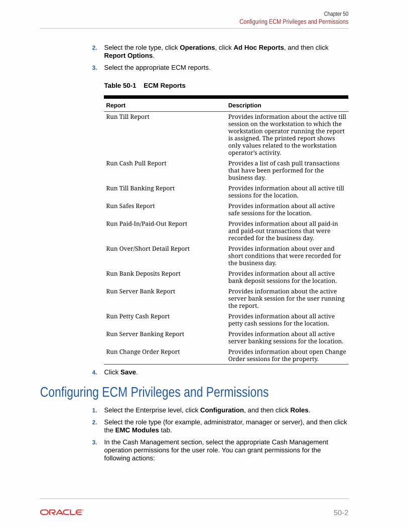
2. Select the role type, click Operations, click Ad Hoc Reports, and then clickReport Options.
3. Select the appropriate ECM reports.
Table 50-1 ECM Reports
Report Description
Run Till Report Provides information about the active tillsession on the workstation to which theworkstation operator running the reportis assigned. The printed report showsonly values related to the workstationoperator’s activity.
Run Cash Pull Report Provides a list of cash pull transactionsthat have been performed for thebusiness day.
Run Till Banking Report Provides information about all active tillsessions for the location.
Run Safes Report Provides information about all activesafe sessions for the location.
Run Paid-In/Paid-Out Report Provides information about all paid-inand paid-out transactions that wererecorded for the business day.
Run Over/Short Detail Report Provides information about over andshort conditions that were recorded forthe business day.
Run Bank Deposits Report Provides information about all activebank deposit sessions for the location.
Run Server Bank Report Provides information about the activeserver bank session for the user runningthe report.
Run Petty Cash Report Provides information about all activepetty cash sessions for the location.
Run Server Banking Report Provides information about all activeserver banking sessions for the location.
Run Change Order Report Provides information about open ChangeOrder sessions for the property.
4. Click Save.
Configuring ECM Privileges and Permissions1. Select the Enterprise level, click Configuration, and then click Roles.
2. Select the role type (for example, administrator, manager or server), and then clickthe EMC Modules tab.
3. In the Cash Management section, select the appropriate Cash Managementoperation permissions for the user role. You can grant permissions for thefollowing actions:
Chapter 50Configuring ECM Privileges and Permissions
50-2

• View: Open and view a Cash Management module. If you allow a user to Edit, Add,or Delete, you must also grant View access (otherwise the user cannot open themodule).
• Edit: Update fields or records within a module.
• Add: Add records to a module. You cannot add records to the Cash ManagementClass Behavior module.
• Delete: Delete records from a module. You cannot delete records from the CashManagement Class Behavior module.
• Add Override: Override records in a module. You cannot override records in theCash Management Classes module.
4. Click the Operations tab, and then click the Cash Management subtab.
5. Select the appropriate options for the privileges. The following table summarizes theprivileges associated with ECM functionality and the recommended roles to have theprivilege set.
Table 50-2 ECM Privileges
Section Option Number Privilege Name Allow theEmployee toPerform orAuthorize...
RecommendedRole(s)
GeneralOperations
249 Change CountSheet
Changing thecount sheet thatthe receptaclesession uses
Manager
GeneralOperations
250 Pull Cash A cash pull Cashier,Manager
GeneralOperations
258 Threshold LevelException
A Cash PullThresholdException(bypass thethresholdnotification)when promptedand permitted
Manager
GeneralOperations
260 View ReceptacleSession Status
Viewing ofsummaryinformation forall activereceptaclesessions
Manager
GeneralOperations
267 Update Balanceon Count
Updating thebalance on acount when theamount isoutside thecount thresholdvalues
Manager
GeneralOperations
301 View CashManagementDashboard
Viewing theCashManagementDashboard page
Manager
Chapter 50Configuring ECM Privileges and Permissions
50-3

Table 50-2 (Cont.) ECM Privileges
Section Option Number Privilege Name Allow theEmployee toPerform orAuthorize...
RecommendedRole(s)
GeneralOperations
302 View CashManagementDashboardDetail
Viewing the tilland server bankdetail from theCashManagementDashboard page
Manager
Till Operations 201 Assign Till toCash Drawer
Assignment of atill to a cashdrawer on aworkstation
Manager
Till Operations 202 Unassign Tillfrom CashDrawer
Unassignment ofa till to a cashdrawer on aworkstation
Manager
Till Operations 203 Assign User toTill
Perform orauthorize theassignment of anemployee to anactive till session
Manager
Till Operations 204 Unassign Userfrom Till
Unassignment ofan employee toan active tillsession
Manager
Till Operations 205 Count Till Counting of a tillsession
Cash Handler
Till Operations 206 Adjust Till Count Adjustment ofthe last count fora till session
Manager
Till Operations 207 Paid-In/Paid-Out Posting of anECM paid-in orpaid-out on a tillsessionWorkstationoperators canperformstandard paid-inand paid-outtransactionsbased onTender/Mediaconfiguration.
Manager
Till Operations 209 Transfer Funds Transfer ofitems from a tillsession toanother cashreceptaclesession
Cashier,Manager
Chapter 50Configuring ECM Privileges and Permissions
50-4

Table 50-2 (Cont.) ECM Privileges
Section Option Number Privilege Name Allow theEmployee toPerform orAuthorize...
RecommendedRole(s)
Till Operations 210 Deposit Funds Deposit of cashfrom a tillsession to a bankdeposit session
Cash Handler
Till Operations 212 Close Till Closing of a tillsession
Cash Handler
Till Operations 213 Reopen Till Reopening of atill session
Manager
Till Operations 251 Quick Start Till Opening of a tillsession andassignment ofthe currentoperator to aworkstation cashdrawer
Cash Handler
Till Operations 259 Adjust TillStarting Amount
Adjustment ofthe till startingamount
Manager
Server BankOperations
241 Start ServerBank
Opening of anew server banksession
Manager
Server BankOperations
242 Count ServerBank
Counting of aserver banksession
Manager
Server BankOperations
243 Adjust ServerBank Count
Adjustment ofthe last count fora server banksession
Manager
Server BankOperations
244 Paid-In/Paid-Out Posting of anECM paid-in orpaid-out on aserver banksessionWorkstationoperators canperformstandard paid-inand paid-outtransactionsbased onTender/Mediaconfiguration.
Manager
Server BankOperations
245 Transfer Funds Transferring offunds from aserver banksession toanother cashreceptaclesession
Manager
Chapter 50Configuring ECM Privileges and Permissions
50-5

Table 50-2 (Cont.) ECM Privileges
Section Option Number Privilege Name Allow theEmployee toPerform orAuthorize...
RecommendedRole(s)
Server BankOperations
246 Deposit Funds Deposit of cashfrom a serverbank session to abank depositsession
Manager
Server BankOperations
247 Close ServerBank
Closing of aserver banksession
Manager
Server BankOperations
248 Reopen ServerBank
Reopening aclosed serverbank
Manager
Server BankOperations
265 Adjust ServerBank StartingAmount
Adjustment ofthe server banksession startingamount
Manager
Server BankOperations
269 ConsolidateServer Banks
Consolidatingtwo server banksessions
Manager
Safe Operations 214 Open Safe Opening of anew safe session
Manager
Safe Operations 215 Count Safe Counting of asafe session
Manager
Safe Operations 216 Adjust SafeCount
Adjustment ofthe last count fora safe session
Manager
Safe Operations 217 Paid-In/Paid-Out Posting of anECM paid-in orpaid-out on asafe sessionWorkstationoperators canperformstandard paid-inand paid-outtransactionsbased onTender/Mediaconfiguration.
Manager
Safe Operations 218 Transfer Funds Transferring offunds from asafe session toanother cashreceptaclesession
Manager
Safe Operations 219 Deposit Funds Deposit of cashfrom a safesession to a bankdeposit session
Manager
Chapter 50Configuring ECM Privileges and Permissions
50-6

Table 50-2 (Cont.) ECM Privileges
Section Option Number Privilege Name Allow theEmployee toPerform orAuthorize...
RecommendedRole(s)
Safe Operations 220 Close Safe Closing of a safesession
Manager
Safe Operations 261 Add Funds toSafe
Adding newfunds into ECMthrough a safereceptacle
Manager
Safe Operations 262 Remove Fundsfrom Safe
Removing fundsfrom ECMthrough a safereceptacle
Manager
Petty CashOperations
222 Open Petty Cash Opening of anew petty cashsession
Manager
Petty CashOperations
223 Count Petty Cash Counting of apetty cashsession
Manager
Petty CashOperations
224 Adjust Petty CashCount
Adjustment ofthe last pettycash sessioncount
Manager
Petty CashOperations
225 Paid-In/Paid-Out Posting of anECM paid-in orpaid-out on apetty cashsessionWorkstationoperators canperformstandard paid-inand paid-outtransactionsbased onTender/Mediaconfiguration.
Manager
Petty CashOperations
226 Transfer Funds Transferring offunds from apetty cashsession toanother cashreceptaclesession
Manager
Petty CashOperations
227 Deposit Funds Deposit of cashfrom a pettycash session to abank depositsession
Manager
Petty CashOperations
228 Close Petty Cash Closing of apetty cashsession
Manager
Chapter 50Configuring ECM Privileges and Permissions
50-7

Table 50-2 (Cont.) ECM Privileges
Section Option Number Privilege Name Allow theEmployee toPerform orAuthorize...
RecommendedRole(s)
Bank DepositOperations
233 Create a BankDeposit
Opening of anew bankdeposit session
Manager
Bank DepositOperations
234 Transfer Funds Transferring offunds from abank deposit toanother cashreceptaclesession
Manager
Bank DepositOperations
237 Adjust CashDeposit
Adjustment of acash depositamount in abank depositsession
Manager
Bank DepositOperations
239 Reconcile BankDeposit
Reconciliation ofa bank depositsession
Manager
Bank DepositOperations
264 Adjust BankDepositReference
Adjustment of areference on abank depositsession
Manager
Change OrderOperations
230 Create ChangeOrder
Creation of anew ChangeOrder requestfrom a safesession
Manager
Change OrderOperations
232 ReconcileChange Order
Reconciliation ofa Change Order
Manager
Change OrderOperations
252 Submit ChangeOrder
Submission of anew ChangeOrder requestfrom a safesession
Manager
Change OrderOperations
268 Save / RecallChange Order
Saving orrecalling aChange Order
Manager
6. Click Save.
Allowing Users to View Blind TotalsIn some cases, you can require that workstation operators view the difference betweenthe amount entered during a count and the amount expected by applicationtransaction activity. Selecting View Blind Totals allows workstation operators withinthe Employee Class to view application expected values and the difference on thecount sheet. When an over or short condition exists, the workstation operator canselect the reason for the variance.
1. Select the property, click Configuration, and then click Employee Classes.
Chapter 50Allowing Users to View Blind Totals
50-8

2. Select the role type, and then click Operator Options.
3. Select 25 - View Blind Totals.
4. Click Save.
Allowing Assigned Receptacle Access and CountsECM requires that you assign a workstation operator to a till or server bank receptaclesession to perform transactions against the session. Managers need access to work withinthese receptacle sessions without being assigned to the sessions. You can create anEmployee Class for management workstation operators with a configuration set that allowsthem to perform transactions against the till or server banking session without priorassignment.
1. Select the property, click Configuration, and then click Employee Classes.
2. Select the role type, and then click Operator Options.
3. Select 26 - Allow Assigned Receptacle Access to:
• Allow workstation operators to view and perform transactions for till receptacles whenthe operator is not the owner or an assigned user.
• Show a list of employees with closed server bank sessions that can be reopened.
4. To prevent the workstation operator from counting a till session more than once, select 27- Prevent Multiple Receptacle Counts.
If the till session was already counted, the workstation operator cannot count it againimmediately afterwards.
5. Click Save.
Configuring Accounting Methods for UsersYou can specify the type of accounting method a workstation operator uses to track cashmanagement activities. The method you select determines the type of Front of Housereceptacles the workstation operator can access.
1. Select the property, click Configuration, and then click Employee Classes.
2. Select the role type.
3. On the General tab, select the appropriate Cash Management Accounting Method:
• None: Select this option to prevent the workstation operator from executing till orserver banking transactions.
• Till Banking: Select this option for workstation operators that maintain and work froma till that is assigned to a workstation (for example, bartenders and cashiers).
• Server Banking: Select this option for workstation operators who maintain and workfrom an individual server bank on their person (for example, servers who areresponsible for accepting payment on guest checks). This accounting method doesnot allow workstation operators to perform transaction activity on a till session whenthe operator is an assigned user.
4. Click Save.
Chapter 50Allowing Assigned Receptacle Access and Counts
50-9

Allowing Users to Override Employee Class OptionsYou can optionally override Employee Class configuration options for individualworkstation operators.
1. Select the Enterprise, zone, property, or revenue center, click Configuration, andthen click Employee Maintenance.
2. Select a property and revenue center, and then click Search.
3. Select Operator Records.
4. Select Override Class Options for an employee.
5. Select the override options.
Table 50-3 Override Employee Class Options
Option Description
Options When you select Override ClassOptions, the application automaticallyselects the Operator Options for theemployee’s revenue center. You canoverride option 25 - View Blind Totalshere.
Cash Management Accounting Method When you select a Cash Managementaccounting method here for anemployee, you override the accountingmethod set in the Employee Classmodule.
Cash Drawer This option indicates the cash drawerthat is defined for the workstationoperator within the revenue center: 0 (nocash drawer assignment, userprompted), 1, or 2. The Quick Start tilloperation uses the defined cash drawer.
6. Click Save.
Tracking Tender Transaction ItemsYou can identify tender media transaction items (for example, cash, check, and othercurrency based tenders) that you want ECM to track.
1. Select the Enterprise, zone, or property, click Configuration, and then clickTender/Media.
2. Double-click the tender media record.
3. Click the Options tab, and then click the Ops Behavior subtab.
4. Select the appropriate Tender Media options, and then click OK.
• 4 - Use with Currency Conversion: Select this option for the foreign currencyclass payment tender.
• 91 - Cash Management Transaction Item: Select this option to include thetender record in ECM tracking and reporting.
Chapter 50Allowing Users to Override Employee Class Options
50-10

• (Optional) 92 - Affects Cash Pull Threshold: Select this option to have transactionsperformed for this tender record affect the Cash Pull Threshold Set balance. Selectthis option for tender records that represent a loss if they are lost or stolen (forexample, cash and checks). You must select option 91 to use option 92.
5. Click Save.
Tracking Service Charge TransactionsYou can identify service charge transactions (for example, gift card sales) that you want ECMto track.
1. Select the Enterprise, zone, or property, click Configuration, and then click ServiceCharges.
2. Double-click the service charge.
3. Select 28 - Cash Management Transaction Item to include the service charge record inECM tracking and reporting.
4. Click Save.
Tracking Discount TransactionsYou can identify discount transactions (for example, coupons and promotional vouchers) thatyou want ECM to track.
1. Select the Enterprise, zone, or property, click Configuration, and then click Discounts.
2. Double-click the discount.
3. Select the appropriate discount options on the General tab:
• 33 - Cash Management Transaction Item: Select this option to include the discountrecord in ECM tracking and reporting.
• (Optional) 34 - Affects Cash Pull Threshold: Select this option to have transactionsperformed for this discount record increase the value in a receptacle. You must selectoption 33 to use option 34.
4. Click Save.
Creating, Editing, and Deleting Cash Management ReasonsCertain ECM operations allow (and sometimes require) the workstation operator to enter areason for performing the operation. For example, workstation operators must provide areason for adjusting transactions.
1. Select the Enterprise, zone, property, or revenue center, click Descriptors, and then clickCash Management Reasons.
2. Highlight the Cash Management transaction, and then select Add Reason.
3. Enter the reason name, based on the following guidelines:
• You can define multiple reasons for each transaction.
• You can use each reason name only once per transaction type.
When you enter a No Sale Reason, the cash drawer opens only after the workstationoperator enters a reason when performing a No Sale transaction. You can set and use
Chapter 50Tracking Service Charge Transactions
50-11

No Sale reason codes without activating ECM. You can also access No Salereason codes through extensibility or a System Interface Module (SIM)-basedevent.
4. Click Save.
5. To edit a reason, highlight the reason record, change the reason name, and thenclick Save.
After you change a reason, the new reason appears when viewing historicalreporting activity.
6. To delete a reason, highlight the reason record, and then select Delete Reason.
The application allows you to delete only reasons that are not referenced inhistorical reporting activity.
Cash Management ClassesBeginning with Simphony version 18.1, the ECM supports multiple classes (currencyand non-currency based). Non-currency items include credit card vouchers, gift cards,and coupons. Classes can be based on primary or alternate currencies. TheEngagement console shows multiple classes in widgets.
Reporting and Analytics version 18.1 Enterprise reports and workstation propertyreports support the tracking of multiple classes. If you upgrade to Simphony version18.1, but do not upgrade to Reporting and Analytics version 9.0 (for example,Reporting and Analytics remains at version 8.5.0), Enterprise reports do not showinformation for multiple classes, nor do they show the correct base class.
Adding Transaction ItemsYou must map transaction items (for example, tenders) to the Cash Managementcurrency class to measure their impact (increase or decrease) on the balance of alltransactions. ECM tracks only transaction items that are mapped to the class.
1. Select the Enterprise, zone, or property, click Setup, and then click CashManagement Classes.
2. Insert a Cash Management class record, and then double-click it.
3. Click the Transaction Items tab.
4. Enter the name of the class to track in ECM (for example, Cash US Dollars, CashCanadian Dollars, Vouchers, and so on).
5. Select an available Currency from the list to associate with the Cash Managementclass.
You can only associate the currency with a single class. Select 0 - None for non-currency tracking (for example, vouchers and stored value cards) as these itemsare always based on the property’s local currency.
6. Click Save.
7. Select the Enterprise, zone, property, or revenue center, click Setup, and thenclick Cash Management Class Behavior.
Records are automatically created and removed in the Cash Management ClassBehavior module based on the creation and deletion of records in the CashManagement Classes module. If you have the appropriate permission, you can
Chapter 50Cash Management Classes
50-12

use the Cash Management Class Behavior module to customize and override the classconfiguration. Configuring ECM Privileges and Permissions contains more informationabout the Add Override permission.
8. Right-click a record, select Override Record, and then select one of the following:
• Use Existing Record
• Create Blank Record
9. Select Display on Status to show the currency class on the POS client workstation whenviewing the receptacle status.
The Oracle Hospitality Simphony Manager User Guide contains information on ViewingReceptacle Status.
10. Select Add Transaction Item.
11. Select the Transaction Item Type (for example, Tender).
12. Select the Transaction Item (for example, Euro Cash).
The Cash Management Transaction Item options in the tender, service charge, ordiscount determine the items that appear in the Transaction Item list. You can use eachtransaction item only once per currency class.
13. Click Save.
Adding Counting UnitsAfter you add a denomination unit to a Cash Management class, ECM includes the unit whenbuilding Count Sheets and PAR Level Sets. The following figure shows an example of theunits mapping setup.
Figure 50-1 Counting Units
1. Select the Enterprise, zone, property, or revenue center, click Setup, and then click CashManagement Classes.
2. Double-click a Cash Management class record.
3. Click the Counting Units tab.
Chapter 50Adding Counting Units
50-13

4. Select Add Unit.
5. Enter the name of the unit (for example, Pennies, Fives, Twenties, TravelersChecks, and so on).
6. If the unit has a consistent cash value (for example, notes and coins), selectDenominated. Do not select this option for transaction items that haveinconsistent cash values (for example, personal checks, credit cards, and giftcards).
7. If the unit is denominated, enter the units value relative to the base currency unit inthe Numerator field. For example, when the base currency is US dollars, the basecurrency unit is 1 ($1.00).
8. If the unit is denominated, enter the number of units relative to the base currencyunit in the Denominator field. For example, when the base currency is US dollars,the base currency unit is 1 ($1.00).
9. After you enter the numerator and denominator, the Value field shows thecalculated value per unit.
10. Click Save.
Cash Pull Threshold SetThe optional Cash Pull Threshold Set provides a group of balance-based levels tocompare against a till or server banking session during a transaction. The Cash PullThreshold Set indicates when notifications occur for cash pulls. These notificationsminimize risk by limiting the amount of cash circulating in the Front of House. You canadd one or more threshold levels to a Cash Pull Threshold Set. If you create athreshold based on one or more currency classes, a cash pull notification occurs whena till or server banking session meets or exceeds the amount of a specific currencyclass.
Creating, Editing, and Deleting a Cash Pull Threshold Set1. Select the Enterprise, zone, property, or revenue center, click Setup, and then
click Cash Pull Threshold Sets.
2. Insert a record, enter the name of the Cash Pull Threshold Set, and then click OK.
3. Double-click the record to open it.
4. Enter the Chit Quantity.
This is the number of chits that print when a workstation operator performs a cashpull. A cash pull chit represents the funds that are removed from the till or serverbank.
5. Select Add, and then enter the name of the threshold set.
The name is part of the notification that appears in the application.
6. Enter the Amount.
This is the amount-based threshold (for example, 100 dollars) that elevates thecash pull notification to the threshold level. If you configure more than onethreshold level, subsequent amounts cannot be equal to or lower than the previouscash pull amount in the same set.
Chapter 50Cash Pull Threshold Set
50-14

7. Select Approval to allow a workstation operator with the Threshold Level Exceptionprivilege to authorize the operator to ignore the exception and to process transactionsagainst the receptacle without performing a cash pull.
8. Click Save.
9. To edit a cash pull threshold set, highlight the record, change the values, and then clickSave.
The last (final) threshold level does not allow a threshold exception (bypass). Thisrequires the workstation operator to perform a cash pull first to execute additionalactivities against the till or server bank later.
10. To delete a cash pull threshold set, highlight the record, and then select Delete.
You cannot delete a Cash Pull Threshold Set associated with one or more templates.
Cash Count Threshold SetThe optional Cash Count Threshold Set provides an allowable variance threshold forcountable receptacles. This threshold is the difference between counted totals and expectedtotals. The threshold indicates the overage and shortage amounts allowed to complete areceptacle count. You can add one or more cash count threshold sets to a count sheet. Youcan also configure multiple currency classes for a cash count threshold set, and allowworkstation operators to set varying thresholds against the classes.
Creating, Editing, and Deleting a Cash Count Threshold Set1. Select the Enterprise, zone, property, or revenue center, click Setup, and then click Cash
Count Threshold Sets.
2. Add a Cash Count Threshold Set, enter the name, and then click OK.
3. Enter the Short amount.
This value is the minimum variance amount allowed to complete the receptacle count.
4. Enter the Over amount.
This value is the maximum variance amount allowed to complete the receptacle count.
5. Enter the number of Max Count Attempts.
This value limits the number of times a workstation operator can attempt to submit acount when the count is over or short beyond the defined threshold.
6. To define additional over or short amounts for each currency class, click the Add Classlink.
You cannot define multiple over or short amounts for the same primary class within aCash Count Threshold Set.
a. Select the Class from the drop-down list.
b. (Optional) In the Over field, enter the approved over variance amount for workstationoperators to enter for the count.
c. (Optional) In the Short field, enter the approved short variance amount forworkstation operators to enter for the count.
7. Click Save.
Chapter 50Cash Count Threshold Set
50-15
8. To edit a cash count threshold set, highlight the record, change the values, andthen click Save.
9. To delete a cash count threshold set, highlight the record, and then select Delete.
You cannot delete a Cash Count Threshold Set associated with one or moretemplates.
PAR Level SetPeriodic Automatic Replenishment (PAR) Level Sets specify the suggested quantity tomaintain of each currency denomination kept in a safe (for example, rolls of coins orquantity of a denominated note). PAR Level Sets are comprised of count units drawnfrom the list of denominated items in a Cash Management class. The PAR determinesthe values required when issuing a Change Order request to return the receptacleback to the PAR based on the last known count of the receptacle. The use of a PARLevel Set is optional.
Creating, Editing, and Deleting a PAR Level Set1. Select the Enterprise, zone, property, or revenue center, click Setup, and then
click PAR Level Sets.
2. Insert a record, and enter the PAR Level Set name.
3. Double-click the record to open it.
4. Select the CM Class.
The CM Class list includes all Cash Management classes that you created. TheseCash Management classes contain the units that are allowed within the PAR LevelSet.
5. Add a Counting Unit using one of the following methods:
• Select Add All Units to have ECM add all defined units for the CashManagement class to the PAR Level.
• Select Add Unit to manually add specific units.
6. For each of the defined units, enter the quantity of units to maintain as part of thePAR Level Set for each day of the week.
The Totals row beneath the Units table shows the cash value required for eachunit quantity and day of the week.
7. Click Save.
8. To edit a PAR Level Set, highlight the record, change the values, and then clickSave.
9. To delete a PAR Level Set, highlight the record, and then select Delete.
You cannot delete a PAR Level Set that is associated with one or more templates.
Count SheetA Count Sheet is a custom form used to audit the contents of a safe, till, server bank,or petty cash receptacle. A workstation operator uses a Count Sheet during the
Chapter 50PAR Level Set
50-16

physical counting of a receptacle session. You can configure the count to include one of thefollowing:
• Expected funds where variances are recorded
• A simple counting of funds where no variance is tracked (blind count)
You can create unique Count Sheets for each receptacle session to determine the items andorder in which a count is performed, as well as the format for the printed Count Sheet results.Creating a Count Sheet is similar to building a report. You can associate multiple classes witha Count Sheet. When you create a Count Sheet, you define Pages, Groups, and Units.
Pages
A Count Sheet Page is similar to a chapter in a report. Pages allow you to see totals for allvalues counted within the page. For example, you can create a page for each currency class(US Dollars, Euros, and Pounds Sterling).
Groups
Transaction Items are reported in Count Sheet groups. Groups allow you to see totals for allvalues counted within the group. For example, you can create separate groups for Notes(paper money) and Coins. Within the Notes group, you can assign the currency class (suchas Euros).
Units
A unit is optional but recommended for groups that report based on counting units. If you donot add a unit, a Total entry appears for the group. Units define the denominations associatedwith a currency. Notes, coins, traveler's checks, and gift certificates are examples ofdenominated items. Personal checks and credit cards are not denominated items, becausethe amount of money associated with them varies with the transaction.
The currency is used as a tender in most cases, but not always. Some tenders indicatewhether the unit has a consistent cash value. A twenty dollar bill is always worth $20.00 US.If the unit is denominated, you must define a value relative to the base currency. Forexample, if the base currency is US Dollars (US$), the following ratios can be defined:
• Twenties = 20:1 (twenty US$ per unit)
• Tens = 10:1 (ten US$ per unit)
• Quarters = 1:4 (1/4 of a US$ per unit)
• Dime Roll = 5:1 (five US$ per unit)
Creating, Editing, and Deleting a Count Sheet1. Select the Enterprise, zone, property, or revenue center, click Setup, and then click
Count Sheets.
2. Insert a record, enter a unique name for the Count Sheet, and then click OK.
3. To add or delete a Count Sheet Page:
a. In the Pages section, click the Add link.
b. Enter a name for each page in the Name column (for example, Cash and Vouchers).
c. To delete a page, highlight the page name record, and then click the Delete link. Theapplication deletes all units associated with a group for the selected page, along withthe page.
Chapter 50Creating, Editing, and Deleting a Count Sheet
50-17

4. To add or delete a Count Sheet Group:a. In the Pages section, highlight a page.
b. In the Groups section, click the Add link.
c. Enter a name for each group in the Name column. For example, you can havea Cash page with the groups Notes (paper currency) and Coins.
d. Select the Cash Management currency class for each group from the Classdrop-down list.
When you select a Class, the Name column shows the name of the class if itwas not previously entered. Change the Name value to show itsrepresentation on the Count Sheet POS client view and chit printout.
e. Select the appropriate Options for each group:
• 1 - Allow Multiple Entries: Select this option to allow unique entry ofcertain items (for example, gift cards and checks). The Group provides amultiple entry list when performing a count. This type of count is used toinclude non-denominated transaction items, such as personal checks orgift cards as part of a count, where the amount of each individual itemmust be tracked (for example, check and gift card amounts).
• 2 - Reference Required: Select this option to have the POS client promptthe workstation operator to enter a reference on the Count Sheet (forexample, gift card number, personal check number, credit card, or vouchernumber) for each amount entered. Deselect this option to skip thereference prompt when entering non-denominated values on the countsheet.
f. Repeat Steps 4a through 4e to add other groups to track.
g. To delete a group, highlight the group record, and then click the Delete link.The application deletes the group and all units associated with the group.
5. Too add or delete Count Sheet Units:a. In the Groups section, highlight a group.
b. In the Units section, click the Add link to add all units to count as part of thegroup.
c. Select the Units for each group from the Units drop-down list.
Only the Unit Types associated with the Cash Management Class for thegroup are available in the Units drop-down list. When you select a Unitsvalue, the Name column shows the name of the unit selected. Change theName value to show its representation on the Count Sheet POS client viewand chit printout. You can use each Unit Type only once on a page.
d. To delete a unit, highlight a unit record, and then click the Delete link.
6. Click Save.
7. To sort and alter the order in which pages, groups on a page, and units within agroup appear on the Count Sheet at the POS client, use the up and down arrows.
All units that are part of the selected group remain with the group as it moves.Units that are part of groups for the selected page remain with the page as itmoves. Groups that are part of the selected page remain with the page as itmoves.
8. To edit a Count Sheet, highlight the count sheet record, change the values, andthen click Save.
Chapter 50Creating, Editing, and Deleting a Count Sheet
50-18

When you change a Count Sheet, the application removes all units associated with thegroup.
9. To delete a Count Sheet, highlight the record, and then select Delete.
You cannot delete a Count Sheet associated with one or more templates.
Creating, Editing, and Deleting an AccountYou can use accounts to report general ledger accounting information for ECM paid-in andpaid-out transactions (for example, produce, meat, bakery, or flower shop).
1. Select the Enterprise, zone, property, or revenue center, click Setup, and then clickAccounts.
2. Insert a record, enter a unique name for the account, and then click OK.
3. Click the ellipsis point (...) button in the Options column.
a. Select 1 - Deactivate Account to deactivate or suspend an account that is no longerbeing used. A newly created account is active by default.
b. Select 2 - Exclude on Paid In to exclude the account and associated vendors frombeing used when a workstation operator performs a paid-in transaction.
c. Select 3 - Exclude on Paid Out to exclude the account and associated vendors frombeing used when a workstation operator performs a paid-out transaction.
4. To edit an account, highlight the record, change the values, and then click Save.
5. To delete an account, highlight the record, and then click Delete on the toolbar.
The application only allows you to delete accounts that are not referenced in historicalreporting activity. When an account is assigned to a vendor, you cannot delete it. You canunassign the account from the vendor.
6. Click Save.
Creating, Editing, and Deleting a VendorYou can use a vendor to associate companies with ECM paid-in and paid-out transactions forreporting purposes.
1. Select the Enterprise, zone, property, or revenue center, click Setup, and then clickVendors.
2. Insert a record, enter a unique name for the vendor, and then click OK.
3. (Optional) Select an account from the Account drop-down list to associate with thevendor.
The vendor always uses the selected account for ECM paid-in and paid-out transactions.
4. Click the ellipsis point (...) button from the Options column and select the appropriatevendor options:
• 1 - Deactivate Vendor: Select this option to prevent further selection of the vendorwhen performing transactions. For example, you can place a credit hold. A newlycreated vendor is active by default.
• (Optional) 2 - Invoice Data Required: Select this option to require the workstationoperator to enter invoice information (for example, Date, Invoice Number, and
Chapter 50Creating, Editing, and Deleting an Account
50-19

Description) when performing a transaction for the vendor that can collectinvoice data (for example, paid-out).
• 3 - Require Reference on Use: Select this option to require the workstationoperator to enter a reference when performing a transaction that requires avendor.
5. To edit a vendor, highlight the record, change the values, and then click Save.
6. To delete a vendor, highlight the record, and then click Delete on the toolbar.
The application only allows you to delete vendors that are not referenced inhistorical reporting activity.
7. Click Save.
Creating and Editing a TemplateYou need to use a template to set the initial configuration and operating values for allnew receptacle tracking sessions. This includes setting the amount, assigning a countsheet, and specifying how the application handles the opening balance after theworkstation operator closes the receptacle. A template allows additional configurationfor specified classes or class exclusions (till and server bank receptacles only) basedon the receptacle type.
1. Select the Enterprise, zone, property, or revenue center, click Setup, and thenclick Templates.
2. Insert a template record with a unique name, and then click OK.
3. Double-click the template record to open it.
4. On the General tab, enter or select information in the following fields:
• (Optional) Description: A description provides further understanding of thetemplate that might not be distinguishable by looking at the template name.The Description is not shown as part of the receptacle when the workstationoperator opens the receptacle from a template
• Receptacle Type: Depending on the type of receptacle you select, additionalfields become active. The following table describes the fields and receptacletypes.
Table 50-4 Template Receptacle Types and Fields
Field orOption
Template Receptacle Type
Safe Till ServerBank
BankDeposit
Petty Cash
StartingAmount
Optional Optional
StartingAmountSource
Required Optional
Prompt forStartingAmount
Optional Optional
Chapter 50Creating and Editing a Template
50-20

Table 50-4 (Cont.) Template Receptacle Types and Fields
Field orOption
Template Receptacle Type
Safe Till ServerBank
BankDeposit
Petty Cash
Cash PullThreshold
Optional Optional
Cash PullDestination
Optional Optional
Count Sheet Required Required Required Required
Cash CountThreshold
Optional Optional Optional Optional
Close onCountCompletion
Optional Optional
PAR Level Optional
Maximum Required Required
Minimum Required
CashDepositRouting
Optional Optional
• Start Amount: The starting amount determines the initial currency value of thesession upon opening.
• Starting Amount Source: The starting amount source determines where the startingamount for the session originates. You can specify different starting amount sourceconfigurations for the General and Class Detail tabs (for example, if the source is adifferent safe that holds only foreign currencies).
The source for a server bank session must be either an internal (House supplied) orexternal (server supplied) starting amount for all defined ECM classes (not internaland external). If you select None for a server bank, the starting amount is consideredto be part of the receptacle and funds are not transferred from a source receptaclesession. For example, a server who self funds a bank does not receive a fundstransfer from the safe when opening the bank. Selecting a defined safe transfers thestarting amount from the safe session to the receptacle session upon opening.
• Prompt for Starting Amount: Select this option to prompt the workstation operatorto enter the starting amount for the receptacle session upon opening. When youselect this option, the application ignores the value in the starting amount field. Thisoption is typically used for server banks where the server self-funds the bank.
• Cash Pull Threshold: This field defines the Cash Pull Threshold Set that areceptacle session uses. If you set cash pull values, select a threshold set from thedrop-down list to be used for the template.
• Cash Pull Destination: Select a destination receptacle into which funds from cashpull operations will transfer; if you select None, funds do not transfer and ownershipremains with the receptacle session.
• Count Sheet: The Count Sheet value in a template determines the Count Sheet thatis used to count the receptacle.
Chapter 50Creating and Editing a Template
50-21

• Cash Count Threshold: This field defines the Cash Count Threshold Set thata receptacle session uses. If you set cash count values, select a ThresholdSet from the drop-down list to be used for the template.
• Close on Count Completion: Select this option to have the applicationattempt to automatically reconcile the receptacle session upon completion ofthe count. This process transfers funds from the receptacle session to thesessions designated under Starting Amount Source and Cash DepositRouting to bring the session to zero. Deselect this option to leave the sessionopen after the count completes. The workstation operator must then manuallyreconcile all funds and close the receptacle.
• PAR Level: The PAR Level defines the PAR Level Set (quantity to maintain ofeach currency denomination) to use for the safe session.
• Minimum: The minimum balance determines the lowest amount of fundspermitted as part of a receptacle session. The application prevents workstationoperators from processing most activity that takes the session balance belowthis amount. If you do not set a minimum balance, the application defaults to 0(no minimum).
• Maximum: The maximum balance determines the largest amount of fundspermitted as part of a receptacle session. The application prevents workstationoperators from processing most activity that takes the session balance beyondthis amount. If you do not set a maximum balance, it defaults to 0 (nomaximum).
• Cash Deposit Routing: Select the destination receptacle (safe or bankdeposit) session to receive funds that transfer from a receptacle session aspart of a cash deposit operation. When you select None, the applicationprompts the workstation operator to select a location to deposit cash.
5. Click the Class Details tab.
a. To create additional currency classes (alternate currency such as Dollar, Peso,Euro, or Pounds, or non-currency such as gift cards) for a receptacle sessionor operation, click the Add Class link.
When you configure the base currency in the Class Details tab, these settingsoverride the configuration set in the General tab. Use the Add Class link forreceptacle sessions and operations that have multiple cash managementclasses. You can add alternate classes for bank deposit, till, server bank, andpetty cash receptacle templates only. You cannot add a duplicate class entry.
b. To remove a class, click the Delete Class link, select the class, and then clickOK.
c. To add additional PAR Levels, click the Add PAR Level link.
You can add a PAR Level for safe receptacle templates only.
d. To remove a PAR Level, click the Delete PAR Level link, select the PARLevel, and then click OK.
6. Click the Class Exclusions tab.
a. To specify currency classes that cannot be used in till and server bankreceptacles created with the receptacle template, click the Add Class link, andthen select the class.
For example, if a till uses the template which excludes the Euros currencyclass, the Count Sheet does not show the Euro page. You can exclude
Chapter 50Creating and Editing a Template
50-22

classes for the till and server bank receptacle templates only. A till and server bankreceptacle accepts any currency class unless you exclude it here.
b. To remove classes from the class exclusion list, click the Delete Class link, select theclass, and then click OK.
7. To edit a template, highlight the template record, change the values, and then click Save.
Creating, Editing, and Deactivating ReceptaclesA receptacle represents a physical or virtual location used to store funds and drawtransactions.
1. Select the Enterprise, zone, property, or revenue center, click Setup, and then clickReceptacles.
2. Insert a record, enter a unique name for the receptacle, and then click OK.
3. Double-click the receptacle record to open it.
4. Enter or select information in the receptacle fields.
• Receptacle Type: Select the type of receptacle.
• Template Name: Select the template to use for this receptacle.
• Location: Select the location where the receptacle is defined.
You can define a receptacle type that is commonly used across an Enterprise orregion without uniquely defining it at each property or revenue center. The locationallows you to specify a receptacle name and configuration to be used in multiplelocations. When you select 2 - Property, a receptacle is defined for each propertybased on the values entered. When you select 3 - Revenue Center, a receptacle isdefined within each revenue center.
For example, each property might have one safe to maintain all cash transactions forthe entire property. Create a safe receptacle from the Enterprise level or zone, andthen specify the property in the Location field. The safe receptacle is defined at allproperties under the selected level.
• Options: Select Deactivate Receptacle to prevent workstation operators fromperforming further activity against the receptacle.
5. To edit a receptacle, highlight the record, change the values, and then click Save.
6. To deactivate a receptacle, highlight the record, and then select Deactivate Receptacle.
Deleting a receptacle is not permitted.
7. Click Save.
Setting Cash Management Parameters1. Select the Enterprise, zone, property, or revenue center, click Setup, and then click Cash
Management Parameters.
2. Click the Configuration tab.
3. Enter or select the appropriate information.
Chapter 50Creating, Editing, and Deactivating Receptacles
50-23

Table 50-5 Cash Management Parameters Configuration Fields
Field Description
Cash Pull Notification Frequency Specify when the application notifiesworkstation operators of the cash pullthreshold levels being reached orexceeded.• 0 - None: Select this option to disable
cash pull notifications (default).Workstation operators can use themanual process for cash pulls.
• 1 - On Threshold Level Only: Selectthis option to notify the workstationoperator once upon reaching orexceeding a defined threshold levelin the Threshold Level Set.
• 2 - On Each Transaction: Select thisoption to notify the workstationoperator with each new check accessattempt upon reaching or exceedinga defined threshold level in theThreshold Level Set.
Receptacle Balancing Class Select the class that is based on thecurrency in which the property operates.All transaction items included in theCash Management Class selectiondetermine the appearance of thereceptacle balance on views and reports.
Change Order Report Count Enter the number of reports to printwhen a workstation operator creates anew Change Order request.
Counting Method Select the method in which theworkstation operator must entercounting units when performing a countor change order.• 1 - Quantity: Select this option to
require the workstation operator toenter the quantity of the countingunits. The application calculates thevalue based on the quantity enteredfor the associated counting unit.
• 2 - Value: Select this option torequire the workstation operator toenter the value of the counting units.The application calculates thequantity based on the value enteredfor the associated counting unit.
Paid-In/Paid-Out Chit Count Enter the number of chits to print whenthe workstation operator performs anECM paid-in or paid-out transaction.
Server Banking Template Select the default template to use when aworkstation operator opens a new serverbanking session. You can override thissetting from the Employee Classesmodule.
4. Click the Options tab.
Chapter 50Setting Cash Management Parameters
50-24
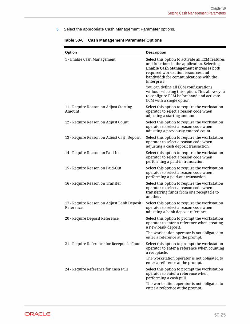
5. Select the appropriate Cash Management Parameter options.
Table 50-6 Cash Management Parameter Options
Option Description
1 - Enable Cash Management Select this option to activate all ECM featuresand functions in the application. SelectingEnable Cash Management increases bothrequired workstation resources andbandwidth for communications with theEnterprise.You can define all ECM configurationswithout selecting this option. This allows youto configure ECM beforehand and activateECM with a single option.
11 - Require Reason on Adjust StartingAmount
Select this option to require the workstationoperator to select a reason code whenadjusting a starting amount.
12 - Require Reason on Adjust Count Select this option to require the workstationoperator to select a reason code whenadjusting a previously entered count.
13 - Require Reason on Adjust Cash Deposit Select this option to require the workstationoperator to select a reason code whenadjusting a cash deposit transaction.
14 - Require Reason on Paid-In Select this option to require the workstationoperator to select a reason code whenperforming a paid-in transaction.
15 - Require Reason on Paid-Out Select this option to require the workstationoperator to select a reason code whenperforming a paid-out transaction.
16 - Require Reason on Transfer Select this option to require the workstationoperator to select a reason code whentransferring funds from one receptacle toanother.
17 - Require Reason on Adjust Bank DepositReference
Select this option to require the workstationoperator to select a reason code whenadjusting a bank deposit reference.
20 - Require Deposit Reference Select this option to prompt the workstationoperator to enter a reference when creatinga new bank deposit.The workstation operator is not obligated toenter a reference at the prompt.
21 - Require Reference for Receptacle Counts Select this option to prompt the workstationoperator to enter a reference when countinga receptacle.The workstation operator is not obligated toenter a reference at the prompt.
24 - Require Reference for Cash Pull Select this option to prompt the workstationoperator to enter a reference whenperforming a cash pull.The workstation operator is not obligated toenter a reference at the prompt.
Chapter 50Setting Cash Management Parameters
50-25

Table 50-6 (Cont.) Cash Management Parameter Options
Option Description
25 - Require Reason on Over/Short Select this option to require the workstationoperator to enter a reason code whenposting an operation that finds a variance invalues.
26 - Allow Count of Assigned Till Select this option to allow the workstationoperator to count a till that is assigned to aworkstation. When you deselect it, youunassign the till from the workstations tocount.After upgrading to Simphony version 2.7MR2, existing customers who want tocontinue to count assigned tills need to setthis option.
27 - Require Check Closed Before ReceptacleClose
Select this option to allow the workstationoperator to close a till or server bankingsession only after all checks with assignedusers as the check owner are closed. Theworkstation operator must close all openchecks before closing the till or serverbanking session.Setting this option ensures that a receptacleis available to settle cash tenders to openchecks for workstation operators assigned tothe receptacle.
28 - Restrict a Single User per Till Select this option to restrict a till session toonly allow one user. When the workstationoperator has option 26 - Allow AssignedReceptacle Access set from the EmployeeClass, the Allow All button is available onthe POS client during the assignmentoperation.
29 - Save Count Progress Select this option to allow the workstationoperator to save an incomplete count sheetwhen counting a receptacle session.
30 - Enable Change Order Tracking Select this option to track change ordertransactions, save, and recall change orderrequests.
31 - Require Reference for Change Order Select this option to prompt the workstationoperator to enter a reference whensubmitting a change order request.The workstation operator is not obligated toenter a reference at the prompt.
32 - Cash Pull Threshold Notification onTransaction Close
Select this option to prompt the workstationoperator after completing an activetransaction that exceeds the cash pullthreshold level.
33 - Prompt for Business Date on Open BankDeposit
Select this option to prompt the workstationoperator to select a business date whenopening a bank deposit receptacle. Theoperator can select the current business dateor up to seven dates in the past.
Chapter 50Setting Cash Management Parameters
50-26

Table 50-6 (Cont.) Cash Management Parameter Options
Option Description
34 - Hide Bank Deposits on Dashboard Select this option to hide the Bank Depositstab on the Cash Management Dashboard.
35 - Hide Petty Cash on Dashboard Select this option to hide the Petty Cash tabon the Cash Management Dashboard.
36 - Hide Safes on Dashboard Select this option to hide the Safes tab on theCash Management Dashboard.
37 - Hide Server Banks on Dashboard Select this option to hide the Server Bankstab on the Cash Management Dashboard.
38 - Hide Tills on Dashboard Select this option to hide the Tills tab on theCash Management Dashboard.
39 - Display Employee First for Tills onDashboard
Select this option to show the Employeecolumn first in the Tills tab on the CashManagement Dashboard.Additionally, when this option is enabled,the Tills Counted column appears in theBank Deposit tab on the Cash ManagementDashboard. When disabled, the Expectedcolumn appears in the Bank Deposit tab onthe Cash Management Dashboard.
41 - Require Reference for Paid-In whenvendor not defined
Select this option to prompt the workstationoperator to enter a reference whenperforming a paid-in transaction without avendor defined.The workstation operator is not obligated toenter a reference at the prompt.If a vendor is defined, the paid-intransaction follows the configuration of 3 -Require Reference on Use in the Vendorsmodule. When option 3 is enabled, theworkstation operator is required to enter areference when performing a transaction(such as paid-in to till, safe, or server bank)that requires a vendor.
42 - Require Reference for Paid-Out whenvendor not defined
Select this option to prompt the workstationoperator to enter a reference whenperforming a paid-out transaction without avendor defined.The workstation operator is not obligated toenter a reference at the prompt.If a vendor is defined, the paid-outtransaction follows the configuration of 3 -Require Reference on Use in the Vendorsmodule. When option 3 is enabled, theworkstation operator is required to enter areference when performing a transaction(such as paid-out to till, safe, or server bank)that requires a vendor.
43 - Prompt to Confirm Transfer DuringClose on Count
Select this option to prompt the workstationoperator with a confirmation when closing acount and transferring the cash from a till orserver bank receptacle to a deposit.
Chapter 50Setting Cash Management Parameters
50-27

Table 50-6 (Cont.) Cash Management Parameter Options
Option Description
44 - Enforce Close Till and Deposit Till Roles Select this option to override Role privilegeoptions 210 - Deposit Funds and 212 - CloseTill. If this option is enabled, Role option 205- Count Till is enabled, and 210 and 212 aredisabled, the till receptacle does not closeafter the user performs a count.Configuring ECM Privileges and Permissionscontains information on options 210 and212.
45 - Prompt for Drawer on Quick Start Till Select this option to prompt the workstationoperator to select the cash drawer onworkstations with more than one drawerwhen performing the Quick Start Tillfunction.When 45 is enabled, the Quick Start Tillfunction ignores the cash drawerconfiguration of the workstation operator.On a workstation with a single drawer, theselected till session is automatically assignedto that drawer (if it does not have onealready assigned). On a workstation withtwo drawers, the operator is prompted for acash drawer when both are available, orauto assigned to the available drawer whenone is in use.
46 - Prevent Assignment of Tills with ActiveSessions to Cash Drawers
Select this option to show only tillreceptacles that do not have an activesession and are not assigned to a cashdrawer when the workstation operatorperforms either the Assign Till To CashDrawer or the Quick Start Till function.When 46 is enabled, a workstation operatorcannot assign a till session that has beencounted to a cash drawer. The till sessionneeds to be closed and a new one started.You must also select option 28 - Restrict aSingle User per Till.
6. Click Save.
7. Select the Enterprise, zone, property, or revenue center, click Setup, and thenclick Control Parameters.
8. Click the Options tab.
9. Select 68 - Require Reason on No Sale to require the workstation operator toselect a reason code when performing a No Sale operation.
10. Click Save.
Creating Cash Management Touchscreens and DashboardOracle Hospitality recommends that you create a page with tabs on which to place thecash management functions. Create and configure tabs to show operations byreceptacle type. Create buttons on the page for the required cash management
Chapter 50Creating Cash Management Touchscreens and Dashboard
50-28

functions listed. The following figure shows an example of a page with cash managementfunctions created in the Page Design module.
Figure 50-2 Cash Management Touchscreen in Page Design
You can also add the Cash Management Dashboard to page layouts using the Page Designmodule. The Dashboard lets managers view:
• The number of each type of open receptacle
• A summary level and detail view of each type of open receptacle
The Dashboard also includes one-button navigation to open, count, adjust, transfer, andfinalize receptacles.
Option 1 - Enable Cash Management must be set in the Cash management Parametersmodule to use the Cash Management Dashboard.
1. Select the Enterprise, property, or revenue center, click Configuration, and then clickPage Design.
2. Open the page on which to place cash management buttons.
3. On the Edit tab, select the page area in which to define the cash management functions.
4. Create tabs for Safe, Bank Deposit, Till, Server Bank, Petty Cash, General, andPayments.
5. On each tab, create buttons for each of the functions listed in the following table.
Table 50-7 Cash Management Tabs and Buttons
Tab Button Name Function
Safe Add Funds Add money to the safe.
Adjust Count Correct values from theprevious count.
Chapter 50Creating Cash Management Touchscreens and Dashboard
50-29

Table 50-7 (Cont.) Cash Management Tabs and Buttons
Tab Button Name Function
Change Count Sheet Adjust the count sheet thatworkstations operators useto perform a count.
Close Receptacle Close the safe’s trackingsession.
Count Receptacle Count the money in the safe.
Deposit Cash Deposit cash from the safe toa bank deposit.
Open New Change OrderRequest
Open a Change Order when asafe is low on a particulardenomination or to stock upfor an event.
Open New Receptacle Open a new safe trackingsession.
Paid-In Accept funds for the safeoutside of a guest check.
Paid-Out Distribute funds from thesafe outside of a guest check.
Remove Funds Remove money from a safesession and from tracking.
Transfer Funds Transfer money from thesafe to another receptacle.
Bank Deposit Adjust Bank DepositReference
Change the reference of abank deposit session.
Adjust Cash Deposit Change the amount of a cashdeposit that was placed intothe bank deposit session.
Open New Receptacle Open a new bank deposittracking session.
Reconcile Bank Deposit Close the bank deposit.
Transfer Funds Transfer money from thebank deposit to anotherreceptacle.
Till Adjust Count Correct values from theprevious count.
Adjust Till Starting Amount Change the starting amountof a till session after openingit.
Assign Till to Cash Drawer Assign a till to a cash drawer.
Assign User(s) to Till Assign one or more operatorsto the till session on theworkstation.
Audit Receptacle (Till) Perform a count withoutclosing the till sessionirrespective of the Close onCount Completion option.
Chapter 50Creating Cash Management Touchscreens and Dashboard
50-30

Table 50-7 (Cont.) Cash Management Tabs and Buttons
Tab Button Name Function
Change Count Sheet Adjust the count sheet thatworkstations operators useto perform a count.
Close Receptacle Close the till’s trackingsession.
Count Receptacle Count the money in the till.
Deposit Cash Deposit cash from the till to abank deposit.
Paid-In Accept funds for the tilloutside of a guest check.
Paid-Out Distribute funds from the tilloutside of a guest check.
Pull Cash Remove cash from the tillsession.
Quick Start Till Quickly assign a workstationoperator and till to a cashdrawer on the workstation.
Transfer Funds Transfer money from the tillto another receptacle.
Unassign Till from CashDrawer
Restrict the till to a limitednumber of operations. Thisfunction does not close thetill.
Unassign User(s) from Till Prevent the workstationoperator from performingtransactions on the till. Thisfunction does not close thetill.
Server Bank Adjust Count Correct values from theprevious count.
Adjust Server Bank StartingAmount
Change the starting amountof a till session after openingit.
Close Receptacle Close the server bank’stracking session.
Count Receptacle Count the money in theserver bank.
Deposit Cash Deposit cash from the serverbank to a bank deposit.
Paid-In Accept funds for the serverbank outside of a guestcheck.
Paid-Out Distribute funds from theserver bank outside of aguest check.
Pull Cash Remove cash from the serverbank session.
Chapter 50Creating Cash Management Touchscreens and Dashboard
50-31

Table 50-7 (Cont.) Cash Management Tabs and Buttons
Tab Button Name Function
Transfer Funds Transfer money from theserver bank to anotherreceptacle.
Petty Cash Adjust Count Correct values from theprevious count.
Close Receptacle Close the petty cash trackingsession.
Count Receptacle Count the money in pettycash.
Deposit Cash Deposit cash from the pettycash to a bank deposit.
Open New Receptacle Open a new petty cashtracking session.
Paid-In Accept funds for petty cashoutside of a guest check.
Paid-Out Distribute funds from pettycash outside of a guest check.
Transfer Funds Transfer money from pettycash to another receptacle.
General Cash ManagementDashboard
View the number of eachtype of open receptaclesession, see summary leveland detail of each type ofopen receptacle session, andopen, count, adjust, transfer,and finalize receptaclesessions using a button.
View Receptacle Status Look at summaryinformation for all receptaclesessions.
Till Assignment Status (SmartKey)
Determine whether a till isassigned to a cash drawer onthe workstation.
Payments Payment Types (for example,separate buttons for USD,Euro, and Peso)
Receive payment by type ofcurrency.
Currency Conversion Convert one currency toanother.
6. To add the Cash Management Dashboard:
a. Click Button.
b. On the General subtab, select Function from the Type drop-down list.
c. Click the black arrow beneath the Type drop-down list.
d. Select Cash Management Dashboard, and then click the OK button.
e. Enter a Legend for the button.
f. Position and size the button on the page. Use the Style arrow to change thecolor.
Chapter 50Creating Cash Management Touchscreens and Dashboard
50-32

g. Click Save.
Configuring a Smart Key on a WorkstationA smart key prevents the use of a workstation until you assign a till session to a cash draweron the workstation. After assignment, the key permits the workstation operator to sign on tothe workstation. Follow these steps to implement the optional smart key.
1. Select the Enterprise, zone, property, or revenue center, click Configuration, and thenclick Page Design.
2. Select the Sign In page.
3. On the Edit tab, click Button.
4. Enter information in the Page Design fields.
Table 50-8 Page Design Edit Fields
Field Entry
Legend Enter the name of the button (for example,Till Status).
Type Select Function from the drop-down list.
Sub Type Click the black arrow, and then select SmartKey.
Auto Active Select this option to make the buttonautomatically active.
5. Click the Edit Smart Keys button.
6. Click Add.
7. Enter information in the fields as described in the following table for Smart Key entrynumber 1.
Table 50-9 Smart Key 1 Fields
Field Entry
Condition Select Till Assigned from the drop-down list.
Value Enter 1.
Legend Enter the name of the button (for example,Sign In).
Type Select Function from the drop-down list.
Sub Type Click the black arrow, and then select Sign-In.
8. Click Add.
9. Enter information in the fields as described in the following table for Smart Key entrynumber 2.
Chapter 50Configuring a Smart Key on a Workstation
50-33

Table 50-10 Smart Key 2 Fields
Field Entry
Condition Select Default from the drop-down list.
Value Enter 2.
Legend Enter the name of the button (forexample, Assign Till).
Type Select Function from the drop-down list.
Sub Type Click the black arrow, and then selectAssign Till To Cash Drawer.
10. Click Close.
11. Click Save.
Configuring a Till Through ExtensibilityECM provides the Designate till number during assignment capability throughextensibility. When you set the InitiatingCommand.Arguments to a valid receptacleobject number, the application attempts to use that till when assigning a till to aworkstation. If the till is not found or is assigned to another workstation, the applicationprompts the workstation operator for the till to assign.
Configuring a Bank Deposit Reference Through ExtensibilityECM allows you to define a bank deposit reference through extensibility using theGetReference entry. Transaction and location information is exposed to extensibility toset values that you can use (if required) in the bank deposit reference. The bankdeposit reference entry is based on the following transaction and location information:
• Property Number and Name
• Revenue Center (RVC) Number and Name
• Business Date
• Workstation Number
The extensibility application automatically generates the bank deposit reference. Whenyou set the bank deposit reference value through extensibility, the workstation operatorcannot enter or edit the reference value.
ECM ReportingECM reporting for receptacles and activity is available at the Enterprise and propertyhierarchy levels.
Enabling Reports in Enterprise Back OfficeEnterprise reports must be assigned to an employee role in Oracle HospitalityReporting and Analytics before authorized employees can run them. An administratortypically assigns the reports to a role.
Chapter 50Configuring a Till Through Extensibility
50-34

1. In Reporting and Analytics, click Admin, click Warehouse, click Reports, and then clickReport Roles.
2. Highlight a role, and then click Select.
3. On the Role Reports screen, click Add.
4. Select the report names from the list, and then click Save.
5. Create a report category:
a. Click Admin, click Warehouse, click Reports, and then click Report Categories.
b. Click Add.
c. On the Report Categories screen, enter the Name of the new report category, aDescription, and specify a Sort Order.
d. Click Save.
ECM Enterprise Information in Reporting and Analytics ReportsEnterprise reports provide information about active and completed receptacle sessions forthe Enterprise in Oracle Hospitality Reporting and Analytics, including the reports listed in thefollowing table. These reports contain drill-down options to allow simple auditing for allreceptacle tracking sessions related to the report. You can filter the results by date,organization, property, revenue center, receptacle type, receptacle, receptacle session,status, and class. (Class information is available only if using Reporting and Analytics version18.1.)
The Oracle Hospitality Reporting and Analytics User Guide contains detailed informationabout each report.
Table 50-11 Reporting and Analytics ECM Enterprise Reports
Report Description
Safe Report This report contains information about all safe sessions(regardless of their state) for the selected location andbusiness date.
Petty Cash Report This report contains information about all petty cashsessions (regardless of their state) for the selected locationand business date.
Till Report This report contains information about all till sessions(regardless of their state) for the selected location andbusiness date.
Bank Deposit Report This report contains information about all bank depositsessions (regardless of their state) for the selected locationand business date.
Bank Deposit Adjustment Report This report contains information about bank depositadjustments (amount and references) that were performedfor bank deposit receptacles for the selected location andbusiness date.
Server Bank Report This report contains information about all server banksessions (regardless of their state) for the selected locationand business date.
Chapter 50ECM Enterprise Information in Reporting and Analytics Reports
50-35

Table 50-11 (Cont.) Reporting and Analytics ECM Enterprise Reports
Report Description
Count Adjustment Report This report contains information about count adjustmentsthat were performed for all receptacle tracking sessions forthe selected properties.
Starting Amount AdjustmentReport
This report contains information about adjustments tostarting amounts that were defined for all receptaclesessions for the selected location and business date.
Over/Short Detail Report This report contains information about over and shortconditions that were reported for all receptacle sessions forthe selected location and business date.
Paid-In/Paid-Out Report This report contains information about paid-in and paid-outtransactions that were reported for all receptacle trackingsessions for the selected properties.
Activity Report This report contains information about all transactions andoperations that were performed for receptacle sessions forthe selected business date. Transactions and operations arelisted chronologically, allowing an auditor to view an exactaccount of all activities performed from open to close forthe receptacle session. The Activity Report includes CashCount Threshold Level and Cash Pull Bypass/ThresholdLevel notifications for Till, Safe, Server Bank, and PettyCash receptacles.This report is available through a drill-down from anotherreport and shows only the filter selected from the parentreport. For example, the Activity Report shows only the dateand time range selected in the parent report. The Class filteris also available and functions when selected within theActivity Report.
Change Order Report This report contains information about all Change Orderssubmitted (open) and reconciled (closed) for the selectedbusiness date. Saved Change Orders are not shown.
Count Entry Details Report This report contains information about details entered bythe workstation operator during a receptacle count,including all denominated, non-denominated, andreference entriesThis report is available through a drill-down from theActivity Report for a receptacle count. This report showsonly the filter selected from the parent report. For example,the Count Entry Details Report shows only the date andtime range selected in the parent report.
ECM Property ReportsProperty level reporting at the workstation provides information on active receptaclesessions and transactions to assist in daily operations management. The reportsinclude multiple classes showing additional currency and class details. The summarysection for each report shows the currency name, abbreviation, and values (usingsymbol and separator). You can print these reports to a local printer for theworkstation.
Chapter 50ECM Property Reports
50-36

Filtering a property report by revenue center is based on the employee operator assignmentrecord, reporting privileges (for each report), and the receptacle location.
You can create front of house buttons for each property report listed in the following table. Workstation Touchscreen Pages contains more information on configuring front of housebuttons.
Table 50-12 ECM Property Reports
Report Description
Bank Deposit Report This report contains information about activebank deposit sessions for the location.
Cash Pull Report This report contains information about cashpull transactions posted for the currentbusiness date.
Change Order Report This report contains information about openChange Order sessions and transactions for thelocation.
Count Sheet This report is not selectable, and it printsautomatically after completion of a receptaclecount. The details shown are for countsentered during a receptacle count, includingclass totals and over/short values (ifapplicable).
Over/Short Detail Report This report contains information about overand short conditions recorded for the currentbusiness date.
Paid-In/Paid-Out Report This report contains information about paid-inand paid-out transactions recorded for thecurrent business date. It is based on therevenue center in which the paid-in/paid-outactivity occurred.
Petty Cash Report This report contains information about activepetty cash sessions for the location.
Safes Report This report contains information about activesafe sessions for the location.
Server Bank Report This report contains information about theactive server bank session for the operatorsigned on to the workstation.
Server Banking Report This report contains information about activeserver banking sessions for the location.
Till Banking Report This report contains information about activetill sessions for the location.
Till Report This report contains information about activetill sessions assigned on the workstation.
ECM Workstation HardwareThe following table lists the workstation hardware models and operating systems supportedfor ECM receptacle operations and functions. Some functionality related to the operation oftills is limited with tablets, handhelds, and other mobile devices. These devices are indicatedin the table with an asterisk (*).
Chapter 50ECM Workstation Hardware
50-37

The receptacle’s tracking session includes ECM tracked transactions that areprocessed as part of normal guest check operations, regardless of the hardwaremodel or supported operating system from which they originated.
Table 50-13 Workstation Hardware
Model Operating System ECM Features Supported?
Oracle MICROS Workstation6 Series
Microsoft Windows 8.1 Yes
Oracle MICROS Tablet E-Series (8-inch and 11-inch)
Microsoft Windows 8.1 Yes*
Oracle MICROS Workstation5a
Microsoft Win32 Yes
Oracle MICROS PCWorkstation 2015
Microsoft Win32 Yes
Oracle MICROS PCWorkstation 2010
Microsoft Win32 Yes
DT Research 362 Microsoft POSReady 7 Yes*
DT Research 365 Microsoft Windows 7 Yes*
Zebra MC40 (formerly theMotorola MC40)
Android 4.1 Yes*
Apple iPad (all models) Apple iOS 8 No
Certified Consumer Devices(Android)
Android 4.4 Yes*
ECM Configuration LevelsThe following table lists the hierarchy levels within the EMC that allow configuration ofECM operations.
Table 50-14 EMC Configuration Levels
EMCConfigurationName
Enterprise Property RVC Zone
Accounts X X X X
Cash CountThreshold Sets
X X X X
CashManagementClasses
X X X X
CashManagementParameters
X X X X
CashManagementReasons
X X X X
Chapter 50ECM Configuration Levels
50-38

Table 50-14 (Cont.) EMC Configuration Levels
EMCConfigurationName
Enterprise Property RVC Zone
Cash PullThreshold Sets
X X X X
Count Sheets X X X X
EmployeeClasses
X
EmployeeMaintenance
X X X
Page Design X X X X
PAR Level Sets X X X X
Vendors X X X X
Templates X X X X
Receptacles X X X X
Roles X
Chapter 50ECM Configuration Levels
50-39

51Engagement Cloud Service
The Engagement Cloud Service is Simphony’s web-based user interface for the OracleMICROS Tablet E-Series and Workstation 6 Series. The Engagement Cloud Service isdeployed and automatically enabled with Simphony installation.
There are two types of pages in the Engagement UI:
• Welcome Page: Initial page that appears on tablet devices. You can assign differentWelcome pages to workstations.
• Hub Pages: Pages that appear on the tablet after workstation operators sign on andpress the Hub button. You can assign different Hub pages to each employee.
Pages can contain widgets that allow you to enhance workstation functionality. For example,you can have daily specials, image slideshows, a Twitter feed, and Oracle HospitalityReporting and Analytics reports appear on the tablet’s touchscreen.
The Engagement UI runs on POS operations and allows you to:
• Configure Welcome and Hub pages
• Assign pages to properties, employees or workstations, or both
• Perform Manager Procedures
For more information, see the following:
System Requirements and Supported DevicesThe Engagement module included in Oracle Hospitality Simphony version 19.1 works withOracle Hospitality Enterprise Back Office version 9.0 (or later).
The Engagement service is supported on workstations running the Microsoft Windows 8.1and 10 operating systems.
You can use Engagement on the following devices:
• Oracle MICROS Tablet E-Series 8-inch and 11-inch models
• Oracle MICROS Tablet 700 series
• Oracle MICROS Workstation 6 Series
• Oracle MICROS Compact Workstation 310
Security PrecautionsThe Engagement feature allows you to configure live tiles and content that appear on a POSclient device. Ensure that any external data sources or URLs provided through Engagementare secure and derive from a trusted source.
The URL widget, which shows web content from the configured location, contains built-insecurity precautions. By default, the URL widget locks the workstation operator into the
51-1

domain of the link provided. That is, all links on a page that are outside of the domainare disabled to prevent workstation operators from navigating to these links. Forexample, if you configure a URL widget for http://www.oracle.com, all links outside of*.oracle.com are automatically disabled for the workstation operator.
Consider the following best practices when configuring the URL widget and POS clientdevice on which it runs.
Internet Security Settings
The browser security settings within the Engagement feature are defined by thesettings of Microsoft Internet Explorer. When you change Microsoft Internet Exploreroptions, (for example, Do not allow cookies) you also change the settings for theEngagement browser.
Do not move security levels below Medium-high with Enable Protected Mode on forInternet and Medium-low with Enable Protected Mode off for Local intranet. Theseare the minimum Engagement security settings. You may increase the security levels ifdesired.
Trusted Source
Only enter URLs for the widget from a secure and trusted source. Creating links tounverified sources and untrusted websites increases the security risk for your POSclient device.
Assigning Privileges for Engagement Administrative UsersYou need to assign privileges for Engagement administrative users to access, add,and change new pages or page assignments in the EMC.
1. Select the Enterprise level, click Configuration, and then click Roles.
2. Insert a record for the role (for example, host, bartender, server, manager, oradministrator), and then click OK.
3. Double-click the role type.
4. Click the EMC Modules tab.
5. For the Engagement Page Design and Engagement Page Assignmentmodules listed in the File column, select one or more of the following privileges:
• View: Grants access to view a module. You must select View so thatemployees in the role can open the module.
• Edit: Allows employees in the role to edit Welcome and Hub pages.
• Add: Allows employees in the role to add Welcome and Hub pages.
• Delete: Allows employees in the role to delete Welcome and Hub pages.
6. Click Save.
Language Translation TasksConfiguring language translation for Engagement consists of completing the followingtasks:
• Adding a language to Hub and Welcome pages
Chapter 51Assigning Privileges for Engagement Administrative Users
51-2

• Adding a language to the EMCWeb file
• Adding a language file to the Engagement Configuration application server
• Enabling multi-languages
Adding a New Language to Hub and Welcome Pages1. Browse to the Engagement Language File directory on the workstation.
The default installation path is [DriveLetter]:\Micros\Simphony\WebServer\Engagement\LanguageFile\Resources.xml.
2. Copy the Resources.xml file.
3. Rename the file to Resource.CULTURE-CODE.xml, where CULTURE-CODE is the codeof the new language you are adding (for example, Resources.fr-FR.xml for French orResources.es-ES.xml for Spanish).
4. Change the values of the <string> elements of each language entry to the targetlanguage.
Do not change the values of other elements or attributes.
You can move the number parameters ({0} or {1}) in the language string (left or right ofthe string text), but do not delete them.
5. Save the changes.
Adding a Language to the EMCWeb File1. Browse to the Engagement Language File directory on the Simphony application server.
The default installation path is [Drive Letter]:\MICROS\Install\InstallTools\Text.
2. Copy the EMCWebLanguageStringsEN-US.xml file.
3. Rename the file to EMCWebLanguageStrings.CULTURE-CODE.xml, where CULTURE-CODE is the code of the new language you are adding.
The file name must include the correct CULTURE-CODE naming convention (forexample, EMCWebLanguageStrings.fr-FR.xml for French orEMCWebLanguageStrings.es-ES.xml for Spanish).
4. Change the values of the Text language attribute for each language entry to the targetlanguage.
Do not change the values of the key or screen attributes.
You can move the number parameters ({0} or {1}) in the language string (left or right ofthe string text), but do not delete them.
5. Save the changes.
6. To upload translation files to the database, browse to [DriveLetter]:MICROS\Simphony2\Tools\UploadEMCWebLanguageStrings, and runUploadEMCWebLanguageStrings.exe.
You can also run the executable file from a cmd prompt by enteringUploadEMCWebLanguageStrings.exe -f:UploadedFilesPath -db:DbSettingsFile [-alias:DbAlias].
Chapter 51Adding a New Language to Hub and Welcome Pages
51-3

Adding a Language File to the Engagement ConfigurationApplication Server
1. Browse to the Engagement Language File folder on the Simphony applicationserver.
The default installation path is [DriveLetter]:Micros\Simphony2\Engagement\EngagementConfig\Languages.
2. Copy the en-US.xml file.
3. Rename the file to CULTURE-CODE.xml, where CULTURE-CODE is the code ofthe new language you are adding (for example, fr-FR.xml for French or es-ES.xmlfor Spanish).
4. Change the values of the Text language attribute for each language entry to thetarget language.
Do not change the value of the record key attribute.
You can move the number parameters ({0} or {1}) in the language string (left orright of the string text), but do not delete them.
5. Change the values of the name and code attributes on the second line to theCulture code of the target language (<Language version="32" name="English(US)" code="en-US">).
6. Save the changes.
Setting Multiple Languages1. Select the Enterprise level, click Setup, and then click Languages.
2. Double-click a language record.
3. In the Language Culture field, enter the abbreviated language code. Forexample, the code for English - United States is en-US.
See http://msdn.microsoft.com/en-us/library/ee825488(v=cs.20) for a list oflanguage codes.
4. Repeat Steps 2 and 3 for each language record.
5. Click Save.
Engagement Manager ProceduresThe Web EMC or Web Configuration Console (WCC) widget enables you to assignone of the following manager procedures to a tile:
Chapter 51Adding a Language File to the Engagement Configuration Application Server
51-4

Table 51-1 WCC Widget Manager Procedures
Manager Procedure Allows You To...
Edit Header/Trailer Edit check headers and trailers for a propertyor revenue center. If a logo image is availableat the Enterprise level from the EMC, you canalso add that image to the check header.
Bulk Edit MI Prices Filter and edit menu item prices by revenuecenter, major group, family group, screen lookup (SLU), menu item class, and a keywordentry.
Copy Menu Item Add images to menu items.Add new menu items using existing menu itemrecords as a template.
Copy Employee Add new employees using existing employeerecords as a template.Add or change an image in an existingemployee’s profile.
Adding Engagement Manager Procedure Tiles to the Hub Page1. Log in to the Engagement dashboard, go to the Hub Pages section, and then add a new
WCC widget.
2. From the EMC - Properties dialog, select Copy Employee as the Command Type.
3. (Optional) Enter the Primary Text and Secondary Text to appear on the widget.
4. (Optional) Select the widget Size, and then add a Tile Image for the widget.
5. Click Save.
6. Repeat Steps 1 through 5 to add tiles to the Hub page for the Edit Header/Trailer, BulkEdit MI Prices, and Copy Menu Item manager procedures.
Editing the Check Header and Trailer1. Sign on to the POS client device, and then tap the Hub function.
2. Tap the tile configured for the Edit Header/Trailer manager procedure.
3. Select a property or revenue center.
4. To edit the header and trailer for guest checks, tap Guest Check.
5. To edit the header for a customer receipt, tap Customer Receipt.
6. Enter the details to print on the header in the Header text fields, and then enter thedetails to print on the trailer in the Trailer text fields.
7. To insert a logo for the header:
a. Select a Header text field, and then tap Insert Image.
b. Select a logo from the preview.
8. Click Save.
Chapter 51Adding Engagement Manager Procedure Tiles to the Hub Page
51-5

Editing Bulk Menu Item Prices1. Sign on to the POS client device, and then tap the Hub function.
2. Tap the tile configured for the Bulk Edit MI Prices manager procedure.
3. To edit the price of one menu item:
a. Enter the menu item’s name in the search field, and then tap Search.
b. Tap the Price field of the menu item, enter the new menu item price, and thentap Enter.
4. To edit the prices of several menu items:
a. Tap Filter Menu Item, and then select one or more of the following filtercriteria:
• Major Group
• RVC
• Family Group
• SLU
• Menu Item Class
b. Tap the Price field of the first menu item on the search results, enter the newmenu item price, and then tap Enter. The focus moves to the price of the nextmenu item.
5. Tap Save, and then tap OK to confirm the changes.
Adding an Employee From a Template1. Sign on to the POS client device, and then tap the Hub function.
2. Tap the tile configured for the Copy Employee manager procedure.
3. Tap Filter Employees, select the revenue center, the employee role, and theemployee class to assign to the new employee.
4. Select an employee from the search results, and then tap Copy Employee.
5. Configure the following information for the new employee:
Table 51-2 Configuration Fields for Adding New Employees From aTemplate
Field or Option Name Description
First Name Enter the employee’s first name.
Last Name Enter the employee’s last name.
DOB Select the employee’s date of birth.
Hire Date Enter the date the employee was hired.
(Optional) MagCard ID Enter the magnetic card numberassigned to the employee or swipe thecard to enter the card number into theapplication.
Chapter 51Editing Bulk Menu Item Prices
51-6

Table 51-2 (Cont.) Configuration Fields for Adding New Employees From aTemplate
Field or Option Name Description
(Optional) Finger Print If a fingerprint scanner is connected, youcan scan the employee’s fingerprints intothe application.
RVCs Select the employee’s revenue center.You cannot change the primary revenuecenter of the employee.
Enable Reporting Select this option to grant the employeeaccess to Oracle Hospitality Reportingand Analytics.
Is Salaried Select this option if the employee is paida flat amount.
Pay Rate Enter the employee’s pay rate.
Logon Name Enter the username to use to sign on tothe workstation.If you selected Enable Reporting, theemployee can use the same username tosign on to Reporting and Analytics.
Password Enter the password to use to sign on tothe workstation.If you selected Enable Reporting, theemployee can use the same username tosign on to Reporting and Analytics.
Confirm Password Re-enter the password.
6. To add an image to the employee’s profile:
a. Tap Change Picture, and then tap Browse Image.
b. Select the employee’s image, and then tap Open.
7. Tap Add Employee, and then tap Yes to confirm the insertion.
Deactivating an EmployeeDeactivating an employee removes the employee’s access to Simphony and the EnterpriseBack Office Suite. When an employee is deactivated:
• The employee is clocked out immediately when outside of a transaction.
• The employee can no longer sign on to the Simphony POS client, EMC, Reporting andAnalytics, or the Engagement configuration website.
Labor Management shows the deactivated employee’s status as Terminated. Use the LaborManagement portal to re-hire a deactivated employee.
1. Sign on to the POS client device, and then tap the Hub function.
2. Tap the tile configured for the Copy Employee manager procedure.
3. Search for and select the employee you want to deactivate.
4. Tap Deactivate Employee, and then tap OK to confirm.
Chapter 51Deactivating an Employee
51-7

The Simphony EMC shows the deactivated employee’s status as Is Deleted. TheIs Deleted option from the Employee Maintenance module is automatically set forthe deactivated employee.
Adding a New Menu Item Using an Existing Menu Item as aTemplate
1. Sign on to the POS client device, and then tap the Hub function.
2. Tap the tile configured for the Copy Menu Item manager function.
3. Select a menu item that belongs to the same menu item class and print class thatyou want to assign to the new menu item, and then tap Copy Menu.
4. Configure the following details for the new menu item:
Table 51-3 Configuration Fields for Adding New Menu Items From aTemplate
Field or Option Name Description
Menu Item Master Name Enter the new menu item name.
Definition Select the appropriate menu itemdefinition.If the menu item that you are using asthe template has several definitions, alldefinitions appear in the list.
Menu Item Definition Name Enter the name for the new menu itemdefinition.
Price Enter the menu item price.
5. To change the image for the menu item:
a. Tap Change Picture, and then tap Browse Image.
b. Select the new image, and then tap Open.
6. Click Add Menu, and then tap OK to confirm the insertion.
Adding Images to Menu Items1. Sign on to the POS client device, and then tap the Hub function.
2. Tap the tile configured for the Copy Menu Item manager function.
3. Select the menu item, and then tap Update Image.
4. Tap Browse Image, select the menu item image, and then tap Open.
Adding or Changing an Employee’s Profile Image1. Copy images to the POS client device using a flash drive or download the images
through the Internet.
2. Sign on to the POS client device, and then tap the Hub function.
3. Tap the tile configured for the Copy Employee manager procedure.
Chapter 51Adding a New Menu Item Using an Existing Menu Item as a Template
51-8
4. Select an employee, and then tap Preview.
5. Tap Change Picture, and then tap Browse Image.
6. Browse to and select the employee’s image, and then tap Open.
Image files cannot exceed 50 KB in size. The following image file type formats aresupported:
• .bmp
• .jpeg
• .png
• .gif
7. Close the Employee Summary dialog.
Creating Pages for Engagement UsersYou can create Engagement pages at the Enterprise level. These pages cannot beoverridden at lower levels in the hierarchy.
1. From the dashboard, go to the Pages section, and then tap View All.
2. To add a new page from either the Welcome Pages or Hub Pages section, tap + CreateNew Page in the appropriate section.
You can define Welcome Pages for the following EMC modules:
• Workstation
• Workstation Class
You can override the Welcome Page assignment at any level in the hierarchy below theEnterprise.
The Manager Hub Page is based on the Employee Class of the users.
3. Type the name of the page in the text box, and then tap OK.
Modifying Pages for Engagement UsersYou can modify pages using the controls that appear when you select a page.
1. To make changes to a page, select the page, and then tap Edit.
2. To duplicate a page, select the page, and then tap Clone.
3. To remove a page, select the page, tap Delete, and then tap OK to confirm.
Assigning Logos and Colors to PagesYou can define a logo and color palette on Welcome pages. You can add only a logo to Hubpages because the color palette can be inherited from the Enterprise, property, or revenuecenter level based on the Theme Assignment module configuration.
Image files cannot exceed 1 MB in size. The following image file type formats are supported:
• .bmp
• .jpeg
Chapter 51Creating Pages for Engagement Users
51-9

• .png
• .gif
Copy logo images to the POS client device using a flash drive or download the imagesthrough the Internet.
1. Open the page, and then tap anywhere within the grid.
2. Select the color from the Palette drop-down list.
3. To add a company logo to the page:
a. Tap Open.
b. Browse to the logo image file and select it. The directory path appears in theLogo field.
4. Tap Save.
Assigning Default Welcome and Hub PagesYou can specify the default Welcome and Hub pages in the EMC.
1. Select the Enterprise, property, revenue center, or zone, click Configuration, andthen click Page Assignment.
2. Click the Configuration tab, and then select the following pages from the drop-down lists:
• Default Welcome Page
• Default Hub Page
3. (Optional) To configure the Welcome Page conditions, click the Welcome tab.
a. Select a Condition from the drop-down list.
b. Select a Page to appear for the condition selected.
The Page options appear in sequence, regardless of your selection in theCondition drop-down list.
4. (Optional) To configure the Hub Page conditions, click the Hub tab.
a. Select a Condition from the drop-down list.
b. Select a Page to appear for the condition selected.
The Page options appear in sequence, regardless of your selection in theCondition drop-down list.
5. Click Save.
WidgetsWidgets are tiles that you create to show on Simphony Engagement Cloud ServicePOS client screens. Widgets allow workstation operators to perform optional tasks andprocedures based on the assigned privilege level.
You can assign timing values to three widgets. Timing values affect the duration oftime that widgets appear on an idle Engagement POS client device screen. You canassign custom timing values to the following widgets:
• URL Launcher
Chapter 51Assigning Default Welcome and Hub Pages
51-10

• Image Slideshow
• Today’s Special
Engagement widget timing settings are overridden by Log Off User When Idle settings thatare configured in the Simphony application, with the exception of the Web ConfigurationConsole (WCC) widget. The WCC widget ignores the Simphony idle client timeout settings;the allowed idle time can be configured in MM:SS. The default timing value setting for theEngagement widgets is twenty seconds.
The IP Camera WidgetThe Engagement Internet Protocol (IP) Camera widget is used to display a camera feed onthe user interface (UI) screen as a widget. It allows users to view live video from an IPcamera configured using the Engagement Widget designer. The IP Camera widget uses theMotion-JPEG (MJPEG) video compression format. MJPEG is a video format in which eachframe of video is sent as a separate and compressed JPEG image. The viewer displays theJPEG images as quickly as they are received and that creates the video.
The IP Camera widget is implemented using an image control to render the camera feedsreceived as images on the UI screen. A separate media player is not used. The IP Camerawidget uses an open source library named MJPEG Decoder available in CodePlex.
The widget initializes the MJPEG decoder by passing an IP camera feed URL, which isconfigured using the Engagement widget designer. The widget receives the appropriateevents whenever a new image is available and draws it on the container image control. Thewidget works with all resolutions supported by the IP Camera. The image is resized to fitwithin the widget’s dimensions, while it preserves its native aspect ratio in the detail view,regardless of the resolution of the images received. The widget does not save or storeimages.
The MJPEG Decoder library initiates an asynchronous request to the MJPEG URL providedby the viewer. It then streams the multi-part response data received into separate images asthey are received. The library passes each JPEG image to the viewer using an eventwhenever they are available.
The IP Camera widget supports all network and IP cameras capable of sending a directMJPEG stream. This does not include cameras that are embedded within a web page. Thecamera must provide a direct stream of only the MJPEG for the IP Camera widget tosuccessfully display the feed.
The IP Camera widget does not require additional security measures when displaying the IPCamera feed. Administrators should implement security restrictions on the network toexplicitly allow workstations to connect to the camera feed. Additionally, the IP camera feedshould be configured in a secure manner to ensure that the username and password areincluded in the URL, if possible.
Adding and Moving Widgets1. From the Widget list, tap the widget to add.
2. To move the widget to a new grid location:
a. Tap the widget. A move icon appears.
b. Tap the move icon, and then tap the new grid location.
Chapter 51The IP Camera Widget
51-11

Widgets move based on tapping the left corner (upper left corner on largewidgets) and automatically resize when moved to a smaller section of the grid.
Creating Tiles (Adding Widgets to a Page)1. From the dashboard, tap a page, and then add a widget.
2. (Optional) Enter the Primary Text, Secondary Text, or both to appear on thewidget.
The secondary text appears beneath the primary text in a smaller font.
3. Select the size for the tile:
• Small: One tile (small square)
• Wide: Two tiles (rectangle)
• Large: Four tiles (square)
• Extra Large: Nine tiles (large square) (Only Today’s Special widget supportsthis size)
4. (Optional) To add a background image to the tile:
a. Tap Open.
b. Tap Upload images(s), browse to the location of the image file or type theimage URL, and then tap OK.
c. If images were previously uploaded, tap View Album Contents, and thenselect the image.
d. Tap Select to save an existing image or Crop to modify the image, and thentap Done.
5. To add the URL Launcher widget:
a. Enter the URL for the website.
b. To show the keyboard icon on the tile’s top toolbar, tap Show Keyboard. Thisallows workstation operators to tap the keyboard icon to see the tabletkeyboard on the tile.
6. To add an Image widget, tap Open.
When adding the Image widget, you configure both the tile image and the imagethat appears after the workstation operator selects the tile. If you do not add animage, the assigned tile image appears by default.
7. To add an IP Camera Feed widget, enter the web address (URL) of the IPcamera’s video stream in the Video URL field.
Include the end query that defines the user and password of the camera (forexample, http://CAMERAIPADDRESS/videostream.cgi?user=USERNAME&pwd=PASSWORD&resolution=32&rate=0).
8. To add a PDF Viewer widget, enter the directory path to access the PDF documentin the URL field.
You must install a PDF reader application, such as Adobe Acrobat Reader, on thePOS client device to use this widget.
9. To add a Twitter widget, add a hashtag or account in the Query text field (forexample, #oracle or @oracle).
Chapter 51Creating Tiles (Adding Widgets to a Page)
51-12

10. To add an InMotion Chart widget, select the Report and the data to appear by defaultfrom the Chart drop-down list.
11. To add a Slideshow Item widget:
a. Tap Slideshow Item, and then tap Open.
b. Enter the primary and secondary text that appears on the image during theslideshow.
c. To add images to the slideshow, tap Add More.
d. To remove an image from the slideshow, tap Delete Item.
12. To add a Today’s Special widget:
a. Enter the name of the tile in the Header Text field, and then select a Template.
• Template1 shows each menu item individually during image rotation.
• Template2 shows each menu item and a preview pane of other menu itemsduring image rotation.
b. Tap Menu Item to add an image, enter the menu item name in the Title field, andthen enter a Description of the menu item.
• The Oracle MICROS Tablet E-Series 8-inch supports up to 823 characters,including spaces.
• The Oracle MICROS Tablet E-Series 11-inch supports up to 627 characters,including spaces.
c. Enter the Price and additional text or pricing information in the Extra field.
d. To assign a time range to show specials for different meal periods:
i. Tap Add Group, expand the Group panel, and then tap Recurrence.
ii. Enter a time range in 24-hour format during which the group of menu itemsappear, and then select either Daily or the days of the week when the group ofmenu items appear.
e. Add as many menu items and groups as needed, and then tap OK.
13. To add supported commands, assign one of the available commands to the tile.
The Command widget does not support adding a tile image.
14. To add a Weather widget for weather updates:
a. To use the default service provider, select wunderground from the Provider drop-down list.
b. To use a different service provider, enter the API URL, and then enter the API Key toauthorize running the weather application programming interface (API).
c. Enter a city name or postal code in the Location/Zip Code field for specificforecasts, and then select the desired temperature scale from the Scale drop-downlist.
15. To add an EMC widget, select the EMC task from the Command drop-down list.
EMC widgets allow you to assign procedures, functions, and POS client commands to atile. The EMC tasks are:
• Clock In
• Clock Out
Chapter 51Creating Tiles (Adding Widgets to a Page)
51-13

• Update Database
• Close Application
• Employee Training
• Redirect Order Device
• Edit Menu Item
• Menu Item Availability
• Minimize Application
• Sign In RVC Prompt
16. Tap Save.
Adding Command ButtonsYou can add command buttons that provide additional ways to perform common POSfunctions such as clocking in or out, editing menu items, or updating the workstationdatabase. These buttons remain hidden and appear only when a workstation operatorswipes the upper or lower area of the tablet touchscreen.
1. From the dashboard, tap either the upper or lower directional arrow, depending onwhere you want to add the buttons.
The upper or lower command bars work independently of each other.
2. Tap the plus sign (+) in the upper corner.
3. Enter Primary Text, select the Command to assign the button, and then tapSave.
Configuring Widget Timing ValuesThe following widgets support timing values:
• EMC (WCC)
– Edit Header/Trailer
– Bulk Edit MI Prices
– Copy Menu Item
– Copy Employee
• Image Slideshow
• Today's Special
• URL Launcher
1. Sign on to the POS client device, and then select a page from the dashboard.
2. Select the widget, and then tap Edit.
3. Enter a value in the Allowed Idle Time field.
4. Tap Save.
Chapter 51Adding Command Buttons
51-14
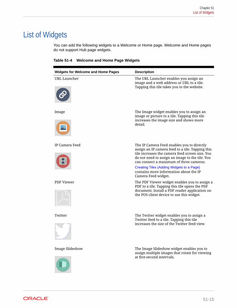
List of WidgetsYou can add the following widgets to a Welcome or Home page. Welcome and Home pagesdo not support Hub page widgets.
Table 51-4 Welcome and Home Page Widgets
Widgets for Welcome and Home Pages Description
URL Launcher
The URL Launcher enables you assign animage and a web address or URL to a tile.Tapping this tile takes you to the website.
Image
The Image widget enables you to assign animage or picture to a tile. Tapping this tileincreases the image size and shows moredetail.
IP Camera Feed
The IP Camera Feed enables you to directlyassign an IP camera feed to a tile. Tapping thistile increases the camera feed screen size. Youdo not need to assign an image to the tile. Youcan connect a maximum of three cameras.Creating Tiles (Adding Widgets to a Page)contains more information about the IPCamera Feed widget.
PDF Viewer
The PDF Viewer widget enables you to assign aPDF to a tile. Tapping this tile opens the PDFdocument. Install a PDF reader application onthe POS client device to use this widget.
The Twitter widget enables you to assign aTwitter feed to a tile. Tapping this tileincreases the size of the Twitter feed view.
Image Slideshow
The Image Slideshow widget enables you toassign multiple images that rotate for viewingat five-second intervals.
Chapter 51List of Widgets
51-15

Table 51-4 (Cont.) Welcome and Home Page Widgets
Widgets for Welcome and Home Pages Description
Today’s Special
The Today’s Special widget enables you toassign one or more menu items, graphics,descriptions, and prices to a tile. When morethan one menu item is configured, the itemsrotate for viewing at five-second intervals. Youcan assign a time range to this widget so thatdifferent specials cycle based on the times theyare being served.
Command Widget
The Command widget enables you to assignprocedures, functions, and POS clientcommands to a tile. The available commandsare:• Clock In• Clock Out• Update Database• Close Application• Employee Training• Redirect Order Device• Edit Menu Item• Menu Item Availability• Minimize Application• Sign In RVC Prompt
Weather
The Weather widget enables you to assign aweather forecast provider and location to atile. Purchase an application programinterface (API) key to use this widget.
You can add the following widgets to a Hub page.
Table 51-5 Hub Page Widgets
Widgets for Hub Pages Description
ECM Alert
The ECM alert widget enables you to viewECM alerts based on cash pull thresholdsfor till and server bank receptacles. Thiswidget is supported for multiple cashmanagement classes. The ECM alert widgetshows:• Receptacle name• Alert type• Alert level (if applicable)• Variance (threshold value – actual
receptacle session amount)The ECM alert widget also indicates whenthere are no active alerts.
Chapter 51List of Widgets
51-16

Table 51-5 (Cont.) Hub Page Widgets
Widgets for Hub Pages Description
ECM Summary
The ECM summary widget enables you toview summary information for active ECMreceptacles. This widget is supported formultiple cash management classes. TheECM summary widget shows:• Receptacle name• Number of open receptacle sessions
for each receptacle type• Current total in base class amountThe ECM summary widget also indicates:• Active alerts for a session• Offline open receptacle sessions• Multiple classes
inMotion Charts
The inMotion Charts widget enables you toassign Oracle Hospitality Enterprise BackOffice reports to a tile. When you select thistile, the assigned report generates first, butall other reports are also accessible. Selecteach report to view more information.The following reports are available:• Sales• Labor Cost• Discount• Sales Per Labor Hour• Check Count• Guest Count• Average Ticket Time
inMotion Stores
The inMotion Stores widget enables you toview cumulative sales report informationfrom all available outlets, or you can selectan individual store from a list that appearswhen selecting this tile.
Labor Cost
The Labor Cost widget enables you to viewpotential employee overtime labor costs.When you select this tile, alerts inform thesupervisor about employees approachingovertime for a particular pay cycle.
WCC (Web Configuration Console)
The WCC widget enables you to assign oneof the following available managerprocedures to a tile:• Edit Header/Trailer• Bulk Edit MI Prices• Copy Menu Item
Chapter 51List of Widgets
51-17

Viewing the Maximum Data Limit for Hosted EngagementServer
You can view the maximum allowable amount and remaining space for uploadingwidget images to your hosted Engagement server. When adding images for widgets,the data limit (2 GB total) appears on the image upload screen, along with theremaining amount of available space for adding more image content.
Chapter 51Viewing the Maximum Data Limit for Hosted Engagement Server
51-18

52Extension Applications
A POS Client .NET Extension Application is a .NET class library that adds new operations orevent handlers to the Simphony POS client.
An Extension Application adds new operations by defining extension methods that areinvoked using buttons created in the Page Designer module. Existing operations areextended by implementing event handlers for POS client events. Extension methods andevent handlers are able to interact with the POS client using the Extension Application API.
The POS Client Extension Application API is the set of data types used by the ExtensionApplication to interact with the POS client; this interaction includes the ability to add items toa guest check, prompt the user for information, invoke existing operations, evaluateconfiguration elements (such as employee options), and more.
Configuring Extension Application Privileges1. Select the Enterprise level, click Configuration, and then click Roles.
2. Select the role type (for example, administrator), and then click the EMC Modules tab.
3. In the Touchscreens section, select the appropriate Extension Application Postingpermissions for the user role. You can grant permissions for the following actions:
• View: Open and view the Extension Application module. If you allow a user to Edit,you must also grant View access (otherwise the user cannot open the module).
• Edit: Update fields or records within the module.
4. Click Save.
Enabling Extension Applications1. Select the Enterprise, property, revenue center, or zone, click Setup, and then click
Extension Application.
2. Highlight the record for the extension application.
3. Click the ellipsis point (...) button in the Options column.
4. To enable the extension application, ensure that 1 - Disable Application is deselected.To disable the extension application, select 1 - Disable Application.
5. To configure the extension application to post check data to the Reporting and Analyticsdatabase without manual intervention, select 5 - Post extension application data toReporting and Analytics.
6. Click OK to close the Extension Application Options dialog.
7. Enter information in the following columns:
• Type: The value in this field indicates how extensibility information appears inReporting and Analytics.
52-1
– Enter 0 if extensibility information is needed only at the POS. Extensibilityinformation does not appear in Reporting and Analytics reports.
– Enter 1 to have extensibility information appear in the standard CheckDetail Report in Reporting and Analytics.
– Enter 2 to hide the extensibility information in the standard Check DetailReport, but show it in the Check Detail with Extension Data report inReporting and Analytics.
If you selected option 5 in Step 5, you must enter 2 as the Type. Checks forextension applications with Type 2 will appear in Reporting and Analyticsreports.
• Data Level: The default value is 2.
– Enter 0 to post nothing (no check header nor detail information) to theReporting and Analytics database.
– Enter 1 to post only the check header information to the Reporting andAnalytics database.
– Enter 2 to post both the check header and detail information to theReporting and Analytics database.
• Max Chars: Enter the maximum characters to appear (from 1 to 2000) foreach extension item. The default value is 200.
If the data entered through the POS client exceeds the maximum characterlimit, the data will be truncated and posted to the Reporting and Analyticsdatabase; the Direct Posting Service (DPS) log will indicate the exceededcharacter limit for each entry with a line item message stating Truncatingextensibility detail - no data.
• Max Items: Enter the maximum extension items to appear (from 1 to 100).The default value is 1.
If the data entered through the POS client exceeds the maximum item limit,the data will be skipped and a message posted to the Reporting and Analyticsdatabase; the Direct Posting Service (DPS) log will indicate the exceeded itemlimit for each entry with a line item message stating Skipping extensibilitydetail - max detail reached.
8. Click Save.
Chapter 52Enabling Extension Applications
52-2

53Transaction Services
Transaction Services is a web service that allows Simphony to interface with third-partyapplications (for example, hotel self-service kiosks or room service devices, menu boards,and Enterprise online ordering). Transaction Services is commonly installed in stadiums thatuse self-ordering devices. Guests can place orders using a third-party application thatinterfaces with a Transaction Services client. The client then sends the guest checks toSimphony.
Configuring the Transaction Services Workstation ClientYou can configure Transaction Services to run on the same hardware device as a Simphonyclient. Kiosks are usually configured as Transaction Services clients. Obtain the followinginformation before you begin the configuration:
• Transaction Services workstation name
• Number of revenue centers using Transaction Services
POS API client workstations do not run as a Windows Service, and administrators cannotconfigure Transaction Services as a Windows Service. This is by design. When option 3 -POSAPI Client is selected as the Type in the Workstations module, the Is Windows Servicefield is disabled and greyed out.
1. Select the property, click Setup, and then click Workstations.
2. Insert a record, enter the workstation name, and then click OK.
3. Double-click the workstation record.
4. From the Type drop-down list, select 3 - POSAPI Client.
POS API client workstations do not run as a Windows Service, and you cannot configureTransaction Services as a Windows Service. This is by design. When option 3 - POSAPIClient is selected, the Is Windows Service field is disabled and greyed out.
5. Select the Service Host ID where the workstation runs.
To host Transaction Services on a separate workstation, select the default Service HostID.
6. In the Address / Host Name field, enter the machine where Transaction Services isinstalled.
7. Enter the Subnet Mask and the Default Gateway of the workstation to configure.
8. Click the Service Host tab.
9. To host Transaction Services and the POS client on a single workstation, select thecorresponding Service Host name from the Service Host drop-down list.
10. Click the Transactions tab.
11. Enter the Minimum Check Number and the Maximum Check Number to use.
12. From the Default Order Type drop-down list, select the order type that the TransactionServices client uses.
53-1

13. Ensure that the Cash Drawer Settings show 0 (zero).
14. Click the Order Devices tab.
15. Select all order devices that use the Transaction Services client for the revenuecenter shown in the list. If multiple revenue centers use Transaction Services,select the appropriate order devices for each revenue center.
16. Click the Printers tab.
17. For each printer, click the Select link, and then select the printer to use for eachprint job.
18. Click the Revenue Centers tab.
19. Select the revenue centers in which this instance of Transaction Servicesoperates.
20. Click the Devices tab, and then ensure that no peripheral devices appear.
21. Click Save.
22. Repeat Steps 1 through 21 for each Transaction Services workstation client.
Configuring the Transaction Services Default EmployeeTransactions that are created and altered by the Transaction Services client must beassociated with a default transaction employee in Simphony. You need to create anemployee record that is not associated with a member of the staff, and is solely usedfor the Transaction Services client to post records to Simphony.
1. Select the Enterprise, property, or revenue center, click Configuration, and thenclick Employee Maintenance.
2. Click the Insert Record button to add an employee.
3. From the Add Employee dialog box, select Add Employee From Template.
4. If you created employees previously, click Employee to Copy, and then select anexisting employee to copy.
5. Enter the first name and the last name of the employee.
6. Assign the employee with an operator record in the revenue center in whichTransaction Services operates. Take note of the employee record number.
7. Select the Property and the Revenue Center, and then click OK.
8. Click Save.
9. Go to the POS client workstation, and run the CAL, selecting the workstation youconfigured through Configuring the Transaction Services Workstation Client.
10. After the CAL installation is complete, navigate to the EGatewayService directoryfrom the workstation, open the web.config file, and then verify that the file containsthe correct Api_WorkstationID value.
Order Information ServiceThe Order Information Service allows third-party solutions to offer mobile ordering fordelivery and pickup (for example, in seat ordering at a stadium) with status updates tothe guest. The Order Information Service includes the latest view of the order content,
Chapter 53Configuring the Transaction Services Default Employee
53-2

such as order ID, items purchased, payment, employee delivering the order, and so on.
Third-party integrators can obtain order detail and status from Simphony in environmentswhere orders enter the Simphony system through the Transaction Services applicationprogram interface (API). Third-party applications can query check status (for example, open,assigned, or closed), and the Order Information Service returns all checks that meet therequest criteria. The Oracle Hospitality Simphony Transaction Services API Documentcontains information for software engineers developing applications that interface withSimphony using Transaction Services.
Activating the Extension Application for Order InformationService
You need to enable the Order Information Service as an extensibility application. No interfaceis needed.
1. Select the Enterprise, property, revenue center, or zone, click Setup, and then clickExtension Application.
2. Highlight the record for the Order Information Service Client, click the ellipsis point (...)button in the Options column, and then verify that 1 - Disable Application is deselected.
3. Ensure that the Interface column value shows 0 - None.
4. Click Save.
Configuring Touchscreen Order Information Service ButtonsYou can create buttons on a page for the Order Information Service functions. You can createmultiple buttons with slightly different functions (for example, Delivered All, Delivered Nothing,Delivered Without Alcohol, Delivered Without Food, Delivered Without Retail, and so on).
1. Select the Enterprise, property, or revenue center, click Configuration and PageDesign.
2. Open the page on which to place Order Information Service buttons.
3. From the Edit tab, select the page area in which to define the Order Information Servicefunctions.
4. Click Button.
5. From the General subtab, in the Legend field, enter the button name (for example,Assign Multiple Checks).
6. Select Function from the Type drop-down list.
7. Click the arrow beneath the Type drop-down list.
8. Select Run Extensibility App, and then click OK.
9. Click the arrow next to the Arguments field. The Edit Extensibility Arguments dialogappears.
10. Enter the appropriate extensibility arguments:
a. Select dll from the Type drop-down.
b. In the appname field, enter the name of the extension application you created for theOrder Information Service (for example, OISClient).
Chapter 53Activating the Extension Application for Order Information Service
53-3

c. In the filename field, enter OISClient.dll.
d. In the function field, enter one of the following:
• Assign
• Close
• CloseAllChecks
e. Enter the argument value in the arg field, and then click OK.
Order Information Service Functions and Extensibility Arguments containsdetailed information about the Assign, Close, and CloseAllChecks functionsand the arguments required for each function.
11. Position and size the button on the page. Use the Style arrow to change the color.
12. Click Save.
13. Repeat Steps 4 through 12 to create each button. The following table lists therecommended Order Information Service buttons.
Table 53-1 Order Information Service Buttons and Functions
Button Name Function Description
Assign Check Assign Assign a single check to a delivery agent.
AssignMultipleChecks
Assign Assign more than one check to a delivery agent.
Delivered Close Close a check after all items are deliveredsuccessfully.
DeliveryFailed
Close Close a check, voiding all items and returning themto inventory.Use this button when the delivery agent cannot findthe guest to deliver the prepared items.
DeliveredWithoutAlcohol
Close Close a check, voiding the alcohol items andreturning them to inventory.
Cancelled Close Void all items and close the check to a zero dollaramount.Use this button when the order is canceled prior tobeing prepared and delivered.
Close All OpenChecks
CloseAllChecks
Void all items on every open check and close thechecks to a zero dollar amount.
Close All OpenChecks byOrder Type
CloseAllChecks
Void all items on every open check created for aspecific Order Type and close the checks to a zerodollar amount.
Close All OpenChecks byEmployee
CloseAllChecks
Void all items on every open check created by aspecific employee and close the checks to a zerodollar amount.
Chapter 53Configuring Touchscreen Order Information Service Buttons
53-4

Order Information Service Functions and ExtensibilityArguments
The Order Information Service supports three functions:
• Assign
• Close
• CloseAllChecks
Each function must contain a set of arguments. The following tables describe the extensibilityarguments that you must include for each function. Each argument is required unlessotherwise indicated.
Table 53-2 Assign Function Arguments
Argument Description Example
ID= Enter anything here (forexample, Assigned,AssignedToRunner,TransferredToRunner). Thistext is visible whenTransaction Services queriesthe check.
ID=Assigned
(Optional) MultipleChecks= To include this argument, setthe value to true, and thefunction refers to AssignMultiple Checks.To exclude this argument, setthe value to false, and thefunction refers to AssignSingle Check.
MultipleChecks=true
ServiceTotalNumber= Enter the object number of theTender/Media record usedwhen performing theoperation (such as the tenderused for Service Total).
ServiceTotalNumber=51
An example of the arg value for the Assign function isID=Assigned,MultipleChecks=true,ServiceTotalNumber=51
Table 53-3 Close Function Arguments
Argument Description Example
Reason= Enter anything here. This textis visible when TransactionServices queries the check.
Reason=Delivered
PaymentNumber= Enter the object number of theTender/Media record usedwhen performing theoperation.
PaymentNumber=3
Chapter 53Order Information Service Functions and Extensibility Arguments
53-5

Table 53-3 (Cont.) Close Function Arguments
Argument Description Example
(Optional) VoidParams= Use this argument to indicatewhich items to remove fromthe check before closing it. Forexample, to delete all items infamily groups 1, 2 and 5, setthe value to FG:1:2:5. FGindicates Family Group. (Thisis the only recognized valuetype.) Use FG=* to void allitems.If you exclude this argument,the function does not allowvoids.
VoidParams=FG:10:11:15:16:30:31:32
(Optional) OrderTypeFilter= Use this filter to close checksfor the tender set in thepayment argument and by aspecific order type.If you exclude this argument,the function includes all ordertypes that can use the paymenttender.
OrderTypeFilter=2
An example of the arg value for the Close function isReason=Delivered,PaymentNumber=3,VoidParams=FG:10:11:15:16:30:31:32,OrderTypeFilter=2
Table 53-4 CloseAllChecks Function Arguments
Argument Description Example
Reason= Enter anything here. Thistext is visible whenTransaction Servicesqueries the check.
Reason=Delivered
PaymentNumber= Enter the object number ofthe Tender/Media recordused when performing theoperation.
PaymentNumber=3
(Optional) OrderTypeFilter= Use this filter to close checksfor the tender set in thepayment argument and by aspecific order type.If you exclude thisargument, the functionincludes all order types thatcan use the payment tender.
OrderTypeFilter=2
Chapter 53Order Information Service Functions and Extensibility Arguments
53-6

Table 53-4 (Cont.) CloseAllChecks Function Arguments
Argument Description Example
(Optional) EmployeeFilter= Use this filter to close checksfor the tender set in thepayment argument and by aspecific employee. Forexample, a TransactionServices user creates thechecks, so including thisemployee in the argumentcloses only the TransactionServices checks.If you exclude thisargument, the functioncloses all employees’ checks.
EmployeeFilter=2
An example of the arg value for the CloseAllChecks function isReason=Delivered,PaymentNumber=3,EmployeeFilter=2
Chapter 53Order Information Service Functions and Extensibility Arguments
53-7

54Cruise Ship Time Zone and Business DaySettings
A cruise ship is a constantly moving property. As a ship moves around the world, the timezone settings for the shipboard systems need to change daily to align with the time zone inwhich the ship is sailing.
There are two methods of changing the time zone:
• A ship’s master clock communicates the current time zone settings. When someonechanges the master clock’s time zone, all shipboard systems (for example, propertymanagement system (PMS) and Simphony) automatically update their settings to ensureconsistent date and time stamp posting across all applications.
• A system administrator manually sets the ship’s time zone within the PMS and Simphony.
Oracle recommends that you perform the following tasks:
• Close all checks before changing the time zone.
• Change the time zone once per day during a slow period of operations (for example,between 2:00 a.m. and 5:00 a.m.).
Changing the Time Zone1. Close all checks in the workstations.
2. From the EMC, select the Enterprise level, click Setup, and then click Properties.
3. Select the new time zone for the ship from the Time Zone drop-down list.
4. Click Save. The CAL client deploys the new time zone to the property and automaticallyupdates the time zones of the workstations connected to the property.
Time zones do not update on workstation tablet devices running generic Androidoperating systems when the property time zone changes. You must manually update thetime zone on these devices.
Start of Business DayIn food service and hotel environments, a business day refers to the beginning and end timesof a day of business. A business day can have any begin time, but typically a business daystarts in the early morning hours during a slow or closed period of operations (for example,3:00 a.m. or 4:00 a.m.). In contrast, a calendar day always begins at 12:00 a.m.
In a cruise ship environment the PMS controls the business date. Simphony posts cabincharges in the PMS. Simphony and the PMS must be in sync to communicate and balancethese transactions. When initializing the Start of Day (SOD) on a ship, change the PMS datebefore changing the Simphony date.
On cruise ships, Simphony allows a manual SOD to run twice in one calendar day. Forexample, the cabins empty at approximately the same time on a cruise ship, and the financial
54-1

information resets. The ship’s PMS and Simphony are closed out after the last guestleaves the ship, which is typically between 12:00 p.m. and 1:00 p.m. The SODchanges in the PMS and in Simphony at that time, and the next cruise begins. Boththe PMS and Simphony change the SOD again at about 3:00 a.m. the following daywhen the cruise is under way.
Configuring Start of DayA system administrator on a ship must take the workstations offline and then manuallyset the daily start and end times.
1. Select the Enterprise level, click Configuration, and then click Roles.
2. Select the appropriate role type (such as manager), click the Operations tab, andthen click the PMC Procedures subtab.
3. Select the appropriate privileges as described in the following table:
Table 54-1 Start of Day Role Privileges
Privilege Option Description
30058 - Run Start of Day from OPS Select this option to allow all employeeswith the role to increment the businessdate from the property’s Check andPosting Service (CAPS) workstation.
30059 - Prevent Running SOD from OPSwith Open Checks
Select this option so that Start of Daycannot run when open checks exist.
4. Click Save.
5. Select the Enterprise, property, or revenue center, click Configuration, and thenclick Page Design.
6. Select the page on which to place the Start of Day button.
7. Add a Start of Day button:
a. In the Legend field, enter Run Start of Day.
b. From the Type drop-down list, select Function.
c. Click the arrow beneath the Type drop-down list, and then select Start of Day.
d. Position and size the new button on the page.
8. Click Save.
9. Select the property, click Setup, and then click Property Parameters.
10. Click the Options tab, and the select 48 - Run Start of Day from OPS.
11. Click the Calendar tab, and then select Run Manually for each day of the week.
12. In the Manual SOD Safety catch time field, set the time when the applicationautomatically increments the business date if someone forgets to manually runSOD.
The application checks to see whether SOD occurred within a 24-hour period forthe selected property. This time is based on the time zone of the property.
13. Click Save.
Chapter 54Configuring Start of Day
54-2
14. Select the Enterprise level, click Configuration, and then click PC Autosequences.
15. Insert a PC Autosequence record, name it Increment Business Day, and then click OK.
16. Open the record and select the Allowed Properties to view the autosequence.
17. (Optional) From the Parameters section, click the Add link to add parameters. Forexample, you can enter a property number and exclude a revenue center number.
a. From the Select Autosequence Parameter dialog, select the Parameter from thedrop-down list.
b. Enter a Value, and then click OK.
18. Click the Steps tab.
19. Click the Add link to add a step.
20. From the Step Type drop-down list, select 3 - Increment Business Date.
21. Click Save.
Workstation Control PrivilegesYou can configure the control of workstation operations during critical events, such as:
• Running Start of Day
• Locking and unlocking workstations
• Locking and unlocking revenue centers
• Updating workstations
• Reloading workstations
You can set the workstation control privileges for each employee role type (for example,manager, server, and host).
Configuring Workstation Control PrivilegesTo set the control of workstation operations during critical events:
1. Select the Enterprise level, click Configuration, and then click Roles.
2. Select the role type (such as manager), click the Operations tab, and then click theMiscellaneous subtab.
3. Select the appropriate privileges:
• 10019 - Unlock UWS or Revenue Center: Select this option to allow employees inthe role to unlock a workstation or revenue center from the locked dialog.
• 10020 - Use Workstation Control: Select this option to allow employees in the roleto use the Workstation Control key to access various workstation functions (forexample, locking and unlocking workstations and revenue centers, and updating thedatabase). Selecting this option also allows employees to unlock a workstation orrevenue center from the locked dialog.
4. Click Save.
5. Select the Enterprise, property, or revenue center, click Configuration, and then clickPage Design.
6. Select the page on which to place the Workstation Control button.
Chapter 54Workstation Control Privileges
54-3

7. Add a Workstation Control button:
a. In the Legend field, enter Workstation Control.
b. From the Type drop-down list, select Function.
c. Click the arrow beneath the Type drop-down list, and then select WorkstationControl.
d. Position and size the new button on the page.
8. Click Save.
Chapter 54Configuring Workstation Control Privileges
54-4

55Interfaces with Simphony
Simphony includes the ability to interface with third-party software, such as PropertyManagement Systems (PMS).
Configuring a Rear Marketing Display (RMD)The Remote Marketing Display (RMD) feature allows you to connect a secondary display toan Oracle MICROS workstation. This application is configured via the Simphony EMC DataExtensions module, and then can be assigned to workstations with a 10–inch displayattached. This extension application only works if there is a secondary display connected to aworkstation. If the secondary display is a touchscreen, you have the option to showcustomers current transaction detail, and then prompt them to confirm their order. If there ischange due, a dialog box is shown to customers. The system can also show customizedimages during a transaction, or videos while the workstation is idle. If video files are placedon workstations (via CAL), then the application plays designated videos every 5 minutes (bydefault).
Pre-Requisite Requirements
• Supported Hardware
– 10–inch Display device
– Oracle MICROS Workstation 6 Series - 610, 620, 650, and 655
Note:
Workstations running Oracle Linux for MICROS are not supported for thisfeature at this time.
Each workstation with a secondary display attached, should be calibrated by following thesteps outlined in the Oracle MICROS Workstation 6 Series Setup Guide for 610, 620, and650 documentation, specifically the Calibrating the Workstation and 10–Inch CustomerDisplay topic.
• Supported Software
– Simphony Workstation Client Versions:
* 18.2.x
* 19.1.x
– Images and (optional) videos are used with the Rear Marketing Display (RMD), andare required in order to fully configure and utilize the application.
55-1

RMD Configuration
To configure this feature, you must have EMC access privileges assigned to your Rolefor the Data Extension, Extension Application, Workstation, and Content modules. Toconfigure the Remote Marketing Display (RMD), complete the following steps:
Configuring the Extension Application
1. Access the EMC.
2. Navigate to the Enterprise or Property level, click the Setup tab, under CustomContent, and then select the Extension Application module..
3. Insert a new record and name it OCS2020. Toggle to Form view.
4. From the General tab, click the Insert Application Content button.
Figure 55-1 Extension Application Module
5. Enter the following text in the fields shown below:
• Zoneable Key: Application
• Description: Main OCS Application
6. Click the Designer tab.
7. From the Content Type drop-down list, select 3 - DLL.
8. Click the Import from a file link, and then select OCS2020.dll.
Note:
The File Name Origin field auto-populates to reflect the full name of theOCS2020.dll.
9. Click the General tab and enter OCS2020.dll in the Disk File Name column of therecord. Note the Disk File Name entry is case-sensitive and must be the same asthe actual file name including its file extension.
10. From the Target field, click the ellipsis (…), enable the Win32 operating systemcheckbox, and then click OK.
11. Enter the appropriate Simphony Minimum / Maximum version information in theVersion field. Click the ellipsis (…), and in this case, enter 19.1 in the Maximumfield, select the checkbox adjacent to the maximum version number, and then clickOK.
Chapter 55Configuring a Rear Marketing Display (RMD)
55-2

Figure 55-2 Edit Application Content Version Window
12. Click Save.
Configuring the Data Extension
Configure the data extension record. This configuration allows you to enable or disable theRMD application on each workstation. Enable this extension for workstations connected to10–inch displays.
1. Access the EMC.
2. Navigate to the Enterprise level, click the Configuration tab, under Reporting and Data,and then click the Data Extensions module.
3. Insert a new record.
4. Click the ellipsis (…), and then select 41 - Workstations from the drop-down list in theTable column.
5. Enter RMDEnabled in the Extra Column Name field.
6. From the Type column, select 4 - Boolean from the drop-down list.
7. Enable the following column check-boxes:
• Is Editable
• Is Viewable
• Is Downloadable
8. Click Save.
Enabling Data Extensions for Workstations
1. Access the EMC.
2. Navigate to the Property level, click the Setup tab, under Hardware/Interfaces, and thenclick the Workstations module.
3. Select a workstation record and toggle to Form view.
4. Select the Data Extensions tab.
5. Enable the check-box under the Value column for the RMDEnabled Data Extension.Perform this step for each workstation connected to a secondary display, and Save.
Enabling the Rear Display on a Workstation
1. Access the EMC.
2. Navigate to the Property, click Setup, under Hardware/Interfaces, and then clickWorkstations.
Chapter 55Configuring a Rear Marketing Display (RMD)
55-3

3. Select the workstation record and toggle to Form view.
4. Click the Options tab, select the Display/Security subtab under the DisplayOptions section, and then select the 6 - Enable Rear Display option.
5. Click Save.
Adding Images in the Content Module
In order to achieve the best look and feel of your images and videos on the RMD,Oracle MICROS Food & Beverage recommends adhering to the following imagedimensions:
All dimensions are provided in the form of Width x Height (pixel count).
• OCSDefaultImage dimensions should be set to 1914 x 1074 pixels.
• OCSRightPanelImage dimensions should be set to 957 x 1074 pixels.
• OCSBannerImage dimensions should be set to 957 x 120 pixels.
• Video dimensions should be set to 1914 x 1074 pixels.
1. Access the EMC.
2. Navigate to the Enterprise level, click the Setup tab
, under Custom Content, and then select the Content module.
3. Insert a new record and name it OCSDefaultImage. Toggle to Form view.
4. From the General tab, click the Content Type drop-down list, and then select 9 -Image (JPG).
5. Click the Import from a file link, and then select the image to show when theworkstation operator is signed out or the workstation is idle.
6. Insert a new record and name it OCSRightPanelImage. Toggle to Form view.
7. From the General tab, click the Content Type drop-down list, and then select 9 -Image (JPG).
8. Click the Import from a file link, and then select the image to show on the rightpanel of the display when a transaction is in progress.
9. Insert a new record and name it OCSBannerImage. Toggle to Form view.
10. From the General tab, click the Content Type drop-down list, and then select 9 -Image (JPG).
11. Click the Import from a file link, and then select the image or logo to show onbottom left panel of the display, directly under the check detail window.
12. Click Save.
Configuring Touchscreen Buttons in Page Design
This extension application supports two button configurations for the workstation orRMD touchscreen displays.
• Manage OCS - This button is used to manage the OCS/RMD application.
1. Access the EMC.
2. Navigate to the Enterprise level, click the Configuration tab, under UserInterface, and then select the Page Design module.
Chapter 55Configuring a Rear Marketing Display (RMD)
55-4

3. Select the touchscreen you want to add the button. Toggle to Form view.
4. Add a new button and configure it using the following settings:
a. Legend: Manage OCS
b. Type: Function - Run Extensibility App
c. Arguments:appname=OCS2020;type=dll;filename=OCS2020.dll;function=manageOCS;arg=
5. Click Save.
• Confirm Order - This button is used to prompt customers to confirm their order andshould only be used if the secondary display is a touchscreen.
1. Access the EMC.
2. Navigate to the Enterprise level, click the Configuration tab, under User Interface,and then select the Page Design module.
3. Select the touchscreen you want to add the button. Toggle to Form view.
4. Add a new button and configure it using the following settings:
a. Legend: Confirm Order
b. Type: Function - Run Extensibility App
c. Arguments:appname=OCS2020;type=dll;filename=OCS2020.dll;function=confirmOrder;arg=
5. Click Save.
(Optional) Create a CAL Package to Distribute Video Files to Workstations
Create a CAL Package to transfer marketing video files to workstations. This is completelyoptional and not required if the secondary display is not being utilized as a RMD.
• Currently, only videos in MP4 format are supported
• A maximum of five videos are supported
• Video file names must be named like this: movieX.mp4, where X = 1 through 5
• Video files must be placed the C:\Micros folder on workstations
• By default, videos play every 5 minutes starting with movie1.mp4, and then in numericalsequence thereafter
OPERA PMS Enhanced Interface Features and RequirementsSupported Software and Hardware
• Simphony release 2.8 or later
• OPERA Interface release 8.7.3.7 or later
• Supported POS client devices as of Simphony release 2.8 running the Service Hostapplication.
– Oracle MICROS PC Workstation 2015
– Oracle MICROS Tablet E-Series 8 inch (OS 1.5) and 11 inch (OS 1.4)
– Oracle MICROS Workstation 6 Series
Chapter 55OPERA PMS Enhanced Interface Features and Requirements
55-5

– Oracle MICROS Workstation 5A (POSReady 2009/7)
– Android 4.4 tablets
– Samsung Galaxy 7, 8, 11 inch
– Google Nexus
– Zebra MC40 – Android 4.4
– DT Research DT365
– Microsoft Windows 7 and 8.1 devices
Posting Capabilities
• Up to 16 Sales Itemizers
• Up to 64 Tax Itemizers
• 16 Discount Itemizers if the Full Discount and Service Charge Breakdown isconfigured accordingly; otherwise 1 Discount Itemizer
• Up to 14 Service Charge Itemizers if the Full Discount and Service ChargeBreakdown is configured accordingly; otherwise 2 Service Charge Itemizers
• Check Details in the final tender event
Inquiries
• Enhanced inquiry by name or room number returns the following information(varies and depends on the setup on the PMS):
– Guest last name, first name, and title
– Arrival and departure dates
– Room number and room type
• Display of guest reservation detail
• Display of guest history
• Display and printing of guest messages
• Entry of guest messages
• Display of guest locator
• Entry of guest locator
Inserting the Extension Application Files for OPERAThis procedure explains how to install and configure the SIM OPERA PropertyMaintenance System (PMS) interface. The configuration requires:
• Simphony release 2.8 or later
• OPERA Interface release 8.7.3.7 or later
1. Run the SIMPH2_ENH_IFC[version number].exe setup application on theSimphony application server.
This application verifies the Simphony installation and copies the following files tothe [Drive letter]:\MICROS\Custom\EnhancedInterface folder:
• CONTENT_EnhIFC_Config.txt
Chapter 55Inserting the Extension Application Files for OPERA
55-6

• McrsExtDialogsML.dll
• MF_ENH.isl
• MF_ENH_Android.isl
• android.htm
2. If you cannot start the setup application on the Simphony application server because ofaccess or user right limitations, but have access to EMC from your local PC, use the /LOCAL parameter to star the application.
This method only works for version 270. That is, SIMPH2_ENH_IFC270.exe. Running theapplication through this methods does not verify the Simphony installation, and it is yourresponsibility to ensure that the Simphony requirements are met. This method copies therequired files into the sub-folder Custom\EnhancedInterface beneath the folder youselected in the setup application.
3. Select the Enterprise, property, revenue center, or zone, click Setup, and then clickExtension Application.
4. Click the Insert icon to add a record.
5. Enter the record name in the Name field (for example, OPERA), and then click OK.
6. Double-click the record to open it in form view.
7. On the General tab, click the Insert Application Content button.
Figure 55-3 Extension Application Insert Application Content Button
8. Enter MF_ENH for both the ZonenableKey and Description fields, and then click OK.
Figure 55-4 Inserting Application Content Records
Chapter 55Inserting the Extension Application Files for OPERA
55-7

a. On the Designer tab, select 19 - Sim Script as the Content Type.
b. Click the Import from a file link.
Figure 55-5 Importing Content From File
c. Browse to and select the MF_ENH.isl file, and then click Open.
d. On the General tab, enter MF_ENH.isl in the Disk File Name column.
Disk File Name entries must exactly match the name of their associated SIMscripts and DLL file names. These entries are case-sensitive.
e. In the Option Bits column, click the ellipsis point (...) button, and then select 2- Main SIM Content.
f. In the Target column, click the ellipsis point (...) button, and then select 1 -Win32.
9. Repeat Steps 7 through 9 to insert a new application content and import theMF_ENH_Android.isl file with the following settings:
• ZonenableKey: Enter MF_ENH_ANDROID.
• Description: Enter MF_ENH_ANDROID.
• Content Type: Select 19 - Sim Script.
• Option Bits: Select 2 - Main SIM Content
• Disk File Name: Enter MF_ENH_ANDROID.isl.
• Target: Select 10 - Android.
10. Repeat Steps 7 through 9 to insert a new application content and import theMcrsExtDialogsML.dll file with the following settings:
• ZonenableKey: Enter McrsExtDialogsML.
• Description: Enter McrsExtDialogsML.
• Content Type: Select 3 - DLL.
• Disk File Name: Enter McrsExtDialogsML.dll• Target: Select 1 - Win32.
11. Repeat Steps 7 through 9 to insert a new application content and import theandroid.htm file with the following settings:
Chapter 55Inserting the Extension Application Files for OPERA
55-8

• ZonenableKey: Enter html. The ZoneableKey entry for the android.htm file mustmatch html, and it is case-sensitive.
• Description: Enter html.
• Content Type: Select 23 - Text.
• Target: Select 10 - Android.
12. Click Save.
13. For multi-tenant environments, you must configure the content information as ExtensionApplication content. In these environments the content feature cannot be used.
a. Insert a new application content for the enhanced interface by clicking the InsertApplication Content button.
b. Configure the following fields:
• ZonenableKey: Enter EnhIFC_Config (case sensitive).
• Description: Enter EnhIFC_Config (case sensitive).
• Content Type: Select 23 - Text.
• Target: Select 10 - Android.
c. Click Save.
d. Insert the content information as outlined in Configuring OPERA Content Information.
Configuring OPERA Content InformationFor multi-tenant environments using releases earlier than Simphony release 2.9, you arerequired to configure the content information as Extension Application content. The contentfeature cannot be used in these environments.
1. Select the Enterprise, property, revenue center, or zone, click Setup, and then clickContent.
2. Insert a record for the PMS content, named PMS.
3. Double-click the new record to open it.
4. Select 4 - String as the Content Type.
5. Enter the following string in the Content tab and make the necessary modifications, asshown in the following figure (the content text file is delivered with the other files).
See Content Text Settings for the OPERA PMS for more information on the configurationstrings.
Chapter 55Configuring OPERA Content Information
55-9

Figure 55-6 Content Text File
6. (Optional) For debugging purposes, add the line "DEBUG_ON=10".
This increases the verbosity, adding additional messages in the Egateway.log file.
7. To override the Content, select the Use Existing Record option.
The Content can be overridden by property, zone, or revenue center.
Figure 55-7 Override Record Controls
8. Click Save.
9. Restart the Service Hosts.
Content Text Settings for the OPERA PMSThe following tables list the string names and values to be used in the Content modulefor the OPERA content text file.
Chapter 55Content Text Settings for the OPERA PMS
55-10

Posting Related Settings
Table 55-1 Posting Related Settings
Configuration String Configuration Value
MAGCARDONLY Set to 0 to allow both magnetic cards andkeyboard inputs.Set to 1 to limit the entries in the Room Chargeevent to magnetic cards.
MAGCARDOVRWRT When MAGCARDONLY is enabled, you canoverwrite the setting for certain revenuecenters by entering a list of revenue centernumbers (separated by comma).
SUPPRESSGSTMSG Set to 1 to suppress the message indicatorduring posting. Enable this setting for high-volume sites.
SUPPRESSNFOREF Non-Room Charge tenders show theDepartment Code for which they were posted.Set to 1 to suppress this reference.
REVERSEGST Set to 1 to make the guest count negative whenthe payment is negative (that is, the payment isvoided). This feature requires specificconfiguration on the Front-Office interface towork correctly.
FULL_DSVC Set to 1 to send the full breakdown of thediscounts. This requires a specific version ofthe Front-Office interface.Set to 2 for an additional full breakdown of theservice charges. This includes the fullbreakdown of discounts.
NO_CONFIRM_GST Set to 0 if magnetic cards are used to identifyguests.Set to 1 to prevent confirmation of the guestname when posting.
POST_64TAXES Set to 1 to send up to 63 Tax Itemizers to theFront-Office interface. This feature requiresIFC8 V.8.7.1.2 or later as well as a certainversion of the Front-Office itself.Set to 0 to send only 8 Tax Itemizers to theFront-Office interface.
SendAllDtls Set to 0 to send only the check details of RoomCharges the Front-Office interface.Set to 1 to send also the check details of non-Room Charges.
Chapter 55Content Text Settings for the OPERA PMS
55-11

Table 55-1 (Cont.) Posting Related Settings
Configuration String Configuration Value
RESTRICTED_POSTING Select to restrict the response returned fromthe Front-Office Interface in the Room Chargeevent. Note that this only works incombination with the optionRESTR_POSTING_EMPL is configured correctly.There are two values supported:• Set to 1 to require both the room number
and at least three characters of thesurname (last name) to post the roomcharge. If less than three characters areprovided an error appears. If the responsefrom the PMS contains more than onerecord, an error appears and theworkstation operator must enteradditional characters to provide a uniqueidentifier.
• Set to 3 to assume that an external devicewill provide the input as keyboard data.There is no touchscreen keyboard shownwhen this option is used. The workstationoperator (or guest) has only the option toabort the input. If the response from thePMS contains more than one record anerror appears and the posting is aborted.There is no confirmation of the guest-name shown, irrelevant of the setting inNO_CONFIRM_GST.
Note that this feature does not work if theinput is restricted to magnetic cards.Therefore, you must either disable therestriction or add the relevant revenue centerto the excluded list of revenue centers.
RESTR_POSTING_EMPL Specify the ISL Option to use with the aboveoption (see ISL Options in the EmployeeMaintenance module). The valid value for thisconfiguration is between 1 and 8.
Locator and Message Settings
Table 55-2 Guest-Locator and Guest-Message Settings
Configuration String Configuration Value
RVCNAMELOC Set to 1 to have the first line of the locatorcontain the revenue center name,otherwise the locator name is blank.Workstations operator can overwrite thisvalue when entering the locatorinformation.
Chapter 55Content Text Settings for the OPERA PMS
55-12

Table 55-2 (Cont.) Guest-Locator and Guest-Message Settings
Configuration String Configuration Value
LOCVALIDMIN Each new locator is only valid for a certaintime. Enter the default time in minutes forwhich the locator is valid. Workstationoperators can overwrite this value whenentering the locator information.
Configuring the OPERA PMS Interface1. Select the Enterprise level, click Setup, and then click Interfaces
2. Insert a record for the OPERA PMS interface. Enter a System Name that reflects theproperty using the interface.
3. Double-click the new interface record to open it.
4. On the General tab, configure the settings as follows:
• Communication Name: Enter the name to use when communicating with theinterface.
• Interface Type: Select 0 - PMS/SIM.
• Communication Type: Select the communication type that the interface uses.
• Timeout: Enter 30.
• Ping Frequency: Set to 0 (zero) to avoid double posting.
Chapter 55Configuring the OPERA PMS Interface
55-13

Figure 55-8 Interface Module
5. Click the Options tab, and then select the options 1 - Use 19 Digit ReferenceEntry for PMS Inquiries, 2 - Enable Interface Log, 3 - Allow Inquiry withoutSign-In, and 5 - ON = Use 9 digits for Terminal IDs; OFF= Use 2 digits forTerminal IDs.
Do not enable option 8, as it causes double posting.
Chapter 55Configuring the OPERA PMS Interface
55-14

Figure 55-9 Interface Module’s Options Tab
6. In the TCP Communications section, enter the following details:
• TCP Host Name: Enter the OPERA PMS application server’s IP address or servername (if DNS is enabled).
• Port Number: Enter the port number for the OPERA PMS server.
7. Click the Properties tab, and then select the properties that can use this interface.
Figure 55-10 Interface Module’s Properties Tab
8. Click the Service Host tab, click Select adjacent to the Service Host field, select theservice host to run the OPERA PMS interface, and then click OK.
Chapter 55Configuring the OPERA PMS Interface
55-15

You can assign any workstation that has enough power to handle the incomingqueries as the service host.
9. Click Save.
10. Select the Enterprise, property, revenue center, or zone, click Setup, and thenclick Extension Application.
This configuration typically occurs at the property level when the PMS interface ison-premises.
11. In the Interface column corresponding to the OPERA extension application record,click the ellipsis point (...) button, and then select the PMS interface to associate itwith the OPERA Extension Application record.
Figure 55-11 Extension Application PMS Interface Assignment
12. Click Save.
Enabling the OPERA PMS Interface for a Revenue CenterYou must enable the OPERA PMS interface for each revenue center that usesOPERA.
1. Select the revenue center, click Setup, and then click RVC Parameters
2. Click the Interfaces tab.
3. Select the PMS interface to enable the OPERA PMS interface for the revenuecenter.
Chapter 55Enabling the OPERA PMS Interface for a Revenue Center
55-16
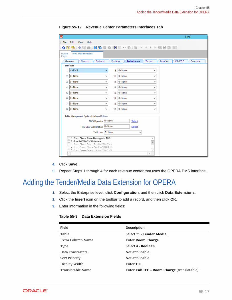
Figure 55-12 Revenue Center Parameters Interfaces Tab
4. Click Save.
5. Repeat Steps 1 through 4 for each revenue center that uses the OPERA PMS interface.
Adding the Tender/Media Data Extension for OPERA1. Select the Enterprise level, click Configuration, and then click Data Extensions.
2. Click the Insert icon on the toolbar to add a record, and then click OK.
3. Enter information in the following fields:
Table 55-3 Data Extension Fields
Field Description
Table Select 71 - Tender Media.
Extra Column Name Enter Room Charge.
Type Select 4 - Boolean.
Data Constraints Not applicable
Sort Priority Not applicable
Display Width Enter 150.
Translatable Name Enter Enh.IFC – Room Charge (translatable).
Chapter 55Adding the Tender/Media Data Extension for OPERA
55-17

Table 55-3 (Cont.) Data Extension Fields
Field Description
Translatable Help Enter Enable this for Room-Charge Payments(translatable).
Figure 55-13 Data Extensions Module
4. Select the following options:
• Is Editable
• Is Viewable
• Is Downloadable
5. Click Save.
Configuring the Tender Media for OPERA1. Select the Enterprise or property, click Configuration, and then click Tender/
Media.
2. Click the Insert icon on the toolbar to add a record, enter Room Charge as thename, and then click OK.
3. Double-click the Room Charge record to open it.
4. On the General tab, select 1 - Payment from the Key Type drop-down list.
Figure 55-14 Tender/Media Room Charge Configuration
Chapter 55Configuring the Tender Media for OPERA
55-18

5. Click the Options tab, and then click the Interface Options subtab.
6. In the View Interface Names for RVC drop-down list, select the revenue center for whichthe OPERA PMS interface was assigned, and then select PMS from the Interface Linkdrop-down list.
The Interface Link and the View Interface Names for RVC fields are only active if theTender/Media configuration is being performed at the property level.
Assign the PMS Interface Link to all payments that must be auto balanced (for example,Cash, Credit Cards, and so on).
7. Select the following options:
• 29 - ON=Post 0.00 Transactions to PMS; OFF=Do Not Post
• 31 - ON=PMS and Credit Cards Use 19 Digit Acct Number; OFF=16 Digits
• 38 - Use ISL TMED Procedure Instead of PMS Interface
Figure 55-15 Tender/Media Room Charge Options
8. Click the Ops Behavior subtab and in the General Options section, ensure that 5 -Reference Entry Required is not enabled.
9. Click the Data Extensions tab, and then select the check box in the Value column for theEnh.IFC – Room Charge.
The Value check-box must be selected for the room charge tender media(s). Deselectthe check-box for all other tender medias.
Figure 55-16 Tender/Media Room Charge Data Extensions Tab
Chapter 55Configuring the Tender Media for OPERA
55-19

10. Click Save.
Configuring the Room Charge Buttons for the OPERA PMSOracle recommends that you create payment card buttons on a page for the PMSroom charge function.
1. Select the Enterprise, property, revenue center, or zone, click Configuration, andthen click Page Design.
2. Open the page on which to place the room charge button.
3. On the Edit tab, select the page area in which to define the room charge function(typically the payment area).
4. Click Button.
5. On the General subtab, enter the button name in the Legend field.
6. Select Payment Tenders from the Type drop-down list.
7. In the Select Tender/Media Payment dialog, select the OPERA PMS room chargepayment tender, and then click OK.
8. In the Select Payment Type area, select Other1:LoadablePms from the PaymentType drop-down list.
9. Click the Edit... link in the Command column.
10. In the Payment Configuration dialog, select the Opera payment method from theFunctions drop-down list.
11. Position and size the button on the page. Use the Style arrow to change the color.
Figure 55-17 Room Charge Payment Button
12. Click Save.
13. Add the room inquiry buttons on any required page. Typically, the room inquirybuttons are created on the payment or function page.
a. Open the page on which to place the Room Charge Inquirye buttons, and thenon the Edit tab, select the page area in which to define the buttons.
Chapter 55Configuring the Room Charge Buttons for the OPERA PMS
55-20

b. Click Button, and then on the General subtab, select Function from the Type drop-down list.
c. Click the black arrow directly beneath the Type drop-down list, and then selectExtensibility from the Type pane.
d. Select SIM Inquire, and then click OK.
e. In the Argument field, enter <EXTENSION APPLICATION NAME>:<INQUIRYNUMBER>.
Enter the inquiry number corresponding to the PMS SIM inquiry. For example, enterOPERA:1 to configure a Room Inquire button.
Table 55-4 Inquire Names and Numbers for Room Inquiry Buttons
Inquire Inquire Number
Room Inquire 1
Info Room Inquire 2
Short Inquire 5
Info Line Inquire 6
View Reservation Inquire 7
Extended Inquire 8
PMS Interface Information Inquire 911
Figure 55-18 Room Charge Inquiry Button
f. Enter a Legend.
g. Repeat Steps 13b through 13f to configure buttons for the remaining PMS SIMinquire buttons listed in Step 13e.
• Click Save.
14. After the room charge button configurations are complete, perform a full reload of allworkstations and restart the service hosts.
Chapter 55Configuring the Room Charge Buttons for the OPERA PMS
55-21

Updating the SIM OPERA Interface to a Newer VersionTo update an available installation:
1. Run the SIMPH2_ENH_IFC[version number].exe setup application on theSimphony application server to update the [Drive letter]:\MICROS\Customfolder.
2. Re-import the ISL and DLL files into the Extension Application.
See Inserting the Extension Application Content for OPERA for more information.
3. Create any additional Data Extensions, if required.
4. Perform a database reload on the workstations and restart the service hosts.
Chapter 55Updating the SIM OPERA Interface to a Newer Version
55-22

56Accessibility
This chapter describes the accessibility feature in the EMC and its configuration. Accessibilityfeatures aim to make using the product easier for persons with disabilities. Simphonycurrently supports the high-contrast settings that are provided by the Microsoft Windowsoperating systems.
Enabling High Contrast Visibility SettingsEnable High Contrast visibility settings based on the operating system that you are runningon your computer.
1. To enable high contrast visibility settings with Microsoft Windows 8.x or MicrosoftWindows 10:
a. Click the Start button from your computer’s Desktop.
b. Type high contrast settings in the Search box, and then select High Contrast fromthe list.
c. Select a high contrast theme from the Choose a Theme drop-down list.
d. Click Apply.
2. To enable high contrast visibility settings with Microsoft Windows 7:
a. Click the Start button from your computer’s Desktop, and then select the ControlPanel.
b. Click Appearance and Personalization, and then click Personalization.
c. Click the high-contrast theme that you want to use under Basic and High ContrastThemes.
Navigating the Home Page Using Keystrokes1. To place focus on the Location panel on the left, press Ctrl+H.
2. To expand a level (Enterprise or property) to show the locations beneath, press the rightarrow key.
3. To move between the locations in the hierarchy, press the up arrow key and the downarrow key.
4. To open a module:
a. Press Ctrl+T to move focus to the tabs on the right, and then press the up arrow keyand the down arrow key to move between the tabs.
b. Press Tab to navigate to the first focusable element in the tab.
c. Continue to press Tab to navigate through the modules in the tab.
d. Press Enter to open the module.
56-1

Keyboard ShortcutsEMC supports standard keyboard shortcuts that are used in Microsoft Windowsoperating systems. Additionally, EMC offers shortcuts to perform tasks that are specificto the application. The following table describes keyboard shortcuts for use with EMC.
Table 56-1 General Keystrokes
Keyboard Shortcut Result
Tab Navigates to the next focusable field or elementfrom top to bottom and left to right.
Down Arrow Varies based on context:• When moving through the location hierarchy in
the Home Page, moves one item downwardthrough the list.
• In a table, moves to the next row.• When the focus is on a drop-down list, moves to
the next item in the list.
Up Arrow Varies based on context:• When moving through the location hierarchy in
the Home Page, moves one item upwardsthrough the list.
• In a table, moves to the previous row.• When the focus is on a drop-down list, moves to
the previous item in the list.
Right Arrow Varies based on context:• In a table, navigates to the next column on the
right.• When moving through the location hierarchy in
the Home Page, expands the location to showthe properties or revenue centers beneath.
Left Arrow Varies based on context:• In a table, navigates to the next column on the
left.• When moving through the location hierarchy in
the Home Page, collapses the list and sets thefocus on the parent location.
Delete Deletes the record selected.
Enter Triggers the activity, when the focus is on a link or abutton.
Insert Adds a new record.
Alt+E Accesses the Edit menu on the toolbar.
Alt+F Accesses the File menu on the toolbar.
Alt+H Access the Help menu on the toolbar.
Alt+V Accesses the (Table or Form) view menu (whereapplicable) on the toolbar.
Ctrl+C In Table view, copies the record or records that areselected.
Ctrl+F Opens the Find dialog which allows you to searchfor records by entering a search criteria.
Chapter 56Keyboard Shortcuts
56-2
Table 56-1 (Cont.) General Keystrokes
Keyboard Shortcut Result
Crtl+G Opens the Go to Record dialog which allows you togo to a record by entering the record's objectnumber.
Ctrl+H In the Home page, moves focus to the locationhierarchy.
Ctrl+K Closes all open modules, including the Home Page,and disconnects the user from the EMC.
Ctrl+O Opens the EMC Login page when disconnected fromthe EMC.
Ctrl+P Print records while in Table view.
Ctrl+Q Closes the module that is active.
Ctrl+S Saves the changes.
Crtl+T Varies based on context:• In the Home page, moves focus to the main tabs.• In Table view, shows or hides the record filters.
Ctrl+V In Table view, pastes the copied records.
Shift+F10 In Table view, opens the right-click menu when thefocus is on a record.
F3/F4 In Table view, allows copy and paste of fields.F3 copies the content in the cell and moves to thecell in the next row. F4 pastes the contents andmoves to cell in the next row. This allows you tocontinually press F4 (or hold it down) and paste thesame information to multiple cells in the samecolumn.
F8 Opens the EMC Record Translation dialog.
Chapter 56Keyboard Shortcuts
56-3