VR-Vantage Configuration Guide - MAK Technologies
318
Configuration Guide VR-Vantage Steatlh VR-Vantage PVD VR-Vantage IG VR-Vantage
-
Upload
khangminh22 -
Category
Documents
-
view
1 -
download
0
Transcript of VR-Vantage Configuration Guide - MAK Technologies
Configuration Guide
VR-Vantage SteatlhVR-Vantage PVDVR-Vantage IG
VR-Vantage


VR-Vantage
Configuration Guide
VR-Vantage SteatlhVR-Vantage PVDVR-Vantage IG
Copyright © 2015 VT MÄKAll rights Reserved. Printed in the United States.
Under copyright laws, no part of this document may be copied or reproduced inany form without prior written consent of VT MÄK.
VR-Exchange™, VR-TheWorld™, and VR-Vantage™ are trademarks of VT MÄK. MÄK Technologies®, VR-Forces®, RTIspy®, B-HAVE®, and VR-Link® are regis-
tered trademarks of VT MÄK.
DI-Guy™ is a trademark of Boston Dynamics.
GL Studio® is a registered trademark of The DiSTI® Corporation.
Portions of this software utilize SpeedTree® RT technology (©2008 Interactive Data Visualization, Inc.). SpeedTree® is a registered trademark of Interactive Data Visual-
ization, Inc. All rights reserved.
SilverLining™ is a trademark of Sundog Software.
All other trademarks are owned by their respective companies.
For third-party license information, please see “Third Party Licenses,” on page xvii. For information about rights to develop applications using third party software,
please see VR-Vantage Developers Guide.
VT MÄK150 Cambridge Park Drive, 3rd Floor
Cambridge, MA 02140 USA
Voice: 617-876-8085Fax: 617-876-9208
www.mak.com
Revision VRV-2.0.1-10-150625
VR-V
Contents
PrefaceHow the Manual Is Organized ................................................................... xi
Documentation Set ............................................................................ xiiMÄK Products ......................................................................................... xiiiHow to Contact Us ................................................................................... xvDocument Conventions ........................................................................... xvi
Mouse Button Naming Conventions................................................ xviiThird Party Licenses ................................................................................ xvii
Boost License.................................................................................... xviilibXML and libICONV .................................................................. xviiiFreefont OpenType Font Set........................................................... xviiiThird-Party Licenses for VR-Vantage Applications.......................... xviii
Chapter 1. Optimizing Performance1.1. Factors that Affect Performance ......................................................... 1-21.2. Displaying Performance Statistics ...................................................... 1-4
1.2.1. Displaying the VR-Vantage Function Profiler ........................ 1-61.2.2. Displaying OSG Statistics ...................................................... 1-6
1.3. Configuring VSync ........................................................................... 1-61.4. Configuring Graphics Quality ........................................................... 1-71.5. Coloring Draw Calls ......................................................................... 1-8
Chapter 2. Windows, Channels, and Display Engines2.6. Managing Display Engine Configurations ......................................... 2-3
2.6.1. Adding a Window .................................................................. 2-32.6.2. Adding a Channel to a Window ............................................. 2-52.6.3. Removing a Window .............................................................. 2-62.6.4. Removing a Channel .............................................................. 2-62.6.5. Saving a Display Engine Configuration .................................. 2-6
iiiantage Configuration Guide
Contents
2.6.6. Loading a Display Engine Configuration ............................... 2-72.7. Changing a Window’s Attributes ...................................................... 2-92.8. Changing a Channel’s Attributes ..................................................... 2-10
2.8.1. Setting the Clipping Planes .................................................. 2-122.8.2. Specifying the Projection Resize Policy Attribute .................. 2-142.8.3. Changing a Channel’s Frustum (Field of View) .................... 2-172.8.4. Changing the Viewport ........................................................ 2-182.8.5. Configuring Water Visibility ................................................ 2-19
2.9. Starting a VR-Vantage Display Engine ............................................ 2-202.10. Connecting to a Display Engine .................................................... 2-21
2.10.1. Disconnecting from a Display Engine ................................ 2-222.11. Configuring Multichannel Displays .............................................. 2-23
2.11.1. Changing the Camera’s Position and Orientation Offset .... 2-252.11.2. Creating a Multichannel Configuration .............................. 2-262.11.3. Loading a Multichannel Configuration .............................. 2-26
2.12. Stereoscopic Displays .................................................................... 2-272.12.1. Configuring Anaglyphic Stereo .......................................... 2-282.12.2. Configuring Polarized Stereo .............................................. 2-29
2.13. Display Issues on Linux ................................................................. 2-30
Chapter 3. Display Engine Tutorials3.1. Saving and Loading Display Engine Configurations .......................... 3-2
3.1.1. Connect a VR-Vantage Display Engine .................................. 3-23.1.2. Save Display Engine Configurations ....................................... 3-53.1.3. Load the Display Engine Configurations in the GUI .............. 3-73.1.4. Loading the Display Engine Configurations from the
Command Line ..................................................................... 3-7
Chapter 4. Composing Terrains4.1. Creating a Composed Terrain ........................................................... 4-3
4.1.1. Considerations and Limitations for Building Terrains ............ 4-34.1.2. Saving a Terrain ..................................................................... 4-4
4.2. Adding Elevation Data (Terrain Patches) to a Terrain ....................... 4-54.3. Adding Images to a Terrain ............................................................... 4-7
4.3.1. Changing the Display Order of Raster Maps ........................ 4-114.4. Adding a Feature Layer ................................................................... 4-124.5. Adding a Dynamic Ocean Layer ..................................................... 4-13
4.5.1. Extracting Water Textures and Adding an Ocean Layer ....... 4-154.5.2. Adding a Dynamic Ocean Layer Directly ............................. 4-164.5.3. Setting the Ocean LOD Elevation ........................................ 4-164.5.4. Configuring the Ocean Height Map .................................... 4-17
4.6. Using Shader-based Effect Maps ..................................................... 4-194.6.1. Debugging Shaders ............................................................... 4-204.6.2. Reloading Shaders ................................................................ 4-21
4.7. Connecting to Terrain Servers ......................................................... 4-224.7.1. Adding Terrain Server Connections ..................................... 4-24
iv VT MÄK
Contents
4.7.2. Editing a Terrain Server Configuration ................................ 4-254.7.3. Connecting to Terrain Servers through a Proxy .................... 4-26
4.8. Loading MetaFlight Terrains ........................................................... 4-264.9. Adding Props to a Terrain ............................................................... 4-27
4.9.1. Extracting Props from a Terrain Patch .................................. 4-274.9.2. Adding Props from a Feature Layer ...................................... 4-294.9.3. Viewing a List of Props ......................................................... 4-314.9.4. Selecting Props ..................................................................... 4-314.9.5. Setting the Opacity of Props ................................................. 4-324.9.6. Changing a Prop’s Type ....................................................... 4-334.9.7. Changing a Prop’s Position or Orientation ........................... 4-334.9.8. Changing a Prop’s Model Definition .................................... 4-33
4.10. Configuring File Caching .............................................................. 4-344.10.1. Caching Terrain Server Data .............................................. 4-344.10.2. Caching osgEarth Terrain Data Offline .............................. 4-354.10.3. Enabling Texture Compression .......................................... 4-364.10.4. Clearing the File Cache ...................................................... 4-37
4.11. Displaying DDS Textures Correctly .............................................. 4-374.11.1. Flipping DDS Textures Globally ........................................ 4-37
4.12. Building Efficient MetaFlight Terrains for VR-Vantage ................ 4-394.13. Preprocessing Paged Terrains ........................................................ 4-394.14. Configuring Paged and Streaming Terrains ................................... 4-404.15. Terrain Databases Provided with VR-Vantage ............................... 4-41
Chapter 5. Streaming Data Using Earth Files5.1. Earth Files ......................................................................................... 5-25.2. A Simple Earth File ........................................................................... 5-25.3. Loading Multiple DTED Files .......................................................... 5-35.4. Processing Streamed Data ................................................................. 5-45.5. Adding Feature Layers to an Earth File .............................................. 5-4
5.5.1. Configuring Point Features .................................................... 5-65.5.2. Configuring Linear Features ................................................... 5-6
5.6. Using Cut-in Sites for High Resolution Insets ................................... 5-75.6.1. Using the Boundary Generation Tool ..................................... 5-8
5.7. Extruded Buildings ............................................................................ 5-95.8. Earth File Options ........................................................................... 5-115.9. Streaming Buoys and Beacons ......................................................... 5-12
5.9.1. Specifying Model Definitions for Streamed Buoys ................ 5-125.9.2. Modeling Buoys Using Texture Atlases ................................ 5-155.9.3. Configuring Streaming Beacons ........................................... 5-155.9.4. Configuring Streamed Navigation Lights ............................. 5-165.9.5. Configuring Seasonal Buoys and Beacons ............................. 5-185.9.6. Streaming Daymarks ............................................................ 5-185.9.7. Streaming Topmarks ............................................................ 5-185.9.8. Generating Signal Sequences ................................................ 5-19
VR-Vantage Configuration Guide v
Contents
Chapter 6. Terrain Tutorials6.1. Composing a Terrain through the GUI ............................................. 6-2
6.1.1. Add Elevation Data (Add a Terrain Patch) ............................. 6-36.1.2. Add Imagery ........................................................................... 6-46.1.3. Add a Feature Layer ............................................................... 6-86.1.4. Add Props .............................................................................. 6-9
6.2. Creating a Terrain with an Earth File .............................................. 6-136.2.1. Add a Map Element and Some Basic Options ...................... 6-146.2.2. Add Elevation Data to the Earth File .................................... 6-146.2.3. Add Imagery to the Earth File .............................................. 6-156.2.4. Add Feature Data to the Earth File ....................................... 6-156.2.5. Save the Earth File ................................................................ 6-186.2.6. Load the Earth File and Save is as an MTF File .................... 6-18
6.3. Extracting Props from a Terrain ...................................................... 6-206.3.1. Create a New Terrain and Add a Terrain Patch .................... 6-206.3.2. Extract the Props .................................................................. 6-216.3.3. Change the Model Definition for a Prop .............................. 6-23
Chapter 7. Processing MetaFlight Files7.1. Processing MetaFlight Files for Use in VR-Vantage .......................... 7-27.2. Splitting Datasets into Individual MetaFlight Files ............................ 7-27.3. Converting Virtual Texture Datasets to Tiled Textures ..................... 7-3
7.3.1. The mftTool .......................................................................... 7-37.3.2. Using the mftTool to Process MetaFlight Files ....................... 7-57.3.3. Convert Geometry Grid Datasets with Tiled Textures ........... 7-6
7.4. Convert Source Data into MEDF Format ......................................... 7-67.5. Create an MTF File for the MetaFlight Terrain ................................ 7-7
Chapter 8. Model and Element Definitions8.1. Creating and Editing Schemas ........................................................... 8-3
8.1.1. Creating Schemas ................................................................... 8-48.1.2. Deleting Schemas ................................................................... 8-58.1.3. Copying Schemas ................................................................... 8-58.1.4. Adding a Parameter to a Schema ............................................ 8-68.1.5. Deleting a Parameter from a Schema ...................................... 8-78.1.6. Editing a Schema Parameter ................................................... 8-7
8.2. Creating and Editing Model Definitions ........................................... 8-88.2.1. Creating a Model Definition .................................................. 8-98.2.2. Deleting a Model Definition ................................................ 8-108.2.3. Copying a Model Definition ................................................ 8-118.2.4. Filtering the List of Model Definitions ................................. 8-118.2.5. Editing a Model Definition .................................................. 8-128.2.6. Saving Model Definitions ..................................................... 8-14
8.3. Creating and Editing Element Definitions ...................................... 8-148.3.1. Creating an Element Definition ........................................... 8-15
vi VT MÄK

Contents
8.3.2. Editing an Element Definition ............................................. 8-168.3.3. Deleting an Element Definition ........................................... 8-208.3.4. Saving Element Definitions .................................................. 8-20
8.4. Configuring 2D Icons ..................................................................... 8-218.4.1. Editing Font-Based 2D Icons ............................................... 8-218.4.2. Using Images for 2D Icons ................................................... 8-238.4.3. Adding Images for Entities ................................................... 8-28
8.5. Adding New Cockpit Display Models ............................................. 8-298.5.1. Installing a Cockpit DLL ...................................................... 8-308.5.2. Creating a Model Definition for a Cockpit ........................... 8-30
8.6. Configuring Wakes ......................................................................... 8-328.6.1. Configuring Tidal Stream Wakes ......................................... 8-35
8.7. Adding Wind-based Controls to Models ......................................... 8-358.8. Flipping DDS Textures for a Model ................................................ 8-368.9. Configuring SpeedTree Trees .......................................................... 8-37
8.9.1. Randomizing the Size of SpeedTrees .................................... 8-398.10. Best Practices for Creating Models for VR-Vantage ....................... 8-41
Chapter 9. Model Tutorials9.1. Adding a Model to VR-Vantage ........................................................ 9-2
9.1.1. Create a Model Definition ...................................................... 9-29.1.2. Add an Element Definition .................................................... 9-59.1.3. Add a Model Mapping ........................................................... 9-89.1.4. Test the Model Mapping ...................................................... 9-10
Chapter 10. Mapping Entity Types to Element Definitions10.1. Introduction to Entity Type Mapping ........................................... 10-2
10.1.1. Adding an Entity Type Mapping ........................................ 10-210.1.2. Editing an Entity Type Mapping ........................................ 10-410.1.3. Filtering the Element Definition List .................................. 10-510.1.4. Deleting an Entity Type Mapping ...................................... 10-510.1.5. How VR-Vantage Maps DI-Guy Models ........................... 10-5
10.2. Clearing the Model Instancing Cache ............................................ 10-610.3. Compressing Model Files .............................................................. 10-7
Chapter 11. Configuring Emitter Volumes11.1. Configuring Emitter Volumes ....................................................... 11-2
11.1.1. Configuring Emitter Volume Color ................................... 11-211.1.2. Controlling Emitter Volume Radius ................................... 11-311.1.3. Configuring Emitter Volume Segments .............................. 11-4
Chapter 12. Mapping CIGI Models and Components12.1. Introduction to CIGI .................................................................... 12-2
12.1.1. The VR-Vantage CIGI Driver ............................................ 12-212.1.2. CIGI Packet Support .......................................................... 12-312.1.3. Mapping CIGI Input to VR-Vantage ................................. 12-4
VR-Vantage Configuration Guide vii
Contents
12.2. Mapping Entity Models for CIGI ................................................. 12-412.2.1. Adding an Articulated Part Mapping to an Entity Model ... 12-5
12.3. Mapping CIGI Components ......................................................... 12-612.3.1. Component Control Message Formats ............................... 12-7
12.4. Mapping a Database .................................................................... 12-1012.5. Mapping CIGI Views .................................................................. 12-11
12.5.1. Mapping a CIGI View to an Observer Mode ................... 12-1212.6. Prototypical Host – IG Configurations ....................................... 12-13
Chapter 13. CIGI Host Emulator Tutorial13.1. Using the CIGI Host Emulator (Windows Only) ......................... 13-2
13.1.1. Start the Host Emulator ..................................................... 13-313.1.2. Connect VR-Vantage to the CIGI Host Emulator ............. 13-413.1.3. Create an Ownship Entity on the Host Emulator ............... 13-513.1.4. Create a Simulated Entity on the Host Emulator ............... 13-713.1.5. Change an Entity’s Model State ......................................... 13-713.1.6. Add an Effect ..................................................................... 13-913.1.7. Change the Weather ......................................................... 13-10
Chapter 14. Creating and Editing Key Mappings14.1. Introduction .................................................................................. 14-214.2. The Key Mapping Editor .............................................................. 14-2
14.2.1. Binary Key Mappings ......................................................... 14-314.3. Editing a Key Map ........................................................................ 14-3
14.3.1. Adding a Key Mapping ...................................................... 14-414.3.2. Changing a Key Mapping ................................................... 14-614.3.3. Deleting a Key Mapping .................................................... 14-6
14.4. Using Combined Key Mappings ................................................... 14-714.5. Filtering the Function List ............................................................ 14-814.6. Creating a Key Map ...................................................................... 14-814.7. Deleting a Key Map ...................................................................... 14-8
Appendix A. The WRM Specification (DIS Notes)A.1. Introduction .................................................................................... A-2A.2. The OpenFlight File Format ........................................................... A-2
A.2.1. Node Name and Comment Fields ........................................ A-3A.2.2. External References and Instancing ....................................... A-3
A.3. Modeling for DIS Interoperability ................................................... A-3A.3.1. The DIS Attribute Lexicon (DAL) ........................................ A-3A.3.2. DAL Keywords ..................................................................... A-4A.3.3. Model Coordinate Systems ................................................... A-5
A.4. Articulated Parts .............................................................................. A-7A.5. Entity Appearances .......................................................................... A-8A.6. Animation ..................................................................................... A-11A.7. DIS Keyword Values ..................................................................... A-12
viii VT MÄK
Contents
Appendix B. CIGI Packets SupportedB.1. CIGI Packet Support ....................................................................... B-2B.2. User Defined CIGI Packet ............................................................... B-9
Appendix C. CIGI UtilitiesC.1. Using asynchHostTest.py ................................................................ C-2C.2. Using logger.py ................................................................................ C-3C.3. Using snooper.py ............................................................................. C-3C.4. The pyCigi Module ......................................................................... C-5
Index
VR-Vantage Configuration Guide ix

Contents
x VT MÄK

VR-V
Preface
This manual is for persons who will configure VR-Vantage. The manual assumes that you are familiar with basic administrative tasks and the graphical window environment for your operating system.
For the latest product information, please see release-specific documentation for your version of VR-Vantage.
How the Manual Is OrganizedThis manual is organized as follows:
Chapter 1, Optimizing Performance, describes issues that may affect performance.
Chapter 2, Windows, Channels, and Display Engines, explains how to add windows and channels and how to configure them. It also explains how to set up multi-channel displays.
Chapter 3, Display Engine Tutorials, shows how to create display engine configurations, save them, and load them.
Chapter 4, Composing Terrains, explains how load terrains and how to build compos-able terrains and scenes.
Chapter 5, Streaming Data Using Earth Files, explains some of the details of how to set up .earth files to configure terrain servers.
Chapter 6, Terrain Tutorials, has tutorials that show how to create a terrain and how to configure a terrain server using local data.
Chapter 7, Processing MetaFlight Files, explains how to process MetaFlight files so that you can open them in VR-Vantage.
Chapter 8, Model and Element Definitions, explains how to create and edit schemas, model definitions, and element definitions.
xiantage Configuration Guide
Preface — How the Manual Is Organized
Chapter 9, Model Tutorials, has tutorials that show how to add an entity model and how to add a SpeedTree.
Chapter 10, Mapping Entity Types to Element Definitions, explains how to map 3D models to objects and effects.
Chapter 11, Configuring Emitter Volumes, explains how to configure sensor volume color and segment size.
Chapter 12, Mapping CIGI Models and Components, explains how to map CIGI models and components, which are different from the mappings used for DIS and HLA.
Chapter 13, CIGI Host Emulator Tutorial, shows how to use the CIGI host emulator with VR-Vantage.
Chapter 14, Creating and Editing Key Mappings, explains how to use the Key Map Editor to create and edit key maps for keyboard navigation.
Chapter A, The WRM Specification (DIS Notes), explains the model specification for articulated parts.
Chapter B, CIGI Packets Supported, lists CIGI packets and the extent to which they are supported by VR-Vantage.
Chapter C, CIGI Utilities, describes a set of scripts that you can use to test your CIGI connection to VR-Vantage.
Documentation Set
Electronic versions of VR-Vantage documentation are in vrvantagex.x/doc. On Windows, the documentation is accessible from the VR-Vantage folder on the Start menu. The VR-Vantage documentation set is as follows:
VR-Vantage Users Guide describes how to use the VR-Vantage applications.
VR-Vantage Configuration Guide explains how to configure schemas, model defini-tions, and object definitions. It also describes how to create and manage terrains.
VR-Vantage Release Notes lists system requirements, release-specific requirements, new features and updates, bug fixes, and known problems.
Online help. The online help, accessible from the Help menu, replicates most of the information in VR-Vantage Users Guide.
First Experience Guides. First Experience Guides are brief pamphlets that provide a guided tour of the most important features of each application. They are primarily for new users and persons evaluating VR-Vantage.
VR-Vantage Developers Guide. The developers guide provides a high level introduc-tion to the APIs, and class documentation, which is generated from the header files. You can open the developers guide and class documentation from the Windows Start menu on the VR-Vantage Documentation submenu or by opening ./vrvantage2.0.1/doc/classdoc/index.html.
xii VT MÄK

Preface — MÄK Products
MÄK ProductsVR-Vantage is a member of the VT MÄK line of software products designed to stream-line the process of developing and using networked simulated environments. The VT MÄK product line includes the following:
VR-Link® Network Toolkit. VR-Link is an object-oriented library of C++ func-tions and definitions that implement the High Level Architecture (HLA) and the Distributed Interactive Simulation (DIS) protocol. VR-Link has built-in support for the RPR FOM and allows you to map to other FOMs. This library minimizes the time and effort required to build and maintain new HLA or DIS-compliant applications, and to integrate such compliance into existing applications.
VR-Link includes a set of sample debugging applications and their source code. The source code serves as an example of how to use the VR-Link Toolkit to write applications. The executables provide valuable debugging services such as gener-ating a predictable stream of HLA or DIS messages, and displaying the contents of messages transmitted on the network.
MÄK RTI. An RTI (Run-Time Infrastructure) is required to run applications using the High Level Architecture (HLA). The MÄK RTI is optimized for high perfor-mance. It has an API, RTIspy®, that allows you to extend the RTI using plug-in modules. It also has a graphical user interface (the RTI Assistant) that helps users with configuration tasks and managing federates and federations.
VR-Forces®. VR-Forces is a computer generated forces application and toolkit. It provides an application with a GUI, that gives you a 2D and 3D views of a simu-lated environment.
You can create and view local entities, aggregate them into hierarchical units, assign tasks, set state parameters, and create plans that have tasks, set statements, and conditional statements. VR-Forces also functions as a plan view display for viewing remote entities taking part in an exercise. Using the toolkit, you can extend the VR-Forces application or create your own application for use with another user interface.
VR-Vantage™. VR-Vantage is a line of products designed to meet your simulation visualization needs. It includes three end-user applications (VR-Vantage Stealth, VR-Vantage PVD, and VR-Vantage IG) and the VR-Vantage Toolkit.
– VR-Vantage Stealth displays a realistic, 3D view of your virtual world, a 2D plan view, and an exaggerated reality (XR) view. Together these views provide both situational awareness and the big picture of the simulated world. You can move your viewpoint to any location in the 3D world and can attach it to entities so that it moves as they do.
– VR-Vantage IG is a configurable desktop image generator (IG) for out the window (OTW) scenes and remote camera views. It has most of the features of the Stealth, but is optimized for its IG function.
– VR-Vantage PVD provides a 2D plan view display. It gives you the big picture of the simulated world.
VR-Vantage Configuration Guide xiii
Preface — MÄK Products
– The VR-Vantage Toolkit is a 3D visual application development toolkit. Use it to customize or extend MÄK’s VR-Vantage applications, or to integrate VR-Vantage capabilities into your custom applications. VR-Vantage is built on top of OpenSceneGraph (OSG). The toolkit includes the OSG version used to build VR-Vantage.
MÄK Data Logger. The Data Logger, also called the Logger, can record HLA and DIS exercises and play them back for after-action review. You can play a recorded file at speeds above or below normal and can quickly jump to areas of interest. The Logger has a GUI and a text interface. The Logger API allows you to extend the Logger using plug-in modules or embed the Logger into your own application. The Logger editing features let you merge, trim, and offset Logger recordings.
VR-Exchange™. VR-Exchange allows simulations that use incompatible commu-nications protocols to interoperate. For example, within the HLA world, using VR-Exchange, federations using the HLA RPR FOM 1.0 can interoperate with simula-tions using RPR FOM 2.0, or federations using different RTIs can interoperate. VR-Exchange supports HLA, TENA, and DIS translation.
VR-TheWorld™ Server. VR-TheWorld Server is a simple, yet powerful, web-based streaming terrain server, developed in conjunction with Pelican Mapping. Delivered with a global base map, you can also easily populate it with your own custom source data through a web-based interface. The server can be deployed on private, classified networks to provide streaming terrain data to a variety of simula-tion and visualization applications behind your firewall.
DI-Guy™. The DI-Guy product line is a set of software tools for real-time human visualization, simulation, and artificial intelligence. Every DI-Guy software offering comes with thousands of ready-to-use characters, appearances, and motions. DI-Guy enables the easy creation of crowds and individuals who are terrain aware, autonomous, and react intelligently to ongoing events. Save time, money and create outstanding simulations with DI-Guy. The DI-Guy product line includes the following products:
– The DI-Guy SDK. Embed the DI-Guy library in your real-time application and populate your world with lifelike human characters.
– DI-Guy Scenario™. Author and visualize human performances in a rich, user-friendly graphical environment. Use DI-Guy Scenario as an end visualization application or save scenarios and load them into your DI-Guy SDK enabled application.
– DI-Guy AI. Generate crowds of autonomous characters to quickly populate your worlds with hundreds and thousands of terrain-aware, collision avoiding DI-Guys. Used as a module on top of DI-Guy Scenario and DI-Guy SDK.
– Expressive Faces Module. Enable DI-Guy characters to have faces that display emotion, eyes that look in directions and blink, and lips that sync to sound files.
– DI-Guy Motion Editor. Create or customize motions to your particular needs in an easy-to-use graphical application.
xiv VT MÄK

Preface — How to Contact Us
RadarFX. RadarFX is a client-server application that can simulates synthetic-aper-ture radar (SAR). The server application, which is based on VR-Vantage and SensorFX, loads a terrain database and, optionally, connects to simulations. A client application requests SAR images from the server. VR-Vantage includes a sample client application.
How to Contact UsFor VR-Vantage technical support, information about upgrades, and information about other MÄK products, you can contact us in the following ways:
Telephone
Internet
Post
When requesting support, please tell us the product you are using, the version, and the platform on which you are running.
Call or fax us at: Voice:Fax:
617-876-8085 (extension 3 for support)617-876-9208
Sales and upgrade information:Technical support:
VR-Vantage support:
[email protected]@[email protected]
MÄK web site home page: www.mak.com
License key requests: www.mak.com/support/get-licenses.html
Product version and platform information: www.mak.com/support/product-versions.html
For the free, unlicensed MÄK RTI: www.mak.com/resources/bonus-material/cat_view/16-bonus-materials/24-mak-high-performance-rti.html
MÄK Community Forum: www.mak.com/community-forum/1-forum.html
Send postal correspondence to: VT MÄK150 Cambridge Park Drive, 3rd FloorCambridge, MA, USA 02140
VR-Vantage Configuration Guide xv
Preface — Document Conventions
Document ConventionsThis manual uses the following typographic conventions:
Directory names are preceded with dot and slash characters that show their position with respect to the VR-Vantage home directory. For example, the directory vrvan-tagex.x2.0.1/doc appears in the text as ./doc.
Monospaced Indicates commands or values you enter.
Monospaced Bold Indicates a key on the keyboard.
Monospaced Italic Indicates command variables that you replace with appropriate values.
Blue text A hypertext link to another location in this manual or another manual in the documentation set.
{ } Indicates required arguments.
[ ] Indicates optional arguments.
| Separates options in a command where only one option may be chosen at a time.
( | ) In command syntax, indicates equivalent alternatives for a command-line option, for example, (-h | --help).
/ Indicates a directory. Since MÄK products run on both Linux and Windows PC platforms, we use the / (slash) for generic discus-sions of pathnames. If you are running on a PC, substitute a \ (backslash) when you type pathnames.
Italic Indicates a file name, pathname, or a class name.
sans Serif Indicates a parameter or argument.
Indicates a one-step procedure.
Menu Option Indicates a menu choice. For example, an instruction to select the Save option from the File menu appears as:
Choose File Save.
Click the icon to run a tutorial video in the default browser.
Indicates supplemental or clarifying information.
Indicates additional information that you must observe to ensure the success of a procedure or other task.
i!
xvi VT MÄK
Preface — Third Party Licenses
Mouse Button Naming Conventions
An instruction to click the mouse button, refers to clicking the primary mouse button, usually the left button for right-handed mice and the right button for left-handed mice. The context-sensitive menu, also called a popup menu or right-click menu, refers to the menu displayed when you click the secondary mouse button, usually the right button on right-handed mice and the left button on left-handed mice.
Third Party LicensesMÄK software products may use code from third parties. This section contains the license documentation required by these third parties.
Boost License
VR-Link, and all MÄK software that uses VR-Link uses some code that is distributed under the Boost License. All header files that contain Boost code are properly attrib-uted. The Boost web site is: www.boost.org.
Boost Software License - Version 1.0 - August 17th, 2003
Permission is hereby granted, free of charge, to any person or organization obtaining a copy of the software and accompanying documentation covered by this license (the “Software”) to use, reproduce, display, distribute, execute, and transmit the Software, and to prepare derivative works of the Software, and to permit third-parties to whom the Software is furnished to do so, all subject to the following:
The copyright notices in the Software and this entire statement, including the above license grant, this restriction and the following disclaimer, must be included in all copies of the Software, in whole or in part, and all derivative works of the Software, unless such copies or derivative works are solely in the form of machine-executable object code generated by a source language processor.
THE SOFTWARE IS PROVIDED “AS IS”, WITHOUT WARRANTY OF ANY KIND, EXPRESS OR IMPLIED, INCLUDING BUT NOT LIMITED TO THE WARRANTIES OF MERCHANTABILITY, FITNESS FOR A PARTICULAR PURPOSE, TITLE AND NON-INFRINGEMENT. IN NO EVENT SHALL THE COPYRIGHT HOLDERS OR ANYONE DISTRIBUTING THE SOFTWARE BE LIABLE FOR ANY DAMAGES OR OTHER LIABILITY, WHETHER IN CONTRACT, TORT OR OTHERWISE, ARISING FROM, OUT OF OR IN CONNECTION WITH THE SOFTWARE OR THE USE OR OTHER DEAL-INGS IN THE SOFTWARE.
VR-Vantage Configuration Guide xvii
Preface — Third Party Licenses
libXML and libICONV
VR-Link and all MÄK software that uses VR-Link, links in libXML and libICONV. On some platforms the compiled libraries and header files are distributed with MÄK Products. MÄK has made no modifications to these libraries. For more information about these libraries please see the following web sites:
The LGPL license is available at: http://www.gnu.org/licenses/lgpl.html.
Information about IconV is at: http://www.gnu.org/software/libiconv/.
Information about LibXML is at: http://xmlsoft.org/.
Freefont OpenType Font Set
VR-Vantage applications and VR-Forces use the Freefont OpenType font set from the Free Software Foundation. It is covered by the General Public License (GPL). For details, please see: http://www.gnu.org/licenses/gpl.html
Third-Party Licenses for VR-Vantage Applications
VR-Vantage applications use a variety of third-party libraries. Developers who want to use these libraries may be required to purchase developer’s licenses. Please see “Third-Party Software and Content,” on page 1-12, in VR-Vantage Users Guide for details.
xviii VT MÄK

VR-V
1. Optimizing Performance
This chapter explains how to monitor performance and improve performance.
Factors that Affect Performance..................................................................... 1-2
Displaying Performance Statistics.................................................................. 1-4Displaying the VR-Vantage Function Profiler......................................... 1-6Displaying OSG Statistics ...................................................................... 1-6
Configuring VSync ....................................................................................... 1-6
Configuring Graphics Quality ...................................................................... 1-7
Coloring Draw Calls ..................................................................................... 1-8
1-1antage Configuration Guide
Optimizing Performance — Factors that Affect Performance
1.1. Factors that Affect PerformanceThe performance of a visualization product such as VR-Vantage depends on:
Processor speed.
Video card. (Always use the latest drivers for your video card.)
Available memory.
Size of the terrain database.
The number and complexity of models loaded.
Number of objects in the simulation and how active they are.
You can display statistics to help you evaluate VR-Vantage’s performance. For details, please see “Displaying Performance Statistics,” on page 1-4.
The following actions can affect performance:
Displaying performance statistics.
Use of ground clamping.
Displaying track histories.
Displaying height-above-terrain lines.
Enabling advanced lighting and various lighting effects.
Enabling dynamic ocean effects. When you are using PVD observer mode, enabling wakes, spray effects, and the buoyancy model can seriously degrade performance. These features are disabled by default. If you inadvertently enable them and experience this problem, switching to Stealth mode and back to PVD restores performance.
Anti-aliasing settings. For details, please see “Configuring Graphics Quality,” on page 1-7.
1-2 VT MÄK

Optimizing Performance — Factors that Affect Performance
The following sections describe options for optimizing performance:
“Configuring SpeedTree Trees,” on page 8-37.
“Configuring File Caching,” on page 4-34.
“Clearing the Model Instancing Cache,” on page 10-6.
“Setting the Clipping Planes,” on page 2-12.
“Enabling Texture Compression,” on page 4-36.
“Considerations and Limitations for Building Terrains,” on page 4-3.
“Setting the Ocean LOD Elevation,” on page 4-16.
“Configuring the Ocean Height Map,” on page 4-17.
Section 10.13, “Displaying Wakes and Spray Effects,” in VR-Vantage Users Guide.
Section 16.7, “Configuring the Skybox Cube Map,” in VR-Vantage Users Guide.
Section 8.1.7, “Improving Performance when Attaching to Ground Entities,” in VR-Vantage Users Guide.
Section 10.14, “Enabling Buoyancy for Surface Entities,” in VR-Vantage Users Guide.
Chapter 16, Lighting Effects, in VR-Vantage Users Guide.
VR-Vantage Configuration Guide 1-3
Optimizing Performance — Displaying Performance Statistics
1.2. Displaying Performance StatisticsVR-Vantage can display two kinds of performance statistics — OSG statistics (Figure 1-1), and VR-Vantage statistics (Figure 1-2). VR-Vantage also has a function profiler that developers can use to assess the performance of new code.
Figure 1-1. OSG performance statistics
Figure 1-2. VR-Vantage performance statistics and function profiler
Performance Statistics Overlay
Function Profiler Overlay
1-4 VT MÄK
Optimizing Performance — Displaying Performance Statistics
To display VR-Vantage performance statistics:
1. Choose Settings Display. The Display Settings dialog box opens.
2. Select the Render Settings page (Figure 1-3).
Figure 1-3. Render Settings page
3. Select the Show Performance Statistics Overlay check box. A statistics display is added to the window (Figure 1-2).
i Displaying performance statistics may affect performance. Displaying OSG statistics may affect performance more than VR-Vantage statistics.
VR-Vantage Configuration Guide 1-5

Optimizing Performance — Configuring VSync
1.2.1. Displaying the VR-Vantage Function Profiler
The VR-Vantage Function Profiler is primarily for the use of developers who are debug-ging VR-Vantage applications. For information about how to integrate the profiler into your code, please see VR-Vantage Developers Guide.
To run the VR-Vantage Profiler:
1. Choose Settings Display. The Display Settings dialog box opens.
2. Select the Render Settings page (Figure 1-3).
3. Select the Show Function Profiler Overlay check box. A statistics display is added to the window (Figure 1-2).
1.2.2. Displaying OSG Statistics
To display OSG performance statistics:
1. Press F2. The frame rate is displayed.
2. Continue pressing F2. Additional statistics are displayed. When all statistics are displayed, pressing F2 closes the display.
1.3. Configuring VSyncBy default, VR-Vantage enables VSync (vertical synchronization), which synchronizes VR-Vantage’s frame rate with your monitor’s refresh rate. This prevents a visual anomaly called tearing, in which parts of two frames of data can be visible at the same time. Use of VSync can also significantly improve terrain and feature data streaming performance.
In some cases, if the frame rate cannot quite keep up with the refresh rate, VSync can force the frame rate to a noticeably lower rate. To avoid this problem, we recommend that you enable triple buffering for your video card. You must do this in the video card’s configuration application; VR-Vantage cannot do this for you.
If you prefer not to use VSync, you can disable it at startup with the --noVSync command-line option, or you can configure your video card to force it to be off.
i If you display OSG statistics and VR-Vantage statistics at the same time, they overlay each other.
1-6 VT MÄK

Optimizing Performance — Configuring Graphics Quality
1.4. Configuring Graphics QualityVR-Vantage has command-line options that let you configure graphics quality. Depending on the capabilities of your graphics card, you may need to adjust the default settings for anti-aliasing and graphics depth and stencil buffers. The command-line options are:
--anti_aliasing level. Anti-aliasing is a technique used to reduce the jagged edges of digital graphics. You can set the level to 0, 2, 4, 8, or 16. Default: 4.
--depth_bits depth. The number of bits in an image determines its quality and the number of colors it supports. You can set the depth to 24 or 32. Default: 24.
--stencil_bits bits. The stencil buffer can be set to 0 or 8. Default: 8.
On older graphics cards, you may need to set anti-aliasing to 0 to improve performance.
Depending on your graphics card and driver, some combinations of these settings may be incompatible. For example, if you set stencil bits to 8, the depth must be set to 24 and anti-aliasing may need to be set to 0 or 2.
VR-Vantage Configuration Guide 1-7
Optimizing Performance — Coloring Draw Calls
1.5. Coloring Draw CallsOne of the factors that affects performance is the number of draw calls it takes to render a scene. VR-Vantage lets you color the draw calls in a scene so that you can see which objects may be creating performance problems.
When you color draw calls, all the drawables in the scene are randomly colorized. The colors themselves do not convey any meaning. The important information is the number of draw calls required for a model. For example, if a vehicle has 25 different colored parts, you know that it requires 25 draw calls and you may want to edit the model to user fewer of them.
Figure 1-4 illustrates a tank with its drawables colorized.
Figure 1-4. Colorized drawables on tank
The colors do not update as new information comes into the scene. Therefore, you can refresh the colorization.
To visualize draw calls:
1. Choose Settings Display. The Display Settings dialog box opens.
2. Select the Render Settings page (Figure 1-3).
3. Select the Colorize Per Drawable check box.
4. To refresh the display, click Refresh.
1-8 VT MÄK
VR-V
2. Windows, Channels, and Display Engines
This chapter explains how to add and configure windows and channels and how to connect to remote display engines. For an introduction to display engines, please see Section 4.2, “The VR-Vantage Display Engine,” in VR-Vantage Users Guide.
Managing Display Engine Configurations..................................................... 2-3Adding a Window .................................................................................. 2-3Adding a Channel to a Window ............................................................. 2-5Removing a Window.............................................................................. 2-6Removing a Channel .............................................................................. 2-6Saving a Display Engine Configuration .................................................. 2-6Loading a Display Engine Configuration................................................ 2-7
Changing a Window’s Attributes................................................................... 2-9
Changing a Channel’s Attributes................................................................. 2-10Setting the Clipping Planes .................................................................. 2-12Specifying the Projection Resize Policy Attribute .................................. 2-14Changing a Channel’s Frustum (Field of View) .................................... 2-17Changing the Viewport ........................................................................ 2-18Configuring Water Visibility ................................................................ 2-19
Starting a VR-Vantage Display Engine ........................................................ 2-20
Connecting to a Display Engine.................................................................. 2-21Disconnecting from a Display Engine .................................................. 2-22
Configuring Multichannel Displays ............................................................ 2-23Changing the Camera’s Position and Orientation Offset....................... 2-25Creating a Multichannel Configuration................................................ 2-26Loading a Multichannel Configuration ................................................ 2-26
Stereoscopic Displays .................................................................................. 2-27
2-1antage Configuration Guide

Windows, Channels, and Display Engines
Configuring Anaglyphic Stereo ............................................................ 2-28Configuring Polarized Stereo ................................................................ 2-29
Display Issues on Linux .............................................................................. 2-30
2-2 VT MÄK
Windows, Channels, and Display Engines — Managing Display Engine Configurations
2.6. Managing Display Engine ConfigurationsA VR-Vantage application has one display engine. You can add windows to the display engine and you can add channels to the windows. The windows and channels make up a display engine configuration. You can save a display engine configuration and load a saved configuration. Chapter 3, Display Engine Tutorials, shows how to edit a channel’s attributes and how to save and load display engine configurations.
2.6.1. Adding a Window
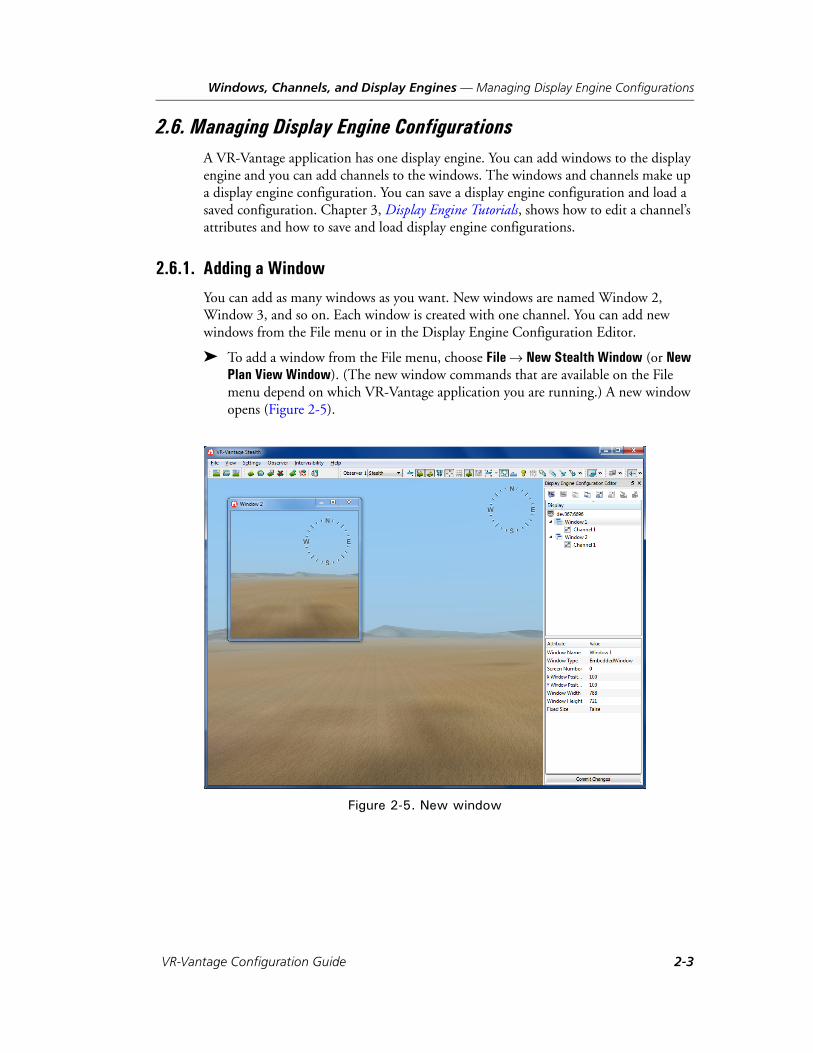
You can add as many windows as you want. New windows are named Window 2, Window 3, and so on. Each window is created with one channel. You can add new windows from the File menu or in the Display Engine Configuration Editor.
To add a window from the File menu, choose File New Stealth Window (or New Plan View Window). (The new window commands that are available on the File menu depend on which VR-Vantage application you are running.) A new window opens (Figure 2-5).
Figure 2-5. New window
VR-Vantage Configuration Guide 2-3

Windows, Channels, and Display Engines — Managing Display Engine Configurations
To add a window from the Display Engine Configuration Editor:
1. Choose View Display Engine Configuration Editor Panel. The Display Engine Configuration Editor Panel is added to the VR-Vantage window (Figure 2-6).
Figure 2-6. Display Engine Configuration Editor Panel
2. Select the display engine at the top of the Display tree.
3. Click the Add a Window button ( ), or right-click the display engine name and choose Add a Window on the context sensitive menu. A new window opens and is listed in the Display Engine Configuration Editor Panel (Figure 2-7).
i The Display Engine Configuration Editor Panel is available only in a VR-Vantage application, not on remote Display Engines.
2-4 VT MÄK

Windows, Channels, and Display Engines — Managing Display Engine Configurations
Figure 2-7. New window
2.6.2. Adding a Channel to a Window
Adding a channel to a window lets you configure multiple views within that window.
To add a channel to a window:
1. In the Display Engine Configuration Editor Panel, select the window to which you want to add a channel.
2. Click the Add a Channel button ( ), or right-click the window name and choose Add a Channel from the menu.
i To see a difference between the channels, change the attributes of the new channel (Figure 2-14). For details about editing channel attributes, please see “Changing a Channel’s Attributes,” on page 2-10.
VR-Vantage Configuration Guide 2-5

Windows, Channels, and Display Engines — Managing Display Engine Configurations
2.6.3. Removing a Window
To remove a window:
1. In the Display Engine Configuration Editor Panel, select the window that you want to remove.
2. Click the Remove Window button ( ), or right-click the window name and choose Remove Window from the menu.
2.6.4. Removing a Channel
To remove a channel:
1. In the Display Engine Configuration Editor Panel, select the channel that you want to remove.
2. Click the Remove Channel button ( ), or right-click the window name and choose Remove Channel from the menu.
2.6.5. Saving a Display Engine Configuration
You can save a display engine configuration so that you can easily replicate the configu-ration at a later time.
To save a display engine configuration:
1. In the Display Engine Configuration Editor Panel, select the display engine whose configuration you want to save.
2. Click the Save Display Engine Configuration button ( ), or right-click the name of the display engine and choose Save Display Engine Configuration on the menu. The Save Display Engine Configuration dialog box opens.
3. Type a name for the display engine configuration.
4. Click Save.
i If you are running two or more display engines, you cannot save the configurations for all of them at once. You have to save the configuration for each display engine individually.
2-6 VT MÄK

Windows, Channels, and Display Engines — Managing Display Engine Configurations
2.6.6. Loading a Display Engine Configuration
To load a display engine configuration:
1. In the Display Engine Configuration Editor Panel, select the display engine at the top of the window.
2. Click the Load Display Engine Configuration button ( ), or right-click the name of the display engine and choose Load Display Engine Configuration on the menu. The Load Display Engine Configuration dialog box opens.
3. Select the display engine configuration you want to load.
4. Click Open.
i You cannot load multiple display engine configurations at the same time in the Display Engine Configuration Editor Panel. You can only load one configuration at a time. However, you can load multiple configurations from the command line. For details, please see “Loading Multiple Display Engine Configurations from the Command Line,” on page 2-8.
VR-Vantage Configuration Guide 2-7

Windows, Channels, and Display Engines — Managing Display Engine Configurations
Loading Multiple Display Engine Configurations from the Command Line
VR-Vantage users often set up multichannel configurations that they wish to reuse. (For details, please see “Configuring Multichannel Displays,” on page 2-23.) You can load these configurations (or any set of configurations) in the Display Engine Configu-ration Editor Panel, as described in “Loading a Display Engine Configuration,” on page 2-7. However, you cannot load them as a group. You must load each one individ-ually. To automate the process of loading multiple display engine configurations, you can load them from the command line.
You load multiple display engine configurations from the command line with the--dispSetting command line argument and the -W or --withDisplayEngine command-line argument. The syntax on Windows is:
vrvIG.exe --dispSetting masterdisplayConfigFile -W port@netAddress;remotedisplayConfigFile1 .... port@netAddress;remotedisplayConfigFileN
The syntax for Linux uses a colon instead of a semi-colon:
vrvIG.exe --dispSetting masterdisplayConfigFile -W port@netAddress:remotedisplayConfigFile1 .... port@netAddress:remotedisplayConfigFileN
The --dispSetting argument specifies the display engine configuration file for the VR-Vantage application. The -W argument specifies the display engine configuration files for the VR-Vantage display engines. The display engine configuration file name can be an absolute path or a path relative to the executable. For example, suppose that you have saved display engine configurations for a master display engine and two remote display engines. You save the configuration for each display engine as follows:
Master display engine — ../appData/settings/stealth/machine1.dcx.
First remote display engine — ../appData/settings/stealth/machine2.dcx.
Second remote display engine — ../appData/settings/stealth/machine3.dcx.
To load these three configurations:
1. Run the remote display engines on the two remote machines.
2. Start VR-Vantage. On Windows use the following command line:
vrvIG.exe --dispSetting ../appData/settings/stealth/machine1.dcx -W 22563@machine2;../appData/set-tings/stealth/machine2.dcx 22563@machine3;../app-Data/settings/stealth/machine3.dcx
On Linux use:
vrvIG.exe --dispSetting ../appData/settings/stealth/machine1.dcx -W 22563@machine2:../appData/set-tings/stealth/machine2.dcx 22563@machine3:../app-Data/settings/stealth/machine3.dcx
2-8 VT MÄK
Windows, Channels, and Display Engines — Changing a Window’s Attributes
2.7. Changing a Window’s AttributesYou can change the following attributes of a window:
Window Name.
Window Type (for details about window types, please see Section 4.2.4, “Window Types,” in VR-Vantage Users Guide).
Screen Number.
Position (X, Y coordinates of upper left corner, in screen pixels).
Width and height, in pixels.
Fixed size.
To change a window’s attributes:
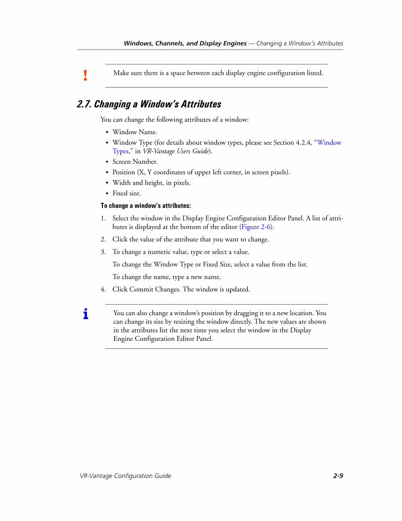
1. Select the window in the Display Engine Configuration Editor Panel. A list of attri-butes is displayed at the bottom of the editor (Figure 2-6).
2. Click the value of the attribute that you want to change.
3. To change a numeric value, type or select a value.
To change the Window Type or Fixed Size, select a value from the list.
To change the name, type a new name.
4. Click Commit Changes. The window is updated.
! Make sure there is a space between each display engine configuration listed.
i You can also change a window’s position by dragging it to a new location. You can change its size by resizing the window directly. The new values are shown in the attributes list the next time you select the window in the Display Engine Configuration Editor Panel.
VR-Vantage Configuration Guide 2-9
Windows, Channels, and Display Engines — Changing a Channel’s Attributes
2.8. Changing a Channel’s AttributesYou can change the following attributes of a channel:
Channel Name.
Observer Name.
Sensor. Use the sensor configured for the current observer, or override the observer and use one of the listed sensors.
Projection Units – field of view, in angles, or database, in meters.
Projection Resize Policy – fixed, vertical, or horizontal.
Frustum (Left, Right, Top, and Bottom) (field of view).
Z Near and Z Far (clipping planes).
Near Far Clip Policy.
Reduce Z Fighting Ratio.
Dynamic Near Clip Attached Policy.
Attached Near Clip Altitude.
Fixed Near Clip When Attached.
Dynamic Water Visibility Enabled.
Dynamic Water Visibility Maximum.
Camera Position Offset (X, Y, Z).
Camera Orientation Offset (Psi (heading), Theta (pitch), Phi (roll)).
Viewport (Left, Right, Bottom, Top).
Keywords – keywords to associate with the channel, for example, “showCockpits”.
2-10 VT MÄK
Windows, Channels, and Display Engines — Changing a Channel’s Attributes
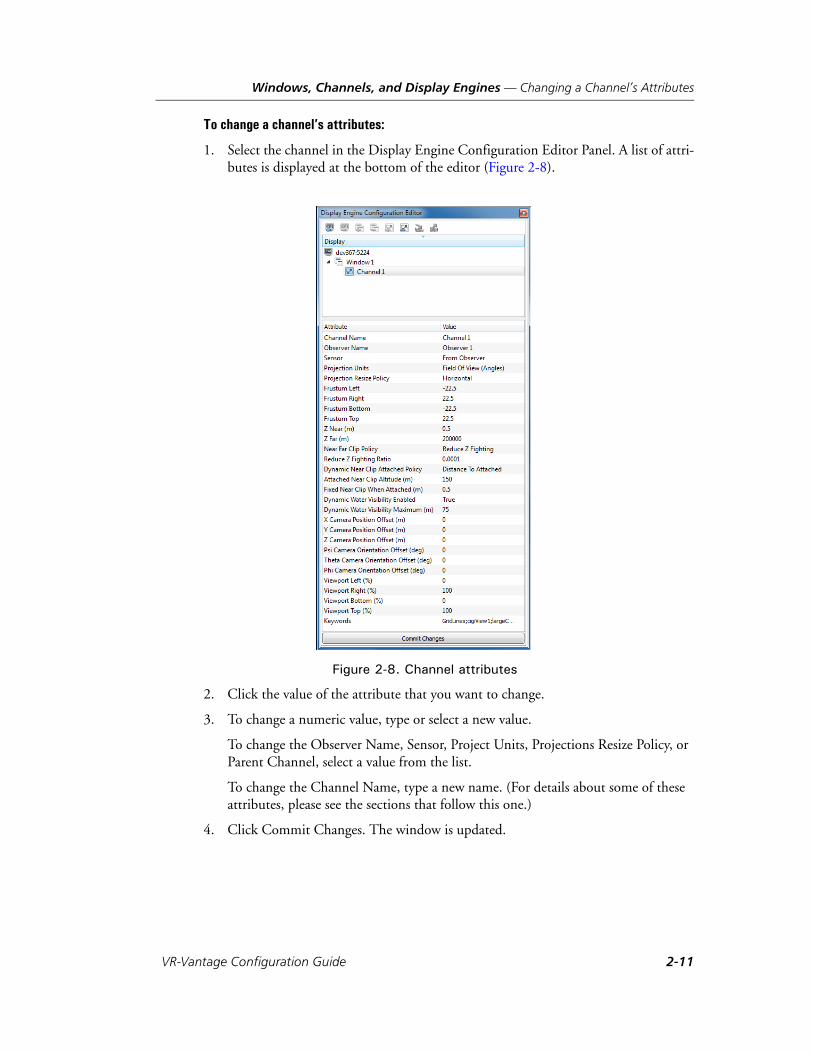
To change a channel’s attributes:
1. Select the channel in the Display Engine Configuration Editor Panel. A list of attri-butes is displayed at the bottom of the editor (Figure 2-8).
Figure 2-8. Channel attributes
2. Click the value of the attribute that you want to change.
3. To change a numeric value, type or select a new value.
To change the Observer Name, Sensor, Project Units, Projections Resize Policy, or Parent Channel, select a value from the list.
To change the Channel Name, type a new name. (For details about some of these attributes, please see the sections that follow this one.)
4. Click Commit Changes. The window is updated.
VR-Vantage Configuration Guide 2-11

Windows, Channels, and Display Engines — Changing a Channel’s Attributes
2.8.1. Setting the Clipping Planes
To improve performance, the graphics engine does not render anything that falls outside of a specified range of distances from the observer. This range is determined by the near and far clipping planes. Clipping planes are set on a per-channel basis.
Figure 2-9 illustrates the effect of changing the near clipping plane (the Z Near attri-bute). Figure 2-10 illustrates the effect of changing the far clipping plane (the Z Far attributes).
Figure 2-9. Near clipping
Figure 2-10. Far clipping
Z Near = 1 Z Near = 500
Z Far = 10000000 Z Far = 10000
2-12 VT MÄK

Windows, Channels, and Display Engines — Changing a Channel’s Attributes
The ratio between the far clipping plane and the near clipping plane determines the precision with which the renderer can determine differences in depth. If this ratio becomes too small, then terrain and objects that are distant may not sort correctly, resulting in what is referred to as Z-fighting. VR-Vantage provides different policies for managing the way near and far clipping planes are determined.
VR-Vantage sets the clipping planes using one of the following policies (the Near Far Clip Policy attribute), plus their modifiers:
Fixed. Clipping planes are set explicitly using the Z Near and Z Far attributes.
Reduce Near Clip. Clipping planes are adjusted dynamically based on the observer’s altitude. The near clipping plane is increased slightly as the observer rises to 20,000 meters, but stays under 1.5 meters. When the observer rises above 20,000 meters, the near and far clipping planes gradually increase. The Reduce Near Clip policy can be modified by the Dynamic Near Clip Attached Policy.
Reduce Z Fighting. Clipping planes are set based on a ratio of the near clipping plane to the far clipping plane (the Reduce Z Fighting Ratio attribute). The near clipping plane can get as large as needed to maintain the ratio. This policy is the default clipping plane policy. The Reduce Z Fighting policy can be modified by the Dynamic Near Clip Attached Policy.
The Reduce Z Fighting clipping plane policy greatly reduces Z-fighting when you are using dynamic ocean. However, if the observer is attached to an entity and its altitude is moderately high, it may be closer to the entity than the near clipping plane and the entity may be clipped away. You can adjust the ratio to provide the best results. If you are not using dynamic ocean or you are frequently attaching to entities, you may want to use one of the other clipping plane policies.
If you set the Near Far Clip Policy to Reduce Z Fighting or Reduce Near Clip and the observer is attached to an entity, VR-Vantage can dynamically change the near clipping plane based on the Dynamic Near Clip Attached Policy, as follows:
Ignore Attached. Do not take entity attachment into account when setting the near clipping plane.
Fixed Near Clip. Set the near clipping plane to the value of the Fixed Near Clip When Attached attribute if the observer altitude is >= the value of the Attached Near Clip Altitude attribute.
Distance To Attached. Use the distance between the observer and the attached entity to determine the near clipping plane if the observer altitude is >= the value of the Attached Near Clip Altitude attribute. When this policy is selected, VR-Vantage compares the near clipping value without this modifier to the value with it and uses the smaller of the two values. This is the default policy.
VR-Vantage Configuration Guide 2-13

Windows, Channels, and Display Engines — Changing a Channel’s Attributes
2.8.2. Specifying the Projection Resize Policy Attribute
The Projection Resize Policy determines how a channel behaves when you resize it. The options are:
Fixed. Keep the aspect ratio the same regardless of how the window is resized.
Horizontal. Maintain the horizontal aspect ratio when the window is resized.
Vertical. Maintain the vertical aspect ratio when the window is resized.
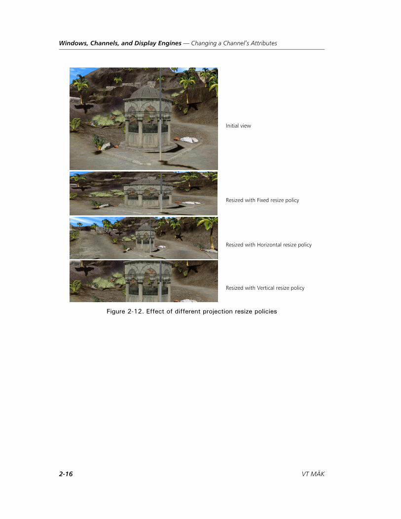
Figure 2-12 illustrates the effect of different resize policies, as follows:
In the window with the fixed resize policy, all of the visual data in the initial view is still in the resized view, although the vertical dimensions are distorted.
In the window with the horizontal resize policy, the field of view is widened to maintain the correct aspect ratio of the visual data.
In the window with the vertical resize policy, the field of view is shortened.
You can change the projection resize policy for individual channels by editing the Projection Resize Policy attribute. You can also change the projection resize policy for all channels.
To change the projection resize policy for all channels:
1. Choose Settings Display. The Display Settings dialog box opens.
2. Select the Render Settings page (Figure 2-11).
2-14 VT MÄK
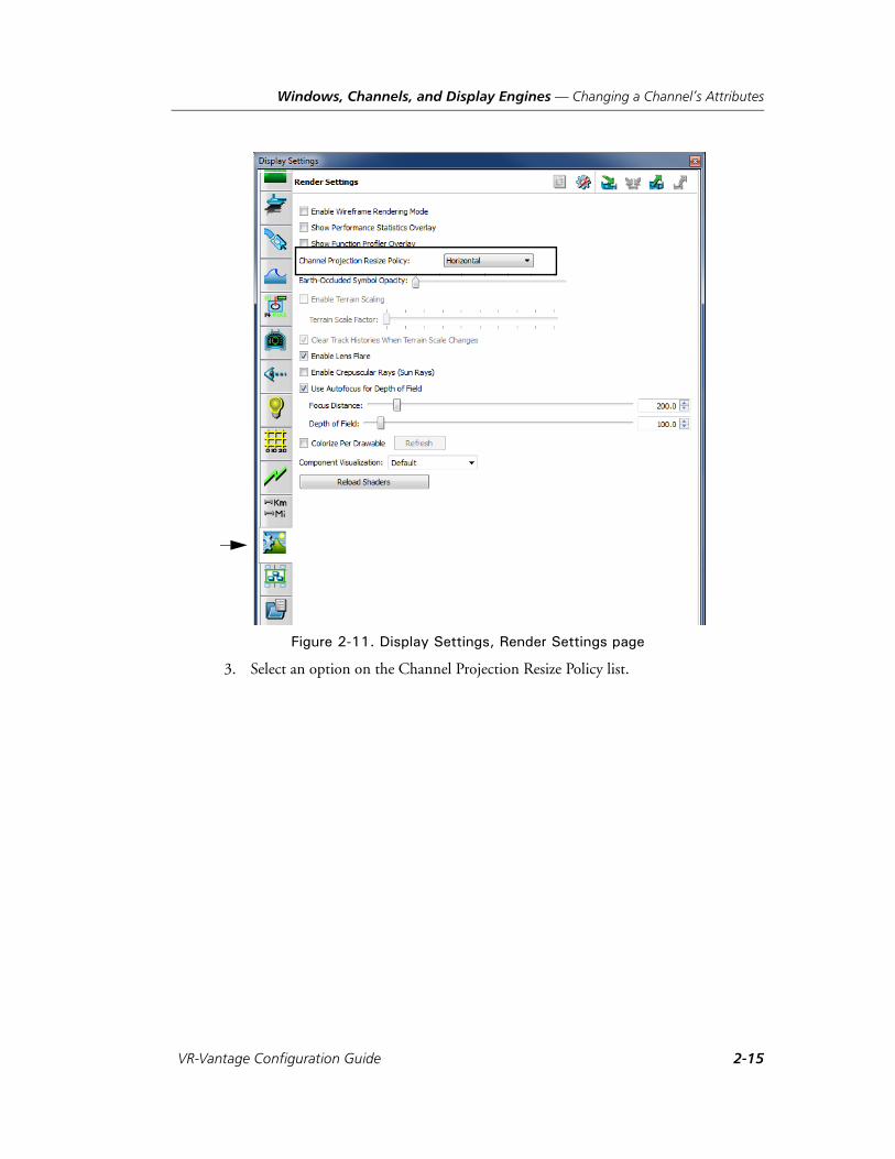
Windows, Channels, and Display Engines — Changing a Channel’s Attributes
Figure 2-11. Display Settings, Render Settings page
3. Select an option on the Channel Projection Resize Policy list.
VR-Vantage Configuration Guide 2-15
Windows, Channels, and Display Engines — Changing a Channel’s Attributes
Figure 2-12. Effect of different projection resize policies
Initial view
Resized with Fixed resize policy
Resized with Horizontal resize policy
Resized with Vertical resize policy
2-16 VT MÄK
Windows, Channels, and Display Engines — Changing a Channel’s Attributes
2.8.3. Changing a Channel’s Frustum (Field of View)
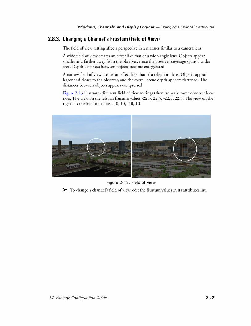
The field of view setting affects perspective in a manner similar to a camera lens.
A wide field of view creates an effect like that of a wide-angle lens. Objects appear smaller and farther away from the observer, since the observer coverage spans a wider area. Depth distances between objects become exaggerated.
A narrow field of view creates an effect like that of a telephoto lens. Objects appear larger and closer to the observer, and the overall scene depth appears flattened. The distances between objects appears compressed.
Figure 2-13 illustrates different field of view settings taken from the same observer loca-tion. The view on the left has frustum values -22.5, 22.5, -22.5, 22.5. The view on the right has the frustum values -10, 10, -10, 10.
Figure 2-13. Field of view
To change a channel’s field of view, edit the frustum values in its attributes list.
VR-Vantage Configuration Guide 2-17
Windows, Channels, and Display Engines — Changing a Channel’s Attributes
2.8.4. Changing the Viewport
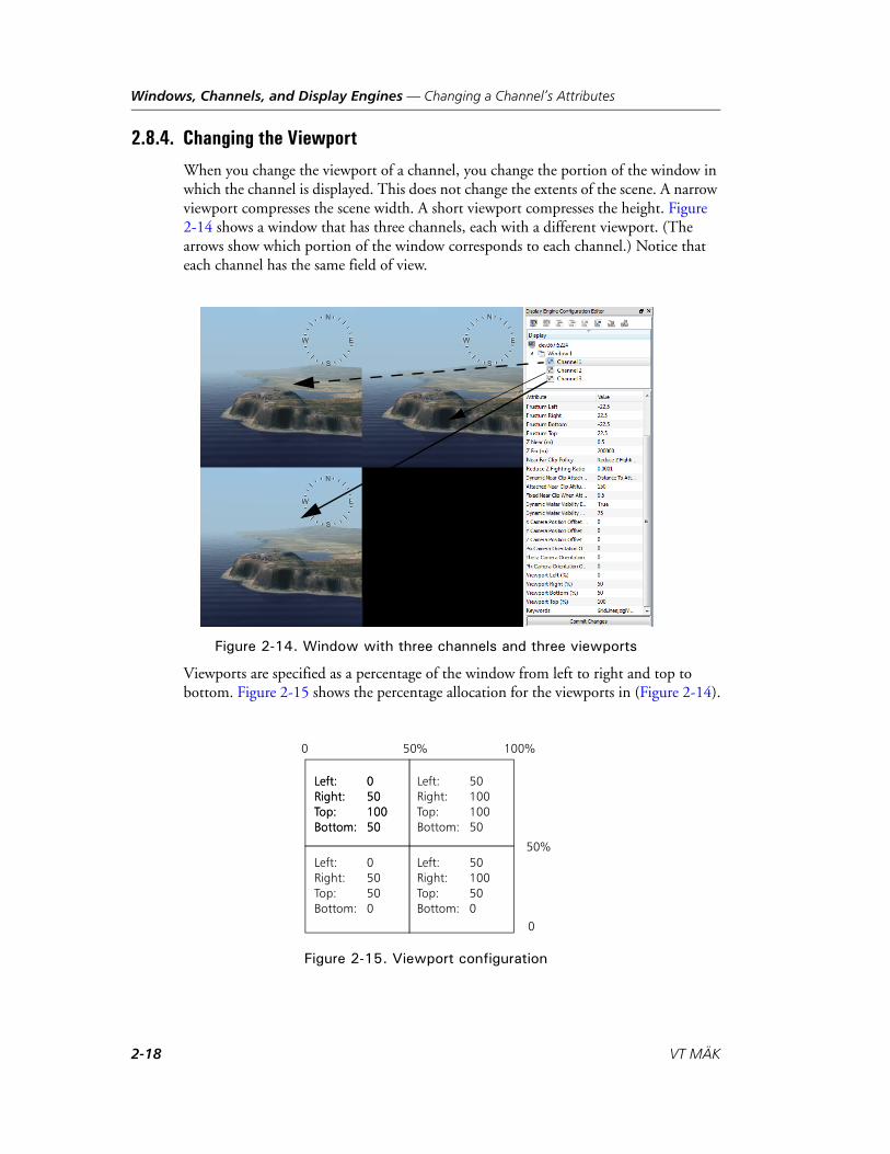
When you change the viewport of a channel, you change the portion of the window in which the channel is displayed. This does not change the extents of the scene. A narrow viewport compresses the scene width. A short viewport compresses the height. Figure 2-14 shows a window that has three channels, each with a different viewport. (The arrows show which portion of the window corresponds to each channel.) Notice that each channel has the same field of view.
Figure 2-14. Window with three channels and three viewports
Viewports are specified as a percentage of the window from left to right and top to bottom. Figure 2-15 shows the percentage allocation for the viewports in (Figure 2-14).
Figure 2-15. Viewport configuration
50% 100%
0
50%
Left: 0Right: 50Top: 100Bottom: 50
Left: 50Right: 100Top: 50Bottom: 0
Left: 50Right: 100Top: 100Bottom: 50
Left: 0Right: 50Top: 50Bottom: 0
Left: 0Right: 50Top: 100Bottom: 50
0
2-18 VT MÄK
Windows, Channels, and Display Engines — Changing a Channel’s Attributes
2.8.5. Configuring Water Visibility
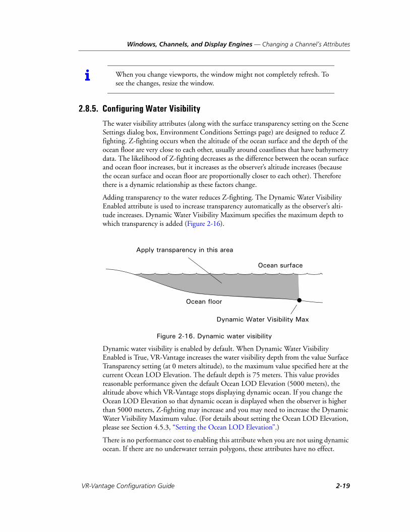
The water visibility attributes (along with the surface transparency setting on the Scene Settings dialog box, Environment Conditions Settings page) are designed to reduce Z fighting. Z-fighting occurs when the altitude of the ocean surface and the depth of the ocean floor are very close to each other, usually around coastlines that have bathymetry data. The likelihood of Z-fighting decreases as the difference between the ocean surface and ocean floor increases, but it increases as the observer’s altitude increases (because the ocean surface and ocean floor are proportionally closer to each other). Therefore there is a dynamic relationship as these factors change.
Adding transparency to the water reduces Z-fighting. The Dynamic Water Visibility Enabled attribute is used to increase transparency automatically as the observer’s alti-tude increases. Dynamic Water Visibility Maximum specifies the maximum depth to which transparency is added (Figure 2-16).
Figure 2-16. Dynamic water visibility
Dynamic water visibility is enabled by default. When Dynamic Water Visibility Enabled is True, VR-Vantage increases the water visibility depth from the value Surface Transparency setting (at 0 meters altitude), to the maximum value specified here at the current Ocean LOD Elevation. The default depth is 75 meters. This value provides reasonable performance given the default Ocean LOD Elevation (5000 meters), the altitude above which VR-Vantage stops displaying dynamic ocean. If you change the Ocean LOD Elevation so that dynamic ocean is displayed when the observer is higher than 5000 meters, Z-fighting may increase and you may need to increase the Dynamic Water Visibility Maximum value. (For details about setting the Ocean LOD Elevation, please see Section 4.5.3, “Setting the Ocean LOD Elevation”.)
There is no performance cost to enabling this attribute when you are not using dynamic ocean. If there are no underwater terrain polygons, these attributes have no effect.
i When you change viewports, the window might not completely refresh. To see the changes, resize the window.
Ocean surface
Ocean floor
Dynamic Water Visibility Max
Apply transparency in this area
VR-Vantage Configuration Guide 2-19

Windows, Channels, and Display Engines — Starting a VR-Vantage Display Engine
2.9. Starting a VR-Vantage Display EngineOn Windows, you can start a display engine from the Start menu or by running a batch file. On Linux, you start a display engine from a script.
To start a display engine on the Windows Start menu, choose All Programs MÄK Technologies VR-Vantage 2.0.1 VR-Vantage Display Engine.
To start a display engine from the Windows console or on Linux, run:
./bin64/displayEngine.extension
where extension is the appropriate script extension for the platform.
2-20 VT MÄK
Windows, Channels, and Display Engines — Connecting to a Display Engine
2.10. Connecting to a Display EngineIf you want to control a display engine, you must first connect to it.
Connections are made using TCP networking. All computers running display engines together must be on the same network. The display engines listen for VR-Vantage on a TCP socket. A display engine can only be connected to a single master application.
To connect to a display engine:
1. On one computer (the master), run VR-Vantage.
2. On another computer, run the VR-Vantage Display Engine application, as described in “Starting a VR-Vantage Display Engine,” on page 2-20.
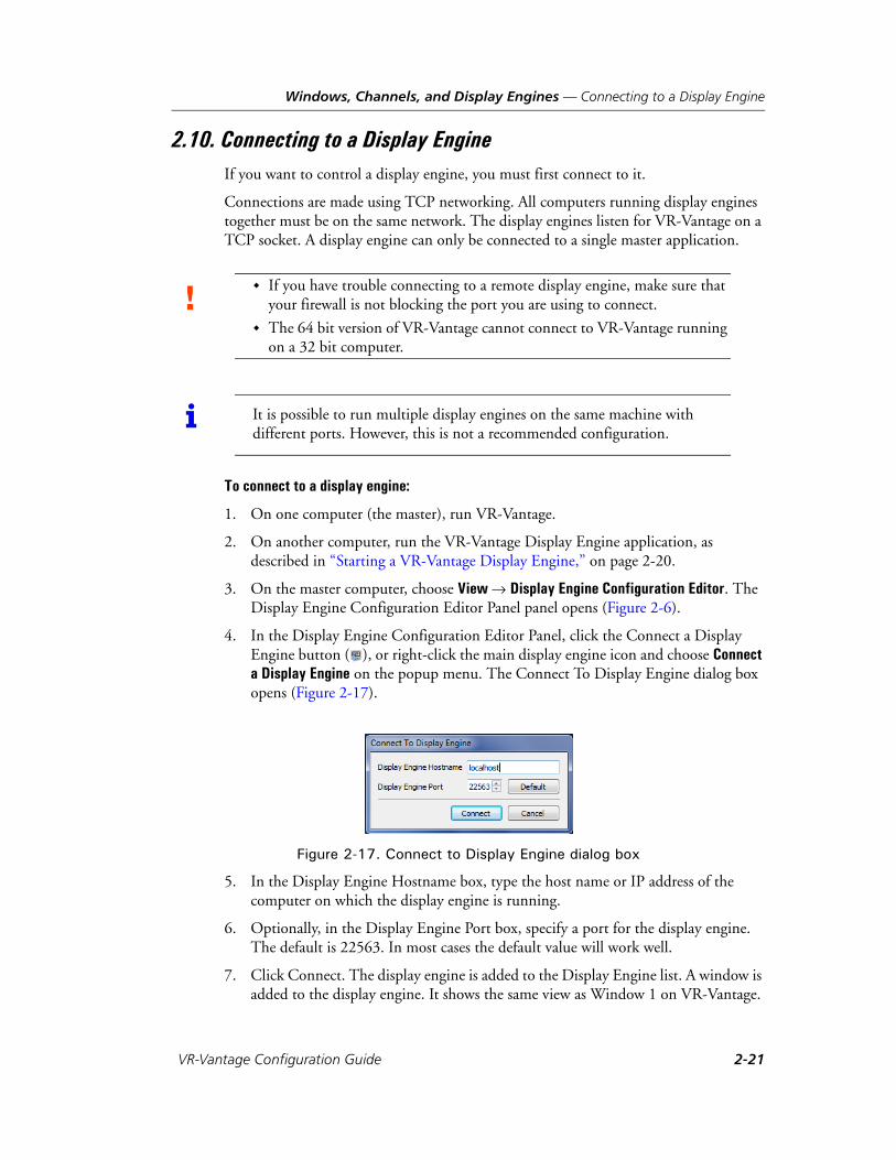
3. On the master computer, choose View Display Engine Configuration Editor. The Display Engine Configuration Editor Panel panel opens (Figure 2-6).
4. In the Display Engine Configuration Editor Panel, click the Connect a Display Engine button ( ), or right-click the main display engine icon and choose Connect a Display Engine on the popup menu. The Connect To Display Engine dialog box opens (Figure 2-17).
Figure 2-17. Connect to Display Engine dialog box
5. In the Display Engine Hostname box, type the host name or IP address of the computer on which the display engine is running.
6. Optionally, in the Display Engine Port box, specify a port for the display engine. The default is 22563. In most cases the default value will work well.
7. Click Connect. The display engine is added to the Display Engine list. A window is added to the display engine. It shows the same view as Window 1 on VR-Vantage.
! If you have trouble connecting to a remote display engine, make sure that your firewall is not blocking the port you are using to connect.
The 64 bit version of VR-Vantage cannot connect to VR-Vantage running on a 32 bit computer.
i It is possible to run multiple display engines on the same machine with different ports. However, this is not a recommended configuration.
VR-Vantage Configuration Guide 2-21

Windows, Channels, and Display Engines — Connecting to a Display Engine
2.10.1. Disconnecting from a Display Engine
To disconnect from a display engine:
1. In the Display Engine Configuration Editor Panel, select the display engine that you want to disconnect.
2. Click the Disconnect a Display Engine button ( ), or right-click the display engine name and choose Disconnect a Display Engine on the menu.
i You cannot disconnect the master display engine.
2-22 VT MÄK
Windows, Channels, and Display Engines — Configuring Multichannel Displays
2.11. Configuring Multichannel DisplaysPeople running simulations often want to set up a multichannel configuration using multiple monitors (on one or more computers) to display exercises. Typical configura-tions are a horizontal alignment, which widens the view, and the angled alignment, which surrounds the observer to simulate an out-the-window view (Figure 2-18). Since VR-Vantage just sends out its view, if you do not configure the displays for multi-channel, the subordinate monitors display the exact same view as the master (Figure 2-20, default window views). Therefore, for multiple views, you must configure the channels to calculate an offset from the master view.
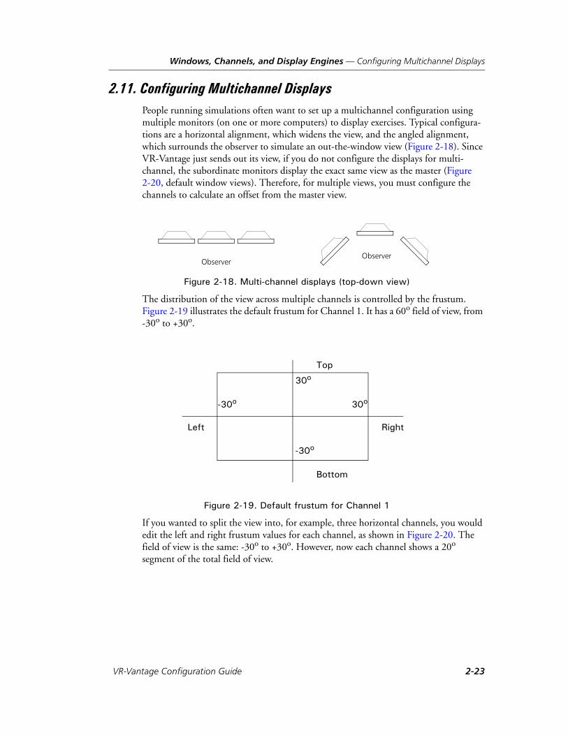
Figure 2-18. Multi-channel displays (top-down view)
The distribution of the view across multiple channels is controlled by the frustum. Figure 2-19 illustrates the default frustum for Channel 1. It has a 60o field of view, from -30o to +30o.
Figure 2-19. Default frustum for Channel 1
If you wanted to split the view into, for example, three horizontal channels, you would edit the left and right frustum values for each channel, as shown in Figure 2-20. The field of view is the same: -30o to +30o. However, now each channel shows a 20o segment of the total field of view.
ObserverObserver
Left Right
Top
Bottom
30o-30o
30o
-30o
VR-Vantage Configuration Guide 2-23

Windows, Channels, and Display Engines — Configuring Multichannel Displays
Figure 2-20. Frustum values for three channels
Left Right
30o-30o -10o 10o
Default window views
Views after changing frustum values
2-24 VT MÄK
Windows, Channels, and Display Engines — Configuring Multichannel Displays
2.11.1. Changing the Camera’s Position and Orientation Offset
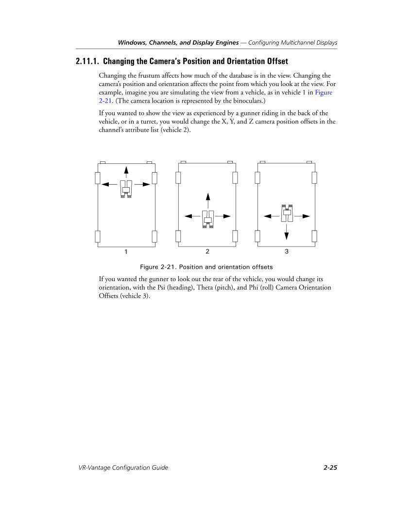
Changing the frustum affects how much of the database is in the view. Changing the camera’s position and orientation affects the point from which you look at the view. For example, imagine you are simulating the view from a vehicle, as in vehicle 1 in Figure 2-21. (The camera location is represented by the binoculars.)
If you wanted to show the view as experienced by a gunner riding in the back of the vehicle, or in a turret, you would change the X, Y, and Z camera position offsets in the channel’s attribute list (vehicle 2).
Figure 2-21. Position and orientation offsets
If you wanted the gunner to look out the rear of the vehicle, you would change its orientation, with the Psi (heading), Theta (pitch), and Phi (roll) Camera Orientation Offsets (vehicle 3).
1 32
VR-Vantage Configuration Guide 2-25

Windows, Channels, and Display Engines — Configuring Multichannel Displays
2.11.2. Creating a Multichannel Configuration
A multichannel configuration is a set of display engine configurations. You must save each configuration individually. Chapter 3, Display Engine Tutorials shows how to create, save, and load a multichannel display engine configuration.
To save a multichannel configuration:
1. Start VR-Vantage and one or more VR-Vantage Display Engines.
2. In the Display Engine Configuration Editor Panel, connect the display engines.
3. Configure the display engines with the windows and channels that you want them to have.
4. For each display engine in the Display Engine Configuration Editor Panel:
a. Select the display engine.
b. Click the Save Display Engine Configuration button ( ).
c. Type a name for the configuration.
d. Click Save.
2.11.3. Loading a Multichannel Configuration
You can load a multichannel configuration in the Display Engine Configuration Editor Panel or from the command line. If you load it in the editor, you must load each config-uration individually. For details about loading multiple configurations from the command line, please see “Loading Multiple Display Engine Configurations from the Command Line,” on page 2-8.
To load a multichannel configuration:
1. Start VR-Vantage and one or more VR-Vantage Display Engines.
2. In the Display Engine Configuration Editor Panel, connect the display engines.
3. For each display engine in the Display Engine Configuration Editor Panel:
a. Select the display engine.
b. Click the Load Display Engine Configuration button ( ).
c. Select the configuration you want to load.
d. Click Load.
2-26 VT MÄK
Windows, Channels, and Display Engines — Stereoscopic Displays
2.12. Stereoscopic DisplaysStereoscopic display produces realistic three dimensional imagery by showing each of the viewer’s eyes a different image, rendered from that eye’s point of view. A stereoscopic display requires a system that can render two channels, one for each eye, and a method of displaying the correct channel to the correct eye of the viewer. Three common display methods are active stereo, polarized display, and anaglyphic stereo. OpenScene-Graph can support all three of these methods, and since VR-Vantage uses OpenScene-Graph for most of its rendering, all three should be possible in VR-Vantage.
Active Stereo: In an active stereo setup, frames are alternated on the display for the left eye and the right eye, and a pair of shutter glasses blocks light to either the left or right eye in synchronization with the display. This method requires hardware support to synchronize the glasses to the display, along with a graphics card capable of quad buffering, and a display that can refresh at twice the desired frame rate. Active stereo should be possible with VR-Vantage, but has not been tested.
Anaglyphic Stereo: Anaglyphic stereo is the cheapest and simplest method to use. A typical setup is a display showing a red channel and a cyan channel simultaneously, along with a pair of glasses with one red lens and one cyan lens for the viewer. This will work with no special hardware aside from the inexpensive glasses. It is also the simplest method to set up in VR-Vantage, requiring only that some OpenScene-Graph environment variables be set.
Polarized Stereo: A polarized display shows the frames for both eyes simultaneously, but with their light polarized in different directions. The viewer wears glasses that have lenses polarized to match the two different frames, allowing each eye to see only the frame intended for it. Polarized stereoscopy requires some specialized equipment to display the images with the correct polarization. One simple method for producing this kind of display is to use two projectors with polarizing filters, projecting onto a rear projection screen. Monitors are available that can polarize the two frames. It is easy to configure a polarized display with VR-Vantage.
VR-Vantage Configuration Guide 2-27

Windows, Channels, and Display Engines — Stereoscopic Displays
2.12.1. Configuring Anaglyphic Stereo
You can configure OpenSceneGraph for anaglyphic stereo rendering through environ-ment variables. To use VR-Vantage in anaglyphic mode, run it with the environment variables described in Table 2-1.
For more information, pleases see the OpenSceneGraph documentation at http://www.openscenegraph.org/projects/osg/wiki/Support/UserGuides/StereoSettings.
Table 2-1: Environment variables for anaglyphic stereo
Environment Variable Description Default
OSG_STEREO Turn stereo on. ON
OSG_STEREO_MODE Use anaglyphic stereo when in stereo. ANAGLYPHIC
OSG_SCREEN_DISTANCE Specifies the distance, in meters, that the viewer is from the screen.
0.50
OSG_SCREEN_HEIGHT Specifies the height of the image, in meters, on the screen.
0.26
OSG_SCREEN_WIDTH Specifies the width of the image, in meters, on the screen.
0.325
OSG_EYE_SEPARATION Specifies the eye separation (interoc-cular distance).
0.06
2-28 VT MÄK

Windows, Channels, and Display Engines — Stereoscopic Displays
2.12.2. Configuring Polarized Stereo
You can configure polarized stereo by taking advantage of VR-Vantage’s ability to produce multichannel displays. You configure one channel per eye. Each channel renders with a camera that is at a slight offset from the other channel’s camera to repre-sent the spacing between the viewer’s eyes.
Varying the eye spacing and focal length can produce different effects, and the best values may depend on what the viewer is looking at. Figure 2-22 shows an example configuration.
Figure 2-22. Polarized stereo channel configurations
Left channel Right channel
VR-Vantage Configuration Guide 2-29

Windows, Channels, and Display Engines — Display Issues on Linux
To compute the correct channel configuration values:
1. Pick a focal length, L. Objects at this distance will appear to be in the plane of the display. Objects that are further away will appear behind the display, and objects closer will appear in front of it.
2. Pick an eye spacing, E, to represent the distance between the viewer’s eyes. Human eyes are typically about 0.063m apart (http://www.cl.cam.ac.uk/~nad10/pubs/EI5291A-05.pdf ).
3. Set the X Camera Position values to –E/2 meters for the left channel and E/2 meters for the right channel.
4. Set the Psi Camera Orientation values to –arctan(E/2)/L degrees for the left channel and arctan(E/2)/L degrees for the right channel.
2.13. Display Issues on LinuxVR-Vantage does not support two separate X screens. The reason is that when you create two separate X screens and try to create two OpenGL windows, they may not share OpenGL contexts. A number of VR-Vantage components require sharing contexts for our rendering to work. These include: SilverLining, SpeedTree, and our 2D overlays (possibly also GL Studio).
The work-arounds to support two screens include:
Use Nvidia driver's TwinView mode. This behavior is identical to the Window multi-monitor behavior and VR-Vantage works correctly with this setting.
Use Xinerama, which is an X extension that behaves similar to TwinView.
Run VR-Vantage on one X Screen and run a Remote Display Engine on the other. This will require two installs to ensure that the appData directories are not compro-mised.
2-30 VT MÄK
VR-V
3. Display Engine Tutorials
This chapter has a tutorial that shows how to connect to a remote display engine, edit display engine configurations, and apply display engine configurations to display engines.
Saving and Loading Display Engine Configurations...................................... 3-2Connect a VR-Vantage Display Engine .................................................. 3-2Save Display Engine Configurations....................................................... 3-5Load the Display Engine Configurations in the GUI.............................. 3-7Loading the Display Engine Configurations from the Command Line... 3-7
3-1antage Configuration Guide
Display Engine Tutorials — Saving and Loading Display Engine Configurations
3.1. Saving and Loading Display Engine ConfigurationsThis tutorial demonstrates how to:
Connect a VR-Vantage application to a VR-Vantage Display Engine.
Change a display engine configuration.
Save display engine configurations.
Load display engine configurations in the Display Engine Configuration Editor Panel.
Load multiple display engine configurations from the command line.
3.1.1. Connect a VR-Vantage Display Engine
To create the display engine configurations:
1. On computer 1, start VR-Vantage.
2. Load makland.mtf.
3. Choose View Display Engine Configuration Editor Panel. The Display Engine Configuration Editor Panel opens. It shows one window and one channel for the VR-Vantage window on the local computer (Figure 3-1).
i This tutorial assumes that you have two computers, one for your VR-Vantage application, and one for the remote display engine. You could run this tutorial on one computer if you have two monitors.
3-2 VT MÄK
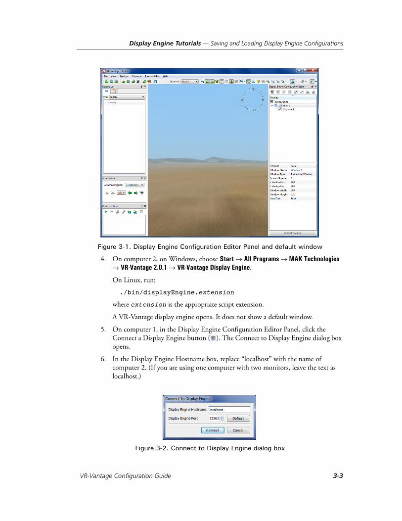
Display Engine Tutorials — Saving and Loading Display Engine Configurations
Figure 3-1. Display Engine Configuration Editor Panel and default window
4. On computer 2, on Windows, choose Start All Programs MAK Technologies VR-Vantage 2.0.1 VR-Vantage Display Engine.
On Linux, run:
./bin/displayEngine.extension
where extension is the appropriate script extension.
A VR-Vantage display engine opens. It does not show a default window.
5. On computer 1, in the Display Engine Configuration Editor Panel, click the Connect a Display Engine button ( ). The Connect to Display Engine dialog box opens.
6. In the Display Engine Hostname box, replace “localhost” with the name of computer 2. (If you are using one computer with two monitors, leave the text as localhost.)
Figure 3-2. Connect to Display Engine dialog box
VR-Vantage Configuration Guide 3-3

Display Engine Tutorials — Saving and Loading Display Engine Configurations
7. Click Connect. An entry for the remote display engine is added to the Display Engine Configuration Editor Panel (Figure 3-3). The remote display engine now displays the Makland terrain with the same view as the VR-Vantage application.
Figure 3-3. Remote display engine connected
3-4 VT MÄK
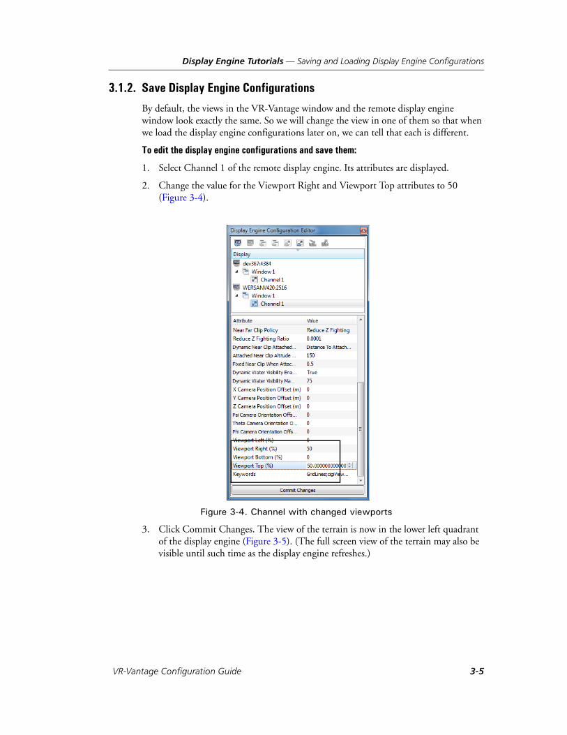
Display Engine Tutorials — Saving and Loading Display Engine Configurations
3.1.2. Save Display Engine Configurations
By default, the views in the VR-Vantage window and the remote display engine window look exactly the same. So we will change the view in one of them so that when we load the display engine configurations later on, we can tell that each is different.
To edit the display engine configurations and save them:
1. Select Channel 1 of the remote display engine. Its attributes are displayed.
2. Change the value for the Viewport Right and Viewport Top attributes to 50 (Figure 3-4).
Figure 3-4. Channel with changed viewports
3. Click Commit Changes. The view of the terrain is now in the lower left quadrant of the display engine (Figure 3-5). (The full screen view of the terrain may also be visible until such time as the display engine refreshes.)
VR-Vantage Configuration Guide 3-5

Display Engine Tutorials — Saving and Loading Display Engine Configurations
Figure 3-5. Remote display engine view after changing configuration
4. Select the display engine on the VR-Vantage application (in this example, WERSANV420).
5. Click the Save Display Engine Configuration button ( ). A save dialog box opens.
6. Call this configuration mainwindow.dcx.
7. Click Save.
8. Select the display engine on the remote display engine (in this example, WERSANV420).
9. Click the Save Display Configuration button. A save dialog box opens.
10. Call this configuration remotedisplay.dcx.
11. Click Save.
3-6 VT MÄK

Display Engine Tutorials — Saving and Loading Display Engine Configurations
3.1.3. Load the Display Engine Configurations in the GUI
We now have two visually distinct display engine configurations. In this part of the tutorial, we simply load them into the two display engines to see that loading a display engine configuration changes the view in the window. This part of the tutorial also demonstrates that display engine configurations are not unique to a particular display engine and are not tied to one either. Any particular configuration can be loaded into any display engine.
To load the display engine configurations in the GUI:
1. Select the display engine on the VR-Vantage application.
2. Click the Load Display Engine Configuration Editor button ( ). The Load Display Configuration dialog box opens.
3. Select remotedisplay.dcx.
4. Click Open. The window on the VR-Vantage application now shows the terrain in the lower left quadrant. (You may need to press Space Bar to reset the observer.)
5. Reload the mainwindow.dcx configuration in the main window.
6. Try loading the two different configurations in the remote display engine.
3.1.4. Loading the Display Engine Configurations from the Command Line
As you have seen in the previous part of this tutorial, you can load display engine configurations for individual display engines through the GUI. However, you cannot load more than one at a time. If you have a complex set of display engines that you need to configure, loading them one at a time can be tedious. To load multiple display engine configurations at one time, you must start VR-Vantage from the command line.
You load multiple display engine configurations from the command line with the--dispSetting command line argument and the -W or --withDisplayEngine command-line argument. The syntax for Windows is:
vrvApplication.exe --dispSetting masterdisplayConfigFile -W port@netAddress;remotedisplayConfigFile1 .... port@netAddress;remotedisplayConfigFileN
The syntax for Linux is:
vrvApplication.exe --dispSetting masterdisplayConfigFile -W port@netAddress:remotedisplayConfigFile1 .... port@netAddress:remotedisplayConfigFileN
VR-Vantage Configuration Guide 3-7
Display Engine Tutorials — Saving and Loading Display Engine Configurations
In this tutorial, we use the default port (22563). The netaddress for the remote display engine is the computer name (WERSANV420). The display engine configuration files are mainwindow.dcx and remotedisplay.dcx.
So the command line to load the two display engine configurations that we created would be:
vrvIG.exe --dispSetting ../appData/settings/van-tageIG/mainwindow.dcx -W 22563@WERSANV420;../app-Data/settings/vantageIG/remotedisplay.dcx
To load the tutorial configurations from the command line:
1. Open a command window.
2. Change directory to ./bin.
3. On Windows, enter the command:
vrvIG.exe --dispSetting ../appData/settings/van-tageIG/mainwindow.dcx -W 22563@WERSANV420;../app-Data/settings/vantageIG/remotedisplay.dcx
On Linux, enter the command:
vrvIG.exe --dispSetting ../appData/settings/van-tageIG/mainwindow.dcx -W 22563@WERSANV420:../app-Data/settings/vantageIG/remotedisplay.dcx
VR-Vantage starts. The display engine configurations are visible in the main window and the remote display engine window.
4. Choose View Display Engine Configuration Editor Panel. In the Display Engine Configuration Editor Panel, confirm that VR-Vantage is connected to the remote display engine.
3-8 VT MÄK
VR-V
4. Composing Terrains
This chapter explains how to combine various types of data to build a terrain. For basic conceptual information about terrain agility, please see Section 4.1, “Terrain Agility and Composability,” in VR-Vantage Users Guide . “Composing a Terrain through the GUI,” on page 6-2 is a tutorial that steps you through the entire process of creating a terrain.
Creating a Composed Terrain ....................................................................... 4-3Considerations and Limitations for Building Terrains............................. 4-3Saving a Terrain...................................................................................... 4-4
Adding Elevation Data (Terrain Patches) to a Terrain.................................... 4-5
Adding Images to a Terrain ........................................................................... 4-7Changing the Display Order of Raster Maps ........................................ 4-11
Adding a Feature Layer ............................................................................... 4-12
Adding a Dynamic Ocean Layer ................................................................. 4-13Extracting Water Textures and Adding an Ocean Layer ........................ 4-15Adding a Dynamic Ocean Layer Directly ............................................. 4-16Setting the Ocean LOD Elevation ........................................................ 4-16Configuring the Ocean Height Map..................................................... 4-17
Using Shader-based Effect Maps ................................................................. 4-19Debugging Shaders............................................................................... 4-20Reloading Shaders ................................................................................ 4-21
Connecting to Terrain Servers ..................................................................... 4-22Adding Terrain Server Connections...................................................... 4-24Editing a Terrain Server Configuration................................................. 4-25Connecting to Terrain Servers through a Proxy .................................... 4-26
Loading MetaFlight Terrains ....................................................................... 4-26
Adding Props to a Terrain ........................................................................... 4-27
4-1antage Configuration Guide

Composing Terrains
Extracting Props from a Terrain Patch .................................................. 4-27Adding Props from a Feature Layer ...................................................... 4-29Viewing a List of Props......................................................................... 4-31Selecting Props ..................................................................................... 4-31Setting the Opacity of Props................................................................. 4-32Changing a Prop’s Type ........................................................................ 4-33Changing a Prop’s Position or Orientation ........................................... 4-33Changing a Prop’s Model Definition .................................................... 4-33
Configuring File Caching ........................................................................... 4-34Caching Terrain Server Data ................................................................ 4-34Caching osgEarth Terrain Data Offline ................................................ 4-35Enabling Texture Compression............................................................. 4-36Clearing the File Cache ........................................................................ 4-37
Displaying DDS Textures Correctly............................................................ 4-37Flipping DDS Textures Globally .......................................................... 4-37
Building Efficient MetaFlight Terrains for VR-Vantage............................... 4-39
Preprocessing Paged Terrains....................................................................... 4-39
Configuring Paged and Streaming Terrains ................................................. 4-40
Terrain Databases Provided with VR-Vantage ............................................. 4-41
4-2 VT MÄK

Composing Terrains — Creating a Composed Terrain
4.1. Creating a Composed TerrainThe most common ways to compose a terrain in VR-Vantage are as follows:
Load individual terrain components through the VR-Vantage GUI and then save the terrain as an MTF file.
Create an earth file that specifies all the terrain components to load. Then load the earth file and save it as an MTF file.
Load an earth file and add local terrain components. Then save the terrain as an MTF file.
This section describes the first option, creating a terrain by loading individual elevation, imagery, and feature files. The general procedure for composing a terrain this way is as follows:
1. Choose File New Terrain, or click the New Terrain button ( ) on the Terrain Toolbar. If any terrain data is loaded, it is removed.
2. Add elevation data, as described in “Adding Elevation Data (Terrain Patches) to a Terrain,” on page 4-5.
3. Optionally, add imagery, as described in “Adding Images to a Terrain,” on page 4-7.
4. Optionally, add feature data, as described in “Adding a Feature Layer,” on page 4-12.
5. Optionally, add a dynamic ocean layer, as described in “Adding a Dynamic Ocean Layer,” on page 4-13.
6. Optionally, add props or extract props, as described in “Adding Props from a Feature Layer,” on page 4-29 and “Extracting Props from a Terrain Patch,” on page 4-27.
7. Save the terrain, as described in “Saving a Terrain,” on page 4-4.
“Composing a Terrain through the GUI,” on page B-2 demonstrates how to create a composed terrain.
4.1.1. Considerations and Limitations for Building Terrains
As you compose a terrain, consider the following issues:
VR-Vantage supports DTED level 0, 1, and 2. DTED is loaded using a Flat Earth projection. The default post spacing for DTED level 0 is 1. For other levels it is 5. You can load a 1 degree cell.
If you load more than one DTED cell, they will be placed on top of each other. If you need to load multiple DTED cells, you can do so using an earth file. For details, please see “Loading Multiple DTED Files,” on page 5-5.
The larger a terrain database is (as measured by the number of polygons), the more it will affect performance.
VR-Vantage Configuration Guide 4-3

Composing Terrains — Creating a Composed Terrain
Loading DTED
By default, when you load DTED files as terrain patches, the files are loaded with their altitude referenced to WGS84. If you want the altitude to reference a different vertical datum (most likely EGM96), you must provide a geoid grid file for that vertical datum. If you use a geoid grid file, the altitudes in the DTED file are adjusted based on the information in the grid file.
To use a geoid grid file, set the environment variable MAK_GEOID_GRID to the path of the file.
For information about EGM96 and geoid files, please see the following URL:
http://earth-info.nga.mil/GandG/wgs84/gravitymod/egm96/egm96.html
4.1.2. Saving a Terrain
When you save a terrain, VR-Vantage saves information about the terrain patches, imagery, and feature layers that you used to create the terrain. Saving a terrain does not save out data to a file format comparable to OpenFlight or GDB that can be loaded into other applications or converted into other formats. If accelerated file loading is enabled, the data gets saved in a format that can be loaded more quickly than from its native format. (For details about accelerated file loading, please see “Configuring File Caching,” on page 4-34.) Terrains get saved with the extension .mtf.
To save a terrain:
1. Choose File Save Terrain, or click the Save Terrain button ( ) on the Terrain Toolbar. The Save Terrain dialog box opens.
2. Type a name for the terrain.
3. Click Save.
i This section does not apply to terrains loaded using an earth file.
4-4 VT MÄK
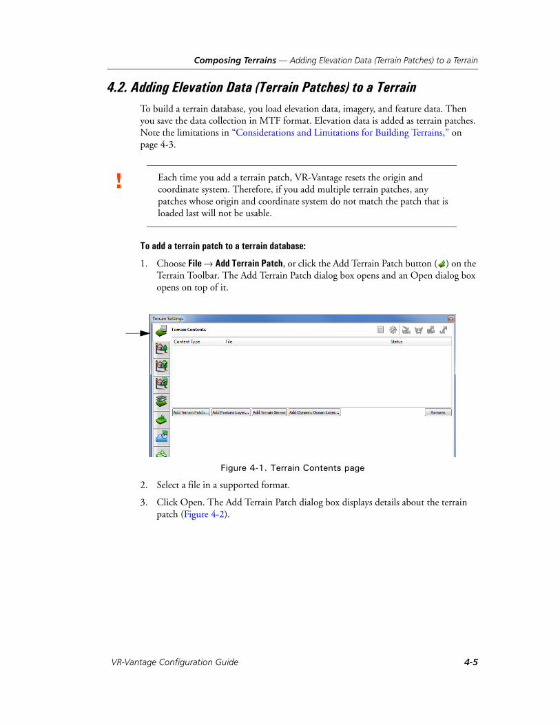
Composing Terrains — Adding Elevation Data (Terrain Patches) to a Terrain
4.2. Adding Elevation Data (Terrain Patches) to a TerrainTo build a terrain database, you load elevation data, imagery, and feature data. Then you save the data collection in MTF format. Elevation data is added as terrain patches. Note the limitations in “Considerations and Limitations for Building Terrains,” on page 4-3.
To add a terrain patch to a terrain database:
1. Choose File Add Terrain Patch, or click the Add Terrain Patch button ( ) on the Terrain Toolbar. The Add Terrain Patch dialog box opens and an Open dialog box opens on top of it.
Figure 4-1. Terrain Contents page
2. Select a file in a supported format.
3. Click Open. The Add Terrain Patch dialog box displays details about the terrain patch (Figure 4-2).
! Each time you add a terrain patch, VR-Vantage resets the origin and coordinate system. Therefore, if you add multiple terrain patches, any patches whose origin and coordinate system do not match the patch that is loaded last will not be usable.
VR-Vantage Configuration Guide 4-5

Composing Terrains — Adding Elevation Data (Terrain Patches) to a Terrain
Figure 4-2. Add Terrain Patch dialog box
4. If the terrain patch has DDS textures that are upside down relative to VR-Vantage’s expectations, select Flip DDS Textures. This setting does not affect paged terrains. (For information about DDS textures, please see “Displaying DDS Textures Correctly,” on page 4-37.)
5. Click OK. The terrain patch is added.
6. Optionally, add additional terrain patches.
7. Save the terrain.
4-6 VT MÄK
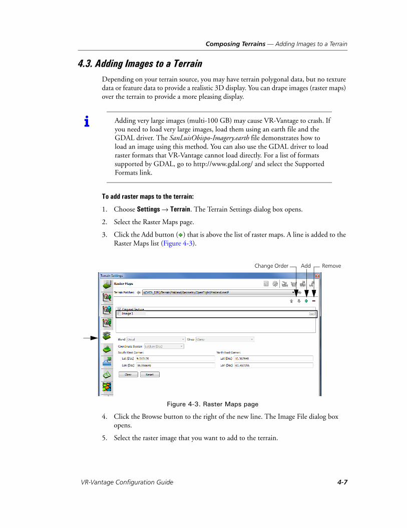
Composing Terrains — Adding Images to a Terrain
4.3. Adding Images to a TerrainDepending on your terrain source, you may have terrain polygonal data, but no texture data or feature data to provide a realistic 3D display. You can drape images (raster maps) over the terrain to provide a more pleasing display.
To add raster maps to the terrain:
1. Choose Settings Terrain. The Terrain Settings dialog box opens.
2. Select the Raster Maps page.
3. Click the Add button ( ) that is above the list of raster maps. A line is added to the Raster Maps list (Figure 4-3).
Figure 4-3. Raster Maps page
4. Click the Browse button to the right of the new line. The Image File dialog box opens.
5. Select the raster image that you want to add to the terrain.
i Adding very large images (multi-100 GB) may cause VR-Vantage to crash. If you need to load very large images, load them using an earth file and the GDAL driver. The SanLuisObispo-Imagery.earth file demonstrates how to load an image using this method. You can also use the GDAL driver to load raster formats that VR-Vantage cannot load directly. For a list of formats supported by GDAL, go to http://www.gdal.org/ and select the Supported Formats link.
Change Order Add Remove
VR-Vantage Configuration Guide 4-7
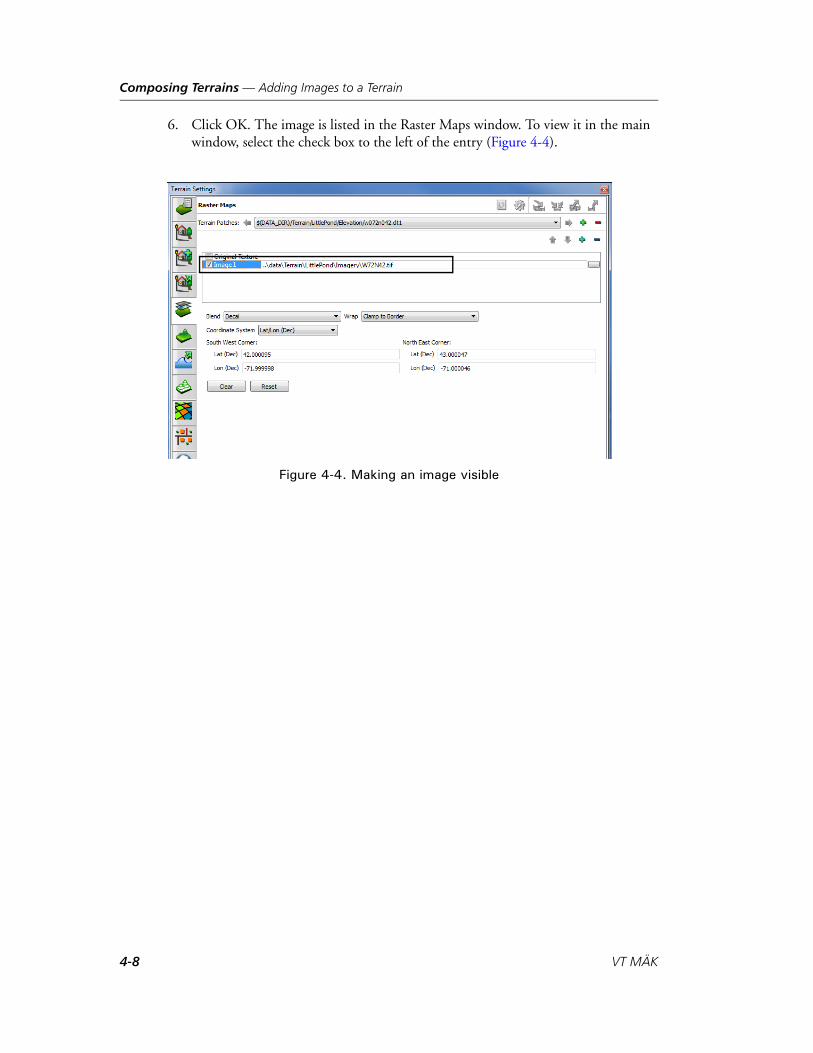
Composing Terrains — Adding Images to a Terrain
6. Click OK. The image is listed in the Raster Maps window. To view it in the main window, select the check box to the left of the entry (Figure 4-4).
Figure 4-4. Making an image visible
4-8 VT MÄK
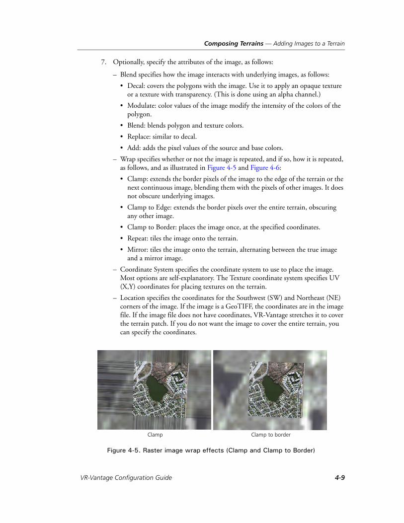
Composing Terrains — Adding Images to a Terrain
7. Optionally, specify the attributes of the image, as follows:
– Blend specifies how the image interacts with underlying images, as follows:
• Decal: covers the polygons with the image. Use it to apply an opaque texture or a texture with transparency. (This is done using an alpha channel.)
• Modulate: color values of the image modify the intensity of the colors of the polygon.
• Blend: blends polygon and texture colors.
• Replace: similar to decal.
• Add: adds the pixel values of the source and base colors.
– Wrap specifies whether or not the image is repeated, and if so, how it is repeated, as follows, and as illustrated in Figure 4-5 and Figure 4-6:
• Clamp: extends the border pixels of the image to the edge of the terrain or the next continuous image, blending them with the pixels of other images. It does not obscure underlying images.
• Clamp to Edge: extends the border pixels over the entire terrain, obscuring any other image.
• Clamp to Border: places the image once, at the specified coordinates.
• Repeat: tiles the image onto the terrain.
• Mirror: tiles the image onto the terrain, alternating between the true image and a mirror image.
– Coordinate System specifies the coordinate system to use to place the image. Most options are self-explanatory. The Texture coordinate system specifies UV (X,Y) coordinates for placing textures on the terrain.
– Location specifies the coordinates for the Southwest (SW) and Northeast (NE) corners of the image. If the image is a GeoTIFF, the coordinates are in the image file. If the image file does not have coordinates, VR-Vantage stretches it to cover the terrain patch. If you do not want the image to cover the entire terrain, you can specify the coordinates.
Figure 4-5. Raster image wrap effects (Clamp and Clamp to Border)
Clamp Clamp to border
VR-Vantage Configuration Guide 4-9

Composing Terrains — Adding Images to a Terrain
Figure 4-6. Raster image wrap effects (Clamp to Edge, Mirror, Repeat)
Clamp to edge
Repeat
Mirror
4-10 VT MÄK

Composing Terrains — Adding Images to a Terrain
4.3.1. Changing the Display Order of Raster Maps
Raster maps are displayed in the order in which they are listed in the Terrain Settings dialog box, Raster Maps page. If they overlay the same portion of the terrain, the topmost image is displayed. You can change the order in which image files are listed, thereby changing which one is displayed in VR-Vantage.
Figure 4-7 shows two views of the detailed portion of the LittlePond terrain, one with the default image order, and one with the order of raster images reversed.
Figure 4-7. Changing the raster map order
To change the order of a raster map.
1. Choose Settings Terrain. The Terrain Settings dialog box opens.
2. Select the Raster Maps page (Figure 4-3).
3. Select the raster image whose order you want to change.
4. Click the Up Arrow or Down Arrow above the upper right corner of the list of raster maps. The image moves in the list and the window changes as appropriate.
VR-Vantage Configuration Guide 4-11
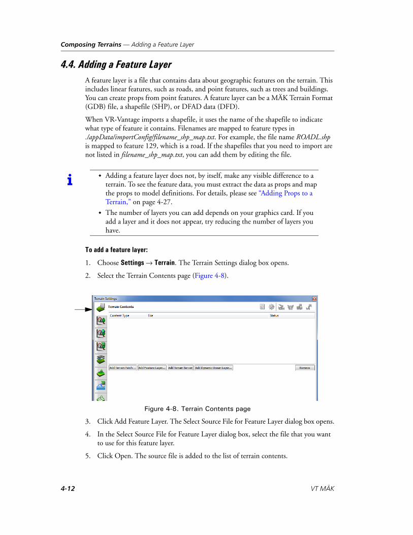
Composing Terrains — Adding a Feature Layer
4.4. Adding a Feature LayerA feature layer is a file that contains data about geographic features on the terrain. This includes linear features, such as roads, and point features, such as trees and buildings. You can create props from point features. A feature layer can be a MÄK Terrain Format (GDB) file, a shapefile (SHP), or DFAD data (DFD).
When VR-Vantage imports a shapefile, it uses the name of the shapefile to indicate what type of feature it contains. Filenames are mapped to feature types in ./appData/importConfig/filename_shp_map.txt. For example, the file name ROADL.shp is mapped to feature 129, which is a road. If the shapefiles that you need to import are not listed in filename_shp_map.txt, you can add them by editing the file.
To add a feature layer:
1. Choose Settings Terrain. The Terrain Settings dialog box opens.
2. Select the Terrain Contents page (Figure 4-8).
Figure 4-8. Terrain Contents page
3. Click Add Feature Layer. The Select Source File for Feature Layer dialog box opens.
4. In the Select Source File for Feature Layer dialog box, select the file that you want to use for this feature layer.
5. Click Open. The source file is added to the list of terrain contents.
i Adding a feature layer does not, by itself, make any visible difference to a terrain. To see the feature data, you must extract the data as props and map the props to model definitions. For details, please see “Adding Props to a Terrain,” on page 4-27.
The number of layers you can add depends on your graphics card. If you add a layer and it does not appear, try reducing the number of layers you have.
4-12 VT MÄK

Composing Terrains — Adding a Dynamic Ocean Layer
4.5. Adding a Dynamic Ocean LayerVR-Vantage can simulate dynamic ocean effects, such as waves, swell, and chop. To simulate the ocean, your terrain must have a dynamic ocean layer. You can add an ocean layer directly or you can add one as part of the process of extracting water textures.
If your terrain has textures assigned to water polygons, then you should extract them. They will be replaced by the ocean layer. If you do not extract the water textures and you simply add an ocean layer, the ocean layer and the water texture will interfere with each other in a process called Z-fighting and create an unacceptable display (Figure 4-9). This problem occurs because the ocean layer and the texture are both at the same height (0, or sea level).
Figure 4-9. Z-fighting
If your terrain does not have a specific water texture assigned to polygons, your only option is to add an ocean layer directly. However, since the ocean layer will be at the same elevation as the terrain texture, you may experience Z-fighting. You may also have to raise the ocean height to actually see the ocean effects.
Figure 4-10 shows the Makland terrain with a water texture and an ocean layer. In the left view, the ocean layer has a height of 0 meters. You cannot see it. In the right view, the ocean layer is set to 1 meter. Now it is visible.
VR-Vantage Configuration Guide 4-13
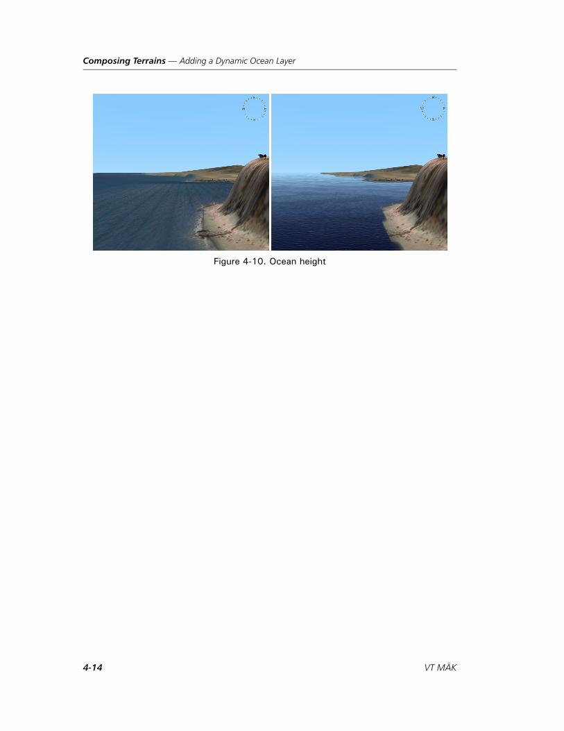
Composing Terrains — Adding a Dynamic Ocean Layer
Figure 4-10. Ocean height
4-14 VT MÄK

Composing Terrains — Adding a Dynamic Ocean Layer
4.5.1. Extracting Water Textures and Adding an Ocean Layer
To extract textures and add an ocean layer:
1. Choose Settings Terrain. The Terrain Settings dialog box opens.
2. Select the Extract Ocean page (Figure 4-11).
Figure 4-11. Terrain Settings dialog box, Extract Ocean page
3. In the External References list on the Extract References tab, select the water textures that you want to extract.
4. Click Extract Selected. The textures are removed and an ocean layer is added to the Terrain Contents page.
5. Select the Terrain Contents page (Figure 4-12).
6. Adjust the Ocean Height so that the dynamic ocean is visible. This might require raising the ocean above sea level.
7. Optionally, adjust the Ocean LOD Elevation. For information about the Ocean LOD Elevation, please see “Setting the Ocean LOD Elevation,” on page 4-16.
VR-Vantage Configuration Guide 4-15

Composing Terrains — Adding a Dynamic Ocean Layer
4.5.2. Adding a Dynamic Ocean Layer Directly
Ocean layers get created at a height of 0 meters, that is, mean sea level.
To add a dynamic ocean layer:
1. Choose Settings Terrain. The Terrain Settings dialog box opens.
2. Select the Terrain Contents page.
3. Click Add Dynamic Ocean Layer. (You can only have one ocean layer.) A layer is added to the Terrain Contents list and two parameters are added to the bottom of the dialog box (Figure 4-12).
Figure 4-12. Terrain Contents with dynamic ocean layer
4. Adjust the Ocean Height so that the dynamic ocean is visible. This might require raising the ocean above sea level.
5. Optionally, adjust the Ocean LOD Elevation. For information about the Ocean LOD Elevation, please see “Setting the Ocean LOD Elevation,” on page 4-16.
4.5.3. Setting the Ocean LOD Elevation
Enabling dynamic ocean affects performance. Since the effects are hard to see once the observer is high above the ocean, VR-Vantage stops displaying them when the observer is more than 5000 meters above sea level. You can change this cutoff point by adjusting the Ocean LOD Elevation.
To set the ocean LOD elevation:
1. Choose Settings Terrain. The Terrain Settings dialog box opens.
2. Select the Terrain Contents page (Figure 4-12).
3. Adjust the Ocean LOD Elevation slider or change the value in the box.
4-16 VT MÄK

Composing Terrains — Adding a Dynamic Ocean Layer
4.5.4. Configuring the Ocean Height Map
The ocean height map is used to blend the dynamic ocean with the coastline. You can configure the height map resolution, its texture size, and the threshold for regenerating the height map. All of these settings interact to affect visual quality and performance.
Height map resolution is specified as meters per pixel. The height map texture size is specified in pixels. Therefore these two settings determine the length of one side of the (square) area that the height map covers. For example, if the value for height map reso-lution is 10 meters per pixel and the texture size is 4096 pixels, this results in a height map that is 40960 meters on a side.
As height map resolution increases and texture size decreases, visual quality may improve, but performance can degrade. Conversely, decreasing resolution and increasing the texture size can improve performance at a cost of visual quality. You will need to experiment to determine the best values for your simulation.
If you are working with a small terrain or scenes in which the observer is close to sea level, you may want to use a higher resolution. If you are less interested in how the coast line looks, you can use a lower resolution. Figure 4-12 shows a coastline at different levels of resolution.
Figure 4-13. Ocean height map resolution
i Setting the surface transparency also affects visualization of the shoreline. Experiment with these values to achieve the best results. For details about water transparency, please see Section 5.5.2, “Configuring Marine Conditions,” in VR-Vantage Users Guide.
1.0 15.0
VR-Vantage Configuration Guide 4-17
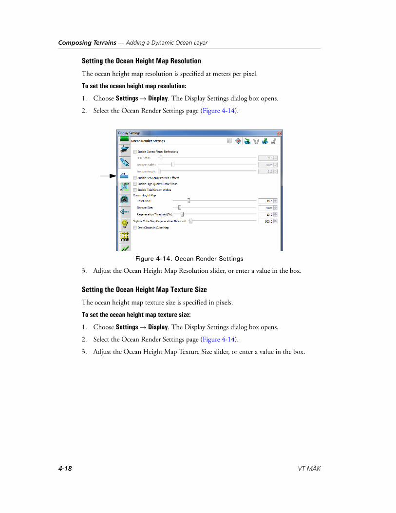
Composing Terrains — Adding a Dynamic Ocean Layer
Setting the Ocean Height Map Resolution
The ocean height map resolution is specified at meters per pixel.
To set the ocean height map resolution:
1. Choose Settings Display. The Display Settings dialog box opens.
2. Select the Ocean Render Settings page (Figure 4-14).
Figure 4-14. Ocean Render Settings
3. Adjust the Ocean Height Map Resolution slider, or enter a value in the box.
Setting the Ocean Height Map Texture Size
The ocean height map texture size is specified in pixels.
To set the ocean height map texture size:
1. Choose Settings Display. The Display Settings dialog box opens.
2. Select the Ocean Render Settings page (Figure 4-14).
3. Adjust the Ocean Height Map Texture Size slider, or enter a value in the box.
4-18 VT MÄK
Composing Terrains — Using Shader-based Effect Maps
Setting the Ocean Height Map Regeneration Threshold
The ocean height map is recalculated as the observer moves. Generating the height map is computationally expensive. Therefore, it is done only when the observer moves by more than a specified threshold. You can adjust this threshold if you want to recalculate the height map more frequently. The default is 10% (0.1). This means that the observer must move by 10% of the length of one side of the height map before the height map is regenerated.
To set the ocean height map regeneration threshold:
1. Choose Settings Display. The Display Settings dialog box opens.
2. Select the Ocean Render Settings page (Figure 4-14).
3. Adjust the Ocean Height Map Regeneration Threshold slider, or enter a value in the box.
4.6. Using Shader-based Effect MapsVR-Vantage supports several types of shader-based effects texture maps. Shaders are computer programs that run on the graphics processing unit (GPU). VR-Vantage makes extensive use of them for lighting effects.
Effect maps are raster images that apply highly realistic textures to the terrain and models. By applying different types of effect maps to terrain and models, you can improve the visual qualities of your simulation without the overhead of high polygon counts.
VR-Vantage supports the following types of shader-based effect maps:
Normal, or bump, maps. Normal maps give terrains the appearance of relief, such as a rocky landscape.
Specular maps. Specular maps affect the highlight color of objects.
Ambient occlusion maps. Ambient occlusion maps model areas that do not receive direct light, such as cracks and crevices and shaded areas of terrain and models. These areas are lit only by ambient light.
Reflection maps. Reflection maps affect the reflectivity of surfaces, such as windows. Reflection maps reflect objects in the sky, not the terrain.
Emissive maps. Emissive maps control the emissivity of whatever they are applied to based on the current ambient light values. The alpha channel is an ID that is set from 0-255. All the pixels that should light together (like a window, and perhaps a surrounding sill) should have the same ID. When the ambient light level drops below a given ID level, those pixels are emissive. Channel 2 (green) is used to indi-cate the intensity of the emissivity. These textures need to use a lossless compression scheme, such as PNG. LittlePond.mtf has sample emissivity textures on many of the houses.
VR-Vantage Configuration Guide 4-19

Composing Terrains — Using Shader-based Effect Maps
You can include effects maps as part of an OpenFlight model or terrain or as raster maps (on the Raster Maps page of the Terrain Settings dialog box). VR-Vantage uses a naming convention for effect map files that lets it process the files properly without any additional configuration. To specify the type of map file, use the following naming conventions:
Normal map: filename_NML.png
Ambient Occlusion map: filename_AO.png
Specular map: filename_SPC.png
Reflection map: filename_RFL.png
Emissive map: filename_EMM.png.
To see the effect of effect maps, you must enable advanced lighting and shading. For details, please see Chapter 16, Lighting Effects, in VR-Vantage Users Guide.
4.6.1. Debugging Shaders
VR-Vantage provides some shader debugging capabilities within its lighting shaders. The shaders are instrumented such that setting different flags (through uniforms) changes the behavior of the shader. Typically it changes fragment colors based on some parameter or parameters. Figure 4-15 shows a view of VR-Village with two different shader debug settings.
Figure 4-15. Shader component visualization
i The map code must be uppercase on Linux.
Bumpmap Normals Diffuse Light
4-20 VT MÄK
Composing Terrains — Using Shader-based Effect Maps
To debug shaders:
1. Choose Settings Display. The Display Settings dialog box opens.
2. Select the Render Settings page (Figure 1-3).
3. Select an option from the Component Visualization list.
4.6.2. Reloading Shaders
Developers who are fine tuning shaders for terrain and object models do so by editing text files that configure the shaders. They can load their new shaders without shutting down VR-Vantage.
To dynamically reload shaders:
1. Choose Settings Display. The Display Settings dialog box opens.
2. Select the Render Settings page (Figure 1-3).
3. Click Reload Shaders.
VR-Vantage Configuration Guide 4-21
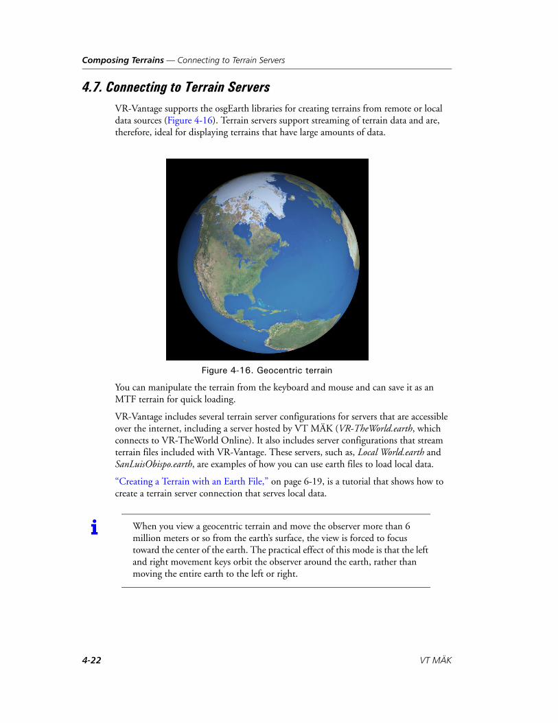
Composing Terrains — Connecting to Terrain Servers
4.7. Connecting to Terrain ServersVR-Vantage supports the osgEarth libraries for creating terrains from remote or local data sources (Figure 4-16). Terrain servers support streaming of terrain data and are, therefore, ideal for displaying terrains that have large amounts of data.
Figure 4-16. Geocentric terrain
You can manipulate the terrain from the keyboard and mouse and can save it as an MTF terrain for quick loading.
VR-Vantage includes several terrain server configurations for servers that are accessible over the internet, including a server hosted by VT MÄK (VR-TheWorld.earth, which connects to VR-TheWorld Online). It also includes server configurations that stream terrain files included with VR-Vantage. These servers, such as, Local World.earth and SanLuisObispo.earth, are examples of how you can use earth files to load local data.
“Creating a Terrain with an Earth File,” on page 6-19, is a tutorial that shows how to create a terrain server connection that serves local data.
i When you view a geocentric terrain and move the observer more than 6 million meters or so from the earth’s surface, the view is forced to focus toward the center of the earth. The practical effect of this mode is that the left and right movement keys orbit the observer around the earth, rather than moving the entire earth to the left or right.
4-22 VT MÄK

Composing Terrains — Connecting to Terrain Servers
To connect to a terrain server:
1. Choose New Scene. The current terrain closes.
2. Choose Settings Terrain. The Terrain Settings dialog box opens.
3. Select the Terrain Contents page (Figure 4-17).
Figure 4-17. Terrain Contents
4. Click Add Terrain Server. The Add Terrain Server dialog box opens (Figure 4-18). The dialog box contains information about the selected terrain server. It is not edit-able. (For information about editing terrain server configurations, please see “Editing a Terrain Server Configuration,” on page 4-25.)
! Integration of osgEarth into VR-Vantage allows you to connect to data sources. However, it does not provide a license to use any data sources. It is your responsibility to comply with the licensing provisions of any site to which you connect.
VR-Vantage Configuration Guide 4-23

Composing Terrains — Connecting to Terrain Servers
Figure 4-18. Add Terrain Server dialog box
5. Select a server from the Servers list.
6. Click Connect. If the terrain data is available (remote sources might not always be accessible), it is displayed.
You can save a terrain server as part of a terrain or scene. For details, please see “Saving a Terrain,” on page 4-4.
4.7.1. Adding Terrain Server Connections
You can add additional terrain server connections to the list provided with VR-Vantage. Terrain server connections are configured in XML files according to the requirements of the osgEarth libraries. It is beyond the scope of this manual to fully describe the config-uration process. However, the server configurations included with VR-Vantage are examples of what you can do. We recommend that you add new servers by copying an existing configuration that is similar to what you want and then editing it to point to your data. (Chapter 5, Streaming Data Using Earth Files, provides a brief introduction to earth file syntax.)
“Creating a Terrain with an Earth File,” on page 6-19, is a tutorial that shows how to create a terrain server that serves local data.
To add a terrain server connection:
1. Choose Settings Terrain. The Terrain Settings dialog box opens.
2. Select the Server Settings page (Figure 4-19). The dialog box displays the contents of the configuration file for the selected server.
4-24 VT MÄK
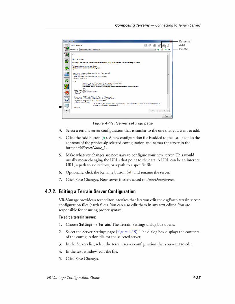
Composing Terrains — Connecting to Terrain Servers
Figure 4-19. Server settings page
3. Select a terrain server configuration that is similar to the one that you want to add.
4. Click the Add button ( ). A new configuration file is added to the list. It copies the contents of the previously selected configuration and names the server in the format oldServerName_1.
5. Make whatever changes are necessary to configure your new server. This would usually mean changing the URLs that point to the data. A URL can be an internet URL, a path to a directory, or a path to a specific file.
6. Optionally, click the Rename button ( ) and rename the server.
7. Click Save Changes. New server files are saved to ./userData/servers.
4.7.2. Editing a Terrain Server Configuration
VR-Vantage provides a text editor interface that lets you edit the osgEarth terrain server configuration files (earth files). You can also edit them in any text editor. You are responsible for ensuring proper syntax.
To edit a terrain server:
1. Choose Settings Terrain. The Terrain Settings dialog box opens.
2. Select the Server Settings page (Figure 4-19). The dialog box displays the contents of the configuration file for the selected server.
3. In the Servers list, select the terrain server configuration that you want to edit.
4. In the text window, edit the file.
5. Click Save Changes.
RenameAddDelete
VR-Vantage Configuration Guide 4-25
Composing Terrains — Loading MetaFlight Terrains
4.7.3. Connecting to Terrain Servers through a Proxy
If you connect to the network through a proxy, you may need to set some environ-mental variables to be able to connect to external terrain servers. VR-Vantage has limited proxy capability. It supports basic authentication and may support domain authentication if your proxy allows it to be accessed through basic authentication. To set up authentication, set the following environmental variables:
OSG_CURL_PROXY. Specifies the proxy machine.
OSG_CURL_PROXYPORT. Specifies the proxy port.
OSGEARTH_CURL_PROXYAUTH=username:password. Specifies the user name and password for the proxy.
4.8. Loading MetaFlight TerrainsVR-Vantage supports MetaFlight terrain databases. To load a MetaFlight terrain, add a terrain patch, as you would for any other terrain. However, before you can load a Meta-Flight file, you must first process it using the mftTool and medfTool. For details, please see Appendix G, Processing MetaFlight Files.
When you load a MetaFlight file, VR-Vantage is actually loading many individual OpenFlight files. If file caching is enabled, VR-Vantage caches the OpenFlight files to disk in a quick-loading, encrypted format so that the files can load more quickly the next time you load the terrain. The cached files are handled the same way that any other cached files are handled. For details, please see “Configuring File Caching,” on page 4-34.
i When you start VR-Vantage, the Choose a Terrain window indicates whether the selected terrain server is available. However if you are connecting through a proxy, the server status feature does not work, even if you have set up the proxy environment variables correctly. So terrain servers will be listed as unavailable. However, you can still connect to a terrain server. To do so, add the earth file as a terrain patch. The filter in the Open dialog box does not include earth files, so you will have to select All Files to see your earth files in the file chooser.
i Geometry files referenced by a MetaFlight file must be in OpenFlight format, and not in Vega Prime's binary format (.vsb). MÄK’s terrain libraries do not support .vsb files.
4-26 VT MÄK
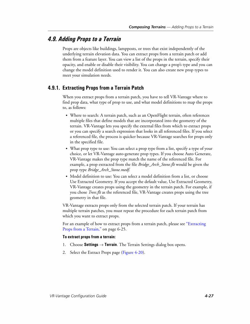
Composing Terrains — Adding Props to a Terrain
4.9. Adding Props to a TerrainProps are objects like buildings, lampposts, or trees that exist independently of the underlying terrain elevation data. You can extract props from a terrain patch or add them from a feature layer. You can view a list of the props in the terrain, specify their opacity, and enable or disable their visibility. You can change a prop’s type and you can change the model definition used to render it. You can also create new prop types to meet your simulation needs.
4.9.1. Extracting Props from a Terrain Patch
When you extract props from a terrain patch, you have to tell VR-Vantage where to find prop data, what type of prop to use, and what model definitions to map the props to, as follows:
Where to search: A terrain patch, such as an OpenFlight terrain, often references multiple files that define models that are incorporated into the geometry of the terrain. VR-Vantage lets you specify the external files from which to extract props or you can specify a search expression that looks in all referenced files. If you select a referenced file, the process is quicker because VR-Vantage searches for props only in the specified file.
What prop type to use: You can select a prop type from a list, specify a type of your choice, or let VR-Vantage auto-generate prop types. If you choose Auto Generate, VR-Vantage makes the prop type match the name of the referenced file. For example, a prop extracted from the file Bridge_Arch_Stone.flt would be given the prop type Bridge_Arch_Stone.medf.
Model definition to use: You can select a model definition from a list, or choose Use Extracted Geometry. If you accept the default value, Use Extracted Geometry, VR-Vantage creates props using the geometry in the terrain patch. For example, if you chose Trees.flt as the referenced file, VR-Vantage creates props using the tree geometry in that file.
VR-Vantage extracts props only from the selected terrain patch. If your terrain has multiple terrain patches, you must repeat the procedure for each terrain patch from which you want to extract props.
For an example of how to extract props from a terrain patch, please see “Extracting Props from a Terrain,” on page 6-25.
To extract props from a terrain:
1. Choose Settings Terrain. The Terrain Settings dialog box opens.
2. Select the Extract Props page (Figure 4-20).
VR-Vantage Configuration Guide 4-27

Composing Terrains — Adding Props to a Terrain
Figure 4-20. Extract Props page
3. In the Terrain Patches box, select the terrain patch from which you want to extract props.
4. To extract props by specifying external files, select the Extract References tab. To extract props using a search expression, select the Advanced tab.
5. If you chose the Extract References tab, in the External References list, select the files from which you want to extract props.
If you chose the Advanced tab, type the search expression in the Search Expression box. Select the Regular Expression check box if you are using a regular expression.
6. Optionally, in the Prop Type box, select the type that you want to assign to the extracted props or type a prop type.
7. Optionally, in the Model Definition box, select the model definition that you want to apply to the extracted props.
8. If you are using the Advanced tab, click Extract. If you are using the Extract Refer-ences tab, click Extract Selected. VR-Vantage extracts the props, if any. You can view the list of props in the Props list on the Edit Existing Props page.
i VR-Vantage uses perl regular expression syntax.
4-28 VT MÄK
Composing Terrains — Adding Props to a Terrain
4.9.2. Adding Props from a Feature Layer
A feature layer source file contains information about point, line, or areal features. Feature information is stored in a table in which each row is a feature and each feature is defined by the values in an arbitrary number of columns. To add a prop from a feature layer, you must build a rule that specifies the column headings and values for the feature you want to import. Then you must associate a prop type and model definition with the prop. You also must specify whether or not to ground clamp the prop.
Please see “Add Props,” on page 6-12 for an example of adding props from a feature layer.
To add a prop from a feature layer:
1. Choose Settings Terrain. The Terrain Settings dialog box opens.
2. Select the Add Props page (Figure 4-21).
Figure 4-21. Terrain Settings, Add Props page
3. In the Feature Layers list, select the feature layer from which you want to import the props.
4. Click the Add button ( ) to the right of the Field/Value window (Figure 4-21). The Build Field/Value Pair dialog box opens (Figure 4-22).
Figure 4-22. Build Field/Value Pair dialog box
VR-Vantage Configuration Guide 4-29

Composing Terrains — Adding Props to a Terrain
5. In the Field list, select a field. Fields are the column headings in the feature defini-tion.
6. In the Value list, select a value. Values are one or more values from the definition table that are available for the column heading.
7. Click OK. The Field/Value pair is added to the window (Figure 4-23).
Figure 4-23. New Field/Value pair
8. Add additional Field/Value pairs as needed to define the prop that you want to add.
9. In the Prop Type list, select the prop type to assign to the prop you want to add.
10. In the Model Definition list, select the model definition you want to use for this prop.
11. In the Ground Clamp box, specify whether or not to ground clamp this prop.
12. Optionally, set the rotation.
13. Click Execute Rule. The prop is extracted from the feature layer and is listed in the History window.
i It is your responsibility to understand the feature definitions for the features that you want to import as props.
4-30 VT MÄK
Composing Terrains — Adding Props to a Terrain
4.9.3. Viewing a List of Props
To view a list of the props in the terrain:
1. Choose Settings Terrain. The Terrain Settings dialog box opens.
2. Select the Edit Existing Props page (Figure 4-24).
Figure 4-24. Edit Existing Props page
3. Expand the list to view the entries under a particular type of prop.
4.9.4. Selecting Props
To select a prop, click it in the window or in the Objects List Panel, or select it in the list of props on the Terrain Settings dialog box, Edit Existing Props page.
Press Ctrl+click to select multiple props.
VR-Vantage Configuration Guide 4-31

Composing Terrains — Adding Props to a Terrain
4.9.5. Setting the Opacity of Props
You can set the opacity of props. This can be useful if you want to see what is inside a building or behind a prop. Figure 4-25 illustrates a building at two levels of opacity.
Figure 4-25. Prop opacity
To set a prop’s opacity:
1. Choose Settings Terrain. The Terrain Settings dialog box opens.
2. Select the Edit Existing Props page (Figure 4-24).
3. In the list of props select the props whose opacity you want to change, or select a prop in the window. The Opacity slider is enabled.
4. Slide the Opacity slider to the right to increase opacity. Slide it to the left to decrease opacity.
Making a Prop Fully Transparent or Opaque
You can quickly set a prop to be fully transparent or opaque.
To make a prop fully transparent, right-click the prop and on the popup menu, choose Make Transparent.
To make a transparent prop fully opaque, right-click the prop and on the popup menu, choose Make Opaque.
100% 40%
4-32 VT MÄK
Composing Terrains — Adding Props to a Terrain
4.9.6. Changing a Prop’s Type
Every prop has a type. Props are organized by type in the list on the Edit Existing Props page.
To change a prop’s type:
1. Choose Settings Terrain. The Terrain Settings dialog box opens.
2. Select the Edit Existing Props page (Figure 4-24).
3. In the list of props, select the props whose type you want to change.
4. Select a prop type from the Prop Type list, or type a new type name. The selected props are moved to the new prop type in the Props window.
4.9.7. Changing a Prop’s Position or Orientation
You can change a prop’s position and orientation. You can change the orientation of multiple props at the same time without affecting their position. However, if you select multiple props and change position, they are all placed in the same position.
To change a prop’s position or orientation:
1. Choose Settings Terrain. The Terrain Settings dialog box opens.
2. Select the Edit Existing Props page (Figure 4-24).
3. In the list of props, select the prop whose position or orientation you want to change.
4. To change position, type or select new values in the X, Y, or Z boxes.
5. To change the orientation, type or select new values in the Yaw, Pitch, or Roll boxes.
4.9.8. Changing a Prop’s Model Definition
You can change the model definition used to render a prop. For information about model definitions, please see Chapter 8, Model and Element Definitions. For an example of changing a prop’s model definition, please see “Test the Model Mapping,” on page C-14.
To change a prop’s model definition:
1. Choose Settings Terrain. The Terrain Settings dialog box opens.
2. Select the Edit Existing Props page (Figure 4-24).
3. In the list of props, select the prop whose model definition you want to change.
4. In the Model Definition list, select a model definition. The selected props are rendered using the new model definition.
VR-Vantage Configuration Guide 4-33

Composing Terrains — Configuring File Caching
4.10. Configuring File CachingWhen file caching is enabled, VR-Vantage stores information about the terrain and models in a format that enables it to be loaded quickly. This improves loading time the next time the cached objects are loaded. If caching is disabled, terrains and models must be loaded from their native formats, which may take longer.
To enable or disable file caching:
1. Choose Settings Application. The Application Settings dialog box opens.
2. Select the File Caching Settings page (Figure 4-26).
Figure 4-26. File Caching Settings page
3. Select or clear the Enable Accelerated File Loading check box.
4.10.1. Caching Terrain Server Data
When file caching is enabled, VR-Vantage caches data from terrain servers in the default locations. You can override this by specifying an alternative caching location in the OSGEARTH_CACHE_PATH environment variable. (Do not use the cache element in the earth file.)
i When VR-Vantage processes a request to load a a file, such as an external reference in a terrain, it checks the cache and the directory of the requested file for an MEDF version of the file. If it does not exist, it loads the file in the original format.
4-34 VT MÄK
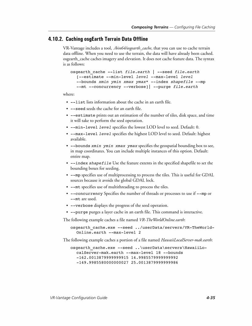
Composing Terrains — Configuring File Caching
4.10.2. Caching osgEarth Terrain Data Offline
VR-Vantage includes a tool, ./bin64/osgearth_cache, that you can use to cache terrain data offline. When you need to use the terrain, the data will have already been cached. osgearth_cache caches imagery and elevation. It does not cache feature data. The syntax is as follows:
osgearth_cache --list file.earth | --seed file.earth [--estimate --min-level level --max-level level --bounds xmin ymin xmax ymax* --index shapefile --mp --mt --concurrency --verbose]| --purge file.earth
where:
--list lists information about the cache in an earth file.
--seed seeds the cache for an earth file.
--estimate prints out an estimation of the number of tiles, disk space, and time it will take to perform the seed operation.
--min-level level specifies the lowest LOD level to seed. Default: 0.
--max-level level specifies the highest LOD level to seed. Default: highest available.
--bounds xmin ymin xmax ymax specifies the geospatial bounding box to see, in map coordinates. You can include multiple instances of this option. Default: entire map.
--index shapefile Use the feature extents in the specified shapefile to set the bounding boxes for seeding.
--mp specifies use of multiprocessing to process the tiles. This is useful for GDAL sources because it avoids the global GDAL lock.
--mt specifies use of multithreading to process the tiles.
--concurrency Specifies the number of threads or processes to use if --mp or --mt are used.
--verbose displays the progress of the seed operation.
--purge purges a layer cache in an earth file. This command is interactive.
The following example caches a file named VR-TheWorldOnline.earth:
osgearth_cache.exe --seed ../userData/servers/VR-TheWorld-Online.earth --max-level 2
The following example caches a portion of a file named HawaiiLocalServer-mak.earth:
osgearth_cache.exe --seed ..\userData\servers\HawaiiLo-calServer-mak.earth --max-level 18 --bounds -162.0013879999999915 14.9985579999999992 -149.9985580000000027 25.0013879999999986
VR-Vantage Configuration Guide 4-35
Composing Terrains — Configuring File Caching
4.10.3. Enabling Texture Compression
When texture compression is enabled, textures are converted internally to a compressed format (DXT). Compressing textures decreases memory use and increases rendering performance.
To enable or disable texture compression:
1. Choose Settings Application. The Application Settings dialog box opens.
2. Select the File Caching Settings page (Figure 4-26).
3. Select or clear the Enable Texture Compression On All Textures check box.
! We strongly recommend that you specify --max-level and seed just the areas that you want.
4-36 VT MÄK

Composing Terrains — Displaying DDS Textures Correctly
4.10.4. Clearing the File Cache
You can clear the file cache if you need to free disk space.
The cache is normally configured to be in ./appData/cache. You can delete files from this directory if you want to. The most likely reason to do this is if you load a terrain and realize that it should have had its DDS textures flipped, but has now been saved with them oriented the wrong way. You could delete the cache, then reload the terrain and toggle DDS Textures to the opposite setting.
To clear the file cache:
1. Choose Settings Application. The Application Settings dialog box opens.
2. Select the File Caching Settings page (Figure 4-26).
3. Click Clear Accelerated File Loading Cache.
4.11. Displaying DDS Textures CorrectlyDDS is a DirectX bitmap format that is often used for textures. DirectX expects the origin of the image to be at the top left corner. OpenGL expects the image origin to be at the bottom left cornet. By default, VR-Vantage assumes that images have the OpenGL orientation. However, sometimes images are not oriented properly and there-fore you may have to tell VR-Vantage to flip them.
You can change the DDS textures setting as follows:
On a per-model basis. (For details, please see “Flipping DDS Textures for a Model,” on page 2-50.)
When you add a terrain patch. (For details, please see “Adding Elevation Data (Terrain Patches) to a Terrain,” on page 4-5.)
As a global setting. (For details, please see “Flipping DDS Textures Globally,” on page 4-37.)
4.11.1. Flipping DDS Textures Globally
You can specify that the DDS textures setting apply to all terrains. This setting is primarily beneficial for paged terrains because you cannot know ahead of time if textures need to be flipped, as you could for a model or terrain patch. If a paged terrain has DDS textures that are upside down relative to VR-Vantage’s expectations, the textures can be flipped when the terrain gets paged in.
To enable or disable DDS texture flipping for all terrains:
1. Choose Settings Display. The Display Settings dialog box opens.
2. Select the Loader Settings page (Figure 4-27).
VR-Vantage Configuration Guide 4-37
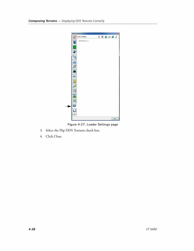
Composing Terrains — Displaying DDS Textures Correctly
Figure 4-27. Loader Settings page
3. Select the Flip DDS Textures check box.
4. Click Close.
4-38 VT MÄK

Composing Terrains — Preprocessing Paged Terrains
4.12. Building Efficient MetaFlight Terrains for VR-VantageVR-Vantage can only load MetaFlight terrains built with certain tools. All MetaFlight files must be pre-processed by VR-Vantage tools before they can be loaded. The following are recommendations for constructing MetaFlight terrains that can be processed and loaded into VR-Vantage:
The MetaFlight terrain can contain one or more Geometry Grid Datasets (GGDS).
The MetaFlight terrain can contain one or more Virtual Texture Datasets.
The MetaFlight terrain can contain one or more Cultural Feature Datasets.
The MetaFlight terrain can be built in the following coordinate systems: Geodetic, Geocentric, UTM, or Flat Earth.
For the best conversion of Virtual Textures into a tiled texture GGDS, match every Virtual Texture layer with a geometry layer.
For optimal performance the GGDS should be set up in a Pyramid structure (Level 1: 1x1, Level 2: 2x2, Level 3: 4x4, and so on).
For optimal performance levels 1-4 should be made of FILE LOD GEOM tiles only. Do not put any children LOD GEOM tiles in these levels.
For optimal performance the terrain should be balanced so that any single FILE LOD GEOM is not too large and can be paged in real-time (based on machine speed and video card). In other words, keep any single file small.
For optimal performance any single FILE LOD GEOM should not contain too many LOD GEOM nodes as children.
Geometry Grid Tile size (in meters) should match Virtual Texture Tile coverage (in meters.)
For optimal performance limit the number of external references. This will reduce cull times. (For example, instead of having 10 individual buildings, externally refer-ence one city block with all 10 buildings.)
4.13. Preprocessing Paged TerrainsVR-Vantage supports preprocessing external references used by paged terrains. VR-Vantage does not require terrain formats such as TerraPage or pageable IVE to be preprocessed. However these terrains may use external references in formats such as OpenFlight, which load slowly. Although VR-Vantage can accelerate these files at run-time using the accelerated cache feature, the first time you load one of these terrains you can experience significant performance issues. You can use the medfTool to preprocess these external references and save them in MEDF format. Thereafter, VR-Vantage will load the accelerated version at all times.
For example, if a TerraPage terrain references /externals/tree.flt, preprocessing will create a file called /externals/tree.medf. When VR-Vantage loads the terrain, it will load the MEDF version instead of the OpenFlight version.
VR-Vantage Configuration Guide 4-39

Composing Terrains — Configuring Paged and Streaming Terrains
We recommend that you preprocess all data to minimize load times and maximize run-time performance. For details about the medfTool, please see “Compressing Model Files,” on page 10-8.
4.14. Configuring Paged and Streaming TerrainsYou can improve performance for some terrains by configuring the following environ-ment variables:
OSG_MAX_PAGEDLOD. OSG_MAX_PAGEDLOD specifies the target maximum number of paged LODs to maintain. Default: 200. Set it to a lower value if you need to reduce memory consumption when using paged terrains.
GDAL_CACHEMAX. GDAL_CACHEMAX specifies the maximum cache size for streaming terrain. The default value is 200 MB, which is often adequate. However, if you are using a highly detailed terrain, increasing the cache size to a larger value, such as 2000, can significantly improve performance.
4-40 VT MÄK
Composing Terrains — Terrain Databases Provided with VR-Vantage
4.15. Terrain Databases Provided with VR-VantageTable 4-1 describes the terrain databases provided with VR-Vantage. Some have vari-ants, which indicate the coordinate system or other variations.
Table 4-1: Terrain databases shipped with VR-Vantage (Sheet 1 of 3)
Database Variation Description
Berkeley Berkeley.mtf UTM. OpenFlight. Feature data. Shows the area around Berkeley, California, USA. It is provided courtesy of Terrex.
Ground ground-db.mtf UTM. OpenFlight. A generic relatively flat ground terrain.
HarrisAfghan-Village
HarrisAfghanVillage-FlatEarthMetaFlight.mtf
Paged terrain using flat earth projec-tion. A terrain of Afghanistan with a high resolution inset of a small village. This terrain was created in VR-Vantage from source data. The terrain data is provided courtesy of Harris, Inc.
HarrisAfghanVillage-FlatEarth.mtf
A static terrain database of Afghani-stan with a high resolution inset.
HarrisAfghanVil-lageGdal.mtf
A streaming version of this terrain using local data.
HarrisAfghanVillageGeo-centricMetaFlight.mtf
Paged terrain using geocentric coordi-nates.
Kabul Kabul.mtf UTM. OpenFlight. The area around Kabul, Afghanistan.
Little Pond LittlePond.mtf Flat earth. DTED. Shape data. Imagery. A detailed suburban inset in a larger, less detailed terrain covering Boston, Massachusetts, U.S.A. and points west. This terrain was created in VR-Vantage using source data as described in “Composing a Terrain through the GUI,” on page 6-2.
Makland Makland.mtf UTM. OpenFlight. A fictional terrain created by MÄK. It includes a variety of terrain and feature data, including underwater features. It is placed in the Indian Ocean.
MaklandCgfTopoMap.mtf A topographic map laid on top of the Makland terrain.
MaklandLocalWorld.mtd Geocentric. Low resolution local terrain.
VR-Vantage Configuration Guide 4-41
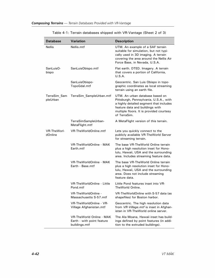
Composing Terrains — Terrain Databases Provided with VR-Vantage
Nellis Nellis.mtf UTM. An example of a SAF terrain suitable for simulation, but not typi-cally used in 3D imaging. A terrain covering the area around the Nellis Air Force Base, in Nevada, U.S.A.
SanLuisO-bispo
SanLuisObispo.mtf Flat earth. DTED. Imagery. A terrain that covers a portion of California, U.S.A.
SanLuisObispo-TopoGdal.mtf
Geocentric. San Luis Obispo in topo-graphic coordinates as local streaming terrain using an earth file.
TerraSim_SampleUrban
TerraSim_SampleUrban.mtf UTM. An urban database based on Pittsburgh, Pennsylvania, U.S.A., with a highly detailed segment that includes feature data and buildings with multiple floors. It is provided courtesy of TerraSim.
TerraSimSampleUrban-MetaFlight.mtf
A MetaFlight version of this terrain.
VR-TheWorl-dOnline
VR-TheWorldOnline.mtf Lets you quickly connect to the publicly available VR-TheWorld Server for streaming terrain.
VR-TheWorldOnline - MAK Earth.mtf
The base VR-TheWorld Online terrain plus a high resolution inset for Hono-lulu, Hawaii, USA and the surrounding area. Includes streaming feature data.
VR-TheWorldOnline - MAK Earth - Base.mtf
The base VR-TheWorld Online terrain plus a high resolution inset for Hono-lulu, Hawaii, USA and the surrounding area. Does not include streaming feature data.
VR-TheWorldOnline - Little Pond.mtf
Little Pond features inset into VR-TheWorld Online.
VR-TheWorldOnline - Massachusetts S-57.mtf
VR-TheWorldOnline with S-57 data (as shapefiles) for Boston harbor.
VR-TheWorldOnline - VR-Village Afghanistan.mtf
Geocentric. The high resolution data from VR-Village.mtf is inset in Afghan-istan in VR-TheWorld online server.
VR-TheWorld Online - MAK Earth - with point feature buildings.mtf
The Ala Moana, Hawaii inset has build-ings defined by point features (in addi-tion to the extruded buildings).
Table 4-1: Terrain databases shipped with VR-Vantage (Sheet 2 of 3)
Database Variation Description
4-42 VT MÄK

Composing Terrains — Terrain Databases Provided with VR-Vantage
VR-Village VR-Village.mtf GDB. Feature data. OpenFlight terrain. VR-Village is a fictional database created by VT MÄK. It has a highly detailed small town in a larger, sparsely detailed desert environment. The town includes multi-level build-ings, underground tunnels, and a road that tunnels through a mountain. The coordinates place it off the west coast of Africa.
VR-VillageNoSpeed-Trees.mtf
VR-Village with no SpeedTrees for improved performance.
World WorldFlatEarthNoEleva-tion.mtf
Flat earth. Low resolution projected image of the world.
WorldGeocentric.mtf Geocentric. Low resolution projection of the world.
Table 4-1: Terrain databases shipped with VR-Vantage (Sheet 3 of 3)
Database Variation Description
VR-Vantage Configuration Guide 4-43

Composing Terrains — Terrain Databases Provided with VR-Vantage
4-44 VT MÄK

VR-V
5. Streaming Data Using Earth Files
This chapter provides an introduction to the syntax of Earth files and explains how to configure them to stream various types of terrain and feature data.
Earth Files..................................................................................................... 5-2
A Simple Earth File....................................................................................... 5-2
Loading Multiple DTED Files ...................................................................... 5-3
Processing Streamed Data ............................................................................. 5-4
Adding Feature Layers to an Earth File.......................................................... 5-4Configuring Point Features..................................................................... 5-6Configuring Linear Features ................................................................... 5-6
Using Cut-in Sites for High Resolution Insets............................................... 5-7Using the Boundary Generation Tool ..................................................... 5-8
Extruded Buildings ....................................................................................... 5-9
Earth File Options ...................................................................................... 5-11
Streaming Buoys and Beacons ..................................................................... 5-12Specifying Model Definitions for Streamed Buoys ................................ 5-12Modeling Buoys Using Texture Atlases ................................................. 5-15Configuring Streaming Beacons ........................................................... 5-15Configuring Streamed Navigation Lights.............................................. 5-16Configuring Seasonal Buoys and Beacons ............................................. 5-18Streaming Daymarks ............................................................................ 5-18Streaming Topmarks............................................................................. 5-18Generating Signal Sequences ................................................................ 5-19
5-1antage Configuration Guide
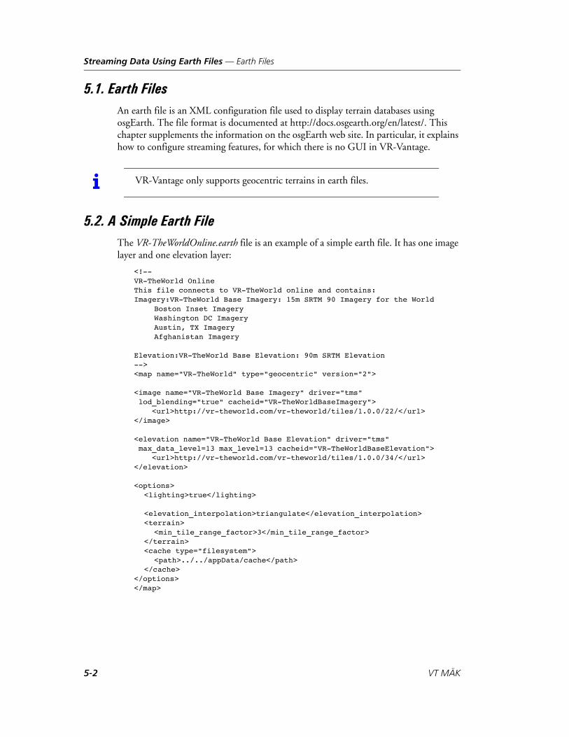
Streaming Data Using Earth Files — Earth Files
5.1. Earth FilesAn earth file is an XML configuration file used to display terrain databases using osgEarth. The file format is documented at http://docs.osgearth.org/en/latest/. This chapter supplements the information on the osgEarth web site. In particular, it explains how to configure streaming features, for which there is no GUI in VR-Vantage.
5.2. A Simple Earth FileThe VR-TheWorldOnline.earth file is an example of a simple earth file. It has one image layer and one elevation layer:
<!--VR-TheWorld OnlineThis file connects to VR-TheWorld online and contains:Imagery:VR-TheWorld Base Imagery: 15m SRTM 90 Imagery for the World
Boston Inset ImageryWashington DC ImageryAustin, TX ImageryAfghanistan Imagery
Elevation:VR-TheWorld Base Elevation: 90m SRTM Elevation--><map name="VR-TheWorld" type="geocentric" version="2">
<image name="VR-TheWorld Base Imagery" driver="tms" lod_blending="true" cacheid="VR-TheWorldBaseImagery"> <url>http://vr-theworld.com/vr-theworld/tiles/1.0.0/22/</url></image>
<elevation name="VR-TheWorld Base Elevation" driver="tms" max_data_level=13 max_level=13 cacheid="VR-TheWorldBaseElevation"> <url>http://vr-theworld.com/vr-theworld/tiles/1.0.0/34/</url></elevation>
<options><lighting>true</lighting>
<elevation_interpolation>triangulate</elevation_interpolation><terrain>
<min_tile_range_factor>3</min_tile_range_factor></terrain><cache type="filesystem">
<path>../../appData/cache</path></cache>
</options></map>
i VR-Vantage only supports geocentric terrains in earth files.
5-2 VT MÄK

Streaming Data Using Earth Files — Loading Multiple DTED Files
Table 5-1 describes the XML elements in the file and their attributes.
5.3. Loading Multiple DTED FilesYou can load multiple DTED files from an earth file. To do so, in the heightfield element, specify a directory instead of a specific file, for example (from SanLuisObispo-Topo.earth):
<heightfield name="SanLuisObispo Elevation" driver = "gdal"><url>../../data/Terrain/SanLuisObispo/Elevation</url><extensions>dt0;dt1;dt2</extensions>...
</heightfield>
The extensions element lets you specify which files to load based on their file exten-sions. If you do not include an extensions list, the GDAL driver tries to load every file in the directory.
Table 5-1: Earth file elements and attributes
Element Attribute Description
<!-- --> Comment block.
map Root level element. All other elements must be in the map block.
name The name of the map.
type The projection. VR-Vantage only supports geocentric terrains, which can be specified as geocentric or globe.
version The VR-TheWorld Server version.
image Specifies an image layer.
name The name of the layer.
driver The driver to use to fetch tiles, for example, TMS, WMS, or GDAL.
url The location of the files. This could be a web address or a local path.
elevation Specifies an elevation layer.
name The name of the layer.
driver The driver to use to fetch tiles, for example, TMS, WMS, or GDAL.
url The location of the files. This could be a web address or a local path.
options Specifies options that affect the entire map. For more information, please see “Earth File Options,” on page 5-11.
VR-Vantage Configuration Guide 5-3

Streaming Data Using Earth Files — Processing Streamed Data
5.4. Processing Streamed DataVR-Vantage has several “processors” that search through streamed-in data looking for things like SpeedTrees, objects that need effects textures attached, buoys, beacons, and so on. In order to do this efficiently, processors register feature names that they want to process. The registration data is in ./importConfig/registrant_feature_list.csv.
For example, in registrant_feature_list.csv, it states that the processor for SpeedTrees, speedTreeManager, is mapped to Vegetation. In VR-TheWorld Online - MAK Earth.earth, SpeedTrees are configured as follows:
<model name="trees" driver="feature_custom"><features name="Vegetation" driver="wfs">
The feature name is Vegetation. This means that it will be processed by the speedTree-Manager.
Similarly, the featureDataBroker, which is responsible for creating streamed buoys, beacons, and the lights and marks that might be attached to them, is mapped to 57-data and dynamicFeatures. (Processors can be mapped to more than one feature type.) Examples of using this processor are:
<model name="LateralBuoysUS5HA52M" driver="feature_custom" enabled="true"><features name="s57-data" driver="ogr">
and
<model name="TaxiwayLights" driver="feature_custom"><features name="dynamicFeatures" driver="ogr">
registrant_feature_list.csv file is fully commented and provides additional information about this scheme.
We have updated earth files to use the new scheme. If you are using custom earth files, you must update them to take advantage of this new processing method. If you use VR-TheWorld Server, you must update your earth files (or your registrant_feature_list.csv files).
5.5. Adding Feature Layers to an Earth FileYou can add the following types of features to a terrain:
Point features, such as trees, buoys, and buildings.
Linear features, such as roads and waterways.
Areal features, such as forests (areal trees), bodies of water, and extruded buildings.
You can add the XML for feature layers to an earth file.
5-4 VT MÄK

Streaming Data Using Earth Files — Adding Feature Layers to an Earth File
Features layers are added to an earth file using the model element. Table 5-2 describes the model element, its attributes, and sub-elements.
Table 5-2: model element attributes
Element Attribute Description
model Base element for specifying a feature layer.
name Name of the layer. This can be any text.
driver Driver to use for creating models.
The features and layout elements specify how to get and load the feature data. The features block is mandatory. layout is optional.
features Specifies source of data.
name Name of the element.
driver Driver to use to get the data.
url Location of the feature data.
layout Specifies how to load the data.
tile_size_factor The data specified in the features element gets cut into tiles. This attribute specifies how aggressively to tile it.
level name The level specifies the level (LOD) beyond which not to display the features.
max_range Distance beyond which the feature is not displayed.
selector class Specifies the type of feature.
styles The styles element and sub-elements specify how to render the scene. This element is manda-tory.
library A texture library.
name Name of the texture library.
url The location of the library.
style A specific style. The name, which precedes the curly brace ({) can be any text you want. For infor-mation about the attributes that you can specify in a style, please see http://docs.osgearth.org/en/latest/refer-ences/symbology.html.
lighting Specifies whether or not to enable lighting. Usually true.
VR-Vantage Configuration Guide 5-5
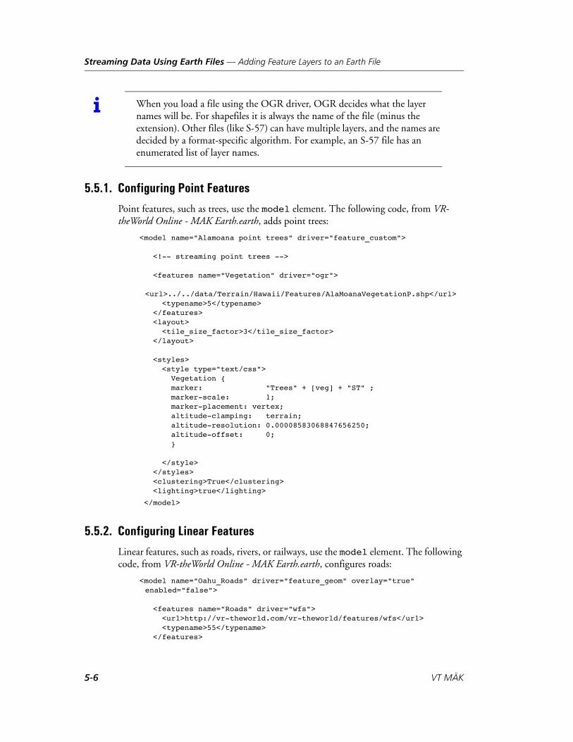
Streaming Data Using Earth Files — Adding Feature Layers to an Earth File
5.5.1. Configuring Point Features
Point features, such as trees, use the model element. The following code, from VR-theWorld Online - MAK Earth.earth, adds point trees:
<model name="Alamoana point trees" driver="feature_custom">
<!-- streaming point trees -->
<features name="Vegetation" driver="ogr">
<url>../../data/Terrain/Hawaii/Features/AlaMoanaVegetationP.shp</url> <typename>5</typename> </features> <layout> <tile_size_factor>3</tile_size_factor> </layout>
<styles> <style type="text/css"> Vegetation { marker: "Trees" + [veg] + "ST" ; marker-scale: 1; marker-placement: vertex; altitude-clamping: terrain; altitude-resolution: 0.00008583068847656250; altitude-offset: 0; }
</style> </styles> <clustering>True</clustering> <lighting>true</lighting>
</model>
5.5.2. Configuring Linear Features
Linear features, such as roads, rivers, or railways, use the model element. The following code, from VR-theWorld Online - MAK Earth.earth, configures roads:
<model name="Oahu_Roads" driver="feature_geom" overlay="true" enabled="false">
<features name="Roads" driver="wfs"> <url>http://vr-theworld.com/vr-theworld/features/wfs</url> <typename>55</typename> </features>
i When you load a file using the OGR driver, OGR decides what the layer names will be. For shapefiles it is always the name of the file (minus the extension). Other files (like S-57) can have multiple layers, and the names are decided by a format-specific algorithm. For example, an S-57 file has an enumerated list of layer names.
5-6 VT MÄK
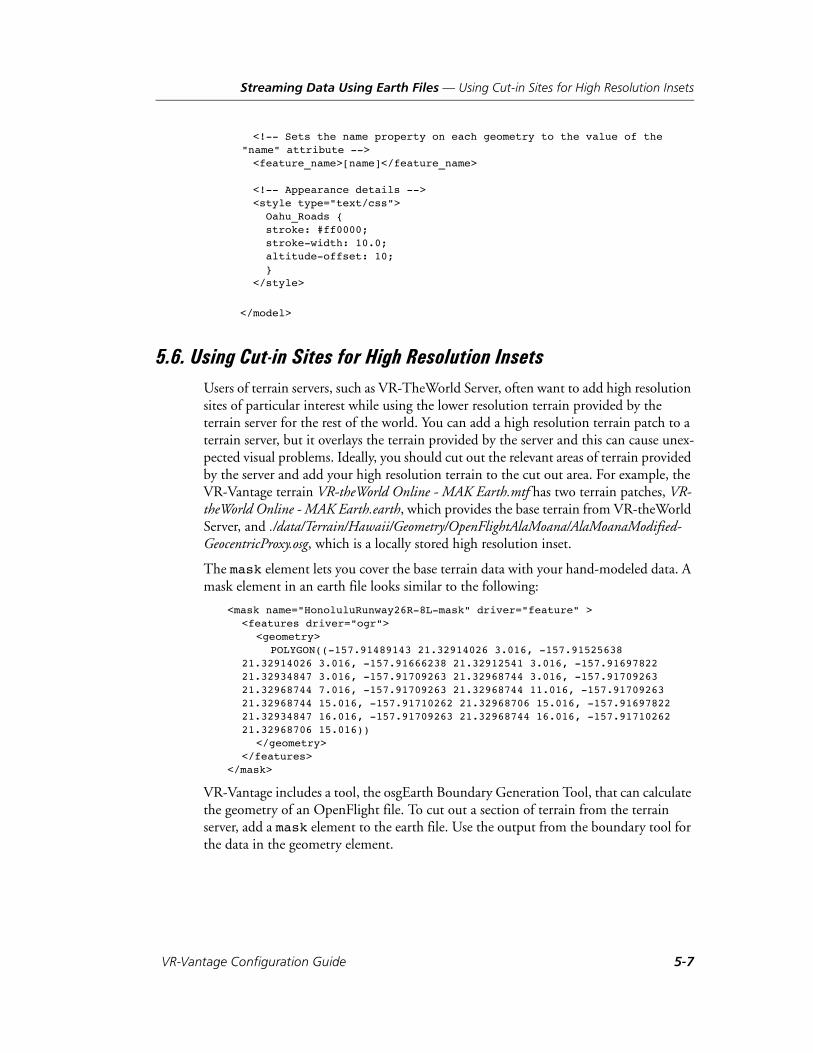
Streaming Data Using Earth Files — Using Cut-in Sites for High Resolution Insets
<!-- Sets the name property on each geometry to the value of the "name" attribute -->
<feature_name>[name]</feature_name>
<!-- Appearance details --> <style type="text/css"> Oahu_Roads { stroke: #ff0000; stroke-width: 10.0; altitude-offset: 10; } </style>
</model>
5.6. Using Cut-in Sites for High Resolution InsetsUsers of terrain servers, such as VR-TheWorld Server, often want to add high resolution sites of particular interest while using the lower resolution terrain provided by the terrain server for the rest of the world. You can add a high resolution terrain patch to a terrain server, but it overlays the terrain provided by the server and this can cause unex-pected visual problems. Ideally, you should cut out the relevant areas of terrain provided by the server and add your high resolution terrain to the cut out area. For example, the VR-Vantage terrain VR-theWorld Online - MAK Earth.mtf has two terrain patches, VR-theWorld Online - MAK Earth.earth, which provides the base terrain from VR-theWorld Server, and ./data/Terrain/Hawaii/Geometry/OpenFlightAlaMoana/AlaMoanaModified-GeocentricProxy.osg, which is a locally stored high resolution inset.
The mask element lets you cover the base terrain data with your hand-modeled data. A mask element in an earth file looks similar to the following:
<mask name="HonoluluRunway26R-8L-mask" driver="feature" ><features driver="ogr">
<geometry>POLYGON((-157.91489143 21.32914026 3.016, -157.91525638
21.32914026 3.016, -157.91666238 21.32912541 3.016, -157.91697822 21.32934847 3.016, -157.91709263 21.32968744 3.016, -157.91709263 21.32968744 7.016, -157.91709263 21.32968744 11.016, -157.91709263 21.32968744 15.016, -157.91710262 21.32968706 15.016, -157.91697822 21.32934847 16.016, -157.91709263 21.32968744 16.016, -157.91710262 21.32968706 15.016))
</geometry></features>
</mask>
VR-Vantage includes a tool, the osgEarth Boundary Generation Tool, that can calculate the geometry of an OpenFlight file. To cut out a section of terrain from the terrain server, add a mask element to the earth file. Use the output from the boundary tool for the data in the geometry element.
VR-Vantage Configuration Guide 5-7

Streaming Data Using Earth Files — Using Cut-in Sites for High Resolution Insets
Table 5-3 describes the mask element and its sub-elements.
5.6.1. Using the Boundary Generation Tool
The Boundary Generation Tool takes an OpenFlight file and calculates the bounding geometry of the file. It returns the coordinates in a text file. The general process of cutting in a site is as follows:
1. Run the Boundary Generation Tool against an OpenFlight file.
2. Insert the output of the of the boundary generation tool in a mask element in your earth file. (For details about mask elements, please see “Using Cut-in Sites for High Resolution Insets,” on page 5-7.)
3. Load the terrain.
4. Add the FLT file as a terrain patch.
5. Save the terrain.
Running the Boundary Generation Tool
The output from the Boundary Generation Tool tool, in boundary.txt or the output file you specify, looks similar to the following:
POLYGON((-157.91489143 21.32914026 3.016, -157.91525638 21.32914026 3.016, -157.91666238 21.32912541 3.016, -157.91697822 21.32934847 3.016, -157.91709263 21.32968744 3.016, -157.91709263 21.32968744 7.016, -157.91709263 21.32968744 11.016, -157.91709263 21.32968744 15.016, -157.91710262 21.32968706 15.016, -157.91697822 21.32934847 16.016, -157.91709263 21.32968744 16.016, -157.91710262 21.32968706 15.016))
Table 5-3: mask element
Element Attribute Description
mask Element for cutting in geometry.
name Name of the mask.
driver The driver to use.
features List of features in the mask.
driver The driver to use. OGR reads raw vector feature data from shapefiles and other formats.
geometry Specifies the 3D boundaries of the site. You must know this information.
geometry_url The location of the file with the feature data.
5-8 VT MÄK
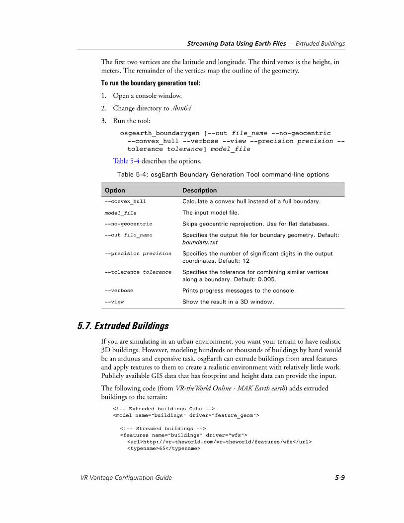
Streaming Data Using Earth Files — Extruded Buildings
The first two vertices are the latitude and longitude. The third vertex is the height, in meters. The remainder of the vertices map the outline of the geometry.
To run the boundary generation tool:
1. Open a console window.
2. Change directory to ./bin64.
3. Run the tool:
osgearth_boundarygen [--out file_name --no-geocentric --convex_hull --verbose --view --precision precision --tolerance tolerance] model_file
Table 5-4 describes the options.
5.7. Extruded BuildingsIf you are simulating in an urban environment, you want your terrain to have realistic 3D buildings. However, modeling hundreds or thousands of buildings by hand would be an arduous and expensive task. osgEarth can extrude buildings from areal features and apply textures to them to create a realistic environment with relatively little work. Publicly available GIS data that has footprint and height data can provide the input.
The following code (from VR-theWorld Online - MAK Earth.earth) adds extruded buildings to the terrain:
<!-- Extruded buildings Oahu --><model name="buildings" driver="feature_geom">
<!-- Streamed buildings --><features name="buildings" driver="wfs">
<url>http://vr-theworld.com/vr-theworld/features/wfs</url><typename>65</typename>
Table 5-4: osgEarth Boundary Generation Tool command-line options
Option Description
--convex_hull Calculate a convex hull instead of a full boundary.
model_file The input model file.
--no-geocentric Skips geocentric reprojection. Use for flat databases.
--out file_name Specifies the output file for boundary geometry. Default: boundary.txt
--precision precision Specifies the number of significant digits in the output coordinates. Default: 12
--tolerance tolerance Specifies the tolerance for combining similar vertices along a boundary. Default: 0.005.
--verbose Prints progress messages to the console.
--view Show the result in a 3D window.
VR-Vantage Configuration Guide 5-9

Streaming Data Using Earth Files — Extruded Buildings
</features>
<layout><tile_size_factor>3</tile_size_factor>
</layout>
<styles><library name="us_resources">
<url>http://vr-theworld.com/vr-theworld/filemanager/download/public/Library/catalog.xml</url>
</library>
<style type="text/css">buildings {
extrusion-height: [hgt2d]; extrusion-flatten: true; extrusion-wall-style: building-wall; extrusion-roof-style: building-rooftop; extrusion-random-seed: 1; altitude-clamping: terrain; altitude-resolution: 0.0001; }
building-wall { skin-library: us_resources; skin-tags: building; skin-random-seed: 1; fill: #ffffff; } building-rooftop { skin-library: us_resources; skin-tags: rooftop; skin-tiled: true; skin-random-seed: 1; fill: #ffffff; } </style>
</styles><lighting>true</lighting><cluster_culling>false</cluster_culling>
</model>
For descriptions of the elements in a model block, please see Table 5-2.
5-10 VT MÄK

Streaming Data Using Earth Files — Earth File Options
5.8. Earth File OptionsAn earth file can have option elements that affect the entire map. Table 5-5 describes the option elements.
Table 5-5: option element
Element Attribute Description
lighting Enables or disables lighting for the entire map. This is usually true.
elevation_interpolation Specifies how OSG interprets elevation between grid posts. If you are using VR-Forces or visualizing a VR-Forces simulation, set this to triangulate to ensure correlation.
cache Specifies caching for terrain data.
type The type of caching to use.
path The location of the data cache.
VR-Vantage Configuration Guide 5-11

Streaming Data Using Earth Files — Streaming Buoys and Beacons
5.9. Streaming Buoys and BeaconsVR-Vantage can display models of buoys and beacons specified in shapefiles and S-57 data and streamed in using earth files.
Streamed features (including buoys) are organized into layers. In the .earth file, the names in the styles block specify the layer the streamed features will belong to. By default, VR-Vantage defines seven layers for buoys. They correspond to the different buoy layers in an S-57 file. These layers are named LateralBuoys, SafeWaterBuoys, ISDBuoys, RegulatoryBuoys, InstallationBuoys, CardinalBuoys, and SpecialPurpose-Buoys.
The configuration file ./appData/importConfig/s57_layer_list.csv is used to specify which style names in an earth file correspond to recognized streamed feature types. The file currently contains two lines. The first starts with the keyword “Buoys” and is followed by a comma-separated list of all the style names that will be recognized (and streamed in) as buoys. The second line starts with the keyword “Beacons” and is followed by the list of recognized beacon styles. They can be anything you like, but need to correspond with whatever style names you use in the earth file.
The following is an example of a style block for a buoy (Special Purpose Buoys):
<model name="buoys" driver="feature_custom"><features name="Special Purpose Buoys" driver="ogr"> ...</features><layout> ...</layout><styles>
<style type="text/css"> <!-- | | | This is the layer name --> <!-- v v v -->
SpecialPurposeBuoys {......}
</style></styles>
5.9.1. Specifying Model Definitions for Streamed Buoys
Within each style block, you specify the model definition to use for a streamed buoy or beacon. Since buoys and beacons have different styles and within each style have different colors and markings, VR-Vantage can map the S-57 data to buoy and beacon models in the following ways:
Specify a model definition for each type of buoy. Buoy color and numbering is the same for all buoys.
Generate a model definition name using a pattern and S57 attributes.
Specify a model definition for a unique buoy based on the buoy's name.
All of these methods are supported by VR-Vantage and are described in this section. However, VR-Vantage uses texture atlases for all streaming buoys and beacons.
5-12 VT MÄK
Streaming Data Using Earth Files — Streaming Buoys and Beacons
Specifying a Model Definition for a Type of Buoy
To specify the model definition for a type of buoy, you specify it as the marker name:
<styles> <style type="text/css">
SpecialPurposeBuoys {marker: "BuoysSpecialPurpose" ;...
In this case, the model definition “BuoysSpecialPurpose” is used for all buoys streamed in for that SpecialPurposeBuoys layer.
This approach is the simplest way to specify model definitions for buoys.
Generating a Model Definition Name for a Buoy
Instead of specifying a model definition, you can have VR-Vantage build a model defi-nition using the buoy’s attributes. This approach is more complex than specifying one model definition for a type of buoy, but it is more flexible. You can accommodate many variations of a given type of buoy without having to specify many model definitions.
Buoy attributes can be strings or enumerated values (such as shape (BOYSHP), color (COLOUR), and COLPATcolor pattern (COLPAT)).
The following code results in model definitions like “Buoys352”.
<styles><style type="text/css">
SpecialPurpose {marker: "Buoys" + [BOYSHP] + [COLOUR] + [COLPAT];
Creating and managing model definitions with coded numbers in this way is difficult. Therefore, VR-Vantage provides a mechanism to map the numeric attribute values to strings.
The enumerated value-to-string mappings are in the file ./appData/import-Config/s57_attr_map.csv. You can change them to any strings that you want to use. Given this information, you can specify your model definition as a pattern and provide the enumerated attribute values. VR-Vantage uses them to decode and build the requested model definition. The pattern and attribute values are specified as a colon (:)-separated list of the following form:
"pattern:Attribute1=value:Attribute2=value" ...
The pattern itself indicates where attribute values should be replaced using ‘[Attribute]’ substrings. For example, consider an input string such as:
"Buoys[COLOUR][BOYSHP]:COLOUR=5:BOYSHP=3"
The default mappings for COLOUR and BOYSHP in s57_attr_map.csv are as follows:
BOYSHP,,Nun,Can,Spherical,Pillar,Spar,Barrel,Super,IceCOLOUR,,White,Black,Red,Green,Blue,Yellow,Grey,Brown,Amber,Violet,Orange
,Magenta,PinkCOLPAT,,HorizontalStriped,VerticalStriped,DiagonalStriped,Squared,Stripe
d,BorderStriped
VR-Vantage Configuration Guide 5-13

Streaming Data Using Earth Files — Streaming Buoys and Beacons
Therefore, the model definition would be BuoysBlueSpherical, since the enumerated COLOUR value ‘5’ (the fifth value in the list) is mapped to “Blue”, and the BOYSHP value ‘3’ is mapped to “Spherical”. Some of these attributes, such as COLOUR, may be lists of enumerated values. The strings for enumerated lists are simply concatenated. The following input string:
"Buoys[BOYSHP][COLOUR][COLPAT]:COLOUR=3,1:BOYSHP=2:COLPAT=2
results in the model definition “BuoysCanRedWhiteVerticalStriped”.
To generate the input string like the one above from a .earth file, you would use:
marker: "Buoys[BOYSHP][COLOUR][COLPAT]" + ":COLOUR=" + [COLOUR] + ":BOYSHP=" + [BOYSHP] + ":COLPAT=" + [COLPAT]
The order that the actual attribute/value pairs are encoded (after the pattern) does not matter.
Designators
Many buoys have some form of one to three number and/or letter symbols that appear on the buoy itself. S-57 does not provide an attribute that indicates what this symbol is, but it is usually found at the end of the OBJNAM attribute, such as “Boston South Channel Buoy 13” or “President Roads Junction Lighted Buoy PR”. If the OBJNAM attribute is provided, the model definition builder tries to extract this symbol. It must be 3 characters or less, and be all numerics, all capital letters, or a mix of the them. You can add this to a model definition pattern using the [DESIGNATOR] substring, for example:
marker: "Buoys[BOYSHP][COLOUR][COLPAT][DESIGNATOR]"+ ":COLOUR=" + [COLOUR]+ ":BOYSHP=" + [BOYSHP]+ ":COLPAT=" + [COLPAT]+ ":OBJNAM=" + [OBJNAM]
This code, when streaming in “Boston South Channel Buoy 13”, would result in a model definition of “BuoysCanGreen13”, since the BOYSHP attribute for that buoy maps to “Can” and COLOUR attribute to “Green”.
Unique Buoys
There may be cases where you want to use a specific model definition for a particular buoy. The buoy might be a special landmark that needs to be recognizable. The file appData/importConfig/s57_modeldef_by_name_map.csv contains a list of buoy names (the OBJNAM attribute) and model definition pairs. If the OBJNAM attribute value is provided in the marker string and if it matches one of the buoy names in s57_modeldef_by_name_map.csv, then the specified model definition is used instead of a generated definition.
5-14 VT MÄK
Streaming Data Using Earth Files — Streaming Buoys and Beacons
5.9.2. Modeling Buoys Using Texture Atlases
This approach is more complex than specifying a model definition per type of buoy or building one from attributes. It requires understanding how to use texture atlases. However, this method allows us to have a large number of buoys in a scene with a wide variety of colors, patterns, and designators using a very limited number of models. This dramatically reduces the scene complexity (thereby increasing frame rate) when you use instancing. This is the approach that VR-Vantage uses for all buoys and beacons it ships with.
Each buoy shape (can, pillar, nun, and so on) is a separate model. Each model has a texture atlas that has all the different colors and patterns needed for that buoy shape. In the marker field (in the model statement) a simple model definition pattern is used:
Buoy[BOYSHP]
The other attributes are passed in the same fashion as described in “Generating a Model Definition Name for a Buoy,” on page 5-13 when mapping attributes to model defini-tion substrings:
marker: "Buoys[BOYSHP]" + ":BOYSHP=" + [BOYSHP] + ":COLOUR=" + [COLOUR] + ":COLPAT=" + [COLPAT] + ":OBJNAM=" + [OBJNAM] ;
In this example, all the attributes will be mapped to strings, but the COLOUR and COLPAT strings are used to look up the appropriate uv texture coordinate offsets for the buoy. The texture-uv mapping file has the same name as the buoy model plus the extension dtxc (for example, PillarBillar.dtxc and Can.dtxc).
The .dtxc files can support multiple atlases that may be used on the same model. VR-Vantage uses multiple atlases for buoys with topmarks, and beacons with daymarks and topmarks. (For information about topmarks and daymarks, please see “Streaming Daymarks,” on page 5-18 and “Streaming Topmarks,” on page 5-18.) The model defi-nition for the buoy specifies a key (found in the .dtxc file) to be used for the main texture (mainTextureKey) and for the topmark's texture (topmarkTexturekey).
The buoy is also built with special geometry and a texture atlas for displaying the alpha-numeric designator. The geometry includes a switch to select between sites for placing one, two, or three alphanumeric characters. The characters themselves are then mapped from a texture atlas using the designator string found and a uv-coordinate texture mapping file that is shared by all buoys (and daymarks), named LettersNumbers.ctxc.
5.9.3. Configuring Streaming Beacons
You can specify beacon feature styles the same way you specify buoys. You can add any number of beacon styles names. The S57 attribute enumeration-to-string mappings for beacons are s57_layer_list.csv.
The following code is an example of a beacon model block:
<model name="beacons" driver="feature_custom" enabled="true">
VR-Vantage Configuration Guide 5-15
Streaming Data Using Earth Files — Streaming Buoys and Beacons
<features name="Lateral Beacons" driver="ogr"> <!-- From S-57 data --> <ogr_driver>S57</ogr_driver> <url>../../data/Terrain/Massachusetts/Features/US5MA10M.000</url> <layer>BCNLAT</layer>
</features><layout>
<tile_size_factor>3</tile_size_factor></layout><styles>
<style type="text/css">LateralBeacons {marker: "Beacons[BCNSHP]"
+ ":BCNSHP=" + [BCNSHP]+ ":COLOUR=" + [COLOUR]
+ ":COLPAT=" + [COLPAT]+ ":PERSTA=" + [PERSTA]+ ":PEREND=" + [PEREND]
+ ":OBJNAM=" + [OBJNAM] ; marker-scale: 1; marker-placement: vertex; altitude-clamping: terrain; altitude-resolution: 0.00008583068847656250; altitude-offset: 0; }
</style></styles>
</model>
Model definitions for beacons work the same way as for buoys. They are configured in s57_attr_map.csv. It can contain enumeration mappings for any enumerated S-57 attri-bute that you want to use to create model definitions. Default values are in s57_defaults.csv. This contains the default name and default model definition for each style group specified in s57_layer_list.csv. The delivered s57_defaults.csv contains:
# If the final model definition generated does not exist, one of these model definitions will be used
Buoys,DefaultModelDefinition,BuoysGreenPillar1Beacons,DefaultModelDefinition,BuoysRedPillar2 # If the feature has no name, use one of theseBuoys,DefaultName,Unnamed BuoyBeacons,DefaultName,Unnamed Beacon
5.9.4. Configuring Streamed Navigation Lights
Navigation lights are managed somewhat differently from other streamed features. These lights do not result in actual objects added to the scene. The information is used to create and attach light controllers to existing objects. The lights themselves need to already exist as part of the buoy or beacon model they appear on.
Each model that has a light should have a comment-tagged switch for choosing a light group of the specified color. Each light in turn has a switch for turning the light itself on or off. We use the tag @dis light_color to tag a color switch, with values 0-3 corresponding to white, green, red, and yellow. The switch to turn lights off and on is @dis navigation_lights.
5-16 VT MÄK
Streaming Data Using Earth Files — Streaming Buoys and Beacons
VR-Vantage streams in light data using model blocks similar to those used for buoys and beacons. Again, style names can be applied and light_layer_list.csv controls which styles will be read. VRTW - Massachusetts S-57 buoys.earth uses a single style name for all lights, NavigationLights. An example light model block is shown below:
<model name="lights" driver="feature_custom" enabled="true"><features name="Navigation Lights" driver="ogr">
<!-- From S-57 data --><ogr_driver>S57</ogr_driver>
<url>../../data/Terrain/Massachusetts/Features/US5MA10M.000</url><layer>LIGHTS</layer>
</features><layout>
<tile_size_factor>3</tile_size_factor></layout><styles>
<style type="text/css">NavigationLights {
marker: "COLOUR=" + [COLOUR] + ":SIGSEQ=" + [SIGSEQ] + ":EXCLIT=" + [EXCLIT];
marker-scale: 1; marker-placement: vertex; altitude-clamping: terrain; altitude-resolution: 0.00008583068847656250; altitude-offset: 0;
}</style>
</styles></model>
Since we are not building model definitions, we do not need to map enumerated values to strings. However, we do map S-57 light colors to the 4 colors that we currently support. This mapping is in light_attr_map.csv. VR-Vantage associates light controllers with other streamed features based on the S-57 or shape file locations of the lights and features, as follows:
If the COLOUR attribute is provided, the attached light controller sets the light color using the light color switch.
If the SIGSEQ attribute is provided, the light will be turned on and off according to the specified sequence.
If the EXCLIT attribute is provided, the light controller enables or disables the light based on daylight and fog conditions.
The light color switch and light switch values can be changed by specifying different ones through the API, specifically using:
de.scene().terrain().navigationLightManager().setLightColorSwitchNumber()
and
de.scene().terrain().navigationLightManager().setLightSwitchNumber()
VR-Vantage Configuration Guide 5-17
Streaming Data Using Earth Files — Streaming Buoys and Beacons
5.9.5. Configuring Seasonal Buoys and Beacons
Seasonal buoys and beacons are supported. Include the PERSTA/PEREND attributes in the .earth file as part of the marker field, and buoys and beacons will only appear during the correct season. Example:
marker: "Buoys[COLOUR][COLPAT][BOYSHP][DESIGNATOR]"+ ":BOYSHP=" + [BOYSHP]+ ":COLOUR=" + [COLOUR]+ ":COLPAT=" + [COLPAT]+ ":PERSTA=" + [PERSTA]+ ":PEREND=" + [PEREND]+ ":OBJNAM=" + [OBJNAM] ;
5.9.6. Streaming Daymarks
VR-Vantage supports streamed daymarks for beacons. A limited number of daymark models and textures are provided as examples. VR-TheWorld Online - Massachusetts S-57 buoys.earth has a model statement to stream daymarks from the Boston Harbor S-57 data. As with buoys and beacons, the model entry specifies a style name (Daymarks), which corresponds to a layer specified in daymark_layer_list.csv. OSGEarth models that use the feature_custom driver and have a style name that is in the layer list file, are processed as daymarks. S-57 attribute values can be mapped using the daymark_attr_map.csv file.
The beacon models provided with VR-Vantage contain multiple daymark placard shapes (Diamond, Square, and Triangle), which are selected based on the TOPSHP attribute. The TOPSHP attribute is mapped to '0', '1', or '2', which are the switch values for the diamond, square, or triangle shaped marks. Other attribute values, including TOPSHP, COLOUR, COLPAT, and CATSPM are used to look up UV coordinates in the model's texture atlas using a uv-texture coordinate mapping file similar to the one described for buoys. The mappings are in ./data/Objects/Beacons/daymark.dtxc. These daymark shapes, plus textures provided, represent all the daymarks attached to beacons in Boston Harbor. The model definition for daymarks includes a parameter that specifies a string key to use in the .dtxc file (“daymarkTextureKey”).
5.9.7. Streaming Topmarks
Topmarks can be streamed in and attached to buoys and beacons similarly to daymarks. The shape is determined by the TOPSHP attribute. The attribute is mapped to a switch value using the topmark_attr_map.csv file. Textures for the topmarks can be selected from a texture atlas similarly to buoys and daymarks. The model definition for a buoy or beacon that needs to map attributes to uv-texture coordinates using that model’s .dtxc file will have a string key (topmarkTextureKey) that identifies the mapping entries in the file that pertain to the topmark texture atlas.
5-18 VT MÄK
Streaming Data Using Earth Files — Streaming Buoys and Beacons
5.9.8. Generating Signal Sequences
The S-57 attribute SIGSEQ (signal sequence) specifies the flashing sequence that a navigational aid light on a buoy or beacon displays. These sequences (along with color) are used to distinguish among different buoys and beacons at night. However, this is not a required S-57 attribute. If the SIGSEQ attribute is not present, VR-Vantage tries to generate a signal sequence using the LITCHR (light characteristic), SIGPER (signal period) and SIGGRP (signal group) attributes for the most commonly seen sequences.
As part of the class responsible for generating these sequences, the VR-Vantage API includes a virtual function for each sequence type that is not implemented, so that a developer can implement it. The assumption is that not many of the other sequence types will be used, but it is data-specific. Once we know what sequences are needed for the S-57 data in use, it should be relatively straight-forward to implement those addi-tional sequence generation methods.
The class used to generate signal sequences is DtLightSignalSequenceGenerator, in the vrvCore library. DtLightSignalSequenceGenerator.h provides documentation, including which methods are implemented and which are not. To extend this class, a creator is provided, DtLightSignalSequenceGeneratorCreator, an extended instance of which can be registered through a plug-in with the display engine.
VR-Vantage Configuration Guide 5-19

Streaming Data Using Earth Files — Streaming Buoys and Beacons
5-20 VT MÄK
VR-V
6. Terrain Tutorials
Although the individual procedures for managing terrain are fairly straightforward, understanding how they fit together to help you achieve your visualization goals is not always obvious. This chapter contains tutorials that demonstrate how to combine various procedures to create terrains and how to create a local terrain server.
Composing a Terrain through the GUI......................................................... 6-2Add Elevation Data (Add a Terrain Patch).............................................. 6-3Add Imagery........................................................................................... 6-4Add a Feature Layer................................................................................ 6-8Add Props............................................................................................... 6-9
Creating a Terrain with an Earth File .......................................................... 6-13Add a Map Element and Some Basic Options ...................................... 6-14Add Elevation Data to the Earth File .................................................... 6-14Add Imagery to the Earth File .............................................................. 6-15Add Feature Data to the Earth File ....................................................... 6-15Save the Earth File................................................................................ 6-18Load the Earth File and Save is as an MTF File .................................... 6-18
Extracting Props from a Terrain .................................................................. 6-20Create a New Terrain and Add a Terrain Patch ..................................... 6-20Extract the Props .................................................................................. 6-21Change the Model Definition for a Prop .............................................. 6-23
6-1antage Configuration Guide
Terrain Tutorials — Composing a Terrain through the GUI
6.1. Composing a Terrain through the GUIThis tutorial shows how to compose a terrain by combining elevation data, imagery, and feature data in the VR-Vantage GUI. It recreates a portion of the LittlePond terrain that is included with VR-Vantage. Little Pond is a small detailed area in a suburb of Boston, Massachusetts, U.S.A.
The basic steps for composing a terrain are:
1. Add elevation data (a terrain patch) (“Add Elevation Data (Add a Terrain Patch),” on page 6-3).
2. Add imagery (“Add Imagery,” on page 6-4).
3. Add a feature layer (“Add a Feature Layer,” on page 6-8).
4. Add props (“Add Props,” on page 6-9).
i This tutorial shows you how to add props to the LittlePond elevation and image data. However, the tutorial does not ask you to add every type of prop that the complete LittlePond terrain contains. Therefore, at the completion of the tutorial, your terrain will not look exactly like the Little-Pond terrain provided with VR-Vantage. If you want to completely recreate the LittlePond terrain, you will have to continue to add props on your own.
To see a set of brief videos that illustrate this tutorial, on the Start menu, choose VR-Vantage 2.0.1 Documentation VR-Vantage Video Tutorials, or open ./doc/vrvantage_tutorialvideos.htm.
6-2 VT MÄK

Terrain Tutorials — Composing a Terrain through the GUI
6.1.1. Add Elevation Data (Add a Terrain Patch)
The first step in building a terrain is to add elevation data. Elevation data is added using terrain patches. The terrain patch in this tutorial is DTED data that covers about 1o east of Boston, Massachusetts, U.S.A.
To add the terrain patch:
1. Choose File New Scene. This results in an empty window (Figure 6-1).
Figure 6-1. No terrain loaded
2. Choose File Add Terrain Patch. The Add Terrain Patch dialog box opens and an Open dialog box opens on top of it.
3. In the Open dialog box, navigate to ./data/Terrain/LittlePond/elevation.
4. Select w072n042.dt1.
5. Click Open. Information about this terrain patch is displayed in the Add Terrain Patch dialog box (Figure 6-2).
Figure 6-2. Add Terrain Patch
6. Click OK. The terrain is added to the scene (Figure 6-3).
VR-Vantage Configuration Guide 6-3

Terrain Tutorials — Composing a Terrain through the GUI
Figure 6-3. Terrain patch added
6.1.2. Add Imagery
The terrain patch you added in the first step of this tutorial is just elevation data. It has no texture and no features. You can get some sense of its contours by enabling elevation coloring (Figure 6-4). However, this still does not provide the rich 3D environment you expect to see in a product like VR-Vantage. Now we will add image data.
Figure 6-4. Elevation coloring
To add image data:
1. Choose Settings Terrain. The Terrain Settings dialog box opens.
2. Select the Raster Maps page (Figure 6-5).
6-4 VT MÄK
Terrain Tutorials — Composing a Terrain through the GUI
Figure 6-5. Raster Maps page
3. Clear the Original Texture check box. (If you leave this selected, the terrain will be green.)
4. Click the Add button ( ) that is at the upper right of the list window (Figure 6-5). A line labeled Image 1 is added to the list in the window (Figure 6-6).
Figure 6-6. New image
5. Click the Browse button at the right end of the image entry. The Image File dialog box opens.
VR-Vantage Configuration Guide 6-5
Terrain Tutorials — Composing a Terrain through the GUI
6. In the Image File dialog box, navigate to ./data/Terrain/LittlePond/imagery.
7. Select W72N42.tif.
8. Click Open. The image is listed in the Raster Maps window. To view it, select the check box at the left end of the entry. This image adds low resolution imagery over the entire terrain (Figure 6-7).
Figure 6-7. Low resolution image
9. Add another image. This time, select LittlePond.tif.
10. Select the check box for the LittlePond.tif image (Figure 6-8). A high resolution image is added to the Little Pond Area of the terrain (Figure 6-9). (The high resolu-tion image might be hard to find. The next section explains how to find it quickly.)
Figure 6-8. Raster Maps page with both images added
6-6 VT MÄK
Terrain Tutorials — Composing a Terrain through the GUI
Figure 6-9. Little Pond image
Finding the High Resolution Image
It is not easy to find the Little Pond image unless you know where to look. To make things easier, we have saved an observer view of the Little Pond image. It will be the starting point for the rest of the tutorial.
To view the Little Pond image:
1. If the Observer Views Panel is not already displayed, choose View Observer Views Panel.
2. On the Observer Views Panel, click the Load View button ( ). The Load and Set Observers dialog box opens.
3. Select LittlePondTutorial.osrx.
4. Click Open. The view should jump to an image similar to Figure 6-9.
i As an alternative to this procedure, you could hide the low resolution image by clearing its selection on the Raster Maps page. Then you could scroll through the terrain until you find the high resolution image.
VR-Vantage Configuration Guide 6-7
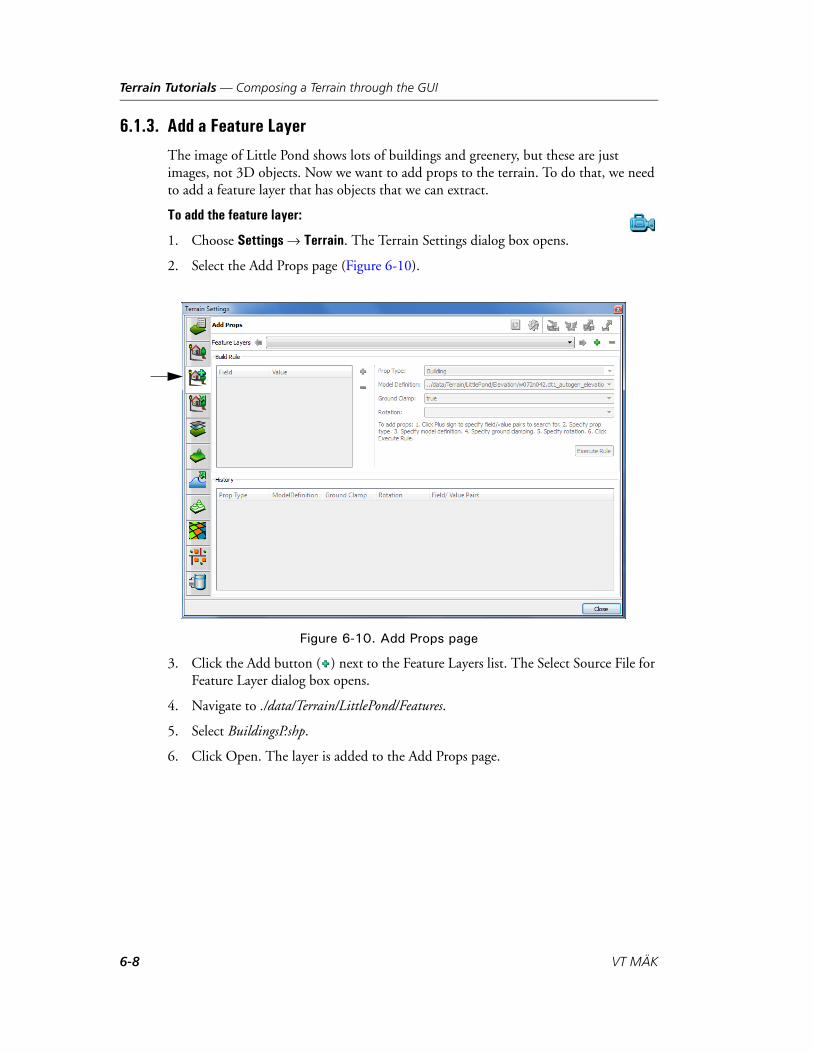
Terrain Tutorials — Composing a Terrain through the GUI
6.1.3. Add a Feature Layer
The image of Little Pond shows lots of buildings and greenery, but these are just images, not 3D objects. Now we want to add props to the terrain. To do that, we need to add a feature layer that has objects that we can extract.
To add the feature layer:
1. Choose Settings Terrain. The Terrain Settings dialog box opens.
2. Select the Add Props page (Figure 6-10).
Figure 6-10. Add Props page
3. Click the Add button ( ) next to the Feature Layers list. The Select Source File for Feature Layer dialog box opens.
4. Navigate to ./data/Terrain/LittlePond/Features.
5. Select BuildingsP.shp.
6. Click Open. The layer is added to the Add Props page.
6-8 VT MÄK

Terrain Tutorials — Composing a Terrain through the GUI
6.1.4. Add Props
When you add a prop, VR-Vantage extracts data from a feature layer and maps it to a model definition. You have to tell VR-Vantage what to extract and what to map it to. You do this by building a rule.
To build a rule and extract feature data:
1. In the Terrain Settings dialog box, on the Add Props page, in the Build Rule group box, click the Add button ( ) (Figure 6-11). The Build Field/Value Pair dialog box opens.
Figure 6-11. Add build rule
2. In the Field list, select TYPE.
3. In the Value list, select HousesColonialGarrison (Figure 6-12).
Figure 6-12. Build Field/Value Pair dialog box
4. Click OK.
5. On the Add Props page, in the Prop Type list, select the prop type for the rule. In this case, select Building.
VR-Vantage Configuration Guide 6-9
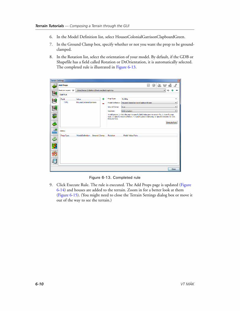
Terrain Tutorials — Composing a Terrain through the GUI
6. In the Model Definition list, select HousesColonialGarrisonClapboardGreen.
7. In the Ground Clamp box, specify whether or not you want the prop to be ground-clamped.
8. In the Rotation list, select the orientation of your model. By default, if the GDB or Shapefile has a field called Rotation or DtOrientation, it is automatically selected. The completed rule is illustrated in Figure 6-13.
Figure 6-13. Completed rule
9. Click Execute Rule. The rule is executed. The Add Props page is updated (Figure 6-14) and houses are added to the terrain. Zoom in for a better look at them (Figure 6-15). (You might need to close the Terrain Settings dialog box or move it out of the way to see the terrain.)
6-10 VT MÄK

Terrain Tutorials — Composing a Terrain through the GUI
Figure 6-14. Build rule implemented
Figure 6-15. Props added to terrain
If you want to, you can add more buildings by creating rules for some of the other building types available.
VR-Vantage Configuration Guide 6-11

Terrain Tutorials — Composing a Terrain through the GUI
Add Vegetation
We will continue the tutorial by adding another feature type.
To add vegetation to the terrain:
1. If the Terrain Settings dialog box is not open, choose Settings Terrain.
2. Select the Add Props page.
3. Click the Add button ( ) next to the Feature Layers list. The Select Source File for Feature Layer dialog box opens.
4. Select ./data/Terrain/LittlePond/features/VegetationP.shp.
5. Click Open. A new feature layer is added to the list.
6. In the Build Rule group box, click the Add button ( ). The Build Field/Value Pair dialog box opens.
7. In the field list, select VEG.
8. In the Value list, select TreesBigLeafMaple.
9. Click OK.
10. In the Prop Type list, select Tree.
11. In the Model Definition list, select TreesBigLeafMapleST. The build rule should look like Figure 6-16.
Figure 6-16. Rule for big leaf maples
12. Click Execute Rule. The page is updated and trees are added to the terrain (Figure 6-17).
6-12 VT MÄK

Terrain Tutorials — Creating a Terrain with an Earth File
Figure 6-17. Little Pond with maples
You can build additional rules to add other types of vegetation to the terrain. When you are done, you can create another feature layer with the architecture shapefile (Infrastruc-tureP.shp) and add light posts, fire hydrants, and street signs to the terrain.
6.2. Creating a Terrain with an Earth FileIn “Composing a Terrain through the GUI,” on page 6-2, we showed you how to compose a terrain by adding various terrain components in the VR-Vantage GUI and saving the resulting terrain as an MTF file. Another way to load terrain into VR-Vantage is by using a terrain server. Terrain servers are configured in earth files, which are XML files using osgEarth syntax. All the information that VR-Vantage needs to load elevation, imagery, and feature data is provided. The data can be stored locally or elsewhere on a network or the internet. Data is streamed over the network and paged in as needed.
In this tutorial we use the same local data we used for the Little Pond terrain in the previous tutorial, except that instead of adding the data through the GUI, we create an earth file to load it.
VR-Vantage comes with a terrain VR-theWorld Online - Little Pond.earth that merges the local Little Pond data with streaming terrain from VR-theWorld Server. For this tutorial we will ignore the rest of the world and focus on Little Pond.
One approach to creating an earth file is to start with one of the earth files provided with VR-Vantage, keep the basic structure, and add, edit, or replace elements as needed. For this tutorial, we will start from an empty file and build all the major elements.
VR-Vantage Configuration Guide 6-13

Terrain Tutorials — Creating a Terrain with an Earth File
6.2.1. Add a Map Element and Some Basic Options
The root element in an earth file is the map element. It encloses all other elements. Open a text editor and add the following code. It is the map element and some basic options that we use in most of our earth files. In particular, it specifies a location for the cache:
<map name="Little Pond" type="geocentric" version="2">
<options><lighting>true</lighting><elevation_interpolation>triangulate</elevation_interpolation><terrain>
<min_tile_range_factor>3</min_tile_range_factor><skirt_ratio>0.1</skirt_ratio>
</terrain><cache type="filesystem">
<path>../../appData/cache</path></cache>
</options>
</map>
6.2.2. Add Elevation Data to the Earth File
Elevation data is configured using an elevation element. We want to specify the same elevation data here that we did in the previous Little Pond tutorial. Add the following text after the map element, but before the options element:
<elevation name="Little Pond Elevation" driver = "gdal"><url>../../data/Terrain/LittlePond/Elevation/w072n042.dt1</url><tile_size>32</tile_size>
</elevation>
The location of data in an earth file is provided in a url element. We need to use the gdal driver to load elevation data.
6-14 VT MÄK

Terrain Tutorials — Creating a Terrain with an Earth File
6.2.3. Add Imagery to the Earth File
Image data is configured using image elements. Add the following text after the elevation block:
<image driver="composite"><image name="Little Pond Imagery" driver="gdal">
<url>../../data/Terrain/LittlePond/Imagery/W72N42.tif</url></image>
<image name="Little Pond Imagery" driver="gdal">
<url>../../data/Terrain/LittlePond/Imagery/LittlePond.tif</url></image>
</image>
The Little Pond terrain has two image files, a large low-resolution image and a smaller higher resolution image. If we were to simply add two image elements to the earth file, only the last one listed would be loaded. We would only see one of the images.
To use more than one image, we place an image element for each image file inside an image element that uses a composite driver. List the images from bottom most to topmost. If you list them in the opposite order from the code, LittlePond.tif would be underneath W72N42.tif and you would not be able to see it.
We use the gdal driver to load the images.
6.2.4. Add Feature Data to the Earth File
In earth files, you add feature data, such as buildings and vegetation, using a model element. You can add as many model elements as you need. A model element specifies the location of a shapefile. Then it adds style elements for each feature type to add from the shapefile. In the previous Little Pond tutorial, we added feature layers using BuildingsP.shp and VegetationP.shp. Then we added one kind of building (green colonial garrison house) and one kind of plant (big leaf maple tree). In this tutorial we will add one kind of house and all of the vegetation in the shapefile.
VR-Vantage Configuration Guide 6-15
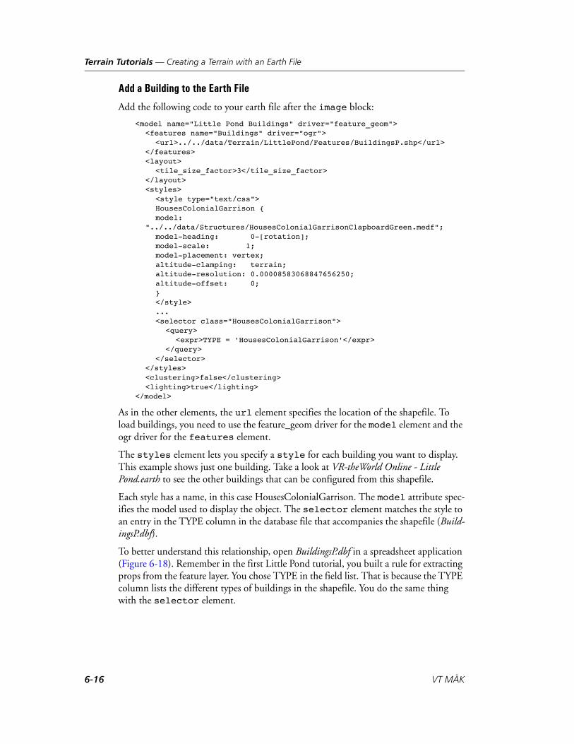
Terrain Tutorials — Creating a Terrain with an Earth File
Add a Building to the Earth File
Add the following code to your earth file after the image block:
<model name="Little Pond Buildings" driver="feature_geom"><features name="Buildings" driver="ogr">
<url>../../data/Terrain/LittlePond/Features/BuildingsP.shp</url></features><layout>
<tile_size_factor>3</tile_size_factor></layout><styles>
<style type="text/css">HousesColonialGarrison {model:
"../../data/Structures/HousesColonialGarrisonClapboardGreen.medf";model-heading: 0-[rotation];model-scale: 1;model-placement: vertex;altitude-clamping: terrain;altitude-resolution: 0.00008583068847656250;altitude-offset: 0;}</style>... <selector class="HousesColonialGarrison">
<query><expr>TYPE = 'HousesColonialGarrison'</expr>
</query></selector>
</styles><clustering>false</clustering><lighting>true</lighting>
</model>
As in the other elements, the url element specifies the location of the shapefile. To load buildings, you need to use the feature_geom driver for the model element and the ogr driver for the features element.
The styles element lets you specify a style for each building you want to display. This example shows just one building. Take a look at VR-theWorld Online - Little Pond.earth to see the other buildings that can be configured from this shapefile.
Each style has a name, in this case HousesColonialGarrison. The model attribute spec-ifies the model used to display the object. The selector element matches the style to an entry in the TYPE column in the database file that accompanies the shapefile (Build-ingsP.dbf).
To better understand this relationship, open BuildingsP.dbf in a spreadsheet application (Figure 6-18). Remember in the first Little Pond tutorial, you built a rule for extracting props from the feature layer. You chose TYPE in the field list. That is because the TYPE column lists the different types of buildings in the shapefile. You do the same thing with the selector element.
6-16 VT MÄK
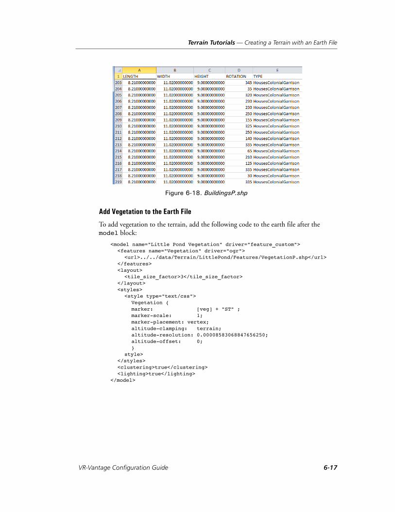
Terrain Tutorials — Creating a Terrain with an Earth File
Figure 6-18. BuildingsP.shp
Add Vegetation to the Earth File
To add vegetation to the terrain, add the following code to the earth file after the model block:
<model name="Little Pond Vegetation" driver="feature_custom"><features name="Vegetation" driver="ogr">
<url>../../data/Terrain/LittlePond/Features/VegetationP.shp</url></features><layout>
<tile_size_factor>3</tile_size_factor></layout><styles>
<style type="text/css">Vegetation {marker: [veg] + "ST" ;marker-scale: 1;marker-placement: vertex;altitude-clamping: terrain;altitude-resolution: 0.00008583068847656250;altitude-offset: 0;}
style></styles><clustering>true</clustering><lighting>true</lighting>
</model>
VR-Vantage Configuration Guide 6-17
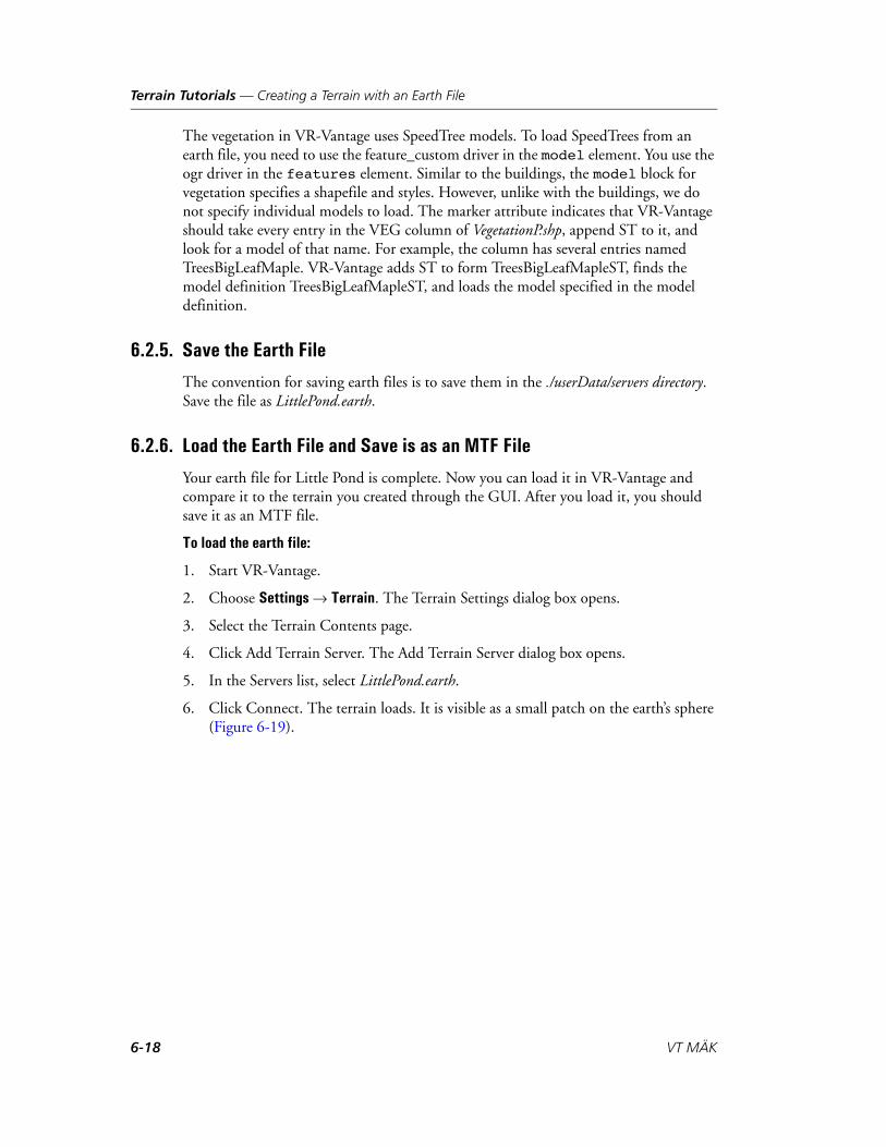
Terrain Tutorials — Creating a Terrain with an Earth File
The vegetation in VR-Vantage uses SpeedTree models. To load SpeedTrees from an earth file, you need to use the feature_custom driver in the model element. You use the ogr driver in the features element. Similar to the buildings, the model block for vegetation specifies a shapefile and styles. However, unlike with the buildings, we do not specify individual models to load. The marker attribute indicates that VR-Vantage should take every entry in the VEG column of VegetationP.shp, append ST to it, and look for a model of that name. For example, the column has several entries named TreesBigLeafMaple. VR-Vantage adds ST to form TreesBigLeafMapleST, finds the model definition TreesBigLeafMapleST, and loads the model specified in the model definition.
6.2.5. Save the Earth File
The convention for saving earth files is to save them in the ./userData/servers directory. Save the file as LittlePond.earth.
6.2.6. Load the Earth File and Save is as an MTF File
Your earth file for Little Pond is complete. Now you can load it in VR-Vantage and compare it to the terrain you created through the GUI. After you load it, you should save it as an MTF file.
To load the earth file:
1. Start VR-Vantage.
2. Choose Settings Terrain. The Terrain Settings dialog box opens.
3. Select the Terrain Contents page.
4. Click Add Terrain Server. The Add Terrain Server dialog box opens.
5. In the Servers list, select LittlePond.earth.
6. Click Connect. The terrain loads. It is visible as a small patch on the earth’s sphere (Figure 6-19).
6-18 VT MÄK
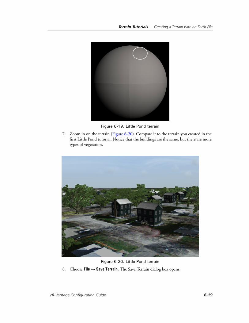
Terrain Tutorials — Creating a Terrain with an Earth File
Figure 6-19. Little Pond terrain
7. Zoom in on the terrain (Figure 6-20). Compare it to the terrain you created in the first Little Pond tutorial. Notice that the buildings are the same, but there are more types of vegetation.
Figure 6-20. Little Pond terrain
8. Choose File Save Terrain. The Save Terrain dialog box opens.
VR-Vantage Configuration Guide 6-19
Terrain Tutorials — Extracting Props from a Terrain
9. Give the terrain a name. Do not use Little Pond unless you want to overwrite the Little Pond terrain provided with VR-Vantage.
6.3. Extracting Props from a TerrainIn the tutorial “Composing a Terrain through the GUI,” on page 6-2, we extract props from a feature layer by building a rule in the Add Props page. In this tutorial, we demonstrate the other way to create a prop – by extracting information from a terrain.
The general steps for extracting props from a terrain are:
1. Create a new terrain with a terrain patch (“Create a New Terrain and Add a Terrain Patch,” on page 6-20).
2. Select the external references that you want to extract as props and extract them (“Extract the Props,” on page 6-21).
3. Optionally, change the model definitions (“Change the Model Definition for a Prop,” on page 6-23).
6.3.1. Create a New Terrain and Add a Terrain Patch
To create the new terrain and add a terrain database:
1. Choose File New Terrain. If any terrain data is loaded, it is removed.
2. Choose File Add Terrain Patch. The Add Terrain Patch dialog box opens and an Open dialog box opens on top of it.
3. Navigate to the ./data/Terrain/Makland/Geometry/OpenFlight directory.
4. Select Makland.flt.
5. In the Add Terrain Patch dialog box, click OK. The terrain is loaded.
6-20 VT MÄK

Terrain Tutorials — Extracting Props from a Terrain
6.3.2. Extract the Props
To extract the props:
1. Move the observer so that you have a view of the plateau in Makland similar to Figure 6-21.
Figure 6-21. Makland
2. Click on the trees or buildings in the scene. Notice that you cannot select them. They are part of the terrain; they do not exist as props.
3. Choose Settings Terrain. The Terrain Settings dialog box opens.
4. Select the Extract Props page (Figure 6-22). On the Extract References tab, the External References window lists all of the objects in the terrain that are incorpo-rated into the terrain by reference. These are the objects that you can extract as props. You can extract them individually. For this tutorial, we will extract all of them.
VR-Vantage Configuration Guide 6-21
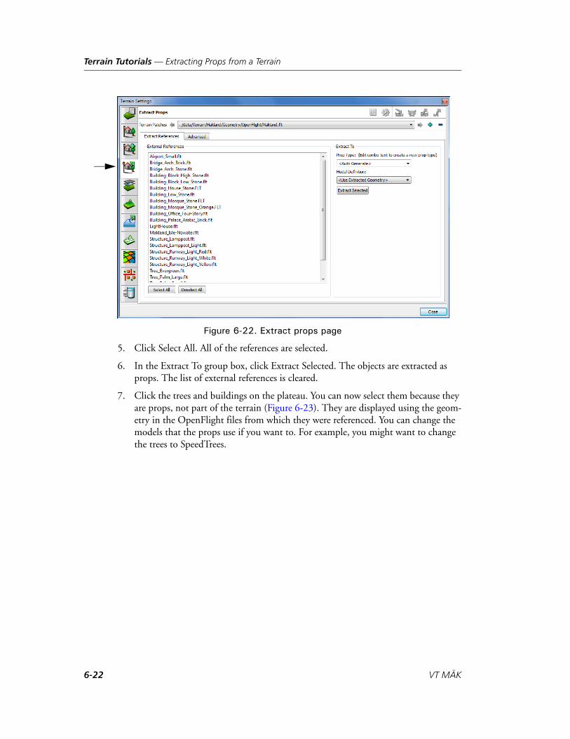
Terrain Tutorials — Extracting Props from a Terrain
Figure 6-22. Extract props page
5. Click Select All. All of the references are selected.
6. In the Extract To group box, click Extract Selected. The objects are extracted as props. The list of external references is cleared.
7. Click the trees and buildings on the plateau. You can now select them because they are props, not part of the terrain (Figure 6-23). They are displayed using the geom-etry in the OpenFlight files from which they were referenced. You can change the models that the props use if you want to. For example, you might want to change the trees to SpeedTrees.
6-22 VT MÄK
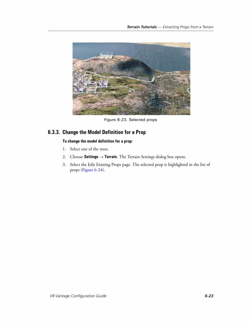
Terrain Tutorials — Extracting Props from a Terrain
Figure 6-23. Selected props
6.3.3. Change the Model Definition for a Prop
To change the model definition for a prop:
1. Select one of the trees.
2. Choose Settings Terrain. The Terrain Settings dialog box opens.
3. Select the Edit Existing Props page. The selected prop is highlighted in the list of props (Figure 6-24).
VR-Vantage Configuration Guide 6-23
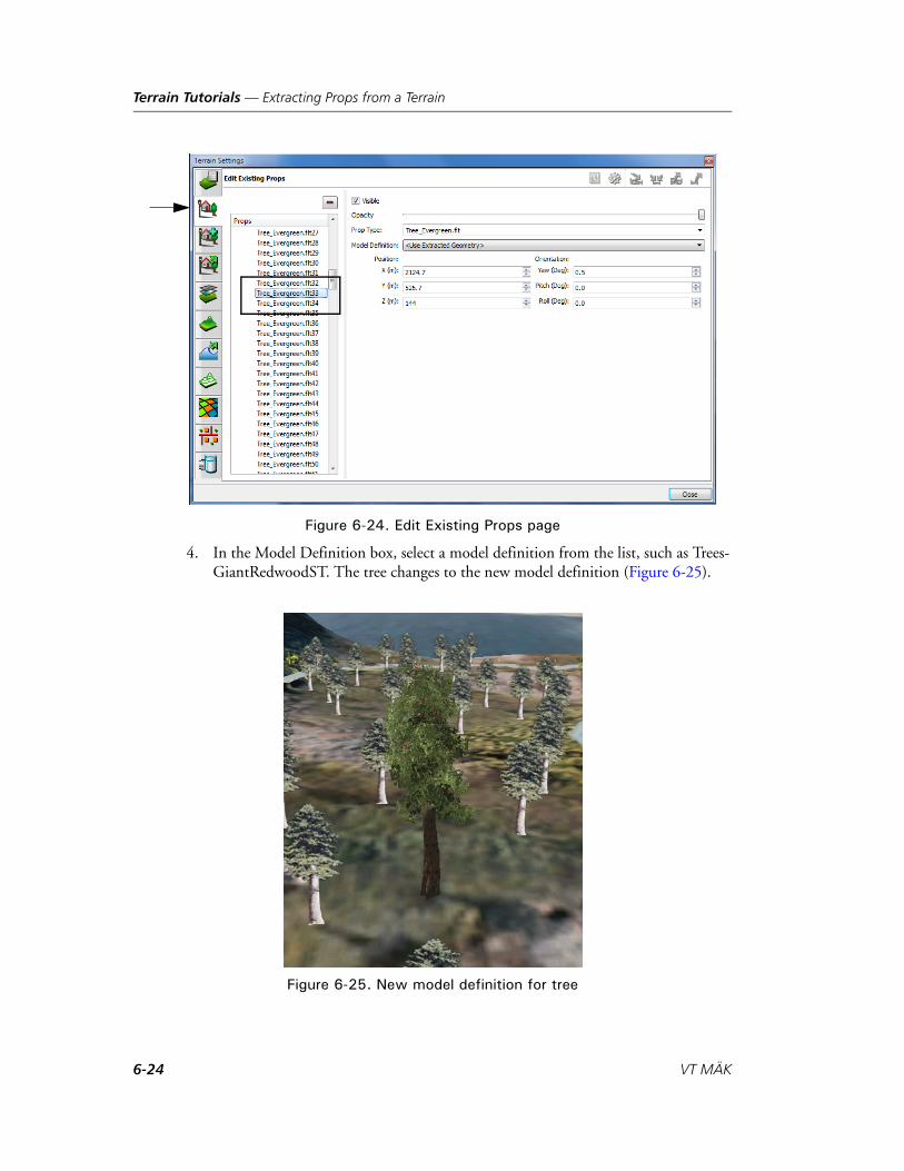
Terrain Tutorials — Extracting Props from a Terrain
Figure 6-24. Edit Existing Props page
4. In the Model Definition box, select a model definition from the list, such as Trees-GiantRedwoodST. The tree changes to the new model definition (Figure 6-25).
Figure 6-25. New model definition for tree
6-24 VT MÄK

Terrain Tutorials — Extracting Props from a Terrain
5. To restore the tree to its original model, on the Edit Existing Props page, change the model definition to Use Extracted Geometry.
VR-Vantage Configuration Guide 6-25
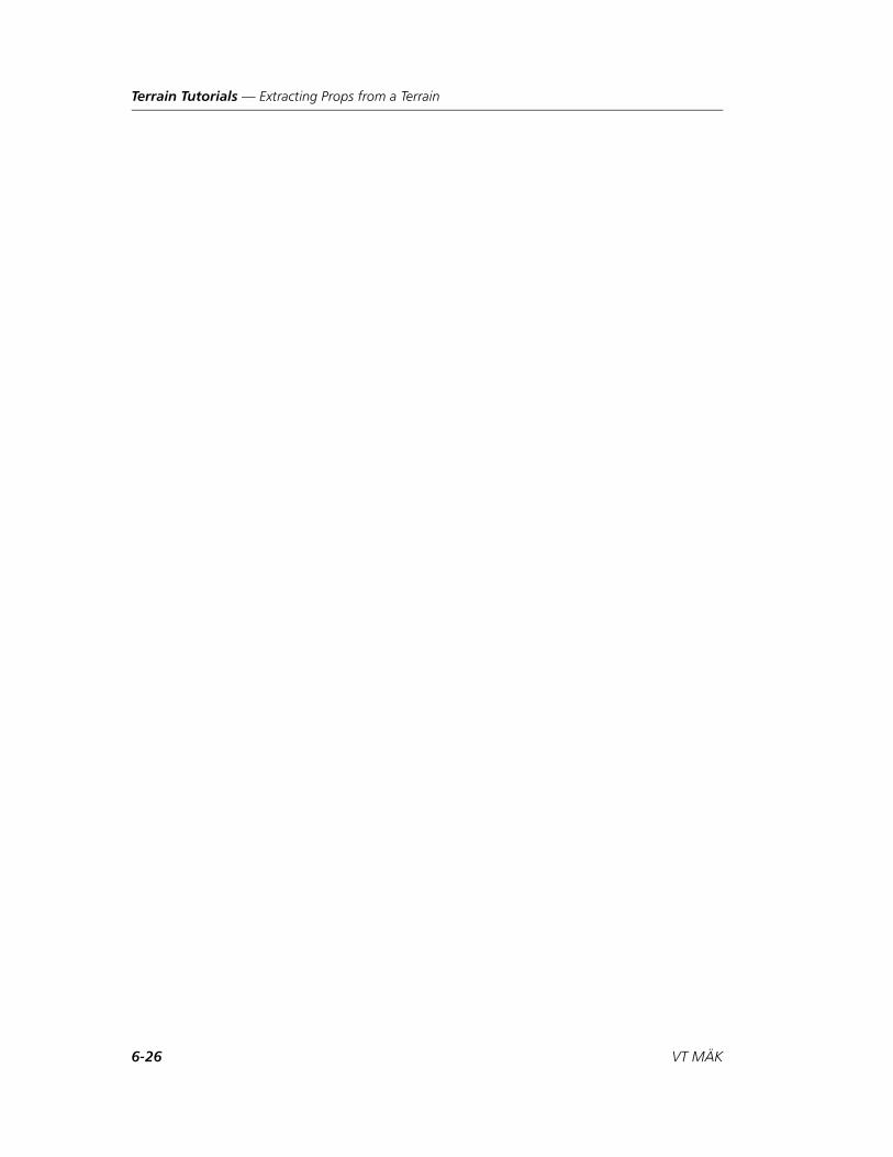
Terrain Tutorials — Extracting Props from a Terrain
6-26 VT MÄK
VR-V
7. Processing MetaFlight Files
To display MetaFlight files in VR-Vantage applications, you must first process them. This chapter explains how to do so.
Processing MetaFlight Files for Use in VR-Vantage ....................................... 7-2
Splitting Datasets into Individual MetaFlight Files........................................ 7-2
Converting Virtual Texture Datasets to Tiled Textures .................................. 7-3The mftTool........................................................................................... 7-3Using the mftTool to Process MetaFlight Files........................................ 7-5Convert Geometry Grid Datasets with Tiled Textures ............................ 7-6
Convert Source Data into MEDF Format..................................................... 7-6
Create an MTF File for the MetaFlight Terrain............................................. 7-7
7-1antage Configuration Guide
Processing MetaFlight Files — Processing MetaFlight Files for Use in VR-Vantage
7.1. Processing MetaFlight Files for Use in VR-VantageBefore you can load a MetaFlight file in a VR-Vantage application, you must process it as described in this chapter. If you try to load an unprocessed MetaFlight file, VR-Vantage displays an error message. When running our processing tools, a MetaFlight database which does not conform will cause an error message to be sent to the console window.
To process a MetaFlight file, you must:
1. Convert source data into MEDF and MEIF format.
2. Split each dataset into its own MetaFlight file.
3. Convert geometry from using virtual texture datasets into using tiled textures. (If the terrain does not use virtual textures, you can skip this step.)
4. Use the VR-Vantage terrain composition process to combine the MetaFlight terrain files and save them in MTF format.
7.2. Splitting Datasets into Individual MetaFlight FilesOur tools work on one Geometry Grid Dataset (GGDS) at a time. Some MetaFlight files contain multiple GGDSs, so each one has to be moved into its own file. It is your responsibility to understand the syntax of the MetaFlight file and to know whether or not you need to split up datasets.
To split datasets:
1. Create a copy of the original file for each dataset. Give each a name that will iden-tify which dataset it contains.
2. Open each copy of the original file in a text editor.
3. In each file, delete all of the <GeometryGridDataset> XML element blocks except the one for the dataset you want to have in this file.
When you are finished, each MetaFlight file will have only one GGDS and possibly one or more Virtual Texture Datasets (VTDS).
i Geometry files referenced by a MetaFlight file must be in OpenFlight format, and not in Vega Prime's binary format (.vsb). MÄK’s terrain libraries do not support VSB files.
7-2 VT MÄK

Processing MetaFlight Files — Converting Virtual Texture Datasets to Tiled Textures
7.3. Converting Virtual Texture Datasets to Tiled TexturesThe display engine does not handle virtual textures at runtime. Therefore you must convert the virtual texture datasets into tiled textures.
7.3.1. The mftTool
The mftTool is a command-line tool for converting virtual texture datasets into tiled textures so that they can be loaded by VR-Vantage. It creates the highest resolution textures possible from the virtual texture dataset and binds them to individual tiles.
The syntax for mftTool is as follows:
mftTool -f filename [-c index -w index -l index -m string -r path ... -x size -s directory -t filename -A -g -e -u -p threads --extendLevelZero distance -- -v -h]
Table 7-1 describes the command-line options.
Table 7-1: mftTool command-line options
Option Description
(-- | --ignore_rest) Ignore all arguments after this one.
(-A | --regenerateAll) Forces the regeneration of all Tiled Textures. This can be much slower and is needed less frequently if the Virtual Texture Dataset does not change.
(-c | --col) index The column to convert, using a zero-based index.
(-e | --encryptImages) The Tiled Textures will be generated in the MEIF file format. If not specified the file format will be DDS.
--extendLevelZero distance Specifies the page-in range (in meters) of grid level zero in the MEDF and MetaFlight files that the mftTool creates. Use of this option is indi-cated if the terrain disappears when you zoom out, particularly in PVD mode. Increasing the range causes the terrain to page in at a greater distance.
(-f | --file) filename The name of the MetaFlight file which contains the GGDS.
VR-Vantage Configuration Guide 7-3
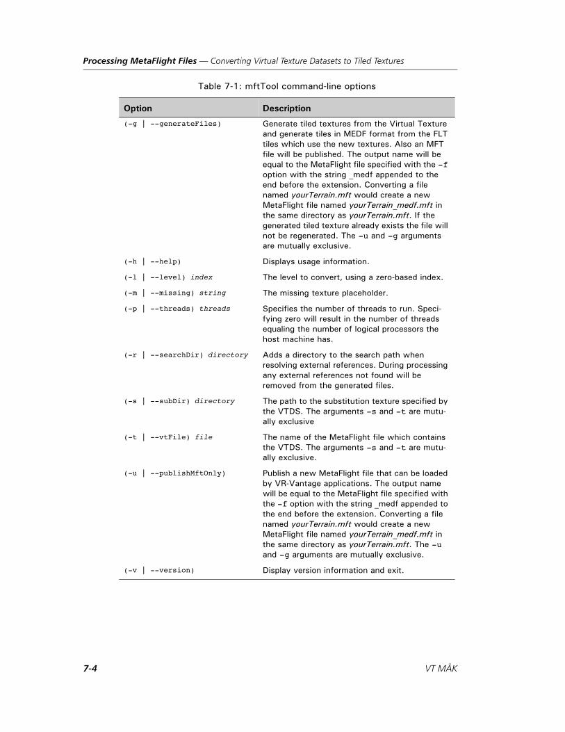
Processing MetaFlight Files — Converting Virtual Texture Datasets to Tiled Textures
(-g | --generateFiles) Generate tiled textures from the Virtual Texture and generate tiles in MEDF format from the FLT tiles which use the new textures. Also an MFT file will be published. The output name will be equal to the MetaFlight file specified with the -f option with the string _medf appended to the end before the extension. Converting a file named yourTerrain.mft would create a new MetaFlight file named yourTerrain_medf.mft in the same directory as yourTerrain.mft. If the generated tiled texture already exists the file will not be regenerated. The -u and -g arguments are mutually exclusive.
(-h | --help) Displays usage information.
(-l | --level) index The level to convert, using a zero-based index.
(-m | --missing) string The missing texture placeholder.
(-p | --threads) threads Specifies the number of threads to run. Speci-fying zero will result in the number of threads equaling the number of logical processors the host machine has.
(-r | --searchDir) directory Adds a directory to the search path when resolving external references. During processing any external references not found will be removed from the generated files.
(-s | --subDir) directory The path to the substitution texture specified by the VTDS. The arguments -s and -t are mutu-ally exclusive
(-t | --vtFile) file The name of the MetaFlight file which contains the VTDS. The arguments -s and -t are mutu-ally exclusive.
(-u | --publishMftOnly) Publish a new MetaFlight file that can be loaded by VR-Vantage applications. The output name will be equal to the MetaFlight file specified with the -f option with the string _medf appended to the end before the extension. Converting a file named yourTerrain.mft would create a new MetaFlight file named yourTerrain_medf.mft in the same directory as yourTerrain.mft. The -u and -g arguments are mutually exclusive.
(-v | --version) Display version information and exit.
Table 7-1: mftTool command-line options
Option Description
7-4 VT MÄK

Processing MetaFlight Files — Converting Virtual Texture Datasets to Tiled Textures
If neither the generate (-g) or the publish only (-u) argument is specified, mftTool prints out information regarding the MetaFlight terrain.
7.3.2. Using the mftTool to Process MetaFlight Files
To process a terrain with a single MetaFlight terrain file that has one GGDS and one VTDS, run the mftTool as follows:
mftTool -f C:\yourTerrain\yourTerrain.mft -s C:\yourTerrain\ds200-vt-otw-virtual-texture -g -A -e
The following example shows how to process a terrain with two MetaFlight terrain files, one with the GGDS and one with the VTDS. In this case, the tiles also contain external references to other OpenFlight models.
mftTool -f C:\yourTerrain\ds100-flight-terrain\ds100-flight.mft -t C:\yourTerrain\ds200-vt-otw-virtual-tex-ture\ds200-vt.mft -r C:\yourTerrain\textures -r C:\your-Terrain\objects -m C:\yourTerrain\MissingTexture.png -x 4096 -g
This creates a new MetaFlight file that references the new geometry grid dataset with virtual textures bound to it.
(-w | --row) index The row to convert, using a zero-based index.
(-x | --textureSize) size Specifies the maximum texture size to generate in pixels per dimension. Larger textures use more memory and are slower to page in, but allow for greater virtual texture resolution.
Table 7-1: mftTool command-line options
Option Description
VR-Vantage Configuration Guide 7-5

Processing MetaFlight Files — Convert Source Data into MEDF Format
7.3.3. Convert Geometry Grid Datasets with Tiled Textures
The mftTool only needs to publish the MFT when the GGDS uses tiled textures. Cultural feature datasets are often built this way. These can be converted using the medfTool like all other files. The command syntax for the medfTool is described in “Compressing Model Files,” on page 10-7.
To only publish a new MetaFlight for the cultural dataset, do the following:
mftTool C:\yourTerrain\flt\ds7_culture_db5_building_area_new-hier_cult\ds7_culture_db5_building.mft -u -p 0
To convert a MetaFlight with tiled textures into a compressed format, use the medf-Tool, as follows:
medfTool -s C:\yourTerrain\flt\textures -s C:\yourTerrain\flt\objects --directory C:\yourTerrain\flt\ds7_culture_db5_building_area_new-hier_cult -x flt -m rgb -m rgba -m jpg -m bmp -p 0 -z 1
7.4. Convert Source Data into MEDF FormatMany file formats, including OpenFlight files, are often slow to load so it is best to convert them to our fast loading MEDF (MAK Encrypted Data Format) format. This should be done on terrains without virtual textures (it is done automatically when creating Geometry Grid Datasets from virtual texture datasets) and on cultural feature datasets. This should be done on all data files being loaded, but is required by all external references used by MetaFlight terrains.
To convert external references in separate directories:
medfTool -s C:\yourTerrain\flt\textures --directory C:\yourTerrain\flt\objects -x flt -m rgb -m rgba -m jpg -m bmp -p 0 -z 1
To convert external reference textures that are in the same directory:
medfTool --directory C:\yourTerrain\flt\textures -m rgb-m rgba -m jpg -m bmp -p 0 -z 1
! The medfTool should never be run on a directory that contains GGDS tiles that use Virtual Textures.
! You must convert the files to MEDF and MEIF before you run the mftTool.
7-6 VT MÄK
Processing MetaFlight Files — Create an MTF File for the MetaFlight Terrain
7.5. Create an MTF File for the MetaFlight TerrainOnce you have processed all of the MetaFlight files, create an MTF file for the terrain.
To create an MTF file for the MetaFlight terrain:
1. Start any VR-Vantage application.
2. Add each MetaFlight terrain as a terrain patch.
3. Save the terrain as an MFT terrain.
i Any missing models or white objects usually indicate missing external references. Fixing any missing search paths passed to the tools should resolve most problems.
VR-Vantage Configuration Guide 7-7

Processing MetaFlight Files — Create an MTF File for the MetaFlight Terrain
7-8 VT MÄK

VR-V
8. Model and Element Definitions
In Section 4.5, “Introduction to VR-Vantage Object Modeling,”, in VR-Vantage Users Guide, we describe the interplay of schemas, model definitions, element definitions, and model mapping. This chapter explains how to create and edit model definitions, element definitions, and model schemas. “Adding a Model to VR-Vantage,” on page 9-2 walks you through the process of adding a model.
Creating and Editing Schemas ...................................................................... 8-3Creating Schemas ................................................................................... 8-4Deleting Schemas ................................................................................... 8-5Copying Schemas ................................................................................... 8-5Adding a Parameter to a Schema ............................................................ 8-6Deleting a Parameter from a Schema ...................................................... 8-7Editing a Schema Parameter ................................................................... 8-7
Creating and Editing Model Definitions ....................................................... 8-8Creating a Model Definition .................................................................. 8-9Deleting a Model Definition ................................................................ 8-10Copying a Model Definition ................................................................ 8-11Filtering the List of Model Definitions ................................................. 8-11Editing a Model Definition .................................................................. 8-12Saving Model Definitions..................................................................... 8-14
Creating and Editing Element Definitions .................................................. 8-14Creating an Element Definition ........................................................... 8-15Editing an Element Definition ............................................................. 8-16Deleting an Element Definition ........................................................... 8-20Saving Element Definitions .................................................................. 8-20
Configuring 2D Icons................................................................................. 8-21Editing Font-Based 2D Icons ............................................................... 8-21
8-1antage Configuration Guide

Model and Element Definitions
Using Images for 2D Icons ................................................................... 8-23Adding Images for Entities ................................................................... 8-28
Adding New Cockpit Display Models......................................................... 8-29Installing a Cockpit DLL ..................................................................... 8-30Creating a Model Definition for a Cockpit........................................... 8-30
Configuring Wakes ..................................................................................... 8-32Configuring Tidal Stream Wakes.......................................................... 8-35
Adding Wind-based Controls to Models..................................................... 8-35
Flipping DDS Textures for a Model............................................................ 8-36
Configuring SpeedTree Trees ...................................................................... 8-37Randomizing the Size of SpeedTrees..................................................... 8-39
Best Practices for Creating Models for VR-Vantage..................................... 8-41
8-2 VT MÄK

Model and Element Definitions — Creating and Editing Schemas
8.1. Creating and Editing SchemasThe elements that make up a scene have parameters that help define them, for example a model filename. The set of parameters for a particular scene element is a schema. VR-Vantage uses schemas to validate element definitions. You can create, copy, and delete schemas. For any schema, you can add and delete parameters and edit parameter values.
Model definition schemas define the elements that can be displayed in a scene. The model definition schemas provided with VR-Vantage are:
3DText
Animation
Channel Compass
Cockpit Display
ControlLine
ControlPoint
ControlPrism
Cuboid
Cylinder
Decal
DiGuyCharacter
EllipsoidArc
Entity
GreatCircleArc
GridLines
Line
ParticleSystem
Ribbon
SpeedTree
TacticalSmoke
Terrain
Tree
WidgetTheme.
i Changes to schemas are saved automatically. For more information, please see Section 3.5, “Managing VR-Vantage Settings,” in VR-Vantage Users Guide.
If you are connected to an exercise, changes to element definitions do not take effect until you disconnect and reconnect.
VR-Vantage Configuration Guide 8-3

Model and Element Definitions — Creating and Editing Schemas
8.1.1. Creating Schemas
To create a schema:
1. Choose Settings Visual Model Editors. The Visual Model Editors dialog box opens.
2. Select the Schema Editor page (Figure 8-1).
Figure 8-1. Schema Editor page
3. Click the Add button ( ) next to the Schemas label. The Create Instance dialog box opens (Figure 8-2).
Figure 8-2. Create Instance dialog box
4. Type a name for the new schema.
5. Click OK.
6. Add parameters as described in “Adding a Parameter to a Schema,” on page 8-6.
8-4 VT MÄK
Model and Element Definitions — Creating and Editing Schemas
8.1.2. Deleting Schemas
To delete a schema:
1. Choose Settings Visual Model Editors. The Visual Model Editors dialog box opens.
2. Select the Schema Editor page (Figure 8-1).
3. In the Schemas list, select the schema you want to delete.
4. Click the Delete button ( ) next to the Schemas label. You are prompted to confirm the deletion.
5. Click Yes. The schema is removed from the list.
8.1.3. Copying Schemas
If you want a new schema that is a variant of an existing one, it can be easier to copy the existing schema and edit it than it is to create a new schema and add all of the parame-ters.
To copy a schema:
1. Choose Settings Visual Model Editors. The Visual Model Editors dialog box opens.
2. Select the Schema Editor page (Figure 8-1).
3. Select the schema that you want to copy.
4. Click the Duplicate button ( ). The Duplicate Schema dialog box opens.
5. Type a name for the copied version of the schema.
6. Click OK.
7. The new schema is added to the list.
8. Edit the parameters as described in “Editing a Schema Parameter,” on page 8-7.
i If a schema is used by a model definition, you cannot delete it. The Delete Schema button will be unavailable.
VR-Vantage Configuration Guide 8-5

Model and Element Definitions — Creating and Editing Schemas
8.1.4. Adding a Parameter to a Schema
To add a parameter to a schema:
1. Choose Settings Visual Model Editors. The Visual Model Editors dialog box opens.
2. Select the Schema Editor page (Figure 8-1).
3. In the Schemas list, select the schema to which you want to add a parameter.
4. Click the Add button ( ) next to the Entries label. A parameter called “key” is added to the parameter list (Figure 8-3).
Figure 8-3. New schema parameter
5. Double-click “key”. The Rename Parameter dialog box opens.
6. Type a name for the parameter.
7. If the parameter has a specific type, click the value in the Type column and edit it.
8. If the parameter is required, click the value in the Required column and change it to True.
9. Optionally, add a description. The description provides context sensitive help on the element definition pages. To add a description:
a. Click the empty field in the Description column. The Edit Text dialog box opens.
b. Type the descriptive text.
c. Click OK.
8-6 VT MÄK
Model and Element Definitions — Creating and Editing Schemas
8.1.5. Deleting a Parameter from a Schema
To delete a parameter from a schema:
1. Choose Settings Visual Model Editors. The Visual Model Editors dialog box opens.
2. Select the Schema Editor page (Figure 8-1).
3. In the Schemas list, select the schema from which you want to delete a parameter.
4. Select the parameter that you want to delete.
5. Click the Delete button ( ) next to the Entries label.
8.1.6. Editing a Schema Parameter
To edit a parameter for a schema:
1. Choose Settings Visual Model Editors. The Visual Model Editors dialog box opens.
2. Select the Schema Editor page (Figure 8-1).
3. In the Schemas list, select the schema for which you want to edit a parameter.
4. Click the parameter attribute that you want to edit. The attribute becomes edit-able.
5. Type the new attribute value.
! If you delete a parameter from a schema, any element definitions that use the schema may become invalid. Invalid element definitions are shown in red in the list of definitions.
VR-Vantage Configuration Guide 8-7
Model and Element Definitions — Creating and Editing Model Definitions
8.2. Creating and Editing Model DefinitionsMany of the visual definitions in an element definition have a model definition param-eter. A model definition specifies a set of parameters that are appropriate to the object type. (The parameters are determined by the model definition’s schema. For informa-tion about model schemas, please see “Creating and Editing Schemas,” on page 8-3.) For most VR-Vantage users, the most important thing to know about model definitions is that for 3D models, the model definition specifies the 3D model, such as an Open-Flight file, that is used to display an entity. If you want to add new models to VR-Vantage, you will probably have to create a new model definition for each one.
VR-Vantage comes with an extensive set of model definitions that are mapped to the included models. You can edit or delete these model definitions and you can create new ones.
Model definitions are created and edited on the Model Definition Editor page of the Visual Model Editors dialog box (Figure 8-4).
Figure 8-4. Model Definition Editor page
8-8 VT MÄK

Model and Element Definitions — Creating and Editing Model Definitions
8.2.1. Creating a Model Definition
To create a model definition:
1. Choose Settings Visual Model Editors. The Visual Model Editors dialog box opens.
2. Select the Model Definition Editor page (Figure 8-4).
3. Optionally, filter the model definitions in the list. (For details, please see “Filtering the List of Model Definitions,” on page 8-11.)
4. Click the Add button ( ) next to the Model Definitions label. The Add Model Definition dialog box opens (Figure 8-5).
Figure 8-5. Add Model Definition dialog box
5. Type a name for the new model definition.
6. In the Schema list, select a schema for the model. (This list matches the list of schemas on the Schemas page.)
7. Add parameters to the model, as described in “Adding Parameters to a Model Defi-nition,” on page 8-12.
! Model definitions for DI-Guy characters must end with the letters DIG. Model definitions for SpeedTrees must end in ST.
VR-Vantage Configuration Guide 8-9
Model and Element Definitions — Creating and Editing Model Definitions
8.2.2. Deleting a Model Definition
To delete a model definition:
1. Choose Settings Visual Model Editors. The Visual Model Editors dialog box opens.
2. Select the Model Definition Editor page (Figure 8-4).
3. Optionally, filter the model definitions in the list. (For details, please see “Filtering the List of Model Definitions,” on page 8-11.)
4. Select the model that you want to delete.
5. Click the Delete button ( ) next to the Model Definitions label. You are prompted to confirm the deletion.
6. Click Yes. The model definition is removed from the list.
i If a model definition is being used, you cannot delete it.
8-10 VT MÄK
Model and Element Definitions — Creating and Editing Model Definitions
8.2.3. Copying a Model Definition
If you want a new model that is a variant of an existing one, it can be easier to copy the existing model and edit it, than to create a new model and add all of the parameters.
To copy a model definition:
1. Choose Settings Visual Model Editors. The Visual Model Editors dialog box opens.
2. Select the Model Definition Editor page (Figure 8-4).
3. Optionally, filter the model definitions in the list. (For details, please see “Filtering the List of Model Definitions,” on page 8-11.)
4. Select the model that you want to copy.
5. Click the Duplicate button ( ). The Duplicate Model Definition dialog box opens (Figure 8-6).
Figure 8-6. Copy model definition
6. Type a name for the copied version of the model.
7. Click OK.
8. The new model definition is added to the list.
9. Edit the parameters as described in “Editing a Model Definition,” on page 8-12.
8.2.4. Filtering the List of Model Definitions
By default, the Model Definition Editor page lists all models that VR-Vantage knows about. You can filter the list to more easily work with a specific type of model.
To filter the list of model definitions, click the Filter button ( ) and select a schema type from the list.
VR-Vantage Configuration Guide 8-11

Model and Element Definitions — Creating and Editing Model Definitions
8.2.5. Editing a Model Definition
You can add parameters to a model definition, you can delete parameters, and you can change their values. You can only add parameters that are appropriate to the schema type for a model.
Adding Parameters to a Model Definition
When you create a new model definition, you must specify the parameters required by its schema. You can only add parameters that are permitted by the schema.
To add a parameter to a model:
1. Choose Settings Visual Model Editors. The Visual Model Editors dialog box opens.
2. Select the Model Definition Editor page (Figure 8-4).
3. Optionally, filter the model definitions in the list. (For details, please see “Filtering the List of Model Definitions,” on page 8-11.)
4. Select the model for which you want to add a parameter.
5. Click the Add Parameter button ( ). A list of parameters is displayed (Figure 8-7).
Figure 8-7. Add parameter list
6. Select the parameter you want to add. It is added to the parameter list.
i If you change the model definition for an entity that is already in the scene, the updated definition is not applied to the entity. To apply an edited model definition to all entities, disconnect from the exercise and then reconnect.
8-12 VT MÄK
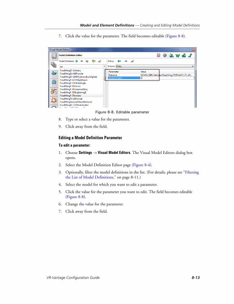
Model and Element Definitions — Creating and Editing Model Definitions
7. Click the value for the parameter. The field becomes editable (Figure 8-8).
Figure 8-8. Editable parameter
8. Type or select a value for the parameter.
9. Click away from the field.
Editing a Model Definition Parameter
To edit a parameter:
1. Choose Settings Visual Model Editors. The Visual Model Editors dialog box opens.
2. Select the Model Definition Editor page (Figure 8-4).
3. Optionally, filter the model definitions in the list. (For details, please see “Filtering the List of Model Definitions,” on page 8-11.)
4. Select the model for which you want to edit a parameter.
5. Click the value for the parameter you want to edit. The field becomes editable (Figure 8-8).
6. Change the value for the parameter.
7. Click away from the field.
VR-Vantage Configuration Guide 8-13

Model and Element Definitions — Creating and Editing Element Definitions
Deleting Parameters from a Model Definition
To delete a parameter from a model:
1. Choose Settings Visual Model Editors. The Visual Model Editors dialog box opens.
2. Select the Model Definition Editor page (Figure 8-4).
3. Optionally, filter the model definitions in the list. (For details, please see “Filtering the List of Model Definitions,” on page 8-11.)
4. Select the model from which you want to delete a parameter.
5. Select the parameter that you want to delete.
6. Click the Delete button ( ) next to the Entries label. The parameter is removed.
8.2.6. Saving Model Definitions
Like all VR-Vantage settings, when you change a model definition, the change is auto-matically saved. You can also use the common settings management controls for exporting, loading, and merging settings. For details about the common settings, please see Section 3.5, “Managing VR-Vantage Settings,” in VR-Vantage Users Guide.
8.3. Creating and Editing Element DefinitionsElement definitions define how VR-Vantage renders scene elements (entities, tactical graphics, interactions, aggregates, and so on).
Element definitions use a tree-style hierarchy to assign visual definitions. At any level of the hierarchy an element definition inherits the visual definitions of its parents. This makes it possible to assign a visual definition to many elements at one time. You can change the inherited parameter values for a specific element at any level of the hier-archy. However, in most cases, you cannot delete an inherited visual definition.
You can create and edit element definitions. The procedures are the same for each element type.
! If you delete a parameter from a model definition, the definition may become invalid. Invalid model definitions are shown in red.
i If you are connected to an exercise, changes to element definitions do not take effect until you disconnect and reconnect.
8-14 VT MÄK
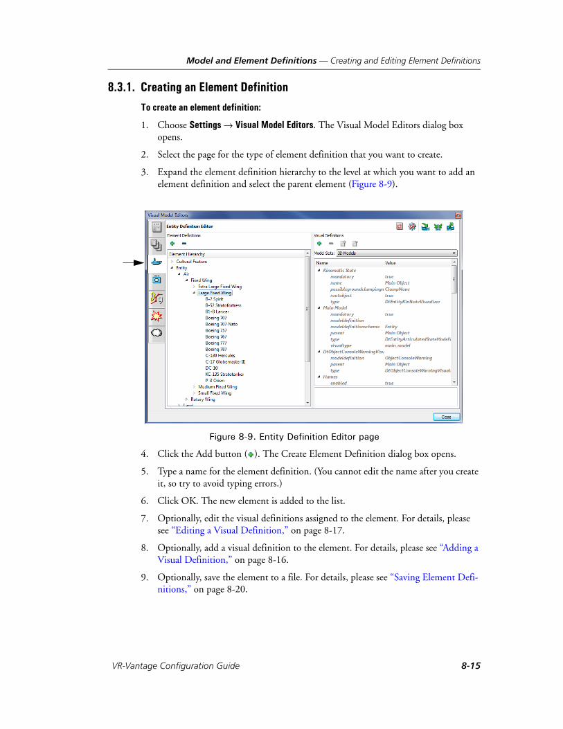
Model and Element Definitions — Creating and Editing Element Definitions
8.3.1. Creating an Element Definition
To create an element definition:
1. Choose Settings Visual Model Editors. The Visual Model Editors dialog box opens.
2. Select the page for the type of element definition that you want to create.
3. Expand the element definition hierarchy to the level at which you want to add an element definition and select the parent element (Figure 8-9).
Figure 8-9. Entity Definition Editor page
4. Click the Add button ( ). The Create Element Definition dialog box opens.
5. Type a name for the element definition. (You cannot edit the name after you create it, so try to avoid typing errors.)
6. Click OK. The new element is added to the list.
7. Optionally, edit the visual definitions assigned to the element. For details, please see “Editing a Visual Definition,” on page 8-17.
8. Optionally, add a visual definition to the element. For details, please see “Adding a Visual Definition,” on page 8-16.
9. Optionally, save the element to a file. For details, please see “Saving Element Defi-nitions,” on page 8-20.
VR-Vantage Configuration Guide 8-15
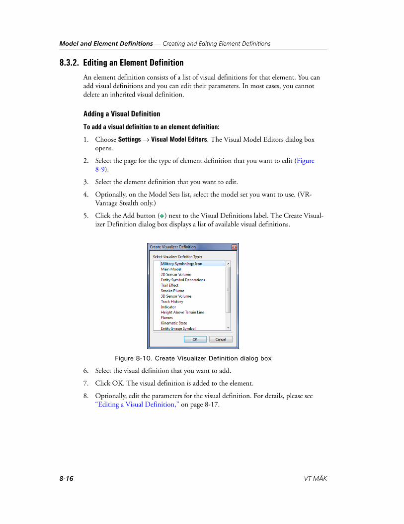
Model and Element Definitions — Creating and Editing Element Definitions
8.3.2. Editing an Element Definition
An element definition consists of a list of visual definitions for that element. You can add visual definitions and you can edit their parameters. In most cases, you cannot delete an inherited visual definition.
Adding a Visual Definition
To add a visual definition to an element definition:
1. Choose Settings Visual Model Editors. The Visual Model Editors dialog box opens.
2. Select the page for the type of element definition that you want to edit (Figure 8-9).
3. Select the element definition that you want to edit.
4. Optionally, on the Model Sets list, select the model set you want to use. (VR-Vantage Stealth only.)
5. Click the Add button ( ) next to the Visual Definitions label. The Create Visual-izer Definition dialog box displays a list of available visual definitions.
Figure 8-10. Create Visualizer Definition dialog box
6. Select the visual definition that you want to add.
7. Click OK. The visual definition is added to the element.
8. Optionally, edit the parameters for the visual definition. For details, please see “Editing a Visual Definition,” on page 8-17.
8-16 VT MÄK
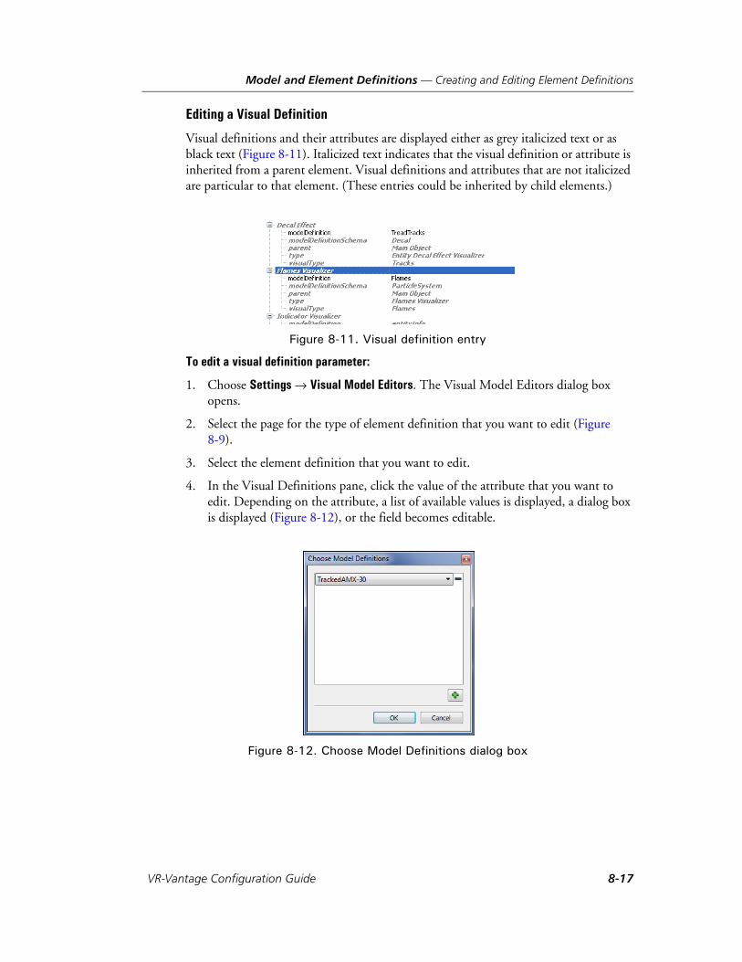
Model and Element Definitions — Creating and Editing Element Definitions
Editing a Visual Definition
Visual definitions and their attributes are displayed either as grey italicized text or as black text (Figure 8-11). Italicized text indicates that the visual definition or attribute is inherited from a parent element. Visual definitions and attributes that are not italicized are particular to that element. (These entries could be inherited by child elements.)
Figure 8-11. Visual definition entry
To edit a visual definition parameter:
1. Choose Settings Visual Model Editors. The Visual Model Editors dialog box opens.
2. Select the page for the type of element definition that you want to edit (Figure 8-9).
3. Select the element definition that you want to edit.
4. In the Visual Definitions pane, click the value of the attribute that you want to edit. Depending on the attribute, a list of available values is displayed, a dialog box is displayed (Figure 8-12), or the field becomes editable.
Figure 8-12. Choose Model Definitions dialog box
VR-Vantage Configuration Guide 8-17

Model and Element Definitions — Creating and Editing Element Definitions
5. For a list, select the new value. For an editable field, type a new value. For a dialog box:
a. If the dialog box window does not have a list, click the Add button ( ). A list of values is added to the dialog box window.
b. Select the value that you want.
c. Click OK.
Mapping to Multiple Model Definitions or Schema
There may be cases where you want to map a visual definition to multiple model defini-tions or multiple schema. If you do this, VR-Vantage randomly assigns the model defi-nition or schema to instances of the object.
To map a visual definition attribute to multiple values:
1. Choose Settings Visual Model Editors. The Visual Model Editors dialog box opens.
2. Select the page for the type of element definition that you want to edit (Figure 8-9).
3. Select the element definition that you want to edit.
4. In the Visual Definitions pane, click the value of the modeldefinition or modeldefini-tionschema parameter that you want to edit. A dialog box opens. If the attribute already has values, they are listed in the dialog box window as a series of lists (Figure 8-13).
Figure 8-13. Parameter with multiple values
5. To add a value, click the Add button ( ). A new list is added to the window.
6. Select a value from the new list.
7. To remove a value, click the Delete button ( ) next to the list for that value.
8. Click OK. The visual definitions list does not show all of the values, but clicking it will open the dialog box again and show the selected values.
8-18 VT MÄK
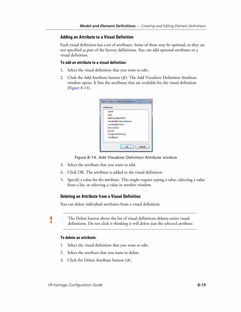
Model and Element Definitions — Creating and Editing Element Definitions
Adding an Attribute to a Visual Definition
Each visual definition has a set of attributes. Some of them may be optional, so they are not specified as part of the factory definitions. You can add optional attributes to a visual definition.
To add an attribute to a visual definition:
1. Select the visual definition that you want to edit.
2. Click the Add Attribute button ( ). The Add Visualizer Definition Attribute window opens. It lists the attributes that are available for the visual definition (Figure 8-14).
Figure 8-14. Add Visualizer Definition Attribute window
3. Select the attribute that you want to add.
4. Click OK. The attribute is added to the visual definition.
5. Specify a value for the attribute. This might require typing a value, selecting a value from a list, or selecting a value in another window.
Deleting an Attribute from a Visual Definition
You can delete individual attributes from a visual definition.
To delete an attribute:
1. Select the visual definition that you want to edit.
2. Select the attribute that you want to delete.
3. Click the Delete Attribute button ( ).
! The Delete button above the list of visual definitions deletes entire visual definitions. Do not click it thinking it will delete just the selected attribute.
VR-Vantage Configuration Guide 8-19
Model and Element Definitions — Creating and Editing Element Definitions
8.3.3. Deleting an Element Definition
To delete an element definition:
1. Choose Settings Visual Model Editors. The Visual Model Editors dialog box opens.
2. Select the page for the type of element definition that you want to delete (Figure 8-9).
3. Select the element definition that you want to delete.
4. Click the Delete button ( ) next to the Entity Definitions label.
5. Confirm the deletion.
8.3.4. Saving Element Definitions
Changes to element definitions get saved automatically. You can also save element defi-nitions using the standard VR-Vantage options for saving settings. For details, please see “Managing VR-Vantage Settings,” on page 3-21, in VR-Vantage Users Guide.
i You cannot delete an element definition if it is being used.
8-20 VT MÄK

Model and Element Definitions — Configuring 2D Icons
8.4. Configuring 2D IconsThe 2D icons in VR-Vantage PVD and the Plan View mode of VR-Vantage Stealth are configured in visual definitions. Font-based icons are configured in the Military Symbol Icon visual definition. Image-based icons use the Entity Image Symbol visual defini-tion.
8.4.1. Editing Font-Based 2D Icons
By default, 2D icons are configured in the Military Symbol Icon visual definition, which is part of an entity’s entity definition. This visual definition uses font-based icons. You can change an entity’s icon by changing the fillGlyph and outlineGlyph attributes.
To change an entity’s icon:
1. Choose Settings Visual Model Editors. The Visual Model Editors dialog box opens.
2. Select the Entity Definition Editor page (Figure 8-9).
3. Select the entity whose icon you want to edit.
4. In the Model Sets list, select 2D Icons.
5. To change the fill glyph:
a. Under the Military Symbology Icon visual definition, select the fillGlyph attri-bute (Figure 8-15).
VR-Vantage Configuration Guide 8-21
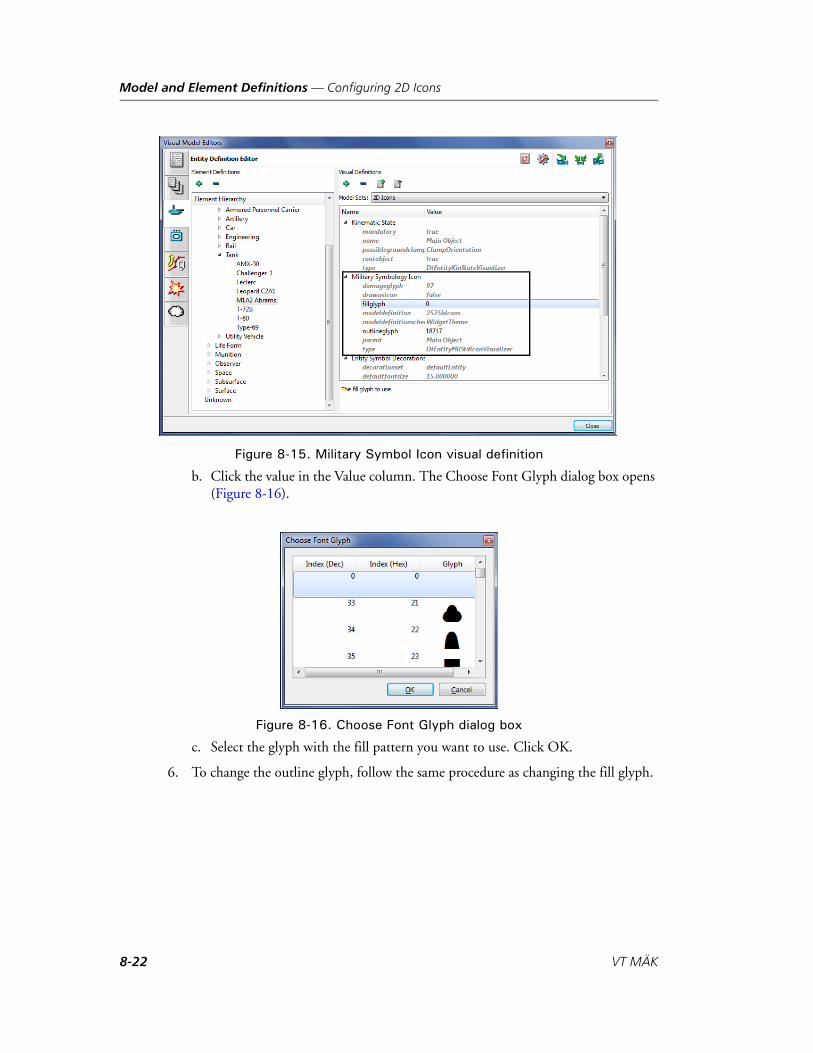
Model and Element Definitions — Configuring 2D Icons
Figure 8-15. Military Symbol Icon visual definition
b. Click the value in the Value column. The Choose Font Glyph dialog box opens (Figure 8-16).
Figure 8-16. Choose Font Glyph dialog box
c. Select the glyph with the fill pattern you want to use. Click OK.
6. To change the outline glyph, follow the same procedure as changing the fill glyph.
8-22 VT MÄK

Model and Element Definitions — Configuring 2D Icons
8.4.2. Using Images for 2D Icons
By default, VR-Vantage uses TrueType fonts for 2D icons. You can replace the font-based icons with images using the Entity Image Symbol visual definition.
To use images for entity icons:
1. Choose Settings Visual Model Editors. The Visual Model Editors dialog box opens.
2. Select the Entity Definitions tab (Figure 8-9). (If you want to change the icon for an aggregate, select the Aggregates tab. To change the icon for a waypoint, select the Tactical Graphics tab.)
3. In the Model Sets list, select 2D Icons.
4. In the Element Definitions list, select Entity. (If you are editing aggregate images, in the Element Definitions list select Aggregate. If you are editing tactical graphics images, in the Element Definitions list select Waypoint. For all other tactical graphics, skip to step 8.)
5. In the Visual Definitions list, select Military Symbology Icon (Figure 8-17).
Figure 8-17. Entity element definition with Military Symbology Icon visual definition
i If you configure images for icons, be sure to save the entity definitions to a file other than the default settings. If you revert to factory defaults or otherwise switch back to font-based icons and you have not saved the image mappings, you will not be able to recover them without repeating the entire mapping process again.
VR-Vantage Configuration Guide 8-23
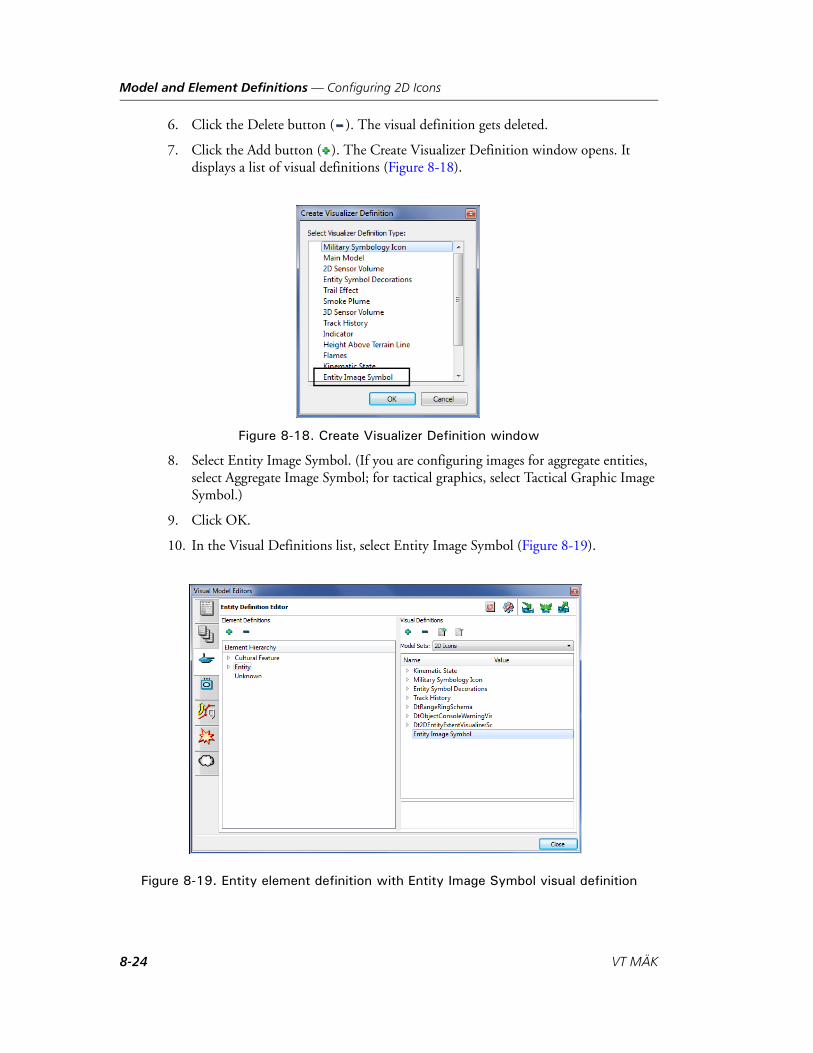
Model and Element Definitions — Configuring 2D Icons
6. Click the Delete button ( ). The visual definition gets deleted.
7. Click the Add button ( ). The Create Visualizer Definition window opens. It displays a list of visual definitions (Figure 8-18).
Figure 8-18. Create Visualizer Definition window
8. Select Entity Image Symbol. (If you are configuring images for aggregate entities, select Aggregate Image Symbol; for tactical graphics, select Tactical Graphic Image Symbol.)
9. Click OK.
10. In the Visual Definitions list, select Entity Image Symbol (Figure 8-19).
Figure 8-19. Entity element definition with Entity Image Symbol visual definition
8-24 VT MÄK
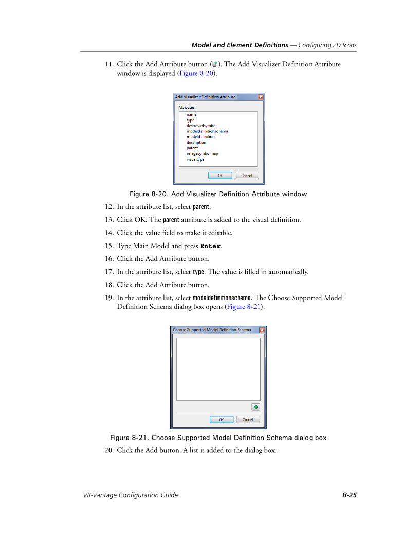
Model and Element Definitions — Configuring 2D Icons
11. Click the Add Attribute button ( ). The Add Visualizer Definition Attribute window is displayed (Figure 8-20).
Figure 8-20. Add Visualizer Definition Attribute window
12. In the attribute list, select parent.
13. Click OK. The parent attribute is added to the visual definition.
14. Click the value field to make it editable.
15. Type Main Model and press Enter.
16. Click the Add Attribute button.
17. In the attribute list, select type. The value is filled in automatically.
18. Click the Add Attribute button.
19. In the attribute list, select modeldefinitionschema. The Choose Supported Model Definition Schema dialog box opens (Figure 8-21).
Figure 8-21. Choose Supported Model Definition Schema dialog box
20. Click the Add button. A list is added to the dialog box.
VR-Vantage Configuration Guide 8-25

Model and Element Definitions — Configuring 2D Icons
21. In the list, select WidgetTheme (Figure 8-22).
Figure 8-22. Completed Choose Supported Model Definition Schema dialog box
22. Click OK.
23. Click the Add Attribute button.
24. In the attribute list, select imagesymbolmap. The 2D Symbol Image Mapper dialog box opens (Figure 8-23).
Figure 8-23. 2D Symbol Image Mapper dialog box
25. Click the Add button. A list is added to the dialog box. It lists the forces for which you can map images. and the images that you can apply to a particular force
8-26 VT MÄK

Model and Element Definitions — Configuring 2D Icons
26. Select a force and an image from the lists (Figure 8-24).
Figure 8-24. 2D Symbol Image Mapper dialog box with force chosen
27. Add an entry for each force that you want to represent with an image.
28. Click OK.
29. Click the Add Attribute button.
30. In the attribute list, select destroyedsymbol. The destroyedsymbol attribute is added to the visual definition.
31. In the destroyedsymbol list, select Destroyed. The completed visual definition should look similar to Figure 8-25.
Figure 8-25. Entity Image Symbol visual definition
VR-Vantage Configuration Guide 8-27
Model and Element Definitions — Configuring 2D Icons
The settings for the Entity Image Symbol visual definition are inherited by each entity in the hierarchy from the base Entity definition. Unless you configure the various entity categories, all entities use the images you configured for the Entity category. Therefore, at a minimum, change the imagesymbolmap values for each force at each generic entity type, such as Fixed Wing and Life Form, to use the proper image for that entity type. Optionally, you can specify an image for each entity definition at the leaf level.
8.4.3. Adding Images for Entities
VR-Vantage includes a representative set of MIL-STD 2525a images. They are in ./data/images. If you want to add your own images, you can do so by adding a new model definition or changing the image mapping for an existing model definition. The new images are automatically added to the list of images for the imagesymbolmap in the Entity Image Symbol visual definition.
To add images for entities:
1. Copy the new images to ./data/images.
2. Choose Settings Visual Model Editors. The Visual Model Editors dialog box opens.
3. Select the Model Definition Editor page (Figure 8-4).
4. In the Schema list, select WidgetTheme.
5. If you want to change the image used for an existing model definition:
a. Select the model definition that you want to change, for example, 2525a_groundF.
b. Change the file specified for the backgroundImage attribute.
If you want to specify an image for a new model definition:
a. Create a new model definition, as described in “Creating and Editing Model Definitions,” on page 8-8. It is recommended that you copy an existing model definition for a 2525a symbol.
b. Specify the image that you want to use for the new model definition.
i When you edit the Entity Image Symbol visual definition attributes, be sure that you select the 2D Icons model set.
8-28 VT MÄK
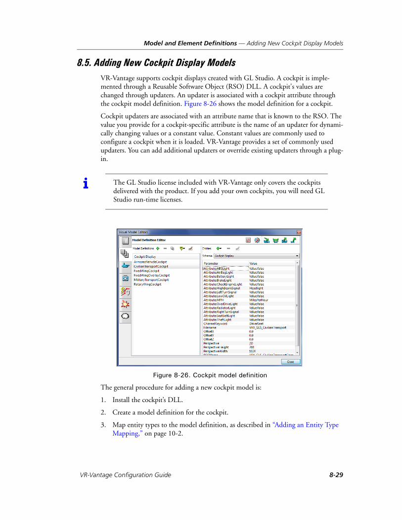
Model and Element Definitions — Adding New Cockpit Display Models
8.5. Adding New Cockpit Display ModelsVR-Vantage supports cockpit displays created with GL Studio. A cockpit is imple-mented through a Reusable Software Object (RSO) DLL. A cockpit's values are changed through updaters. An updater is associated with a cockpit attribute through the cockpit model definition. Figure 8-26 shows the model definition for a cockpit.
Cockpit updaters are associated with an attribute name that is known to the RSO. The value you provide for a cockpit-specific attribute is the name of an updater for dynami-cally changing values or a constant value. Constant values are commonly used to configure a cockpit when it is loaded. VR-Vantage provides a set of commonly used updaters. You can add additional updaters or override existing updaters through a plug-in.
Figure 8-26. Cockpit model definition
The general procedure for adding a new cockpit model is:
1. Install the cockpit’s DLL.
2. Create a model definition for the cockpit.
3. Map entity types to the model definition, as described in “Adding an Entity Type Mapping,” on page 10-2.
i The GL Studio license included with VR-Vantage only covers the cockpits delivered with the product. If you add your own cockpits, you will need GL Studio run-time licenses.
VR-Vantage Configuration Guide 8-29

Model and Element Definitions — Adding New Cockpit Display Models
8.5.1. Installing a Cockpit DLL
If you create your own cockpit, it is implemented as an RSO DLL that you must add to the VR-Vantage file structure.
To install a new cockpit, place the DLL for the cockpit in ./data/Huds and create a model definition for it.
8.5.2. Creating a Model Definition for a Cockpit
Cockpit models are configured using schemas and model definitions, just like any other model in VR-Vantage. This section provides additional details specific to cockpits.
To create a model definition for a cockpit:
1. Add a new model definition, as described in “Creating a Model Definition,” on page 8-9. Be sure to select Cockpit Display as the schema. A new model definition is added to the display (Figure 8-27). The message window lists the parameters that you must add. These are the parameters defined by the schema.
Figure 8-27. New cockpit model definition
2. Add the required parameters, as described in “Adding Parameters to a Model Defi-nition,” on page 8-12. Table 8-1 describes the required parameters.
Table 8-1: Required parameters for cockpit models
Parameter Description
Filename The name of the DLL without the file extension.
RSOName The name of the class to be loaded from the DLL. Default: filenameClass.
8-30 VT MÄK

Model and Element Definitions — Adding New Cockpit Display Models
3. Add the parameters required by the cockpit RSO. To do this, add an Attribute parameter, as follows:
a. Add an Attribute parameter, as described in “Adding Parameters to a Model Definition,” on page 8-12.
b. Double-click the parameter to make its name editable.
c. Add a colon and the name of an RSO attribute that you need to map. For example, Attribute:Heading.
d. In the Value column, click the value to make it editable. Type the name of an updater or specify a constant value in the format Value:value. You can specify an updater that you have added through a plug-in or one of the updaters provided with VR-Vantage, as described in Table 8-2.
4. Map an entity type to your definition, as described in “Adding an Entity Type Mapping,” on page 10-2.
Perspective 2D or 3D. This parameter refers to the perspective of the cockpit display, not the terrain. Currently, only 2D cockpit displays are provided with VR-Vantage.
PerspectiveWidth
PerspectiveHeight
Adjusts the orthogonal projection for a 2D cockpit. Adjusts the perspective projection for a true 3D cockpit.
ChannelKeyword A keyword that tells a channel to display any object that has the keyword in its definition. Default: showCockpits. (This keyword means that any channel that has the showCockpits keyword will show cockpits.)
Offset X
Offset Y
Offset Z
Moves the cockpit offset around the screen. The OffsetX value shifts the cockpit left or right. The OffsetY value shifts it up or down. OffsetZ shifts a 3D cockpit forward and back. It has no effect on 2D cockpits.
Table 8-2: Updaters provided
Updater Description
AOA Angle of Attack. Returns the pitch of the entity clamped (5 to 30 degrees).
FeetAGL Feet Above Ground Level. Returns the feet above the terrain (or buildings below).
FeetMSL Feet Above Mean Sea Level. Returns the altitude above the sea level.
FeetPerMinute Feet Per Minute. Returns the climb rate.
KilometersPerHour Speed of the entity in kilometers per hour.
MilesPerHour Speed of the entity in miles per hour.
Table 8-1: Required parameters for cockpit models
Parameter Description
VR-Vantage Configuration Guide 8-31
Model and Element Definitions — Configuring Wakes
8.6. Configuring WakesWhen dynamic ocean is enabled, VR-Vantage simulates wakes on surface entities. Wakes are configured in the Ship Wake visual definition of an entity’s element defini-tion. If you add your own model, you may want to change the default configuration values for its wake so that it more closely matches the dimensions and velocity of the entity type being modeled.
To configure a ship wake:
1. Choose Settings Visual Model Editors. The Visual Model Editors dialog box opens.
2. Select the Entity Definition Editor page (Figure 8-28).
KnotsPerHour Speed of the entity in nautical miles per hour.
Pitch Returns the pitch of the entity clamped (-180 to 180 degrees).
Roll Returns the roll of the entity clamped (-180 to 180 degrees).
Yaw Returns the yaw of the entity clamped (0 to 360 degrees).
Headlight Returns the headlight state of the entity as true or false.
Value This updater sends any value to the cockpit once and then never again. It is used to configure initial setup and to turn display components on or off.
Table 8-2: Updaters provided
Updater Description
8-32 VT MÄK

Model and Element Definitions — Configuring Wakes
Figure 8-28. Ship Wake visual definition
3. In the Element Hierarchy, expand the Entity list to the Surface level and select the entity that you want to configure.
4. In the Visual Definitions list, select and expand the Ship Wake visual definition.
5. Edit the parameters. Table 8-3 describes each parameter.
Table 8-3: Ship Wake visual definition attributes
Parameter Description
beamwidth The width of the ship at its widest point.
bowsize The size of the bow in world units. This affects the wave-length of the bow wave and the initial spread of spray parti-cles at the bow. Use 0 for a pointy bow.
bowsprayoffset An offset from the ship position from which to emit spray particles.
bowwaveoffset An offset from the ship position, along the direction of travel, at which bow waves will originate.
bowwavescale A scaling factor for the bow wave's amplitude at the bow of the ship.
draft The depth of the hull underwater.
hullsprayend The offset from the ship at which hull spray effects end.
hullspraysizescale A scaling factor applied to the hull spray particles.
VR-Vantage Configuration Guide 8-33
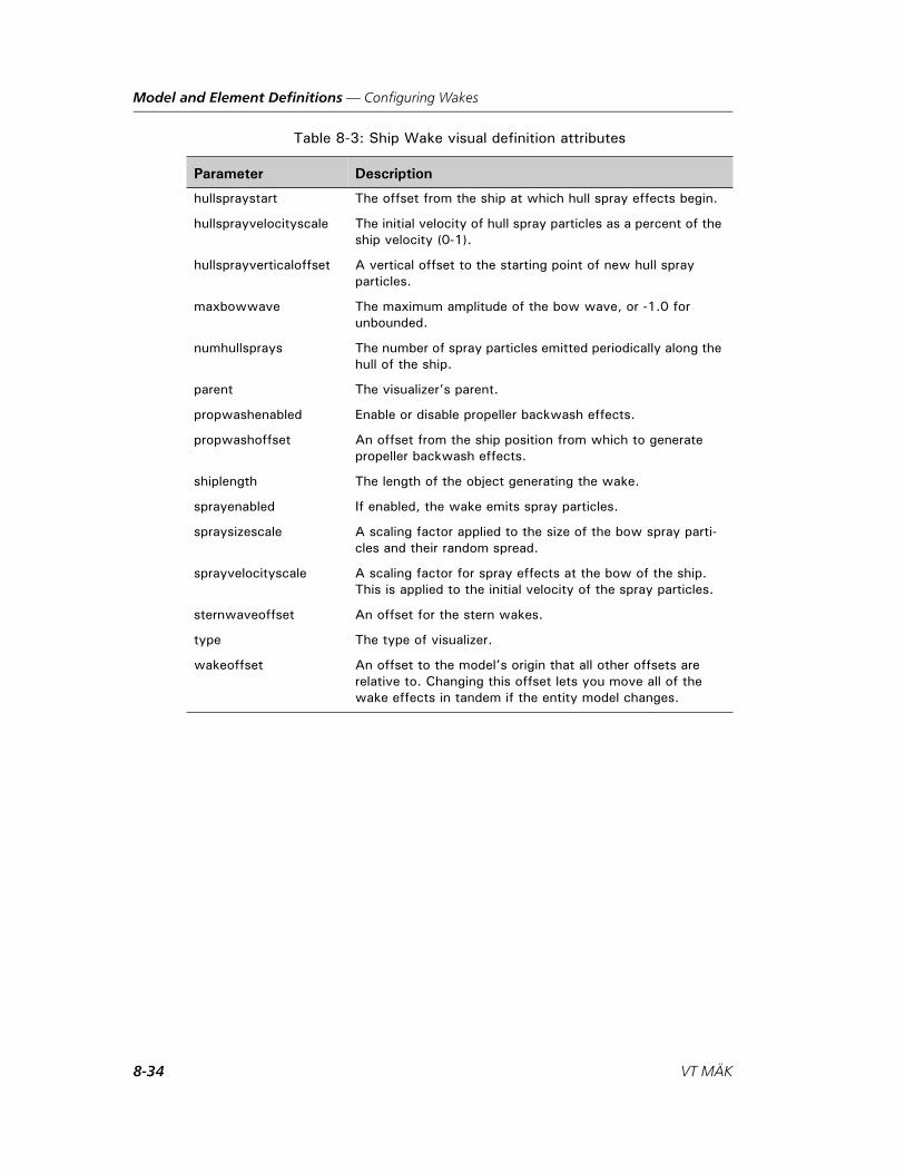
Model and Element Definitions — Configuring Wakes
hullspraystart The offset from the ship at which hull spray effects begin.
hullsprayvelocityscale The initial velocity of hull spray particles as a percent of the ship velocity (0-1).
hullsprayverticaloffset A vertical offset to the starting point of new hull spray particles.
maxbowwave The maximum amplitude of the bow wave, or -1.0 for unbounded.
numhullsprays The number of spray particles emitted periodically along the hull of the ship.
parent The visualizer’s parent.
propwashenabled Enable or disable propeller backwash effects.
propwashoffset An offset from the ship position from which to generate propeller backwash effects.
shiplength The length of the object generating the wake.
sprayenabled If enabled, the wake emits spray particles.
spraysizescale A scaling factor applied to the size of the bow spray parti-cles and their random spread.
sprayvelocityscale A scaling factor for spray effects at the bow of the ship. This is applied to the initial velocity of the spray particles.
sternwaveoffset An offset for the stern wakes.
type The type of visualizer.
wakeoffset An offset to the model’s origin that all other offsets are relative to. Changing this offset lets you move all of the wake effects in tandem if the entity model changes.
Table 8-3: Ship Wake visual definition attributes
Parameter Description
8-34 VT MÄK
Model and Element Definitions — Adding Wind-based Controls to Models
8.6.1. Configuring Tidal Stream Wakes
Tidal stream wakes are supported as stand-alone models and are automatically attached to streamed buoys and beacons. Model definitions for wakes to be used with each of the supported buoy and beacon models are included (BuoysPillarWake, BeaconsLattice-Wake, and so on). You may want to edit them. We recommend wake lengths of at least 20m for best results. (Some of the model definitions specify values less than that.)
By default, VR-Vantage starts with a tidal stream current speed of 0. To see tidal stream wakes, change the speed on the Scene Settings dialog box, Environment Conditions Settings page. For more information, please see “Configuring Marine Conditions,” on page 5-20, in VR-Vantage Users Guide.
You can also change the speed and direction of the tidal stream current using a CIGI Component Control or Short Component Control message. The message uses a component class of Regional Sea Surface(4), a component ID of 1, and two float component data fields - the first is the tidal stream current speed (m/s), and the second is the current direction (0-2PI radians, clockwise from North). The Region ID is ignored.
8.7. Adding Wind-based Controls to ModelsVR-Vantage can simulate the movement of flags and windsocks based on the current simulated wind speed and direction on terrains. It can also simulate movement of flags and windsocks on models added through connections or programatically (this is not supported for props or external references). These features require models with appro-priate switches and articulations, as well as model-specific or terrain-specific meta files.
A meta file is associated with a terrain or model in one of the following ways:
Place it in the same directory as the terrain or model's MEDF file. The meta file must have the same name as the MEDF file, but with a .meta extension.
Specify it in the metaFileName parameter of the model definition used to import the model.
Meta files are user-editable, but require understanding of the annotations and naming conventions in the model file itself.
The meta files are JSON configuration files. They have sections that configure wind control of nodes, as follows:
Control switch nodes based on wind speed.
Control the heading (Z-Axis) of articulating (degree of freedom) nodes based on wind direction.
Each section has a Linkage entry and a FeatureData entry. The Linkage entry specifies an OSG node that should have the feature specified in the FeatureData entry.
VR-Vantage Configuration Guide 8-35
Model and Element Definitions — Flipping DDS Textures for a Model
Linkages can be specified by node name or WRM Specification comment (for example, @dis articulated_part 7872). When a model or terrain file is loaded and a meta file is associated with that file, the model or terrain file is searched for any node or nodes spec-ified in any Linkage entries in that meta file and the necessary instances to implement the FeatureData indicated in that Linkage/FeatureData pair are created.
FeatureData sections indicate a FeatureName (which is mapped to a creator that will instantiate the appropriate object to manage that feature) and any additional parame-ters needed to manage the feature. The meta file used for wind features supports two features - WindSwitchPart and WindDirPart.
WindSwitchPart. The WindSwitchPart feature is used to change the state of a switch node based on the current wind speed. The flag models used by MÄK include a switch with three states. The WindSpeed parameter is a list of wind speeds (in km/h) and the WindState parameter is a list of the switch state values that correspond to the values in the WindSpeed parameter. The number of items in each list should be the same (and only contain switch states supported by the node specified in the Linkage entry.
WindDirPart. The WindDirPart feature is used to modify the heading value (Z-Axis) of an articulation (degree of freedom) node based on wind direction. It has the following parameters:
RotOffsetDeg. Allows a rotation offset to be applied.
RotDir. Indicates if the node should be rotated in a clockwise or counterclockwise direction.
For information about adding new meta files or new meta file features, please see section 8.6, Transforming Nodes Programmatically, in VR-Vantage Developers Guide.
8.8. Flipping DDS Textures for a ModelIf a model is displayed upside down because its DDS textures are not what VR-Vantage expects, you can specify that the model be flipped. (For more information about DDS textures, please see “Displaying DDS Textures Correctly,” on page 4-37.)
To flip DDS textures for a model:
1. Choose Settings Visual Model Editors. The Visual Model Editors dialog box opens.
2. Select the Model Definition Editor page (Figure 8-4).
3. Optionally, filter the model definitions in the list.
4. Select the model for which you want to change the DDS parameter.
5. If the model has the flip DDS textures parameter in its parameters list, set it to 1.
If the model does not have the flip DDS textures parameter in its parameters list, click the Add Parameter button ( ) to see if this is a valid parameter for this model. If it is, you can add the parameter and set it to 1.
8-36 VT MÄK
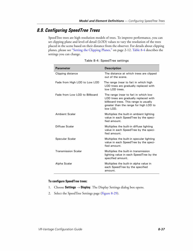
Model and Element Definitions — Configuring SpeedTree Trees
8.9. Configuring SpeedTree TreesSpeedTree trees are high resolution models of trees. To improve performance, you can set clipping plane and level-of-detail (LOD) values to vary the resolution of the trees placed in the scene based on their distance from the observer. For details about clipping planes, please see “Setting the Clipping Planes,” on page 2-12. Table 8-4 describes the settings you can change.
To configure SpeedTree trees:
1. Choose Settings Display. The Display Settings dialog box opens.
2. Select the SpeedTree Settings page (Figure 8-29).
Table 8-4: SpeedTree settings
Parameter Description
Clipping distance The distance at which trees are clipped out of the scene.
Fade from High LOD to Low LOD The range (near to far) in which high LOD trees are gradually replaced with low LOD trees.
Fade from Low LOD to Billboard The range (near to far) in which low LOD trees are gradually replaced with billboard trees. This range is usually greater than the range for high LOD to low LOD.
Ambient Scalar Multiplies the built-in ambient lighting value in each SpeedTree by the speci-fied amount.
Diffuse Scalar Multiplies the built-in diffuse lighting value in each SpeedTree by the speci-fied amount.
Specular Scalar Multiplies the built-in specular lighting value in each SpeedTree by the speci-fied amount.
Transmission Scalar Multiplies the built-in transmission lighting value in each SpeedTree by the specified amount.
Alpha Scalar Multiplies the built-in alpha value in each SpeedTree by the specified amount.
VR-Vantage Configuration Guide 8-37
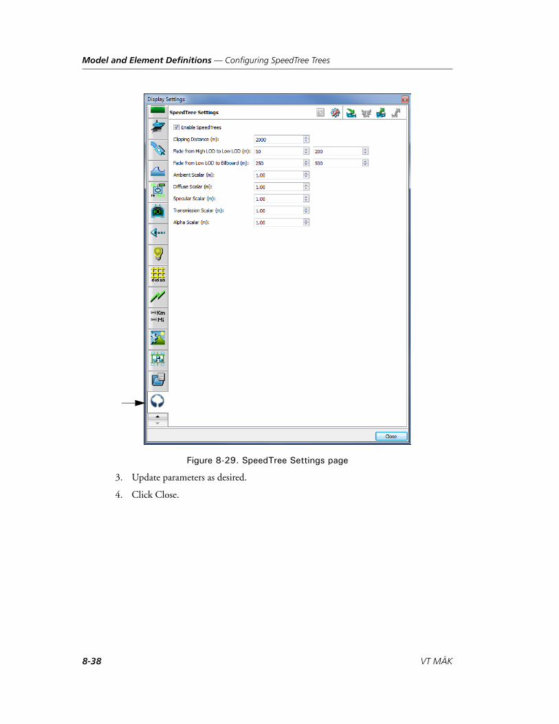
Model and Element Definitions — Configuring SpeedTree Trees
Figure 8-29. SpeedTree Settings page
3. Update parameters as desired.
4. Click Close.
8-38 VT MÄK

Model and Element Definitions — Configuring SpeedTree Trees
8.9.1. Randomizing the Size of SpeedTrees
SpeedTrees can be created as props or streamed into the scene using an earth file. They have a default size. You can configure VR-Vantage to scale the size of SpeedTrees by a fixed amount or you can scale them randomly within a specified range. The scale applied to a SpeedTree is the product of several factors.
If a SpeedTree is a prop, it is scaled as the product of the following settings:
The scale attribute in its model definition. If the scale attribute is not part of the model definition, the value defaults to 1.0.
A random scale factor as specified on the SpeedTree Randomization page on the Terrain Settings dialog box, if enabled.
A feet-to-meters conversion factor of 0.3048.
If a SpeedTree is a streamed in using an earth file, it is scaled as the product of the following settings:
The scale attribute in its model definition. If the scale attribute is not part of the model definition, the value defaults to 1.0.
The marker-scale attribute in the model element that configures the trees.
A random scale factor as specified on the SpeedTree Randomization page on the Terrain Settings dialog box, if enabled.
A feet-to-meters conversion factor of 0.3048.
You can also randomize the orientation of SpeedTrees.
To specify randomization of SpeedTree scaling:
1. Choose Settings Terrain. The Terrain Settings dialog box opens.
2. Select the SpeedTree Randomization page (Figure 8-30).
VR-Vantage Configuration Guide 8-39

Model and Element Definitions — Configuring SpeedTree Trees
Figure 8-30. SpeedTree Randomization page
3. To enable randomization of the SpeedTree scale, select the Enable SpeedTree Scale Randomization check box.
4. If you enabled Enable SpeedTree Scale Randomization, specify values for the Minimum Tree Scale and Maximum Tree Scale.
5. To enable randomization of tree orientation, select the Enable SpeedTree Orienta-tion check box.
8-40 VT MÄK
Model and Element Definitions — Best Practices for Creating Models for VR-Vantage
8.10. Best Practices for Creating Models for VR-VantageIf you build your own models for use in VR-Vantage, following these guidelines will result in models that work efficiently:
Keep all textures to powers of two, for example 256x256, 128x512, or 2048x2048:
– Make sure textures use as many of the pixels as possible and that there are no large black areas in the texture.
– Keep alpha (transparency) to a minimum.
Minimize the number of textures:
– Create a texture atlas that uses multiple textures combined into one.
– Group polygons together that use the same texture.
– Use the same textures for all LOD nodes.
Minimize the number of nodes:
– Keep the hierarchy as flat as possible.
– Move all LOD nodes to the top of the hierarchy.
– Minimize unnecessary transforms.
– When you reuse geometry in the model, use instancing.
Minimize the number of polygons that have different attributes:
– Use the same material on polygons whenever possible.
– Use two polygons with flipped normals instead of using the double sided attri-bute.
– Use the same color on polygons whenever possible.
– Group polygons with similar attributes.
Consider using a more aggressive LOD structure:
– Reduce the switchout distance to be smaller so that the LODs switch sooner.
– Minimize the number of LODs.
– Make sure that models switch out completely at a reasonable distance.
Reduce the number of external references:
– Merge external reference files.
– Create instances from external merged reference files.
VR-Vantage Configuration Guide 8-41

Model and Element Definitions — Best Practices for Creating Models for VR-Vantage
8-42 VT MÄK

VR-V
9. Model Tutorials
Although the individual procedures for managing model definitions and model mappings are fairly straightforward, understanding how they fit together to help you achieve your visualization goals is not always obvious. This chapter contains tutorials that demonstrate how to combine various procedures to add models.
Adding a Model to VR-Vantage .................................................................... 9-2Create a Model Definition...................................................................... 9-2Add an Element Definition .................................................................... 9-5Add a Model Mapping ........................................................................... 9-8Test the Model Mapping ...................................................................... 9-10
9-1antage Configuration Guide

Model Tutorials — Adding a Model to VR-Vantage
9.1. Adding a Model to VR-VantageThis tutorial shows how to add a new model to a VR-Vantage application. To help you with the tutorial, VR-Vantage includes a model of an F/A-18 Hornet that is not mapped to any entities.
To see a set of brief videos that demonstrates this tutorial, choose All Programs MÄK Technologies VR-Vantage 2.0.1 Documentation VR-Vantage Video Tutorials or run ./doc/vrvantage_tutorialvideos.htm.
The basic steps are:
1. Create a model definition (“Create a Model Definition,” on page 9-2).
2. Add an element definition (“Add an Element Definition,” on page 9-5).
3. Map the new model to an entity or object type enumeration (“Add a Model Mapping,” on page 9-8).
4. Test the new model (“Test the Model Mapping,” on page 9-10).
9.1.1. Create a Model Definition
A model definition is an instance of a schema. It specifies values for the parameters required by the schema.
To create the model definition:
1. Choose Settings Visual Model Editors. The Visual Model Editors dialog box opens.
2. Select the Model Definition Editor page (Figure 9-1).
Figure 9-1. Model Definition Editor page
9-2 VT MÄK

Model Tutorials — Adding a Model to VR-Vantage
3. Optionally, filter the model definitions in the list to just show entity model defini-tions. (For details, please see “Filtering the List of Model Definitions,” on page 8-11.)
4. Click the Add button ( ) next to the Model Definitions label. The Add Model Definition dialog box opens (Figure 9-2).
Figure 9-2. Add Model Definition dialog box
5. Type a name for the new model definition, for example, myF18.
6. If you filtered the model definition list, the Schema box says Entity. If not, in the Schema list, select Entity. The dialog box now looks like Figure 9-3.
Figure 9-3. New model definition
7. Click OK. The new definition is added to the list (Figure 9-4). It does not have any parameters specified yet, so VR-Vantage prints an error message. Now you must specify the model file for this model definition.
Figure 9-4. New model definition in list
VR-Vantage Configuration Guide 9-3
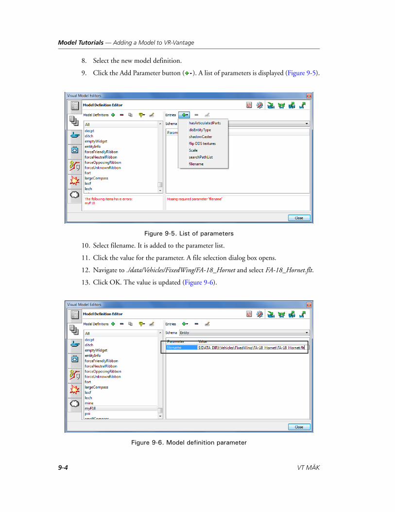
Model Tutorials — Adding a Model to VR-Vantage
8. Select the new model definition.
9. Click the Add Parameter button ( ). A list of parameters is displayed (Figure 9-5).
Figure 9-5. List of parameters
10. Select filename. It is added to the parameter list.
11. Click the value for the parameter. A file selection dialog box opens.
12. Navigate to ./data/Vehicles/FixedWing/FA-18_Hornet and select FA-18_Hornet.flt.
13. Click OK. The value is updated (Figure 9-6).
Figure 9-6. Model definition parameter
9-4 VT MÄK
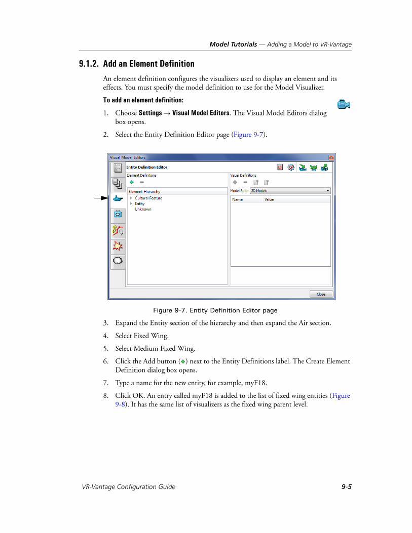
Model Tutorials — Adding a Model to VR-Vantage
9.1.2. Add an Element Definition
An element definition configures the visualizers used to display an element and its effects. You must specify the model definition to use for the Model Visualizer.
To add an element definition:
1. Choose Settings Visual Model Editors. The Visual Model Editors dialog box opens.
2. Select the Entity Definition Editor page (Figure 9-7).
Figure 9-7. Entity Definition Editor page
3. Expand the Entity section of the hierarchy and then expand the Air section.
4. Select Fixed Wing.
5. Select Medium Fixed Wing.
6. Click the Add button ( ) next to the Entity Definitions label. The Create Element Definition dialog box opens.
7. Type a name for the new entity, for example, myF18.
8. Click OK. An entry called myF18 is added to the list of fixed wing entities (Figure 9-8). It has the same list of visualizers as the fixed wing parent level.
VR-Vantage Configuration Guide 9-5
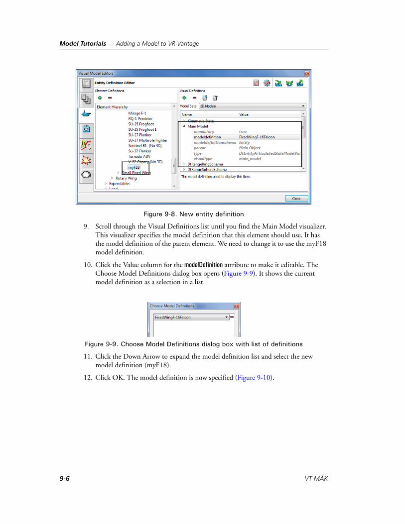
Model Tutorials — Adding a Model to VR-Vantage
Figure 9-8. New entity definition
9. Scroll through the Visual Definitions list until you find the Main Model visualizer. This visualizer specifies the model definition that this element should use. It has the model definition of the parent element. We need to change it to use the myF18 model definition.
10. Click the Value column for the modelDefinition attribute to make it editable. The Choose Model Definitions dialog box opens (Figure 9-9). It shows the current model definition as a selection in a list.
Figure 9-9. Choose Model Definitions dialog box with list of definitions
11. Click the Down Arrow to expand the model definition list and select the new model definition (myF18).
12. Click OK. The model definition is now specified (Figure 9-10).
9-6 VT MÄK
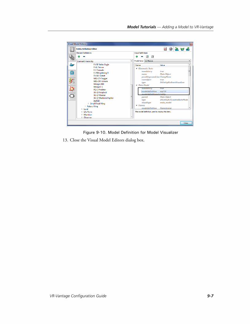
Model Tutorials — Adding a Model to VR-Vantage
Figure 9-10. Model Definition for Model Visualizer
13. Close the Visual Model Editors dialog box.
VR-Vantage Configuration Guide 9-7
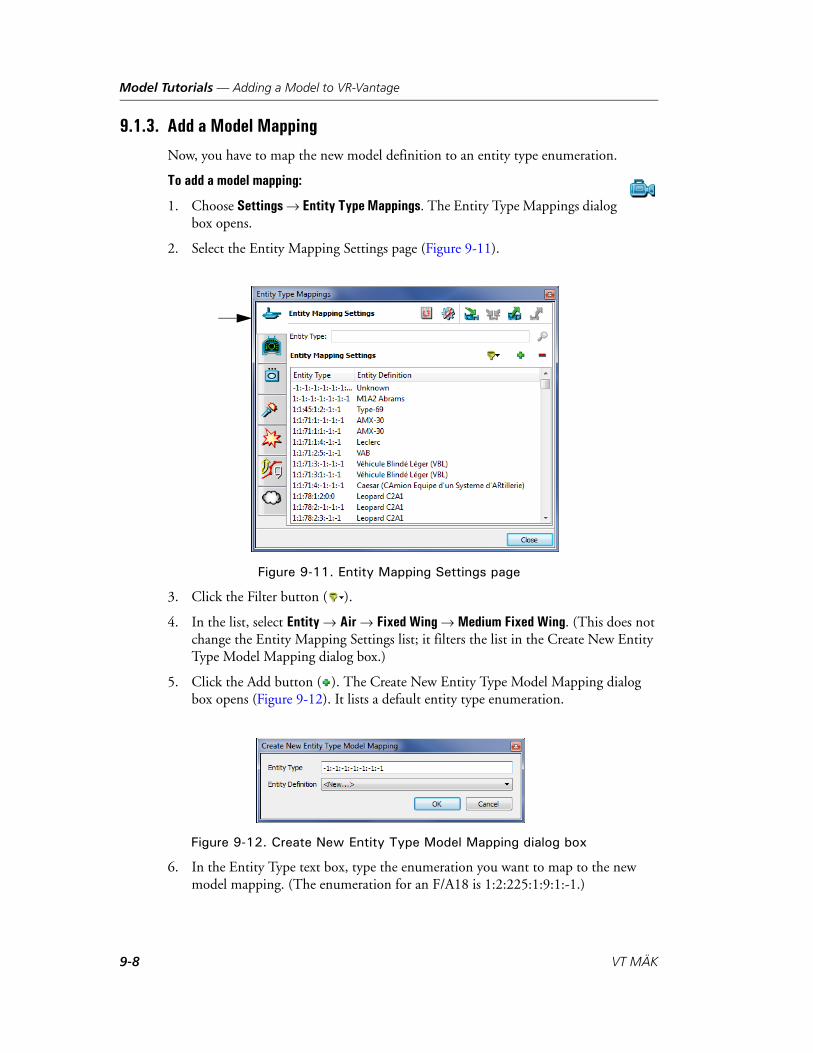
Model Tutorials — Adding a Model to VR-Vantage
9.1.3. Add a Model Mapping
Now, you have to map the new model definition to an entity type enumeration.
To add a model mapping:
1. Choose Settings Entity Type Mappings. The Entity Type Mappings dialog box opens.
2. Select the Entity Mapping Settings page (Figure 9-11).
Figure 9-11. Entity Mapping Settings page
3. Click the Filter button ( ).
4. In the list, select Entity Air Fixed Wing Medium Fixed Wing. (This does not change the Entity Mapping Settings list; it filters the list in the Create New Entity Type Model Mapping dialog box.)
5. Click the Add button ( ). The Create New Entity Type Model Mapping dialog box opens (Figure 9-12). It lists a default entity type enumeration.
Figure 9-12. Create New Entity Type Model Mapping dialog box
6. In the Entity Type text box, type the enumeration you want to map to the new model mapping. (The enumeration for an F/A18 is 1:2:225:1:9:1:-1.)
9-8 VT MÄK
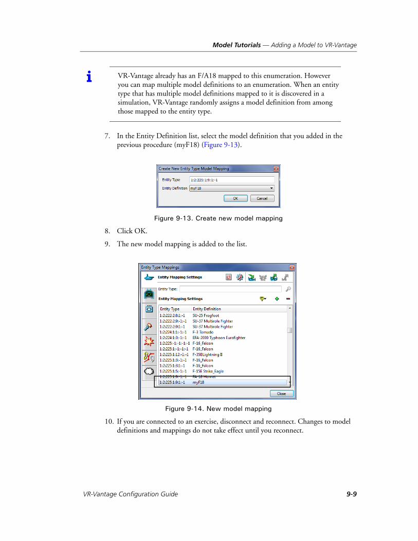
Model Tutorials — Adding a Model to VR-Vantage
7. In the Entity Definition list, select the model definition that you added in the previous procedure (myF18) (Figure 9-13).
Figure 9-13. Create new model mapping
8. Click OK.
9. The new model mapping is added to the list.
Figure 9-14. New model mapping
10. If you are connected to an exercise, disconnect and reconnect. Changes to model definitions and mappings do not take effect until you reconnect.
i VR-Vantage already has an F/A18 mapped to this enumeration. However you can map multiple model definitions to an enumeration. When an entity type that has multiple model definitions mapped to it is discovered in a simulation, VR-Vantage randomly assigns a model definition from among those mapped to the entity type.
VR-Vantage Configuration Guide 9-9

Model Tutorials — Adding a Model to VR-Vantage
9.1.4. Test the Model Mapping
It is a good idea to test the new model mapping to see if the correct model is being displayed. You can test a model by running a simulation that has the entity or object type, or you can perform the simple test described here.
To test a model:
1. Open a terrain database that has easily identifiable props. For the purposes of this tutorial, open the Makland terrain.
2. In the VR-Vantage window, move the observer so that you are viewing the palace on top of the hill near the town in Makland.
3. Click the palace to select it (Figure 9-15).
Figure 9-15. Palace
4. Choose Settings Terrain. The Terrain Settings dialog box opens.
5. Select the Edit Existing Props page. The list of props shows that Building26, the palace, is selected (Figure 9-16).
9-10 VT MÄK

Model Tutorials — Adding a Model to VR-Vantage
Figure 9-16. Edit Existing Props page
6. In the Model Definition list, select the model definition that you added earlier in this tutorial (Figure 9-17). The model of the palace is replaced with the model for the F/A-18 (Figure 9-18). If this is the model that you wanted to add, then you know that you completed the procedure correctly. If this is not the model, you expected, check the filename you specified for the model definition.
VR-Vantage Configuration Guide 9-11
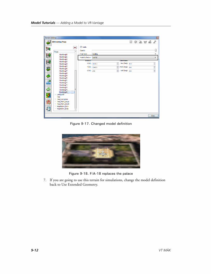
Model Tutorials — Adding a Model to VR-Vantage
Figure 9-17. Changed model definition
Figure 9-18. F/A-18 replaces the palace
7. If you are going to use this terrain for simulations, change the model definition back to Use Extended Geometry.
9-12 VT MÄK
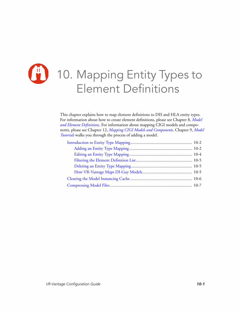
VR-V
10. Mapping Entity Types to Element Definitions
This chapter explains how to map element definitions to DIS and HLA entity types. For information about how to create element definitions, please see Chapter 8, Model and Element Definitions. For information about mapping CIGI models and compo-nents, please see Chapter 12, Mapping CIGI Models and Components. Chapter 9, Model Tutorials walks you through the process of adding a model.
Introduction to Entity Type Mapping......................................................... 10-2Adding an Entity Type Mapping .......................................................... 10-2Editing an Entity Type Mapping .......................................................... 10-4Filtering the Element Definition List.................................................... 10-5Deleting an Entity Type Mapping ........................................................ 10-5How VR-Vantage Maps DI-Guy Models.............................................. 10-5
Clearing the Model Instancing Cache ......................................................... 10-6
Compressing Model Files ............................................................................ 10-7
10-1antage Configuration Guide

Mapping Entity Types to Element Definitions — Introduction to Entity Type Mapping
10.1. Introduction to Entity Type MappingIn order to visualize a scene element (entity, aggregate, detonation, and so on), VR-Vantage must map its entity type enumeration to an element definition. This section explains how to do that. For conceptual background, please see Section 4.5.3, “Mapping Entity Types to Element Definitions,” in VR-Vantage Users Guide.
You map entity types to element definitions in the Entity Type Mappings dialog box. It has pages for mapping:
Aggregate entities.
Cockpit displays.
Detonation effects.
Entities.
Firing effects.
Tactical graphics.
Tactical smoke.
The mapping process is the same for all entity types. You can add new entity type mappings, edit existing mappings, and delete mappings.
10.1.1. Adding an Entity Type Mapping
This procedure describes how to map an element definition to an entity type enumera-tion. The element definition must already exist. The procedure is the same for any page on the Entity Type Mappings dialog box.
To add an entity type mapping:
1. Choose Settings Entity Type Mappings. The Entity Type Mappings dialog box opens.
2. Select the Entity Mapping Settings page (Figure 10-1). The page shows a list of entity type enumerations in the Entity Type column. The entity definition mapped to the entity type is listed in the Entity Definition column.
i You can map more than one element definition to an entity type. If you do this, when entities of this type appear in a simulation, VR-Vantage randomly assigns one of the element definitions to the entity.
You can map an element definition to more than one entity type.
10-2 VT MÄK

Mapping Entity Types to Element Definitions — Introduction to Entity Type Mapping
Figure 10-1. Entity Mapping Settings page
3. Click the Add button ( ). The Create New Entity Type Model Mapping dialog box opens (Figure 10-2). It lists a default entity type enumeration.
Figure 10-2. Create New Entity Type Model Mapping dialog box
4. In the Entity Type text box, type the enumeration you want to map to a model. (Separate each value with a colon(:).)
5. In the Entity Definition list, select the entity definition that you want to map to this entity type.
6. Click OK.
7. The new model mapping is added to the list.
VR-Vantage Configuration Guide 10-3

Mapping Entity Types to Element Definitions — Introduction to Entity Type Mapping
10.1.2. Editing an Entity Type Mapping
This procedure describes how to edit an entity type mapping for an entity. The proce-dure is the same for any page on the Entity Type Mappings dialog box.
To edit an entity type mapping:
1. Choose Settings Entity Type Mappings. The Entity Type Mappings dialog box opens.
2. Select the Entity Mapping Settings page (Figure 10-1).
3. Select the model mapping that you want to edit. If you know the entity enumera-tion that you want to edit, you can type the enumeration in the Entity Type text box and click the Search button ( ). VR-Vantage highlights the entry for that enumeration, if it is present.
4. To change the enumeration associated with an element definition:
a. In the Entity Type column, click the enumeration to make it editable.
b. Change the values of the enumeration.
c. Click someplace else in the window.
5. To change the element definition associated with an enumeration:
a. Optionally, filter the list of available element definitions. (For details, please see “Filtering the Element Definition List,” on page 10-5.)
b. In the Entity Definition column, click the element definition to make it an editable list (Figure 10-3)).
c. Select the new element definition from the list.
d. Click someplace else in the window.
Figure 10-3. Editable entity definition
10-4 VT MÄK

Mapping Entity Types to Element Definitions — Introduction to Entity Type Mapping
10.1.3. Filtering the Element Definition List
You can filter the list of element definitions that are available in the Entity Definition (Figure 10-3) list for mapping to entity types.
To filter the list of element definitions:
1. On any page of the Entity Type Mappings dialog box, click the Filter button ( ). A menu is displayed. A check mark indicates the type of element definition that will be displayed when you make a element definition entry editable. (You may have to expand the hierarchy to see which elements are checked.)
2. Select the element definition type that you want to see in the list or select All to see all element definitions.
10.1.4. Deleting an Entity Type Mapping
The procedure for deleting an entity type mapping is the same for any page on the Entity Type Mappings dialog box.
To delete an entity type mapping:
1. Choose Settings Entity Type Mappings. The Entity Type Mappings dialog box opens.
2. Select the Entity Mapping Settings page (Figure 10-1).
3. Select the model mapping that you want to delete. If you know the entity enumer-ation that you want to edit, you can type the enumeration in the Entity Type text box and click the Search button ( ). VR-Vantage highlights the entry for that enumeration if it is present.
4. Click the Delete button ( ).
10.1.5. How VR-Vantage Maps DI-Guy Models
When VR-Vantage discovers a lifeform entity on the DIS or HLA networks, it chooses the animations to play for a DI-Guy based on the lifeform’s speed, position, and similar attributes. However, if VR-Vantage receives a special DI-Guy state message (PDU) that dictates the lifeform’s character, appearance, or animation, VR-Vantage will no longer try to guess and will expect to be told how to render that lifeform for the remainder of the simulation.
i Filtering does not change the list of entities in the Entity Mapping Settings window. It just changes the list of entities in the Entity Definition list when you change a specific mapping.
VR-Vantage Configuration Guide 10-5
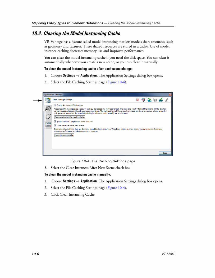
Mapping Entity Types to Element Definitions — Clearing the Model Instancing Cache
10.2. Clearing the Model Instancing CacheVR-Vantage has a feature called model instancing that lets models share resources, such as geometry and textures. These shared resources are stored in a cache. Use of model instance caching decreases memory use and improves performance.
You can clear the model instancing cache if you need the disk space. You can clear it automatically whenever you create a new scene, or you can clear it manually.
To clear the model instancing cache after each scene change:
1. Choose Settings Application. The Application Settings dialog box opens.
2. Select the File Caching Settings page (Figure 10-4).
Figure 10-4. File Caching Settings page
3. Select the Clear Instances After New Scene check box.
To clear the model instancing cache manually:
1. Choose Settings Application. The Application Settings dialog box opens.
2. Select the File Caching Settings page (Figure 10-4).
3. Click Clear Instancing Cache.
10-6 VT MÄK
Mapping Entity Types to Element Definitions — Compressing Model Files
10.3. Compressing Model FilesThe models and image files provided with VR-Vantage are shipped in compressed formats (MÄK Encrypted Data Format (MEDF) and MÄK Encrypted Image Format (MEIF). You may want to compress your models to save space or protect intellectual property. You can convert supported formats to MEDF and MEIF with ./bin/medf-Tool.exe. The compression tool supports the 3D modeling formats supported by VR-Vantage, such as OpenFlight, 3DS, and OBJ, and raster formats such as RGB and PNG.
The syntax for medfTool is as follows:
medfTool [-q simple_filename ... -p <integer> -s directory ... -z optimization -i -o -m extensions ... -x extensions ... --norecurse --directory directory-f filename -- -v -h]
Table 10-1 describes the arguments.
i When VR-Vantage processes a request to load a a file, such as an external reference in a terrain, it checks the cache and the directory of the requested file for an MEDF version of the file. If it does not exist, it loads the file in the original format.
Table 10-1: medfTool arguments
Argument Description
(-- | --ignore_rest) Ignore all arguments after this one.
--directory directory Specifies the directory to search for image and geometry files to convert into MEDF and MEIF. All subdirectories will be visited unless the --norecurse command line option is used.
(-f | --file) filename Convert just this file. The extension of the file must be specified using -x or -m to indicate it is an image or a geometry file.
(-h | --help) Displays usage information.
(-i | --ignore_errors) Ignore errors in the encryption process and continue without exiting.
(-m | --image_extensions) extension
Specifies the extensions of image formats which will be converted into MEIF format. Use this argument to encrypt a directory. Can be used multiple times.
--norecurse Do not recurse through subdirectories. Default: recurse through subdirectories.
(-o | --onlyIfNew) Only generates an encrypted file if the expected output file does not exist.
VR-Vantage Configuration Guide 10-7

Mapping Entity Types to Element Definitions — Compressing Model Files
The following example recursively compresses all FLT, RGB, RGBA, PNG, and DDS files in %MAK_DATADIR%/Terrain:
%MAK_IGDIR%/bin64/medfTool.exe --directory %MAK_DATADIR%/Terrain --extensions flt --image_extensions rgb --image_extensions rgba --image_extensions png --image_extensions dds
The following example compresses all FLT, RGB, RGBA, PNG, and DDS files in %MAK_DATADIR%/Lifeforms. It does not compress files in subdirectories.
%MAK_IGDIR%/bin64/medfTool.exe --directory %MAK_DATADIR%/Lifeforms --norecurse --extensions flt --image_extensions rgb --image_extensions rgba --image_extensions png --image_extensions dds
(-p | --threads) threads
Specifies the number of threads to run. Specifying zero results in the number of threads equaling the number of logical processors the host machine has.
(-q | --forceOpaque) simple_filename
Specifies a filename and extension, but no path, to force polygons with these filenames to be opaque. Accepted multiple times.
(-s | --search) directory
Adds a directory to the search path when resolving external references. During processing, any external references not found are removed from the generated files. Files in the search path are not converted.
(-v | --version) Display version information and exit.
(-x | --extensions) extension
Specifies the extensions of geometry file formats that will be converted into MEDF format. Use this argument to encrypt a directory. Can be used multiple times.
(-z | --optimize) optimization
Specifies the optimization level. Maximum optimization may provide better optimization than the default setting, but it is significantly slower. Possible values are:
0 = None. 1 = Default. 2 = Maximum optimization.
Table 10-1: medfTool arguments
Argument Description
10-8 VT MÄK

VR-V
11. Configuring Emitter Volumes
This chapter explains how to configure display of emitter volumes.
Configuring Emitter Volumes ..................................................................... 11-2Configuring Emitter Volume Color...................................................... 11-2Controlling Emitter Volume Radius ..................................................... 11-3Configuring Emitter Volume Segments ................................................ 11-4
11-1antage Configuration Guide
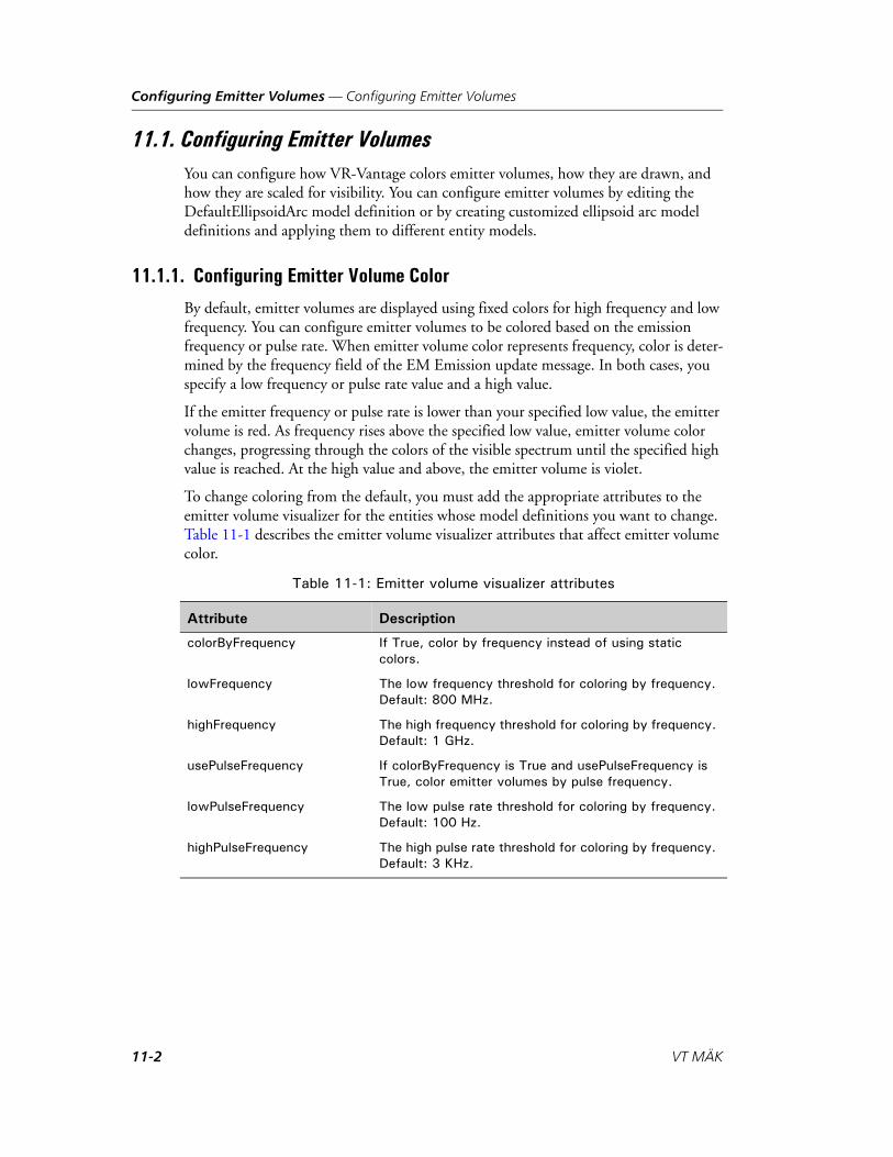
Configuring Emitter Volumes — Configuring Emitter Volumes
11.1. Configuring Emitter VolumesYou can configure how VR-Vantage colors emitter volumes, how they are drawn, and how they are scaled for visibility. You can configure emitter volumes by editing the DefaultEllipsoidArc model definition or by creating customized ellipsoid arc model definitions and applying them to different entity models.
11.1.1. Configuring Emitter Volume Color
By default, emitter volumes are displayed using fixed colors for high frequency and low frequency. You can configure emitter volumes to be colored based on the emission frequency or pulse rate. When emitter volume color represents frequency, color is deter-mined by the frequency field of the EM Emission update message. In both cases, you specify a low frequency or pulse rate value and a high value.
If the emitter frequency or pulse rate is lower than your specified low value, the emitter volume is red. As frequency rises above the specified low value, emitter volume color changes, progressing through the colors of the visible spectrum until the specified high value is reached. At the high value and above, the emitter volume is violet.
To change coloring from the default, you must add the appropriate attributes to the emitter volume visualizer for the entities whose model definitions you want to change. Table 11-1 describes the emitter volume visualizer attributes that affect emitter volume color.
Table 11-1: Emitter volume visualizer attributes
Attribute Description
colorByFrequency If True, color by frequency instead of using static colors.
lowFrequency The low frequency threshold for coloring by frequency. Default: 800 MHz.
highFrequency The high frequency threshold for coloring by frequency. Default: 1 GHz.
usePulseFrequency If colorByFrequency is True and usePulseFrequency is True, color emitter volumes by pulse frequency.
lowPulseFrequency The low pulse rate threshold for coloring by frequency. Default: 100 Hz.
highPulseFrequency The high pulse rate threshold for coloring by frequency. Default: 3 KHz.
11-2 VT MÄK
Configuring Emitter Volumes — Configuring Emitter Volumes
11.1.2. Controlling Emitter Volume Radius
A emitter volume’s radius (that is, the distance it extends from the emitter) is based in part on emitter power and in part on elevation and azimuth sweep data obtained from EM-Emission state messages. A higher emitter power value results in a longer radius, while a wider field of view results in a shorter radius (because the radiated power is distributed over a wider area).
If VR-Vantage relied exclusively on these values, the range of sizes among different emitter types could become too wide to be practical, with some emissions being barely visible, and other emissions covering the entire virtual world. Therefore, a configurable exponent weight and scale factor have been added to help fine tune the emitter beam radii. The radius exponent weight (a value between 0 and 1) slows the growth of the radius when power or area is greater than 1 and increases the growth of the radius when power or area is less than 0. The scale factor increases the radii of all beams by the given value.
To change the scale factor and exponent from the default, you must add one or both of the following attributes to the emitter volume visualizer for the entities whose model definitions you want to change:
linearScale. The amount of linear scaling applied to all emitter volumes. Default: 100.
exponentialScale. The amount of exponential scaling applied to emitter volumes. Default: 0.1.
How VR-Vantage Calculates the Radius
VR-Vantage calculates emitter volume radius by approximating the spread of the emis-sions based on the elevation and azimuth sweeps. If the approximate coverage is zero, it sets the value to 1. Then it applies the linear and exponential scaling values. The code for implementing this is as follows:
double tempVar = 8*elevationSweep*sin(2*azimuthSweep);if (tempVar <=0) tempVar=1.0;scale = linearScale * pow(sqrt(power/tempVar), exponentialScale );
VR-Vantage Configuration Guide 11-3
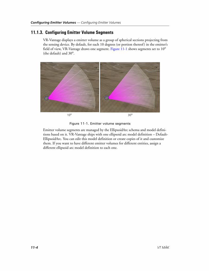
Configuring Emitter Volumes — Configuring Emitter Volumes
11.1.3. Configuring Emitter Volume Segments
VR-Vantage displays a emitter volume as a group of spherical sections projecting from the sensing device. By default, for each 10 degrees (or portion thereof ) in the emitter’s field of view, VR-Vantage draws one segment. Figure 11-1 shows segments set to 10o (the default) and 30o.
Figure 11-1. Emitter volume segments
Emitter volume segments are managed by the EllipsoidArc schema and model defini-tions based on it. VR-Vantage ships with one ellipsoid arc model definition – Default-EllipsoidArc. You can edit this model definition or create copies of it and customize them. If you want to have different emitter volumes for different entities, assign a different ellipsoid arc model definition to each one.
10o 30o
11-4 VT MÄK

Configuring Emitter Volumes — Configuring Emitter Volumes
Specifying the Segment Angle
To specify the segment angle:
1. Choose Settings Visual Model Editors. The Visual Model Editors dialog box opens.
2. Select the Model Definition Editor page.
3. Click the Filter button ( ) and select EllipsoidArc. The ellipsoid arc model defini-tions are listed in the window.
4. Select DefaultEllipsoidArc (Figure 11-2).
Figure 11-2. EllipsoidArc model definition
5. Change the value of the angleSegmentMax parameter. The minimum value is 10 (degrees); the maximum is 45.
Displaying Segment Outlines
By default, VR-Vantage displays opaque outlines showing the segment edges along the surface of the emitter volume.
Figure 11-3. Segment outlines
Off
On
VR-Vantage Configuration Guide 11-5

Configuring Emitter Volumes — Configuring Emitter Volumes
To display or hide segment outlines:
1. Choose Settings Visual Model Editors. The Visual Model Editors dialog box opens.
2. Select the Model Definition Editor page.
3. Click the Filter button ( ) and select EllipsoidArc. The ellipsoid arc model defini-tions are listed in the window.
4. Select DefaultEllipsoidArc.
5. Change the value of the showLines parameter.
Adding a Custom EllipsoidArc Model Definition
If you want to customize the segment angle and segment outlines for a particular entity without changing the values for other entities, you must create a separate ellipsoid arc model definition and add it to the entity’s model definition.
To create a custom ellipsoid arc model definition:
1. Choose Settings Visual Model Editors. The Visual Model Editors dialog box opens.
2. Select the Model Definition Editor page.
3. Click the Filter button ( ) and select EllipsoidArc. The ellipsoid arc model defini-tions are listed in the window.
4. Select DefaultEllipsoidArc.
5. Click the Duplicate Model Definition button ( ). The Duplicate Model Defini-tion dialog box opens with a default definition name.
6. Accept the generated name or type a new name for the model definition.
7. Click OK. The model definition is added to the list.
8. Change the parameter values for the new model definition as desired.
9. Select the Entity Definition Editor page.
10. Select the entity whose emitter volume you want to change.
11. Select the 3D Sensor Volume visualizer for the entity.
12. Click the Value column for the modeldefinition attribute. The Choose Model Defini-tion dialog box opens. It has a list of model definitions.
13. Select the model definition that you just created.
14. Click OK.
15. If you are connected to an exercise, disconnect and then reconnect to enable the new model definition.
11-6 VT MÄK
VR-V
12. Mapping CIGI Models and Components
Unlike DIS or HLA, CIGI does not have a standard set of entity type mappings. There-fore, a CIGI connection cannot use the entity type mappings described elsewhere in this manual. VR-Vantage provides a set of mappings (MAK CIGI Mappings) for the entity models it includes. These mappings work with the CIGI host emulator provided with VR-Vantage. You can add new mappings, and you can edit the default mappings to work with other hosts. This chapter provides a minimal introduction to CIGI and the VR-Vantage CIGI driver and explains how to map CIGI components.
Introduction to CIGI.................................................................................. 12-2The VR-Vantage CIGI Driver .............................................................. 12-2CIGI Packet Support............................................................................ 12-3Mapping CIGI Input to VR-Vantage ................................................... 12-4
Mapping Entity Models for CIGI ............................................................... 12-4Adding an Articulated Part Mapping to an Entity Model ..................... 12-5
Mapping CIGI Components ...................................................................... 12-6Component Control Message Formats ................................................. 12-7
Mapping a Database ................................................................................. 12-10
Mapping CIGI Views ............................................................................... 12-11Mapping a CIGI View to an Observer Mode ..................................... 12-12
Prototypical Host – IG Configurations ..................................................... 12-13
12-1antage Configuration Guide

Mapping CIGI Models and Components — Introduction to CIGI
12.1. Introduction to CIGICIGI (Common Image Generator Interface) is an interface that allows an image gener-ator (IG) to receive messages from a host to control what is drawn by the IG. CIGI defines packets that are sent between the host and the IG. CIGI is an open source project. It provides an interface control document and an open source library to send and receive CIGI messages: the CIGI Class Library (CCL). The VR-Vantage CIGI driver uses the CCL. VR-Vantage ships with the open-source CIGI Host Emulator. The host emulator and CCL are available at http://cigi.sourceforge.net. Chapter 13, CIGI Host Emulator Tutorial describes how to use the host emulator to control VR-Vantage.
12.1.1. The VR-Vantage CIGI Driver
The VR-Vantage CIGI driver supports best-effort (UDP) and reliable (TCP) commu-nication between the CIGI driver and the host. When VR-Vantage uses a best-effort connection, it opens a UDP socket to the host port and tries to exchange data with the host. When it uses a reliable connection, the CIGI driver can act as a TCP client or TCP server. If it runs as a client, on connection the CIGI Driver tries to connect to a TCP server port on the host. If the connection fails, the driver returns to the discon-nected state. If it runs as a server, it opens a TCP server socket on the listen port, and it accepts any connections made to that port. Data is then sent on that connection.
CIGI supports two modes of operation: synchronous and asynchronous. In synchro-nous mode, the IG sends a CIGI Start of Frame packet to the host, which prompts the host to send it data. The data is processed by the IG and is rendered; then the next frame starts. In asynchronous mode, the host sends data at any point and the IG renders the data. Since data may not be received every frame, the IG usually uses dead-reckoning and smoothing to update the positions of the entities until it receives an update.
The VR-Vantage CIGI driver supports synchronous and asynchronous modes. Synchronous mode can be run in single-threaded or multi-threaded mode, as follows:
In single-threaded mode, the driver runs in the same thread as VR-Vantage, so its rate is bound by the VR-Vantage frame-rate. For example, if the driver is set to run at 60 Hz, but VR-Vantage has a frame rate of 20, the driver will only be able to run at 20 Hz. However, if the driver rate is set to 30 Hz, and VR-Vantage is running at 60, the CIGI Driver will only process CIGI messages at 30 Hz.
In multi-threaded mode, the driver and VR-Vantage run in separate threads. The driver tries to maintain the desired rate. It sends start of frame messages, processes received messages, and sends messages to the main application to be rendered. Although this is not a true synchronous mode, it is the recommended synchronous mode for performance reasons.
12-2 VT MÄK
Mapping CIGI Models and Components — Introduction to CIGI
12.1.2. CIGI Packet Support
VR-Vantage can receive the following CIGI packets:
IG Control.
Entity Control. Collision Detection is not supported.
Component Control.
Short Component Control.
Articulated Part Control.
Short Articulated Part Control.
Rate Control.
Celestial Sphere Control. Only date/time is supported.
Weather Control. Only rain and snow are supported.
View Control.
View Definition. Mirror, Pixel Replication, and Orthographic projection are not supported.
HAT/HOT Request.
Line of Sight Segment Request.
Line of Sight Vector Request.
User-defined packet. VR-Vantage supports a user-defined packet for CIGI. For details, please see DtCigiDiGuyCtrl.h.
VR-Vantage can send the following packets:
Start of Frame.
HAT/HOT Response.
Line of Sight Response.
For a complete list of supported and unsupported fields for each packet type, please see Appendix B, CIGI Packets Supported.
VR-Vantage Configuration Guide 12-3

Mapping CIGI Models and Components — Mapping Entity Models for CIGI
12.1.3. Mapping CIGI Input to VR-Vantage
You map CIGI input to VR-Vantage models and other data files in the CIGI Mappings dialog box. You can map the following objects and components:
CIGI entity models.
CIGI entity components.
CIGI system components.
CIGI view components.
CIGI model states.
CIGI model animations.
CIGI database mappings.
CIGI regional sea surface components.
CIGI observer mode mappings.
CIGI active sensor regions.
12.2. Mapping Entity Models for CIGITo view entity models using CIGI, you must map the visual models to the entity types known to the CIGI host. You can also map articulated parts for entities.
To map an entity model to a CIGI entity type:
1. Choose Settings CIGI Mappings. The CIGI Mappings dialog box opens.
2. Select the CIGI Entity Models page (Figure 12-1).
Figure 12-1. CIGI Entity Models page
12-4 VT MÄK

Mapping CIGI Models and Components — Mapping Entity Models for CIGI
3. Click the Add button ( ) above the list of entity types. The Create New Entity Type Model Mapping dialog box opens (Figure 12-2).
Figure 12-2. Create New Entity Type Model Mapping dialog box
4. Type an integer in the Entity Type box.
5. Select a model definition in the Model Definition list.
6. Click OK. The mapping is added to the list.
12.2.1. Adding an Articulated Part Mapping to an Entity Model
You can map articulated parts to an entity.
To add an articulated part mapping to an entity:
1. Choose Settings CIGI Mappings. The CIGI Mappings dialog box opens.
2. Select the CIGI Entity Models page (Figure 12-1).
3. In the list of entity types, select the entity to which you want to add an articulated part. The Articulated Part Mappings window becomes active.
4. Click the Add button ( ) next to the Articulated Part Mappings label. The Create New Art Part Mapping dialog box opens (Figure 12-3).
Figure 12-3. Create New Art Part Mapping dialog box
5. In the CIGI Art Part ID box, type an integer. This is an arbitrary number that must match whatever value the CIGI host uses.
6. In the Model Art Part ID box, type an integer. This value is the DIS comment node in the model.
7. Click OK.
8. The mapping is added to the Articulated Part Mappings window.
VR-Vantage Configuration Guide 12-5
Mapping CIGI Models and Components — Mapping CIGI Components
12.3. Mapping CIGI ComponentsVR-Vantage can process the following CIGI control messages:
Entity component control message. Lets you specify model state, animation frame, animation range, and animation speed.
View component control message. Lets you specify wireframe and whether or not to display the performance statistics overlay.
System component control message. Lets you specify display of shadows.
The various component pages in the CIGI Mapping Settings dialog box let you specify the component IDs for these messages. The model state mappings specify the data for entity component controls.
For each type of component, if there are two or fewer data fields being used, you can use a component control or short component control message to set the component data. If there are more than two data fields in use, you cannot use a short component control.
The process for mapping components is similar for each component type.
To map a component ID:
1. Choose Settings CIGI Mappings. The CIGI Mappings dialog box opens (Figure 12-1).
2. Select the page for the type of component you want to map.
3. Click the Add button ( ) above the mapping window. The Create New Compo-nent Mapping dialog box opens (Figure 12-4).
Figure 12-4. Create New Component Mapping dialog box
4. Type an integer value for the component ID. This is the value that will be used in the Component ID field of a component control message.
5. Complete the dialog box as follows:
– For entity, view, or system components, select the component type from the list. The options vary for the different component types.
– For animation controls, type the name of an animation.
– For model state, select an appearance from the list.
6. Click OK. The mapping is added to the window.
12-6 VT MÄK
Mapping CIGI Models and Components — Mapping CIGI Components
12.3.1. Component Control Message Formats
This section describes the fields of the component control messages that VR-Vantage supports.
Entity Component Controls
You can use entity component controls to set the state in entity models and manipulate animations that are built into the model.
Model State
Model states are the equivalent of DIS appearance states. A model state component control message takes a component ID for a model state as configured on the Entity Components page and a model state mapping as configured on the CIGI Model State mappings page.
Table 12-1: Model state component control
Component Class Entity (0).
Instance ID Entity ID.
Component ID ID for Model State, as set on the Entity Components Mappings page.
Component State The value of the state.
Data 1 Model State, as set in CIGI Model State mappings page (int).
Data 2 Model State, as set in CIGI Model State mappings page (int).
i Multiple nodes can be set to the same state through multiple data fields. You can set up to two states with a Short Component Control message or up to six with a Component Control Message.
VR-Vantage Configuration Guide 12-7
Mapping CIGI Models and Components — Mapping CIGI Components
Animation Control
Entity models can contain named animation nodes. You can set the speed, range, and current frame. The animation node in the model is designated by a string. A mapping from an integer to this string must be specified on the CIGI Model Animations page.
Table 12-2: Animation speed component control
Component Class Entity (0).
Instance ID Entity ID.
Component ID ID for animation speed, as set on the Entity Components Mappings page.
Component State Animation ID, as set on the Model Animations mappings page.
Data 1 Speed (float).
Data 2 Not applicable.
Table 12-3: Animation range component control
Component Class Entity (0).
Instance ID Entity ID.
Component ID ID for animation range, as set on the Entity Components Mappings page.
Component State Animation ID, as set on the Model Animations mappings page.
Data 1 First frame index (unsigned int).
Data 2 Last frame index (unsigned int).
Table 12-4: Animation frame component control
Component Class Entity (0).
Instance ID Entity ID.
Component ID ID for animation frame, as set on the Entity Components Mappings page.
Component State Animation ID, as set on the Model Animations mappings page.
Data 1 Frame index (unsigned int).
Data 2 Not applicable.
12-8 VT MÄK
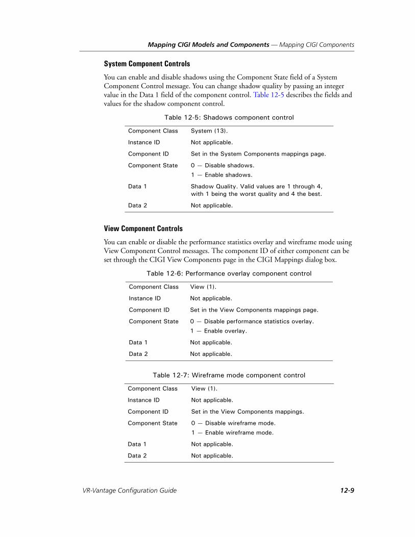
Mapping CIGI Models and Components — Mapping CIGI Components
System Component Controls
You can enable and disable shadows using the Component State field of a System Component Control message. You can change shadow quality by passing an integer value in the Data 1 field of the component control. Table 12-5 describes the fields and values for the shadow component control.
View Component Controls
You can enable or disable the performance statistics overlay and wireframe mode using View Component Control messages. The component ID of either component can be set through the CIGI View Components page in the CIGI Mappings dialog box.
Table 12-5: Shadows component control
Component Class System (13).
Instance ID Not applicable.
Component ID Set in the System Components mappings page.
Component State 0 — Disable shadows.
1 — Enable shadows.
Data 1 Shadow Quality. Valid values are 1 through 4, with 1 being the worst quality and 4 the best.
Data 2 Not applicable.
Table 12-6: Performance overlay component control
Component Class View (1).
Instance ID Not applicable.
Component ID Set in the View Components mappings page.
Component State 0 — Disable performance statistics overlay.
1 — Enable overlay.
Data 1 Not applicable.
Data 2 Not applicable.
Table 12-7: Wireframe mode component control
Component Class View (1).
Instance ID Not applicable.
Component ID Set in the View Components mappings.
Component State 0 — Disable wireframe mode.
1 — Enable wireframe mode.
Data 1 Not applicable.
Data 2 Not applicable.
VR-Vantage Configuration Guide 12-9

Mapping CIGI Models and Components — Mapping a Database
12.4. Mapping a DatabaseSimilar to mapping components to IDs, in a simulation using CIGI you can map data-bases to database numbers. If the host sends a control message that specifies a database, VR-Vantage will load it. If a database is not mapped or the host does not send a control message to load a database, you must load the database in VR-Vantage as you normally would for other connection types.
To map a database:
1. Choose Settings CIGI Mappings. The CIGI Mappings dialog box opens (Figure 12-1).
2. Select the CIGI Database Mapping page (Figure 12-5).
Figure 12-5. CIGI Database Mappings page
3. Click the Add button ( ) above the list of databases. A file chooser dialog box opens.
4. Select the database that you want to map to.
5. Click Open. The Create Database Mapping dialog box opens (Figure 12-6).
Figure 12-6. Create Database Mapping dialog box
6. Type a number for the database. If you choose a number that is in use, this database will replace the currently mapped database.
12-10 VT MÄK
Mapping CIGI Models and Components — Mapping CIGI Views
7. Click OK.
12.5. Mapping CIGI ViewsVR-Vantage associates CIGI views with VR-Vantage channels using channel keywords. (For details about channel keywords, please see “Changing a Channel’s Attributes,” on page 2-10.) Any channel with keyword cigiViewX is associated with CIGI view X. For example, keyword cigiView2 would map to CIGI view 2.
CIGI view control packets actually affect the observer that is controlling the specified view. VR-Vantage looks up the channel that has the keyword that matches the view ID specified in the view control packet. Then it finds the observer controlling that channel and applies the view control commands to that observer. If multiple channels have the same keyword, then the first channel found with a matching keyword is used.
Multiple channels with the same keyword are fine, as long as they are all controlled by the same observer. This removes the need for CIGI view groups, although VR-Vantage supports them.
VR-Vantage Configuration Guide 12-11
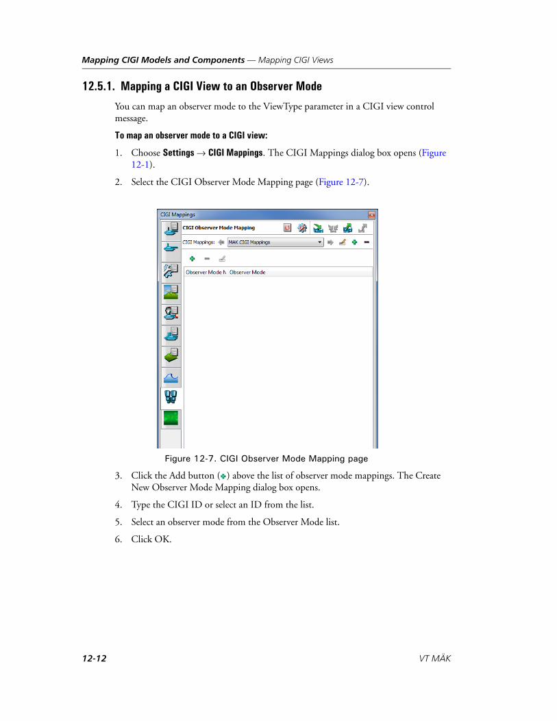
Mapping CIGI Models and Components — Mapping CIGI Views
12.5.1. Mapping a CIGI View to an Observer Mode
You can map an observer mode to the ViewType parameter in a CIGI view control message.
To map an observer mode to a CIGI view:
1. Choose Settings CIGI Mappings. The CIGI Mappings dialog box opens (Figure 12-1).
2. Select the CIGI Observer Mode Mapping page (Figure 12-7).
Figure 12-7. CIGI Observer Mode Mapping page
3. Click the Add button ( ) above the list of observer mode mappings. The Create New Observer Mode Mapping dialog box opens.
4. Type the CIGI ID or select an ID from the list.
5. Select an observer mode from the Observer Mode list.
6. Click OK.
12-12 VT MÄK

Mapping CIGI Models and Components — Prototypical Host – IG Configurations
12.6. Prototypical Host – IG ConfigurationsThis section describes several prototypes for host simulation and image generator configurations. The VR-Vantage CIGI implementation supports the networked IG configuration.
In the classic IG configuration (Figure 12-8), the host simulation connects to the network and filters all the entities and interactions, providing only the relevant ones to the image generator (shown as the VR-Vantage Application) using a protocol like CIGI. The IG renders the scene and presents it to the user on display screens of some sort.
Figure 12-8. Classic IG Configuration
In the networked IG configuration (Figure 12-9), the host simulation communicates only the “ownship” (the one entity the host is simulating) to the image generator, using a protocol like CIGI. The image generator presents all the other entities and interac-tions in the distributed simulation.
Figure 12-9. Networked IG Configuration
In the distributed visual/simulation configuration (Figure 12-10), the host simulation communicates with the visual application over the DIS/HLA network. (This is the way VR-Vantage connects to any distributed simulation entity.)
Friend and FoeSimulations
Ownship HostSimulation
VR-VantageApplication
UserInterface
Entities and interactions
UserInput
DisplayOutput
DIS/HLA network
Friend and FoeSimulations
Ownship HostSimulation
VR-VantageApplication
UserInterface
Entities and interactions
UserInput
DisplayOutput
DIS/HLA network
VR-Vantage Configuration Guide 12-13

Mapping CIGI Models and Components — Prototypical Host – IG Configurations
Figure 12-10. Distributed Visual/Simulation Application IG Configuration
In the integrated visual/simulation application (Figure 12-11), the simulation code is embedded in the visual application. This is the way many games are built. You can use the VR-Vantage toolkit to embed simulation code in VR-Vantage or embed VR-Vantage in a simulation application.
Figure 12-11. Integrated Visual/Simulation Application Configuration
Friend and FoeSimulations
Ownship HostSimulation
VR-VantageApplication
UserInterface
Entities and interactions
UserInput
DisplayOutput
DIS/HLA network
Friend and FoeSimulations
Ownship
HostSimulation
UserInterface
Entities and interactions
UserInput
DisplayOutput
DIS/HLA network
andVR-VantageApplication
12-14 VT MÄK

VR-V
13. CIGI Host Emulator Tutorial
VR-Vantage includes a CIGI host emulator (Windows only). This tutorial explains how to run it and interact with VR-Vantage.
Using the CIGI Host Emulator (Windows Only) ....................................... 13-2Start the Host Emulator ....................................................................... 13-3Connect VR-Vantage to the CIGI Host Emulator................................ 13-4Create an Ownship Entity on the Host Emulator................................. 13-5Create a Simulated Entity on the Host Emulator.................................. 13-7Change an Entity’s Model State ............................................................ 13-7Add an Effect ....................................................................................... 13-9Change the Weather ........................................................................... 13-10
13-1antage Configuration Guide
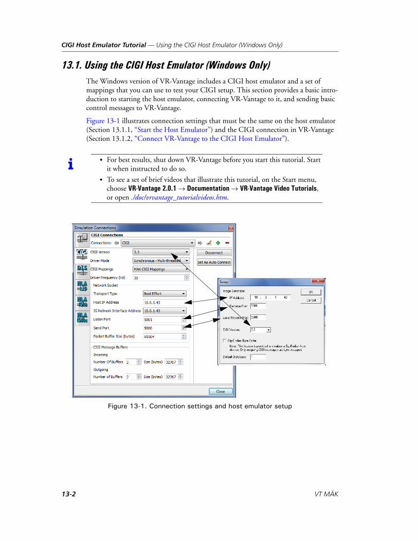
CIGI Host Emulator Tutorial — Using the CIGI Host Emulator (Windows Only)
13.1. Using the CIGI Host Emulator (Windows Only)The Windows version of VR-Vantage includes a CIGI host emulator and a set of mappings that you can use to test your CIGI setup. This section provides a basic intro-duction to starting the host emulator, connecting VR-Vantage to it, and sending basic control messages to VR-Vantage.
Figure 13-1 illustrates connection settings that must be the same on the host emulator (Section 13.1.1, “Start the Host Emulator”) and the CIGI connection in VR-Vantage (Section 13.1.2, “Connect VR-Vantage to the CIGI Host Emulator”).
Figure 13-1. Connection settings and host emulator setup
i For best results, shut down VR-Vantage before you start this tutorial. Start it when instructed to do so.
To see a set of brief videos that illustrate this tutorial, on the Start menu, choose VR-Vantage 2.0.1 Documentation VR-Vantage Video Tutorials, or open ./doc/vrvantage_tutorialvideos.htm.
13-2 VT MÄK
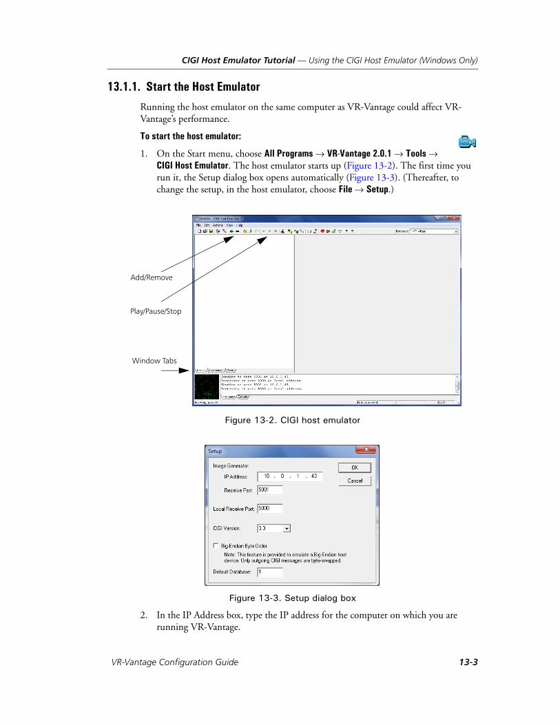
CIGI Host Emulator Tutorial — Using the CIGI Host Emulator (Windows Only)
13.1.1. Start the Host Emulator
Running the host emulator on the same computer as VR-Vantage could affect VR-Vantage’s performance.
To start the host emulator:
1. On the Start menu, choose All Programs VR-Vantage 2.0.1 Tools CIGI Host Emulator. The host emulator starts up (Figure 13-2). The first time you run it, the Setup dialog box opens automatically (Figure 13-3). (Thereafter, to change the setup, in the host emulator, choose File Setup.)
Figure 13-2. CIGI host emulator
Figure 13-3. Setup dialog box
2. In the IP Address box, type the IP address for the computer on which you are running VR-Vantage.
Add/Remove
Play/Pause/Stop
Window Tabs
VR-Vantage Configuration Guide 13-3
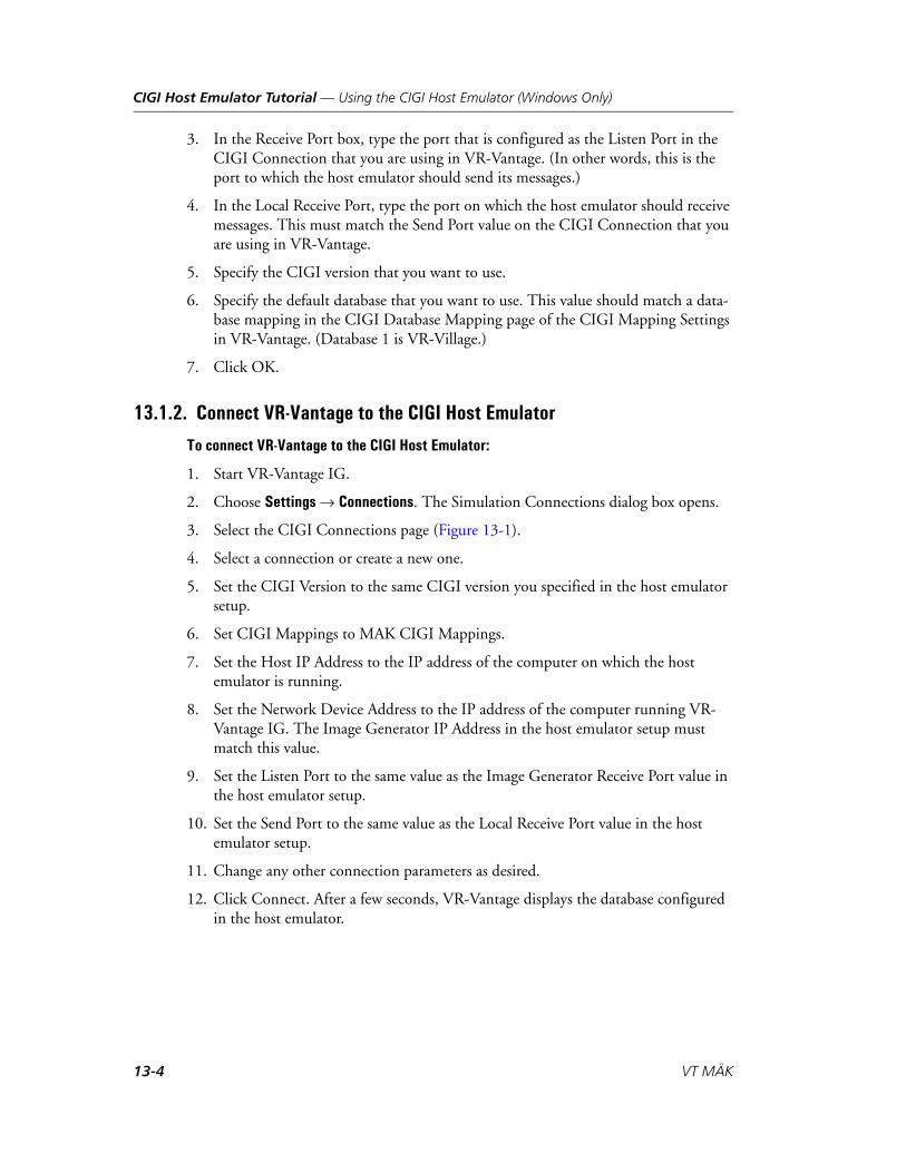
CIGI Host Emulator Tutorial — Using the CIGI Host Emulator (Windows Only)
3. In the Receive Port box, type the port that is configured as the Listen Port in the CIGI Connection that you are using in VR-Vantage. (In other words, this is the port to which the host emulator should send its messages.)
4. In the Local Receive Port, type the port on which the host emulator should receive messages. This must match the Send Port value on the CIGI Connection that you are using in VR-Vantage.
5. Specify the CIGI version that you want to use.
6. Specify the default database that you want to use. This value should match a data-base mapping in the CIGI Database Mapping page of the CIGI Mapping Settings in VR-Vantage. (Database 1 is VR-Village.)
7. Click OK.
13.1.2. Connect VR-Vantage to the CIGI Host Emulator
To connect VR-Vantage to the CIGI Host Emulator:
1. Start VR-Vantage IG.
2. Choose Settings Connections. The Simulation Connections dialog box opens.
3. Select the CIGI Connections page (Figure 13-1).
4. Select a connection or create a new one.
5. Set the CIGI Version to the same CIGI version you specified in the host emulator setup.
6. Set CIGI Mappings to MAK CIGI Mappings.
7. Set the Host IP Address to the IP address of the computer on which the host emulator is running.
8. Set the Network Device Address to the IP address of the computer running VR-Vantage IG. The Image Generator IP Address in the host emulator setup must match this value.
9. Set the Listen Port to the same value as the Image Generator Receive Port value in the host emulator setup.
10. Set the Send Port to the same value as the Local Receive Port value in the host emulator setup.
11. Change any other connection parameters as desired.
12. Click Connect. After a few seconds, VR-Vantage displays the database configured in the host emulator.
13-4 VT MÄK
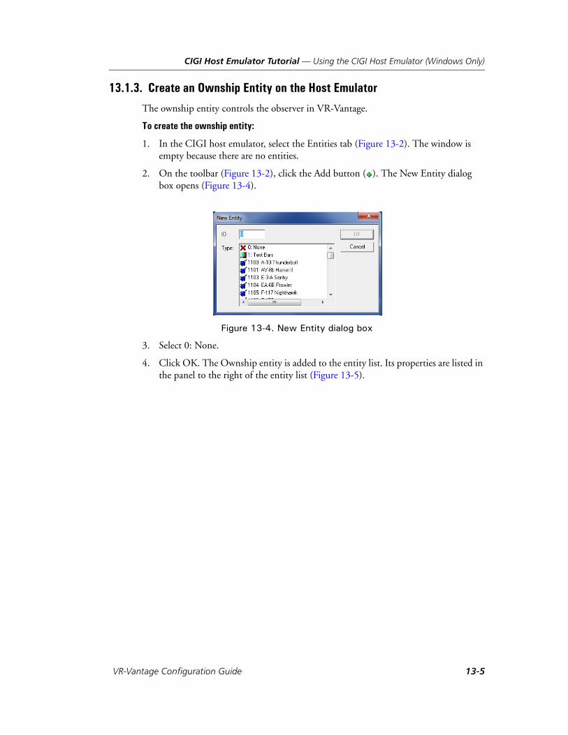
CIGI Host Emulator Tutorial — Using the CIGI Host Emulator (Windows Only)
13.1.3. Create an Ownship Entity on the Host Emulator
The ownship entity controls the observer in VR-Vantage.
To create the ownship entity:
1. In the CIGI host emulator, select the Entities tab (Figure 13-2). The window is empty because there are no entities.
2. On the toolbar (Figure 13-2), click the Add button ( ). The New Entity dialog box opens (Figure 13-4).
Figure 13-4. New Entity dialog box
3. Select 0: None.
4. Click OK. The Ownship entity is added to the entity list. Its properties are listed in the panel to the right of the entity list (Figure 13-5).
VR-Vantage Configuration Guide 13-5
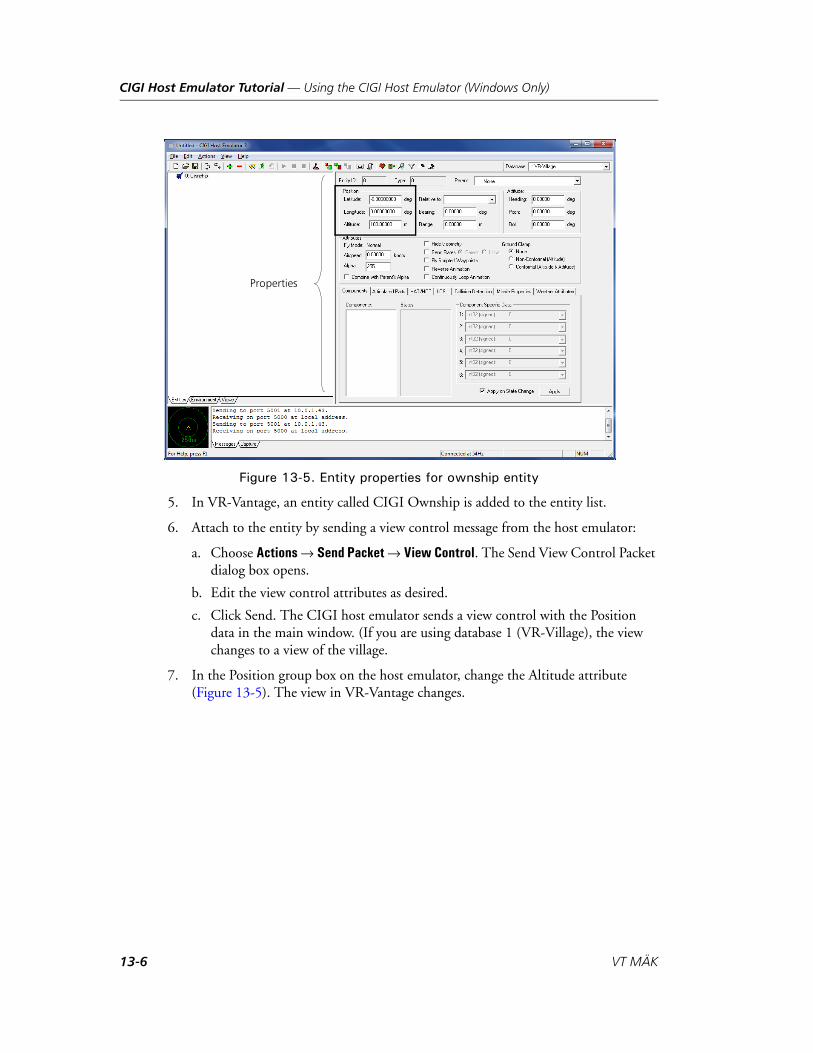
CIGI Host Emulator Tutorial — Using the CIGI Host Emulator (Windows Only)
Figure 13-5. Entity properties for ownship entity
5. In VR-Vantage, an entity called CIGI Ownship is added to the entity list.
6. Attach to the entity by sending a view control message from the host emulator:
a. Choose Actions Send Packet View Control. The Send View Control Packet dialog box opens.
b. Edit the view control attributes as desired.
c. Click Send. The CIGI host emulator sends a view control with the Position data in the main window. (If you are using database 1 (VR-Village), the view changes to a view of the village.
7. In the Position group box on the host emulator, change the Altitude attribute (Figure 13-5). The view in VR-Vantage changes.
Properties
13-6 VT MÄK
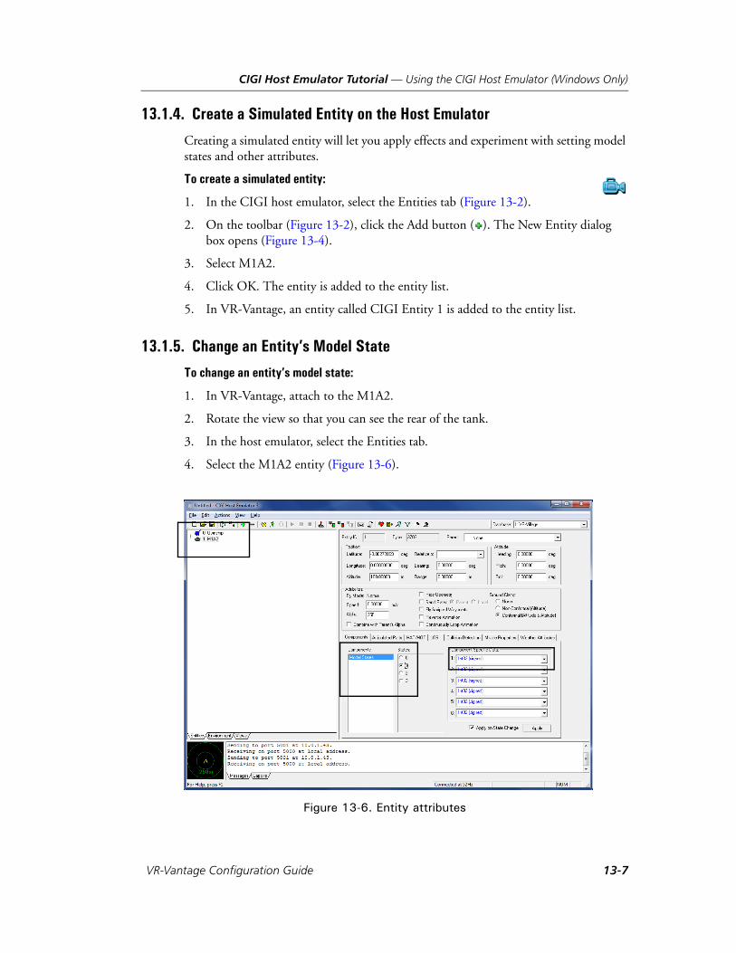
CIGI Host Emulator Tutorial — Using the CIGI Host Emulator (Windows Only)
13.1.4. Create a Simulated Entity on the Host Emulator
Creating a simulated entity will let you apply effects and experiment with setting model states and other attributes.
To create a simulated entity:
1. In the CIGI host emulator, select the Entities tab (Figure 13-2).
2. On the toolbar (Figure 13-2), click the Add button ( ). The New Entity dialog box opens (Figure 13-4).
3. Select M1A2.
4. Click OK. The entity is added to the entity list.
5. In VR-Vantage, an entity called CIGI Entity 1 is added to the entity list.
13.1.5. Change an Entity’s Model State
To change an entity’s model state:
1. In VR-Vantage, attach to the M1A2.
2. Rotate the view so that you can see the rear of the tank.
3. In the host emulator, select the Entities tab.
4. Select the M1A2 entity (Figure 13-6).
Figure 13-6. Entity attributes
VR-Vantage Configuration Guide 13-7
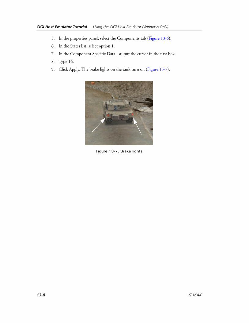
CIGI Host Emulator Tutorial — Using the CIGI Host Emulator (Windows Only)
5. In the properties panel, select the Components tab (Figure 13-6).
6. In the States list, select option 1.
7. In the Component Specific Data list, put the cursor in the first box.
8. Type 16.
9. Click Apply. The brake lights on the tank turn on (Figure 13-7).
Figure 13-7. Brake lights
13-8 VT MÄK

CIGI Host Emulator Tutorial — Using the CIGI Host Emulator (Windows Only)
13.1.6. Add an Effect
To add an effect in the MÄK implementation of CIGI, you add the effect and attach it to an entity.
To add an effect:
1. In the CIGI host emulator, select the Entities tab (Figure 13-2).
2. On the toolbar (Figure 13-2), click the Add button ( ). The New Entity dialog box opens (Figure 13-4).
3. Select Detonation.
4. Click OK. The effect is added to the entity list.
5. On the properties panel, in the Parent list, select M1A2. In the entity list, the Detonation is now subordinate to the M1A2 entity (Figure 13-6).
Figure 13-8. Entity attributes
6. To display the detonation, click Play (Figure 13-2).
VR-Vantage Configuration Guide 13-9
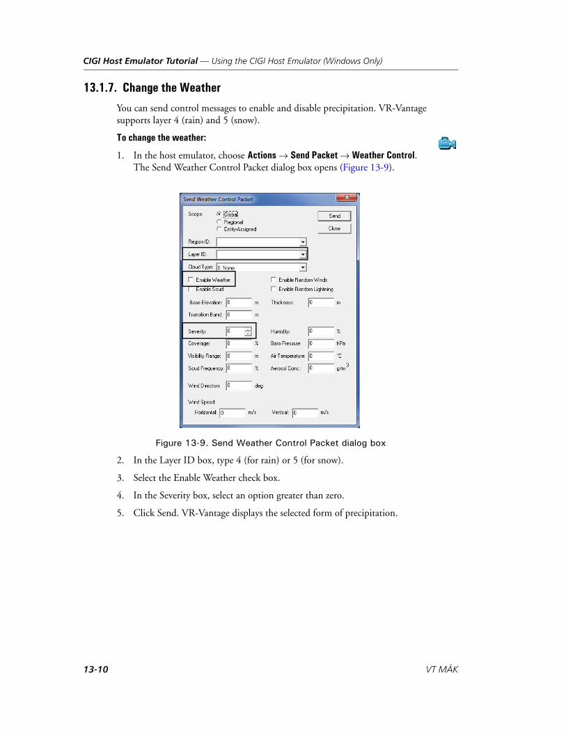
CIGI Host Emulator Tutorial — Using the CIGI Host Emulator (Windows Only)
13.1.7. Change the Weather
You can send control messages to enable and disable precipitation. VR-Vantage supports layer 4 (rain) and 5 (snow).
To change the weather:
1. In the host emulator, choose Actions Send Packet Weather Control. The Send Weather Control Packet dialog box opens (Figure 13-9).
Figure 13-9. Send Weather Control Packet dialog box
2. In the Layer ID box, type 4 (for rain) or 5 (for snow).
3. Select the Enable Weather check box.
4. In the Severity box, select an option greater than zero.
5. Click Send. VR-Vantage displays the selected form of precipitation.
13-10 VT MÄK
VR-V
14. Creating and Editing Key Mappings
This appendix explains how to edit key mappings and create new key mappings.
Introduction ............................................................................................... 14-2
The Key Mapping Editor............................................................................ 14-2Binary Key Mappings ........................................................................... 14-3
Editing a Key Map...................................................................................... 14-3Adding a Key Mapping ........................................................................ 14-4Changing a Key Mapping..................................................................... 14-6Deleting a Key Mapping ...................................................................... 14-6
Using Combined Key Mappings ................................................................. 14-7
Filtering the Function List .......................................................................... 14-8
Creating a Key Map .................................................................................... 14-8
Deleting a Key Map .................................................................................... 14-8
14-1antage Configuration Guide

Creating and Editing Key Mappings — Introduction
14.1. IntroductionWhen you move the observer, you are actually executing functions that control the observer’s movement. For example, the Move Observer Forward function moves the observer forward in observer coordinates. The Move Level Observer Forward function moves the observer forward in level observer coordinates.
The various movement functions are mapped to the keys on the keyboard and to mouse buttons and the mouse wheel.
VR-Vantage comes with key mappings that we think will meet the needs of most VR-Vantage users. However, you can edit the default keyboard mappings and create new mappings of your own with the Key Mapping Editor.
14.2. The Key Mapping EditorThe Key Mapping Editor (Figure 14-1) lists all of the functions that you can control from the keyboard and the keys to which they are mapped. Some functions are mapped to more than one key or key combination. A key can be mapped to more than one function (combined mappings). You can:
Edit a function’s key mappings.
Add new mappings.
Delete mappings.
Changes are saved automatically.
Figure 14-1. Key Mapping Editor
14-2 VT MÄK

Creating and Editing Key Mappings — Editing a Key Map
14.2.1. Binary Key Mappings
Many navigation functions require you to press and hold a key. For example, you press and hold W to move the observer forward. (By contrast some keyboard actions are toggles or unary functions, such as pressing period to attach to the next entity.) For these actions, VR-Vantage needs to keep track of when the key is pressed down (start the action) and when it is released (stop the action). To a human user, a function like Move Observer Forward is experienced as one action. But the computer experiences it as two actions. Therefore, key mappings must take this into account. The Key Mapping Editor shows the key mappings for these functions as paired functions that are subordi-nate (children) to the primary function (the parent), as shown in the Move Observer Up entry in Figure 14-1.
14.3. Editing a Key MapThe Key Mapping Editor lists all of the VR-Vantage functions that you can control from the keyboard.
To edit a key map:
1. Choose Settings Application. The Application Settings dialog box opens.
2. Select the Key Mapping Editor page (Figure 14-1).
3. Select the function whose key mappings you want to edit.
4. Edit the key mappings as described in:
– “Adding a Key Mapping,” on page 14-4.
– “Changing a Key Mapping,” on page 14-6.
– “Deleting a Key Mapping,” on page 14-6.
5. Optionally, export the key map to a file.
6. Click OK.
VR-Vantage Configuration Guide 14-3

Creating and Editing Key Mappings — Editing a Key Map
14.3.1. Adding a Key Mapping
If a function is not mapped to a key, it is marked <unmapped>. You can add a mapping to unmapped functions and you can add additional key mappings to functions that are already mapped. If you add a key mapping to a binary function, the Key Mapping Editor automatically applies it to the child (UP and DN) functions. You can add key mappings to the child functions of binary mappings. When you add a key mapping to a child function, it is not applied to its paired function or the parent function.
To add a key mapping:
1. Optionally, filter the function list. For details, please see “Filtering the Function List,” on page 14-8.
2. Select the function to which you want to add a key mapping.
3. Click the Add button ( ) above the Key Map window (Figure 14-2). The Key Entry dialog box opens (Figure 14-3).
Figure 14-2. Key Mapping Editor
i In most cases, an unmapped function is unmapped because it is not meaningful in the observer frame for the key mapping. For example, the level observer movement functions are not meaningful in the observer frame key mappings.
Function list Key mappings Key Map
14-4 VT MÄK

Creating and Editing Key Mappings — Editing a Key Map
Figure 14-3. Key Entry dialog box
4. On the keyboard, press the key or key combination (such as Ctrl+key or Shift+key) that you want to map to this function.
5. Click OK. (If you choose a key combination that is already in use, VR-Vantage notifies you and asks how to proceed. For details about duplicate key mappings, please see “Using Combined Key Mappings,” on page 14-7.) The mapping is added to the function and is listed in the Keys column of the function list and in the Key Map window.
VR-Vantage Configuration Guide 14-5
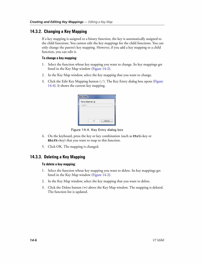
Creating and Editing Key Mappings — Editing a Key Map
14.3.2. Changing a Key Mapping
If a key mapping is assigned to a binary function, the key is automatically assigned to the child functions. You cannot edit the key mappings for the child functions. You can only change the parent’s key mapping. However, if you add a key mapping to a child function, you can edit it.
To change a key mapping:
1. Select the function whose key mapping you want to change. Its key mappings get listed in the Key Map window (Figure 14-2).
2. In the Key Map window, select the key mapping that you want to change.
3. Click the Edit Key Mapping button ( ). The Key Entry dialog box opens (Figure 14-4). It shows the current key mapping.
Figure 14-4. Key Entry dialog box
4. On the keyboard, press the key or key combination (such as Ctrl+key or Shift+key) that you want to map to this function.
5. Click OK. The mapping is changed.
14.3.3. Deleting a Key Mapping
To delete a key mapping:
1. Select the function whose key mapping you want to delete. Its key mappings get listed in the Key Map window (Figure 14-2).
2. In the Key Map window, select the key mapping that you want to delete.
3. Click the Delete button ( ) above the Key Map window. The mapping is deleted. The function list is updated.
14-6 VT MÄK
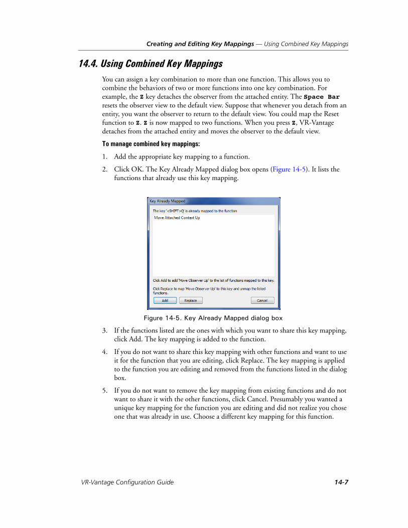
Creating and Editing Key Mappings — Using Combined Key Mappings
14.4. Using Combined Key MappingsYou can assign a key combination to more than one function. This allows you to combine the behaviors of two or more functions into one key combination. For example, the Z key detaches the observer from the attached entity. The Space Bar resets the observer view to the default view. Suppose that whenever you detach from an entity, you want the observer to return to the default view. You could map the Reset function to Z. Z is now mapped to two functions. When you press Z, VR-Vantage detaches from the attached entity and moves the observer to the default view.
To manage combined key mappings:
1. Add the appropriate key mapping to a function.
2. Click OK. The Key Already Mapped dialog box opens (Figure 14-5). It lists the functions that already use this key mapping.
Figure 14-5. Key Already Mapped dialog box
3. If the functions listed are the ones with which you want to share this key mapping, click Add. The key mapping is added to the function.
4. If you do not want to share this key mapping with other functions and want to use it for the function that you are editing, click Replace. The key mapping is applied to the function you are editing and removed from the functions listed in the dialog box.
5. If you do not want to remove the key mapping from existing functions and do not want to share it with the other functions, click Cancel. Presumably you wanted a unique key mapping for the function you are editing and did not realize you chose one that was already in use. Choose a different key mapping for this function.
VR-Vantage Configuration Guide 14-7
Creating and Editing Key Mappings — Filtering the Function List
14.5. Filtering the Function ListYou can filter the function list in the Key Mapping Editor. Functions are grouped thematically.
To filter the function list, click the Filter button ( ) and select an option on the list.
14.6. Creating a Key MapTo create a key map:
1. Choose Settings Application.The Application Settings dialog box opens.
2. Select the Key Mapping Editor page (Figure 14-1).
3. Click the Add button ( ). The Create New Key Map dialog box opens.
4. Type a name for the new key map.
5. Click OK.
6. Add key mappings for the movement actions as described in “Adding a Key Mapping,” on page 14-4.
14.7. Deleting a Key MapTo delete a key map:
1. Choose Settings Application.The Application Settings dialog box opens.
2. Select the Key Mapping Editor page (Figure 14-1).
3. In the key mapping list, select the key mapping that you want to delete.
4. Click the Delete button ( ).
5. Confirm that you want to delete the selected key map.
14-8 VT MÄK

VR-V
A. The WRM Specification (DIS Notes)
Some OpenFlight files contain information specified by the WRM Entity Model Specification for DIS Interoperability. This information makes it possible for VR-Vantage to depict the state of an entity's articulated and attached parts correctly and to switch among different entity appearances.
This appendix contains information that can help you build entity models that comply with the WRM specification, or add that compliance to existing models.
The WRM specification was developed by MÄK Technologies (now VT MÄK), Para-digm Simulation Inc., MultiGen Inc., and SAIC, for the ARPA War Breaker project. (Paradigm Simulation and MultiGen merged and were later acquired by Presagis.)
Introduction ................................................................................................. A-2
The OpenFlight File Format ......................................................................... A-2Node Name and Comment Fields .......................................................... A-3External References and Instancing......................................................... A-3
Modeling for DIS Interoperability ................................................................ A-3The DIS Attribute Lexicon (DAL) ......................................................... A-3DAL Keywords....................................................................................... A-4Model Coordinate Systems..................................................................... A-5
Articulated Parts............................................................................................ A-7
Entity Appearances ....................................................................................... A-8
Animation................................................................................................... A-11
DIS Keyword Values ................................................................................... A-12
i Although the WRM specification was developed for DIS, it is used in the HLA RPR FOM.
A-1antage Configuration Guide
The WRM Specification (DIS Notes)
A.1. IntroductionIn order for visualization applications such as VR-Vantage to change the state of a model in response to network messages, they must have certain information about the model. For example, which piece of the model’s geometry is associated with which articulated part, and which piece of a model is associated with a particular entity appearance attribute.
This appendix describes a method of encoding information in an OpenFlight format model so that applications can make these associations. For the most part, information is associated with a MultiGen node by including it as a comment associated with the node. Comments that contain this information begin with the token, @dis.
VR-Vantage depicts the movement of articulated parts and changes in entity appear-ances only when using models constructed to this specification.
This appendix represents a subset of the Model Specification for DIS Interoperability (version 001). For more details, please refer to that document. You can obtain the Model Specification at http://local.wasp.uwa.edu.au/~pbourke/dataformats/wrm/.
Although VR-Vantage implements only a subset of the functionality enabled by the WRM Model Specification, we recommend that models conform to as much of the specification as is appropriate for the model, to promote compatibility with future versions of VR-Vantage, and with visualization applications from other vendors.
A.2. The OpenFlight File FormatThe OpenFlight file format organizes geometry into the following types of nodes:
Face nodes represent individual polygons.
Object nodes represent face nodes that are logically or geographically related. Object nodes can have only face nodes (polygons) as children.
Level of detail (LOD) nodes provide a means to select alternate geometries based on a user-definable range. Using lower resolution geometry for objects that are far from the observer saves memory and improves performance.
Degree of Freedom (DOF) nodes specify translational or rotational freedom, or both, for portions of a model. They can be used for DIS articulated parts or animated special effects. They specify a type of transformation and its limits, such as “rotate about the x axis between 45 and 135 degrees”. The OpenFlight approach to degrees of freedom is hierarchical.
Group nodes represent logically-related or geographically-related object nodes. Group nodes are the most general, and may have any type of nodes, except face nodes, as children.
A-2 VT MÄK

The WRM Specification (DIS Notes) — Modeling for DIS Interoperability
A.2.1. Node Name and Comment Fields
Each node contains a comment field for user-definable data. The WRM Specification defines keywords that, when placed in a comment field, provide the information that DIS applications need to properly render a model.
A.2.2. External References and Instancing
The following OpenFlight constructs provide a means to avoid duplicating massive amounts of geometry:
An external reference (or xref ) is a pointer to another OpenFlight file that contains additional geometry.
A transformation matrix is usually attached to an xref to locate the position and orientation of the referenced object’s coordinate system geometry. Each instance may have a transformation matrix controlling the position and orientation of the child’s coordinate system.
A.3. Modeling for DIS InteroperabilityThe WRM Specification provides uniform standards for locating and orienting the model coordinate system and a way to map DIS codes to associated models and parts. By conforming to these standards, applications that support the WRM Specification do not need customized software to interpret the multiple potential model formats that might otherwise exist.
A.3.1. The DIS Attribute Lexicon (DAL)
DIS attributes are specified using the following syntax:
@dis keyword values # comment
where:
@dis must precede the keyword.
keyword is one of the DAL keywords.
values can be a number or string. Depending on the requirements of the keyword, the values specified can be an individual value, a comma separated list, or a range.
# indicates the start of a comment. Comments are case sensitive. A comment continues until the next @dis entry.
Remember that all comments will be parsed by VR-Vantage, so spelling counts.
VR-Vantage Configuration Guide A-3

The WRM Specification (DIS Notes) — Modeling for DIS Interoperability
A.3.2. DAL Keywords
The WRM Spec supports the following keywords:
articulated_part part. Identifies the moveable parts of a model with a unique DIS Articulated Part code. This keyword is placed in a Group node that is a child to the DOF node that identifies an articulated part, and above the geometry that is going to be articulated. This keyword is always followed by the motion keyword. The articulated part codes are specified in DIS Standard SISO-REF-010-2006 Enumerations and Bit Encoded Values Articulated Parts. They are listed in Table A-3.
This keyword is always followed by the switch keyword.
switch appearance. Identifies a model appearance attribute with a DIS keyword. This keyword is placed in a Switch node in the model above the geometry that is going to be switched.
The switch keyword takes the name value in DIS Standard SISO-REF-010-2006 Enumerations and Bit Encoded Values Entity Appearance (General and Specific), joined by the underscore character ( _ ) if the name is multiple words, as its value. Note that frozen_status, power_plant_status, and state are preceded by an abbrevi-ation for their domain, as follows: gm_ for guided munitions and lf_ for life forms. For a list of supported values, please see Table A-2.
state state,state... . Specifies the state of the appearance attribute with a DIS appearance state code. This keyword is placed in a Group node just below the switch node. For a list of supported values, please see Table A-2.
A-4 VT MÄK

The WRM Specification (DIS Notes) — Modeling for DIS Interoperability
A.3.3. Model Coordinate Systems
OpenSceneGraph (OSG) and the DIS Standard use different right-hand coordinate systems. Table A-1 describes the two systems. Figure A-1 illustrates them.
Figure A-1. Model coordinate systems
When you create models, it is recommended that you use the OpenSceneGraph coordi-nate system. The simulation application will convert the coordinates, as follows:
xmodel = yDIS.
ymodel = xDIS.
zmodel = -zDIS.
Location of the Origin for Models
The origin of the model’s coordinate system should be located as follows, depending on the domain of the entity:
Land: on the base of the vehicle, on the axis of yaw rotation.
Surface: On the axis of the center of buoyancy, in the plane of the waterline for unloaded ship.
Subsurface: On the axis of the center of buoyancy, in the plane of the waterline for surfaced submarine.
Air and Space: At the center of gravity.
Figure A-2 illustrates the location of a model’s origin for each platform domain.
Table A-1: Model coordinate systems
Coordinate OpenSceneGraph DIS
X Right Forward
Y Forward Right
Z Up Down
OSG coordinate system DIS coordinate system
X
Z
X
Y
Z
Y
VR-Vantage Configuration Guide A-5
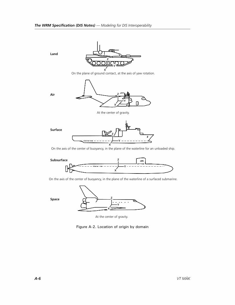
The WRM Specification (DIS Notes) — Modeling for DIS Interoperability
Figure A-2. Location of origin by domain
On the plane of ground contact, at the axis of yaw rotation.
At the center of gravity.
On the axis of the center of buoyancy, in the plane of the waterline for an unloaded ship.
On the axis of the center of buoyancy, in the plane of the waterline of a surfaced submarine.
Land
Air
Surface
Subsurface
Space
At the center of gravity.
X
Z
Y
X
Z
Y
X
Z
Y
X
Z
Y
X
Z
Y
A-6 VT MÄK
The WRM Specification (DIS Notes) — Articulated Parts
A.4. Articulated PartsIn order for VR-Vantage to properly depict the state of articulated parts, models must conform to the following specifications:
There must be one DOF node for each articulated part. (This means that if there are several LODs, they should be children of the DOF.) Each articulation DOF should be a descendant of the DOF for the part to which it is attached (unless the parent part is just the base model itself ). For example, the DOF for a gun should be a descendant of the DOF for a turret.
Each articulated part DOF node must have all of the geometry and other nodes associated with the part underneath it. This DOF node must have a comment asso-ciated with it. The comment must be of the form:@dis articulated_part part-number
where part-number is the enumeration for the particular type of part that this part of the model represents. For example, the part number of a turret is 4096, and the part number of a gun is 4416.
Therefore, the child group of a turret’s DOF must be commented with:
@dis articulated_part 4096
The child group of a gun’s DOF must be commented with:
@dis articulated_part 4416
The WRM Model Specification specifies that information about the legal motions of each articulated part be encoded in the comment field. Currently, VR-Vantage does not use this information.
Do not include static offsets in the DOF attributes. That is, when you set all of the DOF parameters (X, Y, Z, heading, pitch, roll) to 0, the model should appear in its neutral position.
VR-Vantage Configuration Guide A-7

The WRM Specification (DIS Notes) — Entity Appearances
A.5. Entity AppearancesVR-Vantage supports switching between different pieces of a model’s geometry based on appearance attributes. For instance, a tank’s turret should look different if the hatch is open or closed. An entire tank should look different if it is damaged or destroyed.
Switch nodes are used to represent a choice between several different children, based on a particular appearance attribute.
We define a switch node as a group node with a comment of the form:
@dis switch attribute
where attribute is the name of the attribute that should be used to select a child. (For example, damage, smoke, hatch, and so on.) “Entity Appearances,” on page A-8, lists the attributes you can use with VR-Vantage.
The children of the switch node represent the different portions of a model among which VR-Vantage will select, based on the appearance attribute. If a switch node is commented with:
@dis switch hatch
it may, for example, have three children containing geometry for a closed hatch, popped hatch, and open hatch.
These children of the switch node must be commented so that VR-Vantage knows which child matches which values of the appearance attribute. The comment is of the form:
@dis state value-list
value-list is of the form m[,m]+ where m is one of the following:
An integer representing the enumeration of a value that an appearance attribute may take on, for example, 1 for hatch closed.
Two integers, a and b, separated by a hyphen, representing all enumerations from a through b, for example, 2-5 for all states whose enumerations are 2, 3, 4, or 5.
The integer -1, which indicates that this child is the default child, to be used when the attribute state matches no values in any children.
For instance, the child of the hatch switch node that represents a closed hatch might be used when the hatch attribute value is either 0 (not-applicable), 1 (closed), or any value other than those enumerated in other children. This child would be commented:
@dis state 0,1,-1
The child with the popped hatch geometry should be used when the value is 2 (popped) or 3 (popped with person visible) and is commented:
@dis state 2,3
The child that contains the open hatch geometry should be used when the value is 4 (open) or 5 (open with person visible) and is commented:
@dis state 4,5
A-8 VT MÄK
The WRM Specification (DIS Notes) — Entity Appearances
There may be many switch nodes for the same attribute. For example, there may be several pieces of a tank’s geometry that are affected by the destroyed attribute.
The WRM Model Specification also discusses the inheritance of appearance attributes from ancestor nodes. VR-Vantage does not support this functionality. To tell VR-Vantage to, for example, display a camouflaged tank when the paint scheme attribute is set to camouflage, and a normal tank otherwise, you must use the switch node method described previously.
In Figure A-3, the turret DOF node is attached to the body Group node. The barrel, gun, and hatch DOF nodes are attached to the turret. This allows the turret to be posi-tioned in the coordinate system of the body, and the barrel, gun, and hatch to be posi-tioned in the coordinate system of the turret.
This model also contains a switch node that is flagged with animation. The comment on this node is @dis switch moving. This switches between two Group nodes – Stop and Go. Under the Stop node there is a single mesh of the treads of the tank. Under the Go node there is a Group node, with the animation flag set on. This creates a flipbook animation of all nodes below this Group node. There are three meshes in different states of moving: Frame 1, Frame 2 and Frame 3. At runtime OpenScene-Graph will animate these meshes when the velocity is not 0.
If multiple color schemes are needed to represent camouflage, winter, and desert versions, another switch is needed.
VR-Vantage Configuration Guide A-9
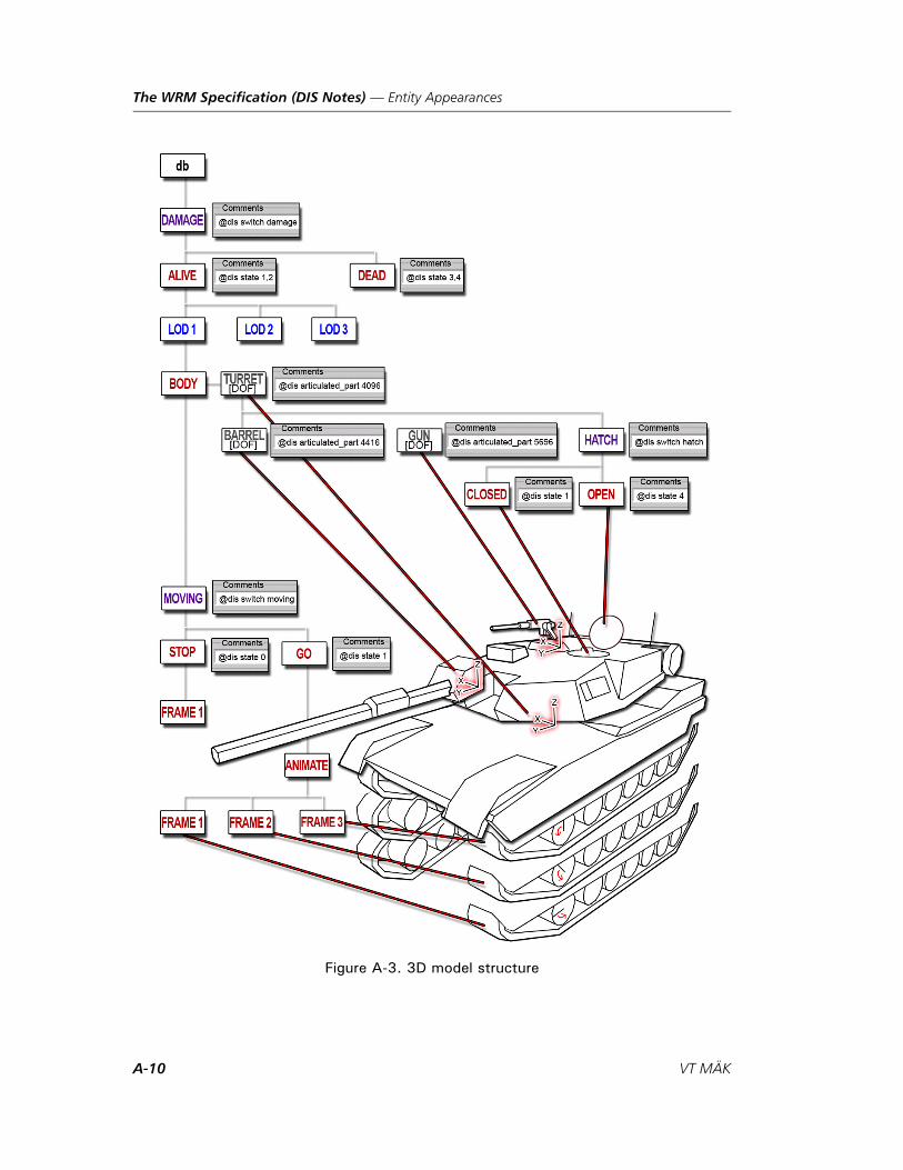
The WRM Specification (DIS Notes) — Entity Appearances
Figure A-3. 3D model structure
A-10 VT MÄK

The WRM Specification (DIS Notes) — Animation
A.6. AnimationBy default, animation sequences are displayed as quickly as possible. However, you can configure the animation sequence rate using a WRM animation comment in the animation node's comment field.
The comment syntax is as follows:
@dis animation num_frames_per_second [ skip | noskip ]
where:
animation tells VR-Vantage that animation instructions follow.
num_frames_per_second is the rate at which VR-Vantage should display the frames.
skip and noskip indicate whether the elapsed time should be used to choose the next frame, or whether at most one frame should be advanced each frame.
VR-Vantage Configuration Guide A-11

The WRM Specification (DIS Notes) — DIS Keyword Values
A.7. DIS Keyword ValuesTable A-2 lists the values that you can use for the @dis switch keyword. For any switch keyword, the supported state values (@dis state [value 1],[value 1]...) are listed in the State column. The Bit column lists the appearance bit for setting DIS appearances. (Some bit number are repeated because they are valid only for a particular platform.)
Table A-2: DIS Appearance and States (Sheet 1 of 4)
Values DescriptionState/Description
Bit
afterburner State of an air platform's afterburner.
0 = Off
1 = On
16
anticollision_lights State of anti-collision lights.
0 = Off
1 = On
14
blackout_brake_lights State of blackout brake lights.
0 = Off
1 = On
27
blackout_lights State of blackout lights. 0 = Off
1 = On
26
brake_lights State of brake lights. 0 = Off
1 = On
14
camouflage_type Type of camouflage. 0 = Desert
1 = Winter
2 = Forest
3 = Unused
17-18
compliance Compliance of lifeform. 0 = Lifeform None
1 = Detained
2 = Surrender
3 = Using Fists
4 = Verbal Abuse 1
5 = Verbal Abuse 2
6 = Verbal Abuse 3
7 = Passive Resistance 1
8 = Passive Resistance 2
9 = Passive Resistance 3
10 = Non-Lethal Weapon 1
11 = Non-Lethal Weapon 2
12 = Non-Lethal Weapon 3
13 = Non-Lethal Weapon 4
14 = Non-Lethal Weapon 5
15 = Non-Lethal Weapon 6
A-12 VT MÄK

The WRM Specification (DIS Notes) — DIS Keyword Values
concealed Type of concealment. 0 = Not Concealed 19
1 = In Concealed Position
damage Damaged appearance of an entity.
0 = None
1 = Slight
2 = Moderate
3 = Destroyed
3-4
density Density of environmental. 0 = Clear
1 = Hazy
2 = Dense
3 = Very Dense
4 = Opaque
5 = Unused
fire_power Characteristics of fire-power kill.
0 = No
1 = Yes
2
flaming State of flames rising from an entity.
0 = No
1 = Yes
15
flashlight State of lights. 0 = Off
1 = On
formation_lights State of formation lights. 0 = Off
1 = On
24
frozen_status Frozen status of an entity.
0 = Not Frozen
1 = Frozen
21
hatch State of the primary hatch.
0 = Not Applicable
1 = Closed
2 = Popped
9-11
3 = Popped and Person Visible
4 = Open
5 = Open and Person Visible
6 = Custom1
7 = Custom2
head_lights State of headlights. 0 = No
1 = Yes
12
health State of injury. 0 = None
1 = Slight
2 = Moderate
3 = Fatal
Table A-2: DIS Appearance and States (Sheet 2 of 4)
Values DescriptionState/Description
Bit
VR-Vantage Configuration Guide A-13
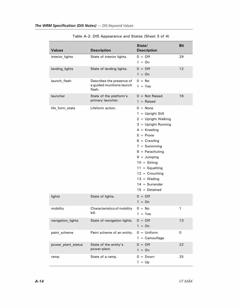
The WRM Specification (DIS Notes) — DIS Keyword Values
interior_lights State of interior lights. 0 = Off
1 = On
29
landing_lights State of landing lights. 0 = Off
1 = On
12
launch_flash Describes the presence of a guided munitions launch flash.
0 = No
1 = Yes
launcher State of the platform's primary launcher.
0 = Not Raised
1 = Raised
16
life_form_state Lifeform action. 0 = None
1 = Upright Still
2 = Upright Walking
3 = Upright Running
4 = Kneeling
5 = Prone
6 = Crawling
7 = Swimming
8 = Parachuting
9 = Jumping
10 = Sitting
11 = Squatting
12 = Crouching
13 = Wading
14 = Surrender
15 = Detained
lights State of lights. 0 = Off
1 = On
mobility Characteristics of mobility kill.
0 = No
1 = Yes
1
navigation_lights State of navigation lights. 0 = Off
1 = On
13
paint_scheme Paint scheme of an entity. 0 = Uniform
1 = Camouflage
0
power_plant_status State of the entity’s power-plant.
0 = Off
1 = On
22
ramp State of a ramp. 0 = Down
1 = Up
25
Table A-2: DIS Appearance and States (Sheet 3 of 4)
Values DescriptionState/Description
Bit
A-14 VT MÄK
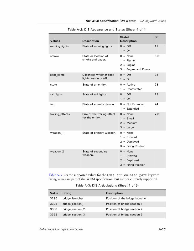
The WRM Specification (DIS Notes) — DIS Keyword Values
Table A-3 lists the supported values for the @dis articulated_part keyword. String values are part of the WRM specification, but are not currently supported.
running_lights State of running lights. 0 = Off
1 = On
12
smoke State or location of smoke and vapor.
0 = None
1 = Plume
2 = Engine
3 = Engine and Plume
5-6
spot_lights Describes whether spot-lights are on or off.
0 = Off
1 = On
28
state State of an entity. 0 = Active
1 = Deactivated
23
tail_lights State of tail lights. 0 = Off
1 = On
13
tent State of a tent extension. 0 = Not Extended
1 = Extended
24
trailing_effects Size of the trailing effect for the entity.
0 = None
1 = Small
2 = Medium
3 = Large
7-8
weapon_1 State of primary weapon. 0 = None
1 = Stowed
2 = Deployed
3 = Firing Position
weapon_2 State of secondary weapon.
0 = None
1 = Stowed
2 = Deployed
3 = Firing Position
Table A-3: DIS Articulations (Sheet 1 of 5)
Value String Description
3296 bridge_launcher Position of the bridge launcher.
3328 bridge_section_1 Position of bridge section 1.
3360 bridge_section_2 Position of bridge section 2.
3392 bridge_section_3 Position of bridge section 3.
Table A-2: DIS Appearance and States (Sheet 4 of 4)
Values DescriptionState/Description
Bit
VR-Vantage Configuration Guide A-15

The WRM Specification (DIS Notes) — DIS Keyword Values
7616 fuselage_fold Fold on plane’s body.
1184 helicopter_main_rotor Describes main rotor rotation.
1216 helicopter_tail_rotor Describes tail rotor rotation.
3072 landing_gear Landing gear on a plane.
3520 launcher_arm_primary Position of the primary launcher arm.
1120 left_aileron Position of the left aileron.
1056 left_flap Position of the left flap.
3168 left_weapon_bay_door Left door to weapon bay.
3552 other Position of other articulated parts.
3424 primary_blade_1 Position of the primary blade 1.
3456 primary_blade_2 Position of the primary blade 2.
3488 primary_boom Position of the primary boom.
5056 primary_defense_systems_1 Position of the primary defense systems 1.
5088 primary_defense_systems_2 Position of the primary defense systems 2.
5120 primary_defense_systems_3 Position of the primary defense systems 3.
5152 primary_defense_systems_4 Position of the primary defense systems 4.
5184 primary_defense_systems_5 Position of the primary defense systems 5.
5216 primary_defense_systems_6 Position of the primary defense systems 6.
5248 primary_defense_systems_7 Position of the primary defense systems 7.
5280 primary_defense_systems_8 Position of the primary defense systems 8.
5312 primary_defense_systems_9 Position of the primary defense systems 9.
5344 primary_defense_systems_10 Position of the primary defense systems 10.
4416 primary_gun_number_1 Position of the primary gun number 1.
4448 primary_gun_number_2 Position of the primary gun number 2.
4480 primary_gun_number_3 Position of the primary gun number 3.
4512 primary_gun_number_4 Position of the primary gun number 4.
4544 primary_gun_number_5 Position of the primary gun number 5.
4576 primary_gun_number_6 Position of the primary gun number 6.
4608 primary_gun_number_7 Position of the primary gun number 7.
4640 primary_gun_number_8 Position of the primary gun number 8.
4672 primary_gun_number_9 Position of the primary gun number 9.
4704 primary_gun_number_10 Position of the primary gun number 10.
Table A-3: DIS Articulations (Sheet 2 of 5)
Value String Description
A-16 VT MÄK
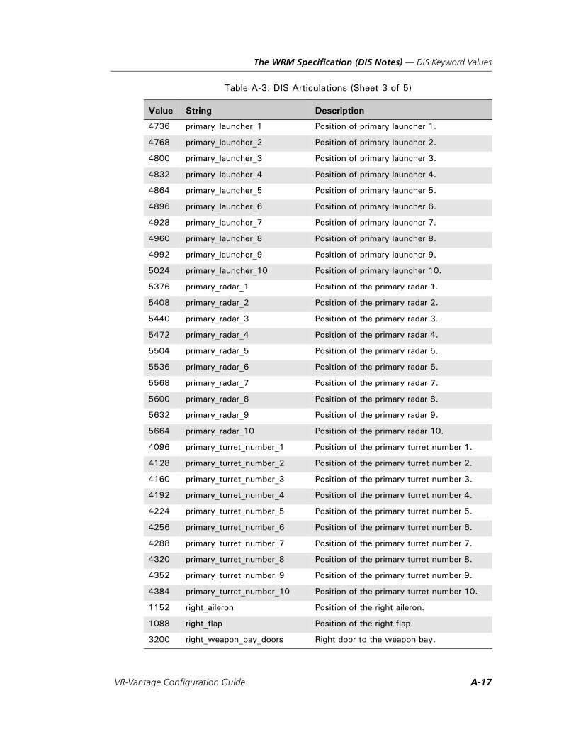
The WRM Specification (DIS Notes) — DIS Keyword Values
4736 primary_launcher_1 Position of primary launcher 1.
4768 primary_launcher_2 Position of primary launcher 2.
4800 primary_launcher_3 Position of primary launcher 3.
4832 primary_launcher_4 Position of primary launcher 4.
4864 primary_launcher_5 Position of primary launcher 5.
4896 primary_launcher_6 Position of primary launcher 6.
4928 primary_launcher_7 Position of primary launcher 7.
4960 primary_launcher_8 Position of primary launcher 8.
4992 primary_launcher_9 Position of primary launcher 9.
5024 primary_launcher_10 Position of primary launcher 10.
5376 primary_radar_1 Position of the primary radar 1.
5408 primary_radar_2 Position of the primary radar 2.
5440 primary_radar_3 Position of the primary radar 3.
5472 primary_radar_4 Position of the primary radar 4.
5504 primary_radar_5 Position of the primary radar 5.
5536 primary_radar_6 Position of the primary radar 6.
5568 primary_radar_7 Position of the primary radar 7.
5600 primary_radar_8 Position of the primary radar 8.
5632 primary_radar_9 Position of the primary radar 9.
5664 primary_radar_10 Position of the primary radar 10.
4096 primary_turret_number_1 Position of the primary turret number 1.
4128 primary_turret_number_2 Position of the primary turret number 2.
4160 primary_turret_number_3 Position of the primary turret number 3.
4192 primary_turret_number_4 Position of the primary turret number 4.
4224 primary_turret_number_5 Position of the primary turret number 5.
4256 primary_turret_number_6 Position of the primary turret number 6.
4288 primary_turret_number_7 Position of the primary turret number 7.
4320 primary_turret_number_8 Position of the primary turret number 8.
4352 primary_turret_number_9 Position of the primary turret number 9.
4384 primary_turret_number_10 Position of the primary turret number 10.
1152 right_aileron Position of the right aileron.
1088 right_flap Position of the right flap.
3200 right_weapon_bay_doors Right door to the weapon bay.
Table A-3: DIS Articulations (Sheet 3 of 5)
Value String Description
VR-Vantage Configuration Guide A-17

The WRM Specification (DIS Notes) — DIS Keyword Values
7584 rotor_fold Fold on helicopters rotors.
1024 rudder Position of the rudder.
6656 secondary_defense_systems_1
Position of the secondary defense systems 1.
6688 secondary_defense_systems_2
Position of the secondary defense systems 2.
6720 secondary_defense_systems_3
Position of the secondary defense systems 3.
6752 secondary_defense_systems_4
Position of the secondary defense systems 4.
6784 secondary_defense_systems_5
Position of the secondary defense systems 5.
6816 secondary_defense_systems_6
Position of the secondary defense systems 6.
6848 secondary_defense_systems_7
Position of the secondary defense systems 7.
6880 secondary_defense_systems_8
Position of the secondary defense systems 8.
6912 secondary_defense_systems_9
Position of the secondary defense systems 9.
6944 secondary_defense_systems_10
Position of the secondary defense systems 10.
6016 secondary_gun_number_1 Position of the secondary gun number 1.
6048 secondary_gun_number_2 Position of the secondary gun number 2.
6080 secondary_gun_number_3 Position of the secondary gun number 3.
6112 secondary_gun_number_4 Position of the secondary gun number 4.
6144 secondary_gun_number_5 Position of the secondary gun number 5.
6176 secondary_gun_number_6 Position of the secondary gun number 6.
6208 secondary_gun_number_7 Position of the secondary gun number 7.
6240 secondary_gun_number_8 Position of the secondary gun number 8.
6272 secondary_gun_number_9 Position of the secondary gun number 9.
6304 secondary_gun_number_10 Position of the secondary gun number 10.
6336 secondary_launcher_1 Position of the secondary launcher 1.
6400 secondary_launcher_3 Position of the secondary launcher 3.
6432 secondary_launcher_4 Position of the secondary launcher 4.
6464 secondary_launcher_5 Position of the secondary launcher 5.
Table A-3: DIS Articulations (Sheet 4 of 5)
Value String Description
A-18 VT MÄK

The WRM Specification (DIS Notes) — DIS Keyword Values
6496 secondary_launcher_6 Position of the secondary launcher 6.
6528 secondary_launcher_7 Position of the secondary launcher 7.
6560 secondary_launcher_8 Position of the secondary launcher 8.
6592 secondary_launcher_9 Position of the secondary launcher 9.
6624 secondary_launcher_10 Position of the secondary launcher 10.
6368 secondary_launcher_2 Position of the secondary launcher 2.
6976 secondary_radar_1 Position of secondary radar 1.
7008 secondary_radar_2 Position of secondary radar 2.
7040 secondary_radar_3 Position of secondary radar 3.
7072 secondary_radar_4 Position of secondary radar 4.
7104 secondary_radar_5 Position of secondary radar 5.
7136 secondary_radar_6 Position of secondary radar 6.
7168 secondary_radar_7 Position of secondary radar 7.
7200 secondary_radar_8 Position of secondary radar 8.
7232 secondary_radar_9 Position of secondary radar 9.
7264 secondary_radar_10 Position of secondary radar 10.
5696 secondary_turret_number_1 Position of the secondary turret number 1.
5728 secondary_turret_number_2 Position of the secondary turret number 2.
5760 secondary_turret_number_3 Position of the secondary turret number 3.
5792 secondary_turret_number_4 Position of the secondary turret number 4.
5824 secondary_turret_number_5 Position of the secondary turret number 5.
5856 secondary_turret_number_6 Position of the secondary turret number 6.
5888 secondary_turret_number_7 Position of the secondary turret number 7.
5920 secondary_turret_number_8 Position of the secondary turret number 8.
5952 secondary_turret_number_9 Position of the secondary turret number 9.
5984 secondary_turret_number_10 Position of the secondary turret number 10.
3104 tail_hook Tail hook on a plane for aircraft carrier land-ings.
7584 wing_fold Fold on plane’s wings.
Table A-3: DIS Articulations (Sheet 5 of 5)
Value String Description
VR-Vantage Configuration Guide A-19

The WRM Specification (DIS Notes) — DIS Keyword Values
A-20 VT MÄK

VR-V
B. CIGI Packets Supported
This appendix lists the various CIGI packets and the fields that VR-Vantage supports.
CIGI Packet Support .................................................................................... B-2
User Defined CIGI Packet ............................................................................ B-9
B-1antage Configuration Guide
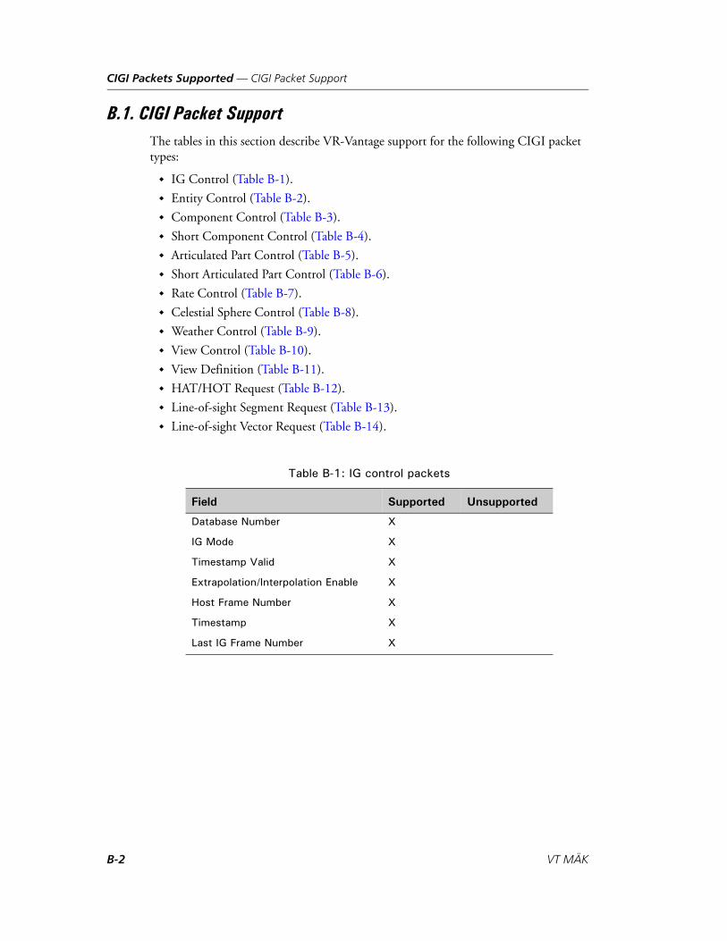
CIGI Packets Supported — CIGI Packet Support
B.1. CIGI Packet SupportThe tables in this section describe VR-Vantage support for the following CIGI packet types:
IG Control (Table B-1).
Entity Control (Table B-2).
Component Control (Table B-3).
Short Component Control (Table B-4).
Articulated Part Control (Table B-5).
Short Articulated Part Control (Table B-6).
Rate Control (Table B-7).
Celestial Sphere Control (Table B-8).
Weather Control (Table B-9).
View Control (Table B-10).
View Definition (Table B-11).
HAT/HOT Request (Table B-12).
Line-of-sight Segment Request (Table B-13).
Line-of-sight Vector Request (Table B-14).
Table B-1: IG control packets
Field Supported Unsupported
Database Number X
IG Mode X
Timestamp Valid X
Extrapolation/Interpolation Enable X
Host Frame Number X
Timestamp X
Last IG Frame Number X
B-2 VT MÄK
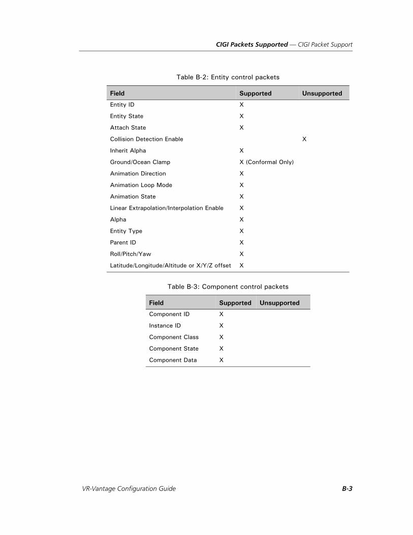
CIGI Packets Supported — CIGI Packet Support
Table B-2: Entity control packets
Field Supported Unsupported
Entity ID X
Entity State X
Attach State X
Collision Detection Enable X
Inherit Alpha X
Ground/Ocean Clamp X (Conformal Only)
Animation Direction X
Animation Loop Mode X
Animation State X
Linear Extrapolation/Interpolation Enable X
Alpha X
Entity Type X
Parent ID X
Roll/Pitch/Yaw X
Latitude/Longitude/Altitude or X/Y/Z offset X
Table B-3: Component control packets
Field Supported Unsupported
Component ID X
Instance ID X
Component Class X
Component State X
Component Data X
VR-Vantage Configuration Guide B-3

CIGI Packets Supported — CIGI Packet Support
Table B-4: Short component control packets
Field Supported Unsupported
Component ID X
Instance ID X
Component Class X
Component State X
Component Data X
Table B-5: Articulated part control packets
Field Supported Unsupported
Entity ID X
Articulated Part ID X
Articulated Part Enable X
X/Y/Z Offset Enable X
Roll/Pitch/Yaw Enable X
X/Y/Z Offset X
Roll/Pitch/Yaw X
Table B-6: Short articulated part control packets
Field Supported Unsupported
Entity ID X
Articulated Part ID 1 X
Articulated Part ID 2 X
DOF Select 1 X
DOF Select 2 X
Articulated Part Enable 1 X
Articulated Part Enable 2 X
DOF 1 X
DOF 2 X
B-4 VT MÄK
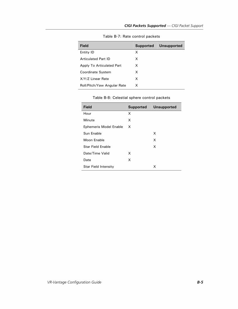
CIGI Packets Supported — CIGI Packet Support
Table B-7: Rate control packets
Field Supported Unsupported
Entity ID X
Articulated Part ID X
Apply To Articulated Part X
Coordinate System X
X/Y/Z Linear Rate X
Roll/Pitch/Yaw Angular Rate X
Table B-8: Celestial sphere control packets
Field Supported Unsupported
Hour X
Minute X
Ephemeris Model Enable X
Sun Enable X
Moon Enable X
Star Field Enable X
Date/Time Valid X
Date X
Star Field Intensity X
VR-Vantage Configuration Guide B-5

CIGI Packets Supported — CIGI Packet Support
Table B-9: Weather control packets
Field Supported Unsupported
Entity/Region ID X
Layer ID X (Only Rain/Snow)
Humidity X
Weather Enable X
Random Winds Enable X
Random Lightning Enable X
Cloud Type X
Scope X
Severity X
Air Temperature X
Visibility Range X
Scud Frequency X
Coverage X
Base Elevation X
Thickness X
Transition Band X
Horizontal Wind Speed X
Vertical Wind Speed X
Wind Direction X
Barometric Pressure X
Aerosol Concentration X
Table B-10: View control packets
Field Supported Unsupported
View ID X
Group ID X
X/Y/Z Offset Enable X
Roll/Pitch/Yaw Offset Enable X
Entity ID X
X/Y/Z Offset X
Roll/Pitch/Yaw X
B-6 VT MÄK
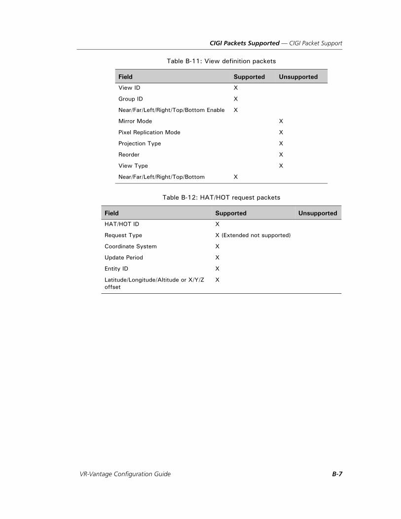
CIGI Packets Supported — CIGI Packet Support
Table B-11: View definition packets
Field Supported Unsupported
View ID X
Group ID X
Near/Far/Left/Right/Top/Bottom Enable X
Mirror Mode X
Pixel Replication Mode X
Projection Type X
Reorder X
View Type X
Near/Far/Left/Right/Top/Bottom X
Table B-12: HAT/HOT request packets
Field Supported Unsupported
HAT/HOT ID X
Request Type X (Extended not supported)
Coordinate System X
Update Period X
Entity ID X
Latitude/Longitude/Altitude or X/Y/Z offset
X
VR-Vantage Configuration Guide B-7
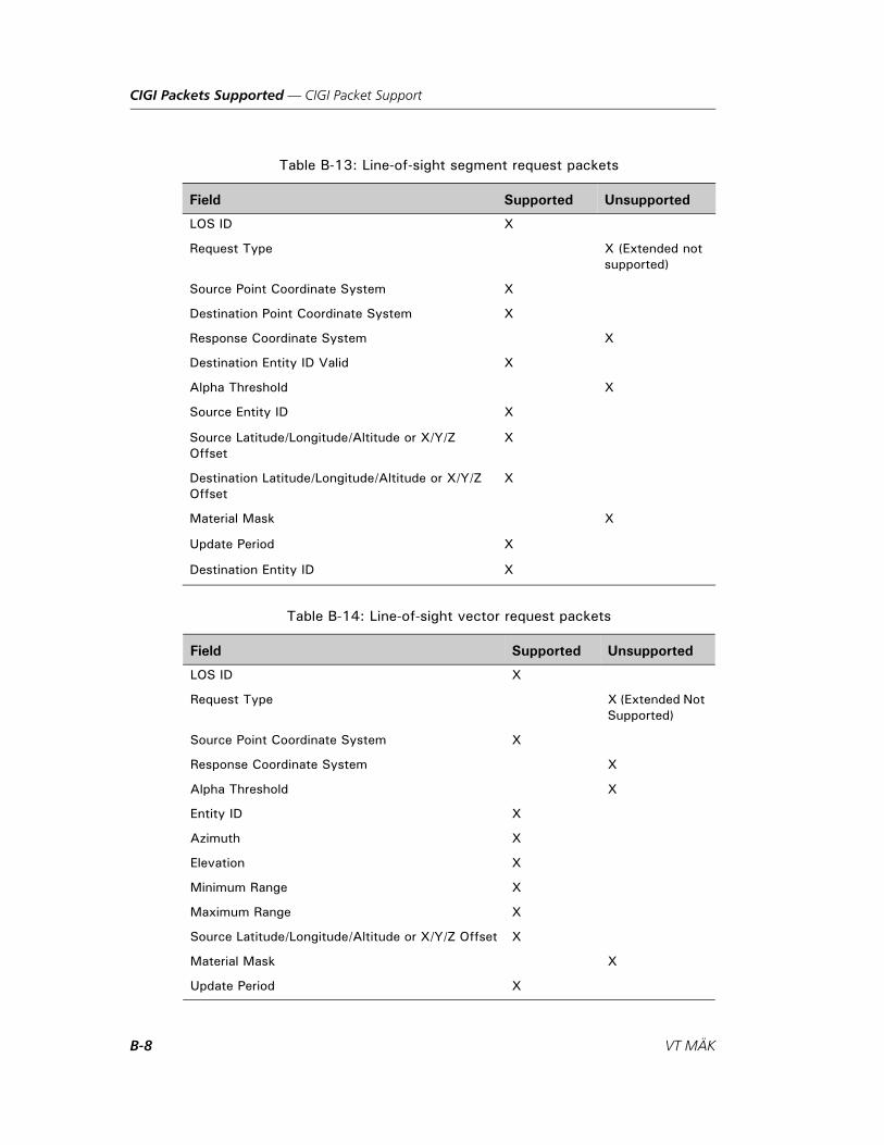
CIGI Packets Supported — CIGI Packet Support
Table B-13: Line-of-sight segment request packets
Field Supported Unsupported
LOS ID X
Request Type X (Extended not supported)
Source Point Coordinate System X
Destination Point Coordinate System X
Response Coordinate System X
Destination Entity ID Valid X
Alpha Threshold X
Source Entity ID X
Source Latitude/Longitude/Altitude or X/Y/Z Offset
X
Destination Latitude/Longitude/Altitude or X/Y/Z Offset
X
Material Mask X
Update Period X
Destination Entity ID X
Table B-14: Line-of-sight vector request packets
Field Supported Unsupported
LOS ID X
Request Type X (Extended Not Supported)
Source Point Coordinate System X
Response Coordinate System X
Alpha Threshold X
Entity ID X
Azimuth X
Elevation X
Minimum Range X
Maximum Range X
Source Latitude/Longitude/Altitude or X/Y/Z Offset X
Material Mask X
Update Period X
B-8 VT MÄK

CIGI Packets Supported — User Defined CIGI Packet
B.2. User Defined CIGI PacketVR-Vantage supports a user-defined packet for CIGI. For details, please see DtCigiDi-GuyCtrl.h.
VR-Vantage Configuration Guide B-9

CIGI Packets Supported — User Defined CIGI Packet
B-10 VT MÄK

VR-V
C. CIGI Utilities
This appendix describes the utilities provided for testing CIGI connections.
Using asynchHostTest.py ............................................................................. C-2
Using logger.py ............................................................................................ C-3
Using snooper.py ......................................................................................... C-3
The pyCigi Module ..................................................................................... C-5
C-1antage Configuration Guide
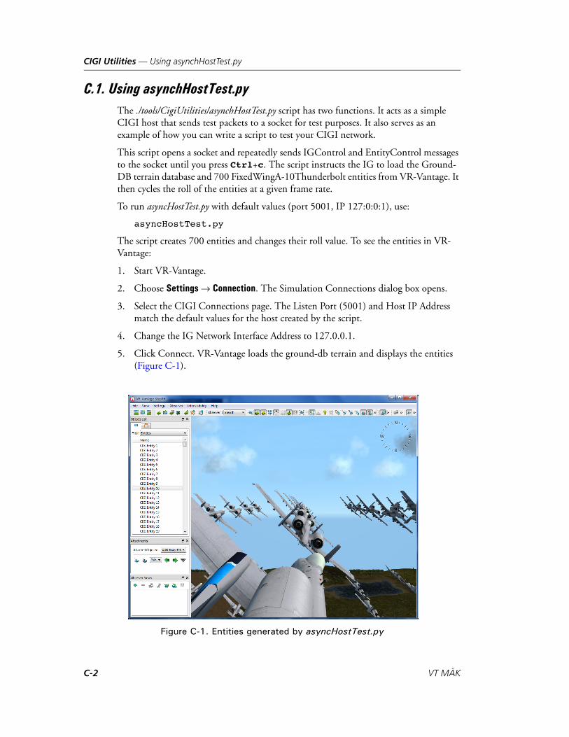
CIGI Utilities — Using asynchHostTest.py
C.1. Using asynchHostTest.pyThe ./tools/CigiUtilities/asynchHostTest.py script has two functions. It acts as a simple CIGI host that sends test packets to a socket for test purposes. It also serves as an example of how you can write a script to test your CIGI network.
This script opens a socket and repeatedly sends IGControl and EntityControl messages to the socket until you press Ctrl+c. The script instructs the IG to load the Ground-DB terrain database and 700 FixedWingA-10Thunderbolt entities from VR-Vantage. It then cycles the roll of the entities at a given frame rate.
To run asyncHostTest.py with default values (port 5001, IP 127:0:0:1), use:
asyncHostTest.py
The script creates 700 entities and changes their roll value. To see the entities in VR-Vantage:
1. Start VR-Vantage.
2. Choose Settings Connection. The Simulation Connections dialog box opens.
3. Select the CIGI Connections page. The Listen Port (5001) and Host IP Address match the default values for the host created by the script.
4. Change the IG Network Interface Address to 127.0.0.1.
5. Click Connect. VR-Vantage loads the ground-db terrain and displays the entities (Figure C-1).
Figure C-1. Entities generated by asyncHostTest.py
C-2 VT MÄK
CIGI Utilities — Using snooper.py
C.2. Using logger.pyThe ./tools/CigiUtilities/logger.py script listens to a UDP socket (unicast or multicast) and records the packets it receives. It can then play the packets back.
To record:
logger.py -r
The default log file is cigiSession.log.
To play:
logger.py
The logger records data in a binary format. However, you can convert it to a readable format. To convert the data, run:
logger.py -c
The default output file is cigiSession.txt. The following is an example of converted log entries:
<Time(0.000000)><IGControl({'lastFrame': 0, 'timeStamp': 0, 'dbNum': 6, 'frameNum': 1})><EntityControl({'bits2': 0, 'alt': 140.0, 'parentID': 0, 'lon': -122.988,
'pitch': 0.0, 'entType': 1100, 'roll': 1.0, 'alpha': 255, 'yaw': 0.0, 'lat': 36.00827037, 'entID': 1, 'bits1': 1})>
<EntityControl({'bits2': 0, 'alt': 140.0, 'parentID': 0, 'lon': -122.9883, 'pitch': 0.0, 'entType': 1100, 'roll': 1.0, 'alpha': 255, 'yaw': 0.0, 'lat': 36.00827037, 'entID': 2, 'bits1': 1})>
<EntityControl({'bits2': 0, 'alt': 140.0, 'parentID': 0, 'lon': -122.98859999999999, 'pitch': 0.0, 'entType': 1100, 'roll': 1.0, 'alpha': 255, 'yaw': 0.0, 'lat': 36.00827037, 'entID': 3, 'bits1': 1})>
<EntityControl({'bits2': 0, 'alt': 140.0, 'parentID': 0, 'lon': -122.98889999999999, 'pitch': 0.0, 'entType': 1100, 'roll': 1.0, 'alpha': 255, 'yaw': 0.0, 'lat': 36.00827037, 'entID': 4, 'bits1': 1})>
<EntityControl({'bits2': 0, 'alt': 140.0, 'parentID': 0, 'lon': -122.98919999999998, 'pitch': 0.0, 'entType': 1100, 'roll': 1.0, 'alpha': 255, 'yaw': 0.0, 'lat': 36.00827037, 'entID': 5, 'bits1': 1})>
C.3. Using snooper.pyThe ./tools/CigiUtilities/snooper.py script can connect to the host and the IG at the same time and can record traffic and then play it back. Figure C-2 illustrates the snooper as follows:
Host/IG interaction without the snooper.
Host/IG interaction with the snooper mediating. The snooper receives the packets from the host and IG and passes them on. It also records them to a file.
Snooper playback. The snooper sends the logged packets to the proper destination.
i When the logger records packets, it does not compress them. The log file can quickly grow quite large.
VR-Vantage Configuration Guide C-3
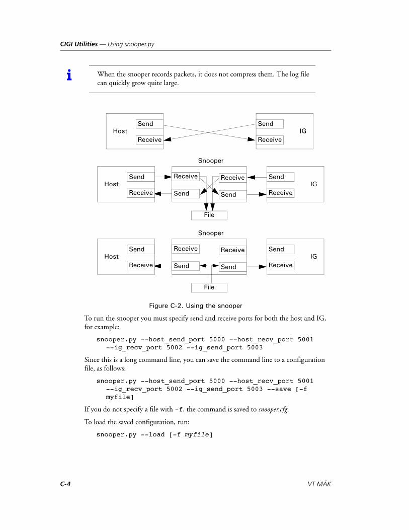
CIGI Utilities — Using snooper.py
Figure C-2. Using the snooper
To run the snooper you must specify send and receive ports for both the host and IG, for example:
snooper.py --host_send_port 5000 --host_recv_port 5001 --ig_recv_port 5002 --ig_send_port 5003
Since this is a long command line, you can save the command line to a configuration file, as follows:
snooper.py --host_send_port 5000 --host_recv_port 5001 --ig_recv_port 5002 --ig_send_port 5003 --save [-f myfile]
If you do not specify a file with -f, the command is saved to snooper.cfg.
To load the saved configuration, run:
snooper.py --load [-f myfile]
i When the snooper records packets, it does not compress them. The log file can quickly grow quite large.
HostSend
Receive
Snooper
File
IGSend
Receive
HostSend
ReceiveIG
Send
Receive
Receive
Send Send
Receive
Snooper
File
HostSend
ReceiveIG
Send
Receive
Receive
Send Send
Receive
C-4 VT MÄK

CIGI Utilities — The pyCigi Module
C.4. The pyCigi ModuleThe pyCigi module (./tools/CigiUtilities/byCigi) is a package of modules to handle the reading, writing, packing and unpacking of CIGI messages. pyCigi has modules to handle each of the CIGI message types that are supported by VR-Vantage. For a list of supported packets, please see Chapter B, CIGI Packets Supported.
Each module within pyCigi is self documented and contains a unit test. The documen-tation for a module can be seen from inside a Python shell:
python>>> import pyCigiStartOfFrame>>> help(pyCigiStartOfFrame.StartOfFrame)
To run the unit test for a module, run the module as a script from a shell window:
pyCigiStartOfFrame.py
The script pyCigiMappings.py gets information about mappings from ./appData/settings/stealth/MAK CIGI Mappings.mcsx. Do not move this file or the script will not work.
For complete documentation of the pyCigi module, please see Readme.txt.
VR-Vantage Configuration Guide C-5

CIGI Utilities — The pyCigi Module
C-6 VT MÄK
VR-V
Index
-- command-line option 7-3--anti_aliasing command-line option 1-7--col command-line option 7-3--depth_bits command-line option 1-7--dispSetting command-line option 2-8, 3-7--encryptImages command-line option 7-3--extendLevelZero command-line option 7-3--file command-line option 7-3--generateFiles command-line option 7-4--help command-line option 7-4--ignore_rest command-line option 7-3--level command-line option 7-4--missing command-line option 7-4--noVSync command-line option 1-6--publishMftOnly command-line option 7-4--regenerateAll command-line option 7-3--row command-line option 7-5--searchDir command-line option 7-4--stencil_bits command-line option 1-7--subDir command-line option 7-4--textureSize command-line option 7-5--threads command-line option 7-4--version command-line option 7-4--vtFile command-line option 7-4--withDisplayEngine command-line option 2-8, 3-
7
Symbols@dis comment 5-16@dis navigation_lights 5-16
Numerics2525B icon 8-21
antage Configuration Guide
2Dicon
configuring 8-21editing 8-21
A-A command-line option 7-3active stereo 2-27add image attribute 4-9Add Model Definition dialog box 8-9Add Props page 4-29, 6-8, 6-12, 6-20Add Terrain Patch dialog box 4-5, 6-3, 6-20Add Visualizer Definition Attribute window 8-19adding
attribute, visual definition 8-19channel 2-5cockpit model 8-29entity bitmap image 8-28entity image 8-28feature layer 4-12key mapping 14-4model mapping 10-2ocean layer 4-15, 4-16parameter
model definition 8-12schema 8-6
prop 4-27from feature layer 4-29
terrain patch to terrain 4-5terrain server 4-24visual definition 8-16window 2-3
alpha 8-41ambient, occlusion map 4-19
i-1
Index
anaglyphic stereo 2-27configuring 2-28
Angle of Attack 8-31angleSegmentMax parameter 11-5animation
DI-Guy, choosing 10-5model A-11
animation control message 12-6, 12-8anti-aliasing 1-7AOA updater 8-31Application Settings dialog box
File Caching Settings page 4-34, 4-36, 4-37, 10-6
Key Mapping Editor page 14-3, 14-8Keyboard Mappings Editor page 14-8
applying updated model definitions 8-12arc, segment 11-5articulated part A-2, A-7
mapping in CIGI 12-5Articulated Part Control 12-3asynchHostTest.py C-2asynchronous, CIGI operation 12-2Attached Near Clip Altitude, attribute 2-13attribute
Attached Near Clip Altitude 2-13BOYSHP 5-13buoy 5-13
building model definition 5-13cockpit updater 8-29COLOUR 5-13COLPAT 5-13DESIGNATOR 5-14destroyedsymbol 8-27Dynamic Near Clip Attached Policy 2-13Dynamic Water Visibility Enabled 2-19Dynamic Water Visibility Maximum 2-19Fixed Near Clip When Attached 2-13image 4-9imagesymbolmap 8-26, 8-28light characteristic 5-19LITCHR 5-19marker-scale 8-39modeldefinitionschema 8-25Near Far Clip Policy 2-13OBJNAM 5-14parent 8-25Reduce Z Fighting Ratio 2-13sensor 2-10SIGGRP 5-19signal group 5-19
i-2
attribute (continued)signal period 5-19SIGPER 5-19SIGSEQ 5-19TOPSHP 5-18type 8-25visual definition 8-17
adding 8-19WidgetTheme 8-26window 2-9
authentication, proxy 4-26Auto Generate 4-27availability, terrain server 4-26
Bbeacon 5-19
model definition 5-13seasonal 5-18streaming 5-12, 5-15topmark 5-18
beadDOF A-7switch A-8
best practice, model design 8-41binary key mapping 14-3bit, depth and stencil 1-7bitmap
adding new 8-28displaying 4-7icon 8-23
blend image attribute 4-9Boundary Generation Tool, using 5-8boundary tool 5-7
running 5-9boundary.txt 5-8BOYSHP, attribute 5-13building
extruded 5-9prop type 4-33terrain 4-5
bump map 4-19buoy
attributes 5-13daymark 5-18designator 5-14model definition 5-12, 5-13
using texture atlas 5-15seasonal 5-18signal sequence 5-19
VT MÄK
Index
buoy (continued)streaming 5-12topmark 5-18unique 5-14
C-c command-line option 7-3cache
clearing 4-37clearing model instancing 10-6model instance 10-6streaming terrain 4-40
cachingearth file, offline 4-35file 4-34terrain server data 4-34
camera, position and orientation 2-25Camera Orientation Offset 2-10Camera Position Offset 2-10, 2-25Celestial Sphere Control 12-3changing
channel attributes 2-10field of view 2-17image display order 4-11key mapping 14-6model definition, prop 6-23prop
model definition 4-33position or orientation 4-33type 4-33
viewport 2-18weather, in host emulator 13-10window attributes 2-9
channeladding 2-5attribute
editing 3-2sensor 2-10
changing attributes 2-10keyword 2-10multichannel configuration, loading 2-26multiple 2-23projection resize policy 2-14property 2-10removing 2-6
Channel Name 2-10ChannelKeyword parameter 8-31child, element definition 8-14
VR-Vantage Configuration Guide
CIGI 12-2adding effect in host emulator 13-9articulated parts, mapping 12-5changing model state 13-7Class Library 12-2component control message, formats 12-7configuring tidal stream speed and direction 8-
35connection types 12-2creating simulated entity on host emulator 13-7driver 12-2host emulator 12-2, 13-2
connecting to 13-4starting 13-3tutorial 13-2
mapping database 12-10mappings 12-1model mapping 12-4model state 12-7network configurations 12-13packet
supported 12-3user-defined 12-3
socket 12-2synchronous and asynchronous 12-2system component control messages 12-9view, mapping to observer mode 12-12view component control 12-9view control packet 12-11views 12-11weather control 13-10
Common Image Generator Interface, See also CIGI
CIGI Connections page 13-4CIGI control message, mapping 12-6CIGI Database Mapping page 12-10, 13-4CIGI Entity Models page 12-4, 12-5CIGI Mapping Settings dialog box 12-4, 12-5, 12-
6, 12-10, 12-12CIGI Model Animations page 12-8CIGI Model State mappings page 12-7CIGI Observer Mode Mapping page 12-12CIGI View Components page 12-9clamp image attribute 4-9clamp to border image attribute 4-9clamp to edge image attribute 4-9class
DtLightSignalSequenceGenerator 19DtLightSignalSequenceGeneratorCreator 19
i-3

Index
clearingfile cache 4-37model instancing cache 10-6
clipping plane 8-37cockpit display 8-29, 10-2
adding new 8-29element definition 8-14installing 8-30model definition, creating 8-30updater 8-29
attribute 8-29color
emitter volume, pulse rate 11-2pattern 5-13represents emitter volume frequency 11-2
COLOUR attribute 5-13COLPAT attribute 5-13combining, key mapping 14-7command-line option
-- 7-3-A 7-3--anti_aliasing 1-7-c 7-3--col 7-3--depth_bits 1-7--dispSetting 2-8, 3-7-e 7-3--encryptImages 7-3--extendLevelZero 7-3-f 7-3--file 7-3-g 7-4--generateFiles 7-4-h 7-4--help 7-4--ignore_rest 7-3-l 7-4--level 7-4-m 7-4--missing 7-4--noVSync 1-6-p 7-4--publishMftOnly 7-4-r 7-4--regenerateAll 7-3--row 7-5-s 7-4--searchDir 7-4--stencil_bits 1-7--subDir 7-4
i-4
command-line option (continued)-t 7-4--textureSize 7-5--threads 7-4-u 7-4-v 7-4--version 7-4--vtFile 7-4-W 2-8, 3-7-w 7-5--withDisplayEngine 2-8, 3-7-x 7-5
comment, @dis 5-16Common Image Generator Interface 12-2Component Control 12-3component control message 12-6
formats for 12-7Component Visualization 4-20compressing, model and image files 10-7compression, texture 4-36configuration
CIGI 12-13display engine 2-3
loading 2-7saving 2-6
image generator 12-13multichannel
loading 2-26saving 2-26
configuring2D icon 8-21earth file 5-2emitter volume 11-2
segments 11-4LOD 4-40model definition 8-8multichannel display 2-23projection resize policy 2-14pulse rate 11-2schema 8-3ship wakes 8-32stereo
anaglyphic 2-28polarized 2-29
terrain server 4-25Connect To Display Engine dialog box 2-21connecting
display engine to 2-21emulator, CIGI host 13-4
constructing, terrain 4-5
VT MÄK
Index
coordinates, UV 4-9copying
model definition 8-11schema 8-5
Create Database Mapping dialog box 12-10Create New Art Part Mapping dialog box 12-5Create New Component Mapping dialog box 12-6Create New Entity Type Model Mapping dialog
box 10-3creating
CIGI ownship entity 13-5element definition 8-15key map 14-8MEDF and MEIF files 10-7model, guidelines for 8-41model definition 8-8, 8-9, 9-2
cockpit display 8-30schema 8-4terrain 4-3
cut-in site 5-7
Ddata
caching terrain 4-34streamed, processing 5-4
databasemapping for CIGI 12-10terrain, provided 4-41
dataset, virtual and tiled 7-3daymark, buoy 5-18daymark_attr_map.csv 5-18daymark_layer_list.csv 5-18daymark.dtxc 5-18DDS texture 4-37
flipping 4-6, 8-36debugging, shaders 4-20decal effects 10-2decal image attribute 4-9DefaultEllipsoidArc, model definition 11-2definition
element 8-14model, buoy 5-12
degrees of freedom A-7deleting
channel 2-6element definition 8-20key map 14-8key mapping 14-6model definition 8-10
VR-Vantage Configuration Guide
deleting (continued)model mapping 10-5parameter
model definition 8-14schema 8-7
schema 8-5terrain, cached 4-37window 2-6
depth, buffer 1-7DESIGNATOR, attribute 5-14designator, buoy 5-14destroyedsymbol attribute 8-27detonation
adding in host emulator 13-9effects 10-2
dialog boxAdd Model Definition 8-9Add Terrain Patch 4-5, 6-3, 6-20Application Settings
File Caching Settings page 4-34, 4-36, 4-37, 10-6
Key Mapping Editor page 14-3, 14-8Keyboard Mappings Editor page 14-8
CIGI Mapping Settings 12-4, 12-5, 12-6, 12-10, 12-12
Connect To Display Engine 2-21Create Database Mapping 12-10Create New Art Part Mapping 12-5Create New Component Mapping 12-6Create New Entity Type Model Mapping 10-3Display Settings
Loader Settings page 4-37Ocean Render Settings page 4-18, 4-19Render Settings page 1-5, 1-6, 1-8, 2-14, 4-
21SpeedTree Settings page 8-37
Duplicate Model Definition 8-11Entity Type Mappings 10-2Terrain Settings
Add Props page 4-29, 6-8, 6-12Edit Existing Props page 4-31, 4-32, 4-33, 6-
23, 9-10Extract Ocean page 4-15Extract Props page 4-27, 6-21Raster Maps page 4-7, 4-11, 6-4Server Settings page 4-24, 4-25SpeedTree Randomization page 8-39Terrain Contents page 4-12, 4-15, 4-16, 4-
23Visual Model Editors 8-8
i-5
Index
DI-Guychoosing animation 10-5model definition 8-9
DirectX 4-37DIS
appearance state 12-7encoding information in OpenFlight format A-
2WRM specification A-1
disabling, texture compression 4-36disconnecting, display engine 2-22display
field of view 2-17Linux 2-30perspective 2-17
display engineconfiguration 2-3
loading 2-7, 3-2loading multiple 2-8, 3-7saving 2-6, 3-2
connecting to 2-21disconnecting from 2-22remote, connecting to 3-2starting 2-20tutorial 3-2window, adding 2-3
Display Settings dialog boxLoader Settings page 4-37Ocean Render Settings page 4-18, 4-19Render Settings page 1-5, 1-6, 1-8, 2-14, 4-21SpeedTree Settings page 8-37
displayingperformance statistics 1-4raster maps 4-7segment outlines 11-5
Distance To Attached, policy 2-13DLL
cockpit display 8-29installing cockpit display, installing 8-30
DOF bead A-7driver
CIGI 12-2OGR 5-6
DtCigiDiGuyCtrl.h header file 3, 9DTED
loading 4-4loading multiple 5-3support for 4-3
DtLightSignalSequenceGenerator class 19DtLightSignalSequenceGeneratorCreator class 19
i-6
DtLightSignalSequenceGenerator.h header file 19duplicate, key mapping 14-7Duplicate Model Definition dialog box 8-11Dynamic Near Clip Attached Policy, attribute 2-
13dynamic ocean
layer 4-13wakes 8-32
Dynamic Water Visibility Enabled, attribute 2-19Dynamic Water Visibility Maximum, attribute 2-
19
E-e command-line option 7-3earth file 5-2
adding mask 5-7buoys and beacons 5-12caching, offline 4-35loading DTED 5-3
Edit Existing Props page 4-28, 4-31, 4-32, 4-33, 6-23, 9-10
editingchannel attributes 2-10, 3-2element definition 8-16frustum 2-17icon, 2D 8-21key maps 14-2, 14-3model definition 8-8, 8-12model mapping 10-4parameter
model definition 8-13schema 8-7
terrain server configuration 4-25visual definition 8-17
parameter 8-18window attributes 2-9
effectadding in host emulator 13-9lighting 4-19mapping 10-2
electromagnetic emissions, segment angle 11-5element
mask 5-7model 5-5, 8-39option 5-11parent 8-17
element definition 8-14adding visual definition 8-16creating 8-15
VT MÄK

Index
element definition (continued)deleting 8-20editing 8-16filtering list in Entity Type Mappings dialog
box 10-5saving 8-20
EM-Emission update message 11-3Emitter Power 11-3emitter volume
color 11-2configuring 11-2outlines 11-5pulse rate 11-2radius 11-3segment angle 11-5segment size 11-4
emulatorCIGI host 12-2, 13-2
starting 13-3enabling, texture compression 4-36entity
animation control in CIGI 12-8appearance A-2articulated parts, mapping for CIGI 12-5element definition 8-14icon, adding new image 8-28model state 12-7
changing in host emulator 13-7ownship, creating 13-5surface, configuring wake 8-32type, enumeration 10-2
entity component control 12-7message 12-6
Entity Components Mappings page 12-7, 12-8Entity Control 12-3Entity Definition Editor page 8-21, 8-32, 9-5, 11-
6Entity Image Symbol, visual definition 8-21, 8-23,
8-28Entity Mapping Settings page 9-8, 10-2, 10-4, 10-
5entity type, mapping 10-2Entity Type Mappings dialog box 10-2
filtering element definition list 10-5enumeration 10-2Environment Conditions Settings page 2-19, 8-35environment variable
GDAL_CACHEMAX 4-40MAK_GEOID_GRID 4-4OpenSceneGraph, anaglyphic stereo 2-28
VR-Vantage Configuration Guide
environment variable (continued)OSG_MAX_PAGEDLOD 4-40OSGEARTH_CACHE_PATH 4-34
environmental variableOSG_CURL_PROXY 4-26OSG_CURL_PROXYPORT 4-26OSGEARTH_CURL_PROXYAUTH 4-26
external reference 8-41Extract Ocean page 4-15Extract Props page 4-27, 6-21extracting
prop 6-20from terrain patch 4-27
water texture 4-15extruded, building 5-9
F-f command-line option 7-3far clipping plane 2-12feature
data, buoys and beacons 5-12extracting as prop 4-27layer 5-12
feature data, processing 5-4feature layer
adding 4-12adding prop from 4-29
FeatureData section in meta file 8-35featureDataBroker 5-4FeatureName parameter 8-36Feet Above Ground Level 8-31Feet Above Mean Sea Level 8-31FeetAGL updater 8-31FeetMSL updater 8-31FeetPerMinute updater 8-31field of view 2-17, 2-18, 11-3
changing 2-17file
cache, clearing 4-37caching 4-34compressed 10-7
File Caching Settings page 4-34, 4-36, 4-37, 10-6Filename parameter 8-30filename_shp_map.txt configuration file 4-12filtering
element definition list 10-5function list 14-8model definition list 8-11
firing, effects 10-2
i-7
Index
Fixed Near Clip 2-13Fixed Near Clip When Attached, attribute 2-13flag, movement in wind 8-35flaming effects 10-2flipping, DDS textures 4-6, 8-36format
component control message 12-7OpenFlight A-2
frame rate 1-2, 1-6frequency, color of 11-2frustum 2-10, 2-25
editing 2-17function
movement 14-2profiler 1-6
function list, filtering 14-8
G-g command-line option 7-4GDAL, configuring cache 4-40GDAL_CACHEMAX, environment variable 4-40GDB terrain, shapefile 4-12geocentric, terrain 4-22geoid grid file 4-4geometry 8-41
sharing 10-6Geometry Grid Dataset 7-2, 7-6GeoTIFF, image 4-9GGDS 7-6GL Studio 8-29graphic
buffer, depth and stencil 1-7guidelines 8-41
creating models 8-41
H-h command-line option 7-4HAT/HOT Request 12-3HAT/HOT Response 12-3header file
DtCigiDiGuyCtrl.h 3, 9DtLightSignalSequenceGenerator.h 19
Headlight updater 8-32height, ocean 4-15, 4-16
i-8
height mapocean 4-17
regenerating 4-19resolution 4-17, 4-18texture size 4-17, 4-18
hierarchy, element definition 8-14horizontal navigation 14-2host
CIGI, configurations 12-13host emulator 12-2
CIGI 13-2connecting to 13-4
HUD. See cockpit display
Iicon
2525B 8-212D 8-23
bitmap 8-23editing 8-21
bitmap, adding new 8-28configuring 2D 8-21image 8-23
adding new 8-28IG Control 12-3image
adding 8-28attributes 4-9compressing 10-7display order 4-11displaying 4-7GeoTIFF 4-9icon 8-23texture coordinate system 4-9
imagesymbolmap, attribute 8-26imagesymbolmap attribute 8-28inheritance, element definition 8-14IP address, for CIGI connections 13-3IVE 4-39
JJSON, configuration file 8-35
Kkey map 14-2
creating 14-8
VT MÄK
Index
key map (continued)deleting 14-8editing 14-3
key mappingadding 14-4binary 14-3changing 14-6combining 14-7deleting 14-6
Key Mapping Editor 14-2adding mapping 14-4binary mapping 14-3changing mapping 14-6deleting mapping 14-6filtering function list 14-8
Key Mapping Editor page 14-3, 14-8keyboard 14-2
mappings 14-2navigation 14-2
Keyboard Mappings page 14-8keyword, channel 2-10KilometersPerHour updater 8-31KnotsPerHour updater 8-32
L-l command-line option 7-4lamppost, prop type 4-33layer
feature 5-12adding 4-12adding prop from 4-29
name 5-6shapefile 5-6
ocean 4-13adding 4-16
LettersNumbers.ctxc 5-15level-of-detail 8-37
See also LODlibrary, CIGI class 12-2light, navigation 5-16light characteristic attribute 5-19light_layer_list.csv 5-17lighting, effects 4-19limitation, terrain 4-3Line of Sight Response 12-3Line of Sight Segment Request 12-3Line of Sight Vector Request 12-3Linkage section in meta file 8-35Linux, display 2-30
VR-Vantage Configuration Guide
list, props 4-31LITCHR attribute 5-19Little Pond terrain 4-41Loader Settings page 4-37loading
display engine configuration 2-7, 2-8, 3-7DTED 4-4MetaFlight 4-26models 4-34multichannel configuration 2-26multiple DTED files 5-3terrain 4-34
location, window 2-9location image attribute 4-9LOD 8-37, 8-41
configuring 4-40ocean elevation 4-16
logger.py C-3
M-m command-line option 7-4MÄK CIGI Mappings 12-1MÄK Encrypted Data Format 7-6MAK_GEOID_GRID, environment variable 4-4Makland terrain 4-41map, texture 4-19mapping
CIGI control message 12-6database, CIGI 12-10entity type 10-2keys 14-2model
CIGI 12-4to entity type 10-2
shapefiles to features 4-12marker-scale attribute 8-39mask
adding to earth file 5-7element 5-7
MEDF 7-6creating 10-7
medfTool 7-6MEIF, creating 10-7memory 1-2
improving use of 10-6.meta extension 8-35meta file, configuring for windsocks and flags 8-35metaFileName parameter 8-35
i-9

Index
MetaFlightbuilding efficient terrains 4-39loading 4-26processing 7-2
mftTool 7-3, 7-5MilesPerHour updater 8-31Military Symbol Icon, visual definition 8-21mirror image attribute 4-9model
adding, tutorial 9-2animation A-11compressing 10-7creating 8-41definition, buoy 5-12DI-Guy, choosing 10-5editing model mapping 10-4element 5-5file caching 4-34flipping DDS textures 8-36instance, caching 10-6instancing, clearing cache 10-6mapping
adding 10-2CIGI 12-4deleting 10-5editing 10-4
schema 8-8set 8-16sharing resources 10-6state
changing in host emulator 13-7CIGI 12-7
model definitionapplying updated 8-12buoy 5-13
building from attributes 5-13texture atlas 5-15
copying 8-11creating 8-8, 8-9, 9-2
cockpit display 8-30DefaultEllipsoidArc 11-2deleting 8-10DI-Guy character 8-9editing 8-12filtering list of 8-11parameter
adding 8-12deleting 8-14editing 8-13
prop, changing 4-33, 6-23
i-10
model definition (continued)saving 8-14schema 8-3SpeedTree 8-9
Model Definition Editor page 8-8, 8-9, 8-10, 8-11, 8-12, 8-13, 8-14, 8-28, 8-36, 9-2, 11-5, 11-6
model element 5-4, 8-39model instancing 10-6Model Specification for DIS Interoperability A-2model state component control message 12-7model state control message 12-6modeldefinitionschema, attribute 8-25module, pyCigi C-5monitor, multiple 2-23multichannel
configuration, saving 2-26configuring 2-23
MultiGen-Paradigm, OpenFlight format A-2multiple, parameter values 8-18
Nname, layer 5-6navigation
function, editing key map 14-3key map 14-2keyboard 14-2light 5-16lights, streaming 5-16
navigational aid light 5-19near clipping plane 2-12Near Far Clip Policy, attribute 2-13new, terrain 4-3normal map 4-19
Oobject, count 1-2Objects List Panel
props, selecting 4-31OBJNAM, attribute 5-14observer
camera, changing 2-25CIGI views 12-11LOD, ocean 4-16mode, mapping to CIGI view 12-12movement, functions 14-2
Observer Name 2-10
VT MÄK
Index
oceanheight 4-15, 4-16height map 4-17height map resolution 4-17layer 4-13
adding 4-15, 4-16ocean height map
regenerating 4-19texture size 4-17, 4-18
Ocean Height Map Regeneration Threshold 4-19ocean height map resolution 4-18Ocean LOD Elevation 2-19, 4-16Ocean Render Settings page 4-18, 4-19OffsetX parameter 8-31OffsetY parameter 8-31OffsetZ parameter 8-31OGR, driver 5-6opacity
prop 4-32setting 4-32
OpenFlight, format A-2OpenGL 4-37OpenSceneGraph, environment variables for
anaglyphic stereo 2-28optimizing, performance 1-2option, element 5-11orientation
camera 2-25prop, changing 4-33
OSG_CURL_PROXY, environmental variable 4-26
OSG_CURL_PROXYPORT, environmental variable 4-26
OSG_MAX_PAGEDLOD, environment variable 4-40
osgEarth 4-22, 5-2adding terrain servers 4-24
osgEarth Boundary Generation Tool 5-7, 5-9osgearth_cache 4-35OSGEARTH_CACHE_PATH, environment
variable 4-34OSGEARTH_CURL_PROXYAUTH, environ-
mental variable 4-26outline
emitter volume segment 11-5segment 11-5
out-the-window view 2-23ownship 12-13
entity, creating 13-5
VR-Vantage Configuration Guide
P-p command-line option 7-4packet
CIGI 12-3user-defined 12-3
pageAdd Props 6-20CIGI Observer Mode Mapping 12-12Edit Existing Props 4-28Entity Definition Editor 8-21, 8-32, 9-5, 11-6Entity Mapping Settings 9-8Environment Conditions Settings 2-19, 8-35File Caching Settings 10-6Model Definition Editor 8-28, 8-36, 11-5, 11-6Raster Maps 4-20SchemaEditor 8-9Terrain Contents 4-15
paged terrainflipping DDS textures 4-37preprocessing 4-39
parameteradding, to model definition 8-12angleSegmentMax 11-5ChannelKeyword 8-31deleting, from model definition 8-14FeatureName 8-36Filename 8-30metaFileName 8-35model definition, editing 8-12, 8-13OffsetX 8-31OffsetY 8-31OffsetZ 8-31Perspective 8-31PerspectiveHeight 8-31PerspectiveWidth 8-31RotDir 8-36RotOffsetDeg 8-36RSOName 8-30schema
adding 8-6deleting 8-7editing 8-7
showLines 11-6visual definition, editing 8-18WindSpeed 8-36WindState 8-36
parentelement 8-17element definition 8-14
i-11
Index
parent, attribute 8-25pattern, color 5-13performance 1-7, 4-17
compressing texture 4-36function profiler 1-6improving 10-6model, best practices 8-41optimizing 1-2statistics
displaying 1-4enabling in CIGI 12-9
terrain 4-3visual 1-6
perspective, in display 2-17Perspective parameter 8-31PerspectiveHeight parameter 8-31PerspectiveWidth parameter 8-31Pitch updater 8-32pixel 8-41polarized stereo 2-27
configuring 2-29policy
Distance To Attached 2-13Reduce Near Clip 2-13Reduce Z Fighting 2-13
polygon 8-41count 4-3
portCIGI connection 13-4proxy 4-26
positioncamera 2-25prop, changing 4-33window attribute 2-9
preprocessingterrain, paged 4-39
processing, MetaFlight 7-2processing streamed data 5-4profiler, function 1-6Projection Resize Policy 2-10
configuring 2-14Projection Units 2-10prop
addingfrom feature layer 4-29to terrain 4-27
extracting 4-27, 6-20model definition, changing 4-33, 6-23opacity 4-32opaque 4-32
i-12
prop (continued)selecting 4-31transparent 4-32type 4-33viewing list of 4-31
propertychannel 2-10window 2-9
proxyconnecting through 4-26port 4-26
pulse repetition rate 11-2pyCigi module C-5
R-r command-line option 7-4radius, emitter volume 11-3raster map
display order 4-11displaying 4-7
Raster Maps page 4-7, 4-11, 4-20, 6-4Rate Control 12-3Reduce Near Clip, policy 2-13Reduce Z Fighting, policy 2-13Reduce Z Fighting Ratio, attribute 2-13reflection map 4-19refresh rate 1-6regenerating, ocean height map 4-19registrant_feature_list.csv 5-4remote
display engine, loading configurations 2-8, 3-7removing
channel 2-6window 2-6
renaming, terrain server 4-25Render Settings page 1-5, 1-6, 1-8, 2-14, 4-21repeat image attribute 4-9replace image attribute 4-9resizing, windows 2-14resolution
ocean height map 4-18tree 8-37
reusable software object 8-29Roll updater 8-32RotDir parameter 8-36RotOffsetDeg parameter 8-36RSO 8-29RSOName parameter 8-30running, boundary tool 5-9
VT MÄK

Index
S-s command-line option 7-4S-57
buoys and beacons 5-12signal sequence 5-19
s57_attr_map.csv 5-13, 5-16s57_defaults.csv 5-16s57_layer_list.csv 5-12, 5-15s57_modeldef_by_name_map.csv 5-14San Luis Obispo terrain 4-42saving
display engine configuration 2-6element definition 8-20model definition 8-14multichannel configuration 2-26schemas 8-3terrain 4-4
scaleSpeedTree, random 8-39
schema 8-3copying 8-5creating 8-4deleting 8-5model definition 8-3parameter
adding 8-6deleting 8-7editing 8-7
saving 8-3visual definition 8-3
Schema Editor page 8-4, 8-5, 8-6, 8-7, 8-9Screen Number attribute 2-9seasonal buoys and beacons 5-18segment
angle, setting 11-5arc size 11-5edge 11-5emitter volume 11-4outline, displaying 11-5
selecting, props 4-31Send Weather Control Packet dialog box 13-10sensor, channel attribute 2-10server
status 4-26terrain
caching 4-34cutting in site 5-7
Server Settings page 4-24, 4-25
VR-Vantage Configuration Guide
settingemitter volume radius 11-3prop opacity 4-32segment arc size 11-5
shader 4-19debugging 4-20
shadowenabling and disabling in, CIGI in 12-9quality, setting in CIGI 12-9
shapefilebuoys and beacons 5-12layer name 5-6mapping to feature 4-12
sharing, resources 10-6ship
wake, configuring 8-32Short Articulated Part Control 12-3Short Component Control 12-3short component control message 12-6Show Function Profiler Overlay 1-6Show Performance Statistics Overlay check box 1-
5showHuds 2-10showLines parameter 11-6SIGGRP, attribute 5-19signal group, attribute 5-19signal period, attribute 5-19signal sequence 5-19SIGPER, attribute 5-19SIGSEQ attribute 5-19simulation, objects 1-2site, cutting in 5-7size
SpeedTree, randomizing 8-39window 2-9
snooper.py C-3specifying, segment angle 11-5specular, map 4-19SpeedTree
configuring 8-37model definition 8-9scale, random 8-39
SpeedTree Randomization page 8-39SpeedTree Settings page 8-37speedTreeManager 5-4SpeedTrees 5-4starting
display engine 2-20host emulator, CIGI 13-3
statistics, displaying 1-4
i-13

Index
status, terrain server 4-26stencil buffer 1-7stereo display, types of 2-27streamed data, processing 5-4streaming
beacon 5-15buoys and beacons 5-12navigation lights 5-16terrain, configuring cache 4-40
surface entitywake, configuring 8-32
surface transparency 2-19switch bead A-8synchronization, vertical 1-6synchronous, CIGI operation 12-2system component control message 12-6System Components mappings page 12-9
T-t command-line option 7-4tactical graphic 10-2
element definition 8-14TCP, CIGI 12-2terrain
building 4-5creating 4-3databases provided 4-41deleting cached 4-37displaying raster image on 4-7DTED support 4-3file caching 4-34Little Pond 4-41Makland 4-41MetaFlight
designing 4-39loading 4-26processing 7-2
pagedconfiguring LODs 4-40flipping DDS textures 4-37preprocessing 4-39
paging, MetaFlight 4-26patch
adding to terrain 4-5extracting props from 4-27
propadding 4-27extracting 6-20list 4-31
i-14
terrain (continued)San Luis Obispo 4-42saving 4-4server, cutting in site 5-7server. See terrain serverstreaming, cache 4-40tutorial 6-2VR-TheWorld 4-42
Terrain Contents page 4-12, 4-15, 4-16, 4-23terrain server 4-22
adding 4-24caching data 4-34configuration, editing 4-25connecting through proxy 4-26mask, adding 5-7renaming 4-25status 4-26
Terrain Settings dialog boxAdd Props page 4-29, 6-8, 6-12Edit Existing Props page 4-31, 4-32, 4-33, 6-23,
9-10Extract Ocean page 4-15Extract Props page 4-27, 6-21Raster Maps page 4-7, 4-11, 6-4Server Settings page 4-24, 4-25SpeedTree Randomization page 8-39Terrain Contents page 4-12, 4-15, 4-16, 4-23
TerrraPage file 4-39texture 8-41
compression, enabling and disabling 4-36coordinate system for image 4-9DDS 4-37flipping, paged terrain 4-37map 4-19sharing 10-6tiled and virtual 7-3water 4-13
texture atlas, buoy and beacon 5-15texture size, ocean height map 4-17, 4-18threading, CIGI 12-2tidal stream
speed and direction, configuring in CIGI 8-35wake 8-35
tiled texture 7-3topmark, buoy and beacon 5-18topmark_attr_map.csv 5-18TOPSHP attribute 5-18trailing effects 10-2transparency 8-41
prop, setting 4-32
VT MÄK
Index
transparency (continued)surface 2-19
treeprop type 4-33SpeedTree 8-37
TrueType font, 2D icon 8-23tutorial
adding model 9-2CIGI host emulator 13-2composing terrain 6-2configuring display engine 3-2extract props 6-20
type, prop 4-33type, attribute 8-25
U-u command-line option 7-4UDP, CIGI 12-2unique, buoy 5-14updater 8-29
AOA 8-31attribute 8-29FeetAGL 8-31FeetMSL 8-31FeetPerMinute 8-31Headlight 8-32KilometersPerHour 8-31KnotsPerHour 8-32MilesPerHour 8-31Pitch 8-32Roll 8-32Value 8-32Yaw 8-32
Use Extracted Geometry 4-27user-defined CIGI packet 12-3using, Boundary Generation Tool 5-8UV, coordinates 4-9
V-v command-line option 7-4Value updater 8-32video card, processor speed 1-2view
CIGI 12-11mapping to observer 12-12
view component control 12-9message 12-6
View Control 12-3
VR-Vantage Configuration Guide
view control packet, CIGI 12-11View Definition 12-3viewing, list of props 4-31viewport 2-10
changing 2-18virtual texture 7-3Virtual Texture Datasets 7-2visibility, water 2-19visual definition 8-3, 8-14, 8-16
adding 8-16attribute 8-17
adding 8-19editing 8-17, 8-18Entity Image Symbol 8-21, 8-23, 8-28Military Symbol Icon 8-21schema 8-3
Visual Model Editors dialog box 8-8visual quality 4-17visualizer 8-14VR-TheWorld, terrain 4-42VSync 1-6VTDS 7-2
W-W command-line option 2-8, 3-7-w command-line option 7-5wake
ship, configuring 8-32tidal stream 8-35
watertexture 4-13
extracting 4-15visibility 2-19
weather, changing in host emulator 13-10Weather Control 12-3weather control message 13-10WidgetTheme, attribute 8-26wind, moving flags and windsocks 8-35WindDirPart 8-36window
Add Visualizer Definition Attribute 8-19adding 2-3attributes, editing 2-9channel, adding 2-5location, changing 2-9property 2-9removing 2-6size, changing 2-9
Window Name attribute 2-9
i-15

Index
Window Type attribute 2-9windsock, movement in wind 8-35WindSpeed parameter 8-36WindState parameter 8-36WindSwitchPart 8-36wireframe mode, enabling in CIGI 12-9WRM Entity Model Specification A-1, A-9WRM Specification, and meta file 8-36
X-Y-Z-x command-line option 7-5X screen 2-30XML 5-2Yaw updater 8-32Z Far 2-10Z Near 2-10Z-fighting 2-13, 2-19, 4-13
i-16
VT MÄK

Link - Simulate - Visualize
VRV-2.0.1-10-150625
150 CAMBRIDGE PARK DRIVE, 3RD FLOOR CAMBRIDGE, MA 02140 617.876.8085 www.mak.com