
COMPUTER SYSTEM - bitsavers.org
393
COMPUTER SYSTEM Pocket Reference Placement of New Device Sections or ReVisions on Older • New Device Sections should be placed in the Pocket Re- ference Book in their entirety • • Revisions on Older Sections will replace the existing page in the Pocket Reference Book. Only the sides which have changes show a revision date • • For additional copies and/or suggestions for contact the Training and Documentation Department.
-
Upload
khangminh22 -
Category
Documents
-
view
12 -
download
0
Transcript of COMPUTER SYSTEM - bitsavers.org

COMPUTER
SYSTEM
Pocket Reference
~ Placement of New Device Sections or ReVisions on Older ~
• New Device Sections should be placed in the Pocket Reference Book in their entirety •
• Revisions on Older Sections will replace the existing page in the Pocket Reference Book. Only the sides which have changes show a revision date •
• For additional copies and/or suggestions for i~rovement, contact the Training and Documentation Department.


CONTENTS
PRINTER Controller 1-1 to 1-9G Qume 1-10 to 1-27 Teletype 1-29 to 1-52 Data Products 1-53 to 1-57 NEC 1-59 to 1-60 5100 Series Printer 1-61 to 1-78 Centronics 702 1-79 to 1-99
2 DISC Controller 2-1 to 2-2C Iomec 2-3 to 2-19 Western Dynex 2-21 to 2-37 FRODO 2-39 to 2-42 Century 114 2-43 to 2-57 Board Functions & Interchangability 2-58 Preventive Maintenance Schedule 2-59 Memorex 2-60 to 2-65B Per sci 277 2-66 to 2-81 IOU 42 2-82 to 2-84 Marksman 2-85 to 2-87 Fujitsu 2-88 to 2-100
TAPE DRIVE Controller 3-1 to 3-5 Pertec 3-7 to 3-24 Kennedy 3-25 to 3-32 Digi-Data 3-33 to 3-63
4 CRT Controller 4-1 to 4-4C CRT (1&2) 4-5 to 4-23 VT3 4-24 to 4-39
CARD READER 5-1 to 5-3
PAPER TAPE 6-1
7 COMMUNICATIONS 7-1 to 7-6
PROCESSOR 8-1 to 8-28
RCNs
10 GENERAL 10-1 to 10-13

ACTIVITY CODE
01 Basic llail1tenance 02 Preventi.ve ~.i.n1:enallce 03 Il1Stalla~on 04 Removal 05 Customer RelatiClns 06 Equipment llod1!1.caUo:ls 07 Customer Training 08 Carry Parts 09 Other 10 Customer Call Back: 11 Parts Call Back: 12 Scheduled Call Back: 13 Bench llaintenance 14 Cont 1aued Repair
ACTION 00 Noae 01 Replaced 02 Repaired 03 Reseated 04 llech. Adj. - T1gbten 05 Cleaned - lube 06 Elee. A11gnmeat 07 ltoved 08 Order Parts 09 Update 10 Completed 11 Ass1st 12 Operator Error 13 ':'raiaed 14 No Trouble Found 15 Vendor Service 16 Tested 17 Pre-site Inspection 18 rncolllplete 19 l!amoved 20 Coat1jfUrat1on 21 Inspectioa 22 "a1t 23 Observe
O-l
00 None 01 Power Supply 02 Cable, I/O - DEV. 03 COl1l1ector 04 COil troller , IOU as P.C. Board 06 Processor 07 ¥emory 08 Itead, R/VI 09 Itammer. Priat 10 ltotor. A-C Spia 11 Soleaoid 12 Rilleoa llecllan1slDS 13 Belt 14 Video Moaitor 15 Backplaae 16 Tral1sducer/llagnet1c Seasors 17 Clutches 1S Systel!l 19 Device 20 Electro-14ecbal1ical 21 Illdicators/!.1gl1ts 22 Soft"are 23 UauoWII 24 !i1sc. 25 &:eyboa.rda 26 Data lled1a 27 Vliril1c/!taruess 28 !tea.a. Prill t 29 Pr111t Drum 30 IIotor, D.C. 31 ltotor. Stepper 32 lfotor(l1l1ear), Posit1ol1er 33 R1bboll 34 !.igtlt Sellsors 35 Jumper Boud 36 Fus 37 Ellviroameat 38 Spilldle 39 Switches 40 1'ilters 41 Platea 42 COllllllUllicatioa liaes 43 Strapping 44 vnr 45 Sheet lIetal 46 A.C. Po_r 47 Tractor Assembly 48 PulIce. Assembly 49 Paper Stock: SO Gears 51 I.a.tches 52 !tUbs. Rollers. n.e.ls 53 Resistor 54 Ca.pacitor 55 Diode

6841 ASYNC MODEM ELIMINAl' 5280 :::OU-04 AlB, A/C 6852 ASYNC-l'O-S!NC CONVTR 5018 IOU-05, 5R 5311 BADGE READER 5308 IOU-Q6 2000 BPU-A/B/C 5708 IOU-09 5010 BULL PRINTER 4209 IOU-l0 5006 CENT. 702 VIDEO PTR. 6300 IOU-l1A 5003 CENT. PTR. W/IOU-39 6200 IOU-11AlB 5002 CENTRONIC 702 PTR. 6100 IOU-l1A/C 5001 CENTRONICS 101 PTR 3080 IOU-13 AlB 5004 CENTRONICS PTR (210) 6001 IOU-15A/B SYNC. 5005 CENTRONICS PTR (QSP) 6101 IOU-15A/B ASYNC. 3201 CEN'roRY DISC 30M 6201 IOU-15A/C RCU MUX 3000 CENTURY DISC 7.6M 6301 IOU-15A/E AUDIO 2001 CPU A/B CPU AR/BR 5009 IOU-17 2002 CPU-AS,'BS 5709 IOU-18 2004 CPU-Q29BR 5281 IOU-20A/B 25IPS 5300 D.P. CARD READER 5285 IOU-20A/B 45IPS 5213 DIGI 1600 (1400) 5282 IOU-21A/B 25IPS 5215 DIGI 1600 (2-3XX) 5286 IOU-2U/B 45IPS 5216 DIGI 1600 (2-3XX)S/A 6202 IOU-22 5214 DIGI 1600-CE (1400) 5029 IOU-23 5205 DIGI 800 (2-3XX) 3081 IOU-24 Al3, !RIC 5206 DIGI 800 (2-3XX) S/A 2901 IOU-25 5203 DIGI 800 BPI (1400) 5309 IOU-26 5204 DIGI 800-CE (1400) 5019 IOU-2'T 5011 DIGITRONIC PRINTER 4802 IOU-28 24/48)0 BAUD 5041 DP 2230 PTR 64ch 4801 IOU-28 AlB, AIC 5042 DP 2230 PTR 96ch 5049 IOO-30 5046 DP 2230 VIDEO PTR-64 4381 IOO-31 5041 DP 2230 VIDEO m-96 3481 IOO-32A/B COMA) 5051 DP 2260 m 64ch 3485 IOU-32A/B (NON-DMA) 5052 DP 2260 Pl'l! 95ch 5069 IOO-31 5021 DP 2420 PTR 64ch 3381 IOU-38 5022 DP 2420 P'l'R 96ch 5180 IOU-39P 5031 DP 2440 P'l'R 64ch 4804 I011-39Q 5032 DP 2440 P'l'R 96ch 4803 I011-39'I' 6111 D'I'C Cc:M ASnlC 6251 IOU-40 6011 DTC Cc:M SYNC 3481 IOtJ-42 FOR MARXSMAB 2003 D'I'C CPU 3486 IOO-42 FOR MEK)RE% 4081 DTC CRT CONTR. 3488 IOU-43 3382 D'I'C FLOPPY CONTR. 5212 IENNEDY TAPE 1600 4091 D'I'C InBOARD 5202 KEmlEDY TAPE 800 BPI 2202 DTC HEM 48I 4832 LINE DRIVER 2204 D'I'C HEM, 64lt 3021 HAUSMAN 10MB 4101 RlZELl'Im: CRT 3033 MARISMAN 20M 1450S/A 4831 HtJB 1JBI'f 3031 MA.RX.SMm 20MB 4202 IBM SELECTRIC/IOU-' 3032 MARISMJN 20MB 81 A 4201 IBM SELECTRIC/IOU-tO 3041 M&RISMAB 40MB 3001 ICItEC DISC 3+3 3042 MAI!I3WI 40MB 31 A 3101 IOH!C DISC 6+6 2100 K!M-2 OR COR! HEM 3102 IOH!C S/A 6+6 2101 HEM-3B 4I MODULE 4208 IOU-01AIB 2111 HEM-5AP MEMORY MlB 5409 IOO-o2 2102 MEM-5B 8I MODULE 6000 I011-o3 2101 HEM6A MEMORY MlB
0-2

2108 MEM6B 32I MEMORY 3426 MEMOREI S/A 140M 3D: 340 1 MEmREX SI1 25M 3402 HEMOREI SI1 25M (lL2) 3411 MEMOREX SI1 5014 3425 HEMOREI SI A 10M 3D: 3421 MEMOREX SI A 15M 3422 HEMOREI S/! 15M (42) 4441 NEe lUX PTR 4431 NEC lUX PTR (QSP) 4451 !fEC lUX PTR(120/210) 4446 NEC lUX PTR-Bn!FEED 4456 !fEC PTl! BTM-FED(210) 4447 !fEe PTl! FRONT-FEED 4436 !fEe PTR-BTMFED (QSP) 4421 NEC VIDEO m 4426 NEe VIDEO PTR-BTMFED 5301 P.O. I. CARD READER 5211 PEC 'rUE 1600-1.0-5209 PEC UPE 800,,10.5" 5200 F-C UPE 800-12.5IPS 5201 PEC 'rAPE 800-1"25IPS 3301 PERSCI 1.3 ~.IBY'l'E 3311 PERSCI 2.6 M/BY'l'E 3303 PERSCI S/I 1.-314 1400 3302 PERSCI s/A 1.314 210 3312 PERSCI SIA 2.614 120 3313 PERSCI S/A 2.6M 1400 1954 POWER SUPPLY (6.5) 1950 POWER St1PPLY (PS-1) 1951 POWER SUPPLY (PS-2) 1952 PowER SUPPLY (PS-3) 1953 POWER SUPPLY (PS-oIl) 1955 POWER SUPPLY 120/ 21 0 2905 PROG. CONSOLE Q29A1B
231 Q29 SISIMARC 10/2014 331 Q29 SYS/MAlIXS 20M 232 Q29 SIS/HARXS 4014 332 Q29 SIS/MARXS 4014 246 Q29 SISIMEMI 140M 346 Q29 SYS/MEMX 140M 245 Q29 SISIMEMI 7014 3115 Q29 SYS/MEMX 7014 253 Q29 SIS/STC 200MB 353 Q29 STSI STC 200MB 251 Q29 SIS/STC 40MB 351 Q29 SYS/STC 40MB 252 Q29 SIS/STC 90MB 352 Q29 SIS/STC 90MB 218 Q29 SIS/W-i) 3+314 220 Q29 SIS/W-D 6+614 320 Q29 SIS/W-D 6..014 970 Q29 SYS'l'EM 975 Q29 SYS'!'!M
1450 Q29 SYSttM 1960 Q5 SYS'l'El! 4K 1961 Q5 SYSTEM SI 1912 Q6 SIS'l'EH 12K 1913 Q6 SYSTEM 16I 1976 Q6 SYS'l'EH 20K 19711 Q6 SYSTEM 211I 1977 Q6 SIS'l'EH 2SK 1975 Q6 SYSTEM 321: 1970 Q6 SYS'l'EH 4I 1911 Q6 SYSTEM SI
800 Q6.5 SYS'l'EM 900 Q6.5 SYS'l'EH 950 Q6.5 SIS'l'EH 960 Q6 .5 SYS'l'EH 96 5 Q6 .5 SYS'l'EH
1100 qr SISTEM 1200 qr SYS'l'~ 1300 qr.5 SYS'rEM 1400 qr.5 SYS'l'El! 4001 QCR'rl 4011 QCRT2 (zr LINE) 4012 QCRT2 li/LINE DRMRS 4013 QC'L'R2 240014800 BAUD 5131 QPTR 150CPS-13- W/39 5133 QPTR 15OCPS-13-(210) 5132 QPTR 150CPS-13-(QSP) 5136 QPTR 150CPS-13-VIDEO 4835 QSP CABLE n:mmfA:rcR 4341 QtlME WI PTR 4342 QtJME WI PTR( goOSYS) 4346 QtlME lUX PTR-BmFEED 4921 QIlME FORMS l'RJ.C'l'OR 4922 QtlME PDIFEED PU om 4321 QtIME VIDEO m 4326 QtlME VIDEO PTR-B'IMFD 4301 QtIME W/aIBD 4302 QOME W/IElBD (SOO) 4306 QIlME W/XEIBD-B'I'MFEED 4805 Rmon: DEV.llfrERFACE 5400 RamON PAPEJl !APE
120 SINGLZ USER 12.6MB 210 SIlIiLZ USER SIS. 48I
9998 SOFT'IARE 3452 STC 200MB-2ND DISC 3432 S'rC 40MB-2ND DISC 31142 STC 90MB-2ND DISC 3451 STC SI A 200MB 3453 STC S/1 200MB(1400) 3431 S'rC s/1 40MB 3441 STC S/A 90MB 3443 STC S/1 90MB (1400) 9999 SISttM 2902 'I'CU CONSCU (Q-Sj
0-3

6804 TEI-C~ MODEM (202T) 5065 TELETYPE PTR (1450) 5066 'l'!LETYPE PTR (2-3IX) 5061 TELE'l'!PE PTR 64ch-31 5062 TELE'l'!PE PTR 96ch-37 5063 TELE'l'!PE P'L'R-64( 210) 5064 TELE'l'!PE PTR-96(210) 5701 TEN lEY DEVICE-BUFF 5700 TEN IE! DEVICE-UlmUF 2904 TPi 2903 TPlJ CONSOLE 5067 m PTR (QSPI1400) 5068 m PTR (QSP/2-3IX) 6801 VADIC 1205G II/REV. 6802 VADIC 1230~ WO/REV 6803 VADIC 34IX DIAL-UP 4026 VT2 4082 VT2 ON 120/210 SIS 4031 VT3 Terminal 3011 ll-D DISC 3+3 3111 ll-D DISC 6+6 3010 W-D DISC 3+3 2IXI3IX 3110 il-D DISC 6+6 2IXI3IX 3114 W-D S/A 6+6 2IXI3IX 3113 il-D S/A 6+6 (1400) 3112 ll-D S/A 6+6 (goO) 3112 i-D S/A 6+6 (goo)
0-4

120 SINGLE USER I 2. 6MB 2102 HEM-SB 8! MODULE 210 SINGLE usn SYS. 48t 2107 HEM6A MEMORY MlB 218 Q29 SYS/W-D 3+3M 2108 HEM6B 32I MEMORY 220 Q29 SYS/W-D 6+6M 2111 MEM-5AP HEM)RY MlB 231 Q29 SYs/MARIS 1 01 20M 2202 DTC HEM 4B!: 232 Q29 SYS/HARIS 40M 2204 DTC MEM, 64t 245 Q29 SYS/MEMX 10M 2901 lOU-25 246 Q29 SYS/MEMJ: 140M 2902 TCU CONSOLE (Q-S) 251 Q29 SYS/5TC 40MB 2903 TPtJ CONSa.E 252 Q29 SYS/STC 90MB 2904 'l'PA 253 Q29 SYSI STC 200MB 2905 PBOl. CONSa.E Q29A/B 320 Q29 SYS/W-D 6+6M 3000 CENTtIRY DISC 1.5M 331 Q29 SYS/MARIS 20M 3001 IOHEC DISC 3+3 332 Q29 SYS/MARXS 40M 3010 W-D DISC 3+3 2II13XI 345 Q29 SYS/MEMX 10M 3011 W-D DISC 3+3 346 Q29 SYS/MEMJ: 140K 3021 H1l!ISMAJJ 10MB 351 Q29 SYS/STC 40MB 3031 MARKSMAN 20MB 352 Q29 sys/STC 90MB 3032 IW!KSMAN 20MB SI A 353 Q29 SYS/STC 200MB 3033 MARKSMAN 20M 1450SfA 800 Q6.S SYS'rEM 3041 IW!KSMAN 40MB 900 Q6.5 SYSTg.{ 3042 MARISMAN 40MB Sf A 950 Q6.5 SYSTEM 3080 IOU-13 AlB 960 Q6.S SYSTEM 3081 IOU-24 AlB, AB/C 965 Q6.5 SYSTEM 3101 IOMEC DISC 6+6 910 Q29SYSTEM 3102 IOMEC Sf A 5 +6 975 Q29 SYSTEM 3110 W-D DISC 6 +6 2III3XI
1100 qr SYSTEM 3111 w-o DISC 6"+6 1200 qr SYSTEM 3112 W-D S/1 6+6 (900) 1300 qr .5 SYSTg.{ 3113 ll-D Sf A 6+6 (1400) ,.00 qr.5 SYS'rEM 3114 W-D S/1 6~ 2IIl3XI 1450 Q29 SYSTnI 3201 CENTtJRY DISC 30M 1950 POWER SUPPLY (PS-1) 3301 PERSCI 1.3 HlBl'l'! 1951 POWER SUPPLY (PS-2) 3302 PERSCI Sf A 1.3M 210 1952 POWER SUPPLY (PS-3) 3303 PERSCI 3/1 1. 3M 1400 1953 POWER SUPPLY (P5-4) 3311 PERSCI 2.6 MlBnE 1954 POWER SUPPLY (6.5) 3312 P!RSCI S/A 2.6M 120 1955 POWER SUPPLY 1201210 3313 PERSCI Sf1 2.6M 1400 1960 ~ SYSTEM 4X 3381 IOO-38 1961 Q5 SYSTEM ax 3382 DTC FLOPPY COITR. 1970 Q6 SYSTEM lilt 3401 MEM:lREX SI A 25M 1971 Q6 SYST'EM 8!: 3402 HEMOREI SI A. 2SH (42) 1972 Q6 SYSTEM 1 2!t 34'1 HEK)REX S/1 SOH 1973 Q6 SISTEK 16K 3421 HEMOREI 3/1 15M 1974 Q6 SYSTEM 241: 3422 HEKlBEX S/1 15M (42) 1975 Q6 SYSTEM 32K 3425 HEMOREI Sf A 10M 3XI 1916 Q6 SYSTEM 201: 3426 HEK)REX S/1 140M 3XI 1977 Q6 SYSTEM 28K 3431 STC Sf! 40MB 2000 BPU-AlB/C 3432 S'TC 4OMB-2.'ID DISC 2001 CPO AlB CPO AB/B! 3441 STC S/A 90MB 2002 CPU-WBS 3442 STC 9OMB-2ID DISC 2003 OTt CPU 3443 S'TC Sf A 90MB (1400) 2004 CPU..Q29BR 3451 S'TC SI A 200MB 2100 HEM-2 OR CORE MEM 3452 STC 200MB-2ND DISC 2'01 MEM-3E !;.JC MCDtr'..2 3453 S'!'C S/! 200MBC14QO)
0-5

3481 IOO-32A1B (DMA) 5010 BULL PRINTER 3485 loo-32A1B (NON-DMA) 5011 DIGITRONIC PRINTER 3486 loo-42 FOR MEMOREI 5018 loo-o5, 5R 3487 loo-42 FOR MARXSMAH 5019 loo-27 3488 loo-43 5021 DP 2420 P'rlI 64ah 4001 QCR1'1 5022 DP 2420 P'rlI 96ah 4011 QCRT2 (27 LINE) 5029 IOO-23 4012 QCRT2 Ii/LINE DRIVERS 5031 DP 2440 P'rlI 64ah 4013 QC'l'R2 2400/ 48)0 BAOD 5032 DP 2440 PTR 96ah 4026 VT2 5041 DP 2230 P'rlI 64ah 4031 VT3 Terminal 5042 DP 2230 PTR 96ch 4081 DTC C1!T CON'rR. 5046 DP 2230 VIDEO P'rlI-64 4082 VT2 Oll 1201210 SIS 5047 DP 2230 VIDEO PTR-96 4091 DTC XEYBOARD 5049 loo-30 4101 liAZEI. TINE C1!T 5051 DP 2260 P'rlI 64ch 4201 IBM SELECTRIC/loo-10 5052 DP 2260 P'rlI 96ah 4202 IBM SELECTRIC/IOO-1 5061 'l'ELET!PE PTR 64ah-37 4208 IOU-01A1B 5062 'l'ELET!PE P'l'R 96ah-37 4209 IOU-10 5063 'l'ELET!PE PTR-64(210) 4301 QtJME 1i/n:YBD 5064 'l'ELE'l'!PE P'rlI-96(210) 4302 QOME Ii/KEYBD (800) 5065 l'ELE'l'!PE PTR (1450) 4306 QtJME li/IEIBD-BTMFEED 5066 l'ELE'l'!PE PTR (2-3IX) 4321 QUME VIDEO PTR 5067 m PTR (QSP/1400) 4326 QUME VIDEO P'!'R-BTMFD 5068 'l"l'! PTR (QSP/2-3II) 4341 QOME AUX P'rlI 5069 loo-37 4342 QtJME AIJX PTR( goOSYS) 5131 QPTR 15OCPS-13ft li/39 4346 QUME AUX P'rlI-BTMFEED 5132 QPTR 150CPS-13ft (QSP) 4381 loo-31 5133 QP'rlI 15CCPS-13ft (210) 4421 NEe VIDEO PTR 5136 QP'l'R 150CPS-13"VIDEO 4426 NEC VIDEO P'rlI-B'l'MFED 5180 IOO-39P 4431 NEC lUX P'rlI (OSP) 5200 PEe TAPE 800-12.5IPS 4436 NEe P'l'R-B'l'MFED (QSP) 5201 PEe TAPE 800-7ft25IPS 4441 NEe lUX PTR 5202 ICENHEDY TAPE 800 BPI 4446 NEe AUX P'!'R-B'l'MFEED 5203 DIGI SOO BPI (1400) 44J!7 NEC P'rlI FRONT-FEED 520J! DIGI 800-a: (1400) 4451 NEC AIJX PTR( 120/21 0) 5205 DIGI 800 (2-3IX) 4456 NEC PTR B1'M-nD(210) 5206 DIGI 800 (2-3XX) 51 A 48)1 loo-28 AlB, Ale 5209 PEe TAPE acO-10 .58
4S02 loo-28 24/4aoO BAOD 5211 PEC TAPE 1600-7.0· 4803 loo-39T 5212 mmEDY TAPE 1600 4SOJ! loo-39Q 5213 DIGI 1600 (1400) 48)5 REKlTE DEV. INTElIF ACE 5214 DIGI 160c-a: '(1400) 4831 IfDB I1llIT 5215 DIGI 1600 (2-3%%) 4832 LINE DRIVER 5216 DIGI 1600 (2-3II)S/A 4835 QSP CoUlLE TEllHINA TOR 5280 loo-o4 AlB, Ale 4921 QtJME FORMS TRACTOR 5281 IOU-20AlB 25IPS 4922 QOME PlNFEED PU'lN 5282 loo-21 AlB 25IPS 5001 CENTRONICS 101 P'rlI 5285 IOU-20AlB 45IPS 5002 CENnONIC 102 P'l'lI. 5286 loo-2U/B 45IPS 5003 CEN'l'. PTR. Ii/IOO-39 5300 D.P. CllID READER 5004 CElITRORICS P'rlI (210) 5301 P".D.I. c.um READER 5005 CEN'l'RONICS P'rlI (QSP) 5308 IOO-06 5006 CENT. 702 VIDEO PTR. 5309 loo-26 5009 loo-17 5311 BADGE READER
0-6

5400 ROYTIlON PAPER TAPE 5409 Ioo-o2 5700 TEN IE!' DEVICE-tmBI1F 5701 TEN aI DEVICE-BUFF 5708 IOO-o9 5709 I0I1-18 6000 Ioo-o3 6001 IOO-15A1B SYNC. 6011 DTC COM SYNC 6100 IOO-1U/C 6101 IOO-15A1B !SINC. 6111 DTC COM ASnIC 6200 Ioo-11 AlB 6201 Ioo-15A/C RCU MOl: 6202 Ioo-22 6251 Ioo-4O 6300 I017-111 6301 IOO-15A/! ADDIO 6801 VADIC 1205G W/REV. 6802 VADIC 1230I WO/REV 6803 VADIC 34IX DIAL-tIP 6804 'l'EI-CCM MODEM (202T) 6841 !SYNC MODEM ELDmIAr 6852 ASnlC-'l'O-SYNC CONVTI! 9998 SOF'l'WARE 9999 SYSTEM
0-7

PI
30
P2
50
IOU-IA/B IBM SELECTRIC
QANTEL MODEL 4208
8 4 2 1
flllDClID
[;]~[;][:]
IOU-IA
ADDRESS SWITCHES O-F
Ul iii
INTERRUPT ENABLE
56 P5
IOU-IB
P3
35
P4
35
I-I
MAX. PWR. REOUIREMENTS
+5V 1. 61A +l2V .34A -12V .s4A +26V .92A
SELECTRIC POWER
lls VAC 60 HZ. 1.sA FOR .05 SEC. 0.7A NOR!1AL
PRINTER HEAT CEN
300 BTU/HR.
WRITE CONTROL INSTRUCTIONS
lXYY9D X = DEVICE ADDRESS YY = CONTROL BYTE
CONTROL BYTE
00 01 02 03 05 06 07 09
FUNCTION
NULL SIC 1 OFF SIC 2 OFF SIGS 1 & 2 OFF SIC 1 ON SIG 2 ON SIGS 1 & 2 ON SET TEST
STATUS IN INSTRUCTIONS
4XYY9D X = DEVICE ADDRESS YY = STATUS BYTE
STATUS BYTE
01 02 04 08 10 20 40 80
MEANING
READ BUSY WRITE BUSY END SERVICE REQUEST FLAG I/INTERRUPT FLAG 2 FLAG 3 ERROR
Revised 11/77

IULl-5 UR JR RULL
~ANTr:1. IIOIJEL )OIH
IOU-5 OR 5R
Qillillm m[mmn
PI I 2 4 8 P3
)0 ADDRESS SYITCHES O-F 35
P2 P4
50 35
[{RITE CONTRII! INSTRllqI!l!IS
MAX. PilI{. REQU IRfJIENTS
-12V = .13A +f2V = .13A +5v = .30A +26V = .03A
PRINTER PUYER
115 VAC 60 liZ. 12.5A FUR I. 2 SEC. 4.0A NUR!lAL
PRINTER HEAT GEN
550 BTU IHR.
IXYY9D x z DEVICE ADDRESS YY = CONTROL BYTE
COtHROL BYTE
30 31 32 33 34 35 36 37
FUNCTION
GO TO CfWlNEL 0 GO TO CIIANNEL 1 GO TO CHANNEL 2 GO TO CIlANNEL 3 GO TO CHANNEL 4 GO TO END OF FORtI GO TO TOP OF FORM ADVANCE ONE LINE
STATUS IN INSTRUCTIONS
4XYY9D X ~ DEVICE ADDRESS YY z STATUS BYTE
STATUS MEANING BYTE
01 NtA 02 IiRlTE BUSY 04 END 08 SERVICE REQUEST
10 NtA 20 NtA 40 END OF FORI!
80 INOPERABLE 1-2 Rev 1 sed I 1/7 7

Pi
30
P2
50
8 4 2 1
IDITl[;][D [;JIDITlID
IOU-10 SELECTRIC
QANTEL MODEL 4209
IOU-10
P3 ADDRESS SWITCHES O-F
35 ill - INTERRUPT ENABLE
ID
P4
35
I/RITE CONTROL INSTRICTIONS
MAX. PWR. REQUIREMENTS
-12V = .19A +l2V = .18A +5V = 1.35A +26V ~ .92A
SELECTRIC POWER
115 VAC 60 HZ. 1.5A FOR .05 SEC. 0.7A NORlIAL
SELECTRIC HEAT GEN.
300 BTU/HR.
lXYY9D X - DEVICE ADDRESS YY = CONTROL BYTE CONTROL FUNCTION
BYTE 01 RESET SIGNAL 1 02 RESET SIGNAL 2 03 RESET SIGNAL 1 AND Z 05 SET SIGNAL 1 06 SET SIGNAL 2 07 SET SIGNAL 1 AND 2 08 FILL BUFFER ONLY /READ CORR. 00 READ ASCII/PRINT CONT. OE PRINT AND COLLECT ECHO 10 RESET ALLOW TERMINATION INTERRUPT 14 SET ALLOW TERlllNATION INTERRUPT
STATUS IN INSTRUCTIONS
4XYY9D X = DEVICE ADDRESS YY = STATUS BYTE STATUS MEANING
BYTE 01 READ BUSY 02 I/RITE BUSY
04 END 08 SERVICE REQUEST
10 FLAG l/INTERRUPT
20 FLAG 2 40 FLAG 3 80 INOPERABLE
1-3 Revised 11/77

PI
30
IOU-17
IOU-I 7 CENTRUN Ies PR INTERS
QANTf:L MUDEL ';009
I 2 4 8
[;]ITl[;]1I]
II][;]IT][;] ADDRESS SWlTCIlES O-F P3
35
MAX. PWR. RE()U IRfl1ENTS
+5V .32A -12V .44A
PRINTER POWER
115 VAC 60 HZ. 2.8A MAX. FOR .l SEC. l. SA NORMAL
60-100 LPM FOR 64 OR 96 CIIAR. I/O CABLE LENGTH
15 FT. ONLY
P2 P4
50 35 PRINTER HEAT GEN.
650 BTU/HR.
WRITE CONTROL INSTRUCTIONS
lXYY9D
CONTROL BYTE
01 06 07 OE 20 60
STATUS
4XYY9D
STATUS BYTE
00 02 04 08 10 20 40 80
IN
x - DEVICE ADDRESS
FUNCTION
VERTICAL TAB FORII FEED LINE FEED
YY - CONTROL BYTE
EXPAND PRINT - USE SOE IN DATA STREAM INSTEAD RESET ALLOW TERMINATION INTERRUPT SET ALLOW TERMINATION INTERRUPT
INSTRUCTIOH~
X - DEVICE ADDRESS YY - STATUS BYTE
MEANING
NIA WRITE BUSY END SERVICE REQUEST NIA NIA NIA INOPERABLE
1-4 Revised 5/82

IOU-23 DATA PRODUCTS 2420/2440
QANTEL MODEL 5029
IOU-23 1 2 4 8 64 MAX. PWR. REQUIREMENTS
ITlillITlITl ITl +5V
illillITlITl ITl .OBA
+12V .67A PI ADDRESS SWITCHES O-F 96 P3
30 35 PRINTER POWER
SET FOR 64 115 VAC 60 HZ. OR 96 CHAR. 2420 DRUM 15A FOR 2.5 SEC.
7.BA NORMAL
2440 25A FOR 3.0 SEC. 13A NORMAL
P2 P4 PRINTER HEAl: GIlIl
50 3S 2420 = 3075 BTU/HR. 2440 = 5125 BTU/HR.
WRITE CONTROL INSTRUCTIONS
lXYY9D
CONTROL BYTE
OX IX 20 60
x = DEVICE ADDRESS IT = CONTROL BYTE
FUNCTION
SLEW TO CHANNEL X (X = 1-7) SLEW X LINES (X = I-F) RESET ALLOW TERMINATION INTERRUPT SET ALLOW TERMINATION INTERRUPT
STATUS IN INSTRUCTIONS
4XYY9D
STATUS BYTE
01 02 04 08 1U 20 40 80
X = DEVICE ADDRESS
MEANING
ALWAYS ZERO WRITE BUSY END SERVICE REQUEST INTERRUPT ALWAYS ZERO ALWAYS ZERO INOPERABLE
IT = STATUS BYTE
1-5 Revised 11/77

lOU-27 DIGlTRUNICS
QANTEL tlODI::L 5019
IUU-27 MAX. rWR. REQUIRE!1ENTS
PI
30
P2
50
I 2 4 8
mmm~ mm~](I1
ADDRESS SWITCHES O-F
96 CIIARACTER
P3
35
rn P4 [;] 64 CHARACTER 35
+5V - .S3A
PRl!HER POWER
115 VAC 60 HZ. 4. SA FUR .6 SEC. 2 • 3A NOIUIAL
PRINTER HEAT GEN.
1000 BTU IHR.
WRITE CONTROL INSTRICTlONS
IXYY9D CONTROL
BYTE 00 01 02 0)
04 05 06 07 11 12 20 60
X - DEVICE ADDRESS FUNCTION
YY - CONTRUL BYTE
SKIP TO CHANNEL 8 - INTERFACE TOF SKIP TO CHANNEL I - PRINTER TOF SKIP TO CIIANNEL 2 SKIP TO CHANNEL 3 SKIP TO CIIANNEL 4 SKIP TO CHANNEL S SKIP TO CHANNEL 6 SKIP TO CHANNEL 7 LINE FEED LINE FErn 2 LINES RESET ALLOW TERJIINATlON INTERRUPT SET ALLOW TERJIINATlON INTERRUPT
STATUS IN INSTRUCTIONS
4XYY9D STATUS
BYTE 01 02 04 08 10 20 40 80
x - DEVICE ADDRESS MEANING
ALWAYS ZERO
YY - STATUS BYTE
BUSY - WRITE, PRINTER, PAPER ADVANCE END SERVICE REQUEST INTERRUPT ALWAYS ZERO ALWAYS ONE INOPERABLE
1-6 Revised 11/77

IOU-29 C. ITOH
llAX. PWR. REQUIRENENTS
PI ill ITHIlill illillilllIl
P3 +5V = .59A
30 1 2 4 8
ADDRESS SWITCHES O-F
P2
50
WRITE CONTROL INSTRUCTIONS
IXYY9D
':ONTROL BYTE
x = DEVICE ADDRESS
FUNCTION
35
P4
35
YY = CONTROL BYTE
ON SLEW TO CHANNEL N (N = 0-3) IN SLEW N LINES (N = 0-3) 20 RESET ALLOW TER!llNATION INTERRUPT 30 SUPPRESS LINE FEED 60 SET ALLOW TERHINATION INTERRUPT
STATUS IN INSTRUCTIONS
4XYY9D X = DEVICE ADDRESS YY = STATUS BYTE
STATUS MEANING BYTE
01 N/A 02 WRITE BUSY 04 END 08 SERVICE REquEST 10 INTERRUPT 20 N!A 40 N/A 80 INOPERABLE
1-7 Revised 11/77

L
IOU-30 DATA PRonueTS 2230/2260
QANTEL MODEL 5U49
PI
30
P2
50
IT1IT11Il1Il
mmmlIl I 2 4 8
64
ill [] 96
ADDRESS SWITCHES O-F P3
35
P4
35
MAX. PWR. RE~UIREHENTS
+5V = .7IA
PRINTER POWER
115 VAC 60 liZ. 9.0A FOR 2.0 SEC. 4.6A NORMAL
PRINTER HEAT GEN.
1840 BTU /IIR.
STATUS IN INSTRUCTIONS
4XYY9D X-DEV. ADDRESS YY=STATUS BYTE
STATUS MEANING BYTE
01 ALWAYS ZERO 02 WRITE BUSY 04 END 08 SERVICE REQUEST 10 INTERRUPT
WRITE CONTROL INSTRUCTIONS 20 VFU LD. REQUEST 40 ALWAYS ONE
lXYY9D X- DEVICE ADDRESS YY- CONTROL BYTE 80 INOPERABLE
CONTROL FUNCTION BYTE
00 SLEW TO CHANNEL 0 (TOP OF FORM) 01 SLEW TO CHANNEL 1 02 SLEW TO CHANNEL 2 03 SLEW TO CIIANNEL 3 04 SLEW TO CllANNEL 4 05 SLEW TO CHANNEL 5 06 SLEW TO CHANNEL 6 07 SLEW TO CHANNEL 7 08 SLEW TO CHANNEL 8 09 SLEW TO CHANNEL 9 OA SLEW TO CHANNEL 10 OB SLEW TO CHANNEL 11 (BOTTOM OF FURlI) OX SLEW TO LINE X IX SLEW X LINES 20 RESET ALLOW TERMINATION INTERRUPT 60 SET ALLOW TERMINATION INTERRUPT EE EF
START DAVFU liEHORY LOAD STOP DA VFU HEl10R Y LOAD
1-8 Revised 11/77

IOU-31 QUME
QANTEL MODEL 4381
~!!~!UPT ill ill[;]illlTI IOU-31
1 2 4 8 I illilllTIilllI!
P1 ADDRESS SWITCHES O-F P3
30 ALLOWS F1 TO GENERATE 35
P2
50
INTERRUPT TO PROCESSOR
MAX. PWR. REOUIREMENTS
-12V = 0.16A +12V = 0.05A +5V = 2.33A
QUME HEAT GEN.
770 BTU/HR.
P3 DEVICE 31
~OER: I • •
P1 TO QUtiE
50 8El8 4EJ EJ 2EJ EJ 18 El
TERMINAL NUMBER O-F
P2 TO KEYBOARD
50
DATA FROM lOU-31 P4
[JJ. • • • • 1-9
P4
35
STATUS IN INSTRUCTIONS
4XYY9D X=DEV. ADDRESS YY=STATUS BYTE
STATUS MEANING BYTE
01 READ BUSY 02 WRITE BUSY 04 END 08 SERV. REQUEST 10 FLAG 1 (INT.) 20 FLAG 2 40 FLAG 3 80 INOPERABLE
PRINTER POI-IER
115 VAC 60 HZ. 4.0A FOR .1 SEC. 1.93A NORMAL
WRITE CONTROL INSTRUCTIONS
1XYY9D X = DEVICE ADDRESS YY = CONTROL BYTE
CONTROL BYTE
01 02 03 04 05 06 07 09 OA OB OC OD OE OF 10 12 13 14 15 B2 D2
FUNCTION
RESET SIG. 1 RESET SIG. 2 RESET SIG. 1 & 2 SET BLIND ENTRY SET SIG. 1 SET SIG. 2 SET SIG. 1 & 2 SET BLACK RIBBON RESET ATI (WRITE) SET 8 LINES/INCH SET KANA MODE SET RED RIBBON SET ATI (WRITE) SET 6 LINES/INCH RESET ATI (READ) SET lOCH. /INCH LOAD TAB REGISTER SET ATI (READ) SET DUAL FRAME SET 12CH./INCH SET 8 CH. /INCH
Revised 11/77

0lI OIl OHIII 2 4 8
BIT VALUES
TYPICAL POWER REQUIREMENTS
-12V = .100A +12V = .150A
+5V = 1. 5A 40G4G
20G2G 10 CE 1 CEJ ""-CONFICURATION SI"!ITCHES:
PRINTER TYPE
Set for Printer Type and Baud Rate per the following Bit Values.
BAUD RATE
$ 08
300 BPS 1200 BPS 2400 BPS 9600 BPS
$ 80 $ 40 $ 20
1'11'10 NONE CENTRONICS ( Reverse Channel Mode)
o 1 CENTRONICS (REV-3j using ETX lACK) 1'1 1 TELETYPE 40
NEC SPINWRITER NONE QANTEl 5111 NONE
MODH1 REMOTE/LOCAL
BIT VALUES
$04
Direct to printer or line driver
Connected to Modem
BIT VALUES $02, $01 equal DON'T CARE Valu~. SET TO 0
1-9A '5/82

IOU 39-P
WRITE CONTROL INSTRUCTIONS
1dyy90 d=Oevice Address yy=Control Byte
'" (,,) w c.. ~ c. Write ~
>- x a: ~ U Control ~ ~ I.LJ x
~ z ~ Byte 0 w w z FUNCTION (,,) ~
$t:!t:! X Reset Interruot HI X eset Allow Terminatcn Interruot 11. X et Allow lerminaticn Interrupt 18 X oft IPL 60 X )iOQnostic Write
73 X Dump Trace Buffer
~F X I !::let 6 LPI ((IB X Set 8 LPI
X et 8 CPl IX et 10-Cpr X et fZ t.Yl
a( X eiect Red Ribbon X elect Blad< Ribbon
1-98

IOU 39P
STATUS IN INSTRUCTIONS 4dyy90 d=Oevice Address yy=Test Sit Value
READ STATUS 2
STA TUS BYTE FUNCTION
$ aG---Inoperable
I.~---Always ~
20---Always G 1 G---Termination G8----ServiceR~est
~4---End
~----Write Busy ~1---Read Busy
xdyyB6 d. DEV I CE ADDRESS x. DON I T CARE yy. TEST BIT VALUE
$Al - Indicates IOU-39 is in Printer Mode of operation.
SPEC IAL CONTROLLED WR I TE
NOTE: Teletype 40 wi II interface with IOU-39P only through
a Dev i ce 39. (Dev 39 rece i ves i ts powe r th rough the
Teletype ItO. )
l-9C

RDI/NPC
REMOTE DEV I CE I NTERFACE/NE"NORK PR I NTER CONTROLLER
The R8IIOt. Davl" Inteda" (R.D.I.) i. a single card z-at controlled
asynchronous ~Icatlon protoc:ol conv.rter. It's prl .. ry function is
to allow a Standard RS-232 prlnt.r to be linked to tit. IOU )gq daisy
chain along wltlt VIdeo T ..... ln.I ••
Not.: Us. of this device r.qulres tIta following considerations:
1) Configuration switches of tit. IOU-)9q network ... t.r
(S .. IIT-3 Section pg. 4-25.J
2) Operating Syst_ configuration as d.t ..... lned by CFIG
3) eeles _t confo .... to proper installation procedur.s
(5 •• IIT-3 Section pg. 4-27.J
S.rvlce lED 5 conditions:
PRINTER Q.SP NE"NORK
-1) Dark OK NOT POLLING
2) Bright lnoperat Ive NOT POLLING
3) _tly OK I OK Dark
II) _tly Inoperative OK
Bright
5) Flashing at API>roxi ... tely 1 sec: RDI/NPC FAILURE:
aJ BAD FIRMWARE
bi FIRMWARE/HAIIIIWARE I NCO"PATI BlE
cJ I LLEGAL NETWORK ADDRESS
d) UNDEFI NED PR I NTER TYPE
1-9D

device RDi / NPC
REMOTE DEVICE INTERFACE used as NETWORK PRINTER CONTROLLER
IDENTIFlCATION of TYPE of ATTACHED PRINTER
BIT VALUES PRINTER TYPE $80 $40 $20
r~~1HJ2~ :.w:.aJ ADCRESS -12v I
~ • +5v I
IpOWER SUPP\j' All. 3 MUST BE ON CURING OPERATIONS
• ~ r:::J I +12v • r'~ .. '--;~rs111 ~~~~
IETWORK DEVICE ADDRESS FOR THE NETWORK PRINTER MUST BE SET TO A UNIQUE VALUE JUST AS IF AN AOOmONAL VIDEO TERMINAL IS PLACED ON AN IOU39Q
LINE DRIVER
lR-iR.!r-Ir·1
ONLY ONE JUMPER CN EACH CHANNEl. iO SELECT BAUD RATE
A a NETWORK BAUD RATE B to PRINTER BAUD RATE
0" ON .. JUMPER INSTALLED FOR ALL JU~S\0"OFF .. NO JUMPER PRESCNT
• Self Test: Installed - Normal operation
Removed - Printer will print short test pattern at the time of R.D.I. power on. Do not leave in th I 5 pos i t ion!
1-9E

RDIINPC
LOCAL or REMOTE CABLE STRING
aANTEL CURRENT LOOP
*NEXT DEVICE'\ VTJ or /Oevice ROI or /asp Terminator MAY BE: ) '/ ;/ ,
~ LOS Plug IS REQUIRED In CURRENT LOOP CONFIGURATIONS
lolNE DRIvER SELECT r loOS I Pl..UG
PART NlJIoI8ER M43021-001
QSP TERMINATOR
PART NUM8ER M4254O-001
1-9F

RDIINPC
IOEfIIfIFICA"f10N of TYPE of ATTACHED PRINTER
SIT VALUES PRINTER TYPE
sae .'" .20 o ·0 .. : ;::=~~=:n..~AC~l CL...-.J....-I--TII.(n .. 4Q '-L--.4-.NIC _m 1--D...-1-MONI 1---1--G..-!it •• , , , "Kt ....
Tel
ONLY ONE JUMPER ON EACH CHANNEl. TO SEl.ECT BIUJ RATE
A = NETWORK BAUD RATE B = PRINTER 8AUO RATE
CFOR ALL JYMPEi'lS; '-ON. JU~R INSTAI.L.EO .-OFF- NO JUIoIPER PRESE"IT
**SELF TEST: Pl..EASE REFER TO page l-9E
TO DUMP TRACE BUFFER:
(IPL) BB20A7 QBB2B (CR) ld309D 0B13f20040Bd ldl19D BB2BA8
QB0413 (CR) B2nn0BB00BBB0B0000000000000000BB 01E9F3
(28 -B·s)
5/82
l-9G

QUME ELECTRICAL ALIGN~IENT
Electrical alignment must be performed when the Qume is installed, or when either board 2 or board) are changed. The first portion of the electrical alignment given below is for introduc,ing new boards. If the machine ,has been running, and the purpose is verification or fine adjustment, the steps that are flagged by an asterisk (*) can be skipped. It is good procedure to check all of the electrical adjustments even if only one board is replaced. All adjustments require an oscilloscope, and the printer must be on line to the computer.
NOTE Disable switches were replaced by test points on some boards. Where a function is to be disabled, short the test points together.
r-------------..... WMWING-----------------, The procedure listed below requires the carrier to move rapidly under full power, and with the cover removed. Keep hands and tools away from the carrier movement area except where specifically directed otherwise.
• Remove the printer top cover if it is not already removed.
• Bypass the interlock switch connection, so the printer will run with the covers off.
rn0 0 INTERLOCK
COO BYPASS o 0 (SIDE PLUG)
• Place the carrier disable switch on BD.ll in the OFF position.
• Place the printwheel disable switch on BD.ll in the OFF position.
• Place the hammer disable switch on BD.I) in the OFF position.
• Apply power to the pr inter.
• Set the oscilloscope as follows:
VERT: Zv/c. (calibrated) IlORIZ:
TRlGGEl: lo-/ea (_y be chaoged for best display) Aut~tic, Interul, Positive
• Vertically center the oscilloscope trace 110 tbat zero volta, or ground, is on the center gradicule line •
• Connect an oscilloscope probe to TP ) all Board 2 •
• Manually _e the carrier. and observe the oscilloscope pattern. A sille WaYS ahould be displayed tbat is +fly to -6v (12 volta pealt-to-pealt and centered about around - Gain and Offset)
1-10 Revi .... 11/77

QUME .Adjust RV5 to center any offset, and RV3 for overall signal
amplitude. See the illustration below for adjustment locations.
SERVO
12 v p-p
A INVERTED tVl B INVERTED
(MOTOR DRIVE) / INDEX ---. ENCODER} GROUND
POS SUM B A ENCODER VVV\lV -750 mv
CARRIAGE SERVO (PCB 12)
• Hove the oscilloscope probe to TP 4 on Board 2 •
• Adjust RV 4 and RV 2 for offset and gain as 1n the steps above.
PRINTWHEEL SERVO (PCB 13)
1-11 Revised 11/77

QUME • Hove the oscilloscope probe to TP 3 on Board 3.
• Adjust RV 6 and RV 4 (Board 3 shown below) to 12v peak-to-peak (gain), and centered about ground (offset) while manually moving the printwheel.
• !Iove the oscilloscope probe to TP 4 on Board 3.
• Adjust RV 5 and RV 3 for offset and gain as explained above.
NOTE The preceeding (manual) steps of this procedure can be skipped if the boards are not newly introduced into the system, and need only to be re-adjusted.
• Verify: The 10U-31 must be at or above REV L.
• Place the printwheel disable switch, and the carrier disable switch in the ON position.
r-------------WARN1~------------~
From this point on, keep hands and tools away from the carriage movement area.
• From the keyboard, type in the following (where x is the Qume address or the CRT address in the slave printer configuration).
Regular Printer: (lPL) OOOcfJ0100000008f30200000100a7 (XM1T)
1x1S9d0008f20200bx0100a7 (XMIT) 40a0769140bOS091 (XMIT)
Slave Printer (to CRT): (lPL) 0000f10100000100a7 (XMIT)
0007f20109b00100a7040e76091cS001 (XMIT)
The carrier should be oscillating approximately one inch. The printwheel is also moving, but is difficult to see when the carrier is moving.
• Place the oscilloscope channel #1 probe on TP 9 on Board 2.
• Place the oscilloscope channel #2 probe on TP 3 on Board 2.
Set the oscilloscope as follows:
Vert:
Horiz: Trigger:
Source:
Channel #1 5v/cm (calibrated) Channel 12 2v/ca (calibrated) 10 ms/cm Normal, Internal, Positive. Channel 1
Display channel 12.
1-12 Revised 11/77

QUME The waveform should be similar to the left hand illustration
below. The pattern should be centered on the screen (offset) and 12 volts peak-to-peak at the minimum point (gain).
• Adjust RV 5 and RV 3 on Bd.12 if necessary for offset and gain.
• Move the CII 2 probe to TP 4 on Board #2. The pat tern should change to one similar to the right hand illustration below.
n A
I
V it
• Adjust RV 4 and RV 2 on Bd.#2 for offset and gain (siclilar to the steps above).
NOTE Slave printers using the single buffer ROM board can not be adjusted for symetry. They must be removed to a non-slave system configuration to be adjusted. Slave prnters I;'ith the ROM R board can be adjusted in the system; The platen will advance with each back and forth movement of the carriage.
• Hove the CII 2 probe to TP 8 on Board 12.
• Set the CII 2 vertical to Sv/cm.
• Rotate (uncalibrate) the HORIZONTAL control until the waveform triggers and displays alternate positive and negative Signals.
• Display CII 1. It should look similar to the waveform below.
• Depress the lOX magnification but ton on the oscilloscope and verify that the negative going edge is still displayed.
• Adjust the horizontal position of the trace if necessary for the correct display.
• Adjust RV 1 on Board 12 (carriage symmetry) until the negative going edge is stable (see the illustration below). The adjustment is "TOUCHY" and must be done with care.
• Return the HORIZONTAL control to CALIBRATE, and release the lOX button by depressing it again.
1-13 Revised 11/77

QUME
•--_._----_ ..•......... _ ....
BAD GOOD
...... - .. -...... - _......... ........ .... ........ ... .............. _ ..
SYl1METRY ADJUSTIlENT
• Place the oscilloscope channel #1 probe on TP 9 on Board 3.
• Place the channel 112 probe on TP 3 on Board 3.
• Set the CH 112 gain to 2v/cm.
• Set the horizontal time base to 5ms/ cm.
• Display channel #2, and adjust RV 6 and RV 4 on Board3 for offset and 12v peak-to-peak. The pattern that is displayed should be similar to that for board 2.
• Move the oscilloscope channel 112 probe to TP 4 on Board 3.
• Adjust RV 5 and RV 3 on Board 3 for offset and gain as in the previous step above.
• Set the CH #2 gain to 5v/cm.
• Move the CH #2 prpbe to TP 8 on Board 113.
• Set the trigger level to display alternate positive and negative signals (this is similar to the procedure that was performed for Board #2).
• Set the oscilloscope to display channel #1.
• Depress the lOX magnification button and adjust the horizontal position to display the negative going edge.
• Adjust RV 2 (printwheel symmetry) until the dropoff of the pattern remains stable (the same pattern as shown for Board 2).
• Release the lOX magnification button.
PRINT SPEED
• Return the channel #1 oscilloscope probe to TP 9 on Board 2.
• Enter the following program from device zero.
(IPL) 0084f20100000084f20100bx0006a7 (XMlT) ppppppppp ••• entire line (132 char.) (XMlT)
1-14 Revised 11/77

QUME • Carefully measure the time interval between the posit ive going
trigger, and the return to positive (see the illustration). The time should be 25ms if the printer is to operate at an average
of 45 characters per second. If the time LJ that is measured is less than 25ms, the I printer will run faster than 45cps and may cause other problems. The carriage servo f...-- 25ms--t encoder amplifiers (TP J and TP 4 on board 2) can be adjusted to greater than 12 volts to increase the time (above) to 25 ms.
lWIMER INTENSITY
This adjustment is factory set, and should only be changed if the overall print quality for a particular set of for"s is too heavy. First check all of the mechanical adjustments for the hammer and associated parts. Check that the proper ribbon is used for the particular job. Verify that the hammer plunger moves freely. If the print is still too light or heavy, adjust as follows.
• Install the forms or paper that will be used.
• Set the forms thickness lever for the forms that are being used (see the Operator Manual).
• Type in ten to twenty upper case !I's or W's.
• Type the same number of lower case n's, a's, or o' s.
• Type in a number of comMS, periods, and lower case i' s.
• Adjust RV 1 on Board 13 if necessary to lighten or darken the print.
• Repeat the letters typed above, adjusting again if necessary until the overall print quality is the best possible. The factory setting is 3.2ms for an upper case H, and I.7ms for a lower case g, measured at TP-II.
POWER SUPPLY
The +5 volt power supply to the printer must be maintained at full value. In a worst case, 4.7 volts can cause a power failure detection, and consequently a restore. In the table configuration the +5 volts should be adjusted to 5.00 volts (under load) at the printer end (+5v.T.P.) of the supply cable with a DVM. However, the 6.5 processors use the same supply for the processor and the printer. The 6.5 processors are model numbers 800, 900, 900, and 950. In these, the voltage should be adjusted to 5.1 volts (under load) at pin 2 of the terminal strip at the back of the power supply.
1-15 Revised 11/77

QUME MECHANICAL ADJUSTMENTS
11echanical adjustments for the printer require strict attention to detail, and must be performed in the order that is given. Do not make adjustments indescriminately, or atteopt any procedure that is not completely understood.
Mechanical misalignment is usually observed in the overall print quality, or the alignment of one character to the next. Once the printer has been properly adjusted, it should not need re-adjustment unless it has received violent physical abuse. However, re-adjustment is necessary when one or more of the following parts is replaced:
Printwheel Carriage Printwheel Servomotor Printhammer Solenoid Ribbon Lift Solenoid Carriage Servomotor Paper Feed Stepper Motor Platen Paper Feed Rollers Platen Drive Gears Plastic Card Guide
All adjustments are not required for each of the parts that are listed; the necessary adjustments are listed with the part removal instructions.
REHOVE COVERS
The printer cover is in three sections, an upper snap-on cover, and middle" and lower sections that are fastened by screws. Removing the top and middle sections exposes all of the electronics and mechanics. It will be seldom, if ever, that the bottom cover must be removed.
Top Cover
Removing the top cover is an operator function, and must be done to replace the ribbon cartridge or exchange printwheels for various type styles. The top cover snaps out with firm pressure, and is replaced in the same way. When replacing the top cover, be sure that the interlock switch is activated. The interlock switch is at the left-rear corner of the top cover, and disables the carriage and printwheel while the top is open.
KiddIe Section
• Remove the three 8/32 screws at the rear of the unit.
• Remove the seven 10/32 screws inside the periphery of the cover.
• Remove the platen by grasping at each end, and depressing both 1a tch mechanisms.
1-16 Revised 11/77

QUME • Lift the center cover section free of the printer chassis. Be
careful to dl sconnect the associated wiring.
• If the printer is to be run with the covers off, a jumper must be pL"!ced on J47 where the inter lack. S\l!tch cable yas removed'll
PRINTllAMMER ALIGNllE1lT
Pr inthammer misadjustment usually produces characters that are too light, too dark, or uneven. Occasionally, however, a faulty adjustment will cause noisy operation or printwhee1 breakage. Printhammer adjustments should be made as a group, and in the given order. Check all adjustments first. Do not change hammer adjustments unless there is a known problem, or a check shows one or taOre dimensions out of specification.
• Remove all power from the unit.
• Remove the top cover and ribbon cartridge.
• Deter .. ine which of the three hammer types you are adjusting by referring to the drawings below. Use the desil\nated character and dil'M!nsions for the style hammer that is being adjusted •
. 055' t. .060" , • ..- with top of
fri:\t~, Iowor •• 0 w ~,'. -. /'
:'J '·~C· ..,
z_ to .010" tlefleet_ Sol C to _a. c'-ronco ......... tyeo •
. 055" t • • 060" I , IYOII with top
~~,,~ ........... r. ®r.l~/
.-J)2O" to .035" tlefloctle.
........ 025·-.".
-• Manually position the character petal at the top position.
• Displace the prlnthammer out until it touches or deflects the spoke as indicated in the dra\ling. Observe the vertical pos i t iOll of the hammer on the character petal.
• Adjust the height if necessary by loosening the two screws, "A" in the drawing.
• Re-tighten the two screws (A). ~lhen adjusting the h3r.Jl'ler height, the angl .. must remat'll 7 degrees from horizontal.
1-17 Revised 11/77

QUME • Using a 3/16" wrench, loosen the retaining nut at the opposite
end of screw C.
• Rotate the bumper beneath screw C to. the maximum clearance possible between the bumper and the armature. Do not re-tighten, this adjustment will be completed later.
• Loosen the three screws, (D).
• While pinching the armature lever against the core piece, position the entire assembly so that the tip of the printhammer deflects the printwheel spoke by about .the amount specified in the drawing.
• Hold assembly in the proper position, and tighten screws (D).
• Hold the armature to the core piece.
• With a screwdriver, rotate the eccentric bumper (C) to within .003" + or - .002" between the armature and the coil piece.
• While holding the adjustment with a screwdriver, tighten the nut at the opposite end of C.
• Loosen the retaining nut at the opposite end of screw (E)
• Place the proper thickness gauge between the bumper and the armature.
• With the thickness gauge in place, rotate the bumper (E) until the armature is against the polepiece (F).
• Hold the adjustment with a screwdriver, and tighten the nut at the opposite end of screw (E).
PRINTWHEEL INDEX ADJUSTMENT (HUB)
Although the printwheel index adjustment is not technically a printhammer adjustment, it should be checked when the printhammer adjustments are made. Printhammer maladjustment can produce symptoms ranging from poor print quality to physically breaking the printwheel spokes. The printwheel should not be adjusted until after all other adjustments are perfect, and then only if the misalignment is greater than 10% of the character width.
The printwheel index adjustment requires two special tools, and a 1/8" screwdriver. These tools are illustrated below. 00 NOT ATTEMPT ADJUSTMENT IHTHOUT THESE TOOLS •
.-------------WMrnING------------~
This adjustment is made with the printer energized. Keep hands and tools clear of the carriage and printwheel, except as specifically instructed in the text.
1-18 Revised 11/77

QUME
I;:> •• --------n----.[)=c-. ~~. ) ~ ~------_ .. - . -
o c 80471
• Remove the top cover, if it is not already off.
• Bypass the interlock switch by placing a small bit of folded paper into the opening to hold the switch lever. The interlock switch is located at the left rear of the top cover opening (as seen from the operator position).
• Disconnect the data cable from the QuIllE! device and apply power.
• Extend the printhammer and verify that the lower case "w" is squarely in front of the printhammer. If it is aligned properly, skip the remaining procedure, otherwise continue.
• Release the carriage locking lever by depresing the "0" button on the carriage.
• Remove the prlntwheel by grasping firmly at the hub, and pull away from the shaft.
• Briefly activate the ribbon feed switch inside the lower right portion of the carrier travel area. The ribbon will raise and advance, then return to the lowered position. Ilhen the ribbon returns to the lowered posit lon, the printwheel will index to a "home position", where the lower case 'w' is in the printing position.
• Using the collet adjusting tool and the concentric screwdriver, hold the shaft with the screwdriver and loosen the hub collet. The collet loosens by twisting the knur iieci knob of the tool counterclockwise.
1-19 Revised 11/7 7

QUME • Hount the alignment disc on the printwheel hub with the "UP"
side away from the motor. The "UP" marking references the nat surface, not the rotation.
• Place a folded piece of paper between the printhammer slug and the armature, causing the printhammer to extend.
• While holding the motor shaft with the screwdriver portion of the adjustment tool, rotate the disc (but not the motor shaft) until the extended tip of the printhammer engages (or aligns with) the cut in the nat edge of the disc.
• Carefully tighten the collet hub by turning the knurlled knob clockwise. DO NOT tighten with brut force. A very snug fit is sufficient.
• Remove the alignment tools, the disc, and the paper wedge in the printhammer.
• Re-mount the printwheel onto the motorshaft.
• Briefly activate the ribbon feed switch again.
• Verify that the lower case "w" is squarely in front of the printhammer. If it is not, remove the printwheel and repeat the adjust_nt.
• When the adjustment is complete, return the carriage to the operating pOSition, and press the "c" button to lock it into place.
PLATEN ADJUS'IHENTS
Platen misalig_ent usually causes variation in print quality over the width of the page, ragged lines, lines that taper, or lines that gradUally fade from side to side. Difficulty in accurate overprinting may also indicate platen maladjustment. The platen should be aligned routinely when any of the follOWing items are replaced:
Paper Feed Stepper Motor. Paper Feed Idler Gear Carriage Printwheel Servo Motor.
Adjust_nts within this group are highly interdependent, and should be performed as a group, in the order that 1s given.
Platen Depth
• a..ove the top and middle cover sections. Cover removal instructions are given in the first portion of this section of the _nual.
1-20 Revised 11/7 7

QUME • Place the forms thickness lever in
the extreme forward position. The forms thickness lever is behind the platen on the top lef t side. Be sure that the platen is properly seated and latched into position (the two platen releases have returned to the latch position).
• Tilt the carriage forward, and remove the pr intwheel.
• Return the carriage to the operating position, and lock into place by depressing the "e" but tOil.
• Manually position the carriage to the end of travel on the side that is to be adjusted.
• Place the alignment jig (80474) on the platen, printwheel hub, and front carriage rail as shown in the folloWing illustration.
~ Carriage ~ 11
80474
1-21
r ------..-',
PARAllEl ,... "
" " . , ,. ,
Revised 11/77

QUME • The figure below shows the adjustment on the carrier side plate.
The adjustment locations are the same for each end, and are "mirror images" of each other. Each adjustment has a slotted locking screw, and 5/8" hex adjustment eccentric. With a screwdriver, loosen, but do not remove~ the two lock screws.
• Using the hex eccentric, adjust the plate until the forward edge of the platen barely touches the flattened vertical edge of the alignment gauge.
• When the adjustment is correct, tighten the lock screws, and repeat the procedure for the opposite end of the platen.
Platen Height
• Place the alignment gauge (80474) as shown on the previous page. This is the same tool, in the same place as for the depth adjustment.
• Loosen the locking screw for the eccentric (See the illustration above).
• Adjust until the top of the platen barely touches the gauge.
• Re-tighten the locking screw, being careful not to change the adjustment.
PLATEN DRIVE GEAR ADJUSTMENT
Adjust the platen drive gear for minimum backlalJh in the paper feed gear train. A drive mechanism that is too tight will bind, causing poor vertical pOSitioning. A mechanism that is too loose causes poor registration and overprintin&, or uneven lines.
The gear train is adjusted at the factory, but must be checked when any of the platen adjustments are made, or when a paper feed motor is replaced. The illustration below shows the location of the adjustment screws. Access to the screw labeled A is through a hole in the large gear.
• Loosen the two retaining screws, A and B. These should be loose enough to allow adjustment, but retain the position without being held.
• .Iove the large gear into both of the other gears. This should gently bottom without binding.
• Re-tighten the securing screws, and check for backlash or binding. The large gear should be able to slide in and out on the shaf t (without the limits of the endplay)
1-22 Revised 11/77
QUME • but it should not have any rotational motion.
• Rotate the platen knob tu verify that there is no binding or backlash at Some other puint in the rotation. The paper fe(>d motor will exert some resistance, even without power.
• If the gear cannot be adjusted to elillinate backlash, the condition must be corrected by replacing worn parts. However, the qua 11 ty of the printout should determine if that is necessary.
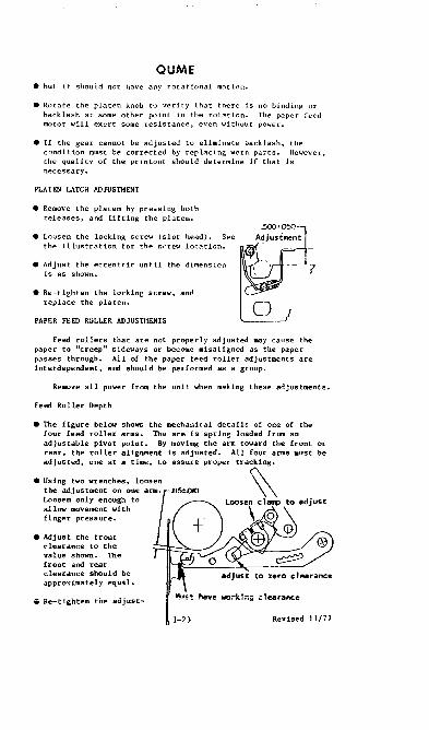
PLATEN LATCH ADJUSllIENT
• Remove the platen by pressing both releases, and lifting the platen.
• Loosen the locking screw (slot head). See the illustration for the screw location.
• Adjust the eccentric until the dimension is as shown.
• Re-tighten the locking screw, amI replace the pIa ten.
PAPER FEED ROLLER ADJUSTIlENTS o
Feed rollers that are not properly adjusted may cause the paper to "creep" sideways or become misaligned as the paper passes through. All of the paper feed roller adjustments are interdependent, and should be perforlled as a group.
Remove all power from the unit when making these adjustments.
Feed Roller Depth
the IllE!chanical details of one of the
• Using two wrenches, loosen the adjustllent on one am. Loosen only enough to allow movement with finger pressure.
• Adjust the front clearance to the value shown. The front and rear clearance should be approximately equal.
5 Re-tighten the adjust-
or be
Revised 11/77

QUME ment screws, being careful that the adjustment does not change when the screw is tightened.
• Adjust the other three arms in the same manner. Before operating the unit, manually slide the carriage over the entire travel to verify that there is no interferrence between the front portion of the arm and the printwheel hub.
• Remove the platen from the unit.
• Carefully lift the paper guide pan (under the platen) and allow it to lay back, out of the way. Do not stretch the springs that are attached to the pan.
~Rear Clearance .
+ adjust
.02;003 @ o
Front Clearance Forward movement increases front clearance.
Pivot Point Rear movement reduces front clearance and increases rear clearance.
• Move the paper release all the way forward; replace the platen. Place a .115" gauge between the platen and one lever arm (see the illustration).
• Adjust the arm for zero clearance by loosening the clamp, and changing the position of the lever.
• Re-tighten the clamp, making sure that the adjustment does not change when doing so.
• Adjust the other three arms in the same manner.
• Re-install the paper guide pan and the platen.
CARRIAGE CABLE TENSION ADJUSTMENT
Cable tension should be checked routinely during preventive maintenance inspections or whenever the carriage is removed and replaced. Cable tension is maintained by spring tension on one idler pulley at the right side of the printer. Adjust the cable tension as follows:
• Using a 3/16" wrench, turn the adjust_nt out (1t_ A in the illustration) until the shaft, B, 1s centered in the hole of the pulley mounting bracket, or 1" from the frame if the bracket does not have a hole. Either, or both ends may be
1-24 Revised 11/77

QUME adjusted whichever is convenient, but DO NOT TiHST THE CABLE.
A Hold here when adjusting
~~ UJ~~
LEFT MARGIN PIIOTO SENSOR
The optical sensor sets th" beginning point for carriage travel. It is used only during the RESTORE sequence, which is issued in inl tialization and reset sequences.
• Initialize the printer by removing power, then returning the power. The carriage should move to the left side of the travel.
• Using a graduated rule or other suitable measuring instrument, measure the distance from the printhammer axis to the frame (see the illustration).
• If the distance must be adjusted, 'loosen the two mounting screws on the photo sensor, and move the assembly.
• When the adjustment has been moved, re-initialize the pr inter by power OFF/ON. The carriage will move to the adjusted location.
DEGELERATlON STOPS
• The deceleration stops are located at each end of the carrier travel. Normally these stops are not touched. However, when the stops are used (by mis-programming or malfunction) the stopping force must be as close to the cable as is practical. Adjust by loosening the screws (A) and moving the stop (B).
CARD GUIDE ADJUSTMENT
:1:.015 .078
!.020 •
•
2025 1 A
B
The card guide IDUst operate with both proper clearance and alignment. The clearance is adjusted (with power off) by loosening the tw.o mount ing sctews (B) that are shown in the illustrstion below. The card lIuide should lil!:htlv touch the platen along the entire working surface of th; guide. Be sure
1-25 Revised 11/77

QUME that when the adjustment is made, there is clearance between the guide and the front platen rollers (see the lower illustration) •
To set the card guide height, type several lines of capital I's at 6 lines per inch spacing. Adjust the guide by loosening the two screws (A) shown in the illustration. At 6 lines/inch, two lines should "rest" on the guide lines, while the center line is between the guide lines. The vertical mark, indicating the print position, should point directly at the center of the letter (see the illustration below) •
. 125 MIN.
RIBBON LIIT HEIGHT
Print a few characters, alternating between the apostrophe (') and the underscore ( ). Examine the ribbon to be sure that the characters are striking the ribbon properly as shown in the illustration. If adjustment is required, loosen the mounting screws (A) for the ribbon lift solenoid and re-position the solenoid until the ribbon is struck correctly.
KlTHERBOARD AL IGNMENT
If difficulty is encountered when inserting or removing the power and data connectors at the rear of the chassis, re-aligning the motherboard may help.
1-26 Revised 11/77

QUME • Re"ove all power from the unit.
• Remove the top and middle spctions.
• Remove all four printed circui t boards from the inside of the printer.
• Loosen, but do not remove, the eight pan-head screws that hold the motherboard.
• Insert the power and data connectors. Be sure that both connectors are well seated onto the motherboard connector flange.
• Tighten the jackscrews on the connectors.
• Tighten the eight motherboard mounting screws.
• Replace the printed circuit cards and the covers. 8e sure that all printed circuit cards are securely seated, and the board switches are in the proper positions.
ASC II EXCEPTIONS
"5 -------iiJtI' ~ "" 'i" lb. b3 b, b,lS 00 o 0 a
:OiO o I' J '0 0 1 0 2 010 "11 3 o 1 o 0 4 0 1 o 1 5 0 1 1 0 6 0 1 11 7 1 000 8 1 001 9 1 010 A 1 o 1 1 B 1 1 00 C 1 1 o 1 D 1 1 1 0 E 1 1 1 1 F
°0 0
01
BS TAB"
~IOX lOX
tRIO CR
RIO
1-27
SELECTRIC
58 = + 5C = ¢ 5E ~ ~
08 ~ BS 09 ~ TAB
OA = INDEX OD = CR
Revised 11/77


IOU-37 TELETYPE
Qantel Model 5061, 5062
100-37 MAX. PIDl., ~l.lIR&l:IEl:lIS
ADDRESS SWITCHES O-F +5V 1.70A -12V .04A
PI 18E1 P3 2E1 E3
30 48 EI 35 en tins roW!;;! 888
U5 VAC 60 HZ. Uses Even Parity lOA MAX. FUR .4 SEC.
1.3A NORMAL
300 LPM c 64 Char. Belt 220 LPM = 96 Char. Belt 1[0 CABLE LENGTH
Can Be Up To 2000 FT.
P2 Min. Rev. Level = K P4
50 35 PRINTER HEAT GEN.
513 BTU/HR.
WRITE CONTROL INSTRUCnONS
lXYY9D
CONTROL BYTE
06 07 20 60
x - DEVICE ADDRESS
FURM FEED LINE FEED
YY - CONTROL BYTE
FUNCTION
RESET ALLOW TERMINATION INTERRUPT SET ALLOW TERMINATION INTERRUPT
STATUS IN INSTRUCTIONS
4XYY9D
STATUS BYTE
D1 02 04 08 10 20 40 80
x - DEVICE ADDRESS
MEANING
ALWAYS ZERO WRITE BUSY END
YY z STATUS BYTE
SERVICE REQUEST INTERRUPT FLAG ALWAYS ZERO ALWAYS ZERO INOPERABLE
1-29 5/82

TELETYPE POWER SUPPLY ADJUSTMENTS (Fig.1)
The regulator card is located in the power module assembly. Access to the -24 volt DC voltage adjustment and fuse is at the rear of the' printer. The regulator card is adjustable from approximately -21 volts to -26 volts. This card has an over~ voltage protection (crowbar) at approximately a -27 volt level. When an overvoltage occurs (malfunction), the output is shorted to ground and should cause fuse F1 to blow. Fuse F1 should not exceed the 2.5 amp fast blow rating.
• The LED provides a visible indication that the DC voltage is present. The LED is located next to the adjustment pot (R9).
• The DC voltage on fuse Fl is approximately -35 volts.
• Plu:e a DVM between GND and the pin on J1l4 as shown in Fig. 1.
• Adjust potentiometer R9 to equal -24 ± .25 volts on the DVM.
• The 410151 Regulator Board has two option screws (A & B). Screw "A" should be on the component side, which connects the -24v common to chassis. Screw "B" should also be on the component s:i.de, which connects the -24v common to the +1l.3v common.
NOTE: You must remove the power module assembly and the regulator board frOm the power module to reach screws "A" and "B".
FIG.l
BAClGJP BAR ADJUSTMENT (Fig. 2, 3 & 4)
The backup bar determines the distance between the hammers aDd the type carrier. This d1s~ance is initially set up with 4 thicknesses of paper (or 3-part paper with carbons) which should satisfy most customers for print quality on one to six part paper. The Backup Bar adjustment should only be necessary under special circumstances with customer forms.
11/77

TELETYPE • Remove the type carrier.
• Use a new or almos t new ribbon for this adjustment •
• Insert the customer's forms in question for print quality •
• Insert 402868 gauge (Fig.) into carrier track and hold firmly against the backup bar at one side of the print station.
• With printer power turhed on, place the printer test switch in "on" position and pass a steel object (screwdriver) over the flag sensor to initiate hammer' firing. While hammers are firing, areas 2, 4, and 6 should not be visible, areas) and 5 should be just visible, and areas 1 and 7 should be the darkest and approximately equal (Fig.). This requirement must be met with the 402868 gauge at both sides of the print station.
HAMMER I/~ ~:::BBON (Lef t Side View)
2> ~402868 GAUGE
~ ~ BACKUP BAR
CARRIER TRACK
Position gauge against backup bar.
FIG.2
_J"" '1~"'" 5 _
Area 1
Area 2
Area 3
Area 4
FIG. 3
Area 5
Area 6
Area 7
402868 GAUGE
elf adjustment is neces\iary, loosen the five track assembly mounting screws friction tight.
• Turn the adjustment screw clockwise to move backup bar closer to hammers and counterclockwise to muve backup bar away fro=. hammers. Fig.4 shows mounting and adjustment screw locations.
1-31 11/77

TELETYPE • When the proper printout is achieved (Fig.3) on the left and
right side, place the "test" switch in the off position.
• Tighten the five track assembly mounting screws.
• Remove the 402868 gauge.
NOTE: For maximum ribbon life, the BACKUP BAR adjustment should be made t.o give the lightest acceptable printed copy.
NOTE: Each time the BACKUP BAR adjustment is made, the left and right CARRIER SPROCKETS, left and right RIBBON GUIDES, and the PAPER POSITIONER ROLLER adjustments must be made"
MOUNTING SCREWS
CAUTION: DO Nar LOOSEN THESE SCREWS.
FIG. 4
To perform the CARRIER SPROCKET, RIBBON GUIDE, and PAPER POSITIONER ROLLER adjustments, turn the printer A-C power off, and remove the paper and ribbon. Insert gauges 402716 and 402717 in the left and right carrier track positions respectively as shown in Figures Sand 6.
LEFT CARRIER SPROCKET ADJUSTMENT (Fig.S)
• Position the 402716 gauge against the backup bar.
• Position the finger lever of the sprocket hub parallel to the track assembly (Fig.S).
• Turn the adjusting nut clockwise or counterclockwise until the rear surface of sprocket flange clears the 402716 gauge by .006" (Max.) to some (Min.) at its closest point.
RIGHT CARRIER SPROCKET ADJUSTMENT (Fig.S)
• Position the 402717 gauge against the backup bar.
• Loosen the two hub clamp
1-32 11/77

TELETYPE • Turn the split adjusting nut clockwise or counterclock\lise
until the sprocket flange clears the 402717 gauge by .005" (Hax.) to some (IUn.) at its closest point.
• Tighten the two hub clamp screws.
LEFT AND RIGUT RIBBON GUIDE ADJUSTllliNTS (Fig.5)
• Loosen the two left and right ribbon guide mounting screws.
• Position the 402716 and 402717 gauges against the backup bar.
• As a prel i.lnary adjustment, position the left and right ribbon guides to clear the Vagues.
• Tighten the two left and right ribbon guide mounting screws.
FlG.5
LEFT
RIGHT GARRIER
SPROCKET
SP~~~ET .1 ~I __ SPRING II ~ II
~~ 7-=1]] TYPE PALLETS
MOUNTl:G MOUNTING seRE SCREW
e e LEFT
RIBBON GUIDE
FIG.6 RIGHT
RIBBON GUIDE
NOTE: The remaining ribbon guide adjustment is performed with the type carrier installed. The adjustment is a final operational check to assure proper clearance between the type pallets and ribbon guides •
• Seat all pallets of the type carrier against the rear surface of the large diameter flange of the left carrier sprocket.
1-33 5/82

TELETYPE • Position a .010" flat gauge against each ribbon guide and
rotate the impeller shaft through one complete rotation of the carrier to check for a minimum .010" clearance between the closest pallet and ribbon guide (Refer to Fig. 6).
PAPER POSITIONER ROLLER ADJUSTMENT (preliminary) (Fig.7)
• Position the 402716 and 402717 gauges against the backup bar.
• Loosen the two eccentric clamp screws friction tight.
• Rotate the eccentrics on both sides until the paper positioner roller just touches the gauge posts.
• Tighten the eccentric clamp screws.
• Remove the 402716 and 402717 gauges and install the type carrier, ribbon, and paper.
FIG. 7
PAPER POSITIONER ROLLER ADJUSTMENT (final)
Further adjustment will be necessary if the two requirements below are not met. These requirements do not apply when printing within two lines of a fold on fan-fold paper.
a) The printed copy should not be illegible due to ribbon smudging after a one minute printer idle period.
b) There shall be no smudge when printing a text character (not font or identification symbol) •
• If adjustment is needed, looSen the left and right eccentric clamp screws friction tight •
• Rotate eccentrics to meet the requirements above.
5/82

TELETYPE IMPELLER SHAFf SENSOR ADJUSTMENT (Fig. 8 & 9)
NOTE: It is preferable to use nonmagnetic gauges to check the gaps on both magnet tc
Air Gap (Fig.8) • Loosen sensor clamp screw.
• Insert a .015" flat gauge between the magnetic sensor pole piece and a tooth on the timing wheel and adjust the gap for a snug fit. The tolerance is minimum .008" -- maximum .020". Tighten the sensor clamp screw and remove gauge.
TIMING WHEEL
Under Power (Fig.9) • With the unit 1n the "test" position and printing the test
character. turn the impeller sensor adjusting screw COUNTERCLOCKWISE until a colulBD/s does not print. The impeller sensor adjusting screw can be reached through a hole in the top cover just above the screw (FIG.9).
• Slowly turn the adjusting screw CLOCKWISE until all columns print correctly for at least ten lines.
• Turn the adjusting screw CLOCKWISE an additional 2.5 turns.
FIG.9
1-35
SCREW MOUNTING BRACKET TAB
5/82

TELETYPE FLAG SENSOR ADJUSTMENT (Fig. 10 & 11)
Air Gap (Fig.10) • Loosen the Flag Sensor clamp screw.
• Insert a .020" flat gauge between the magnetic sensor pole piece and a Flag on the font belt and adjust for a snug fit. This should meet the requirement for a minimum .010" clearance between the· closest Flag and magnetic sensor pole piece and a maximum .030" clearance between any Flag and sensor pole piece.
• Tighten the Flag Sensor clamp screw.
~/"~r<i~ TYPE ::: 0.025-
CAa;:::.---:~ t ./
~SENSOR MOUNTING
SENSOR CLAMP ~ BRACKET SCREW ~
MAGNETIC SENSOR FIG.lO
Under Power (Fig.Il) • Loosen the Flag Sensor bracket clamp screws friction tight.
• Turn printer "test" switch on.
• Move the sensor bracket CLOCKWISE until a different or no character prints in one or more columns. Note the position of the indicator on the range scale.
• Move the sensor bracket COUNTERCLOCKWISE until again a different· or no character prints in one or more columns. Note the pOSition of the indicator on the range scale.
• Position the Flag Sensor indicator midway between the two previously noted failure points.
• Turn the "test" switch off.
• Tighten the clamp screws.
FIG. 11
MAGNBTlC SENSOR
1-36 5/82

TELETYPE IMPELLER SHAFf TO CARRIER PHASING (Fig.12)
• Enter a program to print a full line of capital II's.
• Print several lines, place printer off-line, and wait for motor to stop.
• Inspect the characters to see if the right or left portion of the characters are being clipped.
• To make adJustment, push the impeller shaft gear (which has a strong spring tension) away [rom the knurled adjusting collar and turn the collar:
a) CLOCKWISE if right portion of character is clipped. b) COUNTERCLOCKIHSE if left portion of character is clipped.
• Place the printer back on-line and repeat above steps until proper printing of complete character is achieved.
NOTE: When multicopies are used, phasing should be adjusted to minimize clipping on the last copy with no clipping on the original copy.
TRACfOR SIDE PLATE UPPER
MOUNTING SCREW
SPUNED SHAFT ---_-L15
TRACTOR PHASING (Fig.l3)
FIG. 12
UPPER PAPER GUIDE
• This adjustment is done by the factory and should not be needed unless tractors are removed or replaced.
• The phasing marks (white dot) on the left and right tractors shall be on the Same spline shaft groove.
• To adjust!' remove the left tractor frcm the: splined shaft, turD the tractor, and reassemble on the correct spline shaft groove.
1-37 11/17

TELETYPE RIBBON MECHANISH DRAG (Fig.14)
• Place a spring scale over the ribbon disc drive pin.
• A force of 8 to 10 ounces should start the free .. heeling ribbon drive disc moving .. hen pulling tangentially on its drive pin.
• To adjust, rotate the adjusting nut CLOCKWISE to increase drag and COUNTERCLOCKWISE to decrease drag to meet the requirement above.
• Reverse the ribbon mechanism by pulling up on the reversing lever adjacent to the free wheeling drive disc.
• Manually rotate the impeller shaft clockwise as viewed from the right side of the printer until ribbon reversal occurs.
• The other ribbon drive disc is now the free wheeling disc and may be checked and 'adjusted as above.
NOTE: Before checking the drag, rotate the free wheeling drive disc at least one-half revolution in the direction to be pulled in order to take up all play.
TENSION ADJUSTING
NUTS
FIG.l4
RIBBON MECHANISM DRIVE BELT TENSION (Fig.lS)
• Loosen the two ribbon mechanism mounting screws.
• Place a spring scale gauge around the bottom of the belt.
• Position the ribbon mechanism left or right to obtain a minimum 11/32" -- maximum 1/2" between the outside surfacea of the drive belt when a force of 8 ounces ia applied adjacent to the ribbon mechanism frame.
1-38 11/77
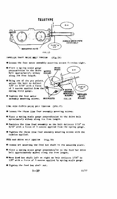
FIG.15
IMPELLER SHAFT DRIVE BELT TENSION (Fig.16)
• Loosen the four motor assembly mounting screws friction tight.
• Place a spring scale gauge perpendicular to the drive MOTOR belt approximately midway along its free length.
• Using one of the pry points, adjust the belt to deflect l/S" to 3/16" with a force of 5 ounces applied from the spring scale gauge.
• Tighten the four motor assembly .aunting screws. PRY POINTS
LINE FEED CLUTCH DRIVE BELT TENSION (FIG. (7)
• Loosen the three line feed assembly mounting screws.
• Place a spring scale gauge perpendicular to the drive belt aproxiaately midway along its free length.
• Position the line feed assembly so the belt deflects 1/16" to 5/32" with a force of 5 ounces applied from the spring gauge.
• Tighten the three line feed 8sse1lbly mounting screws with the tension applied.
FEED BAR DRIVE BELT TENSION (Fig. IS)
• Loosen nut mounting the feed bar shaft to the mounting plate.
• Place a spring scale gauge perpendicular to the feed bar drive belt approximately midway along its free length.
• Move feed bar shaft left or right so belt deflects 1/16" to l/S" with a force of 5 ounces applied by spring scale gauge.
• Tighten the feed bar shaft nut.
1-39 !l/77

TELETYPE
LINE FEED ASSEMBLY MOUNTING SCREWS (3)
FIG.17 FIG.lS
PAPER-QUT SWITCH ADJUSTMENT (Fig. 19)
• Loosen the two switch clamp screws friction tight.
• Place a .075" gauge between end of paper-out switch arm and rear paper guide. The switch should trip before arm contacts .075" gauge.
• Place a .095" gauge between end of paper-out switch arm and rear paper guide. The switch should not trip when lightly held against the .095" gauge.
• Tighten the clamp screws while meeting the requirements.
CLAMP SCREWS
FIG.19
TYPE CARRIER PALLET ALIGNMENT (Fig.20)
• The pallet location in the carrier should be a ainilllUlll .070" from the stea end to the rear surface of the carrier.
'1-40 11/77

TELETYPE CLUTCH STOP LEVER (Fig.21)
• Loosen the two Magnet Assembly Mounting nuts and the Armature Stop Mounting screw (back of Magnet Mounting nut) friction tight.
• Position Armature Stop so that Clutch Stop lever is a minimum flush -- maximum .005" overflush with the top surface of the Shoe Release Arm.
• Tighten the Armature Stop screw and Magnet Hounting nuts.
ARMATURE
MAGNET ASSEMBLY ~t~:JI' MOUNTING NUT SCREW
ARMATURE STOP ~ront MAGNET ASSEMBLY
MOUNTING NUT
SHOE RELEASE
ARM FlG.21
LINE FEED ARMATURE GAP (Fig. 22)
back
• Loosen the two Magnet Assembly Mounting nuts and the Magnet Assembly Mounting Post (in front of right Magnet Assembly llaunting nut) friction tight.
• Rotate the llagnet Assembly about mounting post so that a .025" gauge will enter between the armature and magnet pole piece but will not pass beyond the midpoint of the pole piece.
• Tighten the Magnet nounting nuts and the Magnet Hounting Post.
ARMATURE 8TOI'
CLU'ICH
MAGNET A88BIIBLY MOUN'I1NGNUT
~% .~,-Lk.'~· 9==~~ii':'l
~E / ~~~==~ ARM
A o.0Z5-lNCH GAUGE iiiL .. NOi' PASS MIDPOINT OF POLE PIBCB
FlG.22
IOU 37 adjustments are in Tech Memo t25
1-41 5/82

TaETYPE
FORI1-0UT CONTACT GAP
1.
2.
Check that when the form-out contacts are
~~g;~!:~~ g~61~ f~~hi;P a~at~~025 t~~c~~~:acts Adjust the contact gap if necessary by turning the eccentric bushing. This adjustment will be finalized in the Form-out Contact to Belt Spacing Section on the next page.
o..e. rGrut-outbe!t Wt.Il.,....idl ....... ~pU'.,..AOt.om. dUpped.orbrotL-.
FORI1-OUT CONTACT ASSEMBLY LATERAL ADJUSTMENT
1.
2.
3.
4.
~~~~~nf~~St~d~~~f~1~~ 2~ setting the form-out
·Advance the belt manually until one of the short lobes on the belt rests against the end of the form-out contact assembly. Push the line-feed pawls away from the line-feed gear to aLLow the belt pulleys to turn freely.
Center the tip of the contact assemb lyon the lobe, if necessary. Loosen the contact assemb ly mounting screws to allow the contact assembly
;~l~~t:v~s~~~~a~nL h~~: ~gt~~er~~6eed on early models.
Retighten the contact assembly mounting screws.
5/82 1-41A

TELETYPE
FORM-OUT GEAR BACKLASH
1.
2.
3.
Check the backlash (free play) of the form-out
~~~~ing T~~e t~ i~~r7e!~e g!~~m;~~ii~~~~y ~hi le
:~i¥~~ roo~~u~f g~:~k t~s~w~~~~adb~~k d:~actible fourth.
Ha:~ ~~i~si~an~!: ~~~e~~~~!ou~O~~~~a~~~m three forward or backward to allow a slight (and only a slight) amount of backLash between the gear teeth.
Retighten the clamp nuts.
FORM-OUT CONTACT TO BELT SPACING
1.
2.
3.
4.
5.
Lift the line feed pawls off the Line feed gear and advance the form-out bel t unti l a cam lObe just touches the tip of the form-out contact assembly.
~ ~ ~~w f~~a ~!~~ :~~h~a~~~m~~u~ng:y~ ~ ~ t~~~a Slightly back from the form-out contact assembly. The line feed gear should click into position.
The clearance between the front of the cam Lobe and the tip of the form-out contact assembly shouLd be some to 0.010 inches.
The tip of the form-out contact assembly should clear the surface of the belt by some to 0.015 inches.
g~~~~~~y a~~o~~~ ~~~ ~gt~~n~0~~!nic2~~t~~~e~~~~: The eccentric bUShing primari ly adjusts the form-out contact in the forward and reverse directions. The eccentric post primari ly adjusts the form-out contact in the up and down
~~~!;;~~~. th~~w~~;~, a Y~:r~~~~~~m~~t t~~~:at~ni~~ they are both CQrrectly adjusted.
1-418 5/82

TELETYPE
6. If there is not enough adjustment range to meet the above requirements, the form-out gear wilL have to be dlsengaged and moved one tooth in either direction. In this case, go back to the Form-Out Gear Back Lash Adj ustment.
5/82
1-41C

TELETYPE
INTERPOSER BACKSTOP ADJUSTMENT
THIS ADJUSTMENT SHOULD ONLY BE DONE IF THE CHARACTERS IN ONE OR MORE COLUMNS ARE NOT PRINTING AND IF ALL OTHER ADJUSTMENTS HAVE BEEN MADE.
In some cases, a weak interposer spring may cause a misalignment of the bottom of an interposer with the tip of its armature. When this happens, the armature is unable to raise the interposer sufficiently to
~g¥:~~o~~~ ;~~h b~r n~h~r i~~~ l t ~~o t~~ i ~a::~en~~d t~~us prevents a character from bein!! printed in t~e hammer's coLumn.
This problem wi II usually app~ar as an intermittant
:~s:~~~~: ~a;~!r:c~~~~O:::a~ ~~r~~~~~~~a~~t~~{a~~: in If a coLumn is cQnsistantly qlank, it could also be caused by a bad winding in aA armature magnet, or by broken interposer spring. In such a case:
1.
2.
3.
Turn off the printer and ·remove the logic PWA from the underside of the printer.
Examine the armatul"es and the interposers for missing or broken ~prings.
~~~~~. thttr~~~~~;n~:a~~r:n~O s~~~:;t~d o~~~ l from the commQn termin,l to the terminal of the cOi l uni t being measured.
When the printer is tilted up expOsing the terminals, the upper row of terminals go to the armatures that operate the odd numbered hammers, and the lower row of terminals go to the armat\Jres th,t operate the even m.mbered hammers.
1-410
5/82

TELETYPE
A cross section ot the print head assembly is shown below to illustrate what needs to be adjusted and how a II the parts tunct i on togetner:
1~:::J!;~~~~~~~~~"An:U. MACNa·
::r: l!P9TOI'W'BUMPEII 0
~"',;'OQi---- SHillS ~
(''ENTER CASnNG "IMAGN£TS
.::c DAMPER ROD
Il<nRlOSEIl SPRlHC
Fol Low this procedure for the Interposer Back Stop Aaj ustment:
1. I)isconnect the MoLex Connectors at the mechanical VFU assembly.
1-41E
5/82
TEI.ETYPE
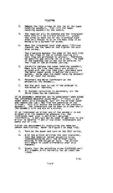
2. Remove the four screws at the top of the paper handling assembly. Then lift the paper handling assembly by the handle.
3. J~~k i~~~~ l=~ l ~i ~~ er s r~~~s~~h f~g ~~~ i L~~~~~ser the screw at each end of the interposer back stop only enough to allow the back stop to be moved with a screwdriver blade.
4. Move the interposer back stop about 1/32-inch towards the the impeller and tighten the back stop screws.
The clearance between the edge of the back stop and the ridge of the printhead casting will vary from one printhead to another. Therefore, no specific gap setting can be given. The edge ~~e t~'d~~c~~t~~e m~~ i~~h~~~ ~~it~~g~aral lel to
5. Carefully replace the paper handling assembly. Make sure the line feed pawls are properly
~~!g~:~ati~~p~~e g~i~: ;:ege~~~~' t~~dpT:~~i ~ure guides. Screw down the paper handling assembly wi th at least two screws.
6. Reconnect the Molex Connectors at the mechanical VFU aSsembly.
7. Run the self test to see if the problem is corrected or improved.
8. If further correction is necessary, all the above steps may be repeated.
IT IS EXTREMELY IMPORTANT NOT TO OVERCORRECT WHEN DOING THE INTERPOSER BACKSTOP ADJUSTMENT. If there is any doubt about this procedure, turn oH the printer power
~~n~~veT~~: ;~[c e~~~s:r~e t~~t~~e~~i~~e o:r~~~ure assembly. The interposers can be seen at either ena of the assembly with the aid of a mirror.
!ti~~e~n!~~~o~~~ ~;s~!g~~~/~~m~iu~~etf~~~!y is not
~~~~~~~~Hy~ac~ ~;~~i~~td:!~n~~e~~e~di~s~a~ition to the mirror to observe if any of the other interposers are badly out of Line.
Finish the adjustment by readjusting the impeller sensor positioning. Refer to Figure 9 on page 1-35:
1.
2.
3.
Turn on the power and turn on the TEST Switch.
With the printer printing the test Character, turn the impeLLer sensor adjusting screw COUNTERCI.OCKWISE until the printer Starts misSing in one column or more. The printer wi II begin to sound differently when this happens.
~t~w~to~~ ~~1n~d~~~~!~¥l~c+~~ ~~Ot~~~~Et~gti l lines.
Si82
1-41F

4.
TELETYPE
Turn the adjusting screw CLOCKWISE another 2-112 turns. This wilL usually place the impeller sensor in the optimum position, but this adjustment sometimes varies with some printers.
5/82
1-41G
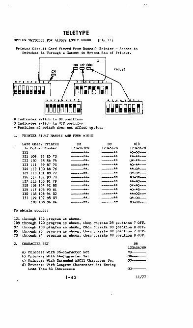
TELETYPE OPTION SWITCHES FOR 410072 LOGIC BOARD (Fig.21)
Printer Circuit Card Viewed From Beneath Printer - Access to Switches is Through a Cutout in Bottom Pan of Printer.
o D8 D9 D10
* Indicates switch in ON position. o Indicates switch in OFF position. - Position of switch does not affect option.
1. PRINTER RIGHT MARGIN AND FORM WIDTH
Last Char. Printed D8 D9 DI0 in Column Number 123456789 12345678 12345678
132 ---** *0-00---121 109 97 85 73 --**- ---** **-**---122 110 98 86 74 ---** 0*-**--123 111 99 87 75 ---** *0-**---124 112 100 88 76 -----**- ------** **-0*---125 113 101 89 77 ----**- 0*-0*---126 114 102 90 7B -----**- -----** *0-0*---127 115 103 91 79 ------** **-*0---12B 116 104 92 SO ------** 0*-*0---129 117 105 93 B1 ---**- ----** *0-*0---130 lIB 106 94 82 -----**- -----** **-00---131 119 107 95 83 ------** 0*-00---
120 lOB 96 B4 ---**- -----** *0-00---
To obtain counts:
121 through 132 program as shown. 109 through 120 program as shown. then operate D9 position 7 OFF. 97 through lOB program as shown. then operate D9 position 8 OFF. 85 through 96 program as shown. then operate D8 pOSition 7 OFF. 73 through B4 program as shown. then operate D8 position 8 OFF.
2. CHARACTER SET
a) Printers With 96-Gharacter Set b) Printers With 64-Gharacter Set c) Printers With Extended ASCII Character Set d) Printers With Longest Characater Set Having
Less rnan 64 Characters
1-42
DB 123456789 *0-----0*------00-------00----
11/77

TELETYPE
OPTION SETTING FOR THE 4Hl729 lOGIC CARD (2 SWITCH PADS)
• Set the 64 character printer switch as shown in Figure 1 •
• Set the 96 character printer switch as shown in Figure Z.
NOTE: This logic board can only be used with the lOU-37.
ON
OFF
SW #11 SW #13
FIGURE 1
ON
OFF
SW #11 SW #13
FIGURE Z
1-4ZA

TELETYPE
OPTION SETTINGS fOR THE 410072 LOGIC BOARD (4 SWITCH PADS)
lOU~37 OPTION REQUlRHOlTS
• Set the 64 character switches (shown in black) as in r igure 1.
• The 96 character switch variations (c~ared to the 64) are in
dicated with an X.
• The Following swi tches must be changed; SW 09-1. SW 00-1, and
5N 06-2. 09 010
C4 FIGURE 1 DB
100-39 AfI) DTC CIJ4 OPT ION REQUIRH£NTS
.Set the 64 character switches (shown in black) as in Figure 2.
• The 96 character switch variations on 51'/ 09-1, 51'1 08-1, and
SW 08-2, are indicated with an X.
C4
09
DB
r IGURE 2
1-426
010

TELETYPE 3. PRINTER LEFT MARGIN AND FORM WIDTH
a) First Printed Column -- Column 1 b) First Printed Column -- Column 2 e) First Printed Column -- Column 3 d) First Printed Column -- Column 4 e) First Printed Column -- Column 5 f) First Printed Column -- Column 6 g) First Printed Column -- Column 7 h) First Printed Column -- Column 8 i) First Printed Column -- Column 9 j) First Printed Column -- Column 10 k) First Printed Column -- Column 11 1) First Printed Column -- Column 12 m) First Printed Column -- Column 13
4. SSI/OEM INTERFACE
a) SSI b) OEM
5. FOLDOVER ON PRINTERS WITH 96-GHARACTER SET
a) Lower Case and Upper Case Print b) Lower Case Prints as Upper Case
6. FOLDOVER ON PRINTERS WITH 64-GHARACTER SET
a) Lower Case Prints as Error Symbol b) Lower Case Prints as Upper Case
7. PRINTER PAPER FEED OUT
a) No Paper Feed Out b) Paper Feed Out on DSR or RM Loss --
16 Lines or One Form. e) Paper Feed Out on DSR or LRM Loss or ETX ,..-
16 Lines or One Form.
8. INCOMPLETE FORM SUPPRESSES PAPER ALARM
a) No (Paper Out Not Gated With Form Out) b) Yes (Paper Out Gated With Form Out)
9. AUX. ALARM
a) Enable b) Disable
10. IDLE LINE MOTOR CONTROL
a) Uisabled - Motor Held ON Indefinitely During Idle Line.
b) Enabled - Motor Turned Off After 40-seeond Idle Line.
1-43
D8 123456789
-****---**0*----**00---*000---~O*O--
~OO*--~*OO--
-*0*0--~O**-~*O*--
-***0----*00*--~**O---
D8 123456789
-----~
D9 12345678 0--
*-------D9
12345678 0----*----
D9 12345678
-<>0----
-*0-----D9
12345678
--<>----
D9 12345678 -~------*---
D9 12345678
----0-----*--
11/77

TELETYPE 11. SI/SO DETECTION 010
12345678 a) SI/SO Detection Not Used -0-----b) SI/SO Detection Enables Printing Additional Char.--*-----
12. PRINTER ERRORED CHARACTER SYMBOL
a) Printed on Even Parity Error b) Printed on Odd Parity Error c) Not Printed on Parity Error d) Prints Extended ASCII Characters
(No Parity Check)
13. PRINTING OF ESCAPE SEQUENCES SUPPRESED
a) Character After ESC Prllnted as Received b) Printing of Character After ESC Suppressed
14. SPEED SELECTION (applies only if opt ion 4b is selected)
a) 75 Baud b) 150 Baud c) 300 Baud d) 600 Baud e) 1200 Baud f) 2400 Baud g) 4800 Baud h) 9600 Baud
OPTION SWITCHES FOR 410729 LOGIC BOARD (Flg.22)
o
1. INCOKPLETE FORM SUPPRESSES PAPER ALARH
a) No (Paper Out Not Gated With Form Out) b) Yes (Paper Out Gated \lith Form Out)
2. PRINTER ERltORED CHARACTER SYMBOL
a) Printed on Even Parity Error b) Printed on Odd Parity Error =) Mot Pr!~ted en .Parity Error d) Prints Extended ASCII Characters- No Parity Chk.
1-44
010 12345678 -----*0------0*-
----00-
010 12345678 -------0
C4 12345678 *00000OO 0*000000 000*0000 00*00000 000000*0 0000"000 00000*00 0000000*
011 123456
0-----
011 123456 -*0----0*---_'!I!'*----00---
11/77

3.
4.
TELETYPE
PR I NTER PAPER FEED OUT
a) No Paper Feed Out b) Paper Feed Out on DSR Loss - 16 lines c) Paper Feed Out on DSR Loss or ETX
CHARACTER SET
a) Printers With 96 Character Set b) Pr inters With 64 Character Set c) Printers With Extended ASCII Character d) Printers With Longest Character Set
Hav i ng Less than 64 Characters
5. FOLDOVER ON UP-LOW PR INTER
a) Lower Case and Upper Case Pr i nt b) Lower Case Pr i nts as Upper Case
6. FOLDOVER ON !1QNOCASE PR INTER
a) Lower Case Prints as Error Symbol b) Lower Case Prints as Upper Case
7. PR INTER I1ARG I N ANO FORM II 10TH
a) Last Character on Column 132 b) Last Character on Column 131 c) Last Character on Column 130 d) Last Character on Column 129 e) Last Character on Column 128 f) Last Character on Column 127 g) Last Character on Column 126 h) Last Character on Column 125 i) Last Character on Column 124 j) Last Character on Colurm 123 k) Last Cha~acter on Column 122 I) Last Character on Column 121
1-45
011 013 123456 123456 ---*-- 0--------0-- 0--------0-- *-----
011 123456 ----0* ----*0
Set ---00
----*0
013 123456 -0-----*----
013 123456 -0-----*----
013 123456 --*000 --0*00 --**00 --*0*0 --0**0 --***0 --*00* --0*0* --**0* --*0** --0*** --****

TELETYPE
LUBRI CAT! ON
General
The printer can be lubricated by positioning it in the ribbon chang i ng (ma i n tenance) pos i t ion.
Lubricate printer just prior to placing in service or before putting it in storage. The printer should be re-Iubricated after it has been in service a few w~eks. Thereafter, lubricate mechanisms every 2000 hours of running time.
Apply lubricant to points as indicated.
On sma 11 parts, a mi n imum amount of I ubri cant shoul d be app lied so that the lubricant remains on the parts and does not run off.
Excessive lubricant should be removed with a dry, lint-free cloth.
The following areas must be kept dry, free of all lubricant:
• All e lectr i ca I components, i nclud i ng termi na Is.
• All parts normally touched by the operator, including exposed surfaces in ribbon, paper handl ing areas, and all large flat areas.
The fol low ing symbo 1 sind i cate the quant i ty of I ub r i cant to be used in a specified area: Symbols 01, 02, 03, etc., refer to I, 2, 3, etc., drops of oi I. The follOWing I ist of symbols applies to the lubrication instructions and the type of lubricant to be used:
o 88970 oi I. G Apply thin fi 1m of 145867 grease. S. Saturate felt Oilers, waShers, and wicks with oil. o Keep dry, no lubricant permi tted.
NOTE: All ball bearings are packed with grease and normally "eed no re-I ubr i cat ion. However, if I ubri cat ion is requ ired 195298 (Beacon 325) grease should be used. Grease is to be appl ied 1/64 inch max i mum th i cknes s .
1-46

TELETYPE LUBRICATION
Front and Top 01 Springs (Each End, _ Z Springs)
01 ;i;~~c~;~C'~Side, ',to.
NOTE: The type carrier '. ;t be removed to gain access to the pad. i;t,
01
01 Motor Shaft Searings
I ,/J?;i
~~. (B~O:..t_h __ E_n.dS) 02 Ribbon !-Iechanism
Rollers
~--~'I------------~
Felt wick Under Type Carrier
G Front Flange of Left Idler
~ 'Re", Su"""
~~) IDLER
1-47
Rollers

02
01 Paper Feed S Felt Wick
TELETYPE
LUBRICATION (Cone)
.01 Left Ribbon Guide Bracket Pivot
ifO' ~k. G Cam Surfaces (6 Places)
(Top View)
1-48

01
04 Eccentrics (Approximately)
01
TELETYPE
01 Detent
03 Sleeve Oil Hole
1-49
Gear Teeth

I.,,(t Side
Right Side
TELETYPE LUBRICATION (Cont)
/
G Stop Lever Engaging Surface
01 Hooks (Each End of Sl>ring)
Ol Right Ribbon Guide Bracket
1-50
Phasing Hechanism Hooks (Each End)
G Impeller Driven Gear Teeth
G Shaft Bearings (Pack Bearings. Each End)

~ 0 00 00 0 1 0 10 10 1 1 1 1
o 11
'; '\[''1''1' Iii 0
1 1 1 0 0
Is 4 3 2 1 ---e>o 0 1 2 3 4 5 6 7 Row"
°iololoi 0 SP 0 @ p \ @ p
010101 l' 1 I ! 1 A Q A Q
OiOll10 2 .. 2 B" R B R
ole 11 11 3 "' # 3 c 5 C s
O! 1]010 4 ~ $ 4 0 T 0 T -
i o! 1 :01 11 5 0:
tj % 5 E U E U ! ~ -'--
10; 1 i 1: 0 6 I ~ & 6 F V F V I
10i 111! 11 7 I 5
~ 7 G W G W .,
1 iololol 8 ~ ( 8 H X H x
~1 9 8 1 9 I y I Y -:~
Z ! Z 110'1 10: A '"
.. : J J
11011ili B + ; K [ K [
1! 11010 C I < l , l , i 1 ' 1 '0 11 0 i I I - = M , J M I J
E i > I N I '" N !
'" I I ~ I ~ i ~ ; ~ i F I I I / I ? J 0 I - 01-BASIC CODE SET FOR 64 CHARACTER PRINTERS
NOTES: HEXIDEClMAL = ASCII COLUMN, ASCII ROW.
IOU's FOR 64 CHARACTER PRINTERS IGNORE BIT 6 (25), AND REPLACE IT WITH THE INVERTED BIT 7 (26). THIS PRINTS COLUMNS ~ and 1 AS CHARACTERS IN COLUMNS 2 AND 3, AND COLUMNS 6 AND 7 AS CHARACTERS IN COLUMNS 5 AND 6.
ALL BITS ARE ENABLED FOR CONTROL CODES (SEE TABLE).
EXACT CHARACTERS IN POSITIONS 6,~ AND 7B THRU 7F MAY VARY SLIGHTLY BETWEEN PRINTERS. THESE POSITIONS ARE NOT AVAILABLE ON THE SELECTRIC.
1-51

~ ..
00 00 0 1 0 1 Po 10 1 1 1 1 7b So 6 b
" 0 1 0 1 i 0 1 o 1 I 5 j I. b4
b3
bJ b~ !
1 ...... 0 1 2 3 4 5 6 7 Row.
o 0 o 0 0 SP 0 @ P \
000 1 1 ! 1 I A Q a
0 o 1 0 2 .. 2 B R b
0 o 1 1 3 # 3 c s (
0 1 o 0 4 ~ $ 4 D T d
0 1 0 1 5 e % 5 E U e
0 1 1 0 6 ~ & 6 F V I
0 1 1 1 7 7 G VI 9 .....
8 I 100 0 ! 8 H X h
1 o 0 1 9 1 9 I Y i
1 0 1 0 A .. .. .. J Z i
1 o 1 1 B + ; K [ ~
1 1 o 0 C ! < l , I
1 1 0 1 0 : - = M J m
1 1 1 0 E I > N '" n
1 1 1 1 F I ? 0 - 0
BASIC CODE SET FOR 96 CHARACTER PRINTERS
NOTES: HEXIDEClMAL : ASCII COLUMN, ASCII ROW.
IOU's FOR 96 CHARACTER PRINTERS FORCE BIT 6 TO A ~HEN BIT 7 (26) IS~. THIS PRINTS COLUMNS ~ AND AS CHARACTERS IN COLUMNS 2 AND 3.
P
q
r . I
u
v
w . Y
I
{ I
} ~
DEL
ALL BITS ARE ENABLED FOR CONTROL CODES (SEE TABLE).
EXACT CHARACTERS IN POSITIONS 6,~ AND 7B THRU 7F MAY VARY SLIGHTLY BETWEEN PRINTERS. THESE POSITIONS ARE NOT AVAILABLE ON THE SELECTRIC.
1-52

DATA PRODUCTS
ADJUSTMENT PROCEDURES FOR DP-2230 SERVO PCB
These adjustments will help to alleviate problems of overprinting
with possible hammer faults and/or format errors. Also, print
speed can be increased as much as 3m~. All adjustments are on the
Servo PCB and should be performed anytime Servo PCB is replaced
or problems in Servo systems come up.
The adjustments are in order as follows:
6/B lPI Ad justment
• Scope Settings
CH1 - 0.5 VCM, TP J11-2
CH2 - 0.5 VCM, TP J11-3
Time - 10 MS Div.
Trig - EXT (-), TP J21-1
Vert. Mode - Chop
• 6 lPI Adjustment
Place a loop of single part 11 X 14 paper around drum gate
for this adjustment. Establish APT "Print" test, manual
section, print E's. Adjust R21B for minimum overshoot
and undershoot of both signals. (Refer to Figure 1 below.)
J11-2 (PFPOS) ~~ Undershoot
I • \ .... > Overshoot
~ ~undershoot '---/'-V<-
Jll-3 (PFVEL)
FIGURE 1
6 lPI & B lPI PAPER STEP
• B lP I Adjustment
leave all scope settings and TP' s as established in 6 lPI
adjustment. Place the 6/B lPI switch on operator panel
to the B lPI position and start "Print" test. Adjust R204
for minimum overshoot and undershoot of both signals. 1-53

DATA PRODUCTS
AQJUSTI£NT PROCEDURES fOR 'OP-2230 SERVO PCB Continued
Slew ~eed Adjustment
•
•
Scope SettinCjs
CHl - 2 VCM, TP J20-4
Time - 1 MS Div.
Trig - INT (-) CHl
Vert. Mode - CHl
Adjustment Procedure
1. Tape down paper out switches (no paper in printer).
2. Place 6/6 lPI switch in 6 lPI position.
3. load following test program:
[IPl] ldD09D 4d449D OOOOA3 0OO3A7 [XMIT]
(d - To be replaced by Controller Address.)
4. On Terminate, the tractors will rotate then stop as
system checks status, and then rotate again, etc. As
tractors are rotating, adjust R206 for 8.1 rns (~O.2 ms)
from trailing edge to trailing edge as indicated in
Figure 2 below.
I.....--_____ n_ r 8.1 rns .! .2 ms-----~,;)I
fiGURE 2
Vertification Procedure for 6/8 lPI and Slew Speed Ad justment
• Scope Settings CHl - 10 VCM, TP J21-1
CH2 - 2 VCM, TP J20-4
Time - 5 MS Div.
Trig - INT (-) CHl
Vert. Mode - Chop
1-54

DATA PRODUCTS
ADJUSTt-ENT PROCEDURES FOR DP-2230 SERVO PCB Continued
Slew Speed Adjustment For 6/8 LPI Continued
• Test Procedure
1 • Remove tape from paper out switches and load paper into
printer.
2. Establish ATP "Print", manual section, print E's.
3. Look at CH2 and verify that it is 50 ms or less from
trailing edge to trailing edge. There are no adjustments
to this procedure.
4. If the 6/8 LPI and slew speed are correct, then verifica
tion will be correct. Refer to Figure 3 for correct
adjustment.
J21-1 (PFPM) I I I
,: 11 J20-4 (PFCK) L....-.-.-.J L-~<50 IDS-4
FIGURE 3
PAPER FEED TIMING VERIFICATION
NOTE: If time delay is greater than 50 ms, the paper feed
servo needs repair. No further adjustments should be
atte~ted. Replace paper feed servo board and make
previous adjustments again.
Move HarII1ler Bank Left/Right Servo Adjustment
• Scope Settings
CH1 - 0.5 YCM, TP J3-5
CH2 - 0.5 YCM, TP J3-3
Trig - EXT (-), TP J23-2 (Trailing Edge, HI to LO)
Time - 20 ms Div. (10 ms after signal is established)
NOTE: Signal may be easier to catch if scope is in NORM
mode instead of Auto mode.
1-55

DATA PRODUCTS
ADJUSTMENT PROCEDURES FOR DP-2230 SERVO PCB CONTINUED
l10ve Hammer 8ank Left/Right Servo Adjustment
• Test Procedure
The test can be done using the ATP test or with the test pro
gram written at the end of this procedure. If ATP test is
used, a paper loop should be used in the printer. Ihth the
test program, no paper is used. (Paper is loaded for Paper
Out Switch.)
• ATP Test Procedure
Start ATP Print Test, manual section, print E's. As printer
is printing, adjust R145 to resemble Figure 4. f1inimize the
over/under shoot of signal.
• Test Program Procedure
Load program at Device "Zero". ;·Iake sure Paper Out Switches
are down, paper or taped. Follow adjustment procedure as
above using Figure 4.
Overshoct
J3-S (HBPOS)
Undershoot
J3-3 (HBTS) Overshoot
FIGURE 4
~IOVE (LEFT TO RIGHT) ADJUSH1E\T
Final Hammer Bank Servo Adjustment
• Same as previous adjustment except for trigger.
Trig - EXT (+i, LO to HI
• Establish test procedure as in previous adjustment and adjust
R127 to resemble Figure 5, again minimizing the over/under
shoot of the signal.
I-56

DATA PRODUCTS
AOJUSTr-lENT PROCEDURES FOR DP-2230 SERVO PCB CONTI~'UEO
Hammer Bank Servo Adjustment
Undershoot
J3-S (HBPOS)
J3-3 (HBTS)
FIGURE 5
FINAL BALANCE (RIGHT TO LEFT) ADJUSTMENT
NOTE: Test Program for Hammer Bank Servo .J,djustment:
[ IPL] 0088FZZ00000 0000A8 [X;·11 T]
Enter 2 1/2 CRT Lines of Spaces [Xr·lIT].
[ IPL] 1 d009D 0088F22000Bd 00il0A 7 [xrm]
(d = Printer Device ',<umber)
Verification Test of Hammer Bank Servo Adjustments
• Scope Set tings
CHl - 2 Vet'i, TP J22-3 CHZ - 5 VC~i, TP J23-1 Time - 5 ms Oi v . Trig. - INT (.) CHl Vert. Hade - Chop (Place Trigger r'lode to NOR~I)
• Test Procedure
Establish UP Test "Print", manual section. print E's. The sig
nal must be less than 50 ms from leading edge of HBr·iC to the
trailing edge of HBDOS, and should fall between 37-50 ms (refer
to Figure 6).
J22-3 (HBMC) n FIGURE 6 I HAMMER BA1'lK I
fL J23-1 (HBDOS) I TIMING I I
~ ?j VERIFICATION
\jOTE: I f the veri fication test does not meet these requirements,
stop all other tests or adjustments until problem in Hammer
Bank Servo System is resolved. Problem is either in pre-
v ious adjustment, Servo PCB, or HalllTler Bank System.
l-Si


NEe
, 2 J 4 Ii II i1laQN
~,..........,...,--., I u ~ .""OF;: ~ER OR1VE ENABLED W ' . 'tlil'GRIVER l.OCl< NORMAl..
I.HAMMER DRIVE DISABLED I ! ~I-ORIVER LOO< SERVO DISABLE
QaCI.RRIER DEiECT CO'ITROI. [;'.KEYBOARD ENABLE IKSRl NORMAl.. IMODEMl ,I· KEYBOARO tNHtBtT I ROI
"*1.CAflRIER DETECT tlISABLE (NO MOOEM""I:.....-___ ..J
G9CUR Boord for the old Processor
D ~ i ~ n ~ ~ ~1-ON I i I U III I Ill-oFF
*1'1- "IAMMeR DRIVE ENABLEO I • I + t ' , • , 1-~ DRIVE OISABLEDi ! I! I ~EO ~-CARRIER OEiECT CONTROl. I I
NORMAl.. {MODEMI " ".CARRIER OETECT 0ISABl.E0
INO MOD"-!E::;M:.!oI ____ ..J
a-KEYBOARD ENASLEDIKSRI ".K£YBOARD INHIBIT {ROI
""'-ORIVER LOCK NOR~AL
I-ORIVER::LOC<====~ **",NORMAL
I-MEMORY READ INHIBIT
G9GLB Board for the New Processcr
G9BNF Boad
1-59
*NOTE: MUST BE OFF *9ANTELSmNSj
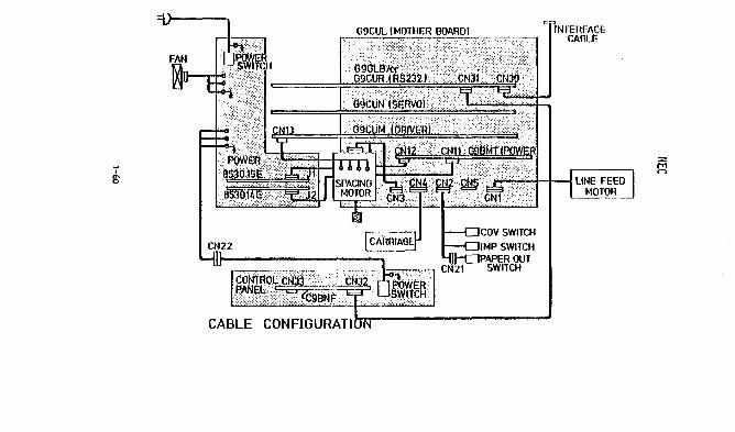
I
g-
c::J
INTERFACE CABLE

5100 SERIES PRINTER
UNPACKING
Stand the printer carton on its end, open and remove the foam end
piece. The printer may now be lifted from the carton. Next clip
the cable tie used to hold the head securely during shipping.
Save all packing material for possible return shipment.
CABLING AND SWITCH SETTINGS
The printer can be directly driven by the IOU-39P, or may serve
as a slave pri nter for the CRT2 or the 210 system. The 232/V24
cable is used in all three configurations. This cable is availa
bl e 1n four 1 engths:
Part Number
42055-001
42055-002
42055-003
Lenqth
6 ft.
12 ft.
25 ft.
42055-004 50 ft. Note: Greater lengths will require line drivers.
* The 5100 printer can also be cabled to an R.O.!. Box. Refer to pages 1-90 to 1-9G for this configuration.
IOU-39P Interface System Flri nter-
CONFIGURATION #1 LOCAL (LESS THAN OR EQUAL TO 50 FT)
~~~J~4 ____ ~23~Z~V~Z4 ______________ ~1 ~ PRINTER
II-__ ----50 ~~t ------------• ..,!
• A Maximum length of 50 ft. of 232V24 cable can be used to connec
the Printer and IOU-39.
1-61

5100 SERIES PRINTER CONFIGURATION #2 LOCAL (Greater than 50 ft.)
-- Line Driver ______ Unit
Ir:l ~52V24 n r'-l i ~- I L-J~----\----~LJ L----J Max i mum
I 50 feetl 4 condo unsh ielded 'I
10,000 ft. Max.
H2:Z4 'I POI NT" Maxlmum!-, ___ ....
50 fee1
• Two line driver units needed: One connects to rOU-39 through
232V24 cable, the other connects to printer through 232V24
cable.
• Note: the P3 connector of the IOU-39 is used in this case.
• Detail on the line driver unit connection is shown ~elow.
LINE DRIVER UNIT
00
O-~-D

5100 SERIES PRINTER
• Line driver assembly, box and P.C.S ...•. Part number -
M42118-001
• The 4 conductor unshield cable used between line drivers is
available in five different lengths:
Part Number Length
M42851-001 100 ft.
M42851-002 500 ft.
M42851-003 1000 ft.
M42851-004 5000 ft.
M42851-005 10,000 ft.
CONFIGURATION #3 MODEMS
(1200 BPS ONLY)
• If printer to system distance exceeds 2 miles modems are
required. Modem cOlllllunications take place over leased or
dial-up Hnes using asychronous modems at 1200 BPS. Order
ing and installation of modems and phone lines is the re
spans ibi 1i ty of the customer. Controll er and prj nter are
connected to the modems using 232V24 cabl es.
A) Leased Lines
The suggested modem for 1 eased 1 ines is the Bell 202T with
the options 1 i sted on the follow; ng page.
1-63

5100 SERIES PRINTER
Circuit 4-wire, multipoint, private line
Received data $qyelch 9 msec
Cl ear-to-send del ay 8 msec
Fast carrier detection IN
Soft carri er turn-off 8 msec
Receive data clamp IN
Grounding AS connected to AA
Alternate voice Optional
Dial backup Optional
Carrier detector reset OUT
Continuous carrier IN at master site, OUT at all slave stations.
B) Dial-up Lines
A pair of dial-up full duplex Z-wire line modems may be used
between an IOU-39 controller and a remote site. The suggest
ed IIIOdf!lll is the Bell 212A data set with the following
options:
CC indication for AL Speed control Interface contro 11 ed Busy Transmitter timing 1200 bps operation Character 1 ength Receiver responds to DL Interface contro 11 ed DL Loss of carrier disconnect Recei ve space di sconnect CB/eF indications Send space disconnect Auto Answer Answer mode indication-CE Speed mode Interface speed indication CN and TM ass i gnments Grounding
1-64
ON By HS button OUT Internal Asynchronous 10 bit OUT OUT OUT OUT Separate OUT IN OFF H!GH OUT CN25, TM not connected AS connected to AA

5100 SERIES PRINTER
SWITCH SETTINGS - lou39P
• CONF I GURAT I ON SW ITCHES SETT I NG FOR I OU-39P BOARDS:
IOU39 P and 5100 ROMS must be Rev L or higher.
10U-39 CONFIGURATION $'WITCHES
80 T Zoo ZO I 10 8 ,. z I 1 I
~~I nt.1' 5131 I 1 1 o I I I (1)* I I
Type ~~rnt.~
I I I 0 I I 0 I 0
I
I I I
I I 1 ZOO I , I
(1)*
SAUO I BPS 0 0 0 0
RATE I I
I I ~600 I
I (1)*
I IPS I 1 1 0 0 0 I
*NOTE: SET SW ITCH 4 TO 1 FOR REMOTE AND 0 FOR LOCAL
1-65

5100 SERIES PRINTER
210 System Interface Printer
• OTC-COM S (preferred) or OTC-COM R (alternate_ is used In
any empty s lot in the card cage. Place the connector for
the board as shown below. (This connector is part of the
cable harness inside the 210). Connect 2321V24 extension
cab 1 e as shown.
RPTR-llC or later ROMS must be used on the COM S or COM R
boards.
Sw i tcn Sett i ngs OTC-COM S, OTC-COM R
8/1 4q 2/1 111 /18 14
/12 III
1-66
ON ON OFF ON ON
OTC-C:JH 5 (pr.' .... nd)
or OTC-COM R
COM S • ON COM R • OFF OFF OFF

5100 Series Prinler
k-.,==-:=--' LogIc 80"'0

5100 SERIES PRINTER
SWITCH SETTINGS - PRINTER
• Two DIP switch packs are located on the printer board (See
Interconnection Diagram, Figure F). The 8 switch pack at
3N establishes UART controls as follows:
a-OFF I-oN
BPS SWI SW2 SW3 sw4
50 0 a a a 75 0 a a 1
110 0 a 1 0
134.5 0 a 1 I 1 , 150 I 0 1 0 I 0
300 ! 0 I 1 0 ,
1
600 0 I 1 1 0
1200 0 ! 1 1 1
1800 1 I 0 0 0
2000 1 0 0 1
2400 1 a 1 0
3600 1 I a 1 1
4800 1 1 0 0
7200 1 1 0 1
Ci60a5 1 1 1 0
19.2K 1 1 1 1
SW5 ~- PARITY
F -NO PARITY
sw6 ON 2 STOP BITS @9- 1 STOP BIT
SW7 @D- 8 DATA BITS OFF - 7 DATA BITS
sw8 ~- ODD PARITY OFF - EVEN PARITY
>z z<
1-68

5100 SERIES PRINTER
• The 10 switch DIP pack. located at 4N on the Printer logic
board (See Interconnection Diagram, Figure F).
MODEL 5131 5133 5136
MODEL 5111 5113 5116
ON
OFF
ON
OFF
1 2 3 4 5 6 7 8 9 10
136 Column
1 2 3 4 5 6 7 8 9 10
80 Column
~--------------~
1-69

5100 SERIES PRINTER
POWER OPTIONS
• The foiiowing power options exist:
100 VAC
115 VAC
220 VAC
240 VAC
50/60 Hz
50/60 Hz
50/60 Hz
50/60 Hz
• Printers shipped to international sites may require modifi
cation of the line cord wall plug. It is the responsibility
of the distributor to install the 1 ine cord plug cOlllllOn to
their locale.
• Pl ace the proper fuse in the 1 ine fuse recepti cl e located
below the power On/Off switch on the back panel.
110 VAC 2A. SLO-BLO. 125 V
115 VAC 2A. SLO-BLO. 125 V
220 VAC lA t SLO-BLO t 250 V
240 VAC lA. SLO-BLO t 250 V
• The following four illustrations show the power option strap
ping configurations on the terminal barrier strip which is
adjacent to the power trans former on the rear panel assemb 1 y .
• Two styles of barrier strip jumpers are used for the power option
confi gurati ons :
Jumper Part Number
2 position barrier strip jumpers A1l669-001
3 pos i ti on barr; er stri p jumpers A1l669-002
i-70

5100 SERIES PRINTER
POWER OPTIONS
100 VAC
50/60 Hz
Install a jumper wire as shown
in detail "AM from pin II to
pin #4
Install barrier strip jumpers
as shown
Insta 11 2A, SLO-BLO, 125V Fuse
in fuse holder on rear panel
115 VAC
10: 50/60 Hz
:~10
!~; , ~:. ::~~:hite :1 '\ Brown
: '\' Orange
;.; j, : :::::" i ,2 Violet
~ 1 Black
L~
1-71
Detail "AN
~==========~ I I r---.3 FT -
~ 10
9 'tlhite
Brn/~lhite
Brown
6 Orange
5 Red/~lhi te
i~ 4 Red
Via/Red
Violet
1 Black
Install barrier strip jumpers
as shown
Install 2A, SLO-BLO, 125V Fuse
in fuse holder on rear panel

5100 SERIES PRINTER POWER OPTIONS
220 VAC
50/60 Hz
Install a jumper wire as shown in
detail "A" from pin 113 to pin 117
Install barrier strip jumpers as
shown
Install a lA, SLO-BLO, 250 V Fuse
in the fuse holder
Detail "A" ~~========~~
!.:-- . .3 FT I
10
9 \~hite
8rn/White
Brown
rr=~=C~ill <6i Orange
5 Red/'lihite
.:. Red
3 Yio/~lhite
Violet
1 Black
240 VAC
50/60 Hz
Detail "A" @J o@
~.3FT --J
9 White
8 Brn/\ihite
7 Brown
6 Orange
5 Red/White
4 Red
3 Via/Red
Z Violet
1 Black
Install a jumper wire as shown
in detail "A" from pin III to 16
Install a jumper wire as shown
in detail "Au from pin 1#3 to
pin /17
Install barrier strip jumpers as
shown
Install a lA, SLO-BLO, 250 V Fuse
in the fuse holder
1-72

5100 SERIES PRINTER
PLATEN ADJUSTMENT
• With the printer assembly removed from the clamshell enclo
sure, remove the ribbon cartridge from the print head. Ro
tate the form thickness knob clockwise situating the print
head in its closest position relative to the platen bar.
00 not change the pos I t i on of the form th i ckness knob th rough
out this adjustment procedure.
Paper Feed Knob
o @ "-=-"
Otfo'~\ ;~~~ess 0 i \~... . .. ~: ADJUSTMEN~ . .= .
KNOB Platen Retainer ...------,
Screws
Figure G
• Loosen 51 ightly the platen retainer screws (2 located
on each end of the platen bar) enabling the platen bar to
be moved, yet still held in position. (See Figure G).
Manually position the print head carriage as far toward
the left margin as possible. Using a feeler gauge, al ign
1-73

5100 SERIES PRINTER
PLATEN ADJUSTMENT CONT.
the platen bar to be 0.010 inches from the nozzle of
the print head (see Figure H).
• Manually position the print head carriage as far toward
the right margin as possible and likewise align the platen
bar to a 0.010 inch clearance from the nozzle of the print
head using a feeler gauge •. The platen retainer screws on
the right margin end of the platen bar are now tightened.
Figure H
LOWER GUIDE
PRINTHEAD,--.....
UPPER CARRIAGE GUIDE SHAfT
PR!NTHEAD CARRIAGE ______ ...i
1-74

5100 SERIES PRINTER
ATP TEST
• Use the ATP program PRINT or QAN 39 for testing.
OPERATING SYSTEM DIAGNOSTIC UTILITITES
• The PRINT program is also available as one of the Operating System Diagnostic Utility programs under the name "PRINT.
SELF TEST
• Depress i ng the SELF TEST switch whi 1 e in the OFFlINE mode
causes the printer to print the complete character set in
bidirectional mode. Momentarily tapping the SELF TEST
switch at the end of a print line will cause printing to
stop. Depressing the ONLINE switch will also stop the
test printing.
1-75

5100 SERIES PRINTER
PR I NT HEAD TEST PROCEDURES
Shorted coi Is in the print head can produce the following symptoms:
the carriage moves back and forth normally, but the print-wi re
so lenolds don I t fl reo Th isis usua Ity accompan i ed by the failure
of fuse Flo The logic board wi 11 probably be damaged. In the
event of such a fai lure, both the print head and the logic board
should be checked.
To check the print head:
1. Unplug the AC I ine cord.
2. Unplug the head cable from connector J8.
3. Verify the coil resistances via the head cable pB
accol"ding to the following table:
Pin Numbel"s Resistance
to 2 Ribbon HotOI" 20-30 ohms
to 4 Solenoid #1 3-4 ohms
to 6 Solenoid #3 3-4 ohms
7 to Solenoid #5 3-4 ohms
9 to 10 Solenoid #7 3-4 ohms
11 to 12 Solenoid #2 3-4 ohms
13 to 14 Solenoid #4 3-4 ohms
15 to 16 Solenoid #6 3-4 ohms
17 to 18 Solenoid #8 3-4 ohms
19 to 20 Solenoid #9 3-4 ohms
Note: Some method must be used to access the pins on J8,
such as a shol"t piece of wil"e, 01" sharply pointed
ohm metel" pl"obes used at the end of the ribbon cable.
1-76
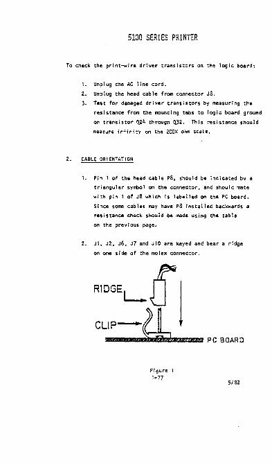
5100 SERIES PRINTER
To check the print-wire driver transistors on the logic board:
I. Unp I ug the AC line cord.
2. Unplug the head cable from connector Ja. 3. Test for damaged driver transistors by measuring the
resistance from the mounting tabs to logic board ground
on transistor 0.24 through Q.32. This resistance should
measure infinity on the 200K ohm scaLe.
2. CABLE ORIENTATION
1. Pin 1 of the head cable pS, should be indicated by a
triangular symbol on the connector, and should mate
with pin 1 of Ja whiCh Is labelled on the PC board.
Since some cab I es may have p8 ins ta II ed backwards a
res i stance check shou I d be made us i ng the tab 1 e
on the previous page.
2. Jl, J2, J6, J7 and Jl0 are keyed and bear a ridge
on one side of the molex connector.
Figure 1-77
5/82

5100 SERIES PRINTER
3. PC BOARD MOUNT I NG
To prevent shorts be sure the fibre washers have been instal
led under the mounting screws when the Logic Board is
replaced. Also check to be sure that nylon caps are in place
on the standoffs and that the ground lead is not shorting.
4. POWER TRANSFORMER SECONDARY CABLES
1. The C<lb Ie of ye 11 ow wi res from the power transformer
secondary is routed to connector J5 on all logic
boards.
2. The cab Ie of blue wi res from the power transformer
secondary Is routed to the logic board only if a 411
connector exists on the ba.rd. On some boards 411
will reside at the end of a short pigtail of wires.
Ba.rds not having 411 do not use the blue c.ble from
the power transformer secondary, yet are still totally
compatib Ie.
5/82
1-78

CENTRON I CS 702
PRINT HEAD ASSEMBLY
F; REF. CARRIAGE ASSEMBLY
Figure 1 Print Head Assembly
REMOVAL/REPLACEMENT PROCEDURES
TOOLS REQU I RED: None
• Remove the ribbon frem the print head ribbon guides.
• Remove the fingerboard P037 on the print head cable frem connector J037 on the video Imp I ifler.
• On the left side of carriage assembly release clamping spring tension by pul i ing spring up and over spring retainer.
• Remove print head by 51 iding off carriage towards front of printer.
Note: Releasing tension on clamping spring wi 11 enable print head to be removed. When installing print head assembly, ensure the clamping spring catches the lip underneath the he.d, then pull spring up and over spring retainer.
1-79

CENTRON I CS 702
ADJUSTMENTS
Print Head Penetration
• Loosen penetration control knob and hardware securing head adjusting indicator.
• Move penetration control knob away from platen and as close as possible, but not contacting, the print head.
• Lightly tighten indicator hardware.
• Insert a 0.177II1II (0.007 in.) feeler gauge between the print head and platen. Move penetration control knob towards the platen until O.lnlllll (0.007 in.) gap is met. Tighten penetration control knob.
• Holding penetration control knob, loosen hardware securing head adjusting Indicator and position indicator against penetration control knob.
• Tighten head adjusting indicator hardware.
• Loosen penetration control knob and move back and forth.
• Retighten control knob against Indicator and recheck for O.I77mm (0.007 in.) gap.
PENETRATl ON CONTROL ADJUSTMENT PR I NT HEAD ASSEMBLY
1-80

CENT RON I CS 702
VIDEO AMPLIFIER ASSEMBLY
REMOVAL/REPLACEMENT PROCEDURES
TOOLS REQUIRED: Phillips Head Screwdriver.
• Remove print head cable fingerboard P037 from connector J037 on video amplifier.
• Remove connector J036, on cable of video amp I ifier, from connector P036 on log i c board.
• Remove the four carriage solenoid wires attached to the bottom of the video ampl ifier.
• Remove the two screws {2}, lockwashers (3) and flatwashers (4) and remove video amp I ifier (1) and attaching cable from printer.
ADJUSTMENTS
NOTE: The video amplifier contains an optical pickup assembly
which must be adjusted. Steps 1 and 2 detail the mechani
cal alignment of the pickup assembly, while step 3 outlines
1-81

CENTRONICS 702
ADJUSTMENTS (cont.)
the electrical adjustments.
Optical Pickup Al ignment With Respect To Timing Fence.
• Loosen the hardware supporting the video amplifier to the carriage.
• Ensure the timing fence is centered in the slot of the optical pickup assembly. If required, loosen .,ptrcal pickup mounting hardware and position pickup assembly so that timing fence is centered in slot and tighten hardware.
• Ensure the bottom of the optical pickup assembly is parallel wi th bottom of timing fence, once positioned.
• When above conditions have been met, tighten video ampl ifier mount i ng hardware.
VIOEO ... MPLIFIE SOARO
O"'CAL ASSEMBLY
Figure"
OPT! CAL P' CKUP ASSEMBLY ADJUSTMENT W' Ttl RESPECT TO TI M' NG FENCE
1-82

CENT RON I CS 702
VERTICAL AND HORIZONTAL ALIGNKENT OF OPTICAL PICKUP ASSEMBLY
• Sight right edge of optical pickup assembly and ensure
para I I e I a I ignment wi th respect to timing fence encoder Ii nes.
If not parallel, loosen right side hardware mounting the
video amplifier to carriage and adjust video amplifier
until optical pickup assembly Is parallel with encoder
lines.
• Sight bottom edge of optical pIckup assembly and ensure
parallel ism with bottom edge of timing fence.
Figure 5
VERTICAL AND HORIZCNTAL ALIGNMENT OF OPTICAL PICKUP ASSEMBLY
1-83

CENTRONICS 702
ELECTR I CAL ADJUSTMENTS OF V IDEO AHPL I F I ER
NOTE: The main logic board determines the forward and reverse
direction of the print head by comparing the leading and
trailing edges of one video channel pulse with the other
video channel pulse. The outputs from both channels are
adjusted for a 50t duty cycle and a constant 90° phase
shift between channels. Both the duty cycle adjustment and
the phase adjustment are performed separately as follows.
DUTY CYCLE ADJUSTMENT
• Ensure that the optics block on the und~rside of the video ampl ifier board is centered ove~ the timing fence, so that the block does not rub the timing 'enc:e u the print head is manually meved right and left.
• Monitor video output Vl at test l'I'int El 00 the power driver board while the print head is meving at a constant speed.
Note: The print hud ~n be moved at a constant speed by depressing the OVERRIDE switch while the printer Is deselected. This places the printer In the self-test mode.
• Check the duty cycle of the VI ~veform and, if it Is not 50% as shown in Figure 6 proceed to next step.
• Stop ~"rlage motion by deactivating selt-test mode, turn adjusting pot R4 51 ightly, reactivate self-test mode, and again recheck for a 50% duty cycle. Repeat until 50% duty cycle Is achieved for V1.
Note: If the 50% duty cycle ~nnot be achieved, check the pulse width and make sure it is constant over the complete travel of the print head. If not, the timing fence should be adjusted so that it is parallel with the guide bars. If the timing fence is adjusted, recheck the duty cycle for the previously set-up video channel.
• Repeat Steps 2 through 4 above while monitoring V2 at E2 and, if necessary, adjust RIO to obtain a 50% duty cycle for V2. Refer to Figure 6.
i-81t

CENT RON I CS 702
PHASE ADJUSTMENT OF V r DEO AMPL r Fr ER
PHASE SH r FT ADJUSTMENT
AD.IUIT 1141101IIvt'
O1(AT'II~
\",...j......j _ DUTY CYCU: A ••
AD.IUIT 11110 IIORW cn(ATI2I~
~ _DUTYCYCU: A·.
L _ AO.aISTMDTOl' Vi AHO ~
Figure 6
• Monitor Vl and V2 sil11Ultaneously at El and E2 on the power driver board while the print head is moving at a constant speed (see figure 20).
• Cheek the phase re I at i onsh i I' between Vl and V2 as the head moves I n both the forward and reverse direct ions. As shown in Figure 6, the phase relationship between V.l and V2 should be a constant 90·phase shift over the eomplete travel of the print head (i .e., width C equals 90· when It· equals 1/4 width D). If phase adjustment is required, proceed to next step.
• Stop carriage by deactivating the self-test mode, and turn printer power off. Manually move earriacJe all the _y right to the EOP sw Itch.
5/82 1-85

CENTRONICS 702
PHASE. SHIFT ADJUSTMENT (cont.)
• Loosen (approximately one turn) the left side mounting screw which attaches the video amplifier circuit board to the carriage.
• Hove left side of the circuit board all the way up until the bottom of the slotted mounting hole touches the mounting screw.
• Turn printer pClWer on, activate self-test mode, and check phase adjustment again. Refer to Figure 6.
• If further adjustment is required, turn printer power off, move left side of bOlrd sl ightly down in the slotted mounting hole and check phase again IS in the previous step.
• Repeat the two previous steps unti I phase adjustment of VI and V2 is correct.
• When phase is correct, tighten left side mounting screw on video amp I ifler.
REMOVAL/REPLACEMENT PROCEDURE - Timing Fence AssenC Iy
TOOLS REQU I RED: )tin Hex Key.
• Loosen the four screws from left and right timing fence moun t i ng b racke ts and remove fence.
Adjustments
• Loosen four screws mounting timing fence and adjust fence so thlt the fi rs t window is located 106.6nIn (4.2 in.) from left frame.
Note: This adjustment allows for the left hand print margin to align with the number 1 on the column scale assembly.
Figure 7 - Timil"g Fen.;e Assembly Adju5t!!le!'!t
1-86 5/82

CENTRONICS 702
TIKING FENCE ASSEI'IBLY (cont.)
Preventive l1aintenance
• Using soft, clean cloth wipe both sides of timing fence, if necessary use I iquid freon.
CAUTION: NEVER USE AN ORGAN I C SOLVENT AS TH I S WILL DAMAGE THE TI I'll NG FENCE.
• Inspect for scratches in the encoder I ines and proper mechanical alignment on the timing fence.
CARR I AGE AS S EI1BL Y
Remova) IRep I acement Procedure
Tools Required: Slotted and Phillips Head Screwdriver Snap Ring Tool.
WARNING: TURN POWER OFF BEFORE REMOVING CARRIAGE ASSEMBLY
• Hove the carriage assembly to the center of the printer.
• Remove the ribbon cartridge assetmly.
• Remove the print head and video amclifier assemblies per pages 1-79 and 1-81.
• Remove the power driver board asse.~ly per page 1-99.
• Loosen the carriage drive belt by turning, counter-clockwise, the two adjust ing nuts on the i d I er pu i ley assemb Iy. NOTE: The idle pulley assembly is located on the left side of the printer.
• Remove the retaining ring on the left end of the upper guide bar.
• Remove the two screws mounting the upper guide bar to the right frame.
• Loosen the locknut and screw attaching the bottom of carriage to the bottom of the gu i de bar.
• Remove the upper and lower ribbon drive monofi lament from the ribbon drive shaft.
1-87

CENTRON I CS 702
CARRIAGE ASSEMBLY {cont.l Remova IIRep I acement Procedure
• Remove the two screws and lockwashers clamping the carriage drive belt to the coll'riage assembly.
• While supporting the carriage assembly, slide the upper guide bar to the rIght through the carriage assembly.
NOTE: Retain the rubber 0 ring removed from the left end of the upper guide bal'.
• Remove the carriage assembly from the printer.
Figure 8
Carriage Assembly Removal/Replacement
1·88
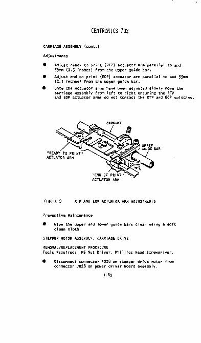
CENT RON I CS 702
CARRIAGE ASSEMBLY (cont.)
Adjustments
• Adjust ready to print CRTP) actuator arm parallel to and 59rrm (2.3 inches) from the upper guide bar.
• Adjust end on print (EOP) actuator arm parallel to and 55rrm (2.1 inches) from the upper guIde bar.
• Once the actuator arms have been adjusted s lowly move the carriage assembly from left to right ensuring the RTP and EOP actuator arms do not contact the RTP and EOP s..,i tclles.
FIGURE 9 RTP AND EOP ACTUATOR ARM ADJUSTMENTS
Preventive Maintl!llance
• Wipe the upper and lower guide bars clean using a soft clean cloth.
STEPPER MOTOR ASSEMBLY, CARR IAGE DR I VE
REHQVAL/REPLACEMENT PROC EDURE Tools Required: M5 Nut Driver, Phillips Head Screwdriver.
• Disconnect connector P02S on stepper drive motor from connector J02S on power driver board assemb ly.
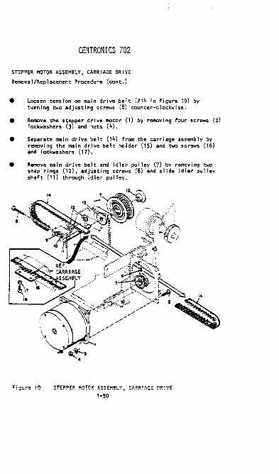
CENTRONICS 702
STEPPER HOTOR ASSEMBL'f. CARR rAGE DR I VE
Removal/Replacement Procedure (cont.)
• • • •
Loosen tens i on on main dri ve be It (#14 in Fi gure 10) by turning two adjusting screws (8) counter-clockwise.
Remove the stepper drive motor (1) by removing four screws (2) 10ckwashers (3) and nuts (4).
Separate main drive belt (14) from the carriage assembly by removing the main drive belt holder (15) and two screws (16) and lockwashers (17).
Remove main drive belt and idler pulley (7) by removing two snap rings (12). adjusting screws (8) and 51 ide idler pulley shaft (11) through idler pulley.
~i9!Jre 10 STEPPER ~QTOR ASSEM!L Y. CARR! AGE DR! VE
1-90

CENT RON I CS 702
STEPPER MOTOR ASSEMBLY, CARR I AGE DR I VE
8-9l11li1 (3.14-.354 inches)
MAIN DRIVE BELT 300 grams (10.6 ounces)
« (J Fi gure 11
MA I N DR IVE BELT ADJUSTMENT
Adjustments
• With the carriage assembly in the left moH po-.;ition adjust main drive belt to deflect S to 9mm (.314 to .354 In.) when a 300 gram (.66 l&s.) Io.d is applied at the center of the belt.
Note: It is best to use a wide load distributed 63.5mm to 76.2mm (2-1/2 in. to 3 in.) over the bE:lt.
STEPPER MOTOR ASSEMBLY, PAPER DR I VE
Remova l/Repl acement Procedures
Tools Requl red: 1'15 Nut Driver
• Disconnect two pin connector P02S of stepper motor assembly from connector J028. (See following page, Figure 12).
1-91

CENTRONICS 702
STEPPER HOTOR ASSEI1Bl Y. PAPER DR I VE
Remova IIRep I acement Pr-ocedures (cont.)
2
~l ~ '-""" ~ .. l.P/.:~.:~;;ii:. ,,~0-:':~,:::;:;[ N '" i. /f1..~ ..... . .... ,::>:;; 5
3 1 "<~:~Q:~}~7 ~Igure 12
STEPPER I1QTOR ASSEI1Bl Y, PAPER DR J VE
• Remove line feed pulley (7) by removing set-screw (6) and sl iding pulley off stepper motor shaft.
• Remove four screws (2,3) lockwashers (It) and nuts (5) and remove stepper motor assembly from pl"fnter.
Adjustments
• At a point equidistant fr-OIII the line feed pulley and paper feed pulley, adjust tension of the belt to deflect 1t-5/1111 (.18 inch) wi th a 300 gram (10.6 ounces) load applied.
Note: The belt tension is adjusted by the tension roller on the right frame.
X4.5/1111 (.18 inches)
: ..... ", 300 grams (~0.6 ounces)
!) -: ~ I GURE 1 3
1-92
PAPER ~EED TI HI NG BELT ADJUSTMENT

CENTRONICS 702
PLATEN ASSEMBLY
~~REF'
.. ;. ';3.-~ • LEFT
,. ~-! '4 FRAME
PART OF -- <' _
TRACTOR ~ _.:'" DRIVE
Figure 14
PLATEN ASSEMBLY
Remova ItRep lacement Procedure
Tools Requi red: H4 Hex Key, Flat Blade Screwdriver
• Remove the paper feed knob f rem the r i gh t side of the platen assembly.
• Loosen tension of paper feed timing belt and remove timing belt from pulley.
• Remove the two stop collar springs OJ on ends of platen assembly.
• Remove pin tractor drive pulley (5) and timing belt from left end of platen.
• SI ide the two brass bushing (2,4) towards the center of the pr I nur and 1 i ft platen assemb I y out of the prl ntar.
1-93

PLATEN ASSEMBLY
Adjustments
CENT RON I CS 702
The plate!'! usembly must be parallel to tile ti"avel of the c:.arriage, if not adjust .as follows:
• Operate printer and ensure print quality Is uniform for the full 132 character printed.
• If print quality is not uniform. loosen bolt and rotate adjusting plate until platen assembly is parallel to the travel of carriage assembly.
• Once adjusted tighten mounting hardware.
L .... ~AIl"''''lll'' ... ~TI
Figure 15 PLATEN ASSEMBLY ADJUSTMENT
Preventive Maintenance
Clean platen .aSSembly using a mild detergent.
TRACTOR DRIVE AHD PIN FEED ASSEMBLY
Remova I/Rep I ac:ement Procedure
Tools Required: Phi II ips Head Screwdriver
Tractor Drive Assembly
• Disconnect connector P044 of harness assembly (9) from connector J044.
1-94

CENTRON I CS 702
TRACTOR OR I VE AND PIN FEED ASSEMBLY
Remova I/Rep lacement Procedure (cont.)
• Remove left (2) and right (3) stud screws, two flatwashers (5) and nuts (4) supporting the sub-tractor drive assembly.
• Remove the two screws (6) lockwashers (7) and flatwashers (8) and remove sub-tractor drive assembly from the printer.
Tractor Units, Left and Right
• Remove the sub-tractor drive assembly per paragraph above.
• Loosen set-screw mounting drive pulley on left side of tractor drive assembly and remove pulley and side plate.
• Loosen set-screw mounting hardware bushing to the left support assembly and remove bushing and support plate.
• Slide the left and right tractor units off drive shaft and support bar of tractor drive assembly.
1-95

CENT RON I CS 702
TRACTOR OR I VE AND PIN FEED ASSEHBl Y
Adjustments
Tractor Ori ve oe it Tens ion
• Adjust tension of belt such that when a lo.d of 156-2"9 grams (5-8 ounces) is applied at the center of the belt, belt tieflection will be 6.35II1II (0.25 in.).
6.35II1II (0.25 inches)
Figure 17 TRACTOR DRIVE TIMING BELT TENSION
Paper Travel
• Using the eccentric knob on the right hand side of the printer, adjust tractor units so that plane of paper travel (top side of tractor unit) is tangent to the platen.
Figure 18 PAPER TP.AVE!. .o.OJUSTMENT TP.ACTO~ O~! 'IE ASS EM!!. Y
1-96

CENTRON I CS 702
LOG I C BOARD ASSE11BL Y
Remova I/Rep I aeemen t P roeedu re Tools Requi red: Phi 11 ips Head Screwdriver
• Disconnect all eonnectors plugged into logic board.
• Remove the three screws (2,5) ioekwashers (3,6) and flatwashers, (1t.7) .and remove the logic board from the printer.
Adjustments
The follow i ng electri ca I adjustments may be requi red on the ma I n logic board.
Signal .2!!!!!!... Element/Pin
+5 Volts +5V out Test Point-Tp4
Print head l1e89 , pin 10 speeds
Pr( nter PRTSTB ME73, pin Strobe
1-97
Adjustment Res i stor
R4
Pulse ~
Adjust to +5V Level
R40 650-660 usec.
R50 425-450 usec.

CENTRONICS 702
POWER DR I VER BOARD ASSEI1BL y
Figure 20
Remova I/Rep I acement Procedure
Tools Required: Phillips Head Screwdriver
• Remove the following connectors from one another:
POWER DRIVER BOARD CONNECTOR DISCONNECT FROM:
28
29 30 31
32
P028 of Carriage Drive Stepper Motor P029 of Paper Drive Stepper Motor P030 of Video Amplifier Cable Assy. P031 of Hain Wire Harness (63703112-4001) P032 of Control Panel Harness
• Remove the six screws (2) and flatwashers (3) and remove the power driver board from the printer.
5/82 1-98
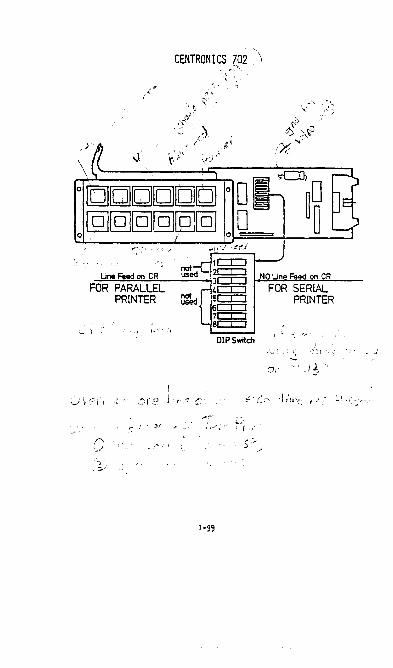
CENT RON I CS 702. , i!':'i"-.
';
;
\ \.
",~t,:", I ".~
1c::r::J Une Feed on CR 2c:::c::::J NO Une Feed on CR
F-O~R~P":"::A~R~AL:':"LE~L----lt§5 ~W:FO~R~S=.::!ER"'::'l~A::::!.L:--
PRINTER ~ed [ 5c:::r::J PRINTER 6c::r::J 7CCJ 8c:::r::J
,I -.I
DIP Switch 1,:
,_.; ':)1 .'
1-99

IOU 13 CENTURY 111 Qante1 Model 3000
IOU-UA
J 2 4 8
ljgljlj ADDRESS SWITCHES O-F
IOU-UB
S1 S2
~Q [j Q
"Q" INTERFACE OPTION NOT USED
SWITCHES SHOULD BE m AS
SHOWN
2-1
MAX. PWR • REQU IREMENTS
-12v = .35A +l2v = .10A + 5v 2.19
DISC UNIT PWR
20A for 10 sec. SA normal
WRITE CONTROL INSTRUCTIONS
lXYY9D x = DEVICE ADDRESS YY = CO)!TROL BYTE
CONTROL FUNCTION BYTE
01 SET INHIBIT TR VERIFY 02 SET INIlIBIT READ
AFTER IiRITE CHECK
STATUS IN It<SIJ{UCllOl'IS
4XYY9D x = DEVICE ADDRESS YY = STATUS BYTE
STATUS MEANING BYTE
D1 02 01/ 08 10 20 40 80
READ BUSY WRITE BUSY END SERVICE REQUEST ERROR MARKED SECTOR INVALID SEEK !NOP.
5/82

IOU 24
114/6+6
ADDRESS SWITCHES O-F
WRITE CO~TROL INSTRUCTIONS
lXYY9D
CO~TROL BYTE
01 02 10 14
4XYY9D
STATUS BYTE
01 02 04 08 10 20 40 80
x = DEVICE ADDRESS YY = CO~TROL BYTE
FUNCTION
INHIRlT TR\CK VERI FY ISIlIRIT READ ArTER liRITf: CHECK
Res. Allow Term Int. (resets Fl) Set Termination Interrupt
x = DEVICE ADDRESS YY = STATUS BYTE
40 20
c o 1 1 -
MEANING
READ BUSY - - - - - - - -WRITE RUSy-------ABSENCE OF ALL 3 = HEAD IS ~lOTIO!'i EI\D------- -------SERVICE REQUEST SEEK OR WRIlT TERm NATE
SEE BELOW
INOP. I [lACK OFF
SEEK
O. K. ERROR MRKD SCTRINV.SEE!( -
2-2
WRITE
O. K. DEFl:CTIVE DISC PACK HARKI'n SECTOR INVALID SEEK
Revised 3/10/76

IOU-32A/B
MEMOREX DISC 25 M/BYTE
MEMOREX DISC 75 M/BYTE
1 c::El 2E!CJ 4c::El 8CEl
Q7a::J7.S
TYPICAL POWER REqUIREMENTS
-12V = .02A +12V = .26A
I,OU-32A P3 +5V = 7.6A
P2
t-lIst be set to 07. 5
lOU-32 works only with
AS/BS CPU (OMA)
0298 CPU (Non-()t.lA)
IOU-32B
. , I I .
.J
o [jEJEU [MEull I r L·1 :
: : i i t __ ........... _______________________ ... __ .. __ J
2-2A
DISC UNIT POWER
START UP: Not to exceed 30A for 18 seconds
NORMAL : 8. OA nominal ® 117 VAC
Rom labels lower than Rev. H indicate a DMA 10U-32. To update these controllers for non-OMA operation factory modi fication is required •
Rom labels Rev. H or higher may be modified from OMA to non-OMA or the reverse by si""ly changing the RIJ.1's.
ROM NUt-BERS . ROM LABEL
M1H~ OMA 100-32
M1H NDl-lA ~ = NON-OMA
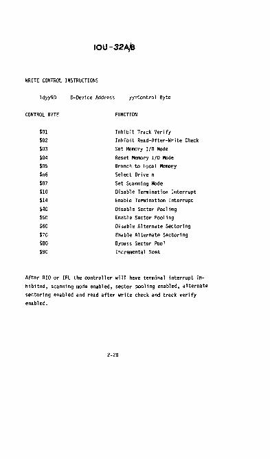
IOU-32A/B
WRITE CONTROL INSTRUCTIONS
Idyy9D D=Device Addres·s yy=Contro 1 Byte
CONTROL BYTE FUNCTION
$01 Inhi bit Track Verify
$02 Inhibit Read-After-Write Check
$03 Set Memory 1/0 Mode
$04 Reset Memory 1/0 Mode
$05 Branch to Local Memory
$n6 Select Drive n
$07 Set Scanni ng Mode
$10 Disable Termination Interrupt
$14 Enable Termination Interrupt
$40 Disable Sector Pooling
$50 Enable Sector Pooling
$60 Disable Alternate Sectoring
$70 Enable Alternate Sectoring
$80 Bypass Sector Pool
$90 Incrementa 1 Seek
After RIO or IPL the controller will have terminal interrupt in
hibited, scanning mode enabled. sector pooling enabled. alternate
sectoring enabled and read after write check and track verify
enabled.
2-2B

IOU-32A/B
STATUS IN INSTRUCTIONS
4dyy9D d = Device Address yy = Test Bit Value
STATUS BYTE fUNCTION
$01 Read Busy
$02 Write Busy
$04 End
$08 Service Request
$10 Seek or Write Terminate
$2}-2· 2' READ WRITE
$40
'" '" 01< 01<
'" 1 Hard Read Error Defective Disc Pack
1
'" Marked Sector Marked Sector
1 1 Invalid Seek Invalid Seek
$80 Inoperable
• The $10 weight status byte is set whenever a Seek or Write Se
quence terminates for any reason. It is reset by a Read, Write,
Seek and fill Buffer the same unit, Write Control Requesting
Selected Unit Number or a Write Control Disabling Termination
Interrupt.
• The $20 and $40 weight status bits are valid only if the $10
weight status bit is set.
• The $80 weight status bi t is always valid and signals a disc or
controller fault requiring operator attention.
READ STATUS 2
xdyy86 d = Device Address yy = Test Bit Value
x = Don I t Care
$fD is returned by the lOU-32 A/B
2"'2C

IOMEC (3001, 3101) TROUBLESHOOTING AID
IOMEC DISC , INTERMITTENT INVALID SEEK/TEMPORARY READ ERRORS
INTRODUCTION
Invalid seek (IVS) and temporary read errors (TMP RD ERR) that are intermittent are frequently caused by electromechanical problems rather than electronic failure. Some steps to eliminate this problem are given below.
No attempt should be made to evaluate, test, or adjust a disc unit until it stabilizes with temperature. The pack must run for a minimum of 15 minutes, or more if it was taken from another temperature environment.
TESTING
Intermittent errors should be tested by running the Acceptance Test. The test must run error free overnight to be reasonably sure the problem is fixed.
GENERAL PRECAUTIONS
The following is a list of procedures that will help to minimise disc difficulties.
- The disc pack must be in the same temperature environment for at least one hour, and allowed to spin 15 minu tes before use.
- Before writing records or generating disc copies, allow the disc to be 'ready' for at least 5 min.
- When the drive is not in use (disc not spinning), the power swi tch shou Id be "OFF".
- The disc should be powered from the unswitched outlet to protect against power loss when the disc is running and the system is shut down.
Moving The Drive
The heads must be taped in the retracted position when ever the disc drive is moved. Without power, the heads are extremely free to move and would be damaged if the drive is til ted of moved suddenly.
Protec ting The Fixed Disc
The diagnostic tests write on most or all disc areas. The customer information on the fixed disc must be copied (use FILFIL) before running disc tests.
Protecting The C.E. Pack
When the C.E. pack is used for head alignment, the pack must be protected from being writen upon. To disable the write circuits, instal a jumper between pins 1 and 2 (the two top pins) on plug Bl of the drive control PCB, AO. With this jumper installed, an attempt to wri te causes a loss of 'READY'. Disable Restore by unsoldering the jumper from U7-6 on the motherboard and connecting it to U7-7 (ground). Spindle Binding must be guarde~ . .against by ensuring that the pack is evenly seated on the base. If the motor is started when the spindle is binding, the motor burns up.
2-3

IOMEC TROUBLE SHOOTING CHART
The chart below lists things that should be tried before swapping cards. Be aware that the disc may need realignment after some of the mounting screws are tightened.
FOSS IBLE CAUSE II CHECK FOR ~REFERENCE
Head Misalignment -Loose base plate screws F .A.4f33
-Loose opt trnsdcr or shutter Below
-Align with C.E.pk
Servo misadjus ted -Use Iomec procedure Manual
Faulty heads -Dirty heads * -Damaged heads
R/W card ground -Gr. strap loose at *
base plate
Head leads binding -Properly dressed leads F.A.lf3l
VCO temp. drift -Install temp. compo * speed se 1. modu Ie * -Adjust VCo
Servo Actuator side play -Loose mtg. screws *
Missing sector pulses -Install FCOiFlS
Sec tor burs t off - Loose sec tor trnsd~r. * -Adjust with C.E pk.
Oscillation in IOU-24A -Instal Rev.F (IOU-24~ F.A.4f20 -Sv supply
*See la ter text.
="\=\\=-~\_~~ ======~"X.... ~ REAR ADJUST
m~ I SHUTTER MOUNTING SCREWS
2-4

IOMEC DIRTY OR DAMAGED HEADS
The illustrations below show some examples of head dirt buildup and damage. Clean heads with 917. isopropyl alcohol, and wipe clean. Do not allow alcohol to dry on the surface.
A. SIi9ht oxide buildup. Head .hould ~ cleaned and U5ed.
C. Oxide buildup In pole picce. Head _ be replaced.
E. Oxide buildup due 10 .cratches. Head must be replaced.
2-5
B. Alcohol r .. id .... Head must be d .. ned.
D. Slight scratches. No oxide buildup. Hud i5 usable,.
F. Crashed (usually burned I. Head must replaced.

IOMEC GROUND STRAP ON R/W CARDS
Some versions of the R/W card have a ground strap to the base plate. If the screw at the base plate is loose, intermittent errors can occur. Check that the screw is tight whenever there is doubt.
IOU - 24C VCO ADJUSTMENT
~n~~l·) "fuHy- e6I:iQteJ:cl~e. f1 0
Connect a DV .. probe to Test Point 1.
Adjust R15 (frequency) clockwise until the voltage at TP1 is .5v!.5v (OY to 1v).
Connect Channel of the oscilloscope to 5C, pin 12. Connec t channe 1 2 to 5C pin 11. Tr igge r on ch 1, neg. at 50 nsec/ cm.
Adjust R1 (phase) until the crossover of the signals is as shown belovo I v( .. /~ p~ em +Sy.
1.5Y.
... I
I 2400 IU'M TIME A .110 NS! 2011S I TIME A I 1500 RPM TIIIIl A • 185 lIS t 2011S ~
+Sy. I. , I
~~'-Wi----YNOTE' TP4 is\ : ~ ground.
SERVO ACTUATOR SIDE PLAY
The servo actuator mechanism is mounted to the base plate by two screws (see the illustration beloW). If these screws become loose, there can be intermi ttent seek and read errors.
5/82 2-6

IOMEC MISSING SECTOR PULSES
If the sec tor transducer is loose or not properly adjusted, one or more sector pulses can be missed, causing seek or read errors. Check that the sec tor transducer is secure and proper ly adjus ted (see the illustration below). FCO #15 must also be installed in all IOMEC drives.
m
SECTOR TRANSDUCER - SCREWS'
2-7

IOMEC IOMEC TROUBLESHOOTING HINTS
1. Slots on the fixed disc sector plate get dirty and miss sector pulses. Revision D to the interface board makes a modification that unloads the heads when a sector count is missed. This means that if the heads seem to unload for no reason, the sec tor p la te on the fixed disc needs cleaning.
2. The fixed disc may become loose and s lip on the spindle. The symptom for this is that the disc needs re-initializing every time it is fired up. Change the fixed disc.
3. R 10 on the interface card has been removed to increase the amplitude of the fixed disc sector pulses.
4. Sticking or burned brushes in the servo motor cause failures in the harmonic test. This condition gets worse until the disc fails all of the time. Remove the cap over the brushes, and clean the armature. Sticking brushes are caused by an allen screw that is too long, and presses against the brush holder deforming it.
5. Be sure to check the ECN's for compatability of the motherboard and the interface card.
6. The new style motor with thermal protection has one less black wire. This motor needs a 40 mfd. capacitor between the red motor lead and pin 2 of the starting re lay.
7. R 86 on the power supply board (250lun lOw) has been removed, and a jumper put in its place. The resistor was added externally to allow heat dissipation. However, with this modification there must also be the fan· modification. If there is not, the resistor will become hot enough to unsolder itself.
8. Poor lead dressing on the head wires will cause errors in the harmonic tes t.
9. Many read/write cards do not have shielding on them. These may work well until something on the card is disturbed (such as replacing a component). Symptoms may then appear that give temporary read errors. This one is very subtle, and is hard to believe when it is encountered.
10.On the old style drives, the head carriage can come off the track in a sideways direction. This happens during service procedures. Check that the carriage is on track before starting the drive.
11.Loose lugs on the filter capacitors may cause ripple. Some screws were too long, leaving the lugs loose when the screw was tight (bottomed).
2-8

IOMEC 12. Rattling during start up is caused by a bad
motor start relay.
13. Loosing "Ready" can be caused by one of the following:
Cover micro switch Loose fuse in power supply Motherboard Missing sector pulse Power supply failure (low voltage) Unsafe - se lec ting more than one head
14. Cables can get pinched in the front bezel, or rub agains t the drive be 1 t. This causes jus t about any symptom that the machine will ever exhibit.
15. The mask portion of the optics (cylinder seek count) may become loose, or even fall off. This can cause seek errors at a minimum, or complete failure.
16. Servo power can be lost from one of the following causes:
No 7070 speed signal from the interface card Bad servo 1 or 2 card Q12 and Q13 in the power supply (usually shorted) Relay Kl on the power supply may have dirty or misadjusted contacts.
2-9

IOMEC Removable Disc Head Adjustment
IROCEDURE
1. Remove, user cartridge, remove po'Wer, and extend drive to obtain access to back of drive.
I 2. Remove drive component cover.
3. Connect and set oscilloscope to observe the read test points.
NOTE
Drives below serial number 30400 that do not have F.A. 1116 installed , must have U7, pin 6 on the motherboard grounded to prevenc
4. Power up drive, install alignment pack.
5. Insert SEEK parameters into memory.
6. Allow ample time for the C.E.pack to equalize in temperature with the drive (minimum of 30 minutes) .
7. Position the heads to cylinder 146, head 12.
2-10
REMARKS
Set CARTRIDGE switch to UNLOCK. b. When UNLOCK lamp lights, remove
cartridge. c. Set POWER switch to POWER OFF. d. Set ae switch on drive rear panel
to OFF.
Connect CHANNEL 1 to pin 10 of the A2 PC card by attuching a mini test clip to U3, pin 3.
b. Connect CHANNEL 2 to pinll of the A2 card by attaching a mini test clip to U3, pin 4. Attach external sync lead (CHAN A) to TPI on the AS card by attaching a 16 pin extender to U12;pin 13 is TPI.
d. Set VERTICAL gain to 50 mvlcm (both channels).
e. Set TIME BASE to 2 ms/cm. f. Set SYNC to EXT (+), CH A. g. Set MODE to ADD. h. INVERT channel 2.
Set ae power switch (rear) to ON. b. Set power switch to POWER ON. e. Install a1 ignment pack. d. Set cartridge switch to LOCK.
Attach a 14 pin extender to AS, U24. When the disc is spinning at full speed, attach a ground to pin 11 (pit 7 is ground).
Enter the following on the console device: (IPL) 0006F30400000000AS (CR)
l!l3~32393230 (CR) (IPL) 0006F30500000000A8 (CR)
ID3032393330 (CR)
NOTE: The D in the first byte is the disc address. If disc is not at this address, change to suit.
Length of time required for thermal expansion to equa lize depends upon how great the change was in environment from storage to installing.
Enter the following on the console: (IPL) 0400S00000AS (CR)

IOMEC Removable Disc Head Adjustment
Adjustment Locations
8. Display the "cats eyes".
NOTE The object of this adjustment is to position the alignment mark at the crossover pOint. Centering the oscilloscope display is not necessary. (Diablo C.E. pack shown, make loop~ equal length for other type C.E. packs)
9. Slightly loosen the clamping screw on head 12. Turn the adjusting
III Head Too Far In
II ,.,,~, ,,,' :"'_"'1
, I
Head Too Far Out
•
Hove head #2 adjusting screw clock- I wise to move crossover to the right .. I
screw as required until the alignment mark is positioned as in Figure. b.. Move the adjusting screw counter- I
clockwise to move the crossover to the left.
2-11
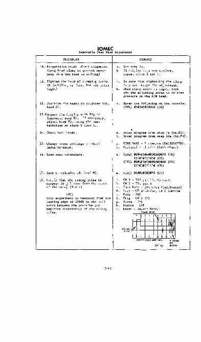
IOMEC Removable Disc Head Adjustment
PROCEDURE
10. Re-position heads. Check aligrunent (snug head clamp to prevent movement when the head is seeking)
11. Tighten the head IF2 clamping screw. (8 inch/lbs~ or firm, but not extra tight)
12. Position the heads to cylinder 146, head 1i3. .
13 Compare the display with Figure (opposite step 8). If necessary, adjust head -iF3 J using the same technique as steps 8 thru 11.
14. Check both heads.
IS. Change scope settings to check Index-to-burst.
16. Load seek parameters.
17. Seek to cylinder 10, head 112.
18. Verify that the timing pulse is delayed 30 .:t 5 usee from the start of the sweep (Index)
NOTE This adjustment is measured from the leading edge of INDEX to the null point between the positive and negative transitions of the timing pulse.
2-12
REMARKS
a. See step 7 a . b. If display does not conform,
repeat steps 8 and 9.
Be sure that tightening the clamp does not change the adjustment A
b. When clamp screw ~s tight, back off the adjusting screw to release pressure On the R/W head.
Enter the following on the console: (IPL) 0500800000A8 (CR)
~
Enter program from step 7a (hd .1i2). b. Enter program from step 12. (hd .1t3) .
a. TIME BASE - S usec/cm (CALIllRATID). b. Vertical - .1 v/cm (both chan.)
(IPL) 00\16F30600(1{100{1(1A8 (CR) 1D303iil32303{1 (CR)
(IPL) \l006.F3~7000iil00\1\lA8 (CR) 1D303\l32313\1 (CR)
(IPL) 06\108\1\10\1\1A8 (CR)
CH 1 - U12,pin 13, AS card. b. CH 2 - U3, pin 4
Time Base - S,.:sec/cm (Calibrated) d. Vert - CH 1-.2v/cm, CH 2-SOrnv/cm
Mode • ADD f. Trig - CH 1 (+) g. Slope - (+) h. Source - INT i. Reset - Invert Switch
·~~\Irfmfl ~JO±S",SEC--.j :~i0R.DED
Delay IUll.STS

IOMEC Removable Disc Head Adjustment
PROCEDURE
19. Seek to cylinder 10, head 113.
20. If required, adjust the delay.
21. Power down, and renove all external connect ions.
22. Mount a "scratch II cartridge J and allcrw a minimum 5 minute warm up.
23. Initialize both the removable arid fixed platters with DISCINT.
24. Exercise the unit with test DISC6.
25. Load the customer I s fixed data on to the fixed platter uSing FILFn..
REMARKS
Enter the following on the console: (IPL) ¢7¢080iil¢¢0A8 (CR)
a. Adjust R3 on the Interface board AS. b. If unable to reach acceptable delay,
adjust the sector pickup in the removable section, as outlined in the following pages.
2-13

IOMEC Sector Pickup Adjustment
ffiOCEIJURE
The first four steps of this adjustment must be made if the delay adjustment (step 20 of the Removable Disc Head Adjustment) can not be brought to within specifications.
1. Cycle the disc drive down and dismOllnt the pack.
2. Loosen the sector transducer screws (see Figure on pg.2-7) Position the transducer to a pOint that allows R3 on the Interface card, AS, to be adjusted within specifications. when the pack is mounted and the disc drive is cycled up.
NOTE: Be su re the sc rew ho Id ing the transducer to the mounting block is tight.
3. Re-tighten the sector transducer
4. Check the adjustment again.
5. Set the oscilloscope to check transducer gain. ..
6. Check display for 1.2 v (+D,-.I) peak-to-peak.
7. Re-check index-to-burst delay J
by repeating steps 15 thru 20 of Removable Disc Head Adjustment.
REMARKS
If the display resembles below, move the transducer to the
left.~
~ b. If the display resembles below,
move transducer to the right.
~ ~
Connect CHAN 1 to pin 5 of pc card AS.
b. VERT GAIN - 2Omv/cm. Time base - minimum.
d. Mode - CH 1.
To adjust, loosen Allen lock screw. b. Increase amplitude by moving toward
spindle; decrease by moving away.
2-14

IOMEC ACCESS TIME ADJUSTMENT
• Connect the Channel oscilloscope probe to TP4 (POS DR) on card A4.
• Connec t the channel 2 probe to pin E (ACCESS RDY) on card AS.
• Connec t the EXT SYNC lead to pin P (SET CYLINDER) on the AS card.
• Set up the oscilloscope as follows:
CH 1 2v/cm CH 2 2v/cm HORIZ lOms/cm SYNC = EXT (-) Mode = Chop
• Power up the system, including the disc drive.
• Enter the following instruction: 1PL 000980000f800000a71d3030303030ld3032363830 (TR)
(If the drive is 100 tr/in modify the last 12 digits to read as follows) ld3031333430 (TR)
The disc will seek continously between track zero (sec tor 0) and track 134 (sec tor 2680). If the drive is a 100 tr/in, it will seek between 0 and 67 (sector 1340).
The average access time should be 55ms, or 38ms for units with the high speed actuator. If the access time is not acceptable, the adjustment below must be made. If the access time is acceptable, the following adjustment need not be made.
• Move the SYNC lead to pin 4 (LINEAR ZONE ENABLE) on the A3 card. Set the HORIZ time to 5ms/cm.
• Adjust R77 on card A3 to get a waveform similar to those shown below.
--j r LINEAR ZONE
-~~-~ < 1 TRACK 1 TRACK 2 TRACKS
(ALLOWED) (ALLOWED) (NOT ALLOWED)
2-15

IOMEC OPTICAL TRANSDUCER/SHUTTER ALIGNMENT
• Disconnec t leads E 13 and E 14 from the power supply (see the figure below.
• Connec t the CH 1 osc i lloscope probe to TP6 on the A4 card.
• Connect the LXT (HORIZ) INPUT from the oscilloscope to TP7 on the A4 card.
• Se t the osc i lloscope as follows:
Set ground trace to top graticle of the scope. Inpu t Se lec tor = dc CH 1 = .5v/cm Horiz. = .5v/cm Time Base = EXT Coupling = dc Slope ~ + Mode ~ AUTO
• Move the carriage back and forth between the crash stop and the point just short of the head load position. A lissajous pattern will appear on the scope. The samples below show the relationship of the pattern to position.
GROUND GROUND GROUND
SAFE WAVEFORM Too much space (spJce is
0.005 inches nominal)
2-16
DANGER
Too little space

IOMEC • Adjust for the correct pattern by loosening the
front screw (see illustration below) and moving the shutter slightly.
~~Nl~ ~ ~ REA, ~ ~ ADJUST I • Position the carriage to cylinder 100, then move
the carriage between cylinders 100 and 200. Check the lissajous pattern to be sure that the shutter is not too close. If it is too close, loosen the rear adjusting screw on trr. shutter and move it away from trr. actuator motor.
• Position the carriage at cylinder 300, and move between cylinders 300 and 400.
• Adjust the rear of the shutter until the correct pattern appears.
• Move the carriage between cylinders 000 and 400 to verify that the lissajous pattern is correct through the entire travel. Adjust the shutter slightly if necessary until the pattern is correct throughout the full travel.
NOTE: It is possible to obtain a pattern that is similar
to the correct pattern, but is the wrong amplitude. Ignore these positions, and adjust to the right amplitude and shape.
• Connect the CH 1 oscilloscope probe to TPl on A4 (HOME POSITION).
• Adjust the oscilloscope to detect zero and +5v levels.
• Move the carriage against the crash stop. The HOME signal should go low approximately .020" to .040" before the carriage reaches the stop (each division of the scale is .020").
If necessary, adjust by loosening the transducer mounting screw slightly, and sliding the transducer.
• Connec t the CH 1 probe to pin E (TRACK 000) of A4, and se t the sensitivity to 5v/cm.
• Connect the CH 2 probe to TP2 (ARRIVAL) on A4, and set the sensitivity to. 2v/cm. Trigger from channell, slope minus.
2-17

IOMEC • Manually move the carriage toward the spindle,
observing the waveform on the osc i lloscope as the carriage moves past track 000. The correc t waveform is shown below.
TRACK 000
ARRIVAL
CORRECT WAVEFORM If the waveform is not correc t, loosen the transducer mounting screw slightly so that it can be tilted. If the waveform resembles figure A below, lift the rear of the block; if it resembles B, lift the front of the block.
TRACK 000
ARRIVAL
~
n~ __ B
• Connec t the CH 1 probe to TP6 on A4, and CH 2 to TP7; set the oscilloscope as follows:
Set the ground traces of CH 1 and CH2 to match. Sensitivity (both channels)= .5v/cm Selector = dc Mode = AUTO Slope = (+)
• Select CH 1, and move the carriage between cylinders 000 and 400. The waveform should be as shown below, with an ampli tude be tween 1. 5 and 2. a vol ts. If the pattern is not correct, reset the lissajous pattern as given on the previous pages.
GROUND
WWT,·5t02.0 volts peak to peak
• Selec t CH 2, moving the carriage the same as before. pattern should be as shown above, with an amplitude of 1. 5v to 2. Ov. GROUND
The
• Selec t both CH land CH 2 (CHOP) moving the carriage as above. The scope pattern shou ld look similar to that to t1!E right. If the difference be tween the ~ t 200 mvolts peak amplitudes is greater than 200mv, the lissajous pattern must be adjusted as was described earlier.
2-18

IOMEC
• Connect the channel 1 probe to pin S on A4.
• Move the carriage s lowly back and for th through cylinder 000. Verify that the voltage at pin S goes to -2.0 volts as the carriage is moved through cylinder 000.
• Check that the transducer block mounting screw is tight (8-inch/lbs).
• Check head alignment with a C.E. pack.
2-19


weSTERN DYNEX WESTERN DYNEX DISC Qantel Model 3001, 3101
The following paragraphs are a discussion and instructions concerning the Western Dynex top-load disc unit as configured to the Qantel system. The marketing model number remains the same as for the disc tha t it replaces: 3001 for the 3+3, and 3101 for the 6+6.
The operating sequence is interlocked electronically to prevent damage to the unit and disc pack. The following is a reproduction of the general operating instructions that are included with each unit. Failure to follow these instructions can cause an interlock dropout that may appear as a disc failure.
DISC OPERATING INSTRUCTIONS
START/LOAD
• Depress the top portion of the DISC POWER switch. This is a rocker type switch, and is illuminated when it is in the ON position.
• Wait approximately ten seconds for the SAFE indicator to light.
• Insert the disc pack onto the spindle, and place the protective cover from the pack on top of it. The pack protective cover must be turned bottom side up.
• Depress the top portion of the DISC DRIVE switch. The switch should light, and the motor and fan should start.
• Wait until the READY indicator is lit before attempting to read or write. The delay is approximately 90 seconds. During the delay, the speed will increase, then drop to the running level for a time before READY comes ON.
UNLOAD/STOP
• Wait until the disc is off line, i.e. not reading or writing.
• Depress the lower portion of the DISC DRIVE switch. The lamp inside the switch will go OFF and the rotation speed will begin to drop.
• Wait approximately 90 seconds. The SAFE indicator will light, and the mechanical interlock on the protective cover (on top of the disc pack) will release.
• Change or remove the disc pack, returning the pack to its protective cover. A disc pack should remain in the drive at all times when the system is powered down as a protection against dust on the internal working surfaces of the drive.
• To resume operation, START as listed above.
• If the system "is to be powered down, depress the lower portion of the DISC POWER switch. The lamp inside the swi tch wi 11 go OFF, and the fan wi 11 stop.
~OTE: If an attempt is made to start the drive without the pack protective cover in place, allow disc to stop, turn power OFF, then restart.
2-21

WESTERN DYNEX GENERAL DESCRIPTION
The Western Dynex drive uses a linear motor (voice coil) to position the head carriage. Physical head carriage position is monitored by a transducer that consists of a glass reticule that is marked with the exact track spacing, and a tungsten filament bulb/photo diode arrangement to read the position marks.
Velocity measurement for the head carriage is accomplished by a coil plunger combination that essentially generates voltage with movement. The faster it is moved, the higher voltage is generated. Both position (relative to destination) and velocity are fed to the servo loop for motion control.
The drive, as configured for Qantel, has a spindle speed of 2400 rpm. It uses a 20 sector disc that is electrically counted to ten sectors of data. Conversion to a Western dynex drive is a field change, but requires heavier slide rails, and in some main frames, extensions to the framing itself. Installation is discussed in a later sec tion.
ADJUSTMENTS
Unlike some units, the Western Dynex has demonstrated through experience that once properly adjusted, the drive seldom if ever needs readjusting. The obvious exception to this is when a part needs replacing or repair. All drives are thoroughly checked aDd adjusted at the factory, and are shipped in top working conditlOn. Installation failures are not likely to be adjustments; the usual installation failure is lack of operating knowledge (causing the interlock to drop out) or a printed circuit board that has become unseated in shipment.
If adjustments are to be made to the drive, follow the instructions exactly, checking the values first, then adjusting only if necessary. Some adjustments affect others, and must be followed by checks in other areas. These will be pointed out in the text where they are needed. Adjust the IOU-24 vco as given on page 2-6. ----+5 Volt Check
Before any adjustments are made to other areas, check the plus five volts. The collector (case) of the regulator, "', can be used as a test point for the +5v. If necessary, adjust as shown in the illustration to ~ 5. (">6"
Revised 5/82

WESTERN DYNEX Sec tor/Index Transducers
The sector/index transducers are both coil type devices incased in plastic. These seldom if ever need adjustment unless they are physically disturbed by part replacement. The initial mechanical settings are .OOZ" for the fixed disc, and .027" for the removeable disc. Final adjustment is made by voltage measurment as outlined below.
• Place a disc pack or dummy sec tor ring onto the spindle of the drive.
• Connec t an osc i lloscope probe to TP 1 on board Al (see the illustration below).
I A4 A3 A2 Al
.'! • With the power off, remove connector JZ from the motherboard.
This disables the linear motor power.
• Jumper pin 15 on A3 to ground (see the illustration for Ilin sequence). This disables the emergency retract circuits. *
Pin 9 of AZ is the same electrical point, and can be used if it is easier to reach with the jumper.
MOTHERBOARD CONNECTOR (REAR VIEW)
2-23
* Note: ft Alay be easier to J~er TP3 to TP4 on lIZ (control card).
5/82
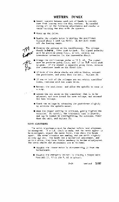
WESTERN DYNEX • Insert spacers between each set of heads to prevent
them from loading onto the disc surface. Be careful during all of the following adjustments and checks to avoid touching the disc with the spacers.
• Power up the drive.
• Enable the spindle motor by pushing the positioner forward about l;; inch (no more). Do not push heads off the loading ramps.
• Observe the pattern on the oscilloscope. The voltage should be1VP-P± 350mv peak-to-peak. The signal polarity must be positive going first, if not, reverse the transducer connector (on the removeable disc)'.
• Change the oscilloscope probe to TP 2, A1. The signal must be positive going first, and 1.5 to 3.8 volts peakto-peak. If the signal is negative going first, reverse the transducer leads on the fixed disc.
• If both of the above checks are within limits, retract the positioner, and power down the unit. Replace J2.
• If one or both of the voltages are not within specifica: tions, continue with the steps below.
• Retrac t the positioner and allow the spindle to come to a stop.
• Loosen the set screw on the transducer that is to be adjusted, and move inward for more voltage, and outward for less voltage.
• Check the voltage by advancing the positio'J.er slightly to activate the spindle motor.
• When the proper setting is achieved, gently tighten the setscrew. Be careful, the transducer case is plastic, and can be broken by overtightening the setscrew. Power down the unit, and replace J2.
SERVO ADJUSTMENTS
The servo adjustments must be checked before head alignment is attempted. If a C.E. check is made, and the heads appear to be misaligned, adjust the servo first, then check the heads again. The servo circuits are analog, and can drift slightly as they age etc. The heads are a mechanical adjustment, and on this drive, they have little tendency to become misadjusted. The servo checks and adjustments are as follows:
• Disable the linear motor by disconnec ting J2 from the motherboard •
• Disable the emergency retract by placing a jumper wire from pin 15, A3 or pin 9, A2 to ground.
2-24 Revised 5/82

WESTERN DYNEX Index Balance Check/Adjustment
• Connec t ch I probe to TP 5 on board A3 (see illustration)
• Connect ch 2 to TP 6 (A3).
• Set oscilloscope as follows: CH 1 Sv/dh,f.4on CH 2 SvJdfvf.ton Horiz './ca Auto sync Chopped
• Power up the drive.
• Manually move the carriage about the index area (the area that would be track -1.5).
• The output of channel I (INDEX) should have at least ftw volts change from the high point to the low point. TheSv includes any crosstalk on the signal and must ce centered about ground.
• Adjust ~f necessary to make the signal equal above and below ground. Clockwise adjusts the offset positive, and counterclockwise adjusts negative.
• Verify that the signal on channel 2 (the digital result of the same signal) has an output that transitions from zero to +5v, and changes only once for each direction of movement at track -1.5. The read/write heads must be past the plastic loading ramp when the high to low trans ition occurs. If not, adjust the position lamp/head as described in a later paragraph.
x + O· Amplitude and Balance
• Connect the channell oscilloscope probe to TP I on A3.
• Connec t the channe I 2 probe to TP 2 (on A3). Refer to the illustration above for test points and adjustment locations.
• Manually move the carriage while observing the signal on the oscinoscope. The signal should be 9v (+ 57.) centered about ground. Adjust R37 (on A3) for -;'plitude if the 9v peak-to-peak is not wrt'h'in specifications.
• Adjust R21 (on A3) unti"l the sinewave is within .25v of being ;Y;;;;trical about ground. Clockwise adjustment offsets the signal positive, counterclockwise offsets the signal negative.
• Observe the signal from TP 2 (ch2). It should be a digital (0 to 5v) signal that approximately corresponds to the crossover of the analog signal from TP I (ch 1).
5/82 2-25

WESTERN DYI)IEX
x + 90· Amplitude and Balance R I <.::, 0 • Connect the channel 1 oscilloscope probe to TP 3 on A3.
~>,. Connec t the channe 1 2 pro be to TP 4 on the same board.
• Manually move the carriage back an:! forth.
• Observe the signal on the oscilloscope. The signal from TP 3 (ch 1) should be from 5v to 25v peak-to-peak, and symetrical about ground.
• If necessary, adjust ~ (on A3) until the signal is symetrical about ground, and within 30'7. of the peak-topeak amplitude.
• The signal from TP 4 (ch 2) should be a digital signal (0 to 5v) that approximately corresponds to the crossover of the analog signal.
x + a· and X + 90· Phasing
This adjustment is only necessary when the photodiode assembly (the position read head) has been physically moved or replaced. The diode head and lamp replacement is described in a later paragraph.
• Connect the channel 1 oscilloscope probe to TP 3 on A3.
• Connect the channel 2 probe to TP 2 (on A3).
• Se t the osc illoscope as fo llows:
CH 1 .2v/cm (lax probe) CH 2 l.Ov/cm (lax probe) Horiz .2ms/cm Sync on CH 1 pos Add (CH 1 + CH 2)
• Slowly move the carriage in the direction of the spindle.
• Observe the oscilloscope pattern. The digital signal (added to the analog signal) should occur within + IS· of the positive peak of the analog signal. -
• When the carriage is moved in the direction away from the spindle, the digital signal should occur within + 15· of the negative peak of the analog signal. -
2-26 . Revised 3/77

WESTERN DYNEX
Up Clock Down Clock
• Connec t an osc i lloscope probe to TP 11 on A3.
• Set the scope to INTernal trigger, negative.
• Manually move the carriage toward the spindle. The scope should display a series of negative going pulses when the carriage is moved toward the spindle.
• Move the oscilloscope probe to TP 12 (just below TP 11).
• !-!anually move the carriage back and forth. A string of pulses should be generated as the carriage is moving away from the Spilld Ie, and no pulses as it is move d toward the spindle.
Velocity Reference Adjustment
• Manually T'S'trao:t the carriage, if it is not already retracted.
• Remove the head spacers that were placed there for the previous tests and adjustments.
• With the power removed, reconnect J2 to the motherboard. The location of J2 can be seen in the illustration at the beginning of this section.
• Install a jumper from pin 15, board A3, to ground, or from pin 9, board A2 to ground, or from TP 3 on the Control ~
board to ground.
2-27 ~C\ Ised 3/77

WESTERN DYNEX Velocity Reference Adjustment (Continued)
• Connect the I/O cable to either I/O connector, A4 or AS.
• Connect the channell oscilloscope probe to pin 1, A2 (on the motherboard). The motherboard connections as seen from the rear, are odd numbers to the right, even numbers to the left (see below).
• Connec t the channe 1 2 probe to TP 7 on the A3 board (see the illustration on the previous page for TP 3 location).
• Se t the asci lloscope as fo llows :
CH 1 2v/division CH 2 .5/division Horiz 10msl em
• Mount an Acceptance Test Pack on the drive. Or alternately, mount a scratch pack on the drive if the ATP s are to be read from a tape.
• Start the disc drive, and allow it to become ready.
• Initialize the DISC 6 test to the point where the program says: Start te.st disc x or man section disc x? When useing an ATP pack, it is not necessary (during this test) to replace it
with a scratch pack.
• On the IPL device (device zero), enter (lPL) 1000A7 (CR). This is an unconditional branch to location 1000 (hex) in memory. At this address in memory the DISC 6 program has placed the Fast Realization of Disc Operation (FRODO) program. The program will respond with "INSTRUCTIONS" and the ENTER lamp will light on the IPL device.
• Enter the following: ESl ES2 BL SKl CS~4 SK2 CS~4 EL (Depress FLAG 2, then CR)
Note: spaces can be used between instruc tions (as shown above), or they can be omitted as desired.
2-28 Revised 5/82

WESTERN DYNEX
Reference Adjustment (Continued)
he entries that were made (on the previous page) ranslate as follows:
ES 1 Enter seek parameter ES2 Enter seek parameter BL Begin loop SKI Seek to parame ter 1 CS04 = Check for status 04 (04 is end, allowing the
seek to complete before starting the next seek) SK2 = Seek to parameter 2 CS04 = Wai t for end again EL = End loop (All instructions between BL and EL
will be repeated)
Depressing Flag 2 before transmit causes the FRODO inst:ruc tions to loop repeatedly until hal ted by the operator.
Inter the two seek parameters:
R00000 (CR) R02560 (CR)
rhe disc should seek continuously between track 0 and crack 128.
)bserve the oscilloscope (channell), and record the seek time (see the illustration below).
~L-1+ ..,j
Seek Time
IPL, and enter the following:
lOOOA7 (CR)
The program branches back to FRODO, and prints out "INSTRUCTIONS".
Enter: ESI ES2 BL SKI CS04 SK2 CS04 EL (FLAG 2) (CR) R02560 (CR) R05120 (CR)
This is the same program as before, but with new seek parameters (track 128 to track 256).
Record the seek time as shown above.
IPL, and enter the same FRODO program as above, but with the following seek parameters:
R05120 (CR) Track 256 R07680 (CR) ! Track 384
2-29

WESTERN DYN EX Velocity Reference Adjustment (Continued)
• Record the seek time as before.
• Determine which of the seek times is the shortest time. The shortest seek time should be 34 ms or ~lJ$~<~_l)T .. <l_on"~~r. If it is not, adjust as follows:
• Perform the seek that had the shortest time •
• A~g R63 on board A3 until the seek time is 34ms. Clockwise is slower, counterclockwise is faster •
• Recheck the other two seek times to verify that tJ-e adjustment has not made one of them too short.
", r ,"< ,', ~I~. '
• IPL, and branch to FRODO again (100M?)
• Enter: ESi ES2 BL SKI CS04 SK2 CS04 EL (FLAG 2) (CR) R00000 (CR) R08080 (CR)
• Verify that there is no overshoot on the full seek (see the illustration below). Look for this pattern on CH 2.
• If there is overshoot, adjust R63 (on A3) clockwise until the overshoot dissapears. .-
• Move the channel 2 oscilloscope probe to TP 5 on A3.
• Verify that the INDEX signal does not become more positive than minus 1.5v. If it does, replace the servo board, A3.
• Remove the jumper from pin 15, A3, and restore the drive to normal operating condition.
POSITION READ HEAD/LAMP ADJUST CHECK-- DON'T ADJUST
This adjustment is only necessary if the position read transducer head or lamp has been physically moved or replaced. When replacing these elements, the lamp filement should be as nearly vertical as possible. The photodiode assembly should also be vertical, with the large dark segment to the bottom (see below).
(J)./ Duk "gruen' " boUom
• Adjust as follows:
2-30
5182

WESTERN DYNEX POSITION READ HEAD/LAMP ADJUST (Continued)
• Disable the linear motor by disconnec ting J2 from the motherboard. The location of J2 is shown in the illustration at the beginning of this section.
• Disable the emergency retract by placing a jumper from A3, pin 15 to ground, or from A2, pin 9 to ground.
• Insert spacers between each set of heads to prevent them from loading onto the disc surface. Be careful during the following tests and adjustments that the spacers do not touch the disc when the head carriage is moved manually.
• Connec t an osci lloscope probe to TP 3 on board A3. The location of A3 test points is shown on a previous page.
Lamp Adjustment
• Loosen the lamp se tsc rew so the lamp can be ro ta ted.
• Manually move the carriage back and forth, observing the voltage pattern on the oscilloscope.
• Rotate the lamp slightly while still moving the carriage. Find the point where the maximum deflection is made. This must be in excess of 5v peak-to-peak (2.5v each way from ground) •
• Re-tighten the setscrew, and make the following checks:
x + 0 0 Amplitude and Balance X + 90 0 Amplitude and Balance X + 0 0 and X + 90 0 Phasing Up Clock Down Clock .
• If any of the above tests are not within specification, re-position the lamp to another m~imum position and repeat the procedure. ,.
~ransducer (Diode) Head Adjustment
• Loosen the head setscrew so the head can be rotated.
• While moving the carriage, slightly rotate the head for maximum deflection (the same as in the lamp check above).
• Re-tighten the setscrew, and make all of the checks that are listed in the lamp adjustment above. In difficult cases, the head and lamp may require adjusting in conjunction.
2-31

WE~ERN DYNEX Index to Clock Check K ~3 6
• Check or adjust the velocity reference as given previously.
• Connect the channel oscilloscope probe to TP 6 on A3.
• Connec t the channel probe to A3, pin 2.
• Set the oscilloscope to trigger on Channel positive.
• If the DISC 6 test is still in memory, (i.e. the processor has not been powered down since the velocity reference was made) branch to FRODO by entering (IPL) lOOOA7.
• If DISC 6 is not in memory, load it from tape or disc, and initialize the test to where it prints "LOAD SCRATCH PACK". If the DISC 6 program was loaded from a disc pack, the pack need not be removed for this test. Instead, IPL, and enter lOOOA7 ~R). "'-
• When the FRODO program responds with "IN$TRUCTIONS" enter:
BL RES CS",4 EL
• Obser~e the oscilloscop~pattern. The clock signal (ch 2) must be more than 500 us from the negative (falling) edge of the INDEX signal on TP 6 (ch 1). If it is less t'han 2Qg~~~, adjust u..on A3 (400 to 500 is O.K.)
• If R 30 is adjusted, repeat the INDEX BALANCE check (the first servo adjustment) to verify that the index balance
il lUll between +2v .nd -3v. If the index to clock cannot be adjusted without moving the index balance out of limits, the Position Read Head must be rotated slightly (see Position Read Head/Lamp Adjustment).
X + 0 0 Cell Balance Check
• Check or adjust all other servo settings.
• Connect an oscilloscope probe to TP 1 on board A3.
• With the carriage retracted, the voltage level on TP should be between + 2.5v and" - 2.5v. If it is not, the position read lamp must be adjusted (see Position Read Head/Lamp Adjustment.
2-32 Revised 5/82

WESTERN DYNEX READ/\>,;RITE HEAD ALIGNMENT NOn: e JLAPer fa required on the IOU 24C tor heed elfglWMlnt.
To ensure that data that is put onto a romovable pack by one disc drive is readable by any other drive of the same type requires that the read/write heads are positioned accurately.
i The fixed disc heads, of course, do not require positional alignment because the platters are not exchanged between units. Whenever a fixed disc or ~e of the fixed disc heads is changed, initialization is all that is required.
Heads 0 and I (top, or removable, platter) must be checked or alligned whenever any mechanical change occurs to the heads, the head carriage, or the position read mechanism. However, before head alignment is started, all servo checks and adjus tmen ts mus t be made.
Head alignment is very sensitive to temperature and environment. The entire disc drive must be stabilized at room temperature (72°F
: to 82°F) for at least three hours before the alignment is started. I;~~~. allows all portions of the drive to reach expansion equilib-
It is also very important that during the head alignment procedure, the front panel must not support any weight. The unit should be supported by the side rails only.
The procedure below covers situations where unknown problems may exist in the drive, and could damage a C.E. pack. Checks are \lade to verify that the drive is working well enough to install the C.E. pack. If a drive is known to be working, and only needs checking or alignment, the steps that are preceded by an asterik :(*) may be skipped. However, if the drive is at all questionable, .the small investment in extra checks will be rewarded by assured protection of the C.E. pack.
• Remove the outer top cover from the drive.
• Remove the smaller plastic cover from over the head carriage region.
• (*) Mount a spare (scratch) pack on the drive.
• (*) Place both protect switches in the PROTECT position.
• (*) Start the disc spinning and wait for 30 minutes for the pack to stabilize.
• (*) Measure the voltage accros R22 on A4 (see the illustration). If there is any voltage accros R22, the erase circuit is ON, and the C.E. pack must not be mounted until this condi tion is correc ted.
• (*) If the is no voltage accross R22, power down the drive, and remove the spare pack.
2-33
A4 A3 A2 Al
5/82

WESTERN DYNEX • Mount a C.E. pack on the disc drive, and power up the
unit. See note with the illustration, below.
• Allow the C.E. pack to spin for at least 30 minutes before continuing. If the C.E. pack was carried from a different temperature environment, allow one hour. Leave the two plastic covers off during this time.
• Place a short jumper wire accrosS the two points of jumper position I on board A3 (servo). These two points are labeled C and 2 (see the illustration). The jumper point 2 is not test point 2 that was shown in the earlier illustrations.- The jumper introduces an offset in the
NOTE: If an unsec tored C.E. pack is used, emergency unload must be disabled by jumpering A2, pin 9 to ground, or A3, pin 15 to ground.
If the IOU-24C is at revision Ii or higher, ground
4D13. Or JI.IIIPef' top of C4 to gnd. (see P. 2-54).
servo control circuit that compensates for the thermal difference of removing the covers. If the jumper is not used during alignment, the heads will drift out of alignment when the covers are replaced •
• Connect the channell oscilloscope probe to test point 12 on board Al (see the illustration above) •
• Set the oscilloscope to measure:
CH 1 2v/divilion AC coupled CH 2 .5v/cm HORIZ 2IIl/divhlon uneal. Sync INT (CH 1) POS
2-34 Revised 5/82

WESTERN DYNEX -", j
• Connec t the channel 2 osc illoscope probe to TP 3 or~ 41 on board A4 (see the illustration below). F
NOTE:
TP3 lies ides higher on late model P.C. boards.
• Seek to the C.E. track and se lec t the lower head by entering the following program. (IPL)
0006800000A8lx3032393230
~ Device number, usually D
• Observe the pattern on the oscilloscope. Adjust the time base on the oscilloscope to center the "cat' s eyes" on the screen. Both loops must be equal when the head is properly aligned. The illustrations below show examples of the patterns that can be expected.
~ POSITlOhEO 100 FAR FROM SPINOlE t£AD POSITlONEO TOO CLOSE TO SPtNCl.£
• If head adjustment is necessary, first disable the emergency retract by jumpering either A2, pin 9 to ground, or jumpering A3, pin 15 to ground.
2-35 Revised 3/10/76

WESTERN DYNEX • When the lower head is properly aligned, switch to the
upper head by entering the following program.
(IPL) 0006800000A8lx3032393330
"'Device no., usually D
• The pattern should be the same as it was for the lower head. Be sure the emergency retract is disabled before attempting head adjustment.
• When both heads are properly aligned, the index to burst (circumferencial alignment) must be checked as follows.
• Move the osc i lloscope probe to TP 3 on board A4 (the location of TP 3 is near TP 1, and is shown on the previous page).
• Set the oscilloscope as follows:
Trigger INT (CH 1) pas CH 2 20mv/cm (with lOx probe) , HOR1Z Sus/cm '
• Enter the following program:
(IPL) 0006800000A8lx3030323030
\Device number, usually D
• This program seeks to the burst track and selects the lower head.
• The oscilloscope pattern should be similar to the illustration below. The delay should be 19us + 4us. Make a notation of the delay time. For single ;ector packs Time= 19us + 19 (Ems -1) where x= measured rotation time.
Trigger point Burst Data
~ELA&-1 NOTE: Burst may appear as reversed polarity.
• Select the upper head by entering the following program.
(IPL) 0006800000A8lx3030323130
~ Device number, usually D
2-36 Revised 3/77

WESTERN DYNEX
• Compare the delay of the upper head to that of the lower head (from the previous seek). If the difference is greater than 7us, one or both heads are improperly seated against the side guide block. In that case, the mechanical correction must be made, and the entire alignment check repeated.
HERE WHEN
ALLIGNING HEADS
that is within 7us of each
A4 A3 A2 Al is insufficient, do the following:
• Power down the disc, and remove the pack.
• Loosen, but do not. remove, the five Allen-head screws that ho ld the fixed disc cover. Do not loosen the three round head Allen screws that are in the same vicinity.
• Rotate the fixed disc cover (within the allowance of the screw holes) and re-tighten the screws.
Clockwise increases the time; counterc lockwise decreases the time .
• Re-insert the disc pack and power up and ready the drive •
• Seek to the burst track, as given above, and try again to adjust R 84 •
• When the above checks and adjustments are correct, return the disc drive to normal operating status by removing any disabling jumpers, and replacing the covers.
2-37


FRODO
FRODO (Fast Realization of Disc Operations) is loaded into memory, and can be used by the operator, any time after START TEST DISC X or MAN SECTION DISC X ? is printed.
FRODO is initialized after an error halt in DISC6 by turning ON Flags 2 and 3 and pressing the ST-SP button. The operator can also enter FRODO by branching to location 1000 in memory at any time.
The program will print "INSTRUCTIONS:" and the ENTER lamp will light. The user program consists of a series of two or three character symbolic codes. Each code causes a specific function. Some codes require following digits as noted in the code description. All codes may be (but need not be) seperated by spaces.
Program entry is tenninated by turning ON Flag 2 an.d/or Flag 3 and pressing TERM or TRANSMIT. Flag 2, alone, causes the program to be executed repeatedly at machine speed until stopped by the user. Flag 3, alone, causes the program to halt after each instruction is executed, and repeat uDtil stopped by the user. Flag 2 and Flag 3 cause the program to execute only once at machine speed.
If a code that is entered cannot be recognized, the program will print "illegal entry" and return to the program entry phase.
When an ESI or ES2 are used in the instructions, the program halts after termination of the instruction entry phase to await the seek parameters. The operator must then enter the seek address (see below).
The symbolic codes for FRODO are explained below.
CODE DESCRIPTION
ESI Enter Seek parameter 4ft. Causes the program to wait in a loop, allowing the operator to enter a seek address that will be used by the SKI instruction. The address is a 5-digit decimal number that must be preceeded bv "F" or ''R'' (fixed or removable) if the disc is· a 3+3 or 6+6.
ES2 Enter Seek parameter 4;2. Same as ESl, except that the number is used by the SK2 instruction.
SKI Seek 1. A seek using the parameter given above. If no parameter was given, the parameter is read from the first six positions of the write buffer (where it would have been put). These positions will be hex zeros that were set when the program was read into memory.
If one seek follows another, use a CS¢4 instruc tion between the two, to allow the seek to complete before the new seek is at tempted.
2-39 Revised 3/10/7 6

FRODO SK2 Seek 2. Same as for SK1, except that
parameter lfo2 is used. When FRono is loaded, defaul t values for parameter lfo2 are set to 11111 for 111 discs, 21111 for 114 discs, or 01111 for 5444 discs.
ED Enter Data. Hex data is read from the terminal. If only one or two bytes (two or four hex digits) are entered, these characters will be propagated through the entire write buffer. Otherwise, up to one typewriter line of data may be placed in the first 64 positions of the write buffer following the seek parameter.
WRT Write to the disc. Data in the write buffer is written to the disc. The write routine does not include seek or status check.
RD Read from the disc. The first sixteen bytes of the read buffer are cleared to hex zeros, then data from the disc is entered into those positions. The read routine does not include seek, status check, or data checks.
CD Check Data. The contents of the read buffer are compared against the contents of the write buffer. Unless the SER instruction has been executed, errors are printed if they occur.
PWB Print Write Buffer. The contents of the write buffer are displayed. Flag 2 terminates the current line; Flag3 terminates the operation.
PRB Print Read Buffer. The read buffer is displayed.
ACS Add Constant to Sector. The sector number in parameter In is increased by one. When it overflows from 9 to 0, the head number is increased by one. When the highest allowed seek is exceeded, the program skips to the next symbolic code beyond EL, thus terminating the loop.
ACH Add Constant to Head. The head number in seek parameter in is increased by one. Overflow increases the cylinder number by one. When the highest allowable parameter is exceeded, seek parameter is reset to zero, and the program skips to the next instruction beyond EL, terminating the loop.
ACT Add Constant to Track. The cylinder number in seek param£ter i1 is increased by one. When the highest allowable parameter is exceeded, seek parameter #1 is reset to zero, and the program skips to the next instruction beyond EL, terminating the loop.

FRODO
PCS Print Changing Status. Every 425 microseconds a Status-in instruction is issued to the disc. The status obtained is stored in a stack. If the status changes within 250 milliseconds, the new status is entered in the stack. When status remains constant for more than 250 milliseconds, all of the status bytes obtained are displayed.
PS Print Status. Status is printed after each completed operation.
CSxx Check for Status xx. When the status (represented by xx) is reached, the next instruction is executed. If the specified status is not reached within 250 milliseconds, the sector number (in bytes 2-6 of the write buffer) is printed along with the last status byte obtained. Errors are not printed if the SER instruction was executed.
SOF Skip On Failure. Placed after a CD or CSxx instruction. If a failure occurs, the program skips to the next instruction beyond EL, or if there are no loops, to the beginning of the program.
SER Suppress Error Report. Instead of displaying errors, signal lamps one and two blink each time an error is made. Error reporting is automatically restored during program entry.
SR Soft Rom. All seeks issued after this instruction is executed are software progranmed, and execute in the micro instruction mode. SR is disabled during program entry.
ITC Inhibit Track Check. Issues CTL 01 to the controller, causing it to disable (the normal) track check that would be made.
IRC Inhibit Read Check. Issues CTL 02 to the controller inhibiting the read-after-write check.
RIO Reset I/O.
BL,EL Begin Loop, End Loop_ Instructions to be repeated are placed between these symbols. The loop continues until: 1. The operator presses Flag 2 or 3, causing the
program to fall through EL the next time it is reached.
2. A CSxx followed by SOF does not detect the expected status, or a CD followed by SOF detects a data error.
3. An ACS, ACH, or ACT increment seek parameter #1 pas.t the highes t valid sec tor number.
RES Restore. Sends a series of micro instructions to restore the disc and set the cylinder to 00.
2-41

FRODO
SWR Set Write.
SRD Set Read.
MWxx Micro Write. The one byte of hex (represented by xx) is transfered from the processor to the controller.
MR Micro Read. One byte of data is read from the controller, and typed or displayed.
TER Terminate.
RSI Read Status 1. The status byte from the controller is read and displayed.
CTL Control. Sends the CTL signal to the controller.
RH Reset Head register. Resets the head register in the controller.
SCxxx Set Cylinder to xxx. The decimal number represented by xxx is converted to hex, and the cylinder is set accordingly. The highest acceptable value for the 114 and 6+6 is 202.
SHxx Set Head to xx. The decimal number represented by xx can be 00-J9 for the 111, 00-19 for the 114, or 00 or 01 for the 3+3 or 6+6.
SSCx Set sector to x. The x represents a decimal number of the sector to be set.
SD Set Difference. Used by the 111 to set the address difference. Not used by the 114. Used for one addressing digit by the 6+6.
SSK Start Seek.
A practical example of the use of FRODO instructions is given in the Western Dynex portion of this book. In there the instructions are used to allow seek time measurement and test for overshoot. With very little practice, FRODO can be one of your best and easiest tools.
W HD W(;teh~~- O~r
2-42

CENTURY 114 The test points and procedures in the following
instructions are for the Model "D", covering all machines above serial number 5000. For machines below serial number 5000, settings and test !>'lints differences are shown as follows (*05C04).
Remove the front and rear panels by pulling firmly at the top portion of the panel. There are two friction catches toward the top. When these release, the panel swings out at the top, pivoting at the bottom. The panel can then be lifted free of the unit.
The card cage/power supply module at the rear of the unit swings out for access to motherboard test points •. The entire module is secured by a large captive screw at the lower left of the module.
Indi vidual procedures are labeled in the text. Spot checks can be made on any of these single adjustments. However, if adjustments are made, the alignment IIUst be made in the order that is given: Power Supply, Servo, and Read/Write System.
POWER SUPPLY
Use the S 1 swi tch inside the lower unit to apply power. Do not activate The operator switch on top. Using a digital voltmeter, check the voltages as shown in the figure and table below. The 36 volts IWSt be checked at the motherboard, 15B53 (see the illustration the next page for adjustment location). NOTE
On Mrliw mod .. unib. thII phvsial location of the de voltage I.min"" .. if .. ,. from the, .hown .., F .....
Voltage Termlf'als GrO\.Il"d Termmal
I DC CO'"
(T:::2-3)
+5V (:50mvdc, adjustablel +24V 1':1.2vdc) ·24V 1+.0.48 vde) adjustable ·24'1 SVD I: 0.48 vde) a,1justabl. +45V 1+2.25, -4.5 vdel +36 vde I± 1.8 vdc, al 15853)
-.f!u .. able
2- 43
+2@C IA
-2"'VDC
~::~:~vo ~
+'~r
+4$V CIRCUIT BfIIEAK&PI:

CENTURY 114
power~1 rt1
~:'Y I~ p ..... ~
t j I
SERVO SYSTEM
100 KHz Oscillator
Connect the Channel 1 oscilloscope probe to 06B01 (card 6, bank B, pin 01). Gnd. lead to chassis •
• Set the oscilloscope as follows: SYNC = INT POSitive HORIZ = 10 usec/cm VERT = 1 v/cm dc
• The display should be a Sv pIp + .0Sv sinewave centered about ground, with a cycle length of 10 Usec + 1 Usec. If it is not within these limits, adjust the Oscillator control, R6 on
2- 44

CENTURY 114 card 6B (see illustration). The frequency is not adjustable, and if it is beyond limits, the oscillator card (6B) must be replaced.
Oscillator 114
Servo ~:OS8!f~
Balance 1140
Sc ~
®
13A Cylinder Transducer Check
• Remove power from the drive by turning S 1, on the relay panel at the front of the unit to the OFF position.
• Remove card 15A (servo amplifier) from the unit.
• Remove the top cover (over the servo motor).
13A
• Remove ONE wire (only) from the linear motor.
• Cover the end of the wire to avoid accidental contact.
------------WARNING------------DO NOT REVERSE THE LINEAR MOTOR LEADS; it will destroy the drive and injure nearby persons.
• Connect the oscilloscope CHl probe to 13A31 (*05C04) (cylinder transducer). This probe stays at this point through the Cylinder Transducer check, the DC Of fset adjustment, Servo Balance,
2- 45

CENTURY 114 Position Gain, and Velocity checks.
• Be sure to ground the shield connection on the oscilloscope lead.
• Connect the CH2 probe to 05B33 (*llA30)(GTDATN). This probe will not be used until later.
• Connect an external sync lead to 06BOI (Osc).
• Set the oscilloscope as follows: Sync = Ext pos Horiz = 2 ms/cm CHI = 200 mv/ cm
• If it is not already connected, install the I/O cable between the IOU /24 and the drive.
• Return the ac power switch, 51, to the ON position.
• Power up the main processor.
• Power up the drive from the operator panel on top of the uni t.
• Wait for the pack to reach speed, and the SELECT LOCK indicator to light.
• Grasping the head carriage toward the rear (near the coil, or bobin), move the heads onto the disc pack.
• While moving the heads back and forth over the entire range, observe the pattern on the oscilloscope. The wave form (shown below) lWst be 800 + 200mv with less than 20% variation. This movement should be approximately
The waveform illustration is shown on the following page.
2- 46

CENTURY 114
.. -between tracks 000 and 202. The end of rack magnets will induce large distortions into the transducer signal. Ignore this effect.
• Manually retract the heads, unloading them.
• Power down the disc unit at the operator panel, and wait for the pack to stop.
• Turn S 1, on the relay panel, to the OFF position.
• Ke-install the 15A card.
• Re-connect the linear motor lead.
----------------WARN ING -----------------DO NOT REVERSE the linear motor leads; it will destroy the drive and cause personel injury to anyone nearby.
• Return the Sl swithch to the ON position.
• Power up the drive from the operator panel.
2- 47

CENTURY Set the oscilloscope to:
CH 1 = 100 mv!cm HORIZ = 5 usec! cm
114
• Load the ATPs from either another disc drive, or f];om a tape unit.
• Call for the "disc6" test, and initialize to the point where the test askes "manual section disc x?".
• Depress IPL, and enter 1000A7 (TRANSMIT).
• The FRODO portion of the disc6 test will print "instructions".
• Enter:
• Enter:
ES 1 ES2 BL SK1 SK2 EL .Depress F2, then RETURN
00000 (RETURN) 00100 (RETURN)
• The disc will begin a repetitive one cylinder seek.
D.C. Offset
• Observe the pattern on the oscilloscope screen The correct waveform is shown below.
• Adjust the DC OFFSET (bottom pot on 13A) (*pot close; to pins on SC) and the SERVO BALANCE (next pot abovt DC OFFSET) (*top pot on 13A) to make the heavy center line in the display as flat as possible.
• Stap the repetitive seeks by depressing the START !STOP button on the processor.
• With the processor stopped, the heavy line can usually be made a little flatter by slightly adjusting the DC OFFSET and SERVO BALANCE. Do not radically change either control unless the repetitive seek is restarted.
2- 48

CENTURY 114 • Start tne seek again by depressing the processor
START /STOP button.
• Verify that the heavy center line stays flat. If it does not, the adjustments IOOSt be repeated.
Position Gain
• Move the oscilloscope sync probe to 09A5 (SKFD).
• Reset the oscilloscope as follows; do not move the CH I and CH2 probes.
CHl CH2 Horiz Sync
100 mv/cm ac 2v/cm dc 2 ms / cm added
= Ext. Pas.
• Vary the horizontal sweep (uncalibrated) until both forward and reverse waveforms are displayed. The illustration below shows approximately the way it should look.
1m I ITI IJIV
l3'bmv GroATN"::::'
• Take note of the waveform for comparason to the one that will follow.
• Depress F2 on the controlling terminal, and enter: 40100 (RETURN) 40200 (RETURN)
The disc will start a single cylnder seek between tracks 201 and 202.
• Compare the display to the previous one. They should be nearly identical. If they are not, adjust the POSITION GAIN (2nd pot from top on 13A) (*farthest pot from pins on 5C) slightly to make both waveforms alike. Keep in mind that the GTDATN portion IOOSt not exceed 130 mv.
• If adjustment was made, return to the seek between
2- 49

CENTURY 114 cylinders 0 and 1 by pressing F2 on the controlling terminal, and entering:
00000 (RETURN) 00100 (RETURN)
• Alternate between the two one track seeks until both waveforms are alike.
Velocity
• Depress F2 on the controlling terminal, and enter: 00000 (RETURN) 40200 (RETURN)
This creates a repetitive 203 track seek.
• Reset the oscilloscope to the following; do not change the probe positions.
CHl 200 mv/cm CH2 2 v/cm ADD Horiz 10 ms/cm Neg. (CAL)
• Adjust the VELOCITY (top pot on 13A) (*bottom pot on 13A) if necessary, to make the GTDATN signal start 65 ms + 5 ms from the beginning of ,the sweep. The display should look like the illustration below. Change triger if start point does not "swoop" out as shown.
• Depress F2 and release. Depress F2 again, then F3 and RETURN.
READ/WRITE SYSTEM
Sector And Index Pulses
Continue from the tests and adjustments above (scratch pack mounted and spinning)
• Connect the Channell probe to 06C13 (index/sector)
• Set the oscilloscope controls as follows: Vert .5v/cm Horiz = 5 ms/cm
2- 50

CENTURY 114 hync = lnt Neg
• The pulses should be 1.3v peak-to-peak mininrum, to 2.25v pip maxinrul!1 (similar to the illustration below). Ignore the INDEX pulse •
•............... , ............... -- .~. - - - .... - ... - .- .--
• Move the CHI probe to 03A30 (index)
• Reset the oscilloscope as follows: Horiz = 5 ms/cm Sync = Internal Pos CHI = 2 v/cm
The wave should be positive pulses approximately 25 ms apart.
I\, 11\ J
Head Amplitude
• Move the Channell probe to 02Cl3.
• Connect the Channel 2 probe to 02CI5.
• Connect the Sync lead to 07A50 (read gate).
• Set the oscilloscope controls as follows: CHI = 100 mv/cm ac CH2 = 100 mv/cm ac inverted Sync = Ext. neg. Horiz =.1 ms/cm Mode = Add, inverted
• On the controlling terminal the printout will say, "instructions".
2- 51

CENTURY 114 -------------WARN INC ----------------Keep hands out of head carriage area.
• Enter: ES 1 ED SK1 WRT BL SK1 RD EL (F2 RETURN)
• Enter: 00000 (RETURN)
The computer will respond with "ED:".
• Enter: FF (RETURN)
The oscilloscope will display a stream of one bits alternated with zero bits.
• Note the ampltude (in mv) of the one bits (the smaller amplitude).
• If the amplitude is less than 75 mv on a single head, replace the head. However, if several heads show less than the 75 mv reading, the READ pre-amp board for that side may be faulty, and require replacing.
• Depress F2.
• Enter: 00010 (RETURN) The computer will respond with "ED:".
• Enter: FF (RETURN) This produces the same pattern as above, but selects the next head.
• Increment to each head by pressing F2 and entering the next higher number, then entering FF for data. Head numbers progress from 00000 to 00090 (head 9), then from 10000 (head 10) to 10090 (head 19).
2- 52

CENTURY 114 • ~inen all heads have been checked at track
zero (the previous procedure) depress F2.
• Enter: 29900 (RETURN) ED: FF (RETURN)
This causes the same pattern of ones and zeros at track 199.
The minimum amplitude for the pattern of 1's must not be less than 75mv.
• Increment to each head as before by adding one, to the head number, then entering FF for data. The heild sequence is 29900 (head zero, track 199) through 29990 (head 9, track 199), then 39900 (head 10, track 199) to 39990 (head 19, track 199).
-----------------NOTE----------------------The amplitude of head 19 is usually lower than all of the others, but must be 75mv minimum.
• When all heads are checked, power down the disc drive depressing the POWER ON button.
HEAD ALIGNMENT
• Remove the power from the disc drive by turning 51 (on the relay panel at the front of the unit) to the OFF position.
• Remove the Write Driver card, 3C, from its slot.
• If the CE pack has only an index slot (no sector slots), card lIB must also be removed.
----------CAUT ION ----------If card llB is removed, only a single slot disc pack can be used. Failure to return the llB card to its slot before running a sectored disc pack will cause an immediate HEAD CRASH.
• If the IOU-24C controller board is at level G or higher, ground pin 13 on the oneshot
2- 53

CENTURY 114 located at D 9 on the IOU-24C board. (These jumper pOints are shown in the illustration that follows)
• Depress IPL on the main processor.
• Restore power to the drive by returning Sl to the ON position.
• Mount the CE pack in the drive.
• Power up the unit from the operator panel, and start the disc spinning.
----------------NOTE-------------------The CE pack must be allowed to Equalize in tempeature before head alignment is made. This can be as long as an hour if the pack has just come from a greatly different environment.
• If the Disc6 test is not already in main memory. load it and initialize to where the printout reads "manual section disc x?".
• Call in the FRODO subroutine by entering (IPL) 1000A7 (TRANSMIT)
• When the program prints "insructions" enter:
ESl BL TSP SKi ACH RIO EL (F3 RETURN)
• Enter: 07300 (RETURN)
The START/STOP lamp will light.
• Depress the ST/SP button on the processor. The seek parameter will be printed out.
2- S4

CENTURY 114 ---------------WARNING----------------Keep hands and tools clear of the head carriage when depressing ST/SP. At various stages in the program, the heads will quickly restore or seek, and can cause serious injury.
• Connect the oscilloscope CH 1 probe to 02C13.
• Connect the CH 2 probe to 02C 15.
• Set the oscilloscope as follows: CH 1 100mv/cm CH 2 = 100MV /CM INV. ADD Horiz = 2mv/cm Sync = Ext Pos (on 03A30, INDEX)
• Noting the warning above, depress ST/SP until the heads seek (to track 73). Head zero will be selected.
• Observe the pattern on the oscilloscope. It will have a pattern that resembles a figure eight, or sometimes called cats eyes. This figure is sometimes difficult to see until the oscilloscope brightness is adjusted to the right level.
Some examples of the the "cats eyes" display are shown below. The sweep time on the oscilloscope may require adjustment to center the display on the screen.
Proper head alignment is shown when both loops are equal. The loops need not be the same amplitude, as long as they are the same length. If the loops are less than 100 mv, do
•• ~ ~ ...... -
a weak head check for the head that is selected. Do not adjust the head if the loops are within 10% of each other (2 small
2- 55

CENTURY 114 divisions on the oscilloscope).
• To select the next head, depress the ST Isp button four times. This can be done to select each head in order.
• If after checking all heads, a particular head must be selected, use the followi~g procedure.
• Depress F2
• Depress ST/sp repeatedly until the ENT lamp on the entry station lights.
• Enter the head number, retaining the track address of 73. For example, head It3 would be 07330; head U5, 17350.
• After the address is entered, press (F3) RETURN, then ST/sp until the seek is made.
• Adjust any heads that may require it. Adjust as follows:
• Loosen each of the four screws, but retighten the screw slightly to allow the head to be moved with resistance.
• Move the head beyond the proper adjustment useing a screwdriver.
• With a screwdriver, carefully pry the head back to the proper position.
• Tighten all four screws to 5.5 inch/pounds (use a torque wrench for this).
ITEM HEAO
J 02
J 06
310 AS VIEWED F!'IIOM ~INE""A MOTOR
HEADITEtI
~
IIITJ 011 2
2- 56
Head Locations

When all heads are aligned or checked, depress F2 •
• Enter: 21890 (F3) (RETURN)
Change the oscilloscope sweep to 1 us/ cm.
Observe the pattern , it should look similar to the following illustration. The seperation of index to burst IWst be 3 usec. + 2 usec.
Verify the above by looking at head 10.
(F2) Enter: 31800 (F3) (RETURN)
• The pattern should be nearly the same as above.
2- 57
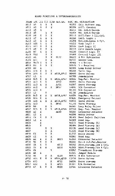
BOARD FUNCTIONS & INTERCHANGABILITY
BOARD LOC III 114 114D ALT.BD. PART NO. DESCRIPTION AF10 A4 X X X 90202 Cyl. Address reg. AFll A9 X X X 90206 Diff. Counter AF12 A5 X 90214 Hd. Add. & Decode AFl3 A5 X X 91069 Hd. Add. & Decode AL10 A8 X X X 90210 Diff.Cntr & Ill.Cyl. ALll A7 X X X 90246 Cntl. Logic 1 AL12 A3 X X X 90258 Det.ldx.Speed & Cyl. ALl3 A10 X X X 90222 Seek Logic 1 AL14 All X X X 90226 Seek Logic· II AL1S B8 X X X 90218 File Unsafe Logic AL16 B7 X X X 90230 Control Logic II AL19 B12 X X 91089 Control Logic III AL20 A6 X X DL52 98622 8 Bit Subtractor AL22 Bll X X 91725 Sector Gen. AN18 B4/5 X X X 90966 5 v Driver AN19 B3 X X X 90970 5 v Receiver AP10 B9 X 90306 Lamp Relay Driver AP14 A15 X X X 90559 Servo Amp. AP16 A14 X X X AP29,DPS2 90680 Servo Driver AP17 C5 X 90789 Demodulator AP18 B15 X X X AP26,AP47 90904 Reg.Pwr. Monitor AP21 Al3 X X AP22 91093 Servo Pre-amp AP22 Al3 X X AP21 91097 Servo Pre-amp AP23 A12 X X DP57 14891 D/A Converter AP24 A12 X 91105 D/A Converter AP25 C5 X 91109 Demodulator AP26 BlS X X X AP18,AP47 93059 Reg.Pwr. Monitor AP28 B14 X X 91826 Emergency Retract AP29 A14 X X X AP16,DP52 91933 Servo Driver AP32 Al3 X DPS6 93146 Servo Pre-amp AP39 B9 X X 94081 Lamp Relay Driver AP47 B15 X X X AP18,AP26 97740 Reg. Pwr. Monitor ARlO A2 X AR20 90282 Crossover Detector AR11 C3 X 90298 Write Driver AR12 C4 X X X 90383 Head Select Switches ARl3 C2 X 90389 Read Amp. AR14 X 90172 Read Pre-amp (L) AR15 X 90386 Read Pre-amp (R) AR16 X X 91126 Read Pre-amp (L) AR17 X X 91122 Read Pre-amp (R) AR18 C3 X X 91057 Write Driver AR19 C2 X X 91061 Read Amp. AR20 A2 X X X DR53 91065 Crossover Detector AT 10 B6 X X X 90266 osc.& D.C.Pwr.Monitor AXI0 C6 X X AX12 90262 Xdcr.Pre-amp,ldx & Cyl. AX12 C6 X X AX 10 92303 Xdcr.Pre-amp, Idx & Cyl. AX14 C6 X 93062 Transducer Pre-amp AZ16 A6 X 91321 Jumper Module DL52 A6 X X AL20 90974 8 Bit Subtractor DP52 A14 X X X AP16,AP29 13150 Servo Driver DP56 Al3 X AP32 14856 Servo Pre-amp DP57 A12 X X AP23 91101 D/A Converter DR53 A2 X X X AR20 l3144 Crossover Detector
2- 58

PREVENTIVE MAINTENANCE SCHEDULE
IOMEC WESTERN CENT. CENT DYNEX 111 114/l14D
When On Site
Clean Heads X X X X Ck.Lamps/lnd. , Switches X X X X
Every 30 Days
Clean Heads X X X X Ck. Filters/ Air Press. X X X X Ck. Index Ring Thru Hole X Ck.Lamps/Ind. , Switches X X X X
Clean Heads X Cover Microswitch X
Every 90 Days
Cln.Fixed Disc X X Ck.24A/C Adj. * X X X Ck. SR8's (See F .A.ItSO) X X X X Ck.Head Alignment * X X X X Ck.Sect/Idx.Amp & Idx/burst* X X X X Ck.Cyl. Xducer X X X X Run Diagnostics X X X X Ck.Pack Standoffs X
Every 180 Days
Clean Entire Unit X X X l\. Ck.Pwr.Supply X X X X Ck. Osc. * X X Ck. Servo * X X X Ck.Cln.Lube Carrier /Pos. X X X X Ck. Absolute Filter X X Advise Cust. To Have Packs Cld. (DO NOT DO IT YOURSELF) X X X X
* Run diagnostics if any changes or adju s tment s are made.
2- 59

MEMOREX
MEItlREX DRIVE ADJUSTMENTS
D.C. VOLTAGES
• Insert a Memorex extender card into the A01 slot. Using 8 DVM,
measure the supply voltages on the extender. They should be:
+15!O.1v on Pins lIR 15
A06
A05
A04
A03
A02
A01
+.05!O.05v on Pins lIK 25
-S.2!O.05v on Pins lIR 3D
-15!O.1v on Pins lIR 35
R/W
DETC
VFO
PLOX
NOT USED
NOT USED
REAR
50
B06
B05
604
B03
B02
B01
CARD CAGE
PSER
VSER
NOT USED
SCDN
REGS
INTF A
F A N
• Adjust the voltage pots in the pedestal to bring all voltages
to within tolerance.
SERVO OFFSET ADJUSTMENT
• Enter the following macro program:
IPL
Do not enter spaces un .. , •• a Q29 fa used.
0020A7 (CR) (QOO20)
1d409D 002980 0040A8 xd3030303030 (CR) (Q0040)
1d4090 004980 0020A8 xd3330343438 * (XMIT)
d = Controller Address x = Port Address
* If on a 75 MB drive the seek parameter should be: xd3931333434
Every time the Start/Stop button is pressed the drive should
do a seek between tracks 0 and 348.
• Using a DVM measure the vol tage between TP11 on the PSER card
and ground, wi th the heads at the track 0 position.
2-60
MEMOREX
5182

MEMOREX
SERVO OfFSET ADJUSTMENT Continued
• Use the Start/Stop button to seek to track 348 and again measure
the voltage at TP11.
• The voltage measurement should change slightly. The difference
measured should be centered around zero volts. Use the small
one-turn l>ot on the PAMP board (visible through a hole on the
back of the POU) to center the offset voltage around zero volts.
The voltage difference between tracks 0 and 348 should not be
greater than 15()nV.
TACH SlOPE ADJUSTI£NT
• Set up a scope as follows: CH1 = 2V / Div
Sweep Rate = 10 ms / Div
Trig Source = CH1
Trig Slope = Neg
Trig Mode = Normal
• Power the drive down and extend the SCON board. Connect the
CH1 scope lead to IC 6C-6 or to pin R46 on the SCON board.
Power the drive back up.
• Enter the foHowing macro program to cause the drive to alter-
nate seek between tracks e and 1e5:
IPL NOt required on IOU 42
eQl2M7 (CR) (Il0020) /
1d4e9D Qle4080 wee6eS0 002eA7 (CR) (1I004I)
xd3e3e303e3e (CR) (Q0060)
xd3e39323430 * (XMIT)
d = Controller Number x = Port Number
iI- for 75 MB drives enter xd323737323e on the last line instead.
5/81
2-61

MEMOREX
TACH SLOPE ADJUSTfo£NT Continued
• A scope pattern similar to the one shown below should appear.
The two-seek time "t" should be 68 ms for new style servo drives
(large bearing cap) or 72 ms for old style servo drives (small
bearing cap). Adjust R54 (the largest pot) on the VSER board
to bring the seek time to within ~ ms of specification.
NEGATIVE TRIGGER
( nl I II
t
- I i ~
= 68 ms For New Servo Types
= 72 ms For Old Servo Types
2-62

BYTES per SECTOR~
..... .-... IV OJ
(I)
5 -f
»0 n " w ~6 ox

*ON = 1 OFF=0
MEMOREX
INTERFACE CARD
SlOT B01
2-64

TO TO rt:1tMI !M'!?
2-65

MEMO REX
Servo Loop Gain Adjustment
• Connect scope lead to TP11 on PSER card (Refer to i Ilustra
tion of PSER card below).
• Set oscilloscope as follows:
ChI
Horlz
Sync:
lv./c:m
2ms ./c:m
R18 on VSER Card
• Using the c:olt tester execute routine 24 (incremental seek).
(If Colt Tester is unavailable refer to pg. 2-6Sb).
• Adjust the servo loop gain potentiometer RI03 on PSER (Refer
to illustration of PSER below) to minimize servo
overshoot without causing the servo system to oscillate.
The correct adjustment is illustrated below.
CAUTION - DO NOT change the setting of the AGC pot on PSER (R63)
f\ v
f\ I OVERSHOOT shou I d
t .SV and 1.3V)
V
T Properly adjusted overshoot
be between
• Run Colt Tester routines 27 and 28 to verify operation.
PSER P'JA -• TEST pt "-ij:) POSITIVE
POSIllON ERROR
R1 SERYOIJIOP GAIN ADJUSTMEHT
PSER card SLOT B06
2-65a 5/82

MEMO REX
PSER adjustment without a Colt:
I ncrementa I seeks may be obta i ned th rough the use of MXATPH
or MXQ29 tes ts us i ng the fo 11 ow i ng procedure.
1) Load I1XATPH or I1XQ29 Test
2) Spec:ifyaddress. Be sure to place an R after the address.
This wi II put the test in Repeat Mode.
3) Respond to the questions in the following manner:
Selec:t options? Yes
FRODO On I y? Ho
Print Alt. Sec:tors? Yes
Ha I t after Error? No
Enter i terat i on count? Yes
Manual - (XHIT or CR)
Address - FF
All remaining Test blocks - (XI1IT or CR)
4) Proceed wi th overshoot adjustment.
Note: The drive will do incremental seeks fonvard and
then res tore to Cy 1 # when the max Cy I # is
reached. The adjustment waveform is inval id
during this short restore period. Make the
adjustment whi Ie the drive is seeking fonvard.
2-65b
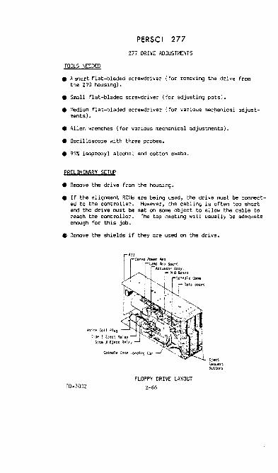
PERSCI 277
277 DRIVE ADJUSH1ENTS
TOOLS NEEDED
• A short flat-bladed screwdriver (for removing the drive from the 210 housing).
• Small flat-bladed scre~Jdriver (for adjusting pots).
• r'~dium flat-bladed screwdriver (for various mechanical adjust-ments). .
• Allen wrenches (for various mechanical adjustments).
• Oscilloscope with three probes.
• 91~'; isopropyl alcohol and cotton swabs.
PRELIMINARY SETUP
• Remove the drive from the housing.
• If the alignment ROHs are being used, the drive must be connected to the controller. However, the cabling is often too short and the drive must be set on some object to allow the cable to reach the controller. The top casting will usually be adequate enough for this job.
• Remove the shields if they are used on the driYe.
T0-7002 FLOPPY DRIVE LAYOUT
Z-66

PERSCI 277
277 DRIVE ADJUSTMENTS
SERVO ADJUSn1ENTS
Quick Reference
I R£r. ro 1 i STEP ,
1.2
1.3
'\DJUST"E~T
Track Sense ~l.
f rack Sense Bal.
f'UIe Po~utlon .lornpl.
Fine Pas i tion Sa 1.
POT
R'
P19
R8
R10
TEST POI~I
TP6
TP6
TP2
TP2
SETTI'-C
... ,.7o;V Change .. hen movlnq from track ':"3 to .:.4.
",'.25, ',lith positloner anywhere between track .:.~ and the spindle.
J.}V pp ,:O.3V..hen ;>os1t1oner 13
Centerea about ~round ~. 1V wnen positioner is !1'IOVlng.
Same seek ~imes for for· .... std and reverse ",hen doing al ternate seeks bettJeen tracks Sl and 52.
~ oversnoot ....... lle dlung alternate see-ks :'et ... een tracks Sl 3I'ld 52. Maxlf\UfI allal1able seek time lS 1 Z'ltS. rnlnimum is IOns,
.. Use the test point on the exerciser or Pl-10 on the drive inter face connector.
NOTE: All pots and test points are on the La"", Amplifier board except R33. which is on the servo board. (Refer to pre-ceding illustration). Use the eject motor _--_ ground strap for ground.
TP7 0 TP6 0 TP5 ·0
:~~~~ POSITION POSITION SPEED TRACK SENSE LAMP BALANCE AMPLITUDE VOLTAGE
LAMP AMPLIFIER BOARD
2-67

PERSCI 277
277 DRIVE ADJUSTMENTS
SERVO ADJUSTMENTS
1.1 TRACK SENSE AMPLITUDE
• Set up a scope as follows:
CH1 0.5V/cm, DC coupled Channel Select: Ch. 1 Sweep Rate 1 ms/cm Trig. Node Auto Trig. Source : Normal
• Observe TP6 on the scope.
• Make the positioner cross over tracks 43 and 44 by unplugging the voice coil and mov ing it by hand.
• Plug the voice coil back in and perform one of the following:
a) Use the ALRI'l command DT to alternate seek between tracks 32 and 64, or
b) use the exerciser to alternate seek between tracks 40 and 47.
• Adjust R4 so the waveform is 1. 75V peak-to-peak.
1 • 2 TRACK SENSE BALANCE
• Use the same scope setup as in step 1.1.
• Adjust R19 to make the negative portion of the display -1. 25V. Be sure the ground is calibrated correctly.
1.3 FINE POSITION AHPLITUDE
• Use the same scope setup as in step 1.1.
• Observe TP2 on the scope.
• r·love the pOSitioner back and forth by:
a) Unplugging the voice coil and moving it by hand.
b) Using the ALRM command DP to alternate seek between tracks III and B. Voice coil must be p lugged in.
• Adjust R8 to get a 3.Sv - 3.8vp-p waveform.
5/82
2-68

PERSCI 277
277 DRIVE ADJUsn~E\lTS
SERVO ADJUSn-eHS
1.4 FINE POSITION BALANCE
• Use the same scope setup as in step 1.1.
• Be sure the ground is calibrated correctly •
• Adjust Rl0 to balance the signal about ground::. O.lV.
1 .5 SEEK SYMl~ETRY
• Set up a scope as follows:
CHl CH2 Channel Select: Sweep Rate Trig. Node Trig. Source Trig. Slope
O.5V/cm,DC coupled 2.0V/cm, DC coupled Ch. 2 1 ms/cm Normal Ch. 2 Positive
• Connect Ch. to TP2.
• Connect Ch. to seek complete using either the exerciser test point, Pin 10 on the interface connector, or PS, Pin 2.
• Do an alternate seek between tracks 51 and 52 by,
a) using the alignment RGr·l command SY or
b) using the exerciser.
• Observe Ch. 2. There should not be any jitter on its trailing edge. If the trailing edge is not visible adjust the scope's sweep rate calibration until the edge can be seen.
• ,J,djust R33 on the Servo Board to eliminate the jitter as in the illustration on the following page.
• Use lOX to increase visibility of jitter.
5/82
2-69

PERSCI 277
277 DRIVE ADJUSTMENTS
T ! ! I I I I 1 1 i I i i
I !
i
I i i I
ADJUST R33 UNTIL TRAILING EDGES CONVERGE
SERVO ADJUSTMENTS Continued
1 .6 SEEK SPEED
• Use the same setup as in step 1.5.
• Observe Ch. 2 and adjust R5 to make the seek complete signal high, 10 ms. The Seek Time must not exceed 12 ms. If jitter appears on the trailing edge, go back to step 1.5.
• Change the channel select to Ch. 1 and look for overshoot as illustrated below.
OVERSHOOT
• Observe the trailing portion of the 'f/aveform, if it is not Yisible adjust the scope's sf/eep rate calibration until it can be .een.
2-70 5/82

PERSC I 277
277 DRIVE AOJUSTt4ENTS
SERVO AOJUSTI-IENTS
1 .6 SEEK SPEED Continued
• If overshoot is visible, adjust RS to slow down the seek speed until the overshoot is eliminated.
• Recalibrate the scope and check the seek time on Ch. 2.
1.7 DIRTY SCALE CHECK
• Restore the positioner to the track 0 position and move the positioner slowly by hand out to the spindle and back.
• Sudden changes in resistance (which may feel like a bump or dent in the positioner guides) indicates a dirty spot on the tach scale.
• ,'!hen unsure whether the bump is a dirty tach or a physical problem in the positioner, power the drive down and move the positioner by hand. If the symptom goes aI-lay it is a dirty scale problem. Use a dry swab to clean the scale.
2-71

PERSCI 277
277 DRIVE ADJUSTr1ENTS
MECHANICAL APJUSHlENTS
Quick Reference
i-: '....:.;r....:.r~p:....ro ....... I_ .. _0_JU_~T_i.1[_ •• T __ ..I-_pp_.oc_EO_UR_E _______ ----I :.1 or 1.1
Z.!. or ~. ::.
l.30r I I.J
2.:'.:lr I .•
>£ .. 0 RESOLUTION
HE"!) ""LOAD
CQ.\[C>f;CK
~t~r~~ :~\~dr~~~;~;y'l~l:~~d~e~~y t~:~l~~demd ! I r..LCJr, F'requenc:- CJI".ohtude S 9,-. LOI' r:-erJuenCj 1
~~~l!~~~f~~~~~~ ~·~3~ette. 1
Less than 15:, amphtul1e :::o1u!<ltlon ::In :e9d .-jata after sevenl ~JectS :..00 l,nsertJtl.cns.
:;,.-::.ller C:lts e~e lCbe~ 9," of the larger cats ~~e ~obe :1hen on tr,;,ck 38.
.. In all cases use TP4 and TP5 for Side il read signal and TP6 and TP7 for Side 1 read signal. Use the eject motor ground strap for ground. On radial alignments use index (P11-2 on Side 0 and P9-2 on Side 1) for scope sync.
I
I u
OAT" AND I~TERFACE PR!:.;TED CIRCUIT BOARD
r;:;j191171 S 11019111116I1sl12II~11312QI1916 ! i I
• ;.cross C21. C26 for data stream monitoring. Older version drives . below level i( may not nave these test P01~tS.
2-72

PERSCI 277
277 DRIVE ADJUSTMENTS
MECHANICAL ADJUSn1ENTS
DATA BOARD CONNECTOR DEFINITIONS
(Refer to Data and Interface PCB illustration on the previous page.)
£.I2l!:!Q!i
P1 I/O Cable P3 Power Input P4 Spindle Power P5 Spindle Servo P6 Data Separator P7 Positioner Servo POtIer P8 Posi tioner Servo
P11 Index Transducer P1 Z Index LED P14 Head Load Solenoid P16 R/~I Head P18 Eject Notor PZO Write Protect
P9-P10 P13 P15 P17 P19
The system may be forced to IPl to Side 1 by exchanging P11 /P9. P14/P13, and P16/P15. To read and write with Side ~/1 exchanged, the write protect lines P20/P19 must also be eXChanged.
2.1 HEAD RESOLUTION - SlOE a
• Set up a scope as follows:
CH1 O.1V/cm AC coupled CH2 O.1V/cm AC coupled, Inverted Channel Select: Add Sweep Rate 1 ms/cm Trig. r-Iode Auto Tt'ig. Source Normal
• Connect Ch. 1 to TP4 on the Data Soard and Ch. 2 to TP5. Use the eject motor ground strap as the scope' 5 ground point.
• Insert a test diskette into the Side 0 slot. The diskette should have a double frequency pattern written on track 1 and 76. This can be accomplished by writing a standard 1 's and a's pattern with the exerciser or by first seeking to track 1 (S1 option) and then using the ';101 option \'lith the alignment RONs.
NOTE: I'Iriting the above pattern will ruin the soft-sectoring on the diskette, making it useless for all other purposes.
• Seek to track 1 and observe the scope pattern. It should be similar to the illustration on the following page. The inner envelope amplitude should be less than 95% of the outer amplitude.
2-73

PERSCI 277
277 DRIVE ADJUSTt-1ENTS
MECHANICAL ADJUSnlENTS
HEAD RESOLUTION AT TRACK
2.1 HEAD RESOLUTION - SIDE 0 Continued
• Seek to track 76 and observe the scope pattern. It should be similar to the illustration below. The inner envelope amplitude should be greater than 50% of the outer amplitude.
8
50: MIN.
HEAD RESOLUTION AT TRACK 76
• If either 0 f the above checks fail, slightl y increase the Pressure Pad pressure by hand. The signal should improve; if it does not, the head or diskette is bad. I f the signal improved, rotate the head pad slightly and again increase the pressure. Continue this process until a minimum change in signal quality is observed.
5/82 2-74

PERSCI 277
277 DRIVE ADJUSTI£NTS
MECHANICAL ADJUSTMENTS
2.2 HEAD UNLOAD - SIDE £I
• Use the same scope setup as in step 2.1 •
• load and unload the head, both tracks £I and 76 by using either the exerciser head load swit:h or the alignment ROM Ii) option.
• When the head is unloaded, the read signal on the scope should drop by 5~ or more.
• If the read signal did not decrease enough, lift the Pressure Pad Arm by hand (illustrated below) to determine whether the unload bailor the head penetration is at fault.
,,~ --
PICK\P BAIL ALLEN SCR£lI
• If the signal did not iqlrove, the head penetration is toe great and little may be done to correct the problem.
• However, if the pickup bail is at fault adjust it using a (3/32") allen wrench.
2-75

PERSCI 277
277 DRIVE ADJUSTt4ENTS
MECHANICAL ADJUSn~ENTS
2.3 CONE CHECK - SIDE 11
• Use the same scope setup as in step 2.1.
• Eject and reinsert the diskette several times and observe the read signal at track 0.
• The signal should never have more than 15·~ amplitude modulation. If it does, either the positioning cone is bad or the diskette hole is worn.
2.4 RADIAL ALIGNNENT - SIDE 0
• Use the same scope setup as in step 2.1 except sync. external on Side iii index (Pl1 Pin 2) and set the sl'leep rate to 20 ms/cm.
• Seek to track 38 by using the exerciser or the 538 option in the alignment ROt1.
• Insert an alignment diskette and observe the cat' s eye pattern on the scope. The smaller lobe must have 95;. or more of the larger lobe's amplitude.
• If realignment is needed, remove the optical slide cover and loosen the two 3/32" allen screws holding the optical transducer assembly as illustrated below.
PO$ITtONE"
:~!~~ING ~(:
2-76
TRANSouCER ADJUSTMENT SCA£Y.'5

PERSCI 277
277 DR IVE ADJUSTtlENTS
MECHANICAL ADJUSn~ENTS
2.~ RADIAL ALIG~I·1ENT - SIDE 0 Continued
• Reinsert the alignment diskette and gently move the optical transducer assembly, using the Lamp Amplifier Board as a handle.
• ~lhen proper alignment has been aChieved. eject the alignment diskette and tighten down the mounting screws.
• Recheck the alignment before replacing the slide cover.
3.1 HEAD RESOLUTION - 5 IDE 1
~OTE: The Side 1 alignment depends on the Side " alignment be ing properly adjusted. DO NOT attempt to adjust Side 1 without first checking Side 0.
• FollOl' the same procedures outlined in step 2.1, except use TP6 and TP7.
3.2 HEAD UNLOAD - SIDE 1
• Follow the same procedures outlined in step Z. 2. except use rp6 and TP7.
• The head penetration can be adjusted on Side 1 by using the head penetration adjustment screw as shown in the following illustration.
.a:2S ~ .015
I i
PRESSURE ARM
2-77

PERSCI 277
277 DRIVE ADJUSTMENTS
MECHANICAL ADJUSH1ENTS
3.3 CONE CHECK - SIDE
• Follol-1 the same procedures outlined in step 2.3, except use TP6 and TP7.
3.4 RADIAL ALIGNMENT - SIDE
• Follow the same procedures outlined in step 2.4, except use TP6 and TP7.
• Sync. externally on P9-2 for Side 1 Index.
• The Side 1 head may be moved into alignment by loosening the two 3/32" allen screws as shown below.
HEAD PENETRATION ADJUSTMENT SCREW
AZIMUTH SCREWS
NOTE: Be careful to keep the head seated against its upper mounting surface to avoid Azimuth misalignment.
2-78

PERSCI 277
277 DRIVE ADJUSnlENTS
PlO ADJUSTI1ENTS
Quick Reference
R[F. 00 lO.!USrTl£';T TE'lT POT STEP ! PlJl'T
Free \UMl.n'1 rrequcnc', TP!
:".2 rrequenc) F"lne -klJust fP2 q16
4.3 Phase {Po TP7
4.1 FREE RUNN ING FREQUENCY
• Set up a scope as follows:
CH1 : Channel Select: Sweep Rate Trig. Mode Trig. Source : Trig. Scope
lV/em DC coupled Ch. 1 'li,S/division Normal Ch. 1 ~egative
PROC£OUP.(
... rtJUS~ ~or ! Il1z .. ~ 'JS ..• It'"lout 3d.:.<;kette:)rcsent.
.. djust to !:)rinq contro.i. 'IIolt.,qe as close to )E'"ound as ~os:;;lole .~ltn :hsk:ette preser'lt.
':'dJust phase to ':cnter tra.i.llr.q edge 11"', t!1e ::iat3 IIlndol/ ",hile readlf'IIJ a formatted Jis"ette.
• Adjust R16 (R41 on later revisions) on the PLO card for a sawtooth waveform (iL lustrated below) wi th a one m; crosecond perioC! on TP3.* There should not be a diskette inserted in the drive during this adjustment.
, I I I I
i 1 I I AA.I1~ ~-¥··f--""'-·
j
i i i
i I
jj AJ'1 -- --- -. ..y.--
I
2-79
/1 I 1£. ,{ .•
I
"Heasure the period over ten cycles to insure accuracy.
5/82

PERSCI 277
Z77 DRIVE ADJUSTMENTS
PLO ADJUSTMENTS
4. Z FREQUENCY FINE ADJUSTMENT
.1·love the Ch. 1 probe to TPZ on the PLO Board.
• Change the vertical sensitivity to D.1V/cm, DC Coupled.
• Insert a formatted diskette.
• SeLect Side a and seek to Tracie O.
• Fine-adjust R16 to center the noise band around III volt Make sure the scope ground is properly calibrated.
• The sawtooth frequency may no longer be 1.0 ~1Hz after performing this adjustment. Readjust if necessary.
4.3 PHASE ADJUSTMENT
• Insert a formatted diskette and read track Ill.
• Change the Ch. 1 vertical sensitivity to Z.OV/cm.
• Setup Ch. Z to Z. OV / cm, DC Coupled and set the channel select switch to Ali.
• Move the Ch. 1 probe to TP6 and the Ch. Z probe to TP7. The scope display should be similar to the one shown below.
• Adjust R4 to center the trailing edge of the Ch. Z signal between the rising and falling edges of the Ch. 1 signal.
5/82 2-80

PERSC I 277
277 DRIVE ADJUSTMENTS
Aoon lONAL ADJUSHlENTS
• The following adjustments may need to be checked under rare circumstances. Refer to FA 101C for details.
1) Spindle Instantaneous Speed Variation (ISV) Check
2) Spindle Speed Check
3) Azimuth Alignment (Side 0 and Side 1)
2-81

8-4 __
2--1-- ADDRESS SWITCHES
80-40--
;g=CONFIG.
IOU 42
B- SWITCH i== SETTINGS 1- P4
ersonality ROM
CONFIGURATION SWITCH SETTINGS
.. ~
.. -=:I
.. -=:I FUJ ITSU ;:~ 84MB ... -= -~ .~ $92
Personality ROM Memorex
Label 42MEM(y)
~~I-' .' .~.
Part Number A42671-001
b
y=Rev Level 2-82
O~OFF 1=ON
Marksman/Fuji
42MRK(y)
, i ' . .' . A42671-002
5/82

IOU 42
WRITE CONTROL INSTRUCTIONS
Idyy9D
Control Byte
S01
S02
S03
504
SOS S10
$14
560
$70
S7F
599
SAO
SBO
d - Controller Address yy. Control Byte
Function
Inhibit Track Verify
Inhibi t Read After Wri te Check
Set Memory I/O Mode
Reset Memory 1/0 Mode
Jump to Memory Location 54200
Disable Termination Interrupt
Enable Termination Interrupt
Disable Alternate Sectoring
Enable Alternate Sectoring
Send Identification String
Incremental Seek
Move ROM Version to Status 0
Reset Status 0 to 04
Add n times 100,000 to Next Seek Parameter
STATUS I N I NSTRUCTI ONS
ltdyy9D d • Contr"ol1er Address yy. Test Bit value
Status Byte
$8(1~ $1t(I $2(1 $11 $118 $(14 $112 IIfl
Function
See'" Tab Ie on Next Page
Seek or Write Terminated Se rv i c:e Reques t End Wrl te Busy Read Busy
2-83
5/82
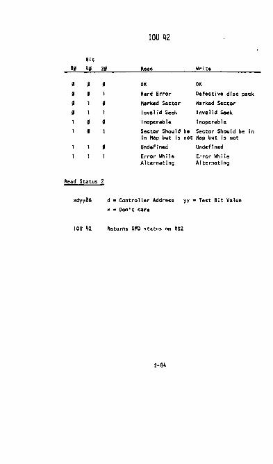
Bit
8, 4, 2' , 8
If If
If If
If
If
If
Read Status
xdyy86
IOU 42
IOU 42
Read Write
OK OK
Hard Error Defec:tive disc pac:k
Harked Sec:tor Harked Sector
Inval id Seek I nva 11 d Seek
Inoperable I noperab Ie
Sector Should be Sec:tor Shou I d be in Hap but is
Undefined
Error While A I ternat i ng
not Hap but Is not
Undefined
Error Wh il e AI ternat Ing
d • Contro lIer Address yy. Tes t Bit Va I ue
x • Don I t care
Returns $FD status on RS2
2-84
In

IV 0
~ (l)
(j)
m » r m 0
'" I
0 ~ ........ (j) ()
() » OJ r m 0 ........ » G> :0 » 3:
OANTEL DEV42 M20
~WCI ~~. '* rr061 , __
OFF -OPEN-
ON O~OOOO SIIIlEJAIlI
BASIC DRIVE CONTROL LOGIC PWA VR124
fO SIEl'I'fIl MOTOR
TO IIfI loY COHllIOL ASSE_Y
TO POSITIOHEII ASSEMBlY
*ALL SWITCHES SHOULD BE IN THE OFF POSITION

':' 0 ~ Vi
(')
(')
» OJ
~ o t-t
» G> ::0 » 3:
EA COHNECTOR5
\
-TO VAUI-
L....I---.L"::..;;2~ OOIIAMMABLE J6
o'TI'"o :::'":'~ \,1<12 N " ..... _ ......... .... . ~ Rt1 '''H
~":'" " IR II OItTRot.-~W1I1OJ ~I JJ P~J .. TO ::J-~:l~ X 711 O. A [~ , · • """H"-INTERFACE 0 4] 'ASSEMBLY ADAPTER PROGRAM J4 )(AU nOMs/,)
-/ H~,..n ...... II '':'0''-
. n~ REAO/WRITE IlEA05
C DRIVE '::PL OULD BASI L LOG/(;I V '''" * SWITCHES SH CONTRO S ALL THE OFF PWA DRIVE BE IN VR126 MOTOR POSITION J6c.
o TO IHDill!cUM:1I SOUCERS TAAN

ON.--OFF-
SYSTEM POWER/ CIRCUIT BREAKER
"1J(J') ONE N N • OF FOUR :em 0 w -'- MOUNTING -<}> '- x 0 SCREWS (J')r .f' '-....... m 0
~O ~ w W SPIN MOTOn ~ rO OJ X 7-J
PUllEY ~ "t r ....... OCI }>(J') DRIVE DELT $ ~
-<(') :z CONTROl RELAY INDEX CLOCK 0 ASSEMBLY TUANSDUCER C
ASSEMBLY -I SPINOI.E GROUND
I'EAMAIlEN' 10 AIR FILTER A.C. POWER

FUJITSU INITIAL SETUP OF THE FUJITSU DISC DRIVE
NOTE: BEFORE you apply power to the disc drive, be CERTAIN that the Spindle Lock, Motor Lock, and the Actuator Lock are all released.
Unlocking the Spindle The spindle lock is located at the bottom of the spindle. The spindle lock must be released by loosening the two screws as shown below. Be certain to slide the lock back on BOTH screws so that the spindle grounding brush is centered on the spindle shaft. Do not allow the plate to move while tightening the screws.
Spindle Pulley (Rotate only in direction of the arrow)
SPINDLE LOCKED
SPINDLE RELEASED
LABEL DETAIL
Center of Spindle Shaft
V'
Spindla G:cu:"ldi:'l~ Bcu.b" Spindle Gro~ndin9 P1Uo
SPINDLE RELeASED - SIDE VIEW
2-58

FUJITSU Unlocking the Actuator The actuator must be released by rotating the lock as shown below. The lock can be seen through the top of the disc enclosure. The actuator locking lever can be reached direccly beneath the lock, under the disc enclosure (see the illustration below).
STOPPER
r:13:'\ NO
._ Lever
--11~:JO , i
co ~.-
! O'n<iuhc!. at actuator lack)
ACTUATOR LOCRED ACTUATOR RELEASED
2-89

FUJITSU Unlocking the Spindle Motor To unlock the motor, loosen the two screws that hold the motor cover against the pulley and slide the motor cover to the left as far as it will go. With the motor lock in the "off" position, as shown in the illustrations below, tighten the screws.
MOTOR LOCKED Motor Screws
ONLY OS!O FOR MOVING 'l'!!E IlRIVE Loo.e" screws and slide motor cover as far aa possible towards the ON ;>olitio".
MO'l'OR UNLOCKED
2-90

FUJITSU +2~V DC Select Confirm that the +2llVdc is selected by the switch on the rear side of the power supply unit as shown below:
Note: There should be a restraining bracket holding the select switch in the +2~v position. If there is no bracket and/or the switch is not in the +2~v position, the unit has probably been severely damaged. DO NOT APPLY POWER IN THIS CASE. Call Tech Support.
Power Cable Connection The Fujitsu Disc Drive utilizes three power cables that run from the power supply. The AC cable runs from PW1, the DC cable runs from PW2, and the Power Control cable runs from CN18 as shown below. Three of the wires that run from CN,8 merge with the harness that runs to front panel conector Jl. The other three wires in this harness must be connected to CNl on the motherboard which is under the card cages. CN' must be reached from underneath the disc drive. For operation, SWl (the main power switch) should be switched on and the other switch should be in wremote. w HARNlHG SWl must be turned ~ before any PWAs can be removed.
2-91

FUJITSU DC Voltage Adjustment Using a DVM, measure the DC voltages at TRM1 (on the card cage motherboard) shown in the illustration below. Adjust the voltages as necessary by turning the respective potentiometers, which are located on the power supply chassis. These potentiometers are shown in the previous illustration.
Interface Cabling The illustration below shows the PWA chassis at the front of the disc drive and the cable conbections to it. The interface cabling conLsts of two cables, nAIf and "B.n Cable A is to b~ connected to OM2, and Cable B is to be connected to OM3. A line terminator is to be connected to OM,.. The grounding wire from the line terminator must be connected to the signal ground at TRM1(-2). Be sure that the small connector coming from the TRM1 harness is connected to PWC1.
0112
l I /
Cable A
PWA CHASSIS
Cable B
2-92
Line 'terminator rOllnd1n<; 'II'ir.
I DC Power

FUJITSU Maintenance Aid Display and Switches
The switches on the PWA chassis function as follows:
CKCtR - This is a momentary contact switch that resets a Device Check Status. Note that if a fault persists, it will not be reset.
FPT - This Switch inhibits any write operation, and it should normally be in the off position.
H-V - This jumper switch must be set in the H (for horizontal mounting) position.
The illustration below shows the location of the switches and diagnostic LEOs. The table defines the tED signal configurations.
Note: TG2 ·ONn and TG' nOFFn indicates nNo Fault."
@ H r •• _Iv CXCLR
00000000 TG2 TGt m IT. ST3 ST2 ITt $TO
2-93
ON
0,""
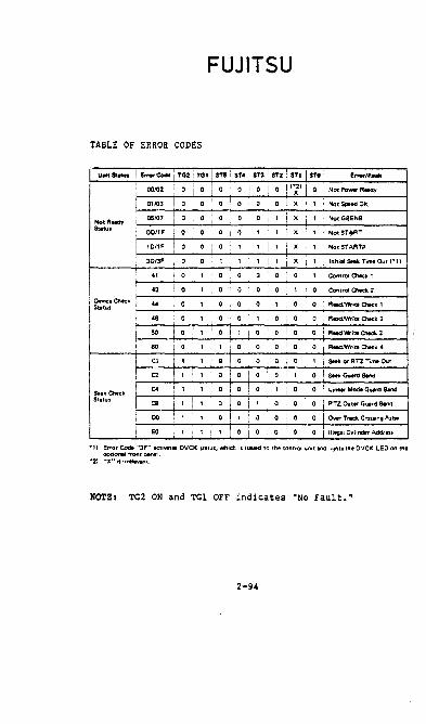
FUJITSU
TABLE OF ERROR CODES
Unit Status ! I!nwCode TG2! TGI STS 1 ST. i ST3 I ST2 i STI I STO E ...... /F .....
, 00102 o i 0 i 0 I o 1 0 I 0 I ';1 I 0 Not Power Roady
I 01103 0 I 0 I 01010-rolx ! 1 Not SpoedOK
NotA-., I 05107 i 0 I 0 o I 0 I 0 ! ' i X I ' ! NorGeENB
SUa.. I OO/IF o ! 0 0 I 0 I 1 , I X I , ! NotSTo!oRT I
,O/IF 1 0 0 o i , , I , i X , ! NotSTARTP I i
30/3F 0 0 , , , ' 1 X I
1 Initial Seek Time Out '·1) I I 1
, 41 0 , 0 0 o [ 0 o , , Control ChOCk ,
I OevM:.Choc;k
42 ; 0 1 0 0 o I 0 1 . 0 • Control Chock 2
S .. a.. 44 0 , 0 0 0 i 1 0 0 R_Jw.iro Chock ,
I 4B Oi' i 0 0 1 I o i 0 I 0 I R_lWriro Chock 2
I 50 01, ! 0 I , I o I 0 I 0 1 0 : R_ Wriro Chock 3
i 60 I 0 i 1 I , 0 0 i 0 I 0 I 0 i R_lWrite Chock 4
I Cl i 1 i 1 i Q i 0 : 0 i 0 \ 0 I 1 \ $HI< 01 RTZ Ti .... Out I
r C2 I ,1 , i oro I 0 I 0 I 1 I 0 : _ Guord Bond I I
I c. f 1 I , o I 0 I 0 I 1 I o I 0 ; L.i.- Modo GUOI'd B_ SeekChoc;k Status I C8 i 1 I , o ! 0 i 1 i 0 o I o i RTZ Out ... G_d Bond
, 00 I 1 i 1 or 1 0 i 0 i 0
I 0 I 0- Track Cro ... ng P.I .. I I
EO 1 I 1 1 r 0 i 0 I o i 0 0 Illegol Cvlinder Addr ...
.,) Error Code '~3F" activate OVCK stltUs, whien is iuued to the eof1trol unit and lighf:l the OVCK LEO on me optional front panel.
-21 "X" is ir ..... vant.
NOTE I TG2 ON and TGl OFF indicates -NO Fault.-
2-94
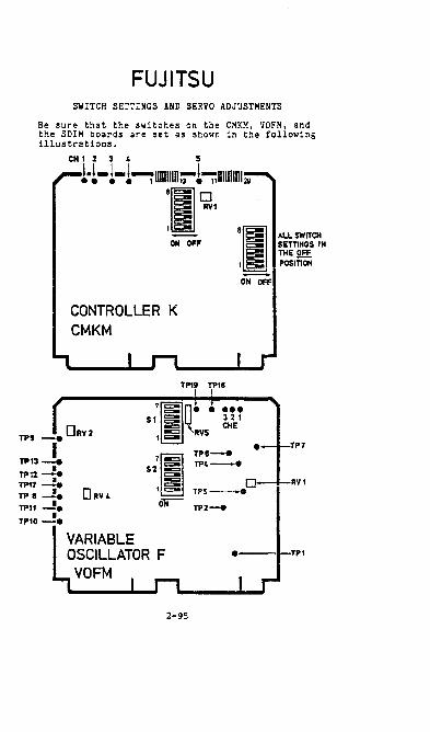
FUJITSU SWITCH SETTINGS AND SERVO ADJUSTMENTS
Be sure that the switches on the CMKM, VOFM, and the SDIM boards are set as shown in the following illustrations.
ON OFF
CONTROLLER K CMKM
Sf g:
TP1V I
'I~l ~L~~ §: SETTINGS IN l3: THE gEE
1 §: POSITION
ON OFF
TPIS
••• 321
TPI _.DRv2 llr ~ 1 ~ 'RVS eME
I • TP7
'[I TPs-e TP13 __ TP4-. • 52 ~ TP11-e
TP11-+ RVI
DRY4 t §:: TP5--.
TPS -. ~ TPI1 -!. TP2-e
TP10 -!.
• TPI
2-95
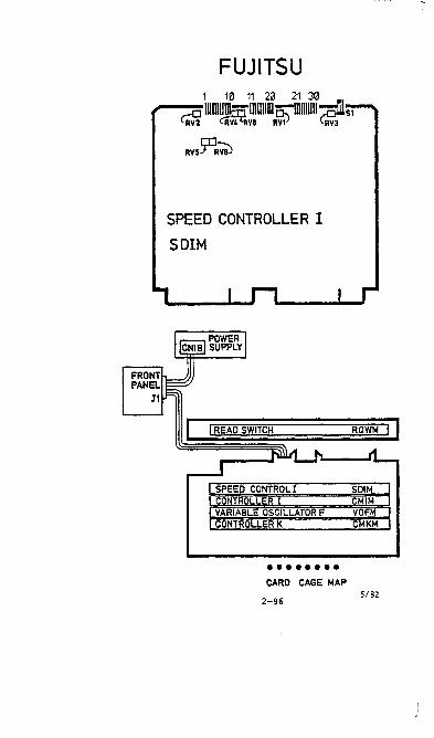
FUJITSU 1 10 11 2\3 21 30
~-_~O IUIIIUmmIllIlIlWn:-IDUIIIII-(,ofils1 l RVl cRV4'itva Rv1) RV3
RV55q~
SPEED CONTROLLER I
SDIM
I READ SWITCH
SPEED CONTROL I CONTROL LER I VARIABLE OSCILLATOR F CONTROLLER K
•••••••• CARD CAGE MAP
2-96
RQWM
SDIM CMIM VOFM CMKM
5/82

FUJITSU Note: All of the following adjustments are to be made on the SDIM board. Potentiometers rotate only 3/ij of a turn.
Position Signal Adjustment on SDIM (servo) Board
• Set up the scope as follows: CH 1 1 v/cm (10x probe), DC coupled CH 2 1 v/cm (10x probe), DC coupled Trigger on CH 1 POSe Horizontal 5ms/cm
• Type in the alternate seek instruction to seek between cylinders 0 and 512 as shown below:
For i68 mb: (IPL) Q0020 004080 1d1D90 006080 0020A7 (CR) Q0040 Od3030303030 (Ca) I For 84 W· I Q0060 Od3232383830 (XMIT Omit ld9l9D ~nd change Note: d = device number. 00960 to 0d3631343439
• Connect the channel 1 oscilloscope probe to TP19 on the SOIM (servo) board.
• Connect the channel 2 oscilloscope probe to TP7 on the same board.
• Observe channel 2 and adjust RV2 until the signal is B.Ov ± 0.4v peak-to-peak.
Note: If adjustments are so far off that the alternate seek will not run, use the RTZ (return to zero) command by repeatedly hitting IPL. Watch the scope and do the RV2 adjustment as described above. This should allow you to adjust the position signal accurately enough to allow the alternate seek to run.
'l'Pl9
TP7 A{ ]f\_ --=-v v_____ 0 __ --'-
2-97 5/82

FUJITSU Overshoot Adjustment on the SDIM (servo) Board
•
•
• For
•
•
Leave the scope probes and scope settings as they were for the previous adjustment.
Start with the same scope settings that you u~ed for the above tests.
Issue the alternate seek command as shown below to seek between cylinders 0 and 8:
168 mb: (IPL) Q0100 012080 014080 0100A7 (CR) Q0120 Od3030303030 (CR) Q0140 Od3031393230 (XMI!) Note: d = device number.
For 84 mb: Change Q0140
to 0d3030393630 Center the channel 2 trace about ground and then set the, channel 2 scope voltage selector to .Sv/cm. Set the horizontal sweep selector to 1ms/cm to superimpose the forward and reverse overshoot traces.
Adjust RV4 so the larger of the two overshoot signals is 1.0v above or below ground. (as shown in the illustration). Set the adjustment as close as pos~1ble to zl.Ov (be sure not to exceed 1.0v) as fastest seek ~imes occur as 1.0v is approached.
"~PERFECT OK mu u-u----_ •• ~v -)?:;--- O.K
- ------1v --- - ---------
5/82 2-98

FUJITSU Positioning Time Adjustment on the SDIH (servo) Board • Use the alternate seek command as shown at
the beginning of the "Position Signal Adjustment" section to seek between cylinders 0 and 512 (if the processor has been running continuously since the beginning of these adjustments, IPL and branch to address 0020 by typing: 0020A7 [XMIT]) •
• Leave the channell probe on TP19. Set the channel 2 voltage selector to lv/cm and the horizontal sweep to 2ms/cm.
• Connect channel 2 (DC coupled) to TP26 and trigger on the negative edge of the channel 1 signal or on the positive edge of the channel 2 signal (one may be easier to sync on than the other).
• Observe channel 2 and adjust the deceleration time (Tdc) to 13ms Z lms by turning RV1. Be sure the entire waveform is visible on the scope. Be certain that both the horizontal and vertical are accurately calibrated, as this is a very critical adjustment.
• Connect channel 2 of the oscilloscope to TP30 and keep the channel 1 probe connected to TP19. Trigger on the positive edge of the signal on channell.
• Observe channel 2. Turn the channel 2 voltage sensitivity to 5v/cm and the horizontal sweep to 5ms/cm. If the horiziontal time base is uncalibrated, it will enable observation of the entire waveform.
• Check the Vdc amplitude (deceleration amplitude) of the signal on channel 2. It must be 6.0v or less. Adjust RV1 only if the signal is greater than 6.0 volts. This will slightly increase the deceleration time measured at TP26, but this is acceptable.
• Go back and check the overshoot adjustment. Readjust if necessary (IPL and branch to 0100-- by typing: 0100A7'[XMIT]-- to seek from 0 to 8).
2-99

TP30
FUJITSU
TP19
TP26 I I
I , , ,
, , "",~ ,
-6.8v ± 0 .2v 1.---------11-- Tdc
~-11 V DC
Tdc-13ms ± 1ms
eOMPLETE SIGNAL LOOKS LIKE THIS. MEASURE THE LOWER. CURVED PEAKS AS SHOWN ABOVE..J
2-100


IOU-4 PERTEC
NOT READ-AFTER-~IRITE
QANTEL MODEL 5200
ADDRESS SWITCHES O-F MAX. P't.'R. REQUIREMENTS
-12v= .03A + 5vs 1.69
Tape Uni t Pwr.
115 vac 60 Hz 2.OA for .1 sec. 0.8A normal
800 BPI 12.5 IPS MAC1ETIC TAPE ~IODULE
I~RITE CONTROL INSTRUCTIONS
lXYY9D
CONTROL BYTE
00 01 02 03
x - DEVICE ADDRESS
FUNCTION
SET ERASE
IT - CONTROL BYTE
SET CHECK READ SET BACKSPACE SET REWIND
STATUS IN INSTRUCTIO:-lS
4XYY9D
STATUS BYTE
01 02 04 08 10 20 40 80
x - DEVICE ADDRESS yy. STATUS BYTE
MEANING
READ BUSY WRITE BUSY END SERVICE REQUEST l-IAGNETIC TAPE ALAP.J-I (ERROR) ILLEGAL BLOCK LENGTH E. F. M. I E. O. T. I LOAD POINT INOr.
3-1 5/82

IOU - 20A/B KENNEDY / PERTEC 800 BPI READ-AFTER-vIRITE
c=:--.
t ).. 3.84 I 2 DRIVES n n l -W .M . . H. Z L,
" ;-2!§ lily 75 0 T' D~TAL ~ CONTROL • ~ SWITCH 2S/J7.S 2S M SPEED SWITCH
3014 DRIVES
ADD. SWITCHES
NOTES:
QANTEL MODEL 5201
'·~-'·~\.PI.'R. REQURED
+5v ~ 2.3SA
T .;?E D? i VE P\· .. "F ••
t~E::-&ned\~
~oOHZ 4.2A for .1 sec. 2. SA normal
Per tee Tl5~c &0 Hz 5.DA for .1 sec. 2.5A normal
JOU- 20 CA:' DAISY CHArK ll? TO 4 ~~;G TAPE U~;rTS. THE SWITCHES TELL THE SYSTEl-i Ifi" !;U~:Bi:R OF DRIV:;:S ATTACii:::D.
THE IOU -20 CAN HAj,DLE ~I;HER 25 ips 3i.5 ips or 7S ips.
NRITE CONTROL IX57RUCTIO:-':S
CONi?OL BYTE
00 0] 02 03 04
X a DEVICE ADDRESS YY ~ COi'iTROL un·:::
FUl.JCTJO~
SET ER.~SE SET CHF.C;: ~r:AD SET IlACi:S;',\C[ SET RE:11 ::0 SET U:\LC,\D (REWlS!; ;,~;D 0;:;: LIXE)
STATUS 11\ !N5TRUCT!CNS
4XH9D
STA7US BYTE 01 02 04 08 10 20 ':0 80
x = DEVICE ,\DDRESS Y¥. S7.'.TUS bYTE
~!EANI~G
READ RUSY l':Rlii: BUSY EN!) SER\'! CE I:EQUEST ERROR ILLEGAL IlLOCK LENGj·H iNg/· I E.iLT. / LOAD PO]:/!
3-2 5/82

2 DRIVES
U U 3014 DKIVES
NOTES:
IOU-21A/B KENNEDY / PERTEC 1600 BPI PHASE ENCOLIED
.~ ~J''' m W 1-~ONTROL I ~ *' t SWITCH 25/37.5 2S I
SPEED SWITCH ....
ADD. SWITCHES
o~ .... ::;) .... 0 ~O ~
QANTEL NODEL 5211, 5212
~IAX. P0\1ER REQUIREf-1ENTS
+l2v ,. .01A + 5v = 3.78A
TAPE DRIVE PI."R. K"nnedv ~60Hz 4.2A for .1 sec. 2.8A normal
Pertec "iT57ac 60 Hz Z.OA for .1 sec. l.OA nor,"-a1
THE IOU-2l C..I.:, DAISY CHAIN UP TO 4 ~·!AG TAPE UNITS. THE SWITCHES TELL THE SYSTEN THE :W:·:BER OF DRIVES ATTACHED.
THE IOU - 21 CAN HANDLE E IT:;ER 25 ips 37.5 ips or 75 ips.
WRITE CO!'lTROL INSTRUCTIOXS
lXYY9D
CONTROL BYTE
x • DEVICE ADDRESS
FUNCTION
00 SET ERASE 01 SET CHECl( READ 02 SET BACKSPACE 03 SET REliI'lD
YY z CON7ROL BYTE
04 SET UNLOAD (REI;'Il\D AXD OFF U'lE) STATUS IN INSTRl'CTIO'lS
4XYY9D X z DEVICE ADDRESS YY = STATUS BYTE
STATUS ~lEANING BYTE
01 READ BUSY OZ WRITE BUSY 04 END 08 SER"! CE REQUEST 10 UNCORRECTAOLE ERROR 20 ERROR CORRECTlO~ rERFOR.~IED
40 B.O.T. / E.O.T. / LOAD POINT 80 II"OP.
00 ~1r",1 ~fr..j..I)S 3-3 5/82

3014 DillVES
NOTES:
IOU-20A/B DIGI- DATA
800 BPI NRZ 45 IPS c==-=-...
ADD. SWITCHES
QAtI. TEL HODEL 5203
:~AX It-rur·' PO'iIER REQUIRH1E~T
... 12v .01A
... 5v = 3. 7SA
T,!IPE DRIVE PO\':ER 115 vac 60 Hz 1 .73A NORHAL
THE IOU-20A C,!IN DAISY CH,!IIN UP TO 4 i-lAG TAPE UNITS. THE S:'IlTCHES TELL THE SYSTEf·' THE NUi·13ER Of DRIVES ATTACHED. THE IOU-20A CAN HANDLE EITHER 25 ips, 37.5 ips, or 75 ips.
I'IRITE CONTROL INSTRUCTIONS 1dyy9D d = D£I.'ICE ADDRESS yy = CONTROL BYTE
CO'iTROL BYTE 00 01 02 03 04
FUNCTIOi"
SET ER,!ISE SET CHECK READ SET BACKSPACE SET REWIND SET UNLOAD (REWIND AND OFF LI'JE)
STATUS IN INSTRUCTIONS 4dyy9D d = DEVICE ADDRESS yy = STATUS BYTE
STATUS BYTE
01 02 04 OS 10 20 40 80
MEANING
READ BUSY I~RITE BUSY END SERVICE REQUEST ERROR ILLEGAL ALOCK LE'JGTH B.O.1. I E.O. T. I INOP.
3-4 5/82

2 DRIVES
U U
3 oa 4 DRIVES
NOTES:
IOU-21A/B DIGI-DATA
1600 BPI PE 45 IPS
4~ ~2J-4 75 37.5 m 1-2 1 n ~
CONTROL I r SWITCH 25/37.5 25
S?EED SWITCH ....
ADD. SWITCHES
o~ .... ::> .... 0
~~
QANTEl l"ODEl 5213
t<1AXIr4UI4 PO~IEq REQUIREr-1ENT
+12v = .01A + 5v = 3.78A
TAPE DRIVE PO\'IER 115 vac 60 Hz 1 .73A NORt<1Al
THE IOU-21 A CAN DAISY CHAIN UP TO 4 l·lAG TAPE UNITS. THE SWITCHES TELL THE SYSTEM THE NUI-1BER OF DRIVES ATTACHED. THE IOU-21A CAN HANDLE EITHER 25 ips, 37.5 ips, or 75 ips.
WRITE CONTROL INSTRUCTIONS 1dyy9D d = DEVICE ADDRESS yy = CONTROL BYTE
CONTROL FUNE:TION BYTE 00 01 02 03 04
STATUS 4dyy9D
STATUS BYTE
01 02 04 08 'io 20
i~
SET ERASE' SET CHECK READ SET BACKSPACESET REWIND SET UNLOAD (RE\HND AND OFF LI"lE)
IN I"lSTRUCTIONS d = DEV ICE ADDRESS yy = STATUS BYTE
t4EANING
READ BUSY WRITE BUSY END SERV ICE REQUEST UNCORRECTABLE ERROR ERROR CORRECTION PERFOR~1ED' B.O. T. / E.O. T. / E~D FILE INOP.
5/82


PERTEC
PERTEC TRANSPORT ALIGNI-lENT
The mechanical/electrical adjustments for the Pertec 5200 (BOO BPI, 12.5 IPS), 5201 (BOO BPI, 25.0 IPS) and the 5211 (1600 BPI P. Eo, 25 IPS) are included in the following instructions.
Each check and/or adjustment should be performed in the order that it is given. This is important, as most adjustments affect much or all of the alignment that follows.
In most cases the minimum and maximum acceptable limits for adjustments will be defined within their particular adjustment procedure. If a value is checked and falls within the acceptable limits, no adjustments should be attempted. However, if a value does not fall within the acceptable limits, then and only then, should the adjustment be performed.
INSPECTION - 5200! 5201, and 5211
Careful inspection of the transport will actually save time and prevent minor problems from becoming major.
Visually inspect and check the following:
• Inspect the Head and all Tape Guides; the Tension Arms for travel; Capstan; Roller Guides; and all Push Buttons.
5200 FIGURE
,----I I G::J \
CE:J I G::l i ~i c:::::J I
,.._~I ,-."" I g§51
'-----"
• Inspect all P.C. Boards; verify that they are properly seated.
• Inspect .il.rm Optics and miscellaneous i4echanical Items in back.
• Inspect all Holex Connectors (if any of the individual pin connectors have separated, crimp th~m back together).
3-7 SI7S

PERrEC
ELECTRICAL ADJUSTMENTS - 5200
PO~IER SUPPLY
The .51i and -'Ii regulators are located on the Tape Control A Board, see Figure 2 below.
• \'/ith the power on, use a DVt~ to measure the voltage between TP9 (.5V) and TP7 (OV, ground). The voltage should fall between +4.S5V and .S.15V.
• I f the voltage in the previous step doesn I t fall within the speci fied limits, adjust R1302 to .. 5V as seen on TP9 •
....... fP6
.rP'!S
FIGURE 2
.uII
UJI ... -TP1J. TP1Z ,
"?i'::::;; .'02BOI,ooJ) , ~40Z (OT ~J. !
• '\low use the DVM to measure the voltage between TPS (-5V) and TP7 (OV, ground). The voltage should fall between -4.S5Y and -5.15V.
• If the voltage in the previous step doesn I t fall within the speci fied limits, adjust R130S to -5Y as seen on TPS.
'\IOTE: On all Control Boards the EOT IBCT pots l11'.Jst be adjusted for zero ohms resistance before per forming adjustments on the Eor IBOr Amp Soard.
• Load a scratch tape.
• vlith the power ON, the tape should be tensioned but not at Load Point.
3-8 8178

PERlEC
ELECTRICAL ADJUSTI~ENTS - 5200
EDT IBOT CONTINUED
• Using a DV~l, connect the probes to TPZ4 (ground) and TPl (on the EaT IBOT amp board). See Figure 3.
• I f necessary, adjust R3 (on the amp board) to obtain between +4V and 4.ZSV on TP1.
FIGURE 3
• Again, using a DVH, connect the probes to TPZ4 (ground) and TPZ.
• If necessary, adjust R9 (on the amp board) to obtain between +4V and 4. Z,V on TPZ.
• Load a scrat.::h tape and apply power to the drive.
• Depress and release the LOAD control two times. The tape will advance to the load Point and stop.
• IPL the system and from device zero enter the following program:
0010nOl00000010F20100Bdld029D0006A7 (d = Device) TRANSmT ENTER 32 F's TRANSmT
3- 9 6/76

PERTEC
ELECTRICAL ADJUSHlENTS - 5200
RAMP CONTINUED
• Connect the scope probes to TP7 (ground) and TP6 (on the Tape Control A Board, refer to Figure 2).
• Observe the drive hubs, they should be rotating back and forth.
• The wave form (as viewed on the scope) should fall 30 ms ... 1, level off to zero and fall another 30 ms ... 1. The entire ;ave from should fall 60 ms. See Figure 4. -
F ~
" " ~
~ .,- ... FIGURE 4 ~
~ ~ ~
/-30 ms--I /-30 ms-j START STOP 10 ms/div.
• I f the wave form does net meet the values as stated above, adjust R913 on the Tape Control A Board until it is corrected.
• r·lount a SKEl-1 tape on the transport.
• To advance the tape, IPl the system and from device zero enter the following program:
0010F20100OdOGOOA7 (d = Device) TRANS~lIT
• I f the system is not available for use, load a SKEVI tape and then manually advance the tape beyond load Point. I f tape tension is lost. press Load Point twice and the tape will advance.
3-10 8li8

PERlEC
ELECTRICAL ADJUSTHENTS - 5200
SPEED CONTINUED
• Connect the scope probes to TPS (ground) and TP603 (Data A Board) • See Figure 5.
""" T~1._ .rn .TP3 .... TP101 efP102 @"" .TP103
...,.. i TP20'··ypzoz ~R2" eTP20} • rpzo~ TP6e l
d C'oO i
TP.,Ol·.TPJ02 TP10'j-,
-rPJ04 TP20~'f= ~RJ11 • TPJQ}
TP30S.\ rp~l·.rp'-GZ • R411 .rp~J !
'P50' •• ~ TP40S·t
eYP50!& TP50S·; TP6ll,T~:C2i~ ~R5tl • TP';QJ
(P70,T:6025; • q611 .TP60J TP60S-;
rp70S-'
'=' -TP7G2 @Fl711 .TP1'JJ
• TP704 TP805e, :
TPBOle. TPS02 ,. Ra1' _IPeO) TP9C5.'P
TP9IJ1-· yP9QZ -rP9Q4
"TP5 ~R911 erMO)
FIGURE 5
• The wave form (as viewed on the scope) should appear as in Figure 6. The distance between the peaks must be .2ms.
r·2m'l t 1 r ~ I 1
I
I ..... I I I
I I ~ I 1 FIGURE 6 I "~ 1 \
I I
I I -I U [)~ iJ i I i
I I
! i I i i I
• If the wave form does not meet the above value adjust R1001 on the Tape Control A Board until it is corrected. Refer to Figure 2.
3-11 8/78

PERTEC
ELECTRICAL ADJUSTMENTS - 5200
READ AI·1PS
• Load a scratch tape.
• Advance the tape to Load Point.
• IPL the system and from device zero enter the following program:
0010F'30100000010F20100Bd0006A7 (d = Device) TRANSIHT Enter - 32 F's
• Allow the program to run for a good portion of the tape. This procedure creates an I all ones I tape.
• Rewind the tape back to the Load Point.
• IPl the system and from device zero enter the following program:
0010F201000dOOOOA7 (d = Device) TRANSrHT
• Connect the scope probes to TPS (ground) and TP103 (Data A Card). Refer to Figure 5.
• The wave form (as v iewed on the scope) should appea r as in Figure 7. The distance from peak-to-peak must fall between 10.0V to 11.0V.
lo.OV
TO
1l.0V
L
! fi
i
I i
!
! ! i
i :e i -!
...... ::
! ~ o' ....J
I I ::
;
-!
FIGURE 7
3-12
I J
i I I
! I !' I
! I I I
I I I! I ! I
I t
I J 1 I I
8/78

PERTEC
ELECTRICAL ADJUSHIENTS - 5200
READ M~PS CONT INUED
• All Read Test Points must be checked in the manner described above. Check points TP103-TP903 (on the Data A Board).
• I f any of the wave forms do not meet the above value, adjust the proper pot R111-R911 on the Data A Board until they are corrected.
• Hount a SKEW tape on the transport.
• Advance the tape to Load Point.
• Connect the scope probes to TPS (ground) and TP3 (Data A Board).
• Display one full waveform, as in Figure 8.
FIGURE 8
TIME
• FAlL TIME MUST BE LESS THAN ONE DIVISION
• The distance between the rise and the fall cannot be more than five (5) of the small divisions.
• Perform the adjustment by shimming one of the guides on either side of the head. ONLY SHIM ON[ OF THE GUIDES. There should ~ be shims under both guides.
3-13 8/78

PERTEC
ELECTRICAL ADJUSmENTS - 5201 AND 5211
POWER SUPPL Y
The +5V and -SV regulators are located on the Tape Control B1 Board (see Figure 9) •
1 :
• TP1 TPJ • TPl.I.-
• TPS • TP6
rp7.
FIGURE 9
• With the power ON, use a OVf.1 to measure the voltage between TP17 (+5) and TP24 (OV, ground) on the Tape Control Board. The voltage should fall between +4.8SV and +5.1SV.
• If the voltage did not meet the above values, adjust R1202 (+5) on the Tape Control Board to +SV as seen on TP17.
• Now use the DVt1 to measure the voltage between TP23 (-5V) and TP24 (OV, ground) on the Tape Control B1 Board. The voltage should fall between -4. 85V and -5. 1SV •
• If the voltage in the previous step did not fall within the specified limits, adjust R1208 on the Tape Control B1 Board (Figure 9) to -5V as seen on TP23.
NOTE: On all Control Boards the EDT/BOT pots must be adjusted for zero ohms resistance before performing adjustments on the EDT/BOT Amp Board.
• Load a scratch tape.
• I'lith the power ON, press the LOAD control one time. The tape should be tensioned but not at load point.
3-14 8/78

PERTEC
ELECTRICAL ADJUSHIENTS - 5201 AND 5211
EOT /90T CONTI~UED
• Using a DVr·l, connect the probes to TP11 (ground) on the Data C9 90ard (Figure 10) and TP1 on the EOT/90T Amp Board (see Figure 11).
IS 8
!
I: I: , I
r;; n,1 TP3 "Tr~ TP9 TP1" "';,J
R18 RJZ TP4"" TPS " TP10
TP103"
TPZ03 "
R112 " TP1Z @
TP10"
R~Z ~ TPZ04"
TP7"" TP8 TPJOJ" RJ12 TPJ04
TP101" "~Pl02 R412 TPZ" TP201" "TPZ02 TP4OJ" ~ TP~04 "
~ TPJ01" " TP30' i TP50J :;12 TPS04 "
TP401 " ~ ~ TP60J R.~2 lP604"
~:6S00~ : ~ "@ TP7~" TP70J R712
TP701" " TP702 R81Z
TPS01" "TPS02" TP11 T~OJ @ TPB04" "TP13 " @ TP90~"
TP903 R912 TP901 " • TP902
FIGURE 10
FIGURE 11
TP14
TP10;'
TPZOS'
TPJOS"
TP40S"
TPSOS"
TP60S"
TP70S"
TP80S"
TP90S'
1 : T~lS i:
TP106 .~ TP16 • e\
! I TPZ06". i TPJ06 "' I
~ TP~6 .
TP506 "
TP606 " TP706 •
TP806 • TP906 •
• If necessary adjust R3 (on the Amp Board) to obtain between ... 3.95 and 4.05V on TP1.
• Again, using a DVr~, connect the probes to TP11 (ground) on the Data C9 Board and TP2 on the EOT /90T Amp Board.
3-15 BI7B

PERTEC
ELECTRICAL ADJUSTI1ENTS - 5201 AND 5211
EDT IBOT CONT INUED
• I f necessary adjust R9 (on the Amp Board) to obtain between +3.95V and 4.05V on TP2.
• Load a scratch tape and apply power to the drive.
• Depress and release the LOAD control two times. The tape will advance to Load Point and stop.
• IPL the system and from device zero enter the following program:
0010F301 0000001 OF20100Bd1d029DOO06A7 (d = Device) TRANSIHT Enter 32 F's TRANSHIT
• COrv1ect the scope probes to TP11 (ground) on the Data C9 Board (Figure 10) and TP1B on the Tape Control B1 Board (Figure 9).
• The wave form (as viewed on the scope) should fall 15ms +1, level off to zero and fall another 15ms =' (see Figure 12).
;
- ~ ~ ~ ,:
FIGURE 12 ., , r ~
'" F-
!--15 IIIS-l !-15 mS-1 START I I STOP I 5 ms/div
t If the wave form does not meet the values as stated above, adjust R1113 on the Tape Control B1 Board (Figure 9) until it is corrected.
3-16 8/78
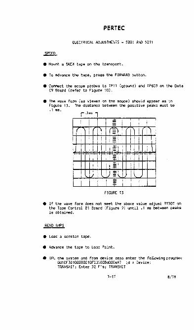
PERTEC
ELECTRICAL ADJUSTt-IENTS - 5201 AND 5211
• f40unt a SKEW tape on the transport.
• To advance the tape, press the FORWARD button.
• Connect the scope probes to TP11 (ground) and TP603 on the Data C9 Board (refer to Figure 10).
• The wave form (as viewed on the scope) should appear as in Figure 13. The distance between the positive peaks must be .1 ms.
r·1m'l
I ! /'
I i I " -: I I I
I - I
,I ~ i
I "~ L I I i I I
I I ! = I 1 :;: !
I i t i FIGURE 13
• If the wave form does not meet the above value adjust R1501 on the Tape Control B1 Board (Figure 9) until .1 ms between peaks is obtained.
READ Af·1PS
• Load a scratch tape.
• Advance the tape to Load Point.
• IPL the system and from device zero enter the following program: 0010F30100000010F20100Bd0006A7 (d = Device) TRANSI4IT; Enter 32 F' s; TRANSMIT
3-17 8/78

PERTEC
ELECTRICAL AOJUSTI£NTS - 5201 AND 5211
READ AI~PS CONT INUED
• Allow the program to run for a good portion of the tape. This procedure creates an 'all ones' tape.
• Rewind the tape back to Load Point.
• Connect the scope probes to TP11 (ground) on the Data C9 Board (Figure 10) and the following test points, depending upon which drive is being adjusted:
5201 - TP103 on the Data C9 Board. 5211 - TP104 on the Data H Board (see Figure 14).
I • TP104
~ I
[ R1170
• TP204
• TPJQII. RJ17 0 a
• TP404 j R5170 • TP504
• TP604
I R717 0 • TP7Q11.
\
I • TPS04
I R917 0 • TP90lI
1.1 G'lO 11 eM).
FIGURE 14
• Take the transport OFF LINE and push the FORWARD button.
• The wave form (as v ie\Oed on the scope) should appear as in Figure 15. The distance from peak-to-peak must fall between the following vol tages:
5201 - 10.0V to 11.0V 5211 - 5.0V to 6.0V
• Check all the Read Amp Test Points as described above. The follOWing Test Points must be checked:
5201 - TP103 to TP903 on the Data C9 Board. 5211 - TP104 to TP904 on the Data H Board.
3-18 8/78

PERTEC
ELECTRICAL ADJUSmENTS - 5201 AND 5211
READ A~lPS CONT INUED
lO.OV S201 - TO
1l.0V
S.OV S211 - TO
6.0V
L-
f
~ "
* ==
I ~ ~
I~
= 1/ ~
== FIGURE 15
I i I
i I
I I
I
"
• If any of the wave forms do not meet the correct values, adjust the proper pot until it is corrected.
5201 - R112 to R912 on the Data C9 Board 5211 - R117 to R917 on the Data H Board
READ STATICISER DENSITY - 5201 TRANSPORT ONLY!
• Generate an I all ones I tape as in the Read Amp procedure.
• Rewind the tape back to Load Point, take OFT LINE and push the fORWARD button.
• Connect the scope probes to TP11 (ground) and TP10 on the Data C9 Board (Figure 10).
• Observe the wave form at TP10. It should appear as in Figure 16.
• .:\djust R32 on the Data C9 Board to obtain 25 usec. However, do not exceed 26.3 usee maximum or 23.7 usec minimum.
3-19 B/78

PERTEC
ELECTRICAL ADJUSTMENTS - 5201 AND 5211
READ STATICTSER DENSITY C01"TI"lUED J. ,
I ! ! :E I 1 T 1 I I ! I
..... 1/ ,/ ~ I
r I I :E ! I I il
II I. - I J /. FIGURE 16 "~ 'I ' i I
I i I I
! i ~ I i
I I
~ ; I i I
I I :;: ! i I :t: I I i
'- 25ul"'<". --I
~IRITE SKEW - 5201 TRANSPORT ONLY!
• Generate an 'all ones' tape.
• While the tape is writing and On line, connect the scope probes to TP11 (ground) and TP15 on the Data C9 Board (Figure 10) •
• Observe the wave form at TP15. I t should appear as in Figure 17.
~flflJl YES
N\ANO FIGURE 17
3-20 8/78

PERlEC
ELECTRICAL ADJUSTt4ENTS - 5201 AND 5211
I'IRITE SKE\'j CONTINUED - 5201 TRANSPORT ONLY!
• If necessary, adjust R18 on the Data C9 Beard until the waveform appears as in Figure 17.
• t-tount a SKEW tape on the transpc rt.
• Advance the tape to Load Point.
• Connect the scope probes to TP11 (ground) and the following test points:
5201 - TP15 on the Data C9 Board 5211 - TP10 on the Data H Board.
• Display one full waveform as in Figure 18.
FIGURE 18
TIME
• FAlL TIME MUST BE LESS THAN ONE DIVISION
• The distance beb~een the rise and the fall cannot be more than five (5) of the small divisions.
• Perform the adjustment by shimll)ing one of the quides on either side of the head. ONLY SHIt-1 ONE OF THE GUIDES. There should never be shims under both guides.
3-21 8/7B

PERTEC
MECHANICAL ADJUSTr4ENTS - 5200, 5201 AND 5211
NOTE: Before attempting any of the following adjustments, thoroughly clean the tape path and then check the transport for proper operation. If a problem exists, proceed with the necessary adjustment.
TENSION ARN LIMIT SWITCH
SHUTTER FIGURE
• Loosen the cam retaining set-screw.
SUPPLY TENSION ARM SENSOR
• Rotate the cam on its shaft until the limit switch roller is in the position shown in Figure 19.
• Tighten the cam retaining set-screw.
'IjOTE: The set-screw must be tightened sufficiently to prevent rotation of the cam when the tension arm strikes against its backstop.
3-22 8/78

PERTEC
MECHANICAL ADJUSHlENTS - 5200, 5201. AND 5211
TENSION ARI4 LIm T S\'iITCH CONTINUED
• The limit switch plate should be rotated to a position where the limi t swi tch trips when its roller is one-half of the distance up the slope from its rest position.
• The switch should be closed when the roller moves on the cam lobe between the semi-circular cutouts.
TENSION ARM SENSORS
NOTE: The +SV and -SV Regulators, Ramp Timing and Tape Speed must be correctly adjusted before adjusting the tension arm sensor.
• Remove tape from the transport.
• When adjusting the sensors. they should be shielded from high concentrations of light.
• Loosen the retaining nut securing the optical shutter to the tension arm shaft. See figure 19.
• Loosen the nut so that the shutter can be rotated by hand, yet tight enough to prevent the setting from changing when the nut is tightened.
• Apply power to the transport.
• ~otate the shutter until moving the tension arm to the middle of its range stops reel motion.
NOTE: The LOAD control must be continuously depressed or the Limit Switch shorted to perform this procedure.
REEL SERVO BELT TENSION
• Loosen the three screws that secure the motor mounting plate to the deck standoffs.
3-23

PERTEC
MECHANICAL ADJUSTMENTS - 5200, 5201 AND 5211
REEL SERVO BEL T TENSIO~ CONTINUED
• Adjust the pulley so that the timing is snug. Note the last belt tooth that is completely seated in a slot on the large pulley. See Figure 20.
IIFOII MU DffLfCTION. LAST rOQ1'H fNGAGlD
FIGURE 20
• Count two to three teeth from the last engaged tooth. Hold the large pulley to ensure that it does not turn. Depress the toothed belt at the point between the second and third tooth with sufficient force to deflect the belt against the gear.
• Adjust the drive motor assembly so that the second tooth is firmly engaged in a slot on the large pulley, but the third tooth is not engaged.
• Tighten the three screws on the motor mounting plate.
TAPE CLEANER
• Remove the screw holding the tape cleaner to the transport and loosen the two screws which hold the cleaner blade to the housing.
• Use a cotton swab moistened in isopropyl alcohol to clean the blade and hOUSing.
• Be sure that the tape cleaner blade surface is parallel to the tape when mounted on the deck.
3-24 8/78

KENNEDY The following instructions include mechanical and electrical
adjustments for both the sao bpi and 1600 bpi Kennedy tape transport~. All of the mechanical adjustments are identical between the t .. o types of r~cording systems, and most of the electrical adjustments are also the same. Ioihere differences exist between types, the differences are indicated within the text.
~Iake each check or adjustment in the order that it is given, checking and/or performing all of thi! adjustr.1ents that follow. This is important. as most adjustments affect much or all of the alignment that follows.
Access to the internal test points and adjust:r.ents (on the printed circuit cards) is gained from the front (operator side) of the transport. To expose the printed circuit boards, release the captive screw directly below the head assembly, and swing the entire panel and mechanism outward.
The following adjustments are used to align th~ tape handling hardware. Before making the adjust::,.ent, check for proper operation as described at the beginning of each procedure. Adjust if needed, but only when needed.
Tape Path
• Tape should wind evenly on the center of the takeup reel with no tendency to pile \,Ip toward one side or the other.
The tape should enter the roller guides con:ectly, exerting equal pressure on both the inside and outside edges of the tape.
Adjust as follows:
• Remove the roller guide that is to be adjusted.
• Temporarily replace the guide with a short length (about 4") of 18-8 or other non-magnetic stainless steel ground stock that is .1875" (3/10") diameter.
• Loosen the roller guide adjustment lock screw (A in the drawing below) slightly until the rod can be moved with modera te pressure.
'0 ADJUSTMENT N;;T .. WASMER
3-2.5

KENNEDY • Thread the recording tape over the rod.
• While holding the rod, run the tape forward. Adjust the angle by tilting the rod back and forth until the tape has equa 1 tens ion towa rd the edges, and enters the guides (or ree I) properly.
• When the rod is positioned correctly, tighten the lockscrew. Leave the tape threaded for adjustment below.
Replace and Adiust Roller Guide (after adjusting angle, above)
• Loosen the roller guide retaining screw (item C in the illustration on the previous page). Do ~ loosen item A.
• Insert the roller guide shaft until part of the threaded portion of the shaft protrudes from the other side. Then lightly snug the clamping (retaining) screw, C.
• Place several number 10 flat washers over the threaded portion of the shaft, and install a 10-32 nut.
• Using the 10-32 nut as a fine adjustment, tighten until the roller is aligned (centered on the tape). If this adjustment is moved too far, loosen the clamp screw (C) again and the 10-32 nut to re-position the !haft for another try.
Idler Alignment
• The tape should track at the same place on the capstan dt:ring forward and backward operation.
Adjust as follows:
• Loosen the locknut on the idler adjustment screw (see the illustration below).
LOCK NuT
3-26

KENNEDY • Loosen the collar setscrew (refer to the illustration
on the previous page).
• Adjust the idler adjusting screw until the tape tracks at the same place on the capstan in either direction.
• Re-tighten the collar screw and the locknut.
Head Face Shield Adjustment
• Remove the tape from the transport and lift the shield as shown in the illustration below.
LOAD POINT/ END OF TAPE
SENSOR
TAPE GUIDE
:otISSING TAPE SENSOR
NOTE: Head cover removed for clarity.
• Loosen the stop screw on the face shield.
• Insert .006" thickness of tape (three layers of .002" tape) between the shield sllrface and the head. Do NOT use feeler gauges; metal will destroy the head by scratchini it'.
• Compress the shims firmly by holding the shield toward the head, and tighten the the stop screw.
• Lift the shield and remove the tape pieces.
3-27

K~NNEDY
ELECTRICAL ADJUSTMENTS AND C~ECKS
r:::
<D®@@@@
j J .il]J. :r~
. I~
A-HOv I -lOv C +5v
L
Power SupplY Voltage Cheeks
;;.;0 _PI Write Des~;ew switch settings for reco_·d llead.
Preamp Adjus tment! and Test points
Power supply voltages should be checked at the test points shown in the illustrations above. The plus and minus 24v (case of Q8 and Q9 on AS) will be a nominal + 20v under light load. The LOy supplies should be regulated to within ± .5v. The +5v should be adjusted if necessary to within ± .25v.
3-28 Revised 3/77

KENNEDY Tape Speed
The following adjustment is one of the most important and most neglected of the entire procedure. The adjustment is exactly the same for 800 bpi and 1600 bpi transports. The 800 bpi Skew Mas ter tape is used for both types.
• Mount the Skew Master tape onto the transport.
• Connect an oscilloscope probe to one of the preamplifier test points. The preamplifier printed circuit board is located on the back of the "swing out" portion of the transport front panel (shown on page 3-7).
• Start the tape reading in a forward direction.
• Adjust the NORMAL SPEED pot, R14, on the Ramp Generator printed circuit board until the waveform shows lOOusec for each sinewave. The sinewave may not be entirely stable on the screen because of small rapid speed variations.
Ramp Time
RAMP GENERATOR
STOP RAMP
START RAMP
NORMAL SPEED
::I-"----TE5T POINT A
TEST POINT B ~==~~~~~----GROUND
• Load a scratch tape onto the transport. and place the uni t ON LINE.
• Connect an oscilloscope probe to TEST POINT A (see the illustration above).
• From system device zero, enter the following program:
0020 no 100000100 a ~ CARRIAGE RETURN 0 r TERMINATE 0010f20aOObxlx029d0010f20aOOOxlxOi9d0109a7 CARRIAGE RET.
x .. Tape controller device number.
or TERMINATE
• The waveform should appear as shown; adjust the START and STOP ramp times by using pots R3 and R4 (labeled START and STOP in the illustration above).
I
I
I -.... iSms STOP
3-29

KENNEDY Photo Sensor
• Verify by looking at the light source that both lamps are lit.
• Connec t a dc vo l tme te r be tween tes t po in ts E and F t'n the sensor amplifier/driver module (see below).
<D®@@®®
J 1q .
Vi ~,~~
,--NOTE \
: Tape should NOT be . mounted in the drive I . for this check or ;
~:""or-I . : adjus tment. I
R 16i . ...-' -----
... • Vary potentiometer Rl6 until there is zero voltage
between the two points.
Caps tan Se rvo
• Test the capstan for proper operation as follows:
The capstan should never "creep" when it should be standing still.
Load a tape and advance to the LOAD point. Gently irasP the capstan and try to rotate it in either direction. The resistance to rotation should be the same in both directions. A small "dead" zone should be felt midway between the resistance to rotation.
Adjus t as fo 110w5:
• With the tape at LOAD point. adjust the ZERO ADJUST potentiometer until there h zero volts between TPA and chassh ground.
o o
3-30
CAPSTAN
SERVO
.OARD
Revised 3/10/76

KENNEDY Reference Freguencv (1600 bpi Transport Onlv)
• Load a scratch tape onto the transport (include a Write Enable ring).
• Place the transport into the TEST MOQE.
• Place an oscilloscope probe on TEST POINT A of the READ CONTROL printed circuit board.
• Depress the ';RITE TEST button on the test "anel.
• Adjust the REFERENCE FREQUENCY, Rl, on the READ CONTROL board until the frequency is 320 kHz, or 3.lusec for a single cycle.
Read Level
• Load a sc ra tch tape (wi th a Wri te Enab le ring) on to the transport. DO NOT USE THE SKEW TAPE.
• Place an oscilloscope probe on the test point for Read Preamplifier Channei 1. The Read Preamplifier test points and adjustments are on the back of the "swing out" panel (see illustration on page 3-7).
• Place the transport into TEST MODE.
• Depress the WRITE TEST and FORWARD RUN but tons.
• Adjust the potentiometer tq make the signal 5v::!: O.Ov for 1600 b.p. L drives or 9v ::!: O.Ov for 800 b.p.i. drives.
Notes: 1. There will be some crosstalk noise from the write heads,
ignore this effec t. 2. The amplitude is approximately 10'7. higher in the Read
After-Wri te mode because of magne tk remnance in the write and erase heads.
• Adjust the remaining channeJ.s by moving the test probe to each channel and adjusting in the same manner.
Skew Adjustment
• Load the Skew Master tape onto the transport and place the unit into the TEST MODE.
• Place an oscilloscope probe on the test point at the bottom of the test panel.
• Depress FORWARD RUN. The pattern will be a grouping of nine pulses that are repeated (similar to that below).
1'01 11 I~!iij • Adjust the skew until the grouping
is as small as possible.
3-31 Revised 3/10/16
SI[. ""115''':''' SC.hl

KENNEDY
Write Skew (800 bpi Transports Only)
The write skew is a digital delay that is controlled by a four-swi tch se lee tor for each channe l that is adjusted. All channels are referenced to the P (parity) channel which has no adjustment.
• Perform the Read Skew adjus tment as given on the previous page. Connect an oscilloscope probe to the P (pari ty) channel on the Wri te Amplifier Module. See the illustration below for test point locations •
• Mount a scratch tape on the drive. Be sure that the scratch tape contains a Write Enable ring.
• Connec t a second osc i lloscope probe to the CH 5 test point. ChannelS is one of the outermost channe is on the tape.
• Set the oscilloscope to trigger on the P channel test point (CH 1, INT), and ALTernate sweep.
• With the unit in the TEST MODE, depress WRITE and FORWARD RUN.
• Se t the CH5 deskewing swi tches for a minimum seperation between the two displayed peaks.
• Move the probe from CH5 to CH4. Channel .. is the other outer extreme track on the tape.
• Use the CH4 deskewing swi tches to minimize the seperation between peaks.
• Adjust each channel in the same way as above.
CD CD
IEID WilT[ ""LlF lEI l"'~ I F lEI !!oDULE~ MODULEI
Deskewing switches are located on ·:oards band 7.
3-32 Revised 3/77

DIGI-DATA 1730
DIG I-DATA TRANSPORT ALIGNt'IENT
The mechanical/electrical adjustments for the 800 bpi and 1600 bpi Digi-Data tape transports are included in the following instructions. t40st of the adjustments for the two types of transports are the same. However, some differences do exist and are noted in the text.
Each check and/or adjustment should be performed in the order that it is given. This is important, as most adjustments affect much or all of the alignment that follows.
INSPECTION
Careful inspection of the transport will actually save time and prevent minor problems from becoming major.
Visually inspect and check the following:
.Inspect Flux Gate and Heads; both Tension Arms for travel; Reel Hub; all Tape Guides; and all Push Suttons.
FIGURE 1
• Inspect EDT ISOT Sensor j the BEC P. C. Board gn back of panel); all the Boards, verify seating and that boards are held in with (2) screws; and inspect the EDT ISOT pots on the RA-16 card (Verify that they are turned counter-clockwise, all the way).
3-33 5/82

DIGI-DAT A 1730
NOTE: To gain access to the MC-17 card, remove the two screws holding the card cage and swing it open.
CAUTION should be taken when replacing the screws if the power is ON •
• Inspect Arm Optics; miscellaneous Hechanical Items in back; the Harness (wire) in order; and the Write Enable Assembly.
7A F.B
+20Y 3A S.B
-20Y
EaT BOT AOJ.
1.5A S.B LINE
FWD. RE'i SERVICE
PA-16 RA-16 SWITCH MC-17
WRITE ....:::.::~ .. +r-+---t-tt-- ENABLE
ASSY.
FIGURE Z
INITIAL OffLINE CHECK AND .u,DJUSTMPH
Check that the input voltage noted on the transports model number tag and the actual line voltage at the intended installation agree. If not, refer to the Table below (figure 3) to rearrange the transformer taps. The transport is supplied with a standard U.S. power cord and polarized 3-prong plug. In other countries it may be necessary to remove this plug and install the locally required power plug.
TRANSI'Om.:rR PRm,'R~ C~~N£CTIONS ON TBI
HIGH SIDE GROUt\'O LOW SIDE
VOl lACE RANG[ TB1-1 TBI-2 T81-3 T81-4 TBI-5 TBI-6 95-115 VAC BR'I, YEL REO,GRN (ORN) (flUll
105-125 VAC BF.~!, YEL OR~j,BLU (RED) (GRN) 195-235 VAC 8P.N GREEN RED, VEL (0P.r\) (6lU) 205-2\5 VAC B'lN GREEN ORN, YEL (RED) (BLU) 215-255 VAC SRN BLOC ORN, YEL (REO) (GilN)
FIGURE 3
3-34 5/82

DIGI-DATA 1730
• Check all three fuses visually. (Refer to Figure 2 )
• Check/Adjust +12V, .:..1V (after 10 min. warm-up)(Refer to Fig.4)
• Check -12V and +5V, for .:. 5~ ••
• Check +5(s)V for 4.5 - 5.5.
• Check ARM P.C. for 5.6V.
You May Ground The Meter To The Chassis.
-5
fWO SP Rev sp
ZERO 15
RAMP -ReWIND
;:: ~ 12V c::::I ARM BULBS
» c r SUPPLY 47"'" ~ r,BOT/eOT 1O.t\ ":C:::l-- LEO SUPPlY
EgT/BOT SENSgR
..!.. 24 +I2VOC _-25 ARM PC
..:.. 27 .SISIVOC - 26 +SVOC
..... - 21 -12VOC
~ I
TU ARC ~ TU C!N SUP CEN
SUP ARC
FIGURE 4
• Thread a 10.5" reel of brown tape on drive and "load".
• Warm up for at least (1) minute.
• Locate the three-poSition service switch (see Figure 2 ) and run the tape forward away from the BOT mark.
• Refer to Figure 2 for BEC card location and check the voltage from ground to the EaT and BOT test points. It should be about 8. a volts. I f you use black tape it should be about 9. 0 ~
iP"7 ~ :;:; '''::;;/y' oo.g~'DV(ce,,~«eJJ f (35 rrz iF 8" I ,0 Cjrc' k}(e lip It
r~ t-o (ell disL cJJ' USfM~~

DIGI-DATA 1730
FIGURE 5
NOTE: The BOT and EDT pots on the RA-16 (1600 bpi Figure 6 ) card and the RC-11 (800 bpi Figure16) card must be turned all the way counter-clockwise before you adjust the pots on the BOT IEOT Sensor card. 00 NOT REMOVE ANY CARD FOR (1) MINUTE AFTER
THE POWER IS OFF!
FIGURE 6
3-36 5/82

DIGI-DATA 1730
EaT IBOT SENSOR CONTINUED
• Push Rewind (hold the button for one second). After the tape has reached load point, check the ON/OfF LINE pushbutton switch by pressing it repeatedly and verifying that the associated indicator light alternately glows and is extinguished.
• With the transport ON LINE, verify that the service switch is inoperable.
• With the transport OFF LINE, move the service switch to the FORWARD position. After several feet of tape have run onto the take-up reel, return the serivce switch to the NORHAL position; tape motion should cease.
• Hove the service switch to the REVERSE position. After several feet of tape have run onto the supply reel, return the switch to the NORf1AL position; tape motion will again ceas'!.
CAUTION: The service switch ignores the BOT and EaT markers.
• Use the service switch to run the tape forward again. Visually check all the tape path components for smooth operation.
• Check the arm positions. (1) maximun positions for forward and reverse, and (2) mid positions for stopped. NOTE: The punch marks on deck.
• Perform the previous two steps near EaT.
• After stopping the tape, place th" transport ON LINE, then press the RE\HND pushbutton switch. The transport will go OFF LINE and the tape will rewind until the BOT reflective marker is sensed. When rewinding, the tape will overshoot the load by several inches, and then return forward to the exact load point location.
• Use the service switch to again run fifty to a hundred feet of tape onto the take-up reel. Return the service switch to the NORf1AL position. Press the REWIND switch. After the tape has reached the full rewind speed, press the POWER switch off. The transport should stop smoothly without spilling the tape. Do this several times; make sure the tape stays on the guides.
• If possible perform the previous step on a small reel that is almost empty.
• Press the POWER switch on again. Press LOAD and REWIND simultaneously; continue to hold them down until the transport begins to rewind.
3-37 5/82

DIGI-DATA 1730
EDT /BoT SENSOR CONTINUED
• After the tape has returned to the load point, press REWIND again. The tape should unload at slow speed.
• Remove the tape from the transport.
• Important!! Since the service switch must be in the NaRI-1AL position for normal on-line operation, make sure that is where you left it.
'PRELIMINARY REEL SERVO SETUP
ADJUST ONLY If DRIVE DOES NOT flJllCTION PRaPERL Y.
• Put a piece of tape in the EaT/BaT Sensor and depress the LOAD button. The take-up and supply reel motors should rotate as long as the button is depressed.
• Hold the supply tension arm in the center of the available arc.
• Depress LOAD and ON LINE simultaneously. Verify that this causes the capstan motor to halt.
• With the supply motor turning and the arm held center, adjust the SUP CEN potentiometer to make the supply reel motor stop turning. See Figure 4 for the location of all pots and test points.
NOTE: rhe capstan must not be turning.
• Secure the supply arm so it cannot return to the rest position. A write ring looped around the arm roller and the nearby tape guide is a convenient way to accomplish this.
NOTE: If the supply arm is accidentally moved to either extreme of the operating arc, it will trip a microswitch which shuts down all motors. If this occurs, secure the supply arm, and press LOAD to start the motors. Then press LOAD and ON LINE to halt the capstan motor. The capstan motor must be halted to properly perform the preliminary arm centering adjustment.
• Check both extremes by doing the above.
• Hold the take-up tension arm in the center of its available arc and adjust the TU CEN pot to make the take-up reE;l motor stop turning.
• Load a scratch tape and press LOAD. The tape should advance to BOT and halt. If the arms move out of range and shut down the machine, ,adjust the TU ARC and/or SUP ARC pots counterclockwise to keep the arms within the operating area (see figure 4).
3-38 5/82
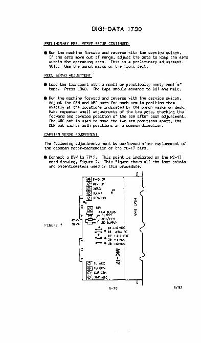
DIGI-DATA 1730
PRELIMINARY REEL SERVO SETUP CONTINUED
• Run the machine forward and reverse with the service switch. If the arms move out of range, adjust the pots to keep the arms within the operating area. This is a preliminary adjustment. NOTE: Use the punch marks on the front deck.
REEL SERVO ADJU5Tr'IENT
• Load the transport with a small or practically empty reelof tape. Press LOAD. The tape should advance to BOT and halt.
• Run the machine forward and reverse with the service switch. Adjust the CEN and ARC pots for each arm to position them .exactly at the locations indicated by the punch marks on deck. Hake repeated small adjustments of the two pots, checking the forward and reverse position of the arm after each adjustment. The· ARC pot is used to move the two arm positions apart, the CEN pot shifts both positions in a cornmon direction.
CAPSTAN SERVO ADJUSTt-1PH
The following adjustments rust be performed after replacement of the capstan motor-tachometer or the t4C-17 card.
• Connect a DVM to TP15. This point is indicated on the f4C-17 card drawing, Figure 7. This Figure shows all the test points and potentiometers used in this procedure.
FIGURE 7
.,
FWD SP ~ev SP ZERO 15
RAMP • REWIND
..., ~ 12V c::::l ARM BULBS
> C r SUPPLY 47.J'L i""'CJ"4 r.BOT/EOT IO.J'L ~ LEO SUPPLY
~
>
~ 24 +12vOC .--. • 25 ARM PC ..:.. 27 +'IS)VDC
·26 +'vOC -- .21 -12VOC
~ n I
TU "'RC ':i TU CEN SUP CEN
SUP ARC
3-39 5/82

DIGI-DATA 1730
CAPSTAN SERVO ADJUSn1ENT CONTINUED
• Turn on the tape transport.
• Adjust the ZERO pot to get zero volts on the meter.
• Put the meter on IPS, on the r·£-17 card •
. .-.... Forward speed. Load a SCRATCH TAPE on the machine. Press .• (' LOAD, and wait for the tape to halt at BOT.
• Place the service switch in the forward position. Adjust the FWO SP pot for the proper voltage on TPS, as per lable next to motor.
• Repeat for reverse speed •
.... ':lti"_.,Aitxiitb~
:-'}Oid a SKEW TAPE. ;0 • Set the scope to <2V/cm, ~us/cm) TPO-7 or TPP (on PA-16,
Figure 8) and measure speed for a 55.55 microsecond period to verify the adjustments.
• Repeat for reverse speed.
• Repeat for rewind, except verify for 16.67us. Set the scope to (10V/cm, 2us/cm).
FIGURE B
~ TPII.
,EI<9 . .. 17. rP7 • , . ... 5e l5e 4. ",e 2e Il. 2e.
'2. 11. '·1 ~~'- iP~:1 ~ ',' I
• TP9 SKEWS:
• TPI9 CHO e 20
e 21
e 22
• 23 e 24
• 25
• 2' • 27 CHP
,.--,GG
3-40 5/82

DlGI-DA TA 1730
READ SKEW 14EASUREMENT AND ADJUSTt-1ENT
• Following replacement of the tape head or any tape guiding component, check the transport skew. A master skew tape is required (BOJ cycles per inch).
• Set the scope for 1us/cm and 1V/cm.
• 1600 BPI - Connect the scope probe to skew TP9 on the PA-16 card.
• BOO BPI - Connect the scope probe to the right side of diode CR108, labled STP on the RC-11 card. (See Fig. 15)
• With a master skew tape loaded, IPL the system and enter OOOOOd (d = device) on the CRT and TRANSIHT. A staircase wave-form (see Figure 9) should be displayed, with the first positive step triggering the oscilloscope sweep. The time between the first and last step represents the total read skew and should be less than 3.3 microseconds.
JITTER
FIGURE 9
• I f the skew exceeds the speci fication by a large amount, check the head mounting screws and head orientation. The direction of the skew may be determined by simultaneously observing TP4 and TP5 on an oscilloscope.
NOTE: ADJUST THE SKEW ONL Y ~IHEN ABSOLUTELY POSITIVE IT IS REQUIRED.
• If the skew is excessive, determine which of the two tracks (4 or 5) arrives first.
3-41 5/82

DIGI-DAT A 1730
READ SKEW t-EASUREMENT AND ADJUSHIENT CONTINUED
• 1600 BPI - (See Figure B) To establish which track arrives first, position the scope probes as follows:
CH1 - TP4 on the PA-16 board (Track 4).
CH2 - TP5 on the PA-16 board (Track 5).
• BOO BPI - (See Figure 16) To establish which track arrives first, position the scope probes as follows:
CH1 - The right hand side of R406 on the RC-11 board (Track 4).
CH2 - The right hand side of R506 on the RC-11 board (Track 5).
• Correct the skew by inserting preciSion shims between the recorder front plate and one of the two spring loaded tape guides. If track 4 arrives first,. shim the guide on the supply reel side of the head.
• If track 5 arrives first, shim the guide on the take-up side of the head. A shim thickness of 200 microinches will change tl"e skew by approximately 15% of the specification. Shim only one guide. After installation of the shimming, check SKEW TP to ensure that the machine is now within specifications.
CONNECT ION TO CONTROLLER AND ADJUSTr<lENT
NOTE: DO NOT PLUG OR UNPLUG ANY CABLE OR P. C. BOARD IN THE DRIVE FOR (1) rHNUTE AFTER TURNING orF THE POWER.
• Set the switches on the IOU-21A as shown on Page -.2-,,; • Plug in 4.608 ~1Hz crystal and 45 IPS speed module into IOU-21.
(Speed module has two .0027 microfarad caps ~nd one 56 picofarad cap).
3-42 5/82

DIGI-DA T A 1730
CONNECTION TO CONTROLLER AND AOJUSTr-lENT CONTI:'JUED
• Connect the cable to IOU-21.
Termination resistor rnodl.:les inaeread if this is the last drive in a daiS'l cr.ain.
FIGURE 10
• Route the cables up through the base. Connect the other end of the cable (P.C. Board) into the back of the drive. Squeeze the "DEV 45" into the J101 connector on the RA-16 card (refer to Figure 6), and attach it to the chassis with screws.
If this is the last transport, insert resistor lIOdules.
If another transport is used put on extension cable.
FIGURE 11
3-43 5/82

DIGI-DATA 1730
CONNECTION TO CONTROLLER AND ADJUSmENT CONTINUED
CABt.I1IC or MUt.TIPIZ 'rIAl'ISPORTS
FIGURE 12
FLUX GATE,
• The flux gate is a hinged shield located directly in front of the tape head and provides magnetic shielding between the write and read gaps. Its adjustment should be checked following head replacement or if errors are occurring in the Read-After-~Irite mode. The drive must be operating and writing "burst ones" (16 chars.) patterns to properly check the flux gate position.
• Load a scratch tape.
• (IPL] 301fM"2000ABd01l00A7FFFF (F's to end of line) (d = DEVICE ADDRESS) (Transmit]
• Set the scope to e2ms/em, lV/em)
• Put the scope on TPO. (Re fer to Figure 8)
• l"Ieasure the cross talk. (See Figure 13)
• Repeat the above two procedures for TPl-7 and TPP.
3-44 5/82

DIGI-DATA 1730
FLUX GATE CONTINUED
MAXIMUM IS .SV
FIGURE 13
• When you Ii ft the flux gate, the signal should increase (.8 - 1.9V).
• I f the waveform exceeds the speci fication, readjust the flux gate by loosening the two screws securing it to the front plate. Move it to obtain the smallest possible peak-to-peak signal. The shielding material must not touch the tape. The top of the flux gate rests against the e,dge of the head. Adjust the assembly so that it is parallel to the head, and as close as possible without interfering with the tape motion. Tune for minimulll cross talk amplitude by shifting the assembly from side-to-side very slowly to locate the optimum position.
• Then carefully tighten the two mounting screws and verify that the assembly is still at the optimum position.
RAMP ADJUSTMENT
• With the test switch, move the tape forward a few feet.
• [IPL] 0100fZ0000Bd1 d029D0000A 7 (d = DEVICE ADDRESS) [Transmit]
• The tape will vibrate and creep forward.
• Set the scope. Uncalibrate verticle and • 5V / em TRIG - or + to see all parts of I.ave form.
NOTE: Adjust the verticle wave form height to (4) divisions. (See Figure 14)
3-45 5/82

DlGt-DATA 1730
RAl-IP ADJUSTl-ENT CONT INUED
• Observe TP5 on the '-IC-17 card and adjust the ramp pot For 7.5ms · .. amp time.
7.5 MS
FIGURE 14
READ AI·IPLIFIER GAIN ADJUSTMENT
• Load a scratch tape.
• Advance the tape to LOAD point.
• IPL the system and from device zero enter the following program:
i!", !1In11l1 00111"11101 !1In!1l1!11I11Bc100!1l6A 7 (d = DEVICE) (Transmit] Enter - 3Z F's
• Allow the tape to write for 30 to 60 seconds. This procedure creates an all ones tape.
• Rewind the tape back to the LOAD point.
• IPL the system and from device zero enter the following program:
0010F"2!11100i!d!1li!11I0A 7 Cd = DEVICE) [Transmit]
• 1600 BPI - Connect the scope probe to TPP and adjust the voltage with the respective pot. (Refer to Figure 8) Adjust for a maximum of 6 volts peak-to-peak.
3-46 5/82
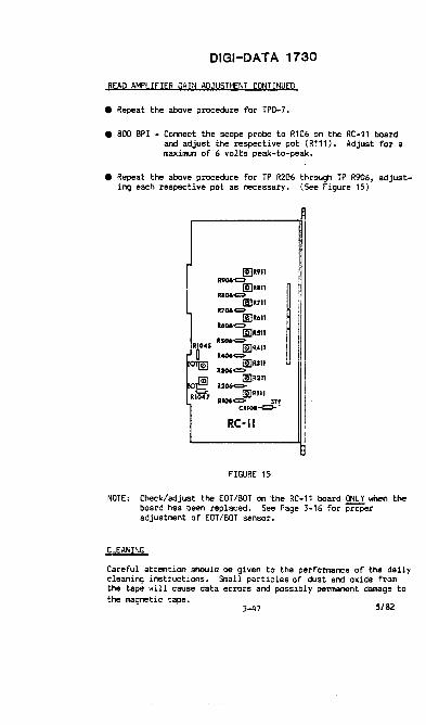
DIGI-DAT A 1730
READ AMPLIFIER GAIN ADJUSH1ENT CONTINUED
• Repeat the above procedure for TPO-7.
• aDO BPI - Connect the scope probe to R106 on the RC-11 board and adjust the respective pot (R111). Adjust for a maxilllJm of 6 volts peak-to-peak.
• Repeat the above procedure for TP R206 through TP R906, adjusting each respective pot as necessary. (See Figure 15)
I!IR9n R906c::1-
I!] Rill Rl06~
ImR7t1 11106~
!mR61l R606~
!ERSil RS06~
~R41l R406<="
!mUll R306~
[!IR2n R2Q6C:1-
[!JRI1I R1Q6<:::> srI'
C.'0'~~
RC-II
FIGURE 15
NOTE: Check/adjust the EDT/BOT on the RC-11 board ONLY when the board has been replaced. See Page 3-16 for proper adjustment of EDT/BOT sensor.
Careful attention should be given to the performance of the daily cleaning instructions. Small particles of dust and oxide from the tape will cause data errors and possibly permanent damage to the magnetic tape.
3-47 5/82

DIGI-DA TA 1730
CLEANING CONTINUED
Daily Cleaning of Head and Guides
Perform the following procedure after every eight hours of system use, or after every reel of tape if system use is infrequent.
• Remove tape from the transport.
• Moisten Q-Tip applicator, cotton swab, or any lint-free clean cloth with isopropyl (91%) alcohol.
• Lifting the flux gate clean the head{s), then the two tape guides.
• Clean the tape cleaner, the tension arm rollers, and the stationary rollers. (Excessive liquid is not required')
Weekly Cleaning of Capstan
Clean the capstan outer surface \1eekly following this procedure:
• r10isten Q-Tip applicator, cotton swab, or cloth with water. USE ONLY WA TER! !
• Rotate the capstan with one hand on the center shaft (not the outer surface, as it may be accidently deformed, while holding the cleaning implement with the other hand against the outer surface.
• Dry in a similar fashion.
• If the capstan outer surface shows signs of cracking or polish advise the maintenance engineer.
CHECK OUT ON THE SYSm~
• Close the transport and tighten thumbscrews (hand tighten only).
• Run ATP Test Run Manual; I~P Test: (one time) Timing Test: (one time) End of Tape Test: (two times) Run Automatic Test: (10 iterations) (On full 10.5" reel) Run Automatic Test: (4 iterations) (On mostly empty 7.5"
reel)
3-48 5/82

DIGI-DATA 1730
PARTS REPLACEf.1ENT
Tension Arm Roller
The current practice of replacing the entire tension arm assembly when the arm roll~r malfunctions is unnecessary and can possibly create skew problems.
The part number for the arm roller assembly is; 4110051-0001. To remove/replace a binding or noisy arm roller see Figure 16 and perform the following steps.
• Remove the 4-40 screw from the center of the arm roller.
• Pull off the arm roller; watch for any shims.
• Slip on the replacement roller. Insert and tighten the screw. check height.
• Load the tape and use the service switch to verify proper operation.
ARM
~-+-g---H--!---f--- Ref . 055"~
ROLLER
FIGURE 16
3-49 5/82


1740 DIGI-DATA
POWER SUPPLY The transport has four r~ulated voltages, two of whil:h are adjustable. Max AC ripple is 50 mV p-p.
" Connel:t voltmeter between TP10 (grid) & TP5 (+5) on the M(18 ' card. Adjust R62 to obtain +5 ! 0.05"-
2) Adjust potentiometer R52 to obtain +12V ! 0.05 between TP10 & TP2 (+12). See fig 20.
3) Ver; fy that the vo l tage at TP3 is +5 ! 0.1 and that the vo l tage at TP6 is -12 ! 0.6.
CAPSTAN SERVO ADJUSTMENT These adjustments determine the transport'S tape speed and tape acceleration.
ZERO ADJUSTMENT Load a reel of magnetiC tape to BOT. With no tape motion, adjust R46 (ZERO) to achieve a reading of O.OOV ! 0.01 between TP7 and TP10 of IIIC18.
SPEED ADJUSTMENT The transport's forward and reverse speeds are each adjustable with a unique potentiOlHter. The rewind speed, since it is directly proportional to the reverse speed, requires no adjustment. THESE ADJUSTMENTS SHOULD BE PERFORMED WHEN REPUCING THE MOTOR CONTROL CARD, MC18.
1) Locate the round label affixed to the capstan tachometer. This label indicates the voltage readings at TP1 (tachometer feedback) when the factory technician properly adjusted the forward and reverse speeds at the tilDe of manufacture.
2) Connect an accurate voltmeter between TP10 (GND) and TP1 of IIIC18.
3) Move tape forward using the service switch. Adjust R48 to d,uplicate the voltage preceded by an "F" on the capstan Label.
4) Switch tape moti4n to reverse, using service switch, and adjust R49 to duplicate the voltage preceded bY an "R" on the capstan label.
Nota: The service switch ignores the BOT marker.
Pg 3-051

J2
J1
1740 DIGI-oATA
ASSEMBLY MOTOR CONTROL
-4 ." N
J.~ ." -w
== r- ... (Dec + ~
I!El
• t -4
J
t .;g
SUP CEN
Pg 3-052
NC18 PWA Fig 20
5/82

1740 DIGI-DATA
RAMP ADJUSTMENT Thi s procedure requ i res the use of an osc illoscope.
1) Load- a.reel of scratch tape to BOT and place the transport on line.
7.5 MS
RAMP TIMING WAVEFORM Fig 21
2) IPL the system and from device zero enter the following program: ¥
0100F200~dsd 1d029D OOOOA7 CXMITJ dsDevi ce address
3) Trigger the scope negative on TP12 of the Me18 card and view TP1.
4) Uncalibrate the scope amplitude, and position the trace such that the 90% amplitude point of the start ramp may be easilY ascertained. See figure 21.
5) Adjust the RAMP potentiometer, R4S, to achieve a ramp time of 7.S milliseconds as shown in th, figure.
6) Trigger the sc~e positive and view the stop raa:p. Verify that it is approximately equal in time to the start-ramp time.
Note: The tape should be creeping forward.
PHOTODISIC AUGNMENT
1) Power up, but do not load tape.
2) Connect a voltmeter between ground and TP16 (supply photocell) or TP15 (take-up Photocell) on. the lIIe18 card.
3) With your hand hold the appropriate a/'lll in th. approxim.tote center of its operlti n9 arc.
Pg 3-053

1740 DIGI-DATA
4) The voltmeter should read 2.7V+o.1. If not Loosen the photodisk and rotate it until the-meter does read 2.7V.
ARM LIMIT SWITCH ALIGNMENT ." Photo disk alignment must be checked before performing this
adjustment. Refer to figure 22 with regard to this alignment.
1) Insure that the screws holding the microswitch in place are tight. Power off the unit.
LIMIT REACTOR
ARM LIMIT S\jITCH Fig 22
2) Connect In ohllllleter between the two connected Lugs of the switch.
3) Lift the take-up Irm off its stop. The meter should go from "short" to "open" before the first dimple (punch on deck plate) is reached. Release the arm, the meter should return to "short".
4) PIove the tak~ arm to the oppas i te end of its arc. The meter should go frOll "open" to "short" Ifter tha second dimple is passed. Bring the arm back again and the meter should indiclte "open" before the same dimple is reached.
5) If the conditions il'1clicated in steps 3 and 4 do not exist, Loosen and move the appropriate arm limit relctor(s) on the tak~ Photodisk to achieve those COnditions. DO NOT move the entire photo disc.
-JAR" POSITION ADJUSTMENTS
1) Load the transport with a scratch tape. The tape should advance to BOT and ha l t.
5/82
Pg 3-054

J6
Js
174O·DIGI-oATA
ASSEM DUAL WRITE CONTROL CARD
Pc; 3-055
Wri tel Control Card Fig 23
5/82

1740 DIGI-oATA
Zl Run the machine forward and reverse w;th the servi ce swi tch. AdJ ust the CEN and ARC pots for each arm to pos i t~ on them exact ly at the locations indicated by the punch marks on the deck-plate. Make repeated small adjustments of the two pots, checking the forward, and reverse position ot the arm after each adjustment. The ARC pot is used to lIIove the two arm positions apart, the CEN pot shHts both positions in a cQlllllOn direction •
. ~BOT/EOT SENSOR ADJUSTMENTS (These adjustments are required whenever e;ther the write/control ""'Card or the BOT/EOT sensor assembly is replaced. Only a voltmeter
is needed.
1) Power up and wai t at least one minute for warm-up before pertoming the vOltage measurements indicated in the following steps.
2) Thread ma~net;c tape on the unit and turn the reels so that the tape is taut through the BOT I EOT sensor. Insure that ne i ther the BOT nor the EOT reflective tab ; s located w; thin the sensor assembly.
3) Connect the voltmeter ben.een ground and TP15 on the write/control card and adjust R81, the BOT potentiometer, so that the IHter reads at Least +9 voL ts.
4) Connect the voltmeter between grOund and TP16 on the writa/control card and adjust R82, the EOT potentlocaeter, so that the meter readS at lelSt +9 vo l ts.
5) Racve the, magnetic tape frOlll within tha sensor asSembly. The voltages at TP15 .rid TP16 !lUst droP belov +1 volt.
fIl.E PROTECT ALlGNft1ENT ,";;--The point of depression at which the ring-detecting plunger ~'actuates the RING IN lIicrosvitch must be set when the file-protect
assembly is replaced.
1) Power off and no tape loaded.
2) Connect an ohallleter between the n.o connected lugs of the RING IN (WRT EN) microswitch. The lIeter should indicate an "open".
3) Depress the plunger which protrudes through the deck-plate. The DIeter shou ld I nd i cate a "short" when the plunger rlaches the inner lip of the supply h~.
Pg 3~56

1740 DIGI-oATA
4) If necessary loosen the set SCl"ew in the plungel" cam and move ~:eO~:i~~d~he plungel" so that the condition described in step 3
5) Disconnect the meter. Powel" up, load a reel of tape with a write enable I";ng installed and verify that the solenoid I"etracts the plunger fully when the LOAD Pushbutton is pl"essed, and that the WRT EN incHcator lamp is illuminated.
READ GAIN ADJUSTMENTS The gain of the I"ead pre-amps IllUst be adjusted when the read card 01" the magnetic tape head is I"lIlllced. In making these adjustments a reliable sCl"atch tape should be used. DO NOT use a master alignment tape (skew tape).
i T1i ,- I" I ~ I I I111 !
rT iT I ':/ ; I / I I I II J
1\ I 1 III I
PE READ GAIN (1600 BPI)
T h'
I
I
III
rl I--
I I
r----II 6v P-P
PE
I
I \ -L __
Read Gai n WavefOMll Fig 24
Any transport capable of reading phase encoded tapes should be adj usted by means of the fo llow; ng procedul"e.
1) Wr; te an all ones tape us ing the program shown on page 3-063.
2) After writing and rewinding the tape to load point, IPt.. the syst .. and enter the progl"am for I"eading an all ones tape.
3) Tape should I"ewind automatically and continue I"unning to allow you to make the following adjustments ... ithout continually checking the fl"ont of the drive to see if tape is about to run cut.
4) View TP102 with an oscilloscope and adjust potentiOllllt.r R108 to obtain a ~ peak-to-peak signal. See fig 25 for location of tlst points and pots.
Pg 3-057

;;u -n. ~ .. oQD.
c::: ... D.
.,p, '{>
~m
~ m £< ~ -u S rn
0 :0 ... rn G\
» ~ 0 :.-n -i :.-» :0 0

1740 DIGI-oATA
5) Repeet step Z for each of the remaining eight channels (TPZ02 and R208, TP302 and R308, etc.).
NaZI READ GAIN To adjust the read .. pLifier gains on a transport capable of reading ~ NRZI tapes, perform the following procedure:
1) Load a scrltch tape on the driye and pllce the uni.t ON ~INE.
2) IPL the system and frOID deyi ce zero enter the progr_ to wri U an ILL ones tape. Refer to progr .. on page 3-063.
3) After writing and rewinding the tape to load point. IP~ the system and enter the program for reading an all ones tape. Refer to page 3-063.
4) Tape should rewind automaticaLLy and continue running to allow you to make the following adjustments without continually checking the front of the drive to see if tape is about to run out.
5) View TP101 of NaZI read card ... ith an oscilloscope and adjust potentiometer R108 to obtain a 10 volt pelk-to-peak signal. Refer to figs 24 & ZS
6) Repeat step 2 for each of the remaining channels CTP201 and R208, TP301 and R308, etc.).
READ SKEW MEASUREMENT AND ADJUSnmrr Following replacement of the tape head or any tape guiding cQlllPOnent, check the transport skew. A IIIster skew tape and an oscilloscope are required.
1) s.t the scope for 1us/cm sweep time and 1ViCII yerticil deflection.
1600 BPI - Connect the scope probe to TP9 (skew) on the PE read card.
800 BPI - Connect the scope proae to the anode side of diode CR1Q9 on the NRZI read card.
2> With a master stew tape loaded, IPI.. the systllll and enter 10000d OOOOA7 Ca-devi ce' on deyi ce zero and TRANSMIT. A stai rcase .... ye-form (s.e fig 26) Should appear, ... ith the first positive steP triggering the o.ciLlosc~ sweep. The time between the first and last steps represents the total read skew and should be less than 3.3 mi croseconds.
Pg 3-059

1740 DIGI-DATA
IOTE When you reach the end of the skew tape you should reverse :he tape at s low speed to keep from stretchi ng it. The program to 'everse the tape is this: 1c1029D OOOOA7. Do not RE\J.l!!2-1~lt.!!2L.
JITTER
Skew waveform Fig 26
5) It the skew exceeds the specUication by more than 1 aicrosecond check the head mounting screws and head orientation.
*lTE: ADJUST THE SKEW ONLY WHEN ABSOLUTELY POSITIVE IT'S MECESSARY.
4) If the skew is exceSSive, determine which of the two tracks (4 or 5) arrives first.
5) "8efor. concluc:ling that one of the tape guides needs to be shi_ecI uke the follOWing checks.
a) Verify that the tape has been properly threaded.
b) Clean all tape-handling cOlllPOnents.
c) Check each tension arm roller for axial play. The roller should not move up and down. Horizontal tilt is nOrmal. If .Hher roller exhibHs vertical plaY,. remove and replace it. Arm roller height is adjustable with the center screw.
d) Check the stationary rollers for the absence of vert~cal play, and replace either if necessary. Stationary roller height is also adjustable with the center screw.
Pg 3-060

1740 DIGI-IlATA
e) Check the tape guide springs for freedOlll of movement. lihen depressed and then reLeased the bottom flange shouLd snap up to Hs originaL position. If the flange's movement feels spongy or sticks, remove, disassembLe, and clean the tape guide. Recommended solvents are heptane and alcohol.
6) If none of the above is the cause of the skew problem then tape guide shims must be added or removed. A small libel on the rear of the front plate near the head indicates which guide, if either, was shillllled at the time of manufacture and how much it was shilllllled. To determine which guide to shim perform the following. Press lightly on the outside edge of the tape near each tape guide in turn. The guide where the skew is worsened by this pressing is the one whi ch IllUst be rai sed.
NRZI SKEW GAT! ADJUSTMENT (aco bpi) This adjustment is required whenever the read card is replaced on any transport capable of reading NRZI tapes. The SKEW GATE ; s a one-shot which defines the time during which aLL the data bits in a character must arrive; it is triggered by the first bit to arrive. Nine-track ANSI standards require that all bits arrive within 34% of the character period.
1) Read any tape. Vi ew TP6 on the NRZI-read card wi th an osc i ltoscope.
Z) Adjust the width of the skew gate (TP6) wave-form with potentiOlll8ter RZ7 to achieve a 10us signal width.
\CROSS-FEED MINIMIZATION 'If errors are occurring in the read-after-write lIIOCIe, or if I dual gap head is replaced, sOllIe adjustment of the "flux gate" may be necessary to minimi ze the cross-feed between the write and read stacks.
1) Verifythat the gain of each read pre-amplifier is properLY adjusted; refer to pages 3-etr3 of this section.
~-QS7 Z) Note the position of the density select Plug jumper located next to the service switch on the write/control card. If this jumper is not in 11119 then move it from IIZ0 or WZ1 to W19 for the duration of this adjustment. Refer to fig 23 for location of W19, IIZO & WZ1. 3) Turn power on, and thread a scratch tape on the transport
without going around the capstan.
4) Refer to page 3-063 to write all "ones" tape at aco BPI or a 3200 FRPI tape 1600 BPI. Press the LOAD pushbutton swi tcn and the reel motors will apply tension to the tape and the capstan
Pg 3-061

1740 DIGI-DATA
will rotate CCW. Press 1.0AD and ON I.INE simultaneously to simulate aOT detection; the capstan will stOP and then start forward again as the pushbuttons are released. The write circuHs are now active. However, Since the tape is not IIIOving the read circuits cannot really read-after....,rite, and therefore, any activity in the read channels is cross-feed from the write circuits.
5) With an oscilloscope view the pre-amplifier output TP101 of the Read Card. The pealc-to-pealc Signal must not exceed .5 Volts P-P. Refer to Fig 7:l.
III ~ "--1 1
MAXIMUM 1S.511
Flux Gate Adjust Fig 'l:7
6) If signal amplitude exceeds the specification in step 5 loosen the two screws which hold the "flux gate" aSSemblY to the plate. IIIove the assembly slowly fl'Olll side to side noting the position whi ch resul ts in the smallest pealc-to-pealc cross-feed signal. The asSembLy should be parallel to the head and IS close as possible to it without touching the tape.
7) When the OPtimum position for minimum cross-feld has been ~etermined, tighten the two mounting screws; then verify that the aSSembly has not shifted whHe tightening the screws. View also TP201 through TP9Q1 and verify that these signals are within the IIIXilllUlll values ina; cated in step 5.
8) Turn off power, remove the tape, and return the density seLect llug Jumper to W20 or W21 if previouslY moved in step 2.
Pg 3~2

1740 DIGI-oATA
--HELPFUL PROGRAMS--
WRITING Of ALL ONES TAPE
1'\ '\ 11 1 3, l \ /\ 4000FC1000870011 4000F21000Bcl OOOSA7 FF
wai t for most of tape to be wri tten ••• then ••••
0001 F2000CBcI 1d039D OOOOAS 13
\.!/ \/ \1(
~ , READING ALL ONES T~E ./ \ " '{...... ,r 7 \.
10000d 4d409D aooOA4 1d039D OOOOA7
This procedure will read the tape looking for End Of Fi la marks. UPon finding one, the tape will r .... i.nd and begin reading again unti l stop,;ed by the IPL button.
Pg 3-063
CXPlITJ
CIPLJ CXluTl CIPLJ
CXPlITl


IOU 28 CRT
Qantel Model 4011, 40Z1
IOU-Z8A
ADDRESS SWITCHES O-F
IOU-Z8B
KANA 9600
A~J~l200 NOTE: SELECT PROPER BAUD RATE ON THE I/O CARD IN THE TERMINAL ALSO.
4-1
MAX. PW"R. REQUIREMENTS
-lZv = .50A +lZv ~ .10A + 5v = Z.69A
TERMINAL PWR.
115 vac 60 Hz 2.0A for .1 sec. l.OA normal

QCRT 2
IOU 28 CRT
Qante1 M6de1 4011, 4021 (BLACK AND GREEN SCREEN)
IOU-28A/B
WRITE CONTROL INSTRUCTIONS
1XYY9D
CONTROL BYTE
00 10 14 2N 30
50
x = DEVICE ADDRESS
FUNCTION
RESET INTERRUPT
YY = CONTROL BYTE
RESET ALLOW TERMINATION INTERRUPT SET ALLOW TERMINATION INTERRUPT POLL TERMINAL "N" START SCANNING(BEGIN WITH NEXT SEQUENTIAL TERMINAL AFTER STOP). SEND MEMORY CONTENTS ON NEXT READ INSTRUCTION
STATUS- IN INSTRUCTIONS
4XYY9D X = DEVICE ADDRESS YY = STATUS BYTE
STATUS MEANING BYTE
01 READ BUSY 02 WRITE BUSY 04 END 08 SERVICE REQUEST 10 INTERRUPT (FLAG 1) 20 FLAG 2 40 FLAG 3 80 Slave printer inop
READ STATUS
YXYY86 X = DEVICE ADDRESS Y = DON'T CARE
THE READ STATUS 2 INSTRUCTION HAS NO MEANING IN THE TYPEWRITER MODE ON THE QCRT. IN DIRECT ACCESS MODE. THE STATUS 2 BYTE HAS THE FOLLOWING MEANINGS:
STATUS BYTE
ON
IN 4N 6N 7N 8N BN CN DN EN FN
OPERATION IN PROGRESS
SCAN
SCAN READ READ READ WRITE WRITE POLL POLL POLL POLL
N = TERMINAL NUMBER
4-2
CAUSE OF INTERRUPT
ALL 16 TERMINALS TIMED OUT READ REQUEST READ COMPLETE READ OVERFLOW ERROR OR TIMEOUT WRITE COMPLETE ERROR OR TIMEOUT POLL COMPLETE READ REQUEST TER.'1INAL BUSY ERROR OR TIMEOUT
Revised 3/77

QANTEL 4001
IOU 28 CRT CRT-1
-A-
LOCAL £J REMOTE·
BLANK IIIl[] KANA []J1
-B-
DnI []JD HALT STEP
-C-
-A- LOCAL / REMOTE SELECT RHIOTE FOR ~IODEM USE ALSO 1200 BAUD
BLANK ILLIMINATES DISPLAY OF ~1HIORY POS ITIONS WITH SUPPRESS BIT PRESENT
KANA
1200/9600
SET TO KANA FOR JAPANESE CHARACTER GENERATOR.
SELECT TRANSMISSION RATE
-B- STANDARD ADDRESS SWITCHES O-F
-C- HALT & STEP USED TO HALT EXECUTION or RO~1 INSTRUCTIONS AND STEP SINGLE INSTRUCTION AT A TIME.
NOTE: CRT-l MS TWO-LINE, NON- bLINKING CURSOR
4-3

IOU 28 CRT
QA'lTEL 4011 CRT-2
I/O
4021
-B-
BLM,K
-A-
~. n 1200 U E§ 9600
III LOCAL
U RH!OTE
HAL T []JJ []I] STEP
CIII OIl 50 60 15 27
-C-
.VIDEO POT.
-A- BLANK ILLHUKATES DISPLAY OF MEMORY POSITIO:;S WITH SUPPRESS B IT PRESENT.
1200/9600 TRA~9IISSION RATE SELECTION. LOCAL/REMOTE SELECT RHIOTE FOR MODEM USE.
ALSO 1200 BAUD -B- STA!'lDARD ,\DDRESS SWITCHES O-F
-C- HALT & STEP HALTS RON EXECUTION AND ALLOWS SINGLE STEPPING OF ROM INSTRUCTIO~:S.
50-60 Hz POWER SOURCE SELECTION
15-27 LINES SCREEN SIZE SELECT.
NOTE: CRT-2 HAS SINGLE-LINE, BLINKING CURSOR.
4-4
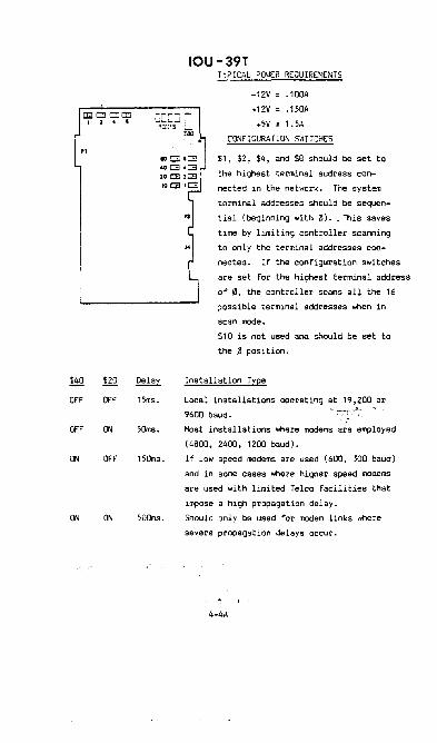
1i40
OFF
OFF
ON
ON
$20
OFF
ON
OFF
ON
15ms.
5Oms.
15Oms.
sOOrns.
IOU-39T TYPIC~L P0I1ER REQUIREMENTS
-12V .100A
+12V .150A
+5V = 1.5A
CONFIGURA nON SI'II TCHES
$1, $2, $4, and $8 should be set to
the highest terminal address con-
nected in the network. The system
terminal addresses should be sequen
tial (beginning with 0). , This saves
time by limiting controller scanning
to only the terminal addresses cor:t
nected. If the configuration switches
are set for the highest terminal address
of 0, the controller scans all the 16
;Jossible terminal addresses when in
scan mode.
$10 is not used and should be set to
the 0 position.
Installation Type
Local installations operating at 19,200 .or
9600 baud.
Most installations where modems are employed
(4800, 2400, 1200 baud).
If low speed modems are used (600, 300 baud)
and in some cases where higher speed modems
are used with limited Telco facilities that
impose a high propagation delay.
Should only be used for modem links where
severe propagation delays occur.
4-4A
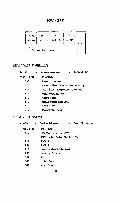
IOU-39T
ROM ROM ROM
5'Jx-14y 39x-13y 39x-12y
x = y = Current Rev. Leve 1
IfIRITE CONTROL INSTRUCTIONS
ROM
39x-l1y
ldyy90 d = Dev ice Address yy Control Byte
STATUS BYTE:
$00
$10
$14
$ZN
$30
$40
550
$60
fl.J>lCTION
Reset Interrupt
Reset Allow Termination Interrupt
Set Allow Termination Interrupt
Poll Terminal 'N'
Start Scan
Reset Print Complete
Send Memory
Diagnostic Write
STATUS IN INSTRUCTIONS
4dyy90 d = Dev ice Address yy Test Bit Value
STATUS BYTE: FUNCTION
$BO IPL Mode CRT 11 INOP
SCAN ~Iode: Video Printer INOP
$40 FLAG 3
$ZO FLAG Z
$10 Termination ( Interrup t)
$OB Serv ice Request
$04 End
$OZ Write Busy
$01 Read Busy
4-4B

READ STATUS 2
xdyy86
CONTROL 8YTE
$AO
$1N
$2N
$3N
$4N
$6N
$7N
$8N
$BN
$CN
$ON
$EN
$FN
IOU-39T
d = Device Address yy = Test Bit Value
x = Don't Care
FUNCTION
After IPl or Reset I/O: Hade of Operation
SCAN: Read Request (On CRT indicated: N)
SCAN: Print Complete
SCAN: Read Request &: Print Complete
READ: Complete
READ: Overflow
READ: Timeout/Error
~IRITE : Complete
vIRITE: Error
POLL: Complete
POLL: Read Request
POLL: Printer Busy
POLL: Error
4-4C

QANTEL VIDEO TERMINAL
REMOVE/REPLACE/REPAIR
SAFETY NOTES The Internal components of the CRT terminal contain some voltages that, If contacted, could cause severe discomfort or personal injury. These circuIts are well protected with Insulation when the unit leaves the factory, but later damage or disassembly of a lIve unIt could expose a hazardous condition.
Always remove all power (unplug the power cord) when disassembling a portion of the terminal. Inspect the entire unit for damage to protective Insulation, and replace or repair any wiring or connectors that are damaged.
The picture tube of the monitor unit is protected from damage on the face by a bonded safety shield. Never replace the tube with a variety that does not contain this shield. Use care when the cover Is off the unit to avoid damage to the glass. A scratch or sharp blow can sometimes cause a tube to implode. In effect, an implosion resembles a small explosion, sending glass particles In all directions.

, ..... SPOI<'"
~y IQ;VflClAIW) ()IN£CTICH DerAILS
I ~ ,

DISASSEMBLY TOP COVER
• Remove the two cover screws under the rear ledge of the cover assembly (see the Illustration).
• Grasp the cover Just above the chassis level, and slide It about 2 Inches or more toward the rear (away from the tube face).
• Press the sides inward at the front edges, releasing the retainers, then 11ft the cover straight up and aw~y from the unit. Set the cover In a safe place where It will not be damaged or fall and damage sonethlng else.
REMOVE PRINTED CIRCUIT CARDS
• Re.move power from the unit by switching the power switch OFF or unplugging the line cord.
• Remove the Jumper board at the rear of the printed circuit cards (near the power supply tan). This Jumper is best removed by gently pulling alternately at the top and bottom. Place the jumper card where it can~ot be damaged or the contacts become dirty.
• Remove the desired printed circuit card by lifting gently on the loose end of the card, then pulling toward the rear of the unit.

+' I
(Xl
REMOVE MOTHERBOARD
• Remove a II of the pr I nted cI rcu i t cards.
• DIsconnect JS, allowIng It to lay to one side.
• Remove the four pan-head screws that hold the motherboard.
• LI ft the motherboard from the un I t.
REMOVE THE LOGIC POWER SUPPLY
• Remove all of the prInted circuIt cards.
• DIsconnect PI3 and PI3A (the 'two smaller connectors, one at the side and one toward the rear of the un It).
• Remove the four retaining screws for the power supply at the bottom of the unIt. To remove these screws, sl ide thp. POWf''' sUDnly p.nd of the terminal over th~ encl :)f the vlcrkber.ch or table until the screw heads can be reached. It is not recommp.nded that the unit be tIlted up to reach the screws, as the Po\~..!f supply may fall lnto the l1'or.:tor when the screws are released.

REMOVE THE MONITOR ASSEMBLY
• Tip the terminal up so that the two retaining screws that are near the bottom center of the unit can be removed. Remove these two screws only, then set the terminal back down.
• Slide the rear edge of the terminal to the edge of the table or workbench so that the rear panel assembly extends over the edge.
• Remove the two screws at each side of the rear panel assembly (on the rear surface of the terminal).
• Allow the rear panel assembly to move down and to the rear (out of the way).
• Remove the two remaining monitor mounting screws that were exposed by moving the rear panel assembly.
• Unplug all electrical connections to the monitor assembly.
• Lift the monitor assembly up and back (away from the bezel).
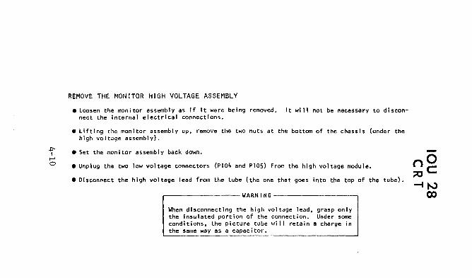
REMOVE THE MONITOR HIGH VOLTAGE ASSEMBLY
• Loosen the monitor assembly as if It were being removed. It will not be necessary to disconnect the Internal electrical connections.
• Lifting the monitor assembly up, remove the two nuts at the bottom of the chassis (under the high voltage assembly).
• Set the monitor assembly back down.
• Unplug the two low voltage connectors (PI04 and PIOS) from the high voltage module.
• Disconnect the high voltage lead from the tube (the one that goes Into the top of the tube).
r-----------------WARNING-------------------,
When disconnecting the high voltage lead, grasp only the Insulated portion of the connection. Under some conditions, the picture tube will retain a charge in the same way as a capacitor.

.$:'I t-' t-'
REMOVE THE KEYBOARD ASSEMBLY
• Slide the keyboard portion of the terminal partially over the edge of the table or workbench.
• Remove the protective panel from below the keyboard by removing the two screws that hold the front rubber feet and the panel.
G CAUTION
The speaker wires will allow only about 6" of panel movement. Disconnect PS (speaker wires) If the panel Is to be moved farther .
• loosen and remove the four screws that fasten the keyboard assembly to the main frame.
• Disconnect the small connector to the speaker CPS) and the larger connector at the edge of the keyboard assembly.
REPLACE THE INDICATOR LIGHT
• Remove the motherboard.
• Remove the Indicator lights by carefully unplugging the LED unit from the motherboard. Be sure, when replacing the Indicator, that the LED contact marked + is inserted Into the + socket on the ~therboard.

~ I
I--' N
, - - - - - - - - - ", , .. -. - - - - - --, t ": , , .
"-'-. -,
FRONT , ,
ALL HODELS WITH WITE CHARACTER DISPLAY -
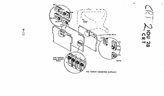
. ,- ---I'
( \.. I "'- ........
FRONT
- --, - - - - , I I
I I , I
I {
' .... ">-
"' '~~~
CR2 (GREEN CHARACTER 01 SPLAY)

SWITCH
HALT
STEP
50/60 CV
15127 LINES
ADDRESS
t OPERATION
--.-.-- - -- --- - - - - -Test swItch that is used for troubleshooting. It stops the normal logic process i rig wi th i n the CRT. Logic sequences can be stepped through one micro-Instruction at a time by using the STEP switch.
Test switch that Is used in conjunction with the HALT switch. When the HALT switch Is in the HALT position, moVe the the STEP position and then return to step the microprogram one instruction at a time.
-- - t-- - ----- ---- -------- --------
Changes the internal timIng to be compatible with the power lIne frequency.
Allows full screen display of 27 lines or limits the logic to 15 lines of display and memory (the unused memory is physically removed In the 15-llne units).
------- --These swl tches set the terminal address as seen by the controller (not the IOU device address as seen by the CPU). The subordinate order is reversed from one model to the other but up is always ON. The illustration shows the terminal address as hexldecimal F.

[------_--._._--_._-------_ .. _.- ._. __ ....• __ . __ ... BLANK When the switch Is set to the BLANK position (as shown In the illustration),
all characters that contain a blanking bit will not be displayed on the screen. When set away from the BLANK position, all characters except space characters will be displayed. Invalid characters, such as control characters, are displayed as blanks. Blanks that are used to fill a suppressed b:lc!~gro\.:r..:l field c:re displayed when the sw!tch !s il,;<:i'l frc,m t1." ElLAr~K pes I t ion.
1----------4-----_._----------_ ..... -. ---------. BAUD Sets the baud rate of the CRT input and output data lines. If the
LOCAL/REMOTE switch is in the REMOTE position, the baud rate must be set at 1200. LOCAL baud rate can be 1200 but preferably should be 9600. ~II terminals that are connected to the same IOU controller (either directly or through modems) must be set to the same baud rate.
1-.----.-----1------.. - .... --.-.- ..... ---------.---.- ... _.. ----.-------. -
LOCAL/REMOTE Changes the I/O characteristics of the CRT unit. The LOCAL position is I used where all units of one controller are directly attached through cables (within a maximum of 2000 feet). REMOTE must be used on all terminals of a controller that has one or more terminals that are remote enough to require a modem. When the REMOTE setting is used, the baud rate for all terminals that are connected to the same controller must be set to 1200.
r·---------J-------··--------····-·-·· --... ----------AUXMODE Enables an auxlillary ROM that Is programmed for the Katakana keyboard. (15-llne white This ROM is not present in an ASCII terminal. However, if the AUXMODE display only) switch Is enabled in an ASCII terminal, certain Greek letters and some
special symbols will be displayed when the LTRS key is in the down position. Releasing the L"TRS key wi 11 not autornatically release the condition; either SHIFT or RETURN must be depressed to exit the special character condition. The AUXMODE switch should normally be OFF In an ASCII terminal. 1-___________ '---___________ .. _ .-... _._. _______ ... _. _____ . __ . __________ ---01

ALvJSTMENTS This section describes adjustments that are norma'lly only performed by field engineering personnel. External operator adjustments are described in the OPERATION section of this manual. All adjustments within this section require that the CRT has power, the cover Is off and Is not online. These steps are not repeated for each procedure. Each adjustment Is complete and Independent In Itself, but many adjustments are either directly or subtly Interactive and may, requlrp. that another adjustment be repeated. Those situations that are clearly interactive are Indicated In the adjustment procedure. t AIIJtUlt dtlBbS, ) "'~ '\ \
o un Ir SP n, '" J J on Icreen , -'i;; ',// I
wumt f'" ~ ~ /$1:') ~ :.; ~]~} '\~W~
, Rotah enUre roke :a; @ttfdlIPI"1Inot I.VI' ~
(j)R124
i HE +15 V AdJult " t. (Jehtnll 'over .u .... II') RI21
VERT N
+15 V ADJUSTMENT Power supply voltage Is extremely Important for proper display monitor operation. Always check the power supply voltage and low/high load regulation when random errors or failures are Indicated. Use a good quality 20,000 n/volt meter (or better) to measure the voltage when adJu~tlng.
Make the +15 volt adjustment as follows: • Attach the measuring probes at PI03 (see the Illustration for location of P103). The positive
probe connects to the orange wire; the return connects to the black wire .
.. Adjust R208 (on the small PC board behind the monitor power supply) until the measurl'!d vol tage Is as close as possible to 15.00 volts.

VERTICAL FREQUENCY
The vertical frequency is the synchronism that keeps the screen from "roiling." Center the adjustment as follows:
• Slowly move the control (Rli6) In one direction until the screen begins to roll. Note the position of the control.
• Slowly move the control In the opposite direction until the screen begins to roll In the opposite direction. Note the position of the control.
• Return the control to the midpoint between the two extremes.
• Check the vertical linearity; this adjustment may have affected It.
TILT (LEVEL>
If the top and bottom lines of the display are not level with the bezel (facemask), adjust as follows:
• Slightly loosen the yoke clamp screw (on the neck of the tube). loosen only as much as necessary to allow movement of the yoke yet retain a firm "drag."
• Rotate the entire yoke assembly slightly until the top and bottom of the display are level.
• Carefully re-tlghten the clamp screw until the yoke is again secure. Do not over tighten, as the tube can be broken.
• It may be necessary to adjust centering when tilt has.been corrected.

VIDEO DRIVE
The video drive adjustment Is located at the rear edge of the I/O card. Proper adjustment is essential for clear, undlstorted character display. The control Is at the top of the card, slightly above the rear Jumper board connector. On the older white character display models, the adjustment is located on the rear of the I/O card but is below the jumper board connector. The adjustment requires only a small screwdriver and Is performed as follows:
• Disconnect the I/O cable at the rear of the terminal.
• Enter several groups of semicolons (;) at various places on the screen. Be sure there are some at the top, mid screen, and the bottom.
• For CRT 2, use a short jumper wire, touching momentarily from +5V to pin 11 on chip 2A.
• For CRT I, momentarily touch from pin 2 of chip 2 to ground (5V return).
• When the jumper Is touched, the screen display wIll reverse to a background display; the semicolons will remain as b?c~gr~ur.d d!spJays.
• Adjust the video drive (on the I/O board) clockwise until the character Intensity becomes bright enough to cause a ghost or shadow beside the character elements.
• Move the adjustment counterclockwise until the shadow disappears and the character is clear. If the adjustment Is moved too far In a counterclockwise direction, the characters will fade Into the background.
• Clear the screen by simultaneously depressing SHIFT and F2.

HEIGHT AND VERTICAL LINEARITY
These two adjustments are so interdependent that neither can be adjusted without affecting the other. Make sure the vertical frequency Is electrically centered (as described In a previous paragraph) before adjusting the vertical linearity, as the vertical frequency being off has a tendency to "squeeze" the screen.
• Fill the screen with upper case letters. Hs, Ms, or Ws are best, because they fill the character space, making It easier to see" linearity problems.
• Adjust the height control (RI24) until the display fills the screen. If either the top or bottom has a larger space, re-center the display,
• Adjust the linearity control (RI21) until the letters are the same height on all lines. The total display height wi'll increase or decrease as I ineari ty Is adjusted; Ignore this effect temporarily.
• Re-adjust the height until the display again fits the vertical space on the screen.
• It may be necessary to alternate between linearity and height, making smaller and smaller adjustments each time.
CENTERING To center the display on the screen, rotate the two tabs that are located on the deflection yoke until the display is centered. Each tab moves the display at an angle as compared to vertical or horizontal. By moving one, then the other. and both in conjunction, the display can Oe centered. After the display is centered, the focus, width, and helghth may need adjustment.
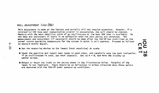
~ I
N o
NULL ADJUSTMENT (Iou-28B) ThIs adjustment Is made at the factory and normally will not requIre attention. However, If a termlnal-to-IOU (one way) communication problem is encountered, the null should be checked. Measure wIth the most sensItive scale of an oscilloscope or the best VOM that is available. Do not make any adjustment If there Is no deflection when the test points are contacted. The measurement and adjustment (if necessary) should be made after the lou-28 has stabilized to the normal system operatIng temperature for the system In whIch It will operate. Proceed as follows to measure and/or adjust.
• Set the measurIng device to the lowest (most sensItive) de scale.
• Touch the posItIve and return test leads to each other, and carefully note the zero IndIcation. If an oscilloscope Is used, use both channels. Set to A + e, and move the display to center screen.
• Attach or touch the ieads to the pOInts shown In the illustration below. Polarity of the leads Is not important. There should be no deflection In either direction when these points are measured with the IOU-28 under powered up conditions.
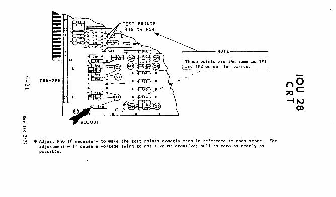
I
IOU-28B
.----""---- NOTE -----__
These points are the same as TPI and TP2 on earlier boards.
• Adjust R50 If necessary to make the test points exactly zero in reference to each other. The adjustment will cause a voltage swing to positive or negative; null to zero as nearly as possible.

~ I
N N
FOCUS Before adjusting the focus control, adjust the BRIGHTness control at the operator level that It will normally be set • • Adjust the focus control (RI07) for the best character definition over the entire screen.
Sometimes a portion of the screen focuses at a different adjustment than the rest. In that case, the adjustment is a compromise for the best overall effect.
If the monitor tube has a second set of tabs like those that are used for centering, the overall focus can be adjusted to a better degree. These tabs wIll be located toward the connector end of the tube .
• Rotate one tab, then the other, then both In conjunction, while watching the screen for the focus across the entIre screen.
WIDTH
The width coil can only be adjusted by usIng a .100 Inch hex tool that is made of plastic. This size tool Is a common standard for TV adjustments and can be purchased at most electronic parts stores. Never attempt this adjustment using a screwdriver; the powered iron slug will breu:" making It necessary to replace the entire assembly. Metal, such as an Allen wrench, affects the electrical field, making It impossible to properly adjust the width .
• Using a .100 Inch plastic hex tool, adjust. the width of the display until It Is within a small margin of both edges. The adjustment Is made by rotating the threaded slug Inside the coil, making It move In or out of the coil area .
• If one edge of the display Is closer than the other, re-center the display.

~ ...
00 00
00
01
01 10 10 1 I. I 1 IlIo " 6 b
&00 0 0 1 0 1 0 1 0 1 B. S
• I. b. 1>3 b, b, ~ 0 0 1 2 3 4 5 6 7 ~.w (l:SCAP!)
o 0 o 0 0 HULL ;0 BLWK 0 @ p p r--
1 J~ToIl ! i ~ o 0 1 (j A Q a q
0 0 1 0 2 ~:~T r .. 2 II II b r
r0- O 1 1 3 ETJ. V # 3 c 5 c . 0 1 o 0 4 UCAI'C ¢ $ 4 0 r d , 0 1 0 1 5 rrlfAi "X % 5 E U . u serle" 0 1 1 0 6 ~~~~~ 1l' & 6 f V f .,
0 1 1 1 7 SOUND W 7 G W iii w ALARM
I--B S'kjj'D 12 ( 8 H X h ~ 0 o 0 rollOlVS . 9 Rfsr.:lif' J I i 1 o 0 1 ~~
9 I Y Y
...!- .... 0 1 0 10 FOI.iUNJ Il'OLLU" - .. I J Z I I
1 0 1 1 11 r-JUlT /lOLl DOWN .... + ; K t k { rOlLO!(l t-sumr"'cSCD 1 1 o 0 12 ItAIIS t < l I I bClIM Iwraro:tl/o FtJI.LOWS:
1 1 0 1 13 H:~ Tf~~~1TDr + - = M l m J 1 ~ 1 0 14 t,7,'fff,y Pt.%1fJ!tl~ E > N 'A'- n ~
1 1 1 1 15 I~~j PRINT :'CI2lCIi ~ I ? 0 - . VIDEO TERMINAL

VT3
VT3 Hardware Installation
1. Install IOU39Q's (for VT3) per customer installation
specs.
2. Set IOU39Q switches per page 4-25.
3. Install cables, line drivers. hub units, terminals and
terminators per pages 4-26 thru 4-30.
4. Set switches on VT3 Logie boards per page 4-31.
5. Check VT3 power supply per page 4-33.
6. Check/perform VT3 mOnitor adjustments per pages 4-33 thru 4-37
7. Perform VT3 Manual test per page 4-38.
8. Run CRT3 and ACRT3 AT?' s
Remember that a VT3 is a Type 4 terminal when running the
CFIG program.
4-24
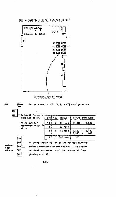
IOU - 39Q SWITCH SETTINGS FOR VT3
CInClDCEc::I!l 1 2 A •
Address $wi tehes
CONFIGURATION S\iITCHES
iON Set to a ~ in all IOU39Q - VT3 configurations
$4Ol $~ Temlnal response
Time-out delay. $40 $20 TIMEOUT TYPICAL BAUD RATE
axi_ s~n
ddress
*Ti_-out for non-modem installation
*' , 15 msec: 19,200 - 9,600 , 1 50 msec:
1 , 150 msec 4,800 - 2,;'00 1,200 -
1 1 500 msec: 300
Switches should be set to the highest terminal
address connected in the net..ork. The system
terminal addresses should be sequential {be
ginning with 'l.
4-25
600

VT3 ·IOU-39Q Switch Settings for VT3 continued
y • Current Rev Level
I/O Cable Part Numbers
.On 9xx/14xx Systems:
IOU to Hub Unit. Line Driver, VT3. Modem. IOU 40. RDI
Pri nter. or VT3 to VT3
RS232/V24 cable:
6 ft. 42055-1
12 ft.
25 ft.
50 ft.
42055-2
42055-3
42055-4
• On 2xx/3xx Systems:
IOU to Hub Unit. Line Driver. Modem or IOU 40
EIA/4F cabl e
12 ft. 43207-1
25 ft.
50 ft.
43207-2
43207-3
IOU to VT3, RDI. Pri nter
EIA/4m cable
12 ft.
25 ft.
50 ft.
43102-1
43102-2
43102-3
4-26

VT3
I/O Cable Part Numbers ConUnued
VT3 to VT3
RS232/V24
6 ft. 42055-1
12 ft. 42055-2
25 ft. 42055-3
50 ft. 42055-4
Hub Unit to Line Driver cable
100 ft. 42851-001
500 ft.
1000 ft.
5000 ft.
10000 ft.
42851-002
42851-003
42851-004
42851-005
VT3 CONFIGURATION GUIDE
VT3's attached to a single IOU-39Q may be arranged in the con
ffguntions described in the following section. A network in
volving one rOU-39Q may contain a maximum of 31 VT3's. All Baud
Rates should be identical within the network as set by jumper
switches Jl through J7. (See diagram on following page.)
4-27
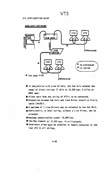
VT3 VT3 CONF I GUM TI ON GU I DE
HUB UNIT NETWORK
'* See page 4-26
• In conjunction with Line Dl"ivers, the Hub Unit utends the
range of direct strings (1 mile at 19,200 bps; 2 miles at
9600 bps).
• A II ows more than one s t ring of VT3' s to be connected.
• Connection between Hub Unit and Line Driver should be 4_ire
cable (M428S1).
• A maximum of 7 Line Drivers may be attached to the Hub Unit •
• Additionally, a local string, without a Line Driver, may be
attached.
• Maximum COII'IIIunieation speed: 19,200 bps .
• IOU-39Q. timeout at 19,200 bps: 15 milliseconds •
• Terminator plugs IDUst be attached to female connector af the last VT3 in all strings.
4-28

VT3
VT3 CONFIGURATION GUICE CONTINUED
DIRECT STRING NETWORK
TERMINATOR
• A string of 1 to 31 VT3' s connected by 232/V24 cables.
• Total length of string no IIIOre than 250 feet.
• No IIIOr. than SO feet between individual VTJ's.
• COIIIIIUn1cation speed: 19,200 bits per second.
• IQU..39Q timeout: 15 IIi 11 fseconds.
• Terminator plug (M42540-001) IlUst be .tt.ehed to f'eaule
connecter of the last 'y'T3 in the string.
4-29

VT3
VT3 CONFIGURATION GUIDE CONTINUED
• For longer distances than 1 mi Ie (or 2 miles ott 9600 bps).
a Remote Network is necessary.
• Asynchronous modems (or Sync. modems wi th Async. to Sync.
Converter) link the IOU39Q. and the remote site.
• A string of VTl's may be attached to modem.
• COIIIIMIieation speed is dependent on modem type.
• IOU39Q. timeout is dependent onmoclemspeed and line conditions.
(See page 4-25l.
• Terminator plugs must be installed in the lut VTl in each
string.
Note: When conmunicating over "Leased Line" Modems there
may be more than one remote (s lavel modem.
4-30

VT3 JUMPER SmlNGS FOR VT3 LOGIC BOARD
P1 P2
MODI! JI30
~. 00 EjEjE!] U c:!lJ9 1y y ., CCJIO
[J !!OJ II a:::JJ12
JIS
AODaI!SS
y • REV LEVEL
Jumper Jl through J7 determine Baud rate. Install only one Jl.lllper.
Jl 19.2K Baud*
J2 9600 Baud
J2 4800 Baud
J4 2400 Baud
JS 1200 Baud
J6 600 Baud
J7 300 Baud
* Denotes typical Jl.IIIper placement for USA, non-modem installations.
The VT3 device address jumpers J8 through J12 determine the
VT3 address. Allowable addresses are $00 to $IE. ~ address
a VT3 to SlF (all switches installed) .•
J8 $01
J9 $02
Jl0 $04
Jll $08
J12 $10
5/82
4-31

VT3
Jumper Settings for VT3 Logic Board Continued
The relUining jumpers J13 through J15 set mode control. (* Denotes typical jumper placement for USA, non-modem installations).
J13
J14
J15
installed
removed
Installed
removed
removed
installed
Default is 64 char/line*
Default 15 80 char/1lne
60 Hertz*
50 Hertz
Normal Operating Position
Once installed shift/F2 must be
depressed to in it i ate llil... mode.
• When in TEST mode the following changes in operation
occur:
.) When polled with its address the terminal will
display a slash (f) between FZ and F3 on the
control line.
b) When the "clear" key 15 depressed a lower case
alpha character wi 11 be displayed to the
right of F3 on the control line. This alpha
character corresponds to the termina 1'5 address
In the following manner:
addr. -char. addr.-char. addr. -char.
" - a B-1 16 - 101
1 - b C - m 17 - x Z - c o - n 18 - Y
3 - d E - 0 19 - z
4 - e F - P lA -{
5 - f' 19 - lB - : 6 - g 11 - r lC - }
7 - h 12 - s 10 -f"J
8 - 13 - IE -. 9 - 14 -
A - k 15 - v 4-32

VT3 Honltor Adjustments
• Component Ac:c:ess
1) Twist two zues fasteners on back of c:over 1; turn. Cover
should new slide bac:k and off.
2) There are four sc:rews sec:urlng the logic: c:ard to the VT3
frame. Remove the two sc:rews nearest the front and
loosen the two sc:rews nearest the rear of the unit.
Ti It logic: card to upright (or personnally preferred
position) and tighten two rear sc:rews to hold c:ard In
plac:e.
• Power Supp Iy
1) Cheek for +5, +15, and -12 supplies at pins 3,5, & 6
respec:tlvely on P1 of the logic: card. (Refer to
next page).
2) There are no adjustments to the PS9. I f any of the
supply voltages drift more than 5% at their respec:tlve
test points replac:e the entire Pan Assembly Pin,
42198-001.
.~ )} -ttv R~ ~ i-15V
'-/. 75 i-~ ~. 2 ~ g A/'-/ {is to )5, jS I, S (J ItJ, ~ .J.O Is, 2. • 0-6,~
4-33

WIDTH
VIDEO CENTERING
VERTICAL LINEARITY
PICO fUSE (2 AMP)
HEIGHT
VERTICAL HOLD

VT3
Pl CONTROL LOG I C BOARD
PIN #1 GND PIN #2 GND
J +2V ~ +2v 5 +15V (; -12V 7 V+(for I ine driver) 8 V- (for line driveri 9 XMITD {Tol 10 REQ.TOS (RTSj
11 CLRTOS 1 CTS! 12 RCVDD (RDj 13 ROY (DTR) 14 12 16
** 17 CLOCK+ ** 18 ALARM-
** 19 DKEY+ ** 20 K. B. STROBE+ 21 ** 22 GND
* 23 VIDEO 24 GND
* 2S DRVC- * 26 GND
* 21 ORHC+ * 28 !iNO 22 30 Jl J2 33 +5V 34 +5V 35 GND 36 GND
** To Keyboard * To Moni tor
VI deo Mon i tor Board
• Vertical Hold
1) Vertical Hold keeps screen from roiling. Adjust as
follows:
Rot~te R 302 (V. Hold) toward rear of unit. Display
should be rolling. Slowly rotate R 302 In opposite
dl rectlon unt i I dlsp lay stab 11 i zes and then c:ont I nue
to rotate R 302 approximately 1/8 turn further •
• Vertlc~1 Linearity & Height
The height adjustment makes the space at the top and the
bottom of the screen equ~l. The vertical I inearity adjust
ment makes the letters the same height on all lines.
1) Fi II the screen wi th upper case letters. Hs. Ms. or
Ws are best. becaUSe they fi 11 the character space, making
it easier to see linearity problems. Also, turn on Flags
2 & 3. 4-35

VT3
Vertical Linearity '0:' Height continued
2) Adjust the height control R(303) unti I the display
fills the screen.
3) Adjust the I inearity control R(301) unti I the letters
are the same height on a 11 the lines. The tota I di sp lay
height will increase or decrease as the I inearity is ad
Justed; Ignore this affect temporarily.
4) Readjust the height until the display again fits the
vertical space on the screen.
5) It may be necessary to alternate between I inearlty and
height, making smalTer and smaller adjustments each time •
• Horizontal Linearity
Only make this adjustment when necessary. The horizontal
I inear-Ity adjustment makes the characters on the left and
right side of equal height and removes any curviture of the
characters.
1) SI ightly loosen the yoke clamp screw (on the neck of the
tUbeL Loosen only as much as,necessary to allow move
ment of the yoke, yet retain a firm "drag".
2) Hove the 51 eeve under the yoke forward or backward.
The sleeve should not have to be moved very far In or
out.
3) Hake sure the letters are straight across and are not
curved at the edges •
• Adjust 5quareness
If the top and bottom I ines of the display are not level with
the facemask, adjust as follows:
1) 51 ightly loosen the yoke clamp screw (on the neck of the
tube). Loosen only as much as necessary to allow movement
of the yoke, yet retain a firm "drag".
2) Rotate the ent ire yoke assemb I y unt i I the top and bottom
display are level.
3) Carefully re-tighten the clamp screw unti I the yoke screw
is secure. Do not over t i gh ten, as the tube can be broken.
4-36

VT3
Adjust Squareness continued
4) It may be necessary to adjust centering when squareness
has been corrected •
• Horizontal Width
The width coi 1 can be adjusted by us ing a .100 hex tool tha,t
15 made of plastic. Never attempt to do this adjustment using
a screwdriver; the metal affects the eletrical field making it
Impossible to properly adjust the width.
1) Using a .100 hex tool, adjust the width of the display
until it 15 within a small margin of both edges. The
adjustment is made by rotating the threaded slug inside
the coi I L(I+02) , making it move in or out of the eoi I
area.
• Centering
1) Adjust R(410) to the center of its adjustment rotation.
2) To center the d Isp lay on the sereen, rotate the two tabs
that are located on the deflection yoke unti I the display
is centered. Each tab moves the dis play a t an angl e
compared to vertical or horizontal. By moving one, then
the other, and both fn conjunction, the display can be
centered, the focus, width and height may need adjustment.
• Brightness
1) Adjust R(1) on back of pan assembly for mxlmum brightness.
Then adjust R(10S) on monitor board unitl raster disappears.
Next adjust R(24) video gain, on the main logic card for
optimum clarity. Then readjust R(I) on pan assembly for
des ired br 'ghtness.
• Focus
1) Adjust R(40]) for optimum focus.
4-37

VT3
VT3 MANUAL TEST
1. Turn the VT3 on. After approximately 30 sec:onds, the c:ursor
wi II appear in the upper left corner as a space blinking fore-
9 round/backg round.
2. Press A on the keyboard. The letter A should be displayed
In the upper-left corner and the cursor is advanced one
position left.
3. Press RETURN on the keyl?Oard. The cursor should move to
one I ine below the A.
It. Press F2 on the keyboard. F2 is displayed in background on
the bottam screen I ine (control line). Press F2 again and
it should disappear. Repeat with n.
S. Press TAB. The cursor should disappur. Press A and the
Vi3 will beep. Press SHIFT/F2 and tM Vi3 will beep, clear
the screen, and the cursor wi I I bl ink in the upper-left
corner.
SPACE
BACKSPACE
SH 1FT/BACKSPACE
INS CHAR
SHIFT/INS CHAR
7. The keyboard reput function Is activated by simultaneously
press i ng SH I FT and the '. lin the n..-r Icc I us ter • Ver Il'y
that the next key entered repeats. (I t cannot be a control
key.)
4-38

VT3
VT3 Manual Test continued
8. Verify that the LTRS key t09gles the upper/lower case for
a I phabet i c characters.
9. Press each non-control key on the keyboard (with and without
the SHIFT) and verify that the correct character Is displayed
on the screen. Refer to the Serial Keyboard Specifications
for the keyboard being tested, e.9., U.S. Domestic and Kana
(A30761) • On the !(ana VT3 J ver i fy each key in both A I pha
and Kana modes.
10. Set the Jumper so that the VT3 is in 64 character defaul t
mode. Press SHIFT/F2 and enter some characters to verify
the mode. Set the jl.lllper for 80 character mode, press SHIFTI
F2, and verify the 80 character mode. Be sure to return the
VT3 to 64 character defaul t afterwards.
ATP Checkout
• The VT3 may. be tested by the following two ATP's.
-CRT3 (use operating procedure for CRT 2 ATP)
-ACRT3 (use operat i ng procedure for ACRT)
Operating System Tests
• Many BEST packs conta i n *VT] prov i ding the ab i1 i ty to
test the VT3 in the BEST envi ronment.
4-39

IOU 6 DATA PROD. CARD ROR.
Qantel Model 5300
8 4 2 1
ADDRESS SWITCHES O-F
MAX. PWR • REQU IREMENTS
-12v - .30A +12v -, .16A + 5v = 2.54A +26v = .59A
CARD RDR. PWR •
115 vac 60 Hz S.OA for .1 sec.
L2.4A normal
~L----!~ WRITE CONTROL INSTRUCTIONS
1XYY9D
CONTROL BYTE ---
N/A
x = DEVICE ADDRESS IT CONTROL BYTE
FUNCXION_
STATUS Ii .. INSTRUCTIONS
4XIT9D
STATUS BYTE
01 02 04 08 10 20 40 80
x = DEVICE ADDRESS YY STATUS BYTE
MEANING
BUSY READING BUSY OFF LINE END SERVICE REQUEST READ ERROR FEED ERROR HOPPER EMPTY STACKER FULL / HOLD DEVICE INOP.
5/82
5-1

IOU 26 POI CARD ROR.
Qantel Model 5301
DISt;r *
NORMAL
8 4 2 1
~[j~~ ADDRESS SWITCHES O-F
MAX. PWR. REQU IREMENTS
-12v = .16A +l2v = .12A +5v=.79A
CARD RDR. PWR.
L 115 vac 60 :-lz 3.0A for .1 sec. 1. 55A normal
~,-----_J * DISABLES ERROR STATUS FOR NON-HOLLERITH CHARACTERS.
WRITE CONTROL INSTRUCTIONS
lXYY9D
CONTROL BYTE
02 04 OC
x = DEVICE ADDRESS
FUNCTION
SET READ BINARY
YY CONTROL BYTE
RESET ALLOW TERNINATION INTERRUPT SET ALLOW TERMINATION INTERRUPT
STATUS IN INSTRUCTIONS
4XYY9D
STATUS BYTE
01 02 04 08 10 20 40 80
X : DEVICE ADDRESS YY - STATUS BYTE
MEANING
READ BUSY N/A END SERVICE REQUEST INTERRUPT READ CHECK DEVICE HOLD DEVICE INOP.
5-2

o 1 0 1 o l'1iOI o 1 1 1 100 0 1 0 0 1 9 IN, II~I~_. :;_1-8 ~ 12~. _! . o~a 12-~. 11-~8 1 0 loA !I-~~' ~'t-~ II!. I 2~8 II~I o-~ 12).-1 II-~q
ASCII/HOLLERITH CODE CHART
5-3


IOU 2 ROYTRON
PAPER TAPE READER/PUNCH
Qantel Model 5400
D~~~ 1 2 4 8
ADDRESS SWITCHES O-F
WRITE CONTROL INSTRUCTIONS N/A
STATUS IN INSTRUCTI ONS
4XYY9D X = DEVICE ADDRESS
STATUS MEANING BYTE
01 READ BUSY 02 WRITE BUSY 04 END
L
MAX. PWR.REQUIREMENTS
-12v = .20A +l2v = .17A + 5v ~ .63A +26v = .92
RDR/PUNCH PWR.
YY
115 -.rae 60 Hz
3.0A for .05 sec. 1. SA normal
STATUS BYTE
08 SERVICE REQUEST 10 N/A 20 READER INOP. 40 PUNCH INOP. 80 INOP.
5/82
6-1


IOU 3 COMMUNICATIONS
[]I DDI OJ ODD
ADDRESS SWITCHES
O-F
III] DIBIT USED WITH 201 TYPE DATA SETS (SYNC)
BIT RATE *
* SELECT ONLY ONE AT A TIME
Qantel Model 6000
MAX. PWR • REQU IREMENTS
-12v = .09A +12v = .09A + 5v = .58A
** BOTH SWITCHES MUST BE IN SAME DIRECTION
!'IRITE CONTROL INSTRUCTIONS
lXIT9D
CONTROL BYTE
01 02 04 08 10 20 40
x = DEVICE ADDRESS
FUNCTION
NDI NB2 NB4 NBB DPF. CRQ CD
YY CONTROL BYTE
STATUS IN INSTRUCTIONS
4XIT9D
STATUS BYTE
81 02 04 08 10 20 40 80
x = DEVIC= ADDRESS IT STATUS BYTE
7-1
MEANING
CFS N/A N/A READ SERVICE REQUEST INTERRUPT ecs N/A END 1'1ME OUT
5/82

IOU 11 BUFFERED
COMMlJNICATIQNS
ADDRESS SWITCHES
O-F 8 4 2 1
g~~[j
HP"* BIT RATE* n
1200 300 ~
~~l~lj 600 150 ~
XTAL BIT RATES FDX
Qante1 Model 6l00, 6200
MAX. PWR. REQUIRED
-12v= .18 +l2v=.13 + 5v = 1. 32
FULL DUPLEX-
4.92 1200,600,300,150 HOLDS REQUEST TO SEND AND CLEAR TO SEND-TRUE
4.41 1076,538,269,134.5 FOR Z"-WIRE-OPERATION. 3.60 880,440,220,110
FeRMAT - 7 & 8 DN= 1 START, 8 7 8 DATA, 2 STOP BITS
~~ (TELETYPE)
- 7 DN 8 UP= 1 START, 8 DATA, 1 STOP BIT. ~
I FORMAT
'----------- - 7 & 8 UP= 1 START,
* SELECT ONLY ONE AT A TIME. MUST BE 1200 FOR HB OR HC.
7 DATA, 1 STOP BIT (8TH DATA BIT MUST
BE A 1, SUPPLIED BY PROGRAM).
** PART OF RATE SELECTION, SET TO HI FOR 402 OPERATION.
WRITE CONTROL INSTRUCTIO:-.lS
1XYY9D
CONTROL BYTE
01 02 04 08 10
x = DEVICE ADDRESS
FUNCTIO:-.l
YY CONTROL BYTE
1 = SET SELECTED F. F. 0 = RESET SELECTED F. F. SELECT INHIBIT INTERRUPT F. F. SELECT ~IODE F. F. RESET INTERRUPT SET DIAL
STATUS IN INSTRUCTIONS
4XYY9D
STATUS BYTE
01 02 04 08 10 20 40 80
x = DEVICE ADDRESS YY = STATUS BYTE
MEANING
NIA WRITE BUSY END SERVI CE REQUEST INTERRUPT FULL EMPTY NO DATA TIME OUT
7-2 5/82
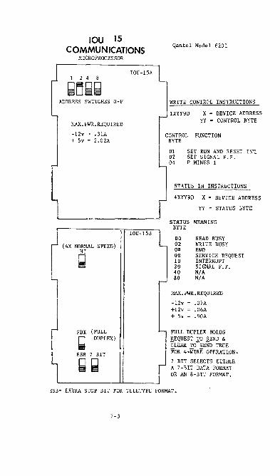
IOU 15 COMMUNICATIONS
MICROPROCESSOR
1 2 4 8
~[j~~ ADDRESS SWITCHES O-F
MAX.PWR.REQUIRED
-12v ' .31A + Sv = 2.02A
(4X NORMAL SPEED)
Q
FDX (FULL
~ DUPLEX)
ESB 7 BIT
~~
IOU-1SA
IOU-ISB
Qantel Model 6201
WRITE CONTROL INSTRUCTIONS
lXH9D x = DEVICE ADDRESS YY = CONTROL BYTE
CO~TROL FUNCTION BYTE
01 SET RUN AND RESET INt 02 SET SIGNAL F.F. 04 P MINUS 1
STATUS IN INSTRUCTIONS
4XYY9D X = DEVICE ADDRESS
YY = STATUS BYTE
STATUS MEANING BYTE
00 02 04 08 10 20 40 80
READ BUSY WRITE BUSY END SERVICE REQUEST INTERRUPT SIGNAL F.F. N/A N/A
MAX. PWR. REQUIRED
-12v = .07A +l2v = .06A + Sv = .90A
FULL DUPLEX HOLDS REQUEST TO SEND & CLEAR TO-SEND TRUE FOR 4-WIRE OPERATION.
7 BIT SELECTS EITHER A 7-BIT DATA FORMAT OR AN 8-BIT FORMAT.
~SB= EXTRA STOP BIT FOR TELETYPE FORMAT.
7-3

IOU 22 PARALLEL
COMMUNICATIONS Qantel Model 6202
S 4 2 1
~g~~
MAX. PWR • REQ.
-12v = .07A +l2v .06A + 5v "- 1. 27A
ADDRESS SWITCHES O-F
ESB 7 BIT
~~
ESB= EXTRA STOP BIT FOR TELETYPE FORMAT.
7 B IT= SELECTS EITHER A 7 -BIT OR AN 8-BIT DATA FORMAT. 7-BIT IS USED FOR SYNCHRONOUS COMMUNICATION.
WRITE CONTROL INSTRUCTIONS
lXYY9D
CONTROL lIYTE 00 01 02 03 04 05 06 07 08 09 OA OB OC OD OE OF STATUS IN
4XTI9D
STATUS BYTE 01 02 04 08 10 20 40 80
X = DEVICE ADDRESS YY CO:-JTROL BYTE
FUNCTION
RESET BYTE ~10DE SET BYTE ~~ODE RESET SYNC ~IODE SET SYNC mOE RESET 1/8 SPEED SET 1/8 SPEED RESET SX SPEED SET 8X SPEED RESET CALL REQUEST SET CALL REQUEST RESET ALLOW INTERRUPT SET ALLOI~ INTERRUPT RESET INTERRUPT GIVE NEW SYNC RESET DATA HI SPEED SYNCHRONUS SET DATA HI SPEED SYNCHRONUS
INSTR!JCTIONS
x = DEVICE ADDRESS YY = STATUS BYTE
MEANING
NIA NIA TRANSMIT SERVICE REQUEST READ SERVICE REQUEST INTERRUPT EVEN PARITY IN TRANS~lIT REGISTER ENEN PARITY IN RECEIVE REGISTER END TIME OUT
7 -4

aDCDJCllIcm 1 2 • 8
'1
IOU-39Q
00000 ROM'S zao
TYPICAL POWER REgUIRE~NTS
-12V = .100A
+12V = .150A
+5V = 1.5A
$aD- MASTER DEfAULT should be set if the lOU-39Q is at ad
dress 1'1 in the backplane with terminal device 0 (the
IPL device) connected.
$4OJ $2~ RECEIVE TI~OUT 2*' 2*' TI~OUT
1'1 0 15 msec
0 1 50 msec
1 1'1 150 msec
1 1 500 msec
:~} Used only when the IOU-J9Q is
$04 SLAVE TERMINAL ADDRESS used in Slave Mode. Addresses
$02 $01 through $1f may be used.
$01
I~~~:: ~~~'II»::I,IEl 7-5

P1
STATUS IN Instructions
*P2 is used with a Test Panel
ltdyy9D d • Devl ce Address yy • test bit value
Status Byte:
" Read Busy '2 Wr i te Busy ,4 End ,8 Serv I ce Requas t " Interrupt (if enabled) 2. Channel A Te .. minatlon signal Itt Channel B Termination slgnCi~ Sf RAft Poll" i ty Er .. o ..
READ Status
xdyy86 d • Device Address
Ha .. cIw I .. ad to SA3
WRITE CONTROL Instructions
ldyy9D d • Device Address
Control Byte: 1st. High RAM address 2nd • Low RAM address
7-6
yy • test bit value
yy • Contro I Byte
/Allows read or write ............. to two-port RAM

PROCESSOR
CENTRAL PROCESSING UNIT
The Central Processing Unit (CPU)cordinates program activities by manipulating (add, subtract, edit, etc.), storing (read/write), and moving data. Each function is accomplished by stepping through micro-instruction routine from a Read Only.Memory (ROM).
The CPU always operates from macro, or machine language, instructions. Macro instructions can be entered i'P.. hexidecimal form directly from a peripheral, but are usually created by a compiler or assembler (QIC or QBAL).
Each macro instruction contains the initial address for a ROM routine. The ROM address is loaded into a counter that is incremented one count at a time, or reloaded with a new ROM address if the ROM routine requires a branch within the ROM program.
During the course of a macro instruction, the CPU generates and stores certain results. Some of these results are placed into flip-flops, some into hardware registers, and some are placed into the lower addresses of main memory. The hardware registers are assigned alphabetic names (A, B, P, etc.) and the portion of memory that is used for temporary storage is called Reserved memory.
Rese rved Memory
Reserved memory is not exclusive, protected, or seperate from main memory as the name implies. It is the first (lowest) 32 bytes in memory, designated as addresses 0 to 31. Bytes, as refered to in this text, are a set of eight bits. These 8 bits may translate to an ASCII character, but are always stored in memory as the two 4-bit characters of a hexidecimal notation pair. Specific areas of reserved memory are used for each type of storage. The areas and use are listed below.
AREA
OOOO-OOOF
OOlO-OOll
0012
0013-0014
USE
Accumulator positions, a scratch pad area for the results of multiple add instructions, etc. When a single address instruction is used, the implied second operand is the accumulator and its contents.
Stores the current program address while the CPU is servicing an interrupt.
Stores the contents of the condition switches (flip-flops) Carry, Minus, and Non-zero.
Also contains the Interrupt Enable bit.
The address in these two bytes will replace the current program address when an interrupt is recognized.
8-1 Revised 5/82

PROCESSOR Reserved Memory (Continued)
AREA
0015-0016
0017
0018-0019
USE
One count more than the final address at the conclusion of an I/O operation. During an I/O .operation, as data is taken from or placed into memory, the address count is incremented. When the last transfer is completed, the address is incremented once more, and the count is stored. The progr8lllIler can use this for self-terminating, continuous, non-counting I/O instructions.
Stores the I/O status byte when a Status-In instruction is executed.
Q5 only: Stores the current program address when a Branch instruction is executed.
Q6, 6.5, 7, and 7.5: Contains the ''Match'' address for the fo llowing ins truc tions.
Search Equal (SEQ) Search Equal L&R (SER, SEL) Search Unequal L&R (SNR, SNL)
001 A-D01 D Micro program utility area.
001E-D01F Q-29 P.C. before soft IPL Test Panel
The test panel has the ability to suspend normal timing, and stop processor actions so they can be examined. Test panel displays include the major hardware registers, and the contents of any byte in memory. The test panel is primarily used to examine processor actions as they are being performed. Selectively, the processor can be made to stop at each micro instruc tion, or at the end of each macro instruction. In either case, the operator must manually step to the next instruction. Using the test panel as a tool, and by knowing what should be each register at different times, the field engineer can isolate difficu 1 t hardware or progran problems. The test panel operator controls and indicators are shown and described in the illustrations and tables that follow.
Some test panel functions are different when a test panel is modified and .placed into a 7.5 (model l300) processor.
8-2 Revised 5/82

I~ 9.
IBJ
PROCESSOR
TEST PANEL _ :E CONFIGURATIONS 1 WI 10
• CD S, Z IPL
,9s, g g 1; g :al
IPl MIlIA ZSP AMI ADOI. I
0000 ooo~ I .~t
1888Q 00000 QQQQQQ
8-3

PROCESSOR
Test Panel (Continued)
NAME
FR Function Repeat
SF Single Function
ICSP Ins t ruc t ion Complete Stop
IPL Ini tia te Program Load
MIM Micro Ins truc t ion Mode
MASP/ZSP Memory Addr. Stop/Z Reg. Stop
FUNCTION
A two-position switch, when in the FR position, repeats the current micrtJ instruction continuously. When the SF switch (2) is in the SF position, the micro instruction will only be repeated when the ST-SP switch (13) is pressed.
A two position switch, when in the SF (single function) position, enables the ST-SP switch (13) to perform one micro instruction at a time. If the SF switch is turned ON when the processor is running, processing halts after the current micro instruction is executed.
A two position switch, when in the ICSP (Instruction Complete Stop) position, causes th .. processor to halt after executing and completing the current macro instruction. The ST-SP switch (13) is used to fetch and execute the next instruction.
Momentary-contact switch, provides a general reset to the processor. The IPL routine generates an instruction to read hex (without count) from device zero to memory location zero.
A two-position switch, when in the MIM position, places the processor control into the micro instruction mode. Micro instructions are then taken from main memory, rather than from a ROH.
A three position switch. When in the HASP position, the processor will execute instructions at full machine speed, until it is required to read/write to whatever address is selected on the switch/lamps (12). The read or wri te is executed, but the processcr is halted at that micro instruction. The readh.rite address may come from the A, B, or P register. In the ZSP position, the processor will proceed at full machine speed until a micro instruction is fetched by the z register from a ROM address that is the same as that selec ted by the switch lamps (12). However, the A, B, and P registers will also halt processing if their contents compare with the switch lamp settings. This is to allow the processor to stop at a particular micro instruction when it is in the MIM mode. To avoid confusion, keep all r/w program at memory addresses above 1000. The center switch position allows the processor to proceed normally, unless the sitj.gle function or instruction stop switches are in use.
8-4

PROCESSOR Test Panel (Continued)
AMI A two' position switch, When in the M!l position, Address prevents increroenting the selected address when either Modification the WR (11) or RD (0) switch is depressed, The N!l Inhibit switch also controls a periodic READ function to
dynamically display the contents of a location. Do NOT operate either the RD (II) or HR (11) switch when the processor is running, and this switch is in the AMI pos ition.
DATA/E/ADDR A three' position switch to control the display or entry of data and addresses. Is used in conjunction with the RD (10), HR (11), SWITCH/LA,"-\PS (2), Z, P, and SP controls.
R Push-button switch. When pressed, resets any data Rese t or addresses that are se lec ted on the switch/ lamps.
When the switch/lamps are reset, the lamps are not lit (zero state).
RD A momentary-contact switch. When depressed, reads from a previously selected address in memory. Displays the data in the two least significant columns of the switch/lamps (only if the DATA/E/ADDR switch is in the DATA position). The selected memory address is then automatically incremented by one count, unless the AMI swi tch is ON.
HR A momentary-contact switch. Writes whatever data is selec ted on the switch/lamps, to a previous ly se lec ted position in memory. The selected memory address is then automatically incremented by one count, unless the AMI switch is ON.
SWITCH/LAMPS Four columns of lighted push-button switches. Each column represents four binary bits, with the lowerright bit being the least significant. The lamp is lit when the bit position is in the "I" state. The switch/lamps are used as follows:
To address any location in main memory by placing the DATA/E/ADDR switch in the ADDR position, and select the desired address.
b. To read the contents of the selected position in memory by settin,! the DATA/E/ADDR switch to the DATA position. rJata is displayed in the two least significant (right hand) colums.
To alter (place data into) memory at the selected location by placing the DATA/E/ADDR switch in the DATA position, selecting the character code in the two least significant colums of the switch/lamps, and depressing the HR switch.
d, To display the contents of the E register (the micro instruction that is being performed) by placing the DATA/E/ADDR switch in the E position.
5/82 8-5

PROCESSOR
Test Panel (Continued)
ST-SP A momentary-contact switch that will hal t the processor Start/Stop at the end of the current macro instruction. It will
restart processing if in a halt condition, by initiating the next instruction. If the SF (2) switch is ON, ST-SP must be depressed for each micro instruction. If SF is OFF, and ICSP is ON, ST-SP is depressed for each macro instruction.
A momentary-contact switch that will display the contents of the Z register (the micro instruction address) on the switch/lamps if the DATA/E/ ADDR switch is in the ADDR position.
A momentary-contact switch that will display the contents of the P register (program address) on the switch/lamps if the DATA/E/ADDR switch is in the ADDR position.
SP A momentary-contact switch that will enter the Set P address that is displayed (selected) on the switch/
lamps if the DATA/E/ADDR switch is in the ADDR position.
A
CD
DMA SEL
Direc..t Hemory Access Select
A momentary-contact switch that displays the 15 loworder bits of the B register on the switch/lamps if the DATA/E/ADDR switch is in the ADDR position.
A momentary-contact switch that displays the 15 loworder bits of the A register on the switch/lamps if the DATA/E/ADDR switch is in the ADDR position.
A momentary-contact switch that displays the contents of the C and D registers on the switch/lamps if the DATA/E/ADDR switch is in the DATA position.
A lO-position thumbwheel switch. Selects one of nine direct memory access devices. When the wheel is moved from zero, all processing stops in the devices and the processor. The ST-SP switch will allow all devices and the processor to perform one micro instruction at a time. The A, B, Z, and P registers of the selected direct memory access device can be displayed on the swi tch/ lamps instead of the processor registers.
5/82
8-6

£i,
PROCESSOR MEMORY ORGANIZATION AND INSTALLATION
.The first 16k of memory must reside within one (either) of the MEM slots in the mainframe. It will be either a MEM 3 with the HI/La switch set to La, or the lower two MEM SB cards on a MEM SAP.
(
If a fully configured MEM SAP board (containing 4 MEM SBs) is used, it must reside in one (either) of the MEM slots, and the other MEM slot must remain empty. Additional memory can be added, but only in slots IOCl or IOC2 ~."ax. 16k each).
Only one fully configured MEM SAP is allowed in 7.0 or lower processors (mode 1 1200 or lower) .
• La memory in either of the IOC slots, or greater than 32k total in the MEM slots causes random processor errors. La memory can be a MEM 3 with the swi tch se t to La, or a MEM SAP wi th one or both MEM SB boards in the lower posi tion .
• The lowest 16k of memory is designated as bank A, and is avai lab le regardless which upper memory bank is se lec ted. After a reset (RIO) or IPL, the second 16k of memory, bank C,is automatically selected along with bank A. Memory beyond 32k is selected by bank switching instructions as follows:
NOTE:
MEM 3
j,lj,lj,lj,lAC = Access A and C (used to return to C) 00!i10AD = Access A and D (third 16k of memory) j,l!il!il!ilAE = Access A and E (fourth 16k of memory)
Bank switching instructions should only be issued by a program running in the A bank (first 16k) of memory.
Mem 3 boards accommodate up to four 4k modules (MEM 3B) of 4k each. Addresses within the card are shown be low. Except for the first 16k of memory (addresses 0000-3FFF) in the MEM slot, the switch must be in the HI position.
NOTE:
',.11 ~I' !;IQ g~
While MEM 3 boards will operate in the 900 and 950 processors (6.5 backplane) the BEST operating system requirements make this combination imprac tical.
5/82
8-7

PROCESSOR
MEM SAP boards will accommodate up to four modules (MEM 58) of 8k each. It also has the capability of pari ty checking and storage. The MEM SAP addresses within the board are shown in the illustration below.
NOTE: The pari ty reporting portion of the MEM SAP appear< to the processor as an I/O device. If the MEM SAP address switches are set to the same address as an IOU, the IOU wi 11
4TH not function. 8K
6OO0-7fff
2ND 8K
Set 7/7.5 switch DOWN (7 position) for Q6, Q6.5, and Q7. Set in UP position (7.5) for all others.
Parity checking and reporting are distinctly seperate from memory operation, and the memory is not affected or inhibited in any way by the parity circuits. However, IOUs can be affec ted if the MEM SAP address swi tches are improperly se t. Parity is always generated, and is stored as a ninth bit when data is put into memory. Odd parity is nomal, but even parity can be set by microinstruction for special diagnostics. Parity errors are not reported or stored (fuses blown) unless enabled by write control instructions. However, many programs and diagnostics "arm tl the memory automatically, useing these w-rite control instructions.
If parity checking is used, the memory must be writen into in every location (initialized) to assure that every position has proper parity. The disc loader, LOADQ, automatically initializes the memory and enables both parity checking and error storage.
Parity error storage physically blows a fuse. which inturn causes an LED indicator to light. There is one fuse/indicator circuit for each 8k modu le.
The device control instructions are as follows: 1dyy<}D 20 Resets 'Allow Parity Check' (disables checking)
21 Enables Parity Check
40 Inhibit Interrupt
41 Allow Interrupt. When parity error is found when checking is enabled, Interrupt is raised to the processor.
61 Enables parity error storage.
Address switches for the parity reporting portion of the MEM SAP board are arranged as shown below.
Switches are shown set to address 5.
8-8 Revised 5/82

Status - In Instructions 4dtt9D (d '" device number)
tt
Sal 0 $92 0 $94 1 $08 Even Parity $19 Parity Error $20 Which Chip Group on SB $49 See Below $80 See Below
$80 $49 Which Mem SB
0 0 First 0 1 Second 1 0 Third 1 1 Fourth
NOTE: Normal Status is $E4.
5/82
8-8A
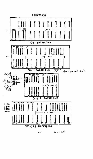
PROCESSOR
Q 5 BACKPlANE
in~ Til i i iUHIi J 1 2 3 4 5 6 7 8 9 10 11 12 13 14 15 16 17
Q'J"L I I/O'S ONLY I
11I1! I J II , III1 J 18 19 2021 22 23 24 25 26 2( 28 29 JO 31
06 BACKPlANE 7Pi).--r_ t' "'/1 } "''', 'f--Ie;;;..$' p, p "
11 RA I TPU n MEAt I/o ' I
~~a 1'1 I~ I iliil &o/BR~ J 1 2 3 .. S 6 7 8 9 101112
HfG{ III II r~iS T-j 113 14 IS 1617 18. )9' '21) ~I
Q 6.5 BACKPLANE
TPU n MfM 1/0/MENI
g:~ I n 1 illS 1'111 8;li
913
1~ J I 2 3 4 S f 7 • 9 1 11 12 13 14 II 1611 1_ 1- I/O'S ONLY I
.IUlIl J I I I J I J I , Q7, Q 7.5 BACKPLANE
8-9 Revised 3/77

CPU- A/AR
CPU-· I/IR
PROCESSOR
CPU IOARD LAYOUT
MICROPROCESSOR
REGISTERS AND ALU
P REGISTER C REG
A REGISTER DREG
I REGISTER ALU
8-10

.JO 0 3 \-10 0:;:::
fb
....Q
T- O> ()
...., c .. "'
(jJ ~ 11 [ V\
t- v.> "-
C: 0 "-
u '" ~ <Y\ ~f __
'c ~
PROCESSOR REVISION LEVEL
Q 5 LEVEL 1 BPU - ROM 1 & 2
Q 5 LEVEL 2 BPU - ROM 1,2, & 3
Q 6 LEVEL 1 CPU A/B ROM 1,2, & 3
Q 6 LEVEL 2 CPU A/B ROM l,2,FL3
Q 6 LEVEL 3 CPU AR/B ROM 5,6,7
Q 6.5 LEVEL 1 CPU AR/B ROM 5,6,8,9
Q 6.5 LEVEL 2 CPU AR/BR ROM 5,6,8,9
Q 7 LEVEL 1 CPU AR/BR ROM 5,6,8
Q 7 LEVEL 2 CPU AR/BR ROM 5,6,8,9
Q 7.5 LEVEL 1 CPU AS/BS
2311 DISK
NO
YES
YES
YES
YES
NO
NO
NO
NO
NO
HARDWARE COMPATIBILITY GUlDE
2314 3+3/6+6 QCRT MEM2 MEM3 MEM5 DISK DISK
NO NO NO YES NO NO
NO NO NO YES NO NO
--- -----
NO NO NO NO YES YES
YES NO :;0 NO YES YES
YES NO NO NO YES YES
----YES YES YES NO YES YES
YES YES YES NO YES YES
-YES YES YES NO YES YES
YES YES YES NO YES YES
YES YES YES NO NO YES
* Selectric cannot be used on these models. ~ (# II Ib(.lJ~r
MAX MEMORY SYSTEM
8K V
8K V
---- ---- ---
32K VI
32K VI
32K VI
--"---"._--"-- f---------
32K 800 * 900 *
48K 950 ,~
64K 1100 1200
--64K 1100
1200
--"---"._---
128K 1300
S?' D PJ Y
"tJ :::tJ o n m Ion Ion
o :::tJ

PROCESSOR
MACRO INSTRUCTION SET
BACKPLANE \JILnQ'\O'O"O"--...J"'''-J
l.n l.n LEVEL OP VAR VAR 121231121 INSTRUCTION MNEMONIC CODE 1 2
*********READ RD 0 *********READHEX RHX 0 * * * * * * * * * READ AND COUNT ROC 0 * * * * * * * * * READ HEX AND COUNT RHC 0 * * * * * * * * * ADD DEC lMAL ADD 1 * * * * * * * * * SUBTRACT DECIMAL SBD 2 * * * * * * * * * MULTIPLY DECIMAL MPY 3 * * * * * * * * * DIVIDE DECIMAL DIV 4 *********LOAD LD 5 * * * * * * * * * STORE ACCUMULATOR STA 6 *********MOVE MOV 6 * * * * * * * * * COMPARE LOGICAL CMP 7
* * * * * * * * SEEK SEK 8 * * * * * * * * DISC BOOTSTRAP 8
* LOAD BASE REGISTER LBR 8 * * * * * * * TRANSLATE TRN 8
* LOAD DMA BANK LDM 8 * * * * * SEARCH EQUAL SEQ 8 * * * * * COMPARE NUMERIC CN 8 * * * * * COMPARE ZONE CZ 8
* * * * READ STATUS 2 RS2 8 * LOAD IMMEDIATE LDI 8 * ADD IMMEDIATE ADI 8 * SUBTRACT IMMEDIATE SBI 8 * READ BASE REGISTER RBR 8 * TRANSLATE RIGHT TO LEFT TRR 8
* * SCAN UNEQ RIGHT TO LEIT SNR 8 * * SCAN EQUAL RIGHT TO LEIT SER 8 * * FILL RIGHT TO LEIT FR 8
* * * MOVE RIGHT TO LEIT MR 8 * * * EXCHANGE RIGHT TO LEIT XR 8 * * * COMPARE RIGHT TO LEIT CR 8 * * TRANSLATE LEIT TO RIGHT TRL 8
* * SCAN UNEQ LEIT TO RIGHT SNL 8 A * * SCAN EQUAL LEIT TO RIGHT SEL 8 B * * FILL LEIT TO RIGHT FL 8 * * MOVE LEIT TO RIGHT ML 8 D
* * * EXCHANGE LEIT TO RIGHT XL 8 * * * COMPARE LEIT TO RIGHT CL 8
* * INTERRUPT SCAN SCI 8 * LOAD BASE REG & BRANCH LBB 8
* * UNStACK AND RETURN RET 8 * * STACK RET ADD & BRJI..NCH SUB 8 * * PULL DATA OFF TOP OF STACK PUL 8 * * STACK DATA & RET 0 IN LINE PSH 8
* * * UNSTK DATA & RET. IN LINE POP 8 * * * INCREMENT BY 1 IN1 8 A * * * DECREMENT BY 1 OCl 8 B * * * INCREMENT BY 2 IN2 8
* * DECREMENT BY 2 OC2 D
8-12 Revised 3/10/76

PROCESSOR MACRO INSTRUCTION SET
BACKPLANE
LEVEL 121231121 INSTRUCTION
* * INCREMENT BY 3 * * * DECREMENT BY 3
*********AND *********OR * * * * * * * * * EXCLUSIVE OR * * * * * * * "* * TEST BIT * * * * * * * * * MOVE NUMERIC *********MOVE ZONE * * * * * * * * * COMPARE DECIMAL * * * * * * * * * SHIFf BIT LEFf * * * * * * * * * SHIFf BIT RIGHT * * * * * * * * * EDIT * * * * * * * * * UNEDIT * * * * * * * * * PACK * * * * * * * * * UNPACK * * * * * * * * * I/O EXECUTE * * * * * * * * * DEVICE CONTROL * * * * * * * * * SET READ * * * * * * * * * STATUS-IN * * * * * * * * * RESET I/O * * * * * * * * * RETURN FROM INTERRUPT * * * * * * * * * NO OPERATION * * * * * * * * * BRANCH ON OVERFLOW * * * * * * * * * BRANCH ON MINUS * * * * * * * * * BRANCH ON NON-ZERO * * * * * * * * * BRANCH EQUAL
** * BRANCH NOT MINUS * BRANCH NOT OVERFLOW
* * * * * * * * * UNCONDITIONAL BRANCH * * * * * * * * * HALT AND BRANCH * * * * * * * * * BRANCH AND LINK
* BRANCH PLUS ******** MICRO INSTRUCTION MODE
* * * * BANK SELECT C * * * * BANK SELECT D
* * * BANK SELECT E * BRANCH NOT PLUS
* * * * * * * * * WRITE * * * * * * * * * WRITE HEX * * * * * * * * * WRITE AND COUNT * * * * * * * * * WRITE HEX AND COUNT * * * * * * * * * ADD BINARY * * * * * * * * * SUBTRACT BINARY * * * * * * * * * LOAD ADDRESS
OP VAR VAR MNENONIC CODE 1 2
IN3 DC3 AND OR XOR TBT MN MZ CD SBL SBR EDT UED PAK UPK lOX CTL SRD SIN RIO RTl NOP BOV
BMI(BGT) BNZ(BNE) BEQ(BZ) BNM(BLE)
BNO BRU HLT BLI BPL MIM BSC BSD BSE BNP WR WHX WRC WHC ADB SBB lOA
8 8 9 9 9 9 9 9 9 9 9 9 9 9 9 9 9 9 9 9 9 A A A A A A A A A A A A A A A A B B
A
D D D
A
B C
8-13 Revised 3/10/76

TEST PANEL OPERATION WITH l300
The TPA and TPU test panels are compatab1e with the l300 (7.5 backplane) but some of the functions display or control different registers. The following is a list and explanation of the test panel functions when used with the 7.5 backplane. Operation of the DMA switch becomes complex with the 7.5, and is explained in text, but is followed by a table. The table sumarizes all of the registers that can be selected through the DMA switch.
FR Creates the 216 bit that is needed for test panel addressing in the 7.5.
SF When the Single Function is ON, the 7.5 runs at machine speed until it reaches a "bus" cycle, then it halts. A bus cycle is either a memory cycle or an I/O cycle.
ICSP Stops after each macro instruction.
IPL General reset of the processor. The processor halts just before executing whatever instruction is at memory location zero. IPL does NOT generate a read hex instruction as it does in the earlier processors.
MIM Generates tie 215
bit for memory addressing from the test panel.
MASP/ In the MASP position, causes the pr0cessor to halt ZSP when the processor is required to access the memory
address that is contained in the test panel address register. The contents of the test panel address register is displayed when the DATA/E/ADDR switch is in the ADDR position. In the OFF position, the MSAP/ZSP switch has no effect. The ZSP position is not used with the 7.5 backplane.
AMI When in the ON position, inhibits the address advance that is normally automatic when the RD (read) or WR (write) function is used. When the machine is running and AMI is ON, the memory contents from the test panel ADDRess register is read into the test panel DATA register after every refresh cycle.
DATA/E/ ADDR The E position has no effect in the 7.5 backplane processor. The DATA and ADDR positions display the contents of the data and address registers within the test panel. These registers can be reset (by pressing the R button) to a zero state, then reloaded by depressing the desired bit switches.
R Resets the particular register (DATA or ADDR) that is selected by the DATA/E/ADDR switch. The other (unse1ected) register is not reset.
8-14 Revised 3/77
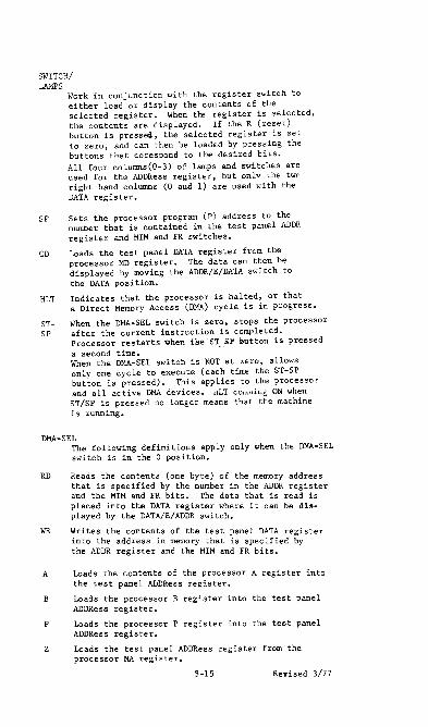
SWITCH/ LAMPS
Work in conjunction with the register switch to ei ther load or display the contents of the selected register. When tre register is selectee, the contents are displayed. If the R (reset) button is pressed, the selected register is set to zero, and can then be loaded by pressing the buttons that corespond to the desired bits. All four columns(0-3) of lamps and switches are used for the ADDRess register, but onlY the twn right hand columns (0 aud 1) are used with the DATA register.
SP Sets the processor program (p) address to the number that is contained in the test panel ADDR register and MIM and FR switches.
CD Loads the test panel DATA register from the processor MD register. The data can then be displayed by moving the ADDR/E/DATA switch to the DATA position.
HLT Indicates that the pzocessor is halted, or that a Direct Memory Access (DMA) cycle is in progress.
ST- When the DMA-SEL switch is zero, stops the processor SP after the current instruction is completed.
Processor restarts when tee ST .. SF' eutton is pressed a second time. When the DMA-SEL switch is NOT at zero, allows only one cyc Ie to execute (each time the ST-SP button is pressed). This applies to the processor and all active DMA devices. nLT cOlOming ON when ST/SP is pressed no longer means that the machine is running.
DMA-SEL The following definitions apply only when the DMA-SEL switch is in the 0 position.
RD Reads the contents (one byte) of the memory address that is specified by the number in the ADDR register and the MIM and FR bits. The data that is read is placed into the DATA register where it can be displayed by the DATA/E/ADDR switch.
WR Writes the contents of the test panel DATA register into the address in memory that is specified by the ADDR register and the MIM and FR bits.
A Loads the contents of the processor A register into the test panel ADDRess register.
B Loads the processor B register into the test panel ADDRess register.
P Loads the processor P register into the test panel ADDRess register.
Loads the test panel ADDRess register from the processor MA register.
8-15 Revised 3/77
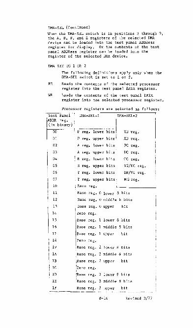
DMA-SEL (Continued)
When the DMA-SEL switch is in positions 3 through 9, the A, B, P, and Z registers of the selected DMA device can be loaded into the test panel ADDRess register for display. Or the contents of the test panel ADDRess register can be loaded into the register of the selected DMA device.
DMA SET TO 1 OR 2
The following definitions apply only when the DMA-SEL switch is set to 1 or 2.
RD Reads the contents of the selected processor register into the test panel DATA register.
WR Loads the contents of the test panel DATA register into the selected processor register.
Processor registers are selected as follows:
I Test Panel I DMA-SEL=l DMA-SEL=2 ADDR reg.
I (in binary) --- ------------- -----1
00 P reg. lower bi ts , TD reg.
01 P reg. upper bits! XD reg.
02 , A reg. lower bits FC reg.
03 ' A reg. upper bits DC reg.
04 :, B reg. lower bits CC reg •
as • B reg. upper bits' V2/EC reg.
06 T reg. lower bits OP/Vl reg.
07 T reg. upper bits M S reg.
10 : Zero reg.
11 Base reg. a lower 8 bits
12 Base reg. a middle 8 bits
1.0. Base reg. a upper bit
14 Zero reg.
15 Base reg. 1 lower 8 bi ts
16 Base reg. 1 middle 8 bits
17 Base reg. uppel bit
18 I"" reg.
19 Base reg. lower 8 bits
lA IBase reg. 2 middle 8 bits I
IB iBase reg. upper bit
Ie I :Zero reg.
ID :Base reg. lower 8 bits
IE Base reg. 3 middle 8 bits
IF ~ase reg. 3 upper bit ,._--_. -.--~ ... -------~
<'\-16 Revised 3/77

Q298
CENTRAL PROCESSING UNIT
The 0299 logic assembly serves as the CPU for the OANTEl 970 and
1450 Systems. It is a single board CPU, utilizing bipolar bit
slice microprocessing elements, field progra/l1llable logic arrays
(FPlA), and a pipelined architecture. It contains ROI,I microcode
which interprets the standard OANTEl instruction set. The 0299
is slightly faster than the 07.5 processor and introduces a main
memory capability of one megabyte (1024K).
No Direct-I·1emory Access (Dt-IA) controllers are supported on the
029B. In particular the controllers and their replacements are:
DI·1A CONTROLLER
IOU-15 COII1lIunications
IOU-Z8 OCRT
IOU-3Z l-Iemorex Disc
MACHINE LANGUAGE CONPATIBILITY
REPLACEt£NT
IOU-40
IOU-39T
Non-Dl·1A IOU-3Z
• All machine instructions available an the 07.5 processor are
i~lemented on the 0299. The condition switches (NZ, rH, OV)
are set as on the 07.5.
• The load Decimal instruction sets the Nonzero switch if the field
being moiled is not equal to decimal zeros.
• There are t\~O new instructions which enable and disable I/O in
terrupts. location $1 Z (bit Z .... 7) is no longer used as the inter
rupt enable switch.
• There are sixteen ZO-bit base registers as compared to four 17
bit registers in the 07.5. This allows a main memory capacity
of 11i!lZ4K. The old Set 9ank and load Base Register instructions
are supported in addition to new base register instructions.
8-17

0298
9298 IPl FEATURE
• At power-on or when the IPl but ton is pressed, the CPU performs
the following operations:
1) loads its base registers to point to the first 32K of main memory C banks A/C).
2) Resets all I/O controllers (0-F).
3) Reads from device 0.
4) Branches to fetch the first QANTEL instructions.
• The data entered on device 0 may have many forms. If the opera
tor only presses TRANSf.1IT, the CPU will bootstrap to disc 00.
If the entered data consists of b.o hexadecimal characters, the
CPU bootstraps to the disc with this device number Ceg, 10 or 0C).
Otherwise, the data should be hexadecimal QANTEl machine language
instructions. The data is packed, two hex digits per byte, and
placed starting at location 0 in memory. Non-hex characters
(except Q and ') are ignored. Execution of Q~NTEL code begins
at location 0.
• r f a Q is encountered, then the next 4 characters form a hexa
decimal address. This address is used as the location to place
the subsequent data. As a special case, if Q is the first char
acter entered, then the hex address following the Q is used as
the execution start address for the QANTEL machine code. The
CPU branches to fetch instructions from the address speci fied
after the Q.
• If an apostrophe C') is encountered, then the following data char
acters are interpreted as ASCII and placed directly into memory
(with no packing). No characters are ignored. ASCII mode is
terminated by another apostrophe.
8-18

Q298
0298 HACHlt£ lANGUAGE: INSTRUCTION SET
OOJ[C r Coo[ INSTRUCTION ItVOIIC
aaasl'ld Read RD IInn1 aaaal'ld Read He~ RHX ecccr2 aaaal'ld Read With Count ROC cecen aaaaSd Read Hex With Count 1M:
N ccccfli bbbb8x 88B8 CRC Calculation eRe [bbbbfl] asaa1l Add Decill81 NlO (bbbbfl] aaaa2l Subt ract Dec illl81 S8D [bbbbfL] aaasJl ttlItiply Oeci_l HPY [bbbbfl] aaaa4l Divide Oeci_l DIY (bbbbfl] aaaa5l load Decimal LD bbhb6L Store Acctallator STA bbldL aaaa6L Move KIY [bbbbfl] aaaa7l COIIpal't! CHI'
uea88 Seek SEK 8881181 Diac Bootstrap OBS a88882 load Base Register lBR
bbbbfx aaaaB2 tt Tr_late TRN bbbbfl aaaaB3 lL Search [qual SEQ [bbbbfL] aaaaBli COIIpare Nuoaer ic CN [bbbbfl] aaaaB5 COIIpBre Zone CZ
xdsaB6 Raad Status 2 RS2 bbbbfll aaaa86 Load l~iate LDI bbbbf1 aaaa86 Add IlIIIediate ADI bbbbf2 aaaa86 Subtract llIIIediate 581
N bbbbfJ aaaaB6 Move IRediate MVI _87 Read Base Register RBR
ecccr8 bbbb87 aaaa Translate Right TR ecccr2 bbbb87 aaaa Scan Ik1equal Right SNR cecer3 bbbb87 saaa Scan [qual Richt SER cecerli bbbb87 aaaa fill Right fR cecer5 bbbb87 Baaa Move Right til cecer6 bbbb87 aaaa Exchange Right XI ccccf7 bbbb87 88aa COIIpare Right at ccccf8 bbbb87 88aa Tr_late left TL
N ccccf9 bbbb87 aaaa Hex To Ascii Converaion HAC ecccrA bbbb87 aaaa Scan Ik1equal left SNL cecefB bbbb87 asaa Scan [qual lert SEL ecccrc bbbb87 88aa Fill Lert rL ccccfO bbbb87 aaaa Move Lert fI. cecer[ bbbb87 aaaa Excllonge Left XL ccccrf bbbb87 aaaa COIIpal't! Left a.
asaaB8 Scan Interrupt SCI bbbbf. aaaaBB Load Base Register" Branch LIlI
[] Fields enclosed in parentheses are optional.
N lnatructions IIlInked with an N are new.
8-19

N N
N N
N N
Q298
9299 MACHINE LANGUAGE INSTRUCTI~ SET Continued
OBJECT CWE INSTRUCTI~
SIIsaS9 Retul'n rl'OftI Subl'outine aassrl' "aa8889 Subl'outine Call sassFt aaaa89 Pull Data 8sssF2 saaa89 Puah Data s .. sFl aaaaS9 Pop Data
aass8A Jncl'ement By 1 ttttrlll aaaeSA Bunch On Table bbbbfl aaaaSA LoadsI' Relocation
naaOB Decrement By t cc:ccflll ssaaSB 1111 Load Base Uat cc:ccfl aaasBB 1111 Read Base Uat
aaaaBC Increment By 2 aaaeSO Decreaent By 2 aaaa8E Jnc~t By 3 aaaaSr Decr.-nt By 3
[bbbbh) aaaa9111 And [bbbbfx) aaaa9t Dr [bbbbfx) aaaan Exclusive 01' [bbbbfx) aaaa93 Teat Bit [bbbbrx) aaaa94 Hove "'-r1c [bbbbFx) aaaa95 Hove Zone (bbbbf"x) _a96 Callpare Dec 111191
88aa97 Shift Bit Left ccccrL aaaa97 Shift Held Lert
aaaa98 Shift Bit Right ccccrL aaa898 Shift Held Right [bbbbf"L) aa8a99 Edit bbbbf"l aaaa9A lk1edit [bbbbrl) aaaa98 Pack [bbbbrL) aaaa9C ~ack
IIIdxx90 I/O Execute ldes9D Device Control 2dxx9D Set Read lIdas90 Status In xdxx9E Reset I/O xxxx9r Return rrom Interrupt
xxur, xxxx9r Disable Interrupts xxxlln XllXX9r Enable Interrupts
eaaaAil No ~erotion auaAt Branch On Overflow _sA2 Branch On Hinua aaaaAl Branch On Nonzero _aAit Branch On Zero aaoaA5 Branch On Not ~'int19 .... A6 Branch On No Overflow naaA7 Branch lncondi ti_l
8-20
foKHONIC
RET SlII Pll. PSH POP INt BT lOR DCt LBl R8l IN2 DC2 IN3 DC3 AND OR XOR TBT ... HZ CO SBl SHl. 58ft stIR EDT 11:0 PAl( IJ'I(
JOX CTl SRO SIN RJO RTI OJ EI NO!' BOY BHI BNZ BZ Bt*t BNO 8RU
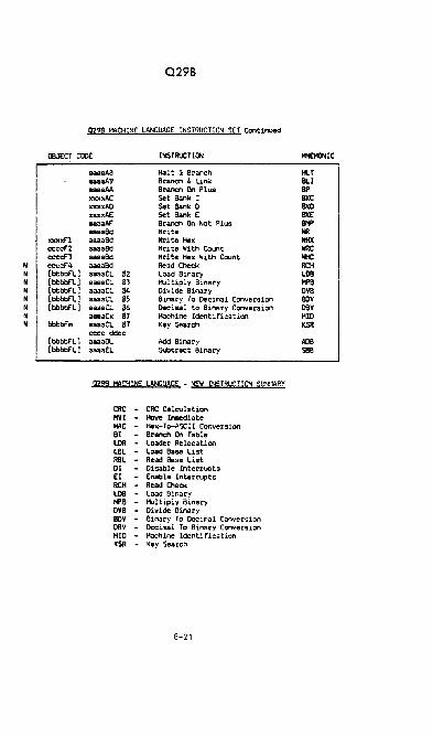
H H H H N N H H
Q29B
9298 MACHINE LANGUAGE INSTRUCTION SET Continued
OBJECT Coo( INSTROCTION
xxxxf"l ccccf"2 ccccf"J c:a.cf"4 [bbbbf"l] [bbbbf"L] [bbbbf"L.] [bbbbf"L.] [bbbbf"l]
bbbbf ..
(bbbbfll [bbbbf"l]
aaaaAS Halt & Branch IIIIIIaA9 Branch & link IIlIa8AA Branch On Plus xxxxAC Set Bank C xxxxAO Set Bank 0 xxxxAE Set Bank E .. aaAl" Branch On Not Plus lIeaaed Write aaaaed Write Hex aaaaed Write With Count aaaaed Write Hex With Count aaaaed Read Check aaaaCl \!!2 Load Binary aaaaCl In I-\JI tipl y Binary aaaaCL. \!14 Divide Binary aaaaCL. \!!5 Binary To Decimal Conversion aaaaCl \!!6 Decimal to Binary Conversion aaaaCx "7 Machine Identification aaaaeL. "7 Key Search =c ddee aaaaOL. Add Binary aauEL. Subtract Binary
Q298 MACHINE LANGUAGE - f:!EW I~'5TRUCTION SUlt·lAP.Y
CRt - CRe Calculation MYI - Hove Immediate HAC - Hex-To-ASCII Conversion BT - Branch On Table LOR - L.oader Relocation L.BL. - load Base L.ist RBL - Read Base List 01 - Disable Interrupts EI - Enable Interrupts RCH - Read Check LOB - load Binary MP8 - ..... ltiply Binary OVB - Divide Binary BOY - Binary To Decimal Conversion oev - !lccimal To Binary Conversion HID - Machine Identification KSR - Key Search
8-21
fot£HONIC
HlT BlI BP BKC BKD B1<E BNP IIR IiHX IiRC tIC RCH LOB MfB ova BOV DeY HID KSR
ADB sea

Q298
BASE REGISTERS AND r~E~10RY ADDRE"SING
The 029B system uses base register addressing. There are 16 base
registers with 20 bits each for one megabyte of addressing capa
bility. The base registers are numbered kl - F.
Any memory address referenced in a Oantel machine instruction con
sists of 16 bits. Bit 15 is the indirect addressing bit which is
resolved by the microcode (and is meaningless to the hardware).
Bits 11-14 from the memory address are used as the base register
selector. Bits kl-1kl are used as the displacement added to the
base register contents. Displacements are 11 bits in length,
giving 2K memory partitioning.
r4ENORY ADDRESS
bddd dddd dddd
I! Dikplacement
Base Register Selector
Indirect Bit
On every memory reference the hardware adds the l1-bit displace
ment to the 20-bit contents of the base register selected to form
the actual 20-bi t memory address.
8-22

0298
970 .... CKPL ... NE
I'&SO .... CICPL ... NE ME.'!ORV bA/S'
• 1.'he t'lrat ME!'t oA/! IDOduL~ should be pl.Jccd in slot number one .JIM tne t'ollowIn", ~£;M 6A/B's in numetic.l sequ .. nce.
8-23

MEM 6AfS
• The r·1£t.l 6A/8 is used with the Q298 CPU exclusively. It consists
of a t-1Et46A board assembly together with from one to eight MEI·168
modules. The f<1Et468 module is organized in 32K nine-bit words
(eight data bits and one parity bit). Each f4Et'!6A assembly can
accomodate up to eight 32K t4EH68 modules for a maximum of 256K
bytes of memory per MEt46A board assembly.
• The Q298 CPU has the capability of addressing up to 1 megabyte
of memory. The QANTEL 1450 can accomodate up to four fully
loaded ~1EM6A assemblies, for a maximum of 1 megabyte of memory
per system. The QANTEL 970 System has one memory slot (256K).
• The addressing of the ~lEt46A assemblies is location sensitive to
the backplane, which can accomodate from one to four t£M6A board
assemblies (refer to backplane illustration on previous page).
The addressing of the MEM68 modules (0-7) on each t·1Er·l6A board
assembly is shown below, and is listed more c~letely on the
following page.
~ 256K
{J8000 • JFFFF}
1281
{18000 • lFFFF} ~
IES£T SWI'ICH
8-24

MEM 6A/B MEMORY MAP
1st MEN 6A 2nd t·1Et-l 6A
0) $ 00000 - 07FFF 0) $ 40000 - 47FFF
1) 08000 - OFFFF 1) 48000 - 4FFFF
2) 10000 - 17FFF 2) 50000 - 57FFF
3) 18000 - 1FFFF 3) 58000 - 5FFFF
4) 20000 - 27FFF 4) 60000 - 67FFF
5) 28000 - 2FFFF 5) 68000 - 6FFFF
6) 30000 - 37FFF 6) 70000 - 77FFF
7) 38000 - 3FFFF 7) 78000 - 7FFFF
3rd t£N 6A 4th ~1Et4 6A
0) $ 80000 - 87FFF 0) $ COOOO - C7FFF
1) 88000 - 8FFFF 1) C8000 - CFFFF
2) 90000 - 97FFF 2) DOOOO - D7FFF
3) 98000 - 9FFFF 3) 08000 - OFFFF
4) AOOOO - A7FFF 4) EOOOO - E7FFF
5) A8000 - AFFFF 5) E8000 - EFFFF
6) 90000 - 97FFF 6) FOOOO - F7FFF
7) 68000 - 9FFFF 7) FBOOO - FFFFF
8-25

MEM 6AjB
MEM 6A/B CONTINUED
• The Q29B CPU generates a 20-bit memory address. The tl~O high
order address bits, AD19-AD18, are decoded to generate one of
four, BRD ENA-N, signals used to enable one of the four HGI6A
board assemblies per system.
• The four address lines, AD17-AD14, go directly to each of the
t4Er·16A board assemblies. Each r-016B module consists of two banks
of nine 16K dynamic RAr-Is For a total of eighteen dynamic RAI·IS and
32K 9-bit words of memory per r-1Ef.168 module. The 16K dynamic RAt·ls
employ a seven-bit multiplexed address in which a seven-bit row
address and a seven-bit column address are latched into the RAI1
at di fFerent times by the row address strobe, RAS-N, and the
column address strobe, CAS-N, respectively. The four non-multi
plexed address bits, AD17-AD14, are decoded by the r·IEl-16A board
assembly to generate the row address strobe, RAS-~, for one of
the sixteen posible 16K banks of RAt·' per t·1EfI6A board assembly.
The row address strobe acts as a chip select enabling the sub
sequent memory operation in the 16K bank which is selected.
• Fourteen address lines are multiplexed on the backplane in two
7-bit bytes, AD13-AD07 and AD06-AOOO, which are latched and buf
fered on the f.1Er16A assembly and go directly to the 16K dynamic
RAI4s on the r4Et16B modules.
• The refresh timing is generated by the Q298 processor. A refresh
cycle is performed every 16 microseconds maximum. The refresh
address counter is provided by the Q298 processor, which generates
an 128-cycle refresh every 2 milliseconds.
• The t·IEt-IORY 6 SYSTEf·l responds to the I/O control signals from the
backplane. The device address for selecting the t-1Ef.IORY 6A board
assembly is fixed at 5. If more than one r·TEH6A board assembly
is in the backplane, all 1-1E11 6A/B boards will be selected when
the CPU selects device address 5.
8-26
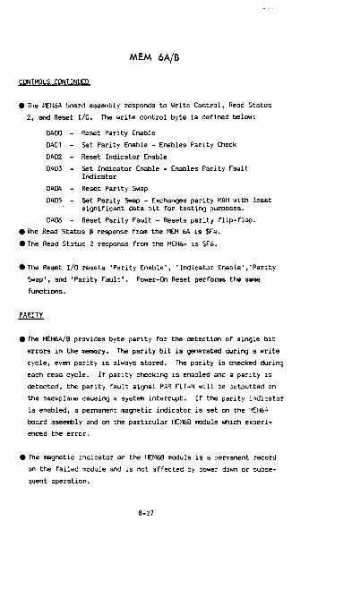
MEM 6A/B
CONTROLS CONTINUED
• The 1'1El-I6A board assembly responds to ~Irite Control, Read Status
2, and Reset I/O. The I~rite control byte is defined below:
DADO - Reset Parity Enable
DA01 - Set Parity Enable - Enables Parity Check
DA02 - Reset Indicator Enable
DA03 - Set Indicator Enable - Enables Parity Fault Indicator
DA04 - Reset Parity Swap
DA05 - Set Parity Swap - Exchanges parity RAt·l l'iith least significant data bit for testing purposes.
DA06 - Reset Parity Fault - Resets parity flip-flop.
• The Read Status 0 response from the t-lEH 6A is $F4.
• The Read Status 2 response from the t-lHI6A is $F6.
• The Reset I/O resets 'Parity Enable', 'Indicator Enable',' Parity
Swap', and 'Parity Fault'. Power-On Reset performs the same
functions.
• The NEt-16MB provides byte parity for the detection of single bit
errors in the memory. The parity bit is generated during a write
cycle, even parity is always stored. The parity is checked during
each read cycle. If parity checking is enabled and a parity is
detected, the parity fault signal PAR FU-N will be outputted on
the backplane causing a system interrupt. If the parity indicator
is enabled, a permanent magnetic indicator is set on the :-1E1-l6A
board assembly and on the particular 1·1[1-16B module which experi
enced the error.
• The magnetic indicator on the r·1Et16B module is a permanent record
on the failed module and is not affected by power down or subse
quent operation.
8-27

MEM 6A/B
PARITY CONTINUED
• The ~IEH6A board assembly has a momentary switch to reset the
magnetic indicator on the 1·1E~16A board when the defective module
has been replaced.
• The parity fault signal can be reset by a ~Irite control instruc
tion to memory (see control codes given on previous page). The
magnetic parity indicators are not affected by the reset of the
parity fault. However, to manually reset the magnetic indicator
on the MEM6A board assembly, it is necessary that the parity
fault be reset.
• A parity swap function is proY ided for memory testing purposes.
The parity RAI1 is eXChanged with the least significant data bit
of main memory RAt·l on the entire 14£I16A board assembly. This
facilitates the testing of the parity RAM by normal ATP memory
programs.
8-28


BEST ERROR CODES
ERROR CODES FOR 10x,20x,3[Jx AND 40x OPERATING SYSTE~lS Effective: December 1, 1979
ERROR
EIJ2 E[J3 E04 E05 E06 E07 E08 E09 EI0 Ell E12 E13 E14 E19 E20 E21 E22 E23 E24 E25 E26 E27 E28 E29 E30 E31 E32 E33 E34 E35 E36 E37 E38 E39 E41 E42 E43 E44 E46 E47 E48 E50 E51 ES3 ES4 E60
DESCRIPTIOn
END OF FILE DISC FULL KEYED FILE l'lRITE ~HTHOUT INDEX CREATE WITHOUT DISC LABEL DIRECTORY NOT FOUND FILE UNAVAILABLE--LOCK/UNLOCK ERROR ATTEl-lPTED LOCK ON UNOPENED LUU ATTENPTED t'lRITE/DELETE TO DIRECTORY FILE HEADER UNAVAIL FOR RE-vlRITE FILE NOT FOUND FILE ALREADY EXISTS NO FREE DIRECTORY ENTRIES DIR HEADER UNAVAIL FOR RENAHE SPOOL DIRECTORY HEADER OPEN ERROR SPOOL JOB FILE OVERFL~'l SPOOL JOB CREATE ERROR IUSSING DEVICE/SPOOL QUE CREATE ERR v/RONG DEVICE TYPE/SPOOL QUE OPEN ERR CARD READ ERR/SPOOL CONTROL IUSSING CARD READER ERR/SPOOL QUE FULL EOF /SPOOL QUE JOB RECORD mUTE ERR TAPE ERROR/SPOOL QUE JOB ~yRITE ERR VFU ERROR/SPOOL JOB OPEN ERROR LOAD READ ERROR/SPOOL BUFFER UNAVAIL DEVICE INOPERATIVE DEVICE UNAVAILABLE KEY. NOT FOUND RECORD UNAVAILABLE--EXTRACT ERROR LOGICAL UNIT • UNAVAILABLE FOR OPEN FILE NOT OPEN FOR READ OR HRITE CANNOT ERASE OPEN FILE DISC UNAVAILABLE FOR GET OR PUT DEVICE / FILE CAN'T PERFORU FUNCTION DISC UNAVAILABLE FOR LOCK OR UNLOCK EDIT l·lASK LENGTH INCORRECT RESERVE AHT GT 3DK OUT OF RESERVABLE !·lEUORY I/O BUFFER OVERFLmi Nm~-NUJ.!ERIC INPUT IN NUHERIC FIELD PARAHETER TOO LARGE INVALID KEY OR RECORD SIZE: CREATE ARRAY SUBSCRIPT OUT OF RANGE DIVIDE OVERFLOH INVALID FILE ACCESS CANNOT DELETE IN NON-KEYED FILE CMlNOT IPL WHILE OTHER USERS ACTIVE
10-1

~EST ERROR CODES
ERROR CODES FOR 10x, 2h, 30x AND 4Cx OPEP.ATING SYSTE1IS Effective: Dececber 1, 1979
ERROR
~r;l
E62 E63 E64 E65 E66 E67 E69 E75 E76· E77 E78 E79 E80 E81 E82 E83 E84 E85 E86 E87 E88 E89 E90 E91 E92 E93 E94 E95 E96 E97 E98 E99
DESCRIPTION
PROGRAH NOT fOU~m PROGRM1 TOO LARGE fOR PARTITION CAUNOT RUN NON-OBJECT FILE INVALID PARTITION NAHE PARTITION BUSY-PROGRAH RUNNING PARTITION NOT BACKGROUND PARTITION BUSY-NORllAL TERilI~iATIon PARTITION BUSY-ERROR TERHINATION AFL LAST REC SECT DOESN'T IlATCH fILE AfL POINTER STACK OVERFLOH FILE ACCESS ON mop DISC DISC DESCRIPTOR UNAVAILABLE FEATURE UNAVAILABLE ON THIS SYSTEH 1·1AXIHU[.\ I/O BUFFER SIZE EXCEEDED SECTOR ALLOCATION E~~OR - CREATE TOP KEY SECTOR NOT III DELETE STACK DISC ERROR KEY SECTOR SEARCH LEVEL HlPOSSIBLE INVALID REAL PARAI·IETERS ACTIVE FILE LIST OVERFLOU DISC ERROR DURUlG ERASE OR OPEN I~rvALID AFL RECORD SECTOR OFFSET DIRECTORY INSERT ERROR - CREATE SYSTEH RETURN STACK bVER/UHDERFLOH INVALID LOAD ITEl1 IN OBJECT FILE GOSUS STACK UNDERFLOl-l GOSOB STACK OVERFLOU DIRECTORY ENTRY UNAVAILABLE / CLOSE NEXT KEY UNAVAILABLE FOR DELETION NEt-; KEY FOUND DURING INSERT NEt'l FIRST KEY FOUND DURING INSERT EXTRACTED RECORD NOT FOUND IN TABLE GET/RETURN SECTOR OUT OF DISC LIHITS
10-2

SYSTEM PACK
0-2
3-4 5-9
10-299
300-999 1000- ...
USER PACK
0-2 3-4
5-9 10-39
40- ..
BEST DISC ORGANIZATION
TO BEST 13/14.9.10
100 Sectors for operating system.
System Loader
Allocation Bit Map Beginning of User File Directory
Core Image Programs
Operating System User Files
40 Sectors for operating system. System Loader
Allocation Bit Map Beginning of User File Directory Core Image Programs
User Files
SIMPLE DFULL USES
SOlD (or 00)
RD 1000,300
DP 1000,300
SDA xxxxx
EA 1000,7
Eli 1000,7
Sets device used by following instructions.
Read 300 (hex) bytes from the selected disc
to position 1000 in memory. List on (dump to) the printer 300 bytes
starting at location 1000 in memory. Set disc address (enter 5-digit sector address) .
Exhibit ASCII translation for 7 bytes start
ing at location 1000 in memory. Exhibit the hexidecimal contents- of 7 bytes'
from location 1000 in memory.
10-3 3/10/76

BEST OPERATING SYSTEMS
DISC LAYOUT SYST::lI 30:'[
StC":'OR ~ c:"'rs"~" ~!""3
o - 3 !:isc P~oq~a", Loade~ 4 Coee! ...... e Oitectory 5 ::lise CeOiceiption Record 6 A~ 3it ~ap
7 - 9 Oi~ecto~1'S keys 10 -14 rir3t Cirectory's ~eeorc!s 15-~99 :lEST Cor~i","'c;u 500-834 gtS':' H1es
Syste,. lOX
SC:C':'DR ."u·,":t"3 C:·J's~r-:f "aCY
o - 3 Clsc Pro'lra", Loader 4 Core!:a .. e Directory
SEC'!'CR 'T"?":"'!' ';"~'\ ~],<:E
5 :li3c Oeser1;>:ion Reeor:! S AU Sit :'.1'
7 - 9 :l i ree to ry' s It eys 2 - 4 Fiut Oireetor1' I recoeds
10-a34 BES':' files
SE:C":'O!! '!IT'f'CIC"R l"!.""'a oac!,
o - 1 Disc P~o9r ... LOoldec
, Cise :lesc:i"t:'on Rleo~d Oi~~ctory Ceseri?ti"n Reo:o~<!
5 DiSc Oesc:~iption !lecer:! ::lirectory Ducri!'tion !leco,d
5 "'0 ait :: .. " S A:l iUt ::.1' 1- 3 'i:.e~Q,yfs ;.:eys
lG- 14 Oi:ec:oq"s records 15-499 3~S'!' Cocei"'"gu ~OO-~34 3E:S'l' fil ..
SEC':'OR "'S' .... co3 SVC:'"'!:', ~4CE
o - 3 Dilc 1r09r ... Loadu 4 CoreINge Directory 5 Disc Oeser lption Recocd ,
~e9inni1'l9 of lIIult1ple cHrectory description ~.cords
S - , flult1ple directory De.cription lIecords
10 -44 AO ail: lIap 15 - lEST Coui:aa9 ••
'" 1000+ !'Iult.l.ple di,.ctor1es , ell IIEST fU ••
10-4
7- g Ol:eeto~y; I lte11 2- "Oi.:IIC:OCY' S r~-::=C'ds
SEC':'OI ~ ~a"'a run
o - J DUe Proqru t,oadu 4 CoreINge Directory 5 Disc De.er 1ptlon aeeord ,
beqinnlnq of lIIulti~h directory d.scription records
( - 9 Multipl. Directory Oesctiption lIec:ords
10 -14 AU Bit ~lap 15 -39 Selected lEST Coce1maqu
40+ P!ulUple directoriU , ell BEST HI ..

BEST OPERATING SYSTEi'lS
DISC LAYOUT
'!'~. BEST Operati" .. Syste!ll defi"es its reser'/ed s;ace Or! • disc as fol!.ows:
"xsr~! lOX
S~C":"oR
"!"'''~'
o - 3 , 5
5 - 9 10 -l4 H -
999 1000 ...
~isc l'ro .. r~,. t.oader CereIillage !lirectory Disc O.scriptio" Record,
one direceory dncri;>ti:n :.cord
~Iot used AU Bit ~ap ns"t' Corei:ttlIgu
en. directory file all B!ST Hi ..
sysm WS
S~CTOR ~fr·'~=''2 iYS"'CO'4 ':uCI
0 - 3 ouc i'rcqr.llll toader ~ Cere I:r.age CHcetory 5 Oisc Oesc:irtion Ol.ecord i
~e .. i:tni:l9 ot Quleii'le directory due:ipti.c<"I t.cords
S - 9 :·!u1ti"le diractory Desctil'tien !l.ecords
10 -l4 r.u 31t l!ap :.s - aEST Cerei.ma'ies
999 1000+ t·:u1til'le directories ,
all BESt' Hlu
10-5
o - 3 4 5
6 - 9 10 -14 15 -39
SECTOR 'T'-'E'
0 - 3 , 5
6 - ~
10 -14 15 -39
40+
Cis.; P:oqc!.::l r.oadet Cer.!:o<1g4 Ciractory Disc ::escril'eion :l.ecor:! ,
0"" direct~ry descr irtio" record
!!ot !.lsed AU Sit ~!~p Select~d 3EST Corei.", .... es
One <!i:ectory tile all a~ST tU ..
!"I"",,! '2&C3'
Disc ?rogralll Leader <:o~eI~aqe Directory Oise Cese r i;:tio<"l Record ,
beqi:tni!"!9 of :':!ulti~l. circctoci :!e:.sc:'i.~e:'on records
::ultiple :lirectory Oescri;:ticn :I..cords .W alt ::ap Selected 3ZS'l' Cor.i=~ges
t'oultiple die.cteeie. , all aEST files
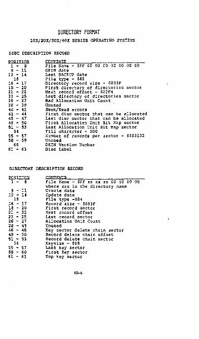
DIRECTORY FORMAT lOX/20X/30X/40X SERIES OPERATING SYSTEMS
DISC DESCRIPTION RECORD
PQSITION 1 - 8 9 - 11
12 - 14 15
16 - 17 18 - 20 21 - 22 23 - 25 26 - 27 28 - 39 40 - 41 42 - 44 45 - 47 48 - 50 51 - 53
54 55 - 57 58 - 59
60 61 - 63
CQ~.JTE~!TS
File Name - $FF 00 00 00 00 00 00 00 DUN date Last BACKUP date File type - $82 Directory record size - S003F First directory of directories sector Next record offset - $C2F4 Last directory of directories sector Bad Allocation Unit Count Unused Seek/Read errors First disc sector that can be allocated Last disc sector that can be allocated First Allocation Unit Bit Map sector Last Allocation Unit Bit ~lap sector Fill character - $00 Number of records per sector - S303l32 Unused DKIN Version Number Disc Label
DIRECTORY DESCRIPTION RECORD
PQSITTON 1 - 8
9 - 11 12 - 14
15 16 - 17 18 - 20 21 - 22 23 - 25 26 - 27 28 - 45 46 - 48 49 - 50 51 - 53
54 55 - 57 58 - 60 61 - 63
File Name - $FF xx xx xx 00 00 00 00 where xxx is the directory name Create date Update date File type "'S84 Record size - $003F First record sector Next record offset Last record sector Allocation Unit Count Unused Key sector delete chain sector Record delete chain offset RecoC'd delete chain sectoC' Keysize - $08 Last key sectoC' FiC'st Key sectoC' Top key sectoC'
10-6

DIRECTORY FORMAT lOX/20X/30X/40X SERIES OPERATING SYSTEMS
CONTIGUOUS FILE
PQSI'T'TQN 1 - 8 9 - 11
12 - 14 15
16 - 17 18 - 20 21 - 22 23 - 25 26 - 27 28 - 53
54 55 - 57 58 - 63
;r~;E~~~!-e-----------------------------*Create Date *Update Date File Type =$02 Record Size First Record Sector Next Record Offset Last Record Sector Allocation Unit Count Unused Fill Character ~umber of records/sector Unused
*New items in the directory format
OBJECT/STANDALONE FILE
POSITION 1 - 8 9 - 11
12 - 14 15
16 - 17 18 - 20 21 - 22 23 - 25 26 - 27 28 - 42
43 44 - 51 52 - 53 54 - 55 56 - 57 58 - 59 60 - 61 62 - 63
~?~;Ell~~~;~e---------------------------*Create Date *Update date File type ~S10 - Object File type =$30 - Star.dalone Record Size First Record Sector Next Record Offset Last Record Sector
*Allocation Unit Count Unused
*Version Number *Source File Name */lessage Address (Standalone only) Execution Start Address Common Length Suffer Length Local Length I?rogram Length
*New items in the directory foc~at
10-7

DIRECTORY FORMAT lOX/20X/30X/40X SERIES OPERATING SYSTEM
KEYED FILE
J)(lST'T'ION
1 - S 9 - 11
12 - 14 15
16 - 17 18 - 20 21 - 22 23 - 25 26 - 27 28 - 45 46 - 48 49 - 50 51 - 53
S4 S5 - 57 58 - 60 61 - 63
~~S ______________________ __
File Name *CREATE date *Update date File type - $04 Record Size 1st Record Sector Next Record Sector Offset Last Record Sector Allocation Unit Count Unused Key Sector Delete Chain Sector Record Delete Chain Offset Record Delete Chain Sector Key Size Last Key Sector First Key Sector Top Key Sector
*New items in the directory format
SEQUElfrIAL FILE
.f.Q.Sll..!Qli 1 - 8 9 - 11
12 - 14 15
16 - 17 18 - 20 21 - 22 23 - 25 26 - 27 28 - 63
File Name *Create Date *Update Date File Type = $01 Record Size First Record Sector Next Record Offset Last Record Sector Allocation Unit Count Unused
*New items in the directory format

1-3 4
5-12 13
14-16 17-18 19-20 21-23
24 25-26 27-29 30-31 32-34 35-37
34-48
DIRECTORY ENTRIES KEYED SEQUENTIAL
TOP KEY SECTOR UNUSED FILE NAME FILE TYPE-04 LAST DATA SECTOR RECORD SIZE AU COUNT LAST KEY SECTOR KEY SIZE DELETE CHAIN OFFSET DELETE CHAIN SECTOR NEXT RECORD OFFSET FIRST DATA SECTOR FIRST SECTOR OF FIRST KEY AU UNUSED
1st DATA SECTOR UNUSED FILE NAME FILE TYPE-Ol LAST DATA SECTOR RECORD SIZE AU COUNT UNUSED X X· X X X X X UNUSED
SECTOR CONTROL BYTES
1-756 USER DATA 757-759 DISC NAME-APPEARS IN TOP LEVEL DIRECTORY
SECTORS AND ALL TOP LEVEL KEY SECTORS.
760 KEY LEVEL-LEVEL OF SECTOR. FOR KEY AND DIRECTORY SECTORS.
761-763 UNUSED 764-766 FOR1~ARD LINK-EVERY DATA SECTOR LINKS TO THE
NEXT DATA SECTOR. IN KEY SECTORS THE 5th KEY SECTOR OF AN A.U. WILL POINT TO THE NEXT KEY A.U.
767-768 OFFSET-GIVES THE NEXT AVAILABLE BYTE IN THE SECTOR FOR DATA ENTRY. ALL INFOR~~TION IN THE SECTOR BEFORE THE OFFSET ADDRESS IS GOOD DATA.
KEY ENTRY
1-2 DATA OFFSET-STARTING ADDRESS WITHIN A DATA SECTOR FOR THE RECORD ASSOCIATED WITH THIS KEY.
3- 5 SECTOR NU~fBER OF NEXT SECTOR OR DATA. A LEVEL
6 UNUSED 7 KEY
o KEY SECTOR WILL HAVE THE SECTOR NUMBER OF THE DATA SECTOR FOR ITS KEY. ALL KEY LEVELS ABOVE 0 WILL MERELY POINT TO THE NEXT LOWER KEY LEVEL TOWARDS O.
10-9
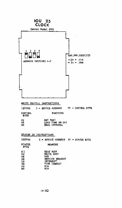
IOU 25 CLOCK
Qantel Model 2901
ADDRESS SWITCHES O-F
WRITE CO~TROL INSTRUCTIO~S
lXYY9D
CONTROL BYTE
02 09 OC
x • DEVICE ADDRESS
FUNCTIOS
SET TEST LOAD TIME Of. DAY READ INTERVAL
STATUS IN INSrRUCTIoNS
-12v "' .OlA + 5v "' .86A
'{'! • CONTROL BYTE
4XYY9D
STATUS
x • DEVICE ADDRESS yy. STATUS BYTE
MEANING BYTE
01 02 04 08 10 20 40 80
READ BUSY WRITE BUSY END SERVICE REQUEST INTERRUPT TIME CORRECT MIA MIA
10-10

IOU 9 UNBUFFED TEN KEY
[jofjo i 8 4 2 1
ADDRESS SWITCHES O-F
TEN KEY ~IODULE UN- BUFFERED
WRITE CO:-iTRCL INSTRUCTIONS
'MAX. PWR • REQUIREMENTS
-12v· .16A + Sv ... 33A
lXYY9D
CONTROL BYit
x • DEVICE ADDRESS
FUNCTION
YY • CONTROL BYTE
00 01
RESET TONE SET TONE
STATUS IN INSTRUCTION'S
4XYY9D
STATUS BYTE
00 02 04 08 10 20 40 80
x • DEVICE ADDRESS yy. STATUS BYTE
MEANING
BUSY N/A END SERVICE REQUEST N/A FLAG TWO FLAG THREE N/A
10-11

IOU 18 BUFFERED TEN KEY
Qantal Mode 1 5701
8 4 Z 1
~~[jQ ADDRESS SWITCHES O-F
WRITE CONTROL INSTRUCTIONS
lXYY9D
CONTROL BYTE
00 01
x • DEVICE ADDRESS
FUNCTION
RESET SIGNAL SET SIG~AL
YY • CONTROL BYTE
04 05
RESET ALLO\~ TERHI~ATIO~ INTERRUPT SET ALLOW TERNI:>:ATIOl\ DiTERRUPT
STATUS IN I::STTUICTIONS
4XYY9D
STATUS BYTE
01 02 04 08 10 20 40 10
x • DevICE ADDRESS yy. STATUS BYTE
MEANING
READ BUSY NIA END SERVICE REQUEST INTERRUPT FLAG TWO FLAG THREE MIA.
10-12

FlLFIL or BFl.LFlL EXAMPL£S
~I.FD.F-o.C-oSOOO (RETUllN) or (TRANSMIT) "'O.RD.F-o.C-8000 (RETURN) or (TRANSMIT) Copies everything (8000 sectors) bit-far-bit from the fixed disc to the removab le liisc. By exchanging the FD and RD copy is from the removable to the fixed. The D is the disc adliress.
*1. FD .F-oOOOO .C-08000 (RETUllN) or (TRANSMIT) *O.MS.R-j.&S.B-7&SO (RETUllN) or (TRANSMIT) From fixed liisc (FD) to mag tape (MS) in block.s of ten sectors.
*I.M8.R-7&S,a-7&80 "'O.RD,F-o,C-/iOOO
From mag tape to the removable liisc.
*1, RD ,F-xxxxx, C-yyyyy "'O,LF,a-7&S Prints (on lievice LF) everything from the removable ci1sc (RD), starting at address xxxxx, and conti!IUing for YY1YY !lUmber of sectors.
*I,C£,R-80 lII(),LF ,a-so Prints from punch carlis to deVice LF.
FORMAT
*I,RD,a.-nnn,B .. nnnn,S-nnt1,F-nnnnn,Cannnnn
I - Input or FROM; 0 • output or TO a - Removab le (disc); F • Fixed (disc) L - Lineprinter; C - Card reader Ii - Mag tape o to F - Device address (2nd liigit of 2nd expression) R - Record length (1.- 7&S if not specified) B - Block. length S - Number characters froQl each record F • Starting sector (disc only) C • Number of sectors (disc only) ;lIII1st be 5 digits.
Defaults: Record length - 80 for Cards; 3S0 for ill disc. OUtput
record length can not be shorter than input (S).
alock. length - To record length. Can not be lIIOre than 3S0 for ill or 7&S for &+&,3+3,or 114.
Input length (S) - T record length. Used for limited !lUmber of sectors.
Number of sectors (C) - Must bave 5 digits. C in the output vill terminate when reached, regardless of C in the input.
10-13