electronics® - bitsavers.org
94
THIN-FILM LOG I-F Inductors are no problem, p 46 A McGraw-Hill Weekly 75 Cents June 7, 1.IJ63 electronics ® " VOLTMETER" DOESN'T MOVE Uses saturable reactor and neon, p 50 TACTICAL DISPLAY GOES TO SEA Inside our floating war rooms, p 20 NEW cold-cathodes under study show blue circles on mirror surface as a result of interference effects, p 39 soJ:1v so .... Cl !:{)J.Dri-lt.O::l 1 11s1mD rn a B
-
Upload
khangminh22 -
Category
Documents
-
view
0 -
download
0
Transcript of electronics® - bitsavers.org

THIN-FILM LOG I-F Inductors are no problem, p 46
A McGraw-Hill Weekly 75 Cents June 7, 1.IJ63
electronics® "VOLTMETER" DOESN'T MOVE Uses saturable reactor and neon, p 5 0
TACTICAL DISPLAY GOES TO SEA Inside our floating war rooms, p 20
NEW cold-cathodes under study show blue circles on mirror surface as a result of interference effects, p 39
!'lV~ soJ:1v so .... Cl !:{)J.Dri-lt.O::l O'::~ ~
1 11s1mDrn a B

• • • • • • • •
I I I I I I I I
Complete System
only $1885
Here are two instruments that work together to provide a permanent and accurate record of frequency response on a truly logarithmic scale. With this system you can conveniently study and analyze the performance of filters, networks, amplifiers, equalizers, loudspeakers, microphones, and transducers of all types .
The recorder, in its own right, finds extensive use in any electronics laboratory. It has an inherent versatility that permits its use as a general-purpose de recorder, or for recording the output levels of a variety of other instruments including spectrum analyzers .
Type 1304-B Beat· Frequency Audio Generator .. . ... . .. . $795
Type 1521-A Graphic Level Recorder (with 40·db potentiometer) .. . .. . ..... .. .... . ..... . .... $995
Type 1521-PlO Drive Unit . .. . .. .. ... .... ... .............. $ 72
Type 1521-Pl4 Link Unit. ................... .. .... ... .. . . $ 23
Complete System $1885
Frequency Range: Generator, 20c to 20 kc on logarithmic scale, 20 kc to 40 kc. Recorder, traces rms level 20c to 200 kc.
Generator Output: Flat within ±0.25 db from 20c to 20 kc. Output is adjustable from 5 mv to 50v open -circuit. Harmonic distortion is less than 0.253 from lOOc to 10 kc, 0.53 below lOOc, 13 above 10 kc.
Recorder Sensitivity: 1 mv, maximum (corresponds to 0 db). Can be varied from 1 mv to lv in 10-db steps with input attenuator.
Recorder Range: 40-db full scale, with plug-in potentiometer supplied ; 20-db and 80 -db pots also available.
Recorder Accuracy: Static accuracy better than 0.43 of full scale. Fast servo system with low overshoot provides excellent dynamic accuracy.
•
Pen Writing Speed: 20 in / sec maximum with 40-db Pot (200 db/ sec) with less than 1-db overshoot. Slower speeds (1, 3, or 10 in / sec) selected by panel switch to provide mechanical filtering of rapidl y fluctuating levels.
Paper Speeds: 2.5, 7.5, 25, and 75 in / min. Optional slow-speed motor available fo r speeds from 2.5 to 75 in/ hr.
Charts: Four different type charts avail able, each 5 inches wide with 8 major divisions. Each frequency decade on the logarithmic scale is equal in length to the 30-db calibration on the vertical scale, as specified by EIA Standard SE-103.
Write for Complete Information
GENERAL RADIO COMPANY In EUROPE General Radio
Overseas Zurich, Swilzertand
WEST CONCORD , MASSACHUSETT S
NEW YORK, N. Y .. 964-1711 CHICAGO PHILADELPHIA, 414-7419 WASHINGTON, D.C . SYRACUSE DALLAS SAN FRANCISCO LOS ANGELES ORLANDO, FLA. Ridgefield, N. J., 943-3140 (Oak Par k) 848-9400 Ab in gto n, 887-8486 (Rockv ill e, Md.) 946-1600 454-9323 FL 7-4031 (Los Alt os) 948-8233 469-6201 425-4671
CIRCLE 900 ON READER SERVICE CARD
IN CANADA (Toronto) 247-2171

W. W. MacDONALD, Editor
J . M . CARROLL, Managing Editor
SENIOR EDITORS Samuel Weber, George W . Sideris
SENIOR ASSOCIATE EDITORS Michael F. Wolff, John F. Mason
ASSOCIATE EDITORS Michael F. Tomaino, William P. O'Brien, Sy Vogel, George J. Flynn, Laurence D. Shergalis, George V . Novotny, Leon H. Dulberger , Alexander A. McKenzie
ASSISTANT EDITORS Stanley Freud, Stephen B. Gray, Roy J. Bruun, Barry A. Briskman, Dan Smith, Joel A. Strasser
REGIONAL EDITORS Harold C. Hood (Pacific Coast, Los Angeles), Thomas Maguire (New England, Boston), Cletus M. Wiley (Midwest, Ch icago)
ART DIRECTOR
Howard R. Berry
ASSISTANT ART DIRECTOR John C. Wright, Jr
EDITORIAL ASSISTANTS
Lorraine Rossi, V irginia T. Bastian, Lynn Emery, Ann Mella, Lorraine Werner, Al ice M . O' Brien, Sharon Porks, Patricia Mitchell, Claire Benell
FOREIGN NEWS BUREAU DIRECTOR, John W ilhe lm;
Alyne Elias, Charles Obertance LONDON-John Shinn, Derek
Barlow, Nicholas Landon BONN-Bruce Bendow,
Richard Mikton, Silke McQueen
BRUSSELS- Peter Forboth PARI S-Robert Ferrell,
Arthur Erikson
MILAN-Marc A . Messina MEXICO CITY-Wesley Perry, Jr RIO DE JANEI RO-Leslie Warren MOSCOW-Stewart Ramsey TOKYO-Richard Halloran,
Charles Cohen, John Yamaguchi
CIRCULATION MANAGER Hugh J. Quinn
W. W. GAREY, Publisher
June 7, 1963
electronics A McGraw-Hill Weekly 75 Cents
SOME LABORATORY apparatus used in recent cold-cathode studies. More than a dozen cold cathodes have been deposited on the mirror surface in the foreground. At the left is a jig used in cold cathode deposition. Waveform is a cold-cathode characteristic curve. One application: r -f modulation of light beams. See p 39 COVER
FREQUENCY-CONTROL Advances Pushed by Army. Army still isn't satisfied with crystals for s ingle-sideband gear, and wants cheaper, more reliable clocks. One of newsbrealcs at last 1ceelc's symposium was that thallium-beam standards may be 11101'e accurate than cesium-beam ones 16
AIR-SEA-SUB DISPLAY Plots Naval Targets. Tactical Navigational Display System is slaved to radar and sonar to show enemy movements. A scaled-down version of an air-defense display, it is going aboard aircraft carriers 20
PRINTED-CIRCUIT FIGHT. Technograph loses round 1 in the huge Eisler patents court case. Federal _judge rules that patent claiims are invalid. This case affects scores of companies in tlie electronics industry 24
DEFENSE SATELLITE NET Is Set for Contracts. Awards next month will la unch $l -b illion project. Unlike civilian communications satellites, the military ones will have few channels, use mobile ground stations 26
COLOR-TV CAMERA Size Pared. Japanese developing system that needs only two image orthicons. One tube is for color, the other is luminance pickup 28
V ARACTOR Cutoff is 800 Ge. Gallium-arsenide diode electrically formed in waveguide raises frequency limit some 300 Ge. Developer expects it to extend range of parametric devices into millimeter region 31
ARE HOT CATHODES ON THE WAY OUT? Nonthermionic emission mechanisms under study use photoelectric, fi eld emission, secondary emiss.ion and plasma effects. They promi1se to provide high current density, low power consu mption, low beam noise and instant startling. A few are already in use for special applications such as high-speed x-ray photography.
By W. M. Feist and G. Wade, Raytheon 39
NEW THIN-FILM LOG 1-F: Inductors Are No Problem. Inductors required in logarithmic i-f amplifiers of tuned-sibage design are not compaJtible with thin film fabr.ication. This oircui t uses untuned R-C coupled amplifiers, gives a 20 to 120-Mc bandwidth at 10-db gain. Use of high-performance vhf chip transistors makes it possible. By R. Lesl.ie and T. Townsend, AIL Divisiion, Cutler-Hammer 46
Contents Continued

2
electronics June 7 , 1963 Volume 36 No. 23
Published weekly, with Electronics Buyers' Guide as part of the subscription, by McGraw-Hill Publishing Company, Inc. Founder : Jame1 H. McGraw (1 860-1948).
Title ® registered U.S. Patent Office ; © copyright 1963 by McGraw-Hill Publishing Co., Inc. All rights reserved, including the right to repro duce the contents of this publication , in whole or in part.
Executive, editorial, circulation and advertising offices : McGraw-Hill Bu ilding , 330 West 42nd Street, New York 36, N. Y. Telephone Longacre 4-3000. Teletype TWX N.Y. 212-640-4646 . Cable McGrawhill, N. Y. PRINTED IN ALBANY, N. Y.; second class postage paid at Albany, N. Y.
OFFICERS OF THE PUBLICATIONS DIVISION, Shelton Fisher, President; Vice Presidents, Joseph H. Allen , Operations; John R. Callaham, Editorial; Ervin E. DeGraff, Circulation ; Donald C. McGraw, Jr ., Advertising Sales; Angelo R. Venezian, Marketing .
OFFICERS OF THE CORPORATION , Donald C. McGraw, President; Hunh .I Kelly, Harry l. Waddell, l. Keith Goodrich, Executive Vice Presidents; John l. McGraw, TreosurPr; John J. Cooke, Vice Presiden t and Secretary .
Subscriptions are solicited only from those actively engaged in the field of the publication. Position and com pany connection must be indicated on orders. Subscription rates : United States and Possessions, $6.00 one year, $9.00 two years, $12.00 three years. Canada, $10.00 one year. All other countries $20.00 one year. Single copies, United States and Possessions and Canada 75¢. Single copies all other countries $1.50.
THE PUBLISHER, UPON WRITIEN REQUEST FROM ANY SUBSCRIBER TO OUR NEW YORK OFFICE AGREES TO REFUND THAT PART OF THE SUBSCRIPTION PRICE APPLYING TO COPIES NOT YET MAILED.
Subscribers: Please send change of address notices, subscription orders or complaints to Fulfillment Manager, Electronics, at the address below. Change of address notices should provide old as well as new address, including postal zone number if any. If possible, attach address label from recent issue. Allow one month for change to become effective.
Postmaster: Please send Form 3579 to Fulfillment Manager, Electronics, P. 0. Box 430, Hightstown, New Jersey.
Audited Paid Circulation
CONTENTS continued
VOJ,TAGE MONITOR Needs Only Two Saturable Cores. This "Yoltmeter" needs no moving coil. A power supply being monitored is compared with a reference and the difference voltage feeds control windings of saturable cores. When cores satu1'ate, a neon lamp lights. By M. C. Herzig and D. C. Colbert, Electronic Communications 50
TUNNEL DIODES: How to Make Them Even More UsefuL Here is a novel contribution to tunnel-diode circuit design. Four diodes can be combined to produce a characteris·tic curve with three positive-resistance regions separated by negativeresistance regions. It makes a good tristable circuit or bipolar pulse generator.
By L. L. Williams and D. J. Hamilton, Univ. of Arizona 52
DEPARTMENTS
Cros·stalk. Tunnel Diodes Revisited 3
Comment. M et1'ic Sy stern. Dichotomy 4
Electronics Newsletter. Superconducting Mag-nets Reach th e Magic Number: 100,000 Gauss 7
Washington This Week. This Summer, "Report Cards" for Military Contractors 12
Meetings Ahead_ Ae1·ospace Electrical/ Electronic Con/ er ence 36
Research and Development. Computer Translates Chinese into English 56
Components and l\Iaiterials. Microcircuits are Busting Out in Britain 60
Production Techniques. Pilot Plant Mass Pro-duces Thin Films 64
New Products. Automate With This Versatil e Counter 70
Literature of the Week 80
People and Plants_ Raytheon Promotes Three Executives 82
Index to Advertisers 90
June 7, 1963 • electronics

CROSSTALK
Tunnel Diodes Revisited
WE'VE ALL HEARD the story of the child prodigy who, after a brilliant pre-adolescent academic career in which he reputedly performs unheard of mental feats, carries the awed expectations of parents and friends into the waiting world. Then he fades into obscurity, to be discovered by an enterprising cub reporter forty years later performing some dreary routine bookkeeping task.
That could have been the story of the tunnel diode. But the career of Dr. Esaki's brainchild appears headed for a much happier ending.
When the tunnel diode first made its appearance in the literature five years ago, it was hailed as the answer to a circuit designer's prayer. With one simple device, an engineer could achieve oscillation, amplification, conversion, switching and even combine some of these functions simultaneously. In addition, the device offered high-speed, high-frequency operation, low power consumption, resistance to nuclear radiation and temperature, small size, and light weight! Small wonder that the drums began to beat for the tunnel diode as the replacement for the transistor and the panacea for all circuit problems.
But then reality broke through and disillusionment appeared. Circuit designers were just beginning to feel comfortable with the low-impedance design quirks of the transistor. Now they were expected to accept with equanimity a two-terminal device with no isolation between input and output, coupled with the unfamiliar concept of negative resistance. On top of this, reports began to filter in concerning deterioration of tunnel diode properties on the shelf, of inst ability of diode characteristics, lack of uniformity from diode to diode. Gradually enthusiasm waned.
Although the manufacturing problems were solved rather quickly, interest in the tunnel diode was considerably diminished in 1961. But over the last two years, we couldn't help noticing that the td has been making a quiet but effec-
electronics • June 7, 1963
EARLY APPLICATION for tunnel diode was in GE's battery-operated chronometer, shown in fore ground. In the background is a 1365 clock
tive comeback and, without the hullabaloo accompanying its debut, is taking its rightful place in the pantheon of semiconductor devices.
We thought that this would be an appropriate time to reevaluate the tunnel diode as a design component. We asked two experts, Eric Gottlieb and John Giorgis, of GE's Semiconductor Products department, to bring our readers up to date on the latest applications and design techniques using this versatile device. The result is a comprehensive four-part series beginning in next week's issue. It may well be the definitive work on tunnel-diode circuit design.
You'll find that the prodigy can be made to live up to its childhood potentialities, provided, as in all such cases, the talent is nurtured and developed carefully, with allowances made for personality quirks.
3

4
now available
for immediate
delivery:
JERROLD RF SWEEP
EQUIPMENT ... the industry's
finest I
Model 9008 Super Sweep Ge ner ator
Wide plus narrow band in one versatile instrument. Handles all l F, VHF, UHF sweep requirements. Sweep widths from lOkc to 400mc. Frequency range from 500kc to 1,200mc. Built-in crystalcontrolled harmonic markers, de or ac scope preamplifier, precision attenuator. $1,980.00
Model LA·5100 rf Log Amplifier
Accurate within ±ldb over 80db dynamic range. Frequency range 500kc to lOOmc. Lets you make exact measurements of attenuation in networks, fi lters, amplifiers with dynamic ranges down to 85 db. Total rf response displayed in precise log ratio on standard de-coupled scope.
$795.00
M odel 900A W l de·Band Sweeper Sweep widths from lOOkc to 400mc. Frequency range from 500kc to 1,200mc. $1,260.00
M odel 707 Ultra•Flat Sweeper Flatness of ±0.05db in highest single octave. Plug-in oscillator heads. $840.00
All for immediate delivery. Prices f.o.b. Philadelphia. Write for complete technical data on these and other Jerrold rf test instruments.
J~~ROlD ELECTRONICS
Industrial Products Division, Philadelphia 32, Pa.
~ A subsidiary of THE JERROLD CORPORATI ON
CIRCLE 4 ON READER SERVICE CARD
COMMENT
Metric System
In spite of having spent the first 27 years of my life in a country where the metric system is enforced by law, I must admit that I am strongly in favor of this strange way of expressing physical measurements .
The pulse that triggers this letter was the Newsletter item about underwater laser tests on p 7 of your April 19 issue, where both meters and feet are used separately and together.
May I suggest a method that might ease the inevitable conversion to the metric system in this country. The various measurements mentioned in the article could have been shown as follows: "Underwater tests show laser ranges up to 1,000 ft (305 meters) ... about 150 feet ( 46 meters) are possible ... two five-inch (12.5-cm) diameter . . . estimated at 150 ft ( 46 meters) ... be about 1,000 feet (305 meters) .... "
Then after a few years of this, vou would reverse the terms like this: "about 45 meters (148 feet) are ... two 12.5-cm (5-inch) diam-eter .... " A few more years of this and the metric system could stand alone on its own 60.69 cm (two feet).
work is analogous to that in other fields of engineering. It is true that an engineer is an innovator; but this does not place him necessarily in the laboratory. Rather, he is the man who takes scientific knowledge, which may be the result of the research of other men, and applies it to produce a given result. This is consistent with the old definition which sees an engineer "using men, money and materials to advance the welfare of mankind."
On the other hand, the man who applies himself to research, with the desire "to find out why" rather than "to achieve a result," is a scientist, and in the case of electronics, probably a physicist.
To sum up, our contention is that the man doing research into fundamental principles is a scientist; the man reducing the results of such research to practical form is an engineer. It is obvious that both these roles are necessary and worthwhile. Further, they are complementary, and at times overlap. A publication such as yours is valuable because it keps both these groups informed of matters of common interest.
PETER H. GRIFFIN ERIC G. WARREN DANIEL B. SOOTHILL
Department of Civil Aviation Waverton, N.S.W. Australia
FINN POULSEN Radio-Interference Control Arlington Heights, Illinois
P.S. In my eagerness to express my views on the merit of the metric system, I forgot to tell you that I enjoy the range of articles you have in the magazine, from decimal-tobinary rotary switches and simple transistor testers to space guidance and telemetry systems. All in all, A-OK.
Dichotomy
Congratulations on your editorial highlighting the dichotomy existing at the professional level in the field of electronics. However, we feel that you have incorrectly named the two professions.
Engineering is a profession with many branches, and the term of engineer in the electronics field should be applied to those whose
An unfortunate transposition took place in the printing of my article, Radio-Interference Control -What it Means to Systems Design (p 56, April 26).
The text is broken at line 6 of column 2, p 58, and picks up at line 10 of column 3, p 58. The correct text should read " ... during their discussions, the rfi engineer reviews and evaluates the vari011s apvroaches ... "
The transposed section, 44 lines long, belongs after line 15 of column 1, p 59. The correct text should read " ... t..f = 3 db bandwidth at f., ; f. = frequency to which the preselector is tuned ... " and ending with " ... the susceptibility threshold is -97 dbm, which is more than adequate."
Loral Electronics Corp. Bronx, New York
M. REVZIN
J u ne 7 , 1963 • electronics

Lambda announces 3 new LE models
EnvironmentEngineered at competitive prices
LE 1060-.18VDC15 AMP • LE 107 0-18VDC 22 AMP • LE 110 0·9VDC 20 AMP
Note these quality design features
CONVECTION COOLED No• blowers or filters; mointenonce free .
Wide input voltoge and frequency range -105-135 VAC, 45-66 CPS and 320-480 CPS in two bands selected by switch.
LE SERIES
CONDENSED DATA
COMPLETELY PROTECTED against-short circuit and electrical overload; input line voltage transients; excess ive ambient temperatures. No voltage spikes due to"turn-on, turn-off" or power failure.
*9 modelsavailable
CONSTANT VOLTAGE CONSTANT CURRENT
by automatic switchover.
REMOTELY PROGRAMMABLE AND CONTINUOUSLY VARIABLE
Voltage continuously variable over entire range. Programmable over voltage and current range.
OTHER PEATURES
• All solid sfcite. • Adjustable automatic current limiting. • 0°·C to + 50°C ambient. • Grey ripple finish. • Ruggedized vol~meters and ammeters
per MIL-M-103048 on metered models.
REGULATED VOLTAGE: Regulation
(line and load) .. . ... Less than .05 per cent or 8 millivolts' (whichever is greater). For input variations from 105-135 VAC and for load variations from 0 to full load.
DC OUTPUT (VOLTAGE REGULATED FOR LINE AND LOAD) Cll Remote Programming .... 50 ohms/volt constant over entire) voltage range. Model
LElOl LE102 LE103 LE104 LE105 LE106 LE107 LE109 LEllO
Voltage Range 0-36VDC 0-36 VDC 0-36VDC 0-36 VDC 0-18 VDC 0-18 VDC 0-18 VDC 0- 9VDC 0- 9VDC
Current Range 0- 5 Amp 0-10 Amp 0-15 Amp 0-25 Amp 0- 8 Amp 0-15 Amp 0-22 Amp 0-10 Amp 0-20 Amp
Cl) Current ratinA applies over entire voltage range.
Price<2>
$420 525 595 775 425 590 695 4 30 675
C2> Prices are for nonmetered m odels . For models with ruggedized MIL meters add suffix "M" to model number and add $40 to the n on· metered price. For metered models and front panel control add suffix " FM,, and add $50 to the nonmetered price.
Ripple and Noise . ....... Less than 0.5 millivolt rms.
Temperature Coefficient .. Less than 0.015%/°C.
AC INPUT: .....•.... 105-135 VAC; 45-66 CPS and 320-480' CPS in two bands selected by switch.
PHYSICAL DATA: Mounting .......... .. Standard 19" rack mounting.
Size ••••.•.. LE 101, LE 105, LE 109 31/2 " H x 19" W x 16" D\ LE102,LE106, LE110 5 1/4" Hx19"Wx16" D LE103, LE107 .... ... 7" Hx19"Wxl6•/2" D LE 104 .....•.•.... . 101/2" H x 19" W x 16•/2" D .
SEND FOR LAMBDA CATALOG.
LAMBDA ELECTRONICS C 0 RP. 515 BROAD HOLLOW ROAD • MELVILLE, L. I .. NEW YORK • 516 MYRTLE 4·4200
SALES OFFICES AND REPRESENTATIVES CONVENIENTLY LOCATED IN MAJOR CITIES
. CIRCLE 5 ON READER SERVICE CARD

SIMPLIFY NEW portable test set
measures
communications maintenance
The new ~ 3550A Portable Test Set, designed specifically for transmission system testing, is
especially useful for alignment and maintenance of multichannel communication systems. It incorporates a 5 cps to 560 kc oscillator with fully floating output, a 1 mv to 300 v 5 cps to 2 me voltmeter, and attenuator and impedance matching networks to individually match the oscillator and voltmeter to 135, 600 and 900 ohm lines.
The solid state instruments are housed in a compact case with a splashproof cover, and both the oscillator and voltmeter operate from internal rechargeable batteries or from an ac line. The three instruments may be used separately in or out of the case.
The oscillator provides flat frequency response and excellent amplitude and frequency stability. The highly accurate voltmeter provides a db scale for easy measurement -72 to + 52 dbm. The at·cenuator and impedance matching unit includes calibrate features to eliminate insertion loss. Oscillator and voltmeter batteries recharge during ac operation.
Check the specifications for the remarkable versatility and convenience of this test set, then contact your ~ representative or call direct for a demonstration on your bench or in the field.
' CIRCLE 6 ON READER SERVICE CARD
Frequency Range:
• gain, attenuation,
frequency response
SPECIFICATIONS OSCILLATOR(~ H07-204Bl 5 cps to 560 kc, 5 ranges
Dial Accuracy: frequency Response:
±3% ±3% into rated load 600 ohms Output Impedance: 10 mw (2.5 v rms) into 600 ohms, 5 v rms open circuit, completely isolated
Output:
Distortion: Less than 1% Hum and Noise: Less than 0.05%
Temperature Range: -20° to +50° C
8090
Range: Frequency Range:
Accuracy:
Nominal Input Impedance:
DC Isolation: Noise:
Attenuation: Accuracy:
Impedance: Input and Output:
VOLTMETER(~ 4038) 0.001 to 300 v rms full scale; -72 to +52 dbm 5 cps to 2 me 0°C to 50°C, within ± 2% of full scale from 10 cps to 1 me, within ± 5% of full scale from 5 to 10 cps and 1 to 2 me (on 300 v range, accuracy is ± 10% from 1 to 2 me; AC-21A 10:1 Divider Probe allows measurements to 300 v in the 1 to 2 me range with an accuracy of ± 5%); 0°C to - 20°C, ± 8% of full scale from 5 cps to 2 me 2 megohms, shunted by approximately 40 pf on 0.001 v to 0.03 v ranges, 20 pf on 0.1 v to 3 v ranges, 15 pf on 10 to 300 v ranges Signal ground may be ± 500 v de from external case Less than 4% of full scale on 1 mv range, 3% on other ranges ATTENUATOR/PATCH PANEL 110 db in 1 db steps 10 db section, error less than ± 0.125 db at any step, de to 100 kc; less than ± 0.25 db, 100 kc to 1 me. 100 db section, error less than ±0.25 db at any step up to 70 db, less than ±0.5 db above 70 db, from de to 100 kc; less than ± 0.5 db up to 70 db, less than ± 0.75 db above 70 db, 100 kc to 1 me 600 ohms 50 cps to 560 kc; balance better than 40 db; frequency response ±0.5 db, 50 cps to 560 kc; impedance, 135, 600, 900 ohms center tapped. Input includes lOK bridging impedance; insertion loss, less than 0.75 db at 1 kc; maximum level +10 dbm (2.5 v into 600 ohms) GENERAL
Power: Voltmeter and oscillator each use a power supply of 4 rechargeable batteries (furnished, 40 hr. operation per recharge [20 hours at -20° CJ, up to 500 recharging cycles). Automatic recharging during ac operation
Dimensions: 83/s" high, 19¥4" wide, 13¥4'' deep. Weight 30¥2 lbs. Price: $990.00
Data subj;riwl.gETT~tPACKAfRDaCOMPANY 1501 Page Mill Road, Palo Alto, California, Area Code 415, DA 6-7000 Sales and service representatives in all principal areas; Europe, Hewlett-Packard S. A., 54-54bis Route des Acacias, Geneva; Canada, Hewlett-Packard (Canada) Ltd., 8270 Mayrand Street, Montreal
June 7, 1963 • electronics

ele ctronics NEWSLETTER
Superconductor Hits 101,000 Gauss
SUPERCONDUCTING magnet has created fields up to 101,000 gauss in laboratory experiments, GE says. This is the strongest field yet reported for a superconductor, although earlier advances in materials and techniques (p 18, March 1) indicated that the 100,000-gauss barrier was likely to be broken before the end of the year. Previously, 75,000 gauss, achieved by Magnion (p 8, May 10) , was the strongest field reported.
GE's record-breaking solenoid was made from 600 feet of 1/40-inch-diameter niobium-tin conductor wound on a :\-inch diameter tube. The coil is approximately 2 inches long and 2 inches in diameter. Currents as high as 266 amps were applied and the temperature was maintained at 1.8 K. Six ordinary automobile storage batteries were used as the power source. GE says it has devised fabricating techniques that circumvent niobiumtin's major disadvantage, extreme brittleness. The material has a critical field of 190,000 gauss.
Poland Constructs Radio Factory in Cuba
BELGRADE-According to the Warsaw daily "Tribuna Ludu", Poland has completed construction of a $8.5-million radio-receiver factory at Rancho Bayoros, near Havana, Cuba. All installations are of Polish manufacture, the newspaper said. The receivers to be produced will be a counterpart of the Polish "Figaro" sets. The new plant is one of 14 different factories Poland has agreed to build in Cuba.
Electron Beam Checks Microelectronic Structures
APPLICATIONS of optoelectronic and molecular techniques to microelectronic structures highlighted a
electronics • June 7, 19 6 3
closed meeting last month sponsored by DOD's Advisory Group on Electron Devices at Research Triangle Inrstitute, Durham, N. C. Topics included: a low-level silicon chopper activated by photon emission from gallium arsenide; the use of phonon coupling in silicon structures, including a thermal flip-flop structure; a scann·ing electronbeam machine used as a nondestructive diagnostic instrument for microeleotronic structures. In the latter, potential gradients associated with junctions and with failure modes are clearly indicated in the image tube.
Long-Run Experiment Shows Cryotron Utility
Balancing Act
SA TE LLITE simulator at Westinghouse Air Arm simulates movements of orbiting satellite. It's balanced on 12-inch, air-fioa ted ball bearin g. Attitude is changed by small air jets, warm al1lminiim dish overhead simulates earth
CAMBRIDGE, MASS.-A cry 0 tr 0 n thin-film memory-logic C•ircuit in continuous cycling at A. D. Little, Inc. here had gone through 11 days of persistent-current operation early this week. It is believed to be the first time a cryotron device has been operated in a closed-cycle refrigerator.
A total of 140 cryotrons are used in the seven-level memory-logic de-
vice to demonstrate typical computer circuit functions that can be performed by cryotrons: clock, pulse shaper, double-layer binary counter, tree switch, and 32-bit non-destructive memory (8 words, 4 bits per word). Information orig-
Foot Soldier Needs Better Power Sources ARMY ISN'T saying anything officially, but it is dissatisfied that power sources used by individual soldiers have not kept pace with other advances in electronics, that there have been orders-ofmagnitude improvement in such areas as microminiaturization but only a three-to-one improvement in power sources for field use.
Roughly 75 percenrt of field failures of communications gear is blamed on power supplies. Army wants an efficient source of 150-w power, the average requirement for hand-held electronics.
Here's what the Army says is wrong with present devices: Thermionic power sources are hot and inefficient; fuel cells
are not yet reliable or efficient in any practical size; nuclear techniques require extensive shielding and reach prohibitive weights rapidly; cadmium-class batteries aren't efficient enough and it is often two to three seconds before power is available.
In a recent radio design, the Army went back to its old standby, the carbon-zinc battery
7

J•
Instant X-Ray
BETATRON automated x -ray system made for R edstone A rsenal by Allis-Chalmers indicates flaws on roll-chart r ecording instead of film . Photosensitive system det ects flaws in rocket (foreground) as difference in light output of sodiumiodide cr ystals
inally stored has been read billions of times. Only one word of the original has been rewritten, demonstrating the nondestructive character of the memory. The device does not require an outside driver. Speed of circuit can be varied by varying oscillator speed from 50 Kc to 200 Kc. ADL researchers say speed could be pushed up to 500 Kc.
Radio Inside Eye May Probe Glaucoma
PASSIVE MINIATURE radio transmitter placed within the eye of an animal or human being may provide a revolutionary method for studying glaucoma, suggests Prof. R. Stuart Mackay, of the Universrity of California at Berkeley. The device could indicate over the long run what psycho.Jogical and physical effects contribute to a buildup of pressure within the eye, he said. Glaucoma r~epends on such increases in pressure.
Mackay said experiments carried out at 60 Mc by one of his students, Arthur Chen, indicate the feas•ibility of this method. Chen employed
.. "
the two perpendicular coil method and, while sweeping the transmitteT frequency, noted the instant of maximum response in the receiver circuit.
Russian Describes Soviet Plasma Work
...
DETAILS of several Soviet plasma oscillators and amplifiers were given ELECTRONICS last week by Professor Z. S. Chernov of Moscow's Academy of Science, an exchange fellow at Brooklyn Polytechnic Institute. He reported gains of 40 to 50 db with 3-cm waves amplified over a 15-cm path with a 5 to 7-cm discharge, and gains of 20 db for 8-mm waves. Soviet plasma amplifiers have shown an output of 100 to 200 mw.
Studies have shown, he said, that noise is not affected by the interaction between plasma and beam. A noise factor of 30 to 40 db was obtained in his amplifiers at a few microns pressure, both with and without the beam. Professor Chernov believes that work on plasma amplifiers should and will be continued. At the present, however, no practical devices are in sight.
Cold-Cathode Source Pumps Portable Laser
MOUNTAIN VIEW, CALIF.-SpectraPhysics, Inc., reports successful operation of a portable laser designed for labs and classrooms that uses a cold cathode d-c pumping source instead of a conventional r-f source. It consumes 5 w, gives an output of 2 mw.
The company says high efficiency is due to elimination of an r-f exoitation unit with its vacuum tubes and associated power losses in heaters. The device weighs 9! pounds, compared with 55 pounds for the r-f-pumped version.
The classic problem of "cleanup" of the helium-neon gas in the laser tube was solved in part by going to a tube pressure of 5 Torr, or about five times as high as normal. Operating at 6,328 A, the confocal resonator device will sell for "considerably under $2,000."
· .
In Brief
ARMY IS GOING ahead with the Kathryn System, a flexible coding and decoding system for high-frequency intercontinental communication, des igned to minimize interference. Fort Monmouth has just given General Atronics Corp . a follow-on research contract for $47,205.
RUSSIA SAYS a defect in the orientation system has resulted in loss of radio contact with the Mars I space probe.
NEW TYPE of radio noise was discovered in signals telemetered from a two-stage rocket launched by Tokyo University. The lowfrequency half-periodic noi se originates in space and is most intense at 100, 17.44 and 5 Kc at altitudes between 100 and 200 kilometers.
SYLVANIA is readying a plan under which satellites will collect weather and oceanographic data from unmanned stations, buoys and balloons.
RAYTHEON received $3.7-million contract from the Army for ABAR ( Alternate Baittery Acquisition Radar) radars.
CONTROL DATA CORP. has acquired Beck's, Inc., printed circu it manufacturer.
TELEPROMPTER Corp. is p·lanning to sell its electronics manufact uring operations at Cherry Hill, N. J. to a group in investors.
NAVY IS ISSUING a $1,568,188 contract to Texas Instruments for guidance control equipment and airframes for the Shrike rada rhunting and killing missile.
DOD is selling its Value Engineering Handbook for 40 cents. It will be available from the Government Prinit:Jing Office, in Washington.
TRANSISTORIZED ma r in e r ad a r priced at $2,650 has been developed by Decca Radar Ltd. of London. Its 3,000-w transmitter uses a 4-foot slotted waveguide antenna weighing 77 pounds .
June 7, 1963 • electronics
t •

AVAILABLE
SURPASS MIL-R-10509 ............................ PERFORMANCE REQUIREMENTS
~.~~~P.~~Q.~4~. R~$1$TAN(.~ TO MOISTURE ..................
. ~~.!;>. M~(.t.t~N~~A~. DAMAGE
~~.9.~~,Q. ~.~.Q=-~~.~ ~.Q.~.~TRl).~J.19N FOR LONG TERM STABILITY
l=l&llllllSFO• METAL FILM RESISTORS OFFER S DISTINCT
TEMPERATURE COEFFICIENTS TO
MEET ALL CIRCUIT
Providing close accuracy, reliability and stability with low controlled temperature coefficients, these molded case metal-film resistors outperform precision wirewound and carbon film resistors. Prime characteristics include minimum inherent noise level, negligible voltage coefficient of resistance and excellent long-time stability under rated load as well as under severe conditions of humidity.
Close tracking of resistance values of 2 or more resistors over a wide temperature range is another key performance characteristic of molded-case Filmistor Metal Film Resistors. This is especially important where they are used to make highly accurate ratio dividers.
Filmistor Metal Film Resistors, in Vs. %, 1h and I watt ratings, surpass stringent performance requirements of MILR-10509D, Characteristics C and E. Write for Engineering Bulletin No. 7025A to: Technical Literature Service, Sprague Electric Co., 35 Marshall Street, North Adams, Mass. REQUIREMENTS
For application engineering assistance write: Resistor Division, Sprague Electric Co., Nashua, New Hampshire.
SPRAGUE COMPONENTS
RESISTORS
CAPACITORS
MAGNETIC COMPONENTS
TRANSISTORS M(CROCIRCUITS
INTERFERENCE FILTERS
PULSE TRANSFORMERS
PIEZOELECTRIC CERAMICS
PULSE-FORMING NETWORKS
TOROIDAL INDUCTORS
HIGH TEMPERATURE MAGNET WIRE
CERAMIC-BASE PRINTED NETWORKS
PACKAGED COMPONENT ASSEMBLIES
FUNCTIONAL DIGITAL CIRCUITS
ELECTRIC WAVE FILTERS
SPRAGUE® THE MARK OF RELIABILITY
'Sprague• and'@' are registered trademarks of the Sprague Electric Co.
electronics • June 7, 1963 CIRCLE 9 ON READER SERVICE CARD 9

Direct readout in: • gp111, rp111, psi ...
SENSITIVITY
I Ii • ~
A----lNPUT----8
ALL FUNCTIONS
(/''~ .... J ,,.-
• ...., __
RATIO ONLY IOV RMS MAX
3 4 ;;,_-: , .. ) Cl
Measure, normalize, control . .. with the new Today's most versatile electronic counter, in addition to measuring frequency and period and totalizing:
measures normalized rate
measures normalized time {period)
measures ratio
measures normalized ratio measures time for N events to occur
counts N events, providing an output pulse at the start and end of the count
N may be set to any integer from 1 to 100,000
Gallons per minute, pounds per hour, revolutions per second or minute - any event that can be converted to an electrical pulse can be measured in the exact units that are most helpful to your application. The ability to select gate times on the hp 5214L Preset Counter permits normalizing of any measurement.
For example, connecting a tachometer generator to a rotating shaft produces an output which is applied to the counter. Presetting the counter gate permits direct measurement of rps or rpm. Thus, if the tachometer generator produces 100 pulses per revolution, the gate would be set at N = 1000 (0.01 sec) to measure rps or N = 600 (0.6) sec to measure rpm.
Besides making measurements common to most universal counters, the 5214L measures N periods;
10
measures ratio; measures normalized ratio ; measures time for N events to occur; counts N events. This versatility is achieved by using two sets of decades, one of which registers the signal being counted, the other, which may be preset to any integer from 1 to 100,000 by front panel thumb-wheel switches, controls the gate. The number N also may be remotely programmed. Separate output signals are available to operate external equipment whenever the gate opens or closes. Since the 5214L can count N events, it is particularly useful in batching.
The 5214L measures ratio over a wide range of frequencies and with a wide choice of norma lizing factors. The reading displayed is N x A/ Bx Mu ltiplier. Hence, input B can be used as an external time base input for extending gate time or for normalizing an input signal so that percent change of input signal A may be read directly. The 5214L measures the time in milliseconds for N events to occur-period and multiple period measurements are made easily.
The solid state 5214L incorporates display storage, for continuous display of the most recent measurement and a flicker-free presentation on long I ife rectangular Nixie tubes. The four-line BCD code output with assigned weights of 1-2-2-4 is convenient for systems use.
Call your Hewlett-Packard representative for assistance in applying the remarkable 5214L Preset Counter to your particular measuring, recording and control problem. He will offer a demonstration at the same time.
June 7, 1963 • e lect ronics
TO

STOP
(}
•
you na111e it!
FUNCTION r---N---, RATE PRESET SAMPLE AA1E
1 2 3 4 5 RATIO N A/B
HOU)
XIO
MULTIPLIER 5214L PRESET COUNTER
HEWLETT ~ PACKARD RESET
hp 5214l UNIVERSAL PRESET COUNTER SPECIFICATIONS
FUNCTIONS
Totalize (input A): Range, 2 cps to 300 kc; sensitivity, 0.1 volt rms sine wave; 1 volt negative pulse, 1 µsec minimum width; gate time, manual control; input impedance, 1 megohm, 50 pf shunt; capacity, 99,999 counts x Multiplier (1, 10 or 100); check, counts 1 kc, 100 cps or 10 cps
Rate (input A): 10 µsec to 1 sec, 10 µsec steps 100 µsec to 10 sec, 100 µsec steps 1 msec to 100 sec, 1 msec steps
Preset (input A): Input frequency range, 2 cps to 100 kc; preset range, 1 to 99,999; outputs, -30 volts to -1.3 volts transition at gate opening and gate closing; check, 100 kc counted, reads N
Time (input A): Input frequency range, 2 cps to 100 kc; reads, time for N events in msec; period and multiple period, reads time in msec for N periods; time base, 10 µsec, 0.1 msec, or 1 msec; accuracy, ± 1 count ± time base accuracy ± trigger error*; check, 100 kc counted, reads time in msec for N cycles
Ratio (input A & B): Input A: Frequency range, 2 cps to 300 kc Input 8 : Frequency range, 2 cps to 100 kc; sensitivity, 0.1
volt rms sine wave; input impedance, 1 megohm; reads, NA x Multiplier; accuracy, ::': count; check,
8 reads N x Multiplier (requires an input to Bl
TIME BASE STABILITY
Internal: Aging rate, < ± 2 parts in 106
+ 1s 0 c to +3S°C, < ± 20 parts in 106 - 20 °C to ± 65°C, < ± 100 parts in 106
Line Voltage ± 10%, < ± 1 part in 106
electronics • June 7, 19 63
GE NERAL
Maximum Cou nting Rate: 300 kc** Regist ration: 5 long-life rectangular Nixie tubes with display
storage Sample Rate : Time following a gate closing, during which gate
cannot be reopened, is continuously variable from less than 0.2 sec to greater than 5 sec in rate mode
Operati ng Tem perature: -20 to +65° C Dimensions: 16%" wide, 3-13/16" high, 131/4'' deep Printer Out put: Output, 4-line BCD (1-2-2-4); 1-2-4-8 code on spe
cial order; print command, step from -29 volts to -1 volt Pri ce: $1475
. . 0.3% of one period . *Trigger error (sine wave) = number of periods for 40 db s1gnal-to-
noise ratio. Trigger error decreases with increased signal amplitude and slope.
**See detailed specifications under Functions
Data subject to change without notice. Price f.o.b. factory.
8475
HEWLETT <#j) PACKARD · COMPANY " 1501 Page Mill Rd ., Palo Alto, Calif., (415) 326-7000. Sales and service representatives in principal areas. Europe, Hewlett-Packard S.A., 54 Route des Acacias, Geneva , Switzerland; Canada, Hewlett-Packard (Canada) Ltd ., 8270 Mayrand St., Montreal , Que.
CIRCLE 11 ON READER SERVICE CARD 11

PENTAGON
WILL GRADE
CONTRACTORS
NAVY SET
FOR MORE
BIDDING
USSR HAS BIG
DATA CENTER
WHY NOT U. S.?
AEROSPACE SAYS ITS CUSTOMER ISN'T RIGHT
SHRINKING
PROFITS
12
WASHINGTON THIS WEEK
SOMETIME THIS SUMMER, the Defense Department will initiate the "report card" system (ELECTRONrcR, p 10, March 1) for evaluating performance of companies with at least $5 million a year in development contracts. The records will influence future awards, target profits and reports to the Renegotiation Board. Military project managers will prepare six-month interim reports and a final one on contract completion. After departmental review and investigation, comment by the contractor, and further evaluation, reports will be centrally filed.
UNDER CONGRESSIONAL pressure, Navy is pushing plans to minimize sole-source procurement of electronic equipment. Special schedules for individual projects will provide timetables for delivery of prototypes and drawings and for introduction of competitive bidding. For example, Gilfillan is developing the AN/ SPS-48 shipboard radar. Navy will buy 14 production models this year and 7 next year, and also have competitive bidding for 8 more next year. The AN/ URC-32 h-f shipboard transceiver and AN/ WRT-1 and -2 h-f shipboard transmitters will go competitive. So will Collins Radio's AN/ PRC-38 vhf transceiver but buying volume is still under study because the radio is a modification of Collins' proprietary commercial model.
SHOULD THE U. S. do like the USSR and centralize scientific and technical data handling and processing? A new ad hoc committee formed by Rep. Roman C. Pucinski, of the House Education and Labor Committee, is raising the notion-and whispering up a giant data center for Pucinski's home town, Chicago. He is impressed by VINITI, Moscow's giant abstracting, translating and information-handling institute, and has introduced legisiation modeled on VINITI.
Testimony by information specialists before Pucinski's group may lead him to soft-pedal the approach. Favored are recommendations that science-sponsoring agencies upgrade their own data programs, serve as a focus for related nongovernment efforts and coordinate informally through interagency coordinators like the White House's Office of Science and Technology.
PROVOCATIVE ANALYSIS of the aerospace industry's unusual -often hectic-relationships with its one big customer, the government, is contained in a Stanford Research Institute study published by the Aerospace Industries Association.
It says industry is peeved by over-regulation and administrative bungling, by the Pentagon's unsympathetic view of profit rates and cost allowances, by mixing procurement with "socio-economic goals," and by policy inconsistencies like the stress on incentive contracting as opposed to Renegotiation Board actions. Aerospace producers are asked to encourage the government to stop over-managing by "suggesting simpler, more effective and less costly surveillance techniques."
RENEGOTIATION BOARD'S latest reports show that average earnings of defense contractors, before renegotiation and taxes, dropped from 6.3 percent of sales in 1956 to 3.1 percent in 1962.
June 7, 1963 • electronics

--~llen:Bradleyt- lYPe-V-Var.r ia1Jle- Resisto'-' used • I I I I . 1 I I I I I I I I I I • I --in constant-1mP.edance~-attenuators-provf~---
---.....-.i--~ .+ I I --! I I I I ~ 1- ---quiet, smooth control ... at ow cost. -n
attenuators, of these characteristics is most important to you-stability, or smooth control, or constant impedance? Not only will Allen-Bradley Type J variable resistors give you all of these ... but also long life and a high wattage tating in a remarkably compact structure.
The famous Type J solid resistance element-made by A-B's exclusive hot molding process-provides smooth control at all times-you'll never experience an abrupt change in impedance or attenuation during adj ustment.
Allen-Bradley's control of the resistance-rotation characteristics during production assures the desired attenuation -approaching calibration accuracy. And, the characteristic impedance can be held to 10% throughout rotation -end to end! The discrete steps inherent in all wire-wound units are eliminated. Don't forget-freedom from inductance insures excellent high-frequency response.
The Allen-Bradley Type J variable resistors are available in dual or triple units for use in attenuators rated up to 5 watts. For more complete information on these Type J controls, please send for Technical Bulletin B5200B. Write: Allen-Bradley Co., 110 W. Greenfield Ave., Milwaukee 4, Wis. In Canada: Allen-Bradley Canada Ltd., Galt, Ontario.
Q UAL.ITY EL.ECTRONIC COM PO N ENT S IALLE N - BRAD LEY electronics • Jun e 7, 1963 CIRCLE 13 ON READER SERVICE CARD 13

Responsibility: Total capability ... in support of aerospace programs USAF Every facet of procurement, supply, maintenance engineering
and transportation in support of aerospace and weapons sys
tems for the Air Force is now the supervisory responsibility of
the Air Force Logistics Command. The implications of such a
vast assignment strain conceivability.
Responsibility so widespread-coupled with needs so urgent
demand the ultimate in preparation, experience and ability from
the scientists, the engineers, the people of many different dis·
ciplines who carry out this miss ion.
The accelerating development of technology in support of aero
space and weapons programs and the immediate application of
the technology is the concern of the civilian-mi li tary team of
AFLC at ten different installations in various sections of the
AIR FORCE LOGISTICS COMMAND has immediate openings for engineers and scientists in these areas. Al I positions offer full Civil Service status and benefits .
STAFF ARCHITECT- Will be responsible for conceptual design of facilities in which aircraft and missile components are calibrated, overhauled, repaired, assembled and tested. ELECTRONIC ENGINEER-Wi ll be responsible for solving complex engineering problems involving inert ial guidance systems and stable platforms. ELECTRONIC ENGINEER-Respons ibility will involve the maintainabi lity and reliability of elect ronic missile gu idance and support systems. PROFESSOR OF ELECTRICAL ENGINEERING-Will instruct at the USAF Institute of Technology highest level courses in theoretical and experimental electronics. SUPERVISORY MECHANICAL ENGINEER-Will direct staff in developing advanced packaging and materials handling systems. SENIOR OPERATIONS ANALYST- Will be responsible for carrying out difficult analyses in supply, maintenance, transportation, procu rement, planning and programming.
To arrange an early interview, direct your resume or Application for Federa l Employment (SF57) with geographical preference and salary requirement in strict professiona l confidence to: United States Air Force AFSC·AFLC Joint Professional Placement Office 527 Madison Avenue, Dept. F, New York 22, N. Y. An Equal Opportunity Employer
14
country. Communications-electronics engineering and installa
tion, inventory control, service engineering, a vast variety of
projects relating to the total aerospace program are the busi·
ness of every day at AFLC. The importance of accomplishing
this business with dispatch is overwhelmingly evident.
AFLC employment benefits include patent protection for inven·
tions, opportunity for advanced study, authorship credit on sci·
entific papers, honorary, academic and cash awards, promotion
based on merit, health and retirement benefit programs, low
cost life insurance, paid vacations and sick leave.
If your qualifications are appropriate, we would be interested in
discussing with you the unique career opportunities with Air
Force Logistics Command.
June 7, 1963 • e lectronics

VlW N - ...,. ,.__ -t
;:; <Tl (.11 ~ o:> (.11 I\) 2 fTt
• "'O c.o 0:> '"' o t;0 0\ w • Pr-•• 00()00€.)0 • • 00000000 • • 00000000 • • 00000000 • • 00000000 • • 00000000 • • OOOOOQO<) • • 00000000 • • 00000000 • • 00000000 • • OOOOC)OOO • • 00000000 • • 00000000 • • 0000000 •
How can you make a telephone remember numbers you often call and then dial them for you ?
Engineers at Bell Telephone Laboratories are solving this problem in more than one way. One solution is the CardDialer telephone shown at the right. Here the required memory is in the form of economical plastic cards which fit into a slot in the telephone.
Each card contains a complete telephone number punched out in a simple pattern (see upper right) . When a card is inserted in a Card-Dialer telephone, the recorded number is automatically dialed. To do this, the telephone senses the code on the card and generates a corresponding train of dial pulses. These pulses are then detected by central office equipment in the · same way as those generated by a regular telephone dial. Simply by punching out the necessary holes with a pencil, you can prepare as many cards as you wish for both local or Direct Distance Dialing.
JONES, JO+tN 311 - 555 - 2368
tnWN- -..J A. - _,. 6 O'> t.11 ::0.. CO U1 N %f11
• ,, t0 o:> ""' o '° en w • Pr-
• • • 000 • 00 • ..s> •••oooooe• w • ooo • ooo•• • ooo • ooo•• • oo• ooo • o• (J'j • oo • ooo• o• (".J -• ·tDo • oo·o• o • (1j • oo• ooooe• N{ • 0 • 00000••.w· • €,) • 0 0 0 0 • 0 • C' '
• oo • oo• oo• m ••0000000 • • 00000000 ~
\,. 0000000 • '
The new Card-Dialer telephone is now being manufactured for the Bell System by the Western Electri,c Company.
As the card is pushed down, the square holes engage sprockets which wind a spring. Then, as the card emerges, it contacts plastic rollers which detect the round holes and appropriately actuate a pulse generator. The 2 -outof-7 code is easy to use and does not require a costly sensing mechanism.
D \Q ... -:· D \Q
,~···. · · . · oig "-~ OIQ ~ •• ~ OIQ ',., . · · . •l OIQ
t.:i 0 111· "f11'1 I'll"
Bell Telephone Laboratories World center of communications research and development

ALBERT KELLEY (second fro1n right) with W. L. Doxey, Col. J. M. Kimbrough, Jr., and E. A. Gerbe1., of USAERDL. Kelley, director of electronics and control in NASA's Office of Advanced Research ancl Technology, said that while an estimated 70 percent of major spacecraft costs are for electronics, about 90 percent of flight failures arise from electronic failures
Frequency Control Lags SSB
Army wants better
frequency standards for
single-sideband use
By MICHAEL F. WOLFF Senior Associate Editor
ATLANTIC CITY, N. J.-Need for crystal frequency standards capable of meeting the stringent requirements of Army portable ssb equipment and for more reliable atomic clocks was emphasized at the 17th Annual Frequency Control Symposium here last week.
Points were made by G. K. Guttwein, 0. P. Layden and F. H. Reder, of U.S. Army Electronics R&D Laboratory, who surveyed progress and problems in quartz crystal R&D, quartz crystal circuits and measurements, and atomic frequency control, respectively.
New data on thallium and hydrogen standards were also reported at the symposium. Reports indicated that thallium may be more accurate than the cesium-beam standards.
QUARTZ CRYSTALS-USAERDL's most pressing frequency control problem is connected with new ssb equipment. In suppressed carrier ssb systems, maximum deviation between transmitter and receiver frequencies should not
16
exceed 50 cycles. At 70 Mc-highest frequency of present concern -required frequency-control stability is 3.5 x 10⁻¹
•
Guttwein said power consumption must be reduced so stability requirements could be met in small frequency standards suitable for battery-operated, portable equipments . Power required for crystal ovens is prohibitive so the crystal should be used without an oven. But tempera tu re control difficulties require more work on low-po·wer ovens, temperature-dependent elements in the oscillator circuit, and direct electrical and mechanical compensation of the crystal unit.
Suppressing spurious modes in filter crystals is another problem.
BEAM JOINING PRISM KDP DIFFERENTIAL CON TROL
'
"PZT" PIEZOCRYSTAL HETERODYNE DETECTOR
DOUBLE CAVITY for laser frequency standard described by Gordon Gould, of TRG, would have two independent laser oscillations going through the same reflector. E x pected accuracy of locking onto center of spectral line is 1 part in 10"
Better ways to design above 60 Mc are requird. Vhf crystal filters are needed, particularly 250-Mc filters for parametric up-converters.
Resistance to nuclear radiation is also important. Early experiments with pulsed nuclear reactors, showing crystals relatively insensitive to radiation, were contradicted in an actual nuclear weapons test. Gamma rays caused permanent frequency changes between 1.6 and 10 ppm.
ATOMIC CLOCKS-Poor reliability is the main enemy of all clock applications, Reder said. He wants top priority given to extending operational reliability to beyond 3,-000-hour mtbf with 90-percent confidence and to getting five years average useful life. He also asked for simpler basic design and better production techniques to reduce clock price below $10,000.
Two programs to provide users with attractive hardware are:
• Tactical rubidium gas cell clock is supposed to be delivered this fall by General Technology Corp. It will have outputs down to 1 pps, inaccuracy of 10-10
, lack of precision of 3 x 10-11
, and longterm instability of 5 x 10-12 under reasonable field conditions.
• Production capability for small, versatile high-performance cesium-beam standards is to be
June 7, 1963 • electronics

THALLIUM MEASUREMENT SYSTEM at National Bureau of Standards has phase-locked klystron loop to excite resonance
demonstrated by National Co. and Varian under a three-service-coordinated Air Force procurement. This is also expected to slash beamstandard prices through standardized and simplified production methods.
NEWS BREAKS-Technical developments arousing interest at the sessions included:
• Preliminary evaluation of ·the thallium-beam frequency standard (see illustration) reported by R. E. Beehler, National Bureau of Standards. It may offer improved accuracy and precision comparable to cesium-beam standards. Main advantage is that the contribution to inaccuracy produced by the magnetic C field is 1/ 50 as large for thallium as for cesium; main problem is that a more complicated detector system is needed.
Beehler reported precision of measurement typically 4 x 10-12
and occasionally 5 x 10⁻¹•. He esti
mated accuracy could be ma de significantly less than 1 x 10-11
,
said work would be accelerated. • Comparison me as u rem en ts
made by beating two atomic hydrogen masers, presented by R. F. C. Vessot, of Varian. He reported rms deviation for hourly measurements over 45 days of 4.8 x 10⁻¹³
, stability as measured against Loran of 2 x 10-12 over 5 to 6 days and systematic drift be-
electronics • June 7, 1963
tween the masers less than 2 x 10-" per day. More work is needed, but the maser may be the best practical device in terms of shortterm stability.
• Microwave pulse-coherent technique that can be applied in a gas cell to artificially narrow the linewidth of the microwave resonance was described in a la te paper by Maurice Arditi, of ITT Federal Labs. He said that for a rubidium cell a linewidth narrower than 15 cycles at 6,834 Mc had been obtained with good s / n.
Because there is no light frequency shift caused by pumping light, long-term stability one order of magnitude better than present gas cells is predicted.
• Developments in quartz crystals included showing for the first time how to measure directly the amplitude distribution of a shear mode crystal (G. Sauerbrey, Technical University of Berlin), use of parallel field excitation to eliminate transients that occur when crystal drive current or temperature is changed (A. W. Warner, Bell Labs ) , an x-ray extinction method that allows photographing lattice imperfections and interna l stresses due to crystal vibrations (W. J. Spencer, Bell Labs ) , and a theory explaining the lack of interaction in multiple electrode filter crystals (W. Shockley, Clevite).
PC>TTE~
UllllOtlllC&S
flf!illet 'o'iwS1iJn
As part of our continuing effort to
serve the needs of the rapidly expand
ing Electronic Data Processing field
we take great pleasure in announcing
the fact that our new printer facility
is now fully operational.
The new Printer Division building
increases our plant and production
capacity by more than 65% , enabling
us to provide you with faster delivery
and better service. For example, we
can now deliver our standard tape
transports in 4 weeks and standard
printers in 12 weeks from receipt of
order. If you require fast delivery
with no sacrifice in performance or
reliability-write us today.
• r::-, , -.-T.M. POTTER I N STRUM ENT CO .• INQ.,
PRINTER DIVISION Eas t Bethpage Road • Plainview, New Y ork
TAPE TRANSPORT DIVISION 151 Sunnyside B ouleva r d• Pla·inview, N ew Y ork
CIRCLE 17 ON READER SERVICE CARD 17

All solid state-5 digit readout-fast-quiet- $2795 An entirely new concept in circuitry design enables Hughes to bring you a digital voltmeter equal or superior in performance to devices priced at $3000 to $4000 or more. The Hughes 5000 Digital Vol tmeter is an all electronic solid state unit incorporating a new and unique voltage to frequency converter* as the heart of the machine. This device represents a breakthrough in the state of the art and practically eliminates t he use of critical or trouble-making components. The resu lt is a voltmeter offering remarkab le re liability, the highest degree of accuracy and re peatab il ity, and ease of maintenance.
Compare these specifications with any voltmeter on the market: Full 5 digit readout with .001% resolution.
Accuracy of .01% of reading ... in-line display ... 10 readings per second from 100 microvolts to 999.99 volts. Fully automatic. All for $2795. (See full specifications. below.)
Thi s remarkable unit is the backbone of a new l ine of digital measuring instruments which possesses complete capab ility for remote program ming, printout, and system integration with a minimum of interface problems. The basic unit possesses a flexible output capability wh ich prevents obso lescence. All rem ote programming and output driver circuitry is contained on one plug-in card which can be readily changed to meet a specific requirement. Under final deve lopment are ratio capabi lity and auxiliary AC and ohms converters. These devices, like the basic DC machine, are designed for simple integration with existing scanner

and printoutequipmentto realizefull system capability. We would like to demonstrate the Hughes 5000 Digital Voltmeter and prove to you that it is the best value on the market. Write, wire or call Hughes Instruments, 2020 Short Street, Oceanside, California. For export information write Hugh es International, Cu Iver City, Cal if. SPECIFICATIONS Hughes 5000 Digital Voltmeter Ranges:± 9.999 volts,± 99.999 volts, ± 999.99 volts with full 5-digit readout. A ccuracy:± .01% of reading or 1 digit. linea rity:± .005% of full scale. Resolution : 100 µV over entire lowest range. Inpu t Impedance: 1000 megohms on ± 9.9999 volt scale, 10 megohms on higher ranges. Features : Automatic polarity; automatic ranging; 10 readings per second average. Faculty to incorporate automatic programming and printout. ,-------------------,
I I Mechanical : 5.25" panel height with : HUGHES : 17" panel width. Detachable ears 1 ,
are provided for mounting in a ~;;;;;;;5--;._~;c_R_A-;,~-,;0-.,-;A~~ standard 19" rack. *Pat. Pend. VACUUM TUBE PRODUCTS DIV.
-
+ 9 .9 g 9 g
CIRCLE 19 ON READER SERVICE CARD

FORERUNNER of the TNDS system is North American A ir Def ense Command's big air-def ense display at Colorado Springs
AIR-SEA-SUB
Display Plots Na val Targets Scaled-down version of
air-defense system goes
aboard Navy combat ships
By MARVIN REID Mc Graw-Hill W or ld N e ws
DALLAS-Modified and scaleddown versions of the air-defense displays used by Strategic Air Command are now going to sea. The USS Essex has one system and the USS K earsarge will get another.
Called Tactical Navigational Display System ( TNDS), the naval system was specifically designed to plot and record enemy surface, air and underwater movements at sea,
and display them to ships' officers in real time.
The information, color-coded for identification, is displayed on maps, oceanographic charts, geographic grid coordinates, or local tactical grids. Among the operating modes are:
• Relative: the ship is seen in the center of the screen and targets are displayed relative to the ship.
• Geographic: the ship's position, derived from the ship's deadreckoning analyzer, is also shown ais a moving track.
• Navigational: this also shows the ship on a moving track, but interchanges the position of the radar target and the ship, and provides a fix.
TNDS was developed by Ling-
Temco-Vought's T,emco Electronics Display Systems plant, which h as supplied some 60 systems for ground-air defense.
DATA GENERATORS-TNDS is essentially a multichannel, t wodimensional plotting sys tem. Data is derived from five radar r epeaters, a sonar repeater, the ship's navigational equipment and manual inputs.
What information is displayed, and how it is displayed, is det ermined by an evaluator who s its at a console fa cing the screen.
The display is generated by a battery of 10 projectors behind the screen: s ix plotting projectors, two spotting projectors and two reference projectors.
MN.U PltOJ(CfOR ASSJCNEDSICNAL
+ RUERENC£VOlTAGE
- R!f{RlNCEVOl.TAGE
XS'f'MBOLOR UACtlSPDT
X OffSOVOlTACE
Y OFfSUVot.TAGC
Y SYMBOL OR TRACK SPOT
Pl.OTCONIROl
XREfUCHCf>VOlTAGC TRACE.I lVOl.To\Gt
fX&YVOlTAG[ · YYOt.IAGE
B~~:~~WT l--+ -'RH-"£R::!£NC;::[ '-.,,-[D - +j YUFCREMCEVOl.TACiC
CON TR OU
Pl.OT CONTROL
XSHl,POSHIOHVOll.t.Cf
YSltlPPOSITIOHVOHACC
VUIABl E RHEm+CE
lVOUAGC
YYOt.TAC[
>,_TYP,-'IC,_Al~Y =-..1 PllOICCTOR
CHANNELVOLTAGE : ~~~H:
I I I
,,-----TO SIJMMJNC AMPL!fltl$•
TO TIM( SUBSYSTEM
10 SYMBOL SU9SYSTEM
TO TIM( AHO SYMBOL SUBSYSTEMS
TO Pl.OT CONTROL INPUTS Of l'llOKCTOR A$S!GNMEHJ "1UJ
TO SUMMING AMPUf'IEI
Pl.OT CONTROL
SCAVO RACK
2SV 11S VAC 400-CYCI.£
I .smus
COMPLETE OPERATIONAL ORGANIZATION of the Tactical N avigational Display System. All invuts, plus a ty pical plotting channel are shown
20 J u ne 7, 1963 • electronics

Target tracks are plotted automatically, from position signals that are generated when the repeater operators position their range strobes and cursors. Symbols identifying the targets are applied to the screen and manual inputs put additional information on the tracks.
HOW A CHANNEL WORKS-All channels are similar in operation. Here is how one displays a radar target:
When a radar operator positions his cursor over a target on the ppi. X and Y-coordinate voltages are automatically generated. An alert switch on the radar keyboard signals the evaluator-through a light on the alert panel-that information is available and waiting.
If the information is required for the plotted image on the screen, the evaluator may assign one of the plotting projectors to that radar. The coordinate voltages are fed to servo amplifiers in the projector's control unit and drive a plotting stylus to the correct position on a slide in a series of slides in the projector.
In the navigational mode, the
AUTOMATIC PLOTTING system replaces hand d?·awing of target tracks and data. Artist's rendering of TNDS shows, from left, repeaters, evaluation console and manual input board
electronics • June 7, 1963
X-Ray Vidicon
X-ray TV Image of metal-clad transistor and encapsul
ated diode-a typical non-destructive testing application.
High quality-static and in-motionX-ray TV images ...
The New ML-589 DYNAMICON is a 1" x-ray
sensitive vidicon camera tube which is capable
of providing high contrast images with detail
resolution down to 0.0005", and penetrameter
sensitivities up to 2%, when used with an ade
quate CCTV system and x-ray source. Magnifi
cations to 50X are easily obtainable. ML-589 is
particularly suited for non-destructive testing and
biological applications, permitting both static
and in-motion examinations of small encapsulated
components and materials such as plastics,
ceramics, steel, aluminum, and rubber.
For complete details write
The Machlett Laboratories,
Inc., Springdale, Conn. An
affiliate of Raytheon Co.
electron tube speclallst
CIRCLE 21 ON READER SERVICE CARD 21

Hy~u macbins into a flaw in a Morris Bsan casting, we'll nplacs tbs casting and pay you for lost machining time
request free Resources and Capabilities booklet
MORRIS BEAN & COMPANY, YELLOW SPRINGS 8, OHIO aluminum and duct il e iron foundries
22 CIRCLE 22 ON READER SERVICE CARD
polarity of the X and Y voltages are reversed.
The evaluator assigns a color to the track, the stylus contacts the slide and the image is projected to the screen. If a continuous track is desired, the radar operator puts the plot control switch in continuous position and the stylu s follows the cursor as the radar operator tracks the target.
With pushbuttons, the evaluator can identify the track with geometric symbols, time of day and track number.
Display scale can be 20,000 yards an inch, 15,000 yards, or system scale. The system scale is a potentiometer-con trolled a d j u s table scale ranging from 500 to 10,000 yards an inch.
A manual plotting board can be employed. This usually involves
1230
TARGET TRACKS are identified with sym bols , numbers and position times
maps and charts. In this case, the plotting stylu s in the projector follows the position of a trac ing reticle over the information t o be displayed.
Tv Set Size Shrinks
Two .firms introduce 11-inch portables
selling around $100
BOTH GE AND ADMIRAL have made it official: their new home entertaiinment electronics lines will include lightweight, 11-inch televisiion sebs.
Both sets provide 60 square inches of picture area, both have earphone jacks for private listening, both come in polypropylene cabinets. GE has its set priced a.t $99.95. Admiral says its 11-incher will be competitively priced.
Among design features in GE's
O.O~~ 3.3 K
±10%1 IW
275 V
1200
-1soo PEAK PICTURE
1/ 2 6 J T8 VIDEO AMP
PEAK PICTURE control circuit used by Zenith to improve pictures
set is a new trans.istor continuous uhf tuner. The company says t he set is available in vhf-uhf all-channel models. Admiral also announced a $399.95 color-tv table model.
The two companies were among four introducing thefr new consumer electronics lines during the last two weeks. Others are RCA and Zenith. RCA has made numerous styling changes and refinemenents in its lines and introduced a 16-inch black-and-white portable tv priced a.t $129.95. It has 21 color models listing at $495 to $1,700.
Zenith has several design f eatures in its tv line. One is automatic fringe lock (ELECTRONICS,
p 49, May 3). Another is a new tuner that can accommodate any mixture of 12 vhf or uhf channel strips and provides for continuously variable uhf tuning with or without remote tuning.
A peak picture control (see di agram) uses a variable resistor to changie video detector load resistance for black-and-white sets or degeneration in screen video ampl.ifier of color receivers. This, says Zenith, makes pictures lacking high-frequency response appear crisper or introduces smear to improve snc:i'wy pictures in fringe areaJs.
· ·J u n e 7, l 9 6 3 • e I e ctr on i cs

There's business out there. You ' re looking at more than a horizon. It's a future, yours and America 's. Out there is Europe and Latin America and Asia and Africa. But in 1960, of all U.S. manufacturers, less than 5% saw these foreign shores for what they are worth: a 19-billion-dollar export market, a vast source of foreign trade.
Move in for your share. Build your business and help keep America growing. Extra production creates more jobs, helps balance the outflow of gold, and wins new friends abroad with U. S. -made products.
Even if you 've never sold overseas, you have a rare op-
portunityto start-now. Your U.S. Department of Commerce will help with counsel by experts on what, where and how to sell-with data on credits, payments and financing. A package of invaluable know-how is yours for the asking.
Now's the time to discover the many ways in which your business can grow. In the lucrative export markets. In new U.S. markets. In developing new products. In attracting new industry to your community. Just write or phone the U.S. Department of Commerce Office of Field Services in "'i(t. your city, or Washington 25 , D. C. They are ready to ~· '.' help you grow 'Nith America! ~~.,.
NOW'S THE TIME TO GET GROWING IN A GROWING AMERICA!
electronics • June 7, 1963 23

Big Printed-Circuit Fight: Federal judge rules
Technograph Loses Round 1 that Eisler patent
claims are invalid
By DAN SMITH, Assistant Editor
AFTER DELIBERATING more than a year, a federal judge in Baltimore last week handed down the first legal decision on one of the most far-reaching patent fights in the history of the electronics industry. Judge R. Dorsey Wrutk•ins ruled that Bendix hais not infringed rights claimed by Technograph for the manufacture of printed circuits. He also said that the patent claims of Technograph that were specifically at issue in this case are invalid.
NEXT CASE-But the fight is not over. Technograph plans to appeal the ruling and bring to trial in different U.S. District Courts similar suits against other companies. The cases of Packard Bell, to be tried in Los Angeles, and Admiral, in Chicago, are the most likely to come to court next. If Technograph should be successful in winning one of these, the matter would automatically go to the Supreme Court for a ruling.
If it lost, Bendix would be 1iable for "a million dollars or two" in past royalties plus posSlible future fees under the Technograph claims, according to Harold J. Birch, a Washington, D. C., attorney who represented Bendix in this matter. Bendix so far has spent about $250,000 in legal fees and related costs on the court case, Birch said.
There is much more money at stake-$20 minion would be a conservative estimate, according to Hubert L. Shortt, president of Technograph Printed Electronics, Inc., a U. S. corpora.tion affiliated with the British firm, Technograph Printed Circuits, Ltd., both of which are named as plaintiffs in the Bendix case.
71 MORE-Technograph has suits against 71 other firms, plus the U. S. government, for allegedly infainging its patent rights on printed circuits. The firms .(see panel) almost make up the blue book of the industry.
Reaction to the Bendix decision among companies already licensed
WHO IS SUED, WHO ISN'T
24
Technograph says it has filed suit against the following firms : Admiral, American Bosch Arma, Arvin Industries, Avco, Beckman Instruments, Bendix, Boeing, Bureau of Engraving Inc . and Colbuk Inc., Cohu Electronics, Computer Control Co., Inc., Consolidated Systems Corp., Croname Inc., Cubic Corp., Cutler-Hammer, Daystrom, Digital Equipment Corp., Electralab Electronics Corp., Electralab Inc. and Farrington Manufacturing Co., Electro Instruments Inc ., Electronic Associates Inc., Electronic Engineering Co. of California, Electronic Specialty Co., Emerson Radio & Phonograph, Epsco Inc. and Monitor Systems Inc., Gates Radio Co., General Dynamics, GE, General Motors, General Telephone, General Time Corp., Goodyear Tire & Rubber, Hazeltine, Hewlett-Packard, Hoffman Electronics, Hughes Aircraft, Indiana General Corp., International Resisance Co., ITT, Laboratory for Electronics, Lear Siegler, Ling-Temco-Vought, Litton Industries, Lockheed Aircraft, McDonnell Aircraft, Magnavox, MartinMarietta, Mel par, Meth ode Electronics, Minneapolis-Honeywell, Non-Linear Systems Inc., North Electric Ca., Northrop Corp., Pacific Mercury Electronics Inc., Packard-Bell, Philco, Radiation Inc., RCA, Raytheon, Ryan Aeronautical, Sanders Associates, Sperry Rand, Systron-Donner Corp., Tatnall Measuring Systems Co. and The Budd Co., Thompson Ramo Wooldridge, Trav-ler Industries, United Aircraft, United-Carr Fastener, Warwick Manufacturing Corp., Webcar, Western Electric and Westinghouse.
Technograph says the following firms are its licensees in the U. S. : Alvie Products Co., Amerace Corp., Ampex, Baldwin-Lima-Hamiltan, Bell & Howell, Collins Radio, Consolidated Electro-Dynamics, Ditto, Inc., Eastman Kodak, Formica Corp., General Precision, IBM, Link Aviation, National Cash Register, National Vulcanized Fiber, North American Aviation, Photocircuits Corp., Texas Instruments and ACF
by Technograph (see panel) was generally cautious. Patent counsels said they would need time to study Judge Watkins' 154-page opinion. One attorney commented: "I think much of the steam has gone from Technograph's drive." But another said: "I don't think our po1icies will be much affected."
Technograph has received more than $1.5 million in royalties from firms it has licensed, according to Shortt. But it has not always been able to hold firms after the original license agreement ran out. According to Bfrch, who is also counsel for RCA, RCA paid Technograph $75,-000 in roya1tiies over a five-year period but let its license lapse when it ran out in 1960. Burroughs told ELECTRONICS it had had a threeyear agreement with Technograph but had not renewed it when it expired last December.
DESCRIPTION OF PATENTSThe patents involved in the Technograph suits were originally filed by Paul Eisler, an Austriian who emigrated to England in the 1930's. Judge Watkins ruled on Claims 1 and 2 of Patent 2441960; Claims 1, 2, 6 and 7 of Reissue Patent 24165 and Claims 4, 5, 10, 14, 15 and 16 of Patent 2706697.
Patent 24165 is the broadest of the three, claiming complete rights over the manufacturing and assembling of printed circuits and associated components. Patent 2441960 is directed to the manufacture of circuit boards where crossover connections are involved and P.atenrt 2706697 is directed generally to the negative or metallic-resist process of making printed circuits.
In his opinion, Judge Watkins says " ... th:vt the pa.tents were invalid in view of the prior ar<t when the avaiilable literature, both patents and public:vtions, not cited, is considered, and also the ability of persons unaware of the alleged inventions to reach the same results by the same means. The Court has no hesitrution in holding the patents, and the claims in suit, to be invalid."
June 7, 1963 • electronics

MINIATURIZATION in MICROELECTRONICS
SUPER SUB-MINIATURE SOLID CARBIDE DRILLS IN MICRO-SIZES NEVER OFFERED BEFORE!
SUPER SOLID CARBIDE MICRO-MINIATURE DRILLS go right to the heart of the problem ...
Previously made by Super in wire sizes to #80 (.0135") List 202, these solid carbide drills are now available in millimeter diameters from .34MM (.0134") including twelve sizes smaller to .23MM (.0091") List 202.
MM Diameter Size Inches Price
.34 .0134" $ 5.25
.33 .0130'' 5.50
.32 .0126'' 6.00
.31 .o 122" 7.00
.30 .0118" 8.00
.29 • 0114" 9.00
.28 .011 O" 10.50
.27 .0106'' 12.75
.26 .o 102" 14.00
.25 • 0098" 15.50
It is important to note that special equipment with definite
accurate set-ups are required in the use of these items,
Those of you who are familiar with miniature drilling tech·
niques are aware of the fragile nature of these items and
the personal care required. Should you have applications
which may require these SUB-MINIATURES, kindly request
our technical assistance which can be furnished promptly
throughout the United States and Canada •
Super is also a leading producer of Solid Carbide Circuit
Board Drills in general use throughout the electronics in•
dustry, our List 202 CB - Wire Sizes •
.24 .009411
.23 • 0091"
15.50
15.50 Kindly r equest General Catalog 63 detailing these and other associated items of interest throughout the electronics and metal cutting industries .
~llflflt, electronics • June 7, 1963 CIRCLE 25 ON READER SERVICE CARD 25

Prime contract awards
ne;i.~t month will launch
$1 / 4-billion project
By JOHN F. MASON Senior Associate Editor
WASHINGTON - The military communications satellite program is expected to get moving next month when program definition phase contractors submit the results of their two-month studies to the Defense Communications Agency.
If the Defense Department's Director of Defense Research and Engineering decides to go into fullscale development of the experimental network-as is expected -USAF will select a prime contractor from one of its two study teams to build the satellites, and Army will name one of its three teams to build the transportable link terminals for the ground.
The program will cost up to $250 million and will be completed by 1965.
The satellite contractors, which are responsib le to the Air Force Systems Command's Space Systems Division (SSD), are General Electric and a joint venture consisting of Philco and Space Technology Laboratories. The ground gear candidates, supervised by the Army Satellite Communications Agency (Satcom), Fort Monmouth, N. J., are RCA, Sperry, and Hughes.
Besides developing the spacecraft, Air Force's SSD will integrate it with an Atlas Agena
26
SATCOM'S Test Operations Center, Fort Monmouth, N. J., will manage the communications exveriments
USNS KINGSPORT, equipped to ti·ack Syncom, will be modified and used for military net
DOD Satellite Net Set
booster system, conduct the launch, tracking, command, and control functions necessary to place the satellites in orbit.
HOW SYSTEM WILL WORKThe development system will consist of from 20 to 30 satellites orbiting the earth in several polar orbital planes at altitudes of from 5,000 to 10,000 miles. A single booster will launch from five to seven satellites, separating each one at slightly different velocities, causing them to spread out along the orbit in random fashion.
Since one satellite at an altitude of 5,000 miles is visible to two ground stations 8,500 miles apart, the system is expected to provide all areas of the earth access to one or more of the satellites most of the time. Minimum elevation of ground antennas will be seven degrees above the horizon to avoid poor transmission.
FEW CHANNELS-Although the military communications satellite system will use much of the demonstrated technologies of the Telstar, Relay and Syncom programs, there will be basic differences between these commercial type systems and a military network. Commercial satellites must provide hundreds of standard voice channels or one or two tv channels, while a military system needs relatively few channels for voice, tele-
typewriter and digital data. The first development satellites will provide only two voice and two teletypewriter channels.
The military satellite will be about 90-percent transistorized, it will be lightweight, and designed for long life. It will operate continuously whereas Telstar and Relay were turned on and off.
MOBILE TERMINALS - Commercial sytems require large permanent terminals conveniently situated to concentrations of population. Some ground stations will be controlled by foreign governments. Terminals for military systems must be rapidly transportable to remote areas, such as underdeveloped countries where few if any communication systems exist. They require anti-jamming capability through higher transmitter power and a much greater ratio of frequency bandwidth to information bandwidth than is normal for commercial use. They must be survivable under physical or electronic attack.
Unlike synchronous satellites which hover over one spot on the earth, medium-altitude, random satellites move quickly and must be constantly tracked. They will carry a beacon for this, or else rely on the communications carrier frequency itself.
TRAFFIC CONTROL-A big prob-
Ju ne 7, 1963 • electronics

,ground terminals may be similar to this 30-ft dish, 11-vehicle system built by B endix for Syncom
for Awards
lem, for which definition phase contracts will be awarded next week to two or more companies, is how this world-wide, fast-moving, multi-station network can be controlled. A satellite communications control center, or centers, must provide each ground station with advance data on the time and location each satellite will appear over the horizon, and with the satellite channels available at any given moment. The magnitude of this contract depends on the complexity of the system finally selected.
EXISTING FACILITIES - Army ground stations that will be used for the military development system include four that are now being used for the National Aeronautics and Space Administration's Syncom satellite: 60-ft dishes at Ft. Dix, N. J. and Camp Roberts, Calif., the converted Liberty ship USNS Kingsport equipped with a 30-ft antenna, and an air-transportable terminal built by Bendix and located at Lakehurst, N. J. The Bendix terminal is contained in 11 vehicles and uses a 30-ft parabolic reflector. A similar system, by Bendix, is being checked out.
Other existing terminals that may be used include another air-transportable system by Bendix, now being checked out, and two ITT terminals at Camp Roberts, Calif. and Nutley, N. J.
electronics • June 7, 1963
1
Proof! 1 amp avalanching in less than 1 nanosecond at 1 megacycle
High amplitude, high rep rate, fast rise/ fall times are feat~res ~f Tl's Model 7101 Avalanche Pulse Generator. Voltage amplitude is variable to ±50 volts into 50 ohms, rise/fall times are less than one nanosecond, repetition frequency is variable from 100 cycles to one megacycle. Ideal for advanced applications such as thin-film work, the 7101 furnishes selectable width pulses by means of plug-in modules from 5 to 100 ~· ~x~~= nanoseconds or by external charge lines. Delay with respect to sync pulse is variable from 40 to 400 nanoseconds. Like all TI pulse generators, the Model 7101 is compact, lightweight and portable, extremely convenient to use. Circuitry is all solid-state. Write for complete information.
INDUSTRIAL PRODUCTS GROUP
TEXAS INSTRUMENTS INCORPORATED P, o. BOX eeo21 HOUSTON CS, TEXAS
SENSING• RECORDING• TESTING• DIGITIZING INSTRUMENTS
T H E I N S T R U M E N T S 0 F T E X A S I N S T R U M E N T S 601
CIRCLE 27 ON READER SERVICE CARD
HELP YOUR POST OFFICE TO SERVE YOU BETTER
BY MAILING EARLY IN THE DAY
NATIONWIDE IMPROVED MAIL SERVICE PROGRAM
27

Modtl 111 Continuous-Wave G.s Laser
WHAT TC LOCK FDR
IN A
LASER A laser is more than a beam of light, more than just a laboratory toy. Just how much more depends upon what you look for. These parameters of CW gas lasers are worth your looking into:
Wavelengths Will one or two be sufficient? The Perkin-Elmer I Spectra-Physics Model 115 provides three; visible and infra-red: 6328A, ll,523A, and 33,912A. Power Is specified power for multi-transverse mode or single transverse mode wavefront? Most lasers are incapable of operation in the lowest order transverse mode. The Model 115 produces at least one milliwatt of power in a uniphase, lowestorder mode. This specification is also a measure of optical quality. Adjustability Can you make precision adjustments of both resonator length and reflector angle? The Model 115 resonator is precisely adjustable over 2 cm in length and adjusts in reflector angle to 0.1 arc second resolution.
Precision in construction and alignment-A good test is whether it is possible to operate the laser in the plane-parallel resonator configuration. This is also a revealing index of the laser's stability. Exciter Is it designed specifically for laser use? If it is, as in the Model 115, control will be simpler and you'll avoid problems arising from misadjustment of needless controls. Warranty Is the laser guaranteed? Who made it? How many has he made? Who's now using them? Over 70% of all commercial CW gas lasers in use today were developed and produced by Spectra. Physics. The Model 115, backed by an unmatched continuity of experience and user-proved perform· ance, carries a complete warranty (including plasma tube}. Price Most lasers are worth what they cost; you can buy some for under $1000. But if you want the quality and serviceability of a precision laboratory instrument, you'll find the Model 115, with a price tag of $4650, to be the best value available today. DEMONSTRATION Have you seen the Model 115 in operation (or the higher-powered Model 112l? Drop us a note (or call collect} for a demonstration in your lab. Meantime, we'd like to send you our newest product brochure and put your name on the list to receive future applications bulletins.
28
SPECTRA-PHYSICS INC.
738 Terra Bella/Mountain View3 /California (415) 968-4467
CIRCLE 28 ON READER SERVICE CARD
TAK ING HALF FIELD LENS MIRROR LENS
RELAY LENS
SEOUENTIALSIMULTANEOUS CONVERTER
t--0- ~-0-++-TRIPLE PRIMARY COLOR PICKUP COLOR FILTER 3" IMAGE I
(IN FIELOLENS) ORTHICON L ___ _:P~_:PF
OB JECT
LUMINANCE PICKUP - 1
4 1/2"
GAM MA CORRECTION CIRCUITs -------.....Es
IMAGE OR THICON
SEPARATE LUMINANCE
SIGNAL EM
COLOR SIGNAL
CORR~CTION CIRCUITS
(A) (8)
IMAGE IS SPLIT for luminance and colo1· pickup. NTSC color signals are generated by combination of color filter, image orthicon and gating circuit (A). Filter consists of alternating red, blue and green color stripes ( B)
Two-Tube Color Camera One image orthicon
handles color, other
is luminance pickup
TOKYO-Japan's answer to the new four-vidicon color-tv cameras developed in the U. S. may be a camera using only two image orthicons and a special filter to generate NTSC color signals.
The two-orthicon camera is now in development at the Technical Research Laboraitories of NHK, Japan's government bro•adcasiting system. An experimental prototype in operation at the lab produces pictures that are "quite promising."
The U. S. cameras add a fourth vidicon as a luminance tube to sharpen color and black-and-white picture quality (ELECTRONICS, p. 42, April 12). NHK's camera also has separate luminance and color pickup, plus the added prospect of being only two-<thirds t he size of conventional cameras using three image orthicons.
Other advantages claimed for the camera are:
• Improved resolution and signalto-noise ratio for better color
•Improved black-and-white com-
patibi li ty, improved color shading and stable white balance
•Possibility of good color transmission with relatively low illumination, about 2,000 lux
•Registration adjustments is '9implified by using only two tubes.
OPERATION - A half-silvered mirror directly behind the front camera lens (see diagram ) splits the incoming light from the scene being televised into two· parts. Half of the light falls directly on the 4} inch image orthicon of the luminance channel. The other half goes through an opitical filter with alternate vefltical stripes of the three primary colors . The filtered image strikes the color-ehannel's 3~inch
image orthicon. The vertical stripes of primary
colors in the optical filter cause the output of the image orthicon to be a sequential color signal. The three primary color signals are separated in a gate circuit and passed through low-pass filters to obtain a threecolor simultaneous color signal. Color signal bandwidth is 500 Kc.
IMPROVED FILTER-Generation of the gate pulse is the camera's most difficult design problem. Dur-
June 7 , 1963 • ele ctronics

LOW COST INSURANCE ·
AGAINST TRANSIENT
VOLTAGE
GENERAL ELECTRIC THYRECTOR NOW AVAILABLE IN A COMPLETE LINE OF CELL SIZES CAPABLE OF HANDLING UP TO 300 AMPS
DISCHARGE CURRENT DIODES Increase circuit reliability at lower cost . .. reduce the possibility of •xp•n~iv• equipment breakdown! With G-E Thyrector Diodes, design engineers can now know the values to which transients will be limited in their circuit, can select silicon and germanium components rated to operate under known transient values, and can select their components according to actual design requirements instead of using overrated devices.
G-E Thyrector Diodes are specially manufactured selenium semiconductors whose reverse characteristics have been designed to provide
a sharp I vs. E trace. making them ideal for voltage surge suppression applications . They offer instantaneous voltage response, relative insen· sitivity to temperature, non.linear resistan ce and stability with use. Unlike selenium rectifiers, Thyrector Diodes in AC shunt protection circuits do not age, so they offer transient voltage protection for a virtually unlimited period of time . Six basic Thyrector Diode types are available with shunt protection current ranges from 7.5 amperes to 300 amperes. And one Thyrector Diode can often save you 10, 20, or even 40 times its cost!
INSTANTANEOUS VOLTAGE RESPONSE
LINE 150V
TYPICAL CIRCUIT:
SUPPLY lhJ11 .___._ _ _,,_ __ ~------i~----1---"'""
TRANSIENT DEVELOPED IN S""PL Y LINE
AC THYRECTOll f\J(\/\ SUPPRESSED TRANSIENT
400 VOLTS PEAK
r-----------------------------, Rectifier Components Deportment, Section 16F65-R Generol Electric Compony, Auburn, New York
Please send me FREE complete information on General Electric Thyrector Diodes.
Name _________________ Job Title _____ _
Company Nam•-----------------------
Addr•••·~-------------------------
City Zone ___ State------
L-----------------------------~ electronics • June 7, 1963
UNSUPPRESSED TRANSIENT VOLTAGE
VOLT PEAK -1500 RECURRENT PEAK-220 APPLIED VOLTAGE· 150
Available through your G-E Semiconductor Distributor
GENERAL. ELECTRIC
CIRCLE 29 ON READER SERVICE CARD 29

30
A Mallory doubler or a full-wave center-tap package costs less than two rectifiers ... a Mallory full-wave bridge costs less than four rectifiers. You have fewer pieces to handle, fewer soldered connections to make. At a labor rate of $1.60 per hour, for example, you can expect additional savings of $300 on your production line for 25,000 doubler packages, compared to 50,000 single rectifiers. And you reduce your purchasing, handling and stocking expenses. Circuit reliability is increased, because of the reduction in soldered connections ... one less on a doubler or full-wave package, two less on a bridge. A comprehensive line of Mallory rectifier packages is available. All are based on our unique cell construction which gives exceptional reliability, low forward drop, low reverse leakage, and excellent temperature
stability. All come in ratings from 50 .to 600 volts.
Encapsulated models, with cold case design, include Type FW full-wave bridge, rated 1.0 ampere at 100° C; Type VB voltage doubler, rated 0.5 ampere .at 100° C; and Type CT full-wave center tap, with either positive or negative polarity, rated 1.0 ampere at 100° C. New economy-priced packages, rated for 85° C, include the Type VBM doubler with 0.35 ampere rating, and the Type CTM full-wave center tap circuit, rated 0.70 ampere.
Hermetically sealed models, in standard E.l.A. package, include doubler and full-wave center-tap types, also rated 0.5 ampere.
Write to us for data and for a consultation on your circuit requirements.
Mallory Semiconductor Company, Du Quoin, Illinois, a division of MALLORY Silicon rectifiers • Packaged rectifier circuits • Zener diodes • Silicon controlled rectifiers
CIRCLE 30 ON READER SERVICE CARD June 7, 1963 • electronics

See your franchised Mallory Distributor for Mallory rectifier packages
Encapsulated Types
Mallory No .
VB50 VBlOO VB200 VB300 VB400 VB500 VB600
"VB" Voltage Doubler (0.5 Amperes Ir @ 100°C)
Max. PRV
50 100 200 300 400 500 600
"CT" Full-Wave Rectifier (1.0 Amperes Ir @ l00°C)
Mallory No. Max. PRV CT Neg. CT Pos.
CTN50 CTP50 CTNlOO CTPlOO CTN 200 CT P200 CTN300 CTP300 CTN400 CTP400 CTN500 CTP500 CTN600 CTP600
50 100 200 300 400 500 600
"FW" Full-Wave Bridge (1.0 Amperes Ir @ 100°C)
Mallory Max. I No. PRV FW50 50 FWlOO 100 FW200 200 FW300 300 FW400 400 FW500 500 FW600 600
"VBM" Voltage Doubler (0.35 Amperes Ir @ 85°C)
Mallory Max. No. PRV
VBM50 50 VBMlOO 100 VBM200 200 VBM300 300 VBM400 400 VBM500 500 VBM600 600
"CTM" Full-Wave Rectifier (0.7 Amperes Ir @ 85°C)
Max. RMS Volts
18 35 70
105 140 180 210
Max. RMS Volts
18 35 70
105 140 180 210
Max. RMS Volts
35 70
140 210 280 350 420
Max. RMS Volts
18 35 70
105 140 180 210
Mallory No. Max. Max. RMS CT Neg. CT Pos. PRV Volts CTMN50 CTMP50 50 18 CTMNlOO CTMPlOO 100 35 CT MN 200 CTM P200 200 70 CTMN300 CTMP300 300 105 CTMN400 CTMP400 400 140 CTMN500 CTMP500 500 180 CTMN600 CTMP600 600 210
Metal case, hermetically sealed types
"VBH" Voltage Doubler (0.5 Amperes Ir @ l00°C)
Mallory No.
VBH50 VBHIOO VBH200 VBH300 VBH400 VBH500 VBH600
Max . PRV
50 100 200 300 400 500 600
"CTH" Full-Wave Rectifier (1.0 Amperes J, @ l00°C)
Mallory No. CT Neg. CT Pos. CTHN50 CTHP50 CTHNIOO CTHPlOO CTH N 200 CTH P200 CTHN300 CTHP300 CTH N400 CTH P400 CTHN500 CTHP500 CTHNGOO CTHP600
Max. PRV
50 100 200 300 400 500 600
Max. RMS Volts
18 35 70
105 140 180 210
Max. RMS Volts
18 35 70
105 140 180 210
Write us for the name and address of the Mallory Distributor nearest to you.
Mallory Distributor Products Company P. O. Box 1558
Indianapolis 6, Indiana CIRCLE 31 ON READER SERVICE CARD
electronics • June 7, 1963
ing initial experiments the pulse generator wais synchronized by sync pulses at the beginning of every sweep cycle.
In presenit experiments a filter that has a black stripe before every wlor-st11ipe tripleit is used to generate synchronizing pulses. Stabil-
ity is improved. Width of the black stripe is 140 microns, width of the color stripes is 110 microns each; total width of the black s1tripe and three color stripes is 470 microns.
Fabrication of the stripe filter is difficult. Colors of stripes on experimental filte1is are not yeit optimum.
Varactor Cutoff 800 Ge
GaAs diode formed in waveguide raises frequency limit 300 Ge
LOS ANGELES-Report on a varacfor dliode with a cutoff frequency of 800 Ge at zero volts bias -300 Ge higher than the presently accepted limit-sparked considerable interest among the 600 registrants at the microwave symposium sponsored May 20 to 22 at Santa Monica by the IEEE-PTGMTT.
B. C. DeLoach, o~ Bell Telephone Labs, feels that use of the diode should extend the range of parametric devices well into the millimeter region. He gave details on how the electrically formed galliium-arsenide (0.003 ohm-cm) crystal diode is directly fabricated in waveguide.
At 0.65 bias voltage, R, is 13.5 ohms, C is 0.022 pf and L is 0.4 nh. At zero bias voltage, the values are about 12, 0.016 and 0.41, respectively. Reverse bias breakdown voltage is about 7 v.
Another Bell Labs development, described by M. R. Barber, is a high-power protector for varactor diodes in low-noise parametric receiver'S. It uses two quarter-wavespace pin diodes (see diagram).
Ratings include 70-db isolation with 0.16-db low-level loss, 1-Kw continuous r-f power and 100-Kw peak power. Pin diodes are applicable to high-power switching, it was pointed out, because their microwave impedance is essentially a controllable cond uctance in shunt with a nearly constant capacitance. This conductance rises to as high as 10 mhos.
M. D. Coleman, of Mullard Research Labs, reported on a practical 4-port, crossed-junction, wave-
GUIDE 3 0 i 1.5 IN. R1DGE VI 0 5 6 IN.
SWITCHING PULS£' ~-.-,'--,
G.AP 0 060 IN
-~~LE=1:Ll~;~ ~ OUT
L........ · FIXED "===·~=::_=_=~ =_=Joz===! IRIS
SOLID-ST ATE switched protector is designed to protect varactors in pctrarnetric receivers
guide circulator. While electrical characteristics do not yet match 3-port types, the new device has size and weight advantages. Successfu l operation at 3 Ge, 9 Ge and 20 Ge was disclosed.
Eight modes of circulation were shown for the circulator. Circulation can be obtained in opposite directions at two different frequencies with a constant value of applied magnetic field. With two different field values, circulation in the same direction is achieved.
Computers Will Control Tv Broadcast Centers
BOTH CBS AND NBC television neitworks are installiing computer control systems in tv broadcast centers. While the systems differ, both will largely automate the compiling of preplanned programs from studio audio and video faciJ.ities and handle on-aiir continuity.
CBS will use two Thompson Ramo Wooldridge TRW-330 computers at its New York broadcast center, scheduled to go on the air early in 1964. NBC will install a Daystrom 636 in its Burbank, Calif., center. The 636 will be pro-
31

32
the Model 310 - AB!
Look at all the features Krohn-Hite packs into one low-cost filter! Krohn-Hite's Model 310-AB variable band-pass filter covers the range from 20 cps to 200 kc. It fea tures continuous independent adjustment of the high and low cut-off frequencies, so that the center frequency and band width are both adj ustable.
Sl ope · i s 24 db per octave. Dial s are direct-rea ding for quick and accurate measurement. Cut-off frequency accuracy is ± 10%, with ± 5% available.
A big advantage of the M ode l 310-AB is its hig h input impedance. It can be bridged across sensi ti ve circuit s withou t disturbing them. Its low output impedance is another advantage, and the output doesn't requ ire terminating in a spec ific load.
Low noise is anothe r feature of th e 310-AB. Its hum and noise spec is that of other much more expensive fi lters (less than 0.25 millivolt rms), allow ing the filter to w ork at low signal levels.
How does Krohn -Hite put so many features into a $350 filter? Easy -Krohn-Hite are filter specialists ·- the fi rst to introduce many filtering techniques now in widespread use. So, for the most for the money, ask for a demonstration of the 310-AB. Check it out, and then check the price tag! Wri te for full specifications.
KROHN-HITE CORPORATION 580 Massachusetts Avenue • Cambridge 39, Mass.
Pioneering in Qu ality Electronic Instruments
CIRCLE 32 ON READER SERVICE CARD
PROGRAMMER'S console for the Daystrom system
grammed for a full day's studio operation.
According to TRW, a novel feature of its installation will be studio lighting preset storage and retrieva1. CBS has been using a TRW computer for control of KNXT, Los Angeles, since Dec. 31, 1960.
Portable Generator Will Power Tv Sets TOKYO-Sony and Honda Motor Co. are jointly developing a portable generator driven by a gasoline engine to supply power to Sony's micro-tv sets. Sony says it expects big demand both here and abroad because at present battery capacity severely limits portable use of its set. Prototype uses four-cycle, 15-cc engine to drive a 40-w generator. It runs five hours on one-half liter of gasoline.
NAVY BUYS DORR
Navy wi ll install one of Northrop Ventura's DDRR antennas (ELECTRONICS, p. 44, Jan . 11 ) on a Pacific Missile Range instrumentation ship now under construction , according to Northrop . The ship is designed to recover manned spacecraft.
The antenna array wi ll consist of fi ve concentric circular e lements, 3 to 35 feet in diameter and 5 feet high. It will operate at 2 to 30 Mc. Effi ciency will be c lose to that of a 120-foot-high tower antenna, the company says
Jun e 7, 1963 • el ectronics

Atlas SLV launches Mariner
Electron microscope for epitaxy research
· What exists "behind the scenes" of the world's most advanced satellite and spacecraft tracking system? What is Glotrac? Glotrac is the world 's most advanced system of its kind, designed and built by General Dynamics I Astronautics in San Diego for the Air Force Missile Test Center, Cape Canaveral. Basically, Glotrac is a range and range rate Global Tracking Network of some 23,000 statute miles extent.
The system utilizes continuous wave techniques involving Doppler and CW phase delay principles to determine velocities accurate to better than 0.5 fps and to fix vehicle position within 100 feet. Glotrac's ground system consists of air-transportable equipment trailers, amplidyne-driven precision antennas and coaxial cable interconnections. The exactly positioned srations develop input for computer solutions - in real time for target acquisition-and posdlight for highly precise trajectory dara and orbital parameter analysis.
Among other significant achievements, an Astronautics Type CT airborne transponder has successfully transmitted data from a vehicle throughout the severe ionization period of re-entry.
What makes Glotrac tick? What is the basis for the Glotrac system's dramatic capabilities - and the many other
highly advanced electronic programs in study, design or hardware stages at Astronautics ?
The answer is - men like yourself: if you are an electronic engineer or scientist of superior abilities ... if you have a special way with success in your work .. . if you delight in the sudden insights that result from intense involvement with your field ... if you have the experienced skills that give practical form to your far-ranging ideas ... if you have the drive that sees you through to crack the toughest problems .. . if you hunger for new challenges after the unknown becomes known to you.
If you are this kind of man, you will be interested in the extensive opportunities for important contributions and career advancement at completely space-oriented General Dynamics I Astronautics.
W hat are Astronautics' future programs? Dozens of active study contracts and inprocess hardware projects involve electronic engineering of a high order. To name a few: CENTAUR The top-priority NASA space vehicle designated for soft-landing instrument packages on the moon plus other im-
portant missions. NOV A Brawny booster for manned interplanetary space probes. ATLAS SL V III Standardized version of the famous NASA Mercury series and Venus fly-by launch vehicle. SCIENTIFIC PASSENGER PODS for varied research programs. COMMUNICATION SATELLITES and related equipment. FUTURE TRACKING SYSTEMS.
Consider the scope of electronic engineering activities at Astronautics. Also consider the General Dynamics Corporation, of which Astronautics is an important part. In research and development for fiscal year 1962, General Dynamics topped the list of 500 leading military prime contractors.
If you are qualified ... If you are highly qualified for one of the positions detailed on the next page-consider joining the Astronautics staff. Your reply, which will be held in complete confidence, may be made on the attached Professional Placement Inquiry form, or by writing to Mr. R. M. Smith, Chief of Professional Placement and Personnel, Mail Zone 130 - 90, General Dynamics / Astronautics, 5838 Kearny Villa Road, San Diego 12, California.
G 11111 ID GENERAL DYNAMICS ASTRONAUTICS
AN EQUAL OPPORTUNITY EMPLOYER

A MESSAGE OF INTEREST TO ELECTRONIC ENGINEERS
ADVANCED SKILLS in electronic
miniaturization at Astronautics are
demonstrated in Glotrac's Type G
airborne transponder. This high
density flight article weighs a mere
5.6 pounds.
Reliability is enhanced by use of
solid state elements and welded mod
ule construction throughout. Func
tions which can be added through
the Glotrac transponder for tracking
of the future include space com
munication, time and frequency
multiplex, telemetry and command
functions.
Glotrac transponder welded module
To learn more about Astronautics or to provide additional information abo1tt your qualifications - or if the Prof essional Placement Inquiry card has been removed - please write to Mr. R. M. Smith, Chief of Professional Placement and Personnel, Mail Zone 130-90, General Dynamics I Astronautics, 5838 Kearny Villa Road, San Diego 12, California.
Important positions exist in the following areas:
ADVANCED ELECTRONIC SYSTEMS
Assignments are on such projects as giant boosters, advanced tracking systems, unmanned satellites, nuclear-propelled space vehicles, earth-to-moon logistics bus, and space stations. Experience should include advanced design work in such electronic areas as guidance, communications, telemetry, data processing systems or antenna systems. An advanced degree is required.
ELECTROMAGNETIC INTERFERENCE CONTROL Strong design experience in communication systems required. Assignment will be to lead evaluation of designs from an interference control standpoint, as E.I.C. on missile and space systems involving individual subsystems and complex composites of electrical and electronic equipment. Must be capable of original and creative efforts. BSEE or MSEE is required.
TRACKING EQUIPMENT DESIGN
Positions are for circuit and system designers with experience in UHF, SHF, and microwave equipment. Solid stare background in development of receivers; ultra-stable oscillators; high-frequency, high-powered amplifiers, and similar type circuitry desirable. Openings also exist for system designers, experienced in CW tracking equipment and related peripheral equipment, for development of hardware for ground station and space vehicle applications.
INSTRUMENTATION SYSTEMS ENGINEERING
Engineers able to analyze data requirements for various missile systems including propulsion, fluid mechanics, flight control and structures; to determine validity of requirements, and design feasibility for making measurements; and to determine the general para mere rs for airborne/ ground instrumentation systems. Derail hardware design capability is not required, however. BS or MS in EE, physics, or AE is required, with desired experience of 3 to 5 years in instrumentation planning or resting.
RELIABILITY Engineers with BS in EE, physics, math or ME to administer Reliability Program. Openings exist in reliability analyses, systems, dara retrieval and corrective action, and parrs control. Mathematicians to qualify should have knowledge of probability theory and statistics of quality control. Engineers and physicists should have 2 to 8 years of experience in design and/ or environmental testing of aerospace products. Typical tasks include vendor surveillance, collection of test data from all sources and evaluation for failure and effect modes, review of product specifications and drawings for reliability requirements, writing of reliability rest plans, test monitoring, and participation in design reviews.
TELEMETRY DESIGN Engineers with ability to develop both FM and PCM telemetry systems, transmitters , antennas, signal conditioners and transducers; tasks involve detail design on signal conditioners, measuring circuits, and analog or digital circuitry; analysis and development of telemetry systems based on modulation and information theory; and evaluation of vendor-furnished transmitters and transducers. BS or MS degree in EE or ME and two or more years of experience required.
GUIDANCE and CONTROL SYSTEMS
Requirements exist in three general areas: (I) analytical area for those with experience in establishing guidance and flight control system requirements and analysis of system performance; ( 2) activities involving detail design and development of rhe autopilot, programming devices and passive tracking equipment with additional responsibility for design of associated test equipment; ( 3) design liaison group, responsible for assuring accuracy and reliability of the guidance system by monitor of the systemmanufacturing sub-contractor, and activities to assure that delivered G .S.E. and airborne systems mate with rhe missile and its checkout complex. BS degree in EE and / or physics, plus 3 to 5 years of direct experience with navigation and guidance systems design or test, are required.
Openings also exist for graduate engineers who are highly qualified in these activities:
AIRBORNE AND GROUND ELECTRICAL/ELECTRONIC LOGIC CIRCUIT DESIGN, ADVANCED SYSTEMS DESIGN, FLIGHT TEST, ENGINEERING WRITING and TEST EQUIPMENT DESIGN. Special openings for recent college graduates also are available in a wide variety of engineering areas, including the above.
Giii ii iD GENERAL DYNAMICS ASTRONAUTICS
AN EQUAL OPPORTUNITY EMPLOYER

The day when the designer selected his materials
all by his lonesome is past-especially in electronics.
Lots of engineers, from many departments, get into
the electronics buying act with the design engineer
today. Production engineers, for example, feel free
to bare their fangs at any specified product they
feel would snafu the production line. Procurement
people growl for their freedom to respecify for the
sake of better prices or delivery. Service engineers,
once burned by a faulty component or subassembly,
are twice shy and thrice loud about its inclusion in
future equipment. And management's oxen are
notoriously goreable. That's what makes electronics
marketers turn gray. The advertiser today must
reach the design engineer and everyone else in
electronics engineering. He can do so either through
a passel of splinter publications, or through
electronics.
Well, that's the price of progress.
electronics is the weekly, contemporary engineering publication of the modern electronics industry. It
integrates the interests of 57,000 engineers in all
phases and functions of electronics-the people who
pass on your products before they are bought. In a
field abounding with free publications, these 57,000
engineers pay up to $6 a year to subscribe to
electronics. They need electronics. You need them.
Advertise in electronics.
electronlcs: your basic buy for electronics advertising I A McGRAW-HILL PUBLICATION ;I: • 330 West 42nd St., New York 36, N. Y.

HOW TO lACE FOR Why Gudebrod's Common Sense Approach to Lacing Problems
Pays Dividends for Customers! Recently a customer involved in the missile program came to us with a problem. He wanted a lacing tape that would be easy to use but must withstand extremely high temperatures ••• well above 1000°Fl
We had to admit that we had no such tape. Our high temperature tapes such as GUDE-GLASS® have a maximum temperature range of 800°F. To solve this customer's problem, we developed GUDE-Q®, a revolutionary new lacing tape that is essentially stable to temperatures in excess of 1500°F.
GUDE-Q is a flat braid made from continuous length silica fibers that have been especially impregnated with a silicon finish to produce excellent handling and tying qualities. G UDE-Q lacing tape allows harnesses to be easily tied ••• knots don't slip, yet it withstands temperatures in excess of 1500°F.
Creating a new tape to meet high temperature requirements is but one of many ways in which we serve customers' needs. Whatever your lacing tape needs-civilian, military, fungus proofing, high temperature, color coding -Gudebrod's common sense approach .t_o the problem will pay dividends for you because:
1. Gudebrod lacing tape increases production!
2. Gudebrod lacing tape reduces labor costs!
3. Gudebrod lacing tape means minimal maintenance after installation!
4. Gudebrod is quality-our standards for lacing tape are more exacting than those required/or compliance with MIL-Tl
Write today for our Technical Products Data Book which explains in detail the many advantages of Gudebrod lacing tape for both civilian and military use.
Address your inquiry and your lacing tape problems to:'
UDEBROD BROS. SILK C0.1 INC.
~J)~ 12 SOUTH 12th STREET, PHILADELPHIA 7, PENNA.
CIRCLE 36 ON READER SERVICE CARD
MBE'l'lNGS AHEAD
INTERNATIONAL TELECOMMUNICATION UNION PANEL OF EXPERTS MEETING, IEEE, et al; Geneva, Switzerland, June 4-23.
RELIABILITY TRAINING CONFERENCE, IEEE-PTGR, ASQR; Bishop's Lodge, ' Santa Fe, N. M., June 10-14.
BIO-ENGINEERING SYMPOSIUM, ISA; Union Oil Co. Bldg., Los Angeles, June 14-16.
SUMMER GENERAL MEETING IEEE; Royal York Hotel, Toronto, Canada, June 16-21. •
BROADCAST & TV RECEIVERS CONFERENCE,~ IEEE-PTGTR; O'Hara Inn, Chicago, ' June 17-18.
JOINT AUTOMATIC CONTROL CONFERENCE, IEEE, ISA, et al; University of Minnesota, Minneapolis, Minn., June 19-21.
X-RAY AND ELECTRON PROBE' ANALYSIS SYMPOSIUM, American Society for Testing and Materials; ChalfonteHaddon Hall, Atlantic City, N. J., June 23-28.
IMPACT OF MICROELECTRONICS CONFERENCE, Armour Research Foundation and ELECTRONICS Magazine; Illinois Institute of Technology, Chicago, Illinois, June 26-27.
COMPUTERS & DATA PROCESSING SYMPOSIUM, University of Denver; at the University, Denver, Colo., June 26-27.
LOUDSPEAKER INDUSTRY CONFERENCE, EIA; Pick Congress Hotel, Chicago, June 27.
INFORMATION THEORY IN SCIENCE & ENGINEERING SEMINAR, Dartmouth College; at Dartmouth, Hanover, New Hampshire, July 1·12.
ADVANCED CONTROL THEORY AND APPLICATIONS, Massachusetts Institute of Technology; at MIT, Cambridge, Mass., July 8·19.
WESTERN ELECTRONIC SHOW AND CONFERENCE, WEMA, IEEE; Cow Palace, San Francisco, Calif., August 20-23.
ADV ANGE REPORT
AEROSPACE ELECTRICAL/ELECTRONIC CONFERENCE~ Aerospace Electrical Socie ty .: Pan Pacific and American Institute of Aeronautics and Astronautics Auclitoriums, Los Angeles, Oct. 9-11. July 1 is the deadline for submitting three copies of 100 to 200-word abstracts and one reproducible copy of paper to Rudolf Steiner, AES Technical Program Chairman, Astro Reliability Corp., Sherman Oaks, Ccilif. Of interest are the following electrical and electronic aspects of aircraft, missiles and space system vehicles: development; testing; performance_,,· fail1.tre analysis,· environmen.tal conditions of atmosphere; temperature; vibration; heat transfer; shock; acceleration_..· radiation; acoustics .; radio-frequency and interference; landing and launch equipment; telemetry ; tracking; guiclance; range safety; fuel flow and storage; reliability considerations of systems compatibility.
June 7, 1963 • electronics

Freeze it. Here's why you can practically do anything to this new Yi" square Micropot® trimmer: SILVER BRAZED TERMINATIONS-no fine wire connections
POSITIVE, NO-SLIP WIPER POSITIONING-detent prevents movement even under severe shock and vibration
CLUTCH MECHANISM PREVENTS DAMAGE at end of travel
BONDABLE TEFLON LEADS assure most relio ble possible sealing
SPECIAL HIGH TEMPERATURE (DU PONT ML) INSULATION between mandrel and resistonce element prevents catastrophic failures
CIRCLE 37 ON READER SERVICE CARD
Wet it. Heat it. Jar it. Where else can you get a Yz" square trimmer with all these features-in your choice of terminal configuration? The subminiature Model 2900 Micropot trimmer is designed to meet all requirements of MIL-R-27208A. It is humidityproof, dustproof, and shockproof to 100 g's. You can take it down to -65°C or heat it up to l 75°C.
Now scan this trimmer's specs. Interested? Phone your nearby Borg distributor. Or drop a line to R. K. Johnson, Sales Manager.
Resistance values •••••••••••• 10 ta 100 K ohms
Resistance tolerance •••••••••••••• ,, ••• ± 5%
Power roting •••• 1 watt at 70°C, 0 watt at 175°C
Resolution of adjustment ••••••• 1 .0% to 0.084%
M echanical adjustment •••••••• 25 turns nominal
Temp coeffic ient of-Pot. •••• 30 ppm/ °C nominal
Operating temperature range •• -65 to + 17S°C
Humidity-proof ••••••••••••• MIL-R-27208A
Mechanical stops., .clutch allows contact idling
BORG EQUIPMENT A Division of Amphenol-Borg Electronics Corporation
Jonetville, Wisconsin

n D margin f Dr error Straight down it's 12,000 feet! As these sky divers swoop together to pass this aerial baton there can be no margin for error. Less than perfect accuracy in timing could mean a mid-air collision or a complete miss. To users of electronic time delay relays, precision solid state programmers, and magnetostrictive pulse counting devices, a "miss,'' or error of accuracy in timing, could have far more disastrous results. That's why military and industrial users turn to TEMPO for infallible accuracy and reliability. Do you have a time problem which allows no margin for error? Let TEMPO know-how offer a fast, efficient and economical solution. _ .. ________ ~
TBMPO INSTRUMBNT INCORPORATBD • East Bethpage Road • Plainview, LI., N.Y., 516 MYrtle 4-4400
38 CIRCLE 38 ON READER SERVICE CARD June 7, 1963 • elec tr on ics

electronics A ·McGraw-Hill W eek ly J une 7, 196.1
SECONDARY emission studies are being conducted in this laboratory lash-up
ARE HOT CATHODES ON THE WAY OUT? Research into new types of cold-cathode materials and structures
is slowly overcoming difficulties. Characteristics of the various
types may eventually allow elimination of hot cathodes in most devices
By w. M. FEIST and G. WADE, Raytheon Co. Research Div., Burlington, Mass.
NONTHERMIONIC cathodes, when fully developed, will allow new types of electronic devices not possible now with hot or thermionic cathodes. Cold cathodes of various types will provide high current density, low power consumption, low beam noise, and instant starting. Photoemitter cathodes, for example, may provide another technique for generating millimeter wavelengths; field emitter cathodes have already been used to obtain high speed x-ray pictures.
CATHODE PRINCIPLE-Electrons are commonly supplied from substances containing large numbers of bound electrons available for emission. Effects used to give bound electrons sufficient energy for ejection from a cathode substance include: thermionic emission, in which phonons or thermal lattice vibrations collide with the bound electrons;
el e ctronics • Jun e 7 , 1963
photoelectric emission, in which photons from incoming light collide with the bound electrons; secondary emission, in which energetic electrons coming from the outside or created within the substance collide with the bound electrons; and field emission, in which strong forces are exerted upon the bound electrons by a large external electric field.
Free electrons can also be obtained from plasmas, which exist in both gases and solids. Emission from a plasma can be obtained by diffusion, an effect brought about by a gradient in the electron density.
Most devices today use thermionic cathodes, but these cathodes can never be completely satisfactory as electron sources. Obtainable emission density is basically determined by work-function cf> and cathode temperature T, according to Richardson's equation i = AT2e-•1
•T, where A is 120 amp/cm2K0 (K =degrees Kelvin) and k is Boltzmann's constant. For high
39

LATEST BOX SCORE IN COLD-CATHODE PROGRESS
Present T ypical Typical Present Present Cathode Current Densities Materials or Structure Limitations Applications
1. Field Emitter 107 amps/cm' d-c w Severe vacuum High speed x-ray l 08 amp/cm' pulsed (from requirements, equipment small points) High electric field
require men ts Large energy spread
2. Photo Emitter 10- 3 amp/cm' d-c Cs,Sb, Efficient cathodes Photo detection 1 amp/cm2 pulsed Bi-Ag-0-Cs exist only for Photo mixing
very limited frequencies Solar cells
3. Secondary Emitter io-1 amp/cm2 d-c Pt, W-ThO,, Large energy spread. Current amplifiers, 102 amp/cm2 pulsed MgO, BeO Heat dissipation and Microwave tubes
charging problems Image and infor-mation storage
4. Plasma Emitter 10 to 102 amp /cm' d-c Hg, Arc discharge Differential pres- Heat source
5. Mg 0-type Emitter 10-3 amp/cm2 d-c Ni-NiO-MgO 10-1 amp/cm2 pulsed
6. P-N Junction Emitter 10-1 to 10-s amp/cm' d-c Si, SiC
7. Tunnel Emitter 10-3 amp/cm• d-c Al-Al 203-Au, 10 amp/cm2 pulsed Be-BeO-Au
•Cathode efficiency = (emitted current)/(power supplied to cathode)
VACUUM BARRIER
METAL EMITTER
ENERGYL .
:::: 10 7 VOLTS/CM DISTANCE
TUNNELING PROCESS
-==----T VACUUM I
v ,
ANODE
SIMPLIFIED REPRESENTATION OF THE FIELD EMISSION PROCESS
IN FIELD-EMITTER cathode, strong electric fields pull electrons from cathode surface-Fig. 1
40
sure requirements. Large energy spread. Inefficiency as vacuum tube cathode
Slow time response. Starting process necessary. Strong response to anode voltage
Inefficiency
Low efficiency Poor de-stability
current density at high efficiency, the work function should be low. Heating requires that the cathode be made of refractory material to prevent evaporation at high temperatures. The emitting surface should be sufficiently conductive to avoid an excessive internal voltage drop. These requirements are met ordinarily by coating a refractory metal, like tungsten, with an oxide or with a material of low work function. The cathode surface is maintained in dynamic equilibrium with respect to temperature and field evaporation, decomposition by heat, ion and electron bombardment, diffusion within the cathode, and various chemical reactions. Current density from thermionic cathodes is normally limited to about 100 amp/cm". This amount of current can be drawn only for microseconds" 2 but longer periods are desirable in many applications.
A small emitting area allows smaller device size, facilitates focusing and reduces noise resulting from position fluctuation. Noise can sometimes be reduced merely by allowing the beam to expand. For good resolution in electron microscopy and in display and storage, a point source emitter is desirable. High current density from a small emitting area is par-
~ June 7, 1963 o electronics
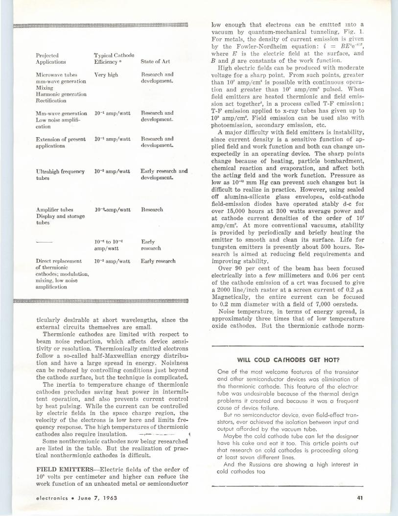
Projected Applications
Microwave tubes mm-wave generation Mixing Harmonic generation Rectification
Mm-wave generation Low noise amplifi-cation
Extension of present applications
Ultrahigh frequency tubes
Amplifier tuhes Display and storage tubes
Typical Cnthode Efficiency a
Very high
10-1 amp/watt
10-1 amp/watt
10-a amp/watt
10--2.amp/watt
10--11 to 10-4
amp/watt
Direct replacement 10-3 amp/watt of thermionic cathodes; modulation, mixing, low noise amplification
State of Art
Research and development.
Research and development.
Research and development.
Early research and development.
Research
Early research
Early research
ticularly desirable at short wavelengths, since the external circuits themselves are small.
Thermionic cathodes are limited with respect to beam noise reduction, which affects device sensitivity or resolution. Thermionically emitted eleclrons follow a so-called half-Maxwellian energy distribution and have a large spread in energy. Noisiness can be reduced by controlling conditions just beyond the cathode surface, but the technique is complicated.
The inertia to temperature change of thermionic cathodes precludes saving heat power in .intermittent operation, and also prevents current control by heat pulsing. While the current can be controlled by electric fields in the space charge region, the velocity of the electrons is low bere and limits frequency response. The high temperatures of thermionic cathodes also require insulation. - -.--·-· ~
Some nonthermionic cathodes now being researched are listed in the table. But the realization of practical nonthermion_.ic cathodes is difficult.
FIELD EMITTERS-Electric fields of the order of 10° volts per centimeter and higher can reduce the work function of an unheated metal or semiconductor
electronics • June 7, 1963
low enough that electrons can be emltte<l mto a vacuum by quantum-mechanical tunneling, Fig. 1. For metals, the density of current emiss ion is given by the Fowler-Nordheim equation: i = BE'e-~ 18 , where E is the electric field at the su rface, and B and f3 are constants of the work function.
High electric fi elds can be produced with moderate voltage for a sharp point. From such points, greater than 10' amp/cm• is possible with continuous operation and greater than 10• amp/ cm2 pulsed. When field emitters are heated thermionic and field emission act together•, in a process called T-F emission: T-F emission applied to x-ray tubes has given up to to• amp/cm•. Field emission can be used also with photoemission, secondary emission, etc.
A major difficulty with field emitters is instability, since current density is a sensitive function of applied field and work function and both can change unexpectedly in an operating device. The sharp points change because of heating, particle bombardment, chemical reaction and evaporation, and affect both the acting field and the work function. Pressure as low as 10-"' mm Hg can prevent such changes but is difficult to realize in practice. However, using sealed off alumina-silicate glass envelopes, cold-cathode field-emission diodes have operated stably d-e for over 15,000 hours at 300 watts average power and at cathode current densities of the order of 10' amp/cm' . At more conventional vacuums, stability is provided by periodically and briefly heating the emitter to smooth and clean its surface. Life for tungsten emitters is presently about 500 hours. Research is aimed at reducing field requirements and improving stability.
Over 90 per cent of the beam has been focused electrically into a few miJJimeters and 0.06 per cent of the cathode emission of a crt was focused to give a 2000 line/ inch raster at a screen current of 0.2 µ.a Magnetically, the entire current can be focused to 0.2 mm diameter with a field of 7,000 oersteds.
Noise temperature, in terms of energy spread, is approximately three times that of low temperature oxide cathodes. But the thermionic cathode norm-
WILL COLD CA"fHODES GET HOT?
One of the most welcome features of the transistor and other semiconductor devices was elimination o f the thermionic cathode. This feature of the electror: tube was undesirable because of the thermal design problems it created and because it was a frequent cause of device failure.
But no semiconductor device. even field-effect transistors, ever achieved the isolation between input and output afforded by the vacuum tube.
Maybe the cold cathode tube can let the designer have his cake and eat it too. This article points out rhat research on cold cathodes is proceeding along at least seven different lines.
And the Russians are showing a high interest in cold cathodes too
41

TUNNEL cathodes are being fabricat ed in ultrahigh vacuum
ally requires beam area compression, while with field emission beam expansion can be allowed. Thus noise temperature for transverse electron travel can be less using field emission.
In addition to high current density, field emitters have strong nonlinearity between applied field and emitted current, instant time response, and high efficiency. In a new high-speed x-ray tube developed by the Field Emission Corp. of McMinnville, Oregon, a high-energy electron beam is pulsed on for a fraction of a microsecond to produce an intense burst of x-rays. Tube uses include stop-action radiography
and radiation effect studies at 10• rad/sec. The high current densities of field emission are
attractive at extremely high frequencies for amplifiers, oscillators, mixers, harmonic generators, and rectifiers; Field Emission Corp. has experimented with frequency quadrupling up to 8 mm, but practical devices need more development. a, • . •. '
PHOTOEMITTERS - Present photocathodes are sensitive only to frequencies in the near infrared and higher. Some present cathodes have• yields close to 0.5 electron per incident photon.
RESULTANT PHOTOCURRENT'
I photo ' A~ SELECTIVITY TO f5
DETERMINED BY FILTER AND PHOTOSURFACE RESPONSE
SELECTIVITY TO Is
DETERMINED BY RECEIVER AND LOCAL OSCILATOR TUNING
---------
A; • EFFECTIVE MAGNITUDE OF LIGHT VECTOR OF FREQUENCY f;
re
'?i ( f;)' RESPONSE OF PHOTOSURFACE AT FREQUENCY f;
(Al RESULTANT PHOTOCURRENT
FROM PHOTOELECTRIC MIXING
Is FILTER
AMPLITUDE MODULATION -MODULATED CURRENT
FREQUENCY MODULATION -FREQUENCY SENSITIVE EMISSION
- MODULATED CURRENT
( 8) STRAIGHT RECEPTION (C)
PRINCIPLES of photoelectric mixing (A), examples of modulation detection (B) and (C) by interaction with the electrons, and Siegman's frequency-modulation detector (D ). These techniques may provide a way to generate submillimeter
42 June 7, 1963 • electronics

Photoemission is a nonlinear process and can be used in detecting modulation on a light beam• (See Fig. 2). When light falls upon a photoemitter, the density of the emitted stream varies with the modulation. In one photoemission detection scheme, density-modulated current is fed into the slow-wave circuit of a traveling-wave tube to amplify and extract the modulation. The frequency limit for this type of detection may be as high as several hundred Gc10
• •
The nonlinearity also holds promise for mixing two laser beams, separated by a microwave or millimeterwave frequency, to obtain a density-modulated beam at the difference frequency. The modulation can then be amplified and extracted, offering possibilities for generating millimeter and even submillimeter-waves.
The photoemitter may also produce a low-noise electron beam for microwave amplifiers.11 Theoretically, a beam from a photoemitter can have a small velocity spread and therefore low noise. According to the Einstein relationship for the maximum energy of emitted electrons, Em .. = hv - '/!, where .µ = the photoelectric work function, h = Planck's constant, and v = the frequency of the light.
The quantity Em .. can be small if the light frequency is close to the threshold frequency '/l/h of the photocathode response. Calculations indicate sufficient photoemitter current to drive a microwave tube even when E"' .. is small enough to give low beam noise.
SECONDARY EMITTERS - A secondary emitter emits electrons when bombarded by other electrons or ions, with more elecitrons emitted than are used in the bombardment." Hence the current density and current variations of a bombarding beam can be amplified, with large amplification possible
While many of the details of secondary emission are unknown, practical devices have been developed. One limitation is the large velocity spread in the emitted electrons and hence an inherent noisiness in the emitted beam.
An applica.tion of secondary emitter amplification is
the photomultiplier phototube whose operation has been extended recently to microwave frequencies.13
Another application is the self-sustained emission in magnetrons and amplitrons. In these tubes, some electrons are used to bombard the cathode and produce further secondary emission. Such tubes do not require external heating once emission i's started by a heating or microwave pulse.
PLASMA ELECTRON SOURCES-In this type of emission, the electrons come from a gas rather than a solid (See Fig. 3). Plasma sources can produce current densities much higher than thermionic cathodes can." But the apparatus for producing the discharge is cumbersome and the extraction of electrons into the vacuum is difficult. In addition, the emission tends to be inefficient, unstable and noisy.
While plasma cathodes are difficult for small devices, they have already been used in a heat source developed by Alloyd Electronics Co., Cambridge, Mass., for melting, annealing and heat treating metals by electron bombardment. After initial plasma activation by r-f, positive ions from the discharge region bombard a cathode and heat it until thermionic emission takes place. The thermionically emitted electrons pass through the plasma, releasing further electrons by ionization, and pos·itive ions to bombard the cathode. This operation is self-sustained. A present heat source delivers 30 Kw and can melt 200 lb. of stainless steel per hour.
MgO-TYPE EMITTERS-Sustained emission from MgO and other metal oxides was obtained about a decade ago. An MgO-type emitter usually consists of a nickel sleeve coated with a metal oxide several tens of microns thick,15 (See Fig. 4).
In operation, an initial surface charge is produced by the incidence of ultraviolet light, radioactive radiation or bombarding electrons. This starts the emission, which continues after the radiation is turned off. A recent theory of operation presumes that an electron avalanche is produced by a breakdown in the metal-oxide layer under the influence of
PRISM
~ELECTROMMNET ELECTRON COLLECTOR
Ni NiO
ANODE
(D)
MICROWAVE STRUCTURE COUPLING TO TRANSVERSE MOTION OF ELECTRONS~
SIEGMAN'S FREQUENCY MODULATION DETECTOR
longitudinal motion of photoemitted waves-Fig. 2
electronics • June 7, 1963
ION TRAP
ACCELERATOR,
STABILIZER
DISCHARGE ANODE
PLASMA
=,,..,,.-,,..,,,--"'- DISCH AR GE CATHODE
MERCURY POOL
PLASMA cathodes, as suggested by K. G. Hernquist-Fig. 3
'--------Yr.--------' ELECTRONS are multiplied in MgO layer and some escape-Fig. 4
43

the strong electric fields from the surface charge. The avalanching electrons may be emitted directly or may produce secondary emission from the MgO layer before reaching the vacuum. A primary research goal is a better understanding of the process.
Current densities achieveable from MgO-type emitters are comparable with those from thermionic cathodes. Major shortcomings of this type of emitter include: a large energy spread in emitted electrons (several tens of electron volts) leading to high noise and poor beam resolution; ·a drop of about 200 volts across the metal-oxide layer, making the cathode inefficient; the necessity for a starting process.
The time constant for starting causes problems in rectifier operation even at low frequencies.
Further development depends on a better understanding of the process, and research objectives include stability improvement, noise reduction, and self-starting."
P-N JUNCTION EMITTERS-The n-type material in the back-biased p-n junction diode of Fig. 5 is some tens of Angstroms thick, with the outer surface the cathode surface. The bias voltage can excite hot electrons into the n-type material, with most of these electrons originating in the valence band of the p-type material and transposed by tunneling or avalanche breakdown. Some of the transposed electrons arrive in the n-type material :with energies higher than the vacuum level. The electrons then drift and diffuse through the n-type material, and some are emitted into the vacuum,17 in an operation similar to the tunnel cathode.
But the emitter has serious limitations. The rate at which energy is Jost as a hot electron travels in the n-type material is high and an electron, after tunneling at an energy level above the vacuum level, may still not be able to escape because of losing energy before it reaches the surface. The n-type layer can only be so thin before the properties of the junction are affected, and the minimum possible thickness is too great to permit many of hot electrons to escape. The experimental data thus far reported involve current densities of about 0.1 microamp/cm', too low to be useful.
The velocity spread of the emitted current gives
P·TYPE MATERIAL
TU NNELI NG ELECTRON
METAL
SUBSTRATE
FERMI SEA-
ENERGY BAND PICTURE FOR ELECTRON
EMISSION FROM A P-N JUNCTION
ELECTRON DENSITY IN ME TAL
SUBSTRATE
noise temperatures of about 6,000 K. The hot electrons that are not emitted flow through
the battery and constitute a circulating current, which produces a lateral voltage drop across the cathode surface. Emission is critically dependent upon surface voltage, thus serious nonuniformity in emission results.
TUNNEL CATHODES-This type cathode promises more desirable features than the other types, including high current densities, low temperature operation, low-noise beams and instant starting. High current density and low noise beams would not be obtained simultaneously, however. In addition, space charge limited operation should be possible.
The tunnel cathode is a metal-insulator-metal sandwich, as illustrated in Fig. 6. Electrons tunnel from the metal substrate and appear in the metal film as hot electrons. Some of the hot electrons have sufficient energy to pass over the cathode surface barrier into the vacuum.'" In the figure, a temperature of 0 K is assm:ned for simplicity.
Electrons in the metal substrate occupy energy levels up to fermi level F,; those in the metal film, up to fermi level F.. F , has been shifted down with respect to F , by the battery voltage, which appears across the insulator. Since the insulator is a thin film, electrons can tunnel through it into the metal film. The battery voltage exceeds the height of the vacuum barrier and some of the tunneling electrons arrive with energies higher than the vacuum level. If the mean free path for the hot electrons is large enough compared to the thickness of the metal film, emission into the vacuum can occur. Electrons arriving at the cathode surface with energies lower than the vacuum level eventually fall to below F , and are conducted away through the battery, to constitute a circulating current.
Energy spread 8 of the emitted electrons can be controlled by adjusting the battery voltage. Beam noise is critically dependent upon 8, and noise temperature is Tn = 27308. The equation actually applies only when 8 is small and when the cathode is at absolute zero. For a finite temperature, the velocity spread and hence beam noise temperature will be above actual cathode temperature.
For Tn = 30K, and & = 0.01 eV, only about one per-
CATHODE SURFACE
(A)
PYRE X GLASS
!Bl
P-N JUNCTION cathode must overcome severe problems to become practical-Fig. 5
ENERGY relations (A) and one type of construction (B) for tunnel cathodes-Fig. 6
44 Juno 7, 1963 o electronics

cent of the tunneling electrons are emitted into the vacuum10 and the remainder becomes the circulating currrent. For the same conditions, a beam current of 50 µ,a was computed for a cathode 20 mils in diameter, enough to operate a low-noise twt.
For a twt beam with a noise temperature of 30K, circuit losses must be small or Johnson noise will be greater than beam noise. But losses can be reduced by cooling the circuit.
Cooling can also provide superconduction in the metal film, thus eliminating the lateral voltage drop due to circulating current; even .a small lareral voltage drop would cause nonuniform emission.
Where low noise is not required, high current densities appear possible, giving a circulating current small compared to emitted current.
Problems of practical tunnel cathodes include materials and a detailed knowledge concerning their energy structure. Second, better control of the tunnel process is needed. In the experimental cathodes thus far constructed, zener tunneling-in addition to the desired quantum mechanical tunneling-probably occurs from the insulator valence band into the insulator conduction band or directly into the metal. Any tunneling into the insulator conduction band leads to inelastic scattering of the electrons passing through and adds to the circulating current.
Uniformly smooth surfaces and uniform properties over the cathode area are also necessary and the cathode films must be free of pinholes. Thicknesses must be maintained to close tolerance. F-0r low-noise emission, the work function over the emitting surface must be uniform or the useful emission area will be small.
In spite of the difficulties, tunnel cathodes offer inherent advantages, and experimental results are encouraging. Densities to 10 amp/cm2-pulsed, to avoid thermal breakdown~have been reported20
;
densities for d-c opemtion are several orders of magnitude lower. In experiments to now, emitted current has been -0nly a small fraction of the total circula1ting current.
CONCLUSION-Work -On cold cathodes is partly aimed at developing electron sources that eliminate
REFERENCES
1. G. H errman & S. Wagener, "The Oxide Coated Cathode", vol. II, Chapman & Hall l.itd., l.iondon 1951.
2. L. S. Nergaard, " Thermionic Emitters", Pro·c . of the 4th Ntl. Conference on Tube T echniques, p. 197, SeP't. 1958, N. Y. Universlty hess 1959.
3. W. P. Dyke & F. M. Charbonnier, " Recenlt Progress in Field Emission", Paper presented at the AIEE Winter General Meeting Jan. 28-Feb. 2, 1962, New York.
4. M. I. Yelinson, F. F. Dobry•akova, V. F. Krapivin, Z. A. Malina, & A. A. Y.asnopol'skaya, On the Theorie af Field Emission and Thermionic Field Emission {)f Metals and Semioonduotors, Radio Engineering and Electron Physics, No. 8, p. 1191, Aug. 1961.
5. E. G. Brock, F. M. Charbonnier, J . D. Sleeth, and W. P. Dyke, "The RF Modulated Field Emission Cathode as a Harmonic Genera-tor", Proc. o.f the 4th Ntl. Conference on Tube Techniques, p. 125, Sep t. 1958, N. Y . University Press, 1959.
6 . J. P. Barbour, F. M. Charbonnier, L. F . Garrett & P. Dyke, "On Application of Field Emission to a Two-Cavity Microwave Amplifier", Proc. of the 4th Ntl. Conference on Tube Tec·hniques, p . 133, Sept. 1958, N . Y . Univ. Press 1959.
7. K. D. Froome, "Proposed H •armonic Gene rator or Mixer for Optical Frequencies", Nature 192, p. 859, 1961.
8. W. E. Spicer, Phoitoemission and Related Properties of the Alkali-Antimonides, J. Appl. Phys. , 31, No. 12, p. 2077, Dec. 1960.
9. A. T. FX>rrester, Photoelectric Mixing a,s a Spectrosoopic Tool, J. Opt. Soc., 51, No. 3, March 1961.
10. A. E. Siegman, "Microwave Phototubes and Demodula-
electronics • June 7, 1963
INSPECTING a tunnel cathode
inherent shortcomings of thermionic cathodes, which include limited current density, high power consumption, high temperature operation, high beam noise, and long starting time. In addition, cold cathodes are of interest for their nonlinear characteristics. Potential new applications exist in millimeter wave generation and amplification, low-noise amplification, high beam resolution, high cathode efficiency, fast starting, mixing, rectification and harmonic generation. At present, the performance of cold cathode leaves much to be desired, and none have replaced the thermionic cathode in any important way. Nevertheless, a number of unique devices have already been built.
The authors wish to acknowledge the assistance of Dr. W. P. Dyke in preparing this article.
tJors", NEREM Record 1961, p. 118. 11. W. Feist, "New Applioations of Photocathodes and Asso
ciated Prol>lems", Paper PTe•senrted a;t the AIE-E Winter Gener.al Meeting, J ·an. 28-Feb. 2, 1962, New York.
12. A. J. Dekker, " Solid State Physics", Prentice Hall Inc., 1960.
13. O. L . Gra-ddy, and D. F. Hals.houser, High-Griain Dynamic Microwave Photomultiplier, Proo IRE, 50, No. 2, p. 207, Feb. 1962.
14. K. G. Hernquis-t, High VoJ.tage Electron Ext!"action from an Arc Discharge Pla,sma, RCA Review, p. 170, June 1960.
15. A. M. Ske llet, B. G. Firth, D. W. Mayer, "Some Properties of the MgO Primary Electrnn Emitter", Proc. of the 4th Ntl. Conference on Tube Techniques, September 1958, p . 138, N. Y. Univ. Press 19 59.
16. D. Dobischek, " The Magnesium Oxide Type Cold Oathode, Presenit Status a nd Aspects of Further Advancement", Paper presented at the AIEE Winter Generial Meeting, J an. 28-Feb. 2, 1962, New York.
17. J. L. Moll, N. I . Meyer, and D. J. Bartelink, Hot Electron Emission from Silicon p -n Junctions Pariallel to the Surface, Phys Rev L etters. 7, No. 3, p. 87, Aug. 1, 1961.
18. C. A. Mea-d, Operation of Tunnel E-missive Devices, J Appl Phys, 32, No. 4, p. 646, April 1961.
19. G. Wade, R. Briggs, and L. Lesensky, Low Noise Beams from Tunnel Cathodes, J Appl Phys, 33, No. 3, p. 836, March 1962 .
20. C. E. Horton & C. E. Mead, "Tunnel Emission", Paper presented at the AIEE Winter Genenal Meeting, J ·an. 28-Feb. 2, 1962, New York.
45

INDUCTORS NO PROBLEM
New Thin-Film Amplifier
By RICHARD LESLIE and THOMAS TOWNSEND. AIL Div is ion , Cutler-Hammer, Inc . D eer Park, N. Y.
WHAT ABOUT THOSE BIG INDUCTORS?
Don't use them. That's how the authors solved the problem of making a thin-film amplifier. In addition, they solved a couple of other problems inherent with this type of device. They won't say what the amplifier is used for, except that it is in a classified space program and is working well
LOGARITHMIC i-f amplifiers, of tuned-stage design, do not lend themselves to microminiaturization. Inductors required are not compatible with size reductions possible with solid-circuit or thin-film techniques. A 60-mc log i-f amplifier with untuned stages has been specifically designed for microcircuit fabrication. Of modular construction, the amplifier occupies only 4 cubic inches, which is a reduction in volume of 20 to 1 over previous log i-f amplifiers.
Successive-detection log i-f am-
plifiers derive the log characteristic from the sum of the individual responses of each amplifier stage. These amplifiers have been designed using tuned common-emitter or common-base amplifiers. But there is a major problem of miniaturizing inductors. Also, a tedious alignment procedure is required because of reciprocal interaction of tuning and logging adjustments.
Investigation showed that RCcoupled amplifiers provide one solution to these problems. Untuned stages at 60 Mc are possible using
--e-.....,..,1r-<o--~~--------------I-FOUTPUT
46
Ci 1 l,OOOpF J
---------- VIDEO OUTPUT
EX TERNAL RE SISTOR l--1--4---------~
R6 R1 560 4,700
...__--------------:-- -12V C4
1 1,000p F
SINGLE log i -f module-Fig. 1
one of the higher performance vhf planar transistors. To minimize the interaction of the i-f stages when driving a common video load, one video stage is included with each i-f amplifier.
The log i-f stage is shown in F ig. 1. Under small-signal conditions, video section Q, can be considered as a small shunt conductance. Its presence has only a second-order effect on the operation of i-f section Qi- In this case, Q1 acts as a linear r-c amplifier. Low-frequency cutoff is determined by the coupling capacitor and by the bypass circuits in the emitter. The upper-frequency cutoff is a function of the load r esistance and the stray capacitances in the circuit. With the values shown, the i-f bandwidth extends from 20 Mc to 120 Mc (Fig. 2) Gain is about 10 db for good log operation.
As signal amplitude increases. rectification occurs in the emitter base diode of Q,, causing the diode current and the emitter voltage of Q, to increase.
Since the base of Q, is held fixed. the collector current of Q, decreases. This action observed acr oss RL produces the sloped portion of the video transfer characterist ic The low-pass section between t he emitters of Q, and Q, prevents the appearance of i-f a t the emitter of Q,. As the signal level increases further , transistor Q, cuts off completely so that any further increase in input-signal level does not appear in the video output. The power
June 7 , 1963 • elect r on ics

Solving the problem
of inductor size in a
thin-film amplifier design
resulted in other
plus f ea tu res
range over which log action takes place is 10 db. By properly selecting the bias point, Q, can be made to cut off before the i-f output power of Q, saturates.
A thin-film technique of fabrication was chosen because of the design flexibility allowed. For a 0.5 by 0.5 inch wafer, the normal limits are: Resistors less than 100 kilohms· and greater than 10 ohms; capacitors no greater than 1,000 pf; ratio of resistors within a module less than 1,000 ; and resistor tolerances greater than 5 percent. For unusual applications, the limits can be extended slightly at a greater cost.
FABRICATION-In thin-film circuit fabrication, Fig. 3, a substrate made of either glass or fired alumina ceramic is placed in a vacuum chamber. A mask containing the desired circuit pattern is interposed between the substrate and the material to be deposited, nichrome for resistors, beryllium copper for conductors, and silicon monoxide for dielectrics, is heated in a crucible. Vapor is driven off in all directions within the vacuum chamber. The evaporating m ate r i a 1 pas s es through the holes in the mask and condenses on the substrate. Several masks and deposition cycles are required to produce the finished circuit containing resistors and conductors. During deposition, the substrate is heated to provide a permanent molecular bond between the materials. Deposited silicon monoxide capacitors were not used in this amplifier because of a number of
electronics o J une 7 , 1963
COMPLETE log i-f amplifier showing module construction and relative size compared with a penny
CD Cl
z ;;:;: ~-3 t----J~--~------''><--l > ;::: <I -' w 0: 20 60 120
FREQUENCY IN MC
GAIN characteristic of a single log i-f stage-Fig. 2
associated problems-primarily dielectric breakdown due to minute pin holes. Standard techniques for eliminating pin holes result in too low an insulation resistance.
After the material has been deposited and removed from the vacuum chamber, chip transistors and capacitors are bonded to the substrate. These components are soldered to the appropriate deposited elements.
LAYOUT-After careful study, the complete layout of the log i-f stage including transistors was devised, Fig. 4. Environmental and electrical testing of this circuit shows that i-f circuit performance is not degraded when converting from conventional components to thin-film circuits. In many instances, circuit operation can be enhanced by microminiaturization because of the lowering of series lead inductances and stray shunt capacitances. The performance results for the thin-film stage are identical to those shown in Fig. 2 for the conventional stage.
After determining feasibility of the basic log stage, the require-
ments of the complete amplifier were considered. In general, for the successive-detection amplifier, the accuracy is limited to either input dynamic range divided by 100, or 0.5 db, whichever is greater. The number of stages, N, required to achieve this accuracy is
N = Input Dynamic Range (db) ;-1
Stage Gain (db)
For this application, the input dynamic range can be considered to extend from -10 dbm to -70 dbm so that the maximum accuracy is 0.6 db, and N ~ 7. Choosing seven stages, a translation amplifier with a gain of 8 to 10 db is necessary to
EVAPORATION SOURCE -~~~
FABRICATION of thin-film circuits is performed using a vacuurn evaporation system-Pig. 8
47

48
PHYSICAL LAYOUT of a log i-f module with resistors, capacitors and transistors identified-Fig. 4
+12v
27
VIDEO
~---<:g~~~e~~ I 470 I I ,....,,_...__,E--1---++-+--1--+r -F
I ~g I I __,.. 100 I I . I STAGES J -.120 820 -+470
2
OUTPUT
5
I VIDEO 2,700 2,700 OUTPUT I .
TRANSLATION 1ST THROUGH-11---1--7-T-H----r-----+--V-ID-E+-O- -l2V
AMPLIFIER LOG I 6 · LOG EMITTER
UNLESS OTHERWISE1 NOTED: I-F I I I-F I FOLLOWER
RESISTANCE VALUES IN OHMS, CAPACITANCE VALUES IN PF.
SEVEN-STAGE log i-f requires a translation amplifier to limit bandwidth an.d a video emitter-follower to match the output to the load-Fig. 5
ensure the start of the log curve at the lowest input power.
The overall log amplifier, Fig. 5, requires about 7 Mc of band-pass limiting so that a one-pole filter is included in the translation amplifier. However, the tuning inductor is placed outside the translationamplifier module to permit substitution of other filters for other applications. The video emitter follower is required to match the available 10-volt video output to its load. Parallel emitter followers are required to produce the necessary video power to a 100-ohm cable and load.
Log operation by the successivedetection principle can be explained with the aid of the curves shown in Fig. 6. Under no-signal conditions, each video stage is adjusted to contribute 1.5 ma to the common load resistor RL. At a particular low signal power level, stage 7 begins to detect causing the video current to decrease. As the power increases further, the video portion of stage 7 cuts off. Ideally, if the db gains of stages 5 and 6 are exactly equal to the range over which stage 7 contributes to the initial portion of the log response, stage 6 will start to detect at the point where the video portion of stage 7 cuts off. In this manner, for each 10-db increase in input power, 1.5-ma current increments are removed from the common load resistor producing the complete dashed curve of Fig. 6. After each stage has contributed its portion of the overall curve, its individual i-f output saturates thereby limiting the drive power to successive stages and minimizing recovery problems because of the unequal positive and negative conduction impedances.
A straight-line curve is not achieved in practice for several reasons. First, preceding stage gains are not absolutely equal or fixed producing variations in the point at which each stage starts detecting, when referenced to the input. Second, the absolute power level at which the emitter-base diode of each stage begins to detect is not accurately defined and the break point is not sharp. Third, the cutoff point of each video stage is rounded.
Seven log stages provide the required accuracy when taking into
June 7, 1963 " electronics

10
9
8
~ 7 0 > ~ 6 I=> ::: 5 :::> 0
8 4 Cl
> 3
2
----IDEAL
-ACTUAL
-60 - 50 -40 -10
~ 200
~ 100 0:
--- WITHOUT TEMPERATURE COMPENSATION
~ Ol----::~~--::';.....r:::::--------0: w -100
- 200
(A) -10 -60 -50 -40 -30 -20 -10 POWER IN DBM
200
> :::; DECREASING ~ VOLTAGE o: r::::::------'.._!_{ R L CONSTANT ~ - 1ooi:-o: w-200
-300
-4o~70 -60 -50 -40 -30 -20 -10
INPUT SIGNAL POWER IN DBM
OVERALL PERFORMANCE characteristics of the complete seven-stage amplifier-Fig. 6
(8) POWER IN DBM
TEMPERATURE COMPENSATION of the load resistor decreases error at the high power levels (A); further improvement may be had by using a temperature compensated -6 volt supply (B)-Fig. 7
account gross deviations from the ideal curve due to the limited power range over which each stage adds to the overall curve. Other factors contributing to the inaccuracy cannot be remedied by using additional stages.
PROBLEMS-Size reduction introduced a number of problems. The greatest was that of stability. Because of the large gain of about 18 db per linear inch, oscillations were a constant problem. These oscillations can vary from 5 Mc (due to improper power-supply isolation ) to 70 Mc (when interstage shielding is inadequate or poorly grounded) ,
By using toroidal choke power decoupling between the translation amplifier and the first log i-f, and' between the first and second log' i-f's, the low-frequency oscillation can be eliminated. Toroids are desirable since much of the field is contained within the iron core. Careful stage shielding and grounding can prevent feedback oscillations due to the proximity of the stages. However, it is necessary to maintain a center-to-center stage spacing of about 0.3 inch for the shielding to be successful.
Alignment of the stages to produce the overall log response can be accomplished by either of two meth-
electronics • June 7, 1963
ods. The first and simplest starts with the individual stages. As a part of the module test, the value of R,. (Fig. 1) that produces a known video stage current (/. 0 ) is determined. In this amplifier, it is chosen as 1.5 ma, which is a compromise between the size of RL and the change in i-f stage current as detection takes eplace. With small initial values of l , 0 , RL must be large to produce the required video output voltage. Combined with the parallel output capacity of the seven stages, too large an RL will limit the high-frequency video response. On 'the other hand, if I .. is too large, the variation of i-f emitter current (!,.) is too large over the detection range, thereby affecting the i-f gain during detection.
After the modules have been assembled in a complete amplifier , the nearest fixed resistor to the required value of R., is added to each stage, and RL chosen to be equal to V /7, • ., where V is the required maximum video output voltage. Experimental results show that an accuracy of ±200 mv with respect to the ideal curve can be obtained in this manner.
For greater accuracy, potentiometers can be substituted for the fixed resistors. The potentiometers of the subminiature square type can be inserted in the interstage space
required for stability. By this means, the overall inaccuracy can be reduced to ±50 mv with several points out only ±100 mv (0.67 db) .
TEMPERATURE EFFECT-Average error from the ideal curve as a function of input power with temperature as a variable, Fig. 7 A, demonstrates the effect of optimum temperature compensation of RL. The result is to decrease the error at high power levels at the sacrifice of increasing the error at low power levels, although the overall maximum is decreased.
Although comp ens at in g RL proved sufficient for the particular application, further improvement is possible by introducing a temperature-variable -6 volt power supply. The required variation is only of the order of tenths of a volt, but has the effect of changing the slope of the error-vs-power curve as a function of temperature, Fig. 7B, thereby providing complete compensation along with a variable RL.
Acknowledgment is given for the assistance of William McCarthy and Joel Byer in developing the complete amplifier. The basic logarithmic stage is the work of Allan Brown. Layout and fabrication of the thin film modules was performed by Varo, Inc., Garland, Texas, under subcontract to AIL.
49

AUTHORS Herzig (left) and Colbert check out the voltage monitoring system that they have developed
r--------->..tl/\r------rlEFERENCE SUPPLY
r--1 I I I I I I I I t L~-
(A)
115 V 400 l\J
D-C SUPPLY '
'---------..JVo.Ar-----~BEING
(CHOSEN FOR MON/TORE() REQUIRED SENSITIVITY)
REDUCED inductance of saturated core (A) permits of different polarity (B), two control windings are
Voltage Monitor Needs Only· Two Supply being monitored is compared with reference. Difference voltage feeds
saturable cores. Core saturation operates indicator lamp or closes relay
By MARIN C. HERZIG and DONALD C. COLBERT Electronic Communications Inc., St. Petersburg, Florida
THE VOLTAGE MONITORING device described here is essentially a saturable reactor controlling a ! watt neon lamp as shown in A. The monitor-unit consists of two control windings and a signal winding wound on a pair of high-permeability cores. The control windings are connected between a reference supply and the voltage-divided output of the d-c supply being monitored. When the power supply output is at its proper potential, the voltages are identical and d-c current flows through the control windings, producing no d-c flux in the core. Consequently, the reactance of the 400-cps signal winding is high, the volt drop across resistor R is low and the neon indicator glows. If the d-c supply output increases or decreases from any cause, the difference in potential across the control windings causes a current-flow which will saturate the cores. The reactance of the 400 cps signal winding is then reduced, the drop across R is increased, and the neon indicator is extinguished.
Using a common commerical core material, a control winding current of about 0.2 ma will control full operation of the indicator. With more sensitive cores and more control-winding turns, a lower current of 0.05 ma will control the indicator. In a typical power supply, a voltage variation sufficient to cause 0.05 ma current differential is very small,
50
giving a high sensitivity figure to the indicator. Typical design data for a 400 cps indicator are given in the table. These values can be varied over wide ranges to provide an optimum design.
The minimum core size is limited chiefly by the physical size necessary for the windings since the power requirements are very low. The number of turns on the signal winding is a function of the core material since the inductance must be sufficient to develop the neon firing potential without self saturation when no d-c flux is present. Typical formulas are
E = 4.44 f NA. B .. 10-s (1) where E = impressed voltage (about 50 volts for a small neon), f = supply frequency in cps, N = number of turns, A . = effective core area in square centimeters, and B .. = maximum flux density.
1.25 N' A. M. 10-• Alternatively L = (2)
l:ore
I .
REACTOR DETAILS
Orthonic, 1.000 OD, 0.625 ID, 0.188 thick
Control Winding .. .. 750 turns of No. 36 gage wire each winding
Signal Winding...... 500 turns of No. 36 gage wire Lamp . . . . • . . . . . . . . • NE51 or NE2 Limiting Resistor R.. 56,000 ohms, % W
June 7, 1963 • electronics

,--1
1 I I I I I I '-~<:..-' I L_
(Bl (CHOSEN FOR REQUIRED SENSITIVITY)
REFERENCE SUPPLY
r---I
I I I
115V I 400'V \ II
I I I L ___
D-C s·uPPLY BEING MONITORED
( C}
REFERENCE SUPPLY
--, I
R I
115 V 400'1.1
I __J
~ ~
TO LOAO
D-C SUPPLY BEING (C HOSEN MONITORE[) FOR
REQUIRED SENSITIVITY l
high value of 400-cycle current, turns off indicator through large dr op in R . ~it~ re(ere~ce and m onitored supplies used. S ensitive relay can be used instead of indicator lamp (C) i f remote indication is needed
Saturable Cores current through control windings of
contacts
where L = approximate inductance in henries, N = number of turns, A . = effective core area in square centimeters, M . = inritial permeability, and I . = effective core length in centimeters.
The two cores used in the monitor balance out any a-c from the signal winding, which would otherwise be induced in the control winding by transformer action. Balancing-out the a-c is necessary, since it would appear in the power supply as increased ripple and could also saturate the cores, preventing proper indication.
The indicator can be used with any frequency in the audio range. Since the control power requirements are modest, the indicator would monitor audio and r-f potentials with the addition of a detector between these sources and the control windings.
An additional control winding identical to the first could be added to operate the indicator where the reference voltage and the power supply voltage to be monitored are of opposite polar it y, B. This would have application in a multivoltage power supply using both positive and negative outputs and where a single indicator is desired. One control winding would connect between the reference and ground. The other control winding would connect in phase opposition between power supply voltage and ground.
By adding a relay and rectifier configuration as shown in C, an audible alarm or other high-power
electro!1ics • June 7, 1963
REPLACING THE INDEX FINGER
Some electrical pioneers used to check working voltages by moistening a finger and placing it firmly on the live terminal. Their reactions were calibrated in the distance they jumped. Later came the conventional voltmeter, doubtless devised for the less hardy experimenters. And now, with a whole slew of stringent 'fequirements placed on electronic equipment, even voltmeters are barely adequate. If the system vibrates, the voltmeter becomes unreliable; if lots of voltage sources are to be monitored simultaneously, a string of voltmeters takes too much panel space; and if a readout is required for under-voltage conditions, the meter gets prohibitively expensive.
Obviously, something simple and cheap is required to replace the meter-and saturable core units are just the animals. The only panel space needed is that required for a neon bulb. The bulb itself is also fairly rugged and the same pair of cores can operate a relay with few extra components
readout may be controlled by the saturable reactor" The unit will still sense over and under voltage conditions with only one relay.
The indicator can also be used as an accurate means of presetting a power supply voltage by adjusting the voltage until the light comes on. Since the indicator is a proportional control device rather than an on-off device, the output voltage may be adjusted for maximum lamp brightness, where low voltage sensitivity is involved.
REFERENCE (1) "Refe r ence Data fo r R a dio E ngineem," Interna tional
T elephone a nd T elegraph Corpo r a tic>n, Ne w York, N . Y.
51

TUNNEL DIODE pair (A) produces the composite volt-ampere curve of (B). A series diode combination vroduces the curve of (C)-Fig. 1
How to Make Tunnel Diodes Four tunnel diodes can be combined to produce a curve exhibiting three
positive-resistance regions separated by negative-resistance regions.
This can be used to make a tristable circuit or -a bipolar pulse generator
A NUMBER of solid-state devices have been developed that exhibit a negative-resistance characteristic. Notable examples are the tunnel diode, the avalance transistor, the pnpn transistor and the unijunction transistor. A considerable body of information is available in the literature regarding the use of these devices as bistable elements, pulse generators, logic elements and amplifiers. However, little has been reported regarding the combination of negative-resistance devices to produce unusual terminal behavior.
Perhaps the best-known circuit that combines negative-resistance devices is the tunnel diode Goto pair. The composite volt-ampere characteristic of the Goto pair provides a convenient means of understanding the terminal behavior of the circuit, and an investigation of this characteristic reveals that the pair possesses many ·outstanding features not shared by the single tunnel diode.
This article shows that four tunnel diodes may be combined to produce a composite volt-ampere characteristic that exhibits three positive-resistance regions separated by negative-resistance regions. The salient features of the composite characteristic are shown and a tristable circuit and bipolar pulse generator described. These techniques also apply to the combination of other negative resistance devices. ·
TUNNEL DIODES-A tunnel diode is a two-terminal nonlinear device that exhibits a static volt-
52
ampere characteristic characterized by peak current, peak voltage, valley current, valley voltage and forward voltage. For an applied voltage less than valley voltage, the nonlinear characteristic is due to quantum-mechanical tunneling. For applied voltages larger that the valley voltage, the nonlinear characteristic is due to the usual forward conduction of a semiconductor junction. Because of this,. the valley region is relatively broad and temperature dependent in contrast to the peak region which is sharp and well defined.
TUNNEL DIODE PAIR-One extension of the nonlinear characteristics of the tunnel-diode is the tunnel diode pair shown in Fig. lA. This circuit combines the volt-ampere characteristics of two tunnel-diodes in such a way to form still another nonlinear characteristic. The composite voltampere characteristic is as shown in Fig. lB. The volt-ampere characteristics of the individual tunnel-
THREE-LEVEL TUNNEL
Tunnel diodes have become type-cast as high-speed or high-frequency devices. Often overlooked is the fact that several tunnel diodes can be combined to produce unusual terminal behavior. As shown in this article, you can now build a simple circuit having three stable states
June 7, 1963 • electronics

TRISTABLE circuit (A) produces the composite curve (B) with operation explained by (C)-Fig. 2
Even More Useful diodes used in the circuit are displaced along the voltage axis an amount equal to supply voltage E and then the values of current at any given value of voltage are added. The peaks of the pair characteristic are determined primarily by peak current of the individual diodes, thus both current peaks will be more stable with respect to temperature than the valley region of either tunnel diode used.
Two tunnel diodes may also be connected in series to form the volt-ampere characteristic shown in Fig. IC. When one of the tunnel diodes is in the forward conduction region, the other is in the reverse tunneling region. Note that both connections have the same resulting volt-ampere characteristic.
A TRISTABLE CIRCUIT-A circuit having three positive-resistance regions separated by negative resistance regions, and which can be used as a tristable element is shown in Fig. 2A and 2B. This circuit combines both the tunnel diode pair and the series connection. For the peaks of the resulting volt-ampere characteristic to be maximum, it is necessary that the peaks of the pair characteristic occur at the valley voltages of the series connection. This requires that the supply voltages each be equal to E = V. + V •.
To maximize current peaks of the tunnel diode pair alone, each supply voltage should be set to E = ( V. + V./2). Thus, a problem in selecting the optimum supply voltage arises and it is necessary to use diodes having different valley voltages for the pair and series connections. In the circuit to be discussed, gallium arsenide tunnel diodes were used in the pair circuit and germanium tunnel diodes were used in the series connection. For this configuration, each supply voltage should be set between E = V.w.i + v p(GeA•) and E = ( v v<OnAo) + v v <G•A•» /2.
Since valley voltage V. of the gallium arsenide
electronics • June 7, 1963
By L. L. WILLIAMS and D. J. HAMILTON Department of Electrical Engineering University of Arizona, Tuscon, Arizona
tunnel diodes is considerably larger than the valley voltage of the germanium diodes, reasonable limits for the supply voltage can be set.
All four current peaks are primarily dependent upon the tunneling region of a particular tunnel diode in the circuit, therefore temperature problems attendant with the valley regions are minimized.
Tristable operation can be achieved by using a static load line which intersects all three positiveresistance regions. A simple implementation of this would be to connect a resistor in parallel with the circuit as shown in Fig. 2C. Since the load line must intersect all three positive resistance regions, the minimum resistance is either (V.1/-I.1 ) or (-v • .11 •• )' whichever is larger.
APPLICATION-One application of the four-diode circuit is the generation of a bi-polar voltage pulse for the read-rewrite sequence of a tunnel diode memory and such a pulse is shown in Fig. 3A. The positive pulse reads the information out of the memory and the negative pulse rewrites the information destroyed in the read operation.
The volt-ampere characteristic of the tristable circuit is first altered by inserting tunnel diodes with different peak current ratings such that the current peaks of the composite characteristic will appear as shown in the lower curve of Fig. 3A. An inductor is then connected in parallel with the tristable circuit. Since the static load line coincides witht the current axis, the circuit will have only one stable operating point located at the origin. This is under the assumption that the internal resistance of the inductor is negligible. The dynamic load line is horizontal, however, and intersects the composite volt-ampere characteristic at three points.
If a positive current pulse of sufficient amplitude is applied to the circuit, the operating point rises
53

BIPOLAR vo ltage pulse with tristable cornposite curve (A) . Linear equivalent model is shown at ( B) and a practical circuit at (C)-Fig. 3
above the first current peak at A, and switches to B. When the trigger pulse is removed, the operating point moves to point C. This is under the assumption that the inductor is sufficiently large that the current in the inductor remains essentially zero during the application of the current pulse. The current in the inductor now increases until the operating point reaches point D; a further increase of inductor current causes switching to point E. A reverse voltage is now applied to the inductor and the current in the inductor builds up in the opposite direction. When the current reaches the value designated by point F, switching occurs to the center positive resistance region to point G. The current in the inductor then decreases and the operating point moves back to the origin.
The output voltage across the circuit during the time it is in the transient condition will be a bi-
TRIS TABLE volt-ampere characteristics (A), bipolar voltage pulse (B) and bipolar voltages with high-speed pulses shown at (C) Fig. 4
54
polar voltage pulse similar to the one shown in Fig. 3A. By a similar reasoning it can be seen that if a negative current pulse is applied to the circuit, a single negative voltage pulse will be generated.
The length of either the negative or positive voltage pulse can be found by considering a linear equivalent model (Fig. 3B) of the circuit while it is in either of the positive-resistance regions. The value of the voltage source is the zero current crossing point of the composite volt-ampere characteristic in the particular region of interest. One of the series resistors is equal to the effective resistance of the composite volt-ampere characteristic and the other is equal to the internal resistance of the inductor. The pulse length is given by Ti = (L ! R ) log, [ (!, -/ ,)]/[ (/, - I, )].
Here, I, is the initial current in the inductor and I , is the value of current at which the circuit will switch to another stable state. The final value I ,, is found by dividing the equivalent source voltage by the sum of the inductor internal resistance and the approximate circuit resistance obtained from the composite characteristic.
PRACTICAL CIRCUIT- A practical circu it for the generation of bipolar voltage pulses is shown in Fig. 3C. When constructing the composite volt-ampere characteristic, include each internal resist ance R by considering it a resistance in series with each of the tunnel-diodes used in the tunnel-diode pair.
The positive-resistance regions of an experimental device are shown in Fig. 4A. Since the sweep mechanism was essentially a current source, negative resistance regions are not evident. The gallium arsenide tunnel diodes that were used in the tunnel-diode pair configuration were rated at 10 ma peak current. The germanium tunnel-diodes used in the series combination had peak currents of 20 ma and 4. 7 ma. A bipolar voltage pulse from this particular circuit with an inductor of 0.9 mh is shown in Fig. 4B. A much higher speed voltage pulse is shown in Fig. 4C. For this circuit an inductor of 3.8 µ.h was used.
June 7, 1963 •electronics

THIS RECORDER WEARS TWO HATS
Practically every instrumentation tape recorder has two heads, but this is the only one that wears two hats. Wearing the first , it records and plays back in the conventional reel·to -reel manner. (Not entirely conventional, at that-the reels are uniquely stacked to provide at least a 2:1 saving in space over ordinary recorders).
Wearing its other hat, the instrument becomes a continuous loop recorder (either fixed or variable) that will run circles around anything else you've ever seen ... in such jobs as monitoring recording, repetitive analysis, and continuous recording and playback.
Changing hats is as simple as, well, changing hats.
-electronics • June 7, 1963
Because the tape is housed in compact, interchangeable magazines, you need merely detach the first and snap the other into place, in seconds. No need to rewind or wait until the end of the reel; the interchange can take place at any time, any place on the tape.
We'd like to show you some of the many other useful features of the highly versatile Pl-200 recorder. One of these features- its great economy of space and weight-will enable us to carry a 14-chan-nel demonstrator into your laboratory in one hand. May we? For a copy of our Pl-200 brochure, address us at Stanford Industrial Park, Palo Alto 20, California.
PRECISION INSTRUMENT
@ CIRCLE 55 ON READER SERVICE CARD 55

RESEARCH AND DEVELOPMENT
Computer Translates Chinese into English
New IBM device may speed processing of technical texts
YORKTOWN HEIGHTS, N. Y.Machine translation from Chinese into English has been achieved on a limited scale by IBM Research Laboratories here, working under sponsorship of the U. S. Air Force.
Heart of the system is an ingenious method of encoding the thousands of Chinese ideographs into digital language, in the form of punched tape (18 bits per character), a process which can be done by an operator without any knowledge of Chinese, simply on the basis of geometrical comparison. The present input unit uses a modified typewriter.
Once the ideographs are entered on tape, they are then subjected
.ttt_ ~t Ji/.fai~ ~"' •':J I~~ ~~ aj- fa~ or,,.;... .t.~ ~.a , ~t ~E: m >t.~ 1-t>c .. '--~;!_ ~3 -1~1~ jf; J •.
56
WORD-FOR-WORD TRANSLATION:
Rec e n t I y discover/ discovery magnetic core (de) switching time possible shorten, therefore use/consume 'it come make even high speed (de) storage device (le).
MACHINE TRANSLATION:
Recently discover switching time of magnetic core possible shorten, therefore possible use it in order to make storage device of even higher speed.
HUMAN TRANSLATION:
It has been discovered recently that the switching time of magnetic cores can be shortened. They, therefore, can be used to make storage devices of even higher speed.
to the basic steps of machine translation:
(1) Automatic dictionary lookup, which divides up the input stream into meaningful words and phrases,
(2) Addressing system, which compares the resulting "record lengths" of symbols against a store of words (2,000 at present) on a photographic disk film memory, and finds the longest possible match for each sequence. This match may be a phrase, word or subclause, and provides grammatical and semantic tags to identify each part of the sentence.
(3) Automatic grammatical analysis, which scans each Chinese sentence five times to check for word sequences and special words that may have an effect on the meaning, and finally
(4) Automatic contextual analysis, a process that tries to identify words which remain ambiguous even after grammatical ana lysis .
CODING CHINESE-The coding system is based on a system devised by Chinese novelist Lin ·Yutang. It classifies about 6,500 ideographs into groups which have the same or similar top and bottom features. When the operator finds the group with the correct top and bottom features, an automatic display presents a table containing all the words with these two features. It is then only necessary to match the desired character with one on the table and punch out the appropriate number.
The input device, called a Sinowriter, is being built jointly by IBM and the Mergenthaler Linotype Company for the Air Force Information Processing Laboratory. It is expected that nonChinese-speaking operators can be trained to type Chinese characters into the translator at rates comparable to ordinary typing of English. It is expected that the vocabulary can be increased to about 16,500 characters, necessary
for general translating. Present translating speed of ma
chine is limited only by input and output operations. IBM spokesmen told ELECTRONICS that there are no plans as yet for using automatic pattern recognition for encoding ideographs, on account of their extreme complexity.
WORD MEMORY-The processing unit that actually does the translating makes use of the same type of large-capacity memory used by IBM for Russian translation. The memory can store some 500,-000 Russian words, along with grammatical rules and other translation information. Storage is on 11-inch photographic film discs, with tracks of black rectangles photographed on it on a ~ -inch path near the outer edge. The ~-million
instructions are represented by 60 million binary bits.
Readout is by narrowly focused light beam scanning the rotating disc using a photocell. This process is used for matching words; when a match is found the code for it is transferred into a storage register. Average time to find a word on the disc is 1/ 30 of a second. Each word is followed by pertinent grammatical information.
Direct MHD Conversion Seen By Air Force Report
ELECTRICAL ENERGY can be extracted directly from hot ionized gas, in the opinion of Air Force researchers, according to a newly released joint RCA-Air Force report on electrodeless MHD generator research.
In seeking a simplified MHD (magnetohydrodynamic) induction generator, analysis was made of the electrical and gas characteristics of a travelling-wave type generator. In such a unit, a-c power would be taken out by electromagnetic induc-
June 7, 1963 • electronics

ITT TUBES FOR RADAR SYSTEMS
r--I I I I I I MODULATOR I 1-- 44 hydrogen
thyratrons I 13 power triodes I I I. I RF OSC & DRIVER I 40 TWT's r- 21 BWO's I L, S, C and X bands I I I I RECEIVER
~-DISPLAY
28 storage tubes I 2112 to 11 inches I I I
HV SUPPLY I I 12 vacuum diodes ._ __ .
8 hydrogen diodes
5 to 200 kw
For today's radar and ECM systems . .a166 tube types by ITT
HYDROGEN THYRATRONS-ITT Kuthe makes the most complete line on the market today ... 52 basic types including the industry's broadest line of metalceramic types designed to operate at high repetition rates and high temperatures in radar pulse circuits.
HV POWER TUBES-ITT offers a full line of basic types from 5 to 200 kw, including the most complete line of coaxial, ceramic, and evaporative cooled tubes
electronics • June 7, 1963
available. 25 types are specially designed for radar switching, rectifier, clipper and charging applications.
STORAGE TUBES-ITT offers the industry's most complete line with 28 types from 2\12 to 11 inches. Features include ITT's exclusive ring flood gun which eliminates trapezoidal distortion. Writing speeds up to 500,000 ips and erase times as fast as 1 millisecond with high brightness for radar display.
TWT's-ITT has recently added a complete line of PM BWO's to its existing lines of 40 TWT's and 21 BWO's. Latest TWT introduction is series of light, rugged 1 kw metal-ceramic tubes ideal for ECM and radar driver applications in L, S, C and X bands.
These types are available today. Write for complete specs. If you have a unique problem which one of these 166 types won't solve, please tell us about it. We'll be happy to come up with number 167.
ITT ELECTRONC~.~~~. ~~~I.~!?.~ INTERNATIONAL TELEPHONE AND TELEGRAPH CORPORATION
CIRCLE 57 ON READER SERVICE CARD 57

Manufactured and sold under
Patent # 2. 959, 648 and pats. pend.
WHICH CHOPPER ·WOULD YOU DESIGN
INTO YOUR SYSTEM? Experienced pilots recognize
. the versatility of the big chopper pictured above.
Upon inspection, seasoned electronic engineers will be
quick to recognize the versatility of USEC's new
line of Talon DC-AC choppers. They offer extremely low
noise level, low driving power and are inherently reliable.
Offered in many different packaging configurations, both plug-in and wire-in,
the new line of Talon DC-AC choppers are hermetically
sealed and provide unequaled flexibility of application.
The new line of Talon DC-AC choppers are normally supplied
for operation from a DC-450 CPS 6V source. Inquiries for
special requirements are welcomed.
Write today for complete operating specifications.
C~U N I T E D S T A T E S
ENERGY CORP. use (A Subsi d iHy of T a l o n I nc. )
300 MT. LEBANON BLVD., PITTSBURGH 3 4 , PA. Telephone ( 4 12 ) 56 1-3440
Ad #634
58 CIRCLE 58 ON READER SERVICE CARD
tion, thus eliminating electrodes. A possible design of such a gen
erator uses a large tube open at one end and having a hollow sphere at the other end. Heated air passes over coal in the hollow sphere and into the duct. Electrical coils placed along the duct create a magnetic field.
The report concludes that supersonic operation of the generator would yield higher power densities than subsonic operation. Power factor characteristics would be improved by adding a ferromagnetic material outside the generator. Predicted power factors are 0.2 to 0.4, with a 60-cps frequency and the conductivity of the working fluid of 100 to 200 mhos per meter .
Xeledop Trolls for H-F Antenna Patterns
BOMB-SHAPED transmitter is fitt ed in flight with vertical 10-ft dipoles above and below , and a 16-f oot trai ling dipole
FIRST AIRBORNE tests of Stanford Research Institute's X el e do p (Transmitting Elementary Dipole with Optional Polarity) prove out the feasibility of towing by airplane a multichannel, batterypowered transmitter through the electromagnetic fields of large h-f antennas to measure their patterns.
Trailing 200 feet behind the airplane at the end of a nonconducting plastic line, the device pulses four times per second on four different crystal-controlled frequencies in sequence, and simultaneously provides data for establishing four different antenna patterns.
Dipole for picking up vertical polarization consists of two 10-foot
-
HOW do you want to
record your
TRACES?
Single Frame?
<.;:;;:;;;;;;;;:===~ • Polaroid<fP Prints?
The new Beattie-Coleman KD-5 Oscillotron is a most versatile 'scope camera. Available with continuous-flow 35mm electric magazine, 35mm electric pulse magazine or Polaroid back for 10 sec. prints. Dichroic mirror for simultaneous, parallax-free viewing. Rotates 90° for vert. or horiz. format. Hinged mounting for easy focusing.
RECORD DATA, TOO Written data, counter and 24 hr. clock can all be recorded on same frame as trace. Write for information on the full Oscillotron line.
BEATTIE· COLEMAN INC.
1004 N. OLIVE ST., ANAHEIM, CALIFORNIA
CIRCLE 201 ON READER SERVICE CARD June 7, 1963 • electronics

CASING is removed to s how fou r' t ransmitter sections. Each section t ransmits f or 115 second each second on i ts own fr equency
sections of wire, one weighted to hang vertically from the bottom of the device's fiberglass casing and the other suspended vertically from the tow line to the device. The horizontal dipole consists of a 16-ft end - fed wire trailing behind Xeledop, and horizontal members of its chassis.
In tests to date, the pilot of a Beech T-11 trainer has flown precise circles around the antenna at distances up to 10 miles and altitudes to 12,000 feet.
Four receivers on the ground, linked by a multicoupler to the test antenna, picked up a range of signal elevations. Outputs from the receivers, and from optical tracking equipment which established the plane's azimuth and elevation, were fed into a multichannel recorder. Strip-chart read - out correlated position of the transmitter with relative field strength measurements and the end result was the relative field-strength pattern of the test antenna at each frequency and polarity.
SRI reports that the device can satisfactorily establish patterns for any type of large h-f antenna, such as rhombic, log-periodic, open-V, and longwire structures.
In the past, single-chanel transmitters have been towed by helicopter . for pattern measurement (ELECTRONICS p 134, Nov. 1955) . While that technique is slower and more expensive th~n the Xeledop method, it overcame the shortcomings of testing radiation patterns by scale models. Model testing is oblivious to variations stemming from the magnetic profile peculiar to the specific terrain, and to reradiation from nearby antennas.
electronics • June 7, 1963
opirector of Marketing, North. Atlantic Industries
how to measure ac ratios to 1.0 ppm ... at a sensible price
In fact, any of North Atlantic's field representatives can quickly demonstrate how
NAl's Ratio Boxes will economically meet critical requirement~ for AC ratio
measurements-in the laboratory, or in field and production testing.
These high-precision inductive voltage dividers are available in a complete range
of models for particular applications. Standard types include Model RB-503 for
bench or rack use, the miniaturized RB-521 for panel mounting in military specifi·
cation equipment and PRB-506, a versatile system module programmable from
punched cards or tape for automatic testing. Abridged specifications of these
models are given below.
RB-503 RB-504 RB-521 PRB-506
MODEL RACK OR RACK OR MINIATURE MINIATURE BENCH BENCH PANEL MTD. PROGRAMMED
Ratio Range 0.000000 -0.111110 0.0000 0.0000 to +l.111110 to +l.111110 to +l.1110 to +u11110•
Nominal Accuracy 10 ppm ! •ppm 10 ppm lOppm (Term. linearity) Freq. Range (Useful) SO cps-10 Kc SO cps -13 Kc SO cps.-10 Kc SO cps .3 Kc Input Impedance >60K >ZOOK >SOK >SOK at 400 cps Nominal Input O.Sf volts I.Of volts .3Sf volts .3Sf volts Voltage Ratings (fin cps) 350v max. 350v max. 300v max. 300v max.
Maximum Output 3.2!1 8.0!l 3.S!l 3.4-3.9n• Series Resistance
Resolution S decades S decades 3 decades 3, 4, Sor 6 plus pot. plus pot. plus pot. coded decades
Size 19" x 3'/z" x 8"d 19" x 3'/i" x 8"d 2%" X 3¥u" X 6 '1• ' l. 9'/z" x 3'/z " x 13" d Price $295.00 $450.00 $275.00 $900 to $1500* Abridged specification -send for full details •Depends on number of decades
Also from North Atlantic: Model RB-510 for 2.5ppm precision at lOkc, 'RB-503T
and ·504T with ratio ranges from -1.111110 to +1.111110, and PRS-531 Resolver
Ratio Simulator.
For complete technical and application data, write for Data File RB,
or contact the North Atlantic man in your area.
NORTH ATLANTIC industries,inc. TERMINAL DRIVE, PLAINVIEW, L. I., NEW YORK • OVerbrook 1·8600
CIRCLE 59 ON READER SERVICE CARD 59

COMPONENTS AND MATERIALS
INTEGRATED silicon microcircuit by Ferranti Ltd. is constructed from two silicon chips and contains two transistoi·s and si.i; resistors. Photo of circuit at right shows mounting in ci 1·educed height JEDEC T0-5 case
Microcircuits Are Busting Out in Britain
Production starts in thin fi_lm and integrated circuits
By DEREK BARLOW, McGraw-H ill World News
LONDON -Microminiature units cheaper than conventional component assemblies, new modular construction methods, high power waveguide loads and calorimeters, a new piezoelectric ceramic material and microminiature 300 Mc planar transistors were the highlights of the recent British Radio and Electronic Component Exhibition held here. Attendance at the show was a record-breaking 49,000, while over 250 exhibitors represented Britain's burgeoning component industry.
Component output in Britain is now running at 3,000 million components a year, with a sales value of $384 million for 1962/63-an increase of more than 6 percent over 1961.
THIN FILMS - Greatest talking points of the show was industry's
60
commercial adoption of microminiature elements and the number of companies offering either production thin film units, or fully integrated solid state circuits. Of the British companies now in full production on thin films , the Welwyn Electric Co. is producing 1,000 ci rcu its a week and expect to produce 10,000 a week by the end of the yea1·. Welwyn anticipate that in five years 50 percent of all their tum-over will be from thin film circuits, with main applications in logic elements.
Another manufacturer, Elliott Brothers Ltd., is switching oYer its Minilog logic system entirely to thin film circuits; this step alone will require : million thin film units next year.
The Welwyn system uses high alumina ceramic as the base of the film substrate. The advantages claimed over glass substrates include higher strength, production in any geometry, higher thermal conductivity giving uniform heat distribution without hot spots, and better control over surface smoothness allowing better film adhesion . Films of nickel alloy are deposited
with res istance from 10 ohms to 50 kilohms with 1.5 watt per sq. in . dissipation. At this power, resistance does not change after the first 1,000 hours more than 0.04 percent per thousand hours. Capacitors are formed from aluminum plates and silicon dioxide dielectric. While costs of the substrate are 25 to 50 percent higher than for the individual unwired conventional components, thin films are cheaper when compared with final wired assemblies of conventional components .
Also in _production with thin film circu its for industrial applications is Mullard Ltd. Using a glass subst rate 30 x 20 mm, Mullard is currently achieving packing densities of 350,000 components per cubic foot. Circuits developed to date include 50 Mc oscillators and 65 Mc video a mplifiers. In the osci llator a 0.7 microhenry inductor was vacuum deposited.
CIRCUIT PACKAGING - While not giving packing densities anything like thin films, a new component packing system, Ministac, developed by Standard Telephones and
June 7, 1963 • electronics

.. .. n
~
0 :l
n
"' • 'c :l .. " '<> ow
n ;; n ,.. '" °' .... 0 z :llJ
'" J> Cl
'" :llJ
"' '" :llJ < ;:; '" n J> :llJ Cl
°' ...
-i~
....
High resolution, permanent recordings of
waveforms displayed on the hp 175A 50 MC
Oscilloscope are now possible with the new
hp 1782A Display Scanner Plug-in.
Used with an x-y recorder, such as the Moseley 135 or
20, the plug-in transforms high speed phenomena to
the bandwidth of the recorder and permits large, per
manent recordings to be made. The x-y plots provide
greater resolution than photographs, are easy to study
and keep as permanent records.
This new plug-in offers new versatility for your hp 175A
-a 50 me universal oscilloscope which combines these
..::. t ~~~-~ '<U<T tm;lll}f
PLOT SCOPE TRACES wilh vour no 175A 50 MC oscmoscooe unparalleled advantages:
Full 6 x 10 cm no-parallax display
Rise times of less than 7 nsec at all sensitivities
Sweep speeds to 10 nsec/ cm
Vertical and time axis plug-in versatility
Easy to calibrate, easy to maintain
Get complete details on the 175A, its dual trace, fast
rise and high gain plug-in amplifiers, and its horizontal
plug-ins for sweep delay and time marker. A call to
your hp representative will bring a 175A to you for com
parison against any high-frequency scope. hp 175A,
$1325 without plug-ins; hp 1782A Display Scanner, $425.
Data subject to change without notice. Prices f.o.b. factory. a•33
HEWLETT ~ PACKARD COMPANY ®
1501 Page Mill Rd ., Palo Alto, Calif., (415) 326-7000. Sales and service representatives in principal areas. Eli rope, Hewlett-Packard S.A., 54 Route des Acacias, Geneva, Switzerland; Canada, Hewlett-Packard (Canada) Ltd., 8270 Mayrand St., Montreal, Quebec.

62 CIRCLE 62 ON READER SERVICE CARD
Cables Ltd. (ITT subsidiary) consists of two side mouldings each carrying the requir.ed circuit configuration on a two layer gr1id system wi1th sfotted solder terminals on a 0.1 in. pitch for mounting components. The side mouldings are suppo1rited by a p·air of end plates which carry the e:icternal module terminals. Internal connections to these terminals are made by the end tags on the side assembly, with a maximum of four connections per end. End plaites can also be mounted within the module.
The wiring pattern is formed from a 0.01 in. thick nickel-silver sheet punched with a standard pattern. To form the wiring pattern, the unwanted portions are cut away and the remainder is mounted on the moulding to form an interconnecting side assembly.
MICROWARE - Integrated circuits too are moving from research and development into production. Already Hughes, Texas Instruments, and SGS-Fairchild are marketing units in Britain. But new to the integrated circuit field is the British firm, Ferranti Ltd. Developed with only minimal government backing, the Ferranti system does not rely on integrating all circuits in one silicon chip. Often multiple chips are used, interconn e ct e d by thermocompression bonded gold wires. Linear amplification units and high speed logic circuits are now available. The linear units include a servo amplifier, demodulator and a 100 Mc linear amplifier with a 7.5 current gain. In addition to conventional single and double entry NOR gates and emitter followers, a transient memory unit is under development to allow serial machines with clock rates up to 5 Mc. Typical delay times of the gate units are less than 12 nsec.
FASTER SEMICONS-One experimental microminiature 300 Mc silicon planar transistor developed by Mullard is only 0.05 inch in diameter. A three-lead npn device for direct soldering on microcircuit substrates, the transistor has an amplification factor of 40 to 120 with 10-ma collector current. An experimental planar diode, also from
TYPICAL rninistac circuit w ith wiring on side mountings; dark side-sections are wiring punched frorn standard material
Mullard, is claimed to have better piv rating, forward drop and shunt capacitance characteristics than present devices. Its recovered charge is less than 20 picocoulombs at 10 ma and it has a piv of 50.
Other new semiconductor devices on view include first U.K. production avalanche rectifiers. An STC 1.25-amp rectifier operates with a 1,000-v reverse working voltage and 4-kw energy dissipation; an Associated Electrical Industries 1,200-v all diffused rectifier handles 10 amps.
Application of Eoff snap action diodes in pulse shaping networks sharpens up the leading edges of the pulse. A new diode developed by Ferranti obtains rise times of one nanosecond from 20-ns pulse generators. In the diode, the magnitude of the forward current control the delay time of the high reverse conduction period up to 100-ns. Transition from this state to reverse blocking takes 0.8-ns.
PIEZOELECTRIC IGNITION-In the other component areas the most significant innovation was a new high sensitivity ceramic piezoelectric material capable of generating automobile ignition sparks directly. Developed by Mullard, the subtance, primarily a lead zirconate titanate, generates 400 v per millimeter of thickness when subjected to a 7,000 lb. psi pressure. Piezo sensitivity up to 100 v /mm per kg/mm' is controllable by the amount of polarization imparted to the material during manufacture.
Highlights from the remainder
June 7, 1963 • electronics

of the show include : • High power microwave loads
and power meters developed by Marconi's Wireless Telegraph Company Ltd. now allow on-line measurements up to 3-kv. The new load, shown for the first time, consists of a ceramic compound moulded integrally into a normal length of waveguide to produce a taper from all four internal corners of the waveguide. This new ceramic absorbs power at a much h igher rate than other types of load material, while the shape of the moulding produces an even absorption of power throughout the material. Maximum power dissipation is governed by surface temperature. Specially brazed and reinforced ends allow waveguide pressures up to 60 lb./in' while surface temperature maximum is now 300C, although up to 450C can be tolerated under certain conditions.
The power meter operates up to the same power level and comprises a h igh power waveguide load surrounded by an oval-shaped water jacket maintaining good t hermal contact between the wavegu ide wall and the cooling water. Thermocouples mounted at the inlet and outlet water connections measure the water temperature rise.
• Vacuum capacitors now being manufactured by the English Electric Valve Company will handle up to 40 amps and provide tunable capacitance ranges of 5 to 750 pf. Other types extend the r ange to 2,000 pf.
Development is under way to raise current capacity to 75 amps.
• A new component fixi ng technique that eliminates all circuit board punching or drilling has been successfully developed by J & S Engineers Ltd. The hydrostatic method employed enables relatively soft objects to be punched through harder materials. The component being inserted acts as its own punch and locks itself securely within the circuit board. Special brass terminations are swaged onto the component lead wires, wh ich are then cropped and formed to shape before punching.
On punching, the termination secures itself mechanically and connects electrically with t he printed circuit wiring.
·&l'!c t r Ol].i cs • Jun~ 7 , 196 3
ree relays 15 VA Contacts
... But Don't Overlook Low Level Circuits!
Typical Struthers-Dunn reed relays give millions of reliable opera tions at rated loads . . . many more million operations at low levels. T iny, inexpensive, extremely fast , and with, oh, so many contact possibilities, they're doing jobs that could never be done before by conventional relays.
And, That's Not All-they offer ...
• Complete Mechanical Protection • Contaminate-Proof Contacts • Only 1 Movi ng Part Per Pole • 1 to 2 Milli second Operation • Form "A,'' Form "B," Form "C" Contacts • 4 or 15 VA Contacts • Magnetic Latching Contacts • Magnet ic Shield ing • Mount in Any Position • Low-Cost Logic
But, for the complete story on the industry's most complete reed relay line, write for Catalog B. Address: Struthers-Dunn, Inc., Pitman, N . J.
STRUTHERS-DUNN 5,348 Relay Types
@ Member, National Association of Relay M anufacturer•
Sales Engineering Offices in : Atlanta • Boston • Buffalo • Cha rlotte • Chicago • Cincinnati Cleveland • Dal las • . Dayton • Denver • Detroit • Houston • Kansas City • Las Vegas Los Angeles • Memphis • New York. • Orlando • Pittsburgh • St. Loui s • Salt Lake City San Antonio •. San Diego • San. Francisco • Scottsdale • Seattle • Wichita. Canadian licensee: Renfrew Electric Co., Toronto, Ontario, Canada. Export Department: 1505 Race St., Philadelphia 2, Pa., U.S.A.
1 CIRCLE 63 ON READER SERVICE CARD•'"'' 63 .·

PRODUCTION TECHNIQUES
SOLID
MASK HOLDER SUPPORT FRAME
RADIATION SOURCE MATERIAL ANGLE OF j w ~EVAPORATED BY
~""""'"
/h I ~~...;, I I . I I I 'o I / I
I · I I 1 ! I I I I/ I : +I
1 , m cos ~ cos e
"P'2
e I
I ~t7 , I I · I I '·! I I
I I / I I , I I I ! I I
I ~ I m cos 2t cos e
t'- 2 "P r
CHROME GOLD SOURCE SILICON MONOXIDE SOURCE (BOATS) (DRUMHELLER)
t 'THICKNESS p 'FILM DENSITY m' MASS OF MATERIAL EVAPORATION
NOT E: THICKNESS TOLERANCES DETERMINED BY VALUES OF h, 8, OR ro
ONE-SHOT process equipment (left), shown with vacuum chamber removed, deposits films on several substrates with one firing of source material. Diagram (center) shows details of substrate holder and general location with respect to source material. Geometric diagrams (right) are used to accurately position holder with respect to source material in accordance to material used; note also modifications in shape of holder's support frame to accommodate silicon monoxide deposition-Fig. 1
Pilot Plant Mass Produces Thin Films By R. D. KRAUS, Solid State Systems Division, Motorola Inc., Phoenix, Arizona
Processes turn out several thousand units daily
VACUUM DEPOSITION of thinfilm circuits, which in the recent past has been subject to the vagaries of uncertain personal control, now appears to be achieving basis for practical mass production. Demand for thin-film circuits over the past few years has increased efforts in this direction. Motorola has set up an engineering pilot-production facility to meet this demand and also to preview and evaluate massproduction feasibility. This is a moderate cost facility. Using multiple shifts, it has a production capability of several thousand units per day. While not using full automation (not now economically justified), those steps requiring very precise control are automated. Thin-film elements in production are: chrome gold conductors and
64
RECIPES AND MASS PRODUCTION
Not long ago, the successful thin-fllm vacuum worker was described as being almost as much an alchemist as a physicist. He followed "recipes" telling how to: clean surfaces, set deposition, rate, time process, select evaporant metal, preserve metal film once formed, etc. Such personalized approaches cannot be followed in mass thin-film production now attaining practicality
soldering pads; silicon monoxide capacitors; tantalum oxide electrolytic capacitors; nichrome resistors.
BASIC PROBLEMS-Production setup at the pilot plant had to overcome basic problems common to all thin-film vacuum deposition outside as well as inside the electronics industry. These problems hinge around the basic process mechanism of heating a source material in a vacuum atmosphere and collecting resultant vapor on a smooth surface. Critical in this operation are: source material form (slug,
wire, granule, powder, ribbon) and amount, both effecting ease of evaporation (amount of exposed surface) ; makeup of device for heating source material as effecting device life and contamination of source material and film; substrate temperature; oxide coating formation during deposition; proper positioning of substrate with respect to source to obtain uniform deposition. In solving such problems, and others peculiar to processes, standard vacuum evaporators were modified.
Probably the most difficult prob-
June 7, 1963 • electronics

•••••••••••••••••••••••••••••••••••••••••••• : In FIXED COMPOSITION RESISTORS : if it's news, expect it first from IRC ••••••••••••••••••••••••••••••••••••••••••••
90
80
60
1 io.ooo n 1
10
l l l llill.O l J 0.2
IRC Fixed Composition Resistors give you
SUPERIOR HIGH FREQUENCY CHARACTERISTICS
HERE'S WHY ... IRC's resistance element is a film of carbon composition thermally bonded to a glass body. The small cross-sectional area of this exclusive film assures inherently low, shunt capacitance.
All other brands of composition resistors use a slug consisting of carbon granules mixed with organic binders. Due to the large mass of binder material the slug type resistor has a high shunt capacitance.
The best high frequency characteristic is achieved when the ratio of cross-sectional area to the length of the resistor is minimized. IRC's film construction with fewer carbon-binder contacts results in superior performance at high frequencies.
Specify IRC composition resistors for applications where low shunt capacitance, superior pulse shaping and high frequency performance are needed. Write for GBT Bulletin. International Resistance Co., Philadelphia 8, Pa.
electronics • lune 7, 1963
PERFORMANCE ADVANTAGES
IRC Type GBT's also provide
• Greater moisture protection • Lower operating temperature • Better resistance-temperature characteristics • Outstanding load life • Ranges to 100,000 megohms • Stronger termination • Weldable leads
CIRCLE 65 ON READER SERVICE CARD 65

!! !!I MALLORY SETS NEW
STANDARDS IN "SOLIDS"
Type TAS solid tantalum capacitor meets or beats all MIL specs for capacitance stability, low DC leakages, low dissipation factor, close tolerances, resistance to environmental exposure. For data on four MIL sizes, from 0.33 to 330 mfd ., write for Bulletin 4-40E.
In our plant at Greencastle, Indiana ... the first, incidentally, built exclusively for tantalum capacitors, and first to fly the Signal Corps RIQAP pennant ... we've engineered random moisture out of the production line. Laboratory-like precision in control of moisture eliminates one of the most critical variables affecting capacitor life and performance.
Automatic air conditioning keeps plant humidity below 50 % , even during the sultriest dog days. Uncased tantalum elements are exposed to this dry air for a maximum of 45 minutes . Between steps in the production cycle, they are kept in desiccators.
Mastery of moisture is typical of our advanced techniques in production and quality control that assure consistently high reliability of Mallory tantalum capacitors. Write or phone for complete data on the Mallory line, the widest in the industry. Mallory Capacitor Company, Indianapolis 6, Indiana ... a division of P. R. Mallory & Co. Inc.
WET SLUG • •• FOIL ••• SOLID ELECTROLYTE TANTALUM CAPACITORS MiiIORY CIRCLE 66 ON READER SERVICE CARD

Mallory tantalum capacitors delivered from stock at factory prices by these distributors:
Baltimore, Md. Radio Electric Service
Binghamton, N.Y. Wehle Electronics
Birmingham, Ala. MG Electronics & Equipment Co.
Boston, Mass. Cramer Electronics DeMambro Radio Supply Co. Lafayette Radio QPL House, Inc.
Bridgeport, Conn. Westconn Electronics
Buffalo, N. Y. Summit Distributors, Inc.
Chicago, Ill. All ied Electronics Corp. Newark Electronics Corp.
Cincinnati, Ohio Un ited Radio
Cleveland, Ohio Pioneer Electronics
Dallas, Texas Engineering Supply Co. Hall·Mark Electronic Corp.
oas:~:1~~~1~dman co. Denver, Colo.
Newark Denver El ectronic Supply Houston, Texas
Harrison Equipment Co., Inc. Lenert Company
Indianapolis, Ind. Graham Electronics
Kansas City, Mo. Radio Lab
Los Angeles, Calif. California Electronics Kierulff Electronics, Inc. Lynch Electronics Radio Product Sales
Minneapolis, Minn. Northwest Electronics Corp.
Montreal, Que. Canadian Electrical Supply Co.
Muskegon, Mich. Fitzpatrick Electric Co.
Nashville, Tenn. Electra Dist. Co.
Newark, N.J. Lafayette Radio
New York, N.Y. Harrison Radio Corp. Harvey Radio Co., Inc. Lafayette Radio Milo Electronics Terminal Hudson Electronics
Oakland, Calif. Elmar Electronics, Inc.
Oklahoma City, Okla. Radio, Inc.
Orlando, Fla. Hammond Electronics, Inc.
Ottawa, Ont. Wackid Radio.TV Lab.
Palo Alto, Calif. Zack Electronics
Perth Amboy, N .J. Atlas Electronics
Philadelphia, Pa. Herbach & Rademan Philadelphia Electronics
Phoenix, Ariz. Kierulff Electronics, Inc.
Pittsburgh, Pa. Radio Parts Co.
Salt Lake City, Utah Kimball Electronics
San Antonio, Texas Perry Shankle
San Francisco, Calif. Kierulff Electro nics, Inc.
St. Louis, Mo. Olive Electronics
Seattle, Wash. F. B. Connelly Co.
Springfield, N.J. Federated Purchaser, Inc.
Toronto, Ont. Alpha Aracon Radio Co. Electro Sonic Supply Wholesale Radio & Electronics
Tulsa, Okla. Engineering Supply Co.
Washington, D.C. Capitol Radio Wholesalers Electronic Industrial Sales
White Plains, N.Y. Westchester Electronic Supply Co .. Inc.
Winston-Salem, N .C. Electronic Wholesalers Inc.
CIRCLE 67 ON READER SERVICE CARD
electronics • June 7, 1963
SOLID RADIATION ANGLE OF VAPORIZATION
SEQUENTIAL process equipment (left) (vacuum chamber removed) deposits films on successive substrates with sepa1'ate firings of source material. Diagram (right) shows how substrates are located far enough away from source material to subtend small cl?'ca of minimum vaporization a11g/e thus gett-ing high depositional accm·acy-Fig. 2
!em is maintaining properly scheduled evaporation rates such that the deposited film has optimum characteristics for its intended purpose. The criteria for a chrome gold conductor and soldering pad are adhesion, solderability and conductivity; looked-for in a nichrome resistor are resistance, adhesion, temperature coefficient of resi stivity and long term stability. These properties, and others, can be achieved through suitable evaporation control involving positional geometries, precision shutoff of processes.
Due to the long mean-free-path of the evaporated molecules at high vacuum, the molecules travel in a straight line similar to light rays. Therefore, masking techniques can be employed to limit deposition to specified areas with high accuracy.
Aside from the afore-described basic problems and requirements, production differs for each thin-film element manufactured by one of two process types in use-"oneshot" and "sequential."
PROCESS TYPES-Both process types were installed so that comparisons cou ld be made to benefit design of future production systems. Considerations such as accu1·acy 1·equirements, overall cycle time, a nd power requirements dictate process choice. With both proc-
esses, about 100 thin-film units can be deposited during one pump-down of the evaporator equipment.
With the single-shot process, all required films are deposited in one firing of the source material. The substrates are held in groups on seven mask holders symmetrically arranged around the source using geometry described in Fig. 1. Angular positions shown are imparted to substrates by holder to insure that all substrates are subjected to same deposition rates so as to achieve equal total deposition on each. As can be seen the holder must be located quite some distance from source-evaporating device so as to intercept a suitably large area of the "solid angle of vapor radiation." Beca use of the necessarily large subtended angle, deposition accuracy of one-shot process is limited. Even so, deviations in thickness over entire deposition area are less than ± 10 percent.
The sequential process uses the same mask holders as the single shot process but these have a horizontal orientation. Eight to ten mask holders are used in the process and are sequentially centered over the source or sources as shown in Fig. 2 to make deposits; the sources being fired each time. Sequential process provides greater deposition accuracy by having substrates located at a greater distance
67

Exotic Windows .. . from 17th Century Leaded
to 20th Century Pressurizing 1
Windows of Old Salem, such as those shown above, were beautifully leaded . . . exotic windows if you please. Today, METCOM, INC., Salem's first aerospace company, produces "exotic windows" of the 20th Century variety ... electronically known as High Power Pressurizing Windows ... available in S, C, X and K Bands, and at all other radar frequencies, including Very High Power Handling Versions.
Please write us for full details and listings of our complete line of Pressurizing Windows • • • and 1963 Catalogue.
METCOM INC. ... ... ... ... ~ ... SALEM, MASSACHUSETTS
for better ..._ ______ microwave tubes and devices
68 CIRCLE 68 ON READER SERVICE CARD
so that vapor-radiation area intercepted barely covers each substrate. Device firing source metal also imparts a narrow vapor-radiation angle. Using this approach, deviation of thickness can be controlled to less than ± 2 percent over substrate area. In addition to greater deposition accuracy, the sequential process has lower power requirements, accommodates a greater number of sources but has a longer cycle time than one-shot process.
SILICON MONOXIDE - Silicon monoxide dielectric for capacitors is quickly deposited using single-shot process. Since capacitance is inversely proportional to thickness and proportional to the dielectric constant, these parameters must be carefully controlled. A variation in thickness can occur in one batch or evaporation because of radiation pattern geometry. The substrate holder shape was designed on a theoretical basis to limit this effect to ±5 percent with tests indicating an actual ± 6 percent. Fig. 1 gives the detailed requirements. To insure good control of thickness from batch to batch, the evaporation rate is monitored and controlled using a momentum gage and the process heating time is fixed. The momentum gage balances the torque created by the silicon monoxide vapor impinging on a vane attached to a D' Arson val meter movement against the torque produced by a known current. Evaporation rate is increased until a null balance occurs. The silicon monoxide is evaporated from an Allen Jones # AJ2 Drumheller heating device in the presence of oxygen which helps produce consistent values of dielectric constant. Substrate heating is set at its degree C temperature. Aluminum electrodes are used with the s ilicon monoxide dielectric and also evaporation deposited. The electrode, dielectric, and counterelectrode masks all differ and each one-shnt evapora.tion and deposition is done on separate pump-downs. Heating current applied to source material controls deposition rate.
TANTALUM CAPACITOR -The sequential technique, with electron bombardment for hooting, is used for producing tantalum-dielectric capacitors. In this system a base electrode of aluminum uses the
June 7, 1963 • electronics

same masking pattern as t h e tantalum dielectric. Accordingly, during the same pump-down, aluminum and tantalum are deposited sequentially until all groups of substrates are completed. The thickness of the tantalum does not affect the value of capacitors; this is determined by the subsequent anodizing process which converts the tantalum to tantalum oxide. The capacitor is completed by the addition of a gold counterelectrode using the gold chrome process.
For the source material a tantalum slug is placed on one crucible and tightly rolled aluminum wire on another crucible.
CHROME GOLD CONDUCTORSince the thickness of the chrome gold conductor or pad is not critical, the shorter cycle single shot system was selected to increase production rate (see Fig. 1) . Two adjacent metal sources, gold and chrome (with a small amount of gold added for wetting action to increase heat transfer) are used. Sources are fired so that the final film consists of an initial chrome layer followed by a gradual blending of chrome and gold with a final coating of pure gold. The blended alloy has excellent adhesion: a tensile stress of 2,500 psi can be obtained reliably; in some tests, the adhesion was greater than the cohes ion of the glass test substrate. A nominal thickness of 7,000 Angstroms provided good conductivity and excellent joinability to wiring by soldering or welding.
NICHROME RE S I S TOR -Nichrome is probably the most useful material for intermediate values of resistance.
Sequential evaporation is used. A nichrome ball is placed on a water-cooled, insu lated crucible, and heated by electron bombardment: E lectrons emitted by a tungsten filament are accelerated by the high potential of the crucible and source material. The concentration of these high-energy electrons melts and evaporates the nichrome. Evaporation rate is established by the bombardment power. However, the resistance value is control led by stopping deposition automatically upon achieving the desired value of film resistance using a bridge-circuit control system.
e l e ct ronics • Ju n e 7, 1963
New Bausch & Lomb Wo@J~L=~ RECORDER ... an all-new, complete 5-inch strip-chart recorder that breaks all precedent in the field . . . brings you the finest features of potentiometric recorders for one low price. Compare these exclusive advantages, all these "extras" a t no extra cost, with any other recorder in its class.
• Five voltage ranges, 10 millivolts to 500 volts D.C.- full scale deflection.
• Six linear ohms scales, 1-to-100,000 ohms full scale, with zener diode D.C. supply.
• Four D .C. current ranges-10 microamperes to 100 milliamperes.
• E vent marker, with interchangeable pens.
• Function switch with mechanica l pen letdown.
• Operates in fla t , 30° tilt, or wall-mounted position.
• Compact-only 4 %" x 14%" x 11%".
• Portable--only 16 lbs. • Off balance input impedance-over 10 megohms.
• Five chart speeds, 400-to-1 ran ge.
And more. Lots more! Mail the coupon now for the whole story on this new 5-speed recorder with versatility-plus!
~-----------------~~~~~!!.~-~9~~.Y-~ I D P lease demonstrate the V.O.M .-5 R ecorder I I at m y convenience. I : BAUSCH & LOMB D Send R ecorder Catalog D -2032. I I INCORPORATED Name .......... ................. .... .. ................... T itle .... .................... I : 6~~~~e~~~:~~ ~~r~_et Company ....................... ....... ....... ..................... ........................ l I Address ....................... .... .. ... ........... ........ ................................... I I City ................................ ............ .. Zone ........ State...... .......... I L-----------------------------------~
CIRCLE 69 ON READER SERVICE CARD 69

NEW PRODUCTS
Automate With This Versatile Counter
Same unit counts, stores,
reads-out, and controls remote digital indicator
CONVENTIONAL electromechanical counters usuially display their total count and that's it; this one incorporates a 10-line electrical output for controlling remote indicato1~ or feeding parallel data to similar counters. The built-in prfoted circuit IO-line switch can also be hooked up to the counter's own drive coil to motor the displaydrum to the value of incoming parallel information. Indirect mechanical drive enables an electrical drive pulse to store energy by cocking a spring; at end of drive-pulse the
spring ratchets the counter round one step. This technique provides rapid switching action, completing the rotor travel in about 2 milliseconds as shown in the timing diagram.
Printed circuit techniques developed by the company have achieved low contact resistances of less than
Revamped 12AT7 Handles 3/4 Amp
NEWLY DESIGNED vacuum tube designated A2900 is intended as a replacement for the 12AT7 in critical applications where the new tube's tightly controlled parameters reduce the adjustment and maintenance involved. Owing to the A2900's greatly increased plate-curent during pulsed-operation, the new tube also opens up applications in radar and related fields for pulses of short duration and high power.
The illustration shows how little the characteristics drift during the life of sample tubes tested. The company, Calvert Electronics Inc., 220 East 23rd Street, N. Y. 10, N. Y., backs up its claim for tightly controlled specs and minimum life of 10,000 hours by issuing a warranty for purchases of 10 tubes or more. Besides the continuous duty performance of this tube, operation in the pulsed mode enables it to handle i amp pulses
70
12----------~
t 10 ~uzz::0 .W!fJJ: =
HOURS 10,000 16,000 ANODE CURRENT ANO gm
in blocking oscillator and similar circuits. Maximum pulse duration is 5 microseconds, peak plate voltage is 1,000 volts. (302)
Precision Limit Switch MODEL ASM45 limit-switch triggers an internal scr and self-contained relay when sensing-coil-current differs from a predetermined value by as little as one microampere. Oper-
t >
60'\..SINEWAVE DRIVE PULSES
START COCr< lr\G MOTION
(
STA RT WIPER MOTION
(
COMPLETE WIPER MOTI ON
'--~~__.___.__ _ _._~.L_ __ _ T-- 4.5 6 10 12
MS MS MS MS
SWITCHING ACTION~ 1+- 2MS
0.1 ohm even after 100 million opera.tions, while use of modern plastic materials confer lubrication-free life on the mechanical parts. The unit is priced at around $35 and comes from Durant Manufacturing Company, Milwaukee 1, W.isconsin.
CIRCLE 301, READER SERVICE CARD
ation is in the zero-to-1.15 milliamp sensing range but the low-drift magamp input stage withstands 100 times overload without damage. The unit operates on a differential principle with currents in reference and 75 ohm sensing coil cancelling for zero response.
Individual screwdriver adjustments alter sensitivity (1 µ,a to 1.15 ma) and hysteresis (2 to 150 µ,a) for independent pick-up and dropout levels. Feeding both the sensing and reference winding from tachogenerator outputs enables the unit to detect a 1 percent speed difference for tachometers with 1 milliampere full scale ou,tput. Other uses are in monitoring temperature, pressure and many other industrial variables where the appro-
n 1·,ov 60"'
June 7, 1963 • electronic s

ELECTRICAL INTEGRATORS
,., ...
~'*'
''tl A new "!lay o{ lntegrctti~g ~lectrical signals. If y
e GAS CHROMATOGRAPHY
e COULOMETRIC TITRATION
e CONVEYOR BELT WEIGHING
e MASS FLOW RECORDING
e SUN LIGHT RECORDING
e NUCLEAR DOSIMETER
e ELECTRO-PLATING ANALYSIS
e BATTERY EVALUATION
e LABORATORY APPARATUS
Request Technical Data No. 90
sign~I is a DC valtage, or can be changed into o these. new units · integratf: Jt to 0.5% £Ot better ace
fil racy. Delivery is trom stof~· Mee only!$139.00; qu ~ tity discount•.- n '' · ~
CIRCLE 202 ON READER SERVICE CARD
THE OKI LADDER I RON® This MM-Wave Generator Produces 15 Watts C.W. at 34 and 50 KMC
The Oki Laddertron is a new high power millimeter-wave generator which
has been developed to meet the needs of research and development in
the mm-wave field. This double-ladder Klystron is extremely stable and
has a long and economical operating life. Its unique ladder construction
and specially designed electron gun system give it long
life for such high power output. Frequency and output
are as stable as a frequency standard. It maintains con
stant output level throughout its wide 1.5 KMC
tuning range. And, the Oki Laddertron operates
from conventional power units at 1.8 KV, eliminat
ing the need for special and costly power supply·
ing equipment.
Write, on your letterhead, for further information.
Type Number 35F10 50Fl0 Heater 6 .3 V, 1·2 A 6 .3 V, 1·2 A Resonator 1850V, 110 mA 2140V, 120 mA Tunable Frequency 33.2-34.8 KMC 49.0-51.0 KMC Output 15 W, 34 KMC 15W, 50 KMC Electronic Tuning 40 MC 40 MC
Butler Roberts Assocs., Inc. A Subsidiary of OKI Electronics of America 500 SE 24 St. Ft. Lauderdale, Fla . 523-7202 202E, 44 St., N.Y. MU 2-2987
OKI elec•tri <' indu .. rr~ ('0 • • I ld • TO• •C JAPAN
10, Shiba Kotohiracho, Minato-ku, Tokyo, Japan
Tel. 501-3111 Cable : OKI DENKI TOKYO
electronics • June 7, 19,q!i CIRCLE 71 ON READER SERVICE CARD , 7-1

NOW! ••• read diode and zener characteristics at operating temperatures
Seco Model 210T
• 0-1-10-30 amp forward voltage drop test • 0-150 V and 0-1500 V reverse current
leakage test e 0-30 V and 0-300 V zener saturation
knee test • -20° to 160° C temperature test
The Model 210T tests signal and power diodes from 20 MA to 30 amps and from 0-1500 volts. Zener diode test range is from a fraction of a volt to 300 volts and up to 100 MA. Selenium rectifier testing range is from a fraction of a volt forward drop to 300 volts. Temperature readings are continuous. This analyzer operates on standard 110 V 60 cycle AC current with two 1.5 V "C" cells powering the thermometer. MODEL 210T . $274.95 NET analyzer and thermometer in one unit.
SECO MODEL 21 2 ELECTRONIC
THERMOMETER Thermistor probe in unique bridge circuit gives accurate, continuous readings from anything it touches- -20° to 160° C range. Sensing tip is heat-insulated-can be held in hand or fastened to unit under test.
MODEL 212 $79.50 NET thermometer only
SECO MODEL 210 DIODE AND
ZENER ANALYZER Gives you all features of Model 210T except temperature test. • Tests zener diodes • T ests silicon diodes • Tests germanium diodes • T ests selenium rectifiers Five sources of power pro
vide over a dozen fully variable test voltages and currents-even a manually reset over-current relay. A practical test set for laboratory and engineer's use-or for incoming stock inspection.
MODEL 210 . . . . . . $199.50 NET analyzer only
72
SECO ELECTRONICS, INC. 1213 S. Clover Drive Minneapolis 20, Minn.
CIRCLE 72 ON READER SERVICE CARD
priate transducer is available. The units are manufactured by Airpax Electronics Inc., Seminole Division, Ft. Lauderdale, Fla.
CIRCLE 303, READER SERVICE CARD
Fewer SC R's Needed Now For High-Power Applications NEW SCR with current rating of 300 amperes and reverse voltage capability of 400 volts means that fewer individual scrs need be paralleled for high-capacity variable supplies. These scrs, which are said to have the highest power rating in the industry, are intended for replacing thyratrons, ignitrons, saturable reactors, contactors, and other control gear.
Maximum forward current rating of scr Type 6RW71 is 470 amps, peak one-cycle current is 5,500 amps, while storage and operating temperatures are from -40C to 125C. A lower-current unit Type CSO handles 235 amp forward current and withstands 800 reverse volts; its one-cycle peak current is 3,500 amps. Both units are available from G. E. Rectifier Components Department, West Genesee St., Auburn, N. Y. (304)
Phase-Shift Capacitor Trimmer PHASE-SHIFTING capacitor provides highly accurate phase-trimming in phase lock circuits. Fixed phase
trim in circuit is easily adjusted by screwdriver and locked to prevent accidental rotation. Designated Phasetrim model P21A02, the compact unit is housed in a glass filled diallyl phthalate case. All units are temperature cycled to improve stability. Capacitance as measured between one of four input plates to the common output plate, is a minimum of 1.6 pf to a maximum of 2.7 pf. Capacitance is variable as a function of phase-trim adjustment. Nilsen Mfg. Co., P. 0. Box 127, Haines City, Fla. (305)
Delay Line Can Store 7,000 Bits LOW-COST standard magnetostrictive delay line, model SD-4, can store as many as 7,000 bits at a digit rate of 1.5 Mc in a non-return-to-zero mode. It provides its large storage capacity in a compact case measuring lH in. by 10 ~ in . by 7/ 16 in. The delay line may also be operated at a digit rate of 750 Kc in a return-to-zero mode as well as 1.5 Mc in a non-return-to-zero mode. Price is $125. Sonic Memory Corp., 494 Oak St., Copiague, N. Y. (306)
Zener Diodes of Cold Case Design TYPE ZA zener diodes of cold case design incorporate the same zener
June 7, 1963 • electronics

diode cell used in hermetically sealed units and meet the electrical and environmental requirements of computers, commercial and entertainment applications. Transfer molding techniques are used in manufacturing the high-strength, moisture-resistant package. Case length is 0.375 in. max; diameter is 0.200 in. max. Power rating is 1 w. Standard tolerances are 20, 10 and 5 percent. Mallory Semiconductor Co., DuQuoin, Ill. (307 )
Cold Chambers for General Purpose Use LINE of general purpose cold chambers employ the latest technology in thermoelectric cooling. The GPC seri es are available in several models, all of which operate with an input current of 10 amp or less. The model pictured will pump a maximum of 28 w or 95 Btu's in a 74 F ambient and can attain cold temperatures as low as 3 F in room temperature ambient. Its interior measures 51 in. by 51 in. by 5l in. Scientific Columbus, Inc., 840 Kinnear Road, Columbus 12, 0 . (308 )
A-C Power Amplifier Covers Wide Band NEW a-c power amplifier with 160 v-a power output, 45 cps to 10 Kc frequency range, is announced. Model 1160 features special circuitry for improved amplitude stability, load regulation and low distortion. Typically the amplitude regulation is Jess than ± 0.25 percent for 10 v line change. Unit is a regulated wide band amplifier with
electr on ic s • J u n e 7 , 196 3
NEW! SENSITIVE VIDEO BALLANTINE VTVM
Measures 100 JJV to 1 DOV at frequencies 1 O cps to 6 Mc
Gives you 2% accuracy of reading over the entire scale - more accurate over lower half ol the scale than a linear meter rated at 1 % ol lull scale
Price: $250
Ballantine's Model 310B Video VTVM is a general purpose instrument for use over an extremely wide range of both voltage and frequency. A newly improved version of the popular Model 310A, it gives you these benefits: (1) a. wider frequency range; (2) a larger indicating meter; (3) greater accuracy; (4) increased feedback and longer life; (5) greater sensitivity; (6) provision for choice of co-axial or binding post input; (7) use as a 60 db amplifier, 10 cps to 6 Mc; and (8) improved serviceability.
SPECIFICATIONS
Voltage Range ........................... .100 µ.V to lOOV (to 1,000 V or 10,000 V rms with optional accessories)
Frequency Range ...... ................. .10 cps to 6 Mc (3 db bandwidth is 2 cps to 10 Mc)
Accuracy AT ANY POINT ON SCALE. ANY VOLTAGE. Error does not exceed 2%,
20 cps to 2 Mc; 3%, 10 cps to 4 Mc; 5%, 10 cps to 6 Mc
Null Detector Mode ...... ............ Sensitivity 30 µV Scales .... One logarithmic voltage scale, 0.9 to
11 and one linear db scale, 0 to 20 Input lmpedance ................ 2 MO shunted by 15
or 25 pF
Write for brochure giving many more details
~&\ BALLANT1NE"IABORATORIES INC. ~ Boonton, New Jersey
CHECK WITH BALLANTINE FIRST FOR LABORATORY VACUUM TUBE VOlTMETERS, REGARDLESS OF YOUR REQUIREMENTS FOR AMPi1fuot FREQUENCY, OR WAVEFORM. WE HAVE A LARGE LI NE, WITH AOOITIONS EACH YFAR. ALSO AC/ OC LINEAR CONVERTERS, CALIBRATORS, WIOE BANO AMPLIFIERS, OIRECT·REAOING CAPAClTANCE METERS, ANO A LINE OF LABORATORY VOLTAGE STANOAROS 0 TO 1,000 MC.
CIRCLE 73 ON READER SERVICE CARD 73

74
Airbrasive® Unit The Airbrasive is not the way to open your breakfast egg. But it is often the only way to cut many extremely hard, fragile materials. It would pay you to look around your production line or laboratory to see where you can use the Airbrasive. Any tool that can make tricky cuts like these in such a fragile object as an empty egg-shell can surely do jobs for you that you previously thought were impossible. The secret of its unique ability lies in a finely controlled stream of microscopic abrasive particles gas-propelled through a precise nozzle. This stream cuts or abrades or cleans without shock, heat, or vibration. Use it to make cuts as fine as 0.005" ... remove surface coatings .. . adjust microminiature circuits ... debur tiny parts ... and many more delicate tasks. The cost is low. For under $1,000 you can set up your own Airbrasive cutting unit. I Send us samples of your WRITE FOR "impossible" ]obs and let us BULLETIN ~ test them for you at no cost. 6006• :-:•'"
S S. WHITE INDUSTRIAL DIVISION I·"'., - :::~7 Dept. EU, 10 East 40th St., New York 16, N. Y. • Telephone 212 MU 3-3015 collect.
CIRCLE 74 ON READER SERVICE CARD
plug-in modules to permit multiple a-c power source applications. Six different plug-in modules include variable frequency, fixed frequency and frequency standard oscillators for stable input to the amplifier. Elin Division, International Electronics Research Corp., 135 W. Magnolia Blvd., Burbank, Calif.
CIRCLE 309, READER SERVICE CARD
Variable Delay Lines For P-C Mounting ULTRAMINIATURE series of variable lumped constant delay lines are announced. Representative of the series is model V 447 illustrated, which provides a delay range of 0 to 55 nsec in a case only 1 in. by Ai- in. by H in. long. Impedance is 140 ohms. Output rise time is 15 nsec. Attenuation is less than 10 percent and resolution is less than 5 nsec. Temperature stability is better than 50 ppm/ deg C. Computer Devices Corp., 6 W. 18 St., Huntington Station, N. Y. (310)
Servo Programmer Is Transistorized SERVO PROGRAMMER, the DY-2307A, is available ,to assist in accurate remote, local or preset positioning of rotating shafts. Typical applications include programming of microwave attenuators and signal generators, and kits are available to mechanically adapt the instrument for these purposes. The DY-2307 A is equally suitable for driving any rotating shaft with less than 40 oz-in. load. The instrument incorporates a control amplifier package and remote servo-drive unit which attaches directly to the
June 7, 1963 • electronics

instrument to be driven. The drive unit may be operated up to 1,000 ft away from the control amplifier. Dymec, a division of Hewlett-Packard Co., 395 Page Mill Road, Palo Alto, Calif. (311 )
''I fi
' JI • I •••. L-
Precision Pots of Conductive Plastic HIGH RELIABILITY prec,ision pots with practically any required nonlinear output, from s.imple to highly complex functions, are offered in a complete range of s.izes and configurations. In military, industrial and commercial controls and ins.trumentation where long life, infinite resolution, high reliability and precision are required, the new units meet close conformity requirements. Design and manufacturing techniques used for the units permit the use of less complicated circuitry and fewer associated components, resul,ting in increased system reliability and reduced space and weight. Markite Corp., 155 Waverley Place, N. Y. C. (312)
Circuit Breakers Are Ambient Insensitive TRIP-FREE, light weight (2 oz)' ambient insensitive, magnetic circuit breaker with either push-pull or toggle actuation plus an optional, built-in auxiliary indication circuit is announced. The Klixon 2 MC (toggle) and 3 MC (push-pull) is now being used in data processing, power supplies, communica-
el e ct r on i cs • Jun e 7 , 1963
Type 320
3-VVATT ~ CARBON-CERAMIC VARIABLE
RESISTOR AT THE 2-VVATT PRICE
Type 320 variable resistor (1 Yi6·inch dio.) offers o full 3-worr roting of 70°( de roted to zero of 15 0°C.
Resistance range from 250 ohms through 2.5 megohms.
CTS Type 320 and Type 300
EXCEED Styles RV4 and RV6
MIL-R-948 Characteristic Y. Excellent Heat Sink Due to
Corban-Ceramic Element Qualities. Completely Enclosed Construction.
Type 300
%-VVATT CARBON-CERAMIC VARIABLE RESISTOR AT THE ~-VVATT PRICE
Type 300 variable resistor (!12-inch dio.) offers *·wort roting at 70°( deroted to no load at 150°(.
Resistance range from 100 ohms through 2.5 megohms.
CT S of Berne, Inc., Berne, Indiana subsic;fiory of CTS CORPORATION • ELKHART, INDIANA
West Coast: Chicago Telephone of Cali fornia, Inc. , 1010 Sycamore Ave., So. Pasadena, Calif. In Canada: CTS of Canada Ltd., Streetsville, Ontari o
CIRCLE 75 ON READER SERVICE CARD 75

Type 23RV4al
Here's a top rated re· solver that's priced surprisingly low. So why settle for less than Ford Instrument's highly accurate Size 23 Resolver ••• the reso Iver that exceeds MIL·E·5272A.
SPECIFICATIONS:
o Maximum Functional Error (over 360° of shaft rotation) ... 0.01 % of input voltage at maximum coupling o Maximum Total Null Voltage ... 1 mv/ volt input maximum o Maximum lnteraxis Error (rotor) ... 1.5 minutes o Maximum lnteraxis Error (stat· or) ... 1.5 minutes o Maximum Variation of Transformation Ratio (with input voltage from 6-18 volts with 12 volts input as reference) ... 0.03 % o Maximum Variation of Transformation Ratio (with input voltage from 0.3 to 6 volts) ... 0.02 % of 6 volts 0.025% accuracy available in size 15 Bulletin FR 62-1 gives full speci· fications. It's yours for the asking. Write:
FORD INSTRUMENT CO. Division of Sperry Rand Corporation
31-10 Thomson Ave., Long Island City l, N. Y.
76 CIRCLE 76 ON READER SERVICE CARD
tions, panel boards, electrical and electrnnic test equipment, aircraft, missile and ground support equipment. Metals & Controls Inc., a corporate division of Texas Instruments Inc., Attleboro, Mass.
CIRCLE 313, READER SERVICE CARD
R-F Oven Offers High-Speed Heating BENCH-TYPE, portable r-f oven is capable of heating liquid epoxy resins and similar insulating materials in a matter of seconds. The rapid r-f heating may be used to heat heavily filled compounds to an ideal pour viscosity for void free casting as well as accelerate cure times for long pot life resins. Features include adjustable electrode, cycle timer, safety-door inter-lock and ease of operation. Price is $495. Empire Research Corp., 31-2 Ontario St., Cohoes, N. Y. (314)
Vacuum Chamber Tests Solid State Detectors LOW COST model VC-10 vacuum chamber for testing solid state detectors and alpha sources provides an infinite number of source to detector distances from O to 3~ in. Detector a nd source insertion and removal is simple and quick. Vacuum enclosure is a stainless steel bell jar. Venting to vacuum and
Acoustical Components of Superior Quality
JAPAN PIEZO supplies 80% of Japan's crystal product requirements.
STEREO CARTRIDGE Crystal - "PIEZO" Y -130
X'TAL STEREO CARTRIDGE At 20°C, response : 50 to 10,000 c/s with a separation of 16.5 db. 0.6 V output at 50 mm/sec. Tracking force: 6± I gm. Compliance: 1.5 x 10⁻⁶ cm/dyne. Termination : IM!1 + 150 pF. Write for detailed catalog on our complete line of acoustical products including pickups, microphones, record players, phonograph motors and many associated products.
JAPAN PIEZO ELECTRIC co.; LTD. Kami-renjaku, Mitako, Tokyo, Japan
CIRCLE 203 ON READER SERVICE CARD June 7, 1963 • electronics

atmosphere is separately valved for reliability. Nuclear Diodes Inc., 1640 Old Deerfield Road, Highland Park, Ill. (315)
Push-Button Switch Is 34-Inch Wide SERIES 761 push-to-lock, push-torelease push-butiton swikh is designed for convenient swi.tiching of multiple circuits in electronic and communication equipments for commercial and military applications. Construction features a roller mounted plunger and positive locking mechanism for smooth, reliable operartion. Width is i in.; depth behind panel, 2H. Donald P. Mossman, Inc., P. 0. Box 265, Brewster, N. Y. (316)
Frequency Multipliers Are Factory Timed OPERATING at frequencies from 125 Mc to 10 Ge, these multipliers may be used as single units or cascaded to provide any multiplication to customer's desired frequency. Standard doublers and triplers with typical 60 perceQt efficiency are available now at pow·er levels up to several watts and spurious rejections of 20 db to 30 db. Units are factory tuned to customer's exact frequency requirements. Lel, Inc., 75 Akron St., Copiague, N. Y. (317)
Lacing Tapes Are Burn-Proof BURN-PROOF TAPES, constructed in a flat braid, are made of pure Da-
electronics • Jun e 7, 1963
AC INPUT
MAGNETIC CONTROLLER
RECTIFIER FILTER
DC LOAD
Magitran® Magnetic/Transistor DC Lab Power Supplies ~ Popular "Work Horses'~
Now at New Low Prices Well-known ERA Magitran DC Laboratory Power Supplies, with their unmatched reputation for reliability, are now available at new low prices. These "work horses" combine the rugged properties of magnetic regulators with the fast response characteristics of transistor regulators (see diagram).
Magitrans are in use today by the thousands, providing tight regulation, low ripple and other essential features in an uncomplicated, easy-to-maintain, trouble-free package. Write today for new literature.
Model Voltage Current Regulation Regulation Ripple Price No. voe Amps Line Load RMS FOB Factory
203M * 10-300 0-0.2 ±0.05% 0.05% 0.01 % $295.
TR36-4 0-36 0-4 ±0.02% 0.05% 0.005% $340.
TR36-8 0-36 0-8 ±0.02% 0.05% 0.005% $445.
TR36-12 0-36 0-12 ±0.02% 0.05% 0.005% $495.
TR36-20 0-36 0-20 ±0.05% 0.1% 0.005% $675.
TR36-30 0-36 0-30 ±0.05% 0.1% 0.01% $885.
TR36-50 0-36 0-50 ±0.05% 0.1% 0.01 % $1635.
TR160-1 10-160 0-1 ±0.05% 0.05% 0.01 % $315.
TR300-1 150-300 0-1 ±0.05% 0.1% 0.02% $515.
Note: Add $30.00 ond suffix M for meters. *Includes meters.
ELECTRONIC RESEARCH ASSOCIATES, INC.
•
Also DC Power Modules, Inverters, Converters, Frequency Changers, Special Test Equipment.
Dept. E-6, 67 Factory Place • Cedar Grove, N. J. • CEnter 9-3000
SUBSIDIARIES: ERA Electric Co. • Advanced Acoustics Co. • ERA Dynamics Corp. • ERA Pacific, Inc.
CIRCLE 77 ON READER SERVICE CARD 71

WHICH DEFLECTION YOKE CV FOR YOUR DISPLAY o
78
Consult SYNTRONIC
YOKE SPECIALISTS Syntronic's team of experts knows more about yoke desi gn , eng ineering and quality control than anyone else. A solid 10-year record of leadershipacknowledged throughout the industry. Benefit from it.
• syntrontc INSTRUM ENTS, INC. 100 Industrial Road, Addison, Illinois Phone: Kingswood 3-6444
CIRCLE 204 ON READER SERVICE CARD
COMINCO clip and save HIGH PURITY METALS
AVAILABLE FORMS
Product ALUMINUM ANTIMONY ARSfN IC BI SMUTH CADMI UM GOLD INDI UM LEAD SILVER TIN ZI NC
BARS .,/ v v v v v v v v v v SHEETS , 1 v " / v v v , 1 v WIRE , ; v ,; v v v POWDER v v v , 1 ,/ v v v v v SHOT v v v , 1 v v , / v v ROD , 1 v v , 1 v v v v RIBBON "/ v PRE · .. / v v v , 1 v v ··../ FORMS
SALTS v v
COMINCO PRODUCTS, INC. electronic materials division 933 W est T hi rd A ven ue, Spokane 4, Was hi ngton
Phone A rea Cod e 509 RI 7-7103 • TWX 509 328-1207
(IRCLE 78 ON READER SERVICE CARD • ~D
cron fibers and meet or exceed all requirements for MIL-T-713A. The burn proofing exceeds requirements of ASTM-D626-55T. Two types of tape are provided-Stur-D-Lace Fl-H is impregnated with a flame proof fungistatic synthetic rubber finish, while Stur-D-Lace-R is impregnated with a flameproof fung istatic vinyl finish. Both types are 1es.sentially stable from -100 to 350 F. Gudebrod Bros. Silk Co., Inc., 12 S. 12th St., Philadelphia 7, Pa.
CIRCLE 318, READER SERVICE CARD
Regulated Supply Provides 26 V D-C REGULATED 1-v power supply, type ND04, is a full-wave rectifier type which provides an electronically regulat ed output of 26 v d-c. Unit is particularly adaptable to provide controlled power to a reactor safety system network including logic elements, annunciators, and relays or other appli cations which require a r eliab le regulated 1-v power output. Genera l Electric Co., Nuclear Electronic P roducts Section, 175 Curtner Ave., San Jose, Calif . (319)
X-Band Klystron Used in F -M Systems MODEL R9687 klystron has an improved electron gun design which imparts complete freedom from ion oscillation. This is important in frequency-modulated systems, where such oscillation results in spurious modulation of the output. This low power klystron operates in an external resonator and, in suitable cavities, is useful in the frequency range 6.5 Ge to 12 Ge. Fixed-frequency or tunable cavities may be employed and these may be either of the radial-line or coaxial-line type. Operators of f-m microwave and tv links will find the new tube an ideal local oscillator. EMI Electronics Ltd., Hayes, Middlesex, E ngland. (320)
J u n e 7 , l 9 6 3 • e I e c,tJ on i cs

~ROTARY SWITCHES TABET U S Patent 2.841.660
•For Critical Reliability Applications. Meet MIL·S-22710 • Quick changing of programs, configurations, clrcults. • Maintenance problems completely eliminated by unique.
S·second wafer replacement models.
lW 11~· Rotary Selector Switch, Series RS15. 214• xw,• Rotary Selector Switch, Series R$21. Manually (illustrated), motor or solenoid Solenoid , manually or motor operated. operated.
3" x 2~· Rotary Selector Switch, Series RS30. Manually (illustrated), solenoid or motor operated.
Reduce production cabling time with ...
PANDUIT'S PNEUMATIC CABLING TOOL* Insert strap , , , touch valve • • • the STA-STRAP
is tensioned, trimmed flush and the cut-off por
tion automatically ejected. Tool weighs less than one pound and needs no air regulator. No twist
ing of strap required. For further information,
write Panduit Corporation, 17301 Ridgeland Avenue, Tinley Park, Illinois. *Pat. applied for.
J]Df o o o o o o l 1
~ !IDlliDvrr
CIRCLE 205 ON READER SERVICE CARD CIRCLE 206 ON READER SERVICE CARD
1 to 5 Reeds .095 - .215 dia. 6 to 48 V.D.C. Lead or Pin Term.
Coils for Contact
Capsules
Also Available with Reeds.
Write for Bulletin and Prices •
ELECTRICAL COIL WINDINGS
Wire sizes #6 to #56, Classes A, B, F and H. Complete engineering service available.
Coto-Coils ~~1-rf t.~~ 65 Pavilion Avenue, Providence 5, R. I.
CIRCLE 207 ON READER SERVICE CARD electronics • June 7, 1963
The Notes hm·e no/ been and are 110/ being offered for sale lo /he public. TMs a111101111(a11e111 appears as a 11wller of record only.
::'\E\\' ISSUE
$20,000,000
Aerojet-General Corporation Promissory Notes due May 1, 1983
\Ve have assisted in placing the Xotes privately with institutional investors .
Kidder, Peabody & Co. R. W. Pressprich & Co. Incorpor a t ed
.\la_y l8, 1963.
CIRCLE 79 ON READER SERVICE CARD 79

6 reasons why:
® WESTON VAMISTORS
PRECISION METAL FILM RESISTORS
have lowest noise ... highest reliability
Weston Vamistors, the most reliable precision metal film resistors available, have the lowest average noise level. Using NBS resistor measurement techniques, Vamistors average below -33db (0.023 µ.v/ v), and are guaranteed to have a level no greater than -20db (1 µ.Viv in a decade of frequency).
The Vamistor's lowest noise and, therefore, outstanding reliability is a result of superior Weston design and specialized production techniques. Six major factors contribute to its remarkably low noise level:
1 Silver terminations are treated to prevent migration;
2 Tough glaze seals out moisture; .3 Resistance alloy is thermally
bonded into glaze with patented Weston process;
4 Resistance spiral is precision-cut and controlled;
5 Capping method assures virtually perfect contact;
6 Incoming materials inspection, inprocess control, testing and quality assurance programs guarantee specifications!
Weston Vamistors are available with the highest resistances and voltage ratings in sizes from 1/s to 2 watts. Tolerance: to 0.05%. Temperature coefficient: 0 ± 25 or 50 ppm!°C. Stability: exceeds all MIL R-10509D specs. Write for details. We'll include Weston Spec 9800 covering High Reliability Vamistors.
WESTON~ Instruments & Electronics Division of Daystrom, Incorporated, Newark 14, N. J.
80 CIRCLE 80 ON READER SERVICE CARD
Literature of the Week
TELEMETRY TRACKING SYSTEM Canoga Electronics Corp., 15330 Oxnard St., Van Nuys, Calif., has available a technical brochure covering the Teltrac vhf telemetry tracking system. CIRCLE 321, READER SERVICE CARD
TUNING FORK RESONATORS Philamon Laboratories Inc., 90 Hopper St., Westbury, L. I., N. Y., offers a short form catalog on tuning fork resonators, filters and frequency generators. (322)
TUBE SOCKETS Connector Corp., 6025 No. Keystone Ave., Chicago 46, Ill. Data sheet 23A covers a complete line of versati le firm-fit Compactron tube sockets. (323)
WELDABLE STRAIN GAGES Microdot Inc., 220 Pasadena Ave., South Pasadena, Calif. An eight-page brochure describes the company's weldable strain gage. (324)
CONNECTORS Winchester Electronics, Inc., 19 Willard Rd., Norwalk, Conn . Condensed catalog No. 363 covers a line of connectors, accessories and terminals for missile, aerospace and commercial applications. (325)
COLOR TV CAMERA Tokvo Shihaura Electric Co., Ltd., Hibi ya Mitsui Bldg· . 12, Tokyo, Japan, has published a data sheet on the IK-32 color image orthicon camera. (326)
DRAINING RFI Corning Glass "Works, Corning, N. Y., offers a brochure telling how radio frequency interference can be drained from fluorescent ligh ting fixtures. (327)
AUDIO SPECTRUM ANALYZER Kay Electric Co., Maple Ave., Morris County, Pine Brook, N. J., has available a catalog covering the Sona-Graph audio spectrum analyzer. (328)
REED RELAYS Douglas Randall Inc., 6 Pawcatuck Ave., Westerly, R. I. A set of five specification sheets offer a standard line of custom designed reed relays. (329)
MICROWAVE RECEIVER. Melabs, 3300 Hillview Ave., Stanford Industrial Park, Palo Alto, Calif. Brochure describes a versatile microwave laboratory receiver. (330)
NANOSECOND DATA Lumatron Electronic s, HG Count~, Courthouse Road, New Hyde Park, N. Y., announces a data chart that lists 12 tables of parameters useful in the design and appli cation of nanosecond circuits . (331)
POWER SUPPLY Electronic Engineering Co. of California, 1601 E. Chestnut Ave., Santa Ana, Calif. Catalog sheet describes model 745 power supply for a-c line/ battery operation. (332)
TUBE BENDER Datex Corp ., 1307 S. Myrtle Ave., Monrovia, Calif. A 4-
The perfect companion for
professional recording Foster's dynamic DF-1 is an omnidirectiona l bar-type microphone for both professional and home use. This versatile mike weighs only Y4 lb. including cord, and is just 3!l,i 11 long and Ys" in diameter. Yet it has a range of 100 to 12,000 c.p.s. and sensiti vity of - 58dB (50 KD) ±3dB at 1,000 c/s (OdB = lV/pbar). Your choice of600ohm, 10,000 ohm, o r 50,000 ohm impedances.
Rugged and precision made, the DF-1 assures professional results right in your Jiving room. Used with hi-fi , stereo, or tape recorder it fait hfull y recreates a broad ba nd of audio frequencies - and takes up less space doing it. The DF-1 can be hand held, suspended from its neck cord, or clipped to your lapel. A strong diecast frame gives it complete protection for long trouble-free service.
You can get this outstanding a ll-new microphone now at popular prices. For furth er information write directly to the address below.
~ FOSTER ELECTRIC CO., LTD.
384 Shimo-Renjaku, Mitaka, Tokyo, Japan CABLE : FOSTERELECTRIC MUSASHINOMITAKA
CIRCLE 208 ON READER SERVICE CARD Jun e 7, 1963 • electronics

page folder describes the PTB-100 tape controlled machine tool for automatically forming precise bends in thin-wall tubing. (333)
SILICON POWER TRANSISTORS Silicon Transistor Corp., Carle Place, L. I., N. Y ., has published a 12-page brochure covering a wide line of silicon power transistors. (334)
R-F TEST EQUIPMENT J enold Electronics Corp., 15th and Lehigh Av<'., Philadelphia 32, Pa., has published a short form catalog entitled "R-F Test Equipment for Quantitative Measurements." (335)
FAN Howard Industries, Inc., 1760 State St., Racine, vVisc., announces a new catalog on the Cyclohm fa il model 8010 with a 105 cfm air ou tput figure. (336)
ACCE•LEROMETERS Columbia Research Laboratories, McDade Blvd. and Bul!ens Lane, Woodl yn, Pa. Data sheet describes miniature triaxial accelerometers for in-flight and laboratory test applications. (337)
LITERATURE INDEX P. R. Mallory & Co. Inc., Indianapolis, Ind., offers a 12-p age booklet that contains descriptions of more than 100 Mallory catalogs and bulletins on components, dry battery systems, special metals and materials. (338)
ADJUSTABLE ROTARY POTS Weston-Ins truments & Electronics Division, 614 Frelinghuysen Ave., Newark 14, N. J., offers a technical data sheet on Daystrom 319 series gangable potentiometers. (339)
PREAMPLIFIER SYSTEM Applied Technology, Inc., 930 Industrial Ave., Palo Alto, Calif. Specification sheet covers a preamplifier system for use from 0.55 to 10.75 Ge. (340)
DIGITAL SIGNAL SIMULATOR Telemetries, Inc., 12927 So. Budlong Ave., Gardena, Calif. Description and specifications of the model 510 digital s ignal simulator are provided in data sheet 14. (341)
RECORDER/ REPRODUCER Winston Re!'<earch Corp., 6711 S. Sepulveda Blvd., Los Angeles 45, Calif., has available a specification sheet on the model P-4000 which weighs less than 40 lb for a complete 14-track record / reproduce system. (342)
BATTERY PACKAGING Yardney Electric Corp., 40-52 Leonard St., New York 13, N. Y. Technical brochure describes latest developments in the design and packaging of silver-cadmium Silcad batteries. (343)
REGULATF.D POWER SUPPLIES Kepco Inc., 131-38 Sanford Ave., Flushing 52, 2\1. Y. A 40-page reference handbook on appli cations of regulated power supplies for systems use is available. Request on company letterhead
CAMERA TUBES General Electric Co., 316 E. 9th St., Owensboro, Ky. Characteristics and operating data for five types of tv broadcast image orthicons are given in brochure ETR-3402A. (344)
electr onic s • June 7, 1963
TO SEE WHAT AIR CAN DO SEE GARDNER -DENVER
In the sixties alone we have added hundreds of new and improved products to our lines of compressors, rock drills, air tools, drilling rigs. So before you invest in new air equipment, find out-from Gardner-Denver-how air can serve you better.
"WIRE-WRAP~' TOOLS CONNECT TERMINALS FOR KEEPS
' ~\ Make permanent, solder less connections that remain gas tight under severe corrosion and vibration conditions. More than 15 billion connections have been made this way-without a reported electrical failure.
Less than three seconds are required per connection.
For miniaturized components use "WireWrap" tools with wire as fine as 30- or 32-gauge.
Take your choice of Gardner-Denver "Wire-Wrap" tools-air, electric or battery powered, or hand-operated models.
For complete information on "WireWrap" tools-and automatic "Wire-Wrap" machines for modular panels-write for Bulletins 14-1 and 14-121.
KEEP UP-TO-DATE VVITH
GARDNER-DENVER Gardner-Denver Company, Quincy, Illinois
CIRCLE 81 ON READER SERVICE CARD 81

PEOPLE AND PLANTS
Raytheon Promotes Three Executives
W. Rogers Hamel Robert E. Sonnekson John G. Stobo
RAYTHEON COMPANY, Lexington, Mass., has announced the elevation by the board of directors of three executives to the position of company vice presidents.
Elected were: W. Rogers Hamel, general man
ager, Submarine Signal division, who joined Raytheon in 1951. He took his present position in July, 1959.
Robert E. Sonnekson, general manager, Commercial Apparatus and Systems division. He came to the company in 1958 from Bell Aircraft Corp., and was named to his current position in December, 1960.
John G. Stobo, assistant manager, Missile Systems division, a 21-year veteran of the company. He was named to his present post in December, 1962.
Vitro Electronics Appoints Stephens
ROBERT R. STEPHENS has been appointed manager of engineering for Vitro Electronics, a division of Vitro Corp. of America, Silver Spring, Md.
Stephens joined Vitro in 1961, and prior to taking his new post,
Martin-Orlando Reports Expansion
82
A $2~-MILLION expansion program, including creation of a 127,800-square-foot research center, has been announced by G. T. Willey, vice president and general manager of Martin Marietta's Orlando division. Construction will be completed during this year. Facilities will be provided in the center for research in electromagnetics, electronics, physical sciences, aerospace physics, structures and mechanics and matm·ials
was chief engineer, products development, with the responsibility for initiating, expanding and converting Vitro's new and proprietary equipment to solid state circuitry and modular construction.
Royal Industries Elects McGraw
ELECTION of John T. McGraw as vice president of Royal Industries, Inc., is announced.
McGraw is executive vice president of Royal Industries' Vard division, Pasadena, Calif. He joined Vard as director of engineering in 1960, and was named executive vice president in October, 1962.
The Vard division designs and manufactures precision equipment for the nuclear and aerospace industries.
Beckman Acquires Sharp Laboratories
BECKMAN INSTRUMENTS. INC., Fullerton, Calif., has acquired Sharp Laboratories, Inc., of LaJ olla, Calif., developer of advanced nuclear instrumentation.
Arnold 0. Beckman, president of Beckman Instruments, said Sharp will continue to operate at its present location, functioning primarily as a developmental laboratory in the nuclear instrumentation field. The operation will continue to be headed by Rodman A. Sharp, who founded Sharp Laboratories three and a half years ago.
Metcom Elevates Wellesley Dodds
APPOINTMENT of Wellesley J . Dodds as president of Elcon Laboratories, Inc., Watertown, Mass., a wholly owned research subsidiary of Metcom, Inc., Salem, Mass., is announced.
Since December 1961, Dodds has been vice president of engineering of beam tubes at Metcom, where he
June 7, 1963 • electron ics

****************************** * * i LEASE A i * * iBRANDNEW i ! PLANT ! * *
: 65s!Ft. i ! built for you in the finest ! * industrial location in the East * $ THE PHILADELPHIA INDUSTRIAL PARK $ ! 651 Acres surrounding the North Philadelphia ! * Airport. Suburban environment with all * * metropolitan utilities, services, conveniences. * * * * Developer: TISHMAN INDUSTRIAL PARKS, INC. * ! Exclusive Agent: ! i BINSWANGER $ * CORPORATION • INDUSTRIAL LOCATION SPECIALISTS * ! 1420 Walnut St., Phila. 2, Pa . • PEnnypacker 5-0202 ! ******************************
CIRCLE 209 ON READER SERVICE CARD
r--------------------------1 Planning to change your address?
Use the form below to indicate a change of address. Because our issues are addressed in advance, please try to allow at least S weeks for change of address to become effective. Attach the address label from your most recent issue in the space provided below.
(Please pr int the following information for proper service)
Title or position .........•.•.•.••• . •...••.•.•...•••
Name .............•.•.•.••••••••••••.•...•..•.••
Chief Job Responsibility •••••••••.•..••.•.. .. ........ Distributor D
Manufacturer D
Company and Div ....•..•••••••••••...•..•........•
~~~~i~~t ~~ ....... . .. . . . . . . . . . ... . . ...... . ~f PE~pl~:~es ........ .
Address .................•..... .•....••. .......••
City . . . . . . . . . . . • . • • . . . . . . Zone .. •• . ~~~~~ 0'. ••••••••• •
Mail to home address below:
Address ...... •• .. • ..•..•......... ....• .••••••••• . lli~m
City ...... . .......... . .... Zone ..... Prov. . ......... .
Mail to: Fulfillment Manager, electronics 330 West 42nd Street, New York City 36, N. Y.
*Paste present mailing label or address
from wrapper or envelope here.
electronics • June 7, 1963
in J 3 O % increase in number of visitors 1963 20% increase in number of exhibitors
for 1964 j projections indicate still greater increases ...
Exhibit at the
INTERNATIONAL EXHIBITION OF ELECTRONIC COMPONENTS
FEBRUARY 7 TO 12, 1964
IN PARIS, PORTE DE
VERSAILLES
The largest display in the world covering the field of electronics
All components, valves and semiconductors, measuring, testing and electro-acoustic equipments
Send now for full information and literature from:
F.N.l.E. FEDERATION NATIONALE DES INDUSTRIES ELECTRONIQUES 23, RUE LUBECK-PARIS 16° TEL. PASSY 01-16
CIRCLE 83 ON READER SERVICE CARD 83

MIDDLE TENNESSEE The Plus location for
Your Electronics Plant! Consider the advantages of a Middle Tennessee location. You'll be in the center of an area with 23 atomic, electronic, and other research centers, including AEDC and the new state-sponsored Space Institute at Tu llahoma, and NASA at Huntsville. You can draw on the facilities and faculties of 43 coll eges and universities, 19 of which are in Midd le Tennessee itself. In addition, Middle Tennessee also offers:
• An abundant supply of stable, easily trained, highly productive labor.
• Electric power as low as 4.25 mills per kwh, and low-cost natural gas, fuel oil and coal.
• Choice of 3 State-approved plans for local financing.
• Excellent 4-way transportation; air, rail, highway and water.
• Construction costs as low as $5.50 per square foot, including air conditioning.
• A location central to America's major markets.
• Excellent climate with unusually fine educational, recreational and cultural advantages.
. ;! .
@ FREE BOOKLET - For your free copy of "Industrial Aptitude of Midd le Tennessee", containing factual in-formatio n on Lo catio n, Climate, Education, Recreatio n, Governme nt, Taxes,
Labor, Transportation, Utilities and Fuel, Financing Programs and Construction Costs, write or call:
84
M. C. Gravel y, Jr., Executive Director (telephone 256-8164, area code 615)
MIDDLE TENNESSEE
INDUSTRIAL DEVELOPMENT ASSOCIATION
500 UNION ST. - DEPARTMENT 104 NASHVILLE J, T E NNESSEE
CIRCLE 84 ON READER SERVICE CARD
was responsible for gas plasma amplifiers and traveling wave devices.
Canoga Electronics Elects Dickinson
CANOGA ELECTRONICS CORP. , Van Nuys, Calif., has elected Holley B. Dickinson president and member of the board of direcitors.
During his 25 years of general management and engineering experience, Dickinson has held the positions of pres1ident of Anadex Insitrumenrts, Inc.; vice president and one of the founders of American Systems, Inc.; and diirector of Data Lab division of Consolidated Electrodynamics Corp.
Canoga Eleetronics produces systems for telemetry tracking, radar, digital data handling, antennas, and pedes.tals.
Kollsman P romotes Frank Dupre
FRANK c. DUPRE has moved up from general manager to the newly created position of president of Kollsman Motor Corp., Dublin, Pa., a subsid.iary of Standard Kollsman Industries. He was a lso named prE!sident of the company's Canadian subsidiary, Kollsman Motor (Canada) Ltd., Toronto. Kollsman
NEW MINIATURE DELAY LINES % CU . INCH PER µ.SEC.
OU UDU&DIIOI
Total delay of 24.65 µ. sec. in a 41/a" x 4" package
and r--only this
t h ick
• Total weight: 8V2 oz. • Total delay accuracy better than 112 of 1 % • Total delay to rise time ratio better than
40:1 • Distortion under 4% • Temp. coefficient: 50 ppm ±20 ppm / °C WRITE FOR DETAILS Opening exists for a Delay Line Design Engineer
b)IQll1§F PALO A~ Palo Alto Division of Admiral Co rpo ration
Stanford Industrial Park, Palo Alto, California
CIRCLE 210 ON READER SERVICE CARD
.,# ~
THE EalinacoRPORAT10N ........... ....,_.,.,
2245 Massachusetts Ave., Cambridge 38, Massachusetts
Tele phone: 617-491-1515
CIRCLE 211 ON READER SERVICE CARD

Motor produces high quality synchronous motors, servo motors and components, amplifiers and aircraft instruments.
Polarad Appoints Schindler
JOE P. SCHINDLER has been named vice president of marketing of Polarad Electronic Instruments division of Polarad Electronics Corp., Long Island City, N. Y. He was formerly director of marketing of the division.
Schindler brings to the vice presidency over 13 years of product development and engineering experience in addition to an extensive background in marketing and sales.
Alpha Wire Elects Vice President
HAROLD MASON has been elected vice president, manufacturing and engineeriing of Alpha Wire Corporation. He has been associated with Alpha for more than six years, and was previously plant manager and chief engineer.
In his new position, Mason will have complete responsibility for all manufacturing and engineering operations in all Alpha plants. Alpha, a subsidiary of Loral Electronics,
electronics • June 7, 1963
. ' "-•• a;.L'
~ Have you heard about I~
the progress at ...
flor1da·s newest metropol11ian 1ndustr1al areas General Electric chose Daytona Beach as the Headquarters of their Command Systems Division. The same advantages that impressed them are also available to you. LOW-COST INDUSTRIAL SITES; FAVORABLE TAXES; AMPLE POWER, WATER, AND FUEL; MINIMUM ABSENTEE-ISM, THANKS TO A MILD YEAR-ROUND CLIMATE AND CLEAN OCEAN AIR WITH A POLLEN COUNT OF LESS THAN ONE; AN INDUSTRY-MINDED COMMUNITY-ALL YOURS IN ...
rnroW®QJffi oo~©oo INDUSTRIAL AREAS THRESHOLD OF THE RACE TO SPACE Ormond Beach • Holly Hill • Daytona Beach • South Daytona • Daytona Beach Shores • Port Orange
THE DAYTONA BEACH AREA COMMITTEE OF 100 pledges its complete cooperation in helping you find a profitable industrial site. Direct your inquiry to J. Saxton Lloyd, Chairman, who will hold all such inquiries in his personal file in the very strictest confidence.
r.---------------------------, I Mr. J. Saxton Lloyd, Chairman I
Committee of 100 I Daytona Beach Industrial Areas I I Dept.B 12 -Daytona Beach, Fla. I I Please send detailed information on the I I Daytona Beach Industrial Areas. I I NAME ... ....................... TITLE .... .. .... . . I I COMPANY ....... . ............... . ................ I I ADDRESS ........... . .................... . .... .. .. I I CITY ...................... ZONE .... STATE .. .. .. I 1 1 All inquiries held in strict confidence J .._.. __________________________ _
CIRCLE 85 ON READER SERVICE CARD 85

HIGH VOLTAGE POWER SUPPLIES
PSR Series, pictured above offer these important features: Range 5 to 30 KV, 2 to 30 MA • Regulation ± .05% • Ripple .1 % RMS • Completely Sol id State Circuitry • Light Weight • Rack Height 8 3A" maximum • Dry Insulation • Overload Protection • Reversible Polarity • Simplified Controls; coarse and fine voltage, ON-OFF meter reversing switch • Triple·Range Kilovoltmeter and Mill iameter. Write for New 1963 High Voltage Bulletin.
Bft!lllJl/t'# ll//1/#1/J# RESEARCH-COTTRELL, INC., BOUNO BROOK, NEW ~ERBEY
CIRCLE 212 ON READER SERVICE CARD
~UT IT, ~RAP IT!
Guard against performance degradation from unpredictable
magnetic field conditions to which your equipment may be exposed.
Economical CO-NETIC and NETIC Magnetic Shielding Foils are adaptable
to any size or shape components. Simply cut with ordinary scissors.
' ~ETIC AND CO-NETIC MAGNETIC SHIELDS ~PPLIED ' IN SECONDS
Available in continuous lengths on rolls up to 15" wide. Furnished
in final annealed state. Co-Netic and Netic alloys are not affected
significantly by vibration or shock, assuring components performance repeatability
over a wider range of flux intensities. They are also non-retentive and do not
require periodic annealing. When grounded, they shield electrostatic as well as
magnetic fields. They have inany applications in satellite instrumentation
and many other magnetically sensitive devices.
86 CIRCLE 86 ON READER SERVICE • CARD
has plants in New York City, Los Angeles, and Holbrook, Long Island.
Simpson Instruments Appoints Billman
CHARLES R. BILLMAN has been named executive vice president of Simpson Instruments, Inc., South P asadena, Calif. He was formerly vice president of manufacturing for the Simpson Electric Co. of Chicago.
PEOPLE IN BRIEF
Gene Hegedus, formerly with Ryan Aeronautical Co., appointed engineering mgr. at Mechatronics div., Servomechanisms/Inc. R. L. P r itchar d, previously with Texas Instruments, named director of engineering at Motorola's Semiconductor Products div. U. Victor Turner promoted to engineering mgr. for the Sperry Electro Devices Laboratory. David L. Hill, founder of P hysical Science Corp., heads up its outgrowth, Nanosecond Systems, Inc. Associated with him as v-p for engineering is Albert L. Whets tone, recently with th e U. of P ennsylvania Physics dept. E. Grogan Shelor Jr. moves up to d irector of engineering at Bendix Radio div. Thomas Lyons advances to mgr., quality assur ance, at Potter Instrument Co., Inc. Robert J . Weismann, from mgr. of mfg. to mgr. of engineering for Ampex Corp. video and in strumentation div. Three promotions at United Aircraft Corporation's Norden div.; Robert D. Rinehart to component engineering mgr.; Leo Botwin, radar syst ems engineering mgr.; and Frank S. Preston, advance eng ineering mg r. Corning Glass Works ups Richard A. O'Brien to product mgr.-fluid am plifi ers in its Electronic Products div. Ronald T . F ogg, exCanadian Aviation Electroni cs, Ltd., appointed v-p, manufacturing, of the Servotron Corp. Hugh Brady leaves Space Technology Labs to become director of the Apollo Program at the Milwaukee plants of AC Spark Plug di v. of General Motors . Donald Rappaport elevated to v-p, g-m of the Pacifi c div. of Alph a Wire Corp.
June 7 , 1963 • electronics

EMPLOYMENT OPPORTUNITIES ~.;-
electronics WEEKLY QUALIFICATION FORM
FOR POSITIONS AVAILABLE ;:<':!
ATTENTION: ENGINEERS, SCIENTISTS, PHYSICISTS
This Qualiflcation Form is designed to help you advance in the elec
tronics industry. It is unique and compact. Designed with the a11istance
of professional personnel management, it isolates specific experience
in electronict and deals only in essential background information.
The advertisers listed here are seeking profe11ional experience. Fill in
the Qualiflcation Form below.
STRICTLY CONFIDENTIAL Your Qualiflcation form will be handled as "Strictly Confldential" by
ELECTRONICS. Our proce11in9 system is such that your form will be
forwarded within 24 hours to the proper executivH In the companies
you select. You will be contacted at your home by the interested
companies.
WHAT TO DO 1. Review the positions in the advertisements.
2. Select those for which you qualify.
3. Notice the key numbers. 4. Circle the corresponding key number below the Qualiflcation Form.
S. Fill out the form completely. Please print clearly.
6. Mail to : Classified Advertising Div., ELECTRONICS, Box 12, New
York 36, N. Y. (No charge, of course).
COMPANY
ATOMIC ENERGY OF CANADA LIMITED Chalk River, Ontario, Canada
ATOMIC PERSONNEL INC. Philadelphia, Penna .
SEE PAGE
88
53•
GENERAL DYNAMICS/ ASTRONAUTICS 33, 34 San Diego , California
INTERNATIONAL BUSINESS MACHINES CORP. 89 New York , New York
JERROLD ELECTRONICS CORPORATION Philadelphia, Penna .
LOCKHEED MISSILES & SPACE CO. Div. of Lockheed Aircraft Corp. Sunnyvale, California
PAN AMERICAN WORLD AIRWAYS INC. Guided Missiles Range Div. Patrick AFB , Fla .
UNION CARBIDE NUCLEAR COMPANY A Div. of Union Carbide Corporation Oak Ridge, Tennessee
U.S. A.F. AIR FORCE LOGISTICS COMMAND Joint Professional Placement Office New York, N. Y.
88
49•
55•
88
14
• These advertisements appeared in the May 31st issue.
KEY #
2
3
4
5
6
7
8
9
~-------------------~------------···· (cut here) electronics WEEKLY QUALIFICATION FORM FOR POSITIONS AVAILABLE (cut here)
(Please type or print clearly. Necessary for reproduction.)
Personal Background Education NAME •••••••••••.••..••••..••.••.....••.••••••.•••••. HOME ADDRESS ••••••••••••...•.••••......•.•..•.•.••.. CITY ••.......••......... ZONE ..•.•• . STAn •.•.•.••..... HOME TELEPHONE ...........•........••.•.•••..•.......
PROFESSIONAL DEGREE($) .••.•.••.••••••••••••••••••••••• MAJOR($) ....•. •• . •••••• •••••••••••••••••••••••••••••• UNIVERSITY ••...••• ••••• •••.•••••••••••••••••••••••••• DATE(S) .••.•..•••••••••.••.••••.•••.••••••••••••••••••
FIELDS OF EXPERIENCE (Please Check) 6763 CATEGORY OF SPECIALIZATION Please indicate number of months
0 A•r..,•ce
OA•fl .... 0ASW
0 Circultl
0 Cem•u.lcllflHI
D Components
0 Computers
0ECM
D Electron Tubes
D Engineering Writl111
0 Fire Co11trel
D Hu•a11 Fact1rs
0 l11fraretl
0 l111tru•111tatlH
0Metllc1H
0 Mlcrewaw1
0 Nawlgatl••
0 Operations Reuarch
0 Optics
0 Packagl111
0 Ratlar
0Rat11._n
0 Sl•ulatll'I
0 Stlltl Stat•
0 Telemetry
0 Transformers
D Other ••••.••••••••
0 .................. . 0 .................. . 0 .................. .
experience on proper lines.
RESEARCH (pure, funda111e11tal, ltaslc)
RESEARCH (Applletl) SYSTEMS (New Concepts) DEVELOPMENT (Model) DESIGN (Product) MANUFACTURINI (Product) FIELD (Service) SALES (Proposals & Products)
Technlcel su,.rvlsory h•erlHce l11ferlHc• (MHllls) (llellftls)
:• .....
CIRCLE KEY NUMBERS OF ABOVE COMPANIES' POSITIONS THAT INTEREST YOU
2 3 4 5 6 7 8 9 10 11 12 13 14 15 16 17 18 19 20 21 22 23 24 25
electronics • June 7, 1963 87

88
EMPLOYMENT OPPORTUNITIES The Advertisements in this section include all employment opportunities-execu. tive mauagement, technical. selling, office. skilled, manual, etc. Look in . t_he forWard section of the magazine for additional Employment Opportun1t1es advertising.
Positions Vacant Positions Wanted Part Time Work
Civil Service Opportunities Selling Opportunities Wanted Selling Opportuniti es Offered
Employm ent Agencies Employment Services Labor Bureaus
DISPLAYED ---RATES--- UNDISPLA YEO
The ad\•ertising ram is $40.17 per inch for a.11 adver~ I $2. 70 pf'r Line, minimum 3 lines. To ~gure ad\·ancc li-;ing aorx•arin~ in other 1han a. contract basis. pay111en1 ('OUnL 5 aH•rage wol'ds a~ a line. ('ontract rates quoted on re(luest. nox i\'\uuJxirs-counts as l Hne .
. \n 11dn•rtisini.: inc!1 i"' mrasurC'd '~ " l'ertlcally on a DisC"ount of 10% if fulJ payment ts mad<' In ad\·ancC' column-:l columns-~0 inchC's to a page. for 4 c·onsN·ut h·e tnSC'rtions.
8ubkct to .\ g-('nc·.v Commi:-:sion. l"\ot subject to Agen ry Commission.
Send NEW ADS to CLASS IFIED ADV. DIV. of ELECTRONICS. P.O. Box 12, N. Y. 36, N. Y.
PHYSICISTS AND ELECTRICAL ENGINEERS for the
PHYSICS DIVISION CHALK RIVER NUCLEAR LABORATORIES
The Electronics Branch of this Division hos a number of openings for Graduates with M.Sc. or Ph.D. degrees in physics and electrical engineering who ore interested in the application of digital techniques to data handling systems for nuclear physics research and to reactor control and safety problems. These positions offer excellent opportunities to do original circuit design and to participate in active physics research and reactor development programs.
Qualified physicists or engineers should send a resume of their qualifications and experience to:
FILE 5 A
ATOMIC ENERGY OF CANADA LIMITED Chalk River, Ontario
INSTRUMENT TECHNICIANS THE OAK RIDGE NATIONAL LABORATORY
Operated by UNION CARBIDE NUCLEAR COMPANY
at Oak Ridge, Tennessee HAS OPENINGS FOR
highly skilled instrument technicians to work with engineers in the installation and maintenance of process control and electronic in strumentation for nuclear reactors and associated experiments. Nuclear reactor control system experience desirab le but not essential. Minimum high school education . with additional
~=~~~~foni.n o~it~r;ct~~~ic~.hy~i:3 1 a~ci~~:::· 31 n;~~~;
experience in installation and maintenance of com. plex instrumentation and control systems. Entrance rate $3.19 per hour : $3.25 per hour after six months. Reasonable interview and relocation expenses paid by the Company.
Excellent Working Conditions and
Employee Benefit Plans An Equal Opportunity Employer
Send detailed resume to: Central Employment Office
UNION CARBIDE NUCLEAR COMPANY A Division of Union Carbide Corporation
Post Office Box M Oak Ridge, Tennessee
SENIOR DESIGN ENGINEER INDUSTRIAL TEST EQUIPMENT
Well established steadily expanding company has an immediate opening for a Senior Engr. with BSEE or equivalent who has acquired at least 5 yrs. of valuable experience in the design of test equipment with particular emphasis on high frequency. Salary commensurate with experience. Send resume and salary requirements to:
Director of Industrial Relations Jerrold Electronics Corporation . 15th & Lehi11h Sts.
Philadelphia. Pennsylvania
SEARCHLIGHT SECTION
(Classified Advertising)
BUSINESS OPPORTUNITIES
EQUIPMENT - USED or RESALE
DISPLAYED RATE The advertising rate ls $27.25 J)<lr inch for all advertising appearing on other than a contract basis. Contract rates quoted on request. AN ADVEHTISI NG INCIT is mea sured % inch ''ertica.lly on <'ne column, 3 columns-30 inches-to & pa$rf'. EQU TPJ\ffiNT WANTED or FOrt SALE ADVE H TTSE~fENTS acceptable onl y in Di splayed St~·Il'.
UNDISPLAYED RATE $2.10 & line, minimum 3 lines. To tlgure a.drnnce oayment coun t 5 average words as a line. PilOl'OSALS. $2. 70 a line an Insertion. BOX NUMBERS count as one line additional in undisplayed ads. DI SCOUNT OF 10% if full payment is made in ad,·ance fo r four consecutive insertions or undls· plo:red ads (not Including proposals).
RADIO RESEARCH INSTRUMENT CO. AUTO·TRACK & TELEMETRY ANTENNA PEDESTALS 3 & 10 CM. SCA. 584 AUTOTRACK RADARS. AN ' TPS·10 SEARCH. AN TPS·lO HT. FINDERS. AN i FPN ·l2GCA. AN APS-10 NAlllG . & WEATHER . AN APS · 1SB PRECISION . AN ·APQ ·JSB PRECISION . AN .1 APS · 31A SEARCH. DOZEN S MORE . . 5 · 1·2 MEGAWATT HIGH POWER PULSERS.
RADIO A £SEARCH INSTRUMENT CO 550 Fifth Ave., New York Jud !.on 6-4691
RADAR SYSTEMS & COMPONENTS/ IMMEDIATE DELIVERY
CIRCLS 'so ON READER SERVICE CARD
USED/ SURPLUS ELECTRONIC EQUIPMENT /COMPONENTS?
For an up-to-date listing of such equipment see Searchlight Section of May 1 Oth.
Are you a COMPLETELY INFORMED electronics engineel'?
Today you may be working in microwaves. But on what project will you be working tomorrow? You could have read electronics this past year and kept abreast of, say, microwave technology. There were 96 individual microwave articles between July, J.961 and June, 1962!
But suppose tomorrow you work in some area of standard electronic components, in semiconductors, in systems? Would you be up-to-date in these technologies? Did you read the more than 3,000 editorial pages that electronics' 28-man editorial staff prepared last year?
electronics is edited to keep you current wherever you work in the industry, whatever your job function ( s). If you do not have your own copy of electronics, subscribe today via the Reader Service Card in this issue. Only 7112 cents a copy at the 3 year rate.
electronics June 7, 1963 • electronics

fBJ4 asks basic questions in materials
How can we develop better semiconductors?
In this method of preparing ultrapure gallium arsenide, gallium reacts with arsenic in a quartz tube with oxygen added under pressure to suppress dissociation ef Si02 •
The immense speeds at which computers must operate place stringent requirements on the transistors and diodes which perform calculations. To increase further the speed of semiconductor devices now operating in millionths or even billionths of a second requires not only refinements in present designs and fabrication techniques, but also new materials that are inherently superior to materials presently being used, like germanium and silicon. IBM has been working to transform the great potential of one such new material, gallium arsenide, into useful devices.
Gallium arsenide has a much higher electron mobility than germanium and silicon. Thus it is potentially much faster . It has a larger band gap, permitting operation at higher temperatures. It is chemically and mechanically stable. However, the difficulty of producing gallium arsenide of sufficient purity has, until recently, limited its application.
IBM scientists have developed the reproducible processes, shown above, which greatly improve the purity of the material. Using their new processes, they can produce materials with electron mobilities -an important measure of purity-of about 8,000 cm2/volt-sec., as compared with previously reported mobilities of about 6,000 cm2/volt-sec. Mobilities in this high-purity gallium arsenide are about twice those of germanium and fo ur times those of silicon. These mobilities may make it feasible to fabricate semiconductor devices of higher speed than previously available. The potential of h igh-purity gallium arsenide was
ele c tr o n ic s • Jun e 7, 1963
In this alternative method, gallium arsenide crystals are pulled from gallium and arsenic melted in aluminum nitride crucibles, which do not Liberate silicon contaminates.
first exploited by IBM scientists in a new gallium arsenide-germanium heterojunction d iode. The difference in conduction band energies between gallium arsenide and germanium permits a diode to be made using n-type material on both ?ides of the junction. In other words, n-type gallium arsenide is used on one side of the junction and n-type germanium on the other. Such a configuration virtually eliminates minority carriers. Since the chief barrier to faster diode switching has been minority-carrier storage time, the heterojunction device has the potential for much faster switching than conventional p-n junction diodes. Its calculated switching time is on the order of a few picoseconds (trill ionths of a second). Measurements have shown it to be faster than the fastest available measuring circuits. This configuration had been tried earlier, but was unsuccessful until better gallium arsenide was made by IBM
scientists. This is a n example of the way in which the development of new materials like gallium arsenide makes it possible to produce components which can keep up with the increasing speeds of new generations of computers.
If you have been searching for an opportunity to make important contributions in materials, space, programming systems, or any of the other fields in which IBM scientists and engineers are finding answers to basic questions, please contact us. IBM is a n Equal Opportunity Employer. Write to: Manager of Professional Employment, IBM Corp., Dept. 554Fl , 590 Madison Avenue, New York 22, N. Y.
89

INDEX TO ADVERTISERS Admiral Corp.
Plalo Alto Div ... . ........... . . .
o Acrom1ag, Inc. . ...... .. ...... . .. .
Allen-Bradley Co . ..... . ... . .... . .
• Ballantine L aboratories, Inc . . .... .
Bausch & Lomb, Inc . . ..
Beattie-Coleman Inc . . .. ... ..•.. ..
Bean & Co .. :\forris ... . .. . ....... .
84
71
13
7 3
69
58
22
Bell Telepho ne Laboratories . ... . . . 1;;
Binswanger Corp. . . . . . . . . . . . . . . . . 83
• Borg Equipment Division Amphenol-Borg E lectronics Corp. 37
• Brush In struments Div. of C levite Corp . . ....... 3rd cover
Ch ioago Dynamic Industries Inc ... .
Oominco Products, Inc ..... ..... . .
• Coto-Coil Co., Inc ... . . . ..... . .... .
CTS o r Berne, Inc .. ........ ... .. . .
DaY'bona Beach .... ... . ..... .... .
Ealing Corp., The .... ... ......... .
79
78
79
75
85
84
Electronic :VIodules Corp.. . . . . . . . . . 62
Electronic Research Assoc iates, Inc. 77
F . N . I. E. .. ..... . . . .. . .......... 83
F'ord Instrume nt Co. Div. or Sperry R and Corp. . . . . . . 80
• Foster Electric Co., Lbd.......... . 80
Gardner-Denver Company . . . . . . . . 81
Gene!'al Dynamics/ Astronautics . ..... . ......... 33, 34
• General Electric Co. Rectifier Components Dept.. . 29
General Radio Co ...... ...... 2nd cover
Gudebrod Bros. Silk Co., Inc. . . . . . . 36
90
electronic s ......... _ • I •
I I • ·- . ........... Audit Bureau of Circulation
AHoclated Buslneaa Publlcatlona
Audited Paid Circulation
JAMES T. HAUPTLI Advertising Sales Manager
DAVID CUNNIFF Promotion Manager
• Electronics Buyers' Guide
R. S. QUINT General Manager
• RICHARD J. TOMLINSON
Business Manager
THEODORE R. GEIPEL Production Manager
• Hewlett-Packard Company ...... 6, 11.
Hug-hes Aircraft Co .. ... ....... 18,
• IT&T, Electron Tube Div . ..... ... .
International Resisbance Co ..... . . .
• Japan Piezo Electric Co., Ltd ..
J erro ld !electronics ...... . ... . . .. .
10 61
19
57
65
76
4
Kid cler Peabody & Co., Inc. ..... .. . 79
K roh n- IIi te Corp. . . . . . . . . . . . . . . . . 32
• L a m bda Electron ics Corp. . . . . . . . . . 5
:\lachlett L abof'atories, Inc ..... . .. .
• MagnE>ti c Shield Di,·ision of PerfeC'tion Mica Co ...
:\Iallor~· and Co .. Inc., P. R. ..... 30, 66,
:\Ietcom Inc.
Middl E> T ennessee Industrial Development Association . ... .. .
21
86
31 67
68
84
• Xorth Atlantic Industries. Inc . . . . . . 59
OKI Electric Indust ry Co., Ltd. . . . . 71
• Panduit Corp. . . . . . . . . . . . . . . . . . . . 79
• Perfec tion Mica Co. Magnetic Shie ld Div. ....... .... 86
• Potter Instrument Co., Inc..... . . . . 17
Prec ision Instrume nt Co....... . . . . 55
• Radio Corporation of America . .. . . .. . .......... 4th cover
Rese arch -Cottrell, Inc. . . . . . . . . . . . 86
Seco Elect ronics, Inc .. . . . . . . . • . . . . 72
Spectra-Physics Inc. . . . . . . . . . . . . . 28
Sprague l~ l ectric Co.. . . . . . . . . . . . . . 9
Struthers-Dunn Inc . ............ . 63
Su1>er T ool Co ........ .........•..
• Syntronic Instruments, Inc . ...•...
• Tempo Instrument, Inc .... . .. .... . 3R
Texia.s Instruments Incorporated Industri a l Products Group ..... . 27
U nited Scates Air F orce .......... .
United States Energy Corp.. . . . . . . 5~
Weston Ins truments A Division of Daystrom Inc ..
White, S.S .......... . .... . .
• CLASSIFIED ADVERTISING
F. ] . Eberle. Business Mgr.
EMPLOYMENT OPPORTUNITI ES 88,
EQUIPMENT ( Used or Surplus New ) For Sale ............... .... •....
ADVERTISERS INDEX
Atomic Energy of Canada Limited
so 74
89
88
!T11ternational Business -.\'la.chines. . . S~t
Jerrold Electronics Corporation... 8S • R a di o Research Inst rume n t Co.. 8~
U nio n Carbide :-.'uclear Company a Division of Un ion Carbide Corporation . . . . . . . . . . . . . . . . . . . SS
• • See advertisement in the July 25, 1962 issue of Electronics Buyers' Guide for comple'e line of products or services .
This Index and our Reader Service Numbers are published as a service. Every precaution is taken to make them accurate, but electronics assumes no responsibilities for errors or omissions.
ADVERTISING REPRESENTATIVES
ATLANTA (9), Michael H. Miller, Robert C. Johnson 1375 Peachtree St. N.E., Trinity 5-0523
(area code 404)
BOSTON (16 ), William S. Hodgkinson, Donald R. Furth McGraw-Hill Building, Copley Square, Congress 2-1160 (area code 617)
CHICAGO (11 ), Harvey W. Wernecke, Robert M. Denmead 645 North Michigan Avenue, Mohawk 4-5800
(area code 312)
CLEVELAND (13), Paul T. Fegley 55 Public Square, Superior 1-7000
DALLAS ( 1), Frank le Beau
(area code 216)
The Vaughn Bldg., 1712 Commerce St. Riverside 7-9721 (area code 214)
DENVER (2), John W . Patten Tower Bldg ., 1700 Broadway, Alpine 5-2981 (area code 303)
HOUSTON (25), Kenneth George Prudential Bldg ., Holcombe Blvd., Riverside 8-1280 (area code 713)
LOS ANGELES (17), Ashley P. Hartman, John G. Zisch, William C. Gries 1125 W. 6th St., Huntley 2-5450
(area code 213 ) NEW YORK (36) :
Donald H. Miller, Henry M. Shaw, George F. Werner 500 Fifth Avenue, L0-4-3000
(area code 212 ) PHILADELPHIA (3),
Warren H. Gardner, William J. Boyle 6 Penn Center Pla<a, LOcust 8 -4330
(area code 215) SAN FRANCISCO (11):
Richard C. Alcorn 255 California Street, Douglas 2-4600
(area code <415) LONDON Wl ,
Edwin S. Murphy Jr . 34 Dover St.
FRANKFURT/ Main : Matthce Herfurth 85 Westendstrasse
GENEVA, Michael R. Zeynel 2 Place du Port
TOKYO, George Olcott, 1. Kotohiracho, Shiba, Minato-ku
June 7, 1963 • electronics

Actual width of record is 6 inches
At Brush it's a matter of record
-CJRCLE 901 ON READER SERVICE CARD
s -=:::-_) --=:
.J
-=:::- J <:::::: )
-==.. ) )
... and this record speaks for itself. It was made by the new oscillograph Series 2300 ... a product of Brush's advanced recording system design. Its unique optical system produces these high contrast traces . . . at all writing speeds. An extremely stable tungsten light source eliminates clu ttered records caused by ultra-violet -"jitter" or RF interference. The start-up of this low-cost lamp is virtually instantaneous. Overall system linearity is better than 23. Eight record speeds are controlled by pushbuttons. Paper take-up is builtin. A complete line of accessories accommodates special requirements. So now, you can record over the whole range of most-used frequencies with Brush systems incorporating all the known refinements in oscillography. Write for full details.
---~rush INSTRUMENTS DIVI SION OF !CLEVITE I 37TH AND PERKINS , CLEVELAND 14 , OHIO

Now from RCA ...
THE RECTIFIERS THAT STARTED A NEW ERA
IN SPACE SAVINGS AND RELIABILITY 111
Space-consuming plate-type rectifiers take valuable chassis area, require additional space for adequate isolation and mounting hardware.
New, space-saving, single-ended tubular RCA silicon diffused-junction rectifiers cut chassis size and weight ... ADD the proved reliability of silicon ... at no extra cost.
NEW RCA 125-MA SILICON RECTIFIERS OFFER SPACE SAVINGS UP TO 90% AT NO EXTRA COST
RCA I I
I I I
Here's silicon rectifier reliability-in a hermetically sealed package-at prices you 'd expect to pay for selenium types . RCA 1 N3754, 1 N3755, and 1N3756 now provide the dependability of the silicon diffused junction in 125-milliampere rect ifiers for the 100- to 400-PRV range.
By combining the small size of the standard hermetically sealed T0-1 transistor case and the small size of the silicon junction , RCA engineers have reduced rectifier space requirements up to 90% compared with conventional plate-type rectifiers. These tiny 125-ma units measure %" x 1/. "
diameter compared with conventional 100-ma selen ium un its which occupy approximately a cubic inch.
If your product can use the long-life advantages of silicon rectifiers ... if you can make use of substantial space savings ... call your RCA Representative now or write RCA Semiconductor and Materials Division , Commercial Engineering , Sec. EN6 -1, Somerville, N. J.
NEW IB 1000-VOLT INSULATED AXIAL-LEAD RECTIFIER 1N3563 Now A vailab/e in Quantity For high-voltage applications, RCA has now added a new member to its family of oxialleod tubular silicon diffused-junction rect if iers. This new 400-mo rectifier is hermetically sealed in the standard T0-1 size transistor case and insulated with on extremely-high-dielectric plastic.
Ask your RCA Representative about the new 1,000-Volt Rectifier and the eight other types in RCA's family of axial-lead tubula r sil icon rectifiers with PRV's from 200 to 800 volts.
RCA SEMICONDUCTOR AND MATERIALS DIVISION FIELD OFFICES-East , 744 Broad St .. Newark 2, N. J .• HU 5·3900
ea~t~~0~:r~~~~.P;~~·5 E.'.~~nst" ~ :vrw~i~i~1t~/i.1 d_~m.ehsh~88"! ioo~ih~;;t~u~: ~°A ·~ si.: ~:ed4,;;~9 ~;ig~;:a~~'. Available through your RCA Distributor Mass .. HI 4-7200 • Southeast, 1520 Edgewater Or. , Su ite No. 1, Orlando , Fla .. GA 4-4768 • Central, Suite 1154
~."c';1~T~fiMv~~r~i~~a::po~~i;ar M~~. ~ 1~E 5~~~~~ •• 1~l3~e~35Je;~rs~id~n~i~~~r~\is2 :·M:~~ : i~ ;:;~gg : ~~g~ e Carpenter Freeway, Dallas 7, Texas , ME ·1·9720 • Continental Terrace Bldg., 2785 North Spee r Blvd, Room 301, ~ Denver 11 , Colo .. 477-1688. West, 6801 E. Washington Blvd ., Los Angeles 22, Calif .. RA 3-8361 • 1838 El Camino • • The Most Trusted Na me 1'n Electron1'cs Real , Burlingame , Calif ., OX 7-1620 • 2250 First Ave . So., Seattle 4, Wash .. MA 2-8816 • Government, 224 N. Wilk in- u ® son St. , Dayton 2, Ohio, BA 6-2366 • 1725 "K" St. , N.W., Washington 6, o.c .• FE 7-8500 • RCA INTERNATIONAL DIVISION, 30 Rockefeller Plaza . New York 20, N. Y .• Cable Address , RAOIOINTER , N. Y.
CIRCLE 902 ON READER SERVICE CARD