00 MicroFlex e190A5.book - ABB Group
210
ABB motion control User’s manual MicroFlex e190 servo drive
-
Upload
khangminh22 -
Category
Documents
-
view
2 -
download
0
Transcript of 00 MicroFlex e190A5.book - ABB Group

ABB motion control
User’s manualMicroFlex e190 servo drive

List of related manuals
You can find manuals and other product documents in PDF format on the Internet. See section Document library on the Internet on the inside of the back cover. For manuals not available in the Document library, contact your local ABB representative.
*Firmware build version that supports the option card: MicroFlex e190 Build 5900.4.0 and later.
Drive hardware manuals and guides Code (English)MicroFlex e190 Quick Installation Guide 3AXD50000037325MicroFlex e190 Wall chart 3AXD50000037323
CertificatesMicroFlex e190 & OPT-SIO-1 EU Single Declaration of Conformity 3AXD10000540159MicroFlex e190 STO (TÜV) Certificate 3AXD10000540318MicroFlex e190 UL Certificate 3AXD10000540319
Option manuals and guidesOPT-MF-200 Encoder Breakout Quick Installation Guide 3AXD10000692233 OPT-MF-201 Resolver Adapter Quick Installation Guide 3AXD10000688314 OPT-SIO-1 Option Card* User's Manual 3AXD50000351336OPT-SIO-1 Option Card Quick Installation Guide 3AXD50000296361

User’s manual
MicroFlex e190
3AXD50000037326 REV CEN
EFFECTIVE: 2020-6-9
2020 ABB Beijing Drive Systems Co. Ltd.All Rights Reserved.
1. Safety
Table of contents
4. Mechanical installation
6. Electrical installation: AC input / DC input, motor
9. Start-up


Table of contents 5
Table of contentsList of related manuals . . . . . . . . . . . . . . . . . . . . . . . . . . . . . . . . . . . . . . . . . . . . . . . . . . . . . . . 2
1. Safety
What this chapter contains . . . . . . . . . . . . . . . . . . . . . . . . . . . . . . . . . . . . . . . . . . . . . . . . . . . 13Use of warnings . . . . . . . . . . . . . . . . . . . . . . . . . . . . . . . . . . . . . . . . . . . . . . . . . . . . . . . . . . . . 13Safety in installation and maintenance . . . . . . . . . . . . . . . . . . . . . . . . . . . . . . . . . . . . . . . . . . 14
Electrical safety . . . . . . . . . . . . . . . . . . . . . . . . . . . . . . . . . . . . . . . . . . . . . . . . . . . . . . . . . 14Grounding . . . . . . . . . . . . . . . . . . . . . . . . . . . . . . . . . . . . . . . . . . . . . . . . . . . . . . . . . . . . . 16Permanent magnet motor drives . . . . . . . . . . . . . . . . . . . . . . . . . . . . . . . . . . . . . . . . . . . . 17
General safety . . . . . . . . . . . . . . . . . . . . . . . . . . . . . . . . . . . . . . . . . . . . . . . . . . . . . . . . . . . . . 18Printed circuit boards . . . . . . . . . . . . . . . . . . . . . . . . . . . . . . . . . . . . . . . . . . . . . . . . . . . . 18
Safe start-up and operation . . . . . . . . . . . . . . . . . . . . . . . . . . . . . . . . . . . . . . . . . . . . . . . . . . . 19General safety . . . . . . . . . . . . . . . . . . . . . . . . . . . . . . . . . . . . . . . . . . . . . . . . . . . . . . . . . . 19Network security . . . . . . . . . . . . . . . . . . . . . . . . . . . . . . . . . . . . . . . . . . . . . . . . . . . . . . . . 20
2. Introduction to the manual
What this chapter contains . . . . . . . . . . . . . . . . . . . . . . . . . . . . . . . . . . . . . . . . . . . . . . . . . . . 21Target audience . . . . . . . . . . . . . . . . . . . . . . . . . . . . . . . . . . . . . . . . . . . . . . . . . . . . . . . . . . . . 21Contents of this manual . . . . . . . . . . . . . . . . . . . . . . . . . . . . . . . . . . . . . . . . . . . . . . . . . . . . . . 22Related documents . . . . . . . . . . . . . . . . . . . . . . . . . . . . . . . . . . . . . . . . . . . . . . . . . . . . . . . . . 23Quick installation and start-up flowchart . . . . . . . . . . . . . . . . . . . . . . . . . . . . . . . . . . . . . . . . . 24Terms and abbreviations . . . . . . . . . . . . . . . . . . . . . . . . . . . . . . . . . . . . . . . . . . . . . . . . . . . . . 25
General terms . . . . . . . . . . . . . . . . . . . . . . . . . . . . . . . . . . . . . . . . . . . . . . . . . . . . . . . . . . 25Trademarks . . . . . . . . . . . . . . . . . . . . . . . . . . . . . . . . . . . . . . . . . . . . . . . . . . . . . . . . . . . . 25
3. Operation principle and hardware description
What this chapter contains . . . . . . . . . . . . . . . . . . . . . . . . . . . . . . . . . . . . . . . . . . . . . . . . . . . 27Product overview . . . . . . . . . . . . . . . . . . . . . . . . . . . . . . . . . . . . . . . . . . . . . . . . . . . . . . . . . . . 27
Layout - front . . . . . . . . . . . . . . . . . . . . . . . . . . . . . . . . . . . . . . . . . . . . . . . . . . . . . . . . . . . 28Layout - top . . . . . . . . . . . . . . . . . . . . . . . . . . . . . . . . . . . . . . . . . . . . . . . . . . . . . . . . . . . . 29Layout - bottom . . . . . . . . . . . . . . . . . . . . . . . . . . . . . . . . . . . . . . . . . . . . . . . . . . . . . . . . . 29Main circuit . . . . . . . . . . . . . . . . . . . . . . . . . . . . . . . . . . . . . . . . . . . . . . . . . . . . . . . . . . . . 30
Type designation label . . . . . . . . . . . . . . . . . . . . . . . . . . . . . . . . . . . . . . . . . . . . . . . . . . . . . . . 31Type designation key . . . . . . . . . . . . . . . . . . . . . . . . . . . . . . . . . . . . . . . . . . . . . . . . . . . . 31Memory unit - MU . . . . . . . . . . . . . . . . . . . . . . . . . . . . . . . . . . . . . . . . . . . . . . . . . . . . . . . 32
4. Mechanical installation
What this chapter contains . . . . . . . . . . . . . . . . . . . . . . . . . . . . . . . . . . . . . . . . . . . . . . . . . . . 33Contents of the package . . . . . . . . . . . . . . . . . . . . . . . . . . . . . . . . . . . . . . . . . . . . . . . . . . . . . 34Main dimensions . . . . . . . . . . . . . . . . . . . . . . . . . . . . . . . . . . . . . . . . . . . . . . . . . . . . . . . . . . . 35Cabinet construction . . . . . . . . . . . . . . . . . . . . . . . . . . . . . . . . . . . . . . . . . . . . . . . . . . . . . . . . 36
Cooling and degrees of protection . . . . . . . . . . . . . . . . . . . . . . . . . . . . . . . . . . . . . . . . . . 36Disposition of the devices . . . . . . . . . . . . . . . . . . . . . . . . . . . . . . . . . . . . . . . . . . . . . . . . . 38Preventing the recirculation of hot air . . . . . . . . . . . . . . . . . . . . . . . . . . . . . . . . . . . . . . . . 38Grounding of mounting structures . . . . . . . . . . . . . . . . . . . . . . . . . . . . . . . . . . . . . . . . . . . 39

6 Table of contents
Cabinet heaters . . . . . . . . . . . . . . . . . . . . . . . . . . . . . . . . . . . . . . . . . . . . . . . . . . . . . . . . 39Installation procedure . . . . . . . . . . . . . . . . . . . . . . . . . . . . . . . . . . . . . . . . . . . . . . . . . . . . . . . 39
Requirements for the installation site . . . . . . . . . . . . . . . . . . . . . . . . . . . . . . . . . . . . . . . . 39Required tools . . . . . . . . . . . . . . . . . . . . . . . . . . . . . . . . . . . . . . . . . . . . . . . . . . . . . . . . . 39Direct wall mounting . . . . . . . . . . . . . . . . . . . . . . . . . . . . . . . . . . . . . . . . . . . . . . . . . . . . . 40Mains filter installation . . . . . . . . . . . . . . . . . . . . . . . . . . . . . . . . . . . . . . . . . . . . . . . . . . . 40Braking resistor installation . . . . . . . . . . . . . . . . . . . . . . . . . . . . . . . . . . . . . . . . . . . . . . . 40
5. Planning the electrical installation
What this chapter contains . . . . . . . . . . . . . . . . . . . . . . . . . . . . . . . . . . . . . . . . . . . . . . . . . . . 41Motor selection . . . . . . . . . . . . . . . . . . . . . . . . . . . . . . . . . . . . . . . . . . . . . . . . . . . . . . . . . . . . 41Supply connection . . . . . . . . . . . . . . . . . . . . . . . . . . . . . . . . . . . . . . . . . . . . . . . . . . . . . . . . . 41Supply disconnecting device . . . . . . . . . . . . . . . . . . . . . . . . . . . . . . . . . . . . . . . . . . . . . . . . . 42Thermal overload and short circuit protection . . . . . . . . . . . . . . . . . . . . . . . . . . . . . . . . . . . . 42
Thermal overload protection . . . . . . . . . . . . . . . . . . . . . . . . . . . . . . . . . . . . . . . . . . . . . . 42Protection against short-circuit in motor cable . . . . . . . . . . . . . . . . . . . . . . . . . . . . . . . . . 42Protection against short-circuit in the supply cable or the drive . . . . . . . . . . . . . . . . . . . . 42Motor thermal protection . . . . . . . . . . . . . . . . . . . . . . . . . . . . . . . . . . . . . . . . . . . . . . . . . 43
Ground fault protection . . . . . . . . . . . . . . . . . . . . . . . . . . . . . . . . . . . . . . . . . . . . . . . . . . . . . . 43Emergency stop devices . . . . . . . . . . . . . . . . . . . . . . . . . . . . . . . . . . . . . . . . . . . . . . . . . . . . 43Residual current device (RCD) compatibility . . . . . . . . . . . . . . . . . . . . . . . . . . . . . . . . . . . . . 43Safe Torque Off . . . . . . . . . . . . . . . . . . . . . . . . . . . . . . . . . . . . . . . . . . . . . . . . . . . . . . . . . . . 44Selecting the power cables . . . . . . . . . . . . . . . . . . . . . . . . . . . . . . . . . . . . . . . . . . . . . . . . . . 45
General rules . . . . . . . . . . . . . . . . . . . . . . . . . . . . . . . . . . . . . . . . . . . . . . . . . . . . . . . . . . 45Alternative power cable types . . . . . . . . . . . . . . . . . . . . . . . . . . . . . . . . . . . . . . . . . . . . . 45Motor cable shield . . . . . . . . . . . . . . . . . . . . . . . . . . . . . . . . . . . . . . . . . . . . . . . . . . . . . . 46
Selecting the control cables . . . . . . . . . . . . . . . . . . . . . . . . . . . . . . . . . . . . . . . . . . . . . . . . . . 46Connection of a motor temperature sensor to the drive . . . . . . . . . . . . . . . . . . . . . . . . . . 46
Routing the cables . . . . . . . . . . . . . . . . . . . . . . . . . . . . . . . . . . . . . . . . . . . . . . . . . . . . . . . . . 47Control cable ducts . . . . . . . . . . . . . . . . . . . . . . . . . . . . . . . . . . . . . . . . . . . . . . . . . . . . . 47Typical installation example . . . . . . . . . . . . . . . . . . . . . . . . . . . . . . . . . . . . . . . . . . . . . . . 48
6. Electrical installation: AC input / DC input, motor and brake
What this chapter contains . . . . . . . . . . . . . . . . . . . . . . . . . . . . . . . . . . . . . . . . . . . . . . . . . . . 49Checking the insulation of the assembly . . . . . . . . . . . . . . . . . . . . . . . . . . . . . . . . . . . . . . . . 50
Drive . . . . . . . . . . . . . . . . . . . . . . . . . . . . . . . . . . . . . . . . . . . . . . . . . . . . . . . . . . . . . . . . . 50Supply cable . . . . . . . . . . . . . . . . . . . . . . . . . . . . . . . . . . . . . . . . . . . . . . . . . . . . . . . . . . . 50Motor and motor cable . . . . . . . . . . . . . . . . . . . . . . . . . . . . . . . . . . . . . . . . . . . . . . . . . . . 50Braking resistor assembly . . . . . . . . . . . . . . . . . . . . . . . . . . . . . . . . . . . . . . . . . . . . . . . . 50
Power cable connection . . . . . . . . . . . . . . . . . . . . . . . . . . . . . . . . . . . . . . . . . . . . . . . . . . . . . 51AC power cable connection diagram . . . . . . . . . . . . . . . . . . . . . . . . . . . . . . . . . . . . . . . . 51Procedure . . . . . . . . . . . . . . . . . . . . . . . . . . . . . . . . . . . . . . . . . . . . . . . . . . . . . . . . . . . . . 52DC power cable connection diagram (optional) . . . . . . . . . . . . . . . . . . . . . . . . . . . . . . . . 54
24 V control circuit supply (optional) . . . . . . . . . . . . . . . . . . . . . . . . . . . . . . . . . . . . . . . . . . . 56Motor brake connection . . . . . . . . . . . . . . . . . . . . . . . . . . . . . . . . . . . . . . . . . . . . . . . . . . . . . 57
Thermal switch connection . . . . . . . . . . . . . . . . . . . . . . . . . . . . . . . . . . . . . . . . . . . . . . . . 58
7. Electrical installation: input / output
What this chapter contains . . . . . . . . . . . . . . . . . . . . . . . . . . . . . . . . . . . . . . . . . . . . . . . . . . . 59

Table of contents 7
Connecting the control cables . . . . . . . . . . . . . . . . . . . . . . . . . . . . . . . . . . . . . . . . . . . . . . . . . 60Analog I/O . . . . . . . . . . . . . . . . . . . . . . . . . . . . . . . . . . . . . . . . . . . . . . . . . . . . . . . . . . . . . . . . 61
X3: Analog input AI0 . . . . . . . . . . . . . . . . . . . . . . . . . . . . . . . . . . . . . . . . . . . . . . . . . . . . . 61X3: Analog output AO0 . . . . . . . . . . . . . . . . . . . . . . . . . . . . . . . . . . . . . . . . . . . . . . . . . . . 63
Digital I/O . . . . . . . . . . . . . . . . . . . . . . . . . . . . . . . . . . . . . . . . . . . . . . . . . . . . . . . . . . . . . . . . . 64Using a digital input as a drive enable input (optional) . . . . . . . . . . . . . . . . . . . . . . . . . . . 64Using a digital input as a home switch input (optional) . . . . . . . . . . . . . . . . . . . . . . . . . . . 64X4: Digital inputs - Safe Torque Off (STO) inputs . . . . . . . . . . . . . . . . . . . . . . . . . . . . . . . 64X3: Digital inputs - general purpose DI1 & DI2 . . . . . . . . . . . . . . . . . . . . . . . . . . . . . . . . . 65Special functions on inputs DI1 & DI2 . . . . . . . . . . . . . . . . . . . . . . . . . . . . . . . . . . . . . . . . 66X3: Digital inputs - general purpose DI0 & DI3 . . . . . . . . . . . . . . . . . . . . . . . . . . . . . . . . . 69X3: Digital outputs - general purpose DO0 - DO3 . . . . . . . . . . . . . . . . . . . . . . . . . . . . . . . 71
Other I/O . . . . . . . . . . . . . . . . . . . . . . . . . . . . . . . . . . . . . . . . . . . . . . . . . . . . . . . . . . . . . . . . . 72X2: External power supply for the control unit (optional) . . . . . . . . . . . . . . . . . . . . . . . . . . 72SW1 linear switches - startup functions . . . . . . . . . . . . . . . . . . . . . . . . . . . . . . . . . . . . . . 72Control cable grounding . . . . . . . . . . . . . . . . . . . . . . . . . . . . . . . . . . . . . . . . . . . . . . . . . . 73
Ethernet ports . . . . . . . . . . . . . . . . . . . . . . . . . . . . . . . . . . . . . . . . . . . . . . . . . . . . . . . . . . . . . 74E1 / E2: Real-time Ethernet port . . . . . . . . . . . . . . . . . . . . . . . . . . . . . . . . . . . . . . . . . . . . 74E1 / E2: Ethernet port configuration . . . . . . . . . . . . . . . . . . . . . . . . . . . . . . . . . . . . . . . . . 75E3: Ethernet host . . . . . . . . . . . . . . . . . . . . . . . . . . . . . . . . . . . . . . . . . . . . . . . . . . . . . . . 75
Motor feedback (X8) . . . . . . . . . . . . . . . . . . . . . . . . . . . . . . . . . . . . . . . . . . . . . . . . . . . . . . . . 76Incremental encoder with Halls . . . . . . . . . . . . . . . . . . . . . . . . . . . . . . . . . . . . . . . . . . . . . 77Serial interfaces & SinCos . . . . . . . . . . . . . . . . . . . . . . . . . . . . . . . . . . . . . . . . . . . . . . . . 78Extra incremental encoder . . . . . . . . . . . . . . . . . . . . . . . . . . . . . . . . . . . . . . . . . . . . . . . . 81
Incremental encoder input/output (X7) . . . . . . . . . . . . . . . . . . . . . . . . . . . . . . . . . . . . . . . . . . 83OPT-MF-201 Resolver adapter . . . . . . . . . . . . . . . . . . . . . . . . . . . . . . . . . . . . . . . . . . . . . 85
Supported feedback type . . . . . . . . . . . . . . . . . . . . . . . . . . . . . . . . . . . . . . . . . . . . . . . . . . . . . 86Encoder 0 input . . . . . . . . . . . . . . . . . . . . . . . . . . . . . . . . . . . . . . . . . . . . . . . . . . . . . . . . . 88Encoder 1 input . . . . . . . . . . . . . . . . . . . . . . . . . . . . . . . . . . . . . . . . . . . . . . . . . . . . . . . . . 89Encoder 2 input . . . . . . . . . . . . . . . . . . . . . . . . . . . . . . . . . . . . . . . . . . . . . . . . . . . . . . . . . 89
8. Installation checklist
Checklist . . . . . . . . . . . . . . . . . . . . . . . . . . . . . . . . . . . . . . . . . . . . . . . . . . . . . . . . . . . . . . . . . 91
9. Start-up
What this chapter contains . . . . . . . . . . . . . . . . . . . . . . . . . . . . . . . . . . . . . . . . . . . . . . . . . . . 93Safety . . . . . . . . . . . . . . . . . . . . . . . . . . . . . . . . . . . . . . . . . . . . . . . . . . . . . . . . . . . . . . . . . . . 93Introduction . . . . . . . . . . . . . . . . . . . . . . . . . . . . . . . . . . . . . . . . . . . . . . . . . . . . . . . . . . . . . . . 93Connect the MicroFlex e190 to the PC . . . . . . . . . . . . . . . . . . . . . . . . . . . . . . . . . . . . . . . . . . 93Install Mint WorkBench . . . . . . . . . . . . . . . . . . . . . . . . . . . . . . . . . . . . . . . . . . . . . . . . . . . . . . 94Configure the PC Ethernet adapter . . . . . . . . . . . . . . . . . . . . . . . . . . . . . . . . . . . . . . . . . . . . . 94Enable the Ethernet adapter for Mint WorkBench . . . . . . . . . . . . . . . . . . . . . . . . . . . . . . . . . . 95Start the MicroFlex e190 . . . . . . . . . . . . . . . . . . . . . . . . . . . . . . . . . . . . . . . . . . . . . . . . . . . . . 95
Preliminary checks . . . . . . . . . . . . . . . . . . . . . . . . . . . . . . . . . . . . . . . . . . . . . . . . . . . . . . 95Power on checks . . . . . . . . . . . . . . . . . . . . . . . . . . . . . . . . . . . . . . . . . . . . . . . . . . . . . . . . 95
Start Mint WorkBench . . . . . . . . . . . . . . . . . . . . . . . . . . . . . . . . . . . . . . . . . . . . . . . . . . . . . . . 96Commissioning Wizard . . . . . . . . . . . . . . . . . . . . . . . . . . . . . . . . . . . . . . . . . . . . . . . . . . . . . . 97
Using the Commissioning Wizard . . . . . . . . . . . . . . . . . . . . . . . . . . . . . . . . . . . . . . . . . . . 97Further tuning - no load attached . . . . . . . . . . . . . . . . . . . . . . . . . . . . . . . . . . . . . . . . . . . 99Further tuning - with load attached . . . . . . . . . . . . . . . . . . . . . . . . . . . . . . . . . . . . . . . . . 101

8 Table of contents
Optimizing the velocity response . . . . . . . . . . . . . . . . . . . . . . . . . . . . . . . . . . . . . . . . . . . . . 102Correcting overshoot . . . . . . . . . . . . . . . . . . . . . . . . . . . . . . . . . . . . . . . . . . . . . . . . . . . 102Correcting zero-speed noise in the velocity response . . . . . . . . . . . . . . . . . . . . . . . . . . 103Ideal velocity response . . . . . . . . . . . . . . . . . . . . . . . . . . . . . . . . . . . . . . . . . . . . . . . . . . 104Performing test moves - continuous jog . . . . . . . . . . . . . . . . . . . . . . . . . . . . . . . . . . . . . 104Performing test moves - relative positional move . . . . . . . . . . . . . . . . . . . . . . . . . . . . . 105
Further configuration . . . . . . . . . . . . . . . . . . . . . . . . . . . . . . . . . . . . . . . . . . . . . . . . . . . . . . 106Configuration tool . . . . . . . . . . . . . . . . . . . . . . . . . . . . . . . . . . . . . . . . . . . . . . . . . . . . . . 106EtherCAT tool . . . . . . . . . . . . . . . . . . . . . . . . . . . . . . . . . . . . . . . . . . . . . . . . . . . . . . . . . 106Ethernet POWERLINK . . . . . . . . . . . . . . . . . . . . . . . . . . . . . . . . . . . . . . . . . . . . . . . . . . 106Parameters tool . . . . . . . . . . . . . . . . . . . . . . . . . . . . . . . . . . . . . . . . . . . . . . . . . . . . . . . 107Spy window . . . . . . . . . . . . . . . . . . . . . . . . . . . . . . . . . . . . . . . . . . . . . . . . . . . . . . . . . . 107Other tools and windows . . . . . . . . . . . . . . . . . . . . . . . . . . . . . . . . . . . . . . . . . . . . . . . . 108
Safe Torque Off (STO) acceptance test . . . . . . . . . . . . . . . . . . . . . . . . . . . . . . . . . . . . . . . . 108
10. Fault tracing
What this chapter contains . . . . . . . . . . . . . . . . . . . . . . . . . . . . . . . . . . . . . . . . . . . . . . . . . . 109Problem diagnosis . . . . . . . . . . . . . . . . . . . . . . . . . . . . . . . . . . . . . . . . . . . . . . . . . . . . . 109SupportMe feature . . . . . . . . . . . . . . . . . . . . . . . . . . . . . . . . . . . . . . . . . . . . . . . . . . . . . 109Power-cycling the MicroFlex e190 . . . . . . . . . . . . . . . . . . . . . . . . . . . . . . . . . . . . . . . . . 110
MicroFlex e190 indicators . . . . . . . . . . . . . . . . . . . . . . . . . . . . . . . . . . . . . . . . . . . . . . . . . . 111EtherCAT® mode . . . . . . . . . . . . . . . . . . . . . . . . . . . . . . . . . . . . . . . . . . . . . . . . . . . . . . 111Ethernet POWERLINK mode . . . . . . . . . . . . . . . . . . . . . . . . . . . . . . . . . . . . . . . . . . . . . 112Drive status display . . . . . . . . . . . . . . . . . . . . . . . . . . . . . . . . . . . . . . . . . . . . . . . . . . . . 114Power . . . . . . . . . . . . . . . . . . . . . . . . . . . . . . . . . . . . . . . . . . . . . . . . . . . . . . . . . . . . . . . 116Communication . . . . . . . . . . . . . . . . . . . . . . . . . . . . . . . . . . . . . . . . . . . . . . . . . . . . . . . 116Mint WorkBench . . . . . . . . . . . . . . . . . . . . . . . . . . . . . . . . . . . . . . . . . . . . . . . . . . . . . . . 116Tuning . . . . . . . . . . . . . . . . . . . . . . . . . . . . . . . . . . . . . . . . . . . . . . . . . . . . . . . . . . . . . . 117Ethernet . . . . . . . . . . . . . . . . . . . . . . . . . . . . . . . . . . . . . . . . . . . . . . . . . . . . . . . . . . . . . 117
Warning messages generated by the drive . . . . . . . . . . . . . . . . . . . . . . . . . . . . . . . . . . . . . 119Axis warnings . . . . . . . . . . . . . . . . . . . . . . . . . . . . . . . . . . . . . . . . . . . . . . . . . . . . . . . . . . . . . . . . 119Controller warnings . . . . . . . . . . . . . . . . . . . . . . . . . . . . . . . . . . . . . . . . . . . . . . . . . . . . . . . . . . . 120
Error messages generated by the drive . . . . . . . . . . . . . . . . . . . . . . . . . . . . . . . . . . . . . . . . 122Autotuning errors . . . . . . . . . . . . . . . . . . . . . . . . . . . . . . . . . . . . . . . . . . . . . . . . . . . . . . . . . . . . . 122Parameter errors . . . . . . . . . . . . . . . . . . . . . . . . . . . . . . . . . . . . . . . . . . . . . . . . . . . . . . . . . . . . . 131Communication errors . . . . . . . . . . . . . . . . . . . . . . . . . . . . . . . . . . . . . . . . . . . . . . . . . . . . . . . . 132Axis errors . . . . . . . . . . . . . . . . . . . . . . . . . . . . . . . . . . . . . . . . . . . . . . . . . . . . . . . . . . . . . . . . . . . 133Controller errors . . . . . . . . . . . . . . . . . . . . . . . . . . . . . . . . . . . . . . . . . . . . . . . . . . . . . . . . . . . . . . 139
11. Maintenance
What this chapter contains . . . . . . . . . . . . . . . . . . . . . . . . . . . . . . . . . . . . . . . . . . . . . . . . . . 141Safety . . . . . . . . . . . . . . . . . . . . . . . . . . . . . . . . . . . . . . . . . . . . . . . . . . . . . . . . . . . . . . . . . . 141Maintenance intervals . . . . . . . . . . . . . . . . . . . . . . . . . . . . . . . . . . . . . . . . . . . . . . . . . . . . . 141Heat sink . . . . . . . . . . . . . . . . . . . . . . . . . . . . . . . . . . . . . . . . . . . . . . . . . . . . . . . . . . . . . . . 142Cooling fan . . . . . . . . . . . . . . . . . . . . . . . . . . . . . . . . . . . . . . . . . . . . . . . . . . . . . . . . . . . . . . 143
Removing the fan . . . . . . . . . . . . . . . . . . . . . . . . . . . . . . . . . . . . . . . . . . . . . . . . . . . . . . 143Replacing the fan . . . . . . . . . . . . . . . . . . . . . . . . . . . . . . . . . . . . . . . . . . . . . . . . . . . . . . 144
Reforming the capacitors . . . . . . . . . . . . . . . . . . . . . . . . . . . . . . . . . . . . . . . . . . . . . . . . . . . 145Other maintenance actions . . . . . . . . . . . . . . . . . . . . . . . . . . . . . . . . . . . . . . . . . . . . . . . . . 145
Transferring the memory unit to a new drive . . . . . . . . . . . . . . . . . . . . . . . . . . . . . . . . . 145

Table of contents 9
12. Technical data
What this chapter contains . . . . . . . . . . . . . . . . . . . . . . . . . . . . . . . . . . . . . . . . . . . . . . . . . . 147Ratings . . . . . . . . . . . . . . . . . . . . . . . . . . . . . . . . . . . . . . . . . . . . . . . . . . . . . . . . . . . . . . . . . 148
Derating . . . . . . . . . . . . . . . . . . . . . . . . . . . . . . . . . . . . . . . . . . . . . . . . . . . . . . . . . . . . . . 149Cooling . . . . . . . . . . . . . . . . . . . . . . . . . . . . . . . . . . . . . . . . . . . . . . . . . . . . . . . . . . . . . . . . . 150Cooling characteristics, noise levels . . . . . . . . . . . . . . . . . . . . . . . . . . . . . . . . . . . . . . . . . . . 150Efficiency . . . . . . . . . . . . . . . . . . . . . . . . . . . . . . . . . . . . . . . . . . . . . . . . . . . . . . . . . . . . . . . . 150Supply cable fuses . . . . . . . . . . . . . . . . . . . . . . . . . . . . . . . . . . . . . . . . . . . . . . . . . . . . . . . . 151AC input (supply) connection . . . . . . . . . . . . . . . . . . . . . . . . . . . . . . . . . . . . . . . . . . . . . . . . . 152
Effect of AC power supply voltage on DC-bus voltage . . . . . . . . . . . . . . . . . . . . . . . . . . 152DC input (supply) connection . . . . . . . . . . . . . . . . . . . . . . . . . . . . . . . . . . . . . . . . . . . . . . . . 154Motor connection . . . . . . . . . . . . . . . . . . . . . . . . . . . . . . . . . . . . . . . . . . . . . . . . . . . . . . . . . . 154Brake resistor connection . . . . . . . . . . . . . . . . . . . . . . . . . . . . . . . . . . . . . . . . . . . . . . . . . . . 154Control unit . . . . . . . . . . . . . . . . . . . . . . . . . . . . . . . . . . . . . . . . . . . . . . . . . . . . . . . . . . . . . . 155Feedback . . . . . . . . . . . . . . . . . . . . . . . . . . . . . . . . . . . . . . . . . . . . . . . . . . . . . . . . . . . . . . . . 156
X7 Incremental encoder without Halls . . . . . . . . . . . . . . . . . . . . . . . . . . . . . . . . . . . . . . . 156X8 Incremental encoder with Halls . . . . . . . . . . . . . . . . . . . . . . . . . . . . . . . . . . . . . . . . . 156X8 Serial interfaces + SinCos . . . . . . . . . . . . . . . . . . . . . . . . . . . . . . . . . . . . . . . . . . . . . 156
Dimensions and weights . . . . . . . . . . . . . . . . . . . . . . . . . . . . . . . . . . . . . . . . . . . . . . . . . . . . 157Ambient conditions . . . . . . . . . . . . . . . . . . . . . . . . . . . . . . . . . . . . . . . . . . . . . . . . . . . . . . . . 157Degrees of protection . . . . . . . . . . . . . . . . . . . . . . . . . . . . . . . . . . . . . . . . . . . . . . . . . . . . . . 158Materials . . . . . . . . . . . . . . . . . . . . . . . . . . . . . . . . . . . . . . . . . . . . . . . . . . . . . . . . . . . . . . . . 158
WEEE notice . . . . . . . . . . . . . . . . . . . . . . . . . . . . . . . . . . . . . . . . . . . . . . . . . . . . . . . . . . 158RoHS compliance . . . . . . . . . . . . . . . . . . . . . . . . . . . . . . . . . . . . . . . . . . . . . . . . . . . . . . 159China RoHS marking . . . . . . . . . . . . . . . . . . . . . . . . . . . . . . . . . . . . . . . . . . . . . . . . . . . 159
Applicable standards . . . . . . . . . . . . . . . . . . . . . . . . . . . . . . . . . . . . . . . . . . . . . . . . . . . . . . . 160Design and test standards . . . . . . . . . . . . . . . . . . . . . . . . . . . . . . . . . . . . . . . . . . . . . . . 160Environmental test standards: . . . . . . . . . . . . . . . . . . . . . . . . . . . . . . . . . . . . . . . . . . . . . 160Functional safety standards . . . . . . . . . . . . . . . . . . . . . . . . . . . . . . . . . . . . . . . . . . . . . . 161
RCM marking . . . . . . . . . . . . . . . . . . . . . . . . . . . . . . . . . . . . . . . . . . . . . . . . . . . . . . . . . . . . . 161CE marking . . . . . . . . . . . . . . . . . . . . . . . . . . . . . . . . . . . . . . . . . . . . . . . . . . . . . . . . . . . . . . 161Compliance with the European EMC Directive . . . . . . . . . . . . . . . . . . . . . . . . . . . . . . . . . . . 161Compliance with the European Machinery Directive . . . . . . . . . . . . . . . . . . . . . . . . . . . . . . . 163UL marking . . . . . . . . . . . . . . . . . . . . . . . . . . . . . . . . . . . . . . . . . . . . . . . . . . . . . . . . . . . . . . 164
UL checklist . . . . . . . . . . . . . . . . . . . . . . . . . . . . . . . . . . . . . . . . . . . . . . . . . . . . . . . . . . . 164
13. Mains filters
What this chapter contains . . . . . . . . . . . . . . . . . . . . . . . . . . . . . . . . . . . . . . . . . . . . . . . . . . 165When is a mains filter required? . . . . . . . . . . . . . . . . . . . . . . . . . . . . . . . . . . . . . . . . . . . . . . 165
Footprint filter (single phase only) . . . . . . . . . . . . . . . . . . . . . . . . . . . . . . . . . . . . . . . . . . 166Installation guidelines . . . . . . . . . . . . . . . . . . . . . . . . . . . . . . . . . . . . . . . . . . . . . . . . . . . . . . 167
Connection diagram . . . . . . . . . . . . . . . . . . . . . . . . . . . . . . . . . . . . . . . . . . . . . . . . . . . . 167Selection table . . . . . . . . . . . . . . . . . . . . . . . . . . . . . . . . . . . . . . . . . . . . . . . . . . . . . . . . . 167
Specifications and dimensions . . . . . . . . . . . . . . . . . . . . . . . . . . . . . . . . . . . . . . . . . . . . . . . 168
14. Resistor braking
What this chapter contains . . . . . . . . . . . . . . . . . . . . . . . . . . . . . . . . . . . . . . . . . . . . . . . . . . 171Introduction . . . . . . . . . . . . . . . . . . . . . . . . . . . . . . . . . . . . . . . . . . . . . . . . . . . . . . . . . . . . . . 172System braking capacity . . . . . . . . . . . . . . . . . . . . . . . . . . . . . . . . . . . . . . . . . . . . . . . . . . . . 172

10 Table of contents
Braking energy calculation . . . . . . . . . . . . . . . . . . . . . . . . . . . . . . . . . . . . . . . . . . . . . . . . . . 173Braking energy . . . . . . . . . . . . . . . . . . . . . . . . . . . . . . . . . . . . . . . . . . . . . . . . . . . . . . . . 174Braking power and average power . . . . . . . . . . . . . . . . . . . . . . . . . . . . . . . . . . . . . . . . 174Resistor choice . . . . . . . . . . . . . . . . . . . . . . . . . . . . . . . . . . . . . . . . . . . . . . . . . . . . . . . . 175Resistor derating . . . . . . . . . . . . . . . . . . . . . . . . . . . . . . . . . . . . . . . . . . . . . . . . . . . . . . 176Duty cycle . . . . . . . . . . . . . . . . . . . . . . . . . . . . . . . . . . . . . . . . . . . . . . . . . . . . . . . . . . . . 176Dimensions . . . . . . . . . . . . . . . . . . . . . . . . . . . . . . . . . . . . . . . . . . . . . . . . . . . . . . . . . . 177
15. Accessories
What this chapter contains . . . . . . . . . . . . . . . . . . . . . . . . . . . . . . . . . . . . . . . . . . . . . . . . . . 17924 V power supplies . . . . . . . . . . . . . . . . . . . . . . . . . . . . . . . . . . . . . . . . . . . . . . . . . . . . 179
Encoder breakout OPT-MF-200 . . . . . . . . . . . . . . . . . . . . . . . . . . . . . . . . . . . . . . . . . . . . . . 180Resolver adapter OPT-MF-201 . . . . . . . . . . . . . . . . . . . . . . . . . . . . . . . . . . . . . . . . . . . . . . 181Option card OPT-SIO-1 . . . . . . . . . . . . . . . . . . . . . . . . . . . . . . . . . . . . . . . . . . . . . . . . . . . . 182Cables . . . . . . . . . . . . . . . . . . . . . . . . . . . . . . . . . . . . . . . . . . . . . . . . . . . . . . . . . . . . . . . . . 183
Motor power cables . . . . . . . . . . . . . . . . . . . . . . . . . . . . . . . . . . . . . . . . . . . . . . . . . . . . 183Feedback cables . . . . . . . . . . . . . . . . . . . . . . . . . . . . . . . . . . . . . . . . . . . . . . . . . . . . . . 184Ethernet cables . . . . . . . . . . . . . . . . . . . . . . . . . . . . . . . . . . . . . . . . . . . . . . . . . . . . . . . 184
Connectors . . . . . . . . . . . . . . . . . . . . . . . . . . . . . . . . . . . . . . . . . . . . . . . . . . . . . . . . . . . . . . 185
16. Appendix: Safe Torque Off (STO)
What this chapter contains . . . . . . . . . . . . . . . . . . . . . . . . . . . . . . . . . . . . . . . . . . . . . . . . . . 187Basics . . . . . . . . . . . . . . . . . . . . . . . . . . . . . . . . . . . . . . . . . . . . . . . . . . . . . . . . . . . . . . . . . . 187Special considerations for using the STO function . . . . . . . . . . . . . . . . . . . . . . . . . . . . . . . . 190
Drive location . . . . . . . . . . . . . . . . . . . . . . . . . . . . . . . . . . . . . . . . . . . . . . . . . . . . . . . . . 190Hazard analysis . . . . . . . . . . . . . . . . . . . . . . . . . . . . . . . . . . . . . . . . . . . . . . . . . . . . . . . 190Additional stopping methods . . . . . . . . . . . . . . . . . . . . . . . . . . . . . . . . . . . . . . . . . . . . . 190IGBT failure . . . . . . . . . . . . . . . . . . . . . . . . . . . . . . . . . . . . . . . . . . . . . . . . . . . . . . . . . . 190
Terminology . . . . . . . . . . . . . . . . . . . . . . . . . . . . . . . . . . . . . . . . . . . . . . . . . . . . . . . . . . . . . 190Wiring principles . . . . . . . . . . . . . . . . . . . . . . . . . . . . . . . . . . . . . . . . . . . . . . . . . . . . . . . . . . 191
Connected components . . . . . . . . . . . . . . . . . . . . . . . . . . . . . . . . . . . . . . . . . . . . . . . . . 191Short circuit testing . . . . . . . . . . . . . . . . . . . . . . . . . . . . . . . . . . . . . . . . . . . . . . . . . . . . . 191Power supply . . . . . . . . . . . . . . . . . . . . . . . . . . . . . . . . . . . . . . . . . . . . . . . . . . . . . . . . . 191Drive enable input . . . . . . . . . . . . . . . . . . . . . . . . . . . . . . . . . . . . . . . . . . . . . . . . . . . . . 191Single drive module: internal power supply . . . . . . . . . . . . . . . . . . . . . . . . . . . . . . . . . . 192Single drive module: external power supply . . . . . . . . . . . . . . . . . . . . . . . . . . . . . . . . . . 192Multiple drive modules: internal power supply . . . . . . . . . . . . . . . . . . . . . . . . . . . . . . . . 193Multiple drive modules: external power supply . . . . . . . . . . . . . . . . . . . . . . . . . . . . . . . 194
Operation of the STO function and diagnostics . . . . . . . . . . . . . . . . . . . . . . . . . . . . . . . . . . 195Hardware activation of the STO function . . . . . . . . . . . . . . . . . . . . . . . . . . . . . . . . . . . . 195Firmware monitoring of the STO function . . . . . . . . . . . . . . . . . . . . . . . . . . . . . . . . . . . 195Software monitoring of the STO function . . . . . . . . . . . . . . . . . . . . . . . . . . . . . . . . . . . . 196
STO status indications . . . . . . . . . . . . . . . . . . . . . . . . . . . . . . . . . . . . . . . . . . . . . . . . . . . . . 197STO software functional diagram: . . . . . . . . . . . . . . . . . . . . . . . . . . . . . . . . . . . . . . . . . 198
Monitoring the delay between the STO inputs . . . . . . . . . . . . . . . . . . . . . . . . . . . . . . . . . . . 198STO function activation and indication delays . . . . . . . . . . . . . . . . . . . . . . . . . . . . . . . . . . . 198Validating the operation of a safety function . . . . . . . . . . . . . . . . . . . . . . . . . . . . . . . . . . . . 199
Authorized person . . . . . . . . . . . . . . . . . . . . . . . . . . . . . . . . . . . . . . . . . . . . . . . . . . . . . 199Acceptance test reports . . . . . . . . . . . . . . . . . . . . . . . . . . . . . . . . . . . . . . . . . . . . . . . . . 199Preliminary checks . . . . . . . . . . . . . . . . . . . . . . . . . . . . . . . . . . . . . . . . . . . . . . . . . . . . . 199

Table of contents 11
Start-up, acceptance, and proof test interval checklist . . . . . . . . . . . . . . . . . . . . . . . . . . . . . 200Restarting the drive . . . . . . . . . . . . . . . . . . . . . . . . . . . . . . . . . . . . . . . . . . . . . . . . . . . . . . . . 201Maintenance / servicing . . . . . . . . . . . . . . . . . . . . . . . . . . . . . . . . . . . . . . . . . . . . . . . . . . . . . 201Error messages generated by the drive . . . . . . . . . . . . . . . . . . . . . . . . . . . . . . . . . . . . . . . . 202Decommissioning . . . . . . . . . . . . . . . . . . . . . . . . . . . . . . . . . . . . . . . . . . . . . . . . . . . . . . . . . 203Technical data . . . . . . . . . . . . . . . . . . . . . . . . . . . . . . . . . . . . . . . . . . . . . . . . . . . . . . . . . . . . 204
STO safety relay type . . . . . . . . . . . . . . . . . . . . . . . . . . . . . . . . . . . . . . . . . . . . . . . . . . . 204STO cable . . . . . . . . . . . . . . . . . . . . . . . . . . . . . . . . . . . . . . . . . . . . . . . . . . . . . . . . . . . . 205Ambient conditions . . . . . . . . . . . . . . . . . . . . . . . . . . . . . . . . . . . . . . . . . . . . . . . . . . . . . 205
Data related to safety standards . . . . . . . . . . . . . . . . . . . . . . . . . . . . . . . . . . . . . . . . . . . . . . 206Safety data . . . . . . . . . . . . . . . . . . . . . . . . . . . . . . . . . . . . . . . . . . . . . . . . . . . . . . . . . . . 206Failure rates . . . . . . . . . . . . . . . . . . . . . . . . . . . . . . . . . . . . . . . . . . . . . . . . . . . . . . . . . . 206
Abbreviations . . . . . . . . . . . . . . . . . . . . . . . . . . . . . . . . . . . . . . . . . . . . . . . . . . . . . . . . . . . . . 207Product and service inquiries . . . . . . . . . . . . . . . . . . . . . . . . . . . . . . . . . . . . . . . . . . . . . . . . 209Product training . . . . . . . . . . . . . . . . . . . . . . . . . . . . . . . . . . . . . . . . . . . . . . . . . . . . . . . . . . . 209Providing feedback on ABB Drives manuals . . . . . . . . . . . . . . . . . . . . . . . . . . . . . . . . . . . . . 209Document library on the Internet . . . . . . . . . . . . . . . . . . . . . . . . . . . . . . . . . . . . . . . . . . . . . . 209

12 Table of contents

Safety 13
1Safety
What this chapter contains
This chapter contains the safety instructions which you must obey when installing, operating and servicing the drive. If ignored, physical injury or death may follow, or damage may occur to the drive, motor or driven equipment. Read the safety instructions before you work on the unit.
Use of warnings
Warnings caution you about conditions which can result in serious injury or death and/or damage to the equipment and advise on how to avoid the danger. The following warning symbols are used in this manual:
Electricity warning warns of hazards from electricity which can cause physical injury and/or damage to the equipment.
General warning warns about conditions, other than those caused by electricity, which can result in physical injury and/or damage to the equipment.
Electrostatic sensitive devices warning warns of electrostatic discharge which can damage the equipment.
Hot surface warning warns of component surfaces that may become hot enough to cause burns if touched.

14 Safety
Safety in installation and maintenance
These warnings are intended for all who work on the drive, motor cable or motor.
Electrical safety
WARNING! Ignoring the following instructions can cause physical injury or death, or damage to the equipment.
• Only qualified electricians are allowed to install and maintain the drive!
• Be sure the system is properly earthed/grounded before applying power. Do not apply AC or DC power before earths/grounds are connected.
• Never work on the drive, motor cable or motor when input power is applied. After disconnecting the input power, always wait for 5 minutes to let the intermediate circuit capacitors discharge before you start working on the drive, motor or motor cable. Always ensure by measuring with a multimeter (impedance at least 1 Mohm) that:1. Voltage between drive input phases L1, L2 and L3 is close to 0 V.2. Voltage between terminals UDC+ and UDC- and the frame is close to 0 V.3. There is no voltage between terminals R+ and R- and the ground.
• Do not work on the control cables when power is applied to the drive or to the external control circuits. Externally supplied control circuits may cause dangerous voltages inside the drive even when the main power on the drive is switched off.
• Do not make any insulation or voltage withstand tests on the drive.
• Do not connect the drive to a voltage higher than that marked on the type designation label. Higher voltage can activate the brake chopper and lead to brake resistor overload, or activate the over-voltage controller which can lead to the motor rushing to maximum speed.
• If a drive is installed on a corner-grounded TN system, the drive could be damaged.
• All ELV (extra low voltage) circuits connected to the drive must be used within a zone of equipotential bonding, i.e. within a zone where all simultaneously accessible conductive parts are electrically connected to prevent hazardous voltages appearing between them. This is accomplished by proper factory grounding.
• To prevent equipment damage, be certain that input and output signals are powered and referenced correctly.
• To ensure reliable performance of this equipment be certain that all signals to/from the drive are shielded correctly.
• Do not tin (solder) exposed wires. Solder contracts over time and can cause loose connections. Use crimp connections where possible.

Safety 15
• If the drive is subjected to high potential (‘hipot') testing, only DC voltages may be applied. AC voltage hipot tests could damage the drive. For further information please contact your local ABB representative.
• The safe integration of the drive into a machine system is the responsibility of the machine designer. Be sure to comply with the local safety requirements at the place where the machine is to be used. In Europe these are the Machinery Directive, the Electromagnetic Compatibility Directive and the Low Voltage Directive. In the United States this is the National Electrical code and local codes.
• To comply with CE directive 2014/13/EU an appropriate AC filter must be installed.
• Motor overtemperature sensing is required to satisfy UL 61800-5-1. The drive has no provisions for motor overtemperature protection, so external provisions are required. The motor thermistor connection must be isolated (see page 58).
• The AC supply, DC supply (if used) and the 24 V DC control circuit supply must be fused.
• The 24 V DC control circuit supply must be installed so that the 24 V DC supplied to the unit is isolated from the AC supply using double or reinforced insulation, or by using basic insulation with a protective earth.
• The input of the control circuit must be limited to Safety Extra Low Voltage circuits.
• For UL installations use 75 °C copper wiring only.
• For UL installations: Integral solid state short circuit protection does not provide branch circuit protection. Branch circuit protection must be provided in accordance with the National Electrical Code and any additional local codes.
• For use in Canada: Transient surge suppression shall be installed on the line side of this equipment and shall be rated 240V (phase to ground), 240V (phase to phase), suitable for overvoltage category III, and shall provide protection for a rated impulse withstand voltage peak of 2.5kV.
Note:
• The motor cable terminals on the drive are at a dangerously high voltage when the input power is on, regardless of whether the motor is running or not.
• The DC terminals (UDC+, UDC-) carry a dangerous DC voltage that is approximately 1.4 times the AC supply voltage, e.g. 336 V DC when operating on a 240 V AC supply.
• The Safe Torque Off function does not remove the voltage from the main and auxiliary circuits. The function is ineffective against deliberate sabotage or misuse. See page 187.

16 Safety
Grounding
These instructions are intended for all who are responsible for the grounding of the drive.
WARNING! Ignoring the following instructions can cause physical injury or death, increased electromagnetic interference and equipment malfunction:
• Ground the drive, motor and adjoining equipment to ensure personnel safety in all circumstances, and to reduce electromagnetic emission and interference.
• Make sure that grounding conductors are adequately sized as required by safety regulations.
• In a multiple-drive installation, connect each drive separately to protective earth (PE).
• Where EMC emissions must be minimized, make a 360° high frequency grounding of cable entries in order to suppress electromagnetic disturbances. In addition, connect the cable shields to protective earth (PE) in order to meet safety regulations.
Note:
• Power cable shields are suitable for equipment grounding conductors only when adequately sized to meet safety regulations.
• Standard EN 61800-5-1 (section 4.3.5.5.2.) requires that as the normal touch current of the drive is higher than 3.5 mA AC or 10 mA DC, you must use a fixed protective earth connection and:- cross-section of the protective earthing conductor of at least 10 mm2 Cu or 16 mm2 Al, or- automatic disconnection of the supply in case of discontinuity of the protective earthing conductor, or- a second protective earthing conductor of the same cross-sectional area as the original protective earthing conductor.

Safety 17
Permanent magnet motor drives
These are additional warnings concerning permanent magnet motor drives.
WARNING! Ignoring the following instructions can cause physical injury or death, increased electromagnetic interference and equipment malfunction.
• Do not work on the drive when the permanent magnet motor is rotating. Also, when the supply power is switched off and the inverter is stopped, a rotating permanent magnet motor feeds power to the intermediate circuit of the drive and the supply connections become live.
• Before installation and maintenance work on the drive:- Stop the motor.- Ensure that there is no voltage on the drive power terminals according to step 1 or 2, or if possible, according to both steps:1. Disconnect the motor from the drive with a safety switch or by other means. Check by measuring that there is no voltage present on the drive input or output terminals (L1, L2, L3, U, V, W, R+/UDC+, UDC-, R-).2. Ensure that the motor cannot rotate during work. Make sure that no other system, like hydraulic crawling drives, is able to rotate the motor directly or through any mechanical connection like felt, nip, rope, etc. Check by measuring that there is no voltage present on the drive input or output terminals (L1, L2, L3, U, V, W, R+/UDC+, UDC-, R-). Ground the drive output terminals temporarily by connecting them together as well as to the PE.
• Do not run the motor over the rated speed. Motor over-speed leads to over-voltage which may damage or explode the capacitors in the intermediate circuit of the drive.

18 Safety
General safety
These instructions are intended for all who install and service the drive.
WARNING! Ignoring the following instructions can cause physical injury or death, increased electromagnetic interference and equipment malfunction:
• Handle the unit carefully.
• Take care when lifting. When carrying, do not suspend the unit from the front panel as it could detach and cause the unit to be dropped.
• Beware of hot surfaces. The metal heat sink on the left side of the MicroFlex e190 can become very hot during normal operation. The surfaces of drive system components (such as a mains choke or braking resistor, if present) become hot when the system is in use, and remain hot for a while after disconnection of the electrical supply. A brake resistor can generate enough heat to ignite combustible materials. To avoid fire hazard, keep all combustible materials and flammable vapors away from brake resistors.
• Ensure that debris from drilling and grinding does not enter the drive when installing. Electrically conductive debris inside the unit may cause damage or malfunction.
• Drives must be installed inside an electrical cabinet that provides environmental control and protection. Installation information for the drive is provided in this manual. Motors and controlling devices that connect to the drive should have specifications compatible with the drive. If not installed in an electrical cabinet, barriers around the equipment are required.
• Avoid locating the drive immediately above or beside heat generating equipment, directly below water or steam pipes, or in the vicinity of corrosive substances or vapors, metal particles and dust.
• Ensure sufficient cooling.
• Do not attach the drive by riveting or welding.
• The MicroFlex e190 must be installed where the pollution degree according to UL and EN 61800-5-1 shall not exceed 2.
Printed circuit boards
WARNING! Ignoring the following instructions can cause damage to the printed circuit boards and/or void the warranty:
• Wear a grounding wrist band when handling the boards. Do not touch the boards unnecessarily. The printed circuit boards contain components sensitive to electrostatic discharge.

Safety 19
Safe start-up and operation
General safety
These warnings are intended for all who plan the operation of the drive or operate the drive.
WARNING! Ignoring the following instructions can cause physical injury or death, or damage to the equipment.
• After changing or maintaining the fan, make sure that the bottom cover is correctly attached before connecting voltage to the drive. Keep the bottom cover attached during operation.
• Before adjusting the drive and putting it into service, make sure that the motor and all driven equipment are suitable for operation throughout the speed range provided by the drive. The drive can be adjusted to operate the motor at speeds above and below the speed provided by connecting the motor directly to the power line.
• Do not activate any automatic fault reset functions of the drive control program if dangerous situations can occur. When activated, these functions will reset the drive and resume operation after a fault.
• Do not control the motor with an AC contactor or disconnecting device (disconnecting means); instead, use external commands via fieldbus or the I/O of the drive. The maximum allowed number of charging cycles of the DC capacitors (i.e. power-ups by applying power) is one per two minutes.
• Make sure that any safety circuits (for example, emergency stop and Safe torque off) are validated in start-up. See chapter Start-up for reference of the validation instructions.
• The drive is not field repairable. Never attempt to repair a malfunctioning drive; contact your local ABB representative or Authorized Service Center for replacement.
• When operating a rotary motor with no load coupled to its shaft, remove the shaft key to prevent it flying out when the shaft rotates.
• Operating the MicroFlex e190 in torque mode with no load attached to the motor can cause the motor to accelerate rapidly to excessive speed.
• Improper operation or programming of the drive may cause violent motion of the motor and driven equipment. Be certain that unexpected motor movement will not cause injury to personnel or damage to equipment. Peak torque of several times the rated motor torque can occur during control failure.
• Violent jamming (stopping) of the motor during operation may damage the motor and drive.
• The drive can be programmed to start up and begin to turn the motor (auto-enable) immediately after an input voltage break or a fault reset. If an external

20 Safety
source for start command is selected and it is ON, the drive could start immediately after an input voltage break or fault reset.
• MEDICAL DEVICE / PACEMAKER DANGER: Magnetic and electromagnetic fields in the vicinity of current carrying conductors and industrial motors can result in a serious health hazard to persons with cardiac pacemakers, internal cardiac defibrillators, neurostimulators, metal implants, cochlear implants, hearing aids, and other medical devices. To avoid risk, stay away from the area surrounding a motor and its current carrying conductors.
Network security
This product is designed to be connected to and to communicate information and data via a network interface. It is the customer’s sole responsibility to provide and continuously ensure a secure connection between the product and the customer network or any other network (as the case may be). The customer shall establish and maintain any appropriate measures (such as but not limited to the installation of firewalls, application of authentication measures, encryption of data, installation of anti-virus programs, etc) to protect the product, the network, its system and the interface against any kind of security breaches, unauthorized access, interference, intrusion, leakage and/or theft of data or information. ABB and its affiliates are not liable for damages and/or losses related to such security breaches, any unauthorized access, interference, intrusion, leakage and/or theft of data or information.

Introduction to the manual 21
2Introduction to the manual
What this chapter contains
This chapter describes the manual. It contains a flowchart of steps for checking the delivery, installation and start-up of the drive. The flowchart refers to chapters/sections in this manual and to other manuals.
Target audience
This manual is intended for people who plan the installation, install, start-up, use and service the drive. Read the manual before working on the drive. You are expected to know the fundamentals of electricity, wiring, electrical components and electrical schematic symbols.
The manual is written for readers worldwide. Both SI and imperial units are shown.

22 Introduction to the manual
Contents of this manual
The manual consists of the following chapters:
• Safety (page 13) gives safety instructions you must follow when installing, commissioning, operating and servicing the drive.
• Introduction to the manual (this chapter, page 21) describes applicability, target audience, purpose and contents of this manual. It also contains a quick installation and commissioning flowchart.
• Operation principle and hardware description (page 27) describes the operation principle, connector layout, type designation label and type designation information in short.
• Mechanical installation (page 33) describes how to check the installation site, unpack, check the delivery and install the drive mechanically. It also provides the dimensions of the drive.
• Planning the electrical installation (page 41) describes the requirements for the AC supply, cabling and RCDs.
• Electrical installation: AC input / DC input, motor and brake (page 49) describes the installation of high power connections including the AC supply, motor output, brake resistor, and optional DC supply / sharing.
• Electrical installation: input / output (page 59) describes the installation of low power connections, including analog and digital input/outputs (including Safe Torque Off), motor feedback and Ethernet.
• Installation checklist (page 91) provides a list of checks to confirm that the physical installation has been completed correctly.
• Start-up (page 93) describes the steps for applying power to the drive, installing the Mint Machine Center software, and tuning and optimizing the motor/drive combination.
• Fault tracing (page 109) describes the drive’s LED indicators and provides solution to common problems encountered during installation.
• Maintenance (page 141) describes the maintenance required to maintain optimum performance from the drive.
• Technical data (page 147) contains the technical specifications of the drive, e.g. the dimensions, ratings, technical specifications, and provisions for fulfilling the requirements for CE and other markings.
• Mains filters (page 165) describes optional mains filters that can be used with the drive.
• Resistor braking (page 171) describes how to select, protect, and wire braking choppers and resistors.
• Accessories (page 179) describes additional components that are useful for the drive installation.
• Appendix: Safe Torque Off (STO) (page 187) describes STO features, installation, and technical data.

Introduction to the manual 23
Related documents
See List of related manuals on page 2 (inside the front cover).

24 Introduction to the manual
Quick installation and start-up flowchart
Task See
Plan the electrical installation and acquire the accessories needed (cables, fuses,
etc.). Check the ratings, required cooling air
flow, input power connection, compatibility of the motor, motor
connection, and other technical data.
Planning the electrical installation(page 41)
Cooling and degrees of protection (page 36)
Technical data (page 147)
Check the installation site. Cabinet construction(page 36)
Unpack and check the units (only intact units may be started up).
Check that all necessary optional modules and equipment are present and
correct. Mount the drive.
Contents of the package (page 34)Installation procedure (page 39)
Route the cables. Routing the cables (page 47)
Check the insulation of the supply cable, the motor and the motor cable.
Checking the insulation of the assembly (page 50)
Connect the power cable.Connect the motor cable.
Connect the control cables.
Power cable connection (page 51)Electrical installation: input / output
(page 59)
Check the installation. Installation checklist (page 91)
Start the drive. Start-up (page 93)

Introduction to the manual 25
Terms and abbreviations
The following units and abbreviations might appear in this manual.
General terms
Term/Abbreviation Explanation
EMC Electromagnetic Compatibility.
IGBT Insulated Gate Bipolar Transistor; a voltage-controlled semiconductor type widely used in inverters due to their easy controllability and high switching frequency.
I/O Input/Output.
MU-xx The memory unit attached to the control unit of the drive.
RFI Radio-frequency interference.
RGJxxx Series of optional braking resistors for the MicroFlex e190.
See also page 207 for safety related abbreviations.
Trademarks
EtherCAT® is registered trademark and patented technology, licensed by Beckhoff Automation GmbH, Germany.
PROFINET® is defined by Profibus & Profinet International, an umbrella organization headquartered in Karlsruhe, Germany.
Ethernet/IP™ is managed by ODVA, Inc., a global trade and standards development organization.
Windows 7, Windows 8 and Windows 10 are registered trademarks of the Microsoft Corporation.
Mint™ and MicroFlex® are registered trademarks of Baldor, a member of the ABB group.

26 Introduction to the manual

Operation principle and hardware description 27
3Operation principle and hardware description
What this chapter contains
The chapter briefly describes the operation principle, layout, type designation label and type designation information. It also shows a general diagram of power connections and control interfaces.
Product overview
The MicroFlex e190 is an IP20 drive for controlling AC motors. It is to be installed into a cabinet by the customer. The MicroFlex e190 is available with several output power ratings.

28 Operation principle and hardware description
Layout - front
Motor feedback input (page 76)
Motor output(page 51)
DC supply connection(page 54)
AC supply connection(page 51)
Fieldbus status LEDs (page 111)
7-segment display (page 114)
Fieldbus mode selectors (page 75)
Start-up function selectors (page 72)
Safe Torque Off inputs (page 187)
Digital inputs / outputs (pages 64-71)
Analog inputs / output (page 61-63)
PC host Ethernet connection (page 75)
Earth bar
Brake resistor connection (page 171)
Option card (page 182)
Encoder breakout (page 180)
Resolver adapter (page 181)

Operation principle and hardware description 29
Layout - top
Ethernet fieldbus ports (page 74)
PE connection(page 53)
Memory unit (page 32)
Layout - bottom
X8 voltage output selector (page 78)
Optional 24 V control circuit
supply input (page 56)
Incremental encoder feedback input (page 83)

30 Operation principle and hardware description
Main circuit
The diagram below shows the main circuit of the drive. For further information on the power unit, see the chapter Electrical installation: AC input / DC input, motor and brake.
~=
Motor output
+ –
R+/UDC+ UDC- L2 L3L1
~=
V WU R- R+/UDC+
AC supply
MicroFlex e190
Inverter
Mains choke (optional)
Mains filter
RGJxxx braking resistor (optional)
3
2
4
5
1-phase or 3-phase supply1
1. AC supply. 1-phase 200...240 V or 3-phase 200...240 V phase-to-phase (±10%).
2. Rectifier. Converts alternating current and voltage to direct current and voltage.
3. DC link. DC circuit between rectifier and inverter.
4. Inverter. Converts direct current and voltage to alternating current and voltage.
5. Brake chopper. Conducts the surplus energy from the intermediate DC circuit of the drive to the brake resistor when necessary. The chopper operates when the DC link voltage exceeds a certain maximum limit. The voltage rise is typically caused by deceleration (braking) of a high inertia motor. The user must obtain and install a brake resistor when needed.

Operation principle and hardware description 31
Type designation label
Before attempting installation and operation, check the information on the type designation label to verify that the unit is of the correct type. The label is located on the right-hand side of the drive.
IP20UL open type
Material code
C USULLISTED
IND. CONT. EQ.E470302
*3AXD50000038570*
ABB OyHiomotie 1300380 HelsinkiFinland
Type code (see description below)
Serial number
Compliance markings
I1 = Input currentI2 = Output current
The first digit of the serial number refers to the manufacturing plant. The 2nd and 3rd digits indicate the year of manufacture, while the 4th and 5th digits indicate the week. Digits 6 to 10 are a running integer starting every week at 00001.
Type designation key
The type code contains information on the specifications and configuration of the drive. The type code is explained in the following table. Not all selections are necessarily available for all types; refer to MicroFlex e190 Ordering Information, available on request.
MFE190-04UP-03A0-2+N8020
MFE190
-2
-04
U
P-0 A
+N8020
MicroFlex e190
Drive module
Universal encoder
Programming: P = programmable, N = not programmable
Size: 01A6 = 1.6 A, 03A0 = 3 A, 06A0 = 6 A, 09A0 = 9 A. See page 148.
Input voltage: 2 = 200...240 V AC ±10%
Memory unit: MFE190-MU-OCU+N8020

32 Operation principle and hardware description
Memory unit - MU
The memory unit defines the identity and features of the drive, and holds the drive’s firmware and saved parameters. The memory unit holds the Mint program on models with programming capability. The memory unit is an essential part of the drive and must always be fitted. It is not designed for frequent removal and insertion.
All power to the drive must be turned off before removing or inserting the memory unit.
The memory unit can be inserted into an identical replacement drive. If the replacement drive does not have an identical specification, it must be re-tuned before using the memory unit to
the drive. Retuning the drive using Mint WorkBench allows the correct tuning parameters to be saved in the memory unit.
The memory unit can be used only with MicroFlex e190 drives. It is not compatible with any other product that uses a similar unit, e.g. ZMU-02. The MicroFlex e190 memory unit can be identified by the part MFE190-MU-OCU+N8020 on the label and provide motion programming capability.The older drive is not provided with the MFE190-MU-OCU+N8020 (order code: 3AXD50000048603) memory unit. Contact your local supplier for details.

Mechanical installation 33
4Mechanical installation
What this chapter contains
The chapter describes the mechanical installation of the drive.

34 Mechanical installation
Contents of the package
The box contains:
• MicroFlex e190 drive
• Connector pack containing terminal blocks for the drive.
• Memory unit
• Quick Installation Guide.
MicroFlex e190
Quick Installation Guide
Connector pack

Mechanical installation 35
Main dimensions
MicroFlex e190 drives can be installed side by side. The main dimensions of the drive and free space requirements are shown below.
72(2.83)
155(6.10)
200*(7.87)
7(0.28)
5(0.2)
6(0
.24)
188.
4(7
.42)
200
(7.8
7)
223*
(8.7
8)
Ø 5(0.20)
5(0
.20)
5(0
.20)
Ø 12(0.47)
73.45(2.89)
Unit:mm(inches)
* Approximate dimensions. Allow extra space for feedback and other control cables.
Weights:1.6 A: 1.65 kg (3.64 lb)3 A: 1.70 kg (3.75 lb)6 A: 1.75 kg (3.86 lb)9 A: 1.75 kg (3.86 lb)

36 Mechanical installation
Cabinet construction
The cabinet frame must be sturdy enough to carry the weight of the drive components, control circuitry and other equipment installed in it.
The cabinet must protect the drive against contact and meet the requirements for dust and humidity (see the chapter Technical data).
Cooling and degrees of protection
The cabinet must have enough free space for the components to ensure sufficient cooling. Observe the minimum clearances given for each component.
90 mm [3.54”]
0 mm [0”]
90 mm [3.54”]
The air inlets and outlets must be equipped with gratings that
• guide the air flow
• protect against contact
• prevent water splashes from entering the cabinet.
The temperature of the cooling air entering the unit must not exceed the maximum allowed ambient temperature (see Ambient conditions in the chapter Technical data).

Mechanical installation 37
Consider this when installing heat-generating components (such as other drives and braking resistors) nearby.
The drawing below shows two typical cabinet cooling solutions. The air inlet is at the bottom of the cabinet, while the outlet is at the top.
Air inlet
Air outlet
Air outlet
Arrange the cooling of the drives so that the requirements given in chapter Technical data are met:
• Cooling air flow. Note that the values in Technical data apply to continuous nominal load. If the load is less than nominal, less cooling air is required.
• Allowed ambient temperature.
Make sure the air inlets and outlets are sufficient in size. Note that in addition to the power loss of the drive, the heat dissipated by cables and other additional equipment must also be ventilated.
The internal cooling fans of the drives are usually sufficient to keep the component temperatures low enough in IP22 cabinets.
In IP54 cabinets, thick filter mats are used to prevent water splashes from entering the cabinet. This entails the installation of additional cooling equipment, such as a hot air exhaust fan.
The installation site must be sufficiently ventilated.

38 Mechanical installation
Disposition of the devices
For easy installation and maintenance, a spacious layout is recommended. Sufficient cooling air flow, obligatory clearances, cables and cable support structures all require space.
For layout examples, see section Cooling and degrees of protection.
Preventing the recirculation of hot air
COOL AREA
Air baffle plates
Airflow in
Outside the cabinet
Prevent hot air circulation outside the cabinet by leading the outgoing hot air away from the area where the inlet air to the cabinet is taken. Possible solutions are listed below:
• gratings that guide air flow at the air inlet and outlet
• air inlet and outlet at different sides of the cabinet
• cool air inlet in the lower part of the front door and an extra exhaust fan on the roof of the cabinet.
Inside the cabinet
Prevent hot air circulation inside the cabinet with leak-proof air baffle plates. No gaskets are usually required.

Mechanical installation 39
Grounding of mounting structures
Make sure all cross-members or shelves on which drive system components are mounted are properly grounded and the connecting surfaces left unpainted.
Notes:Ensure that the components are properly grounded through their fastening points to the installation base. It is recommended that the mains filter (if present) and the drive be mounted on the same mounting plate.
Cabinet heaters
Use a cabinet heater if there is a risk of condensation in the cabinet. Although the primary function of the heater is to keep the air dry, it may also be required for heating at low temperatures. When placing the heater, follow the instructions provided by its manufacturer.
Installation procedure
Requirements for the installation site
The drive must be installed in an upright position with the mounting plate against a wall. MicroFlex e190 drives can be installed tightly side by side. Make sure that the installation site complies with these requirements:
• The installation site has sufficient ventilation to prevent overheating of the drive.
• The operation conditions of the drive agree with the specifications in Ambient conditions (page 157).
• The wall is vertical, not flammable and strong enough to hold the weight of the drive. See Dimensions and weights (page 157).
• The material below the installation is not flammable.
• There is enough free space above and below the drive for cooling air flow, service and maintenance. There is enough free space in front of the drive for operation, service and maintenance.
Required tools
• Slot screwdrivers for the screw type connectors.
• A drill and screws or bolts for mounting the MicroFlex e190.
• Wire stripper.
• For UL installations, use UL listed closed loop connectors that are of appropriate size for the wire gauge being used.
Connectors are to be installed using only the crimp tool specified by the manufacturer of the connector.

40 Mechanical installation
Direct wall mounting
1. Mark the locations for the two holes. The mounting points are shown in Main dimensions on page 35.
2. Fix the screws or bolts to the marked locations.
3. Position the drive onto the screws on the wall. Note: Only lift the drive by its chassis.
4. Tighten the screws.
Mains filter installation
See the chapter Mains filters on page 165.
Braking resistor installation
See the chapter Resistor braking on page 171.

Planning the electrical installation 41
5Planning the electrical installation
What this chapter contains
This chapter contains the instructions that you must follow when selecting the motor, cables, protections, cable routing and way of operation for the drive. If the recommendations given by ABB are not followed, the drive may experience problems that the warranty does not cover.
Note: The installation must always be designed and made according to applicable local laws and regulations. ABB does not assume any liability whatsoever for any installation which breaches the local laws and/or other regulations.
Motor selection
Select the (3-phase AC induction) motor according to the rating table in the chapter Technical data. The table lists the typical motor power for each drive type.
Only one permanent magnet synchronous motor can be connected to the inverter output. It is recommended to install a safety switch between the permanent magnet motor and the drive output in order to isolate the motor from the drive during maintenance work on the drive.
Supply connection
Use a fixed connection to the AC power line or DC supply. Alternatively, the drive can be powered from a suitable fixed DC supply.
WARNING! As the leakage current of the device typically exceeds 3.5 mA, a fixed installation is required according to EN 61800-5-1.

42 Planning the electrical installation
Supply disconnecting device
Install a hand-operated input disconnecting device (disconnecting means) between the AC power source and the drive. The disconnecting device must be of a type that can be locked to the open position for installation and maintenance work.
Europe:If the drive is used in an application which must meet the European Union Machinery Directive according to standard EN 60204-1 Safety of Machinery, the disconnecting device must be one of the following types:
• a switch-disconnector of utilization category AC-23B (EN 60947-3)
• a disconnector that has an auxiliary contact that in all cases causes switching devices to break the load circuit before the opening of the main contacts of the disconnector (EN 60947-3).
Other regions:
The disconnecting means must conform to the applicable safety regulations.
Thermal overload and short circuit protection
Thermal overload protection
The drive protects itself and the input and motor cables against thermal overload when the cables are dimensioned according to the nominal current of the drive. No additional thermal protection devices are needed.
Protection against short-circuit in motor cable
The drive protects the motor cable and the motor in a short-circuit situation when the motor cable is dimensioned according to the nominal current of the drive. No additional protection devices are needed.
Protection against short-circuit in the supply cable or the drive
Protect the supply cable with fuses. Fuse recommendations are given in the chapter Technical data. When placed at the distribution board, standard IEC gG fuses or UL type CC fuses will protect the input cable in short-circuit situations, restrict drive damage and prevent damage to adjoining equipment in case of a short circuit inside the drive.
Operating time of the fuses
Check that the operating time of the fuse is below 0.5 seconds. The operating time depends on the type, the supply network impedance, and the cross-sectional area, material and length of the supply cable. US fuses must be of the CC “fast acting” type. Circuit breakers cannot be used with the MicroFlex e190 for UL compliant applications. Fuses must be used.

Planning the electrical installation 43
Motor thermal protection
According to regulations, the motor must be protected against thermal overload and the current must be switched off when overloading is detected.
The drive can be configured to include a motor temperature input that protects the motor and switches off the current when necessary. For more information about motor thermal protection see Thermal switch connection on page 58, and the Mint keyword MOTORTEMPERATUREINPUT in the Mint WorkBench help file.
Ground fault protection
The drive is equipped with an internal ground fault protective function to protect the unit against ground faults in the motor and the motor cable. This is not a personal safety or a fire protection feature.
The optional mains filter includes capacitors connected between the main circuit and the frame. These capacitors and long motor cables increase the ground leakage current and may cause fault current circuit breakers to function.
Emergency stop devices
For safety reasons, install the emergency stop devices at each operator control station and at other operating stations where emergency stop may be needed.
Note: Stopping motion and/or disabling the drive in software does not separate the drive from dangerous potential.
Residual current device (RCD) compatibility
MicroFlex e190 drives are suitable to be used with residual current devices of Type B. Other measures for protection in case of direct or indirect contact, such as separation from the environment by double or reinforced insulation or isolation from the supply system by a transformer, can also be applied.

44 Planning the electrical installation
Safe Torque Off
The drive supports the Safe Torque Off function according to standards EN 61800-5-2; IEC 61800-5-2; EN 60204-1; EN 61508.
The Safe Torque Off function disables the control voltage of the power semiconductors of the drive output stage, thus preventing the inverter from generating the voltage required to rotate the motor (see diagram below). By using this function, short-time operations (like cleaning) and/or maintenance work on non-electrical parts of the machinery can be performed without switching off the power supply to the drive.
+24 VX4:4
X4:1
X4:2
U/V/W
Control circuit
UDC+
UDC-
MicroFlex e190
Output stage (1 phase shown)
Safe Torque Off connection
Activationswitch
Notes:• The STO function is activated when one or both of the safety circuit contacts open. If the period between both contacts opening or closing exceeds a predefined value, a fault in the safety circuit or wiring is assumed and an error is reported. See Appendix: Safe Torque Off (STO) on page 187.• The maximum cable length between the drive and the activation switch is 30 m (98 ft)
WARNING! The Safe Torque Off function does not disconnect the voltage of the main and auxiliary circuits from the drive. Therefore maintenance work on
electrical parts of the drive or the motor can only be carried out after isolating the drive system from the main supply.
Note: It is not recommended to stop the drive by using the Safe Torque Off function. If a running drive is stopped by using the Safe Torque Off function, the drive will stop by coasting. If this is not acceptable (e.g. causes danger), the drive and machinery must be stopped using the appropriate stopping mode before using this function.
For further information on the function, see Appendix: Safe Torque Off (STO) on page 187.

Planning the electrical installation 45
Selecting the power cables
General rules
Dimension the supply (input power) and motor cables according to local regulations.
• The cable must be able to carry the drive load current. See the chapter Technical data for the rated currents.
• The cable must be rated for at least 70 °C maximum permissible temperature of conductor in continuous use. For UL installations use 75 °C copper wiring only.
• The conductivity of the PE conductor must be equal to that of a phase conductor (i.e. same cross-sectional area).
• 600 VAC cable is accepted for up to 500 VAC.
• Refer to the chapter Technical data for EMC requirements.
Symmetrical shielded motor cable must be used (see the figure below) to meet the EMC requirements of the CE mark.
A four-conductor system is allowed for input cabling, but shielded symmetrical cable is recommended. Compared to a four-conductor system, the use of symmetrical shielded cable reduces electromagnetic emission of the whole drive system as well as motor bearing currents and wear.
The motor cable and its PE pigtail (twisted shield) must be kept as short as possible in order to reduce electromagnetic emission.
Alternative power cable types
Power cable types that can be used with the drive are represented below.
Symmetrical shielded cable: three phase conductors and a concentric or otherwise symmetrically constructed PE conductor, and a shield
Motor cable(also recommended for supply cabling)
PE conductor and shield
Shield Shield
Note: A separate PE conductor is required if the conductivity of the cable shield is not sufficient for the purpose.
A four-conductor system: three phase conductors and a protective conductor.
Shield
PEPE
Allowed for supply cabling
PE PE

46 Planning the electrical installation
Motor cable shield
To function as a protective conductor, the shield must have the same cross-sectional area as a phase conductor when they are made of the same metal. To effectively suppress radiated and conducted radio-frequency emissions, the shield conductivity must be at least 1/10 of the phase conductor conductivity. The requirements are easily met with a copper or aluminum shield. The minimum requirement of the motor cable shield of the drive is shown below. It consists of a concentric layer of copper wires with an open helix of copper tape. The better and tighter the shield, the lower the emission level and the bearing currents.
Insulation jacket Copper wire screen Helix of copper tape
Cable core
Inner insulation
Selecting the control cables
It is recommended that all control cables be shielded.
Double-shielded twisted pair cable is recommended for analog signals. For pulse encoder cabling, follow the instructions given by the encoder manufacturer. Use one individually-shielded pair for each signal. Do not use a common return for different analog signals.
Double-shielded cable (Figure a) is the best alternative for low-voltage digital signals but single-shielded twisted multi-pair cable (Figure b) is also usable.
a b
Run analog and digital signals in separate cables.
Never mix 24 VDC and 240 VAC signals in the same cable.
Connection of a motor temperature sensor to the drive
See page 58.

Planning the electrical installation 47
Routing the cables
Route the motor cable away from other cable routes. Motor cables of several drives can be run in parallel installed next to each other. It is recommended that the motor cable, input power cable and control cables be installed on separate trays. Avoid long parallel runs of motor cables with other cables in order to decrease electromagnetic interference caused by the rapid changes in the drive output voltage.
Where control cables must cross power cables make sure they are arranged at an angle as near to 90 degrees as possible. Do not run extra cables through the drive.
The cable trays must have good electrical bonding to each other and to the grounding electrodes. Aluminum tray systems can be used to improve local equalizing of potential.
A diagram of the cable routing is below.
min 500 mm (20”)
Control cables
min 200 mm (8”) min 300 mm (12”)
Supply cable
Motor cable
Drive
Braking resistor cable min 500 mm (20”)
Motor cable
90°
90°
Supply cable
90°
Control cable ducts240 V24 V24 V 240 V
Lead 24 V and 240 V control cables in separate ducts inside the cabinet.
Not allowed unless the 24 V cable is insulated for 240 V or insulated with an insulation sleeving for 240 V.

48 Planning the electrical installation
Typical installation example
Footprint filter OFI-01 saves panel space.
The filter can be inverted if the AC input is above
the drive.
AC powerfrom fusesor reactor
Connect AC power cable shield to metal panel, using conductive shield earth/ground clamps.
On painted panels, remove paint to expose bare metal.AC power wires should be as short as possible, typically
less than 0.3 m (1 ft).Longer wires must be shielded as shown.Wire colors may vary according to region.
ProtectiveEarth(PE)
DO NOT TOUCH!Brake resistors can become extremely hot! Locate away from vulnerable components and wiring.
CAUTION
Drive earth wire must be at least
10 mm2 (7 AWG)
Installation cabinet
‘star point’

Electrical installation: AC input / DC input, motor and brake 49
6Electrical installation: AC input / DC input, motor and brake
What this chapter contains
The chapter describes how to connect input power cables, motor and brake resistor.
WARNING! The work described in this chapter may only be carried out by a qualified electrician. Follow the instructions in chapter Safety on page 13.
Ignoring the safety instructions can cause injury or death.Make sure that the drive is disconnected from the input power during installation. If the drive is already connected to the input power, wait for 5 minutes after disconnecting the input power.

50 Electrical installation: AC input / DC input, motor and brake
Checking the insulation of the assembly
Drive
Do not make any voltage tolerance or insulation resistance tests (e.g. hi-pot or megger) on any part of the drive as testing can damage the drive. Every drive has been tested for insulation between the main circuit and the chassis at the factory. Also, there are voltage-limiting circuits inside the drive which cut down the testing voltage automatically.
Supply cable
Check the insulation of the supply (input) cable according to local regulations before connecting to the drive.
Motor and motor cable
Check the insulation of the motor and motor cable as follows:
• Check that the motor cable is connected to the motor, and disconnected from the drive output terminals U, V and W.
• Measure the insulation resistance between each phase and the motor PE conductor by using a measuring voltage of 1 kV DC. The insulation resistance must be higher than 1 Mohm.
ohm
M
3~
U
V
W PE
Braking resistor assembly
Check the insulation of the braking resistor assembly (if present) as follows:1. Check that the resistor cable is connected to the resistor, and disconnected from
the drive output terminals R- and R+.
2. At the drive end, connect the R- and R+ conductors of the resistor cable together. Measure the insulation resistance between the combined conductors and the PE conductor by using a measuring voltage of 1 kV DC. The insulation resistance must be higher than 1 Mohm.
ohm
R+
R-
PE
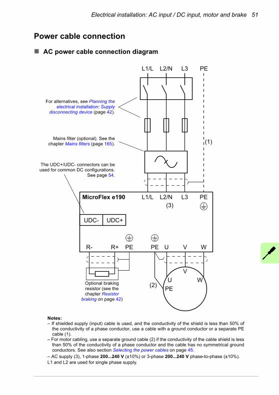
Electrical installation: AC input / DC input, motor and brake 51
Power cable connection
AC power cable connection diagram
MicroFlex e190 L1/L L2/N L3
L1/L L2/N L3
UPE
PE
PE
PE
(1)
(2)
V W
UV
W
R- R+
UDC- UDC+
PE
(3)
Optional braking resistor (see the chapter Resistor
braking on page 42)
Mains filter (optional). See the chapter Mains filters (page 165).
Notes:– If shielded supply (input) cable is used, and the conductivity of the shield is less than 50% of
the conductivity of a phase conductor, use a cable with a ground conductor or a separate PE cable (1).
– For motor cabling, use a separate ground cable (2) if the conductivity of the cable shield is less than 50% of the conductivity of a phase conductor and the cable has no symmetrical ground conductors. See also section Selecting the power cables on page 45.
– AC supply (3), 1-phase 200...240 V (±10%) or 3-phase 200...240 V phase-to-phase (±10%). L1 and L2 are used for single phase supply.
The UDC+/UDC- connectors can be used for common DC configurations.
See page 54.
For alternatives, see Planning the electrical installation: Supply
disconnecting device (page 42).

52 Electrical installation: AC input / DC input, motor and brake
Procedure
Cabling drawings with tightening torques are presented on page 53.
1. Strip the power cables so that the shields are bare at the cable clamps.
2. Twist the ends of the cable shield wires into pigtails.
3. Strip the ends of the phase conductors.
4. Connect the phase conductors of the supply cable to the L1 and L2 terminals of the drive (or L1, L2 and L3 for three phase supply).Connect the phase conductors of the motor cable to the U, V and W terminals.Connect the conductors of the resistor cable (if present) to the R- and R+ terminals.
5. Tighten the cable clamps onto the bare cable shields.
6. Crimp a cable lug onto each shield pigtail. Fasten the lugs to ground terminals.Note: Try to work out a compromise between the length of the pigtail and the length of unshielded phase conductors as both should ideally be as short as possible.
7. Cover visible bare shield and pigtail with insulating tape.
8. Secure the cables outside the unit mechanically.
9. Ground the other end of the supply cable shield or PE conductor(s) at the distribution board. In case a mains choke and/or a mains filter is installed, make sure the PE conductor is continuous from the distribution board to the drive.
Grounding the motor cable shield at the motor end
For minimum radio frequency interference, ground the cable shield 360 degrees at the lead-through of the motor terminal box or ground the cable by twisting the shield so that the flattened shield is wider than 1/5 of its length.
a b
b > 1/5 · a
360 degrees grounding
Conductive gaskets

Electrical installation: AC input / DC input, motor and brake 53
AC power cable connection
Supply cable
Cover bare shield with insulating tape
Cable clamp on bare shield
Cable clamp on bare shield
0.5...0.6 N·m (4.4...5.3 lbf·in)
Motor cable
0.5...0.6 N·m (4.4...5.3 lbf·in)
M4, 10 mm max.1.0...1.3 N·m (8.9...11.5 lbf·in)
M4, 10 mm max.1.0...1.3 N·m (8.9...11.5 lbf·in)
Motor earth wire

54 Electrical installation: AC input / DC input, motor and brake
DC power cable connection diagram (optional)
The UDC+ and UDC- terminals are intended for common DC configurations of a number of MicroFlex e190 drives.
AC supply (DC sharing)
DC sharing allows regenerative energy from one drive to be utilized by other drives that are in motoring mode. Each drive is connected to the AC supply* and has its own brake resistor. The MicroFlex e190 drives’ DC connections are linked as shown in the diagram below.
~~
M3~
M3~
~~
UDC+
UDC-
UDC+
UDC-
M3~
~~
UDC+
UDC-
AC supply
Fuses
* The MicroFlex e190 DC connection is not designed to provide the primary power source to other drives.
DC supply
MicroFlex e190 can use a DC supply as the primary power source (see page 154). Each drive is powered from the DC supply and has its own brake resistor. There is no AC supply.
~~
M3~
M3~
~~
UDC+
UDC-
UDC+
UDC-
M3~
~~
UDC+
UDC-
DC supply
Fuses

Electrical installation: AC input / DC input, motor and brake 55
Each drive has an independent DC capacitor pre-charging circuit.
~=
+ –
UDC+ UDC- L2 L3L1
~=
V WU
Micro
Fle
xe
19
0
Pre-charging circuit
The ratings of the DC connection are given on page 154.

56 Electrical installation: AC input / DC input, motor and brake
24 V control circuit supply (optional)
A 24 V DC supply can be provided to power the controlling electronics. This is useful for safety reasons where the main AC (or DC) power supply is removed from the power stage, but the controlling electronics must remain powered to retain position, I/O information and communications.
A separate fused 24 V supply should be provided for the MicroFlex e190.
Use a twisted pair cable.
Customer supplied24 V DC Fuse *
* Recommended fuse: Bussman S504 20 x 5 mm anti-surge 2 A.
X2
+24 V
GND

Electrical installation: AC input / DC input, motor and brake 57
Motor brake connection
A rotary motor might require a brake. The brake prevents the uncontrolled release of suspended or tensioned loads when power to the motor is removed or disconnected, e.g. by a motor circuit contactor. Contact your local supplier for details of appropriate brakes.
You can wire a motor's brake, via relays, to a digital output on connector X3; see Connecting the control cables on page 60. This provides a way for the MicroFlex e190 to control the motor's brake. A typical circuit is shown in the following diagram:
2
+24 V 0 V
12
X3
DO2+
DO2-
UsersupplyGND
User supply
V+Relay
Separate customer supplied
24 V DC supply
The relay has normally open contacts and is shown deactivated (contacts open, brake engaged).
The inner shield surrounding the brake wires should be earthed/grounded at one point only.
from motor brake connections
This circuit uses DO2 as a motor brake output. The output is configured using Mint keyword MOTORBRAKEOUTPUT; see the Mint help file for details. With this configuration, the following sequences can be used to control the brake.
To engage the brake:
• The motor is brought to rest under normal control;• The relay is deactivated, causing the brake to engage;• The drive is disabled, removing power from the motor.
To disengage the brake:
• The drive is enabled;• The drive applies power to the motor to hold position under normal control;• The relay is activated, causing the brake to be disengaged.
It is sometimes necessary to include a small delay after the relay has been activated, before starting motion. This delay allows time for the relay contacts to engage and the brake to release. See the Mint keyword MOTORBRAKEDELAY.
WARNING! The 24 V DC power supply used to power the brake must be a separate supply as shown in the diagram. Do not use the supply that is
powering the MicroFlex e190 digital outputs. The brake wires often carry noise that could cause erratic drive operation or damage. The brake contacts must never be wired directly to the digital outputs. The relay should be fitted with a protective flyback diode, as shown. The separate 24 V DC supply used for the motor brake can also be used to power the relay in the thermal switch circuit (see below).

58 Electrical installation: AC input / DC input, motor and brake
Thermal switch connection
You can use the motor's thermal switch contacts (normally closed), to control a relay connected to a digital input on connector X3. This allows the MicroFlex e190 to respond to motor over-temperature conditions. Using the Mint WorkBench Digital I/O tool, the input can be configured to be the motor temperature input. The Mint keyword MOTORTEMPERATUREINPUT can also be used to configure a digital input for this purpose. A typical circuit, using DI2 as the input, is shown in the following diagram:
+24 V 0 V+24 V 0 V
14
4
X3
DI2+
DI2-
The relay has normally open contacts and is shown deactivated (contacts open, motor overheated).
motorthermalswitch
Separate customer supplied
24 V DC supply
Customer supplied24 V DCsupply
WARNING! The 24 V DC power supply connected to the thermal switch must be a separate supply as shown in the diagram. The thermal switch wires often
carry noise that could cause erratic drive operation or damage. The thermal switch contacts must never be wired directly to a digital input. The separate 24 V DC supply used for the thermal switch can also be used for the motor brake circuit.

Electrical installation: input / output 59
7Electrical installation: input / output
What this chapter contains
The chapter describes how to connect low voltage control signals.
The following conventions will be used to refer to the inputs and outputs:
I/O Input / OutputAI Analog InputAO Analog OutputDI Digital InputDO Digital OutputSTO Safe Torque Off
WARNING! The work described in this chapter may only be carried out by a qualified electrician. Follow the instructions in chapter Safety on page 13.
Ignoring the safety instructions can cause injury or death.Make sure that the drive is disconnected from the input power during installation. If the drive is already connected to the input power, wait for 5 minutes after disconnecting the input power.
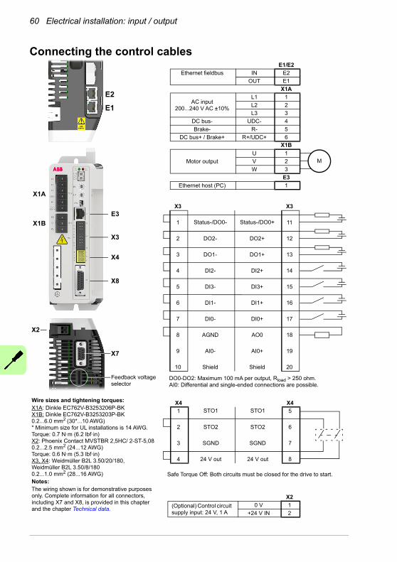
60 Electrical installation: input / output
Connecting the control cables
Wire sizes and tightening torques:X1A: Dinkle EC762V-B3253206P-BK X1B: Dinkle EC762V-B3253203P-BK0.2...6.0 mm2 (30*...10 AWG)* Minimum size for UL installations is 14 AWG.Torque: 0.7 N·m (6.2 lbf·in)X2: Phoenix Contact MVSTBR 2,5HC/ 2-ST-5,080.2...2.5 mm2 (24...12 AWG)Torque: 0.6 N·m (5.3 lbf·in)X3, X4: Weidmüller B2L 3.50/20/180,Weidmüller B2L 3.50/8/1800.2...1.0 mm2 (28...16 AWG)Notes:The wiring shown is for demonstrative purposes only. Complete information for all connectors, including X7 and X8, is provided in this chapter and the chapter Technical data.
E1/E2
Ethernet fieldbus IN E2
OUT E1
X1A
AC input200...240 V AC ±10%
L1 1
L2 2
L3 3
DC bus- UDC- 4
Brake- R- 5
DC bus+ / Brake+ R+/UDC+ 6X1B
Motor output
U 1
V 2
W 3
E3
Ethernet host (PC) 1
X3 X3
1 Status-/DO0- Status-/DO0+ 11
2 DO2- DO2+ 12
3 DO1- DO1+ 13
4 DI2- DI2+ 14
5 DI3- DI3+ 15
6 DI1- DI1+ 16
7 DI0- DI0+ 17
8 AGND AO0 18
9 AI0- AI0+ 19
10 Shield Shield 20
E2
E1
X1A
X1B
E3
X3
X4
X8
X7
X2
Feedback voltage selector
DO0-DO2: Maximum 100 mA per output, Rload > 250 ohm.AI0: Differential and single-ended connections are possible.
X4 X4
1 STO1 STO1 5
2 STO2 STO2 6
3 SGND SGND 7
4 24 V out 24 V out 8
Safe Torque Off: Both circuits must be closed for the drive to start.
X2
(Optional) Control circuit supply input: 24 V, 1 A
0 V 1
+24 V IN 2
M

Electrical installation: input / output 61
Analog I/O
The MicroFlex e190 provides:
• One 12-bit resolution ±10 V analog input.
• One 12-bit resolution ±10 V analog output.
An analog input receives the torque / velocity reference signal when operating as an analog drive (see CONTROLREFSOURCE in the Mint help file) or it can be used as a general purpose ADC input.
A additional analog input can be provided by the option card (see page182).
X3: Analog input AI0
The analog input passes through a differential buffer and second order low-pass filter with a cut-off frequency of approximately 1.2 kHz.
The analog input can be connected as either a differential or a single ended input as shown below. The analog input is not optically isolated from internal power rails, so care must be taken to avoid earth/ground loops and similar associated problems. To minimize the effects of noise, the analog input signal should be connected to the system using an individually shielded twisted pair cable with an overall shield. The overall shield should be connected to the chassis at one end only. No other connection should be made to the shield.When the MicroFlex e190 is connected to Mint WorkBench, the analog input value (expressed as a percentage) can be viewed using the Spy window’s Monitor tab. Alternatively, the command Print ADC(0) can be used in the command window to return the value of the analog input. See the Mint help file for full details of ADC, ADCMODE and other related ADC... keywords.
Differential inputs: connect input to AIN+ and AIN-. Leave AGND unconnected:
AIN0+ AIN0+19 19
X3 X3
9 9AI0 AI0( )ADC.0 ( )ADC.0
8 8
AIN0-
GND
Differential connection Single ended connection

62 Electrical installation: input / output
+24 V DC
19
X3
9AI0( )ADC.0
8
0 V
potentiometer
Typical input circuit to provide 0-10 V (approx.) input from a 24 V source:
Analog input - typical connections from a PLC/controller:
MintADC.0
+15V
MicroFlex e190
AI0+ 19
X3
9AI0-
-15VShield
PLC/controller
Connect overall shield at one end only
Analog input - typical connections from an ABB AO561:
MintADC.0
+15V
MicroFlex e190
AI0+ 19
X3
9AI0-
-15V18
13 O0U+
17 O01-
SG
AO561
Connect overall shield at one end only
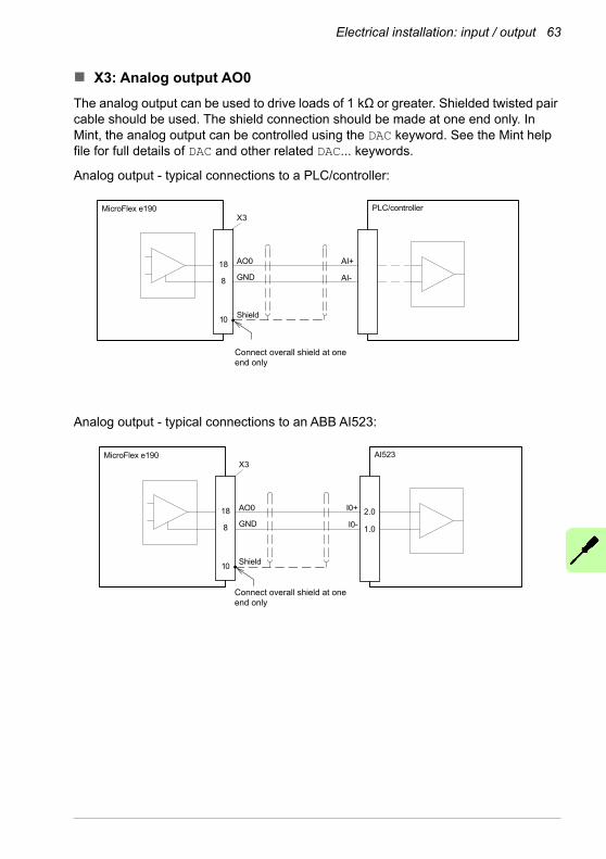
Electrical installation: input / output 63
X3: Analog output AO0
The analog output can be used to drive loads of 1 kΩ or greater. Shielded twisted pair cable should be used. The shield connection should be made at one end only. In Mint, the analog output can be controlled using the DAC keyword. See the Mint help file for full details of DAC and other related DAC... keywords.
Analog output - typical connections to a PLC/controller:
18
X3PLC/controllerMicroFlex e190
8
10
GND
AO0 AI+
AI-
Shield
Connect overall shield at one end only
Analog output - typical connections to an ABB AI523:
2.0
1.0
18
X3AI523MicroFlex e190
8
10
GND
AO0 I0+
I0-
Shield
Connect overall shield at one end only

64 Electrical installation: input / output
Digital I/O
The MicroFlex e190 provides:
• 4 general purpose digital inputs.
• 2 dedicated Safe Torque Off (STO) inputs.
• 3 general purpose digital outputs.
6 additional general purpose digital inputs and 4 additional general purpose digital outputs can be provided by the option card (see page 182).
Using a digital input as a drive enable input (optional)
A general purpose digital input can be configured as a ‘drive enable input’. This input must be activated to allow the drive to operate. This provides an additional method for stopping the drive using a hardware switch or external PLC/controller (e.g. AC500) although it does not provide any of the formal safety features of the Safe Torque Off inputs (see page 187). The optional drive enable input is configured using the Digital I/O tool in Mint WorkBench.
Using a digital input as a home switch input (optional)
If homing is being handled locally by the MicroFlex e190, the axis home switch (if present) must be wired directly to the home input on the MicroFlex e190, otherwise it will not be able to complete its internal homing routines. The home switch input is configured using the Digital I/O tool in Mint WorkBench, or by using the Mint HOMEINPUT keyword. Other HOME… keywords define the homing sequence.
If homing is being handled by an EtherCAT® master over Ethernet, and the master is profiling the motion, there are three options. The choice depends on the accuracy required for the homing and the EtherCAT cycle-time:
• The axis home switch is wired to an input on the MicroFlex e190, and then mapped back to the master over EtherCAT;
• The home switch is wired directly to the EtherCAT master;
• The home switch is wired to one of the fast inputs (DI1 / DI2), and the master (or the manager node) enables the drive’s touch probe function. See the Mint WorkBench help file for details.
X4: Digital inputs - Safe Torque Off (STO) inputs
The two safe torque off (STO) inputs are identical. Each input directly enables part of the motor output control circuit. Both inputs must be powered to allow the MicroFlex e190 to supply power to the motor. If an additional hardware drive enable input is used to control the MicroFlex e190, it must not be wired with the STO input circuit. The state of the STO inputs can be viewed using the Mint WorkBench Spy window's Axis tab or via the Mint SAFETORQUEOFF keyword. See the Mint help file for details.
See Appendix: Safe Torque Off (STO) on page 187.

Electrical installation: input / output 65
X3: Digital inputs - general purpose DI1 & DI2
These general purpose fast digital inputs are buffered by an opto-isolator, allowing the input signal to be connected with either polarity. When the MicroFlex e190 is connected to Mint WorkBench, the digital inputs can be configured using the Digital I/O tool. Alternatively, Mint keywords including RESETINPUT, ERRORINPUT, STOPINPUT, FORWARDLIMITINPUT, REVERSELIMITINPUT, DRIVEENABLEINPUT, MOTORTEMPERATUREINPUT,PHASESEARCHINPUT and HOMEINPUT can be used. The state of the digital inputs can be viewed using the Mint WorkBench Spy window's Axis tab. See the Mint help file for details.
Digital input - typical connections from a PLC/controller:
PLC/controller
X3
16
6TLP118
10
MicroFlex e190
DI1+
DI1-
Shield
User supply 24 V
User supply GND
Digital input - typical connections from an ABB DO561 PLC output module:
DO561
11
20
19X3
16
6
10
MicroFlex e190
UP
DI1+O0
DI1-
Shield
TLP118ZP
User supply 24 V
User supply GND

66 Electrical installation: input / output
Special functions on inputs DI1 & DI2
DI1 and DI2 can be configured to perform special functions. The ENCODERMODE keyword controls the configuration. When operating as an encoder input or step and direction inputs, DI1 and DI2 can be used for a dual-loop feedback system or connected to a master encoder for position following applications (see the FOLLOW, FLY and CAM keywords in the Mint help file).
Fast latch input
(ENCODERMODE bit 2 = 0)DI1 or DI2 can be configured using the LATCHTRIGGERCHANNEL keyword to become a fast latch input. This allows the position of the axis to be captured in real-time and read using the Mint keyword LATCHVALUE. The input can be configured using the LATCHTRIGGEREDGE keyword to be triggered either on a rising or falling edge. Further control of position capture is provided by various other keywords beginning with LATCH. See the Mint help file for details.
The maximum latency to read the fast position depends on the feedback device. For an incremental encoder, the latency is approximately 150 - 300 ns. For other feedback devices latency can be up to 62.5 μs, resulting from the 16 kHz sampling frequency used for these types of feedback device. The fast interrupt is latched on a pulse width of about 30 μs, although a width of 100 μs is recommended to ensure capture. The captured value is latched in software to prevent subsequent inputs causing the captured value to be overwritten.
Note: The fast inputs are particularly sensitive to noise, so inputs must use shielded twisted pair cable. Do not connect mechanical switches, relay contacts or other sources liable to signal ‘bounce’ directly to the fast inputs. This could cause unwanted multiple triggering.
Encoder input
(ENCODERMODE bit 2 = 0)Whilst operating as general purpose digital inputs, DI1 and DI2 are simultaneously interpreted by the drive as an additional quadrature (CHA, CHB) incremental encoder input. DI1 is CHA and DI2 is CHB. In Mint, the input formed by digital inputs DI1 and DI2 is encoder 1. The encoder value can be read using the ENCODER keyword.
Step (pulse) and direction inputs
(ENCODERMODE bit 2 = 1)If ENCODERMODE bit 2 is set, DI1 and DI2 are interpreted as step and direction inputs. In Mint, the input formed by digital inputs DI1 and DI2 is channel (encoder) 1.
• DI1 is used as the step input. The step frequency controls the speed of the motor.
• DI2 is used as the direction input. The state of the direction input controls the direction of motion. The motor direction itself can be reversed if necessary via the MOTORDIRECTION Mint keyword.

Electrical installation: input / output 67
The controller providing the step and direction signals may use current sourcing / open emitter outputs or it may use current sinking / open collector outputs. In both cases it is still vital to ensure twisted pairs are used for these signals (twist the signal for DIN1+ with the signal for DIN1- and twist the signal for DIN2+ with the signal for DIN2-).
Step and direction inputs - typical connections from a PLC/controller using open emitter outputs:
PLC/Controller
X3
16
6
MicroFlex e190
DI1+
DI1-
Shield
TLP118
10
14
4
DI2+
DI2- TLP118
Shield
Usersupply 24 V
UsersupplyGND
DirectionOutput
Dir
StepOutput
Step
Step
Direction
10
Twisted pairs
Twisted pairs
Usersupply 24 V
UsersupplyGND

68 Electrical installation: input / output
Step and direction inputs - typical connections from a PLC/controller using open collector outputs:
PLC/Controller
11
X3
16
6
MicroFlex e190
DI1+
DI1-
Shield
TLP118
10
14
4
DI2+
DI2- TLP118
Shield
Usersupply 24 V
Usersupply 24 V
UsersupplyGND
GND
GND
StepOutput
DirectionOutput
GND
Dir
Step
Step
Direction
10
Twisted pairs
Twisted pairs

Electrical installation: input / output 69
X3: Digital inputs - general purpose DI0 & DI3
These general purpose digital inputs are buffered by an opto-isolator, allowing the input signals to be connected with either polarity. When the MicroFlex e190 is connected to Mint WorkBench, the digital inputs can be configured using the Digital I/O tool. Alternatively, Mint keywords including RESETINPUT, ERRORINPUT, STOPINPUT, FORWARDLIMITINPUT, REVERSELIMITINPUT, DRIVEENABLEINPUT, MOTORTEMPERATUREINPUT,PHASESEARCHINPUT and HOMEINPUT can be used. The state of the digital inputs can be viewed using the Mint WorkBench Spy window's Axis tab. See the Mint help file for details.
Digital input - typical connections from a PLC/controller:
X3
17
7
MicroFlex e190PLC/controller
DI0+
DI0-
User supply 24 V
User supply GND
Digital input - typical connections from an ABB DO561 PLC output module:
11
20
19X3
17
7
UP
O0
ZP
MicroFlex e190DO561
DI0+
DI0-
User supply 24 V
User supply GND

70 Electrical installation: input / output
Digital input - typical current sourcing connections to a digital input:
X3
17
7
MicroFlex e190
DI0+
DI0-
User supply 24 V
User supply GND

Electrical installation: input / output 71
X3: Digital outputs - general purpose DO0 - DO3
The general purpose digital outputs are optically isolated. They source current from the user supply as shown below. The maximum saturated voltage across the outputs when active is 1.0 V DC, so it can be used as a TTL compatible output.
The output includes a self-resetting fuse that operates at approximately 200 mA. The fuse can take up to 20 seconds to reset after the load has been removed. If the output is used to directly drive a relay or any other inductive load, a suitably rated diode must be fitted across the load, observing the correct polarity. This is to protect the output from the back-EMF generated by the load when it is de-energized.
When the MicroFlex e190 is connected to Mint WorkBench, the active level of the output can be configured using the Digital I/O tool. Alternatively, the Mint keyword OUTPUTACTIVELEVEL can be used in the command window. Other Mint keywords such as COMPAREOUTPUT, GLOBALERROROUTPUT, DRIVEENABLEOUTPUT and MOTORBRAKEOUTPUT can be used to configure the output. The state of the digital outputs can be viewed using the Mint WorkBench Spy window Axis tab.
Note: By default DO0 is configured as a global error output. Use the Digital I/O tool or the Mint command GLOBALERROROUTPUT = -1 to release the output for other purposes. See the Mint help file for details.
Digital output - typical connections to a PLC/controller:
13
3
X3 PLC/controller:MicroFlex e190
DO1+
DO1-
User supply 24 V
User supply GND

72 Electrical installation: input / output
Digital output - typical connections to an ABB DI561 PLC input module:
2
1
13
3
X3MicroFlex e190
DO1+
DO1- I0
C0..7
DI561
User supply 24 V
User supply GND
Other I/O
X2: External power supply for the control unit (optional)
An external +24 V, 1 A power supply for the control board can be connected to terminal block X2. Using an external supply is recommended if:
• the application requires fast start after connecting the drive to the main input supply.
• fieldbus communication is required when the main input supply is disconnected.
SW1 linear switches - startup functions
The linear switches are read once at startup.
1: Selects normal IP address configuration, or a fixed IP address. The fixed IP address (192.168.0.1) allows the drive to be accessed if the software assigned IP address is not known.
Software assigned IP address Fixed IP address 192.168.0.1
2
1
2
1
2: Selects normal operation or firmware recovery mode. Recovery mode allows new firmware and other configuration files to be downloaded. The fixed IP address 192.168.0.1 is enabled and the symbol is displayed. Mint WorkBench allows you to update firmware and view the file system.
Normal operation Recovery mode
2
1
2
1

Electrical installation: input / output 73
Control cable grounding
The shields of all control cables must be grounded at the earth bar. Use M4 screws to fasten cable clamps.
The shields should be continuous as close to the terminals as possible. Only remove the outer jacket of the cable at the cable clamp so that the clamp presses on the bare shield. At the terminal block, use shrink tubing or insulating tape to contain any stray strands. The shield (especially in case of multiple shields) can also be terminated with a lug and fastened with a screw at the earth bar. Leave the other end of the shield unconnected or ground it indirectly via a few nanofarads high-frequency capacitor (e.g. 3.3 nF / 630 V). The shield can also be grounded directly at both ends if they are in the same ground line with no significant voltage drop between the end points.
Keep any signal wire pairs twisted as close to the terminals as possible. Twisting the wire with its return wire reduces disturbances caused by inductive coupling.
Remove outer jacket of cable at clamp to expose cable shield
Use shrink tubing or tape to contain strands
Earth barM4, 10 mm, 1.0...1.3 N·m (8.9...11.5 lbf·in)
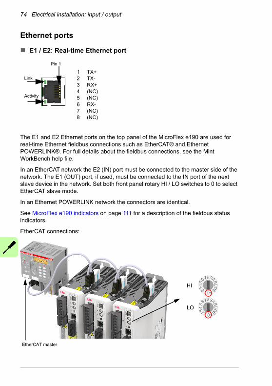
74 Electrical installation: input / output
Ethernet ports
E1 / E2: Real-time Ethernet port
The E1 and E2 Ethernet ports on the top panel of the MicroFlex e190 are used for real-time Ethernet fieldbus connections such as EtherCAT® and Ethernet POWERLINK®. For full details about the fieldbus connections, see the Mint WorkBench help file.
In an EtherCAT network the E2 (IN) port must be connected to the master side of the network. The E1 (OUT) port, if used, must be connected to the IN port of the next slave device in the network. Set both front panel rotary HI / LO switches to 0 to select EtherCAT slave mode.
In an Ethernet POWERLINK network the connectors are identical.
See MicroFlex e190 indicators on page 111 for a description of the fieldbus status indicators.
EtherCAT connections:
EtherCAT master
12345678
TX+TX-RX+(NC)(NC)RX-(NC)(NC)
Pin 1
Link
Activity

Electrical installation: input / output 75
E1 / E2: Ethernet port configuration
The rotary switches are read once at startup. The switches select the mode of operation for the E1 and E2 Ethernet fieldbus connectors on the top panel of the drive. See page 74.
Value Mode
00 EtherCAT slave mode01-EF Ethernet POWERLINK CN mode: selected value is node IDF0-FF Reserved
E3: Ethernet host
The Ethernet host port is used to connect a PC for configuring the MicroFlex e190. See section Start-up on page 93 for details about configuring the PC’s Ethernet adapter for communication with the MicroFlex e190.
The host port also can be used for Modbus TCP, Ethernet/IP and PROFINET fieldbus connections.

76 Electrical installation: input / output
Motor feedback (X8)
MicroFlex e190 supports incremental encoder, EnDat 2.1, SinCos, BiSS-B (Bi-directional Synchronous Serial Interface), SSI (Synchronous Serial Interface), EnDat 2.2, Smart Abs absolute encoder or Hiperface feedback, for use with linear and rotary motors. Resolvers are supported by using the optional resolver adapter (see page 85). There are some important considerations when wiring the feedback device:
• The inputs are not isolated.
• The feedback device wiring must be separated from power wiring.
• Where feedback device wiring runs parallel to power cables, they must be separated by at least 76 mm (3 in).
• Feedback device wiring must cross power wires at right angles only.
• To prevent contact with other conductors or earths / grounds, unearthed / ungrounded ends of shields must often be insulated.
• Linear motors use two separate cables (encoder and Hall). The cores of these two cables will need to be wired to the appropriate pins of the 15-pin D-type mating connector or the encoder breakout option (see page 180) can be used to simplify linear feedback connections.
• A maximum combined total of 500 mA can be supplied by X8 pin 12 and X7 pin 9 to feedback devices. Self-resetting fuses protect the 5.5 / 8-12 V supply on X8 and the 5.5 V supply on X7.
Connection summary
1 9
8 15
* The switch selects the voltage output on pin 12 (see page 78).
Pin Inc.encoderwith Halls
EnDat2.1
SinCos BiSS-B, SSI
EnDat 2.2 Smart Abs Hiperface
1 CHA+ Data+ (NC) Data+ Data+ Data+ Data+
2 CHB+ Clock+ (NC) Clock+ Clock+ (NC) (NC)
3 CHZ+ (NC) (NC) (NC) (NC) (NC) (NC)
4 (NC) (NC) (NC) (NC) (NC) (NC) (NC)
5 Hall U- Sin- Sin- (NC) (NC) (NC) Sin-
6 Hall U+ Sin+ Sin+ (NC) (NC) (NC) Sin+
7 Hall V- Cos- Cos- (NC) (NC) (NC) Cos-
8 Hall V+ Cos+ Cos+ (NC) (NC) (NC) Cos+
9 CHA- Data- (NC) Data- Data- Data- Data-
10 CHB- Clock- (NC) Clock- Clock- (NC) (NC)
11 CHZ- (NC) (NC) (NC) (NC) (NC) (NC)
12 +5.5 V out +5.5 V out +5.5 V out +5.5 V out +5.5 V out +5.5 V out +8 V out*
13 DGND DGND DGND DGND DGND DGND DGND
14 Hall W- (NC) (NC) (NC) (NC) (NC) (NC)
15 Hall W+ (NC) (NC) (NC) (NC) (NC) (NC)

Electrical installation: input / output 77
Twisted pairs must be used for each complementary signal pair e.g. CHA+ and CHA-or Data+ and Data-.
The overall cable shield (screen) must be connected to the metallic shell of the D-type connector.
In Mint WorkBench, the primary motor feedback encoder on connector X8 is encoder 0. The extra incremental encoder input formed by digital inputs DI1 and DI2 is encoder 1 (see page 66). The other extra incremental encoder input on connector X7 is encoder 2 by default (see page 83), but alternatively connector X8 can be configured as encoder input 2 (see page 81).
Incremental encoder with Halls
The incremental encoder connections (ABZ channels and Hall signals) are made using the 15-pin D-type female connector X8. The encoder inputs (CHA, CHB and CHZ) accept differential signals only. Twisted pairs must be used for each complementary signal pair e.g. CHA+ and CHA-. The Hall inputs may be used as differential inputs (recommended for improved noise immunity) or single ended inputs. When used as single ended inputs, leave the Hall U-, Hall V- and Hall W- pins unconnected. The overall cable shield (screen) must be connected to the metallic shell of the D-type connector. The encoder supply on pin 12 typically provides 5.5 V to the encoder (500 mA maximum, less if other encoder inputs are in use; see page 76). Maximum cable length is 30 m.
192
10311
12
X8
65
8 71514
13
Connect overall shield to connector
backshells
Twisted pairsMotor
CHA+CHA-CHB+CHB-CHZ+ (INDEX)CHZ- (INDEX)
Hall U+Hall U-Hall W+Hall W-Hall V+Hall V-
+5.5 V outDGND
Encoder Feedback
Hall Feedback

78 Electrical installation: input / output
Serial interfaces & SinCos
The MicroFlex e190 supports the following feedback types, for use with linear and rotary motors:
• EnDat 2.1
• SinCos encoders (1 V pk-pk, 2.5 V reference)
• BiSS-B (Bi-directional Synchronous Serial Interface), SSI (Synchronous Serial Interface) or EnDat 2.2
• Smart Abs absolute encoders
• Hiperface
Twisted pairs must be used for each complementary signal pair e.g. CHA+ and CHA-or Data+ and Data-. Maximum cable length is 30 m.
The overall cable shield (screen) must be connected to the metallic shell of the D-type connector. The encoder supply on pin 12 provides either 5.5 V or 8-12 V to the encoder, selected using the switch behind connector X7 (500 mA maximum, less if other encoder outputs are in use; see page 76).
WARNING! Check the feedback device’s power input specifications before using the 8 V position. Selecting the wrong voltage could damage your feedback device.Typically 8 V is only used when using an Hiperface encoder.
5 V 8 V(Default)

Electrical installation: input / output 79
EnDat interface
Incremental and absolute (multi and single turn) devices are supported. It is possible to read and write information to the encoder. The Sin and Cos channels are not required when using a version 2.2 EnDat encoder.
EnDat 2.1 interface cable connections:
X8
1956782101213
Data+Data-Sin-Sin+Cos-Cos+Clock+Clock-+5.5 V outDGND
AbsoluteEncoder
MotorTwisted pairs
Connect overall shield to connector backshells
EnD
at
Inte
rfac
e
Connectinternalshields topin 13.
SinCos interface
SinCos interface cable connections:
X8
56781213
Sin-Sin+Cos-Cos++5.5 V outDGND
Chassis
SinCosFeedback
MotorTwisted pairs
Connect overall shield to connector backshells
Connectinternalshields topin 13.
BiSS-B interface
The BiSS-B (Bi-directional Serial Synchronous interface) is an open-source interface that can be used with many types of absolute encoder.
BiSS-B interface cable connections:
X8
192101213
Data+Data-Clock+Clock-+5.5 V outDGND
Chassis
AbsoluteEncoder
MotorTwisted pairs
Connect overall shield to connector backshells
BiS
S-B
Inte
rfa
ce
Connectinternalshields topin 13.

80 Electrical installation: input / output
SSI encoders
SSI interface cable connections:
X8
192101213
Data+Data-Clock+Clock-+5.5 V outDGND
Chassis
AbsoluteEncoder
MotorTwisted pairs
Connect overall shield to connector backshells
SS
IIn
terf
ace
Connectinternalshields topin 13.
Smart Abs encoders
Smart Abs interface cable connections:
X8
19
1213
Data+Data- +5.5 V outDGND
Chassis
ER6V
AbsoluteEncoder
MotorTwisted pairs
Connect overall shield to connector backshells
Sm
art
Ab
sIn
terf
ace
Multi-turn Smart Abs encoders require an additional battery supply to retain position information when the drive is not powered.
Hiperface interface
Hiperface interface cable connections:
X8
195678
1213
Data+Data-Sin-Sin+Cos-Cos++8 V outDGND
Chassis
AbsoluteEncoder
MotorTwisted pairs
Connect overall shield to connector backshells
Hip
erfa
ceIn
terf
ace
Connectinternalshields topin 13.

Electrical installation: input / output 81
Extra incremental encoder
Some applications require the connection of multiple encoders typically when:
• A single axis has multiple encoders on the same motion system to eliminate mechanical errors (a dual encoder application).
• The drive is required to follow encoder signals given to it from a master encoder input.
In both cases the drive can support a connection to an extra incremental encoder by X7 (see page 83) or X8. The default extra incremental encoder input (encoder 2) is X7.If X7 is occupied as an encoder output and the primary feedback type is one that does not use the Hall/sin/cos inputs (Incremental encoder without Halls, BiSS-B, SSI, EnDat 2.2, Smart Abs or resolver), the extra incremental encoder also can be connected to X8.
Note: In Mint, this extra encoder input (encoder 2 on X8) is available only when connector X7 has been configured as an encoder output (see page 84).
When connector X8 is specified as encode 2, a encoder breakout OPT-MF-200 need to be mounted to split one 15-pin connector X8 into one 15-pin connectors X8A and one 9-pin X8B. X8A is connected to motor feedback, while X8B is connected to an extra incremental encoder (see page 180).
Pin X8A (Primary encoder)
Inc. encoderwithout Halls
BiSS-B SSI EnDat 2.2 Smart Abs
1 CHA+ Data+ Data+ Data+ Data+
2 CHB+ Clock+ Clock+ Clock+ (NC)
3 CHZ+ (NC) (NC) (NC) (NC)
4 (NC) (NC) (NC) (NC) (NC)
5 (NC) (NC) (NC) (NC) (NC)
6 (NC) (NC) (NC) (NC) (NC)
7 (NC) (NC) (NC) (NC) (NC)
8 (NC) (NC) (NC) (NC) (NC)
9 CHA- Data- Data- Data- Data-
10 CHB- Clock- Clock- Clock- (NC)
11 CHZ- (NC) (NC) (NC) (NC)
12 +5.5 V out +5.5 V out +5.5 V out +5.5 V out +5.5 V out
13 DGND DGND DGND DGND DGND
14 (NC) (NC) (NC) (NC) (NC)
15 (NC) (NC) (NC) (NC) (NC)

82 Electrical installation: input / output
The inputs may be used as differential inputs (recommended for improved noise immunity) or single ended inputs. When used as single ended inputs, leave the CHA-, CHB- and CHZ- pins unconnected. The overall cable shield (screen) must be connected to the metallic shell of the D-type connector. The encoder supply on pin 12 provides 5.5 V to the encoder (500 mA maximum, less if other encoder inputs are in use; see page 76). Maximum cable length is 30 m.
Extra incremental encoder cable connections:
192
10311
12
X8
65
8 71514
13
192
10311
1213
7
Connect overall shield to connector
backshells
Twisted pairs
+5.5 V outDGND
Encoder Feedback
CHA+CHA-CHB+CHB-CHZ+ (INDEX)CHZ- (INDEX)
Extra incremental encoder:
Used by incremental encoder without Halls, BiSS-B, SSI, EnDat 2.2, or Smart Abs primary encoder
Encoder Feedback
Pin X8B (extra Inc. encoder without Halls) Corresponding pin on X8
1 CHA+ 6
2 CHB+ 8
3 CHZ+ 15
4 (NC) (NC)
5 DGND 13
6 CHA- 5
7 CHB- 7
8 CHZ- 14
9 +5.5 V out 12

Electrical installation: input / output 83
Incremental encoder input/output (X7)
The incremental encoder input/output connection provides A/B channels and a Z index channel. Twisted pairs must be used for each complementary signal pair e.g. CHA+ and CHA-. The Mint keyword ENCODEROUTCHANNEL is used to set the mode of operation for X7. When set to the default value of -1, X7 operates as an input.
Input mode: ABZ incremental encoder (default)
By default, X7 is configured as an extra ABZ incremental encoder input (encoder 2). When operating as an encoder input, X7 can be used for a dual-loop feedback system or connected to a master encoder for position following applications.
Incremental encoder cable connections:
162738
9
X7
5
Connect overall shield to connector
backshells
Twisted pairs
CHA+CHA-CHB+CHB-CHZ+ (INDEX)CHZ- (INDEX)
+5.5 V outDGND
Encoder Feedback
Input mode: Step (pulse) and direction
Optionally, connector X7 can be configured as a step and direction input. Use one of the following methods to select step and direction mode.
• In Mint WorkBench, choose the Parameters tool and expand the Encoder family. Click the EncoderMode entry, then click the value next to EncoderMode (Encoder Channel 2). Check Bit 2: Step/Direction, then click OK. On the menu, choose Tools, Store Drive Parameters.
• In Mint WorkBench, choose the Edit & Debug tool. In the Command window enter the command: ENCODERMODE(2)=4 (or other value where bit 2 is set). On the menu, choose Tools, Store Drive Parameters.
12345
CHA+CHB+CHZ+(NC)GND
6789
CHA-CHB-CHZ-+5.5 V out
Pin 1

84 Electrical installation: input / output
The step and direction inputs are both differential and must be controlled from a RS422 differential source. Single-ended connections cannot be used.
• The A channel pins (1 & 6) are used as the step input. The step frequency controls the speed of the motor.
• The B channel pins (2 & 7) are used as the direction input. The state of the direction input controls the direction of motion.
• The Z channel input is not used.
Step / direction inputs - typical connections from a PLC/controller:
X7
1
6
2
7
PLC/controller
Step+
Connect shields at one end only.
Step output
Dir output
Twisted pairs
Dir+
MicroFlex e190
Shield
Step-
Dir-
Note: The inputs should be use shielded twisted pair cable with an overall shield. Connect the input signals correctly according to the pin assignment for connector X7.
Encoder output mode
Optionally, connector X7 can be configured as an encoder output (encoder output 0). This automatically enables the extra incremental encoder input on connector X8, which then becomes encoder input 2 (see page 81). When operating as an encoder output, X7 can be connected to the encoder input of a motion controller to provide position feedback. The A/B outputs are a pair of synthesized pulse trains with a 50% duty cycle, 90 degrees out of phase. The ENCODEROUTCHANNEL Mint keyword is used to define the source signal that will be output at X7:
• -1 = (Default) No encoder source assigned, X7 operates as an encoder input.
• 0 = Encoder 0, the primary encoder input on X8.
• 1 = Encoder 1, the encoder input formed by digital inputs DI1 and DI2 when they are set to behave as an encoder input (see Special functions on inputs DI1 & DI2 on page 66).
• 2 = Encoder 2, the extra incremental encoder interface on X8.
The frequency of the A/B outputs is varied according to the source signal, and can be scaled using the ENCODEROUTRESOLUTION Mint keyword. The output at X7 is identical to the input at X8, with no propagation delay, provided the output resolution

Electrical installation: input / output 85
is set to match the input resolution. In all other cases there is a propagation delay of up to 125 µs.
Use one of the following methods to configure X7 as an encoder output:
• In Mint WorkBench, choose the Drive Setup tool and proceed to the Motor Feedback page. In the Simulated Encoder Output 0 area, click in the Encoder source channel drop down and choose one of the encoder sources 0, 1, or 2 as described above. Proceed to the end of the wizard and follow the instructions to save the changed parameter.
• In Mint WorkBench, choose the Parameters tool and expand the Encoder family. Click the EncoderOutChannel entry, then click the value next to EncoderOutChannel (Encoder Channel 0). Choose one of the encoder sources 0, 1, or 2 as described above. On the menu, choose Tools, Store Drive Parameters.
• In Mint WorkBench, choose the Edit & Debug tool. In the Command window enter the command: ENCODEROUTCHANNEL(0)=n, where n is 0, 1, or 2, as described above. On the menu, choose Tools, Store Drive Parameters.
OPT-MF-201 Resolver adapter
The optional resolver adapter OPT-MF-201 allows a motor with resolver feedback to be connected to the MicroFlex e190. See page 181 for details.

86 Electrical installation: input / output
Supported feedback type
Various feedback types are offered as options on linear and rotary servo motors, the feedback types supported by MicroFlex e190 include the incremental encoder, EnDat 2.1, SinCos, BiSS-B, SSI, EnDat 2.2, Smart Abs absolute encoder, Hiperface encoder and resolvers (supported by using the optional resolver adapter, see page 85).
When selecting an encoder, you need to determine which type of encoder feedback is required in order to be compatible with the drive that will be receiving the encoder signals. Choosing the wrong encoder type will result in a non-functional system and possibly hardware damage.
The right feedback type for your application is automatically set when the motor is selected in Mint WorkBench.The Mint keyword ENCODERTYPE can also be used to
define the feedback type of encoder input. Moreover, MicroFlex e190 supports two different types of incremental encoder signal inputs, see more details below.
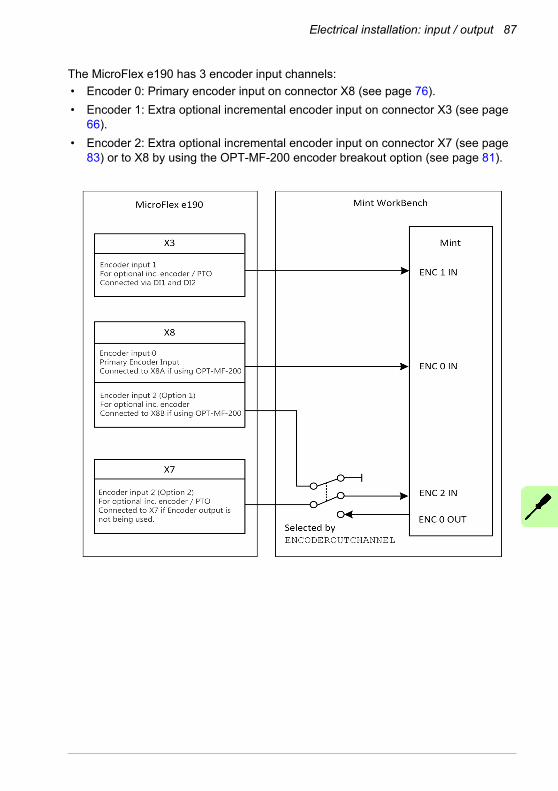
Electrical installation: input / output 87
The MicroFlex e190 has 3 encoder input channels:
• Encoder 0: Primary encoder input on connector X8 (see page 76).
• Encoder 1: Extra optional incremental encoder input on connector X3 (see page 66).
• Encoder 2: Extra optional incremental encoder input on connector X7 (see page 83) or to X8 by using the OPT-MF-200 encoder breakout option (see page 81).

88 Electrical installation: input / output
Encoder 0 input
Encoder 0 on connector X8 is the e190 drive's universal encoder input channel, supports a wide range of feedback types as follows.
Note: When using the incremental without Halls, BiSS-B, SSI, EnDat 2.2, Smart Abs or resolver (via OPT-MF-201), an extra incremental encoder can be simultaneously connected to X8 (configured as encoder 2, via OPT-MF-200, see page 81).
No. Feedback type Parameter
1
Incremental encoder
Rotary incremental encoder without Halls ENCODERTYPE(0)=0
2 Linear incremental encoder without Halls ENCODERTYPE(0)=1
3 Rotary incremental encoder with Halls ENCODERTYPE(0)=2
4 Linear incremental encoder with Halls ENCODERTYPE(0)=3
5Hall sensor
Rotary Hall sensors only without encoder ENCODERTYPE(0)=4
6 Linear Hall sensors only without encoder ENCODERTYPE(0)=5
7
SSI
Baumer SSI encoder of ABB motor ENCODERTYPE(0)=6
8 Linear SSI encoder ENCODERTYPE(0)=19
9 Generic SSI encoder ENCODERTYPE(0)=24
10 Rotary EnDat v2.1 ENCODERTYPE(0)=7
11EnDat v2.2
Rotary EnDat v2.2 ENCODERTYPE(0)=9
11 Linear EnDat v2.2 ENCODERTYPE(0)=10
13
SinCos
Rotary SinCos encoder ENCODERTYPE(0)=11
14 Linear SinCos encoder ENCODERTYPE(0)=12
15 Linear SinCos encoder with Halls ENCODERTYPE(0)=21
16 Rotary Hiperface encoder ENCODERTYPE(0)=13
17 Smart Abs absolute encoder ENCODERTYPE(0)=16
18BiSS-B
Rotary BiSS encoder ENCODERTYPE(0)=17
19 Linear BiSS encoder ENCODERTYPE(0)=18
20 Resolver (fitted with OPT-MF-201 resolver adapter) ENCODERTYPE(0)=25

Electrical installation: input / output 89
Encoder 1 input
Encoder 1 is an extra incremental encoder input channel and can be used to set up dual-encoder control system or be connected to a master encoder. It comes from fast digital inputs 1 and 2 on connector X3.
The incremental encoder signal type:
• 24 V DC signal levels
• Logic levels: “0” < 2 V, “1” > 12 V
• A/B single ended, no Z index
• User power supply: 24 V DC
Encoder 2 input
Encoder 2 is extra incremental encoder input channel and can be used to set up dual-encoder control system or be connected to a master encoder. The encoder input is 5V differential line driver (RS422).
The incremental encoder signal type:
• RS422 A/B/Z differential
• Max. input frequency A / B: 2 MHz
• Power supply: 5.5 V DC
See application note AN00262 for more information about dual encoder control.
No. Feedback type Parameter
1 Rotary incremental encoder without Halls ENCODERTYPE(1)=0
2 Linear incremental encoder without Halls ENCODERTYPE(1)=1
3 Step & Direction inputs ENCODERMODE(1)=4
No. Feedback type Parameter
1 Rotary incremental encoder without Halls ENCODERTYPE(2)=0
2 Linear incremental encoder without Halls ENCODERTYPE(2)=1
3 Step & Direction inputs ENCODERMODE(2)=4

90 Electrical installation: input / output

Installation checklist 91
8Installation checklist
Checklist
Check the mechanical and electrical installation of the drive before start-up. Go through the checklist together with another person.
WARNING! Only qualified electricians are allowed to carry out the work described below. Read the safety instructions on the first pages of this manual
before you work on the unit. Ignoring the safety instructions can cause injury or death. Open the main disconnector of the drive and lock it to open position. Measure to ensure that the drive is not powered.
Check
MECHANICAL INSTALLATION
The ambient operating conditions are allowable. (See Mechanical installation, Technical data: Ratings, Ambient conditions.)
The unit is fastened properly to the cabinet. (See Cabinet construction and Mechanical installation.)
The cooling air will flow freely.
The motor and the driven equipment are ready for start. (See Planning the electrical installation, Technical data: Motor connection.)
ELECTRICAL INSTALLATION (See Planning the electrical installation, Electrical installation: AC input / DC input, motor and brake.)
The capacitors are reformed if stored over one year (ask local ABB representative for more information).
The drive is grounded properly.

92 Installation checklist
The supply (input power) voltage matches the drive nominal input voltage.
The supply (input power) is connected to L1/L2/L3 (UDC+/UDC- in case of a DC supply) and the terminals are tightened to specified torque.
Appropriate supply (input power) fuses and disconnector are installed.
The motor is connected to U/V/W, and the terminals are tightened to specified torque.
The braking resistor (if present) is connected to R- and R+/UDC+, and the terminals are tightened to specified torque.
The motor cable (and braking resistor cable, if present) is routed away from other cables.
There are no power factor compensation capacitors in the motor cable.
The external control connections to the control unit are OK.
There are no tools, foreign objects or dust from drilling inside the drive.
The supply (input power) voltage cannot be applied to the output of the drive through a bypass connection.
Check

Start-up 93
9Start-up
What this chapter contains
This chapter describes software installation and the start-up procedure of the drive.
Safety
WARNING! Read the Safety instructions on the first pages of this manual before performing any maintenance on the equipment. Ignoring the safety
instructions can cause injury or death.
Introduction
Before powering the MicroFlex e190 you must connect it to the PC using an Ethernet cable and install the Mint WorkBench software on the PC. This includes a number of applications and utilities to allow you to configure, tune and program the MicroFlex e190. Mint WorkBench and other utilities can be downloaded from the pages of
Connect the MicroFlex e190 to the PC
Connect a CAT5e Ethernet cable between the PC and the MicroFlex e190 E3 Ethernet port on the front panel. Do not connect the cable to the E1 or E2 ports on the top of the drive.
NOTE! You cannot connect an ordinary office PC to the MicroFlex e190 without first altering the PC's Ethernet adapter configuration. See Configure
the PC Ethernet adapter on page 94.

94 Start-up
Install Mint WorkBench
The Windows user account requires administrative user rights to install Mint WorkBench. To install Mint WorkBench from new.abb.com/motion, download the application and run it.
Configure the PC Ethernet adapter
It is necessary to alter the PC's Ethernet adapter configuration to operate correctly with the MicroFlex e190. By default, the MicroFlex e190 has a static IP address of 192.168.0.1. This can be changed using the Configuration tool in Mint WorkBench.
NOTE! You cannot connect an ordinary office PC to the MicroFlex e190 without first altering the PC's Ethernet adapter configuration. However, if you
have installed a second Ethernet adapter dedicated for use with the MicroFlex e190, then this adapter's configuration can be altered without affecting the PC's office Ethernet connection. A USB to Ethernet adapter is a convenient way to add a second Ethernet adapter to a PC. If you are unsure about making changes to your PC's Ethernet adapter configuration, or are prevented by user permission levels, ask your I.T. administrator to assist you.
The following explanation assumes the PC is connected directly to the MicroFlex e190, and not across an intermediate Ethernet network. If you wish to attempt the connection through an intermediate Ethernet network, then the network administrator must be consulted to ensure that the necessary IP address is allowed and is not already allocated on the network.
1. On the Windows 7 Start menu, choose Control Panel, then Network and Sharing Center. (Windows 8.1: Apps screen, Control Panel, Network and Internet, Network and Sharing Center. Windows 10: Start, Settings, Network & Internet, Ethernet).
2. On the left of the window, click Change Adapter Settings (Windows 10: Change adapter options). Double click the icon for the required Ethernet adapter, then click Properties.
3. Select the ‘Internet Protocol Version 4 (TCP/IPv4)' entry and click Properties.
4. On the General tab, make a note of the existing settings. Click Advanced... and make a note of any existing settings. Click Cancel and then click the Alternate Configuration tab and make a note of any existing settings.
5. On the General tab, choose the ‘Use the following IP address' option.
6. In the IP address box, enter an IP address, e.g. 192.168.0.241. This is the IP address that will be assigned to the Ethernet adapter.
7. In the Subnet mask box, enter 255.255.255.0 and click OK.
8. Click Close to close the Local Area Connection Properties dialog.
9. Click Close to close the Local Area Connection Status dialog.

Start-up 95
Enable the Ethernet adapter for Mint WorkBench
Before Mint WorkBench can use the Ethernet adapter to discover the MicroFlex e190, the adapter must be enabled in the Mint Sidebar.
1. On the Windows 7/10 task bar in the notification area, right-click the Mint HTTP Server icon and choose Properties. (Windows 8.1: On the Start screen, click the Desktop icon to access the desktop first.)
2. In the Discovery area, check the required local area connection, then click OK.
Note:If the Mint Sidebar can't discover the drive then you may need to disable or modify your Firewall and/or Anti-virus settings.
Start the MicroFlex e190
If you have followed the instructions in the previous sections, you should have now connected the power sources, your choice of inputs and outputs, and the Ethernet cable linking the PC to the MicroFlex e190.
Preliminary checks
Before you apply power for the first time, check all items in Installation checklist, starting on page 91.
Power on checks
See section Drive status display on page 114 for symbols that show if the drive has detected a fault.
1. Turn on the 24 V DC control circuit supply (if present).
2. Turn on the AC supply (or DC supply, page 54).
3. The drive status display shows a test sequence which normally takes approximately 15-20 seconds. The sequence ends with the symbol, or if an STO input (page 187) is not powered. Start-up can take more than 1 minute after downloading new firmware.
4. To allow the Commissioning Wizard to function, the Safe Torque Off inputs (page 187) must be powered to allow the MicroFlex e190 to be enabled.

96 Start-up
Start Mint WorkBench
Mint WorkBench is a fully featured application for programming and controlling the MicroFlex e190. Mint WorkBench includes a comprehensive help file that contains information about every Mint keyword, how to use Mint WorkBench, and background information on motion control topics. Press F1 to display the help file. For help on using Mint WorkBench, click the red Mint WorkBench icon on the opening page.
1. On the Windows Start menu, select All Programs, ABB, Mint WorkBench, Mint WorkBench. (Windows 8.1: On the Apps screen, click the Mint WorkBench icon.)
2. In the opening dialog box, click Start Online Project...
3. Wait until the MicroFlex e190 is listed in the Controllers found box, e.g. “MicroFlex e190 on 192.168.0.1”.
4. Select the MicroFlex e190 in the list, and check Launch Commissioning Wizard.
5. Click Select.
Note: If the MicroFlex e190 is not listed, check the Ethernet cable is connected to the E3 port on the front panel of the drive, not E1 or E2 on the top panel. Check that the MicroFlex e190 is powered correctly and the start-up sequence (see Power on checks, above) has completed. Ensure you have enabled the Ethernet adapter for Mint WorkBench (see page 95). Click Scan to re-scan the ports. It can take up to 5 seconds for Mint WorkBench to detect the MicroFlex e190.
6. Mint WorkBench connects to the MicroFlex e190 and displays the Commissioning Wizard.
Note: If Launch Commissioning Wizard was not checked, Edit & Debug mode is displayed.

Start-up 97
Commissioning Wizard
Each type of motor and drive combination has different performance characteristics. Before the MicroFlex e190 can be used to control the motor accurately, the MicroFlex e190 must be ‘tuned'. Tuning is the process where the MicroFlex e190 powers the motor in a series of tests. By monitoring the drive's output and the feedback from the motor's encoder, the MicroFlex e190 can make small adjustments to the way it controls the motor. This information is stored in the MicroFlex e190 and can be uploaded to a file if necessary.
The Commissioning Wizard provides a simple way to tune the MicroFlex e190 and create the necessary configuration information for your drive/motor combination, so this is the first tool that should be used. If necessary, any of the parameters set by the Commissioning Wizard can be adjusted manually after commissioning is complete.
Using the Commissioning Wizard
Each screen of the Commissioning Wizard requires you to enter information about the motor, drive or application. Read each screen carefully and enter the required information. When you have completed a screen, click Next > to display the next screen. If you need to change something on a previous screen, click the < Back button. The Commissioning Wizard remembers information that you have entered so you do not need to re-enter everything if you go back to previous screens. If you need extra help, click Help or press F1.
Select your Motor Type:
Select the type of motor that you are using; rotary or linear, brushless or induction.
Select your Motor:
Carefully enter the details of your motor. If you are using a Baldor motor, the catalog number or spec. number can be found stamped on the motor's nameplate. If you are using a motor with EnDat feedback, are using a different manufacturer’s motor, or need to enter the specification manually, select the ‘Enter motor parameters manually’ option.
Confirm Motor and Drive information:
If you entered the catalog or spec. number on the previous page, it is not necessary to change anything on this screen; all the required data is entered already. However, if you selected the ‘Enter motor parameters manually’ option, it is necessary to enter the required information before continuing.
Motor Feedback:
If you entered the catalog or spec. number on the previous page, it is not necessary to change anything on this screen; the feedback resolution is entered already. However, if you selected the ‘Enter motor parameters manually’ option, it is necessary to enter the feedback resolution before continuing.

98 Start-up
Drive Setup complete:
This screen confirms that drive setup is complete.
Select Operating Mode and Source:
In the Operating Mode section, choose the required operating mode. In the Reference Source section, it is important to select the correct operating source (‘Direct’ or ‘RT Ethernet’) as the Reference Source. This allows the Autotune Wizard to operate correctly, and allows further initial testing to be performed using Mint WorkBench. Although the MicroFlex e190 might eventually be controlled over EtherCAT (or Ethernet POWERLINK), the ‘RT Ethernet' reference source should be selected only after the MicroFlex e190 has been commissioned and is ready to add to the EtherCAT (or Ethernet POWERLINK) network. This is selected by choosing the Operating Mode tool in the Toolbox.
Application Limits:
Application maximum speed (App. Max. Speed) defaults to zero and need to be entered the correct speed value. It is often not necessary to change other parameters on this screen. However, if you wish to adjust the application peak current (App. Peak Current) , then click in the appropriate box and enter a value.
Select Scale Factor:
It is often not necessary to change anything on this screen. However, it is recommended to select a user unit for position, velocity and acceleration. This allows Mint WorkBench to display distance, speed and acceleration using meaningful units, instead of encoder counts. For example, selecting a Position User Unit of Revs (r) means that all position values entered or displayed in Mint WorkBench will represent revolutions. The Position Scale Factor value changes automatically to represent the required scale factor (the number of quadrature counts per revolution). If you need to use an alternative unit, for example degrees, type “Degrees” in the Position User Unit box and enter a suitable value in the Position Scale Factor box. Separate velocity and acceleration units can also be defined. See the Mint help file for more information about scale factors.
Profile Parameters:
It is often not necessary to change anything on this screen. However, if you wish to adjust the parameters for any control method, click in the appropriate box and enter a value.
Analog input parameters:
It is not necessary to change anything on this screen. However, if you wish to adjust the analog inputs, click Common Settings to select the input range. The Tune Offset button automatically adjusts the input to compensate for any DC offset.

Start-up 99
Operation setup complete:
This screen confirms that operation setup is complete.
Autotune Wizard
The Autotune Wizard tunes the MicroFlex e190 for optimal performance with the attached motor. This removes the need for manual fine-tuning of the system, although in some critical applications this might be required.
Click Options... to configure optional autotuning parameters. Each Option shows settings relevant to the adjacent test.
WARNING! The motor moves during autotuning. For safety it is advisable to disconnect any load from the motor during initial autotuning. The motor can be tuned with the load connected after the Commissioning Wizard has finished.
Autotune:
Click START to begin the auto-tuning process. Mint WorkBench takes measurements from the motor and then performs small test moves.
For further information about tuning with the load attached, see Further tuning - with load attached on page 101.
Note: Even if you do not perform any further tuning or configuration, the STO function must be tested; see Appendix: Safe Torque Off (STO) on page 187.
Further tuning - no load attached
The Autotune Wizard calculates many parameters that allow the MicroFlex e190 to provide good control of the motor. In some applications, these parameters need to be fine-tuned to provide the exact response that you require.
1. Click the Fine-tuning icon in the Toolbox on the left of the screen.The Fine-tuning window is displayed at the right of the screen. This already shows some of the parameters that have been calculated by the Commissioning Wizard.The main area of the Mint WorkBench window displays the capture window. When further tuning tests are performed, it displays a graph representing the response.
2. The Fine-tuning window has a number of tabs the bottom. Click on the Current tab to fine tuning the current loop.Click on the Velocity/ Position tab to fine tuning the velocity/position loop in velocity / torque servo configuration.

100 Start-up
Some tabs might not be available depending on the configuration mode you selected in the Commissioning Wizard.
3. In the Test Parameters area at the bottom of the tab, click in the Move Type drop down box and select Forward. Enter values in the Velocity and Distance boxes to create a short move. The values you enter depend on the velocity scaling factor that was selected in the Commissioning Wizard. This example assumes the velocity scaling factor was selected as Revs Per Minute (rpm), so entering a value of 1000 here creates a move with a velocity of 1000 rpm. Similarly, assuming the position scaling factor had been set to Revolutions (r), the value 10 creates a move lasting for 10 revolutions of the motor.
4. Click Go to start the test move. Mint WorkBench performs the test move and displays a graph of the result.
5. Click on the graph labels to turn off unwanted traces. Leave just Demand Velocity and Measured Velocity turned on.
Typical autotuned response (no load):
Measured velocity
Demand velocity
Note: The graph that you see will not look exactly the same as this one! Each motor has a different response.
The graph shows that the response reaches the demand quickly and only overshoots the demand by a small amount. This can be considered an ideal response for most systems.

Start-up 101
For further information about tuning with the load attached, see Further tuning - with load attached on page 101.
Further tuning - with load attached
To allow Mint WorkBench to adjust the basic tuning to compensate for the intended load, it is necessary to attach the load to the motor and then perform the autotune procedure again.
1. Attach the load to the motor.
2. Click the Autotune icon in the Toolbox on the left of the screen.
3. Clear all of the check boxes. Only “Measure the inertia” and “Calculate speed and position loop gains” must be selected.
4. Click START to begin the auto-tuning process. Mint WorkBench takes measurements from the motor and then performs small test moves.
5. Click the Fine-tuning icon in the Toolbox on the left of the screen.
6. In the Velocity tab's Test Parameters area, ensure the same move parameters are entered and then click Go to start the test move. Mint WorkBench performs the test move and displays a graph of the result.

102 Start-up
Optimizing the velocity response
It can be desirable to optimize the default autotuned response to better suit your application. The following sections describe the two main tuning factors and how to correct them.
Correcting overshoot
The following graph shows a response where the measured velocity overshoots the demand by a significant amount.
1. Go to the Fine-tuning window's Velocity tab. To reduce the amount of overshoot, click Calculate... and increase the bandwidth using the slider control. Alternatively, type a larger value in the Bandwidth box.Click OK to close the Bandwidth dialog.
2. Click Go to start the test move. Mint WorkBench performs the test move and displays a graph of the result.
Velocity overshoots demand:
Measured velocity
Demand velocity

Start-up 103
Correcting zero-speed noise in the velocity response
The following graph shows a response where there is very little overshoot but a significant amount of zero-speed noise. This can cause undesirable humming or ringing in the motor.
1. Go to the Fine-tuning window's Velocity tab. To reduce the amount of noise, click Calculate... and decrease the bandwidth using the slider control. Alternatively, type a smaller value in the Bandwidth box. Click OK to close the Bandwidth dialog.
2. Click Go to start the test move. Mint WorkBench performs the test move and displays a graph of the result.
Zero-speed noise:
Measured velocity
Demand velocity
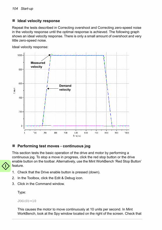
104 Start-up
Ideal velocity response
Repeat the tests described in Correcting overshoot and Correcting zero-speed noise in the velocity response until the optimal response is achieved. The following graph shows an ideal velocity response. There is only a small amount of overshoot and very little zero-speed noise.
Ideal velocity response:
Measured velocity
Demand velocity
Performing test moves - continuous jog
This section tests the basic operation of the drive and motor by performing a continuous jog. To stop a move in progress, click the red stop button or the drive enable button on the toolbar. Alternatively, use the Mint WorkBench ‘Red Stop Button’ feature.
1. Check that the Drive enable button is pressed (down).
2. In the Toolbox, click the Edit & Debug icon.
3. Click in the Command window. Type: JOG(0)=10This causes the motor to move continuously at 10 units per second. In Mint WorkBench, look at the Spy window located on the right of the screen. Check that

Start-up 105
the axis tab is selected. The Spy window's Velocity display should show 10 (approximately). If there seems to be very little motor movement, it is probably due to the scale factor. In the Commissioning Wizard, on the Select Scale Factor page, if you did not adjust the scale factor then the current unit of movement is feedback counts per second. Depending on the motor's feedback device, 10 feedback counts per second could equate to a very small velocity. Issue another JOG command using a larger value, or use the Operating Mode Wizard to select a suitable scale factor (e.g. 4000 if the motor has a 1000 line encoder, or 10,000 for a 2500 line encoder).
4. To stop the test, type:STOP(0)
5. If you have finished testing click the Drive Enable button to disable the drive.
Performing test moves - relative positional move
This section tests the basic operation of the drive and motor by performing a positional move. To stop a move in progress, click the red stop button or the drive enable button on the toolbar. Alternatively, use the Mint WorkBench ‘Red Stop Button’ feature.
1. Check that the Drive enable button is pressed (down).
2. In the Toolbox, click the Edit & Debug icon.
3. Click in the Command window. Type: MOVER(0)=10GO(0)=10This causes the motor to move to a position 10 units from its current position.The move stops when completed.
4. If you have finished testing click the Drive Enable button to disable the drive.

106 Start-up
Further configuration
Mint WorkBench provides a number of other tools for testing and configuring the MicroFlex e190. Every tool is explained fully in the help file. Press F1 to display the help file, then navigate to the Mint WorkBench book. Inside this is the Toolbox book.
Configuration tool
The Configuration tool shows the MicroFlex e190 integrated configuration interface.
1. Click the Configuration tool icon in the Toolbox on the left of the screen.
2. Select Upload configuration from controller or Start new configuration.
3. Enter a descriptive name for the controller and click NEXT at the bottom of the screen.
4. Continue through the screens making the required changes. Press F1 to display help.
5. Click APPLY to save the changed settings, then CLOSE to complete the configuration.
EtherCAT tool
The EtherCAT tool shows all information relating to the EtherCAT connection.
1. Click the EtherCAT tool icon in the Toolbox on the left of the screen.
2. Wait until data is uploaded from the MicroFlex e190.
3. The Summary tab shows basic information about the EtherCAT connection.
4. Click the Object Dictionary tab (above the table) to view the current state of the drive’s object dictionary. Press F1 to see the Mint WorkBench help file for instructions about the screen’s tool bar.
5. Click the “Save as...” button to export the ESI file.
Ethernet POWERLINK
The Ethernet POWERLINK tool shows all information relating to the Ethernet POWERLINK connection.
1. Click the Ethernet POWERLINK tool icon in the Toolbox on the left of the screen.
2. Wait until data is uploaded from the MicroFlex e190.
3. The Summary tab shows basic information about the Ethernet POWERLINK connection.
4. Click the Object Dictionary tab (above the table) to view the current state of the drive’s object dictionary. Press F1 to see the Mint WorkBench help file for instructions about the screen’s tool bar.
Click the “Save as...” button to export the XDD file.

Start-up 107
Parameters tool
The Parameters tool can be used to view or change most of the drive's parameters.
1. Click the Parameters icon in the Toolbox on the left of the screen. The main area of the Mint WorkBench window displays the Parameters editor screen. Items listed with a grey icon are read only so cannot be changed.Items listed with a green icon are currently set to their factory default value.Items listed with a yellow icon have been changed from their factory default value, either during the commissioning process or by the user.
2. In the parameters tree, scroll to the required item. Click on the small + sign beside the item's name. The list expands to show all items in the category. Click on the item you wish to edit.
3. The adjacent table lists the chosen item. Click in the Active Table cell and enter a value. This immediately sets the parameter, which remains in the MicroFlex e190 until another value is defined or power is removed. The icon to the left of the item becomes yellow to indicate that the value has been changed. On the menu, choose Tools, Store Drive Parameters to ensure the value remains after a power cycle.Many of the MicroFlex e190's parameters are set automatically by the Commissioning Wizard, or when tests are performed in the Fine-tuning window.
Spy window
The Spy window can be used to monitor and capture parameters in real-time. If you tried the test moves in Performing test moves - continuous jog on page 104 or Performing test moves - relative positional move on page 105 then you have already seen the Spy window, as it is displayed in conjunction with Edit & Debug mode. See the Mint help file for full details of each tab.
1. Click the Edit & Debug icon in the Toolbox on the left of the screen. The Spy window is displayed on the right of the screen. Click on the tabs at the bottom of the window to select the required function.
2. The Axis tab displays the five most commonly monitored parameters, together with the state of special purpose inputs and outputs.
3. The I/O tab displays the state of all the digital inputs and outputs.Click on an output LED to toggle the output on/off.
4. The Monitor tab allows up to six parameters to be selected for monitoring. Click in a drop down box to select a parameter. At the bottom of the Monitor tab, real-time data capture can be configured.

108 Start-up
Other tools and windows
Remember, for help on each tool press F1 to display the help file, then navigate to the Mint WorkBench book. Inside this is the Toolbox book.
Edit & Debug Tool
This tool provides a work area including the Command window and Output window. The Command window can be used to send immediate Mint commands to the MicroFlex e190. If you tried the test moves in Performing test moves - continuous jog on page 104 or Performing test moves - relative positional move on page 105, then you have already used Edit & Debug mode. Press Ctrl+N to open a Mint programming window.
Note: Mint programming only supported if a Mint memory module is installed.
Scope Tool
Displays the capture screen. This screen is also shown when the Fine-tuning tool is selected.
Digital I/O Tool
This tool allows you to configure the active states and special assignments for the digital inputs and outputs. For example, a general purpose digital input can be configured as an optional ‘drive enable input’, which must be active to enable the drive; see pages 64 to 69.If a digital input is to be used as a home switch input, see Using a digital input as a home switch input (optional) on page 64 for important details.
Safe Torque Off (STO) acceptance test
Drive commissioning is not complete until the STO function has been tested. The acceptance test of the safety function must be carried out by an authorized person with expertise and knowledge of the safety function. The test must be documented and signed by the authorized person.See Appendix: Safe Torque Off (STO) on page 187.

Fault tracing 109
10Fault tracing
What this chapter contains
This section explains common problems and their solutions. The LED indicators are described in MicroFlex e190 indicators on page 111.
Problem diagnosis
If you have followed all the instructions in this manual in sequence, you should have few problems installing the MicroFlex e190. If you do have a problem, read this section first.
• In Mint WorkBench, use the Error Log tool to view recent errors and then check the help file.
• If you cannot solve the problem or the problem persists, the SupportMe feature can be used.
SupportMe feature
The SupportMe feature is available from the Help menu, or by clicking the button on the motion toolbar. SupportMe can be used to gather information which can then be e-mailed, saved as a text file, or copied to another application. The PC must have e-mail facilities to use the e-mail feature. If you prefer to contact ABB technical support by telephone or fax, contact details are provided on the back cover of this manual. Have the following information ready:
• The serial number of your MicroFlex e190 (if known).
• Open the Help, SupportMe menu item in Mint WorkBench to view details about your system.
• The catalog and specification numbers of the motor that you are using.
• A clear description of what you are trying to do, for example trying to establish communications with Mint WorkBench or trying to perform fine-tuning.

110 Fault tracing
• A clear description of the symptoms that you can observe, for example the Status LED, error messages displayed in Mint WorkBench, or errors reported by the Mint error keywords ERRORREADCODE or ERRORREADNEXT.
• The type of motion generated in the motor shaft.
• A list of any parameters that you have setup, for example the motor data you entered/selected in the Commissioning Wizard, the gain settings generated during the tuning process and any gain settings you have entered yourself.
Power-cycling the MicroFlex e190
The term ‘power-cycle the MicroFlex e190’ is used in the Troubleshooting sections. If the mains AC supply (or DC supply) is removed, wait for 2 minutes before reapplying the supply.

Fault tracing 111
MicroFlex e190 indicators
EtherCAT® mode
The Ethernet LEDs display the overall condition of the Ethernet interface once the startup sequence has completed. The LED codes conform to the EtherCAT Technology Group (ETG) standard at the time of production.
NET ERR (Red)
Off: No errors or not powered.
Blinking:Invalid mailbox configuration in BOOT.Invalid mailbox configuration in PREOP.Invalid Sync manager configuration.Invalid output configuration.Invalid input configuration.Invalid watchdog configuration.Invalid DC Sync configuration.Invalid DC latch configuration.
1 flash:Unspecific error.No memory.Invalid request state change.Unknown requested state.Bootstrap not supported.No valid firmware.No valid inputs available.No valid output.Synchronization error.Invalid Sync manager types.Slave needs cold start.Slave needs INIT.Slave needs PREOP.Slave needs SAFEOP.Invalid input mapping.Invalid output mapping.Inconsistent settings.FreeRun not supported.SyncMode not supported.
FreeRun needs 3 buffer mode.Background watchdog occurred.No valid inputs and outputs.Fatal sync error.No sync error.PLL error.DC sync IO error.DC sync time-out error.Invalid DC Sync cycle time.DC Sync0 cycle time.DC Sync1 cycle time.Message box EoE error.Message box CoE error.Message box FoE error.Message box SoE error.Message box VoE error.EEPROM no access.EEPROM error.Slave restarted locally.
2 flashes: Sync manager watchdog.

112 Fault tracing
Ethernet POWERLINK mode
The Ethernet LEDs display the overall condition of the Ethernet interface once the startup sequence has completed. The LED codes conform to the Ethernet POWERLINK Standardization Group (EPSG) standard at the time of production.
NET RUN (Green)
Off: INITIALISATION state (or not powered).
Blinking: PRE-OPERATIONAL state. 1 flash: SAFE-OPERATIONAL state.3 flashes: Device identification. This state can be set from the master to locate the device.
Continuously illuminated, not flashing: Node in OPERATIONAL state. EtherCAT is operating normally.
Green (status)
Off: Node in NOT ACTIVE state or a previous initialization state. The controlled node is waiting to be triggered by the manager node.
1 flash: Node in PRE-OPERATIONAL1 state. Ethernet POWERLINK mode is starting.2 flashes: Node in PRE-OPERATIONAL2 state. Ethernet POWERLINK mode is starting.3 flashes: Node in READY TO OPERATE state. The node is signalling its readiness to operate.Blinking (continuous flashing): Node in STOPPED state. The controlled node has been deactivated.Flickering (very fast flashing): Node in BASIC ETHERNET state (Ethernet POWERLINK is not operating, but other Ethernet protocols may be used).
Continuously illuminated, not flashing: Node in OPERATIONAL state. Ethernet POWERLINK is operating normally.

Fault tracing 113
LED flash periods
The following diagram shows the definitions of the terms ‘blinking’, ‘flashing’ and ‘flickering’ used in the previous sections, as defined by the EtherCAT Technology Group.
LED flash timing definitions:
200 ms
1 s
1 s
1 s
1 s
1 s
Off
1 flash
2 flashes
Inverted 2 flashes
3 flashes, etc.
Blinking
Flickering
On
(Not illuminated)
(Continuously illuminated)
Red (error)
Off: Ethernet POWERLINK is working correctly.
Continuously illuminated: An error has occurred.

114 Fault tracing
Drive status display
STO error
The drive status display indicates errors and general MicroFlex e190 status information. When an error occurs the drive displays a sequence starting with the symbol E, followed by the five digit error code. For example, error code 10015 is displayed:
1 s
0.25
s
0.25
s
0.25
s
0.25
s
0.25
s
0.25
s
0.25
s
0.25
s
0.25
s
0.25
s
The decimal point to the right of the number also illuminates to indicate STO errors. If a symbol appears followed by an error code, please contact ABB technical support. For a complete list of error codes, open Mint WorkBench, press F1, and locate the Error Handling book. This contains topics listing the drive status display indicators and basic error codes. See also Start the MicroFlex e190 on page 95.
The following information symbols can be displayed:
Symbol Description
Drive disabled, and one or both STO inputs are not powered. The drive must be enabled before operation can continue. Both STO inputs must be powered. If an optional drive enable input has been configured, it must also be powered.
Initialization error / recovery mode. If this is the only symbol shown after powering the drive, remove all power, check the memory unit is inserted correctly, then reapply power. This symbol is also displayed during recovery mode (see page 72).
Drive disabled. The drive must be enabled before operation can continue. If an optional drive enable input has been configured, it must also be powered.
Suspend active. The Mint SUSPEND command has been issued and is active. Motion ramps down to zero demand whilst active.
Firmware loading (segments are illuminated sequentially). This sequence is followed by a numerical sequence representing firmware initialization stages.
Hold to Analog (HTA) mode. The axis is in Hold To Analog mode. See the Mint keyword HTA.

Fault tracing 115
User defined symbols can be displayed using Mint keywords LED and LEDDISPLAY.
Drive enabled, but idle.
Cam move. A cam profile is in progress. See the Mint keyword CAM.
Dwell. A dwell (wait) ‘move’ is in progress. See the Mint keyword MOVEDWELL.
Flying shear. A flying shear is in progress. See the Mint keyword FLY.
Follow move. The drive is in follow mode. See the Mint keyword FOLLOW.
Homing. The drive is currently homing. See the Mint keyword HOME.
Incremental move. An incremental linear move is in progress. See the Mint keywords INCA and INCR.
Jog. The drive is jogging. See the Mint keywords JOG, JOGCOMMAND and related topics.
Offset move. An offset move is in progress. See the Mint keyword OFFSET.
Position move. A linear move is in progress. See the Mint keywords MOVEA and MOVER.
Torque move. The drive is in torque mode. See the Mint keywords TORQUEREF, TORQUEREFSOURCE and related commands.
Firmware recovery mode in operation; see SW1 linear switches - startup functions on page 72.
Stop input active. A Mint STOP command has been issued or an optional stop input is active.
Velocity reference move. The drive is under velocity control. See the Mint keywords VELREF and related keywords.
Spline. A spline move is in progress. See the Mint keyword SPLINE and related keyword.
Symbol Description

116 Fault tracing
Power
Drive does not start when applying AC power:
• Check that the motor output phases are not short circuited. The drive trips on a motor phase short circuit and will not restart unless AC power is removed. Remove all power from the drive, correct the short circuit and restart the drive.
Communication
Drive status display is off:
• Check that the 24 V DC control circuit supply is correctly connected at X2, and is switched on. If a 24 V DC supply is not provided, an AC supply (or DC supply, page 54) must be present at X1 to allow communication.
Drive status display shows ‘I’:
• The MicroFlex e190 is in firmware recovery mode. This means that it does not boot fully, and allows Mint WorkBench to download firmware from the Choose Firmware dialog. See SW1 linear switches - startup functions on page 72.
Mint WorkBench fails to detect the MicroFlex e190:
• Ensure that the MicroFlex e190 is powered and the drive status display is illuminated (page 114).
• Check that the Ethernet cable is connected between the PC and MicroFlex e190. Check that the cable is connected to port E3 (on the front panel) and not port E1 or E2.
• Check that the PC's Ethernet port has been correctly configured for TCP/IP operation, and enabled for use with Mint WorkBench (see Configure the PC Ethernet adapter on page 94).
• Check that any PC firewall or security software does not prevent communication on TCP ports 5000 and 5001, and UDP port 5050. These ports are essential for communication with the MicroFlex e190.
• Try an alternative cable or different port on the PC.
Mint WorkBench
The Spy window does not update:
• The system refresh has been disabled. Go to the Tools, Options menu item, select the System tab and then choose a System Refresh Rate (500 ms is recommended).
Cannot communicate with the controller after downloading firmware:
• After firmware download, always power-cycle the MicroFlex e190.

Fault tracing 117
Tuning
Cannot enable the MicroFlex e190 because there is an error 10010:
• Check the drive enable input, if assigned, is connected and powered correctly.
Cannot enable the MicroFlex e190 because there is an error 10033 and/or 10035:
• Check the Safe Torque Off inputs on connector X2 are both connected and powered correctly.
When the MicroFlex e190 is enabled the motor is unstable:
• Check that the load is firmly coupled to the motor.
• Use the Mint WorkBench Drive Setup Wizard to confirm that the correct motor data has been entered.
• Use the Mint WorkBench Autotune Wizard to re-tune the motor.
• If the motor is still unstable, select the Mint WorkBench Autotune Wizard once more. Click Options.... On the Bandwidth tab, move the Current and/or Position and Speed Control sliders to a slower position to select a lower bandwidth. Click OK to exit and then start the Autotune Wizard again.
Ethernet
Cannot connect to the drive:
• Check that the PC's Ethernet adapter has been correctly configured, as described in Configure the PC Ethernet adapter on page 94.
How do I configure my EtherCAT manager to operate with the MicroFlex e190?
• An EtherCAT ESI file (.xml) that describes the drive to the EtherCAT manager can be uploaded from the controller using the Mint WorkBench EtherCAT tool.

118 Fault tracing
I cannot control the MicroFlex e190 from my EtherCAT or Ethernet POWERLINK manager
The drive reference source must be set to allow the EtherCAT or Ethernet POWERLINK manager to take control of the MicroFlex e190. There are several ways to do this:
• Set the CONTROLREFSOURCESTARTUP parameter to '1' using the Mint WorkBench Parameter viewer or Command window, save the parameters and restart the drive. This gives control to the manager each time the MicroFlex e190 starts.
• Set the Control Ref. Source to ‘RT Ethernet (CiA402)’ in the Mint WorkBench Operating Mode Wizard or Commissioning Wizard.
• Click the Direct button on the Mint WorkBench Motion tool bar, and select ‘RT Ethernet (CiA402)’ in the Axis 0 drop down.
• Confirm that the reference source on all controlled nodes has been set to real time Ethernet in the Mint WorkBench Operating Mode Wizard, and that the master has been configured correctly.

Fault tracing 119
Warning messages generated by the drive
Axis warnings
Code Warning Cause What to do
20003 All axis warnings cleared (_ecAXIS_WARNINGS_CLEARED)
This information message can appear in the error log to indicate that all axis warnings have been cleared.
No Action required
20004 Encoder battery low (_ecENCODER_BATTERY_LOW)
When using an encoder with battery backup (e.g. Smart Abs multi-turn) a battery low condition has been reported.
Consider changing the Encoder battery

120 Fault tracing
Controller warnings
Code Warning Cause What to do
40006 Attempt to configure too many axes (_ecTOO_MANY_AXES)
The device configuration file has attempted to assign more axes than are available on the controller.
Re-run the System Configuration Wizard .
40007 CamBox segments have been skipped (_ecCAM_BOX_OVERRUN)
The cam box has skipped a segment. This can happen if the source is moving fast enough to cause a segment to be skipped.
See CAMBOX in Mint WorkBench Help, look at "position_array". Either slow down the source or increase the size of the segments
40012 A host event has failed with retries (_ecEVENT_RETRY_WARNING)
A host (i.e. ActiveX) event handler has failed to acknowledge an event that has been raised by the controller. There is a 'time-out' period of 1 second in which the host must acknowledge an event.
If the host does not acknowledge the event after 3 time-out periods, the controller generates warning 40012. See ERRDATA for details of the error.
40013 Attempted to assign too many servo axes (_ecTOO_MANY_SERVO_AXES)
During the processing of the ..CMCF / .DCF (device configuration file), too many servo axes were configured.
To fix this issue, use the System Config Wizard to reduce the number of configured servo axes.
40014 Attempted to assign too many stepper axes (_ecTOO_MANY_STEPPER_AXES)
During the processing of the ..CMCF / .DCF (device configuration file), too many stepper axes were configured.
To fix this issue, use the System Config Wizard to reduce the number of configured stepper axes.
40015 Attempted to assign too many virtual axes (_ecTOO_MANY_VIRTUAL_AXES)
During the processing of the ..CMCF / .DCF (device configuration file), too many virtual axes were configured.
To fix this issue, use the System Config Wizard to reduce the number of configured virtual axes.
40016 Attempted to assign too many remote axes (_ecTOO_MANY_REMOTE_AXES)
During the processing of the ..CMCF / .DCF (device configuration file), too many remote axes were configured.
To fix this issue, use the System Config Wizard to reduce the number of configured remote axes.
40021 All controller warnings cleared (_ecCONTROLLER_WARNINGS_CLEARED)
This information message can appear in the error log to indicate that all controller warnings have been cleared.
No Action Required
40022 Last reset was not controlled (_ecRESET_NOT_CONTROLLED)
Last reset was not controlled
To fix this issue, use the System Config Wizard to reduce the number of configured servo axes.

Fault tracing 121
See AN00267 ABB Motion Drives Error trouble shooting manual for more details on error handing.
Code Warning Cause What to do
40023 Default MAC detected (_ecDEFAULT_MAC_DETECTED)
Default MAC has been detected, valid MAC address is not set.
Set valid MAC address
40024 Could not open license file or Error reading license file (_ecMISSING_LICENCE_FILE)
Could not open license file or Error reading license file
If this error is received, please contact ABB technical support.
40025 Licence file doesn't match hardware ID(_ecFOREIGN_LICENCE_FILE_PRESENT)
Wrong licencing version or platform,or Flash unique ID does not match the one in the license file
If this error is received, please contact ABB technical support.
40026 Invalid Licence file (_ecINVALID_LICENCE_FILE_PRESENT)
Licence data hash does not match the one in the Licence File
If this error is received, please contact ABB technical support.
40027 Warning applying parameter value (_ecPARAM_WARNING)
This warning will be generated if an attempt is made to write to a parameter that is no longer supported.
If necessary recommission the drive to create a new parameter table
40028 Warning fan fault (_ecFAN_FAULT_WARNING)
The fan is possibly faulty, unplugged or jammed.
Firstly ensure the latest firmware is in use (as the fan is controlled by firmware). Check the bottom of the drive to determine that the fan inlets are not blocked and the fan is rotating. If the drive fan does not turn see the drive installation manual for instructions on how to replace the fan

122 Fault tracing
Error messages generated by the drive
Autotuning errors
Code Error Cause What to do
4000 No autotuning error (_ecAUTOTUNE_SUCCESS)
There is no autotuning error. No Action
4001 Drive rating data invalid One of the following conditions has not been met1. Drive bus nominal voltage < 12. Drive rated current <= 0
Check memory module is connected correctly, check power supply level is correct
4002 Drive speed max invalid DriveSpeedMax <= 0Only check AutoTune test ID auoDESIGN_MOTION_CONTROL .
Re-run commissioning and check that DriveSpeedMax is set correctly
4003 Config doesn't support that test(_ecCONFIG_NOT_RIGHT_TYPE)
The autotuning operation does not support this controller configuration.
This error will not occur unless the configuration has been manually changed using the CONFIG keyword.
4004 Axis error has occurred (_ecAXIS_ERROR)
An asynchronous axis error or drive error has occurred during the autotuning operation.
See the Mint WorkBench Motion toolbar for more information on the error.
4005 Calculated torque constant invalid Drive had calculated a Torque Constant which is too small.
Check motor data is correct.
4006 Inductance value is zero E For the selected motor the winding inductance is zero
To avoid this error, make sure that a motor has been selected from the database in the Drive Setup Wizard. Alternatively, if a custom motor has been selected and you are unsure of motor data, check that the “Measure motor resistance and inductance" test has been selected and run using the Autotune tool.
4007 Resistance value is zero (_ecZERO_RESISTANCE_VALUE)
For the selected motor the winding resistance is zero
To avoid this error, make sure that a motor has been selected from the database in the Drive Setup Wizard. Alternatively, if a custom motor has been selected and you are unsure of motor data, check that the "Measure motor resistance and inductance" test has been selected and run using the Autotune tool.
4008 User has aborted test (_ecUSER_TEST_ABORT)
The autotuning operation has been manually aborted.
This will occur if the Autotune tool's STOP button is clicked while tests are being performed.
4009 Cannot capture data during test (_ecCAPTURE_FAILED)
Many of the autotuning operations use the data capture facility. This error message can occur if the capture facility is in use prior to performing the autotuning operation.
Not normally a probem, but to prevent this before autotuning, type CP=0 in the Command window to halt any capture operations.

Fault tracing 123
Code Error Cause What to do
4010 Resistance too low, possible short circuit (_ecPOSSIBLE_SHORT_CIRCUIT)
This error can occur during the Measure motor resistance and inductance test and indicates that the effective motor winding resistance is very low.
Check that there are no short circuits between the U, V and W terminals of the motor and that the motor power cable is wired correctly.
4011 Autotuning doesn't support feedback device (_ecUNSUPPORTED_FEEDBACK_TYPE)
The Test the feedback or Feedback calibration test (EnDat absolute encoders only) does not operate on this feedback type.
This error will not normally occur because Mint WorkBench will not allow autotuning on unsupported feedback types. Ie the combination of Motor and Feedback device is not supported by Mint Workbench.
4012 Encoder resolver rotation sense is wrong (_ecFEEDBACK_SENSE_WRONG)
During the Measure the voltage constant and Measure the motor inertia tests, a torque is applied to the motor. This error will occur if the resulting motion is in the opposite direction to the torque (a positive torque should cause positive velocity).
The most common cause of this error is an incorrectly wired or set up feedback device (encoder or resolver), or an incorrectly wired motor. Select the Test the feedback option. This will indicate if there is a problem with the wiring or setup of the drive and will automatically compensate for certain wiring errors. Note that the Test the feedback test should ideally be run with the motor disconnected from the load. This error can also occur when autotuning a motor connected to some types of load. In particular, loads with a lot of compliance (e.g. belt drives) or torque offsets (e.g. gravitational loading) can cause problems for autotuning. Another cause of the error may be because the position feedback is noisy, perhaps due to long cables on resolver feedback systems, for example. In either of these cases, it may be necessary to manually tune the system using the Fine-tuning tool.

124 Fault tracing
Code Error Cause What to do
4013 Hall sequence doesn't behave as expected (_ecHALL_FAULT_OR_NO_ROTATION)
The Hall sequence doesn't behave as expected. This error can occur during the Test the feedback test when using an incremental encoder + Halls feedback system.
The error can occur for a number of reasons, so try the following tests:•Return to the Confirm Motor Information page of the Drive Setup Wizard to check these values. If the resolver is not a standard ABB product, check that the specification is compatible in the drives hardware manual•A common cause of this error is an incorrectly wired or set up encoder/resolver. Try manually moving the rotor and watching the position field in the Axis tab. If the position does not change, or it changes erratically, this indicates a problem with the encoder wiring.•Run the Test the feedback test again. Ideally, the Test the feedback test should be run with the motor disconnected from the load, although it will operate successfully where the load is purely inertial or load friction is small.Note: watch the movement of the rotor. For rotary motors, the shaft should rotate through just over one revolution in one direction followed by one revolution in the opposite direction. For linear motors, the rotor should move through just over one pole pitch in one direction followed by one pole pitch in the opposite direction. If the rotor moves significantly more or less than these distances, this indicates that the number of motor poles is not set correctly (rotary motors), or the pole pitch is not set correctly (linear motors). If the motion during the test is not smooth, this indicates that friction is high and the test will not be able to obtain conclusive results.
4015 Position control update rate invalid Position loop control rate (ControlRate(0, 1)) < 1.
Change control rate to expected value (normally 4000)

Fault tracing 125
Code Error Cause What to do
4016 Mathematic error in gain calculations (_ecGAIN_CALCS_FAILED)
This error can occasionally occur during the Calculate current loop gains or Calculate the speed and position gains tests, indicating a numerical problem in the gain equations. It can also indicate a problem with the values of motor resistance and inductance (MOTORRS and MOTORLS) when it occurs during current loop gain calculations, or with the values of inertia and damping (LOADINERTIA and LOADDAMPING) when it occurs during speed/position loop gain calculations.
The error can usually be cleared by changing the design bandwidth for the appropriate operation (click Options... in the Autotune tool). If that fails, try running the entire autotuning sequence again.
4017 Drive setup is invalid This error can potentially occur in any of the autotuning operations, although it is rare. It indicates a problem with the fundamental setup of the drive such as the settings for motor rated current or peak current.
Try running the Commissioning Wizard again, making sure that the I am starting a new application. Reset memory to factory defaults option on the Welcome page is selected.
4018 Can't fit model to voltage/current data (_ecCANNOT_FIT_RESISTANCE_MODEL)
During the Measure motor resistance and inductance test, a gradually increasing voltage is applied to the motor and the generated current is logged. The process is stopped when the drive current reaches 80% of the specified motor rated current value. The resulting voltage/current characteristic is used to calculate the resistance of the windings and certain parameters of the drive's power stage. Error 4018 will occur if there is not enough data in the voltage/current characteristic to perform the calculation.
Check the wiring between the drive and motor and the motor windings for open circuits
4019 Can't fit model to voltage/current transient (_ecCANNOT_FIT_INDUCTANCE_MODEL)
During the Measure motor resistance and inductance test, stator inductance is measured by applying a voltage step to the motor and logging the generated current waveform. Inductance is then calculated from the resulting voltage/current characteristic. Error 4019 indicates that this calculation cannot be performed because of insufficient data or an unusual characteristic.
Try skipping the Measure motor resistance and inductance test. To do this, manually enter the motor resistance and inductance in the Confirm Motor Information page of the Drive Setup Wizard (most motor manufacturers will supply this information) and confirm that the test is not selected in the Autotune tool. Once autotuning is complete, check that the response of the current controllers is satisfactory using the Fine-tuning tool's Current tab.

126 Fault tracing
Code Error Cause What to do
4020 Can't fit load model speed data (_ecCANNOT_FIT_LOAD_MODEL)
During the Measure the motor inertia test, a torque waveform is applied by the motor and the motor speed logged. A simple inertia/damping model is then fitted numerically to the resulting torque/speed characteristic. Error 4020 indicates that the fitting process failed. A common cause for this is lack of sufficient information to fit the load model.
Click Options... in the Autotune tool and then select the Limits tab. Increase the value in the Max Travel box to allow the motor to rotate further during the test and consequently log more data. The model fitting process can also fail for certain types of load. For example, loads with high coulomb or static friction will not conform well to an inertial load model. Likewise gravitational loading (i.e. vertical axes) will cause problems for autotuning. If the Measure the motor inertia test continues to fail then the subsequent Calculate the speed and position gains test will also fail, as it requires values for load inertia and damping. It may be necessary to manually tune the system using the Fine-tuning tool's Speed and Position tabs.
4021 Motor test timed out (_ecAUTOTUNE_TEST_TIMEOUT)
During the Measure the voltage constant and Measure the motor inertia tests, current is applied to the motor to accelerate the motor and load. Error 4021 indicates that the rotor did not reach a sufficient speed, or travel a sufficient distance, within the duration of the test. Error 4021 can occur if the torque (or force) generated by the motor is insufficient to overcome friction in the load.
Click Options... in the Autotune tool and then select the Limits tab. Increase the value in the Max Torque box to allow the motor to generate sufficient torque to overcome friction. If the Measure the motor inertia test continues to fail then the subsequent Calculate the speed and position gains test will also fail, as it requires values for load inertia and damping. It may be necessary to manually tune the system using the Fine-tuning tool's Speed / Velocity and Position tabs.
4022 Motor travelled too far during test (_ecAUTOTUNE_TEST_OVERTRAVEL)
During the Measure the voltage constant and Measure the motor inertia tests, current is applied to the motor to accelerate the motor and load. Once the motor has reached a sufficient speed, the direction of applied current is reversed to bring the rotor to a halt within specified travel limits. Error 4022 indicates that the test was unable to impose these limits.
Click Options... in the Autotune tool and then select the Limits tab. Increase the value in the Max Travel box to allow the motor to rotate further during the test. Also, try reducing the value in the Max Speed box. If the Measure the motor inertia test continues to fail then the subsequent Calculate the speed and position gains test will also fail, as it requires values for load inertia and damping. It may be necessary to manually tune the system using the Fine-tuning tool's Speed / Velocity and Position tabs.

Fault tracing 127
Code Error Cause What to do
4023 Not enough test data to analyse (_ecINSUFFICIENT_TEST_DATA)
This error can occur during any of the autotuning tests, namely the Measure motor resistance and inductance test, the Measure the voltage constant and Measure the motor inertia tests, and the Feedback calibration test (for absolute encoders only). Generally, error 4023 means that insufficient data was logged during the test to obtain accurate parameter measurement.
See errors 4018 , 4019 and 4020 for the reasons why these tests fail.
4024 Flux model parameters are invalid (_ecINVALID_FLUX_MODEL)
The Measure the motor inertia test will fail with this error if the voltage constant has not been defined.
To determine the voltage constant, either select a standard motor from the database in the Drive Setup Wizard , enter a voltage constant value in the Confirm Motor Information page of the Drive Setup Wizard (see manufacturer's motor data), or run the Measure the voltage constant test.
4025 Load model is invalid (_ecINVALID_LOAD_MODEL)
If this error occurs during the Measure the motor inertia test, it suggests that the characteristics of the load are such that inertia cannot be accurately calculated.
See error 4020 for more information.
Error 4025 can also occur during the Calculate the speed and position gains test if the values of load inertia and damping have not been defined.
In this case, run the Measure the motor inertia test to measure load inertia and damping.
4026 Encoder parameter invalid Either;EncoderResolution < 1 or EncoderCycleSize = 0.
Correct Encoder parameters and re run autotune tests
4027 Motor inductance is not set When motor type is AM, Lm or Llr <= 0.
To avoid this error, make sure that a motor has been selected from the database in the Drive Setup Wizard. Alternatively, if a custom motor has been selected and you are unsure of motor data, check that the "Measure motor resistance and inductance" test has been selected and run using the Autotune tool.

128 Fault tracing
Code Error Cause What to do
4028 Can't set stator resistance (_ecCANNOT_SET_STATOR_RESISTANCE)
Can't set stator resistance. Error codes 4028 to 4054 will occur if the associated drive parameter, calculated by one of the autotuning tests, or set by the user is outside the allowable range of values. These errors should not normally occur.If the problems persist, make sure that a motor has been selected from the database in the Drive Setup Wizard. Alternatively, if a custom motor has been selected and you are unsure of motor data, check that the "Measure motor resistance and inductance" test has been selected and run using the Autotune tool. If the problem persists you will need to manually tune the control loops in the drive.
4029 Can't set stator leakage inductance (_ecCANNOT_SET_STATOR_INDUCTANCE)
Can't set stator leakage inductance.
4030 Motor pole pitch invalid Calculated motor pole pitch <= 0.
4031 Motor pole number invalid Calcualted motor poles < 2.
4032 Load inertia is not set Calcaulted load inertia <= 0.
4033 Can't set maximum motor flux (_ecCANNOT_SET_MOTOR_MAX_FLUX)
Can't set motor flux model time constant.
4035 Can't set load inertia (_ecCANNOT_SET_LOAD_INERTIA)
Can't set load inertia.
4036 Can't set load damping (_ecCANNOT_SET_LOAD_DAMPING)
Can't set load damping.
4037 Can't set controller proportional gain (_ecCANNOT_SET_GAIN_KIPROP)
Can't set controller proportional gain.
4038 Can't set current controller integral gain (_ecCANNOT_SET_GAIN_KIINT)
Can't set current controller integral gain.
4039 Can't set speed controller proportional gain (_ecCANNOT_SET_GAIN_KVPRO
Can't set speed controller integral gain.
4040 Can't set speed controller integral gain (_ecCANNOT_SET_GAIN_KVINT)
Can't set speed controller integral gain.
4041 Can't set position proportional gain (_ecCANNOT_SET_GAIN_KPROP)
Can't set position proportional gain.
4042 Can't set position derivative gain (_ecCANNOT_SET_GAIN_KDERIV)
Can't set position derivative gain.
4043 Can't set position integral gain (_ecCANNOT_SET_GAIN_KINT)
Can't set position integral gain.
4044 Can't set velocity feedforward gain (_ecCANNOT_SET_GAIN_KVELFF)
Can't set velocity feedforward gain.
4045 Can't set velocity feedback gain (_ecCANNOT_SET_GAIN_KVEL)
Can't set velocity feedback gain.
4046 Can't set acceleration feedforward gain (_ecCANNOT_SET_GAIN_KACCEL)
Can't set acceleration feedforward gain.
4047 Inertia test failed (_ecINERTIA_TEST_FAILED)
Inertia measurement failed

Fault tracing 129
Code Error Cause What to do
4048 Voltage constant test failed (_ecVOLTAGE_CONSTANT_TEST_FAILED)
Voltage constant measurement failed
Error codes 4028 to 4054 will occur if the associated drive parameter, calculated by one of the autotuning tests, or set by the user is outside the allowable range of values. These errors should not normally occur.If the problems persist, make sure that a motor has been selected from the database in the Drive Setup Wizard. Alternatively, if a custom motor has been selected and you are unsure of motor data, check that the "Measure motor resistance and inductance" test has been selected and run using the Autotune tool. If the problem persists you will need to manually tune the control loops in the drive.
4049 Can't set offset angle (_ecCANNOT_SET_ANGLE_OFFSET)
Can't set motor feedback offset angle (Possible encoder fault or wrong config)
4050 Can't set observer gain K1 (_ecCANNOT_SET_OBSERVER_GAIN_K1
Can't set observer gain K1.
4051 Can't set observer gain K2 (_ecCANNOT_SET_OBSERVER_GAIN_K2)
Can't set observer gain K2.
4052 Can't set observer gain KJ (_ecCANNOT_SET_OBSERVER_GAIN_KJ)
Can't set observer gain KJ.
4053 Can't enable integral position control (_ecCANNOT_SET_KINT_MODE)
Can't enable integral position control.
4054 Can't set integral term limit (_ecCANNOT_SET_KINT_LIMIT)
Can't set integral term limit.
4055 Invalid autotuning operation number (_ecINVALID_OPERATION)
This will only occur if Mint WorkBench attempts to run an autotuning operation not supported by the firmware.
Check Drive parameters and Re run Autotuning tests
4060 Cannot enable drive (_ecCANNOT_ENABLE_DRIVE)
A drive cannot be enabled unless;the hardware enable is configured but not active or the AC supply (or shared DC bus supply) is present.
Go to Mint Workbench Parameter view and Check; Enabling > DriveEnableInput setting is correct - if so ensure that the input is active before running autotune.To check drives connected voltage Go to Mint Workbench Parameter view and Check;Drive > DriveBusVolts is at the correct level (325VDC for 230VAC supply)
4061 Drive communications error (_ecDRIVE_COMMS_ERROR)
Communication between the host PC and the controller has failed.
Check the serial or USB cable.

130 Fault tracing
Code Error Cause What to do
4063 Encoder fault (_ecPOSSIBLE_ENCODER_FAULT)
General Encoder fault Check encoder configuration, wiring and encoder operation when rotating by hand.
4065 Test move will take too long Test move takes too long time in. Check that test moves are set so that they will not take an excessive amount of time, Also check scaling is set correctly by checking SCALEFACTOR
4066 Test move velocity is too high Calculated velcoity > DriveSpeedMax in veloctiy autotune.
Re-run commissioning and check that DriveSpeedMax is set correctly
4067 Motor rated current undefined Motor rated current < 0.2A Check Motor data is correct, if the motor current is below 0.2A then its too small to be controlled by the drive
4068 Current control loop is not tuned Current loop has not been tuned before performing the Rotor parameters autotuning (applicable to asynchronous motors only)
Re-run Autotuning
4069 Autotuning doesn't support motor type
Cannot do the wanted Autotune for this motor type.
Check Motor data is correct
4070 Can't set flex control proportional gain
Can't set flux control loop proportional gain.
Check Motor data is correct
4071 Can't set flex control integral gain Cannot be shown because there is no error in API.
Check Motor data is correct
4074 Can't set magnetizing inductance Cannot set motor Lm. Check Motor data is correct

Fault tracing 131
Parameter errors
Code Error Cause What to do
6001 Parameter value out of range (_ecPARAM_VALUE_OUT_OF_RANGE)
The value supplied for the parameter is out of range.
The value you have entered or that is stored in the parameter file (.ptx) you have loaded does not fit within the limits specified by the drive firmware version loaded. If needed update the firmware first then load the parameter file. To do this in Mint Workbench go to Tools > Download Firmware > Select and download firmware file. Once complete try again
6004 Parameter definition has changed (_ecPARAM_DEFINITION_ERROR)
The specified parameter exists, but its definition has changed.
Check the latest documentation for the parameter.

132 Fault tracing
Communication errors
Code Error Cause What to do
8000 EtherCAT AL status code (_ecETHERCAT_AL_STATUSCODE)
This error is listed together with a Profile Code in the Mint WorkBench Error Log. Note: The displayed profile code must be converted to hexadecimal to give the specific EtherCAT error code.
This error status indicates that the EtherCAT master has been sent an error code by the drive. Check the error log to determine what the "real" drive error code is.
8001 CIP configuration error (_ecCIP_CFG_ERROR)
This error is listed together with a Profile Code in the Mint WorkBench Error Log. The displayed profile code must be converted to hexadecimal to give the specific CIP general status code.
This error status indicates that the EtherCAT master has been sent a CIP error code by the drive. Check the error log to determine what the "real" drive error code is.
8002 POWERLINK error code (_ecPOWERLINK_ERROR)
This error is listed together with a Profile Code in the Mint WorkBench Error Log. The displayed profile code must be converted to hexadecimal to give the specific POWERLINK error code.
This error status indicates that the POWERLINK master has been sent an error code by the drive. Check the error log to determine what the "real" drive error code is.
8003 PROFInet error code (ecPROFINET_CFG_ERROR)
This error is reported when multicast MAC filter configuration fails.
This error status indicates that the PROFInet master has tried to configure the device ID but has failed.

Fault tracing 133
Axis errors
Code Error Cause What to do
10000 Motion aborted (_ecABORT)
This error is caused by using the ABORT keyword or breaking a Mint program. See ABORT and ABORTMODE .
The ABORT keyword has been issued by the mint program. This may be normal in the operation. If its not find the issue with the Mint program.
10001 Forward hard limit hit (_ecFWD_HARD_LIMIT)
Drive has been configured to have a Forward Limit input and its currently active.
Check Drive configuration, Mint Program and/or Parameter file. See LIMITFORWARD and LIMITMODE.
10002 Reverse hard limit hit (_ecREV_HARD_LIMIT)
See LIMITREVERSE and LIMITMODE .
Check Drive configuration, Mint Program and/or Parameter file. See LIMITREVERSE and LIMITMODE .
10003 Forward soft limit hit (_ecFWD_SOFT_LIMIT)
The axis may be configured to have a maximum and minimum limit of travel in software. If the axis position exceeds one of these limit values, a motion error will be generated.
Check Drive configuration, Mint Program and/or Parameter file. See SOFTLIMITFORWARD and SOFTLIMITMODE .
10004 Reverse soft limit hit (_ecREV_SOFT_LIMIT)
The axis may be configured to have a maximum and minimum limit of travel in software. If the axis position exceeds one of these limit values, a motion error will be generated.
Check Drive configuration, Mint Program and/or Parameter file. See SOFTLIMITREVERSE and SOFTLIMITMODE .
10005 Fatal following error exceeded (_ecFOLLOWING_ERROR)
FOLERRORFATAL sets the maximum permissible following error before an error is generated. The following error is defined as the demand position minus the actual motor position. If the following error exceeds the value set by FOLERRORFATAL (maximum following error) an error may be generated.
If this error occurs the axis may not be free to move, is moving when it should not (for example a suspended load with a bad motor brake) or there could be a limitation within the drive (eg current or speed limit) or motor size (eg Inertia) that stops it moving to the target position with the given ACCEL/DECEL rates before the following error is beyond the value set by the user. See FOLERRORFATAL and FOLERRORMODE. Note: If this error occurs when using a Smart Inc encoder, see Smart Inc encoders in Mint Help.
10006 Fatal velocity error exceeded (_ecVEL_FATAL)
VELFATAL, velocity error checking allows the measured velocity (VEL) of an axis to be compared to its demand velocity (VELDEMAND). If the difference between the two values exceeds the limit set with VELFATAL, then an error will be created.
Check the Mint program or other source of velocity demand is not attempting to run the axis faster than the programmed DRIVESPEEDMAX
10007 Error input active (_ecERROR_INPUT)
An input is defined as an ERRORINPUT and it is activated by an error condition.
See ERRORINPUT and ERRORINPUTMODE.

134 Fault tracing
Code Error Cause What to do
10009 Invalid trajectory (_ecPROFILE_ERROR)
Trajectory generation error. The controller was unable to perform the requested profile. This can occur during CAM moves if an invalid element is detected (e.g. a negative master distance). An axis performing a cam profile can skip over very short slave segments if the master velocity is such that the slave segment is less than one profiler tick in length. If more than 5 slave segments are skipped in one profiler tick, this error will be generated. The axis will be crash stopped and disabled.
Check Mint CAM parameter file for anamolus Data points. Excel is a helpful tool to help with this.
10010 Drive enable input is inactive (_ecDRIVE_ENABLE_INACTIVE)
DRIVEENABLEINPUTMODE is configured to _emCRASH_STOP_DISABLE and the input defined by DRIVEENABLEINPUT has become inactive whilst the drive was enabled
Check Digital Input status and correct
10011 Drive I.T exceeded limit (_ecDRIVE_OVERLOAD)
The drive overload algorithm has integrated up to 100% and has tripped the drive to protect it. This will happen if the RMS current for the application exceeds the DRIVERATEDCURRENT value
Check tuning, check motion profile (especially acceleration and deceleration). If necessary select a larger drive (which may also require an alternative motor)
10012 Power base is not ready to enable (_ecPOWER_BASE_NOT_READY)
The Power base has been asked to enable but is not ready. For it to be so it must have the correct voltage and supply and not be overheated.
Check of power base ambient conditions and supply voltage. Include interlocks in any program being used that check DRIVEENABLEREADY
10013 Power module has an error (_ecPOWER_MODULE_FAULT)
There’s circuit detection in power unit and the signal is connected to the DSP. The power unit generated an error while in operation.over current, earth fault, over temperature on power board
Possible causes of this are Over temperature, Over Current, Brake chopper Short circuit or poor earthing or shielding (particularly of motor power cables). Power cycle to clear the error.
10014 Over current trip (_ecOVER_CURRENT)
Based on the drives currently configured DRIVERATINGZONE the drive has detected a motor overcurrent state. Measured current should not exceed the maximum current. The maximum current is related with the over current and the rated current.
Check the motor is free to rotate, has been sized correctly and there are no short circuits on the drive output wiring.

Fault tracing 135
Code Error Cause What to do
10015 Over speed trip (_ecOVER_SPEED)
The drive has detected the apparent motor velocity has exceeded the trip threshold set by DRIVESPEEDMAX and the VELFATAL parameters
Note: If this error occurs when using a Smart Inc encoder, see Smart Inc encoders (setting a high application max speed and 200% velocity threshold may be necessary when using Smartabs). For other feedback types check the integrity of the feedback wiring and the earthing/shielding of all cables to/from the drive
10016 Over voltage trip (_ecBUS_OVER_VOLTAGE)
The drive has shut down to protect itself after the measured dc bus voltage exceeded the preset limit. This can often occur during deceleration, particularly with large inertial loads
Decrease deceleration rate, add a regen resistor if one is not fitted. Consider use of common dc bus if there are multiple drives where some regenerate and some motor
10017 Under voltage trip (_ecBUS_UNDER_VOLTAGE)
The drive has shut down to protect itself after the measured dc bus voltage fell below a preset limit. This can often occur during acceleration, particularly with large inertial loadsNote: if DRIVEBUSUNDERVOLTSOVERRIDE is 0, low limit will use power data, otherwise will use DRIVEBUSUNDERVOLTSOVERRIDE.
Decrease the acceleration rate. If the fault occurs when the axis is not accelerating check the supply connections to the drive. A larger motor/drive combination may be required if the needed acceleration cannot be achieved
10018 Motor I^2.T exceeded limit (_ecMOTOR_OVERLOAD)
The motor overload algorithm has integrated up to 100% and has tripped the drive to protect the motor. This will happen if the RMS current for the application exceeds the MOTORRATEDCURRENT value
Check tuning, check motion profile. If necessary select a larger motor (which may also require an alternative drive)
10019 Motor temperature trip (_ecMOTOR_TEMP_INPUT)
#1. Motor Over Temperature has been detected on the drive and the drives hardwired Thermistor X10 input has detected Motor overheating from the connected motor PTC sensor
When using feedback temperature monitoring, X10 connections TH1 and TH2 should be connected with a wire link (short-circuited) to suppress the normal temperature trip function.Note: MOTORTEMPERATURETRIP does not monitor the drive's X10 motor thermistor input. Also look for a fault with feedback cable or wiring.
#2. Motor Over Temperature has been detected on the drive and the Motor Encoder is of a serial variety (such as Hiperface DSP which provides motor thermistor resistance as part of the feedback data). If this value exceeds MOTORTEMPERATURETRIP the drive trips with a motor overtemperature error
Set MOTORTEMPERATURETRIP to a resistance that is suitable for the motor's thermistor device. egMOTORTEMPERATURETRIP(0) = 1200.Also look for a fault with feedback cable or wiring.Note: MOTORTEMPERATURETRIP operates only with motors that have a positive temperature coefficient (PTC) thermistor, where resistance increases with temperature, or with motors that have a switch that goes open-circuit at high temperatures.

136 Fault tracing
Code Error Cause What to do
10020 Phase search failure (_ecPHASE_SEARCH_FAILED)
Phase search must be completed to control a motor with type "encoder only"
Phase search must be completed to control a motor with type "encoder only"- if it does not finish successfully check encoder settings in drive and check the correct number of motor poles has been configured.
10021 Hall signals lost or incorrect (_ecHALL_SIGNAL_LOSS)
This error indicates that a feedback type of halls only or Encoder + Halls is used and has detected an error. If this is so the halls sensor state is checked by the drive and that the Hall state detected is illegal (0 or 7).
This error would normally indicate a faulty encoder in the motor (the encoders include simulated hall signals) or bad wiring to the motor encoder. Check the quality of installation, wiring and encoder type selection. Note: You can use Mint Workbench to scope Encoder Hall State to look for problems.
10022 Encoder signals lost or incorrect (_ecENCODER_SIGNAL_LOSS)
This indicates that either there has been a total break or total disruption with the encoder signals.
Check the quality of installation, wiring and encoder type selection. Note: You can use Mint Workbench to scope Encoder Hall State and Encoeder to look for problems.Note: To get more information on this error connect to the Drive with Mint Workbench go to "Parameters > Encoder > Channel 0 > Encoder Parameter(Encoder0, Fault Register)" If this contains a value other than 0 you can use this value to give you more help on the error. See help file subject: ENCODERPARAMETER. Check all earthing and shielding arrangements are as per the instruction manual.
10023 Encoder power supply loss (_ecENCODER_SUPPLY_LOSS)
Power supply to encoder has been lost or has dropped below the minimum level for the selected encoder type. Note: encoder voltage is supplied by the drive.encoder power is given from power board, then transferred from 8v to 5v by control board.
Check that there are no shorts in the encoder wiring to the encoder supply (e.g. ensure the shields are not shorting to the supply or other signal pins). If the wiring is OK and the problem persists then it is likely one of the internal power supplies is failing.
10026 PDO data is not present (Mn to Cn) (_ecPDO_DATA_MISSING_MN_TO_CN)
EtherCAT or EPL PDO data from the manager (MN) to the remote axis (CN) has been lost. This error occurs if the remote axis detects that at least two consecutive PDO packets have not been received correctly.
This error will occur on the drive if it has lost its connection to the Manager. Check that the Manager is running, configured correctly and the network is operating correctly.
10027 Remote motion command failed (_ecREMOTE_MOTION_FAILED)
Unable to load motion on the remote axis. Generally speaking, this error indicates MML in drive is not ready for operation.
This can be caused by a number of reasons, such as incorrect operating mode, the motor brake being enabled or the move buffer being full.

Fault tracing 137
Code Error Cause What to do
10028 Encoder not ready to operate (_ecENCODER_NOT_READY)
The drive is configured to use a Serial Encoder and it is not able to provide position information.
The encoder may take several seconds to become ready and this error will be generated if an attempt is made to enable the axis before the encoder is ready. This error can also occur if the resolution configured on the drive is not compatible with the encoder. The axis will be crash stopped and disabled.Note: To get more information on this error connect to the Drive with Mint Workbench go to "Parameters > Encoder > Channel 0 > Encoder Parameter(Encoder0, Fault Register)" If this contains a value other than 0 you can use this value to give you more help on the error. See help file subject: ENCODERPARAMETER
10029 Supply phase loss detected (_ecSUPPLY_PHASE_LOSS)
The three phase drive has detected that one of the AC supply phases may been lost. The drive can normally only operate using a three phase supply. MotiFlex e100 drives have dedicated phase monitoring hardware, MotiFlex e180 drives monitor the ripple on the dc bus and if this becomes excessive then they assume an input phase has been lost
Check the connection of the input phases. If the connections are OK and a MotiFlex e180 is tripping spuriously (e.g. because the application requires harsh repeated accel and decel cycles) then you can disable phase loss detection using PHASELOSSMODE(0) = 0
10030 PDO data is not present (Cn to Mn) (_ecPDO_DATA_MISSING_CN_TO_MN)
PDO data from the remote axis (CN) to the manager (MN) has been lost. This error occurs if the manager detects that at least two consecutive PDO packets have not been received correctly.
This error will occur on the NextMove e100 if it detects a drive disappears from the network. This may be "normal" for an optional node (and the error must be handled via the ONERROR event). If this error is unexpected check the drive is not resetting and check the integrity of the Ethernet (EPL) cabling
10032 PDO value out of range (_ecPDO_VALUE_OUT_OF_RANGE)
When controlling an axis using Real time Ethernet one of the PDOs sent to the drive were out of range. This is often the velocity reference PDO and can be caused when an axis is geared to a master axis/encoder and the master position/encoder value is changed via the program to a new value causing an infinite velocity demand
Connect to the drive whilst the error is active and use the Error Log to determine which PDO is out of range. If it's velocity then check the Mint program to ensure axes that are geared to master references are not geared when those master references position/encoder values are written to
10033 STO active (_ecSTO_ACTIVE)
Either one or both of the Safe Torque Off inputs is not powered. This error can occur only when the drive is enabled.
Check drive STO inputs, if used check the wiring of the safety circuit or for open guards or Emergency stops etc.

138 Fault tracing
Code Error Cause What to do
10034 STO hardware fault (_ecSTO_HARDWARE_FAULT)
Either one or both of the internal fault circuit outputs has been asserted, indicating an internal hardware fault in the STO circuits. This error can occur when the drive is enabled or disabled.
Check drive STO inputs, if used check the wiring of the safety circuit or for open guards or Emergency stops etc.
10035 STO input mismatch (_ecSTO_INPUT_MISMATCH)
The drive has detected a mismatch in its internal STO registers. This error can occur when the drive is enabled or disabled.
Check the two drive STO inputs are in the same state with a multimeter. It may be necessary to adjust STOMISMATCHTIME to account for any timing discepancies in the connected safety circuit.
10036 Encoder reading wrong or Hall fault (_ecENCODER_READING_WRONG)
The drive has detected that the measured Hall transition angle differs from the electrical angle used in the control by at least 70 degrees.
Check the quality of installation, wiring and encoder type selection. Note: You can use Mint Workbench to scope Encoder Hall State and Encoder to look for problems. Check that all earthing / shielding is as per the drive installation manual
10037 All axis errors cleared (_ecAXIS_ERRORS_CLEARED)
This information message can appear in the error log to indicate that all axis errors have been cleared.
No action required
10038 Encoder battery dead (_ecENCODER_BATTERY_DEAD)
This information message can appear at startup, or when the drive is enabled, if the battery backup supply for a Smart Abs encoder has failed.
Change the Encoder battery
10039 Resolver signals lost or incorrect (_ecRESOLVER_SIGNAL_LOSS)
An error has occurred when using the Resolver Adapter (OPT-MF-201 or FB-03). The error is caused by the loss of resolver signals.
Check the wiring to the motor’s feedback device, the integrity of the motor connector, and the connections inside to the adapter.Note: To get more information on this error connect to the Drive with Mint Workbench go to "Parameters > Encoder > Channel 0 > Encoder Parameter(Encoder0, Fault Register)" If this contains a value other than 0 you can use this value to give you more help on the error. See help file subject: ENCODERPARAMETER. Check all earthing / shielding is as per the drive installation manual
10040 Hiperface DSL encoder error (_ecHIPERFACE_DSL_ENCODER_ERROR
An error has occurred when reading the position over Hiperface DSL.
10041 Output frequency over limit (_ecOUTPUT_FREQ_OVER_LIMIT)
The drive has detected that the output frequency exceeded 550 Hz. This restriction is required to meet relevant European Export Control Regulation.
Reduce your application's speed.
10042 ecDRIVESPEEDMAX_OUT_OF_RANGE
Motor velocity is above parameter DriveSPeedMax(0)
Go to parameters > Drive > DriveSpeedMax and check value is set correctly. Check Commanded Drive Speed is not too high.

Fault tracing 139
Controller errors
Code Error Cause What to do
30001 Controller over-temperature (_ecOVER_TEMPERATURE)
The drive has detected it is dangerously hot.
Check the drive ambient conditions allow for sufficient cooling.Note: TEMPERATURE will return the current temperature, in degrees Celsius, from the drive's internal temperature sensor. If the temperature exceeds the predefined TEMPERATURELIMITFATAL value (model dependent), then an overtemperature trip will be caused.TEMPERATURELIMITFATAL for each drive is;e190 3A is 80°C, e190 6A and 9A is 75°C
30005 FPGA failed to initialise (_ecFPGA_INITIALISATION_ERROR)
The controller FPGA has failed to initialize. If this error is received
Power cycle. If Error Persists Replace the Drive
30007 Error accessing non-volatile memory (_ecNON_VOL_MEMORY_FAILURE)
Unable to access non-volatile memory.
Power cycle. If Error Persists Replace the Drive
30008 Error applying parameter value (_ecPARAM_ERROR)
Errors have occurred during a parameter table download or during startup. Some of the parameters could not be applied correctly. See the Error Log for details of the failures. The controller's status display will flash only 'E', and will not be followed with the usual error code digits.
This Error is most commonly ascociated with either a parameter file (.ptx) issue. It is a common problem if the parameter file is generated from an older firmware version with either different parameters or different parameter limits. Read the Error log for specific guidance on the effected parameters.
30009 General internal controller error (_ecINTERNAL_ERROR)
An internal error has occurred. Read parameter failed
Power cycle. If Error Persists Replace the Drive
30010 Fan is not operating correctly (_ecFAN_LOSS)
The drive has detected that an internal cooling fan has failed.
Check the bottom of the drive to determine that the fan inlets are not blocked and the fan is rotating. If the drive fan does not turn, the general is the fan hardware failure, need to replace the fan.
30029 Controller under-temperature (_ecUNDER_TEMPERATURE)
The controller has detected an ambient temperature lower than -5 °C.
The ambient temperature must be increased before the drive can be enabled.
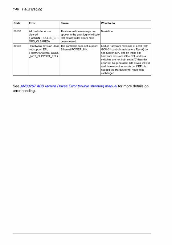
140 Fault tracing
See AN00267 ABB Motion Drives Error trouble shooting manual for more details on error handing.
Code Error Cause What to do
30030 All controller errors cleared (_ecCONTROLLER_ERRORS_CLEARED)
This information message can appear in the error log to indicate that all controller errors have been cleared.
No Action
30032 Hardware revision does not support EPL (_ecHARDWARE_DOES_NOT_SUPPORT_EPL)
The controller does not support Ethernet POWERLINK.
Earlier Hardware revisions of e180 (with GCU-01 control cards before Rev A) do not support EPL and on these old hardware revisions if the EPL address switches are not both set at '0' then this error will be generated. Old drives will still work in every other mode but if EPL is needed the Hardware will need to be exchanged

Maintenance 141
11Maintenance
What this chapter contains
This chapter contains preventive maintenance instructions.
Safety
WARNING! Read the Safety instructions on the first pages of this manual before performing any maintenance on the equipment. Ignoring the safety
instructions can cause injury or death.
Maintenance intervals
If installed in an appropriate environment, the drive requires very little maintenance. This table lists the routine maintenance intervals recommended by ABB.
Maintenance Interval Instruction
Capacitor reforming Every year of storage See Reforming the capacitors.
Heat sink temperature check and cleaning
Depends on the dustiness of the environment (every 6 to 12 months)
See Heat sink.
Cooling fan change Every 6 years if the ambient temperature does not exceed 45 °C (113 °F).Every 3 years if the ambient temperature is higher than 45 °C (113 °F).
See Cooling fan.

142 Maintenance
Heat sink
The heat sink fins pick up dust from the cooling air. The drive might report overtemperature warnings and faults if the heat sink is not clean. In a normal environment, the heat sink should be checked annually, in a dusty environment more often.
WARNING! Obey the instructions in Safety on page 13. Ignoring the instructions can cause physical injury or death, or damage to the equipment.
WARNING! Use a vacuum cleaner with an anti-static hose and nozzle. A normal vacuum cleaner can cause static discharges which can cause damage to circuit boards:
Clean the heat sink as follows (when necessary):
1. Stop the drive and disconnect it from input power.
2. Wait for 5 minutes and measure to make sure that there is no voltage. Refer to Electrical safety on page 14.
3. Remove the cooling fan (see section Cooling fan on page 143).
4. Blow clean, dry, and oil free compressed air from the bottom of the heat sink to the top. Use a vacuum cleaner at the air outlet to trap the dust. If there is a risk that dust can go into other equipment, clean the heat sink in another room.
5. Install the cooling fan.

Maintenance 143
Cooling fan
The actual lifespan of the cooling fan depends on the drive usage and ambient temperature. Fan failure can be predicted by the increasing noise from fan bearings and the gradual rise in the heat sink temperature in spite of heat sink cleaning. If the drive is operated in a critical part of a process, fan replacement is recommended once these symptoms start appearing. Replacement fans are available from ABB. Do not use other than ABB-specified spare parts.
Removing the fan
Place the drive on its side as shown. Push in the two retaining clips (1) at the back of the drive. Remove the base (2) by pulling on the top edge first. Disconnect the fan cable (3). Carefully bend the clips on the fan holder (4) to release the fan.
Airflow direction
1
3
4
2

144 Maintenance
Replacing the fan
Insert the new fan (1) ensuring the airflow direction is bottom-to-top. Route the wire through the retaining clip and connect the cable to the circuit board (2). Insert the front edge of the base into the front panel (3). Apply outward pressure at the centre of the base and simultaneously push the fan into the drive (4). Check that the plastic lug fits into the recess in the heat sink (5). Check that the fan cable has not moved or obstructed the encoder voltage switch (6, see page 78 to check the correct position). Check that the retaining clips are fitted into the mounting plate (7).
Airflow direction
2
1
4
4
4
3
5
7
6

Maintenance 145
Reforming the capacitors
The capacitors must be reformed if the drive has been stored for a year or more. See page 31 for information on finding out the manufacturing date. For information on reforming the capacitors, contact your local ABB representative.
Other maintenance actions
Transferring the memory unit to a new drive
When a drive is replaced, the parameter settings can be retained by transferring the memory unit from the defective drive to the new. However, non-volatile data stored using the NVRAM... keywords is not stored on the memory unit by default. Before removal, use the NVRAMSAVE keyword to store the data on the memory unit.
WARNING! Do not remove or insert a memory unit when the drive is powered.

146 Maintenance

Technical data 147
12Technical data
What this chapter contains
The chapter contains the technical specifications of the drive, for example, the ratings, sizes and technical requirements as well as provisions for fulfilling the requirements for CE and other marks.

148 Technical data
Ratings
The nominal current ratings for the MicroFlex e190 with 200...240 V AC supply are given below. For example, if a 6 A model is required to provide brief 300% overloads, assume its rated current is only 5.3 A.
The DriveSize dimensioning tool available from ABB is recommended for selecting the drive, motor and gear combination for the required motion profile.
* The maximum overload current between 0 Hz and 2 Hz is 150% of rated current.
Drive typeMFE190-04xx...
PWM switchingfrequency
(Hz)
300%3 s
overload(Arms)
200%3 s
overload(Arms)
Low speedoutput*(< 2 Hz)(Arms)
Stationary:DC output, any phase
(A)
-01A6-2 8000 1.6 1.6 1.6 2.3
Drive typeMFE190-04xx...
PWM switchingfrequency
(Hz)
300%3 s
overload(Arms)
200%3 s
overload(Arms)
Low speedoutput*(< 2 Hz)(Arms)
Stationary:DC output, any phase
(A)
-03A0-2 8000 2.5 3.0 3.0 4.2
Drive typeMFE190-04xx...
PWM switchingfrequency
(Hz)
300%3 s
overload(Arms)
200%3 s
overload(Arms)
Low speedoutput*(< 2 Hz)(Arms)
Stationary:DC output, any phase
(A)
-06A0-2 8000 5.3 6.0 6.0 8.5
Drive typeMFE190-04xx...
PWM switchingfrequency
(Hz)
300%3 s
overload(Arms)
200%3 s
overload(Arms)
Low speedoutput*(< 2 Hz)(Arms)
Stationary:DC output, any phase
(A)
-09A0-2 8000 7.5 9.0 9.0 12.7

Technical data 149
Derating
The continuous output currents stated above must be derated if any of the following conditions apply. The final derating factor is a multiplication of all applicable derating factors.
Ambient temperature derating: 1.6 A models
A temperature derating is required when operating the 1.6 A models in ambient temperatures between 45 °C (+113 °F) and the maximum of 50 °C (122 °F):
Ambient temperature
1.00
0.80
+45 °C +50 °C+113 °F +122 °F
Derating factor for 1.6 A models:
Ambient temperature derating: 3 A, 6 A & 9 A models
No temperature derating is required in ambient temperatures up to the maximum of 55 °C (131 °F).
Altitude derating
At altitudes from 1000 to 2000 m (3280 to 6560 ft) above sea level, the derating is 1% for every 100 m (328 ft). For a more accurate derating, use the DriveSize PC tool.

150 Technical data
Cooling
Cooling characteristics, noise levels
Efficiency
Approximately 98% at nominal power level.
Method Internal fan, flow from bottom to top, air-cooled heat sink.
Free space around the unit
See Cooling and degrees of protection on page 36
Drive typeMFE190-04xx...
Power lossW
Air flow
m3/h
Noise leveldBA
-01A6-2 20 (No fan) (No fan)
-03A0-2 40 56.4 45
-06A0-2 80 56.4 45
-09A0-2 120 56.4 45

Technical data 151
Supply cable fuses
Fuses for short circuit protection of the supply cable are listed below. The fuses also protect the adjoining equipment of the drive in case of a short circuit. Check that the operating time of the fuse is below 0.5 seconds. The operating time depends on the supply network impedance and the cross-sectional area and length of the supply cable. See also chapter Planning the electrical installation.
Note: Fuses with a higher current rating must not be used
1Φ AC supply
3Φ AC supply
Drive typeMFE190-04xx...
Input current
(A)
IEC fuse UL fuse Cross-sectional area of cable
Rated current
(A)
Voltage (V)
Class Rated current
(A)
Voltage (V)
UL Class
mm2 AWG
-01A6-2 3
20
500 gG
20
600
CC
1.5...4 16…12
-03A0-2 7 500 gG 600 1.5...4 16…12
-06A0-2 14 500 gG 600 1.5...4 16…12
-09A0-2 20 500 gG 600 1.5...6 16…10
Drive typeMFE190-04xx...
Input current
(A)
IEC fuse UL fuse Cross-sectional area of cable
Rated current
(A)
Voltage (V)
Class Rated current
(A)
Voltage (V)
UL Class
mm2 AWG
-01A6-2 2
20
500 gG
20
600
CC
1.5...4 16…12
-03A0-2 4 500 gG 600 1.5...4 16…12
-06A0-2 8 500 gG 600 1.5...4 16…12
-09A0-2 12 500 gG 600 1.5...6 16…10
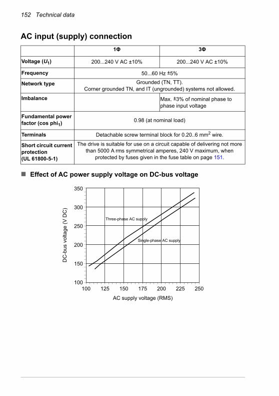
152 Technical data
AC input (supply) connection
Effect of AC power supply voltage on DC-bus voltage
100100
150
200
250
300
350
125 150 175 200 225 250
AC supply voltage (RMS)
DC
-bu
s vo
ltage
(V
DC
)
Three-phase AC supply
Single-phase AC supply
1Φ 3Φ
Voltage (U1) 200...240 V AC ±10% 200...240 V AC ±10%
Frequency 50...60 Hz ±5%
Network type Grounded (TN, TT).Corner grounded TN, and IT (ungrounded) systems not allowed.
Imbalance Max. ±3% of nominal phase to phase input voltage
Fundamental power factor (cos phi1) 0.98 (at nominal load)
Terminals Detachable screw terminal block for 0.20..6 mm2 wire.
Short circuit current protection (UL 61800-5-1)
The drive is suitable for use on a circuit capable of delivering not more than 5000 A rms symmetrical amperes, 240 V maximum, when
protected by fuses given in the fuse table on page 151.

Technical data 153
Effect of AC power supply voltage on DC-bus ripple voltage
1000
10
20
30
40
50
125 150 175 200 225 250
AC supply voltage (RMS)
DC
-bus
rip
ple
(% o
f DC
-bus
vol
tage
)
All models, three-phase AC supply
9 A model, single-phase AC supply
1.6 A, 3 A, 6 A models, single-phase AC supply
Effect of output current on DC-bus ripple voltage
200
10
20
30
40
50
60
70
30 40 50 60 70 80 90 100 110 120 130 140 150
% of drive rated current
DC
-bus
rip
ple
volta
ge (
Vpk
-pk)
All models, three-phase AC supply
9 A model, single-phase AC supply
1.6 A, 3 A, 6 A models, single-phase AC supply

154 Technical data
DC input (supply) connection
Motor connection
Brake resistor connection
Voltage 270...340 V DC ±10%
Ratings Drive typeMFE190-04xx...
IdcN
(A)
C(µF)
-01A6-2 1.96 560
-03A0-2 3.67 560
-06A0-2 7.35 1120
-09A0-2 11.02 1120
IdcN is the average DC input current requirement.
Terminals Detachable screw terminal block for 0.20...6 mm2 wire.
Motor types Asynchronous induction motors, asynchronous servo motors, synchronous permanent magnet motors
Frequency 0...550 Hz
Current See section Ratings.
Switching frequency 8 kHz
Maximum motor cable length
50 m (164 ft) with screened cable
Terminals Detachable screw terminal block for 0.20...6 mm2 wire.
Description Unit All models
Nominal switching threshold V DC on: 388, off: 376
Nominal power(10% peak power, r = 57 Ω
kW 0.25
Peak power(10% peak power, r = 57 Ω
kW 2.7
Maximum brake switching current Apk 10
Minimum load resistance Ω 39
Maximum load inductance µH 100

Technical data 155
Control unit
X2: Control circuit supply input
24 V (±10%) DC, 1 AOptional external power supply through connector X2 (pitch
5.08 mm, wire size 2.5 mm2).
X3: Analog input AI0 Connector pitch 3.5 mm, wire size 1.0 mm2
Voltage input: –10…10 V, Rin: 60 kohmDifferential inputs, common mode ±10 VSampling interval per channel: 0.25 msFiltering: Adjustable using ADCTIMECONSTANT keyword (see Mint WorkBench help file)Resolution: 11 bit + sign bit (±4.9 mV)
X3: Analog output AO0 Connector pitch 3.5 mm, wire size 1.0 mm2
AO0 (voltage): –10…10 V, Rload > 1 kohmUpdate interval: 1 kHzResolution: 12 bit (±4.9 mV)
X3: Digital inputs DI1…DI2 Connector pitch 3.5 mm, wire size 1.0 mm2
Logic levels: “0” < 2 V, “1” > 12 VRin: 3.3 kohmHardware latching: Minimum pulse width: 250 ns Minimum step time: 250 ns Minimum space time: 250 ns Direction input setup time: 250 ns Direction input hold time: 100 ns Maximum input frequency: 2 MHzSampling interval: 1 kHzFiltering: Adjustable using INPUTDEBOUNCE keyword (see Mint WorkBench help file)
X3: Digital inputs DI0, DI3 Connector pitch 3.5 mm, wire size 1.0 mm2
Logic levels: “0” < 2 V, “1” > 12 VRin: 3.3 kohmMinimum pulse width: 5 µsFiltering: Adjustable using INPUTDEBOUNCE keyword (see Mint WorkBench help file)
X3: Digital outputs DO0...DO2
User supply: 24 V DCOutput current: 100 mA max. per output, Rload > 250 ohm
X4: Safe Torque Off (STO) Connector pitch 3.5 mm, wire size 1.0 mm2
Output supply: 24 V DC, 30 mA per inputPulse tolerance: < 1 msFor the drive to start, both connections STO1 and STO2 must be powered.
E1: Ethernet host PC connection
Connector: RJ-45Cable length < 3 m
Memory capacity 256 KB program / variables; 1 KB non-volatile data

156 Technical data
Feedback
X7 Incremental encoder without Halls
* Total combined current for this encoder and X8 primary encoder, which may be connected simultaneously (see page 76).
X8 Incremental encoder with Halls
* Total combined current for this encoder and the X7 encoder input, which may be connected simultaneously (see page 76).
X8 Serial interfaces + SinCos
Supports BiSS-B, SSI, EnDat 2.1, EnDat 2.2, Smart Abs, SinCos and Hiperface using required combinations of the following inputs:
* Total combined current for this encoder and either the X8 extra incremental encoder or X7 encoder, which may be connected simultaneously (see page 76).
Encoder interface RS422 A/B differential, Z index
Max. input frequency A / B 2 MHz (8 MHz quadrature counts)
Output power supply to encoder 5.5 V DC (±7%) 500 mA max.*
Maximum recommended cable length
30 m
Encoder interface RS422 A/B differential, Z index
Max. input frequency A / B 2 MHz (8 MHz quadrature counts)
Hall inputs RS422 A/B differential
Output power supply to encoder 5.5 V DC (±7%) 500 mA max.* or 8 V DC set by switch
Maximum recommended cable length
30 m
Signals Differential input pairs for Data, Clock, Sin, Cos.
Device types: BiSS-B, Smart Abs SSI EnDat, SinCos Hiperface
Single or multi-turn devices.Single turn devices up to 18-bit.Single or multi-turn devices, 512 or 2048 cycles per turn, absolute positioning up to 65536 steps.SinCos signal: 1 V pk-pk sine wave centered on a 2.5 V reference.
Output power supply to encoder 5.5 V or 8-12 V set by switch, 500 mA max.*
Maximum recommended cable length
30 m

Technical data 157
Dimensions and weights
For basic weights and dimensions, see Main dimensions on page 35.
Ambient conditions
Environmental limits for the drive are given below. The drive is to be used in a heated, indoor, controlled environment.
Operation installed for stationary
use
Storagein the protective
package
Transportationin the protective
package
Installation site altitude 0 to 2000 m (6560 ft) above sea level. [See also section Altitude derating on page 149.]
- -
Air temperature 1.6 A model:0 to +50 °C (32 to 122 °F)3 A, 6 A, 9 A models:
0 to +55 °C (32 to 131 °F).
No frost allowed. See section Derating on page 149.
-40 to +70 °C(-40 to +158 °F)
-40 to +70 °C(-40 to +158 °F)
Relative humidity 0 to 95% Max. 95% Max. 95%
No condensation allowed. Maximum allowed relative humidity is 60% in the presence of corrosive gases.
Contamination levels No conductive dust allowed.
The drive must be installed in clean air according to enclosure classification. Cooling air must be clean, free from corrosive materials and electrically conductive dust.
Sinusoidal vibration: EN 60068-2-6: 2008
Tested according to, mechanical conditions:
2…9 Hz: 3.0 mm (0.12”)9…200 Hz: 1g
– –
Shock:EN 60068-2-27: 2009IEC 60068-2-27:2008
– Max. 10g, 11 ms Max. 10g, 11 ms
Free fall Not allowed 76 cm (30”) 76 cm (30”)

158 Technical data
Degrees of protection
MicroFlex e190 complies with EN 60529, IP20.
For UL purposes the MicroFlex e190 is defined as an open-type, three phase single axis servo amplifier.
The drive must be installed in a cabinet to fulfill the requirements for shielding from contact. Access to the cabinet should be restricted to trained maintenance staff.
See chapter Cabinet construction.
The top surface of cabinets / enclosures which are accessible when the equipment is energized shall meet at least the requirement of protective type IP3x with regard to vertical access only.
Materials
WEEE notice
According to the requirements of the Waste Electrical and Electronic Equipment Directive (WEEE) the following information is provided.
This symbol indicates that the product must not be disposed of with other general waste. It is your responsibility to dispose of your waste electrical equipment by handing it over to a designated collection point for the
recycling of waste electrical and electronic equipment. The separate collection and recycling of your waste equipment at the time of disposal will help conserve natural resources and ensure that it is recycled in a manner that protects human health and the environment. For more information about where you can recycle your waste, please contact your local authority.
Drive enclosure PC/ABS, color NCS 1502-Y (RAL 9002 / PMS 1C Cool Grey) and RAL 9017 (Traffic black).Hot-dip zinc coated steel sheet extruded aluminum AlSi.
Packaging Corrugated cardboard, PP bands.
Disposal The drive contains raw materials that should be recycled to preserve energy and natural resources. The package materials are environmentally compatible and recyclable. All metal parts can be recycled. The plastic parts can either be recycled or burned under controlled circumstances, according to local regulations. Most recyclable parts are marked with recycling marks.If recycling is not feasible, all parts excluding electrolytic capacitors and printed circuit boards can be landfilled. The DC capacitors contain electrolyte, which is classified as hazardous waste within the EU. They must be removed and handled according to local regulations.For further information on environmental aspects and more detailed recycling instructions, contact your local ABB distributor.

Technical data 159
RoHS compliance
MicroFlex e190 is in conformity with Directive 2011/65/EU of the European parliament and of the council of 8th June 2011 on the restriction of the use of certain hazardous substances in electrical and electronic equipment. The RoHS declaration 3AXD10000540158 is available on new.abb.com/motion.
China RoHS marking
The People's Republic of China Electronic Industry Standard (SJ/T 11364-2014) specifies the marking requirements for hazardous substances in electronic and electrical products. The green mark is attached to the drive to verify that it does not contain toxic and hazardous substances or elements above the maximum concentration values, and that it is an environmentally-friendly product which can be recycled and reused.
Hazardous substances
Lead(Pb)
Mercury(Hg)
Cadmium(Cd)
Hexavalent chromium
(Cr(VI))
Polybrominated biphenyls (PBB)
Polybrominated diphenyl ethers
(PBDE)
O O O O O O
O O O O O O
O O O O O O
Hg: 1000 ppm (0.1%)PBB: 1000 ppm (0.1%)
Cd: 100 ppm (0.01%)PBDE: 1000 ppm (0.1%)
Part
PCB
Metal parts
Plastic parts
O: Indicates that said hazardous substance contained in all of the homogeneous materials for this part is below the limit requirement of GB/T 26572.
X: Indicates that said hazardous substance contained in at least one of the homogeneous materials used for this part is above the limit requirement of GB/T 26572. The limits are:
Pb: 1000 ppm (0.1%)Cr6+: 1000 ppm (0.1%)

160 Technical data
Applicable standards
MicroFlex e190 complies with the following standards.
Design and test standards
See also the CE Declaration of Conformity available on the internet; see Document library on the Internet on page 209.
Environmental test standards:
UL 61800-5-1 Power Conversion Equipment.
EN 61800-5-1:2007 Adjustable speed electrical power drive systems. Safety requirements. Electrical, thermal and energy.
EN 60529:1991 + A2:2013
Degrees of protection provided by enclosures.
EN 61800-3:2004 + A1:2012
Adjustable speed electrical power drive systems. Electromagnetic compatibility.
Conducted emissions:When installed as directed in this manual, MicroFlex e190 conforms to Category C2 conducted limits.
Radiated emissions:When installed as directed in this manual, MicroFlex e190 conforms to Category C2 radiated limits.
All frame sizes conform to the ‘second environment’ immunity requirements defined by this standard.
EN 60068-1:2014 Environmental testing, general and guidance.
EN 60068-2-1:2007 Environmental testing, Test A. Cold.
EN 60068-2-2:2007 Environmental testing, Test B. Dry heat.
EN 60068-2-6:2008 Environmental testing, Test Fc. Vibration (sinusoidal).
EN 60068-2-27:2009 Environmental testing, Test Ea. Shock.
EN 60068-2-30:2005 Environmental testing, Test Db. Damp heat, cyclic.
EN 60068-2-31:2008 Environmental testing, Test Ec. Rough handling shocks
EN 60068-2-78:2013 Environmental testing, Test Cab. Damp heat, steady state.

Technical data 161
Functional safety standards
RCM marking
RCM marking is required in Australia and New Zealand. A RCM mark is attached to each drive in order to verify compliance with the relevant standard (IEC 61800-3, Adjustable speed electrical power drive systems - Part 3: EMC product standard including specific test methods).
CE marking
A CE mark is attached to the drive to verify that the unit follows the provisions of the European, EMC, and machinery directives.
CE Declaration of Conformity
The declaration (3AXD10000540159) is available on the internet. See Document library on the Internet on page 209.
Compliance with the European EMC Directive
The cabinet builder is in responsible for the compliance of the drive system with the European EMC Directive. For information on items to consider, see:
• Subsections Compliance with EN 61800-3, category C2 & C3 and Compliance with EN 61800-3, category C4, below.
• The chapter Planning the electrical installation in this manual.
• Technical Guide No. 3 – EMC Compliant Installation and Configuration for a Power Drive System (3AFE61348280 [English]).
Definitions
EMC stands for Electromagnetic Compatibility. It is the ability of electrical/electronic equipment to operate without problems within an electromagnetic environment. Likewise, the equipment must not disturb or interfere with any other product or system within its locality.
EN 61508:2010,Parts 1, 2
Functional safety of electrical/electronic/programmable electronic safety-related systems
EN 61800-5-2:2007IEC 61800-5-2:2016
Adjustable speed electrical power drive systems: Safety requirements, Functional
EN ISO 13849-1:2015 Safety of machinery: Safety-related parts of control systems. Part 1: General Principles for Design
EN ISO 13849-2:2012 Safety of Machinery: Safety-related parts of control systems. Part 2: Validation
EN 62061:2005 + A1: 2013 + A2: 2015
Safety of machinery: Functional safety of safety-related electrical, electronic and programmable electronic control systems

162 Technical data
First environment includes domestic premises. It also includes establishments directly connected without intermediate transformers to a low-voltage network which supplies buildings used for domestic purposes.
Second environment includes all establishments other than those directly connected to a low-voltage network which supplies buildings used for domestic purposes.
Drive of category C2. Power drive system with rated voltage less than 1000 V which is neither a plug-in device nor a movable device and, when used in the first environment, is intended to be installed and commissioned only by a professional.
Drive of category C3. Power drive system with rated voltage less than 1000 V, intended for use in the second environment and not intended for use in the first environment.
Drive of category C4. Power drive system with rated voltage equal to or above 1000 V, or rated current equal to or above 400 A, or intended for use in complex systems in the second environment.
WARNING! The drive can cause radio interference if used in residential or domestic environment. The user is required to take measures to prevent
interference, in association to the requirements for the CE compliance listed above, if necessary.
Compliance with EN 61800-3, category C2 & C3
The drive meets the requirements of the EMC Directive with the following provisions:
1. The drive is equipped with optional mains filter (see page 165).
2. The motor and control cables are selected as specified in the chapter Planning the electrical installation.
3. The drive is installed according to the instructions given in this manual.
Motor cable length does not exceed 50 metres (164 ft)

Technical data 163
Compliance with EN 61800-3, category C4
The drive meets the requirements of the EMC Directive with the following provisions:
1. It is ensured that no excessive emission is propagated to neighbouring low-voltage networks. In some cases, the natural suppression in transformers and cables is sufficient. If in doubt, a supply transformer with static screening between the primary and secondary windings can be used.
Low voltage
Equipment
Low voltage
Equipment
Equipment(victim)
Supply transformer
Medium voltage network
Static screen
Point of measurement
Drive
Neighbouring network
2. An EMC plan for preventing disturbances is drawn up for the installation. A template is available from the local ABB representative.
3. The motor and control cables are selected as specified in the chapter Planning the electrical installation.
4. The drive is installed according to the instructions given in this manual.
Compliance with the European Machinery Directive
This safety related drive complies with the European Union Machinery Directive requirements for a safety component intended to be integrated into machinery. Compliance with the machinery directive has been verified according to standards EN 61800-5-2, IEC 61800-5-2, EN ISO 13849-1, EN 62061, and EN 61508 parts 1 & 2. The drive has been designed, constructed and equipped in such a way that when installed as instructed in this manual, all hazards of an electrical nature are, or can be, prevented. The drive complies with EN 61800-5-1 which specifies safety requirements in terms of electrical, thermal and energy.
Note: The final assembler of the machinery must take the necessary precautions to prevent all hazards of an electrical nature when integrating this equipment. General specifications for design of electrical equipment of machinery is given in EN 60204-1 and EN 60204-11. Specifications for electrical equipment are also given in many standards for specific categories of machinery.

164 Technical data
UL markingSee the type designation label for the valid markings of your drive.
UL checklist
Input power connection – See section AC input (supply) connection on page 152.
Disconnecting device (Disconnecting means) – See section Supply disconnecting device on page 42.
Ambient conditions – The drive is to be used in a heated indoor controlled environment. See section Ambient conditions on page 157 for specific limits.
Input cable fuses – For installation in the United States, branch circuit protection must be provided in accordance with the National Electrical Code (NEC) and any applicable local codes. To fulfill this requirement, use the UL classified fuses given in section Supply cable fuses on page 151.
For installation in Canada, branch circuit protection must be provided in accordance with the Canadian Electrical Code and any applicable provincial codes. To fulfill this requirement, use the UL classified fuses given in section Supply cable fuses on page 151.
Power cable selection – See section Selecting the power cables on page 45.
Power cable connections – For the connection diagram and tightening torques, see section Power cable connection on page 51.
Control connections – For the connection diagram and tightening torques, see section Connecting the control cables on page 60.
Overload protection – The drive provides overload protection in accordance with the National Electrical Code (US).
Braking – The MicroFlex e190 has an internal braking chopper. When applied with appropriately sized braking resistors, the braking chopper allows the drive to dissipate regenerative energy (normally associated with quickly decelerating a motor). Braking resistor selection is discussed in the chapter Resistor braking on page 171.
UL standards – See section Applicable standards on page 160.

Mains filters 165
13Mains filters
What this chapter contains
This chapter describes how to select and install mains filters for the MicroFlex e190. The chapter also contains the relevant technical data.
When is a mains filter required?
The EMC product standard (EN 61800-3) covers the specific EMC requirements stated for drives (tested with motor and cable) within the EU. EMC standards such as EN 55011 or EN 61000-6-3/4 apply to industrial and household equipment and systems including drive components inside. Drive units complying with the requirements of EN 61800-3 are always compliant with comparable categories in EN 55011 and EN 61000-6-3/4, but not necessarily vice versa. EN 55011 and EN 61000-6-3/4 do neither specify cable length nor require a motor to be connected as a load. The emission limits are comparable according to the following table.
EN 61800-3, product standard
EN 61800-3, product standard
EN 55011, product family standard for industrial,
scientific and medical (ISM) equipment
1st environment, unrestricted distribution
Category C1 Group 1 Class B
1st environment, restricted distribution
Category C2 Group 1 Class A
2nd environment, unrestricted distribution
Category C3 Group 2 Class A
2nd environment, restricted distribution
Category C4 Not applicable
EMC standards in general

166 Mains filters
A mains filter is required in order for MicroFlex e190 to meet the category C2 level, using a motor with a max. 50 m cable. This level corresponds to the A limits for Group 1 equipment according to EN 55011.
WARNING! A mains filter must not be installed if the drive is connected to an IT power system (i.e. an ungrounded, or a high resistance grounded [over 30 ohm] power system).
Footprint filter (single phase only)
The single-phase footprint AC power filter, part OFI-01, provides mounting holes for the MicroFlex e190. This allows the filter and MicroFlex e190 to use minimal panel mounting space.

Mains filters 167
Installation guidelines• If a mains choke is also installed, the mains filter is connected between the mains
choke and the drive. See the diagram below.
• For optimal operation of the filter, the drive and the filter must be mounted on the same conductive surface.
• Ensure the filter does not block the airflow through the drive.
• Keep the cable between the drive and the filter as short as possible.
Connection diagram
~
AC supply
MicroFlex e190
Mains choke (if present)
Mains filter
~
L1 L2 L3
L1’ L2’
L1 L2 L3
PE
PE
L3’
L1 L2 L3
Selection table
230VAC 1ØMeets EN 61800-3, category C2
with motor cable <50m
230VAC 3ØMeets EN 61800-3, category C2
with motor cable <50m
The mains filters are protected to IP20.
Drive typeMFE190-04xx...
-01A6-2 OFI-02or
OFI-01
OFI-03
-03A0-2
-06A0-2OFI-01
JFI-02
-09A0-2

168 Mains filters
Specifications and dimensions
G 5.3 mmH 10.25 mm
F
E
B
D
AC
GH
GH
I
I
Mounting slot detail
Dimensions, type OFI-01:
Part Ratedvolts
Ratedamps
@ 40°C
Leakage current
(mA)
Weightkg (lbs)
OFI-02 250 8 0.7 0.33 (0.73)
OFI-03 480 7 33 0.5 (1.1)
JFI-02 480 16 33 0.8 (1.76)
OFI-01 250 20 12 0.72 (1.59)
Dimension OFI-01Dimensions: mm (inches)
A 260 (10.23)
B 73 (2.87)
C 239.5 (9.43)
D 50 (1.97)
E 40 (1.57)
F 21.5 (0.87)
I M5×10 (0.39) max. depth

Mains filters 169
FG
HC
L
AED
B
JK
Dimensions, type OFI-02:
Dimension OFI-02Dimensions: mm (inches)
A 113.5 (4.47)
B 57.5 (2.26)
C 45.4 (1.79)
D 94 (3.7)
E 103 (4.06)
F 25(0.98)
G 12.4 (0.49)
H 32.4 (1.28)
J 4.4 (0.17)
K 6 (0.24)
L 15.5 (0.61)

170 Mains filters
CD
A
E
BGF
M5
Dimensions, types OFI-03 / JFI-02:
Dimensions: mm (inches)
Dimension OFI-03 JFI-02
A 190 (7.48) 250 (9.84)
B 40 (1.57) 45 (1.77)
C 70 (2.76) 70 (2.76)
D 160 (6.30) 220 (8.66)
E 180 (7.09) 235 (9.25)
F 20 (0.79) 25 (0.98)
G 4.5 (0.18) 5.4 (0.21)

Resistor braking 171
14Resistor braking
What this chapter contains
This chapter contains information about calculating the regenerative power created by the motor when it decelerates or is driven by the load. The chapter then describes the process for selecting an appropriate resistor to dissipate the regenerative power.
WARNING! Electrical shock hazard. DC-bus voltages can be present at the brake resistor terminals. Use a suitable heat sink (with fan if necessary) to cool
the brake resistor. The brake resistor and heat sink (if present) can reach temperatures in excess of 80 °C (176 °F).

172 Resistor braking
Introduction
Each drive has a braking capacity that defines the amount of regenerative energy its DC bus capacitors can store before the voltage on the capacitors exceeds the drive’s over-voltage level. In a common DC system, all of the drive’s DC bus capacitors are connected, so the system braking capacity becomes the sum of all the drives’ braking capacities. If the total regenerative energy in the system exceeds the system braking capacity, the excess energy must be diverted into a brake resistor (also known as a regeneration or ‘regen’ resistor) to be dissipated as heat. The brake resistor can be connected to one drive in the system, but if that drive’s braking chopper cannot withstand the total regenerative power in the system, more than one drive must be fitted with a brake resistor.
System braking capacity
The braking capacity of the drive is calculated from the following formula:
Bdc = 0.5 x DC bus capacitance x (Brake switching threshold)2 – ( x Supply voltage)22( )
where the Brake switching threshold is 388 V. This gives the following typical values:
MicroFlex e190 Braking capacity, Bdc (J)
Model FrameDC bus
capacitance (μF)240 V AC supply
01A6-2 A560 12.5
03A0-2 A
06A0-2 A1120 25
09A0-2 A

Resistor braking 173
Braking energy calculation
The following calculations can be used to estimate the type of brake resistor that will be required for the application. To complete the calculation, some basic information is required. Remember to use the worst-case values to ensure that the braking power is not underestimated. For example, use the maximum possible motor speed, maximum inertia, minimum deceleration time and minimum cycle time that the application might encounter.
Requirement Enter value here
a) Initial motor speed, before deceleration begins, in radians per second. Multiply RPM by 0.1047 to give radians per second.
Initial motor speed, U = _________ rad/s
b) Final motor speed after deceleration is complete, in radians per second. Multiply RPM by 0.1047 to get radians per second. This value will be zero if the load is going to be stopped.
Final motor speed, V = _________ rad/s
c) The deceleration time from initial speed to final speed, in seconds.
Decel time, D = _________ s
d) The total cycle time (i.e. how frequently the process is repeated), in seconds.
Cycle time, C = _________ s
e) Total inertia.This is the total inertia seen by the drive, accounting for motor inertia, load inertia and gearing. Use the Mint WorkBench Autotune tool to tune the motor, with the load attached, to determine the value. This will be displayed in kg·m2 in the Autotune tool. If you already know the motor inertia (from the motor spec.) and the load inertia (by calculation) insert the total here.Multiply kg·cm2 by 0.0001 to give kg·m2. Multiply lb-ft2 by 0.04214 to give kg·m2.Multiply lb-in-s2 by 0.113 to give kg·m2.
Total inertia, J = ________ kg·m2

174 Resistor braking
Braking energy
The braking energy to be dissipated, E, is the difference between the initial energy in the system (before deceleration begins) and the final energy in the system (after deceleration has finished). If the system is brought to rest then the final energy is zero.The energy of a rotating object is given by the formula:
E12--- J 2=
where E is energy, J is the moment of inertia, and ω is the angular velocity. The braking energy, which is the difference between the initial energy and the final energy, is therefore:
E12--- J U
2 1
2--- J V
2 –=
12--- J U
2 V2 –=
= ________________ J (joules)
Calculate the braking energy for the motor. If the value is less than the system braking capacity Bdc, calculated on page 172, a brake resistor will not be required.
Braking power and average power
The braking power, Pgen,max, is the rate at which the braking energy is dissipated. This rate is defined by the deceleration period, D (see page 172). The shorter the deceleration period, the greater the braking power.
Pgen,max =ED
Pgen,max = ________________ W (watts)The brake resistors shown in the table on page 175 can withstand brief overloads, but the average power dissipation must not exceed the stated continuous power rating. The average power dissipation is determined by the proportion of the application cycle time spent braking. The greater the proportion of time spent braking, the greater

Resistor braking 175
the average power dissipation. This average value can be used to represent an equivalent continuous braking power, where C is the cycle time (see page 173):
Pgen,ave = Pgen,max ×DC
= ________________ W (watts)
Calculate the maximum braking power Pgen,max and the equivalent continuous braking power Pgen,ave for the motor.
Resistor choice
Pgen,ave is the value to use when assessing which brake resistor to use. However, a safety margin of 1.25 times is recommended to ensure the resistor operates well within its limits1, so:Required resistor power rating = 1.25 × Pgen,ave
________________ W (watts)
The range of suitable brake resistors is shown in the following table. Choose the resistor that has a power rating equal to or greater than the value calculated above.
WARNING! The brake resistance must be 39 Ω or greater to ensure the drive’s maximum regeneration switching current (10 A) is not exceeded.
Failure to observe the minimum resistance could result in damage to the drive. See Brake resistor connection on page 154.
1. The brake resistors listed in the following table can withstand a brief overload of 10 times the rated power for 5 seconds. Please contact ABB if larger power ratings are required.
Part Resistance Power rating
RGJ139 39 Ω 100 W
RGJ160 60 Ω 100 W
RGJ260 60 Ω 200 W
RGJ360 60 Ω 300 W

176 Resistor braking
Resistor derating
The brake resistors shown in the previous table can achieve their stated power rating only when mounted on a heat sink. In free air a derating must be applied. Furthermore, in ambient temperatures greater than 25 °C (77 °F), a temperature derating must be applied.
Duty cycle
The braking duty cycle is the amount of time taken braking as a proportion of the overall application cycle time. For example, the following diagram shows a system which performs a trapezoidal move profile, with braking during part of the deceleration phase. The braking duty is 0.2 (0.5 second braking / 2.5 second cycle time):
t
vDecel time Braking active
2.5 s(Cycle time)
2.5 s(Cycle time)
2.5 s(Cycle time)
0.5 s 0.5 s 0.5 s
Resistor part number
Nominal power rating
(W)
In free air On heat sink
RGJ139RGJ160
100 Derate power linearly from:80% @ 25 °C (77 °F)
to70% @ 55 °C (113 °F)
Derate power linearly from:100% @ 25 °C (77 °F)
to88% @ 55 °C (113 °F)
Typical heat sink:200 mm x 200 mm x 3 mm
RGJ260RGJ360
200300
Derate power linearly from:70% @ 25 °C (77 °F)
to62% @ 55 °C (113 °F)
Derate power linearly from:100% @ 25 °C (77 °F)
to88% @ 55 °C (113 °F)
Typical heat sink:400 mm x 400 mm x 3 mm

Resistor braking 177
Dimensions
B
A C
G
D
EF
Part Power W
Res.Ω
Dimensions mm (inches)
A B C D E F G
RGJ139 100 39 165 (6.49)
41 (1.61)
22 (0.87)
152 (5.98)
12 (0.47)
10 (0.39)
4.3 (0.17)
RGJ160 100 60 165 (6.49)
41 (1.61)
22 (0.87)
152 (5.98)
12 (0.47)
10 (0.39)
4.3 (0.17)
RGJ260 200 60 165 (6.49)
60 (2.36)
30 (1.18)
146 (5.75)
17 (0.67)
13 (0.51)
5.3 (0.21)
RGJ360 300 60 215 (8.46)
60 (2.36)
30 (1.18)
196 (7.72)
17 (0.67)
13 (0.51)
5.3 (0.21)

178 Resistor braking

Accessories 179
15Accessories
What this chapter contains
This section describes accessories and options that you might need to use with your MicroFlex e190. Shielded (screened) cables provide EMI / RFI shielding and are required for compliance with CE regulations. All connectors and other components must be compatible with the shielded cable.
24 V power supplies
A range of compact 24 V DIN rail mounting power supplies are available. The supplies include short circuit, overload, over-voltage and thermal protection.
CP-E 24/0.75 100-240 V AC 24 V DC 0.75 A
CP-E 24/1.25 100-240 V AC 24 V DC 1.25 A
CP-E 24/2.5 100-240 V AC 24 V DC 2.5 A
CP-E 24/5.0 115/230 V AC 24 V DC 5 A
CP-E 24/10.0 115/230 V AC 24 V DC 10 A
CP-E 24/20.0 115/230 V AC 24 V DC 20 A
Part Input voltage Output voltage Output rating

180 Accessories
Encoder breakout OPT-MF-200
The encoder breakout (part OPT-MF-200) can be used to connect motor feedback and an extra incremental encoder (see page 76). Alternatively, the connectors can be used together to connect a single motor that has separate cables for encoder and Halls (e.g. a linear motor).
Motor feedback
MicroFlex e190
OPT-MF-200
OPT-MF-200
Incremental encoder

Accessories 181
Resolver adapter OPT-MF-201
The resolver adapter (OPT-MF-201) allows a motor with resolver feedback to be connected to the MicroFlex e190. The MicroFlex e190 must be power-cycled after connecting the resolver adapter. The resolver adapter sends an absolute position to the MicroFlex e190 at startup, so a phase search is not required. In Mint WorkBench, select a resolver motor in the Drive Setup Wizard. The wizard’s Feedback page will show the feedback type as Resolver Adapter. The resolver adapter can be used in conjunction with the encoder breakout (OPT-MF-200).
Resolver adapter specifications
• Excitation frequency: 10 kHz
• Maximum input speed: 60000 rpm (2 pole resolver)
• Output resolution: 12-bit
• Accuracy: +/-11 arc minutes
Resolver requirements
• Transformation ratio: 0.5
• Excitation supply load: 100 mA maximum.

182 Accessories
Option card OPT-SIO-1
The option card can provides:
1 general purpose analog input
6 general purpose digital inputs
4 general purpose digital outputs
1 RS485/ RS422 serial port
One analog input with a 12-bit resolution receives a wide range from -10V to +10V.Six digital input channels are divided into 2 groups. Each group is powered by separate external power supply and allows the input signal to be connected with either polarity. All digital outputs share one common external power supply and the maximum voltage across the outputs when active is 30VDC. Serial port supports 4-wire or 2-wire connections. DIP switch SW2 is used for connecting terminal resistor.See OPT-SIO-1 option card user’s manual (code:3AXD50000351336) for details.Note: The firmware build version that supports the option card is MicroFlex e190 Build 5900.4.0 and later.
X9 X10
Pin 1 Pin 8 Pin 14 Pin 7
Switch Purpose OFF ON
2 RS422 RX terminator NO 120Ω
1 RS422 TX terminator or RS485 terminator
NO 120Ω
1 TX+/ A 8 TX+/ A 14 Shield 7 DIN4
2 TX-/ B 9 TX-/ B 13 CREF1 6 DIN5
3 Shield 10 Shield 12 DIN8 5 DIN6
4 RX+ 11 RX+ 11 DIN9 4 DIN7
5 RX- 12 RX- 10 USRV+ 3 CREF0
6 Shield 13 Shield 9 DOUT5 2 DOUT3
7 AIN1- 14 AIN1+ 8 DOUT6 1 DOUT4

Accessories 183
Cables
A wide range of motor and feedback cables are available.
Motor power cables
For easier installation, it is recommended that a color-coded motor power cable is used. The part number for a BSM rotary motor power cable is derived as follows:
CBL 025 SP -12 S
m ft1.5 5*2.5 8.23.0 10*5.0 16.46.1 20*7.5 24.69.1 30*10 32.815 49.215.2 50*20 65.622.9 75*30.5 100*
RP
SP
WPS
-
61220355090
BSM style threaded motor connector (motor end only)
Raw cable(no connector)
Current(Amps)
Standardconnector
Stainless connector
* North America only
Larger motors requiring 35 A cable or greater normally use terminal box connections, so a motor power connector is not required. For this reason connectors are not available on 35 A - 90 A cable.Examples:A 6.1 m cable, with a CE threaded standard connector, rated for 12 A has part number CBL061SP-12.
A 30.5 m cable, with a CE threaded stainless steel connector, rated for 20 A has part number CBL305SP-20S. A 50 ft cable, with no connector, rated for 50 A has part number CBL152RP-50.
SDM style threaded motor connector (motor end only)

184 Accessories
Feedback cables
The part number for a feedback cable is derived as follows:
CBL 020 SF -E 1 S
RF
DF
WF
SF
D
B
E
S
A
1
-
2
S
-m ft
2.5 8.25.0 16.47.5 24.610 32.815 49.220 65.630 98.4
R
Raw cable Standardconnector
Stainless steel connector
Incremental encoder
EnDatSinCos
BiSSBSM servo motor feedback cable with at least 1 connector
Raw cable(no connector)
Other lengths available on request
Example:A 2 m encoder feedback cable for a MicroFlex e190 drive, with required connectors at both ends, has part number CBL020SF-E2.
Legacy controllers
e100 / e150e180 / e190
SSI
Smart Abs
Servo motor feedback cable with drive connector only
SDM servo motor feedback cable with at least 1 connector
Resolver
These feedback cables have the outer shield tied to the connector housing(s). If you are using an alternative cable with your chosen feedback device, be sure to obtain a cable that is a shielded twisted pair 0.34 mm2 (22 AWG) wire minimum, with an overall shield. Ideally, the cable should not exceed 30.5 m (100 ft). Maximum wire-to-wire or wire-to-shield capacitance is 50 pF per 300 mm (1 ft) length, to a maximum of 5000 pF for 30.5 m (100 ft).
Ethernet cables
The cables listed in this table connect MicroFlex e190 to other Ethernet nodes such as the controller, additional MicroFlex e190s, or other Ethernet compatible hardware. The cables are standard CAT5e shielded twisted pair ‘crossover’ Ethernet cables:
Cable description Part Length
m ft
CAT5e Ethernet cable CBL002CM-EXSCBL005CM-EXSCBL010CM-EXSCBL020CM-EXSCBL050CM-EXSCBL100CM-EXSCBL200CM-EXS
0.20.51.02.05.0
10.020.0
0.651.63.36.6
16.432.865.6

Accessories 185
Connectors
The MFE190 DRIVE CONNECTOR KIT (order code: 3AXD50000038521) containing terminal blocks for the e190 drive can be provided separately if necessary.
The connector pack contains:
No. Connector Description Quantity
1 X1A 1
2 X1B 1
3 X2 1
4 X3 1
5 X4 1

186 Accessories

Appendix: Safe Torque Off (STO) 187
16Appendix: Safe Torque Off (STO)
What this chapter contains
The appendix describes the basics of the Safe torque off function (STO) for the MicroFlex e190. In addition, application features and technical data for the safety system calculation are presented.
Basics
The drive supports the Safe Torque Off (STO) function according to standards:
EN ISO 13849-1: 2015EN ISO 13849-2: 2012EN 61508-1/-2/-4/-6/-7: 2010EN 61800-5-2: 2007, IEC 61800-5-2: 2016EN 62061: 2005 + A1: 2013 + A2: 2015.
The STO function disables the control voltage of the power semiconductors of the drive output stage, which prevents the inverter generating the voltage required to rotate the motor (see diagram below). By using this function, short-time operations (like cleaning) and/or maintenance work on non-electrical parts of the machinery can be performed without switching off the power supply to the drive.

188 Appendix: Safe Torque Off (STO)
X4:1
X4:4
X4:2
U
DC+
DC-
MicroFlex e190
U+V+W+
U-V-W-
Safety circuit(emergency stop switch,
relay etc.
Motor output (U phase shown)
IntegratedPowerModule
PWM control circuitSafe Torque Off
connections
Drivers
High
Low
PWM power circuit
Internal24V
source.
Using internal 24 V drive source:

Appendix: Safe Torque Off (STO) 189
X4:1
X4:2X4:3
U
DC+
DC-
MicroFlex e190
U+V+W+
U-V-W-
+24 V
+24 V
+0 V
Safety circuit(emergency stop switch,
relay etc.
Motor output (U phase shown)
Integrated PowerModule
PWM control circuit
Safe Torque Offconnections
Drivers
High
Low
PWM power circuit
Common
External24 V
source.
Notes:* The STO function is activated when one or both of the safety circuit contacts open. If the period between both contacts opening or closing exceeds a predefined value, a fault in the safety circuit or wiring is assumed and an error is reported.* The maximum cable length between drive and the safety switch is 30 m (98 ft).
Using external 24 V sources:
WARNING! The STO function does not disconnect the voltage of the main and auxiliary circuits from the drive. Therefore maintenance work on electrical parts
of the drive or the motor can only be carried out after isolating the drive system from the main supply. If the drive was connected to the input power, wait for 5 minutes after disconnecting the input power.

190 Appendix: Safe Torque Off (STO)
Special considerations for using the STO function
Drive location
The MicroFlex e190 and all associated STO wiring must be installed in an indoor location. The MicroFlex e190 must be installed in a cabinet. The suitability of the cabinet for the intended environment must be determined by the installer. See Ambient conditions on page 157 for further details.
Hazard analysis
A hazard analysis of the application should be performed before using the STO function in the application.
Additional stopping methods
It is not recommended to stop the drive by using the STO function. If a running drive is stopped by using the function, the drive trips and stops by coasting. If this is not acceptable e.g. causes danger, the drive and machinery must be stopped using the appropriate stopping mode before using this function. For example, suspended or tensioned loads (e.g. cranes, hoists) will require additional brakes or mechanical interlocks.
IGBT failure
If a permanent magnet motor drive experiences multiple power semiconductor failure, the drive system can produce an alignment torque which maximally rotates the motor shaft by 180/p degrees (p = pole pair number), even if the STO function has been correctly activated.Failure of one or more IGBTs can cause the drive output to fail due to:
• IGBT desaturation protection causing all IGBTs to be stopped.
• Rupture of the AC input fuse.
Terminology
‘Active’ or ‘activated’ means that the STO function has been triggered. This removes power from the motor and disables the drive. The drive cannot be restarted without further operator intervention.
‘Standby’ means that the STO function has not been triggered. The drive can power the motor, provided all other criteria are satisfied to allow motor operation.

Appendix: Safe Torque Off (STO) 191
Wiring principles
The Safe Torque Off connector is X4 on MicroFlex e190 drives.
Wiring principles are shown in the diagrams below. See chapter Technical data for the cable specification and possible safety relay types.
• The wiring to each STO input must be routed separately.
• Wiring the STO inputs in accordance with the following diagrams provides Safety Integrity Level 3 (SIL3). It is not permissible to control both STO inputs from one safety circuit, as this does not provide SIL3 protection.
• The Safe Torque Off (STO) function provides a stop function equivalent to ‘stop category 0’ according to EN 60204-1.
• The STO element is classified as type A, according to EN 61508-2.
Connected components
Ensure that all components controlling the STO inputs, including cabling, do not cause the STO inputs to become constantly powered (a ‘dangerous failure’) or constantly unpowered (a ‘safe failure’).
Diagnostic pulses produced by Safe Digital Output devices are not recognized by the MicroFlex e190, and will not activate the STO function provided they have a period of less than 1 ms.
Short circuit testing
Short circuit conditions on the STO inputs must be tested within the proof test interval.
Power supply
It is recommended to use the 24 V DC supply provided on pin 4 of connector X4. This supply is derived from the bus voltage (if present) or from the optional 24 V logic supply on connector X2 (if present).
If an external 24 V DC power supply is connected to X4 it must fulfill the following criteria:
• It must be a Safety Extra Low Voltage (SELV) supply.
• It must be suitable for the desired safe application and safety integrity level.
• It must be protected against over voltages.
• It must limit the output voltage under all fault conditions <60V.
• It must be TüV certified to EN 60950.
Drive enable input
If an additional hardware ‘drive enable’ input is used to control the drive, it must not be wired as part of the STO input circuit.

192 Appendix: Safe Torque Off (STO)
Single drive module: internal power supply
X4:4
X4:2
MicroFlex e190
X4:1
Safety circuit (emergency stop
switch, relay, etc.)
SafeTorque Off
connections
Single drive module: external power supply
X4:1
X4:2X4:3
MicroFlex e190
+24 V
+0 V
Safety circuit (emergency stop
switch, relay, etc.)
SafeTorque Off
connections
External 24 V
source

Appendix: Safe Torque Off (STO) 193
Multiple drive modules: internal power supply
X4:4
X4:2
MicroFlex e190
MicroFlex e190
X4:3
MicroFlex e190
X4:1
X4:1
X4:2
X4:3
X4:1
X4:2
X4:3
Safety circuit (emergency stop switch, relay, etc.)
SafeTorque Offconnections
Note: The maximum number of drives is 16.
SafeTorque Offconnections
SafeTorque Offconnections

194 Appendix: Safe Torque Off (STO)
Multiple drive modules: external power supply
+24 V
+0 V
X4:1
X4:2
MicroFlex e190
MicroFlex e190
X4:3
MicroFlex e190
X4:1
X4:2
X4:3
X4:1
X4:2
X4:3
24 V External Supply
Safety circuit (emergency stop switch, relay, etc.)
SafeTorque Off
connections
Note: The maximum number of drives is 16.
SafeTorque Off
connections
SafeTorque Off
connections

Appendix: Safe Torque Off (STO) 195
Operation of the STO function and diagnostics
Hardware activation of the STO function
The drive contains two STO inputs. If both STO inputs are powered, the STO function is in the standby state and the drive operates normally.If power is removed from one or both of the STO inputs, the STO function is activated. The drive motor output power stage is disabled. Enabling is possible only after both STO inputs have been powered, and all the faults have been cleared.
Firmware monitoring of the STO function
STO function activation
The firmware detects when the STO function is activated and will generates the ‘STO active’ error (10033) if the drive is enabled. The drive can be enabled again only after all the faults have been cleared.
STO input states
The state of the STO inputs are monitored by the firmware. The state of the STO inputs are stored in a hardware register within the drive. The register is monitored by the drive over a period specified by the STOINPUTMISMATCHTIME Mint keyword (the default value is 100ms) . If the inputs are in different states after the specified period has elapsed, the ‘STO input mismatch’ error (10035) is generated.

196 Appendix: Safe Torque Off (STO)
Software monitoring of the STO function
The drive can be programmed using the Mint language. The software application Mint WorkBench is available for configuring, programming and monitoring the status of the drive. The SAFETORQUEOFF Mint keyword can be used to report the status of the STO hardware registers. SAFETORQUEOFF contains an array of values indicating the states of the STO channel 1 and STO channel 2, the internal STO status output and the internal STO fault latch. This array is described in the following table:
See the table in STO status indications on page 197 for a complete listing of SAFETORQUEOFF values.
See Error messages generated by the drive on page 202, which describes the error codes displayed by the drive.
Parameter Meaning
SAFETORQUEOFF(0) The combined state of the two STO inputs:STO1 = bit 0, STO2 = bit 10 = not powered, 1 = powered
SAFETORQUEOFF(1) The state of STO1 input:0 = not powered, 1 = powered
SAFETORQUEOFF(2) The state of STO2 input:0 = not powered, 1 = powered
SAFETORQUEOFF(6) The state of the internal STO status output:0 = fault, 1 = no fault
SAFETORQUEOFF(7) The latch state of the internal STO status output: 0 = fault, latched, 1 = no fault, not latchedThe latched value (0) can not be cleared until the drive is enabled.

Appendix: Safe Torque Off (STO) 197
STO status indications
The following table lists the state of the STO function with reference to:
• values of the SAFETORQUEOFF Mint keyword (see page 196).
• status of the STO inputs STO1 and STO2.
SAFETORQUEOFF(1) and SAFETORQUEOFF(2)return 1 when the respective STO input is powered (STO in standby, motor output enabled).
SAFETORQUEOFF(6)returns 1 when both inputs are powered.
No FAULTs FAULTSTO1present
FAULTSTO2present
FAULTSTO1 FAULTSTO2 both present
STO1&
STO2powered
STO in standby.Motor output enabled.SAFETORQUEOFF(0)=3SAFETORQUEOFF(1)=1SAFETORQUEOFF(2)=1SAFETORQUEOFF(6)=1
STO activated.Motor output disabled.SAFETORQUEOFF(0)=3SAFETORQUEOFF(1)=1SAFETORQUEOFF(2)=1SAFETORQUEOFF(6)=0
STO activated.Motor output disabled.SAFETORQUEOFF(0)=3SAFETORQUEOFF(1)=1SAFETORQUEOFF(2)=1SAFETORQUEOFF(6)=0
STO activated.Motor output disabled.SAFETORQUEOFF(0)=3SAFETORQUEOFF(1)=1SAFETORQUEOFF(2)=1SAFETORQUEOFF(6)=0
STO1not
powered
STO activated.Motor output disabled.SAFETORQUEOFF(0)=2SAFETORQUEOFF(1)=0SAFETORQUEOFF(2)=1SAFETORQUEOFF(6)=0
STO activated.Motor output disabled.SAFETORQUEOFF(0)=2SAFETORQUEOFF(1)=0SAFETORQUEOFF(2)=1SAFETORQUEOFF(6)=0
STO activated.Motor output disabled.SAFETORQUEOFF(0)=2SAFETORQUEOFF(1)=0SAFETORQUEOFF(2)=1SAFETORQUEOFF(6)=0
STO activated.Motor output disabled.SAFETORQUEOFF(0)=2SAFETORQUEOFF(1)=0SAFETORQUEOFF(2)=1SAFETORQUEOFF(6)=0
STO2not
powered
STO activated.Motor output disabled.SAFETORQUEOFF(0)=1SAFETORQUEOFF(1)=1SAFETORQUEOFF(2)=0SAFETORQUEOFF(6)=0
STO activated.Motor output disabled.SAFETORQUEOFF(0)=1SAFETORQUEOFF(1)=1SAFETORQUEOFF(2)=0SAFETORQUEOFF(6)=0
STO activated.Motor output disabled.SAFETORQUEOFF(0)=1SAFETORQUEOFF(1)=1SAFETORQUEOFF(2)=0SAFETORQUEOFF(6)=0
STO activated.Motor output disabled.SAFETORQUEOFF(0)=1SAFETORQUEOFF(1)=1SAFETORQUEOFF(2)=0SAFETORQUEOFF(6)=0
STO1STO2
both not powered
STO activated.Motor output disabled.SAFETORQUEOFF(0)=0SAFETORQUEOFF(1)=0SAFETORQUEOFF(2)=0SAFETORQUEOFF(6)=0
STO activated.Motor output disabled.SAFETORQUEOFF(0)=0SAFETORQUEOFF(1)=0SAFETORQUEOFF(2)=0SAFETORQUEOFF(6)=0
STO activated.Motor output disabled.SAFETORQUEOFF(0)=0SAFETORQUEOFF(1)=0SAFETORQUEOFF(2)=0SAFETORQUEOFF(6)=0
STO activated.Motor output disabled.SAFETORQUEOFF(0)=0SAFETORQUEOFF(1)=0SAFETORQUEOFF(2)=0SAFETORQUEOFF(6)=0

198 Appendix: Safe Torque Off (STO)
STO software functional diagram:
STO2
STO1
MicroFlex e190
SAFETORQUEOFF(6)
SAFETORQUEOFF(1)SAFETORQUEOFF(0)
SAFETORQUEOFF(2)
X4:1
X4:2
STO1
STO2
STO
Monitoring the delay between the STO inputs
The STO function monitors the switching time difference between the STO inputs. See Operation of the STO function and diagnostics on page 195.
STO function activation and indication delays
Hardware activation delay (the delay between removing power from an STO input and switching off the drive output bridge): < 50 ms.
Hardware indication delay (the delay between switching off the drive output bridge and being indicated to the Mint program): < 50 ms.
Software STO indication delay, Mint program (the delay between a mismatch occurring on the STO inputs and being indicated to the Mint program): < 200 ms user defined period, set by STOINPUTMISMATCHTIME.

Appendix: Safe Torque Off (STO) 199
Validating the operation of a safety function
EN 61508, EN 62061 and EN ISO 13849-1 require that the final assembler of the machine validates the operation of the safety function with an acceptance test at the installation site. The acceptance tests for the standard safety functions of the drive are described in the drive manual.
The acceptance test must be performed:
• by an authorized person
• at initial start-up of the safety function
• after any changes related to the safety function (wiring, components, settings, etc.)
• after any maintenance work related to the safety function.
• at the proof test interval, T1.
Authorized person
Commissioning of the drive and the acceptance test of the safety function must be carried out by an authorized person with expertise and knowledge of the safety function. The test must be documented and signed by the authorized person.
Acceptance test reports
Signed acceptance test reports must be stored in the logbook of the machine. The report shall include documentation of start-up activities and test results, references to failure reports and resolution of failures. Any new acceptance tests performed due to changes or maintenance shall be recorded in the logbook.
Preliminary checks
Before powering the drive, check:
• Grounding has been properly connected.
• Energy sources have been properly connected and are operational.
• Transportation stops and packing materials have been removed.
• No physical damage is present.
• All instruments have been properly calibrated.
• All field devices are operational.
• Interfaces are operational.
• Interfaces to other systems and peripherals are operational.

200 Appendix: Safe Torque Off (STO)
Start-up, acceptance, and proof test interval checklist
Action
Ensure that the drive can be run and stopped freely during the commissioning.
Stop the drive (if running), switch off the input power and isolate the drive from the power line by a disconnector.
Check the STO circuit connections against the circuit diagram.
Check that the shield of the STO input cable is grounded to the drive frame.
Close the disconnector and switch on the power.
Test the operation of the STO function when the motor is stopped:
• Disable the drive and ensure the motor shaft is not rotating.
• Activate the STO function (remove power from the STO inputs) and attempt to enable the drive.
• Ensure that the drive can not be enabled (see section Operation of the STO function and diagnostics on page 195.)
• Deactivate the STO function (apply power to the STO inputs).
Test the operation of the STO function when the motor is running:
• Deactivate the STO circuit (apply power to the STO inputs).
Document and sign the acceptance test report which verifies that the safety function is safe and accepted to operation.
• Enable the drive and start motion. Ensure the motor is rotating.
• Activate the STO function (remove power from the STO inputs).
• Ensure that the drive disables and the motor stops rotating.
• Attempt to enable the drive.
• Ensure that the drive can not be enabled (see section Operation of the STO function and diagnostics on page 195.)

Appendix: Safe Torque Off (STO) 201
Restarting the drive
Restarting the drive is not part of the STO test or certification processes, but is included here for convenience.
Action
Deactivate the STO circuit (apply power to the STO inputs).
If the drive holds a Mint program, or is connected to an Ethernet master device that can enable the drive, it is possible for the drive to restart and begin to control the motor without further intervention. If the drive does not hold a Mint program, some of the following actions are necessary, depending on the installation:
• Activate the additional drive enable input (if present).
• In Mint WorkBench (if connected), click the Clear errors button on the System toolbar, followed by the Drive Enable button on the Motion toolbar.
• Enable the drive from the Ethernet master device (if connected).
Maintenance / servicing
Include the STO operation tests described in Start-up, acceptance, and proof test interval checklist on page 200 in the routine maintenance program of the machinery to which the drive is connected.
The STO function must be tested by authorized service personnel as frequently as required by the proof test interval T1; see Start-up, acceptance, and proof test interval checklist on page 200. See also Data related to safety standards on page 206.
The STO input terminals do not need any maintenance. Maintain the drive according to the instructions given in this manual.
The exchange of safety related systems or subsystems must be performed only in a powerless condition.
The drive may only be opened by ABB authorized personnel.

202 Appendix: Safe Torque Off (STO)
Error messages generated by the drive
STO error
When an error occurs, the drive displays the error code on its front panel 7 segment display. The symbol E is displayed, followed by the digits of the error code in sequence.For example, error code 10033 is displayed as E....1..0..0..3..3. Additionally, the right decimal point is illuminated for any STO error.The STO errors are listed in the following table.
Note: The STO function is activated when one or both of the safety circuit contacts open. If the period between both contacts opening or closing exceeds a predefined value (defined by the STOINPUTMISMATCHTIME Mint keyword) a fault in the safety circuit or wiring is assumed and an error is reported. The maximum allowed cable length between the drive and the activation switch is 30 m (98 ft).

Appendix: Safe Torque Off (STO) 203
Error Cause What to do
10033ecSTO_ACTIVE
Either one or both of the STO inputs is not powered.This error is detected when the drive is enabled, or when attempting to enable the drive in software.
- safe switch or relay has dropped an output that controls the STO input.
Use a test meter to check that the device controlling the STO input is providing the required output.
- emergency stop switch has been operated.
Check the operation of the emergency stop switch. Check that the contacts close correctly when the switch is reset.
- faulty safety relay Check the operation of the safety relay.
10035ecSTO_INPUT_MISMATCH
The drive has detected a mismatch in its internal STO registers.This error can occur while the drive is enabled or disabled.
Check the operation of the emergency stop switch. Check that the contacts close correctly when the switch is reset.Check that the period defined by STOINPUTMISMATCHTIME is long enough to allow both STO inputs to settle.
- emergency stop switch fault
Check the operation of the emergency stop switch. Check that the contacts close correctly when the switch is reset.
- wiring fault Check all wiring for the STO inputs.
Decommissioning
Before decommissioning any safety system from active service:
• Evaluate the impact of decommissioning on adjacent operating units and facilities or other field services.
• Conduct a proper review and obtain required authorization.
• Ensure that the safety functions remain appropriate during decommissioning activities.
Implement appropriate change management procedures for all decommissioning activities.

204 Appendix: Safe Torque Off (STO)
Technical data
STO safety relay type
General requirements EN 61508 and/or EN 61511 and/or EN ISO 13849-1
Output requirements
No. of current paths 2 independent paths (one for each STO path)
Switching voltage capability 30 V DC per contact
Switching current capability 10 mA per contact per drive
Maximum switching delay between contacts
<200 ms
Internal supply/multiple units
Maximum length of safety circuit from operating contact to most distant drive
30 m (98.4 ft)
Maximum number of drives in circuit
16
External supply/multiple units
External power supply 24 V DC +10% SELV
Current requirement 20 mA per connected drive
Example 1 Simple SIL3 approved safety relay
Type and manufacturer PSR-SCP- 24UC/ESP4/2X1/1X2 by Phoenix Contacts
Approvals EN 954-1, cat 4; EN 61508, SIL3
Example 2 Programmable safety logic
Type and manufacturer PNOZ Multi M1p by Pilz
Approvals EN 954-1, cat 4; EN 61508, SIL3; and EN ISO 13849-1, PL e

Appendix: Safe Torque Off (STO) 205
STO cable
Type 2×2×0.75 m2 low voltage, single shielded, twisted pair cable
Maximum length 30 m between STO inputs and the operating contact
Example cable Li YCY TP 2×2×0.75 mm2 shielded twisted pair cable by HELUKABEL or CEAM
Ambient conditions
Description Unit 1.6 A model
Operating temperature range °C °F °C °F
Minimum
Maximum
0
+55*
+32
+122*
0
+55
+32
+131
Storage temperature range °C
°F
-40 to +85
-40 to +185
All models
Humidity(maximum, non-condensing)
% 95
Maximum installation altitude (above m.s.l.)
non-STO parts:
STO function:
m
ft
m
ft
1000. Above 1000 m derate 1.1% / 100 m
3280. Above 3280 ft derate 1.1% / 330 ft
2000
6560
Shock 10 G
Vibration 1 G, 2-200 Hz
* Subject to derating; see page 149.
3 A, 6 A, 9 A models

206 Appendix: Safe Torque Off (STO)
Data related to safety standards
Safety data
Proof test interval (PTI) T1 = 2 years.Mean repair time MRT = 0 h (circuit boards are not intended to be repaired).Mean time to restoration MTTR = 48 h (MRT plus time used to locate the failure).
Failure rates
Tested with:
• Control board build version:3AXD100000451859 Rev.03.
• Power unit build version:3AXD100000446920 Rev.03.
• Firmware build version: MicroFlex e190 Build 5850.1.34 and later.
Frame SIL / SILCL
PL SFF [%]
PFHD
[1/h]
PFDG
[1/h]
MTTFd
[a]
DC [%]
SC Cat. HFT CCF Lifetime [a]
UEI 3 e 98.32% 3.04E-09 2.33E-05 13943 ≥90 3 3 1 80 20
Channel λsd
[FIT]
λsu
[FIT]
λdd
[FIT]
λdu
[FIT]
SFF[%]
Total 209.2 225.0 0.7 7.4 98.3%CHX 15.2 6.8 0.0 2.8 88.6%CH1 191.0 217.8 0.7 4.6 98.9%CH2 194.0 218.3 0.7 4.6 98.9%

Appendix: Safe Torque Off (STO) 207
Abbreviations
Abbreviation Reference Description
CCF EN ISO 13849-1 Common Cause Failure (%)
DC EN ISO 13849-1 Diagnostic Coverage
FIT EN 61508 Failure In Time: 1 × 10⁻⁹ hours
HFT EN 61508 Hardware Fault Tolerance
IGBT Insulated-gate bipolar transistor: The electrical components that drive the motor power outputs
MTTFD EN ISO 13849-1 Mean Time To dangerous Failure: (The total number of life units) / (the number of dangerous, undetected failures) during a particular measurement interval under stated conditions
PFD EN 61508 Probability of Failure on Demand
PFH EN 61508 Probability of Dangerous Failures per Hour
PL EN ISO 13849-1 Performance Level: Corresponds SIL, Levels a-e
PTI EN 61508 Proof Test Interval
SFF EN 61508 Safe Failure Fraction (%)
SIL EN 61508 Safety Integrity Level
STO EN 61800-5-2 IEC 61800-5-2
Safe Torque Off
CE Declaration of Conformity
The declaration (3AXD10000540159) is available on the internet. See Document library on the Internet on page 209.
TüV Certificate
The TüV Certificate (3AXD10000540318) is available on the internet. See Document library on the Internet on page 209.

208 Appendix: Safe Torque Off (STO)

Further information
Product and service inquiries
Address any inquiries about the product to your local ABB representative, quoting the type designation and serial number of the unit in question.
Product training
For information on ABB product training, navigate to new.abb.com/service/training and select Training courses.
Providing feedback on ABB Drives manuals
Your comments on our manuals are welcome. Go to new.abb.com/drives/manuals-feedback-form and select Document Library – Manuals feedback form (LV AC drives).
Document library on the Internet
You can find manuals and other product documents in PDF format on the Internet. Go to new.abb.com/drives and select Drives Document Library. You can browse the library or enter selection criteria, for example a document code, in the search field.

Contact us
new.abb.com/motionnew.abb.com/drives new.abb.com/drives/drivespartnersnew.abb.com/PLC
3AXD50000037326 REV C (EN) EFFECTIVE: 2020-6-9