670 series Version 2.2 IEC Engineering manual - ABB
148
Relion ® 670 SERIES 670 series Version 2.2 IEC Engineering manual
-
Upload
khangminh22 -
Category
Documents
-
view
0 -
download
0
Transcript of 670 series Version 2.2 IEC Engineering manual - ABB

Relion® 670 SERIES
670 seriesVersion 2.2 IECEngineering manual


Document ID: 1MRK 511 398-UENIssued: June 2021
Revision: KProduct version: 2.2
© 2017 - 2021 Hitachi Power Grids. All rights reserved

CopyrightThis document and parts thereof must not be reproduced or copied without written permission fromHitachi Power Grids, and the contents thereof must not be imparted to a third party, nor used for anyunauthorized purpose.
The software and hardware described in this document is furnished under a license and may be usedor disclosed only in accordance with the terms of such license.
This product includes software developed by the OpenSSL Project for use in the OpenSSL Toolkit.(https://www.openssl.org/) This product includes cryptographic software written/developed by: EricYoung ([email protected]) and Tim Hudson ([email protected]).
TrademarksABB is a registered trademark of ABB Asea Brown Boveri Ltd. Manufactured by/for a Hitachi PowerGrids company. All other brand or product names mentioned in this document may be trademarks orregistered trademarks of their respective holders.
WarrantyPlease inquire about the terms of warranty from your nearest Hitachi Power Grids representative.

DisclaimerThe data, examples and diagrams in this manual are included solely for the concept or productdescription and are not to be deemed as a statement of guaranteed properties. All personsresponsible for applying the equipment addressed in this manual must satisfy themselves that eachintended application is suitable and acceptable, including that any applicable safety or otheroperational requirements are complied with. In particular, any risks in applications where a systemfailure and/or product failure would create a risk for harm to property or persons (including but notlimited to personal injuries or death) shall be the sole responsibility of the person or entity applyingthe equipment, and those so responsible are hereby requested to ensure that all measures are takento exclude or mitigate such risks.
This document has been carefully checked by Hitachi Power Grids but deviations cannot becompletely ruled out. In case any errors are detected, the reader is kindly requested to notify themanufacturer. Other than under explicit contractual commitments, in no event shall Hitachi PowerGrids be responsible or liable for any loss or damage resulting from the use of this manual or theapplication of the equipment.

ConformityThis product complies with the directive of the Council of the European Communities on theapproximation of the laws of the Member States relating to electromagnetic compatibility (EMCDirective 2004/108/EC) and concerning electrical equipment for use within specified voltage limits(Low-voltage directive 2006/95/EC). This conformity is the result of tests conducted by Hitachi PowerGrids in accordance with the product standard EN 60255-26 for the EMC directive, and with theproduct standards EN 60255-1 and EN 60255-27 for the low voltage directive. The product isdesigned in accordance with the international standards of the IEC 60255 series.
Table of contents
Section 1 Introduction....................................................................................................51.1 This manual...........................................................................................................................51.2 Intended audience.................................................................................................................51.3 Product documentation......................................................................................................... 61.3.1 Product documentation set..................................................................................................61.3.2 Document revision history...................................................................................................71.3.3 Related documents............................................................................................................. 71.4 Document symbols and conventions.....................................................................................91.4.1 Symbols...............................................................................................................................91.4.2 Document conventions......................................................................................................101.5 IEC 61850 edition 1 / edition 2 mapping............................................................................. 10
Section 2 Engineering tool set.................................................................................... 212.1 Introduction..........................................................................................................................212.2 IED engineering process.....................................................................................................22
Section 3 Engineering process................................................................................... 253.1 Workflow..............................................................................................................................25
Section 4 Setting up a project..................................................................................... 274.1 PCM600 projects.................................................................................................................274.2 Installing Connectivity packages......................................................................................... 274.3 Setting technical key........................................................................................................... 284.4 Setting up communication between PCM600 and the IED................................................. 304.5 Project managing in PCM600..............................................................................................344.6 Building a plant structure.....................................................................................................354.6.1 IEC 61850 naming conventions to identify an IED............................................................364.6.2 Changing the SCL version of an IED................................................................................ 374.7 Inserting an IED...................................................................................................................384.7.1 Setting IED IP address in the project................................................................................ 45
Section 5 Ethernet configuration tool.........................................................................495.1 Introduction..........................................................................................................................495.1.1 User interface....................................................................................................................495.2 Starting the Ethernet configuration tool...............................................................................54
Section 6 Protection and control engineering ..........................................................556.1 Creating an application configuration with ACT.................................................................. 556.1.1 Overview........................................................................................................................... 556.1.2 Function blocks................................................................................................................. 576.1.3 Signals and signal management....................................................................................... 586.1.4 Conditional blocking functionality ..................................................................................... 596.1.5 Function block execution parameters................................................................................59
1MRK 511 398-UEN Rev. K Table of contents
670 series 1Engineering manual
© 2017 - 2021 Hitachi Power Grids. All rights reserved

6.1.6 Configuration parameters..................................................................................................616.1.7 Connections and variables................................................................................................616.1.8 Hardware channels........................................................................................................... 626.1.9 Validation...........................................................................................................................636.2 Setting configuration and setting parameters in PST..........................................................646.2.1 Graphical Parameter Setting Tool..................................................................................... 656.3 Connecting signals in SMT..................................................................................................66
Section 7 Local HMI engineering................................................................................ 697.1 LED and function key engineering...................................................................................... 697.1.1 Local HMI engineering process.........................................................................................697.1.2 LED operation modes........................................................................................................737.2 Single-line diagram engineering .........................................................................................787.2.1 Concept description to present and generate diagrams in graphical display editor..........787.2.2 Supported single-line diagram symbols............................................................................ 817.2.3 Bay configuration engineering...........................................................................................867.3 Events and indications........................................................................................................ 89
Section 8 IEC 61850 communication engineering.....................................................918.1 IEC 61850 interface in the IED and tools............................................................................ 918.1.1 Function view for IEC 61850 in PCM600.......................................................................... 918.1.2 Access points ................................................................................................................... 918.1.3 IEC 61850 interface in IED................................................................................................918.1.3.1 GOOSE data exchange............................................................................................... 938.1.4 Station configuration description file types........................................................................948.2 IEC 61850 engineering procedure...................................................................................... 948.2.1 IEC 61850 protocol references and pre-conditions...........................................................948.2.2 Sequence for engineering of IEC 61850 protocol............................................................. 948.3 Exporting SCL files from PCM600 ......................................................................................958.3.1 Exporting SCD files........................................................................................................... 958.3.2 Exporting ICD or CID files................................................................................................. 968.4 Easy GOOSE engineering in the application configuration tool..........................................978.4.1 User interface....................................................................................................................988.4.2 Enable Easy GOOSE Engineering in PCM600...............................................................1028.4.3 Making GOOSE connections in the application configuration tool..................................1038.4.3.1 Create GOOSE connections via GOOSE receive functions...................................... 1038.4.3.2 Create GOOSE connections via normal function blocks............................................1058.4.3.3 Connect to GOOSE dialog window user interface – Extended Mode........................ 1068.4.3.4 Connecting to a IEC 61850 SCL data attribute from sending IED............................. 1078.4.3.5 Easy GOOSE engineering when GOOSE is configured via IEC 61850
configuration protocol.................................................................................................1078.4.4 Deleting connections.......................................................................................................1078.4.5 Cut-Paste and Copy-Paste of ACT GOOSE variables....................................................1088.4.6 GOOSE Online Monitoring .............................................................................................1088.5 Engineering of vertical and horizontal communication in IET600 .....................................1088.6 Importing SCL files to PCM600.........................................................................................1098.6.1 Importing SCD files......................................................................................................... 109
Table of contents 1MRK 511 398-UEN Rev. K
2 670 seriesEngineering manual
© 2017 - 2021 Hitachi Power Grids. All rights reserved

8.6.2 Importing ICD or CID files................................................................................................1108.7 Writing IEC 61850 communication configuration to an IED...............................................111
Section 9 IEC 60870-5-103 communication engineering.........................................1139.1 Engineering in PCM600.....................................................................................................1139.1.1 Settings for RS485 and optical serial communication..................................................... 113
Section 10 DNP3 communication engineering.......................................................... 11510.1 Signal configuration user information................................................................................ 11510.2 Adding setting groups........................................................................................................11510.3 Configuring DNP3 protocol signals....................................................................................11710.4 Setting DNP3 signal parameters....................................................................................... 11810.4.1 Configuring DNP3 class.................................................................................................. 119
Section 11 Flexible product naming........................................................................... 12111.1 IEC 61850 Structure Mapping Tool................................................................................... 12111.1.1 User interface..................................................................................................................12111.1.2 IED and Signal Naming Convention................................................................................12211.2 Importing the System Configuration Description file......................................................... 12211.3 Starting the IEC 61850 Structure Mapping Tool................................................................12311.4 IEC 61850 Structure Mapping...........................................................................................12411.4.1 IED mapping....................................................................................................................12411.4.1.1 IED mapping in PCM600 Plant Structure...................................................................12411.4.1.2 IED mapping in the IEC 61850 Structure Mapping Tool.............................................12411.4.2 Data Attribute Mapping....................................................................................................12611.4.2.1 Data Attribute Level Mapping.....................................................................................12711.4.2.2 Data Object Level Mapping........................................................................................12711.4.2.3 Logical Node Level Mapping......................................................................................12811.4.2.4 Excluding Data Attributes from Mapping....................................................................12811.5 Setting the data attribute value..........................................................................................12911.6 Validation...........................................................................................................................12911.7 Creating Template............................................................................................................. 13011.7.1 Creating a Mapping Template......................................................................................... 13011.7.2 Applying Mapping Template on IED................................................................................ 13011.7.3 Exporting FPN templates................................................................................................ 13011.8 Reporting and Printing.......................................................................................................131
Section 12 Glossary..................................................................................................... 13312.1 Glossary............................................................................................................................ 133
1MRK 511 398-UEN Rev. K Table of contents
670 series 3Engineering manual
© 2017 - 2021 Hitachi Power Grids. All rights reserved

4
Section 1 Introduction
1.1 This manualGUID-AB423A30-13C2-46AF-B7FE-A73BB425EB5F v20
The engineering manual contains instructions on how to engineer the IEDs using the various toolsavailable within the PCM600 software. The manual provides instructions on how to set up a PCM600project and insert IEDs to the project structure. The manual also recommends a sequence for theengineering of protection and control functions, as well as communication engineering for IEC 61850.
1.2 Intended audienceGUID-C9B8127F-5748-4BEA-9E4F-CC762FE28A3A v11
This manual addresses system and project engineers involved in the engineering process of aproject, and installation and commissioning personnel, who use technical data during engineering,installation and commissioning, and in normal service.
The system engineer must have a thorough knowledge of protection and/or control systems,protection and/or control equipment, protection and/or control functions and the configured functionallogics in the IEDs. The installation and commissioning personnel must have a basic knowledge ofhandling electronic equipment.
1MRK 511 398-UEN Rev. K Section 1Introduction
670 series 5Engineering manual
© 2017 - 2021 Hitachi Power Grids. All rights reserved
1.3 Product documentation
1.3.1 Product documentation setGUID-3AA69EA6-F1D8-47C6-A8E6-562F29C67172 v16
IEC07000220-4-en.vsd
Plan
ning
& p
urch
ase
Engi
neer
ing
Inst
allin
g
Com
mis
sion
ing
Ope
ratio
n
Mai
nten
ance
Dec
omm
issi
onin
gD
eins
tallin
g &
disp
osal
Application manual
Operation manual
Installation manual
Engineering manual
Communication protocol manual
Cyber security deployment guideline
Technical manual
Commissioning manual
IEC07000220 V4 EN-US
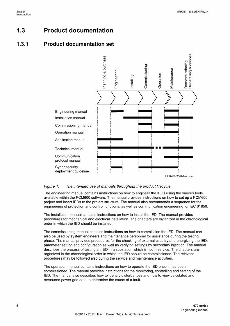
Figure 1: The intended use of manuals throughout the product lifecycle
The engineering manual contains instructions on how to engineer the IEDs using the various toolsavailable within the PCM600 software. The manual provides instructions on how to set up a PCM600project and insert IEDs to the project structure. The manual also recommends a sequence for theengineering of protection and control functions, as well as communication engineering for IEC 61850.
The installation manual contains instructions on how to install the IED. The manual providesprocedures for mechanical and electrical installation. The chapters are organized in the chronologicalorder in which the IED should be installed.
The commissioning manual contains instructions on how to commission the IED. The manual canalso be used by system engineers and maintenance personnel for assistance during the testingphase. The manual provides procedures for the checking of external circuitry and energizing the IED,parameter setting and configuration as well as verifying settings by secondary injection. The manualdescribes the process of testing an IED in a substation which is not in service. The chapters areorganized in the chronological order in which the IED should be commissioned. The relevantprocedures may be followed also during the service and maintenance activities.
The operation manual contains instructions on how to operate the IED once it has beencommissioned. The manual provides instructions for the monitoring, controlling and setting of theIED. The manual also describes how to identify disturbances and how to view calculated andmeasured power grid data to determine the cause of a fault.
Section 1 1MRK 511 398-UEN Rev. KIntroduction
6 670 seriesEngineering manual
© 2017 - 2021 Hitachi Power Grids. All rights reserved

The application manual contains application descriptions and setting guidelines sorted per function.The manual can be used to find out when and for what purpose a typical protection function can beused. The manual can also provide assistance for calculating settings.
The technical manual contains operation principle descriptions, and lists function blocks, logicdiagrams, input and output signals, setting parameters and technical data, sorted per function. Themanual can be used as a technical reference during the engineering phase, installation andcommissioning phase, and during normal service.
The communication protocol manual describes the communication protocols supported by the IED.The manual concentrates on the vendor-specific implementations.
The point list manual describes the outlook and properties of the data points specific to the IED. Themanual should be used in conjunction with the corresponding communication protocol manual.
The cyber security deployment guideline describes the process for handling cyber security whencommunicating with the IED. Certification, Authorization with role based access control, and productengineering for cyber security related events are described and sorted by function. The guideline canbe used as a technical reference during the engineering phase, installation and commissioningphase, and during normal service.
1.3.2 Document revision historyGUID-34B323E4-1319-4D42-80CE-29B0F2D36E2C v5
Documentrevision
Date Product version History
- 2017–05 2.2.0 First release for product version 2.2
A 2017–10 2.2.1 Ethernet ports with RJ45 connector added.
B 2018–03 2.2.1 Document enhancements and corrections
C 2018–06 2.2.2 Technical data updated for PSM. Case dimensionsupdated.
D 2018–11 2.2.3 Functions CHMMHAI, VHMMHAI, DELVSPVC,DELISPVC and DELSPVC added. Updates/enhancements made to ZMFPDIS, ZMFCPDIS,CCRBRF, REALCOMP, PTRSTHR and FNKEYMDx.Ordering section updated.
E 2019-05 2.2.3 PTP enhancements and corrections
F Document not released
G Document not released
H Document not released
J 2020-09 2.2.4 Minor document enhancements and corrections
K 2021-06 2.2.5 Minor document enhancements and corrections
1.3.3 Related documentsGUID-94E8A5CA-BE1B-45AF-81E7-5A41D34EE112 v8
Documents related to REB670 Document numbersApplication manual 1MRK 505 370-UEN
Commissioning manual 1MRK 505 372-UEN
Product guide 1MRK 505 373-BEN
Technical manual 1MRK 505 371-UEN
Type test certificate 1MRK 505 373-TEN
1MRK 511 398-UEN Rev. K Section 1Introduction
670 series 7Engineering manual
© 2017 - 2021 Hitachi Power Grids. All rights reserved
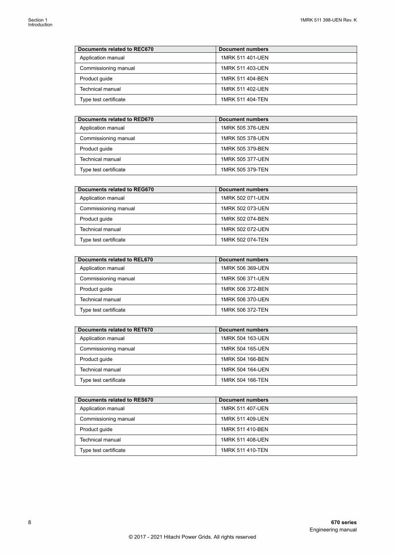
Documents related to REC670 Document numbersApplication manual 1MRK 511 401-UEN
Commissioning manual 1MRK 511 403-UEN
Product guide 1MRK 511 404-BEN
Technical manual 1MRK 511 402-UEN
Type test certificate 1MRK 511 404-TEN
Documents related to RED670 Document numbersApplication manual 1MRK 505 376-UEN
Commissioning manual 1MRK 505 378-UEN
Product guide 1MRK 505 379-BEN
Technical manual 1MRK 505 377-UEN
Type test certificate 1MRK 505 379-TEN
Documents related to REG670 Document numbersApplication manual 1MRK 502 071-UEN
Commissioning manual 1MRK 502 073-UEN
Product guide 1MRK 502 074-BEN
Technical manual 1MRK 502 072-UEN
Type test certificate 1MRK 502 074-TEN
Documents related to REL670 Document numbersApplication manual 1MRK 506 369-UEN
Commissioning manual 1MRK 506 371-UEN
Product guide 1MRK 506 372-BEN
Technical manual 1MRK 506 370-UEN
Type test certificate 1MRK 506 372-TEN
Documents related to RET670 Document numbersApplication manual 1MRK 504 163-UEN
Commissioning manual 1MRK 504 165-UEN
Product guide 1MRK 504 166-BEN
Technical manual 1MRK 504 164-UEN
Type test certificate 1MRK 504 166-TEN
Documents related to RES670 Document numbersApplication manual 1MRK 511 407-UEN
Commissioning manual 1MRK 511 409-UEN
Product guide 1MRK 511 410-BEN
Technical manual 1MRK 511 408-UEN
Type test certificate 1MRK 511 410-TEN
Section 1 1MRK 511 398-UEN Rev. KIntroduction
8 670 seriesEngineering manual
© 2017 - 2021 Hitachi Power Grids. All rights reserved
Documents related to RER670 Document numbersApplication manual 1MRK 506 375-UEN
Commissioning manual 1MRK 506 377-UEN
Product guide 1MRK 506 378-BEN
Technical manual 1MRK 506 376-UEN
Type test certificate 1MRK 506 378-TEN
670 series manuals Document numbersOperation manual 1MRK 500 127-UEN
Engineering manual 1MRK 511 398-UEN
Installation manual 1MRK 514 026-UEN
Communication protocol manual, DNP3 1MRK 511 391-UUS
Communication protocol manual, IEC 60870-5-103 1MRK 511 394-UEN
Communication protocol manual, IEC 61850 Edition 1 1MRK 511 392-UEN
Communication protocol manual, IEC 61850 Edition 2 1MRK 511 393-UEN
Communication protocol manual, LON 1MRK 511 395-UEN
Communication protocol manual, SPA 1MRK 511 396-UEN
Point list manual, DNP3 1MRK 511 397-UUS
Accessories guide 1MRK 514 012-BEN
Cyber security deployment guideline 1MRK 511 399-UEN
Connection and Installation components 1MRK 513 003-BEN
Test system, COMBITEST 1MRK 512 001-BEN
Application guide, Communication set-up 1MRK 505 382-UEN
1.4 Document symbols and conventions
1.4.1 SymbolsGUID-2945B229-DAB0-4F15-8A0E-B9CF0C2C7B15 v13
The electrical warning icon indicates the presence of a hazard which could result inelectrical shock.
The warning icon indicates the presence of a hazard which could result in personalinjury.
The caution hot surface icon indicates important information or warning about thetemperature of product surfaces.
The caution icon indicates important information or warning related to the conceptdiscussed in the text. It might indicate the presence of a hazard which could result incorruption of software or damage to equipment or property.
The information icon alerts the reader of important facts and conditions.
1MRK 511 398-UEN Rev. K Section 1Introduction
670 series 9Engineering manual
© 2017 - 2021 Hitachi Power Grids. All rights reserved
The tip icon indicates advice on, for example, how to design your project or how touse a certain function.
Although warning hazards are related to personal injury, it is necessary to understand that undercertain operational conditions, operation of damaged equipment may result in degraded processperformance leading to personal injury or death. It is important that the user fully complies with allwarning and cautionary notices.
1.4.2 Document conventionsGUID-96DFAB1A-98FE-4B26-8E90-F7CEB14B1AB6 v9
• Abbreviations and acronyms in this manual are spelled out in the glossary. The glossary alsocontains definitions of important terms.
• Push button navigation in the LHMI menu structure is presented by using the push button icons.For example, to navigate between the options, use and .
• HMI menu paths are presented in bold.For example, select Main menu/Settings.
• LHMI messages are shown in Courier font.For example, to save the changes in non-volatile memory, select Yes and press .
• Parameter names are shown in italics.For example, the function can be enabled and disabled with the Operation setting.
• Each function block symbol shows the available input/output signal.• the character ^ in front of an input/output signal name indicates that the signal name may
be customized using the PCM600 software.• the character * after an input signal name indicates that the signal must be connected to
another function block in the application configuration to achieve a valid applicationconfiguration.
• Dimensions are provided both in inches and millimeters. If it is not specifically mentioned thenthe dimension is in millimeters.
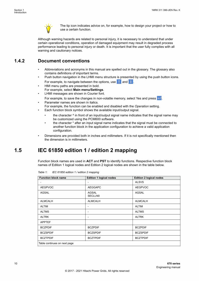
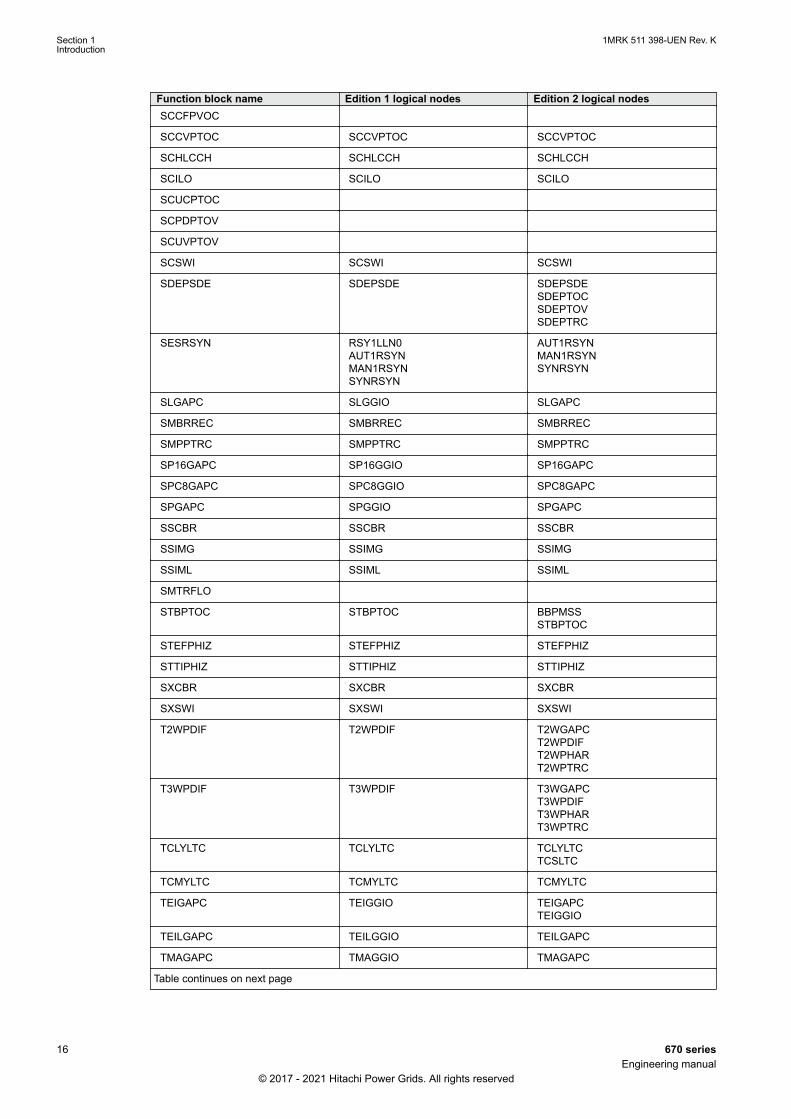
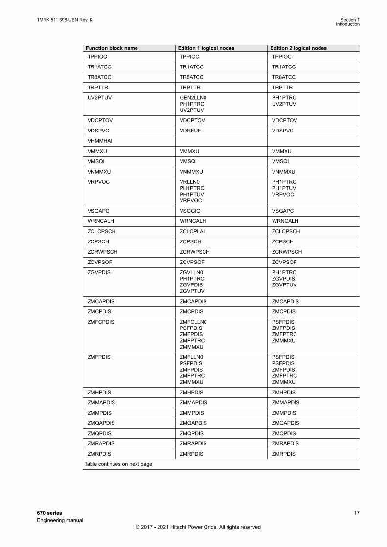
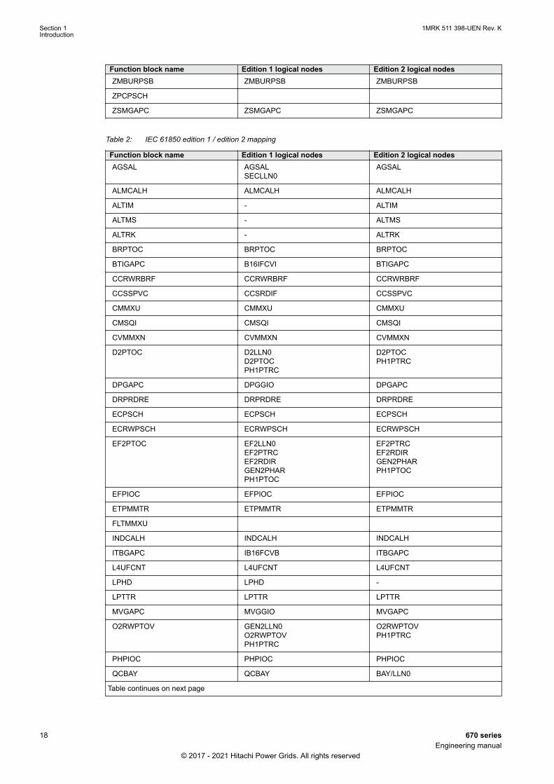
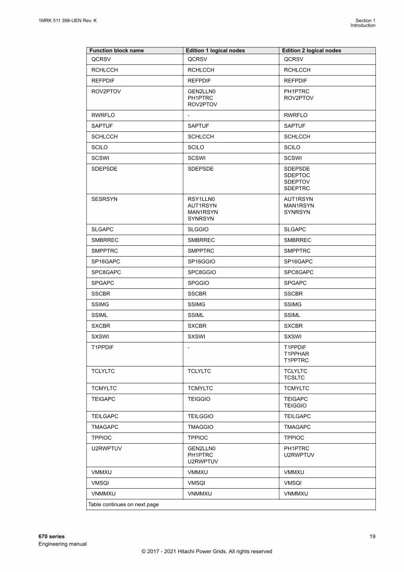
1.5 IEC 61850 edition 1 / edition 2 mappingGUID-C5133366-7260-4C47-A975-7DBAB3A33A96 v9
Function block names are used in ACT and PST to identify functions. Respective function blocknames of Edition 1 logical nodes and Edition 2 logical nodes are shown in the table below.
Table 1: IEC 61850 edition 1 / edition 2 mapping
Function block name Edition 1 logical nodes Edition 2 logical nodes- - ALSVS
AEGPVOC AEGGAPC AEGPVOC
AGSAL AGSALSECLLN0
AGSAL
ALMCALH ALMCALH ALMCALH
ALTIM - ALTIM
ALTMS - ALTMS
ALTRK - ALTRK
APPTEF
BCZPDIF BCZPDIF BCZPDIF
BCZSPDIF BCZSPDIF BCZSPDIF
BCZTPDIF BCZTPDIF BCZTPDIF
Table continues on next page
Section 1 1MRK 511 398-UEN Rev. KIntroduction
10 670 seriesEngineering manual
© 2017 - 2021 Hitachi Power Grids. All rights reserved
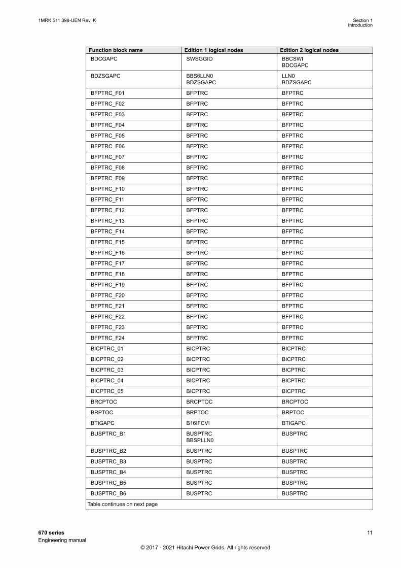
Function block name Edition 1 logical nodes Edition 2 logical nodesBDCGAPC SWSGGIO BBCSWI
BDCGAPC
BDZSGAPC BBS6LLN0BDZSGAPC
LLN0BDZSGAPC
BFPTRC_F01 BFPTRC BFPTRC
BFPTRC_F02 BFPTRC BFPTRC
BFPTRC_F03 BFPTRC BFPTRC
BFPTRC_F04 BFPTRC BFPTRC
BFPTRC_F05 BFPTRC BFPTRC
BFPTRC_F06 BFPTRC BFPTRC
BFPTRC_F07 BFPTRC BFPTRC
BFPTRC_F08 BFPTRC BFPTRC
BFPTRC_F09 BFPTRC BFPTRC
BFPTRC_F10 BFPTRC BFPTRC
BFPTRC_F11 BFPTRC BFPTRC
BFPTRC_F12 BFPTRC BFPTRC
BFPTRC_F13 BFPTRC BFPTRC
BFPTRC_F14 BFPTRC BFPTRC
BFPTRC_F15 BFPTRC BFPTRC
BFPTRC_F16 BFPTRC BFPTRC
BFPTRC_F17 BFPTRC BFPTRC
BFPTRC_F18 BFPTRC BFPTRC
BFPTRC_F19 BFPTRC BFPTRC
BFPTRC_F20 BFPTRC BFPTRC
BFPTRC_F21 BFPTRC BFPTRC
BFPTRC_F22 BFPTRC BFPTRC
BFPTRC_F23 BFPTRC BFPTRC
BFPTRC_F24 BFPTRC BFPTRC
BICPTRC_01 BICPTRC BICPTRC
BICPTRC_02 BICPTRC BICPTRC
BICPTRC_03 BICPTRC BICPTRC
BICPTRC_04 BICPTRC BICPTRC
BICPTRC_05 BICPTRC BICPTRC
BRCPTOC BRCPTOC BRCPTOC
BRPTOC BRPTOC BRPTOC
BTIGAPC B16IFCVI BTIGAPC
BUSPTRC_B1 BUSPTRCBBSPLLN0
BUSPTRC
BUSPTRC_B2 BUSPTRC BUSPTRC
BUSPTRC_B3 BUSPTRC BUSPTRC
BUSPTRC_B4 BUSPTRC BUSPTRC
BUSPTRC_B5 BUSPTRC BUSPTRC
BUSPTRC_B6 BUSPTRC BUSPTRC
Table continues on next page
1MRK 511 398-UEN Rev. K Section 1Introduction
670 series 11Engineering manual
© 2017 - 2021 Hitachi Power Grids. All rights reserved

Function block name Edition 1 logical nodes Edition 2 logical nodesBUSPTRC_B7 BUSPTRC BUSPTRC
BUSPTRC_B8 BUSPTRC BUSPTRC
BUSPTRC_B9 BUSPTRC BUSPTRC
BUSPTRC_B10 BUSPTRC BUSPTRC
BUSPTRC_B11 BUSPTRC BUSPTRC
BUSPTRC_B12 BUSPTRC BUSPTRC
BUSPTRC_B13 BUSPTRC BUSPTRC
BUSPTRC_B14 BUSPTRC BUSPTRC
BUSPTRC_B15 BUSPTRC BUSPTRC
BUSPTRC_B16 BUSPTRC BUSPTRC
BUSPTRC_B17 BUSPTRC BUSPTRC
BUSPTRC_B18 BUSPTRC BUSPTRC
BUSPTRC_B19 BUSPTRC BUSPTRC
BUSPTRC_B20 BUSPTRC BUSPTRC
BUSPTRC_B21 BUSPTRC BUSPTRC
BUSPTRC_B22 BUSPTRC BUSPTRC
BUSPTRC_B23 BUSPTRC BUSPTRC
BUSPTRC_B24 BUSPTRC BUSPTRC
BUTPTRC_B1 BUTPTRCBBTPLLN0
BUTPTRC
BUTPTRC_B2 BUTPTRC BUTPTRC
BUTPTRC_B3 BUTPTRC BUTPTRC
BUTPTRC_B4 BUTPTRC BUTPTRC
BUTPTRC_B5 BUTPTRC BUTPTRC
BUTPTRC_B6 BUTPTRC BUTPTRC
BUTPTRC_B7 BUTPTRC BUTPTRC
BUTPTRC_B8 BUTPTRC BUTPTRC
BZNPDIF_Z1 BZNPDIF BZNPDIF
BZNPDIF_Z2 BZNPDIF BZNPDIF
BZNPDIF_Z3 BZNPDIF BZNPDIF
BZNPDIF_Z4 BZNPDIF BZNPDIF
BZNPDIF_Z5 BZNPDIF BZNPDIF
BZNPDIF_Z6 BZNPDIF BZNPDIF
BZNSPDIF_A BZNSPDIF BZASGAPCBZASPDIFBZNSGAPCBZNSPDIF
BZNSPDIF_B BZNSPDIF BZBSGAPCBZBSPDIFBZNSGAPCBZNSPDIF
BZNTPDIF_A BZNTPDIF BZATGAPCBZATPDIFBZNTGAPCBZNTPDIF
Table continues on next page
Section 1 1MRK 511 398-UEN Rev. KIntroduction
12 670 seriesEngineering manual
© 2017 - 2021 Hitachi Power Grids. All rights reserved

Function block name Edition 1 logical nodes Edition 2 logical nodesBZNTPDIF_B BZNTPDIF BZBTGAPC
BZBTPDIFBZNTGAPCBZNTPDIF
CBPGAPC CBPLLN0CBPMMXUCBPPTRCHOLPTOVHPH1PTOVPH3PTUCPH3PTOCRP3PDOP
CBPMMXUCBPPTRCHOLPTOVHPH1PTOVPH3PTOCPH3PTUCRP3PDOP
CCPDSC CCRPLD CCPDSC
CCRBRF CCRBRF CCRBRF
CCSRBRF CCSRBRF CCSRBRF
CCSSPVC CCSRDIF CCSSPVC
CHMMHAI
CMMXU CMMXU CMMXU
CMSQI CMSQI CMSQI
COUVGAPC COUVLLN0COUVPTOVCOUVPTUV
COUVPTOVCOUVPTUV
CVGAPC GF2LLN0GF2MMXNGF2PHARGF2PTOVGF2PTUCGF2PTUVGF2PVOCPH1PTRC
GF2MMXNGF2PHARGF2PTOVGF2PTUCGF2PTUVGF2PVOCPH1PTRC
CVMMXN CVMMXN CVMMXN
DPGAPC DPGGIO DPGAPC
DRPRDRE DRPRDRE DRPRDRE
ECPSCH ECPSCH ECPSCH
ECRWPSCH ECRWPSCH ECRWPSCH
EF4PTOC EF4LLN0EF4PTRCEF4RDIRGEN4PHARPH1PTOC
EF4PTRCEF4RDIRGEN4PHARPH1PTOC
EFPIOC EFPIOC EFPIOC
EFRWPIOC EFRWPIOC EFRWPIOC
ETPMMTR ETPMMTR ETPMMTR
FDPSPDIS FDPSPDIS FDPSPDIS
FLTMMXU
FMPSPDIS FMPSPDIS FMPSPDIS
FRPSPDIS FPSRPDIS FPSRPDIS
FTAQFVR FTAQFVR FTAQFVR
FUFSPVC SDDRFUF FUFSPVCSDDSPVC
Table continues on next page
1MRK 511 398-UEN Rev. K Section 1Introduction
670 series 13Engineering manual
© 2017 - 2021 Hitachi Power Grids. All rights reserved
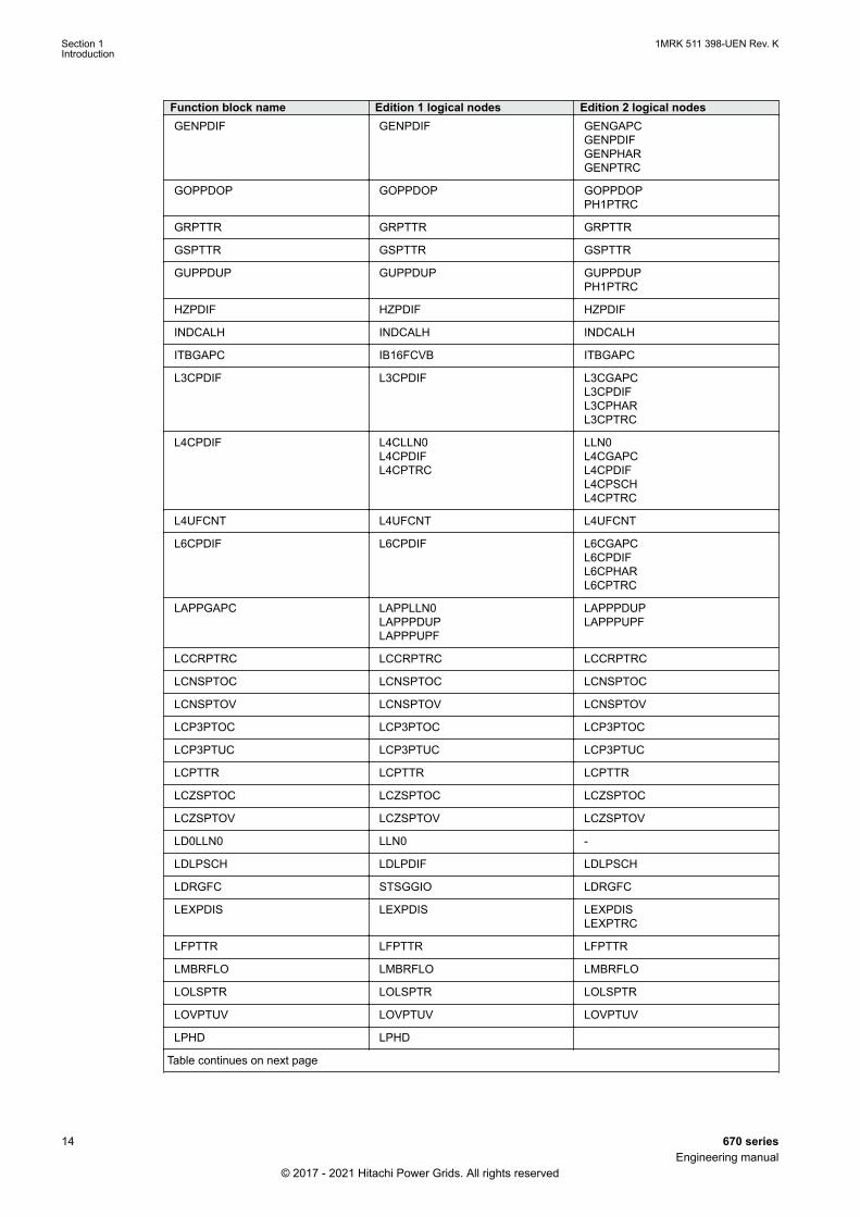
Function block name Edition 1 logical nodes Edition 2 logical nodesGENPDIF GENPDIF GENGAPC
GENPDIFGENPHARGENPTRC
GOPPDOP GOPPDOP GOPPDOPPH1PTRC
GRPTTR GRPTTR GRPTTR
GSPTTR GSPTTR GSPTTR
GUPPDUP GUPPDUP GUPPDUPPH1PTRC
HZPDIF HZPDIF HZPDIF
INDCALH INDCALH INDCALH
ITBGAPC IB16FCVB ITBGAPC
L3CPDIF L3CPDIF L3CGAPCL3CPDIFL3CPHARL3CPTRC
L4CPDIF L4CLLN0L4CPDIFL4CPTRC
LLN0L4CGAPCL4CPDIFL4CPSCHL4CPTRC
L4UFCNT L4UFCNT L4UFCNT
L6CPDIF L6CPDIF L6CGAPCL6CPDIFL6CPHARL6CPTRC
LAPPGAPC LAPPLLN0LAPPPDUPLAPPPUPF
LAPPPDUPLAPPPUPF
LCCRPTRC LCCRPTRC LCCRPTRC
LCNSPTOC LCNSPTOC LCNSPTOC
LCNSPTOV LCNSPTOV LCNSPTOV
LCP3PTOC LCP3PTOC LCP3PTOC
LCP3PTUC LCP3PTUC LCP3PTUC
LCPTTR LCPTTR LCPTTR
LCZSPTOC LCZSPTOC LCZSPTOC
LCZSPTOV LCZSPTOV LCZSPTOV
LD0LLN0 LLN0 -
LDLPSCH LDLPDIF LDLPSCH
LDRGFC STSGGIO LDRGFC
LEXPDIS LEXPDIS LEXPDISLEXPTRC
LFPTTR LFPTTR LFPTTR
LMBRFLO LMBRFLO LMBRFLO
LOLSPTR LOLSPTR LOLSPTR
LOVPTUV LOVPTUV LOVPTUV
LPHD LPHD
Table continues on next page
Section 1 1MRK 511 398-UEN Rev. KIntroduction
14 670 seriesEngineering manual
© 2017 - 2021 Hitachi Power Grids. All rights reserved

Function block name Edition 1 logical nodes Edition 2 logical nodesLT3CPDIF LT3CPDIF LT3CGAPC
LT3CPDIFLT3CPHARLT3CPTRC
LT6CPDIF LT6CPDIF LT6CGAPCLT6CPDIFLT6CPHARLT6CPTRC
MVGAPC MVGGIO MVGAPC
NS2PTOC NS2LLN0NS2PTOCNS2PTRC
NS2PTOCNS2PTRC
NS4PTOC EF4LLN0EF4PTRCEF4RDIRGEN4PHARPH1PTOC
EF4PTRCEF4RDIRPH1PTOC
OC4PTOC OC4LLN0GEN4PHARPH3PTOCPH3PTRC
GEN4PHARPH3PTOCPH3PTRC
OEXPVPH OEXPVPH OEXPVPH
OOSPPAM OOSPPAM OOSPPAMOOSPTRC
OV2PTOV GEN2LLN0OV2PTOVPH1PTRC
OV2PTOVPH1PTRC
PAPGAPC PAPGAPC PAPGAPC
PCFCNT PCGGIO PCFCNT
PH4SPTOC GEN4PHAROCNDLLN0PH1BPTOCPH1PTRC
GEN4PHARPH1BPTOCPH1PTRC
PHPIOC PHPIOC PHPIOC
PSLPSCH ZMRPSL PSLPSCH
PSPPPAM PSPPPAM PSPPPAMPSPPTRC
PSTPDIF
PTRSTHR PTRSTHR PTRSTHR
QCBAY QCBAY BAY/LLN0
QCRSV QCRSV QCRSV
RCHLCCH RCHLCCH RCHLCCH
REFPDIF REFPDIF REFPDIF
ROTIPHIZ ROTIPHIZ ROTIPHIZROTIPTRC
ROV2PTOV GEN2LLN0PH1PTRCROV2PTOV
PH1PTRCROV2PTOV
SAPFRC SAPFRC SAPFRC
SAPTOF SAPTOF SAPTOF
SAPTUF SAPTUF SAPTUF
Table continues on next page
1MRK 511 398-UEN Rev. K Section 1Introduction
670 series 15Engineering manual
© 2017 - 2021 Hitachi Power Grids. All rights reserved
Function block name Edition 1 logical nodes Edition 2 logical nodesSCCFPVOC
SCCVPTOC SCCVPTOC SCCVPTOC
SCHLCCH SCHLCCH SCHLCCH
SCILO SCILO SCILO
SCUCPTOC
SCPDPTOV
SCUVPTOV
SCSWI SCSWI SCSWI
SDEPSDE SDEPSDE SDEPSDESDEPTOCSDEPTOVSDEPTRC
SESRSYN RSY1LLN0AUT1RSYNMAN1RSYNSYNRSYN
AUT1RSYNMAN1RSYNSYNRSYN
SLGAPC SLGGIO SLGAPC
SMBRREC SMBRREC SMBRREC
SMPPTRC SMPPTRC SMPPTRC
SP16GAPC SP16GGIO SP16GAPC
SPC8GAPC SPC8GGIO SPC8GAPC
SPGAPC SPGGIO SPGAPC
SSCBR SSCBR SSCBR
SSIMG SSIMG SSIMG
SSIML SSIML SSIML
SMTRFLO
STBPTOC STBPTOC BBPMSSSTBPTOC
STEFPHIZ STEFPHIZ STEFPHIZ
STTIPHIZ STTIPHIZ STTIPHIZ
SXCBR SXCBR SXCBR
SXSWI SXSWI SXSWI
T2WPDIF T2WPDIF T2WGAPCT2WPDIFT2WPHART2WPTRC
T3WPDIF T3WPDIF T3WGAPCT3WPDIFT3WPHART3WPTRC
TCLYLTC TCLYLTC TCLYLTCTCSLTC
TCMYLTC TCMYLTC TCMYLTC
TEIGAPC TEIGGIO TEIGAPCTEIGGIO
TEILGAPC TEILGGIO TEILGAPC
TMAGAPC TMAGGIO TMAGAPC
Table continues on next page
Section 1 1MRK 511 398-UEN Rev. KIntroduction
16 670 seriesEngineering manual
© 2017 - 2021 Hitachi Power Grids. All rights reserved
Function block name Edition 1 logical nodes Edition 2 logical nodesTPPIOC TPPIOC TPPIOC
TR1ATCC TR1ATCC TR1ATCC
TR8ATCC TR8ATCC TR8ATCC
TRPTTR TRPTTR TRPTTR
UV2PTUV GEN2LLN0PH1PTRCUV2PTUV
PH1PTRCUV2PTUV
VDCPTOV VDCPTOV VDCPTOV
VDSPVC VDRFUF VDSPVC
VHMMHAI
VMMXU VMMXU VMMXU
VMSQI VMSQI VMSQI
VNMMXU VNMMXU VNMMXU
VRPVOC VRLLN0PH1PTRCPH1PTUVVRPVOC
PH1PTRCPH1PTUVVRPVOC
VSGAPC VSGGIO VSGAPC
WRNCALH WRNCALH WRNCALH
ZCLCPSCH ZCLCPLAL ZCLCPSCH
ZCPSCH ZCPSCH ZCPSCH
ZCRWPSCH ZCRWPSCH ZCRWPSCH
ZCVPSOF ZCVPSOF ZCVPSOF
ZGVPDIS ZGVLLN0PH1PTRCZGVPDISZGVPTUV
PH1PTRCZGVPDISZGVPTUV
ZMCAPDIS ZMCAPDIS ZMCAPDIS
ZMCPDIS ZMCPDIS ZMCPDIS
ZMFCPDIS ZMFCLLN0PSFPDISZMFPDISZMFPTRCZMMMXU
PSFPDISZMFPDISZMFPTRCZMMMXU
ZMFPDIS ZMFLLN0PSFPDISZMFPDISZMFPTRCZMMMXU
PSFPDISPSFPDISZMFPDISZMFPTRCZMMMXU
ZMHPDIS ZMHPDIS ZMHPDIS
ZMMAPDIS ZMMAPDIS ZMMAPDIS
ZMMPDIS ZMMPDIS ZMMPDIS
ZMQAPDIS ZMQAPDIS ZMQAPDIS
ZMQPDIS ZMQPDIS ZMQPDIS
ZMRAPDIS ZMRAPDIS ZMRAPDIS
ZMRPDIS ZMRPDIS ZMRPDIS
Table continues on next page
1MRK 511 398-UEN Rev. K Section 1Introduction
670 series 17Engineering manual
© 2017 - 2021 Hitachi Power Grids. All rights reserved
Function block name Edition 1 logical nodes Edition 2 logical nodesZMBURPSB ZMBURPSB ZMBURPSB
ZPCPSCH
ZSMGAPC ZSMGAPC ZSMGAPC
Table 2: IEC 61850 edition 1 / edition 2 mapping
Function block name Edition 1 logical nodes Edition 2 logical nodesAGSAL AGSAL
SECLLN0AGSAL
ALMCALH ALMCALH ALMCALH
ALTIM - ALTIM
ALTMS - ALTMS
ALTRK - ALTRK
BRPTOC BRPTOC BRPTOC
BTIGAPC B16IFCVI BTIGAPC
CCRWRBRF CCRWRBRF CCRWRBRF
CCSSPVC CCSRDIF CCSSPVC
CMMXU CMMXU CMMXU
CMSQI CMSQI CMSQI
CVMMXN CVMMXN CVMMXN
D2PTOC D2LLN0D2PTOCPH1PTRC
D2PTOCPH1PTRC
DPGAPC DPGGIO DPGAPC
DRPRDRE DRPRDRE DRPRDRE
ECPSCH ECPSCH ECPSCH
ECRWPSCH ECRWPSCH ECRWPSCH
EF2PTOC EF2LLN0EF2PTRCEF2RDIRGEN2PHARPH1PTOC
EF2PTRCEF2RDIRGEN2PHARPH1PTOC
EFPIOC EFPIOC EFPIOC
ETPMMTR ETPMMTR ETPMMTR
FLTMMXU
INDCALH INDCALH INDCALH
ITBGAPC IB16FCVB ITBGAPC
L4UFCNT L4UFCNT L4UFCNT
LPHD LPHD -
LPTTR LPTTR LPTTR
MVGAPC MVGGIO MVGAPC
O2RWPTOV GEN2LLN0O2RWPTOVPH1PTRC
O2RWPTOVPH1PTRC
PHPIOC PHPIOC PHPIOC
QCBAY QCBAY BAY/LLN0
Table continues on next page
Section 1 1MRK 511 398-UEN Rev. KIntroduction
18 670 seriesEngineering manual
© 2017 - 2021 Hitachi Power Grids. All rights reserved
Function block name Edition 1 logical nodes Edition 2 logical nodesQCRSV QCRSV QCRSV
RCHLCCH RCHLCCH RCHLCCH
REFPDIF REFPDIF REFPDIF
ROV2PTOV GEN2LLN0PH1PTRCROV2PTOV
PH1PTRCROV2PTOV
RWRFLO - RWRFLO
SAPTUF SAPTUF SAPTUF
SCHLCCH SCHLCCH SCHLCCH
SCILO SCILO SCILO
SCSWI SCSWI SCSWI
SDEPSDE SDEPSDE SDEPSDESDEPTOCSDEPTOVSDEPTRC
SESRSYN RSY1LLN0AUT1RSYNMAN1RSYNSYNRSYN
AUT1RSYNMAN1RSYNSYNRSYN
SLGAPC SLGGIO SLGAPC
SMBRREC SMBRREC SMBRREC
SMPPTRC SMPPTRC SMPPTRC
SP16GAPC SP16GGIO SP16GAPC
SPC8GAPC SPC8GGIO SPC8GAPC
SPGAPC SPGGIO SPGAPC
SSCBR SSCBR SSCBR
SSIMG SSIMG SSIMG
SSIML SSIML SSIML
SXCBR SXCBR SXCBR
SXSWI SXSWI SXSWI
T1PPDIF - T1PPDIFT1PPHART1PPTRC
TCLYLTC TCLYLTC TCLYLTCTCSLTC
TCMYLTC TCMYLTC TCMYLTC
TEIGAPC TEIGGIO TEIGAPCTEIGGIO
TEILGAPC TEILGGIO TEILGAPC
TMAGAPC TMAGGIO TMAGAPC
TPPIOC TPPIOC TPPIOC
U2RWPTUV GEN2LLN0PH1PTRCU2RWPTUV
PH1PTRCU2RWPTUV
VMMXU VMMXU VMMXU
VMSQI VMSQI VMSQI
VNMMXU VNMMXU VNMMXU
Table continues on next page
1MRK 511 398-UEN Rev. K Section 1Introduction
670 series 19Engineering manual
© 2017 - 2021 Hitachi Power Grids. All rights reserved

Function block name Edition 1 logical nodes Edition 2 logical nodesVSGAPC VSGGIO VSGAPC
WRNCALH WRNCALH WRNCALH
XENCPOW - XENCPOW
ZCPSCH ZCPSCH ZCPSCH
ZCRWPSCH ZCRWPSCH ZCRWPSCH
ZCVPSOF ZCVPSOF ZCVPSOF
ZGTPDIS ZGTLLN0ZGPDISZGPTRC
ZGPDISZGPTRC
ZRWPDIS - PSRWPDISZRWPDISZRWPTRC
Section 1 1MRK 511 398-UEN Rev. KIntroduction
20 670 seriesEngineering manual
© 2017 - 2021 Hitachi Power Grids. All rights reserved
Section 2 Engineering tool set
2.1 IntroductionSEMOD58253-4 v11
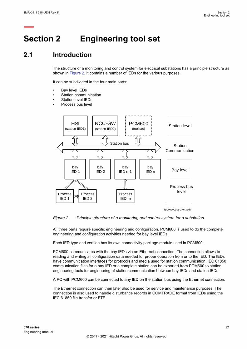
The structure of a monitoring and control system for electrical substations has a principle structure asshown in Figure 2. It contains a number of IEDs for the various purposes.
It can be subdivided in the four main parts:
• Bay level IEDs• Station communication• Station level IEDs• Process bus level
Bay level
Station level
Station
Communication
Station bus
bay
IED 1
bay
IED 2
bay
IED n-1
bay
IED n
NCC-GW(station-IED2)
PCM600(tool set)
HSI(station-IED1)
Process bus
level
IEC08000101-2-en.vsdx
Process
IED 1
Process
IED 2
Process
IED m
IEC08000101 V2 EN-US
Figure 2: Principle structure of a monitoring and control system for a substation
All three parts require specific engineering and configuration. PCM600 is used to do the completeengineering and configuration activities needed for bay level IEDs.
Each IED type and version has its own connectivity package module used in PCM600.
PCM600 communicates with the bay IEDs via an Ethernet connection. The connection allows toreading and writing all configuration data needed for proper operation from or to the IED. The IEDshave communication interfaces for protocols and media used for station communication. IEC 61850communication files for a bay IED or a complete station can be exported from PCM600 to stationengineering tools for engineering of station communication between bay IEDs and station IEDs.
A PC with PCM600 can be connected to any IED on the station bus using the Ethernet connection.
The Ethernet connection can then later also be used for service and maintenance purposes. Theconnection is also used to handle disturbance records in COMTRADE format from IEDs using theIEC 61850 file transfer or FTP.
1MRK 511 398-UEN Rev. K Section 2Engineering tool set
670 series 21Engineering manual
© 2017 - 2021 Hitachi Power Grids. All rights reserved

The IEDs of today are designed on the concept of the IEC 61850 standard. This is mainly given forthe organization of functions represented by an equivalent logical node in the IEC 61850 standard.The mapping between the logical node data model in the IED, following the structure and rules inpart 7 of the IEC 61850 standard, and the function blocks in an IED configuration is given in the IEC61850 communication protocol manual.
The same IEC 61850–based concept is also used for the DNP3 protocol. The signals used ordelivered by a function block are automatically generated and available for station communication.This concept allows a very efficient time saving signal engineering.
The engineering of the used communication protocols is a separate task and an addition to theengineering of control functions.
PCM600 can be used for different purposes throughout the IED life cycle. A set of special tools isavailable for different applications.
The applications can be organized in:
• IED product engineering• IED communication engineering per protocol• IED system monitoring• IED product diagnostic
This manual is valid for PCM600 supporting the Relion 670/650 series product ver.2.2.
2.2 IED engineering processSEMOD58260-4 v14
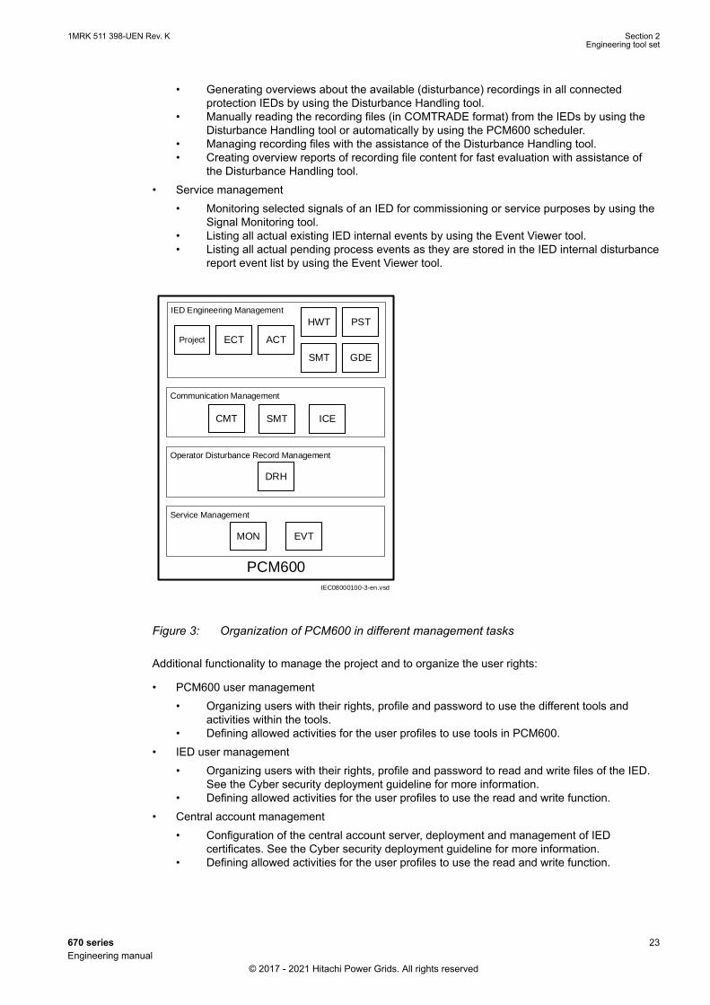
PCM600 is used for various tasks in the IED engineering process. See Figure 3:
• IED engineering management• Organizing the bay IEDs in the structure of the substation by defining voltage levels and
bays below the substation. A PCM600 project can have only one substation.• Configuring Ethernet ports, Routes and Merging units using the Ethernet configuration
tool.• Configuring the IED functions (for example protection and control functions and LHMI
functions) by using the Application Configuration tool.• Configuring the parameters and setting values for the IED itself and for the process
functionality by using the Parameter Setting tool.• Drawing single line diagrams and do the link to dynamic process values by using the
Graphical Display Editor tool. The single line diagrams are shown on the LHMI on the bayIED.
• Configuring connections between the application configuration function blocks andphysical hardware input and outputs by using the Signal Matrix tool or the ApplicationConfiguration tool.
• Communication engineering• IEC 61850 station communication engineering can be done in two ways, with a separate
tool, IET600 or with the PCM600 built in IEC 61850 configuration tool. PCM600 interactswith IET600 by importing and exporting SCL files. The built in tool can be used for smallprojects including Hitachi Power grids IEDs only. To engineer communication betweenHitachi Power grids IED's and third party devices it's recommended to use IET600.
• Organizing GOOSE messages received is done by using the Signal Matrix tool.• Communication engineering for the DNP3 protocol by using the Communication
Management tool.• Disturbance record management
Section 2 1MRK 511 398-UEN Rev. KEngineering tool set
22 670 seriesEngineering manual
© 2017 - 2021 Hitachi Power Grids. All rights reserved
• Generating overviews about the available (disturbance) recordings in all connectedprotection IEDs by using the Disturbance Handling tool.
• Manually reading the recording files (in COMTRADE format) from the IEDs by using theDisturbance Handling tool or automatically by using the PCM600 scheduler.
• Managing recording files with the assistance of the Disturbance Handling tool.• Creating overview reports of recording file content for fast evaluation with assistance of
the Disturbance Handling tool.• Service management
• Monitoring selected signals of an IED for commissioning or service purposes by using theSignal Monitoring tool.
• Listing all actual existing IED internal events by using the Event Viewer tool.• Listing all actual pending process events as they are stored in the IED internal disturbance
report event list by using the Event Viewer tool.
IEC08000100-3-en.vsd
PCM600
IED Engineering Management
Project ECT
SMT
HWT
GDE
PST
Communication Management
CMT
Operator Disturbance Record Management
DRH
Service Management
MON EVT
SMT ICE
ACT
IEC08000100 V3 EN-US
Figure 3: Organization of PCM600 in different management tasks
Additional functionality to manage the project and to organize the user rights:
• PCM600 user management• Organizing users with their rights, profile and password to use the different tools and
activities within the tools.• Defining allowed activities for the user profiles to use tools in PCM600.
• IED user management• Organizing users with their rights, profile and password to read and write files of the IED.
See the Cyber security deployment guideline for more information.• Defining allowed activities for the user profiles to use the read and write function.
• Central account management• Configuration of the central account server, deployment and management of IED
certificates. See the Cyber security deployment guideline for more information.• Defining allowed activities for the user profiles to use the read and write function.
1MRK 511 398-UEN Rev. K Section 2Engineering tool set
670 series 23Engineering manual
© 2017 - 2021 Hitachi Power Grids. All rights reserved

Once the engineering of the IED is done, the results must be written to the IED. Conversely someparts of the engineering information can be uploaded from the IED for various purposes.
The connection between the IED and PCM600 is established via an Ethernet link on the front or rearport on the IED.
The IP addresses of the different ports on the IED are not allowed to belong to thesame subnet.
Section 2 1MRK 511 398-UEN Rev. KEngineering tool set
24 670 seriesEngineering manual
© 2017 - 2021 Hitachi Power Grids. All rights reserved
Section 3 Engineering process
3.1 WorkflowSEMOD58465-5 v13
IEC08000122-6-en.vsd
Make GOOSE connections
Export SCL files, IED-level
CID files, etc. from PCM600
Import SCL files to IET600
and do signal engineering.
Export SCL files from
IET600.
Import SCL files, IED-level
CID files, etc. to PCM600
Write configuration
to IED
Start
HWT
ACT/
SMT
PST
GDE
CMT
ACT
Export
IED
WRITE
IET600
Import
IED
WRITE
EndEnd
Optional, can be used to add
additional hardware modules
Configure IED functionality
Parametrization
Signal engineering
Create Single line diagram
for local HMI
Save the work
between the
different steps
ProjectCreate plant structure
Write configuration
to IED
IEC 61850Supported
protocols
IEC 61850
configuration
tool
SMT
FPN
ECTConfigure Ethernet ports,
Routes and Merging units
ACTEasy GOOSE
engineering
IEC08000122 V6 EN-US
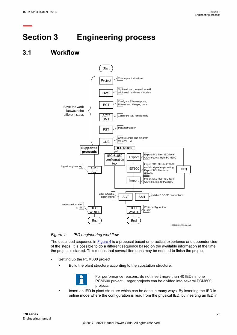
Figure 4: IED engineering workflow
The described sequence in Figure 4 is a proposal based on practical experience and dependenciesof the steps. It is possible to do a different sequence based on the available information at the timethe project is started. This means that several iterations may be needed to finish the project.
• Setting up the PCM600 project• Build the plant structure according to the substation structure.
For performance reasons, do not insert more than 40 IEDs in onePCM600 project. Larger projects can be divided into several PCM600projects.
• Insert an IED in plant structure which can be done in many ways. By inserting the IED inonline mode where the configuration is read from the physical IED, by inserting an IED in
1MRK 511 398-UEN Rev. K Section 3Engineering process
670 series 25Engineering manual
© 2017 - 2021 Hitachi Power Grids. All rights reserved

offline mode, by importing a *.pcmi file or by selecting an IED template from the templatelibrary (*.pcmt).
• Rename the IED objects in PCM600 to the projects definitions.• Set the IEC 61850 technical key (or use the default one from PCM600).
• ECT Ethernet configuration• Configure the access points, routes and merging units
• Check and adjust if needed the setting values for example for:• Operation of the access points• Redundant communication on the access points• Route for communication of devices in different subnetworks• Operation of merging unit receivers.
• ACT Application configuration• Save the configuration made with ACT to make the interfaces and signals available for
other engineering tools within PCM600, for example for PST.• PST Parameter setting and configuration
• Check the configuration parameters of the physical IED for communication channels, forexample, CT and VT conversion values of the transformer module.
• Check and adjust the setting values if needed for example for:• Presentation parameters for local HMI.• Settings for control functions.• Number of setting groups.
• GDE Single line diagram configuration• Create a single line diagram.• Include measurements when needed.• Link the dynamic elements to functions created in ACT, for example a breaker object to
the switch function.• Local HMI engineering
• Include and engineer the function blocks for LHMI element groups with ACT and SMT.• Define the LED behavior with PST.• Configure the LEDs with ACT and SMT.
• Communication protocol engineering• The engineering steps are protocol dependent.• Use the communication management tool (CMT) for DNP3 engineering.• Use the IET600 station configuration tool or the PCM600 IEC 61850 Configuration tool for
IEC 61850 engineering.• See the application manual for other protocols (LON, SPA, IEC103).
Section 3 1MRK 511 398-UEN Rev. KEngineering process
26 670 seriesEngineering manual
© 2017 - 2021 Hitachi Power Grids. All rights reserved

Section 4 Setting up a project
4.1 PCM600 projectsSEMOD58401-5 v3
A typical project in PCM600 contains a plant structure including one or several IED objects, whereeach IED object contains the engineering data created or modified using the different PCM600 tools.
Several projects can be created and managed by PCM600, but only one project can be active at atime.
4.2 Installing Connectivity packagesGUID-0863CF81-30F7-468C-957D-61E99CD5010D v10
A Connectivity package contains the complete description of the IED data signals, parameters andprotocol addresses for a certain IED type and version. Several types of IEDs can be managed in onePCM600 project, thus the corresponding Connectivity package has to be installed on the PC.Connectivity Packages and Connectivity Package Updates are managed in the Update Manager.
PCM600 must be installed before the connectivity packages can be installed.
PCM600 version 2.10 or newer must be used with the 2.2 version of the IED. TheConnectivity package used with PCM600 2.10 and the 2.2 version of the IED mustbe of version 3.4.0.0.
A Connectivity package for a specific IED type and version is divided in two parts. The IEDConnectivity package base module is common for all IEDs. The IED specific module is separate foreach type of IED.
Installing the IED Connectivity packageThe Connectivity package is available on the media that was distributed along with the IED. The usermanuals for all IEDs are contained in a separate installation package Relion 670 v.2.2 series UserDocumentation. This package must be installed to access manuals for a specific IED type inPCM600.
Procedure
1. Close PCM600 before running the IED connectivity package installation.2. Install the IED series Connectivity package base.3. Select and install the IED modules as required.4. Install the documentation.
Installing 670 2.1.5 (or lower) version of the Connectivity package on top of the 6703.4.0.0 Connectivity package will corrupt the Connectivity package installation. Towork around this, uninstall all the Connectivity packages (starting from the lowestversion first), and then install the 670 3.4.0.0 Connectivity package freshly again.Because of parallel Connectivity package support, 670 3.4.0.0 Connectivity packagewill background install 670 3.3.0.0, 670 3.2.6.0, 670 3.1.2.0, 670 3.0.2.0, 670 2.1.6and 670 2.1.5 Connectivity packages.
1MRK 511 398-UEN Rev. K Section 4Setting up a project
670 series 27Engineering manual
© 2017 - 2021 Hitachi Power Grids. All rights reserved
4.3 Setting technical keyGUID-6E273043-7AC6-4262-9522-ED24D8E31E93 v9
Both IED and an IED object in PCM600 have a technical key. The purpose of the technical key is toprevent writing a configuration to wrong IED. The technical key in the IED and PCM600 must be thesame, otherwise it is not possible to write a configuration. Each IED in a PCM600 project must havea unique technical key. It is therefore not possible to set the same technical key for several IEDs inthe same PCM600 project.
For details on technical key settings, see Naming conventions for IEC 61850
The technical key property in PCM600 corresponds to the IED name attribute in SCLfiles. Avoid changing the IED name attribute outside PCM600, because data inPCM600 might be lost when importing SCL files.
When using PCM600 for writing to the IED, it is important that the LHMI is not in aposition where settings can be made. Only one active transaction, from LHMI orPCM600, is allowed at any one time.
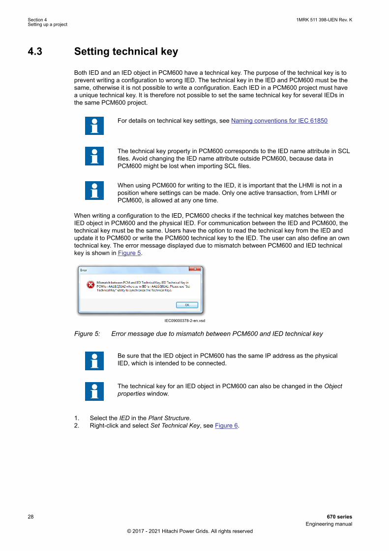
When writing a configuration to the IED, PCM600 checks if the technical key matches between theIED object in PCM600 and the physical IED. For communication between the IED and PCM600, thetechnical key must be the same. Users have the option to read the technical key from the IED andupdate it to PCM600 or write the PCM600 technical key to the IED. The user can also define an owntechnical key. The error message displayed due to mismatch between PCM600 and IED technicalkey is shown in Figure 5.
IEC09000378-2-en.vsdIEC09000378 V2 EN-US
Figure 5: Error message due to mismatch between PCM600 and IED technical key
Be sure that the IED object in PCM600 has the same IP address as the physicalIED, which is intended to be connected.
The technical key for an IED object in PCM600 can also be changed in the Objectproperties window.
1. Select the IED in the Plant Structure.2. Right-click and select Set Technical Key, see Figure 6.
Section 4 1MRK 511 398-UEN Rev. KSetting up a project
28 670 seriesEngineering manual
© 2017 - 2021 Hitachi Power Grids. All rights reserved
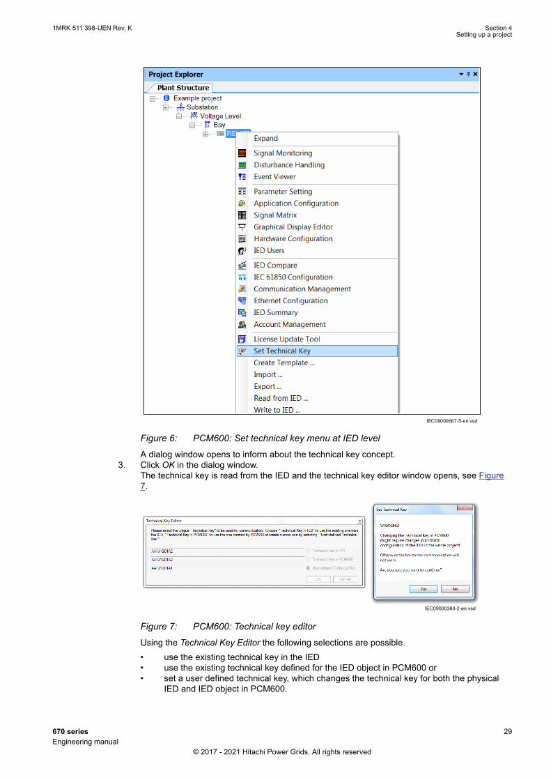
IEC09000667-5-en.vsdIEC09000667 V5 EN-US
Figure 6: PCM600: Set technical key menu at IED level
A dialog window opens to inform about the technical key concept.3. Click OK in the dialog window.
The technical key is read from the IED and the technical key editor window opens, see Figure7.
IEC09000380-2-en.vsdIEC09000380 V2 EN-US
Figure 7: PCM600: Technical key editor
Using the Technical Key Editor the following selections are possible.• use the existing technical key in the IED• use the existing technical key defined for the IED object in PCM600 or• set a user defined technical key, which changes the technical key for both the physical
IED and IED object in PCM600.
1MRK 511 398-UEN Rev. K Section 4Setting up a project
670 series 29Engineering manual
© 2017 - 2021 Hitachi Power Grids. All rights reserved
The maximum technical key length is 25 characters for IEC 61850 Edition 1and 55 characters for IEC 61850 Edition 2.
4. Click OK to confirm the selection.It is not possible to set a user defined name or select the Technical key in IED if the value is thesame as already given to another IED object in the PCM600 project. A dialog window opens ifthis is the case.
4.4 Setting up communication between PCM600 and theIED
SEMOD58570-5 v15
The communication between the IED and PCM600 is independent of the communication protocolused within the substation or to the NCC.
The communication media is always Ethernet and the used transport layer is TCP/IP.
Each IED has an RJ-45 Ethernet interface connector on the front. The front Ethernet connector isrecommended to be used for communication with PCM600.
When an Ethernet-based station protocol is used, PCM600 communication can use the sameEthernet port and IP address.
To connect PCM600 to the IED, two basic variants must be considered.
• Direct point-to-point link between PCM600 and the IED front port. The front port can be seen asa service port.
• A link via a station LAN or from remote via a network.
The physical connection and the IP address must be configured in both cases to enablecommunication.
The communication procedures are the same in both cases.
1. If needed, set the IP address for the IEDs.2. Set up the PC or workstation for a direct link (point-to-point), or3. Connect the PC or workstation to the LAN/WAN network.4. Configure the IED IP addresses in the PCM600 project for each IED to match the IP addresses
of the physical IEDs.
Setting up IP addressesCommunication between the IED and PCM600 is enabled from the LHMI. The IP address and thecorresponding communication subnetwork mask must be set via the Ethernet configuration tool(ECT) for each available Ethernet interface in the IED. Each Ethernet interface has a default factoryIP address when the IED is delivered. The IP adress and the subnetwork mask might have to bereset when an additional Ethernet interface is installed or an interface is replaced.
DHCP is available for the front port, and a device connected to it can thereby obtain an automaticallyassigned IP address via the local HMI path Main menu/ Configuration/ Communication/ Ethernetconfiguration/ Front port/ DHCP.
Alternatively the default IP address for the IED front port is 10.1.150.3 and the correspondingsubnetwork mask is 255.255.255.0, which can be set via the local HMI path Main menu/Configuration/ Communication/ TCP-IP configuration/ ETHFRNT:1Main menu/ Configuration/Communication/ Ethernet configuration/ AP_FRONT.
Section 4 1MRK 511 398-UEN Rev. KSetting up a project
30 670 seriesEngineering manual
© 2017 - 2021 Hitachi Power Grids. All rights reserved

Setting up the PC or workstation for point-to-point access to IEDs frontportAn ethernet cable (max 2 m length) with RJ-45 connectors is needed to connect two physicalEthernet interfaces together without a hub, router, bridge or switch in between.
If an IED is equipped with optical LC interface, a converter between RJ-45 and LC isneeded.
1. Select Search programs and files in the Start menu in Windows.
IEC13000057-1-en.vsdIEC13000057 V1 EN-US
Figure 8: Select: Search programs and files
2. Type View network connections and click on the View network connections icon.
1MRK 511 398-UEN Rev. K Section 4Setting up a project
670 series 31Engineering manual
© 2017 - 2021 Hitachi Power Grids. All rights reserved

IEC13000058-1-en.vsdIEC13000058 V1 EN-US
Figure 9: Click View network connections
3. Right-click and select Properties.
IEC13000059-1-en.vsd
IEC13000059 V1 EN-US
Figure 10: Right-click Local Area Connection and select Properties
4. Select the TCP/IPv4 protocol from the list of configured components using this connection andclick Properties.
Section 4 1MRK 511 398-UEN Rev. KSetting up a project
32 670 seriesEngineering manual
© 2017 - 2021 Hitachi Power Grids. All rights reserved
IEC13000060-1-en.vsdIEC13000060 V1 EN-US
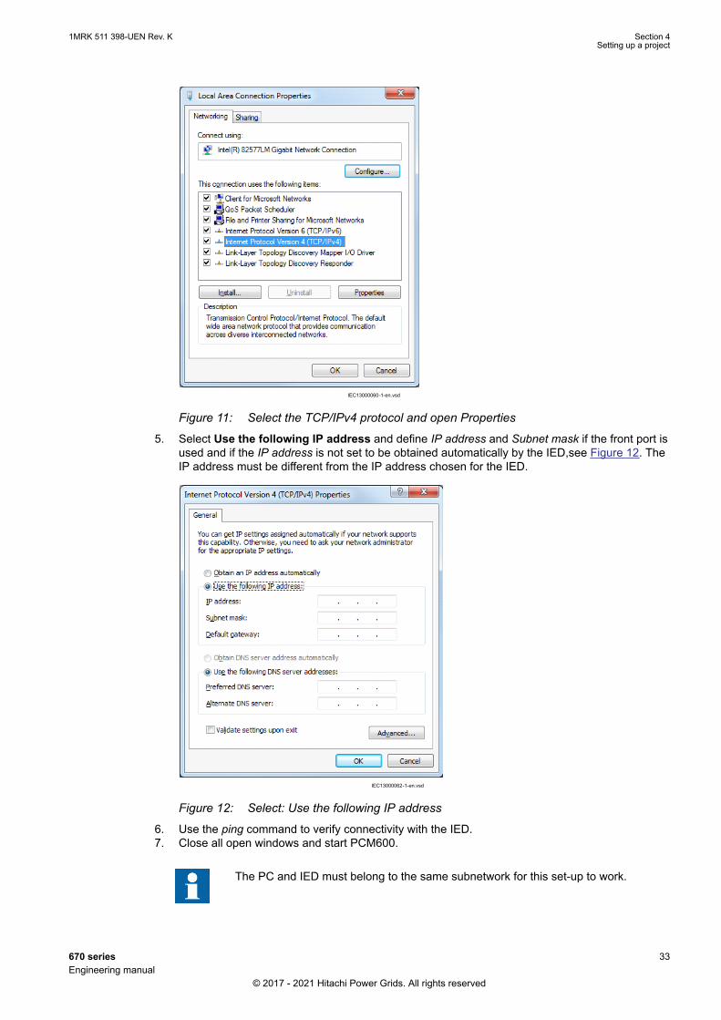
Figure 11: Select the TCP/IPv4 protocol and open Properties
5. Select Use the following IP address and define IP address and Subnet mask if the front port isused and if the IP address is not set to be obtained automatically by the IED,see Figure 12. TheIP address must be different from the IP address chosen for the IED.
IEC13000062-1-en.vsdIEC13000062 V1 EN-US
Figure 12: Select: Use the following IP address
6. Use the ping command to verify connectivity with the IED.7. Close all open windows and start PCM600.
The PC and IED must belong to the same subnetwork for this set-up to work.
1MRK 511 398-UEN Rev. K Section 4Setting up a project
670 series 33Engineering manual
© 2017 - 2021 Hitachi Power Grids. All rights reserved

Setting up the PC to access the IED via a networkThe same method is used as for connecting to the front port.
The PC and IED must belong to the same subnetwork for this set-up to work.
4.5 Project managing in PCM600SEMOD58451-5 v9
It is possible to:
• Open existing projects• Import projects• Create new projects• Export projects• Delete projects• Rename projects• Copy and paste projects• Back up projects• Migrate projects from one product version to another
It is possible to open projects created in previous versions of PCM600 to thecurrent version, but the opposite is not possible.
Extension of the exported project file is *.pcmp and those files are only used for exporting andimporting the projects between different installations of PCM600.
Creating a new projectProcedure
1. Select File and Open/Manage Project ... to see the projects that are currently available in thePCMDataBases.
2. Open Projects on my computer.3. Click the icon New Project. To create new project currently open projects and object tools shall
be closed.4. The New Project window opens, see Figure 13.
Section 4 1MRK 511 398-UEN Rev. KSetting up a project
34 670 seriesEngineering manual
© 2017 - 2021 Hitachi Power Grids. All rights reserved

IEC05000609‐3‐en.vsdxIEC05000609 V3 EN-US
Figure 13: PCM600: Create a new project window
5. Name the project and include a description (optional) and click Create.6. PCM600 sets up a new project that will be listed under Projects on my computer.
4.6 Building a plant structureSEMOD58409-5 v7
The plant structure is used to identify each IED in its location within the substation organization. It isa geographical image of the substation and the bays within the substation. The organization structurefor the IEDs may differ from the structure of the primary equipment in the substation. In PCM600 it ispossible to set up a hierarchical structure of five levels for the IED identification.
Build up the plant structure according to the project requirements. PCM600 offers several levels tobuild the hierarchical order from Center down to the IEDs in a bay.
The following levels are available:
1. Project = project name2. Substation = name of the substation3. Voltage Level = voltage level in substation4. Bay = bay within the voltage level5. IED = IED in the bay.
IEC09000710-4-en.vsdxIEC09000710 V4 EN-US
Figure 14: PCM600: Set up a plant structure
1MRK 511 398-UEN Rev. K Section 4Setting up a project
670 series 35Engineering manual
© 2017 - 2021 Hitachi Power Grids. All rights reserved

Once a plant structure is built, the name of each level in the structure should be renamed by thenames/identifications used in the grid. Use the right mouse button to build the plant structure byselecting the elements from the context menu. Rename the level after insertion using the Renamepossibility or the Object Properties. Figure14 shows the start of a project with two IEDs placed butstill not renamed.
The plant structure corresponds to the complete grid including the needed IEDs.
Procedure to build a plant structure:
• Right-click on the plant structure, select New and Create from Template ..., or• Right-click on the plant structure, select New, General and select either IED Group or
Substation.• Click View in the menu bar and select Object Types. Select the needed elements and drag and
drop them into the plant structure. Close the window if it does not close automatically.
4.6.1 IEC 61850 naming conventions to identify an IEDSEMOD58409-38 v10
This section is only valid when the IEC 61850 standard is used for station bus communication.According to the IEC 61850–6 clause 8.4, the SCL model allows two kinds of project designation inthe object properties.
• A technical key is used on engineering drawings and for signal identifications. The technical keyis used within SCL for referencing other objects. Observe that name is a relative identificationwithin a hierarchy of objects. The maximum number of characters allowed for a technical key is25 for Edition 1 and 55 for Edition 2.
• A user-oriented textual designation is contained in the attribute desc. Attributes cannot containcarriage return, line feed or tab characters. The semantics of desc must also be relative withinan object hierarchy.
PCM600 takes care of these two possibilities. The two possible signal designations are available perobject in the object properties for all hierarchical levels beginning with the station as the highest level.
The technical key is automatically generated based on the rules and type specifications of IEC 61346and the extended definitions done for substations by a technical committee. The technical key isshown in the Object Properties under SCL Technical Key or Technical Key.
• The station level is predefined by "AA1", where 1 is the index.• The voltage level is predefined by "J1", where 1 is the index.• The bay level is predefined by "Q01", where 01 is the index.• The IED is predefined by "A1", where 1 is the index.
The predefined full path name of the technical key for the IED would be AA1J1Q01A1.
For all practical engineering purposes (both towards the IED and towards the 61850 engineeringprocess), the user should keep the default SCL technical key. However, it is possible, for exampledue to company naming policies, to rename the SCL technical key for the station level, voltage level,bay level and IED level using the Object properties window as shown in Figure 15.
• The station level has been renamed as "DMSTAT"• The voltage level has been renamed as "C1"• The bay level has been renamed as "Q1"• The IED has been renamed as "SB1"
The renamed full path name of the technical key for the IED would be DMSTATC1Q1SB1.
Section 4 1MRK 511 398-UEN Rev. KSetting up a project
36 670 seriesEngineering manual
© 2017 - 2021 Hitachi Power Grids. All rights reserved

GUID-BDE605BB-5ACA-456A-9334-65B3CE3C46F5 V2 EN-US
Figure 15: PCM600: IEC 61850 signal designation concept
4.6.2 Changing the SCL version of an IEDGUID-3188FA18-D04E-4BAC-9224-10F43F30F049 v4
You can change the SCL version of an IED in PCM600 from Edition 1 of IEC 61850 to Edition 2 orthe other way around. You can also convert a .pcmi file from Edition 1 to Edition 2 or the other wayaround.
1. Enable SCL version changing in PCM600.
1MRK 511 398-UEN Rev. K Section 4Setting up a project
670 series 37Engineering manual
© 2017 - 2021 Hitachi Power Grids. All rights reserved
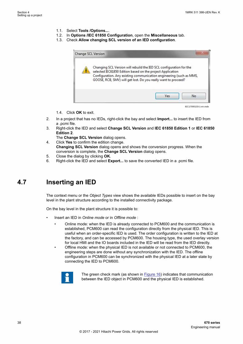
1.1. Select Tools /Options....1.2. In Options /IEC 61850 Configuration, open the Miscellaneous tab.1.3. Check Allow changing SCL version of an IED configuration.
IEC17000133-1-en.vsdx
1.4. Click OK to exit.2. In a project that has no IEDs, right-click the bay and select Import... to insert the IED from
a .pcmi file.3. Right-click the IED and select Change SCL Version and IEC 61850 Edition 1 or IEC 61850
Edition 2.The Change SCL Version dialog opens.
4. Click Yes to confirm the edition change.Changing SCL Version dialog opens and shows the conversion progress. When theconversion is complete, the Change SCL Version dialog opens.
5. Close the dialog by clicking OK.6. Right-click the IED and select Export... to save the converted IED in a .pcmi file.
4.7 Inserting an IEDSEMOD58416-5 v13
The context menu or the Object Types view shows the available IEDs possible to insert on the baylevel in the plant structure according to the installed connectivity package.
On the bay level in the plant structure it is possible to:
• Insert an IED in Online mode or in Offline mode :• Online mode: when the IED is already connected to PCM600 and the communication is
established, PCM600 can read the configuration directly from the physical IED. This isuseful when an order-specific IED is used. The order configuration is written to the IED atthe factory, and can be accessed by PCM600. The housing type, the used overlay versionfor local HMI and the IO boards included in the IED will be read from the IED directly.
• Offline mode: when the physical IED is not available or not connected to PCM600, theengineering steps are done without any synchronization with the IED. The offlineconfiguration in PCM600 can be synchronized with the physical IED at a later state byconnecting the IED to PCM600.
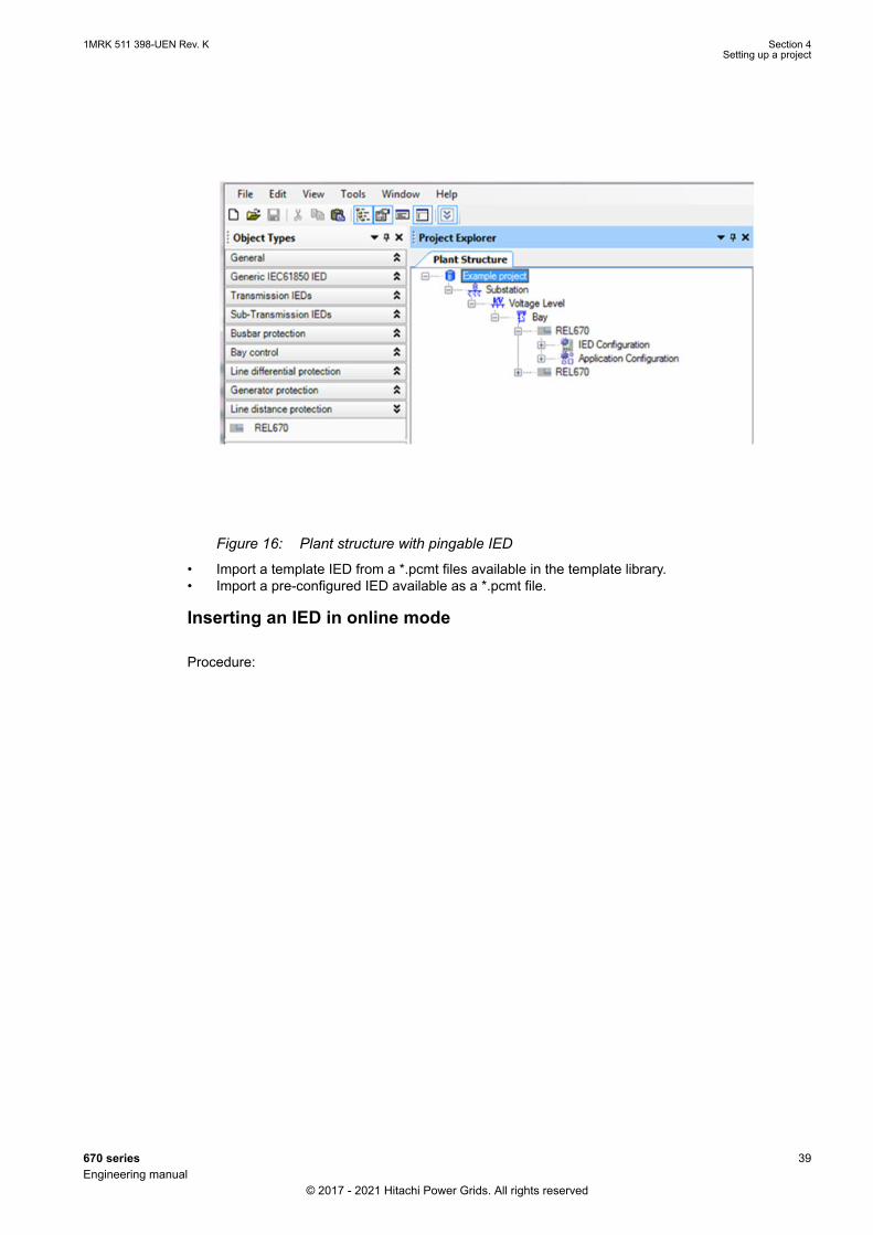
The green check mark (as shown in Figure 16) indicates that communicationbetween the IED object in PCM600 and the physical IED is established.
Section 4 1MRK 511 398-UEN Rev. KSetting up a project
38 670 seriesEngineering manual
© 2017 - 2021 Hitachi Power Grids. All rights reserved
IEC09000361 V3 EN-US
Figure 16: Plant structure with pingable IED
• Import a template IED from a *.pcmt files available in the template library.• Import a pre-configured IED available as a *.pcmt file.
Inserting an IED in online mode
Procedure:
1MRK 511 398-UEN Rev. K Section 4Setting up a project
670 series 39Engineering manual
© 2017 - 2021 Hitachi Power Grids. All rights reserved
IEC15000329-1-en.vsdxIEC15000329 V2 EN-US
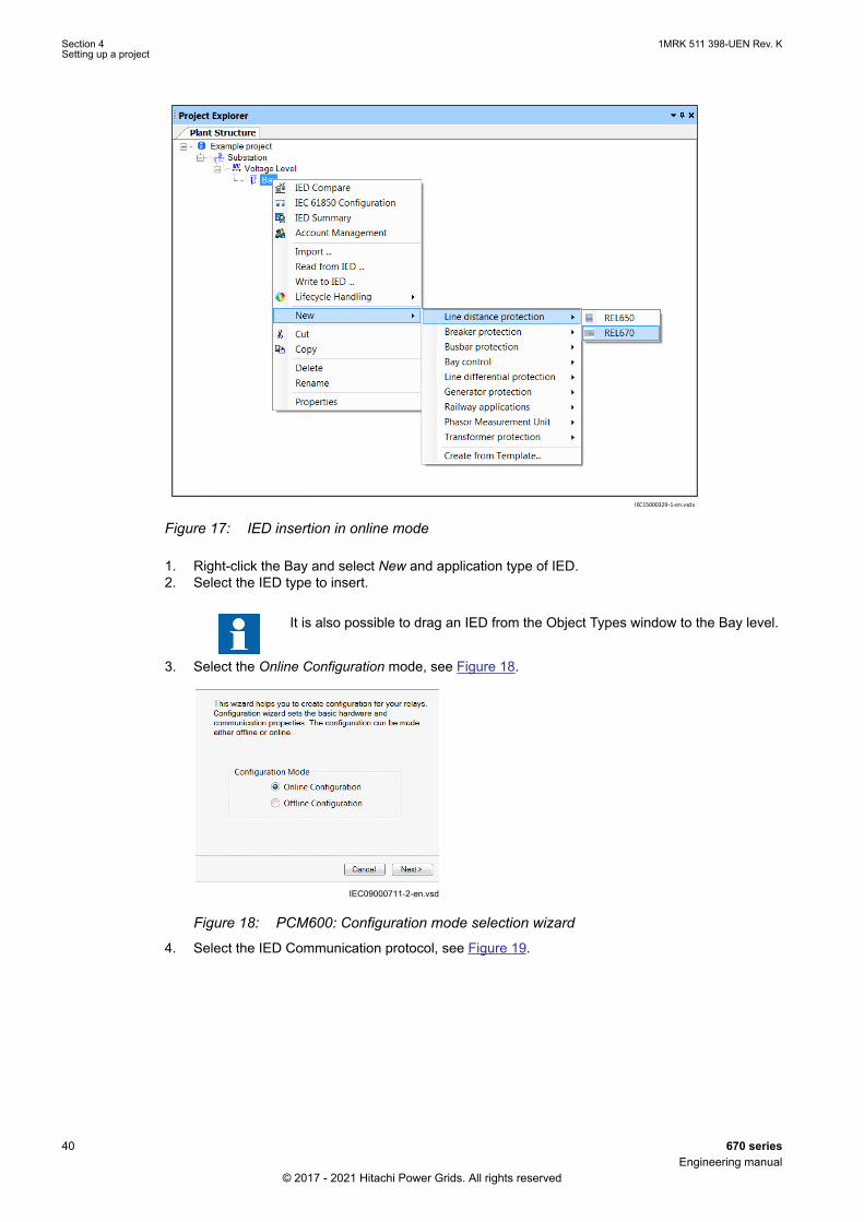
Figure 17: IED insertion in online mode
1. Right-click the Bay and select New and application type of IED.2. Select the IED type to insert.
It is also possible to drag an IED from the Object Types window to the Bay level.
3. Select the Online Configuration mode, see Figure 18.
IEC09000711-2-en.vsdIEC09000711 V2 EN-US
Figure 18: PCM600: Configuration mode selection wizard
4. Select the IED Communication protocol, see Figure 19.
Section 4 1MRK 511 398-UEN Rev. KSetting up a project
40 670 seriesEngineering manual
© 2017 - 2021 Hitachi Power Grids. All rights reserved

IEC15000332-1-en.vsdxIEC15000332 V1 EN-US
Figure 19: PCM600: Communication protocol selection wizard
5. Select the port and insert the IP address of the physical IED to configure, see Figure 20.
IEC09000713-2-en.vsdIEC09000713 V2 EN-US
Figure 20: PCM600: Communication port and IP address
6. Cross-check that the IED whose IP address has been inserted, has been detected online byPCM600, see Figure 16.
The user cannot scan data from the IED or proceed further if the IED is notonline or if the IP address is not correct.
7. Click the Scan option to scan/read the IED Type and IED Version for the IED that is online, seeFigure 21.
1MRK 511 398-UEN Rev. K Section 4Setting up a project
670 series 41Engineering manual
© 2017 - 2021 Hitachi Power Grids. All rights reserved

IEC09000714-4-en.vsdIEC09000714 V4 EN-US
Figure 21: PCM600: IED Version detection
The IEC 61850 protocol edition can be changed later in the Plant Structure view by right-clicking on the IED and selecting Change SCL Version.SCL versions can be changed only if option 'Allow changing SCL version of an IEDconfiguration' is selected from options in Tools menu.
8. Click Next to open the Housing Selection Page. The IED housing type and display type aredetected and displayed as shown in Figure 22.
IEC09000742-3-en.vsdIEC09000742 V3 EN-US
Figure 22: PCM600: IED housing and display type detection
9. The Setup Complete Page dialog shows the summary of the IED Type, IED Version, IP Addressof IED and Order Option, see Figure 23. It is possible to Cancel the insertion or confirm theconfiguration and do the insertion with Finish.
IEC09000715-5-en.vdsxIEC09000715 V5 EN-US
Figure 23: PCM600: IED Setup completion wizard
Section 4 1MRK 511 398-UEN Rev. KSetting up a project
42 670 seriesEngineering manual
© 2017 - 2021 Hitachi Power Grids. All rights reserved
It is not possible to go back and do any modifications in the setup complete page. Ifan error is detected, the insertion has to be canceled and the IED has to be insertedagain.
When the online configuration is completed, it is advised to read the configurationfrom the IED to ensure that the IED object in PCM600 has the same configurationdata as the physical IED.
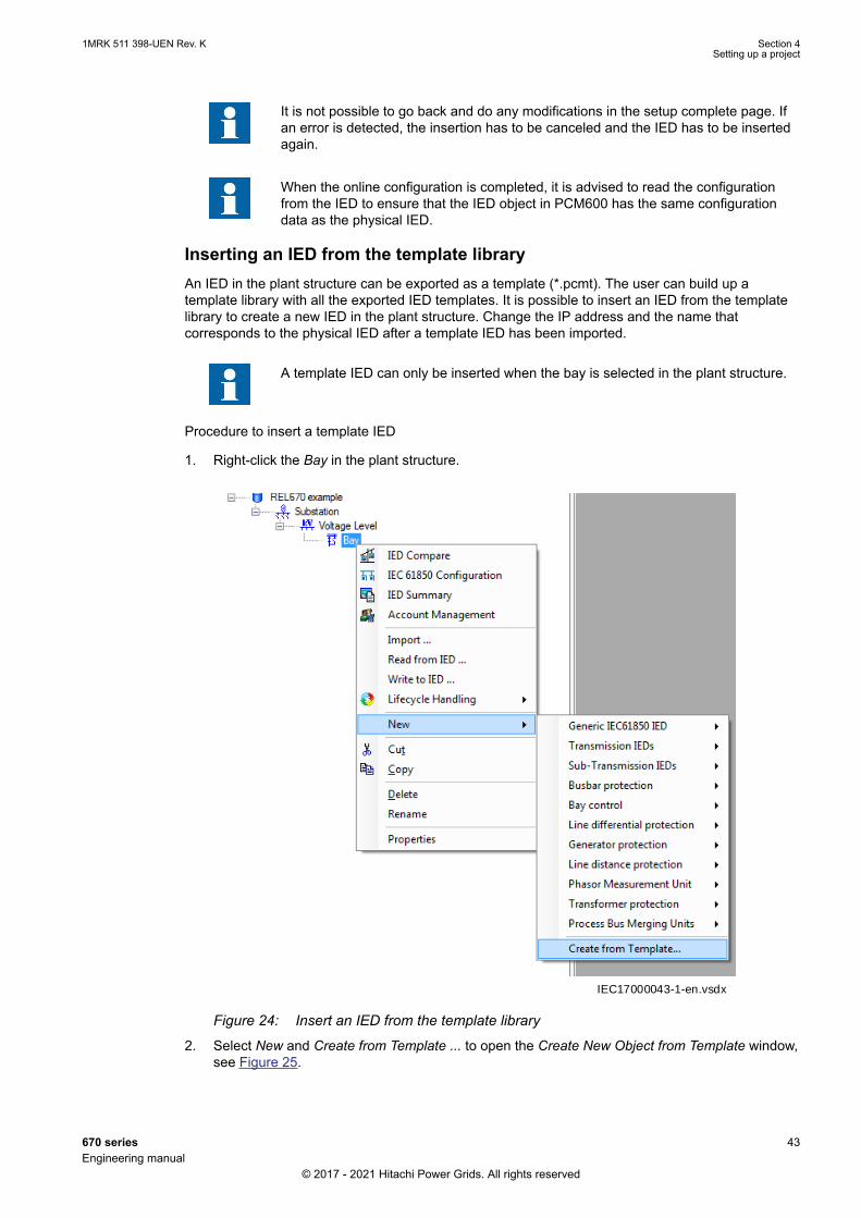
Inserting an IED from the template libraryAn IED in the plant structure can be exported as a template (*.pcmt). The user can build up atemplate library with all the exported IED templates. It is possible to insert an IED from the templatelibrary to create a new IED in the plant structure. Change the IP address and the name thatcorresponds to the physical IED after a template IED has been imported.
A template IED can only be inserted when the bay is selected in the plant structure.
Procedure to insert a template IED
1. Right-click the Bay in the plant structure.
IEC17000043-1-en.vsdxIEC17000043 V1 EN-US
Figure 24: Insert an IED from the template library
2. Select New and Create from Template ... to open the Create New Object from Template window,see Figure 25.
1MRK 511 398-UEN Rev. K Section 4Setting up a project
670 series 43Engineering manual
© 2017 - 2021 Hitachi Power Grids. All rights reserved

IEC15000268-3-en.vsdx
IEC15000268 V3 EN-US
Figure 25: PCM600: Selecting an IED from the template library
3. Select the IED from the list of available IEDs.4. Click the icon in the right column of the list of available templates to open the Template
Properties. Verify the template information, see Figure 26 and click Close to close the window.
IEC09000718-2-en.vsdIEC09000718 V2 EN-US
Figure 26: PCM600: IED Template Properties
5. Click Delete Template to delete the template, click Import Template to import a template from theselection window or click Create to insert the selected IED to the bay, see Figure 25.
It is possible to insert more than one IED from the Create New Object fromTemplate window and the selection window remains open until the user clicksClose.
Importing a pre-configuration to template libraryPre-configurations in PCM600 are available as *.pcmt files and include all information that is relatedto the IED object in PCM600. A given pre-configuration is bound to a specific hardware configuration.
Section 4 1MRK 511 398-UEN Rev. KSetting up a project
44 670 seriesEngineering manual
© 2017 - 2021 Hitachi Power Grids. All rights reserved
Options to insert pre-configuration files:
• Use the pre-configuration that has been shipped together with the IED.• Install the pre-configuration from the Connpack media.• Download and install pre-configuration from Update Manager.
To insert a pre-configuration in to plant structure, see section Inserting an IED from the templatelibrary.
Because IEC 61850 edition 1 and IEC 61850 edition 2 templates are incompatible,convert an IEC 61850 edition 1 template to IEC 61850 edition 2 before you insert it.
Ordered pre-configurations are not locked. The user can use any of the availablepre-configurations for a particular product type as a base to create an ownconfiguration. The only requirement is that all needed hardware and software optionsare available.
It is possible to give the inserted IED in the plant structure a user-defined name. Besure to only user characters a-z, A-Z, 0-9 and _. Do not use space character in IEDnames.
Importing configuration to a template libraryTemplate configurations in PCM600 are available as *.pcmt files and include all information that isrelated to the IED object in PCM600.
Options to insert template configuration files:
• Install the template configuration from the Connpack media.• Download and install the template configuration from Update Manager.
To insert the template configuration in to a plant structure, see section Inserting an IED from thetemplate library.
Because IEC 61850 edition 1 and IEC 61850 edition 2 templates are incompatible,convert an IEC 61850 edition 1 template to IEC 61850 edition 2 before you insert it.
It is possible to give the inserted IED in the plant structure a user-defined name. Besure to only user characters a-z, A-Z, 0-9 and _. Do not use space character in IEDnames.
4.7.1 Setting IED IP address in the projectGUID-4C451305-E268-49D8-B237-4EDFAFF6E322 v8
There are two alternatives to set the IP address of the IED object in PCM600. The IED object inPCM600 must have the same IP address and subnetwork mask as the front or rear port on thephysical IED to which the PC is connected.
• Via the first window of the wizard when including a new IED in a project, see Figure 27.
1MRK 511 398-UEN Rev. K Section 4Setting up a project
670 series 45Engineering manual
© 2017 - 2021 Hitachi Power Grids. All rights reserved

IEC09000713-2-en.vsdIEC09000713 V2 EN-US
Figure 27: Alternative 1: IP address via the first Wizard window
• Via the IP address property of the IED in the Object Properties window, see Figure 28.
IEC08000121-4-en.vsdx
IEC08000121 V4 EN-US
Figure 28: Alternative 2: IP address via the IED Object Properties window
Procedure
Section 4 1MRK 511 398-UEN Rev. KSetting up a project
46 670 seriesEngineering manual
© 2017 - 2021 Hitachi Power Grids. All rights reserved

1. Select the IED to enter the IP address.2. Open the Object Properties window.3. Place the cursor on the IP address row and enter the IP address.
The used alternative depends on the time at which the IP address is available.
1MRK 511 398-UEN Rev. K Section 4Setting up a project
670 series 47Engineering manual
© 2017 - 2021 Hitachi Power Grids. All rights reserved

48
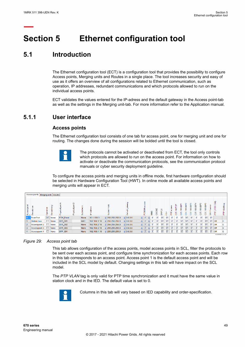
Section 5 Ethernet configuration tool
5.1 IntroductionGUID-27895183-D8EC-48B1-8B42-6C3B469AE67B v2
The Ethernet configuration tool (ECT) is a configuration tool that provides the possibility to configureAccess points, Merging units and Routes in a single place. The tool increases security and easy ofuse as it offers an overview of all configurations related to Ethernet communication, such asoperation, IP addresses, redundant communications and which protocols allowed to run on theindividual access points.
ECT validates the values entered for the IP-adress and the default gateway in the Access point-tabas well as the settings in the Merging unit-tab. For more information refer to the Application manual.
5.1.1 User interfaceGUID-7931FEA9-DDFE-46D8-8651-701C3612CBDB v5
Access pointsThe Ethernet configuration tool consists of one tab for access point, one for merging unit and one forrouting. The changes done during the session will be bolded until the tool is closed.
The protocols cannot be activated or deactivated from ECT, the tool only controlswhich protocols are allowed to run on the access point. For information on how toactivate or deactivate the communication protocols, see the communication protocolmanuals or cyber security deployment guideline.
To configure the access points and merging units in offline mode, first hardware configuration shouldbe selected in Hardware Configuration Tool (HWT). In online mode all available access points andmerging units will appear in ECT.
IEC16000089-1-en.vsdx
IEC16000089 V1 EN-US
Figure 29: Access point tab
This tab allows configuration of the access points, model access points in SCL, filter the protocols tobe sent over each access point, and configure time synchronization for each access points. Each rowin this tab corresponds to an access point. Access point 1 is the default access point and will beincluded in the SCL model by default. Changing settings in this tab will have impact on the SCLmodel.
The PTP VLAN tag is only valid for PTP time synchronization and it must have the same value instation clock and in the IED. The default value is set to 0.
Columns in this tab will vary based on IED capability and order-specification.
1MRK 511 398-UEN Rev. K Section 5Ethernet configuration tool
670 series 49Engineering manual
© 2017 - 2021 Hitachi Power Grids. All rights reserved
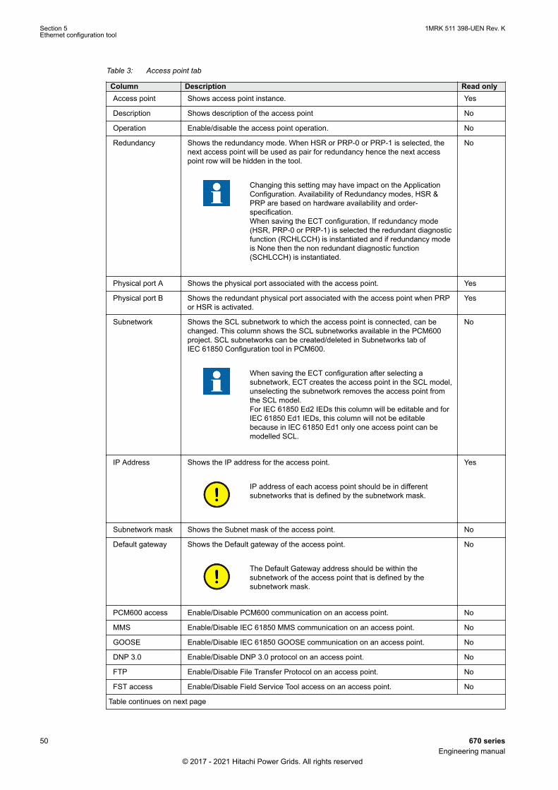
Table 3: Access point tab
Column Description Read onlyAccess point Shows access point instance. Yes
Description Shows description of the access point No
Operation Enable/disable the access point operation. No
Redundancy Shows the redundancy mode. When HSR or PRP-0 or PRP-1 is selected, thenext access point will be used as pair for redundancy hence the next accesspoint row will be hidden in the tool.
Changing this setting may have impact on the ApplicationConfiguration. Availability of Redundancy modes, HSR &PRP are based on hardware availability and order-specification.When saving the ECT configuration, If redundancy mode(HSR, PRP-0 or PRP-1) is selected the redundant diagnosticfunction (RCHLCCH) is instantiated and if redundancy modeis None then the non redundant diagnostic function(SCHLCCH) is instantiated.
No
Physical port A Shows the physical port associated with the access point. Yes
Physical port B Shows the redundant physical port associated with the access point when PRPor HSR is activated.
Yes
Subnetwork Shows the SCL subnetwork to which the access point is connected, can bechanged. This column shows the SCL subnetworks available in the PCM600project. SCL subnetworks can be created/deleted in Subnetworks tab ofIEC 61850 Configuration tool in PCM600.
When saving the ECT configuration after selecting asubnetwork, ECT creates the access point in the SCL model,unselecting the subnetwork removes the access point fromthe SCL model.For IEC 61850 Ed2 IEDs this column will be editable and forIEC 61850 Ed1 IEDs, this column will not be editablebecause in IEC 61850 Ed1 only one access point can bemodelled SCL.
No
IP Address Shows the IP address for the access point.
IP address of each access point should be in differentsubnetworks that is defined by the subnetwork mask.
Yes
Subnetwork mask Shows the Subnet mask of the access point. No
Default gateway Shows the Default gateway of the access point.
The Default Gateway address should be within thesubnetwork of the access point that is defined by thesubnetwork mask.
No
PCM600 access Enable/Disable PCM600 communication on an access point. No
MMS Enable/Disable IEC 61850 MMS communication on an access point. No
GOOSE Enable/Disable IEC 61850 GOOSE communication on an access point. No
DNP 3.0 Enable/Disable DNP 3.0 protocol on an access point. No
FTP Enable/Disable File Transfer Protocol on an access point. No
FST access Enable/Disable Field Service Tool access on an access point. No
Table continues on next page
Section 5 1MRK 511 398-UEN Rev. KEthernet configuration tool
50 670 seriesEngineering manual
© 2017 - 2021 Hitachi Power Grids. All rights reserved

Column Description Read onlySNTP Server Enable/Disable SNTP server communication on an access point. No
PTP(IEEE 1588) Precision Time protocol on an access point. No
PTP VLAN tag PTP VLAN identifier. No
The columns that are updated during a partial write are highlighted when holding thepointer over the partial write button. The highlighted columns will be written to theIED but not synchronized towards SCL.
Changing an IED’s IEC 61850 configuration from IEC 61850 edition 2 to IEC 61850edition 1 will remove the Access points that are modelled in SCL except the defaultAccess point and also if the redundancy is modelled then it will also be removed.
Merging units
IEC16000090-1-en.vsdxIEC16000090 V1 EN-US
Figure 30: Merging units tab
Access points should be configured before configuring merging units. This tab allows configuring ofthe reception of data from merging units. Each row in this tab corresponds to a merging unit.Changing settings in this tab will not have any impact on the SCL model. The IED can be configuredto receive IEC 61850–9–2E sample value streams from merging units.
This tab’s availability will be based on order-specification.
Migration of merging unit configuration from 670 2.0/2.1 to 2.2 series is notsupported. From 670 2.2 series onwards, merging unit modules can be created/deleted from the merging unit tab of ECT, not from HWT.
1MRK 511 398-UEN Rev. K Section 5Ethernet configuration tool
670 series 51Engineering manual
© 2017 - 2021 Hitachi Power Grids. All rights reserved
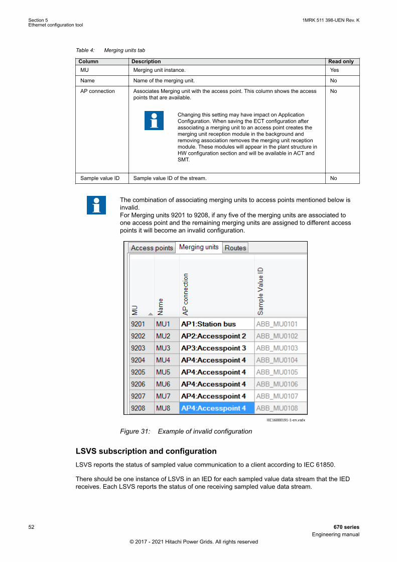
Table 4: Merging units tab
Column Description Read onlyMU Merging unit instance. Yes
Name Name of the merging unit. No
AP connection Associates Merging unit with the access point. This column shows the accesspoints that are available.
Changing this setting may have impact on ApplicationConfiguration. When saving the ECT configuration afterassociating a merging unit to an access point creates themerging unit reception module in the background andremoving association removes the merging unit receptionmodule. These modules will appear in the plant structure inHW configuration section and will be available in ACT andSMT.
No
Sample value ID Sample value ID of the stream. No
The combination of associating merging units to access points mentioned below isinvalid.For Merging units 9201 to 9208, if any five of the merging units are associated toone access point and the remaining merging units are assigned to different accesspoints it will become an invalid configuration.
IEC16000191-1-en.vsdxIEC16000191 V1 EN-US
Figure 31: Example of invalid configuration
LSVS subscription and configurationLSVS reports the status of sampled value communication to a client according to IEC 61850.
There should be one instance of LSVS in an IED for each sampled value data stream that the IEDreceives. Each LSVS reports the status of one receiving sampled value data stream.
Section 5 1MRK 511 398-UEN Rev. KEthernet configuration tool
52 670 seriesEngineering manual
© 2017 - 2021 Hitachi Power Grids. All rights reserved
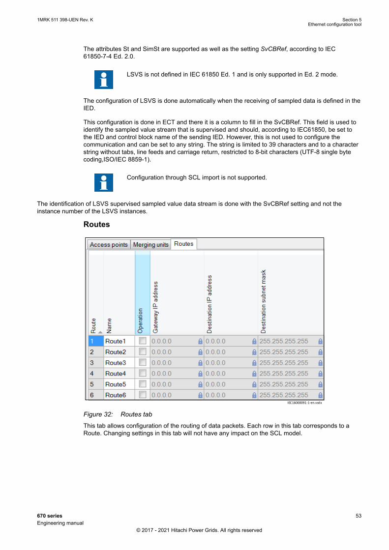
The attributes St and SimSt are supported as well as the setting SvCBRef, according to IEC61850-7-4 Ed. 2.0.
LSVS is not defined in IEC 61850 Ed. 1 and is only supported in Ed. 2 mode.
The configuration of LSVS is done automatically when the receiving of sampled data is defined in theIED.
This configuration is done in ECT and there it is a column to fill in the SvCBRef. This field is used toidentify the sampled value stream that is supervised and should, according to IEC61850, be set tothe IED and control block name of the sending IED. However, this is not used to configure thecommunication and can be set to any string. The string is limited to 39 characters and to a characterstring without tabs, line feeds and carriage return, restricted to 8-bit characters (UTF-8 single bytecoding,ISO/IEC 8859-1).
Configuration through SCL import is not supported.
The identification of LSVS supervised sampled value data stream is done with the SvCBRef setting and not theinstance number of the LSVS instances.
Routes
IEC16000091-1-en.vsdxIEC16000091 V1 EN-US
Figure 32: Routes tab
This tab allows configuration of the routing of data packets. Each row in this tab corresponds to aRoute. Changing settings in this tab will not have any impact on the SCL model.
1MRK 511 398-UEN Rev. K Section 5Ethernet configuration tool
670 series 53Engineering manual
© 2017 - 2021 Hitachi Power Grids. All rights reserved
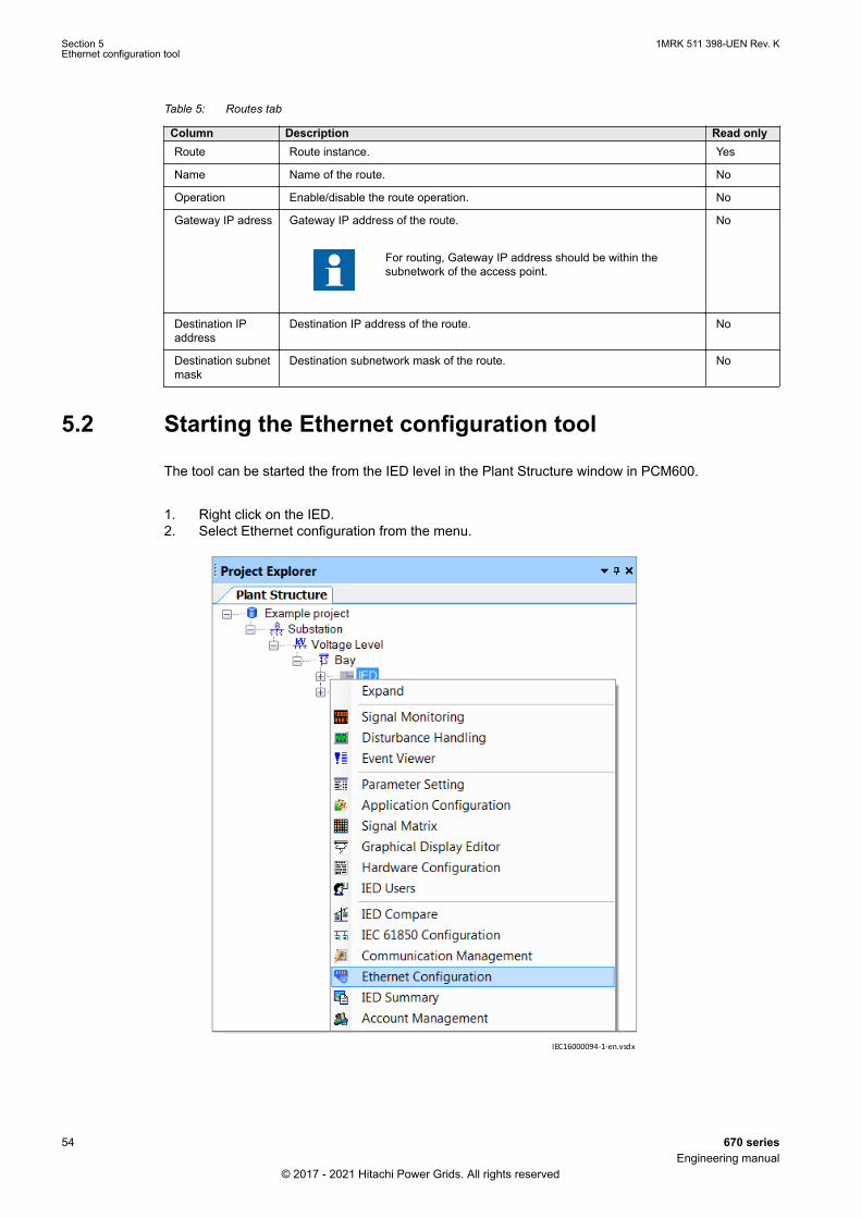
Table 5: Routes tab
Column Description Read onlyRoute Route instance. Yes
Name Name of the route. No
Operation Enable/disable the route operation. No
Gateway IP adress Gateway IP address of the route.
For routing, Gateway IP address should be within thesubnetwork of the access point.
No
Destination IPaddress
Destination IP address of the route. No
Destination subnetmask
Destination subnetwork mask of the route. No
5.2 Starting the Ethernet configuration toolGUID-3DB1C6C8-09C6-4460-A903-AA722888AFD9 v1
The tool can be started the from the IED level in the Plant Structure window in PCM600.
1. Right click on the IED.2. Select Ethernet configuration from the menu.
IEC16000094-1-en.vsdx
IEC16000094 V1 EN-US
Section 5 1MRK 511 398-UEN Rev. KEthernet configuration tool
54 670 seriesEngineering manual
© 2017 - 2021 Hitachi Power Grids. All rights reserved

Section 6 Protection and control engineering
6.1 Creating an application configuration with ACT
6.1.1 OverviewGUID-E9990B51-52BA-434C-8BC4-2418EA56B31B v10
ACT is used to create the application configuration for an IED. The application configuration is builtup with function blocks.
Function blocks are dedicated for different functionality, for example:
• Control related functions• Monitoring functions• Communication
For detailed information about function blocks see the technical manual and theapplication manual.
Some function blocks are mapped as logical nodes according to the IEC 61850 standard. Otherfunction blocks are not mapped as logical nodes, for example:
• Logical gates• Timers
1MRK 511 398-UEN Rev. K Section 6Protection and control engineering
670 series 55Engineering manual
© 2017 - 2021 Hitachi Power Grids. All rights reserved
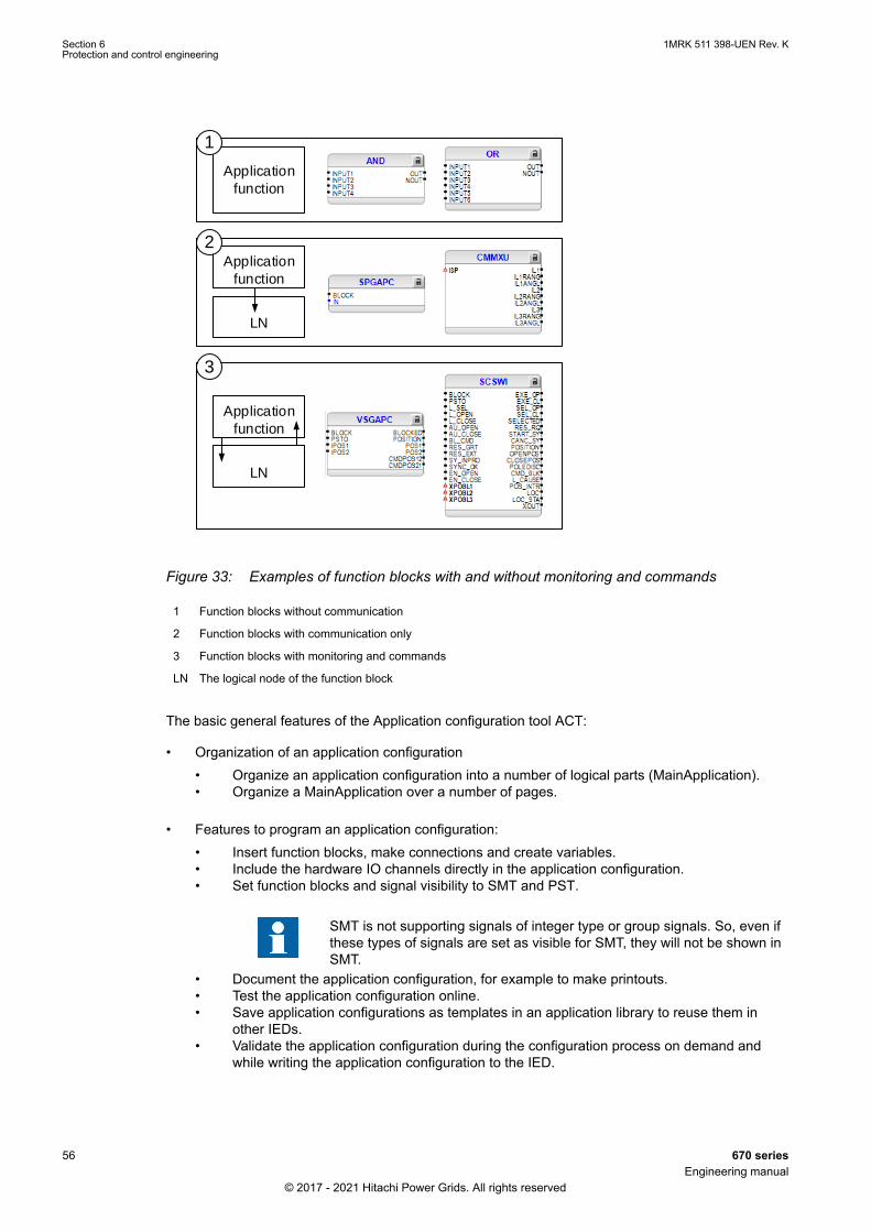
Application
function
Application
function
LN
1
2
3
Application
function
LN
GUID-CF053FE9-0BA6-448A-A1D9-9697027ECCBC V2 EN-US
Figure 33: Examples of function blocks with and without monitoring and commands
1 Function blocks without communication
2 Function blocks with communication only
3 Function blocks with monitoring and commands
LN The logical node of the function block
The basic general features of the Application configuration tool ACT:
• Organization of an application configuration• Organize an application configuration into a number of logical parts (MainApplication).• Organize a MainApplication over a number of pages.
• Features to program an application configuration:• Insert function blocks, make connections and create variables.• Include the hardware IO channels directly in the application configuration.• Set function blocks and signal visibility to SMT and PST.
SMT is not supporting signals of integer type or group signals. So, even ifthese types of signals are set as visible for SMT, they will not be shown inSMT.
• Document the application configuration, for example to make printouts.• Test the application configuration online.• Save application configurations as templates in an application library to reuse them in
other IEDs.• Validate the application configuration during the configuration process on demand and
while writing the application configuration to the IED.
Section 6 1MRK 511 398-UEN Rev. KProtection and control engineering
56 670 seriesEngineering manual
© 2017 - 2021 Hitachi Power Grids. All rights reserved

For instructions on how to perform the different tasks in PCM600, see PCM600online help.
6.1.2 Function blocksGUID-2303AD45-1FFA-465F-8CA5-C59541535903 v7
• Function blocks are the main elements of an application configuration. They are designed for avarious number of functions and organized in type groups. The different function block types areshown in the Object Types View. Figure 34 presents an overview of the main parts that arerelevant for function blocks.
• Set user defined names for function blocks and signals marked with blue text.
Signals that have a user defined name created in ACT, will only be visible inPST if the IED configuration is written to the IED and read back to PCM600.Otherwise the default signal name is shown in PST.
Do not use other characters than a-z, A-Z, 0-9 and _ when setting user definednames for signals and function blocks, since other characters might not displayproperly in local HMI. Also avoid using space character.
The maximum user defined name length or size is 16 characters or 39 bytesand the user defined name will be truncated to the corresponding limit if any ofthe limit gets exceeded.
• Set IEC or/and ANSI naming style.• Lock function blocks.• Set visibility for execution order, cycle time and instance number.• Manage signals, for example hide, show and rearrange.• Invert Boolean inputs and Boolean outputs.
Mandatory signals must be connected.
For RED670/REG670/RET670, remote current received through LDCM must beconnected only to 1ms pre-processing SMAI block. Consequently, the same 1mspre-processing block used for differential protection must be used for connectingremote currents to the disturbance recorder. The 3ms or 8ms pre-processing SMAIblocks must not be connected to the remote currents. In all other 670 products, LDCM is preferably intended to be used in binary mode.However, in case the LDCM module is used in the analog mode, then the onlyavailable pre-processing SMAI blocks will be either in 3ms or 8ms cycle. Connectingthe remote currents to either of these two types of SMAI blocks might impact theperformance of protection functions. Namely, all functions that are running in thesame cycle as the used processing SMAI block for the remote currents mayexperience extra time delays in the operation due to the impact of LDCM bufferingand transmission delays. Thus, the application of LDCM in analog mode in otherproducts than RED670 shall be used with caution.
1MRK 511 398-UEN Rev. K Section 6Protection and control engineering
670 series 57Engineering manual
© 2017 - 2021 Hitachi Power Grids. All rights reserved

IEC08000258.vsd
1 3 7 8 9
1716
121110
2 5 6
151413
4
IEC08000258 V1 EN-US
Figure 34: ACT: Function block overview
1 Connection(s)
2 User defined function block name
3 Function block, selected (red)
4 Mandatory signal (indicated by a red triangle if not connected)
5 Function block name
6 Function block, locked (red)
7 ANSI symbol
8 Inverted output
9 Hardware, binary output channel
10 Hardware, analog input channel
11 User defined signal name
12 Hardware, binary input channel
13 Execution order
14 Cycle time
15 Instance number
16 Inverted input
17 Signal description note
6.1.3 Signals and signal managementGUID-E0D11B1F-F289-4A28-B289-168795818D53 v7
A function block has set of input and output signals.
A function block can contain more signals than needed in that application part. A signal that is notused in a particular application is possible to hide in the function block view in ACT. It is notnecessary to connect all inputs and outputs at a function block. If not connected, the signals alwayshave a default value. The default value can be seen when hove over the signal with the mouse.
Signals are located on both sides of the middle position up and down. When there is space left, movesome signals up or down for a better visibility and connection routing.
Boolean input and output signals may need to be inverted to fulfill the logic. ACT supports to add theinversion logic to a binary signal.
The input signal on glue logic function blocks can only be inverted if a glue logicfunction block with lower execution order in the same cycle time is available. Similar,the output signal can only be inverted if a glue logic function block with higherexecution order in the same cycle time is available. Up to two input signals and twooutput signals can be inverted for glue logic blocks in the same cycle time.
Section 6 1MRK 511 398-UEN Rev. KProtection and control engineering
58 670 seriesEngineering manual
© 2017 - 2021 Hitachi Power Grids. All rights reserved
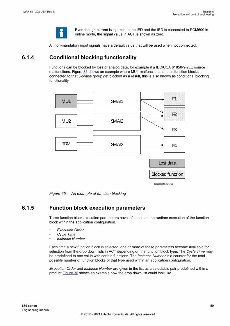
Even though current is injected to the IED and the IED is connected to PCM600 inonline mode, the signal value in ACT is shown as zero.
All non-mandatory input signals have a default value that will be used when not connected.
6.1.4 Conditional blocking functionalityGUID-37C7609A-D9CD-435F-BBEE-7518B88BEEDF v1
Functions can be blocked by loss of analog data, for example if a IEC/UCA 61850-9-2LE sourcemalfunctions. Figure 35 shows an example where MU1 malfunctions, and all function blocksconnected to that 3-phase group get blocked as a result, this is also known as conditional blockingfunctionality.
TRM
F1
F2
F3
F4
MU2
MU1
Lost data
Blocked function
SMAI3
SMAI2
SMAI1
IEC16000049-2-en.vsdx
IEC16000049 V2 EN-US
Figure 35: An example of function blocking
6.1.5 Function block execution parametersGUID-ADA51480-0DE7-4D18-9B23-99EB3B5E8813 v9
Three function block execution parameters have influence on the runtime execution of the functionblock within the application configuration.
• Execution Order• Cycle Time• Instance Number
Each time a new function block is selected, one or more of these parameters become available forselection from the drop down lists in ACT depending on the function block type. The Cycle Time maybe predefined to one value with certain functions. The Instance Number is a counter for the totalpossible number of function blocks of that type used within an application configuration.
Execution Order and Instance Number are given in the list as a selectable pair predefined within aproduct.Figure 36 shows an example how the drop down list could look like.
1MRK 511 398-UEN Rev. K Section 6Protection and control engineering
670 series 59Engineering manual
© 2017 - 2021 Hitachi Power Grids. All rights reserved

IEC09000720-2-en.vsdIEC09000720 V2 EN-US
Figure 36: ACT: function block organization parameters
A minus sign in front of the cycle time, for example -200ms, indicates that theapplication is time driven, otherwise the application is analog data driven. Analogdata driven applications require sample values from Analog input modules - in casethe physical module is broken, applications are not executed. Time drivenapplications are executed periodically regardless of the status of the analog signalprocessing.
The Cycle Time can be selected to different values for certain functions. Depending on the functionblock and IED type, one or more possibilities may be available.
The combination Execution Order, Instance Number is predefined by Hitachi Power grids. Mainly forbasic logic function blocks like for example AND, OR, a set of combinations spread over the fullrange of execution orders is available. This gives the possibility to select a combination which fits tothe execution order range needed in that application part.
Application configuration cycle time and execution order organizationThe application execution within the IEDs is organized in different classes, see Figure 37.
IEC09000737 V1 EN-US
Figure 37: Example of configuration cycle time and execution order
For the same time point, faster cycle times are executed first.
A function block that is placed after a function block in the execution flow must havethe same or a higher cycle time and/or execution order. See Figure 38.
Section 6 1MRK 511 398-UEN Rev. KProtection and control engineering
60 670 seriesEngineering manual
© 2017 - 2021 Hitachi Power Grids. All rights reserved
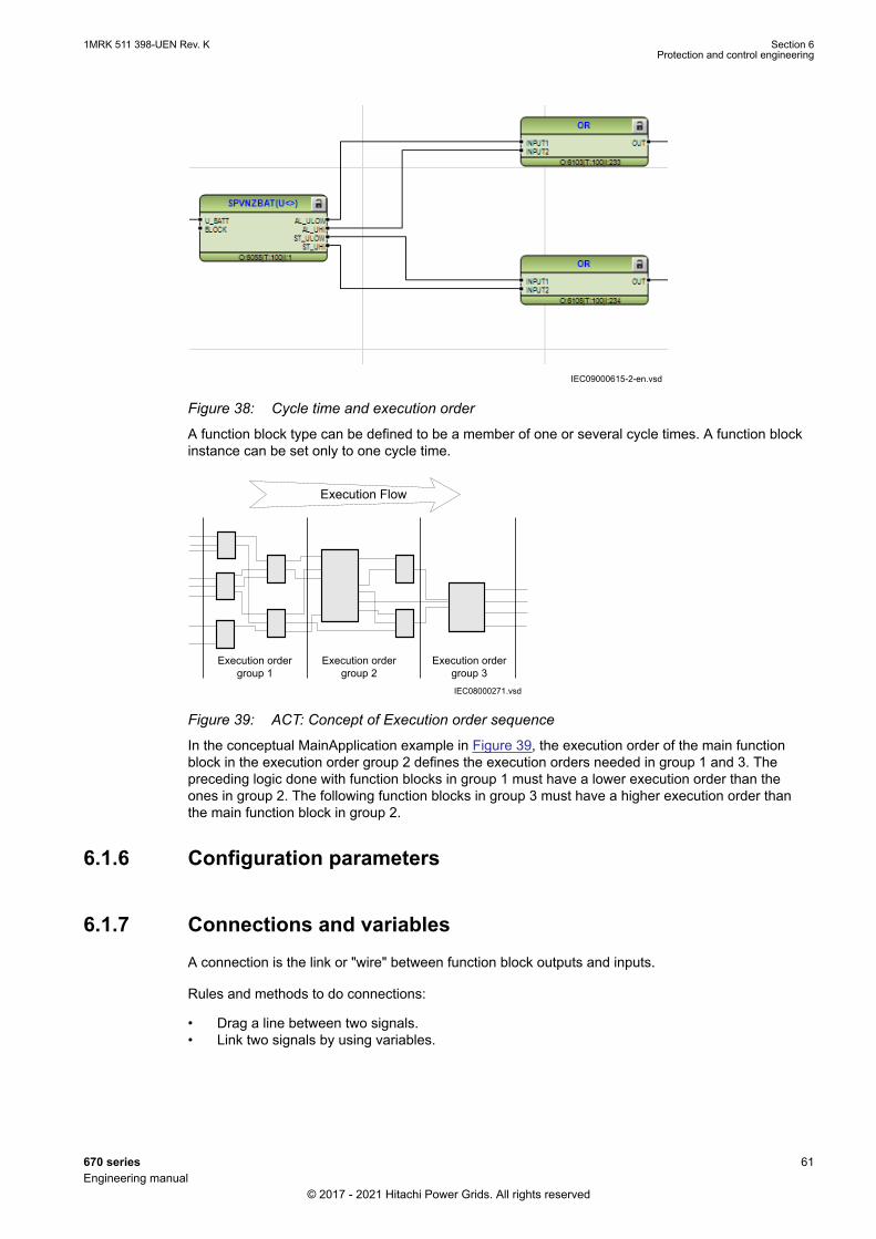
IEC09000615-2-en.vsdIEC09000615 V2 EN-US
Figure 38: Cycle time and execution order
A function block type can be defined to be a member of one or several cycle times. A function blockinstance can be set only to one cycle time.
IEC08000271.vsd
Execution ordergroup 1
Execution ordergroup 2
Execution ordergroup 3
Execution Flow
IEC08000271 V1 EN-US
Figure 39: ACT: Concept of Execution order sequence
In the conceptual MainApplication example in Figure 39, the execution order of the main functionblock in the execution order group 2 defines the execution orders needed in group 1 and 3. Thepreceding logic done with function blocks in group 1 must have a lower execution order than theones in group 2. The following function blocks in group 3 must have a higher execution order thanthe main function block in group 2.
6.1.6 Configuration parametersGUID-52044790-0A7C-4D83-8634-887593A903BC v4
6.1.7 Connections and variablesGUID-1564FB6D-2682-49AE-A1D5-8B7F03E4204B v4
A connection is the link or "wire" between function block outputs and inputs.
Rules and methods to do connections:
• Drag a line between two signals.• Link two signals by using variables.
1MRK 511 398-UEN Rev. K Section 6Protection and control engineering
670 series 61Engineering manual
© 2017 - 2021 Hitachi Power Grids. All rights reserved

It is possible to search and replace variable names in ACT.
Connection validationA connection is only useful and possible between two signals of the same data type, see Figure 40.
IEC08000304-2-en.vsdIEC08000304 V2 EN-US
Figure 40: ACT: Warning message by signal mismatch for a connection
6.1.8 Hardware channelsGUID-3455B27F-8F45-4510-A376-0F6C8B6BE3BF v4
Hardware channels can only be connected to a function block input or output. A hardware connectioncan be established in ACT or SMT. When a hardware channel is connected a graphical symbolappears in ACT, see Figure 41. The connection is also represented in SMT with a cross mark.Hardware channels are always visible in SMT.
Supported hardware channels are:
• Binary input channels• Binary output channels• Analog input channels
A hardware input channel can be used as often as it is needed. A hardware binary output channel istaken from the list of available channels when a new channel is requested. That prevents for using ahardware binary output channel twice. As an example, see Figure 41.
Section 6 1MRK 511 398-UEN Rev. KProtection and control engineering
62 670 seriesEngineering manual
© 2017 - 2021 Hitachi Power Grids. All rights reserved
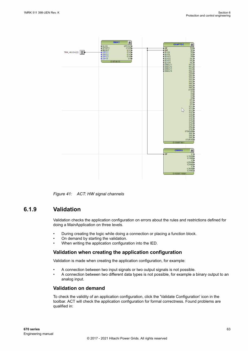
IEC09000723 V4 EN-US
Figure 41: ACT: HW signal channels
6.1.9 ValidationGUID-7407C36C-15EB-4987-AF29-5DCEFB95A613 v4
Validation checks the application configuration on errors about the rules and restrictions defined fordoing a MainApplication on three levels.
• During creating the logic while doing a connection or placing a function block.• On demand by starting the validation.• When writing the application configuration into the IED.
Validation when creating the application configurationValidation is made when creating the application configuration, for example:
• A connection between two input signals or two output signals is not possible.• A connection between two different data types is not possible, for example a binary output to an
analog input.
Validation on demandTo check the validity of an application configuration, click the 'Validate Configuration' icon in thetoolbar. ACT will check the application configuration for formal correctness. Found problems arequalified in:
1MRK 511 398-UEN Rev. K Section 6Protection and control engineering
670 series 63Engineering manual
© 2017 - 2021 Hitachi Power Grids. All rights reserved
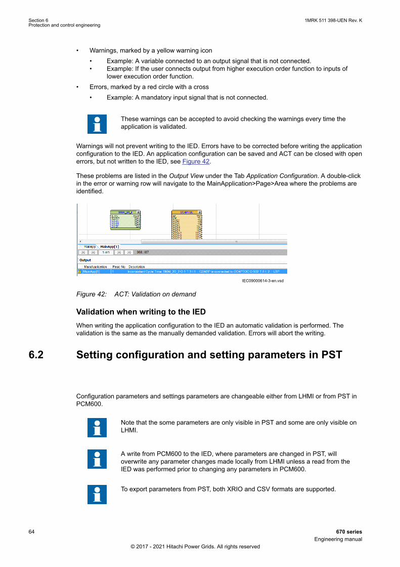
• Warnings, marked by a yellow warning icon• Example: A variable connected to an output signal that is not connected.• Example: If the user connects output from higher execution order function to inputs of
lower execution order function.• Errors, marked by a red circle with a cross
• Example: A mandatory input signal that is not connected.
These warnings can be accepted to avoid checking the warnings every time theapplication is validated.
Warnings will not prevent writing to the IED. Errors have to be corrected before writing the applicationconfiguration to the IED. An application configuration can be saved and ACT can be closed with openerrors, but not written to the IED, see Figure 42.
These problems are listed in the Output View under the Tab Application Configuration. A double-clickin the error or warning row will navigate to the MainApplication>Page>Area where the problems areidentified.
IEC09000614-3-en.vsdIEC09000614 V3 EN-US
Figure 42: ACT: Validation on demand
Validation when writing to the IEDWhen writing the application configuration to the IED an automatic validation is performed. Thevalidation is the same as the manually demanded validation. Errors will abort the writing.
6.2 Setting configuration and setting parameters in PSTSEMOD58493-4 v9
Configuration parameters and settings parameters are changeable either from LHMI or from PST inPCM600.
Note that the some parameters are only visible in PST and some are only visible onLHMI.
A write from PCM600 to the IED, where parameters are changed in PST, willoverwrite any parameter changes made locally from LHMI unless a read from theIED was performed prior to changing any parameters in PCM600.
To export parameters from PST, both XRIO and CSV formats are supported.
Section 6 1MRK 511 398-UEN Rev. KProtection and control engineering
64 670 seriesEngineering manual
© 2017 - 2021 Hitachi Power Grids. All rights reserved
All variables listed and shown in the parameter list can be sorted into two groups:
• Configuration parameter or• Setting parameter
Configuration parameterA configuration parameter specifies an operation mode of an application function or of the IED.These are basic configurations, which are normally configured only once and then settled. The IEDconfigures itself at start-up according to the given configuration parameter values.
Setting parameterA setting parameter (short form only “setting”) is a parameter that take immediate effect whenchanged.
Setting groupUp to six setting groups can be configured with different values. The IED supports the selection of asetting group at runtime.
IED parameters organizationThe organization of the parameters in a tree structure is visible in the plant structure by expandingthe setting tree. For each function, the parameters are organized in basic and advanced groups. Theadvanced settings are used for application optimization.
During a write both the basic and advanced settings are written to the IED.
6.2.1 Graphical Parameter Setting ToolGUID-C726930D-D55E-4426-A14F-F4E6C7F6131C v2
The Graphical Parameter Setting tool (GPST) is a tool in PCM600 that is used to present parametersettings in a graphical user interface. GPST is a part of the Parameter Setting tool (PST), the settingsare done in PST and can be presented in GPST.
GPST is available for distance protection functions:
Under impedance protection for generators and transformers ZGTPDIS
Distance protection, quadrilateral characteristic ZRWPDIS
Distance protection zone, quadrilateral characteristic ZMQPDIS, ZMQAPDIS
Distance measuring zone, quadrilateral characteristic for series compensated lines ZMCPDIS, ZMCAPDIS
Fullscheme distance protection, mho characteristic ZMHPDIS
Fullscheme distance protection, quadrilateral for earth faults ZMMPDIS, ZMMAPDIS
Distance protection zone, quadrilateral characteristic, separate settings ZMRPDIS, ZMRAPDIS
High speed distance protection, quadrilateral and mho ZMFPDIS
High speed distance protection for series compensated lines, quadrilateral and mho ZMFCPDIS
Directional impedance element for mho characteristic ZDMRDIR
Directional impedance quadrilateral ZDRDIR
Directional impedance quadrilateral, including series compensation ZDSRDIR
Underimpedance protection for generators and transformers ZGVPDIS
Power swing detection ZMRPSB
Table continues on next page
1MRK 511 398-UEN Rev. K Section 6Protection and control engineering
670 series 65Engineering manual
© 2017 - 2021 Hitachi Power Grids. All rights reserved

Phase selection, quadrilateral characteristic with fixed angle FDPSPDIS
Phase selection, quadrilateral characteristic with settable angle FRPSPDIS
Faulty phase identification with load encroachment FMPSPDIS
For more information on GPST, see the online help for PCM600.
6.3 Connecting signals in SMTGUID-B413A348-61AA-482E-AA4A-E351D3B2ED8F v5
SMT is used to connect the application to I/O, binary, analog and GOOSE, see Figure 43:
• between physical IO signals and function blocks.• for the GOOSE engineering.
IEC09000709.vsd
BIM
TRM
FBs
BinaryInput
BinaryOutput
AnalogInput
HardwareIO interfaces(X-direction)
Signal Matrix FBs
(Y-direction)
GOOSE Inputs Goose_BinIntl_AP
GOOSEInput blocks
IEC 61850
SMAI
FBs
HMI LEDs
IOM BI
LEDs
BOM
IOM BO
IEC09000709 V1 EN-US
Figure 43: SMT: Operation principles
Section 6 1MRK 511 398-UEN Rev. KProtection and control engineering
66 670 seriesEngineering manual
© 2017 - 2021 Hitachi Power Grids. All rights reserved
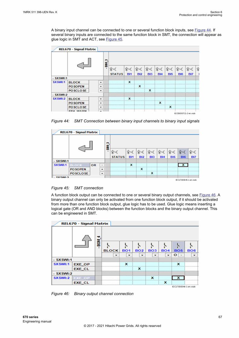
A binary input channel can be connected to one or several function block inputs, see Figure 44. Ifseveral binary inputs are connected to the same function block in SMT, the connection will appear asglue logic in SMT and ACT, see Figure 45.
IEC09000721-2-en.vsdx
IEC09000721 V2 EN-US
Figure 44: SMT Connection between binary input channels to binary input signals
IEC17000045-1-en.vsdx
IEC17000045 V1 EN-US
Figure 45: SMT connection
A function block output can be connected to one or several binary output channels, see Figure 46. Abinary output channel can only be activated from one function block output, if it should be activatedfrom more than one function block output, glue logic has to be used. Glue logic means inserting alogical gate (OR and AND blocks) between the function blocks and the binary output channel. Thiscan be engineered in SMT.
IEC17000046-1-en.vsdxIEC17000046 V1 EN-US
Figure 46: Binary output channel connection
1MRK 511 398-UEN Rev. K Section 6Protection and control engineering
670 series 67Engineering manual
© 2017 - 2021 Hitachi Power Grids. All rights reserved

Connections made in SMT are automatically shown in ACT and vice versa.
It is possible to group and collapse hardware channels in SMT to get a betteroverview.
Depending on the IED capability, SMT has a separate sheet for each possible combination.
The possible sheets are:
• Binary Inputs• Binary Outputs• Analog Inputs• GOOSE Receive
Section 6 1MRK 511 398-UEN Rev. KProtection and control engineering
68 670 seriesEngineering manual
© 2017 - 2021 Hitachi Power Grids. All rights reserved
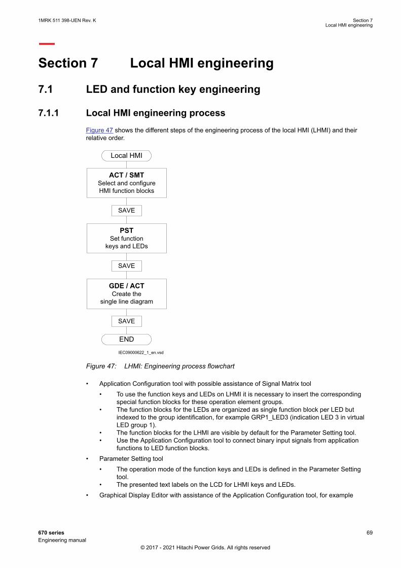
Section 7 Local HMI engineering
7.1 LED and function key engineering
7.1.1 Local HMI engineering processGUID-35126910-CF1C-4411-ACA9-72E1DB9BC68F v9
Figure 47 shows the different steps of the engineering process of the local HMI (LHMI) and theirrelative order.
IEC09000622_1_en.vsd
Local HMI
ACT / SMTSelect and configure HMI function blocks
PSTSet function
keys and LEDs
END
SAVE
SAVE
GDE / ACT Create the
single line diagram
SAVE
IEC09000622 V1 EN-US
Figure 47: LHMI: Engineering process flowchart
• Application Configuration tool with possible assistance of Signal Matrix tool• To use the function keys and LEDs on LHMI it is necessary to insert the corresponding
special function blocks for these operation element groups.• The function blocks for the LEDs are organized as single function block per LED but
indexed to the group identification, for example GRP1_LED3 (indication LED 3 in virtualLED group 1).
• The function blocks for the LHMI are visible by default for the Parameter Setting tool.• Use the Application Configuration tool to connect binary input signals from application
functions to LED function blocks.• Parameter Setting tool
• The operation mode of the function keys and LEDs is defined in the Parameter Settingtool.
• The presented text labels on the LCD for LHMI keys and LEDs.• Graphical Display Editor with assistance of the Application Configuration tool, for example
1MRK 511 398-UEN Rev. K Section 7Local HMI engineering
670 series 69Engineering manual
© 2017 - 2021 Hitachi Power Grids. All rights reserved

• to make the single line diagram of the primary process part.• to make the dynamic links for the apparatus.• to make the dynamic links for measurements.
Application Configuration tool and local HMI function blocks
See the Technical Manual for more information on function blocks.
The LHMI provides a set of special function blocks to be utilized in the Application Configuration tool:
• LHMICTRL• FNKEYMD1 to FNKEYMD5• LEDGEN• GRP1_LED1 to GRP1_LED15• GRP2_LED1 to GRP2_LED15• GRP3_LED1 to GRP3_LED15
The function blocks for the LEDs are organized in function blocks per LED. They can be placed closeto the logic where the information per LED is built in the Application Configuration tool.
Figure 48 describes the basic LHMI and the operation element groups. These are the 15 LEDs andtheir belonging text elements on the LCD [A]. They are operated by keys [a] and [b].
The other group is the five function keys with their LEDs and the corresponding text elements on theLCD [B].
Section 7 1MRK 511 398-UEN Rev. KLocal HMI engineering
70 670 seriesEngineering manual
© 2017 - 2021 Hitachi Power Grids. All rights reserved

IEC13000289-2-en.vsd
Basic key area
LCD
a b
B A
GUID-A374CBAE-CFB8-47CE-A2AD-514F8B6F20CA V2 EN-US
Figure 48: Local HMI: Placement of local HMI operation elements
Function block LEDGEN
• Handles an external acknowledge signal as source to acknowledge the LEDs.• Generates an additional pulse for general purposes whenever the LEDs are acknowledged by
the operator.• Generates a pulse whenever a new LED signal occurs. It may be used to trigger an acoustical
alarm.• Handles timers tReset and tMax for the LED operation mode 'LatchedReset-S'.
Function block GRP1_LED1 to GRP3_LED15
• The 15 LEDs on the right side of the LCD can indicate in total 45 alarms, warnings or othersignals to the operator. They are organized in three groups 1 to 3.
• Each signal group belongs to one function block.• Each LED illuminates in one of the three colors: RED, YELLOW or GREEN.• The organization of flashing, acknowledgment and group selection is done directly between the
function blocks and the basic LHMI keys, the 'Multifunction' key [a] to toggle between the threegroups or the 'Clear' key [b] to acknowledge or reset the LEDs.
• Only the programming of the signals is needed for the LEDs.• The operation mode of the LEDs is defined in the Parameter Setting tool.
Function block FNKEYMD1 to 5
1MRK 511 398-UEN Rev. K Section 7Local HMI engineering
670 series 71Engineering manual
© 2017 - 2021 Hitachi Power Grids. All rights reserved
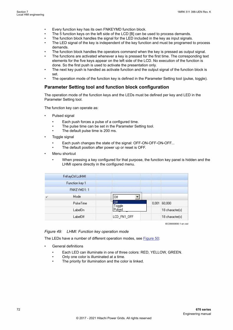
• Every function key has its own FNKEYMD function block.• The 5 function keys on the left side of the LCD [B] can be used to process demands.• The function block handles the signal for the LED included in the key as input signals.• The LED signal of the key is independent of the key function and must be programed to process
demands.• The function block handles the operators command when the key is pressed as output signal.• The functions are activated whenever a key is pressed for the first time. The corresponding text
elements for the five keys appear on the left side of the LCD. No execution of the function isdone. So the first push is used to activate the presentation only.
• The next key push is handled as activate function and the output signal of the function block isset.
• The operation mode of the function key is defined in the Parameter Setting tool (pulse, toggle).
Parameter Setting tool and function block configurationThe operation mode of the function keys and the LEDs must be defined per key and LED in theParameter Setting tool.
The function key can operate as:
• Pulsed signal• Each push forces a pulse of a configured time.• The pulse time can be set in the Parameter Setting tool.• The default pulse time is 200 ms.
• Toggle signal• Each push changes the state of the signal: OFF-ON-OFF-ON-OFF...• The default position after power up or reset is OFF.
• Menu shortcut• When pressing a key configured for that purpose, the function key panel is hidden and the
LHMI opens directly in the configured menu.
IEC09000656-1-en.vsdIEC09000656 V1 EN-US
Figure 49: LHMI: Function key operation mode
The LEDs have a number of different operation modes, see Figure 50:
• General definitions• Each LED can illuminate in one of three colors: RED, YELLOW, GREEN.• Only one color is illuminated at a time.• The priority for illumination and the color is linked.
Section 7 1MRK 511 398-UEN Rev. KLocal HMI engineering
72 670 seriesEngineering manual
© 2017 - 2021 Hitachi Power Grids. All rights reserved

• Prio 1 = RED• Prio 2 = YELLOW• Prio 3 = GREEN• When RED and YELLOW are ON at the same time, the LED will illuminate in RED.
• The operator's acknowledgement for the LED signals is done for all three signals (RED,YELLOW, GREEN) of the LED.
• A reset of the LEDs operates also on all three signals of the LEDs.
• Follow-S• The LED illumination follows the status of the signal. The LED illuminates steady (S).
• Follow-F• The LED illumination follows the status of the signal. The LED illuminates flashing (F).
• LatchedAck-F-S• The LED latches the signal change OFF-ON and flashes (F) until it is acknowledged.• When the signal is still ON at the time the signal is acknowledged, the LED changes to
steady (S) mode.• When the signal has already changed to OFF before the time it is acknowledged, the LED
turns to OFF.• LatchedAck-S-F
• The same as LatchedAck-F-S but the LED starts with steady state and flashes afteracknowledgment.
• LatchedColl-S• The LED illuminates in all cases in steady mode only• The LED latches a signal change from OFF-ON until it is acknowledged by the operator.• The LED stays in steady mode when it is reset and the signal is still in ON state.• The LED is OFF only after the signal has changed to OFF state AND it is reset by the
operator via 'Clear' operation.• LatchedReset-S
• This mode is used for all LEDs that are used to indicate a disturbance. The LEDs will stayin the last state after the disturbance run time until they are reset after a defined time.
• The timers are set in the Parameter Setting tool in the function block LEDGEN.
IEC09000657-1-en.vsdIEC09000657 V1 EN-US
Figure 50: LHMI: LED operation mode
7.1.2 LED operation modesGUID-40B89A33-3C2D-488C-8932-F862E0C9F477 v5
The SequenceType parameter enables each LED to operate in one out of six different modes.
1MRK 511 398-UEN Rev. K Section 7Local HMI engineering
670 series 73Engineering manual
© 2017 - 2021 Hitachi Power Grids. All rights reserved

• Follow-S• Follow-F• LatchedAck-F-S• LatchedAck-S-F• LatchedColl-S• LatchedReset-S
LED operation mode Follow-S
IEC08000395.vsd
= Steady = FlashIllumination =>
RYG
RYG
Sign
als
LED
IEC08000395 V1 EN-US
Figure 51: LHMI: LED operation mode Follow-S
In the Follow-S mode, the LED adopts a steady behavior. It is lit on a binary On signal and switchedoff on a binary Off signal. See Figure 51 for details.
LED operation mode Follow-F
IEC08000396.vsd
= Steady = FlashIllumination =>
RYG
RYG
Sign
als
LED
IEC08000396 V1 EN-US
Figure 52: LHMI: LED operation mode Follow-F
In the Follow-F mode, the LED starts flashing when receiving a steady binary On signal. At othertimes it is unlit. SeeFigure 52. This mode may be used to indicate that a tap changer or Petersen coilis moving.
Section 7 1MRK 511 398-UEN Rev. KLocal HMI engineering
74 670 seriesEngineering manual
© 2017 - 2021 Hitachi Power Grids. All rights reserved
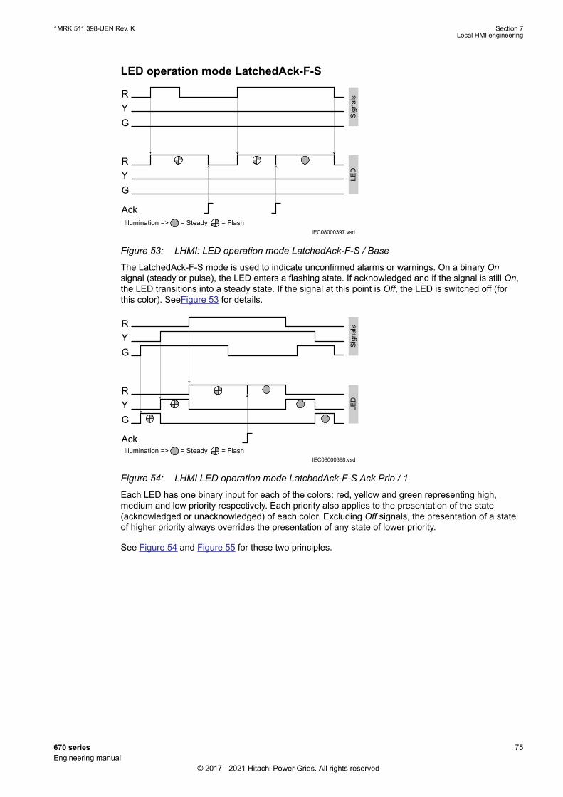
LED operation mode LatchedAck-F-S
IEC08000397.vsd
RYG
RYG
Sign
als
LED
Ack= Steady = FlashIllumination =>
IEC08000397 V1 EN-US
Figure 53: LHMI: LED operation mode LatchedAck-F-S / Base
The LatchedAck-F-S mode is used to indicate unconfirmed alarms or warnings. On a binary Onsignal (steady or pulse), the LED enters a flashing state. If acknowledged and if the signal is still On,the LED transitions into a steady state. If the signal at this point is Off, the LED is switched off (forthis color). SeeFigure 53 for details.
IEC08000398.vsd= Steady = FlashIllumination =>
RYG
RYG
Sign
als
LED
Ack
IEC08000398 V1 EN-US
Figure 54: LHMI LED operation mode LatchedAck-F-S Ack Prio / 1
Each LED has one binary input for each of the colors: red, yellow and green representing high,medium and low priority respectively. Each priority also applies to the presentation of the state(acknowledged or unacknowledged) of each color. Excluding Off signals, the presentation of a stateof higher priority always overrides the presentation of any state of lower priority.
See Figure 54 and Figure 55 for these two principles.
1MRK 511 398-UEN Rev. K Section 7Local HMI engineering
670 series 75Engineering manual
© 2017 - 2021 Hitachi Power Grids. All rights reserved
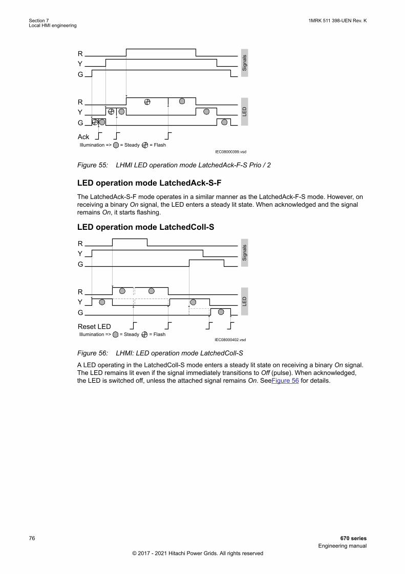
IEC08000399.vsd
RYG
RYG
Sign
als
LED
Ack= Steady = FlashIllumination =>
IEC08000399 V1 EN-US
Figure 55: LHMI LED operation mode LatchedAck-F-S Prio / 2
LED operation mode LatchedAck-S-FThe LatchedAck-S-F mode operates in a similar manner as the LatchedAck-F-S mode. However, onreceiving a binary On signal, the LED enters a steady lit state. When acknowledged and the signalremains On, it starts flashing.
LED operation mode LatchedColl-S
IEC08000402.vsd= Steady = FlashIllumination =>
RYG
RYG
Sign
als
LED
Reset LED
IEC08000402 V1 EN-US
Figure 56: LHMI: LED operation mode LatchedColl-S
A LED operating in the LatchedColl-S mode enters a steady lit state on receiving a binary On signal.The LED remains lit even if the signal immediately transitions to Off (pulse). When acknowledged,the LED is switched off, unless the attached signal remains On. SeeFigure 56 for details.
Section 7 1MRK 511 398-UEN Rev. KLocal HMI engineering
76 670 seriesEngineering manual
© 2017 - 2021 Hitachi Power Grids. All rights reserved
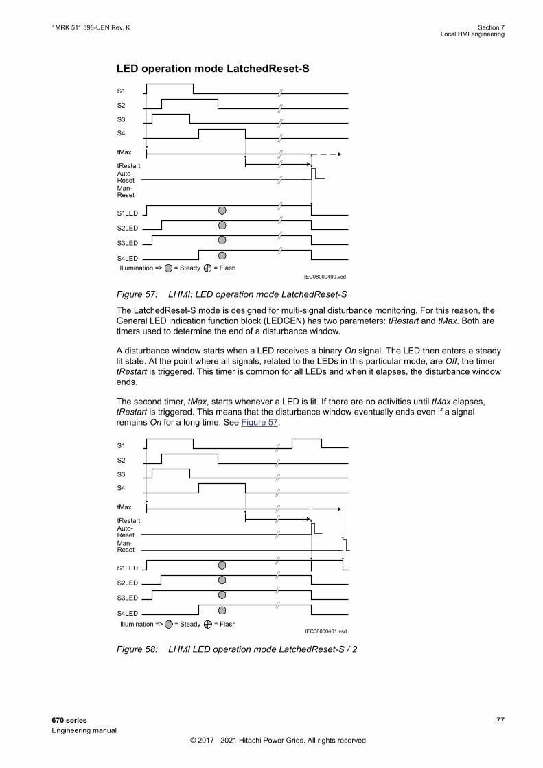
LED operation mode LatchedReset-S
IEC08000400.vsd= Steady = FlashIllumination =>
Man-Reset
S1
S2
S3
S4
tMax
tRestart
S1LED
S2LED
S3LED
S4LED
Auto-Reset
IEC08000400 V1 EN-US
Figure 57: LHMI: LED operation mode LatchedReset-S
The LatchedReset-S mode is designed for multi-signal disturbance monitoring. For this reason, theGeneral LED indication function block (LEDGEN) has two parameters: tRestart and tMax. Both aretimers used to determine the end of a disturbance window.
A disturbance window starts when a LED receives a binary On signal. The LED then enters a steadylit state. At the point where all signals, related to the LEDs in this particular mode, are Off, the timertRestart is triggered. This timer is common for all LEDs and when it elapses, the disturbance windowends.
The second timer, tMax, starts whenever a LED is lit. If there are no activities until tMax elapses,tRestart is triggered. This means that the disturbance window eventually ends even if a signalremains On for a long time. See Figure 57.
IEC08000401.vsd= Steady = FlashIllumination =>
Man-Reset
S1
S2
S3
S4
tMax
tRestart
S1LED
S2LED
S3LED
S4LED
Auto-Reset
IEC08000401 V1 EN-US
Figure 58: LHMI LED operation mode LatchedReset-S / 2
1MRK 511 398-UEN Rev. K Section 7Local HMI engineering
670 series 77Engineering manual
© 2017 - 2021 Hitachi Power Grids. All rights reserved
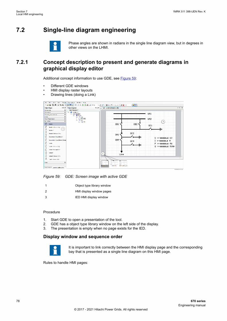
7.2 Single-line diagram engineeringGUID-4EF97104-327A-443F-AA00-7C4BF143D46D v3
Phase angles are shown in radians in the single line diagram view, but in degrees inother views on the LHMI.
7.2.1 Concept description to present and generate diagrams ingraphical display editor
GUID-3C532F5A-3E26-4A3A-ACE3-C7758494BE4D v8
Additional concept information to use GDE, see Figure 59:
• Different GDE windows• HMI display raster layouts• Drawing lines (doing a Link)
IEC08000123-3-en.vsd
3
1
2
3
IEC08000123 V3 EN-US
Figure 59: GDE: Screen image with active GDE
1 Object type library window
2 HMI display window pages
3 IED HMI display window
Procedure
1. Start GDE to open a presentation of the tool.2. GDE has a object type library window on the left side of the display.3. The presentation is empty when no page exists for the IED.
Display window and sequence order
It is important to link correctly between the HMI display page and the correspondingbay that is presented as a single line diagram on this HMI page.
Rules to handle HMI pages:
Section 7 1MRK 511 398-UEN Rev. KLocal HMI engineering
78 670 seriesEngineering manual
© 2017 - 2021 Hitachi Power Grids. All rights reserved
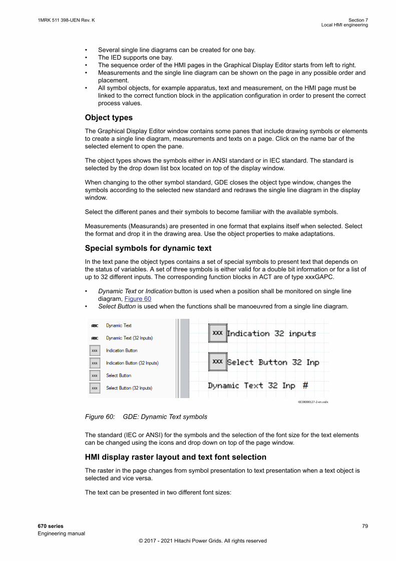
• Several single line diagrams can be created for one bay.• The IED supports one bay.• The sequence order of the HMI pages in the Graphical Display Editor starts from left to right.• Measurements and the single line diagram can be shown on the page in any possible order and
placement.• All symbol objects, for example apparatus, text and measurement, on the HMI page must be
linked to the correct function block in the application configuration in order to present the correctprocess values.
Object typesThe Graphical Display Editor window contains some panes that include drawing symbols or elementsto create a single line diagram, measurements and texts on a page. Click on the name bar of theselected element to open the pane.
The object types shows the symbols either in ANSI standard or in IEC standard. The standard isselected by the drop down list box located on top of the display window.
When changing to the other symbol standard, GDE closes the object type window, changes thesymbols according to the selected new standard and redraws the single line diagram in the displaywindow.
Select the different panes and their symbols to become familiar with the available symbols.
Measurements (Measurands) are presented in one format that explains itself when selected. Selectthe format and drop it in the drawing area. Use the object properties to make adaptations.
Special symbols for dynamic textIn the text pane the object types contains a set of special symbols to present text that depends onthe status of variables. A set of three symbols is either valid for a double bit information or for a list ofup to 32 different inputs. The corresponding function blocks in ACT are of type xxxGAPC.
• Dynamic Text or Indication button is used when a position shall be monitored on single linediagram, Figure 60
• Select Button is used when the functions shall be manoeuvred from a single line diagram.
IEC08000127-2-en.vsdx
IEC08000127 V2 EN-US
Figure 60: GDE: Dynamic Text symbols
The standard (IEC or ANSI) for the symbols and the selection of the font size for the text elementscan be changed using the icons and drop down on top of the page window.
HMI display raster layout and text font selectionThe raster in the page changes from symbol presentation to text presentation when a text object isselected and vice versa.
The text can be presented in two different font sizes:
1MRK 511 398-UEN Rev. K Section 7Local HMI engineering
670 series 79Engineering manual
© 2017 - 2021 Hitachi Power Grids. All rights reserved

• UniCode characters (6 x 12 pixels)• UniCode characters (13 x 14 pixels)
The total size of the presented white area (page) represents the visible part of the local HMI displaywithout header and foot-line.
The visible display for a single line diagram is organized in a raster of 13 x 8 (columns x rows). Eachsymbol presented by 24 x 24 pixels included by the drag and drop method must be dropped in araster box. The apparatus object name can be placed in all four directions around the symbol. Thename is part of the apparatus object.
Handling textThe raster switches when text is selected in a raster of 45 x 15 (columns x rows). One raster box isthe placeholder for one character. A text element must be placed in the position of the raster. Thesignal name can changed either by double click or via the property window. Unit and scaling of thesignal can only be changed via the property window.
Select and toggle Show Texts using the IED Fonts to get a view how it will look like later on the realHMI display.
Doing Link to draw linesThe line width has to fit to the line width used for the symbols. The standard size is 2. Choose theline width in a selection box placed in the upper area above the page. A line that is not connected toa symbol may be done in any line width in the range 1 - 5. But it needs to be simple connectionpoints to be drawn.
For the procedure to draw lines when the apparatus symbols are placed, see Figure 61.
1. Place the apparatus or transformer symbols by drag and drop in a raster box.2. Place the connections symbols by drag and drop in a raster box.3. Center the mouse pointer on the center of a connection point; visible in two triangles if not
connetions are made, otherwise two circles at the endpoints of a line, to draw a line.4. Click to start and move the mouse pointer to the destination connection point. Center once again
the mouse pointer and click to drop the line.5. Draw all line elements that are necessary.
IEC05000598-4-en.vsdx
IEC05000598 V4 EN-US
Figure 61: GDE: Drawing a line
Section 7 1MRK 511 398-UEN Rev. KLocal HMI engineering
80 670 seriesEngineering manual
© 2017 - 2021 Hitachi Power Grids. All rights reserved
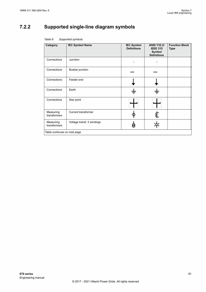
7.2.2 Supported single-line diagram symbolsGUID-AA86E5A0-4060-436A-93A9-D5901F91BD09 v6
Table 6: Supported symbols
Category IEC Symbol Name IEC SymbolDefinitions
ANSI Y32.2/IEEE 315Symbol
Definitions
Function BlockType
Connections Junction
Connections Busbar junction
Connections Feeder end
Connections Earth
Connections Star point
Measuringtransformers
Current transformer
Measuringtransformers
Voltage transf. 2 windings
Table continues on next page
1MRK 511 398-UEN Rev. K Section 7Local HMI engineering
670 series 81Engineering manual
© 2017 - 2021 Hitachi Power Grids. All rights reserved
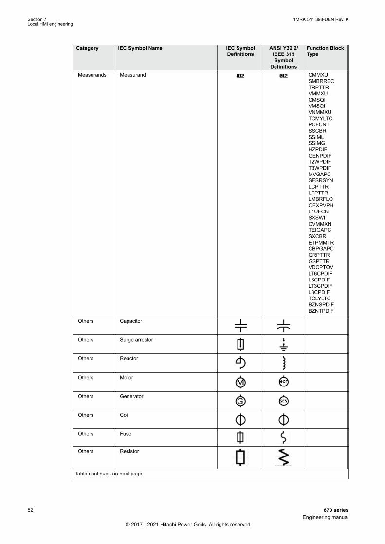
Category IEC Symbol Name IEC SymbolDefinitions
ANSI Y32.2/IEEE 315Symbol
Definitions
Function BlockType
Measurands Measurand CMMXUSMBRRECTRPTTRVMMXUCMSQIVMSQIVNMMXUTCMYLTCPCFCNTSSCBRSSIMLSSIMGHZPDIFGENPDIFT2WPDIFT3WPDIFMVGAPCSESRSYNLCPTTRLFPTTRLMBRFLOOEXPVPHL4UFCNTSXSWICVMMXNTEIGAPCSXCBRETPMMTRCBPGAPCGRPTTRGSPTTRVDCPTOVLT6CPDIFL6CPDIFLT3CPDIFL3CPDIFTCLYLTCBZNSPDIFBZNTPDIF
Others Capacitor
Others Surge arrestor
Others Reactor
Others Motor
Others Generator
Others Coil
Others Fuse
Others Resistor
Table continues on next page
Section 7 1MRK 511 398-UEN Rev. KLocal HMI engineering
82 670 seriesEngineering manual
© 2017 - 2021 Hitachi Power Grids. All rights reserved
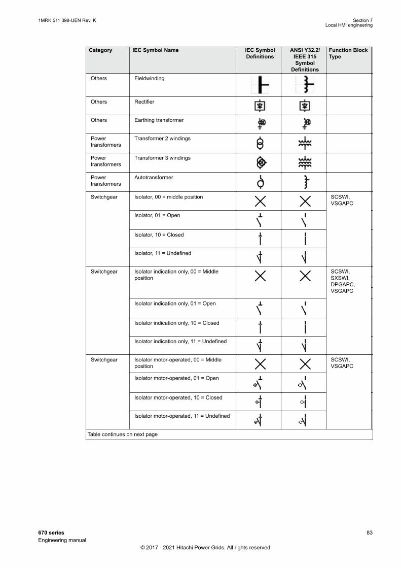
Category IEC Symbol Name IEC SymbolDefinitions
ANSI Y32.2/IEEE 315Symbol
Definitions
Function BlockType
Others Fieldwinding
Others Rectifier
Others Earthing transformer
Powertransformers
Transformer 2 windings
Powertransformers
Transformer 3 windings
Powertransformers
Autotransformer
Switchgear Isolator, 00 = middle position SCSWI,VSGAPC
Isolator, 01 = Open
Isolator, 10 = Closed
Isolator, 11 = Undefined
Switchgear Isolator indication only, 00 = Middleposition
SCSWI,SXSWI,DPGAPC,VSGAPC
Isolator indication only, 01 = Open
Isolator indication only, 10 = Closed
Isolator indication only, 11 = Undefined
Switchgear Isolator motor-operated, 00 = Middleposition
SCSWI,VSGAPC
Isolator motor-operated, 01 = Open
Isolator motor-operated, 10 = Closed
Isolator motor-operated, 11 = Undefined
Table continues on next page
1MRK 511 398-UEN Rev. K Section 7Local HMI engineering
670 series 83Engineering manual
© 2017 - 2021 Hitachi Power Grids. All rights reserved
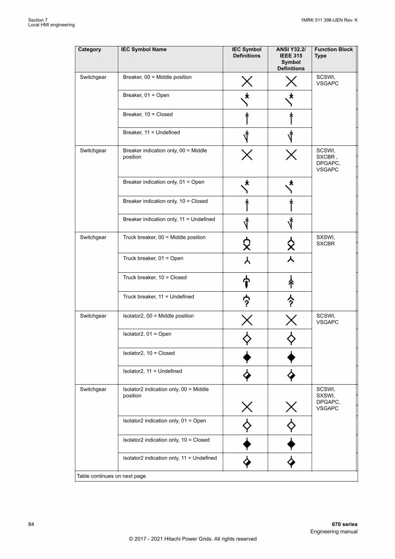
Category IEC Symbol Name IEC SymbolDefinitions
ANSI Y32.2/IEEE 315Symbol
Definitions
Function BlockType
Switchgear Breaker, 00 = Middle position SCSWI,VSGAPC
Breaker, 01 = Open
Breaker, 10 = Closed
Breaker, 11 = Undefined
Switchgear Breaker indication only, 00 = Middleposition
SCSWI,SXCBR ,DPGAPC,VSGAPC
Breaker indication only, 01 = Open
Breaker indication only, 10 = Closed
Breaker indication only, 11 = Undefined
Switchgear Truck breaker, 00 = Middle position SXSWI,SXCBR
Truck breaker, 01 = Open
Truck breaker, 10 = Closed
Truck breaker, 11 = Undefined
Switchgear Isolator2, 00 = Middle position SCSWI,VSGAPC
Isolator2, 01 = Open
Isolator2, 10 = Closed
Isolator2, 11 = Undefined
Switchgear Isolator2 indication only, 00 = Middleposition
SCSWI,SXSWI,DPGAPC,VSGAPC
Isolator2 indication only, 01 = Open
Isolator2 indication only, 10 = Closed
Isolator2 indication only, 11 = Undefined
Table continues on next page
Section 7 1MRK 511 398-UEN Rev. KLocal HMI engineering
84 670 seriesEngineering manual
© 2017 - 2021 Hitachi Power Grids. All rights reserved
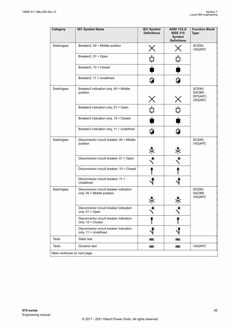
Category IEC Symbol Name IEC SymbolDefinitions
ANSI Y32.2/IEEE 315Symbol
Definitions
Function BlockType
Switchgear Breaker2, 00 = Middle position SCSWI,VSGAPC
Breaker2, 01 = Open
Breaker2, 10 = Closed
Breaker2, 11 = Undefined
Switchgear Breaker2 indication only, 00 = Middleposition
SCSWI,SXCBR ,DPGAPC,VSGAPC
Breaker2 indication only, 01 = Open
Breaker2 indication only, 10 = Closed
Breaker2 indication only, 11 = Undefined
Switchgear Disconnector circuit breaker, 00 = Middleposition
SCSWI,VSGAPC
Disconnector circuit breaker, 01 = Open
Disconnector circuit breaker, 10 = Closed
Disconnector circuit breaker, 11 =Undefined
Switchgear Disconnector circuit breaker indicationonly, 00 = Middle position
SCSWI,SXCBR,VSGAPC
Disconnector circuit breaker indicationonly, 01 = Open
Disconnector circuit breaker indicationonly, 10 = Closed
Disconnector circuit breaker indicationonly, 11 = Undefined
Texts Static text
Texts Dynamic text VSGAPC
Table continues on next page
1MRK 511 398-UEN Rev. K Section 7Local HMI engineering
670 series 85Engineering manual
© 2017 - 2021 Hitachi Power Grids. All rights reserved
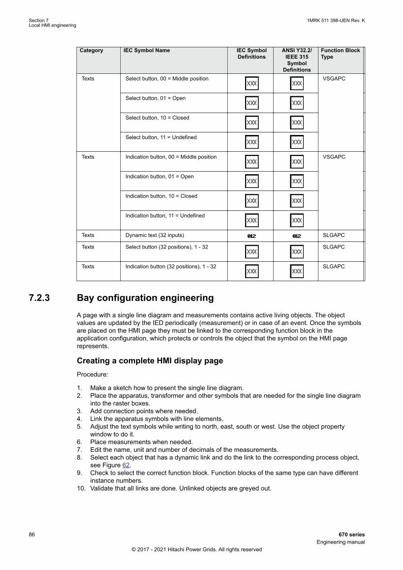
Category IEC Symbol Name IEC SymbolDefinitions
ANSI Y32.2/IEEE 315Symbol
Definitions
Function BlockType
Texts Select button, 00 = Middle position VSGAPC
Select button, 01 = Open
Select button, 10 = Closed
Select button, 11 = Undefined
Texts Indication button, 00 = Middle position VSGAPC
Indication button, 01 = Open
Indication button, 10 = Closed
Indication button, 11 = Undefined
Texts Dynamic text (32 inputs) SLGAPC
Texts Select button (32 positions), 1 - 32 SLGAPC
Texts Indication button (32 positions), 1 - 32 SLGAPC
7.2.3 Bay configuration engineeringGUID-0D9CFE29-F00B-450F-9802-F461112B1CF4 v10
A page with a single line diagram and measurements contains active living objects. The objectvalues are updated by the IED periodically (measurement) or in case of an event. Once the symbolsare placed on the HMI page they must be linked to the corresponding function block in theapplication configuration, which protects or controls the object that the symbol on the HMI pagerepresents.
Creating a complete HMI display pageProcedure:
1. Make a sketch how to present the single line diagram.2. Place the apparatus, transformer and other symbols that are needed for the single line diagram
into the raster boxes.3. Add connection points where needed.4. Link the apparatus symbols with line elements.5. Adjust the text symbols while writing to north, east, south or west. Use the object property
window to do it.6. Place measurements when needed.7. Edit the name, unit and number of decimals of the measurements.8. Select each object that has a dynamic link and do the link to the corresponding process object,
see Figure 62.9. Check to select the correct function block. Function blocks of the same type can have different
instance numbers.10. Validate that all links are done. Unlinked objects are greyed out.
Section 7 1MRK 511 398-UEN Rev. KLocal HMI engineering
86 670 seriesEngineering manual
© 2017 - 2021 Hitachi Power Grids. All rights reserved

11. Save the complete picture.12. Repeat the steps for all pages when more than one is needed.13. Write the display configuration to IED from the GDE tool.
IEC09000666-3-en.vsd
IEC09000666 V3 EN-US
Figure 62: GDE: Establish a dynamic object link
Linking process objectsTo describe a process object within an IED it needs to be established in the application configuration,configured when given with its parameters by PST and linked to be displayed in the HMI.
Three tools are involved for the described steps:
• ACT to program the application function block for apparatus and/or measurements.• PST to adapt the settings and/or configuration parameter of the application function block.• GDE to establish the link for updating the selected data attribute in the HMI of the application
function block.
The following application function blocks are used to deliver the needed information:
• Switch controller (of type CSWI) for an apparatus.• All configured function blocks with measurements (of type MMXU) for the measurements.• VSGAPC for two bit indications for the dynamic text symbols.• SLGAPC for 32 bit indications for the dynamic text symbols.
Procedure
1. Right-click the apparatus symbol and select Select Input Signal. A list of engineered switchcontrol application function blocks opens, see Figure 63.
2. Select the switch control application function block that corresponds to the selected apparatus.3. Right-click the measurement symbol and select Select Input Signal. A list of the engineered
measurement application function blocks opens.4. Select the measurement application function block that corresponds to the selected symbol.
1MRK 511 398-UEN Rev. K Section 7Local HMI engineering
670 series 87Engineering manual
© 2017 - 2021 Hitachi Power Grids. All rights reserved
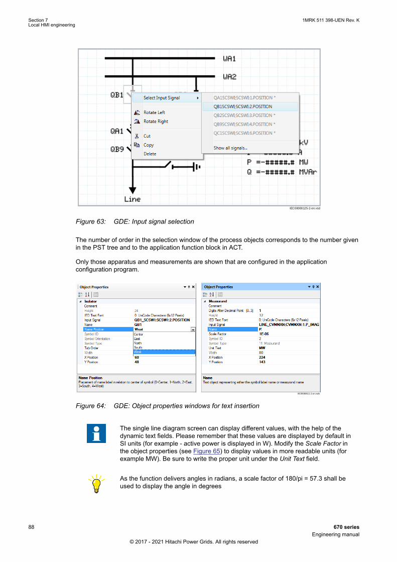
IEC08000125-2-en.vsd
IEC08000125 V2 EN-US
Figure 63: GDE: Input signal selection
The number of order in the selection window of the process objects corresponds to the number givenin the PST tree and to the application function block in ACT.
Only those apparatus and measurements are shown that are configured in the applicationconfiguration program.
IEC05000611-2-en.vsdx
IEC05000611 V2 EN-US
Figure 64: GDE: Object properties windows for text insertion
The single line diagram screen can display different values, with the help of thedynamic text fields. Please remember that these values are displayed by default inSI units (for example - active power is displayed in W). Modify the Scale Factor inthe object properties (see Figure 65) to display values in more readable units (forexample MW). Be sure to write the proper unit under the Unit Text field.
As the function delivers angles in radians, a scale factor of 180/pi = 57.3 shall beused to display the angle in degrees
Section 7 1MRK 511 398-UEN Rev. KLocal HMI engineering
88 670 seriesEngineering manual
© 2017 - 2021 Hitachi Power Grids. All rights reserved

IEC10000174.vsdIEC10000174 V1 EN-US
Figure 65: GDE: Object properties window for unit change
7.3 Events and indicationsGUID-B895D621-07EF-4788-863D-19C361C66917 v3
To get IED events to the LHMI event list and indications for Ready, Start and Trip indication LEDs,disturbance report needs to be engineered.
Detailed information about disturbance report subfunctions is found in the technicalmanual.
1MRK 511 398-UEN Rev. K Section 7Local HMI engineering
670 series 89Engineering manual
© 2017 - 2021 Hitachi Power Grids. All rights reserved

90
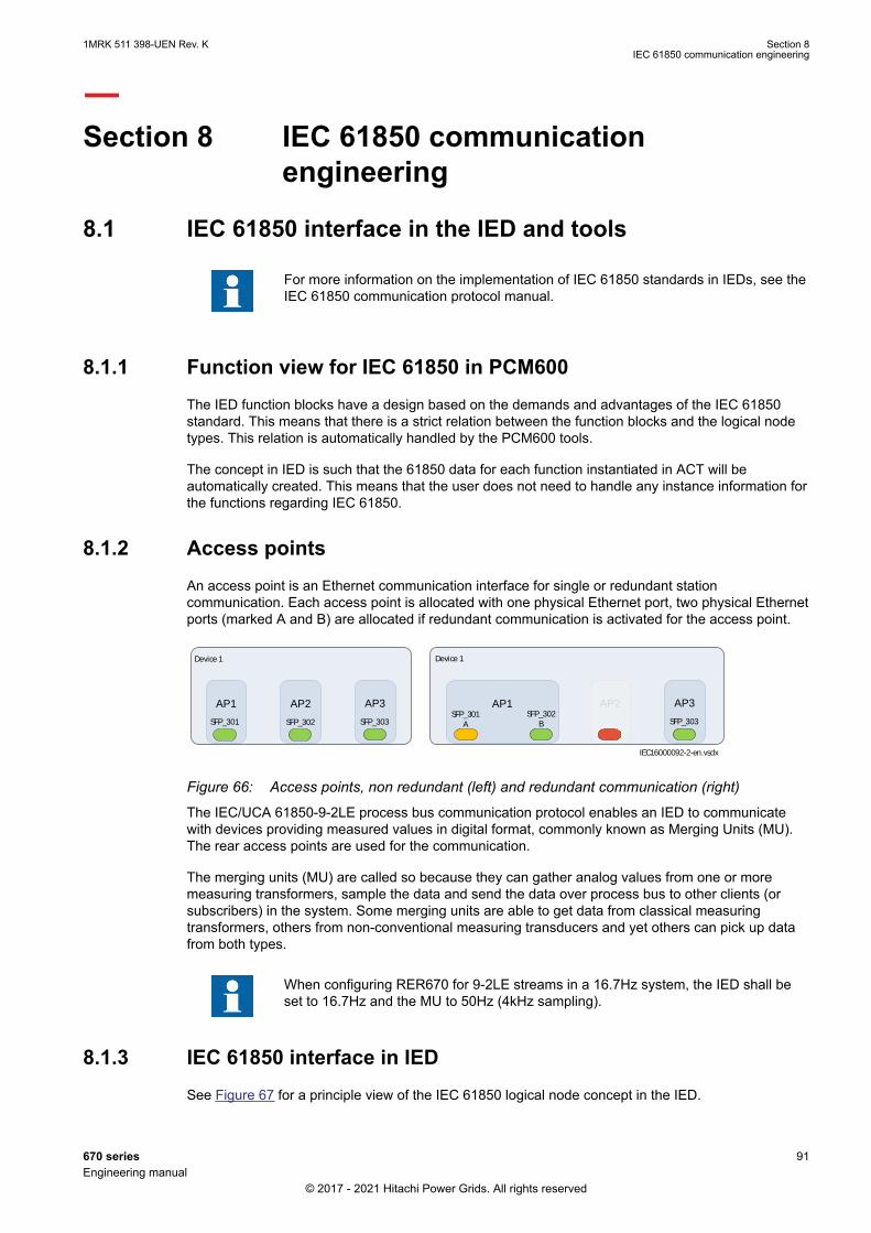
Section 8 IEC 61850 communicationengineering
8.1 IEC 61850 interface in the IED and toolsSEMOD120868-5 v3
For more information on the implementation of IEC 61850 standards in IEDs, see theIEC 61850 communication protocol manual.
8.1.1 Function view for IEC 61850 in PCM600GUID-3F996419-2724-43F3-AD0D-FD7ED15DC431 v4
The IED function blocks have a design based on the demands and advantages of the IEC 61850standard. This means that there is a strict relation between the function blocks and the logical nodetypes. This relation is automatically handled by the PCM600 tools.
The concept in IED is such that the 61850 data for each function instantiated in ACT will beautomatically created. This means that the user does not need to handle any instance information forthe functions regarding IEC 61850.
8.1.2 Access pointsGUID-6E5D2696-A8EE-43E7-A94B-69C3D0612127 v3
An access point is an Ethernet communication interface for single or redundant stationcommunication. Each access point is allocated with one physical Ethernet port, two physical Ethernetports (marked A and B) are allocated if redundant communication is activated for the access point.
AP1SFP_302
BSFP_301
A
Device 1
AP1SFP_302SFP_301
Device 1
AP2
IEC16000092-2-en.vsdx
SFP_303
AP3 AP2SFP_303
AP3
IEC16000092 V2 EN-US
Figure 66: Access points, non redundant (left) and redundant communication (right)GUID-E630C16F-EDB8-40AE-A8A2-94189982D15F v1
The IEC/UCA 61850-9-2LE process bus communication protocol enables an IED to communicatewith devices providing measured values in digital format, commonly known as Merging Units (MU).The rear access points are used for the communication.
The merging units (MU) are called so because they can gather analog values from one or moremeasuring transformers, sample the data and send the data over process bus to other clients (orsubscribers) in the system. Some merging units are able to get data from classical measuringtransformers, others from non-conventional measuring transducers and yet others can pick up datafrom both types.
When configuring RER670 for 9-2LE streams in a 16.7Hz system, the IED shall beset to 16.7Hz and the MU to 50Hz (4kHz sampling).
8.1.3 IEC 61850 interface in IEDSEMOD58549-61 v5
See Figure 67 for a principle view of the IEC 61850 logical node concept in the IED.
1MRK 511 398-UEN Rev. K Section 8IEC 61850 communication engineering
670 series 91Engineering manual
© 2017 - 2021 Hitachi Power Grids. All rights reserved

IEC08000364-2-en.vsd
LNGOOSE
Send
Com
mu
nic
ation
han
dle
r
IEC
61
85
0 p
roto
col
Commands
Event
handler
Event
queue
Com
ma
nd
/ I
N /
OU
T inte
rfa
ce A
F p
art
GOOSE
Send
GOOSE
Receive
FBs
with
monitoring
and
commands
FBs
with
monitoring
only
GO
OS
E inte
rf.
LNpart
LNpart
LNpart
LNGOOSE
Send
FBsGOOSEReceive
FBsGOOSEReceive
FBapplicat ion
function
FBapplicat ion
function
FBapplicat ion
function
IEC08000364 V2 EN-US
Figure 67: IEC 61850: Communication interface principle
IEC 61850 has as a concept for the identification of all signals for communication that belong to afunction by a logical node as a placeholder. All signal information in command and monitoringdirection, which belongs to a function, is available within the logical node.
Whenever a function block is instantiated ACT , PCM600 automatically generates the correspondinglogical node data. In Figure 67 this is shown by two parts per function block. The upper part is thevisible function block in ACT Application Configuration tool and the lower part is the logical node datafor the function block.
Horizontal data communication between IEDs is illustrated in Figure 68.
Section 8 1MRK 511 398-UEN Rev. KIEC 61850 communication engineering
92 670 seriesEngineering manual
© 2017 - 2021 Hitachi Power Grids. All rights reserved

en05000830.vsd
IED 3
Send
Data-set
Rec
eive
Rec
eive
LN
LN
LNLN
LN
IED 2
Send
Data-set
Rec
eive
Rec
eive
LNLN
LN LN
IED 1
Send
Data-set
Rec
eive
Rec
eive
LN
LNLN
LNLN
LN
IEC 61850 Subnetwork
IEC05000830 V1 EN-US
Figure 68: IEC 61850: Horizontal communication principle
8.1.3.1 GOOSE data exchangeSEMOD58549-71 v11
The IEC 61850 protocol supports a method to directly exchange data between two or more IEDs.This method is described in the IEC 61850–7–2 clause 15. The concept is based on sending amulticast over the Ethernet. Whoever needs the information detects the telegram by its sourceaddress and will read the telegram and deals with it. The telegrams are multicast sent and notacknowledged by the receiver.
en05000830.vsd
IED 3
Send
Data-set
Rec
eive
Rec
eive
LN
LN
LNLN
LN
IED 2
Send
Data-set
Rec
eive
Rec
eive
LNLN
LN LN
IED 1
Send
Data-set
Rec
eive
Rec
eive
LN
LNLN
LNLN
LN
IEC 61850 Subnetwork
IEC05000830 V1 EN-US
Figure 69: IEC 61850: Horizontal communication principle
Figure 69 shows an example with three IEDs where each one communicates with all the others.
When a GOOSE message is to be sent is defined by configuring the data set with the defined triggeroption and the GOOSE control block (GoCB). This engineering process is done in the IET600 stationconfiguration tool. The task involves configuring lists with the signal, value and quality (dataattributes) that belong to the GOOSE message dataset.
In the opposite direction the standard only defines the IED as a receiver of the GOOSE message.How the GOOSE input signals are handled must be defined in the IED application configuration. The
1MRK 511 398-UEN Rev. K Section 8IEC 61850 communication engineering
670 series 93Engineering manual
© 2017 - 2021 Hitachi Power Grids. All rights reserved
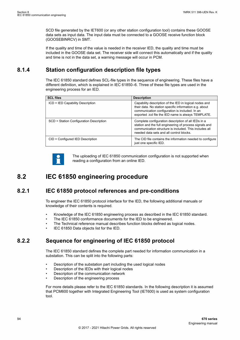
SCD file generated by the IET600 (or any other station configuration tool) contains these GOOSEdata sets as input data. The input data must be connected to a GOOSE receive function block(GOOSEBINRCV) in SMT.
If the quality and time of the value is needed in the receiver IED, the quality and time must beincluded in the GOOSE data set. The receiver side will connect this automatically and if the qualityand time is not in the data set, a warning message will occur in PCM.
8.1.4 Station configuration description file typesSEMOD58549-93 v7
The IEC 61850 standard defines SCL-file types in the sequence of engineering. These files have adifferent definition, which is explained in IEC 61850–6. Three of these file types are used in theengineering process for an IED.
SCL files DescriptionICD = IED Capability Description Capability description of the IED in logical nodes and
their data. No station specific information e.g. aboutcommunication configuration is included. In anexported .icd file the IED name is always TEMPLATE.
SCD = Station Configuration Description Complete configuration description of all IEDs in astation and the full engineering of process signals andcommunication structure is included. This includes allneeded data sets and all control blocks.
CID = Configured IED Description The CID file contains the information needed to configurejust one specific IED.
The uploading of IEC 61850 communication configuration is not supported whenreading a configuration from an online IED.
8.2 IEC 61850 engineering procedure
8.2.1 IEC 61850 protocol references and pre-conditionsSEMOD58549-4 v4
To engineer the IEC 61850 protocol interface for the IED, the following additional manuals orknowledge of their contents is required.
• Knowledge of the IEC 61850 engineering process as described in the IEC 61850 standard.• The IEC 61850 conformance documents for the IED to be engineered.• The Technical reference manual describes function blocks defined as logical nodes.• IEC 61850 Data objects list for the IED.
8.2.2 Sequence for engineering of IEC 61850 protocolSEMOD58549-17 v10
The IEC 61850 standard defines the complete part needed for information communication in asubstation. This can be split into the following parts:
• Description of the substation part including the used logical nodes• Description of the IEDs with their logical nodes• Description of the communication network• Description of the engineering process
For more details please refer to the IEC 61850 standards. In the following description it is assumedthat PCM600 together with Integrated Engineering Tool (IET600) is used as system configurationtool.
Section 8 1MRK 511 398-UEN Rev. KIEC 61850 communication engineering
94 670 seriesEngineering manual
© 2017 - 2021 Hitachi Power Grids. All rights reserved
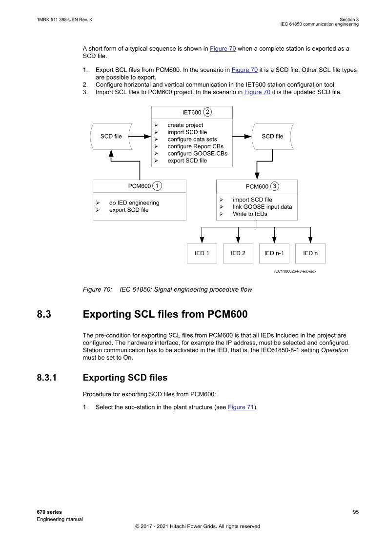
A short form of a typical sequence is shown in Figure 70 when a complete station is exported as aSCD file.
1. Export SCL files from PCM600. In the scenario in Figure 70 it is a SCD file. Other SCL file typesare possible to export.
2. Configure horizontal and vertical communication in the IET600 station configuration tool.3. Import SCL files to PCM600 project. In the scenario in Figure 70 it is the updated SCD file.
SCD file
do IED engineering export SCD file
PCM600
create project import SCD file configure data sets configure Report CBs configure GOOSE CBs export SCD file
IET600
import SCD file link GOOSE input data Write to IEDs
PCM600
SCD file
IED 1 IED nIED 2 IED n-1
IEC11000264-3-en.vsdx
2
31
IEC11000264 V3 EN-US
Figure 70: IEC 61850: Signal engineering procedure flow
8.3 Exporting SCL files from PCM600GUID-2A07D447-0EC8-45BC-9C71-1A015F030C3F v9
The pre-condition for exporting SCL files from PCM600 is that all IEDs included in the project areconfigured. The hardware interface, for example the IP address, must be selected and configured.Station communication has to be activated in the IED, that is, the IEC61850-8-1 setting Operationmust be set to On.
8.3.1 Exporting SCD filesGUID-2FDA859B-3761-4310-BEFF-11BB046A406B v4
Procedure for exporting SCD files from PCM600:
1. Select the sub-station in the plant structure (see Figure 71).
1MRK 511 398-UEN Rev. K Section 8IEC 61850 communication engineering
670 series 95Engineering manual
© 2017 - 2021 Hitachi Power Grids. All rights reserved

IEC08000415 V3 EN-US
Figure 71: IEC 61850: Export SCD step 1
2. Right-click on the sub-station, and select Export...3. Select a location to store the SCD file with a chosen name.4. The SCL Export Options window opens (see Figure 72).
IEC09000627-2-en.vsdIEC09000627 V2 EN-US
Figure 72: IEC 61850: SCL Export Options
5. Select the data to be exported and the version of the IEC 61850 standard.
PWC600 1.1 only supports IEC 61850 Edition 1.
6. Click Export to export the SCD file to your chosen location.
8.3.2 Exporting ICD or CID filesGUID-4F25EC7C-D0E7-4B61-8507-34E1CDC152DF v6
Procedure for selecting the export type when an IED is selected in the plant structure:
1. Right-click on the IED in the plant structure and select Export to open the Export window.2. Select the type of file to export from the Save as type drop down list (see Figure 73):
• Configured IED Description (*.cid) for the IEC 61850 structure as needed for the IED atruntime.
• IED Capability Description (*.icd) for the IEC 61850 structure.
Section 8 1MRK 511 398-UEN Rev. KIEC 61850 communication engineering
96 670 seriesEngineering manual
© 2017 - 2021 Hitachi Power Grids. All rights reserved
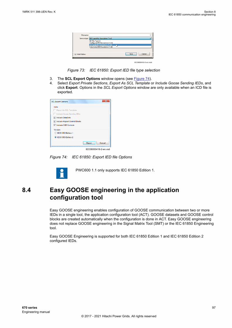
IEC08000416-3-en.vsdx
IEC08000416 V3 EN-US
Figure 73: IEC 61850: Export IED file type selection
3. The SCL Export Options window opens (see Figure 74).4. Select Export Private Sections, Export As SCL Template or Include Goose Sending IEDs, and
click Export. Options in the SCL Export Options window are only available when an ICD file isexported.
IEC08000418-2-en.vsdIEC08000418 V2 EN-US
Figure 74: IEC 61850: Export IED file Options
PWC600 1.1 only supports IEC 61850 Edition 1.
8.4 Easy GOOSE engineering in the applicationconfiguration tool
GUID-7EF7A8E8-943A-472D-85A6-F07382A0FC94 v2
Easy GOOSE engineering enables configuration of GOOSE communication between two or moreIEDs in a single tool, the application configuration tool (ACT). GOOSE datasets and GOOSE controlblocks are created automatically when the configuration is done in ACT. Easy GOOSE engineeringdoes not replace GOOSE engineering in the Signal Matrix Tool (SMT) or the IEC 61850 Engineeringtool.
Easy GOOSE Engineering is supported for both IEC 61850 Edition 1 and IEC 61850 Edition 2configured IEDs.
1MRK 511 398-UEN Rev. K Section 8IEC 61850 communication engineering
670 series 97Engineering manual
© 2017 - 2021 Hitachi Power Grids. All rights reserved
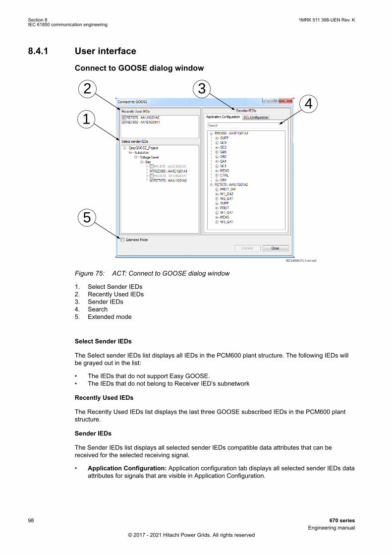
8.4.1 User interfaceGUID-407AAE50-53E1-4112-91FE-FCC5B33A38E9 v1
Connect to GOOSE dialog window
1
2 34
5
IEC16000171-1-en.vsd
IEC16000171 V1 EN-US
Figure 75: ACT: Connect to GOOSE dialog window
1. Select Sender IEDs2. Recently Used IEDs3. Sender IEDs4. Search5. Extended mode
Select Sender IEDs
The Select sender IEDs list displays all IEDs in the PCM600 plant structure. The following IEDs willbe grayed out in the list:
• The IEDs that do not support Easy GOOSE.• The IEDs that do not belong to Receiver IED’s subnetwork
Recently Used IEDs
The Recently Used IEDs list displays the last three GOOSE subscribed IEDs in the PCM600 plantstructure.
Sender IEDs
The Sender IEDs list displays all selected sender IEDs compatible data attributes that can bereceived for the selected receiving signal.
• Application Configuration: Application configuration tab displays all selected sender IEDs dataattributes for signals that are visible in Application Configuration.
Section 8 1MRK 511 398-UEN Rev. KIEC 61850 communication engineering
98 670 seriesEngineering manual
© 2017 - 2021 Hitachi Power Grids. All rights reserved
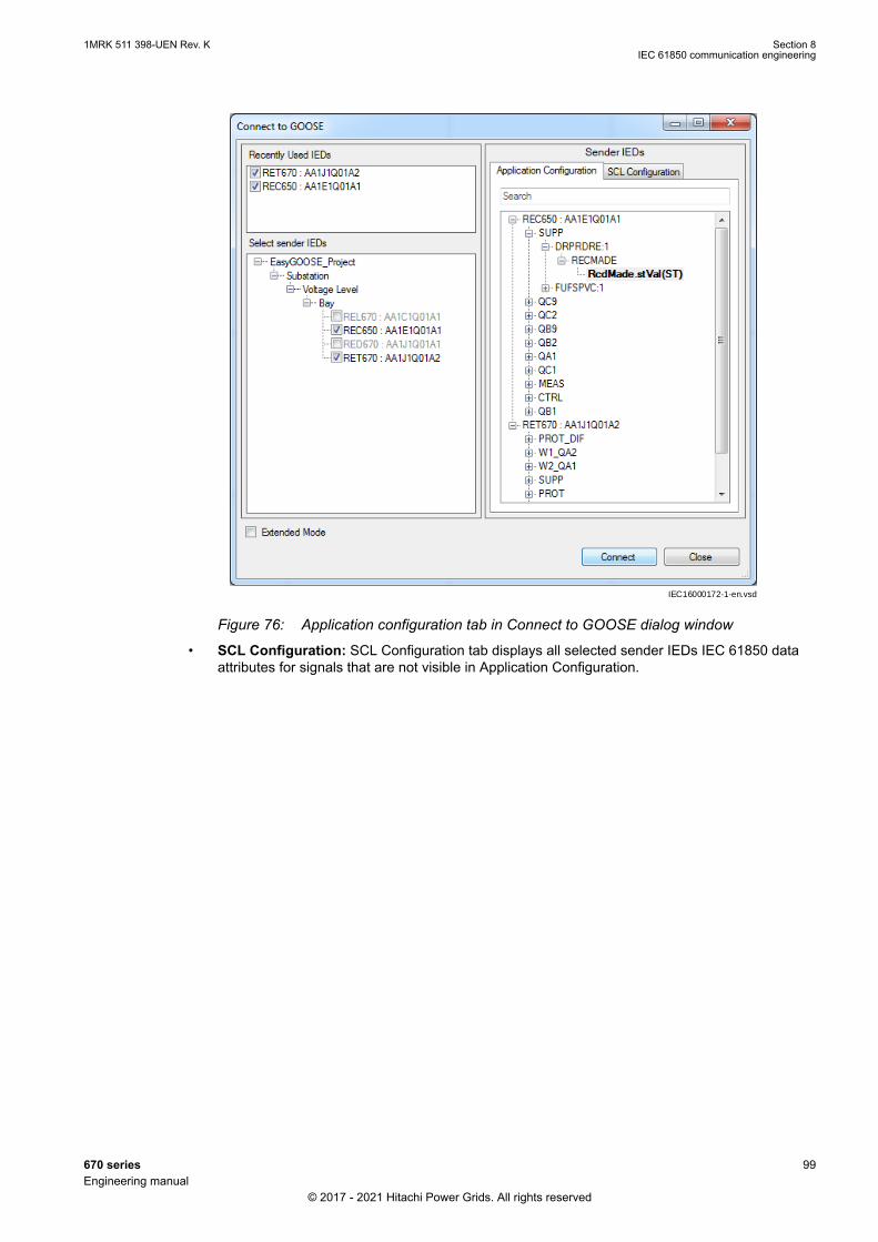
IEC16000172-1-en.vsd
IEC16000172 V1 EN-US
Figure 76: Application configuration tab in Connect to GOOSE dialog window
• SCL Configuration: SCL Configuration tab displays all selected sender IEDs IEC 61850 dataattributes for signals that are not visible in Application Configuration.
1MRK 511 398-UEN Rev. K Section 8IEC 61850 communication engineering
670 series 99Engineering manual
© 2017 - 2021 Hitachi Power Grids. All rights reserved

IEC16000173-1-en.vsd
IEC16000173 V1 EN-US
Figure 77: ACT: SCL Configuration tab in Connect to GOOSE dialog window
Search
In the Application Configuration tab, the Main Application, function block, signal, data attribute andIED name is considered in the filtering.
In the SCL Configuration tab, the logical device, logical node, data object and data attribute isconsidered in the filtering.
Extended Mode
Extended Mode is used to create multiple GOOSE connections without selecting an input signal inApplication Configuration. For detailed information about Extended Mode functionality, see Section"Connect to GOOSE dialog window user interface – Extended Mode".
Select GOOSE Block and Signal dialog windowThis dialog window will provide a list of compatible GOOSE Receive function blocks andcorresponding GOOSE input signals.
Section 8 1MRK 511 398-UEN Rev. KIEC 61850 communication engineering
100 670 seriesEngineering manual
© 2017 - 2021 Hitachi Power Grids. All rights reserved
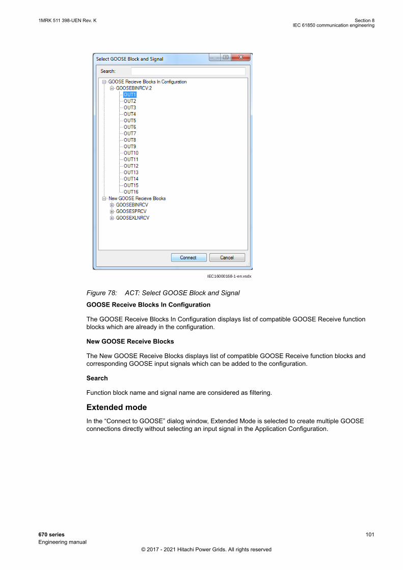
IEC16000168-1-en.vsdx
IEC16000168 V1 EN-US
Figure 78: ACT: Select GOOSE Block and Signal
GOOSE Receive Blocks In Configuration
The GOOSE Receive Blocks In Configuration displays list of compatible GOOSE Receive functionblocks which are already in the configuration.
New GOOSE Receive Blocks
The New GOOSE Receive Blocks displays list of compatible GOOSE Receive function blocks andcorresponding GOOSE input signals which can be added to the configuration.
Search
Function block name and signal name are considered as filtering.
Extended modeIn the “Connect to GOOSE” dialog window, Extended Mode is selected to create multiple GOOSEconnections directly without selecting an input signal in the Application Configuration.
1MRK 511 398-UEN Rev. K Section 8IEC 61850 communication engineering
670 series 101Engineering manual
© 2017 - 2021 Hitachi Power Grids. All rights reserved
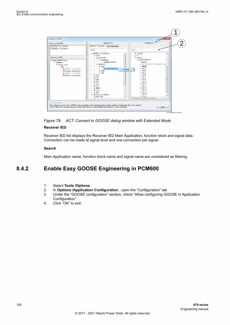
1
2
IEC16000190-1-en.vsdx
IEC16000190 V1 EN-US
Figure 79: ACT: Connect to GOOSE dialog window with Extended Mode
Receiver IED
Receiver IED list displays the Receiver IED Main Application, function block and signal data.Connection can be made at signal level and one connection per signal.
Search
Main Application name, function block name and signal name are considered as filtering.
8.4.2 Enable Easy GOOSE Engineering in PCM600GUID-65A0F83C-522C-4920-AA2D-479A640ECE28 v1
1. Select Tools /Options2. In Options /Application Configuration , open the “Configuration” tab3. Under the “GOOSE configuration” section, check “Allow configuring GOOSE in Application
Configuration”.4. Click “OK” to exit.
Section 8 1MRK 511 398-UEN Rev. KIEC 61850 communication engineering
102 670 seriesEngineering manual
© 2017 - 2021 Hitachi Power Grids. All rights reserved

IEC16000099-1-en.vsdx
IEC16000099 V1 EN-US
Figure 80: PCM600: Options dialog window
The “IEC 61850 configuration engineering mode enabled” option under Tools /Options /IEC 61850 Configuration /Enginneering tab has to be checked to get theoption above enabled.
8.4.3 Making GOOSE connections in the application configurationtool
GUID-2847BE10-3519-4EC8-97A2-A5A11A9ADCEC v1
GOOSE connections via Easy GOOSE can be created in two ways:
• via GOOSE receive functions• via normal function blocks.
8.4.3.1 Create GOOSE connections via GOOSE receive functionsGUID-F16104FF-C8BB-4455-807E-336E1AA09124 v1
1. Select and right click on the input signal of the GOOSE Receive function, point to “Connect”and select the “GOOSE” option.
1MRK 511 398-UEN Rev. K Section 8IEC 61850 communication engineering
670 series 103Engineering manual
© 2017 - 2021 Hitachi Power Grids. All rights reserved
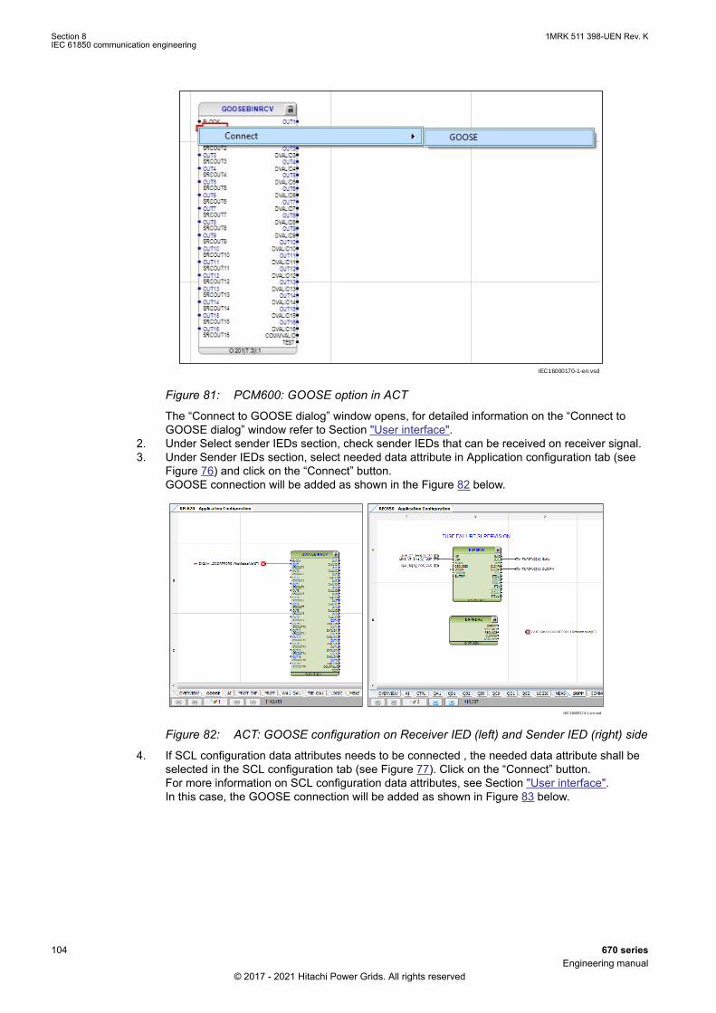
IEC16000170-1-en.vsd
IEC16000170 V1 EN-US
Figure 81: PCM600: GOOSE option in ACT
The “Connect to GOOSE dialog” window opens, for detailed information on the “Connect toGOOSE dialog” window refer to Section "User interface".
2. Under Select sender IEDs section, check sender IEDs that can be received on receiver signal.3. Under Sender IEDs section, select needed data attribute in Application configuration tab (see
Figure 76) and click on the “Connect” button.GOOSE connection will be added as shown in the Figure 82 below.
IEC16000174-1-en.vsd
IEC16000174 V1 EN-US
Figure 82: ACT: GOOSE configuration on Receiver IED (left) and Sender IED (right) side
4. If SCL configuration data attributes needs to be connected , the needed data attribute shall beselected in the SCL configuration tab (see Figure 77). Click on the “Connect” button.For more information on SCL configuration data attributes, see Section "User interface".In this case, the GOOSE connection will be added as shown in Figure 83 below.
Section 8 1MRK 511 398-UEN Rev. KIEC 61850 communication engineering
104 670 seriesEngineering manual
© 2017 - 2021 Hitachi Power Grids. All rights reserved
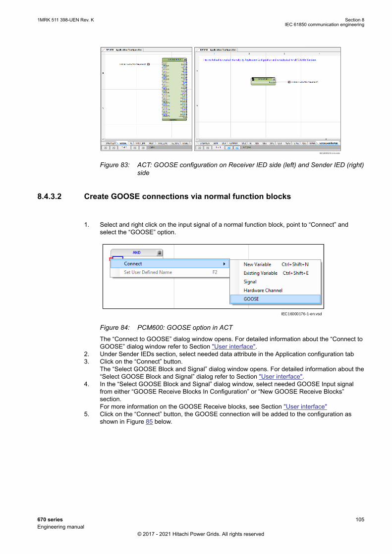
IEC16000175-1-en.vsdx
IEC16000175 V1 EN-US
Figure 83: ACT: GOOSE configuration on Receiver IED side (left) and Sender IED (right)side
8.4.3.2 Create GOOSE connections via normal function blocksGUID-573EF145-F558-4A2C-9F0E-B3614B2ECD29 v1
1. Select and right click on the input signal of a normal function block, point to “Connect” andselect the “GOOSE” option.
IEC16000176-1-en.vsd
IEC16000176 V1 EN-US
Figure 84: PCM600: GOOSE option in ACT
The “Connect to GOOSE” dialog window opens. For detailed information about the “Connect toGOOSE” dialog window refer to Section "User interface".
2. Under Sender IEDs section, select needed data attribute in the Application configuration tab3. Click on the “Connect” button.
The “Select GOOSE Block and Signal” dialog window opens. For detailed information about the“Select GOOSE Block and Signal” dialog refer to Section "User interface".
4. In the “Select GOOSE Block and Signal” dialog window, select needed GOOSE Input signalfrom either “GOOSE Receive Blocks In Configuration” or “New GOOSE Receive Blocks”section.For more information on the GOOSE Receive blocks, see Section "User interface"
5. Click on the “Connect” button, the GOOSE connection will be added to the configuration asshown in Figure 85 below.
1MRK 511 398-UEN Rev. K Section 8IEC 61850 communication engineering
670 series 105Engineering manual
© 2017 - 2021 Hitachi Power Grids. All rights reserved

IEC16000177-1-en.vsd
IEC16000177 V1 EN-US
Figure 85: ACT: GOOSE configuration on Receiver IED (left) and Sender IED (right) side
6. If SCL configuration data attributes needs to be connected the needed data attributes needs tobe selected in the SCL configuration tab (See Figure 77).6.1. Click on the “Connect” button.6.2. Select the needed GOOSE input signal in the “Select GOOSE Block and Signal” dialog
window.6.3. Click on the Connect button.
In this case, GOOSE connection will be added as shown in Figure 86 below.
IEC16000178-1-en.vsd
IEC16000178 V1 EN-US
Figure 86: ACT: GOOSE configuration on Receiver IED (left) and Sender IED (right) side
Creation of GOOSE connections via normal function blocks is not supportedfor the GOOSEINTLKRCV function.
8.4.3.3 Connect to GOOSE dialog window user interface – Extended ModeGUID-908FBED9-8F16-425E-8546-1969596C45CD v1
In the “Connect to GOOSE” dialog window, “Extended Mode” is selected to create multiple GOOSEconnections directly without selecting an input signal in the Application Configuration.
1. Under “Receiver IED” section, select GOOSE Receive or normal function input signal.2. Under “Sender IEDs” section, select and right click on data attribute in either Application
Configuration or SCL Configuration tab3. Click on Connect option.
The GOOSE connections will be added to the configuration. Refer to Figure 76, 77, 83 and 84for GOOSE connections appearance in ACT.
Section 8 1MRK 511 398-UEN Rev. KIEC 61850 communication engineering
106 670 seriesEngineering manual
© 2017 - 2021 Hitachi Power Grids. All rights reserved

8.4.3.4 Connecting to a IEC 61850 SCL data attribute from sending IEDGUID-2B09E287-61BF-456F-A35D-3B876064B86C v2
When a GOOSE connection is created by selecting data attribute under "SCL Configuration" tab inthe Connect to GOOSE dialog window (see Figure 77), a seperate MainApp calledGOOSESenderApp is created automatically and added to application configuration in the sender IEDside. GOOSESenderApp contains the graphical representation of the IEC 61850 SCL data attributesfor signals that are not visible in Application Configuration.
IEC16000169-1-en.vsdx
IEC16000169 V1 EN-US
Figure 87: ACT: GOOSESenderApp
GOOSE datasets and GOOSE control blocks are created automatically when theGOOSE configuration is done in ACT.
If the sender IED and receiver IEDs do not belong to same subnetworks, GOOSEreceiving is not possible.
Creation of GOOSE communication for GOOSEVCTRRCV function via EasyGOOSE Engineering is not supported.
GOOSESenderApp MainApp cannot be copied or deleted in the ApplicationConfiguration.
8.4.3.5 Easy GOOSE engineering when GOOSE is configured via IEC 61850configuration protocol
GUID-0D498334-DB06-4038-9FAB-D9ADE2585D51 v1
After enabling Easy GOOSE Engineering in PCM600 (see section "Enable Easy GOOSEEngineering in PCM600"), GOOSE can be configured either via the IEC 61850 configuration tool andthe Signal matrix tool or via Easy GOOSE. When GOOSE is configured via the IEC 61850configuration tool and Signal matrix tool, the GOOSE configuration is also added to the applicationconfiguration in the sender IED and the receiver IED as shown in Figure 82, 83, 85, and 86.
When Easy GOOSE engineering is enabled in PCM600, GOOSE can be still beconfigured via IEC 61850 configuration tool and Signal Matrix Tool as well.
8.4.4 Deleting connectionsGUID-0D3B0D71-7077-4A39-9A33-E1E37F98324C v1
The following connections cannot be deleted in ACT:
1MRK 511 398-UEN Rev. K Section 8IEC 61850 communication engineering
670 series 107Engineering manual
© 2017 - 2021 Hitachi Power Grids. All rights reserved

• GOOSE sending variable• Link between the GOOSE sending variable and signal• Function block to which the GOOSE sending variable is connected• MainApp/Page containing the GOOSE sending variable.
8.4.5 Cut-Paste and Copy-Paste of ACT GOOSE variablesGUID-48CAD18F-99B4-41C4-BEF7-0BC389E8EC2E v1
The GOOSE variables alone cannot be pasted. They can be cut or pasted only with the connectedblock.
Copying and pasting of GOOSE variables within the same IED is not allowed. If the GOOSE variableis copied along with the connected block, only the block is copied provided that the instance isavailable.
GOOSE variables and worksheets can be copied and pasted into other IEDs. However, the GOOSEsending variables are not copied. The receiving GOOSE variables are copied unless they are alreadypresent in the other IED.
8.4.6 GOOSE Online MonitoringGUID-1778C485-55D8-4DBB-B90C-16A5D5545BB3 v2
Click Work online on the toolbar in ACT for Online Monitoring for the GOOSE sending signals andreceiving signals. The sending or receiving GOOSE variable shows the value being sent or receivedover GOOSE.
8.5 Engineering of vertical and horizontal communicationin IET600
GUID-04ED1306-BAE6-49D2-8C84-11849EACC711 v10
For IEC 61850 engineering, a separate system configuration tool may be needed with PCM600 (forexample, when using other than Hitachi Power grids IEDs).
Procedure for vertical engineering using IET600:
1. Create a project in IET600.2. Import the SCD file exported from PCM600.
All data sets, report control blocks and GOOSE control blocks must be locatedat LD0/LLN0. There are limitations regarding the maximum number of data sets,number of entries in a data set and the number of report control blocks that canbe used.
3. Add and/or reconfigure data sets. The configured IED includes a number of predefined datasets, but it is possible to add additional data sets and/or reconfigure default data sets accordingto the requirements.
Reporting data sets only contain data intended to be used by vertical clients, forexample MicroSCADA or RTU560.
4. Configure report control blocks for each data set used in vertical communication. Pre-configuredIEDs include predefined report control blocks which can be reconfigured. If additional controlblocks are needed, it is possible to add them according to requirements.
Up to 8 vertical clients can be configured.
5. Connect the report control blocks to vertical clients.
Section 8 1MRK 511 398-UEN Rev. KIEC 61850 communication engineering
108 670 seriesEngineering manual
© 2017 - 2021 Hitachi Power Grids. All rights reserved
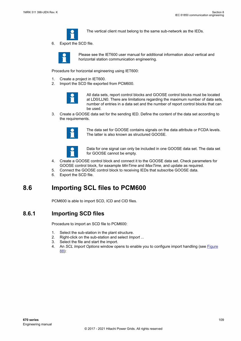
The vertical client must belong to the same sub-network as the IEDs.
6. Export the SCD file.
Please see the IET600 user manual for additional information about vertical andhorizontal station communication engineering.
Procedure for horizontal engineering using IET600:
1. Create a project in IET600.2. Import the SCD file exported from PCM600.
All data sets, report control blocks and GOOSE control blocks must be locatedat LD0/LLN0. There are limitations regarding the maximum number of data sets,number of entries in a data set and the number of report control blocks that canbe used.
3. Create a GOOSE data set for the sending IED. Define the content of the data set according tothe requirements.
The data set for GOOSE contains signals on the data attribute or FCDA levels.The latter is also known as structured GOOSE.
Data for one signal can only be included in one GOOSE data set. The data setfor GOOSE cannot be empty.
4. Create a GOOSE control block and connect it to the GOOSE data set. Check parameters forGOOSE control block, for eaxample MinTime and MaxTime, and update as required.
5. Connect the GOOSE control block to receiving IEDs that subscribe GOOSE data.6. Export the SCD file.
8.6 Importing SCL files to PCM600GUID-DA35857B-999B-4533-8148-864B69ECDBCE v2
PCM600 is able to import SCD, ICD and CID files.
8.6.1 Importing SCD filesGUID-93604C46-1A65-4A25-9334-59478FC1C0A0 v6
Procedure to import an SCD file to PCM600:
1. Select the sub-station in the plant structure.2. Right-click on the sub-station and select Import ...3. Select the file and start the import.4. An SCL Import Options window opens to enable you to configure import handling (see Figure
88):
1MRK 511 398-UEN Rev. K Section 8IEC 61850 communication engineering
670 series 109Engineering manual
© 2017 - 2021 Hitachi Power Grids. All rights reserved
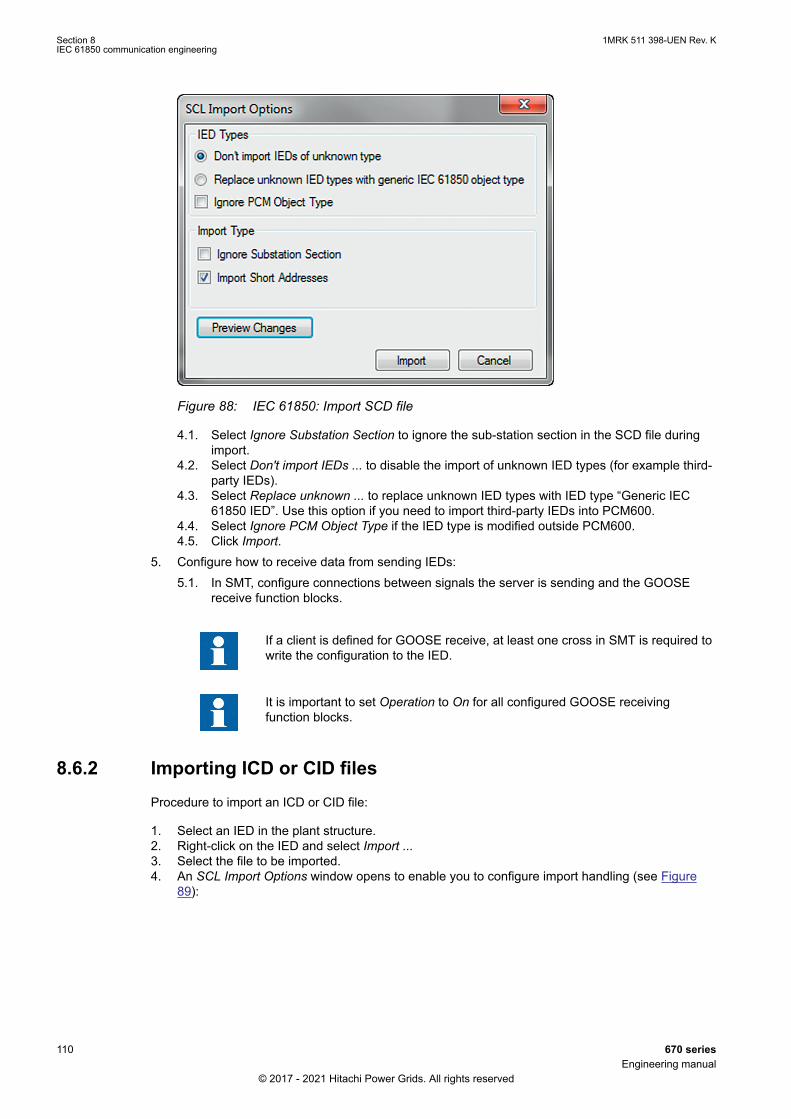
IEC09000631 V3 EN-US
Figure 88: IEC 61850: Import SCD file
4.1. Select Ignore Substation Section to ignore the sub-station section in the SCD file duringimport.
4.2. Select Don't import IEDs ... to disable the import of unknown IED types (for example third-party IEDs).
4.3. Select Replace unknown ... to replace unknown IED types with IED type “Generic IEC61850 IED”. Use this option if you need to import third-party IEDs into PCM600.
4.4. Select Ignore PCM Object Type if the IED type is modified outside PCM600.4.5. Click Import.
5. Configure how to receive data from sending IEDs:5.1. In SMT, configure connections between signals the server is sending and the GOOSE
receive function blocks.
If a client is defined for GOOSE receive, at least one cross in SMT is required towrite the configuration to the IED.
It is important to set Operation to On for all configured GOOSE receivingfunction blocks.
8.6.2 Importing ICD or CID filesGUID-D8A6D372-7E16-4004-AAF6-F6E3BAC64E30 v3
Procedure to import an ICD or CID file:
1. Select an IED in the plant structure.2. Right-click on the IED and select Import ...3. Select the file to be imported.4. An SCL Import Options window opens to enable you to configure import handling (see Figure
89):
Section 8 1MRK 511 398-UEN Rev. KIEC 61850 communication engineering
110 670 seriesEngineering manual
© 2017 - 2021 Hitachi Power Grids. All rights reserved

4.1. Select Ignore Substation Section to ignore the sub-station section in the chosen file duringimport.
4.2. Select Don't import IEDs ... to disable the import of unknown IED types (for example third-party IEDs).
4.3. Select Replace unknown ... to replace unknown IED types with IED type “Generic IEC61850 IED”. Use this option if you need to import third-party IEDs into PCM600.
4.4. Select Ignore PCM Object Type if the IED type is modified outside PCM600.4.5. Click Import.
IEC09000631 V3 EN-US
Figure 89: IEC 61850: SCL Import option
8.7 Writing IEC 61850 communication configuration to anIED
GUID-EE2F7AE2-2EA6-4F16-94F1-E9472CF6BB50 v8
After changing any aspect of IEC 61850 communication in PCM600 the updated configuration needsto be written to the IED. This is done through a full Write to IED... from the context menu or theTools menu.
1MRK 511 398-UEN Rev. K Section 8IEC 61850 communication engineering
670 series 111Engineering manual
© 2017 - 2021 Hitachi Power Grids. All rights reserved

112

Section 9 IEC 60870-5-103 communicationengineering
9.1 Engineering in PCM600GUID-284EB0BA-BC79-4B90-8B78-878BA225479E v7
The Application Configuration tool (ACT) and the Parameter Setting tool (PST) in PCM600 are usedto configure the communication for IEC 60870-5-103 protocol.
1. Add the desired IEC 60870-5-103 function blocks to the application configuration in theApplication Configuration tool.
2. Connect the outputs of desired protection and monitoring function in the applicationconfiguration to the inputs of the corresponding IEC 60870-5-103 function block.
3. Set the function type and desired information number, where an information number must besupplied, for each IEC 60870-5-103 function block instance in the Parameter Setting tool.
4. Set the general communication settings for IEC 60870-5-103 and time synchronizationparameters in the Parameter Setting tool.
See the Communication protocol manual for IEC 60870-5-103 for more information about the IEC60870-5-103 implementation in the IED series.
9.1.1 Settings for RS485 and optical serial communicationM17109-118 v13
General settingsSPA, DNP and IEC 60870-5-103 can be configured to operate on the SLM optical serial port whileDNP and IEC 60870-5-103 additionally can utilize the RS485 port. A single protocol can be active ona given physical port at any time.
Two different areas in the HMI are used to configure the IEC 60870-5-103 protocol.
1. The port specific IEC 60870-5-103 protocol parameters are configured under:Main menu /Configuration /Communication /Station Communication /IEC60870-5-103 /• <config-selector>• SlaveAddress• BaudRate• RevPolarity (optical channel only)• CycMeasRepTime• MasterTimeDomain• TimeSyncMode• EvalTimeAccuracy• EventRepMode• CmdMode• RepIntermediatePos
<config-selector> is:• “OPTICAL103:1” for the optical serial channel on the SLM• “RS485103:1” for the RS485 port
2. The protocol to activate on a physical port is selected under:Main menu /Configuration /Communication /Station Communication /Port configuration /• RS485 port
1MRK 511 398-UEN Rev. K Section 9IEC 60870-5-103 communication engineering
670 series 113Engineering manual
© 2017 - 2021 Hitachi Power Grids. All rights reserved
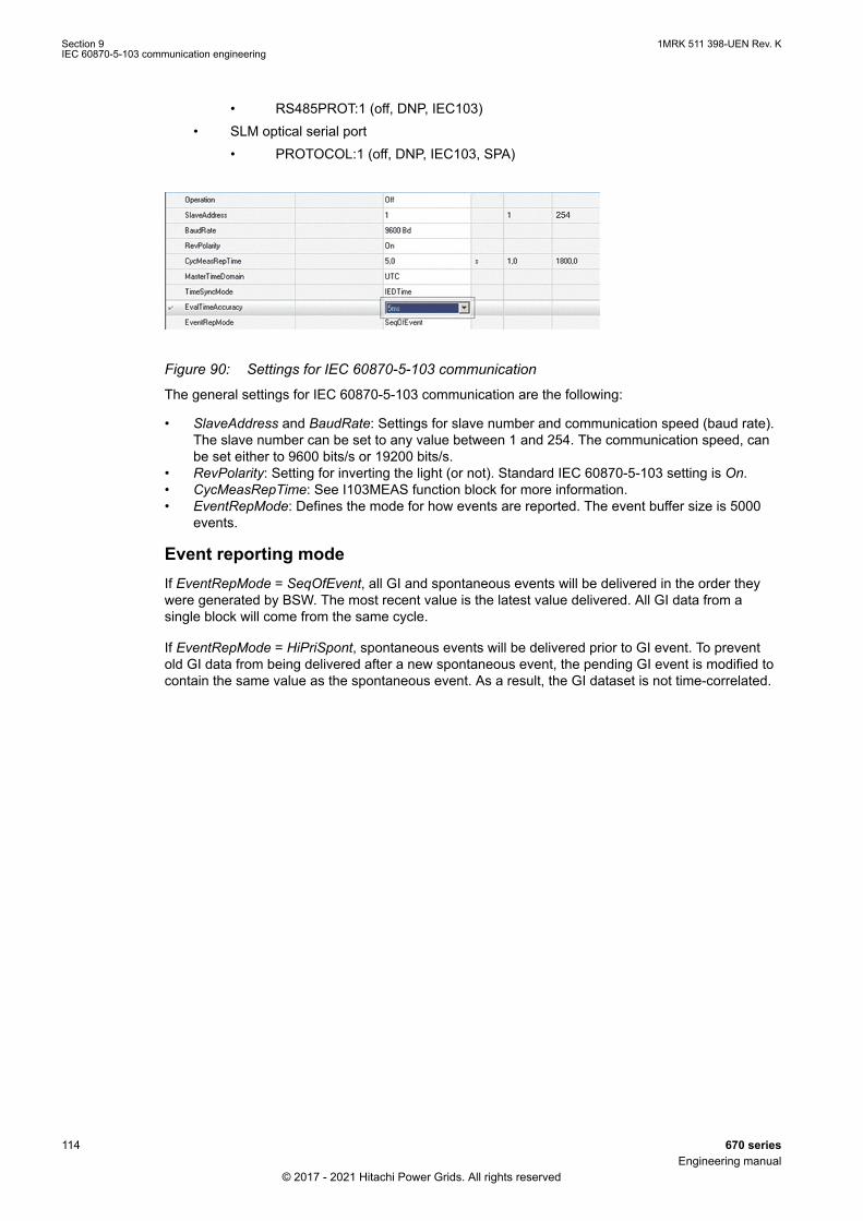
• RS485PROT:1 (off, DNP, IEC103)• SLM optical serial port
• PROTOCOL:1 (off, DNP, IEC103, SPA)
GUID-CD4EB23C-65E7-4ED5-AFB1-A9D5E9EE7CA8 V3 ENGUID-CD4EB23C-65E7-4ED5-AFB1-A9D5E9EE7CA8 V3 EN-US
Figure 90: Settings for IEC 60870-5-103 communication
The general settings for IEC 60870-5-103 communication are the following:
• SlaveAddress and BaudRate: Settings for slave number and communication speed (baud rate).The slave number can be set to any value between 1 and 254. The communication speed, canbe set either to 9600 bits/s or 19200 bits/s.
• RevPolarity: Setting for inverting the light (or not). Standard IEC 60870-5-103 setting is On.• CycMeasRepTime: See I103MEAS function block for more information.• EventRepMode: Defines the mode for how events are reported. The event buffer size is 5000
events.
Event reporting modeIf EventRepMode = SeqOfEvent, all GI and spontaneous events will be delivered in the order theywere generated by BSW. The most recent value is the latest value delivered. All GI data from asingle block will come from the same cycle.
If EventRepMode = HiPriSpont, spontaneous events will be delivered prior to GI event. To preventold GI data from being delivered after a new spontaneous event, the pending GI event is modified tocontain the same value as the spontaneous event. As a result, the GI dataset is not time-correlated.
Section 9 1MRK 511 398-UEN Rev. KIEC 60870-5-103 communication engineering
114 670 seriesEngineering manual
© 2017 - 2021 Hitachi Power Grids. All rights reserved

Section 10 DNP3 communication engineering
10.1 Signal configuration user informationGUID-AC54A350-D43E-4C0C-995C-012D7533ECC1 v4
Basic knowledge about DNP3 and the used definitions are required to use CMT. Seethe DNP3 communication protocol manual for information on the DNP3implementation in the IED.
CMT is a part of PCM600 and allows to configure the signals that are used to communicate withclients or master units for DNP3 protocols.
On the left window CMT organizes all available signals from the application configuration incontainers that are preselected as signal types.
On the right window CMT provides containers that are selected by tabs. Each container representsone communication channel. The number of possible communication channels is IED typedependent. The IED uses TCP/IP as communication channel. DNP3 can be tunneled over TCP/IP.Serial communication over RS485 or optical is supported. .
Use direction icons that are located between the windows to move all signals or a set of individualsignals between the windows.
DNP3 signal types, index and default setting for classes are predefined in CMT. Adapt the signalconfiguration to project definitions. The signal type can not be modified due to the fact that theinternal signal set up is fixed.
When the default configuration values are sufficient, the task is finished when all signal are movedaccording to the project requirements.
With the Save option, the signals are stored for the communication part of the IED according to thedefault selections.
Only for analog measurements additional configuration parameters are shown to do signal scaling toDNP3 protocol presentation. This can be done when the Configuration Table View is selected.
Finally, the signal configuration to the different DNP3 channels can be listed in a report on demandand per signal type.
10.2 Adding setting groupsGUID-9C636C53-898E-4A60-9DDA-1DB13A65EE30 v3
In order to show for a DNP master which setting group is used, the procedure outlines here can beperformed.
In this example, only setting groups one and two are used. The DNP master will get two binaryinputs: the first is set if setting group one is used, the second is set if setting group two is used.
1. Configure ACTVGRP (Basic IED functions) and SP16GAPC (Monitoring) with the ApplicationConfiguration Tool (ACT).
1MRK 511 398-UEN Rev. K Section 10DNP3 communication engineering
670 series 115Engineering manual
© 2017 - 2021 Hitachi Power Grids. All rights reserved

IEC11000423 V4 EN-US
Figure 91: Application configuration tool
To make it easier to recognize the signals for the active setting group, user-defined names are used.
2. Open the Communication Management Tool (CMT). Set the Signal Type to Binary Input Object,and choose the connection of the master for which the values should be presented.
IEC11000424-2-en.vsd
IEC11000424 V2 EN-US
Figure 92: Communication Management tool
3. Select the signals and move them into the DNP signal list of the master. DNP point zero and oneof the Binary Input Objects are used for indicating the active setting group in this case.
Section 10 1MRK 511 398-UEN Rev. KDNP3 communication engineering
116 670 seriesEngineering manual
© 2017 - 2021 Hitachi Power Grids. All rights reserved
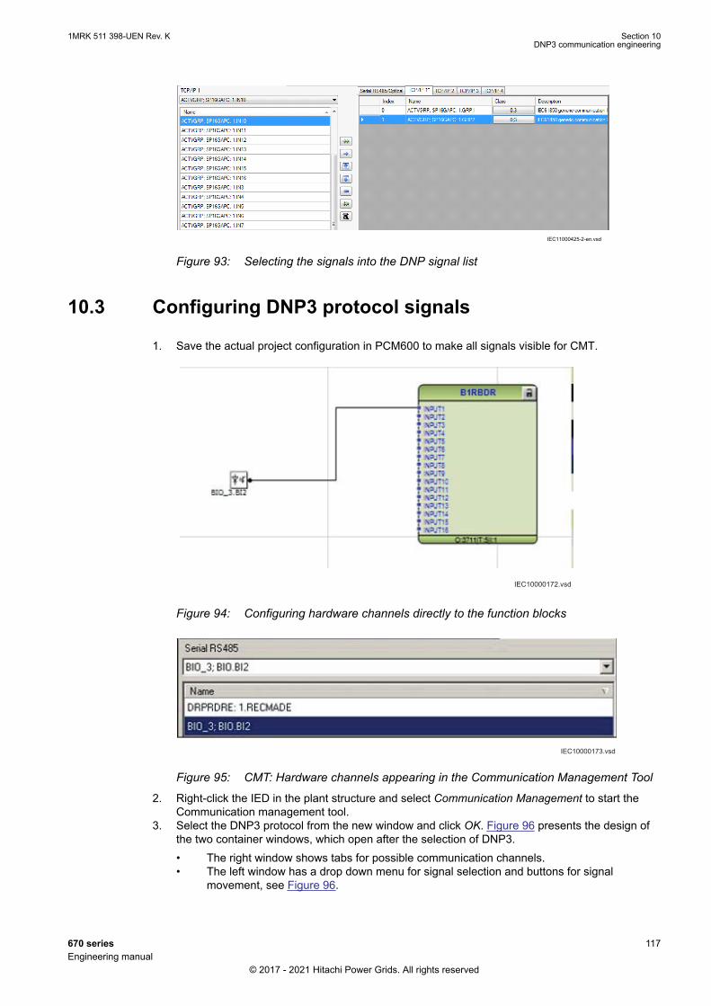
IEC11000425-2-en.vsdIEC11000425 V2 EN-US
Figure 93: Selecting the signals into the DNP signal list
10.3 Configuring DNP3 protocol signalsGUID-4908ED38-733F-4A8B-AEB2-90C0CB9A5274 v4
1. Save the actual project configuration in PCM600 to make all signals visible for CMT.
IEC10000172.vsd
IEC10000172 V1 EN-US
Figure 94: Configuring hardware channels directly to the function blocks
IEC10000173.vsdIEC10000173 V1 EN-US
Figure 95: CMT: Hardware channels appearing in the Communication Management Tool
2. Right-click the IED in the plant structure and select Communication Management to start theCommunication management tool.
3. Select the DNP3 protocol from the new window and click OK. Figure 96 presents the design ofthe two container windows, which open after the selection of DNP3.• The right window shows tabs for possible communication channels.• The left window has a drop down menu for signal selection and buttons for signal
movement, see Figure 96.
1MRK 511 398-UEN Rev. K Section 10DNP3 communication engineering
670 series 117Engineering manual
© 2017 - 2021 Hitachi Power Grids. All rights reserved
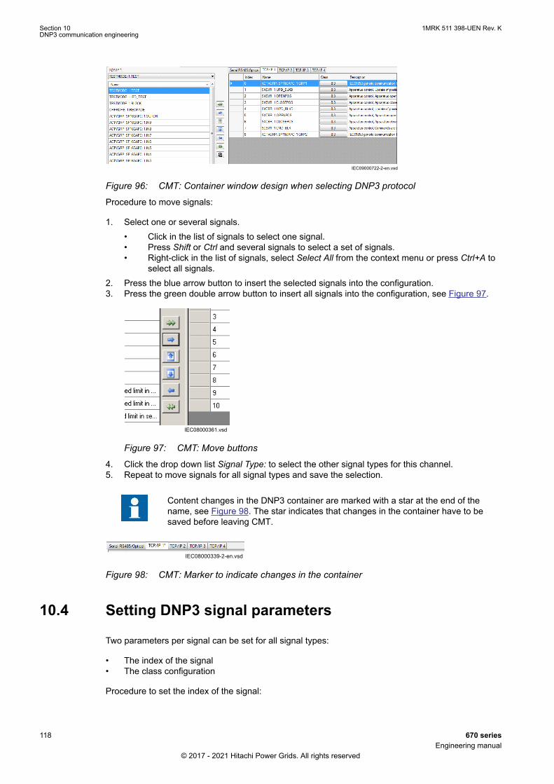
IEC09000722-2-en.vsdIEC09000722 V2 EN-US
Figure 96: CMT: Container window design when selecting DNP3 protocol
Procedure to move signals:
1. Select one or several signals.• Click in the list of signals to select one signal.• Press Shift or Ctrl and several signals to select a set of signals.• Right-click in the list of signals, select Select All from the context menu or press Ctrl+A to
select all signals.2. Press the blue arrow button to insert the selected signals into the configuration.3. Press the green double arrow button to insert all signals into the configuration, see Figure 97.
IEC08000361.vsdIEC08000361 V1 EN-US
Figure 97: CMT: Move buttons
4. Click the drop down list Signal Type: to select the other signal types for this channel.5. Repeat to move signals for all signal types and save the selection.
Content changes in the DNP3 container are marked with a star at the end of thename, see Figure 98. The star indicates that changes in the container have to besaved before leaving CMT.
IEC08000339-2-en.vsdIEC08000339 V2 EN-US
Figure 98: CMT: Marker to indicate changes in the container
10.4 Setting DNP3 signal parametersGUID-F762121A-41E5-49F1-9359-205CF9E15304 v1
Two parameters per signal can be set for all signal types:
• The index of the signal• The class configuration
Procedure to set the index of the signal:
Section 10 1MRK 511 398-UEN Rev. KDNP3 communication engineering
118 670 seriesEngineering manual
© 2017 - 2021 Hitachi Power Grids. All rights reserved
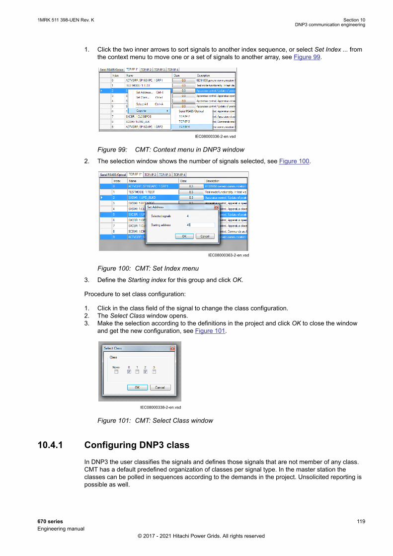
1. Click the two inner arrows to sort signals to another index sequence, or select Set Index ... fromthe context menu to move one or a set of signals to another array, see Figure 99.
IEC08000336-2-en.vsdIEC08000336 V2 EN-US
Figure 99: CMT: Context menu in DNP3 window
2. The selection window shows the number of signals selected, see Figure 100.
IEC08000363-2-en.vsdIEC08000363 V2 EN-US
Figure 100: CMT: Set Index menu
3. Define the Starting index for this group and click OK.
Procedure to set class configuration:
1. Click in the class field of the signal to change the class configuration.2. The Select Class window opens.3. Make the selection according to the definitions in the project and click OK to close the window
and get the new configuration, see Figure 101.
IEC08000338-2-en.vsdIEC08000338 V2 EN-US
Figure 101: CMT: Select Class window
10.4.1 Configuring DNP3 classGUID-B46924F8-B960-4B79-8EB8-4DFADABDFB10 v1
In DNP3 the user classifies the signals and defines those signals that are not member of any class.CMT has a default predefined organization of classes per signal type. In the master station theclasses can be polled in sequences according to the demands in the project. Unsolicited reporting ispossible as well.
1MRK 511 398-UEN Rev. K Section 10DNP3 communication engineering
670 series 119Engineering manual
© 2017 - 2021 Hitachi Power Grids. All rights reserved

Modify the organization of the classes for each signal individually.
Procedure
1. Click in the Class field of the signal. A new window Select Class opens where the user classifiesthe signal.
2. Select the signal classes and choose between None and 0 to 3 according to the projectdemands.
3. Click OK to set the signal classification.4. Write to IED.
Section 10 1MRK 511 398-UEN Rev. KDNP3 communication engineering
120 670 seriesEngineering manual
© 2017 - 2021 Hitachi Power Grids. All rights reserved

Section 11 Flexible product naming
11.1 IEC 61850 Structure Mapping ToolGUID-079F55A1-84A7-4920-87DF-0251A08D2BD4 v2
IEC 61850 Structure Mapping Tool is used to manage the data model of IED, where one can changethe IEDs IEC 61850 data model as per the requirement. This can be done by mapping the datamodel with customer specific data model. The IEC 61850 structure mapping tool is available only inFPN projects in PCM600. A PCM600 project can be converted into an FPN project by importing anFPN SCD file into it. FPN is supported for both IEC 61850 Edition 1 and IEC 61850 Edition 2.
FPN allows the use of standardized, predefined and IED-vendor independent templates for buildingand maintaining substations. Refer to the PCM600 online help for more detailed information aboutFPN.
11.1.1 User interfaceGUID-7E8E092D-E671-4A8E-9069-237D2A62515B v2
IEC15000082-2-en.vsdx
1 2 3
IEC15000082 V2 EN-US
Figure 102: Mapping Tool
1. Plant Structure2. IEC 61850 Structure Mapping3. Object Properties
Plant Structure
The data tree displays the Flexible Product Naming (FPN) IEDs, non-FPN IEDs and mapped IEDsunder substation; internal IEDs under unassigned IEDs.
IEC 61850 structure Mapping
The IEC 61850 structure mapping list displays the FPN objects based on the current selection in theplant structure. The list may display either IEDs or data attributes. The FPN object’s name isdisplayed in the column on the left and the mapped PCM600 internal object name is displayed in thecolumn on the right. The IEC 61850 structure mapping displays customer data structure andcustomer data attribute on the left; internal data structure and internal data attribute on the right.
Object Properties
Object properties window displays properties of objects currently selected in the FPN Mappings andInternal Data Attribute lists. The properties are read-only and cannot be modified by user.
1MRK 511 398-UEN Rev. K Section 11Flexible product naming
670 series 121Engineering manual
© 2017 - 2021 Hitachi Power Grids. All rights reserved
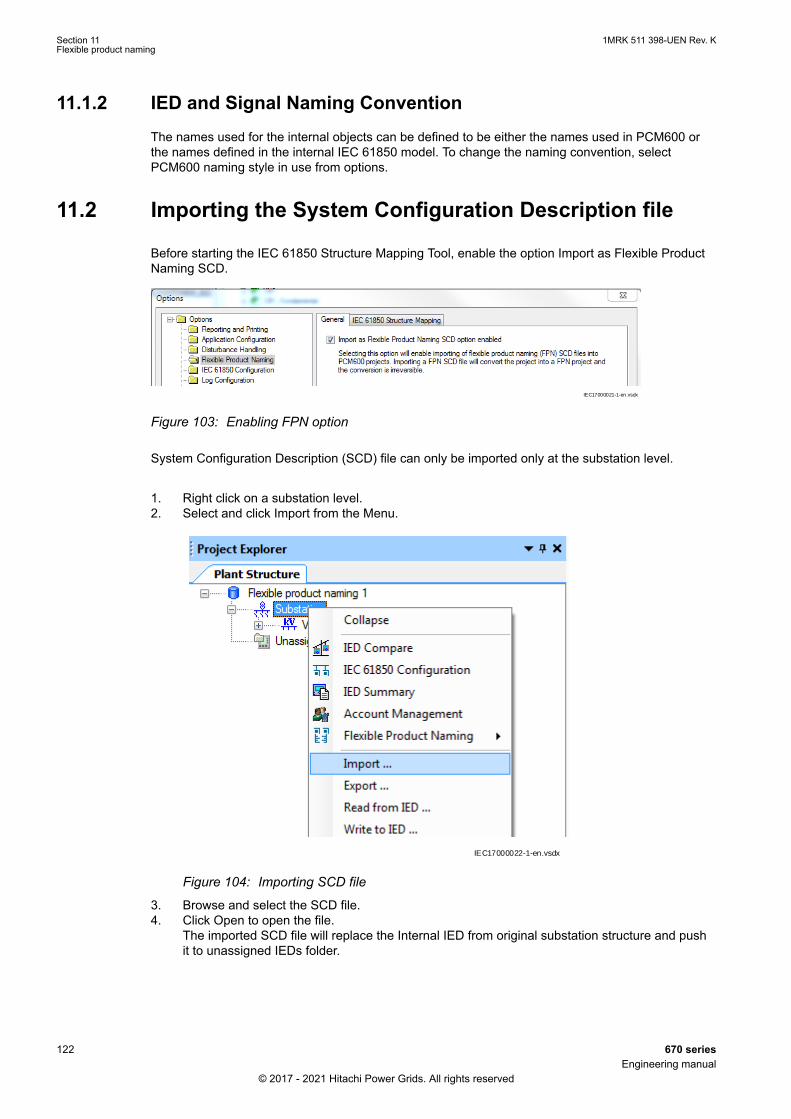
11.1.2 IED and Signal Naming ConventionGUID-9432AA02-F2F5-4CEE-BCD3-D47713A60345 v2
The names used for the internal objects can be defined to be either the names used in PCM600 orthe names defined in the internal IEC 61850 model. To change the naming convention, selectPCM600 naming style in use from options.
11.2 Importing the System Configuration Description fileGUID-897210DF-7BC8-4A49-B567-EBEF3DAAF2C6 v1
Before starting the IEC 61850 Structure Mapping Tool, enable the option Import as Flexible ProductNaming SCD.
IEC17000021-1-en.vsdx
IEC17000021 V1 EN-US
Figure 103: Enabling FPN option
System Configuration Description (SCD) file can only be imported only at the substation level.
1. Right click on a substation level.2. Select and click Import from the Menu.
IEC17000022-1-en.vsdx
IEC17000022 V1 EN-US
Figure 104: Importing SCD file
3. Browse and select the SCD file.4. Click Open to open the file.
The imported SCD file will replace the Internal IED from original substation structure and pushit to unassigned IEDs folder.
Section 11 1MRK 511 398-UEN Rev. KFlexible product naming
122 670 seriesEngineering manual
© 2017 - 2021 Hitachi Power Grids. All rights reserved

IEC17000023-1-en.vsdx
IEC17000023 V1 EN-US
Figure 105: Unassigned IEDs
Importing the FPN SCD file will convert the project into a FPN project and theconversion is irreversible.
FPN projects does not support Easy Goose Engineering.
11.3 Starting the IEC 61850 Structure Mapping ToolGUID-3216206E-D6FF-4BCE-9A85-CD4DBE4B5F51 v2
The tool can be started from any node from Substation to IED level.
1. Right click on one of the nodes.2. Select Flexible Product Naming from the menu.3. Click on IEC 61850 Structure Mapping.
The FPN object’s name is displayed in the column on the left and the name of the mappedPCM600 internal object is displayed in the column on the right.
1MRK 511 398-UEN Rev. K Section 11Flexible product naming
670 series 123Engineering manual
© 2017 - 2021 Hitachi Power Grids. All rights reserved
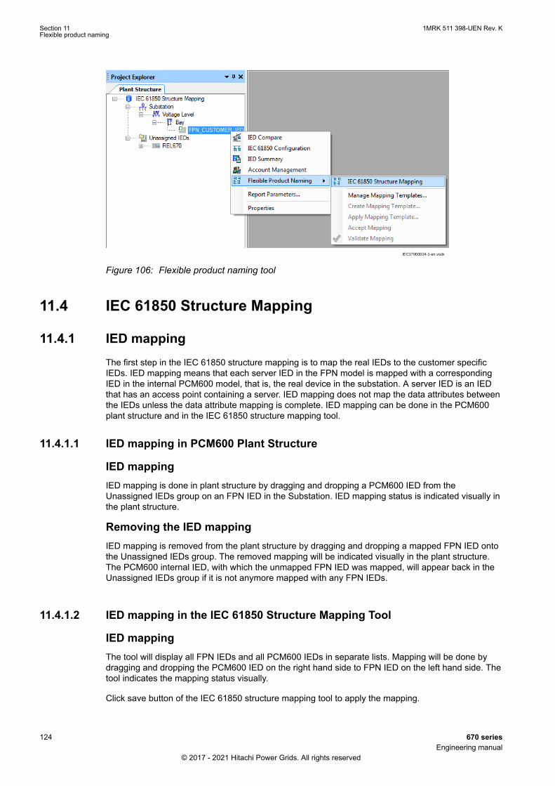
IEC17000024-1-en.vsdxIEC17000024 V1 EN-US
Figure 106: Flexible product naming tool
11.4 IEC 61850 Structure Mapping
11.4.1 IED mappingGUID-6588A7B6-5075-4FBE-9CE1-140A27AE8995 v2
The first step in the IEC 61850 structure mapping is to map the real IEDs to the customer specificIEDs. IED mapping means that each server IED in the FPN model is mapped with a correspondingIED in the internal PCM600 model, that is, the real device in the substation. A server IED is an IEDthat has an access point containing a server. IED mapping does not map the data attributes betweenthe IEDs unless the data attribute mapping is complete. IED mapping can be done in the PCM600plant structure and in the IEC 61850 structure mapping tool.
11.4.1.1 IED mapping in PCM600 Plant StructureGUID-AD017D10-E128-44E0-A758-E3CD95FA5975 v2
IED mappingIED mapping is done in plant structure by dragging and dropping a PCM600 IED from theUnassigned IEDs group on an FPN IED in the Substation. IED mapping status is indicated visually inthe plant structure.
Removing the IED mappingIED mapping is removed from the plant structure by dragging and dropping a mapped FPN IED ontothe Unassigned IEDs group. The removed mapping will be indicated visually in the plant structure.The PCM600 internal IED, with which the unmapped FPN IED was mapped, will appear back in theUnassigned IEDs group if it is not anymore mapped with any FPN IEDs.
11.4.1.2 IED mapping in the IEC 61850 Structure Mapping ToolGUID-07F9D393-FE3C-4392-8943-202D7ECB1587 v2
IED mappingThe tool will display all FPN IEDs and all PCM600 IEDs in separate lists. Mapping will be done bydragging and dropping the PCM600 IED on the right hand side to FPN IED on the left hand side. Thetool indicates the mapping status visually.
Click save button of the IEC 61850 structure mapping tool to apply the mapping.
Section 11 1MRK 511 398-UEN Rev. KFlexible product naming
124 670 seriesEngineering manual
© 2017 - 2021 Hitachi Power Grids. All rights reserved

IEC15000090-2-en.vsdx
IEC15000090 V2 EN-US
Figure 107: Mapping of IEDs in IEC 61850 structure mapping tool
IEC15000091-2-en.vsdxIEC15000091 V2 EN-US
Figure 108: Visual indication of the mapping
Removing the IED mappingRemoving IED mapping is done in the IEC 61850 Structure Mapping Tool by right-clicking themapping and selecting the context menu option or pressing the Delete key. The tool indicates themapping status visually.
Click save button of the IEC 61850 structure mapping tool to remove the mapping.
Data tree viewData tree view consists of Customer Data Structure in the column on the left and the name of themapped PCM600 Internal Data Structure in the column on the right.
IEC17000025-1-en.vsdxIEC17000025 V1 EN-US
Figure 109: Data tree view
1MRK 511 398-UEN Rev. K Section 11Flexible product naming
670 series 125Engineering manual
© 2017 - 2021 Hitachi Power Grids. All rights reserved

Data attribute list viewData attribute list view consists of Customer Data Attribute in the column on the left and the PCM600Internal Data Attribute in the column on the right.
IEC17000026-1-en.vsdxIEC17000026 V1 EN-US
Figure 110: Data Attribute List view
FiltersDisplayed objects can be filtered using the filtering options in the quick access Toolbar.
IEC17000027-1-en.vsdxIEC17000027 V1 EN-US
Figure 111: Filters
Free text filter
The objects are filtered by free text, showing all the objects with a certain name in both DataStructure level and Data Attribute level.
Show/hide objects by status
The objects are filtered by status, showing only selected objects in Data Structure level and DataAttribute level.
Enable and disable type filters
Objects in the FPN can be filtered using additional filtering options available in the quick accessmenu.
11.4.2 Data Attribute MappingGUID-42EEE38C-FAE4-4D17-A822-EAC8F392186A v2
Data attribute mapping means that each FPN data attribute in the FPN model is mapped with acorresponding data attribute in the internal PCM600 model, that is, the real device in the substation.
The mapping status is indicated visually. It can be seen what FPN data attribute is mapped to whatPCM600 internal data attribute and how many FPN data attributes are mapped to a PCM600 internaldata attribute.
Section 11 1MRK 511 398-UEN Rev. KFlexible product naming
126 670 seriesEngineering manual
© 2017 - 2021 Hitachi Power Grids. All rights reserved

Data attribute mapping is complete when all data attributes of the FPN IED, which are not excludedfrom the mappings, are mapped with a PCM600 internal data attribute. The data attribute mappingmust be complete in order to be able to write to IED.
Data attribute mapping is broken if any of the data attributes - FPN or PCM600 internal - that aremapped, does not exist in the SCL database.
When performing data attribute mapping, understand the following visual signs:
Completely mapped
Not mapped
Broken mapping
Partially mapped
Object is excluded from the mappings
All data attributes in the FPN model must be mapped or excluded, otherwise write toIED fails.
11.4.2.1 Data Attribute Level MappingGUID-21AF369A-EF96-4039-BBE4-E925E5A3C488 v2
The IEC 61850 Structure Mapping Tool displays the FPN data attributes and PCM600 internal dataattributes in separate lists. The mapping is done by dragging and dropping the FPN data attributeonto a PCM600 internal data attribute.
The mapping is removed by right clicking and selecting remove from the context menu or by clickingthe Delete key while the mapping is selected.
IEC17000030-1-en.vsdx
IEC17000030 V1 EN-US
Figure 112: Data attribute level mapping
11.4.2.2 Data Object Level MappingGUID-8CEB9EC3-78C5-427A-8E64-9B826493E108 v2
Data attribute mapping can be created on the data object level in one of the alternative ways.
• Drag a data object from the customer data structure onto a data object in the internal datastructure
• Drag a data object from the internal data structure onto a data object in the customer datastructure.
1MRK 511 398-UEN Rev. K Section 11Flexible product naming
670 series 127Engineering manual
© 2017 - 2021 Hitachi Power Grids. All rights reserved
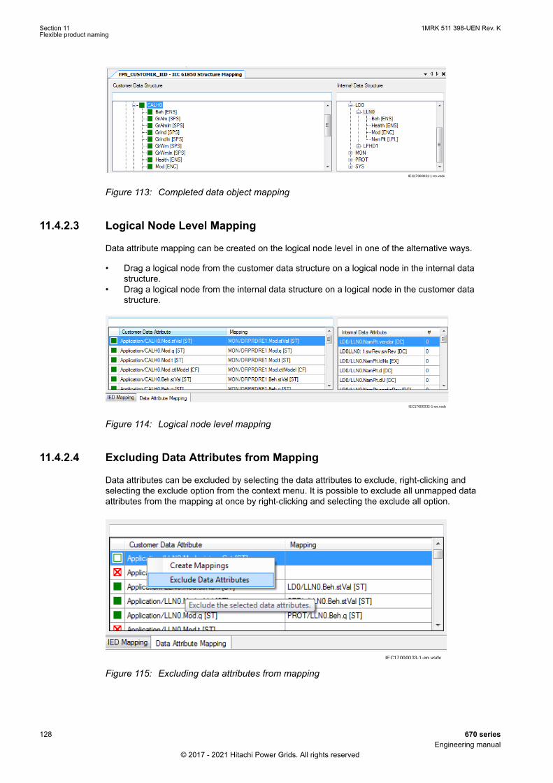
IEC17000031-1-en.vsdx
IEC17000031 V1 EN-US
Figure 113: Completed data object mapping
11.4.2.3 Logical Node Level MappingGUID-EC1034CF-B5A3-4C4D-A922-6E450C04EF87 v2
Data attribute mapping can be created on the logical node level in one of the alternative ways.
• Drag a logical node from the customer data structure on a logical node in the internal datastructure.
• Drag a logical node from the internal data structure on a logical node in the customer datastructure.
IEC17000032-1-en.vsdx
IEC17000032 V1 EN-US
Figure 114: Logical node level mapping
11.4.2.4 Excluding Data Attributes from MappingGUID-67C28230-1E21-4769-A24B-0588EC34002E v2
Data attributes can be excluded by selecting the data attributes to exclude, right-clicking andselecting the exclude option from the context menu. It is possible to exclude all unmapped dataattributes from the mapping at once by right-clicking and selecting the exclude all option.
IEC17000033-1-en.vsdxIEC17000033 V1 EN-US
Figure 115: Excluding data attributes from mapping
Section 11 1MRK 511 398-UEN Rev. KFlexible product naming
128 670 seriesEngineering manual
© 2017 - 2021 Hitachi Power Grids. All rights reserved

The data attributes that are excluded from the mapping will not be excluded from the model.Excluded mappings will be ignored when determining if an IED mapping is complete.
It is crucial to set a value to the excluded data attributes before initiating themapping.
11.5 Setting the data attribute valueGUID-C45518A9-4AD2-44B1-8AAE-6092E0F890F2 v1
The data attribute value can be set by editing the Value field in the Object Properties window. Forenum type of data attributes there is a list of available values to select. For numeric and string typedata attributes the value can be entered directly in the Value field.
IEC15000132.vsdx
IEC15000132 V1 EN-US
Figure 116: Setting the data attribute value
Value cannot be set for all types of data attributes, for example, quality andtimestamp values cannot be edited.
11.6 ValidationGUID-32B7AFB1-D7EC-4B92-95DC-07CA933B762B v1
Once the FPN mapping is complete, all mapping can be validated in three ways using the validateoption available in quick access menu
1. Validate All2. Validate Current3. Validate Selected
IEC17000029-1-en.vsdxIEC17000029 V1 EN-US
Figure 117: Validate mapping
1MRK 511 398-UEN Rev. K Section 11Flexible product naming
670 series 129Engineering manual
© 2017 - 2021 Hitachi Power Grids. All rights reserved
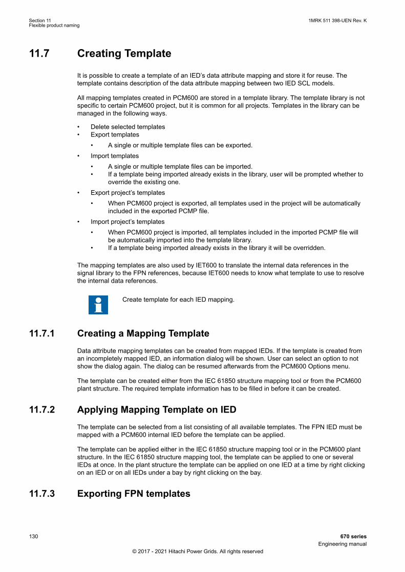
11.7 Creating TemplateGUID-5C4BBE6F-60BE-4563-9038-BF7A3EF0798D v2
It is possible to create a template of an IED’s data attribute mapping and store it for reuse. Thetemplate contains description of the data attribute mapping between two IED SCL models.
All mapping templates created in PCM600 are stored in a template library. The template library is notspecific to certain PCM600 project, but it is common for all projects. Templates in the library can bemanaged in the following ways.
• Delete selected templates• Export templates
• A single or multiple template files can be exported.• Import templates
• A single or multiple template files can be imported.• If a template being imported already exists in the library, user will be prompted whether to
override the existing one.• Export project’s templates
• When PCM600 project is exported, all templates used in the project will be automaticallyincluded in the exported PCMP file.
• Import project’s templates• When PCM600 project is imported, all templates included in the imported PCMP file will
be automatically imported into the template library.• If a template being imported already exists in the library it will be overridden.
The mapping templates are also used by IET600 to translate the internal data references in thesignal library to the FPN references, because IET600 needs to know what template to use to resolvethe internal data references.
Create template for each IED mapping.
11.7.1 Creating a Mapping TemplateGUID-E31298E4-439D-41C7-B73B-D7F388C30EE9 v2
Data attribute mapping templates can be created from mapped IEDs. If the template is created froman incompletely mapped IED, an information dialog will be shown. User can select an option to notshow the dialog again. The dialog can be resumed afterwards from the PCM600 Options menu.
The template can be created either from the IEC 61850 structure mapping tool or from the PCM600plant structure. The required template information has to be filled in before it can be created.
11.7.2 Applying Mapping Template on IEDGUID-59226241-AE98-4248-9BEA-A427AE7127A5 v2
The template can be selected from a list consisting of all available templates. The FPN IED must bemapped with a PCM600 internal IED before the template can be applied.
The template can be applied either in the IEC 61850 structure mapping tool or in the PCM600 plantstructure. In the IEC 61850 structure mapping tool, the template can be applied to one or severalIEDs at once. In the plant structure the template can be applied on one IED at a time by right clickingon an IED or on all IEDs under a bay by right clicking on the bay.
11.7.3 Exporting FPN templatesGUID-348026ED-B9B3-432C-8125-6A9C2242BEE4 v1
Section 11 1MRK 511 398-UEN Rev. KFlexible product naming
130 670 seriesEngineering manual
© 2017 - 2021 Hitachi Power Grids. All rights reserved

1. Right click on the PCM600 plant structure.2. Select Manage Mapping Templates under Flexible Product Naming in the menu.3. Select the templates to export and click Export.
IEC15000501-2-en.vsdx
IEC15000501 V2 EN-US
4. Select the folder where to export the templates and click OK.
11.8 Reporting and PrintingGUID-FDF73D7F-C615-4F11-A562-314E967693AB v3
The report consist of a cross-reference list of the IED and data attribute mappings. I.e. a table of allFPN objects together with the PCM600 internal objects they are mapped with.
Table 7: Table 3. IED mappings.
Parameter CustomerI ED Internal IEDTechnical Key FPN_CUSTOMER_IED FPN_CUSTOMER_IED
Description FPN_CUSTOMER_IED FPN_CUSTOMER_IED
IEDType 7SJ82 670 series
Configuration Version V07.00.15 REL670ver2.2.0
Manufacturer Customer Hitachi Power grids
Table 8: Data Attribute Mappings
Customer Data Attribute Internal Data Attribute Signal NameApplication/LLN0.Mod.origin.orCat[ST]
CTRULLN0.Beh.stVal [ST]
CB111.LN0.Mod.stVal [ST] CTRULLN0.Beh.stVal [ST]
CB 111.LN0.Mod . t [ST] CTRULLN0.Beh.t [ST]
1MRK 511 398-UEN Rev. K Section 11Flexible product naming
670 series 131Engineering manual
© 2017 - 2021 Hitachi Power Grids. All rights reserved

132
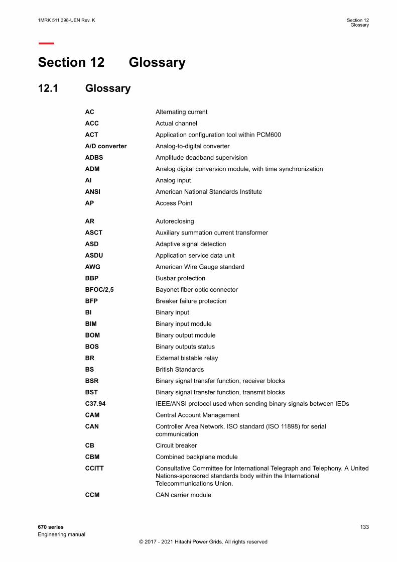
Section 12 Glossary
12.1 GlossaryM14893-1 v20
AC Alternating current
ACC Actual channel
ACT Application configuration tool within PCM600
A/D converter Analog-to-digital converter
ADBS Amplitude deadband supervision
ADM Analog digital conversion module, with time synchronization
AI Analog input
ANSI American National Standards Institute
AP Access Point
AR Autoreclosing
ASCT Auxiliary summation current transformer
ASD Adaptive signal detection
ASDU Application service data unit
AWG American Wire Gauge standard
BBP Busbar protection
BFOC/2,5 Bayonet fiber optic connector
BFP Breaker failure protection
BI Binary input
BIM Binary input module
BOM Binary output module
BOS Binary outputs status
BR External bistable relay
BS British Standards
BSR Binary signal transfer function, receiver blocks
BST Binary signal transfer function, transmit blocks
C37.94 IEEE/ANSI protocol used when sending binary signals between IEDs
CAM Central Account Management
CAN Controller Area Network. ISO standard (ISO 11898) for serialcommunication
CB Circuit breaker
CBM Combined backplane module
CCITT Consultative Committee for International Telegraph and Telephony. A UnitedNations-sponsored standards body within the InternationalTelecommunications Union.
CCM CAN carrier module
1MRK 511 398-UEN Rev. K Section 12Glossary
670 series 133Engineering manual
© 2017 - 2021 Hitachi Power Grids. All rights reserved
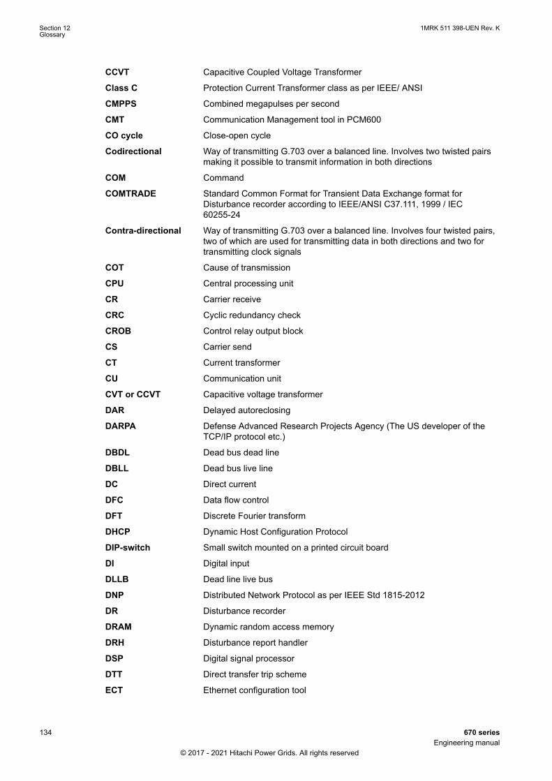
CCVT Capacitive Coupled Voltage Transformer
Class C Protection Current Transformer class as per IEEE/ ANSI
CMPPS Combined megapulses per second
CMT Communication Management tool in PCM600
CO cycle Close-open cycle
Codirectional Way of transmitting G.703 over a balanced line. Involves two twisted pairsmaking it possible to transmit information in both directions
COM Command
COMTRADE Standard Common Format for Transient Data Exchange format forDisturbance recorder according to IEEE/ANSI C37.111, 1999 / IEC60255-24
Contra-directional Way of transmitting G.703 over a balanced line. Involves four twisted pairs,two of which are used for transmitting data in both directions and two fortransmitting clock signals
COT Cause of transmission
CPU Central processing unit
CR Carrier receive
CRC Cyclic redundancy check
CROB Control relay output block
CS Carrier send
CT Current transformer
CU Communication unit
CVT or CCVT Capacitive voltage transformer
DAR Delayed autoreclosing
DARPA Defense Advanced Research Projects Agency (The US developer of theTCP/IP protocol etc.)
DBDL Dead bus dead line
DBLL Dead bus live line
DC Direct current
DFC Data flow control
DFT Discrete Fourier transform
DHCP Dynamic Host Configuration Protocol
DIP-switch Small switch mounted on a printed circuit board
DI Digital input
DLLB Dead line live bus
DNP Distributed Network Protocol as per IEEE Std 1815-2012
DR Disturbance recorder
DRAM Dynamic random access memory
DRH Disturbance report handler
DSP Digital signal processor
DTT Direct transfer trip scheme
ECT Ethernet configuration tool
Section 12 1MRK 511 398-UEN Rev. KGlossary
134 670 seriesEngineering manual
© 2017 - 2021 Hitachi Power Grids. All rights reserved
EHV network Extra high voltage network
EIA Electronic Industries Association
EMC Electromagnetic compatibility
EMF Electromotive force
EMI Electromagnetic interference
EnFP End fault protection
EPA Enhanced performance architecture
ESD Electrostatic discharge
F-SMA Type of optical fiber connector
FAN Fault number
FIPS Federal Information Processing Standards
FCB Flow control bit; Frame count bit
FOX 20 Modular 20 channel telecommunication system for speech, data andprotection signals
FOX 512/515 Access multiplexer
FOX 6Plus Compact time-division multiplexer for the transmission of up to sevenduplex channels of digital data over optical fibers
FPN Flexible product naming
FTP File Transfer Protocol
FUN Function type
G.703 Electrical and functional description for digital lines used by local telephonecompanies. Can be transported over balanced and unbalanced lines
GCM Communication interface module with carrier of GPS receiver module
GDE Graphical display editor within PCM600
GI General interrogation command
GIS Gas-insulated switchgear
GOOSE Generic object-oriented substation event
GPS Global positioning system
GSAL Generic security application
GSE Generic substation event
GSM GPS time synchronization module
GTM GPS Time Module
HDLC protocol High-level data link control, protocol based on the HDLC standard
HFBR connector type Plastic fiber connector
HLV circuit Hazardous Live Voltage according to IEC60255-27
HMI Human-machine interface
HSAR High speed autoreclosing
HSR High-availability Seamless Redundancy
HV High-voltage
HVDC High-voltage direct current
ICT Installation and Commissioning Tool for injection based protection inREG670
1MRK 511 398-UEN Rev. K Section 12Glossary
670 series 135Engineering manual
© 2017 - 2021 Hitachi Power Grids. All rights reserved
IDBS Integrating deadband supervision
IEC International Electrical Committee
IEC 60044-6 IEC Standard, Instrument transformers – Part 6: Requirements forprotective current transformers for transient performance
IEC 60870-5-103 Communication standard for protection equipment. A serial master/slaveprotocol for point-to-point communication
IEC 61850 Substation automation communication standard
IEC 61850–8–1 Communication protocol standard
IEEE Institute of Electrical and Electronics Engineers
IEEE 802.12 A network technology standard that provides 100 Mbits/s on twisted-pair oroptical fiber cable
IEEE P1386.1 PCI Mezzanine Card (PMC) standard for local bus modules. References theCMC (IEEE P1386, also known as Common Mezzanine Card) standard forthe mechanics and the PCI specifications from the PCI SIG (SpecialInterest Group) for the electrical EMF (Electromotive force).
IEEE 1686 Standard for Substation Intelligent Electronic Devices (IEDs) Cyber SecurityCapabilities
IED Intelligent electronic device
IET600 Integrated engineering tool
I-GIS Intelligent gas-insulated switchgear
IOM Binary input/output module
Instance When several occurrences of the same function are available in the IED,they are referred to as instances of that function. One instance of a functionis identical to another of the same kind but has a different number in theIED user interfaces. The word "instance" is sometimes defined as an item ofinformation that is representative of a type. In the same way an instance ofa function in the IED is representative of a type of function.
IP 1. Internet protocol. The network layer for the TCP/IP protocol suite widelyused on Ethernet networks. IP is a connectionless, best-effort packet-switching protocol. It provides packet routing, fragmentation andreassembly through the data link layer.2. Ingression protection, according to IEC 60529
IP 20 Ingression protection, according to IEC 60529, level 20
IP 40 Ingression protection, according to IEC 60529, level 40
IP 54 Ingression protection, according to IEC 60529, level 54
IRF Internal failure signal
IRIG-B: InterRange Instrumentation Group Time code format B, standard 200
ITU International Telecommunications Union
LAN Local area network
LIB 520 High-voltage software module
LCD Liquid crystal display
LDAPS Lightweight Directory Access Protocol
LDCM Line data communication module
LDD Local detection device
LED Light-emitting diode
LNT LON network tool
Section 12 1MRK 511 398-UEN Rev. KGlossary
136 670 seriesEngineering manual
© 2017 - 2021 Hitachi Power Grids. All rights reserved

LON Local operating network
MCB Miniature circuit breaker
MCM Mezzanine carrier module
MIM Milli-ampere module
MPM Main processing module
MVAL Value of measurement
MVB Multifunction vehicle bus. Standardized serial bus originally developed foruse in trains.
NCC National Control Centre
NOF Number of grid faults
NUM Numerical module
OCO cycle Open-close-open cycle
OCP Overcurrent protection
OEM Optical Ethernet module
OLTC On-load tap changer
OTEV Disturbance data recording initiated by other event than start/pick-up
OV Overvoltage
Overreach A term used to describe how the relay behaves during a fault condition. Forexample, a distance relay is overreaching when the impedance presentedto it is smaller than the apparent impedance to the fault applied to thebalance point, that is, the set reach. The relay “sees” the fault but perhaps itshould not have seen it.
PCI Peripheral component interconnect, a local data bus
PCM Pulse code modulation
PCM600 Protection and control IED manager
PC-MIP Mezzanine card standard
PELV circuit Protected Extra-Low Voltage circuit type according to IEC60255-27
PMC PCI Mezzanine card
POR Permissive overreach
POTT Permissive overreach transfer trip
Process bus Bus or LAN used at the process level, that is, in near proximity to themeasured and/or controlled components
PRP Parallel redundancy protocol
PSM Power supply module
PST Parameter setting tool within PCM600
PTP Precision time protocol
PT ratio Potential transformer or voltage transformer ratio
PUTT Permissive underreach transfer trip
RASC Synchrocheck relay, COMBIFLEX
RCA Relay characteristic angle
RISC Reduced instruction set computer
RMS value Root mean square value
1MRK 511 398-UEN Rev. K Section 12Glossary
670 series 137Engineering manual
© 2017 - 2021 Hitachi Power Grids. All rights reserved

RS422 A balanced serial interface for the transmission of digital data in point-to-point connections
RS485 Serial link according to EIA standard RS485
RTC Real-time clock
RTU Remote terminal unit
SA Substation Automation
SBO Select-before-operate
SC Switch or push button to close
SCL Short circuit location
SCS Station control system
SCADA Supervision, control and data acquisition
SCT System configuration tool according to standard IEC 61850
SDU Service data unit
SELV circuit Safety Extra-Low Voltage circuit type according to IEC60255-27
SFP Small form-factor pluggable (abbreviation)Optical Ethernet port (explanation)
SLM Serial communication module.
SMA connector Subminiature version A, A threaded connector with constant impedance.
SMT Signal matrix tool within PCM600
SMS Station monitoring system
SNTP Simple network time protocol – is used to synchronize computer clocks onlocal area networks. This reduces the requirement to have accuratehardware clocks in every embedded system in a network. Each embeddednode can instead synchronize with a remote clock, providing the requiredaccuracy.
SOF Status of fault
SPA Strömberg Protection Acquisition (SPA), a serial master/slave protocol forpoint-to-point and ring communication.
SRY Switch for CB ready condition
ST Switch or push button to trip
Starpoint Neutral point of transformer or generator
SVC Static VAr compensation
TC Trip coil
TCS Trip circuit supervision
TCP Transmission control protocol. The most common transport layer protocolused on Ethernet and the Internet.
TCP/IP Transmission control protocol over Internet Protocol. The de facto standardEthernet protocols incorporated into 4.2BSD Unix. TCP/IP was developedby DARPA for Internet working and encompasses both network layer andtransport layer protocols. While TCP and IP specify two protocols at specificprotocol layers, TCP/IP is often used to refer to the entire US Department ofDefense protocol suite based upon these, including Telnet, FTP, UDP andRDP.
TEF Time delayed earth-fault protection function
Section 12 1MRK 511 398-UEN Rev. KGlossary
138 670 seriesEngineering manual
© 2017 - 2021 Hitachi Power Grids. All rights reserved

TLS Transport Layer Security
TM Transmit (disturbance data)
TNC connector Threaded Neill-Concelman, a threaded constant impedance version of aBNC connector
TP Trip (recorded fault)
TPZ, TPY, TPX, TPS Current transformer class according to IEC
TRM Transformer Module. This module transforms currents and voltages takenfrom the process into levels suitable for further signal processing.
TYP Type identification
UMT User management tool
Underreach A term used to describe how the relay behaves during a fault condition. Forexample, a distance relay is underreaching when the impedance presentedto it is greater than the apparent impedance to the fault applied to thebalance point, that is, the set reach. The relay does not “see” the fault butperhaps it should have seen it. See also Overreach.
UTC Coordinated Universal Time. A coordinated time scale, maintained by theBureau International des Poids et Mesures (BIPM), which forms the basis ofa coordinated dissemination of standard frequencies and time signals. UTCis derived from International Atomic Time (TAI) by the addition of a wholenumber of "leap seconds" to synchronize it with Universal Time 1 (UT1),thus allowing for the eccentricity of the Earth's orbit, the rotational axis tilt(23.5 degrees), but still showing the Earth's irregular rotation, on which UT1is based. The Coordinated Universal Time is expressed using a 24-hourclock, and uses the Gregorian calendar. It is used for aeroplane and shipnavigation, where it is also sometimes known by the military name, "Zulutime." "Zulu" in the phonetic alphabet stands for "Z", which stands forlongitude zero.
UV Undervoltage
WEI Weak end infeed logic
VT Voltage transformer
X.21 A digital signalling interface primarily used for telecom equipment
3IO Three times zero-sequence current.Often referred to as the residual or theearth-fault current
3UO Three times the zero sequence voltage. Often referred to as the residualvoltage or the neutral point voltage
1MRK 511 398-UEN Rev. K Section 12Glossary
670 series 139Engineering manual
© 2017 - 2021 Hitachi Power Grids. All rights reserved

140

141

ABB Power Grids Sweden ABGrid Automation ProductsSE-721 59 Västerås, SwedenPhone +46 (0) 10 738 00 00
https://hitachiabb-powergrids.com/protection-control
© 2017 - 2021 Hitachi Power Grids.All rights reserved
Scan this QR code to visit our website
1MR
K 51
1 39
8-U
EN