HS/S4.2.1 Outside Light Sensor Interface, MDRC - ABB Group
46
HS/S4.2.1 Outside Light Sensor Interface, MDRC Status: Oct-17 (Subject to change) Page 1 of 46 HS/S4.2.1 Outside Light Sensor Interface, MDRC HS/S4.2.1 2CDG120044R0011
-
Upload
khangminh22 -
Category
Documents
-
view
1 -
download
0
Transcript of HS/S4.2.1 Outside Light Sensor Interface, MDRC - ABB Group
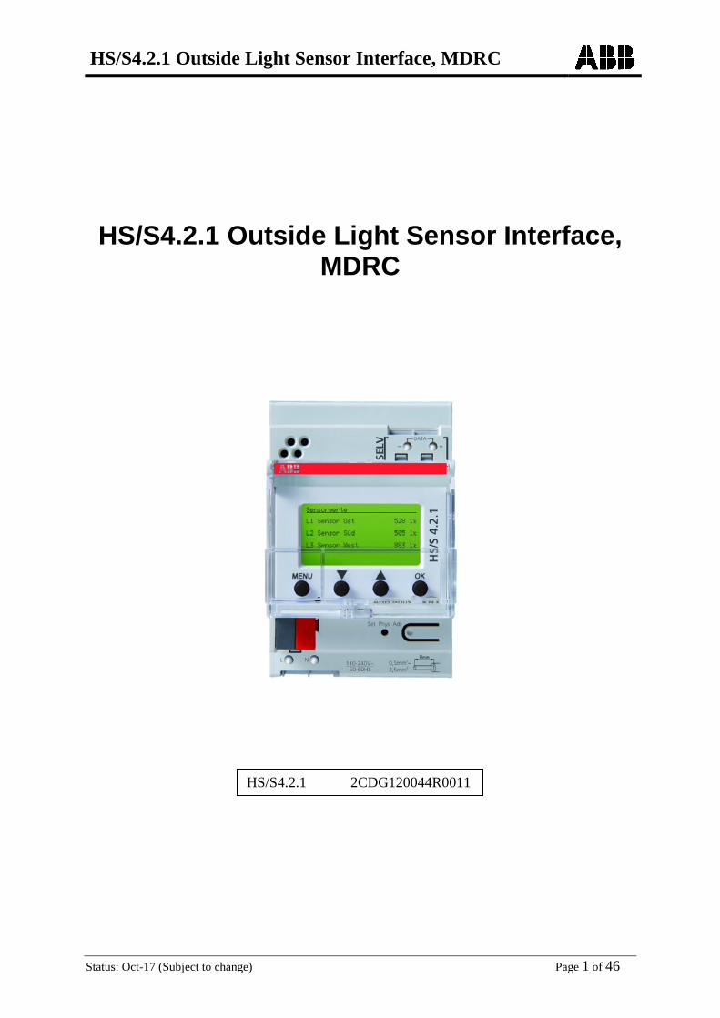
HS/S4.2.1 Outside Light Sensor Interface, MDRC
Status: Oct-17 (Subject to change) Page 1 of 46
HS/S4.2.1 Outside Light Sensor Interface, MDRC
HS/S4.2.1 2CDG120044R0011
HS/S4.2.1 Outside Light Sensor Interface, MDRC
Status: Oct-17 (Subject to change) Page 2 of 46
Contents 1 Functional characteristics ................................................................................................ 3
1.1 Special features ......................................................................................................... 3
2 Technical data ................................................................................................................... 4
3 The "Brightness Sensor Interface 4C/1.0" application program ................................... 5
3.1 Selection in the product database ........................................................................... 5
3.2 Communication objects ........................................................................................... 6 3.2.1 Description of objects ........................................................................................... 18
3.3 Parameter ................................................................................................................ 25 3.3.1 Parameter pages .................................................................................................... 25 3.3.2 Parameter description ........................................................................................... 26
4 Appendix .......................................................................................................................... 44
4.1 Allocate sensors ...................................................................................................... 44
HS/S4.2.1 Outside Light Sensor Interface, MDRC
Status: Oct-17 (Subject to change) Page 3 of 46
1 Functional characteristics HS/S4.2.1 measures the brightness with 1, 2 or 3 external data bus sensors. The measured values can be sent to the bus. HS/S4.2.1 has the following channel types:
• 10 brightness-dependent switching channels • 4 threshold channels with per cent, 8-/16- bit counter values or floating-point number
(DPT 9.xxx) • 6 logic channels (AND, OR, XOR)
See attachment for a detailed description of the channel types.
1.1 Special features
• Up to 3 external data bus brightness sensors can be connected (see attachment). • Switching channels can react to the values of the individual sensors as well as the
highest value of all the sensors. • Switching channels with delay with exceeding and falling below thresholds • Logic channels can be configured with 4 input objects + internal link with status of the
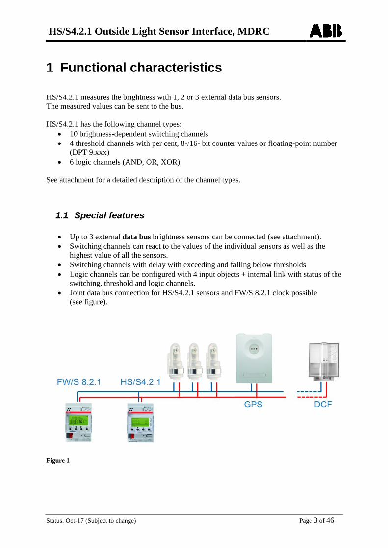
switching, threshold and logic channels. • Joint data bus connection for HS/S4.2.1 sensors and FW/S 8.2.1 clock possible
(see figure).
Figure 1

HS/S4.2.1 Outside Light Sensor Interface, MDRC
Status: Oct-17 (Subject to change) Page 4 of 46
2 Technical data Operating voltage 110 – 240 V AC
Frequency 50 – 60 Hz
Operating voltage KNX Bus voltage, ≤10 mA
Standby output 0.8 W
Brightness measuring range 1 – 100,000 lx
On/off switching delay 0 – 60 min
Number of channels 10
Width 3 module
Installation type DIN-rail
Connection type Bus connection: KNX bus terminal | sensor connection: DuoFix plug-in terminals
Max. cable cross-section 2 x 0.75 mm²
Max. line length to sensor 100 m
Ambient temperature -5 °C … +45 °C -40 °C … +70 °C (sensor)
Protection class II
IP rating IP 20 (HS/S 4.2.1) IP 55 (LFO/A 1.1)

HS/S4.2.1 Outside Light Sensor Interface, MDRC
Status: Oct-17 (Subject to change) Page 5 of 46
3 The "Brightness Sensor Interface 4C/1.0" application program
3.1 Selection in the product database Manufacturer ABB STOTZ-KONTAKT GmbH Product family Phys. Sensors Product type Outdoor Brightness Program name Brightness Sensor Interface 4C/1.0 The ETS database can be found on our downloads page: www.abb.com/knx. Table 1
Number of communication objects: 171 Number of group addresses: 255 Number of associations: 255

HS/S4.2.1 Outside Light Sensor Interface, MDRC
Status: Oct-17 (Subject to change) Page 6 of 46
3.2 Communication objects Table 2
No. Object name Function Type DPT
Flags C R W T
0 Brightness value sensor 1 Physical value 2 byte 9,004 C R - T
1 Brightness value sensor 2 Physical value 2 byte 9,004 C R - T
2 Brightness value sensor 3 Physical value 2 byte 9,004 C R - T
3 Maximum brightness value Physical value 2 byte 9,004 C R - T
17 Brightness sensors status 0=OK, 1=min. 1 sensor defective
1 bit 1.001 C R - T
20 C1.1 switching channel
Switching 1 bit 1.001 C R - T
Value 1 byte 5,010 C R - T
priority 2 bit 2,001 C R - T
21 C1.2 switching channel
Switching 1 bit 1.001 C R - T
Value 1 byte 5,010 C R - T
priority 2 bit 2,001 C R - T
22 C1 lock Disable = 0 1 bit
1.001 C R W -
Disable = 1 1 bit 1.001 C R W -
23 C1 brightness threshold set/query 2 byte
9,004 C R W T
Request 2 byte 9,004 C R - T
24 C2 1 switching channel
Switching 1 bit 1.001 C R - T
Value 1 byte 5,010 C R - T
priority 2 bit 2,001 C R - T

HS/S4.2.1 Outside Light Sensor Interface, MDRC
Status: Oct-17 (Subject to change) Page 7 of 46
Continuation:
No. Object name Function Type DPT
Flags C R W T
25 C2 2 switching channel
Switching 1 bit 1.001 C R - T
Value 1 byte 5,010 C R - T
priority 2 bit 2,001 C R - T
26 C2 lock Disable = 0 1 bit
1.001 C R W -
Disable = 1 1 bit 1.001 C R W -
27 C2 brightness threshold set/query 2 byte
9,004 C R W T
Request 2 byte 9,004 C R - T
28 C3 1 switching channel
Switching 1 bit 1.001 C R - T
Value 1 byte 5,010 C R - T
priority 2 bit 2,001 C R - T
29 C3 2 switching channel
Switching 1 bit 1.001 C R - T
Value 1 byte 5,010 C R - T
priority 2 bit 2,001 C R - T
30 C3 lock Disable = 1 1 bit
1.001 C R W -
Disable = 0 1 bit 1.001 C R W -
31 C3 brightness threshold set/query 2 byte
9,004 C R W T
Request 1 bit 1.001 C R - T
32 C4 1 switching channel
Switching 1 bit 1.001 C R - T
Value 1 byte 5,010 C R - T
priority 2 bit 2,001 C R - T

HS/S4.2.1 Outside Light Sensor Interface, MDRC
Status: Oct-17 (Subject to change) Page 8 of 46
Continuation:
No. Object name Function Type DPT
Flags C R W T
33 C4 2 switching channel
Switching 1 bit 1.001 C R - T
Value 1 byte 5,010 C R - T
priority 2 bit 2,001 C R - T
34 C4 lock Disable = 0 1 bit
1.001 C R W -
Disable = 1 1 bit 1.001 C R W -
35 C4 brightness threshold Request 2 byte
9,004 C R - T
set/query 1 bit 1.001 C R W T
36 C5 1 switching channel
Switching 1 bit 1.001 C R - T
Value 1 byte 5,010 C R - T
priority 2 bit 2,001 C R - T
37 C5 2 switching channel
Switching 1 bit 1.001 C R - T
Value 1 byte 5,010 C R - T
priority 2 bit 2,001 C R - T
38 C5 lock Disable = 1 1 bit
1.001 C R W -
Disable = 0 1 bit 1.001 C R W -
39 C5 brightness threshold set/query 2 byte
9,004 C R W T
Request 1 bit 1.001 C R - T
40 C6 1 switching channel
Switching 1 bit 1.001 C R - T
Value 1 byte 5,010 C R - T
priority 2 bit 2,001 C R - T

HS/S4.2.1 Outside Light Sensor Interface, MDRC
Status: Oct-17 (Subject to change) Page 9 of 46
Continuation:
No. Object name Function Type DPT
Flags C R W T
41 C6 2 switching channel
Switching 1 bit 1.001 C R - T
Value 1 byte 5,010 C R - T
priority 2 bit 2,001 C R - T
42 C6 lock Disable = 1 1 bit
1.001 C R W -
Disable = 0 1 bit 1.001 C R W -
43 C6 brightness threshold set/query 2 byte
9,004 C R W T
Request 1 bit 1.001 C R - T
44 C7 1 switching channel
Switching 1 bit 1.001 C R - T
Value 1 byte 5,010 C R - T
priority 2 bit 2,001 C R - T
45 C7 2 switching channel
Switching 1 bit 1.001 C R - T
Value 1 byte 5,010 C R - T
priority 2 bit 2,001 C R - T
46 C7 lock Disable = 1 1 bit
1.001 C R W -
Disable = 0 1 bit 1.001 C R W -
47 C7 brightness threshold set/query 2 byte
9,004 C R W T
Request 1 bit 1.001 C R - T
48 C8 1 switching channel
Switching 1 bit 1.001 C R - T
Value 1 byte 5,010 C R - T
priority 2 bit 2,001 C R - T

HS/S4.2.1 Outside Light Sensor Interface, MDRC
Status: Oct-17 (Subject to change) Page 10 of 46
Continuation:
No. Object name Function Type DPT
Flags C R W T
49 C8 2 switching channel
Switching 1 bit 1.001 C R - T
Value 1 byte 5,010 C R - T
priority 2 bit 2,001 C R - T
50 C8 lock Disable = 1 1 bit
1.001 C R W -
Disable = 0 1 bit 1.001 C R W -
51 C8 brightness threshold set/query 2 byte
9,004 C R W T
Request 1 bit 1.001 C R - T
52 C9 1 switching channel
Switching 1 bit 1.001 C R - T
Value 1 byte 5,010 C R - T
priority 2 bit 2,001 C R - T
53 C9 2 switching channel
Switching 1 bit 1.001 C R - T
Value 1 byte 5,010 C R - T
priority 2 bit 2,001 C R - T
54 C9 lock Disable = 0 1 bit
1.001 C R W -
Disable = 1 1 bit 1.001 C R W -
55 C9 brightness threshold set/query 2 byte
9,004 C R W T
Request 1 bit 1.001 C R - T
56 C10 1 switching channel
Switching 1 bit 1.001 C R - T
Value 1 byte 5,010 C R - T
priority 2 bit 2,001 C R - T
HS/S4.2.1 Outside Light Sensor Interface, MDRC
Status: Oct-17 (Subject to change) Page 11 of 46
Continuation:
No. Object name Function Type DPT
Flags C R W T
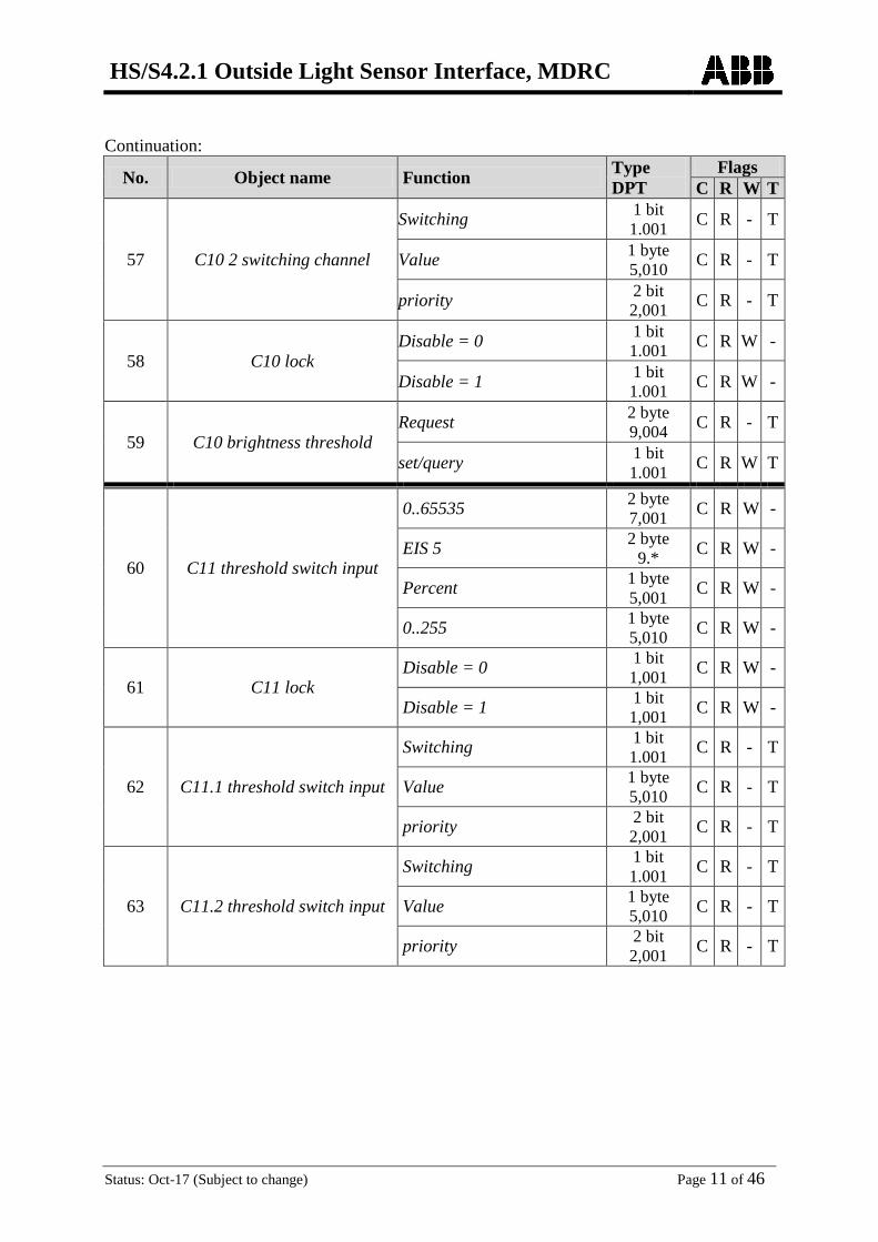
57 C10 2 switching channel
Switching 1 bit 1.001 C R - T
Value 1 byte 5,010 C R - T
priority 2 bit 2,001 C R - T
58 C10 lock Disable = 0 1 bit
1.001 C R W -
Disable = 1 1 bit 1.001 C R W -
59 C10 brightness threshold Request 2 byte
9,004 C R - T
set/query 1 bit 1.001 C R W T
60 C11 threshold switch input
0..65535 2 byte 7,001 C R W -
EIS 5 2 byte 9.* C R W -
Percent 1 byte 5,001 C R W -
0..255 1 byte 5,010 C R W -
61 C11 lock Disable = 0 1 bit
1,001 C R W -
Disable = 1 1 bit 1,001 C R W -
62 C11.1 threshold switch input
Switching 1 bit 1.001 C R - T
Value 1 byte 5,010 C R - T
priority 2 bit 2,001 C R - T
63 C11.2 threshold switch input
Switching 1 bit 1.001 C R - T
Value 1 byte 5,010 C R - T
priority 2 bit 2,001 C R - T

HS/S4.2.1 Outside Light Sensor Interface, MDRC
Status: Oct-17 (Subject to change) Page 12 of 46
Continuation:
No. Object name Function Type DPT
Flags C R W T
64 C12 threshold switch input
0..65535 2 byte 7,001 C R W -
EIS 5 2 byte 9.* C R W -
Percent 1 byte 5,001 C R W -
0..255 1 byte 5,010 C R W -
65 C12 lock Disable = 0 1 bit
1,001 C R W -
Disable = 1 1 bit 1,001 C R W -
66 C12.1 threshold switch input
Switching 1 bit 1.001 C R - T
Value 1 byte 5,010 C R - T
priority 2 bit 2,001 C R - T
67 C12.2 threshold switch input
Switching 1 bit 1.001 C R - T
Value 1 byte 5,010 C R - T
priority 2 bit 2,001 C R - T
68 C13 threshold switch input
0..65535 2 byte 7,001 C R W -
EIS 5 2 byte 9.* C R W -
Percent 1 byte 5,001 C R W -
0..255 1 byte 5,010 C R W -
69 C13 lock Disable = 0 1 bit
1,001 C R W -
Disable = 1 1 bit 1,001 C R W -
70 C13.1 threshold switch input
Switching 1 bit 1.001 C R - T
Value 1 byte 5,010 C R - T
priority 2 bit 2,001 C R - T

HS/S4.2.1 Outside Light Sensor Interface, MDRC
Status: Oct-17 (Subject to change) Page 13 of 46
Continuation:
No. Object name Function Type DPT
Flags C R W T
71 C13.2 threshold switch input
Switching 1 bit 1.001 C R - T
Value 1 byte 5,010 C R - T
priority 2 bit 2,001 C R - T
72 C14 threshold switch input
0..65535 2 byte 7,001 C R W -
EIS 5 2 byte 9.* C R W -
Percent 1 byte 5,001 C R W -
0..255 1 byte 5,010 C R W -
73 C14 lock Disable = 0 1 bit
1,001 C R W -
Disable = 1 1 bit 1,001 C R W -
74 C14.1 threshold switch input
Switching 1 bit 1.001 C R - T
Value 1 byte 5,010 C R - T
priority 2 bit 2,001 C R - T
75 C14.2 threshold switch input
Switching 1 bit 1.001 C R - T
Value 1 byte 5,010 C R - T
priority 2 bit 2,001 C R - T
76
C15 Logic module
Logic input 1 in AND/OR/XOR gate
1 bit 1,001 C R W -
77 Logic input 2 in AND/OR/XOR gate
1 bit 1,001 C R W -
78 Logic input 3 in AND/OR gate
1 bit 1,001 C R W -
79 Logic input 4 in AND/OR gate
1 bit 1,001 C R W -
80 C15 Logic module Disable = 0 1 bit
1,001 C R W -
Disable = 1 1 bit 1,001 C R W -

HS/S4.2.1 Outside Light Sensor Interface, MDRC
Status: Oct-17 (Subject to change) Page 14 of 46
Continuation:
No. Object name Function Type DPT
Flags C R W T
81 C15.1 Logic module
Switching 1 bit 1.001 C R - T
Value 1 byte 5,010 C R - T
priority 2 bit 2,001 C R - T
82 C15.2 Logic module
Switching 1 bit 1.001 C R - T
Value 1 byte 5,010 C R - T
priority 2 bit 2,001 C R - T
83
C16 Logic module
Logic input 1 in AND/OR/XOR gate
1 bit 1,001 C R W -
84 Logic input 2 in AND/OR/XOR gate
1 bit 1,001 C R W -
85 Logic input 3 in AND/OR gate
1 bit 1,001 C R W -
86 Logic input 4 in AND/OR gate
1 bit 1,001 C R W -
87 C16 Logic module Disable = 0 1 bit
1,001 C R W -
Disable = 1 1 bit 1,001 C R W -
88 C16.1 Logic module
Switching 1 bit 1.001 C R - T
Value 1 byte 5,010 C R - T
priority 2 bit 2,001 C R - T
89 C16.2 Logic module
Switching 1 bit 1.001 C R - T
Value 1 byte 5,010 C R - T
priority 2 bit 2,001 C R - T
90
C17 Logic module
Logic input 1 in AND/OR/XOR gate
1 bit 1,001 C R W -
91 Logic input 2 in AND/OR/XOR gate
1 bit 1,001 C R W -
92 Logic input 3 in AND/OR gate
1 bit 1,001 C R W -
93 Logic input 4 in AND/OR gate
1 bit 1,001 C R W -

HS/S4.2.1 Outside Light Sensor Interface, MDRC
Status: Oct-17 (Subject to change) Page 15 of 46
Continuation:
No. Object name Function Type DPT
Flags C R W T
94 C17 Logic module Disable = 1 1 bit
1,001 C R W -
Disable = 0 1 bit 1,001 C R W -
95 C17.1 Logic module
Switching 1 bit 1.001 C R - T
Value 1 byte 5,010 C R - T
priority 2 bit 2,001 C R - T
96 C17.2 Logic module
Switching 1 bit 1.001 C R - T
Value 1 byte 5,010 C R - T
priority 2 bit 2,001 C R - T
97
C18 Logic module
Logic input 1 in AND/OR/XOR gate
1 bit 1,001 C R W -
98 Logic input 2 in AND/OR/XOR gate
1 bit 1,001 C R W -
99 Logic input 3 in AND/OR gate
1 bit 1,001 C R W -
100 Logic input 4 in AND/OR gate
1 bit 1,001 C R W -
101 C18 Logic module Disable = 0 1 bit
1,001 C R W -
Disable = 1 1 bit 1,001 C R W -
102 C18.1 Logic module
Switching 1 bit 1.001 C R - T
Value 1 byte 5,010 C R - T
priority 2 bit 2,001 C R - T
103 C18.2 Logic module
Switching 1 bit 1.001 C R - T
Value 1 byte 5,010 C R - T
priority 2 bit 2,001 C R - T

HS/S4.2.1 Outside Light Sensor Interface, MDRC
Status: Oct-17 (Subject to change) Page 16 of 46
Continuation:
No. Object name Function Type DPT
Flags C R W T
104
C19 Logic module
Logic input 1 in AND/OR/XOR gate
1 bit 1,001 C R W -
105 Logic input 2 in AND/OR/XOR gate
1 bit 1,001 C R W -
106 Logic input 3 in AND/OR gate
1 bit 1,001 C R W -
107 Logic input 4 in AND/OR gate
1 bit 1,001 C R W -
108 C19 Logic module Disable = 1 1 bit
1,001 C R W -
Disable = 0 1 bit 1,001 C R W -
109 C19.1 Logic module
Switching 1 bit 1,001 C R - T
Value 1 byte 5,010 C R - T
priority 2 bit 2,001 C R - T
110 C19.2 Logic module
Switching 1 bit 1,001 C R - T
Value 1 byte 5,010 C R - T
priority 2 bit 2,001 C R - T
111
C20 Logic module
Logic input 1 in AND/OR/XOR gate
1 bit 1,001 C R W -
112 Logic input 2 in AND/OR/XOR gate
1 bit 1,001 C R W -
113 Logic input 3 in AND/OR gate
1 bit 1,001 C R W -
114 Logic input 4 in AND/OR gate
1 bit 1,001 C R W -
115 C20 Logic module Disable = 0 1 bit
1,001 C R W -
Disable = 1 1 bit 1,001 C R W -

HS/S4.2.1 Outside Light Sensor Interface, MDRC
Status: Oct-17 (Subject to change) Page 17 of 46
Continuation:
No. Object name Function Type DPT
Flags C R W T
116 C20.1 Logic module
Switching 1 bit 1,001 C R - T
Value 1 byte 5,010 C R - T
priority 2 bit 2,001 C R - T
117 C20.2 Logic module
Switching 1 bit 1,001 C R - T
Value 1 byte 5,010 C R - T
priority 2 bit 2,001 C R - T

HS/S4.2.1 Outside Light Sensor Interface, MDRC
Status: Oct-17 (Subject to change) Page 18 of 46
3.2.1 Description of objects
3.2.1.1 Physical values
• Object 0 "Brightness sensor 1" Sends the current brightness value at the first brightness sensor (data bus).
• Object 1"Brightness sensor 2" Sends the current brightness value at the second brightness sensor (data bus).
• Object 2"Brightness sensor 3"
Sends the current brightness value at the third brightness sensor (data bus).
• Object 3 "Maximum brightness value"
Reports the highest measured value from objects 0, 1 and 2. Received external brightness values are not considered.
• Objects 4-16
Not used.
• Object 17 "Brightness sensors status" 0 = All sensors OK 1 = at least 1 sensor defective.
• Object 18.19 Not used.
HS/S4.2.1 Outside Light Sensor Interface, MDRC
Status: Oct-17 (Subject to change) Page 19 of 46
3.2.1.2 Switching channels C1..C10
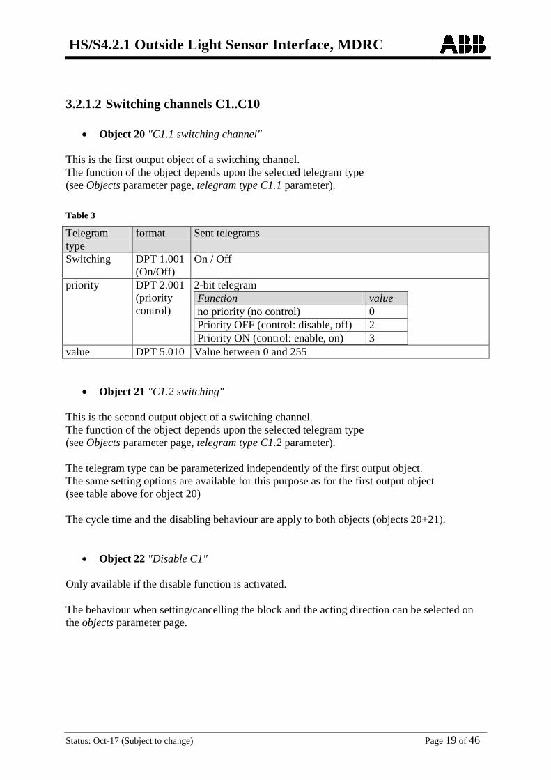
• Object 20 "C1.1 switching channel" This is the first output object of a switching channel. The function of the object depends upon the selected telegram type (see Objects parameter page, telegram type C1.1 parameter). Table 3
Telegram type
format Sent telegrams
Switching DPT 1.001 (On/Off)
On / Off
priority DPT 2.001 (priority control)
2-bit telegram Function value no priority (no control) 0 Priority OFF (control: disable, off) 2 Priority ON (control: enable, on) 3
value DPT 5.010 Value between 0 and 255
• Object 21 "C1.2 switching" This is the second output object of a switching channel. The function of the object depends upon the selected telegram type (see Objects parameter page, telegram type C1.2 parameter). The telegram type can be parameterized independently of the first output object. The same setting options are available for this purpose as for the first output object (see table above for object 20) The cycle time and the disabling behaviour are apply to both objects (objects 20+21).
• Object 22 "Disable C1" Only available if the disable function is activated. The behaviour when setting/cancelling the block and the acting direction can be selected on the objects parameter page.
HS/S4.2.1 Outside Light Sensor Interface, MDRC
Status: Oct-17 (Subject to change) Page 20 of 46
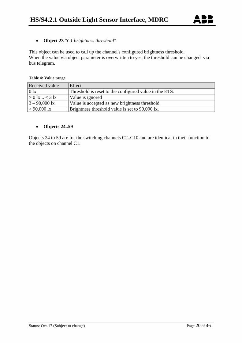
• Object 23 "C1 brightness threshold"
This object can be used to call up the channel's configured brightness threshold. When the value via object parameter is overwritten to yes, the threshold can be changed via bus telegram.
Table 4: Value range.
Received value Effect 0 lx Threshold is reset to the configured value in the ETS. > 0 lx .. < 3 lx Value is ignored 3 – 90,000 lx Value is accepted as new brightness threshold. > 90,000 lx Brightness threshold value is set to 90,000 lx.
• Objects 24..59 Objects 24 to 59 are for the switching channels C2..C10 and are identical in their function to the objects on channel C1.
HS/S4.2.1 Outside Light Sensor Interface, MDRC
Status: Oct-17 (Subject to change) Page 21 of 46
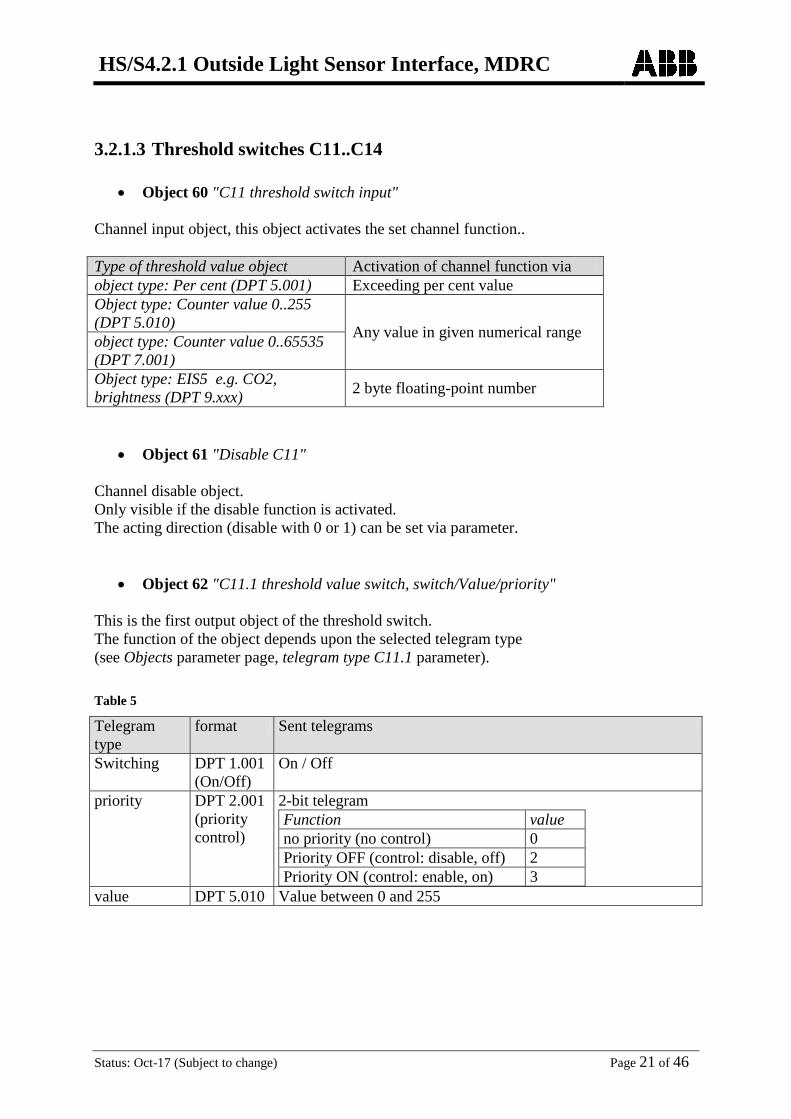
3.2.1.3 Threshold switches C11..C14
• Object 60 "C11 threshold switch input" Channel input object, this object activates the set channel function.. Type of threshold value object Activation of channel function via object type: Per cent (DPT 5.001) Exceeding per cent value Object type: Counter value 0..255 (DPT 5.010) Any value in given numerical range object type: Counter value 0..65535 (DPT 7.001) Object type: EIS5 e.g. CO2, brightness (DPT 9.xxx) 2 byte floating-point number
• Object 61 "Disable C11" Channel disable object. Only visible if the disable function is activated. The acting direction (disable with 0 or 1) can be set via parameter.
• Object 62 "C11.1 threshold value switch, switch/Value/priority" This is the first output object of the threshold switch. The function of the object depends upon the selected telegram type (see Objects parameter page, telegram type C11.1 parameter). Table 5
Telegram type
format Sent telegrams
Switching DPT 1.001 (On/Off)
On / Off
priority DPT 2.001 (priority control)
2-bit telegram Function value no priority (no control) 0 Priority OFF (control: disable, off) 2 Priority ON (control: enable, on) 3
value DPT 5.010 Value between 0 and 255
HS/S4.2.1 Outside Light Sensor Interface, MDRC
Status: Oct-17 (Subject to change) Page 22 of 46
• Object 63 "C11.2 threshold value switch, switch/Value/priority"
This is the second output object of the threshold switch. The function of the object depends upon the selected telegram type (see Objects parameter page, telegram type C11.2 parameter). The telegram type can be parameterized independently of the first output object. The same setting options are available for this purpose as for the first output object (see table above for object 86) The cycle time and the disabling behaviour are apply to both objects (objects 86+87).
• Objects 64..75 Objects 64 to 75 are for the switching channels C12/C14 and are identical in their function to the objects on channel C11.

HS/S4.2.1 Outside Light Sensor Interface, MDRC
Status: Oct-17 (Subject to change) Page 23 of 46
3.2.1.4 Logic modules C15..C20
• Object 76 "C15 logic module, logic input 1 in UND/OR/XOR gate" First input object of the logic module.
• Object 77 "C15 logic module, logic input 2 in UND/OR/XOR gate" Second input object of the logic module.
• Object 78 "C15 logic module, logic input 3 in AND/OR gate" Third input object of the logic module. Not used with XOR link.
• Object 79 "C15 logic module, logic input 4 in AND/OR gate" Fourth input object of the logic module. Not used with XOR link.
• Object 80"C15 logic module, disable" Channel disable object. Only visible if the disable function is activated. The acting direction (disable with 0 or 1) can be set via parameter.
HS/S4.2.1 Outside Light Sensor Interface, MDRC
Status: Oct-17 (Subject to change) Page 24 of 46
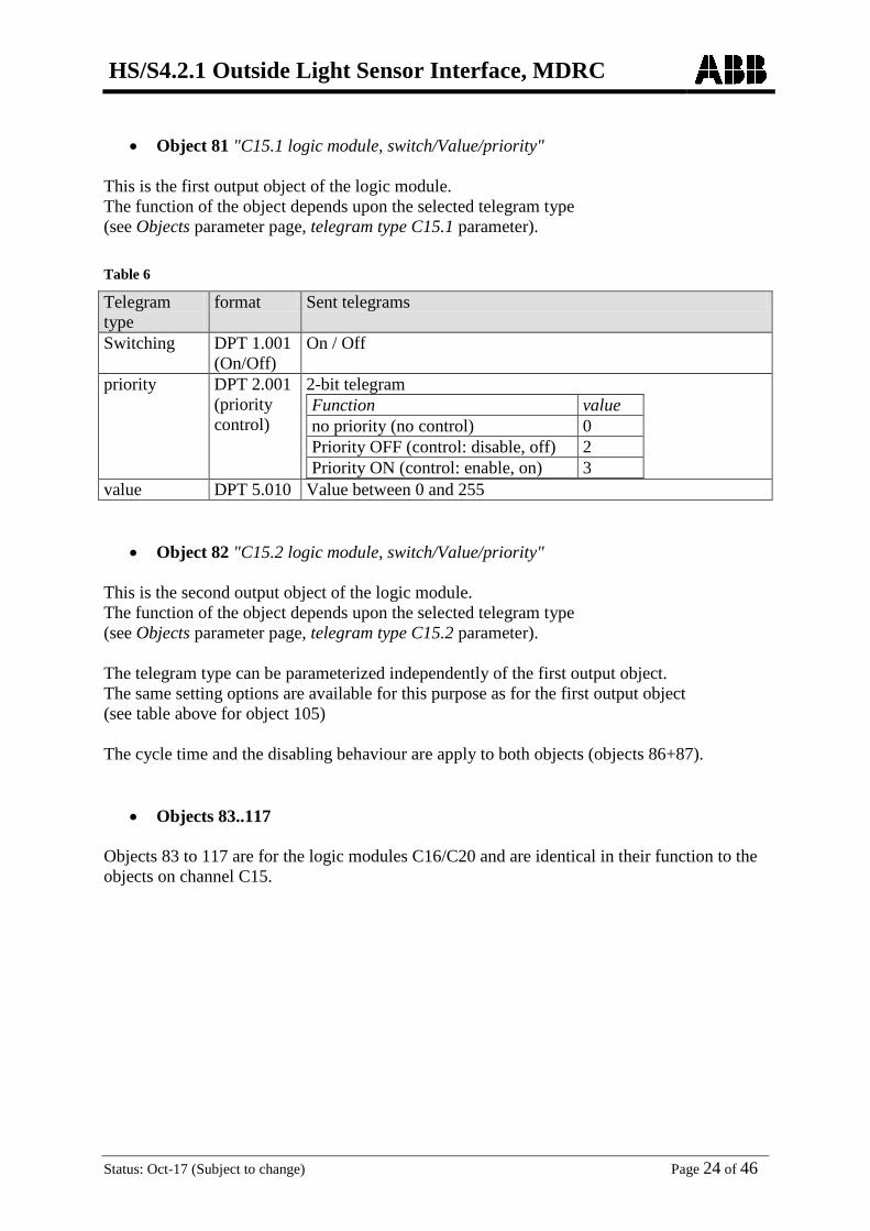
• Object 81 "C15.1 logic module, switch/Value/priority"
This is the first output object of the logic module. The function of the object depends upon the selected telegram type (see Objects parameter page, telegram type C15.1 parameter). Table 6
Telegram type
format Sent telegrams
Switching DPT 1.001 (On/Off)
On / Off
priority DPT 2.001 (priority control)
2-bit telegram Function value no priority (no control) 0 Priority OFF (control: disable, off) 2 Priority ON (control: enable, on) 3
value DPT 5.010 Value between 0 and 255
• Object 82 "C15.2 logic module, switch/Value/priority"
This is the second output object of the logic module. The function of the object depends upon the selected telegram type (see Objects parameter page, telegram type C15.2 parameter). The telegram type can be parameterized independently of the first output object. The same setting options are available for this purpose as for the first output object (see table above for object 105) The cycle time and the disabling behaviour are apply to both objects (objects 86+87).
• Objects 83..117 Objects 83 to 117 are for the logic modules C16/C20 and are identical in their function to the objects on channel C15.

HS/S4.2.1 Outside Light Sensor Interface, MDRC
Status: Oct-17 (Subject to change) Page 25 of 46
3.3 Parameter
3.3.1 Parameter pages
Table 7
Function Description General Activation of the required channel types. Language
setting, backlighting, PIN code. Measured values Settings for sending brightness and sensor adjustment. Switching channel C1: Function .. Switching channel C10: Function
Basic settings, delays etc.
objects* Telegram type, switching and disable response etc. Threshold channel C11: Function .. Threshold channel C14: Function
Type of threshold value object, delays etc.
objects* Telegram type, switching and disable response etc. Logic channel C15: Function .. Logic channel C20: Function
Number of inputs, links etc.
objects* Telegram type, switching and disable response etc. * Own parameter page for each channel.

HS/S4.2.1 Outside Light Sensor Interface, MDRC
Status: Oct-17 (Subject to change) Page 26 of 46
3.3.2 Parameter description Settings that lead to the display of other pages or functions are identified by ... Example: yes/no
3.3.2.1 The "General" parameter page Designation Values Description Activate switching channel C1
No Yes.
The switching channels can issue telegrams independent of brightness.
Activate switching channel C2
No Yes.
Activate switching channel C3
No Yes.
Activate switching channel C4
No Yes.
Activate switching channel C5
No Yes.
Activate switching channel C6
No Yes.
Activate switching channel C7
No Yes.
Activate switching channel C8
No Yes.
Activate switching channel C9
No Yes.
Activate switching channel C10
No Yes.
Activating threshold channel C11
No Yes.
Switch threshold value channels based on received bus telegram depending whether a value is exceeded or not achieved.
Activating threshold channel C12
No Yes.
Activating threshold channel C13
No Yes.
Activating threshold channel C14
No Yes.

HS/S4.2.1 Outside Light Sensor Interface, MDRC
Status: Oct-17 (Subject to change) Page 27 of 46
Continuation: Designation Values Description Activating logic channel C15
No Yes.
Logic channels enable the linking of up to 4 input sizes. These can be both specific logic input objects (max. 4) and the switching statuses of other channels (switching, threshold or logic channels).
Activating logic channel C16
No Yes.
Activating logic channel C17
No Yes.
Activating logic channel C18
No Yes.
Activating logic channel C19
No Yes.
Activating logic channel C20
No Yes.
Language after download
German English French Italian
Spanish Dutch
Reserved for additional language 7 ..
Reserved for additional language 15
Language for displayed text info.
Backlit display after download
After download, the display backlighting…
Off allow to switch on or off.
On switch on or leave on continuously.
when operating only switch on when the device is being used (automatic switch-off after approx. 1 minute).
unchanged: As set on device do not change Settings on device enabled
No PIN code: The device is always operable.
Released via PIN The device can only be used after the input of a PIN code.
PIN code 1000-9999
Manual input 1000-9999
Default value: 1234
Enter desired PIN number here.

HS/S4.2.1 Outside Light Sensor Interface, MDRC
Status: Oct-17 (Subject to change) Page 28 of 46
3.3.2.2 "Brightness measurement" parameter page"
Designation Values Description Send brightness value on change
no
Only send cyclically (if enabled)
of 20 %, at least but 1 lx of 30 %, at least but 1 lx of 50 %, at least but 1 lx of 10 %, at least but 1 lx
Send if the value has changed by 10%, 20% etc. since it was last sent. However, if a change of 10% corresponds to a brightness change < 1 lx, then the value is not sent until the change is at least >1 lx.
Send brightness value and sensor status cyclically
do not send cyclically every min
every 2 min every 3 min
every 5 min every 10 min every 15 min every 20 min every 30 min every 45 min every 60 min
how often should the current brightness value and the current status of the brightness sensors be sent?
Name for brightness sensor 1 (appears in display)
Text input (max. 16 characters) Free choice of description for the sensor e.g. "south side". Is displayed on device as sensor name.
Brightness adjustment sensor 1 [%]
-30..30 (Default = 0)
Individual adjustment value for the brightness measurement at sensor 1, if the transmitted value deviates from the actual ambient brightness. Example: Brightness = 10,000 lx Transmitted = 11,000 lx Adjustment value = -10 %
Brightness adjustment sensor 2 [%] if available
-30..30 (Default = 0)
Individual adjustment value in per cent, for the brightness measurement at sensor 2
Name for brightness sensor 2 (appears in display)
Text input (max. 16 characters) Free choice of description for the sensor e.g. "west side". Is displayed on device as sensor name.
Brightness adjustment sensor 3 [%] if available
-30..30 (Default = 0)
Individual adjustment value in per cent, for the brightness measurement at sensor 3
Name for brightness sensor 3 (appears in display)
Text input (max. 16 characters) Free choice of description for the sensor e.g. "east side". Is displayed on device as sensor name.
HS/S4.2.1 Outside Light Sensor Interface, MDRC
Status: Oct-17 (Subject to change) Page 29 of 46
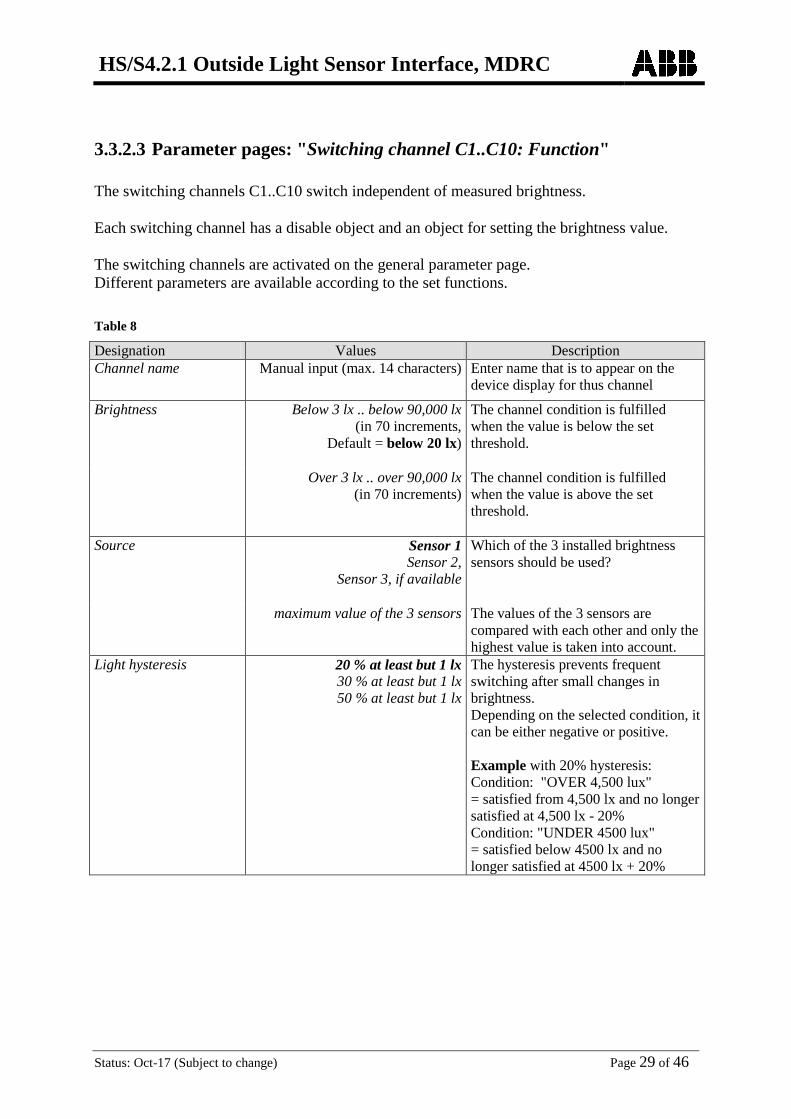
3.3.2.3 Parameter pages: "Switching channel C1..C10: Function" The switching channels C1..C10 switch independent of measured brightness. Each switching channel has a disable object and an object for setting the brightness value. The switching channels are activated on the general parameter page. Different parameters are available according to the set functions. Table 8
Designation Values Description Channel name Manual input (max. 14 characters) Enter name that is to appear on the
device display for thus channel
Brightness Below 3 lx .. below 90,000 lx (in 70 increments,
Default = below 20 lx)
The channel condition is fulfilled when the value is below the set threshold.
Over 3 lx .. over 90,000 lx (in 70 increments)
The channel condition is fulfilled when the value is above the set threshold.
Source Sensor 1 Sensor 2,
Sensor 3, if available
Which of the 3 installed brightness sensors should be used?
maximum value of the 3 sensors The values of the 3 sensors are compared with each other and only the highest value is taken into account.
Light hysteresis 20 % at least but 1 lx 30 % at least but 1 lx 50 % at least but 1 lx
The hysteresis prevents frequent switching after small changes in brightness. Depending on the selected condition, it can be either negative or positive. Example with 20% hysteresis: Condition: "OVER 4,500 lux" = satisfied from 4,500 lx and no longer satisfied at 4,500 lx - 20% Condition: "UNDER 4500 lux" = satisfied below 4500 lx and no longer satisfied at 4500 lx + 20%
HS/S4.2.1 Outside Light Sensor Interface, MDRC
Status: Oct-17 (Subject to change) Page 30 of 46
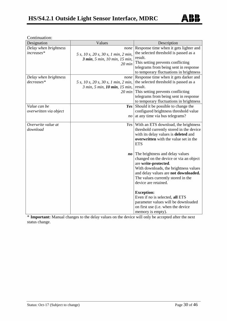
Continuation: Designation Values Description Delay when brightness increases*
none Response time when it gets lighter and the selected threshold is passed as a result. This setting prevents conflicting telegrams from being sent in response to temporary fluctuations in brightness
5 s, 10 s, 20 s, 30 s, 1 min, 2 min, 3 min, 5 min, 10 min, 15 min,
20 min
Delay when brightness decreases*
none Response time when it gets darker and the selected threshold is passed as a result. This setting prevents conflicting telegrams from being sent in response to temporary fluctuations in brightness
5 s, 10 s, 20 s, 30 s, 1 min, 2 min, 3 min, 5 min, 10 min, 15 min,
20 min
Value can be overwritten via object
Yes
no
Should it be possible to change the configured brightness threshold value at any time via bus telegrams?
Overwrite value at download
Yes
With an ETS download, the brightness threshold currently stored in the device with its delay values is deleted and overwritten with the value set in the ETS
no The brightness and delay values changed on the device or via an object are write-protected. With downloads, the brightness values and delay values are not downloaded. The values currently stored in the device are retained. Exception: Even if no is selected, all ETS parameter values will be downloaded on first use (i.e. when the device memory is empty).
* Important: Manual changes to the delay values on the device will only be accepted after the next status change.

HS/S4.2.1 Outside Light Sensor Interface, MDRC
Status: Oct-17 (Subject to change) Page 31 of 46
3.3.2.4 Parameter pages "Objects"
All universal, threshold and logic channels have this type of parameter page. The reaction to fulfilling or not fulfilling the link is configured here..
Table 9
Designation Values Description Telegram type C1.1 Switching command
1 bit ON/OFF
Priority
2-bit Function value Priority inactive (no control) 0 (00bin)
Priority ON (control: enable, on) 3 (11bin)
Priority OFF (control: disable, off) 2 (10bin)
value 1-byte 0 ... 255 If the condition is met no telegram
send following telegram once send cyclically
Send response if channel condition is fulfilled.
Telegram Type of telegram for the first output object on the channel with fulfilled condition.
ON OFF
For telegram type Switching command.
no priority priority, ON (down)
priority, OFF (up)
For telegram type Priority.
Telegram 0 ... 255 For telegram type Value If the condition is not met no telegram
send following telegram once send cyclically
Send response if channel condition is unfulfilled.
Telegram Type of telegram for the first output object on the channel with unfulfilled condition.
ON OFF
For telegram type Switching command.
no priority priority, ON (down) priority, OFF (up)
For telegram type Priority.
Telegram 0 .. 255 For telegram type Value

HS/S4.2.1 Outside Light Sensor Interface, MDRC
Status: Oct-17 (Subject to change) Page 32 of 46
Continuation:
Designation Values Description Should a second telegram be sent?
Yes no
If yes is selected, further parameters and a second transmission object appear. It can be used to send 2 different telegrams at the same time on the same channel. The cycle time and the disabling behaviour apply to both objects.
Telegram type C1.2 Second output object on channel Switching command
1 bit ON/OFF
Priority
2-bit Function value Priority inactive (no control) 0 (00bin)
Priority ON (control: enable, on) 3 (11bin)
Priority OFF (control: disable, off) 2 (10bin)
value 1-byte 0 ... 255 If the condition is met no telegram
send following telegram once send cyclically
Send response if channel condition is fulfilled.
Telegram Type of telegram for the second output object on the channel with fulfilled condition.
ON OFF
For telegram type Switching command.
no priority priority, ON (down)
priority, OFF (up)
For telegram type Priority.
Telegram 0 ... 255 For telegram type Value If the condition is not met no telegram
send following telegram once send cyclically
Send response if channel condition is unfulfilled.
Telegram Type of telegram for the second output object on the channel with unfulfilled condition.
ON OFF
For telegram type Switching command.
no priority priority, ON (down) priority, OFF (up)
For telegram type Priority.
Telegram 0 .. 255 For telegram type Value
HS/S4.2.1 Outside Light Sensor Interface, MDRC
Status: Oct-17 (Subject to change) Page 33 of 46
Continuation:
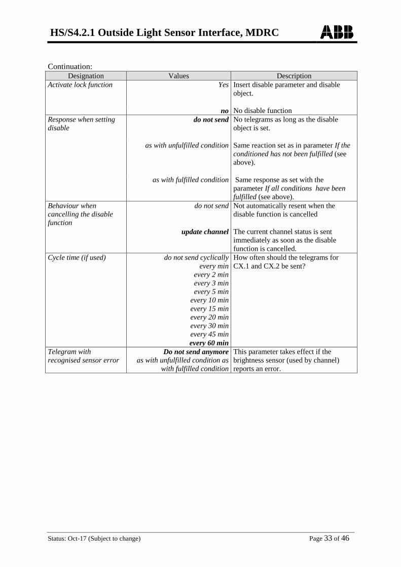
Designation Values Description Activate lock function Yes
Insert disable parameter and disable object.
no No disable function Response when setting disable
do not send No telegrams as long as the disable object is set.
as with unfulfilled condition Same reaction set as in parameter If the conditioned has not been fulfilled (see above).
as with fulfilled condition Same response as set with the parameter If all conditions have been fulfilled (see above).
Behaviour when cancelling the disable function
do not send
Not automatically resent when the disable function is cancelled
update channel The current channel status is sent immediately as soon as the disable function is cancelled.
Cycle time (if used) do not send cyclically every min
every 2 min every 3 min
every 5 min every 10 min every 15 min every 20 min every 30 min every 45 min every 60 min
How often should the telegrams for CX.1 and CX.2 be sent?
Telegram with recognised sensor error
Do not send anymore as with unfulfilled condition as
with fulfilled condition
This parameter takes effect if the brightness sensor (used by channel) reports an error.

HS/S4.2.1 Outside Light Sensor Interface, MDRC
Status: Oct-17 (Subject to change) Page 34 of 46
3.3.2.5 Parameter pages "Threshold channel C11..C14" The threshold channel block forms a separate unit that is completely independent of the brightness measurement. Principle: A value is received from the bus and compared with the set threshold. The condition is fulfilled if the value is higher than the set threshold. In turn, not fulfilled if the value is below it. The response of the output objects to fulfilling/not fulfilling the condition is set on the Objects parameter page. The channel status (condition fulfilled/unfulfilled) for each threshold channel can also be configured as input value for logic channels (see below, The logic channels). The switching channels are activated on the General parameter page. Table 10
Designation Values Description Type of threshold value object
object type: Per cent (DPT 5.001)
Object type: Counter value 0..255 (DPT 5.010)
object type: Counter value 0..65535 (DPT 7.001)
Object type: EIS5 e.g. CO2, brightness, etc. (DPT 9.xxx)
Value type for threshold.
Parameter for Percent threshold object Threshold value (in %) 1..99
Default = 50 Desired threshold value as percentage.
Hysteresis (as %) 1..99 Default = 5
Prevents frequent switching after small changes in readings. The hysteresis is uniformly negative for all threshold types, e.g. threshold 50, hysteresis 5 means: Switch on at 50 a switch off at 50 – hysteresis = 45
Parameter for threshold value object Counter value 0..255 Threshold value 1..254
Default = 127 Desired threshold value as 1 byte number from 1 to 254.
Hysteresis 1..254 Default = 5
The hysteresis prevents frequent switching after small changes in readings.

HS/S4.2.1 Outside Light Sensor Interface, MDRC
Status: Oct-17 (Subject to change) Page 35 of 46
Continuation:
Designation Values Description Parameter for threshold value object Counter value 0..65535
Threshold value 1..65534 Default = 1,000
Desired threshold value as 2 byte number from 1 to 65534.
Hysteresis 1..65534 Default = 5
The hysteresis prevents frequent switching after small changes in readings.
Parameter for threshold value object EIS5 (e.g. CO2, brightness…) Threshold value format: (-000.00..9999)
-9999..99999 Default = 20.0
Desired threshold value as decimal number with prefix. Format: A maximum of 5 characters are permitted including decimal point and prefix. Examples with five characters: -9999 -9.99 10.35 100.6 99999 etc.
Hysteresis format: 0.00..9999
0.00..9999 Default = 1.0
The hysteresis prevents frequent switching after small changes in readings. Format: Max. 4 characters, positive numbers only. Examples: 0.01 99.9 9999
Common parameters Delay with exceeding None, The channel sends immediately.
5 s, 10 s, 20 s, 30 s, 1 min, 2 min,
3 min, 5 min, 10 min, 15 min, 20 min
The channel only sends after set delay is completed.
Delay with falling below none The channel sends immediately.
5 s, 10 s, 20 s, 30 s, 1 min, 2 min, 3 min, 5 min, 10 min, 15 min,
20 min
The channel only sends after set delay is completed.

HS/S4.2.1 Outside Light Sensor Interface, MDRC
Status: Oct-17 (Subject to change) Page 36 of 46
3.3.2.6 Parameter pages "Objects"
All universal, threshold and logic channels have this type of parameter page. The reaction to fulfilling or not fulfilling the link is configured here..
Table 11
Designation Values Description Telegram type C11.1 Switching command
1 bit ON/OFF
Priority
2-bit Function value Priority inactive (no control) 0 (00bin)
Priority ON (control: enable, on) 3 (11bin)
Priority OFF (control: disable, off) 2 (10bin)
value 1-byte 0 ... 255 When exceeding the threshold
no telegram send following telegram once
send cyclically
Send response if channel condition is fulfilled.
Telegram
Type of telegram for the first output object on the channel with fulfilled condition.
ON OFF
For telegram type Switching command.
no priority priority, ON (down)
priority, OFF (up)
For telegram type Priority.
Telegram 0 ... 255 For telegram type Value When below threshold no telegram
send following telegram once send cyclically
Send response if channel condition is unfulfilled.
Telegram Type of telegram for the first output object on the channel with unfulfilled condition.
ON OFF
For telegram type Switching command.
no priority priority, ON (down) priority, OFF (up)
For telegram type Priority.
Telegram 0 .. 255 For telegram type Value

HS/S4.2.1 Outside Light Sensor Interface, MDRC
Status: Oct-17 (Subject to change) Page 37 of 46
Continuation:
Designation Values Description Should a second telegram be sent?
Yes no
If yes is selected, further parameters and a second transmission object appear. It can be used to send 2 different telegrams at the same time on the same channel. The cycle time and the disabling behaviour apply to both objects.
Telegram type C11.2 Second output object on channel Switching command
1 bit ON/OFF
Priority
2-bit Function value Priority inactive (no control) 0 (00bin)
Priority ON (control: enable, on) 3 (11bin)
Priority OFF (control: disable, off) 2 (10bin)
value 1-byte 0 ... 255 When exceeding the threshold
no telegram send following telegram once
send cyclically
Send response if channel condition is fulfilled.
Telegram
Type of telegram for the second output object on the channel with fulfilled condition.
ON OFF
For telegram type Switching command.
no priority priority, ON (down)
priority, OFF (up)
For telegram type Priority.
Telegram 0 ... 255 For telegram type Value When below threshold no telegram
send following telegram once send cyclically
Send response if channel condition is unfulfilled.
Telegram Type of telegram for the second output object on the channel with unfulfilled condition.
ON OFF
For telegram type Switching command.
no priority priority, ON (down) priority, OFF (up)
For telegram type Priority.
Telegram 0 .. 255 For telegram type Value

HS/S4.2.1 Outside Light Sensor Interface, MDRC
Status: Oct-17 (Subject to change) Page 38 of 46
Continuation:
Designation Values Description Activate lock function Yes
Insert disable parameter and disable object.
no No disable function Response when setting disable
do not send
No telegrams as long as the disable object is set.
as with unfulfilled condition Same reaction set as with parameter If below threshold (see above).
as with fulfilled condition Same reaction set as with parameter When exceeding threshold (see above).
Behaviour when cancelling the disable function
Do not send
Not automatically resent when the disable function is cancelled
update channel The current channel status is sent immediately as soon as the disable function is cancelled.
Cycle time (if used) do not send cyclically every min
every 2 min every 3 min
every 5 min every 10 min every 15 min every 20 min every 30 min every 45 min every 60 min
How often should the telegrams for CX.1 and CX.2 be sent?

HS/S4.2.1 Outside Light Sensor Interface, MDRC
Status: Oct-17 (Subject to change) Page 39 of 46
3.3.2.7 Parameter pages "Logic channel C15..C20" The logic channel block forms a separate unit that is completely independent of the brightness measurement. The logic channels can thus be used for a broad range of tasks in the KNX device. Principle: Up to four 1 bit input values can be logically linked to each other. These input values can be:
• Logic inputs • Status of switching channels (fulfilled/unfulfilled) • Status of threshold channels (fulfilled/unfulfilled) • Link result of other logic channels (a logic channel cannot be connected with itself)
The response of the output objects to fulfilling/not fulfilling the condition is set on the Objects parameter page. The logic channels are activated on the general parameter page. Table 12
Designation Values Description Type of link Selection of logical link between 1-bit
input values (see below) AND
2 to 4 inputs
OR
XOR 2 inputs Use input 1 Yes
Input is used
Yes, inverted Input appears inverted Use input 2 Yes
Yes, inverted See above, input 1
Use input 3 No
Input is hidden
Yes Yes, inverted
See above.
Use input 4 No
Input is hidden
Yes Yes, inverted
See above.
HS/S4.2.1 Outside Light Sensor Interface, MDRC
Status: Oct-17 (Subject to change) Page 40 of 46
Continuation:
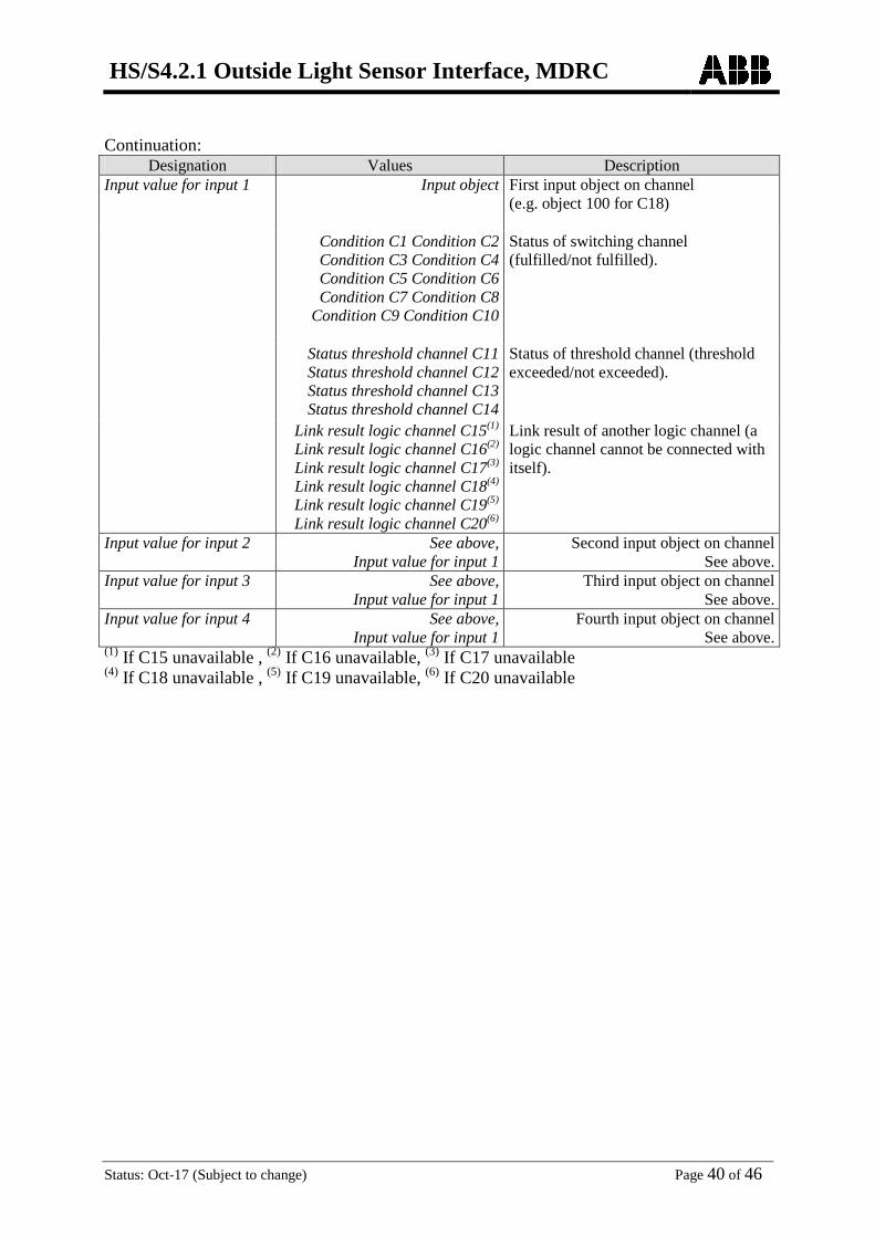
Designation Values Description Input value for input 1 Input object First input object on channel
(e.g. object 100 for C18)
Condition C1 Condition C2 Condition C3 Condition C4 Condition C5 Condition C6 Condition C7 Condition C8
Condition C9 Condition C10
Status of switching channel (fulfilled/not fulfilled).
Status threshold channel C11 Status threshold channel C12 Status threshold channel C13 Status threshold channel C14
Status of threshold channel (threshold exceeded/not exceeded).
Link result logic channel C15(1) Link result logic channel C16(2) Link result logic channel C17(3) Link result logic channel C18(4) Link result logic channel C19(5)
Link result logic channel C20(6)
Link result of another logic channel (a logic channel cannot be connected with itself).
Input value for input 2 See above, Input value for input 1
Second input object on channel See above.
Input value for input 3 See above, Input value for input 1
Third input object on channel See above.
Input value for input 4 See above, Input value for input 1
Fourth input object on channel See above.
(1) If C15 unavailable , (2) If C16 unavailable, (3) If C17 unavailable (4) If C18 unavailable , (5) If C19 unavailable, (6) If C20 unavailable
HS/S4.2.1 Outside Light Sensor Interface, MDRC
Status: Oct-17 (Subject to change) Page 41 of 46
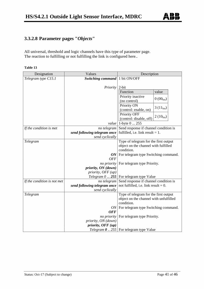
3.3.2.8 Parameter pages "Objects"
All universal, threshold and logic channels have this type of parameter page. The reaction to fulfilling or not fulfilling the link is configured here.. Table 13
Designation Values Description Telegram type C15.1 Switching command
1 bit ON/OFF
Priority
2-bit Function value Priority inactive (no control) 0 (00bin)
Priority ON (control: enable, on) 3 (11bin)
Priority OFF (control: disable, off) 2 (10bin)
value 1-byte 0 ... 255 If the condition is met no telegram
send following telegram once send cyclically
Send response if channel condition is fulfilled, i.e. link result = 1.
Telegram
Type of telegram for the first output object on the channel with fulfilled condition.
ON OFF
For telegram type Switching command.
no priority priority, ON (down)
priority, OFF (up)
For telegram type Priority.
Telegram 0 ... 255 For telegram type Value If the condition is not met no telegram
send following telegram once send cyclically
Send response if channel condition is not fulfilled, i.e. link result = 0.
Telegram Type of telegram for the first output object on the channel with unfulfilled condition.
ON OFF
For telegram type Switching command.
no priority priority, ON (down) priority, OFF (up)
For telegram type Priority.
Telegram 0 .. 255 For telegram type Value
HS/S4.2.1 Outside Light Sensor Interface, MDRC
Status: Oct-17 (Subject to change) Page 42 of 46
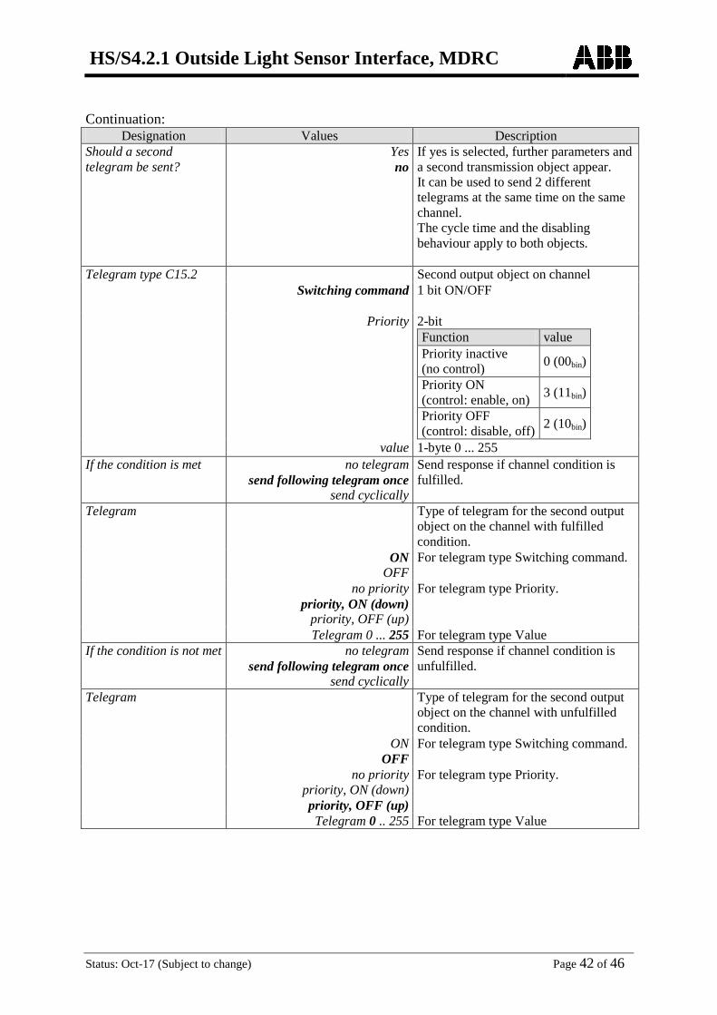
Continuation:
Designation Values Description Should a second telegram be sent?
Yes no
If yes is selected, further parameters and a second transmission object appear. It can be used to send 2 different telegrams at the same time on the same channel. The cycle time and the disabling behaviour apply to both objects.
Telegram type C15.2 Second output object on channel Switching command
1 bit ON/OFF
Priority
2-bit Function value Priority inactive (no control) 0 (00bin)
Priority ON (control: enable, on) 3 (11bin)
Priority OFF (control: disable, off) 2 (10bin)
value 1-byte 0 ... 255 If the condition is met no telegram
send following telegram once send cyclically
Send response if channel condition is fulfilled.
Telegram
Type of telegram for the second output object on the channel with fulfilled condition.
ON OFF
For telegram type Switching command.
no priority priority, ON (down)
priority, OFF (up)
For telegram type Priority.
Telegram 0 ... 255 For telegram type Value If the condition is not met no telegram
send following telegram once send cyclically
Send response if channel condition is unfulfilled.
Telegram Type of telegram for the second output object on the channel with unfulfilled condition.
ON OFF
For telegram type Switching command.
no priority priority, ON (down) priority, OFF (up)
For telegram type Priority.
Telegram 0 .. 255 For telegram type Value
HS/S4.2.1 Outside Light Sensor Interface, MDRC
Status: Oct-17 (Subject to change) Page 43 of 46
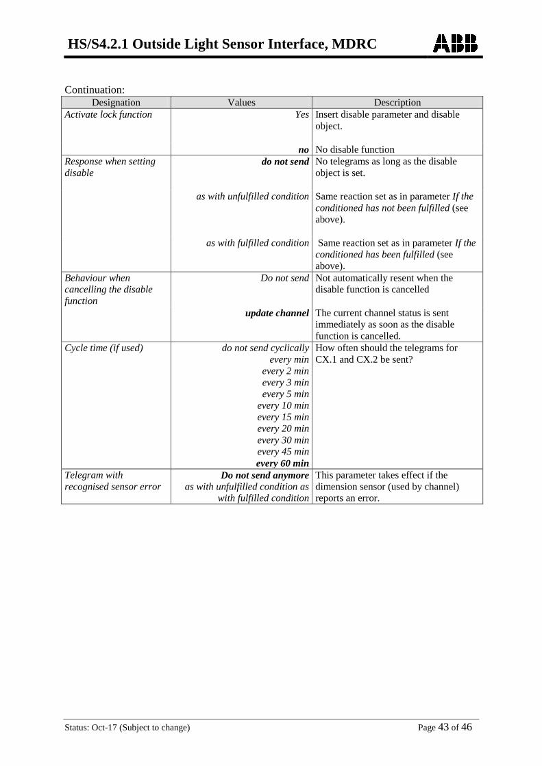
Continuation:
Designation Values Description Activate lock function Yes
Insert disable parameter and disable object.
no No disable function Response when setting disable
do not send
No telegrams as long as the disable object is set.
as with unfulfilled condition Same reaction set as in parameter If the conditioned has not been fulfilled (see above).
as with fulfilled condition Same reaction set as in parameter If the conditioned has been fulfilled (see above).
Behaviour when cancelling the disable function
Do not send
Not automatically resent when the disable function is cancelled
update channel The current channel status is sent immediately as soon as the disable function is cancelled.
Cycle time (if used) do not send cyclically every min
every 2 min every 3 min
every 5 min every 10 min every 15 min every 20 min every 30 min every 45 min every 60 min
How often should the telegrams for CX.1 and CX.2 be sent?
Telegram with recognised sensor error
Do not send anymore as with unfulfilled condition as
with fulfilled condition
This parameter takes effect if the dimension sensor (used by channel) reports an error.

HS/S4.2.1 Outside Light Sensor Interface, MDRC
Status: Oct-17 (Subject to change) Page 44 of 46
4 Appendix
4.1 Allocate sensors Up to 3 brightness sensors, which are connected to the data bus, can be allocated. These vary according their serial numbers.
Settings • Select sensors with ▲ or ▼ . Language.. Display.. System.. Sensors..
• Confirm by pressing OK. Back Process sensors • Select desired sensor with ▲ or ▼
(e.g. sensor 1). L1 sensor 1 inactiv
e L2 sensor 2 inactiv
e
L3 sensor 3 inactiv
e • Confirm by pressing OK. Back
Query data bus according to available sensors: L1 sensor 1 • Select next serial number. inactive next serial number
• Confirm by pressing OK. Back
Menu • Press menu button. This brings up the settings.. Settings..
C1: C2: C3: C4: C5:
• Confirm by pressing OK. Back

HS/S4.2.1 Outside Light Sensor Interface, MDRC
Status: Oct-17 (Subject to change) Page 45 of 46
The first detected sensor is displayed with serial number. A flashing LED on the sensor makes it instantly identifiable without having to make the effort of reading the serial number on the device. The measured brightness value of the sensor is also displayed. This can also be helpful for the allocation of sensors, particularly when they are already installed. Table 14
Case 1: The displayed sensor is accepted. Case 2: If you want continue searching rather than accepting the sensor.
L1 sensor 1
SN:104405325 inactive 445 lx next serial number Allocate Back
Select allocate and confirm by pressing OK.
L1 sensor 1
SN:104405325 inactive 445 lx next serial number Allocate Back
Select next serial number and confirm by pressing OK.
Leave settings for sensor 1 by pressing Back.
L1 sensor 1 SN:104405325
445 lx Deactivate next serial number Back
An incorrectly allocated sensor can be separated at any time via the menu item Deactivate.
Another sensor is found. Select using Allocate or search for another via Next serial number.
L1 sensor 1 SN:104405340
inactive 445 lx next serial number Allocate Back
Process sensors L1 sensor 1 SN:104405325 L2 sensor 2 inactive L3 sensor 3 inactive Back
Set the second sensor using L2 sensor 2 or leave the sensor menu by pressing Back.
HS/S4.2.1 Outside Light Sensor Interface, MDRC
Status: Oct-17 (Subject to change) Page 46 of 46
Service address ABB STOTZ-KONTAKT GmbH Eppelheimer Straße 82 69123 Heidelberg Germany Tel. +49 6221 701-434 Fax +49 6221 701-724 www.abb.com/knx