
Outside Air Applications - Unilog
48
MANUFACTURING • QUALITY • SERVICE • MANUFACTURING • QUALITY • SERVICE • MANUFACTURING • QUALITY • SERVICE • MANUFACT ® Outside Air Applications dixonvalve.com • Customer Service: 877.963.4966
-
Upload
khangminh22 -
Category
Documents
-
view
0 -
download
0
Transcript of Outside Air Applications - Unilog

MA
NU
FAC
TUR
ING
• Q
UA
LITY
• SE
RVIC
E • M
AN
UFA
CTU
RIN
G •
QU
ALI
TY •
SERV
ICE
• MA
NU
FAC
TUR
ING
• Q
UA
LITY
• SE
RVIC
E • M
AN
UFA
CTU
RIN
®
OutsideAir
Applications
dixonvalve.com • Customer Service: 877.963.4966

877.963.49662 dixonvalve.com
Safety
The Importance of Whip Hose
OSHA RegulationsASME Air Receiver Manifold- 1910.169; 1926.306King Safety Cable- 1926.302 (b1)Air King Safety Clip- 1926.302 (b2)
Safety Check Valve- 1926.302 (b7)Safety Vented Ball Valve- 1910.147
The regulations may be viewed in full on the OSHA website, osha.gov. Please check the website for updates.
Installation and Inspection ProceduresProcedure # 1000 Boss clamp selectionProcedure # 2000 Installation of Boss 2 bolt clampProcedure # 2001 Installation of Boss 4 bolt clamp
Procedure # 2300 Installation of King Cable Safety CableProcedure # 2306 Crimping Unirange, Air King, Dix-Lock and Dual-Lock couplingsProcedure # 3001 Bolt Clamp Inspection
A printed copy of the complete Installation and Inspection Procedures Manual is available upon request.
The constant vibration created by air tools, like air drills and pavement breakers, is destructive to air hose couplings, especially the quick-acting type. To provide a safer working enviroment, connect one end of a 3' to 10' length of air hose to the tool using Dixon's No. 3500 Steel Nipple. This nipple is designed to specifically handle vibration applications. Connect the other end of hose to the air supply using the standard quick-acting coupling. The Whip Hose should remain permanently connected to the tool.
All dimensions are nominal.All package quantity shown is optional.
Dixon's couplings and retention devices are designed to work safely for their intended use. The selection of the proper hose, coupling and retention device, and the proper application of the coupling to the hose are of utmost importance.
Users must consider the size, temperature, application, media, pressure and hose and coupling manufacturer's recommendations when selecting the proper hose assembly components. Dixon recommends that all hose assemblies be tested in accordance with the Association for Rubber Products Manufacturer's (ARPM) recommendations and be inspected regularly (before each use) to ensure that they are not damaged or have become loose. Visit ARPMINC.com for more information.
Where safety devices are integral to the coupling, they must be working and utilized. The use of supplementary safety devices such as safety clips or safety cables are recommended.
If any problem is detected, couplings must be removed from service immediately.
Dixon is available to consult, train and recommend the proper selection and application of all fittings we sell. We strongly recommend that distributors and end users make use of Dixon's Testing and Recommendation Services. Call 877.963.4966 or click dixonvalve.com to learn more.
Scan me with your Smart Phone.No reader?
Download a free QR-Code 2D barcode reader.mobile-barcodes.com/qr-code-software/
Coupling Procedures Dixon Customer Service Facebook Page YouTube Videos

877.963.4966 3dixonvalve.com
Detailed view of manifold assembly

877.963.49664 dixonvalve.com
Compressor
125 CFM

877.963.4966 5dixonvalve.com
Compressor
600 CFM

877.963.49666 dixonvalve.com
Air King meets pressure requirements as specified in Commercial Item Description A-A-59553that supersedes Mil Spec. WWC-633D.
Dixon Air King couplings are recommended for use on virtually any type of pneumatic equipment.
Air-King
Universal Couplings
Service:• The maximum recommended working pressure for Dixon Air King is 150 PSI at ambient temperature (70°F).• for air and water service only. Warning: Not to be used for steam.
Features:• A universal head that is identical for all parts in the 1/4" to 1" range. With this head, any Dixon fittings within that range can be connected regardless of hose shank or thread size.• Couplings with optional ferrules permanently attached are provided ready to install.• Safety - There are three safety features built into every Dixon Air King:
1. Washer design (A) – Dixon AWR4 washers supplied with every Air King are designed to seal up to 150 PSI. The washer design helps keep the coupling together while pressurized.
2. Internal lug design (B) –Cast inside each Air King lug is a ninety-degree step that locks with an opposite step on the outside of the adjoining Air King part. These step-locks provide additional holding power to keep the Air King connected up to its 150 PSI rating at 70° F ambient temperature.
3. Safety Clip (C) – Unexpected twisting of hose assemblies can occur during use. To eliminate the possibility of accidentally disconnecting, each Air King comes with a Safety Clip. This clip is designed to be inserted into the locking holes (D) on the fittings. The use of a Safety Clip assures the users that the fittings have been properly connected. Connecting:• Push two couplings together and turn the one in your right hand until they seat.• Insert an Air King safety clip through the hole in the flanged area of the head. If a safety clip is not available, use a cotter pin or wire type retainer. Lanyards (not pictured, see page 9) are available separately to fasten the Safety Clip to the locking head.
Disconnecting:• Remove the safety clip, cotter pin or wire. Press the couplings together and turn the one in your right hand until they unseat. Never attempt to disconnect any hose while pressure is in the line.
Interchange:• Although Air King may couple with other manufacturers' fittings, we do not recommend their use with other products. Not all universal locking heads are made to the same standard.
C
B
D
A

877.963.4966 7dixonvalve.com
Male NPT Ends
Female NPT Ends
AIR KING
Features:• male NPT thread with hex for a wrench• available in iron, brass or 316 stainless steel• available in sizes ¼" to 1", ¼" not available in stainless steel
DimensionsSize A B C D E NPT1/4" 2-1/2" 2-9/16" 1" 9/16" 5/8" 1/4"3/8" 2-1/2" 2-9/16" 1" 9/16" 5/8" 3/8"1/2" 2-1/2" 2-11/16" 1-1/8" 1/2" 3/4" 1/2"3/4" 2-1/2" 2-13/16" 1-3/8" 9-16" 13/16" 3/4"1" 2-1/2" 2-13/16" 1-1/2" 3/8" 13/16" 1"
Features:• female NPT thread with hex for a wrench• available in malleable iron, brass or 316 stainless steel• available in sizes ¼" to 1", ¼" not available in stainless steel
DimensionsSize A B C D NPT1/4" 2-1/2" 2-7/16" 1-1/8" 3/8" 1/4"3/8" 2-1/2" 2-7/16" 1-1/8" 3/8" 3/8"1/2" 2-1/2" 2-7/16" 1-1/8" 3/8" 1/2"3/4" 2-1/2" 2-7/16" 1-7/16" 3/8" 3/4"1" 2-1/2" 2-1/16" 1-5/8" 3/8" 1"
SizeIron Opt
QtyBrass Opt
Qty
316 Stainless Steel
Part # Part # Part #¼" AMB1 25 ABB1 25 ---⅜" AMB 25 ABB 25 RAMB½" AM2 50 AB2 1 50 RAM2¾" AM7 50 AB7 1 50 RAM71" AM12 50 AB12 1 50 RAM12
SizeIron Opt
QtyBrass Opt
Qty
316 Stainless Steel
Part # Part # Part #¼" AMC1 25 ABC1 25 ---⅜" AMC 25 ABC 25 RAMC½" AM3 50 AB3 1 50 RAM3¾" AM8 50 AB8 1 50 RAM81" AM13 50 AB13 1 50 RAM13

877.963.49668 dixonvalve.com
Hose Ends
Clamps
1 may be used with Air King ferrules
Features:• available in iron, brass or 316 stainless steel• available in sizes 3/8" to 1", 5/8" not available in stainless steel
DimensionsSize A B C D3/8" 2-1/2" 3-7/16" 1-5/8" 7/16"1/2" 2-1/2" 3-7/16" 1-5/8" 17/32"5/8" 2-1/2" 4-1/4" 2-7/16" 11/16"3/4" 2-1/2" 4" 2-1/16" 25/32"1" 2-1/2" 4-25/32" 2-11/16" 1-1/16"
Note: Torque values for clamps are based on dry bolts. The use of lubricant on bolts will adversely effect clamp performance.
Features:• Air King clamps should be used on all Air King shank fittings• clamp fingers engage on the collar behind the universal head to
anchor the coupling to the hose• the ridges on the underside provide additional retention• available in zinc plated iron in sizes 3/8" to 1"
1 recommended torque rating in lbs. 2 can be used with AM6 and AM113 global investment cast carbon steel
DimensionsSize A B C D3/8" 17/32" 1-11/16" 1-7/16" 1/8"1/2" 25/32" 2-1/16" 1-17/32" 5/32"3/4 7/8" 2-13/16" 1-21/32" 1/8"1" 1" 2-19/32" 1-15/16" 9/32"1" 3/4" 3-1/32" 2-1/4" 5/32"
SizeIron Opt
QtyBrass Opt
Qty
316 Stainless Steel
Part # Part # Qty⅜" AMH 1 25 ABH 25 RAMH½" AM1 50 AB1 1 50 RAM1⅝" AM5 50 AB5 50 ---¾" AM6 50 AB6 1 50 RAM61" AM11 50 AB11 1 50 RAM11
SizeHose OD Plated Iron
Opt Qty Torque 1From: To: Part #
⅜" 44/64" 56/64" CD 3 100 6½" 1" 1-12/64" A4 50 6¾" 1-8/64" 1-20/64" A9 3 50 211" 1-20/64" 1-32/64" A10 2, 3 50 211" 1-32/64" 1-52/64" A14 50 21

877.963.4966 9dixonvalve.com
Washers
AIR KINGBlank Ends
Air King Safety Pins, Clips, Lanyards and Washers
Triple Connections
Standard Safety Clips Air King Safety Pins
Lanyards Stainless Steel Clips
Features:• 2 lug couplings use the same size washer (AWR4, AWS6)• 4 lug couplings use the same size washer (AWR14)• rubber temperature range: -20°F to 160°F• neoprene temperature range: -20°F to 190°F• neoprene is oil resistant
The use of an Air King safety clip or wire type retainer is necessary to ensure the couplings will not become accidentally disconnected. The clip will not go through the locking holes unless the couplings are locked in place. Only one safety clip or wire type retainer is required for each assembly.
Features:• Blank end fittings have no outlet and are used to block the line
at any coupling point.• The end opposite the coupling head is flat, with an eye for a
chain to secure the fitting when not in use.• available in iron, brass and 316 stainless steel
Features:• Triple connection consists of three universal couplings that
provide an extra outlet when connected to the line.• available in iron or brass
Features:• same size for all coupling
sizes
Features:• heavy duty, oversized
Features:• breaking strength: 160 lbs.
Features:• same size for all coupling sizes
Features:• same size for all coupling
sizes
Iron OptQty
Brass OptQty
316 Stainless Steel
Part # Part # Part #AM0 25 AB0 1 25 RAM0
1 global investment cast
1 global investment cast
Iron OptQty
Brass OptQtyPart # Part #
AM10 25 AB10 1 25
Wire Diameter
Part #Pkg Qty
.080 AC1 25
Wire Diameter
Part #
.058 AKSP1
.091 AKSP25
Wire Diameter
Part #
.072 AC7
• synthetic cord
Part # Pkg QtyACL8 25
304 Stainless Part #LR7
• overall length: 7" eye to eye
Part # Material Style Pkg QtyAWR4 1 rubber 2 lug 50AWS6 neoprene 2 lug 50AWR14 rubber 4 lug ---
1 made from Styrene-butadiene (SBR)
AWR4 AWS6 AWR14
877.963.496610 dixonvalve.com
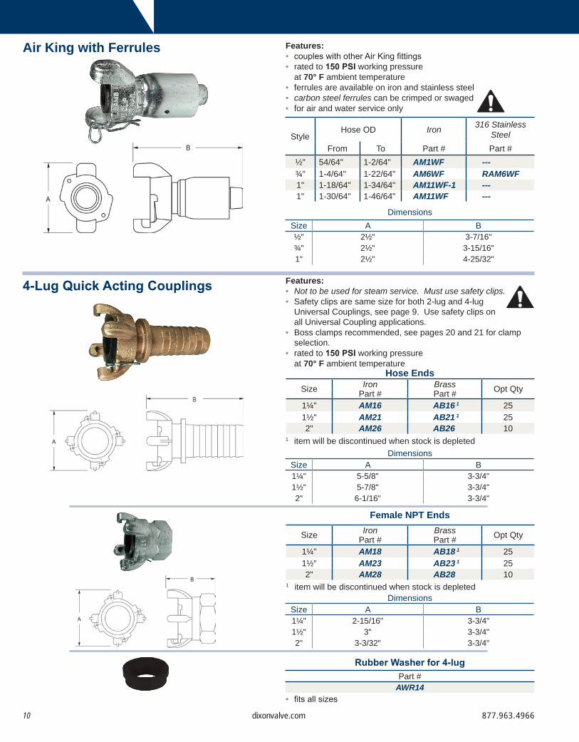
Air King with Ferrules
4-Lug Quick Acting Couplings
Female NPT Ends
Features:• Not to be used for steam service. Must use safety clips.• Safety clips are same size for both 2-lug and 4-lug
Universal Couplings, see page 9. Use safety clips on all Universal Coupling applications.
• Boss clamps recommended, see pages 20 and 21 for clamp selection.
• rated to 150 PSI working pressure at 70° F ambient temperature
Features:• couples with other Air King fittings• rated to 150 PSI working pressure
at 70° F ambient temperature• ferrules are available on iron and stainless steel• carbon steel ferrules can be crimped or swaged• for air and water service only
DimensionsSize A B½" 2½" 3-7/16"¾" 2½" 3-15/16"1" 2½" 4-25/32"
Hose Ends
DimensionsSize A B1¼" 5-5/8" 3-3/4"1½" 5-7/8" 3-3/4"2" 6-1/16" 3-3/4"
DimensionsSize A B1¼" 2-15/16" 3-3/4"1½" 3" 3-3/4"2" 3-3/32" 3-3/4"
• fits all sizes
Rubber Washer for 4-lugPart #
AWR14
StyleHose OD Iron 316 Stainless
SteelFrom To Part # Part #
½" 54/64" 1-2/64" AM1WF ---¾" 1-4/64" 1-22/64" AM6WF RAM6WF1" 1-18/64" 1-34/64" AM11WF-1 ---1" 1-30/64" 1-46/64" AM11WF ---
1 item will be discontinued when stock is depleted
Size Iron Brass Opt QtyPart # Part #1¼" AM16 AB16 1 251½" AM21 AB21 1 252" AM26 AB26 10
1 item will be discontinued when stock is depleted
Size Iron Brass Opt QtyPart # Part #1¼" AM18 AB18 1 251½" AM23 AB23 1 252" AM28 AB28 10

877.963.4966 11dixonvalve.com
GLOBAL AIR KINGMale NPT Ends
Features:• male NPT thread with hex for a wrench• supplied with safety clip and rubber washers
DimensionsSize A B C D E NPT½" 2½" 2-11/16" 1" 3/8" 7/8" ½"¾" 2½" 2-11/16" 1-11/32" 21/64" 7/8" ¾"1" 2½" 2-3/4" 1½" 5/16" 1" 1"
Female NPT Ends
DimensionsSize A B C D NPT½" 2½" 2-1/8" 1-1/8" 3/8" ½"¾" 2½" 2-5/32" 1-7/16" 3/8" ¾"1" 2½" 2-13/16" 1-5/8" 3/8" 1"
Features:• female NPT thread with hex for a wrench• supplied with safety clip and rubber washers
Size Plated Steel PkgQtyPart #
½" GAM2 25¾" GAM7 501" GAM12 50
Size Plated Steel PkgQtyPart #
½" GAM3 25¾" GAM8 501" GAM13 50

877.963.496612 dixonvalve.com
Blank Ends
Features:• Blank end fittings have no outlet and are used to block the line
at any coupling point.• The end opposite the coupling head is flat, with an eye for a
chain to secure the fitting when not in use.
DimensionsSize A B C D½" 2½" 3-3/8" 1-21/32" 17/32"¾" 2½" 3-31/32" 2-1/8" 25/32"1" 2½" 4-21/32 2-25/32" 1-1/16"
Hose Ends
Triple Connection
Feature:• Triple connection consists of three universal couplings that
provide an extra outlet when connected to the line.
Size Plated Steel PkgQtyPart #
½" GAM1 25¾" GAM6 501" GAM11 50
Plated Steel PkgQtyPart #
GAM0 25
Plated Steel PkgQtyPart #
GAM10 25

877.963.4966 13dixonvalve.com
GLOBAL AIR KING
4-Lug Quick Acting Couplings - Hose EndsFeatures:• supplied with safety clip and rubber washers• pressure rating: 150 PSI at ambient temperature (70°F)• use with Boss clamps• not to be used for steam service• must use safety clips, safety clips are same size for both 2-lug
and 4-lug Air King Couplings
Size A B1¼" 3¾" 5-5/8"1½" 3¾" 5-7/8"2" 3¾" 6-1/16"
Size A B1¼" 3¾" 2-15/16"1½" 3¾" 3"2" 3¾" 3-3/32"
4-Lug Quick Acting Couplings - Female NPT Ends
Plated Steel PkgQtyPart #
GAM0 25
Plated Steel PkgQtyPart #
GAM10 25
Size Plated Steel Pkg QtyPart #
1¼" GAM16 251½" GAM21 252" GAM26 10
Size Plated Steel Pkg QtyPart #
1¼" GAM18 251½" GAM23 252" GAM28 20

877.963.496614 dixonvalve.com
Boss Couplings supply a convenient threaded fitting to connect two lengths of hose, or a single length to a male or female threaded (NPT) outlet.
Boss
Coupling System
Worn-out hose couplings can be dangerous. They should be checked regularly and replaced when necessary.Each coupling user should review applications and add safety devices where indicated.
Features: The spud part of the coupling serves as one half of the connection and is usually fixed to the equipment. The stem part that is clamped to the hose is the other half. The two halves are connected or disconnected by rotating the wing nut onto the spud. When connected they achieve a mechanical, as well as, a pressure seal.
Services: Boss couplings are all-purpose hose couplings, universally recommended for steam hose connections. They are also widely used for air, water, fluid petroleum, chemicals and liquid petroleum gas up to 1" ID. Boss couplings can be applied to many types of rubber, synthetic, plastic, metallic or semi-metallic hose. Consult the factory for specific media capabilities.
Purpose: Boss couplings supply a convenient threaded fitting to connect two lengths of hose, or a single length to a male or female threaded (NPT) outlet.
Material: • stem: ¼" - 1" plated steel, 1¼" - 4" plated iron, 6" tubular steel• spud: ¼" - 1" plated steel, 1¼" - 6" plated iron• wing nut: ¼" plated steel, 3/8" - 6" plated iron

877.963.4966 15dixonvalve.com
Positive Metal-to-Polymer SealFeatures:• A leakproof seal is formed when the metal head of the stem makes contact with the patented polymer seat in the spud.• The non-metallic polymer seat resists most chemicals found in
manufacturing facilities.• recommended for steam service up to 450°F• easy to seal• works with existing Ground Joint fittings• use with Boss clamps found on pages 20 and 21
Ground Joint
1 1/4", 3/8" and 6" come only with copper seat spuds.2 not to be used with #250 or #306 Boss clamps3 GB36 will be replaced with GB36CR, this replacement part will have a machined hose shank to accommodate a Boss clamp,
King Crimp sleeve or ferrule
Plated Steel and/or Iron
stem nuts female spud
wing nutthread NPT
Hose Shankx NPT
Complete FemalePart #
StemPart #
OptQty
Wing NutPart #
Knurled NutPart #
Female SpudPart #
Male SpudPart #
Double SpudPart #
¼" GF1 1 GBA 100 SLS4 --- GBC 1 --- ---⅜" GF3 1 GCA 100 CB --- GCC 1 GMC 1 ---½" GF6 GB1 100 B2 --- GB3 GM3 GDB3
½" x ¾" GF26-1 GB6-1 50 B12 --- --- --- ---¾" GF26 GB6 50 B12 KB12 GB8 GM8 GDB131" GF36 GB11 50 B12 KB12 GB13 GM13 GDB13
1¼" GF51 GB16 25 B17 --- GB18 GM18 GDB231½" GF61 GB21 25 B17 --- GB23 GM23 GDB232" GF81 2 GB26 2 10 B27 --- GB28 GM28 GDB28
2½" GF96 GB31 5 B32 --- GB33 GM33 GDB333" GF111 GB36 3 5 B37 --- GB38 GM38 GDB384" GF141 GB46 5 B47 --- GB48 --- ---6" GF201 1 GB66 2 B67 --- GB68 1 --- ---
wing nutthread NPT
male spud
wing nutthread
double spudcomplete female
• 'A' dimension represents a complete coupling length with a female spud
• 'B' dimension is the largest dimension over the wing nut1 1/4" coupling has a hex style nut2 4" and 6" couplings have a 3 wing nut design
DimensionsSize A B1/4" 2-1/2" 1-5/32" 1
3/8" 3-1/32" 1-3/4"1/2" 3-21/32" 2-3/8"3/4" 4-15/16" 3-9/16"1" 5-3/16" 3-9/16"
1-1/4" 7" 4-1/4"1-1/2" 7-1/4" 4-1/4"
2" 7-23/32" 5-5/8"2-1/2" 9-5/32" 6-3/4"
3" 10-1/32" 7-3/4"4" 11-1/2" 9-1/2" 2
6" 12" 12-1/4" 2
BOSS FITTINGS
knurled

877.963.496616 dixonvalve.com
Features:• recommended for steam service up to 450°F• easy to seal• Klingersil® C-4401 washer is inserted between the stem and
spud• leakproof seal forms by rotating the wing nut and hammering it
tight• works with existing fittings• plated steel and / or iron• use with Boss clamps found on pages 20 and 21
Washer Type
1 washer is nitrile rubber bonded, non-asbestos Klingersil® C-44012 not to be used with #250 or #306 Boss clamps
Plated Steel and/or Iron
washercoupling female stem nuts femalespud
wing nutthread
NPT
malespud
NPTwing nutthread
doublespud
wing nutthread
Hose Shankx NPT
Complete FemalePart #
StemPart #
Wing NutPart #
Knurled NutPart #
OptQty
Female SpudPart #
Male SpudPart #
Double SpudPart #
Washer 1
Part #
⅜" WF3 SS337 CB --- --- CC WMC --- WBC½" WF6 B1 B2 --- --- B3 WM3 DB3 W2
½" x ¾" WF26-1 B6-1 B12 --- --- --- --- --- ---
¾" WF26 B6 B12 KB12 25 B8 WM8 DB13 W121" WF36 B11 B12 KB12 25 B13 WM13 DB13 W12
1-¼" WF51 B16 B17 --- --- B18 WM18 DB23 W171-½" WF61 B21 B17 --- --- B23 WM23 DB23 W17
2" WF81 2 B26 2 B27 --- --- B28 WM28 DB28 W272-½" WF96 B31 B32 --- --- B33 --- --- W32
3" WF111 B36 B37 --- --- B38 WM38 DB38 W37
• 'A' dimension represents a complete coupling length with a female spud.
• 'B' dimension is the largest dimension over the wing nut.
DimensionsSize A B3/8" 2-25/32" 1-3/4"1/2" 3-7/16" 2-3/8"3/4" 4-25/32" 3-9/16"1" 4-31/32" 3-9/16"
1-1/4" 6-21/32" 4-1/4"1-1/2" 6-7/8" 4-1/4"
2" 7-15/32" 5-5/8"2-1/2" 8-25/32" 6-3/4"
3" 9-7/16" 7-3/4"
877.963.4966 17dixonvalve.com
BOSS FITTINGS
Hose Menders
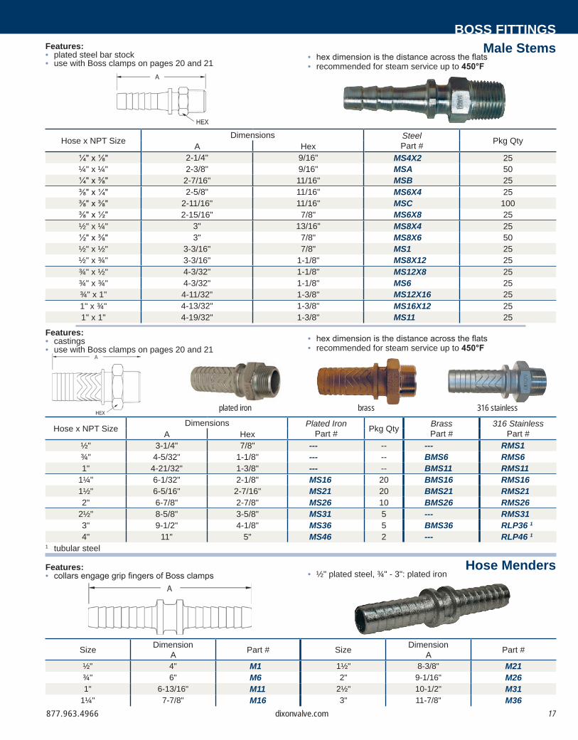
Male Stems
Hose x NPT Size Dimensions SteelPart # Pkg QtyA Hex
¼" x ⅛" 2-1/4" 9/16" MS4X2 25¼" x ¼" 2-3/8" 9/16" MSA 50¼" x ⅜" 2-7/16" 11/16" MSB 25⅜" x ¼" 2-5/8" 11/16" MS6X4 25⅜" x ⅜" 2-11/16" 11/16" MSC 100⅜" x ½" 2-15/16" 7/8" MS6X8 25½" x ¼" 3" 13/16" MS8X4 25½" x ⅜" 3" 7/8" MS8X6 50½" x ½" 3-3/16" 7/8" MS1 25½" x ¾" 3-3/16" 1-1/8" MS8X12 25¾" x ½" 4-3/32" 1-1/8" MS12X8 25¾" x ¾" 4-3/32" 1-1/8" MS6 25¾" x 1" 4-11/32" 1-3/8" MS12X16 251" x ¾" 4-13/32" 1-3/8" MS16X12 251" x 1" 4-19/32" 1-3/8" MS11 25
Features:• plated steel bar stock• use with Boss clamps on pages 20 and 21
• hex dimension is the distance across the flats• recommended for steam service up to 450°F
Hose x NPT Size Dimensions Plated IronPart # Pkg Qty Brass
Part #316 Stainless
Part #A Hex½" 3-1/4" 7/8" --- -- --- RMS1¾" 4-5/32" 1-1/8" --- -- BMS6 RMS61" 4-21/32" 1-3/8" --- -- BMS11 RMS11
1¼" 6-1/32" 2-1/8" MS16 20 BMS16 RMS161½" 6-5/16" 2-7/16" MS21 20 BMS21 RMS212" 6-7/8" 2-7/8" MS26 10 BMS26 RMS26
2½" 8-5/8" 3-5/8" MS31 5 --- RMS313" 9-1/2" 4-1/8" MS36 5 BMS36 RLP36 1
4" 11" 5" MS46 2 --- RLP46 1
Features:• castings• use with Boss clamps on pages 20 and 21
• hex dimension is the distance across the flats• recommended for steam service up to 450°F
Size DimensionA Part # Size Dimension
A Part #
½" 4" M1 1½" 8-3/8" M21¾" 6" M6 2" 9-1/16" M261" 6-13/16" M11 2½" 10-1/2" M31
1¼" 7-7/8" M16 3" 11-7/8" M36
Features:• collars engage grip fingers of Boss clamps • ½" plated steel, ¾" - 3": plated iron
plated iron brass 316 stainless
1 tubular steel

877.963.496618 dixonvalve.com
Adapters
Holedall Fittings
• 'A' dimension represents a complete coupling length with a female spud.
• 'B' dimension is the largest dimension over the wing nut.
DimensionsSize A B3/4" 4-3/4" 3-9/16"1" 5-1/8" 3-9/16"
1-1/2" 7-1/16" 4-3/8"2" 7-9/16" 5-5/8"3" 9-1/2" 7-3/4"
1 uses a special wing nut, part # B27-3
Male NPT
DimensionsSize A B¾" 3-1/16" 3-9/16"1" 3-5/16" 3-9/16"
1¼"1½"
4"4-1/8"
4-1/4"4-1/4"
2" 4-5/16" 5-5/8"
1 part is produced as a welded fabrication
Female NPT
DimensionsSize A B¾" 3-1/8" 3-9/16"1" 3-5/16" 3-9/16"
1¼"1½"
4"3-25/32"
4-1/4"4-1/4"
2" 5" 5-5/8"
Applications:• designed for air and liquid applications where a permanent, low
profile clamping system is desired• not for steam service
Features:• supplied with carbon steel ferrules• consult Dixon for swage and/or crimp specifications
Size Hose ODPlated Iron /
SteelStainless Steel
From: To: Part # Part #1-10/64" 1-14/64" GF26P1 ---
¾" 1-15/64" 1-18/64" GF26P2 ---1-19/64" 1-22/64" GF26P3 ---1-30/64" 1-34/64" GF36P1 ---
1" 1-35/64" 1-38/64" GF36P2 ---1-39/64" 1-42/64" GF36P3 ---1-20/64" 2" GF61P1 RGF61P1
1½" 2-1/64" 2-8/64" GF61P2 RGF61P22-9/64" 2-16/64" GF61P3 ---
2-36/64" 2-40/64" GF81P1 RGF81P12" 2-41/64" 2-48/64" GF81P2 RGF81P2
2-49/64" 2-56/64" GF81P3 ---3-26/64" 3-40/64" GF111P1 ---
3" 3-41/64" 3-48/64" GF111P2 ---3-49/64" 3-56/64" GF111P3 ---
Features:• plated steel and / or iron• designed to fit the standard ground joint spuds on page 15• supplied with a wing nut, as shown• for safety tags and safety tape, see page 45
Size Part # Pkg Qty¾" GMAS6 251" GMAS11 25
1¼" GMAS16 101½" GMAS21 102" GMAS26 1 10
Size Part #¾" GFAS61" GFAS11
1¼" GFAS161½" GFAS21 1
2" GFAS26

877.963.4966 19dixonvalve.com
Features:• rounded steel head of stem fits concave inserts in spuds for superior sealing• metal-to-metal copper seat seal• plated steel and / or iron• use with Boss clamps on page 20 and 21
Ground Joint Air Hammer Couplings
Wing Nut CapsBOSS FITTINGS
Style Hose ID and NPT Sizes Coarse Thread
Complete FemalePart #
Plated Steel StemPart #
Iron Wing Nut
Part #
Plated Steel w/ Copper
seatFemale Spud
Part #
Plated Steel w/ Copper
seatMale Spud
Part #
Plated Steel w/ Copper
seatDouble Spud
Part #
Compact½"
1-31/64" OD x 8 T.P.I.GDF6 GBA45 J47 GJ65 GJ60 GJ75
¾" GDF8 GBA46 J47 GJ55 GJ50 GJ75
Heavy¾"
1-47/64" OD x 8 T.P.I.GDF10 GBB18 DLB12 GDL8 GDL7 GDL25
1" GDF12 GBB11 DLB12 GDL13 GDL10 GDL25
coupling female stem wing nut
coarsethread
female spud
NPT
coarsethread
male spud
NPT
coarsethread
double spud
coarsethread
• 'A' dimension represents a complete coupling length with a female spud
• 'B' dimension is the largest dimension over the wing nut
DimensionsStyle Size A B
Compact 1/2" 4-5/32" 2-15/16"3/4" 4-15/16" 2-15/16"
Heavy 3/4" 5" 3-5/8"1" 5-13/32" 3-5/8"
Features:• plated steel and / or iron• supplied with 12" chain and washer• for best results, use with washer style spuds and washers on page 16
Size Part # Opt Qty¾" and 1" B12SC 25
1¼" and 1½" B17SC 252" B27SC 103" B37SC 5
Boss wing nut caps are not intended for pressure applications.
877.963.496620 dixonvalve.com
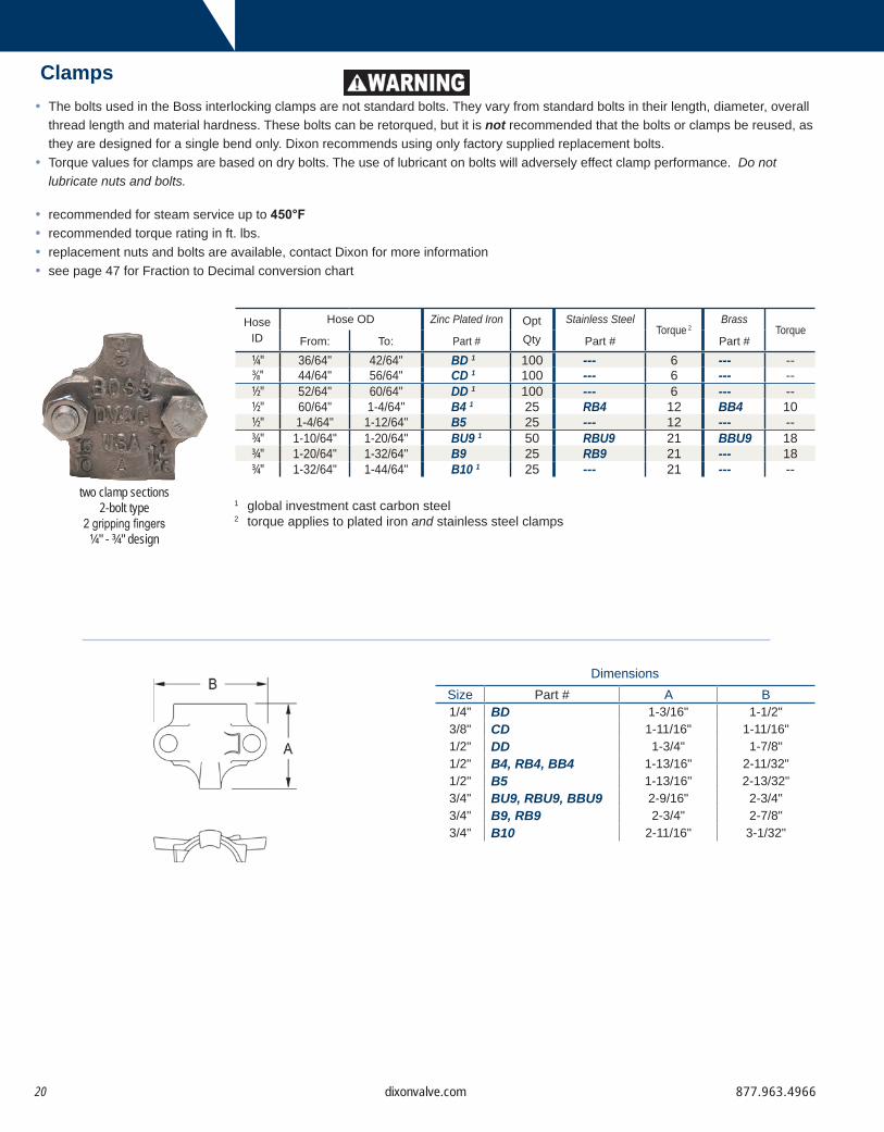
Clamps
1 global investment cast carbon steel2 torque applies to plated iron and stainless steel clamps
DimensionsSize Part # A B1/4" BD 1-3/16" 1-1/2"3/8" CD 1-11/16" 1-11/16"1/2" DD 1-3/4" 1-7/8"1/2" B4, RB4, BB4 1-13/16" 2-11/32"1/2" B5 1-13/16" 2-13/32"3/4" BU9, RBU9, BBU9 2-9/16" 2-3/4"3/4" B9, RB9 2-3/4" 2-7/8"3/4" B10 2-11/16" 3-1/32"
two clamp sections2-bolt type
2 gripping fingers¼" - ¾" design
• The bolts used in the Boss interlocking clamps are not standard bolts. They vary from standard bolts in their length, diameter, overall thread length and material hardness. These bolts can be retorqued, but it is not recommended that the bolts or clamps be reused, as they are designed for a single bend only. Dixon recommends using only factory supplied replacement bolts.
• Torque values for clamps are based on dry bolts. The use of lubricant on bolts will adversely effect clamp performance. Do not lubricate nuts and bolts.
• recommended for steam service up to 450°F• recommended torque rating in ft. lbs.• replacement nuts and bolts are available, contact Dixon for more information• see page 47 for Fraction to Decimal conversion chart
HoseID
Hose OD Zinc Plated Iron OptQty
Stainless SteelTorque 2
BrassTorque
From: To: Part # Part # Part #¼" 36/64" 42/64" BD 1 100 --- 6 --- --⅜" 44/64" 56/64" CD 1 100 --- 6 --- --½" 52/64" 60/64" DD 1 100 --- 6 --- --½" 60/64" 1-4/64" B4 1 25 RB4 12 BB4 10½" 1-4/64" 1-12/64" B5 25 --- 12 --- --¾" 1-10/64" 1-20/64" BU9 1 50 RBU9 21 BBU9 18¾" 1-20/64" 1-32/64" B9 25 RB9 21 --- 18¾" 1-32/64" 1-44/64" B10 1 25 --- 21 --- --

877.963.4966 21dixonvalve.com
BOSS FITTINGS
two clamp sections4-bolt type
2 gripping fingers
two clamp sections4-bolt type
4 gripping fingers
Clamps
Size Part # A B1/2" 968 1-11/16" 2-1/16"1" 156 2-21/32" 3-3/16"1" BU14, RBU14, BBU14 3-3/32" 3-1/2"1" B14, RB14, BB14 3-1/8" 3-3/8"1" B15 3-1/8" 3-3/4"
1-1/4" BU18 3-11/16" 3-5/8"1-1/4" 187 3-1/16" 3-9/16"1-1/4" BU19 3-11/16" 3-7/8"1-1/4" 206 2-29/32" 3-21/32"1-1/4" B19, RB19 3-3/4" 4"1-1/2" BU22 3-13/16" 4"1-1/2" B22 3-13/16" 4-1/8"1-1/2" 212 3-3/8" 4"1-1/2" 225 3-5/8" 4"1-1/2" BU24, RBU24 3-25/32" 4-3/32"1-1/2" B24, RB24 3-31/32" 4-1/8"1-1/2" B25 3-15/16" 4-1/2"
Size Part # A B2" 250 3-13/16" 4-3/16"2" BU28 3-15/16" 4-7/16"2" 275 3-7/8" 4-1/2"2" BU29, RBU29, BBU29 3-7/8" 4-13/32"2" B29, RB29 4-5/16" 5-1/16"2" 306 4-1/8" 5-1/8"2" B30 4-1/4" 5-5/8"
2-1/2" 350 4-1/8" 5-3/4"2-1/2" BU34 4-5/16" 5-3/4"2-1/2" B34 5" 6-9/16"
3" 375 4-15/32" 6-1/8"3" BU35, RBU35 5" 6-1/2"3" 401 4-23/32" 6-1/2"3" B35 5-1/16" 6-11/16"3" 418 4-29/32" 7"3" B39 5-1/2" 7-1/2"3" 450 5-3/16" 7-1/2"
1 4 gripping fingers and 4 bolts2 will become obsolete as inventory is depleted3 torque applies to plated iron and stainless steel clamps4 not to be used with GF81, GB26, WF81, B26, RGF81, RGB26, BGF81, BGB26, RWF81, RB26
HoseID
Hose OD Zinc Plated Iron OptQty
Stainless SteelTorque3
BrassTorque
From: To: Part # Part # Part #½" 58/64" 1-2/64" 968 1 50 --- 6 --- --1" 1-26/64" 1-36/64" 156 1 20 --- 21 --- --1" 1-34/64" 1-46/64" BU14 25 RBU14 21 BBU14 181" 1-44/64" 1-60/64" B14 25 RB14 21 BB14 181" 1-60/64" 2-8/64" B15 20 --- 21 --- --
1¼" 1-32/64" 1-50/64" BU18 10 --- 40 --- --1¼" 1-44/64" 1-56/64" 187 1 10 --- 21 --- --1¼" 1-50/64" 2-6/64" BU19 10 --- 40 --- --1¼" 1-56/64" 2-4/64" 206 1 20 --- 21 --- --1¼" 2-8/64" 2-24/64" B19 10 RB19 40 --- 281½" 1-52/64" 2" BU22 10 --- 40 --- --1½" 2" 2-14/64" B22 10 --- 40 --- --1½" 2" 2-8/64" 212 1 10 --- 21 --- --1½" 2-4/64" 2-16/64" 225 1 10 --- 40 --- --1½" 2-12/64" 2-24/64" BU24 10 RBU24 40 --- 281½" 2-24/64" 2-36/64" B24 10 RB24 40 --- --1½" 2-36/64" 2-48/64" B25 10 --- 40 --- --2" 2-16/64" 2-32/64" 250 1, 4 10 --- 40 --- --2" 2-22/64" 2-34/64" BU28 10 --- 60 --- --2" 2-32/64" 2-48/64" 275 1, 4 10 --- 40 --- --2" 2-32/64" 2-50/64" BU29 10 RBU29 60 BBU29 2 402" 2-48/64" 3-4/64" B29 10 RB29 60 --- --2" 2-48/64" 3-4/64" 306 1, 4 10 --- 60 --- --2" 3-6/64" 3-28/64" B30 5 --- 60 --- --
2½" 3-4/64" 3-32/64" 350 1 5 --- 60 --- --2½" 3-6/64" 3-28/64" BU34 5 --- 60 --- --2½" 3-32/64" 3-60/64" B34 5 --- 150 --- --3" 3-32/64" 3-48/64" 375 1 5 --- 60 --- --3" 3-32/64" 3-60/64" BU35 5 RBU35 150 --- --3" 3-48/64" 4" 401 1 5 --- 150 --- --3" 3-52/64" 4-4/64" B35 5 --- 150 --- --3" 4" 4-12/64" 418 1 4 --- 200 --- --3" 4-4/64" 4-28/64" B39 5 --- 200 --- --3" 4-12/64" 4-32/64" 450 1 2 --- 200 --- --
A
B
B
A

877.963.496622 dixonvalve.com
Dix-Lock coupling’s non-valved design allows air flow to the tool, while providing a quick, secure connection.
Dix-Lock
Quick Acting Couplings
Service:• pressure: 300 PSI in brass; 500 PSI in steel, 303 stainless steel at ambient temperature (70°F)• The operating temperature range is -40° to +250°F (-40° to +121°C).
Features:• dual-guide sleeve tabs ensure smooth action• corrosion resistant coatings and materials improve performance• pneumatically energized seal for optimal performance at a variety of pressures• wide variety of end configurations
Materials:• female and male bodies: zinc plated steel optional - brass or 303 stainless steel• sleeve: steel• retaining ring and spring: phosphor bronze• seal: nitrile (buna-n)
Connecting:• convenient push-twist and click
Disconnecting:• retract sleeve, twist and pull Never attempt to disconnect any hose while pressure is in the line.
Interchange:• interchanges with the MIL-C-3486 Standard and the A-A50431-A Commercial Item Description• interchanges with Bowes and National brands
sleeve
spring
male
female
retaining ring
seal

877.963.4966 23dixonvalve.com
DIX-LOCKMale Head x Hose End
Female Head x Hose End
Male Head x Male NPT End
A
B
HEX
A
B
B
A
Dimensions
Dimensions
Dimensions
Body Size
Hose Shank
Plated Steel
Pkg Qty Brass Pkg
QtyStainless
Steel Pkg Qty
⅜" ½" QM1 25 --- -- --- --½" ⅜" QM2 25 QB2 -- --- --½" ½" QM3 25 QB3 -- --- --½" ¾" QM4 25 QB4 -- QSS4 --½" 1" QM5 25 QB5 25 --- --
Body Size
Hose Shank A B
⅜" ½" 3.73" 1.13"½" ⅜" 4.36" 1.40"½" ½" 4.63" 1.40"½" ¾" 4.77" 1.40"½" 1" 4.77" 1.40"
Body Size
Hose Shank
Plated Steel
Pkg Qty Brass Pkg
QtyStainless
Steel Pkg Qty
⅜" ½" QM20 25 --- -- --- --½" ⅜" QM21 25 QB21 -- --- --½" ½" QM22 25 QB22 -- --- --½" ¾" QM23 25 QB23 -- QSS23 --½" 1" QM25 25 QB25 25 --- --
Body Size
Hose Shank A B
⅜" ½" 2.41" 1.20"½" ⅜" 2.98" 1.33"½" ½" 3.37" 1.33"½" ¾" 3.37" 1.33"½" 1" 3.49" 1.33"
Body Size
Hose Shank
Plated Steel
Pkg Qty Brass Pkg
QtyStainless
Steel Pkg Qty
⅜" ½" QM20 25 --- -- --- --½" ⅜" QM21 25 QB21 -- --- --½" ½" QM22 25 QB22 -- --- --½" ¾" QM23 25 QB23 25 QSS23 10½" 1" QM25 25 QB25 -- --- --
Body Size
Hose Shank A B Hex
⅜" ½" 3.28" 1.13" 1-3/16"½" ⅜" 3.65" 1.40" 1-1/8"½" ½" 3.65" 1.40" 1-1/8"½" ¾" 3.74" 1.40" 1-3/8"½" 1" 3.78" 1.40" 1-1/2"

877.963.496624 dixonvalve.com
Dimensions
Dimensions
Dimensions
Female Head x Female NPT End
HEX
B
A
HEX
B
A
Female Head x Male NPT End
HEX
B
A
Male Head x Female NPT End
1 valved coupler not shown
Body Size
Hose Shank
Plated Steel
Pkg Qty Brass Pkg
QtyStainless
Steel Pkg Qty
⅜" ½" QM60 25 --- -- --- --½" ⅜" QM61 25 QB61 -- --- --½" ½" QM62 25 QB62 -- --- --½" ¾" QM63 25 QB63 -- QSS63 --½" 1" QM65 25 QB65 25 --- --
Body Size
Hose Shank A B Hex
⅜" ½" 1.72" 1.20" 1-3/16"½" ⅜" 1.77" 1.33" 1-3/8"½" ½" 1.77" 1.33" 1-3/8"½" ¾" 1.77" 1.33" 1-3/8"½" 1" 1.84" 1.33" 1-1/2"
Body Size
Hose Shank
Plated Steel
Pkg Qty Brass Pkg
QtyStainless
Steel Pkg Qty
½" ⅜" QM81 25 QB81 -- --- --½" ½" QM82 25 QB82 -- --- --½" ¾" QM83 25 QB83 -- QSS83 --½" 1" QM85 25 QB85 25 --- --
Body Size
Hose Shank A B Hex
½" ⅜" 2.73" 1.40" 1-1/8"½" ½" 2.73" 1.40" 1-1/8"½" ¾" 3.34" 1.40" 1-3/8"½" 1" 3.37" 1.40" 1-1/2"
Body Size
Hose Shank
Plated Steel
Pkg Qty Brass Pkg
QtyStainless
Steel Pkg Qty
½" ⅜" QM101 25 QB101 -- --- --½" ½" QM102 25 QB102 -- --- --½" ¾" QM103 25 QB103 -- QSS103 --½" 1" QM105 25 QB105 25 --- --
Body Size
Hose Shank A B Hex
½" ⅜" 1.63" 1.33" 1-3/8"½" ½" 1.63" 1.33" 1-3/8"½" ¾" 1.63" 1.33" 1-3/8"½" 1" 1.68" 1.33" 1-1/2"

877.963.4966 25dixonvalve.com
DIX-LOCKMale Locking Head x Hose End
B
ADimensions
B
A
Male Locking Head x Male NPT
Dimensions
Body Size Hose Shank Plated Steel Part #
Brass Part #
½" ½" QM33 QB33½" ¾" QM44 QB44
Body Size A B½" 4.63" 1.40"¾" 4.77" 1.40"
Body Size Male NPT Plated Steel Part #
Brass Part #
½" ½" QM66 QB66½" ¾" QM88 QB88
Body Size A B½" 3.65" 1.40"¾" 3.74" 1.40"
Feature:• positive safety lock; with locking nut in place sleeve cannot be
moved to open coupling
Feature:• positive safety lock; with locking nut in place sleeve cannot be
moved to open coupling

877.963.496626 dixonvalve.com
Male Locking Head
Female Head
Male Head Features:• working pressure: 300 PSI at ambient temperature (70°F)• for crimp recommendations visit dixonvalve.com• also available in stainless steel, contact Dixon for further
information
Features:• working pressure: 300 PSI at ambient temperature (70°F)• for crimp recommendations visit dixonvalve.com• also available in stainless steel, contact Dixon for further
information
Features:• working pressure: 300 PSI at ambient temperature (70°F)• for crimp recommendations visit dixonvalve.com• also available in stainless steel, contact Dixon for further
information
Converter
Cap
(Buna-N) Gaskets
Body Size Brass Part # Steel Part # Pkg. Qty.½" QBCAP QMCAP 25
Body Size Plated Steel Part # Pkg. Qty.½" QM0 25
Body Size Part #⅜" QBM1½" QBM2
Body Size
Hose ID
OD Range Plated Steel Part #
Brass Part #From: To:
½" ½" 27/32" 1-1/32" QM3WF QB3WF½" ¾" 1-5/32" 1-11/32" QM4WF QB4WF
Body Size
Hose ID
OD Range Plated Steel Part #
Brass Part #From: To:
½" ½" 27/32" 1-1/32" QM22WF QB22WF½" ¾" 1-5/32" 1-11/32" QM23WF QB23WF
Body Size
Hose ID
OD Range Plated Steel Part #
Brass Part #From: To:
½" ½" 27/32" 1-1/32" QM33WF QB33WF½" ¾" 1-5/32" 1-11/32" QM44WF QB44WF

877.963.4966 27dixonvalve.com
Dual-Lock couplings allow full air flow for general purpose air handling requiring high flow and pneumatic impact tools.
Dual-Lock
Quick Acting Couplings
Service:• The recommended working pressure: 300 PSI at ambient temperature (70°F)• The operating temperature range is -40° to +250°F (-40° to +121°C).
Features:• interchanges with National A type, Dixon Quick Coupling P type and Thor PHC series couplings• PM and PF series must be used with mating locking sleeve fittings• spring loaded interlocking engagement• full opening permits full flow to tool• optional locking key prevents sleeve retraction• trivalent chrome plated
Materials:• body: trivalent chrome plated steel optional - brass or 303 stainless steel• sleeve: steel optional - brass or 303 stainless steel• retaining ring and spring: phosphor bronze• seal: nitrile (buna-n) optional - FKM
Connecting:• push and twist Locking clip is available to prevent unintentional disconnection.
Disconnecting:• pull and twist Never attempt to disconnect any hose while pressure is in the line.
Interchange:• interchangeable with National A type, Dixon Quick Coupling P type and Thor PHC series couplings
sleeve
spring
retaining ring
seal

877.963.496628 dixonvalve.com
Hose Barb with Locking Sleeve
Male Pipe Thread with Locking Sleeve
Female Pipe Thread with Locking Sleeve
Male Pipe Thread
A
B
A
B
A
B
FLAT
A
B
HEX
Dimensions
Dimensions
Dimensions
Dimensions
Must be used with locking sleeve fittings above.
Body Size
Hose Shank
Plated Steel
Pkg Qty Brass Pkg
QtyStainless
Steel Pkg Qty
½" ⅜" PHL6 25 --- -- --- --½" ½" PHL8 25 --- -- --- --½" ¾" PHL12 25 PHLB12 25 PHL12SS 10½" 1" PHL16 25 PHLB16 25 --- --
Size A B⅜" 3.53" 1.55"½" 3.95" 1.55"¾" 3.95" 1.55"1" 6.06" 1.55"
Body Size
Male NPT
Plated Steel Pkg Qty Stainless Steel Pkg
Qty½" ⅜" PML6 25 --- --½" ½" PML8 25 --- --½" ¾" PML12 25 PML12SS 10
Size A B½" 2.93" 1.55"¾" 2.98" 1.55"1" 2.98" 1.55"
Body Size
Female NPT Plated Steel Pkg
Qty Stainless Steel Pkg Qty
½" ⅜" PFL8 25 --- --½" ½" PFL12 25 PFL12SS 10
Size A B Hex½" 2.75" 1.55" 1.25"¾" 2.75" 1.55" 1.25"
Body Size
Male NPT
Plated Steel
Pkg Qty Brass Pkg
QtyStainless
Steel Pkg Qty
½" ⅜" PM6 25 -- -- --- --½" ½" PM8 25 PMB8 25 --- --½" ¾" PM12 25 PMB12 25 PM12SS 10½" 1" PM16 25 PMB16 25 --- --
Size A B Flat⅜" 2.00" 1.55" 0.88"½" 2.25" 1.55" 0.97"¾" 2.55" 1.55" 1.13"1" 3.25" 1.55" 1.38"

877.963.4966 29dixonvalve.com
DUAL-LOCK
Male Pipe Thread with Knurled Flanged Sleeve
Female Pipe Thread with Knurled Flanged Sleeve
Female Pipe Thread
Hose Barb with Knurled Flanged Sleeve
FLAT
B
A
B
A
B
A
B
A
Features:• zinc coated• Large, raised collar sleeve permits easier handling when wearing gloves.
Features:• zinc coated• Large, raised collar sleeve permits easier handling when wearing gloves.
Feature:• Large, raised collar sleeve permits easier handling when
wearing gloves.
Dimensions
Dimensions
Dimensions
Dimensions
Must be used with locking sleeve fittings on page 28.
Body Size
Female NPT
Plated Steel
Pkg Qty Brass Pkg
QtyStainless
Steel Pkg Qty
½" ⅜" PF6 25 --- -- --- --½" ½" PF8 25 PFB8 25 --- --½" ¾" PF12 25 PFB12 25 PF12SS 10½" 1" PF16 25 PFB16 25 --- --
Size A B Flat⅜" 1.79" 1.55" 0.88"½" 2.25" 1.55" 1.31"¾" 2.34" 1.55" 1.31"1" 2.76" 1.55" 1.44"
Body Size
Hose Shank
Plated Steel Pkg Qty
½" ⅜" PHL6FS 25½" ½" PHL8FS 25½" ¾" PHL12FS 25
Size A B⅜" 3.53" 1.55"½" 3.95" 1.55"¾" 3.95" 1.55"
Body Size
Male NPT
Plated Steel Pkg Qty
½" ⅜" PML6FS 25½" ½" PML8FS 25½" ¾" PML12FS 25
Size A B⅜" 2.93" 1.55"½" 2.98" 1.55"¾" 2.98" 1.55"
Body Size
Female NPT
Plated Steel Pkg Qty
½" ½" PFL8FS 25½" ¾" PFL12FS 25
Size A B½" 2.75" 1.55"¾" 2.75" 1.55"

877.963.496630 dixonvalve.com
DUAL-LOCK
Dual-Lock with Ferrule
Replacement Gaskets Sleeve Locking KeyFeatures:• fits couplings with locking sleeve• prevents sleeve retraction
Features:• working pressure: 300 PSI at ambient temperature (70°F)• trivalent chrome plated coupling with plated steel ferrule• also available in brass and stainless steel• for crimp recommendations visit dixonvalve.com• ⅜" and 1" sizes available upon request, contact Dixon
Body Size
Hose ID
OD Range Plated SteelPart #From: To:
½" ½" 54/64" 1-2/64" PHL8WF½" ¾" 1-10/64" 1-22/64" PHL12WF
Part # Description855206 Buna-N (standard)452963 FKM
Part #855231
877.963.4966 31dixonvalve.com
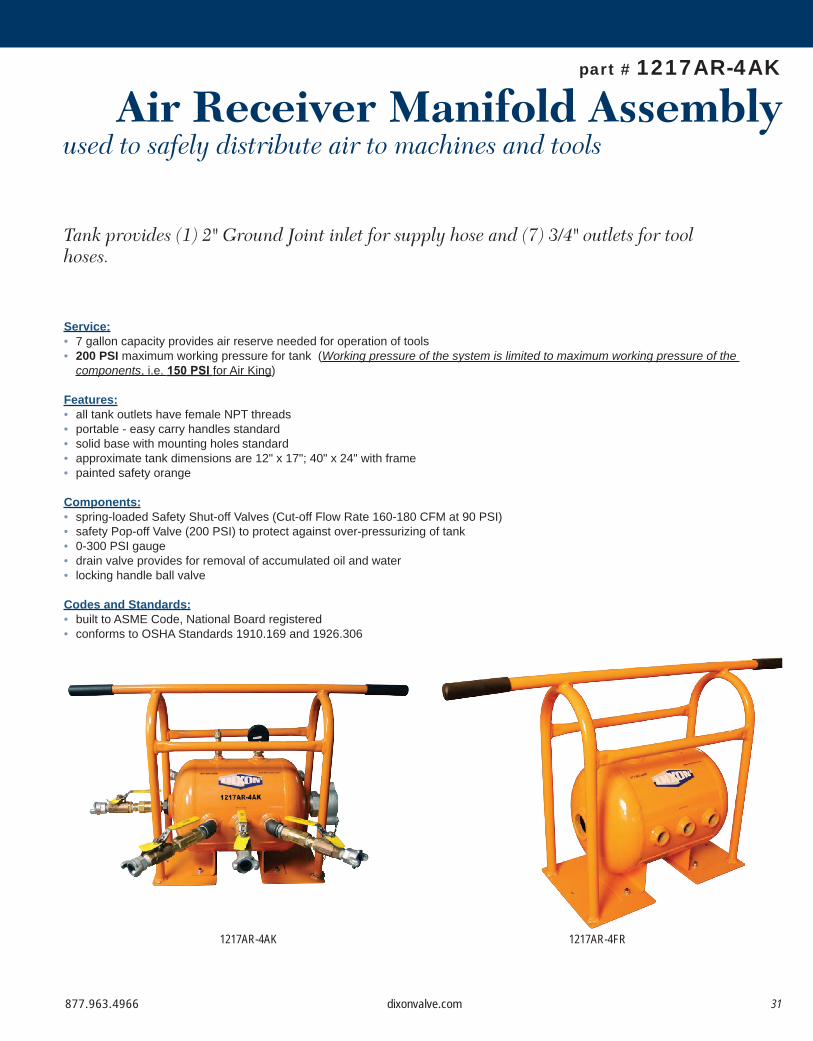
Air Receiver Manifold Assemblyused to safely distribute air to machines and tools
Tank provides (1) 2" Ground Joint inlet for supply hose and (7) 3/4" outlets for tool hoses.
part # 1217AR-4AK
Service:• 7 gallon capacity provides air reserve needed for operation of tools• 200 PSI maximum working pressure for tank (Working pressure of the system is limited to maximum working pressure of the
components, i.e. 150 PSI for Air King)
Features:• all tank outlets have female NPT threads• portable - easy carry handles standard• solid base with mounting holes standard• approximate tank dimensions are 12" x 17"; 40" x 24" with frame• painted safety orange
Components:• spring-loaded Safety Shut-off Valves (Cut-off Flow Rate 160-180 CFM at 90 PSI)• safety Pop-off Valve (200 PSI) to protect against over-pressurizing of tank• 0-300 PSI gauge• drain valve provides for removal of accumulated oil and water• locking handle ball valve
Codes and Standards:• built to ASME Code, National Board registered• conforms to OSHA Standards 1910.169 and 1926.306
1217AR-4AK 1217AR-4FR

877.963.496632 dixonvalve.com
MANIFOLD
* Dixon recommends the use of safety clips and King safety cables on all air hose connections.
PressureGauge
SafetyPop-offValve
1 Inletport7 Outlet
ports
* Drain cock not shown
Protectiveframe
40" 10-1/2"
23-1/4"
17" 12"
3/4" 1/2"
1/2"
2" 2"
1" 1"1"3
1 2
8
7 4, 5, 6 9, 10, 11
Three 1" holes located180° of this side
Dixon 1217AR-4AK air receiver manifold assembly with Air King outlet ports includes the following components:Part # / Locations Qty Description
1217AR-4 1 ASME compressed air receiver1217FRAME 1 protective frame
Location 1 1 HB2F6M ¾" male x ¼" female hex bushing1 GL345 0-300 PSI gauge
Location 2 1 HB2F4M ½" male x ¼" female hex bushing1 SV200 safety pop-off valve
Location 3 1 GM28 2" male spud1 B27SC wing nut cap
Locations 6 HB1075G 1" male x ¾" female bushings4, 5, 6, 9, 6 BCN75 ¾" brass hex nipples
10, 11 6 BBLV75 ball valves6 SCVS6 safety shut-off valves6 AM7 Air King universal couplings4 SE45100 45° street elbow (1 each in locations 4, 6, 9 and 11 only)
Location 7 1 HB2075 2" male x ¾" female bushing1 BCN75 ¾" brass hex nipples1 BBLV75 ball valve1 SCVS6 safety shut-off valve1 AM7 Air King universal coupling
Location 8 1 HB2F4M ½" male x ¼" female hex bushing1 D04 ¼" drain cock--- Labor cost for assembly of complete unit
1217AR-4AK 1 7 gallon ASME compressed air receiver manifold complete assembly with Air KingTank and Frame only
1217AR-4FR 1 7 gallon ASME compressed air receiver with frame only

877.963.4966 33dixonvalve.com
Wilkerson Combination Unit with Protective Frame
ASME Air Tank with Fittings and Watts Filter
Application:• Designed to remove compressed air contaminants such as
water, compressor oil, dirt, pipe scale and water particles from the air supply at the point of entry into the ASME air receiver manifold.
Features:• includes basic 1217AR-4AK ASME manifold assembly• F602-16WJR 2" auto drain filter with 26 ounce metal bowl and
related plumbing installed on the inlet port of the ASME air receiver manifold
• air supply hose connects directly to GM28 2" male spud on the filter air inlet
• includes a B27SC wing nut cap with a chain
Inlet Outlet Part #2" ¾" 1217AR-4AKWF
Features:• provides downstream air preparation with protective frame• C31-08AMB 1" FRL with metal bowls and auto drain filter• FBV100 1" brass ball valve and AM12 air king on inlet port• BBV100DTW 2-way ball valve installed between regulator and
lubricator provides option for non-lubricated air• heavy duty frame protects air prep components• operating: maximum pressure: 250 PSIG temperature range: 40°F to 150°F flow: 320 SCFM
Size Part #1" C31-08FRAME

877.963.496634 dixonvalve.com
Safety Check ValvePrevents dangerous hose whip on portable air compressors
Questions to ask when selecting a safety shut-off valve:1. What is the hose ID size you are using?2. What is the operating pressure of the compressor, in PSI?3. What is the SCFM of your compressor? (printed on the side of most air compressors)4. How much air flow, in SCFM, does the tool(s) require?5. What is the maximum air flow possible, in SCFM, through your air hose, at the end of the length of the hose? Contact Dixon for recommendations if the hose length is over 100'.
Safety
Use:• Safety Check Valves operate by using the pressure differential across the valve to operate the valve and spring assembly. The pressure differential is directly related to the flow of air through the valve.• When the pressure differential is within the operating limits -- below the cutoff flow -- of the unit, the force on the valve exerted by the spring is greater than that caused by the pressure differential (see open position graphic below). The valve remains open and normal operation continues.• When the pressure differential is above the cutoff limit, the force on the valve exerted by the pressure differential is greater than the force exerted by the spring, and the valve closes (see the closed position graphic below).• After the repair is made, normal operation is automatically enabled when pressure across the valve equalizes through the bleeder hole.• The valve spring size can be specified by determining the air flow during normal operation and by estimating the air flow if a failure or rupture occurs.
Construction:• solid brass body and valve• stainless steel spring and roll pin• maximum working pressure: 250 PSI• maximum temperature: 250°F
Features:• does not prevent backflow• high flow valve to provide optimum performance• controls excess air flow (SCFM) in only one direction• not for use in applications where 100% of the available air is required, i.e. sand blast, pile driving rigs,expansion joint blow down pipes, etc.• automatically senses change in air flow and shuts off the flow in the event of a surge in excess of valve flow rating thus preventing hose whip• conforms to OSHA regulation 1926.302 (b) (7) requiring a safety device at the source of the air supply and at branch air lines.• applications include temporary plant/factory air, construction sites, shipyards or utilities
Check Valve In Open Position Check Valve In Closed Position

877.963.4966 35dixonvalve.com
Sizing the safety shut-off valve:1. The safety shut-off valve NPT size must be the same as the nominal ID size of the air line on which it is used. Note: Never increase or decrease the hose size from the compressor to the tool or from the compressor to the manifold.2. One safety shut-off valve must be used on each hose outlet from the manifold.3. To avoid nuisance cut-off's, the shut-off valve selected should have a cut-off range of 110% of the maximum anticipated air flow to the tool, or tools, to be used.4. The maximum SCFM of the supply side air line must be above the cut-off range of the valve. The cut-off range of Dixon's shut-off valves is given at 90 PSI. To determine the cut-off range at other PSI's, use the formula or the sample numbers in the Cut-off Rate Chart below to find the flow rate multiplier. Multiply the flow rate multiplier by the numbers in the cut-off flow range column to find the cut-off range at your PSI.
SAFETY CHECK VALVE
Installation:A safety shut-off valve should be placed immediately after the air control valve and before the hose on a compressor, and on each dis-charge port on a manifold (see drawing above).
Safety Shut-off Valve Cut-off Ratesat PSI's Other Than 90 PSI
Operation:Before starting the compressor the air control valve should be closed completely. When the compressor unloads, open the air control valve very slowly. Full port ball valves tend to work better than gate or butterfly type valves.
The air control valve must be fully open for the safety shut-off valve to work. Some portable air compressor manufacturers recommend start-up with the air control valve slightly open. In this case you may have to close the valve and reopen it slowly to the full open posi-tion, or wait for the safety shut-off valve to reset itself.
If the valve fails to operate despite meeting all conditions, check the hose line for obstructions or a hose mender restricting normal air flow.
PSIG + 14.7104.7
Flow rate multiplier = Inlet pressure (PSI) 25 50 75 100 125
Flow rate multiplier .62 .79 .93 1.05 1.16

877.963.496636 dixonvalve.com
1. Sketch the position of the tool, fittings, safety check and supply line. Measure the length of hose from the safety check to the tool. There should be no jump sizes in the hose between the safety check and the tool. You will need one safety check valve for each branch line feeding the tool. A safety check in the main supply line is also recommended.
2. Determine the hose size you want to protect. Select the same size safety check as the hose size. For example, a ⅜" hose will require a ⅜" safety check. Do not use a different size safety check. One exception to this rule is for ⅝" hose, use a 1/2" safety check valve.
3. Determine the maximum operating air flow (SCFM) required through the safety check during normal use. For example, the maximum air consumption of the largest tool used on that supply line. Determine the optimum cutoff flow by multiplying the maximum operating air flow by 110%.
4. Add to the length of hose, you measured in step 1, length adders to compensate for system components. Add 0.91m (3') for each elbow, 0.91m (3') for each tee, 3.05m (10') for each globe valve, 0.61m (2') for each gate valve, 0.91m (3') for each hose fitting. This calculation will result in the total length for your safety check valve selection. Find the column in the Unobstructed Air Flow Chart, below, that corresponds to your hose size and the row that corresponds to your calculated total length. Where they intersect, is the unobstructed air flow in SCFM.
5. If the optimum cutoff flow is 80% of the unobstructed air flow or less, you should use the optimum cutoff flow (110% of the maximum calculated air flow) to select the appropriate safety check valve. To do this, find the safety check that has a corresponding cutoff flow rate in the product list on the next page.
6. If the optimum cutoff flow is greater than 80% of the unobstructed air flow, there may be a problem with the safety check valve sensing the difference between normal air demand and a line rupture. You may want to consider removing fittings from the flow path, reducing the length of your hose or increasing your hose diameter. If you are not sure, call your Dixon distributor for assistance.
7. Always install one safety check and test the performance of the system before you continue other installations. When start-up is underway, open the air control valve at the compressor or manifold very slowy to allow air to bleed through the check valve so that pressure is equalized on each side of the valve. If the valve fails to operate despite meeting all conditions, check the supply line for obstructions or a hose mender restricting normal air flow.
SCV-Series Selection Guide:
Not recommended for applications requiring 100% of the available air supply. These applications include, but are not limited to, sand blast equipment, pile driving rigs, and expansion joint blow down pipes.It is recommended to install auxiliary safety devices, including Safety Cables, to ensure optimum safety for the operator in the event of a coupling failure or hose rupture. (see page 39)
• Use ½" Safety Check Valve for ⅝" Hose.Length Adders: 3' for each elbow 3' for each tee 10' for each globe valve 2' for each gate valve 3' for each hose fitting
Unobstructed Air Flow Chart (SCFM)Total Length
(feet)Hose Size (ID)
¼" ⅜" ½" ⅝" ¾" 1" 1¼" 1½" 2" 2½" 3"5 28 66 124 199 294 550 1200 1800 3300 5300 79008 27 65 123 196 290 540 1140 1700 3100 5000 7500
10 27 64 121 194 286 531 1100 1640 3000 4600 720020 26 62 116 189 278 520 960 1420 2500 4200 630030 24 58 108 175 258 480 850 1280 2300 3800 560050 22 54 101 163 240 447 720 1080 2000 3200 470075 20 47 86 140 207 385 670 960 1850 3000 4400
100 17 41 77 124 178 340 620 940 1760 2800 4200150 15 35 65 105 158 290 590 870 1630 2600 3900200 13 30 57 92 136 253 550 820 1520 2400 3600250 11 27 51 83 123 228 520 780 1450 2300 3400300 10 25 47 56 114 210 500 750 1390 2200 3300

877.963.4966 37dixonvalve.com
SAFETY CHECK VALVE
• high flow design results in maximum flow with minimal pressure drop • automatically and instantly protects the operator against hose whip in the event of a damaged hose or coupling • In the event of a hose rupture or coupling failure, the valve will automatically reset after the problem is fixed. • SCV-Series is available in a large selection of sizes ranging from 1/4" to 3", NPTF or BSPP/BSPT threads. • Valve operation is fully compliant with OSHA Safety Regulation 1926.302(b)(7), (referenced on Page 5).
Performance Specifications
1 Air flow rating is based upon calculated values using unobstructed air flow for the applicable hose size.
NPT and HoseID Size Part # Cut-off Flow Range
(SCFM at 90 PSI)¼" SCVL2 23-29
⅜" SCVM3 39-47SCVS3 52-65
½" SCVM4 70-78SCVS4 80-96
¾"
SCVL6 72-88SCVM6 92-108SCVR6 112-128SCVJ6 132-148SCVS6 160-180SCVH6 180-200
1"
SCVL8 165-195SCVM8 220-260SCVS8 280-320SCVH8 310-340
1¼"
SCVL10 260-290SCVM10 300-340SCVS10 440-500SCVH10 570-630
1½"
SCVL12 300-360SCVM12 470-530SCVS12 640-720SCVH12 750-830
2"
SCVL16 510-590SCVM16 725-825SCVS16 900-1050SCVH16 1100-1200
3"SCVL24 1200-1400SCVS24 2400-2700SCVH24 2850-3050
PerformanceSpecifications
OperatingBar (PSI)
Minimum BurstBar (PSI)
Temperature°C (°F)
Air Flow 1
30.5m (100')¼" 17 (250) 138 (2,000) 121 (250) 17 SCFM⅜" 17 (250) 138 (2,000) 121 (250) 41 SCFM½" 17 (250) 138 (2,000) 121 (250) 77 SCFM¾" 17 (250) 138 (2,000) 121 (250) 178 SCFM1" 17 (250) 138 (2,000) 121 (250) 340 SCFM
1¼" 17 (250) 138 (2,000) 121 (250) 620 SCFM1½" 17 (250) 138 (2,000) 121 (250) 940 SCFM2" 17 (250) 138 (2,000) 121 (250) 1,760 SCFM
2½" 17 (250) 138 (2,000) 121 (250) 2,800 SCFM3" 17 (250) 138 (2,000) 121 (250) 4,200 SCFM

877.963.496638 dixonvalve.com
Incorrect InstallationKing Safety Cable is not installed in the extended position
(too much slack).
Correct InstallationKing Safety Cable installed in the extended position
(no slack).
When a pressurized air hose becomes accidentally uncoupled, or a hose failure occurs, the quick exhaust of air causes the hose assembly to whip violently, creating a potentially dangerous situation.
King Safety Cables prevent hose whip in the event of the accidental separation of a coupling or clamp device. The steel cables span the hose fittings to provide standby safety for the hose. Spring-loaded loops in the cable ends are easily opened to pass over the couplings and provide a firm grip on the hose.
The cables can be used in hose to hose installations, as well as hose to rigid outlet, or tool.
On hose to hose applications the King Safety Cable should be installed on the hose portion of the assembly in afully extended position. When used on hose to rigid outlet, or tool, the spring loaded end should be over the hose,while the choker end is installed on the outlet, or tool. King Safety Cable should always be installed in a fully extended position.
A positive safeguard for air hose connections King Safety Cable helps you meet today's safety standards
King
Safety Cable
• Hose-to-hose or hose-to-rigid outlet styles available• Low cost answer to eliminating injuries caused by broken air hose connections• Highly resistant to rust and corrosion• Easy installation and removal - no tools needed• Custom lengths available
Standards - 29 CFR, 1915.131 (partial):(e) Before use, pneumatic tools shall be secured to the extension hose or whip by some positive means to prevent the tool from becoming accidentally disconnected from the whip.
Standards - 29 CFR, 1926.302 (partial):(b)(1) Pneumatic power tools shall be secured to the hose or whip by some positive means to prevent the tool from becoming accidentally disconnected.
Standards - 29 CFR, 1926.603 (partial):(a)(9) Steam hose leading to a steam hammer or jet pipe shall be securely attached to the hammer with an adequate length of at least 1/4-inch diameter chain or cable to prevent whipping in the event the joint at the hammer is broken. Air hammer hoses shall be provided with the same protection as required for steam lines.(a)(10) Safety chains, or equivalent means, shall be provided for each hose connection to prevent the line from thrashing around in case the coupling becomes disconnected.
OSHA Regulations

877.963.4966 39dixonvalve.com
Note: Cables are shipped with safety restraint labels attached. Labels are not pictured.
Features:• hose-to-hose or hose-to-rigid outlet• King Cable is the low cost answer to eliminate injuries caused by broken air hose connections
KING SAFETY CABLE
A. For Hose to Tool Installation (WSR1, WSR2, WSR3, WSR4) 1. Loosen cinch on end of cable without spring. 2. Loop cable over tool or connection. The connection must be shaped so that the cable will not slip off if a failure occurs. The connection or tool is the anchor for the cable. 3. Open the cable loop on the spring end and slide it over the hose end. 4. Attach hose to tool or connection. 5. Remove slack from cable by loosening spring on hose and sliding cable as far away as possible from tool or connections.
B. For Hose to Hose Installation (WB1, WA2, WB3, WA4) 1. Open the cable loop on one end and slide it over the coupling of one hose. 2. Open the cable loop on the connecting end and slide it over the coupling on the other hose. 3. Couple the hoses together. 4. Remove slack by sliding both cables equally apart.
King Safety Cable Options
• highly resistant to rust and corrosion• no tools needed - easy to install and remove• maximum working pressure 200 PSI
Hose End Tool End Hose End Hose End
WSR1EWSR1E with stainless steel marine eye
WB1CWB1 with safety clip and lanyard
King Safety Cable Installation Procedures
Style WSR, for hose-to-tool service Style W, for hose-to-hose service
Hose ID Cable LengthMaximum Working
Pressure (PSI)
Steel Stainless Steel
Part # Part #½" - 1¼" ⅛" 20¼" 200 WSR1 WSR1SS½" - 2" 3/16" 28" 200 WSR3 ---1½" - 3" ¼" 38" 200 WSR2 WSR2SS
4" ⅜" 44" 200 WSR4 ---
Hose ID Cable LengthMaximum Working
Pressure (PSI)
Steel Stainless Steel
Part # Part #½" - 1¼" 1/8" 20¼" 200 WB1 WB1SS½" - 2" 3/16" 28" 200 WB3 ---
1½" - 3" 1/4" 38" 200 WA2 WA2SS4" 3/8" 44" 200 WA4 ---
Hose ID Cable Part # DescriptionMax. Work.Press. PSI
½" - 1¼" ⅛" WSR1C WSR1 with safety clip and lanyard used to lock Air King couplings 200½" - 1¼" ⅛" WB1C WB1 with safety clip and lanyard used to lock Air King couplings 200½" - 1¼" ⅛" WSR1E WSR1 with stainless steel safety marine eye used to connect safety cable to a bolt on tool 2001½" - 3" ¼" WA2B WA2 with bronze/copper ferrule for special environmental conditions 200

877.963.496640 dixonvalve.com
Dixon
In-Line LubricatorsDesigned for use with hose-connected tools that are too far from the compressor to be lubricated by a permanently mounted unit.
Description:• The lubricator has two reservoirs. The upper reservoir holds the oil, and a lower reservoir that is the passageway for the air to enter.
The air and oil mixture exits through the lower reservoir. The oil adjustment valve between the two compartments initially allows air to enter the reservoir to pressurize it, and then it controls the amount of oil entering the air stream.
How it works:• Before the hose is charged with air, the pressure in both chambers of the lubricator are equal. When the tool is turned on it draws air
from the compressor through the lower chamber. As air passes through the lower chamber it creates an area of low pressure. When the pressure in the lower chamber is less than the pressure in the upper chamber the dual purpose oil adjustment valve allows oil to flow at the set rate into the airstream of the chamber below to lubricate the tool. When the flow of air stops, the oil adjustment valve allows pressure to build in the top chamber until the pressure is equal between the top and bottom. As long as the pressure in the upper chamber is less than or equal to the pressure in the lower chamber no oil will flow through the oil adjustment valve.
Note: These lubricators are only recommended for use with tools that are frequently turned on and off.
Features:• The minimum flow rate that must be achieved for the PL series lubricators to work is 30 SCFM. A flow rate less than 30 SCFM will not create the pressure difference needed between chambers to force the oil into the air stream.• Install within 25 feet of the air tool requiring lubrication. Refer to the arrow for proper air flow direction.• transparent sight disc allows visual inspection of oil level• oil flow regulated by screwdriver adjustment of oil adjustment valve inside body• not recommended for constant flow applications• for use on reciprocating tools only• can dispense standard air tool lubricant or Dixon anti-freeze lubricant• lubricator body is 356-T6 aluminum
UpperReservoir
LowerReservoir
OilAdjustment
Valve
Installation: • At start up, additional lubricant is required to coat the inside of the line between the lubricator and the tool. To avoid operating a dry tool, add 1/2 ounce (15cc) of oil directly into the line.• By removing the fill plug and using a screwdriver, the operator can adjust the amount of oil flowing into the air stream. It is not necessary to shut off the airflow to do this.• The viscosity of the oil used and uniqueness of the application determine the right setting for proper lubrication. A setting of 5 is suitable for average conditions using 10-weight oil. Remember that the lag time between adjustment and resulting effect at the tool may be as long as an hour. Make small adjustments, and check the result.
Storage:• The simple principle behind the operation of this lubricator does not provide for oil shut off when the tool is not being used. To prevent a pressure differential from forcing the remaining oil from the reservoir into the air line, turn the lubricator upside down or open the fill plug to depressurize the reservoir.
Safety Notes:• Wear eye protection when connecting or disconnecting couplings. Always use a whip hose with impact tools, King Cable to protect junctions, and couplings that are compatible with the media being transferred. • Always unscrew fill plug slowly to depressurize upper chamber before filling or adjusting valve.

877.963.4966 41dixonvalve.com
IN-LINE LUBRICATOR
Type of oil to use: • Any petroleum-base, non-detergent light weight oil (SAE 10/150SSU) which will readily break up into a mist, i.e., Mobil DTE light or comparable oil. Do not use any synthetic oil or oils containing additives or solvents.
Lubricant Anti-Freeze
A
B
CD
E
G
F
C
A B
Available with Filter
Repair Parts(same for all sizes)
NPT Sizes Part # Oil Capacity Max. Working Pressure Air Flow at 70 PSI Length A Width B Height C Weight½" PL300 1.4 fluid ozs. 500 PSI 30 SCFM 4½" 2¼" 2¼" 14 ozs.¾" PL400 3.7 fluid ozs. 200 PSI 70 SCFM 6" 2¾" 2¾" 22 ozs.¾" PL400L 11.0 fluid ozs. 300 PSI 70 SCFM 7" 3½" 3¾" 38 ozs.1" PL500 16.0 fluid ozs. 250 PSI 100 SCFM 10" 4¼" 4" 69 ozs.
Description Part #(A) oil adjustment valve assembly 851661(B) valve gasket 452531(C) fill plug 452525(D) fill plug O-ring 844319(E) sight disk 452532(F) sight disk seal 847272(G) sight disk lock nut 452533
Part # Size Pkg. Qty.DATL016 1 pint 12DATL128 1 gallon 4
Part # Size Pkg. Qty.DATL016W 1 pint 12DATL128W 1 gallon 4
In-Line Lubricator Base
DescriptionAluminum
Part #leveling base for PL300 LB300leveling base for PL400 LB400leveling base for PL500 LB500
Feature:• consists of 9076M particle filter with 40 micron sintered bronze
element and PL400 (3.7 ounce) or PL400L (11.0 ounce) lubricator
NPT SizeOil
CapacityMax. Work. Press. at ambient temp. (70°F)
AluminumPart #
¾" 3.7 fluid ozs. 200 PSI PL400WF¾" 11.0 fluid ozs. 300 PSI PL400LWF
Features:• base can be fitted to any existing PL lubricator• keeps lubricator from flipping or rolling over, ensuring that it
provides continuous lubrication to the downstream air tool
lubricator is not includedwith the base

877.963.496642 dixonvalve.com
Air AccessoriesAdditional Contractor Air Related Products
Accessories
Safety Pop-Off Valves:• section E in the DPL (Dixon Price List)
Filters and Lubricators:• section E in the DPL (Dixon Price List)
Gauges:• section E in the DPL (Dixon Price List)
Ball Valves:• section N in the DPL (Dixon Price List)
Boss Fittings and Clamps:• section D in the DPL (Dixon Price List)
3500 Series nipples:• section F in the DPL (Dixon Price List)
Bent Stem Swivels:• section E in the DPL (Dixon Price List)
Compressor Y fitting:• section E in the DPL (Dixon Price List)

877.963.4966 43dixonvalve.com
ACCESSORIESGauges
Compressor Y
3500 Nipples
Features:• National Board Certified Safety Valves• max operating temperature 400°F (204°C)• material brass and stainless steel• available in heavy duty high capacity, standard, and soft seat • Offered in the Dixon Price List Catalog
Features:• used with whip hose to withstand vibration• zinc plated steel material• male nipple: hose size ¼" - 1", NPT size 1/8" - 1"
female nipple: hose size ¼" - ¾", NPT size ¼" - ¾"• Offered in the Dixon Price List Catalog
Features:• designed for long reliable service• materials available brass, stainless steel, plastic• standard dry and liquid-filled pressure gauges, compound
pressure gauges, vacuum gauges, and welding gauges• Offered in the Dixon Price List Catalog
Features:• converts a single supply source to a dual outlet• female NPT 1" (1), male NPT ¾" (2)• material: iron• Offered in the Dixon Price List Catalog
Safety Pop-Off Valves

877.963.496644 dixonvalve.com
Safety Vented Ball Valves
Features:• handle position quickly indicates if valve is open or closed• rated to 600 PSI• blow-out proof stem design• RTFE seats and stuffing box ring• Offered in the Dixon Price List Catalog
Features:• convenient air tool connectors• designed for normal operation at 90 PSI as ambient
temperature (70°F)• comes in 7/8" thread which fits most chipping hammers• Offered in the Dixon Price List Catalog
Steel Bent Stem Swivels
Hose Rack and Reels
Features:• Reelcraft® spring driven hose reels
5000, 7000, and 80000 series available• hose racks for hose sizes 1½" to 2½", 50' to 200'• Offered in the Dixon Price List Catalog
877.963.4966 45dixonvalve.com
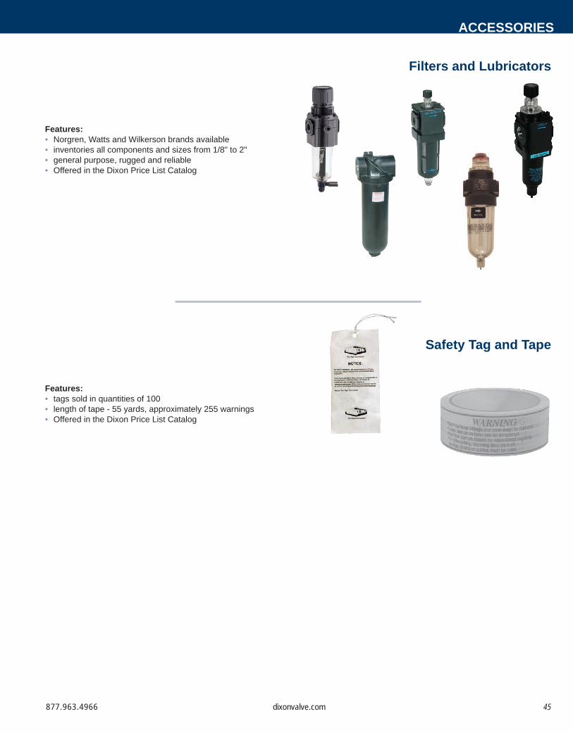
Filters and Lubricators
Features:• Norgren, Watts and Wilkerson brands available• inventories all components and sizes from 1/8" to 2"• general purpose, rugged and reliable• Offered in the Dixon Price List Catalog
Safety Tag and Tape
Features:• tags sold in quantities of 100• length of tape - 55 yards, approximately 255 warnings• Offered in the Dixon Price List Catalog
ACCESSORIES

877.963.496646 dixonvalve.com
Size
Temperature
Application
Pressure
Ends
Dixon
Media
T
A
M
P
E
D
S
S.T.A.M.P.E.D.
Questions to Ask
100 PSI = 6.9 Bars250 PSI = 17.25 Bars600 PSI = 41.4 Bars
5 Bars = 72.5 PSI10 Bars = 145 PSI25 Bars = 362.5 PSI
Pressure Conversions
Force ChartForce (In Pounds)
Note: For hose ID's from 1-1/4" to 12" the force in pounds is greater than the PSI.• Force is the dynamic power which is exported longitudinally through a hose, towards the ends. To arrive at the number of pounds of force exerted, you merely multiply the area of the ID times the working pressure being used.• Area of a circle: x r2 (PI [3.1416] times radius squared)• Force = Area x Pressure
Air Supply Requirements (operating pressure: 90 PSI)
Tool ClassTypical Air
Consumption (CFM)
Hose Size (inches)
0-10 ft. 10-50 ft. 50-200 ft.
Paving Breakers
25 lb.35 lb.60 lb.80 lb.
45506580
1/21/21/23/4
1/23/43/43/4
3/43/411
Claydiggers 45 1/2 1/2 3/4
Hand Drills 8 lb.15 lb.
2032
3/83/8
3/81/2
1/21/2
Rock (Sinker) Drills
45 lb.55 lb.
105130
3/43/4
3/41
11
Tampers 5" butt6" butt
2030
3/81/2
1/21/2
1/23/4
Sump PumpSludge Pump
3 HPEjector
10090
3/41
3/41
11
Vibrators 2-1/2"3"
6060
11
11
11
Chipping Hammers
25 3/8 1/2 1/2
Impact Wrenches
3/8" sq. dr.1/2"3/4"1"
10152550
5/165/163/81/2
3/83/81/23/4
3/81/21/23/4
Drills 1/4" - 1/2" 22 3/8 3/8 1/2
Grinders die/burrsmall angle
3 HP vertical
202075
3/83/81/2
3/83/83/4
1/21/21
HoseID
25PSI
50PSI
75PSI
100PSI
150PSI
200PSI
250PSI
300PSI
500PSI
1000PSI
1/4" 1 2 4 5 7 10 12 15 25 493/8" 3 6 8 11 17 22 28 33 55 1101/2" 5 10 15 20 29 39 49 59 98 1963/4" 11 22 33 44 66 88 110 133 221 4421" 20 39 59 79 118 157 196 236 393 785
1-1/4" 31 61 92 123 184 245 307 368 614 12271-1/2" 44 88 133 177 265 353 442 530 884 1767
2" 79 157 236 314 471 628 785 942 1571 31422-1/2" 123 245 368 491 736 982 1227 1473 2454 4909
3" 177 353 530 707 1060 1414 1767 2121 3534 70694" 314 628 942 1257 1885 2513 3142 3770 6283 125665" 491 982 1473 1964 2945 3927 4909 5891 9818 196356" 707 1414 2121 2827 4241 5655 7069 8482 14137 282748" 1257 2513 3770 5027 7540 10053 12566 15080 25133 50266
10" 1964 3927 5891 7854 11781 15708 19635 23562 39270 7854012" 2827 5655 8482 11310 16965 22620 28274 33929 56549 113098

877.963.4966 47dixonvalve.com
TECHNICAL INFORMATIONFraction - Decimal Conversion Chart
MillimetersInches MillimetersInches
13.096913.493813.890714.287614.684415.081315.478215.875116.271916.668817.065717.462617.859418.256318.653219.050119.447019.843820.240720.637621.034521.431321.828222.225122.622023.018823.415723.812624.209524.606325.003225.4001
.015625
.03125
.046875
.0625
.078125
.09375
.109375
.125
.140625
.15625
.171875
.1875
.203125
.21875
.234375
.250
.265625
.28125
.296875
.3125
.328125
.34375
.359375
.375
.390625
.40625
.421875
.4375
.453125
.46875
.484375
.500
.3969
.79381.19061.58751.98442.38132.77813.17503.57193.96884.36564.76255.15945.55635.95316.35006.74697.14387.54067.93758.33448.73139.12829.52509.921910.318810.715711.112511.509411.906312.303212.7001
.515625
.53125
.546875
.5625
.578125
.59375
.609375
.625
.640625
.65625
.671875
.6875
.703125
.71875
.734375
.750
.765625
.78125
.796875
.8125
.828125
.84375
.859375
.875
.890625
.90625
.921875
.9375
.953125
.96875
.9843751.000
1641
32 3641
16 5643
32 7641
8 9645
32 11643
16 13647
32 15641
4 17649
32 19645
16 216411
32 23643
8 256413
32 27647
16 296415
32 31641
2
336417
32 35649
16 376419
32 39645
8 416421
32 436411
16 456423
32 47643
4 496425
32 516413
16 536427
32 55647
8 576429
32 596415
16 616431
32 6364
1

®
dixonvalve.com • Customer Service: 877.963.4966
Dixon is recognized as the premier manufacturer and supplier of hose fittings and accessories spanning a wide range of industrial uses. Dixon’s range includes products for food, dairy processing, beverage and brewery, mobile tankers, mining, construction, chemical processing, petroleum, oilfields, refining and manufacturing.
800 High Street, Chestertown, MD 21620Fax: 800.283.4966
Dixon Valve
© 2014 DVCC Printed in the USA OUTAIR0115-web