Product specification - Controller software IRC5 - ABB Group
190
ROBOTICS Product specification Controller software IRC5
-
Upload
khangminh22 -
Category
Documents
-
view
0 -
download
0
Transcript of Product specification - Controller software IRC5 - ABB Group

ROBOTICS
Product specificationController software IRC5

Trace back information:Workspace 22A version a11Checked in 2022-03-03Skribenta version 5.4.005
Product specificationController software IRC5
6.13
Document ID: 3HAC050945-001Revision: W
© Copyright 2022 ABB. All rights reserved.Specifications subject to change without notice.
The information in this manual is subject to change without notice and should notbe construed as a commitment by ABB. ABB assumes no responsibility for any errorsthat may appear in this manual.Except as may be expressly stated anywhere in this manual, nothing herein shall beconstrued as any kind of guarantee or warranty by ABB for losses, damage to personsor property, fitness for a specific purpose or the like.In no event shall ABB be liable for incidental or consequential damages arising fromuse of this manual and products described herein.This manual and parts thereof must not be reproduced or copied without ABB'swritten permission.Keep for future reference.Additional copies of this manual may be obtained from ABB.
Original instructions.
© Copyright 2022 ABB. All rights reserved.Specifications subject to change without notice.
Table of contents9Overview of this specification ..........................................................................................................
131 Introduction to RobotWare
152 Option restructuring
173 RobotWare-OS173.1 Multiple Axis Positioner ......................................................................................183.2 Fixed Position Events ........................................................................................203.3 File and Serial Channel Handling .........................................................................223.4 Advanced RAPID ..............................................................................................253.5 Auto acknowledge input .....................................................................................263.6 Logical Cross Connections .................................................................................273.7 Analog Signal Interrupt .......................................................................................283.8 Electronically Linked Motors ................................................................................293.9 Service Information System ................................................................................313.10 Robot Web Services ..........................................................................................
334 General RobotWare334.1 RobotWare Add-In prepared [988-1] ......................................................................
355 Motion Performance355.1 Advanced robot motion [687-1] ............................................................................365.2 Advanced Shape Tuning .....................................................................................385.3 WristMove .......................................................................................................405.4 Absolute Accuracy, floor mounted [603-1] ..............................................................425.5 Motion Process Mode ........................................................................................
456 Motion Coordination456.1 MultiMove Coordinated [604-1] ............................................................................486.2 MultiMove Independent [604-2] ............................................................................506.3 Tracking unit interface [1552-1] ............................................................................516.4 Conveyor Tracking [606-1] ..................................................................................536.5 Indexing Conveyor Control [606-2] .......................................................................556.6 Sensor Synchronization [607-1] ...........................................................................566.7 Analog Synchronization [607-2] ...........................................................................
597 Motion Events597.1 World Zones [608-1] ..........................................................................................
618 Motion Functions618.1 Independent Axis [610-1] ....................................................................................638.2 Path Recovery [611-1] ........................................................................................648.3 Path Offset [612-1] .............................................................................................658.4 SoftMove [885-1] ...............................................................................................
679 Motion Supervision679.1 Collision Detection [613-1] ..................................................................................689.2 Collision Avoidance ...........................................................................................
7110 Communication7110.1 FTP & SFTP Client [614-1] ..................................................................................7210.2 NFS Client ......................................................................................................7310.3 PC Interface [616-1] ...........................................................................................
Product specification - Controller software IRC5 53HAC050945-001 Revision: W
© Copyright 2022 ABB. All rights reserved.
Table of contents
7410.4 IoT Gateway .....................................................................................................7410.4.1 IoT Date Gateway [1582-1] ........................................................................7510.5 FlexPendant Interface [617-1] ..............................................................................7610.6 Field bus Command Interface [618-1] ....................................................................7710.7 RobotStudio App Connect [688-1] ........................................................................7910.8 Socket Messaging ............................................................................................
8111 Engineering Tools8111.1 Multitasking [623-1] ...........................................................................................8311.2 Continuous Application Platform [624-1] ................................................................8411.3 Optical Tracking [813-1] ......................................................................................8511.4 Tracking Interface [1553-1] ..................................................................................8611.5 Discrete Application Platform [625-1] ....................................................................8711.6 Sensor Interface [628-1] .....................................................................................8911.7 Robot Reference Interface ..................................................................................9111.8 Externally Guided Motion [689-1] ..........................................................................9411.9 MultiFunction [824-1] .........................................................................................9511.10 Production Screen [637-1] ...................................................................................9611.11 RAPID Message Queue ......................................................................................9811.12 Production Framework [1243-1] ...........................................................................
9912 Motor Control9912.1 Tool Control [1180-1] .........................................................................................
10112.2 Servo Tool Change [630-1] ..................................................................................
10313 Vision10313.1 Integrated Vision ...............................................................................................10413.2 Prepared for FlexLoader Vision [1554-1] ................................................................10613.3 Prep. Visual Servoing [1586-1] .............................................................................
10714 Application options10714.1 MultiProcess [634-1] ..........................................................................................10814.2 Arc 6 [633-4] .....................................................................................................11114.2.1 Included Power Source functions ...............................................................11114.2.1.1 AristoMig integrated .....................................................................11214.2.1.2 ABB RPC S Integrated ..................................................................11314.2.1.3 Fronius TPS Integrated .................................................................11414.2.1.4 Fronius TPSi ...............................................................................11814.2.1.5 Fronius TPS 4000/5000 .................................................................12014.2.1.6 Standard I/O Welder .....................................................................12114.2.1.7 Lincoln ArcLink ...........................................................................12414.2.1.8 SKS Synchroweld ........................................................................12614.2.1.9 Fronius TPSi Seam tracking ..........................................................12914.2.2 Other included functions and options ..........................................................12914.2.2.1 Torch Service Equipment ..............................................................13114.2.2.2 Production Monitoring ..................................................................13614.2.2.3 Additional Arc System, Two additional .............................................13714.2.2.4 Included options ..........................................................................13814.3 Arc options ......................................................................................................13914.3.1 SmarTac - I/O version [657-1] ....................................................................14114.3.2 Navigator [814-1] .....................................................................................14414.3.3 Optical Tracking Arc [660-1] ......................................................................14514.3.4 WeldGuide [815-2] ...................................................................................14914.4 BullsEye [652-1] ................................................................................................15114.5 Spot 6 [635-6] ...................................................................................................15514.6 Movable gun arm search [1583-1] .........................................................................15614.7 Process Data Access [1585-1] .............................................................................15714.8 Bosch Interface [832-1] ......................................................................................
6 Product specification - Controller software IRC53HAC050945-001 Revision: W
© Copyright 2022 ABB. All rights reserved.
Table of contents
15814.9 Dispense [641-1] ...............................................................................................16014.10 Packaging ........................................................................................................16014.10.1 PickMaster Ready ...................................................................................16014.10.1.1 PickMaster Cell Ready [1580-1] ......................................................16114.10.1.2 PickMaster Robot Ready [1580-2] ...................................................16214.10.2 PickMaster Vision ...................................................................................16214.10.2.1 PickMaster Vision Ready [1581-1] ...................................................16314.11 Prep. for PickMaster&PowerPac ..........................................................................16314.11.1 PickMaster 3 [642-1] ................................................................................16514.11.2 Palletizing PowerPac [642-2] .....................................................................16714.12 Force Control Base [661-2] .................................................................................17414.13 Machining FC GUI [877-1] ...................................................................................17614.14 PROFIenergy [963-1] .........................................................................................17714.15 RobotWare Cutting [951-1] ..................................................................................18014.16 RobotWare Machine Tending [1167-1] ...................................................................18314.17 Other functions .................................................................................................18314.17.1 Production Manager ................................................................................
187Index
Product specification - Controller software IRC5 73HAC050945-001 Revision: W
© Copyright 2022 ABB. All rights reserved.
Table of contents

This page is intentionally left blank
Overview of this specificationAbout this product specification
It describes all RobotWare (that is controller software) options for the IRC5 controller
UsageProduct specifications are used to find data and performance about the product,for example to decide which product to buy. How to handle the product is describedin the product manual.
UsersIt is intended for:
• Personnel dealing with ordering of ABB robots• Personnel seeking to obtain an overview of RobotWare functionality• Sales and marketing personnel
References
Document IDReference
3HAC047400-001Product specification - Controller IRC5
3HAC051016-001Application manual - Additional axes and stand alone controller
3HAC050798-001Application manual - Controller software IRC5
Document.ID-1Application manual - Continuous Application Platform
Document.ID-1Application manual - Discrete Application Platform
Document.ID-1Product specification - Integrated Vision
3HAC050967-001Application manual - PROFIenergy Device
3HAC051193-001Application manual - RobotWare Add-Ins
3HAC052355-001Product specification - Robot user documentation, IRC5 with Robot-Ware 6
Revisions
DescriptionRevision
First revision-
Released with RobotWare 6.01.• Added the option RobotWare Add-In prepared [988-1] on
page 33.• The functionality of RAPID Message Queue is corrected,
see RAPID Message Queue on page 96.• The option Miller AutoAxcess [650-4] is removed.• The previous option Servo Tool Control is now included in
the option Spot 6, see Tool Control [1180-1] on page 99,• Minor corrections/update
A
Released with RobotWare 6.02.• Added the option 963-1 PROFIenergy.
B
Continues on next pageProduct specification - Controller software IRC5 93HAC050945-001 Revision: W
© Copyright 2022 ABB. All rights reserved.
Overview of this specification
DescriptionRevision
Released with RobotWare 6.03.• Updated the option Motion Process Mode on page 42.• Updated the spot features, see Spot 6 [635-6] on page 151.• Limitation for option Machine Tending [1167-1] is changed.
This option is now available for 4-axis robots.• The option Production Manager [812-1] is removed.
C
Released with RobotWare 6.04.• Updated the option Motion Process Mode on page 42.• Limitations for option Force Control Base [661-2] is updated.• Information and links to ARCITEC is removed.• Options Advanced Rapid [626-1] and Fixed Position Events
[609-1] are removed from the list of included options inPickMaster.
• PhraseRobotWare DVD in sectionCommunication/PC Inter-face, is changed to RobotWare Download package.
• Robot Web Services added to section RobotWare-OS.• Phrase Support for MultiMove in section Externally Guided
Motion/Features is deleted.• Function SKSSynchroweld added to Included Power Source
functions.• Function Productionmanager for Arc is renamed to Produc-
tion manager and moved from Arc options to Applicationoptions.
• FunctionBullsEye is moved fromArc options toApplicationoptions.
• Option Arc 6 is updated.• Option numbers for Advanced Rapid and Fixed Position
Events are deleted in section Prepared for PickMaster 3.
D
• Minor corrections.E
Released with RobotWare 6.05.• Minor corrections.
F
• Released with RobotWare 6.06.• Added Absolute Accuracy parameters for IRB 1200• The limitations on Servo Tool Change [630-1] is updated• Changed the description of option 642-2 to Palletizing
PowerPac• Option Bosch Interface [832-1] is updated• Option Externally Guided Motion [689-1] is updated• Option Arc 6 [633-4] is updated.• Minor correction
G
Released with RobotWare 6.07.• Minor correction• Added Fronius TPSi• Option Tracking unit interface [1552-1] is added• Option Tracking Interface [1553-1] is added• Option Externally Guided Motion [689-1] is updated• Option Conveyor Tracking [606-1] is updated• Option MultiProcess [634-1] is updated• Option Sensor Synchronization [607-1] is updated and the
requirement is removed• Option FTP Client [614-1] is updated and the description is
changed• NFS Client is updated
H
Continues on next page10 Product specification - Controller software IRC5
3HAC050945-001 Revision: W© Copyright 2022 ABB. All rights reserved.
Overview of this specificationContinued

DescriptionRevision
Released with RobotWare 6.08.• Up to seven motion tasks can now be used for options
MultiMove Coordinated [604-1] andMultiMove Independent[604-2].
• Option Prepared for FlexLoader Vision [1554-1] is added• Option Production Framework [1243-1] is added• Added Fronius TPSi Seam tracking• Added Collision Avoidance
J
Released with RobotWare 6.09.• Added limitation on Externally Guided Motion [689-1]• Updated the Externally Guided Motion [689-1] Position
Guidance, added support for IRB 14000• Updated the limitations of Independent Axis [610-1]• Removed Absolute Accuracy, inverted [603-2]• Updated information about Absolute Accuracy• Moved Production Manager to Other functions
K
Released with RobotWare 6.09.• Option Tracking unit interface [1552-1] is updated
L
Released with RobotWare 6.10.• List of limitations of supported robots updated in section
Collision Avoidance on page 68.• Updated the Requirements for option PickMaster 3 [642-1]• Updated option Arc 6 [633-4] with included options
M
Released with RobotWare 6.10.01• Updated the limitations for option Bosch Interface [832-1]• Updated Weaving feature for option Arc 6 [633-4]• Updated the requirement for option Tracking unit interface
[1552-1]
N
Released with RobotWare 6.10.02• Removed Production Screen [637-1] from Fronius TPSi re-
quirements. Production Screen [637-1] is included in optionRobotWare Arc [633-4]
• Minor changes
P
Released with RobotWare 6.11• Added new options related to PickMaster Twin, PickMaster
Cell Ready [1580-1], PickMaster Robot Ready [1580-2],PickMaster Vision Ready [1581-1]
• Updated Collision Avoidance limitation and added Rapidinstruktion
• Remove IRB 6620LX as it is phased out• Added OPC UA Server [1582-1]• Minor changes
Q
Released with RobotWare 6.11.01• Updated the requirement for option RobotWare Machine
Tending [1167-1]• Updated general information and the features for option
Tool Control [1180-1]
R
Released with RobotWare 6.11.02• Updated the limitations of option Independent Axis [610-1]• Updated the limitations of option SoftMove [885-1]• Updated the limitations of option Externally Guided Motion
[689-1]
S
Continues on next pageProduct specification - Controller software IRC5 113HAC050945-001 Revision: W
© Copyright 2022 ABB. All rights reserved.
Overview of this specificationContinued
DescriptionRevision
Released with RobotWare 6.12• Changed the name Local IO to Scalable I/O• Added OPCUA [1582-1]• Added Movable gun arm search [1583-1]• Updated the requirements of optionMultiMove Coordinated
[604-1]• Updated the limitations of option MultiMove Independent
[604-2]
T
• Performance description for optionMultiMove Coordinated[604-1] and MultiMove Independent [604-2] had been up-dated.
U
Released with RobotWare 6.12.03• Limitations updated for the options Independent Axis and
Path Offset.• Change the name and description for option [1582-1].
V
Released with RobotWare 6.13.02.• Added the option Process Data Access [1585-1].• Added the option Prep. Visual Servoing [1586-1].
W
12 Product specification - Controller software IRC53HAC050945-001 Revision: W
© Copyright 2022 ABB. All rights reserved.
Overview of this specificationContinued
1 Introduction to RobotWareSoftware products
RobotWare is a family of software products from ABB Robotics. The products aredesigned tomake youmore productive and lower your cost of owning and operatinga robot. ABB Robotics has invested many years into the development of theseproducts and they represent knowledge and experience based on several thousandsof robot installations.
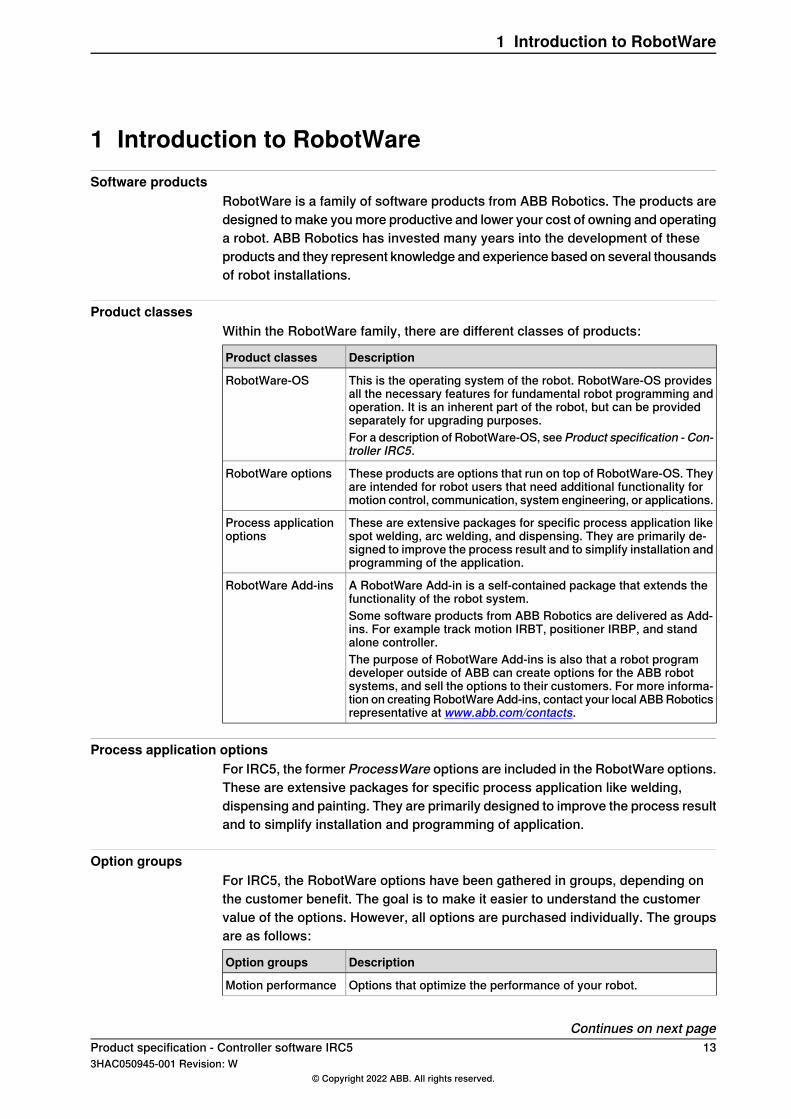
Product classesWithin the RobotWare family, there are different classes of products:
DescriptionProduct classes
This is the operating system of the robot. RobotWare-OS providesall the necessary features for fundamental robot programming andoperation. It is an inherent part of the robot, but can be providedseparately for upgrading purposes.
RobotWare-OS
For a description of RobotWare-OS, see Product specification - Con-troller IRC5.
These products are options that run on top of RobotWare-OS. Theyare intended for robot users that need additional functionality formotion control, communication, system engineering, or applications.
RobotWare options
These are extensive packages for specific process application likespot welding, arc welding, and dispensing. They are primarily de-signed to improve the process result and to simplify installation andprogramming of the application.
Process applicationoptions
A RobotWare Add-in is a self-contained package that extends thefunctionality of the robot system.
RobotWare Add-ins
Some software products from ABB Robotics are delivered as Add-ins. For example track motion IRBT, positioner IRBP, and standalone controller.The purpose of RobotWare Add-ins is also that a robot programdeveloper outside of ABB can create options for the ABB robotsystems, and sell the options to their customers. For more informa-tion on creating RobotWare Add-ins, contact your local ABBRoboticsrepresentative at www.abb.com/contacts.
Process application optionsFor IRC5, the former ProcessWare options are included in the RobotWare options.These are extensive packages for specific process application like welding,dispensing and painting. They are primarily designed to improve the process resultand to simplify installation and programming of application.
Option groupsFor IRC5, the RobotWare options have been gathered in groups, depending onthe customer benefit. The goal is to make it easier to understand the customervalue of the options. However, all options are purchased individually. The groupsare as follows:
DescriptionOption groups
Options that optimize the performance of your robot.Motion performance
Continues on next pageProduct specification - Controller software IRC5 133HAC050945-001 Revision: W
© Copyright 2022 ABB. All rights reserved.
1 Introduction to RobotWare
DescriptionOption groups
Options that make your robot coordinated with external equipmentor other robots.
Motion coordination
Options that supervise the position of the robot.Motion Events
Options that control the path of the robot.Motion functions
Options that supervise the movement of the robot.Motion Supervision
Options that make the robot communicate with other equipment.(External PCs etc.)
Communication
Options for the advanced robot integrator.Engineering tools
Options that make the robot controller operate external motors, in-dependent of the robot.
Servo motor control
14 Product specification - Controller software IRC53HAC050945-001 Revision: W
© Copyright 2022 ABB. All rights reserved.
1 Introduction to RobotWareContinued
2 Option restructuringGeneral
A change in the option structure has been implemented, in order to achieve asimplified product offer. This means that a number of options have been removedfrom the specification form. The corresponding functionality has been eitherincluded in the basic robot product or merged with other options.In this product specification, all options are still described as before. A commenthas been added in the beginning of each chapter affected by the change, to indicatethat options have been included in the base product or merged with another option.
Product specification - Controller software IRC5 153HAC050945-001 Revision: W
© Copyright 2022 ABB. All rights reserved.
2 Option restructuring

This page is intentionally left blank
3 RobotWare-OS3.1 Multiple Axis Positioner
General
Note
This functionality is included in RobotWare - OS.
The option Multiple Axis Positioner enables coordination of robot motion withmultiple axis manipulators or robot carriers (gantries).
Note
Note that simultaneous coordination with several single axis manipulators, forexample track motion and work piece manipulators, does not require the optionMultiple Axis Positioner.
Features• Coordinated movement of robot and multiple axis manipulator
ApplicationThis option shall be used for all types of multiple axis manipulators for examplepositioners for arc welding.The kinematic model of the positioner enables the coordinated movement of robotand manipulator together, meaning correct TCP movement relative to the workpiece, also when the work piece or the robot (for robot carrier Application) is movedaround, during program execution or jogging.
PerformanceThe performance of the coordinated robot movement with a moving work objecton amultiple axis manipulator is the same as for a fix work object, if the manipulatoris correctly calibrated.
Requirements
Note
A configuration file describing the kinematics of the manipulator is necessaryand is normally supplied by the manipulator supplier.
RAPID instructionsThere are no RAPID instructions included in this option.
Product specification - Controller software IRC5 173HAC050945-001 Revision: W
© Copyright 2022 ABB. All rights reserved.
3 RobotWare-OS3.1 Multiple Axis Positioner
3.2 Fixed Position Events
General
Note
This functionality is included in RobotWare - OS.
The option Fixed Position Events is used to issue certain events depending on thecurrent robot position. The events can be used to control or check the status ofsurrounding equipment.
Features• Change the value of an I/O signal, when the TCP is at a certain time and/or
distance before or after a programmed position.• Generate an interrupt, when the TCP is at a certain time and/or distance
before or after a programmed position.• Check the value of an I/O signal, when the TCP is at a certain time and/or
distance before or after a programmed position.• Make a procedure call, when the TCP is at a certain position on the path or
in the middle of a corner zone.
Application
DescriptionApplication
To provide a safe communication system between the robot and thepress and to reduce cycle time. At the instant when the robot leavesa press, an output is set and restarts the press action. This functionis also useful for other process equipment. The start/stop will alwaysoccur when the robot is at the exact position, irrespective of the robotspeed.
Handling presswork
For example a robot which is used for extracting parts from a diecasting machine. Before entering, the robot can check if the gate isopen (check an I/O signal) or check a number of logical conditionsand take care of the complete press start (make procedure call).
Check status of pro-cess equipment
PerformanceThe event issued with Fixed Position Event will always occur when the robot is atthe exact position, irrespective of the robot speed.
RequirementsThere are no software or hardware requirements for this option.
RAPID instructionsRAPID instructions included in this option:
InstructionInstruction
Definition of trigg conditions for an outputTriggIO
Definition of trigg conditions for process equipment with com-pensation for equipment delay
TriggEquip
Continues on next page18 Product specification - Controller software IRC5
3HAC050945-001 Revision: W© Copyright 2022 ABB. All rights reserved.
3 RobotWare-OS3.2 Fixed Position Events

InstructionInstruction
Definition of trigg conditions for check of signal valueTriggCheckIO
Definition of trigg conditions for an interruptTriggInt
Position fix output/interrupt during linear movementTriggL
Position fix output/interrupt during circular movementTriggC
Position fix output/interrupt during joint movementTriggJ
Procedure call in the middle of the path or in corner zone,during linear movement
MoveLSync
Procedure call in the middle of the path or in corner zone,during circular movement
MoveCSync
Procedure call in the middle of the path or in corner zone,during joint movement
MoveJSync
Product specification - Controller software IRC5 193HAC050945-001 Revision: W
© Copyright 2022 ABB. All rights reserved.
3 RobotWare-OS3.2 Fixed Position Events
Continued
3.3 File and Serial Channel Handling
General
Note
This functionality is included in RobotWare - OS.
File and Serial Channel Handling is an option, which allows the robot system tocommunicate with external units.
Features• Transferring information via serial channels.• Read part numbers from a bar code reader• Print out production statistics on a printer during production• Transfer data between the robot and a PC• Data transfer via files• Write/read production data on a USB memory stick or other mass storage
memory from RAPID program
Application
DescriptionApplication
Bar code readers can be used to trace a product with its cor-responding production information, for every work objectthroughout a production line.
Transferring information viaserial channels
Bar code readers can also be used to make the robot performthe proper actions, corresponding to the work object, in lineswhich handle different types of products, for example in packingand pelletizing Application. This is the same as controlling therobot production from a file. This file may have been createdin a PC, stored on a USB memory stick, and read by the robotat a later time.
Storing production statistics on a USB memory stick or othermass storagememory. This information can then be processedby an ordinary PC.
Data transfer via files
Performance
DescriptionData/Information
The transfer is controlled entirely from the robot’s work pro-gram. To control the transfer from a PC, use the option PC In-terface.
Transferring information viaserial channels
Data in the form of text strings (characters), numerical valuesor binary information can be read/written.
Data transfer via files
RequirementsThis option includes software functionality only. Serial channels (RS232 or RS 485serial channel), bar code readers etc. need to be purchased separately, from ABBor external provider.
Continues on next page20 Product specification - Controller software IRC5
3HAC050945-001 Revision: W© Copyright 2022 ABB. All rights reserved.
3 RobotWare-OS3.3 File and Serial Channel Handling
RAPID instructionsRAPID instructions included in this option:
DescriptionInstruction
Open/Close a file/serial channelOpen/Close
(Write/WriteBin/WriteStrBin/WriteAnyBin)Write to a character-or string-based/binary serial channel or file.
Write
(Read/ReadNumReadStr/ReadBin/Read-StrBin/ReadAnyBin)Read a string/number/binary value from aserial channel or file.
Read
Get the size of a file systemFSSize
Create a new directoryMakeDir
Delete a directoryRemoveDir
Open a directory to read the underlying files or subordinatesOpenDir
Close a directoryCloseDir
Read next object in a directory, file or subdirectoryReadDir
Check the type of a fileIsFile
Get the size of a fileFileSize
Copy a file, from RAPIDCopyFile
Rename a file from RAPIDRenameFile
Delete a fileRemoveFile
Start reading from the beginning of a fileRewind
Clear the input buffer of a serial channelClearIOBuff
Read data from raw byteReadRawBytes
Write data raw byte to a deviceWriteRawBytes
Clear all contents of a rawbytes variableClearRawBytes
Copy raw byte dataCopyRawBytes
Pack data from variables into rawbytesPackRawBytes
Unpack data from rawbytes into variablesUnpackRawBytes
Returns the amount of data in a ‘container’ of type raw byte(bytes)
RawBytesLen
Data types
DescriptionDatatype
A general data ‘container’, for communication with I/O devicesrawbytes
Product specification - Controller software IRC5 213HAC050945-001 Revision: W
© Copyright 2022 ABB. All rights reserved.
3 RobotWare-OS3.3 File and Serial Channel Handling
Continued
3.4 Advanced RAPID
General
Note
This functionality is included in RobotWare-OS.
The option Advanced RAPID is directed towards advanced RAPID programmers.The package includes a detailed reference manual on the RAPID language kerneland a number of instruction and function groups useful for application development,as listed below.The groups are:
• Bit Functions• Data Search Functions• RAPID Support Functions• Power Failure Functions• Advanced Trigg Functions
Technical reference manual - RAPID kernelThe manual describes the RAPID language syntax and semantics in detailconcerning the kernel, that is all general language elements which are not usedto control robot or other equipment. In addition to this the manual includesdescriptions on:
• Built-in Routines• Built-in Data Objects• Built-in Objects• Intertask Objects• Text Files• Storage allocation for RAPID objects
Bit FunctionsBit functions is a package for handling, that is setting, reading and clearing,individual bits in a byte. The instructions/functions are:
DescriptionInstructions/Functions
Data type for a byte databyte
Set a specified bit in a byteBitSet
Clear a specified bit in a byteBitClear
Check if a specified bit in a byte is setBitCheck
Logical bitwise AND operation on byteBitAnd
Logical bitwise OR operation on byteBitOr
Logical bitwise XOR operation on byteBitXOr
Logical bitwise NEGATION operation on byteBitNeg
Continues on next page22 Product specification - Controller software IRC5
3HAC050945-001 Revision: W© Copyright 2022 ABB. All rights reserved.
3 RobotWare-OS3.4 Advanced RAPID
DescriptionInstructions/Functions
Logical bitwise LEFT SHIFT operation on byteBitLSh
Logical bitwise RIGHT SHIFT operation on byteBitRSh
Data Search FunctionsWith these functions it is possible to search all data in a RAPID program, wherethe name or the data type is given as a text string. This might be useful for instancein the following examples:
• A common need is to check if a data with a certain name is declared in thesystem, and in such case what is its value, for example a robtarget.
• Another need is to list all variables of a certain datatype, which are declaredin the system, and write their values on the screen, for example all weld data.
The following instructions/functions are included in the data search functions:
DescriptionInstructions/Functions
Define the search criteriaSetDataSearch
Search next data and get its name as a stringGetNextSym
Get the value of a data, specified with a string for the nameGetDataVal
Set the value of a data, specified with a string for the nameSetDataVal
Set the value of all searched dataSetAllDataVal
RAPID Support FunctionsThis package includes a number of miscellaneous instructions etc., which are usedin application development.
DescriptionInstruction
Instruction used to define a signal of any type with an alias(alternative) name. The instruction can be used tomake genericmodules work together with site specific I/O, without changingthe program code.
AliasIO
Function used inside a routine to get the name of a data object,which is referenced as argument in the call of the routine. Thename is given as a string. The function can also be used toconvert the identifier of a data into a string.
ArgName
Instruction used to book a new RAPID system error number.This should be used to avoid error number conflicts if differentgeneric modules are combined in a system.
BookErrNo
Write a system error message.ErrLog
Write a system errormessage andRAISE the error to the callingroutine.
ErrRaise
Function used to get the text table number of a user definedtext table during runtime.
TextTabGet
Function used to get a text string from the system text tables(installed at cold start).
TextGet
Instruction used to install a text table in the system.TextTabInstall
Function to test whether the text table name (text resourcestring) is free to use.
TextTabFreeToUse
Continues on next pageProduct specification - Controller software IRC5 233HAC050945-001 Revision: W
© Copyright 2022 ABB. All rights reserved.
3 RobotWare-OS3.4 Advanced RAPID
Continued
DescriptionInstruction
Instruction which will activates the specified system data (toolor workobject). With this instruction it is possible to changethe current active tool or workobject.
SetSysData
Function which will return information about the movement ofthe Program Pointer (PP).
IsStopStateEvent
Read system configuration data.ReadCfgData
Write system configuration data.WriteCfgData
Restart the system.WarmStart
Power Failure FunctionsThe package is used to get I/O signal values before power failure and to reset themat power on. The following instructions are included and are normally used in thepower on event routine:
DescriptionInstruction
Check if path has been interruptedPFRestart
Advanced Trigg Functions
DescriptionInstruction
Instruction to define conditions and actions for control of ananalog output signal with an output value proportional to theactual TCP speed.Note that this instruction must be used incombination with a TriggL/C/J instruction.
TriggSpeed
Instruction used to move backward on its path in a RESTARTevent routine.
StepBwdPath
Generation of restart data at program stop or emergency stop.TriggStopProc
An interrupt when changing a persistent.IPers
An interrupt at event (error) generation.IError
Used in a trap routine to obtain all information about the inter-rupt that caused the trap routine to be executed.
GetTrapData
Used in a trap routine to obtain numeric information (domain,type and number) about an error, a state change, or a warning,that caused the trap routine to be executed.
ReadErrData
24 Product specification - Controller software IRC53HAC050945-001 Revision: W
© Copyright 2022 ABB. All rights reserved.
3 RobotWare-OS3.4 Advanced RAPIDContinued
3.5 Auto acknowledge input
General
Note
This functionality is included in RobotWare-OS.
Auto Acknowledge Input is a system input which will acknowledge the dialogpresented on the FlexPendant when switching from operator modemanual to autowith the key switch on the robot controller.
WARNING
Note that using such an input will be contrary to the regulations in the safetystandard ISO 10218-1 chapter 5.3.5 Single point of control with following text:"The robot control system shall be designed and constructed so that when therobot is placed under local pendant control or other teaching device control,initiation of robot motion or change of local control selection from any othersource shall be prevented."Thus it is absolutely necessary to use other means of safety to maintain therequirements of the standard and the machinery directive and also to make arisk assessment of the completed cell. Such additional arrangements and riskassessment is the responsibility of the system integrator and the system mustnot be put into service until these actions have been completed
FeaturesAn optional system input can be created, which will acknowledge the dialogpresented at the FlexPendant when switching from operator mode manual to auto.The option must be activated in Installation Manager and then the system inputdefined in the configuration file for I/O.
LimitationsThe system parameter cannot be defined using the FlexPendant or RobotStudio,only with a text string in the I/O configuration file.
Product specification - Controller software IRC5 253HAC050945-001 Revision: W
© Copyright 2022 ABB. All rights reserved.
3 RobotWare-OS3.5 Auto acknowledge input
3.6 Logical Cross Connections
General
Note
This functionality is included in RobotWare-OS.
The option Logical Cross Connections can be used to check or control processequipment, which is external to the robot. The functionality can be compared tothe one of a simple PLC.
Features• Boolean values (true/fault) based on the logical conditions: AND, OR, NOT
ApplicationAny application where logical conditions are used for digital signals.
DescriptionApplication
To be interrupted when both inputs 3 and 4 are ‘high’.Program execution
When input 5 is set, but only when output 5=1 and input 3 = 0.Register is to be incremen-ted
PerformanceMaximum of 300 cross connections can be configured.
RequirementsThere are no software or hardware requirements for this option.
RAPID instructionsThere are no RAPID instructions included in this option.
26 Product specification - Controller software IRC53HAC050945-001 Revision: W
© Copyright 2022 ABB. All rights reserved.
3 RobotWare-OS3.6 Logical Cross Connections
3.7 Analog Signal Interrupt
General
Note
This functionality is included in RobotWare-OS.
The option Analog Signal Interrupt can be used to generate a program interrupt,when a supervised analog signal reaches a predefined limit.The interrupt can be used to give an error message for example ‘temperature abovelimit’, or make the robot wait for a door to be opened.
Features• Supervision of analog signals
ApplicationSupervision of external equipment, such as temperature sensors and equipmentdoors. In the later case, the Analog Signal Function can be used to minimize cycletime of the cell, since the robot can enter an area, which is enclosed by a door, atan optimal moment.
PerformanceAnalog Signal Interrupt requires less computer capacity than handshakingmethods.
RequirementsThere are no software or hardware requirements for this option.
RAPID instructionsRAPID instructions included in this option:
DescriptionInstruction
Interrupt from analog input signalISignalAI
Interrupt from analog output signalISignalAO
Product specification - Controller software IRC5 273HAC050945-001 Revision: W
© Copyright 2022 ABB. All rights reserved.
3 RobotWare-OS3.7 Analog Signal Interrupt
3.8 Electronically Linked Motors
General
Note
This functionality is included in RobotWare-OS.
Electronically LinkedMotors is used tomakemaster/slave configurations of motors,which are defined as external axes. The main application is to replace mechanicaldriving shafts of gantry machines, but the option can be used to control any otherset of motors as well. In addition to plain position following, also a torque/slavefunction is available, where the combined torque will be distributed betweenmasterand slaves.
Features• Up to 4 master motors• Up to 11 motors total (masters and followers)• Jogging and calibration routines• Replacement of mechanical driving shafts• Arm/Motor position available on the TPU• Possibility to activate/deactivate link during process• Automatic calibration at startup
ApplicationGantry machines: to replace mechanical driving shafts.
Performance
DescriptionPerformance
the electronically linked motors will follow the master motorWhen jogging
running follower motors independent of the master - is per-formed through a RAPID calibration program, to ensure highpersonnel safety
Calibration
a routine will automatically set the master- and follower motorsat the start position, through a safe maneuver
At startup
RequirementsThere are no software or hardware requirements for this option.
RAPID instructionsThere are no RAPID instructions included in this option.
28 Product specification - Controller software IRC53HAC050945-001 Revision: W
© Copyright 2022 ABB. All rights reserved.
3 RobotWare-OS3.8 Electronically Linked Motors
3.9 Service Information System
General
Note
This functionality is included in RobotWare-OS.
Service Information System is a service routine, which gives an alarm on theFlexPendant when the robot needs service.Service alarms intervals exist for gearbox supervision as default. There is also apossibility to set user specific service intervals for calendar and operational timeas well as for gearbox supervision.The status of the service values can be checked on the FlexPendant when therobot is in manual mode.Service information system furthermore includes a duty time counter function. Thisfunction is available for all robot types.
Note
There is also a hardware duty time counter available as option.
Service Information System is a free option and comes with all robots (does nothave to be ordered).
Features• Duty time. Sum of time, when the controller has been in the state ‘Motors
on’.• Calendar time. Elapsed time from latest service.• Gearbox supervision. Calculated from advanced algorithms.• Service interval alarms (Default and User set). The default alarms indicates
when service should be performed. The user can also make alarms appearat a given interval before the default alarms.
• WebWare Support.
ApplicationAll robot installations, with high quality demands. The Service Information Systemfunction gives possibility to predict the maintenance production stops.
Performance• FlexPendant. Alarms are given when a service interval is passed. (Both when
robot in production and manual mode.) Possibility to check the status of theservice values. (Manual mode, only).
• WebWare. The option provides support for building WebWare interfaces,with possibility to check Service Information status via a computer network(LAN).
Continues on next pageProduct specification - Controller software IRC5 293HAC050945-001 Revision: W
© Copyright 2022 ABB. All rights reserved.
3 RobotWare-OS3.9 Service Information System
RequirementsService Information System does not require any additional software or hardware.
RAPID instructionsThere are no RAPID instructions included in this option.
30 Product specification - Controller software IRC53HAC050945-001 Revision: W
© Copyright 2022 ABB. All rights reserved.
3 RobotWare-OS3.9 Service Information SystemContinued
3.10 Robot Web Services
GeneralRobot Web Services provides a Web interface for external clients to interact withthe robot controller. Allows system integrators and end-users to program their ownoperator interfaces and client applications for the robot controller.Robot Web Services can be used for any kind of software running on externaldevices. It will facilitate platform independent communication with the robotcontroller.The online manual and more information can be found in Developer Center on theRobotStudio Online Community.
FeaturesEnables the possibility to interact with the robot controller using PC clients , webclients and mobile clients. The messages are composed of XHTML or JSON andthe protocol is based on the HTTP.
ApplicationRobot Web Services is designed after the architectural style "RepresentationalState Transfer" (REST). REST consists of a coordinated set of components,connectors, and data elements within a distributed hypermedia system, where thefocus is on component roles and a specific set of interactions between dataelements rather than implementation details. Its purpose is to induce performance,scalability, simplicity, modifiability, visibility, portability, and reliability.
PerformanceThere is no specific performance data available for this option.
Requirements• Knowledge of Hypertext Transfer Protocol (HTTP)• Knowledge of XML or JSON• Programming library which can initiate HTTP requests and parse the
response.• A client such as a standard browser
RAPID instructionsThere are no RAPID instructions included in this option.
Product specification - Controller software IRC5 313HAC050945-001 Revision: W
© Copyright 2022 ABB. All rights reserved.
3 RobotWare-OS3.10 Robot Web Services

This page is intentionally left blank
4 General RobotWare4.1 RobotWare Add-In prepared [988-1]
GeneralThe option RobotWare Add-In preparedmakes it possible to run licensed Add-Insfrom 3rd party developers on the IRC5 controller.
FeaturesAdd-Ins allow to create installable supplemental software packages that extendthe capabilities offered by RobotWare, making ABB's robot controllers even smarterand evenmore user-friendly. Creating RobotWare Add-Ins is also the recommendedway for 3rd party developers to add new features into RobotWare.An Add-In can include a number of RAPID modules, system modules, or programmodules which hold the basic code for the Add-In. The Add-In also includes somefiles for loading and configuration at start up. The Add-In may also include .xmlfiles with event log messages in different languages.An Add-In can also consist of more advanced coding, such as C# code, forFlexPendant applications. This manual will cover the first case, with coding donein RAPID only. For more advanced coding, use RobotStudio SDK applications.
Note
The RobotWare option RobotWare Add-In prepared is only needed for licensedAdd-Ins. It is not needed for open Add-Ins or Add-Ins delivered together withRobotWare, for example track motion and positioners.
For more information, see Application manual - RobotWare Add-Ins.
ApplicationAdd-Ins can be used for any application, equipment, or functionality that extendsthe capabilities offered by RobotWare.
PerformanceThere is no specific performance data available for this option.
Requirements
Unlicensed, open, Add-InsWhat you need from ABB to package and run your own open Add-In is:
• RobotWare Add-In Packaging tool
Licensed Add-InsWhat you need from ABB to package and run your own licensed Add-In is:
• RobotWare Add-In Packaging tool• a licence certificate for the RobotWare Add-In Packaging tool for your Add-In
name
Continues on next pageProduct specification - Controller software IRC5 333HAC050945-001 Revision: W
© Copyright 2022 ABB. All rights reserved.
4 General RobotWare4.1 RobotWare Add-In prepared [988-1]

• RobotWare option RobotWare Add-In preparedTo license the Add-In, you will also need:
• License Generator• a publisher certificate.• a licensing certificate for the License Generator
RAPID instructionsThere are no RAPID instructions included in this option.
34 Product specification - Controller software IRC53HAC050945-001 Revision: W
© Copyright 2022 ABB. All rights reserved.
4 General RobotWare4.1 RobotWare Add-In prepared [988-1]Continued
5 Motion Performance5.1 Advanced robot motion [687-1]
About Advanced robot motionThe option Advanced robot motion gives you access to:
• Advanced Shape Tuning, see Advanced Shape Tuning on page 36.• Wrist Move, see WristMove on page 38.• Changing Motion Process Mode from RAPID, see Motion Process Mode on
page 42.
Product specification - Controller software IRC5 353HAC050945-001 Revision: W
© Copyright 2022 ABB. All rights reserved.
5 Motion Performance5.1 Advanced robot motion [687-1]
5.2 Advanced Shape Tuning
General
Note
This functionality is included in the optionAdvanced robot motion, see Advancedrobot motion [687-1] on page 35.
Advanced Shape Tuning offers the possibility to compensate for frictional effectsthat might appear at low speed cutting robot motion (10-100 mm/s). This isespecially useful when cutting advanced shapes, for example, small circles, orother similar applications when path accuracy is crucial. Friction tuning can beused to improve path accuracy of the robot in cutting applications.The option gives the user access to tuning parameters and the possibility to changethe tuning parameters for each axis during program execution with RAPIDcommands in the robot program. The option also includes RAPID instructions forautomatic fine tuning of friction level for each specific shape. The softwareautomatically repeats the movement until the best friction level for each axis hasbeen found. After the tuning has been completed each robot axis has a unique setof tuning values for each shape. The tuning is performed by the user and for eachspecific shape.
Features• Very accurate path performance for advanced motion at low speed, e.g.
shape cutting• Automatic tuning of the friction level using RAPID• Access to tuning parameters• Tuning axis by axis• Change tuning from RAPID program
ApplicationFriction effects typically arise when cutting small, advanced shapes like for examplecircles. The major source of friction effects comes changing direction of axismovement. The effects appear in the form of up to 0.5 mm path deviations.Typical applications are cutting of small shapes, such as holes, slots, rectangles.Other applications may be high precision gluing or dispense of small geometries.
PerformanceUsing Advanced Shape Tuning, typically a 0.5 mm path deviation can be reducedto about 0.1 mm. This however, requires careful tuning of the friction level (seeOperatingmanual - IRC5 with FlexPendant for tuning procedure, and the instructionTuneServo described in Technical reference manual - RAPID Instructions,Functions and Data types). Note that even with careful tuning, there is no guaranteethat "perfect" paths will always be generated.
Continues on next page36 Product specification - Controller software IRC5
3HAC050945-001 Revision: W© Copyright 2022 ABB. All rights reserved.
5 Motion Performance5.2 Advanced Shape Tuning
RequirementsThere are no hardware or software requirements for this option.
RAPID instructionsRAPID instructions included in this option:
DescriptionInstruction
Instruction to start the friction level identificationFricIdInit
Function that will return the friction level that produced the bestresults
FricIdEvaluate
Instruction to set friction levelsFricIdSetFricLevels
Change of tuning from RAPID is done with standard parameters.
DescriptionInstruction
Technical reference manual - RAPID Instructions, Functionsand Data types
TuneServo
Limitations• For the IRB66X0 and 7600 families of robots, no significant effects can be
expected by applying Advanced Shape Tuning.• For a MultiMove system, friction tuning can only be done for one robot at a
time.• The movement sequence for which friction tuning is done must begin and
end with a fine point.• The tuning process requires about 15 iterations of the movement per axis.• The movement sequence between FricIdInit and FricIdEvaluate
cannot be longer than 4 seconds.
Product specification - Controller software IRC5 373HAC050945-001 Revision: W
© Copyright 2022 ABB. All rights reserved.
5 Motion Performance5.2 Advanced Shape Tuning
Continued
5.3 WristMove
General
Note
This functionality is included in the optionAdvanced robot motion, see Advancedrobot motion [687-1] on page 35.
WristMove is an interpolation method that only uses two axes to perform themovement. It is favorable to use in applications where one need to improve theaccuracy for small shapes, for example in cutting applications. For shapes likesmall holes, the friction effects from the main axes (axes 1-3) of the robot maycause path deviations.WristMove is a method to limit the axes movement to onlyuse two wrist axes, and thereby minimizing the friction effects on the path. Inaddition, a movement with WristMove interpolation is faster than correspondingmovement withoutWristMove as less robot weight needs to be moved. The usercan define which axis pair to be used for the specific movement.
Features• Interpolation method to only use a pair of two axes. Allowable combinations,
Axis5/Axis6, Axis4/Axis5 or Axis4/Axis6• Support for any shape consisting of circular arc and straight lines, e.g. holes,
slots, rectangles, etc.• Lead in - Lead out -> any shape• Activate interpolation mode prior to shape generation• Used together with RAPID instruction CirPathMode and movement
instructions for circular arcs, that is, MoveC, TrigC, CapC, etc
ApplicationWristMove is an option that can be used in cutting applications, like laser cutting,water jet cutting, routing, etc, to improve the accuracy for small shapes. The solutionis a flexible, easy-to-use software feature that can be applied in any applicationwhere the robot needs to perform small shape movements.The option can help to reduce path deviations up to or above 50% in favorablecircumstances
PerformanceWristMove is especially useful in cutting small holes, or other similar movements,with radius up to 25mm. For these kinds of movements one can expect an accuracyof about ±0.1 mm when usingWristMove at normal cutting speeds. This accuracyis the radial deviation between the actual movement and the programmed circle.This however, requires careful usage of the WristMove option (see Operatingmanual - IRC5 with FlexPendant for details, and the instruction CirPathModedescribed in Technical referencemanual - RAPID Instructions, Functions and Datatypes). Note that even with careful usage, there is no guarantee that "perfect" pathswill always be generated.
Continues on next page38 Product specification - Controller software IRC5
3HAC050945-001 Revision: W© Copyright 2022 ABB. All rights reserved.
5 Motion Performance5.3 WristMove
WristMove can potentially improve cycle time as a movement with WristMove isfaster than a correspondingmovement withoutWristMove interpolation. The reasonis that less robot weight needs to be moved in order to achieve the movement.
RequirementsThere are no specific hardware or software requirements for this option.
RAPID instructionsThere are no RAPID instructions included in this option.Change of interpolation mode is done by setting parameters in RAPID instructionCirPathMode.
Limitations• WristMove cannot be used if the work object is moving• WristMove cannot be used if the robot is mounted on a track that is moving• Can only use movement instructions for circular arcs, that is, MoveC, TrigC,
CapC etc• When cutting holes, or other shapes, the edges will be conical depending
on the robot movement and the distance between tool and workobject• The tool's height above the surface and the distance to the cutting point will
vary during the cut due to the movement of only two axes
Product specification - Controller software IRC5 393HAC050945-001 Revision: W
© Copyright 2022 ABB. All rights reserved.
5 Motion Performance5.3 WristMove
Continued
5.4 Absolute Accuracy, floor mounted [603-1]
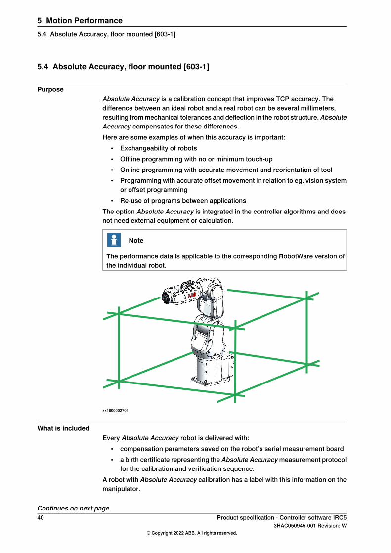
PurposeAbsolute Accuracy is a calibration concept that improves TCP accuracy. Thedifference between an ideal robot and a real robot can be several millimeters,resulting frommechanical tolerances and deflection in the robot structure.AbsoluteAccuracy compensates for these differences.Here are some examples of when this accuracy is important:
• Exchangeability of robots• Offline programming with no or minimum touch-up• Online programming with accurate movement and reorientation of tool• Programming with accurate offset movement in relation to eg. vision system
or offset programming• Re-use of programs between applications
The option Absolute Accuracy is integrated in the controller algorithms and doesnot need external equipment or calculation.
Note
The performance data is applicable to the corresponding RobotWare version ofthe individual robot.
xx1800002701
What is includedEvery Absolute Accuracy robot is delivered with:
• compensation parameters saved on the robot’s serial measurement board• a birth certificate representing the Absolute Accuracymeasurement protocol
for the calibration and verification sequence.A robot with Absolute Accuracy calibration has a label with this information on themanipulator.
Continues on next page40 Product specification - Controller software IRC5
3HAC050945-001 Revision: W© Copyright 2022 ABB. All rights reserved.
5 Motion Performance5.4 Absolute Accuracy, floor mounted [603-1]
Absolute Accuracy supports floor mounted, wall mounted and ceiling mountedinstallations. Compensation parameters saved in the robot’s serial measurementboard differ depending on which Absolute Accuracy option is selected.
When is Absolute Accuracy being usedAbsolute Accuracy works on a robot target in Cartesian coordinates, not on theindividual joints. Therefore, joint based movements (e.g. MoveAbsJ) will not beaffected.If the robot is inverted, the Absolute Accuracy calibration must be performed whenthe robot is inverted.
Absolute Accuracy activeAbsolute Accuracy will be active in the following cases:
• Any motion function based on robtargets (e.g. MoveL) and ModPos onrobtargets
• Reorientation jogging• Linear jogging• Tool definition (4, 5, 6 point tool definition, room fixed TCP, stationary tool)• Work object definition
Absolute Accuracy not activeThe following are examples of when Absolute Accuracy is not active:
• Any motion function based on a jointtarget (MoveAbsJ)• Independent joint• Joint based jogging• Additional axes• Track motion
Note
In a robot system with, for example, an additional axis or track motion, theAbsolute Accuracy is active for the manipulator but not for the additional axis ortrack motion.
RAPID instructionsThere are no RAPID instructions included in this option.
Performance dataThe performance data is described in the product specification for the respectivemanipulator.
Product specification - Controller software IRC5 413HAC050945-001 Revision: W
© Copyright 2022 ABB. All rights reserved.
5 Motion Performance5.4 Absolute Accuracy, floor mounted [603-1]
Continued
5.5 Motion Process Mode
General
Note
This functionality is included in the optionAdvanced robot motion, see Advancedrobot motion [687-1] on page 35.
The purpose ofMotion Process Mode is to simplify application specific tuning, i.e.to optimize the performance of the robot for a specific application.For most applications the default mode is the best choice.
Available motion process modesA motion process mode consists of a specific set of tuning parameters for a robot.Each tuning parameter set, that is each mode, optimizes the robot tuning for aspecific class of applications.There following modes are predefined:
• Optimal cycle time mode – this mode gives the shortest possible cycle timeand is normally the default mode.
• Accuracy mode – this mode improves path accuracy. The cycle time will beslightly increased compared to Optimal cycle time mode. This is therecommended choice for improving path accuracy on small andmedium sizerobots, for example IRB 2400 and IRB 2600.
• Low speed accuracy mode – this mode improves path accuracy. The cycletime will be slightly increased compared to Accuracy mode. This is therecommended choice for improving path accuracy on large size robots, forexample IRB 4600.
• Low speed stiff mode - this mode is recommended for contact applicationswhere maximum servo stiffness is important. Could also be used in somelow speed applications, where a minimum of path vibrations is desired. Thecycle time will be increased compared to Low speed accuracy mode.
• Press tending mode – Changes the Kv Factor, Kp Factor and Ti Factor inorder to mitigate tool vibrations. This mode is primarily intended for use inpress tending applications where flexible grippers with a large extension inthe y-direction are used.
There are also four modes available for application specific user tuning:• MPM User mode 1 – 4
Selection of modeThe default mode is automatically selected and can be changed by changing thesystem parameter Use Motion Process Mode for type Robot.Changing the Motion Process Mode from RAPID is only possible if the optionAdvanced Robot Motion is installed. The mode can only be changed when therobot is standing still, otherwise a fine point is enforced.
Continues on next page42 Product specification - Controller software IRC5
3HAC050945-001 Revision: W© Copyright 2022 ABB. All rights reserved.
5 Motion Performance5.5 Motion Process Mode
The following example shows a typical use of the RAPID instructionMotionProcessModeSet.
MotionProcessModeSet OPTIMAL_CYCLE_TIME_MODE;
! Do cycle-time critical movement
MoveL *, vmax, ...;
...
MotionProcessModeSet ACCURACY_MODE;
! Do cutting with high accuracy
MoveL *, v50, ...;
...
Product specification - Controller software IRC5 433HAC050945-001 Revision: W
© Copyright 2022 ABB. All rights reserved.
5 Motion Performance5.5 Motion Process Mode
Continued

This page is intentionally left blank
6 Motion Coordination6.1 MultiMove Coordinated [604-1]
GeneralThe optionMultiMove Coordinatedmakes a robot system aMultiMove systemwithcoordinated robots functionality.A MultiMove system is a system where a common controller controls up to fourrobots, each equipped with its own drive module. MultiMove exists in two differentmodes - Independent and Coordinated.With theMultiMove Coordinated option, aMultiMove system is able to work togetheron a common work piece and coordinated in a common workobject. MultiMoveCoordinated also includes all MultiMove Independent functionality.
Features• Up to four robots simultaneously coordinated with a common work object• Up to seven simultaneous motion tasks, handing for example four robots,
one positioner and two single additional axes• The work object can be in motion during processing. This motion can be
executed by an additional axis, a multi-axis positioner or by one or severalof the robots in the MultiMove group
• Any of the robots in a MultiMove group can work independently while otherswork coordinated. Which robots are coordinated and which are independentcan change dynamically during the cycle
• Coordination is active both in automatic andmanual mode. In the latter case,this means that robots can maintain their position and orientation in relationto the work object when this is moved by the joystick
• Calibration features to define coordinate systems between robots orpositioners
• Synchronizing of movements in different tasks. This means that the differentmovements will be executed synchronized and in the same time
• MultiMove user interface on FlexPendant• RobotWare - Multitasking• RobotWare - Multiple Axis Positioner
Application• Multi robot processing on a work piece mounted on a positioner.• Processing by one or multiple robots on a work piece handled by another
robot. (Flex positioner)• Moving of heavy or flimsy objects by multiple robots.
Continues on next pageProduct specification - Controller software IRC5 453HAC050945-001 Revision: W
© Copyright 2022 ABB. All rights reserved.
6 Motion Coordination6.1 MultiMove Coordinated [604-1]
PerformanceThe motion performance of robots in a MultiMove group is equivalent to that of asingle robot system, in terms of speed and acceleration. The total path accuracywhen one robot is moving the work object and another is doing processing on thesame, will consist of a superimposition of the two robot's accuracy. This meansan error, which is less than or equal to the sum of those of the individual robots.Regarding absolute accuracy, see Requirements on page 46.For very demanding RAPID processing, theremay be a slight impact on cycle time,compared to a single robot system.The impact on the cycle time is higher whenrobots are running in independent mode compared to coordinated mode.
Requirements• For communication with additional drive units, the hardware option 710-1 is
required.• This option is relevant and required only for systems, when coordination
between robots and/or manipulators, controlled from different tasks, isneeded. Each RAPID task can control one robot and up to six external axes(positioners without TCP).
• Coordination between robots, controlled from different tasks but working ina common moveable workobject, is only possible within synchronizedmovement sequences (see instructions below). When working in a stationaryworkobject, no synchronization is needed, and the option MultiMoveIndependent can be used.
• The accuracy of coordinated motion is obviously depending on the positionaccuracy of each robot. To achieve the best possible coordination betweenrobots, it is highly recommended to use Absolute Accuracy [603-1] on therobots involved.
LimitationsA MultiMove system is to be regarded as one machine, in the sense that all robotsinvolved are always in the same state, since there is only one common safetysystem. MultiMove can thus not be applied for robots in different cells.When a robot is moved by an additional axis, e.g. a track, the track and the robotmust be controlled by the same task. This implies that the same additional axiscannot move multiple robots. There are two exceptions where such a set-up is,after all, possible:
• The robots are working independently and the robots in other tasks than theone controlling the additional axis are not dependent on knowing their positionin the world coordinate system.
• All robots moved by the same additional axis are working synchronized allthe time (i.e. using SyncMoveOn and attaching an identno to each Moveinstruction). The only possible exception (outside aSyncMoveOn/SyncMoveOff sequence) is using MoveAbsJ.
A maximum of two IRB 360 can be used in a MultiMove system.This option is not available with IRC5C Compact controller.
Continues on next page46 Product specification - Controller software IRC5
3HAC050945-001 Revision: W© Copyright 2022 ABB. All rights reserved.
6 Motion Coordination6.1 MultiMove Coordinated [604-1]Continued
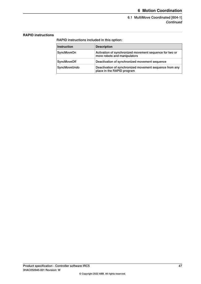
RAPID instructionsRAPID instructions included in this option:
DescriptionInstruction
Activation of synchronized movement sequence for two ormore robots and manipulators
SyncMoveOn
Deactivation of synchronized movement sequenceSyncMoveOff
Deactivation of synchronized movement sequence from anyplace in the RAPID program
SyncMoveUndo
Product specification - Controller software IRC5 473HAC050945-001 Revision: W
© Copyright 2022 ABB. All rights reserved.
6 Motion Coordination6.1 MultiMove Coordinated [604-1]
Continued
6.2 MultiMove Independent [604-2]
GeneralThe optionMultiMove Independentmakes a robot system aMultiMove systemwithindependent robots functionality.A MultiMove system is a system where a common controller controls up to fourrobots, each equipped with its own drive module. MultiMove system exists in twodifferent modes - Independent and Coordinated.With MultiMove Independent, the robots run independently of each other, i.e.controlled by separate RAPID tasks. It is also possible to run positionersindependently (controlled by separate RAPID tasks.)
Features• Up to four robots in a MultiMove System• Up to seven simultaneous motion tasks, handing for example four robots,
one positioner and two single additional axes• The robots in the MultiMove system work independently of each other• MultiMove user interface on FlexPendant• RobotWare - Multitasking• RobotWare - Multiple Axis Positioner
ApplicationMulti robot processing where each robot is working independently, controlled byseparate RAPID tasks.
PerformanceThe motion performance of robots in a MultiMove system is equivalent to that ofa single robot system, in terms of speed and acceleration. For very demandingRAPID processing, there may be an impact on cycle time, compared to a singlerobot system. In some applications where the RAPID processing requirements arehigh and requirements on the robot performance are also high, for example pickand place with two IRB 360 robots, the cycle time impact can be higher.
Requirements• For communication with additional drive units, the hardware option 710-1 is
required.
LimitationsA MultiMove system is to be regarded as one machine, in the sense that all robotsinvolved are always in the same state, since there is only one common safetysystem. MultiMove can thus not be applied for robots in different cells.When a robot is moved by an additional axis, e.g. a track, the track and the robotmust be controlled by the same task. This implies that the same additional axis
Continues on next page48 Product specification - Controller software IRC5
3HAC050945-001 Revision: W© Copyright 2022 ABB. All rights reserved.
6 Motion Coordination6.2 MultiMove Independent [604-2]
cannot move multiple robots. There are two exceptions where such a set-up is,after all, possible:
• The robots are working independently and the robots in other tasks than theone controlling the additional axis are not dependent on knowing their positionin the world coordinate system.
• All robots moved by the same additional axis are working synchronized allthe time (i.e. using SyncMoveOn and attaching an identno to each Moveinstruction). The only possible exception (outside aSyncMoveOn/SyncMoveOff sequence) is using MoveAbsJ.
A maximum of two IRB 360 can be used in a MultiMove system.This option is not available with IRC5C Compact controller.
RAPID instructionsThere are no RAPID instructions included in this option.
Product specification - Controller software IRC5 493HAC050945-001 Revision: W
© Copyright 2022 ABB. All rights reserved.
6 Motion Coordination6.2 MultiMove Independent [604-2]
Continued
6.3 Tracking unit interface [1552-1]
GeneralThe option Tracking unit interface is required to setup conveyor tracking applicationsusing remote Conveyor Tracking units. This option is included in Conveyor Trackingunits, option Conv.Tracking unit Int. [1550-1] and option Conv. Tracking unit Ext.[1551-1].
Features• Connect to remote Conveyor Tracking units over an Ethernet connection• RobICI, a high performance communication protocol
ApplicationAny application where conveyor tracking is used, for example painting, arc welding,picking, and other applications.
PerformanceAConveyor TrackingModule is able to communicate with up to 40 robot controllersin parallel.
Requirements• A remote Conveyor Tracking unit DSQC2000• One of the software options that enables conveyor tracking functionality:
Conveyor Tracking [606-x] or Prep. for PickMaster 3 [642-1]
RAPID instructionsThere are no RAPID instructions included in this option.
50 Product specification - Controller software IRC53HAC050945-001 Revision: W
© Copyright 2022 ABB. All rights reserved.
6 Motion Coordination6.3 Tracking unit interface [1552-1]
6.4 Conveyor Tracking [606-1]
GeneralThe option Conveyor Tracking (also known as line tracking) contains functionalitywhich makes the robot follow a work object on a moving conveyor. While trackingthe conveyor, the programmed TCP speed, relative to the work object, will bemaintained even when the conveyor speed is changing slowly.
Features• Linear and circular conveyors• Up to 4 conveyors simultaneously. Switch between tracking the one or the
other• Up to 254 objects can be organized in an object queue that can be
manipulated by RAPID instructions• Possibility to define a start window in which an object must be before tracking
can start• A maximum tracking distance may be specified• If the robot is mounted on a parallel track motion, the system can be
configured such that the track will follow the conveyor and maintain therelative position to the conveyor.
• Tracking of a conveyor can be activated on the fly, that is it is not necessaryto stop in a fine point.
ApplicationAny application where conveyors are used for example painting, arc welding,picking and other applications.
PerformanceAt 150 mm/s constant conveyor speed, the TCP will stay within 2 mm of the pathas seen with no conveyor motion. When the robot is stationary relative to theconveyor, the TCP will remain 0.7 mm of the intended position.
Note
Make sure that the robot is within its dynamic limits with the added conveyormotion and that the conveyor is accurately calibrated.
RequirementsThe following hardware components are required for measuring the conveyorposition:
• DeviceNet• Encoder card DSQC 377B or DSQC 2000
See the product specification for the respective robot.
Continues on next pageProduct specification - Controller software IRC5 513HAC050945-001 Revision: W
© Copyright 2022 ABB. All rights reserved.
6 Motion Coordination6.4 Conveyor Tracking [606-1]
RAPID instructionsRAPID instructions included in this option:
DescriptionInstruction
Connects to a work object in the start windowWaitWObj
Disconnects from the current objectDropWObj
52 Product specification - Controller software IRC53HAC050945-001 Revision: W
© Copyright 2022 ABB. All rights reserved.
6 Motion Coordination6.4 Conveyor Tracking [606-1]Continued
6.5 Indexing Conveyor Control [606-2]
GeneralThe option Indexing Conveyor Control offers functionality which makes the robotfollow a work object on a fast moving indexing conveyor. An indexing conveyorhas a number of equally sized partitions or pockets, where the handled objectsare placed. To receive an object in such a pocket requires that the conveyor ismomentarily stopped to get the object, and then very quickly moved to receive anew object in the next pocket etc. This kind of fast stopping and moving in specificdistances is called indexing. While the conveyor is indexing, the robot will betracking the objects on the conveyor, and the position, relative to the work object,will be maintained even when the conveyor speed is changing during indexing.
Features• Linear conveyors• Up to two IRB 360 in a MultiMove setup, working with separate indexing
conveyors• Up to 2 indexing conveyors and up to 2 regular conveyors may be handled
simultaneously. Switch between tracking the one or the other.• Indexing conveyors are controlled by the robot system, i.e. no encoder board
is needed.• Synchronizing of the indexing conveyor with the incoming objects through
digital input.• Up to 100 objects can be organized in an object queue that can be
manipulated by RAPID instructions.• Possibility to define a start window in which an object must be before tracking
can start.• A maximum tracking distance may be specified.• Tracking of a conveyor can be activated on the fly, that is it is not necessary
to stop in a fine point.• Can work independently or in combination with PickMaster 3.
ApplicationAny application where high speed indexing conveyors are used, for example smallparts handling and other applications. Normally, in a box loading application, anin feeder will place the objects on the indexing conveyor with high rate frequency.After that the robot is picking the objects from the indexing conveyor and placingthem on an out feeder conveyor.
PerformanceIn a typical case with box widths of 50 mm, 2 kg robot payload, product feedingfrequency of 7.5 Hz and with accelerations/decelerations up to 35 m/s2, the TCPwill stay within 2 mm of the path as seen with no conveyor motion.(Make sure that the robot is within its dynamic limits with the added conveyormotion and that the conveyor is accurately calibrated.)
Continues on next pageProduct specification - Controller software IRC5 533HAC050945-001 Revision: W
© Copyright 2022 ABB. All rights reserved.
6 Motion Coordination6.5 Indexing Conveyor Control [606-2]
RequirementsSince the indexing conveyor is controlled by the robot system, there is no needfor an encoder board. However, if also handling parts on a regular conveyor,hardware components for measuring the conveyor position are needed likeDeviceNet option and encoder board DSQC 377B. See the product specificationfor the respective robot.For the synchronization of the indexing conveyor with the incoming objects, asynchronization pulse shall be provided at a digital input minimum 200 ms inadvance (depending on robot pay load).To ensure accuracy, the conveyor transmission must follow specific rules (seeApplication manual - Conveyor tracking).
RAPID instructionsRAPID instructions included in this option:
DescriptionInstruction
Connects to a work object in the start windowWaitWObj
Disconnects from the current objectDropWObj
Initiation of conveyorIndCnvInit
Enabling indexing modeIndCnvEnable
Disabling indexing modeIndCnvDisable
Resetting indexing mode back to normal modeIndCnvReset
Adding an object to object queueIndCnvAddObject
LimitationsIndexing conveyor control is only available for IRB 360.Indexing conveyor should be equipped with an ABBmotor package or similar, seeApplication manual - Additional axes and stand alone controller.
54 Product specification - Controller software IRC53HAC050945-001 Revision: W
© Copyright 2022 ABB. All rights reserved.
6 Motion Coordination6.5 Indexing Conveyor Control [606-2]Continued
6.6 Sensor Synchronization [607-1]
GeneralSensor Synchronization adjusts the robot speed to an external moving device (forexample a press or conveyor) with the help of a sensor. The option can also beused for synchronizing two robots with each other.This Sensor Synchronization option simplifies programming and improvesproductivity of any loading /unloading application, since it provides automaticsensor status check and speed adjustment.The robot TCP speed will be adjusted in correlation to the sensor output, so thatthe robot will reach the programmed robtargets at the same time as the externaldevice reaches the programmed position. The synchronization is started/stoppedwith a RAPID instruction combined with movement instructions (fine points orcorner zones).
Features• Synchronize robot with sensor: Up to 4 sensors/robot• On-the-fly activation• Valid for any type of movement• RAPID access to sensor and queue data• Object queue, see Conveyor Tracking
Application• Synchronization of robots and press equipment
PerformanceThe TCP will stay within +/- 50ms delay of the taught sensor position, for linearsensors and constant sensor speed.
RAPID instructionsRAPID instructions included in this option:
InstructionInstruction
Start/stop synchronizationSyncToSensor
Connect to an object in the start windowWaitSensor
Disconnect from current objectDropSensor
Product specification - Controller software IRC5 553HAC050945-001 Revision: W
© Copyright 2022 ABB. All rights reserved.
6 Motion Coordination6.6 Sensor Synchronization [607-1]
6.7 Analog Synchronization [607-2]
GeneralAnalog Synchronization adjusts the robot speed to an external moving device (forexample amachine) with the help of an analog linear sensor attached to themovingdevice. This Analog Synchronization option simplifies programming and improvesproductivity of any loading/unloading application, since it provides automatic sensorstatus check and speed adjustment.The robot TCP speed will be adjusted in correlation to the sensor output, so thatthe robot will reach the programmed robtargets at the same time as the externaldevice reaches the programmed position. The synchronization is started/stoppedwith a RAPID instruction combined with movement instructions (fine points orcorner zones).
Features• Synchronized move in• Supervised move out• On-the-fly activation• Valid for any type of movement
ApplicationWhenAnalog Synchronization is used, the work flow of robot andmachines overlapto save time. With Analog Synchronization, at machine opening, as soon as thereis enough space for the robot between the machine platens, the sensor triggersthe robot to start to move into the machine, synchronized with the moving platenof the machine. Time is saved by the robot’s early entering.At machine closing, as soon as the part has been gripped, the robot starts to moveout of the machine. When the robot has reached the machine closing point on itssynchronized path, the machine starts to close. The machine closes safely whilethe robot moving out. Time is also saved by the machine's early closing. Applicableto injection moulding, die-cast or other machine tending or material handling.
PerformanceThe TCP will stay within +/- 50ms delay of the taught sensor position, for linearsensors and constant sensor speed.
RequirementsSee the product specification for the robot controller:
• Analog linear sensor with analogue signal between 0 and 10 V (for exampleBalluf)
• Fieldbus coupler to connect the sensor to the IRC5• Analog I/O card (3rd party DeviceNet solution)• Optional: Electronic position switches
Continues on next page56 Product specification - Controller software IRC5
3HAC050945-001 Revision: W© Copyright 2022 ABB. All rights reserved.
6 Motion Coordination6.7 Analog Synchronization [607-2]
RAPID instructionsRAPID instructions included in this option:
InstructionInstruction
Start/stop synchronizationSyncToSensor
Connect to an object in the start windowWaitSensor
Disconnect from current objectDropSensor
Limitations• 607-1 and 607-2 cannot be combined.
Product specification - Controller software IRC5 573HAC050945-001 Revision: W
© Copyright 2022 ABB. All rights reserved.
6 Motion Coordination6.7 Analog Synchronization [607-2]
Continued

This page is intentionally left blank
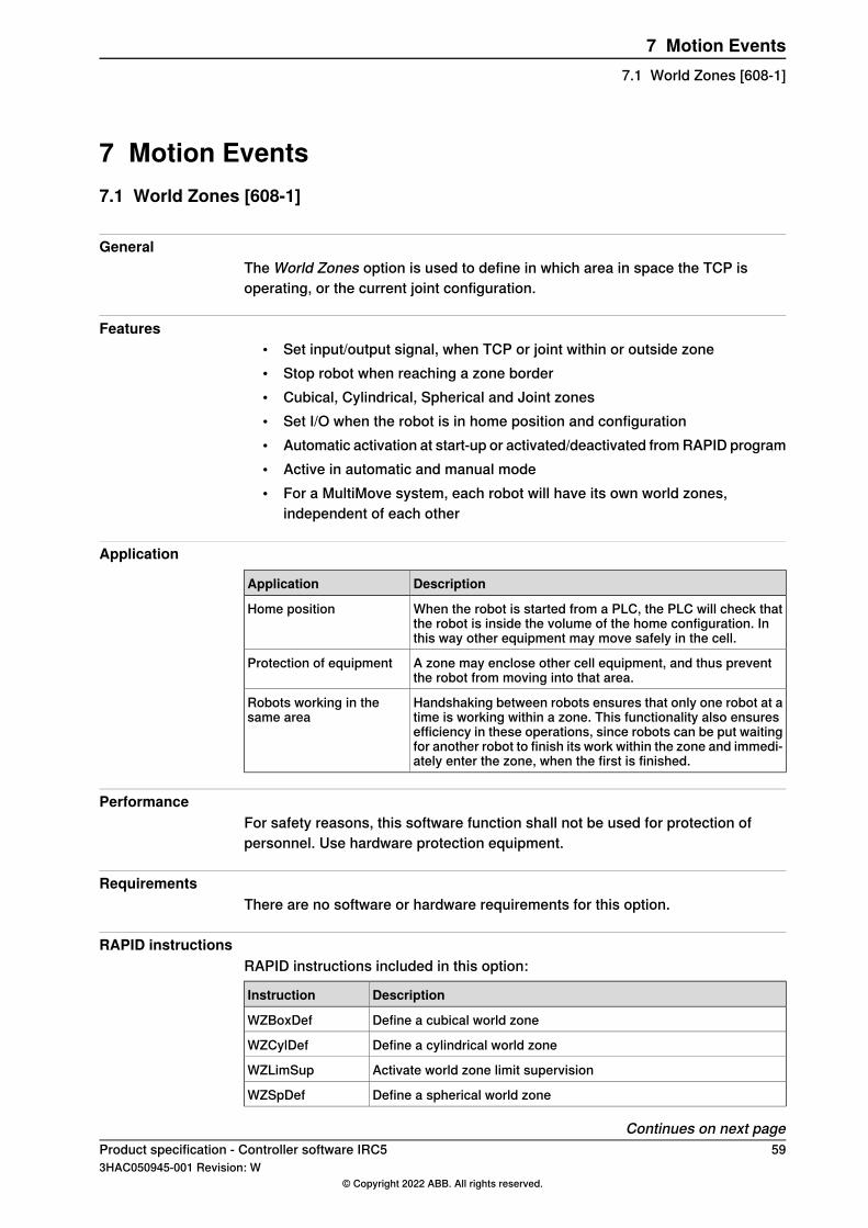
7 Motion Events7.1 World Zones [608-1]
GeneralThe World Zones option is used to define in which area in space the TCP isoperating, or the current joint configuration.
Features• Set input/output signal, when TCP or joint within or outside zone• Stop robot when reaching a zone border• Cubical, Cylindrical, Spherical and Joint zones• Set I/O when the robot is in home position and configuration• Automatic activation at start-up or activated/deactivated fromRAPID program• Active in automatic and manual mode• For a MultiMove system, each robot will have its own world zones,
independent of each other
Application
DescriptionApplication
When the robot is started from a PLC, the PLC will check thatthe robot is inside the volume of the home configuration. Inthis way other equipment may move safely in the cell.
Home position
A zone may enclose other cell equipment, and thus preventthe robot from moving into that area.
Protection of equipment
Handshaking between robots ensures that only one robot at atime is working within a zone. This functionality also ensuresefficiency in these operations, since robots can be put waitingfor another robot to finish its work within the zone and immedi-ately enter the zone, when the first is finished.
Robots working in thesame area
PerformanceFor safety reasons, this software function shall not be used for protection ofpersonnel. Use hardware protection equipment.
RequirementsThere are no software or hardware requirements for this option.
RAPID instructionsRAPID instructions included in this option:
DescriptionInstruction
Define a cubical world zoneWZBoxDef
Define a cylindrical world zoneWZCylDef
Activate world zone limit supervisionWZLimSup
Define a spherical world zoneWZSpDef
Continues on next pageProduct specification - Controller software IRC5 593HAC050945-001 Revision: W
© Copyright 2022 ABB. All rights reserved.
7 Motion Events7.1 World Zones [608-1]
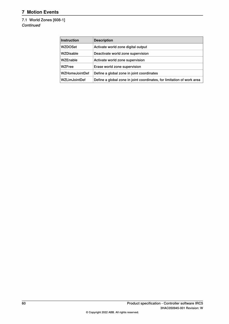
DescriptionInstruction
Activate world zone digital outputWZDOSet
Deactivate world zone supervisionWZDisable
Activate world zone supervisionWZEnable
Erase world zone supervisionWZFree
Define a global zone in joint coordinatesWZHomeJointDef
Define a global zone in joint coordinates, for limitation of work areaWZLimJointDef
60 Product specification - Controller software IRC53HAC050945-001 Revision: W
© Copyright 2022 ABB. All rights reserved.
7 Motion Events7.1 World Zones [608-1]Continued
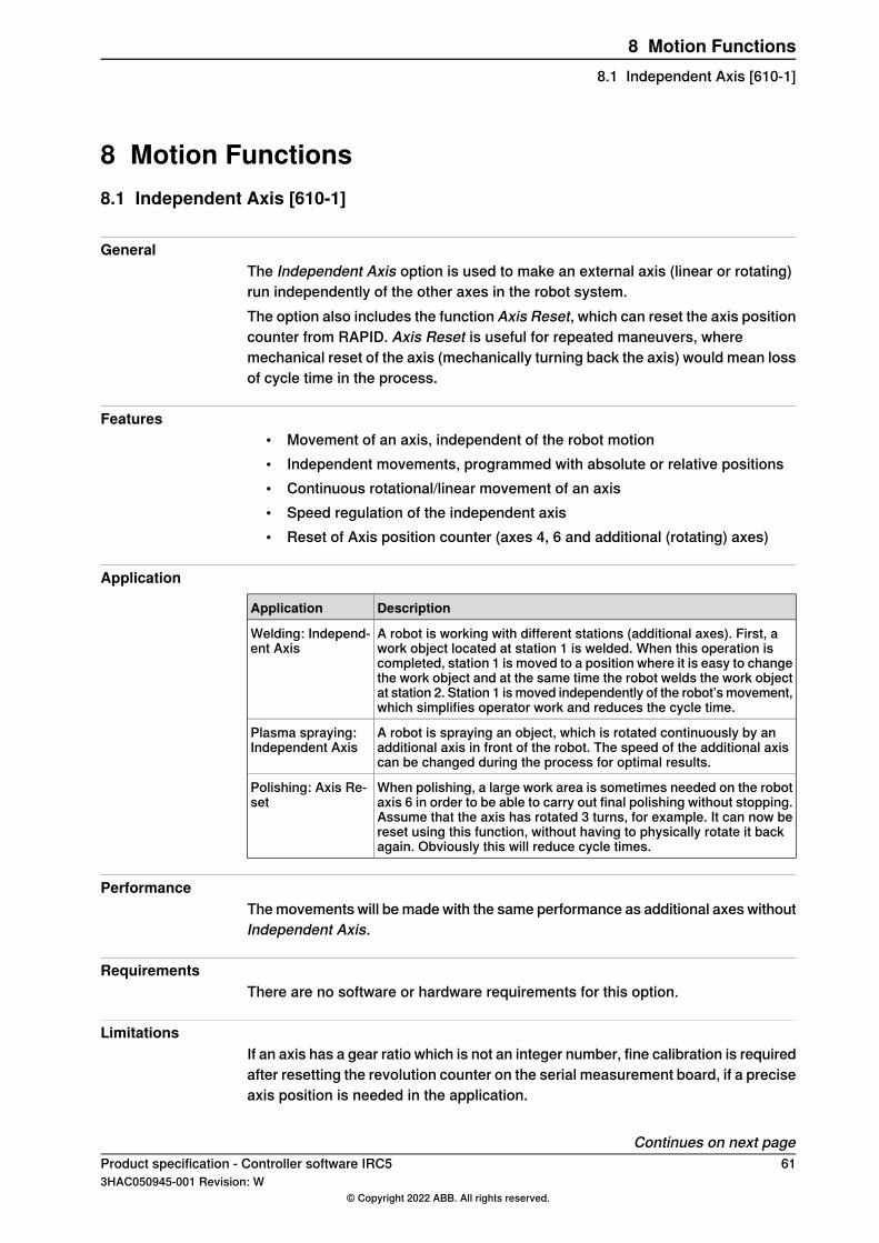
8 Motion Functions8.1 Independent Axis [610-1]
GeneralThe Independent Axis option is used to make an external axis (linear or rotating)run independently of the other axes in the robot system.The option also includes the function Axis Reset, which can reset the axis positioncounter from RAPID. Axis Reset is useful for repeated maneuvers, wheremechanical reset of the axis (mechanically turning back the axis) would mean lossof cycle time in the process.
Features• Movement of an axis, independent of the robot motion• Independent movements, programmed with absolute or relative positions• Continuous rotational/linear movement of an axis• Speed regulation of the independent axis• Reset of Axis position counter (axes 4, 6 and additional (rotating) axes)
Application
DescriptionApplication
A robot is working with different stations (additional axes). First, awork object located at station 1 is welded. When this operation iscompleted, station 1 is moved to a position where it is easy to changethe work object and at the same time the robot welds the work objectat station 2. Station 1 ismoved independently of the robot’smovement,which simplifies operator work and reduces the cycle time.
Welding: Independ-ent Axis
A robot is spraying an object, which is rotated continuously by anadditional axis in front of the robot. The speed of the additional axiscan be changed during the process for optimal results.
Plasma spraying:Independent Axis
When polishing, a large work area is sometimes needed on the robotaxis 6 in order to be able to carry out final polishing without stopping.Assume that the axis has rotated 3 turns, for example. It can now bereset using this function, without having to physically rotate it backagain. Obviously this will reduce cycle times.
Polishing: Axis Re-set
PerformanceThemovements will bemade with the same performance as additional axes withoutIndependent Axis.
RequirementsThere are no software or hardware requirements for this option.
LimitationsIf an axis has a gear ratio which is not an integer number, fine calibration is requiredafter resetting the revolution counter on the serial measurement board, if a preciseaxis position is needed in the application.
Continues on next pageProduct specification - Controller software IRC5 613HAC050945-001 Revision: W
© Copyright 2022 ABB. All rights reserved.
8 Motion Functions8.1 Independent Axis [610-1]
Internal and customer cabling and equipment may limit the ability to useindependent axis functionality on axis 4 and 6. For information about what capabilitya specific robot’s axis 4/6 has, please contact ABB.The option is not possible to use together with:
• SafeMove I
• IRB 910SC (4-axis SCARA robot)I Independent Axis can in some cases be combined with SafeMove2 if the additional axis does not
move the robot, and the additional axis is not monitored by SafeMove. Contact your local ABBsales office team for additional information.
Note
The collision detection is deactivated when at least one axis is run in independentjoint mode. This is also the case when an external axis that runs in same motiontask runs as independent joint.
RAPID instructionsRAPID instructions included in this option:
DescriptionInstructions
Running an axis continuouslyIndCMove
Running an axis independently a specified distanceIndDMove
Running an axis Independently to a position within one revolution,without taking into consideration the number of turns the axis hadrotated earlier
IndRMove
Running an axis Independently to an absolute positionIndAMove
Checking whether or not an independent axis has reached the pro-grammed position
IndInpos
Checking whether or not an independent axis has reached the pro-grammed speed
IndSpeed
Change an axis to dependent mode and/or reset the working areaIndReset
62 Product specification - Controller software IRC53HAC050945-001 Revision: W
© Copyright 2022 ABB. All rights reserved.
8 Motion Functions8.1 Independent Axis [610-1]Continued
8.2 Path Recovery [611-1]
GeneralThe Path Recovery option is used to store all system data, when an interrupt occurs(fault message or other) and restore them after necessary actions have been taken.
Features• Store path data (all current system information)• Restore path data (all system information, as was before interrupt/fault)
Application
DescriptionApplication
When an error message occurs, the position/path data can be storedand the robot moves automatically to a service area. After service,the robot moves back to the exact same position, including all systemdata and continues welding.
Service of weldingguns
PerformanceThere is no specific performance data available for this option.
RequirementsThere are no software or hardware requirements for this option.
RAPID instructionsRAPID instructions included in this option:
DescriptionInstruction
Stores the path when an interrupt occursStorePath
Restores the path after an interruptRestorePath
Start the path recorderPathRecStart
Stop the path recorderPathRecStop
Move path recorder backwardsPathRecMoveBwd
Move path recorder forwardPathRecMoveFwd
Product specification - Controller software IRC5 633HAC050945-001 Revision: W
© Copyright 2022 ABB. All rights reserved.
8 Motion Functions8.2 Path Recovery [611-1]
8.3 Path Offset [612-1]
GeneralPath Offset (path corrections) changes the robot path according to the input froma sensor. The robot can thus follow/track a contour, such as an edge or a weld.The path corrections will take effect immediately when receiving data from thesensor, also during movement between two positions. The path corrections areentered from the RAPID program. Path Offset can be made in the path coordinatesystem.
Features• Track a robot path at a user set offset• Read current path offset• Change path offset in action
Application
DescriptionApplication
Mainly used in arc welding, to track a work object at a certaindistance.
Path offset
A sensor is used to define the robot input for path correctionduring motion. The input can be defined via an analog input,a serial channel or similar. Multitasking or interrupts are usedto read this information at specific intervals. Based on the inputvalue, the path can then be adjusted
PerformanceMinimum offset: 0.1 mm.
Note
The instruction CorrWrite is intended with low speed and moderate values ofcorrection. Too aggressive values will be clamped. The correction values shouldbe tested in RobotStudio to confirm the performance.
RequirementsThere are no software or hardware requirements for this option.
RAPID instructionsRAPID instructions included in this option:
DescriptionInstruction
Activating path correctionCorrCon
Deactivating path correctionCorrDisCon
Read current path correctionCorrRead
Changing path correctionCorrWrite
Removes all correction generatorsCorrClear
64 Product specification - Controller software IRC53HAC050945-001 Revision: W
© Copyright 2022 ABB. All rights reserved.
8 Motion Functions8.3 Path Offset [612-1]

8.4 SoftMove [885-1]
GeneralSoftMove is a cartesian soft servo option that allows the robot to be compliant orfloating in order to adjust to external forces or variations in work objects. SoftMovecan lower the stiffness of the robot in one or several pre-defined cartesiandirection(s) (in relation to either the tool or the work object) while keeping theoriginal behavior in the other directions. The behavior of the softness is controlledby two parameters Stiffness and Damping. With SoftMove, the robot is compliantin the specified direction(s) only which facilitates high accuracy and reliability. Theoption reduces robot programming time and enables effective interaction betweenrobot and machine, which reduces cycle time.
FeaturesSoftMove is used to set up softness in one of the following directions:
• one of the Cartesian directions (x, y or z)• one of the Cartesian planes (xy, xz or yz)• all directions (xyz)• the plane xy and rotational around the z axis
ApplicationsMachine tending of different machines, for example die castingmachines, injectionmoulding machines, machine tools, etc. Extraction of parts from machine
• Insertion of parts into the machine – robot holds or pushes• Extraction of parts from machine• Placing/picking a work object in a tool• Placing a molded or cast part in a fixture• Tool exchanging on peripheral machines• Absorbing of shocks and vibrations
Assembly functions• Framing - a robot holds and presses a part towards the rest of the car body
while another process attaches the part to the body• Simple assembly functions not requiring searching or fitting
Welding• Hold-and-Weld• Hotplate welding
Press tending• Follow movement of press
Polishing/Grinding• Simple polishing and grinding applications with low process forces not
requiring process feedback
Continues on next pageProduct specification - Controller software IRC5 653HAC050945-001 Revision: W
© Copyright 2022 ABB. All rights reserved.
8 Motion Functions8.4 SoftMove [885-1]

RAPID instructionsSee Application manual - SoftMove.
LimitationsCollision Detection is deactivated when SoftMove is activated.Activation and deactivation of SoftMove can only be done in fine points.SoftMove does not work for 4-axis robots, for example IRB 360, IRB 660 and IRB910SC.SoftMove does not work together with:
• MultiMove Coordinated• Tracking functionality such as, CorrWrite,Conveyor Tracking, seam tracking
and WeldGuide.• Force control options
CSSAct does not activate motion control. A movement instruction is required toactivate the motion control.
66 Product specification - Controller software IRC53HAC050945-001 Revision: W
© Copyright 2022 ABB. All rights reserved.
8 Motion Functions8.4 SoftMove [885-1]Continued
9 Motion Supervision9.1 Collision Detection [613-1]
GeneralCollision Detection is a software option, which reduces collision impact forces onthe robot. In this way, the robot and external equipment can be protected fromsevere damage.
Features• Protection of robot and equipment• Protection from collisions from any direction• Robot movement stops and the robot moves back, along the programmed
path• Can reduce the collision force to 30%
ApplicationAbnormal torque levels on any robot axis (for additional axes, only positionerslisted below are covered) are detected and will cause the robot to stop quickly andthereafter back off to relieve forces between the robot and environment.
PerformanceThe sensitivity (with default tuning) is comparable to the mechanical alternative(mechanical clutch) and it is in most cases much better. In addition, CollisionDetection has the advantages of no added stick-out and weight, no need forconnection to the e-stop circuit, no wear, the automatic backing off after collisionand, finally, the adjustable tuning.Tuning is normally not required, but the sensitivity can be changed from RAPID ormanually. Collision Detection can also be switched off completely for part of aprogram. This may be necessary when strong process forces are acting on therobot.
RequirementsThis option is available for all robot types and for positioners:
• IRBP A• IRBP K• IRBP L• IRBP R
RAPID instructionsRAPID instruction included in this option:
DescriptionInstruction
Changing the sensitivity of the collision detection or activat-ing/deactivating the function.
MotionSup
Product specification - Controller software IRC5 673HAC050945-001 Revision: W
© Copyright 2022 ABB. All rights reserved.
9 Motion Supervision9.1 Collision Detection [613-1]
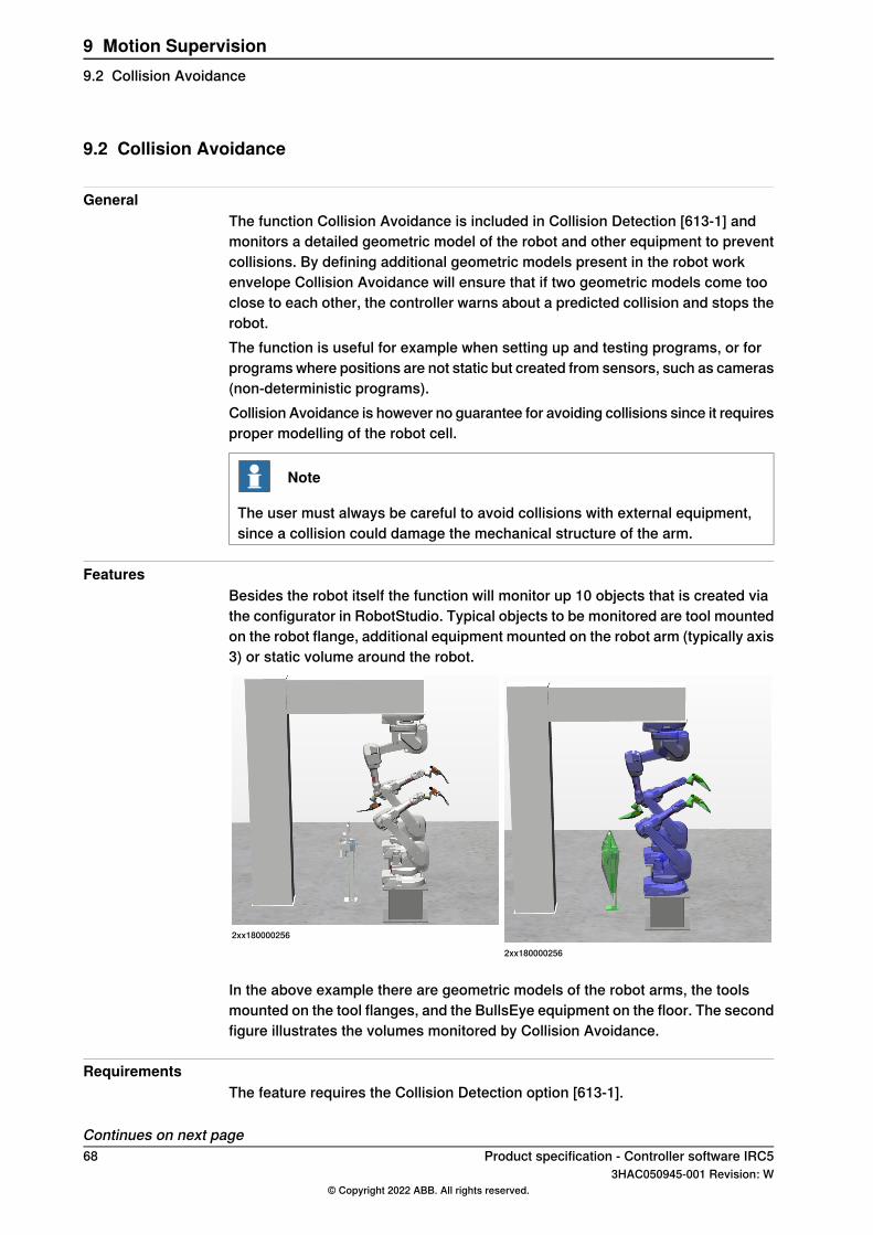
9.2 Collision Avoidance
GeneralThe function Collision Avoidance is included in Collision Detection [613-1] andmonitors a detailed geometric model of the robot and other equipment to preventcollisions. By defining additional geometric models present in the robot workenvelope Collision Avoidance will ensure that if two geometric models come tooclose to each other, the controller warns about a predicted collision and stops therobot.The function is useful for example when setting up and testing programs, or forprogramswhere positions are not static but created from sensors, such as cameras(non-deterministic programs).Collision Avoidance is however no guarantee for avoiding collisions since it requiresproper modelling of the robot cell.
Note
The user must always be careful to avoid collisions with external equipment,since a collision could damage the mechanical structure of the arm.
FeaturesBesides the robot itself the function will monitor up 10 objects that is created viathe configurator in RobotStudio. Typical objects to be monitored are tool mountedon the robot flange, additional equipment mounted on the robot arm (typically axis3) or static volume around the robot.
2xx180000256
2xx180000256
In the above example there are geometric models of the robot arms, the toolsmounted on the tool flanges, and the BullsEye equipment on the floor. The secondfigure illustrates the volumes monitored by Collision Avoidance.
RequirementsThe feature requires the Collision Detection option [613-1].
Continues on next page68 Product specification - Controller software IRC5
3HAC050945-001 Revision: W© Copyright 2022 ABB. All rights reserved.
9 Motion Supervision9.2 Collision Avoidance
Limitations• The Collision Avoidance functionality between 2 robots (or more) can only
be achieved when using a MultiMove system.• There is no support for applications that do corrections to the path such as
conveyor tracking, WeldGuide, Force Control, SoftMove, SoftAct etc.• Paint robots and IRB 360 are not supported.• Only standard (non-reponsive) jogging mode is supported.
RAPID instructionsRAPID instruction included in this option:
DescriptionInstruction
Can be used to check whether a specified jointtarget is collisionfree or not. Multiple jointtarget can be specified in MultiMovesystems.
IsCollFree
Product specification - Controller software IRC5 693HAC050945-001 Revision: W
© Copyright 2022 ABB. All rights reserved.
9 Motion Supervision9.2 Collision Avoidance
Continued

This page is intentionally left blank

10 Communication10.1 FTP & SFTP Client [614-1]
General
Note
In the specification form, this option is called FTP, SFTP and NFS client, sincethese functions are merged into a common option.
The option makes it possible to read information from a remote computer, directlyfrom the controller.Once the application protocol is configured, the remote computer can be accessedin the same way as the controller's internal hard disk.
PerformanceThere is no specific performance data available for this option.
RequirementsThe FTP implementation has a limited set of FTP servers supported. The followingservers are supported:
• vsftd 1.2.2 (ReadHat Linux 9.0)• MS IIS, (Windows XP SP2)• Serv-U, 6.4 (Windows XP SP2)• ftp (HP-UX version 10.20)• Distinct ftp server, version 3.0 (Windows XP SP2)
RAPID instructionsThere are no RAPID instructions included in this option.
Product specification - Controller software IRC5 713HAC050945-001 Revision: W
© Copyright 2022 ABB. All rights reserved.
10 Communication10.1 FTP & SFTP Client [614-1]
10.2 NFS Client
General
Note
This option is merged into option 614-1 FTP, SFTP and NFS client.
The option NFS client (Network File System) makes it possible to read informationfrom a remote computer, directly from the controller.Once the application protocol is configured, the remote computer can be accessedin the same way as the controller's internal hard disk.
PerformanceThere is no specific performance data available for this option.
RequirementsThe NFS implementation has a limited set of NFS servers supported. The followingservers are supported:
• OmniNFS version 4.3 (Windows XP SP2)• Distinct, version 3.0 (Windows XP SP2)• nsf (HP-UX, version 10.20)
RAPID instructionsThere are no RAPID instructions included in this option.
72 Product specification - Controller software IRC53HAC050945-001 Revision: W
© Copyright 2022 ABB. All rights reserved.
10 Communication10.2 NFS Client
10.3 PC Interface [616-1]
General
Note
This option includes also Socket Messaging (see Socket Messaging on page79).
PC Interface provides the communication interface between the robot controllerand network connected PCs.
Features• Manual robot backup to a networking PC (included in RobotStudio)• OPC Server interface for SCADA integration is included in RobotWare
Download package.• Communication interface for use with ABB Industrial Software Products;
WebWare and PC-SDK.• RAPID Message Queue (see description in RAPID Message Queue on
page 96).
Application
DescriptionApplication
RobotStudio - offers manual tools for commissioning of robots,including activities like update/booting of the systems software,system parameter update, RAPID programming and recordingof the robot log file. With the PC Interface option RobotStudiocan connect to a controller over a LAN. If the PC Interface op-tion is missing, RobotStudio only connects through the localservice port.
RobotStudio
IRC5 OPC Server is an OPC interface to the IRC5 controller(according to the OPC standard).
IRC5 OPC Server
WebWareTM Server - offers a 24 hours a day solution forautomated backup and version control of robot programs aswell as local and remote access to production reports anddiagnostic information using a standard Internet browser.
WebWare Server
PC-SDK, which is included in RobotStudio, allows system in-tegrators and end-users to program their own operator inter-faces for the IRC5 robot controller. These custom applicationsare either added to the general functionality of the FlexPendantusing FP-SDK or run as independent PC applications usingPC-SDK. The PC Interface option is required to use a customPC-based application with a robot.
PC - SoftWare DeveloperKit
RequirementsApplication needs to be developed with the software product: PC-SDK.
RAPID instructionsRAPID instruction included in this option:
DescriptionInstruction
Sends a message to the network PCSCWrite
Product specification - Controller software IRC5 733HAC050945-001 Revision: W
© Copyright 2022 ABB. All rights reserved.
10 Communication10.3 PC Interface [616-1]
10.4 IoT Gateway
10.4.1 IoT Date Gateway [1582-1]
GeneralThe option IoT Data Gateway [1582-1] is needed to enable IoT Gateway tocommunicate with RobotWare.IoT Gateway is an application that share information from the robot controller withother parts of the process/production unit. The information can be configuredaccording to the OPCUA standard format or MQTTwith a customer defined format.The IoTGateway application software is deployed/installed on a customerWindowsPC or Server, connected to the same network as the robot controller(s) and canaccess data frommultiple robot controllers at the same time (each robot controllerrequire to have the option IoT Data Gateway [1582-1].)The application software package is available for download at the ABB-DeveloperCenter (robotstudio.com)(https://developercenter.robotstudio.com).In the download package, an Application manual (3HAC078375-001) and videotutorial are available illustrating the configuration and usage of the IoT Gateway.The option IoT Data Gateway [1582-1] includes option PC Interface [616-1].
74 Product specification - Controller software IRC53HAC050945-001 Revision: W
© Copyright 2022 ABB. All rights reserved.
10 Communication10.4.1 IoT Date Gateway [1582-1]
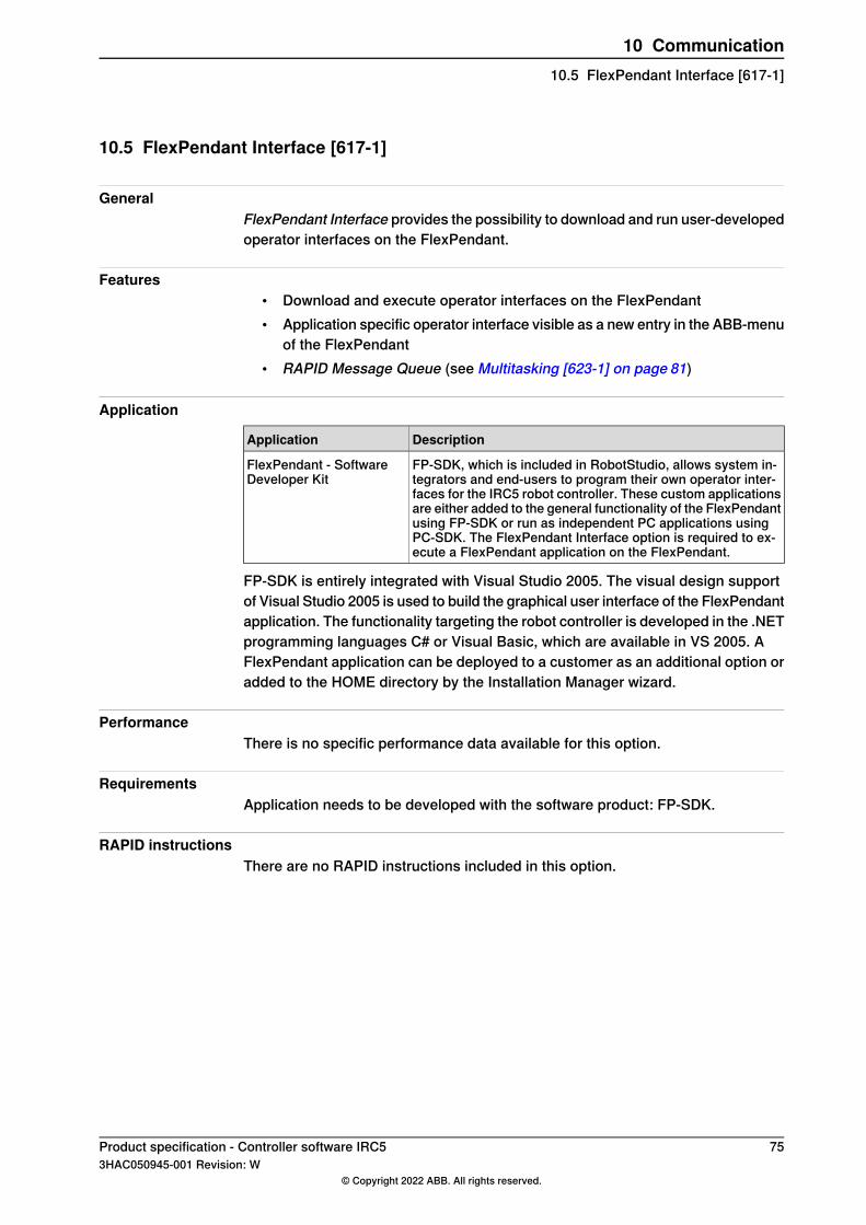
10.5 FlexPendant Interface [617-1]
GeneralFlexPendant Interface provides the possibility to download and run user-developedoperator interfaces on the FlexPendant.
Features• Download and execute operator interfaces on the FlexPendant• Application specific operator interface visible as a new entry in the ABB-menu
of the FlexPendant• RAPID Message Queue (see Multitasking [623-1] on page 81)
Application
DescriptionApplication
FP-SDK, which is included in RobotStudio, allows system in-tegrators and end-users to program their own operator inter-faces for the IRC5 robot controller. These custom applicationsare either added to the general functionality of the FlexPendantusing FP-SDK or run as independent PC applications usingPC-SDK. The FlexPendant Interface option is required to ex-ecute a FlexPendant application on the FlexPendant.
FlexPendant - SoftwareDeveloper Kit
FP-SDK is entirely integrated with Visual Studio 2005. The visual design supportof Visual Studio 2005 is used to build the graphical user interface of the FlexPendantapplication. The functionality targeting the robot controller is developed in the .NETprogramming languages C# or Visual Basic, which are available in VS 2005. AFlexPendant application can be deployed to a customer as an additional option oradded to the HOME directory by the Installation Manager wizard.
PerformanceThere is no specific performance data available for this option.
RequirementsApplication needs to be developed with the software product: FP-SDK.
RAPID instructionsThere are no RAPID instructions included in this option.
Product specification - Controller software IRC5 753HAC050945-001 Revision: W
© Copyright 2022 ABB. All rights reserved.
10 Communication10.5 FlexPendant Interface [617-1]
10.6 Field bus Command Interface [618-1]
General
Note
This functionality is included in RobotWare-OS.
Field bus Command Interface is an option, which is used when transferringcommands or messages other than I/O signals from the controller to/from unitsconnected via the physical DeviceNet.
Features• Open a DeviceNet unit• Read from a DeviceNet unit• Write to a DeviceNet unit• Close a DeviceNet unit
ApplicationThe option will be used for example when an intelligent control unit for externalequipment is connected to the robot controller via the DeviceNet bus.After such a unit is configured as a device on DeviceNet, it can be handled likeother communication devices for example using the RAPID commands Open\Bin,Close, ReadRawBytes, WriteRawBytes.
PerformanceThe Fieldbuses Command Interface can handle data blocks of a size of 1024 bytes.
RequirementsThis option requires the DeviceNet option and the option File and Serial ChannelHandling. See File and Serial Channel Handling on page 20.
RAPID instructionsRAPID instructions included in this option:For open and close, the standard Open and Close instructions shall be used.
DescriptionInstruction
Pack the header of a DeviceNet messagePackDN Header
76 Product specification - Controller software IRC53HAC050945-001 Revision: W
© Copyright 2022 ABB. All rights reserved.
10 Communication10.6 Field bus Command Interface [618-1]

10.7 RobotStudio App Connect [688-1]
GeneralRobotStudio App Connect provides the possibility to use standard commerciallyavailable tablets for commissioning at the shop floor as an alternative to theFlexPendant.
FeaturesEnables the possibility to interact with the robot controller using RobotStudio Onlineapps.
ApplicationRobotStudio Online is a suite of apps for Windows tablets to interact with the IRC5controller.The following RobotStudio Online apps are available for free download at theWindows Store:
RobotStudio Online ManageRobotStudio Online Manage is a tool to manage ABB industrial robots with IRC5controllers on a network. The network can be partitioned into groups. Statusinformation will be shown either for an individual robot controller or for a group.Features:
• Show status for one or several robot controllers• Show event logs with color coded event log messages• Show the controller data and properties• Save diagnostics data• Take a backup• Locate robot controllers• Input/Output signal view• Launch another RobotStudio Online app
RobotStudio Online AdjustRobotStudio Online Adjust is a tool for calibration and definition of frames for anABB industrial robot with an IRC5 controller.Features:
• Base frame definition• Tool, workobject and payload definition• Fine calibration• Revolution counter update• Execute service routines
RobotStudio Online JogRobotStudio Online Jog is a tool for manual positioning (jogging) of the ABBindustrial robot with an IRC5 robot controller. The robot can be moved usingdifferent settings and directions.
Continues on next pageProduct specification - Controller software IRC5 773HAC050945-001 Revision: W
© Copyright 2022 ABB. All rights reserved.
10 Communication10.7 RobotStudio App Connect [688-1]
Features:• Jog individual axis• Jog a tool linearly• Reorient a tool• Change settings• Jog supervision• Align tool to workobject
RobotStudio Online TuneRobotStudio Online Tune is a tool for shop floor editing of RAPID programs.Features:
• Start and step through a RAPID program• Cut, copy and paste RAPID• Comment and uncomment RAPID lines• Manipulating program pointer• Load and unload of RAPID programs and modules
PerformanceThere is no specific performance data available for this option.
Requirements• The controller needs to be connected to a wireless network• To move the robot in manual mode (that is jogging or program execution)
the options [976-1] T10 or [983-1] Jokab are required as mandated by safetyregulations.
RAPID instructionsThere are no RAPID instructions included in this option
78 Product specification - Controller software IRC53HAC050945-001 Revision: W
© Copyright 2022 ABB. All rights reserved.
10 Communication10.7 RobotStudio App Connect [688-1]Continued
10.8 Socket Messaging
GeneralThe purpose of Socket Messaging is to allow a RAPID program to exchange TCP/IPmessages over a network, with a C/C++ program on another computer or a RAPIDprogram on another robot controller.Socket Messaging sends and receives messages over the permanent Ethernetchannel of the robot controller (which can simultaneously be used for other networktraffic, for example communication with RobotStudio or WebWare Server).Socket Messaging is a standard supported by for example UNIX and MicrosoftWindows.
Features• Creating and closing of sockets• Setting up of a communication session• Sending and receiving data
ApplicationSockets can be used for any kind of network communication betweencomputers/controllers. Typical examples are:
• Two robot controllers exchanging interlocking information• Communication between a robot controller and peripheral devices like
sensors, bar code readers or process controllers• Intertask communication within the same controller
PerformanceThere is no specific performance data available for this option.
RequirementsThere are no hardware or software requirements for this option.
RAPID instructionsRAPID instructions included in this option:
DescriptionInstruction
Create a new socket and assign it to a socketdev variableSocketCreate
Close a socket and release all resourcesSocketClose
Bind the socket to a specified port numberSocketBind
Make the computer act as a server and accept incoming con-nections
SocketListen
Make a connection request to a remote computerSocketConnect
Accept an incoming connection requestSocketAccept
Send data via a socket connection to a remote computerSocketSend
Receive data and store itSocketReceive
Continues on next pageProduct specification - Controller software IRC5 793HAC050945-001 Revision: W
© Copyright 2022 ABB. All rights reserved.
10 Communication10.8 Socket Messaging
DescriptionInstruction
Returns the current state of a socketdev variableSocketGetStatus
80 Product specification - Controller software IRC53HAC050945-001 Revision: W
© Copyright 2022 ABB. All rights reserved.
10 Communication10.8 Socket MessagingContinued
11 Engineering Tools11.1 Multitasking [623-1]
GeneralTheMultitasking option gives the possibility of executing up to 20 programs (tasks)in parallel, including the main program. Multitasking can be used to controlperipheral equipment or other processes concurrently with robot motion.
Features• Automatic start at power on• START/STOP commands for task execution• Tasks are programmed using standard RAPID instructions• Priorities can be set between tasks• All input and output signals and the file system are accessible for each task• RAPID Message Queue
Application
DescriptionApplication
A task can be used to continuously monitor certain signalseven when the main program has stopped, thus taking overthe job traditionally allocated to a PLC.
Supervision
An operator dialogue might be required at the same time asthe robot is performing, for example welding. By putting thisoperator dialogue into a parallel task, the operator can specifyinput data for the next work cycle without having to stop therobot.
Operator dialogue
The robot can control a piece of external equipment in parallelwith the normal program execution.
Control of external equip-ment
PerformanceIt is possible to configure if the task shall react on START/STOP requests or if itshall start automatically. In the later case it will not stop at emergency stops, whichcan be useful for some applications.
Note
The response time of Multitasking does not match that of a PLC. Multitasking isprimary intended for less demanding tasks.The normal response time is 5-120 ms. The longer time is for cases when heavycalculation of movement is performed.
RequirementsThere are no software or hardware requirements for this option.
Continues on next pageProduct specification - Controller software IRC5 813HAC050945-001 Revision: W
© Copyright 2022 ABB. All rights reserved.
11 Engineering Tools11.1 Multitasking [623-1]
RAPID instructionsRAPID instructions included in this option:
DescriptionInstruction
Synchronize several program tasks at a special point in eachprogram.
WaitSyncTask
82 Product specification - Controller software IRC53HAC050945-001 Revision: W
© Copyright 2022 ABB. All rights reserved.
11 Engineering Tools11.1 Multitasking [623-1]Continued
11.2 Continuous Application Platform [624-1]
GeneralContinuous Application Platform (CAP) is a software platform for time criticalapplication, where a continuous process, for example arc welding, must besynchronized with the TCP movement of the robot.Target users are advanced application software engineers and system integrators,for example for arc welding, laser welding, or laser cutting. The main advantagesare achieved in the following areas:
• Development time• Program execution time• Similar look and feel for application• Stable software kernel (RobotWare)
Features• Special RAPID instructions and data types• A single instruction for motion and process control• Supports encapsulation of the process and motion in RAPID wrappers
provided to the end-user• Flying start/Flying end support
ApplicationCreation of advanced application software with a continuous process to besynchronized with robot movement, for example arc welding, laser cutting, or laserwelding.
PerformancePart of the RobotWare kernel and RAPID instructions: CAP is designed to supportfast and quality secured continuous application demands. The application developerdefines the degree of ease-of-use by hiding process complexity from the end-user.
RequirementsThere are no software or hardware requirements for this option.
RAPID instructionsSee Application manual - Continuous Application Platform
Product specification - Controller software IRC5 833HAC050945-001 Revision: W
© Copyright 2022 ABB. All rights reserved.
11 Engineering Tools11.2 Continuous Application Platform [624-1]
11.3 Optical Tracking [813-1]
GeneralThe option Optical Tracking is identical to the option Optical Tracking Arc [660-1],except for that it is integrated with the CAP movement instructions instead of withthe arc welding movements.This means that Optical Tracking can be used together with customized processinstructions, which are using the CAP option, seeContinuous Application Platform[624-1] on page 83.For further description, see Optical Tracking Arc [660-1] on page 144.
84 Product specification - Controller software IRC53HAC050945-001 Revision: W
© Copyright 2022 ABB. All rights reserved.
11 Engineering Tools11.3 Optical Tracking [813-1]
11.4 Tracking Interface [1553-1]
GeneralThe new Tracking Interface optionmakes it possible for a customer to use externalequipment as source of robot path corrections. The interface is easy to access:either by using analog input or output signals, or simply RAPID persistent data toprovide corrections. The interface is set up simply using a RAPID instruction. Thenew Tracking Interface can be used together with both CAP and RW Arc.Some areas of use are e.g. height control for Plasma welding or TIP TIG welding.
FeaturesCapAPTrSetupAI is used to setup an At-Point-Tracker controlled by analog inputsignals.CapAPTrSetupAO is used to setup an At-Point-Tracker controlled by analog outputsignals.CapAPTrSetupPERS is used to setup an At-Point-Tracker controlled by persistentvariables.
RequirementsArc [633-4] or CAP [624-1]
Product specification - Controller software IRC5 853HAC050945-001 Revision: W
© Copyright 2022 ABB. All rights reserved.
11 Engineering Tools11.4 Tracking Interface [1553-1]

11.5 Discrete Application Platform [625-1]
GeneralDiscrete Application Platform (DAP) is a software platform for time criticalapplication, where certain actions shall be performed at specific robot positions.Target users are advanced application software engineers and system integrators,for example for spot welding, drilling, measuring, quality control. The mainadvantages are achieved in the following areas:
• Development time• Program execution time• RAPID program memory needed• Similar look and feel between application• Tested kernel software
Features• Specialized RAPID instructions and data types• A single instruction for motion and process execution• Combination of fine point positioning with execution of up to 4 parallel
processes• Specialized process for monitoring of external process devices, like spot
welding controllers• Supports encapsulation of the process andmotion, in shell-routines provided
to the end-user
ApplicationCreation of software for advanced application with a discrete behavior, such asspot welding, drilling, measuring, quality control.
PerformanceThe DAP platform is designed to have an internal kernel, administrating the fastand quality secured process sequence skeleton. The kernel calls RAPID routines,which are prepared by the application developer to fulfill the specific tasks. Theapplication developer regulates the degree of flexibility of the end-user.
RequirementsIn order to use DAP, the option MultiTasking needs to be installed.
RAPID instructionsApplication manual - Discrete Application Platform
86 Product specification - Controller software IRC53HAC050945-001 Revision: W
© Copyright 2022 ABB. All rights reserved.
11 Engineering Tools11.5 Discrete Application Platform [625-1]
11.6 Sensor Interface [628-1]
GeneralThe Sensor Interface option can be used to integrate sensor equipment for adaptivecontrol, like path correction or process tuning. For communication between thesensor and the robot controller two different communication links are available:serial link (RS 232) and Ethernet.If the RS232 link is used, the sensors have to be adapted to the ABB standardapplication protocol, LTAPP. Sensors that are adapted to LTAPP are available fromcompanies like Servo Robot, Meta and Scout.The Ethernet link is available for optical sensors from ServoRobot, which use theapplication protocol Robo-Com Light, defined by ServoRobot.The communication link makes it easy to exchange data between the robotcontroller and the sensor system, using predefined numbers for different data likex,y,z offset values, gap between sheets, time stamp etc.If the Ethernet link, available for optical sensors from ServoRobot, is installed andconfigured, then the application protocol Robo-Com Light, defined by ServoRobot,will be used (see Optical Tracking Arc [660-1] on page 144).
Features• Interrupt routines, based on sensor data changes• Read/write sensor data from/to sensors using RAPID functions• Store/retrieve sensor data as a block to/from a mass memory• Seam tracking functionality, when combined with option Path Offset [612-1]• Easy calibration with dedicated FlexPendant interface
ApplicationSensor Interface can be used in any application to read/control a sensor duringexecution, and to react on changes in certain data, like path offset or processsupervisory data, thusmaking adaptive seam tracking and process control possible.
PerformanceThere is no specific performance data available for this option.
RequirementsExternal sensors, communicating with the robot controller via serial link, usingapplication protocol LTAPP, or Ethernet, using Robo-Com Light protocol.For calibration, the hardware option calibration plate [1250-1] is required.
RAPID instructionsRAPID instructions included in this option:
DescriptionInstruction
Used to order and enable an interrupt when the value of avariable accessed via the serial sensor interface has beenchanged
IVarValue
Continues on next pageProduct specification - Controller software IRC5 873HAC050945-001 Revision: W
© Copyright 2022 ABB. All rights reserved.
11 Engineering Tools11.6 Sensor Interface [628-1]
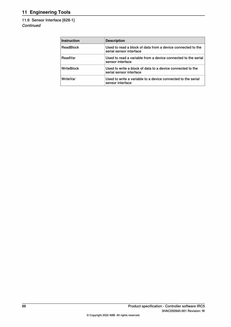
DescriptionInstruction
Used to read a block of data from a device connected to theserial sensor interface
ReadBlock
Used to read a variable from a device connected to the serialsensor interface
ReadVar
Used to write a block of data to a device connected to theserial sensor interface
WriteBlock
Used to write a variable to a device connected to the serialsensor interface
WriteVar
88 Product specification - Controller software IRC53HAC050945-001 Revision: W
© Copyright 2022 ABB. All rights reserved.
11 Engineering Tools11.6 Sensor Interface [628-1]Continued
11.7 Robot Reference Interface
General
Note
Robot Reference Interface is included in the RobotWare option Externally GuidedMotion, see Externally Guided Motion [689-1] on page 91.
Robot Reference Interface (RRI) is an option which enables high performance dataexchange between the robot controller and an external device using Ethernet linkwith Internet Protocol (IP). The supported data exchange provides the possibilityto periodically send planned and actual robot position data as well as the exchangeof other RAPID variables.
FeaturesThe message contents are represented in XML format and are configurable usingappropriate configuration files.Data distributed from controller to external device
• Planned robot position (Cartesian TCP or Joint values with time stamp)• Actual robot position (feedback from drives)• Additional application data, which can be any RAPID data or operation mode
status• Data obtained from external device to controller• Application data
ApplicationThis option can be used for a number of different applications where accurateinformation about planned and actual robot position are essential. Some examples:
• High precisionmeasuring devices, mounted on the robot, where the relevanceof the collected data is based on a real time knowledge of the actual positionof the robot.
• Remote laser welding, where a laser equipment with moveable laser headis held by andmoved by the robot. Such an equipment can then superimposea complex pattern over the robot movements, based on accurate robotposition information.
PerformanceThe cyclic communication channel can be executed in the high-priority networkenvironment of the IRC5 Controller which ensures a stable data exchange up to250Hz.
RequirementsExternal devices communicating with the controller via Ethernet link, using TCP/IP.Specific application protocol (CDP – Cyclic Data Protocol) used.
Continues on next pageProduct specification - Controller software IRC5 893HAC050945-001 Revision: W
© Copyright 2022 ABB. All rights reserved.
11 Engineering Tools11.7 Robot Reference Interface
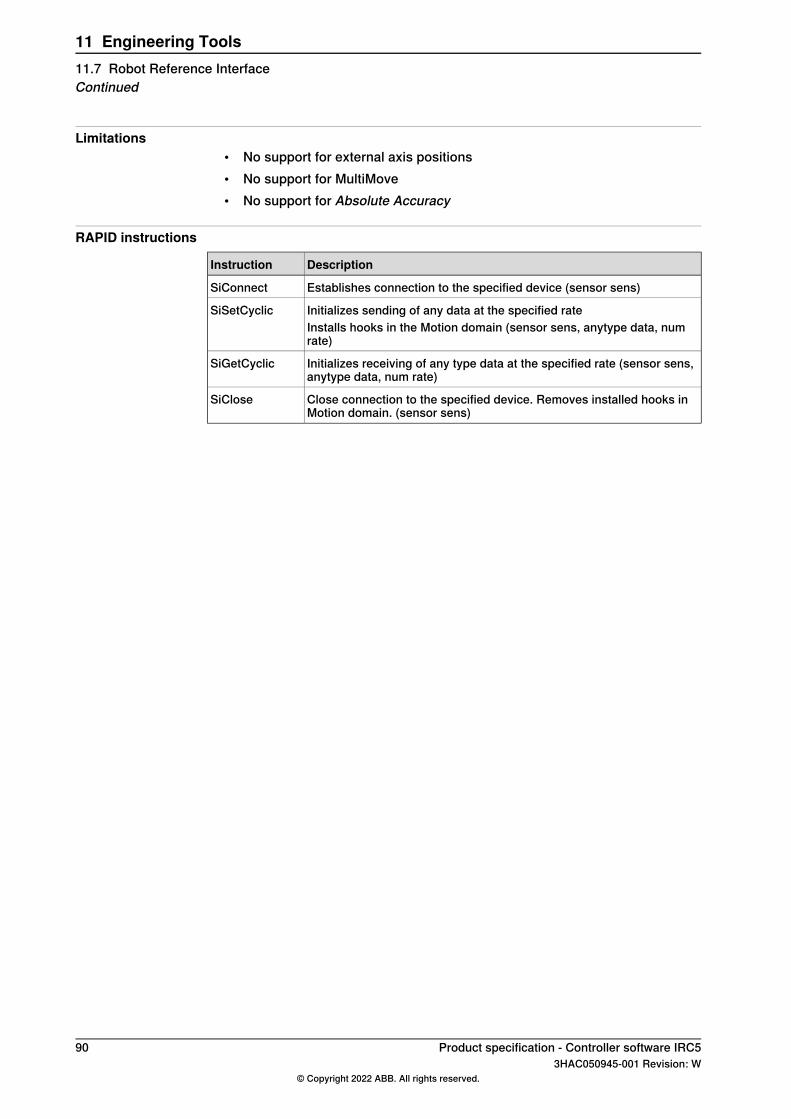
Limitations• No support for external axis positions• No support for MultiMove• No support for Absolute Accuracy
RAPID instructions
DescriptionInstruction
Establishes connection to the specified device (sensor sens)SiConnect
Initializes sending of any data at the specified rateSiSetCyclicInstalls hooks in the Motion domain (sensor sens, anytype data, numrate)
Initializes receiving of any type data at the specified rate (sensor sens,anytype data, num rate)
SiGetCyclic
Close connection to the specified device. Removes installed hooks inMotion domain. (sensor sens)
SiClose
90 Product specification - Controller software IRC53HAC050945-001 Revision: W
© Copyright 2022 ABB. All rights reserved.
11 Engineering Tools11.7 Robot Reference InterfaceContinued
11.8 Externally Guided Motion [689-1]
GeneralExternally Guided Motion (EGM) offers three different features:
• EGMPosition Stream is available for UdpUc communication only. It providesthe possibility to periodically send planned and actual mechanical unit (e.g.robot, positioner, track motion …) position data from the robot controller.The message contents is specified by the Google Protobuf definition fileegm.proto. The cyclic communication channel (UDP) can be executed in thehigh-priority network environment of the IRC5 Controller which ensures astable data exchange up to 250 Hz.
• EGM Position Guidance is designed for advanced users and provides a lowlevel interface to the robot controller, by by-passing the path planning thatcan be used when high responsiveness to robot movements are needed.EGM can be used to read positions from and write positions to the motionsystem at a high rate, every 4 ms with a control lag of 10–20 ms dependingon the robot type. The references can either be specified using joint valuesor a pose. The pose can be defined in any work object for robots.EGM Position Guidance can be combined with Logical settings (setting I/O:setc.) or enabling other control modes e.g. using Force Control assemblyinstructions. This can be achieved by using optional argument to not waitfor EGM convergence (\NoWaitCond).
• EGM Path Correction gives the user the possibility to correct a programmedrobot path. The device or sensor that is used to measure the actual path hasto be mounted on the tool flange of the robot and it must be possible tocalibrate the sensor frame.The corrections are performed in the path coordinate system, which gets itsx-axis from the tangent of the path, the y-axis is the cross product of the pathtangent, and the z-direction of the active tool frame and the z-axis is the crossproduct of x-axis and y-axis.EGM Path correction has to start and end in a fine point. The sensormeasurements can be provided at multiples of about 48 ms.
FeaturesThe RobotWare option Externally Guided Motion gives you access to:
• Instructions to start and stop EGM Position Stream.• Instructions to set up, activate, and reset EGM Position Guidance.• Instructions to set up, activate, and reset EGM Path Correction.• Instructions to initiate EGM Position Guidance movements, synchronized
with RAPID execution or not, and to stop them.• Instructions to perform EGM Path Correction movements.• A function to retrieve the current EGM state.• System parameters to configure EGM and set default values.• Support of Absolute Accuracy.
Continues on next pageProduct specification - Controller software IRC5 913HAC050945-001 Revision: W
© Copyright 2022 ABB. All rights reserved.
11 Engineering Tools11.8 Externally Guided Motion [689-1]
• Including Robot Reference Interface (RRI).
ApplicationThe purpose of EGM Position Stream is to provide external equipment with thecurrent and planned positions of mechanical units that are controlled by the robotcontroller.Some example of applications are:
• Laser Welding, where the Laser head is controlling the Laser beamdynamically.
• Any robot mounted equipment that controls the "robot"-TCPwith an externalcontroller.
The purpose of EGM Position Guidance is to use external devices to generateposition data for one or several robots. The robots will be moved to that givenposition.Some examples of applications are:
• Place an object (e.g. car door or window) at a location (e.g. car body) thatwas given by an external sensor.
• Bin picking. Pick objects from a bin using an external sensor to identify theobject and its position.
The purpose of EGM Path Correction is to use external robot mounted devices togenerate path correction data for one or several robots. The robots will be movedalong the corrected path, which is the programmed path with added measuredcorrections.Some examples of applications are:
• Seam tracking.• Tracking of objects moving near a known path.
PerformanceEGM Position Stream can be used to read positions from and write positions tothe motion system at a high rate, every 4 msEGM Position Guidance can be used to read positions from and write positions tothe motion system at a high rate, every 4 ms with a control lag of 10–20 msdepending on the robot type.EGM Path Correction can handle sensor measurements at a rate of about 48 ms.
RequirementsExternal devices communicating with the controller via Analog Signals, Groupsignals or an Ethernet link (UDP). For the Ethernet link, the application protocol(UdpUc – UDP UniCast) is used.
LimitationsEGMdoes not support coordinatedMultiMove (option 604-1MultiMove coordinated).EGM Position Stream:
• It is not possible to stream positions of coordinated MultiMove systems.
Continues on next page92 Product specification - Controller software IRC5
3HAC050945-001 Revision: W© Copyright 2022 ABB. All rights reserved.
11 Engineering Tools11.8 Externally Guided Motion [689-1]Continued
• Absolute Accuracy is not supported if streaming is started usingEGMStreamStart, but it is supported if it started usingEGMActXXX\StreamStart.
• EGM Position Stream is not compatible with EGM Path Correction.EGM Position Guidance:
• Has to start and to end in a fine point.• It is not possible to perform linear movements, the actual path of the robot
will depend on the robot configuration, the start position and the generatedposition data.
• Pose mode supports only 6-axis robots and YuMi robots.EGM Path Correction:
• Supports only 6-axis robots.• Has to start and to end in a fine point.• The external device has to be robot mounted.• Corrections can only be applied in the path coordinate system.• Only position correction in y and z can be performed. It is not possible to
perform orientation corrections, nor corrections in x (which is the pathdirection/tangent).
RRI• Only supports 6- and 4-axis robots in the first RAPID task (T_ROB1).
The option EGM is not available for IRB 910SC.
RAPID instructionsFor information about the included RAPID instructions, functions, and data typessee 3HAC073319-001.
Product specification - Controller software IRC5 933HAC050945-001 Revision: W
© Copyright 2022 ABB. All rights reserved.
11 Engineering Tools11.8 Externally Guided Motion [689-1]
Continued
11.9 MultiFunction [824-1]
GeneralMultiFunction provides a discount package of a number of popular RobotWareoptions.
Features• 608-1 World Zones• 611-1 Path Recovery• 617-1 FlexPendant Interface• 623-1 Multitasking
RequirementsThere are no software or hardware requirements for this option.
RAPID instructionsSee the respective options listed above.
94 Product specification - Controller software IRC53HAC050945-001 Revision: W
© Copyright 2022 ABB. All rights reserved.
11 Engineering Tools11.9 MultiFunction [824-1]
11.10 Production Screen [637-1]
GeneralProduction Screen is a user-friendly HMI that upgrades your FlexPendant to agraphical user-interface. The software is based on widgets or graphical elementsthat are used to execute features of your choosing. You can create widgets orchoose them from a wide selection of downloads in RobotApps.With Production Screen you can use several widgets at once just by togglingbetween them. In the portal’s working area, you can add widgets that controlapplications like arc welding, spot welding and dispensing. The variety of widgetcontent is endless, including features for control, monitoring and notification.
Features• Application-independent FlexPendant portal, launches apps and displays
widgets.• Window handling, new navigation feature.• Operator information available in an easy, accessible way.• Seamless integration of Spot, Arc, Dispense, ProductionManager, and other
applications.• Possible to customize the appearance on-screen.• Possible to create widgets using ScreenMaker or Visual Studio.
ApplicationProduction Screen can be used in all applications to upgrade the FlexPendant toa graphical user-interface.
PerformanceThere is no specific performance data available for this option.
Requirements• A FlexPendant of type SxTPU3.• ScreenMaker in RobotStudio.
LimitationsProduction Screen is only used to launch applications. A separate tool like ScreenMaker is required to create the applications.
Product specification - Controller software IRC5 953HAC050945-001 Revision: W
© Copyright 2022 ABB. All rights reserved.
11 Engineering Tools11.10 Production Screen [637-1]

11.11 RAPID Message Queue
GeneralRAPID Message Queue is included in the following options:
• Multitasking• PC Interface
The purpose of RAPID Message Queue is to communicate with another RAPIDtask or an external client. Some examples of application:
• Sending data between two RAPID tasks executing on the same controller.• Sending data between a RAPID task and a PC application executing on a
PC connected to the robot controller via Ethernet.
Features• Configuration of communication channels and message queues using DIPC
(Distributed Inter-ProcessCommunication) techniques for distributed programexecuting
• Sending and receiving messages with specific RAPID commands forsynchronous and asynchronous communication
• Interrupt controlled message handling
ApplicationsRAPID Message Queue can be used for any kind of application software runningon a PC. It will facilitate communication based on specific RAPID instructions foreasy programming and fast response based on interrupt hand-ling. Typicalexamples are:
• Fast and easy communication with peripheral devices like sensors, bar codereaders and process controllers
• Efficient inter task communication within the same controller
PerformanceNo performance data available.
RequirementsNo specific requirements for this option.
RAPID instructionsRAPID instructions included in this option:
DescriptionInstruction
Find the identity number of a RAPID task or an external clientRMQFindSlot
Send data to the queue of a RAPID task or an external clientRMQSendMessage
Get the first message from the RAPID Message QueueRMQGetMessage
Send a message and wait for the answerRMQSendWait
Extract header information from a messageRMQGetMsgHeader
Continues on next page96 Product specification - Controller software IRC5
3HAC050945-001 Revision: W© Copyright 2022 ABB. All rights reserved.
11 Engineering Tools11.11 RAPID Message Queue
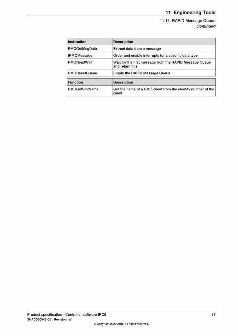
DescriptionInstruction
Extract data from a messageRMQGetMsgData
Order and enable interrupts for a specific data typeIRMQMessage
Wait for the first message from the RAPID Message Queueand return this
RMQReadWait
Empty the RAPID Message QueueRMQResetQueue
DescriptionFunction
Get the name of a RMQ client from the identity number of theclient
RMQGetSlotName
Product specification - Controller software IRC5 973HAC050945-001 Revision: W
© Copyright 2022 ABB. All rights reserved.
11 Engineering Tools11.11 RAPID Message Queue
Continued
11.12 Production Framework [1243-1]
GeneralProduction Framework is a customizablemodular platform for order based externalcontrol of an ABB robot system.It shares some features with the older product Production Manager but is generallymore focused on providing a flexible and customizable platform rather than aprovided-as-is fixed solution.The main purpose of the framework is to handle orders from an external source,typically a PLC in charge of managing the various equipment in the cell. Theseorders are then executed by the framework by running user-specified RAPIDroutines.
Features• Safely transferring orders from the TRAP execution level to normal execution
level• A state-based production loop• Events, which can be used by the programmer to run code at various times
in the production loop, or when certain system events occur• Multi-tasking and MultiMove abstraction layer for easier (compared to using
the basic RAPID API) synchronization of orders and events that are runningon several RAPID tasks
• Aborting orders• Enqueueing orders• Customizable order constraints• General logging• Traceability• Running independently on any RAPID task, including background tasks• Flexible architecture with customizable features
Add-In distributedThis option requires an Add-In (Production Framework), available through theRobotStudio Add-In repository.
Requirements• Multitasking [623-1]• Production Screen [637-1] is required if selecting graphical user interface in
Production Framework (recommended)
98 Product specification - Controller software IRC53HAC050945-001 Revision: W
© Copyright 2022 ABB. All rights reserved.
11 Engineering Tools11.12 Production Framework [1243-1]
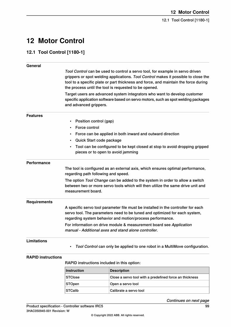
12 Motor Control12.1 Tool Control [1180-1]
GeneralTool Control can be used to control a servo tool, for example in servo drivengrippers or spot welding applications. Tool Control makes it possible to close thetool to a specific plate or part thickness and force, and maintain the force duringthe process until the tool is requested to be opened.Target users are advanced system integrators who want to develop customerspecific application software based on servomotors, such as spot welding packagesand advanced grippers.
Features• Position control (gap)• Force control• Force can be applied in both inward and outward direction• Quick Start code package• Tool can be configured to be kept closed at stop to avoid dropping gripped
pieces or to open to avoid jamming
PerformanceThe tool is configured as an external axis, which ensures optimal performance,regarding path following and speed.The option Tool Change can be added to the system in order to allow a switchbetween two or more servo tools which will then utilize the same drive unit andmeasurement board.
RequirementsA specific servo tool parameter file must be installed in the controller for eachservo tool. The parameters need to be tuned and optimized for each system,regarding system behavior and motion/process performance.For information on drive module & measurement board see Applicationmanual - Additional axes and stand alone controller.
Limitations• Tool Control can only be applied to one robot in a MultiMove configuration.
RAPID instructionsRAPID instructions included in this option:
DescriptionInstruction
Close a servo tool with a predefined force an thicknessSTClose
Open a servo toolSTOpen
Calibrate a servo toolSTCalib
Continues on next pageProduct specification - Controller software IRC5 993HAC050945-001 Revision: W
© Copyright 2022 ABB. All rights reserved.
12 Motor Control12.1 Tool Control [1180-1]
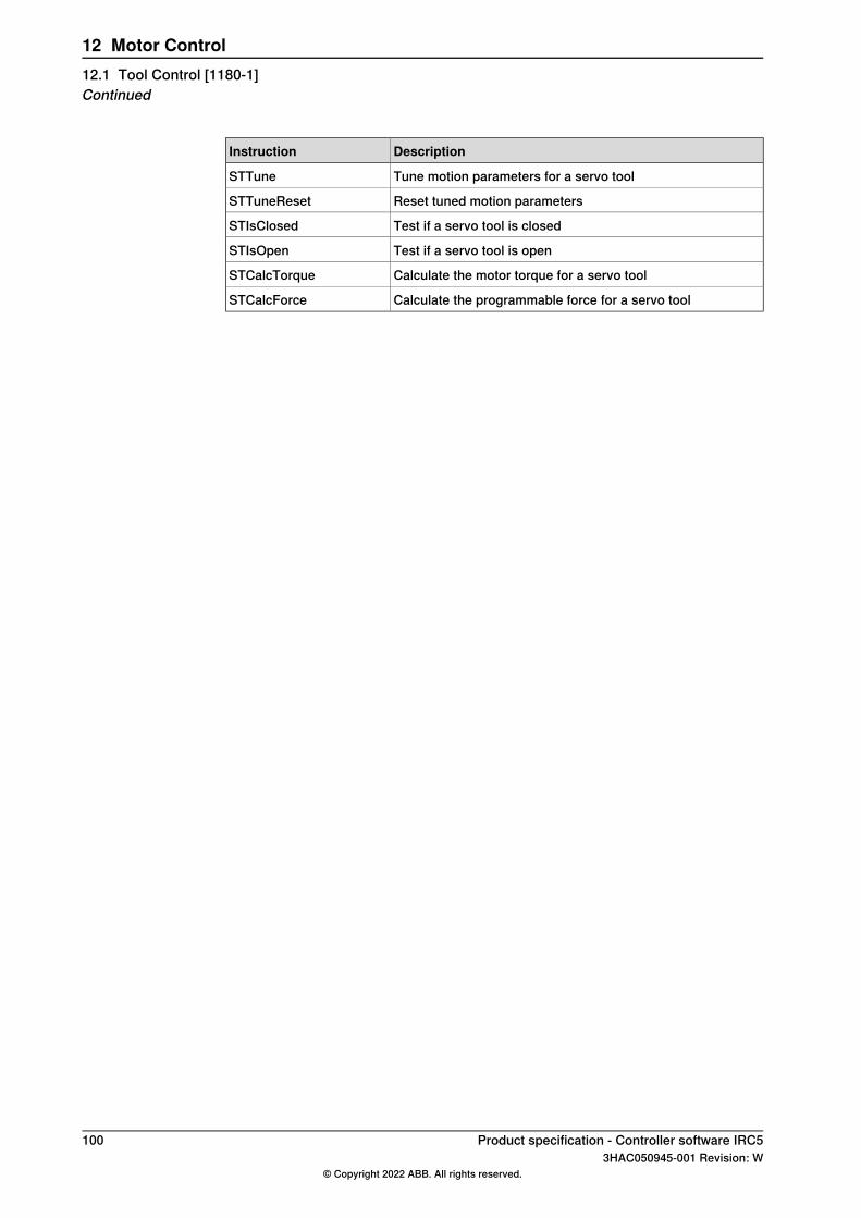
DescriptionInstruction
Tune motion parameters for a servo toolSTTune
Reset tuned motion parametersSTTuneReset
Test if a servo tool is closedSTIsClosed
Test if a servo tool is openSTIsOpen
Calculate the motor torque for a servo toolSTCalcTorque
Calculate the programmable force for a servo toolSTCalcForce
100 Product specification - Controller software IRC53HAC050945-001 Revision: W
© Copyright 2022 ABB. All rights reserved.
12 Motor Control12.1 Tool Control [1180-1]Continued
12.2 Servo Tool Change [630-1]
GeneralServo Tool Change enables an on-line change of tools (external axes), for a certaindrive- and measurement system. The control is switched between the axes byswitching themotor cables from one servomotor to another. The switch is performedon-line during production.Main advantages:
• Flexibility in the production process. One robot handles several tools.• Minimized equipment. A single drive-measurement system shared by many
tools.
Features• On-line change of tools• Up to 8 different tools
Application
DescriptionApplication
Robot held servo guns, designed for different reach and weldforces, equipped with different brands and sizes of servo mo-tors, may be held and operated by a robot, switching from oneservo gun to another.
Servo gun changing
Can be used as an independent option, or as an addition tothe RobotWare Spot Servo options.
Servo Tool Change
PerformanceWhen switching tools, the following steps are performed (switching from Axis 1 toAxis 2):
• Axis 1 is deactivated using the RAPID instruction DeactUnit• Axis 1 is disconnected from the motor cables• Axis 2 is connected to the motor cables• Axis 2 is activated using RAPID instruction ActUnit• After activation, axis 2 is ready to run
Themotor position at themoment of deactivation of one axis is saved and restorednext time the axis is activated.
Note
The motor position must not change more than half a motor revolution, whenthe axis is disconnected. In RobotWare Spot Servo, there is a calibration routine,which handles larger position changes.
RequirementsServo Tool Change requires a mechanical wrist interface, a tool changer.
Continues on next pageProduct specification - Controller software IRC5 1013HAC050945-001 Revision: W
© Copyright 2022 ABB. All rights reserved.
12 Motor Control12.2 Servo Tool Change [630-1]
AMOC service parameter,Disconnect deactive (typeMeasurement channel), mustbe defined as YES for each tool (external axis) used with this function.
Limitations• Servo Tool Change can only be applied to one robot in a MultiMove
configuration• Servo Tool ChangeServo tool change can be used up to 8 different tools but
is limited by 14 axes in total for the drive module. E.g if robot is on a trackmotion or if another additional axis is connected to a drive module it reducesthat number of allowed tools that can be used with servo disconnect.
RAPID instructionsThere are no RAPID instructions included in this option.
102 Product specification - Controller software IRC53HAC050945-001 Revision: W
© Copyright 2022 ABB. All rights reserved.
12 Motor Control12.2 Servo Tool Change [630-1]Continued
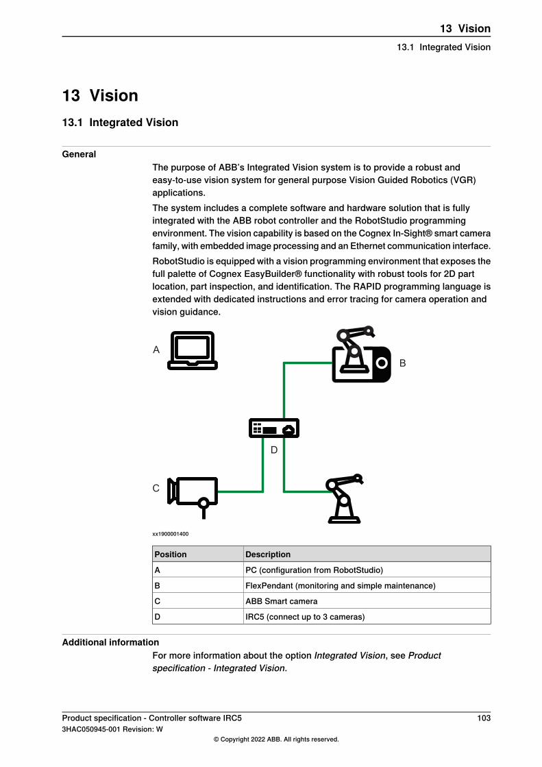
13 Vision13.1 Integrated Vision
GeneralThe purpose of ABB’s Integrated Vision system is to provide a robust andeasy-to-use vision system for general purpose Vision Guided Robotics (VGR)applications.The system includes a complete software and hardware solution that is fullyintegrated with the ABB robot controller and the RobotStudio programmingenvironment. The vision capability is based on the Cognex In-Sight® smart camerafamily, with embedded image processing and an Ethernet communication interface.RobotStudio is equipped with a vision programming environment that exposes thefull palette of Cognex EasyBuilder® functionality with robust tools for 2D partlocation, part inspection, and identification. The RAPID programming language isextended with dedicated instructions and error tracing for camera operation andvision guidance.
B
C
A
D
xx1900001400
DescriptionPosition
PC (configuration from RobotStudio)A
FlexPendant (monitoring and simple maintenance)B
ABB Smart cameraC
IRC5 (connect up to 3 cameras)D
Additional informationFor more information about the option Integrated Vision, see Productspecification - Integrated Vision.
Product specification - Controller software IRC5 1033HAC050945-001 Revision: W
© Copyright 2022 ABB. All rights reserved.
13 Vision13.1 Integrated Vision
13.2 Prepared for FlexLoader Vision [1554-1]
GeneralThe option Prepared for FlexLoader Vision enables the use of the PC-basedFlexLoader Vision function package with one IRC5 controller.The option is used as licensing mechanism for the application software. TheFlexLoader function packages themselves are ordered separately, typically fromthe application center for machine tool tending or your local ABB sales contact.For further information see product specification FlexLoader Vision(3HAC064614-001).
Features• PC-based architecture, scalable up to 4 cameras• Pre-pick collision avoidance• Supports user-defined grippers• Out of reach prevention• Choice of moving and rolling part avoidance• User defined parameter to robot or external PLC• Supports both 2D and 3D sensors• Simple and intuitive user interface designed for machine tool tending• Handles an unlimited number of components without mechanical fixtures• Teach-in time of new workpieces is less than 10 minutes• Faster changeover time between components• Parameterized teach-in interface for lathe applications provides a quick and
easy user experience• Pre-programmed robot code provides short installation time• Single point of operating control
ApplicationFlexLoader Vision is a robot guiding vision system for machine tool tendingapplications. It identifies the workpiece location and orientation from the pickingarea and guides the robot with precision in the robot cell. It allows a completeteach-in that is very simple and intuitive from beginning to end. It is well-provenwith high speed, short teach-in times and reliable production in a user friendly way.The FlexLoader Vision can be used for both 2D and semi-oriented 3D applications.The system reverts complex 3D images to well-known 2D images in order toincrease the usability for the operator. No CAD files are required to teach-in newcomponents.FlexLoader Vision is part of most function packages in the FlexLoader productfamily, offering a wide range of machine tool tending solutions.
PerformanceSee product specification FlexLoader Vision (3HAC064614-001).
Continues on next page104 Product specification - Controller software IRC5
3HAC050945-001 Revision: W© Copyright 2022 ABB. All rights reserved.
13 Vision13.2 Prepared for FlexLoader Vision [1554-1]

RequirementsRequired RobotWare options
• PC Interface [616-1]• World Zones [608-1]• FlexPendant Interface [617-1]• Multitasking [623-1]
Product specification - Controller software IRC5 1053HAC050945-001 Revision: W
© Copyright 2022 ABB. All rights reserved.
13 Vision13.2 Prepared for FlexLoader Vision [1554-1]
Continued

13.3 Prep. Visual Servoing [1586-1]
GeneralVisual Servoing is a PC-based software which allows to increase the robot accuracyfor high precision assembly and alignment applications.Visual servoing involves the use of one or more cameras and a computer visionsystem to control the position of the robot's end-effector relative to the workpieceas required by the task.
Features• Enabling 6-axis robots for high precision assembly• Improved alignment speed compared to traditional look-then-move approach.• Reduced variance of alignment speed compared to look-then-move approach.• Easy commissioning with auto calibration and tuning for servoing purpose.• Compatible with a wide number of vision sensors.
ApplicationAssembly for high accuracy needed applications, especially in Electronics.
• Assembly applications• Alignment of components• Picking/placing a work object in a tool• Placing a part in a fixture
RequirementsThe option Prepared for Visual Servoing requires option EGM [689-1] and PCInterface [616-1].
LimitationsHigh Accuracy assembly only verified for IRB 120.
106 Product specification - Controller software IRC53HAC050945-001 Revision: W
© Copyright 2022 ABB. All rights reserved.
13 Vision13.3 Prep. Visual Servoing [1586-1]

14 Application options14.1 MultiProcess [634-1]
GeneralMultiProcess is used for applying RobotWare Arc or RobotWare Dispense orRobotWare Spot (max two robots) to multiple robots in a MultiMove system.
FeaturesMultiProcess enables process capabilities on any number of robots. The setup ofwhich robot(s) that should have capabilities is done in the Additional MultiMoveselections part of the specification form. It can also be carried out at the finalinstallation in RobotStudio.
RequirementsOption 633-4 Arc 6 or 641-1 Dispense or 635-6 Spot 6 must be specified, as wellas any of the options:
• 604-1 MultiMove Coordinated or• 604-2 MultiMove Independent
Product specification - Controller software IRC5 1073HAC050945-001 Revision: W
© Copyright 2022 ABB. All rights reserved.
14 Application options14.1 MultiProcess [634-1]

14.2 Arc 6 [633-4]
GeneralRobotWare Arc comprises a large number of dedicated arc welding functions,which make the robot well suited for arc welding.RobotWare Arc is a simple yet powerful option since both the positioning of therobot and the process control and monitoring are handled in one and the sameinstruction. I/O signals, timing sequences and weld error actions can be easilyconfigured to meet the requirements of a specific installation.
Features• Adaptation to different equipment. The robot can handle different types of
weld controllers and other welding equipment. Normally communication withthe welding controller uses parallel signals but a serial interface is alsoavailable.
• Advanced process control. Voltage, wire feed rate, and other process datacan be controlled individually for each weld or part of a weld. The processdata can be changed at the start and finish of a welding process in such away that the best process result is achieved.
• Testing the program. When testing a program, welding, weaving or weldguiding can all be blocked. This provides a way of testing the robot programwithout having the welding equipment connected.
• Automatic weld retry. A function that can be configured to order one or moreautomatic weld retries after a process fault.
• Weaving I . The robot can implement a number of different weaving patternsup to 10 Hz depending on robot type. These can be used to fill the weldproperly and in the best possible way. Weaving movement can also beordered at the start of the weld in order to facilitate the initial striking of thearc.
• Wire burn back and rollback. These are functions used to prevent the weldingwire sticking to the work object.
• Fine adjustment during program execution. The welding speed, wire feedrate, voltage and weaving can all be adjusted whilst welding is in progress.This makes trimming of the process much easier because the result can beseen immediately on the current weld. This can be done in both manual andautomatic mode.
• RobotWare Arc can be applied to several robots in a MultiMove system(requires option MultiProcess).
• Seam Displacement allows the operator to shift seams in relation to areference frame. The displacement are applied via FlexPendant operatorsscreens without stopping production.
• Weld error recovery. During robot production process errors sometimes arisecausing the robot to stop. TheWeld Error Recovery feature provides severaldifferent solutions for process error recovery, which allows operators throughdialogs to automatically move the robot out of the error location to a service
Continues on next page108 Product specification - Controller software IRC5
3HAC050945-001 Revision: W© Copyright 2022 ABB. All rights reserved.
14 Application options14.2 Arc 6 [633-4]
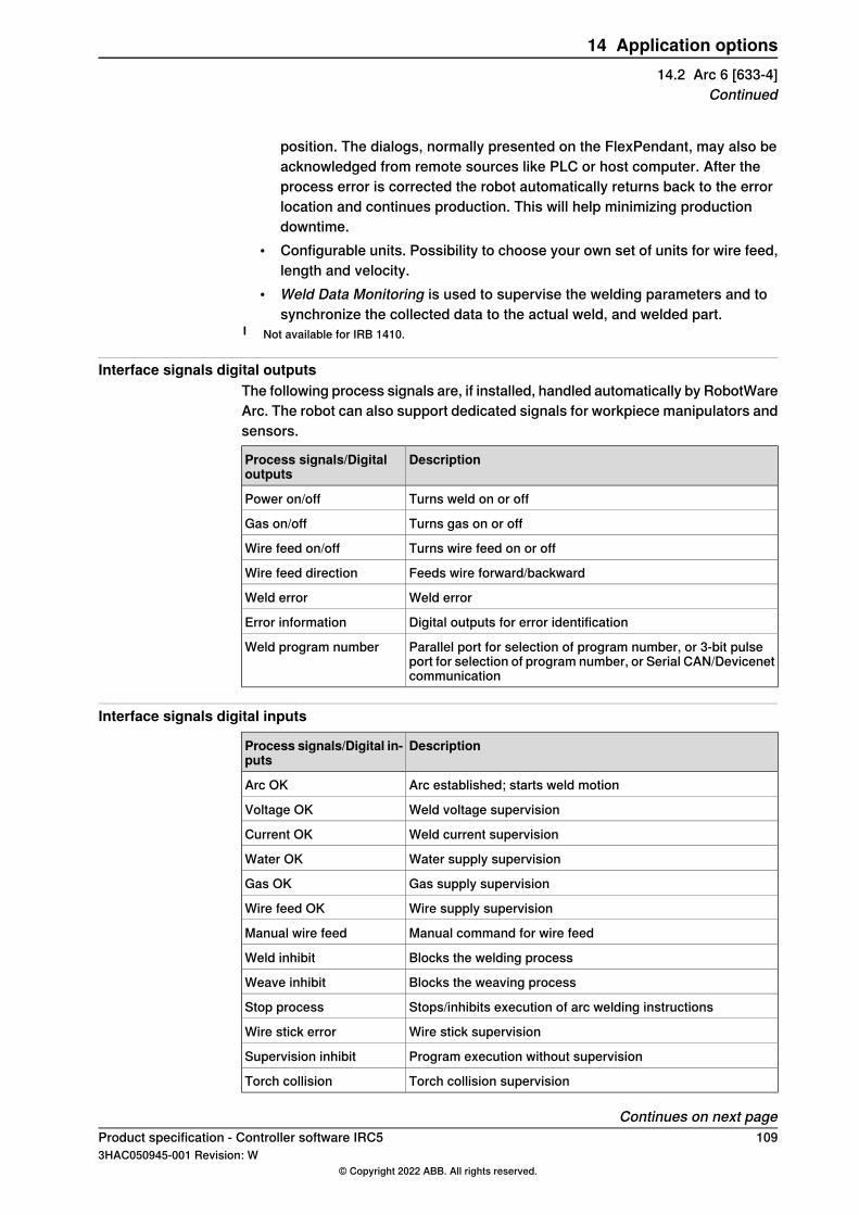
position. The dialogs, normally presented on the FlexPendant, may also beacknowledged from remote sources like PLC or host computer. After theprocess error is corrected the robot automatically returns back to the errorlocation and continues production. This will help minimizing productiondowntime.
• Configurable units. Possibility to choose your own set of units for wire feed,length and velocity.
• Weld Data Monitoring is used to supervise the welding parameters and tosynchronize the collected data to the actual weld, and welded part.
I Not available for IRB 1410.
Interface signals digital outputsThe following process signals are, if installed, handled automatically by RobotWareArc. The robot can also support dedicated signals for workpiece manipulators andsensors.
DescriptionProcess signals/Digitaloutputs
Turns weld on or offPower on/off
Turns gas on or offGas on/off
Turns wire feed on or offWire feed on/off
Feeds wire forward/backwardWire feed direction
Weld errorWeld error
Digital outputs for error identificationError information
Parallel port for selection of program number, or 3-bit pulseport for selection of program number, or Serial CAN/Devicenetcommunication
Weld program number
Interface signals digital inputs
DescriptionProcess signals/Digital in-puts
Arc established; starts weld motionArc OK
Weld voltage supervisionVoltage OK
Weld current supervisionCurrent OK
Water supply supervisionWater OK
Gas supply supervisionGas OK
Wire supply supervisionWire feed OK
Manual command for wire feedManual wire feed
Blocks the welding processWeld inhibit
Blocks the weaving processWeave inhibit
Stops/inhibits execution of arc welding instructionsStop process
Wire stick supervisionWire stick error
Program execution without supervisionSupervision inhibit
Torch collision supervisionTorch collision
Continues on next pageProduct specification - Controller software IRC5 1093HAC050945-001 Revision: W
© Copyright 2022 ABB. All rights reserved.
14 Application options14.2 Arc 6 [633-4]
Continued
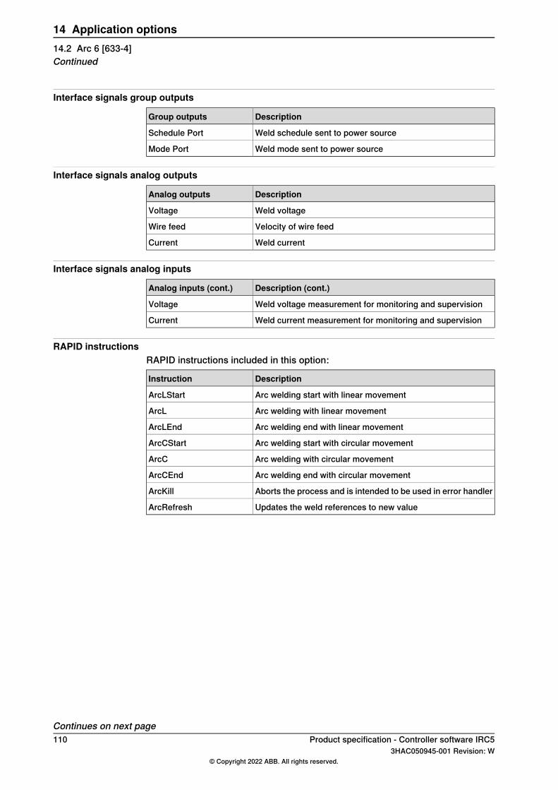
Interface signals group outputs
DescriptionGroup outputs
Weld schedule sent to power sourceSchedule Port
Weld mode sent to power sourceMode Port
Interface signals analog outputs
DescriptionAnalog outputs
Weld voltageVoltage
Velocity of wire feedWire feed
Weld currentCurrent
Interface signals analog inputs
Description (cont.)Analog inputs (cont.)
Weld voltage measurement for monitoring and supervisionVoltage
Weld current measurement for monitoring and supervisionCurrent
RAPID instructionsRAPID instructions included in this option:
DescriptionInstruction
Arc welding start with linear movementArcLStart
Arc welding with linear movementArcL
Arc welding end with linear movementArcLEnd
Arc welding start with circular movementArcCStart
Arc welding with circular movementArcC
Arc welding end with circular movementArcCEnd
Aborts the process and is intended to be used in error handlerArcKill
Updates the weld references to new valueArcRefresh
Continues on next page110 Product specification - Controller software IRC5
3HAC050945-001 Revision: W© Copyright 2022 ABB. All rights reserved.
14 Application options14.2 Arc 6 [633-4]Continued
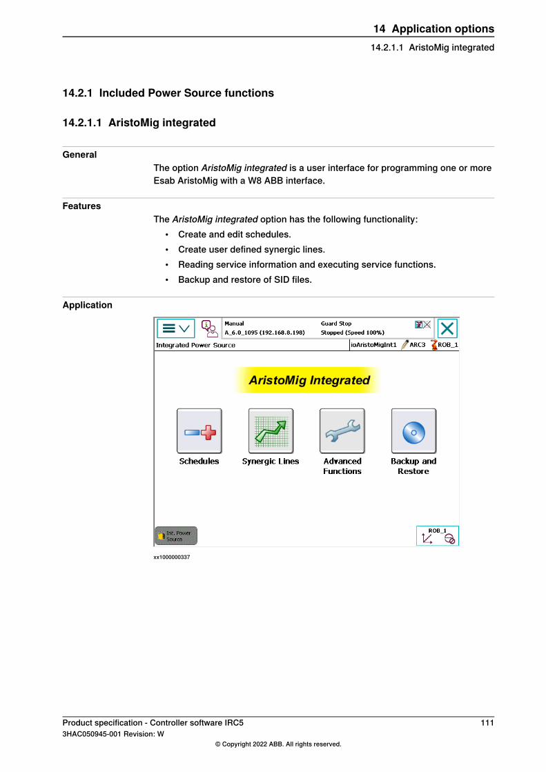
14.2.1 Included Power Source functions
14.2.1.1 AristoMig integrated
GeneralThe option AristoMig integrated is a user interface for programming one or moreEsab AristoMig with a W8 ABB interface.
FeaturesThe AristoMig integrated option has the following functionality:
• Create and edit schedules.• Create user defined synergic lines.• Reading service information and executing service functions.• Backup and restore of SID files.
Application
xx1000000337
Product specification - Controller software IRC5 1113HAC050945-001 Revision: W
© Copyright 2022 ABB. All rights reserved.
14 Application options14.2.1.1 AristoMig integrated
14.2.1.2 ABB RPC S Integrated
GeneralThe option ABB RPC S Integrated is a software option for managing the RPC S400 Power source.
FeaturesThe ABB RPC S Integrated option has the following functionality:
• Create and edit schedules.• Monitoring of current and voltage.• Backup and restore of schedules in the RPC S 400 Power source.
RequirementsThe following RobotWare options are required for theABBRPCS Integrated option:
• Arc• Standard I/O welder
112 Product specification - Controller software IRC53HAC050945-001 Revision: W
© Copyright 2022 ABB. All rights reserved.
14 Application options14.2.1.2 ABB RPC S Integrated
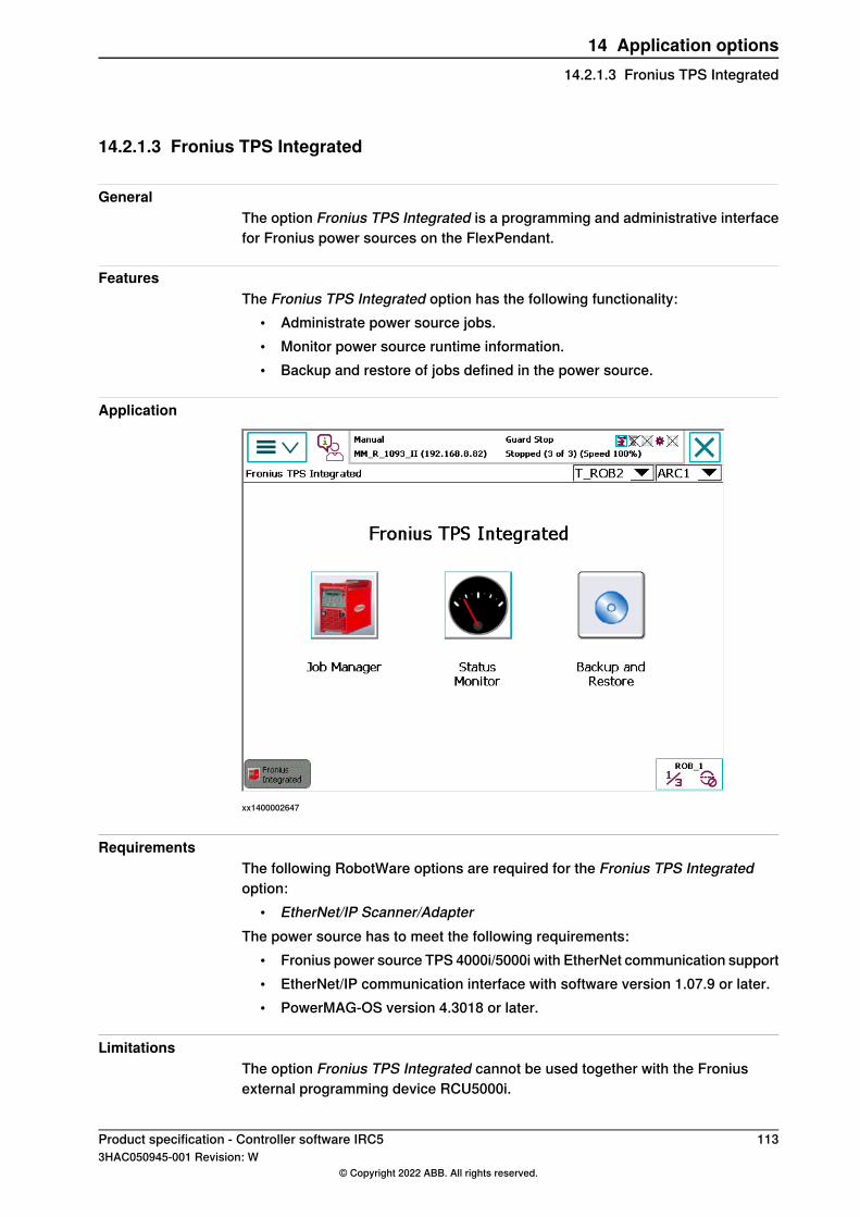
14.2.1.3 Fronius TPS Integrated
GeneralThe option Fronius TPS Integrated is a programming and administrative interfacefor Fronius power sources on the FlexPendant.
FeaturesThe Fronius TPS Integrated option has the following functionality:
• Administrate power source jobs.• Monitor power source runtime information.• Backup and restore of jobs defined in the power source.
Application
xx1400002647
RequirementsThe following RobotWare options are required for the Fronius TPS Integratedoption:
• EtherNet/IP Scanner/AdapterThe power source has to meet the following requirements:
• Fronius power source TPS 4000i/5000i with EtherNet communication support• EtherNet/IP communication interface with software version 1.07.9 or later.• PowerMAG-OS version 4.3018 or later.
LimitationsThe option Fronius TPS Integrated cannot be used together with the Froniusexternal programming device RCU5000i.
Product specification - Controller software IRC5 1133HAC050945-001 Revision: W
© Copyright 2022 ABB. All rights reserved.
14 Application options14.2.1.3 Fronius TPS Integrated
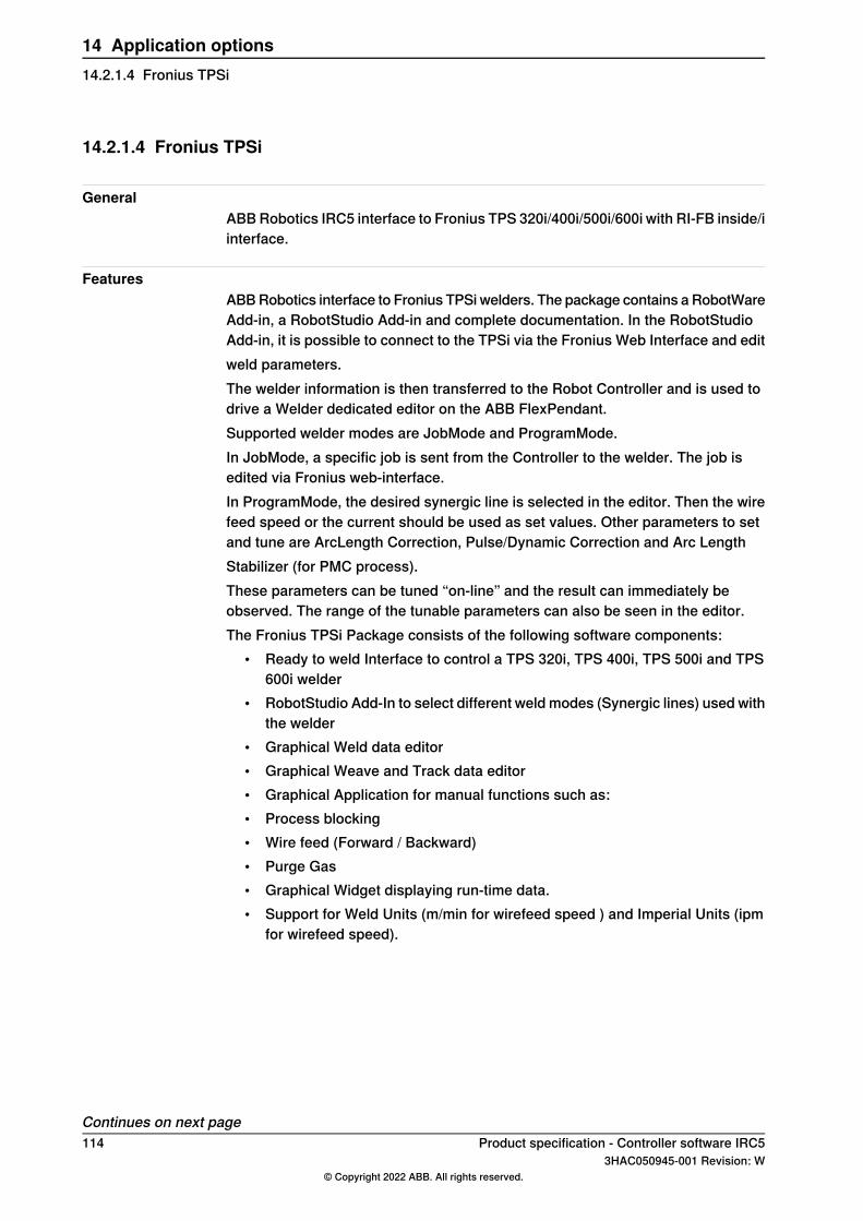
14.2.1.4 Fronius TPSi
GeneralABBRobotics IRC5 interface to Fronius TPS 320i/400i/500i/600i with RI-FB inside/iinterface.
FeaturesABBRobotics interface to Fronius TPSi welders. The package contains a RobotWareAdd-in, a RobotStudio Add-in and complete documentation. In the RobotStudioAdd-in, it is possible to connect to the TPSi via the Fronius Web Interface and editweld parameters.The welder information is then transferred to the Robot Controller and is used todrive a Welder dedicated editor on the ABB FlexPendant.Supported welder modes are JobMode and ProgramMode.In JobMode, a specific job is sent from the Controller to the welder. The job isedited via Fronius web-interface.In ProgramMode, the desired synergic line is selected in the editor. Then the wirefeed speed or the current should be used as set values. Other parameters to setand tune are ArcLength Correction, Pulse/Dynamic Correction and Arc LengthStabilizer (for PMC process).These parameters can be tuned “on-line” and the result can immediately beobserved. The range of the tunable parameters can also be seen in the editor.The Fronius TPSi Package consists of the following software components:
• Ready to weld Interface to control a TPS 320i, TPS 400i, TPS 500i and TPS600i welder
• RobotStudio Add-In to select different weld modes (Synergic lines) used withthe welder
• Graphical Weld data editor• Graphical Weave and Track data editor• Graphical Application for manual functions such as:• Process blocking• Wire feed (Forward / Backward)• Purge Gas• Graphical Widget displaying run-time data.• Support for Weld Units (m/min for wirefeed speed ) and Imperial Units (ipm
for wirefeed speed).
Continues on next page114 Product specification - Controller software IRC5
3HAC050945-001 Revision: W© Copyright 2022 ABB. All rights reserved.
14 Application options14.2.1.4 Fronius TPSi
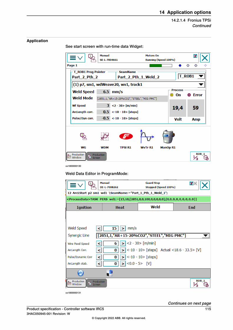
ApplicationSee start screen with run-time data Widget:
xx1800000130
Weld Data Editor in ProgramMode:
xx1800000131
Continues on next pageProduct specification - Controller software IRC5 1153HAC050945-001 Revision: W
© Copyright 2022 ABB. All rights reserved.
14 Application options14.2.1.4 Fronius TPSi
Continued
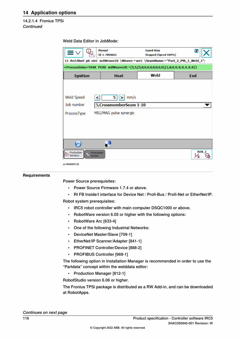
Weld Data Editor in JobMode:
xx1800000132
RequirementsPower Source prerequisites:
• Power Source Firmware 1.7.4 or above.• RI FB Inside/I interface for Device Net / Profi-Bus / Profi-Net or EtherNet/IP.
Robot system prerequisites:• IRC5 robot controller with main computer DSQC1000 or above.• RobotWare version 6.05 or higher with the following options:• RobotWare Arc [633-4]• One of the following Industrial Networks:• DeviceNet Master/Slave [709-1]• EtherNet/IP Scanner/Adapter [841-1]• PROFINET Controller/Device [888-2]• PROFIBUS Controller [969-1]
The following option in Installation Manager is recommended in order to use the“Partdata” concept within the welddata editor:
• Production Manager [812-1]RobotStudio version 6.06 or higher.The Fronius TPSi package is distributed as a RW Add-in, and can be downloadedat RobotApps.
Continues on next page116 Product specification - Controller software IRC5
3HAC050945-001 Revision: W© Copyright 2022 ABB. All rights reserved.
14 Application options14.2.1.4 Fronius TPSiContinued
LimitationsCurrently only the first Arc System is supported with this interface. If you havemore than one welder connected per Robot you have to use the Arc Sub-option“Standard I/O Welder”Tuning of weld speed and weld parameters is no longer supported by RobotWareArc GUI, this is done in the Fronius Weld data editor.JobMode with Correction is not supported.The Fronius TPSi Web Browser interface is a licensed option from Fronius.To be able to connect to the Fronius TPSi Welder via the Web Browser interfacein the RobotStudio Add-in, this option is needed. Contact Fronius for moreinformation.
Product specification - Controller software IRC5 1173HAC050945-001 Revision: W
© Copyright 2022 ABB. All rights reserved.
14 Application options14.2.1.4 Fronius TPSi
Continued
14.2.1.5 Fronius TPS 4000/5000
GeneralThe Fronius TPS 4000/5000 user interface is a standard arc programming tool usedfor operating and managing one or more TPS/TP-type of power sources.The Fronius TPS and TS welding machines are totally digitized,microprocessor-controlled inverter power sources. An interactive power-sourcemanager is coupled with a digital signal processor, and together they control andregulate the entire welding process.The communication is performed through a robot DeviceNet interface, which allowsthe operator to program the main process parameters from the robot FlexPendant.The operator can through this software can for example call for pre-programmedjobs (called schedules in robot controller), which prior have been made in on theFronius power source operator panel.This software option is using the RobotWare standard seam and weld data typesto supply welding process information to the power supply.The arc option Fronius TPS 4000/5000 interface provides complete access to allFronius modes.The arc option Fronius TPS 4000/5000 gives the user access to following Froniusmodes:
1 Job mode2 Job mode with correction3 Standard program mode4 Pulsed program mode5 Manual
Job modeAll weld parameters, including start and end data, are stored in the Fronius powersource.The user can in this mode select a pre-programmed job in the Fronius powersource, and use this job as the weld data in the FlexPendant.
Job mode with correctionAll weld parameters, including start and end data, are stored in the Fronius powersource. Same functionality as Job Mode, but the user can also get access to wirefeed speed and voltage in the "weld data" to "trim" the synergic values specifiedin the Job.
Standard program modeStandard synergic welding, were the user specifies wire feed speed and Froniuspower source will select an appropriate voltage. Voltage may be trimmed usingthe voltage field. This mode gives RW - Arc the control over start and end data.
Continues on next page118 Product specification - Controller software IRC5
3HAC050945-001 Revision: W© Copyright 2022 ABB. All rights reserved.
14 Application options14.2.1.5 Fronius TPS 4000/5000
Pulsed program modePulsed synergic welding, were the user specifies wire feed speed and Froniuspower source will select an appropriate voltage. Voltage may be trimmed usingthe voltage field. This mode gives RW - Arc the control over start and end data.Depending on how the system is configured, appropriate fields will be masked orexposed in weld data and seam data so that the user only sees the fields valid forthe mode that is selected.
Arc errors displayThe Fronius interface displays in the error number provided by Fronius in the arcerrors displayed on the FlexPendant.
Robot software requirementThe RobotWare option Arc is required for the Fronius TPS 4000/5000 option.
Minimum Fronius power source hard- and software requirements• Fronius Welding Power Source (TPS/TS 4000 or 5000)• Fronius Wire feed Systems (VR1500)• Fronius Software option, Jobexplorer• Fronius Interface (Bus Systems and standard discrete)
OptionalFronius Remote Control Units (RCU 4000 and 5000)
Note
The above Fronius equipment and software options are not included in RWFronius TPS 4000/5000.
For more information see separate Application manual-Fronius TPS 4000/5000IRC5 Interface.
Product specification - Controller software IRC5 1193HAC050945-001 Revision: W
© Copyright 2022 ABB. All rights reserved.
14 Application options14.2.1.5 Fronius TPS 4000/5000
Continued
14.2.1.6 Standard I/O Welder
GeneralThe Standard I/O Welder user interface is a standard arc programming tool usedfor operating and managing one or more I/O-based power sources. Thecommunication is performed through a robot I/O based interface, which allows theoperator to program the main process parameters from the robot FlexPendant.The operator can through this software set required wire feed speed, voltage leveland welding speed for each specific weld in the robot program. Following maintasks can be handled from the FlexPendant, Standard I/O Welder process userinterface:
• Set required wire feed speed, voltage level and absolute welding speed.
120 Product specification - Controller software IRC53HAC050945-001 Revision: W
© Copyright 2022 ABB. All rights reserved.
14 Application options14.2.1.6 Standard I/O Welder
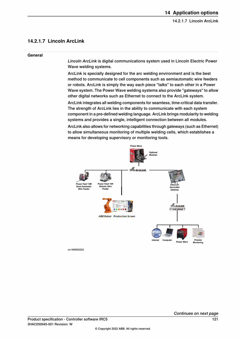
14.2.1.7 Lincoln ArcLink
GeneralLincoln ArcLink is digital communications system used in Lincoln Electric PowerWave welding systems.ArcLink is specially designed for the arc welding environment and is the bestmethod to communicate to cell components such as semiautomatic wire feedersor robots. ArcLink is simply the way each piece "talks" to each other in a PowerWave system. The Power Wave welding systems also provide "gateways" to allowother digital networks such as Ethernet to connect to the ArcLink system.ArcLink integrates all welding components for seamless, time-critical data transfer.The strength of ArcLink lies in the ability to communicate with each systemcomponent in a pre-defined welding language. ArcLink bringsmodularity to weldingsystems and provides a single, intelligent connection between all modules.ArcLink also allows for networking capabilities through gateways (such as Ethernet)to allow simultaneous monitoring of multiple welding cells, which establishes ameans for developing supervisory or monitoring tools.
xx1400002223
Continues on next pageProduct specification - Controller software IRC5 1213HAC050945-001 Revision: W
© Copyright 2022 ABB. All rights reserved.
14 Application options14.2.1.7 Lincoln ArcLink
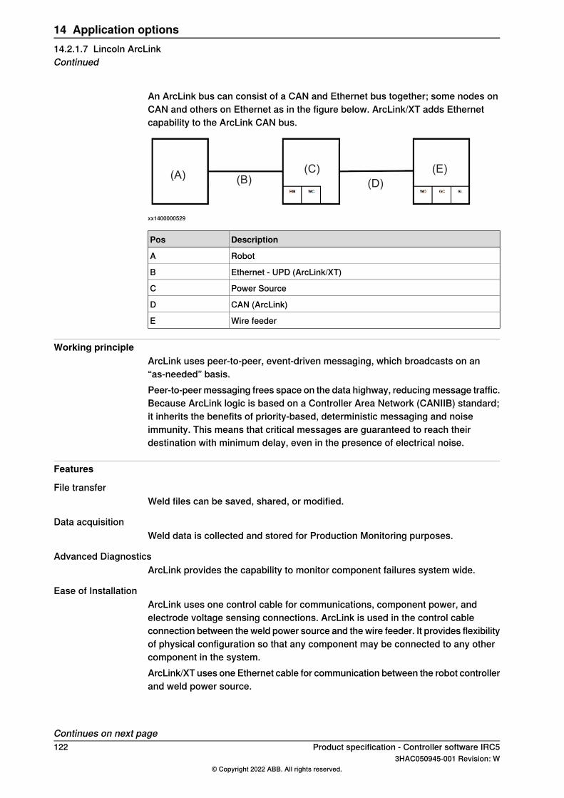
An ArcLink bus can consist of a CAN and Ethernet bus together; some nodes onCAN and others on Ethernet as in the figure below. ArcLink/XT adds Ethernetcapability to the ArcLink CAN bus.
(A)(D)(B)
(E)(C)
xx1400000529
DescriptionPos
RobotA
Ethernet - UPD (ArcLink/XT)B
Power SourceC
CAN (ArcLink)D
Wire feederE
Working principleArcLink uses peer-to-peer, event-driven messaging, which broadcasts on an“as-needed” basis.Peer-to-peermessaging frees space on the data highway, reducingmessage traffic.Because ArcLink logic is based on a Controller Area Network (CANIIB) standard;it inherits the benefits of priority-based, deterministic messaging and noiseimmunity. This means that critical messages are guaranteed to reach theirdestination with minimum delay, even in the presence of electrical noise.
Features
File transferWeld files can be saved, shared, or modified.
Data acquisitionWeld data is collected and stored for Production Monitoring purposes.
Advanced DiagnosticsArcLink provides the capability to monitor component failures system wide.
Ease of InstallationArcLink uses one control cable for communications, component power, andelectrode voltage sensing connections. ArcLink is used in the control cableconnection between the weld power source and the wire feeder. It provides flexibilityof physical configuration so that any component may be connected to any othercomponent in the system.ArcLink/XT uses one Ethernet cable for communication between the robot controllerand weld power source.
Continues on next page122 Product specification - Controller software IRC5
3HAC050945-001 Revision: W© Copyright 2022 ABB. All rights reserved.
14 Application options14.2.1.7 Lincoln ArcLinkContinued
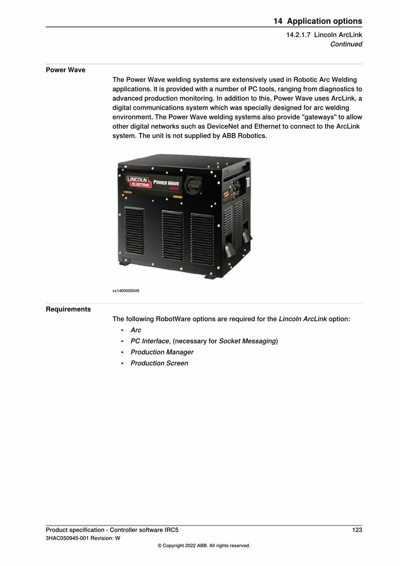
Power WaveThe Power Wave welding systems are extensively used in Robotic Arc Weldingapplications. It is provided with a number of PC tools, ranging from diagnostics toadvanced production monitoring. In addition to this, Power Wave uses ArcLink, adigital communications system which was specially designed for arc weldingenvironment. The Power Wave welding systems also provide "gateways" to allowother digital networks such as DeviceNet and Ethernet to connect to the ArcLinksystem. The unit is not supplied by ABB Robotics.
xx1400000549
RequirementsThe following RobotWare options are required for the Lincoln ArcLink option:
• Arc• PC Interface, (necessary for Socket Messaging)• Production Manager• Production Screen
Product specification - Controller software IRC5 1233HAC050945-001 Revision: W
© Copyright 2022 ABB. All rights reserved.
14 Application options14.2.1.7 Lincoln ArcLink
Continued
14.2.1.8 SKS Synchroweld
GeneralThe option SKS Synchroweld is a software option for managing the SKSSynchroweld powersource with the Fieldbus 5 interface.
FeaturesSynchroweld unites robot and welding machine to a procedural entity. Thiscombination is made possible because thanks to Synchroweld the weldingmachineknows the actual welding speed, that is, the TCP speed of the robot and its externalaxes. The speed information is directly processed in the weld controller.Synchroweld opens up new welding process options.
Advantages of SyncroWeldOptimumwelding results with constant weld penetration and identical appearanceat all points of the weld seam (even at the torch reorientation points).Constant energy input per length – the energy provided in time remains constantduring welding.Process optimization – visualization of the actual TCP speed during weldingsupports easy optimization of the process.Work made easier and time saved – even with complicated weld seam geometriesonly one welding program and one welding speed setting is required.
ApplicationThe SKS graphical user interface on the FlexPendant is called SKS Interface.The SKS Interface shows valuable process information, such as:
• Real-time voltage and current• Real-time wire feed speed• Real-time welding speed• Reference Speed• Active Schedule (Group/Part/Program)• Active Signal status• Power source status• Average Energy
The SKS Interface also includes a welddata editor that allows the user to changethe following data:
• Group port value• Part port value• Schedule port value (Program Number)
Finally the relay contacts and digital inputs of the Feldbus 5 interface can becontrolled from here if configured.
Continues on next page124 Product specification - Controller software IRC5
3HAC050945-001 Revision: W© Copyright 2022 ABB. All rights reserved.
14 Application options14.2.1.8 SKS Synchroweld
RequirementsIRC5 controller RobotWare 6.01 or higher with RobotWare Arc Fieldbus Interface(DeviceNet, PROFIBUS, PROFINET)
Product specification - Controller software IRC5 1253HAC050945-001 Revision: W
© Copyright 2022 ABB. All rights reserved.
14 Application options14.2.1.8 SKS Synchroweld
Continued
14.2.1.9 Fronius TPSi Seam tracking
GeneralThis is ABB Robotic's IRC5 Seam tracking interface to the Fronius TPSi welders.
FeaturesThe Fronius TPSi Seam tracking Add-In is a powerful software based TAST(Through Arc Seam Tracking) RobotWare Add-in option. The function is based ona feedback signal provided by the TPSi power source. This feedback signal isrepresenting a wire stick-out value to support both vertical and lateral seam trackingand is used as a sensor to indicate variations in the welding current which is causedby changes in welding current and voltage.Supported track types:
• Centerline tracking• Height only tracking• Y corrections tracking only• Inverted Centerline tracking
There is support for MultiPass welding.The version is Fronius TPSi Seamtracking 1.00 and can be found at RobotApps inthe RobotStudio Add-ins tab.User documentation is included in the distribution.
Continues on next page126 Product specification - Controller software IRC5
3HAC050945-001 Revision: W© Copyright 2022 ABB. All rights reserved.
14 Application options14.2.1.9 Fronius TPSi Seam tracking

ApplicationThere are dedicated FlexPendant user applications for editing track data relatedparameters and run-time information from the tracking process.
Weave and track data editor
xx1800002516
Continues on next pageProduct specification - Controller software IRC5 1273HAC050945-001 Revision: W
© Copyright 2022 ABB. All rights reserved.
14 Application options14.2.1.9 Fronius TPSi Seam tracking
Continued
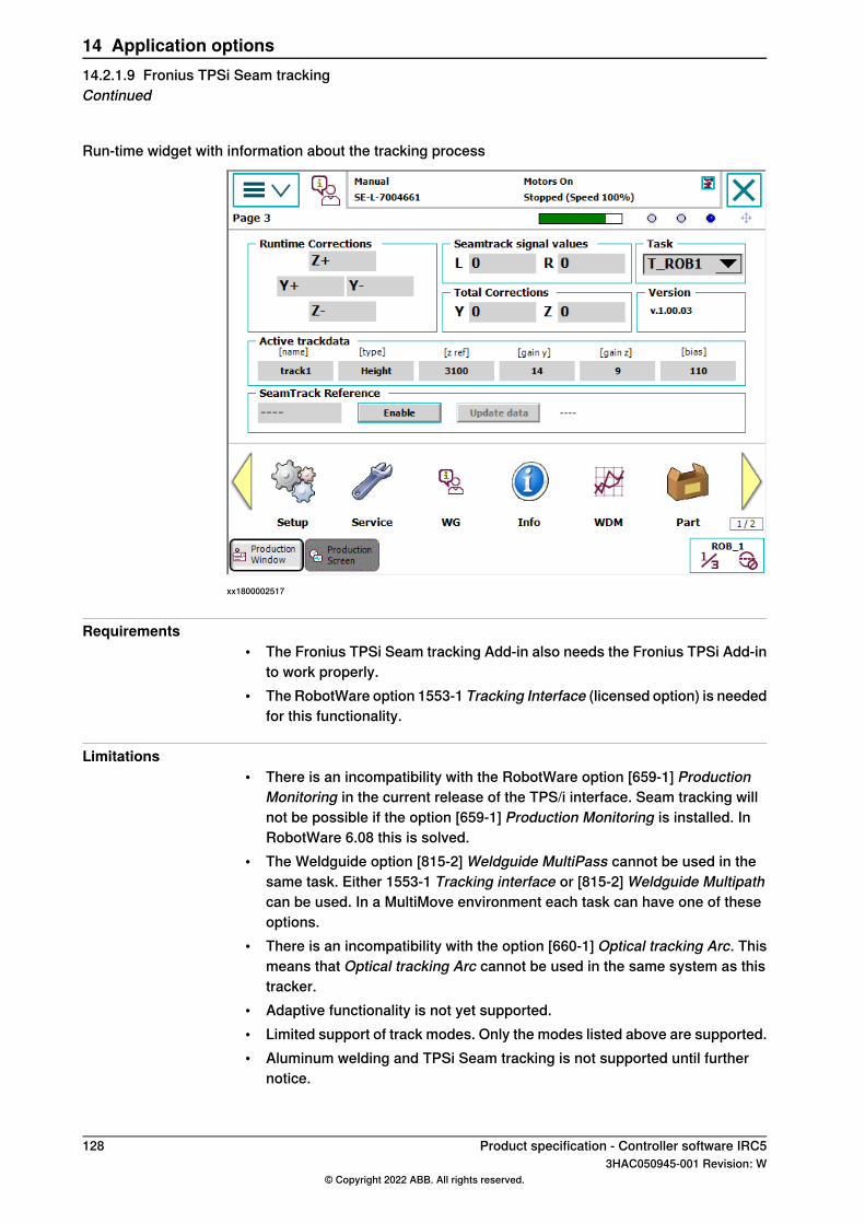
Run-time widget with information about the tracking process
xx1800002517
Requirements• The Fronius TPSi Seam tracking Add-in also needs the Fronius TPSi Add-in
to work properly.• The RobotWare option 1553-1 Tracking Interface (licensed option) is needed
for this functionality.
Limitations• There is an incompatibility with the RobotWare option [659-1] Production
Monitoring in the current release of the TPS/i interface. Seam tracking willnot be possible if the option [659-1] Production Monitoring is installed. InRobotWare 6.08 this is solved.
• The Weldguide option [815-2] Weldguide MultiPass cannot be used in thesame task. Either 1553-1 Tracking interface or [815-2] Weldguide Multipathcan be used. In a MultiMove environment each task can have one of theseoptions.
• There is an incompatibility with the option [660-1] Optical tracking Arc. Thismeans that Optical tracking Arc cannot be used in the same system as thistracker.
• Adaptive functionality is not yet supported.• Limited support of track modes. Only the modes listed above are supported.• Aluminum welding and TPSi Seam tracking is not supported until further
notice.
128 Product specification - Controller software IRC53HAC050945-001 Revision: W
© Copyright 2022 ABB. All rights reserved.
14 Application options14.2.1.9 Fronius TPSi Seam trackingContinued
14.2.2 Other included functions and options
14.2.2.1 Torch Service Equipment
GeneralThe Torch Service Equipment software option provides automatic cleaning of thewelding torch. It automatically clears and reduces buildup of spatter, which ensurescontinuous and reliable operation of the robot cell. The Torch Service Equipmentoption includes software that is loaded into all arc welding motion tasks.
Note
The Torch Service Equipment software loads unique equipment drivers, but theRAPID instruction interface is the same regardless of hardware selected.
Torch Service Equipment software maximizes arc on time and minimizes downtime since it can be programmed to clean automatically between weld or stationinterchanges. This reduces the need to manually disassemble and clear the nozzle.Torch Service Equipment software makes it possible to perform torch cleaningduring positioner interchange, which reduces cycle time. Once Torch ServiceEquipment is programmed the operator can decide how often the cleaning processneeds to take place to prolong the contact tip and gas nozzle life.
ABB - TC 2013This software option will give the user the possibility to define torch cleaning andanti spatter procedures in a robot system for the hardware option, ABB - TC 2013.The hardware option is available in separate application product price list.The followingmain tasks can be handled from theABB - TC 2013 software options:
• Procedure for automatic cleaning of gas nozzle interior wall and the exteriorof the contact tip and face of the gas diffuser for quick removal of weld spatter.
• Procedure for anti spatter spray program to provide longer interval betweentorch cleaning.
• Procedure for define automatic wire cutting for consistent wire electrodeextension (wire stick-out).
Continues on next pageProduct specification - Controller software IRC5 1293HAC050945-001 Revision: W
© Copyright 2022 ABB. All rights reserved.
14 Application options14.2.2.1 Torch Service Equipment

Binzel - TC97This software option can be used to define torch cleaning and anti spatterprocedures in a robot system for the hardware option, Binzel - TC97. The hardwareoption is available in the separate price list for application products.
xx1000000345
The following main tasks can be handled with the Binzel - TC97 software:• Procedure for automatic cleaning of the interior wall of the gas nozzle, the
exterior of the contact tip, and the face of the gas diffuser for quick removalof weld spatter.
• Procedure for anti spatter spray program to provide longer interval betweentorch cleaning.
130 Product specification - Controller software IRC53HAC050945-001 Revision: W
© Copyright 2022 ABB. All rights reserved.
14 Application options14.2.2.1 Torch Service EquipmentContinued

14.2.2.2 Production Monitoring
GeneralThe Production Monitoring option enables logging of production information in aWebWare Server database. The database is stored on a WebWare Server and isdisplayed on a regular web page through the WebWare Client. Access to thisinformation will help users improve part quality and production throughput.
FeaturesThe Production Monitoring option provides detailed, automated data collection forevery weld seam on each part produced. This feature has driven standardizationof process measurement to a new level, by proactive manage welding productionrather than just react to problems.Key features include:
• Online reporting of production data and faults• Logging of production data for part traceability• Real-time reporting via standard web browser• Fixed cost deployment without added software development expense
The Production Monitoring option provides a systematic way to capture theproduction data needed to achieve continuous improvement goals.Typical applications include:
• Cycle time analysis• Tracking production output• Quantify lost production time• Monitor equipment utilization rates• Archiving of production data for traceability• Data capture to document acceptance criteria
WebWare tables in Production MonitorProductionMonitor promotesWebWare Server tables that contain statistical results.For example, RobotWare Arc will provide a table of Cycle Results that combinesinformation from CycleEvents data with SeamResults data to create the CycleResult table.Event Tables:
• Event tables provide specific, time-stamped information that occur in thesystem. These include start and end events for cycles, service routine callsand setup routine calls. These tables are characterized by having recordsfor start events and end events. To determine the duration of an event fromstart to end requires calculations based on the data stored in the database.
Result Tables:• Result tables contain data that is calculated on the fly within RAPID. These
tables provide useful information about production without making SQLqueries frommultiple tables. These tables are typically written after an eventhas finished and usually include a Duration column that provides the time
Continues on next pageProduct specification - Controller software IRC5 1313HAC050945-001 Revision: W
© Copyright 2022 ABB. All rights reserved.
14 Application options14.2.2.2 Production Monitoring
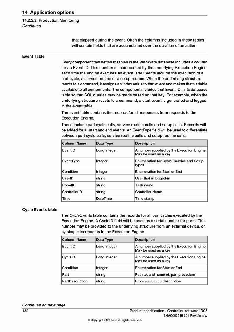
that elapsed during the event. Often the columns included in these tableswill contain fields that are accumulated over the duration of an action.
Event TableEvery component that writes to tables in theWebWare database includes a columnfor an Event ID. This number is incremented by the underlying Execution Engineeach time the engine executes an event. The Events include the execution of apart cycle, a service routine or a setup routine. When the underlying structurereacts to a command, it assigns an index value to that event andmakes that variableavailable to all components. The component includes that Event ID in its databasetable so that SQL queries may be made based on that key. For example, when theunderlying structure reacts to a command, a start event is generated and loggedin the event table.The event table contains the records for all responses from requests to theExecution Engine.These include part cycle calls, service routine calls and setup calls. Records willbe added for all start and end events. An EventType field will be used to differentiatebetween part cycle calls, service routine calls and setup routine calls.
DescriptionData TypeColumn Name
A number supplied by the Execution Engine.May be used as a key
Long IntegerEventID
Enumeration for Cycle, Service and Setuptypes
IntegerEventType
Enumeration for Start or EndIntegerCondition
User that is logged-instringUserID
Task namestringRobotID
Controller NamestringControllerID
Time stampDateTimeTime
Cycle Events tableThe CycleEvents table contains the records for all part cycles executed by theExecution Engine. A CycleID field will be used as a serial number for parts. Thisnumber may be provided to the underlying structure from an external device, orby simple increments in the Execution Engine.
DescriptionData TypeColumn Name
A number supplied by the Execution Engine.May be used as a key
Long IntegerEventID
A number supplied by the Execution Engine.May be used as a key
Long IntegerCycleID
Enumeration for Start or EndIntegerCondition
Path to, and name of, part procedurestringPart
From partdata descriptionstringPartDescription
Continues on next page132 Product specification - Controller software IRC5
3HAC050945-001 Revision: W© Copyright 2022 ABB. All rights reserved.
14 Application options14.2.2.2 Production MonitoringContinued
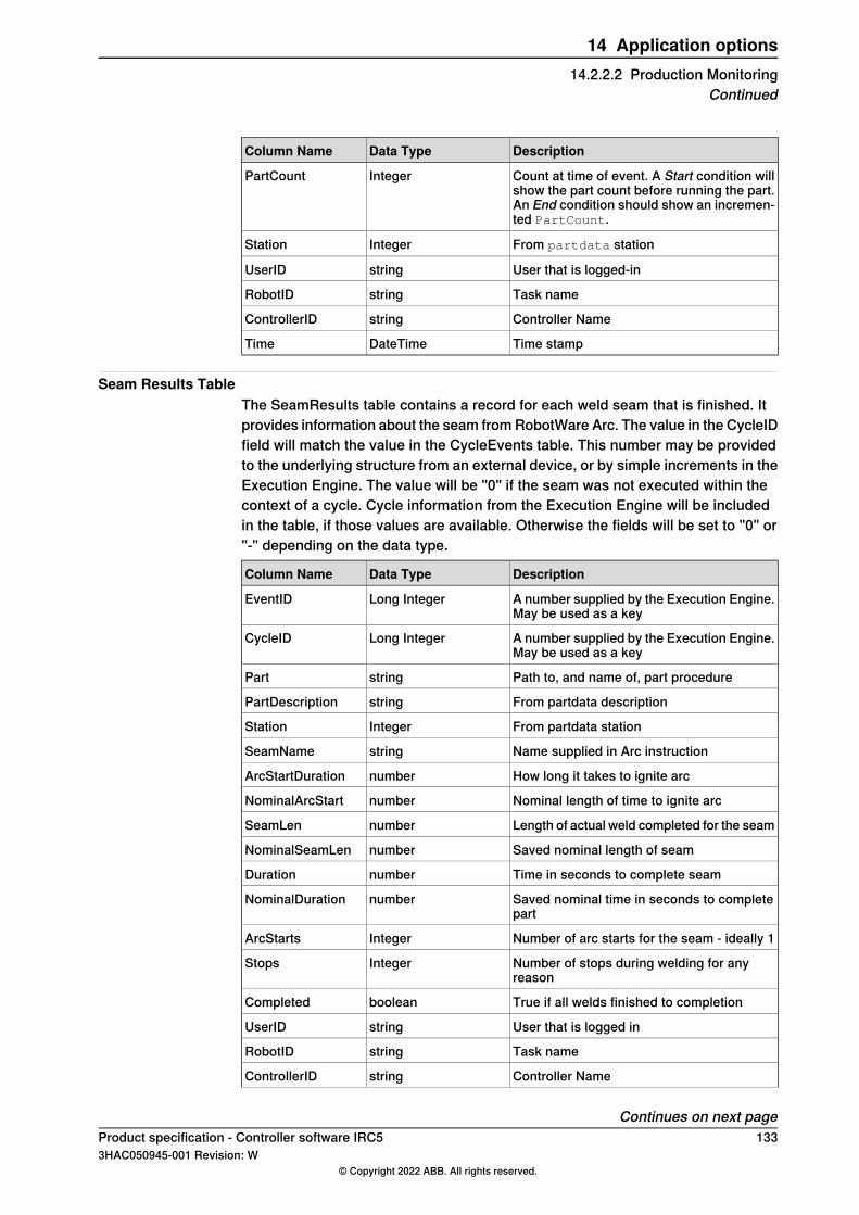
DescriptionData TypeColumn Name
Count at time of event. A Start condition willshow the part count before running the part.An End condition should show an incremen-ted PartCount.
IntegerPartCount
From partdata stationIntegerStation
User that is logged-instringUserID
Task namestringRobotID
Controller NamestringControllerID
Time stampDateTimeTime
Seam Results TableThe SeamResults table contains a record for each weld seam that is finished. Itprovides information about the seam fromRobotWare Arc. The value in the CycleIDfield will match the value in the CycleEvents table. This number may be providedto the underlying structure from an external device, or by simple increments in theExecution Engine. The value will be "0" if the seam was not executed within thecontext of a cycle. Cycle information from the Execution Engine will be includedin the table, if those values are available. Otherwise the fields will be set to "0" or"-" depending on the data type.
DescriptionData TypeColumn Name
A number supplied by the Execution Engine.May be used as a key
Long IntegerEventID
A number supplied by the Execution Engine.May be used as a key
Long IntegerCycleID
Path to, and name of, part procedurestringPart
From partdata descriptionstringPartDescription
From partdata stationIntegerStation
Name supplied in Arc instructionstringSeamName
How long it takes to ignite arcnumberArcStartDuration
Nominal length of time to ignite arcnumberNominalArcStart
Length of actual weld completed for the seamnumberSeamLen
Saved nominal length of seamnumberNominalSeamLen
Time in seconds to complete seamnumberDuration
Saved nominal time in seconds to completepart
numberNominalDuration
Number of arc starts for the seam - ideally 1IntegerArcStarts
Number of stops during welding for anyreason
IntegerStops
True if all welds finished to completionbooleanCompleted
User that is logged instringUserID
Task namestringRobotID
Controller NamestringControllerID
Continues on next pageProduct specification - Controller software IRC5 1333HAC050945-001 Revision: W
© Copyright 2022 ABB. All rights reserved.
14 Application options14.2.2.2 Production Monitoring
Continued
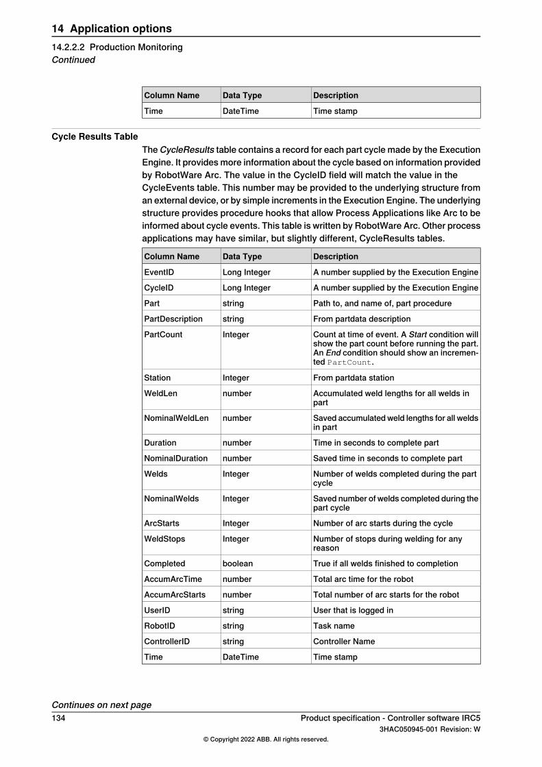
DescriptionData TypeColumn Name
Time stampDateTimeTime
Cycle Results TableTheCycleResults table contains a record for each part cycle made by the ExecutionEngine. It providesmore information about the cycle based on information providedby RobotWare Arc. The value in the CycleID field will match the value in theCycleEvents table. This number may be provided to the underlying structure froman external device, or by simple increments in the Execution Engine. The underlyingstructure provides procedure hooks that allow Process Applications like Arc to beinformed about cycle events. This table is written by RobotWare Arc. Other processapplications may have similar, but slightly different, CycleResults tables.
DescriptionData TypeColumn Name
A number supplied by the Execution EngineLong IntegerEventID
A number supplied by the Execution EngineLong IntegerCycleID
Path to, and name of, part procedurestringPart
From partdata descriptionstringPartDescription
Count at time of event. A Start condition willshow the part count before running the part.An End condition should show an incremen-ted PartCount.
IntegerPartCount
From partdata stationIntegerStation
Accumulated weld lengths for all welds inpart
numberWeldLen
Saved accumulatedweld lengths for all weldsin part
numberNominalWeldLen
Time in seconds to complete partnumberDuration
Saved time in seconds to complete partnumberNominalDuration
Number of welds completed during the partcycle
IntegerWelds
Saved number of welds completed during thepart cycle
IntegerNominalWelds
Number of arc starts during the cycleIntegerArcStarts
Number of stops during welding for anyreason
IntegerWeldStops
True if all welds finished to completionbooleanCompleted
Total arc time for the robotnumberAccumArcTime
Total number of arc starts for the robotnumberAccumArcStarts
User that is logged instringUserID
Task namestringRobotID
Controller NamestringControllerID
Time stampDateTimeTime
Continues on next page134 Product specification - Controller software IRC5
3HAC050945-001 Revision: W© Copyright 2022 ABB. All rights reserved.
14 Application options14.2.2.2 Production MonitoringContinued
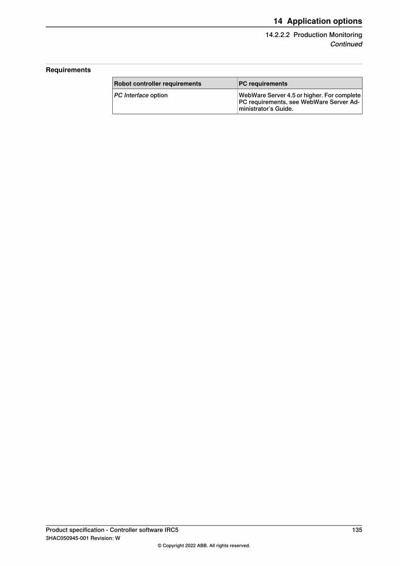
Requirements
PC requirementsRobot controller requirements
WebWare Server 4.5 or higher. For completePC requirements, see WebWare Server Ad-ministrator’s Guide.
PC Interface option
Product specification - Controller software IRC5 1353HAC050945-001 Revision: W
© Copyright 2022 ABB. All rights reserved.
14 Application options14.2.2.2 Production Monitoring
Continued
14.2.2.3 Additional Arc System, Two additional
GeneralThe Additional Arc Systems software option is designed to prepare a robot systemto control two or three arc systems. An example of that could be to control aMIG/MAG process equipment together with a TIG process equipment through onerobot. In order to prepare the software communication to control two or three arcsystems with the same robot, ABB has developed software options, in which oneor two additional process equipment can be defined.
136 Product specification - Controller software IRC53HAC050945-001 Revision: W
© Copyright 2022 ABB. All rights reserved.
14 Application options14.2.2.3 Additional Arc System, Two additional
14.2.2.4 Included options
The option Arc 6 [633-4] includes the options below:• 637-1 Production Screen [637-1]• FlexPendant Interface [617-1] if the option is not selected with option
MultiFunction [824-1]• Cont. Appl. Platform [624-1]
Product specification - Controller software IRC5 1373HAC050945-001 Revision: W
© Copyright 2022 ABB. All rights reserved.
14 Application options14.2.2.4 Included options
14.3 Arc options
GeneralRobotWare Arc Options is a collection of software applications, designed to simplifythe use of different hardware options to improve productivity and lower the costof owning and operating an ABB arc welding system. Some of the software optionsneed to be purchased together with specific hardware option available in separateIRC5 Application product prices list, and other software option can be purchasedindividually. This document will describe these software Arc options in terms ofbasic functionality and if it is connected to a specific hardware.The software is distributed with RobotWare and is activated when building a systemusing the Installation Manager.
Continues on next page138 Product specification - Controller software IRC5
3HAC050945-001 Revision: W© Copyright 2022 ABB. All rights reserved.
14 Application options14.3 Arc options
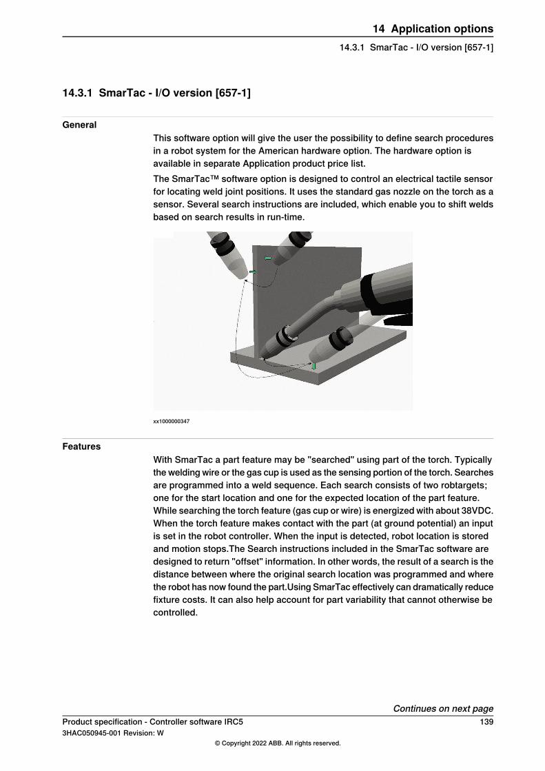
14.3.1 SmarTac - I/O version [657-1]
GeneralThis software option will give the user the possibility to define search proceduresin a robot system for the American hardware option. The hardware option isavailable in separate Application product price list.The SmarTac™ software option is designed to control an electrical tactile sensorfor locating weld joint positions. It uses the standard gas nozzle on the torch as asensor. Several search instructions are included, which enable you to shift weldsbased on search results in run-time.
xx1000000347
FeaturesWith SmarTac a part feature may be "searched" using part of the torch. Typicallythe welding wire or the gas cup is used as the sensing portion of the torch. Searchesare programmed into a weld sequence. Each search consists of two robtargets;one for the start location and one for the expected location of the part feature.While searching the torch feature (gas cup or wire) is energized with about 38VDC.When the torch feature makes contact with the part (at ground potential) an inputis set in the robot controller. When the input is detected, robot location is storedand motion stops.The Search instructions included in the SmarTac software aredesigned to return "offset" information. In other words, the result of a search is thedistance between where the original search location was programmed and wherethe robot has now found the part.Using SmarTac effectively can dramatically reducefixture costs. It can also help account for part variability that cannot otherwise becontrolled.
Continues on next pageProduct specification - Controller software IRC5 1393HAC050945-001 Revision: W
© Copyright 2022 ABB. All rights reserved.
14 Application options14.3.1 SmarTac - I/O version [657-1]
HardwareThe main component is an electronic sensor board, which detects contact with thepart feature to be located. The SmarTac board can be ordered as an add-on unitand is installed in the robot cabinet. Different hardware is used on the Europeanand North American markets, but the functionality is identical.
Note
Note! The hardware options are not included in below specified software option.
140 Product specification - Controller software IRC53HAC050945-001 Revision: W
© Copyright 2022 ABB. All rights reserved.
14 Application options14.3.1 SmarTac - I/O version [657-1]Continued
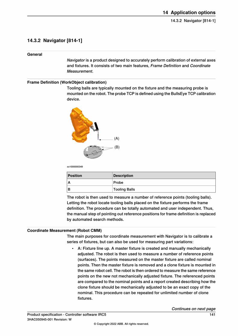
14.3.2 Navigator [814-1]
GeneralNavigator is a product designed to accurately perform calibration of external axesand fixtures. It consists of two main features, Frame Definition and CoordinateMeasurement.
Frame Definition (WorkObject calibration)Tooling balls are typically mounted on the fixture and the measuring probe ismounted on the robot. The probe TCP is defined using the BullsEye TCP calibrationdevice.
(A)
(B)
xx1000000349
DescriptionPosition
ProbeA
Tooling BallsB
The robot is then used to measure a number of reference points (tooling balls).Letting the robot locate tooling balls placed on the fixture performs the framedefinition. The procedure can be totally automated and user independent. Thus,the manual step of pointing out reference positions for frame definition is replacedby automated search methods.
Coordinate Measurement (Robot CMM)The main purposes for coordinate measurement with Navigator is to calibrate aseries of fixtures, but can also be used for measuring part variations:
• A: Fixture line up. A master fixture is created and manually mechanicallyadjusted. The robot is then used to measure a number of reference points(surfaces). The points measured on the master fixture are called nominalpoints. Then the master fixture is removed and a clone fixture is mounted inthe same robot cell. The robot is then ordered to measure the same referencepoints on the new not mechanically adjusted fixture. The referenced pointsare compared to the nominal points and a report created describing how theclone fixture should be mechanically adjusted to be an exact copy of thenominal. This procedure can be repeated for unlimited number of clonefixtures.
Continues on next pageProduct specification - Controller software IRC5 1413HAC050945-001 Revision: W
© Copyright 2022 ABB. All rights reserved.
14 Application options14.3.2 Navigator [814-1]

• B: Production batch monitoring. Instead of measuring fixture points thenominal points are created on a master part. Subsequent parts/batches arethereafter checked periodically for deviation from the master part. The resultis logged, which creates a possibility to automatically stop production.
HardwareThe Navigator hardware for frame definition consists of the measurement probe(for example gas nozzle equipped with a tooling ball) and mounting holes on thefixture for the tooling balls. This hardware is sold separately.
Expected performanceThe repeatability accuracy of localization of a single sphere is in the samemagnitude as the robots repeatability accuracy, which is estimated to 0.05 [mm].The expected repeatability accuracy of calibration of the base frame for an externalrotational axis is maximum 0.16 [mm] and an average of 0.09 [mm]. The expectedmaximum position deviation of an entire cell calibration including probe TCPcalibration, external axis calibration and workobject/fixture calibration is 0.24 [mm]and the average position deviation is 0.13 [mm]. These numbers are based onempirical tests and should only serve as an estimate of expected performance.ABB cannot be held responsible for deviations from these values. For bestperformance the robot should be equipped with BullsEye TCP calibration andSmarTac tactile sensor.
RequirementsA tactile sensor (preferably SmarTac).
RAPID instructionsRAPID instructions included in this option:
DescriptionInstruction
SearchSpL is an instruction for tactile measuring the positionof the center of a sphere (for example tooling ball). The robotmoves with linear motion to the starting point for the searchpattern. From the starting point the robot moves in a downwardspiral pattern until the probe touches the tooling ball. The pat-tern is repeated several times and the center of the tooling ballis calculated.
SearchSpL
SearchSpJ is an instruction for tactile measuring the positionof the center of a sphere (for example tooling ball). The robotmoves with joint motion to the starting point for the searchpattern. From the starting point the robot moves in a downwardspiral pattern until the probe touches the tooling ball. The pat-tern is repeated several times and the center of the tooling ballis calculated.
SearchSpJ
Continues on next page142 Product specification - Controller software IRC5
3HAC050945-001 Revision: W© Copyright 2022 ABB. All rights reserved.
14 Application options14.3.2 Navigator [814-1]Continued
DescriptionInstruction
Measure_1D is an instruction used for tactile measuring a pointperpendicular to its plane. The robot will make a linear move-ment to the position ApprPoint. The search equipment willbe activated andmotion will start towards the point to measure,NominalPoint. The robot will continue past the search pointfor amaximum total search distance twice the distance betweenApprPoint and NominalPoint. Once the feature is sensed,motion stops, and the distance between NominalPoint andsearch position is logged and displayed on the FlexPendant.If the argument \UpdateNominal is used the NominalPointwill get the value of the search.
Measure_1D
Product specification - Controller software IRC5 1433HAC050945-001 Revision: W
© Copyright 2022 ABB. All rights reserved.
14 Application options14.3.2 Navigator [814-1]
Continued
14.3.3 Optical Tracking Arc [660-1]
GeneralThe option Optical Tracking Arc is a software option that allows integration ofexternal optical sensors, which can be used for real time seam tracking. Forcommunication between the sensor and the robot controller two differentcommunication links are available: serial link (RS 232) and Ethernet.If the RS232 link is used, the sensors have to be adapted to the ABB standardapplication protocol, LTAPP. Sensors that are adapted to LTAPP are available fromcompanies like Servo Robot, Meta, and Scout.The Ethernet link is available for optical sensors from ServoRobot, which use theapplication protocol Robo-Com Light, defined by ServoRobot.
FeaturesKey features include:
• Easy calibration with dedicated FlexPendant interface and calibration plate,art. No. 3HAC032252-001. Contact ABB Robotics.
• Contour tracking integrated with arc welding movements.• Adaptive process control during path motion and tracking.• TCP/IP enabled to facilitate plug and play capability, using the Ethernet link.• Separate sensors can be installed for each robot in a MultiMove system (if
using serial link, the number of serial ports may be limited).• Includes all features of the option Sensor Interface [628-1].
PerformanceDesigned to work for normal arc welding applications. Real performance, i.e. pathfollowing accuracy, is however depending on current speed, curvature, look ahead,sampling frequency etc.
RequirementsFor calibration, the hardware option calibration plate [1250-1] is required.
144 Product specification - Controller software IRC53HAC050945-001 Revision: W
© Copyright 2022 ABB. All rights reserved.
14 Application options14.3.3 Optical Tracking Arc [660-1]
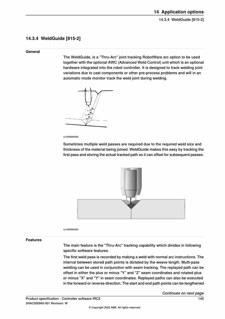
14.3.4 WeldGuide [815-2]
GeneralThe WeldGuide, is a "Thru-Arc" joint tracking RobotWare arc option to be usedtogether with the optional AWC (Advanced Weld Control) unit which is an optionalhardware integrated into the robot controller. It is designed to track welding jointvariations due to cast components or other pre-process problems and will in anautomatic mode monitor track the weld joint during welding.
xx1000000350
Sometimes multiple weld passes are required due to the required weld size andthickness of the material being joined. WeldGuide makes this easy by tracking thefirst pass and storing the actual tracked path so it can offset for subsequent passes.
xx1000000355
FeaturesThe main feature is the "Thru-Arc" tracking capability which divides in followingspecific software features.The first weld pass is recorded by making a weld with normal arc instructions. Theinterval between stored path points is dictated by the weave length. Multi-passwelding can be used in conjunction with seam tracking. The replayed path can beoffset in either the plus or minus "Y" and "Z" seam coordinates and rotated plusor minus "X" and "Y" in seam coordinates. Replayed paths can also be executedin the forward or reverse direction. The start and end path points can be lengthened
Continues on next pageProduct specification - Controller software IRC5 1453HAC050945-001 Revision: W
© Copyright 2022 ABB. All rights reserved.
14 Application options14.3.4 WeldGuide [815-2]
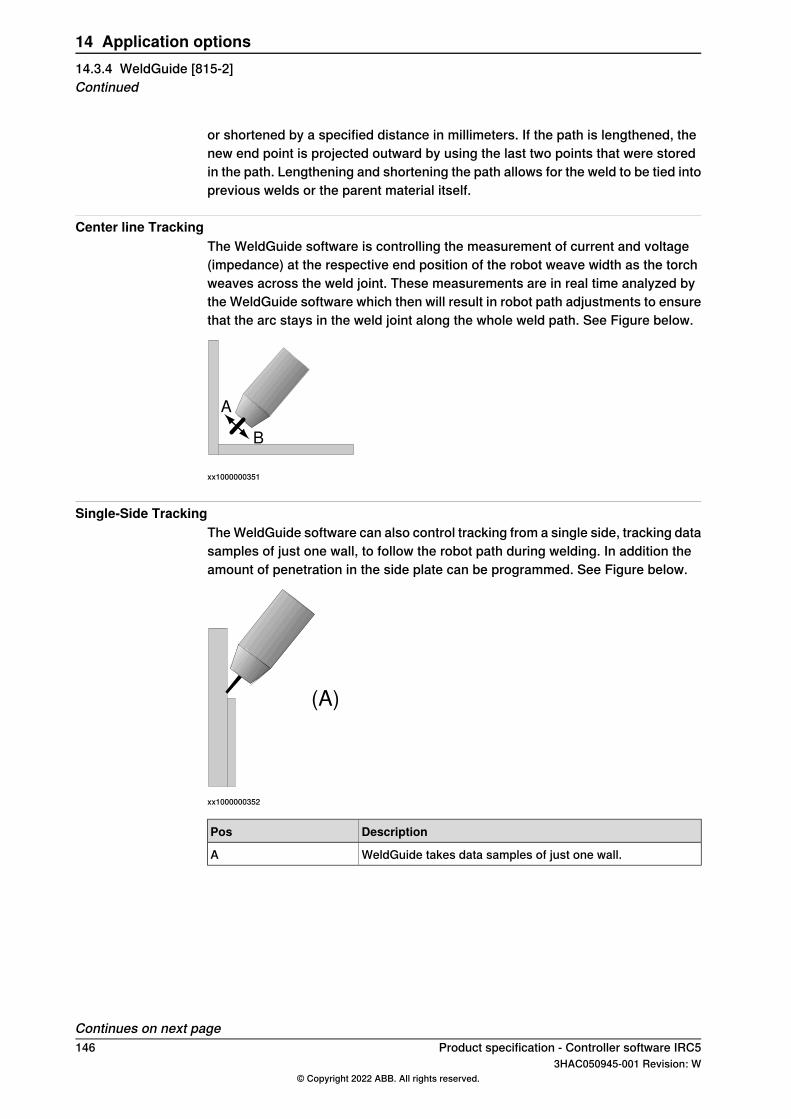
or shortened by a specified distance in millimeters. If the path is lengthened, thenew end point is projected outward by using the last two points that were storedin the path. Lengthening and shortening the path allows for the weld to be tied intoprevious welds or the parent material itself.
Center line TrackingThe WeldGuide software is controlling the measurement of current and voltage(impedance) at the respective end position of the robot weave width as the torchweaves across the weld joint. These measurements are in real time analyzed bythe WeldGuide software which then will result in robot path adjustments to ensurethat the arc stays in the weld joint along the whole weld path. See Figure below.
A
B
xx1000000351
Single-Side TrackingTheWeldGuide software can also control tracking from a single side, tracking datasamples of just one wall, to follow the robot path during welding. In addition theamount of penetration in the side plate can be programmed. See Figure below.
(A)
xx1000000352
DescriptionPos
WeldGuide takes data samples of just one wall.A
Continues on next page146 Product specification - Controller software IRC5
3HAC050945-001 Revision: W© Copyright 2022 ABB. All rights reserved.
14 Application options14.3.4 WeldGuide [815-2]Continued
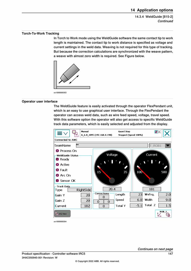
Torch-To-Work TrackingIn Torch to Work mode using theWeldGuide software the same contact tip to worklength is maintained. The contact tip to work distance is specified as voltage andcurrent settings in the weld data. Weaving is not required for this type of tracking.But because the correction calculations are synchronized with the weave pattern,a weave with almost zero width is required. See Figure below.
xx1000000353
Operator user interfaceThe WeldGuide feature is easily activated through the operator FlexPendant unit,which is an easy to use graphical user interface. Through the FlexPendant theoperator can access weld data, such as wire feed speed, voltage, travel speed.With this software option the operator will also get access to specific WeldGuidetrack data parameters, which is easily selected and adjusted from the display.
xx1000000354
Continues on next pageProduct specification - Controller software IRC5 1473HAC050945-001 Revision: W
© Copyright 2022 ABB. All rights reserved.
14 Application options14.3.4 WeldGuide [815-2]
Continued
RequirementsThe optionWeldGuide for RobotWare Arc communicates within the robot controllerthrough the RS232 serial port. The robot hardware option [714-1] RS232 to 422converter is needed as the hardware AWC unit communicates through an RS484serial connection.WeldGuide parameters are factory downloaded using the providedparameters disk, and the AWC Companion software installed on a laptop PC,following the hardware option delivery. Parameters can be transferred betweenthe PC and the WeldGuide software through the serial port.
Note
Note: The RW Arc Option“ WeldGuide” does not include the AWC hardwareoption.For more information see separate product application price list.
LimitationsThe following limitations apply for WeldGuide (815-1 or 815-2) in a MultiMovesystem:
• If more than one robot is to be equipped with WeldGuide, multiple serialchannels are needed. This is available on request only (based on the previousmain computer).
• Multiple WeldGuides can not be used when the workpiece is held by amechanical unit (robot or positioner). This limitation applies also when theworkpiece is stationary during welding.
RAPID instructionsRAPID instructions included in this option:For more information, see Operating manual - Seam tracking with Weldguide IIIand MultiPass.
148 Product specification - Controller software IRC53HAC050945-001 Revision: W
© Copyright 2022 ABB. All rights reserved.
14 Application options14.3.4 WeldGuide [815-2]Continued
14.4 BullsEye [652-1]
GeneralBullsEye™ provides completely automated Tool Center Point (TCP) definition forwelding robots controlled by the IRC5 robot controller. By checking and updatingthe TCP alignment at regular intervals the robot will always operate with an accurateTCP.
FeaturesThe following main tasks can be handled from the BullsEye software options:
• Definition of tool data.• Definition and programming of QuickCheck™ procedures.• Definition and programming of full scan sequence and update the tool data.• Programming of extended Electrode Extension (Wire Stick-out) on existing
tool data.• Instruction to view the deviation in tool data that has been checked over time.
DescriptionThe robot moves the welding wire across an optical beam in several differentorientations and the TCP is calculated through triangulation. At designed intervals,the robot can be programmed to zero in on BullsEye, do a quick check in about10 seconds, and go back to work. If the TCP is misaligned BullsEye automaticallyrecalculates TCP and torch angle.The BullsEye software option will give the user the possibility to define and programa standalone BullsEye hardware device, see below pictures of different availablehardware. The BullsEye arc option includes software that is loaded into all arc
Continues on next pageProduct specification - Controller software IRC5 1493HAC050945-001 Revision: W
© Copyright 2022 ABB. All rights reserved.
14 Application options14.4 BullsEye [652-1]
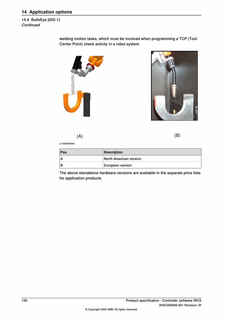
welding motion tasks, which must be involved when programming a TCP (ToolCenter Point) check activity in a robot system.
(A) (B)
xx1000000343
DescriptionPos
North American versionA
European versionB
The above standalone hardware versions are available in the separate price listsfor application products.
150 Product specification - Controller software IRC53HAC050945-001 Revision: W
© Copyright 2022 ABB. All rights reserved.
14 Application options14.4 BullsEye [652-1]Continued
14.5 Spot 6 [635-6]
GeneralThe RobotWare Spot option is a general and flexible software platform for creationof customized and easy to use function packages for different types of spot weldingsystems and process equipment.There are three different main Spot configurations supporting spot welding, twofor servo guns and one for pneumatic guns. All Spot configurations providesdedicated spot welding instructions for fast and accurate positioning combinedwith gunmanipulation, process start and supervision of the different gun equipment.The included instructions can be used for sequential welding with one or severalgun equipment or for welding with up to four guns at the same time.The Spot configurations are also general and can be customized extensively. Theyhave a default "ready to use" functionality directly after installation and can be ifneeded, customized via process configuration.The Spot option software is also distributed separately from RobotWare as aRobotWare Add-In, accessible from theRobotStudio Add-InsGallery. The SpotWareAdd-in has is own release cycle and is not connected to a specific RobotWarerelease. This allows for faster update of the software when needed.
FeaturesThe Spot option package contains the following features:
• Fast and accurate positioning using the unique QuickMove and TrueMoveconcept.
• Gun pre-closing, gun closing will be synchronized with robot reaching theweld position to save cycle time.
• Software equalizing functions (if the Spot Servo Equalizing configuration isinstalled).
• Support for mechanical gun equalizing systems.• Support functions for tip wear management.• Constant or changeable gun force during welding for servo guns.• Gravity compensation of gun force during welding.• Calibration functions for servo guns.• Detection of missing or improper plates for servo guns.• Reverse execution with gun control.• Manual actions for welding and gun control.• Support for fast tool changing between up to 8 different servo guns. Note
that this requires the option 630-1 Servo Tool Change.• Support for simultaneous welding with up to four guns at the same time (for
MultiMove systems with 2 robots, up to two guns each for simultaneouswelding).
• Several simulation possibilities for test purposes.• Weld error recovery with automatic rewelding.
Continues on next pageProduct specification - Controller software IRC5 1513HAC050945-001 Revision: W
© Copyright 2022 ABB. All rights reserved.
14 Application options14.5 Spot 6 [635-6]
• Default "ready to use" functionality directly after installation if a SpotPackconfiguration is selected.
• Wide customizing possibilities, process data types, spotdata, gundata, suchas weld counters and tip wear data, for each used gun.
• Built in error handling and possibility for customizable user-definedsupervision and error recovery.
• A dedicated Spot operator interface on the FlexPendant.• Integrated weld equipment fault management (for the options 782-x Bosch
Weld timer)• Support for Spotwelding on two robots in a MultiMove system, and run semi
coordinated using WaitSyncTask. Note that option 634-1 MultiProcess isrequired for more than one robot in a MultiMove system.
• Possibility to run some Spot functionality without a robot selected, i.e. a standalone controller system.
• Possibility for weld process data access. Note that option 1585-1 Processdata access is required.
SpotWare Servo Equalizing FeaturesFor the Spot Servo Equalizing configuration the gun equalizing features areembedded in the Spot Servo process software. Spot Servo Equalizing allows youto solve spot welding gun equalizing without mechanical equalizing hardware onthe weld gun and thus provides an opportunity to reduce investment cost andimprove productivity. Removed hardware on the gun also reduces weight, and inaddition, no gravitational influence means easier optimizing when programmingthe robot path.Furthermore, with the Spot Servo Equalizing software instead ofmechanical equalizing, less spare parts are required and lower maintenance costsare achieved. Spot Servo Equalizing is valid for:
• Robot mounted C- and X-type guns• Pedestal C- and X-type guns• Tool changing between guns with different equalizing data• Weld position touch up - Simplifies adjustment of the programmed weld
positions.• Release of the fixed gun arm - Automatic gun arm release from the welded
sheets when the robot is moving among weld points.• Gun arm deflection compensation - The robot program compensates for the
gun arm deflection automatically.• Tip wear measurement and compensation - The robot program automatically
compensates the weld gun TCP (Tool Center Point) for tip wear without usingexternal sensors.
• The equalizing type (mechanical or software) is determined by data set inthe gundata for each used gun.
• SoftMove Equalizing - The robot will be set to a "soft state" in the toolz-direction during the gun closing.
Continues on next page152 Product specification - Controller software IRC5
3HAC050945-001 Revision: W© Copyright 2022 ABB. All rights reserved.
14 Application options14.5 Spot 6 [635-6]Continued
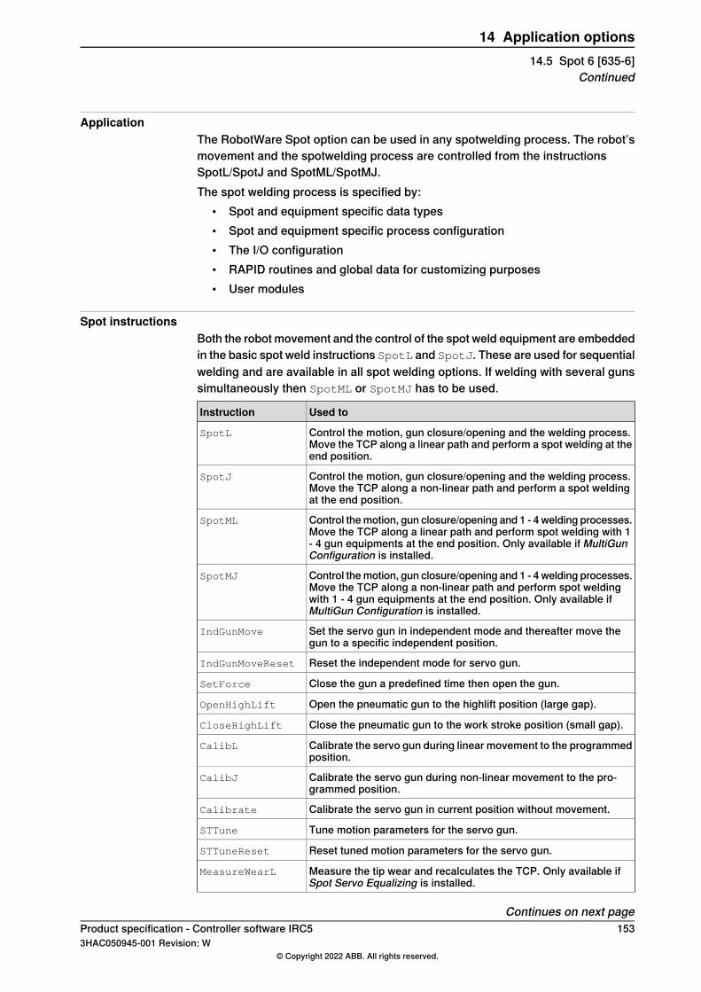
ApplicationThe RobotWare Spot option can be used in any spotwelding process. The robot’smovement and the spotwelding process are controlled from the instructionsSpotL/SpotJ and SpotML/SpotMJ.The spot welding process is specified by:
• Spot and equipment specific data types• Spot and equipment specific process configuration• The I/O configuration• RAPID routines and global data for customizing purposes• User modules
Spot instructionsBoth the robot movement and the control of the spot weld equipment are embeddedin the basic spot weld instructions SpotL and SpotJ. These are used for sequentialwelding and are available in all spot welding options. If welding with several gunssimultaneously then SpotML or SpotMJ has to be used.
Used toInstruction
Control the motion, gun closure/opening and the welding process.Move the TCP along a linear path and perform a spot welding at theend position.
SpotL
Control the motion, gun closure/opening and the welding process.Move the TCP along a non-linear path and perform a spot weldingat the end position.
SpotJ
Control themotion, gun closure/opening and 1 - 4 welding processes.Move the TCP along a linear path and perform spot welding with 1- 4 gun equipments at the end position. Only available if MultiGunConfiguration is installed.
SpotML
Control themotion, gun closure/opening and 1 - 4 welding processes.Move the TCP along a non-linear path and perform spot weldingwith 1 - 4 gun equipments at the end position. Only available ifMultiGun Configuration is installed.
SpotMJ
Set the servo gun in independent mode and thereafter move thegun to a specific independent position.
IndGunMove
Reset the independent mode for servo gun.IndGunMoveReset
Close the gun a predefined time then open the gun.SetForce
Open the pneumatic gun to the highlift position (large gap).OpenHighLift
Close the pneumatic gun to the work stroke position (small gap).CloseHighLift
Calibrate the servo gun during linear movement to the programmedposition.
CalibL
Calibrate the servo gun during non-linear movement to the pro-grammed position.
CalibJ
Calibrate the servo gun in current position without movement.Calibrate
Tune motion parameters for the servo gun.STTune
Reset tuned motion parameters for the servo gun.STTuneReset
Measure the tip wear and recalculates the TCP. Only available ifSpot Servo Equalizing is installed.
MeasureWearL
Continues on next pageProduct specification - Controller software IRC5 1533HAC050945-001 Revision: W
© Copyright 2022 ABB. All rights reserved.
14 Application options14.5 Spot 6 [635-6]
Continued
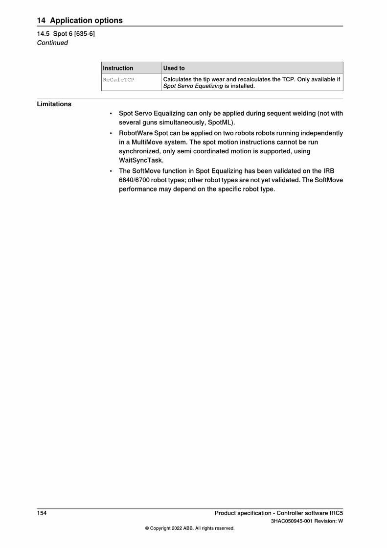
Used toInstruction
Calculates the tip wear and recalculates the TCP. Only available ifSpot Servo Equalizing is installed.
ReCalcTCP
Limitations• Spot Servo Equalizing can only be applied during sequent welding (not with
several guns simultaneously, SpotML).• RobotWare Spot can be applied on two robots robots running independently
in a MultiMove system. The spot motion instructions cannot be runsynchronized, only semi coordinated motion is supported, usingWaitSyncTask.
• The SoftMove function in Spot Equalizing has been validated on the IRB6640/6700 robot types; other robot types are not yet validated. The SoftMoveperformance may depend on the specific robot type.
154 Product specification - Controller software IRC53HAC050945-001 Revision: W
© Copyright 2022 ABB. All rights reserved.
14 Application options14.5 Spot 6 [635-6]Continued
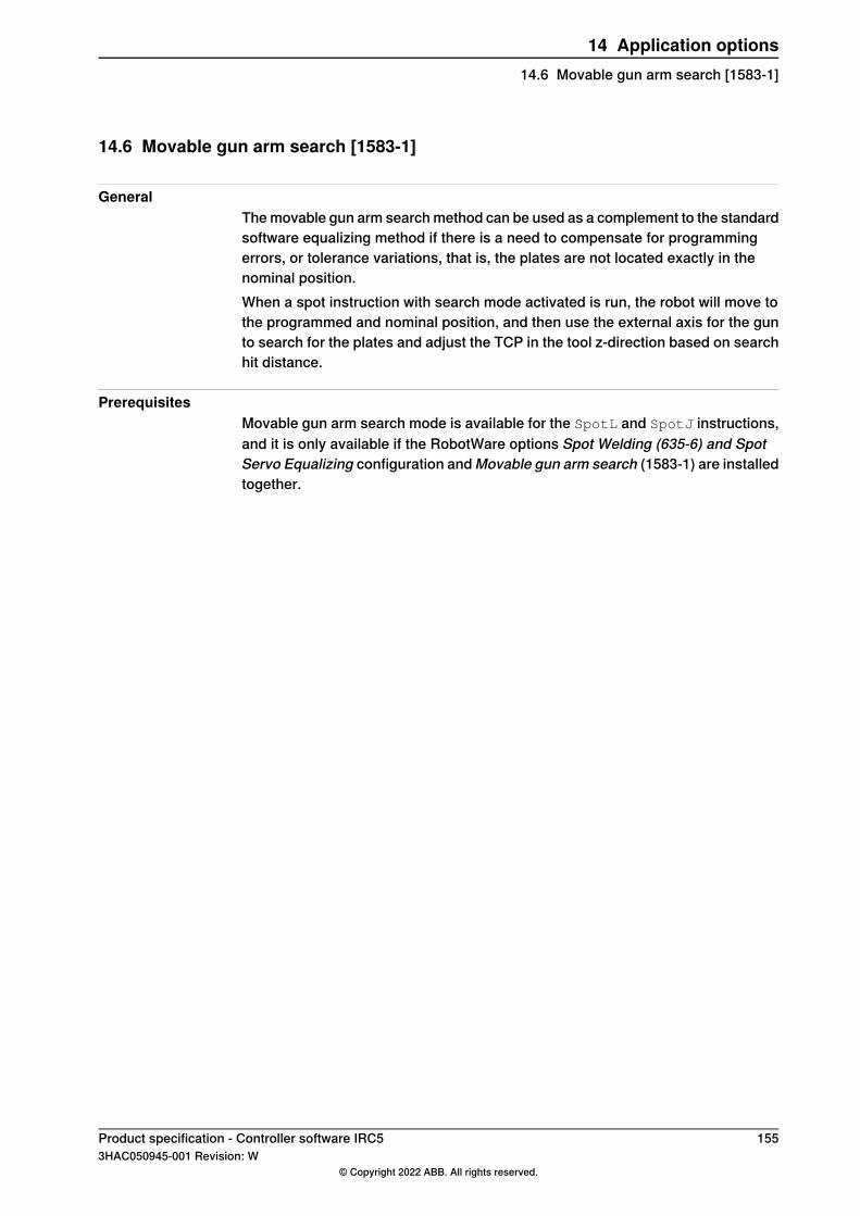
14.6 Movable gun arm search [1583-1]
GeneralThemovable gun arm searchmethod can be used as a complement to the standardsoftware equalizing method if there is a need to compensate for programmingerrors, or tolerance variations, that is, the plates are not located exactly in thenominal position.When a spot instruction with search mode activated is run, the robot will move tothe programmed and nominal position, and then use the external axis for the gunto search for the plates and adjust the TCP in the tool z-direction based on searchhit distance.
PrerequisitesMovable gun arm search mode is available for the SpotL and SpotJ instructions,and it is only available if the RobotWare options Spot Welding (635-6) and SpotServo Equalizing configuration andMovable gun arm search (1583-1) are installedtogether.
Product specification - Controller software IRC5 1553HAC050945-001 Revision: W
© Copyright 2022 ABB. All rights reserved.
14 Application options14.6 Movable gun arm search [1583-1]
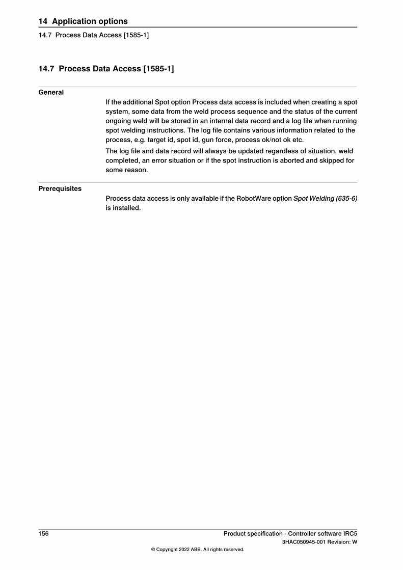
14.7 Process Data Access [1585-1]
GeneralIf the additional Spot option Process data access is included when creating a spotsystem, some data from the weld process sequence and the status of the currentongoing weld will be stored in an internal data record and a log file when runningspot welding instructions. The log file contains various information related to theprocess, e.g. target id, spot id, gun force, process ok/not ok etc.The log file and data record will always be updated regardless of situation, weldcompleted, an error situation or if the spot instruction is aborted and skipped forsome reason.
PrerequisitesProcess data access is only available if the RobotWare option SpotWelding (635-6)is installed.
156 Product specification - Controller software IRC53HAC050945-001 Revision: W
© Copyright 2022 ABB. All rights reserved.
14 Application options14.7 Process Data Access [1585-1]
14.8 Bosch Interface [832-1]
GeneralThe Bosch interface option is used to simplify programming and monitoring of theBosch weld timer. The option includes a robot FlexPendant interface that could beused for setting or editing weld parameters, monitor weld status and give easyaccess information if weld error occurs.The option is integrated as an add on functionality to the RobotWare Spot option:
• Option 635-6. Spot Welding
FeaturesThe features within the option are designed to support needs during normalproduction conditions. Some examples of useful functions are given below:
• Features to set or edit the weld parameter• Information about weld errors plain text and also proposal of recovery steps• Pre-warning of electrode wear• Information of last performed weld
Weld timersThe option is prepared to be used in combinations with the following weld timers:
DescriptionWeld timer
Option 782-13, Bosch MFDC ProfiNetBosch PSI 61C0.751OEM
The option includes both software as well as necessary additional cabling betweenthe weld timer and the robot controller.
LimitationsThis software does not replace the need for the PC software BOS5000/6000 wichis needed during setup, and to backup parameters etc.Advanced setup and configuration can not be performed from this software, thissoftware is a complement to the BOS5000/BOS6000 PC software.Before using the Bosch interface option some necessary setup is needed. This isdone by using a Bosch specific PC software (BOS5000/BOS6000). The PC softwarewill also be required if extra ordinary weld faults (hardware faults) occur.It is only possible to connect one weld timer to a robot controller since there isonly one serial communication connection on the robot controller.This option can not combined with option MultiProcess [634-1].
Product specification - Controller software IRC5 1573HAC050945-001 Revision: W
© Copyright 2022 ABB. All rights reserved.
14 Application options14.8 Bosch Interface [832-1]
14.9 Dispense [641-1]
GeneralTheRobotWare Dispense option provides support for different types of dispensingprocesses such as gluing and sealing. The option provides fast and accuratepositioning combined with a flexible process control. Communication with thedispensing equipment is carried out by means of digital and analog outputs.RobotWare Dispense is an option that can be extensively customized.
Features• On/Off gun support• Proportional gun support• Handles up to 4 gun equipment in the same program• Fast and accurate positioning and process control• Dispensing in wet or dry mode• Restart an interrupted dispensing sequence• Speed proportional AO• Different anticipated times for the DO and AO• Equipment delay compensation for the TCP speed proportional analog signals• Global or local flow rate correction factors• Automatic reduction of the robot acceleration/deceleration during dispensing• Wide opportunities of customizing the functionality to adapt to different types
of dispensing equipment• A dedicated Dispense GUI on the FlexPendant• RobotWare Dispense can also be used in MultiMove system, where up to
four dispensing robots can be controlled from the same IRC5 system.• Dispense robots can be combined with other process application robots in
one MultiMove system.
ApplicationRobotWare Dispense can be used in any gluing or sealing process.The robot’s movement and the dispensing process are controlled from theinstructions DispL and DispC.A dispensing process is specified by:
• Bead specific dispensing data• Equipment specific dispensing data• Equipment specific process configuration• RAPID routines and global data for customizing purposes• System Module DPUSER• The I/O configuration
Continues on next page158 Product specification - Controller software IRC5
3HAC050945-001 Revision: W© Copyright 2022 ABB. All rights reserved.
14 Application options14.9 Dispense [641-1]
RAPID instructionsRAPID instructions included in this option:
DescriptionInstruction
Move the TCP along a linear path and perform dispensing withthe given data
DispL
Move the TCP along a circular path and perform dispensingwith the given data
DispC
Product specification - Controller software IRC5 1593HAC050945-001 Revision: W
© Copyright 2022 ABB. All rights reserved.
14 Application options14.9 Dispense [641-1]
Continued
14.10 Packaging
14.10.1 PickMaster Ready
14.10.1.1 PickMaster Cell Ready [1580-1]
GeneralThe option PickMaster Cell Ready
• Checked by PickMaster Runtime when connecting to a robot, duringcommissioning when configuring position source and when starting a recipe
• The license is needed to enable PickMaster Runtime with vision for one robot• Digital I/O is needed for PickMaster functions• The option is used with Conveyor Tracking options: Conv. Tracking unit Int.
[1550-1], Conv. Tracking unit Ext. [1551-1], Tracking unit interface [1552-1]
Includes RobotWare options• Conveyor Tracking [606-1]• PC-Interface [616-1]• PickMaster Vision Ready [1581-1]
LimitationsThe option PickMaster Cell Ready is not possible to combine with option:
• Multi Move [604-1,604-2]
160 Product specification - Controller software IRC53HAC050945-001 Revision: W
© Copyright 2022 ABB. All rights reserved.
14 Application options14.10.1.1 PickMaster Cell Ready [1580-1]
14.10.1.2 PickMaster Robot Ready [1580-2]
GeneralThe option PickMaster Robot Ready
• Checked by PickMaster Runtimewhen connecting to one robot without visionor External Sensor and when starting a recipe
• The license is needed for a robot to be included in PickMaster Runtime• Digital I/O is needed for PickMaster functions• The option is used with Conveyor Tracking options: Conv. Tracking unit Int.
[1550-1], Conv. Tracking unit Ext. [1551-1], Tracking unit interface [1552-1]
Includes RobotWare options• Conveyor Tracking [606-1]• PC-Interface [616-1]
LimitationsThe option PickMaster Robot Ready is not possible to combine with option:
• Multi Move [604-1,604-2]
Product specification - Controller software IRC5 1613HAC050945-001 Revision: W
© Copyright 2022 ABB. All rights reserved.
14 Application options14.10.1.2 PickMaster Robot Ready [1580-2]
14.10.2 PickMaster Vision
14.10.2.1 PickMaster Vision Ready [1581-1]
GeneralThe option PickMaster Vision Ready
• Checked by PickMaster Runtime during commissioning when configuringposition source and when starting a recipe
• The License is needed to receive positions generated by a sensor, either thestandard vision or External Sensor
• Valid for multiple sensor driven position sources• The option is included in PickMaster Cell Ready [1580-1]
RequirementsThe option PickMaster Vision Ready requires option PickMaster Robot Ready[1580-2]
LimitationsThe option PickMaster Vision Ready is not possible to combine with option:
• Multi Move [604-1,604-2]
162 Product specification - Controller software IRC53HAC050945-001 Revision: W
© Copyright 2022 ABB. All rights reserved.
14 Application options14.10.2.1 PickMaster Vision Ready [1581-1]
14.11 Prep. for PickMaster&PowerPac
14.11.1 PickMaster 3 [642-1]
GeneralPrepared for PickMaster/PickMaster 3 supports the PickMaster 3 applicationsoftware residing on a PC. Prepared for PickMaster features together with thePickMaster 3 application configurable integration of robots, vision and conveyors.The option contains all necessary functions and further options to interfacePickMaster 3 and to run enhanced conveyor tracking. PickMaster 3 is approvedfor running on one IRC5 controller with multiple robots. For further information seeProduct Specification - PickMaster 3.
Feature• Dedicated data types and instructions for efficient data transfer between PC
and controller• Built-in enhanced conveyor tracking capability with capability to control up
to six conveyors. Maximum approved conveyor speed is 1400 mm/s.• Enables run-time cell control by PickMaster with fully autonomous application
startup• Supports minimal parameterized RAPID code downloaded from PickMaster
at startup• Boundary checks and start/stop control on conveyors• High performance camera trigger synchronization to fixed work areas and/or
conveyor frames. Maximum eight work areas in total.• Type and quality selection• Advanced functions for mixing and sorting• Approved for running two MultiMove robots on one controller.
Includes RobotWare options• Advanced Rapid• Fixed Position Events• Tracking functionality included• PC-Interface [616-1]
ApplicationAimed for packaging applications, typically random high-speed picking and packingon the fly. Further, PickMaster 3 is the ideal standard vision integration for all robottypes in material handling and machine tending applications.
PerformanceSee Product specification - PickMaster 3.
Continues on next pageProduct specification - Controller software IRC5 1633HAC050945-001 Revision: W
© Copyright 2022 ABB. All rights reserved.
14 Application options14.11.1 PickMaster 3 [642-1]
RequirementsEach robot operated by PickMaster requires the option Prepared for PickMaster.
• At least one digital Local I/O device options Base Dig. 16In/16Out [1541-1]or Add-on Dig. 16In/16Out [1542-1] *
• To support conveyor tracking, software option Tracking unit interface [1552-1]is needed **). This option is included with Conveyor Tracking unit options[1550-1] and [1551-1]
• Tracking Unit interface [1550-1] or [1551-1] is required to support 1-4conveyors **). This option can be shared remotely with neighboring controllersvia a local network
• Cannot be combined with Conveyor Tracking [606-1]* Alternativeely, one Digital 24 VDC I/O [716-1] or AD Combi I/O [717-1]** Alternatively, one encoder interface unit [726-1] is needed for each conveyorwork area
PickMaster 3 user manualThe PickMaster user manual describes the application as well as related RAPIDdata and instructions in detail.
RAPID InstructionsRAPID data types
AckItmTgtitmsrc
CreateInstDatitmsrcdat
FlushItmSrcitmtgt
FreeAllItmSrcselectiondata
FreeItmSrcsortdata
GetAllItmSrc
GetItmTgt
ItmSrcByName
NewItmSrc
NextItmTgtType
QstartItmSrc
QstopItmSrc
ResetItmSrc
164 Product specification - Controller software IRC53HAC050945-001 Revision: W
© Copyright 2022 ABB. All rights reserved.
14 Application options14.11.1 PickMaster 3 [642-1]Continued
14.11.2 Palletizing PowerPac [642-2]
GeneralPrepared for Palletizing PowerPac works with the offline Palletizing PowerPacsoftware residing on a PC. It features a flexible ease of use application softwarefor palletizing. Prepared for Palletizing PowerPac operates alone in runtimeindependently on the controller as a self-contained single cell application. Theapplication is operated by the FlexPendant Palletizing application. The optioncontains all necessary functions and further options to interface PalletizingPowerPac and to run the application. Palletizing PowerPac is approved for runningon one IRC5 controller with one single robot. For further information see Productspecification - Palletizing PowerPac.
FeaturesPalletizing PowerPac offers advanced automated palletizing functions formulti-station cells and mixed pallet loads. It is configured and commissionedthrough a Palletizing PowerPac PC-application residing on a standard laptopcomputer. Palletizing PowerPac is Robot Studio Add-In, hence offers all theadvantages of offline robot programming, which is found in Robot Studio.Dedicated data types and instructions for efficient template based RAPID executionand application information exchange.Open code for user enhancements. DedicatedFlexPendant application for launching and controlling Palletizing PowerPacprojects.
• Fully autonomous operation without online PC-connection• Dedicated palletizing production panel on the FlexPendant.• Parametrized fly-in and –out trajectories• Stack search functions• Safety height calculations• Built-in automatic application sequencer logics• I/O inter connectivity to station controls production run orders, and equipment.• Integrated control of generic multiple zone grippers addressing both vacuum
and mechanical grippers.• Approved for running one robot per controller Applicable on both 4 and 6
axes robots
Includes RobotWare options• Advanced Rapid [626-1]• Fixed Position Events [609-1]• FlexPendant Interface [117-1]• PC-Interface [616-1]
ApplicationAimed for pelletizing applications.
PerformanceSee Product specification - Palletizing PowerPac.
Continues on next pageProduct specification - Controller software IRC5 1653HAC050945-001 Revision: W
© Copyright 2022 ABB. All rights reserved.
14 Application options14.11.2 Palletizing PowerPac [642-2]
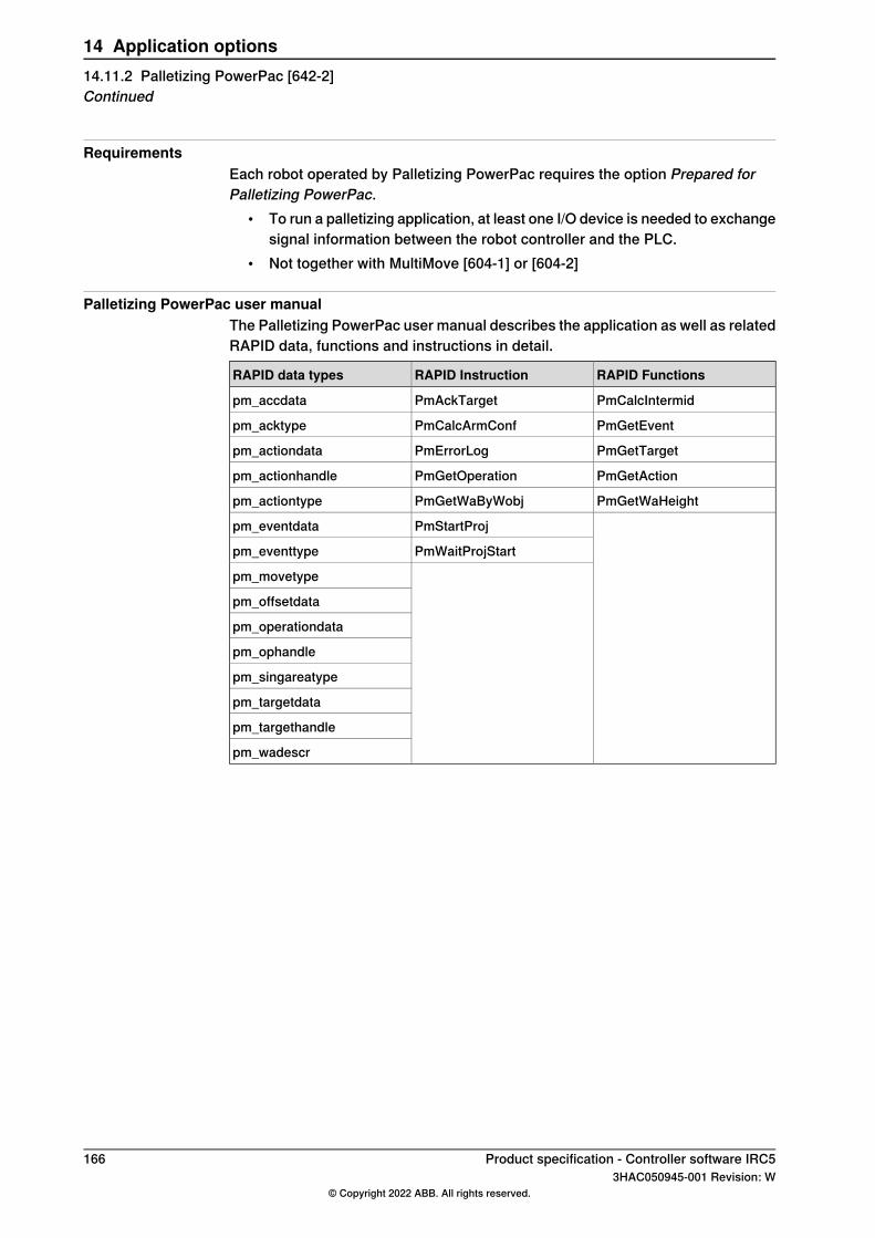
RequirementsEach robot operated by Palletizing PowerPac requires the option Prepared forPalletizing PowerPac.
• To run a palletizing application, at least one I/O device is needed to exchangesignal information between the robot controller and the PLC.
• Not together with MultiMove [604-1] or [604-2]
Palletizing PowerPac user manualThe Palletizing PowerPac user manual describes the application as well as relatedRAPID data, functions and instructions in detail.
RAPID FunctionsRAPID InstructionRAPID data types
PmCalcIntermidPmAckTargetpm_accdata
PmGetEventPmCalcArmConfpm_acktype
PmGetTargetPmErrorLogpm_actiondata
PmGetActionPmGetOperationpm_actionhandle
PmGetWaHeightPmGetWaByWobjpm_actiontype
PmStartProjpm_eventdata
PmWaitProjStartpm_eventtype
pm_movetype
pm_offsetdata
pm_operationdata
pm_ophandle
pm_singareatype
pm_targetdata
pm_targethandle
pm_wadescr
166 Product specification - Controller software IRC53HAC050945-001 Revision: W
© Copyright 2022 ABB. All rights reserved.
14 Application options14.11.2 Palletizing PowerPac [642-2]Continued
14.12 Force Control Base [661-2]
GeneralForce Control Base is an option that contains the RAPID instructions required torun force control. The option contains what was previously the option AssemblyFC and the RAPID layer of the optionMachining FC. TheMachining FC GUI is stilla separate option, Machining FC GUI [877-1].
Assembly FCAssembly FC (Force Control) is a set of functions, which will highly facilitate theuse of robots for assembly tasks. Assembly is a very demanding application whereparts with very small tolerances shall fit together, e.g shafts into gear wheels. Sincetolerances are in the size of robot repeatability, this normally requires high accuracyfixtures and robots with very high precision and still the risk for position failure,where parts are stuck or damaged, is very high. In many cases also parts are notfixed but can have random positions, and thus traditional position controlled robotsare not possible to use.With Assembly FC and a 6-DOF Force/Torque sensor the robot is equipped with"tactile" sense and thus can handle the parts like a human worker, that is searchalong a predefined pattern and try pushing until parts slip into position with onlysmall contact forces used. If measured force gets larger than desired the robotwould move back so as to decrease the force. This will save both installation costand programming time but also reduce the process cycle time.Other areas where Assembly FC is useful are:
• Product testing - apply the same amount of force to a product repetitive• Part mating• Automated fastening
Assembly FC includes functions to use different predefined assembly patterns,designed for different tasks, but also possibility to combine some of them to createnew patterns for more complex assembly tasks.
Machining FCMachining FC is a set of functions, which will highly facilitate the use of robots formachining applications. Machining FC includes solutions for using force controlin different machining applications where the robot needs to be sensitive to processforces. Machining FC offers two kinds of process control, optimized for differentkinds of machining, namely FC Pressure and FC Speed Change.
FC Pressure functionalityWith the FC Pressure functionality the robot will always keep a constant forceagainst a surface, resulting in that the robot will follow the curvature of the surface.The FC Pressure functionality is for example advantageous to use in machiningprocesses like grinding and polishing where the robot needs to obtain a definedpressure (force) between the tool and part for proper result. With FC Pressurefunctionality, the programmed path roughly needs to follow the surface as the robot
Continues on next pageProduct specification - Controller software IRC5 1673HAC050945-001 Revision: W
© Copyright 2022 ABB. All rights reserved.
14 Application options14.12 Force Control Base [661-2]
position will be adjusted to achieve the defined contact force between tool andpart. This will save programming time as well as improve the product quality.
FC Speed Change functionalityFC Speed Change will allow programming at the maximum process speed andautomatically slow down the robot when the machining forces are too high.The FC Speed Change functionality can for example be favorable to use in amachining process like deburring, where the robot needs to slow downwhen hittingexcessive burr, or even retract for sequential machining. The robot is positioncontrolled, that is it will follow the programmed path, in this functionality. With theFC Speed Change functionality the robot will vary the processing speed. This willsave programming time but also reduce the process cycle time.
Functional descriptionNormally robots are position controlled, which means that the robot is forced tomove to a certain ordered position. If the robot is prevented to reach the target,the servo will increase power until max torque or collision is detected.With Assembly FC it will be possible to let the robot search along a surface whilekeeping a predefined contact force. Once the mounting hole is found, the part will“fall” into place and the robot will push the part in to the opening until correctposition is reached.A typical assembly task will for example be the mounting of axis and gear wheelsin a clutch. Such a task will include several different movements to find the correctlocation and insert the axis. For any assembly task it will be possible to tailor thebest optimum search pattern/movement and choose between a number of criteriafor accepting/ending the operation.With Force Control for Machining it will be possible to either let the robot maintaina constant force perpendicular to the path while following the surface curvature(FC Pressure) or let the robot slow down on the pre-defined path to reduce theforce acting on the robot (FC Speed Change).
About FC PressureThe purpose of FC Pressure is to make the robot sensitive to contact forcesperpendicular to the move direction. The robot can “feel” its surroundings andfollow the surface of the processed part to obtain a certain pressure against anobject. This means that the robot will change its position in order to apply a constantforce/pressure on a surface, even if the exact position of the surface is not known.Since pressure is obtained by moving the robot path, this function is more suitedfor polishing, grinding and cleaning, where a surface should be made even andsmooth. The material that is removed and the changes of the surface topology /dimensions depends on the process parameters like tooling, applied pressure,robot speed etc.See below some examples from foundry and metal fabrication where FC Pressureis useful:
• Grinding of faucets• Polishing of kitchen sinks
Continues on next page168 Product specification - Controller software IRC5
3HAC050945-001 Revision: W© Copyright 2022 ABB. All rights reserved.
14 Application options14.12 Force Control Base [661-2]Continued
• Deflashing and cleaning of castings• Deburring of castings
About FC Speed ChangeIn processes where path accuracy is important and where the finished result shallcomply with specific dimensions, FC Speed Change is recommended. This functionwill be useful combined with force sensor or other input indicating excessive forces,which can negatively affect the finished result. When speed change is active andif machining forces exceed a certain value, then the path speed will automaticallybe reduced, thus decreasing forces, minimizing changed dimensions due todeflections of the robot arm and most probably avoid damaging the part/tool dueto stress and heat. This will guarantee path accuracy even if much material shallbe removed. Some examples where FC Speed Change may be used:
• (Wheel) Grinding unevenly distributed material on casted surfaces• Milling along the edge of a work piece• Deburring along contour of a work piece• Deflashing unevenly distributed burr along a part line on castings• Deburring of castings
Assembly FC features• Sensor calibration and load identification, which will calibrate the force sensor
to remove offsets such as the gravity force. RAPID instructions: FCCalib,FCLoadId
• Activation and deactivation of Force Control. When activating Force Controlfor instance the following can be set up.
• Force control coordinate system• Damping, that is how the robot speed depends on the contact force. RAPID
instructions: FCAct, FCDeact, FCRefStart• Definition of reference values (desired force, torque and/or search pattern).
When activating a force/torque reference, the robot will move in order toachieve the specified reference level. When activating a search reference,the robot will attempt to move according to the specified pattern, like circular,spiral or linear movement. RAPID instructions: FCRefForce, FCRefLine,FCRefCircle, FCRefSpiral, FCRefSpringForce etc.
• End conditions (how long to apply the force, torque and search pattern). Thereference force, torque and movement is used to search for a fit. The endconditions are used to determine when this search has been successful. Allconditions have a time-out that allows execution to continue even if the endcondition is not met. RAPID instructions: FCCondPos, FCCondForce,FCCondTime, FCCondWaitWhile etc.
• Supervision, that is Force Control data can be supervised and limits set thatmust be met. Any data outside supervision conditions will result in anemergency stop. This can be used as a safety measurement by limiting thework area, robot speed, etc. RAPID instructions: FCSupvForce, FCSupvPosetc.
Continues on next pageProduct specification - Controller software IRC5 1693HAC050945-001 Revision: W
© Copyright 2022 ABB. All rights reserved.
14 Application options14.12 Force Control Base [661-2]
Continued
• Functions providing feedback from the process, which will give a snapshotof some process data like contact forces, actual load, speed, or if the conditionwas met or if timed out. RAPID functions: FCGetForce,FCGetProcessData, FCIsForceMode
• Data types supporting the instructions and functions• Up to four robots can be controlled independently in a MultiMove cell.
Machining FC feature• Instructions for programming FC Pressure start, movements and stop.• Instructions for activating/deactivating FC Speed Change.• Instruction to setup gravity compensation and sensor offset calibration.• Instructions for defining reference values (desired force, speed change
parameters or movement).• Instructions for defining recover function for Speed Change• Instructions for supervision.• Functions returning data about load, detected forces or process status.• Data types supporting the instructions and functions
Example of setting up an assembly applicationThe following steps will illustrate how to set up a new assembly task:
1 Calibrate force sensor2 Calibrate work piece weight and center of gravity3 Done once for one type of work piece by executing a RAPID program4 Determine start point to activate force control, that is where contact is possible5 Determine nominal contact for magnitude and direction period during which
assembly take place6 Driving force to make two parts fit together
No motion command necessary during this period7 Determine the search pattern magnitude, frequency and direction8 Determine supervision criteria
Optional, may be used to prevent robot to move into fragile areas9 Determine end point to deactivate force control
Typical point for the completion of assembly10 Activate Force Control and references and wait until criteria are fulfilled
Robot will move until assembly end condition or time out is reached
ProductThe option Force Control Base will include following:
• Advanced software for the force control• A specific set of RAPID instructions for assembly• A specific set of RAPID instructions for machining• Manual
Continues on next page170 Product specification - Controller software IRC5
3HAC050945-001 Revision: W© Copyright 2022 ABB. All rights reserved.
14 Application options14.12 Force Control Base [661-2]Continued
The option Force Control Base requires the option 738-1, Prep. for Force Control,adapted for force control.The following is not included but must be purchased and installed separately:
• Force sensor to be mounted on mounting plate• Cabling between robot and controller• Interface board for the sensor, to be mounted in the controller on the axis
computer
Force sensorForce Control Base requires either a 6 DOF (Degree Of Freedom) full force/torquesensor or a 1 DOF Force sensor. The 6 DOF sensor offers more flexibility in forcecontrol directions than the 1 DOF sensor, as 1 DOF sensor only controls the forcein one direction. With 1 DOF sensor it is normally very important that the tool iscorrectly orientated.The choice of sensor input depends on the required flexibility of the application.The sensor may be mounted on the robot (between the toolflange and the tool) orstationary in a room fixed position. It is not necessary to mount sensor and toolon the same place.
ABB Force sensorABB provides a 6 DOF force sensor that is fully integrated into the robot hardwareand software.The force sensor is included in a Force Control Package, which contains all requiredhardware and software to run the robot in force control mode. The specification ofthe Force Control Package can be found in Product specification - Controller IRC5.
ATI Force sensorThe ABB alternative 6 DOF sensors are ATI Force/Torque sensors of model Delta,Theta and Omega. See http://ati-ia.com/ for more information.The following items need to be ordered from ATI in order to complete the ForceControl installation:ATI provides the following Sensor product range adapted to ABB Force Control.
DescriptionItems to complete the Force Control install-ation
See details of part number belowSensor including adapter plate for ABB robot
See details of part number belowConnection cable
9030-05-1005ABB data disk
ATI Sensor Type, including adapter plate for ABB tool flange
Proposed sensor typeRobot
Mini45IRB 120
Continues on next pageProduct specification - Controller software IRC5 1713HAC050945-001 Revision: W
© Copyright 2022 ABB. All rights reserved.
14 Application options14.12 Force Control Base [661-2]
Continued
Proposed sensor typeRobot
DeltaIRB 140IRB 2400LIRB 1600IRB 2400-10/-16IRB 2600
ThetaIRB 4400Omega160IRB 4600
Omega160, Omega190, Omega250IRB 66XX
Omega250IRB 7600
These sensors and adapter plates are only recommendations. For correct selectiondepending on robot type, ATI should be consulted.
ATI IP-environment protectionSensors are available in the following protection classes: IP60, Dust protection,IP65, Wet spray protection, IP65V, with Viton seals for applications with exposureto solvents and aggressive oils and IP68 for underwater protection (10m).
ATI Sensor Part numberThe part number shall be:
DescriptionPart number
Where:9105-TIF-Type-IPxxType is equal to sensor type according to table in ATI SensorType, including adapter plate for ABB tool flange on page 171.IPxx is chosen according to ATI IP-environment protection onpage 172.
ATI Cable Part numberThe part number shall be:
DescriptionPart number
Where:9105-C-Lx-AM-yyLx has to be chosen L for IP60, IP65 and IP68, LV for IP65Vyy will be chosen according cable length in meters that is re-quired (from measuring board to sensor).Standard lengths available are 12, 17, 20, 25, 27, 32, 35 and40m (robot floor cable + 5meter for small robots and 10metersfor large robots). Other lengths are available on request.
Limitations for Force Control Base• Force Control Base is not available for IRB 260, IRB 360, IRB 460, IRB 660,
IRB 760 and IRB 910SC.• Force Control Base requires IRC5 controller (all variants).• The total load, that is the sum of gravitational forces and external contact
forces, must not exceed limits as specified in the load diagrams for a specificrobot.
Continues on next page172 Product specification - Controller software IRC5
3HAC050945-001 Revision: W© Copyright 2022 ABB. All rights reserved.
14 Application options14.12 Force Control Base [661-2]Continued
• If Force Control is used together with SafeMove or Electronic PositionSwitches, the function Operational Safety Range must be used. See therespective manual for these options.
When the robot is force controlled, the following functionality is not accessible:• Arc• Collision Detection• Conveyor tracking• Independent axes• MultiMove Coordinated• Joint soft servo (instruction SoftAct)• Path Offset• PickMaster• RAPID instructions such as FCAct, FCDeact, FCConditionWaitWhile,
and FCRefStop can only be called from normal level in a motion task.• Sensor or Analog synchronization• Sensor interface• SoftMove• Tracking functionality like Conveyor Tracking, Optical Tracking, and Weld
Guide.• Force controlled pressure applications (FCPressL etc) and Force controlled
speed change applications (FCSpdChgAct etc) cannot be combined withEGM instructions.
• World Zones
Product specification - Controller software IRC5 1733HAC050945-001 Revision: W
© Copyright 2022 ABB. All rights reserved.
14 Application options14.12 Force Control Base [661-2]
Continued
14.13 Machining FC GUI [877-1]
Machining FC GUIMachining FC GUI is a set of instructions, which will highly facilitate the use ofrobots for machining applications. Machining FC GUI includes solutions for usingforce control in different machining applications where the robot needs to besensitive to process forces. Machining FC provides a Graphical User Interface(GUI) supporting a new solution for solving difficulties in programming complex3D paths through lead-through programming.
Lead-through programmingLead-through programming: allow easy, quick and accurate creation of complexrobot paths. It is supported by an icon based Graphical User Interface where theuser first leads the robot by hand and then the robot automatically generates thepath.The Machining FC GUI requires a sensor input that measures the process forcesthat will adjust the behavior of the robot.
• The GUI requires a 6DOF sensor mounted on the robot.
About the Lead-through programmingMain components in the lead-through programming tool are:
• Lead-through• Automatic Path Learning• Testing of the path running the actual process• Export of the final result to include in the original robot program
These features use online active force control technique, which means that theprogramming becomes less time consuming andmore effective. The programmingtechnique offered by this option is by teaching certain geometric targets bylead-through dragging and collision free jogging of the robot. Then the robot goesinto a self-learningmode where the robot automatically follows the previous taughtgeometric positions exerting a pressure perpendicular to the work object and atthe same time recording the path.
Machining FC GUI features• Graphical User Interface on the FlexPendant for easy, quick and accurate
programming
Examples of setting up a machining functionThe following steps will illustrate how to set up a new FC Pressure task:
1 Identify the load and calibrate the system2 Move to a point close to contact3 Set up desired force and start movement towards the surface4 Move linear or circular performing the process with contact.5 Leave surface and deactivate force control.
Continues on next page174 Product specification - Controller software IRC5
3HAC050945-001 Revision: W© Copyright 2022 ABB. All rights reserved.
14 Application options14.13 Machining FC GUI [877-1]
All of the above steps are supported in the GUI for lead-through programmingthrough icon based programming wizard.The following steps will illustrate how to set up a new FC Speed Change task:
1 Configure the parameters for speed change controller2 Identify the load and calibrate the sensor (if 6DOF sensor is used)3 Define recover function4 Activate FC Speed Change5 Execute the machining task; move along the path performing the process.6 Deactivate FC Speed Change.
All of the above steps are supported in the GUI for lead-through programmingthrough icon based programming wizard.
ProductThe Machining FC GUI software option includes following:
• Advanced software for the force control• An icon basedGraphical User Interface supporting lead-through programming• Manual
The option Machining FC GUI requires the option Force Control Base.
Limitations• Force Control can not be activated when the robot is running in MultiMove
Coordinated mode.• The total load, that is the sum of gravitational forces and external contact
forces, must not exceed limits as specified in the load diagrams for a specificrobot.
• Force Control shall not and can not be activated simultaneously with thefollowing functions:
- Sensor or Analog synchronization- Sensor interface- Conveyor tracking- Independent axes- SoftMove- Path Offset- CAP with Optical tracking- Arc- PickMaster
Product specification - Controller software IRC5 1753HAC050945-001 Revision: W
© Copyright 2022 ABB. All rights reserved.
14 Application options14.13 Machining FC GUI [877-1]
Continued
14.14 PROFIenergy [963-1]
GeneralPROFIenergy is a profile of the PROFINET communications protocol that allowsthe power consumption of automation equipment in manufacturing (such as robotassembly cells, laser cutters and sub-systems such as paint lines) to be managedover a PROFINET network. It offers an open and standardizedmeans of controllingenergy usage during planned and unplanned breaks in production. PROFINET isan open standard for Industrial Ethernet. PROFINET satisfies requirements forautomation technology. PROFINET solutions can be implemented for factory andprocess automation, for safety applications, and for the entire range of drivetechnology right up to clock-synchronized motion control.
ApplicationFor details, see Application manual - PROFIenergy Device.
176 Product specification - Controller software IRC53HAC050945-001 Revision: W
© Copyright 2022 ABB. All rights reserved.
14 Application options14.14 PROFIenergy [963-1]
14.15 RobotWare Cutting [951-1]
GeneralRobotWare Cutting is a software product primarily developed for laser cutting andother similar cutting methods requiring advanced robot motion performance. Thesoftware provides an interactive user interface on the Flexpendant that helpsprogram, configure and operate an ABB Robot in cutting applications.The RobotWare Cutting software contains motion performance tools, such asautomatic friction tuning, iterative learning control, and WristMove, which cansubstantially improve the path accuracy in laser cutting applications. The softwarealso contains dedicated user interfaces that will help program and configure themotion performance tool set. To help the programmer the software incorporatesimplified shape generation through a library of pre-defined shapes and cutinstructions. These have automatic optimization and interaction to the other cuttingcomponents (friction tuning, iterative learning control, equipment classes, etc). Tofacilitate integration of external equipment such as cutting heads, laser sources,etc the software include pre-defined communication interfaces, equipment classtemplates, between the robot controller and the equipment. The pre-defined cutinstructions and external equipment can be configured through user screens onthe Flexpendant, which helps the programmer to program, install and configure arobotic cutting application. In addition the software supports standard ABB Robotmotion features for example TrueMove, QuickMove and BullsEye.ABB also offer a cutting add-in to the RobotStudio PC tool. The cutting add-in,called RobotStudio Cutting PowerPac currently includes feature based 2D cutinstruction generation, wizard to generate customized 2D cut shape based on CADmodels, free form path generation from the edges, simulation and pre-definedvirtual signals for the cutting equipment.
FeaturesUser interface
• Intuitive user interface for online programming• Predefined 2D shape generation Instructions• Auto shape tuning integrated with cut instructions• Standard cutting and laser equipment interfaces• HMI - Quick argument checking and editing
Customizable operator interface made by Screen maker• General laser equipment operator interface• Cell logic (support by Product Manger)
Shape generation• Library of pre-defined shapes and cut instructions (Circle, Slot, Rectangle,
Hexagon, CAD)• Free-Form Cut Instructions (Linear, Circular)• Automatic optimization and interaction to other cutting components
Continues on next pageProduct specification - Controller software IRC5 1773HAC050945-001 Revision: W
© Copyright 2022 ABB. All rights reserved.
14 Application options14.15 RobotWare Cutting [951-1]
Equipment interfaces• Standard Laser Equipment functions controlled from dedicated equipment
classes• General cutting process interface for customized cutting equipment
Advanced shape tuning - automatic friction compensation• Automatic tuning for optimum motion performance for a specific shape at a
specific locationILC - Iterative learning control
• Shape perimeter adjustment & compensationSpeed modulation
• Laser power can be modulated by TCP speedAdditional features (require additional robot options)
• WristMove - Movement method that only use two robot axes to move thetool
• BullsEye - Allows the operator to automatically define an accurate TCP
ApplicationThe software is primarily targeting laser cutting applications. From a roboticsperspective, laser cutting is typically characterized by high motion performancerequirements, complex paths and shapes, and advanced equipment integration.
RobotWare optionsRW Cutting includes the following RobotWare options:
• 602-1 Advanced Shape Tuning• 617-1 FlexPendant Interface• 611-1 Path recovery
Additional options that may be required for special use cases:• 623-1 Multitasking• 616-1 PC interface• 812-1 Production Manager, in Installation Manager
Limitations• RobotWare Cutting is not available as MultiMove system.• RobotWare Cutting is available for IRC5 and all 6-axes ABB robots.• The RobotWare Cutting option will not improve the motion performance for
large robots, IRB 66XX / IRB 76XX.• As a general rule of thumb, typically no improvement of motion performance
can be achieved for circle diameters smaller than 3 mm or cutting speedabove 400 mm/s. The unique conditions (robot, tools, material, fixtures, etc)in the cutting application will determine the overall performance.
• The software is not designed for cutting applications with high contact forces.• Available languages are English and Chinese. Operator interface can be
customized to any language with RobotStudio ScreenMaker.
Continues on next page178 Product specification - Controller software IRC5
3HAC050945-001 Revision: W© Copyright 2022 ABB. All rights reserved.
14 Application options14.15 RobotWare Cutting [951-1]Continued
• RobotWare Cutting requires an additional option license that is deliveredwith the controller.
• RobotWare Cutting does not work together with option 633-4 Arc 6.
Product specification - Controller software IRC5 1793HAC050945-001 Revision: W
© Copyright 2022 ABB. All rights reserved.
14 Application options14.15 RobotWare Cutting [951-1]
Continued
14.16 RobotWare Machine Tending [1167-1]
GeneralRobotWare Machine Tending is a software product for programming, installationand operation of ABB robots in machine tending andmaterial handling applications.The software canmake it easier to manage the robot and the peripheral equipmentin handling applications, both for the operator as well as for the programmer. Itprovides a RAPID framework and graphical user interface for programming andconfiguration.The RAPID framework is modular and flexible as it is fully integrated with ABB’sstandard programming language. A set of RAPID data types, instructions andfunctions are provided in the RobotWare Machine Tending facilitating integrationto application programs.The software also provides an easy to understand and customizable graphicaloperator interface that facilitate trouble-free operation. The graphical user interfacegives the users an overview of operating states of the stations and productionprocesses. RobotWare Machine Tending has functions for production monitoringand control, hot edit, safe home run, production statistics, control over gripperactuation, selection of production cycles, user authorization, error handling, etc.
FeaturesGraphical user interface
• Visualization of the operating states and production processes• Operation screen with information and status of stations and production
cycles, and robot movements• Customizable graphical user interface• Gripper actuation and gripper monitoring• Cycle handling and program control – Definition and selection of production
cycles• Execution of setup and service routines• Advanced Hot Edit – modification of robot positions• Automatic and safe HomeRun• Error handling and messaging tasks• Production statistics and other information available in the program• Event log• Signal status• Status and error indication in colors
RAPID program framework• Modular functions based on standard RAPID syntax - Data types, instructions
and functions covering the following- Software engine that controls the program and necessary data to
display graphic elements on the user interface- Instructions and functions signal handling, and parametrization and
instructions to execute movement routinesContinues on next page180 Product specification - Controller software IRC5
3HAC050945-001 Revision: W© Copyright 2022 ABB. All rights reserved.
14 Application options14.16 RobotWare Machine Tending [1167-1]
- Data types, instructions and functions, for actuating and controllingthe robot grippers
- Association of events with routines- Declaration of signals and variables- Automatically return the robot to home from any position
• The RAPID framework provides several features such as- Different operating modes- Pre-condition check of part handling in production- Move robot to pre-defined service positions with help of digital input
signalsProcess configuration
• Configuration and parameterization of the machine tending process- Influence the appearance of the graphical user interface- Parameters with which the signals can be set for the remote operation
of the RWMT-functions as well as other functional values- Parameters for signals andmovements to positions, e.g. home position,
safe position, and up to three service positions- Definition of the external interface, which is necessary to execute a
pre-selected program or service request- Modify behavior of automatic and safe home run
• Configure the graphical user interface to start customized FlexPendantapplications
• Pre-configured configuration files for Euromap and SPI
PerformanceRobotWareMachine Tending has amodularizedmachine tending programstructure,which essentially consists of three components:
• graphical user interface• RAPID data types, instructions and functions• process configuration
The user interface gives the operator and programmer an overview of the handlingcell with all its stations such as the processing machines, conveyors, controlstations, etc and it also contains control functions. A library of RAPID data types,instructions and functions supports creating the robot programs and designing thedetails of the user interface. RobotWare Machine Tending functionality can easilybe modified through the process configuration, for example the graphical userinterface appearance or the digital signal assignments that controls the mostcommon functionality.This gives a very powerful and flexible programming tool. Users can utilize advancedprogramming possibilities to create and modify stations, grippers and configuringprogram execution. The architecture of RobotWare Machine Tending makes itpossible to integrate the software into existing robot automation cells, becausethe software only adds of additional data, commands and functions in the robotprogram.
Continues on next pageProduct specification - Controller software IRC5 1813HAC050945-001 Revision: W
© Copyright 2022 ABB. All rights reserved.
14 Application options14.16 RobotWare Machine Tending [1167-1]
Continued
RobotWare Machine Tending works best together with the PC tool RobotStudioMachine Tending PowerPac. With the RobotStudio Machine Tending PowerPacusers can program, simulate, and configuremachine tending programs in an offlineenvironment. The Machine Tending PowerPac is seamlessly integrated with theRobotWare Machine Tending software, which facilitates easy deployment,installation and operation.
Requirements• RobotWare 5.15 and later• Software option 617-1 FlexPendant interface (included)• Software option 608-1 World Zones
Optional:• Software option 623-1 Multitasking
- If interface signals or RAPID variables needs to be set to a specificvalue when operation mode changes, e.g. when using Euromapinterface for injection molding machines
Limitations• RobotWare Machine Tending cannot be used with MultiMove Coordinated• RobotWare Machine Tending is available on all 6-axis robots.• RobotWareMachine Tending is available on following 4-axis robots, IRB 260,
IRB 460, IRB 660 and IRB 760.• RobotWare Machine Tending requires an additional option license that is
delivered with the controller• Application manual available in English. Additional languages will follow.• Operating manual available in multiple languages.• Default operator interfaces on the FlexPendant is available in English, but it
is possible to customize to any language by the user.
182 Product specification - Controller software IRC53HAC050945-001 Revision: W
© Copyright 2022 ABB. All rights reserved.
14 Application options14.16 RobotWare Machine Tending [1167-1]Continued
14.17 Other functions
14.17.1 Production Manager
GeneralProduction Manager is a process independent middle-layer software running onthe IRC5 controller.Production Manager is working between the operating system of the robot and theend user application – that is true production ready software.Production Manager is a software package, written in RAPID, used for productioncontrol.Production Manager can be used in autonomous cells or in a PLC controlledproduction lineProduction Manager has a highly modular structure that allows partners/linebuilders/customers to plug in applications. Production Manager provides no realvalue to the end-user without an application built on top of it. However, it providesa tremendous value to systems integrators, line builders and application developers,especially to secure compatibility with other applications and to avoid developmentof redundant functionality. Production Manager also decreases time to market fornew features to be developed and provides the following benefits and features.Production Manager can be selected in Installation Manager as an option.
Continues on next pageProduct specification - Controller software IRC5 1833HAC050945-001 Revision: W
© Copyright 2022 ABB. All rights reserved.
14 Application options14.17.1 Production Manager
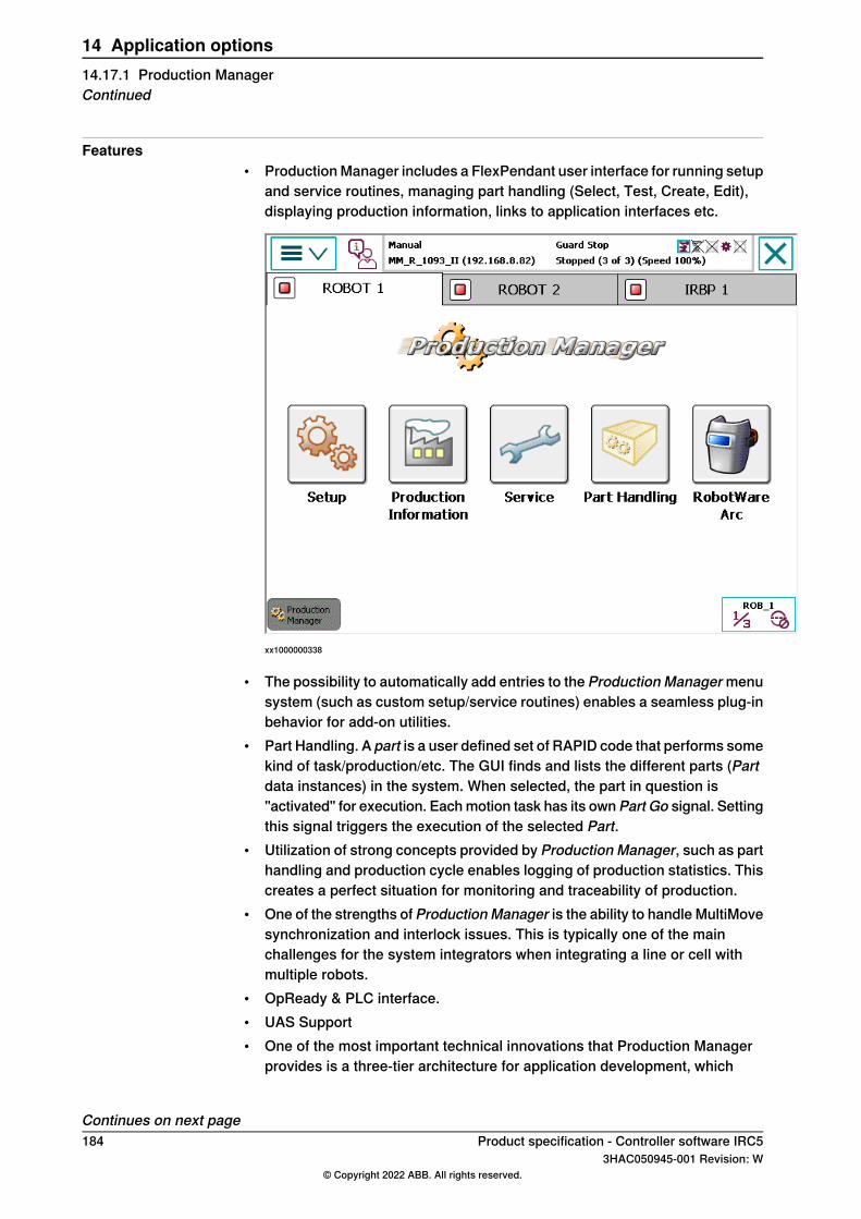
Features• ProductionManager includes a FlexPendant user interface for running setup
and service routines, managing part handling (Select, Test, Create, Edit),displaying production information, links to application interfaces etc.
xx1000000338
• The possibility to automatically add entries to the Production Managermenusystem (such as custom setup/service routines) enables a seamless plug-inbehavior for add-on utilities.
• Part Handling. A part is a user defined set of RAPID code that performs somekind of task/production/etc. The GUI finds and lists the different parts (Partdata instances) in the system. When selected, the part in question is"activated" for execution. Eachmotion task has its ownPart Go signal. Settingthis signal triggers the execution of the selected Part.
• Utilization of strong concepts provided by Production Manager, such as parthandling and production cycle enables logging of production statistics. Thiscreates a perfect situation for monitoring and traceability of production.
• One of the strengths of ProductionManager is the ability to handle MultiMovesynchronization and interlock issues. This is typically one of the mainchallenges for the system integrators when integrating a line or cell withmultiple robots.
• OpReady & PLC interface.• UAS Support• One of the most important technical innovations that Production Manager
provides is a three-tier architecture for application development, which
Continues on next page184 Product specification - Controller software IRC5
3HAC050945-001 Revision: W© Copyright 2022 ABB. All rights reserved.
14 Application options14.17.1 Production ManagerContinued
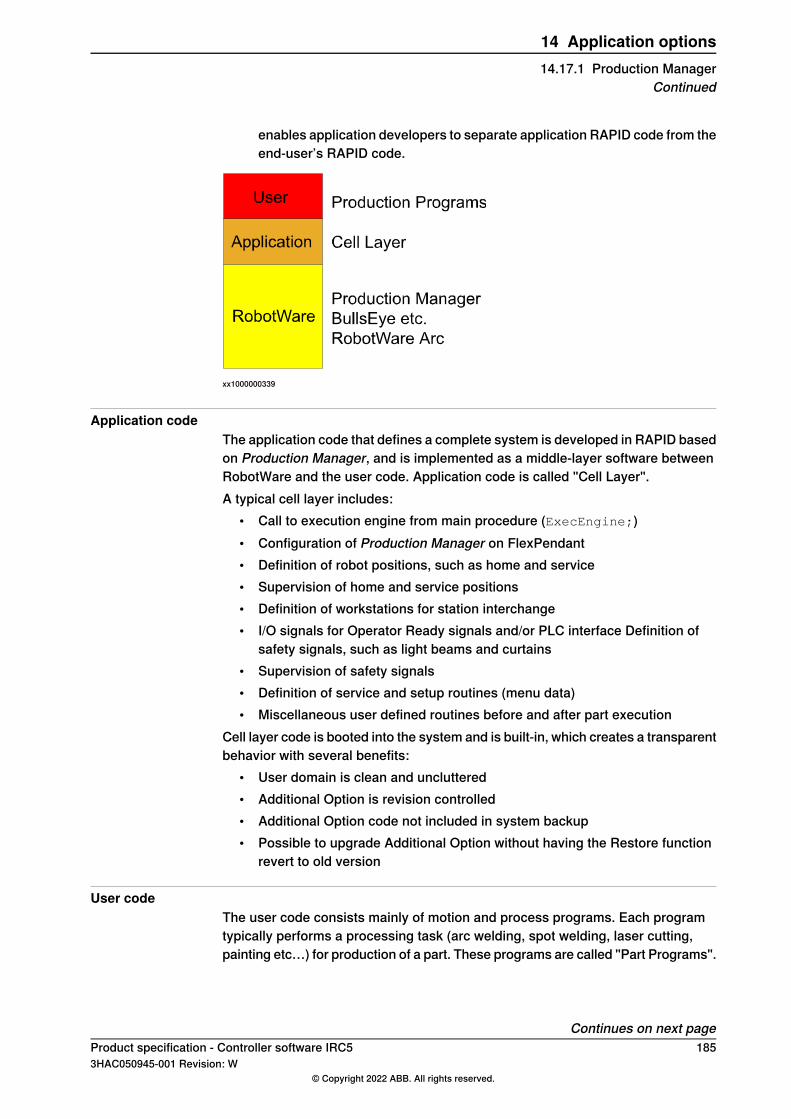
enables application developers to separate application RAPID code from theend-user’s RAPID code.
xx1000000339
Application codeThe application code that defines a complete system is developed in RAPID basedon Production Manager, and is implemented as a middle-layer software betweenRobotWare and the user code. Application code is called "Cell Layer".A typical cell layer includes:
• Call to execution engine from main procedure (ExecEngine;)• Configuration of Production Manager on FlexPendant• Definition of robot positions, such as home and service• Supervision of home and service positions• Definition of workstations for station interchange• I/O signals for Operator Ready signals and/or PLC interface Definition of
safety signals, such as light beams and curtains• Supervision of safety signals• Definition of service and setup routines (menu data)• Miscellaneous user defined routines before and after part execution
Cell layer code is booted into the system and is built-in, which creates a transparentbehavior with several benefits:
• User domain is clean and uncluttered• Additional Option is revision controlled• Additional Option code not included in system backup• Possible to upgrade Additional Option without having the Restore function
revert to old version
User codeThe user code consists mainly of motion and process programs. Each programtypically performs a processing task (arc welding, spot welding, laser cutting,painting etc…) for production of a part. These programs are called "Part Programs".
Continues on next pageProduct specification - Controller software IRC5 1853HAC050945-001 Revision: W
© Copyright 2022 ABB. All rights reserved.
14 Application options14.17.1 Production Manager
Continued
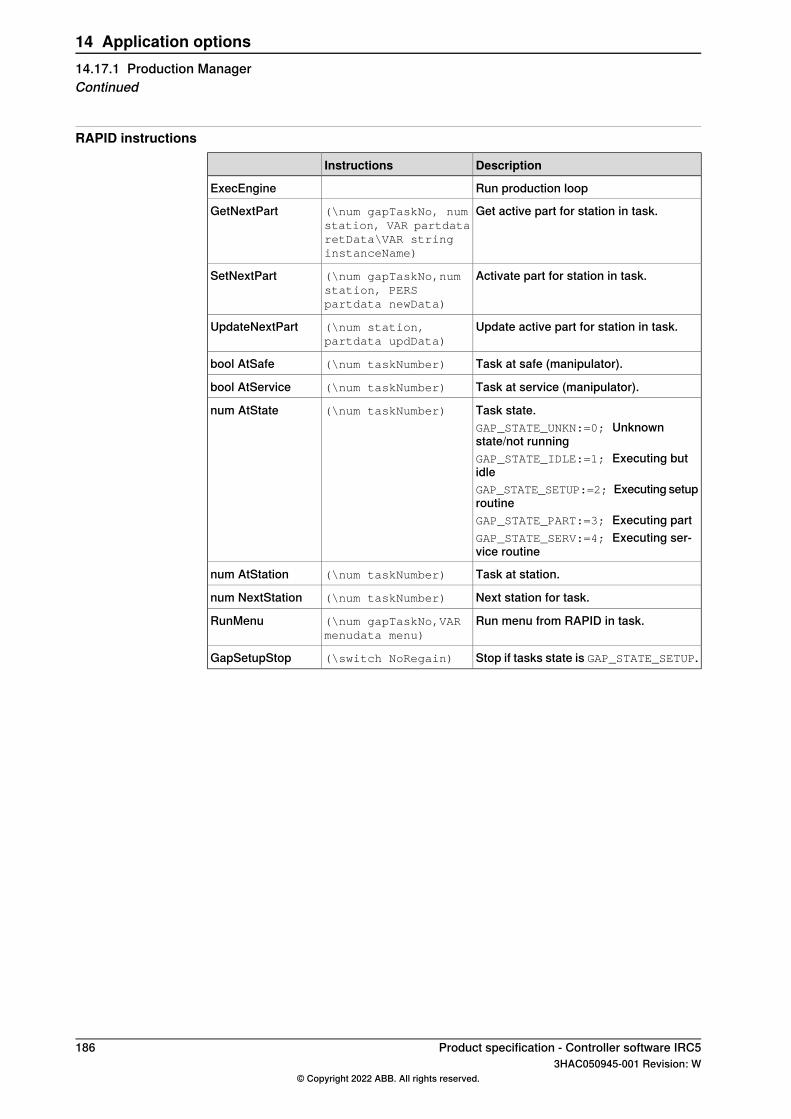
RAPID instructions
DescriptionInstructions
Run production loopExecEngine
Get active part for station in task.(\num gapTaskNo, numstation, VAR partdataretData\VAR stringinstanceName)
GetNextPart
Activate part for station in task.(\num gapTaskNo,numstation, PERSpartdata newData)
SetNextPart
Update active part for station in task.(\num station,partdata updData)
UpdateNextPart
Task at safe (manipulator).(\num taskNumber)bool AtSafe
Task at service (manipulator).(\num taskNumber)bool AtService
Task state.(\num taskNumber)num AtStateGAP_STATE_UNKN:=0; Unknownstate/not runningGAP_STATE_IDLE:=1; Executing butidleGAP_STATE_SETUP:=2; Executing setuproutineGAP_STATE_PART:=3; Executing partGAP_STATE_SERV:=4; Executing ser-vice routine
Task at station.(\num taskNumber)num AtStation
Next station for task.(\num taskNumber)num NextStation
Run menu from RAPID in task.(\num gapTaskNo,VARmenudata menu)
RunMenu
Stop if tasks state is GAP_STATE_SETUP.(\switch NoRegain)GapSetupStop
186 Product specification - Controller software IRC53HAC050945-001 Revision: W
© Copyright 2022 ABB. All rights reserved.
14 Application options14.17.1 Production ManagerContinued
IndexAAbsolute Accuracy, 40
Ccompensation parameters, 40
Ffunction name, 31
MMotion Process Mode, 42
PPROFIenergy
description, 176
Product specification - Controller software IRC5 1873HAC050945-001 Revision: W
© Copyright 2022 ABB. All rights reserved.
Index


ABB ABRobotics & Discrete AutomationS-721 68 VÄSTERÅS, SwedenTelephone +46 (0) 21 344 400
ABB ASRobotics & Discrete AutomationNordlysvegen 7, N-4340 BRYNE, NorwayBox 265, N-4349 BRYNE, NorwayTelephone: +47 22 87 2000
ABB Engineering (Shanghai) Ltd.Robotics & Discrete AutomationNo. 4528 Kangxin HighwayPuDong DistrictSHANGHAI 201319, ChinaTelephone: +86 21 6105 6666
ABB Inc.Robotics & Discrete Automation1250 Brown RoadAuburn Hills, MI 48326USATelephone: +1 248 391 9000
abb.com/robotics
3HAC050945-001,Rev
W,en
© Copyright 2022 ABB. All rights reserved.Specifications subject to change without notice.