Digitric 100 Versatile, universal controller for all ... - ABB
200
Digitric 100 Versatile, universal controller for all standard applications Installation, commissioning, configuration, parameterization, and operation Manual 42/61-10010 EN Rev. 01
-
Upload
khangminh22 -
Category
Documents
-
view
0 -
download
0
Transcript of Digitric 100 Versatile, universal controller for all ... - ABB

Digitric 100 Versatile, universal controller for all standard applicationsInstallation, commissioning, configuration, parameterization, and operation
Manual 42/61-10010 EN Rev. 01
42/61-10010 EN
Digitric 100ns
hotocopying and diseminating it in any formhotomechanical or electronic reproduction ore permission of the copyright owner and non-
2 Digitric 100
Versatile, universal controller for all standard applicatio
ManualDocument No. 42/61-10010 EN
Edition: 10.01Revision: 01
Manufacturer:ABB Automation Products GmbHHöseler Platz 2D-42579 HeiligenhausGermany
Phone: +49 (0) 20 56 - 12 - 51 81Fax: +49 (0) 20 56 - 12 - 50 81
© Copyright 2001 by ABB Automation Products GmbHSubject to technical changes.
This technical documentation is protected by copyright. Translating, pwhatsoever - even editings or excerpts thereof - especially as reprint, pstorage on data processing systems or networks is not allowed without thcompliance will lead to both civil and criminal prosecution.

3
Table of contents . . . . . . . . . . . . . . . . . . . . . . . . . . . . . . . . . . . . . . . . . . . . . . . . . . . . . . . . . . . . . . . . . . . . . . . . . . . . . . . . . . . . . . . . . . Page
. . . . . . . . . . . . . . . . . . . . . . . . . . . . . . . . . 9
. . . . . . . . . . . . . . . . . . . . . . . . . . . . . . . . . 9
. . . . . . . . . . . . . . . . . . . . . . . . . . . . . . . . . 9
. . . . . . . . . . . . . . . . . . . . . . . . . . . . . . . . .10 . . . . . . . . . . . . . . . . . . . . . . . . . . . . . . . . .10s . . . . . . . . . . . . . . . . . . . . . . . . . . . . . . . .10 . . . . . . . . . . . . . . . . . . . . . . . . . . . . . . . . .11
. . . . . . . . . . . . . . . . . . . . . . . . . . . . . . . . .12
. . . . . . . . . . . . . . . . . . . . . . . . . . . . . . . . .13 . . . . . . . . . . . . . . . . . . . . . . . . . . . . . . . . .13 . . . . . . . . . . . . . . . . . . . . . . . . . . . . . . . . .13 . . . . . . . . . . . . . . . . . . . . . . . . . . . . . . . . .13 . . . . . . . . . . . . . . . . . . . . . . . . . . . . . . . . .14 . . . . . . . . . . . . . . . . . . . . . . . . . . . . . . . . .14 . . . . . . . . . . . . . . . . . . . . . . . . . . . . . . . . .14 . . . . . . . . . . . . . . . . . . . . . . . . . . . . . . . . .14
. . . . . . . . . . . . . . . . . . . . . . . . . . . . . . . . .15 . . . . . . . . . . . . . . . . . . . . . . . . . . . . . . . . .15 . . . . . . . . . . . . . . . . . . . . . . . . . . . . . . . . .15 . . . . . . . . . . . . . . . . . . . . . . . . . . . . . . . . .16 . . . . . . . . . . . . . . . . . . . . . . . . . . . . . . . . .16 . . . . . . . . . . . . . . . . . . . . . . . . . . . . . . . . .17
. . . . . . . . . . . . . . . . . . . . . . . . . . . . . . . . .19 . . . . . . . . . . . . . . . . . . . . . . . . . . . . . . . . .19 . . . . . . . . . . . . . . . . . . . . . . . . . . . . . . . . .21 . . . . . . . . . . . . . . . . . . . . . . . . . . . . . . . . .31
. . . . . . . . . . . . . . . . . . . . . . . . . . . . . . . . .34 . . . . . . . . . . . . . . . . . . . . . . . . . . . . . . . . .34
42/61-10010 EN Digitric 100, Content
Preface . . . . . . . . . . . . . . . . . . . . . . . . . . . . . . . . . . . . . . . . . . . . . . . .
Delivery state . . . . . . . . . . . . . . . . . . . . . . . . . . . . . . . . . . . . . . . . . .
Switching on the device . . . . . . . . . . . . . . . . . . . . . . . . . . . . . . .
1 How to use this instruction . . . . . . . . . . . . . . . . . . . . . .1.1 Visual orientation hints . . . . . . . . . . . . . . . . . . . . . . . .1.2 Hints for the configuration and parameterization table1.3 Hints for the configuration menu . . . . . . . . . . . . . . . . .
2 General safety instructions . . . . . . . . . . . . . . . . . . . . . .
3 Description and application . . . . . . . . . . . . . . . . . . . . .3.1 Description . . . . . . . . . . . . . . . . . . . . . . . . . . . . . . . . .3.2 Basic unit . . . . . . . . . . . . . . . . . . . . . . . . . . . . . . . . . .3.3 Operating and indicator elements on the front panel .3.4 Programmer . . . . . . . . . . . . . . . . . . . . . . . . . . . . . . . .3.5 Controller outputs . . . . . . . . . . . . . . . . . . . . . . . . . . . .3.6 Parameterization . . . . . . . . . . . . . . . . . . . . . . . . . . . .3.7 Configuration . . . . . . . . . . . . . . . . . . . . . . . . . . . . . . .
4 Installing Digitric 100 . . . . . . . . . . . . . . . . . . . . . . . . . . . .4.1 Identifying the device . . . . . . . . . . . . . . . . . . . . . . . . .4.2 Choosing the installation site . . . . . . . . . . . . . . . . . . .4.3 Mounting . . . . . . . . . . . . . . . . . . . . . . . . . . . . . . . . . . .4.3.1 Panel cutout . . . . . . . . . . . . . . . . . . . . . . . . . . . . . . . .4.3.2 Mounting instructions . . . . . . . . . . . . . . . . . . . . . . . . .
5 Connecting Digitric 100 . . . . . . . . . . . . . . . . . . . . . . . . . .5.1 Signal connections of the basic unit . . . . . . . . . . . . . .5.2 Signal connections for modules and PC . . . . . . . . . . .5.3 Connecting the power supply . . . . . . . . . . . . . . . . . . .
6 Retrofitting . . . . . . . . . . . . . . . . . . . . . . . . . . . . . . . . . . . . . . .6.1 Safety instructions in accordance with DIN VDE . . . .

42/61-10010 EN
6.2 Mounting the module . . . . . . . . . . . . . . . . . . . . . . . . . . . . . . . . . . . . . . . . . . . . . . . . . . . . . . . . . .34 . . . . . . . . . . . . . . . . . . . . . . . . . . . . . . . . .35 . . . . . . . . . . . . . . . . . . . . . . . . . . . . . . . . .36 . . . . . . . . . . . . . . . . . . . . . . . . . . . . . . . . .37 . . . . . . . . . . . . . . . . . . . . . . . . . . . . . . . . .38 . . . . . . . . . . . . . . . . . . . . . . . . . . . . . . . . .38
. . . . . . . . . . . . . . . . . . . . . . . . . . . . . . . . .39 . . . . . . . . . . . . . . . . . . . . . . . . . . . . . . . . .39 . . . . . . . . . . . . . . . . . . . . . . . . . . . . . . . . .40 . . . . . . . . . . . . . . . . . . . . . . . . . . . . . . . . .43 . . . . . . . . . . . . . . . . . . . . . . . . . . . . . . . . .44 . . . . . . . . . . . . . . . . . . . . . . . . . . . . . . . . .45 . . . . . . . . . . . . . . . . . . . . . . . . . . . . . . . . .46 . . . . . . . . . . . . . . . . . . . . . . . . . . . . . . . . .47 . . . . . . . . . . . . . . . . . . . . . . . . . . . . . . . . .49 . . . . . . . . . . . . . . . . . . . . . . . . . . . . . . . . .49 . . . . . . . . . . . . . . . . . . . . . . . . . . . . . . . . .49 . . . . . . . . . . . . . . . . . . . . . . . . . . . . . . . . .50 . . . . . . . . . . . . . . . . . . . . . . . . . . . . . . . . .51 . . . . . . . . . . . . . . . . . . . . . . . . . . . . . . . . .52 . . . . . . . . . . . . . . . . . . . . . . . . . . . . . . . . .53 . . . . . . . . . . . . . . . . . . . . . . . . . . . . . . . . .53 . . . . . . . . . . . . . . . . . . . . . . . . . . . . . . . . .55 . . . . . . . . . . . . . . . . . . . . . . . . . . . . . . . . .55 . . . . . . . . . . . . . . . . . . . . . . . . . . . . . . . . .56 . . . . . . . . . . . . . . . . . . . . . . . . . . . . . . . . .56 . . . . . . . . . . . . . . . . . . . . . . . . . . . . . . . . .57 . . . . . . . . . . . . . . . . . . . . . . . . . . . . . . . . .57
. . . . . . . . . . . . . . . . . . . . . . . . . . . . . . . . .58
. . . . . . . . . . . . . . . . . . . . . . . . . . . . . . . . .60 . . . . . . . . . . . . . . . . . . . . . . . . . . . . . . . . .62 . . . . . . . . . . . . . . . . . . . . . . . . . . . . . . . . .62 . . . . . . . . . . . . . . . . . . . . . . . . . . . . . . . . .63 . . . . . . . . . . . . . . . . . . . . . . . . . . . . . . . . .64
4 Digitric 100, Content
6.2.1 Mounting the module . . . . . . . . . . . . . . . . . . . . . . . . .6.3 Modifying modules . . . . . . . . . . . . . . . . . . . . . . . . . . .6.4 Adding input AI02 . . . . . . . . . . . . . . . . . . . . . . . . . . . .6.5 Disabling the password . . . . . . . . . . . . . . . . . . . . . . .6.6 Updating the firmware . . . . . . . . . . . . . . . . . . . . . . . .
7 Operation . . . . . . . . . . . . . . . . . . . . . . . . . . . . . . . . . . . . . . . .7.1 Operating elements on the Digitric 100 front panel . .7.2 LC Display . . . . . . . . . . . . . . . . . . . . . . . . . . . . . . . . .7.3 Alarm handling . . . . . . . . . . . . . . . . . . . . . . . . . . . . . .7.4 Automatic mode (A) . . . . . . . . . . . . . . . . . . . . . . . . . .7.5 Manual mode (M) . . . . . . . . . . . . . . . . . . . . . . . . . . . .7.6 Setpoints . . . . . . . . . . . . . . . . . . . . . . . . . . . . . . . . . . .7.7 Ratio controller . . . . . . . . . . . . . . . . . . . . . . . . . . . . . .7.8 Programmer . . . . . . . . . . . . . . . . . . . . . . . . . . . . . . . .7.8.1 Selecting the program . . . . . . . . . . . . . . . . . . . . . . . .7.8.2 Starting the program . . . . . . . . . . . . . . . . . . . . . . . . . .7.8.3 Displays during program execution . . . . . . . . . . . . . .7.8.4 Stopping the program . . . . . . . . . . . . . . . . . . . . . . . . .7.8.5 Fast forward/backward . . . . . . . . . . . . . . . . . . . . . . . .7.9 DDC control . . . . . . . . . . . . . . . . . . . . . . . . . . . . . . . .7.9.1 Resetting (cancelling) the program . . . . . . . . . . . . . . .7.10 Stations . . . . . . . . . . . . . . . . . . . . . . . . . . . . . . . . . . . .7.10.1 Manual station . . . . . . . . . . . . . . . . . . . . . . . . . . . . . .7.10.2 Setpoint station . . . . . . . . . . . . . . . . . . . . . . . . . . . . . .7.10.3 Ratio station . . . . . . . . . . . . . . . . . . . . . . . . . . . . . . . .7.10.4 Positioner . . . . . . . . . . . . . . . . . . . . . . . . . . . . . . . . . .7.11 Remote control (Profibus or Modbus) . . . . . . . . . . . . .
8 Error information on the display . . . . . . . . . . . . . . . . .
9 Menu structure . . . . . . . . . . . . . . . . . . . . . . . . . . . . . . . . . . .9.1 Indication 2 . . . . . . . . . . . . . . . . . . . . . . . . . . . . . . . . .9.1.1 Parameter display . . . . . . . . . . . . . . . . . . . . . . . . . . . .9.1.2 Inputs/outputs . . . . . . . . . . . . . . . . . . . . . . . . . . . . . . .9.1.3 Effective PID parameter . . . . . . . . . . . . . . . . . . . . . . .

5
9.1.4 Identification . . . . . . . . . . . . . . . . . . . . . . . . . . . . . . . . . . . . . . . . . . . . . . . . . . . . . . . . . . . . . . . . .64 . . . . . . . . . . . . . . . . . . . . . . . . . . . . . . . . .65 . . . . . . . . . . . . . . . . . . . . . . . . . . . . . . . . .65 . . . . . . . . . . . . . . . . . . . . . . . . . . . . . . . . .66
. . . . . . . . . . . . . . . . . . . . . . . . . . . . . . . . .68
. . . . . . . . . . . . . . . . . . . . . . . . . . . . . . . . .70 . . . . . . . . . . . . . . . . . . . . . . . . . . . . . . . . .70 . . . . . . . . . . . . . . . . . . . . . . . . . . . . . . . . .71 . . . . . . . . . . . . . . . . . . . . . . . . . . . . . . . . .72 . . . . . . . . . . . . . . . . . . . . . . . . . . . . . . . . .72 . . . . . . . . . . . . . . . . . . . . . . . . . . . . . . . . .72 . . . . . . . . . . . . . . . . . . . . . . . . . . . . . . . . .75 . . . . . . . . . . . . . . . . . . . . . . . . . . . . . . . . .75 . . . . . . . . . . . . . . . . . . . . . . . . . . . . . . . . .75 . . . . . . . . . . . . . . . . . . . . . . . . . . . . . . . . .76 . . . . . . . . . . . . . . . . . . . . . . . . . . . . . . . . .78 . . . . . . . . . . . . . . . . . . . . . . . . . . . . . . . . .79 . . . . . . . . . . . . . . . . . . . . . . . . . . . . . . . . .79
. . . . . . . . . . . . . . . . . . . . . . . . . . . . . . . . .80 . . . . . . . . . . . . . . . . . . . . . . . . . . . . . . . . .80 . . . . . . . . . . . . . . . . . . . . . . . . . . . . . . . . .81 . . . . . . . . . . . . . . . . . . . . . . . . . . . . . . . . .81 . . . . . . . . . . . . . . . . . . . . . . . . . . . . . . . . .82 . . . . . . . . . . . . . . . . . . . . . . . . . . . . . . . . .83
. . . . . . . . . . . . . . . . . . . . . . . . . . . . . . . . .84 . . . . . . . . . . . . . . . . . . . . . . . . . . . . . . . . .85 . . . . . . . . . . . . . . . . . . . . . . . . . . . . . . . . .85 . . . . . . . . . . . . . . . . . . . . . . . . . . . . . . . . .86 . . . . . . . . . . . . . . . . . . . . . . . . . . . . . . . . .87 . . . . . . . . . . . . . . . . . . . . . . . . . . . . . . . . .88 . . . . . . . . . . . . . . . . . . . . . . . . . . . . . . . . .88 . . . . . . . . . . . . . . . . . . . . . . . . . . . . . . . . .89 . . . . . . . . . . . . . . . . . . . . . . . . . . . . . . . . .89
42/61-10010 EN Digitric 100, Content
9.1.5 Library identification . . . . . . . . . . . . . . . . . . . . . . . . . .9.1.6 Version display . . . . . . . . . . . . . . . . . . . . . . . . . . . . . .9.2 Operate 2 . . . . . . . . . . . . . . . . . . . . . . . . . . . . . . . . . .
10 Password protection . . . . . . . . . . . . . . . . . . . . . . . . . . . . .
11 Parameterization . . . . . . . . . . . . . . . . . . . . . . . . . . . . . . . . .11.1 Parameterization menu . . . . . . . . . . . . . . . . . . . . . . .11.2 Selecting and changing parameters . . . . . . . . . . . . . .11.3 Parameter categories . . . . . . . . . . . . . . . . . . . . . . . . .11.3.1 Instrument parameterization . . . . . . . . . . . . . . . . . . . .11.3.2 Loop 1 parameterization . . . . . . . . . . . . . . . . . . . . . . .11.4 Self-tune . . . . . . . . . . . . . . . . . . . . . . . . . . . . . . . . . . .11.4.1 Procedure . . . . . . . . . . . . . . . . . . . . . . . . . . . . . . . . . .11.4.2 Parameters . . . . . . . . . . . . . . . . . . . . . . . . . . . . . . . . .11.4.3 Starting self-tuning . . . . . . . . . . . . . . . . . . . . . . . . . . .11.4.4 Accepting the parameters . . . . . . . . . . . . . . . . . . . . . .11.4.5 Rejecting the parameters . . . . . . . . . . . . . . . . . . . . . .11.4.6 Cancelling self-tuning . . . . . . . . . . . . . . . . . . . . . . . . .
12 Configuration . . . . . . . . . . . . . . . . . . . . . . . . . . . . . . . . . . . .12.1 Selecting the configuration . . . . . . . . . . . . . . . . . . . . .12.2 Configuration table structure . . . . . . . . . . . . . . . . . . .12.3 Sequence of configuration . . . . . . . . . . . . . . . . . . . . .12.4 Changing the configuration . . . . . . . . . . . . . . . . . . . . .12.5 Exit configuration menu . . . . . . . . . . . . . . . . . . . . . . .
13 Configuration examples . . . . . . . . . . . . . . . . . . . . . . . . .13.1 Device . . . . . . . . . . . . . . . . . . . . . . . . . . . . . . . . . . . . .13.1.1 Hardware . . . . . . . . . . . . . . . . . . . . . . . . . . . . . . . . . .13.1.2 Password . . . . . . . . . . . . . . . . . . . . . . . . . . . . . . . . . .13.2 AI definition . . . . . . . . . . . . . . . . . . . . . . . . . . . . . . . . .13.2.1 General . . . . . . . . . . . . . . . . . . . . . . . . . . . . . . . . . . . .13.2.2 Sensor problems . . . . . . . . . . . . . . . . . . . . . . . . . . . .13.2.3 Dimension . . . . . . . . . . . . . . . . . . . . . . . . . . . . . . . . . .13.2.4 Filtering . . . . . . . . . . . . . . . . . . . . . . . . . . . . . . . . . . . .

42/61-10010 EN
13.2.5 mA inputs . . . . . . . . . . . . . . . . . . . . . . . . . . . . . . . . . . . . . . . . . . . . . . . . . . . . . . . . . . . . . . . . . . .90 . . . . . . . . . . . . . . . . . . . . . . . . . . . . . . . . .90 . . . . . . . . . . . . . . . . . . . . . . . . . . . . . . . . .90 . . . . . . . . . . . . . . . . . . . . . . . . . . . . . . . . .91 . . . . . . . . . . . . . . . . . . . . . . . . . . . . . . . . .91 . . . . . . . . . . . . . . . . . . . . . . . . . . . . . . . . .92 . . . . . . . . . . . . . . . . . . . . . . . . . . . . . . . . .92 . . . . . . . . . . . . . . . . . . . . . . . . . . . . . . . . .93 . . . . . . . . . . . . . . . . . . . . . . . . . . . . . . . . .93 . . . . . . . . . . . . . . . . . . . . . . . . . . . . . . . . .93 . . . . . . . . . . . . . . . . . . . . . . . . . . . . . . . . .94 . . . . . . . . . . . . . . . . . . . . . . . . . . . . . . . . .94 . . . . . . . . . . . . . . . . . . . . . . . . . . . . . . . . .95 . . . . . . . . . . . . . . . . . . . . . . . . . . . . . . . . .96 . . . . . . . . . . . . . . . . . . . . . . . . . . . . . . . . .98 . . . . . . . . . . . . . . . . . . . . . . . . . . . . . . . . .98 . . . . . . . . . . . . . . . . . . . . . . . . . . . . . . . . .98 . . . . . . . . . . . . . . . . . . . . . . . . . . . . . . . . .99 . . . . . . . . . . . . . . . . . . . . . . . . . . . . . . . .100 . . . . . . . . . . . . . . . . . . . . . . . . . . . . . . . . 102 . . . . . . . . . . . . . . . . . . . . . . . . . . . . . . . . 102 . . . . . . . . . . . . . . . . . . . . . . . . . . . . . . . . 102 . . . . . . . . . . . . . . . . . . . . . . . . . . . . . . . .104 . . . . . . . . . . . . . . . . . . . . . . . . . . . . . . . . 104 . . . . . . . . . . . . . . . . . . . . . . . . . . . . . . . . 106 . . . . . . . . . . . . . . . . . . . . . . . . . . . . . . . .109 . . . . . . . . . . . . . . . . . . . . . . . . . . . . . . . .111 . . . . . . . . . . . . . . . . . . . . . . . . . . . . . . . . 111 . . . . . . . . . . . . . . . . . . . . . . . . . . . . . . . . 112 . . . . . . . . . . . . . . . . . . . . . . . . . . . . . . . . 114 . . . . . . . . . . . . . . . . . . . . . . . . . . . . . . . .114 . . . . . . . . . . . . . . . . . . . . . . . . . . . . . . . .114 . . . . . . . . . . . . . . . . . . . . . . . . . . . . . . . . 115 . . . . . . . . . . . . . . . . . . . . . . . . . . . . . . . . 116 . . . . . . . . . . . . . . . . . . . . . . . . . . . . . . . . 116 . . . . . . . . . . . . . . . . . . . . . . . . . . . . . . . . 117
6 Digitric 100, Content
13.2.6 Thermocouple input . . . . . . . . . . . . . . . . . . . . . . . . . .13.2.7 Resistance thermometer input . . . . . . . . . . . . . . . . . .13.2.8 Teletransmitter input . . . . . . . . . . . . . . . . . . . . . . . . . .13.3 Characteristic curve . . . . . . . . . . . . . . . . . . . . . . . . . .13.4 Setpoints . . . . . . . . . . . . . . . . . . . . . . . . . . . . . . . . . . .13.4.1 Setpoint 1 . . . . . . . . . . . . . . . . . . . . . . . . . . . . . . . . . .13.4.2 Setpoint SP2 to SP4 = Ratio setpoint SR1 to SR3 . . .13.4.3 Computer setpoint . . . . . . . . . . . . . . . . . . . . . . . . . . .13.4.4 Setpoint ramp . . . . . . . . . . . . . . . . . . . . . . . . . . . . . . .13.5 Programmer . . . . . . . . . . . . . . . . . . . . . . . . . . . . . . . .13.5.1 Configuring programs . . . . . . . . . . . . . . . . . . . . . . . . .13.5.2 Parameterizing programs . . . . . . . . . . . . . . . . . . . . . .13.5.3 Programming table for a program . . . . . . . . . . . . . . . .13.6 Fixed-value control . . . . . . . . . . . . . . . . . . . . . . . . . . .13.6.1 Task . . . . . . . . . . . . . . . . . . . . . . . . . . . . . . . . . . . . . .13.6.2 Configuration . . . . . . . . . . . . . . . . . . . . . . . . . . . . . . .13.6.3 Example 1 . . . . . . . . . . . . . . . . . . . . . . . . . . . . . . . . . .13.6.4 Example 2 . . . . . . . . . . . . . . . . . . . . . . . . . . . . . . . . . .13.7 Multi-component control . . . . . . . . . . . . . . . . . . . . . . .13.7.1 Application . . . . . . . . . . . . . . . . . . . . . . . . . . . . . . . . .13.7.2 Configuration . . . . . . . . . . . . . . . . . . . . . . . . . . . . . . .13.8 Ratio control . . . . . . . . . . . . . . . . . . . . . . . . . . . . . . . .13.8.1 Ratios and setpoints . . . . . . . . . . . . . . . . . . . . . . . . . .13.8.2 Ratio control: Mixed control . . . . . . . . . . . . . . . . . . . .13.9 Multiplication . . . . . . . . . . . . . . . . . . . . . . . . . . . . . . . .13.10 Parameter changeover/control (Gain scheduling) . . .13.10.1 Parameter changeover . . . . . . . . . . . . . . . . . . . . . . . .13.10.2 Parameter control . . . . . . . . . . . . . . . . . . . . . . . . . . . .13.11 State correction . . . . . . . . . . . . . . . . . . . . . . . . . . . . .13.11.1 Input and output routing . . . . . . . . . . . . . . . . . . . . . . .13.11.2 Terms and abbreviations . . . . . . . . . . . . . . . . . . . . . .13.11.3 Configuration for gas and steam . . . . . . . . . . . . . . . .13.11.4 Configuration for water mass flow . . . . . . . . . . . . . . .13.11.5 Configuration for drum water level . . . . . . . . . . . . . . .13.11.6 Gas and steam . . . . . . . . . . . . . . . . . . . . . . . . . . . . . .

7
13.11.7 Water mass flow . . . . . . . . . . . . . . . . . . . . . . . . . . . . . . . . . . . . . . . . . . . . . . . . . . . . . . . . . . . . . 120 . . . . . . . . . . . . . . . . . . . . . . . . . . . . . . . . 121ction results . . . . . . . . . . . . . . . . . . . . . 122
. . . . . . . . . . . . . . . . . . . . . . . . . . . . . . . . 124 . . . . . . . . . . . . . . . . . . . . . . . . . . . . . . . .125 . . . . . . . . . . . . . . . . . . . . . . . . . . . . . . . . 126 . . . . . . . . . . . . . . . . . . . . . . . . . . . . . . . . 127 . . . . . . . . . . . . . . . . . . . . . . . . . . . . . . . . 127 . . . . . . . . . . . . . . . . . . . . . . . . . . . . . . . . 127 . . . . . . . . . . . . . . . . . . . . . . . . . . . . . . . .128
. . . . . . . . . . . . . . . . . . . . . . . . . . . . . . . . 129 . . . . . . . . . . . . . . . . . . . . . . . . . . . . . . . .130 . . . . . . . . . . . . . . . . . . . . . . . . . . . . . . . . 130 . . . . . . . . . . . . . . . . . . . . . . . . . . . . . . . .131 . . . . . . . . . . . . . . . . . . . . . . . . . . . . . . . .131 . . . . . . . . . . . . . . . . . . . . . . . . . . . . . . . . 132 . . . . . . . . . . . . . . . . . . . . . . . . . . . . . . . .132I01 . . . . . . . . . . . . . . . . . . . . . . . . . . . . 133
. . . . . . . . . . . . . . . . . . . . . . . . . . . . . . . . 135
. . . . . . . . . . . . . . . . . . . . . . . . . . . . . . . . 136 . . . . . . . . . . . . . . . . . . . . . . . . . . . . . . . .137 . . . . . . . . . . . . . . . . . . . . . . . . . . . . . . . . 138 . . . . . . . . . . . . . . . . . . . . . . . . . . . . . . . . 139
. . . . . . . . . . . . . . . . . . . . . . . . . . . . . . . . 140 . . . . . . . . . . . . . . . . . . . . . . . . . . . . . . . . 142 . . . . . . . . . . . . . . . . . . . . . . . . . . . . . . . .143 . . . . . . . . . . . . . . . . . . . . . . . . . . . . . . . . 144 . . . . . . . . . . . . . . . . . . . . . . . . . . . . . . . . 145 . . . . . . . . . . . . . . . . . . . . . . . . . . . . . . . . 146 . . . . . . . . . . . . . . . . . . . . . . . . . . . . . . . . 148 . . . . . . . . . . . . . . . . . . . . . . . . . . . . . . . . 150 . . . . . . . . . . . . . . . . . . . . . . . . . . . . . . . . 151
/Service/Supervisor . . . . . . . . . . 152
42/61-10010 EN Digitric 100, Content
13.11.8 Drum water level . . . . . . . . . . . . . . . . . . . . . . . . . . . . .13.11.9 Configuring an analog output for outputting state corre13.12 Control outputs . . . . . . . . . . . . . . . . . . . . . . . . . . . . . .13.12.1 Two-point controller . . . . . . . . . . . . . . . . . . . . . . . . . .13.12.2 Three-point controller . . . . . . . . . . . . . . . . . . . . . . . . .13.12.3 Motorized valve control (Step controller) . . . . . . . . . .13.12.4 Positioner . . . . . . . . . . . . . . . . . . . . . . . . . . . . . . . . . .13.12.5 Controller with relay output . . . . . . . . . . . . . . . . . . . . .13.12.6 Continuous controller . . . . . . . . . . . . . . . . . . . . . . . . .
14 Service . . . . . . . . . . . . . . . . . . . . . . . . . . . . . . . . . . . . . . . . . . .14.1 Information (general) . . . . . . . . . . . . . . . . . . . . . . . . .14.2 Hardware information . . . . . . . . . . . . . . . . . . . . . . . . .14.3 Display unit . . . . . . . . . . . . . . . . . . . . . . . . . . . . . . . . .14.3.1 Contrast of the LCD . . . . . . . . . . . . . . . . . . . . . . . . . .14.4 Adjustment . . . . . . . . . . . . . . . . . . . . . . . . . . . . . . . . .14.4.1 Example: Adjusting the Pt100, 2-wire, for AI01 . . . . .14.4.2 Example: Adjusting a teletransmitter, 1500 ohms, on A14.5 Calibration . . . . . . . . . . . . . . . . . . . . . . . . . . . . . . . . .
15 Supervisor . . . . . . . . . . . . . . . . . . . . . . . . . . . . . . . . . . . . . . .15.1 Plausibility . . . . . . . . . . . . . . . . . . . . . . . . . . . . . . . . . .15.2 Master reset . . . . . . . . . . . . . . . . . . . . . . . . . . . . . . . .15.3 Template (Quick configuration) . . . . . . . . . . . . . . . . . .
16 Quick configuration in the Template menu . . . . . .16.1 Setting the controller to the desired language . . . . . .16.2 Navigating through the template . . . . . . . . . . . . . . . . .16.3 Possible entries in the template . . . . . . . . . . . . . . . . .16.4 Basic variants in the template . . . . . . . . . . . . . . . . . . .16.5 Additional variants in the template . . . . . . . . . . . . . . .16.6 Alarm variants in the template . . . . . . . . . . . . . . . . . .16.7 Type of analog input AI01 and AI02 in the template . .16.8 Examples for template variants . . . . . . . . . . . . . . . . .
17 Tables for menus: Indication2/Operate2/Selftune

42/61-10010 EN
18 Tables for the configuration menu . . . . . . . . . . . . . . . . . . . . . . . . . . . . . . . . . . . . . . . . . . . . . . .160
. . . . . . . . . . . . . . . . . . . . . . . . . . . . . . . . 179
. . . . . . . . . . . . . . . . . . . . . . . . . . . . . . . . 184 . . . . . . . . . . . . . . . . . . . . . . . . . . . . . . . . 184 . . . . . . . . . . . . . . . . . . . . . . . . . . . . . . . .185 . . . . . . . . . . . . . . . . . . . . . . . . . . . . . . . . 187 . . . . . . . . . . . . . . . . . . . . . . . . . . . . . . . . 188 . . . . . . . . . . . . . . . . . . . . . . . . . . . . . . . .189
. . . . . . . . . . . . . . . . . . . . . . . . . . . . . . . . 190 . . . . . . . . . . . . . . . . . . . . . . . . . . . . . . . . 190 . . . . . . . . . . . . . . . . . . . . . . . . . . . . . . . .191 . . . . . . . . . . . . . . . . . . . . . . . . . . . . . . . . 191 . . . . . . . . . . . . . . . . . . . . . . . . . . . . . . . . 192 . . . . . . . . . . . . . . . . . . . . . . . . . . . . . . . . 192 . . . . . . . . . . . . . . . . . . . . . . . . . . . . . . . . 192. . . . . . . . . . . . . . . . . . . . . . . . . . . . . . . . . 192 . . . . . . . . . . . . . . . . . . . . . . . . . . . . . . . .193 . . . . . . . . . . . . . . . . . . . . . . . . . . . . . . . . 193 . . . . . . . . . . . . . . . . . . . . . . . . . . . . . . . . 194 . . . . . . . . . . . . . . . . . . . . . . . . . . . . . . . . 196 . . . . . . . . . . . . . . . . . . . . . . . . . . . . . . . . 198 . . . . . . . . . . . . . . . . . . . . . . . . . . . . . . . . 198
turer . . . . . . . . . . . . . . . . . . . . . . . . . .199
8 Digitric 100, Content
19 Tables for the parameter setting menu . . . . . . . . . .
20 Error codes . . . . . . . . . . . . . . . . . . . . . . . . . . . . . . . . . . . . . .20.1 Device errors . . . . . . . . . . . . . . . . . . . . . . . . . . . . . . .20.1.1 Error codes . . . . . . . . . . . . . . . . . . . . . . . . . . . . . . . . .20.1.2 Error details . . . . . . . . . . . . . . . . . . . . . . . . . . . . . . . .20.2 Error codes of the controller selftune routine . . . . . . .20.3 Error codes of the input/output level . . . . . . . . . . . . . .
21 Technical data . . . . . . . . . . . . . . . . . . . . . . . . . . . . . . . . . . .Inputs . . . . . . . . . . . . . . . . . . . . . . . . . . . . . . . . . . . . .Outputs . . . . . . . . . . . . . . . . . . . . . . . . . . . . . . . . . . . .Serial interfaces . . . . . . . . . . . . . . . . . . . . . . . . . . . . .CPU data . . . . . . . . . . . . . . . . . . . . . . . . . . . . . . . . . .Power supply . . . . . . . . . . . . . . . . . . . . . . . . . . . . . . .Environmental conditions . . . . . . . . . . . . . . . . . . . . . .Electromagnetic compatibility . . . . . . . . . . . . . . . . . . Connection, case, safety . . . . . . . . . . . . . . . . . . . . . .Modules . . . . . . . . . . . . . . . . . . . . . . . . . . . . . . . . . . .Analog inputs . . . . . . . . . . . . . . . . . . . . . . . . . . . . . . .Binary inputs/outputs . . . . . . . . . . . . . . . . . . . . . . . . .Analog outputs . . . . . . . . . . . . . . . . . . . . . . . . . . . . . .Interface modules . . . . . . . . . . . . . . . . . . . . . . . . . . . .
22 Packaging for transport or return to the manufac

9
Prefacetroller contains instructions for:
on for menu-guided configuration and param-e locally via the device’s front panel operating
rameterization program.
the IBIS-R+ program. The description of this
he factory setting is adjusted to the following
tting the controller to the desired language)ual. Customized versions are available upon
tomatically performs a selftest of the internal. Usually, no special attention has to be paid
42/61-10010 EN Digitric 100
This documentation No. 62/61-10010 delivered with the Digitric 100 concommissioning, installation,configuration,parameterizationoperation
The following additional documents are available upon request:Operating instructions for IBIS-R, IBIS-R+ 42/62-50020Operating instructions for IBIS-R+ 42/62-50030Interface description (MODBUS) 42/62-50040Interface description (Profibus DP-V1) 42/62-50050
The operating instructions in this manual include all important informatieterization of he Digitric 100 controller. All necessary entries can be madelements, or remotely from a PC with the IBIS-R+ configuration and pa
The configuration options of the Digitric 100 menu are also available inprogram is beyond the scope of this manual.
Delivery stateThe devices are delivered off stock and without customized settings. Tfunctions: – Single-loop continuous controller– Input: 4...20 mA– Output: 4...20 mA– Language: German
(setting to english or french is shown in Section 16.1, SeThe factory setting and its definitions are described in detail in this manspecial request.
Switching on the deviceUpon power-on or return of the power after power failure the device aufunctions. The progress of the test program can be seen on the displayto this display.

42/61-10010 EN
1 How to use this instruction
scription
ons
dicator 7-1me name is lighted
me name is off
les
ructure
10 Digitric 100, Chapter 1 "How to use this instruction"
1.1 Visual orientation hints<Enter> Control buttons on the device front panel, with de<Ind><Menu>, <Enter> Buttons that are always enabled for operator acti[P-SP] Texts or text parts shown by the digital indicator[P-SP], A Flashing texts or text parts shown by the digital in
/8/ Reference to the numbers/fields specified in Fig.M, A Light emitting diode (LED) at the button of the saM, A
Menu, Enter Light emitting diode (LED) at the button of the saSxt External setpoint source Manual Operating mode
1.2 Hints for the configuration and parameterization tab
I InstrumentAI Analog inputAO Analog outputBIO, BI/BO Binary input/outputL1 Control loop No. 1SC State correctionPxx Programmer for program PO1 to P10P01 Parameter 1B01 Block 01Q01 Question 01ParameterizationL1-P01 Loop 1, Parameter 01 = Gain
ConfigurationI-B01, Q01 Instrument, block 1, question 1 = languageL1-B03-Q02 Loop 1, block 3, question 2 = multi component st

11
1.3 Hints for the configuration menubles in the device.
ngeover between AI01 and AI02 with simulta-
r AO01. AI02 is an optional input that can be
s input BI0x or as output BO0x, depending on
ts.
dule slot.
lug-in modules. In the device, the inputs and
42/61-10010 EN Digitric 100, Chapter 1 "How to use this instruction"
The input values AIx, BIx and the outputs AO1 and BOx are global varia
The binary inputs can simultaneously trigger several functions, e.g. chaneous parameter changeover.
The binary outputs can output several logically ORed data.
Be careful when configuring the controller.
Input and output names and numbers
Basic unit:The analog inputs and outputs have the designations AI01 and AI02 oconnected to the main board.
The binary inputs/outputs are called BIO01 and BIO02. They are used athe configuration.
The relay outputs are called BO03, BO04 and BO05 and are NO contac
Modules:Besides the optional AI02 the Digitric 100 controller also provides a mo
Up to 4 analog or up to 6 binary input/outputs can be processed in the poutputs have the following designation:
AI1y Analog input No. y of the module in slot 1AI12 Input 2 of the module in slot 1BI16 Binary input 6 in slot 1BO14 Binary output 4 in slot 1

42/61-10010 EN
2 General safety instructions
process controller.
r transportation and storage, installation andnce.
ioning, operation and maintenance of this or
operation of electrical systems.
instructions are applicable in Germany. When the relevant regulations, standards and direc-ed.
EN 61 010-1 = IEC 1010-1 = DIN VDE 0411ratory Apparatus" and has been supplied in a cautions marked accordingly, which must bere safe operation. Otherwise, persons can beamaged or fail.
operating instructions please contact the ABB
f single control loops which can be connected
a sheets and in Section 21, Technical data of
12 Digitric 100, Chapter 2 "General safety instructions"
Safety instructions This chapter contains important instructions for your safety!Read and observe.
Instructions forproper use
These operating instructions are a reference manual for the Digitric 100
Proper and safe operation of the Digitric 100 controller requires propecommissioning by qualified personnel, proper use and careful maintena
Only qualified personnel who are familiar with the installation, commisssimilar devices are authorized to work on Digitric 100.Observe– the present operating instructions,– the safety instructions attached to the device– the relevant safety regulations and standards for the installation and
The regulations, standards and directives referred to in these operating using the Digitric 100 controller outside the German Federal jurisdiction,tives applicable in the country where the device is used must be observ
Digitric 100 has been designed, produced and tested in accordance withPart 1 "Safety Requirements for Electrical Measuring, Control and Labosafe condition. The present operating instructions contain warnings andfollowed by the user to retain the device in a safe condition and to ensuendangered or the device itself or other devices or equipment may be d
If you should need any information which is not contained in the present Service.
Proper use Digitric 100 is a single-loop compact controller for the instrumentation oto supervisory controllers and systems.
To ensure proper use, read and observe the "Technical data" in the datthis manual.
! STOP
!

13
3 Description and application
entation of single control loops. It is universal
/4...20 mA standard signals can be connectedon-linearized temperature transmitters the lin-
red in the device.
or actual value, electrically isolated.
r outputs, as required. They can be used as the controller (e.g. from manual to automatic
, input circuit, ratio control, etc.)
/4...20 mA standard signals can be connectedon-linearized temperature transmitters the lin-
red in the device.
process status and permit direct operator in-tpoints and output values and allow the oper-
42/61-10010 EN Digitric 100, Chapter 3 "Description and application"
3.1 DescriptionThe industrial controller Digitric 100 is a compact controller for the instrumand can be used for both simple and complex control tasks.
3.2 Basic unit1 universal input for the process valueThermocouples, Pt100 resistance thermometers, teletransmitters and 0to the basic unit without requiring any hardware changes. When using nearization is performed in the controller. The appropriate linearization tables for all standard transmitters are sto
1 output 0/4-20 mA for the output signal or other values, e.g. setpoint
2 binary inputs/outputs 24 V DC which can be configured as inputs ocontroller outputs or alarm outputs, but also as inputs for switching overmode.)
3 relays for the output signal or alarm outputs, or for error messages.
One 2nd universal input for additional functions (e.g. external setpointThis input is optional and can be plugged onto the main board. Thermocouples, Pt100 resistance thermometers, teletransmitters and 0to the basic unit without requiring any hardware changes. When using nearization is performed in the controller. The appropriate linearization tables for all standard transmitters are sto
1 module slot for extending the inputs/outputs.
3.3 Operating and indicator elements on the front panelVarious operating and indicator elements inform the operator about thetervention. Numerical and plain text displays give an exact reading of seator to modify the settings if required.

42/61-10010 EN
3.4 Programmerpendent setpoint. Up to 10 programs with 15
one continuous and one switching output.
continuous output signals
accessed in the menu level. On this level the can be set.
be accessed in the menu level. On this leveligitric 100 can be configured either locally via. Remote configuration can considerably sim-g are to be configured.
14 Digitric 100, Chapter 3 "Description and application"
Every device contains a configurable programmer for defining a time-desegments each can be saved in the device.
3.5 Controller outputsS1 On/Off controller, PID actionS2 Controller for heating-off-cooling, optionally with two switching orM Motorized valve control (step control)C Continuous controller, optionally with split-range output with two
3.6 ParameterizationThe parameter level - which can be protected with a password - can beexisting device function parameters like controller gain or time constant
3.7 Configuration
List configurationThe configuration level - which can be protected with a password - canthe standard functions can be selected from a list saved in the device. Dits front panel operating elements, or remotely from a PC with IBIS_R+plify the configuration procedure if several devices with the same settin

15
4 Installing Digitric 100
and on machines. When choosing the instal-fied in the "Technical data" section.
evice in the installed state.
42/61-10010 EN Digitric 100, Chapter 4 "Installing Digitric 100"
4.1 Identifying the deviceSee the rating plate attached to the side of the device for the device ID.
4.2 Choosing the installation siteDigitric 100 is designed for front mounting in control rooms, in cabinetslation site observe the environmental and mechanical capabilities speci
WarningTo ensure full protection against accidental contact only use the d

42/61-10010 EN
4.3 Mounting
of 10 mm between theme proper ventilation
.
16 Digitric 100, Chapter 4 "Installing Digitric 100"
4.3.1 Panel cutout
Fig. 4-1 Panel cutout (dimensions in mm) Z-19166
• Panel cutout to DIN 43 700: 92+0.8 mm × 92+0.8 mm• When mounting the devices side by side, observe a minimum spacing• Provide for a sufficient spacing above and below the devices to ensur
Minimum spacing above and below: 40 mmNoteThe spacing between the devices must not be affected by the cables
17
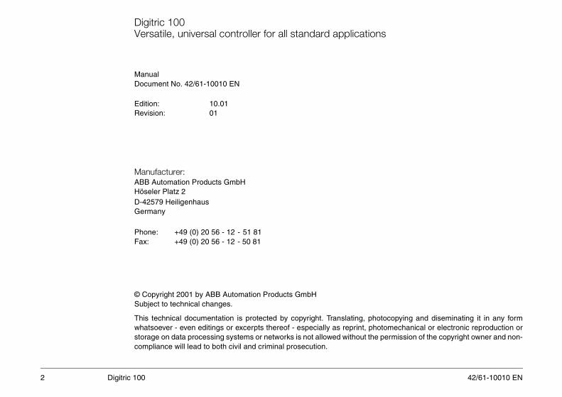
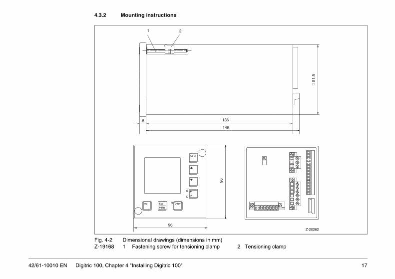
4.3.2 Mounting instructions
ning clamp
91
.5
Z-20262
42/61-10010 EN Digitric 100, Chapter 4 "Installing Digitric 100"
Fig. 4-2 Dimensional drawings (dimensions in mm)Z-19168 1 Fastening screw for tensioning clamp 2 Tensio
96
96
8 136
145
1 2

42/61-10010 EN
Mounting procedure
lockwise until you are able to snap in the ten-
until the tensioning clamp snaps in behind the is a conductive bonding between the housing,
etic compatibility (EMC) of the device.
18 Digitric 100, Chapter 4 "Installing Digitric 100"
Step Action
1. Remove at the front both screw covers.2. Turn the fastening screw for the tensioning clamp (1) counterc
sioning clamp (2) behind the panel. 3. Insert the device into the panel cutout from the front.4. Turn the fastening screw of the tensioning clamp (1) clockwise
front panel and retains the device reliably. Make sure that there the fastening screw and the panel.NoteThe conductive bonding is required to ensure the electromagn
5. Pull in both screw covers.

19
5 Connecting Digitric 100ns down for around 15 seconds. The progress
SA up to 1.5 mm2, for relays up to 2.5 mm2.
0
0
B
z-20
263
16 17 18 19 2120
Tele
Tele
BO03Relay
BO04Relay
BO05Relay
42/61-10010 EN Digitric 100, Chapter 5 "Connecting Digitric 100"
Note When the device is switched on, an internal test routine is started and ruof the self-test is seen on the display.
5.1 Signal connections of the basic unit(see Fig. 5-1 and Fig. 5-2)Connect with pluggable screw-terminals for wire or stranded wire, wire C
Fig. 5-1 Signal connections of the basic unit(description see next page)
+24 V
mA
21 Vint
AI01+-
mA +-
+-
mA +-
B
B
8
B
9
13
12
13 13
11
9 9
10
7
6 6
7
9
10
11
13 13 13
11 11
10 10
9
7
6
ext
3
4
24 V
9
+-
BI01...BI02
1
2
8
9
10
11
12
13
14
7
6
5
4
3
15
BO02
BO01
AO01
Transmitter
Transmitter
Thermo couple
Thermo couple
Pt1002-wire
Pt1003-wire
Pt1004-wire
Pt1003-wire
AI02
Pt1002-wire
InputsOutputs

42/61-10010 EN
Description for Fig. 5-1
input or output))
ia terminal 1 or Pt100 (2-wire/3-wire) or rovide a low-resistance connection
inputs and outputs (is available only
20 Digitric 100, Chapter 5 "Connecting Digitric 100"
1 21 V int (optional)2 Input of power supply for binary outputs 3 Binary port 1 (a binary port can be used as binary 4 Binary port 25 Zero potential6 Analog input 17 Analog input 18 Analog input 19 Analog input 1+ 2 (AI02 optional)10 Analog input 2 (AI02 optional)11 Analog input 2 (AI02 optional)12 Analog input 2 (AI02 optional)13 Analog input 2 (AI02 optional)14 Analog output 115 Analog output 116, 17 Relay output (NO contact) BO0318, 19 Relay output (NO contact) BO0420,21 Relay output (NO contact) BO05AO01 Analog output 1 (0/4...20 mA)AI01 Universal inputAI02 Optional universal inputB The bridge is only required for transmitter supply v
teletransmitter supply via AI 02. The bridge must pbetween terminals 9 and 13 on the shortest way.
BI01,BI02 Binary inputs BO01, BO02 Binary outputsBO03,BO04,BO05 Relay outputs (NO contacts)Tele Teletransmitter21-V int. Optional supply for 2-wire transmitter and/or binary
if 2. universal input is installed).24-V ext. External power supply
21
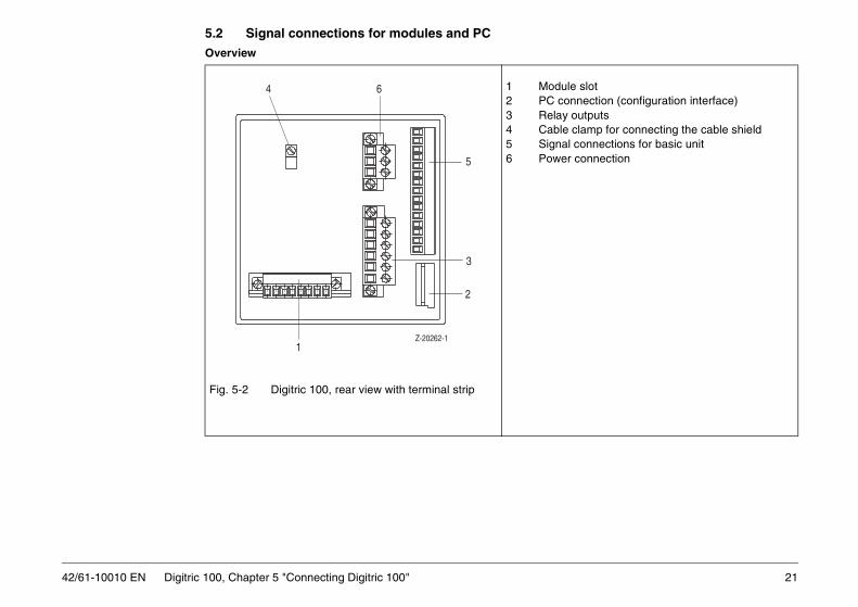
5.2 Signal connections for modules and PC
le slotnnection (configuration interface) outputs clamp for connecting the cable shieldl connections for basic unitr connection
42/61-10010 EN Digitric 100, Chapter 5 "Connecting Digitric 100"
Overview
Fig. 5-2 Digitric 100, rear view with terminal strip
1 Modu2 PC co3 Relay4 Cable5 Signa6 Powe
Z-20262-1
4 6
5
3
2
1

42/61-10010 EN
Modules (can be retrofitted) overview of the available module types. The and is not considered as a module.
ID see Catalog number
E Fig. 5-5 62619-0346280
B Fig. 5-4 62619-0346250
F Fig. 5-6 62619-0346255
G Fig. 5-7 62619-0346281
H Fig. 5-8 62619-0346444
A Fig. 5-3 62619-0346254
M Fig. 5-11 62619-0346282
N Fig. 5-9 62619-0346252
P Fig. 5-10 62619-0346253
T Fig. 5-12 62619-0346263
U Fig. 5-14 62619-0346324
le Y Fig. 5-13 62619-0346326
Z – 62619-0346470
22 Digitric 100, Chapter 5 "Connecting Digitric 100"
A module can be retrofitted at a later time. The following table shows anoptional analog input AI02 is plugged onto the main board of the device
Table 5-1 Module overview
Module type Designation
Inputs
AI4_mV=AE4_mV 4-fold thermocouple with electronic isolation
AI2_mA/mV_OI=AE2_mA/mV_TR
2-fold thermocouple or mA with opto isolation
AI4_PT_2W =AE4_PT_2L
4-fold Pt100 2-wire circuitry
AI2_PT_3/4W=AE2_PT_3/4L
2-fold Pt100 3/4-wire circuitry
AI4_F=AE4_F 4-fold frequency input
AI4_mA=AE4_mA 4-fold mA with electronic isolation
Binary inputs/outputs
BIO6_BIN=BEA6_BIN
6-fold binary input/output
Outputs
AO3_mA=AA3_mA
3-fold 20 mA
AO3_mV=AA3_mV
3 -fold 10 V
BO4_REL=BA4_REL
4-fold relay
Interfaces
RS 485 RS 485, independent of protocol, bus-compatible, transmission rate of up to 187500 bauds
RS 232 RS 232, independent of protocol, not bus compatib
PROFIBUS PROFIBUS DP /DP-V1 (slave)

23
AI4_mA=AE4_mA: Analog input module 4 × mA
hermocouple / mV thermocouple/mV (-10...80 mV) by setting the
8)
Z-19
152
42/61-10010 EN Digitric 100, Chapter 5 "Connecting Digitric 100"
4 inputs, 0/4...20 mA, with electronic isolation
Fig. 5-3 Analog input module 4 × mAz-19152
AI2_mA/mV-OI=AE2_mA/mV_TR: Analog input module 2 × mA or t2 inputs, 0/4...20 mA with opto isolation; each input can be switched to jumper accordingly (see "Modifying modules").
Fig. 5-4 Analog input module 2 × mA or thermocouple / mV (z-1914
1
I1
A
+ + + +- - - -
I2 I3 I4
2 3 4 5 6 7 8

42/61-10010 EN
AI4_mV=AE4_mV: Analog input module 4 × thermocouple
8 z-19
156
I4
7 8
Z-19
155
24 Digitric 100, Chapter 5 "Connecting Digitric 100"
4 inputs, -10...80 mV, with electronic isolation
Fig. 5-5 Analog input module 4 × thermocouplez-19156
AI4_PT_2W=AE4_PT_2L: Analog input module 4 × Pt100, 2-wire4 inputs for 2-wire Pt100
Fig. 5-6 Analog input module 4 × Pt100, 2-wirez-19155
1
I1
E
I2 I3 I4
2 3 4 5 6 7
I1 I2 I3
1F 2 3 4 5 6

25
AI2_PT_3/4W=AE2_PT_3/4L: Analog input module 2 × Pt 100, 3-wire/4-wire
Z-1
949
42/61-10010 EN Digitric 100, Chapter 5 "Connecting Digitric 100"
2 inputs for 3-wire or 4-wire Pt 100 or teletransmitter
Fig. 5-7 Analog input module 2 × Pt100, 3-wire or 4-wirez-19149
1
I1
0 0
I2
3 4 5 6 7 82G

42/61-10010 EN
AI4_F=AE4_F: Frequency input module 4 × F
, only.
ed. Two inputs are linked and give a resulting
moving direction is recognized and set to zeroree inputs are linked to each other and give a
Increment Incrementwith zero point
AIx1AIx1
ZeroAIx3
disabled
26 Digitric 100, Chapter 5 "Connecting Digitric 100"
4 frequency inputs
Fig. 5-8 Frequency input modules 4 × F (z-19194)
Table 5-2 1 if 0...20 kHz only input 1
The four inputs of a module can be used with the same measuring task
With increment measurement the rotation or moving direction is recognizinput.
With increment measurement with zero point recognition the rotation or via a third input. This permits an absolute travel/angel measurement. Thresulting input. The fourth input cannot be used in this case.
Input Frequency measurement
Time measurement
Pulsecounter
I1 AIx11 AIx1 AIx1
I2 AIx2 AIx2 AIx2
I3 AIx3 AIx3 AIx3
I4 AIx4 AIx4 AIx4

27
AO3_mA=AA3_mA: Analog output module 3 × mApen-circuit-proof
Z-1
9150
z-19
151
42/61-10010 EN Digitric 100, Chapter 5 "Connecting Digitric 100"
3 current outputs 0/4...20 mA on maximum 750 Ω, short-circuit-proof, o
Fig. 5-9 Analog output module 3 × mA
AO3_V=AA3_V: Analog output module 3 × V3 voltage outputs 0/2...10 V
Fig. 5-10 Analog output module 3 × V
1N
+ + +- - -
2 3 4 5 6 7 8
O2O1 O3
1P
+ + +- - -
2 3 4 5 6 7 8
O2O1 O3

42/61-10010 EN
BIO6_BIN=BE06_BIN: Binary input/output module (with electrical isolation)
t 1 A, cosϕ = 0.9plied to the same module, one relay betweenp distances between the individual circuits in
8 z-19
157
R4
28 Digitric 100, Chapter 5 "Connecting Digitric 100"
6 binary inputs, can be configured as inputs or outputs
Fig. 5-11 Binary input/output module 6 × binaryz-19158
BO4_REL=BA4_REL: Binary output module 4 × relay4 relays with NO contacts
Fig. 5-12 Binary output module 4 × relayz-19157
WarningMaximum switching voltage 250 V AC, maximum switching currenIf extra low voltages (≤ 50 V) and mains voltages (≥ 100 V) are to be apthose must remain unused to provide the necessary air gaps and creeaccordance with EN 61 010-1.
1 2 3 4 5 6 7TR
1
R2
R3
!

29
RS-232 interface module
ment see below
42/61-10010 EN Digitric 100, Chapter 5 "Connecting Digitric 100"
Fig. 5-13 RS 232 Interface modulez-19180
Connection of the interface via 9-pin SUB-D connector plug, pin assignSUB-D connector RS 232 interfacePin 2 RxD Pin 1 TxDPin 3 TxD Pin 3 RxDPin 5 GND Pin 5 Zero

42/61-10010 EN
RS-485 interface module (with electrical isolation)
be interrupted when the connector is un
ment see below
used for signal transmission, and an insulatednections and all other electrically isolated bus
additionally improves the EMI/RFI resistancee rear panel (see Fig. 5-2).
. The insulated wire in the data transmission(except the PC) are also electrically isolated.
l potential equalization cable with a sufficient
30 Digitric 100, Chapter 5 "Connecting Digitric 100"
Fig. 5-14 RS 485 interface modulez-19181 The jumpers are only required if the interface link must not
plugged.
Connection of the interface via 9-pin SUB-D connector plug, pin assignSUB-D connector RS 485 interface modulePin 3 RxD Pin 1 R+Pin 8 RxD Pin 3 R–Pin 5 GND Pin 5 Zero
Note The bus cable is a shielded cable with at least 3 wires: a twisted wire pairwire for realizing the equipotential bonding between the "module zero" costations.
The cable shield is necessary to comply with the EMC requirements andof the interface. The cable shield is connected via the cable clamp to th
Potential equalization is vital to ensure proper operation of the interfacecable can only provide for potential equalization if all other bus stations
When using bus stations that are not opto isolated, usually an additionaCSA must be added.
PROFIBUSSee operating instructions 42/62-50050
31
5.3 Connecting the power supply
s with a rated voltage of up to 1000 V (DINer connections.
ent grounding conductor between the PEental contact.
V power supply is used.
42/61-10010 EN Digitric 100, Chapter 5 "Connecting Digitric 100"
WarningObserve the regulations for the installation of high-voltage systemVDE 0100) when selecting the cable material and installing the pow
Prior to making any other connections always provide an equipmconnector and protective earth, to ensure protection against accid
Note The protective earth conductor (PE) must also be connected if only a 24
! STOP

42/61-10010 EN
ower supply
ations for the installation of high-voltageed voltage of up to 1000 V (DIN VDE 0100)e cable material and installing the power to making any other connections alwaysent grounding conductor between the PEtective earth, to ensure protection against.
conductor (PE) must also be connected ifupply is used.
device always disconnect all hazardous volt- for power supply and on relay modules). Theg voltage of the device is seen on the rating side of the device.
ct the 24 V DC device to supply systemsage and protective separation from other
32 Digitric 100, Chapter 5 "Connecting Digitric 100"
Fig. 5-15 115/230 V AC power connectionz-19161 L live conductor
N neutral conductorPE conductor
Fig. 5-16 24 V UC power connectionz-19163 DC Plus on L/L+
Zero on N/L-AC L/L+ and N/L-PE conductor
Connecting the p
WarningObserve the regulsystems with a ratwhen selecting thconnections. Priorprovide an equipmconnector and proaccidental contact
NoteThe protective earthonly a 24 V power s
WarningPrior to opening theages (mains voltagepermissible operatinplate attached to the
WarningExclusively connewith extra low voltcircuits.
!
!
!
33
A special, externally installed isolating switch in accordance with n 6.12,2 must be provided to disconnect thef required.ector "L“ or „L/L+“ has an internal fuse T 2.5
nal fuse protection is required for the control-
le screw terminals for wire or stranded wire,.
the device make sure that the rated operat-vice is identical with the mains voltage. Seeched to the side of the device for specifica-
switched on, an internal test routine is startedround 15 seconds. The progress of the self-isplay.
42/61-10010 EN Digitric 100, Chapter 5 "Connecting Digitric 100"
EN 61 010-1, sectiodevice from power iThe live power connA 250 V. No additioler. Connect via pluggabCSA up to 2.5 mm2
WarningPrior to switching oning voltage of the dethe rating plate attations.
NoteWhen the device is and runs down for atest is seen on the d
!

42/61-10010 EN
6 Retrofitting
e without using a tool - be aware that liver to opening the device and when workingre aware of the potential risks are allowed
evice has already been disconnected from
iately put the device out of operation and
device
e been damaged during transport
ains voltage for power supply and on relay
ing must be closed properly (rear panel in
34 Digitric 100, Chapter 6 "Retrofitting"
6.1 Safety instructions in accordance with DIN VDEWhen opening covers or removing parts - except if this is possiblparts may be exposed. Note that even connections may be live. Prioon the device always disconnect it from power. Only experts who ato work on the open device when it is live. Capacitors inside the device may still be charged, even when the dpower.If you are in doubt whether safe operation is still ensured, immedsecure it against being put in service by accident.
It must be assumed that safe operation is no longer ensured if the- has visible damages- does no longer work- has been stored under detrimental conditions- has been submitted to harmful transport conditions and may hav
6.2 Mounting the moduleWarningPrior to mounting the module switch off all hazardous voltages (mmodules).
During operation the module must be in the housing, and the housplace).
! STOP
!

35
6.2.1 Mounting the module
n interface)g the cable shield
roceed as described below:
ing by using a screw driver. and take it out from the back.
the board.
he housing until it snaps in at the upper and
odule, the cable shield should by electrically
-20262-1
5
3
2
42/61-10010 EN Digitric 100, Chapter 6 "Retrofitting"
Fig. 6-1 Digitric 100, rear view with terminal strips1 Module slot 2 PC connector (configuratio3 Relay outputs 4 Cable clamp for connectin5 Signal connections, basic unit6 Power connector
Note If you want to install a module for the first time (no module exists yet), p
1. Unlock the rear panel at the upper and lower edge of the hous2. Remove the rear panel that carries the CPU and power boards3. Remove the cover plate from the rear panel.4. Slide the module into the guide notch and carefully plug it onto5. Plug the cover plate into the rear panel to lock the module. 6. Slowly and carefully insert the rear panel with the boards into t
lower edge.Note If the controller is equipped with a Modbus or Profibus DP interface m
connected with the rear panel through the cable clamps.
Z
4 6
1

42/61-10010 EN
6.3 Modifying modules
isolation.le /mV by setting the jumper accordingly.
36 Digitric 100, Chapter 6 "Retrofitting"
Analog input module 2 × mA or thermocouple / mV2 inputs, 0/4...20 mA, or thermocouple and mV (-10...80 mV) with opto Each of the two inputs can be configured for 0/4...20 mA or thermocoup
Fig. 6-2 Analog input module 2 × mA or thermocouple / mVz-19185 Input 1: Input 2:
mA XB1A bridged mA XB2A bridgedmV XB1B bridged mV XB2B bridged

37
6.4 Adding input AI02
e and connected to the main board as piggy- open it to access the boards.
42/61-10010 EN Digitric 100, Chapter 6 "Retrofitting"
Fig. 6-3 Main board with piggyback board AI02
If required, the optional universal input AI02 can be added at a later timback board. Disconnect the controller from power, dismount it, and then
42/61-10010 EN
6.5 Disabling the password
ssword is active and valid. If the jumper is set
.1.2).l position.
will then download the new firmware revision
38 Digitric 100, Chapter 6 "Retrofitting"
1. Switch off power.2. Dismount and open the device.If the jumper is set in such a way that it links pin 1 and pin 2, the set pato pins 2 and 3, the set password will be ignored.
3. Set the jumper accordingly (see Fig. 6-3).4. Close and mount the device.5. Switch on power.The password-protected menu levels are now freely accessible. 6. Read and, if applicable, change the password (see Section 137. Repeat steps 1 and 2 and then set the jumper back to its initia
6.6 Updating the firmwarePlease contact ABB Service if you need a firmware update. ABB Servicevia the optional RS 232 module.

39
7 Operation
25
14
15/22
17/23
10
19
21
20
42/61-10010 EN Digitric 100, Chapter 7 "Operation"
7.1 Operating elements on the Digitric 100 front panel
Fig. 7-1 Operating elements on the Digitric 100 front panel(description see next page)
Digitric
Ind
A
M
EnterEsc
Menu
Sp-w
123
56
8
9
11
25
16
4
7

42/61-10010 EN
Description for Fig. 7-11 Text line
eters)
40 Digitric 100, Chapter 7 "Operation"
2 Digital indicator for process value PV3 Designation of the process value4 Dimension of the process value5 Digital indicator:
indicates setpoint SP in automatic modeand output value OUT in manual mode
6 Designation of the value indicated in 57 Dimension of the value indicated in 58 Alarm indicator 9 Indicator for programmer activity10 Remote control indicator11 Freely configurable binary messages (6 binary flags) 14 Setpoint changeover (see Section 7.6 “Setpoints“)15 Button for incrementing the values indicated in 5, 6 and 7 16 Toggle switch for indicators 5, 6 and 7 17 Button for decrementing the values indicated in 5, 6 and 719 Mode switch for selecting manual or automatic mode, with indicator LEDs 20 Button for accessing the configuration or parameterization level 21 Button for alarm acknowledgement and confirmation of data (configuration and param22 Up button for incrementing in manual mode23 Down button for decrementing in manual mode25 Cap for covering fastening elements for panel mounting
7.2 LC Display
The values seen in the “2nd line“ column of the table below can be accessed in two different ways:1. From left to right:
Press <Ind> button (several times).2. From right to left:
Press and hold <Ind> button

41
uotient numerator)
ator (continued on the next page)
Input circuit/ 1st line 2nd line Programmer
Err OUT ALi
PS PGt
Err OUT ALi
Err OUT ALi
Err OUT ALi
Err OUT ALi
Err OUT ALi
Err OUT ALi
Err OUT ALi
Err OUT ALi
Err OUT ALi
– OUT ALi – –
– – –PS Pt
Err OUT ALi
(Err) ALi PS Pt
hen theyon.
42/61-10010 EN Digitric 100, Chapter 7 "Operation"
Table 7-1 Grayed indicators flash. These values are only displayed, but are currently not active.
PV Measured value (with ratio control: measured value in the q
SP1-SP4 Setpoints 1 to 4SR1 - SR3 Ratio setpoints 1 -3Sxt, Rxt External setpoint SPC, SRC Computer setpointP0x Programmer setpoint (indicated as P01 to P10)IC2 With ratio control: measured value in the quotation denomin
function Controller
Fixed value PV SP1-SP4 Sxt SPC P0x –
Multi components PV SP1-SP4 Sxt SPC P0x –
Multiplication PV SP1-SP4 Sxt SPC P0x –
Ratio (RPV, RSR) RPV SR1-SR3 Rxt SRC P0x SR
Ratio (PV, SR*IC2) PV SR1-SR3 Rxt SRC P0x SR
Fixed value/Ratio FV RPV SP1 SR1-SR3
Rxt SRC P0x SR
(RPV, SR) Ratio RPV SP1 SR1-SR3
Rxt SRC P0x SR
Fixed value/ratio FV PV SP1 SR1-SR3
Rxt SRC P0x SR
(PV, SR*IC2 Ratio PV SP1 SR1-SR3
Rxt SRC P0x SR
Extreme value (max, min, PV, SP) PV SP1-SP4 Sxt SPC P0x –
Load control - air same as ratio
Load control - fuel same as fixed value
Manual station PV – – – – –
Setpoint station – SP1-SP4 Sxt SPC P0x –
Ratio station PV SR1-SR3 Rxt SRC P0x SR
Positioner PV=OUTfb SP1-SP4 Sxt SPC P0x –
Alarm station PV (SP1-SP4) (Sxt) (SPC) (P0x) –
Setpoints are only indicated ware enabled in the configurati

42/61-10010 EN
Description for Fig. 7-1, continued from previous page: SR Setpoint active during ratio control (R* IC2) or (R*IC2)/(1-R)
42 Digitric 100, Chapter 7 "Operation"
Err Control deviationOUT Controller output or position feedbackALi Alarm limits AL1 to AL4, if enabled
Programmer:PS Currently executed program segment PSPt Program run time since startup
43
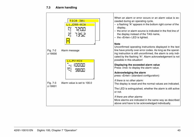
7.3 Alarm handling
arm or error occurs or an alarm value is ex-ng an operating cycle, “A“ appears in the bottom right corner of the
r alarm source is indicated in the first line of y instead of the TAG name,r> LED is lighted.
operating instructions displayed in the textority over error codes. As long as the operat-n is still unconfirmed, the alarm is only indi- flashing “A“. Alarm acknowledgement is nothis situation!
the exceeded alarm value to display the alarm value.
ging the alarmr> (standard configuration):
other alarm:is reset and the normal values are indicated.
extinguished, whether the alarm is still active
ther alarms are indicated in the same way as describedave to be acknowledged individually.
42/61-10010 EN Digitric 100, Chapter 7 "Operation"
Fig. 7-2 Alarm messagez-19000
Fig. 7-3 Alarm value is set to 100.0 z-19001
When an alceeded duri– a flashing
display,– the error o
the displa– the <Ente
NoteUnconfirmedline have priing instructiocated by thepossible in t
Displaying Press <Ind>
Acknowledpress <Ente
If there is noThe display
The LED is or not.
If there are oMore alarmsabove and h

42/61-10010 EN
7.4 Automatic mode (A)
e active setpoint is seen on the digital indica-
44 Digitric 100, Chapter 7 "Operation"
Possible operator actionsWhen the controller is switched over from manual to automatic mode, thtor. Other values can be selected by pressing the <Ind> button.<M/A> Switch over from manual to automatic mode<SP-w> Switch over the setpoint (if configured)<> <> Increment/decrement the setpoint<Menu> Switch over to another menu level

45
7.5 Manual mode (M)
and <> buttons are defined either throughf the step controller, through the appropriateritical state - e.g. a higher furnace tempera-sing the < > button.
een changed over from automatic to manual OUT is shown by the digital indicator. Othery pressing the <Ind> button.
with double output (split range or heating-off-00% corresponds to the full output range of
normal characteristic curve)ds to 100 % coolingds to 0 % cooling and 0 % heatingds to 100 % heating
nsr: change the output signalld <Enter>, additionally press <>:t jumps to end value -5 %ld <Enter>, additionally press < >:t jumps to end value +105 % increment/decrement the setpointrom manual to automatic modehe setpoint (if configured)er menu level
42/61-10010 EN Digitric 100, Chapter 7 "Operation"
Fig. 7-4 Output OUT is indicatedz-19020
The functions of the < >configuration or, in case owiring. Usually, a more cture - is reached by pres
After the controller has bmode, the output variablevalues can be selected b
In the case of controllers cooling) the display 0...1both outputs.
Example:Heating-off-cooling (with OUT = 0 % corresponOUT = 50 % corresponOUT = 100 % correspon
Possible operator actio< > <> OUT indicato
Press and hocontrol outpuPress and hocontrol outpu
<> < > SP indicator:<M/A> Switch over f<SP-w> Switch over t<Menu> Select anoth

42/61-10010 EN
7.6 Setpointsurces, provided that the controller has been
e by pressing the < > or <> button or
the digital indicator, independent of the num-
ive with a delay of 3 seconds. This means thatwitched over quickly.
SP4] ––>––↓
xt] ––<–––
SR3] ––>––↓
xt] ––<–––
46 Digitric 100, Chapter 7 "Operation"
The <SP-w> button can be used to toggle between several setpoint soconfigured accordingly.
Possible setpoint sources are:– setpoints SP1 to SP4 (SR1 to SR3) that can be selected on the devic– an external setpoint Sxt (Rxt) via analog input
or– a computer setpoint SPC (SRC) via serial interface
or– a programmer with 10 programs P01 to P10
Display in field /6/:
for ratio control
Unconfigured setpoints are suppressed.
Pressing the <SP-w> button will call up the current setpoint for display byber of available setpoints.
The setpoint is indicated immediately, but first flashes and becomes actonly the last setpoint selected becomes active when the setpoints are s
––– [SP1] ––>–– [SP2] ––>–– [SP3] ––>--–[↑––––<––– [POx] –––<–– [SPC] ––<–– [S
––––––––––>–– [SR1] ––>–– [SR2] ––>--–[↑––––<––– [P0x] –––<–– [SRC] ––<–– [R

47
7.7 Ratio controller
r controls
the configuration,
r can output the actual ratio to an analog out-f configured accordingly.
d SR displays are configured, the ratio set-in the fields /5/, /6/ and /7/ of the digital indi-et.
ordingly, several setpoint sources (SR1 tor program generator) can be selected byw> button. tual ratio is indicated in the fields /2/, /3/ and
cess value) SR set ratio( ) FlowAFlowB-----------------= =
V SR FlowAFlowA FlowB+-----------------------------------------==
42/61-10010 EN Digitric 100, Chapter 7 "Operation"
Fig. 7-5 Ratio control
Fig. 7-6 Display RPV and SR1, z-19018 SR1 is adjustable
The ratio controlle
or, depending on
The ratio controlleput (0/4...20 mA) i
When the RPV anpoint is indicated cator and can be s
If configured accSR3, Rexternal opressing the <SP-The measured ac/4/.
Flow A
Flow B
F
FFC
F
Z-19068
RPV(ratio pro
RP

42/61-10010 EN
SP displays are configured, the calculated is indicated in the fields /5/, /6/ and /7/. /4/ indicate the measured actual value of
utton to call up the SR1value in the display and then change it.
48 Digitric 100, Chapter 7 "Operation"
Fig. 7-7 Process value PV = flow A and SP = setpoint flow A
z-19019
Fig. 7-8 SR1 is adjustablez-190051
When the PV andsetpoint of flow A The fields /2/, /3/, flow A.
Press the <Ind> bfields (/5/, /6/, /7/)

49
7.8 Programmergrams with 15 segments each can be saved.
cting the program
er is configured, the [Pxy] display can be se-ng the <SP-w> button. The flashing Pxy dis-e number of the currently selected program.
<> to toggle between up to 10 saved pro-10).
ting the program
splay has stopped flashing, the program canssing the <Enter> button. The question if the started appears for 3 second in the text line.nter>. The question mark is replaced with anrk for a few seconds. If the selection is notEnter> within 3 seconds, the selection is ig-am selection is enabled again.
42/61-10010 EN Digitric 100, Chapter 7 "Operation"
A programmer can be configured in the controller. Up to 10 different proRefer to Section 12, Configuration for details about setting the values.
Fig. 7-9 Program has been selected,z-19002 but not yet started
7.8.1 Sele
If the programmlected by pressiplay indicates th
Press < > or grams (P01 to P
Fig. 7-10 Start?z-19004
7.8.2 Star
Once the Pxy dibe started by preprogram is to beConfirm with <Eexclamation maconfirmed with <nored and progr
42/61-10010 EN
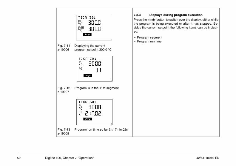
lays during program execution
button to switch over the display, either whilebeing executed or after it has stopped. Be-t setpoint the following items can be indicat-
entime
50 Digitric 100, Chapter 7 "Operation"
Fig. 7-11 Displaying the current z-19006 program setpoint 300.0 °C
Fig. 7-12 Program is in the 11th segmentz-19007
Fig. 7-13 Program run time so far 2h:17min:02sz-19008
7.8.3 Disp
Press the <Ind>the program is sides the currened:
– Program segm– Program run t
51
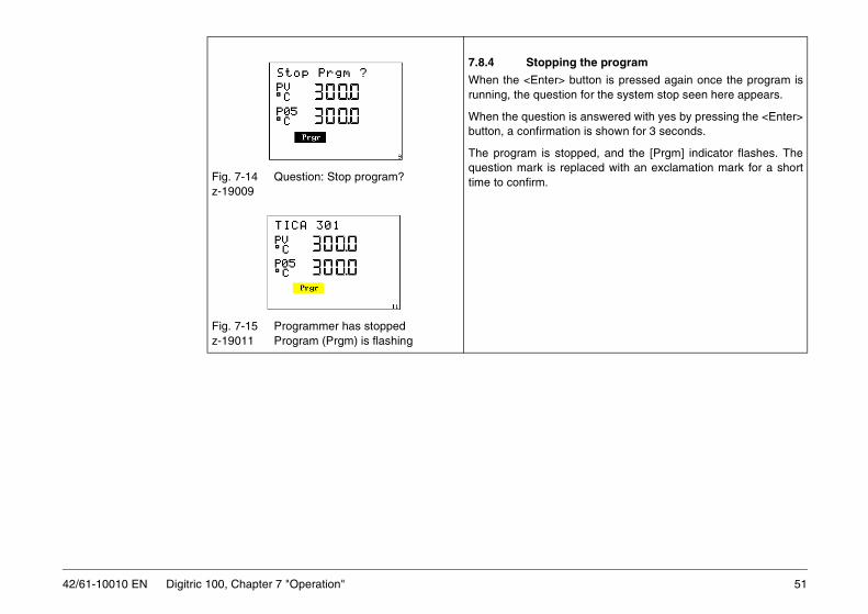
the program
utton is pressed again once the program is for the system stop seen here appears.
answered with yes by pressing the <Enter>n is shown for 3 seconds.
ped, and the [Prgm] indicator flashes. Thelaced with an exclamation mark for a short
42/61-10010 EN Digitric 100, Chapter 7 "Operation"
Fig. 7-14 Question: Stop program?z-19009
Fig. 7-15 Programmer has stoppedz-19011 Program (Prgm) is flashing
7.8.4 Stopping
When the <Enter> brunning, the question
When the question isbutton, a confirmatio
The program is stopquestion mark is reptime to confirm.
42/61-10010 EN
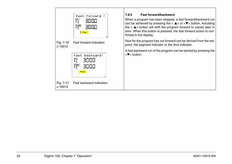
ard/backward
been stopped, a fast forward/backward runpressing the < > or <> button. Actuating shift the program forward to values later inon is pressed, the fast forward action is con-.
has run forward can be derived from the set-dicator or the time indicator.
of the program can be started by pressing the
52 Digitric 100, Chapter 7 "Operation"
Fig. 7-16 Fast forward indicationz-19012
Fig. 7-17 Fast backward indicationz-19013
7.8.5 Fast forw
When a program hascan be achieved by the < > button willtime. When this buttfirmed in the display
How far the programpoint, the segment in
A fast backward run <> button.

53
e of a computer failure the Digitric controller
the serial interface.
g (cancelling) the program
rted after it has been run down completely, itn the 1st segment. No reset is required in this
a be reset or cancelled by pressing the
wered with yes by pressing the <Enter> but-, the program is reset to the start. The mes-rs for a short time.
pts to switch during a running program to an-SP1) by actuating the <SP-w> button, thens“ appears in the display for 3 seconds, see
42/61-10010 EN Digitric 100, Chapter 7 "Operation"
7.9 DDC controlWith DDC control a supervisory computer provides for control. In casbumplessly takes over control.
Possible operating modes LED is off
LED is flashing with 0.5 to 1 Hz⊗ LED is flashing with 2 Hz
LED is onCR The computer is ready, i.e. there is regular data traffic via
M, A LEDs to the side of button 19 on the front panel (Fig. 7-1)
Fig. 7-18 Question: Reset?z19014
Fig. 7-19 During running program switching to other setpoints is not possible
z19-016
7.8.6 Resettin
If a program is restastarts automatically icase.
A stopped program c<SP-w> button.
If the question is anston within 3 secondssage “Reset!“ appea
If the operator attemother setpoint (e.g. warning “Program ruFig. 7-19.

42/61-10010 EN
nnot be switched to DDC mode.
A flashes with low frequency. In “automatic“
e at any time.
trol in the configured mode. cy.
uency.
ighted permanently.
DDC configuration DDC configurationatic backup mode
modeLED
RBM A
0 0
disabled 0 1
11
ode
⊗ 01
54 Digitric 100, Chapter 7 "Operation"
No computer ready signal (CR = 0)As long as no computer ready (CR) signal is available, the controller ca
Computer ready (CR = 1)The changeover to DDC operation is enabled. In “manual“ mode LEDbackup mode LED M flashes with low frequency.
It is possible to switch from DDC operation to manual or automatic mod
Computer not readyIf the CR signal is not received any longer, the controller takes over conIn backup mode "manual" LED A flashes with increased frequenIn backup mode "automatic" LED M flashes with increased freqIt is not possible to switch over to another mode (non-DDC).The LED of the disabled mode flashes. The LED of the active mode is l
with manual backup mode with autom
Operating modeLED
CRM A
Manual 0Automatic 0DDC disabled 0Manual 1Automatic 1DDC 1Backup mode
M-backup ⊗ 0M-backup 1
Operating
Manual
Automatic
DDC
Manual
Automatic
DDC
Backup m
M-backup
M-backup
55
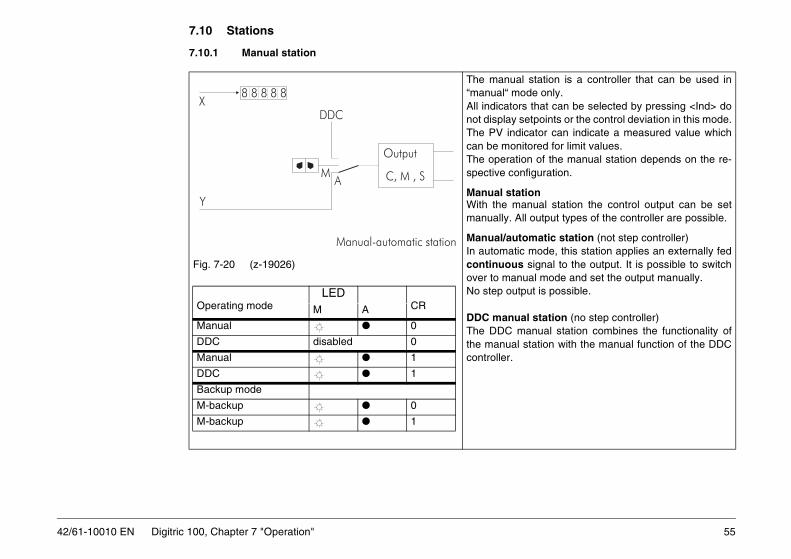
7.10 Stations
l station is a controller that can be used inde only.
s that can be selected by pressing <Ind> doetpoints or the control deviation in this mode.cator can indicate a measured value whichitored for limit values. n of the manual station depends on the re-figuration.
ionnual station the control output can be set
ll output types of the controller are possible.
omatic station (not step controller) mode, this station applies an externally fed signal to the output. It is possible to switchual mode and set the output manually.ut is possible.
l station (no step controller)anual station combines the functionality ofstation with the manual function of the DDC
88
88
8
42/61-10010 EN Digitric 100, Chapter 7 "Operation"
7.10.1 Manual station
Fig. 7-20 (z-19026)
The manua“manual“ moAll indicatornot display sThe PV indican be monThe operatiospective con
Manual statWith the mamanually. A
Manual/autIn automaticcontinuousover to manNo step outp
DDC manuaThe DDC mthe manual controller.
AM
DDC
Y
X8 8 8 8 8
Manual-automatic station
Output
C, M , S
Operating modeLED
CRM A
Manual 0
DDC disabled 0
Manual 1
DDC 1
Backup mode
M-backup 0
M-backup 1
42/61-10010 EN
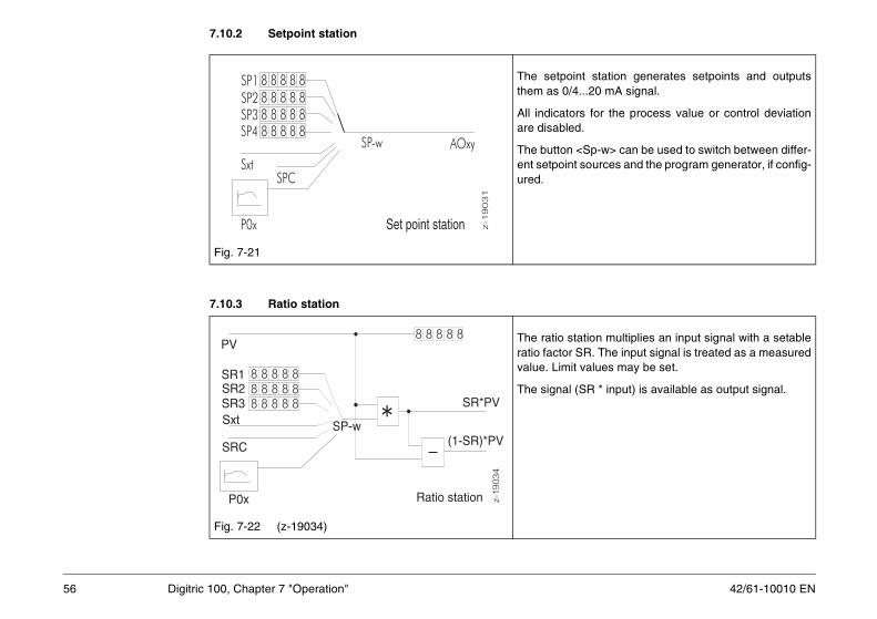
7.10.2 Setpoint station
t station generates setpoints and outputs...20 mA signal.
s for the process value or control deviation.
Sp-w> can be used to switch between differ-sources and the program generator, if config-
tion multiplies an input signal with a setableR. The input signal is treated as a measured
values may be set.
SR * input) is available as output signal.
88
88
8
88
88
8
88
88
88
88
88
88
88
8
88
88
8
88
88
88
88
88
56 Digitric 100, Chapter 7 "Operation"
7.10.3 Ratio station
Fig. 7-21
The setpointhem as 0/4
All indicatorare disabled
The button <ent setpoint ured.
Fig. 7-22 (z-19034)
The ratio staratio factor Svalue. Limit
The signal (
8 8 8 8 8
8 8 8 8 8
8 8 8 8 88 8 8 8 8
AOxy
P0x
SPCSxt
SP-wSP4SP3SP2SP1
Set point station z-1
90
31
*
8 8 8 8 8
8 8 8 8 8
8 8 8 8 88 8 8 8 8
P0x
Sxt
PV
SRC
SP-w
SR*PVSR3SR2SR1
Ratio station
(1-SR)*PV
z-19
034

57
7.10.4 Positioner
ks the actuator position (valve position) to ansition is indicated on the controller as the pro-
ndicator is active. The control buttons on thent panel are disabled, with some exceptions.
erator actions
Permits to switch over the displayAccesses the configuration menu, among other reasons to start remote control.
u> to switch to the menu level from which re-l can be disabled.
42/61-10010 EN Digitric 100, Chapter 7 "Operation"
The positioner is a motorized valve controller (step controller) which tracexternal setpoint. This task requires position feedback. The returned pocess value PV and the position feedback OUT.
7.11 Remote control (Profibus or Modbus)
Only remote control
Fig. 7-23 Remote control is active z-19035
The [Rem] icontroller fro
Possible op
<Ind> <Menu>
Press <Menmote contro

42/61-10010 EN
8 Error information on the display
Configuration
cked through a binary I-B02-Q01I-B02-Q02
figuration. L1- B01-Q05
ment (e. g. no Pt100
d with constant current,
require an adjustment.
hed to exclusive remote I-B04-Q01
it must be enabled via I-B04-Q01
58 Digitric 100, Chapter 8 "Error information on the display"
Table 8-1 Error information
Operating notes Meaning
locked by BI Access to parameterization, configuration, service, and supervisor level is bloinput.
generate After configuration the instrument is busy with the program generation.
locked for SP Self-tuning is blocked for this control loop. It can only be released via the con
no adj. possible The selected input has not been activated for the type intended for the adjustinput).This message is displayed for mA position feedback or remote transmitters feif the difference between start and end value is smaller than 10%.
no adjustment The configured module does not permit an adjustment respectively does not
local only The instrument has only been configured for local operation. It cannot be switcoperation.
remote only The instrument has been configured for remote operation. For local operationmenu “Operate 2” or via the configuration.

59
Error message Cause Remedy
sappear within a few seconds you can try to g off the supply voltage for approximately 60 actory settings must be restored via the nfiguration must be reloaded via IBIS_R .
sappear within a few seconds after initiate a restart by switching off the supply 0 s. If the error persists, the factory settings pervisor” menu or the configuration must be
slot 1 and register the module
the display with <Enter> and change it.
42/61-10010 EN Digitric 100, Chapter 8 "Error information on the display"
Table 8-2 Error information
Error xxxx An error occurred while processing the program.The number is intended as help for the service.
If this message does not diinitiate a restart by switchins. If the error persists, the f“supervisor” menu or the co
IP stopped! Processing has been temporarily stopped.This error occurs during downloading.
If this message does not didownloading you can try tovoltage for approximately 6must be restored via the “sureloaded via IBIS-R+ .
Slot 1! When downloading a configuration the configuration request a module that is located in the instrument.
Insert the correct module in(I-B11-Q01 = 1).
invalid resp. The response entered may be incompatible with other existing settings.Enter is activated together with this message.
Get the invalid response on

42/61-10010 EN
9 Menu structure
Z-202521
2. Menu level
see attached tables
see attached tables
see attached tables
see attached tables
see attached tables
see attached tables
see attached tables
60 Digitric 100, Chapter 9 "Menu structure"
Fig. 9-1 Menu structure1 Confirm selection, go down one menu level2 Change or confirm input, go down one menu level3 Go up one menu level without change(press 3 s → main operating level)4 From main operating level to menu5 Move sideways within one menu level
EscMenu
Enter1
2
3
4
5EscMenu
Pas
swor
d -
chec
kif
inC
ON
FI /
INS
TR
UM
EN
T /
B20
def
ined
Ope
ratio
n le
vel
1. Menu level
Indication 2
Operate 2
Selftune
Parameter
Configuration
Service
Supervisor

61
Indication 2ings of the controller, but you cannot change
figured functionality. During parameterization
ctuator output type).are frozen). (See also tables and section 12.)
o tables). an expert manner, the instrument is rendered
Template (see also tables and Section 15,
42/61-10010 EN Digitric 100, Chapter 9 "Menu structure"
In this menu you can view all parameters, measuring values, and settthem (see also tables and section 9.1).
Operate 2In this menu you can toggle between local and remote operation.(See also tables and section 9.2)
SelftuneSelf-tuning is enabled in the configuration menu under
CONFI / LOOP1 / B01 / Q05After enabling it can be used without knowing a password (see also tables and section 11.4).
ParameterThis menu contains the settings of the parameters required for the conthe control action stays on (see also tables and section 11).
ConfigurationThis menu contains sub-menus for instrument function definition (e. g. aDuring configuration the control action is switched off (actuator outputs
ServiceThis menu contains sub-menus for calibration, Adjustment, etc. (see alsCalibration is only required in exceptional cases. If it is not executed in unusable (see also tables and Section 14, Service).
SupervisorThis menu contains the sub-menus: Master reset, Plausibility, and Supervisor).

42/61-10010 EN
9.1 Indication 2
u you can display all parameters of the
changes can only be performed via theotected parameterization menu.
62 Digitric 100, Chapter 9 "Menu structure"
9.1.1 Parameter display
Fig. 9-2 Parameter displayz-19104
In this meninstrument.
Parameter password-pr

63
9.1.2 Inputs/outputs
you can display all binary and analog inputs used in the application.
r> to switch to the next menu level.
analog input AI01 is displayed in the first lineed scale.
line shows the PV. In simple control taskse measuring value both values are identical, different decimal point position.
and <> to select the desired input or output.
nary input BI01 has the value
42/61-10010 EN Digitric 100, Chapter 9 "Menu structure"
Fig. 9-3 Start menu for displaying -19081 inputs and outputs
Fig. 9-4 Analog input AI01 = 250.5 mbarz-19082
Fig. 9-5 Binary input BI01 = 1z-19083
In this menuand outputs
Press <Ente
The value ofof the select
The bottomwith only onpossibly with
Press < >
Currently, bilogical “1”.
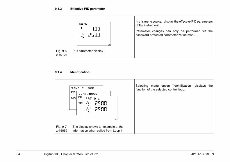
42/61-10010 EN
9.1.3 Effective PID parameter
you can display the effective PID parametersment.
changes can only be performed via theotected parameterization menu.
enu option ”Identification“ displays thee selected control loop.
64 Digitric 100, Chapter 9 "Menu structure"
9.1.4 Identification
Fig. 9-6 PID parameter displayz-19104
In this menuof the instru
Parameter password-pr
Fig. 9-7 The display shows an example of the z-19065 information when called from Loop 1.
Selecting mfunction of th

65
9.1.5 Library identification
uration is based on library 3.6.0. Thisis only relevant for processing the
with IBIS-R+.
rmware version used in the instrument itself. quired to know this version number when IS-R PC software.
42/61-10010 EN Digitric 100, Chapter 9 "Menu structure"
9.1.6 Version display
Fig. 9-8 Library identificationz-19080
The configinformation configuration
Fig. 9-9 The firmware (instrument software) has the z-19042 index 01.250
This is the fiIt may be reusing the IB

42/61-10010 EN
9.2 Operate 2
ment has been configured exclusively foration, the remote operation can be disabled– e. g. for emergency intervention – via menu
on the configuration the following displayn selecting the menu option:
d for remote operationn cannot be changed.
ration means that values are input to theia Modbus RTU respectively PROFIBUS DP.
ration is activatedration “Rem” can be toggled to local opera-
n “Toggle to local operation?“ cal?" is confirmed with <Enter> or negated
ent is toggled to local operation the keys are [Rem] starts flashing.
66 Digitric 100, Chapter 9 "Menu structure"
Fig. 9-10 Not intended for remote operationz-19041
Fig. 9-11 Remote operation is activatedz-19040
If the instruremote opertemporarily “Operate 2”.
Depending appears whe
Not intendeThe operatio
NoteRemote opeinstrument v
Remote opeRemote opetion. The questio= "Rem>Lowith <Esc>.
If the instrumenabled and

67
ration is deactivatedration is – temporarily – switched off. Pressrestore the operating condition “Remotes defined by the configuration. Then, thean only be remote-operated. flashing.
42/61-10010 EN Digitric 100, Chapter 9 "Menu structure"
Fig. 9-12 Remote operation is deactivatedz-19039
Remote opeRemote ope<Enter> to operation” ainstrument c[Rem] stops

42/61-10010 EN
10 Password protection
ord protection has been configured (I-B20),nter a password to access the protectedanging the predefined value “00000”.
rd is a 5-digit number.
ft a flashing (changeable) field:d>ange digit:> and <>
nfirm password:ter>
password is correct, the desired level isu can now switch between all levels of the
without having to re-enter the password B20-Q01).
ord is not correct, the main operating level isain.
e lock has been configured (I-B02-Q01) andnput is set, the message “locked by BI” ishen attempting to open a protected level.
e is displayed for 3 s, then the operating levelally switched back.
68 Digitric 100, Chapter 10 "Password protection"
Fig. 10-1 Input of password. 1st field from the rightz-19101
Fig. 10-2 Locking the parameterization and z-19103 configuration level via binary input
If the passwyou must elevels, by ch
The passwo
1. Shi<In
2. Ch<
3. Co<En
When the entered. Yomenu system(Question: I-
If the passwdisplayed ag
If a hardwarthe binary idisplayed w
The messagis automatic

69
Cancelling the password input
rily rearranging a jumper within the instrument.tion refer to section 6.5.
42/61-10010 EN Digitric 100, Chapter 10 "Password protection"
Cancel with <Esc>
Forgotten passwordIf a password is no longer known, the password can be reset by temporaFor this action the control loop must be switched off. For further informa

42/61-10010 EN
11 Parameterization operation.
he parameter changes could interfere with the
4. menu level
1 1.0000
Enter
EscMenu
EscMenu
EscMenu
Ind
confirm
abbort
70 Digitric 100, Chapter 11 "Parameterization"
During parameterization the instrument in online, i. e. all functions are in
During parameterization the instrument should be set to manual, since tautomatic operation.
11.1 Parameterization menu
Fig. 11-1 Parameterization menu
Operation level 1. menu level 2. menu level 3. menu level
Indication 2 INSTRUMENT 1 GAINOperate 2 LOOP1 2 RESET TIME TrSelftune PROGRAM 1 3 DERI. TIME TdParameter PROGRAM 2 4 GdConfiguration . . . . . 5 MANUAL RESET1Service PROGRAM 9 . . . . . . . . .Supervisor PROGRAM 10 199 TAG NAME
EscMenu
EscMenu
Enter Enter Enter
edit
EscMenu
EscMenu

71
11.2 Selecting and changing parameters
to parameterization menu:enu>quired, enter password (procedure ording to items 4 through 8):
ect parameter:> and <>ble parameter change:ter>
position flashes.
ange the flashing position: d>ft the decimal point:ss and hold <Ind>ange value:> and <>ept changed parameter (including decimal
nt change):ter>
card changes:c>
42/61-10010 EN Digitric 100, Chapter 11 "Parameterization"
Fig. 11-2 Selecting parametersz-19112
Fig. 11-3 Gain selected for changingz-19104
(Menu )
1. Go<M
2. If reacc
(Menu )
3. Sel<
4. Ena<En
(Enter )
A parameter
5. Ch<In
6. ShiPre
7. Ch<
8. Accpoi<EnorDis<Es
Enter .

42/61-10010 EN
11.3 Parameter categoriesn) have the following headings:
n tables. The dimension (EU) depends on the
nfiguration (e. g. AI-Bx-Q02).
ugh L1-P29
l output OUT2 (e. g. “Cooling”)ain 2 set time 2 Trrivative time 2 Tdrivative gain 2 Gd
anual reset 2 MRoling or split-range, if available).ired parameters from range P06 through P21isplay. The values currently in effect are alsoID parameters” if parameter control (Gain
art and end value of the values (P06 throughr control.
72 Digitric 100, Chapter 11 "Parameterization"
The parameter tables in these instructions (Section 11, Parameterizatio
Instrument all parameters valid for the entire instrument.Loop 1 parameters specific for a control loop.Program 1-10 Programs 1 through 10 for the programmer(refer to section “programmer”).
11.3.1 Instrument parameterization
The parameterization for the instrument consists of the four linearizatioconfigured application. It is not shown in the tables.
The tables can only be parameterized if the tables are linked into the co
11.3.2 Loop 1 parameterization
PID parameters (L1-P01 through L1-P19) and possibly L1-P25 thro
For a standard PID controller, only these parameters are accessibleControl output OUT1 Contro01 Gain 25 G02 Reset time Tr (only if integral part present) 26 Re03 Derivative time Td (only if derivative part present) 27 De03 Derivative gain Gd (only if derivative part present) 28 De05 Manual reset MR (if no integral part present) 29 MThe OUT2 parameters are valid for a 2nd control output (heating-off-coIf a parameter control has been configured (L1-B02-Q7...Q18), the requ(OUT1) resp. P30 through P37 (OUT2) are in effect and visible on the dshown in P01 through P05 in menu option “Indication 2”/“Actual Pscheduling) is active.
For parameter changeover, a binary input is used to toggle between stP21 for OUT1, P30 through P37 for OUT2) parameterized for paramete

73
Self-tune L1-P125 - L1-P128ng, in order to guarantee that illegal operating
t function has been configured (L1-B01-Q02).
y setting render them ineffective.
Q05, Q06, and L1-B10-Q03, Q05).
nd their change rate. The factory settings of
e been configured as parameters.
eter P96 defines the time period during which
/min:
42/61-10010 EN Digitric 100, Chapter 11 "Parameterization"
Using parameters P125 through P128 you can define limits for self-tunisituations cannot occur.
Control output (parameters L1-P55 through L1-P72)Parameters P55 through P72 are only visible if the corresponding outpu
Control signal limits (P67 through P70) are always available. The factor
The safety values P71, P72 depend on the configuration (L1-B07-Q03,
Setpoint values (parameters L1-P75 through L2-P84)Parameters P75 through P80 define the limits for the setpoint values aparameters P77 through P80 render them ineffective.
Parameters P81 through P84 are only visible, if the setpoint values hav(L1-B05-Q02 ff.)
Alarm values (parameters L1-P91 through L1-P96)If alarm value has been configured for monitoring the change rate, paramthe value set by P91 through P95 must not be exceeded as change.
There are only three values possible for P96:1 = 0:00:01 h = 1 second2 = 0:01:00 h = 1 minute3 = 1:00:00 h = 1 hour
Example:Alarm value 1 is supposed to switch at a change rate of more than 15°CAL1 L1-B08-Q01 = 11 (AL1: function dx/dt)
L1-P96 = 2 minL1-P91 = 15 15 (°C, if SP in °C)

42/61-10010 EN
Input evaluations (parameters L1-P101 through L1-P104)
ne the limits of the ratio setpoint and the bias.
urbance feedforward.
acters). 9...0, space, – t.
is exited and you move back to the operation
74 Digitric 100, Chapter 11 "Parameterization"
These parameters are explained in the description of the input circuits.
Input ratio (parameters L1-P115 through L1-P117)These parameters are only effective in ratio input circuits. They determi
Disturbance feedforward (parameter L1-P120, L1-P121)These parameters determine the transition function of a differential dist
TAG name (parameter L1-P199)
Fig. 11-4 Parameter 199 “TAG name” selected for changingz-19105
Parameter 199, the TAG name, is set in the text line (maximum 12 char< > and <> allow the setting of A...Z, a...z, +, ., /, %, _, ), (, °,<Enter> terminates the input and takes over the text inpu<Ind> moves the input position.
Exit parameterization level<Menu> jumps one level up in the menu system. If you press and hold this key longer than 5 seconds, the menu systemlevel.

75
11.4 Self-tunent for some time. Before starting selftune this
NG, the temperature of the controlled systemr COOLING can be activated.l) and positioners. (See also tables.)
ocess at the beginning of the self-tuning. This
nd the first parameters. For controlled processameters more precisely.
nu, these parameters must be adapted to the
occurs in the controlled process, without the
ected control compensation time Tg. Factory
mplete jump response (in either direction), noation.
ator pulse is decreased to the initial value.
lied to the process the controller reduces this
42/61-10010 EN Digitric 100, Chapter 11 "Parameterization"
Notes Self tuning should only be started, if the process value has been constacan be achieved in manual mode.
For parameterizing a controller with the function HEATING-OFF-COOLImust be high enough for cooling to become active, before self-tuning foSelf tuning cannot be performed for motorized valve control (step contro
11.4.1 Procedure
For exciting the controlled process a jump is applied to the controlled prjump is taken away after an adjustable duration.From this jump the controller recognizes the type of controlled process awith compensation another jump is applied, in order to calculate the par
11.4.2 Parameters
Four parameters have been defined for self-tuning in the parameter mecontrolled process, if need arises:
Jump L1-P125This value must be selected in such a way that a detectable change controlled process operating in a critical range. Factory setting: +5.0 %.
Max. jump duration L1-P126Duration of first jump. The duration should be at least 1/10 of the expsetting: 0.25 min (15 s).
If the duration of the first test jump is long enough to accommodate a cofurther jump will occur, not even for controlled processes with compens
Max. pos. control deviation L1-P127Max. neg. control deviation L1-P128If the control variable is likely to exceed the defined range, the first actuFactory setting: 99999 EUIf – for controlled processes with compensation – a second jump is appsecond jump in such a way that the limits will no longer be exceeded.

42/61-10010 EN
11.4.3 Starting self-tuning
ll up self-tuning:enu> < > < >
f-tuning can only be started if it has been bled in the configuration menu (L1-B01-Q05 ) If self-tuning is locked, the message Selftune” is displayed.
r selecting the menu option lftune”, rt self-tuning:ter>
76 Digitric 100, Chapter 11 "Parameterization"
Fig. 11-5 Self tuningz-19043
Fig. 11-6 Locked for self-tuningz-19143
Fig. 11-7 Start self-tuning?z-19047
1. Ca<M
2. Selena> 0“no
3. Afte“Sesta<En
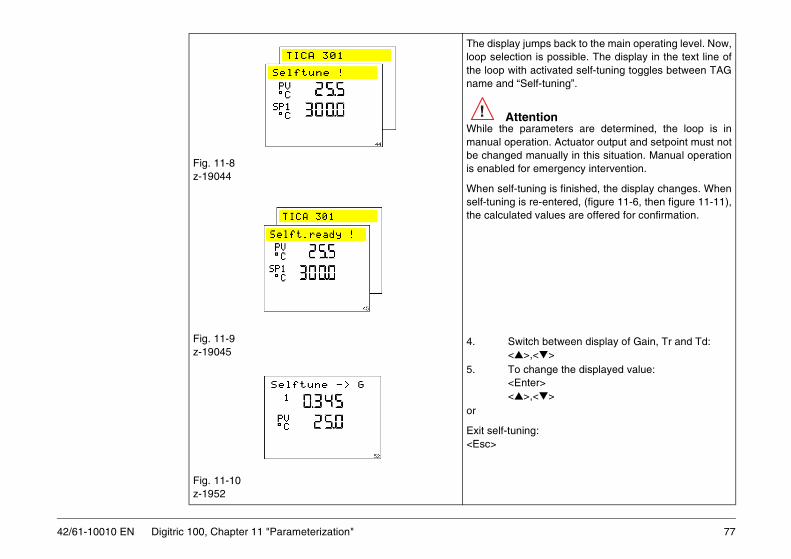
77
jumps back to the main operating level. Now,n is possible. The display in the text line of activated self-tuning toggles between TAGelf-tuning”.
entionarameters are determined, the loop is in
ration. Actuator output and setpoint must not manually in this situation. Manual operationr emergency intervention.
ning is finished, the display changes. When re-entered, (figure 11-6, then figure 11-11),d values are offered for confirmation.
itch between display of Gain, Tr and Td:>,<>change the displayed value:ter>
>,<>
ing:
42/61-10010 EN Digitric 100, Chapter 11 "Parameterization"
Fig. 11-8z-19044
Fig. 11-9z-19045
Fig. 11-10z-1952
The display loop selectiothe loop withname and “S
AttWhile the pmanual opebe changedis enabled fo
When self-tuself-tuning isthe calculate
4. Sw<
5. To <En<
or
Exit self-tun<Esc>
!
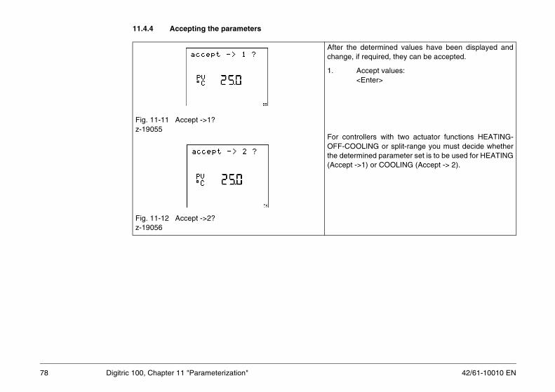
42/61-10010 EN
11.4.4 Accepting the parameters
termined values have been displayed andquired, they can be accepted.
ept values:ter>
ers with two actuator functions HEATING-NG or split-range you must decide whethered parameter set is to be used for HEATING or COOLING (Accept -> 2).
78 Digitric 100, Chapter 11 "Parameterization"
Fig. 11-11 Accept ->1?z-19055
Fig. 11-12 Accept ->2?z-19056
After the dechange, if re
1. Acc<En
For controllOFF-COOLIthe determin(Accept ->1)

79
11.4.5 Rejecting the parameters
ject parameters:ter>
sly set values are retained.
ning is executing, you can cancel self-tuningg the menu level and opening the self-tuning.
ncel self-tuning:ter>
not cancel self-tuning:enu>jumps back to the menu level.
42/61-10010 EN Digitric 100, Chapter 11 "Parameterization"
11.4.6 Cancelling self-tuning
Fig. 11-13 Reject?z-19057
1. Re<En
The previou
Fig. 11-14 Cancel self-tuning?z-19046
While self-tuby re-enterinmenu option
1. Ca<En
or
2. Do<M
The display
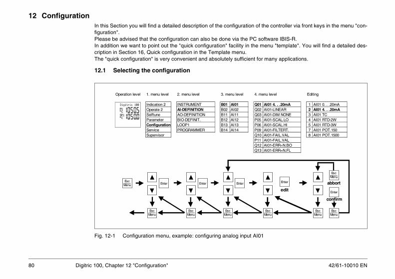
42/61-10010 EN
12 Configurationthe controller via front keys in the menu "con-
oftware IBIS-R.enu "template". You will find a detailed des-
r many applications.
1
enu level Editing
AI01 4. . .20mA 1 AI01 0. . .20mAAI01-LINEAR 2 AI01 4. . .20mAAI01-DIM NONE 3 AI01 TCAI01-SCAL.LO 4 AI01 RTD-2WAI01-SCAL.HI 5 AI01 RTD-3WAI01-FILTERT. 7 AI01 POT.150AI01-FAIL.VAL 8 AI01 POT.1500AI01-FAIL.VALAI01-ERR=N.BOAI01-ERR=N.FL
EscMenu
Enter
Enter
EscMenu
EscMenu
EscMenu
confirm
abbort
edit
80 Digitric 100, Chapter 12 "Configuration"
In this Section you will find a detailed description of the configuration of figuration".Please be advised that the configuration can also be done via the PC sIn addition we want to point out the "quick configuration" facility in the mcription in Section 16, Quick configuration in the Template menu.The "quick configuration" is very convenient and absolutely sufficient fo
12.1 Selecting the configuration
Fig. 12-1 Configuration menu, example: configuring analog input AI0
Operation level 1. menu level 2. menu level 3. menu level 4. m
Indication 2 INSTRUMENT B01 AI01 Q01Operate 2 AI-DEFINITION B02 AI02 Q02Selftune AO-DEFINITION B11 AI11 Q03Parameter BIO-DEFINIT. B12 AI12 P05Configuration LOOP1 B13 AI13 P06Service PROGRAMMER B14 AI14 P09Supervisor Q10
P11Q12Q13
EscMenu Enter Enter Enter
EscMenu
EscMenu
EscMenu

81
12.2 Configuration table structureanual) are structured as follows:
, linearization, filtering,
ctuator output, input relations,
commended:
42/61-10010 EN Digitric 100, Chapter 12 "Configuration"
The configuration tables depicted in these instructions (see end of the mInstrument all parameters valid for the entire device.AI definition Analog inputs with the functions defining sensors
scalingAO definition Define signal ranges of the analog outputsBIO definitions Define binary inputs/outputs as inputs or outputsLoop 1 Configure control function with the functions for a
PID structureState corr.1 Select and parameterize state correction.Programmer Activate programs
12.3 Sequence of configuration
The following sequence for the configuration of a new instruments is re1. Instrument2. Analog inputs3. State correction, if applicable4. Analog outputs5. Binary inputs/outputs6. Control function
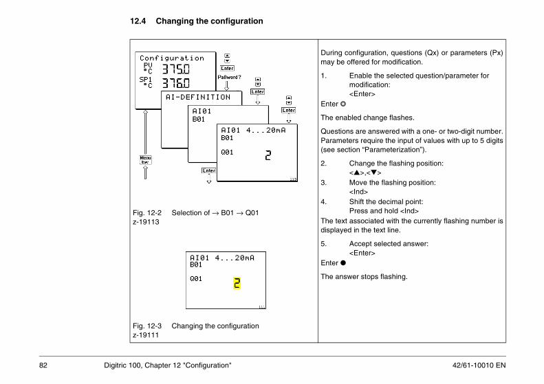
42/61-10010 EN
12.4 Changing the configuration
guration, questions (Qx) or parameters (Px)red for modification.
ble the selected question/parameter for dification:ter>
change flashes.
re answered with a one- or two-digit number. require the input of values with up to 5 digits “Parameterization”).
ange the flashing position:>,<>ve the flashing position:d>ft the decimal point:ss and hold <Ind>ociated with the currently flashing number is the text line.
ept selected answer:ter>
stops flashing.
82 Digitric 100, Chapter 12 "Configuration"
Fig. 12-2 Selection of → B01 → Q01z-19113
Fig. 12-3 Changing the configurationz-19111
During confimay be offe
1. Enamo<En
Enter
The enabled
Questions aParameters(see section
2. Ch<
3. Mo<In
4. ShiPre
The text assdisplayed in
5. Acc<En
Enter
The answer

83
12.5 Exit configuration menu
ps one level up in the menu system.
this key longer than 5 seconds, the menuited.
sibility function is enabled (see section), the instrument checks the configuration fors and plausibility when exiting the menu.
ly, the function settings are processed for
ssful configuration the instrument switchesonfiguration menu.
uration menu:
42/61-10010 EN Digitric 100, Chapter 12 "Configuration"
Fig. 12-4 Check answerz-19138
Fig. 12-5 Generate…z-19140
Fig. 12-6 Configurationz-19141
<Menu> jum
If you presssystem is ex
If the plau“Supervisor”completenesconfiguration
Subsequentexecution.
After succeback to the c
1. Exit config
<Esc>
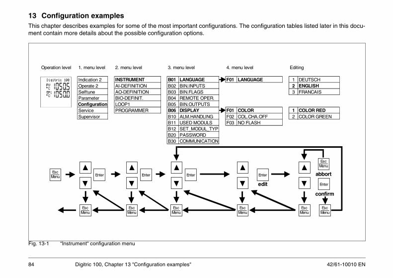
42/61-10010 EN
13 Configuration examplesfiguration tables listed later in this docu-
Editing
E 1 DEUTSCH2 ENGLISH3 FRANCAIS
1 COLOR REDFF 2 COLOR GREEN
nter
Enter
EscMenu
EscMenu
EscMenu
confirm
abbort
dit
84 Digitric 100, Chapter 13 "Configuration examples"
This chapter describes examples for some of the most important configurations. The conment contain more details about the possible configuration options.
Fig. 13-1 “Instrument“ configuration menu
Operation level 1. menu level 2. menu level 3. menu level 4. menu level
Indication 2 INSTRUMENT B01 LANGUAGE F01 LANGUAGOperate 2 AI-DEFINITION B02 BIN.INPUTSSelftune AO-DEFINITION B03 BIN.FLAGSParameter BIO-DEFINIT. B04 REMOTE OPER.Configuration LOOP1 B05 BIN.OUTPUTSService PROGRAMMER B06 DISPLAY F01 COLORSupervisor B10 ALM.HANDLING F02 COL.CHA.O
B11 USED MODULS F03 NO FLASHB12 SET_MODUL_TYPB20 PASSWORDB30 COMMUNICATION
EscMenu
EscMenu
Enter Enter Enter E
EscMenu
EscMenu
EscMenu
e

85
13.1 Device
tion should be paid to item I-B11-Q01 “Hard-on“. Which input/output modules can be con-ends on the available modules that are I-B12-Q01. When the hardware recognitionI-B11-Q01=1), the existing module is auto-cognized and entered in I-B12-Q01. I-B11-automatically reset to zero.
at does not (yet) exist can be entered manu- to be considered for the configuration. How-evice cannot be commissioned with an
hardware. In this case, the error messagetput.
42/61-10010 EN Digitric 100, Chapter 13 "Configuration examples"
13.1.1 Hardware
Fig. 13-2z-19070
Fig. 13-3z-19071
Special attenware definitifigured depregistered inis enabled (matically reQ01 is then
A module thally in I-B12ever, the dincomplete “Slot 1“ is ou

42/61-10010 EN
13.1.2 Password
ber of up to 5 digits.xisting password is deactivatedassword protection is enabled. pon exit from the menu system the pass-ord protection will become active immedi-tely.pon exit from the menu system the assword protection will only be activatedfter 3 seconds. Within this delay it is ossible to select the parameter or onfiguration level again without re-entering he password.ctive password, changes enabled. arameter(s) being changed.
86 Digitric 100, Chapter 13 "Configuration examples"
Fig. 13-4 Setting the passwordz-19117
The password is a numI-B20-Q01 = 0 EI-B20-Q01 = 1 P
Uwa
I-B20-Q01 = 2 Upapct
I-B20-Q02 AP

87
13.2 AI definition
Editing
mA 1 AI01 0. . .20mAR 2 AI01 4. . .20mAONE 3 AI01 TCLO 4 AI01 RTD-2WHI 5 AI01 RTD-3WRT. 7 AI01 POT.150AL 8 AI01 POT.1500AL
N.BON.FL
nter
Enter
EscMenu
EscMenu
EscMenu
confirm
abbort
dit
42/61-10010 EN Digitric 100, Chapter 13 "Configuration examples"
Fig. 13-5 Analog input menu
Operation level 1. menu level 2. menu level 3. menu level 4. menu level
Indication 2 INSTRUMENT B01 AI01 Q01 AI01 4. . .20Operate 2 AI-DEFINITION B02 AI02 Q02 AI01-LINEASelftune AO-DEFINITION B11 AI11 Q03 AI01-DIM NParameter BIO-DEFINIT. B12 AI12 P05 AI01-SCAL.Configuration LOOP1 B13 AI13 P06 AI01-SCAL.Service PROGRAMMER B14 AI14 P09 AI01-FILTESupervisor Q10 AI01-FAIL.V
P11 AI01-FAIL.VQ12 AI01-ERR=Q13 AI01-ERR=
EscMenu
EscMenu
Enter Enter Enter E
EscMenu
EscMenu
EscMenu
e
42/61-10010 EN
13.2.1 General
ice. The scaling is used to define the mea-further processing steps in the device.
range and number of digits to the right of the
cted according to its type and connection dia- AI-B01-Q01.
he number of the input on the module.
s replaced with a default value, which may beer action.
ller output does not react on the sensor trou-
e independently of the controller reaction.
88 Digitric 100, Chapter 13 "Configuration examples"
All analog input must be scaled to permit their further use in the devsuring values, which are then used as floating point values for all
How the digital input, i.e. process value PV, is displayed in terms of thepoint can be set independently.
Example:Thermocouple type KMeasuring range of the sensor: -200...+1400 °CControl range: 300.0...500.0 °CAI01 is the universal input of the basic unit. The sensor is conne
gram. The input type must be entered in the device moduleAI02 is an optional universal input connected to the main board.AI1y are the analog inputs of the module in slot 1; y represents t
13.2.2 Sensor problems
All inputs and sensor types are monitored.
1. Reaction of the controller:
AI-Bxy-Q10 = 1In case of sensor troubles or cable break the missing measured value ioutside the normal measuring range to force the corresponding controll
AI-Bxy-Q10 = 2L1-B07-Q06=1An unchanged measured value is simulated to the controller. The controble.
2. Signal transmission:With AI-Bxy-Q12 > 0 and AI-Bxy-Q13 > 0 signal transmission is possibl

89
13.2.3 Dimension
is scaled separately and can be provided withnsion.
ep, the dimension “° C“ is assigned by defaultature sensor inputs.
ious dimensions for selection. If the neededs not available, a 4-digit dimension can beI-Bxy-Q04 through AI-Bxy-Q03 = 1.
g signals can be attenuated with a first de-filter to suppress all measured value varia-e troubles resulting from them. The time be set with AI-Bxy-Q090 h = 2 min).
42/61-10010 EN Digitric 100, Chapter 13 "Configuration examples"
13.2.4 Filtering
Fig. 13-6 Defining a user-specific dimensionz-19118
Every input an own dime
In the first stto all temper
AI-Bxy-Q03 provides vardimension icreated in A
Fig. 13-7 Filter time constant 0.00.20 h = 20 sz-19120
All measuringree delay tions and thconstant can(max. 0.02.0

42/61-10010 EN
13.2.5 mA inputs
selected scaling.
resulting measured value is forced to 0
ized temperature transmitter, .an be set.
on.
le. “Service“).
90 Digitric 100, Chapter 13 "Configuration examples"
AI-Bxy-Q01 = 1,2 Signal range 0 or 4 to 20 mA.AI-Bxy-Q03 Measured value is indicated linearly and with theAI-Bxy-P05 Display with measured value 0 or 4 mA. AI-Bxy-P06 Display with measured value 20 mA.AI-Bxy-Q02 = 2,3 Measured value is square-rooted. Below PV0 the
or replaced with a linear calculated value.AI-Bxy-P08 Used for setting PV0.AI-Bxy-Q02 = 4...14 If the measured value is provided by a non-linear
the sensor characteristic may be used by defaultWith AI-Bxy-P05 and P06 the transmitter range c
Example:Transmitter300 to 700 °C, type K = 0... 20 mA, mV-proportional:AI-Bxy-Q01 = 1AI-Bxy-Q02 = 6AI-Pxy-Q05 = 300,0AI-Pxy-Q06 = 700,0AI-Bxy-Q03 = 3 (automatic)
13.2.6 Thermocouple input
AI-Bxy-Q01 = 3 Thermocouple.AI-Bxy-Q02 = 4...13 Selection of thermocouple type.AI-Bxy-Q03 = 3 Can be switched to °F; AI-Bxy-Q03 = 4.AI-Bxy-Q07 = 0...4 Depending on the reference junction compensati
13.2.7 Resistance thermometer input
AI-Bxy-Q01 = 4, 5, 6 Depending on the used connection typeAI-B01-Q02 There are 2 ranges for AI01:
= 13 -200.0...+200.0 °C= 15 -200.0...+800.0 °C
AI-B02-Q02 As AI01, if existing, 4-wire circuitry is also possibWith 2-wire circuitry line balancing (adjustment) is required (see Section
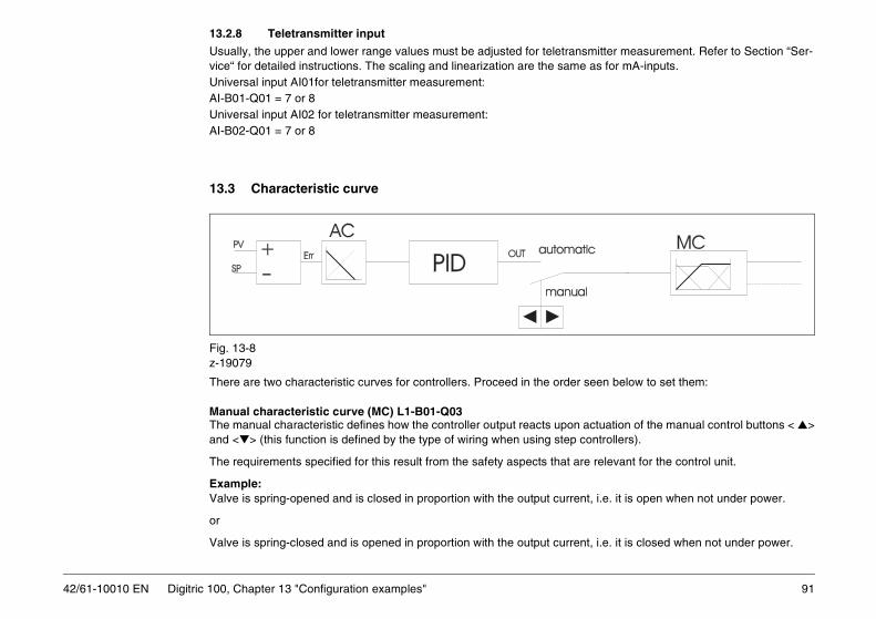
91
13.2.8 Teletransmitter input
smitter measurement. Refer to Section “Ser-e as for mA-inputs.
seen below to set them:
actuation of the manual control buttons < >controllers).
re relevant for the control unit.
nt, i.e. it is open when not under power.
nt, i.e. it is closed when not under power.
42/61-10010 EN Digitric 100, Chapter 13 "Configuration examples"
Usually, the upper and lower range values must be adjusted for teletranvice“ for detailed instructions. The scaling and linearization are the samUniversal input AI01for teletransmitter measurement:AI-B01-Q01 = 7 or 8 Universal input AI02 for teletransmitter measurement:AI-B02-Q01 = 7 or 8
13.3 Characteristic curve
Fig. 13-8z-19079
There are two characteristic curves for controllers. Proceed in the order
Manual characteristic curve (MC) L1-B01-Q03The manual characteristic defines how the controller output reacts uponand <> (this function is defined by the type of wiring when using step
The requirements specified for this result from the safety aspects that a
Example:Valve is spring-opened and is closed in proportion with the output curre
or
Valve is spring-closed and is opened in proportion with the output curre

42/61-10010 EN
Through selection of the proper characteristic curve it is possible to open the valve by actuating the < > button, in-
t signal into two output signals with the same
pon a change of the controlled variable, i.e.value. Is the system cooling to be intensified
matic characteristic curve.
e serial interface
accordingly.
with only an external setpoint.ol.or via the interface. follows the active setpoint.
tion.er with the configuration data. P1 and saved accordingly. This value can be
the operation level resulting from the process
92 Digitric 100, Chapter 13 "Configuration examples"
dependent of the type. An open valve is indicated through y = 100 %. The MC block may additionally define splitting of the PID function outpuor different characteristic curves (split-range).
Automatic characteristic curve (AC) L1-B02-Q01The automatic characteristic curve defines how the controller reacts uwhether the output shall increase or decrease with increasing process with increasing temperature, or shall heating be reduced?
Observe the selected manual characteristic curve when setting the auto
13.4 SetpointsUp to 7 setpoint sources are available in the controller:
– up to 4 setpoints (SP1 to SP4) that can be entered manually or via th– 1 external setpoint Sxt, in conjunction with an analog input,– 1 computer setpoint SPC and– 1 programmer with 10 programs P01 to P10.
Which of the setpoints are available is defined by configuring the device
13.4.1 Setpoint 1
L1-B05-Q01 = 0 Setpoint SP1 can be switched off for applicationsSetpoint SP1 cannot be activated with ratio contr
L1-B05-Q01 = 1 Setpoint can be changed via the control buttons L1-B05-Q01 = 2 When another setpoint is active, the setpoint SP1
This permits bumpless transfer to setpoint SP1.L1-B05-Q02 = 0 The current setpoint is not saved in the configura
It cannot be transmitted to another device togethL1-B05-Q02 = 1 On the parameter level L1-P81 is set as setpoint S
transmitted to other devices. Setpoint changes onare not saved in the configuration.

93
13.4.2 Setpoint SP2 to SP4 = Ratio setpoint SR1 to SR3
oint 1 (difference can only be set on the pa-
tio setpoints SR1 to SR3. Setpoint SP 1 does
e factory setting 99999 EU/s.
p) or L1-P79 (decreasing ramp).
d
42/61-10010 EN Digitric 100, Chapter 13 "Configuration examples"
It can be configured for every setpoint if: – it can be changed via the front panel– it can be changed and saved as parameter L1-P82 to L1-P84 or– it is active as absolute value or differential value as compared to setp
rameter level). – For ratio control the setpoints SP2 to SP4 always correspond to the ra
not exist.
13.4.3 Computer setpoint
The computer setpoint can only be modified via the interface.
13.4.4 Setpoint ramp
The setpoint ramp is always active, but is practically disabled through th
The setpoint ramp function can be enabled with L1-P77 (increasing ram
Setpoint display during transfer from old setpoint to target setpoint:
L1-B05-Q09 = 1 Target setpoint displayedL1-B05-Q09 = 2 Current setpoint, defined by the ramp is displaye
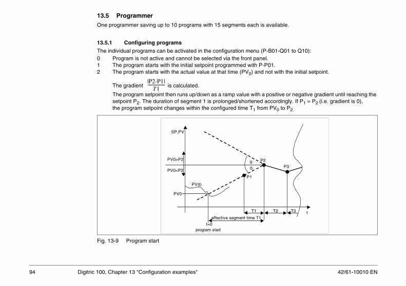
42/61-10010 EN
13.5 Programmervailable.
B01-Q01 to Q10):
01.ot with the initial setpoint.
ositive or negative gradient until reaching the cordingly. If P1 = P2 (i.e. gradient is 0),
PV0 to P2.
T2 T3
P3
t
94 Digitric 100, Chapter 13 "Configuration examples"
One programmer saving up to 10 programs with 15 segments each is a
13.5.1 Configuring programs
The individual programs can be activated in the configuration menu (P-0 Program is not active and cannot be selected via the front panel.1 The program starts with the initial setpoint programmed with P-P2 The program starts with the actual value at that time (PV0) and n
The gradient is calculated.
The program setpoint then runs up/down as a ramp value with a psetpoint P2. The duration of segment 1 is prolonged/shortened acthe program setpoint changes within the configured time T1 from
Fig. 13-9 Program start
|P2-P1|T1
-----------------
t=0 program start
T1
PV(t)
PV0
P1
P2
SP,PV
effective segment time T1
ßßPV0<P2
PV0>P2

95
Additionally, it can be configured how programs shall behave when the power returns (P-B02-Q01):
the same point where it has stopped when the
is not valid when the program is in the first
f the setpoint in dependence of the time. Pa-ached after a time period Px-P17. For a step
the previous segment has been run through.
ts of the setpoint program. These four binary be entered in the respective parameter:
r under L1 - B11 - Q10 to Q13.
een the segments number Px-P47 and nerator will run through this loop until the totalmaining segments will be processed.
rogram is stopped in the individual segments
d value is within the tolerance band (setpoint
42/61-10010 EN Digitric 100, Chapter 13 "Configuration examples"
0 Program is reset upon power return1 Program restarts in the previous operating mode, i.e. continues at
power outage occurred:Exception:If the program is configured to start up with the actual value, this segment when the power outage occurs.
13.5.2 Parameterizing programs
Parameters P-P01 to P-P31The program generator parameters Px01 to Px31 define the behavior orameter Px-P01 is the initial value. The value of parameter Px-P02 is reresponse the time has to be set to “0“.
CautionA segment with an end value of -9999 will terminate the program when
Parameters P-P32 to P-P46There are four binary tracks that are time-synchronous with the segmentracks can be set in each segment. The sum of the wanted outputs is toBinary track 1 set in segment x: P0x = 1Binary track 2 set in segment x: P0x = 2Binary track 3 set in segment x: P0x = 4Binary track 4 set in segment x: P0x = 8Example:Binary tracks 1, 3 and 4 are to be set in segment 2:Px-P33 = 13 = 1 + 4 + 8.The 4 binary tracks can be applied to the binary outputs of the controlle
Parameters P-P47 to P-P49The parameters Px-P47 to Px-P49 can be used to configure a loop betwPx-P48. After reaching the end of the segment Px-P48, the program genumber of runs reaches the amount set under Px-P49. After this, the re
Parameters P-P50 to P-P64The parameters P-P50 to P-P64 are used to define whether or not the pwhen the measured value cannot follow the given setpoint. This will stop the ramps, and hold times will only run when the measure± tolerance). The factory setting 99999 disables this function.
!

42/61-10010 EN
13.5.3 Programming table for a program
nce (+/-) 4 binary tracks
1 Px-P332 Px-P343 Px-P354 Px-P365 Px-P376 Px-P387 Px-P398 Px-P409 Px-P410 Px-P421 Px-P432 Px-P443 Px-P454 Px-P46
0 Px-P32
96 Digitric 100, Chapter 13 "Configuration examples"
x = program; x = 01 to 10
Table 13-1 Programming table
segment setpoint segment time toleraPx-P1 = start valuePx-P2 = end value
2 Px-P3 = end value Px-P18 Px-P53 Px-P4 = end value Px-P19 Px-P54 Px-P5 = end value Px-P20 Px-P55 Px-P6 = end value Px-P21 Px-P56 Px-P7 = end value Px-P22 Px-P57 Px-P8 = end value Px-P23 Px-P58 Px-P9 = end value Px-P24 Px-P59 Px-P10 = end value Px-P25 Px-P510 Px-P11 = end value Px-P26 Px-P511 Px-P12 = end value Px-P27 Px-P612 Px-P13 = end value Px-P28 Px-P613 Px-P14 = end value Px-P29 Px-P614 Px-P15 = end value Px-P30 Px-P615 Px-P16 = end value Px-P31 Px-P6
1 Px-P17 Px-P5

97
7 = end segment P48 of repeat loop
. . . . 15
t
2 P23 . . . . P315 P56 . . . . P647 P38 . . . . P46
= P49
P7
P8
P15
P16
42/61-10010 EN Digitric 100, Chapter 13 "Configuration examples"
Fig. 13-10 Programmer with loop, segments 3 to 7
setpoint
segment number 1 23 = start
segment P47 of repeat loop
4 5 6
segment time P17 P18 P19 P20 P21 P2segment tolerance P50 P51 P52 P53 P54 P54 binary tracks P32 P33 P34 P35 P36 P3
In total n-times operated ; n
P4 P5
P3P2P6
start atprocess value PV0
start atsetpoint P1

42/61-10010 EN
13.6 Fixed-value control
inside or outside the controller. When used d additionally (see “State correction“).
dicator.dicator
alue for Gain. For a P-controller with Gain = 1
98 Digitric 100, Chapter 13 "Configuration examples"
Fig. 13-11 Fixed-value control
13.6.1 Task
The process value PV is controlled until reaching setpoint SP generatedfor steam or gas flow control, a state correction function may be enable
13.6.2 Configuration
Input linkagesL1-B03-Q01 = 1; Input circuit for fixed-value control.L1-B03-Q02 Not used.L1-B03-Q03 Usually 2; Err in EU.L1-B03-Q04 Dimensions for PV/SP display.L1-B03-P05 User-defined dimension.L1-B03-Q06 Decimal point position in the digital indicator.L1-B03-P07 Value (number) for lower range value of digital inL1-B03-P08 Value (number) for upper range value of digital inL1-B03-P16 Desired lower range value for analog indicatorL1-B03-P17 Desired upper range value for analog indicatorThe difference between L1-B03-P08 and L1-B03-P07 is the reference van output change of 100% results from a input change of P08 - P07.

99
13.6.3 Example 1
s will be achieved between -200 °C and
e number of digits of the display, the number
it makes sense from the point of view of the
the signal is applied to an analog output
ntrol.
42/61-10010 EN Digitric 100, Chapter 13 "Configuration examples"
Thermocouple type K, measuring range -200...+1400 °C: Correct value+1400 °C.
Control range900.0 to 1100.0 °C with one digit to the right of the decimal point:L1-B03-Q04 = 3 Indication in °CL1-B03-Q06 = 1 Decimal point position 0000.0
Note When the number of digits or decimals of the measured value exceeds thof decimals is automatically reduced. L1-B03-P07 = 900 Lower range valueL1-B03-P08 = 1100 Upper range valueNo need to change the position of the decimal point.
Analog indicatorL1-B03-P16 = 900 Lower range valueL1-B03-P17 = 1100 Upper range valueAny other setting between -200 and +1400 is possible and permitted if plant. No need to change the position of the decimal point.AnnotationSince Digitric 100 has no analog indicator, this setting is only relevant if(0/4...20 mA).
Setpoint limitsThe setpoint limits should be set to useful values within the range of coL1-B03-P75 SPmin = 900 (°C)L1-B03-P76 SPmax = 1050 (°C)

42/61-10010 EN
13.6.4 Example 2
propriate units (mbar, bar, °C). The resulting
ssible.
ntrol.
:
ut AI02 can execute various tasks:
100 Digitric 100, Chapter 13 "Configuration examples"
Fixed-value control with state correction.The inputs needed to calculate the flow rate must be configured in the apsignal can, for example, be calculated in m3/h.
Measuring range0...20000 m3/h After state correction
Control rangeSame as measuring rangeL1-B03-Q04 = 7 Indication in m3/hL1-B03-Q06 = 0 No decimal point positionNoteWith a display up to 20000 no digit to the right of the decimal point is poL1-B03-P07 = 0 Lower range valueL1-B03-P08 = 20000 Upper range value
Analog indicatorL1-B03-P16 = 0 Lower range valueL1-B03-P17 = 20000 Upper range value
Setpoint limitsThe setpoint limits should be set to useful values within the range of coL1-B03-P75 SPmin = 5000 (m3/h)L1-B03-P76 SPmax = 18000 (m3/h)
Analog input routingUsually, the following is valid for single-loop controllers without modulesL1-B04-Q01 = 1: Input AI01 = process value PV.However, another configuration is also possible. The second analog inp1. Position feedback for step controllers
L1-B01-Q04 = 22. External setpoint
L1-B05-Q06 = 2

101
3. 2nd switchable measured value source
e different measuring ranges.
and pyrometer measurement between 1000
rollers)
42/61-10010 EN Digitric 100, Chapter 13 "Configuration examples"
L1-B04-Q02 = 2 together withL1-B04-Q06 = 1 to 16, depending on the available binary input
Note The two measured values must have the same dimension, but may havExamples:– Level control of two different tanks.– Temperature control with thermocouple measurement up to 1200 °C
and 2500 °C.
4. Parameter controlGain: L1-B02-Q07 = 13 or/andTr: L1-B02-Q10 = 13 or/andTd: L1-B02-Q13 = 13 or/andMR: L1-B02-Q16 = 13 or/and
5. Disturbance variable feedforwardL1-B02-Q25 = 2 together withL1-B02-Q26 = 1 to 4
6. Output tracking(Output is temporarily forced to value of input 2, not for step contL1-B10-Q10 = 2 together with L1-B09-Q11 = 1 to 16 (BIxy)

42/61-10010 EN
13.7 Multi-component controlV from several measured variables.
steam flow measurement (see the respective
are to be summed up in a single-loop control-cient to use the basic device.
ulti-component measurementErr = IC1 × CONST1 + CONST2 (IC2 + CONST3 ×IC3) - SP
r 5
with only two inputsdepending on the input configuration
Start value of the analog indicator End value of the analog indicator
102 Digitric 100, Chapter 13 "Configuration examples"
The multi-component input circuit is used to calculate the actual value P
13.7.1 Application
Summation circuits for measuring signals or setpoints.Example: Control of the cumulative values of two flow rate signals. Additionally, state correction is possible and can be integrated for gas orsection of this manual).
13.7.2 Configuration
Fig. 13-12 Flow rate summation
If only two values ler, it may be suffi
Input circuit for mL1-B03-Q01 = 2
L1-B03-Q02 = 2 oL1-P101 = 1L1-P102 = 1L1-P103 = 0 L1-B03-Q03
to P08L1-B03-P16 L1-B03-P17
Flow A
Flow B
F
FFC
F
Z-19068
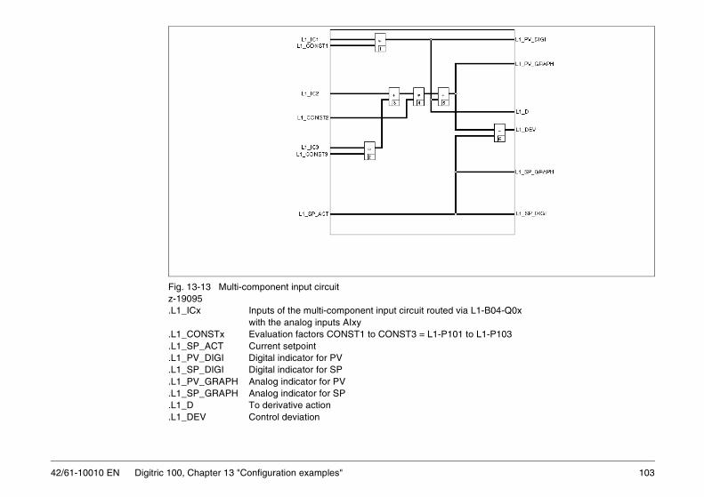
103
L1-B04-Q0x
to L1-P103
42/61-10010 EN Digitric 100, Chapter 13 "Configuration examples"
Fig. 13-13 Multi-component input circuitz-19095.L1_ICx Inputs of the multi-component input circuit routed via
with the analog inputs AIxy.L1_CONSTx Evaluation factors CONST1 to CONST3 = L1-P101 .L1_SP_ACT Current setpoint.L1_PV_DIGI Digital indicator for PV .L1_SP_DIGI Digital indicator for SP.L1_PV_GRAPH Analog indicator for PV.L1_SP_GRAPH Analog indicator for SP.L1_D To derivative action.L1_DEV Control deviation

42/61-10010 EN
13.8 Ratio control measured variable.
ratio setpoint (input current), the programmer,
. In this case, the setpoint SP1 is added.
cked as long as it is not used, to ensure bump-
ntrol. in case of fixed value control or when anotherpossible.
nt ratio.
104 Digitric 100, Chapter 13 "Configuration examples"
The ratio input circuit is used to proportion the controlled variable to the
13.8.1 Ratios and setpoints
Several ratio sources SR1 to SR3 (setpoint = SP2 to SP4), one external and a computer ratio setpoint are available as ratio setpoints.
All ratio input circuits can also be used as fixed value/ratio input circuits
The circuitry can be configured in such a way that the setpoint SP1 is traless transfer from ratio to fixed value control.
Configuration:L1-B05-Q01 = 3 The setpoint SP1 is tracked during ratio coThe ratio setpoint SR1 can be configured to track another ratio setpoint setpoint is used. Thus, a bumpless transfer to the ratio setpoint SR1 is
Configuration:L1-B05-Q03 = 6 The setpoint 2 = SR1 is tracked to the curre
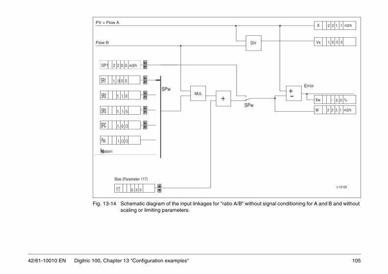
105
ut signal conditioning for A and B and without
Error
m3/h122X 1.
5Vx 0
W
%0- 2.Xw
m3/h122 3.
+-
z-19125
01.
42/61-10010 EN Digitric 100, Chapter 13 "Configuration examples"
Fig. 13-14 Schematic diagram of the input linkages for “ratio A/B“ withoscaling or limiting parameters.
PV = Flow A
Flow B
SR1
SR2
SR3
SRC
Pxx
Rxt
SP1
011.
117
500
51.
001.
001.
002.
00.22 m3/h
DIV
MUL+
Bias (Parameter 117)
SPw
SPw
1.
1
Vextern
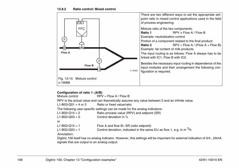
42/61-10010 EN
13.8.2 Ratio control: Mixed control
n 0 and an infinite value.
rs:)
as flow 1, e.g. in m 3/h
mportant for external indication of 0/4...20mA
o different ways to set the appropriate set- mixed control applications used in the fieldngineering:
of the two components:RPV = Flow A / Flow B
utralization controlcomponent related to the final product:
RPV = Flow A / (Flow A + Flow B)t content of milk products uting is as follows: Flow A always has to beC1, Flow B with IC2.
necessary input routing in dependence of thees and their arrangement the following con-required.
106 Digitric 100, Chapter 13 "Configuration examples"
Configuration of ratio 1: (A/B)Mixture control RPV = Flow A / Flow BRPV is the actual value and can theoretically assume any value betweeL1-B03-Q01 = 4 or 5 Ratio or fixed value/ratioThe following user-specific settings can be made for the analog indicatoL1-B03-Q15 = 2 Ratio process value (RPV) and setpoint (SRL1-B03-Q03 = 0 Control deviation in % orL1-B03-Q15 = 1 Flow A and flow B× SR (ratio setpoint)L1-B03-Q03 = 1 Control deviation, indicated in the same EUAnnotation:Digitric 100 itself has no analog indicator. However, this settings will be isignals that are output to an analog output.
Fig. 13-15 Mixture controlz-19068
There are twpoint ratio inof process e
Mixture ratioRatio 1 Example: nePortion of a Ratio 2 Example: faThe input rolinked with I
Besides the input modulfiguration is
Flow A
Flow B
F
FFC
F
Z-19068

107
Configuration of flow A:3
et ratio) or PV (flow A) and
R display
input signals value.nd SR (set ratio) or PV (flow A) and
ge
3-Q15 to P17 via analog output
+ flow B)een 0 and 1. Therefore, the scaling is set to
tions:
20 mA)]d input signals with equal measuring
R (Set ratio) or
42/61-10010 EN Digitric 100, Chapter 13 "Configuration examples"
L1-B03-Q04 Dimension e.g. m /hL1-B03-Q06 Decimal point, depending on the applicationL1-B03-P07 Lower range value (usually 0) L1-B03-P08 Upper range valueConfiguration of the ratio:L1-B03-Q09 Digital indicator RPV (ratio value) and SR (s
SR (set ratio) × flow BL1-B03-Q10 Dimension for R, e.g. without or % L1-B03-Q12 Digits to the right of the decimal point for theL1-B03-P14 Flow A (20 mA) / flow B (20 mA)
Numerical value of the quotient of the scaledwith equal measuring values in mA, e.g. end
L1-B03-Q15 Analog indicator RPV (ratio process value) aSR × flow B
L1-B03-P16 Analog indicator, start of wanted display ranL1-B03-P17 End of wanted display range L1-B03-Q18 Output of the display defined through L1-B0
Configuration of ratio 2: (A/(A+B))Mixture control for portion of the final product RPV = flow A/ (flow ARPV as an actual value or SR (setpoint) can only assume a value betw0...100% or even smaller. The configuration is the same as for ratio 1, but with the following excepL1-B03-Q10 = 2 usually %L1-B03-P14 = [flow A (20 mA)] / [flow A (20mA) + flow B (
Numerical value of the quotient of the scalevalues in mA, e.g. end value.
L1-B03-Q15 Analog indicator RPV (ratio process) and SPV (flow A) and (SR × flow B)/(1-SR)

42/61-10010 EN
nputs via L1-B04 100Digital indicator for PVDigital indicator for RactualAnalog indicator for SP
108 Digitric 100, Chapter 13 "Configuration examples"
Fig. 13-16 Input circuit for fixed value /ratio control 2 (Z-19126).L1_ICx Inputs of ratio input circuit are routed to the analog i.L1_R R-sepoint CONST_R100.L_SP_ACT Current fixed value setpoint .L1_PVDIGI .L_-SPDIGI Digital indicator for SP .L1_RACTDIGI .L1_PV_GRAPH Analog indicator for PV .L1_SP_GRAPH.L1_RV_FV Switching between fixed value and ratio

109
13.9 Multiplication
input the required subtraction.
cation input circuit permits product controlut variables. Instead of an input variable theal may consist of two variables.
IC2 +CONST3 × IC3)-SP
e application is a heat control system. The in-utgoing flow of a heat carrier (e.g. water) isn a heat consumer, as well as the tempera-ce between the flow and the return flow.high-precision measurement, the pressureture are determined and then used to correct accordingly (for water usually only the tem-orrected). The corresponding flow or return
ature - depending on where the flowmeter ise circuit (flow or return flow) - is used for cor-
42/61-10010 EN Digitric 100, Chapter 13 "Configuration examples"
ConfigurationThe three inputs are to be scaled with their dimensions. Input linkages:L1-B03-Q01 = 3 MultiplicationRouting of state correction:SC1-B02-Q01 = Flow signal depending on the used input SC1-B02-Q02 = 0 No pressure correctionSC1-B02-Q03 = Flow temperature, depending on the used inputSC1-B02-Q04 = 0 No density correctionRouting of input linkages:L1-B04-Q01 = 91 Corrected flow signal from state correction 1L1-B04-Q02 = Flow temperature, depending on the used inputL1-B04-Q03 = Return flow temperature, depending on the usedParameter: Setting L1-P103 = -1 will change the addition into
Fig. 13-17 Heat control
The multipliwith two inpweighted tot
Err = IC1 × (
One possiblcoming or omeasured oture differenTo ensure and temperathe flow rateperature is cflow temperlocated in threction.
TC
TT
TT
Z-19127

42/61-10010 EN
Digital indicator for PV Digital indicator for SPPH Analog indicator for PVPH Analog indicator for SP
To derivative actionControl deviation
110 Digitric 100, Chapter 13 "Configuration examples"
Fig. 13-18 Multiplication input circuitZ-19096.L1_ICx Inputs of the input circuit
Ratio routed to analog inputs via L1-B04 .L1_CONST3 Weighting factor for IC3.L1_SP_ACT Current setpoint
.L1_PVDIGI
.L1_SPDIGI
.L1_PV-GRA
.L1_SP-GRA
.L1_D
.L1_DEV
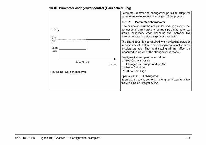
111
13.10 Parameter changeover/control (Gain scheduling)
ontrol and changeover permit to adapt theto reproducible changes of the process.
arameter changeover
ral parameters can be changed over in de-f a limit value or binary input. This is, for ex-essary when changing over between twoasuring signals (process variable).
over is not required when switching between with different measuring ranges for the sameiable. The input scaling will not affect the
alue when the changeover is made.
n and parameterization: = 11 or 12 ver through AL4 or BIxin-Lowin-High
: P-PI changeover:-Low is set to 0. As long as Tr-Low is active, no integral action.
42/61-10010 EN Digitric 100, Chapter 13 "Configuration examples"
Fig. 13-19 Gain changeover
Parameter cparameters
13.10.1 P
One or sevependence oample, necdifferent me
The changetransmittersphysical varmeasured v
ConfiguratioL1-B02-Q07
ChangeoL1-P07 = GaL1-P08 = Ga
Special caseExample: Trthere will be
Z-19086
Gain
GainHigh
AL4 or BIx
GainLow

42/61-10010 EN
13.10.2 Parameter control
ter is changed linearly between a start valuein dependence of a freely selectable analog
easured value, output variable, etc.).
arameterization:5 or 13 ugh selected variable-B02-Q07 = 2)
howigh
112 Digitric 100, Chapter 13 "Configuration examples"
Fig. 13-20 Linear parameter control, U is the controlling variable
LinearThe active parameand an end value variable (setpoint, m
Configuration and pL1-B02-Q07 = 1 to
Gain control throe.g. setpoint (L1
L1-P06 = Gain-LowL1-P07 = Gain-HigL1-P08 = U-Gain LL1-P09 = U-Gain H
Gain
GainHigh
U-Gain HighU-Gain Low
GainLow
U-GainZ-19085
GainG-Hi( ) UG-Hi UG-Lo–( ) G-Lo( ) UG-Hi UG-Lo–( )+
UG-Hi UG-Lo–---------------------------------------------------------------------------------------------------------------------------------------=

113
ue control the gain considerably varies with. The greatest gain is reached with pH 7, the
values are reached with pH0 and pH14.eciprocal gain is provided in the controllers.
n: = 7 Parameter control
through process variable PVvia table 1
rameterized with the control loop gain (de-e volumetric analysis curve).
42/61-10010 EN Digitric 100, Chapter 13 "Configuration examples"
Fig. 13-21 Non-linear parameter control through measured value pH
Non-linearWith pH-valthe pH valuelowest gainTherefore, r
ConfiguratioL1-B02-Q07
Table 1 is parived from th
Z--19099
pH
Gain
pH
Process
Gain
Controller

42/61-10010 EN
13.11 State correctionsigned for special pressure and temperaturemeasuring errors may occur. Therefore, cor-le for correcting both ideal and real gases.
tandardized flow (at 0 °C and 1.013 bar).
tate correction is only possible when the func- (flow control with state correction)).
put module slots. Note that the inputs mustectly or via a transmitter.
ype)
114 Digitric 100, Chapter 13 "Configuration examples"
The measuring instruments for gas or steam flow measurement are devalues. If the actual values differ from the design values, considerable rection circuits are provided for correcting these errors. They are suitab
The state correction calculates from the current measuring values the sThe state correction can be used together with all input linkages.
Usually, additional analog inputs are required for state correction, and stion has been integrated in the configuration (e.g. with L1-B04-Q01 = 91
13.11.1 Input and output routing
The state correction inputs can be routed in dependence of the analog inbe scaled. It is negligible whether a temperature value is connected dir
13.11.2 Terms and abbreviations
Index “r“ stands for “calculated values“ (values for orifice design)
Qv Operating volume flow in m3/hQn Volume flow in the normal state in m3/hQm Mass flow in the normal state in t/hP in bar absolute or overpressure (depending on transmitter tPr Absolute pressure T Temperature in °CPn Standard pressure 1.0135 barTn Standard temperature 273.15 K = 0 °CRHO Density in kg/m3 RHO-MIN Correction range for RHORHO-MAX Correction range for RHOPatm Atmospheric pressure in bar abs(olute)Pr in bar abs(olute)Zn Real gas factor with Pn and Tn (compressibility)
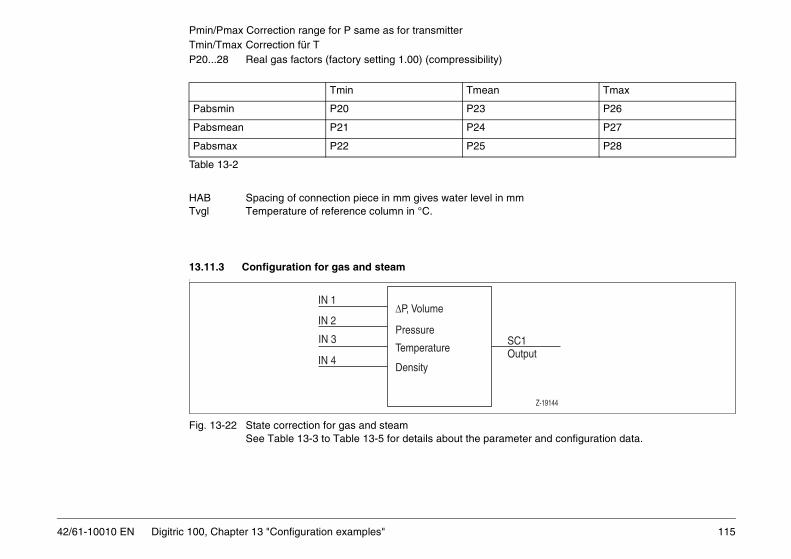
115
Pmin/Pmax Correction range for P same as for transmitter
er and configuration data.
Tmax
P26
P27
P28
put
Z-19144
42/61-10010 EN Digitric 100, Chapter 13 "Configuration examples"
Tmin/Tmax Correction für TP20...28 Real gas factors (factory setting 1.00) (compressibility)
Table 13-2
HAB Spacing of connection piece in mm gives water level in mmTvgl Temperature of reference column in °C.
13.11.3 Configuration for gas and steamf
Fig. 13-22 State correction for gas and steamSee Table 13-3 to Table 13-5 for details about the paramet
Tmin Tmean
Pabsmin P20 P23
Pabsmean P21 P24
Pabsmax P22 P25
SC1Out
∆P, Volume
Pressure
Temperature
IN 1
IN 2
IN 3
IN 4Density

42/61-10010 EN
13.11.4 Configuration for water mass flow
er and configuration data.
eter and configuration data.
Z-19145
SC1Output
SC1Output
Z-19146
116 Digitric 100, Chapter 13 "Configuration examples"
Fig. 13-23 State correction for gas, steam and drum water level See Table 13-6 to Table 13-8 for details about the paramet
13.11.5 Configuration for drum water level
Fig. 13-24 Water levelSee Table 13-7 and Table 13-8 for details about the param
IN 1
IN 2
IN 3
∆P, Volume
Pressure
Temperature
Pressure
∆P
Tvgl (= Tcompare)l
IN 1
IN 2
IN 3

117
13.11.6 Gas and steam
ed steam,low,tial pressure
re correction
Saturated steam,mass flow,differential pressuretemp. correction
Unit
square-rooted
linear square-rooted
4 5 5 –
1 0 1 –
Nm3/h
Value Value Value kg/h
Value mbar
Value bar abs
Value bar abs
Value Value °C
–
kg/m3
42/61-10010 EN Digitric 100, Chapter 13 "Configuration examples"
Table 13-3 Design values of the measuring equipment (calculated values)linear No square-rooting of the transmitter or analog input square rooted Square rooting of the transmitter or analog input grayed No entry required, all entries will be ignored
Question/parame-ter
Gas,differential pressure measurement
Gas,volume measure-ment
Steam,mass flow,differential pressure
Saturatmass fdifferenpressu
SC1-B01 linear square-rooted
linear square-rooted
linear
Q01 1 1 2 3 3 4
Square rooting Q29 0 1 0 1 0
Standard flow Qn,r or P02 Value Value Value
Mass flow Qm, r P02 Value Value Value Value Value Value
Differential pressure ∆P,r P03 Value Value Value
Atmospheric pressure Patm,r,abs
P04 Value Value Value Value Value Value
Pressure P,r,abs P05 Value Value Value Value Value Value
Temperature T,r P06 Value Value Value Value Value
Real gas factor Z(Pr,Tr),r P07 Value Value Value
Standard density ρn, r P08 Value Value Value

42/61-10010 EN
rmined and provided for commissioning.
Tmax
Value (P26)
Value (P27)
Value (P28)
118 Digitric 100, Chapter 13 "Configuration examples"
Fig. 13-25 Basic characteristic curve for Z = f(P,T)
Table 13-4 Real gas factors (factory setting 1.00 for ideal gases).For orifice calculation the real gas factors have to be dete
Tmin Tmean
Pabs,min Value (P20) Value (P23)
Pabs,mean Value (P21) Value (P24)
Pabs,max Value (P22) Value (P25)

119
ter:
the calculated values. If the pressure mea-ure or overpressure limits.
ed steam,low,tial pressure,
re correction
Saturated steam,mass flow,differential pressure,temp. correction
Unit
square-rooted
linear square-rooted
4 5 5 –
1 1 1 –
2 2 2 –
Value bar
Value bar
Value Value °C
Value Value °C
kg/m3
kg/m3
42/61-10010 EN Digitric 100, Chapter 13 "Configuration examples"
Table 13-5 Measuring values and correction ranges
The limits for pressure correction must be entered in accordance with the pressure transmit
– Overpressure transmitters require pressure limits in overpressure. – Absolute pressure transmitters require pressure limits in absolute pressure.
If one or several measuring signals are missing, the correction limits must be identical with surement signal is missing, it must be specified in Q18 whether the limits are absolute press
Question/parame-ter
Gas,differential pressure measurement
Gas,volume measure-ment
Steam,mass flow,differential pressure
Saturatmass fdifferenpressu
SC1-B01 linear square-rooted
linear square-rooted
linear
Q01 1 1 2 3 3 4
Pressure transmitter
Overpressure Q18 1 1 1 1 1 1
Absolute pressure Q18 2 2 2 2 2 2
Correction limits:
Min. pressure P10 Value Value Value Value Value Value
Max. pressure P11 Value Value Value Value Value Value
Min. temperature P12 Value Value Value Value Value
Max. temperature P13 Value Value Value Value Value
Min. density P14 Value Value Value
Max. density P15 Value Value Value
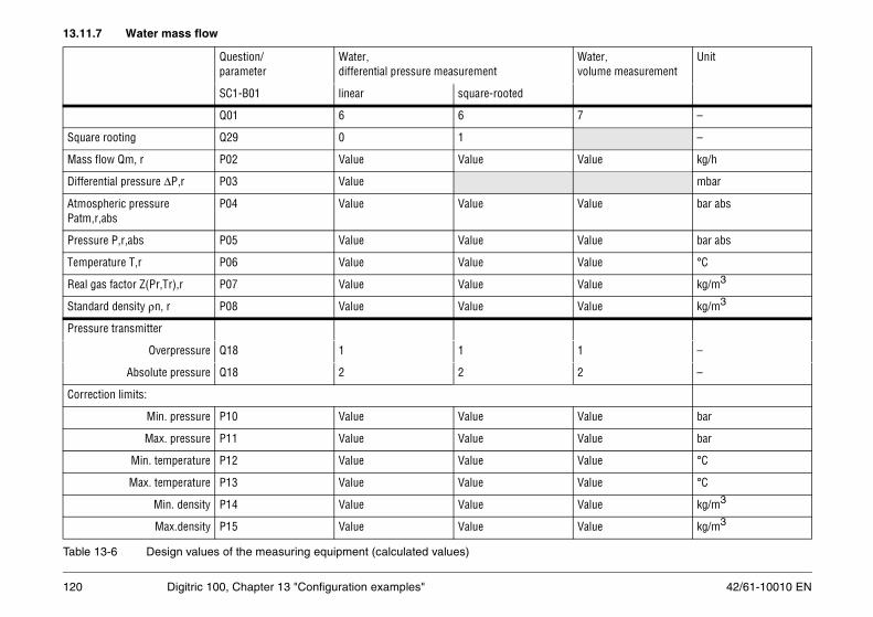
42/61-10010 EN
13.11.7 Water mass flow
Water,volume measurement
Unit
7 –
–
Value kg/h
mbar
Value bar abs
Value bar abs
Value °C
Value kg/m3
Value kg/m3
1 –
2 –
Value bar
Value bar
Value °C
Value °C
Value kg/m3
Value kg/m3
120 Digitric 100, Chapter 13 "Configuration examples"
Table 13-6 Design values of the measuring equipment (calculated values)
Question/parameter
Water,differential pressure measurement
SC1-B01 linear square-rooted
Q01 6 6
Square rooting Q29 0 1
Mass flow Qm, r P02 Value Value
Differential pressure ∆P,r P03 Value
Atmospheric pressure Patm,r,abs
P04 Value Value
Pressure P,r,abs P05 Value Value
Temperature T,r P06 Value Value
Real gas factor Z(Pr,Tr),r P07 Value Value
Standard density ρn, r P08 Value Value
Pressure transmitter
Overpressure Q18 1 1
Absolute pressure Q18 2 2
Correction limits:
Min. pressure P10 Value Value
Max. pressure P11 Value Value
Min. temperature P12 Value Value
Max. temperature P13 Value Value
Min. density P14 Value Value
Max.density P15 Value Value

121
Note The limits for pressure correction must be entered in accordance with the pressure transmitter:re.te pressure.
mits must be identical with the calculatedspecified in Q18 whether the limits are ab-
lues)
e reference column temperature.
asurement Unit
mm
°C
°C
°C
vel measurement Unit
lue mbar
lue bar
lue bar
lue mm
lue mm
42/61-10010 EN Digitric 100, Chapter 13 "Configuration examples"
– Overpressure transmitters require pressure limits in overpressu– Absolute pressure transmitters require pressure limits in absolu
If one or several measuring signals are missing, the correction livalues. If the pressure measurement signal is missing, it must be solute pressure or overpressure limits.
13.11.8 Drum water level
Table 13-7 Design values of the measuring equipment (calculated va
With missing temperature measurement Tmin = Tmax must be set to th
Table 13-8 Measuring values and correction ranges
Question Level me
Q01 = 8
Spacing of connection piece HAB P16 = Value
Tverg P17 = Value
Tmin P12 = Value
Tmax P13 = Value
Question Le
Differential pressure, end value ∆P Q01 = Va
Min. pressure correction, limit Pmin Q10 = Va
Max. pressure correction, limit Pmax Q11 = Va
Output range, start value Q30 = Va
Output range, end value Q31 = Va

42/61-10010 EN
13.11.9 Configuring an analog output for outputting state correction results
vides the calculated results to the input circuit
sults is required, this can be defined by using
/4 mA or 0/2 V 20 mA or 10 V
ulating results.
have no effect on the device itself. However,
g the correction results.
122 Digitric 100, Chapter 13 "Configuration examples"
With the configuration seen in Fig. 13-26 the state correction directly proas measuring values.
If an additional analog current/voltage output with the state correction rethe following parameters:
SC1-B01-P30 Lower range value = measuring value for 0% = 0SC1-B01-P31 Upper range value= measuring value for 100% =
The values for P30 and P31 may be within or outside the expected calc
SC1-B01-Q32 and SC1-B01-P33 can be set, but are not mandatory andthey will simplify possible later verifications of the configuration.
With SC1-B03-Q01 an unused analog output is configured for outputtin
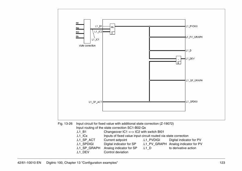
123
(Z-19072)
I01 via state correction
Digital indicator for PVAPH Analog indicator for PV
to derivative action
42/61-10010 EN Digitric 100, Chapter 13 "Configuration examples"
Fig. 13-26 Input circuit for fixed value with additional state correction Input routing of the state correction SC1-B02-Qx.L1_B1 Changeover IC1 <–> IC2 with switch B.L1_ICx Inputs of fixed value input circuit routed.L1_SP_ACT Current setpoint .L1_PVDIGI.L1_SPDIGI Digital indicator for SP .L1_PV_GR.L1_SP_GRAPH Analog indicator for SP .L1_D.L1_DEV Control deviation

42/61-10010 EN
13.12 Control outputs
act)
Of course using other BOxy is also possible.
124 Digitric 100, Chapter 13 "Configuration examples"
The following control outputs can be configured:
Two-point controller– with transistor output or– with relay output(high-low-off control e.g. ∆ − Y – Off = On/Off controller with series cont
Three-point controller (heating- off-cooling)– with transistor output or– with relay outputoptionally 1 output also continuous (parameters L1-P25 to P27 active)
Step controller and positioner– with transistor output or– with relay output
Continuous controlleroptionally with split-range (parameters L1-P25 to P27 are active)
In the following examples the binary outputs BO01 and BO02 are used.

125
13.12.1 Two-point controller
on = BO01
on = BO01on = BO02
phase
to “high“alid.
ured accordingly.
42/61-10010 EN Digitric 100, Chapter 13 "Configuration examples"
Single-loop controller with transistor output in the basic deviceBinary definition:BIO-B01-Q01 = 3 BIO01 is an output with NO contact operatiL1-B01-Q02 = 3 Two-point controllerL1-B10-Q04 = 1 Control output OUT1 to BO01
Two-point controller for high-low-offBinary definition:BIO-B01-Q01 = 3 BIO01 is an output with NO contact operatiBIO-B02-Q01= 2 BIO02 is an output with NC contact operatiL1-B01-Q02 = 3 On/Off controller with series contactL1-B08-Q03 = 4 Alarm value 3 as Errmax series contact L1-P93 = -3 bis -5 % Exact value to be set in the commissioningL1-B10-Q04 = 1 Control output to BO01L1-B11-Q03 = 2 Alarm value 3 on BO02 switches from “low“
Note If the controller is set to manual mode, the changeover to "high" is still v
Single-loop controller with relay outputFor controllers with relay output the available outputs have to be config

42/61-10010 EN
13.12.2 Three-point controller
on = BO01on = BO02
trol output for heating
on = BO01
BO01
ured accordingly.
126 Digitric 100, Chapter 13 "Configuration examples"
(Heating - off - cooling)
Single-loop controller with transistor output in the basic unitBIO-B01-Q01 = 3 BIO01 is an output with NO contact operatiBIO-B02-Q01 = 3 BIO02 is an output with NO contact operatiL1-B01-Q02 = 5 Three-point controllerL1-B10-Q04 = 1 1st control output (heating) OUT1 to BO01L1-B10-Q05 = 2 2nd control output (cooling) OUT2 to BO02
Three-point controller (heating - off - cooling) with continuous conBinary definition
BIO-B01-Q01 = 3 BIO01 is an output with NO contact operatiL1-B01-Q01 = 6L1-B10-Q05 = 1 Switching control output (cooling) OUT2 to L1-B10-Q01 = 1 Continuous output (heating) OUT1 to AO01
Single-loop controller with relay outputFor controllers with relay output the available outputs have to be config

127
13.12.3 Motorized valve control (Step controller)
t can be used for position feedback or another
operation = BO01operation = BO02
sually externally given - position. A positioner
of the transistor outputs BO01 and BO02.
42/61-10010 EN Digitric 100, Chapter 13 "Configuration examples"
When using the basic unit with optional AI02, the second measuring inpufunction.
L1-B01-Q04 = 2 Position feedback to AI02
AI-B02-Q01 = 7 AI02 = 0...150 ΩSee “Service“ section for information about adjusting 0 and 100 %.
Outputs:BIO-B01-Q01 = 3 Binary BIO01 is an output with NO contact BIO-B02-Q01 = 3 Binary BIO02 is an output with NO contact L1-B10-Q04 = 1 Control output “more“ OUT1 to BO01L1-B10-Q05 = 2 Control output “less“ OUT2 to BO02
13.12.4 Positioner
A positioner is a step controller that moves an electrical actuator to a - uneeds a position feedback signal as measured value.
L1-B01-Q01 = 11 PositionerL1-B03-Q01 = 1 Fixed value input circuitL1-B04-Q01 = 1 Position feedback to AI01L1-B05-Q06 = 2 External setpoint to AI02Control output same as for step controller
13.12.5 Controller with relay output
It is also possible to use the relay outputs (BO03, BO04, BO05) instead

42/61-10010 EN
13.12.6 Continuous controller
odule in slot1
128 Digitric 100, Chapter 13 "Configuration examples"
Continuous controllers have a 0/4...20 mA control output.
One control output (factory setting):L1-B01-Q02 = 1AO-B01-Q01 = 1 or 2 depending on signal rangeL1-B10-Q01 = 1 1st control output OUT1 to AO01
Two control outputs (split range)Output module in slot 1 (only one exists in the basic unit).L1-B01-Q01 = 7L1-B10-Q02 = 11 2nd control output to 1st output of output mAO-B31-Q01 = 1 or 2 depending on the signal range

129
14 Service
l 3. menu level
ABBDigitric 100CPU:xF:x.xxxxxx.xF-Dat:dd.mm.yy
ces Konfi-Nr.:xxxxxR-Dat:dd.mm.yyfrei
EscMenu
Enter
42/61-10010 EN Digitric 100, Chapter 14 "Service"
Fig. 14-1 Service menu
Operation level 1. menu level 2. menu leve
Indication 2 InformationOperate 2 Info Hardw.Selftune Display UnitParameter AdjustmentConfiguration CalibrationService Comm.-ServiSupervisor
EscMenu Enter
EscMenu
EscMenu
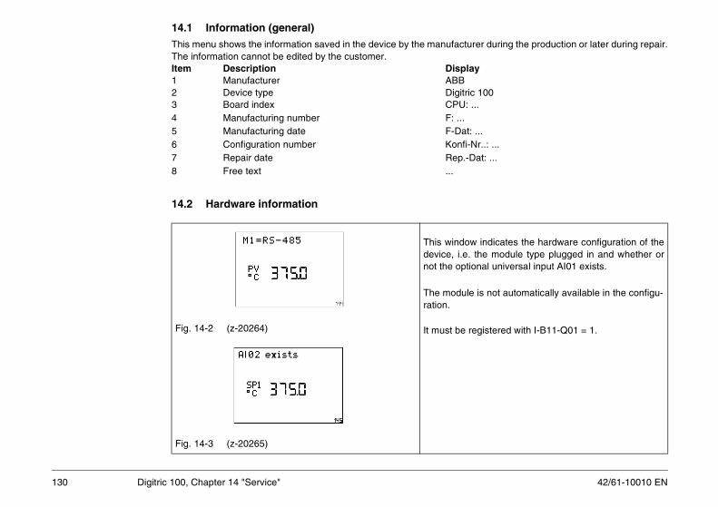
42/61-10010 EN
14.1 Information (general)er during the production or later during repair.
y
100..
...r..: ...at: ...
indicates the hardware configuration of thethe module type plugged in and whether ornal universal input AI01 exists.
is not automatically available in the configu-
gistered with I-B11-Q01 = 1.
130 Digitric 100, Chapter 14 "Service"
This menu shows the information saved in the device by the manufacturThe information cannot be edited by the customer.Item Description Displa1 Manufacturer ABB2 Device type Digitric3 Board index CPU: .4 Manufacturing number F: ...5 Manufacturing date F-Dat: 6 Configuration number Konfi-N7 Repair date Rep.-D8 Free text ...
14.2 Hardware information
Fig. 14-2 (z-20264)
Fig. 14-3 (z-20265)
This windowdevice, i.e. not the optio
The moduleration.
It must be re

131
14.3 Display unit
the LCDect the desired contrast:teps, step 1 = smallest contrast):> <> ept selected changes:ter>
42/61-10010 EN Digitric 100, Chapter 14 "Service"
14.3.1 Contrast of the LCD
Fig. 14-4(Z-19131)
Contrast of1. Sel
(9 s<
2. Acc<En

42/61-10010 EN
14.4 AdjustmentPt 100 resistance thermometer and teletrans-
g
th open input!
lected separately for the individual inputs of the modules.
Ixy Pt100-2W can be selected only if Pt 100ent has been configured for the respective
cable between the sensor and the controller sor side. icates the set default value in the bottom line.
adjustment on the controller:
first line is added.
justment:
132 Digitric 100, Chapter 14 "Service"
This menu is used to adjust the controller for measurement with 2-wire mitters.
See the menu tables in Section 17 for instructions.
14.4.1 Example: Adjusting the Pt100, 2-wire, for AI01
Fig. 14-5 Adjustment for AI01 selectedZ-19132
Fig. 14-6 Do you want to start adjustment?Z-19133
Warnin
Do not adjust wi
Adjustment is sethe basic unit and
Submenu item A2-wire-measureminput before.
Procedure
0. Shorten theon the sen
The controller ind
1. Call 1st <Enter>“?“ in the
Enter
2. Start ad<Enter>
!
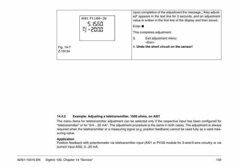
133
1
the respective input has been configured forame in both cases. The adjustment is alwaysedback) cannot be used fully as a valid mea-
t100 module for 3-wire/4-wire circuitry or via
Upon completion of the adjustment the message „“AIxy adjust-e text line for 3 seconds, and an adjustment the first line of the display and then saved.
djustment.
stment menu:
rt circuit on the sensor!
42/61-10010 EN Digitric 100, Chapter 14 "Service"
14.4.2 Example: Adjusting a teletransmitter, 1500 ohms, on AI0
The menu items for teletransmitter adjustment can be selected only if “teletransmitter“ or for “0/4... 20 mA“. The adjustment procedure is the srequired when the teletransmitter or a measuring signal (e.g. position fesuring value.
ApplicationPosition feedback with potentiometer via teletransmitter input (AI01 or Pcurrent input AI02, 0...20 mA.
Fig. 14-7Z-19134
ed“ appears in thvalue is written in
Enter
This completes a
3. Exit adju<Esc>
4. Undo the sho

42/61-10010 EN
mentect the adjustment function from the Service nu by actuating <Enter> several times.e „AI01 Start“ prompts you to set the tele-echanically to its initial position.
the teletransmitter mechanically to its initial ition.
nfirm the message “AI01 Start“ with <Enter> .is carried out, and the message “AI01 End“
djustment the teletransmitter mechanically to its end ition.
nfirm the message “AI01 End“ with <Enter>.
e “AI01 calibrated!“ indicates that you are re- next higher operating level. to return to the main operating level.
134 Digitric 100, Chapter 14 "Service"
Fig. 14-8Z-19135
Fig. 14-9Z-19136
Zero adjust1. Sel
meThe messagtransmitter m2. Set
pos3. CoAdjustment appears.
End value a4. Set
pos5. Co
The messagturned to thePress <Esc>
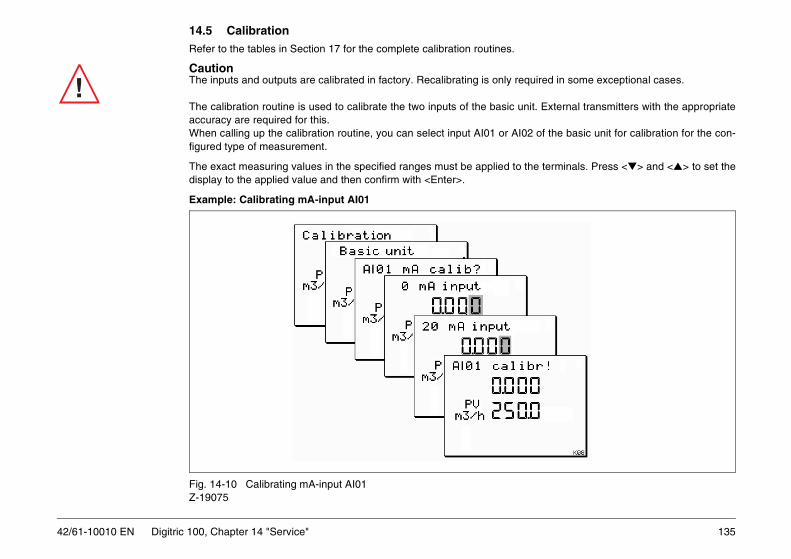
135
14.5 Calibration
quired in some exceptional cases.
nit. External transmitters with the appropriate
02 of the basic unit for calibration for the con-
the terminals. Press <> and <> to set the
42/61-10010 EN Digitric 100, Chapter 14 "Service"
Refer to the tables in Section 17 for the complete calibration routines.
CautionThe inputs and outputs are calibrated in factory. Recalibrating is only re
The calibration routine is used to calibrate the two inputs of the basic uaccuracy are required for this.When calling up the calibration routine, you can select input AI01 or AIfigured type of measurement.
The exact measuring values in the specified ranges must be applied todisplay to the applied value and then confirm with <Enter>.
Example: Calibrating mA-input AI01
Fig. 14-10 Calibrating mA-input AI01Z-19075
!

42/61-10010 EN
15 Supervisor
l 3. menu level
SET MASTER RESET ?
EscMenu
Enter Enter
136 Digitric 100, Chapter 15 "Supervisor"
Fig. 15-1
Operation level 1. menu level 2. menu leve
Indication 2 MASTER REOperate 2 PlausibilitySelftune TemplateParameterConfigurationServiceSupervisor
EscMenu Enter
EscMenu
EscMenu
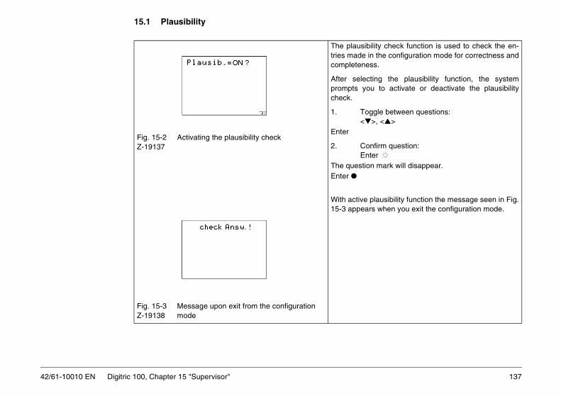
137
15.1 Plausibility
ility check function is used to check the en- the configuration mode for correctness ands.
ting the plausibility function, the systemu to activate or deactivate the plausibility
gle between questions:>, <>
nfirm question:er n mark will disappear.
lausibility function the message seen in Fig.s when you exit the configuration mode.
42/61-10010 EN Digitric 100, Chapter 15 "Supervisor"
Fig. 15-2 Activating the plausibility checkZ-19137
Fig. 15-3 Message upon exit from the configuration Z-19138 mode
The plausibtries made incompletenes
After selecprompts yocheck.
1. Tog<
Enter
2. CoEnt
The questioEnter
With active p15-3 appear

42/61-10010 EN
15.2 Master reset
ster reset function you can reset the entire to the factory setting.
reset function will overwrite all user-set con-ta with the factory setting. Only the language emain as is. ect the master reset menuion of the menu item you will be asked wheth- factory setting is to be restored (Fig. 15-4).
nfirm question:ter>
placed with “!“. The factory setting will be re-sages on the screen indicate the progress of re. You will be returned to the operation level y.
ncel:c>
138 Digitric 100, Chapter 15 "Supervisor"
Fig. 15-4 Configuration and master resetZ-19139
With the maconfiguration
CautionThe master figuration dasetting will r1. SelUpon selecter or not the
Enter
Either2. Co
<En
“?“ will be restored, mesthe proceduautomaticallEnter or3. Ca
<Es

139
15.3 Template (Quick configuration)his function helps you to realize pre-defined r details.
ller to a pre-defined configuration without the
n data will be overwritten and, thus, lost!
in the template menu.
ntroller. The configuration data loaded with d.
42/61-10010 EN Digitric 100, Chapter 15 "Supervisor"
The “Template“ menu is used for quick configuration of the controller. Tsettings quickly. See the “Quick configuration“ section of this manual fo
Similar to the master reset function the template function sets the contronecessity to use the configuration menu. Note that with this function all user-defined parameters and configuratio
A 5-digit character string and some additional answers can be entered Example: 100A0
This means the template menu allows for a quick configuration of the cothis function can be further modified in the configuration menu if requireParameters can be set as usual in the “Parameter“ menu.
Refer to Section 16 for details about the template.

42/61-10010 EN
16 Quick configuration in the Template menuto English user language. Otherwise, set it toating instructions instead. Since the controllerglish language.
d for quickly configuring the Digitric 100 con-n 16.2 describes how to navigate through the
e Section 16.4 for an overview of the possible
Section 16.5 for an overview of the possible
ction 16.6 for an overview of the possible vari-
.
nfiguration.
tten and cannot be restored.
required. It is, for example, possible to changect“.
u.
potentiometers) usually require further adjust-
140 Digitric 100, Chapter 16 "Quick configuration in the Template menu"
Prior to executing the template first make sure that the controller is set English (see Section 16.1 for details) or use the German or French operis usually set to the German language ex factory, you might set it to En
The template available under the Supervisor/Template menu item is usetroller. See Fig. 16-1 for details about how to select the template. Sectiotemplate. Possible entries are described in Section 16.3.
A 5-digit template variant is the core of the template.The first digit defines the base variant of the controller configuration. Sevariants.
The second digit is the sub variant for the controller configuration. Seevariants.
The third digit is the alarm variant of the controller configuration. See Seants.
The fourth digit defines the type of universal controller input AI01.The fifth digit defines the type of optional universal controller input AI02See Section 16.7 for an overview of the possible variants.
Upon execution of the template the controller is booted with the new co
CautionThe previous configuration and parameter settings will be overwri
The configuration can be further optimized in the Configuration menu, if the valve action from “Reverse“ (default setting in the template) to “Dire
The parameter settings can be further optimized in the Parameters men
2-wire Pt 100 resistance thermometers and resistance teletransmitters (ment under “Service/Adjustment“.
!

141
Start menuof template
Enter
EscMenu
5-digit template variant
Navigation in template according
16.2
42/61-10010 EN Digitric 100, Chapter 16 "Quick configuration in the Template menu"
Fig. 16-1 Controller menu
Operation 1. menu level 2. menu levellevel
Indication 2 MASTER RESET
Operate 2 TemplateSelftune PlausibilityParameterConfigurationServiceSupervisor
EscMenu
Enter Enter
EscMenu
EscMenu
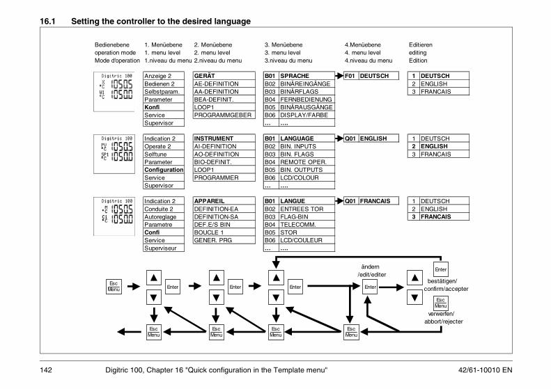
42/61-10010 EN
16.1 Setting the controller to the desired language
ebene Editierenu level editingu du menu Edition
EUTSCH 1 DEUTSCH2 ENGLISH3 FRANCAIS
NGLISH 1 DEUTSCH2 ENGLISH3 FRANCAIS
RANCAIS 1 DEUTSCH2 ENGLISH3 FRANCAIS
Enter
Enterndernit/editer
bestätigen/confirm/accepter
EscMenu
verwerfen/abbort/rejecter
142 Digitric 100, Chapter 16 "Quick configuration in the Template menu"
Bedienebene 1. Menüebene 2. Menüebene 3. Menüebene 4.Menüoperation mode 1. menu level 2. menu level 3. menu level 4. menMode d'operation 1.niveau du menu 2.niveau du menu 3.niveau du menu 4.nivea
Anzeige 2 GERÄT B01 SPRACHE F01 DBedienen 2 AE-DEFINITION B02 BINÄREINGÄNGESelbstparam. AA-DEFINITION B03 BINÄRFLAGSParameter BEA-DEFINIT. B04 FERNBEDIENUNGKonfi LOOP1 B05 BINÄRAUSGÄNGEService PROGRAMMGEBER B06 DISPLAY/FARBESupervisor … ….
Indication 2 INSTRUMENT B01 LANGUAGE Q01 EOperate 2 AI-DEFINITION B02 BIN. INPUTSSelftune AO-DEFINITION B03 BIN. FLAGSParameter BIO-DEFINIT. B04 REMOTE OPER.Configuration LOOP1 B05 BIN. OUTPUTSService PROGRAMMER B06 LCD/COLOURSupervisor … ….
Indication 2 APPAREIL B01 LANGUE Q01 FConduite 2 DEFINITION-EA B02 ENTREES TORAutoreglage DEFINITION-SA B03 FLAG-BINParametre DEF.E/S BIN B04 TELECOMM.Confi BOUCLE 1 B05 STORService GENER. PRG B06 LCD/COULEURSuperviseur … ….
EscMenu
EscMenu
Enter Enter Enter
ä/ed
EscMenu
EscMenu
EscMenu

143
16.2 Navigating through the template
shal
l be
activ
ated
Sec
ond
ques
tion
if T
empl
ate
shal
l be
activ
ated
Act
iv. T
empl
. ?
Ent
er
Ent
er
Tem
plat
e
A r
eset
of t
he c
ontr
olle
r in
to t
he a
djus
ted
Tem
plat
e ha
ppen
s. A
t th
e sa
me
time
the
adju
sted
Tem
plat
e w
ill b
e st
ored
. If
you
ente
r th
e Te
rmpl
ate
late
r yo
u w
ill fi
nd t
he t
he m
ade
adju
stm
ents
. A
tte
nti
on
! T
he
fo
rme
r co
nfi
gu
rati
on
an
d p
ara
me
tris
ati
on
wil
l b
e o
verw
ritt
en
!
The
form
er la
ngua
ge a
djus
tmen
t of
the
con
trol
ler
will
be
kept
. Th
e co
ntro
ller
will
sta
rt w
ith t
he n
ew c
onfi g
urat
ion
in t
he o
pera
tion
leve
l. F
urth
er a
djus
tmen
ts o
f co
nfig
urat
ion
and
para
met
risat
ion
can
be d
one
in t
he m
enu
"Con
figur
atio
n" a
nd "
Par
amet
er".
Esc
Men
u
18
to
1) T
he p
ossi
bilit
y to
adj
ust
°F w
ill b
e av
aila
ble
in c
omin
g ve
rsio
ns
42/61-10010 EN Digitric 100, Chapter 16 "Quick configuration in the Template menu"
Men
u: s
elec
t S
uper
viso
r/T
empl
ate
Tem
pla
te
5-d
igit
T
emp
late
vari
ant
1
00A
0
°C o
r °F
1)
°C (
no
t °F
)
AI0
1-S
CA
LE-L
O0.
0000
AI0
1-S
CA
LE-H
I10
0.00
AI0
1-D
IM_*
***
%
AI0
2-S
CA
LE-L
O0.
0000
AI0
2-S
CA
LE-H
I10
0.00
AI0
2-D
IM_*
***
%
Que
stio
n if
Tem
plat
e A
ctiv
. Tem
pl.
Onl
y if
AI0
1 or
A
I02
is d
efin
ed
as P
t100
or
The
rmoc
oupl
e in
put
Onl
y if
AI0
2 is
de
fined
as
0/4-
20m
A in
put
or a
s po
ti-in
put
(exc
ept
mot
oris
ed v
alve
co
ntro
l with
po
sitio
n fe
edba
ck).
Onl
y if
AI0
1 is
de
fined
as
0/4-
20m
A in
put
or a
s P
oti-i
nput
(ex
cept
fo
r po
sitio
ner)
.
**
**
*
Ent
er
Esc
Men
u
Can
cel ?
Esc
Men
u
Edi
t the
ad
just
men
t by
the
keys
Ind
Ent
er
set
ch
ange
s
Ent
er
go t
o ed
iting
Dis
card
all
chan
ges
sin
ce
ente
rin
g t
he
tem
pla
te
Esc
Men
u
disc
ard
chan
ges
1 2 3 4 5 6 7 8
Po
ssib
le in
sert
po
ints
:
Ent
er
Mov
e ac
tive
digi
t. If
pre
ssed
lo
nger
tha
n 3
s de
cim
al p
oint
st
arts
to
mov
e
Cha
nge
activ
e di
git
or
adju
stm
ent.
In t
he c
ase
of t
he 1
. di
git
of a
nu
mbe
r th
ere
is a
m
inus
sig
n be
twee
n 9
and
0

42/61-10010 EN
16.3 Possible entries in the template
11
hl/h
22
kHz
6
Sta
rt v
alu
e of
sca
le A
I02,
th
at m
ean
s m
easu
red
valu
e fo
r 0
or 4
mA
at
the
inp
ut
AI0
2.
AI0
2-S
CA
LE
-LO
7
En
d va
lue
of s
cale
AI0
2,
that
mea
ns
mea
sure
d
valu
e fo
r 20
mA
at
the
inp
ut A
I02.
A
I02-
SC
ALE
-HI
8D
imen
sio
n (u
nits
) of
th
e va
lue
mea
sure
d at
AI0
2
AI0
2-D
IM_*
***
1) T
he p
ossi
bilit
y to
adj
ust
°F w
ill b
e av
aila
ble
in c
omin
g ve
rsio
ns
On
ly if
AI0
2 h
as b
een
d
efin
ed b
y th
e 5.
dig
it o
f th
e T
emp
late
var
ian
t as
0/4
-20m
A in
pu
t or
as p
oti-
inp
ut (
exce
pt
mo
tori
sed
val
ve
con
tro
l with
po
sitio
n
feed
bac
k)
Num
ber
betw
een
-999
9 an
d 99
999,
dec
imal
po
int c
an b
e m
oved
Sam
e as
inse
rt p
oint
5
144 Digitric 100, Chapter 16 "Quick configuration in the Template menu"
Inse
rt
po
int
Pre
sen
t ?E
ffec
t of i
np
ut
1Y
es, a
lway
s
Th
e 5-
dig
it T
emp
late
va
rian
t def
ines
the
con
figu
ratio
n o
f th
e co
ntr
olle
r. T
he
Tem
pla
te m
ust
be
cho
sen
to s
uit
the
req
uir
ed c
on
tro
l
°C (n
ot °
F)
°F (n
ot °
C)
1)
3
Sta
rt v
alu
e of
sca
le A
I01,
th
at m
ean
s m
easu
red
valu
e fo
r 0
or 4
mA
at
the
inp
ut
AI0
1.
AI0
1-S
CA
LE
-LO
4
En
d va
lue
of s
cale
AI0
1,
that
mea
ns
mea
sure
d
valu
e fo
r 20
mA
at
the
inp
ut A
I01.
A
I01-
SC
ALE
-HI
5D
imen
sio
n (u
nits
) of
th
e va
lue
mea
sure
d at
AI0
1
AI0
1-D
IM_*
***
****
= d
imen
.0
n
one
2
%3
°
C4
°
F5
m
bar
6
b
ar7
m
3/h
8
k
g/h
9
t/h
10
l/h
****
= d
imen
.
12
pH
13
mm
14
m15
m
/h16
m
V17
V
18
mA
19
A20
s
21
Hz
On
ly if
AI0
1 h
as b
een
d
efin
ed b
y th
e 4.
dig
it o
f th
e T
emp
late
var
ian
t as
0/4
-20m
A in
pu
t or
as p
oti-
inp
ut (
exce
pt
po
sitio
ner
)
Num
ber
betw
een
-999
9 an
d 99
999,
dec
imal
po
int c
an b
e m
oved
2O
nly
if A
I01
or A
I02
are
defin
ed a
s P
t100
or
ther
moc
oupl
e in
put
Def
ines
if te
mpe
ratu
res
are
mea
sure
d in
°C
or
°F
Ch
oic
es o
f in
pu
t
**
**
*
Base variant
Sub variantAlarm variantType input AI01Type input AI02
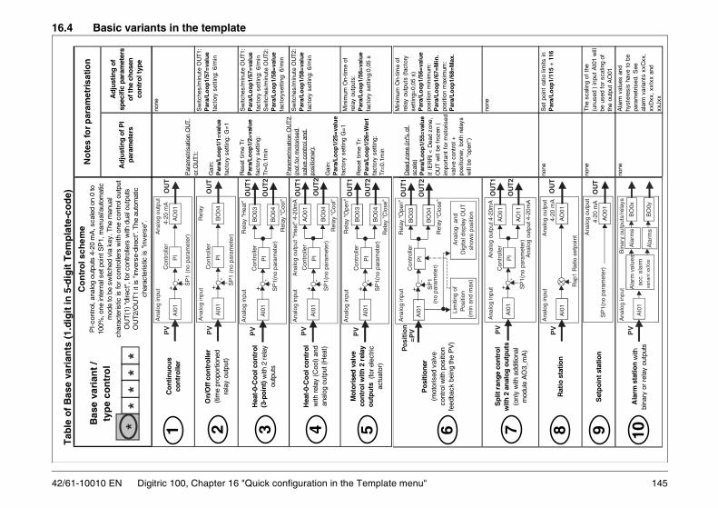
145
16.4 Basic variants in the template
Sp
lit r
ange
con
trol
w
ith 2
ana
log
outp
uts
(onl
y w
ith a
dditi
onal
m
odul
e A
O3_
mA
)
Rat
io s
tatio
n
Set
poi
nt s
tatio
n
Ala
rm s
tati
on w
ith
bina
r y o
r re
lay
outp
uts
The
sca
ling
of t
he
(unu
sed
) in
put
AI0
1 w
ill
be u
sed
for
scal
ing
of
the
outp
ut A
O01
none
Set
poi
nt r
atio
lim
its in
P
ara/
Lo
op
1/11
5 +
116
7 8 9 10A
larm
val
ues
and
hyst
eres
is h
ave
to b
e pa
ram
etris
ed.
See
al
arm
var
iant
s xx
Cxx
, xx
Dxx
, xx
Ixx
and
xxJx
x
none
none
none
Ana
log
inpu
t
Ana
log
outp
ut 4
-20m
A
C
ontr
olle
r
SP
1(no
par
amet
er)
A
nalo
g ou
tput
4-2
0mA
AO
01P
VO
UT1
AO
11O
UT2
PI
+-
AI0
1
Ana
log
inpu
t
A
nalo
g ou
tput
4-2
0 m
A
Rsp
1 R
atio
set
poin
t
AO
01P
VO
UT
AI0
1
A
nalo
g ou
tput
4-
20 m
A
S
P1(
no p
aram
eter
)A
O01
OU
T
Ana
log
inpu
t
B
inar
y ou
tput
s/re
lays
P
VA
I01
Ala
rm v
alue
s ac
c. a
larm
va
riant
xxX
xx
BO
0x
BO
0yA
larm
s
Ala
rms
42/61-10010 EN Digitric 100, Chapter 16 "Quick configuration in the Template menu"
Tab
le o
f B
ase
vari
ants
(1.
dig
it in
5-d
igit
Tem
pla
te-c
od
e)
Adj
ust
ing
of P
I pa
ram
eter
s
Adj
ustin
g o
f sp
ecifi
c pa
ram
eter
s of
the
chos
en
cont
rol t
ype
Co
ntin
uous
co
ntro
ller
On/
Off
co
ntro
ller
(tim
e pr
opor
tione
d re
lay
outp
ut)
Hea
t-0-
Co
ol c
ontr
ol
(3-p
oint
) w
ith 2
rel
ay
outp
uts
Hea
t-0-
Co
ol c
ontr
ol
with
rel
ay (
Coo
l) an
d an
alog
out
put (
Hea
t)
Mot
oris
ed v
alve
co
ntro
l with
2 r
elay
o
utp
uts
(for
ele
ctric
ac
tuat
or)
B
ase
vari
ant
/
ty
pe
con
tro
l
Co
ntr
ol s
chem
e
PI-
cont
rol,
anal
og o
utpu
ts 4
-20
mA
, sca
led
on 0
to
100%
, one
inte
rnal
set
poi
nt S
P1,
man
ual/a
utom
atic
m
ode
to b
e sw
itche
d vi
a ke
y. T
he m
anua
l ch
arac
teris
tic is
for
cont
rolle
rs w
ith o
ne c
ontr
ol o
utpu
t O
UT
(1)
"dire
ct",
for
cont
rolle
rs w
ith d
ual o
utpu
ts
OU
T2/
OU
T1
it is
"in
vers
e-di
rect
". T
he a
utom
atic
ch
arac
teris
tic is
"in
vers
e".
No
tes
for
par
amet
risa
tion
Sw
itche
s/m
inut
e O
UT
1:P
ara/
Lo
op
1/57
=va
lue
fact
ory
sett
ing:
6/m
inS
witc
hes/
min
ute
OU
T2:
Par
a/L
oo
p1/
58=
valu
efa
ctor
yset
ting:
6/m
in
Sw
itche
s/m
inut
e O
UT
1:P
ara/
Lo
op
1/57
=va
lue
fact
ory
sett
ing:
6/m
in
Sw
itche
s/m
inut
e O
UT
2:P
ara/
Lo
op
1/58
=va
lue
fact
ory
sett
ing:
6/m
in
Min
imum
On-
time
of
rela
y ou
tput
s:
Par
a/L
oo
p1/
56=
valu
efa
ctor
y se
ttin
g:0,
05 s
none
1 2 3 4 5
Par
amet
risat
ion
OU
T
or O
UT
1:
Gai
n:P
ara/
Lo
op
1/1=
valu
efa
ctor
y se
ttin
g: G
=1
Res
et t
ime
Tr
Par
a/L
oo
p1/
2=va
lue
fact
ory
sett
ing:
T
r=0.
1min
Par
amet
risat
ion
OU
T2
(not
for
mot
oris
ed
valv
e co
ntro
l and
po
sitio
ner)
:
Gai
n:P
ara/
Lo
op
1/25
=va
lue
fact
ory
sett
ing
G=
1
Res
et t
ime
Tr:
Par
a/L
oo
p1/
26=
Wer
tfa
ctor
y se
ttin
g:
Tr=
0.1m
in
**
**
*A
nalo
g in
put
Ana
log
outp
ut
C
ontr
olle
r
4-2
0 m
A
AO
01P
IP
VO
UT
AI0
1+
-S
P1
(no
para
met
er)
Ana
log
inpu
t
Rel
ay
C
ontr
olle
r
BO
04P
IP
VO
UT
+-
AI0
1
SP
1 (n
o pa
ram
eter
)
Ana
log
inpu
t
R
elay
"H
eat"
Con
trol
ler
SP
1(no
par
amet
er)
AI0
1B
O03
PV
OU
T1
BO
04O
UT2
PI
+-
R
elay
"C
ool"
Ana
log
inpu
t
A
nalo
g ou
tput
"H
eat"
4-2
0mA
Con
trol
ler
SP
1(no
par
amet
er)
AO
01P
VO
UT
1
BO
04O
UT
2P
I+
-A
I01
Rel
ay “
Coo
l”
Ana
log
inpu
t
R
elay
"O
pen"
Con
trol
ler
SP
1(no
par
amet
er)
BO
03P
VO
UT1
BO
04O
UT2
PI
+-
AI0
1
Rel
ay ”
Clo
se”
Po
sitio
ner
(mot
oris
ed v
alve
co
ntro
l with
pos
ition
fe
edba
ck b
eing
the
PV
)
Min
imum
On-
time
of
rela
y ou
tput
s (f
acto
ry
sett
ing=
0,05
s)
Par
a/L
oo
p1/
56=
valu
e po
sitio
n m
inim
um:
Par
a/L
oo
p1/
67=
Min
. po
sitio
n m
axim
um:
Par
a/L
oo
p1/
68=
Max
.6
Dea
d zo
ne (
in%
of
scal
e)P
ara/
Lo
op
1/55
=va
lue
If |E
RR
| < D
ead
zone
, O
UT
will
be
froz
en (
im
port
ant
for
mot
oris
ed
valv
e co
ntro
l +
posi
tione
r, b
oth
rela
ys
will
be
"ope
n")
Ana
log
inpu
t
R
elay
“O
pen”
C
ontr
olle
r
R
elay
“Clo
se”
BO
03P
osi
tio
n
=PV
OU
T1
BO
04O
UT
2P
IA
I01
+-
SP
1 (
no p
aram
eter
)
Ana
log-
and
D
igita
l dis
play
OU
T
show
s po
sitio
n
Lim
iting
of
Pos
ition
(m
in a
nd m
ax)

42/61-10010 EN
16.5 Additional variants in the template
posi
tion
is v
isib
le a
t the
con
trol
ler
and
can
be li
mite
d.
scal
ing
of A
I02.
w
ith A
I02
Lim
iting
of
Pos
ition
(min
and
max
)
Ana
log-
and
Dig
i- ta
l dis
play
OU
T
show
s po
sitio
n
AI0
2
146 Digitric 100, Chapter 16 "Quick configuration in the Template menu"
Tab
le o
f S
ub
var
ian
ts (
2.d
igit
of
5-d
igit
Tem
pla
te-c
od
e)
Th
e b
ase
con
tro
l (B
ase
vari
ant)
will
be
exte
nd
ed o
r m
od
ifie
d a
cco
rdin
g t
he
cho
sen
Su
b v
aria
nt
. Wit
h
"?"
mar
ked
or
stri
ped
ele
men
ts a
re a
cco
rdin
g t
he
cho
sen
Bas
e va
rian
t
Ad
dit
on
al
par
amet
risa
tio
nL
imit
atio
ns
No
Ext
ras.
The
Bas
e va
riant
will
no
t be
mod
ified
at a
llS
ee B
ase
vari
ant
--
Ad
dit
ion
al e
xter
nal
set
po
int
at
AI0
2. T
his
SP
ext e
xist
s in
add
ition
to
the
inte
rnal
set
poin
t SP
1. F
or
Bas
e va
riant
8 th
ere
will
be
inst
ead
of s
et p
oint
s S
Pex
t and
SP
1 th
e R
atio
set
poi
nts
Rsp
ext a
nd R
sp1
-
No
t po
ssib
le fo
r B
ase
vari
ant 1
0.
Th
e in
stru
men
t m
ust
be
equ
iped
w
ith A
I02
Rat
io c
on
tro
l A/B
, dis
pla
y R
pv,
R
sp in
%.
The
val
ue A
will
be
cont
rolle
d in
that
man
ner,
that
a s
et
ratio
to a
mea
sure
d va
lue
B w
ill b
e ac
hiev
ed.T
he d
ispl
ay s
how
s th
e ra
tios
Rpv
and
Rsp
in %
Rat
io c
on
tro
l A/(
A+
B),
dis
pla
y R
pv,
Rsp
in%
. T
he v
alue
A w
ill
be c
ontr
olle
d in
that
man
ner,
that
a
set r
atio
to th
e su
m o
f A a
nd a
m
easu
red
valu
e B
will
be
achi
eved
.The
dis
play
sho
ws
the
ratio
s R
pv a
nd R
sp in
%
Su
b v
aria
nt/
ext
ensi
on
No
t po
ssib
le fo
r B
ase
vari
ants
8,
9 an
d 1
0. T
he
inst
rum
ent m
ust
b
e eq
uip
ed w
ith
AI0
2
Rat
io s
etpo
int-
limiti
ng:
min
imum
: P
ara/
Lo
op1/
115=
Min
. m
axim
um:
Par
a/L
oop
1/11
6=M
ax.
0 A CB
**
**
*
Ana
log
inpu
t
Out
put
C
ontr
olle
r
S
P1(
inte
rnal
set
poin
t)
+-
PV
AI0
1
OU
T1
OU
T2
?
SP
ext
??P
I
SP
-wA
I02
Ana
log
inpu
t
Out
put
C
ontr
olle
r
Rsp
1 (
ratio
set
poin
t)
A(P
V)
AI0
1+
OU
T1
OU
T2
?B
AI0
2
??
-P
I
Ana
log
inpu
t
Out
put
C
ontr
olle
r
B
*Rsp
(
1-R
sp)
Rsp
1 (r
atio
set
poin
t)
A(P
V)
AI0
1
B
PI
AI0
2
OU
T1
OU
T2
???
+-
Pro
cess
val
ue a
s lin
ear
com
bina
tion
of 2
mea
sure
d va
lues
Out
of t
he m
easu
red
valu
es a
t the
inpu
ts A
I01
and
AI0
2 a
set p
oint
can
be
calc
ulat
ed b
y fo
llow
ing
equa
tion:
P
V=C
ON
ST
1*IC
1+
CO
NS
T2*(
IC2+
100*
CO
NS
T3)
Con
stan
t 1:
P
ara/
Lo
op1/
101=
valu
e C
onst
ant
2:
Par
a/L
oop
1/10
2=va
lue
Con
stan
t 3:
P
ara/
Lo
op1/
103=
valu
e N
ote:
Als
o ne
gativ
va
lues
are
pos
sibl
e
Pro
cess
val
ue a
s m
ultip
licat
ion
of 2
mea
sure
d va
lues
The
pro
cess
val
ue w
ill b
e ca
lcul
ated
out
of 2
mea
sure
d va
lues
at t
he in
puts
AI0
1 an
d A
I02
acco
rdin
g th
e eq
uatio
n:
PV
=IC
1*(I
C2+
100*
CO
NS
T3)
Con
stan
te 3
: P
ara/
Lo
op1/
103=
Wer
t N
ote:
Als
o ne
gativ
va
lues
are
pos
sibl
e
posi
tion
feed
back
for
mot
ori
sed
va
lve
cont
rol (
Bas
e va
rian
t 5) o
n A
I02.
The
pos
ition
of t
he e
lect
ric
actu
ator
(va
lve,
but
terf
ly v
alve
et
c.)
is m
easu
red
at A
I02.
The
Lim
iting
of
posi
tion
po
sitio
n m
inim
um:
Par
a./L
oop
1/67
=M
in.
posi
tion
max
imum
: P
ara.
/Loo
p1/
68=
Max
. N
ote:
The
val
ues
of M
in
and
Max
rel
ate
to t
he
On
ly p
oss
ible
for
Bas
e va
rian
t 5.
Th
e in
stru
men
t m
ust
be
equ
iped
No
t po
ssib
le fo
r B
ase
vari
ants
6,
9 an
d 1
0. T
he
inst
rum
ent m
ust
b
e eq
uip
ed w
ith
AI0
2
D E F
Ana
log
inpu
t
Out
put
Con
trol
ler
S
P1
IC1
OU
T1
OU
T2
?IC
2A
I02
??+
-P
IA
I01
PV
=C
ON
ST
1*
IC1
+
CO
NS
T2*
(IC
2 +
100
*
CO
NS
T3)
OU
T1
OU
T2 ?
Ana
log
inpu
ts
Out
put
Con
trol
ler
S
P1
IC1
IC2
AI0
2
??
AI0
1+
-P
V =
IC1*
(IC
2+
100*
C
ON
ST
3)
PI
Ana
log
inpu
t
R
elay
"O
pen"
SP
1
(no
para
met
er)
Rel
ay “C
lose
”
PV
+-
AI0
1
Pos
i.
BO
03O
UT
1
BO
04O
UT2
PI

147
Additional variants in the template, continued
42/61-10010 EN Digitric 100, Chapter 16 "Quick configuration in the Template menu"
Red
uctio
n to
man
ual s
tatio
n (n
o co
ntr
ol) .
OU
T c
an b
e se
t m
anua
lly o
r au
tom
atic
ally
via
inpu
t A
I01.
If c
hang
eove
r to
au
tom
atic
mod
e vi
a ke
y "M
AN
/AU
TO
" sh
all b
e di
sabl
ed y
ou h
ave
to
conf
i gur
e af
ter
activ
atin
g th
e te
mpl
ate
in t
he li
st
conf
igur
atio
n: L
1-B
07-
Q01
=2
(onl
y m
anua
l m
ode
poss
ible
)
Feed
forw
ard
. A d
istu
rban
ce
mea
sure
d at
AI0
2 ca
n be
feed
ed
forw
ard
(add
ed)
to O
UT
.
The
inte
nsity
of
the
dist
urba
nce
can
be
adju
sted
by
the
scal
ing
of A
I02
(if A
I02
is
defin
ed a
s m
A-in
put)
Ext
ensi
on a
s se
rial
bac
kup
co
ntro
ller.
The
out
put o
f a
exte
rnal
mas
ter-
cont
rolle
r w
ill b
e us
ed a
s O
UT
of t
he c
ontr
olle
r if
digi
tal (
bina
ry)
inpu
t BI0
1 is
act
iv. I
f B
I01
is n
ot a
ctiv
(m
aste
r=de
ad)
the
cont
rolle
r w
ill ta
ke o
ver
the
cont
rol.
The
take
ove
r w
ill h
appe
n w
ithou
t jum
p of
OU
T, t
hat m
eans
th
e co
ntro
ller
will
trac
k th
e ou
tput
of
the
exte
rnal
mas
ter.
The
co
ntro
ller
is a
lway
s in
aut
omat
ic
mod
e, th
at m
eans
sw
itchi
ng to
m
anua
l mod
e is
dea
ctiv
ated
(e
xcep
t sen
sor
brea
k at
AI0
1).
War
nin
g !
At s
enso
r br
eak
at A
I01
the
con
tro
ller
wil
l be
set
to
m
anu
al m
ode
(eve
n i
f M
aste
r is
act
iv)
No
t po
ssib
le fo
r B
ase
vari
ants
5,
6, 8
, 9 a
nd
10.
F
or
feed
forw
ard
an
d s
eria
l bac
k u
p th
e in
stru
men
t mu
st
be
equ
iped
with
A
I02.
G H I
Ana
log
inpu
t
Out
put
C
ontr
olle
r
S
P1
OU
T1
OU
T2
???
PI
AI0
1+
+
AI0
2
Pro
cess
PV
+-
Dis
turb
ance
Dis
turb
-an
ce
Mas
ter
LO
OP
1
O
utpu
tA
nalo
g in
put
C
ontr
olle
r
SP
1
Pro
cess
OU
T1
OU
T2
???
OU
TA d
oes
not e
xist
for
Bas
e va
rian
t 1(
cont
in.
cont
rolle
r) A
O01
is th
ere
al c
ontr
olou
tput
OU
T1
AO
01O
UT
A
PV
OU
T M
aste
r
BO
(1=M
aste
r ac
tive)
PV
OU
T C
on.
AI0
1
AI0
2
BI0
1
+-
PI
Inst
rum
ent
Bin
ary
inpu
t 24
VO
utpu
t 4-2
0mA
cont
rolle
r
Ana
log
inpu
t
O
utpu
ts
PV
OU
T1
OU
T2 ?
??A
I01
Dis
play
Mor
e
Less
M A

42/61-10010 EN
16.6 Alarm variants in the template
Ala
rms
ER
Rm
in2
and
E
RR
max
2 to
BO
05
9x
xxx
10xx
xx
xB
xxx
xCxx
x
xG
xxx
Ala
rms
ER
Rm
in1
and
E
RR
max
1 to
BO
01.
Ala
rms
ER
Rm
in2
and
E
RR
max
2 to
BO
02
Not
pos
sibl
e fo
r:
9xxx
x
10
xxxx
xBxx
x
xC
xxx
xGxx
x
xI
xxx
Par
a./L
oop1
/91
= E
RR
min
1
fact
ory
setti
ng: +
9999
9 P
ara.
/Loo
p1/9
2 =
ER
Rm
ax1
fact
ory
setti
ng:+
9999
9 P
ara.
/Loo
p1/9
3 =
ER
Rm
in2
fact
ory
setti
ng: +
9999
9 P
ara.
/Loo
p1/9
4 =
ER
Rm
ax2
fact
ory
setti
ng:+
9999
9 P
ara.
/Loo
p1/9
5 =
Hys
tere
sis
fact
ory
setti
ng:1
.000
0
ER
Rm
ax1
to B
O0x
. Ala
rm
ER
Rm
in2
and
ER
Rm
ax2
to
BO
0y.
T
he d
igita
l out
put B
O0x
will
be
activ
ated
if:
P
V <
SP
- E
RR
min
1 (A
L1)
P
V >
SP
+ E
RR
max
1 (A
L2)
T
he d
igita
l out
put B
O0y
will
be
activ
ated
if:
P
V <
SP
- E
RR
min
2 (A
L3)
P
V >
SP
+ E
RR
max
2 (A
L4)
T
he d
eact
ivat
ion
happ
ens
with
a
hyst
eres
is H
FE
=Hys
tere
sis
BO
0yB
O0x
ER
Rm
ax2
PV
SP
ER
Rm
in2
ER
Rm
ax1
ER
Rm
in1
(AL4
)
(AL
3)
(AL2
)
(AL1
)
148 Digitric 100, Chapter 16 "Quick configuration in the Template menu"
Ala
rms
ER
Rm
in1
and
E
RR
max
1 to
BO
03.
Not
pos
sibl
e fo
r:
3xxx
x
5x
xxx
6xxx
x
A
larm
ER
Rm
in1
and
Tab
le o
f A
larm
var
ian
ts (
3.d
igit
in 5
-dig
it T
emp
late
-co
de)
Sch
eme
of A
larm
s co
nn
ecte
d t
o d
igit
al
ou
tpu
tsP
aram
etri
sati
on
Lim
itat
ion
s
--
No
t fo
r B
ase
vari
ant
10
Ala
rms
to B
O05
(R
elay
N
O-
con
tact
)
Ala
rms
to B
O02
(2
4V
Tra
ns-
isto
r)
Ala
rms
PV
min
1 an
d
PV
max
1 to
B
O03
. A
larm
s P
Vm
in2
and
P
Vm
ax2
to
BO
05
No
t p
oss
ible
fo
r:
3xxx
x
5x
xxx
6xxx
x
9x
xxx
xBxx
x
xC
xxx
Ala
rms
PV
min
1 an
d
PV
max
1 to
B
O01
. A
larm
s P
Vm
in2
and
P
Vm
ax2
to
BO
02
No
t p
oss
ible
fo
r:
9xxx
x
xB
xxx
xCxx
x
xI
xxx
Ala
rm P
Vm
in1
and
PV
max
1 to
BO
0x. A
larm
PV
min
2 an
d
PV
max
2 to
BO
0y.
T
he d
igita
l out
put B
O0x
will
be
activ
ated
if:
P
V <
PV
min
1 (A
L1)
P
V >
PV
max
1 (A
L2)
T
he d
igita
l out
put B
O0y
will
be
activ
ated
if:
P
V <
PV
min
2 (A
L3)
P
V >
PV
max
2 (A
L4)
T
he d
eact
ivat
ion
happ
ens
with
a
hys
tere
sis
H
Par
a./L
oo
p1/
91 =
PV
min
1
fa
ctor
y se
tting
: -99
99
P
ara.
/Lo
op
1/92
= P
Vm
ax1
fact
ory
setti
ng:+
9999
9
Par
a./L
oo
p1/
93 =
PV
min
2
fa
ctor
y se
tting
: -99
99
P
ara.
/Lo
op
1/94
= P
Vm
ax2
fact
ory
setti
ng:+
9999
9
Par
a./L
oo
p1/
95 =
Hys
tere
sis
fa
ctor
y se
tting
:1.0
000
No
t p
oss
ible
for:
xB
xxx
xCxx
x
xG
xxx
9xxx
x
10
xxxx
Ala
rm v
aria
nt
No
ala
rms
on
Dig
ital o
utp
uts
.
Co
llect
ive
alar
m P
Vm
in,
PV
max
, ER
Rm
in,
ER
Rm
ax to
on
e d
igita
l o
utp
ut.
The
dig
ital o
utpu
t will
be
ac
tiva
ted
if
P
V <
PV
min
(AL
1)
P
V >
PV
max
(AL
2)
PV
< S
P-E
RR
min
(AL
3)
X
> S
P+E
RR
max
(AL
4)
T
he d
eac
tivat
ion
happ
ens
with
a h
yste
resi
s H
Par
a./L
oo
p1/
91 =
PV
min
fa
ctor
y se
tting
: -99
99
Par
a./L
oo
p1/
92 =
PV
max
fact
ory
setti
ng:+
9999
9 P
ara.
/Lo
op
1/93
= E
RR
min
fact
ory
setti
ng: +
9999
9 P
ara.
/Lo
op
1/94
= E
RR
max
fact
ory
setti
ng:+
9999
9 P
ara.
/Lo
op
1/95
= H
yste
resi
s
fact
ory
setti
ng:1
.000
0
0 A B C D
**
**
*
ER
Rm
in
BO
05
=Hys
tere
sisPV
SP
PV
min
PV
max
ER
Rm
ax
(AL
2)
(AL
1)
(AL
4)
(AL
3)
PV
min
2
PV
max
2
PV
max
1
PV
min
1
BO
0y
=Hys
tere
sis
BO
0x
PV
(AL
2)
(AL3
)
(AL
1)
(AL
4)
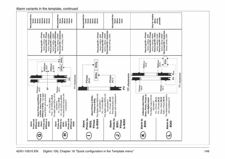
149
Alarm variants in the template, continued
Ala
rm t
o
BO
02
Onl
y fo
r va
rian
ts
xBxx
x
xC
xxx
poss
ible
on
e d
igita
l ou
tpu
t.
The
dig
ital o
utpu
t will
be
activ
ated
if:
P
V <
PV
min
(A
L1)
P
V >
PV
max
(AL
2)
Rat
io <
Rm
in (A
L3)
R
atio
> R
max
(AL
4)
The
dea
ctiv
atio
n ha
ppen
s w
ith a
hys
tere
sis
H
fact
ory
setti
ng: -
9999
Par
a./L
oop1
/92
= P
Vm
ax
fa
ctor
y se
tting
:+99
999
P
ara.
/Loo
p1/9
3 =
Rm
in
fact
ory
setti
ng: 0
.000
0
Par
a./L
oop1
/94
= R
max
fa
ctor
y se
tting
:+99
999
P
ara.
/Loo
p1/9
5 =
Hys
tere
sis
fa
ctor
y se
tting
:1.0
000
L
=Hys
tere
sis
PV
min
Rat
iom
ax
PV
BO
0x
Rat
io
(AL
1)
(AL
3)
42/61-10010 EN Digitric 100, Chapter 16 "Quick configuration in the Template menu"
Ala
rm
PV
min
to
B
O03
, P
Vm
ax
to B
O04
Not
pos
sibl
e fo
r:
3xxx
x
5x
xxx
6xxx
x
9x
xxx
xBxx
x
xC
xxx
Ala
rm
PV
min
to
B
O01
, P
Vm
ax
to B
O02
Not
pos
sibl
e fo
r:
9xxx
x
xB
xxx
xCxx
x
xI
xxx
Ala
rm P
Vm
in to
BO
0x,
PV
max
to B
O0y
The
dig
ital o
utpu
t BO
0x w
ill
be a
ctiv
ated
if:
PV
< P
Vm
in (A
L1)
The
dig
ital o
utpu
t BO
0y w
ill
be a
ctiv
ated
if
PV
> P
Vm
ax (
AL
2)
The
dea
ctiv
atio
n w
ill
happ
en w
ith a
hys
tere
sis
H
Par
a./L
oop1
/91
= P
Vm
in
fact
ory
setti
ng: -
9999
Par
a./L
oop1
/92
= P
Vm
ax
fa
ctor
y se
tting
: +99
999
P
ara.
/Loo
p1/9
5 =
Hys
tere
sis
fa
ctor
y se
tting
:1.0
000
I JP
V
PV
min
PV
max
BO
0y
=Hys
tere
sis
BO
0x
(AL
2)
(AL
1)
Ala
rm t
o
BO
05C
olle
ctiv
e al
arm
Rm
in,
Rm
ax, P
Vm
in, P
Vm
ax to
P
ara.
/Loo
p1/9
1 =
PV
min
K
PV
max
Rat
iom
in
(AL
2)
(AL
4)
Ala
rm
PV
min
an
d
ER
Rm
in to
B
O03
. A
larm
P
Vm
ax a
nd
E
RR
max
to
BO
05
No
t p
oss
ible
fo
r:
3xxx
x
5x
xxx
6xxx
x
9x
xxx
10xx
xx
xB
xxx
xCxx
x
xG
xxx
Ala
rm
PV
min
an
d
ER
Rm
in to
B
O01
. A
larm
P
Vm
ax a
nd
E
RR
max
to
BO
02
No
t p
oss
ible
fo
r:
9xxx
x
10
xxxx
xBxx
x
xC
xxx
xGxx
x
xI
xxx
Ala
rm P
Vm
in a
nd
ER
Rm
in
to B
O0x
. Ala
rm P
Vm
ax a
nd
E
RR
max
to B
O0y
. T
he d
igita
l ou
tput
BO
0x w
ill b
e ac
tivat
ed
if:
P
V <
PV
min
(A
L1)
PV
X <
SP
-ER
Rm
in (
AL
3)
T
he d
igita
l out
put B
O0y
will
be
activ
ated
if:
P
V >
PV
max
(A
L2)
PV
> S
P+
ER
Rm
ax (
AL4
)
T
he d
eact
ivat
ion
happ
ens
with
a
hyst
eres
is H
Par
a./L
oop
1/91
= P
Vm
in
fact
ory
setti
ng: -
9999
Par
a./L
oo
p1/
92 =
PV
max
fact
ory
setti
ng:+
9999
9
Par
a./L
oo
p1/
93 =
ER
Rm
in
fa
ctor
y se
tting
: +99
999
P
ara.
/Lo
op
1/94
= E
RR
max
fact
ory
setti
ng:+
9999
9
Par
a./L
oo
p1/
95 =
Hys
tere
sis
fa
ctor
y se
tting
:1.0
000
G HP
V
SP
PV
min
PV
max
ER
Rm
ax
ER
Rm
in
BO
0x
=H
yste
resi
s
BO
0y
(AL
2)
(AL
1)
(AL
4)
(AL
3)

42/61-10010 EN
16.7 Type of analog input AI01 and AI02 in the template
Pt
100
2-w
ire
(-
200
to +
800°
C=-
328
to 1
472°
F)
Pt 1
00
2-w
ire
(-
200
to +
800°
C=-
328
to 1
472°
F)
Pt
100
3-w
ire
(-
200
to +
200°
C=-
328
to 3
92 °
F)
Pt 1
00
3-w
ire
(-
200
to +
200°
C=-
328
to 3
92 °
F)
Pt
100
3-w
ire
(-
200
to +
800°
C=-
328
to 1
472°
F)
Pt 1
00
3-w
ire
(-
200
to +
800°
C=-
328
to 1
472°
F)
NN P Q
P QP
t 10
0 4-
wir
e
(-20
0 to
+20
0°C
= -3
28 to
392
°F
)
Pt 1
00
4-w
ire
(-
200
to +
800°
C=-
328
to 1
472°
F)
Po
ti 1
50O
hm
(7
5-20
0 O
hm
)P
oti
150O
hm
(7
5-2
00 O
hm
)
Po
ti 15
00O
hm
(75
0-20
00
Oh
m)
Po
ti 1
500
Oh
m
(7
50-2
000
Oh
m)
Not
e: If
yo
u c
hoo
se t
her
mo
cou
ple
inp
uts
, the
inte
rnal
com
pen
sati
on w
ill b
e ac
tive
T U
T U
R S
150 Digitric 100, Chapter 16 "Quick configuration in the Template menu"
Typ
e o
f an
alo
g in
pu
t A
I01
Typ
e o
f an
alo
g in
pu
t A
I02
(4.d
igit
of
Tem
pla
te-c
od
e)(5
.dig
it o
f T
emp
late
-co
de)
Lim
itat
ion
s
No
inp
ut A
I02
Can
on
ly b
e ch
ose
n if
the
vari
ant d
oes
n’t
use
the
anal
og
in
pu
t AI0
2
4-20
mA
4-
20 m
A
0-2
0 m
A
0-20
mA
Th
erm
oco
up
le ty
pe
B
(0
to 1
800°
C =
32
to 3
272°
F)
Th
erm
oco
up
le ty
pe
B
(0
to 1
800°
C =
32
to 3
272°
F)
Th
erm
oco
up
le ty
pe
D
(0
to 2
300°
C =
32
to 4
172°
F)
Th
erm
oco
up
le ty
pe
D
(0
to 2
300°
C =
32
to 4
172°
F)
Th
erm
oco
up
le t
ype
E
(-
200
to 1
000°
C=
-328
to 1
832°
F)
Th
erm
oc
ou
ple
typ
e E
(-20
0 to
100
0°C
=-3
28 t
o 1
832°
F)
Th
erm
oco
up
le ty
pe
J
(-
200
to 1
200°
C=
-328
to 2
192°
F)
Th
erm
oco
up
le t
ype
J
(-
200
to 1
200°
C=
-328
to
219
2°F
)
Th
erm
oco
up
le t
ype
K
(-
200
to 1
400°
C=
-328
to
255
2°F
)T
her
mo
co
up
le ty
pe
K
(-
200
to 1
400°
C=
-328
to
255
2°F)
Th
erm
oco
up
le ty
pe
L
(-
200
to 1
000°
C=
-328
to
183
2°F
)T
her
mo
cou
ple
typ
e L
(-20
0 to
100
0°C
= -3
28 t
o 1
832°
F)
Th
erm
oco
up
le ty
pe
R
(0
to 1
700°
C =
32
to 3
092°
F)
Th
erm
oco
up
le ty
pe
R
(0
to
170
0°C
= 3
2 to
309
2°F
)
Th
erm
oco
up
le t
ype
S
(0
to 1
800°
C =
32
to 3
272°
F)
Th
erm
oc
ou
ple
typ
e S
(0 t
o 1
800°
C =
32
to 3
272°
F)
Th
erm
oco
up
le ty
pe
T
(-
200
to 4
00°C
=-3
28 to
752
°F)
Th
erm
oco
up
le t
ype
T
(-
200
to 4
00°C
=-3
28 t
o 7
52°F
)
Th
erm
oco
up
le t
ype
U
(-
200
to 6
00°C
=-3
28 to
111
2°F
)T
her
mo
co
up
le ty
pe
U
(-
200
to 6
00°C
=-3
28 t
o 1
112°
F)
Pt
100
2-w
ire
(-
200
to +
200°
C=-
328
to 3
92°F
)P
t 10
0 2-
wir
e
(-20
0 to
+20
0°C
=-32
8 to
392
°F)
Typ
e an
alo
g in
pu
t A
I01
Typ
e an
alo
g in
pu
t A
I02
Dig
itric
100
m
ust
be
e
qu
iped
with
o
ptio
nal
inp
ut
AI0
2.
T
he
ch
oic
e is
o
nly
po
ssib
le
if th
e c
ho
sen
va
rian
t use
s th
e an
alo
g
inp
ut A
I02.
A DB EC F G H I J K L M
A DB EC F G H I J K L M0
**
**
*
Th
is i
s th
e o
nly
p
oss
ible
va
ria
nt
for
setp
oin
t st
ati
on
**
**
*
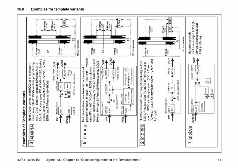
151
16.8 Examples for template variants
type
E
C
ontr
olle
r
R
elay
BO
04P
IO
UT
AI0
1+
-
SP
1 (n
o pa
ram
eter
)
The
rmoc
oupl
e
Man
ual s
tatio
n w
ith
cont
inuo
us o
utpu
t AO
01 (4
-20
mA
). E
xter
nal o
utpu
t at
AI0
1 (4
-20m
A).
1G
0A
0In
put 4
-20m
A
Out
put 4
-20m
A
O
UTe
xtO
UT
AO
01A
I01
Dis
play
Less
M AM
ore
42/61-10010 EN Digitric 100, Chapter 16 "Quick configuration in the Template menu"
Exa
mp
les
of
Tem
pla
te v
aria
nts
Hea
t-0-C
ool c
ontro
l with
BO
03 a
s tim
e pr
opor
t-io
ning
rela
y "H
eat"
, BO
04 a
s tim
e pr
opor
tioni
ng
rela
y "C
ool".
Ext
erna
l set
poi
nt S
Pex
t at A
I02
(4-
20m
A).
Pro
cess
val
ue P
V a
t AI0
1= P
t100
, 3-w
ire (
200
to +
200
°C).
Col
lect
ive
alar
m P
Vm
in, P
Vm
ax,
ER
Rm
ax, E
RR
min
at r
elay
BO
05
3A
AP
A
SP
ext
PV
Rel
ay "
Hea
t”
Pt1
00,3
-wire
C
ontr
olle
r
R
elay
4-20
mA
SP
1(in
tern
al s
etpo
int)
AI0
1
OU
T1
OU
T2
BO
04
BO
03P
I
SP
-w
+-
AI0
2
Mot
oris
ed v
alve
con
trol (
elec
tric
actu
ator
) with
po
sitio
n fe
edba
ck to
AI0
2 (P
oti 1
500O
hm),
Pro
cess
valu
e P
V a
t AI0
1(4-
20m
A).
BO
03 a
s re
lay
for
"ope
n", B
O04
als
rela
y fo
r "cl
ose"
. Col
lect
ive
alar
m
PV
min
, PV
max
, ER
Rm
in, E
RR
max
at r
elay
BO
05
Ana
log
inpu
t
R
elay
"O
pen"
4-20
mA
Con
trol
ler
SP
1
(no
para
met
er)
Pot
i (75
0-20
00 O
hm)
AI0
2
PV
Lim
iting
of
pos
ition
(m
in a
nd m
ax)
Ana
log-
and
dig
i- ta
l dis
play
of O
UT
sh
ows
posi
tion
+-
AI0
1
Po
si.
BO
03O
UT
1
BO
04O
UT
2P
I
R
elay
"C
lose
"
5F
AU
A
On/
Off
cont
rol w
ith ti
me
prop
ortio
ned
rela
y ou
tput
B
O04
, Pro
cess
val
ue P
V a
t AI0
1(Th
erm
ocou
ple
type
E).
BO
03 a
s re
lay
pre
alar
m (P
Vm
in2
and
PV
max
2), B
O05
as
rela
y m
ain
alar
m (P
Vm
in1
and
PV
max
1).
20
CE
0
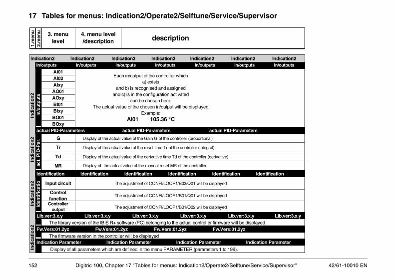
ice/Supervisor" 42/61-10010 EN
17 Tables for menus: Indication2/Operate2/Selftune/Service/Supervisor
d
Indication2
ion Parameter
In/outputs
ntification
Lib.ver:3.x.y
152 Digitric 100, Chapter 17 "Tables for menus: Indication2/Operate2/Selftune/Serv
AI01AI02AIxyAO01AOxyBI01BIxyBO01BOxy
G
Tr
Td
MR
Input circuit The adjustment of CONFI/LOOP1/B03/Q01 will be displayed
Control function
The adjustment of CONFI/LOOP1/B01/Q01 will be displayed
Controller output The adjustment of CONFI/LOOP1/B01/Q02 will be displayed
The library version of the IBIS R+ software (PC) belonging to the actual controller firmware will be displaye
The firmware version in the controller will be displayed
Display of all parameters which are defined in the menu PARAMETER (parameters 1 to 199).
Display of the actual value of the manual reset MR of the controller
1.m
enu
2.m
enu 3. menu
level
Display of the actual value of the derivative time Td of the controller (derivative)
description4. menu level /description
Display of the actual value of the Gain G of the controller (proportional)
Display of the actual value of the reset time Tr of the controller (integral)
In/o
utp
uts
In
dic
atio
n2
Ind
icat
ion
2
In
dic
atio
n2
Ind
icat
ion
2
Indication2 Indication2 Indication2 Indication2 Indication2 Indication2
Indication Parameter Indication Parameter Indication Parameter Indicat
In/outputs In/outputs In/outputs In/outputs In/outputs In/outputs
act
. PID
-Par
.
actual PID-Parameters actual PID-Parameters actual PID-Parameters
Id
enti
fica
tio
Identification Identification Identification Identification Identification Ide
Lib.ver:3.x.y Lib.ver:3.x.y Lib.ver:3.x.y Lib.ver:3.x.y Lib.ver:3.x.y
Fw.Vers:01.2yz Fw.Vers:01.2yz Fw.Vers:01.2yz Fw.Vers:01.2yz
Each in/output of the controller whicha) exists
and b) is recognised and assigned and c) is in the configuration activated
can be chosen here. The actual value of the chosen in/output will be displayed.
Example:AI01 105.36 °C
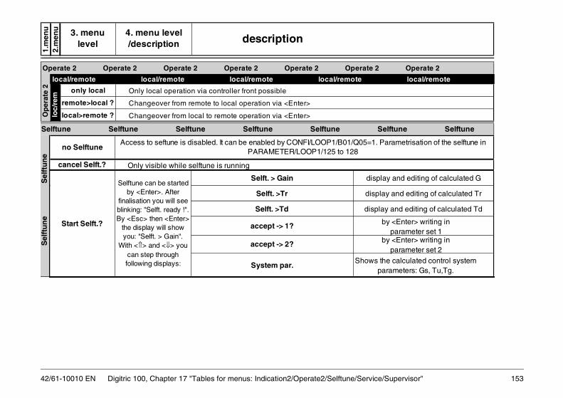
ice/Supervisor" 153
u u
local/remote
2 Operate 2
by <Enter> writing in parameter set 1
by <Enter> writing in parameter set 2
s the calculated control system parameters: Gs, Tu,Tg.
play and editing of calculated Td
splay and editing of calculated G
splay and editing of calculated Tr
Selftune Selftune
1. Parametrisation of the selftune in
42/61-10010 EN Digitric 100, Chapter 17 "Tables for menus: Indication2/Operate2/Selftune/Serv
1.m
en2.
men 3. menu
level description4. menu level /description
only local Only local operation via controller front possible
remote>local ? Changeover from remote to local operation via <Enter>
local>remote ? Changeover from local to remote operation via <Enter> Op
erat
e 2
loc/
rem
local/remote local/remote local/remote local/remote
Operate 2 Operate 2 Operate 2 Operate 2 Operate 2 Operate
Only visible while selftune is running
Selft. > Gain
Selft. >Tr
Selft. >Td
accept -> 1?
accept -> 2?
System par.Show
dis
Selftune can be started by <Enter>. After
finalisation you will see blinking: "Selft. ready !". By <Esc> then <Enter>
the display will show you: "Selft. > Gain".
With <⇑> and <⇓> you can step through following displays:
no Selftune
Start Selft.?
cancel Selft.?
di
di
Sel
ftu
ne
S
elft
un
e
Selftune Selftune Selftune Selftune Selftune
Access to seftune is disabled. It can be enabled by CONFI/LOOP1/B01/Q05=PARAMETER/LOOP1/125 to 128

ice/Supervisor" 42/61-10010 EN
u u
ion by factory
led on main board)ssembled on main board)
Service Service mation Information
Info HardWare Info HardWare
Display Unit Display Unit
S-232/485O3-mAI2-mAmA iO4-RELAISrofibusDP
. . . . ither in CONFI/INSTRUMENT/B12/Q01
ecognised and assigned.
154 Digitric 100, Chapter 17 "Tables for menus: Indication2/Operate2/Selftune/Serv
1.m
en2.
men 3. menu
level description4. menu level /description
ABB company name
Digitric 100 Device name, Digitric 100
CPU:x CPU version, e.g. x=A
F:x.xxxxxx.x Production number, e.g.: F:6.850291.6F-Dat:dd.mm.yy Production dateConfi-No.:xxxxx Configuration number: 00000=standard ; xxxxx= if custom configuratR-Dat:dd.mm.yy Repair date
empty unused
M1= _ _ _ _ _
AI02= _ _ _ _ _ AI02 exists The optional universal input AI02 is present (assembNo AI02 The optional universal input AI02 is not present (not a
Contrast LCD 0 to 9 Adjustment of the contrast at the LCD display
In
form
atio
n S
ervi
ce
Ser
vice
S
ervi
ce
Service Service Service Service Service Service Information Information Information Information Infor
In
fo H
ard
War
e
Info HardWare Info HardWare Info HardWare Info HardWare
Display Unit Display Unit Display Unit Display Unit
Modules assembled in the controller will be shown. Modules can be e.g.: - R - A - A - B - P - .The module is not ready for the Configuration in general. In fact it has to be emanualy assigned or via CONFI/INSTRUMENT/B11/Q01=1 automatically r
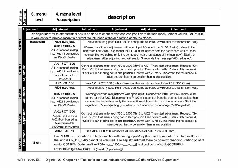
ice/Supervisor" 155
u u
as to be 75 to 200 Ohm)2-wire oder teletransmitter (Poti).
at module). Teletransmitters at done by changing starting point of of scale [CONFI/AI-
measurement values. For Pt-100
start adjustment. Request: "Set irm with <Enter>. After request: r>. Important: the resistance in
nd position.
2-wire oder teletransmitter (Poti).
start adjustment. Request: "Set irm with <Enter>. After request: r>. Important: the resistance in
nd position.
e Pt100 (2 wire) cables to the m the connection cables, then ce at the input now). Start the e message "AI01 adjusted".
to 200 Ohm)
the Pt100 (2 wire) cables to the from the connection cables, then nce at the input now). Start the message "AI02 adjusted".
Adjustment
42/61-10010 EN Digitric 100, Chapter 17 "Tables for menus: Indication2/Operate2/Selftune/Serv
1.m
en2.
men 3. menu
level description4. menu level /description
Basic unit AI01 n.adjust.
AI01 POT1500Adjustment of analog
input AI01 if configured as teletransmitter
1500Ohm
AI01 POT150 see AI01 POT1500 (only difference: the resistance hAI02 n.adjust.
AI02 POT1500Adjustment of input
AI02 if configured as tele-transmitter
1500Ohm (only Digitric
Slot 1
Adjustment only possible if AI02 is configured as Pt100
For Pt-100 2wire identic as in basic unit but with analog Input AIxy (Use pinsthe modul AI2_PT_3/4W cannot be adjusted. The adjustment must there bescale [CONFI/AI-Definition/Bxy/P05= -yclose*100/(yopen-yclose)] and end point Definition/Bxy/P06=(100*(100-yclose))/(yopen-yclose)]).
An adjustment for teletransmitters has to be done to connect start and end position to defined2 wire sensors it is necessary to prevent the influence of the connecting cable resistance.
Connect teletransmitter (poti 750 to 2000 Ohm) to AI02. ThenPot LoEnd", that means bring poti in start position.Then conf"Set Pot HiEnd" bring poti in end position. Confirm with <Ente
start position has to be smaller than in e
Adjustment only possible if AI01 is configured as Pt100
Connect teletransmitter (poti 750 to 2000 Ohm) to AI01. ThenPot LoEnd", that means bring poti in start position.Then conf"Set Pot HiEnd" bring poti in end position. Confirm with <Ente
start position has to be smaller than in e
Warning: don’t do a adjustment with open input ! Connect thcontroller input AI01. Disconnect the Pt100 at the sensor froconnect the two cables (only the connection cable resistan
adjustment. After adjusting you will see for 3 seconds th
AI02 POT150 See AI02 POT1500 (but overall resistance of poti: 75
AI02 Pt100-2W Adjustment of analog
input AI02 if configured as Pt-100 2-wire
Warning: don’t do a adjustment with open input ! Connect controller input AI02. Disconnect the Pt100 at the sensor connect the two cables (only the connection cable resistaadjustment. After adjusting you will see for 3 seconds the
AI01 Pt100-2W Adjustment of analog
input AI01 if configured as Pt-100 2-wire
Ser
vice
S
ervi
ce
Ser
vice
S
ervi
ce
Ser
vice
Ad
just
men
t
A
dju
stm
ent
Ad
just
men
t
A
dju
stm
ent
Adjustment Adjustment Adjustment Adjustment Adjustment

ice/Supervisor" 42/61-10010 EN
u u
rent measurement then start 0 mA then confirm with <Enter>. mA, then confirm with <Enter>. ). Limits: 0mA :-1 to 5 mA ; 20 mA:
alibrated ex factory. If you do a ice to ABB for calibration.
r 4 wire. Digitric 100: connect pins ance. Note: If you use cables the e the same as the cable from pin 9 put", adjust resistance to 0 Ohm, s for 200 and 2000 Ohm. Please nces can be edited (in small m ;2000 Ohm: 2000-2200 Ohm.
igitric 100: connect pins 6+7 with one you use cables the resistance of the e cable from pin 9 to the resistor. Start e to 0 Ohm, then confirm with <Enter>. ase adjust them and confirm with limits). Limits: 0 Ohm: 0-1 Ohm ; 200
Calibration
156 Digitric 100, Chapter 17 "Tables for menus: Indication2/Operate2/Selftune/Serv
1.m
en2.
men 3. menu
level description4. menu level /description
Warning!
Basic unit
AI01 mA calib? Calibration of analog
input AI01 if configured as 0(4)-20 mA input
AI01 Pt calib? Calibration of analog
input AI01 if configured as Pt 100 input
AI01 Pot calib? Calibration of analog
input AI01 if configured as teletransmitter input
Connect a precision current provider to the input for curcalibraton. After request "0 mA input", adjust current to After further request "20 mA input", adjust current to 20 Note: The currents 0 or 20 can be edited (in small limits15 to 22 mA.
In normal cases there is no need for any calibration as our devices are exactly cincorrect calibration the controller will be useless. If you are unsure give your dev
Connect a precision resistance provider to the inputs fo6+7 with one end, pins 9 with the other end of the resistresistance of the cable from pin 6 to the resisitor must bto the resistor. Start calibration. After request "0 Ohm inthen confirm with <Enter>. There will be further requestadjust them and confirm with <Enter>. Note: The resistalimits). Limits: 0 Ohm: 0-1 Ohm ; 200 Ohm: 180-220 Oh
Connect a precision resistance provider to the inputs. Dend, pins 9 with the other end of the resistance. Note: Ifcable from pin 6 to the resisitor must be the same as thcalibration. After request "0 Ohm input", adjust resistancThere will be further requests for 200 and 400 Ohm. Ple<Enter>. Note: The resistances can be edited (in small Ohm: 180-220 Ohm ; 400 Ohm: 360-450 Ohm.
Cal
ibra
tio
n
C
alib
rati
on
Calibration Calibration Calibration Calibration
Ser
vice
Ser
vice
Ser
vice
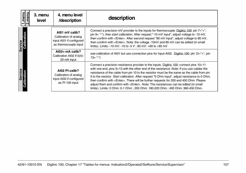
ice/Supervisor" 157
Digitric 100: connect pins 10+11 tance. Note: If you use cables the t be the same as the cable from pin input", adjust resistance to 0 Ohm, ts for 200 and 400 Ohm. Please tances can be edited (in small hm ; 400 Ohm: 360-450 Ohm.
t AI02. Digitric 100: pin 12="+", pin
ocouple. Digitric 100: pin 7="+", input", adjust voltage to -10 mV, V input", adjust voltage to 80 mV, d 80 mV can be edited (in small mV
42/61-10010 EN Digitric 100, Chapter 17 "Tables for menus: Indication2/Operate2/Selftune/Serv
1.m
enu
2.m
enu 3. menu
level description4. menu level /description
AI01 mV calib? Calibration of analog
input AI01 if configured as thermocouple input
AI02= mA calib? Calibration AI02 if 0(4)-
20 mA input
AI02 Pt calib? Calibration of analog
input AI02 if configured as Pt 100 input
Connect a precision resistance provider to the inputs. with one end, pins 9+13 with the other end of the resisresistance of the cable from pin 10 to the resisitor mus9 to the resistor. Start calibration. After request "0 Ohmthen confirm with <Enter>. There will be further requesadjust them and confirm with <Enter>. Note: The resislimits). Limits: 0 Ohm: 0-1 Ohm ; 200 Ohm: 180-220 O
see calibration of AI01 but use connection pins for Inpu13= "-")
Connect a precision mV provider to the inputs for thermpin 9= "-"), then start calibration. After request "-10 mVthen confirm with <Enter>. After second request "80 mthen confirm with <Enter>. Note: the voltage -10mV anlimits). Limits: -10 mV: -10 to -5 V ; 80 mV: +60 to +85
C
alib
rati
on
Cal
ibra
tio
n
S
ervi
ce
S
ervi
ce

ice/Supervisor" 42/61-10010 EN
u u
(mA). That means connect pin 8 20 mA will be calibrated). Other mA ; 20 mA: 15 to 22 mA. For s to be calibrated exactly.
igitric 100: connect pins 10+11 nce. Note: If you use cables the
be the same as the cable from pin input", adjust resistance to 0 Ohm, s for 200 and 2000 Ohm. Please nces can be edited (in small m ;2000 Ohm: 2000-2200 Ohm.
vice FC: 00000, means there had en no communication. The time ifference will then show 00000
ary contact ABB for calibration of
ocouple. Digitric 100: pin 11="+", input", adjust voltage to -10 mV, input", adjust voltage to 80 mV, 80mV can be edited (in small V
Comm.- Service
158 Digitric 100, Chapter 17 "Tables for menus: Indication2/Operate2/Selftune/Serv
1.m
en2.
men 3. menu
level description4. menu level /description
AI02 Pot calib? Calibration of analog
input AI02 if configured as teletransmitter input
AI02 mV calib? Calibration of analog
input AI02 if configured as thermocouple input
AO01= mA calib? Calibration of analog
output Ao01 (0/4-20mA)
Slot1
Modbus Service FC: __ Shows function code of the last Modbus service
Timediff./sec Shows time since the last Modbus service
ProfibusDP Service FC: __ Shows function code of the last Profibus service
Timediff./sec Shows time since the last Profibus service
Connect analog output AO01 (mA) to analog input AI01with 14 and pin 9 with 15:. Then start calibration (0 and values than 0 and 20 can be edited. Limits: omA: 0 to 5correwct calibaration of AO01, the analog input AI01 ha
Connect a precision resistance provider to the inputs. Dwith one end, pins 9+13 with the other end of the resistaresistance of the cable from pin 10 to the resisitor must9 to the resistor. Start calibration. After request "0 Ohmthen confirm with <Enter>. There will be further requestadjust them and confirm with <Enter>. Note: The resistalimits). Limits: 0 Ohm: 0-1 Ohm ; 200 Ohm: 180-220 Oh
Serbed
Analog inputs on modules cannot be calibrated in the controller. If necesssingle modules.
Connect a precision mV provider to the inputs for thermpin 13= "-"), then start calibration. After request "-10 mVthen confirm with <Enter>. After second request "80 mVthen confirm with <Enter>. Note: the voltage -10mV andlimits). Limits: -10 mV: -10 to -5 V ; 80 mV: +60 to +85 m
C
alib
rati
on
Cal
ibra
tio
n
Co
m.-
Ser
.
Comm.- Service Comm.- Service Comm.- Service
Ser
vice
Ser
vice
Ser
vice
Ser
vice
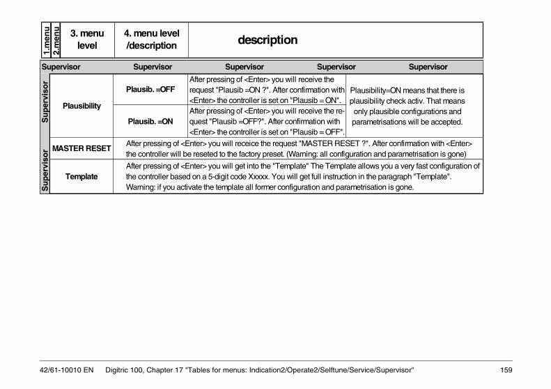
ice/Supervisor" 159
u u
sibility=ON means that there is sibility check activ. That means y plausible configurations and metrisations will be accepted.
lows you a very fast configuration of the paragraph "Template". isation is gone.
". After confirmation with <Enter> on and parametrisation is gone)
Supervisor
42/61-10010 EN Digitric 100, Chapter 17 "Tables for menus: Indication2/Operate2/Selftune/Serv
1.m
en2.
men 3. menu
level description4. menu level /description
Plausib. =OFFAfter pressing of <Enter> you will receive the request "Plausib =ON ?". After confirmation with <Enter> the controller is set on "Plausib = ON".
Plausib. =ONAfter pressing of <Enter> you will receive the re-quest "Plausib =OFF?". After confirmation with <Enter> the controller is set on "Plausib = OFF".
Template
Plausibility
Plauplauonlpara
After pressing of <Enter> you will get into the "Template" The Template althe controller based on a 5-digit code Xxxxx. You will get full instruction inWarning: if you activate the template all former configuration and parametr
MASTER RESETAfter pressing of <Enter> you will receice the request "MASTER RESET ?the controller will be reseted to the factory preset. (Warning: all configurati
Su
per
viso
r
Su
per
viso
r
Supervisor Supervisor Supervisor Supervisor
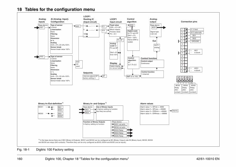
42/61-10010 EN
18 Tables for the configuration menu
Alarms
in = -9999ax = +99999min = +99999max = +99999
16 17 18 19 20 21
BO03Relay(NO-contact)
BO04Relay(NO-contact)
BO05Relay(NO-contact)
+ AI01- 4-20mA
+ AO01- 4-20mA
BI01
BI02
GROUND -
24 V externally
21 V feed
1514
1312
1110
98
76
54
32
1
Connection pins
evice
ypeA
UT1alog
-
160 Digitric 100, Chapter 18 "Tables for the configuration menu"
Fig. 18-1 Digitric 100 Factory setting
Display
BIO01
BIO02
BI01
BO01
BI02
BO02
Binary In-/Out-definition1)
Base device
Use of Binary InputsIn factory setting no function(but they are active)
Base device
BO01 not activ
BO02 not activ
BO03 Relay
BO04 Relay
BI01
BI02
BO05 Relay
Function of Binary OutputsIn factory setting no function
Binary In- and Outpus 1)
Alarm value 1 = SPmAlarm value 2 = SPmAlarm value 3 = ERRAlarm value 4 = ERR
Alarm values
1) In the base device there are 2 BIO (Binary In/Outputs). BIO01 and BIO02 can be configured as BO (Binary Output) oder BI (Binary Input). BIO03, BIO04
and BIO05 are relays (NO-contacts). Therefore they can be only configured as BO03, BO04 and BO05 (not as Inputs).
Base d
Signal t4-20 m
Control outputContinuous
AO01
Control function1-channel
Oan
Analog
output
Out
Control function
Analog-scale forPV SPand
Start =0%End=100%
Digital displayPV, SP,OUT, ERR
PV, SP
Fixed valueERR = IC1-SP ;Which means:Process valuePV = IC1
LOOP1Input circuit
ERR
Controlalgorithm:PI ;G=1;Tr=0.5
Digital scalefor PV and SP.Start = 0%End = 100%Hence ERR isscaled.
OUT (0 to 100)
Controlalgorithm
0
100
Internal setpoint SP1factory setting: 0
IC1
SP
IC2
LOOP1Rooting IC(Input-circuit)
Setpoints
Base deviceAI01
Type of sensor4-20mALinearisationNoneFilteringNoneDimensionin %Scaling4mA = 0%; 20 mA=100%Sensor breakSensor break value 102%
AI02 Type of sensor4-20mALinearisationNoneFilteringNoneDimensionin %Scaling4mA = 0%; 20 mA=100%Sensor breakSensor break value 102%
AI02notused
Analog-Inputs
AI (Analog- Input)-Configuration
AI01

161
1)In
the
base
devic
eth
ere
are
2B
IO(B
inary
In/O
utp
uts
).E
ach
ofth
em
can
be
configure
das
BO
(Bin
ary
Outp
ut)
oder
BI(B
inary
Input)
.In
the
Dig
itric
100,B
IO3,B
IO4
and
BIO
5are
rela
ys
(NO
-conta
ct)
.T
here
fore
they
can
be
only
configure
das
BO
3,B
O4
und
BO
5(n
otas
Inputs
).2
)W
ith
the
configura
tion
question
"auto
matic
chara
cte
ristic"
you
can
achie
ve
achange
ofth
esig
n(a
uto
matic
chara
cte
ristic
"direct"
inste
ad
ofdefa
ult
"invers
e")
3)W
ith
the
configura
tion
question
"Manualchara
cte
ristic"
you
can
change
the
sig
nofall
used
Outp
utsig
nals
(either
only
OU
T1
or
OU
T1
and
OU
T2).
Change
ofsig
nm
eans
:-
for
Bin
ary
Outp
uts
ain
vers
evalu
e;-
for
Analo
gO
utp
uts
ain
vers
ion
ofth
echara
cte
ristic,th
atm
eans
0to
100%
will
be
pro
jecte
don
100
to0%
.
....
.B
Ixy
BIO
xyB
Oxy
Sw
itchi
ng p
aram
eter
con
trol
Sw
itchi
ng b
etw
een
IC1
and
IC2
Sta
rt o
f pro
gram
sD
eny
acce
ss o
f ope
rato
r..
...
Mod
ule
1B
Ixy
BO
04
BO
03
Mod
ule
1
BO
xy
Sig
nal.
exce
ssiv
e lo
adS
igna
l.se
nsor
bre
akS
igna
l.co
mm
unic
atio
n er
ror
Sig
nal.
alar
ms
....
.
BO
05
1 2 3
42/61-10010 EN Digitric 100, Chapter 18 "Tables for the configuration menu"
Fig. 18-2 Basic structure of the list configuration for Loop 1 (continued in Fig. 18-3)
Mod
ule
1
....
..
Bas
e de
vice
AI0
2
AI1
2
AI1
1
AI0
1
Mod
ule
1
....
..A
Ixy
Typ
e o
f se
nso
r0(
4)-2
0mA
,TC
, Pt1
00 .
..L
inea
risa
tio
nS
quar
e ro
ot,T
C-t
ype,
Tabl
e,.
. Filt
erin
gT
ime
cons
t.Lo
w p
ass
Dim
ensi
on
in %
, °C
, bar
, mm
..
Sca
ling
e.g.
:4-2
0mA
= 2
0 to
80°
CS
enso
r b
reak
....
An
alo
g-
Inp
uts
AI (
An
alo
g-
Inp
ut)
-C
on
fig
ura
tio
n
stat
eco
rrec
tion
1AIx
y
AI1
2
AI1
1
AI0
1
AI0
2
Tabl
e4
PV
to O
utpu
t
Onl
y if
setp
oint
stat
ion
BI0
1B
IO01
BO
01
Bin
ary
In-/
Ou
t-d
efin
itio
n1)
Use
of
Bin
ary
Inp
uts
Sw
itchi
ng o
f set
poin
tsS
witc
hing
of o
pera
tion
mod
eA
ctiv
atin
g O
UT-
trac
king
Bas
e de
vice
1)
BI0
2
BI0
1
Bin
ary
Inp
uts
1)
Bas
e de
vice
1)
BO
02
BO
01
Use
of
Bin
ary
Ou
tpu
tsS
igna
lisat
ion
alar
ms
Sig
nalis
atio
n of
ope
ratio
n m
ode
Sig
nalis
atio
n pr
ogra
m e
nd
Bin
ary
Ou
tpu
ts1)
Lim
its, e
.g.:
Pos
ition
min
.,Pos
.max
.P
ositi
on fe
edba
ck, e
.g.
angl
e or
pos
ition
at v
alve
s
Mul
tiplic
atio
nw
ithS
R o
r (1
-S
R)
AIx
yA
Ixy
AIx
yA
Ixy
AIx
yA
Ixy
Set
Rat
io S
R
Set
po
ints
Onl
y if
ratio
stat
ion
Inte
rnal
Set
poin
tsS
P1,
SP
2, S
P3,
SP
4
Ext
erna
l Set
poin
t Sxt
Pro
gram
(ram
p/so
ak)
setp
oint
, up
to 1
0pr
ogra
ms
P01
to P
10
If ra
tio c
ontr
ol:p
ossi
ble
SR
1, S
R2,
SR
3, in
stea
dS
P2,
SP
3,S
P4
Com
pute
r se
tpoi
nt S
PC
IC2
IC1
IC3
IC4
For
IC "
Fix
ed v
alue
"sw
itchi
ng w
ithB
Ixy
poss
ible
SP
SP
min
,S
Pm
ax
poss
ible
100 0L
OO
P1
Ro
oti
ng
IC (
Inp
ut-
circ
uit
)
An
alo
g-
scal
efo
rP
V a
ndS
P.F
ix S
tart
and
End P
VS
P
Dig
ital d
ispl
ay:
PV,
SP,
OU
T,E
RR
alte
rnat
iv if
ratio
:Rac
t, S
R,
OU
T, E
RR
PV,
SP
alte
rnat
iv R
act,S
R
Def
ine
Dim
en-
sion
Fix
ed v
alu
e:E
RR
=IC
1-S
P;P
V=
IC1
Mu
lti c
om
po
nen
ts:
01:
ER
R=
Con
st1*
IC1-
SP
;P
V=
Con
st1*
IC1
...
05:
ER
R=
Con
st1*
IC1-
SP
+C
onst
2*(I
C2+
Con
st3*
IC3)
...
09:
ER
R=
Con
st1*
IC1-
SP
-C
onst
2*(I
C2+
Con
st3*
IC3)
Max
PV
:E
RR
=M
ax(I
C1,
IC2,
IC3)
-SP
Min
PV
:E
RR
=M
in(I
C1,
IC2,
IC3)
-SP
Max
SP
:E
RR
=IC
1-M
ax(S
P,IC
2,IC
3)M
in S
P:
ER
R=
ES
1-M
in(S
P,IC
2,IC
3)
Rat
io A
/B:
ER
R=
IC1-
[R*(
IC2+
Con
st3*
IC3)
+B
ias+
IC4]
Rat
io A
/(A
+B):
ER
R=
IC1-
[R/(
R-1
)*(I
C2+
Con
st3*
IC3)
+B
ias+
IC4]
LO
OP
1 In
pu
t ci
rcu
it
AIx
y
Rat
io s
tatio
n
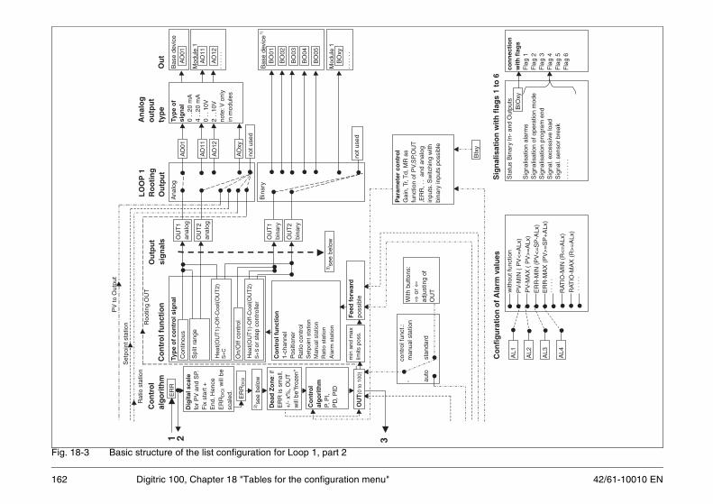
42/61-10010 EN
with
out f
unct
ion
PV
-MIN
( P
V<
=A
Lx)
PV
-MA
X (
PV
>=
ALx
)E
RR
-MIN
(P
V<
=S
P-A
Lx)
ER
R-M
AX
(P
V>
=S
P+
ALx
)..
...
RAT
IO-M
IN (
R<
=A
Lx)
RAT
IO-M
AX
(R
>=
ALx
)..
...
AL1
AL2
AL3
AL4
Co
nfi
gu
rati
on
of
Ala
rm v
alu
es
Sta
tus
Bin
ary
In-
and
Out
puts
Sig
nalis
atio
n al
arm
sS
igna
lisat
ion
of o
pera
tion
mod
eS
igna
lisat
ion
prog
ram
end
Sig
nal.
exce
ssiv
e lo
adS
igna
l.se
nsor
bre
ak..
....
.
con
nec
tio
nw
ith
fla
gs
Fla
g 1
Fla
g 2
Fla
g 3
Fla
g 4
Fla
g 5
Fla
g 6
BIO
xy
Sig
nal
isat
ion
wit
h f
lag
s 1
to 6
BIx
y
e1)
e
162 Digitric 100, Chapter 18 "Tables for the configuration menu"
Fig. 18-3 Basic structure of the list configuration for Loop 1, part 2
PV
to O
utpu
t
Set
poin
t sta
tion
Rat
io s
tatio
n
cont
rol f
unct
.:'
m
anua
l sta
tion
auto
stan
dard
With
but
tons
:⇒
or⇐
adju
stin
g of
OU
T
Par
amet
er c
on
tro
lG
ain,
Tr,T
d, M
R a
sfu
nctio
n of
PV,
SP,
OU
T,E
RR
, ..
and
anal
ogin
puts
.Sw
itchi
ng w
ithbi
nary
inpu
ts p
ossi
ble
ER
R
Dea
d Z
on
e:if
ER
R is
sm
all.
+/-
x%
, OU
Tw
ill b
e"fr
ozen
"
Co
ntr
ol
alg
ori
thm
P, P
I,P
D, P
ID
OU
T(0
to 1
00)
ER
RD
IGI
2)se
e be
low
Dig
ital
sca
lefo
r P
V a
nd S
P.F
ix s
tart
+E
nd.H
ence
ER
RD
IGIw
ill b
esc
aled
.
Typ
e o
f co
ntr
ol s
ign
alC
ontin
ous
Spl
it ra
nge
Co
ntr
ol f
un
ctio
n1-
chan
nel
Pos
ition
erR
atio
con
trol
Set
poin
t sta
tion
Man
ual s
tatio
nR
atio
sta
tion
Ala
rm s
tatio
n3)
see
belo
w
Roo
ting
OU
T
Fee
d fo
rwar
dpo
ssib
lem
in a
nd m
axlim
its p
oss.
On/
Off
cont
rol
S+
C
S+
Sor
ste
p co
ntro
ller
Ou
tpu
t
sig
na
lsC
on
tro
l fu
nct
ion
LO
OP
1R
oo
tin
gO
utp
ut
An
alo
go
utp
ut
typ
e
Ana
log
AO
01
AO
12
AO
11
AO
xy
Typ
e o
fsi
gn
al0
..20
mA
4 ..
20 m
A0
..10
V2
..10
Vno
te:V
onl
yin
mod
ules
not u
sed
OU
T2
anal
og
OU
T1
anal
og
Bin
ary
OU
T1
bina
ry
OU
T2
bina
ry
not u
sed
Bas
e de
vic
Mod
ule
1
....
..
Bas
e de
vic
AO
12
AO
11
AO
01
Mod
ule
1
....
..B
Oxy
BO
01
BO
02
BO
03
BO
04
BO
05
Ou
tC
on
tro
lal
go
rith
m
Hea
t(O
UT
1)-O
ff-C
ool(O
UT
2)
Hea
t(O
UT
1)-O
ff-C
ool(O
UT
2)
1 2 3

163
1S
ELF
TE
ST
=B
O01
BO
01
y =
2 t
o 5
SE
LFT
ES
T=
BO
0yB
O0y
xy=
11 to
16
SE
LFT
ES
T=
BO
xyB
Oxy
Q02
0C
OM
_ER
R=
NO
BO
No
ou
tpu
t
1C
OM
_ER
R=
BO
01B
O01
y =
2 t
o 5
CO
M_E
RR
=B
O0y
BO
0y
xy=
11 to
16
CO
M_E
RR
=B
Oxy
BO
xy
B06
Q01
0C
OL
OR
GR
EE
NC
olo
r g
reen
Bas
e co
lor
1C
OLO
R R
ED
Col
or r
ed
Q02
0C
OL
.CH
A.O
FFno
t co
nnec
ted
to B
I/B
O
1C
OL.
CH
A.B
X01
via
BI/
BO
01
xy=
2 to
5C
OL.
CH
A.B
Xxy
via
BI/
BO
xy
xy=
11 to
16
CO
L.C
HA
.BX
xyvi
a B
I/B
Oxy
Q03
0N
O F
LAS
HN
o fla
shin
g of
col
or
11
SE
CO
ND
Col
or c
hang
es e
ach
seco
nd
22
SE
CO
ND
S C
olor
cha
nges
eac
h 2
seco
nds
35
SE
CO
ND
S C
olor
cha
nges
eac
h 5
seco
nds
410
SE
CO
ND
S C
olor
cha
nges
eac
h 10
sec
onds
Sel
f-te
st
BINARY OUTPUTS
Err
or in
te
legr
am
com
mun
i-ca
tions
Cha
ngin
g co
lor
via
BI/
BO
Fla
shin
g co
lor
if co
lor
chan
ge is
ac
tive
DISPLAY
CONFIGURATION CONFIGURATION CONFIGURATION INSTRUMENT INSTRUMENT INSTRUMENT INSTRU
42/61-10010 EN Digitric 100, Chapter 18 "Tables for the configuration menu"
qu
estio
n /
par
amet
er
B01
Q01
1D
EU
TS
CH
Ger
man
text
s
2E
NG
LIS
HE
nglis
h te
xts
Lang
uage
3F
RA
NC
AIS
Fre
nch
text
s
4.
. .
. . .
. .
. .
. .
.
B02
Q01
0L
OC
K P
AR
OFF
No
loc
king
1LO
CK
PA
R=
BI0
1Lo
ckin
g w
ith B
I01
2LO
CK
PA
R=
BI0
2Lo
ckin
g w
ith B
I02
xy=
11 to
16
LOC
K P
AR
=B
Ixy
Lock
ing
with
BIx
y
Q02
0L
OC
K O
P=
BIO
FFN
o l
ocki
ng o
f o
per
ato
r in
terv
enti
on
s
1LO
CK
OP
=B
I01
with
BI0
1
2LO
CK
OP
=B
I02
with
BI0
2
xy=
11 to
16
LOC
K O
P=
BIx
yw
ith B
Ixy
Q03
0N
O A
LM
:QU
ITN
o a
larm
ack
no
wle
dg
emen
t w
ith
bin
ary
inp
ut
1Q
UIT
ALM
=B
I01
with
BI0
1
2Q
UIT
ALM
=B
I02
with
BI0
2
xy=
11 to
16
QU
IT A
LM=
BIx
yw
ith B
Ixy
Q04
0L
ock
Men
u O
FF
No
lock
ing
of
the
men
u k
ey
1Lo
ckM
enu.
BI0
1w
ith B
I01
2Lo
ckM
enu.
BI0
2w
ith B
I02
xy=
11 to
16
Lock
Men
u.B
Ixy
with
BIx
y
B03
Q01
0FL
AG
1_B
X_O
FF
Fla
g 1
no
t co
nn
ecte
d
1F
LAG
1_B
X01
Fla
g 1
conn
ecte
d to
BI0
1 or
BO
01
y=2
to 5
FLA
G1_
BX
0yF
lag
1 co
nnec
ted
to B
I0y
or B
O05
xy=
11 to
16
FLA
G1_
BX
xyF
lag
1 co
nnec
ted
to B
Ixy
or B
Oxy
Q02
to
Q06
Co
nfi
gu
rati
on
fo
r fla
g 2
to
5,
iden
tic
to f
lag
1
INS
TR
UM
EN
T
I
NS
TR
UM
EN
T
IN
ST
RU
ME
NT
IN
STR
UM
EN
T
LANG-UAGE
mo
d-
ule
des
crip
tion
sett
ing
s
1.menu2.menu
Fla
g1
conn
ecte
d w
ith
bina
ry-
inpu
t/ou
tput
BINARY FLAGS
Lock
ing
of a
ll op
erat
or
inte
rven
tions
B02 BINARY INPUTS
Ala
rm
ackn
owle
dge-
men
t w
ith
bina
ry in
put
Lock
ing
of t
he
men
u ke
y
Lock
ing
of
para
met
er
defin
ition
s an
d co
nfi.
leve
ls
C
ON
FIG
UR
AT
ION
C
ON
FIG
UR
AT
ION
C
ON
FIG
UR
AT
ION
CO
NF
IGU
RA
TIO
N
CONFIGURATION CONFIGURATION CONFIGURATION INSTRUMENT INSTRUMENT INSTRUMENT INSTRUMENT
B04
Q01
1L
OC
AL
OP
ER
.L
oca
l op
erat
ion
of
un
it o
nly
2LO
C/R
EM
OP
.Lo
cal o
pera
tion
of u
nit
or v
ia p
ort.
Cha
ngeo
ver
in o
pera
tion
2
3R
EM
OT
E O
PE
R.
Loca
l ope
ratio
n vi
a po
rt o
nly
4LO
CA
L +
RE
MO
TE
Loca
l ope
ratio
n eq
ually
on
unit
or v
ia p
ort
B05
Q01
0S
EL
FTS
T=
NO
BO
No
ou
tpu
t
Loca
l/Rem
ote
REMOTE OPERATION
CONFIGURATION MENT INSTRUMENT

42/61-10010 ENP
02 E
nter
P
assw
ord
Inp
ut
PA
SS
WO
RD
_ _
_ _
_E
nte
r yo
ur
pas
swo
rd (
5 d
igit
s, c
han
ge
dig
it
wit
h t
he
INT
-key
). D
efau
lt:
0
B30
P01
Mod
bus
adre
ssx
= 1
to
127
M
OD
BU
S a
dre
ss 1
to
127
Dev
ice
adre
ss f
or
Mo
db
us
(00
= g
lob
al a
dre
ss ;
1=
def
ault
val
ue)
Q02
130
0 B
AU
DB
aud
rate
300
260
0 B
AU
DB
aud
rate
600
312
00 B
AU
DB
aud
rate
120
0
424
00 B
AU
DB
aud
rate
240
0
Bau
d ra
te5
4800
BA
UD
Bau
d ra
te 4
800
696
00 B
AU
DB
aud
rat
e 96
00
719
200
BA
UD
Bau
d ra
te 1
9200
838
400
BA
UD
Bau
d ra
te 3
8400
Q03
1R
ES
ER
VE
DR
eser
ve
Pro
toco
l2
MO
DB
US
RT
U M
od
bu
s R
TU
Q04
0N
ON
Eno
par
ity t
est
Par
ity2
EV
EN
even
B30 COMMUNICATIONP
CCONFIGURATION CONFIGURATIONINSTRUMENT INSTRUMENT INSTRUMENT
164 Digitric 100, Chapter 18 "Tables for the configuration menu"
B10
Q01
0T
XT
/AL
AR
M-O
FF
Ala
rm t
exts
are
no
t d
isp
laye
d o
n f
ron
t p
anel
Ala
rm in
dica
tion
(on
the
disp
lay)
1T
XT
/ALA
RM
-ON
Ala
rm t
exts
are
dis
play
ed
Q02
0Q
UIT
_OF
FN
o a
ckn
ow
led
gem
ent
nec
essa
ry
1Q
UIT
_SIN
GLE
Onl
y th
e di
spla
yed
alar
m is
ack
now
ledg
ed
2Q
UIT
_ALL
All
alar
ms
are
ackn
owle
dged
B11
Q01
0B
12:M
AN
UA
LM
od
ule
s h
ave
to b
e en
tere
d m
anu
ally
(se
e In
stru
men
t-B
12)
USED MODULS
Mod
ule
assi
gnm
ent
1B
12:
AU
TO
MA
TIC
Uni
t st
arts
a s
can
proc
edur
e to
rec
ogni
se t
he
asse
mbl
ed m
odul
es (
Thi
s ta
kes
1 se
cond
, th
e yo
u w
ill s
ee a
gain
Q01
=0)
B12
Q01
0M
1=U
NU
SE
Dem
pty
2M
1=R
S48
5S
eria
l int
erfa
ce
4M
1=P
rofib
usD
PP
rofib
us m
odul
e
10M
1=A
I4-m
V4
x th
erm
ocou
ple
/ m
V
15M
1=A
I2-m
Am
A i
2 x
mA
with
gal
vani
c is
olat
ion
16M
1=A
I2-m
Am
V i
1 x
mA
+ 1
x t
herm
ocou
ple
with
gal
vani
c is
olat
ion
17M
1=A
I2-m
Vm
A i
1 x
ther
moc
oupl
e +
1 x
mA
with
gal
vani
c is
olat
ion
Slo
t 1
18M
1=A
I2-m
Vm
V i
2 x
ther
moc
oupl
e w
ith g
alva
nic
isol
atio
n
20M
1=A
I4-m
A p
4 x
mA
with
ele
ctro
nic
isol
atio
n
24M
1=A
I4-f
/tF
requ
ency
or
time
mea
sure
men
t
30M
1=A
I4-P
t-2L
4 x
Pt1
00 2
-wire
circ
uit
35M
1=A
I4-P
t-3/
42
x P
t100
3/4
-wire
circ
uit
40M
1=A
O3-
VO
utpu
t 3
x V
50M
1=A
O3-
mA
Out
put
3 x
20 m
A
60M
1=B
IO6-
BIN
6-fo
ld b
inar
y in
put/
outp
ut
70M
1=B
O4-
RE
LAIS
Out
put
4 x
rela
ys
Ala
rm a
ckno
w-
ledg
emen
t
ALARM HANDLING
SET MODULE TYPE
INSTRUMENT INSTRUMENT INSTRUMENT INSTRUMENT INSTRUMENT CONFIGURATION CONFIGURATION CONFIGURATION
B20
Q01
0P
AS
SW
OR
D_O
FF
Pas
swo
rd p
rote
ctio
n i
s n
ot
acti
ve
1P
AS
SW
OR
D_O
NP
assw
ord
prot
ectio
n is
act
ivat
ed
2P
AS
SW
OR
D_T
IME
Pas
swor
d pr
otec
tion
is a
ctiv
e, b
ut w
ill b
e in
activ
ed
for
30 s
aft
er r
etur
ning
to
the
oper
atin
g di
spla
y
Pas
swor
d pr
otec
tion
ASSWORD
qu
estio
n /
par
amet
er
mo
d-
ule
des
crip
tion
sett
ing
s1.menu2.menu

165
) )
3A
Ixy-
SQ
R2
Squ
are
root
ing
(line
ar b
elow
PV
O)
4A
Ixy-
TY
PE
LT
yp L
(-2
00 .
. .
1000
°C)
5A
Ixy-
TY
PE
JT
yp J
(-2
00 .
. .
1200
°C)
6A
Ixy-
TY
PE
KT
yp K
(-2
00 .
. .
1400
°C)
7A
Ixy-
TY
PE
UT
yp U
(-2
00 .
. .
600°
C)
8A
Ixy-
TY
PE
RT
yp R
( 0
. .
.17
00°C
)
9A
Ixy-
TY
PE
ST
yp S
( 0
. .
.18
00°C
)
10A
Ixy-
TY
PE
TT
yp T
(-2
00 .
. .
400°
C)
Line
aris
atio
n11
AIx
y-T
YP
E B
Typ
B (
0 .
. .
1800
°C)
12A
Ixy-
TY
PE
DT
yp D
( 0
. .
.23
00°C
)
13A
Ixy-
TY
PE
ET
yp E
( -
200
. .
.100
0°C
)
14A
Ixy-
RT
D-2
00P
t 10
0 -
200
. .
.200
°C
15A
Ixy-
RT
D-4
50P
t 10
0 0
. .
.45
0°C
16A
Ixy-
RT
D-8
00P
t 10
0 -2
00 .
. .
800°
C
17A
Ixy-
TA
B1
Tab
le 1
18A
Ixy-
TA
B2
Tab
le 2
19A
Ixy-
TA
B3
Tab
le 3
20A
Ixy-
TA
B4
Tab
le 4
Bxy AI-DEFINITION
AI-DEFINITION AI-DEFINITION AI-DEFINITION AI-DEFINITIONCONFIGURATION CONFIGURATION CONFIGURATION
42/61-10010 EN Digitric 100, Chapter 18 "Tables for the configuration menu"
Q05
0T
IME
OU
T=
OF
Fw
ithou
t m
onito
ring
11
SE
CO
ND
Tim
eou
t: 1
s
2 to
24
2 to
24
SE
CO
ND
ST
imeo
ut:
2 to
24
s
2525
SE
CO
ND
ST
imeo
ut:
25 s
P06
Pro
fibus
ad
ress
1 to
125
DP
-Sla
ve-A
dd
r 1
to 1
25P
RO
FIB
US
dev
ice
adre
ss
(1
=fa
cto
ry s
etti
ng
)
Q07
0C
FG
_I_N
ON
EN
o i
np
ut
dat
a
1C
FG
_I_1
WO
RD
Leng
th o
f in
put
data
: 1
wor
d
2C
FG
_I_2
WO
RD
SLe
ngth
of
inpu
t da
ta:
2 w
ords
3C
FG
_I_4
WO
RD
SLe
ngth
of
inpu
t da
ta:
4 w
ords
4C
FG
_I_8
WO
RD
SLe
ngth
of
inpu
t da
ta:
8 w
ords
5C
FG
_I_1
6WO
RD
SLe
ngth
of
inpu
t da
ta:
16 w
ords
Q08
0C
FG
_0_N
ON
EN
o o
utp
ut
dat
a1
CF
G_0
_1W
OR
DLe
ngth
of
outp
ut d
ata:
1 w
ord
2C
FG
_0_2
WO
RD
SLe
ngth
of
outp
ut d
ata:
2 w
ords
3C
FG
_0_4
WO
RD
SLe
ngth
of
outp
ut d
ata:
4 w
ords
4C
FG
_0_8
WO
RD
SLe
ngth
of
outp
ut d
ata:
8 w
ords
5C
FG
_A_1
6WO
RD
SLe
ngth
of
outp
ut d
ata:
16
wor
ds
1M
OD
BU
S T
imeo
ut
Mo
db
us
(Tim
e s.
Q05
)
2P
RO
FIB
US
Tim
eout
Pro
fibus
(T
ime
s. Q
05)
3M
OD
+ P
RO
FIB
US
Tim
eout
Mod
bus
and
Pro
fibus
Def
ault
DP
co
nfig
urat
ion
Inpu
t da
ta
Q09
Tim
eou
t fo
r M
odbu
s/
Pro
fibus
B30 COMMUNICATION
Def
ault
DP
co
nfig
urat
ion
Out
put
data
Tim
eout
for
m
issi
ng
tele
gram
s on
bu
s
TION CONFIGURATION CONFIGURATION INSTRUMENT INSTRUMENT INSTRUMENT
qu
estio
n /
par
amet
er
mo
d-
ule
des
crip
tion
sett
ing
s
1.menu2.menu
Bxy
(B
01
to B
14)
Q01
0U
NU
SE
DIn
put
unus
ed (
fact
ory
set
tin
g f
or
AI0
2, A
I11
to
AI1
4).
AI0
1can
not
be d
isab
led.
1A
Ixy
0 .
. 20
mA
0 .
. 20
mA
2A
Ixy
4 .
. 20
mA
4 .
. 20
mA
(d
efau
lt f
or
AI0
1)
3A
Ixy
TC
The
rmoc
oupl
e
4A
Ixy
RT
D-2
WP
t100
as
2-w
ire c
ircui
t
5A
Ixy
RT
D-3
WP
t100
as
3-w
ire c
ircui
t
6A
Ixy
RT
D-4
WP
t100
as
4-w
ire c
ircui
t (n
ot f
or A
I01)
Sig
nal r
ange
7A
Ixy
PO
T.1
50T
elet
rans
mitt
er n
omin
al 1
50 O
hm (
75 t
o 20
0 O
hm
8A
Ixy
PO
T.1
500
Tel
etra
nsm
itter
, no
m.
1500
Ohm
(0,
75 t
o 2
kOhm
9 (x
y>10
)A
Ixy
Per
iod
Tim
e m
easu
rem
ent
10 (
xy>
10)
Aix
y F
RE
Q 1
0 k
Fre
quen
cy m
easu
rem
ent
up t
o 10
kH
z
11 (
xy>
10)
AIx
y F
RE
Q 2
0 k
Fre
quen
cy m
easu
rem
ent
up t
o 20
kH
z
12 (
xy>
10)
Pul
seP
ulse
cou
nter
13 (
xy>
10)
Incr
emnt
Incr
em.
tran
sm.
and
dire
ct.
of r
otat
. (2
inpu
ts)
14 (
xy>
10)
Incr
em.0
Incr
em.
tran
sm.
with
zer
o tr
ansm
. (3
inpu
ts)
Q02
1A
Ixy-
LIN
EA
Rli
nea
r
2A
Ixy-
SQ
R1
Squ
are
root
ing
(sw
itch-
off
belo
w P
VO
)
AI-
DE
FIN
ITIO
N
A
I-D
EF
INIT
ION
AI-
DE
FIN
ITIO
N
Bxy AI-DEFINITION
AI-DEFINITION AI-DEFINITION AI-DEFINITION CONFIGURATION CONFIGURATION CONFIGURATIO

42/61-10010 EN
(squ
are
root
)In
pu
tA
Ixy-
SQ
RF
acto
ry s
etti
ng
0.0
P0
9 T
-Filt
er
time
cons
tan
tIn
pu
tA
Ixy-
FIL
TE
RT
.R
ang
e:
0 to
12
0 s
; R
eso
luti
on
: 1
s
Fac
tory
se
ttin
g 0
s (
0.00
.00
h)
1A
Ixy
-FA
IL.V
AL
Def
ault
val
ue
2A
Ixy
-OLD
VA
L.H
old
las
t m
eas
ured
val
ue
P1
1 D
ef.
valu
eIn
pu
tA
Ixy
-FA
IL V
AL
Ran
ge:
0 t
o 1
02%
; R
eso
luti
on
0.0
001
Fac
tory
set
tin
g 1
02%
Q1
2 0
AIx
y-E
RR
=N
.BO
No
me
ssag
e
1A
Ixy-
ER
R=
BO
01B
O01
mn
=2
to 5
AIx
y-E
RR
=B
Om
nB
Om
n
mn
=11
to
16
AIx
y-E
RR
=B
Om
nB
Om
n
Q13
0A
Ixy=
N.F
LN
o e
rro
rs t
o f
lag
1A
IxyE
RR
=F
LG0
1vi
a F
lag
1
2A
IxyE
RR
=F
LG0
2vi
a F
lag
2
3A
IxyE
RR
=F
LG0
3vi
a F
lag
3
4A
IxyE
RR
=F
LG0
4vi
a F
lag
4
5A
IxyE
RR
=F
LG0
5vi
a F
lag
5
6A
IxyE
RR
=F
LG0
6vi
a F
lag
6
Bxy AE-DEFINITION
Q1
0 D
efau
lt va
lue
stra
tegy
fo
r s
enso
r fa
ult
Err
or m
essa
ge
via
Fla
g
Err
or m
essa
ge
via
BO
mn
CCONFIGURATION CONFIGURATION CONFIGUAI-DEFINITION AI-DEFINITION AI-DEFINITION
166 Digitric 100, Chapter 18 "Tables for the configuration menu"
qu
estio
n /
par
amet
er
mo
d-
ule
des
crip
tion
sett
ing
s
1.menu2.menu
Q03
0A
Ixy-
NO
DIM
no
dim
ensi
on
1A
Ixy
DIM
US
ER
4-di
gits
, us
er-d
efin
ed
2A
Ixy
DIM
%%
3A
Ixy
DIM
°C
°C
4A
Ixy
DIM
°F
°F a
utom
atic
ran
ge
switc
h-ov
er
5A
Ixy
DIM
mb
arm
bar
Dim
ensi
on
for
6A
Ixy
DIM
bar
bar
AIx
y7
AIx
y D
IM m
3/h
m3/
h
8A
Ixy
DIM
kg
/hkg
/h
9A
Ixy
DIM
t/h
t/h
10A
Ixy
DIM
l/h
l/h
11A
Ixy
DIM
hl/
hhl
/h
12A
Ixy
DIM
pH
pH
13A
Ixy
DIM
mm
mm
14A
Ixy
DIM
mm
15A
Ixy
DIM
m/h
m/h
16A
Ixy
DIM
mV
mV
17A
Iy D
IM V
V
18A
Ixy
DIM
mA
mA
19A
Ixy
DIM
AA
20A
Ixy
DIM
ss
21A
Ixy
DIM
Hz
Hz
22A
Ixy
DIM
kH
zkH
z
P04
Ent
er s
elf
def.
dim
ensi
on
Inp
ut
AIx
y-U
SE
R D
IM _
_ _
_E
dit
dim
ensi
on
in
th
e d
isp
lay
(if
Q0
3=1)
P05
Sta
rt o
f sc
alin
gIn
pu
tA
Ixy-
SC
AL
.LO
Ran
ge:
-99
99 t
o 9
9999
; R
eso
luti
on
: 1
F
acto
ry s
etti
ng
0%
of
me
asu
rin
g r
ang
eP
06 E
nd o
f sc
alin
gIn
pu
tA
Ixy-
SC
AL
.HI
Ran
ge:
-99
99 t
o 9
9999
; R
eso
luti
on
: 1
F
acto
ry s
etti
ng
: 10
0%
of
mea
suri
ng
ran
ge
Q07
0A
Ixy
NO
NE
no r
efer
enc
e ju
nctio
n
1A
Ixy
TR
EF
IN
Tin
tern
al
2A
Ixy
TR
EF
0C
exte
rnal
0 °
C
3A
Ixy
TR
EF
20C
exte
rna
l 20
°C
4A
Ixy
TR
EF
50C
exte
rna
l 50
°C
5A
Ixy
TR
EF
60C
exte
rna
l 60
°C
P08
Val
ue P
VO
R
ang
e: -
9999
to
+99
999
, R
eso
luti
on
0.0
1
Bxy AI-DEFINITION
Ref
eren
ce
junc
tion
com
pens
atio
n
Bxy AE-DEFINITION
RATION CONFIGURATION CONFIGURATION CONFIGURATION CONFIGURATION AI-DEFINITION AI-DEFINITION AI-DEFINITION AI-DEFINITION
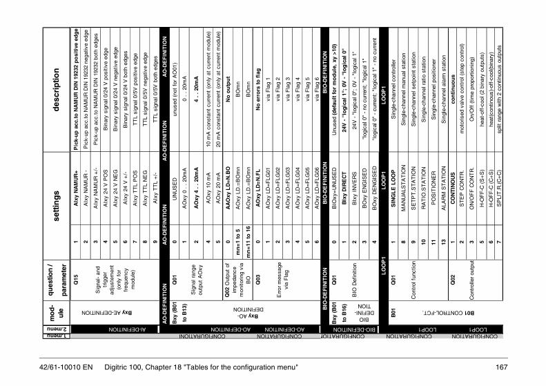
167
3B
Oxy
EN
GIS
ED
"log
ical
0"
- no
cur
rent
; "l
ogic
al 1
"
4B
Oxy
DE
NG
ISE
D"l
ogic
al 0
" -
curr
ent;
"lo
gica
l 1"
- no
cur
rent
B01
Q01
1S
ING
LE
LO
OP
Sin
gle-
chan
nel c
ontr
olle
r
8M
AN
UA
LST
AT
ION
Sin
gle-
chan
nel m
anua
l sta
tion
Con
trol
fun
ctio
n9
SE
TP
T.S
TA
TIO
NS
ingl
e-ch
anne
l set
poin
t st
atio
n
10R
AT
IO.S
TA
TIO
NS
ingl
e-ch
anne
l rat
io s
tatio
n
11P
OS
ITIO
NE
RS
ingl
e-ch
anne
l pos
ition
er
13A
LAR
M S
TA
TIO
NS
ingl
e-ch
anne
l ala
rm s
tatio
n
Q02
1C
ON
TIN
OU
Sco
nti
nu
ou
s
2S
TE
P C
ON
TR
. m
otor
ised
val
ve c
ontr
ol (
step
con
trol
)
Con
trol
ler
outp
ut3
ON
/OF
F C
ON
TR
.O
n/O
ff (
time
prop
ortio
ning
)
5H
-OF
F-C
(S
+S
)he
at-o
ff-c
ool (
2 bi
nary
out
puts
)
6H
-OF
F-C
(C
+S
)he
at(c
ontin
ous)
-off
-coo
l(bin
ary)
7S
PLI
T.R
.(C
+C
)sp
lit r
ange
with
2 c
ontin
uous
out
puts
BIODEFIN
TION
LO
OP
1
LO
OP
1
LO
OP
1
B01 CONTROL-FCT.
BIO-DE LOOP1 LOOP1 CONFIGURATION CONFIGURATION CO
42/61-10010 EN Digitric 100, Chapter 18 "Tables for the configuration menu"
Q15
1A
Ixy
NA
MU
R+
Pic
k-u
p a
cc.t
o N
AM
UR
DIN
192
32 p
osi
tive
ed
ge
2A
Ixy
NA
MU
R -
Pic
k-up
acc
.to
NA
MU
R D
IN 1
9232
neg
ativ
e ed
ge
3A
Ixy
NA
MU
R +
/-P
ick-
up a
cc.t
o N
AM
UR
DIN
192
32 b
oth
edge
s
4A
Ixy
24 V
PO
SB
inar
y si
gnal
0/2
4 V
pos
itive
edg
e
5A
Ixy
24 V
NE
GB
inar
y si
gnal
0/2
4 V
neg
ativ
e ed
ge
6A
Ixy
24 V
+/-
Bin
ary
sign
al 0
/24
V b
oth
edge
s
7A
Ixy
TT
L P
OS
TT
L si
gnal
0/5
V p
ositi
ve e
dge
8A
Ixy
TT
L N
EG
TT
L si
gnal
0/5
V n
egat
ive
edge
9A
Ixy
TT
L +
/-T
TL
sign
al 0
/5V
bot
h ed
ges
Bxy
(B
01Q
010
UN
US
ED
un
used
(no
t fo
r A
O01
)
to B
13)
1A
Oxy
0 .
. 2
0mA
0 .
. 2
0mA
Sig
nal r
ange
ou
tput
AO
xy2
AO
xy 4
. .
20m
A 4
. .
20m
A
4A
Oxy
10
mA
10 m
A c
onst
ant
curr
ent
(onl
y at
cur
rent
mod
ule)
5A
Oxy
20
mA
20 m
A c
onst
ant
curr
ent
(onl
y at
cur
rent
mod
ule)
0A
AO
xy L
D=
N.B
ON
o o
utp
ut
mn
=1
to 5
AO
xy L
D.=
BO
mn
BO
mn
mn
=11
to
16
AO
xy L
D.=
BO
mn
BO
mn
Q03
0A
Oxy
LD
=N
.FL
No
err
ors
to
fla
g
1A
Oxy
LD
=F
LG01
via
Fla
g 1
2A
Oxy
LD
=F
LG02
via
Fla
g 2
3A
Oxy
LD
=F
LG03
via
Fla
g 3
4A
Oxy
LD
=F
LG04
via
Fla
g 4
5A
Oxy
LD
=F
LG05
via
Fla
g 5
6A
Oxy
LD
=F
LG06
via
Fla
g 6
Q02
Out
put
of
impe
danc
e m
onito
ring
via
BO
AO
-DE
FIN
ITIO
N
AO
-DE
FIN
ITIO
N
AO
-DE
FIN
ITIO
N
AO
-DE
FIN
ITIO
N
Err
or m
essa
ge
via
Fla
g
Sig
nal-
and
trig
ger
adju
stem
ent
(onl
y fo
r fr
eque
ncy
mod
ule)
Bxy AE-DEFINITIONBxy AO-
DEFINITION
AO-DEFINITION AO-DEFINITION AI-DEFINITION CONFIGURATION CONFIGURATIONI
qu
estio
n /
par
amet
er
mo
d-
ule
des
crip
tion
sett
ing
s1.menu2.menu
Bxy
(B
01Q
010
BIO
xy=
UN
US
ED
Unu
sed
(def
ault
fo
r m
od
ule
, xy
>10
)
to B
16)
1B
Ixy
DIR
EC
T24
V -
"lo
gic
al 1
"; 0
V -
"lo
gic
al 0
"
BIO
Def
initi
on2
BIx
y IN
VE
RS
24V
- "
logi
cal 0
"; 0
V -
"lo
gica
l 1"
I-B
IO-D
EF
INIT
ION
B
IO-D
EF
INIT
ION
BIO
-DE
FIN
ITIO
N
FINITIONNFIGURATION

42/61-10010 ENP
ID C
ON
TR
OL
Pro
port
iona
l-Int
egra
l-Diff
eren
tial a
lgor
ithm
1D
IFF
. P
Vco
ntr
oll
ed v
aria
ble
2D
IFF
. E
RR
OR
Con
trol
ler
devi
atio
n
Q05
1D
IFF
.BIP
OL
AR
bip
ola
r
Diff
eren
tiatio
n2
DIF
F.P
OS
ITIV
only
pos
itive
cha
nges
3D
IFF
.NE
GA
TIV
only
neg
ativ
e ch
ange
s
Q06
0N
O S
TA
RT
UP
inac
tiv
Q07
0G
CO
NS
T.
off
1G
LIN
. P
Vlin
ear
from
PV
2G
LIN
. S
Plin
ear
from
SP
3G
LIN
. O
UT
linea
r fr
om O
ut4
G L
IN.
ER
Rlin
ear
from
Err
G (
Gai
n) c
ontr
ol5
G L
IN.
|ER
R|
linea
r fr
om |E
rr|
7G
TA
Bm
PV
via
tabl
e m
of
PV
8G
TA
Bm
SP
via
Tab
le m
of
W9
G T
AB
m O
UT
via
Tab
le m
of
Y
10G
TA
Bm
ER
Rvi
a T
able
m o
f X
w
11G
TR
AN
S.A
LM4
G s
witc
hing
by
AL4
(se
e LO
OP
1-B
08-Q
04 a
nd
PA
RA
ME
TE
R-L
OO
P1-
94)
12G
TR
AN
S=
BIx
G s
witc
hing
by
BIx
(se
e Q
08)
13G
CO
NT
R=
AIx
G-li
near
fro
m A
Ix (
see
Q09
)
B02 CONTR.PARAM
Q03
Diff
eren
tial
shar
e co
nnec
ted
with
B02 CONTR.PA
CONFIGURATION CONFIGURATION CONFIGURATION LOOP1 LOOP1 LOOP1 LOOP1
168 Digitric 100, Chapter 18 "Tables for the configuration menu"
Q03
1M
: CH
AR
.-DIR
.
Man
ual
char
acte
ristic
2M
: C
HA
R.-
INV
.
(not
val
id f
or
posi
tione
r an
d st
ep c
ontr
olle
r)3
M:
INV
.-D
IR.
4M
: D
IR.-
DIR
5M
: IN
V.-
INV
.
6M
: D
IR.-
INV
.
0N
O P
OS
.FB
AC
KN
O p
osi
tion
-feed
bac
k si
gna
l1
PO
S.F
BC
K=
AI0
1A
I01
2P
OS
.FB
CK
=A
I02
AI0
2
n=11
to 1
3P
OS
.FB
CK
=A
InA
In
0S
EL
FTU
NE
OF
FO
ff1
Sel
ftun
e O
nO
n
Q04
po
sitio
n-fe
edba
ck s
igna
l an
d di
spla
y
The
out
put
valu
es O
UT
1 or
(O
UT
1 an
d O
UT
2) in
rel
atio
n to
the
out
put
valu
e O
UT
of
the
PID
-alg
orith
m (
at a
nalo
g ba
r) .
The
val
ues
OU
T1
or O
UT
2 ar
e fo
r co
ntin
ous
outp
uts
dire
ctly
und
erst
anda
ble.
If
ther
e ar
e bi
nary
out
puts
the
val
ues
will
be
repr
esen
ted
by t
he k
eyin
g ra
tio T
on/T
cycl
of
the
outp
ut.
Q05
Sel
f-tu
ning
B01 CONTROL-FUNCTION
URATION CONFIGURATION CONFIGURATION CONFIGURATION
100% 0%
0%50
%10
0%OU
T
OU
T 1
OU
T2
100% 0%
0%50
%10
0%
OU
TO
UT
1O
UT
2
100% 0%
0%50
%
OU
TO
UT
1O
UT
2
100%
OU
T1
100% 0%
OU
T
0%50
%10
0%
100% 0%
0%50
%10
0%
OU
T
OU
T1
100% 0%
0%50
%10
0%
OU
T
OU
T1
OU
T2
cont
-in
ous
+
On/
Off
co
ntro
l-le
r
Spl
it ra
nge
+
H
-Off
-Cco
ntro
ller
P1 LOOP1 LOOP1 LOOP1 LOOP1
B02
1A
:CH
AR
.-D
IR.
Aut
omat
ic "
dire
ct"
actio
n ch
arac
teris
tic
2A
:CH
AR
.-IN
V.
Au
tom
atic
"in
vers
e" a
ctio
n c
har
acte
rist
ic
Q02
1P
CO
NT
RO
LP
ropo
rtio
nal a
lgor
ithm
2P
I C
ON
TR
OL
Pro
po
rtio
nal
-In
teg
ral
alg
ori
thm
3P
D C
ON
TR
OL
Pro
port
iona
l-Diff
eren
tial a
lgor
ithm
4
Q01
Aut
omat
ic
char
acte
ristic
Con
trol
-al
gorit
hm
RAM.
CONFIGU LOOP1
qu
estio
n /
par
amet
er
mo
d-
ule
des
crip
tion
sett
ing
s
1.menu2.menu

169
10E
XT
R.S
P.
MA
XE
xtre
me
valu
e S
P:
Err
= I
C1
- M
ax (
SP
1,IC
2,IC
3)11
EX
TR
.SP
. M
INE
xtre
me
valu
e S
P:
Err
= I
C1
- M
in (
SP
1,IC
2,IC
3)
Q02
13
CO
MP
ON
EN
T01
PV
-SP
P
Vh
PV
SP
23
CO
MP
ON
EN
T02
PV
+P
Vh-
SP
P
V
P
V+
PV
h
SP
33
CO
MP
ON
EN
T03
PV
+P
Vh-
SP
P
Vh
PV
SP
43
CO
MP
ON
EN
T04
PV
+P
Vh-
SP
P
Vh
PV
+P
Vh
SP
53
CO
MP
ON
EN
T05
PV
+P
Vh-
SP
P
V+
PV
h
PV
+P
Vh
SP
63
CO
MP
ON
EN
T06
PV
+P
Vh-
SP
P
Vh
PV
SP
7
3 C
OM
PO
NE
NT
07P
V+
PV
h-S
P
PV
+P
Vh
PV
S
P8
3 C
OM
PO
NE
NT
08P
V-(
SP
+P
Vh)
PV
PV
SP
93
CO
MP
ON
EN
T09
PV
-(S
P+
PV
h)
P
V
P
V
S
P+
PV
h
D:
D (
Diff
eren
tial)-
shar
e co
nnec
ted
to
PV
an,
PV
di:
Ana
log-
+ D
igita
l dis
play
for
PV
S
Pan
: A
nalo
g di
spla
y fo
r S
P
B03 INPUT CIRCUIT
Mul
ti co
mpo
nent
st
ruct
ure
Mul
ti co
mpo
nent
str
uctu
re (
subm
enu
of Q
01-2
)P
Vh=
Con
st2*
(IC2+
Con
st3*
IC3)
; P
V=
Con
st1*
IC1
ER
R =
D
P
Van
,PV
di
SP
an
CONFIGURATION CONFIGURATION COLOOP1 LOOP1 LOOP1 LOO
42/61-10010 EN Digitric 100, Chapter 18 "Tables for the configuration menu"
qu
estio
n /
par
amet
er
mo
d-
ule
des
crip
tion
sett
ing
s
1.menu2.menu
Q08
0G
TR
AN
S=
OF
FN
o G
-Ch
ang
eove
r1
G T
RA
NS
=B
I01
Cha
ngeo
ver
with
BI0
12
G T
RA
NS
=B
I02
Cha
ngeo
ver
with
BI0
2xy
=11
to
16
G T
RA
NS
=B
Ixy
Cha
ngeo
ver
with
BIx
y
Q09
0G
AIx
=O
FF
No
G c
on
tro
l b
y A
Ix1
G C
ON
TR
=A
I01
cont
rolle
d by
AI0
12
G C
ON
TR
=A
I02
cont
rolle
d by
AI0
2xy
=11
to
14
G C
ON
TR
=A
Ixy
cont
rolle
d by
AIx
y
Q10
to
Q12
Q13
to
Q15
Q16
to
Q18
Q28
0F
F:A
DD
=O
FF
No
dis
turb
ance
var
iab
le f
eed
forw
ard
to
Ou
t1
FF
:AD
D=
AI0
1A
I01
adds
to
Out
2 F
F:A
DD
=A
I02
AI0
2 ad
ds t
o O
utxy
=11
to
14
FF
:AD
D=
AIx
yA
Ixy
adds
to
Out
91F
F:A
DD
=S
C1
Out
put
stat
e co
rrec
tion
1 ad
ds t
o O
ut
Q29
1F
F:L
INE
AR
lin
ear
2F
F:D
IF.B
IPO
Ldi
ffer
ent.
bip
olar
3F
F:D
IF.P
OS
IT.
diff
eren
t. u
nipo
lar
posi
tive
chan
ges
4F
F:D
IF.N
EG
AT
.di
ffer
ent.
uni
pola
r ne
gativ
e ch
ange
s
B03
Q01
0N
o IN
PU
T C
IRC
With
out
inpu
t si
gnal
con
nect
ion
(sta
tions
)
1O
NE
PV
Fix
ed v
alu
e E
rr =
IC
1-S
P
23
CO
MP
ON
EN
TM
ultic
ompo
nent
s (s
ee s
ubm
enu
Q02
)
E
rr =
fun
ctio
n (I
C1,
IC
2, I
C3)
3M
ULT
IPLI
CA
TE
Mul
tiplic
atio
n
Err
= I
C1
x (
IC2
+ C
onst
3 x
IC3
) -
SP
4R
AT
IO1
(A/B
)ra
tio1
Err
= I
C1
- (
R x
( I
C2
+ C
onst
3 x
IC3
) +
Bia
s +
IC
4 )
5F
IX/R
AT
IO1
Fix
ed v
alue
/rat
io1
switc
habl
e (1
<->
4)
6R
AT
IO2
(A/(
A+
B))
ratio
2
E
rr =
IC
1 -
[(R
/ (
1 -
R))
x (
IC2
+ C
onst
3 x
IC3)
+ B
ias
+ I
C4]
7F
IX/R
AT
IO2
Fix
ed v
alue
/rat
io2
switc
habl
e (1
<->
6)
8E
XT
R.P
V.
MA
XE
xtre
me
valu
e P
V:
Err
= M
ax (
IC1,
....
.IC
3) -
SP
9E
XT
R.P
V M
INE
xtre
me
valu
e P
V:
Err
= M
in (
IC1,
....
.IC
3) -
SP
MR
(m
anua
l res
et)
cont
rol (
like
G,
see
Q7
to Q
9)
B03 INPUT CIRCUIT
Dis
turb
ance
V
aria
ble
Out
+Z
Td
(der
ivat
ive
time)
con
trol
( li
ke G
, se
e Q
7 to
Q9)
G-c
ontr
ol.A
Ix
Tr
(res
et t
ime)
con
trol
(lik
e G
, se
e Q
7 to
Q9)
)
G (
Gai
n)
chan
geov
er
Inpu
t ci
rcui
t (p
aram
eter
s C
onst
1,
Con
st2,
C
onst
3, C
onst
4 an
d B
IAS
see
: P
AR
AM
ET
ER
/ LO
OP
1/10
1 to
10
4 an
d 11
7)
B02 CONTR.PARAM.
Dis
turb
ance
va
riabl
e ad
ds t
o O
ut
NFIGURATION CONFIGURATION CONFIGURATION CONFIGURATIONP1 LOOP1 LOOP1 LOOP1 LOOP1 LOOP1

42/61-10010 EN
P14
Sca
ling-
fact
or R
atio
Inp
ut
Rat
io F
acto
r
Fac
tory
set
tin
g:
SP
= 1
00.0
R
ange
-99
99 t
o 99
999
1A
NA
LO
G P
V,S
PP
V1
and
R x
PV
22
AN
ALO
G R
AT
IOR
act
and
Rse
t
P16
Val
ue
Dis
play
for
0%
Inp
ut
AN
AL
OG
0%
Ana
log.
0% s
. B
03-Q
15
valu
e of
ana
log
disp
lay
for
0%
F
acto
ry s
eetin
g 0.
0 R
ange
-99
99 t
o 99
999
P17
Val
ue
disp
lay
for
100%
Inp
ut
AN
AL
OG
.100
%A
nalo
g.10
0% s
. B
03-Q
15
va
lue
of a
nalo
g di
spla
y fo
r 10
0%
Fac
tory
see
ting
100.
0 R
ange
-99
99 t
o 99
999
0P
V,R
=N
O A
ON
ot
rou
ted
to
ou
tpu
t
1P
V,R
=A
O01
Ana
log
outp
ut A
O01
xy=
11 t
o 1
3P
V,R
=A
Oxy
Ana
log
outp
ut A
Oxy
B04
Q01
0IC
1=0%
IC1
= f
ixed
val
ue 0
%
1IC
1=A
I01
IC1
con
nec
ted
to
AI0
1
2IC
1=A
I02
IC1
conn
ecte
d to
AI0
2
xy=
11 t
o 1
4IC
1=A
Ixy
IC1
conn
ecte
d to
AIx
y
91IC
1=S
C_1
Out
put
of t
he s
tate
cor
rect
ion
1
94IC
1=T
AB
4O
utpu
t of
Tab
le 4
100
IC1=
100%
Fix
ed v
alue
100
%
Q18
PV
ret
rans
-m
issi
on c
urre
nt
cont
rol v
aria
ble
or R
act
to
B03 INPUT CIRCUIT
Q15
Ana
log
disp
lay
for
ratio
Rou
ting_
IC1.
IC1
of in
put
circ
uit
conn
ecte
d w
ith:
B04 ROUTING_IC-AI
CONFIGURATION CONFIGURATION CONFIGLOOP1 LOOP1 LOOP1
170 Digitric 100, Chapter 18 "Tables for the configuration menu"
1IN
D.E
RR
:%in
per
cen
t (1
00%
= m
easu
rin
g r
ang
e o
f IC
1)
2IN
D.E
RR
:EU
in E
U
Q04
0P
,S N
O D
IMW
ith
ou
t d
imen
sio
n1
P,S
US
ER
DIM
4-di
git
dim
ensi
on,
defin
able
2P
,S D
IM %
%
3P
,S D
IM °
C°C
. .
. .
P,S
DIM
. .
. .
see
AI
defin
ition
Q03
22P
,S D
IM k
Hz
kHz
P05
Edi
t th
e us
er d
imen
sion
Inp
ut
Lm
-US
ER
-DIM
. _
_ _
_E
dit
ing
of
the
4 d
igit
Use
r D
imen
sio
n i
n L
oo
p 1
(on
ly i
f Q
04=
1)Q
060
P,S
100
00.
0 de
cim
al p
lace
s
1P
,S 1
000.
01
deci
mal
pla
ces
2P
,S 1
00.0
02
dec
imal
pla
ces
3P
,S 1
0.00
03
deci
mal
pla
ces
4P
,S 1
.000
04
deci
mal
pla
ces
5P
,S F
LOA
T.P
T.
Dis
play
of
float
ing
deci
mal
poi
nt
P
07 S
tart
sc
alin
g fo
r P
V,S
PIn
pu
tD
IG.I
ND
.LO
.S
tart
of
the
scal
e of
PV
and
SP
.
F
acto
ry s
etti
ng
: S
P =
0,0
R
ange
: -9
999
to 9
9999
P08
End
sc
alin
g fo
r P
V,S
PIn
pu
tD
IG.I
ND
.HI.
End
of
the
scal
e of
PV
and
SP
.
Fac
tory
set
tin
g:
SP
= 1
00,0
Ran
ge:
-999
9 to
999
99
1R
AT
IO I
S/S
PR
act
and
Rse
t
2E
S1,
RA
TIO
*ES
2IC
1 an
d R
x I
C2
0R
NO
DIM
wit
ho
ut
dim
ensi
on
(e.
g.
rati
o)
1R
US
ER
DIM
4-di
git
dim
ensi
on f
reel
y de
finab
le
2R
DIM
%%
(F
acto
ry s
etti
ng
fo
r ra
tio
2)
P11
Edi
t th
e us
er d
imen
sion
fo
r ra
tioIn
pu
tR
-US
ER
-DIM
. _
_ _
_E
dit
ing
of
the
4 d
igit
Use
r D
imen
sio
n i
n L
oo
p
m (
on
ly i
f Q
10=
1)
Q12
0R
100
00.
0 de
cim
al p
lace
s
1R
100
0.0
1 de
cim
al p
lace
s
2R
100
.00
2 d
ecim
al p
lace
s3
R 1
0.00
03
deci
mal
pla
ces
4R
1.0
000
4 de
cim
al p
lace
s
5R
FLO
AT
.PT
.D
ispl
ay o
f flo
atin
g de
cim
al p
oint
P13
Sca
ling-
offs
et R
atio
Inp
ut
Rat
io O
ffse
tO
ffse
t ra
tio d
ispl
ay;
Fac
tory
set
tin
g:
SP
= 0
.0;
Ran
ge:
-999
9 bi
s 99
999
Dig
ital s
calin
g of
rat
io d
ispl
ay f
or r
atio
R=
1
Q09
Dig
ital
disp
lay
of r
atio
B03 INPUT CIRCUIT B03 INPUT CIRCUIT
Dec
imal
pla
ces
for
PV
,SP
Q10
Dim
ensi
on
for
ratio
(al
so
for
ratio
and
m
ultip
licat
ion)
Q03
Dis
play
of
the
cont
rol
devi
atio
n
Dim
ensi
on f
or
cont
rol v
aria
ble
and
setp
oint
(n
ot r
atio
and
m
ultip
licat
ion)
Dec
imal
pla
ces
for
Rat
io-
disp
lay
URATION CONFIGURATION CONFIGURATION CONFIGURATION LOOP1 LOOP1 LOOP1 LOOP1 LOOP1
qu
estio
n /
par
amet
er
mo
d-
ule
des
crip
tion
sett
ing
s
1.menu2.menu

1710
SP
.PR
GR
M=
OF
Fo
ff
1S
P.P
RG
RM
=O
Non
1S
P.I
ND
=T
AR
GT
Dis
pla
y o
f th
e ta
rget
ed s
etp
oin
t
2S
P.I
ND
=R
AM
PD
ispl
ay o
f th
e fa
lsifi
ed v
alue
.The
tar
gete
d se
tpoi
nt
is d
ispl
ayed
dur
ing
SP
adj
ustm
ent,
3 s
afte
r th
e la
st a
ctua
ting
key
of t
he c
urre
nt s
etpo
int.
Q10
0
SP
.AC
T=
NO
AO
Set
po
int
no
t o
n o
utp
ut
1S
P.A
CT
=A
O01
Ana
log
outp
ut A
O01
2S
P.A
CT
=A
O02
Ana
log
outp
ut A
O02
xy=
11 t
o 1
3S
P.A
CT
=A
Oxy
Ana
log
outp
ut A
Oxy
Q08
P
rogr
amm
er
setp
oint
Q09
D
ispl
ay o
f se
tpoi
nt
fals
ified
te
mpo
raril
ly b
y ra
mp
Cur
rent
set
poin
t to
AO
x
B05 SETPOINTS
LOOP1 LOO CONFIGURATION CONFIGU
Q11
0
SP
.TR
AN
S=
OF
Fo
ff
1S
P1-
SP
2 B
Ix
2S
P1-
SP
4 B
Iy
Set
poin
t ch
ange
over
BIx
B
Iy
S
etpo
int
0
0
SP
1
1
0
SP
2
0
1
SP
3
1
1
SP
4
D
efin
ition
BIx
, B
Iy s
ee B
09-Q
13 ,
Q14
LOOP1 LOOP1 CONFIGURATION
42/61-10010 EN Digitric 100, Chapter 18 "Tables for the configuration menu"
qu
estio
n /
par
amet
er
mo
d-
ule
de
scri
pti
on
sett
ing
s
1.menu2.menu
Q02
R
outin
g_IC
2Q
03
Rou
ting_
IC3
Q04
R
outin
g_IC
4
Q05
0T
AB
4=N
O A
IN
ot
ind
ivid
ual
ly u
sed
1T
AB
4=A
I01
AI0
1
2T
AB
4=A
I02
AI0
2
xy=
11 t
o14
TA
B4=
AIx
yA
Ixy
Q06
Rou
ting_
B1
0B
1=N
O B
IB
1 u
nu
sed
1B
1=B
I01
BI0
1
2B
1=B
I02
BI0
2
xy=
11 t
o 1
6B
1=B
Ixy
BIx
y
B05
Q01
0S
P1.
INT
=O
FF
off
Set
poin
t 1
of
cont
rolle
r 1
1S
P1.
INT
=O
Nca
n o
nly
be
chan
ged
per
key
s o
r in
terf
ace
2S
P1.
INT
=T
RA
CK
follo
ws
curr
ent
setp
oint
0S
P1=
NO
PA
RA
Mn
o
1S
P1=
PA
RA
Mye
s is
not
tra
cked
Q03
0S
P2.
INT
=O
FF
off
1S
P2.
INT
=O
NO
nly
chan
geab
le p
er k
ey o
r in
terf
ace
2S
P2=
PA
RA
M.F
LXO
nly
oper
atab
le a
t pa
rale
vel D
elta
onl
y
3S
P2=
DE
LTA
.PA
Rop
erat
able
at
para
leve
l
4S
P2=
RA
TIO
.TR
KS
R1
follo
ws
actu
al r
atio
Q04
0S
P3.
INT
=O
FF
off
1S
P3.
INT
=O
NO
nly
chan
geab
le p
er k
ey o
r in
terf
ace
2S
P3=
PA
RA
M.F
LXO
nly
to b
e op
erat
ed a
t pa
ram
eter
men
u
3S
P3=
DE
LTA
.PA
Rde
lta o
nly
to b
e op
erat
ed a
t pa
ram
eter
men
u
4S
P3=
RA
TIO
.TR
KS
R2
trac
ks t
he a
ctua
l Rat
io
Q05
0S
P4.
INT
=O
FF
off
1S
P4.
INT
=O
NO
nly
chan
geab
le p
er k
ey o
r in
terf
ace
2S
P4=
PA
RA
M.F
LXO
nly
to b
e op
erat
ed a
t pa
ram
eter
men
u
3S
P4=
DE
LTA
.PA
Rde
lta o
nly
to b
e op
erat
ed a
t pa
ram
eter
men
u
4S
P4=
RA
TIO
.TR
KS
R3
trac
ks t
he a
ctua
l Rat
io
Q06
0
SP
.EX
T=
OF
Fo
ff1
SP
.EX
T=
AI0
1A
I01
2S
P.E
XT
=A
I02
AI0
2
xy=
11 t
o14
SP
.EX
T=
AIx
yA
Ixy
0S
P.C
OM
P=
OF
Fo
ff
1S
P.C
OM
P=
ON
on
Ro
uti
ng
IC
3: P
rin
cip
le i
s th
e sa
me
as f
or
IC1
(see
Q01
)
Ro
uti
ng
IC
4: P
rin
cip
le i
s th
e sa
me
as f
or
IC1
(see
Q01
)
B05 SETPOINTSB04 ROUTING_IC-AI
Ext
erna
l se
tpoi
nt
Q07
Com
pute
r se
tpoi
nt
Ro
uti
ng
IC
2: P
rin
cip
le i
s th
e sa
me
as f
or
IC1
(see
Q01
)
Q02
SP
1 as
pa
ram
eter
(is
th
en p
art
of t
he
conf
igur
atio
n)
R
outin
g of
bi
nary
sig
nal
with
BIx
setp
oint
3 =
ra
tio s
etpo
int
2 S
R2
setp
oint
4 =
ra
tio s
etpo
int
3 S
R3
B05 SETPOINTS
setp
oint
2 =
ra
tio s
etpo
int
1 S
R1
TA
B4.
AI
T
able
4
conn
ecte
d w
ith
P1 LOOP1 LOOP1 LOOP1 LOOP1 LOOP1 RATION CONFIGURATION CONFIGURATION CONFIGURATION

42/61-10010 EN
n n d
B08
Q01
0A
LRM
1=O
FF
Ala
rm v
alue
with
out
func
tion
1A
LA
RM
1 P
V-M
INA
larm
val
ue
to P
V-M
in2
ALA
RM
1 P
V-M
AX
Ala
rm v
alue
to
PV
-Max
3A
LM1
ER
R-M
INA
larm
val
ue t
o E
rr-M
in
4A
LM1
ER
R-M
AX
Ala
rm v
alue
to
Err
-Max
6A
LM1
|ER
R|-M
XA
larm
val
ue t
o I
Err
I-M
ax
7A
L1 E
R,S
P%
MIN
Ala
rm v
alue
to
Err
-Min
in %
of
SP
Ala
rm v
alue
18
AL1
ER
,SP
%M
AX
Ala
rm v
alue
to
Err
-Max
in %
of
SP
10A
L1 |E
R| S
%,M
AX
Ala
rm v
alue
to
I E
rr I
-Max
in %
of
SP
11A
L1 D
X/D
T-M
AX
Ala
rm v
alue
dx/
dt M
ax
12A
L1 R
AT
IO M
INA
larm
val
ue R
= M
in.
for
inpu
t R
atio
13A
L1 R
AT
IO M
AX
Ala
rm v
alue
R =
Max
. fo
r in
put
Rat
io
14A
L1 O
UT
-MIN
Ala
rm v
alue
to
Out
-Min
15A
L1 O
UT
-MA
XA
larm
val
ue t
o O
ut-M
ax
B08 ALARMS
CONFIGURATION CONFIGURATION LOOP1 LOOP1 LOOP
Not for alarm station
172 Digitric 100, Chapter 18 "Tables for the configuration menu"
qu
estio
n /
par
amet
er
mo
d-
ule
des
crip
tion
sett
ing
s
1.menu2.menu
B07
Q01
1M
OD
E=
MA
N/A
UT
OM
anu
al/A
uto
mat
ic
2M
OD
E=
MA
Non
ly m
anua
l
3M
OD
E=
AU
TO
only
aut
omat
ic
oper
atio
n m
ode
4M
OD
E=
AU
TO
_MIN
only
aut
omat
ic,m
anua
l adj
ustm
ent
has
effe
ct o
min
.thr
esho
ld f
or O
ut
5M
OD
E=
AU
TO
_MA
Xon
ly a
utom
atic
,man
ual a
djus
tmen
t ha
s ef
fect
om
ax.t
hres
hold
for
Out
7M
AN
/AU
TO
/DD
Cm
anua
l/aut
omat
ic/c
ompu
ter(
DD
C)
8M
AN
/DD
Cm
anua
l/com
pute
r(D
DC
)
Q02
0T
RA
CK
SP
OF
FS
P1
trac
kin
g f
or
Man
OF
F
1T
RA
CK
SP
/AC
TS
P1
trac
king
for
Man
On
has
effe
ct o
n S
P1
anR
AM
P
2T
RA
CK
SP
SP
1 tr
acki
ng f
or M
an O
n ha
s ef
fect
onl
y on
R
AM
P
Q03
0D
DC
=O
FF
no
DD
C
1D
DC
=M
AN
,HO
LDIn
cas
e of
com
pute
r fa
ilure
:
M
anua
l + la
st c
orre
ctio
n va
lue
2D
DC
=M
AN
,OU
T=
0M
an.
+ s
afet
y co
rrec
t. v
alue
0%
DD
C f
unct
ion
3D
DC
=M
AN
,DV
1M
anua
l + s
afet
y va
lue
DV
1 (o
n O
ut1)
4D
DC
=M
AN
,DV
2M
anua
l + s
afet
y va
lue
DV
2 (o
n O
ut2)
5D
DC
=A
UT
Obe
gins
aut
omat
ical
ly w
ith la
st c
orre
ctio
n va
lue
0S
P-A
CT
UA
LA
dju
sted
set
po
int
1S
P-C
OM
PC
ompu
ter
setp
oint
2P
V-A
CT
UA
Lla
st c
ontr
ol v
aria
ble
(PV
-tra
ckin
g)
Q05
1P
OW
ER
=O
LD
MO
DE
Pre
vio
us
op
erat
ion
mo
de
2P
OW
ER
=M
AN
,HLD
Man
ual l
ast
corr
ectio
n va
lue
3P
OW
ER
=M
AN
,0%
Man
ual s
afet
y co
rrec
t. v
alue
0%
4P
OW
ER
=M
AN
,DV
1M
anua
l saf
ety
valu
e D
V1
5P
OW
ER
=M
AN
,DV
2M
anua
l saf
ety
valu
e D
V2
Q06
1?A
I=O
LD M
OD
EN
o ch
ange
2?
AI=
MA
N,H
OL
DM
anu
al l
ast
corr
ecti
on
val
ue
3?A
I=M
AN
,0%
Man
ual s
afet
y co
rrec
t. v
alue
0%
4?A
I=M
AN
,DV
1M
anua
l saf
ety
valu
e D
V1
5?A
I=M
AN
,DV
2M
anua
l saf
ety
valu
e D
V2
B07 CONTR.MODES
Ope
ratio
n m
ode
afte
r m
ains
re
sum
ptio
n
Q04
SP
bac
k-up
set
poin
t in
ca
se o
f co
mp.
fa
ilure
(H
OS
T)
SP
-Tra
ckin
g (S
P is
set
to
PV
)
Ope
ratio
n m
ode
durin
g fa
ult
at
inpu
t (f
ault
on
PV
)
B07 CONTR.MODES
CONFIGURATION CONFIGURATION CONFIGURATION CONFIGURATION1 LOOP1 LOOP1 LOOP1 LOOP1

1732
MA
N 0
% D
YN
AM
chan
ge 0
to
1 sw
itche
s: A
UT
-MA
N(O
UT
=0%
)-A
UT
0M
AN
DV
1 B
I=O
FF
no
fu
nct
ion
1M
AN
DV
1=B
I01
by B
I01
2M
AN
DV
1=B
I02
by B
I02
xy=
11 t
o 1
6M
AN
DV
1=B
Ixy
by B
Ixy
1M
AN
DV
1 S
TA
TIC
bin
ary
inp
ut
(0=
AU
T;1
=M
AN
wit
h O
UT
=D
V1)
2M
AN
DV
1 D
YN
AM
chan
ge 0
to
1 sw
itche
s:A
UT-
MA
N(O
UT=
DV
1)-
AU
T
0M
AN
DV
2 B
I=O
FF
no
fu
nct
ion
1M
AN
DV
2=B
I01
by B
I01
2M
AN
DV
2=B
I02
by B
I02
xy=
11 t
o 1
6M
AN
DV
2=B
Ixy
by B
Ixy
1M
AN
DV
2 S
TA
TIC
bin
ary
inp
ut
(0=
AU
T;1
=M
AN
wit
h O
UT
=D
V2)
2M
AN
DV
2 D
YN
AM
Cha
nge
0 to
1 s
witc
hes:
AU
T-M
AN
(OU
T=D
V2)
-AU
T
B09 BIN.INPUTS
depe
nds
on :
Q10
Dyn
.<--
>S
tat.
fun
ctio
n de
pend
s on
:
Q09
C
hang
eove
r to
m
anua
l mod
e w
ith d
efin
ed
valu
e 2
(DV
2)
Q07
C
hang
eove
r to
m
anua
l mod
e w
ith d
efin
ed
valu
e 1
(DV
1)
Q08
Dyn
.<--
>S
tat.
fun
ctio
n de
pend
s on
:
CONFIGURATION CONFIGURATION CONFIGURLOOP1 LOOP1 LOOP1 LOOP1
42/61-10010 EN Digitric 100, Chapter 18 "Tables for the configuration menu"
Q02
n=
0 to
15
Ala
rm v
alue
22
AL
AR
M2
PV
.MA
XD
efau
lt a
larm
val
ue
to P
V-M
ax
Q03
n=
0 to
15
Ala
rm v
alue
33
AL
AR
M3
ER
R.M
IND
efau
lt a
larm
val
ue
to E
rr-M
in
Q04
n=
0 to
15
Ala
rm v
alue
44
AL
AR
M4
ER
R.M
AX
Def
ault
ala
rm v
alu
e to
Err
-Max
adju
stab
le in
dis
play
ed in
1A
LM
1 O
P/O
PO
per
atio
n l
evel
O
per
atio
n l
evel
2A
LM1
PA
R/O
PP
ara-
leve
l
O
pera
tion
leve
l
3A
LM1
PA
R/P
AR
Par
a-Le
vel
Par
a-Le
vel
adju
stab
le in
dis
play
ed in
1A
LM
2 O
P/O
PO
per
atio
n l
evel
O
per
atio
n l
evel
2A
LM2
PA
R/O
PP
ara-
leve
l
O
pera
tion
leve
l
3A
LM2
PA
R/P
AR
Par
a-Le
vel
Par
a-Le
vel
adju
stab
le in
dis
play
ed in
1A
LM3
OP
/OP
Op
erat
ion
lev
el
Op
erat
ion
lev
el
2A
LM3
PA
R/O
PP
ara-
leve
l
O
pera
tion
leve
l
3A
LM
3 P
AR
/PA
RP
ara-
Leve
l
P
ara-
Leve
l
adju
stab
le in
dis
play
ed in
1A
LM4
OP
/OP
Op
erat
ion
lev
el
Op
erat
ion
lev
el2
ALM
4 P
AR
/OP
Par
a-le
vel
Ope
ratio
n le
vel
3A
LM
4 P
AR
/PA
RP
ara-
Leve
l
P
ara-
Leve
l
B09
0M
AN
BI=
OFF
no
fu
nct
ion
1M
AN
=B
I01
by B
I01
2M
AN
=B
I02
by B
I02
xy=
11 t
o 1
6M
AN
=B
Ixy
by B
Ixy
1M
AN
ST
AT
ICb
inar
y in
pu
t (0
= P
RE
VIO
US
MO
DE
,1 =
MA
N)
2M
AN
DY
NA
MIC
chan
ging
0 t
o 1
switc
hes
MA
N-A
UT
-MA
N
0M
AN
0%
BI=
OF
Fn
o f
un
ctio
n1
MA
N 0
%=
BI0
1by
BI0
1
2M
AN
0%
=B
I02
by B
I02
xy=
11 t
o 1
6M
AN
0%
=B
Ixy
by B
Ixy
1M
AN
0%
STA
TIC
bin
ary
inp
ut
(0=
AU
T;1
=M
AN
wit
h O
UT
=0%
)
Ala
rm v
alue
4 li
ke a
larm
val
ue 1
B08 ALARMSB08 ALARMSA
larm
val
ue 3
like
ala
rm v
alue
1
Ala
rm v
alue
2 li
ke a
larm
val
ue 1
Q06
Dyn
.<--
>S
tat.
fun
ctio
n
Q05
Typ
e al
arm
3
Q08
Typ
e al
arm
4
Typ
e al
arm
2
Q07
Typ
e al
arm
1
Q06
Q01
C
hang
eove
r to
M
anua
l with
la
st O
ut-v
alue
Q02
Dyn
.<--
>S
tat.
fun
ctio
n de
pend
s on
:
Q5
C
hang
eove
r to
m
anua
l mod
e w
ith O
ut =
0%
B09 BIN.INPUTS
ATION CONFIGURATION CONFIGURATION CONFIGURATION CONFIGURATION LOOP1 LOOP1 LOOP1 LOOP1 LOOP1
qu
estio
n /
par
amet
er
mo
d-
ule
des
crip
tion
sett
ing
s
1.menu2.menu

42/61-10010 EN1
LES
S=
BI0
1by
BI0
1
2LE
SS
=B
I02
by B
I02
xy=
11 t
o 1
6LE
SS
=B
Ixy
by B
Ixy
Q21
0C
OM
P N
OT
BI
no
t u
sed
1C
OM
PU
TE
R=
BI0
1by
BI0
1
2C
OM
PU
TE
R=
BI0
2by
BI0
2
xy=
11 t
o 1
6C
OM
PU
TE
R=
BIx
yby
BIx
y
B10
Q01
Rou
ting
0O
UT
1 N
O A
Ofo
r sw
itchi
ng c
ontr
olle
rs
1O
UT
1 C
ON
=A
O01
AO
01
xy=
11 t
o 1
3O
UT
1 C
ON
=A
Oxy
AO
xy
0O
UT
2=N
O A
Oun
used
1O
UT
2 C
ON
AO
01A
O01
xy=
11 t
o 1
3O
UT
2 C
ON
AO
xyA
Oxy
0O
UT
A=
NO
AO
No
ou
tpu
t
1O
UT
A=
AO
01A
O01
xy=
11 t
o 1
3O
UT
A=
AO
xyA
Oxy
B10 ROUTE OUT
100%
/60s
-ad
just
men
t
Com
puta
tion
read
y
OU
T1
to a
co
ntin
. co
ntro
l-le
r ou
tput
AO
xy
Q02
Rou
ting
OU
T2
to a
co
ntin
. co
ntro
l-le
r ou
tput
AO
x yQ
03 R
outin
g O
ut t
o A
Ox
Dia
gram
of
posi
tion
disp
lay
Out
for
sw
itch-
ing
cont
rolle
rs
and
split
ran
ge
CONFIGURATION CONFIGURATIOLOOP1 LOOP1 L
174 Digitric 100, Chapter 18 "Tables for the configuration menu"
Q11
0T
RC
KO
UT
BI=
OF
(Ou
t =
AIx
y)1
TR
CK
OU
T=
BI0
1by
BI0
1
2T
RC
KO
UT
=B
I02
by B
I02
xy=
11 t
o 1
6T
RC
KO
UT
=B
Ixy
by B
Ixy
Q12
0S
PR
AM
P B
I=O
FF
SP
ram
p s
top
ped
1S
PR
AM
P=
0=B
I01
by B
I01
2S
PR
AM
P=
0=B
I02
by B
I02
xy=
11 t
o 1
6S
PR
AM
P=
0=B
Ixy
by B
Ixy
Q13
SP
0S
P1-
4 B
x=O
FF
No
set
po
int
chan
geo
ver
wit
h B
Ix1
SP
1-4
Bx=
BI0
1by
BI0
1
2S
P1-
4 B
x=B
I02
by B
I02
xy=
11 t
o 1
6S
P1-
4 B
x=B
Ixy
by B
Ixy
Q14
SP
0S
P1-
4 B
y=O
FF
No
set
po
int
chan
geo
ver
wit
h B
Iy1
SP
1-4
By=
BI0
1by
BI0
1
2S
P1-
4 B
y=B
I02
by B
I02
xy=
11 t
o 1
6S
P1-
4 B
y=B
Ixy
by B
Ixy
Q15
0S
PI-
EX
T B
I O
Fo
ut
of
fun
ctio
n
1S
PI-
EX
T=
BI0
1by
BI0
1
2S
PI-
EX
T=
BI0
2by
BI0
2
xy=
11 t
o 1
6S
PI-
EX
T=
BIx
yby
BIx
y
Q16
DIR
<->
INV
0
CH
AR
BI=
OF
Fo
ut
of
fun
ctio
n
1C
HA
R=
BI0
1by
BI0
1
2C
HA
R=
BI0
2by
BI0
2
xy=
11 t
o 1
6C
HA
R=
BIx
yby
BIx
y
Q17
Sta
tic0
LO
CK
SP
BI=
OF
ou
t o
f fu
nct
ion
1LO
CK
SP
=B
I01
by B
I01
2LO
CK
SP
=B
I02
by B
I02
xy=
11 t
o 1
6LO
CK
SP
=B
Ixy
by B
Ixy
Q18
Ena
blin
g0
RE
MO
TE
BI=
OF
FIn
hib
itio
n o
f re
mo
te a
dju
stm
ent
1R
EM
OT
E S
Pon
ly s
etpo
int
(in a
ll op
erat
ion
stat
es)
2R
EM
OT
E O
UT
only
cor
rect
ion
valu
e (in
man
ual)
3A
=S
P,M
=O
UT
setp
oint
is a
utom
atic
, O
UT
is m
anua
l
Q19
Rem
ote
ad-
0M
OR
E B
I=O
FF
ou
t o
f fu
nct
ion
1M
OR
E=
BI0
1by
BI0
1
2M
OR
E=
BI0
2by
BI0
2
xy=
11 t
o 1
6M
OR
E=
BIx
yby
BIx
y
Q20
Rem
ote
0L
ES
S B
I=O
FF
ou
t o
f fu
nct
ion
B09 BIN.INPUTS B09 BIN.INPUTS B09 BIN.INPUTS
stat
ic
chan
geov
er o
f ch
arac
teris
tic
lock
ing
of t
he
SP
-adj
ustm
ent
capa
bilit
y
ajus
tmen
t (le
ss)
of r
emot
e ad
just
men
t (s
tatic
)
just
men
t (m
ore)
10
0%/6
0s-
adju
stm
ent
chan
geov
er:D
efin
ition
of
BIy
(B
05-Q
11)
Ram
p st
op
stat
ic
chan
geov
er:D
efin
ition
of
BIx
(B
05-Q
11)
Sw
itch
on
outp
ut t
rack
ing
SP
(int)
<->
SP
xt
stat
ic c
hang
e-ov
er f
rom
inte
r-na
l (S
P1
to 4
) to
exte
rnal
SP
N CONFIGURATION CONFIGURATION CONFIGURATIONOOP1 LOOP1 LOOP1 LOOP1 LOOP1
qu
estio
n /
par
amet
er
mo
d-
ule
des
crip
tion
sett
ing
s
1.menu2.menu

175xy
=2
to 5
ALA
RM
3=B
Oxy
BO
xy
xy=
11 t
o 1
6A
LAR
M3=
BO
xyB
Oxy
Q04
0
AL
AR
M4=
NO
BO
No
ou
tpu
t
1A
LAR
M4=
BO
01B
O01
xy=
2 to
5A
LAR
M4=
BO
xyB
Oxy
xy=
11 t
o 1
6A
LAR
M4=
BO
xyB
Oxy
Q05
0
MA
N=
NO
BO
No
ou
tpu
t1
MA
N=
BO
01B
O01
xy=
2 to
5M
AN
=B
Oxy
BO
xy
xy=
11 t
o 1
6M
AN
=B
Oxy
BO
xy
Q06
Fee
dbac
k0
AU
TO
=N
O B
ON
o o
utp
ut
1A
UT
O=
BO
01B
O01
xy=
2 to
5A
UT
O=
BO
xyB
Oxy
xy=
11 t
o 1
6A
UT
O=
BO
xyB
Oxy
Q08
0
WE
XT
=N
O B
ON
o o
utp
ut
1W
EX
T=
BO
01B
O01
xy=
2 to
5W
EX
T=
BO
xyB
Oxy
xy=
11 t
o 1
6W
EX
T=
BO
xyB
Oxy
B
Ala
rm v
alue
3
to o
utpu
t
Fee
dbac
k si
gnal
-ext
erna
l se
tpoi
nt
Ala
rm v
alue
4
to o
utpu
t
B11 BIN. OUTPUTS
sign
al
auto
mat
ic t
o ou
tput
Fee
dbac
k si
gnal
man
ual
to o
utpu
t
CONFIGURATION CON LOOP1 LOOP1 LOOP1
CONFIGURATION
42/61-10010 EN Digitric 100, Chapter 18 "Tables for the configuration menu"
Q04
0O
UT
1=N
O B
Ofo
r co
nti
nu
ou
s co
ntr
oll
er
1O
UT
1=B
O01
BO
01
xy=
2 to
5O
UT
1=B
Oxy
BO
xy
xy=
11 t
o 1
6O
UT
1=B
Oxy
BO
xy
0O
UT
2=N
O B
Ofo
r co
nti
nu
ou
s co
ntr
oll
er
1O
UT
2=B
O01
BO
01
xy=
2 to
5O
UT
2=B
Oxy
BO
xy
xy=
11 t
o 1
6O
UT
2=B
Oxy
BO
xy
Q06
0O
UT
.L M
IT=
OF
Fal
way
s in
activ
e (f
or s
tep
cont
rolle
r)
1O
UT
.L M
IT=
AU
Tac
tive
on
ly i
n a
uto
mat
ic o
per
atio
n
2O
UT
.L M
IT=
ON
activ
e in
man
ual a
nd a
utom
atic
ope
ratio
n
Q08
0O
UT
-MA
X=
PA
Rin
tern
al p
aram
eter
1O
UT
-MA
X=
AI0
1ro
uted
thr
ough
AI0
1
2O
UT
-MA
X=
AI0
2ro
uted
thr
ough
AI0
2
xy=
11 t
o 1
3O
UT
-MA
X=
AIx
yro
uted
thr
ough
AIx
y
Q09
0O
UT
-MIN
=P
AR
inte
rnal
par
amet
er
1O
UT
-MIN
=A
I01
rout
ed t
hrou
gh A
I01
2O
UT
-MIN
=A
I02
rout
ed t
hrou
gh A
I02
xy=
11 t
o 1
3O
UT
-MIN
=A
Ixy
rout
ed t
hrou
gh A
Ixy
Q10
0O
UT
-TR
CK
=O
FF
No
Ou
t tr
acki
ng
1O
UT
-TR
CK
=A
I01
Out
= A
I01
if B
Ix
2O
UT
-TR
CK
=A
I02
Out
= A
Ixy
if B
Ix
xy=
11 t
o 1
3O
UT
-TR
CK
=A
Ixy
Out
= A
Ixy
if B
Ix
B11
Q01
0
AL
AR
M1=
NO
BO
No
ou
tpu
t
1A
LAR
M1=
BO
01B
O01
xy=
2 to
5A
LAR
M1=
BO
xyB
Oxy
xy=
11 t
o 1
6A
LAR
M1=
BO
xyB
Oxy
Q02
0
AL
AR
M2=
NO
BO
No
ou
tpu
t
1A
LAR
M2=
BO
01B
O01
xy=
2 to
5A
LAR
M2=
BO
xyB
Oxy
xy=
11 t
o 1
6A
LAR
M2=
BO
xyB
Oxy
Q03
0
AL
AR
M3=
NO
BO
No
ou
tpu
t
1A
LAR
M3=
BO
01B
O01
B10 ROUTE OUT
Out
-max
in
t./e
xter
n.
defin
ed
Out
-min
in
t./e
xter
n.
defin
ed
11 BIN. OUTPUTS
Ala
rm v
alue
2
to o
utpu
t
Q05
Rou
ting
of
Out
2 o
BO
x se
cond
sw
itch
cont
act(
for
step
co
ntro
ller’l
ess’
)
B10 ROUTE OUT
Out
put
limits
Rou
ting
Out
1 to
B
Ox
Firs
t sw
itch
cont
act
(for
ste
p co
n-tr
olle
r "m
ore’
)
Out
tra
ck (
see
B09
-Q11
)
Ala
rm v
alue
1
to o
utpu
t
FIGURATION CONFIGURATION CONFIGURATION CONFIGURATION LOOP1 LOOP1 LOOP1 LOOP1 LOOP1
qu
estio
n /
par
amet
er
mo
d-
ule
des
crip
tion
sett
ing
s1.menu2.menu

42/61-10010 ENQ
04
0A
LA
RM
4=N
O F
LG
Ala
rm v
alu
e4 n
ot
con
nec
ted
to
an
y F
lag
1A
LAR
M4=
FLG
01D
ispl
ay w
ith F
lag
1
n=
2 to
5A
LAR
M4=
FLG
0nD
ispl
ay w
ith F
lag
n
6A
LAR
M4=
FLG
06D
ispl
ay w
ith F
lag
6
B01
Q01
0P
RO
GR
1=O
FF
No
t ac
tiva
ted
,wit
ho
ut
fun
ctio
n
Pro
gram
11
PG
1-S
TA
RT
SP
0S
tart
at
prog
ram
med
val
ue
2P
G1-
ST
AR
T P
VS
tart
at
inst
anta
neou
s va
lue
Q0n
P
rogr
am n
n=
2 to
9
Q10
0P
G10
=O
FF
No
t ac
tiva
ted
, w
ith
ou
t fu
nct
ion
Pro
gram
10
1P
G10
-ST
AR
T S
P0
Sta
rt a
t pr
ogra
mm
ed v
alue
2P
G10
-ST
AR
T P
VS
tart
at
inst
anta
neou
s va
lue
0P
RG
-RE
SE
TP
rog
ram
res
et a
fter
mai
ns
resu
mp
tio
n
1P
RG
-CO
NT
INU
EO
ld m
ode
afte
r m
ains
res
umpt
ion
Pro
gra
m 2
to
9
Q01
B01 PROGRAMS (activ.
LOOP1/B05/Q08)
B02
P
OW
ER
F
AIL
PR
OG
RA
MM
ER
PR
OG
RA
MM
ER
P
RO
GR
AM
ME
R
Ala
rm v
alue
4
CONFIGUR LOOP1 PROGRAMMER
CONFIGURATION
176 Digitric 100, Chapter 18 "Tables for the configuration menu"
Q09
0
PR
G.H
I=N
O B
ON
o o
utp
ut
1P
RG
.HI=
BO
01B
O01
xy=
2 to
5P
RG
.HI=
BO
xyB
Oxy
xy=
11 t
o 1
6P
RG
.HI=
BO
xyB
O76
Q10
Bin
ary
0P
RG
.BIN
1=N
.BO
No
ou
tpu
t1
PR
G.B
IN1=
BO
01B
O01
xy=
2 to
5P
RG
.BIN
1=B
Oxy
BO
xy
xy=
11 t
o 1
6P
RG
.BIN
1=B
Oxy
BO
xy
Q11
Bin
ary
0P
RG
.BIN
2=N
.BO
No
ou
tpu
t
1P
RG
.BIN
2=B
O01
BO
01
xy=
2 to
5P
RG
.BIN
2=B
Oxy
BO
xy
xy=
11 t
o 1
6P
RG
.BIN
2=B
Oxy
BO
xy
Q12
Bin
ary
0P
RG
.BIN
3=N
.BO
No
ou
tpu
t
1P
RG
.BIN
3=B
O01
BO
01
xy=
2 to
5P
RG
.BIN
3=B
Oxy
BO
xy
xy=
11 t
o 1
6P
RG
.BIN
3=B
Oxy
v
Q13
Bin
ary
0P
RG
.BIN
4=N
.BO
No
ou
tpu
t
1P
RG
.BIN
4=B
O01
BO
01
xy=
2 to
5P
RG
.BIN
4=B
Oxy
BO
xy
xy=
11 t
o 1
6P
RG
.BIN
4=B
Oxy
BO
xy
B12
Q01
0
AL
AR
M1=
NO
FL
GA
larm
val
ue1
no
t co
nn
ecte
d t
o a
ny
Fla
g
1A
LAR
M1=
FLG
01D
ispl
ay w
ith F
lag
1
n=
2 to
5A
LAR
M1=
FLG
0nD
ispl
ay w
ith F
lag
n
6A
LAR
M1=
FLG
06D
ispl
ay w
ith F
lag
6
Q02
0
AL
AR
M2=
FL
GA
larm
val
ue2
no
t co
nn
ecte
d t
o a
ny
Fla
g
1A
LAR
M2=
FLG
01D
ispl
ay w
ith F
lag
1
n=
2 to
5A
LAR
M2=
FLG
0nD
ispl
ay w
ith F
lag
n
6A
LAR
M2=
FLG
06D
ispl
ay w
ith F
lag
6
Q03
0
AL
AR
M3=
NO
FL
GA
larm
val
ue3
no
t co
nn
ecte
d t
o a
ny
Fla
g
1A
LAR
M3=
FLG
01D
ispl
ay w
ith F
lag
1
n=
2 to
5A
LAR
M3=
FLG
0nD
ispl
ay w
ith F
lag
n
6A
LAR
M3=
FLG
06D
ispl
ay w
ith F
lag
6
B12 BIN.FLAGSB11 BIN. OUTPUTS
trac
k 1
of t
he
prog
ram
er t
o bi
nary
out
put
trac
k 2
of t
he
prog
ram
mer
to
bina
ry o
utpu
t
Pro
gram
end
si
gnal
to
outp
ut
trac
k 3
of t
he
prog
ram
er t
o bi
nary
out
put
trac
k 4
of t
he
prog
ram
er t
o bi
nary
out
put
Ala
rm v
alue
1
Ala
rm v
alue
2
Ala
rm v
alue
3
ATION CONFIGURATION CONFIGURATION CONFIGURATION LOOP1 LOOP1 LOOP1 LOOP1
ques
tion
/
para
met
er
mod
-ul
ede
scrip
tion
setti
ngs
1.menu2.menu

177P
15In
pu
tR
HO
-MA
X
P16
Inp
ut
DIS
TA
NC
E
P17
Inp
ut
T-R
EF
ER
EN
C
1O
VE
RP
RE
SS
UR
E
2A
BS
.PR
ES
SU
RE
P20
Inp
ut
CO
MP
.CO
EF
Z1
. .
.In
pu
tC
OM
P.C
OE
F Z
n (
n=
2 to
8)
P28
Inp
ut
CO
MP
.CO
EF
Z9
0S
C1
P-T
M-l
in
1S
C1
P-T
M-S
QR
P30
Inp
ut
RA
NG
E L
OS
tart
val
ue o
f th
e va
lue
area
of
the
corr
ect.
sig
nal.
fact
ory
pre
set:
0.0
;
rang
e: -
9999
bis
999
99
P31
Inp
ut
RA
NG
E H
IE
nd v
alue
of
the
valu
e ar
ea o
f th
e co
rrec
ted
sign
al.
fact
ory
pre
set:
100
.0
; ra
nge:
-99
99 b
is
9999
9
B01 TASK
Q29
sig
nal
squa
re r
oote
d or
not
Q18
O
CONFIGURATION CONFIGURATION STATE CORR 1 STATE CORR
in ax in ax
--
--
--
-H
AB
--
--
--
-T
vgl
--
--
--
-x
xx
xx
xx
-x
xx
xx
xx
--
--
--
Z(1
)Z
(1)
--
--
--
Z(n
)Z
(n)
--
--
--
Z(9
)Z
(9)
-x
xx
xx
xx
-x
xx
xx
xx
RH
Om
axR
HO
max
42/61-10010 EN Digitric 100, Chapter 18 "Tables for the configuration menu"
B01
Q01
0U
NU
SE
Du
nu
sed
(se
e C
onfi-
Loop
1-B
04-Q
0x-9
1)
1S
C1
GA
S O
RIF
Gas
flo
w (
m3/
h)-d
iffer
entia
l pre
ssur
e m
etho
d
2S
C1
GA
S V
OLU
MG
as f
low
(m
3/h)
-vol
ume
mea
sure
men
t
3S
C1
ST
EA
M,O
RI
Ste
am m
ass
flow
-diff
eren
tial p
ress
ure
4S
C1
S.S
TE
AM
,PS
atur
ated
ste
am p
ress
ure
corr
ectio
n
5S
C1
S.S
TE
AM
,TS
atur
ated
ste
am t
empe
ratu
re c
orre
ctio
n
6S
C1
WA
TE
R O
RI
Wat
er m
ass
flow
-diff
eren
tial p
ress
ure
7S
C1
WA
TE
R V
OL
Wat
er m
ass
flow
-vol
ume
mea
sure
men
t
8S
C1
BO
IL.L
EV
.T
ank
wat
er le
vel
P02
Inp
ut
Qn
-CA
LC
UL
P03
Inp
ut
dP
-CA
LC
UL
P04
Inp
ut
P-a
tm-C
AL
CU
L
P05
Inp
ut
P-C
AL
CU
L
P06
Inp
ut
T-C
AL
CU
L
P07
Inp
ut
Z-C
AL
CU
L
P08
Inp
ut
RH
O-C
AL
CU
L
P09
Inp
ut
Q-H
I
P10
Inp
ut
P-M
IN
P11
Inp
ut
P-M
AX
P12
Inp
ut
T-M
IN
P13
Inp
ut
T-M
AX
P14
Inp
ut
RH
O-M
IN
B01 TASK
Sta
te c
orre
ctio
n 1
B01 TASK
ST
AT
E C
OR
R 1
S
TA
TE
CO
RR
1
S
TA
TE
CO
RR
1
GAS ORIF
GAS VOL
S.STEAM,P
S.STEAM,T
SATTD-T
WATER ORI
WAT. VOL
CONFIGURATION CONFIGURATION 1 STATE CORR 1 STATE CORR 1
rese
rved
Qn,
rQ
m,r
-Q
m,r
Qm
,rQ
m,r
--
dP,r
dP,r
-dP
,rdP
,rdP
,r-
-
Pat
m,r
--
Pat
m,r
Pat
m,r
Pat
m,r
Pat
m,r
Pat
m,r
PO
K,r
--
-
T,r
T,r
-T
,rT
,r-
--
Z,r
--
--
--
-
RH
Onr
--
--
--
RH
Onr
Pm
in-
Pm
inP
min
Pm
inP
min
Pm
inP
m
Pm
ax-
Pm
axP
max
Pm
axP
max
Pm
axP
m
Tm
in-
Tm
inT
min
Tm
inT
min
Tm
inT
m
Tm
ax-
Tm
axT
max
Tm
axT
max
Tm
axT
m
--
--
--
PO
K,r
PO
K,r
PO
K,r
PO
K,r
RH
Om
inR
HO
min
ques
tion
/
para
met
er
mod
-ul
ede
scrip
tion
setti
ngs
1.menu2.menu

42/61-10010 EN
178 Digitric 100, Chapter 18 "Tables for the configuration menu"ques
tion
/
para
met
er
mod
-ul
ede
scrip
tion
setti
ngs
1.menu2.menu
Q32
1S
C1
NO
DIM
No
dim
ensi
on
2S
C1
US
ER
DIM
4-di
git,
sel
f de
finab
le P
33
7S
C1
DIM
m3/
hm
3/h
8S
C1
DIM
kg/
hkg
/h
9S
C1
DIM
t/h
t/h
13S
C1
DIM
mm
mm
14S
C1
DIM
mm
P33
Inpu
tD
IME
NS
ION
Ed
itin
g o
f th
e us
er d
imen
sio
n if
Q32
= 2
B02
1IS
C_Q
=A
I01
AI0
1
2IS
C_Q
=A
I02
AI0
2
xy=
11 to
14
ISC
_Q=
AIx
yA
Ixy
0IS
C_P
_CA
LCN
ot
used
(P
= P
r)
1IS
C_P
=A
I01
AI0
1
2IS
C_P
=A
I02
AI0
2
xy=
11 to
14
ISC
_P=
AIx
yA
Ixy
0IS
C_T
_CA
LCn
ot
used
(T =
Tr)
1IS
C_T
=A
I01
AI0
1
2IS
C_T
=A
I02
AI0
2
xy=
11 to
14
ISC
_T=
AIx
yA
Ixy
0IS
C_D
EN
S_C
AL
Cn
ot u
sed
(Rh
o =
Rho
nr)
1IS
C_D
EN
S=
AI0
1A
I01
2IS
C_D
EN
S=
AI0
2A
I02
xy=
11 to
14
ISC
_DE
NS
=A
Ixy
AIx
y
B03
0S
C1=
NO
AO
no
ou
tpu
t
1S
C1=
AO
01A
O01
xy=
11 to
13
SC
1=A
Oxy
AO
xy
F04
Den
sity
m
easu
red
valu
e in
kg/
m3
Q03
T
empe
ratu
re
mea
sure
d va
lue
(T)
in °
C
B02 ROUTING_AI
Dim
ensi
on f
or
AI0
1
Q02
Pre
ssur
e m
easu
red
valu
e (P
) in
bar
Q01
Mea
sure
d flo
w ,
diff
eren
tial
pres
sure
whe
n B
01-Q
01=
8
B03 ROUTIN
G AO
Q01
Sta
te
corr
ectio
n to
an
alog
out
put
CONFIGURATION CONFIGURATION STATE CORR 1
CONFIGURATION STATE CORR 1

179
19 Tables for the parameter setting menu
ENT
user setting
ETER
42/61-10010 EN Digitric 100, Chapter 19 "Tables for the parameter setting menu"
min. max.
10 TAB1.0 Checkpt. 0 at 0% 0,0
11 TAB1.1 Checkpt. val. 1 at 10% 0,1
12 TAB1.2 Checkpt. val. 2 at 20% 0,2
13 TAB1.3 Checkpt. val. 3 at 30% 0,3
14 TAB1.4 Checkpt. val. 4 at 40% 0,4
15 TAB1.5 Checkpt. val. 5 at 50% -9999 99999 EU 0,0001 0,5
16 TAB1.6 Checkpt. val. 6 at 60% 0,6
17 TAB1.7 Checkpt. val. 7 at 70% 0,7
18 TAB1.8 Checkpt. val. 8 at 80% 0,8
19 TAB1.9 Checkpt. val. 9 at 90% 0,9
20 TAB1.10 Checkpt. val. 10 at 100% 1,0
30 TAB2.0 Checkpt. val. 0 at 0% 0,0
31 TAB2.1 Checkpt. val. 1 at 10% 0,1
32 TAB2.2 Checkpt. val. 2 at 20% 0,2
33 TAB2.3 Checkpt. val. 3 at 30% 0,3
34 TAB2.4 Checkpt. val. 4 at 40% 0,4
35 TAB2.5 Checkpt. val. 5 at 50% -9999 99999 EU 0,0001 0,5
36 TAB2.6 Checkpt. val. 6 at 60% 0,6
37 TAB2.7 Checkpt. val. 7 at 70% 0,7
38 TAB2.8 Checkpt. val. 8 at 80% 0,8
39 TAB2.9 Checkpt. val. 9 at 90% 0,9
40 TAB2.10 Checkpt. val. 10 at 100% 1,0
50 TAB3.0
. . . . . . . . . .
60 TAB3.10
70 TAB4.0
. . . . .
80 TAB4.10
as tables 1 and 2
1.m
enu
2.m
enu
Tab
le 1
INSTRUMENT INSTRUMENT INSTRUMENT INSTRUMENT INSTRUM
parameter number
unit factory settingrange
textT
able
2T
able
3T
able
4
descriptionmaxi-mum reso-lution
as tables 1 and 2
PARAMETER PARAMETER PARAMETER PARAMETER PARAMETER PARAM
INS
TR
UM
EN
T
INS
TR
UM
EN
T
IN
ST
RU
ME
NT
I
NS
TR
UM
EN
T P
AR
AM
ET
ER
PA
RA
ME
TE
R
P
AR
AM
ET
ER
PA
RA
ME
TE
R

42/61-10010 EN27
RA
TE
TIM
E 2
Der
iativ
e tim
e T
d2 (
activ
e)0
min
600
min
min
0,00
01
min
0,1
min
28R
AT
EG
AIN
2R
ate
gain
Gd2
110
ohne
0,00
015
29M
AN
UA
L R
ES
ET
2M
anua
l res
et M
R2
(act
ive)
-100
+10
0%
0,1
50
30G
AIN
2 L
OLo
w G
2 fo
r pa
ram
eter
con
trol
0,00
110
00oh
ne0,
0001
1
31G
AIN
2 H
IH
igh
G2
for
para
met
er c
ontr
ol0,
001
1000
ohne
0,00
011
32T
r2 L
OLo
w T
r2 f
or p
aram
eter
con
trol
0 m
in60
0 m
inm
in0,
0001
m
in0,
5 m
in
33T
r2 H
IH
igh
Tr2
for
par
amet
er c
ontr
ol0
min
600
min
min
0,00
01
min
0,5
min
34T
d2
LO
Low
Td2
for
par
amet
er c
ontr
ol0
min
600
min
min
0,00
01m
in0,
1 m
in
35T
d2
HI
Hig
h T
d2 f
or p
aram
eter
con
trol
0 m
in60
0 m
inm
in0,
0001
m
in0,
1 m
in
36M
R2
LO
Low
MR
2 fo
r pa
ram
eter
con
trol
-100
+10
0%
0,1
50
37M
R2
HI
Hig
h M
R2
for
para
met
er c
ontr
ol-1
00+
100
%0,
150
Second PIDfor spl.rang G2 control Tr2 control Td2 control
MR2 control
PARAMETER PARAMETER PARAMETER PARAMET LOOP1 LOOP1 LOOP1 LOOP1 L
r ng
180 Digitric 100, Chapter 19 "Tables for the parameter setting menu"
1G
AIN
GC
ontr
olle
r ga
in G
(ac
tive)
0,00
110
00oh
ne0,
0001
1
2R
ES
ET
TIM
E T
rR
eset
tim
e T
r (a
ctiv
e)0
min
600
min
min
0,00
01
min
0,5
min
3D
ER
I. T
IME
Td
Der
ivat
ive
time
Td
(act
ive)
0 m
in60
0 m
inm
in0,
0001
m
in0,
1 m
in
4R
AT
E G
AIN
Rat
e ga
in G
d1
10oh
ne0,
0001
5
5M
AN
UA
L R
ES
ET
1M
anua
l res
et M
R (
activ
e)-1
00+
100
%0,
150
6G
AIN
LO
Low
G f
or p
aram
eter
con
trol
0,00
110
00oh
ne0,
0001
17
GA
IN H
IH
igh
G f
or p
aram
eter
con
trol
0,00
110
00oh
ne0,
0001
1
8U
-GA
IN-L
OV
alue
of
U1
for
GA
IN L
O0
9U
-GA
IN-H
IV
alue
of
U1
for
GA
IN H
I0
10T
r-L
OLo
w T
r fo
r pa
ram
eter
con
trol
0 m
in60
0 m
inm
in0,
0001
m
in0,
5 m
in
11T
r-H
IH
igh
Tr
for
para
met
er c
ontr
ol0
min
600
min
min
0,00
01
min
0,5
min
12U
-Tr
LO
Val
ue o
f U
2 fo
r T
r-LO
0
13U
-Tr
HI
Val
ue o
f U
2 fo
r T
r-H
I0
14T
d L
OLo
w T
d fo
r pa
ram
eter
con
trol
0 m
in60
0 m
inm
in0,
0001
m
in0,
1 m
in
15T
d H
IH
igh
Td
for
para
met
er c
ontr
ol0
min
600
min
min
0,00
01
min
0,1
min
16U
-Td
LO
Val
ue o
f U
3 fo
r T
d LO
0
17U
-Td
HI
Val
ue o
f U
3 fo
r T
d H
I0
18M
R-L
OM
R-L
O f
or p
aram
eter
con
trol
-100
+10
0%
0,1
50
19M
R-H
IM
R-H
I fo
r pa
ram
eter
con
trol
-100
+10
0%
0,1
50
20U
-MR
LO
Sta
rt v
alue
of
U4
for
MR
-LO
0
21U
-MR
HI
End
val
ue o
f U
4 fo
r M
R-H
I0
25G
AIN
2C
ontr
olle
r ga
in G
2 (a
ctiv
e)0,
001
1000
ohne
0,00
011
26R
ES
ET
TIM
E 2
Res
et t
ime
Tr2
(ac
tive)
0 m
in60
0 m
inm
in0,
0001
m
in0,
5 m
in
param.set e+ H-Off-C
MR (manual reset) contr.
Td (deriv. Time) control
LO
OP
1
L
OO
P 1
L
OO
P 1
LO
OP
1
LO
OP
1
Con
trol
ing
valu
e U
2 is
def
ined
by:
C
ON
FI-
LOO
P1-
B02
-Q10
/Q12
PID-Parameter
Con
trol
ing
valu
e U
1 is
def
ined
by:
C
ON
FI-
LOO
P1-
B02
-Q07
/Q09
Tr (reset time) control
Con
trol
ing
valu
e U
3 is
def
ined
by:
C
ON
FI-
LOO
P1-
B02
-Q13
/Q15
Gain control
Con
trol
ing
valu
e U
4 is
def
ined
by:
C
ON
FI-
LOO
P1-
B02
-Q16
/Q18
EROOP1
G
U
co
ntr
ols
G
GA
IN L
O G
AIN
HI
LOOP 1 LOOP 1 LOOP 1 LOOP 1
U-G
AIN
-LO
U
-GA
IN-H
I
U
PARAMETER PARAMETER PARAMETER
min
.m
ax.
1.menu2.menu
pa
ram
ete
r n
um
be
ru
sese
tti
un
itfa
cto
ry s
etti
ng
ran
ge
tex
td
es
cri
pti
on
max
i-m
um
re
so-
luti
on

181
r g
104
CO
NS
T4
Wei
ghtin
g fa
ctor
in in
put
sign
al c
onne
ctio
n
115
RA
TIO
MIN
Rat
io m
in.
099
999
EU
0,00
010
116
RA
TIO
MA
XR
atio
max
.0
9999
9E
U0,
0001
2
117
BIA
SB
ias
ratio
con
trol
-999
999
999
ohne
0,00
010
120
FF
:TIM
E-C
ON
ST
Tim
e co
nsta
nt d
/dt
0.00
.01
1.00
.00
h.m
m.s
s1s
0.00
.15
121
FF
:DIF
F-G
AIN
Diff
eren
tial g
ain
-10
10oh
ne0,
11
125
dY
-AM
OU
NT
1.po
sitio
ning
ste
p-1
00,0
+10
0,0
%0,
15,
0
126
MA
X.O
UT
.DU
RM
ax.s
tep
dura
tion
0.00
.09
20.0
0 h
h.m
m.s
s1
s15
s
127
MA
X-P
os.
ER
RM
ax.
perm
issi
ble
posi
t.co
ntro
l dev
iatio
n0,
0001
9999
9E
U0,
0001
9999
9
128
MA
X-N
eg.E
RR
Max
. pe
rmis
sibl
e ne
gat.
con
trol
dev
iatio
n0,
0001
9999
9E
U0,
0001
9999
9
TAG-NAME
199
Key
s ⇑
un
d ⇓
act
o
n t
ext
lin
e
TA
G n
ame:
A .
. .
Z,
a .
. .
.
Z,+
,.,/
,%,_
,),(
,°,
9 .
. .
0, s
paci
ng,-
,12
char
acte
r
Wfact
Disturbance value feedforw.Ratio 1 Selftune
Def
ault
-str
ing
"_
_ _
_ _
_ _
_ _
_ _
_"
PARAMETER PARAMETER PARAMETER LOOP 1 LOOP 1 LOOP 1 LOO
42/61-10010 EN Digitric 100, Chapter 19 "Tables for the parameter setting menu"
min
.m
ax.
1.menu2.menu
pa
ram
ete
r n
um
be
ru
sese
ttin
un
itfa
cto
ry s
etti
ng
ran
ge
tex
td
es
cri
pti
on
max
i-m
um
re
so-
luti
on
55D
EA
D Z
ON
ED
ead
zone
025
%%
0,1
0% (
For
On/
off
+ c
ontin
. co
ntr.
),
else
1%
56M
IN.P
UL
SE
TIM
EM
inim
um O
N p
erio
d S
tep
cont
rolle
r0
5 s
s0,
050,
05
57N
PE
R M
IN_1
Tra
nsfe
rs p
er m
inut
e Z
10,
0560
1/m
in0,
056
58N
PE
R M
IN 2
Tra
nsfe
rs p
er m
inut
e Z
20,
0560
1/m
in0,
056
59R
ES
ER
VE
DN
ot in
use
h.m
m.s
s0.
00.0
0 h
60R
ES
ER
VE
DN
ot in
use
h.m
m.s
s0.
00.0
0 h
61R
ES
ER
VE
DN
ot in
use
h.m
m.s
s0.
00.0
0 h
62R
ES
ER
VE
DN
ot in
use
h.m
m.s
s0.
00.0
0 h
67O
UT
_MIN
Con
trol
var
iabl
e m
in.
-510
0%
0,1
0
68O
UT
_MA
XC
ontr
ol v
aria
ble
max
.0
105
%0,
110
0
69O
UT
.RA
MP
+O
utpu
t va
riabl
e ra
mp
risin
g0,
199
99%
/s0,
001
9999
70O
UT
.RA
MP
-O
utpu
t va
riabl
e ra
mp
falli
ng0,
199
99%
/s0,
001
9999
71D
V1
Def
ined
val
ue 1
for
Out
put1
-510
5%
0,1
0
72D
V2
Def
ined
val
ue 2
for
Out
put2
-510
5%
0,1
0
75S
P_
MIN
Set
poin
t m
in.
-999
999
999
EU
0,00
01-9
999
76S
P_M
AX
Set
poin
t m
ax.
-999
999
999
EU
0,00
0199
999
77S
P.R
AM
P +
Set
poin
t ra
mp
risin
g0,
0001
9999
9E
U/s
0,00
0199
999
78T
OL
.SP
.RA
MP
+P
erm
issi
ble
diff
eren
ce b
etw
een
Set
poin
t an
d ac
tual
val
ue0
9999
9E
U0,
0001
9999
9
79S
P.R
AM
P-
Set
poin
t ra
mp
falli
ng0,
0001
9999
9E
U/s
0,00
0199
999
80T
OL
.SP
.RA
MP
-P
erm
issi
ble
diff
eren
ce b
etw
een
Set
poin
t an
d ac
tual
val
ue0
9999
9E
U0,
0001
9999
9
81S
P1
Set
poin
t 1
-999
999
999
EU
0,00
010
82S
P2
Set
poin
t 2
or d
elta
for
set
poin
t 1
-999
999
999
EU
0,00
010
83S
P3
Set
poin
t 3
or d
elta
for
set
poin
t 1
-999
999
999
EU
0,00
010
84S
P4
Set
poin
t 4
or d
elta
for
set
poin
t 1
-999
999
999
EU
0,00
010
91A
LA
RM
1A
larm
val
ue 1
-999
999
999
EU
0,00
01-9
999
92A
LA
RM
2A
larm
val
ue 2
-999
999
999
EU
0,00
0199
999
93A
LA
RM
3A
larm
val
ue 3
-999
999
999
EU
0,00
0199
999
94A
LA
RM
4A
larm
val
ue 4
-999
999
999
EU
0,00
0199
999
95H
YS
TE
RE
SIS
Hys
tere
sis
099
999
EU
0,00
011
96T
IME
-UN
ITT
ime
unit
for
dx/d
t al
arm
val
ue1
3oh
ne1
=s
2 =
min
3
= h
1
101
CO
NS
T1
Wei
ghtin
g fa
ctor
in in
put
sign
al c
onne
ctio
n
102
CO
NS
T2
Wei
ghtin
g fa
ctor
in in
put
sign
al c
onne
ctio
n-9
999
9999
9oh
ne0,
0001
1
103
CO
NS
T3
Wei
ghtin
g fa
ctor
in in
put
sign
al c
onne
ctio
n
Setpoints and alarmseighting ors of IC
Alarm valuesController output
PARAMETER PARAMETER PARAMETER P 1 LOOP 1 LOOP 1 LOOP 1 LOOP1 LOOP1 LOOP1
PARAMETER PARAMETER
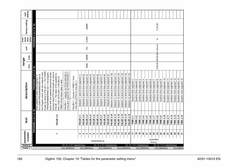
42/61-10010 EN
r g
24T
IME
n.8
Dur
atio
n tim
e se
gmen
t 8
0.00
.00
99.5
9.59
h.m
m.s
s1s
0.10
.00
25T
IME
n.9
Dur
atio
n tim
e se
gmen
t 9
26T
IME
n.1
0D
urat
ion
time
segm
ent
10
27T
IME
n.1
1D
urat
ion
time
segm
ent
11
28T
IME
n.1
2D
urat
ion
time
segm
ent
12
29T
IME
n.1
3D
urat
ion
time
segm
ent
13
30T
IME
n.1
4D
urat
ion
time
segm
ent
14
31T
IME
n.1
5D
urat
ion
time
segm
ent
15
1se
PROGRAM n (n=1 to 1ARAMETER PARAMETE
182 Digitric 100, Chapter 19 "Tables for the parameter setting menu"
min
.m
ax.
1.menu2.menu
pa
ram
ete
r n
um
be
ru
sese
ttin
un
itfa
cto
ry s
etti
ng
ran
ge
tex
td
es
cri
pti
on
max
i-m
um
re
so-
luti
on
1
VA
LU
E n
.0
2V
AL
UE
n.1
Set
poin
t 1
(end
of
time
segm
ent
1)
3V
AL
UE
n.2
Set
poin
t 2
(end
of
time
segm
ent
2)
4V
AL
UE
n.3
Set
poin
t 3
(end
of
time
segm
ent
3)-9
999
9999
9E
U0,
0001
-999
99
5V
AL
UE
n.4
Set
poin
t 4
(end
of
time
segm
ent
4)
6V
AL
UE
n.5
Set
poin
t 5
(end
of
time
segm
ent
5)
7V
AL
UE
n.6
Set
poin
t 6
(end
of
time
segm
ent
6)
8V
AL
UE
n.7
Set
poin
t 7
(end
of
time
segm
ent
7)
9V
AL
UE
n.8
Set
poin
t 8
(end
of
time
segm
ent
8)
10V
AL
UE
n.9
Set
poin
t 9
(end
of
time
segm
ent
9)
11V
AL
UE
n.1
0S
etpo
int
10 (
end
of t
ime
segm
ent
10)
12V
AL
UE
n.1
1S
etpo
int
11 (
end
of t
ime
segm
ent
11)
13V
AL
UE
n.1
2S
etpo
int
12 (
end
of t
ime
segm
ent
12)
14V
AL
UE
n.1
3S
etpo
int
13 (
end
of t
ime
segm
ent
13)
15V
AL
UE
n.1
4S
etpo
int
14 (
end
of t
ime
segm
ent
14)
16V
AL
UE
n.1
5S
etpo
int
15 (
end
of t
ime
segm
ent
15)
17T
IME
n.1
Dur
atio
n tim
e se
gmen
t 1
18T
IME
n.2
Dur
atio
n tim
e se
gmen
t 2
19T
IME
n.3
Dur
atio
n tim
e se
gmen
t 3
20T
IME
n.4
Dur
atio
n tim
e se
gmen
t 4
21T
IME
n.5
Dur
atio
n tim
e se
gmen
t 5
22T
IME
n.6
Dur
atio
n tim
e se
gmen
t 6
23T
IME
n.7
Dur
atio
n tim
e se
gmen
t 7
PR
OG
RA
M n
(n
=1
to 1
0)
PR
OG
RA
M n
(n
=1
to 1
0)
P
RO
GR
AM
n (
n=
1 to
10)
16 Stützstellen5 time gments
0) PROGRAM n (n=1 to 10) PROGRAM n (n=1 to 10) PROGRAM n (n=1 to 10) R PARAMETER PARAMETER PARAMETER PARAMETER PARAMETER
VA
LUE
n.1
n
eg.G
r. f
or P
VO
>V
ALU
En.
1=
VA
LUE
n.0
pos
.Gr.
for
PV
O<
VA
LUE
n.1
VA
LUE
n.1
m
oves
in T
IME
n.1
from
=
VA
LUE
n.0
PV
O t
o V
ALU
En.
1
Sta
rt s
etpo
int
0 (s
tart
tim
e se
gmen
t 1)
. F
or C
ON
FI/P
RO
GR
AM
ME
R/B
01/Q
n=0
the
Pro
gram
sta
rts
with
thi
s se
tpoi
nt a
nd
mov
es a
s ra
mp
to V
ALU
E n
.1.
For
CO
NF
I /P
RO
GR
AM
ME
R/B
01/Q
n=1
the
prog
ram
st
arts
with
the
set
poin
t be
eing
the
act
ual
proc
ess
valu
e P
V0
and
mov
es a
s ra
mp
to
VA
LUE
n.
1. T
he v
alue
of t
he g
radi
ent
is
then
: G
rad
=I(V
ALU
En.
1-V
ALU
En.
0)
/TIM
En.
0I t
he b
elow
tab
le is
val
id.

183
r g
64T
OL
.SE
G15
Tol
eran
ce s
egm
ent
15
PROPA
42/61-10010 EN Digitric 100, Chapter 19 "Tables for the parameter setting menu"
min
.m
ax.
de
sc
rip
tio
nm
axi-
mu
m
reso
-lu
tio
n
1.menu2.menu
pa
ram
ete
r n
um
be
ru
sese
ttin
un
itfa
cto
ry s
etti
ng
ran
ge
tex
t
32S
EG
ME
NT
_ B
INB
inar
y tr
ack
(tim
e se
gmen
t 1)
4 bi
nary
tra
cks
33S
EG
ME
NT
2_B
INB
inar
y tr
ack
(tim
e se
gmen
t 2)
Def
ault
valu
e=0
34S
EG
ME
NT
3_B
INB
inar
y tr
ack
(tim
e se
gmen
t 3)
35S
EG
ME
NT
4_B
INB
inar
y tr
ack
(tim
e se
gmen
t 4)
36S
EG
ME
NT
5_B
INB
inar
y tr
ack
(tim
e se
gmen
t 5)
37S
EG
ME
NT
6_B
INB
inar
y tr
ack
(tim
e se
gmen
t 6)
38S
EG
ME
NT
7_B
INB
inar
y tr
ack
(tim
e se
gmen
t 7)
39S
EG
ME
NT
8_B
INB
inar
y tr
ack
(tim
e se
gmen
t 8)
none
1
40S
EG
ME
NT
9_B
INB
inar
y tr
ack
(tim
e se
gmen
t 9)
41S
EG
ME
NT1
0_B
INB
inar
y tr
ack
(tim
e se
gmen
t 10
)
42S
EG
ME
NT1
1_B
INB
inar
y tr
ack
(tim
e se
gmen
t 11
)
43S
EG
ME
NT1
2_B
INB
inar
y tr
ack
(tim
e se
gmen
t 12
)
44S
EG
ME
NT1
3_B
INB
inar
y tr
ack
(tim
e se
gmen
t 13
)
45S
EG
ME
NT1
4_B
INB
inar
y tr
ack
(tim
e se
gmen
t 14
)
46S
EG
ME
NT1
5_B
INB
inar
y tr
ack
(tim
e se
gmen
t 15
)
47P
GR
.LO
OP
_BE
GF
rom
tim
e se
gmen
t1
14no
ne1
1
48P
RG
.LO
OP
_EN
Dup
to
time
segm
ent
215
none
115
49#
OF
LO
OP
SN
umbe
r of
loop
exe
cutio
ns1
9999
none
11
50T
OL
.SE
G1
Tol
eran
ce s
egm
ent
1
51T
OL
.SE
G2
Tol
eran
ce s
egm
ent
2
52T
OL
.SE
G3
Tol
eran
ce s
egm
ent
3
53T
OL
.SE
G4
Tol
eran
ce s
egm
ent
4
54T
OL
.SE
G5
Tol
eran
ce s
egm
ent
5
55T
OL
.SE
G6
Tol
eran
ce s
egm
ent
6
56T
OL
.SE
G7
Tol
eran
ce s
egm
ent
70
9999
9E
U1
9999
9
57T
OL
.SE
G8
Tol
eran
ce s
egm
ent
8
58T
OL
.SE
G9
Tol
eran
ce s
egm
ent
9
59T
OL
.SE
G10
Tol
eran
ce s
egm
ent
10
60T
OL
.SE
G11
Tol
eran
ce s
egm
ent
11
61T
OL
.SE
G12
Tol
eran
ce s
egm
ent
12
62T
OL
.SE
G13
Tol
eran
ce s
egm
ent
13
63T
OL
.SE
G14
Tol
eran
ce s
egm
ent
14
ToleranceLoops
0 =
he
xade
c2#
0000
15 =
hexa
dec
2# I
I I
I
Binary tracks (see also CONFI/LOOPm/B11/Q10 to Q13)
GRAM n (n=1 to 10) PROGRAM n (n=1 to 10)
Is t
he d
evia
tion
betw
een
the
PV
an
d th
e pr
ogra
mm
er S
P
bigg
er t
han
the
adju
sted
to
lera
nce,
the
pr
ogra
m w
ill b
e fr
ozen
unt
il th
e P
V r
each
es t
he
tole
ranc
e to
the
pr
ogra
mm
er
SP
.
PROGRAM n (n=1 to 10) PROGRAM n (n=1 to 10) PARAMETER PARAMETER PARAMETER PA
0 1 2 3 4 5 6 7 8 9 10 11 12 13 14 15
value
track4 track3 track2track1
0 0
0
0
0 0
0
I0
0
I 0
0 0
I
I0
I
0
00
I
0
I0
I
I
00
I
I
II
0
0 0
I 0
0
II
0
I 0
I 0
I
II
I
0
0
I I
0
I
I I
I
0I
I
I
I
RAMETER PARAMETER PARAMETER

42/61-10010 EN
20 Error codes
emory will be indicated in the top line of the
he error. Refer to 20.1.1 and 20.1.2 for a de-ended steps. If the characters “xy“ appear inrror is available in table19-1.
ct the manufacturer and provide the following
184 Digitric 100, Chapter 20 "Error codes"
20.1 Device errorsErrors occurring during read or write actions in the non-volatile flash mdisplay with the message
!Error ....where the four periods represent the four-digit error code assigned to tscription of the respective errors, the possible reasons, and the recommthe error code, this means that a detailed description of the respective e
If none of the recommended steps can solve your problem, please containformation:– instrument version– firmware version– IBIS_ R/IBIS_ R+ revision– actions taken– configuration– project– error code

185
20.1.1 Error codes
ommended steps
device to factory setting and repeat down-d after approximately 2 minutes.
device to factory setting and repeat down-d after approximately 2 minutes
uce configuration and try again
rm manufacturer.
rm manufacturer.
rm manufacturer.
rm manufacturer.
rm manufacturer.
rm manufacturer.
urn device to manufacturer for repair.
42/61-10010 EN Digitric 100, Chapter 20 "Error codes"
Error code Description Rec
32 Configuration download failed. Setloa
3100 Not enough flash memory available for saving the configuration data.
Setloaorred
3200, 3201 Internal processing action failed. Info
41xy Error when saving the project header. Info
42xy Error when saving the list configuration. Info
43xy, 44xy Error when saving the project version data. Info
45yx Error when saving the hardware configuration. Info
47xy
48xy Error when saving changes of the online param-eters.
Info
49xy
61xy Project header cannot be read.
62xy List configuration cannot be read.
63xy Project version data cannot be read.
64xy
65xy Hardware configuration cannot be read.
68xy Changes of the online parameters cannot be read.
69xy
80xy General hardware error. Ret
81xy Flash memory cannot be initialized completely.

42/61-10010 EN
82xy Flash memory completely erased due to serious
186 Digitric 100, Chapter 20 "Error codes"
Fig. 20-1 Device error codes
error.
83xy84xy85xy86xy87xy
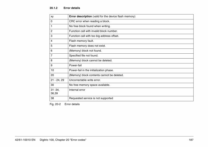
187
20.1.2 Error details
42/61-10010 EN Digitric 100, Chapter 20 "Error codes"
Fig. 20-2 Error details
xy Error description (valid for the device flash memory)
0 CRC error when reading a block.
1 No free block found when writing.
2 Function call with invalid block number.
3 Function call with too big address offset.
4 Flash memory fault.
5 Flash memory does not exist.
6 (Memory) block not found.
7 Specified file not found.
8 (Memory) block cannot be deleted.
9 Power-fail
10 Power-fail in the initialization phase.
20 (Memory) block contents cannot be deleted.
21 - 24, 29 Uncorrectable write error.
30 No free memory space available.
31 -34, 36,39
Internal error
38 Requested service is not supported

42/61-10010 EN
20.2 Error codes of the controller selftune routineeen 1 and 5.
ommended steps
tart selftuning.
tart selftuning.
configurable change of the output variable uld be increased.
ck the connection and configuration of the suring values for possible errors. errors can be found, the controlled system
not be identified due to a dead time that is too .
the selftuning routine and set the control to “manual“ mode. Wait until the controlled ems do no longer change “noticeably“, then art selftuning.
188 Digitric 100, Chapter 20 "Error codes"
Errors are output in the form S.Par.Err.X, where X is an error code betw
Table 20-1 Error codes of controller selftuning
Error code Error description Rec
1 General errorThe requirements for trouble-free selftuning are not fully met. However, the reason for this cannot be determined exactly.
Res
2 Noise bandThe noise band automatically determined in the initial phase of the selftuning routine turned out to be too small. This may happen if disturbances in-crease while the selftuning procedure is in progress.
Res
3 Changes of the controlled variableThe controlled system does not change suffi-ciently to permit proper analysis of its behavior.
Thesho
4 Time-outWithin a given time of 10 hours there were no changes of the controlled system.
ChemeaIf nocanlong
5 No damping No damping of the controlled system occurred within the given time window. However, to be able to identify the controlled system, it must be stationary.
Exitloopsystrest

189
20.3 Error codes of the input/output level
d outputs. If any errors are detected, they are
ecommended steps
he input can be recalibrated via the frontanel by using the respective signal transmit-ers.
ee E_AI01CONF 3
ee E_AI01CONF 3
ee E_AI02CONF 3
alibration through the manufacturer equired.
ee E_BIOCONF 3
42/61-10010 EN Digitric 100, Chapter 20 "Error codes"
Upon power on the device checks the calibrated values for the inputs anindicated as plain text (see table).
Table 20-2 Error codes of the input/output level
Error code Error description R
E_AI01CONF 3 At least one calibrated value of AI01 has vio-lated the low limit.
Only the values required according to theAI01-F01 configuration are checked here.
Tpt
E_AI01CONF 4 At least one calibrated value of AI01 has vio-lated the high limit.
Only the values required according to theAI01-F01 configuration are checked here.
s
E_AI02CONF 3 At least one calibrated value of AI02 has vio-lated the low limit.
s
E_AI02CONF 4 At least one calibrated value of AI02 has vio-lated the high limit.
s
E_BIOCONF 3 At least one calibrated value from BIO01 toDO05 has violated the low limit.
Cr
E_BIOCONF 4 At least one calibrated value from BIO01 toDO05 has violated the high limit.
s

42/61-10010 EN
21 Technical data
pensation0, 20, 50 or 60 °C
ion± 1 °C/10 K
ure 22 °C ± 1 °Ce 0...50 °C
gction
ermometer Pt100 DIN
0.0 °C0.0 °C
e circuit to 40 Ω line resistanceare
etrical lines up to 3 x 10 Ω
letransmitter (potentiometer)
1.5 kΩ (0.75...2 kΩ)
mAe thermometer
190 Digitric 100, Chapter 21 "Technical data"
Inputs
Common data:without electronical isolationResolution ≤ 0.01 %Accuracy (referred to nominal range) ≤ 0.2 %Temperature effects ≤ 0.2 %/10 °CHardware input filter limit frequency 7 Hz
Analog:Universal input AI01connected to internal device ground
used for standard signal0/4...20 mA at 50 Ω ±1 %
Overcurrent/polarity reversal protectionup to ± 40 mA
Linearization, square-rootingconfigurable
at 4...20 mA Line break monitoring with configurable reaction
used for thermocouplesTypes Temperature Voltage Typical
range range accuracyJ -200...1200 °C 77.43 mV ≤ 0.2 %E -200...1000 °C 85.18 mV ≤ 0.2 %K -200...1400 °C 61.53 mV ≤ 0.2 %L -200...1000 °C 78.21 mV ≤ 0.2 %U -200... 600 °C 40.00 mV ≤ 0.3 %R -200...1700 °C 20.22 mV ≤ 0.5 %S -200...1800 °C 18.72 mV ≤ 0.5 %T -200... 400 °C 26.47 mV ≤ 0.4 %B -200...1800 °C 13.24 mV ≤ 0.6 %D -200...2300 °C 36.92 mV ≤ 0.4 %
Reference junction cominternal or external:
Internal reference junctError limitReference temperatAmbient temperatur
Sensor break monitorinwith configurable rea
Used for resistance th
Measuring range-200.0...+20-200.0...+80
Measuring current≤ 1 mA
Measuring circuit: 2-wirLine balancing: by softw
3-wire circuit: for symm
used for resistance teMeasuring ranges
150 Ω, (75...200 Ω);
Measuring current: ≤ 1 other data as resistanc

191
Optional universal input 2 (AI02) Outputs
smission750 Ω, short-circuit and open-circuit proof
t (B03/B04/B05)3 A resistive load≥ 100 mACdO
red
units:99:9 hours, four digital tracks
ection to PC with fixed telegram formattting and configuration program IBIS-R+0 EN).ordering information. Bus capable RS 485ee modules)
42/61-10010 EN Digitric 100, Chapter 21 "Technical data"
with integrated transmitter power supplyInput for mA, Pt100, thermocouple or potentiometer, technical dataas AI01, but with electronical isolation.
Permissible common-mode voltage against device ground± 4 V DC
Permissible differential-mode voltage Uss (50 Hz)50 mV
Transmitter power supplyoutput voltage 20...25 V DC, 50 mA
Short-circuit proofautomatic cut off on overload
binary:2 binary inputs/outputs (B01/B02)
Direct/reverse function configurable
Switching frequency ≤ 8 Hz
Analog output AO01galvanical isolated
Control output or retran0/4...20 mA at max.
Control range0...≥ 21 mA
Load-dependency0.1 %/100 Ω
Resolution≥ 0.01 %
binary:see inputs
3 relays with NO contacfor max. 250 V AC, for min. ≥ 12 V AC, Contact material Ag
Programmer
10 programs can be stoeach program:15 segmentsSet point in physicalSegment time 0...99
Serial interfaces
TTL interface for connmatching parameter se(see Data Sheet 62-6.7For adapter cable see interface retrofittable (s
InputDIN 19240
Rated signalV DC
Voltage range(V)
Current range
Rated level 24 20.4...28.8 approx. 1 mA
1-signal 24 13.0...30.2 approx. 1 mA
0-signal 0 - 3.0... 5.0 < 0.2 mA
OutputDIN 19240
Rated signalV DC
Voltage range(V)
Current range
Rated level 24 ext. 20.4...28.8 100 mA
1-signal 24 13.0...30.2 0...max. mA
0-signal 0 - 3.0... 5.0 0...0.15 mA
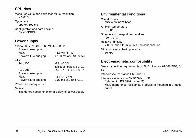
192 Digitric 100, Chapter 21 "Technical data" 42/61-10010 EN
CPU dataMeasured value and correction value resolution
≤ 0.01 %
Cycle timeapprox. 100 ms
Configuration and data backupFlash-EPROM
Power supply115 to 230 V AC (90...260 V), 47...63 Hz
Power consumption:Max. 13.3 VA (11 W)Power failure bridging ≥ 150 ms at ≥ 180 V AC
24 V UC24 V DC -25...+30 %,
residual ripple ≤ ± 3 Vss
24 V AC -15...+10 %, 47...63 HzPower consumption:Max. 15 VA (12 W)Power failure bridging ≥ 20 ms at 0.85 x Unom
Power factor cosϕ = 0.7
SafetyThe device needs no external safety of power supply
Environmental conditionsClimatic class
3K3 to EN 60721-3-3
Ambient temperature0...50 °C
Storage and transport temperature-20...70 °C
Relative humidity< 85 %, short-term to 95 %, no condensation
Minimum atmospheric pressure80 kPa
Electromagnetic compatibilityMeets protection requirements of EMC directive 89/336/EEC, 5/89
Interference resistance EN 61326-1
Interference emission EN 50081-1, 1/92(referred to: EN 55011, class B)Max. interference resistance, if device is mounted in a metalpanel

42/61-10010 EN Digitric 100, Chapter 21 "Technical data" 193
Connection, case, safetyDegree of protection to DIN EN 60529
Front panel: IP 65Case: IP 30Terminals: IP 20
Electrical safety
Class of protection 1 to EN 61010 T.1 (VDE 0411 T.1, March1994)
Clearances and creepage distances as per EN for overvoltagecategory 3, degree of contamination 2
All inputs and outputs, including the interface and the transmitterfeed but excepting all relay outputs are functional extra-low volt-age circuits to DIN VDE 0100, part 410. The safe isolation ofthese circuits meets the requirements to DIN VDE 0106, part 101.
Mechanical stress features
to DIN IEC 68, part 2-27 and 68-2-6Shock 30 g/18 ms; Vibration 2 g/0.15 mm/5...150 Hz
Case dimensionsFront panel 96 mm x 96 mmInstalled depth 145 mm
Panel cutout92 mm x 92 mm to DIN 43700
Mountingin panelHorizontal high-density construction possibleVertical spacing 36 mmFixing with straining screws
Electrical connections
Plug-in screw terminalsfor wire or stranded wire to 1.5 mm2, coded
Power supply2.5 mm2
No shielded cables required – except for interface leads
Mounting orientationany
Weightapprox. 600 g without modulesadditional module approx. 40 gadditional relay module approx. 80 g
Scope of supply and delivery
2 straining screws (integrated in case), Operating Manual andplug-in screw terminals
ModulesOne of the modules listed below can be plugged in for extendingthe I/O or for using digital communication.
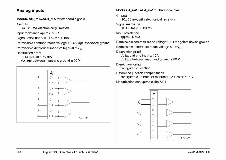
42/61-10010 EN
Analog inputs Module 4_mV =AE4_mV for thermocouples
ctronical isolation
V
ode voltage ≤ ± 4 V against device ground
mode voltage 50 mVss
± 10 Vut and ground ± 50 V
pensationl or external 0, 20, 50 or 60 °C
le like AI01
1
2
4
3
5
6
7
8AE4_MV
E
194 Digitric 100, Chapter 21 "Technical data"
Module AI4_mA=AE4_mA for standard signals
4 inputs0/4...20 mA electronically isolated
Input resistance approx. 50 ΩSignal resolution ≤ 0.01 % for 20 mA
Permissible common-mode voltage ≤ ± 4 V against device ground
Permissible differential-mode voltage 50 mVss
Destruction proofInput current < 50 mAVoltage between input and ground ± 50 V
4 inputs-10...80 mV, with ele
Signal resolution20.000 for -10...80 m
Input resistanceapprox. 5 MΩ
Permissible common-m
Permissible differential-
Destruction proofVoltage at one inputVoltage between inp
Break monitoringconfigurable reaction
Reference junction comconfigurable, interna
Linearization configurab
1
2
4
3
5
6
7
8AE4_MA
+
+
+
+
-
-
-
-
A

195
Module AI2_mA/mV-OI=AE2_mA/mV_TR Module AI4_PT_2W=AE4_PT_2L for RTD 2-wires
ircuit
mode voltage: : 100 mVss
% for 400 Ω mA
urable
are
-circuit monitoring
AE4_PT-2L
F1
2
3
4
5
6
7
8
42/61-10010 EN Digitric 100, Chapter 21 "Technical data"
for mA signals or thermocouple with electrical isolation
2 inputs with electrical isolation0/4...20 mA or -10...80 mV (changeable by means of jumpers)
Input resistance at20 mA: 25 Ω; -10...80 mV: approx. 5 MΩ
Dielectric strength of input and output leads against each otherand against grounded conductor:
Test voltage 500 V ACContinuous operation 45 V AC
Technical data as modules 4_MV or 4_MA
4 inputsfor Pt100 in 2-wire c
Range: 0...400 ΩPermissible differential
Signal resolution ≤ 0.01
Measuring current ≤ 1.5
Measuring range config-200.0...+200.0 °C-200.0...+450.0 °C-200.0...+800.0 °C
Line balancing by softw
Sensor break and shortconfigurable reaction
AE2_MA/MV_TR
B1
2
3
4
5
6
7
8

42/61-10010 EN
Module AI2_PT_3/4W=AE2_PT_3/4L for RTD 3-/4-wires
inary inputs; O = binary outputs
signal Voltage range(V)
Current range
20.4...28.8 approx. 3 mA
13.0...30.2 approx. 3 mA
-3.0...5.0 ≤ 0.1 mA
signal Voltage range(V)
Current range
20.4...28.8 100 mA
13.0...30.2 0...max. mA
-3.0...5.0 0...0.1 mA
BI1/BO1
BI2/BO2
BI3/BO3
BI4/BO4
BI5/BO5
BI6/BO6
BEA6-BIN
M
1
+
2
3
4
5
6
-
196 Digitric 100, Chapter 21 "Technical data"
2 inputsfor Pt100 in 3- or 4-wire circuit or potentiometer
Technical data for Pt100 as module AI4_PT_2_W
Potentiometer R150: 0...150 Ω Series resistance: 0...500 Measuring current < 1.5 mAPotentiometer R1500: 0...1500 ΩSeries resistance: 0...1500 Ω Measuring current < 0.5 mA
Binary inputs/outputs
Module BIO6_BIN=BE06_BIN
6 binary inputs/outputs, opto isolatedConfigurable as input or output, direct or reverse action
*) Connection example: I = bAE2_PT-3/4L
G1
2
3
4
5
6
7
8
InputDIN 19240
Rated V DC
Rated level 24
1-signal 24
0-signal 0
OutputDIN 19240
Rated V DC
Rated level 24 ext
1-Signal 24
0-Signal 0
O*
I*24 V DC
24 V DC
(-)
(+)
(+)

197
Module BO4_REL=BA4_REL Range: 0...20.000 pulses/cycle time µs
ngle (1 input)ulses µs
cording to DIN 19234Ui = 9.5 VRi = 1 kΩL = 0...1.2 mA/H = 2.1...4.0 mA
cording to DIN 19240 (0/24 V DC)RE > 6 kΩL = -3...5 V/H = 13...20.2 V
L (0/5 V DC)RE > 6 kΩL = 0...0.8 V/H = 3.5...24 V
19,5 V DC
9,5 V DC2
4
3
5
6
7
8AE4_F
H
0/5 V
0/5 V
0/5 V
0/5 V
0/24 V
0/24 V
0/24 V
0/24 V
NAMUR
NAMUR
42/61-10010 EN Digitric 100, Chapter 21 "Technical data"
4 relayswith NO contact for max. 250 V AC, 1 A resistive load
Built-in spark-quenching: 0.022 µF + 100 ΩFor max. 250 V, max. 1 A at cosϕ = 0.9
Contact material AgCdO
Module AI4_F=AE4_F
4 inputs for:
Frequency (1/4 inputs)Range 1 input 0...20 kHzRange 4 inputs 0...10 kHzSignal resolution 1 Hz
Period (1-4 inputs)Range 0...20 sSignal resolution 1 ms
Pulses (1-4 inputs)/ incremental angle (2 inputs)
min. pulse length: 50
Absolute incremental aRange: 0...20.000 pmin. pulse length: 50
Types of input signals:
Max. 2 Namur inputs acOpen circuit voltageInternal resistanceSignal range
Max. 4 digital inputs acInput resistanceSignal range
Max. 4 digital inputs TTInput resistanceSignal range
Accuracy: ± 0.1 %
Rel.1
Rel.4
Rel.3
Rel.2
BA4_REL
T1
2
3
4
5
6
7
8
(-)
(+)
(+)
(+)
(+)

42/61-10010 EN
/DP-V1 (Slave)
nal capabilities of DIN 19245, parts 1 to 4. 1.5 MBaud.r see accessories on page 10
1
2
4
3
5
6
7
A (+)
B (-)
1)
RS-232RS-485U
RS-232
RS-485
1,2 Tx
3,4 Rx
5,6
Profibus
CPU
1
2
4
3
5
6
7
1)
Z
VCC
198 Digitric 100, Chapter 21 "Technical data"
Analog outputs
Module AO3_mA=AA3_mA
Triple current output 0/4...20 mA at 750 ΩSignal resolution ≤ 0.02 % for 20 mALoad dependency 0.1 %/100 ΩOutput monitoring, reaction configurable
Module AO3_V=AA3_V
Triple voltage output 0/2...10 V ≥ 5 kΩ
Interface modules
Module RS 485 or RS 232
Interface module in accordance with RS 485 or RS 232 specifica-tion. Electrically isolated. Standard protocol: MODBUS-RTU.
Module PROFIBUS-DP
Module with full functioTransmission rate up toBus terminating adapte
AA3-VAA3_MA
N(mA)P(V)
1
2
3
4
5
6
7
8
RS-485/232
+
-
RS-485

199
22 Packaging for transport or return to the manufacturer
in a padded plastic film or corrugated paperng material (e.g. foam rubber). The thicknessnd the type of shipment.
p the device and the desiccant bag in a heat-e packing volume and the expected transporter of union paper.
42/61-10010 EN Digitric 100, Chapter 22 "Packaging for transport or return to the manufacturer"
If the original packing material is no longer available, wrap Digitric 100board and place it in a box of sufficient size lined with a shock-absorbiof the shock-absorber should be in accordance with the device weight a
The box must be handled with care and has to be labeled accordingly.
For overseas shipment always add a desiccant (e.g. silica gel) and wrasealed polyethylene foil of 0.2 mm. Adapt the amount of desiccant to thtime (at least sufficient for 3 months). Additionally line the box with a lay

ABB Automation Products GmbHHöseler Platz 2, D-42579 HeiligenhausPhone +49(0)20 56 12 - 5181; Fax +49(0)20 56 12 - 5081http://www.abb.com
Subject to technical changesPrinted in the Fed. Rep. of Germany
42/61-10010 EN Rev. 01Edition 10.01