Product specification Controller IRC5 | ABB
166
ROBOTICS Product specification Controller IRC5
-
Upload
khangminh22 -
Category
Documents
-
view
1 -
download
0
Transcript of Product specification Controller IRC5 | ABB
ROBOTICS
Product specificationController IRC5

Trace back information:Workspace 22A version a11Checked in 2022-03-03Skribenta version 5.4.005

Product specificationController IRC5
Design 14
Document ID: 3HAC047400-001Revision: AD
© Copyright 2013-2022 ABB. All rights reserved.Specifications subject to change without notice.

The information in this manual is subject to change without notice and should notbe construed as a commitment by ABB. ABB assumes no responsibility for any errorsthat may appear in this manual.Except as may be expressly stated anywhere in this manual, nothing herein shall beconstrued as any kind of guarantee or warranty by ABB for losses, damage to personsor property, fitness for a specific purpose or the like.In no event shall ABB be liable for incidental or consequential damages arising fromuse of this manual and products described herein.This manual and parts thereof must not be reproduced or copied without ABB'swritten permission.Keep for future reference.Additional copies of this manual may be obtained from ABB.
Original instructions.
© Copyright 2013-2022 ABB. All rights reserved.Specifications subject to change without notice.

Table of contents7Overview of this product specification .............................................................................................
111 Description of the IRC5 controller111.1 Controller variants .............................................................................................111.1.1 Single cabinet controller ...........................................................................181.1.2 Additional drive module ............................................................................201.1.3 IRC5 Panel Mounted Controller ..................................................................291.1.4 IRC5 Compact controller ..........................................................................321.1.5 Stacking of IRC5 modules .........................................................................341.1.6 IRC5 as stand alone controller ...................................................................371.1.7 Empty cabinets .......................................................................................391.1.8 MultiMove ..............................................................................................411.1.9 Additional motors ....................................................................................441.1.10 External panel ........................................................................................451.2 Safety .............................................................................................................451.2.1 Applicable standards ...............................................................................471.2.2 Safety functions ......................................................................................491.2.3 Safety data .............................................................................................531.3 Installation and maintenance ...............................................................................531.3.1 Installation .............................................................................................571.3.2 Maintenance ..........................................................................................591.4 Computer system ..............................................................................................591.4.1 The IRC5 main computer ..........................................................................611.4.2 Communication .......................................................................................631.4.3 Memory .................................................................................................651.4.4 I/O system .............................................................................................731.5 Operator's interface ...........................................................................................731.5.1 FlexPendant ...........................................................................................761.5.2 RobotStudio ...........................................................................................781.5.3 Connected Services .................................................................................791.6 Programming ...................................................................................................791.6.1 Programming .........................................................................................821.6.2 Automatic operation ................................................................................831.6.3 RAPID language and environment ..............................................................841.6.4 Exception handling ..................................................................................851.6.5 Robot motion ..........................................................................................891.7 Additional safety options ....................................................................................891.7.1 Electronic Position Switches [810-1] ...........................................................901.7.2 SafeMove [810-2] ....................................................................................941.7.3 SafeMove Basic [1125-1] and SafeMove Pro [1125-2] .....................................
1012 Specification of variants and options1012.1 Introduction to variants and options ......................................................................1022.2 Basic ..............................................................................................................1022.2.1 Controller variants ...................................................................................1082.2.2 Mains connection type .............................................................................1092.2.3 Main switch ............................................................................................1102.2.4 Controller cooling conditions .....................................................................1142.2.5 Warranty ................................................................................................1152.2.6 Connected Services enabled .....................................................................1162.3 Control module .................................................................................................1192.3.1 PCI options ............................................................................................1232.3.2 Scalable I/O ...........................................................................................1242.3.3 Conveyor ...............................................................................................1262.3.4 Internal DeviceNet I/O ..............................................................................1272.3.5 External DeviceNet I/O .............................................................................
Product specification - Controller IRC5 53HAC047400-001 Revision: AD
© Copyright 2013-2022 ABB. All rights reserved.
Table of contents

1282.3.6 Power supply .........................................................................................1292.3.7 Functional Safety ....................................................................................1322.3.7.1 Discrete I/O Safety .......................................................................1332.3.7.2 Safety Robot Supervison ..............................................................1352.3.8 IMM Interface .........................................................................................1372.3.9 Operator's interface .................................................................................1412.4 Drive module ....................................................................................................1462.4.1 Drive module options ...............................................................................1492.5 RobotWare .......................................................................................................1542.5.1 Vision ...................................................................................................1612.6 Floor cables .....................................................................................................
163Index
6 Product specification - Controller IRC53HAC047400-001 Revision: AD
© Copyright 2013-2022 ABB. All rights reserved.
Table of contents
Overview of this product specificationAbout this product specification
It specifies the properties of the IRC5 robot controller in terms of:• The structure and dimensional prints• The fulfilment of standards, safety and operating equipment• RobotWare OS• I/O system• Additional motors• Variants and options
UsageProduct specifications are used to find data and performance about the product,for example to decide which product to buy. How to handle the product is describedin the product manual.
UsersIt is intended for:
• Product managers and product personnel• Sales and marketing personnel• Order and customer service personnel
References
Document IDReference
3HAC050945-001Product specification - Controller software IRC5IRC5 with main computer DSQC1000 (or later) and RobotWare 6.
3HAC047136-001Product manual - IRC5IRC5 with main computer DSQC1000.
3HAC047138-001Product manual - IRC5 CompactIRC5 with main computer DSQC1000.
3HAC047137-001Product manual - IRC5 Panel Mounted ControllerIRC5 with main computer DSQC1000.
3HAC050944-001Operating manual - Service Information System
3HAC052355-001Product specification - Robot user documentation, IRC5 with Robot-Ware 6
Revisions
DescriptionRevision
First revision-• Minor corrections/update• Two new Force Sensor Package added
A
Continues on next pageProduct specification - Controller IRC5 73HAC047400-001 Revision: AD
© Copyright 2013-2022 ABB. All rights reserved.
Overview of this product specification
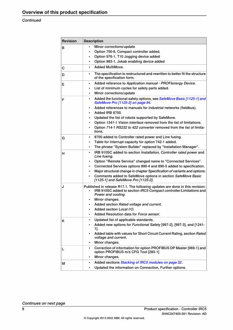
DescriptionRevision• Minor corrections/update• Option 700-8, Compact controller added.• Option 976-1, T10 Jogging device added• Option 983-1, Jokab enabling device added
B
• Added MultiMove.C• The specification is restructured and rewritten to better fit the structure
of the specification form.D
• Added reference to Application manual - PROFIenergy Device.• List of minimum cycles for safety parts added.• Minor corrections/update
E
• Added the functional safety options, see SafeMove Basic [1125-1] andSafeMove Pro [1125-2] on page 94.
• Added references to manuals for industrial networks (fieldbus).• Added IRB 8700.• Updated the list of robots supported by SafeMove.• Option 1341-1 Vision interface removed from the list of limitations.• Option 714-1 RS232 to 422 converter removed from the list of limita-
tions.
F
• 8700 added to Controller rated power and Line fusing.• Table for Interrupt capacity for option 742-1 added.• The phrase "System Builder" replaced by "Installation Manager".
G
• IRB 910SC added to section Installation, Controller rated power andLine fusing.
• Option "Remote Service" changed name to "Connected Services".• Connected Services options 890-4 and 890-5 added to specification.• Major structural change in chapterSpecification of variants and options.• Comments added to SafeMove options in section SafeMove Basic
[1125-1] and SafeMove Pro [1125-2].
H
Published in release R17.1. The following updates are done in this revision:• IRB 910SC added to section IRC5 Compact controller/Limitations and
Power and cooling.• Minor changes.• Added section Rated voltage and current.• Added section Local I/O.• Added Resolution data for Force sensor.
J
• Updated list of applicable standards.• Added new options for Functional Safety [997-2], [997-3], and [1241-
1].• Added table with values for Short Circuit Current Rating, sectionRated
voltage and current.• Minor changes.
K
• Correction of information for option PROFIBUS DP Master [969-1] andoption PROFIBUS m/s CFG Tool [285-1]
• Minor changes.
L
• Added sections Stacking of IRC5 modules on page 32.• Updated the information on Connection, Further options.
M
Continues on next page8 Product specification - Controller IRC5
3HAC047400-001 Revision: AD© Copyright 2013-2022 ABB. All rights reserved.
Overview of this product specificationContinued
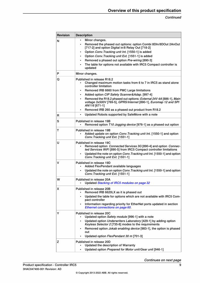
DescriptionRevision• Minor changes.• Removed the phased out options: option Combi 8DIn/8DOut 2AnOut
[717-2] and option Digital in/8 Relay Out [718-2]• Option Conv.Tracking unit Int. [1550-1] is added• Option Conv.Tracking unit Ext. [1551-1] is added• Removed a phased out option Pre-wiring [890-3]• The table for options not available with IRC5 Compact controller is
updated
N
Minor changes.P
Published in release R18.2• Changed maximum motion tasks from 6 to 7 in IRC5 as stand alone
controller limitation• Removed IRB 6660 from PMC Large limitations• Added option CIP Safety Scanner&Adap. [997-4]• Removed the R18.2 phased out options: External 24V 4A [886-1], Main
voltage 3x500V [769-5], GPRS/Internet [890-1], Euromap 12 and SPIAN116 [671-1]
• Removed IRB 260 as a phased out product from R18.2
Q
• Updated Robots supported by SafeMove with a noteR
Published in release 19B• Removed option T10 Jogging device [976-1] as a phased out option
S
Published in release 19B• Added update on option Conv.Tracking unit Int. [1550-1] and option
Conv.Tracking unit Ext. [1551-1]
T
Published in release 19C• Removed option Connected Services 3G [890-4] and option Connec-
ted Services WiFi [890-5] from IRC5 Compact controller limitations• Updated the note on option Conv.Tracking unit Int. [1550-1] and option
Conv.Tracking unit Ext. [1551-1]
U
Published in release 19D• Added FlexPendant available languages• Updated the note on option Conv.Tracking unit Int. [1550-1] and option
Conv.Tracking unit Ext. [1551-1]
V
Published in release 20A• Updated Stacking of IRC5 modules on page 32
W
Published in release 20B• Removed IRB 6620LX as it is phased out• Updated the table for options which are not available with IRC5 Com-
pact controller• Information regarding priority for EtherNet ports updated in section
Ethernet connections on page 60.
X
Published in release 20C• Updated option Safety module [996-1] with a note• Updated option Underwriters Laboratory [429-1] by adding option
Keyless Selector 2 [735-8] modes to the requirements• Removed option Jokab enabling device [983-1], the option is phased
out• Updated option FlexPendant 30 m [701-3]
Y
Published in release 20D• Updated the description of Warranty• Updated option Prepared for Motor unit/Gear unit [946-1]
Z
Continues on next pageProduct specification - Controller IRC5 93HAC047400-001 Revision: AD
© Copyright 2013-2022 ABB. All rights reserved.
Overview of this product specificationContinued

DescriptionRevision
Published in release 21A• Added option Prep. for 3rd party MU [1389-1]• Updated IMM Interface (Further options)• Changed the name Local I/O to Scalable I/O
AA
Published in release 21C• PMC Large is available for IRB 390
AB
Published in release 21D• Updated the chapter Single cabinet - different views.• PROFIBUS DP Master [969-1] phased out.• PROFIBUS DP m/s CFG Tool [285-1] phased out.• Updated safety data.
AC
Published in release 22A.• Updated information about humidity, see Operating requirements on
page 53.• Updated Force sensor weight in Force sensor specification chapter.
AD
10 Product specification - Controller IRC53HAC047400-001 Revision: AD
© Copyright 2013-2022 ABB. All rights reserved.
Overview of this product specificationContinued
1 Description of the IRC5 controller1.1 Controller variants
1.1.1 Single cabinet controller
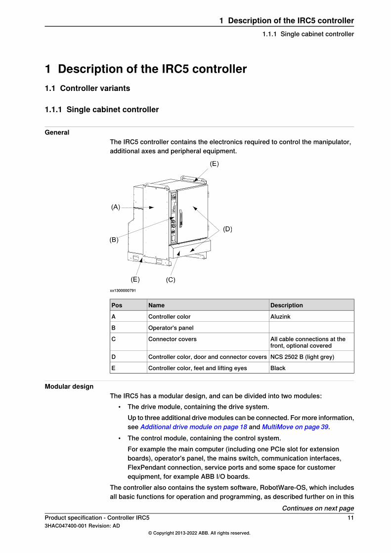
GeneralThe IRC5 controller contains the electronics required to control the manipulator,additional axes and peripheral equipment.
xx1300000791
DescriptionNamePos
AluzinkController colorA
Operator's panelB
All cable connections at thefront, optional covered
Connector coversC
NCS 2502 B (light grey)Controller color, door and connector coversD
BlackController color, feet and lifting eyesE
Modular designThe IRC5 has a modular design, and can be divided into two modules:
• The drive module, containing the drive system.Up to three additional drive modules can be connected. For more information,see Additional drive module on page 18 and MultiMove on page 39.
• The control module, containing the control system.For example the main computer (including one PCIe slot for extensionboards), operator's panel, the mains switch, communication interfaces,FlexPendant connection, service ports and some space for customerequipment, for example ABB I/O boards.
The controller also contains the system software, RobotWare-OS, which includesall basic functions for operation and programming, as described further on in this
Continues on next pageProduct specification - Controller IRC5 113HAC047400-001 Revision: AD
© Copyright 2013-2022 ABB. All rights reserved.
1 Description of the IRC5 controller1.1.1 Single cabinet controller
chapter. On top of RobotWare-OS it is possible to install a number of options withadditional functionality. For description of these options, please see Productspecification - Controller software IRC5.
Single cabinet controllerThe content described above is normally mounted into one single cabinet. Thesingle cabinet offers a compact solution suitable for most applications where thereis less need for additional equipment inside.
Additional IRC5 variantsTwo additional IRC5 variants are available
• IRC5 Panel Mounted Controller, where the integrator takes care of theencapsulation, see IRC5 Panel Mounted Controller on page 20
• IRC5 Compact controller, a small footprint controller available for the smallerIRBs, see IRC5 Compact controller on page 29.
Cabinet data
WeightData
max 150 kgSingle cabinet controller
42 kgEmpty cabinet large
Volume (H x W x D)Data
970 x 725 x 710 mmSingle cabinet controllerEmpty cabinet large
For information on ordering empty cabinets, see Empty cabinets on page 37.
Airborne noise level
DescriptionAirborne noise level
< 70 dB (A) Leq (acc. to the working space Machinery directive2006/42/EG)
Sound pressure level out-side
Continues on next page12 Product specification - Controller IRC5
3HAC047400-001 Revision: AD© Copyright 2013-2022 ABB. All rights reserved.
1 Description of the IRC5 controller1.1.1 Single cabinet controllerContinued

Single cabinet - different views
xx0900000930
DescriptionPos
Optional process module for Single cabinet controllerA
725 for build inB
DescriptionPos
For wheel option, add 10 mm to the height1
For service access to the rear, add 250 mm to the depth2
Optional moist dust filter3
Continues on next pageProduct specification - Controller IRC5 133HAC047400-001 Revision: AD
© Copyright 2013-2022 ABB. All rights reserved.
1 Description of the IRC5 controller1.1.1 Single cabinet controller
Continued
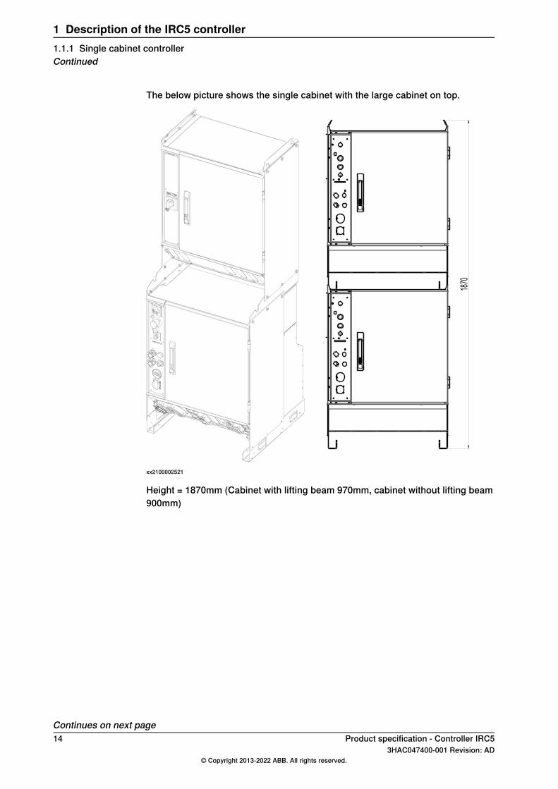
The below picture shows the single cabinet with the large cabinet on top.
1870
xx2100002521
Height = 1870mm (Cabinet with lifting beam 970mm, cabinet without lifting beam900mm)
Continues on next page14 Product specification - Controller IRC5
3HAC047400-001 Revision: AD© Copyright 2013-2022 ABB. All rights reserved.
1 Description of the IRC5 controller1.1.1 Single cabinet controllerContinued

Operator's panel
xx0900000933
NamePos
Mains switch and remote control of power to Drive modulesA
Emergency stop - if pressed in, turn to releaseB
MOTORS ONC
Operating mode selectorD
Safety chain LEDs (option)E
FlexPendant Hot Plug pushbutton (option)G
Service PC connectionH
FlexPendant connectionK
Duty Time Counter (option)L
Service outlet 115/230V, 200W (option)M
Continues on next pageProduct specification - Controller IRC5 153HAC047400-001 Revision: AD
© Copyright 2013-2022 ABB. All rights reserved.
1 Description of the IRC5 controller1.1.1 Single cabinet controller
Continued

Cabinet connectors
xx0900000980
DescriptionPos
Power inlet, option 752-2A
Manipulator motor cableB
Power to additional motors, XS101C
Floor cables for manipulator custom power and signalsE
DeviceNetTM on front, option 730-1 and Connected Services antenna connectorF
Cable glands for external operator’s panelG
External connection of safety signals, option 731-2H
To SMB for additional motors XS41I
Manipulator SMB cableJ
LAN Ethernet RJ45 on connector plate, option 707-1K
Ethernet M12 on connector plate, option 906-1L
Connector parts additional motorsThe controller can include, in addition to drive system for a 4-6 axes robot,equipment to control up to three additional motors. The connection to additionalmotors is collected in one industrial connector type Harting Han-Modular® (XS101),see Cabinet connectors on page 16.When ABB motors or positioners are ordered, the connector is included with thecabling. For other cases, find part numbers in table below.
Miltronic part No.Harting part No.PartPcs
52 01 5700Cable gland1
09 30 024 0531Hood1
09 14 024 0313Hinged frame for 6 modules1
09 14 000 9950Dummy module2-3
09 14 006 30016 pole module2-3
09 14 012 300112 pole module2
Continues on next page16 Product specification - Controller IRC5
3HAC047400-001 Revision: AD© Copyright 2013-2022 ABB. All rights reserved.
1 Description of the IRC5 controller1.1.1 Single cabinet controllerContinued
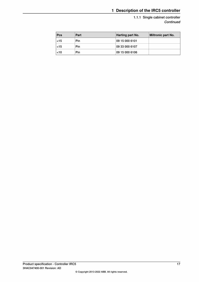
Miltronic part No.Harting part No.PartPcs
09 15 000 6101Pin<15
09 33 000 6107Pin<15
09 15 000 6106Pin<10
Product specification - Controller IRC5 173HAC047400-001 Revision: AD
© Copyright 2013-2022 ABB. All rights reserved.
1 Description of the IRC5 controller1.1.1 Single cabinet controller
Continued

1.1.2 Additional drive module
GeneralAdditional drive modules can be ordered together with the single controller tocontrol additional axes or additional robots, MultiMove.Up to three additional axes can be controlled by each drive module, and up to threeadditional drive modules can be connected. For more information see MultiMoveon page 39.
xx1500000255
DescriptionNamePos
AluzinkController colorA
Operator's panelB
All cable connections at thefront, optional covered
Connector coversC
NCS 2502 B (light grey)Controller color, door and connector coversD
BlackController color, feet and lifting eyesE
Cabinet data
WeightData
100-130 kgDrive module
35 kgEmpty cabinet small
Volume (H x W x D)Data
720 x 725 x 710 mmDrive moduleEmpty cabinet small
For information on ordering empty cabinets, see Empty cabinets on page 37.
Continues on next page18 Product specification - Controller IRC5
3HAC047400-001 Revision: AD© Copyright 2013-2022 ABB. All rights reserved.
1 Description of the IRC5 controller1.1.2 Additional drive module

Operator's panel
xx0900000935
DescriptionPos
Mains isolator switch.A
Stand by lamp indicates that electronic supply is switched on by the ControlModule mains switch.
B
Duty Time Counter (option) accumulates the hours (up to 99999.99 h) whenthe motors are in operation and the brakes are released.
C
Service outlet 115/230V, 200W (option)D
Product specification - Controller IRC5 193HAC047400-001 Revision: AD
© Copyright 2013-2022 ABB. All rights reserved.
1 Description of the IRC5 controller1.1.2 Additional drive module
Continued
1.1.3 IRC5 Panel Mounted Controller
GeneralThe IRC5 Panel Mounted Controller (PMC), is a concept where the controller canbe mounted in a customer cabinet for example when there are special demandson size reduction or hygienic encapsulation. For MultiMove applications the robotca be ordered with only the drive module. Two versions of Panel Mounted Controllerare available, depending on robot version and size, PMC Small and PMC Large.The difference is the size of drive units in the Drive module.
A
B
C
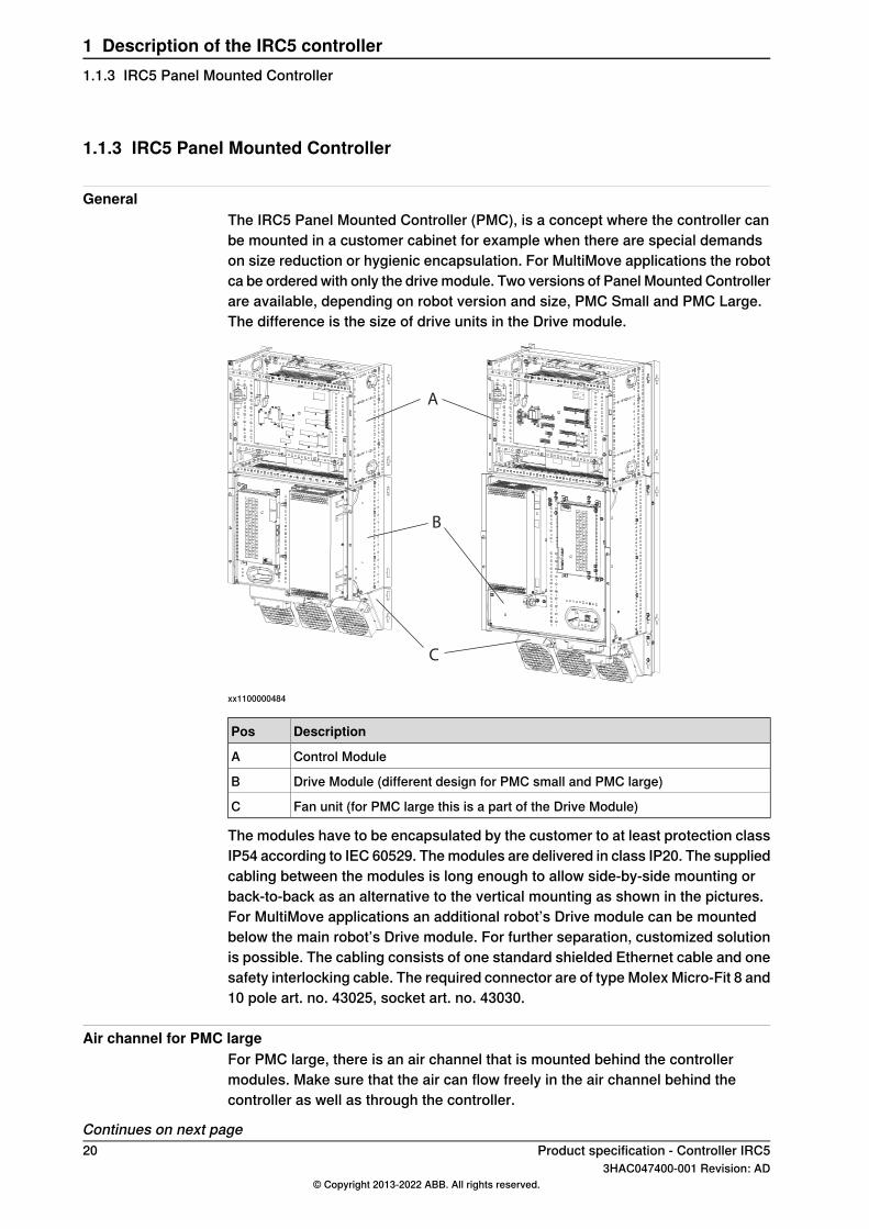
xx1100000484
DescriptionPos
Control ModuleA
Drive Module (different design for PMC small and PMC large)B
Fan unit (for PMC large this is a part of the Drive Module)C
The modules have to be encapsulated by the customer to at least protection classIP54 according to IEC 60529. The modules are delivered in class IP20. The suppliedcabling between the modules is long enough to allow side-by-side mounting orback-to-back as an alternative to the vertical mounting as shown in the pictures.For MultiMove applications an additional robot’s Drive module can be mountedbelow the main robot’s Drive module. For further separation, customized solutionis possible. The cabling consists of one standard shielded Ethernet cable and onesafety interlocking cable. The required connector are of type Molex Micro-Fit 8 and10 pole art. no. 43025, socket art. no. 43030.
Air channel for PMC largeFor PMC large, there is an air channel that is mounted behind the controllermodules. Make sure that the air can flow freely in the air channel behind thecontroller as well as through the controller.
Continues on next page20 Product specification - Controller IRC5
3HAC047400-001 Revision: AD© Copyright 2013-2022 ABB. All rights reserved.
1 Description of the IRC5 controller1.1.3 IRC5 Panel Mounted Controller

If the Control Module is mounted separately, it can be mounted without the airchannel. If it is mounted on top of the Drive Module, it must be mounted on the airchannel so it does not obstruct the air flow.
The air flowThe fan to the right creates an air flow though the air channel behind the controller,where the brake resistor bleeder is located. The two fans to the left creates an airflow though the controller modules.
xx1100000537
LimitationsFollowing IRB robots are available with Panel Mounted Controller.PMC Small avaliable for:
• IRB 140• IRB 360• IRB 1200• IRB 1600
PMC Large available for:• IRB 2400• IRB 2600• IRB 4400
Continues on next pageProduct specification - Controller IRC5 213HAC047400-001 Revision: AD
© Copyright 2013-2022 ABB. All rights reserved.
1 Description of the IRC5 controller1.1.3 IRC5 Panel Mounted Controller
Continued

• IRB 4600• IRB 66XX• IRB 6700• IRB 7600• IRB 460• IRB 660• IRB 760• IRB 390
Drive units for additional motors can not be installed.Standards that concern electrical installation and encapsulation have to beaddressed by the customerRegarding the EU Machinery Directive, the Panel Mounted Controller is designedto fulfill the requirements when mounted in an integrator encapsulation.The Panel Mounted Controller is UL Recognized as standard (UR labelled).However, certain options have to be selected in a proper way. Examples are Safetylamp on the manipulator arm and 2-mode operation mode selector.The motor cable is to be connected to industrial connector on the drive module.The following options are not available with Panel Mounted Controller:
DescriptionOption
UL/CSA (the PMC is UL recognized)429-1
Prepared for CE and China (the mains filter is standard)129-1
Mains connection type752-x
Mains switch742-x
Circuit breaker for rotary switch743-1
Door interlock744-1
Room temperature (customer internal cabinet air max. 45°C)708-x
Air filter764-1
Cabinet connector cover741-x
Ethernet on connector plate707-1, 906-1
Internal I/O and gateway units716-726
24V 8/16A727-x
DeviceNetTM on connector plate730-1
Safety external connector (internal 731-1 included)731-2
IMM interface671-673
Operator’s panel on cabinet733-1
Status LEDs on front737-1
Drives for additional axes907-1
SMB for additional axes757
Extension cables between modules761-x
Duty Time Counter767-1
Continues on next page22 Product specification - Controller IRC5
3HAC047400-001 Revision: AD© Copyright 2013-2022 ABB. All rights reserved.
1 Description of the IRC5 controller1.1.3 IRC5 Panel Mounted ControllerContinued
DescriptionOption
Wheels758-1
Service outlet736-x
Empty cabinet768-x
Installation kit715-1
Prepared for IRBP922-1
Prepared for MU&GU946-1
Prepared for IRBT981-1
Furthermore, options intended for arc welding applications are not available togetherwith Panel Mounted Controller.
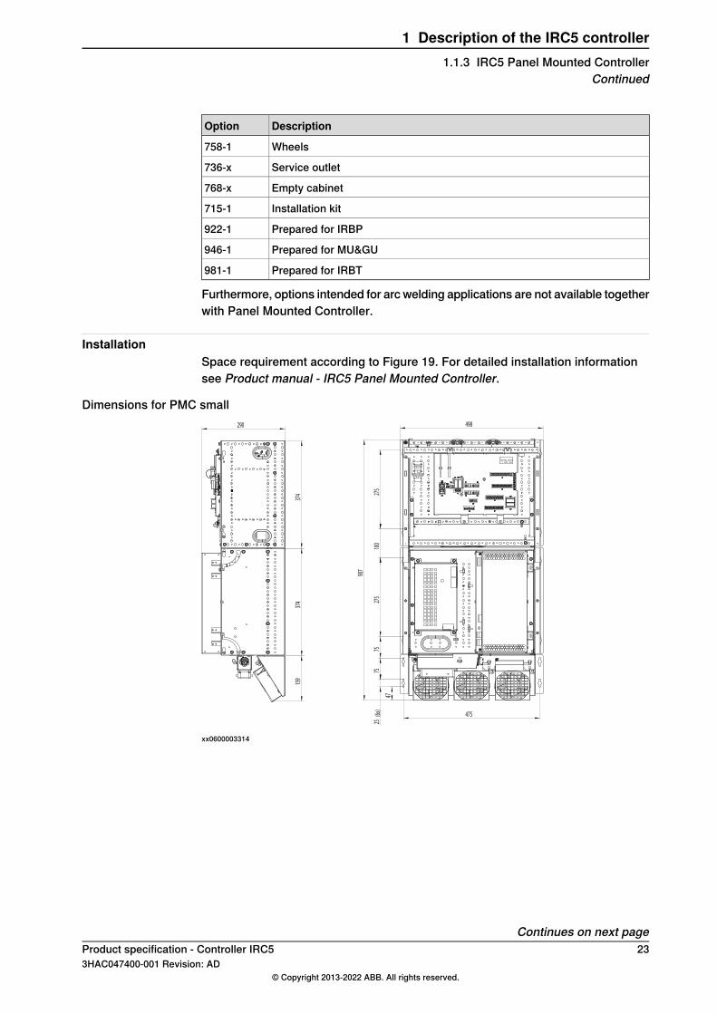
InstallationSpace requirement according to Figure 19. For detailed installation informationsee Product manual - IRC5 Panel Mounted Controller.
Dimensions for PMC small498
907
475
47
25(6x)
7575
275
100
275
374
290
374
159
xx0600003314
Continues on next pageProduct specification - Controller IRC5 233HAC047400-001 Revision: AD
© Copyright 2013-2022 ABB. All rights reserved.
1 Description of the IRC5 controller1.1.3 IRC5 Panel Mounted Controller
Continued
xx0700000031
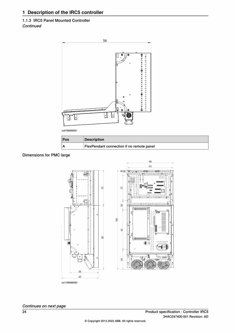
DescriptionPos
FlexPendant connection if no remote panelA
Dimensions for PMC large
475
498
1060
210
425
100
275
M5 (8x)
425
685
375
300
xx1100000533
Continues on next page24 Product specification - Controller IRC5
3HAC047400-001 Revision: AD© Copyright 2013-2022 ABB. All rights reserved.
1 Description of the IRC5 controller1.1.3 IRC5 Panel Mounted ControllerContinued

782
xx1100000534
Dimensions for transformer
175 - 425
25
8 -
38
4
165
xx0900000952
Continues on next pageProduct specification - Controller IRC5 253HAC047400-001 Revision: AD
© Copyright 2013-2022 ABB. All rights reserved.
1 Description of the IRC5 controller1.1.3 IRC5 Panel Mounted Controller
Continued

Dimensions for inductor (only used with PMC Large)
165
149209
xx1100000561
Dimensions for line filter
65
110
160
200
Continues on next page26 Product specification - Controller IRC5
3HAC047400-001 Revision: AD© Copyright 2013-2022 ABB. All rights reserved.
1 Description of the IRC5 controller1.1.3 IRC5 Panel Mounted ControllerContinued

Dimensions for external operator's panel
250
128
200
170
288,4
Weight• Control module 12 kg• Drive module Small 24 kg• Drive module Large 40 kg• Transformer 13-35 kg• Fan unit 0.5 kg• Inductor for Drive module large 5 kg• External Operator panel 3 kg
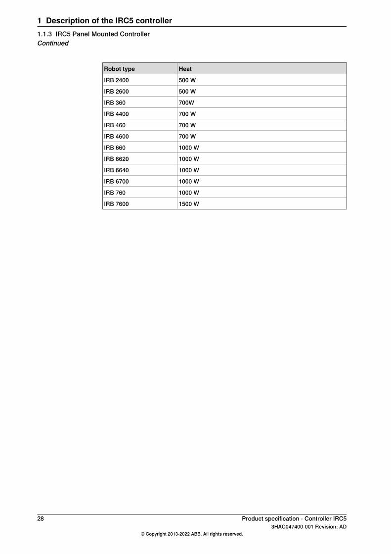
Power and coolingFor PMC Small, a 4 kVA transformer is included. For PMC Large with 400-480 V,a single phase transformer is included. The transformer comes with rotary mainsswitch and secondary fuses.Also the PMC drive module only, option 700-6 intended for MultiMove, includes atransformer.For PMC Large a fan unit for internal cooling is included in the controller delivery,the unit force cooling air through the drive module and bleeder resistor. For PMCSmall the fan unit is optional.For calculation of the enclosure temperature rise, the dissipated heat has to beknown. Since most of the heat depends on the robot motion, the robot programagain is dimensioning, With the above 50 % duty cycle, the generated heat isapproximately:
HeatRobot type
300 WIRB 1200
250 WIRB 140
300 WIRB 1600
Continues on next pageProduct specification - Controller IRC5 273HAC047400-001 Revision: AD
© Copyright 2013-2022 ABB. All rights reserved.
1 Description of the IRC5 controller1.1.3 IRC5 Panel Mounted Controller
Continued
HeatRobot type
500 WIRB 2400
500 WIRB 2600
700WIRB 360
700 WIRB 4400
700 WIRB 460
700 WIRB 4600
1000 WIRB 660
1000 WIRB 6620
1000 WIRB 6640
1000 WIRB 6700
1000 WIRB 760
1500 WIRB 7600
28 Product specification - Controller IRC53HAC047400-001 Revision: AD
© Copyright 2013-2022 ABB. All rights reserved.
1 Description of the IRC5 controller1.1.3 IRC5 Panel Mounted ControllerContinued
1.1.4 IRC5 Compact controller
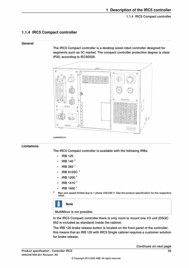
GeneralThe IRC5 Compact controller is a desktop sized robot controller designed forsegments such as 3C market. The compact controller protection degree is classIP20, according to IEC60529.
xx0900000316
LimitationsThe IRC5 Compact controller is available with the following IRBs:
• IRB 120• IRB 140 I
• IRB 360 I
• IRB 910SC I
• IRB 1200 I
• IRB 1410 I
• IRB 1600 I
I Max axis speed limited due to 1 phase 220/230 V. See the product specification for the respectiverobot.
Note
MultiMove is not possible.
In the IRC5 Compact controller there is only room to mount one I/O unit (DSQC652 is included as standard) inside the cabinet.The IRB 120 brake release button is located on the front panel of the controller,this means that an IRB 120 with IRC5 Single cabinet requires a customer solutionfor brake release.
Continues on next pageProduct specification - Controller IRC5 293HAC047400-001 Revision: AD
© Copyright 2013-2022 ABB. All rights reserved.
1 Description of the IRC5 controller1.1.4 IRC5 Compact controller

The following options are not available with IRC5 Compact controller:
DescriptionOption
Prepared for CE and China (the mains filter is standard)129-1
MultiMove604-X
IMM interface671-673
Hot plug (for FlexPendant)702-2
Ethernet connector plate707-1, 906-1
Room temperature 52C (Max temp, 45C is std)708-2
Installation kit715-1
Internal I/O and gateway unit (16in/16out is std)717-726
24V 4/8 16A (24V 4A for external mounting is available)727-x
DeviceNet 24V 4Amps728-1
DeviceNetTM on connector plate730-1
Safety Connection731-X
Panel on Cabinet733-1
Key switch735-X
Service outlet736-X
Status LEDs on front737-1
Cabinet connector cover741-1
Flange disconnect (rotary switch is std)742-3
Circuit breaker743-1
Door interlock744-1
Mains connection type752-x
Drives for additional axes753-766
SMB for additional axes757-x
Wheels758-1
Extension cables between modules761-x
Cooling air filter764-x
Duty Time Counter767-1
empty cabinet768-X
Mains voltage769-x
Electronic Position Switches810-1
SafeMove810-2
PMC without transformer and circuit breaker881-2
Fans882-x
Prepared for IRBT981-1
Dispensepack support901-1
Channel support902-1
Ethernet connector plate906-1
Continues on next page30 Product specification - Controller IRC5
3HAC047400-001 Revision: AD© Copyright 2013-2022 ABB. All rights reserved.
1 Description of the IRC5 controller1.1.4 IRC5 Compact controllerContinued

DescriptionOption
Additional drive907-X
Prepared for IRBP922-1
World transformer931-1
Ethernet switch941-1
Prepared for MU/GU 757-X SMB for additional axes946-1
Drive interface1003-1
Base Dig. 16In/16Out1541-1
Add-on Dig. 16In/16Out1542-1
Add-on Analog 4In/4Out1543-1
Add-on Relay 8In/8Out1544-1
Temperature sensor fans1170-1
All Arc welding related hardware options
Dimensions
51.6 mm48.5 mm449 mm
32
0 m
m
390.4 mm
xx1400002103
Weight 28.5 kg
Power and coolingFor calculation of the enclosure temperature rise, the dissipated heat has to beknown. Since most of the heat depends on the robot motion, the robot programagain is dimensioning, With the above 50 % duty cycle, the generated heat isapproximately:
HeatRobot type
250 WIRB 120
250 WIRB 140
300 WIRB 910SC
300 WIRB 1200
300 WIRB 1600
700 WIRB 360
Product specification - Controller IRC5 313HAC047400-001 Revision: AD
© Copyright 2013-2022 ABB. All rights reserved.
1 Description of the IRC5 controller1.1.4 IRC5 Compact controller
Continued
1.1.5 Stacking of IRC5 modules
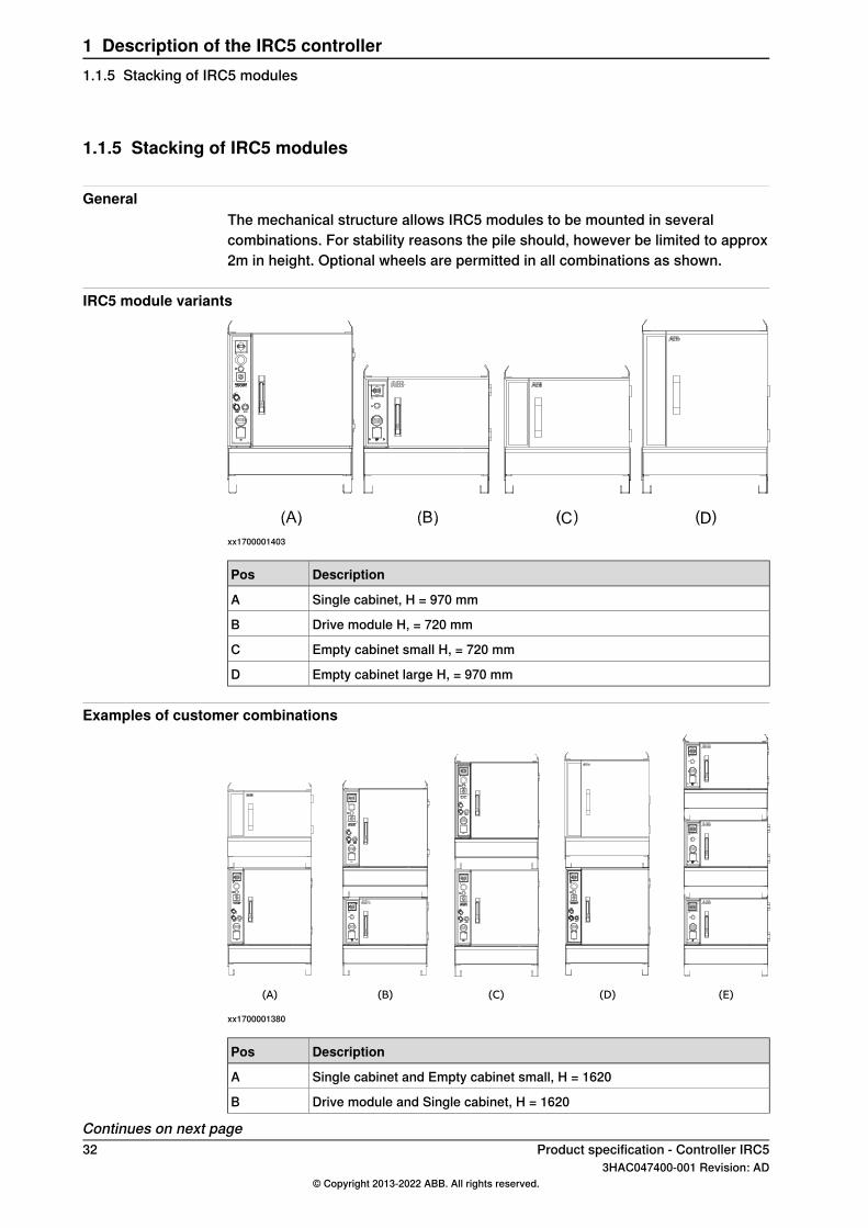
GeneralThe mechanical structure allows IRC5 modules to be mounted in severalcombinations. For stability reasons the pile should, however be limited to approx2m in height. Optional wheels are permitted in all combinations as shown.
IRC5 module variants
xx1700001403
DescriptionPos
Single cabinet, H = 970 mmA
Drive module H, = 720 mmB
Empty cabinet small H, = 720 mmC
Empty cabinet large H, = 970 mmD
Examples of customer combinations
(A) (B) (C) (D) (E)
xx1700001380
DescriptionPos
Single cabinet and Empty cabinet small, H = 1620A
Drive module and Single cabinet, H = 1620B
Continues on next page32 Product specification - Controller IRC5
3HAC047400-001 Revision: AD© Copyright 2013-2022 ABB. All rights reserved.
1 Description of the IRC5 controller1.1.5 Stacking of IRC5 modules

DescriptionPos
Two Single cabinets, H = 1870C
Single cabinet and Empty cabinet large, H = 1870D
Three Drive modules, H = 2020E
Product specification - Controller IRC5 333HAC047400-001 Revision: AD
© Copyright 2013-2022 ABB. All rights reserved.
1 Description of the IRC5 controller1.1.5 Stacking of IRC5 modules
Continued
1.1.6 IRC5 as stand alone controller
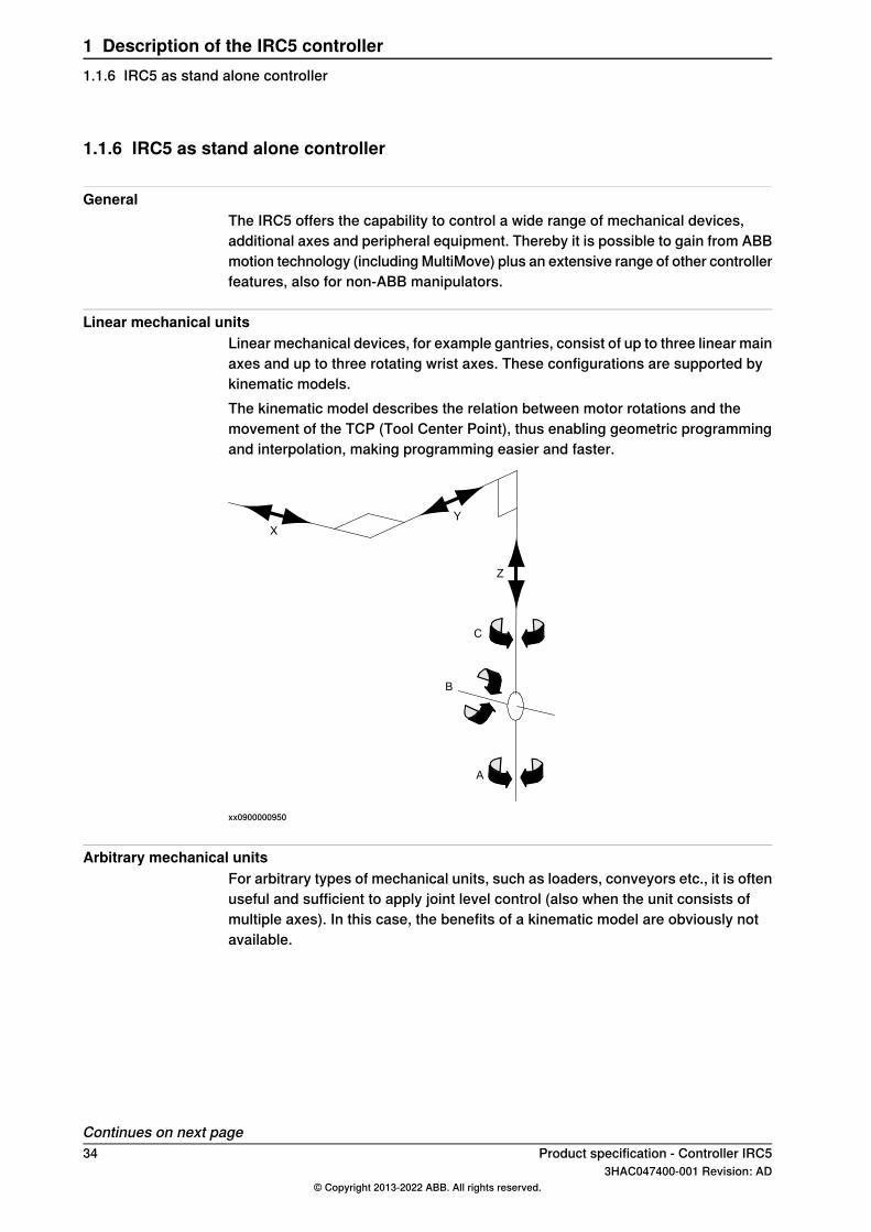
GeneralThe IRC5 offers the capability to control a wide range of mechanical devices,additional axes and peripheral equipment. Thereby it is possible to gain from ABBmotion technology (including MultiMove) plus an extensive range of other controllerfeatures, also for non-ABB manipulators.
Linear mechanical unitsLinear mechanical devices, for example gantries, consist of up to three linear mainaxes and up to three rotating wrist axes. These configurations are supported bykinematic models.The kinematic model describes the relation between motor rotations and themovement of the TCP (Tool Center Point), thus enabling geometric programmingand interpolation, making programming easier and faster.
xx0900000950
Arbitrary mechanical unitsFor arbitrary types of mechanical units, such as loaders, conveyors etc., it is oftenuseful and sufficient to apply joint level control (also when the unit consists ofmultiple axes). In this case, the benefits of a kinematic model are obviously notavailable.
Continues on next page34 Product specification - Controller IRC5
3HAC047400-001 Revision: AD© Copyright 2013-2022 ABB. All rights reserved.
1 Description of the IRC5 controller1.1.6 IRC5 as stand alone controller

ABB manipulators
Note
Information to consider when ordering a Stand alone Controller for ControllerUpgrade.The controller is delivered from factory with the latest available software andhardware revisions. Depending on which manipulator the controller will beconnected to the license key may need to be updated. Above is always applicablewhen selecting option ”NO IRB Manipulator”, but also for some specific robotmodels.If new license key or new options are needed, these are ordered from RoboticsAftersales via Business Online according to current price list. See prices inBusiness Online. For questions concerning orders to Robotics Aftersales, submitvia RobDesk in Service Portal as Spare part/Order Question.
It is possible to exchange earlier ABB controllers connected to ABB IRBmanipulators, thus benefitting from the latest control system technology. The earliermanipulators covered by the 3 phase variants of IRC5 are:
• IRB 140 M2000• IRB 1400 M98 and M2000• IRB 2400 M98A and M2000• IRB 4400 M98A and M2000• IRB 340 M98 and M2000• IRB 6600 M2000• IRB 7600 M2000• IRB 6400R M99 and M2000 (200/2.5 and 200/2.8)
Motor and drive system selectionThe procedure for choosing a stand alone IRC5 drive system is similar to that usedfor additional motors, see Additional motors on page 41.
Note
For more information on motors and measurement system, see Productspecification - Motor Units and Gear Units and Application manual - Additionalaxes and stand alone controller.
LimitationsThe number of axes and mechanical units are limited as follows.For systems without MultiMove:
• One single motion task• Maximum 12 axes (located in 1 or 2 drive modules)• Maximum 1 TCP robot
Continues on next pageProduct specification - Controller IRC5 353HAC047400-001 Revision: AD
© Copyright 2013-2022 ABB. All rights reserved.
1 Description of the IRC5 controller1.1.6 IRC5 as stand alone controller
Continued
• Maximum 6 additional axes (which can be grouped in an arbitrary numberof mechanical units)
Note 1: A TCP robot is a robot equipped with a kinematic model, which isprogrammed in x, y, z coordinates of the TCP, plus tool orientation. An IRBmanipulator is an example of a TCP robot.Note 2: Without MultiMove, semi-independent programming of individual mechanicalunits/axes can be achieved through the option 610-1 Independent Axis. Normally,MultiMove is preferred when independent programming is desired.For systems with MultiMove:
• Maximum 7 motion tasks• All the non-MultiMove limitations above apply per task• Maximum 4 TCP robots in total• Maximum 4 drive modules (that is maximum 32-36 axes)
Note: It is perfectly possible to mix control of IRB manipulators and non-ABB unitsin the same system.
Note
Since non-ABB manipulators are controlled without the support of a dynamicmodel, certain limitations apply, for example:
• Only limited QuickMoveTM and TrueMoveTM
• No automatic adaption to vary load conditions• No Load Identification• No Collision Detection• No Absolute Accuracy
36 Product specification - Controller IRC53HAC047400-001 Revision: AD
© Copyright 2013-2022 ABB. All rights reserved.
1 Description of the IRC5 controller1.1.6 IRC5 as stand alone controllerContinued

1.1.7 Empty cabinets
Empty cabinet small [768-1]
xx0900000977
This option is intended for customer equipment or extended use of I/O units.Mounting plate dimensions (HxW): 511 x 660 mm.Mounting depth (D): 250-325 mmFor cabinet dimensions see Cabinet data on page 18.
Continues on next pageProduct specification - Controller IRC5 373HAC047400-001 Revision: AD
© Copyright 2013-2022 ABB. All rights reserved.
1 Description of the IRC5 controller1.1.7 Empty cabinets

Empty cabinet large [768-2]
xx0900000976
Based on the single cabinet, this option is intended for customer equipment orextended use of I/O units.Mounting plate dimensions (HxW): 711 x 660 mm.Mounting depth (D): 250-325 mmFor cabinet dimensions see Single cabinet controller on page 11.
38 Product specification - Controller IRC53HAC047400-001 Revision: AD
© Copyright 2013-2022 ABB. All rights reserved.
1 Description of the IRC5 controller1.1.7 Empty cabinetsContinued

1.1.8 MultiMove
GeneralIt is possible to connect up to three additional Drive modules, each running onerobot or a number of additional motors, to one Single cabinet controller or Controlmodule. Each robot can control additional motors, seeAdditional motors on page41.
Module connectionsThe Drive modules are connected to the Single cabinet controller or Control moduleby an Ethernet cable and a safety signal cable with a maximum length of 75 m.
Note
Note that it is not necessary to have several Drive modules in order to runMultiMove, as long as the mechanical units are all connected to the same Drivemodule. One example is “manual jog”, where one additional axis is controlledfrom a separate task.
MultiMove systemWith a MultiMove system, it is possible to operate the robots either individually(option 604-2 MultiMove Independant) or in a co-operative manner, (option 604-1MultiMove Coordinated). Examples of the latter are:
• Dual robots welding on work objects rotated by an positioner• Multiple robots together lifting a heavy object• One robot holding a work piece while another robot is processing the work
piece (typically welding)
Robot combinationsArbitrary robot types can be combined in a MultiMove system. For IRB 360 thefollowing limitations apply:
• With two IRB 360 in a MultiMove system, no more robots can be connected.• The IRB 360 can not be coordinated with another robot (IRB 360 or other
type).
Note
For further information, see Application manual - MultiMove.
Note
Note that when several robots are connected to one Single cabinet controller orControl module, the complete cell is regarded as one robot from the safety systempoint of view.
Continues on next pageProduct specification - Controller IRC5 393HAC047400-001 Revision: AD
© Copyright 2013-2022 ABB. All rights reserved.
1 Description of the IRC5 controller1.1.8 MultiMove
LimitationsNote that screw terminals for signals from the additional robots (customer signals,position switches) may not be possible to fit in the main robot cabinet. Especiallythe limited space of the Single cabinet requires attentions. An Empty cabinet (option768-1 or option 768-2) is recommended to give space also for I/O units or customerPLC.
40 Product specification - Controller IRC53HAC047400-001 Revision: AD
© Copyright 2013-2022 ABB. All rights reserved.
1 Description of the IRC5 controller1.1.8 MultiMoveContinued

1.1.9 Additional motors
GeneralThe IRC5 controller cabinet can be supplied with drive units for up to three additionalmotors. These motors are programmed and moved in the same way as the robot’smotors. See figure below.
xx0900000948
Note
Data for the individual drive units is found in chapter Drive unit data in Applicationmanual - Additional axes and stand alone controller.
Additional Drive module connectionAn IRC5 Drive module can be connected to the Single cabinet, independent of therobot type. An Ethernet switch plus cabling is the only additional hardware required.A Drive module is basically equipped with drives for 6 motors but can be suppliedwith drives for further 3 motors. The Drive module is complete with powerdistribution, transformer, dual MOTORS ON contactor circuits, cooling, powersupply and axis computer.Available drive system sizes corresponds to IRB 1600, IRB 2600 and IRB 66XX.
Continues on next pageProduct specification - Controller IRC5 413HAC047400-001 Revision: AD
© Copyright 2013-2022 ABB. All rights reserved.
1 Description of the IRC5 controller1.1.9 Additional motors
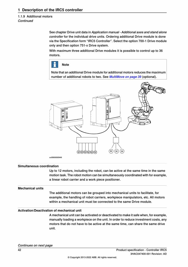
See chapter Drive unit data in Applicationmanual - Additional axes and stand alonecontroller for the individual drive units. Ordering additional Drive module is donevia the Specification form “IRC5 Controller”. Select the option 700-1 Drive moduleonly and then option 751-x Drive system.With maximum three additional Drive modules it is possible to control up to 36motors.
Note
Note that an additional Drive module for additional motors reduces the maximumnumber of additional robots to two. See MultiMove on page 39 (optional).
xx0900000949
Simultaneous coordinationUp to 12 motors, including the robot, can be active at the same time in the samemotion task. The robot motion can be simultaneously coordinated with for example,a linear robot carrier and a work piece positioner.
Mechanical unitsThe additional motors can be grouped into mechanical units to facilitate, forexample, the handling of robot carriers, workpiece manipulators, etc. All motorswithin a mechanical unit must be connected to the same Drive module.
Activation/Deactivation of mechanical unitA mechanical unit can be activated or deactivated to make it safe when, for example,manually loading a workpiece on the unit. In order to reduce investment costs, anymotors that do not have to be active at the same time, can share the same driveunit.
Continues on next page42 Product specification - Controller IRC5
3HAC047400-001 Revision: AD© Copyright 2013-2022 ABB. All rights reserved.
1 Description of the IRC5 controller1.1.9 Additional motorsContinued
Motor selectionFor motor selection, see Product specification - Motor Units and Gear Units.
Note
ABB can not guarantee complete functionality when using third party equipment.Use of ABB verified equipment for optimal performance is recommended.
Absolute positionAbsolute position is accomplished by battery-backed resolver revolution countersin the serial measurement board (SMB). Encapsulated SMB units are also describedin Product specification - Motor Units and Gear Units.
Note
For more information on how to install an additional motor, see Applicationmanual - Additional axes and stand alone controller. This manual also specifiesnecessary resolver data, and how to create a simple dimensioning of the motor.
Product specification - Controller IRC5 433HAC047400-001 Revision: AD
© Copyright 2013-2022 ABB. All rights reserved.
1 Description of the IRC5 controller1.1.9 Additional motors
Continued
1.1.10 External panel
GeneralBoth the operator's panel and the FlexPendant can be mounted externally, that isseparated from the cabinet and the robot can then be controlled from there.The optional remote panel contains:
• Emergency stop• MOTORS ON• Operating mode selector• FlexPendant connector, inclusive optional Hot plug
Remaining on the Control cabinet:• Mains switch• Optional safety LEDs• Service PC connection
The robot can also be controlled remotely from a computer, PLC or from acustomer’s panel, using serial communication (optional) or digital system signals.
Note
For more information on how to operate the robot, see Operating manual - IRC5with FlexPendant, or Operating manual - RobotStudio.
44 Product specification - Controller IRC53HAC047400-001 Revision: AD
© Copyright 2013-2022 ABB. All rights reserved.
1 Description of the IRC5 controller1.1.10 External panel
1.2 Safety
1.2.1 Applicable standards
Note
The listed standards are valid at the time of the release of this document. Phasedout or replaced standards are removed from the list when needed.
GeneralThe product is designed in accordance with ISO 10218-1:2011, Robots for industrialenvironments - Safety requirements -Part 1 Robots, and applicable parts in thenormative references, as referred to from ISO 10218-1:2011. In case of deviationsfrom ISO 10218-1:2011, these are listed in the declaration of incorporation whichis part of the product delivery.
Normative standards as referred to from ISO 10218-1
DescriptionStandard
Manipulating industrial robots - Performance criteria and relatedtest methods
ISO 9283:1998
Robots and robotic devices - Safety requirements for industrialrobots - Part 2: Robot systems and integration
ISO 10218-2
Safety of machinery - General principles for design - Risk as-sessment and risk reduction
ISO 12100
Safety of machinery - Safety related parts of control systems- Part 1: General principles for design
ISO 13849-1:2006
Safety of machinery - Emergency stop - Principles for designISO 13850
Safety of machinery - Electrical equipment of machines - Part1: General requirements
IEC 60204-1
Region specific standards and regulations
DescriptionStandard
Safety requirements for industrial robots and robot systemsANSI/RIA R15.06
Safety standard for robots and robotic equipmentANSI/UL 1740
Industrial robots and robot Systems - General safety require-ments
CAN/CSA Z 434-03
Other standards used in design
DescriptionStandard
Robots and robotic devices -- Coordinate systems and motionnomenclatures
ISO 9787:2013
Electromagnetic compatibility (EMC) – Part 6-2: Genericstandards – Immunity standard for industrial environments
IEC 61000-6-2
Electromagnetic compatibility (EMC) – Part 6-4: Genericstandards – Emission standard for industrial environments
IEC 61000-6-4
Continues on next pageProduct specification - Controller IRC5 453HAC047400-001 Revision: AD
© Copyright 2013-2022 ABB. All rights reserved.
1 Description of the IRC5 controller1.2.1 Applicable standards

DescriptionStandard
Ergonomics of the thermal environment - Part 1ISO 13732-1:2006
Arc welding equipment - Part 1: Welding power sourcesIEC 60974-1:2012 i
Arc welding equipment - Part 10: EMC requirementsIEC 60974-10:2014 i
Classification of air cleanlinessISO 14644-1:2015 ii
Degrees of protection provided by enclosures (IP code)IEC 60529:1989 + A2:2013i Only valid for arc welding robots. Replaces IEC 61000-6-4 for arc welding robots.ii Only robots with protection Clean Room.
46 Product specification - Controller IRC53HAC047400-001 Revision: AD
© Copyright 2013-2022 ABB. All rights reserved.
1 Description of the IRC5 controller1.2.1 Applicable standardsContinued

1.2.2 Safety functions
SafetyThe robot controller is designed with absolute safety in mind. It has a dedicatedsafety system based on a two-channel circuit which is monitored continuously. Ifany component fails, the electrical power supplied to the motors is cut off and thebrakes engage.
DescriptionSafety functions
Malfunction of a single component, such as a sticking relay,will be detected at the next MOTOR OFF/MOTOR ON operation.MOTOR ON is then prevented and the faulty section is indic-ated. The executing circuits are continuously monitored. Thiscomplies with Performance Level d and category 3 of EN ISO13849-1, Safety of machinery - safety related parts of controlsystems - Part 1.
Safety Performance Leveld and category 3
The robot can be operated either manually or automatically. Inmanual mode, the robot can only be operated via the FlexPend-ant or RobotStudio online, that is not by any other externalequipment.
Selecting the operatingmode
In manual mode, the speed is limited to a maximum of 250mm/s (600 inch/min.) and monitored by two independent com-puters. The speed limitation applies not only to the TCP (ToolCenter Point), but also to the center of the mounting plate andthe back of the upper arm. It is also possible to monitor thespeed of equipment mounted on the robot.
Reduced speed
The enabling device on the FlexPendant must be used to movethe robot when in manual mode. The enabling device consistsof a switch with three positions, meaning that all robot move-ments stop when either the enabling device is pushed fully in,or when it is released completely. This makes the robot saferto operate.
Three position enablingdevice
The robot is moved using a joystick instead of the operatorhaving to look at the FlexPendant to find the right key.
Safe manual movement
There is one emergency stop push button on the controllerand another one on the FlexPendant. Additional emergencystop buttons can be connected to the robot's safety chain cir-cuit.
Emergency stop
The controller has a number of electrical inputs which can beused to connect external safety equipment, such as safetygates and light curtains. This allows the robot's safety functionsto be activated both by peripheral equipment and by the robotitself. The stop can be uncontrolled (category 0) or controlled(category 1).
Protective stop
A controlled stop gives a smooth stop. The robot stops thesame way as at a normal program stop with no deviation fromthe programmed path. After approximately 1 second the powersupplied to the motors is cut off.
Controlled protective stop
In case of an unexpected mechanical disturbance like a colli-sion, electrode sticking, etc., the robot will stop and then slightlyback off from its stop position.
Collision detection
Software:• The movement of each axes can be restricted
Hardware:• Moveable mechanical stops
Restricting the workingspace
Continues on next pageProduct specification - Controller IRC5 473HAC047400-001 Revision: AD
© Copyright 2013-2022 ABB. All rights reserved.
1 Description of the IRC5 controller1.2.2 Safety functions

DescriptionSafety functions
“Hold-to-run” means that you must depress a button continu-ously in order to move the robot. When the button is releasedthe robot will stop. The hold-to-run function makes programtesting safer. At reduced speed it can be activated/deactivatedby a system parameter.
Hold-to-run control
The control system complies with the requirement of UL (Un-derwriters Laboratories) for fire safety.
Fire safety
As an option, a safety lamp mounted on the manipulator canbe connected. The lamp is activated when the controller is inthe MOTORS ON state.
Safety lamp
When several robots are connected to one control module, allthese robots are regarded as one robot from the point of viewof the safety system. For example, all robots will be in the sameoperating mode and they will all be affected by an emergencystop or protective stop. When in manual mode one robot, orother mechanical unit, at a time can be jogged, selected fromthe FlexPendant. If in coordinated mode, all coordinated robotscan be jogged simultaneously as well.
MultiMove
Minimum operating cycles for safety partsThe minimum expected cycles for safety parts is listed below.
Minimum cyclesSafety part
100000Enable device
500000Emergency stop (FlexPendant)
500000Emergency stop (operator panel)
100000Mode switch (CAM Switch)
10000000Contactors K42, K43, K44
50000Automatic fuse F1
20000Automatic fuse F2
20000Automatic fuse F5
50000Automatic fuse F6
48 Product specification - Controller IRC53HAC047400-001 Revision: AD
© Copyright 2013-2022 ABB. All rights reserved.
1 Description of the IRC5 controller1.2.2 Safety functionsContinued

1.2.3 Safety data
About this sectionThis chapter describes the necessary safety data required by standard EN ISO13849-1:2015.
Prevailing directives and standardsFor the use of industrial robots and how to protect personnel from being injured,special regulations must be fulfilled as described in the following directives andstandards:
• Machinery Directive 2006/42/EC• EN ISO 10218-1:2011• EN ISO 13849-1:2008 (when explicitly called forth by EN ISO 10218-1:2011
as ISO 13849-1:2006)• EN ISO 13849-1:2015
Performance level and categoryEN ISO 13849-1, which is a B-standard, describes the general concept ofperformance level (PL) and category. Each machine or machinery is potentiallydangerous and can cause personal injury. Based on severity of injury and probabilityof accident, when using the machine, a certain level of safety performance, socalled required performance level (PLr) can be defined, where level a representsthe lowest risk and level e the highest. According to this, the machine must beequipped with safety related parts, meeting the required performance level, toreduce the risk to accepted low level. As specified in EN ISO 10218-1, normallyPL d is required for robots, but depending on the applications a higher requirementcould be needed if a risk analysis will result in PL e.To comply with a certain PLr, in this case d, the safety related parts of the robotsand controllers must be structurally designed according to specific structurecategories and using reliable components.In EN ISO 13849-1 it is in detail specified what category and components data,which must be met, to fulfill PL d. These are:
• Category 3, which is normally fulfilled using double channels• MTTFD (Mean Time To dangerous Failure) – high• DC (Diagnostic Coverage) – low or medium• CCF (Common Cause Failures) – better than 65 scores according to Annex
F
Performance level for ABB IRC5 controllerTo verify that robots and controller comply with at least PL d a self assessmenthas been carried out and documented in a Technical Report. The essentialconclusions are accounted for below.The safety related parts of robot and controller are e.g. the following stop circuits:
• Enabling device• Emergency stop on operator panel
Continues on next pageProduct specification - Controller IRC5 493HAC047400-001 Revision: AD
© Copyright 2013-2022 ABB. All rights reserved.
1 Description of the IRC5 controller1.2.3 Safety data

• Emergency stop on FlexPendant• Limiting robot motion• Protective stops• SafeMove• EPS• SafeMove2
For the overall design and structure, the category 3 has been verified and meetingthe requirements of CCF.Each of the stop circuits includes different components like enabling switch, panelboard, contactor board, relays etc. For each of these the MTTFD and DC have beencalculated according to EN ISO 13849-1 Annex C, D and E resulting in the valuesas specified in the following table.See the SISTEMA/ABB FSDT libraries for details of the safety functions.
IRC5 Single and IRC5 Panel Mounted Controller
DCavgCalculated MTTFD[years]
Safety function
Medium112Emergency stop inputs
Medium120Automatic stop input
Medium120General stop input
Medium120Superior stop input
Medium176Limiting switch input(without customer connection)
Medium75Three-position enabling device inputs
Medium263Emergency stop status outputs
Medium58lSafeMove (option) (without customer connections)
Medium105Electronic Position Switches (option) (withoutcustomer connections)
SafeMove2 functions (option)
Low370Protective stop
Low370Emergency stop
Low370Emergency stop safe fieldbus output
Low370Speed supervision
Low370Speed supervision safe fieldbus output
Low370Position supervision
Low370Position supervision safe fieldbus output
Low88External power control
IRC5C Compact
DCavgCalculated MTTFD[years]
Safety function
Medium56Emergency stop inputs
Continues on next page50 Product specification - Controller IRC5
3HAC047400-001 Revision: AD© Copyright 2013-2022 ABB. All rights reserved.
1 Description of the IRC5 controller1.2.3 Safety dataContinued

DCavgCalculated MTTFD[years]
Safety function
Medium59Automatic stop input
Medium59General stop input
Medium59Superior stop input
Medium176Limiting switch input(without customer connection)
Medium46Three-position enabling device inputs
Medium263Emergency stop status outputs
SafeMove2 functions (option)
Low370Protective stop
Low370Emergency stop
Low160Emergency stop safe fieldbus output
Low370Speed supervision
Low370Speed supervision safe fieldbus output
Low370Position supervision
Low370Position supervision safe fieldbus output
Based on the values from the previous table of MTTFD values, the correspondingPFHD can be calculated using the Annex K, table K1 of EN ISO 13849-1:2008.These are shown in the following table.
IRC5 Single and IRC5 Panel Mounted Controller
PLCalculated PFHDStop circuit
e4.29x10E-08Emergency stop inputs
e4.29x10E-08Automatic stop input
e4.29x10E-08General stop input
e4.29x10E-08Superior stop input
e4.29x10E-08Limiting switch input(without customer connection)
e6.62x10E-08Three-position enabling device inputs
e4.29x10E-08Emergency stop status outputs
d1.03x10E-07SafeMove (option) (without customer connections)
e4.29x10E-08Electronic Position Switches (option)
SafeMove2 functions (option)
d1.01x10E-07Protective stop
d1.01x10E-07Emergency stop
d1.01x10E-07Emergency stop safe fieldbus output
d1.01x10E-07Speed supervision
d1.01x10E-07Speed supervision safe fieldbus output
Continues on next pageProduct specification - Controller IRC5 513HAC047400-001 Revision: AD
© Copyright 2013-2022 ABB. All rights reserved.
1 Description of the IRC5 controller1.2.3 Safety data
Continued

PLCalculated PFHDStop circuit
d1.01x10E-07Position supervision
d1.01x10E-07Position supervision safe fieldbus output
d1.35x10E-07External power control
IRC5C Compact
PLCalculated PFHDStop circuit
d1.19x10E-07Emergency stop inputs
d1.03x10E-07Automatic stop input
d1.03x10E-07General stop input
d1.03x10E-07Superior stop input
e4.29x10E-08Limiting switch input(without customer connection)
d1.54x10E-07Three-position enabling device inputs
e4.29x10E-08Emergency stop status outputs
SafeMove2 functions (option)
d1.01x10E-07Protective stop
d1.01x10E-07Emergency stop
d1.01x10E-07Emergency stop safe fieldbus output
d1.01x10E-07Speed supervision
d1.01x10E-07Speed supervision safe fieldbus output
d1.01x10E-07Position supervision
d1.01x10E-07Position supervision safe fieldbus output
Conclusion according to EN ISO 13849-1:2015The IRC5 controller safety system has a safety category 3 with performance levelPL d according to EN ISO 13849-1 using the simplified method of chapter 4.5.4 ofEN ISO 13849-1 and thus fulfils the safety performance requirement of the robotsafety standard EN ISO 10218-1.The Common Cause Failure (CCF) is met according to the standard requirements.
52 Product specification - Controller IRC53HAC047400-001 Revision: AD
© Copyright 2013-2022 ABB. All rights reserved.
1 Description of the IRC5 controller1.2.3 Safety dataContinued

1.3 Installation and maintenance
1.3.1 Installation
GeneralThe controller is delivered with a standard configuration for the correspondingmanipulator, and can be operated immediately after installation. Its configurationis displayed in plain language and can easily be changed using the RobotStudioor the FlexPendant.
Operating requirements
DescriptionRequirements
Controller electronics IP54, air cooling ducts IP33Dust and water protectionaccording to IEC 529 Variant Panel Mounted IP20
NEMA class 13Cabinet protection
The controller must not be located or operated in an explosiveenvironment according to ATEX 94/9/EC.
Explosive environments
+0°C (+32°F) to +45°C (+113°F)Ambient temperature dur-ing operation (with option 708-2: +52°C (+125°F))
-25°C (-13°F) to +55°C (+131°F)Ambient temperature dur-ing transportation andstorage
for short periods (not exceeding 24 hours):up to +70°C (+158°F).
Max. ca. 0.9 g = ca. 10m/s2Vibration during transporta-tion Max. ca. 0.15g = ca. 1.5m/s2Vibration during operation
Max. 5 g = 50 m/s2 (11 ms)Bumps during transporta-tion and operation
Note
The humidity conditions shall apply with the environmental conditions EN60721-3-3, climatic class 3K3. For temperatures 0-30°C, the relative humiditymust not exceed 85%. For temperatures exceeding 30°C, the absolute humiditymust not exceed 25g/m3 .If the environmental conditions in EN 60721-3-3, climatic class 3K3, are notpossible to meet at the installation site, desiccant bags can be placed inside thecontroller to achieve corresponding conditions. The desiccant bags must bereplaced regularly to maintain approved operating conditions.
Power supply
ValuesMains
200-600 V, 3 phase or 220/230 V, 1 phaseVoltage
+10%, -15%Voltage tolerance
48.5 to 61.8 HzFrequency
Continues on next pageProduct specification - Controller IRC5 533HAC047400-001 Revision: AD
© Copyright 2013-2022 ABB. All rights reserved.
1 Description of the IRC5 controller1.3.1 Installation

Note
The use of three phase power with delta connection (as sometimes used in NorthAmericas and some Asian countries) voids warranty. If the facility has a substationwith any type of delta connection, a grounded Y-configured transformer must beinstalled before the robot controller.
Rated voltage and currentTo find the rated voltage, rated current, and short circuit current rating of thecontroller, see the name plate (label) on the side of the cabinet.The illustration shows an example of the position of the label.
xx0900000273
Controller name plateA
AmpereShort Circuit Current Rating (SCCR)
10 kAUL/CSA
6.5 kAEU(IEC)
Note
The use of three phase power with delta connection (as sometimes used in NorthAmericas and some Asian countries) voids warranty. If the facility has a substationwith any type of delta connection, a grounded Y-configured transformer must beinstalled before the robot controller.
Line fusingRecommended line fusing, slow-blowing diazed or circuit breaker with tripcharacteristic K. Max. fuse 35 A, with options 80 A.
Rated currentVoltageRobot
1x16 A (IRC5 Compact)at 220/230 VIRB 120, 1200, 140, 260, 360, 1410, 1600, 910SC
3x16 Aat 400-660 VIRB 120, 1200, 140, 1410, 1600, 2400, 2600, 260,360, 390, 4400
3x16 Aat 200-220 VIRB 120, 1200, 140, 1410, 1600, 2400, 2600, 260,360, 390, 4400
3x25 Aat 400-600 VIRB 4600, 660, 460, 760, 66XX, 6700, 7600, 8700
Continues on next page54 Product specification - Controller IRC5
3HAC047400-001 Revision: AD© Copyright 2013-2022 ABB. All rights reserved.
1 Description of the IRC5 controller1.3.1 InstallationContinued

Rated currentVoltageRobot
3x35 Aat 200-220 VIRB 660, 66XX, 6700, 760, 7600, 8700
3x35 Aat 200-220 VIRB 4600, 660, 460, 760, 66XX, 6700, 7600, 8700
Note
The label on the robot controller shows the rated voltage, rated current, and ratedshort-circuit current, intended for the electrical installation of the product. Theactual power consumption in an application might be lower as it depends on theactual application.
Power consumptionSee product specification for respective IRB.When a connected manipulator is in MOTORS OFF mode or MOTORS ON withthe brakes engaged (stand still), the typical IRC5 power consumption is 200/250W,customer I/O load excluded.
UPS
ValueComputer system backupcapacity (UPS)
20 sec (maintenance free energy bank)At power interrupt
ConfigurationThe controller is very flexible and can, by using RobotStudio or the FlexPendant,easily be configured to suit the needs of each user:
DescriptionConfiguration
Password protectionAuthorizationIRC5 includes an advanced user authorization system, UAS.It includes administration of users and access rights connectedto user names and passwords. The same user can have differ-ent access rights for different parts of the robot system.
User-defined lists of I/O signals.Most common I/O
User-defined set of instructions.Instruction pick list
User-defined instructions.Instruction builder
Customized operator dialogs.Operator dialogs
All text on the FlexPendant can be displayed in several lan-guages.
Language
Calendar support.Date and time
Action taken when the power is switched on.Power on sequence
Action taken at an emergency stop.EM stop sequence
Action taken when the program is starting from the beginning.Main start sequence
Action taken at program start.Program start sequence
Action taken at program stop.Program stop sequence
Action taken when a new program is loaded.Change program sequence
Continues on next pageProduct specification - Controller IRC5 553HAC047400-001 Revision: AD
© Copyright 2013-2022 ABB. All rights reserved.
1 Description of the IRC5 controller1.3.1 Installation
Continued
DescriptionConfiguration
Working space limitations.Working space
Number, type, common drive unit, mechanical units.Additional axes
Time before brakes are engaged.Brake delay time
Logical names of boards and signals, I/O mapping, cross con-nections, polarity, scaling, default value at start up, interrupts,group I/O etc., see I/O system on page 65.
I/O signals
ConfigurationSerial communication (op-tional)
For a detailed description of the possible configurations, see Technical referencemanual - System parameters.The installation procedure is described in the product manual for the respectivecontroller variant, see References on page 7.
56 Product specification - Controller IRC53HAC047400-001 Revision: AD
© Copyright 2013-2022 ABB. All rights reserved.
1 Description of the IRC5 controller1.3.1 InstallationContinued

1.3.2 Maintenance
GeneralThe controller requires only a minimum of maintenance during operation. It hasbeen designed to make it as easy to service as possible.See the product manual for the controller for maintenance activities and intervals.The controller is enclosed, which means that the electronic circuitry is protectedwhen operating in a workshop environment. The only maintenance parts are coolingfans and optional air filters.
FunctionsThe robot has several functions to provide efficient diagnostics and error reports.
DetailFunction
Internal hardware functionsOnline supervision
CPU temperature
CPU power levels
AC and DC voltage levels
Power Supply functions
UPS capacitor status
All internal communication channels (cables)
CMOS battery
Safety chains (two channel supervision)
Safety chains (function test)
Safety switches
Operating mode switch
Motor temperatures
Drive system: communication cable, voltage levels, temperat-ures, motor current and cable, reference quality
Measurement system: communication cable, resolver functionincluding cables
Fieldbus cable (communication and power)
Fieldbus units (connection, status)
Program execution and resource handling
Built-in self-testPower on
Computer status LEDs and console (serial channel) optionalFault tracing support
Displayed in selected languageError messageThe message includes the reason for the fault and suggestsrecovery action
This makes it possible to detect error chains and provides thebackground for any downtime. The log can be saved to file orviewed from PC tools like RobotStudio, WebWareServer orany OPC client application
Faults and major eventsare logged and time-stamped.
Continues on next pageProduct specification - Controller IRC5 573HAC047400-001 Revision: AD
© Copyright 2013-2022 ABB. All rights reserved.
1 Description of the IRC5 controller1.3.2 Maintenance

DetailFunction
Commands and service programs in RAPID to test units andfunctions
Manual test
Detailed properties of hardware and software in the controllerare available for viewing from FlexPendant or RobotStudio
Properties
On the panel unit (std)Safety chain status LEDsOn the operator’s panel (optionally)
User programMost errors detected by the user program can also be reported to and handled bythe standard error system. Error messages and recovery procedures are displayedin plain language.
58 Product specification - Controller IRC53HAC047400-001 Revision: AD
© Copyright 2013-2022 ABB. All rights reserved.
1 Description of the IRC5 controller1.3.2 MaintenanceContinued

1.4 Computer system
1.4.1 The IRC5 main computer
GeneralThe IRC5 main computer is included in all types of controllers.
PCI optionsTwo slots are available for hardware extension.
A
xx1300000603
DescriptionPos
Slot for PCIe cardsA
Continues on next pageProduct specification - Controller IRC5 593HAC047400-001 Revision: AD
© Copyright 2013-2022 ABB. All rights reserved.
1 Description of the IRC5 controller1.4.1 The IRC5 main computer

Ethernet connections
Power supplyX1
Service (connection of PC)X2 (yellow)
LAN1 (connection of FlexPendant)X3 (green)
LAN2 (connection of Ethernet based options, 888-X, 841-1, 941-1)X4
LAN3 Connection of Ethernet based options, 888-X, 849-1, 941-1)X5
WAN (connection to factory WAN, options 707-1 or 906-1)X6
Panel unitX7 (blue)
Axis computerX9 (red)
USB ports (4 ports)X10, X11
Priority for EtherNet ports vs. options
WANLAN3LAN2OptionPrio
X941-1 EtherNet switch1
X707-1 EtherNet RJ45 on front3
X906-1 EtherNet M12 on front4
XX841-1 EtherNet/IP5
XX888-X PROFINET SW6
60 Product specification - Controller IRC53HAC047400-001 Revision: AD
© Copyright 2013-2022 ABB. All rights reserved.
1 Description of the IRC5 controller1.4.1 The IRC5 main computerContinued

1.4.2 Communication
EthernetThe controller has several Ethernet channels which can be used at 10 Mbit/s or100Mbit/s. The communication speed is set automatically.
xx0900000957
DescriptionPos
Temporary Ethernet for service, not for networkA
Permanent EthernetB
The communication includes TCP/IP with network configuration possibilities like:• DNS, DHCP etc. (including multiple gateway)• Network file system access using FTP/NFS client and FTP server• Control and/or monitoring of controllers over OPC or by Windows applications
built with PC SDK• Boot/upgrading of controller software via the network or a portable PC• Communication with RobotStudio
Continues on next pageProduct specification - Controller IRC5 613HAC047400-001 Revision: AD
© Copyright 2013-2022 ABB. All rights reserved.
1 Description of the IRC5 controller1.4.2 Communication

xx0900000958
DescriptionPos
Factory networkA
Serial channelThe controller has one optional serial channel (option 970-1) RS232 for permanentuse which can be used for communication point to point with printers, terminals,computers and other equipment.The serial channel can be used at speeds up to 115.2 kbit/s.The RS232 channel can be converted to RS422 or RS485 with an adapter. Thefollowing modes of operation are supported:
• RS422• RS485 4-wire (full duplex, Master)
Note
Synchronous (clocked) mode is NOT supported.
62 Product specification - Controller IRC53HAC047400-001 Revision: AD
© Copyright 2013-2022 ABB. All rights reserved.
1 Description of the IRC5 controller1.4.2 CommunicationContinued
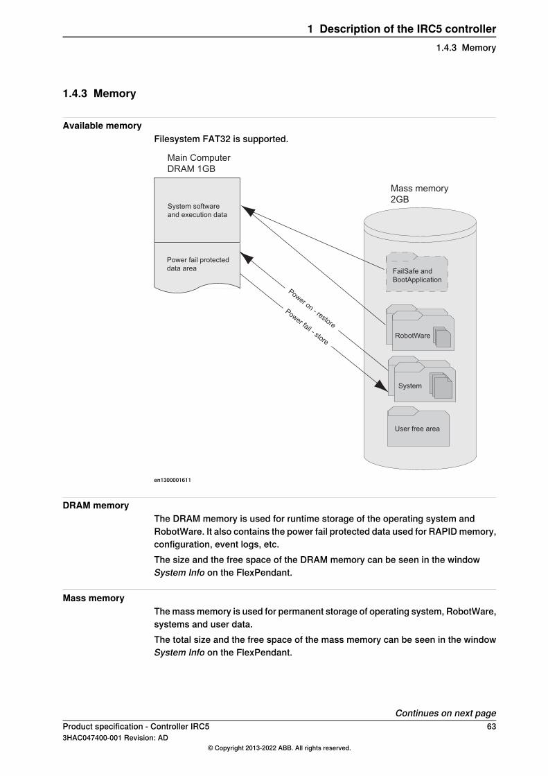
1.4.3 Memory
Available memoryFilesystem FAT32 is supported.
System
User free area
RobotWare
System software
and execution data
Power fail protected
data area
Power on - restore
Power fail - store
Mass memory
2GB
Main Computer
DRAM 1GB
FailSafe and
BootApplication
en1300001611
DRAM memoryThe DRAM memory is used for runtime storage of the operating system andRobotWare. It also contains the power fail protected data used for RAPID memory,configuration, event logs, etc.The size and the free space of the DRAM memory can be seen in the windowSystem Info on the FlexPendant.
Mass memoryThe mass memory is used for permanent storage of operating system, RobotWare,systems and user data.The total size and the free space of the mass memory can be seen in the windowSystem Info on the FlexPendant.
Continues on next pageProduct specification - Controller IRC5 633HAC047400-001 Revision: AD
© Copyright 2013-2022 ABB. All rights reserved.
1 Description of the IRC5 controller1.4.3 Memory

RAPID memoryThe RAPID memory consists of an internal representation of the RAPID programsand data. The memory also contains runtime stacks and data that are needed forthe RAPID interpreter.The RAPID memory is power fail protected and therefore the programs and datado not need to be reloaded after system powered off/on.The total available memory for user programs can vary depending on the numberof installed RobotWare options. The total size of the RAPID memory is staticallyallocated and will not vary during runtime.The total size and the free space of the RAPID memory can be seen in the windowSystem Info the FlexPendant.The storage allocated for the programs depends on the type of data and instructionsthat are used and not on the size of the program files on disk, see Example ofRAPID memory consumption on page 64.
Note
RAPID tasks in a Multitasking and MultiMove system share the same memory.
Example of RAPID memory consumptionFor details on RAPID memory consumption, see Technical referencemanual - RAPID kernel.
Robtarget namedRobtarget marked (*)Introduction
552 bytes312 bytesMoveL or MoveJ
64 Product specification - Controller IRC53HAC047400-001 Revision: AD
© Copyright 2013-2022 ABB. All rights reserved.
1 Description of the IRC5 controller1.4.3 MemoryContinued

1.4.4 I/O system
Fieldbus master/slaveThere is a choice of different fieldbus types (option):
Number of I/O unitsDescriptionOption
20PCIe card certified by ABB includedDeviceNetTM
20PCIe card certified by ABB includedPROFIBUS DP Master
50Software basedPROFINET IO SW
20 units (4049 signals/unit)Software basedEtherNet/IPTM
This makes it possible to mount the I/O units either inside the cabinet or outsidethe cabinet with a bus cable connecting the I/O unit to the cabinet.Multiple fieldbuses can be installed in parallel with both master and slavefunctionality. Maximum total number of I/O units is 40.For all bus types commercially available third party I/O units can be used.For DeviceNetTM , a number of different I/O units are available from ABB, see ABBDeviceNetTM I/O units (node types) on page 70, and Internal DeviceNet I/O onpage 126.
Fieldbus adapter (slave)The adapter is docked directly into the main computer. The adapter consists of aslave unit which enables communication with a master, either of:
• EthernetNet/IPTM
• PROFIBUS DP• PROFINET IO• DEVICNET
Fieldbus gateway (slave)A gateway unit acts as a translator between IRC5 DeviceNetTM and the customerfieldbus master:
• CC-Link
Number of logical signalsThe maximum number of logical signals is 12000 in total for all installed fieldbuses(inputs or outputs, group I/O, analog and digital).
Continues on next pageProduct specification - Controller IRC5 653HAC047400-001 Revision: AD
© Copyright 2013-2022 ABB. All rights reserved.
1 Description of the IRC5 controller1.4.4 I/O system

System signalsSignals can be assigned to special system functions such as program start, so asto be able to control the robot from an additional panel or PLC. Several signals canbe given the same functionality.
Note
For more information on system signals, see Technical referencemanual - Systemparameters.
Digital inputs• Backup• Collision Avoidance• Disable backup• Enable Energy Saving• Interrupt• Limit Speed• Load• Load and Start• Motors Off• Motors On• Motors On and Start• PP to Main• Reset Emergency Stop• Reset Execution Error Signal• SimMode• Soft Stop• Start• Start at Main• Stop• Stop at End of Cycle• Stop at End of Instruction• System Restart• Quick Stop• Write Access
Digital outputs• Absolute Accuracy Active• Auto On• Backup Error• Backup in Progress• Collision Avoidance• CPU Fan Not Running
Continues on next page66 Product specification - Controller IRC5
3HAC047400-001 Revision: AD© Copyright 2013-2022 ABB. All rights reserved.
1 Description of the IRC5 controller1.4.4 I/O systemContinued
• Cycle On• Emergency Stop• Energy Saving Blocked• Execution Error• Limit Speed• Mechanical Unit Active• Mechanical Unit Not Moving• Motion Supervision On• Motion Supervision Triggered• Motors Off• Motors Off State• Motors On• Motors On State• Path Return Region Error• Power Fail Error• Production Execution Error• Run Chain OK• SimMode• Simulated I/O• SMB Battery Charge Low• System Input Busy• TaskExecuting• Temperature Warning• Write Access
Analog outputs• TCP Speed• TCP Speed Reference
General I/OThe inputs and outputs can be configured to suit your installation:
• Each signal and unit can be given a name, for example gripper, feeder• I/O mapping (that is a physical connection for each signal)• Polarity (active high or low)• Cross connections• Up to 32 digital signals can be grouped together and used as a single signal
when, for example, entering a bar code• Sophisticated error handling• Selectable "trust level" (that is what action to take when a unit is "lost")• Program controlled enabling/disabling of I/O units• Scaling of analog signals• Filtering
Continues on next pageProduct specification - Controller IRC5 673HAC047400-001 Revision: AD
© Copyright 2013-2022 ABB. All rights reserved.
1 Description of the IRC5 controller1.4.4 I/O system
Continued
• Pulsing• TCP-proportional analog signal• Programmable delays• Virtual I/O (for forming cross connections or logical conditions without need
for the physical hardware)• Accurate coordination with motion
PLCThe robot can function as a PLC by monitoring and controlling I/O signals:
• I/O instructions are executed concurrent to the robot motion.• Inputs can be connected to trap routines. When such an input is set, the trap
routine starts executing. Following this, normal program execution resumes.In most cases, this will not have any visible effect on the robot motion, aslong as a reasonable number of instructions are executed in the trap routine.
• Background programs (for monitoring signals, for example) can be run inparallel with the actual robot program. This requires the option Multitasking,see Product specification - Controller software IRC5.
Manual functionsManual functions are available to:
• List all the signal values• Create your own list of your most important signals• Manually change the status of an output signal
Scalable I/O
IntroductionScalable I/O is a modular, compact, and scalable I/O system that consists of a baseunit, which is the minimum configuration, and add-on units. Up to four add-on unitscan be controlled by a base unit with maintained performance, and any combinationof add-on units are supported.The I/O devices communicates over the EtherNet/IP communication protocol tothe robot controller or to other EtherNet/IP scanners. When using the standardPlug & Produce interface no additional RobotWare options or hardware optionsare required to connect to the robot controller.In this standard configuration the devices must be connected to the Ethernet portLAN 2 on the main computer.When using the RobotWare option EtherNet/IP Scanner/Adapter more configurationpossibilities are available, and the I/O devices can be connected to any of theEthernet ports WAN, LAN 2, or LAN 3 on the main computer.The add-on devices have an optical interface and must be attached to the basedevice. The additional Ethernet port on the base device can be used to daisy chainany Ethernet based equipment on the same network, for example additional basedevices.
Continues on next page68 Product specification - Controller IRC5
3HAC047400-001 Revision: AD© Copyright 2013-2022 ABB. All rights reserved.
1 Description of the IRC5 controller1.4.4 I/O systemContinued

The I/O devices are designed to be mounted vertically on a mounting rail in anIP20 protected environment with normal air convention. Forced air is needed if thedevices are mounted horizontally.The following I/O devices are available:
• Base module with industrial network connectivity, 16 digital inputs, and 16digital outputs.
• Add-on module with 16 digital inputs and 16 digital outputs.• Add-on module with 4 analog inputs and 4 analog outputs.• Add-on module with 8 digital inputs and 8 relay outputs.
xx1600002032
See options Scalable I/O on page 123.
Features• Easy to install.• Easy to configure in RobotWare with support of the new Plug & Produce
interface.• Compact and scalable.• Can be mounted inside the controller and/or distributed outside.• Supports standard DIN-rail mounting.• Galvanically isolated add-on devices.• Dual port switch for Daisy chaining.
Electrical dataDigital I/O Electrical dataSupply voltage 21 – 28 V DC Output current Nominal 500 mA per output, shortcircuit protected Input voltage levels - 30 – 5 V digital low , 15 – 30 V digital highInput current < 0.5 mA
Continues on next pageProduct specification - Controller IRC5 693HAC047400-001 Revision: AD
© Copyright 2013-2022 ABB. All rights reserved.
1 Description of the IRC5 controller1.4.4 I/O system
Continued
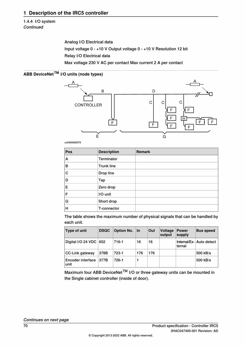
Analog I/O Electrical dataInput voltage 0 - +10 V Output voltage 0 - +10 V Resolution 12 bitRelay I/O Electrical dataMax voltage 230 V AC per contact Max current 2 A per contact
ABB DeviceNetTM I/O units (node types)
CONTROLLER
xx0300000579
RemarkDescriptionPos
TerminatorA
Trunk lineB
Drop lineC
TapD
Zero dropE
I/O unitF
Short dropG
T-connectorH
The table shows the maximum number of physical signals that can be handled byeach unit.
Bus speedPowersupply
Voltageoutput
OutInOption No.DSQCType of unit
Auto detectInternal/Ex-ternal
1616716-1652Digital I/O 24 VDC
500 kB/s176176723-1378BCC-Link gateway
500 kB/s1726-1377BEncoder interfaceunit
Maximum four ABB DeviceNetTM I/O or three gateway units can be mounted inthe Single cabinet controller (inside of door).
Continues on next page70 Product specification - Controller IRC5
3HAC047400-001 Revision: AD© Copyright 2013-2022 ABB. All rights reserved.
1 Description of the IRC5 controller1.4.4 I/O systemContinued
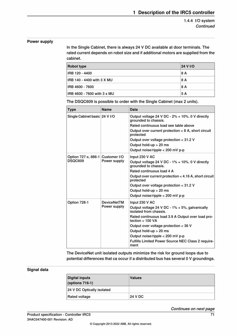
Power supplyIn the Single Cabinet, there is always 24 V DC available at door terminals. Therated current depends on robot size and if additional motors are supplied from thecabinet.
24 V I/ORobot type
8 AIRB 120 - 4400
8 AIRB 140 - 4400 with 3 X MU
8 AIRB 4600 - 7600
5 AIRB 4600 - 7600 with 3 x MU
The DSQC609 is possible to order with the Single Cabinet (max 2 units).
DataNameType
Output voltage 24 V DC - 2% + 10%. 0 V directlygrounded to chassis.
24 V I/OSingle Cabinet basic
Rated continuous load see table aboveOutput over current protection < 8 A, short circuitprotectedOutput over voltage protection < 31.2 VOutput hold-up > 20 msOutput noise/ripple < 200 mV p-p
Input 230 V ACCustomer I/OPower supply
Option 727-x, 886-1DSQC609 Output voltage 24 V DC - 1% + 10%. 0 V directly
grounded to chassis.Rated continuous load 4 AOutput over current protection < 4.16 A, short circuitprotectedOutput over voltage protection < 31.2 VOutput hold-up > 20 msOutput noise/ripple < 200 mV p-p
Input 230 V ACDeviceNetTMPower supply
Option 728-1Output voltage 24 V DC - 1% + 5%, galvanicallyisolated from chassis.Rated continuous load 3.9 A Output over load pro-tection < 100 VAOutput over voltage protection < 36 VOutput hold-up > 20 msOutput noise/ripple < 200 mV p-pFulfills Limited Power Source NEC Class 2 require-ment
The DeviceNet unit isolated outputs minimize the risk for ground loops due topotential differences that ca occur if a distributed bus has several 0 V groundings.
Signal data
ValuesDigital inputs(options 716-1)
24 V DC Optically isolated
24 V DCRated voltage
Continues on next pageProduct specification - Controller IRC5 713HAC047400-001 Revision: AD
© Copyright 2013-2022 ABB. All rights reserved.
1 Description of the IRC5 controller1.4.4 I/O system
Continued

ValuesDigital inputs(options 716-1)
“1” 15 to 35 VLogical voltage levels“0” - 35 to 5 V
6 mAInput current at rated input voltage
max. 500 VPotential difference
hardware filter = 5 ms (± 0.5 ms)Time delayssoftware delay ≤ 0.5 ms i
-1 ms +2 msTime variationsi Software delay time is depending on connection type. The time presented here is for default settings,
Change-Of-State with production inhibit time 10 ms.
ValuesDigital outputs(options 716-1)
short-circuit protected, supply polarity protection24 V DC Optically isolated
19 to 35 VVoltage supply
24 V DCRated voltage
“1” 18 to 34 VLogical voltage levels“0” < 7 V
max. 0.5 A/channelOutput current
max. 500 VPotential difference
hardware ≤ 0.5 msTime delayssoftware ≤ 1 ms
-1ms + 2 msTime variations
72 Product specification - Controller IRC53HAC047400-001 Revision: AD
© Copyright 2013-2022 ABB. All rights reserved.
1 Description of the IRC5 controller1.4.4 I/O systemContinued
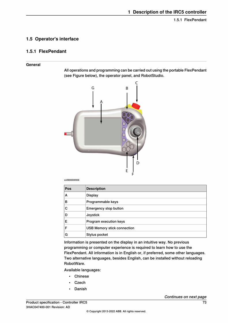
1.5 Operator's interface
1.5.1 FlexPendant
GeneralAll operations and programming can be carried out using the portable FlexPendant(see Figure below), the operator panel, and RobotStudio.
xx0900000936
DescriptionPos
DisplayA
Programmable keysB
Emergency stop buttonC
JoystickD
Program execution keysE
USB Memory stick connectionF
Stylus pocketG
Information is presented on the display in an intuitive way. No previousprogramming or computer experience is required to learn how to use theFlexPendant. All information is in English or, if preferred, some other languages.Two alternative languages, besides English, can be installed without reloadingRobotWare.Available languages:
• Chinese• Czech• Danish
Continues on next pageProduct specification - Controller IRC5 733HAC047400-001 Revision: AD
© Copyright 2013-2022 ABB. All rights reserved.
1 Description of the IRC5 controller1.5.1 FlexPendant

• Dutch• English• Finnish• French• German• Hungarian• Italian• Japanese• Korean• Polish• Portuguese• Romanian• Russian• Slovenian• Spanish• Swedish• Turkish
DescriptionFeatures
A 6.5” color display which displays text as well as graphicalinformation. User input is entered by pressing menu commands,push buttons etc. with the finger or with the supplied stylus onthe display. Several windows can be open simultaneously.Zoom in and out is available in many views.
Display with touchscreen
Many properties of the display can be set by the user for apersonalized look and feel.It is possible to invert the display and joystick directions tomake the FlexPendant suitable for left handed users.The FlexPendant can house powerful user applications builton Microsoft.NET technology.
Keys for program start/stop and stepwise execution for-ward/backward.
Program execution keys
One of the program execution keys must be pressed continu-ously when running the program in manual mode with fullspeed.
Hold-to-run
Four user-defined keys that can be configured to set or resetan output (for example open/close gripper) or to activate asystem input.
Programmable keys
Four action keys for jogging.Jogging keys
A push button which, in manual mode, when pressed halfwayin, takes the system to MOTORS ON.
Three-position enablingdevice
When the three-position enabling device is released or pushedall the way in, the robot is brought to the MOTOR OFF state.
The 3D joystick is used to jog (move) the robot manually; forexample when programming the robot. The user determinesthe speed of this movement, large deflections of the joystickwill move the robot quickly, smaller deflections will move itmore slowly.
Joystick
The robot stops immediately when the button is pressed in.Emergency stop button
Continues on next page74 Product specification - Controller IRC5
3HAC047400-001 Revision: AD© Copyright 2013-2022 ABB. All rights reserved.
1 Description of the IRC5 controller1.5.1 FlexPendantContinued

Example of FlexPendant window
en0400000654
Product specification - Controller IRC5 753HAC047400-001 Revision: AD
© Copyright 2013-2022 ABB. All rights reserved.
1 Description of the IRC5 controller1.5.1 FlexPendant
Continued
1.5.2 RobotStudio
OverviewRobotStudio is a PC application for working efficiently with IRC5 data. RobotStudiocan be seen as a companion to the FlexPendant, where the two complement eachother and each is optimized for its specific tasks. By exploiting the benefits of thispowerful combination, a new efficient way of working can be achieved.The FlexPendant is primarily intended for jogging, teach-in, operation and touch-up,whereas RobotStudio is ideal for dealing with configuration data, programmanagement, on-line documentation and remote access.RobotStudio acts directly on the active data in the controller. Connection to thecontroller can be made locally through the Service PC connection and, if thecontroller is equipped with the RobotWare option PC Interface, over a networkconnection.A safe mastership handling system ensures that RobotStudio can only take controlof a robot if this is acknowledged from the FlexPendant.The main entry to the functionality of RobotStudio is a robot view explorer. Fromthis you select which robot to work with, in case you have several robots installed,and what parts of the system you want to work with.RobotStudio basic delivery contains:
• The Installation Manager for creating, installing and maintaining systems• A Configuration Editor for editing the system parameters of the running
system• A Program Editor for online programming• An Event Recorder for recording and monitoring robot events• Tools for backing up and restoring systems• An administration tool for User Authorization• Other tools for viewing and handling controller and system properties
Access to the full scope of RobotStudio as a powerful off-line programming andsimulating tool is ordered separately.See Operating manual - RobotStudio for detailed information.
Configuration EditorUse the Configuration Editor to make easy and controlled changes of systemparameters on a running system.From the configuration editor you view and edit the system parameters of a specifictopic in a controller. The Configuration Editor has direct communication with thecontroller. This means that changes apply as soon as you complete the command.For some parameters, however, a restart is required in order for the change to takeeffect, in which case you will be notified of this.
Continues on next page76 Product specification - Controller IRC5
3HAC047400-001 Revision: AD© Copyright 2013-2022 ABB. All rights reserved.
1 Description of the IRC5 controller1.5.2 RobotStudio

Program EditorWith the Program Editor you view and edit programs loaded into the controller’sprogram memory. The Program Editor has built in functionality for making it easierto write the RAPID code when programming a robot.
Event RecorderWith the Event Recorder you can view and save events from controllers in yourrobot view. You can start one Event Recorder for each controller.
MiscellaneousRobotStudio has a number of other useful tools, for example:
• Backing up and restoring systems• Administration tool for User Authorization• And other tools for viewing and handling controller and system properties.
for example monitoring of I/O signals
Product specification - Controller IRC5 773HAC047400-001 Revision: AD
© Copyright 2013-2022 ABB. All rights reserved.
1 Description of the IRC5 controller1.5.2 RobotStudio
Continued

1.5.3 Connected Services
Connected Services boxThe purpose of the Connected Services box is to act as a bridge between the robotcontroller and a remote server. The connection between the service box and theremote server is made by using a wireless GPRS or WiFi/3G technology and theInternet. Through the console port and the Ethernet port the information from therobot is buffered, parsed and filtered to obtain valuable service information in theConnected Services application.
xx0900000947
78 Product specification - Controller IRC53HAC047400-001 Revision: AD
© Copyright 2013-2022 ABB. All rights reserved.
1 Description of the IRC5 controller1.5.3 Connected Services

1.6 Programming
1.6.1 Programming
GeneralProgramming the robot can be done both from the FlexPendant or RobotStudioOn the FlexPendant, instructions and arguments are picked from lists of appropriatealternatives. In RobotStudio, programs are typed in a free text format and checkedfor errors when "Apply Changes" is clicked (if no errors, the changes immediatelytake effect in the robot memory).
Programming environmentThe programming environment can be easily customized:
• Shop floor language can be used to name programs, signals, counters, etc• New instructions with suitable names can be created• The most common instructions can be collected in easy-to-use pick lists• Positions, registers, tool data, or other data, can be created
Programs, parts of programs and any modifications can be tested immediatelywithout having to translate (compile) the program.
MovementsA sequence of movements is programmed as a number of partial movementsbetween the positions to which you want the robot to move.
End positionThe end position of a movement is selected either by manually jogging the robotto the desired position with the joystick, by referring to a previously defined positionor by defining numeric values.
Position typesA position can be defined either as:
• a stop point, that is the robot reaches the programmed position.• or a fly-by point, that is the robot passes close to the programmed position.
The size of the deviation is defined independently for the TCP, the toolorientation and the additional axes.
Continues on next pageProduct specification - Controller IRC5 793HAC047400-001 Revision: AD
© Copyright 2013-2022 ABB. All rights reserved.
1 Description of the IRC5 controller1.6.1 Programming
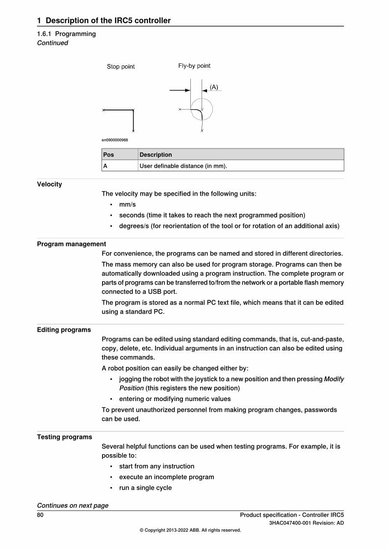
en0900000988
DescriptionPos
User definable distance (in mm).A
VelocityThe velocity may be specified in the following units:
• mm/s• seconds (time it takes to reach the next programmed position)• degrees/s (for reorientation of the tool or for rotation of an additional axis)
Program managementFor convenience, the programs can be named and stored in different directories.The mass memory can also be used for program storage. Programs can then beautomatically downloaded using a program instruction. The complete program orparts of programs can be transferred to/from the network or a portable flash memoryconnected to a USB port.The program is stored as a normal PC text file, which means that it can be editedusing a standard PC.
Editing programsPrograms can be edited using standard editing commands, that is, cut-and-paste,copy, delete, etc. Individual arguments in an instruction can also be edited usingthese commands.A robot position can easily be changed either by:
• jogging the robot with the joystick to a new position and then pressingModifyPosition (this registers the new position)
• entering or modifying numeric valuesTo prevent unauthorized personnel from making program changes, passwordscan be used.
Testing programsSeveral helpful functions can be used when testing programs. For example, it ispossible to:
• start from any instruction• execute an incomplete program• run a single cycle
Continues on next page80 Product specification - Controller IRC5
3HAC047400-001 Revision: AD© Copyright 2013-2022 ABB. All rights reserved.
1 Description of the IRC5 controller1.6.1 ProgrammingContinued
• execute forwards/backwards step-by-step• simulate wait conditions• temporarily reduce the speed• change a position
For more information, seeOperatingmanual - IRC5with FlexPendant andOperatingmanual - RobotStudio.
Product specification - Controller IRC5 813HAC047400-001 Revision: AD
© Copyright 2013-2022 ABB. All rights reserved.
1 Description of the IRC5 controller1.6.1 Programming
Continued
1.6.2 Automatic operation
GeneralA dedicated production window with commands and information required by theoperator is displayed during automatic operation.The operation procedure can be customized to suit the robot installation by meansof user-defined displays and dialogs.The robot can be ordered to go to a service position when a specific signal is set.After service, the robot is ordered to return to the programmed path and continueprogram execution.
Special routinesYou can also create special routines that will be automatically executed when thepower is switched on, at program start and on other occasions. This allows you tocustomize each installation and to make sure that the robot is started up in acontrolled way.
Absolute measurementThe robot is equipped with absolute measurement, making it possible to operatethe robot directly when the power is switched on. For your convenience, the robotsaves the used path, program data and configuration parameters so that theprogram can be easily restarted from where you left off. Digital outputs are alsoset automatically to the value prior to the power failure if this behavior has beenselected.
82 Product specification - Controller IRC53HAC047400-001 Revision: AD
© Copyright 2013-2022 ABB. All rights reserved.
1 Description of the IRC5 controller1.6.2 Automatic operation
1.6.3 RAPID language and environment
GeneralThe RAPID language is a well balanced combination of simplicity, flexibility andpower. It contains the following concepts:
• Hierarchical and modular program structure to support structuredprogramming and reuse
• Routines can be Functions or Procedures• Local or global data and routines• Data typing, including structured and array data types• User defined names on variables, routines and I/O• Extensive program flow control• Arithmetic and logical expressions• Interrupt handling• Error handling (for exception handling in general, see Exception handling
on page 84)• User defined instructions (appear as an inherent part of the system)• Backward handler (user definition of how a procedure should behave when
stepping backwards)• Many powerful built-in functions, for example mathematics and robot specific• Unlimited language (no max. number of variables etc., only memory limited).
Built-in RAPID support in user interfaces, for example user defined pick lists,facilitate working with RAPID
Product specification - Controller IRC5 833HAC047400-001 Revision: AD
© Copyright 2013-2022 ABB. All rights reserved.
1 Description of the IRC5 controller1.6.3 RAPID language and environment

1.6.4 Exception handling
GeneralMany advanced features are available to make fast error recovery possible. Theerror recovery features easily adapt to a specific installation in order to minimizedown time.
Examples• Error Handlers (automatic recovery often possible without stopping
production)• Restart on Path• Power failure restart• Service routines• Error messages: plain text with remedy suggestions, user defined messages• Diagnostic tests• Event logging
84 Product specification - Controller IRC53HAC047400-001 Revision: AD
© Copyright 2013-2022 ABB. All rights reserved.
1 Description of the IRC5 controller1.6.4 Exception handling

1.6.5 Robot motion
QuickMoveTM
The QuickMoveTM concept means that a self-optimizing motion control is used.The robot automatically optimizes the servo parameters to achieve the best possibleperformance throughout the cycle - based on load properties, location in workingarea, velocity and direction of movement.
• No parameters have to be adjusted to achieve correct path, orientation andvelocity.
• Maximum acceleration is always obtained (acceleration can be reduced, forexample when handling fragile parts).
• The number of adjustments that have to be made to achieve the shortestpossible cycle time is minimized.
TrueMoveTM
The TrueMoveTM concept means that the programmed path is followed - regardlessof the speed or operating mode - even after a safeguarded stop, a process stop,a program stop or a power failure.This very accurate path and speed are based on advanced dynamic modelling.
Continues on next pageProduct specification - Controller IRC5 853HAC047400-001 Revision: AD
© Copyright 2013-2022 ABB. All rights reserved.
1 Description of the IRC5 controller1.6.5 Robot motion
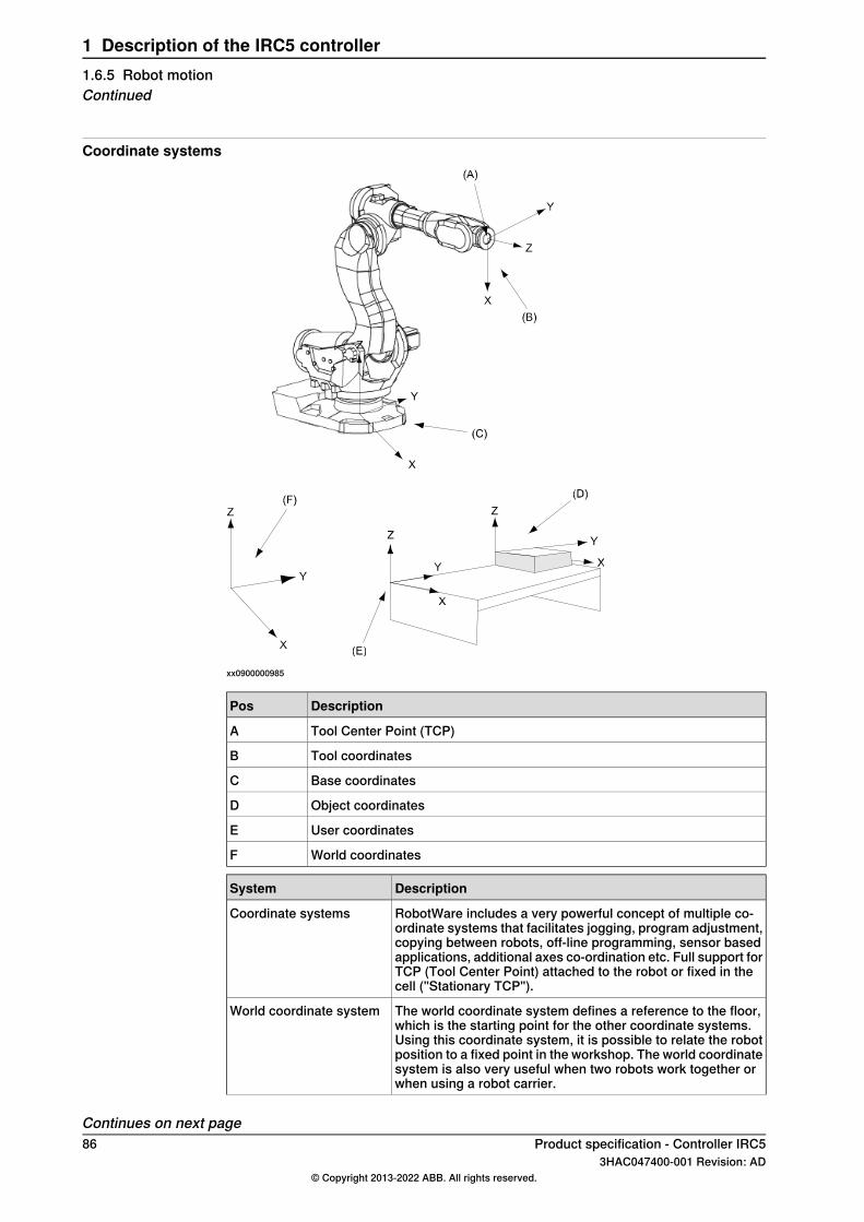
Coordinate systems
xx0900000985
DescriptionPos
Tool Center Point (TCP)A
Tool coordinatesB
Base coordinatesC
Object coordinatesD
User coordinatesE
World coordinatesF
DescriptionSystem
RobotWare includes a very powerful concept of multiple co-ordinate systems that facilitates jogging, program adjustment,copying between robots, off-line programming, sensor basedapplications, additional axes co-ordination etc. Full support forTCP (Tool Center Point) attached to the robot or fixed in thecell ("Stationary TCP").
Coordinate systems
The world coordinate system defines a reference to the floor,which is the starting point for the other coordinate systems.Using this coordinate system, it is possible to relate the robotposition to a fixed point in the workshop. The world coordinatesystem is also very useful when two robots work together orwhen using a robot carrier.
World coordinate system
Continues on next page86 Product specification - Controller IRC5
3HAC047400-001 Revision: AD© Copyright 2013-2022 ABB. All rights reserved.
1 Description of the IRC5 controller1.6.5 Robot motionContinued

DescriptionSystem
The base coordinate system is attached to the base mountingsurface of the robot.
Base coordinate system
The tool coordinate system specifies the tool's center pointand orientation.
Tool coordinate system
The user coordinate system specifies the position of a fixtureor workpiece manipulator.
User coordinate system
The object coordinate system specifies how a workpiece ispositioned in a fixture or workpiece manipulator.
Object coordinate system
The coordinate systems can be programmed by specifyingnumeric values or jogging the robot through a number of posi-tions (the tool does not have to be removed).Each position is specified in object coordinates with respectto the tool’s position and orientation. This means that even ifa tool is changed because it is damaged, the old program canstill be used, unchanged, by making a new definition of thetool.If a fixture or workpiece is moved, only the user or object co-ordinate system has to be redefined.
When the robot is holding a work object and working on a sta-tionary tool, it is possible to define a TCP for that tool. Whenthat tool is active, the programmed path and speed are relatedto the work object.
Stationary TCP
If the location of a workpiece varies from time to time, the robotcan find its position by means of a digital sensor. The robotprogram can then be modified in order to adjust the motion tothe location of the part.
Program displacement
Additional features
DescriptionSystem
The robot can move in any of the following ways:• Joint motion (all axes move individually and reach the
programmed position at the same time).• Linear motion (the TCP moves in a linear path).• Circle motion (the TCP moves in a circular path).
Program execution
Soft servo - allowing external forces to cause deviation fromprogrammed position - can be used as an alternative tomechanical compliance in grippers, where imperfection inprocessed objects can occur.
Soft servo
Any motors (also additional) can be switched to soft servomode, which means that it will adopt a spring-like behavior.
The robot can be manually operated in any one of the followingways:
• Axis-by-axis, that is one axis at a time.• Linearly, that is the TCP moves in a linear path (relative
to one of the coordinate systems mentioned above).• Reoriented around the TCP.
It is possible to select the step size for incremental jogging.Incremental jogging can be used to position the robot with highprecision, since the robot moves a short distance each timethe joystick is moved.
Jogging
During manual operation, the current position of the robot andthe additional axes can be displayed on the FlexPendant.
Continues on next pageProduct specification - Controller IRC5 873HAC047400-001 Revision: AD
© Copyright 2013-2022 ABB. All rights reserved.
1 Description of the IRC5 controller1.6.5 Robot motion
Continued

DescriptionSystem
The robot can pass through singular points in a controlled way,that is points where two axes coincide.
Singularity handling
The behavior of the motion system is continuously monitoredin regards to position and speed level to detect abnormalconditions and quickly stop the robot if something is not OK.A further monitoring function, Collision Detection, is optional(see option Collision Detection, described in Product specific-ation - Controller software IRC5).
Motion supervision
Very flexible possibilities to configure additional motors. In-cludes for instance high performance coordination with robotmovement and shared drive unit for several motors.
Additional motors
One side effect of the dynamic model concept is that the systemcan handle very big load inertias by automatically adapting theperformance to a suitable level. For big, flexible objects it ispossible to optimize the servo tuning to minimize load oscilla-tion.
Big inertia
The robot can automatically identify the load properties andthus ensures a correct dynamic model of the total arm system.This leads to optimum performance and life time, without needfor cumbersome manual calculations or measurements. Loadidentification is available for most robots, and positioners IRBP.For more information, see Operating manual - IRC5 with Flex-Pendant.
Load identification
88 Product specification - Controller IRC53HAC047400-001 Revision: AD
© Copyright 2013-2022 ABB. All rights reserved.
1 Description of the IRC5 controller1.6.5 Robot motionContinued

1.7 Additional safety options
1.7.1 Electronic Position Switches [810-1]
GeneralElectronic Position Switches (EPS) is an additional safety computer in the controller,with the purpose of providing safe output signals representing the position of robotaxes. The output signals are typically connected to cell safety circuitry and/or asafety PLC which takes care of interlocking the robot cell, for example in order toprevent robot and operator to enter a common area simultaneously. SeeApplicationmanual - Electronic Position Switches.
Features• Safety classification according to EN 954-1: Category 3• Supervision of all robot axes.• No installation on manipulator.• 5 safe outputs, representing status for signal axis or a combination of axes.• Safe input from a synchronization switch for repeated checks during
production• Access to status of safe outputs from RAPID, without any wiring• EPS replaces mechanical position switches
Option contentThe following is included with the option delivery
• The safety computer unit, installed close to the axis computer• A 14 pole connector plug for I/O connection.• EPS Configuration Wizard, add-in software to RobotStudio. With EPS
Configuration Wizard you can:- Set up supervision of all robot axes- Quickly modify the supervision settings (password protected)- Print a safety certificate
Limitations• Additional axis, including track motion, positioners etc. connected to
measurement link 2 can not be supervised.• Continuous rotation axes cannot be supervised.• Drive unit cannot be shared for supervised axes, for example between tools.• Not available for IRB 120 and IRB 360.• Not available for non IRB mechanical units.
Product specification - Controller IRC5 893HAC047400-001 Revision: AD
© Copyright 2013-2022 ABB. All rights reserved.
1 Description of the IRC5 controller1.7.1 Electronic Position Switches [810-1]

1.7.2 SafeMove [810-2]
PurposeSafeMove is a safety controller in the robot system. The purpose of the safetycontroller is to ensure a high safety level in the robot system using supervisionfunctions that can stop the robot and monitoring functions that can set safe digitaloutput signals.The supervision functions can be activated by safe digital input signals. Both inputand output signals can be connected to, for instance, a safety PLC that can controlwhich behavior is allowed for the robot at different times.The safety controller also sends status signals to the main computer, that is thestandard IRC5 robot controller.Note that SafeMove is one component in a cell safety system, normallycomplemented by other equipment, e.g. light barriers, for detecting the whereaboutsof the operator.Some examples of applications:
• Manual loading of gripper• Manual inspection in robot cell during operation• Optimization of cell size• Protection of sensitive equipment• Ensuring safe orientation of emitting processes
What is includedThe following is included with the option SafeMove [810-2]:
• Safety controller, DSQC 647 (3HAC026272-001)• Two 12 pole plug contacts and two 10 pole plug contacts for I/O connections.
The option SafeMove gives you access to SafeMove Configurator functionality inRobotStudio.With SafeMove Configurator you can:
• configure supervision functions (active supervision that can stop the robot)• configure activation signals for the supervision functions• configure monitoring functions (passive monitoring, only sets output signals)• configure output signals for the monitoring functions• easily modify the configuration
Supported robotsThe following robot families are supported by SafeMove1:
• IRB 140• IRB 260• IRB 460• IRB 660• IRB 760• IRB 1400
Continues on next page90 Product specification - Controller IRC5
3HAC047400-001 Revision: AD© Copyright 2013-2022 ABB. All rights reserved.
1 Description of the IRC5 controller1.7.2 SafeMove [810-2]

• IRB 1410• IRB 1600/1660• IRB 2400• IRB 2600• IRB 4400• IRB 4600• IRB 6620• IRB 6640• IRB 6660• IRB 6650S• IRB 6700• IRB 6790• IRB 7600• IRB 8700
Other robot models are not supported.SafeMove cannot be used for parallel arm robots, such as IRB 360.SafeMove can only be used together with floor mounted robots.
Supported additional axesBasically the SafeMove option only supports ABB track motion units.Non ABB track motion units, non ABB positioners, and other additional axis maybe supported by the SafeMove option but this needs to be verified case by case.The SafeMove option only supports additional axes that are single axis mechanicalunits. For example, two axes positioners cannot be supported.Further, there are always the following upper and lower work area limitations:
• Track unit length (arm side) max ± 100 m• Rotating axis (arm side) max ± 25 700 degrees or ± 448 radians
On the motor side there is also a limitation of ± 32 000 revolutions.
Stand alone controllerStand alone controller or drive module without TCP-robot, are not supported bySafeMove.
Servo welding gunSafeMove does not support supervision of servo welding guns. That is, the robotaxes can be supervised, but not the axis of the servo welding gun.
Tool changerSafeMove supports up to 4 different tools. All included tools must have theirappropriate settings in the configuration file. Selection of tool to be supervised isdone by 2 binary coded safe inputs on SafeMove.
Continues on next pageProduct specification - Controller IRC5 913HAC047400-001 Revision: AD
© Copyright 2013-2022 ABB. All rights reserved.
1 Description of the IRC5 controller1.7.2 SafeMove [810-2]
Continued

Robot mounted on rotational axisSafeMove does not support supervision or monitoring of a robot mounted on arotational axis.
No deactivationAll supervised and monitored axes must be active all the time. SafeMove does notsupport activation/deactivation of additional axis.The ABB positioners normally use the activation/deactivation feature and thereforethey are not supported by SafeMove.
Independent jointIndependent joint cannot be monitored by SafeMove.
Shared drive modulesDrive units of supervised and monitored axes cannot be shared, for instancebetween positioner axes.
Track motion coordinatesWhen a robot is mounted on a track motion, the following limitations apply:
• It is only possible to define a rotation (no translation) of the robot base framerelative the track motion base frame.
• It is only possible to define a translation (no rotation) of the track motionbase frame relative the world frame.
Limit switch override cannot be usedIf the option SafeMove is used, it is not allowed to connect any signal to the limitswitch override (X23 on the contactor board).
RAPID non motion executionThis test feature cannot fully be used together with the SafeMove option.
Borderline positionsIn very rare cases an error message, elog 20473, might be presented if the robotis stopped for a time longer than 40 min in a position exactly on the border of thedefined range. This is because of the internal safe design of the SafeMovecontroller, using a safe two channel microprocessor solution.
Tip
To avoid this, never leave the robot for a longer period in a position near theborders of Monitor Axis Range.
Continues on next page92 Product specification - Controller IRC5
3HAC047400-001 Revision: AD© Copyright 2013-2022 ABB. All rights reserved.
1 Description of the IRC5 controller1.7.2 SafeMove [810-2]Continued

Alternative calibration positionThe alternative calibration position, which can be used for robots and additionalaxes, is not supported by SafeMove. The calibration position shall be defined tozero position.
Note
Calibration position is set in the system parameter Calibration Position, whichis found under topic Motion and type Arm.
MultiMoveIt is not supported to use a mixture of EPS (Electronic Position Switches) andSafeMove in a MultiMove installation. However, robots can be used with or withoutSafeMove in a mixed setup.
Product specification - Controller IRC5 933HAC047400-001 Revision: AD
© Copyright 2013-2022 ABB. All rights reserved.
1 Description of the IRC5 controller1.7.2 SafeMove [810-2]
Continued

1.7.3 SafeMove Basic [1125-1] and SafeMove Pro [1125-2]
PurposeThe purpose of the safety module and the functional safety options is to providea robust and easy-to-use safety controller in the robot system. Functional safetyincludes a complete software and hardware solution that is fully integrated withthe robot controller and the RobotStudio programming environment.SafeMove is the main functional safety option, but the safety module can also beused in various applications without the SafeMove option. For example tocommunicate with a safety PLC through safe fieldbus communication, or whenusing the keyless mode selector.
SafeMove functionsWhen using SafeMove, the safety controller ensures a high safety level in the robotsystem by using supervision functions that can stop the robot. Note that the safetymodule and the functional safety options is one component in the safety systemof a complete robot cell, normally complemented by other equipment (for examplelight barriers) for detecting the whereabouts of the operator.
DescriptionFunction
Protects the operator and enhances machine and equipment safetyby supervising the position (Tool Position Supervision), speed (ToolSpeed Supervision) and orientation (Tool Orientation Supervision)of the tool.
Tool supervisionfunctions
Protects the surroundings by supervising the axis position (AxisPosition Supervision) and the axis speed (Axis Speed Supervision).
Axis supervisionfunctions
Supervises the stand-still of robot axes without having to switch therobot to Motors Off. It enables operators to perform tasks in theimmediate vicinity of the robot.
Stand Still Supervi-sion
Allows the robot to be in contact with the work-piece in limited areas.This can for example be used in applications where the robot isused for grinding or during tool change.
Contact applicationtolerance
Supervises that the brakes are checked with a cyclic interval.Cyclic brake check
Triggers stop of the robot using safe fieldbus inputs from the safetyPLC.
Stop functions
Some examples of applications:• Manual loading stations• Manual workpiece inspection during operation• Optimization of cell size• Protection of sensitive equipment• Ensuring safe orientation of emitting processes
Functional safety optionsTo use SafeMove or any of the functional safety options it is necessary to havethe safety module in the IRC5 controller:
• [996-1] Safety module (DSQC1015)
Continues on next page94 Product specification - Controller IRC5
3HAC047400-001 Revision: AD© Copyright 2013-2022 ABB. All rights reserved.
1 Description of the IRC5 controller1.7.3 SafeMove Basic [1125-1] and SafeMove Pro [1125-2]

The following options can be ordered together with the safety module:• [997-1] PROFIsafe F-Device• [997-2] PROFIsafe F-Host&Device• [997-3] CIP Safety Adapter• [997-4] CIP Safety Scanner And Adapter• [1241-1] Prepared for ABB CI502• [1125-1] SafeMove Basic• [1125-2] SafeMove Pro• [735-7] Keyless Mode Selector, 3 modes• [735-8] Keyless Mode Selector, 2 modes• [731-1] Safety Internal conn.• [731-2] Safety external conn.
Visual SafeMoveThe safety module option gives you access to the Visual SafeMove configuratorin RobotStudio. With Visual SafeMove you can:
• configure and visualize supervision functions in a 3D environment.• configure stop functions, such as automatic stop.• configure Cyclic Brake Check.• configure safe signals (safe Ethernet communication and I/Os are configured
in I/O Engineering Tool).• configure signal logics.• configure system status outputs.
SafeMove Basic and SafeMove ProThe below table lists the differences between SafeMove Basic and SafeMove Pro.
SafeMove BasicSafeMove ProFunction
99Supported number of axes
88Safe ranges
116Safe zones
-16 toolsTool changer support
YesYesAxis Position Supervision
-YesAxis Speed Supervision
88Total Global Supervision
-YesTool Orientation Supervision
1YesTool Position Supervision
-YesTool Speed Supervision
-YesStand Still Supervision
YesYesContact application support
Continues on next pageProduct specification - Controller IRC5 953HAC047400-001 Revision: AD
© Copyright 2013-2022 ABB. All rights reserved.
1 Description of the IRC5 controller1.7.3 SafeMove Basic [1125-1] and SafeMove Pro [1125-2]
Continued

Basic approachThis is the general approach for setting up the safety module and SafeMove.
1 Connect the safety controller to other safety hardware and configure the safeI/O connections.
2 Configure the settings for the SafeMove functions.3 Download the configuration to the the safety controller. Restart the controller.4 Synchronize the safety controller.5 Make sure the activation input signals are activating the desired supervision
functions.6 Validate the configuration.7 Lock the configuration.
RequirementsRobust supervision functionality in SafeMove requires correct settings of payloadand additional axes, since this will affect the calculated accepted servo lag. Alsonote that external forces applied on the manipulator can cause a negative influenceon the supervision functions, since the servo lag might differ from the calculatedvalues, due to such external forces.
DANGER
A SafeMove configuration must always be validated to verify that the desiredsafety is achieved. If no validation is performed, or the validation is inadequate,the configuration cannot be relied on for personal safety.The validation must also consider that the braking starts after a zone is violated,so additional stopping distances may be required, which depend on many factors,for example mass and speed.
Continues on next page96 Product specification - Controller IRC5
3HAC047400-001 Revision: AD© Copyright 2013-2022 ABB. All rights reserved.
1 Description of the IRC5 controller1.7.3 SafeMove Basic [1125-1] and SafeMove Pro [1125-2]Continued
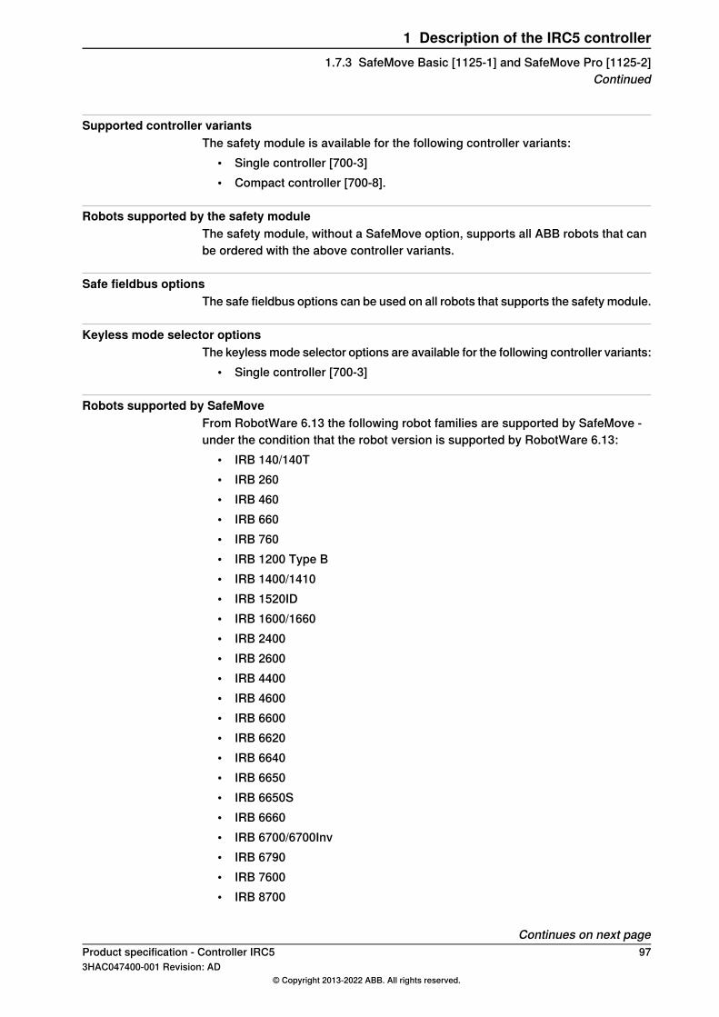
Supported controller variantsThe safety module is available for the following controller variants:
• Single controller [700-3]• Compact controller [700-8].
Robots supported by the safety moduleThe safety module, without a SafeMove option, supports all ABB robots that canbe ordered with the above controller variants.
Safe fieldbus optionsThe safe fieldbus options can be used on all robots that supports the safety module.
Keyless mode selector optionsThe keyless mode selector options are available for the following controller variants:
• Single controller [700-3]
Robots supported by SafeMoveFrom RobotWare 6.13 the following robot families are supported by SafeMove -under the condition that the robot version is supported by RobotWare 6.13:
• IRB 140/140T• IRB 260• IRB 460• IRB 660• IRB 760• IRB 1200 Type B• IRB 1400/1410• IRB 1520ID• IRB 1600/1660• IRB 2400• IRB 2600• IRB 4400• IRB 4600• IRB 6600• IRB 6620• IRB 6640• IRB 6650• IRB 6650S• IRB 6660• IRB 6700/6700Inv• IRB 6790• IRB 7600• IRB 8700
Continues on next pageProduct specification - Controller IRC5 973HAC047400-001 Revision: AD
© Copyright 2013-2022 ABB. All rights reserved.
1 Description of the IRC5 controller1.7.3 SafeMove Basic [1125-1] and SafeMove Pro [1125-2]
Continued

Note
In MultiMove systems with SafeMove pro/basic, robot IRB 1200 type A cannotbe included. The option SafeMove will be excluded for all robots in the systemeven if they are supported by SafeMove.
Note
This also includes ID and LeanID versions.
Note
For information on supported paint robots, see Application manual - Functionalsafety and SafeMove for paint.
Note
Other robot models are not supported, for example:• SafeMove does not support parallel arm robots, such as the IRB 360.• SafeMove does not support SCARA robots, such as the IRB 910.
Supported mounting anglesSafeMove supports any mounting angle. For example floor mounted, tilted, inverted,etcetera.
Supported tracksSafeMove supports all ABB track motion units.
Supported positionersSafeMove supports positioners that are single axis mechanical units. Positionerswith several axes are treated as multiple single axes, for example two axespositioners will be treated by SafeMove as two single axes and can be monitoredas such using axis supervision.Positioners that are used with activation/deactivation feature, is not supported.The axes of the positioner must be active at all times.
Servo welding gunSafeMove does not support supervision of servo welding guns. That is, the robotaxes can be supervised, but not the axis of the servo welding gun.
Non ABB additional axesNon ABB track motion units, non ABB positioners, and other additional axis maybe supported by the SafeMove option but this needs to be verified case by case.To verify if a non ABB additional axis can be used with SafeMove, tune the additionalaxis before configuring the SafeMove parameters. If a properly tuned and configurednon ABB additional axis still generates error messages regarding servo lag, then
Continues on next page98 Product specification - Controller IRC5
3HAC047400-001 Revision: AD© Copyright 2013-2022 ABB. All rights reserved.
1 Description of the IRC5 controller1.7.3 SafeMove Basic [1125-1] and SafeMove Pro [1125-2]Continued

it cannot be used with SafeMove. For more information about tuning an additionalaxis see Application manual - Additional axes and stand alone controller.
Work area for additional axesThere are always the following upper and lower work area limitations for additionalaxes:
• Track unit length (arm side) max ± 448 m• Rotating axis (arm side) max ± 25700 degrees or ± 448 radians
On the motor side there is also a limitation of ± 32000 revolutions.
Combined external axes and robot with gantrySafeMove does not support supervision of combined external axes, such as agantry, or supervision of robots moved by the gantry.It is possible to supervise robots moved by a gantry using the Basic joint supervisionmode. In Basic joint supervision mode, only SafeMove functions working on axesare available.
Basic joint supervision modeIn Basic joint supervision mode, SafeMove supports supervision of some robotsand external axes that are not normally allowed. Examples are robots mounted ona gantry, or other non-track external axes.In Basic joint supervision mode, no safe zones or tool supervision functions areallowed. In addition, there are changes to some internal SafeMove supervisionfunctions:
• The manual mode speed supervision of the TCP, wrist center point, andelbow are disabled. Instead, axis speed limits are set to approximate aCartesian speed limit. The user is responsible for validating that this speedlimit satisfies the requirements for safe manual mode operation.
• The Safe Brake Ramp supervision for the robot during a category 1 stop ischanged, so that SafeMove supervises that all robot axes will stop within 1second.
Stand alone controllerSafeMove supports Stand alone controller and drive modules without TCP-robotwith up to six additional axes. The axes are handled as external single axis.Only SafeMove functions working on axes are available. The functions are:
• Axis Position Supervision (APO)• Axis Speed Supervision (ASP)• Stand Still Supervision (SST)• Safe Brake Ramp
All other functions are deactivated.
Continues on next pageProduct specification - Controller IRC5 993HAC047400-001 Revision: AD
© Copyright 2013-2022 ABB. All rights reserved.
1 Description of the IRC5 controller1.7.3 SafeMove Basic [1125-1] and SafeMove Pro [1125-2]
Continued
Tool changerSafeMove Pro supports up to 16 different tools. All included tools must have theirappropriate settings in the configuration file. The selection of tool must besupervised using a safe fieldbus.
Robot mounted on rotational axisSafeMove does not support supervision of a robot mounted on a rotational axis.Using the Basic joint supervision mode, axis monitoring will be possible but thetool supervision functions are not supported.
No deactivationAdditional axes that are used with activation/deactivation feature are not supported.If additional axes are to be used, they must also be active at all times.
Independent jointIndependent joint cannot be monitored by SafeMove.
Electronically linked motorsSafeMove supports supervision of additional axes using Electronically LinkedMotors. Using this feature may cause servo lag problems, particularly if the followeraxis is included in the safety configuration. It may be necessary to modify the tuningof the axes, or increase the tolerances in the SafeMove configuration. Theperformance should be verified case by case.
Shared drive modulesDrive units of supervised axes cannot be shared, for instance between positioneraxes.
Superior StopIf the safety module is used, it is not allowed to connect any signal to the SuperiorStop input on the Panel Board.If the safety module is used, the configured value for the parameter Soft SuperiorStop (SoftSS) is ignored and Superior Stop will always use a category 0 stop.
RAPID non motion executionThis test feature cannot fully be used together with the SafeMove option.
SoftMoveWhen SafeMove is used together with SoftMove there is a risk for servo lagproblems. The recommended action is to add a Contact Application Tolerance(CAP) in the area where SoftMove is active.For more information about SoftMove, see Application manual - Spot options andApplication manual - SoftMove.
100 Product specification - Controller IRC53HAC047400-001 Revision: AD
© Copyright 2013-2022 ABB. All rights reserved.
1 Description of the IRC5 controller1.7.3 SafeMove Basic [1125-1] and SafeMove Pro [1125-2]Continued

2 Specification of variants and options2.1 Introduction to variants and options
GeneralThe different variants and options for the controller are described below. The sameoption numbers and structure are used here as in the specification form.For details about manipulator options, see the product specification for therespective manipulator.For software options, see Product specification - Controller software IRC5.
Product specification - Controller IRC5 1013HAC047400-001 Revision: AD
© Copyright 2013-2022 ABB. All rights reserved.
2 Specification of variants and options2.1 Introduction to variants and options

2.2 Basic
2.2.1 Controller variants
Drive module [700-1]Additional drive modules can be ordered together with the single controller tocontrol additional axes or additional robots, MultiMove.Up to three additional axes can be controlled by each drive module, and up to threeadditional drive modules can be connected.For more information, see section Drive module on page 141.
xx1500000255
AluzinkController colorA
Operator's panelB
All cable connections at the front,optional covered
Connector coversC
NCS 2502 B (light grey)Controller color, door and connector coversD
BlackController color, feet and lifting eyesE
WeightData
100-130 kgDrive module
35 kgEmpty cabinet small
42 kgEmpty cabinet large
Volume (H x W x D)Data
720 x 725 x 710 mmDrive module small
Continues on next page102 Product specification - Controller IRC5
3HAC047400-001 Revision: AD© Copyright 2013-2022 ABB. All rights reserved.
2 Specification of variants and options2.2.1 Controller variants

Single cabinet [700-3]This option is the standard selection for all robots, also for a MultiMove main robot.For more information, see section Control module on page 116.
xx1300000791
AluzinkController colorA
Operator's panelB
All cable connections at the front,optional covered
Connector coversC
NCS 2502 B (light grey)Controller color, door and connector coversD
BlackController color, feet and lifting eyesE
WeightData
max 150 kgSingle cabinet controller
Volume (H x W x D)Data
970 x 725 x 710 mmSingle cabinet controllerEmpty cabinet large
Continues on next pageProduct specification - Controller IRC5 1033HAC047400-001 Revision: AD
© Copyright 2013-2022 ABB. All rights reserved.
2 Specification of variants and options2.2.1 Controller variants
Continued

Panel Mounted Controller [700-5]The IRC5 Panel Mounted Controller (PMC), is a concept where the controller canbe mounted in a customer cabinet for example when there are special demandson size reduction or hygienic encapsulation.For MultiMove applications the robot ca be ordered with only the drive module.Two versions of Panel Mounted Controller are available, depending on robot versionand size, PMC Small and PMC Large. The difference is the size of drive units inthe Drive module.For more information, see Controller variants on page 11.
A
B
C
xx1100000484
Control ModuleA
Drive Module (different design for PMC small and PMC large)B
Fan unit (for PMC large this is a part of the Drive Module)C
Panel Mounted Drive unit [700-6]Additional drive module for Panel Mounted Controller, small or large. This controlleris intended for integration in customer equipment.For more information, see Controller variants on page 11.
Continues on next page104 Product specification - Controller IRC5
3HAC047400-001 Revision: AD© Copyright 2013-2022 ABB. All rights reserved.
2 Specification of variants and options2.2.1 Controller variantsContinued

Compact controller 2nd generation [700-8]Compact 2nd generation The Compact controller is the standard controller for IRB120, 910SC. Available also for IRB 140, 1200, 1410, 1600, 260 and 360.
xx1400001368
Volume (H x W x D)Data
310 x 449 x 442 mmCompact controller
For more information see section IRC5 Compact controller on page 29.
Continues on next pageProduct specification - Controller IRC5 1053HAC047400-001 Revision: AD
© Copyright 2013-2022 ABB. All rights reserved.
2 Specification of variants and options2.2.1 Controller variants
Continued

IRC5C controller mounting kit [984-1]Enables controller to be mounted in std. 19 inch rack enclosure
xx1400002112
Underwriters Laboratory [429-1]UL/CSAThe robot and the control system are certified by Underwriters Laboratories tocomply with the Safety Standard ANSI/UL 1740-1998 Industrial Robots and RoboticEquipment and CAN/CSA Z 434-94. Law for UL/CSA certification is required insome US states and Canada.UL (UL listed) means certification of the complete robot product. The option isvisualized by a “UL” label attached to the cabinet.
Note
Note that the variant Panel Mounted Controller is labelled UR (UL recognized)as standard
Other required options:• Safety lamp on the manipulator arm (213-1), exception IRB 120 where the
integrator has to take care of the lamp• Door interlock (744-1 or 742-1)• Operating mode selector limited speed max 250 mm/s (735-2 or 735-4 or
735-8)• If optional service outlet is desired, 120V must be selected (736-2)
106 Product specification - Controller IRC53HAC047400-001 Revision: AD
© Copyright 2013-2022 ABB. All rights reserved.
2 Specification of variants and options2.2.1 Controller variantsContinued

Prepared for CE and China [129-1]The option 129-1 consists of a line filter to prevent radio noise emission to theincoming power. Note that the filter is included in the variants PMC and Compact.Note that the filter component for large robots is not specified for more than 525Vac. Thus it is not possible to use together with 600 V line voltage.For small robots it is not specified for more than 480 Vac. Thus it is not possibleto use together with 500 and 600 V line voltage. Another limitation for small robotsis that together with Drive module only (700-1) there is not space enough for theoption 744-1 Door interlock.The certifying document “Declaration of incorporation of partly completedmachinery” (which from November 2009 is supplied with every control system)has e note which tells the machine integrator that the robot (part of a machine) hasto be equipped with this option to be prepared for CE marking.
Note
The integrator/machine builder is responsible for CE-labelling of the robot cellbefore it is taken into operation within EU countries.
Transformer for Panel mounted [881-2]PMC without transformer and circuit breaker.
Main voltage [769]The IRC5 controller can be connected to a rated voltage of between 200 V and 600V, 3-phase and protective earthing.The options below indicate the connection and labelling at delivery.
Servo transformer includedVoltagelabelling
Option
IRB 7600, 8700IRB 4600, 660, 66XX,6700
IRB 120 - 4400
Yes, Size 5Yes, Size 5, (13 kVA)Yes, Size 1, (4.2 kVA)200 V769-7
Yes, Size 5Yes, Size 5, (13 kVA)Yes, Size 1, (4.2 kVA)220 V769-1
Yes, Size 5-Yes, Size 2, (4.2 kVA)400 V769-2
Yes, Size 5-Yes, Size 3, (4.2 kVA)440 V769-3
--Yes, Size 3, (4.2 kVA)480 V769-4
Yes, Size 5Yes, Size 5, (13 kVA)Yes, Size 3, (4.2 kVA)600 V769-6
Multi voltage transformer [931-1]World transformer 6 kVA transformer for robots IRB 120-4400.Voltage range 200-600 V
Product specification - Controller IRC5 1073HAC047400-001 Revision: AD
© Copyright 2013-2022 ABB. All rights reserved.
2 Specification of variants and options2.2.1 Controller variants
Continued

2.2.2 Mains connection type
Mains connection, cable gland [752-1]The customer power cable is routed via the cable gland (A) through a tube (C) upto the mains switch (B). Protective grounding PE (green/yellow cable) is connecteddirectly to structure at (D).
Note
Basic option – no connector means low cost.
A
B
C
D
xx1600000168
Mains connection, 6HSB 6p+PE [752-2]Select when a quick power connection in cabinet end is desired, this option savesinstallation time and time for replacing cabinet.The customer cable connector (Harting) is included. Compared to 752-1 the internalcable is already routed to the mains switch inside the cabinet.
108 Product specification - Controller IRC53HAC047400-001 Revision: AD
© Copyright 2013-2022 ABB. All rights reserved.
2 Specification of variants and options2.2.2 Mains connection type

2.2.3 Main switch
Rotary switch [742-1]For Single cabinet there is only one switch. For MultiMove with several Drivemodules the total power on/off is controlled from the main robot.Rotary switch with padlocking possibility. Customer fuses at the distribution panelare required for short circuit protection of Drive module cabling.See Configuration on page 55.
Circuit breaker [743-1]For Single cabinet there is only one switch. For MultiMove with several Drivemodules the total power on/off is controlled from the main robot.Circuit breaker for the rotary switch. The circuit breaker acts as overload protectionof Drive module cabling for the case when customer fuses are >3x32A. For fuseselection see interrupt capacity table below. Max. customer fuse 3x80A.
Note
Not needed for 16 – 25A fuse (normal case). Selected only when customer fusesare >35A (fuse max. 80A due to internal cabling AWG10, 6 mm2).
Interrupt capacity for option 743-1Mains voltage
100 kA200 V
100 kA220 V
50 kA400 V
30 kA440 V
22 kA480 V
20 kA500 V
10 kA600 V
Door interlock [744-1]Door interlock for rotary switch. A mechanical lock prevents door opening whenthe switch is in ON-position.
Note
Required by UL or customer requirement
Product specification - Controller IRC5 1093HAC047400-001 Revision: AD
© Copyright 2013-2022 ABB. All rights reserved.
2 Specification of variants and options2.2.3 Main switch

2.2.4 Controller cooling conditions
Room temperature
Max 45 C [708-1]Basic selection allows room temperature up to 45C.
A
C
D
B
xx1600000169
Internal air circulating, main computer fanA
Internal air circulating, panel board fanB
Computer section fanC
Drive system:• IRB 120-4400, 2 fans• IRB 4600-7600, 3 fans
D
Continues on next page110 Product specification - Controller IRC5
3HAC047400-001 Revision: AD© Copyright 2013-2022 ABB. All rights reserved.
2 Specification of variants and options2.2.4 Controller cooling conditions
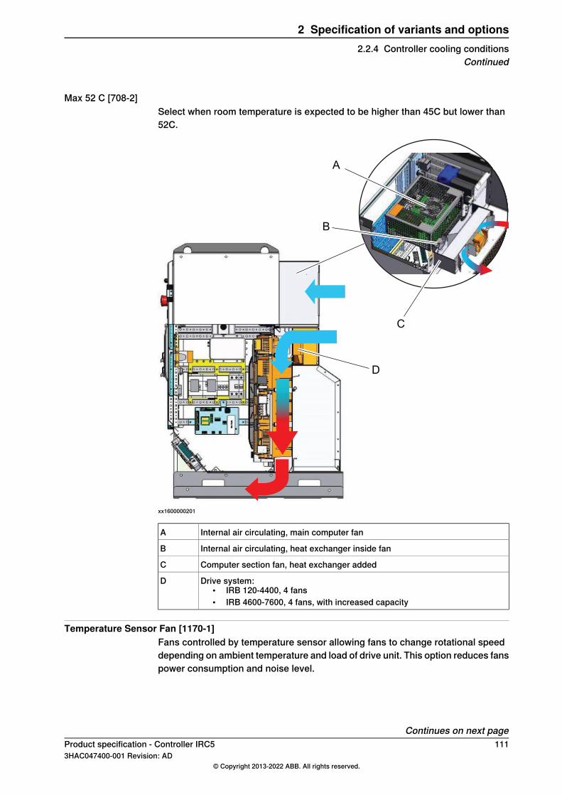
Max 52 C [708-2]Select when room temperature is expected to be higher than 45C but lower than52C.
A
C
D
B
xx1600000201
Internal air circulating, main computer fanA
Internal air circulating, heat exchanger inside fanB
Computer section fan, heat exchanger addedC
Drive system:• IRB 120-4400, 4 fans• IRB 4600-7600, 4 fans, with increased capacity
D
Temperature Sensor Fan [1170-1]Fans controlled by temperature sensor allowing fans to change rotational speeddepending on ambient temperature and load of drive unit. This option reduces fanspower consumption and noise level.
Continues on next pageProduct specification - Controller IRC5 1113HAC047400-001 Revision: AD
© Copyright 2013-2022 ABB. All rights reserved.
2 Specification of variants and options2.2.4 Controller cooling conditions
Continued

Available for Single controller (700-3) and Drive module only (700-1).
Note
Not available with Room temperature max 52 C (708-2).
A
xx1600000202
Fans controlled by temperature sensorA
Fans for Panel Mounted Controller [882-1]Fan unit including 3 fans (Included in PMC Large).
Cooling air filterDucts and fans are exposed to cooling air and are designed to reduce the needfor maintenance in most applications.
Metal mesh filter [764-1]Moist particles are prevented from entering the air ducts and fans by metal meshfilter.Select when cooling air contains moist particles > 0.5 mm.
Polymeric filter [764-2]Moist particles are prevented from entering the air ducts and fans by polymericfilter.Select when cooling air contains moist dust.
Continues on next page112 Product specification - Controller IRC5
3HAC047400-001 Revision: AD© Copyright 2013-2022 ABB. All rights reserved.
2 Specification of variants and options2.2.4 Controller cooling conditionsContinued
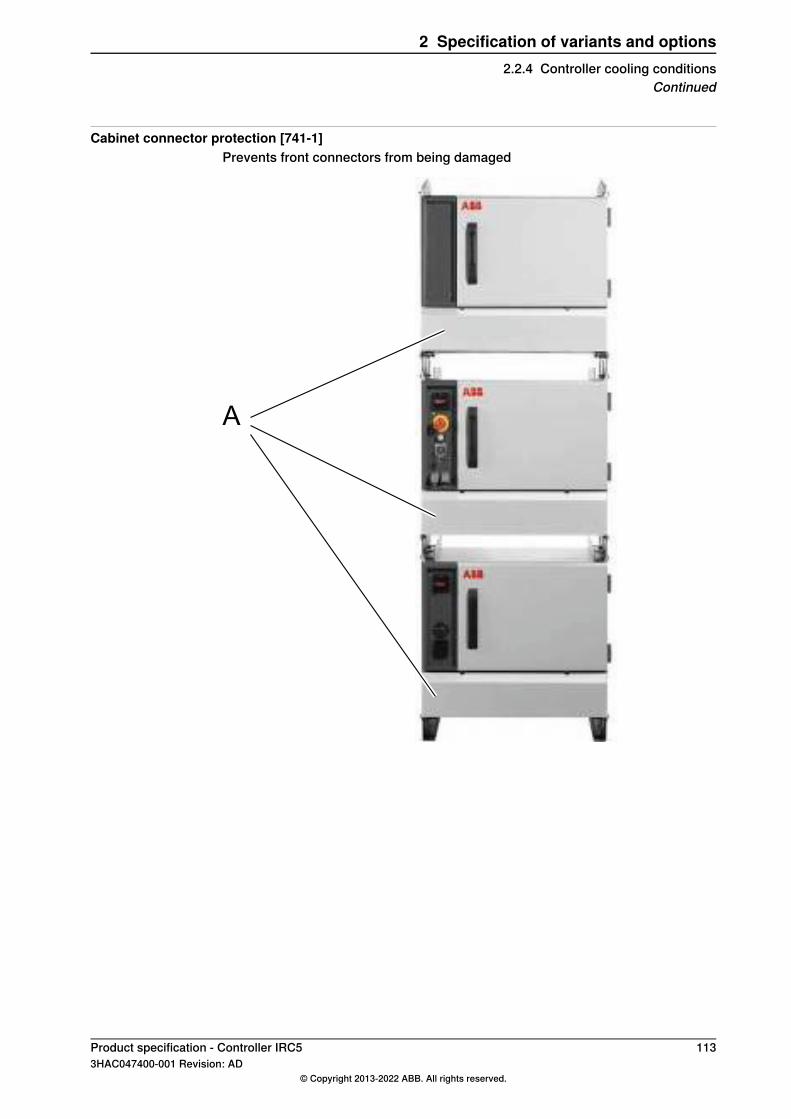
Cabinet connector protection [741-1]Prevents front connectors from being damaged
A
Product specification - Controller IRC5 1133HAC047400-001 Revision: AD
© Copyright 2013-2022 ABB. All rights reserved.
2 Specification of variants and options2.2.4 Controller cooling conditions
Continued
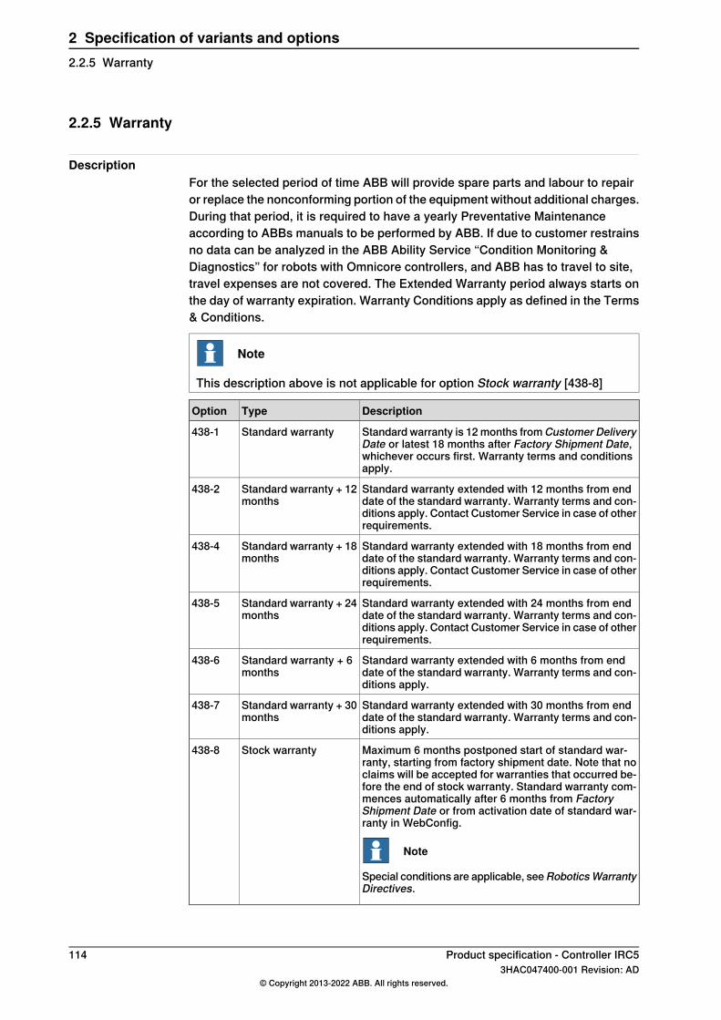
2.2.5 Warranty
DescriptionFor the selected period of time ABB will provide spare parts and labour to repairor replace the nonconforming portion of the equipment without additional charges.During that period, it is required to have a yearly Preventative Maintenanceaccording to ABBs manuals to be performed by ABB. If due to customer restrainsno data can be analyzed in the ABB Ability Service “Condition Monitoring &Diagnostics” for robots with Omnicore controllers, and ABB has to travel to site,travel expenses are not covered. The Extended Warranty period always starts onthe day of warranty expiration. Warranty Conditions apply as defined in the Terms& Conditions.
Note
This description above is not applicable for option Stock warranty [438-8]
DescriptionTypeOption
Standard warranty is 12 months fromCustomer DeliveryDate or latest 18 months after Factory Shipment Date,whichever occurs first. Warranty terms and conditionsapply.
Standard warranty438-1
Standard warranty extended with 12 months from enddate of the standard warranty. Warranty terms and con-ditions apply. Contact Customer Service in case of otherrequirements.
Standard warranty + 12months
438-2
Standard warranty extended with 18 months from enddate of the standard warranty. Warranty terms and con-ditions apply. Contact Customer Service in case of otherrequirements.
Standard warranty + 18months
438-4
Standard warranty extended with 24 months from enddate of the standard warranty. Warranty terms and con-ditions apply. Contact Customer Service in case of otherrequirements.
Standard warranty + 24months
438-5
Standard warranty extended with 6 months from enddate of the standard warranty. Warranty terms and con-ditions apply.
Standard warranty + 6months
438-6
Standard warranty extended with 30 months from enddate of the standard warranty. Warranty terms and con-ditions apply.
Standard warranty + 30months
438-7
Maximum 6 months postponed start of standard war-ranty, starting from factory shipment date. Note that noclaims will be accepted for warranties that occurred be-fore the end of stock warranty. Standard warranty com-mences automatically after 6 months from FactoryShipment Date or from activation date of standard war-ranty in WebConfig.
Note
Special conditions are applicable, seeRoboticsWarrantyDirectives.
Stock warranty438-8
114 Product specification - Controller IRC53HAC047400-001 Revision: AD
© Copyright 2013-2022 ABB. All rights reserved.
2 Specification of variants and options2.2.5 Warranty

2.2.6 Connected Services enabled
3G/Internet [890-4]The service box is an universal service box that can be connected either with a 3Gmodem or through Internet.This service box is included in :
• Retrofit kit 1016 3G + Internet (3HAC049807-001)• Remote Service 3G Factory option
WiFi/Internet [890-5]The service box DSQC1023 WiFi (3HAC058038-001) can be connected only throughInternet wired or wireless. It does not have modem and SIM holder.This service box is used in large installations having Internet and is included withthe following:
• Retrofit kit 1023 WiFi + Internet (3HAC058038-001)• Remote Service 1023 WiFi + Internet Factory Option (890-5).
Product specification - Controller IRC5 1153HAC047400-001 Revision: AD
© Copyright 2013-2022 ABB. All rights reserved.
2 Specification of variants and options2.2.6 Connected Services enabled

2.3 Control module
FlexPendant [701]Color graphic pendant with touch screen. For more information, see Operatingmanual - IRC5 with FlexPendant.
DescriptionOption
FlexPendant 10 m including mounting kit.701-1
FlexPendant 30 m701-3With this option the FlexPendant will be delivered with the cable assembled fromfactory.
xx1400002067
DisplayA
Emergency stop buttonB
Enabling control deviceC
JoystickD
Continues on next page116 Product specification - Controller IRC5
3HAC047400-001 Revision: AD© Copyright 2013-2022 ABB. All rights reserved.
2 Specification of variants and options2.3 Control module
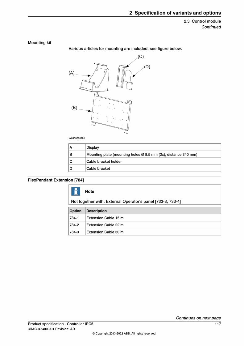
Mounting kitVarious articles for mounting are included, see figure below.
xx0900000981
DisplayA
Mounting plate (mounting holes Ø 8.5 mm (2x), distance 340 mm)B
Cable bracket holderC
Cable bracketD
FlexPendant Extension [784]
Note
Not together with: External Operator's panel [733-3, 733-4]
DescriptionOption
Extension Cable 15 m784-1
Extension Cable 22 m784-2
Extension Cable 30 m784-3
Continues on next pageProduct specification - Controller IRC5 1173HAC047400-001 Revision: AD
© Copyright 2013-2022 ABB. All rights reserved.
2 Specification of variants and options2.3 Control module
Continued
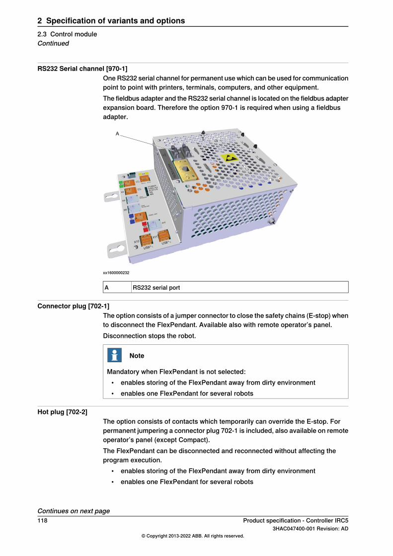
RS232 Serial channel [970-1]One RS232 serial channel for permanent use which can be used for communicationpoint to point with printers, terminals, computers, and other equipment.The fieldbus adapter and the RS232 serial channel is located on the fieldbus adapterexpansion board. Therefore the option 970-1 is required when using a fieldbusadapter.
A
xx1600000232
RS232 serial portA
Connector plug [702-1]The option consists of a jumper connector to close the safety chains (E-stop) whento disconnect the FlexPendant. Available also with remote operator’s panel.Disconnection stops the robot.
Note
Mandatory when FlexPendant is not selected:• enables storing of the FlexPendant away from dirty environment• enables one FlexPendant for several robots
Hot plug [702-2]The option consists of contacts which temporarily can override the E-stop. Forpermanent jumpering a connector plug 702-1 is included, also available on remoteoperator’s panel (except Compact).The FlexPendant can be disconnected and reconnected without affecting theprogram execution.
• enables storing of the FlexPendant away from dirty environment• enables one FlexPendant for several robots
Continues on next page118 Product specification - Controller IRC5
3HAC047400-001 Revision: AD© Copyright 2013-2022 ABB. All rights reserved.
2 Specification of variants and options2.3 Control moduleContinued

2.3.1 PCI options
DeviceNetTM m/s [709-1]DeviceNet is a communications link to connect industrial devices. It is a simplenetworking solution that reduces both cost and time to wire and install industrialautomation devices, and the direct connectivity provides improved communicationbetween devices. DeviceNet is an open network standard.Here are some examples of applications:
• Peer-to-peer data exchange where a DeviceNet product can produce andconsume messages
• Scanner/Adapter operation defined as a proper subset of Peer-to-Peer• A DeviceNet product can function as a client or server, or both
PROFIENERGY [963-1]PROFIenergy is a profile of the PROFINET communications protocol that allowsthe power consumption of automation equipment in manufacturing (such as robotassembly cells, laser cutters and sub-systems such as paint lines) to be managedover a PROFINET network. It offers an open and standardized means of controllingenergy usage during planned and unplanned breaks in production. PROFINET isan open standard for Industrial Ethernet.PROFINET satisfies requirements for automation technology. PROFINET solutionscan be implemented for factory and process automation, for safety applications,and for the entire range of drive technology right up to clock-synchronized motioncontrol.
PROFINET IO
PROFINET IO m/s SW [888-2]PROFINET is an open standard for Industrial Ethernet. PROFINET satisfiesrequirements for automation technology. PROFINET solutions can be implementedfor factory and process automation, for safety applications, and for the entire rangeof drive technology right up to clock-synchronized motion control.PROFINET has a modular design and different PROFINET communication profilesare all combinations of modular elements from the groups transmission technology,communication protocol, and application profiles.Here are some examples of PROFINET communication profiles:
• PROFINET-IO - Distributed I/O (Remote I/O). Here, the familiar I/O view ofPROFIBUS is retained, in which the user data from the field devices areperiodically transmitted into the process model of the control system
• PROFINET-CBA - Based on the object-oriented modelling of technologicalmodules. Based on the object model, machines and installations arestructured in PROFINET in the form of technological modules
With this option the IRC5 Controller can act as a controller, device, or both on thePROFINET network.
Continues on next pageProduct specification - Controller IRC5 1193HAC047400-001 Revision: AD
© Copyright 2013-2022 ABB. All rights reserved.
2 Specification of variants and options2.3.1 PCI options

PROFINET IO slave SW [888-3]PROFINET is an open standard for Industrial Ethernet. PROFINET satisfiesrequirements for automation technology. PROFINET solutions can be implementedfor factory and process automation, for safety applications, and for the entire rangeof drive technology right up to clock-synchronized motion control.PROFINET has a modular design and different PROFINET communication profilesare all combinations of modular elements from the groups transmission technology,communication protocol, and application profiles.Here are some examples of PROFINET communication profiles:
• PROFINET-IO - Distributed I/O (Remote I/O). Here, the familiar I/O view ofPROFIBUS is retained, in which the user data from the field devices areperiodically transmitted into the process model of the control system
• PROFINET-CBA - Based on the object-oriented modelling of technologicalmodules. Based on the object model, machines and installations arestructured in PROFINET in the form of technological modules
With this option the IRC5 controller can only acts as a device.
Ethernet/IPTM [841-1]EtherNet/IP is a communications link to connect industrial devices.The EtherNet/IP (EtherNet Industrial Protocol) is managed by ODVA (OpenDeviceNet Vendors Association). It is a well established industrial Ethernetcommunication system with good real-time capabilities. EtherNet/IP extendscommercial off-the-shelf Ethernet to the CIP (Common Industrial Protocol)— thesame upper-layer protocol and object model found in DeviceNet and ControlNet.CIP allows EtherNet/IP and DeviceNet system integrators and users to apply thesame objects and profiles for plug-and-play interoperability among devices frommultiple vendors and in multiple sub-nets. Combined, DeviceNet, ControlNet andEtherNet/IP promote transparency from sensors to the enterprise software.Here are some examples of EtherNet/IP applications:
• Peer-to-peer data exchange where an EtherNet/IP product can produce andconsume messages
• Scanner/adapter operation defined as a proper subset of peer-to-peer• An EtherNet/IP product can function as a client or server, or both
Ethernet switch [941-1]Can be used for distribution and/or extension of ethernet fieldbus options such asProfinet and Ethernet IP.
Connectors on front plate
DeviceNetTM on front [730-1]One external DeviceNetTM connector.Corresponding customer part is not included. Brad Harrison type 1A5006-34 orABB part number 3HAC 7811-1 is recommended.
Continues on next page120 Product specification - Controller IRC5
3HAC047400-001 Revision: AD© Copyright 2013-2022 ABB. All rights reserved.
2 Specification of variants and options2.3.1 PCI optionsContinued
Ethernet RJ45 [707-1]Internally connected to the computer LAN port.
Ethernet M12 [906-1]Internally connected to either the EtherNet/IPTM port or the PROFINET IO port.For more information about the Ethernet connectors on the main computer, seeEthernet connections on page 60.
Continues on next pageProduct specification - Controller IRC5 1213HAC047400-001 Revision: AD
© Copyright 2013-2022 ABB. All rights reserved.
2 Specification of variants and options2.3.1 PCI options
Continued

Fieldbus adapters (Anybus®)
Ethernet/IPTM [840-1]EtherNet/IPTM
Up to 1024 digital inputs and 1024 digital outputs can be transferred serially to amaster equipped with an EtherNet/IPTM interface. The bus cable is connecteddirectly to the adapter RJ45 connector.For more information see Application manual - EtherNet/IP Anybus Adapter.
PROFIBUS DP [840-2]PROFIBUS DPUp to 512 digital inputs and 512 digital outputs can be transferred serially to amaster equipped with a PROFIBUS DP interface. The bus cable is connected tothe adapter D-sub connector.For more information see Application manual - PROFIBUS Anybus Device.
PROFINET IO [840-3]PROFINET IOUp to 1024 digital inputs and 1024 digital outputs can be transferred serially to amaster equipped with a PROFINET IO interface. The bus cable is connected to theadapter RJ45 connector.For more information see Application manual - PROFINET Anybus Device.
DeviceNet IO [840-4]DeviceNet IOMax 512 bytes of I/O data.Baudrate 125-500 kbit autodetect.For more information see Application manual - DeviceNet Anybus Slave.
122 Product specification - Controller IRC53HAC047400-001 Revision: AD
© Copyright 2013-2022 ABB. All rights reserved.
2 Specification of variants and options2.3.1 PCI optionsContinued

2.3.2 Scalable I/O
Scalable I/O Internal
Base Dig. 16In/16Out [1541-1]DSQC1030 Base unit24 V Digital with 16 Inputs, 16 OutputsFor more information see Scalable I/O on page 68
Add-on Dig. 16In/16Out [1542-1]DSQC103124 V Digital with 16 Inputs, 16 OutputsFor more information see Scalable I/O on page 68
Add-on Analog 4In/4Out [1543-1]DSQC10324 Analog Inputs 4 Analog OutputsFor more information see Scalable I/O on page 68
Add-on Relay 8In/8Out [1544-1]DSQC10338 Digital inputs 8 Relay outputsFor more information see Scalable I/O on page 68
Scalable I/O External
Base Dig. 16In/16Out [1541-2]DSQC1030 Base unit24 V Digital with 16 Inputs, 16 OutputsFor more information see Scalable I/O on page 68
Add-on Dig. 16In/16Out [1542-2]DSQC103124 V Digital with 16 Inputs, 16 OutputsFor more information see Scalable I/O on page 68
Add-on Analog 4In/4Out [1543-2]DSQC10324 Analog Inputs 4 Analog OutputsFor more information see Scalable I/O on page 68
Add-on Relay 8In/8Out [1544-2]DSQC10338 Digital inputs 8 Relay outputsFor more information see Scalable I/O on page 68
Product specification - Controller IRC5 1233HAC047400-001 Revision: AD
© Copyright 2013-2022 ABB. All rights reserved.
2 Specification of variants and options2.3.2 Scalable I/O
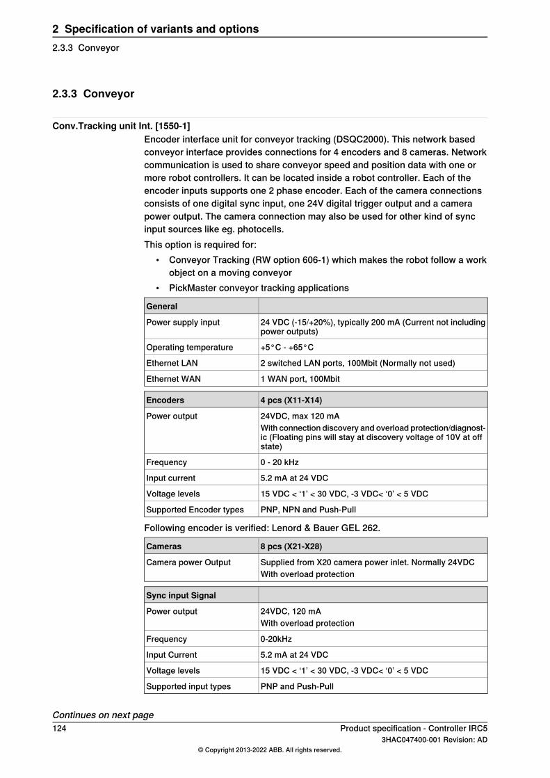
2.3.3 Conveyor
Conv.Tracking unit Int. [1550-1]Encoder interface unit for conveyor tracking (DSQC2000). This network basedconveyor interface provides connections for 4 encoders and 8 cameras. Networkcommunication is used to share conveyor speed and position data with one ormore robot controllers. It can be located inside a robot controller. Each of theencoder inputs supports one 2 phase encoder. Each of the camera connectionsconsists of one digital sync input, one 24V digital trigger output and a camerapower output. The camera connection may also be used for other kind of syncinput sources like eg. photocells.This option is required for:
• Conveyor Tracking (RW option 606-1) which makes the robot follow a workobject on a moving conveyor
• PickMaster conveyor tracking applications
General
24 VDC (-15/+20%), typically 200 mA (Current not includingpower outputs)
Power supply input
+5°C - +65°COperating temperature
2 switched LAN ports, 100Mbit (Normally not used)Ethernet LAN
1 WAN port, 100MbitEthernet WAN
4 pcs (X11-X14)Encoders
24VDC, max 120 mAPower outputWith connection discovery and overload protection/diagnost-ic (Floating pins will stay at discovery voltage of 10V at offstate)
0 - 20 kHzFrequency
5.2 mA at 24 VDCInput current
15 VDC < ‘1’ < 30 VDC, -3 VDC< ‘0’ < 5 VDCVoltage levels
PNP, NPN and Push-PullSupported Encoder types
Following encoder is verified: Lenord & Bauer GEL 262.
8 pcs (X21-X28)Cameras
Supplied from X20 camera power inlet. Normally 24VDCCamera power OutputWith overload protection
Sync input Signal
24VDC, 120 mAPower outputWith overload protection
0-20kHzFrequency
5.2 mA at 24 VDCInput Current
15 VDC < ‘1’ < 30 VDC, -3 VDC< ‘0’ < 5 VDCVoltage levels
PNP and Push-PullSupported input types
Continues on next page124 Product specification - Controller IRC5
3HAC047400-001 Revision: AD© Copyright 2013-2022 ABB. All rights reserved.
2 Specification of variants and options2.3.3 Conveyor

Trigger output
24VDC , Max 120 mADigital outputWith connection discovery and overload protection/diagnost-ic.(Floating pins will stay at discovery voltage of 10V at offstate)
0.1 mAMinimum load
Note
This option includes the software option Tracking unit interface [1552-1].This option is required to support 1-4 conveyors and 1-8 object detecting sensors,e.g. cameras. This option can be shared remotely with neighboring controllersvia a local network if software option Tracking unit interface [1552-1]is available on these controllers.This option is possible to order with Single cabinet [700-3].Requires:
• 24V [727-x]• Conveyor Tracking [606-x] or Prep. for PickMaster 3 [642-1]
Conv.Tracking unit Ext. [1551-1]Encoder interface unit for conveyor tracking (DSQC2000) located in a suitablecabinet. See Conv.Tracking unit Int. [1550-1] on page 124.
Note
This option includes the software option Tracking unit interface [1552-1].This option is required to support 1-4 conveyors and 1-8 object detecting sensors,e.g. cameras. This option can be shared remotely with neighboring controllersvia a local network if software option Tracking unit interface [1552-1]is available on these controllers.This option is possible to order with Controller variants: Single cabinet [700-3],Panel mounted modules [700-5], and Compact 2nd generation [700-8].Requires: Conveyor Tracking [606-x] or Prep. for PickMaster 3 [642-1]
Product specification - Controller IRC5 1253HAC047400-001 Revision: AD
© Copyright 2013-2022 ABB. All rights reserved.
2 Specification of variants and options2.3.3 Conveyor
Continued

2.3.4 Internal DeviceNet I/O
Digital 24V 16In/16 Out [716-1]Digital 24V 16In/16OutDigital 24 VDC I/O (DSQC 652).16 inputs/16 outputs.Also available for external mounting, see External DeviceNet I/O on page 127.
Encoder interface unit [726-1]Encoder interface unit for conveyor tracking (DSQC 377B).This option is required for:
• Conveyor Tracking (RW option 606-1) which makes the robot follow a workobject on a moving conveyor.
• Sensor Synchronization (RW option 607-1) adjusts the robot speed to anexternal moving device (for example a press or conveyor) with the help of asensor.
• PickMaster conveyor tracking applications.The customer encoder and synchronization switch cables are connected directlyto the DSQC 377B (one 16-pole Phoenix connector included). The encoder mustbe of 2 phase type for quadrate pulses, to enable registration of reverse conveyormotion, and to avoid false counts due to vibration etc. when the conveyor is notmoving.Output signal: Open collector PNP output.Voltage: 10-30 V (normally supplied by 24 VDC from DSQC 377B).Current: 50-100 mA.Phase: 2 phase with 90 degree phase shift.Duty cycle: 50%.Following encoder is verified: Lenord & Bauer GEL 262.
CC-Link slave [723-1]CC-Link (DSQC 378B).Up to 176 digital inputs and 176 digital outputs can be transferred serially to a PLCequipped with an CC-Link interface. The bus cables are connected directly to theDSQC 378B (one 6-pole Phoenix connector included).Also available for external mounting, seeCC-Link Slave External [899-1] on page127.
126 Product specification - Controller IRC53HAC047400-001 Revision: AD
© Copyright 2013-2022 ABB. All rights reserved.
2 Specification of variants and options2.3.4 Internal DeviceNet I/O

2.3.5 External DeviceNet I/O
Dig 24V 16In/16Out External [816-1]Digital 24 VDC I/O (DSQC 652).16 inputs/16 outputs.Also available for internal mounting.
CC-Link Slave External [899-1]Digital 24 VDC I/O (DSQC 652).16 inputs/16 outputs.Also available for internal mounting.
Encoder interface unit-External [826-1]The customer encoder and synchronization switch cables are connected directlyto the DSQC 377B (one 16-pole Phoenix connector included).The encoder must be of 2 phase type for quadrate pulses, to enable registrationof reverse conveyor motion, and to avoid false counts due to vibration etc. whenthe conveyor is not moving.
DescriptionParameter
Open collector PNP outputOutput signal:
10 - 30 V (normally supplied by 24 VDC fromDSQC 377B)
Voltage:
50 - 100 mACurrent:
2 phase with 90 degree phase shiftPhase:
50%Duty cycle:
Lenord & Bauer GEL 262Following encoder is verified:
Product specification - Controller IRC5 1273HAC047400-001 Revision: AD
© Copyright 2013-2022 ABB. All rights reserved.
2 Specification of variants and options2.3.5 External DeviceNet I/O

2.3.6 Power supply
GeneralIn combination with DeviceNetTM m/s single channel (option 709-1) and anyDeviceNetTM node (for example option 716-1), the customer power supply ispre-wired in the following ways:Single cabinet
• As standard 24 V I/O supplies the DeviceNetTM bus and is also available forgeneral usage on door terminals XT31. Available current 1.6 - 8 A, see I/Osystem on page 65.
• Option 727-3. 4 A is available for general usage on door terminals X31 inaddition to and separated from above.
• Option 727-1. 2 x 4 A is available for general usage on door terminals XT31in addition to and separated from above. The two outputs are parallelconnected at delivery.
• Option 728-1. The 4 A DeviceNetTM unit supplies the DeviceNetTM bus.
24V 8 Amps [727-1]24 V 8 Amps for bus and process supply.
24V 4 Amps [727-3]24 V 4 Amps for bus and process supply.
Devicenet 24V 4 Amps [728-1]24 V 4 Amps for bus supply. Galvanically isolated from ground.In the normal case the Single cabinet integrated 24 V I/O supply can be used forboth bus and customer I/O. The bus is then grounded at the cabinet chassis.Single point grounding is required by ODVA (Open DeviceNetTM VendorAssociation). If there is a risk for multiple grounds, for example when the bus isdistributed to several places, the option 728-1 is recommended. Then the 24 Vsupply is isolated from ground and the bus can be single point grounded at anycustomer selected place.Another reason for selecting option 728-1 is the < 100 W output, thereby fulfillingrequirements for Limited Power Source class 2 from NEC. This requirement is alsomet by separating the outputs for the 4 A units 727-x.
Safety internal connection [731-1]The signals are connected directly to screw terminals at the panel board insidethe cabinet.
Safety external connection [731-2]The signals are connected via a 40-pole standard industrial connector in accordancewith DIN 43652.The connector is located at the foot of the module. Corresponding customer partis included.
128 Product specification - Controller IRC53HAC047400-001 Revision: AD
© Copyright 2013-2022 ABB. All rights reserved.
2 Specification of variants and options2.3.6 Power supply
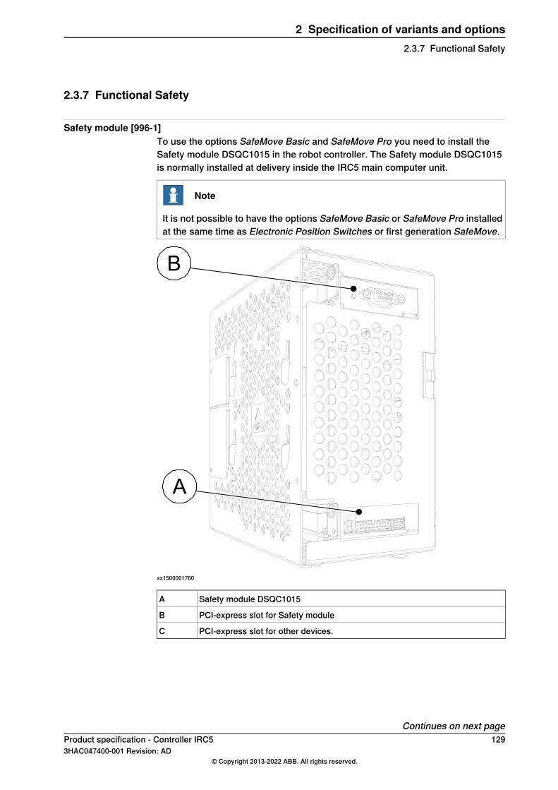
2.3.7 Functional Safety
Safety module [996-1]To use the options SafeMove Basic and SafeMove Pro you need to install theSafety module DSQC1015 in the robot controller. The Safety module DSQC1015is normally installed at delivery inside the IRC5 main computer unit.
Note
It is not possible to have the options SafeMove Basic or SafeMove Pro installedat the same time as Electronic Position Switches or first generation SafeMove.
B
A
xx1500001760
Safety module DSQC1015A
PCI-express slot for Safety moduleB
PCI-express slot for other devices.C
Continues on next pageProduct specification - Controller IRC5 1293HAC047400-001 Revision: AD
© Copyright 2013-2022 ABB. All rights reserved.
2 Specification of variants and options2.3.7 Functional Safety

Note
For a controller with a safety module, status signals for emergency stop can onlybe read from the safe fieldbus (seeApplication manual - Functional safety and SafeMove2).
ProfiSafe F-Device [997-1]All I/O communication for the SafeMove functionallity is done via a safety PLCusing PROFIsafe (safe PROFINET). The safety PLC will act as a PROFIsafecontroller (F-Host) and the IRC5 will act as a PROFIsafe device (F-Device). ThePROFIsafe I/O is connected to one of the the Ethernet ports WAN, LAN 2, or LAN3 on the main computer.A RobotWare license with the options PROFINET Controller/Device, or PROFINETDevice, and PROFIsafe F-Device are required to to run PROFIsafe on the IRC5controller.
xx1300001966
Local Area Network that can host a private industrial network.LAN2X4
Local Area Network that can host a private industrial network.LAN3X5
Wide Area Network that can host a public industrial network.WANX6
PROFIsafe F-Host&Device [997-2]I/O communication for the SafeMove functionality can be done via a safety PLCusing PROFIsafe (safe PROFINET). The safety PLC will act as a PROFIsafecontroller (F-Host) and the IRC5 will act as a PROFIsafe device (F-Device). ThePROFIsafe I/O is connected to one of the Ethernet ports WAN, LAN 2, or LAN 3on the main computer.In addition, using this option, it is possible to have the robot controller act as aPROFIsafe controller and host safe I/O devices (F-Devices) directly. The devicesare connected to the same Ethernet ports on the main computer as describedabove.
Continues on next page130 Product specification - Controller IRC5
3HAC047400-001 Revision: AD© Copyright 2013-2022 ABB. All rights reserved.
2 Specification of variants and options2.3.7 Functional SafetyContinued
A RobotWare license with the options PROFINET Controller/Device and PROFIsafeF-Host&Device are required to run PROFIsafe on the IRC5 controller.
CIP Safety Adapter [997-3]I/O communication for the SafeMove functionality is done with a safety PLC usingCIP Safety (safe EtherNet/IP). The safety PLC will act as a CIP Safety controller(Scanner) and the IRC5 will act as a CIP Safety device (Adapter). The CIP SafetyI/O is connected to one of the Ethernet ports WAN, LAN 2, or LAN 3 on the maincomputer.A RobotWare license with the options EtherNet/IP Scanner/Adapter and CIP SafetyAdapter are required to run CIP Safety on the IRC5 controller.
CIP Safety Scanner&Adap. [997-4]I/O communication for the SafeMove functionality can be done via a safety PLCusing CIP Safety (safe EtherNet/IP). The safety PLC will act as a CIP SafetyScanner and the IRC5 will act as a CIP Safety Adapter.The CIP Safety I/O is connected to one of the Ethernet ports WAN, LAN 2, or LAN3 on the main computer.In addition, using this option, it is possible to have the robot controller act as a CIPSafety Scanner and scan safe I/O devices directly. The devicesare connected to the same Ethernet ports on the main computer as describedabove.A RobotWare license with the options EtherNet/IP Scanner/Adapter and CIP SafetyScanner&Adap are required to run CIP Safety on the IRC5 controller.
Continues on next pageProduct specification - Controller IRC5 1313HAC047400-001 Revision: AD
© Copyright 2013-2022 ABB. All rights reserved.
2 Specification of variants and options2.3.7 Functional Safety
Continued

2.3.7.1 Discrete I/O Safety
Prepared for ABB CI502 [1241-1]Using this option, it is possible to have the robot controller act as a PROFIsafecontroller and host safe I/O devices (F-Devices) from ABB directly. The devicesare connected to one of the Ethernet ports WAN, LAN 2, or LAN 3 on the maincomputer. This option is using PROFIsafe, but is not a general F-Host functionalityas it is locked to specific safe I/O devices from ABB (see application noteUnbundledS500 Safety I/Os 3ADR024128K0201 for more information).A RobotWare license with the options PROFINET Controller/Device and Preparedfor ABB CI502 are required to run PROFIsafe on the IRC5 controller.
132 Product specification - Controller IRC53HAC047400-001 Revision: AD
© Copyright 2013-2022 ABB. All rights reserved.
2 Specification of variants and options2.3.7.1 Discrete I/O Safety

2.3.7.2 Safety Robot Supervison
SafeMove Basic [1125-1]The option SafeMove gives you access to the configurator Visual SafeMove inRobotStudio. With Visual SafeMove you can:
• configure and visualize supervision functions in a 3D environment• configure stop functions, such as automatic stop• configure Cyclic Brake Check• configure safe signals (safe Ethernet communication and I/Os)• configure signal logics• configure system status outputs
For more information, see Application manual - Functional safety and SafeMove2.
Included functions
9Supported number of axes
8Safe ranges
1Safe zones
YesAxis Position Supervision
YesContact application support
SafeMove Pro [1125-2]The option SafeMove gives you access to the configurator Visual SafeMove inRobotStudio. With Visual SafeMove you can:
• configure and visualize supervision functions in a 3D environment• configure stop functions, such as automatic stop• configure Cyclic Brake Check• configure safe signals (safe Ethernet communication and I/Os)• configure signal logics• configure system status outputs
For more information, see Application manual - Functional safety and SafeMove2.
Included functions
9Supported number of axes
8Safe ranges
16Safe zones
Yes (16 tools)Tool changer support
YesAxis Position Supervision
YesAxis Speed Supervision
YesTool Orientation Supervision
YesTool Position Supervision
YesTool Speed Supervision
YesStand Still Supervision
Continues on next pageProduct specification - Controller IRC5 1333HAC047400-001 Revision: AD
© Copyright 2013-2022 ABB. All rights reserved.
2 Specification of variants and options2.3.7.2 Safety Robot Supervison
Included functions
YesContact application support
134 Product specification - Controller IRC53HAC047400-001 Revision: AD
© Copyright 2013-2022 ABB. All rights reserved.
2 Specification of variants and options2.3.7.2 Safety Robot SupervisonContinued

2.3.8 IMM Interface
GeneralIMM (Injection Mould Machines) interface. The Euromap (European Committee ofMachinery Manufacturers for the Plastics and Rubber Industries) and SPI (Societyof Plastics Industry) options are the injection moulding machine – robot signalinterface.The two different options are based on the European and the American standards.
Connection
Euromap 67 and SPI AN146 [671-2]This is the standard in Europe, which offers double channel security from theinjection moulding machine. The robot interface for Europe 67 is implemented inthe standard IRC5 cabinet with a Euromap connector mounted on the connectorplate.For additional information see Further options
Cable [673]
DescriptionOption
Cable 10m673-1
Cable 15m673-2
Further optionsThe Euromap/SPI options require the following options to be ordered with therobot:
• For 671-2, 1 Scalable I/O module, Base Dig. 16In/16Out [1541-1]• For additional devices such as gripper, conveyor, additional Scalable I/O
modules may be neededTo configure the Euromap/SPI input and output signals in the RobotWare,I/O-configuration files are available in the RobotWare installation in the folderUtility.In robot test mode, when the machine is disconnected, the controller jumper plug
Continues on next pageProduct specification - Controller IRC5 1353HAC047400-001 Revision: AD
© Copyright 2013-2022 ABB. All rights reserved.
2 Specification of variants and options2.3.8 IMM Interface
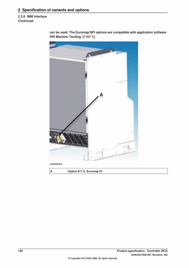
can be used. The Euromap/SPI options are compatible with application softwareRW Machine Tending, [1167-1].
xx0900000978
Option 671-2, Euromap 67A
136 Product specification - Controller IRC53HAC047400-001 Revision: AD
© Copyright 2013-2022 ABB. All rights reserved.
2 Specification of variants and options2.3.8 IMM InterfaceContinued

2.3.9 Operator's interface
Operators panel
GeneralExternal operator’s panels can be either simply a panel or a panel box. Seeillustrations below.
Note
When ordering the external operator's panel as an add-on, the external operator'spanel is delivered empty together with labels and blanking plugs. When installing,the following components must be moved from the controller to the externaloperator's panel:
• Mode switch• Motor ON button• Emergency stop button
Panel on cabinet [733-1]Panel in the front of the cabinet (standard)
xx0600002782
Continues on next pageProduct specification - Controller IRC5 1373HAC047400-001 Revision: AD
© Copyright 2013-2022 ABB. All rights reserved.
2 Specification of variants and options2.3.9 Operator's interface

External panel [733-3]To be mounted in a separate operator’s unit (enclosure not supplied). Seeinstallation requirements in the figure below.
xx0900000984
Holes for operator panelA
Required depth 130 mmB
Holes for cable flangeC
External panel small box [733-4]Operator's panel mounted in a box. See figure below
250
128
200
170
288,4
xx1100000562
Operator's panel cable
DescriptionOption
Panel cable - 15 m734-1
Panel cable - 30 m734-3
Panel cable - 7 m734-5
Continues on next page138 Product specification - Controller IRC5
3HAC047400-001 Revision: AD© Copyright 2013-2022 ABB. All rights reserved.
2 Specification of variants and options2.3.9 Operator's interfaceContinued

Operating mode selector (key switch) [735]
DescriptionStandardOption
Three modes: manual, manual full speed and automatic.Standard735-1
Two modes: manual and automatic.Standard735-2
Three modes manual, manual full speed and automatic.Additional contact735-3
Two modes: manual and automatic.Additional contact735-4
Three modesKeyless Mode Se-lector
735-7735-8 Two modes
Operator mode selection from the FlexPendant withoutkey switch.For more information, see Application manual - Func-tional safety and SafeMove2.
Note
Cannot be combined with option 733-X External Panel.
The three mode types do not comply with UL safety standards, since manual fullspeed is not permitted. The option additional contact means contacts (dualchannels) for customer usage, see Figure below. The connector S21.1.X1 is foundin the cable harness. Customer part is included.
xx0900001033
As standard the mode selector position can be indicated by relay contacts (singlechannel), see figure below. The connector X15 is located at the panel board (seeoption 731-1). Customer part is not included. Recommended type ABB CEWEControl, article number 1SSA 445024 R0100.
xx0900000982
Continues on next pageProduct specification - Controller IRC5 1393HAC047400-001 Revision: AD
© Copyright 2013-2022 ABB. All rights reserved.
2 Specification of variants and options2.3.9 Operator's interface
Continued

Safety chain status LEDs at front [737-1]Select this option when:
• to avoid opening the door• you need a rapid way to check status regardless of actual FlexPendant
window
140 Product specification - Controller IRC53HAC047400-001 Revision: AD
© Copyright 2013-2022 ABB. All rights reserved.
2 Specification of variants and options2.3.9 Operator's interfaceContinued

2.4 Drive module
Single drive unit [907-1]Single drive unit (maximum three), Drive unit ADU-790A
Voltage to motor(V rms)
Max current(Amp rms)
Rated current(Amp rms)
Drive unit type
377-430 i , 2345530ADU-790Ai Depending on line voltage, when used in IRB 66XX/7600
Prepared for Trackmotion [981-1]Option 981-1 opens up for combinations of external drives for Trackmotion,Positioners. Motor units and Servo Gun.Three identical connections for:
• External brake release• External brake release push button• PTC2
External connectors for:• XS7• XS 101/102
Note
Important electric changes:• Lim2 removed from XS7 connection• 0V Brake on axis selector is no longer from PTC2 0V
Prepared for Positioners [922-1]The option makes it possible to link IRBP X-list with IRB X-list in BOL. Drive units907-1 should not be selected in the IRB X-list. The number will be pre-selecteddepending of type of positioner.
Note
Exception! If the IRBP is ordered outside BOL the drive units must be selectedin the IRB X-list
Note
The harnesses XS41/XS41.2 are needed to connect the robot controller with thepositioner. To get the harness with connectors XS41/XS41.2 on the robotcontroller, the option 922-1 Prepared for IRBP has to be booked and the positionertype must be specified.
Continues on next pageProduct specification - Controller IRC5 1413HAC047400-001 Revision: AD
© Copyright 2013-2022 ABB. All rights reserved.
2 Specification of variants and options2.4 Drive module
Prepared for Motor unit/Gear unit [946-1]This option prepares the IRC5 controller to be possible to connect Motor units andGear units.This option makes it possible to link Motor units and Gear units X-list with IRBX-list in BOL.
Note
Drive units must be selected in the IRB X-list.
This option also:• contains a side bracket for MU/GU axis selector lock• Replaces motor power connector XS7 by XS101 if MUGU is ordered together
with a robot system order• The cable harness in the cabinet is generated from the MUGU order and it
will be delivered assembled from factory if the MUGU is ordered togetherwith a robot system order
• Blocks servo gun in BOL
Continues on next page142 Product specification - Controller IRC5
3HAC047400-001 Revision: AD© Copyright 2013-2022 ABB. All rights reserved.
2 Specification of variants and options2.4 Drive moduleContinued

Prep. for 3rd party MU [1389-1]The optionPrep. for 3rd party MU prepares IRC5 controller to be possible to connect3rd party MU to the controller.
xx2000002428
Continues on next pageProduct specification - Controller IRC5 1433HAC047400-001 Revision: AD
© Copyright 2013-2022 ABB. All rights reserved.
2 Specification of variants and options2.4 Drive module
Continued
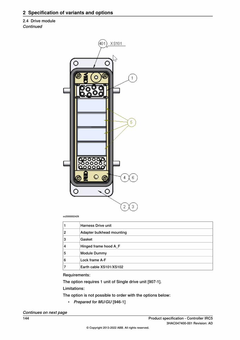
xx2000002429
Harness Drive unit1
Adapter bulkhead mounting2
Gasket3
Hinged frame hood A_F4
Module Dummy5
Lock frame A-F6
Earth cable XS101/XS1027
Requirements:The option requires 1 unit of Single drive unit [907-1].Limitations:The option is not possible to order with the options below:
• Prepared for MU/GU [946-1]
Continues on next page144 Product specification - Controller IRC5
3HAC047400-001 Revision: AD© Copyright 2013-2022 ABB. All rights reserved.
2 Specification of variants and options2.4 Drive moduleContinued
• Controller variants: Panel mounted modules [700-5], Panel mounted driveonly [700-6], Compact 2nd generation [700-8]
SMB for additional motors
External SMB unit [757-1]This option is selected when having customer designed equipment.Contains:
• Serial measurement board as separate unit with battery.
External SMB unit with cables [757-2]This option is selected when having customer designed equipment.Contains:
• serial measurement board as separate unit with battery• one 700 mm cable with connector fitting the measurement link1400 mm• one cable with a 64-pole industrial female connector for resolver connection
Continues on next pageProduct specification - Controller IRC5 1453HAC047400-001 Revision: AD
© Copyright 2013-2022 ABB. All rights reserved.
2 Specification of variants and options2.4 Drive module
Continued
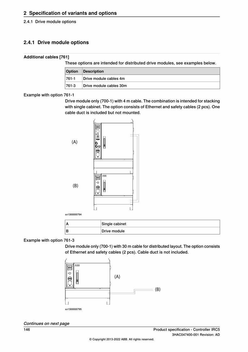
2.4.1 Drive module options
Additional cables [761]These options are intended for distributed drive modules, see examples below.
DescriptionOption
Drive module cables 4m761-1
Drive module cables 30m761-3
Example with option 761-1Drive module only (700-1) with 4 m cable. The combination is intended for stackingwith single cabinet. The option consists of Ethernet and safety cables (2 pcs). Onecable duct is included but not mounted.
(A)
(B)
xx1300000794
Single cabinetA
Drive moduleB
Example with option 761-3Drive module only (700-1) with 30 m cable for distributed layout. The option consistsof Ethernet and safety cables (2 pcs). Cable duct is not included.
(B)
(A)
xx1300000795
Continues on next page146 Product specification - Controller IRC5
3HAC047400-001 Revision: AD© Copyright 2013-2022 ABB. All rights reserved.
2 Specification of variants and options2.4.1 Drive module options

Drive moduleA
To single cabinetB
Duty Time Counter [767-1]Indicates the operating time for the manipulator (released brakes)In addition to the optional hardware duty time counter (DTC) there is also a softwareDTC included in SIS (Service Information System).This function displays the operating time on the FlexPendant. To read the softwareDTC tapABBmenu/System Info/Hardware devices/Mechanical units/ROB_1/GeneralSIS data.For more information, see Operating manual - Service Information System.
Wheels [758-1]The cabinet foot can be equipped with wheels. Three wheels on each side with themiddle wheel raised 5 mm. By balancing on the middle wheels the cabinet caneasily be maneuvered. The cabinet resting position is on the front and middlewheels.
Service outlet
Service outlet 230V [736-1]230 V outlet in accordance with DIN VDE 0620. Single socket suitable for EUcountries.
Note
The outlet is equipped with earth fault protection. Max load is 200 W. The outletis located at the front.
Service outlet 120V [736-2]120 V outlet in accordance with American standard. Single socket, Harvey Hubble.
Note
The outlet is equipped with earth fault protection. Max load is 200 W. The outletis located at the front.
Prepared for Force Control [738-1]For robots which will be equipped with a force sensor by the integrator. A voltagemeasurement board, is encapsulated in a box to be mounted close to themanipulator.The box is connected to the axis computer measurement link 2 with a cable ofsame length as option 210-x.The option Force control package 636-x contains all required hardware and softwareto run the robot in force control mode.See Force control package [636] on page 149.
Continues on next pageProduct specification - Controller IRC5 1473HAC047400-001 Revision: AD
© Copyright 2013-2022 ABB. All rights reserved.
2 Specification of variants and options2.4.1 Drive module options
Continued

Position supervision computer
Electronic position switch (EPS) [810-1]A safety enabled separate computer located behind the axis computer.This option can be selected for several reasons:
• Replacing mechanical switches• Fully integrated in cabinet• Maintenance free• Increased flexibility• Easy to set up• Easy to replace a robot in production• Enabling more compact mechanical units• Suitable in dirty environment
SafeMove [810-2]SafeMove is a safety controller in the robot system. The purpose of the safetycontroller is to ensure a high safety level in the robot system using supervisionfunctions that can stop the robot and monitoring functions that can set safe digitaloutput signals.The supervision functions can be activated by safe digital input signals. Both inputand output signals can be connected to, for instance, a safety PLC that can controlwhich behavior is allowed for the robot at different times.The safety controller also sends status signals to the main computer, that is thestandard IRC5 robot controller.Note that SafeMove is one component in a cell safety system, normallycomplemented by other equipment, e.g. light barriers, for detecting the whereaboutsof the operator.Some examples of applications:
• Manual loading of gripper• Manual inspection in robot cell during operation• Optimization of cell size• Protection of sensitive equipment• Ensuring safe orientation of emitting processes
148 Product specification - Controller IRC53HAC047400-001 Revision: AD
© Copyright 2013-2022 ABB. All rights reserved.
2 Specification of variants and options2.4.1 Drive module optionsContinued

2.5 RobotWare
DispensePac support [901-1]With DispensePac support hardware and software functions can be ordered asoptions when buying the robot. The intention of the DispensePac support is tosupply building blocks supporting the complete Dispense Package that is offeredvia the ABB Global Lead center. For further information on DispensePac support,see Application manual - Dispense.Process Interface board (PIB) with IPS software. Ethernet Communication cables.Ethernet switch. Power supply of PIB and switch. Two DeviceNetTM cables fromPIB to cabinet floor.PIB communication software. RW Dispense adaptations forDispensePac support. Paint Medium package options including Productionmanagement is available in System Builder (RobotStudio).
941-1
xx0900000965
Channel support [902-1]Defines number of control loops (1 - 5 to specify).
Force control package [636]The force control package contains all required hardware and software to run therobot in force control mode.It contains the following components:
• Option 738-1 Prepared for Force Control.See Prepared for Force Control [738-1] on page 147.
• Option 661-2 Force Control Base• Force sensor, adapter plate and cabling as described below.
DescriptionOption
Force Control Package 165636-1
Force Control Package 660636-2
Continues on next pageProduct specification - Controller IRC5 1493HAC047400-001 Revision: AD
© Copyright 2013-2022 ABB. All rights reserved.
2 Specification of variants and options2.5 RobotWare

DescriptionOption
Force Control Package 2500636-3
The integrated force sensor can be mounted on the robot flange using an adaptorplate. The force sensor can also be stationary mounted. A cable is supplied toconnect the force sensor to the voltage measurement board. Cable managementmust be arranged by the user.
(D)
(A)
(E)
(C)
(B)
xx1300000204
Voltage measurement board (option 738-1, Prepared for Force Control)A
Cable between robot controller and voltage measurement boardB
Cable between force sensor and voltage measurement boardC
Force sensor, including adaptor plate and calibration informationD
Force Control software (option 661-2 Force Control Base)E
The force sensor measures all six components of force (Fx, Fy and Fz) and torque(Mx, My and Mz).
Fx, Mx
Fz, Mz
Fy, My
xx1300000205
Continues on next page150 Product specification - Controller IRC5
3HAC047400-001 Revision: AD© Copyright 2013-2022 ABB. All rights reserved.
2 Specification of variants and options2.5 RobotWareContinued

Force sensor dimensions
AB
45º 45º
CD
E
22,5º
F
G
xx1300000206
Sensor package 2500Sensor package 165 and 660
Diameter 168 mmDiameter 104 mmA
Height 62 mmHeight 40 mmB
4 x M10 Min. thread length is 15 mm(on both sides)
4 x M6 Min. thread length is 7.6 mm (onboth sides)
C
Diameter 124 mmDiameter 80 mmD
27 mm27 mmE
Diameter 8.02+0.02 , depth min. 9 mm(on both sides)
Diameter 6.02+0.02 , depth min. 7 mm (onboth sides)
F
Diameter 10.02+0.02 , depth min. 9 mm(on both sides)
Diameter 5.02+0.02 , depth min. 7 mm (onboth sides)
G
Continues on next pageProduct specification - Controller IRC5 1513HAC047400-001 Revision: AD
© Copyright 2013-2022 ABB. All rights reserved.
2 Specification of variants and options2.5 RobotWare
Continued

Adaptor plate dimensions
A
BC
B
A
xx1300000207
Sensor package 2,500Sensor package 660Sensor pack-age 165
Ø 210 mmØ 165 mmØ 140 mmØ 104 mmØ 104 mmA
15 mm15 mm10 mm10 mm10 mmB
20 mm15 mm15 mm--C
Double adaptersDouble ad-apters
Single adapterSingle adapterType
3.8 + 5.3 kg2.3 + 2.5 kg1.1 + 1.7 kg0.6 kg0.6 kgWeight(B + C)
IRB 6620IRB 4400IRB 4400IRB 2400IRB 140Suitablerobots IRB 6640IRB 4600IRB 4600IRB 2600IRB 1200
IRB 6650SIRB 1600IRB 6660IRB 2400IRB 6700IRB 2600
Note
Note that the adaptor plate and force sensor will generate an offset and additionalweight on the tool flange, and hence affect the available payload of the robot.Please refer to the robot load diagram for respective robot.
Continues on next page152 Product specification - Controller IRC5
3HAC047400-001 Revision: AD© Copyright 2013-2022 ABB. All rights reserved.
2 Specification of variants and options2.5 RobotWareContinued

Force sensor specification
Sensor package2500
Sensor package 660Sensor package 165
Capacity:
2,500 N660 N165 NFx, Fy
6,250 N1,980 N495 NFz
400 Nm60 Nm15 NmMx, My, Mz
Resolution:
0.330.090.03Fx, Fy
10.330.11Fz
0.0530.0080.003Mx, My, Mz
Overload capacity:
25,000 N6,600 N1,650 NFx, Fy
62,500 N19,800 N4,950 NFz
4,000 Nm600 Nm150 NmMx, My, Mz
-40 to +100°C-40 to +100°C-40 to +100°COperating temperature
IP65IP65IP65IP rating
7.2 kg1.7 kg1.6 kgSensor weight
Continues on next pageProduct specification - Controller IRC5 1533HAC047400-001 Revision: AD
© Copyright 2013-2022 ABB. All rights reserved.
2 Specification of variants and options2.5 RobotWare
Continued

2.5.1 Vision
Medium resolution camera [1342]The following table provides the basic characteristics of the kit cameras providedby ABB. For additional details, see the technical specification of the camera,available on myABB or the Cognex website. The ABB kit camera DSQC1020 iselectrically and mechanically equivalent to In-Sight 7200.
DSQC1020Specification
800x600Resolution
5.3 mm diagonal, 5.3 x 5.3 μm sq. pixels, monochromeSensor properties
512 MBJob/program memory
256 MB SDRAMImage processing memory
1/1.8-inch CMOSSensor type
16μs to 950 msShutter speed
Rapid reset, progressive scan, full frame integrationAcquisition
C-mountLens type
IP67 with lens cover properly installedProtection
24DC 24±10%, 2 APower consumptionExternal light - Continuously on; output 24V, 500mA max.External light - Strobe; output 24V, 1A max. at 50% dutycycle (max. on time of 100ms)
75 mm (2.95 in) x 84.8 (3.34 in) x 55 mm (2.17 in)M12 Lens, configuration, dimen-sions
0°C to 45°C (32°F to 113°F)Operating temperature
High resolution camera [1343]The following table provides the basic characteristics of the kit cameras providedby ABB. For additional details, see the technical specification of the camera,available on myABB or the Cognex website. The ABB kit camera DSQC1021 iselectrically and mechanically equivalent to 7402.
DSQC1021Specification
1280x1024Resolution
8.7 mm diagonal, 5.3 x 5.3 μm sq. pixels, monochromeSensor properties
512 MBJob/program memory
256 MB SDRAMImage processing memory
1/1.8-inch CMOSSensor type
16μs to 950 msShutter speed
Rapid reset, progressive scan, full frame integrationAcquisition
C-mountLens type
IP67 with lens cover properly installedProtection
Continues on next page154 Product specification - Controller IRC5
3HAC047400-001 Revision: AD© Copyright 2013-2022 ABB. All rights reserved.
2 Specification of variants and options2.5.1 Vision
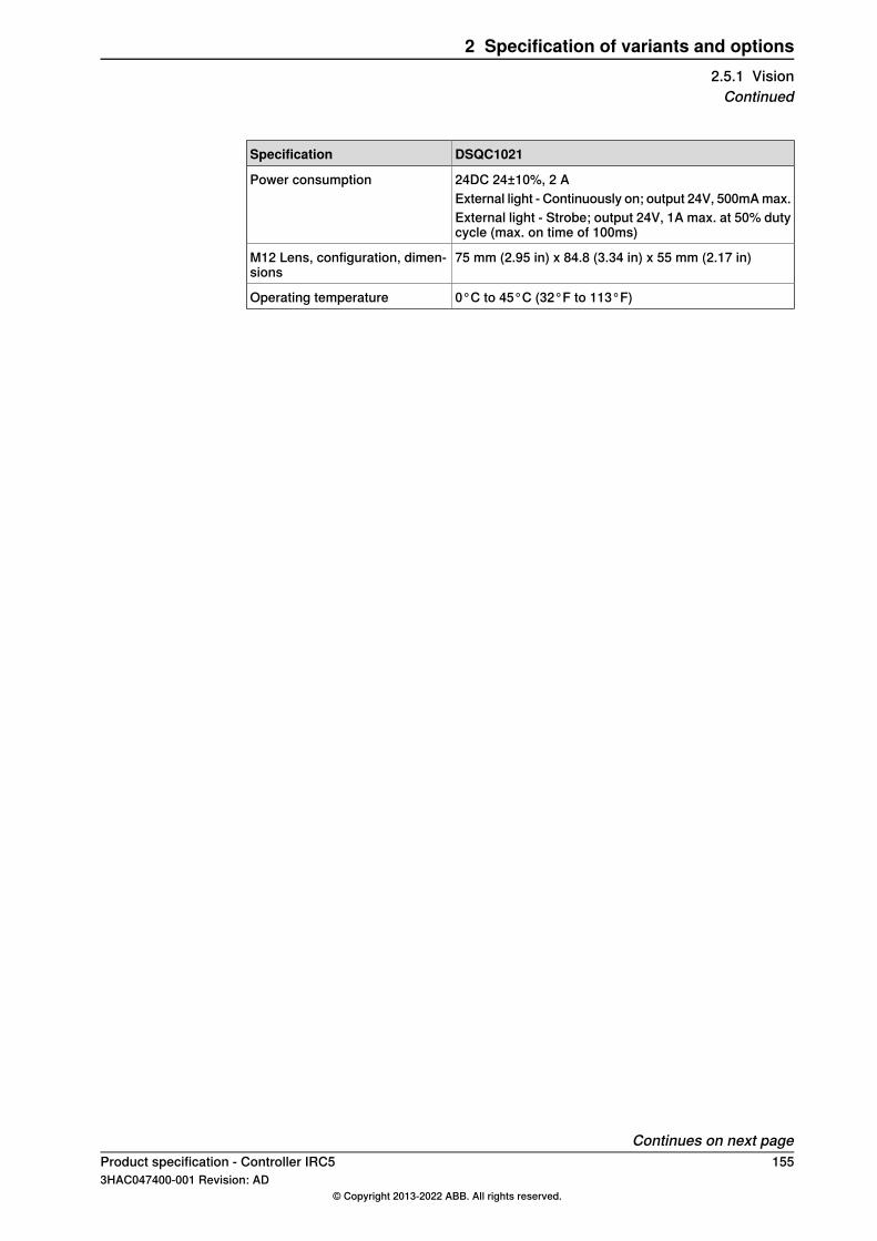
DSQC1021Specification
24DC 24±10%, 2 APower consumptionExternal light - Continuously on; output 24V, 500mA max.External light - Strobe; output 24V, 1A max. at 50% dutycycle (max. on time of 100ms)
75 mm (2.95 in) x 84.8 (3.34 in) x 55 mm (2.17 in)M12 Lens, configuration, dimen-sions
0°C to 45°C (32°F to 113°F)Operating temperature
Continues on next pageProduct specification - Controller IRC5 1553HAC047400-001 Revision: AD
© Copyright 2013-2022 ABB. All rights reserved.
2 Specification of variants and options2.5.1 VisionContinued
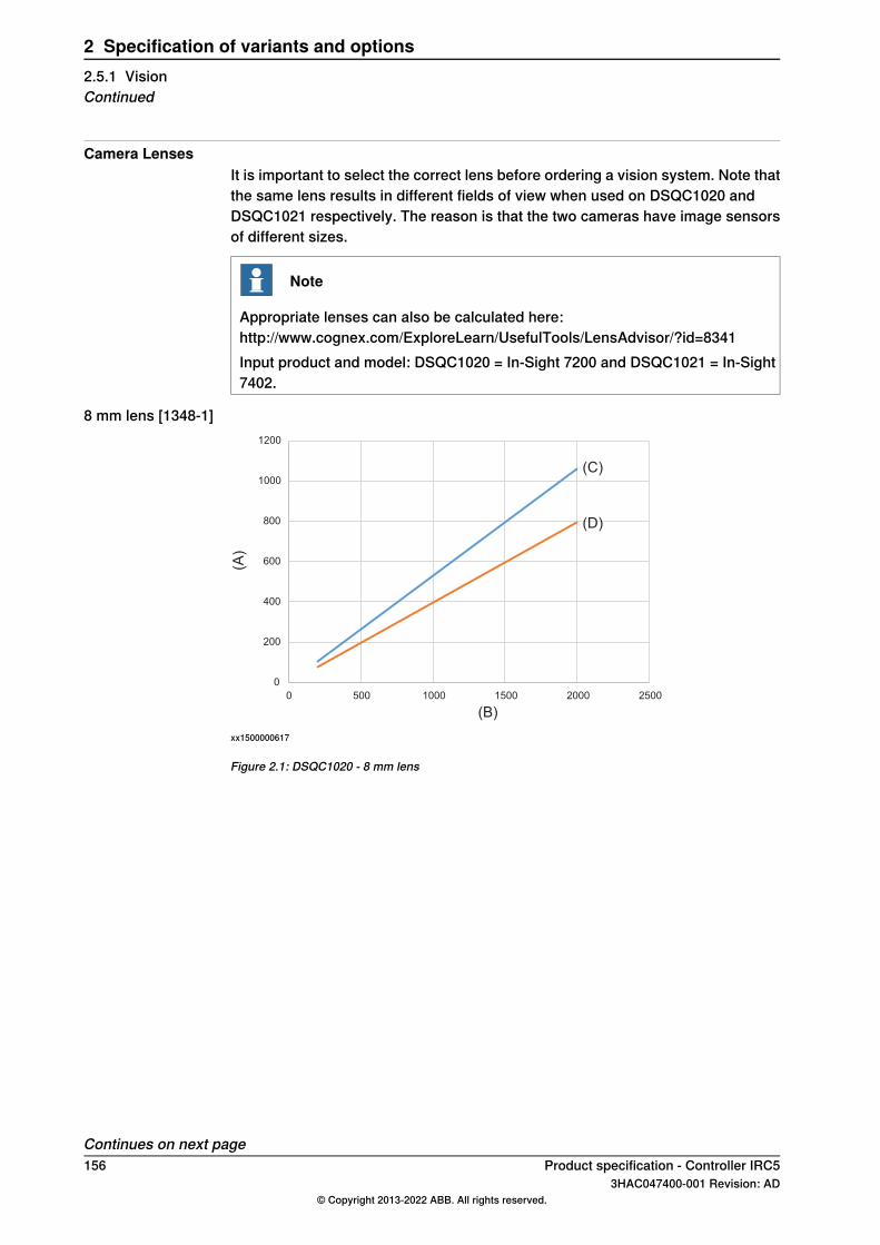
Camera LensesIt is important to select the correct lens before ordering a vision system. Note thatthe same lens results in different fields of view when used on DSQC1020 andDSQC1021 respectively. The reason is that the two cameras have image sensorsof different sizes.
Note
Appropriate lenses can also be calculated here:http://www.cognex.com/ExploreLearn/UsefulTools/LensAdvisor/?id=8341Input product and model: DSQC1020 = In-Sight 7200 and DSQC1021 = In-Sight7402.
8 mm lens [1348-1]
(A)
(B)
(C)
0
200
400
600
800
1000
1200
0 500 1000 1500 2000 2500
(D)
xx1500000617
Figure 2.1: DSQC1020 - 8 mm lens
Continues on next page156 Product specification - Controller IRC5
3HAC047400-001 Revision: AD© Copyright 2013-2022 ABB. All rights reserved.
2 Specification of variants and options2.5.1 VisionContinued
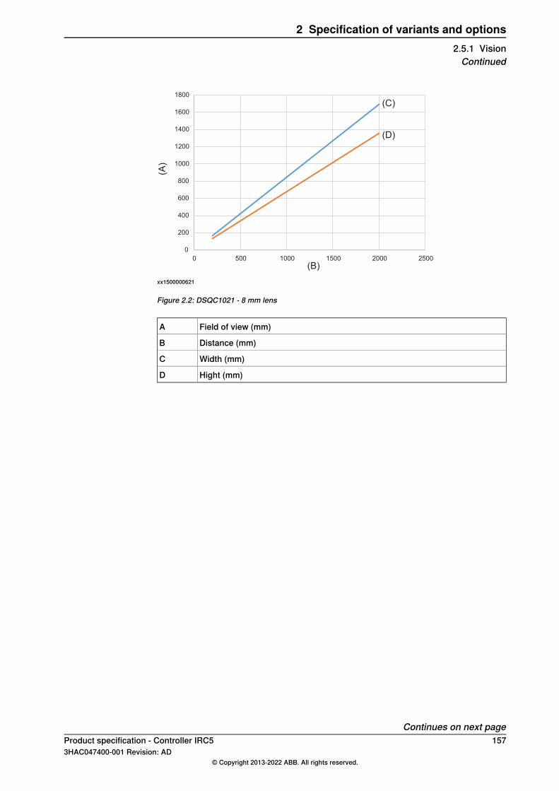
(A)
(B)
(C)
(D)
0
200
400
600
800
1000
1200
1400
1600
1800
0 500 1000 1500 2000 2500
xx1500000621
Figure 2.2: DSQC1021 - 8 mm lens
Field of view (mm)A
Distance (mm)B
Width (mm)C
Hight (mm)D
Continues on next pageProduct specification - Controller IRC5 1573HAC047400-001 Revision: AD
© Copyright 2013-2022 ABB. All rights reserved.
2 Specification of variants and options2.5.1 VisionContinued

12.5 mm lens [1352-1]
(A)
(B)
0
100
200
300
400
500
600
700
800
0 500 1000 1500 2000 2500
(C)
(D)
xx1500000618
Figure 2.3: DSQC1020 - 12.5 mm lens
(A)
(B)
(C)
(D)
0
200
400
600
800
1000
1200
0 500 1000 1500 2000 2500
xx1500000622
Figure 2.4: DSQC1021 - 12.5 mm lens
Field of view (mm)A
Distance (mm)B
Width (mm)C
Hight (mm)D
Continues on next page158 Product specification - Controller IRC5
3HAC047400-001 Revision: AD© Copyright 2013-2022 ABB. All rights reserved.
2 Specification of variants and options2.5.1 VisionContinued

16 mm lens [1349-1]
(A)
(B)
(C)
(D)
0
100
200
300
400
500
600
0 0,5 1 1,5 2 2,5
xx1500000619
Figure 2.5: DSQC1020 - 16 mm lens
(A)
(B)
(C)
(D)
0
100
200
300
400
500
600
700
800
900
0 0,5 1 1,5 2 2,5
xx1500000623
Figure 2.6: DSQC1021 - 16 mm lens
Field of view (mm)A
Distance (mm)B
Width (mm)C
Hight (mm)D
Continues on next pageProduct specification - Controller IRC5 1593HAC047400-001 Revision: AD
© Copyright 2013-2022 ABB. All rights reserved.
2 Specification of variants and options2.5.1 VisionContinued

25 mm lens [1350-1]
(A)
(B)
(C)
(D)
0
50
100
150
200
250
300
350
400
0 0,5 1 1,5 2 2,5
xx1500000620
Figure 2.7: DSQC1020 - 25 mm lens
(A)
(B)
(C)
(D)
0
100
200
300
400
500
600
0 0,5 1 1,5 2 2,5
xx1500000624
Figure 2.8: DSQC1021 - 25 mm lens
Field of view (mm)A
Distance (mm)B
Width (mm)C
Hight (mm)D
For more information about camera lenses and the option Integrated Vision, seeProduct specification - Integrated Vision.
160 Product specification - Controller IRC53HAC047400-001 Revision: AD
© Copyright 2013-2022 ABB. All rights reserved.
2 Specification of variants and options2.5.1 VisionContinued
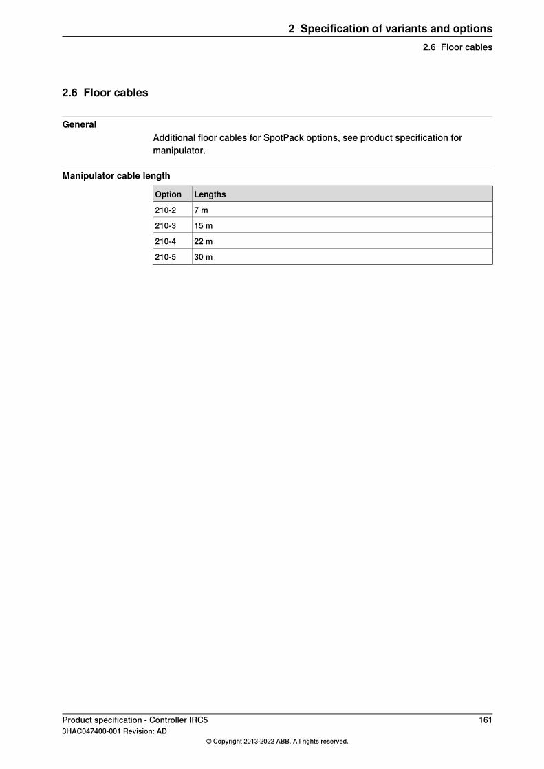
2.6 Floor cables
GeneralAdditional floor cables for SpotPack options, see product specification formanipulator.
Manipulator cable length
LengthsOption
7 m210-2
15 m210-3
22 m210-4
30 m210-5
Product specification - Controller IRC5 1613HAC047400-001 Revision: AD
© Copyright 2013-2022 ABB. All rights reserved.
2 Specification of variants and options2.6 Floor cables

This page is intentionally left blank

IndexAadditional axes, 91, 98
work area limitations, 99
Ccabinets supported by SafeMove, 97category 3, 49CCF, 49CIP, 120Common Cause Failures, 49ControlNet, 120
DDC, 49deactivation, 92, 100DeviceNet, 120Diagnostic Coverage, 49
Eelectronically linked motors, 100EN ISO 13849-1, 49, 52external axes, combined, 99
Ggantry, 99
Iindependent joint, 92, 100ISO 13849-1, 49
Llimit switch override, 92
MMTTFD, 49–51
Nnon ABB additional axes, 98
OODVA, 120
Pperformance level, PL, 49PFHD, 52PL, performance level, 49product standards, 45PROFIenergy
description, 119
RRAPID non motion execution, 92, 100rated current, 55rated voltage, 55required performance level, PLr, 49robots supported by SafeMove, 90, 97robots supported by the safety module, 97
Ssafety controller, 90, 94, 148safety standards, 45SCCR, 54servo tool changer, 91, 100servo welding gun, 91, 98shared drive modules, 92, 100short circuit current rating, 54stand alone controller, 34, 91, 99standards, 45
ANSI, 45CAN, 45EN IEC, 45EN ISO, 45
supported additional axes, 91supported cabinets, 97supported positioners, 98supported robots, 90, 97supported tracks, 98
Ttool changer, 91, 100track motion, 92
Wwork area for additional axes, 99
Product specification - Controller IRC5 1633HAC047400-001 Revision: AD
© Copyright 2013-2022 ABB. All rights reserved.
Index


ABB ABRobotics & Discrete AutomationS-721 68 VÄSTERÅS, SwedenTelephone +46 (0) 21 344 400
ABB ASRobotics & Discrete AutomationNordlysvegen 7, N-4340 BRYNE, NorwayBox 265, N-4349 BRYNE, NorwayTelephone: +47 22 87 2000
ABB Engineering (Shanghai) Ltd.Robotics & Discrete AutomationNo. 4528 Kangxin HighwayPuDong DistrictSHANGHAI 201319, ChinaTelephone: +86 21 6105 6666
ABB Inc.Robotics & Discrete Automation1250 Brown RoadAuburn Hills, MI 48326USATelephone: +1 248 391 9000
abb.com/robotics
3HAC04740
0-001,Rev
AD,en
© Copyright 2013-2022 ABB. All rights reserved.Specifications subject to change without notice.