
Retrofit Insulated Cross Arms (RICA) - National Grid
92
1 Oliver to insert cover page
-
Upload
khangminh22 -
Category
Documents
-
view
4 -
download
0
Transcript of Retrofit Insulated Cross Arms (RICA) - National Grid

1
Oliver to insert cover page
2
Network Innovation Competition: Full Submission Application [NGEN05/V1]
Section 1: Project Summary
1.1 Project Title Retrofit Insulated Cross Arms (RICA)
1.2 Project
Explanation
This project will develop a novel method of uprating Overhead
Lines (OHLs), accelerating the low carbon future by allowing
quicker removal of network constraints, resulting in earlier
connection of renewable generation. RICA also provides the
potential for cost savings and better visual amenity compared with
conventional investment options.
1.3 Funding Licensee National Grid Electricity Transmission
1.4 Project
Description
1.4.1. The Problem(s) it is exploring
The UK has set an ambitious, but necessary, target of delivering
net zero carbon emissions by 2050. To deliver this target there
will be required increases in renewable generation and the
electrification of transport and heat, leading to increased demands
on the transmission network. At the same time, it is becoming
more difficult to deliver increased transmission capacity in a timely
manner, while meeting environmental and community objectives.
Finding innovative ways to deliver network capacity at minimum
credible cost in line with stakeholder values, will deliver better
value for money to consumers and accelerate the low carbon
future.
1.4.2. The Method(s) that it will use to solve the Problem(s)
Insulated Cross Arms (ICAs) replace the standard metallic cross-
arms from which insulators and conductors are suspended.
Retrofit ICAs (RICAs) allow licensees to upgrade the voltage rating
on their existing towers by improving clearances. The project will
enable conversion of NGET 275kV towers to 400kV.
1.4.3. The Solution(s) it is looking to reach by applying the
Method(s)
This project will provide a pathway for the GB’s first full-scale
implementation of RICA technology, by mitigating technology risks
and accelerating its adoption onto transmission investment
schemes. The project will remove the current process, technology,
and specification hurdles that have prevented licensees from
adopting RICA as BAU previously.
1.4.4. The Benefit(s) of the project
RICAs can provide new network capacity without the need for new
build OHL. This leads to shorter project timeframes, reducing
constraint costs earlier (saving £180m per year) and enabling
faster connection of renewable generation. The capability to
operate at higher voltages also means lower losses and associated
emissions (39kt reduction). Wider benefits to stakeholders include
reduced customer impact due to lower construction volumes and

3
better visual amenity of towers compared to new build
alternatives.
1.5. Funding
1.5.1. NIC Funding
Request (£k)
8,115 1.5.2. Network Licensee Compulsory
Contribution (£k)
913
1.5.3. Network
Licensee Extra
Contribution (£k)
0 1.5.4. External Funding – excluding
from NICs (£k)
0
1.5.5. Total Project
Costs (£k)
9,133
1.6. List of Project
Partners, External
Funders and Project
Supporters (and
value of contribution)
Project Supporters: Network Licensees: Scottish Hydro Electric
Transmission plc, Scottish Power Transmission Ltd., Electricity
System Operator Suppliers: Babcock Networks, Balfour Beatty,
Energyline, Nanjing Electric, PACE Networks, Allied Insulators,
Allied Conductors Shemar, Wood Group, ZTT. Academic
Institutes: Cardiff University, The University of Manchester
1.7. Timescale
1.7.1. Project Start Date Jan 2021 1.7.2.
Project
End Date
Mar 2026
1.8. Project Manager Contact Details
1.8.1. Contact Name and Job
Title
Paul
Gallagher
Innovation
Manager
1.8.2.
Email and
Telephone
Number
XXXXXXXXXXXXXX
1.8.3. Contact Address NG Warwick House, Warwick Technology Park, Gallows
Hill, Warwick CV34 6UW
1.9. Cross Sector Projects (only complete this section if your project is a Cross Sector
Project, ie involves both the Gas and Electricity NICs).
1.9.1. Funding requested the
from the [Gas/Electricity]
NIC (£k, please state which
other competition)
0
1.9.2. Please confirm
whether or not this
[Gas/Electricity] NIC Project
could proceed in the absence
of funding being awarded for
the other Project.
0
1.10. Technology Readiness Level (TRL)
1.10.1. TRL at Project Start
Date
TRL 6 1.10.2.
TRL at
Project
End Date
TRL 8

4
Section 2: Project description
2.1 Aims and objectives
2.1.1. The Problem that needs to be resolved
The move towards renewable generation, necessary to achieve the UK government’s net
zero emissions target, is having an increasingly significant effect on transmission
network constraints. A combination of renewable generation connecting in remote areas
and increased demands in urban areas due to the electrification of heat and transport,
are both expected to drive the need for further network development and investment.
While some of this additional demand will be offset by local generation, network
modelling shows there will be significant changes to power flows across the transmission
system, leading to increased constraints which will require network reinforcement to
alleviate. Although new interconnectors will help to address some of these constraints,
reinforcement of the GB network will also be required. This requirement will be
predominantly felt at key transmission boundaries, particularly the critical North-South
links.
Network constraints can be relieved through reinforcement (to increase power transfer
capacity) or by controlling power flows. Reinforcement can be achieved through new
Overhead Lines (OHLs); however, new OHLs are expensive, require significant
stakeholder engagement to manage customer, consumer, and environmental impacts,
and often require lengthy land acquisition and consenting applications. The transmission
industry must balance the need for new OHLs with its commitment to conserving and
enhancing the natural beauty, wildlife, and cultural heritage of the GB landscape.
Alternative options for significant capacity increase include reinforcement of existing
OHLs through reconductoring with modern conductors, installing additional conductors,
uprating the voltage, or a combination of these. These options also bring challenges
from a cost, time-to-deliver, and environmental perspective.
On older OHLs, reconductoring with High Temperature Low Sag (HTLS) conductors can
increase capacity to by around 28%, but also increases network losses and associated
emissions. For further capacity increases, additional conductors can be installed, often
requiring tower and foundation strengthening due to increased mechanical loading.
The GB transmission network currently operates at a mixture of 275 kV and 400 kV.
Uprating a circuit’s voltage from 275kV to 400kV is possible for some tower types (e.g.
L2, L6) by design, however others in the GB network (e.g. L3, L34 and L66) currently
require replacement with new, taller towers to meet minimum clearance requirements.
Given the increasing penetration of renewables to achieve net zero targets in the future,
methods to facilitate large and fast capacity increases at transmission boundaries would
be beneficial to consumers.
This project seeks to solve this problem by establishing an innovative way to greatly
increase the power transfer capacity of existing lines. With this in mind, the project’s
first aim is to:
Develop a new investment option for uprating overhead lines from 275kV
to 400kV that accelerates development of a low carbon network while
delivering on stakeholder priorities (lower cost, reliability, decarbonised,
low visual impact).

5
2.1.2. The Methods being trialled to solve the Problem
The Retrofit Insulated Cross Arm (RICA) is an arrangement of electrical insulators which
have been retrofitted to an existing 275kV tower, allowing it to operate at 400kV without
having to build an entirely new route, as shown in Figure 1. This is done by replacing
the steel cross arms and suspended vertical insulators with an Insulating Cross Arm
(ICA). As the conductors attach directly to the cross-arm, the electrical clearances are
improved as per Figure 1.
Figure 1 – Comparison of Traditional suspension insulator and RICA. Showing how the increase in
electrical clearances is achieved.
The voltage uprate from 275kV to 400kV could provide an additional 45% power transfer
capacity alone while also reducing transmission losses. Larger power increases have also
been estimated when used in conjunction with HTLS conductor types – up to an
additional 150% [1]. We estimate that this technology could be applied to 25% of the
275kV England and Wales Network, with further applications in Scotland.
Figure 2 – Summary of technology gaps for Project RICA

6
The challenges for utilities in adopting this technology have always been finding a
solution which can be installed, maintained, and accessed safely while maintaining
network reliability and delivering at an efficient cost to consumers. A summary of the
current technology gaps preventing immediate adoption is shown in Figure 2.
The project will innovate to address these existing barriers as outlined in the following
sections. The project will also leverage the knowledge and expertise developed over the
last 10 years relating to ICAs (from past innovation projects and the market), to bring
this technology over the last hurdle to allow the opportunity for introduction into
business as usual (BAU).
2.1.3. The Development and Demonstration being undertaken
The RICA project sets out to meet the following SMART (specific, measurable,
achievable, relevant, and time bound) objectives:
1. Fill gaps in research and development related to RICA, to increase the
technological maturity of the whole-line-solution. The RICA solution should be
demonstrated as ready for use as BAU by the end of the project.
2. Develop the alternative investment option to prevent the need for new or
replacement of existing towers. There will be a clear business case for BAU
use on at least one operational route by the end of the project.
3. Develop a family of tower upgrade options which are fully compliant with all
associated NGET protocols. RICAs will be adopted as an option available for
TO and ESO investment planning activities by the end of the project.
Objective 1:
The use of RICAs as an alternative method of uprating has been explored over several
smaller innovation projects over the past 10 years. However, further development of the
technology and system designs are required to resolve the outstanding issues with live
network implementation and ensure risks are effectively managed. The technology needs
to be matured and validated to meet the requirements of multiple tower types and
conditions, along with all of the associated long-term performance, delivery, health &
safety, and asset management implications.
We will select a supplier through a competitive procurement process to develop the RICA
method from design through to type-testing for all relevant tower types and
configurations. The project’s development scope contains all the technological and
process-related design complexities that need to be resolved before the solution can be
rolled-out on the network (in order to demonstrably reach technology maturity of TRL
8). A technical gap analysis has been undertaken for RICA technology and used to
inform the specific areas of design the project will address (see Appendix V.1 for
details).
Objective 2:
This will involve developing a detailed investment case that includes identifying which
routes will benefit from RICAs, and differences in costs and project timescales between
the RICA option and existing options. This will require continual development with
scheme delivery teams, and interfaces with ESO’s network options analysis (NOA)
process. This will support the project implementation into BAU and help to establish
greater certainty for the market.

7
Objective 3:
Once the project delivers on Objective 1, there will be clear technical requirements for
the market to deliver solutions against. It will then be possible to develop a meaningful
set of documentation (standards, specifications, processes and procedures) against
which RICAs can be developed and tested.
The demonstration of the RICA technology to validate its performance on multiple tower
types and under the conditions of the live network will be carried out via a series of full-
scale demonstration trials set up at Deeside and Eakring – see Section 2.3 for details.
Subject to successful trials, the RICA solution will then be subjected to type-tests before
it achieves its TRL8 ambition.
These trials are essential to establishing first time solutions to many of the factors which
will enable RICAs to be a credible and repeatable investment option. This will help to
ensure the specifications are to the right level of detail, and that key functionality
required in the design of the RICAs is specified correctly. Furthermore, identification of
best practice and design improvements are inevitable from the first network installation
and project monitoring will ensure that these are captured and disseminated for future
installations.
2.1.4. The Solution(s) that will be enabled by solving the Problem
RICA is a clean, conceptually straightforward innovation that will use improvements in
ICAs over the last 10 years to deliver an innovative investment option, with multiple
technical advantages as outlined in Figure 3.
Figure 3 – Overview of the solution’s (RICA’s) potential advantages
RICA will provide a faster option to alleviate network constraints through uprating
existing 275kV lines to 400kV, delivering significant savings to consumers. Our financial
assessment of the benefits to consumers is given in Section 3.2, and demonstrates that
uprating a single line could provide significant returns for consumers. Our Core scenario
estimates £286m of savings can be delivered to consumers, as detailed in Appendix
VI.5.
Uprating will increase the efficiency of transmission infrastructure through lower losses,
saving energy and cost. In the near future where GB’s electricity supply still contains a
significant carbon content, lower losses will reduce transmission network CO2 emissions.

8
Using RICA will further decrease emissions through avoiding use of steel and concrete
required for new OHL builds. Our Analysis of the CO2 benefits is given in Section 4.1.3
and shows RICAs can deliver a 39kt reduction of net carbon emissions by 2050.
Additionally, using RICAs on existing towers to uprate OHLs will reduce the disruption to
land and environment that would likely be required if new towers and new foundations
were used instead along existing routes, and will prevent new routes being developed in
greenfield or brownfield sites. The benefits to stakeholders and how this aligns with
broader strategic objectives is provided in detail in Section 3.1, and shows that this
project meets strategic objectives and stakeholder values directly.
As outlined in Section 2.1.2, the project will deliver type-registered RICA designs for use
with key 275kV tower types that aren’t inherently upgradable to 400kV on the NGET
network - these represent 30% of all 275kV towers. Our analysis in Appendix II shows
that there are multiple applications in England and Wales which relate to critical
transmission boundaries and our engagement to date has shown that other licensees
also see applications in their networks. This demonstrates this technology can be rolled
out across the network to deliver value for consumers.
Extensive development and demonstration activities as outlined in Section 2.1.3 will take
the technology out of the innovation phase and ready for BAU - providing a clear path
for a competitive marketplace.
Project RICA will also make these other network investments more credible by:
1. Increasing current rating by providing additional clearances that allow for
increased conductor sag at higher operating temperatures.
2. Providing experience and standards to enable Ultra High Voltage (UHV) networks
– opening the door to UHV networks and associated capacity increases and
reduced losses on 400kV routes throughout the GB network.
3. Providing an additional option for use on Visual Impact Provision (VIP) projects –
enabling existing towers in Areas of Outstanding Natural Beauty (AONBs) to be
reduced in height by around 25%. This will also reduce the disruption to the
environment on such projects.
This project will provide significant risk mitigation for these additional investments to be
considered by GB Network licensees, enabling RICAs to deliver more value to
stakeholders.
2.2 Technical description of project
The project will be delivered in the following stages:
• Stage 1: Initialisation
• Stage 2a: Development
• Stage 2b: Building and testing
• Stage 3: Witness scheme delivery
Across these stages of the project are the following workstreams:
• Procurement: Enabling value for money to be delivered during the NIC project,
de-risking the NIC project, and enabling investment line-of-sight.
• Standards and specifications: Establishing standards and specifications to
enable the marketplace and adopting feedback from stakeholders.
• Design and development: Sizeable workstream, designing whole-life-value
RICAs to meet UK and stakeholder requirements.

9
• Investment Case: Developing a clear justification for the use of RICAs and
bringing critical whole-life design choices into financial terms.
• Stakeholder Engagement: Leveraging wider experience and knowledge to
deliver better innovations, share outcomes and inform key stakeholders of what
RICA can deliver for them.
The project’s focus will shift between these workstreams as it progresses.
2.2.1. Stage 1: Initialisation
Stage 1 will be delivered internally by NGET and use experience of past projects and
further investigation of real-world tower and route condition to prepare a concise set of
work definitions, or ‘knowledge gaps’, to be completed by the supplier in stage 2.
Clear scope and guidance, to include detailed links to existing standards, will be
prepared for potential suppliers. This information will be used to enable a competitive
event. This part of the project is key to reducing technological and delivery risk on the
project through consolidating the future design process. The procurement process will
ensure value for money for consumers, and will ask suppliers to consider contributing to
the project through several mechanisms; as outlined in section 6.1.8.
This stage will also produce a clear and agreed initial investment case, which will outline
the benefits and areas of uncertainty from an investment perspective. This investment
case will then be developed and improved as the project delivers key technical advances.
Table 1 provides a description of the workstreams contained in Stage 1; a description of
key outcomes and the project’s deliverables highlighted in bold.
Table 1: Stage 1 workstream descriptions
Workstream Description Key outputs
Procurement:
Pre-procurement
Activities associated with engaging the market.
Expression of Interest published, Pre-Qualification Questionnaire begun, and detailed design requirements finalised (D.S1.2) – see Section 9.
Design and technology: Preparation
Outline of all design related tasks for completion at detailed design level by chosen supplier.
Reports containing preliminary design considerations, type-testing requirements and the development of design and development scope to drive supplier activities (D.S1.2).
Standards and specifications:
Review
Review existing standards to identify gaps/conflicts. Quantify planning benefits. Assess condition of actual
OHLs.
Documentation plan developed, and
report informing planning and business decision factors.
Investment
Case:
Initial case
Understanding key metrics associated with the economic benefits of the RICAs to enable benchmarking against alternative solutions within optioneering activities.
Drafting of the preliminary Investment Case (D.S1.1) that sets out the break-even point between new towers and RICA solution through life-cycle analysis.
Stakeholder Engagement:
Involve
Stakeholders engaged through Technical Advisory Board (TAB) and actively contributing to project work packages. Communications will begin around RICA through various media.
Stakeholders will directly input to the development and agreement of the detailed design requirements (D.S1.2) and (D.S1.1). Stakeholder input will be required to progress to Stage 2a.

10
2.2.2. Stage 2: (a) Development & (b) Build and Test
The purpose of Stage 2 is to establish the RICAs as a total lifecycle solution and it will
resolve all remaining unknowns into a finished and documented solution. It will involve
the development of a suite of RICA designs for a live operational route and establish a
clear set of specifications for the future market.
This stage will be overseen by NGET and coordinated and delivered by the third-party
supplier, whose selection will be the first key output to Stage 2, following on from earlier
pre-qualification work completed in Stage 1. The supplier will be given clear deliverables
for Stage 2 but it is expected that new solutions will be needed to ensure an optimised
solution that is fit for purpose on the UK network.
Given the uncertainty in the specifications and design requirements, the supplier will
need to be able to work flexibly to address challenges through innovation. This
uncertainty in scope will be reflected in the contractual terms and procurement scoring
methodology, to ensure that the project can proceed at reduced risk while identifying a
sufficiently innovative supplier.
As with any research focused project, there is a risk that innovative discovery, or
‘unknown-unknowns’ will materialise as the project develops leading to schedule delays.
This risk has been accounted for through planned iteration phases of load case
specification, design, and testing to ensure that any final approval work is successfully
completed on-schedule. This has been reflected in the project management plan by the
split of Stage 2 into parts 2a and 2b, where 2a will have flexibility to innovate and
iterate, and 2b will be focused on final testing and approval.
Table 2 and Table 3 provide a description of the workstreams contained in Stages 2a and
2b, with project deliverables highlighted in bold.
Table 2: Stage 2a workstream descriptions
Workstream Description Key outputs
Procurement:
Contract
supplier
Engage a supplier to deliver the technical aspects of the project. This workstream develops the
work completed in stage 1 to completion of the chosen supplier on-boarding process.
Supplier contract awarded (through Innovation Partnership or equivalent).
Design and technology:
Development
Detailed understanding of tower and RICA requirements through load cases, tower evaluations and initial insulator design. Trials will
be performed across a range of sites including
NGET's new outdoor test facility at Deeside, our training facility at Eakring, and within external labs as needed for RICA design validation tests - these need not be accredited labs at this stage.
Iterative design and test cycles to allow learning
to be implemented in updated prototypes and concepts with the final concepts being progressed to Stage 2b for validation.
Design of the enhanced monitoring required for witnessing performance on a real network.
Draft functional specification (D.S2a.1) and First generation
product design portfolio (D.S2a.2).
Proof of principle and design testing at all levels, design improvements as required, culminating in a report on detailed trial outcomes and lessons learned (D.S2a.3).
Standards and specifications:
Development
Ensure that any gaps in knowledge are filled and subsequently produce all required guidance notes, technical reports, NSIs, maintenance manuals and disposal strategies etc.
Draft of all NGET standards, specifications, processes and procedures in line with the documentation plan.

11
Workstream Description Key outputs
Investment Case:
Refine
Develop the Investment Case with further insight as the project develops, e.g. information on the ease of installation or more precise hardware costs, to support economic decision-making. All new information will feed into decision tools such
as NOA to conduct cost benefit analysis.
Investment guide documentation produced.
Stakeholder
Engagement:
Seek support
Stakeholders will be engaged through supporting deliverables, and be actively engaged in the trials to enable detailed feedback. Further stakeholder
input based on the learning from other workstreams will also be incorporated into the investment case, standards and specifications.
Stakeholders will directly input to the functional specification (D.S2a.1), detailed designs (D.S2a.2),
and the lessons learned (D.S2a.3). Agreement from stakeholders will be required
to progress to Stage 2b.
Table 3: Stage 2b – Build and Test workstream descriptions
Workstream Description Key outputs
Procurement:
Supplier management
The functional specification documentation will be refined throughout the project to ensure that, if necessary, the existing supplier could be supplemented or replaced by an alternative.
Functional specification updates.
Design and technology:
Validation
By this stage, all concepts should have been fully
worked through and this will now form the final validation testing in the form of type approval testing required for the type registration. Testing will be completed at Eakring and long term testing will be established at Deeside, to provide
a benchmark for RICA performance that will have
been running for several years prior to any mainstream network installation. External, accredited test labs will be engaged to perform any insulator testing needed for type registration.
Relevant type registration testing complete and type-
approval achieved.
Standards and specifications:
Embed
This is a follow on workstream from Stage 2a - NGET processes and procedures. During this stage all key documentation will be formalised and approved for adoption by the relevant NGET
departments.
High quality draft of all
documentation (D.S2b.1) approved into the business. Full suite of documentation issued (D.S2b.3).
Investment Case:
Adopt
Following development of the investment guide, and proof of technology from the trials, we will
conduct a major project review.
Final Investment Case (D.S2b.2).
Stakeholder Engagement:
Approval
Stakeholders will be included in the design
finalisation and be kept up-to-date on progress through the final stages of development. Input will be gathered for the final investment case and specifications.
Stakeholders will directly output into (D.S2b.1) and (D.S2b.3).
Stage 3 – Witness Scheme Delivery
The intention for this Project is that it will lead straight into but not include the roll-out
of final RICA solutions within a real line refurbishment scheme. This Stage covers a
period of enhanced monitoring of the performance of the route, over and above what
would be carried out as BAU for a line uprating using a type registered technology. It
also covers a final project report so that knowledge of live network implementation can
be disseminated to our stakeholders.

12
Within the course of the project, it is anticipated that business drivers will support a full
line up-rate to 400kV, returning value to the customer in the shortest possible
timeframe. In this event, the scope of Stage 3 will remain the same1.
The network installation will be determined based on an on-going assessment of
business need and benefits provided, i.e. the Investment Case. This case will change
over the lifetime of the project, but evaluation of all possible locations for 275kV to
400kV upgrades within the NGET network is already underway (see Appendix II).
2.3 Description of design of trials
Following extensive workshop-based RICA design development, ICA prototypes will be
produced for testing the different system designs across the trial Stages (Stages 2a, 2b
and 3). Throughout these three stages, stakeholders will be engaged throughout the
process to enable feedback into the design, documentation and processes established.
Stage 2a
In Stage 2a, once a design has been agreed, prototypes will be produced, and
constructability trials will be held at a field-based facility. The purpose of these trials will
be to experiment with different techniques for modifying the towers to accept the new
RICAs and subsequent operation and maintenance techniques. This work would be
completed on new, bespoke structures, either identical to the family of L3 tower types,
or as a minimum, containing the necessary features to allow comprehensive trialling to
be completed.
These constructability trials are expected to culminate in a re-design of the cross arms,
incorporating stakeholder feedback and lessons learnt. A key element of the design will
be enabling ease of use on site and limiting the need for heavy lifting equipment to be
taken to the OHL routes. This will address a significant proportion of the upfront and
enduring costs from a RICA investment.
Testing will also be undertaken at Deeside, as this will have capabilities for testing
insulators under network representative energised conditions with a high level of
monitoring and for testing dynamic performance of conductors and RICAs using a long
span variable tension rig with the ability to add vibrations through a hydraulic shaker
unit. A range of RICAs in different configurations will be installed and tested at Deeside
with the primary purpose of providing confidence in the network performance of the
solution over a long time-frame. Testing of hardware from different manufacturers will
ensure confidence in the security of supply, especially important, given NGET’s first-hand
inexperience with large composite insulators.
These Deeside trials will be ongoing for a minimum of a year as the design is refined,
key technical risks are removed (or reduced to As Low As Reasonably Practicable) and
uncertainties resolved.
Stage 2b
In Stage 2b, after lessons learned have been conducted from the first series of trials at
Eakring and/or Deeside the designs will be finalised. The final RICA designs must then be
type-tested.
1 If no route is available for on-line monitoring within the project timeframes, we will
specify appropriate monitoring arrangements and return the monitoring costs to the
consumer (more detail of mitigation actions provided against risk 12 in Appendix III)

13
Final constructability demonstrations will likely be performed at Eakring, and final
electrical and dynamic assessment will likely be performed at Deeside, using a similar
set up to that used in the Stage 2a demonstration. The difference being that in the
Stage 2b demonstrations, a fully approved procedure will be presented and followed
through to completion. Aside from minor amendments, the demonstrations are expected
to be completed without departure from the procedure. Any departure will be considered
a failure and the trials will need to be repeated following the implementation of the
necessary changes. Successful completion of these demonstrations will be when the
RICAs completed their installation and maintenance regime to the full satisfaction of all
relevant operational stakeholders.
Additionally, for type-testing it is likely that testing of the insulators in an accredited
laboratory will be required for design assurance. Examples of the specific set of tests to
be carried out are given in Appendix V.4.
Stage 3
The purpose of the NIC project is to develop RICA technology to a point where it is
considered as a tool for use in future network option assessments. Stage 3 completes
the final milestone in this ambition by conducting enhanced monitoring and evaluation of
performance, over and above what would normally be done as BAU for accepted design
solutions.
The in-service monitoring will also allow feedback on the first few years of service
experience to be disseminated to other utilities and provide clear validation of design
assumptions. This data and learning will be critical to responding to concerns over the
technology and the applicability of the specifications.
This data will also help remove conservative assumptions in the standards, further
enabling the competitive market. The data will also be used to help improve accuracy of
end-of-life predictions, which will directly impact the risk profile and investment case for
RICA.
The project structure has been kept intentionally flexible to ensure spend is not over
committed in any areas that won’t be applicable to any future network upgrade.
Regarding the scope of the Stage 3 trials, various schemes will be considered from
future NOAs, and the project will attempt to align with one of these.
2.4 Changes since the Initial Screening Process (ISP)
There has been no significant change to the scope since the ISP stage. The total project
costs have decreased from £11.2m to £9.1m due to refinement of the project plan,
revisiting prior assumptions and more granular cost modelling. We have used the FSP
development period to mature and detail the RICA project, including:
• Undertaken a more detailed costing and cost-benefit analysis
• Characterised the technical detail of the technology development - revised the
Start Date TRL from 7 to 6 and the Finish Date TRL from 9 to 8
• Developed a rigorous, implementable project plan
• Defined detailed deliverables against the project plan
• Conducted risk workshops to cover both technology development risks and
project delivery risks
• Continued engagement with our project partners and potential suppliers

14
Section 3: Project business case
We have developed a robust business case for this NIC project case that presents:
• The strategic case for change - how this project aligns with electricity consumer
priorities, government legislation, Ofgem guidance, and NGET business plans.
• The economic case - how this project delivers value for consumers and why now is
the right time to bring this technology to a business-as-usual solution.
• The commercial, financial and management cases - how we have optimised the
project’s procurement strategy, funding and governance to deliver the best
outcomes.
This breakdown follows the HM Treasury five case model for business case development.
The following sections describe each case in further detail, while Appendix VI presents
further detail on this model and the rationale behind using it.
3.1 The strategic case for change
RICA aligns with electricity consumer priorities outlined in our RIIO-2 business plan as
illustrated in Figure 4.
Figure 4 – Project alignment with electricity consumer priorities
First, the project supports and accelerates progress towards a more sustainable energy
system - decarbonisation through connection of more low carbon generation to the
transmission system and reduced electricity losses; while also enhancing the visual
amenity of natural assets with lower tower heights compared with new build OHL.
Second, the new low-carbon generation will connect, thanks to increased capacity at key
transmission boundaries, which in turn maintains a reliable and secure electricity supply
- providing energy as and when it is needed.
Third, the project will help contribute to more affordable energy bill as it delivers a net
present value of £286m relative to the baseline option of using new build OHLs under
15
our Core assessment scenario (in 20/21 real terms). The optimistic value to consumers
has also been estimated as £4bn – See Appendix VI.
The following subsections expand on these themes and demonstrate the project’s
alignment with government legislation, Ofgem guidance, and NGET’s business plan for
RIIO-2 and beyond.
3.1.1. Enabling the transition to net zero
The UK has legislated for a net-zero carbon emissions energy system by 20502. In
parallel to enacting this target in June 2019, the Committee on Climate Change (CCC)
published guidance3 stating that to deliver net-zero, transmission network capacity will
need to keep pace with installation of new low-carbon generation to ensure a reliable
network. This shows that delivering new transmission network capacity, at the lowest
cost to consumers, is at the heart of the UK’s road to net-zero. We have recognised this
as a key area of focus in our sustainability strategy with a target to strengthen network
capacity at a minimum-whole life cost4. RICA directly aligns with this ambition in
providing additional capability to uprate existing lines at a lower whole-life cost to a new
build OHL solution.
The project also aligns with the objectives of regulations and government plans
developed in support of the legislated target, notably Ofgem’s Decarbonisation Action
Plan. The development of RICAs from a prototype technology to a business-as-usual
solution supports the first two of the plan’s actions: “designing cost-effective networks
for net-zero” and “long-term planning and innovation”. For the former, this project will
expand the tool kit available to deliver network capacity increases for existing routes at
a far lower cost than new infrastructure. It will do this while supporting the second
action’s aim to support innovative pathways to net-zero by developing the investment
proposal where there is uncertainty. This is a key element of this project - to understand
and improve the investment proposition for RICAs through de-risking the maturation of
the technology.
The higher voltages RICA uprated towers can enable carbon emissions reductions
through lower electricity losses. We have set a target, formalised in our RIIO-2 business
plan, of net zero direct emissions by 2050. In the shorter term, we have also targeted a
20% reduction in controllable carbon footprint by 2021 vs 2012/13 levels in our NGET
sustainability strategy. NGET’s annual environmental statement describes our progress
towards achieving these goals. This document shows that 81% of NGET’s carbon
footprint in 2018/19 came from losses - therefore any benefits that RICA have in
reducing losses will be a significant contribution to lowering our total carbon footprint,
alongside decarbonisation of the electricity itself.
3.1.2. Improved visual amenity and lower customer impact
The project helps to deliver on other elements of a sustainable energy system in
improving visual amenity of uprated transmission infrastructure in National Parks and
AONBs, while reducing impact of transmission works on customers. It will also build on
2 Enacted through an amendment to the Climate Change Act 2008.
3 Committee on Climate Change. Net Zero The UK's contribution to stopping global
warming, May 2019. Retrieved from: https://www.theccc.org.uk/publication/net-zero-
the-uks-contribution-to-stopping-global-warming/
4 NGET, Delivering our environmental future - Our sustainability strategy, March 2019

16
our efforts to recognise and enhance the value of natural assets, with 29 sites now being
proactively enhanced using a Natural Capital approach against a target of 30 sites by
2021.
Our Visual Impact Provision (VIP) Policy sets out our approach to reducing the impact of
existing infrastructure on important landscapes across England and Wales. A key
intended outcome of this policy is feasible mitigation projects that have a tangible effect
on landscape in National Parks and AONBs. Developing RICA to a BAU solution supports
these aims by providing an option for network investment which may provide a
stakeholder acceptable investment where ungrounding cables are not acceptable to all
stakeholders (e.g. in areas of historical significance).
The reduction in construction timescales and volumes for RICA vs new OHL build also
helps to deliver a sustainable energy system. Reducing impact on our customers and
wildlife during construction is a key part of our Sustainability Strategy; RICA will result in
fewer disruptions to communities and ecosystems.
3.1.3. Energy as and when it is needed
Maintaining a safe and reliable network is a key pillar of our RIIO-2 Business Plan and is
consistently our stakeholders’ number one priority, associated with 60% of our baseline
costs for 2021-26 in our RIIO-2 submission. This focus aims to maintain our world-class
service reliability of 99.9999% while allowing for future network requirements. A key
component to delivering this reliability is flexibility in the delivery plan, allowing for
multiple energy system development scenarios. Adding RICA as a low-cost network
capacity solution will add another investment option to address network constraints
going into the RIIO-3 price control. Maturing this technology will pay dividends when it is
selected as part of cost-reflective investment decision making.
The majority of transmission built in NGET’s network was installed in the 1960s as
shown in Figure 5.
Figure 5 – NGET OHL tower installation years 1950-2017
Internationally, there have also been significant challenges to new OHL construction5 due
to many factors including more difficult consenting, and GB is no exception6. RICA
5 Transmission costs in the US rose by 80% between 1990 and 2007 (GDP growth
adjusted):https://www.utc.wa.gov/_layouts/15/CasesPublicWebsite/GetDocument.ashx?
docID=240&year=2007&docketNumber=072300
6 This is supported by Shemar’s letter of support in Appendix IV, which indicates UK
planning timeframes of 6-9 years for new transmission.
17
provides an additional option to make the best use of the large existing fleet by offering
an uprating capability for 275kV towers. This will help provide the network capacity we
need to ensure energy is provided to consumers when they need it.
3.1.4. An affordable energy bill
A key electricity consumer priority and element of NGET’s RIIO-2 Business Plan is to
create an affordable energy bill for all.
Reduced underlying costs of Transmission network delivery and balancing services are
ultimately reflected in consumer and customer tariffs. Therefore, RICA is well placed to
reduce the pressure on consumer bills through reduced costs of managing constraints on
the system and lower costs of delivering transmission infrastructure. Indeed as shown in
the following section, delivering RICA will deliver a strong net present value (NPV) to
consumers for the innovation funding requested.
3.2 The economic case - how does RICA deliver value to consumers
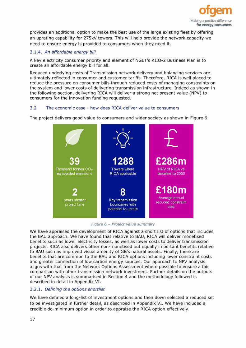
The project delivers good value to consumers and wider society as shown in Figure 6.
Figure 6 – Project value summary
We have appraised the development of RICA against a short list of options that includes
the BAU approach. We have found that relative to BAU, RICA will deliver monetised
benefits such as lower electricity losses, as well as lower costs to deliver transmission
projects. RICA also delivers other non-monetised but equally important benefits relative
to BAU such as improved visual amenity of GB’s natural assets. Finally, there are
benefits that are common to the BAU and RICA options including lower constraint costs
and greater connection of low carbon energy sources. Our approach to NPV analysis
aligns with that from the Network Options Assessment where possible to ensure a fair
comparison with other transmission network investment. Further details on the outputs
of our NPV analysis is summarised in Section 4 and the methodology followed is
described in detail in Appendix VI.
3.2.1. Defining the options shortlist
We have defined a long-list of investment options and then down selected a reduced set
to be investigated in further detail, as described in Appendix VI. We have included a
credible do-minimum option in order to appraise the RICA option effectively.

18
Table 4: Shortlist options summary
Option name Option description
BAU
counterfactual
This comprises the existing BAU toolset to increase
transmission capacity, covering: • Adapting current OHL routes:
o Reconductoring with new higher capacity conductors
o Adding circuits (from single to double)
o Uprating voltage
• Building new OHL
• Non-network solutions (e.g. power control devices, battery
storage)
BAU+RICA
• The set of BAU options.
• Plus the RICA option for uprating lines from 275kV to 400kV
for L3, L34, and L66 tower types.
3.2.2. Assessing the options shortlist
We have conducted a detailed NPV assessment of the shortlist as per the assumptions
stated in Appendix VI. Table 5 shows that RICA has slightly higher present value costs
than the BAU option due to costs being incurred earlier, but provides far higher present
value benefits than the counterfactual due to faster capacity realisation.
Table 5: Shortlist appraisal summary
Options Present Value
Costs (£m)
Present Value
Benefits (£m)
Benefit Cost
Ratio
BAU counterfactual 2.2
BAU+RICA 2.4
In addition to the NPV benefits, RICA also delivers other non-monetised benefits relative
to the counterfactual option, including enhanced visual amenity, less environmental
disruption, and lower customer and community impact.
3.2.3. Selecting the preferred option
We have selected the RICA option due to its clear NPV advantage as well as additional
stakeholder benefits. It also reflects a ‘least regrets’ option, as not implementing RICA
would likely lead to more expensive capacity improvements costing hundreds of millions
of pounds, while the worst regret of the RICA option is the £9.1m cost of the NIC
project.
3.3 Putting it all together - commercial, financial and management considerations
The following subsections describe why this NIC project uses the right procurement
strategy for RICA (the commercial case), why this project is affordable from a costs
perspective (the financial case), and why it is delivered with the appropriate governance
and delivery mechanisms (the management case). Further detail can be found
throughout this submission document as referenced below.
3.3.1. Making the commercial case - choosing the right procurement strategy
NGET is in a strong position to bring RICA to BAU given our experience and leadership in
GB over earlier stage ICA projects, described in Appendix VII. We have the technical
expertise to provide suitable oversight of the planned R&D, as well as world class testing

19
facilities at Deeside and Eakring to meet technology development and demonstration
objectives. We will continue to collaborate with other licensees to fulfil our vision of a
GB-wide RICA rollout.
Our intent is to follow an innovation partnership approach to delivery, detailed in Section
6.1.8 that provides the optimum level of collaboration between NGET and a supplier on
this complex project, while ensuring a competitive method for reducing project costs and
incentivising investment from the market. This is a successful model, validated though
previous large innovation projects and has the support of suppliers as indicated in
Appendix IV. The engagement we have done shows there is sufficient supplier capability
to deliver RICA.
The project plan includes time to perform a clear and transparent process to identify a
suitable supplier for the design, manufacture, and installation of the equipment. The
procurement methods used will follow the EU Public Procurement Directive and the
Public Contracts Regulations. This will enable the best supplier in terms of cost and
technical capability to be identified, ensuring that the consumer obtains value for money
during the NIC project’s delivery.
3.3.2. Making the financial case - why is this project fundable
This project reflects genuine innovation in developing the maturity of a technology, as
explained in Section 4.3. Therefore, innovation funding is the appropriate mechanism to
de-risk its delivery. Furthermore, the size and complexity of this project also means it is
more appropriate for NIC funding rather than NIA funding and requires investment to
deliver and accelerate the technology’s progress. The work completed during previous
NIA projects referenced in Appendix VII is further evidence that now is the right time for
NIC funding to bring RICA to BAU. Overall, we believe that RICA not being available
constitutes a market deficiency; making it available would deliver consumer benefits.
However, the current immaturity of RICA poses unpalatable risk to transmission
licensees. The use of innovation funding is required to correct this market deficiency,
maximise societal value, and accelerate our nation’s low carbon future.
3.3.3. Making the management case - defining robust project governance and efficient
delivery
We have structured the project to ensure maximum efficiency of delivery while
managing potential risks. We have used tried and tested governance arrangements used
on the Deeside project, as well as successful methods and processes used on previous
RICA innovation projects. Section 6 describes the management arrangements for this
project, including our approach to risk management. These governance and
management processes also include a wide range of stakeholders in decisions and
delivery of the project.

20
Section 4: Benefits, timelines, and partners
4.1 (a) Accelerates the development of a low carbon energy sector and/or delivers
environmental benefits whilst having the potential to deliver net financial benefits to
future and/or existing Customers
4.1.1. Accelerates the development of a low carbon energy sector
In the problem statement, we described that additional transmission system constraints
will arise due to the net zero transition, as more renewable generation is installed to
meet an increase in demand in densely populated areas. For example, the ESO 2019
Electricity Ten Year Statement (ETYS) shows that as wind power in Scotland grows, the
flows across all boundaries north of the Midlands (England) are set to double to meet
demand arising in the Midlands (England) and in the London area.
As recognised in the ESO 2019-20 Network Options Assessment (NOA), thermal
constraints are the most common constraints, which can be alleviated with the following
actions: 1. Upgrade existing circuits through conductor replacement or increased
operating voltage, 2. Develop new circuits, 3. Build new substations, usually to optimise
the flows on a pair of OHL circuits, 4. Control power flow with compensating
technologies.
RICAs reduce the cost and therefore remove some of the financial risks associated with
longer-term network reinforcement – meaning significant reinforcement becomes a ‘least
regrets’ option. This accelerates the connection of low-cost, low-carbon generation.
This project addresses several aspects of the net zero transition involved with facilitating
the connection of low carbon generation through capacity increases and facilitating the
demand increase for heating and transport in the regions that need it most.
The project also opens the door for future operation beyond 400kV, exploring the use of
RICA solutions to carry higher voltage lines on existing 400kV towers.
Furthermore, operating at higher voltages also contributes a small but important
reduction to active power losses, and to associated monetary and carbon costs. There
will be a reduced need for new steelwork and concrete bases compared with new build
(and possibly traditionally reinforced OHL towers), helping to deliver investments with a
low cost of carbon.
Crucially to the low-carbon transition, there is the possibility of accelerating project
timescales from need identification to implementation compared with current
reinforcement options. We anticipate that the reduced complexity around mechanical
upgrades (as an uprating alternative) and reduced planning consents (as a new build
alternative) could save significant time during the scheme’s delivery. We expect a line
uprating project with RICA to be at least two years faster than a new build 400kV OHL.
4.1.2. Financial Benefits
Details of how the financial benefits for RICA are calculated are found in Appendix VI.5.
Where possible we have used monetised benefits for both avoided constraint costs and
avoided emissions as described in VI.5.2. The net present value of RICA is presented
alongside the baseline option in Figure 7. It can be seen that the roll out will break even
by 2035, and move past the BAU option by 2032. The RICA option has a higher NPC
because investment can be made sooner. However, this also results in significantly
higher present value benefits and resulting NPV.

21
Figure 7 – Cumulative Discounted Net Benefits - Comparison Between Options
We have followed a single scenario of network development for our core RICA and
Baseline options - the Future Energy Scenarios (FES) 2019 Two Degrees scenario -
reflecting a high level of decarbonisation and transmission connection generation
including offshore wind.
4.1.3. Environmental Benefits
The project provides a range of environmental benefits: improved visual amenity of
transmission infrastructure relative to new build 400kV OHL, and lower emissions
through reduced losses and decreased manufacturing embedded emissions. A joint TO Willingness To Pay (WTP) study commissioned by NGET, SSEN and SPEN
delivered in 20197 indicates that consumer preferences match well with the
environmental benefits of RICA. Specifically, non-domestic consumer WTP for improving
visual amenity of Transmission OHL is nearly 1% of the consumer bill - comparable to
the amount for investing in infrastructure before a definite need to enable EV charging
(0.90%) and connection of renewable generation (1.08%) - two other preferences that
RICA will support. Domestic consumer preferences mirror this trend - additional visual
impact work on OHL in National Parks and AONB merit a >£4 WTP (per household per
year), along with c.£12 for investing to connect renewable generation and nearly £10 to
enable EV adoption. Even allowing for the fact that willingness to pay studies often over-
estimate consumer benefit for networks’ actions, this means that delivering lower tower
heights for uprated lines with RICA is a clear benefit to consumers, and one for which
they are willing to pay.
We know from previous engagement, including as part of major projects consenting,
that consumers in local communities are not supportive of the replacement of existing
lines with larger towers, mainly from a visual amenity perspective. They are also
negatively impacted by the disruption of construction works for as long as there is a
7 https://www.nationalgrid.com/uk/electricity-transmission/document/132056/download

22
presence on site. We see this project as an opportunity to deliver an Innovation that
directly addresses concerns raised by stakeholders.
When assessing the environment impact of a technology on a location, we consider a
range of impacts including effects on local archaeology, water, air quality, noise and
vibration, and soils/geology. Uprating existing lines using RICA will result in reduced
impacts of all of these parameters compared with a new OHL. For instance, using an
existing route will have a reduced impact on soils, sites of archaeological significance
and water resources relative to a new build line that requires excavation for new
foundations. Additionally, shorter construction timescales will reduce the duration of
changes to air quality and noise/vibration. During operation, existing lines uprated with
RICA will have similar effects to a conventional new build OHL line for many of these
parameters and therefore results in a net positive environmental impact.
To estimate the impact of RICA on carbon emissions we have conducted a losses study,
which quantifies the emissions saved when compared to a new build OHL (the
counterfactual). The benefits from RICA compared to a new build OHL from avoided
losses alone are shown in Figure 8. This shows that RICA will enable significant
emissions to be avoided. The benefits will only be decreased by an overall
decarbonisation of the power sector (due to the predicted drop-off in generation carbon
intensity towards 2050).
Figure 8 – AvoidedCO2 emissions delivered by RICA above the counterfactual
For this simplified analysis, we have conservatively assumed that RICA has the same
capital emissions as a new OHL build, but these emissions are incurred earlier for RICA.

23
Details are provided in Appendix VI.5.1. However, this is a conservative approach as we
believe that RICA will also deliver significant additional capital carbon savings. The
carbon benefits table in Appendix I show RICA makes a significant contribution to
reducing net carbon emissions even for a single route.
4.2 (b) Provides value for money to electricity distribution/transmission Customers
The use of RICAs will support the UK government’s legislated net-zero carbon 2050
target while helping to maintain security of supply through increasing capacity of critical
275kV networks at minimum cost and disruption to customer and consumers. The direct
impact of the project is realised in the short to medium term following the project, as the
implementation of RICAs on a live operational route will realise improved flows over key
transmission boundaries.
The right investment decision in any instance will require ongoing collaboration with ESO
as the energy system evolves. However, even with conservative assumptions our NPV
analysis shows that RICA is a very good investment option – delivering £286m of
cumulative discounted net benefit.
In the longer term, this project will unlock further value as the RICA solution is rolled out
across GB. We estimate that RICA could be used to increase capacity on 30% of the
275kV network. Further benefits from targeted interventions are more broadly
applicable, and demonstration of the technology at 275kV would significantly de-risk use
of RICAs on 400kV routes for UHV applications.
RICA would also allow network reconfiguration to occur more easily and without the
need for entirely new routes to be built. This will allow existing assets used to feed
demand centres to be better utilised to reconfigure the network; leveraging the existing
asset base to deliver better overall transmission capacity. The ability to reconfigure the
network more easily also opens the door to considering UHV networks for critical UK
boundaries, establishing a pathway for large long-term benefits to consumers.
In addition to the direct positive impacts to decarbonisation and security of supply,
additional value will be through: a lower visual impact, easier project consents and faster
delivery of network projects; particularly for 275kV circuits which surround major
demand centres (e.g. Midlands and the London area).
Lower capacity uplift costs will be realised due to these shorter duration projects with
less onerous planning activities and reduction of the need for high capital cost, larger
towers. Furthermore, there will be reduced system constraint costs due to curtailment of
renewable generation and disconnection of demand during system events.
4.2.1. Cost Breakdown
Table 6: RICA Cost Summary provides a cost summary for project RICA. Internal labour
costs have been estimated and reviewed internally to ensure minimum requirements for
successful delivery. The project plan has been broken down by task, then a RACI
(responsible, accountable, consulted, informed) was applied to each task to establish
which teams need to be involved. This RACI has then guided a FTE estimate for each
task.
The costs for the contractors have been estimated based on previous experience from
the development of ICAs and ROM estimates from suppliers. The final costs for the

24
suppliers will be determined through our competitive process. The same process has
been followed for equipment budgets and disposal costs.
Legal fees have been estimated from previous innovation project costs and experience
when patenting new technology. Travel costs have been estimated based on the
activities outlined in the project plan. The stakeholder costs (referred to as Stage 4 in
Table 6) have been estimated based on the dissemination plan outlined in Section 5.
Table 6: RICA Cost Summary in 20/21 Prices
4.3 (d) Is innovative (i.e. not business as usual) and has an unproven business case
where the innovation risk warrants a limited Development or Demonstration Project to
demonstrate its effectiveness
Outstanding technological and operational risks currently prevent adoption of RICA by
Transmission licensees and suppliers. These risks persist because the end-to-end RICA
solution is untested for full-scale implementation on a GB network. NIC funding is the
appropriate mechanism to provide this innovation and deliver RICA as a crucial new
investment option.
Innovation funding is required to mitigate risks from RICA to network reliability,
personnel safety and stakeholder buy-in to bring RICA to BAU. A summary of risks is
provided in Table 7, with reference to risk numbers in the project Risk Register
(Appendix III) for more information.
Table 7: Project innovation to mitigate RICA risks
Risk Innovation solutions Risk
#
The novelty of the RICA
technology results in
installation, maintenance and
disposal challenges, reducing
network reliability or affecting
personnel safety
• Cutting edge design and
manufacture of RICA to meet safety
and reliability principles.
• Development of new processes
tailored to the RICA lifecycle.
• Robust, de-risked testing of these
processes at NGET facilities.
5, 8,
11,
16,
21

25
The technical characteristics of
RICA are not understood,
reducing network reliability or
affecting personnel safety
• Apply latest modelling and testing
techniques to establish RICA
technical performance under
operational conditions.
7, 15,
17
Stakeholders do not buy-in to
RICA - preventing its successful
implementation
• Community and stakeholder
engagement plan designed for early
and regular community group
engagement and consultation.
3
These risks prevent NGET’s and other Transmission Licensees’ shareholders from
speculatively funding RICA. Additionally, the uncertainty posed by these unresolved risks
prevents suppliers from offering RICA. Based on our engagement with the market to
date (detailed in the letters of support provided in Appendix IV) all suppliers have
identified key technology gaps which prevent this application and require investment to
overcome. The innovation partnership approach to working with a supplier enabled by
this NIC project will address these gaps. Additionally, the project will develop innovative
solutions to design, manufacture and install RICA that both address these risks and
produce a low cost, rapid deployment method for delivering new network capacity.
While previous projects have provided the proof of concept for ICA implementation on an
existing tower, no work previously has developed the design, manufacture, installation
and disposal processes to a BAU level for GB 275kV only tower types. This is what is
required for a true retrofit solution to meet GB network needs. Previous projects outlined
in Appendix VII have examined the theoretical viability of 275kV to 400kV uprating using
ICA and shown that ICA performance is reasonable when retrofitting to an existing
tower. However, this previous work has not addressed the fundamental risks of RICA -
the reliability, whole life value, and safety concerns due to the novel combination with
NGET’s L3, L34 and L66 tower types.
To support understanding of what needs to be done to deliver the innovative solutions,
we have reviewed close-down reports for previous projects to identify outstanding issues
that prevent RICA from being introduced:
• Further development work is required to deploy ICAs in retrofit applications,
particularly whilst accommodating bundled conductors.
• A full assessment and design assurance is required for various
mechanical/structural load conditions on tower types, as yet unconsidered.
• The appropriate methods of lightning shielding of the existing towers have not
been assessed.
• The planning considerations associated with RICAs have not been explored,
specifically with the voltage upgrade from 275kV to 400kV on existing routes.
The project will fill these gaps to allow NGET to deploy RICAs as BAU in its networks (as
discussed in Section 2, along with other technology gaps not identified in these reports).
NIC funding will accelerate the adoption of RICAs, leveraging the historic investments
made in this area, to deliver an enabling technology for Zero 2050.

26
4.4 (e) Involvement of other partners and external funding
Our partnering strategy is based on two key requirements:
1. Identifying suitable suppliers from the market to deliver the technical outputs of
the project at a reasonable cost to consumers
2. Ensuing we involve key stakeholders in the technology’s development to increase
the chances of success
These two requirements have led to two types of project supporters being identified,
Suppliers and Stakeholders.
4.4.1. Suppliers
Suppliers will provide the delivery mechanism for the design, development and testing of
the physical assets and the operational practices to be developed during this project. The
suppliers involved in the project will be required to develop a solution to the point where
it can be deployed in the network.
This requires two key capabilities from the suppliers. First, the ability to design and
manufacture the range of assets required. Second, the ability to install the equipment in
line with National Grid safety and operational requirements.
Given that several suppliers have demonstrated willingness to support the project, a
competitive process is the best way to identify the supplier(s) who can deliver the best
value for money to consumers. Identifying a project partner outside of transparent
procurement process isn’t seen as the best way to deliver value during the project.
The project plan includes time to perform a clear and transparent competitive event to
identify a suitable supplier for the design, manufacture, and installation of the
equipment. The procurement methods we will use will follow the Utilities Contract
Regulations (2016). This will enable the best supplier in terms of cost and technical
capability to be identified, ensuring that the consumer obtains value for money during
the NIC project’s delivery.
Given the opportunity this presents to the suppliers for a future lead in the marketplace,
and the low risk route that the NIC offers them for the development of this stakeholder
driven innovation, the suppliers must also be willing to contribute to the project. Our
procurement process will ensure that consumers obtain protection from risk, and reward
those suppliers who contribute funds to the project.
This could take several forms:
1. Developing an innovation partnership with the suppliers8
2. Asking suppliers to identify their contribution to the project during the
procurement phase
3. Establishing contract terms which outline how costs from risk are shared
8 This mechanism is outlined in “Public Procurement – The Utilities Contracts Regulations
2016” – Section 49 page 35
27
Furthermore, NGET will ensure that a revenue sharing agreement is in place with the
supplier to ensure that should the technology be used outside the UK, consumers are
rewarded for their investment9.
NGET has begun to engage the market regarding RICA, and have contacted insulator
manufacturers, as well as EPC (Engineering, Procurement, Construction) contractors.
Each company who has been receptive to the project has been invited to provide a letter
of support for the project which can be found in Appendix IV. These letters also highlight
the risks seen by the market place.
We also believe that our process for identifying the right supplier, will also help to
accelerate the rollout of the technology, leading to benefits being realised sooner;
accelerating the project’s low carbon benefits.
4.4.2. Stakeholder Supporters
Stakeholder input is essential to ensure that the benefits from this project are rolled out
across the network; developing further value to consumers. As there have been several
NIA projects during T1 on ICAs, as well as projects seeking to develop new tower
structure, there are clear opportunities to adopt lessons learnt and leverage the
investments made by consumers to date.
The previous work on ICAs has also been heavily driven by UK academia, supported by
utilities, and they have contributed to the technical advances which have taken us to the
point where project RICA can now complete the process and deliver the beneficial
outcomes for consumers.
To ensure that the project can leverage existing knowledge and disseminate new
knowledge effectively, the project will be advised by a Technical Advisory Board (TAB)
which will be made of members from:
1. ESO
2. SPEN
3. SSE
4. Cardiff University
5. University of Manchester
Other UK utilities have also been invited to attend all TAB meetings and help to govern
the project.
Collaboration with the ESO will be important to understanding the cost benefit analysis ,
and how project learning impacts the assessments of options to uprate OHLs,
particularly from 275kV to 400kV. This will ensure the learning delivered from the
project is maximised such that all GB licensees will benefit - increasing the chance of
success and accelerating the project’s progression and implementation. The ESO fully
support the project and have provided named individuals who will contribute to the
project via the TAB.
As the majority of the Scottish transmission network is operated at 275kV, SPEN and
SSE have provided support for the project and given named individuals who will support
the project through the TAB.
9 As per “Electricity NIC Governance Document V3.0” Section 10
28
Furthermore, the TAB will report to other governance committees to ensure that we are
sharing best practice and regular updates with relevant stakeholders. Our approach for
report to other committees is outlined in Section 5.2.4.
4.5 (f) Relevance and timing
The recently legislated net zero target has driven a step change in the potential need for
future onshore network reinforcement. This new paradigm makes faster methods to
achieve network infrastructure capacity increases, such as RICA, highly relevant. The
high quantities of renewable generation connecting will only grow in the next few
decades, making now the appropriate time to provide Transmission Licensees all the
tools they may require to help connect these low carbon sources.
This timing of this project also coincides with a convenient stage in the technology
maturity process. Three NIA projects have demonstrated the technology concept and
taken it as far as a short duration, specific objective project can achieve. It is now a
suitable time for a NIC funded project to mature this technology to an appropriate level
to unlock wider benefits. This project will build upon previous research and development,
taking the RICA technology to the point where it can be applied to an entire existing
route (and therefore achieve the sought-after benefits).
We have extensively reviewed previous UK transmission projects that have developed
the technology and we believe now is the time to bring RICA to BAU. Previous projects
include (detail in Appendix VII):
• Insulated Cross Arms – Lecht & St Fergus Trials (NIA_SHET_0006),
• Insulated Cross Arms – 132kV Trials (NIA_SHET_0007) and
• Composite Cross Arms Study (NIA_NGET0024).
It is also pertinent to be aware of SSE’s NIC project New Suite of Transmission
Structures (NeSTS) for the wider benefits case, although this project focuses on new
build solutions as opposed to retrofit. Our engagement with other Transmission
Licensees demonstrates that this provides a complementary investment option to the
new build transmission structures.
If successful, this NIC project will align well with the objectives of our RIIO-2 business
plan as outlined in Section 3. As RIIO-2 draft determinations have now been published,
we do not expect to update our RIIO-2 business plan specifically for RICA. However, we
would include RICA options as part of our RIIO-3 business plans, assuming this project
achieves the desired outcomes.

29
Section 5: Knowledge dissemination
We do not anticipate needing to deviate from the default IPR position.
The following subsections define the incremental learning expected to be provided by the
project, how it is applicable to the efficient operation of the transmission system, and
how it will be disseminated to other Network Licensees and wider stakeholders.
5.1 Learning generated
The learning generated from the project will take the following forms:
1. Technical designs of cross arms and supporting equipment which deliver whole
life value
2. Installation guides and maintenance practices
3. Functional specifications and technical documentation for composite cross arms
4. Guidance for building the investment case and scheme delivery plan
The following subsections provides further detail on the knowledge gaps that will be filled
by the learning generated during this project.
5.1.1. Technical designs for whole life value
There are several key considerations for the design of the cross arms:
1. The electrical and mechanical designs for different tower types
2. Ensuring that the towers can still be accessed, and the cross arms can be
installed and maintained safely and without the need for changes to access
3. The necessary protection and operation and maintenance to retain the reliability
of the circuit
4. Lifecycle analysis, including RICA carbon footprint
The design portfolio will provide an advanced starting point for other Network Licensees,
and will reduce the technical development risks and barriers to use of RICAs in their own
networks. Much of the whole-life design will be applicable to use of RICAs on different
voltage levels, e.g. in 132kV in both transmission and distribution networks, and also
greatly enabling further innovations to facilitate Ultra High Voltage (UHV) investments.
5.1.2. Installation, maintenance and decommissioning guidance
We will develop operational guidance to support operation of RICAs over the asset’s
lifecycle. This includes supporting equipment for replacing RICA, without the need for
additional investment in site access infrastructure. Rescue procedures and equipment
will also be developed such that operational staff can be safely recovered in the event
that an injury occurs.
We will develop the recommended Examination, Maintenance, Inspection and Testing
(EMIT) processes that must be applied to RICAs to ensure circuit reliability remains as
designed (as above). Decommissioning guidance will include how to recycle the RICAs at
the end of their life.
These solutions will enable efficient operation of the transmission system and allow other
Network Licensees to minimise whole of life costs for the RICA rollout while mitigating
stakeholder impacts and safety risks to personnel.

30
5.1.3. Functional specifications and technical documentation
The learnings from above design and process development will be embedded in
functional specifications, technical guidance documents, and technical reports –
providing a clear guidance for the “What to do”, “How to do it” and “Why it should be
done this way”.
These three critical document types will provide a basis for all future RICA projects and
further developments across the industry.
5.1.4. Investment guidance
Project RICA will build a clear investment case to compete against the counterfactual
options. This will generate two types of knowledge:
1. Specific information on how to perform investment calculations
2. Know-how to understand the specific scope of the RICA investment
The former may contain commercially sensitive information, but it is still essential to
disseminate any general information on this topic to reduce barriers to investing in the
new uprating methods as BAU.
Specific know-how regarding the scopes of work (hence providing an indication of
cost/scale) and sequencing of the investment will also be integrated into this guidance
documentation. This should help to provide confidence for those individuals who are
asked to review RICA for future investment scenarios.
This guidance will include information on the options for minimising the CO2 impact of
the investment, and the experience gained from project RICA. The project costs and
timescales for RICA will also be established through this project. This know-how can help
all licensees consider a broader range of more sustainable solutions. Again, this is
applicable to different voltage levels, so also relevant to DNOs, and in enabling further
innovations that may seek to facilitate UHV investments. This will also be useful to ESO,
who may wish to feed this back into the NOA process as an alternative investment
option.
5.2 Learning dissemination
Sharing the learnings and making time for stakeholders to enable effective dissemination
will be key for project RICA and the enduring success of the technology. The materials
discussed in Section 5.1 are likely to be useful for technical users of the technology, but
further activities will be required to gather feedback and opinions of a wider range of
stakeholders. To deliver on this, we have developed a communications and stakeholder
engagement plan, based on the following requirements:
1. To disseminate the project’s learnings to all stakeholders
2. To provide further support for the RICA investment case from other utilities
3. To enable stakeholders to input into design and technology choices (this includes
gathering requirements from customers as well as functional requirements from
other network operators)
4. To develop internal and external stakeholder confidence with the technology (this
includes customer confidence in the societal value of RICAs)
5. To accelerate and ease the adoption of the technology

31
5.2.1. Stakeholder mapping
The stakeholder map in Figure 9 shows a qualitative assessment of the knowledge and
interest that key stakeholders have in project RICA, what their main priority is in relation
to RICA, and where we want our stakeholder and communications plan to take these
stakeholders over the project.
Figure 9 – Project RICA stakeholder map – Colours shows stakeholder’s main area of interest
The general trend for most stakeholders is to increase their knowledge and interest in
the technology over the project’s delivery. Given the range of stakeholder interests, our
communication strategy is tailored to meet the different focus areas for our
stakeholders.
5.2.2. Learning Dissemination materials and activities
There are many different communication and engagement streams that we propose to
use during the project to meet all stakeholder groups; each of our communication
methods will help different individual stakeholders on their journey as outlined in
Appendix X. These activities will be managed by a dedicated member of the NGET
project team.
The materials generated will be posted publicly and made available for further use. It is
envisaged that these materials will help consenting and community outreach activities
during the delivery of RICA through the chosen scheme, as well as providing support for
all further RICA projects in the future.
Materials on their own are not sufficient for dissemination, and a series of events will be
held which will focus on different RICA stakeholders. The materials will help to provide all
stakeholders with the right information, around which a collaborative and constructive
conversation can be held.
To ensure that designs, guidance and functional specifications outlined in Section 5.1 can
be easily adopted by any UK network licensees – copies of these will be provided to
support collaborative discussion while the NIC project endures. Being transparent in this

32
way will enable further advancements to be made to the marketplace, building upon the
corner stone laid down by project RICA.
5.2.3. Stakeholder engagement strategy and plan
We will maximise value from our stakeholder engagement strategy by:
1. Taking forward learning from the RIIO-2 Business Plan and engagement
2. Using AA1000 principles (Plan do check act) and the framework outlined in our
RIIO-2 business plan
3. Leveraging existing websites and communication channels
4. Reporting to stakeholder groups across the industry
5. Aligning activities to maximise stakeholder value
6. Actively working with stakeholders to adopt learning
An overview of the proposed engagement and communications plan is shown in Figure
10. This plan will target different stakeholder focus areas through different engagement
streams to help deliver the required outcomes which will support the success of the
project.
Figure 10 – Overview of our communication and stakeholder plan
5.2.4. Project reporting
To enable cross network collaboration, the RICA Technical Advisory Board (TAB) will be
established, as shown in Figure 11. This will help to embed RICA as a concept
throughout the UK value chain and help to foster future collaboration. The TAB will also
have key oversight responsibilities as set out in Section 6.
To ensure the project is technically sound and open to challenge, UK universities will also
be a part of the TAB. This will enable technical questions to be openly and honestly
challenged.
Figure 11 – Proposed RICA Technical Advisory Board (TAB).

33
Ofgem will also be invited to attend these meetings and provide guidance as they wish,
and kept abreast of the project’s development as well as of the regular innovation
reporting methods.
RICAs will deliver values in different ways to different stakeholders: through load related
investments, visual impact investment, accelerating the adoption of renewables,
reducing community impact and reducing impact on customers (generators).
Given the range of possible applications and value cases where RICAs could be used,
effective communications and reporting will be essential to make RICAs a common
occurrence in the future. The TAB will increase the chance of project success by
reporting into key stakeholder groups throughout the project’s development as shown in
Figure 12.
Figure 12 – Overview of the other committees and groups that RICA will send updates to on progress and actively seek input from
5.3 Intellectual Property Rights (IPR)
We do not anticipate needing to deviate from the default IPR position. However, should
we find that through our procurement process with suppliers there are specific instances
or elements where we need to deviate from the standard IPR position, we will consult
with Ofgem directly to understand if this is acceptable.
The intellectual property generated from the project is seen to fall into the following
three key categories: Manufacturer-specific RICA designs and test results; Functional
specification, guidance documentation, and technical reports; Know-how.
The IPR terms will be agreed with the suppliers through our competitive procurement
process and clearly outline how a supplier may use the foreground IP that they generate.
Given that this project will produce a tested design and methodology for installing RICAs
into the network, it is likely that these designs could be leveraged across the globe. Our
intent is to ensure that consumers obtain a return for their investment into this IP,
through a royalty – under the terms outlined in the NIC governance.
The first version of the functional specifications, guidance documents and technical
reports will be made freely available to UK network licensees, and be commercially
available to other utilities through our IHS system; Subsequent revisions and updates
will also be made available through this mechanism.
General know-how will be shared with utilities and stakeholders through our
dissemination plan outlined in Section 5.2. All IP produced by the project will be actively
recorded during the project’s delivery.

34
Section 6: Project readiness
6.1 Evidence of why the Project can start in a timely manner
Project RICA is able to start in a timely manner, as the project has:
• High levels of project support across all levels of NGET
• A well-developed project structure and team, with identified key roles and
responsibilities, and has communicated this information to the business
• A robust methodology and a detailed project plan to achieve it, which has been
subject to appropriate challenge
• Experience from previous ICA projects and relevant links to industry and
academia
Details are provided in the subsequent sub-sections.
6.1.1. Project support
An important objective of the project is to run alongside a real route uprating scheme,
identified under NOA, such that the project transitions seamlessly into BAU
implementation of the RICA technology – strong support from within the business is
essential to meet this objective. To this end, the bid team has undertaken a considerable
amount of engagement in defining this project and in FSP preparation.
XXXXXXXXXXXXXXXXXXXXXXXXXXXXXXXXXXXXXXXXXXXXXXXXXXXXXXXXXXXXXXXXX
XXXXXXXXXXXXXXXXXXXXXXXXXXXXXXXXXXXXXXXXXXXXXXXXXXXXXXXXXXXXXXXXX
XXXXXXXXXXXXXXXXXXXXXXXXXXXXXXXXXXXXXXXXXXXXXXXXXXXXXXXXXXXXXXXXX
XXXXXXXXXXXXXXXXXXXXXXXXXXXXXXXXXXXXXXXXXXXXXXXXXXXXXXXXXXXXXXXXX
XXXXXXXXXXXXXXXXX
NGET Executive are fully engaged with the RICA project, having been involved from
project inception and throughout the bid process. The board fully supports the project
aims and objectives, and NGET’s contribution.
We have made a good start with market engagement, and have received letters of
support for the project and technology from receptive parties (see Appendix IV).
6.1.2. Project structure and team
Careful consideration has been given to the make-up of the project team to ensure we
have sufficient resources and the right capabilities within the team to ensure successful
delivery. An overview of the proposed NGET RICA team is given in Figure 13 below, and
key roles are in the process of being filled. As far as possible, key personnel of the NIC
bid team will transfer into the project delivery phases, helping to maintain continuity and
momentum, and to mitigate the risk of losing project knowledge and relationships that
have been built with project partners gained through the bid process.
Responsibilities and accountabilities have been defined in detail for the project team
members using a RACI matrix – this section provides a quick overview of how the team
each contributes to meeting key project objectives.

35
Figure 13 – RICA Core Project Team – including internal and external members. FRR is explained in Section 6.4.
As shown in the figure, some members of the team are expected to be required full-
time, or close to full-time, for the majority of the project. This will include:
• The Project Manager will have overall responsibility for the delivery of RICA.
This includes the management of the external suppliers, leading the rest of the
team and reporting to the Technical Advisory Board and governance boards.
• Operations support will be required to help develop the required maintenance
procedures, perform trials within NGET’s existing training centre, and update
documentation to ensure that key learning is embedded into the business.
• Lifecycle Engineer support will be required to establish the first versions of the
RICA specifications enabling the suppliers to establish a testing plan for their
technology with confidence. Further life cycle support will be required to review
technical outcomes during the project and adopt the lessons learnt into our
functional specifications and technical reports.
• The Investment Engineer will work to develop a credible investment plan for
RICA on a suitable scheme and will lead the iterative updates to this plan as the
project uncovers key learnings. For any chosen scheme, a base-case investment
option will also be developed in parallel (paid for by BAU) as RICAs are not
proven. The investment engineer will be responsible for keeping closest links with
the scheme delivery team.
• Innovation Engineer will be the technical point of contact on the project and
support through all aspects of design, development and trial. They will undertake
much of the standards and specification development, and support the Project
Manager in active sharing of knowledge, progress and lessons learnt.
Part time members of the team will include the following:
• Procurement resource will be required to help run procurement events at two
key points in the project. During Stage 1 and early Stage 2a, the procurement
team will lead the development and delivery of a competitive event to identify a
supplier to deliver the innovation. Further procurement support will be required
during Stage 2b to ensure that the RICA investment is presented in a way that
makes it comparable to the costs from the base-case investment. Otherwise,
light-touch support from procurement will be required to aid with supplier
management.
• Finance support will be required to track costs and importantly provide an
ongoing challenge and review function for all costs associated with the project.

36
• Communications support will ensure that we are updating all stakeholders
regularly through the appropriate media. This will include the production of
specific report, social media updates, videos and podcasts.
• Stakeholder support will also be required to collate the input of stakeholders on
this new type of technology. Given that this technology could enable works to be
carried out under permitted development, engaging with stakeholders will be
essential to ensuring that RICA does not cause any unintentional consequences.
• The Circuit Design Team will review the detailed clearances and loading
calculations for the routes for which we intend to prove Investment Cases.
• The Environmental Team will review the impact design choices on e-fields,
acoustic and other environmental factors that can impact local communities, and
that would form part of any EA assessment during an investment.
• Safety, Heath and Sustainability (SHS) will review the ongoing impact of the
investment, including the cost of carbon during construction.
The structure of the design team (currently under ‘external’) will be developed upon
appointing a supplier; as the exact levels of development required will depend on the
individual supplier.
6.1.3. Methodology and Project plan
We have developed a comprehensive project plan, with interdependencies between tasks
and responsibilities identified. A high-level overview is shown in Figure 14. This plan will
be subject to continual review and refinement as the project progresses, and once the
supplier is on board to undertake the RICA design and development. However, it has
already been subjected to rigorous challenge by subject matter experts to ensure the
assumptions we have made around task length and effort levels are appropriate.
Through two risk workshops we have developed and refined a risk register (more details
on this below) that has also been through subject matter experts for approval. To ensure
our methodology is robust, we have ensured that the activities in the project plan are
sufficient to mitigate the technical risks we have identified, and similarly, we have
reviewed the project plan and ensured any risks associated with its delivery are
appropriately captured and mitigated.
6.1.4. Previous project experience
NGET have previous experience in the development of insulated cross arms from our
previous innovation project on composite cross arms (NIA_NGET0024). Section 4.3
above outlines the previous research and development that this project will build upon,
but in summary, the technology has been developed to TRL6 for the L3 suspension
towers, and this presents a good starting point for design and development for the cross
arms to fit other tower types and configurations.
We have extensively reviewed all previous UK transmission projects that have developed
the technology to date and have sought expert input from industry technology specialists
on the extant technology issues to be resolved. This has helped to identify that the
concept is technically sound and that our approach to development will produce a
reliable and importantly a validated solution.

37
Figure 14 – RICA Project Plan overview

38
6.1.5. Evidence of the measures that the Project will employ to minimise possible cost
overruns and shortfalls in Direct Benefits
We will ensure possible cost overruns are minimised by employing the following
methods:
• Cost estimates and contingencies subject to scrutiny up front
• Robust governance processes
• Robust supply chain management and competitive procurement route
• Proactive risk identification and management
We have not quantified any ‘Direct Benefits’ in a financial sense, as the RICA technology
cannot be implemented on our network until it is proven by the project. However,
significant financial and environmental benefit is projected upon successful completion
through future implementation (as set out in Section 4) and the above methods will also
ensure that the project scope and timeliness remain under review to achieve this. The
third phase of the project shall ensure that this focus is maintained.
Further details and evidence are provided in the sub-sections below.
6.1.6. Cost estimates
In the first instance, we have created an initial but detailed project costing breakdown
using experience from previous ICA projects and other NGET technology development
projects of similar length and complexity, including the previous NIA projects and the T-
pylon project.
For the internal labour elements of this project we have used our fully absorbed costs.
These rates have been developed under the International Financial Reporting Standards
(IFRS), global standards and are benchmarked against present industry figures.
For the labour costs associated with site surveys we have used costs formulated by our
specialised Construction Estimating Hub Team. These cost estimates have been ratified
by our finance team, and we have sought external ROM (Rough Order of Magnitude)
quotations to reduce uncertainty in the ICA production and delivery costs.
The cost estimates have been built with suitable but conservative contingencies where
there are known areas of risk. This ensures, in the event of any risks being realised, that
overspends do not occur and delivery of the project benefits is not affected.
6.1.7. Governance process
As well as providing learning dissemination, a key role of the Technical Advisory Board
(TAB) (see Section 5.2.4) will be to provide project oversight. The TAB will comprise of
representatives of the GB Network Operators, ESO, Ofgem, and academic
representatives. Individuals will be asked to attend four meetings (or teleconferences)
per annum.
Key TAB governance and oversight duties include:
• Provide strategic direction for the RICA project and its deliverables
• Challenge, review and approve/decline project proposals and associated
deliverables
• Approve the continuation of the Project at key stage gates
• Approve any change in Project scope, direction or delivery
• Terminate a project
• Keep executive level stakeholders informed of the progress of the RICA method

39
• Help to resolve any risks that are escalated by the project manager or other
governance
• Monitor the project risk spend and take action if necessary
• Ensure adequate resources are available
• Approve expenditure on any increases to project cost that is met by NGET or
project partners
Project tolerances and key performance indicators will be confirmed at project initiation
by the TAB, and agreed with Ofgem, to ensure that project progress and benefits are
tracked effectively.
As mentioned above, a challenge and review process will be implemented with stage
gates at pertinent stages of the project. These will determine whether to proceed to the
next stage or activity, and if not, what remedial action is required (in the extreme, this
would be a Material Change to the project or even suspension or the project, subject to
Ofgem’s agreement).
The project has developed the following key stage gates to ensure appropriate
consideration is taken before undertaking key activities and releasing project funds:
• Gate 1: this gate occurs once the NGET investment case has been validated and
accepted by the TAB, and suitable procurement documentation developed and
agreed with procurement (see next section). After this point, a contract can be
signed with a supplier for design and ongoing development of RICA.
• Gate 2a: this gate allows trials to proceed at Eakring and Deeside with the
design at a sufficiently mature stage to influence this decision.
• Gate 2b: this reflects a decision following a major project review that commercial
and technical risks have been suitably reduced by the trials. At this point, the
only barrier to BAU implementation is to overcome the risks associated with
passing the type testing required for network use. This gate allows type testing to
proceed. This does not cover approval to deliver a real scheme using RICA.
• Gate 3: a decision is taken following type testing on whether or not the RICA
method can be installed on an operational route, and if applicable will identify this
route. (The cost of this implementation is of course, out of scope.) This gate
allows reflection on whether RICA has achieved all that it set out to achieve.
6.1.8. Management of suppliers
Careful supply chain management will be key to ensure that strong financial controls are
in place. Part of this is ensuring competitive quotes are received in the first instance; the
procurement team use competitive processes and a series of framework arrangements
to ensure value for money. The procurement team will help to ensure supplier
performance is suitably managed, including adherence to our supplier Code of Conduct.
It is also key to ensure we select the most appropriate contracting method, and
discussions are ongoing between the RICA team and procurement to identify this. The
end goal is that our procurement approach should ensure we work in partnership with
our suppliers and share project risk– this will, therefore, likely take the form of an
Innovation Partnership.
The innovation partnership is an established procedure under the Public Procurement
Directive and the Public Contracts Regulations 2015 'where there is a need for the
development of an innovative product or service or innovative works and the subsequent
purchase of the resulting supplies, services or works cannot be met by solutions already

40
available on the market.' Its aim is to cover the development of an innovative product,
service or works following by the subsequent purchase of the resulting supplies, services
or works, provided that they correspond to the performance levels and maximum costs
agreed between the contracting authority and the participants.
Due to the stage of design the RICA is in, it is appropriate to limit the partnership to just
one supplier, as this will provide least project cost and shortest time to deliver.
The competitive phase will take place at the very beginning of the procedure only, when
the most suitable partner will be selected on the basis of their skills, abilities, and price.
The research and development phase can be divided into several stages, which crucially
allows us to flow down our governance process and project gates to our
supplier. It is a fair and robust process, that ensures the requirements and the award
criteria shall be sufficiently met.
Additionally, cost overruns can often happen when the scope is poorly-defined. The first
six-months (Stage 1) of the project involve working closely with procurement to ensure
we have fully understood the capabilities of the marketplace through engagement and
by launching an expression of interest. A key output of the first stage shall be to ensure
the requirements are sufficiently precise to enable potential suppliers to identify the
nature and scope of the required solution and decide whether to request to participate in
the process. This will ensure optimum quality is achieved for the remainder of the
project.
6.1.9. Project risk assessment
A structured project risk assessment process has been followed with a risk workshop
conducted with stakeholders from Technical and Delivery areas. Participants identified
key risks along with criticality (likelihood and consequence) and associated mitigation
actions, with the Risk Register shown in Appendix III. As discussed above, suitable but
conservative contingencies have then been applied to costs where there are known areas
of risk. The risk fund will be tracked by the Project Manager and if this fund is spent
faster than anticipated, the reporting at the TAB will determine options for de-scoping
the work before project overspends occurs.
Project risks will be proactively and dynamically managed. We will regularly review risk
to ensure any new risks are identified, and that all risks remain suitably mitigated and
managed. The project will escalate any major new risks to the TAB, and if considered
necessary by the group or by the Project Manager, an impromptu meeting will be held to
resolve the risk or, in an extreme instance, whether any project changes are required
(including Material Changes requiring Ofgem’s approval).
Key risks associated with cost overruns and/or benefits shortfalls, and their mitigations,
are shown in Table 8:

41
Table 8: Key risks (with cost or benefits implications) and their mitigations (L= likelihood,
C=consequence, S=Score)
Key risks L C S Mitigations
Currency fluctuation or tariff impacts
on delivery or costs of key
components, leading to project cost
increases and delays.
M M 8
We have allowed sensible
conservatism for currency
fluctuations and will review market
activity at project stage gates.
A COVID-19 second wave or
persistence affects personnel health,
procurement events, or trials,
leading to project cost increases
(and delays).
M M 8
Delivery plan developed to account
for COVID-19 risk and distancing
measures. We will engage with
suppliers early to understand impacts
on their operations.
RICA does not secure public support
due to lack of engagement with
communities, leading to project
delays, cost increases, or barriers to
post-project implementation.
M M 8
Community and stakeholder
engagement plan designed for early
and regular community group
engagement and consultation.
Stakeholder buy-in is not achieved
due to lack of engagement with
other utilities, government agencies
and industry bodies, leading to
project cost increases and delays.
M M 8
Early engagement with letters of
support. Clear plan with RACI, active
dissemination of project materials.
Ongoing engagement with
stakeholders.
6.1.10. Verification of all the information included in the proposal
The project was widely reviewed at the ISP stage, mid-FSP development (mid-June), and
again at final FSP issue. Rather than leave the review open ended and risk not getting
the desired level of input, we set a list of questions with specific and measurable
answers in their areas of specialty to guide their review, and proactively sought
responses by an agreed deadline. We have run the submission past all relevant internal
stakeholders and subject matter experts to verify the contents of the proposal. These
include:
• Operations
• Finance
• Stakeholder Liaison
• Communications
• Life Cycle
• Investment
• Procurement
• Regulation
• Visual Impact Provision
(VIP) team
• Safety, Health and
Sustainability (SHS)

42
6.2 How the Project plan will still deliver learning in the event that the take up of low
carbon technologies is lower than anticipated
In the event that the take up of low carbon technologies is lower than anticipated,
project RICA will still deliver key learnings, as it will have shown:
1. A clear alternative for providing faster network reinforcement; enabling the
renewable generation connected now to be used more effectively.
2. A stakeholder acceptable solution for VIP.
3. A technology suitable for targeted ground clearance issues.
4. Robust knowledge dissemination with other internal departments, as well as with
other network operators (on the TAB), will maximise the options for future use of
RICA.
Although timely and successful implementation on the network will have a positive
impact on the speed of adoption of the RICA methods and potentially on the ultimate
benefits case from RICA, it is not necessary for project success.
XXXXXXXXXXXXXXXXXXXXXXXXXXXXXXXXXXXXXXXXXXXXXXXXXXXXXXXXXXXXXXXXX
XXXXXXXXXXXXXXXXXXXXXXXXXXXXXXXXXXXXXXXXXXXXXXXXXXXXXXXXXXXXXXXXX
XXXXXXXXXXXXXXXXXXXXXXXXXXXXXXXXXXXXXXXXXXXXXXXXXXXXXXXXXXXXXXXXX
XXXXXXXXXXXXXXXXXXXXXXXXXXXXXXXXXXXXXXXXXXXXXXXXXXXXXXXXXXXXXXXXX
XXXXXXXXXXXXXXXXXXXXXXXXXXXXXXXXXXXXXXXXXXXXXXXXXXXXXXXXXXXXXXXXX
XXXXXXXXXXXXXXXXXXXXXXXXXXXXXXXXXXXXXXXXXXXXXXXXXXXXXXXXXXXXXXXXX
XXXXXXXXXXXXXXXXXXXXXXXXXXXXXX
We have identified two relevant risks in our risk log:
Table 9: Risks associated take up of low carbon technologies (L= likelihood, C=consequence, S=Score)
Key risks L C S Mitigations
Due to any number of factors
including emergence of other
technologies or changing
network needs, the Investment
Case for RICA is not made.
RICA funding is spent with no
value delivered to consumers.
(Note - We believe the
likelihood of this risk is actually
'very low' (but this isn't a
category in our simplified risk
register)
L H 6
As well as increased capacity and a
potential option under the Visual Impact
Provision, the technology can also be used
in more specific areas where ground
clearances have become an issue.
The project will collaborate with
stakeholders including ESO and internal
NGET departments throughout the project
to identify emerging network needs.
Knowledge dissemination with other
internal departments, and other network
operators (on the TAB), will maximise the
options for future RICA use.
Due to timing misalignment,
RICA cannot be implemented
on short-term delivery routes.
Benefits are delivered later,
with lower present value to
consumer.
M L 4
The project will collaborate with NGET
departments to ensure required
timeframes are met for good opportunities.
As above, the RICA NIC project enables
multiple use cases, as well as those
required by NOA.

43
6.3 Processes to identify circumstances to suspend the Project
The governance procedures and project stage gate management set out above will
provide a firm ‘catch’ for identifying if the project should be suspended for any reason.
The project’s stage gates have also been designed at key stages within the project, and
the progression of the project beyond these gates will require governance approval.
However, project risks will be proactively and dynamically managed on an ongoing basis.
We will regularly review risk to ensure any new risks are identified, and that all risks
remain suitably mitigated and managed. The project will escalate any major new risks to
the TAB, and if considered necessary by the group or by the Project Manager, an
impromptu meeting will be held to resolve the risk or, in an extreme instance, whether
any project changes are required (including Material Changes requiring Ofgem’s
approval).
6.4 Segregation with BAU activities
BAU rollout is not financeable through innovation. This is an important consideration for
a project such as Project RICA, that is taking a high-level TRL project from innovation
and development, and proving its use for BAU. By definition, at some point along its
journey (in this Project, we expect by the end of Project stage 2b) the risks of adoption
will have been sufficiently removed or mitigated that innovation spend is no longer
appropriate. However, timely and successful implementation on the network, whilst
outside of project scope and not necessary for project success, will have a positive
impact on the speed of adoption of the RICA methods and potentially on the ultimate
benefits case from RICA. We have therefore planned for the new RICA investment case
to be developed in parallel to real network schemes. Because of the risks associated with
innovation, this does not negate any development of real network schemes. However, it
does result in staff working on both innovation and scheme delivery activities in parallel.
Use of entirely separate teams for the development of this technology would build
knowledge barriers and increase overall costs to the consumer; this is against our
ambition to change the way we work as a company. Placing project responsibilities on
individuals who also have roles with normal investment process will help to embed this
innovation into our business. Therefore, strong governance is particularly important to
ensure that costs are appropriate and transparent.
We will employ clear governance over and above our standard project controls (though
not unusual for NIC projects) to ensure the innovation funds are used only as intended.
For most projects, the finance and regulatory teams would review project costs at the
beginning and end of a project; we plan to include an enhanced Finance and Regulatory
Review (FRR) function for this project that provides a quarterly review. The FRR team
will be tasked with reviewing the project’s ongoing spend and activities in addition to the
normal internal cost measures. They will critically challenge every line item in the
schedule to ensure no overlap with roll-out or BAU activities, and identify cost savings
measures. The FRR team will then directly report the status of their review to the RICA
TAB, and can escalate any matters to this board for support.
The RICA project manager will ensure it is straightforward for the individuals delivering
the project to accurately keep track of their cost reporting when working on both the
RICA project and on internal investments.

44
Section 7: Regulatory issues
The project does not require any derogations or exemptions to current regulatory
arrangements.

45
Section 8: Customer impact
A key benefit of RICA, and a fundamental objective of the project, is to minimise the
impact on customers. Although land access for work on the towers will be required under
any reinforcement option, the final solution avoids building taller towers traditionally
used for 400kV lines. This would enable the voltage upgrading of circuits whilst
minimising the disruption and visual impact to landowners.
Additionally, the disruption caused by the construction phase would be greatly reduced.
This is also true when comparing with equivalent BAU network upgrades to existing
towers, as the required structural work for tower strengthening would be less with the
RICA due to reduced mechanical stresses. The development of a suitable outage
programme for implementing the technology on a trial route is expected to be managed
by BAU processes. In delivery of the technology’s demonstration, we will undertake all
tower reinforcement work possible without an outage, before moving on to the
significant tower modifications. If RICAs are applied to a scheme at the end of the
project, any impacts on customers would be managed through BAU.
The project will resolve and clarify the planning and permissioning arrangements
required, and produce guidance, with a view to reducing the time and cost in the future.
This guidance can be communicated with external stakeholders and customers. We
believe that the outcome of this project will enable customers will be able to connect to
our network sooner.
Additionally, we must consider the potential environmental benefits, as the RICA method
will lead to minimum disruption of ‘virgin’ land compared with new towers or
replacement towers. Additional environmental benefits are also expected from the
accelerated delivery of onshore reinforcement schemes, which will enable more
renewable generation on the network sooner.
Furthermore, on an equivalent voltage basis, RICAs would provide a solution for
mitigating high levels of electrical field / clearance in a particular area due to the
increased height and smaller spacing between phases. Research suggests that for
voltage upgrades, this cancels out the increased field associated with the higher
voltages. These EMF considerations will be confirmed by the project. Previous projects
have also indicated that ICAs reduce operational noise levels. This can help to reduce
complaints from stakeholders about customer related infrastructure.
During the NIC project delivery we are not expecting any impact on customer premises,
and we will actively engage with customers to build interest and awareness in the
technology and its benefits to customers.

46
Section 9: Project deliverables
A series of key deliverables have been set to ensure clear project reporting and that all
tasks are satisfactorily completed. These deliverables have been carefully selected such
that they have a wide range of dependencies to encapsulate all project tasks. I.e.
successful completion of all project deliverables will mean that all work packages and
sub-tasks have also been completed.
9.1 Deliverable summary table
Table 10: Project deliverables
Refe
ren
ce
Project
Deliverable Deadline Evidence
NIC
funding
request
(%, must
add to
100%)
D.S1.1
Detailed
requirement
definition
July 2021 • Report consisting of all the
information required for potential
suppliers to accurately gauge the
level of work that will be involved in
Stage 2.
• Shared with licensees through TAB
5%
D.S1.2
Preliminary
investment
case
July 2021 • Report on the preliminary
investment case
• Shared with licensees through TAB
• Workshop with TAB members to
review benefits from technology on
their networks.
10%
D.S2a.1
Draft
functional
specification
September
2022
• Draft functional specification
• Workshop with stakeholders to
incorporate feedback into
specifications
• Disseminated through TAB
15%
D.S2a.2
First
generation
product design
portfolio
December
2022
• RICA designs for first generation
• Workshop with stakeholders to
review impact of different design
choices on investments and
applications.
• Disseminated through TAB
15%
D.S2a.3
Report
detailing trial
outcomes and
lessons
learned
July 2024 • Report on hardware trials of RICAs
• Evidence of workshops and lessons
learnt from trails
• Non-confidential information
disseminated through industrial
conference or journal
10%

47
Refe
ren
ce
Project
Deliverable Deadline Evidence
NIC
funding
request
(%, must
add to
100%)
• Report disseminated to licensees
through TAB
D.S2b.1
NGET
processes and
procedures for
RICA
August
2024
• Updated technical specifications
• Guidance note on rational behind
specification
• Guidance on investment case
development
• Installation practices recorded in
report
• Disseminated to licensees through
TAB, and non-confidential
information through industrial
conference or journal
10%
D.S2b.3
Full suite of
documentation
issued
February
2025
• Final technical specifications,
published
• Final guidance note on rational
behind specification
• Final Installation practices recorded
in report
• Materials disseminated through TAB
10%
D.S2b.2
Detailed
uprate
methodology
(final
investment
case)
February
2025
• Report on scheme delivery plan and
methodology
• Disseminated through TAB to
licensees
• Final guidance on investment case
development
• Non-confidential learnings
disseminated through industrial
conference or journal paper
15%
D.S3.1
Enhanced
stakeholder
engagement
March
2025
• Record of RICA engagement with
stakeholders
• Materials for stakeholder
engagement posted publicly
10%
Common
Comply with
knowledge
transfer
requirements
of the
Governance
Document.
End of
Project
1. Annual Project Progress Reports which
comply with the requirements of the
Governance Document.
2. Completed Close Down Report which
complies with the requirements of the
Governance Document.
N/A

48
Refe
ren
ce
Project
Deliverable Deadline Evidence
NIC
funding
request
(%, must
add to
100%)
3. Evidence of attendance and participation
in the Annual Conference as described in
the Governance Document.
9.2 Additional key milestones
The following milestones are not directly linked to deliverables, but will also be important
to track project progress.
Stage 2a, Milestone 1 (M.S2.1): Supplier on board (December 2021)
The project is going to be completed in conjunction with a primary supplier who will
perform all the relevant detailed design engineering tasks and procurement of
equipment and testing necessary to satisfactorily demonstrate that the RICA solution is
robust and technically fit for purpose. In addition to possessing all the necessary
technical attributes needed to deliver the project, they will also need a proven track
record of delivering innovative solutions. This milestone will be completed once the
key supplier has been chosen.
Stage 2a, Milestone 2 (M.S2a.2): Demonstrate ICA prototype (June 2023)
This stage will be completed once an ICA has been delivered that includes all the
essential features as defined in the functional specification. However, it is not necessary
that the ICA is a finished design at this stage.
These are not the only milestones in the project plan, but are seen as two of the key
milestones during the project’s delivery.

49
Section 10: List of Appendices
Appendix I - Benefits Tables ................................................................................. 50
Appendix II - NGET Shortlisted Rollout Routes ........................................................ 53
Appendix III - Risk Register .................................................................................. 55
Appendix IV - Letters of Support ........................................................................... 59
Appendix V - RICA Technical Information ............................................................... 60
Appendix VI - Business Case Methodology .............................................................. 65
Appendix VII - Previous ICA development .............................................................. 74
Appendix VIII - Abbreviations ............................................................................... 86
Appendix IX - List of Figures and Tables ................................................................. 88
Appendix X - Project communications methods ....................................................... 90
Appendix XI - Project Plan .................................................................................... 91

50
Appendix I - Benefits Tables
Table 11: Financial benefits
Scale Method
Method
cost
(£m)
Base
Case
Cost
(£m)
Benefit (£m)
Notes Cross-references
2030 2040 2050
Post-trial solution
(individual
deployment)
RICA 199.9 180.5 66.2 66.1 66.1
Single route with capacity
realised in 2028 (RICA) and
2030 (BAU). RICA option is
slightly cheaper than baseline
in absolute terms but incurs
costs two years earlier. All NPV
benefits quoted relative to the
baseline option.
NPV analysis in Appendix
VI.5.
Licensee scale (If
applicable, indicate the
number of relevant
sites on the Licensees’
network.)
RICA 607.0 544.1 59.4 63.3 194.9
4 routes on the NGET network
Capacity realised in 2028,
2034, 2040, 2046 (RICA).
Baseline capacity realised 2
years later for each route.
NPV analysis in Appendix
VI.5.
GB rollout scale (If
applicable, indicate the
number of relevant
sites on the GB
network.)
RICA 877.1 789.3 -15.9 118.3 286.4
6 routes GB-wide. Capacity
realised in 2028, 2032, 2036,
2040, 2044, 2048 (RICA).
Baseline capacity realised 2
years later for each route.
NPV analysis for project
in Appendix VI.5.

51
Table 12: Additional Capacity benefits
Scale Method
Capacity released (MW)
Notes Cross-references
2030 2040 2050
Post-trial solution
(individual
deployment)
RICA 0 0 0
All values are quoted relative to the
counterfactual (new build OHL). Both
RICA and the counterfactual
contribute 6180MW per uprating.
Capacity explanation in
Appendix V.1
Licensee scale (If
applicable, indicate
the number of
relevant sites on the
Licensees’ network.)
RICA 0 6,180 0 Four routes, implemented in 2028,
2034, 2040, 2046.
Initial shortlisted routes
presented in Appendix II.
GB rollout scale (If
applicable, indicate
the number of
relevant sites on the
GB network.)
RICA 0 6,180 0
Six routes, implemented in 2028,
2032, 2036, 2040, 2044, 2048.
Comprise initial shortlisted routes
plus two potential routes from
SSEN/SPEN.
Engagement plan with
SSEN/SPEN described in Section
5.2.

52
Table 13: Carbon and environmental benefits
Scale Method
Benefit (ktC02e)
Notes Cross-references
2030 2040 2050
Post-trial
solution
(individual
deployment)
RICA 11.9 11.9 11.9
Single route in 2028. All values are net
carbon benefits (avoided emissions from
reduced losses less the expected capital
emissions) above the counterfactual.
Emissions calculation methods
described in Appendix VI.5.1.
Licensee scale
(If applicable,
indicate the
number of
relevant sites on
the Licensees’
network.)
RICA 11.9 11.5 28.5 Four routes, implemented in 2028, 2034,
2040, 2046.
GB rollout scale
(If applicable,
indicate the
number of
relevant sites on
the GB network.)
RICA 11.9 20.2 39.5
Six routes, implemented in 2028, 2032,
2036, 2040, 2044, 2048. Comprise initial
shortlisted routes plus two potential routes
from SSEN/SPEN.
Detailed emissions analysis in
Section 4.1.3.

53
Appendix II - NGET Shortlisted Rollout Routes
II.1 NGET shortlisted rollout routes map
Figure 15 describes the shortlisted routes in the NGET network. Table 14 describes
details of each route.
Figure 15 – RICA routes shortlist

54
Table 14: Shortlisted RICA routes parameters

55
Appendix III - Risk Register
An extract from the project register is found in Table 15, sorted by descending order of (mitigated) risk score.
Legend: Low (L), Medium (M), High (H), Likelihood (Li), Consequence (C), Number (#).
Table 15: Project Risk Register
# Risk summary Li C Score Mitigation Actions Category
1
Currency fluctuation or tariff impacts on
delivery or costs of key components, leading to
project cost increases and delays.
M M 8
Allowing sensible conservatism for currency
fluctuations. Review market activity at project stage
gate.
Delivery
2
COVID-19 - second wave or persistence affects
personnel health, procurement events, or
trials, leading to project cost increases and
delays.
M M 8
Develop delivery plan to account for COVID-19 risk.
Engage with suppliers early to understand impacts of
COVID-19 on their operations.
Delivery
3
RICA does not secure public support due to
lack of engagement with communities, leading
to project delays, cost increases, or barriers to
post-project implementation.
M M 8
Community and stakeholder engagement plan
designed for early and regular community group
engagement and consultation.
Stakeholders
4
Project does not secure stakeholder buy-in due
to lack of engagement with other utilities,
government agencies or industry bodies,
leading to project cost increases and delays.
M M 8
Early engagement with letters of support. Clear plan
with RACI, active dissemination of project materials.
Ongoing engagement with stakeholders.
Stakeholders
5
Insulators are damaged while accessing due to
unfamiliarity of personnel with novel
technology, leading to outages.
M M 8 Develop and testing of access and egress procedures.
Knowledge dissemination to maintenance teams. Technical
6
Due to any number of factors including
emergence of other technologies or changing
network needs, the investment case for RICA
is not made. RICA funding is spent with no
value delivered to consumers.
L H 6
RICA NIC project enables multiple use cases (new
capacity, visual impact, clearance). The project
collaborates with stakeholders including the SO and
NGET departments throughout the project steering
committee to identify emerging network needs.
Outputs

56
7
Dynamic risks due to altered fixity of conductor
compared to conventional cross arms leads to
reduced asset life or safety risk to public.
L H 6
PLSCAD modelling and testing to establish dynamic
behaviour. Pivoted cross arms compared to fixed cross
arms for instabilities.
Technical
8
RICAs increase risk of galloping clashes due to
increased proximity of conductors, potentially
leading to conductor damage and outages.
L H 6 Cross arm spacing designed to increase conductor
spacing. Technical
9
Failure of type testing due to novel design
aspects, leading to project cost increases and
delays.
L H 6 Work with more than one insulator supplier. Engage
type registration engineer early on. Technical
10
Supplier pulls out from project or becomes
insolvent, leading to cost increases and delays
to project.
L H 6
Engage supplier early. Use approved suppliers with
suitable financial background checks. Ensure insurance
covers consumer for cost recovery. Allow new
suppliers sufficient time to be approved.
Procurement
11 New earthing processes for RICA lead to
physical strain on personnel to implement. L M 4
Develop earthing tools and trials (e.g. at
Deeside/Eakring) during NIC project. Design for
constructability. Develop and testing of access and
egress procedures. Knowledge dissemination to
maintenance teams.
Technical
12
Due to timing misalignment, RICA cannot be
implemented on short-term delivery routes
e.g. through NOA or VIP. Live monitoring
cannot be delivered under stage 3 and benefits
are delivered later with lower present value to
consumer.
M L 4
Explore the multiple use cases enabled by RICA which
allow alternative routes. The project will collaborate
with other NGET departments to ensure required
timeframes are met for good opportunities.
Delivery
13
Access to test facilities and laboratories not
secured due to unavailability, leading to
project cost increases and delays.
L M 4 Engage early with the facilities, require suppliers to
identify alternative facilities. Delivery
14
Faults with RICA are difficult to identify visually
due to their composite materials - leading to
longer time to identify faults, potentially
leading to increases in outages.
L M 4 Design for reliability during the feasibility study and
detailed design stages of the NIC project. Technical

57
15
More electrical faults (e.g.
flashover/flashunder) possible due to the
higher volume of insulators in RICA design,
leading to potential increase in outages.
L M 4
Conduct FMEA and other reliability analysis. Engage
closely with insulator suppliers to develop detailed
functional specification addressing material properties
and failure risk.
Technical
16
Compression insulators are heavy - improper
handling could lead to damage due to
composite material properties, leading to
outages.
L M 4 Robust handling and commissioning techniques. Visual
inspection prior to commissioning. Technical
17
Increased mechanical loading on tower due to
increased wind shear on conductors with
height raised by RICA, leading to higher cost of
investment case.
L M 4 Structural assessment of RICA using PLSCAD. Technical
18
No suitable supplier selected through initial
procurement event, leading to project cost
increases and delays.
L M 4
Establish robust, pragmatic procurement process.
Engage market early. Request CVs of suppliers or
consortia.
Procurement
19
Additional scope items required/larger effort
for design and trialling activities new to novel
RICA technology, leading to project cost
increases and delays.
L M 4
Investigate risk sharing between supplier and NGET.
Engage with technical consultants and other networks
to understand potential costs at feasibility stage.
Technical
20
NGET does not have suitable internal resources
or availability to deliver the NIC project due to
other internal requirements, leading to project
cost increases and delays.
L M 4 Engage with senior managers and appropriate teams
at FSP stage and continuously from start of project. Delivery
21
Additional works for installing RICAs due to
novel technology, leading to increased outage
time.
L M 4
Develop detailed installation procedures including new
methods where possible in the Feasibility stage of the
project. Estimate any additional time requirements for
these new procedures and factor this into the Scheme
delivery.
Technical
22
Suppliers indicate that documentation are
already available for processes to be developed
on NIC project due to previous work
internationally, reducing work required on
project.
M L 4
This is an opportunity for the project. Adapt
programme to ensure best use of NIC funds, including
returning funds if possible.
Delivery

58
23
Conflicts of interest between members of the
technical advisory board (TAB) and the chosen
supplier for the innovation partnership, leading
to an unfair procurement process and/or to
project cost increases and delays due to re-
procurement.
L M 4 Mitigated by conflict of interest form at
RFI/procurement stages. Procurement
24
Sharing of information between supplier NG
and project supporters leads to an information
leak and potential legal issues.
L M 4 NDA with suppliers and project supporters. Delivery

59
Appendix IV - Letters of Support
The project has received the following letters of support, which are available upon
request:
• Transmission Licensees:
• ESO
• Suppliers
• Babcock Networks
• Balfour Beatty
• Energyline
• Nanjing Electric
• PACE Networks
• Allied Insulators
• Shemar
• Wood Group
• ZTT
• Academic Institutes
• Cardiff University
• The University of Manchester
SSE and SPEN have also provided email confirmation that they are happy to support the
project and have provided named individuals ( XXXXXXXXXXXXXXXXXXXXXX XXXX
XXXXX XXXXXXXXXXXXXX) have who will be a part of the TAB.
SSE have identified several routes where RICA could be applied in the near term, with
other routes under consideration:
1. 275kV to 400kV: XXXXXXXXXXXXXXXXXXXXXXXXXXXXXXXXXXXXXXXXXXXXXXXXXXXXXXXXXXXXXXXXXXXXXXXXXXXXXXXXXXXXXXXXXXXXXXXXXXXXXXXXXXXXXXXXXXXXXXXXXXXXXXXXXXXXXXXXXXXXXXXXXXXXXXXXXXXXXXXXXXXXXXXXXXXXXXXXXXXXXXXXXXXXXXXXXXXXXXXXXXXXXXXXXXXXXXXX
2. 132kV XXXXXXXXXXXXXXXXXXXXXXXXXXXXXXXXXXXXXXXXXXXXXXXXXXXXXXXXXXXXXXXXXXXXXXXXXXXXXXXXXXXXXXXXXXXXXXXXXXXXXXXXXXXXXXXXXXXXXXXXXXXXXXXXXXXXXXXXXXXXXXXXXX
3. 132kV XXXXXXXXXXXXXXXXXXXXXXXXXXXXXXXXXXXXXXXXXXXXXXXXXXXXXXXXXXXXXXXXXXXXXXXXXXXXXXXXXXXXXXXXXXXXXXXXXXXXXXXXXXXXXXXXXXXXXXXXXXXXXXXXXXXXXXXXXXXXXXXXXXX

60
Appendix V - RICA Technical Information
V.1 RICA technical gap analysis
A technical gap analysis has been undertaken for the RICA technology (see Appendix VII
for details of previous trials) and used to inform the following areas of development:
1. Mechanical design – understand conflicts in established standards and the need
for new guidance documents, and investigate an appropriate ICA form that suits
different applications and dynamic system performance etc. For example, pivoted
RICA vee vs. rigidly-fixed RICA.
2. Tower modifications – can development of new tower strengthening
methodologies / procedures enable hard-to-strengthen areas to be resolved?
Design new anchor points for access and temporary lifting equipment and
platforms, and design modification for condition monitoring stations to collect
data of RICA through life performance.
3. Electrical design – develop conductor specifications for optimal system
performance, identify any dynamic related clearance issues from conductor
galloping or similar, identify any electrical noise implications with RICA towers,
and review electrical tracking (insulator condition) requirements.
4. ICA hardware – can maintenance be supported with new features, how will
conductor jumpers be managed at angle and strain tower locations, and will the
design of hardware meet structural and visual amenity requirements.
5. Health and Safety – can all tower climbing be done safely in consideration of
new insulator proximity to the tower body, what is safe-climbing and working
under single-circuit outage conditions with RICAs, what do safe earthing
strategies look like etc.
6. Lightning protection – assess the impact of the changed phase orientation on
lightning strike performance. Depending on the level of protection needed, can
this be mitigated through implementation of a higher earth wire or a twin bundle
shield wire set up.
7. Installation methods – understand the work that can be done energised vs.
work that requires outages, develop temporary support structures to minimise
outage requirements, and create load cases to ensure no risk of cascade failure
from tower overloading during installation etc.
8. Operation and maintenance – define post installation visual inspection checks,
access and egress solutions, and hardware replacement methodologies etc.
9. Lifecycle analysis – calculate embedded CO2 for different insulator technology,
comparison of predicted life vs embedded CO2 vs. reliability, recycling options,
and development of on-going condition monitoring for advanced warning system
etc.
V.2 RICA capacity delivered
We have conducted a short study to assess the capacity that can be delivered using
RICA for rollout to the NGET network. The results are provided in Appendix II.

61
Firstly, for the shortlist of highly suitable routes for RICA we assembled OHL tower data,
span data, geographical locations of OHL towers and ratings of the corresponding circuits.
Further, we identified transmission boundaries close to these OHL towers, which could
benefit from capacity increases on these routes.
We extracted the existing post fault summer ratings10 for the circuits on the shortlisted
routes. A key observation on this data is that ratings for all these circuits (except one)
were limited by OHL assets, thereby highlighting the need for uprating these assets to
unlock additional capacity.
For the purpose of this study, the conductor for reconductoring is assumed to be Curlew
which is capable of maximum operating temperature of 190 deg C. Twin bundle was
chosen to minimize noise issues that occur on operating single bundle conductors at high
voltages.
We compared the existing ratings of the circuits on the shortlisted routes with those
achievable through BAU option of reconductoring and found that it could provide an
increase of approx. 2.5 times the existing capacity on average. Additionally, RICA can
deliver 3-4 times the existing capacity for routes that would have limitations on
operating temperature due to clearance limits. RICA provides the additional clearance
that permits the conductor sag at maximum operating temperatures.
V.3 RICA Lightning Protection
Two key aspects that will be concluded within the project will be determining the overall
system performance enabled by the increased RICA enabled clearances and the impact
of the changed phase orientation on lightning strike performance Figure 16.
Overall system performance: along with voltage uprate, RICAs offer a range of
system configuration options such as changing conductor type, thermal rating and
moving from single to twin conductors. To illustrate, the increase from 275 to 400kV
only requires a ground clearance increase of 0.7m, however the RICAs could enable
several meters of mid span conductor height increase, which can be used to increase
thermal rating.
Maintenance of required system lightning protection: Depending on the level of
protection needed, this could be mitigated through implementation of a higher earth wire
or a twin bundle shield wire set up. These options have different implications of tower
loading and footprint etc., and the preferred solution will be considered in conjunction
with a line specific study on lightning incidence.
Early studies have been carried out to examine the feasibility of upgrading an L3 tower
from 275kV to 400kV. This is a challenging case as a twin conductor system is required
at 400kV and this significantly increases the loads on the tower. Initial studies have
shown that certain load cases cause overloads of the towers but only in the redundants.
This would be straightforward to resolve through changing these members and studies
10 These are used as summer post fault condition is one of the worst for OHL spans
considering conductor expansion and high ambient temperatures. We do acknowledge that
heavy ice loading conditions also represent severe conditions for OHL spans, but for the
sake of this high-level study, we’ve only considered the former.

62
have confirmed that this approach is valid. Using a novel conductor to reduce tension
requirements is also thought to have a positive impact on the tower performance in the
broken wire case. Alternatively, the additional conductor height enabled by the RICAs
could be utilized to reduce conductor sag.
Based on these studies, this project will focus on validating towers for uprate by means
of a full-scale network trial.
Figure 16 – RICA Clearance increase and effect on lightning strike
V.4 RICA Trials Details
The project has two stages of trials, aligning with Stages 2a and 2b of the project. These
trials are as follows:
Stage 2a
In Stage 2a, trials of prototype designs will be conducted at test facilities such as
Eakring and/or Deeside. We anticipate the Eakring trials will concentrate on aspects of
the project such as:
• Installation methods
• Inspection methods (including access and egress)
• Safe earthing strategies
• Insulator and conductor replacement methodologies
• Development of an approved hardware list
We anticipate the Deeside trials will concentrate on aspects of the project such as:
β
β
Lightning strike angle can be maintained through earth wire peak modifications
β
Existing angle Raised peak Twin earth
wire

63
• Energised testing of the RICA designs
• Dynamic system testing
• Testing the monitoring equipment
These trials will be ongoing for a minimum of a year as the design is refined, key
technical risks are removed (or reduced to As Low As Reasonably Practicable) and
uncertainties resolved.
Design of the trials is key to the project and will evolve over the course of the project.
Stage 2b
In stage 2b, after lessons learned from the first series of trials has been conducted at
Eakring and/or Deeside trials, the designs will be finalised. The final designs must then
be type tested. We anticipate this will be done by repeating the activities at Deeside and
Eakring utilising the now finalised solutions. Additionally, laboratory testing of the
insulators will be required for design assurance (type testing). Examples of the type
testing that will be completed with examples of are shown below:
1 Electrical and mechanical testing of the new structural member end fittings.
These tests involve applying a defined sequence of mechanical and electrical
stresses to insulator end fittings to demonstrate manufacturing integrity. IEC
61109, IEC 62217, IEC 60060-1, IEC 60507, IEC 60815-1
A Reference dry power frequency test
B Sudden load release test
C Thermal-mechanical test
D Water immersion test
E Steep-front impulse voltage test
F Dry power frequency voltage test
2 Electrical testing of the full cross-arm assembly at 400 kV. The efficacy of the
stress relief devices is contained within the electrical testing of the full cross-arm.
A Radio interference test, TS 3.4.17, IEC 60437, BS EN55016-1-1 (CISPR
16-1-1), CISPR 18-2
B Corona extinction test, S 3.4.17, IEC 61284
C Dry Lightning impulse withstand voltage test, IEC 60383-1, IEC 60060-1
D Wet power-frequency test, IEC 60383-1, IEC 60060-1
E Wet Switching impulse withstand voltage test,
F Electric field requirements, The conformance to the requirements stated
below (wet or dry) is to be demonstrated through software including FEA
simulation
- Maximum electric field strength: 0.45 kV/mm
- Maximum electric field magnitude of the housing: average 0.42
kV/mm per 10 mm section
- Maximum electric field magnitude at the triple point: 0.35 kV/mm
3 Mechanical testing of new structural members. ICAs break with traditional OHL
insulator testing as they’re exposed to compression loads as well as tension
loads. IEC 61109, IEC 62231
A Specified Mechanical Tension load
B Specified Mechanical Compression load
C Specified Mechanical Torsion load
4 Mechanical testing of the full cross-arm assembly. The full ICA assembly is
exposed to worst case load conditions, similar to tower type testing, IEC50349,
IEC60652
1.4.1 Load Testing

64
5 Material testing. These test validate the integrity of the materials and ensure
integrity of weather protection. IEC 61109, IEC 62217
1.5.1 Core Dye-Penetration Test
1.5.2 Water Diffusion Test
Depending on the scale of change to the original tower designs, type testing may also be
required on the refurbished tower structures. This would be performed at an established
structural test facility capable of constructing a replica ‘refurbished’ tower and loading it
to worst load case conditions. Tower testing will be according to IEC60652, loading tests
on overhead line structures and other relevant NGET requirements and specifications.
It’s possible that the mechanical testing discussed in point 4 could be combined with the
full scale tower testing.
Stage 3
In Stage 3 of the project, the project team will go on to support the installation of the
now certified hardware on an operational route and begin to monitor their operation.
The scope of the stage 3 network installation will be determined based on an on-going
assessment of business need and benefits provided.

65
Appendix VI - Business Case Methodology
The project has followed the HM Treasury five case model in assembling the business
case for RICA. We have chosen this model as it follows a structured approach to
appraising an investment against alternative options, with a focus on strategic alignment
and delivering social value. Many of the activities from the five case model also align well
with the FSP proforma and provide a useful logical summary of the “why” for RICA.
However, unlike most business cases that use this model, we have spread each case
over this document respecting the FSP proforma. We believe the content in this
document is generally equivalent to an Outline Case11 with some elements of the Full
Business Case completed. We have summarised the information for each case against
the relevant case requirements in Appendix VI.6.
VI.1 SMART objectives
The project has identified objectives described in Table 16 relevant to NGET’s RIIO-2
Business Plan and electricity consumer priorities. These are specific, measurable,
achievable, realistic and time-constrained (SMART).
Table 16: SMART objectives
Top level objective SMART objective
Deliver transmission network capacity
to enable the net zero transition
Increase capacity at key transmission boundaries
from the ETYS (MW)
Decrease constraint cost paid through the Balancing
Mechanism (£m)
Decrease project timings for transmission network
reinforcement (years)
Decrease capacity cost for transmission network
reinforcement (£/MW)
Reduce losses on lines and associated
emissions
Decrease transmission network losses (MWh)
Decrease transmission network emissions (t-CO2-e)
Reduce visual impact of transmission Decrease tower height for network reinforcement (#
of routes, towers per route)
The main benefits of achieving the objectives are described in Section 4, while the main
risks are documented in Appendix III.
VI.2 Critical success factors
We have defined the following critical success factors:
11 See for more details on each case:
https://assets.publishing.service.gov.uk/government/uploads/system/uploads/attachme
nt_data/file/749086/Project_Business_Case_2018.pdf

66
Critical success factor Description
Strategic fit How well does it meet the spending objectives?
Potential value for money How well does it optimise value to electricity
consumer?
Supplier capacity and capability How well does it match the ability of potential
suppliers to deliver the required work?
Potential affordability How well does it satisfy NIC innovation funding
requirements?
Potential achievability Does it match NGET’s skillsets and abilities?
VI.3 Options Longlist`
We have developed a longlist of options that all meet at least the transmission network
capacity objectives outlined in Appendix VI.1.
VI.3.1 BAU option
The current toolset for providing new network capacity comprises a range of different
solutions including uprating existing lines, new build OHL and non-network solutions. The
Network Options Assessment (NOA) process considers network reinforcement proposals
by NGET, and other transmission operators (TOs). NG ESO facilitates the NOA process
and makes recommendations for which investments should go ahead. The following
subsections review the key components of BAU network reinforcement projects. Each of
them may be used in isolation or as part of a single project depending on the particular
network requirement and existing infrastructure.
Uprating existing lines
Either current or voltage uprating can be used for uprating existing lines. For suitable
routes, both current and voltage uprating can be applied concurrently.
Current uprating consists of the range of solutions that increase the current carrying
capacity (in Amps) of the route, primarily by increasing the thermal capacity of the
assets. This could include installing newer High Temperature Low Sag (HTLS)
conductors, more conductors per circuit or more circuits (where a circuit comprises three
phases). It could also comprise upgrades to substations to allow increased thermal
capacity or isolated tower improvements to improve clearances to allow higher
temperature operation.
Voltage uprating covers upgrading assets to permit higher voltage operation. In the
existing NGET network this is from 275kV to 400kV. Some tower types are capable of
400kV by design, such as L2 and L6, while others do not have required clearances to
operate at 400kV without modification, for example L3 and L66. Voltage uprating also
requires the installation of supporting infrastructure including transformers rated to
400kV.
New build OHL
New build OHL can be either in the footprint of an existing route or on
greenfield/brownfield sites. Existing sites require significantly less planning processes

67
than for new sites, however any works on an existing corridor will still be subject to
planning approvals. Project details vary including different tower types, circuit
configurations, and conductor types.
Non-network solutions
Non-network solutions cover any technology or process that provides network capacity
without any additional network infrastructure. This could comprise smart power control
devices, which control power flows to maximise the use of existing network assets.
These could also include installation of battery storage to reduce flows in key regions.
VI.3.2 BAU + RICA 275kV tower types
The RICA option comprises the set of BAU options, plus the RICA option for uprating
lines from 275kV to 400kV. This option considers NGET tower types that can only
operate at 275kV due to clearance requirements - L3, L34, and L66. Section 2 provides
more detail on this option.
VI.3.3 BAU + RICA expanded tower types
This option considers the RICA base option, plus inclusion of L2 and L6 tower types. This
option does not uprate the voltage of existing towers, as L2 towers are already 400kV
capable (possessing the required clearances). However, it does allow incremental
capacity increases for spans where there is insufficient clearance to operate at the
maximum current carrying capacity (due to insufficient clearances). It can also increase
road and river clearances to meet stakeholder requirements.
VI.3.4 BAU + ICA new build
This option considers the RICA base option, plus development of compact ICA towers for
NGET’s network. These are 400kV capable towers that are shorter than conventional
alternatives such as L2 and L6 and utilise the same cross arm technology as RICA.
VI.3.5 BAU + Dynamic Line Rating (DLR) option
This considers the BAU option plus deployment of a full-scale Dynamic Line Rating
system. This would allow us to maximise the efficiency of using existing network
capacity through better understanding of the dynamic thermal capability of assets. The
option comprises a software system with associated processes and NGET internal
resources.

68
VI.4 Longlist appraisal
We have appraised the longlist options above (other than the BAU option) in Table 17.
Table 17: Longlist appraisal
+ RICA 275kV + RICA
expanded
+ICA new
build
+Dynamic
Line Rating
Strategic fit
Very good -
delivers
network
capacity with
lower tower
heights.
Moderate
applies less to
the network
capacity
objectives,
better for visual
impact.
Fair - only
applies clearly
to the visual
impact
objective.
Good for the
network
capacity
objective - but
applies to
marginal gains
on existing
assets,
Potential
value for
money
Very good -
reduced
constraint cost.
Moderate -
incremental
reductions in
constraint cost.
Fair - potentially
equivalent to
new OHL build
costs
Good - but
needs to be
part of wider
solution
Supplier
capacity and
capability
Very good Very good -
suppliers
engaged are
capable
Moderate - less
risk to suppliers
for new build
option.
Moderate -
new
technology.
Potential
affordability
Good Good Good Very good (low
cost)
Potential
achievability
Very good Very good Good Good
Outcome
Proceed Proceed Discard -
doesn’t’ meet all
spending
objectives, not a
good strategic
fit.
Discard -
doesn’t meet
all spending
objectives, not
a good
strategic fit.
VI.5 NPV Analysis
The NPV analysis has followed HM Treasury Green Book practices to support the shortlist
appraisal. In general, we have conducted a discounted NPV analysis in 2020/21 prices
extended to 2050. The following subsections describe the details of the approach.
We have engaged with NG ESO and followed a common approach to benefit assessment
as used in their Network Options Assessment (NOA) process. We have selected a single
Future Energy Scenarios (FES) 2019 scenario for our core NPV projection in accordance
with ESO advice and FSP guidance. This is the Two Degrees scenario, because it reflects
the highest level of decarbonisation to 2050 for the FES 2019 along with the Community
Renewables Scenario. Additionally, Two Degrees reflects a situation where a high
amount of network capacity is required - reflecting an appropriate “worst regrets”
candidate vs the worst regret of RICA being the NIC funding without any additional
financial benefit.

69
XXXXXXXXXXXXXXXXXXXXXXXXXXXXXXXXXXXXXXXXXXXXXXXXXXXXXXXXXXXXXXXXX
XXXXXXXXXXXXXXXXXXXXXXXXXXXXXXXXXXXXXXXXXXXXXXXXXXXXXXXXXXXXXXXXX
XXXXXXXXXXXXXXXXXXXXXXXXXXXXXXXXXXXXXXXXXXXXXXXXXXXXXXXXXXXXXXXXX
XXXXXXXXXXXXXXXXXXXXXXXXXXXXXXXXXX. For this route, we have applied a 400kV
uprating using RICA as well as a reconductoring which is typically completed in
conjunction with voltage uprating. For the BAU option we have selected a new build OHL
as this is the only way to deliver a new 400kV line in a region where there are no 400kV
capable tower types. This therefore reflects the most efficient method to deliver capacity
via voltage uprating and an appropriate Base Case method as per the NIC guidance. We
have assumed capacity would be delivered 2 years earlier for the RICA option vs the
baseline option due to the lower requirements for consenting and construction.
We have estimated 4 similar routes in the NGET network will be uprated to 400kV by
2050 based on a conservative assessment of the routes shortlisted in Appendix II.
Furthermore, we have assumed 2 routes from the SSEN/SPEN network based on our
engagement with these Transmission licensees and the makeup of their network being
predominantly 275kV lines.
VI.5.1 Carbon emissions
Carbon emissions consist of both capital and losses components. We use Traded Carbon
Prices in 2020/21 prices from the RIIO-2 template for our monetised emissions
calculations. The capital emissions analysis is shown in Table 18 for the comparison
route described in Appendix VI.5. This conservatively assumes that RICA has the same
capital emissions as for a new OHL build due to uncertainties in materials, construction
and transportation requirements at this time. We expect that in the long run RICA will
have significantly lower capital emissions reflecting lower requirements for emissions-
intensive steel towers with concrete foundations.
Table 18: Lifecycle emissions (non-losses) for RICA - per route
For losses, emissions intensity is based on the RIIO-2 assumption that there is a linear
decarbonisation of the power sector from 2017/18 to 2050 levels of 10g/kWh.
VI.5.2 Monetised benefits
The key monetised benefit is the avoided constraint cost due to the additional network
capacity.
For this route, NG ESO have provided the present value benefits of implementing XXXX
at its earliest in service date (EISD), with avoided constraint costs extended over 40
years from the EISD. These are discounted using the STPR of 3.5% for the first 30 years
followed by 3.0% thereafter. Note that this includes the investment cost. This does not
consider any impacts of follow on investments.

70
Table 19: XXXX monetised benefit of avoided constraint costs
Constraint + Investment
cost (£m, PV)
Consumer
Evolution
Steady
Progression
Two
Degrees
Community
Renewable
For the annual avoided constraint cost per route, we have added the investment cost of
£283m to the “Net Benefit” and distributed the avoided constraint costs over 40 years
starting from 2027 (XXXX EISD). The ESO has also provided indicative figures for total
additional constraint costs, including the knock on effects on other network
reinforcement projects, if XXXX is removed from the optimal path. These are presented
in Table 20. The significant knock on effects show that key network capacity has
important interdependent impacts. We have used the values above for avoided
constraint costs, without any knock on effects, as this is conservative assessment of the
value of network capacity.
Table 20: Additional total constraint costs without XXXX including knock-on effects
Optimal paths without XXXX Constraint +
Investment cost (£m, PV)
Two
Degrees
Community
Renewables
Consumer
Evolution
Steady
Progression
VI.5.3 Rollout costs
Costs for the baseline option are drawn from NGET costings for current scheme
proposals for new build 400kV OHL, shown in Table 21. This is based on a route length
of 38km which is consistent with the XXXX data that the benefits are based off. It is
assumed that a double circuit, Twin Curlew 400kV solution is implemented (see
Appendix V.1 for details).
Table 21: Baseline option scheme costs per route
Activity Cost per route (£m)

71
The RICA option comprises the elements expected to uprate a line of the same length as
the baseline option to 400kV, as well as reconductoring to Twin Curlew double circuit.
Costs for this option are described in Table 22.
Table 22: RICA option scheme costs per route
Activity Cost per
route (£m)
For the RICA option we have also included the costs of the NIC project, distributed over
the project timeframe according to the FSP spreadsheet.
For both options, we have distributed all scheme costs according to the method used in
our RIIO-2 business plan, outlined in Table 23.
Table 23: Cost allocation per expenditure year
Expenditure year (year 4 is
delivery year) 1 2 3 4
Cost weighting factor
VI.5.4 Methodological considerations
We have applied the HM Green Book STPR rate of 3.5% to discount costs and benefits
for the project as all costs fall within 30 years following 2020/21.
No weighted average cost of capital (WACC) is considered for the purchasing of the
assets. VAT is excluded.
VI.5.5 Sensitivity analysis
We have conducted a sensitivity analysis for variation in key inputs to our NPV analysis.
These are split in Table 24 into different potential outlooks for RICA - from pessimistic
being the worst expected outcome to optimistic as the best outcome. The “core
sensitivity” refers to the inputs used in Section 3 and Section 4 in the document.

72
Table 24: Sensitivity analysis input parameters
Parameter Pessimistic Core Optimistic
Number of routes (GB-wide) 1 6 10
Number of years earlier constraint
benefits delivered 1 2 5
FES scenario Community
Renewables
Two
Degrees
Consumer
Evolution
RICA costs
We present results of this sensitivity analysis in Table 25 and Figure 17. This shows the
core scenario is a conservative assessment of the potential value of RICA based on the
spectrum of potential outcomes. The pessimistic scenario is the only scenario that
produces a negative NPV relative to the BAU option. However, this is primarily due to the
Community Renewables FES scenario which has a lower avoided constraint cost than
cost of uprating (Appendix VI.5.2). In this case, it is likely that the ESO’s NOA process
would recommend no project proceeds, due to negative NPV for both options (new
400kV OHL build and RICA). Therefore, the actual worst regrets outcome is still the cost
of the RICA NIC project.
Table 25: Sensitivity analysis outputs
Output Pessimistic Core Optimistic
Present Value Costs (£m)
Present Value Benefits (£m)
Benefit Cost Ratio
NPV total (£m)
NPV vs BAU option (£m)
Figure 17 – NPV Sensitivity Analysis Results. Note: all values are relative to BAU option
VI.6 Business case alignment
We have compared the alignment between the sections specified in the HM Treasury
templates for the project business case and the current document, presented in Table
26.

73
Table 26: HM Treasury Business Case Alignment
Case Content Section
Strategic Case
Business strategy and aims Section 3.1
Other relevant strategies Section 3.1
Spending objectives Section 3.1 and Appendix VI.1
Existing arrangements Section 3.2.1 and
Appendix VI.3.1 Business needs – current and
future
Section 3.1
Main benefits and risks Section 4 and Appendix III
Constraints and dependencies Section 3.2.1
Economic
Case
Critical success factors (CSFs) Appendix VI.4
Long listed Options Appendix VI.3
Net Present Social Costs (NPSC)/
Net Present Social Value (NPSV)/
findings
Section 3.2.2, 4.1.2 and
Appendix VI.5
Shortlisted Options Section 3.2.1
Sensitivity Analysis Appendix VI.5.1
Risk Assessment Appendix III
Commercial
Case
Procurement strategy and route Section 3.3.1
Key contractual arrangements Section 3.3.1
Financial Case Capital and revenue requirements FSP spreadsheet
Overall affordability and funding Section 3.3.2
Management
Case
Project management & governance
arrangements
Section 5, Section 6
Use of specialist advisers Section 6
Change and contract management
arrangements
Section 6
Benefits realisation arrangements Section 5, Section 6
Risk management arrangements Section 6
Project assurance Section 9
Contingency plans Appendix III

74
Appendix VII - Previous ICA development
Table 27 below summarises the work completed to date which is then described in more
detail in the following sub-sections. These projects were run in cooperation with SSE:
Table 27: summary of previous IFI / NIA trials
Details Primary Purpose Outcome
2008 (2 yrs)
-Concept
initiation
(phase 1) and
Technical
validation
(phase 2)
Confirming theoretical viability of
uprating 275kV towers to >400kV.
Validation of mechanical feasibility
Validation of electrical feasibility
This project resulted in the
generation of the core
enabling IP for existing cross
arms to be replaced with
insulating cross arms with
like-for-like geometry.
2010 (2yrs)
Dead Section
of
Decommission
ed 132kV Line
Scotland, UK
(Lecht,
Cairngorms)
Confirming mechanical
performance and capabilities in
extreme wind and snow conditions,
as well as to show among other
features the relative ease with
which this can be achieved – highly
instrumented
Non-cylindrical geometry of
the horizontal members is
unlikely to affect the
environmental performance
of the cross-arm
2012 (6yrs)
Coastal
Substation.
400kV
Scotland, UK
(St Fergus)
Observing the electrical behaviour
of all insulators within the cross-
arm arrangement and any changes
through variable environmental
conditions – highly instrumented
Trial successfully completed.
Extensive learning into
environmental performance
of composite insulators
No adverse behaviours
detected
2013 (4 yrs)
132kV
Transmission
network.
Scotland, UK
Aberdeen
Installation and monitoring of cross
arms to demonstrate a new
capability to retrofit existing towers
with insulating cross arms operating
at 132kV which provides system
operators with a range of new
system design options – not
instrumented
Successfully validated
bespoke access equipment
and demonstrated timely
cross arm retro-fit
installation process
VII.1 Concept Initiation - Phase 1: NGET Feasibility Study (NIA_NGET0024)
While there had been a small number of examples of insulated cross arms, at the time of
the project, there were no known case studies of utilities replacing existing steel cross
arms with polymeric insulators to achieve voltage uprating.
The project involved looking at the feasibility of uprating a 275kV L2U and L3 tower to
400kV and focused on the key areas of the mechanical uprating of the tower, the

75
electrical requirements and the possibility for using composite materials to support the
very high compression loads associated with the cross arm members which are
traditionally managed through the use of diagonal and redundant bracing members as
shown in Figure 18.
Figure 18 – PLS-tower model of the benchmark steel cross arm
Initially, the concept only considered replicating the geometry and bracing arrangement
of the steel cross arms like-for-like to see if this approach may be feasible, as there were
no composite insulators available on the market that could have withstood the very high
compression loads without incorporating mid span bracing members to prevent buckling
failure.
This concept was validated during the project through the construction of a full-scale test
rig designed to apply full mechanical loading to a traditional steel cross arm and a
prototype cross arm fabricated from pultruded angle sections.
This full-scale composite cross arm trial demonstrated the viability of using glass
reinforced plastic pultruded sections as structural members for transmission tower cross
arms.
As well as demonstrating the mechanical viability, considerable work was undertaken by
the University of Manchester to fully understand the range of electrical benefits that
could be offered by the composite technology.
The potential issues to be overcome were presented in the project conclusions along
with key project findings:
• The use of composite cross arms will significantly reduce the likelihood of
infringing clearances during windy conditions improving the reliability of overhead
line circuits.
• A L2 tower could be uprated to operate at 500kV using a composite cross-arm
technology
• The use of composite cross arms could allow significant increases in current
rating and would be much more beneficial in terms of power transfer than an
increase in voltage rating. Furthermore, it could allow the full utilisation of novel
composite conductors.
• Electric fields are reduced by a composite cross-arm technology and this even
allows up-rating in voltage without exceeding base case electric field levels.
• Magnetic fields are reduced by a composite cross-arm technology.

76
• Lightning flashover rates would be increased by the use of composite cross-arm
technology. This may not be a risk in the UK but could be a risk in other
countries.
• Composite cross arms have no impact on the corona performance of an overhead
line.
While this first project was at the very early stage of the RICA development, it proved
the viability of using composite materials as a replacement to steel within a transmission
tower cross arm.
VII.1.1 Concept Initiation Project achevements:
• Problem statement clearly defined
• Demonstrated technical feasiblity of RICAs at a network level to uprate 275kV to
up to 500kV
• Developed mechanical understanding of the solutions required through
benchmark testing of a representative L3 steel and pultruded cross arm
VII.1.2 Gap Analysis:
• Solution was required to eliminate the diagonal and redundant members needed
to prevent the composite cross arm from buckling failure.
A subsequent innovation of developing the non-circular compression insulator led to the
instation of phase 2 of the project which is detailed below.
VII.2 Technical Validation - Phase 2 (NIA_NGET0024)
Following the conclusion of the feasibility study, it became clear that while the
technology offered benefits, but hurdles remained, preventing technology from becoming
a viable network tool. The largest of these challenges was how to achieve the electrical
coordination insulation, while maintaining the buckling resistance and achieving the
necessary electrical tracking within the crossarm length, and without diagonal or
redundant members.
The answer was that the compression members would need to withstand the buckling
load on their own, without the use of any bracing members, as illustrated in Figure 19.
Figure 19 - electrical requirements of RICAs
Preliminary research into existing composite line post insulators concluded that there
were no products available on the market that could achieve these requirements. This
led the project team to investigate novel shape options that were a move away from a
solid circular profile, which is not very efficient at withstanding compression loads
(Figure 20).

77
Figure 20 – novel shape options for RICA insulator profiles
Ultimately, this line of investigation led to the core enabling IP generated to overcome
the problem, being the non-circular composite profile. This IP was initially filed by the
University of Manchester and subsequently transferred into a spin off company that was
tasked with continuing its evolution through to market readiness. The non-circular
concept was validated during phase 2 through further mechanical and electrical testing.
Figure 21 – Novel high compression strength insulator profiles
To save on tooling costs at this early stage in the project, the composite profile was
initially manufactured by using off-the-shelf composite ‘pultrusions’, bonded together
using high strength adhesive. For the electrical trial, these pultrusions were then over
moulded to create the smooth shape and then over moulded with silicone sheds that
were cast by hand and individually applied to the composite profile. While not suitable
for long term use, this was sufficient to demonstrate the electrical coordination potential
of the solution at 400kV; these are shown in Figure 22.
Figure 22 - The electrical prototype fabrication which shows how the fabricated pultrusion member was encased in a fibreglass mould and cast with resin

78
Finally, silicone sheds were individually cast and adhered to the composite profile using a
silicone adhesive (Figure 23).
Figure 23 – Silicone sheds provided representative electrical insulation characteristics
The insulator assembly was then spray coated in a ‘Sylgard’ (Dow Corning) silicone
insulation product to provide the necessary electrical hydrophobic and weather resistant
properties.
The electrical assembly was tested in the high voltage lab at the University of
Manchester where it was subjected to representative design validation testing such as
switching and lightning impulse in both wet and dry conditions (Figure 24).
Figure 24 – RICA electrical coordination testing at UoM HV labs
VII.2.1 Technical validation Project achevements:
• Validated non-circular insulator concept under full L3 mechanical load conditions
• Validated electrically representative non-circular based RICA under high voltage
conditions
VII.2.2 Gap Analysis:
• Optimisation of both the mechanical and electrical design
• Requirement for long term aging under energised conditions

79
• Better understanding of environmental performance in terms of snow and ice
build up and the effect of the semi-rigid support of the conductor.
• Understanding of erection and maintenance techniques
VII.3 Lecht (NIA_SHET_0006):
Introduction
The Lecht trial was completed on a de-energised section of PL16 Line that was being de-
commissioned in the Cairngorms National Park as a planning condition related to the
new 400kV Beauly-Denny line construction. The project aims were to demonstrate
mechanical feasibility, constructability and environmental performance of the composite
cross arms.
The non-circular insulators incorporated in the cross arms have a relative compression
strength of twice a comparable circular profile as shown in Figure 25. Therefore, for the
same compressive load capacity, a profile will only weigh half a solid circular profile and
therefore be easier to handle, have less material cost and therefore less embedded CO2.
Figure 25 – Relative structural performance of the Arago profile to circular and square hollow sections.
However, the move to non-circular as associated uncertainty due to the unconventional
shape12. Part of the Lecht project was to investigate these impacts in a high-altitude
location known for snow accretion. A project conclusion was that the non-circular
members would accrete less snow and ice if they were rotated around their horizontal
axis by 184 degrees. Other changes to the geometry was to specify that the horizontal
raking members should be inclined by 6 degrees to the horizontal plane to further
improve water run off (Figure 26).
Figure 26 – Rendering of non-circular profile
12 Both of utilising insulators in a horizontal orientation and the relatively flat surfaces of
the insulator profile.

80
Other work completed ahead of the Lecht installation was a thorough structural analysis
of the ICAs including FEA simulations and full testing of normal and broken wire load
conditions (Figure 27).
Figure 27 – Testing and computer simulations to validate performance
The photos below provide a view of the final Lecht installation process (Figure 28).
Figure 28 – Photos of Lecht installation
VII.3.1 Structural Validation Project achievements:
• Understanding of snow and ice performance relative to traditional insulators
• Improvements to the non-circular insulator geometry and ICA arrangement
• Validation of structural performance of 400kV insulator on traditional crossarm
footprint
• Improved undertanding of construction related procedures
VII.3.2 Gap Analysis:
• Only retro-fitted the middle phase insulators so didn’t develop method for top
phase replacement
• No conductor change so no tower strengthening required
VII.4 St. Fergus (NIA_SHET_0006):
VII.4.1 Introduction
The St. Fergus trial involved the long term evaluation of 2 ICAs under 400kV electrical
loading in an off grid coastal environment. Data from this trial was highly monitored and
collected over a 6 year period focusing on electrical leakage currents over all 8 insulating
members (4 No. non-circular compression members and 4 No. Traditional circular
polymeric tension insulators).
The project represented a step change in prototype quality as it incorporated all the of
the improvements identified from the Lecht trials with production quality manufacturing
techniques to make the novel compression insulators.

81
The site was inspected at 6 monthly intervals over the with observations made relating
to the surface condition of the insulators relative to data collected on wind speed,
humidity, precipitation and ambient temperature changes etc.
The trial was de-commissioned in line with the project closure and at the time all
insulators were still performing well. As expected for the coastal location, strong
seasonal variation was seen in leakage currents and this is associated with wind
direction and resulting weather variations. Large areas of algae growth were seen on
upward-facing surfaces of all the insulators and this related to an associated loss of
hydrophobicity on some surfaces.
The project conclusion was that satisfactory performance was maintained during the trial
period and that the algae growth that occurred at around year 3 of the trial could have
been exaserbated by the proximity of local vegitation. However, it is noted that some
level of algae growth should be expected in temperate climates.
The insulators from this trial have been transferred down to the NGET Deeside test
facility so that they can be re-installed there for continued long term testing and
monitoring under the current project, if needed. This will provide valuable insight into
the performance in a second coastal location and will serve as an important early
warning system should further performance related factors start to show in the future.
Further detailed information on the results of this trial are available in a paper published
by the University of Mancehster Titled: Six-year Trial of an HV overhead line Wide
Bodied Composite Insulator which is due to be published in TDEI in a December 2020
special issue on condition monitoring.
VII.4.2 Manufacturing
A milestone for this project was the transition from manual manufacturing to production
quality manufacturing processes where products were produced for use at St. Fergus
and for electrical and mechanical design validation testing in the lab (Figure 29).
Figure 29 – Production of insulators for St. Fergus trials
Before the insulators were installed in the field, they were subjected to tests that would
be required for type approval to demonstrate that they were sufficiently robust for the
trial. Examples of the testing completed are listed below:
VII.4.3 Testing completed in project
• 2D test rig developed for end fitting tension tests

82
• Boiling water test rig to perform 100h boiling test on short samples
• End fitting attachment assembly jig
• Electrical testing at UoM (tracking / erosion / HV with bespoke water spray kit etc)
VII.4.4 St Fergus description
The Figure 30 below shows the ICAs installed on the bespoke support structure and the
surrounding trees. The level of vegetation growth experienced between the start and
the end of the project is seen between the two photos.
Figure 30 – Test tower with ICAs at St. Fergus.
Figure 31 shows how the leakage current varied over the course of the experimental
period. It can be seen that the compression members and tension members performed
in a similar fashion, serving to validate the concept. The variation on leakage currents
was due to different levels of induced currents in the system resulting to the relative
orientation of each insulating member relative to each other and the feed conductor.
Figure 31 – The daily average rms value of current measured on all four of the elements of the south-pointing cross-arm. The missing data in 2017 was due to an outage in instrumentation communications.
A point of interest within the project was the algae growth that occurred on all of the
insulator members. It was reasoned that this growth is more severe due to the

83
proximity to the local low level vegetation. Similaraly the growth was experienced on
both the traditional insulators and the compression members.
Figure 32 – Images showing the level of algae growth after 35 months in service.
VII.4.5 Electrical validation project achievments
• Manufactured production quality prototypes
• Completed lab testing according to industry standards to validate quality
• Designed and installed bespoke test tower to mount insulators and commissioned
test site and 11kV to 400kV transformer
• Established condition monitoring equipment to allow remote monitoring of all
environmental factors and leakage current through a 4G mobile network
• Monitored and reported on outcomes regularly over the full 6 month trial period.
VII.4.6 Gap Analysis
• Some improvements needed to increase the reliability of the monitoring
equipment
• This project didn’t include any work on installation or O&M under standard
network conditions as all work was under taken from a Mobile Elevating Work
Platform (MEWP).
• The trial would have benefited from being undertaken for a longer time frame
VII.5 132kV Aberdeen network installation (NIA_SHET_0007)
VII.5.1 Introduction
Following the long-term operation of the insulators at St. Fergus, the Aberdeen network
installation was the first trial that involved installing the compression insulators on the
energised Network. A pair of PL16-D2 towers linking Cragiebuckler with Kintore
(Aberdeenshire) was chosen for the RICA trial based on ease of access.
The key objectives of this project were to drive the type approval testing to a level that
SHETL engineers would accept them. This involved completing all the necessary quality
assurance documentation and procedures, as well as undertaking the necessary formal
testing. The other key objective was to develop the required installation techniques to
install them under outage conditions with the associated time constraints.
A total of six RICAs were installed for operation at 132kV. These demonstrated a new
capability to retrofit existing towers with insulating cross arms which provides system
operators with a range of new system design options. Namely:
1. Doubling capacity with existing towers through voltage and current upgrade when
using novel conductors.
2. Simple solution to discrete ground clearance issues.
3. Up to 30% height reduction against conventional towers when considering new build.

84
4. Considerable reduction in tower and foundation costs when considering new build
(important in hard to reach locations)
5. Whilst subjective, many consider the elimination of the suspension insulators
improves the look of the towers. This could have particular benefit again when
contending with planning objections for new lines.
VII.5.2 Installation, access and egress
A crane was employed for the study, the exercise provided a useful opportunity to
assess the viability of removing the existing steel cross arms, making the required
modifications to the attachment points13 and re-installing the RICAs.
The photos below show key stages of the installation process, including a light weight
platform that was designed to enable the linemen to walk on top of the insulating sheds
without causing damage.
Figure 33 – Installation of RICAs on SHETL network
VII.5.3 Network installation project achievements
• Completed type approval to SHETL requirements
• Operated RICAs on UK transmission network with no issues for more than 2 years
before the trial was completed
• Positive responses from local residents suggested that they preferred the look of
the RICAs over the traditional insulators strung on the opposite circuit.
VII.5.4 Gap Analysis
• The cross arms were not validated on the network at 400kV geometry of
operation
• A crane was used for installation, leaving many installations questions
unanswered – particularly how to install the top RICA.
• Only suspension towers were modified leaving solutions required for angle and
termination towers.
13 Additional Steel work was required to maintain the phase spacing arrangement and
also to provide a min. 300mm electrical standoff between the tower body and the RICAs.

85
• Potentially more efficient designs such as pivoting Vee type RICAs could be
installed offering further savings to the consumer and improving the RICA
business case.
VII.5.5 Market Progression
The previous sections have highlighted the UK development of this technology. There
have also been other developments driven by the market place, which are now allowing
new build towers to include ICAs. The development in the UK has shown strong potential
for further application, but the developments aboard should also not be ignored as there
are many other designs which may offer advantages.
VII.5.6 Technical References
[1] Kopsidas, K., Rowland, S. M., Baharom, M. N. R. and Cotton, I. (2010) Power
transfer capacity improvements of existing overhead line systems. IEEE International
Symposium on Electrical Insulation, San Diego, CA, 2010, pp. 1-5, doi:
10.1109/ELINSL.2010.5549755.

86
Appendix VIII - Abbreviations
Acronym Description Acronym Description
BS British Standard NGET National Grid Electricity
Transmission
CAD Computer Aided Design NIA Network Innovation Allowance
CISPR
Comité International Spécial
des Perturbations
Radioélectriques
NIC Network Innovation Competition
CO2 Carbon Dioxide NOA Network Options Assessment
COVID Coronavirus Disease NPSC Net Present Social Cost
CSF Critical Success Factor NPSV Net Present Social Value
CV Curriculum Vitae NPV Net Present Value
DLR Dynamic Line Rating NSI National Safety Instruction
DNO Distribution Network Operator OHL Overhead Line
EMF Electromotive Force PLS Power Line Systems
EPC Engineering Procurement
Construction PLSCAD
Power Line Systems Computer
Aided Design
ESO Electricity System Operator RACI Responsibility Accountability
Consultation Information
ETYS Electricity Ten Year Statement RFI Request for Information
EU European Union RICA Retrofit Insulated Cross-arm
EV Electric Vehicle RIIO Revenue Incentives Innovation
Outputs
FEA Finite Element Analysis SF Safety Factor
FMEA Failure Modes Effects Analysis SHET Scottish Hydro Electric Transmission
FRR Finance and Regulatory Review SHETL Scottish Hydro Electric
Transmission Limited
FSP Full Submission Process SHS Safety, Heath and Sustainability
HM Her Majesty's SMART Specific Measurable Achievable
Realistic Time-constrained
HTLS High Temperature Low Sag SML Specified Mechanical Loads
HV High Voltage SO System Operator
I2I Innovation 2 Industry Ltd SPEN Scottish Power Energy Networks
ICA Insulated Cross-arm SSE Scottish and Southern Energy
IEC International Electrochemical
Commission SSEN
Scottish and Southern Electricity
Networks
IFI Innovation Funding Incentive
(replaced by NIA) NeSTS
New Suite of Transmission
Structures
IFRS International Financial
Reporting Standards TAB Technical Advisory Board
IHS
Information Handling Services
[IHS Markit is NGET’s
information management tool]
TDEI Transactions on Dielectrics and
Electrical Insulation
IP Intellectual Property TIRSC Transmission Investment and
Review Sanction Committee
IPR Intellectual Property Rights TO Transmission Operator
ISP Initial Submission Process TRL Technological Readiness Level

87
MDTol MDToL TS Technical Specifications
MEWP Mobile Elevating Work Platform UHV Ultra High Voltage
MW Megawatt VIP Visual Impact Provision
NDA Non Disclosure Agreement WTP Willingness to Pay

88
Appendix IX - List of Figures and Tables
IX.1 Figures
Figure 1 – Comparison of Traditional suspension insulator and RICA. Showing how the
increase in electrical clearances is achieved. ............................................................. 5
Figure 2 – Summary of technology gaps for Project RICA ........................................... 5
Figure 3 – Overview of the solution’s (RICA’s) potential advantages ............................ 7
Figure 4 – Project alignment with electricity consumer priorities ................................ 14
Figure 5 – NGET OHL tower installation years 1950-2017 ......................................... 16
Figure 6 – Project value summary ......................................................................... 17
Figure 7 – Cumulative Discounted Net Benefits - Comparison Between Options ........... 21
Figure 8 – AvoidedCO2 emissions delivered by RICA above the counterfactual ............ 22
Figure 9 – Project RICA stakeholder map – Colours shows stakeholder’s main area of
interest .............................................................................................................. 31
Figure 10 – Overview of our communication and stakeholder plan ............................. 32
Figure 11 – Proposed RICA Technical Advisory Board (TAB). ..................................... 32
Figure 12 – Overview of the other committees and groups that RICA will send updates to
on progress and actively seek input from ............................................................... 33
Figure 13 – RICA Core Project Team – including internal and external members. FRR is
explained in Section 6.4. ...................................................................................... 35
Figure 14 – RICA Project Plan overview .................................................................. 37
Figure 15 – RICA routes shortlist ........................................................................... 53
Figure 16 – RICA Clearance increase and effect on lightning strike ............................ 62
Figure 17 – NPV Sensitivity Analysis Results. Note: all values are relative to BAU option
......................................................................................................................... 72
Figure 18 – PLS-tower model of the benchmark steel cross arm ................................ 75
Figure 19 - electrical requirements of RICAs ........................................................... 76
Figure 20 – novel shape options for RICA insulator profiles ....................................... 77
Figure 21 – Novel high compression strength insulator profiles ................................. 77
Figure 22 - The electrical prototype fabrication which shows how the fabricated
pultrusion member was encased in a fibreglass mould and cast with resin .................. 77
Figure 23 – Silicone sheds provided representative electrical insulation characteristics . 78
Figure 24 – RICA electrical coordination testing at UoM HV labs ................................ 78
Figure 25 – Relative structural performance of the Arago profile to circular and square
hollow sections. .................................................................................................. 79
Figure 26 – Rendering of non-circular profile .......................................................... 79
Figure 27 – Testing and computer simulations to validate performance ...................... 80
Figure 28 – Photos of Lecht installation .................................................................. 80
Figure 29 – Production of insulators for St. Fergus trials ........................................... 81
Figure 30 – Test tower with ICAs at St. Fergus. ...................................................... 82
Figure 31 – The daily average rms value of current measured on all four of the elements
of the south-pointing cross-arm. The missing data in 2017 was due to an outage in
instrumentation communications. .......................................................................... 82
Figure 32 – Images showing the level of algae growth after 35 months in service. ...... 83
Figure 33 – Installation of RICAs on SHETL network ................................................ 84
IX.2 Tables
Table 1: Stage 1 workstream descriptions ................................................................ 9

89
Table 2: Stage 2a workstream descriptions ............................................................ 10
Table 3: Stage 2b – Build and Test workstream descriptions ..................................... 11
Table 4: Shortlist options summary ....................................................................... 18
Table 5: Shortlist appraisal summary ..................................................................... 18
Table 6: RICA Cost Summary in 20/21 Prices ......................................................... 24
Table 7: Project innovation to mitigate RICA risks ................................................... 24
Table 8: Key risks (with cost or benefits implications) and their mitigations (L=
likelihood, C=consequence, S=Score) .................................................................... 41
Table 9: Risks associated take up of low carbon technologies (L= likelihood,
C=consequence, S=Score) ................................................................................... 42
Table 10: Project deliverables ............................................................................... 46
Table 11: Financial benefits .................................................................................. 50
Table 12: Additional Capacity benefits ................................................................... 51
Table 13: Carbon and environmental benefits ......................................................... 52
Table 14: Shortlisted RICA routes parameters ........................................................ 54
Table 15: Project Risk Register ............................................................................. 55
Table 16: SMART objectives ................................................................................. 65
Table 17: Longlist appraisal .................................................................................. 68
Table 18: Lifecycle emissions (non-losses) for RICA - per route ................................ 69
Table 19: XXXX monetised benefit of avoided constraint costs .................................. 70
Table 20: Additional total constraint costs without XXXX including knock-on effects ..... 70
Table 21: Baseline option scheme costs per route ................................................... 70
Table 22: RICA option scheme costs per route ........................................................ 71
Table 23: Cost allocation per expenditure year........................................................ 71
Table 24: Sensitivity analysis input parameters ....................................................... 72
Table 25: Sensitivity analysis outputs .................................................................... 72
Table 26: HM Treasury Business Case Alignment ..................................................... 73
Table 27: summary of previous IFI / NIA trials ....................................................... 74
Table 28: Engagement streams we propose to use. ................................................. 90

90
Appendix X - Project communications methods
A summary of the engagement streams we intend to use is given in Table 28.
Table 28: Engagement streams we propose to use.
Streams Description
TAB &
Approval
gates
Technical Advisory board (TAB) – Attended by UK utilities,
universities and other industry stakeholders. These meeting will
encourage active engagement between the utilities and seek active
input into the project and help provide governance at key decision
gates using stakeholder input.
Group
Reporting
This involves reporting updates and outcomes to other governance
committees: Transmission Investment and Review Sanction
Committee (TIRSC), Visual Impact Provision (VIP) project, and other
stakeholder groups. This will help to ensure senior stakeholders can
be informed and support the project.
Web Videos Videos will be used to provide easily digestible information as a
‘gateway’ communication
Podcast Podcasts will be used to provide more detail on specific questions
and allow the detail around specific issues to be discussed
transparently.
Newsletter Regular progress updates will be provided, which provide
stakeholders the options of reading in their own time. These will be
posted through existing communication channels to include
stakeholders.
Presentations Presentations will be given to different key stakeholder groups and
will be used to promote the concepts and share information with the
wider industry.
Events The project will attend specific events and support the low carbon
narrative through industry events.
Scheme
Support
Materials
Further communication materials will be produced to help future
schemes with disseminating information to stakeholders – where
their community will be impacted by RICAs
Website
Updates
Information will be stored and shared via the National Grid’s website
– leveraging existing communications channels
Social Media Successes and updates will be provided through social media to
deleverage existing communication channels

91
Appendix XI - Project Plan

92