
"Fire Qualification Test on Retrofit Penetration Seals."
113
A. O. SLAB NO.1 . . :.; e , o c.w y . ,. .ym g g, sta . m g -geng-v .. a.: ~,v;g , ,, - g . .+n - ;,w s ..w.e _ ..___ 7aa:e:.a.mm . :. -- . by Michael D. Pish NSP FINAL REPORT , < , gp% DUCl.E92 Y,SER' ACES CORPORAT10D l ' Northern States Power Company 414 Nicollet Mall Minneapolis, Minnesota 55401 Zr-~2"~T '~"~~~ ".~0="~~;C.~ra=C;." C'O JUNE 30,1980 | : uw j - R h | +. ~ SOUTHWEST RESEARCH INSTITUTE , SAN ANTONIO HOUSTON ~ | su103108[>
-
Upload
khangminh22 -
Category
Documents
-
view
4 -
download
0
Transcript of "Fire Qualification Test on Retrofit Penetration Seals."

A.O.
SLAB NO.1. . :.; e , o c.w y . ,. .ym g g, sta . m g -geng-v .. a.: ~,v;g ,
,,-g
..+n - ;,w s ..w.e _ .
..___ 7aa:e:.a.mm . :.-- .
by
Michael D. Pish
NSPFINAL REPORT,
< ,
gp% DUCl.E92Y,SER' ACESCORPORAT10D
l'
Northern States Power Company414 Nicollet Mall
Minneapolis, Minnesota 55401
Zr-~2"~T '~"~~~ ".~0="~~;C.~ra=C;." C'O
JUNE 30,1980
|
:
uw j
- Rh |
+. ~ SOUTHWEST RESEARCH INSTITUTE,
SAN ANTONIO HOUSTON~
|
su103108[>

. i
%-a
Attachment
Director of Nuclear Reactor RegulationOctober 24, 1980
Items 3.1.l(2), 3.1.1(4), 3.2.2(1), and 3.2.2(2)Fire Barrier Penetration Seal Upgrading
Northern States Power Company will upgrade fire 'sarrier seals in safety,
related areas of the Prairie Island plant to a rating at least equalto the worst case fire severity present on either side of each barrier. Inaddition, seals in the following arear will be upgraded to a 3-hour rating:
a. Area 66 barriers adjacent to turbine buildingb. Area 69 and 70 barriers adjacent to auxiliary building
Elevation 735 auxiliary building barriers adjacent to turbine buildingc.
d. Area 61 barriers shared with the auxiliary buildingBarriers between diesel rooms and auxiliary buildinge.
f. Barriers between safety related areas and turbine building notlisted above
A description of the testing program developed to qualify various methodsof seal upgrading was provided for NRC Staff review and comment on November30, 1979. Drawings of proposed seal upgrade methods were also submitted.
Three slabs of 12 inches thick concrete were constructed containing a totalof 38 test penetrations. These penetrations were constructed to simulatethe configurations of existing and proposed upgrade designs, includingpairs of penetissions for non-symetrical configurations. The tes t penetra-tions include configurations like those in the plant and configurationslike th *se in the plant with add-on fire seal materials covering theexisting seal material. In some test penetrations a new seal materialwas substituted for that used in the plant.
The test slabs were subjected to a test by an independent testing laboratoryto IEEE 634-1978, IEEE Standard Cable Penetration Fire Stop QualificationTest, which replaces ASTM E 119 for nuclear power plant cable penetrationsand which uses the time temperature curve from ASTM E 119.
Summaries of the test reports for the three slabs are attached. Thedetails of the test results are considered proprietary to Northern StatesPower Company because of the expense involved in conducting this program.Complete reports are available on site for review by Inspection and Enforce-ment or other NRC personnel.
The reports have been reviewed in detail by our consulting engineer forthis project. All penetrations in safety related areas of the plant willbe surveyed. Where deficient, the seals will be upgraded with a qualifiedadd-on modification or replaced with a qualified seal.
1-1
_ __
o >.
i
SIIMMARY
On 20 March 1980, twenty-three block-out penetrations decigned
by Nuclear Services Corporation for Nortbern States Power Company and
installed by Insulation Consultants and Management Services (ICMS),
Incorporated and Southwest Research Institute were exposed to a three-
hour fire endurance qualification test following the ASTM E119-76 time /
temperature curve.
The purpose of the test was to obtain a three-hour fire racing
for existing referenced retrofit fire stop designs in~ accordance with
ASTM E119-76 time / temperature requirements. In addition, a hose stream
test as ' described in Appendix VI, Section 5.3.12 of IEEE 634 was to be
applied.
Penetration seal construction consisted of vurious loaded cable
tray and pipe sleeve openings sealed with ther=al insulating wool, bulk.
insulation fiber, silicone and polyurethane foams, insulating boards
such as Marinite, and in sone cases, coatings were applied to the
finished seals.
Test Attendees
Conducting the test project:
Mr. Michael D. Fish, Project Manager, Test EngineerMr. Al Schraeder, Senior Engineering Technologist, Test Coordinator
Witnessing the test for Nuclear Services Corporation:
Mr. Bob Dille, Senior Consultant
Witnessing the test for Northern States Pcwer Co=pany:
Mr. Donald R. 3rown,
also witnessing the test were: ;
Mr. J. R. Thomas, ICMS
Mr. Mike I.. Stine, ICMSMr. Cris R. Conner, Carboline Company
|
l-3
:|
,_ _ _ _ __

1
4 *
-.
I.
'
DESCRIPTION
i
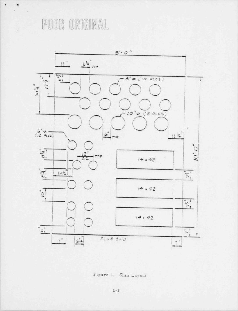
A series of twenty-three block-out cpenings were cast into the
test slab. Three penetrations consisted of 14" x 42" cable tray open-,
ings, and the remainder consisted of 6", 8", and 10" diameter pipe sleeve
openings. A detailed description of each opening is contained in the
discussion of the test slab construction, and the slab layout is shown
in Figures 1 and 2.
All openings were cast into an 8' x 10' x 12" chick concrete
slab. Once cured, the various penetration seal materials identified in
Figure 3, and cabling as described in Appendix I were installed. , Basic
cable loading is shown in Figure 4. The penetration seal materials were
allowed to cu're' prior to the fire exposure test.
The test slab was placed on a horizontal furnace, and exposed to
the standard ASTM E119 time / temperature curve. After three hours the
test slab was lifted in a horizontal position for the hose stream test
and then moved to an area adjacent to the furnace, where it was put on
blocks to cool and view.
1-4
. m
*.
a . a
o s'- C "
!-
. b'4, neff",.
! l |i
|\, ! 'R,"| -5"p (to PLcs.) \W!
: sW? ~-
R 1
1 - 10 " p ( 3 PL C S.)
,
,
|S * ,,
G c r.:1.,, ($ i| tI l,----. 7yn
O b=4
M; - ( ? ,, i
Q - . ..i ! o.c.. -i / + 4 42
, O'"-%
*
M| - p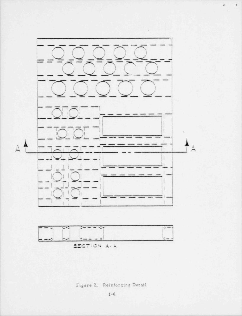
|_ _ _ _
. .,
i
l.
,
.
..
___ _ _ __ _ _ _ _
______________--- - _ _ _ _
i
|
|_ _ .r _ _ _-___
___ _ _ _ _ _
o
-_ ___ _ _
i 1i ..
I I I I
!- - _ _ _ _ _ _I- - i _ _ __
__ __ _. _ _ _ __ _ l I
l l 8 I | | *1 I l, . ,_ _ _; . _ _ __ _ _ _ __ __
_!_ - AA --_
A - - - - , - - , - II ; . ,AIni in ie. ; .
__ _ _I V_ _. i_V_i __ _ .l |.
! l' '
| | | |
- I_ __ _. l_(- i ; ;
__ _ __
_I |__| 1I i
l i
I |I I |_ _ _ _ - l___ __
_ _ l __ t 1* ! I-
,
i
l
I
l
I
_c c .;, .; _ - -; . . c, _.
1
c _- e__e .e__-. _ _ .
_- a_= e. IsN r ,s- -
Figure 2. Reinforcing Detail
1
1-6 i
1
|
__ _ _ _ _ . _. . __ _ __-.--___.-_I_

.
.
.
.
@@888 ,
8888@PIC Pil Pl2 Pl3 Pl+
P11 '
P--9
P2C
PI8 b5
P7n 8' (4Ot\
.
ft.us EHC
Figure 3. Penetration Identification1-7
__- --_ _ . J

1e e
l
I C "' LC EC % FILL,.
i / 'N'
!OO c.
i ! x0 8 8 O JD| .
i| NCWE NCNE NCME NCM3) INC.M E1 i
.
! f
N |0 /
/,
O /, '
! \ // .
/ ~
xU v|x
,
h1 / / !'
. ,
| % %.) , ,
i // |
,
V pg,,p,g , g L,n g 7 9 y, LLFLU E END
Figure 4. Cable Loading
1-8i
- - _ _ _

O h
-.
.
TEST SLAB
A. Construction
A floor section form (8' x 10' x 12" chick) was constructed
of 12" steel channel with a double mat of No. 8 rebar on 10" centers.
A series of twenty-three penetration openings were cast into the slab.
Three of the penetrations were 14" x 42" cable tray openings. Five
penetrations consisted of 6" pipe sleeve pairs into which were sealed
50 percent fill cable bundles. Eight penetrations consisted of 8"
pipe seals into which were sealed 50 percent fill cable bundles. Two
penetratibns were 8" pipe sleeves with a 1" and a 2" conduit sealed
therein. Four penetrations were 10" pipe sleeves with 3" pipes sealed
within, and one penetration was a 10" pipe sleeve with a 5" steel pipe.
The concrete (f, = 3000 psi) was poured on 20 December 79 and
cured for one week at 400'F, using an enclosure constructed for this
purpose. After the concrete had cured, cable tray supports were welded
to the basic framework. Details of the steel framing and slab layout
are shown in Figure 5.
B. Penetration Loading
All penetrations were loaded as defined by the Northarn States
Power Company Specifications, Revision 3, dated 7 February 1980. Table
1 shows the type and number of cables used in each opening.
C. Sealing of Penetrations
All penetrations were filled by ICMS and SwRI personnel using
the materials defined in the referenced specifications, which are re-
produced in Appendix I. A detailed listing of installation procedures
used during the seal preparation also appears in Appendix I. Photographs
1-9
l
_-

_ _ _ _
.\.
.
.
I
L 3* SEAL' U8 FAC E.
/STEEL Pi r EIS L F i! V E.
/// . _ ", O~
vC
O O Oo o O oO
o o O O //O O O
|.3
1
#5 RESM
-11(' CHANN E L
Figure 5. Schematic of Slab Layout
1-10
.
. . _ _ _ _ _ _ _

_
.
.
D R*D *D ~TAUS wS .S E a
,
i
.
TABLE 1
SI:3 CD N71 CF D3LE PEA ?I'; enc! :1PRCE T NC. 03-531*
SL',3 vt2:351 1
Penettstica Catie Dia. * Conduit * Cable P.anufacture;
W :er
36 1 3/16 7 stnnds/ 24 Ckonate4 c:nd.
21 1 3/16 * s rzads/ 24 Ck: nite4 cend.
33 1 1/3 7 strands / 16 c:ntrol (7) Ck:ni:e4 ::nd. cable wires
38 1 16 cond.s Centrol Cableinside F1:33M .
t
33 1 1/4 1 cond. 6 Genersi !!a::ricw/63 wires Super Corenal Oeoprene(1) outer cop- 250 .tC4per sheath
:D 1 3/16 7 strsnds/ 24 Ckenite4 cend. '
19 1 3/16 7 strands / 24 Ckonite4 cend.
7 1 1/16 7 strands / 68 Ckonite4 cand. Ckocrene. 6 AMG cu
20C0 volts
3 1 1/16 7 strands / 51 Ckonite4 c:nd. Ckoprese
1 19 strands / 13 Kerite14 cond. Type 1 - 600 vol:
9 1 1/8 7 strands / 3 Besten Insula:ed19 c:nd. !;r- at:3 - 600 vol:Hyp - PC *LC-33 12 uG
7/1 7 strsnds 11 Bost:n Insu11:ed12 c:nd. I:r- Wire $30 vol:Hy? - FC * L*- 33 LC ANC
3/1 7 s:Tr.ds/ 46 Bost:n insulated7 : nd. ;ft:t 100 v:1:F7R-HY? 1; wCPC C -33
I
j
1-11

_ _ _ _ _ _ _ _ _ -__ _ - .
|.s .
.
.
TABLE 1 (Continued)
f 3/4 7 stnnds/ 52 3cston Insulated i
!
|9 cand. Epr. Wire - 600 voitMyp - 70 ef.0-33 12 AliG
6 3/4 20 st;sads/ 44 General Elect-ic12 cand. 600 voit
1 1 1/4 37 st snds/ :: Genersi !!ect:1:Single tend. $1-33C07 *~
Type RMi SCC.TMit 73C
i3 11/5 39 strands / 23 Unse-kedi
Single cond.
S 1 1/3 39 strands / 22 Urdcto mSlasle cond.
'17 3/4 20 st;sads/ 39 General Electric ,12 cond. 600 volt
2 1 3/16 7 strands / 21 Ckonite4 cand. 600 voit
! 4 1 1/16 39' strand.s/ :3 UrucsomSingle cand.
37 3/4 20 Stra. sis / 39 Ceneral Elect rteo00 voit
.
'%
k
,
1-12

. m.
.
.
taken during the course of seal installation are shown in Appendix II.
Quality Control documents are in Appendix III. Drawings of the pene-
tration assemblies ajpear in F'gures 6 through 29.
,
h
i
1-13 |

,
d *
-.
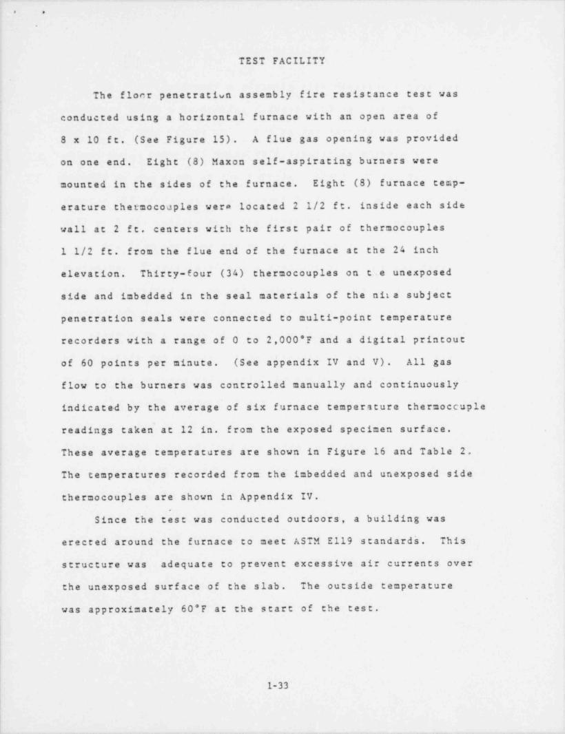
TEST FACILITY
The floor penetration assembly fire resistance test was conducted
using a horizontal furnace with an open area of 8 x 10 ft. (See Figure
30). A flue gas opening was provided on one end. Eight (8) Maxon self-
aspirating -burners were mounted in the sides of the furnace. Eight (8),
furnace temperature thermocouples were located 2-1/2 f t inside each wall
at 2 foot centers with the first pair of thermocouples 1-1/2 ft fron
i the flue end of the furnace at the 24 inch elevation. Eighty-seven (87)
ther= occupies on the unexposed side and imbedded in the seal materials
of the s2bject penetration seals were connected to multi-point tem-
I perature recorders with a range of zero to 2000*F and a digital printout!
of 60 points per minute. (See Appendix IV and V). All gas flow to the
hirners was controlled manually and continuously indicated by the average
of six furnace temperature thermocouple readings taken at 12 inches from
the exposed specimen surface. These average temperatures are shown in
Figure 31 and Table 2. The temperatures recorded from the imbedded and
; unexposed side thermocouples are shown in App c.!!x IV.
Since the test was conducted outdoors, a building was erected
around the furnace to meet ASTM E119 standards. This structure was
adequate to prevent excessive air currents over the unexposed surface--
of the slab. The outside temperature was approximately 68'F at the
start of the test.
,
.
I
l-14
|
|
.
_______ _ _ _ _

-- __ _
!. >
I-
| ( ;u s
|'
i
2) recy7'"
'
$ ND}'
hetestva. ft'
p'ruauAc u. .
,/ 2 7'1 8k s,
,
,..dk\ I /. ~/s, /'.(NI / } { ~}%
/ \ ',d Nif'p, ss ,* -
-)X )'s - y. ex / >.,-
.- s -.
,~ .N
- s ,
'
+< ,**
"/
Figure 30. Test Furnace
1-15.

.
. .
.
.
.
QUADREX SLAB 1 - FURNACE AVERAGE* FURtIACE AVERAGE A E119 STD CLF.vE
:500 __ v E119 + 10% = E119 - 10%
000- ~ ~M"~~ - - - - - - "
,
J'
. .. ; - __ .= , 1-
#" _ _ '_'-^'- > ; ---- -
-:
. __
1000__ jf'
/'
d
.f500_
0| ''
' ' ' ' ' ' ' ' 'i i i i i i i i i
0 20 40 ,60 80 100 120 1.40 160 180
TITE &lIfCTES)
TEST DATE: 20 MAR 50 PROJECT tJ3. 03-5917-001.
|
Figure 31. Furnace Temperature
1
1-16
|i
| .
.- . . . _ , _

. ._ .
. .
D D D D TABLE 2Jb W b\0\
| f11RNECE= TEMPERATURE READINGSi
| Scandard [ l|Time I Cu ve I -10: Ac nal I -10: Ti=et
0 70 63 Go 77 01 1 200 t 130 i 6 220 i 1a2 e 400 6 360 i I 440 1 2i3 I 600 1 540 t i 660 1 3'l4 i 300 i 720 i I 830 1 415 i 1000 1 900 i 380 6 1100 i 5i6 4 1100 1 990 4 6 1212 i 6i7 i 1130 1 1035 I i 1265 i 7i
,
6 3 1 1200 I 1080 1 1320 i 3I I
| 9 i 1250 1 1125 I i 1375 i 9'i 10 i 1300 i 1170 i [[20 6 1430 i 10
11 i 1320 1 1138 i i 1452 i 11 i12 i 1350 1 1206 i i 1474 i 12 i13 i 1360 6 1224 I i 1496 i 13 ila i 1380 1 1242 i I L513 a la i13 i 1399 i .1239 1 1245 i 1339 1 13 i16 i 1414 6 1274 i i 1555 i 16 I17 I 1429 e 1296 i i 1372 1 17 113 1 1435 i 1291 I i 1579 6 13 i19 e 1450 1 1205 i i 1395 e 19 I20 1 1462 1 1316 e 13ti i 1603 1 20 i21 i 1474 5 1327 i i 1621 1 21 l22 i 1436 i 1337 i i 1635 1 22 123 i 1498 i 1348 I ! 1548 I 23 i24 1 1300 1 1350 e i 1650 1 24 i25 ! 1510 1 1359 i L380 i 1661 1 25 i26 1 1520 1 1368 I i 1672 1 26 i27 1 1523 4 1375 6 i 1681 1 27 e29 i 1537 i 1363 I i 1691 1 23 129 i 1541 1 1387 I i 1695 1 29 i30 i 1350 i 1395 t 15l3 1 1705 1 30 135 i 1534 i 1425 i 1996 1 1742 1 35 I40 i 1613 i 1452 1 1603 1 1774 6 40 l45 i 1630 1 1467 6 te30 i 1793 i 45 i50 t 1661 1 1495 i te38 i 1827 i 50 t
i 55 i 1631 1 1313 i- l670 1 1349 3 55 i| 60 1 1700 i 1530 I le77 i 1370 8 60 i| 65 i 1713 1 1346 I te45 i 1390 1 65 i! 70 i 1735 e 1361 i 1735 8 1909 ! 70 ei 75 i 1750 I 1575 t 1754 i 1925 1 75 ii 30 I 1765 i 1539 i t7ed i 19e l 30 1e
} 35 - - 1779 t 1601 i 1777 I 1957 i 25 -| 90 1792 i 1613 i l702 i 1971 * 90 i) 45 I 1604 i 1524 ! 1806 i 19i4 i 15 t
00 ' 1313 1433 i t915 i !?94 8 130 i*
105 i 1325 i 164 5~ t 1927 1 2009 i 10 5 e!!35 i 1651 'I t337 4 2019 i 110 i,210 '
113 1343 1 1659 I L344 1 2007 1 113 ''
120 '.350 i 1665 i as47 i 2035 i .20~120 t li62 1 1676 i Is74 6 20-d-
.30+'
-0 i !!75 1637 ' tse0 i 2063 ';0|i.
150 t 1533 a 1679 L3G2 t 2077 i 150 I-
'l t0 19CO I 1713 i la!3 20 C') i 14.) |i'
'i il lit: 1721 i'll. i 2123+
70-
.!0 17 5 i 1733 '433'
__7 '!Oe e .
1-17i
,
- _ ___ - _ _ _ - .__ - - . ._ .- .

. .
.
.
TEST PROCEDURES,
The prepared floor penetration slab with fire stop materials inThe temperatureplace was pt::ca in position on top of the farnace.
recorders were turned on, natural gas was supplied to themulti-point
burners, ignited, and the test clock was started. The uncxposed surface
was continually observed for penetration by flame or hot gases and itsAt the endtemperature monitored, by using the multipoint recorders.
of the three hour fire exposure period, the fuel gas was shut off and,
as quickly as possible, the enclosure building was removed and the test
slab was 'lif ted from the furnace, remaining in a horizontal position.
A 30* spray stream supplied from a 1-1/2 inch fire hose with a spray
scream setting and 75 rst nozzle pressure and 75 gpm delivery was then
directed at the floor penetrat' ion fire stops from a distance of 10 feet
This hose stream test is identifiedto conduct the hoee strean test.
on page 13, Section 5.3.12 of IEEE 634-1978 (see Appendix VI) and is
co=monly referred to as the "NEL-PIA Hose Stream Test." The required
hose stream application tLme for penetrations installed in a 10 x 8 f t
slab was 2 minutes. The time / temperature record of the test is shown
in Figure 31 and Table 2. Figures 30 and 32 show an exploded view of
the test setup.
1-18
i

.
. .
.
f
.
//, .-
. /'
/ // / ,',' --- :r /b- =/=' I' '
A-/
c - - -- 1 ie
-[. ::====: = ,<--
, . . . - - - - -__, f M. // ~
/' ,
,/ /**
,, /
_
;
/ / '.s
-
5 .-- _' , _ -..- - _//\
"'2W
# < o /;
7, ,
/ 0le
/
\//
!
|
> re s a <rywic u>.5 P/s.A/ ACE EY/.cA/SCJ/ 5l.-- VE
~
C ~uRA/ACf
1
Figure 32. Furnace Assembly
,
| 1
I I( 1-19l
i
'e
-

. .
.
D{{9 bTEST RFSULTS
A. Observations
The fellowing are observations =ade during the fire exposure
cast, :he hose stream test, and the post-test inspection.
TABLE 3 - TEST OBSERVATIONS
Tsst Time Event
-0:05 Furnace loaded, systems ready. Moderate wiad,
clear skie s. Temperature approximately 68 * F.0:00 Surners on, Timer on, recceders on, Star: Tes:0:05 Temperature 880 * F0:10 Tempera:ure I L20 * F0:15 Temperature 1245 * F Heavy smoke0:20 Temperature 13 l5 'F Wind affecting burne rs
'
0:25 T empera:ure 1380 * F Within - 10%0:30 Tempera:ure 15 tS * F0:35 Temperature 1556 *F Erecting wind shield0:40 Tempera:ure 1603 *F Catching up to Normal Curve
0:45 Tempera:ure 1630 *F Right on curve0:50 Tempera:ure 1638'F -
iemperature I670 *F0: 2
1:00 Tempe rature 1677 'F Stable
1:10 Temperature 1735 * F Right on curve1:20 Temperature 1768 * F Smeke from cable trays1:30 Temperature 1792 * F Smcke also through Pl6 and Pl7L:40 Temperatur e 1815 * F Stable, right on curve1:50 Temperature 1837 * F2:00 Temperature 1349'F
2:10 Temperature 1374 * F Slightly abcve norm2:20 Temperature 1880 * F2:30 Temperature 1392 * F Scable
,
2:40 Temperature 1918 * F2:50 Tempers:ure 1922 * F3:00 Te=pera:ure i933 *F3:02 End of fire :es:3:C6 Frctec:ive cover remcved3:10 Slab hooked up :c lii:3:L3 S:22- H c se Scr e am T e 5:3:L5 End ci Hese 5:re am Te s:3:13 Slah se:: led i:: examica:i:n
|
1-20
..

. .
*e
.
Post Test Observations1. There was no passage of flame through any penetration duringthe fire exposure test.
2. There was passage of light smoke through the seals, but smokecoming through was cool to the touch.
3. There was no passage of water or flame through any penetrationduring the hose stream test.
B. Summary of Test Results
A fire stop shall be considered as meeting the requirements
far acceptable performance when it remains in the opening during the
fire endurance test and hose stream test within the following limi-tations:
1. The fire stop shall have withstood the fire endurance
test without permitting the passage of flame, or the occurrence of
flaming on any element of the unexposed surface of the assembly for
a period equal to the hourly classification for the fire stop.2. The fire stop shall have withstood the fire endurance test
and hose stream test without developing an opening that would permit
a projection of water from the stream beyond the unexposed surface.3. The transmission of heat through the fire stop during the fire
endurance test for any recorded temperature on its unexposed surface
shall not exceed 700 F'on penetrations involving cable.
Accordingly, the following shows the performance of the pene-,
trations for the test period of three hnurs as documented in the test
observations and in Appendix IV.
1-21
.
-- ,

_ - .
. .
TABLE 4
TE3T RESULTS i
Penetration Condition
Numbe r 1 2 3_
P1 Pass Pas s Pas s
P2 Pas s Pass Pars
P3 Pass Pass Pas s
P4 Pass Pass. Pass
P5 Pass Pass Pass
P6 Pas s Pas s Pass
P7 Pas s Pass Pas s
P8 Pass Pass Pas s,
P9 Pass Pass Pass
PLO Pass Pass Pass
Pil Pass Pas s Pas s,
_.
P12 Pass Pass Pas s
P 13 Pass Pass Pass-
Pl4 Pass Pas s Pass
P15 Pass Pass Pass
P16 Pass Pass Pass
PIT Pass Pass Pass
Pl9 Pas s Pass Pass
P20 Pass Pas s Pass
P21 P as s Pass Pass
P36 Pass Pass Pass
P37 Pass Pass Pass
P38 P as s Pass Pas s
1-22
_ _ _ . ._. - . _ _

\. .
.
. .
To verify the condition of the~ penetration seals after the test,
an examination was made to determine the char depth, the depth of any
remaining insulation material, such as the urethane foam and TIW, and
the condition of the coatings and insulation boards. The results of
this examination are shown in Figures 33 through 55. Photographs pf
the fire exposure period, the hose stream test, and the post test con-
dicion of the penetrations can be found in Appendix II.
,
,
s
1
e
1-23
.
_ _ _ _ _ . _ . - _ . . 7 _ _ . ,

. - -
. .
|
j
SLAB NO. 2
. .vly W:.w;7:.;g x g g g g g g g g y i- j ew_
i by
Michael D. Pish||
NSPFINAL REPORT< ,
eh DUCLERRd. SERV!CESCORPORAT10IlWNorthern States Power Company
414 Nicollet MallMinneapolis, Minnesata 55401
|
2 . ~ 2,,$ Z Z ~ " D " 1 " L ~, * 2 ! C ' 7.,, 1 7 8 0*l ". C L'''' M "d I
JUNE 30,1980
ChUW[
H j -s
' h|I SOUTHWEST RESEARCH INSTITUTE| ,,
SAN ANTONIO HOUSTON~-
1-24
__ - - - - _ . _ _ _ _ . _ _ _ -- - - - - _ _ _ _ . _ _ _ _ _ _ _ . . _ . - . _ _ . . _ , . . _ . , - , _ _ -- -

_
. . . |;
ISUMMARY !
On 24 March 1980, nine block-out penetrations designed by Nuclear
Services Corporation (NSC) for Northern States Power Company and install-
ed by Insulation Consultants and Management Services (ICMS), Carboline Co.
and Scuchwest Research Institute (SwRI) were exposed to a three-hour fire
endurance qualification test following the ASTM E119-76 time / temperature
curve.
The purpose of the test was to obtain a three-hour fire rating for
existing referenced retrofit fire stop designs in accordance with ASTM
E119-76 time / temperature requirements. In addition, a hose stream test as
described in Appendix VI, Section 5.3.12 of IEEE 634 was to be applied.
Penetration seal construction consisted of various loaded cabla tray
and pipe openings filled with thermal insulating wool, silicone and poly-
urethane foams, marinite board, and in some cases coatings were applied to
the finished seals.
TEST ATTENDEES
Conducting the test project:
Mr. Michael D. Pish, Project Manager
Mr. Al Schraeder, Senior Engineering Technologist, Test Coordinator
Witnessing the test for Nuclear Services Corporation:
Mr. Bob Dille, Senior Consultant
Witnessing the test for Northern States Power Company:
Mr. Don R. Brown
Also attending the test were:
Mr. Cris Conner, Carboline Co.
Mr. Mike Stine, ICMS> .s
1-23

-__ __ __ _
. .
.
DESCRIPTION
A series of nine openings were cast into the test slab. Two
penetrations consisted of 48" x 36" cable tray openings; six penetrat-
ions were each 14" x 14" blockout openings; and one penetration con-
sisted of a 6 inch conduit pipe opening. (See Figures 1 and 2).
All penetrations were cast into an 8 ft. x 10 ft. x 12 in. thick
concrete slab. Once cured, the various penetration seal materials
and cabling as described in Appendix I were installed. (See Figure 3.)
These were allowed to cure prior to the actual test.
The test slab was placed on a horizontal furnace and exposed to
the standard ASTM E119 time / temperature curve. After three hours the
test slab was lif ted in a horizontal position for the hose stream test
and then moved to an area adjacent to the furnace, where it was put-on
blocks to cool and view..
1-26
. - _

. .
.
L S'~ Cei
,
__ l I z", lNZ? I _ l@2E ~
t_ u ifI | | ||
bi | s !'
tO y }~o
'
,o, ,
P3C ?26 P251+=/Y /f e /f /42/f
3
6C --- 4m
_a '
- ,
_ Fl& T~
~{ }
u
pg9 P23 P22
js,je 14 Al$ 14 >.14
=
0,
.
' ."2 5 P29 '
4&x3b +5n3G
.,
ht' f Il "I'l I !C"| i 7"Ii i - i ~iFLUE ENO
Figure 1. Slab Layout and Penetration I. D.
1-27

_ .-. . _ _ - ._ _ _- __
. .
i i i [i ! i
'
! || !!'I-
, , ; .
l ! *'.
I[ t 1 -
i ; i
i i [ i'
l i '
| II,
, ,
.
I \6| .| .-
6 t 1 I
I I ! 'g ;
i l I Ie . I
!- | i i-
!l i , I I
| | 1 -1
| 1 | |
| | | I
I l iI
A|Ai I i i aAi.
i 1, ,-
|i :
|| l. I
| | | I
__ __ _ __ _ _ __ I _ li I_ - _ _ _ _ _ _ _
l
: _; , ..;_ __ . ..
'
II--- c- . .e--
SF.C T ICM A-A
Figure 2. Reinforcing Detail
1
|
||
1-28 !

. .
..
|6' FR AlRIE. ISLAND C.15 L E ,-
70 % FILL.
\
=n! %
P30 } P26 Ps
M c N T I d. EL.L OSC % FILL.
!
hh// [M //=
,,
7 y yCUADRIX SLAB 2
P25 P29
! .\ l k
I!!
\# \
/V I
TRAY I G' t*CHT9C'n ! C TP'AY L , G' PRAIR1 "-
C. ISLE,50 % FILL lSLAN C CSLE, 7C % FILL
Figure 3. Penetration Loading
1-29
|_ _ _ _ _ _ . _ _ .

. .
.
TEST SLAB
-
A. CONSTRUCTION
A floor section form (8 ft. x 10 ft. x 12 in. thick) was constructed
of twelve inch steel channel with a double mat of No. 8 rebar on ten inch
centers. A series of nine penetration openings were cast into the slab,
6 inch diameterSix were 14 inch x 14 inch cable tray openings; one was a
conduit pipe opening; and two were 12 square ft. cable tray openings,
3 ft. x 4 ft.
The concrete (f = 3000 psi) was poured on 20 December 1979 and cured
for one week at 400 F, using an enclosure constructed for this purpose.
After the concrete had cured, cable tray supports were welded to the
basic framework. Details of the steel framing are shown in Figure 4.
B. FENETRATION LOADING
All penetrations were loaded as defined by the Northern States
Power Company Specifications, Revision 3, dated 7 February, 1980.
Table I shows the type and number of cables used in each opening.
C. SEALING OF PENETRATIONS
All penetrations were filled by ICMS and SwRI personnel using the
materials defined in the Northern States Power Co. Specification. The
Specification is reproduced in Appendix I. A detailed listing of in-
sta11ation procedures used during the seal preparation also appears in
Appendix I. Photographs taken during the course of seal installation
are shown in Appendix II. Quality Control documents are in Appendix III.
Drawings of the penetration assemblies appear in Figures 5 through 14.
1-30

_
s 3
-.
og g-o
Jo Ju oJU.S.h h
~ 1 3' sa.g.e UMraq
/ r=,./ -Muv e
o'
<.
'
.
''.I:.y
1
"a,qsag'2" CHA Nu g'
|
Figure 4* 3chematic of Slab Layout|
|
1-31
__ __

_
. .
3 Jd e I - .
TABLE 1,
TYPE AND NUMBER OF CABLES USED
St>3 Nt.St3ER 2
30 7/8 20 strands / 6 Kerite
9 cond. Type 1 600 volt
18 1 7 strands / 13 Chonite6 pr. : cond. 600 volt
:S 5/8 5 strands / 4 Seston Insulated7 cond. 600 voit
7/8 *0 strands / 14 Kerite
9 cond. Type 1600 volts
:S $/8- 8 strands / s loston Insulated7 cond. 600 voit
7/3 20 strands / 14 Kerite9 cond. Type 1 600 volts
2: 7/S 20 strsads/ 14 Karite
9 cond. Type 1 600 volts
5/8 7 strands / 4 Boston Insulated7 cand.
23 5/S 7 strands / 4 Boston Insulated'
7 cand.
7/S 20 strands / 14 T.erite9 cond. 7ype 1 600 volts
*4 5/5 7 strands / 4 Soston Insulated7 cand.
7/5 20 strands / 14 Kerite9 cond. Ty7e 1 600 volts
231st tray 3/4 20 strands / 163 Kerite
7 c:nd. Type 1 600 volts
nd trsy 7/3 7 strseds/ 90 Cenerst Electric27 cdad. Polyethelene
Flamenol Control
'9 .
1st trsy 3/4 :D strands / 170 Kerite7 cond. Type 1 600 volts
*nd tray 1 1/4 65 strsads/ 20 General Electri:w/ copper ring Super Controlsingle cand. Geoprene
1 1/4 36 st sads/ *O t.htknownw/ copper ringsingle cond.
1-32
_ _ _ _ _ _ _ - - - - _ _ _ _ _ _
. .
.
TEST FACILITY
The flocr penetrativn assembly fire resistance test was
conducted using a horizontal furnace with an open area of
8 x 10 ft. (See Figure 15). A flue gas opening was provided
on one end. Eight (8) Maxon self-aspirating burners were
mounted in the sides of the furnace. Eight (8) furnace temp-
erature thermocouples vera located 2 1/2 ft. inside each side
wall at 2 ft. centers with the first pair of thermocouples
1 1/2 ft. from the flue end of the furnace at the 24 inchelevation. Thirty-four (34) thermocouples on t~e unexposed
side and imbedded in the seal materials of the nit a subject
penetration seals were connected to multi-point temperature
recorders with a range of 0 to 2,000*F and a digital printout
of 60 points per minute. (See appendix IV and V). All gas
flow to the burners was controlled manually and continuously
indicated by the average of six furnace temperature thermoccuple
readings taken'at 12 in. from the exposed' specimen surface.
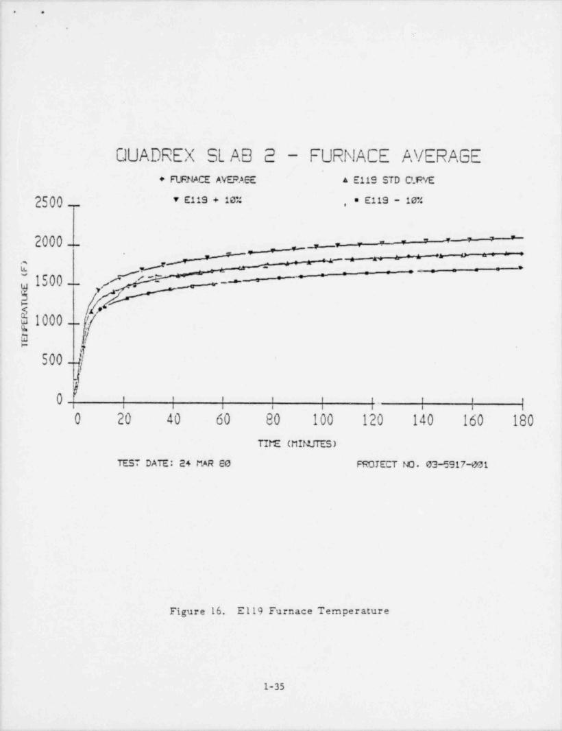
These average temperatures are shown in Figure 16 and Table 2.
The temperatures recorded from the imbedded and unexposed side
thermocouples are shown in Appendix IV.
Since the test was conducted outdoors, a building was
erected around the furnace to meet ASTM E119 standards. This
structure was adequate to prevent excessive air currents over
the unexposed surface of the slab. The outside temperature
was approximately 60*F at the start of the test.
1-33

.. .
|
[IhEI*) n ur
/$sst; '
hg,- /'sutva
~ f'.) / A-ruauAc s. m . ,
/- ../c
\ I / )* ,,)
)<x, -
.
_
: / '- f'V... .v2 g. .
Figure 15. Test Furnace
1-34
-___- _-_
. .
.
QUADREX SL AB 2 - FURNACE AVERAGE4
+ FIENACE AVEPAGE A E119 STD C'R/E
2500__ v E119 + 10% , = E119 - 10%
2000-_ __- - - - - - - -
-_
y_ _= = = =-
m s~
-m-- -
_ , , . _;
_ _
_
_,- -
~ 1500- [ ~r - = =~ _ _
~~
--- -
-
|1000__ [/[d f
500_ f '
90 ; | | | | :. ; :
0 20 40 60 80 100 120 140 160 180
TIME (MINUTES)
TEST DATE: 24 MAR SO PROTECT NO. 03-5917-001
Figure 16. E119 Furnace Temperature
1-35

_. _ _ _ ___
. .
DE Yd" tast.I 3Jhlf3)9D0 mJ P ~ b N ' 4 f11 " LL, AST/. I119 Ti=a/Ta=cora:ure Cur ro
,
Il
| S ca= car:! | | [ |*1:e I C u--r e ! -10* I A::uai I 6'0" l * ' e'
O 70_ __ 63 65 77 0t 130 i i 220 1 1i"
1 i -
2 i ' .- e i 360 I i 440 1 2i
3 I .00 i 540 I i 660 1 3L4 i SCO I 720 i I 330 i et5 l 1000 1 900 1 501 1 1100 1 566 1100 1 990 l' i 1212 1 61
'7 1150 i 1035 i i L265 1 7I3 8 1200 i 1030 i i 1320 6 3i
9 i 1250 i 1125 I i 1375 i 9110 i 1300 * 1170 i ile0 i 1430 i 10 i
l 11 1 1320 1133 i e 1452 i 11 il 12 8 1350 i L206 i i 1474 8 12 II 13 1 1360 4 1224 I i 1496 i 13 il 14 6 1330 i 1242 I i L513 i 14
15 i 1399 t 1259 1 1303 6 1539 1 15
16 i 1414 i 1274 i i 1555 i 16 !17 1 1429 t 1286 i i 1572 1 17 i13 1 1435 6 1291 1 1 1579 i 13 619 6 1450 t 1305 I i L59 5 l 19 i20 1 1462 i 1315 I 1444 i 1608 I 20 121 i 1474 t 1327 i i 16 "
'~
22
"
22 1 1436 i 1337 I i 1635 i
23 i ~1498 I 1343 i i 1643 1 23 124 1 1500 1 1350 i i 1650 1 24 i25 i 15 10 i 1359 i 1541 1 1661 6 25 126 i 1520 i 1363 I i 1672 6 26 i27 | 1523 i 1375 6 i 1631 8 27 i2S I 1537 | 1333 I i 1691 i 28 |29 6 1541 1 136, I i 1695 1 29 i30 1 1550 i 1395 i 1602 i 1705 ! 30 i35 1 1534 i 1425 i 1617 i 1742 i 35 I40 1 1613 i 1452 i 1624 1 1774 i 40 i
' 45 i 1630 i 1467 i 1626 i 1793 1 45 350 6 1661 1 1495 i 1642 i 1327 i 50 i55 i 1631 1 1513 i 1672 I 1349 i 55 i60 l 1700 1 1530 I 16G0 1 1370 6 60 e,
65 i 1713 i 1546 8 1712 i 1390 55 170 1 1735 i 1561 i L731 i 1909 i to I
75 i 1750 i 1575 + [754 i 1925 6 75 iI 30 i 1765 i 153G i L7e8 1941 i i01+
6 35 i 1779 | 1601 i 177e i 1957 35 i'
1613 i 1723 i 1971 i 90 690 1 1792 i
, 95 i 1504 i 162a 1737 i 193a i 95 i.
II:0 1 1315 8 1633 i 121- i 1994 i :00i105 i 1526 1643 i 1227 i 2009 i 10 5 i+
,11 1 1335 i 1651 i 1933 1 2019 110 i1115 i 1943 t 1659 | 1837 1 2027 i 113 ''120 i 1350 i 1665 i teso i 2035 i 120130 t l'56; i 1676 i 1656 i 2:43 i 130140 i is75 1637 i !274 i 2063 140 ,. '
>15 0 1533 i 1699 i 1:a: i 207' i 150'
P. 60 1900 '71: I i403 1 2C90 i lic. .
*1 'O 1912 i 17:1 i 1005 :103 i 177 -'
2117 i 13C I-lic i 1925 1733 l910 '.
l-36
_. . - - . .__ _ _ _ - _ _ -

. o
.
TEST PROCEDURES
The prepared floor penetration slab with fire stop materials in
place vs.s placed in position on top of the furnace. The temperature
multi-point recorders were turned on, natural gas was supplied to
the burners, ignited, and the t___ alock was started. The unexposed
surface was continually observed for penetration by flame or hot gases
and its temperature monitored, by using the multipoint recorders.
At the. end of the three-hour fire exposure period, the fuel gas was
shut off and as quickly as possible the enclosure building was re-
moved and the test slab was lifted from the furnace, remaining in a
horizontal position. A spray stream supplied from a 1-1/2 inch fire
hose with a 30' spray stream setting and 75 psi nozzle pressure and
75 gpm delivery was then directed at the floor penetration fire stops
from a distance of 10 feet to conduct the hose stream test. This hose
stream test is identified on page 13, Section 5.3.12 of IEEE 634-1978|' (See Appendix VI) and is commonly referred to as the "NEL-PIA Hose
Stream Test". The required hose stream application time for penetrations
installed in a 10 x 8 ft. slab wzs 2 minutes. The time / temperature re-
cord of the test is shown in Figure 16 and Tablt 2. Figures 15 and 17
1
show an exploded view of the test setup.
1-371

|. .
|
,--.-.--.----.--------.--,fNm/ ,'' A
/ ,
ZI:W&~4 A''
< - i
["i==. , ' " , // ,''
, c -- - - - _ _ ,, p "- N
,/ /
,A-- --.:.----- _ .| / /'
., - /
' -------.-----a
3
/) ' ' '//
/ \
| g.
,
/ \
i
I.
A TEsr SLAB (7'YP/CA !.)3 FOS / ACE E17t.NSC4' SLEEVEC Cf
Figure 17. Test Assembly
1-38
|
!
_ _ _ _ - ~~

. .
.
TEST RESULTS,
A. TEST OBSERVATIONS
The following are observations made during the fire exposure
test, the hose stream test and the post-test inspection.
TABLE 3 TEST OBSERVATIONS ;-
Test Time Event
0:00 Burners eb, timer on, recorders on, Start
0:05 Light smoke / steam, primarily from arcur.d slab edges.Temperature lagging slightly, 80l* F.
0:10 Temperature ll60 * F - Check burner supply,
Better temp rise0:15 Temperature 1303 *F -
0:20 Temperature 1444* F On curve-
0:25 Temperature 1541 * F - Getting slightly ahead0:30 Temperature 1602* F Back off on burners-
0:35 Temperature 1617'F0:40 Temperature 1624* F
Light smoke on unexposed side. Largest concentrationstill from around slab edges.
0:45 Temperature 1626 *F ' - Furnace stable0:50 Temperature 1642 * F0:55 Temperat:tre 1672 *F1:00 Temperature 1699'F1:05 Temperature 1712 * F1:10 Temperature 1731 * F1:15 Temperature 1754* F1:20 Temperature 1768'F1:25 Temperature 1776 *F1:30 Temperature 1793 *F1:35 Temperature 1797'F1:40 Temperature 1817'F
Light smoke from unexposed side, mainly fromP29 and P30. Smoke cold to touch. Bulk of smokefrom around slab edges.
1:45 Temperature 1827'F1:50 Temperature 183 3 * F1:55 Temperature 1837'F2:00 Temperature 1855'F
Same smoke characteristics as at 1:40Furnace smooth, right on curve.
2:10 Temperature 1855 'F2:20 Temperature 1874* F
1-39
.
~ --

.
!
I
TABLE 3 - TEST OBSERVATIONS (CONT'D)
Test Time Event
2:30 Temperature 1885'F2:40 Temperature 1903*F2:50 Temperature 1908'F3:00 Temperature 1920*F
End of fire test3:05 Protective building removed
3:08 Slab Hooked and removed to hose stream test3:10 Hose stream cest3:12 End of Hose Stream Test
Post-Test Observations
1. All nine seals did not allow the passage of flames during thefire test.
2. Light smoke did pass through, primarily through P28 and P29,but smoke was cold to the touch.
3. All penetrations did not allow the passage of water duringthe hose stream test.
B. SUMMARY OF IEST RESULTS
A fire stop shall be considered as meeting the requirements for
acceptable performance when it remains in the opening during the fire
endurance test and hose stream test within the following limitations:
1. The fire stop shall have withstood the fire endurance test
without permitting passage of flame, or the occurrence of flaming on
any element of the unexposed surface of the assembly for a period equal
to the hourly classification for the fire stop.
2. The fire stop shall have withstood the fire endurance test
| and hose stream test without deveieping an opening that would permit a|
| projection of water from the stream beyond the unexposed surf ace.||
l-40
l.

.
. .
.
3 The transoission of heat through the fire stop during the
endurance test for any ::cerded temperature on its unexoosed surface
shall not exceed 700*F on penetrations involving cable..
Accordingly, the following shows the performance of the pene-
trations for the test period of three hours as documented in the test
observations and in Appendix IV.
ConditionPenetration 1 2 3Number
P18 Pass Pass Pass
P22 Pass Pass Pass
Pd3 Pass Pass Pass
P24 Pass Pass Pass
P25 Pass Pass Pass
P26 Pass Pass Pass
P28 Pass Pass Pass
P29 Pass Pass Pass
P30 Pass Pass Pass
To verify the condition of the penetration seals after the test,
an examination was =ade to determine char depth, the depth of remaining
foam and TIW, and the condition of the coatings and insulating boards.
The results of this examination are shown in Figures lo through 26.
Phr.ographs of the fire exposure period, the hose stream test and the
post-test observations can be found in Appendix II.
1-41
.

_ . ___ _ _ _ _. _. -
.. .
|
|
|
|'
,
h3 h[] .hh. . . .n .- rw e,>.,rm .a.. ..
b31+bb )b'
e- , s, m n - e ~ s - w ___ _,
SLAB NO. 3,
\ ; :. si.5 :;xygdg- mgggy;;W- +
by
Michael D. Pish
NSF.FINAL REPORT-
,
% DUC1.E.92' ~ , SER'1!CES
CORPOR.9710Dl -
Northern States Power Company414 Nicollet Mall
Minneapolis, Minnesota 55401
Z C | % = ''.~''~~,|'. C C C ;":'",,0.' ~ 1: 2 0 '"." r l"
JUNE 30,1980 i
/ R <p! , ,y SOUTHWEST RESEARCH INSTITUTE
g // SAN ANTONIO HOUSTONw
1-42
.
_ _ _ _ _ _ . _ . _ . _ .- ._ .- _
. .
i|
SOD'.ARY
on 25 March,1980, six block-out penetrations designed by Nuclear
Services Corporation for Northern States P;wer Company and installed'
by Insulation Consultants and Management Services (ICMS), Carboline Co.4 and Southwest Research Institute were exposed to a three-hour fire en-
durance qualification test following the ASTM E11^-76 time / temperature
curve.
The purpose of the test was to obtain a three-hour fire rating for
existing referenced retrofit fire stop designs in accordance with ASTM
E119-76 time / temperature requirement . In addition, a hose stream test
as described in Appendix VII, Section 5.3.12 of IEEE 634 was to be
applied. ,
Penetration seal construction consisted of various loaded cable
tray and pipe openings filled with thermal insulating wool, silicone4
and polyurethane foams, marinite board, and in some cases coatings
were applied to the finished seals.
TEST AT ENDEES
Conducting the test project:
Mr. Michael D. Fish, Project Manager, Test EngineerMr. Al Schraeder, Senior Engineering Technologist, Test Coordinator
Witnessing the test for Nuclear Services Corporation:
Mr. Bob Dille, Senior Consultant.
Witnessing the test for Northern States ?cwer Company:
Mr. Don R. Brown
Also attending the test was:
Mr. Mike Stine, ICMS
1-43

. .
DESCRIPTION
A series of six penetration openings were cast into the test slab.
Three penetrations consisted of 30" x 45" cable tray openings; two
penetrations were each 14" x 42" cable tray openings; and one pene-
tration was a 10 inch diameter pipe sleeve. (See Figures 1 and 2).
All penetrations were cast into an 3 ft. x 10 ft. x 12 inch thick
concrete slab. Once cured, the various penetration seal materials and
cabling as described in Appendix I were installed. Basic cable load-
ing is shown in Figure 3. The penetration seal macerials were allowed
to cure prior to the actual test.
The test slab was placed on a horizontal furnace and exposed to
the standard ASTM E119 time / temperature curve. After three hours the
test slab was lif ted in a horizontal position for the hose st:,eam test
and then moved to an area adjacent to the furnace, where it was put on
blocks to cool and view.
I
i
||
1-44 |i
|
_ _ _ _ _ , - _. _ . '

. .
.
5'- c " ,-t
Y v"-
15 z" ( Ic 1_II" , . . . ,ecu= a n,ci i i i
-
1
U| | | | | | | 'ej i
727.' ^ l;
30x +5/4 x 42
|
t4 1
P32_._
n ,I
30 x 45 py
=
0
=' I4>+2 'f7
m::e s
.
30x45 %;,,,
.
wf
.a.s. .:|
10"$*
'
| ) .2 5 |: ,f J1 i
s% '-
.f7.4._"fi i
Figure 1. Slab Layout and Penetration Identification
I
1-45
.
e

_
. .
-.
kI _| _ l ! I
! !i || |
| |, ,
, ' || I ||
| | |I !
'I
| ! l. i__ _ __ _
, ,
|. _ _ _ __ _ _ _ _ _ _ _ _ _ _,
t | !1| L_ __ __ !__ .j
Af i || fAi i
; i-
l 1
l I.,_ _ _ q _ _I.
l_- I.
l 1 |-
! l |
l I j_ l__ _j j __ __
L_ _. _ L _!l I
' '
| || ||
- __| _I I || t ,
_ .c _ _ c _ _ _; _ -; _ _ _
_ _ _c _ __:_ _ _: _ ':____
SiEc_Tt o M L-A
Figure 2. Reinforcing Detail
1-46
_ . _ _ _ _

). .
i
._.
MON 7|fELLC 50 % FILL ,,
--MCN TI' E1 LC SC ", FI LL ,
.'m /
/ \% i
I .% %|
* '
L
'
5.i-, '
117PK21 '-
-
AND NC .CASL'" 'I //d!~
\'5 D _ ._
Aw/ a
_
ti'
,
9
2 :
4I
- CAPPED)(N0 CA?LE
Figure 3. Penetration Loading
1-47

. .
.
TEST SLAB
A. Construction
A floor section form (8 f t x 10 ft x 12 in thick) was constructed
of twelve inch steel channel with a double mat of No. 8 rebar or ten
inch centers. A series of six penetration openings were cast into the
slab. Three of the penetrations were 30" x 45" cable tray openings;
two were 14" x 42" cable tray openings; and one was a 10" diameter
(Sch. 40) pipe sleeve into which was sealed a capped 3 inch steel pipe.
The concrete (f, = 3000 psi) was poured on 20 December, 1979 and
cured for one week at 400*F, using an enclosure constructed for this_
purpose. After the concrete had cured, cable tray supports were welded
to the basic framework. Details of the steel framing and slab layout
are shown in Figure 4
B. Penetration Loading
All penetrations were loaded as defined by the Northern States
Power Company Specifications, Revision 3, dated 7 February,1980.
Table 1 shows the type and nunber of cables used in each opening.
C. Sealing of Penetrations
All penetrations were filled by ICMS, Carboline and SwRI personnel
using the materials defined in the Northern States Power Co. specifica-
tions. The specification is reproduced in Appendix I. A detailed list-
ing of installation procedures used during the seal preparation also
appears in Appendix I. Photographs taken during the course of seal in-
\| stallation are shown in Appendix II. Quanlity control documents are in
| Appendix III. Drawings of the penetration assemblies appear in Figures
5 throuf,h 11.
1-48|
-

, . . . .
. .
.
ad , ,
* a RESAR
. .
\ SL .c,
\ .
N% >
. ..q-.
a m>m
$ T E E L l'I P E,
-12" cHwN EL SLEEVE
Figure 4. Schematic of Slab Layout
.
1-49

. .
.
* c
TABLE 1
SIZE MiD TYP! CF C.ULE PER PENETRATICNPROJEC* NC. 03-5917
St.A8 NutBER 3
33 Pipe
34 1 1/4 62 strands / 24 Unknownw/ copper ringsingle cons.
7/8 7 senads/ 30 Seston Insulated9 cond.w/ carton core
27 1 1/4 62 strands / 1 Otknownw/ ringsingle cond.
I 1/3 7 stn nds/ 3 Boston Insulated20 cond. FPR-inP1 7 strands / 33 Ckonite
6 pr. cond.
carbon core
3/4 7 strands / 29 Soston Insulated7 cond 600 volts5/8 20 strands / 3 Ckonitesingle cond.
311st tray 11/16 7 strands / 124 Urtknown2 cond.
w/ ring
2nd tray 9/16 7 strands / 6 Unknown2 cond.w/ ring
1 7 strands / 43 Unknown12 cond.
3rd trsy 7/8 7 strands / 23 Unknown27 cond.
5/3 7 strands / 743 cond. Anaconda Fisme Cuard
IrJ
5/8 7 strands / 27 General Electric19 cond. California 69w/ ring!
1-50

. .
Dg P'D]
*D ~% [hL 3 J'sj e j\1 ef.
iT ABl.E 1, continued '
4th tray 1 1/4 64 strands / 30 Unknownw/ ringsingle cond.
321st tray 1/2 7 strands / 6 Unknown
2 cond.
1 7 strands / 48 Ur.known10 cond.
2nd tray 1/2 7 strands / 6 t,hknown2 cond.w/ ring
1 7 strands / 48 L%known12 cond.
3rd t:sy 5/8 7 strands / 1:3 General Electri:5 cond. Polyer*flene
4th t;sy 1 1/4 64 strands / 30 Lhknownsingle cond,w/rlag
1 7 strands / 3 Unknown7 ps, w/ ground
331st tray 5/3 7 strands / 138 General Electric
5 cand. Polyethylene
2nd tsay 5/8 7 strands / 138 General Electric5 cond. Polyethylene
3rd t;sy 5/3 7 st sads/ 22 General Electric5 cond. Polyethylene
1/2 7 strands / 16 Ckonite: cond.
3/4 13 strands / 75 Essex - 12 AWG IPR7 cond. 600 volts
4th tray 3/S 7 strands / 53 General Electric5 cond. Polyethylene
1 7 strands / 13 Ckonite I
6 pr. cond.,
w/grounscarton core
1 1/4 60 strands / 13 Unknownw/ ringsingle cond.
1-51
i

. .
TEST FACILITY
The ficor penetration assembly fire resistance test was conducted
using a horizontal furnace with an open area of 8 r 10 8:. (See Figure
12). A flue gas opening was provided on one end. Eight (8) Maxon self-
aspirating burners were mounted in the sides of the furnace. Eight (8)
furnace temperature thermocouples were located 2-1/2 f t inside each
side wall at 2-ft centers with the first pair of thermocouples 1-1/2
ft from the flue end of the furnace at the 24 inch elevation. Thirty-one
(31) thermocouples on the unexposed side and imbedded in the seal mat-
erials of the six subject penetration seals were connected to multi-
point temperature recorders with a range of 0 to 2,000*F and a digital
printout of 60 points per minute. (See Appendix IV and V). All gas
flow to the burners was controlled manually and continuously indicated.
by the average of six furnace termperature thermoccuple readings taken
at 12 in, from the exposed specimen surface. These average temperatures
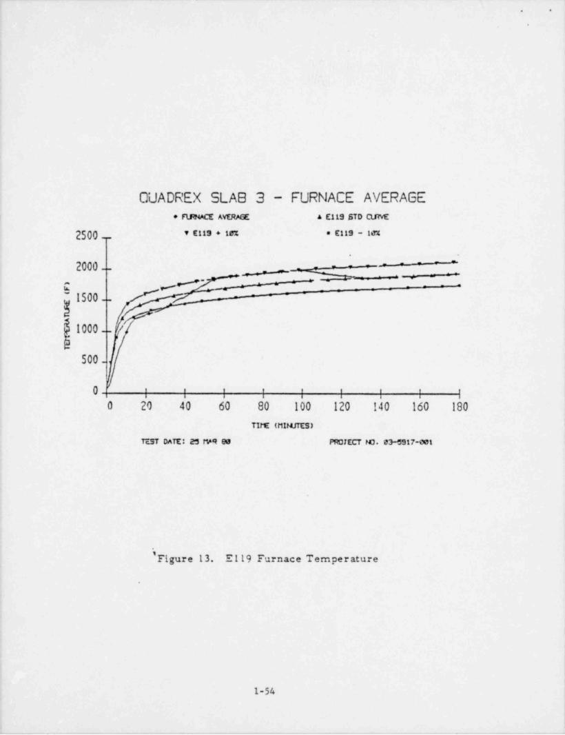
are shown in Figure 13 and Table 2. The temperatures recorded from the
imbedded and unexposed side thernocouples are shown in Appendix IV.
Since the test was conducted outdoors, a building was erected
around the furnace tc meet ASTM E119 standards. This structure was
adequate to prevent excessive air currents over the unexposed surface
of the slab. The outside temperature was approximately 70*F at the
start of the test.
1-52
_

,
. .
.
('
.
nouiI14"DIA(GPUCES) fG.'i~O/R(9 PUCES) /
-
5LEEVE ,
f8"* \'jf.. ~b .4 ,NW[E % / 21 1,
'
$V(/e / .
- @ N.
>?<'-*< N <L /'N ggi'
h,k g, > [/ . ' '
N,,
j ,g '. -+"
. ,./ \
, - .
s ,>-
*e . / %. , s '' ,,1*.
'y-
'
i
Figure 12. Test Furnace
i
)
1-53
:
.. . _
. .
.
QUADREX SLAB 3 - FURNACE AVERAGE* FUtNACE AVERM5E A E119 STD QJtvE
2500__ v EMS + is e EMS - 1M
.
- - -'
2000-- =-=_
_
.
..
_
-- --
;
~ 1500-
-
5
1000__/
500-
0 | | ; ; ; ; ; ;
O 20 40 60 80 100 120 140 160 180
TITE (t11MJTES)
Test DATE: as req es PROJECT NO. 03-5917-001
' Figure 13. El19 Furnace Temperature
;
|
1-54 )
____ _ _

- _ _ _ - _ _ _ _
. .
TA3LE 2.
ASTM E119 Ti=a/Tcmperatura Curva
ScandardTi=e Curve -10% Actual +10: Ti=e
0 70 63 73 77 0
1 6 200 1 130 1 1 220 1 1
2 1 400 1 360 I i 440 1 2
3 I 600 1 340 I I 660 1 3
4 I 800 6 720 I I 880 1 4
5 6 1000 4 900 1 563 i 1100 1 5
6 l 1100 1 990 1 6 1212 l 6
7 I 1150 1 1035 I i 1265 6 7
8 6 1200 I 1080 1 1 1320 i 8
9 1 1250 l 1125 I I 1375 i 9
10 l 1300 6 1170 1 981 1 1430 1 10
11 i 1320 l 1188 I i 1452 I 11
12 1 1350 1 1206 1 1 1474 1 12
13 1 1360 6 1224 4 i 1496 1 13
la 1 1380 1 1242 1 1 1513 6 14
15 1 1399 1 1259 6 1210 6 1539 1 15
16 1 1414 6 1274 e i 1555 i 16
17 1 1429 | 1286 I i 1572 1 17
18 I 1435 | 1291 1 1 1579 6 18
19 6 1450 t 1305 l 1 1595 6 19
20 l 1462 1 1316 6 1279 1 1608 6 20
21 i 1474 1 1327 I I 1621 1 21
22 1 1486 6 1337 I i 1635 i 22 |
23 1 1498 1 1348 I i 1648 1 23
24 1 1500 1 1350 I i 1650 i 24
25 l 1510 1 1359 I 1324 1 166L 1 25
26 1 1520 l 1368 I i 1672 1 26
27 1 1523 1 1375 i i 1681 6 27
23 1 1537 6 1363 ! I 1691 6 2 8__
29 1 1541 1 1387 I i 1695 1 29
30 1 1550 1 1395 1 1390 1 1705 1 30
35 l 1584 | 1525 1 1400 i 1742 6 35
40 1 1613 1 1452 1 1559 1 1774 I 40
45 l 1630 1 1467 I 1o70 i 1793 1 45
50 1 1661 6 1495 i 1755 1 1827 6 50
55 i 1681 1 1513 6 1839 1 1949 1 55
60 1 1700 1 1530 i 1883 | 1370 6 60
65 6 1718 6 1546 6 1848 I 1390 1 65
70 1 1735 l 1561 1 1910 1 1909 4 70
75 1 1750 1 1575 i L924 1 1925 I 75
30 i 1765 I 1589 1 1940 i 1941 1 80
85 1 1779 l 1601 1 1953 1 1957 6 35
90 1 1792 1 1613 1 19e6 6 1971 6 90
95 1 1804 6 1624 1 197e i 1984 1 95
100 1 1815 | 1633 1 1985 i 1994 1 100
105 i 1826 | 1643 1 19o8 1 2009 1 105
110 6 1835 6 1651 6 1941 1 2019 6 110
|115 I 1843 1 1659 | 1919 | 2027 I 115
! 1120 1 1850 6 1665 i 1902 l 2035 1 120
1130 1 1862 4 1676 i 1873 i 2048 I 1301140 1 1375 l 1687 I 18o5 a 2063 1 140!150 l 1888 i 1699 8 l805 a 2077 | 1501160 1 1900 l 1710 1 1891 4 2090 1 1601170 1 1912 1 1721 1905 1 2103 6 170 i!130 l 1925 | 1733 1 1920 1 2117 I 130 i
1-55t
\_ _- -- . _ . . . - . .-

. -
. .,
'.
i
'|
TEST PROCEDURES
The prepared floor penetration slab with fire stop materials in
place was placed in position on top of the furnaco. The temperature
multi-point recorders were turned on, natural gas was supplied to the
burners, ignited, and the test clock was started. The unexposed surface
was continaully observed for penetration by flame or hot gases and its
temperature monitored, by using the multipoint recorders. At the end of
the three-hour fire exposure period, the fuel gas was shut off and, as
quickly as possible, the enclosure building was removed and the test
slab was lifted from the furnace, remaining in a horizontal position.
A spray stream supplied from a 1-1/2 inch fire hose with a 30 * spray
stream setting and 75 psi nozzle pressure and 75 gpm delivery was then
directed at the floor penetration fire stops from a distance of 10 feet
to conduct the hose stream test. This hose stream test is identified
on page 13, Section 5.3.12 of IEEE 634-1978 (See Appendix VI) and is
commonly referred to as the "NEL-PIA Hose Stream Test". The required
hose stream application cima for penetrations installed in a 10 x 8 ft.
slab was 2 minutes. The time / temperature record of the test is shown
in Figure 13 and Table 2. Figures 12 and 14 show an exploded view of the
test setup.
,
,
!
1-56
_

_ _ _ _ _ _ - _ . _
. .
/,---- ,
'' A An / ,'
Ai yil i /t'-
'- -- -
(, ,' -r/j// 1 f a= l /
c -.- - - -, w - .- .'' ,'sv t w na N g,
/ /| / / /, __---------.s- -.
s' s------..-/'
---
B
// \ -.
V. ,
!
,
C
/ \
A) Test Slab (Typical)B) Furnace F_xtension SleeveC) Furnace'
Figure 14. Furnace Assembly
1-57
|._ _

.
. .
TEST RESULTS |
A. OBSERVATIONS
The following are observations made during the fire exp;sure
test, the hose stream test, and the post-test inspection.1
TABLE 3 TEST OBSERV ATIONS-
Test Time Event-0:05 Furnace loaded, systems ready. Light overcast,
light wind, ambient temperature approx. 70 * F0:00 Burners on, timer on, recorders on, Start Test0:05 Temperature 563 *F Holding back on gas0:10 Temperature 981 *F0:15 Temperature 1210*F - Still holding back on gas0:20 Temperature 1279'F0:25 Temperature 1324*F - Increasing gas supply slightly0:30 Temperature 1390 *F - Compensating for early lows0:35 Temperature 1490 *F - Slightly faster rise0:40 Temperature 1559'F - Temp rising smoothly0:45 Temperature 1670 *F - Light smoke, stable0:50 Temperature 1755'F - Now above norm0:55 Temperature 1839'F - Still above norm1:00 Temperature 1699'F - Smooth, on curve1:10 Te mperature 1910* F - High side - readjust1:20 Temperature 1940 *F - back within 10%1:30 Temperature 1966 *F1:40 Temperature 1985'F1:50 Temperature 1941 *F - Stable, all data good2:00 Temperature 1902 * F2:10 Tempe rature 1873 * F2:20 Temperature 1865'F - All smooth and stable2:30 Temperature 1865'F2:40 Temperature 1891 * F - Slightly below norm2:50 Temperature 1905'F300 Temperature 1920 * F' 02 End of fire test,:
3:08 Protective cover removed3:10 Slab hooked up to lift3:12 Start Hose Stream Test3:14 End of Hose Stre am Test3:20 Slab settled for examination
1-58
._

. .
Post Test Observations
1. There was no passage of flame through any penetrationduring the fire exposure test.
2. There was passage of light smoke through the seals, butsmoke coming through was cool to the touch.
3. There was no passage of water through any penetrationduring the hose stream test.
B. SUMMARY OF TEST RESULTS
A fire stop shall be considered as meeting the requirements
for acceptable performance when it remains in the opening during
the fire endurance test and hose stream test within the following
limitations:
1. The fire stop shall have withstood the fire endurance test
without permitting the passage of flame, or the occurrence of flaming
on any element of the unexposed surface of the assembly for a period
equal to the hourly classification for the fire atop.
2. The fire stop shall have withstood the fire endurance test
and hose stream test without developing an opening that would permit
a projection of water from the stream beyond the unexposed surface.
3. The transmission of heat through the fire stop during the
fire endurance test for any recorded temperature on its unexposed|
surface shall not exceed 700 F on penetrations involving cable.I:
Accordingly, the following shows the performance of the pene-
trations for the test period of three hours as documented in the test
observations and in Appendix IV.
1-59
__ _ __ _ _ . _ . .

. _____ ____
. .
l4
||
T AB LE 4i
TEST RESULTS
Penetration ConditionNumber 1 2 3
P27 Pass Pass Pas s
P31 Pass Pass Pass
P32 Pass Pass Pass
P33 Pas s Pas s Pass
P34 Pass Pass Pass
P35 Pass Pas s Pass
.
To verify the condition of the penetration seals after the test,
an examination was made to determine char depth, the depth of any
remaining insulation material, such as the urethane foam and TBV,
and the condition of the coatings and insulation boards. The results
of this exam' ' are shown in Figures 15 through 20. Ph otogr aph s
of the fire exposure period, the hose stream test, and the post test
condition of the penetrations can be found in Appendix II.
1-60
__ _ _ _ _

. .
.
Item 3.1.5(1)Structural Member Coating
Northern States Power Company is committed to coat all Turbine Buildingstructural members in the vicinity of the lube oil reservoirs with asuitable fire retardant coating.
An evaluation of the effects of an unmitigated fire at the turbine lube oilreservoirs to the structural members (beams and columns) supporting thebuilding has been completed. The attached figures illustrate the extentand location of the beams and columns requiring protection.
We will apply a 3-hour coating of Pyrocrete 241 on those columns and beamsper UL design N716 for beams and UL design X-733 or X-736 for columns.
1
l
|
||
2-1
. - -_

. .
.. _ . ,
TYPICAL N0. 1U.L. DESIGN FOR COLUMNS
Design No. X736
Rating 3 Hr.
~'WQ[Npt?.*Ti~'V - ;F(a a a a w -a a
|, f ,i
d
Ia p
f.,..
s.L v_/c ..aa,: ,, 11 si ,-- /,
..
N.W.O.. T Y.A.S.,Y
3
1. Pyrocrete 241*-See table below for appropriate thickness. Prepared bymixing with water according to instructions on each bag of mixture andtrowling in one or more coats to steel surfaces. Min ave density of55 pcf with min ind value of 50 pcf. For method of density determination,see section 3.5, Construction Test Requirements. Surface of material to besmoothly finished with a trowel.
Rating Hr Minimum Thickness, In.3 1 1/4
2. Metal Lath-3.4 lb per sq yd galv expanded steel . Lath lapped 1 in. atjoint and tied together with No. 9 SWG galv steel wire spaced vertically10 in. 0.C.
3. Steel Column-Min size of column, Type W10X49.
Searing the UL Classification Marking.*
2-2

___ . . ___ . - _ _
, .
3
TYPICAL N0. 2
ADPLICATION DETAILS PYR0 CRETE 241
BOXED MEMBERWITH CORNER BEADS
i!i1
Steel Member-
i
Metal Lath
',
Plastic Nose. -
Corner Bead **..
'n ;.' ' Pyrocrete.:-
" Corner bead filled with pyrocrete i
|2-3

_-_ _ -___
. .
TYPICAL NO. 3
U.L. DESIGN FOR BEAMS
DESIGU NO. N715Restrained Beam Ratings-3 Hr.
t
j%7.T1,M C 'U.W($.4. .. .
{$r* .. .S ''- |i'. . .' ' f.0.U.* '.
I . 5.y9gW.... . .|:.t.'. y . . .,
/. p4
@N.:. .
f s...
' *?i:.: ,
h **.
.z. . ., , M.n.-'-
... _ . .
3 2
1. Steel Beam-W8x28 min size.2. Metal Lath-3.4 lbs/sq yd galv or painted expanded steel. Secured to beam
by bending tight around flanges a min of 1 1/2 in toward web of beam.3. Pyrocrete 241*-See table below for appropriate thicknesses. Where metal
lath is present, thicknesses are measured to surface of metal lath, allother thicknesses are measured to steel surface. Prepared by mixing withwater according to instructions and trowel applied on beam surfaces andover lath, as shown. When fluted or corrugated steel floor units areused, crest areas above the beam shall be sealed with pyrocrete.
4
Min avg density of 55 pef with min ind value of 50 pef. For method ofdensity determination, see Section 3.5 Construction Test Requirements.Surface of applied material to be lightly finished with a steel trowel.
Minimum Thickness In.
Rating Hr. Restrained Beam
3 1 1/4Carboline Co.-Type 241
* Bearing the UL Classification Marking.2-4
_ _ - _
. .
'.
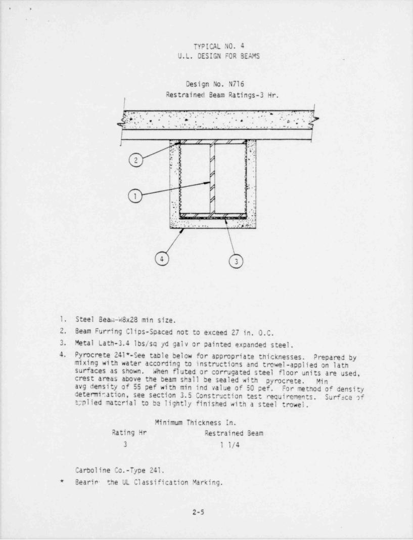
TYPICAL N0. 4U.L. DESIGN FOR BEAMS _
Design No. N716Restrained Beam Ratings-3 Hr.
''**'.....'*;.'..'..-|-'' * . . . . ' ' .:'~
-.. <
_
r . . . .
'. , . - **:* *n; . ' .. , . . , , .. . . . * . ' ' -. . .
.-
l |J f" I' 1
"- "
3:7 { *!
2 : # 1'
5 '. 1'
# ):
. . - .
* :~ j .'-
.: J '
. .%w ,, ,, ,,
-:. ..... 1 . iM'
4 3
1. Steel Beaa-W8x28 min size.2. Beam Furring Clips-Spaced not to exceed 27 in. 0.C.3. Metal Lath-3.4 lbs/sq yd galv or painted expanded steel.4. Pyrocrete 241*-See table below for appropriate thicknesses. Prepared by
mixing with water according to instructions and trowel-applied on lathsurfaces as shown. When fluted or corrugated steel floor units are used,crest areas above the beam shall be sealed with pyrocrete. Minavg density of 55 pef with min ind value of 50 pef. For method of densitydetermination, see section 3.5. Construction test requirements. Surface ofr; plied material to be lightly finished with a steel trowel.
Minimum Thickness In.Rating Hr Restrained Beam
3 1 1/4
Carboline Co.-Type 241.* Bearin- the UL Classification Marking, j
1
2-5 |
||
1

. .
.
TYPICAL NO. 5U.L. DESIGN N 716 WITH MARINITE
/ --
/
kI I i IVI livl I I I I I ikil l*il I I I I 9/
/ I I na a a av i
g u uw
9 1% Beam3
# 2
g N Pyrocrete 241
' '{ " L' "_^__
3.4 Galvanized Lath
I 3
12"
r 1
1x x x / x x#
x X X x x
"Beam
1 x x x x x- +
x x l' x x x- i~
l |
3
1. UL Design No. N716 per Typical Dwg No. .
2. Steel grating at El. 715.3. Johns-Manvilles Marinite I Board .1 inch thick, cut 12 inches wide,
running parallel to the entire beam edge that requires protection.4. Marinite hangers-consists of saddle clamps, bolt, nuts and large washer
located approximately 3 inches in from each edge, spaced to provide 1
a minimum of 3 pairs per 8 foot section. l
2-6 ,
1
|
||

1
1, .
'
.
TYPICAL N0. 6|
U.L. DESIGN N 715 WITH MARINITE
diI I IWI IWI I I I I I IVI IWI I I I I(i | n // // // // , g |
.
u V u u
h2 / Beam
h3 _ _ _ _ _ _ h _ _ _ _
" " f' " " g !.
Pyrocrete 241
3.4 GalvanizedLath '
2
-12"
U, i
lx gx x x x |x x x x x )
ABeam
l: : 7: : raI
'
\
2
1. Steel grating at El. 715.2. Johns-Manvilles Marinite I Board .1 inch thick, cut 12 inches wide,
running parallel to the entire beam edge that requires protection.3. Marinite hangers-consists of saddle clamps, bolt, nuts and large washer
located approximately 3 inches in from each edge, spaced to providea minimum of 3 pairs per 8 foot section.
2-7

. .
9
GENERAL ARRANGEMENT - UNIT 1
TYPICAL PC.7, _..
_
|
w.
n
@- : : :--
=
_
,
@-
.
,~.
.
@ @ @ @ :
'
NOTES:
1. PROTECTIVE C0ATING APPLIED 1/2 THE DISTANCEBETWEEN COLUMN R0WS 6 & 7.
2. PROTECTIVE C0ATING APPLIED 1/4 THE DISTANCE ;
BETWEEN COLUMN R0WS F & G.
3. The 73S El. floor is solid concrete.It rests on steel purlins which aretied into the main steel members.Provide Pyrocrete 241 on first 8"of purlins from main steel beams. 2-8
!

.
.
i10iES:
G f E D
1. See General NotesTypical No. 7 ,21'- 6" 21' 6" >* 21'- 6" *><,
2. Beam at 715 El. shall *
have Marinite edging. Seetypical No. (Later).
.
3. Beam and Column UL Designs N-715are N-series and X-series, 36kr N-715_ 36tf N-715 36WF&l4XI-If4 PL T&B El 735respectively..
d - a11 e
x
24kT N-716 21kT N-716 16kF N-716 ,El. 715
'?
14WF136 14WF158
X-736 X-736 El 695
1Column how 7 1
LOOKlHG WEST|
TYPICAL 7A
i
.

_ _ _ _ _ _ _ _ _ _ _ _ _ _ _ _ _ _ _ _ _ _ _ _ _ _ _ _ _ _ _ _ _ _ _ _
6 7 8s
31'-6" 20'-6" ,
1. See General flotes, Typical ti-715fio. (Later).36W&l 1/4 R. T&B fi-715 27bF
2. Deam at 715 El. shall have El. 735flarinite edging. SeeTypical (Later).
3. Beam and column UL Designare il series and X seriesrespectively. 33F ti-715 N-716 16W g
**y,
E*s
14WF136X-736
L El. 695FLOOR
,
.
COLUMit R0W F
LOOKillG fl0RTil
TYPICAL 7b -
,
,
.
9
. _ _ . _ . . _ _ . _ . _ _ _ _ _ _ _ _ _ _ _ _ - _ _

_ _ _ _ _ _ _ _ _ _ _ _ _ _ _ _ _ _ _ _ _ _ _ . .
. .
.
t
fl0TES:
6 7 81. See General flotes,Typical flo. (Later).
31'-6" 20'-0"2. Beam at 715 El. shall have * ** *
Marinite edging. SeeTypical (Later).
3. Beani and column UL Designare il series and X series
f_1-715 36W tt-715 27Wrespectively. EL_.735.
d7 5"
ti-716 24g 11-716 16W__
EL.715**
'
14WF158X-736-
EL.695.
l
* \
i
COLUMit R0W E
LOOKittG fiORill
TYPICAL 7c i
I
- _ - - - - _ _ _ _ _ _ _ _ _ _ _ _ - - - - - J

|. .
~N
~V...
@'
II
O
NOTE 2,/
O11-
:~
n,
1/2 D,
.-
NOTE 1 % NOTE 1
@ u : :_.
..
>
@ @ O @
NOTES:
1. PROTECTIVE C0ATING APPLIED 1/2 THE DISTANCEBETWEEN COLUMN R0WS 11 & 12.
2. PROTECTIVE C0ATING APPLIED 1/4 THE DISTANCEBETWEEN COLUMN R0WS F'& G.
3. The 735 El. floor is solid concrete.It rests on steel purlins which aretied into the main steel members.Provide Pyrocrete 241 on first 8" ;
of purlins from main steel beams. l
GENERAL ARRANGEMENT-UNIT 2
TYPICAL N0.8
2-12

_ _ _ _ _ _ _ _ _ _ _ _ _ _ _ _ _ _ _ _ _ _ _ _ _ _ _ _ _ _ _ _ _ - _ _ _ _
'
. .
.
G f E D
21'-6" 21'-6" 21'-6"= wm - - n
"~ bNOTES:
30W N-715 36g N-715 36tF& it T&B EL. 7351. See General Notes,
~ ~ - , '-~ ~ ~~ ~ ~~ ~'~ ~ ~
Typical No. (Later).__ .._ ____ __ __ _ _ . _ __
,
2. Beam at 715 El. shallhave Marinite edging.
.
See typical (Later). ~$ .
$3. Beam and column ULy 24W * N-716 24tf N-716 16F N-716 EL. 7154 Design are N series and
__ __ __ __
X series respectively.w
__ __ __
14WF136 14WFIS8.
X-736 X-736EL. 695
COLUMN R0W 11l,
LOOKING WEST
TYPICAL 8a
i
1
_ _ _ _ . _ _ _ . _ _ _ _ _ _ _ _ _ _ _-_-
__ _____________ ______ _ _____ - . _
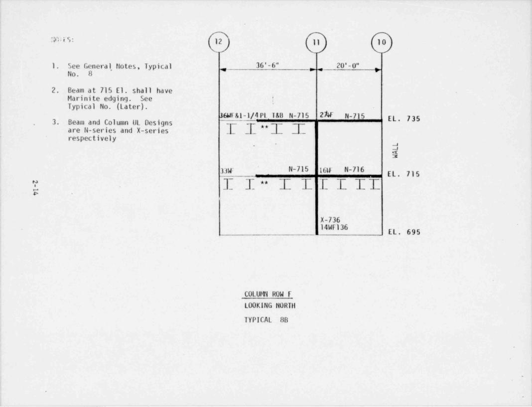
'in:i S: 12 11 10
1. See General, Notes, Typical 36'-6" 20 ' - O", ,No. 8
2. Beam at 715 El. shall haveMarinite edging. See !
.
Typical No. (Later).36Wral-1/.4 Pt 188 N-715 27W N-715 EL. 7353. Beam and Column UL Designs
are N-series and X-series -[ - ,,1 d-,
respectively, a'
N2
33y: N-715 16tr N-716'
EL. 715
I. I I ** I f I I II
X-73614WF136 EL'. 695
COLUMN R0W F
LOOKING NORTil
TYPICAL 8B
-
_ _ - - - - _ _ - - _ - - - _.
,

-_ - _ _ _ _ _ _ _ _ _ _ _ _
- .
.
.
It0TES: 12 11 10
1. See General Notes,31'-6" 20'-0"Typical No. (Later). + >4 >
2. Beam at 715 El. shallhave flarinite edging.See Typical (Later).
36W N-715 27W N-7153. Beam and column UL Design- are N series and X series -,, -~ -~
~-*
respectively.-- -- -- --
14WF158 -j$
2 7W ** N-715 16W N-716EL. 715,
"; T, T_ _I
~~
.T- ~_E T I ~~'
u __ __
14WF158#' X-736
'
EL. 695
COLUMN It0W E
LOOKING NORTil
TYPICAL 8c
i
_ _ _ _ . _ _ _ _ _ _ _ _ _ _ _ _ __ _ _ _ _ _ _ _ ._________l

_ _ _ .. . _ .
NOTES:-
11 10
1. See General Notes, TypicalNo. (Later).
# "2. Beam at 715 El. shall have <Marinite edging. See Typical(Later).'
3. Beam and column UL Design areN series and X series respectively.
27WEl. 735
N-715 .
i a$
7 2
5 .
IfM El. 715
.
El. 695
-;.
COLUMN R0W 1/2 D.
LOOKING NORTil
TYPICAL 8d
|
.
.

. ,
1
|
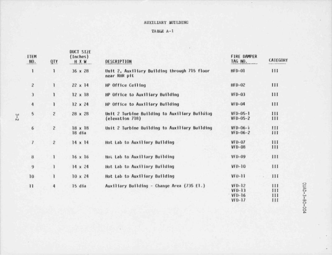
Item 3.2.5(1)Fire Damper Evaluation
The Fire Protection Safety Evaluation Report contains our committment toreview all fire zones containing safety-related systems and equipment toverify that ventilation paths are pvovided with fire dampers. Whereadditional dampers are deemed necessary, they are to be purchaaed andinstalled.
This review has been completed and a number of locations identified whereins tallation of fire dampers was recommended. Refer to the attached tablelisting these locations.
Three hour, UL lable, curtain type fire dampers are being installed atthese locations. Dampers will satisfy the following s tandards:
a. UL 555 dated May 14, 1979b. NFPA 80, 1979c. NFPA 90A, 1978d. NFPA 90B, 1976e. IEEE-344 (1975) where seismic qualification is needed
All dampers will be equipped with a 165 F fusible link and previded witha corrosion resistant coating.
3-1
-
'
AUXILIARY BUILDING
TABLE A-1
.
DUCT SIZEITEM (Inches) FIRE DAMPERNO. QTY 11 X W DESCRIPTION TAG NO. CATEGORY
l 1 36 x 28 Unit 2. Auxiliary Building through 715 floor ilFD-01 III
near RilR pit
2 1 22 x 14 IIP Office Ceiling flFD-02 III
3 1 12 x 18 llP Office to Auxiliary Building VfD-03 III
4 1 12 x 24 IIP Office to Auxiliary Building VFD-04 III
w 5 2 28 x 28 Unit 2 Turbine Building to Auxiliary Buildi;ig VfD-05-1 III
4 (elevation 718) VFD-05-2 III
6 2 18 x 18 Unit 2 Turbine Building to Auxiliary Building VFD-06-i III
18 dia VFD-06-2 III
7 2 14 x 14 llot Lab to Auxiliary Building VFD-07 III
VfD-08 III
8 1 16 x 16 ilot Lab to Auxiliary Building VfD-09 III
9 1 14 x 24 llot Lab to Auxiliary Building VFD-10 III
10 1 10 x 24 Hot Lab to Auxiliary Building VfD-ll . III ;
11 4 15 dia Auxiliary Building - Change Area (735 E1.) VfD-12 III jjVFD-13 III o
VfD-16 III da |
VFD-17 III y; '
a52
.
O
e
|*
_ _ _ _ _ _ _ .

.
-
.
%
AUXILIARY BUILDING
(continued) .
DUCT SIZEITEM (Inches) FIRE DAMPER
NO. QTY ll x W DESCRIPTION TAG NO. CATEGORY
12 4 15 dia Auxiliary Building-Chance Area (735 EL) IIFD-14 III
llFD-15 III
IIFD-18 III
IIFD-19 III
13 2 42 x 26 Control Room Supply llFD-20 III/ SEISMICllFD-21 III/ SEISMIC
14 2 30 x 62 Control Room Return liFD-22 III/SEISHICw0 llFD-23 III/ SEISMIC j
15 1 40 x 22 General' Vent Exhaust 11F0-24 III
16 1 10 x 18 General Vent Exhaust ilFD-25 III
17 1 26 x 14 General Vent Supply llFD-23 III
18 1 26 x 26 General Vent Exhaust ilFD-27 III
19 1 24 x 18 General Vent Exhaust ilFD,28 III
Ea
1 Y !
8 !
aR
!"
.
!

. _ _ _ .
, .
,
QUAD-3-80-004
NUCLEAR SERVICES CORPORATION& DevillON CF
WORDREXOC R AC A ATIO N
Notes: 1. Table A-1 lists the quantity and size of each type of
three hour fire damper. Two spare fusible links shall
be provided for each damper.
2. HFD designates a Horizontal Fire Damper.VFD designates a Vertical Fire Damper.
3. The duct size given in inches describes the height
and width (HxW) of the inside measurement of the ductfor vertical fire dampers (VFD-XX).
4. The horizontal fire damper (HFD-XX) blade dimension
is listed first.
.
3-4
|. - _ _ .- .- _ _ _ _ _ _

_
. .
D**D "O T.-
.b.soc o .a
TURBINE BUILDING
2-111 !!R. RATED FIRE DAMPERS EACil LOCATIONNSP - PRAIRIE ISLAND
FIRE DAMPER LIST.
LOCATION DUCT SIZE WORK TO BE PERFORMED INSTALLATION COND. N8# '
Elev. 695"-0Wall between
Cut hole in duct for F.D. 6'-4 Above floor.Battery Room 12 x 12 Requiring Patch & Access Duct above battery rack. /o12 & 22
DoorGrid 9
Elev. 715'-0 d7Busroom 25 46 x 10 Remove reg. 6 insert 2- Clear Access 10'7 bot.
Register 46 x 10 F.D. Replace of registerWall between Opening Registerbus Rm. 26 &25
18 x 18 Cut hole in duct for F.D. 13'-0 bot. of duct gRequiring patch and access Clear Access to work.
,, door.
Elev. 715'-0
Busroom 26 Remove sq. thr. companion Work to be installedangh elbow and, insert F.D. f rom switch:; ear Ra.
Wall at Crid D 22 x 22 Rebolt elbow & cut in A.D. Side of wall. 8.
46 x 16 Cut hole in duct for F.D. Wrequiring patch & A.D.
Elev. 715'-0
36 x 18 Cut hole in duct. for F.D. 04/"" *Requiring patch & A.D.
Wall at Crld D Work to be ins t.a ll ett f rom.
Switchg"ar Rm. side of wall.32 x .33 Remove sq. thr. companionangle elbow & insert F.D. gRebolt elbow & cut in A.D.
'
I' l ev . 715'-0i Remove Reg. 6 insert Clear access 10'-7
Bus Roon 16 %x 12 2 - 36 x 12 F.D. Replace Bot. ef ::enister dji
register.
Wall between ,
liuss Rm. 16 5 22 x th Cut hole in duct for F.D. I
15 requiring patch and access! door. C.,;i7,,i
i
|
|
Ii
3-5
r ,
__ _ _ _ _ _
_. _ -
. .
.
Item 3.2.6Fire Pump Barrier
Northern States Power Company has investigated the feasibility of. providinga three-hour fire rated enclosure for the motor-driven fire pump located inthe screen house. A fuel oil fire in this area could make both fire pumpsinoperable without additional protection measures.
A three-hour enclosure for the motor-driven pump has been designed and willbe installed. A summary of the design specifications and sketches of theenclosure design are attached for your information.
)
'.
4-1
--_ __ ... __ _
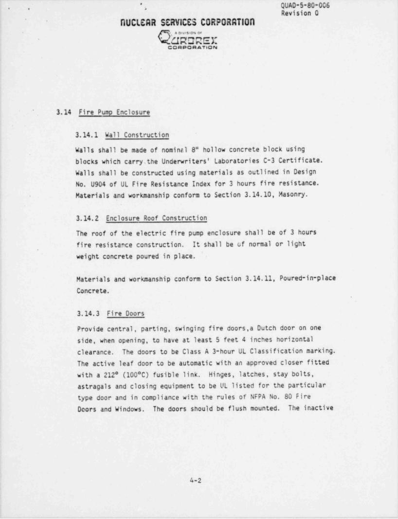
QUAD-5-80-006*
. . >
Revision 0'
'
DUCLEAR SERVICES CORPORRTIOR- a OsvsSSON Of
'
URDREE'
QQ A AQ AATION
3.14 Fire Pump Enclosure'
3.14.1 Wall Construction
Walls shall be made of nominal 8" hollow concrete block using
blocks which carrysthe Underwriters' Laboratories C-3 Certificate.Walls shall be constructed using materials as outlined in DesignNo. U904 of UL Fire Resistance Index for 3 hours fire resistance.Materials and workmanship conform to Section 3.14.10, Masonry.
3.14.2 Enclosure Roof Construction
The roof of the electric fire pump enclosure shall be of 3 hoursfire resistance construction. It shall be of normal or light
,
'
weight concrete poured in place.
Materials and workmanship conform to Section 3.14.11, Poured-in place
Concrete.
3.14.3 Fire Doors
Provide central, parting, swinging fire doors,a Dutch door on oneside, when opening, to have at least 5 feet 4 inches horizontalclearance. The doors to be Class A 3-hour UL Classification marking.The active leaf door to be automatic with an approved closer fittedwith a 212* (100 C) fusible link. Hinges, latches, stay bolts,astragals and closing equipment to be UL listed for the particulartype door and in compliance with the rules of NFPA No. 80 Fire
Dcors and Windows. The doors should be flush mounted. The inactive
4-2|
!
I
l

* *
QUAD-5-80-006.
Rovision 0* - -
RUCLERR SERVICES CORPORATIONg A Divetr04 08
Mr.JRDREXCO A AQ A ATION
leaves are to have hand and foot and side stay bolts as shown on.
Figure 1, Attachment IV. Flat plate astragals are to be mounted onthe active leaf and the upper inactive leaf to serve as stops forthe active leaf.
The doors are to be provided in a door frame, to be UL listed.Frames and doors to fit into an opening of 10'-6!s" x 5'-4" (seeEngineering Drawings).
|
3.14.4 Paintino and Caulking
The enclosure masonry, door and door frame shall be sealed andpainted to match the existing structure from plant paint stock.
All joints between block work and other types of new constructionshall be caulked unless oto rwise shown on the drawings. All
caulkira shall be grey in color. Caulking materials shall conformto Federal Specification TT-C-00598, Grade No.1.
Penetrations into the intake structure shall be sealed as firebarriers in accordance with Section 3.16, Fire Pump EnclosurePenetrations. -
3.14.5 Construction Materials and Workmanshio
3.14.5.1 Work Included
The work shall include but is not necessarily limited to:
1. All form work including special forms necessary to producearchitectural details and/or to accommodate the work of othersand removal of forms.
2. All concrete reinforcement, placement, bending and formingthereof.
|,
4-3

.
*
, ' , QUAD-5-80-006"
,,Revision 0-
NUCLEAR SERVICES CORPORRTIOR. . . . . . . . . . .
(iRGREXCO A AQ A ATION
3. All concrete and cement finishing; all surface treatment andcuring includi g non-slip finishes and color work.
4. Installation of all reglets, bolts, anchors, cins, sleeves,column anchor bolts, etc.
5. The furnishing of all items required to be, or shown on thedrawings, embedded in concrete, which are not specificallyrequired under other sections.
6. Setting headers and screeds, finishing, curing and protectingconcrete.
3.14.5.2 Work Soecified Elsewhere
1. Unit masonry and reinforcing for it (3.14.10, 3.14.7).
2. Inserts, sleeves, cans, etc. (3.14.12).
3. Materials and testing (3.14.11).
3.14.5.3 Defective Work
Work considered to be defective may be ordered by the Owner to be
replaced, in which case the Contractor shall remove and replace the i
defective work at his expense. Work considered to be defectiveshall include, out not be limited to, the following:
l
a. Reinforcing
Kinks and bends therein which are not scheduled or indicatedon the drawings; reinforcing improperly placed, or previouslyheated.
4-4

QUAD-5-80-006'. -
., ,.Revision 0
AUCI. ERR SERVICES CORPORATIONA Div+04 0F
W .J R D R E XCOR AQ A ATH3N
b. Concrete
1) Concrite in which defective or inadequate reinforcingsteel has been placad.
2) Concrete incorrectly formed or not conforming to detailsand dimensions on the drawings or with the intent ofthese documents, or concrete, the surfaces of which areout of plumb or level.
3) Concrete below specified strength.
4) Concrete containing wood, cloth, or other foreign matter,rock pockets, voids, honeycombs, cracks or cold jointsnot scheduled or indicated on the drawings.
The Owner may consent to allow defective work to be corrected incases where the construction schedule will not permit time forreplacement. The Contractor shall, at his expense, make al? suchcorrections and alleviation measures as directed.
Secure approval of chipped-out areas before patching.
3.14.6 Forming
3.14.6.1 General
The forms shall be smooth, mortar-tight, true to the required linesand grade, and of sufficient strength to resist springing out ofshape during the placing and vibrating of concrete. All dirt,
chips, sawdust and other foreign matter shall be completely removedbefore concrete is deposited therein. Forms previously used shallbe thoroughly cleaned of all dirt, mortar and foreign matter beforebeing reused. Before concrete is placed in forms, all insidesurfaces of the forms shall be thoroughly coated with an approvadform sealer. The form sealer shall be of high penetrating qualityleaving no film on the surface of the forms that can be absorbed bythe concrete or be incompatible with concrete paint.
4-5
|

* ' , , QUAD-5-80-006'
..
R0 vision 0.
DUCLERR SERVICES CORPORRT100
m . .. ... ..MUROREX
CQ A A Q R ATION
All exposed sharp edges shall be chamfered with triangular filletsnot less than 3/4 inch by 3/4 inch unless otherwise directed by theOwner. These fillets and chamfer strips shall be milled from clearstraight grain lumber and shall be surfaced on all sides.
3.14.6.2 Stripping
Forms shall be removed in such manner as to insure the completesafety of the structure.
Side forms may be removed after 48 hours provided the concrete issufficiently hard not to be injured thereby.
3.14.7 Reinforcing Steel
3.14.7.1 Materials
Bars for reinforcing shall be deformed, domestic, intermediategrade bars.
Wire mesh for floors shall be rectangular welded wire fabric ofspacing and gauge as indicated on the plans.
Wire for tieing reinforcement in place shall be No. 18 AWG blackannealed or heavier.
3.14.7.2 General Requirements
Except where specified otherwise herein or shown otherwise on the |plans, reinforcing steel shall be' cleaned, fabricated, placed, tied I
and supported in accordance with Section 2610 of the Uniform BuildingCode. Reinforcing shall not be bent or straightened in any mannerthat will injure the material. All splices for deformed bars shallbe not less than 40 bar diameters but in no case less than 12 inches.
4-6
_. - . -

._ __
i QUAD-5-80-006 - *** **
Revision 0,
RUCLEAR SERVICES CORPORATION4 0iv$04 C8
WORDREXCQ A AQ A ATION
3.14.7.3 Protective Covering
Except where otherwise shown, the minimum concrete coverage for
steel reinforcement shall be as follows:o Reinforcing for walls center of wall or 3/4"o Where concrete is deposited
against ground 3"
o Concrete in forms exposedto earth 2"
o Beams, girders and columns 1 1/2"
3.14.7.4 Installation of Reinforcing
Steel reinforcement shall be accurately placed and shall be supportedand secured against displacement by the use of adequate and propersupporting and spacing devices, tie wires, etc., so that it willremain in its correct location in the finished work. No supportingdevices shall be used that will impede the flow of concrete.
The clear spacing between parallel bars shall be not less than1.1/2 times the nominal diameter of the maximum size aggregate, andin no case less than 1 1/2 inches except at splices which may bewired together.
Wherever possible, splices of adjacent bars shall be staggered.Splice wire fabric at least one mesh wide. Rebending of bars on
the job to fit existing conditions will not be permitted withoutthe approval of the Owner.
3.14.8 Sealing
3.14.8.1 Material
The sealant called for on the dra' wings shall meet the requirementsof the ASA 116.1.
4-7
- _ _ _- - --

__ ___ . _ . ____ _ __ _
' * '
QUAD-5-80-006, . ,.
Revision 0DUCLEAR SERVICES CORPORATION
& Orwit:04 08
URDREICO RRO R ATIO N
The batch date of all caulking compound shall be certified. Materialcolor shall be as approved by the Owner.
'
|
Approval of an equal type of material will be judged upon submissionof a certified copy from a qualified testing laboratory which-
indicates performance characteristics of the material tested inaccordance with ASA 116.1 requirements.
3.14.8.2 Workmanship and Installation
All surfaces must be clean and dry before application. Cleaning
shall include removal of scale, grease, dirt and any (C eign ordeleterious materials. Concrete shall be 28 days old before beingcaulked. A joint filler shall be used as backing, as shown on theplans.
Primer shall be allowed to completely dry before sealant is applied.The mixing and application of the material shall comply closelywith the manufacturer's recommendations. Sealant shall be appliedin such a manner as to remove all air voids. The sealant shall beforced into the opening by means of a caulking gun to the requireddepth without layering the sealant.
After application, the uncured compound shall be tooled and smoothedto a plane surface, as shown on the plans. Sealant shall be allowedto cure for four days before painting or other surface treatment isapplied.
3.14.9 Grouting and Dry Packing
3.14.9.1 General
Grouting includes necessary grouting of base plates.
4-8
* '
QUAD-5-80-006' ' ''
Revisicn 0AUCLTRR SERVICCO CORPORATION
Q. 8 OIVIS.0% ofURDREXQQ ADOR ATION
Dry packing includes those concrete to concrete joints called onthe drawings to be dry packed.
3.14.9.2 Materials
Grout
Sulco grouting iron (Sullivan Company, distributed by Conrad SovigCo.), Embeco-non-shrink grout (Master Builders'), A. C. Horn non-shrink ;; rout e: approved equal.
Dry-Pack
One part Portland cement, 2 1/2 parts clean sand, and the minimumamount of water necessary to hydrate the cement without making the
mixture ).lastic.
3.14.9.3 Workmanship
Dry-Packing
After members to be dry packed are positioned and wedged at trueline and grade, they shall be dry packed in place.
The dry pack shall be hand rammed into place with shingle or othersuitable tool. Care shall be taken to avoid leaving air pockets sothat full bearing can be established. The finished work shall beneatly painted if left exposed.
3.14.10 Masonry
3.14.10.1 Materials
1. Concrete masonry units shall be standard lightweight masonryunits conforming to Uniform Building Code and ASTM C90,,
Grade A, for load bearing units. All masonry units shall be
:
4-9
!
i

QUAD-5-80-006- -
,. ,.
Revisien 0NUCLEAR SERVICES CORPORATION
4 Or4SeClls 08
W MDREXCQ A AQ A ATION
the product of one manufacturer, of one composition throughoutthe work, and uniform in texture. Units shall be cured for a
minimum of 28 days prior to delivery at the site. CMU shall
have Drying Shrinkage tests in accordance with ASTM C426. Themaximum linear shrinkage shall be .04 percent.
The following shapes shall be used:
a. 8" x 8" x 16" two cellb. Special shapes as required for construction
'
2. Portland Cement shall conform to ASTM C150, Type 1.
3. Masonry Cement shall conform to ASTM C91,' Type II.
4. Hydrated Lime shall conform to ASTM C207, Type 5.
5. Aggregate for mortar shall conform to ASTM C144 except that, ;
of sand used for the reinforced block masonry, not less than l
4 percent shall pass No. 100 sieve.
6. Reinforcing Steel Bars shall be intermediate grade new billet I
steel conforming to ASTM A15, with an approved deformationconforming to ASTM A305.
7. Anchorage items other than reinforcing steel bars and rodsshall be heavily galvanized steel of the types indicated on |
the drawings or specified.
8. Water shall be clean and free from deleterious amounts ofacids, alkalines or organic materials.
||
4-10

l1. -
.
QUAD-5-80-00G. . . .
Revision 0RUCLEAR SERVICES CORPORATION
,..m.......
4!ROREIQQ A AQ A ATION
l9. Caulking shall be one part polysulfide, PRC 5000.
3.14.10.2 Mortars
The following mixes shall be used:
1. For reinforced concrete block masonry, conform to the BuildingCode for Type A mortar with a minimum compressive strength of2,000 psi in 28 days, and mixed as follows: 1 part Portlandcement (light colored), minimum 1/4 and maximum 1/2 by volumeof hydrated lime or lime putty, not less than 2 1/2 and notmore than 3 times the sum of the volumes of the cement and -
limes.used of damp loose sand.
2. For grout in reinforced concrete block, as required, provide amix composed of one part Portland cement, and 3 parts sand, towhich may be added not more than 1/10 part hydrated lime, andmay contain an addition of pea gravel equal to maximum 2 partsby volume of cement used. Pea gravel shall be maximum 3/8 inchwith not more than 5 percent moisture.
Add sufficient water to produce consistency for pouring withoutsegregation. Grout shall have a compressive strength of2,000 psi in 28 days.
Mortar, as delivered to the mason, shall have a flow after suction
for one minute, of not less than 70 percent of that immediatelybefore suction when determined by the method described in ASTM C91.
3.14.10.3 Erection of Concrete Block Masonry
All masonry shall be laid plumb, true to line, with level andaccurately spaced courses. Work required to be built in with themasonry (including anchors) shall be built in as the wall construc-tion progresses.
4-11|
|
||

QUAD-5-80-006-
. . . .
Revision 0AUCLERR SERVICES CORPORRT100
& Olv'Si0th 08
CRCREXC O A A Q A ATION
Concrete masonry unit walls shall be erected where shown on thedrawings. Fach course shall be solidly bedded in mortar and verticaljoints buttered full.
Jamb units shall be of shapes and sizes required to bond with wallunits and shall be built in where shown on the drawings, or required.
Standard width of mortar joints for both horizontal and verticaljoints shall be 3/8 inch,
Joints on interior exposed surfaces shall be struck. Joints shallbe tooled in such a manner as to squeeze the mortar back into thejoints, and then struck. No tooling shall be done until after themortar has taken its initial set.
.
After tooling, the exposed surfaces shall be wiped down with burlap.Color of mortar will be selected by the Owner.
Cutting and patching of masonry required to accommodate the work ofothers shall be performed by masonry mechanics. Work shall beneatly performed using approved power saws.
Unfinished work shall be stepped back for joining with new work.Toothing may be resorted to only when specifically approved by theOwner.
Before new work is started, all loose mortar shall be removed and
the exposed joint thoroughly wetted before laying new work.
Reinforcement shall conform to the applicable requirements of theUniform Building Code. Laps shall be a minimum of 40 diacetc>s and
centered in the cells of the concrete block. Masonry shall beadequately doweled to foundations and bond beams.
4-12

_
QUAD-5-80-006 - -
i., ..
Revision 0 .
DUCLERR SERVICES CORPORATION |
Q~dRGREXa nivesioe ce
|'
CQ ARQ A ATION
Masonry unit cells shall be filled where called for on the drawirgs.
Block laying sh-11 be scheduled for filling cells in lifts, eachlift to be 4 feet in height and 15 minutes shall elapse from thetime the last block of any lift is in place until grouting commences.
Joints shall be full buttered, and all cells swabbed and clean offoreign matter. Reinforcing bars shall be secured to the indicatedposition in the cell with approved ties. Grout shall be rodded tocompletely fill the cells and eliminate voids.
Provide clean-outs at bottom of cells as required.
3.14.11 Materials and Testing
Except as herein specified or indicated on the drawings only approvedmaterials conforming to ACI 318 shall be used in the work. Ready-Mix
concrete shall be mixed and delivered in accordance with the require-
ments of ASTM C94.
All materials and workmanship shall conform to and be tested inaccordance with the following requirements and standards:
a. Portland cement shall be Type I or Type III, ASTM C150, for
Portlana cement. If the Contractor, in order to facilitate
his own operation, chooses to use high early-strength cement(Type III) in portions of the work, written permission shallbe obtained from the Owner.
b. All concrete aggregates shall conform to ASTM C33.
c. Mix water shall be clean and' free from injurious amounts ofIoil, acids, alkalis, organic materials, or other deleterious
materials or substances.
4-13
.
, ~-

'' *
QUAD-5-80-006. . . .
Revision 0AUCL. ERR SERVICES CORPORATI0n
g A OlvaS104 0F
MdliT[3i2EE):CQ A AQ A ATIO N
d. Design mix strength shall be 3,000 psi at 28 days for normalweight concrete, unless otherwise shown on the drawings. |
|
!e. Testing of mix shall be Contractor's responsibility. Concrete
test specimens shall be made and cured in accordance with !
ASTM C31 and shall be tested in accordance with ASTM C39. Not
less than three specimens shall be laboratory-cured and testedat seven days and twenty-eight days. The Contractor shallengage the services of an approved testing laboratory.
3.14.12 Structural Steel and Miscellaneous Metals
3.14.12.1 Materials
1. All structural and miscellaneous steel, except as noted below,shall be new and of basic open hearth process steel and ofdomestic manufacture conforming to all applicable requirementsof ASTM A36.
2. iiigh-strength bolts shall conform to ASTM A325..
3. Arc welding electrodes shall conform to AWS A5.1.1
4. Power driven shop and field rivets shall conform to ASTM A502.
5. Primer paint snall be red lead or zinc chromate.
6. All steel indicated as galvanized on the drawings shall behot-dipped galvanized after fabrication.
4-14
. _ . .
, .
'
QUAD-5-80-006~,, ,
Revision 0NUCLEAR SERVICE 0 CORPORRTIOR
A cevtS80N OF
M/JRGAEXCO A AQ A ATH3 N
3.14.12.2 Fabrication
The workmanship shall be in accordance with standard specificationspreviously mentioned and of highest quality found in contemporary Istructural work.
1
Verify all dimensions at job site before fabricating steel.|
Welding shall be done by operators who have been qualifiedstsperform the type of work requirsd (ASME Section IX). Use equipment
which will supply proper currelt as recommended by manufacturer forthe size of electrodes used, adjusted to suit arrangements andthickness of base metals used.
Make allowance for line drop when meters are not adjacent to pointof welding. Measure line voltage with suitable meters.
All connections shall be bolted, riveted, or welded as shown andnoted on the drawings.
Apply one coat of metal primer on all steel not galvanized prior toshipment from fabricating shop. Surfaces to be joined by highstrength steel bolts or field welded shall not be painted in theshop.
3.14.12.3 3rection
Temporary shoring and additional bracing of both existing and newsteel frames shall be provided as necessary to adequately andsafely support any or all loads which may be imposed on the struc-ture durinp construction.
4-15

QUAD-5-80-006. . . ..
Revision 0DUCLEAR SERVICES CORPORATIOD
A OtvilsofW 08
W.GADREXQ Q A A Q A ATIQN
After erection, all field welds, field bolts and abraded or scratched |
surfaces shall be cleaned and given an additional spot coat of thesame prime paint used for shop primer coat.
||
Trim trench : overs in field as required to fit around any incidentalequipment selected and installed under the mechanical portion ofthis job.
3.15 Fire Pump Enclosure Cooler
A room cooler shall be installed (Attachment IV) in the fire pumpenclosure to limit room temperature to less than 104*F (the ambienttemperature rating of the fire pump motor), sized for the maximumanticipated heat losses from the fire pump motor (10% of ratedhorsepower). All cooling air will be 100% recirculated; the enclosureis sealed off by normally-closed fire doors. The cooler fan shallbe automatically controlled to come on at above 80 F room temperaturewhen the fire pump is operating.
The room cooler shall consist of a coil unit and fan unit, combined
in an assembly (Attachment VII), suspended below the enclosure
ceiling.
The coil unit shall be equipped with copper / nickel to minimizescale and corrosion deposits. (Cooling water will be fire water /circulating water). The cooling water shall be piped from a tappedconnection in the fire pump casing, through a stop valva, meteringvalve, and stainless steel tubing to the cooling coil, and back toa fluor drain adjacent to the fire pump. The tubing and coil shallbe arranged to permit complete drainage of the coil, and shall beequipped with a high point vacuum relief valve. In order to assurethat cooling water does not flow to the floor drain except when the
4-16

' '
QUAD-5-80-006., .
Revision 0DUCLERR SERVICES CORPORATION
S D'v81804 08
W/lADREXCQ A AQ A ATION
fire pump is operating, the supply tap from the pump casing shallbe equipped with a spring-loaded check valve (Attachment VII) whichprevents flow due to the static head at maximum river level.
The cooling fan shall be powered from the incoming feeders to thefire pump controller (460V, 3P), using a locally-mounted starter,and adjustable thermostat (temperature switch). Control of t s
fan shall be arranged (using auxiliary contacts in the fire pumpcontroller) so that the fan operates automatically when the firepump is running and the room temperature exceeds 80*F.
The cooler and fan shall be sized to maintain less than 104*Fambient temperature in the enclosure with a maximum circulating
,
water temperature of 80*F, and less than 25 gpm water flow (whichis less than 1% of rated pump capacity). Preliminary calculationsshow that the fan / coil assembly will be about 44"L x 36"W x 23"H,310 lbs., 1072 RPM, 0.45 BHP with a 3/4 HP motor, using about 8 gpmof water (after installation, the metering valve shall be adjustedto the required flow rate).
,
Install as follows:
o Insert reducer bushing in existing plug tap in pump dischargecasing.
o Support tubing from fire main piping or enclosure roof atleast every 5 ft.
o Route tubing to allow maintenance access to the pump (minimum
bend radius 4").o Run tubing discharge to existing fic'r drain,o Suspend the fan-coil cooling unit fron, +he enclosure ceiling
using Vendor-supplied vibration isolators and Contractor-suppliedconcrete wedge anchors. Run' supply tubing to uppermost tap of
the coil (leaving air side) with the vacuum relief valve at
4-17
__ ..

-. _ _ _ _ - - _ . _ _ _ _ _ _ _ _ _
QUAD-5-80-006'- .
Revision 0'- *i
RUCLERR SERVICES CORPORATION|
h .o~,.... ..h.!ROREXCQ A AQ A ATION
high point. Run discharge tubing to the lowermost tap (enteringair side). Cap two remaining connections. Use brass caps,tees and reducers. Slope discharge tubing to drain.
Run 3/8" copper drain tubing from fan-coil housing drain
connection to the floor drain.
3.16 Fire Pumo Enclosure Penetrations
3.16.1 Large Penetrations
The two 10" pipes penetrating the enclosure ceiling shall have 12"pipe sleeves, 8" long, packed with ICMS Product 60 and Fiberfrax asshown on Figure 4, Attachment IV.
3.16.2 Small Penetrations
All conduits and small pipes penetrating the enclosure ceiling orthe concrete block wall shall have 6" pipe sleeves, 8" long, packedwith ICMS Product 60 and Fiberfrax as shown on Figure 5, Attach-
ment IV.
.
!
1
|1
4-18
s

*... ..
APPENDIX A QUA0 3-80-007ATTACHMENT IV QUAD-5-80-006
R'evision 0
2" -- CONC. SLAB(FRAME) k ^9 V'/\
'
a
: : zisa , .
a , , . .a. I
O, 'h* I
INACTIVE ig N -STEEL FRAME -iFILL WITH CEMENTi LEAF
I A-A MORTARi
I |
gi h | @ HEAD & FOOTh_ BOLTS OPERATED
_ _ ,
| MANUALLY FROM-- --
A ;q INSIDE.,rC=3 INACTIVE
Ih LEAF I@ APPROVEDI I AUTOMATIC
I DOORCL0gERI I , 3,, 10' 7" HI g WITH 212 FFUSIBLE LINK,
i|g ARRANGED SO
I| AS TO DISCON-
I ACTIVE NECT OCCASIONALLYi
I LEAF FOR 180 CEGREE1 l OPENING OF 000R.
KNOB1I &O =
i uTG I
I l[ i
$I I d i ||i
i i / ''
;
9 I I li i FLAT PLATE ASTRAGALS
4 6" CURB | 9 TO BE PROVIDEDI ON ACTIVE LEAF AND
ON RIGHT EDGE OF_
2*-8" __ _ 2'-8" _UPPER INACTIVE LEAF.
,,
b ki
3 7.,
STEEL FRAMEASTRAGAL { (SAME AS SEC A-A)ACTIVE LEAF
(ANDUPPER
INACTIVE LEAF) FIG'URC 1
FIRE DOORS.
4-19
. _ _ _ _ - - - . . _ . _ _ _ . _ . _ ,_

__
.
,. .
'
ATTACitMENT IV QUAD-5-80-006MAX RIVER ELEVATION (FSAR 2.7-6) Revision 0 *
,
150 YEAR FLOOD 687.8'
1000 YEAR FLOOD 693.5'RN VA(E[/AMAX. FLOOD 703.6'
APPR0X. EL. 680'-- - - -
C0ll-FAN) UNIT
}| TS.
(MAX. FLOOD DIFFERENTIAL '{'
~
HEAD = 23' = 10 PSI !USE A SPRING LOADED ~~ Y -~CllECK VALVE TO HOLD. | |
10 PSI TO PREVEt:I FLO!! 3/4" OD SS TUBING ||
TO DRAIN DURING lilGli!- - - itsi RIVERLEVELS)
o
f (SPhiNG CHECK VALVE10 PSI CRACKING PRESSURE)1
ELECTRIC-
FIRE PUMP
CONTROLLER
X TilROTTLING VALVE
RIVER BASIN \[FLOORDRAIN
ELECTRICFIRE PUMP
FIGURE 2
FLOW DIAGRAM - FIRE PUMP ENCLOSURE
COOLING UNIT A4-2
_ - _ _ _ - - - - - _ _ _

.
. .
. ..
ATTACHMENT IV QUAD 5-80-006
Revision 0
g* COIL INTAKE
('
b EL 8 '-2"FAN
/
7
MOTOR
DISCHARGE h
/'
N p
\ #L R
ORALN I j\ FIRE. PUMPFIRE N/ \ CONTROLLERWATER"
s
NN -
d /fNL>.
-
N,,MOTOR
op ,
h s-: 9! 2
N
hSEE ATTACHMENT VIIFOR DESCRIPTION
FIGURE 3
FIRE PUMP ENCLOSURECOOLING UNITARRANGEMENT
4-21

l
|*
..
ATTACHMENT IV QUAO-5-80-006Revision 0
_
AREA COVERED BY'
FLAMEMASTIC 77
?
\ 0 )' (g) U'
_24" .
V'
(APPROX.)~
& m GA2" FIBERFRAX DAM
-VOID - FILL WITH (TO,P)'
ICMS PRODUCT 60
*
SEE NOTE 2PIPE SLEEVES
1 '. 9" LONG, 2 REQ.
c.9:egay .o6 AG - - : 9a yc. ., .
6 ab.c C7.:;O -.A.':Q:9a.g. 6.'o' p:-
- %cQaL*:9
'.-
P. h.. - - -
1" FIBERFRAX OAM|
(BOTTOM SIDE)NOTE 2: APPLY 1/8"C0ATING OF FLAMASTIC 77
| 8" REINF. CONC.TO TOP SURFACE ONLY. ROOF SLABFILL CRACKS, IF ANY,AFTER DRYING, WITH SAMEMATERIAL. (PURPOSE IS v CD) Ac
TO XEEP MOISTURE AND/0ROIL OUT OF PENETRATIONS,NOT REQUIRED FOR EIRE NOTE 1: THIS DESIGN IS QUALIFIEDRESISTANCE.) 4TER PIPES BY SUCCESSFUL 3 HOUR FIRE
"' 'oMP DISCHARGE) TEST AT SOUTHWEST RESEARCH
SEC A-A INSTITUTE, THEIR PROJECT N0.03-5734-001, PENETRATION N0. 2TEST REPORT DATED NOV. 30, 1979.
FIGURE 4LARGE PIPE PENETRATIONS
4-22
_

. .
,
. . . .
ATTACHMENT IV QUAD-5-80-006REV8Sf0N 0
- _
AREA COVERED BY hA | AFLAMEMASTIC 77 [
''A A
OV
.
/ ~
VOID - FILL WITH ICMS 2" FIBERFRAX OAM (TOP)
PRODUCT 60
SEE NOTE 2 8" REINF. CONC.
\ .- 1 a ROOF SLAB
%_mg a
O : <3 c.O h, N.9 ';G .:.'
-
o . c; Q " -. .. '
. . y .d ' O P'
|
a..o .. o .a.
.. . -.-.
. . ' - .-. .- .-....3.c ..o,;6::.O..
O . D f. .:. 9 . ...
-
.o. a....
- -. . . . . . , . .
. .
1" FICERFRAX DAM (BOTTOM)
9" LONG , STEEL 3 1/2" CONDUITSEC. A - A (EXISTING)
NOTE 1: THIS DESIGN IS QUALIFIED NOTE 2: APPLY 1/8"BY SUCCESSFUL 3 HOUR FIRE COATING OF FLAMEMASTIC 77
TEST AT SOUTHWEST RESEARCH TO TOP SURFACE ONLY.
INSTITUTE THEIR PROJECT FILL CRACKS, IF ANY,NO. 03-5734-001, PENETRATION A'TER DRYING, WITH SAME
NO. 14, TEST REPORT DATED MilERIAL. (PURPOSE ISNOV. 30, 1979. TO KEEP M0ISTURE AND/OR
OIL OUT OF PENETRATIONSjNOT REQUIRED FOR FIRERESISTANCE.)
|
FIGURE 5 l
TYPICAL SMALL PIPE OR CONOUITPENETRATION
4-23
|

. . .. .. - .
!. .
Item 3.2.8Fire Detector Response
In our letter dated November 30, 1979 we provided response testing reportsprepared by Pyrotronics, Incorporated for a number of different cable types
i used in the Prairie Island plant. At that time, response testing data forseveral other cable types was not available. The data is now available and
,
i is attached for your information.
t
1
i
!
|
|
|
|
5-1
-_. ___ . - _ - - - .. _ _ _ . - - _ _ _ _ _

, .
B AM E N'.
Pyrotron.icJ8 Ridgedale Avenue. Cedar Knolls. New Jersey 07927(201) 267-1300 Cable Address: Baker Pyro
o,,,g
September 29, 1980
Mr. D. BrownNorthern State Power CompanyPrairie Island N.P.S.RR 2Welch, Minnesota 55089
Subject: Pyrotronics Fire DetectorsResponse to Burning Cables
Dear Don:
Please forgive our delay in conducting fire tests on the variouscable samples you sent to us quite some time ago. As you know,we were and still are having some leakage problems in our smokeexhaust system 19 the fire test room. However, we recentlystarted conducting these tests one at a time at off scheduledworking hours and fically have completed the series.
The enclosed test report includes the submitted cable samplesas listed below, and we recorded the responses of only our highvoltage detector models 3/5A and 5B. These detectors are thetype installed in P.I.N.P.S.
Cable Type Test Numbers.
Belden 1 and 2Kerite Black 3 and 4Bcston CSPE 5 and 6Westinghouse FEP 7
Teflon Jacket dia. 8 and 9Okonite EPR 1 and 2 (page 4)
Please note that the last listed test of Okonite EPR was conductedpreviously for Commonwealth Edison. We thought that this informa-tion would be acceptable for your purpose as the cable is of thesame type and manufacturer.
5-2
'O A Division of Baker Protective Services Inc
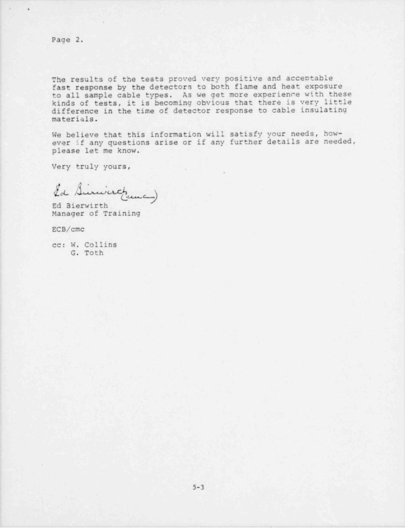
, .
|
I,
Page 2.:
!
The results of the tests proved very positive and acceptablefast response by the detectors to both flame and heat exposureto all sample cable types. As we get more experience with thesekinds of tests, it is becoming obvious that there is very littledifference in the time of detector response to cable insulatingmaterials.
' We believe that this information will satisfy your needs, how-ever if any questions arise or if any further details are needed,please let me know.
Very truly yours, ,
.
--
Ed BierwirthManager of Training
ECB/ cmc
cc: W. CollinsG. Toth
!
i
l
i
j
e
5-3
,_. . _ _ _ ._. . _ _ _ . _ . _ . _,

- _ _ _ _
~ " ' ' '
* ~
jf/'Oi'O.*u)/<CS .,r:7s=:s 7 =..cr ,G% >x/v/ spa 2pO .
..
}-7 'M,676 /.9 './7 i.) b "wrs ?/11//., ivue, rn,o rwic.c ru=nr en.=. e sz<w -ray
DGMC7~~o 4. 72Cs7 / 77 GT~ L n.***S7~~ .9 7257 9'- ;2S7uw.
NO. R<Cn/# 7m \ n>w ?. Mic.o tbr am
.ss% |S3 oyh M6 2W/ F~3 % /9.s- V |Y7 o n/p 'I9s 2:SC c oc '- * 3 01 a ,
? 4% Mri,127,s
*:7,,
5 '- OMA ep4 ans Gc.of.3h" e44 2-f f. V 30 o% 8h ?'M 2.n{> W& |VL n/o 'i04 /.*fi . yn 'I p/. . ,
/9 p_ _3
.
.
'b | "
C L oc/ ."/ oits; epig os/r ~' t gm$ (5~8. Vx,w? ?yy |55 0% ? Ors 3:60 s.p ec, ?Ad I.'n!) ap 6'}.):i 2.?4) rq M /4 !.
!
/o i
ecocnyey I on> s;.w ci/p essi,9'lts M7 vs MO7 f M a w.::.u n . v *37 on oni 2:% nW& :le op
8 -
i
? .
/QI
! ( .
/2 ,.
'
/7
1/%_
hec wn 5szaw r:eeirz cur. /rsk/yrsw.r-
92/GL $ /IM7~ < ric . 4.''C. ray nA.f,"Ghn1 Mc. S "n-P.v:t 3rr,& -/r,./
\
$ 2 6 % /.: ro x x a.oc.s / r-to ,o | SEs 26 / |~ ~~~-
I
| '
NIRX. % 085 i
f2*MP. W Hc)Ma '7,"2 E $ 2 "/o ~~~ ~-
!' I,ip"'/d 4 -t' or G
,
.2 W 7 3 c r a e t.c r /r r / w J C & n 4./ - - -
A/9 M E ppy/y/;rE 72, ,,w - ?. 7/k .* *;~C*
sVO7 q3 : /?& coa /o4. p,3,, c,9vf_,, . ..
.39rn 3.c.>r/r-. . . . . .
. .. .. . .. . . . . . . .
-
&..
A 5-4D*Fi o
A e mm .
--.~ _. . . - _ _ .
--

.
M c)i K o,v'V S f M E. 7 '.-Gr~S7)w w ?M f' o
@ 0 oW3
' --
: w ? 7h=r '7/2/ A/m/ Ann pc.v&n trnitr cAkcf % -+Naf7'2_-_.
,
ZW* ~~dc. 7'~o.,e., 7r vr- / 7?:5rRE 7 Gs7".2 : 72sr ,'A4 72'3,
an |
?N. M.ic iNo. -1tsscninrm | nw_
<:<.ec.n n eu, ce n two
_/ f3/fn /R.f V 2:IO 3.% 90/>, los on % ,*fo :.<oy,<for,, :n ;?C, 77ty
''2ak' #2. 1 * w
77th :T3 .a'a<28 r, I;!n "M'4 em'' "'
c wsh /9 *ts.v \ 2:72 3 M', car,, /:50 os3 p ..
I
Y C'ti''jjC G o c.s ;f,Et cy.itf OMN M,d
e n,'r|IW 27m 8%6' p 5- 5 . >zm m g 7.v 2:.G' 3.C, t'G 2:2c' mb % I:sf ? %n
to*
Cc o C A- # <r' WI'' G'l'* 5 '''' S '''
7 s.s-e w rn n.v' 2*x 3.Wo % %0 o% 'A f?- ;'@ % W) 2??> 8%|
~8 i ._l I
? l I.
-
;
/OL I
i I// .
1
/2,
|*
/3/Y h
A, <. ,,,g. g,,,a.,s,1,s,i.ewa eaemc ,epie, |
-
h ws r v-c w a x6srouem: s~~-:92)er G' A%y7- 2m . c,%ns vn.es cc.-js
_,n . ,.,,, a |
pos /.,./o ,,- |f'/26 hwsr, r,x e 1 ss<= ris. t ,
|tonx. % cas. |-
':
- - - |7'e~A 7 p. 1 H u m . ??.* f S.2?b'
i2
$$$ Y/ A'ic_W |
3872ic7Dt'fxtir ed ( iI
t
fior i:><,,-e ,curas r o w x >rs.cz irorpi ,rs=-
o:i m o-osvo' rd 3 : gzcopoz.7c57%* -iosra d cs pc (Bosrevo"7 ) Q-i>m e</rd- (<,t$c Novc.ropg
.,
s
7s g7 ,eg, , snare As 76* S7 '*'C'*
..
, _ ____
7'!57-afZ -- M/CS??.</&/fo US C 64 A 3 C CAJDuc 7'oic -r-ff z o/J(r ycp>c zy .g.e
VAA/JS fad'/|?d'A 0(/G2. LO,AD 2. 5 '}bC7'S - (o O/4ifP3,*
A"8 Y 7"2)~ Lot.)JncJ-E7' 2 2 CouDuc7'W' (* P &.5 'z-1)/ A' ' '/FC. 6 '2 0 ''''SCwins Th:-p i ,y*,;,,- /,,,,. .- (",. ,,,. ,.,, ,,y ,.,, ,,,,,.,,,,,,,,,) .
--

|AC)I"|0C/f Y ~|d/.X-i ~~/ "$7~ bDM/V/" //Mf *
'G -
,12/C 7~ 6 7)h./ /"Y. ' f 'S |_'~d. MJ.O_ . _ _ _ _ . _ _ .
NY~d6 "T~Ok M9 ~~~~ V M " G7~~ 2- YS~V8 | DSY Y I ID~}|\ un
%. M.ic. INo. -Dc5cg/p r-m ; n~C
/ f.5/.6~ A /8 $ V 'V$ 'o//p YhpC 4 oc. L~ # .3
'
> 9/n.
?sC L OC CM k OA(H
b / }b~/? /0 t/ Y 0*b lob#
f!
l* l'/GGOt.K #/ 12t/p \*
$ / S~-/ % // s or D */ |'M QRio hbh | ,
,
I |,.
D
CCO(^=#f' I e// /*7 rs-n w m' | 'Vs no 7%
'8 -
i
7
/Q_
l
_/ /'
/s - .-
\'
/3,
,
'f6 f404) J HCKC7p*/)5$ k/V)[ k b'A.CACT
,00.9 / 7~~/o /) | \
k/b5 b/$7*ns)CG | *MS / )1
'
mnx. % oss. \.
feivip. E' sua. 7? f *o n \.
l ! |5'/24 W/ k7/E' ]
.'D&Ks&Yoe bxsir?w/ {'
/E/?Ni e/67 *
sVC7"C 3.* N'^~
. ..
N d f I '2 0 0 A / 0 ' C lE' A $ # f~ % O O Oa V 6 ~ d 5 ",'f W 9 f6/*20<.) J/?C Jao
0A8E6~d3/4' VfC G"l'9U4 .//>'Co/J7A.uGA? .if& Cost'a f-.. .
8sfn (mp>rinfurce uix2cwo): ..
m .,g. - ) < v y3
-
e j' 1 S 5-6 :=

.-. . ,- , , . . - . .
..a / ; m ,,r .' ., o _.,..,,io . , ,/ p /.*,fe J.' ) y*- , s , . , . ,:.-, . * * ~ ~j'sf /g.:.yis / s /- . * . ' . //>*/ /L ."/ 4 ' ? N :' *~".-| f', '
*
> * A v | ? $ ( *n M ?.*.2 m a><!. g'. ..:}.~.fd. .:.C'_. .,)p) (,,', .-)_ . . _ .' {||. * /. ( ,............'s'c.a.>'y # r'
'sn*
:.. ,-
./ ,*'E / < '.~. '".,2*
._ .. . . . . . . . . . _ _--
._ .. .; ... , . . . . _ . . ... -- . ._
. ., .. - , _
a , s [. . * -. . . . . .. . . , . . . . , . , ...*"'s ' ~~. . , . . . . , '* **
* *. Q s~~t'~~( ?" Q /J, ; c'- . '/ s / t. . * * * * i*.~o'
*.
'
..'$._$1/..!~~ \, .l|E'.I .'.E, ,?'.?? b.'.i..*I'.l.i I a' .,,.
"?!'a''' ~~/. . .m .I~' Id E..' /.' #I: 'IIil' l~ '~~
. ' . . .~ ~ ~ ~' *~
/Oe ? *~'.~r'M / 2.''./ './ / .< _ilI'.1 f. . . ~ . . . . ...... . s. .. ..
t Wr* rr.,,a . . .
i ,w: n:.:/, .s :''c 2.rrn 3:'u .a.m I i:n . a A l .
| |! i - r=g,
$ l | f3
\ s fi.,i: ; .s ,s :..,.
:.n 2. % . xu 1.% : s't ' s.w '
| |1 eig It '
'
,
|.
!A *
* e *t* .
.-
b( ).' / * .'/ _3 y |,*,*/ /) .$ *.Y * s $ .) ' Ar.Y) *'
/ ,+
| | | | 1 - i'
|*
| |' '
6.. j
. ....
'
% . . ... . ' .! !,.-
,
|=E . !!$|C}!' '
'N . . h $ b'$ " . .L' ']; / ,*l, .. / . .. .
I r | | t I _.{.b - . . .
,
i . , g- !'
. .
} )> j.
|-
,
,Aj / ' -|
-
I,
! | \E3A 3 % }}- 1
'/.
'
'd Y 1 .'.') 7 .,!. , ,r < >-
,
i 6| .
ji i *
*'
, /- e s- e
|* * *| } ,i,* / 3 * A f oJ ;"*2 * ~ . * , ' A ' '' *
. , .
. . 6 g
I a i'' .e
7*
|
. - - . ... ! t
a.. __.
..
| I! 1
- | . . . . ,'.
,
!.
i -./.~
.. . -_ . . . . - . . . . - _ . . - _ ....t.,..
/. .:r' G . s;y c, /.1'' t a sr)f., 3 f*:o 3 r M o.*e *Joh { _.i
.
J"C/e:- ._[ I;, /W''f. '.l. : . . . . , .c') >~(v> /72. [rr . :.t '. / o ~ :- .t~/. /.. - .P.."'**' * ' _' ... - II
- -... - -. .. ..- , . . _ .
' *
226*f.d.s/ .r-*/O r/ & <.; .. .:::',g':> c
- |-
- -
. . s_.r/._c..a.. . --.-. ..
1 I7 ;,. -
/w, - |min:.-%- o a :.:.. .. . _ . ..|...._.......g_-...__
,
7~9: ,c. .s' /./w.-~_. p .a 9'mo - |-- | I
_
.
.
.- . _'7_ _
'a '*-;*.*~--. . . . . _ . .. . .. . . _ . . _ . . _ _ _ _ ._.{ /.~/ / *~
..
(Wit 5.''s^~Q/, ' N!">'.~ /) Af.W ] ._' C/i'_ .* . ) : 3 t't _ . /,:. [ . ,; _ .-. .. t.__ ._ . . _
'
. . '.j :,
. . . . . . . . . .
res r et .wou: i i<><, c.mrp'ra>r v> '750 / tor p.wn.- ,
s '; ",7~rf.k. - /2N:? #/J.$ ~ [];C. /,.;.''t .s oua .$ pp p pj of *,",r /;. ntonff)/ / t M*, f. ",=, g=;*p f f :, .o to .o r. J'. 9* ,* V ,** /'
O'
.ir; ''sFGo~b'E/'?.\3"fC'O'''' " '
jy $7'!3 - 72 /;,.-;
J W AJ . hi
..5-7
.
-% .g.,--- - , -- w _ . - - . + - - - _ . - a - 9

. . . . . . . .
_
.- .s
G-
s)Q-- - k:1-i - ,,
'3=< l f} 7- , ij <
C'l s}j.( l
i
i..
sq g~s.s
't ({.
'L' 9 u R tLi L- @ (g'f' - y , --- 4
,
--- 7 Sn- --
,g',(,,,, - c- >- n--n
2.O c-,
-
.
1.)11
-N .
.b'.
\\ 'h T b)' t |i
i--
.
\9N, fs
-
?,d4)N\~.
b '-
.p s> . - a.
' uy ,-h. (y,: s.
.
---%. ~q
'd"hi'tc/-
1
k/ u'u o "
V'}iRN( 'ed~k'e ' N i! h.
l i s/ '- K o ,g f}{..'
. '
! _'-
h,. O g4p ? ) Q, q -
M .\~~~ j'NN sf s. .n3 j. i.ch ~~ : s 'W ,
U,0N '" M, . , s e''\;s >|.- ,> k'
-.
i.
r-}N ' ''''.-. q .x . q ''
j[>p~ "' "
j yt('
; O ,
; y~
(D !: .
!, y)Ii,;i--
...
4 c.i1 :1
| .-( . . - -j ..g | t
! ....
___
o. _ _'.s .-,
.
s - - -.
. - -
! '
'| | b, . . . , !-
- c2,
/ //. (**'''-' '
-
ij .
i
j . . .
-
t _.
Tb6ci a p_ |_d, .h"i
!,
3-8,
- . . - - - - , .- - ~ - -- ., -

|*os 9
.
} W &
sVU'.L tCAA SN?WC/J !?/~Pd.S* RFd n: :~~$ 7,s'A}
//0. ./QS72*C7'OK 6 6A /S / f/ W/s#Y~~
'
f3/SA /8.5*V/
3 F3/.s A /? Y
f Ff-e /,4 rim 37 v
7 /*f' - 8 SMM / '7 V
Cnes s 7%osW77??- /.Cy,M. E'5'n'. (4MY -/bp//Yn,;t?n'C/ Bez W
2.M rim!-7y/t- / '''%;e. N D w
3 Bosros)-qsAs -i=ow ;o,cL> #7 5S D/n./3c.ac<
Y wcsn,06Houss Egn .3cox>D. f6Kcad Cwd.fG WS. M/Zodd Ack-67~ A2 codouc7sx? ycfzoa wsdurcc
C A8&G d 'D/4. mnua meroecre u.<>-sowJ
.
'
| mi
<