Medium-Voltage Switchgear - Digital Asset Management
185
Medium-Voltage Switchgear Type 8DJH Up to 24 kV, Gas-Insulated Medium-Voltage Switchgear INSTALLATION AND OPERATING INSTRUCTIONS Order No.: 500-8384.9 Revision: 10 Issue: 02-08-2017
-
Upload
khangminh22 -
Category
Documents
-
view
3 -
download
0
Transcript of Medium-Voltage Switchgear - Digital Asset Management

Medium-Voltage SwitchgearType 8DJHUp to 24 kV, Gas-Insulated
Medium-Voltage Switchgear
INSTALLATION AND OPERATING INSTRUCTIONS
Order No.: 500-8384.9 Revision: 10Issue: 02-08-2017

2/185 Revision 10 • INSTALLATION AND OPERATING INSTRUCTIONS • 8DJH • 500-8384.9
About these InstructionsThese instructions do not purport to cover all details or variations in equipment, nor to provide for every possible contingency to be met in connection with installation or operation. For details about technical design and equipment like e.g. technical data, secondary equipment, circuit diagrams, please refer to the order documents. The switchgear is subject to continuous technical development within the scope of technical progress. If not stated otherwise on the individual pages of these instructions, we reserve the right to modify the specified values and drawings. All dimensions are given in mm. Should further
information be desired or should particular problems arise which are not covered sufficiently by these instructions, the matter should be referred to the competent Siemens department. The contents of this instruction manual shall not become part of or modify any prior or existing agreement, commitment or relationship. The Sales Contract contains the entire obligations of Siemens. The warranty contained in the contract between the parties is the sole warranty of Siemens. Any statements contained herein do not create new warranties or modify the existing warranty.

500-8384.9 • INSTALLATION AND OPERATING INSTRUCTIONS • 8DJH • Revision 10 3/185
ContentsSafety instructions ............................................. 61 Signal terms and definitions ............................... 62 General instructions ........................................... 73 IT security .......................................................... 94 Due application .................................................. 95 Qualified personnel ............................................ 9Description ....................................................... 106 Panel versions .................................................. 107 Components .................................................... 127.1 Three-position switch-disconnector .................. 127.2 Vacuum circuit-breaker type 2 .......................... 137.3 Vacuum circuit-breaker type 1.1 ....................... 147.4 Interlocks ......................................................... 147.5 HV HRC fuse assembly ...................................... 157.6 Cable connection ............................................. 177.7 Current and voltage transformers ..................... 227.8 Possibilities for pressure relief........................... 237.9 Protection and control equipment .................... 247.10 Voltage detecting systems................................ 247.11 Ready-for-service indicator ............................... 247.12 Short-circuit/earth-fault indicator...................... 257.13 Accessories ...................................................... 267.14 Low-voltage compartment (option) .................. 268 Technical data.................................................. 278.1 General technical data...................................... 278.2 Three-position switch-disconnector .................. 288.3 Three-position disconnector ............................. 298.4 Vacuum circuit-breaker..................................... 308.5 Classification of the switchgear ........................ 338.6 Standards and guidelines.................................. 348.7 Dimensions and weights .................................. 358.8 Phase sequence................................................ 378.9 Insulating gas................................................... 378.10 Dielectric strength and site altitude................... 378.11 Selection of HV HRC fuse-links .......................... 398.12 Rating plates .................................................... 469 Switchgear maintenance .................................. 4710 End of life ........................................................ 47Installation ....................................................... 4811 Transport and storage ...................................... 4811.1 Unloading and transport to place
of installation ................................................... 48
11.2 Packing ............................................................ 5011.3 Completeness and transport damage................ 5111.4 Intermediate storage ........................................ 5112 Switchgear installation ..................................... 5312.1 Tools / Auxiliary means ..................................... 5312.2 Cleaning agents and cleaning aids .................... 5312.3 Mounting paste................................................ 5312.4 Tightening torques........................................... 5312.5 Comments on electromagnetic compatibility .... 5412.6 Preparing the switchgear room......................... 5512.7 Preparing the foundation ................................. 5612.8 Unpacking the switchgear ................................ 5712.9 Checking service readiness ............................... 5812.10 Installing the pressure relief duct for
pressure absorber system (IAC up to 16 kA) ...... 5912.11 Installing the base and the pressure relief
duct for the pressure absorber system (IAC up to 21 kA).............................................. 60
12.12 Installing the pressure absorber top unit (IAC up to 21 kA).............................................. 65
12.13 Fastening the panel to the foundation .............. 7012.14 Floor openings and fixing points....................... 7212.15 Joining the panels ............................................ 7712.16 Installing the busbar termination...................... 8512.17 Earthing the switchgear ................................... 8912.18 Interconnecting the earthing busbars ............... 9012.19 Installing the low-voltage compartment ........... 9113 Installation of billing metering panel type M ..... 9213.1 Overview: Possibilities of connection for
current and voltage transformers in the billing metering panel type M ........................... 92
13.2 Routing of currents and bars in the metering panel................................................. 92
13.3 Installing instrument transformers in the metering panel................................................. 93
13.4 Mounting earthing accessories in the metering panel type M ................................... 103
13.5 Installing the protection against small animals in metering panels............................. 106
13.6 Interconnecting metering panels with other panels ............................................................ 106
14 Electrical connections..................................... 10714.1 Connecting high-voltage cables...................... 10714.2 Installing cable plugs type
Raychem RICS5xxx with RDA........................... 110

4/185 Revision 10 • INSTALLATION AND OPERATING INSTRUCTIONS • 8DJH • 500-8384.9
14.3 Cable installation in switchgear with
pressure absorber (IAC up to 16 kA and 21 kA) ........................................................... 112
14.4 Cable connection with cable-type current transformers.................................................. 114
14.5 Installing ring-core current sensors at the cable connection ........................................... 117
14.6 Installing voltage sensors ............................... 11814.7 Connecting voltage transformers 4MT8
at the cable feeder ......................................... 11914.8 Installing/removing busbar voltage
transformers.................................................. 12414.9 Connecting the secondary equipment ............ 13014.10 Correcting circuit diagrams ............................ 13115 Recurring activities......................................... 13215.1 Removing and mounting the cable
compartment cover ....................................... 13215.2 Removing and mounting the cross member ... 13316 Commissioning.............................................. 13516.1 Final tests after installation ............................ 13516.2 Mechanical and electrical function test........... 13616.3 Preparing the power-frequency voltage test ... 13716.4 Instructing the operating personnel ............... 13716.5 Applying operating voltage ............................ 138Operation........................................................ 14017 Indicators and control elements ..................... 14117.1 Position indicators.......................................... 14217.2 Operations counter ........................................ 14217.3 "Spring charged" indicator.............................. 14217.4 Ready-for-service indicator ............................. 14317.5 Operating tools.............................................. 14317.6 Mechanical interlocking with padlock............. 14417.7 Local-remote switch (option) ......................... 14517.8 Momentary-contact rotary control switch
for motor operating mechanism (option) ....... 14517.9 Key-operated interlock (option)...................... 14518 Operating the panel with
switch-disconnector....................................... 14618.1 Switching the three-position
switch-disconnector from OPEN to CLOSED position ............................................ 146
18.2 Switching the three-position switch-disconnector from CLOSED to OPEN position................................................ 147
18.3 Switching the three-position switch-disconnector from OPEN to EARTHED position .......................................... 148
18.4 Switching the three-position switch-disconnector from EARTHED to OPEN position................................................ 149
19 Operating the panel with switch-fuse combination .................................................. 150
19.1 Switching the three-position
switch-disconnector from OPEN to CLOSED position ......................................................... 150
19.2 Switching the three-position switch-disconnector from CLOSED to OPEN position................................................ 152
19.3 Switching the three-position switch-disconnector from OPEN to EARTHED position .......................................... 152
19.4 Switching the three-position switch-disconnector from EARTHED to OPEN position ......................................................... 153
19.5 Protection tripping of the switch-fuse combination .................................................. 154
20 Operating the panel with circuit-breaker type 2............................................................ 155
20.1 Charging the spring energy store in circuit-breaker type 2 manually ...................... 156
20.2 Closing circuit-breaker type 2 ......................... 15720.3 Opening circuit-breaker type 2 ....................... 15720.4 Switching the three-position disconnector
from OPEN to CLOSED position....................... 15820.5 Switching the three-position disconnector
from CLOSED to OPEN position....................... 15820.6 Switching the three-position disconnector
from OPEN to EARTHED position..................... 15920.7 Switching the three-position disconnector
from EARTHED to OPEN position..................... 16021 Operating the panel with circuit-breaker
type 1.1......................................................... 16121.1 Charging the spring energy store in
circuit-breaker type 1.1 manually ................... 16221.2 Closing circuit-breaker type 1.1 ...................... 16321.3 Opening circuit-breaker type 1.1 .................... 16321.4 Switching the three-position disconnector
from OPEN to CLOSED position....................... 16421.5 Switching the three-position disconnector
from CLOSED to OPEN position....................... 16521.6 Switching the three-position disconnector
from OPEN to EARTHED position..................... 16621.7 Switching the three-position disconnector
from EARTHED to OPEN position..................... 16722 Verification of safe isolation from supply ........ 16822.1 HR or LRM plug-in sockets .............................. 16822.2 VOIS and CAPDIS indications .......................... 170

500-8384.9 • INSTALLATION AND OPERATING INSTRUCTIONS • 8DJH • Revision 10 5/185
22.3 WEGA indications ........................................... 17223 Replacing HV HRC fuse-links ........................... 17324 Cable testing .................................................. 17624.1 Cable testing via cable plugs........................... 17624.2 Cable sheath test............................................ 177Annex ............................................................. 17825 MCU (Motor Control Unit) .............................. 178
25.1 Extract from the Technical Description............ 17825.2 Application..................................................... 17825.3 Design, function............................................. 17825.4 Fault signals ................................................... 17925.5 Behavior in case of voltage failure .................. 180Siemens Service Hotline .................................181Index...............................................................182
Safety instructions
6/185 Revision 10 • INSTALLATION AND OPERATING INSTRUCTIONS • 8DJH • 500-8384.9
Safety instructions1 Signal terms and definitions
Symbols used ➭ Operation symbol: Identifies an operation. Asks the operator to perform an operation.✔ Result symbol: Identifies the result of an operation.
DANGERas used in these instructions, this means that personal injuries can occur if the relevant precautionary measures are not taken.➭ Observe the safety instructions.
ATTENTIONas used in these instructions, this means that damage to property or environment can occur if the relevant precautionary measures are not taken.➭ Observe the safety instructions.
NOTEas used in these instructions, this points at facilitations of work, particularities for operation or possible maloperation.➭ Observe the notes.
500-8384.9 • INSTALLATION AND OPERATING INSTRUCTIONS • 8DJH • Revision 10 7/185
Safety instructions 2 General instructions
Important • The personnel must read and understand this manual before starting to work.• Observe all safety instructions and warnings in this manual, and follow the instructions.• Store this manual carefully, and so that it is accessible to the personnel at any time.• This manual is a part of the product. When the switchgear is transferred, supply this manual
as well.
The switchgear corresponds to the relevant laws, prescriptions and standards applicable at the time of delivery. If correctly used, it provides a high degree of safety by means of logical mechanical interlocks and shockproof metal enclosure of live parts.Independently of the safety instructions given in these operating instructions, the local laws, ordinances, guidelines and standards for operation of electrical equipment as well as for labor, health and environmental protection apply.The switchgear operator or owner must keep the technical documents supplied with the switchgear throughout the entire service life, and keep them up-to-date in case of modifications of the switchgear.
Five Safety Rules ofElectrical Engineering
The Five Safety Rules of Electrical Engineering must be complied with during operation of the products and components described in these operating instructions:• Isolate.• Secure against reclosing.• Verify safe isolation from supply.• Earth and short-circuit.• Cover or barrier adjacent live parts.
DANGERThe perfect and safe operation of this switchgear is conditional on:➭ Observance of operating and installation instructions. ➭ Qualified personnel.➭ Proper transportation and correct storage of the switchgear.➭ Correct installation and commissioning. ➭ Diligent operation and maintenance.➭ Observance of the instructions applicable at site for installation, operation and safety (e.g.
DIN VDE 0101/0105). (e.g. DIN VDE 0101/0105).
DANGERAny kind of modification on the product or alteration of the product must be coordinated with the manufacturer in advance. Non-coordinated modifications or alterations can cause the expiration of warranty claims, and cause danger to life, limb and other legally protected interests. The fulfillment of the type tests (according to IEC 62271-200) may not be guaranteed anymore. This applies especially though not exclusively to the following actions, e.g in the course of maintenance or repairs:➭ Original Siemens spare parts were not used.➭ Service engineers performing replacement were not trained and certified by Siemens.➭ Parts were fitted or adjusted incorrectly.➭ Settings were not made in accordance with Siemens specifications.➭ After installation and setting, no final check was performed by a service engineer approved
by Siemens, including documentation of the test results.➭ Maintenance was not done according to the operating instructions of the Siemens
products.

Safety instructions
8/185 Revision 10 • INSTALLATION AND OPERATING INSTRUCTIONS • 8DJH • 500-8384.9
Hazardous substances If hazardous substances are required to perform the work, the relevant safety data sheets and
operating instructions must be observed.
Personal protectiveequipment (PPE)
For switchgear with proven internal arc classification according to IEC 62271 Part 200, no personal protective equipment must be worn for operating the switchgear.For switchgear without proof of internal arc classification according to IEC 62271 Part 200, personal protective equipment must be worn for operating the switchgear.If covers have to be removed to work on switchgear, personal protective equipment must be worn for protection against hot gases exhausting in case of internal arc. In case of internal arc, full personal protection is not provided, even if the personal protective equipment is worn.To select the protective equipment, the local laws and regulations must be observed and accomplished.The protective equipment consists of:• Protective clothing• Safety shoes• Gloves• Helmet and face protection• Ear protection
Removing the front plate from the operating mechanism compartment
DANGERRisk of injury by release of charged operating springs when the front cover of the operating mechanism is removed! Bruises or cuts at the hands can be the consequence.➭ To avoid impermissible switching operations, switch off auxiliary voltage, e.g.:
- Switch the auxiliary voltage supply of the motor.- Trip the MCB.- Disconnect the control cables from the low-voltage compartment.
➭ To discharge the spring energy store in the operating mechanism, perform the following operations before removing the front cover:- Actuate the OFF pushbutton.- Actuate the ON pushbutton.- Actuate the OFF pushbutton.
➭ The spring energy store indicator must show "spring not charged".
Fig. 1: "Spring not charged" indication Fig. 2: "Spring charged" indication

500-8384.9 • INSTALLATION AND OPERATING INSTRUCTIONS • 8DJH • Revision 10 9/185
Safety instructions 3 IT securityThe Siemens software is regularly checked for safety. If weak points are identified in the process, which may allow third parties to access protection devices, information thereto is distributed through the SIPROTEC and SICAM Security Update Report Newsletter. The Newsletter can be subscribed to at the following website:www.siemens.com/gridsecurityBefore commissioning the switchgear, it must be verified that the current firmware version is installed on the protection devices. The latest version of firmware can be obtained from the following website:http://w3.siemens.com/smartgrid/global/en/products-systems-solutions/downloads/Pages/Overview.aspxFor information to updates for other makes of protection devices, please contact the respective manufacturer.
4 Due applicationThe factory-assembled, type-tested and metal-enclosed 8DJH switchgear for indoor installation is used for power distribution in secondary distribution systems, e.g. in transformer substations, transfer substations or industrial distribution systems.The switchgear is designed for application under normal ambient conditions according to IEC 62271-1. The switchgear can also be used under special ambient conditions as defined individually between the operator and the manufacturer of the switchgear.SF6 is used as insulating gas in the switchgear vessel.
5 Qualified personnelQualified personnel in accordance with these instructions are persons who are familiar with transport, installation, commissioning, maintenance and operation of the product and have appropriate qualifications for their work, as e.g.:• Training and instruction or authorization to switch on, switch off, earth and identify power
circuits and equipment / systems as per the relevant safety standards.• Instruction regarding the applicable specifications for the prevention of accidents and the
care and use of appropriate safety equipment.• Training in first aid and behavior in the event of possible accidents.

Description
10/185 Revision 10 • INSTALLATION AND OPERATING INSTRUCTIONS • 8DJH • 500-8384.9
Description6 Panel versions
Individual panels Individual panels allow a free selection when arranging the functions within one switchgear row. In limited space conditions, individual panels can simplify switchgear installation on site.
Panel blocks Panel blocks can be operated with up to 4 functions in one common switchgear vessel. Combinations of transformer feeder and circuit-breaker feeder are possible via panel extensions.
Panel type (function) Panel width [mm]
Standard OptionR Ring-main panel 310 500 –K Cable panel 310 430 –K(E) Cable panel with make-proof earthing switch 430 -- --T Transformer panel 430 – –L Circuit-breaker panel 430 500 –S Bus sectionalizer panel with three-position
switch-disconnector430 500 620
H Bus sectionalizer panel with switch-fuse combination
430 –
V Bus sectionalizer panel with circuit-breaker 500 – –E Busbar earthing panel 310 500M Billing metering panel 840 – –M(430) Busbar voltage metering panel with primary
fuse protection M(430)430 – –
M(500) Busbar voltage metering panel with disconnector M(500)
500 – –
Block of 2 panels Block of 3 panels Block of 4 panels
Panel types
Block width Panel types
Block width Panel types
Block width Panel types
Block width
RR 620 mm RRR 930 mm RRRR 1240 mm LLRR 1480 mmRK 620 mm RRT 1050 mm RRRS 1350 mm RRLL 1480 mmKR 620 mm RTR 1050 mm RRRH 1350 mm RTRT 1480 mmRT 740 mm RRL 1050 mm RRRT 1360 mm TRTR 1480 mmRL 740 mm RLR 1050 mm RRRL 1360 mm RLRL 1480 mmKT 740 mm RRS 1050 mm RRTR 1360 mm LRLR 1480 mmKL 740 mm RRH 1050 mm RTRR 1360 mm TTTR 1600 mmTK 740 mm TRR 1050 mm TRRR 1360 mm TTRT 1600 mmTR 740 mm LRR 1050 mm RRLR 1360 mm TRTT 1600 mmRS 740 mm RTT 1170 mm RLRR 1360 mm RTTT 1600 mmRH 740 mm TRT 1170 mm LRRR 1360 mm LLLR 1600 mmLK 740 mm TTR 1170 mm TRRT 1480 mm LLRL 1600 mmLR 740 mm RLL 1170 mm LRRL 1480 mm LRLL 1600 mmK(E)T 860 mm LRL 1170 mm RTTR 1480 mm RLLL 1600 mmK(E)L 860 mm LLR 1170 mm TTRR 1480 mm TTTT 1720 mmTT 860 mm LLL 1290 mm RRTT 1480 mm LLLL 1720 mmLL 860 mm TTT 1290 mm RLLR 1480 mm
500-8384.9 • INSTALLATION AND OPERATING INSTRUCTIONS • 8DJH • Revision 10 11/185
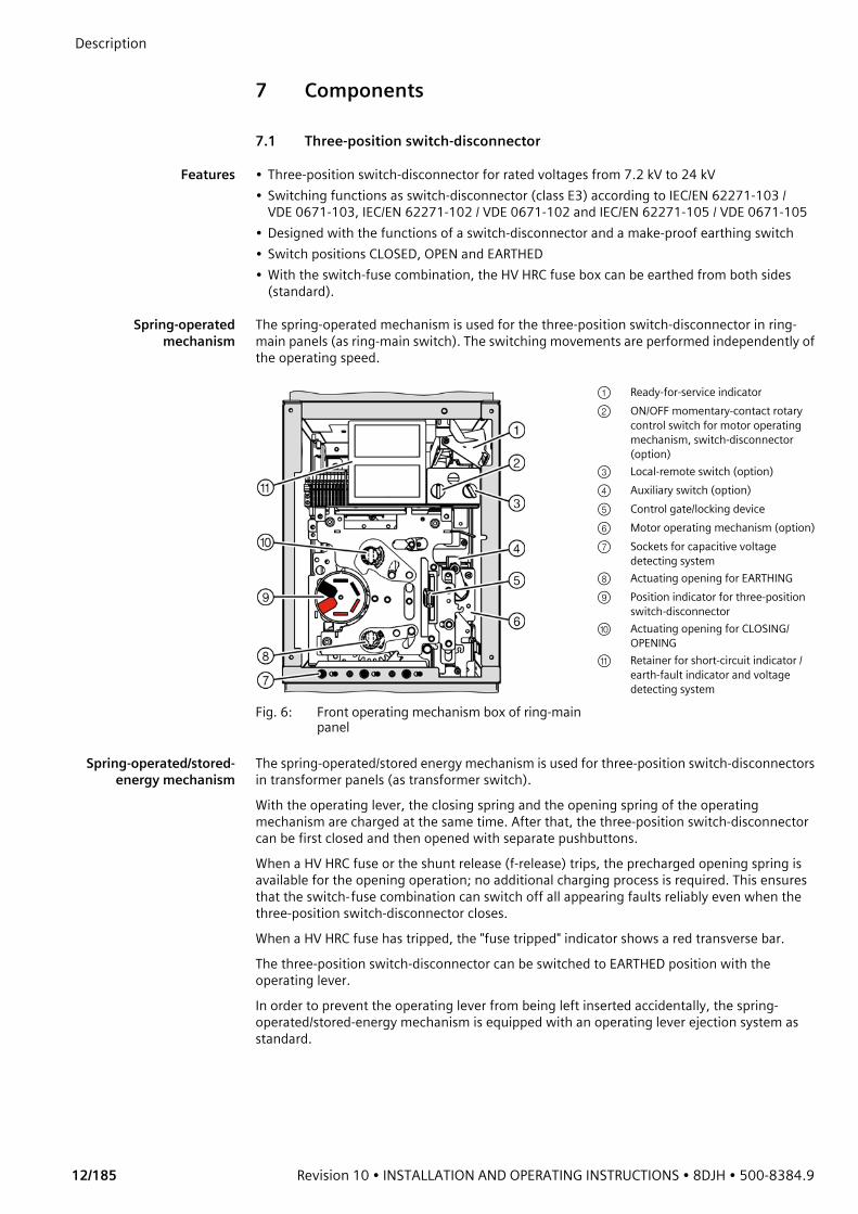
Description Examples for panels
Fig. 3: Ring-main panel type R Fig. 4: Transformer panel type T
Type 1.1 Type 2
Fig. 5: Circuit-breaker panel type L
① Control board ⑧ Bushing for cable plug② Busbar ⑨ Cable compartment cover③ Three-position switch-disconnector ⑩ Earthing busbar④ Pressure relief device ⑪ Partition⑤ Wiring duct (removable) ⑫ HV HRC fuse assembly⑥ Switchgear vessel ⑬ Vacuum circuit-breaker⑦ Operating mechanism of switching
device
Description
12/185 Revision 10 • INSTALLATION AND OPERATING INSTRUCTIONS • 8DJH • 500-8384.9
7 Components
7.1 Three-position switch-disconnector
Features • Three-position switch-disconnector for rated voltages from 7.2 kV to 24 kV• Switching functions as switch-disconnector (class E3) according to IEC/EN 62271-103 /
VDE 0671-103, IEC/EN 62271-102 / VDE 0671-102 and IEC/EN 62271-105 / VDE 0671-105• Designed with the functions of a switch-disconnector and a make-proof earthing switch• Switch positions CLOSED, OPEN and EARTHED• With the switch-fuse combination, the HV HRC fuse box can be earthed from both sides
(standard).
Spring-operatedmechanism
The spring-operated mechanism is used for the three-position switch-disconnector in ring-main panels (as ring-main switch). The switching movements are performed independently of the operating speed.
Spring-operated/stored-energy mechanism
The spring-operated/stored energy mechanism is used for three-position switch-disconnectors in transformer panels (as transformer switch). With the operating lever, the closing spring and the opening spring of the operating mechanism are charged at the same time. After that, the three-position switch-disconnector can be first closed and then opened with separate pushbuttons.When a HV HRC fuse or the shunt release (f-release) trips, the precharged opening spring is available for the opening operation; no additional charging process is required. This ensures that the switch-fuse combination can switch off all appearing faults reliably even when the three-position switch-disconnector closes. When a HV HRC fuse has tripped, the "fuse tripped" indicator shows a red transverse bar.The three-position switch-disconnector can be switched to EARTHED position with the operating lever.In order to prevent the operating lever from being left inserted accidentally, the spring-operated/stored-energy mechanism is equipped with an operating lever ejection system as standard.
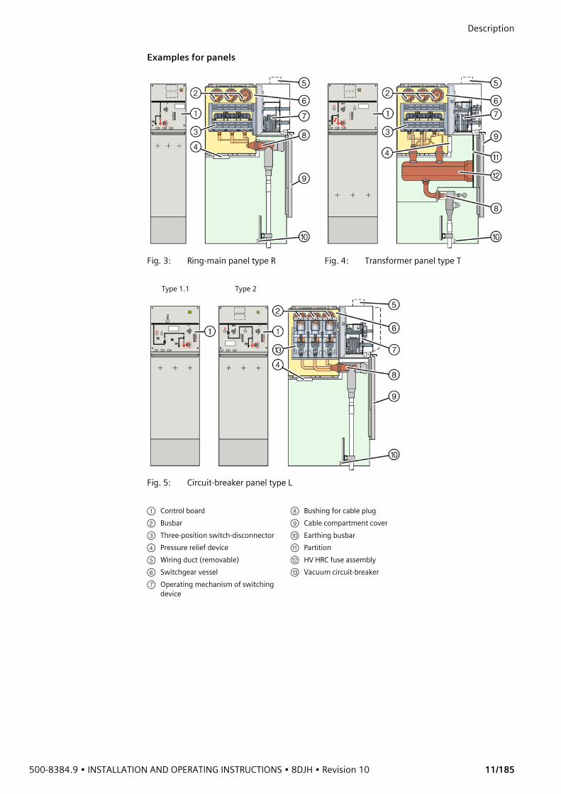
Fig. 6: Front operating mechanism box of ring-main panel
① Ready-for-service indicator② ON/OFF momentary-contact rotary
control switch for motor operating mechanism, switch-disconnector (option)
③ Local-remote switch (option)④ Auxiliary switch (option)⑤ Control gate/locking device⑥ Motor operating mechanism (option)⑦ Sockets for capacitive voltage
detecting system⑧ Actuating opening for EARTHING⑨ Position indicator for three-position
switch-disconnector⑩ Actuating opening for CLOSING/
OPENING⑪ Retainer for short-circuit indicator /
earth-fault indicator and voltage detecting system
500-8384.9 • INSTALLATION AND OPERATING INSTRUCTIONS • 8DJH • Revision 10 13/185
Description
7.2 Vacuum circuit-breaker type 2
Features • Vacuum circuit-breaker for rated voltages from 7.2 kV to 24 kV• According to IEC/EN 62271-100 / VDE 0671-100• Climate-independent vacuum interrupter poles in the gas-filled switchgear vessel• Application in hermetically welded switchgear vessel in conformity with the system• Operating mechanism located outside the switchgear vessel in the front operating
mechanism box• Maintenance-free according to IEC/EN 62 271-1 / VDE 0671-1The vacuum circuit-breaker consists of a vacuum interrupter unit with integrated three-position disconnector located in the switchgear vessel, and the associated operating mechanisms. The vacuum circuit-breaker is a circuit-breaker without automatic reclosing.
Operating function The closing and opening spring is charged by means of the operating lever supplied, or by the motor (option), until the latching of the closing/opening spring is indicated ("spring charged" indication). Then, the vacuum circuit-breaker can be closed manually or electrically (option).
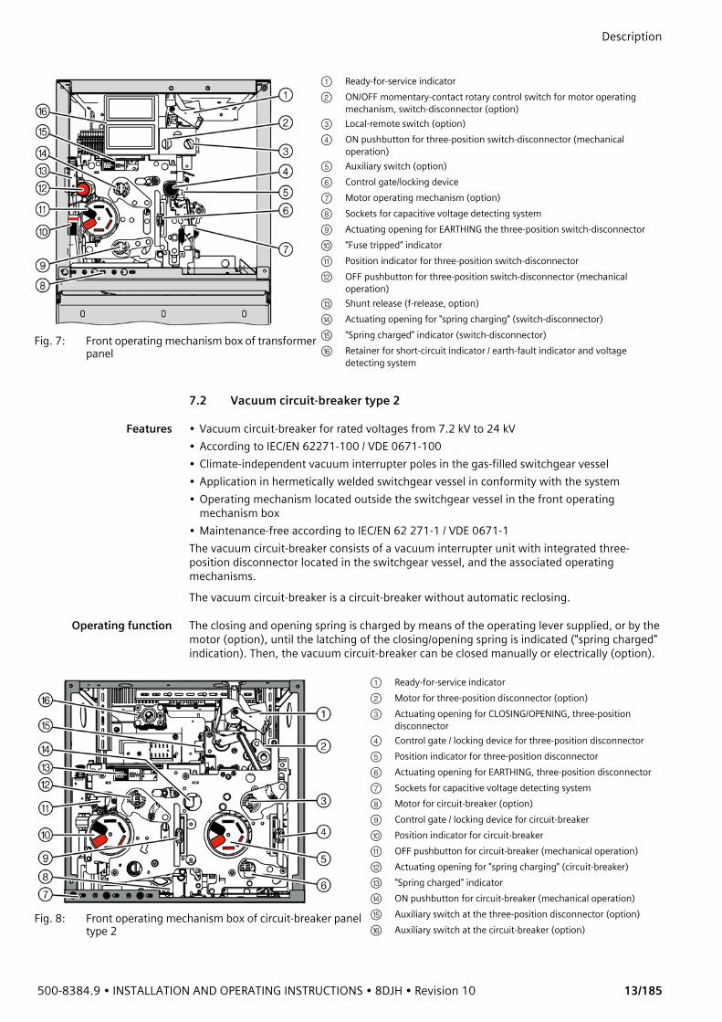
Fig. 7: Front operating mechanism box of transformer panel
① Ready-for-service indicator② ON/OFF momentary-contact rotary control switch for motor operating
mechanism, switch-disconnector (option)③ Local-remote switch (option)④ ON pushbutton for three-position switch-disconnector (mechanical
operation)⑤ Auxiliary switch (option)⑥ Control gate/locking device⑦ Motor operating mechanism (option)⑧ Sockets for capacitive voltage detecting system⑨ Actuating opening for EARTHING the three-position switch-disconnector⑩ "Fuse tripped" indicator⑪ Position indicator for three-position switch-disconnector⑫ OFF pushbutton for three-position switch-disconnector (mechanical
operation)⑬ Shunt release (f-release, option)⑭ Actuating opening for "spring charging" (switch-disconnector)⑮ "Spring charged" indicator (switch-disconnector)⑯ Retainer for short-circuit indicator / earth-fault indicator and voltage
detecting system
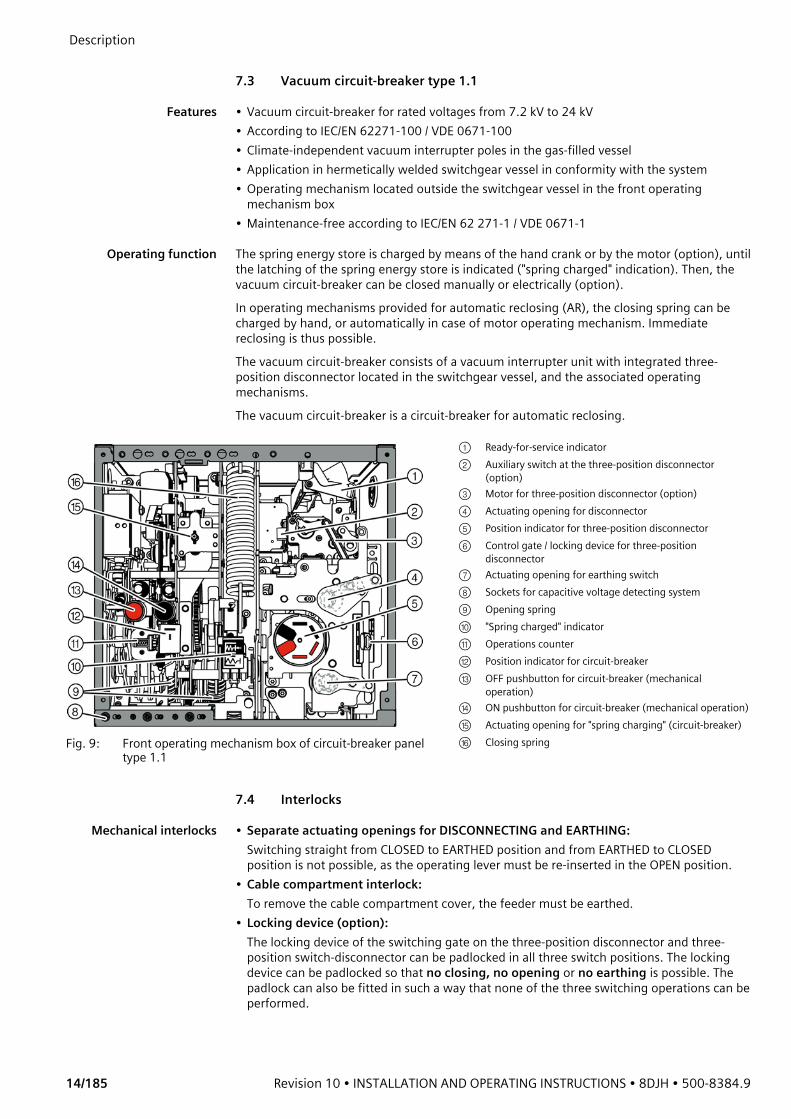
Fig. 8: Front operating mechanism box of circuit-breaker panel type 2
① Ready-for-service indicator② Motor for three-position disconnector (option)③ Actuating opening for CLOSING/OPENING, three-position
disconnector④ Control gate / locking device for three-position disconnector⑤ Position indicator for three-position disconnector⑥ Actuating opening for EARTHING, three-position disconnector⑦ Sockets for capacitive voltage detecting system⑧ Motor for circuit-breaker (option)⑨ Control gate / locking device for circuit-breaker⑩ Position indicator for circuit-breaker⑪ OFF pushbutton for circuit-breaker (mechanical operation)⑫ Actuating opening for "spring charging" (circuit-breaker)⑬ "Spring charged" indicator⑭ ON pushbutton for circuit-breaker (mechanical operation)⑮ Auxiliary switch at the three-position disconnector (option)⑯ Auxiliary switch at the circuit-breaker (option)
Description
14/185 Revision 10 • INSTALLATION AND OPERATING INSTRUCTIONS • 8DJH • 500-8384.9
7.3 Vacuum circuit-breaker type 1.1
Features • Vacuum circuit-breaker for rated voltages from 7.2 kV to 24 kV• According to IEC/EN 62271-100 / VDE 0671-100• Climate-independent vacuum interrupter poles in the gas-filled vessel• Application in hermetically welded switchgear vessel in conformity with the system• Operating mechanism located outside the switchgear vessel in the front operating
mechanism box• Maintenance-free according to IEC/EN 62 271-1 / VDE 0671-1
Operating function The spring energy store is charged by means of the hand crank or by the motor (option), until the latching of the spring energy store is indicated ("spring charged" indication). Then, the vacuum circuit-breaker can be closed manually or electrically (option).In operating mechanisms provided for automatic reclosing (AR), the closing spring can be charged by hand, or automatically in case of motor operating mechanism. Immediate reclosing is thus possible.The vacuum circuit-breaker consists of a vacuum interrupter unit with integrated three-position disconnector located in the switchgear vessel, and the associated operating mechanisms.The vacuum circuit-breaker is a circuit-breaker for automatic reclosing.
7.4 Interlocks
Mechanical interlocks • Separate actuating openings for DISCONNECTING and EARTHING:Switching straight from CLOSED to EARTHED position and from EARTHED to CLOSED position is not possible, as the operating lever must be re-inserted in the OPEN position.
• Cable compartment interlock:To remove the cable compartment cover, the feeder must be earthed.
• Locking device (option):The locking device of the switching gate on the three-position disconnector and three-position switch-disconnector can be padlocked in all three switch positions. The locking device can be padlocked so that no closing, no opening or no earthing is possible. The padlock can also be fitted in such a way that none of the three switching operations can be performed.
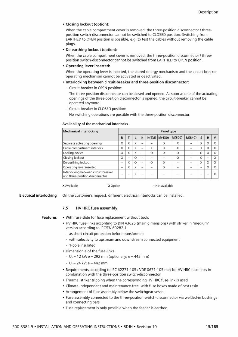
Fig. 9: Front operating mechanism box of circuit-breaker panel type 1.1
① Ready-for-service indicator② Auxiliary switch at the three-position disconnector
(option)③ Motor for three-position disconnector (option)④ Actuating opening for disconnector⑤ Position indicator for three-position disconnector⑥ Control gate / locking device for three-position
disconnector⑦ Actuating opening for earthing switch⑧ Sockets for capacitive voltage detecting system⑨ Opening spring⑩ "Spring charged" indicator⑪ Operations counter⑫ Position indicator for circuit-breaker⑬ OFF pushbutton for circuit-breaker (mechanical
operation)⑭ ON pushbutton for circuit-breaker (mechanical operation)⑮ Actuating opening for "spring charging" (circuit-breaker)⑯ Closing spring
500-8384.9 • INSTALLATION AND OPERATING INSTRUCTIONS • 8DJH • Revision 10 15/185
Description • Closing lockout (option):
When the cable compartment cover is removed, the three-position disconnector / three-position switch-disconnector cannot be switched to CLOSED position. Switching from EARTHED to OPEN position is possible, e.g. to test the cables without removing the cable plugs.
• De-earthing lockout (option):When the cable compartment cover is removed, the three-position disconnector / three-position switch-disconnector cannot be switched from EARTHED to OPEN position.
• Operating lever inserted:When the operating lever is inserted, the stored-energy mechanism and the circuit-breaker operating mechanism cannot be activated or deactivated.
• Interlocking between circuit-breaker and three-position disconnector:- Circuit-breaker in OPEN position:
The three-position disconnector can be closed and opened. As soon as one of the actuating openings of the three-position disconnector is opened, the circuit-breaker cannot be operated anymore.
- Circuit-breaker in CLOSED position: No switching operations are possible with the three-position disconnector.
Availability of the mechanical interlocks
Electrical interlocking On the customer's request, different electrical interlocks can be installed.
7.5 HV HRC fuse assembly
Features • With fuse slide for fuse replacement without tools• HV HRC fuse-links according to DIN 43625 (main dimensions) with striker in "medium"
version according to IEC/EN 60282-1- as short-circuit protection before transformers- with selectivity to upstream and downstream connected equipment- 1-pole insulated
• Dimension e of the fuse-links- Ur = 12 kV: e = 292 mm (optionally, e = 442 mm)- Ur = 24 kV: e = 442 mm
• Requirements according to IEC 62271-105 / VDE 0671-105 met for HV HRC fuse-links in combination with the three-position switch-disconnector
• Thermal striker tripping when the corresponding HV HRC fuse-link is used• Climate-independent and maintenance-free, with fuse boxes made of cast resin• Arrangement of fuse assembly below the switchgear vessel• Fuse assembly connected to the three-position switch-disconnector via welded-in bushings
and connecting bars• Fuse replacement is only possible when the feeder is earthed
Mechanical interlocking Panel type
R T L K K(E)/E M(430) M(500) M(840) S H VSeparate actuating openings X X X – – X X – X X XCable compartment interlock X X X – X X X – X X XLocking device O X X – O X O – O X XClosing lockout O – O – – – O – O – ODe-earthing lockout – X O – O X – – X X OOperating lever inserted – X X – – X – – – X XInterlocking between circuit-breaker and three-position disconnector – – X – – – – – – – X
X Available O Option – Not available

Description
16/185 Revision 10 • INSTALLATION AND OPERATING INSTRUCTIONS • 8DJH • 500-8384.9
• Option for HV HRC fuse-links: "Tripped" indication for remote electrical indication with a
NO contact
Mode of operation If a HV HRC fuse-link operates, the switch is tripped via an articulation which is integrated into the cover of the fuse box.
Thermal protection If the fuse tripping fails, the sudden overpressure trips the switch via a diaphragm and the articulation situated in the cover of the fuse box.The thermal protection works independently of the type and design of the HV HRC fuse-link used. The thermal protection is maintenance-free and independent of any outside climatic effects.
Basic scheme of fusetripping
The HV HRC fuse-links make SIBA (see page 39, "Selection of HV HRC fuse-links") release the striker depending on the temperature and trip the switch-disconnector as early as in the overload range of the fuses. Impermissible heating of the fuse box can be avoided in this way.
Fig. 10: HV HRC fuse assembly
① Fuse box② Fuse slide③ Tripping pin④ Sealing cover with seal⑤ Cap with control electrode⑥ HV HRC fuse-link⑦ Cable connection (bushing)⑧ Switchgear vessel⑨ Fuse bushing
HV HRC fuse-link in service condition
Fuse tripping through striker of HV HRC fuse-link
Fuse tripping due to sudden overpressure in the fuse box
500-8384.9 • INSTALLATION AND OPERATING INSTRUCTIONS • 8DJH • Revision 10 17/185
Description 7.6 Cable connection
Cable connection for cable feeders, ring-main feeders and circuit-breaker feeders
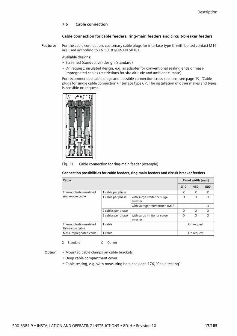
Features For the cable connection, customary cable plugs for interface type C with bolted contact M16 are used according to EN 50181/DIN EN 50181.Available designs:• Screened (conductive) design (standard)• On request: insulated design, e.g. as adapter for conventional sealing ends or mass-
impregnated cables (restrictions for site altitude and ambient climate)For recommended cable plugs and possible connection cross-sections, see page 19, "Cable plugs for single cable connection (interface type C)". The installation of other makes and types is possible on request.
Fig. 11: Cable connection for ring-main feeder (example)
Connection possibilities for cable feeders, ring-main feeders and circuit-breaker feeders
Option • Mounted cable clamps on cable brackets• Deep cable compartment cover• Cable testing, e.g. with measuring bolt, see page 176, "Cable testing"
Cable Panel width [mm]
310 430 500Thermoplastic-insulated single-core cable
1 cable per phase X X X1 cable per phase with surge limiter or surge
arresterO O O
with voltage transformer 4MT8 – – O2 cables per phase O O O2 cables per phase with surge limiter or surge
arresterO O O
Thermoplastic-insulated three-core cable
1 cable On request
Mass-impregnated cable 1 cable On request
X Standard O Option
Description
18/185 Revision 10 • INSTALLATION AND OPERATING INSTRUCTIONS • 8DJH • 500-8384.9
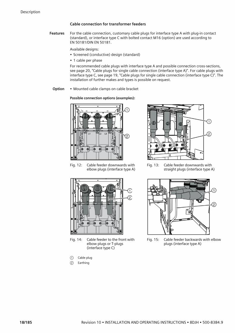
Cable connection for transformer feeders
Features For the cable connection, customary cable plugs for interface type A with plug-in contact (standard), or interface type C with bolted contact M16 (option) are used according to EN 50181/DIN EN 50181.Available designs:• Screened (conductive) design (standard)• 1 cable per phaseFor recommended cable plugs with interface type A and possible connection cross-sections, see page 20, "Cable plugs for single cable connection (interface type A)". For cable plugs with interface type C, see page 19, "Cable plugs for single cable connection (interface type C)". The installation of further makes and types is possible on request.
Option • Mounted cable clamps on cable bracket
Possible connection options (examples):
Fig. 12: Cable feeder downwards with elbow plugs (interface type A)
Fig. 13: Cable feeder downwards with straight plugs (interface type A)
Fig. 14: Cable feeder to the front with elbow plugs or T-plugs (interface type C)
Fig. 15: Cable feeder backwards with elbow plugs (interface type A)
① Cable plug② Earthing
500-8384.9 • INSTALLATION AND OPERATING INSTRUCTIONS • 8DJH • Revision 10 19/185
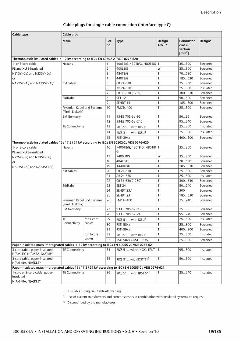
Description Cable plugs for single cable connection (interface type C)
Cable type Cable plug
Make Ser. no.
Type DesignT/W1, 2
Conductor cross-section[mm2]
Design2
Thermoplastic-insulated cables ≤ 12 kV according to IEC / EN 60502-2 / VDE 0276-6201- or 3-core cable, PE and XLPE-insulated N2YSY (Cu) and N2XSY (Cu) or NA2YSY (Al) and NA2XSY (Al)"
Nexans 1 400TB/G, 430TB/G, 480TB/G T 35...300 Screened2 400LB/G W 35...300 Screened3 484TB/G T 70...630 Screened4 440TB/G T 185...630 Screened
nkt cables 5 CB 24-630 T 25...300 Screened6 AB 24-630 T 25...300 Insulated7 CB 36-630 (1250) T 300...630 Screened
Südkabel 8 SET 12 T 50...300 Screened9 SEHDT 13 T 185...500 Screened
Prysmian Kabel und Systeme (Pirelli Elektrik)
10 FMCTs-400 T 25...300 Screened
3M Germany 11 93-EE 705-6 / -95 T 50...95 Screened12 93-EE 705-6 / -240 T 95...240 Screened
TE Connectivity 13 RICS 51 ... with IXSU3 T 25...300 Insulated14 RICS 31 ... with IXSU3 T 25...300 Insulated15 RSTI-39xx T 400...800 Screened
Thermoplastic-insulated cables 15 / 17.5 / 24 kV according to IEC / EN 60502-2 / VDE 0276-6201- or 3-core cable, PE and XLPE-insulated N2YSY (Cu) and N2XSY (Cu) or NA2YSY (Al) and NA2XSY (Al)
Nexans 16 K400TB/G, 430TB/G, 480TB/G
T 35...300 Screened
17 K400LB/G W 35...300 Screened18 484TB/G T 70...630 Screened19 K440TB/G T 185...630 Screened
nkt cables 20 CB 24-630 T 25...300 Screened21 AB 24-630 T 25...300 Insulated22 CB 36-630 (1250) T 300...630 Screened
Südkabel 23 SET 24 T 50...240 Screened24 SEHDT 23.1 T 300 Screened25 SEHDT 23 T 185...630 Screened
Prysmian Kabel und Systeme (Pirelli Elektrik)
26 FMCTs-400 T 25...240 Screened
3M Germany 27 93-EE 705-6 / -95 T 25...95 Screened28 93-EE 705-6 / -240 T 95...240 Screened
TE Connectivity
for 1-core cables
29 RICS 51 ... with IXSU3 T 25...300 Insulated30 RSTI-58xx T 25...300 Screened31 RSTI-59xx T 400...800 Screened
for 3-core cables
32 RICS 51 ... with IXSU3 T 25...300 Insulated33 RSTI-58xx + RSTI-TRFxx T 25...300 Screened
Paper-insulated mass-impregnated cables ≤ 12 kV according to IEC / EN 60055-2 / VDE 0276-6213-core cable, paper-insulated N(A)KLEY, N(A)KBA, N(A)KBY
TE Connectivity 34 RICS 51... with UHGK / EPKT T 95...300 Insulated
3-core cable, paper-insulated N(A)EKBA, N(A)KLEY
35 RICS 51... with IDST 513 T 50...300 Insulated
Paper-insulated mass-impregnated cables 15 / 17.5 / 24 kV according to IEC / EN 60055-2 / VDE 0276-6211-core or 3-core cable, paper-insulated N(A)EKBA, N(A)KLEY
TE Connectivity 36 RICS 51 ... with IDST 513 T 35...240 Insulated
1 T = Cable T-plug, W= Cable elbow plug2 Use of current transformers and current sensors in combination with insulated systems on request3 Discontinued by the manufacturer
Description
20/185 Revision 10 • INSTALLATION AND OPERATING INSTRUCTIONS • 8DJH • 500-8384.9
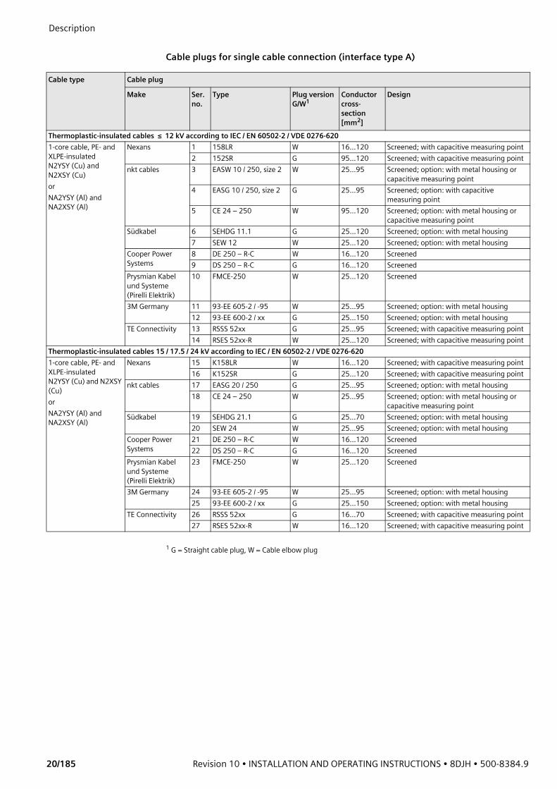
Cable plugs for single cable connection (interface type A)
Cable type Cable plug
Make Ser. no.
Type Plug versionG/W1
Conductor cross-section[mm2]
Design
Thermoplastic-insulated cables ≤ 12 kV according to IEC / EN 60502-2 / VDE 0276-6201-core cable, PE- and XLPE-insulated N2YSY (Cu) and N2XSY (Cu) orNA2YSY (Al) and NA2XSY (Al)
Nexans 1 158LR W 16...120 Screened; with capacitive measuring point2 152SR G 95...120 Screened; with capacitive measuring point
nkt cables 3 EASW 10 / 250, size 2 W 25...95 Screened; option: with metal housing or capacitive measuring point
4 EASG 10 / 250, size 2 G 25...95 Screened; option: with capacitive measuring point
5 CE 24 – 250 W 95...120 Screened; option: with metal housing or capacitive measuring point
Südkabel 6 SEHDG 11.1 G 25...120 Screened; option: with metal housing7 SEW 12 W 25...120 Screened; option: with metal housing
Cooper Power Systems
8 DE 250 – R-C W 16...120 Screened9 DS 250 – R-C G 16...120 Screened
Prysmian Kabel und Systeme (Pirelli Elektrik)
10 FMCE-250 W 25...120 Screened
3M Germany 11 93-EE 605-2 / -95 W 25...95 Screened; option: with metal housing12 93-EE 600-2 / xx G 25...150 Screened; option: with metal housing
TE Connectivity 13 RSSS 52xx G 25...95 Screened; with capacitive measuring point14 RSES 52xx-R W 25...120 Screened; with capacitive measuring point
Thermoplastic-insulated cables 15 / 17.5 / 24 kV according to IEC / EN 60502-2 / VDE 0276-6201-core cable, PE- and XLPE-insulated N2YSY (Cu) and N2XSY (Cu) or NA2YSY (Al) and NA2XSY (Al)
Nexans 15 K158LR W 16...120 Screened; with capacitive measuring point16 K152SR G 25...120 Screened; with capacitive measuring point
nkt cables 17 EASG 20 / 250 G 25...95 Screened; option: with metal housing18 CE 24 – 250 W 25...95 Screened; option: with metal housing or
capacitive measuring pointSüdkabel 19 SEHDG 21.1 G 25...70 Screened; option: with metal housing
20 SEW 24 W 25...95 Screened; option: with metal housingCooper Power Systems
21 DE 250 – R-C W 16...120 Screened22 DS 250 – R-C G 16...120 Screened
Prysmian Kabel und Systeme (Pirelli Elektrik)
23 FMCE-250 W 25...120 Screened
3M Germany 24 93-EE 605-2 / -95 W 25...95 Screened; option: with metal housing25 93-EE 600-2 / xx G 25...150 Screened; option: with metal housing
TE Connectivity 26 RSSS 52xx G 16...70 Screened; with capacitive measuring point27 RSES 52xx-R W 16...120 Screened; with capacitive measuring point
1 G = Straight cable plug, W = Cable elbow plug
500-8384.9 • INSTALLATION AND OPERATING INSTRUCTIONS • 8DJH • Revision 10 21/185
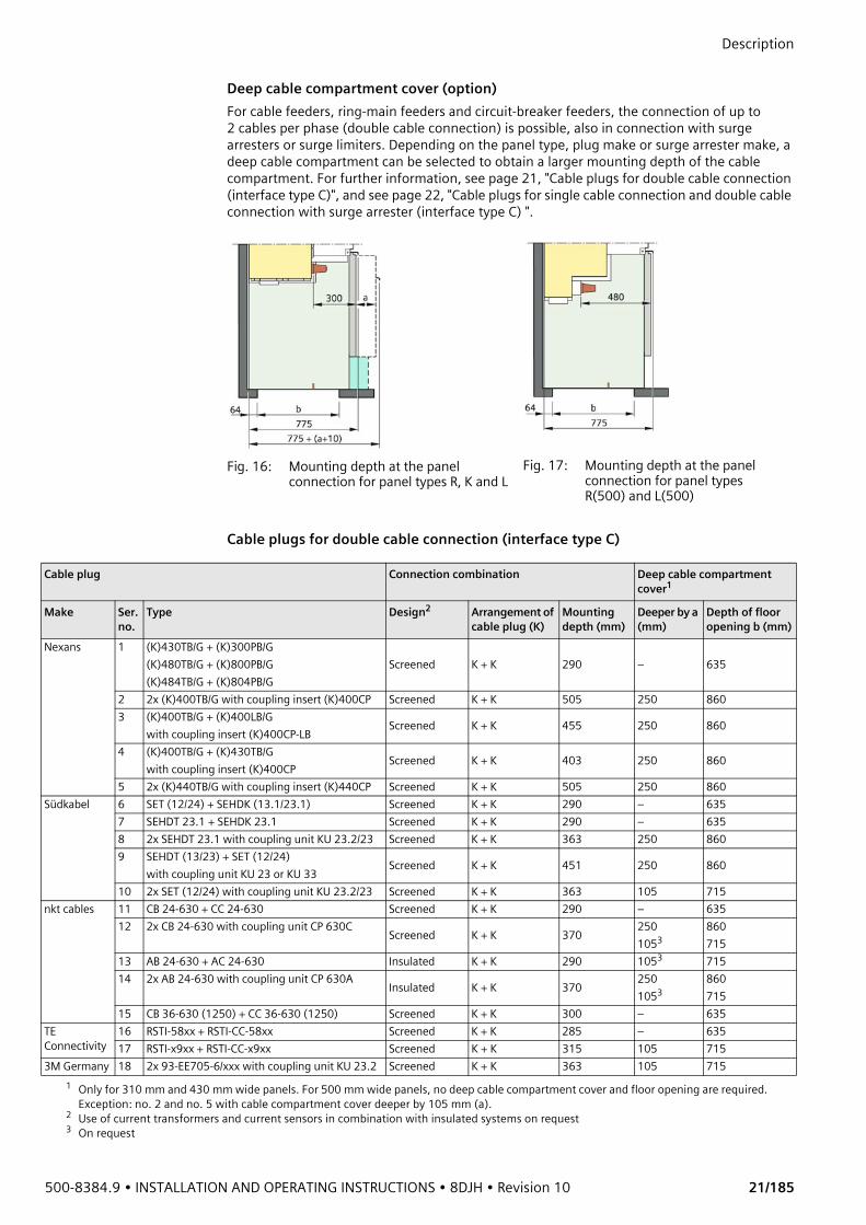
Description Deep cable compartment cover (option)For cable feeders, ring-main feeders and circuit-breaker feeders, the connection of up to 2 cables per phase (double cable connection) is possible, also in connection with surge arresters or surge limiters. Depending on the panel type, plug make or surge arrester make, a deep cable compartment can be selected to obtain a larger mounting depth of the cable compartment. For further information, see page 21, "Cable plugs for double cable connection (interface type C)", and see page 22, "Cable plugs for single cable connection and double cable connection with surge arrester (interface type C) ".
Cable plugs for double cable connection (interface type C)
Fig. 16: Mounting depth at the panel connection for panel types R, K and L
Fig. 17: Mounting depth at the panel connection for panel types R(500) and L(500)
Cable plug Connection combination Deep cable compartment cover1
Make Ser. no.
Type Design2 Arrangement of cable plug (K)
Mounting depth (mm)
Deeper by a (mm)
Depth of floor opening b (mm)
Nexans 1 (K)430TB/G + (K)300PB/G(K)480TB/G + (K)800PB/G(K)484TB/G + (K)804PB/G
Screened K + K 290 – 635
2 2x (K)400TB/G with coupling insert (K)400CP Screened K + K 505 250 8603 (K)400TB/G + (K)400LB/G
with coupling insert (K)400CP-LB Screened K + K 455 250 860
4 (K)400TB/G + (K)430TB/G with coupling insert (K)400CP Screened K + K 403 250 860
5 2x (K)440TB/G with coupling insert (K)440CP Screened K + K 505 250 860Südkabel 6 SET (12/24) + SEHDK (13.1/23.1) Screened K + K 290 – 635
7 SEHDT 23.1 + SEHDK 23.1 Screened K + K 290 – 6358 2x SEHDT 23.1 with coupling unit KU 23.2/23 Screened K + K 363 250 8609 SEHDT (13/23) + SET (12/24)
with coupling unit KU 23 or KU 33 Screened K + K 451 250 860
10 2x SET (12/24) with coupling unit KU 23.2/23 Screened K + K 363 105 715nkt cables 11 CB 24-630 + CC 24-630 Screened K + K 290 – 635
12 2x CB 24-630 with coupling unit CP 630C Screened K + K 370 2501053
860715
13 AB 24-630 + AC 24-630 Insulated K + K 290 1053 71514 2x AB 24-630 with coupling unit CP 630A Insulated K + K 370 250
1053860715
15 CB 36-630 (1250) + CC 36-630 (1250) Screened K + K 300 – 635TE Connectivity
16 RSTI-58xx + RSTI-CC-58xx Screened K + K 285 – 63517 RSTI-x9xx + RSTI-CC-x9xx Screened K + K 315 105 715
3M Germany 18 2x 93-EE705-6/xxx with coupling unit KU 23.2 Screened K + K 363 105 7151 Only for 310 mm and 430 mm wide panels. For 500 mm wide panels, no deep cable compartment cover and floor opening are required.
Exception: no. 2 and no. 5 with cable compartment cover deeper by 105 mm (a).2 Use of current transformers and current sensors in combination with insulated systems on request3 On request

Description
22/185 Revision 10 • INSTALLATION AND OPERATING INSTRUCTIONS • 8DJH • 500-8384.9
Cable plugs for single cable connection and double cable connection with surge arrester (interface type C)
Cable plugs for single cable connection with voltage transformer 4MT8 (interface type C)The voltage transformer 4MT8 can be installed in ring-main feeders and circuit-breaker feeders with a panel width of 500 mm. A deep cable compartment cover is not necessary. For connection, symmetrical cable T-plugs (see table) are required. Before performing a voltage test at the cables (on site with max. 80 % Ud), the voltage transformers must be removed.
7.7 Current and voltage transformers
Technical data The technical data of the current transformers and the voltage transformers is given in the associated order documents.
Cable plug / surge arrester Connection combination Deep cable compartment cover1
Make Ser. no. Type Design2 Arrangement3
Mounting depth[mm]
Deeper by a4
[mm]
Nexans1
(K)430TB/G + 300SA(K)480TB/G + 800SA(K)484TB/G + 800SA
Screened K + Ü 290 –
2 (K)430TB/G + (K)300PB/G + 300SA Screened K + K + Ü 395 105
3 (K)480TB/G + (K)800PB/G + 800SA(K)484TB/G + (K)804PB/G + 800SA Screened K + K + Ü 400 250
Südkabel 4 SET (12 / 24) + MUT (13 / 23) Screened K + Ü 302 1055 SEHDT 23.1 + MUT 23 Screened K + Ü 302 1056 2x SET (12 / 24) + MUT (13/23) with
coupling unit KU 23.2/23Screened K + K + Ü 476 250
7 2x SEHDT 23.1 + MUT 23 with coupling unit KU 23.2/23
Screened K + K + Ü 476 250
8 SEHDT (13 / 23) + MUT 33 Screened K + Ü 540 250nkt cables 9 CB 24-630 + CSA 24... Screened K + Ü 290 –
10 AB 24-630 + ASA 24... Insulated K + Ü 290 10511 CB 36-630 (1250) + CSA... Screened K + Ü 290 –
TE Connectivity 12 RICS 5139 + RDA... Insulated K + Ü 275 –13 RSTI-58xx + RSTI-CC-58SAxx Screened K + Ü 285 –14 RSTI-58xx + RSTI-CC-68SAxx Screened K + Ü 292 –15 RSTI-x9xx + RSTI-CC-58SAxx Screened K + Ü 295 –16 RSTI-x9xx + RSTI-CC-68SAxx Screened K + Ü 302 105
3M Germany 17 2x 93-EE705-6/xxx + MUT 23 mit with coupling unit KU 23.2
Screened K + K + Ü 476 250
1 Only for 310 mm and 430 mm wide panels. For 500 mm wide panels, no deep cable compartment cover and floor opening are required. Exception: no. 2 and no. 5 with cable compartment cover deeper by 105 mm (a).
2 Use of current transformers and current sensors in combination with insulated systems on request3 K = Cable plug, Ü = Surge arrester4 For drawing, see page 21, "Deep cable compartment cover (option)".
Make Type DesignNexans (K)400TB/G Screened
(K)440TB/G ScreenedPrysmian FMCTs-400 ScreenedSüdkabel SEHDT (13/23) Screened
500-8384.9 • INSTALLATION AND OPERATING INSTRUCTIONS • 8DJH • Revision 10 23/185
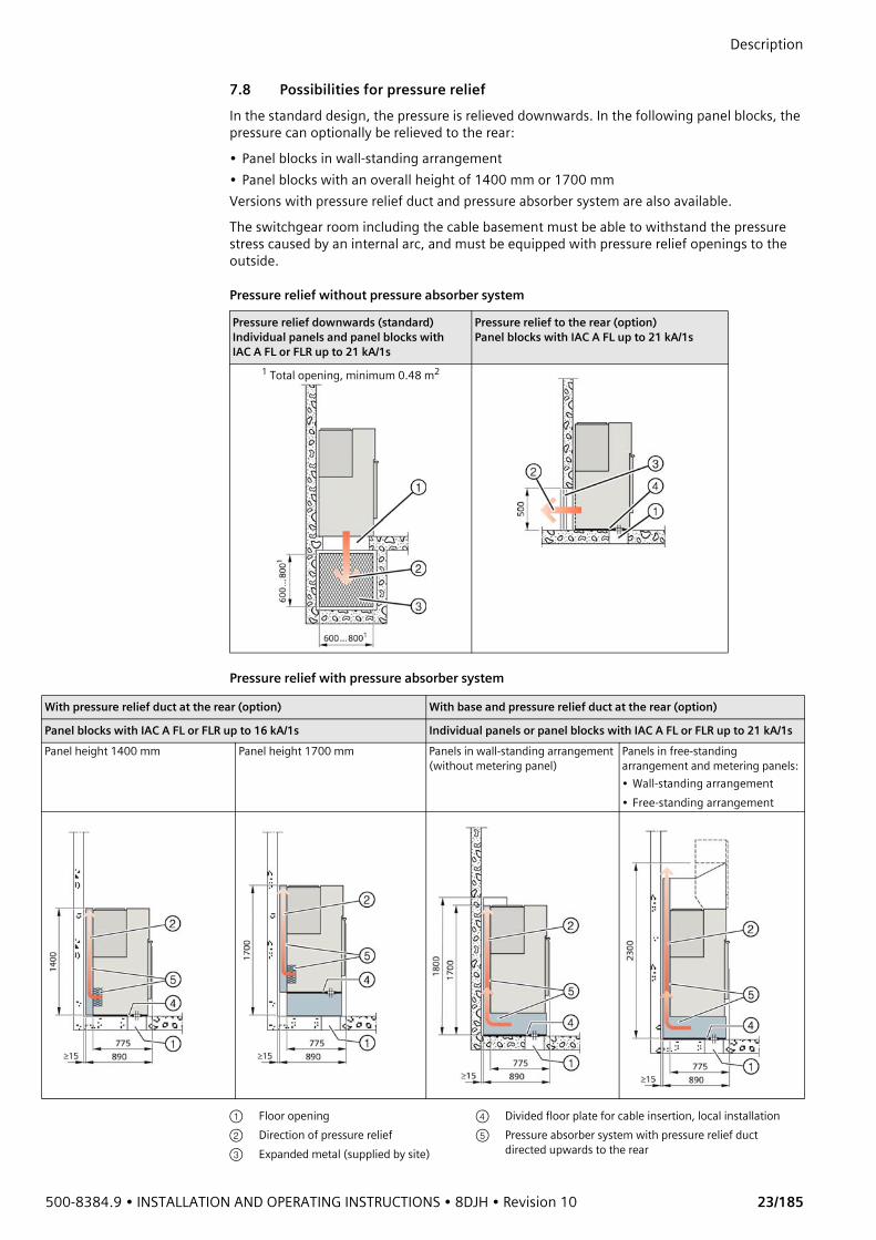
Description 7.8 Possibilities for pressure reliefIn the standard design, the pressure is relieved downwards. In the following panel blocks, the pressure can optionally be relieved to the rear: • Panel blocks in wall-standing arrangement• Panel blocks with an overall height of 1400 mm or 1700 mmVersions with pressure relief duct and pressure absorber system are also available.The switchgear room including the cable basement must be able to withstand the pressure stress caused by an internal arc, and must be equipped with pressure relief openings to the outside.
Pressure relief without pressure absorber system
Pressure relief with pressure absorber system
Pressure relief downwards (standard)Individual panels and panel blocks with IAC A FL or FLR up to 21 kA/1s
Pressure relief to the rear (option)Panel blocks with IAC A FL up to 21 kA/1s
1 Total opening, minimum 0.48 m2
With pressure relief duct at the rear (option) With base and pressure relief duct at the rear (option)
Panel blocks with IAC A FL or FLR up to 16 kA/1s Individual panels or panel blocks with IAC A FL or FLR up to 21 kA/1sPanel height 1400 mm Panel height 1700 mm Panels in wall-standing arrangement
(without metering panel)Panels in free-standing arrangement and metering panels:• Wall-standing arrangement• Free-standing arrangement
① Floor opening ④ Divided floor plate for cable insertion, local installation② Direction of pressure relief ⑤ Pressure absorber system with pressure relief duct
directed upwards to the rear③ Expanded metal (supplied by site)
Description
24/185 Revision 10 • INSTALLATION AND OPERATING INSTRUCTIONS • 8DJH • 500-8384.9
7.9 Protection and control equipmentThe protection equipment and control equipment is designed customer-specifically. The devices are installed in the low-voltage compartment or in the low-voltage niche. Details are given in the respective circuit documentation.
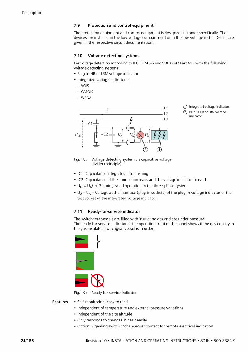
7.10 Voltage detecting systemsFor voltage detection according to IEC 61243-5 and VDE 0682 Part 415 with the following voltage detecting systems: • Plug-in HR or LRM voltage indicator• Integrated voltage indicators:
- VOIS- CAPDIS- WEGA
• -C1: Capacitance integrated into bushing• -C2: Capacitance of the connection leads and the voltage indicator to earth• ULE = UN/ √ 3 during rated operation in the three-phase system• U2 = UA = Voltage at the interface (plug-in sockets) of the plug-in voltage indicator or the
test socket of the integrated voltage indicator
7.11 Ready-for-service indicatorThe switchgear vessels are filled with insulating gas and are under pressure. The ready-for-service indicator at the operating front of the panel shows if the gas density in the gas-insulated switchgear vessel is in order.
Fig. 19: Ready-for-service indicator
Features • Self-monitoring, easy to read• Independent of temperature and external pressure variations• Independent of the site altitude• Only responds to changes in gas density• Option: Signaling switch 1°changeover contact for remote electrical indication
Fig. 18: Voltage detecting system via capacitive voltage divider (principle)
① Integrated voltage indicator② Plug-in HR or LRM voltage
indicator

500-8384.9 • INSTALLATION AND OPERATING INSTRUCTIONS • 8DJH • Revision 10 25/185
Description Mode of operation
For the ready-for-service indicator, a gas-tight measurement box is installed inside the switchgear vessel.A coupling magnet, which is fitted to the bottom end of the measurement box, transmits its position to an armature outside the switchgear vessel through the non-magnetizable switchgear vessel (magnetic coupling). This armature moves the ready-for-service indicator at the operating front of the panel.While changes in the gas density during the loss of gas, which are decisive for the dielectric strength, are displayed, changes in the relative gas pressure resulting from temperature and external pressure variations are not. The gas in the measurement box has the same temperature as that in the switchgear vessel.The temperature effect is compensated via the same pressure change in both gas volumes.• The switchgear operates perfectly in a range between the rated filling level of 150 kPA and
the minimum functional level of 130 kPA.• If the gas pressure falls below 130 kPA, the switchgear must not be operated anymore.
The ready-for-service indicator changes from the green area to the red area ("not ready for service").
• If the ready-for-service indicator changes from the green area to the red area, the signaling switch (option) changes its switching state.
Functional principle of the signaling switch
7.12 Short-circuit/earth-fault indicator The panels can optionally be equipped with short-circuit or earth-fault indicators in different designs. Operating instructions and information on equipment features are available in the respective manufacturing documentation.
Fig. 20: Principle of gas monitoring with ready-for-service indicator
① Switchgear vessel (filled with SF6 gas)
② Measurement box③ Magnetic coupling④ Red indication: not ready for service⑤ Green indication: ready for service
State of the ready-for-service indicator in the green area
State of the ready-for-service indicator in the red area
NC contact open and NO contact closed NC contact closed and NO contact open
① Normally closed contact ② Normally open contact

Description
26/185 Revision 10 • INSTALLATION AND OPERATING INSTRUCTIONS • 8DJH • 500-8384.9
7.13 Accessories
Standard accessories(selection)
• Operating and installation instructions• Operating lever for disconnector, switch-disconnector and circuit-breaker (different
designs)
• Double-bit key with 3 mm diameter for low-voltage door (option)
• Hand crank for charging the spring energy store (only circuit-breaker panel type 1.1)
Other accessories According to the order documents / purchase order (selection):• Surge arresters• Surge limiters• Cable plugs• HV HRC fuse-links• Test fuses for mechanical simulation of the striker of HV HRC fuse-links in transformer
feeders, with extension tube (for slide lengths 292 mm or 442 mm)
• HR or LRM voltage indicators• Units to check the capacitive interface and the voltage indicators• Unit to test the plug-in voltage indicators• Phase comparison test units
7.14 Low-voltage compartment (option)
Features • Overall height: 200, 400, 600 or 900 mm• Installation on the panel is possible per feeder• Customer-specific equipping of the low-voltage compartment • Option: Wiring duct for laying the panel-overlapping wiring on panels without low-voltage
compartment• Option: Cover for switchgear fronts of the same height on panels without low-voltage
compartment
Shipping data andtransport data
When switchgear assemblies are delivered with low-voltage compartments, the changed transport dimensions and transport weights as well as the relocation of the center of gravity must be observed.
500-8384.9 • INSTALLATION AND OPERATING INSTRUCTIONS • 8DJH • Revision 10 27/185
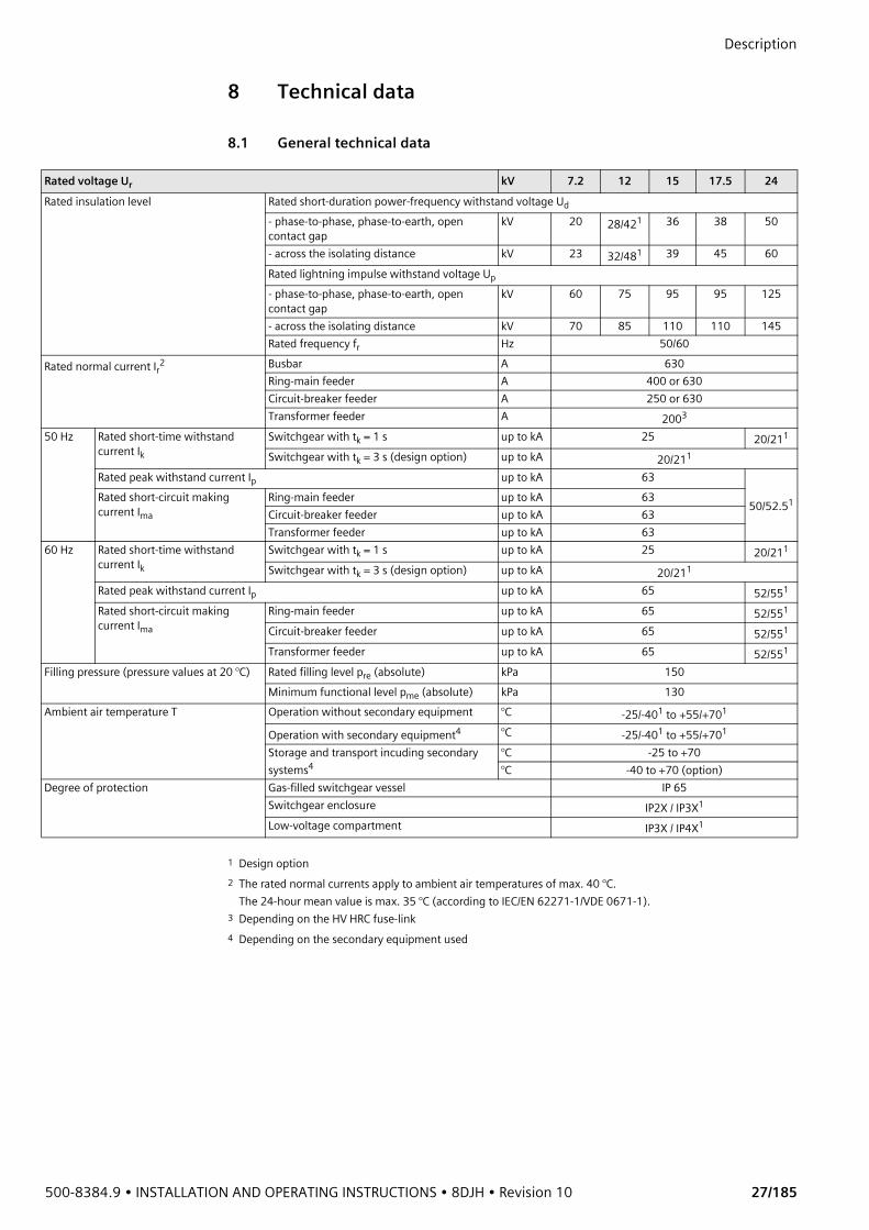
Description 8 Technical data
8.1 General technical data
Rated voltage Ur kV 7.2 12 15 17.5 24Rated insulation level Rated short-duration power-frequency withstand voltage Ud
- phase-to-phase, phase-to-earth, open contact gap
kV 20 28/421 36 38 50
- across the isolating distance kV 23 32/481 39 45 60Rated lightning impulse withstand voltage Up- phase-to-phase, phase-to-earth, open contact gap
kV 60 75 95 95 125
- across the isolating distance kV 70 85 110 110 145Rated frequency fr Hz 50/60
Rated normal current Ir2 Busbar A 630Ring-main feeder A 400 or 630Circuit-breaker feeder A 250 or 630Transformer feeder A 2003
50 Hz Rated short-time withstand current Ik
Switchgear with tk = 1 s up to kA 25 20/211
Switchgear with tk = 3 s (design option) up to kA 20/211
Rated peak withstand current Ip up to kA 63
50/52.51Rated short-circuit making current Ima
Ring-main feeder up to kA 63Circuit-breaker feeder up to kA 63Transformer feeder up to kA 63
60 Hz Rated short-time withstand current Ik
Switchgear with tk = 1 s up to kA 25 20/211
Switchgear with tk = 3 s (design option) up to kA 20/211
Rated peak withstand current Ip up to kA 65 52/551
Rated short-circuit making current Ima
Ring-main feeder up to kA 65 52/551
Circuit-breaker feeder up to kA 65 52/551
Transformer feeder up to kA 65 52/551
Filling pressure (pressure values at 20 °C) Rated filling level pre (absolute) kPa 150Minimum functional level pme (absolute) kPa 130
Ambient air temperature T Operation without secondary equipment °C -25/-401 to +55/+701
Operation with secondary equipment4 °C -25/-401 to +55/+701
Storage and transport incuding secondary systems4
°C -25 to +70°C -40 to +70 (option)
Degree of protection Gas-filled switchgear vessel IP 65Switchgear enclosure IP2X / IP3X1
Low-voltage compartment IP3X / IP4X1
1 Design option2 The rated normal currents apply to ambient air temperatures of max. 40 °C.
The 24-hour mean value is max. 35 °C (according to IEC/EN 62271-1/VDE 0671-1).3 Depending on the HV HRC fuse-link4 Depending on the secondary equipment used
Description
28/185 Revision 10 • INSTALLATION AND OPERATING INSTRUCTIONS • 8DJH • 500-8384.9
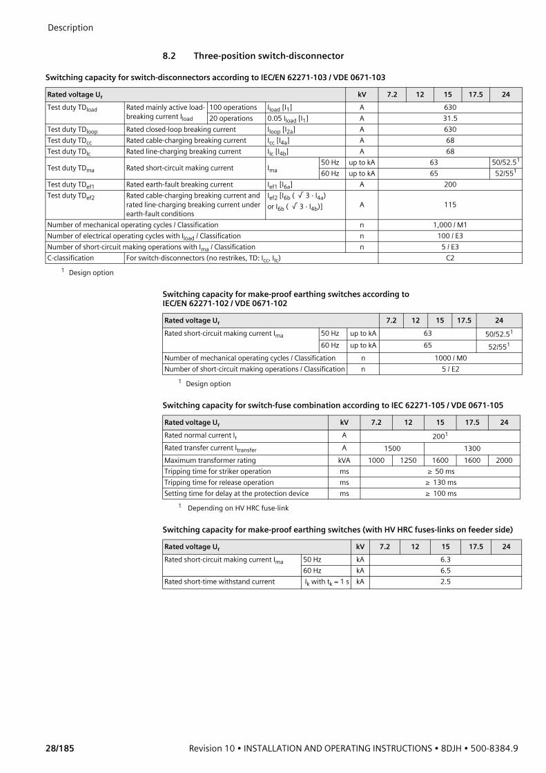
8.2 Three-position switch-disconnector
Switching capacity for switch-disconnectors according to IEC/EN 62271-103 / VDE 0671-103
Switching capacity for make-proof earthing switches according to IEC/EN 62271-102 / VDE 0671-102
Switching capacity for switch-fuse combination according to IEC 62271-105 / VDE 0671-105
Switching capacity for make-proof earthing switches (with HV HRC fuses-links on feeder side)
Rated voltage Ur kV 7.2 12 15 17.5 24Test duty TDload Rated mainly active load-
breaking current Iload100 operations Iload [I1] A 63020 operations 0.05 Iload [I1] A 31.5
Test duty TDloop Rated closed-loop breaking current Iloop [I2a] A 630Test duty TDcc Rated cable-charging breaking current Icc [I4a] A 68Test duty TDIc Rated line-charging breaking current IIc [I4b] A 68
Test duty TDma Rated short-circuit making current Ima50 Hz up to kA 63 50/52.51
1 Design option
60 Hz up to kA 65 52/551
Test duty TDef1 Rated earth-fault breaking current Ief1 [I6a] A 200Test duty TDef2 Rated cable-charging breaking current and
rated line-charging breaking current under earth-fault conditions
Ief2 [I6b ( √ 3 · I4a) or I6b ( √ 3 · I4b)] A 115
Number of mechanical operating cycles / Classification n 1,000 / M1Number of electrical operating cycles with Iload / Classification n 100 / E3Number of short-circuit making operations with Ima / Classification n 5 / E3C-classification For switch-disconnectors (no restrikes, TD: Icc, IIc) C2
Rated voltage Ur 7.2 12 15 17.5 24Rated short-circuit making current Ima 50 Hz up to kA 63 50/52.51
1 Design option
60 Hz up to kA 65 52/551
Number of mechanical operating cycles / Classification n 1000 / M0Number of short-circuit making operations / Classification n 5 / E2
Rated voltage Ur kV 7.2 12 15 17.5 24Rated normal current Ir A 2001
1 Depending on HV HRC fuse-link
Rated transfer current Itransfer A 1500 1300Maximum transformer rating kVA 1000 1250 1600 1600 2000Tripping time for striker operation ms ≥ 50 msTripping time for release operation ms ≥ 130 msSetting time for delay at the protection device ms ≥ 100 ms
Rated voltage Ur kV 7.2 12 15 17.5 24Rated short-circuit making current Ima 50 Hz kA 6.3
60 Hz kA 6.5Rated short-time withstand current Ik with tk = 1 s kA 2.5
500-8384.9 • INSTALLATION AND OPERATING INSTRUCTIONS • 8DJH • Revision 10 29/185
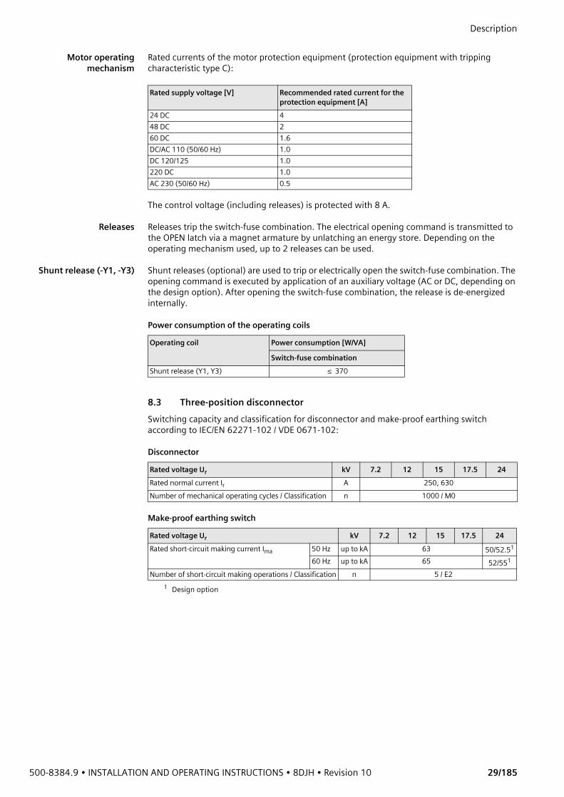
Description Motor operating
mechanismRated currents of the motor protection equipment (protection equipment with tripping characteristic type C):
The control voltage (including releases) is protected with 8 A.
Releases Releases trip the switch-fuse combination. The electrical opening command is transmitted to the OPEN latch via a magnet armature by unlatching an energy store. Depending on the operating mechanism used, up to 2 releases can be used.
Shunt release (-Y1, -Y3) Shunt releases (optional) are used to trip or electrically open the switch-fuse combination. The opening command is executed by application of an auxiliary voltage (AC or DC, depending on the design option). After opening the switch-fuse combination, the release is de-energized internally.
Power consumption of the operating coils
8.3 Three-position disconnector Switching capacity and classification for disconnector and make-proof earthing switch according to IEC/EN 62271-102 / VDE 0671-102:
Disconnector
Make-proof earthing switch
Rated supply voltage [V] Recommended rated current for the protection equipment [A]
24 DC 448 DC 260 DC 1.6DC/AC 110 (50/60 Hz) 1.0DC 120/125 1.0220 DC 1.0AC 230 (50/60 Hz) 0.5
Operating coil Power consumption [W/VA]
Switch-fuse combinationShunt release (Y1, Y3) ≤ 370
Rated voltage Ur kV 7.2 12 15 17.5 24Rated normal current Ir A 250, 630Number of mechanical operating cycles / Classification n 1000 / M0
Rated voltage Ur kV 7.2 12 15 17.5 24Rated short-circuit making current Ima 50 Hz up to kA 63 50/52.51
1 Design option
60 Hz up to kA 65 52/551
Number of short-circuit making operations / Classification n 5 / E2
Description
30/185 Revision 10 • INSTALLATION AND OPERATING INSTRUCTIONS • 8DJH • 500-8384.9
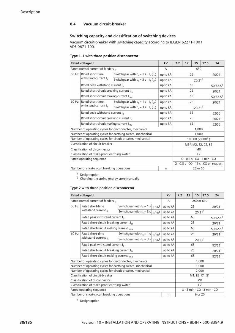
8.4 Vacuum circuit-breaker
Switching capacity and classification of switching devicesVacuum circuit-breaker with switching capacity according to IEC/EN 62271-100 / VDE 0671-100.
Type 1. 1 with three-position disconnector
Type 2 with three-position disconnector
Rated voltage Ur kV 7.2 12 15 17.5 24Rated normal current of feeders lr A 63050 Hz Rated short-time
withstand current IkSwitchgear with tk = 1 s Ik (th) up to kA 25 20/211
1 Design option
Switchgear with tk = 3 s Ik (th) up to kA 20/211
Rated peak withstand current Ip up to kA 63 50/52.51
Rated short-circuit breaking current Isc up to kA 25 20/211
Rated short-circuit making current Ima up to kA 63 50/52.51
60 Hz Rated short-time withstand current Ik
Switchgear with tk = 1 s Ik (th) up to kA 25 20/211
Switchgear with tk = 3 s Ik (th) up to kA 20/211
Rated peak withstand current Ip up to kA 65 52/551
Rated short-circuit breaking current Isc up to kA 25 20/211
Rated short-circuit making current Ima up to kA 65 52/551
Number of operating cycles for disconnector, mechanical 1,000Number of operating cycles for earthing switch, mechanical 1,000Number of operating cycles for circuit-breaker, mechanical 10,000 (2,0002 )
2 Charging the spring energy store manually
Classification of circuit-breaker M12, M2, E2, C2, S2Classification of disconnector M0Classification of make-proof earthing switch E2Rated operating sequence O - 0.3 s - CO - 3 min - CO
O - 0.3 s - CO - 15 s - CO on requestNumber of short-circuit breaking operations n 25 or 50
Rated voltage Ur kV 7.2 12 15 17.5 24Rated normal current of feeders lr A 250 or 63050 Hz Rated short-time
withstand current IkSwitchgear with tk = 1 s Ik (th) up to kA 25 20/211
1 Design option
Switchgear with tk = 3 s Ik (th) up to kA 20/211
Rated peak withstand current Ip up to kA 63 50/52.51
Rated short-circuit breaking current Isc up to kA 25 20/211
Rated short-circuit making current Ima up to kA 63 50/52.51
60 Hz Rated short-time withstand current Ik
Switchgear with tk = 1 s Ik (th) up to kA 25 20/211
Switchgear with tk = 3 s Ik (th) up to kA 20/211
Rated peak withstand current Ip up to kA 65 52/551
Rated short-circuit breaking current Isc up to kA 25 20/211
Rated short-circuit making current Ima up to kA 65 52/551
Number of operating cycles for disconnector, mechanical 1,000Number of operating cycles for earthing switch, mechanical 1,000Number of operating cycles for circuit-breaker, mechanical 2,000Classification of circuit-breaker M1, E2, C1, S1Classification of disconnector M0Classification of make-proof earthing switch E2Rated operating sequence O - 3 min - CO - 3 min - CONumber of short-circuit breaking operations n 6 or 20
500-8384.9 • INSTALLATION AND OPERATING INSTRUCTIONS • 8DJH • Revision 10 31/185
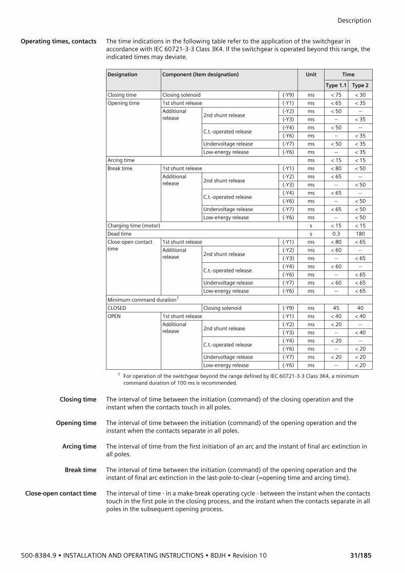
Description Operating times, contacts The time indications in the following table refer to the application of the switchgear in
accordance with IEC 60721-3-3 Class 3K4. If the switchgear is operated beyond this range, the indicated times may deviate.
Closing time The interval of time between the initiation (command) of the closing operation and the instant when the contacts touch in all poles.
Opening time The interval of time between the initiation (command) of the opening operation and the instant when the contacts separate in all poles.
Arcing time The interval of time from the first initiation of an arc and the instant of final arc extinction in all poles.
Break time The interval of time between the initiation (command) of the opening operation and the instant of final arc extinction in the last-pole-to-clear (=opening time and arcing time).
Close-open contact time The interval of time - in a make-break operating cycle - between the instant when the contacts touch in the first pole in the closing process, and the instant when the contacts separate in all poles in the subsequent opening process.
Designation Component (item designation) Unit Time
Type 1.1 Type 2Closing time Closing solenoid (-Y9) ms < 75 < 30Opening time 1st shunt release (-Y1) ms < 65 < 35
Additional release 2nd shunt release (-Y2) ms < 50 --
(-Y3) ms -- < 35
C.t.-operated release (-Y4) ms < 50 --(-Y6) ms -- < 35
Undervoltage release (-Y7) ms < 50 < 35Low-energy release (-Y6) ms -- < 35
Arcing time ms < 15 < 15Break time 1st shunt release (-Y1) ms < 80 < 50
Additional release 2nd shunt release (-Y2) ms < 65 --
(-Y3) ms -- < 50
C.t.-operated release (-Y4) ms < 65 --(-Y6) ms -- < 50
Undervoltage release (-Y7) ms < 65 < 50Low-energy release (-Y6) ms -- < 50
Charging time (motor) s < 15 < 15Dead time s 0.3 180Close-open contact time
1st shunt release (-Y1) ms < 80 < 65Additional release 2nd shunt release (-Y2) ms < 60 --
(-Y3) ms -- < 65
C.t.-operated release (-Y4) ms < 60 --(-Y6) ms -- < 65
Undervoltage release (-Y7) ms < 60 < 65Low-energy release (-Y6) ms -- < 65
Minimum command duration1
1 For operation of the switchgear beyond the range defined by IEC 60721-3-3 Class 3K4, a minimum command duration of 100 ms is recommended.
CLOSED Closing solenoid (-Y9) ms 45 40OPEN 1st shunt release (-Y1) ms < 40 < 40
Additional release 2nd shunt release (-Y2) ms < 20 --
(-Y3) ms -- < 40
C.t.-operated release (-Y4) ms < 20 --(-Y6) ms -- < 20
Undervoltage release (-Y7) ms < 20 < 20Low-energy release (-Y6) ms -- < 20

Description
32/185 Revision 10 • INSTALLATION AND OPERATING INSTRUCTIONS • 8DJH • 500-8384.9
Motor operating
mechanismPower consumption of circuit-breaker motor operating mechanism
Rated current for the motor protection equipment 1
The supply voltage may deviate from the rated supply voltage specified in the table by max. -15% to +10%.
Breaking capacity of auxiliary switch 3SV92
Closing solenoid (-Y9) The closing solenoid closes the circuit-breaker electrically. The closing command is executed by application of an auxiliary voltage (AC or DC, depending on the design option). After closing, the closing solenoid is de-energized internally.
Releases Releases trip the circuit-breaker. The electrical opening command is transmitted to the OPEN latch via a magnet armature by unlatching an energy store. Depending on the operating mechanism used, up to 2 releases can be used.
Shunt release (-Y1) Shunt releases are used to trip or electrically open circuit-breakers. The opening command is executed by application of an auxiliary voltage (AC or DC, depending on the design option). After opening the circuit-breaker, the release is de-energized internally.
Shunt release (-Y2) The shunt release (-Y2) can be operated as an additional release besides the shunt release (-Y1), and works in the same way.
Undervoltage release(-Y7)
Undervoltage releases are used to trip or electrically open circuit-breakers. During normal operation, the shunt releases are supplied with a closed-circuit current from an auxiliary voltage source (DC or AC, depending on the design option). When the auxiliary voltage falls below a specific value, or when it is interrupted, the opening operation takes place.
C.t.-operated release(-Y4)
The c.t.-operated release 3AX1102 (-Y4) is used for protection devices with a relay output, which are supplied with instrument transformer current. The tripping circuit is supplied via auxiliary transformers for tripping. When the required tripping current (0.5 A or 1 A, depending on the design option) flows in the tripping circuit, the opening operation takes place.
Circuit-breaker Max. power consumption
DC ACType 1.1 approx. 500 W approx. 650 VAType 2 approx. 80 W approx. 80 VA
Rated supply voltage[V]
Recommended rated current for the protection equipment [A]
Circuit-breaker type 1.1 Circuit-breaker type 2DC 24 162 8DC 48 10 6DC 60 8 4DC/AC 110 (50/60 Hz) 4 2DC 220 / AC 230 (50/60 Hz) 2 1.6
1 M.c.b. with C-characteristic2 Double bus wire
Breaking capacity Operating voltage [V] Normal current [A]AC 40 Hz to 60 Hz up to 230 10
Resistive load Inductive loadDC 24 10 10
48 10 960 9 7110 5 4220 2.5 2

500-8384.9 • INSTALLATION AND OPERATING INSTRUCTIONS • 8DJH • Revision 10 33/185
Description C.t.-operated release
(-Y6)The low-energy c.t.-operated release 3AX1104 (-Y6) is used for protection devices with a pulse output, which are supplied with instrument transformer current. The tripping circuit is supplied as well through the protection core of the current transformer. When a pulse of 0.1 Ws runs through the tripping circuit, the opening operation takes place.
Low-energy release(-Y6)
The low-energy release (-Y6) is provided for use in combination with the transformer monitor IKI-30 (make Kries) or the protection device 7SJ45 (make Siemens) supplied with instrument transformer current. The tripping circuit is supplied through the current sensor or current transformer. When a pulse of 0.02 Ws runs through the tripping circuit, the opening operation takes place. The low-energy release is available for the vacuum circuit-breaker type 2.
Varistor module The varistor module limits switching overvoltages caused by tripping coils in circuits and auxiliary circuits. The varistor module is integrated in the releases.
Circuit-breaker trippingsignal
When the circuit-breaker is tripped by a release (e.g. by protection tripping), there is a signal through the NO contact -S6. If the circuit-breaker is tripped with the mechanical pushbutton, this signal is suppressed by the NC contact -S7.
Power consumption of the operating coils
8.5 Classification of the switchgear8DJH switchgear is classified according to IEC/EN 62 271-200 / VDE 0671-200.
Partition class
Loss of service continuity category
Accessibility to compartments
Operating coil Power consumption [W/VA]
Circuit-breaker type 1.1 Circuit-breaker type 2Closing solenoid (Y9) ≤ 200 ≤ 370Shunt release (Y1) ≤ 200 ≤ 370Shunt release (Y2) ≤ 200 --C.t.-operated release (Y4) ≤ 20 --C.t.-operated release (Y6) ≤ 30 ≤ 30Low-energy current release (Y6) -- ≤ 10Undervoltage release (Y7) ≤ 20 ≤ 20
Partition class PM (metallic partition)
Switchgear panel Loss of service continuity category
with Three-position disconnector or three-position switch-disconnector LSC 2without LSC 1
Compartment (enclosure) AccessibilityBusbar compartment Non-accessibleSwitching-device compartment Non-accessibleLow-voltage compartment (option) Tool-basedConnection compartment for panel/module With earthing switch Interlock-controlled
Cable feeder (K) Tool-basedMetering panel type M, air-insulated
Tool-based
Description
34/185 Revision 10 • INSTALLATION AND OPERATING INSTRUCTIONS • 8DJH • 500-8384.9
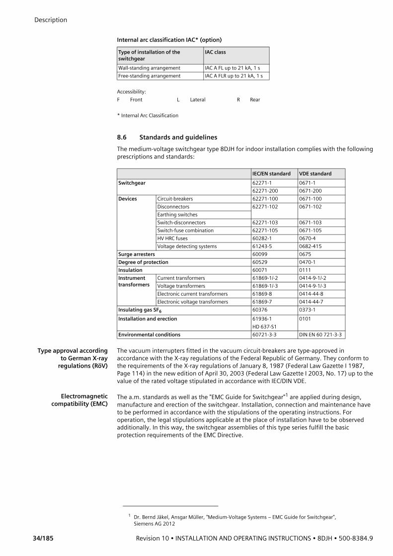
Internal arc classification IAC* (option)
8.6 Standards and guidelinesThe medium-voltage switchgear type 8DJH for indoor installation complies with the following prescriptions and standards:
Type approval accordingto German X-ray
regulations (RöV)
The vacuum interrupters fitted in the vacuum circuit-breakers are type-approved in accordance with the X-ray regulations of the Federal Republic of Germany. They conform to the requirements of the X-ray regulations of January 8, 1987 (Federal Law Gazette I 1987, Page 114) in the new edition of April 30, 2003 (Federal Law Gazette I 2003, No. 17) up to the value of the rated voltage stipulated in accordance with IEC/DIN VDE.
Electromagneticcompatibility (EMC)
The a.m. standards as well as the "EMC Guide for Switchgear"1 are applied during design, manufacture and erection of the switchgear. Installation, connection and maintenance have to be performed in accordance with the stipulations of the operating instructions. For operation, the legal stipulations applicable at the place of installation have to be observed additionally. In this way, the switchgear assemblies of this type series fulfill the basic protection requirements of the EMC Directive.
Type of installation of the switchgear
IAC class
Wall-standing arrangement IAC A FL up to 21 kA, 1 sFree-standing arrangement IAC A FLR up to 21 kA, 1 s
Accessibility:F Front L Lateral R Rear
* Internal Arc Classification
IEC/EN standard VDE standardSwitchgear 62271-1 0671-1
62271-200 0671-200Devices Circuit-breakers 62271-100 0671-100
Disconnectors 62271-102 0671-102Earthing switchesSwitch-disconnectors 62271-103 0671-103Switch-fuse combination 62271-105 0671-105HV HRC fuses 60282-1 0670-4Voltage detecting systems 61243-5 0682-415
Surge arresters 60099 0675Degree of protection 60529 0470-1Insulation 60071 0111Instrument transformers
Current transformers 61869-1/-2 0414-9-1/-2Voltage transformers 61869-1/-3 0414-9-1/-3Electronic current transformers 61869-8 0414-44-8Electronic voltage transformers 61869-7 0414-44-7
Insulating gas SF6 60376 0373-1Installation and erection 61936-1
HD 637-S10101
Environmental conditions 60721-3-3 DIN EN 60 721-3-3
1 Dr. Bernd Jäkel, Ansgar Müller, "Medium-Voltage Systems – EMC Guide for Switchgear", Siemens AG 2012

500-8384.9 • INSTALLATION AND OPERATING INSTRUCTIONS • 8DJH • Revision 10 35/185
Description Degrees of protection The panels of the 8DJH fulfill the following degrees of protection according to IEC 62271-200,
IEC 60529 and DIN VDE 0671-200:• IP2X (standard) for parts under high voltage
- for air-insulated metering panels - for panels with HV HRC fuses
• IP3X (option) for the switchgear enclosure of the operating front and the side walls• IP3X (standard, option: IP4X) for low-voltage compartments• IP65 for parts under high voltage
- for panels without HV HRC fuses - for switchgear without air-insulated metering panels
Transport regulations According to "Annex A of the European Agreement Concerning the International Carriage of Dangerous Goods by Road (ADR)" launched on September 30, 1957, Siemens gas-insulated medium-voltage switchgear does not belong to the category of dangerous goods in respect of transportation, and is exempted from special transport regulations according to ADR, Clause 1.1.3.1 b).
8.7 Dimensions and weightsThe transport weight results from the switchgear weight per transport unit and the packing weight. The packing weight results from the transport dimensions and the type of transport.
Switchgear weights The total weight of the switchgear results from the sum of the weights per functional unit. Depending in the design and the degree to which it is equipped (e.g. current transformers, motor operating mechanism or low-voltage compartment), the actual value might deviate.
Switchgear panel Width Gross weight for a switchgear height of Low-voltage compartment
[mm] 1200 mm 1400 mm 1700 mm 600 mm
approx. [kg] approx. [kg] approx. [kg] approx. [kg]R 310 100 110 120 40R(500) 500 140 150 170 60K 310 100 110 120 40K(E) 430 130 140 160 50T 430 135 145 160 50L 430 130 140 155 50L (type 1.1) without 4MT3 500 210 220 240 60L (type 2) 500 160 170 190 60M (BC/BB/CB) 840 - 370 400 70M(CC) 840 - 270 300 70M(500) incl. 3x4MT3 500 230 240 260 60S 430 130 140 160 50S(500) 500 150 160 180 60S(620) 620 200 220 240 45H 430 135 145 160 50V 500 240 250 270 60E 310 100 110 120 40E(500) 500 140 150 170 60
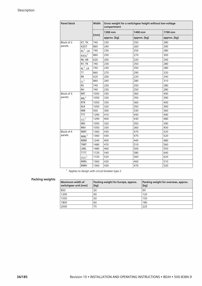
Description
36/185 Revision 10 • INSTALLATION AND OPERATING INSTRUCTIONS • 8DJH • 500-8384.9
Packing weights
Panel block Width Gross weight for a switchgear height without low-voltage compartment
[mm]1200 mm 1400 mm 1700 mm
approx. [kg] approx. [kg] approx. [kg]Block of 2 panels
KT, TK 740 230 250 280K(E)T 860 240 260 290KL1 , LK
1 Applies to design with circuit-breaker type 2
740 230 250 280K(E)L1 860 250 270 300RK, KR 620 200 220 240RT, TR 740 230 250 280RL1, LR 740 230 250 280TT 860 270 290 320RR 620 200 220 240LL1 860 260 280 310RS 740 230 250 280RH 740 230 250 280
Block of 3 panels
RRT 1050 330 360 400RRL1 1050 320 350 390RTR 1050 330 360 400RLR 1050 320 350 390RRR 930 300 330 360TTT 1290 410 440 490LLL1 1290 400 430 480RRS 1050 320 350 390RRH 1050 330 360 400
Block of 4 panels
RRRT 1360 430 470 520RRRL1 1360 430 470 520RRRR 1240 400 440 480TRRT 1480 470 510 560LRRL 1480 460 500 550TTTT 1720 540 580 640LLLL1 1720 520 560 620RRRS 1360 420 460 510RRRH 1360 430 470 520
Maximum width of switchgear unit [mm]
Packing weight for Europe, approx. [kg]
Packing weight for overseas, approx. [kg]
850 30 901200 40 1201550 50 1501800 60 1802000 75 225

500-8384.9 • INSTALLATION AND OPERATING INSTRUCTIONS • 8DJH • Revision 10 37/185
Description 8.8 Phase sequence
Phase sequence for all panel types 8DJH:
8.9 Insulating gasThe sealed pressure system of the switchgear contains the insulating gas SF6 (fluorinated greenhouse gas, GWP 22,800).Example for a typical amount of SF6 gas: Panel block 8DJH RRT with 2.2 kg SF6 (CO2e = 50t).
The respective amount of SF6 gas included is indicated on the rating plate of the switchgear.
Gas leakage rate The gas leakage rate is < 0.1% per year (referred to the absolute gas pressure).
8.10 Dielectric strength and site altitude
Dielectric strength • The dielectric strength is verified by testing the switchgear with rated values of short-duration power-frequency withstand voltage and lightning impulse withstand voltage according to IEC 62271-1/VDE 0671-1.
• The rated values are referred to sea level and to normal atmospheric conditions (101.3 hPa, 20 °C, 11g/m3 humidity according to VDE 0111 and IEC 60071).
• The dielectric strength decreases with increasing altitude. For site altitudes above 1000 m (above sea level) the standards do not provide any guidelines for the insulation rating, but leave this to the scope of special agreements.
All parts housed inside the switchgear vessel which are subjected to high voltage are SF6-insulated against the earthed enclosure.
Site altitude The gas insulation in the switchgear vessel at a relative gas pressure of 50 kPa (= 500 hPa) permits switchgear installation at an altitude of up to 2000 m above sea level without the dielectric strength being adversely affected. This also applies to the cable connection when using screened cable plugs. Site altitudes above 2000 m are possible on request.For site altitudes of more than 1000 m (above sea level), the decrease (reduction) of the dielectric strength must be considered for panels with HV HRC fuses and air-insulated metering panels. For these site altitudes, a higher insulation level must be selected, which results from the multiplication of the rated insulation level for 0 to 1000 m with the altitude correction factor Ka.
Fig. 21: View from the front Fig. 22: View from the left
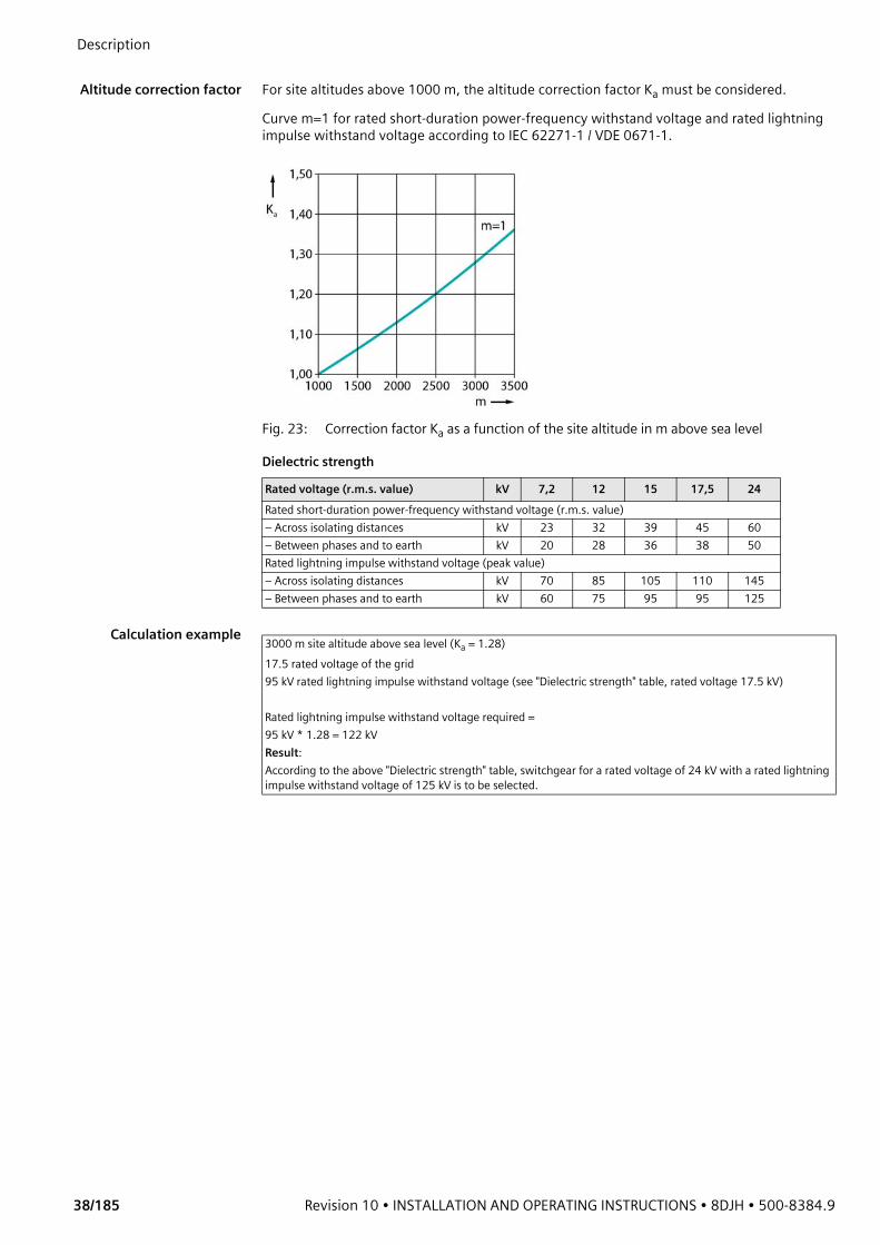
Description
38/185 Revision 10 • INSTALLATION AND OPERATING INSTRUCTIONS • 8DJH • 500-8384.9
Altitude correction factor For site altitudes above 1000 m, the altitude correction factor Ka must be considered.
Curve m=1 for rated short-duration power-frequency withstand voltage and rated lightning impulse withstand voltage according to IEC 62271-1 / VDE 0671-1.
Fig. 23: Correction factor Ka as a function of the site altitude in m above sea level
Dielectric strength
Calculation example
Rated voltage (r.m.s. value) kV 7,2 12 15 17,5 24Rated short-duration power-frequency withstand voltage (r.m.s. value)– Across isolating distances kV 23 32 39 45 60– Between phases and to earth kV 20 28 36 38 50Rated lightning impulse withstand voltage (peak value)– Across isolating distances kV 70 85 105 110 145– Between phases and to earth kV 60 75 95 95 125
3000 m site altitude above sea level (Ka = 1.28)17.5 rated voltage of the grid95 kV rated lightning impulse withstand voltage (see "Dielectric strength" table, rated voltage 17.5 kV)
Rated lightning impulse withstand voltage required = 95 kV * 1.28 = 122 kVResult:According to the above "Dielectric strength" table, switchgear for a rated voltage of 24 kV with a rated lightning impulse withstand voltage of 125 kV is to be selected.
500-8384.9 • INSTALLATION AND OPERATING INSTRUCTIONS • 8DJH • Revision 10 39/185
Description 8.11 Selection of HV HRC fuse-links
Note to HV HRC fuse-links According to IEC 60282-1 (2009) Clause 6.6, the breaking capacity of HV HRC fuse-links is tested within the scope of the type test at 87% of their rated voltage.In three-phase systems with resonance-earthed or isolated neutral, under double earth fault and other conditions, the full phase-to-phase voltage may be available at the HV HRC fuse-link during breaking. Depending on the size of the operating voltage of such a system, this applied voltage may then exceed 87% of the rated voltage.To be observed during configuration of switching devices and selection of HV HRC fuse-links:• Use only fuse-links satisfying the stated operating conditions.• Use only fuse-links whose breaking capacity was tested at least with the maximum system
voltage.In case of doubt, select a suitable HV HRC fuse-link together with the manufacturer.
Allocation of HV HRC fuses and transformersThe three-position switch-disconnector in the transformer feeder (transformer switch) was combined with HV HRC fuse-links and tested in accordance with IEC 62271-105.The following transformer protection table shows HV HRC fuse-links tested by Siemens, which are recommended for transformer protection.The protection table applies to:• Maximum ambient air temperature in the switchgear room of 40 °C according to
IEC62271-1 considering the influence of the switchgear enclosure• Requirements according to IEC 62271-105• Protection of distribution transformers according to IEC 60787 • Rated power of transformer (no overload operation)The specified HV HRC fuse-links make SIBA are type-tested back-up fuses according to IEC 60282-1. The dimensions conform to DIN 43625. The HV HRC fuse-links have a thermal protection in form of a temperature-limiting striker tripping operating in case of defective HV HRC fuse-links or high overload currents.Please contact your regional Siemens representative if you want to use HV HRC fuse-links from other manufacturers.Basis for selection of HV HRC fuse-links:• IEC 60282-1• IEC 62271-105 • IEC 60787 • Recommendations and data sheets of fuse manufacturers• Permissible power loss in the switchgear enclosure at an ambient air temperature of 40° C
ATTENTIONPlease use only fuses tested by Siemens, which are listed in the following fuse tables. ➭ The use of other fuse types must be checked by Siemens in advance. Please contact the
regional Siemens representative.
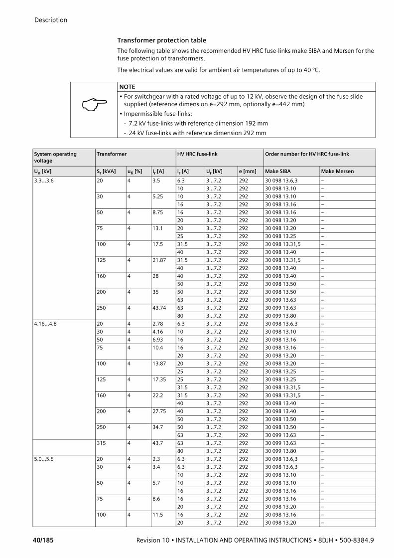
Description
40/185 Revision 10 • INSTALLATION AND OPERATING INSTRUCTIONS • 8DJH • 500-8384.9
Transformer protection tableThe following table shows the recommended HV HRC fuse-links make SIBA and Mersen for the fuse protection of transformers. The electrical values are valid for ambient air temperatures of up to 40 °C.
NOTE• For switchgear with a rated voltage of up to 12 kV, observe the design of the fuse slide
supplied (reference dimension e=292 mm, optionally e=442 mm)• Impermissible fuse-links:
- 7.2 kV fuse-links with reference dimension 192 mm- 24 kV fuse-links with reference dimension 292 mm
System operating voltage
Transformer HV HRC fuse-link Order number for HV HRC fuse-link
Un [kV] Sr [kVA] uK [%] Ir [A] Ir [A] Ur [kV] e [mm] Make SIBA Make Mersen3.3…3.6 20 4 3.5 6.3 3…7.2 292 30 098 13.6,3 –
10 3…7.2 292 30 098 13.10 –30 4 5.25 10 3…7.2 292 30 098 13.10 –
16 3…7.2 292 30 098 13.16 –50 4 8.75 16 3…7.2 292 30 098 13.16 –
20 3…7.2 292 30 098 13.20 –75 4 13.1 20 3…7.2 292 30 098 13.20 –
25 3…7.2 292 30 098 13.25 –100 4 17.5 31.5 3…7.2 292 30 098 13.31,5 –
40 3…7.2 292 30 098 13.40 –125 4 21.87 31.5 3…7.2 292 30 098 13.31,5 –
40 3…7.2 292 30 098 13.40 –160 4 28 40 3…7.2 292 30 098 13.40 –
50 3…7.2 292 30 098 13.50 –200 4 35 50 3…7.2 292 30 098 13.50 –
63 3…7.2 292 30 099 13.63 –250 4 43.74 63 3…7.2 292 30 099 13.63 –
80 3…7.2 292 30 099 13.80 –4.16…4.8 20 4 2.78 6.3 3…7.2 292 30 098 13.6,3 –
30 4 4.16 10 3…7.2 292 30 098 13.10 –50 4 6.93 16 3…7.2 292 30 098 13.16 –75 4 10.4 16 3…7.2 292 30 098 13.16 –
20 3…7.2 292 30 098 13.20 –100 4 13.87 20 3…7.2 292 30 098 13.20 –
25 3…7.2 292 30 098 13.25 –125 4 17.35 25 3…7.2 292 30 098 13.25 –
31.5 3…7.2 292 30 098 13.31,5 –160 4 22.2 31.5 3…7.2 292 30 098 13.31,5 –
40 3…7.2 292 30 098 13.40 –200 4 27.75 40 3…7.2 292 30 098 13.40 –
50 3…7.2 292 30 098 13.50 –250 4 34.7 50 3…7.2 292 30 098 13.50 –
63 3…7.2 292 30 099 13.63 –315 4 43.7 63 3…7.2 292 30 099 13.63 –
80 3…7.2 292 30 099 13.80 –5.0…5.5 20 4 2.3 6.3 3…7.2 292 30 098 13.6,3 –
30 4 3.4 6.3 3…7.2 292 30 098 13.6,3 –10 3…7.2 292 30 098 13.10 –
50 4 5.7 10 3…7.2 292 30 098 13.10 –16 3…7.2 292 30 098 13.16 –
75 4 8.6 16 3…7.2 292 30 098 13.16 –20 3…7.2 292 30 098 13.20 –
100 4 11.5 16 3…7.2 292 30 098 13.16 –20 3…7.2 292 30 098 13.20 –
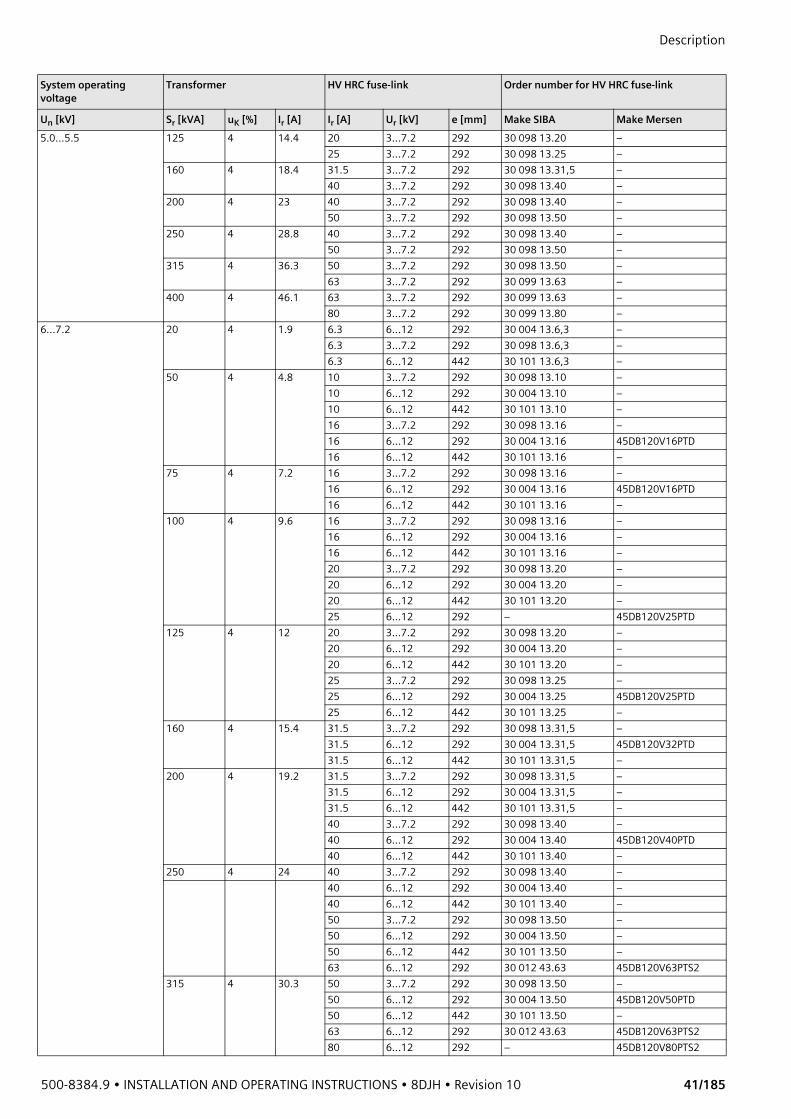
500-8384.9 • INSTALLATION AND OPERATING INSTRUCTIONS • 8DJH • Revision 10 41/185
Description
5.0…5.5 125 4 14.4 20 3…7.2 292 30 098 13.20 –25 3…7.2 292 30 098 13.25 –
160 4 18.4 31.5 3…7.2 292 30 098 13.31,5 –40 3…7.2 292 30 098 13.40 –
200 4 23 40 3…7.2 292 30 098 13.40 –50 3…7.2 292 30 098 13.50 –
250 4 28.8 40 3…7.2 292 30 098 13.40 –50 3…7.2 292 30 098 13.50 –
315 4 36.3 50 3…7.2 292 30 098 13.50 –63 3…7.2 292 30 099 13.63 –
400 4 46.1 63 3…7.2 292 30 099 13.63 –80 3…7.2 292 30 099 13.80 –
6…7.2 20 4 1.9 6.3 6…12 292 30 004 13.6,3 –6.3 3…7.2 292 30 098 13.6,3 –6.3 6…12 442 30 101 13.6,3 –
50 4 4.8 10 3…7.2 292 30 098 13.10 –10 6…12 292 30 004 13.10 –10 6…12 442 30 101 13.10 –16 3…7.2 292 30 098 13.16 –16 6…12 292 30 004 13.16 45DB120V16PTD16 6…12 442 30 101 13.16 –
75 4 7.2 16 3…7.2 292 30 098 13.16 –16 6…12 292 30 004 13.16 45DB120V16PTD16 6…12 442 30 101 13.16 –
100 4 9.6 16 3…7.2 292 30 098 13.16 –16 6…12 292 30 004 13.16 –16 6…12 442 30 101 13.16 –20 3…7.2 292 30 098 13.20 –20 6…12 292 30 004 13.20 –20 6…12 442 30 101 13.20 –25 6…12 292 – 45DB120V25PTD
125 4 12 20 3…7.2 292 30 098 13.20 –20 6…12 292 30 004 13.20 –20 6…12 442 30 101 13.20 –25 3…7.2 292 30 098 13.25 –25 6…12 292 30 004 13.25 45DB120V25PTD25 6…12 442 30 101 13.25 –
160 4 15.4 31.5 3…7.2 292 30 098 13.31,5 –31.5 6…12 292 30 004 13.31,5 45DB120V32PTD31.5 6…12 442 30 101 13.31,5 –
200 4 19.2 31.5 3…7.2 292 30 098 13.31,5 –31.5 6…12 292 30 004 13.31,5 –31.5 6…12 442 30 101 13.31,5 –40 3…7.2 292 30 098 13.40 –40 6…12 292 30 004 13.40 45DB120V40PTD40 6…12 442 30 101 13.40 –
250 4 24 40 3…7.2 292 30 098 13.40 –40 6…12 292 30 004 13.40 –40 6…12 442 30 101 13.40 –50 3…7.2 292 30 098 13.50 –50 6…12 292 30 004 13.50 –50 6…12 442 30 101 13.50 –63 6…12 292 30 012 43.63 45DB120V63PTS2
315 4 30.3 50 3…7.2 292 30 098 13.50 –50 6…12 292 30 004 13.50 45DB120V50PTD50 6…12 442 30 101 13.50 –63 6…12 292 30 012 43.63 45DB120V63PTS280 6…12 292 – 45DB120V80PTS2
System operating voltage
Transformer HV HRC fuse-link Order number for HV HRC fuse-link
Un [kV] Sr [kVA] uK [%] Ir [A] Ir [A] Ur [kV] e [mm] Make SIBA Make Mersen

Description
42/185 Revision 10 • INSTALLATION AND OPERATING INSTRUCTIONS • 8DJH • 500-8384.9
6…7.2 400 4 38.4 63 6…12 292 30 012 43.63 –80 6…12 292 30 012 43.80 45DB120V80PTS280 6…12 442 30 102 43.80 –63 3…7.2 292 30 099 13.63 –63 6…12 292 30 012 13.63 –63 6…12 442 30 102 13.63 –100 6…12 292 – 45DB120V100PTS2
500 4 48 80 6…12 292 30 012 43.80 –80 6…12 442 30 102 43.80 –80 3…7.2 292 30 099 13.80 –80 6…12 292 30 012 13.80 –80 6…12 442 30 102 13.80 –100 6…12 292 30 012 43,100 45DB120V100PTS2100 6…12 442 30 102 43,100 45DB120V100PTS3
630 4 61 100 6…12 442 30 102 43,100 –125 6…12 292 30 103 43,125 45DB120V125PTS2125 6…12 442 30 020 43,125 –
800 4 77 160 6…12 442 – 45DB120V160PTS310…12 20 4 1.15 4 6…12 292 30 004 13.4 –
50 4 2.9 10 6…12 292 30 004 13.10 45DB120V10PTD10 6…12 442 30 101 13.10 –10 10…17.5 292 30 255 13.10 –10 10…17.5 442 30 231 13.10 –10 10…24 442 30 006 13.10 45DB240V10PTD
75 4 4.3 10 6…12 292 30 004 13.10 45DB120V10PTD10 6…12 442 30 101 13.10 –10 10…17.5 292 30 255 13.10 –10 10…17.5 442 30 231 13.10 –10 10…24 442 30 006 13.10 45DB240V10PTD
100 4 5.8 16 6…12 292 30 004 13.16 –16 6…12 442 30 101 13.16 –16 10…17.5 292 30 255 13.16 –16 10…17.5 442 30 231 13.16 –16 10…24 442 30 006 13.16 45DB240V16PTD
125 4 7.2 16 6…12 292 30 004 13.16 45DB120V16PTD16 6…12 442 30 101 13.16 –16 10…17.5 292 30 255 13.16 –16 10…17.5 442 30 231 13.16 –16 10…24 442 30 006 13.16 45DB240V16PTD20 10…24 442 – 45DB240V20PTD
160 4 9.3 20 6…12 292 30 004 13.20 45DB120V20PTD20 6…12 442 30 101 13.20 –20 10…17.5 292 30 221 13.20 –20 10…17.5 442 30 231 13.20 –20 10…24 442 30 006 13.20 45DB240V20PTD
200 4 11.5 25 6…12 292 30 004 13.25 45DB120V25PTD25 6…12 442 30 101 13.25 –25 10…17.5 292 30 221 13.25 –25 10…17.5 442 30 231 13.25 –25 10…24 442 30 006 13.25 45DB240V25PTD
250 4 14.5 25 6…12 292 30 004 13.25 45DB120V25PTD25 6…12 442 30 101 13.25 –25 10…17.5 292 30 221 13.25 –25 10…17.5 442 30 231 13.25 –25 10…24 442 30 006 13.25 45DB240V25PTD31.5 6…12 292 30 004 13.31,5 –31.5 6…12 442 30 101 13.31,5 –31.5 10…17.5 292 30 221 13.31,5 –
System operating voltage
Transformer HV HRC fuse-link Order number for HV HRC fuse-link
Un [kV] Sr [kVA] uK [%] Ir [A] Ir [A] Ur [kV] e [mm] Make SIBA Make Mersen
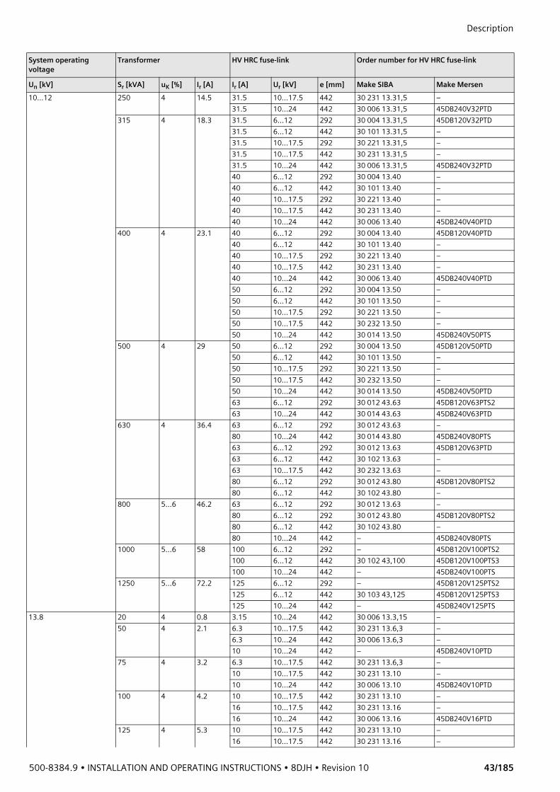
500-8384.9 • INSTALLATION AND OPERATING INSTRUCTIONS • 8DJH • Revision 10 43/185
Description
10…12 250 4 14.5 31.5 10…17.5 442 30 231 13.31,5 –31.5 10…24 442 30 006 13.31,5 45DB240V32PTD
315 4 18.3 31.5 6…12 292 30 004 13.31,5 45DB120V32PTD31.5 6…12 442 30 101 13.31,5 –31.5 10…17.5 292 30 221 13.31,5 –31.5 10…17.5 442 30 231 13.31,5 –31.5 10…24 442 30 006 13.31,5 45DB240V32PTD40 6…12 292 30 004 13.40 –40 6…12 442 30 101 13.40 –40 10…17.5 292 30 221 13.40 –40 10…17.5 442 30 231 13.40 –40 10…24 442 30 006 13.40 45DB240V40PTD
400 4 23.1 40 6…12 292 30 004 13.40 45DB120V40PTD40 6…12 442 30 101 13.40 –40 10…17.5 292 30 221 13.40 –40 10…17.5 442 30 231 13.40 –40 10…24 442 30 006 13.40 45DB240V40PTD50 6…12 292 30 004 13.50 –50 6…12 442 30 101 13.50 –50 10…17.5 292 30 221 13.50 –50 10…17.5 442 30 232 13.50 –50 10…24 442 30 014 13.50 45DB240V50PTS
500 4 29 50 6…12 292 30 004 13.50 45DB120V50PTD50 6…12 442 30 101 13.50 –50 10…17.5 292 30 221 13.50 –50 10…17.5 442 30 232 13.50 –50 10…24 442 30 014 13.50 45DB240V50PTD63 6…12 292 30 012 43.63 45DB120V63PTS263 10…24 442 30 014 43.63 45DB240V63PTD
630 4 36.4 63 6…12 292 30 012 43.63 –80 10…24 442 30 014 43.80 45DB240V80PTS63 6…12 292 30 012 13.63 45DB120V63PTD63 6…12 442 30 102 13.63 –63 10…17.5 442 30 232 13.63 –80 6…12 292 30 012 43.80 45DB120V80PTS280 6…12 442 30 102 43.80 –
800 5…6 46.2 63 6…12 292 30 012 13.63 –80 6…12 292 30 012 43.80 45DB120V80PTS280 6…12 442 30 102 43.80 –80 10…24 442 – 45DB240V80PTS
1000 5…6 58 100 6…12 292 – 45DB120V100PTS2100 6…12 442 30 102 43,100 45DB120V100PTS3100 10…24 442 – 45DB240V100PTS
1250 5…6 72.2 125 6…12 292 – 45DB120V125PTS2125 6…12 442 30 103 43,125 45DB120V125PTS3125 10…24 442 – 45DB240V125PTS
13.8 20 4 0.8 3.15 10…24 442 30 006 13.3,15 –50 4 2.1 6.3 10…17.5 442 30 231 13.6,3 –
6.3 10…24 442 30 006 13.6,3 –10 10…24 442 – 45DB240V10PTD
75 4 3.2 6.3 10…17.5 442 30 231 13.6,3 –10 10…17.5 442 30 231 13.10 –10 10…24 442 30 006 13.10 45DB240V10PTD
100 4 4.2 10 10…17.5 442 30 231 13.10 –16 10…17.5 442 30 231 13.16 –16 10…24 442 30 006 13.16 45DB240V16PTD
125 4 5.3 10 10…17.5 442 30 231 13.10 –16 10…17.5 442 30 231 13.16 –
System operating voltage
Transformer HV HRC fuse-link Order number for HV HRC fuse-link
Un [kV] Sr [kVA] uK [%] Ir [A] Ir [A] Ur [kV] e [mm] Make SIBA Make Mersen
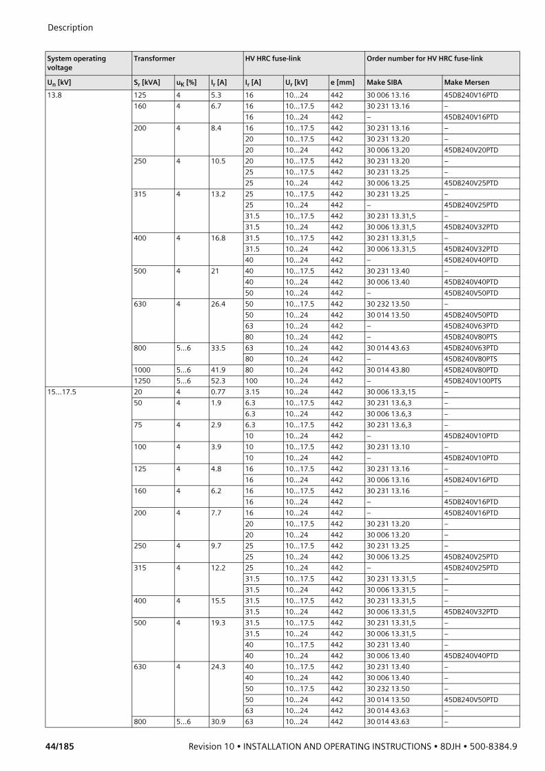
Description
44/185 Revision 10 • INSTALLATION AND OPERATING INSTRUCTIONS • 8DJH • 500-8384.9
13.8 125 4 5.3 16 10…24 442 30 006 13.16 45DB240V16PTD 160 4 6.7 16 10…17.5 442 30 231 13.16 –
16 10…24 442 – 45DB240V16PTD200 4 8.4 16 10…17.5 442 30 231 13.16 –
20 10…17.5 442 30 231 13.20 –20 10…24 442 30 006 13.20 45DB240V20PTD
250 4 10.5 20 10…17.5 442 30 231 13.20 –25 10…17.5 442 30 231 13.25 –25 10…24 442 30 006 13.25 45DB240V25PTD
315 4 13.2 25 10…17.5 442 30 231 13.25 –25 10…24 442 – 45DB240V25PTD31.5 10…17.5 442 30 231 13.31,5 –31.5 10…24 442 30 006 13.31,5 45DB240V32PTD
400 4 16.8 31.5 10…17.5 442 30 231 13.31,5 –31.5 10…24 442 30 006 13.31,5 45DB240V32PTD40 10…24 442 – 45DB240V40PTD
500 4 21 40 10…17.5 442 30 231 13.40 –40 10…24 442 30 006 13.40 45DB240V40PTD50 10…24 442 – 45DB240V50PTD
630 4 26.4 50 10…17.5 442 30 232 13.50 –50 10…24 442 30 014 13.50 45DB240V50PTD63 10…24 442 – 45DB240V63PTD80 10…24 442 – 45DB240V80PTS
800 5…6 33.5 63 10…24 442 30 014 43.63 45DB240V63PTD80 10…24 442 – 45DB240V80PTS
1000 5…6 41.9 80 10…24 442 30 014 43.80 45DB240V80PTD1250 5…6 52.3 100 10…24 442 – 45DB240V100PTS
15…17.5 20 4 0.77 3.15 10…24 442 30 006 13.3,15 –50 4 1.9 6.3 10…17.5 442 30 231 13.6,3 –
6.3 10…24 442 30 006 13.6,3 –75 4 2.9 6.3 10…17.5 442 30 231 13.6,3 –
10 10…24 442 – 45DB240V10PTD100 4 3.9 10 10…17.5 442 30 231 13.10 –
10 10…24 442 – 45DB240V10PTD125 4 4.8 16 10…17.5 442 30 231 13.16 –
16 10…24 442 30 006 13.16 45DB240V16PTD160 4 6.2 16 10…17.5 442 30 231 13.16 –
16 10…24 442 – 45DB240V16PTD200 4 7.7 16 10…24 442 – 45DB240V16PTD
20 10…17.5 442 30 231 13.20 –20 10…24 442 30 006 13.20 –
250 4 9.7 25 10…17.5 442 30 231 13.25 –25 10…24 442 30 006 13.25 45DB240V25PTD
315 4 12.2 25 10…24 442 – 45DB240V25PTD31.5 10…17.5 442 30 231 13.31,5 –31.5 10…24 442 30 006 13.31,5 –
400 4 15.5 31.5 10…17.5 442 30 231 13.31,5 –31.5 10…24 442 30 006 13.31,5 45DB240V32PTD
500 4 19.3 31.5 10…17.5 442 30 231 13.31,5 –31.5 10…24 442 30 006 13.31,5 –40 10…17.5 442 30 231 13.40 –40 10…24 442 30 006 13.40 45DB240V40PTD
630 4 24.3 40 10…17.5 442 30 231 13.40 –40 10…24 442 30 006 13.40 –50 10…17.5 442 30 232 13.50 –50 10…24 442 30 014 13.50 45DB240V50PTD63 10…24 442 30 014 43.63 –
800 5…6 30.9 63 10…24 442 30 014 43.63 –
System operating voltage
Transformer HV HRC fuse-link Order number for HV HRC fuse-link
Un [kV] Sr [kVA] uK [%] Ir [A] Ir [A] Ur [kV] e [mm] Make SIBA Make Mersen
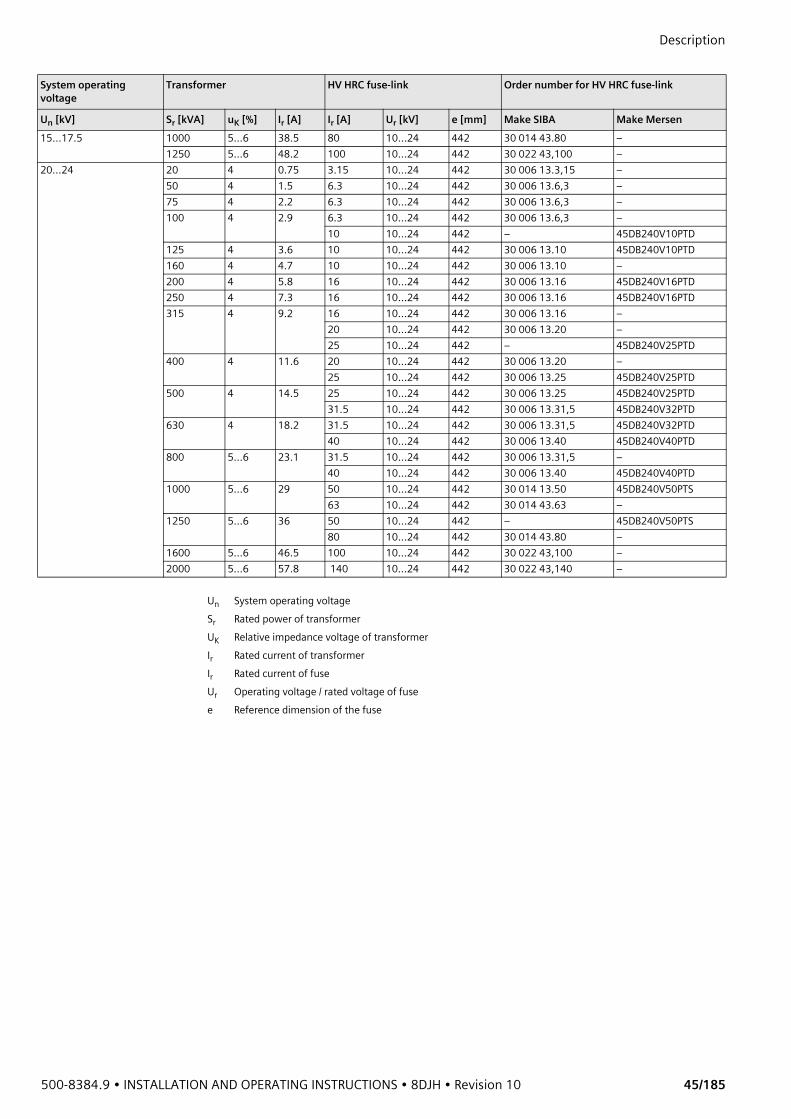
500-8384.9 • INSTALLATION AND OPERATING INSTRUCTIONS • 8DJH • Revision 10 45/185
Description
15…17.5 1000 5…6 38.5 80 10…24 442 30 014 43.80 –1250 5…6 48.2 100 10…24 442 30 022 43,100 –
20…24 20 4 0.75 3.15 10…24 442 30 006 13.3,15 –50 4 1.5 6.3 10…24 442 30 006 13.6,3 –75 4 2.2 6.3 10…24 442 30 006 13.6,3 –100 4 2.9 6.3 10…24 442 30 006 13.6,3 –
10 10…24 442 – 45DB240V10PTD125 4 3.6 10 10…24 442 30 006 13.10 45DB240V10PTD160 4 4.7 10 10…24 442 30 006 13.10 –200 4 5.8 16 10…24 442 30 006 13.16 45DB240V16PTD250 4 7.3 16 10…24 442 30 006 13.16 45DB240V16PTD315 4 9.2 16 10…24 442 30 006 13.16 –
20 10…24 442 30 006 13.20 –25 10…24 442 – 45DB240V25PTD
400 4 11.6 20 10…24 442 30 006 13.20 –25 10…24 442 30 006 13.25 45DB240V25PTD
500 4 14.5 25 10…24 442 30 006 13.25 45DB240V25PTD31.5 10…24 442 30 006 13.31,5 45DB240V32PTD
630 4 18.2 31.5 10…24 442 30 006 13.31,5 45DB240V32PTD40 10…24 442 30 006 13.40 45DB240V40PTD
800 5…6 23.1 31.5 10…24 442 30 006 13.31,5 –40 10…24 442 30 006 13.40 45DB240V40PTD
1000 5…6 29 50 10…24 442 30 014 13.50 45DB240V50PTS63 10…24 442 30 014 43.63 –
1250 5…6 36 50 10…24 442 – 45DB240V50PTS80 10…24 442 30 014 43.80 –
1600 5…6 46.5 100 10…24 442 30 022 43,100 –2000 5…6 57.8 140 10…24 442 30 022 43,140 –
System operating voltage
Transformer HV HRC fuse-link Order number for HV HRC fuse-link
Un [kV] Sr [kVA] uK [%] Ir [A] Ir [A] Ur [kV] e [mm] Make SIBA Make Mersen
Un System operating voltageSr Rated power of transformerUK Relative impedance voltage of transformerIr Rated current of transformerIr Rated current of fuseUr Operating voltage / rated voltage of fusee Reference dimension of the fuse
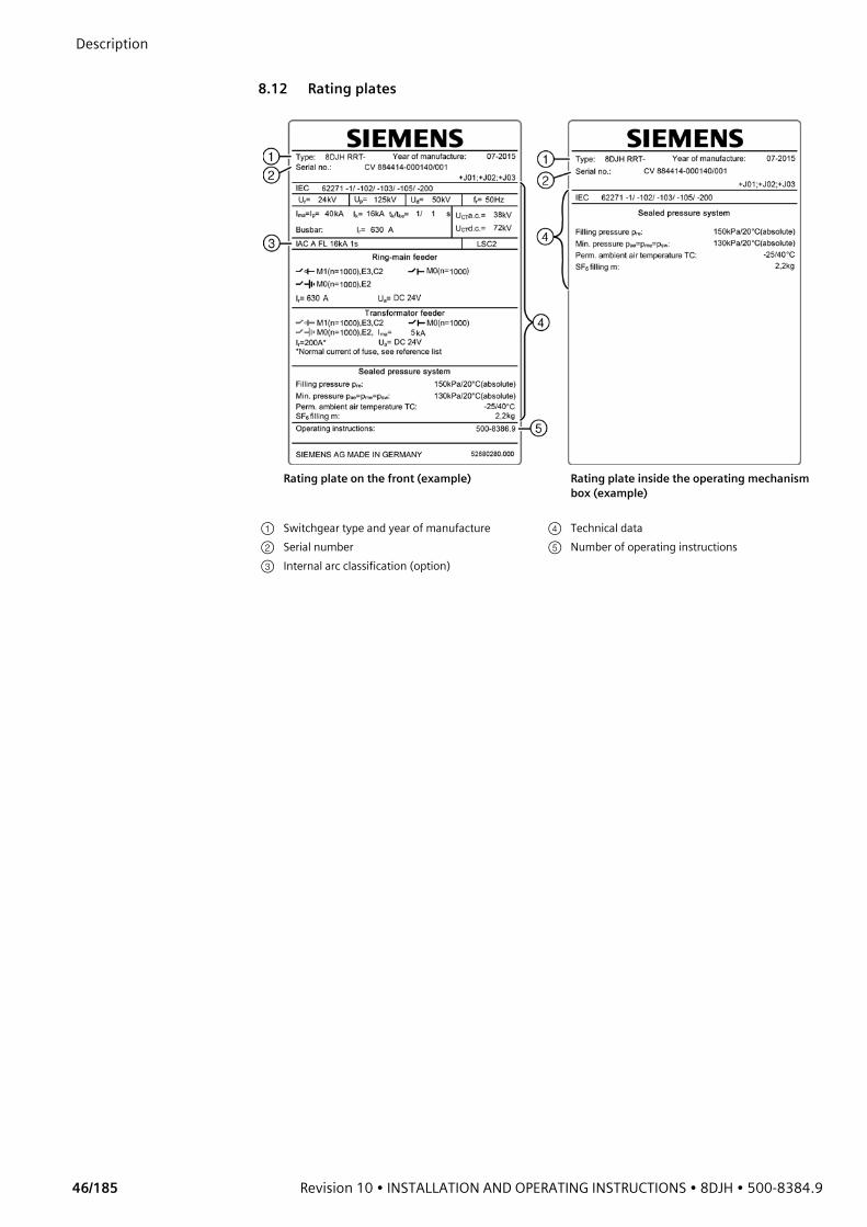
Description
46/185 Revision 10 • INSTALLATION AND OPERATING INSTRUCTIONS • 8DJH • 500-8384.9
8.12 Rating plates
Rating plate on the front (example) Rating plate inside the operating mechanism box (example)
① Switchgear type and year of manufacture ④ Technical data② Serial number ⑤ Number of operating instructions③ Internal arc classification (option)
500-8384.9 • INSTALLATION AND OPERATING INSTRUCTIONS • 8DJH • Revision 10 47/185
Description 9 Switchgear maintenance
Maintenance 8DJH switchgear is maintenance-free under normal ambient conditions according to IEC 62271-1. Inspection or testing of the secondary equipment such as the capacitive voltage detecting system is done within the scope of locally applicable laws and regulations.
Checking the dew point The dew point needs no checking throughout the entire service life.
Checking the gas quality The gas quality needs no checking throughout the entire service life.
Test operation A function test of the switching devices is required only at the time of commissioning, modification or retrofit at the panel.
Replacement ofcomponents
Due to the fact that all parts of this switchgear have been optimized to last the normal service life, it is not possible to recommend particular spare parts.Information required for spare part orders of single components and devices:• Type and serial number of the switchgear (see rating plates)• Description or identification of the device or part on the basis of a sketch, a photo or a circuit
diagram
10 End of life
SF6 gas Before recycling the materials, evacuate the SF6 gas professionally and prepare it for further use. For further information, please contact the Siemens Service Hotline.
Recycling The switchgear is an environmentally compatible product.The components of the switchgear can be recycled in an environmentally compatible way by dismantling into sorted scrap and residual mixed scrap.After evacuating the SF6 gas, the switchgear mainly consists of the following materials:• Steel (enclosure and operating mechanisms) • Stainless steel (vessel) • Copper (conductor bars) • Silver (contacts) • Cast-resin based on epoxy resin (bushings and post insulators)• Plastic materials (switching devices and fuse tripping) • Silicone rubberThe switchgear can be recycled in ecological manner in compliance with existing legislation.Auxiliary devices such as short-circuit indicators have to be recycled as electronic scrap.Any existing batteries have to be recycled professionally.As delivered by Siemens, the switchgear does not contain hazardous materials as per the Hazardous Material Regulations applicable in the Federal Republic of Germany. For operation in other countries, the locally applicable laws and regulations must be observed.For further information, please contact the Siemens Service Hotline.
NOTEThe equipment contains the fluorinated greenhouse gas SF6 registered by the Kyoto Protocol with a global warming potential (GWP) of 22 8001). SF6 has to be reclaimed and must not be released into the atmosphere. ➭ For use and handling of SF6, IEC 62271-4: High-voltage switchgear and controlgear -
Part 4: Use and handling of sulphur hexafluoride (SF6) has to be observed.
1) Source: "Regulation (EU) No 517/2014 of the European Parliament and of the Council of 16th April 2014 on fluorinated greenhouse gases and repealing Regulation (EC) No 842/2006"
Installation
48/185 Revision 10 • INSTALLATION AND OPERATING INSTRUCTIONS • 8DJH • 500-8384.9
Installation11 Transport and storage
11.1 Unloading and transport to place of installation
➭ Attach ropes far away on the hoisting tackle. The ropes must not exert any force on the panel walls under load.
➭ Sling the ropes around the ends of the wooden pallets.➭ During transport to the place of installation or storage place, leave the panels on their
transport base for as long as possible.➭ Set down the transport units close to the place of installation or storage place.➭ Observe the installation order of the panels during transport to the switchgear room; leave
space for moving and mounting.➭ Remove the packing close to the place of installation of the panels, and not before
beginning the installation process.
ATTENTIONNon-observance of the following instructions can endanger people or damage the transport units while unloading.➭ Make sure that nobody is standing in the swinging area of lifted switchgear.➭ Attach ropes far enough on the hoisting tackle so that they cannot exert any forces on the
panel walls under load.➭ Observe the dimensions and weights of the transport unit (delivery note).➭ Observe even weight distribution and the high center of gravity of the switchgear.➭ Ensure that the lifting tools and transport gear used meet the requirements as regards
construction and load-bearing capacity.➭ Do not climb onto the roof of the panels.➭ If the low-voltage compartment is removed, do not step on the mounting plates of the
low-voltage compartment.➭ Observe the instructions on the packing.➭ Unload the transport units in packed condition and leave packed for as long as possible.➭ Do not damage the PE protective foil.

500-8384.9 • INSTALLATION AND OPERATING INSTRUCTIONS • 8DJH • Revision 10 49/185
Installation Transport facilities
Switchgear transport withtransport eyes
The transport eyes are pre-assembled at the factory.
➭ Attach the lifting equipment or the rod.➭ Transport the switchgear.
Craning with pallet Transport with crane rod Transport with lifting truck
Transport with fork-lift truck, suspended Transport with fork-lift truck, standing
① Crane hook ③ Crane rod (Ø 40 mm, observe switchgear weight)② Transport pallet ④ Lifting eye
For delivery without low-voltage compartment and without pressure absorber:
For delivery with low-voltage compartment or pressure absorber:
Before transporting the switchgear, the transport eyes must be turned.➭ Undo the bolt-and-washer assembly ② of the
transport eyes ① , and turn the transport eyes upwards by 180°.
➭ Re-tighten the bolt-and-washer assembly ② .
The transport eyes are fixed to the clamping plate with 2 bolt-and-washer assemblies each.
① Lifting eye ② Bolt-and-washer assembly

Installation
50/185 Revision 10 • INSTALLATION AND OPERATING INSTRUCTIONS • 8DJH • 500-8384.9
➭ Observe the adhesive label with transport information provided on the switchgear. - The angle between the crane chains at the lifting facility must be less than 90°. - The distance between the transport eyes and the lifting facility must be at least half the
switchgear width.
➭ Lift or lower just slowly, as the switchgear will swing into the center of gravity when it is lifted.
➭ While lifting, observe parts laid inside such as cable-type transformers, connecting cables.
11.2 PackingThe transport units can be packed as follows:• On pallets, covered with PE protective foil • In a seaworthy crate (switchgear is sealed with desiccant bags in PE foil)• Other packings in special cases (e.g. latticed crate, cardboard cover for airfreight)
Transport unit Transport units consist either of individual panels or panel blocks with max. four functions, and the switchgear accessories. The switchgear accessories are packed in the cable compartment of the first panel or in a separate transport box, depending on the extent.
ATTENTIONDanger due to transport units falling down. The center of gravity of the transport units is not always located under the fixing point.➭ Lift the transport units slowly.➭ There must be no persons standing in the swinging area of lifted transport units.➭ Transport only transport units with a max. width of 2.00 m or max. height of 2.60 m.
Fig. 24: Adhesive label with transport information on the switchgear (example)
① Pallet② Bolted joint between
transport unit and pallet ③ Transport eyes④ Clearance for fork-lift trucks⑤ Cable compartment cover⑥ Ready-for-service indicator⑦ Center of gravity
ATTENTIONPacking and consumable materials of the switchgear must be disposed of in an environmentally compatible way or recycled.➭ Observe local regulations for disposal and environmental protection.
500-8384.9 • INSTALLATION AND OPERATING INSTRUCTIONS • 8DJH • Revision 10 51/185
Installation 11.3 Completeness and transport damage
Checking forcompleteness
➭ Check whether the delivery is complete using the delivery notes and packing lists.➭ Compare the serial number of the switchgear printed on the delivery note with the serial
number on the packing and the serial number on the rating plate.➭ Check whether the switchgear accessories are complete.
Transport damages ➭ Temporarily open the packing in a weatherproof place to detect hidden damages. In order to prevent pollution of the switchgear, do not remove the PE foil completely until reaching the final mounting position.
➭ Check the switchgear for transport damages.➭ Check service readiness (see page 58, "Checking service readiness").➭ Refit the packing at the best. ➭ Determine and document detected defects and transport damages immediately, e.g. on the
freight documents.➭ Document larger defects and transport damages photographically.➭ Please contact the regional Siemens representative in order to repair the transport damages.
11.4 Intermediate storage
For intermediate storage of delivered switchgear, parts of the switchgear or accessories before installation, select a suitable storage place.
DANGERRisk of injury and damage to the storage place and the stored goods if the storage space is overloaded.➭ Observe the load-bearing capacity of the floor.➭ Do not stack the transport units.➭ Do not overload lighter components by stacking.
ATTENTIONFire risk. The transport unit is packed in flammable materials.➭ No smoking.➭ Keep fire extinguishers in a weatherproof place.➭ Mark the location of the fire extinguisher.
ATTENTIONIf the supplied desiccant bags are not stored in the undamaged original packings, the desiccant bags lose their effectiveness.➭ Do not damage or remove packing of desiccant bags.➭ Do not unpack desiccant bags before use.

Installation
52/185 Revision 10 • INSTALLATION AND OPERATING INSTRUCTIONS • 8DJH • 500-8384.9
Observe the information provided on the switchgear packing and concerning transport and storage.
Ambient air temperaturesfor storage
Permissible ambient air temperatures for storage of the switchgear:• Switchgear with secondary system: -25 °C to +55 °C (option: -40 °C to +70 °C) in
accordance with the installed secondary devices• Switchgear without secondary system: -40 °C to +70 °C
Intermediate storage ofthe transport units
Storage in closed rooms• Intermediate storage is possible in the undamaged original packing including transport base
(all packing types)Outdoor storage:• Intermediate storage is possible in the undamaged original packing including transport
base, executed as seaworthy crate, for a maximum of 6 months • Longer storage time is possible after replacement of the desiccant by expert personnel; to
do this, contact the regional Siemens representativeRequirements on the storage place:• Ground with adequate load-bearing capacity, solid, even and dry• Ambient air temperatures always within the limit values for the switchgear• Protected against mechanical damages, e.g. collision with vehicles, falling objects, tilting,
falling over, vandalism• Protected against humidity, e.g. rain, flooding, melting water, foam, persistent high air
humidity, floor humidity• Protected against direct solar radiation• Protected against corrosive, dust-ridden or arenaceous ambient, and against pollution• Protected against the wind• Protected against vermin (e.g. rats, mice, insects), and vegetation overgrowthInstructions for intermediate storage:• Do not unpack small parts (to prevent corrosion and loss)• Check packing for ingress of humidity (condensation) every 4 weeks
Fig. 25: Storage and transport information (example)
① Transport and store in vertical position
② Fragile contents③ Protect against moisture④ Pressure⑤ Humidity⑥ Storage temperature, values
depending on ordered design
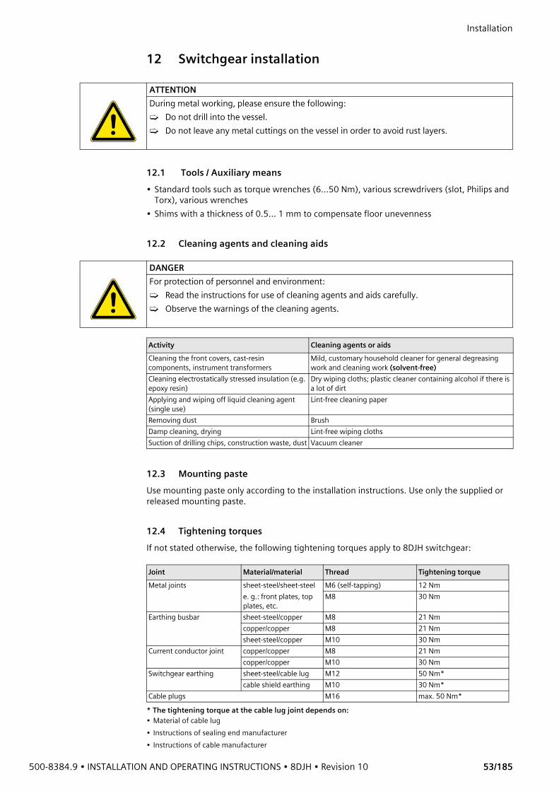
500-8384.9 • INSTALLATION AND OPERATING INSTRUCTIONS • 8DJH • Revision 10 53/185
Installation 12 Switchgear installation
12.1 Tools / Auxiliary means• Standard tools such as torque wrenches (6...50 Nm), various screwdrivers (slot, Philips and
Torx), various wrenches• Shims with a thickness of 0.5... 1 mm to compensate floor unevenness
12.2 Cleaning agents and cleaning aids
12.3 Mounting pasteUse mounting paste only according to the installation instructions. Use only the supplied or released mounting paste.
12.4 Tightening torquesIf not stated otherwise, the following tightening torques apply to 8DJH switchgear:
ATTENTIONDuring metal working, please ensure the following:➭ Do not drill into the vessel.➭ Do not leave any metal cuttings on the vessel in order to avoid rust layers.
DANGERFor protection of personnel and environment:➭ Read the instructions for use of cleaning agents and aids carefully.➭ Observe the warnings of the cleaning agents.
Activity Cleaning agents or aidsCleaning the front covers, cast-resin components, instrument transformers
Mild, customary household cleaner for general degreasing work and cleaning work (solvent-free)
Cleaning electrostatically stressed insulation (e.g. epoxy resin)
Dry wiping cloths; plastic cleaner containing alcohol if there is a lot of dirt
Applying and wiping off liquid cleaning agent (single use)
Lint-free cleaning paper
Removing dust BrushDamp cleaning, drying Lint-free wiping clothsSuction of drilling chips, construction waste, dust Vacuum cleaner
Joint Material/material Thread Tightening torqueMetal joints sheet-steel/sheet-steel
e. g.: front plates, top plates, etc.
M6 (self-tapping) 12 NmM8 30 Nm
Earthing busbar sheet-steel/copper M8 21 Nmcopper/copper M8 21 Nmsheet-steel/copper M10 30 Nm
Current conductor joint copper/copper M8 21 Nmcopper/copper M10 30 Nm
Switchgear earthing sheet-steel/cable lug M12 50 Nm*cable shield earthing M10 30 Nm*
Cable plugs M16 max. 50 Nm** The tightening torque at the cable lug joint depends on:• Material of cable lug• Instructions of sealing end manufacturer• Instructions of cable manufacturer

Installation
54/185 Revision 10 • INSTALLATION AND OPERATING INSTRUCTIONS • 8DJH • 500-8384.9
12.5 Comments on electromagnetic compatibilityTo achieve appropriate electromagnetic compatibility (EMC), some basic requirements must be observed while erecting the switchgear. This applies especially to the installation and connection of external cables and wires.Basic measures for ensuring EMC are already taken during design and assembly of the switchgear panels. Among other things, these measures include:• The low-voltage compartment is an integral part of the panel, which means that the
protection and control devices with the internal wiring are metal-enclosed.• Reliable earth connections of the frame parts via toothed contact washers or locking
washers.• Inside the panel, wires are laid in metal ducts.• Spatial separation of sensitive signal wires from wires with high interference voltage levels.• Limitation of switching overvoltages of inductive loads (e.g. relay or contactor coils, motors)
by means of protective circuits with diode, varistor or RC element.• Within the low-voltage compartment, the secondary devices are mounted in defined zones.• Shortest possible connection between corresponding modules in subracks.• Consideration of the magnetic leakage fields of conductor bars and cables.• Protection of subracks and wiring backplanes against interference by perforated shielding
plates.• Large surface bonding between all modules and devices as well as bonding to the earthing
conductor of the switchgear assembly.These measures basically enable proper operation of the switchgear itself. The planner or operator of the switchgear must decide whether additional measures are required depending on the electromagnetic environment where the switchgear is installed. Such measures must be implemented by the installation company in charge.In an environment with heavy electromagnetic interference it may be necessary to use shielded cables and wires for the external connections. This makes it possible to avoid interferences in the low-voltage compartment and thus, undesired influences on the electronic protection and control or other automation devices.Cable shields must be electrically bonded to be able to carry high frequencies, and contacted concentrically at the cable ends.The shields of cables and wires are connected and earthed in the low-voltage compartment.Connect the shields to earth potential - with high electrical conductivity and all around as far as possible. Protect the contact surfaces from corrosion in case of humidity (regular condensation).When laying cables into the switchgear assembly, separate the control, signaling and data cables and other lines with different signal and voltage levels, e.g. by laying them on separate racks or riser cable routes.Corresponding to the different shield designs, there is a number of methods to perform connection. The planning department or site management determines which of the methods will be used, taking EMC requirements into account. The preceding points should always be taken into account.The shield is connected to cables or wires with clamps contacting all around. If low demands are placed on EMC, it is also possible to connect the shield directly to earth potential (combine or twist the shield wires) or via short cable connections. Use cable lugs or wire-end ferrules at the connecting points.Always keep the connecting leads of the shields as short as possible (< 10 cm).If shields are used as protective earth conductors at the same time, the connected plastic-insulated lead must be marked green/yellow over its entire length. Non-insulated connections are inadmissible.
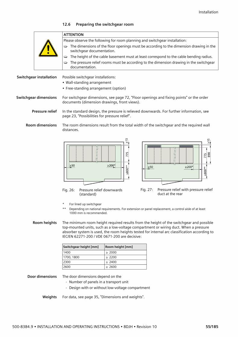
500-8384.9 • INSTALLATION AND OPERATING INSTRUCTIONS • 8DJH • Revision 10 55/185
Installation 12.6 Preparing the switchgear room
Switchgear installation Possible switchgear installations:• Wall-standing arrangement• Free-standing arrangement (option)
Switchgear dimensions For switchgear dimensions, see page 72, "Floor openings and fixing points" or the order documents (dimension drawings, front views).
Pressure relief In the standard design, the pressure is relieved downwards. For further information, see page 23, "Possibilities for pressure relief".
Room dimensions The room dimensions result from the total width of the switchgear and the required wall distances.
Room heights The minimum room height required results from the height of the switchgear and possible top-mounted units, such as a low-voltage compartment or wiring duct. When a pressure absorber system is used, the room heights tested for internal arc classification according to IEC/EN 62271-200 / VDE 0671-200 are decisive:
Door dimensions The door dimensions depend on the- Number of panels in a transport unit- Design with or without low-voltage compartment
Weights For data, see page 35, "Dimensions and weights".
ATTENTIONPlease observe the following for room planning and switchgear installation:➭ The dimensions of the floor openings must be according to the dimension drawing in the
switchgear documentation.➭ The height of the cable basement must at least correspond to the cable bending radius.➭ The pressure relief rooms must be according to the dimension drawing in the switchgear
documentation.
Fig. 26: Pressure relief downwards (standard)
Fig. 27: Pressure relief with pressure relief duct at the rear
* For lined up switchgear** Depending on national requirements. For extension or panel replacement, a control aisle of at least
1000 mm is recommended.
Switchgear height [mm] Room height [mm]1400 ≥ 20001700, 1800 ≥ 22002300 ≥ 24002600 ≥ 2600

Installation
56/185 Revision 10 • INSTALLATION AND OPERATING INSTRUCTIONS • 8DJH • 500-8384.9
12.7 Preparing the foundation• A suitable foundation can be a false floor, a double floor or a reinforced-concrete
foundation. The reinforced-concrete floor must be equipped with foundation rails for supporting the panels.
• As for design and construction of the foundation, the relevant standards DIN 43661 “Fundamentschienen in Innenanlagen der Elektrotechnik” (Foundation rails in electrical indoor installations) and DIN 18202 “Maßtoleranzen im Hochbau” (Blatt 3) (Measuring tolerances in structural engineering (Sheet 3)) apply.
• The dimensions of the floor opening and the fixing points of the switchgear frame are given in the switchgear documentation.
• Determine level differences between the installation surfaces of the panels using a measuring sheet, and compensate with shims.
Stipulations for evennessand straightness
Evenness/straightness tolerance according to DIN 43661: 1 mm for 1 m length, 2 mm over the width of the complete switchgear.
Fig. 28: Measuring sheet for the foundation
① Width of complete switchgear② 750 mm
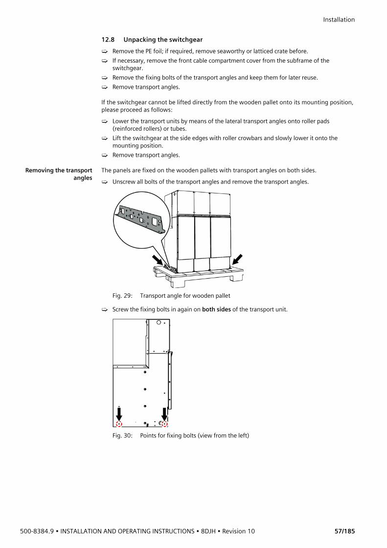
500-8384.9 • INSTALLATION AND OPERATING INSTRUCTIONS • 8DJH • Revision 10 57/185
Installation 12.8 Unpacking the switchgear➭ Remove the PE foil; if required, remove seaworthy or latticed crate before.➭ If necessary, remove the front cable compartment cover from the subframe of the
switchgear.➭ Remove the fixing bolts of the transport angles and keep them for later reuse.➭ Remove transport angles.
If the switchgear cannot be lifted directly from the wooden pallet onto its mounting position, please proceed as follows:➭ Lower the transport units by means of the lateral transport angles onto roller pads
(reinforced rollers) or tubes.➭ Lift the switchgear at the side edges with roller crowbars and slowly lower it onto the
mounting position.➭ Remove transport angles.
Removing the transportangles
The panels are fixed on the wooden pallets with transport angles on both sides.➭ Unscrew all bolts of the transport angles and remove the transport angles.
Fig. 29: Transport angle for wooden pallet
➭ Screw the fixing bolts in again on both sides of the transport unit.
Fig. 30: Points for fixing bolts (view from the left)
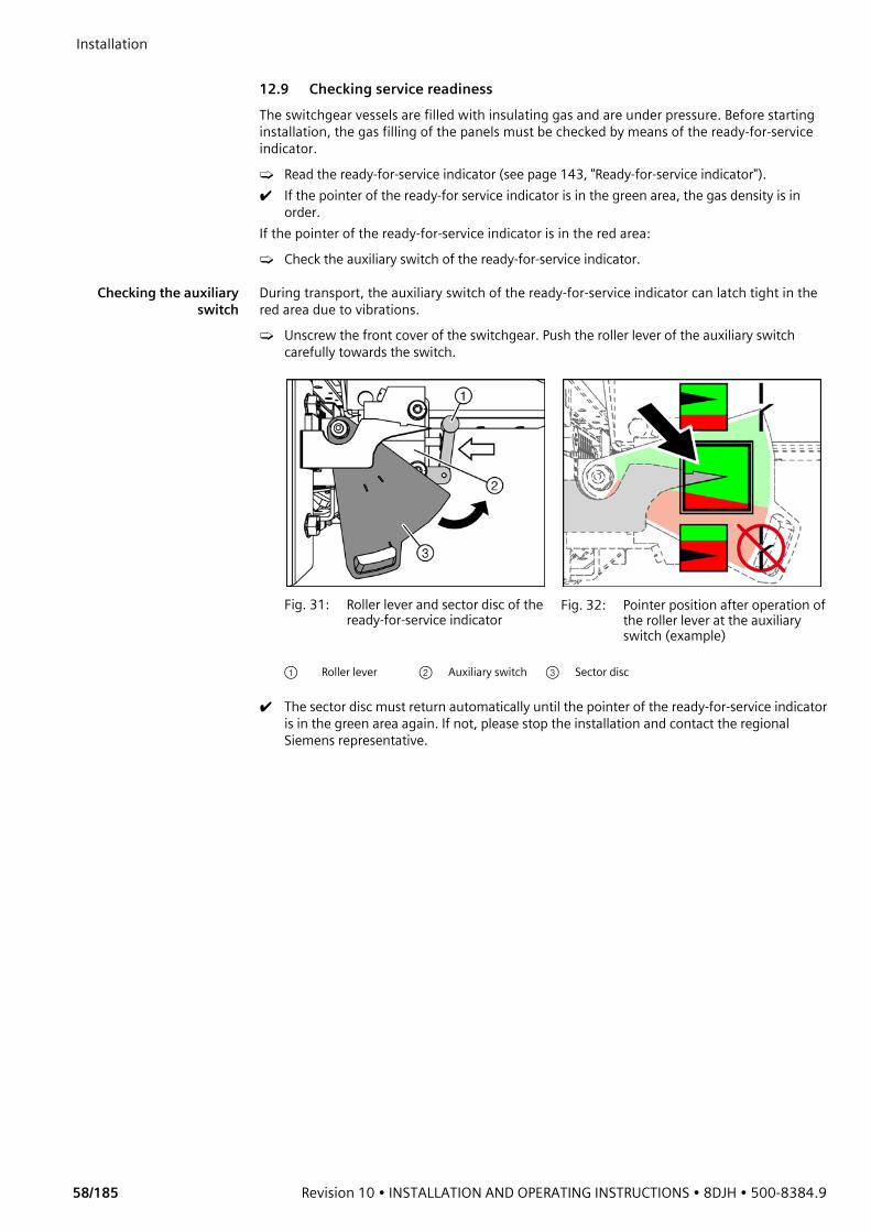
Installation
58/185 Revision 10 • INSTALLATION AND OPERATING INSTRUCTIONS • 8DJH • 500-8384.9
12.9 Checking service readinessThe switchgear vessels are filled with insulating gas and are under pressure. Before starting installation, the gas filling of the panels must be checked by means of the ready-for-service indicator.➭ Read the ready-for-service indicator (see page 143, "Ready-for-service indicator").✔ If the pointer of the ready-for service indicator is in the green area, the gas density is in
order. If the pointer of the ready-for-service indicator is in the red area:➭ Check the auxiliary switch of the ready-for-service indicator.
Checking the auxiliaryswitch
During transport, the auxiliary switch of the ready-for-service indicator can latch tight in the red area due to vibrations.➭ Unscrew the front cover of the switchgear. Push the roller lever of the auxiliary switch
carefully towards the switch.
✔ The sector disc must return automatically until the pointer of the ready-for-service indicator is in the green area again. If not, please stop the installation and contact the regional Siemens representative.
Fig. 31: Roller lever and sector disc of the ready-for-service indicator
Fig. 32: Pointer position after operation of the roller lever at the auxiliary switch (example)
① Roller lever ② Auxiliary switch ③ Sector disc
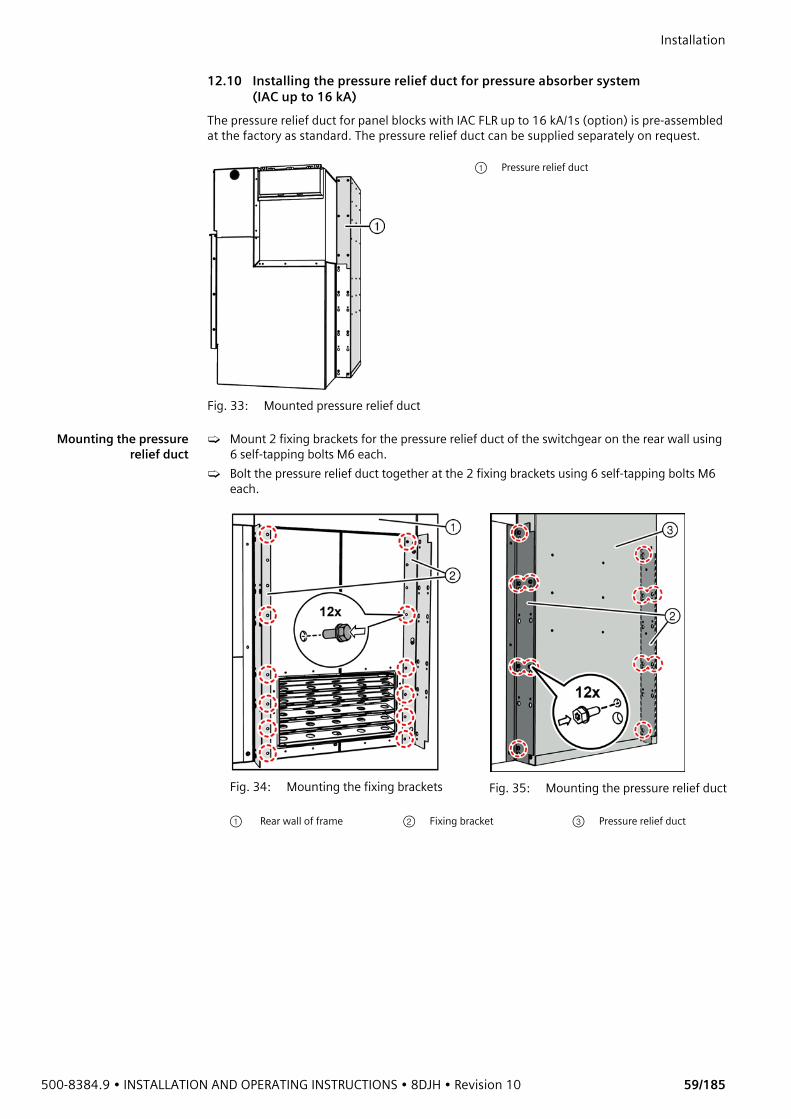
500-8384.9 • INSTALLATION AND OPERATING INSTRUCTIONS • 8DJH • Revision 10 59/185
Installation 12.10 Installing the pressure relief duct for pressure absorber system
(IAC up to 16 kA)The pressure relief duct for panel blocks with IAC FLR up to 16 kA/1s (option) is pre-assembled at the factory as standard. The pressure relief duct can be supplied separately on request.
Mounting the pressurerelief duct
➭ Mount 2 fixing brackets for the pressure relief duct of the switchgear on the rear wall using 6 self-tapping bolts M6 each.
➭ Bolt the pressure relief duct together at the 2 fixing brackets using 6 self-tapping bolts M6 each.
Fig. 33: Mounted pressure relief duct
① Pressure relief duct
Fig. 34: Mounting the fixing brackets Fig. 35: Mounting the pressure relief duct
① Rear wall of frame ② Fixing bracket ③ Pressure relief duct
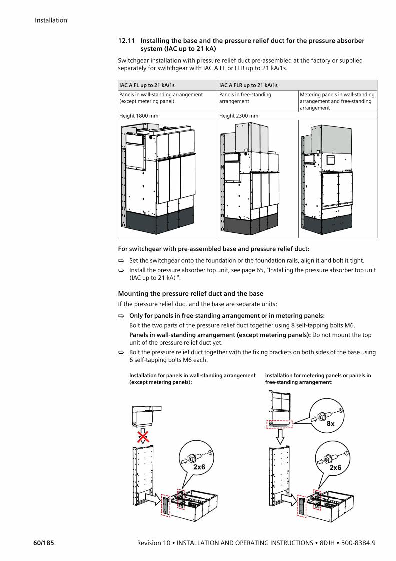
Installation
60/185 Revision 10 • INSTALLATION AND OPERATING INSTRUCTIONS • 8DJH • 500-8384.9
12.11 Installing the base and the pressure relief duct for the pressure absorber
system (IAC up to 21 kA)Switchgear installation with pressure relief duct pre-assembled at the factory or supplied separately for switchgear with IAC A FL or FLR up to 21 kA/1s.
For switchgear with pre-assembled base and pressure relief duct:➭ Set the switchgear onto the foundation or the foundation rails, align it and bolt it tight.➭ Install the pressure absorber top unit, see page 65, "Installing the pressure absorber top unit
(IAC up to 21 kA) ".
Mounting the pressure relief duct and the baseIf the pressure relief duct and the base are separate units: ➭ Only for panels in free-standing arrangement or in metering panels:
Bolt the two parts of the pressure relief duct together using 8 self-tapping bolts M6.Panels in wall-standing arrangement (except metering panels): Do not mount the top unit of the pressure relief duct yet.
➭ Bolt the pressure relief duct together with the fixing brackets on both sides of the base using 6 self-tapping bolts M6 each.
IAC A FL up to 21 kA/1s IAC A FLR up to 21 kA/1s Panels in wall-standing arrangement (except metering panel)
Panels in free-standing arrangement
Metering panels in wall-standing arrangement and free-standing arrangement
Height 1800 mm Height 2300 mm
Installation for panels in wall-standing arrangement (except metering panels):
Installation for metering panels or panels in free-standing arrangement:
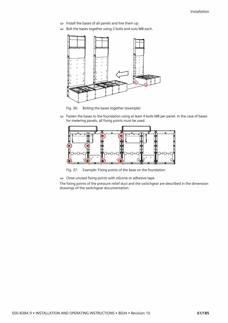
500-8384.9 • INSTALLATION AND OPERATING INSTRUCTIONS • 8DJH • Revision 10 61/185
Installation ➭ Install the bases of all panels and line them up.➭ Bolt the bases together using 2 bolts and nuts M8 each.
Fig. 36: Bolting the bases together (example)
➭ Fasten the bases to the foundation using at least 4 bolts M8 per panel. In the case of bases for metering panels, all fixing points must be used.
Fig. 37: Example: Fixing points of the base on the foundation
➭ Close unused fixing points with silicone or adhesive tape.The fixing points of the pressure relief duct and the switchgear are described in the dimension drawings of the switchgear documentation.
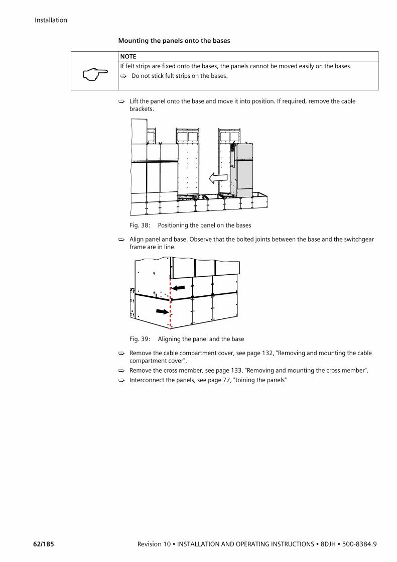
Installation
62/185 Revision 10 • INSTALLATION AND OPERATING INSTRUCTIONS • 8DJH • 500-8384.9
Mounting the panels onto the bases
➭ Lift the panel onto the base and move it into position. If required, remove the cable brackets.
Fig. 38: Positioning the panel on the bases
➭ Align panel and base. Observe that the bolted joints between the base and the switchgear frame are in line.
Fig. 39: Aligning the panel and the base
➭ Remove the cable compartment cover, see page 132, "Removing and mounting the cable compartment cover".
➭ Remove the cross member, see page 133, "Removing and mounting the cross member".➭ Interconnect the panels, see page 77, "Joining the panels"
NOTEIf felt strips are fixed onto the bases, the panels cannot be moved easily on the bases.➭ Do not stick felt strips on the bases.

500-8384.9 • INSTALLATION AND OPERATING INSTRUCTIONS • 8DJH • Revision 10 63/185
Installation Joining the base
and the panel➭ In the front area of the cable compartment, join the switchgear frame and the base using
2 fixing clips. Mount the fixing clips with bolts M8.➭ In the rear area of the cable compartment, join the switchgear frame and the base using at
least 4 fixing clips. If a cooler of the pressure absorber system is mounted in the base, the two rear fixing clips cannot be mounted. In this case, mount the fixing clips at fixing points located more to the front. Mount the fixing clips with bolts M8.
➭ Bolt the base to the cross member using a bolt-and-washer assembly M8x25, a nut-and-washer assembly M8 and 2 conical spring washers.
➭ Mount the tension brace on the base using 4 bolts M8.
Fig. 40: Fixing clips (front) Fig. 41: Possible positions for fixing clips (rear)
Fig. 42: Bolting the base to the cross member
① Bolt-and-washer assembly M8x25
② Conical spring washer (2x)③ Nut-and-washer assembly
M8
Fig. 43: Mounting the tension brace
① Tension brace

Installation
64/185 Revision 10 • INSTALLATION AND OPERATING INSTRUCTIONS • 8DJH • 500-8384.9
Panels in wall-standing
arrangement➭ Only for panels in wall-standing arrangement (except metering panels): Fasten the top
unit for the pressure relief duct using 8 bolt-and-washer assemblies.
Fig. 44: Mounting the top unit
Mounting the cablebracket
➭ Bolt the cable bracket ① , the adjustment rail and the cable clamps together using 4 self-tapping bolts M6. Tightening torque: 12 Nm.
➭ Mount the cross member, see page 133, "Removing and mounting the cross member". ➭ Hook the cable compartment cover in, see page 132, "Removing and mounting the cable
compartment cover".➭ From now, the high-voltage cables can be mounted.
Sealing the joint ➭ Seal the joint between the switchgear and the base all around with silicone.
Fig. 45: Mounting the cable bracket (ring-main panel)
Fig. 46: Mounting the cable bracket (transformer panel)
Fig. 47: Sealing the joint
① Switchgear② Joint③ Base
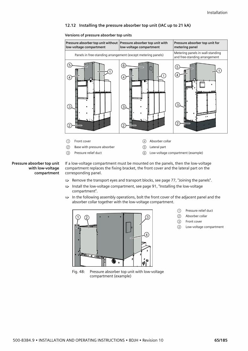
500-8384.9 • INSTALLATION AND OPERATING INSTRUCTIONS • 8DJH • Revision 10 65/185
Installation 12.12 Installing the pressure absorber top unit (IAC up to 21 kA)
Versions of pressure absorber top units
Pressure absorber top unitwith low-voltage
compartment
If a low-voltage compartment must be mounted on the panels, then the low-voltage compartment replaces the fixing bracket, the front cover and the lateral part on the corresponding panel.➭ Remove the transport eyes and transport blocks, see page 77, "Joining the panels".➭ Install the low-voltage compartment, see page 91, "Installing the low-voltage
compartment".➭ In the following assembly operations, bolt the front cover of the adjacent panel and the
absorber collar together with the low-voltage compartment.
Pressure absorber top unit without low-voltage compartment
Pressure absorber top unit with low-voltage compartment
Pressure absorber top unit for metering panel
Panels in free-standing arrangement (except metering panels) Metering panels in wall-standing and free-standing arrangement
① Front cover ④ Absorber collar② Base with pressure absorber ⑤ Lateral part③ Pressure relief duct ⑥ Low-voltage compartment (example)
Fig. 48: Pressure absorber top unit with low-voltage compartment (example)
① Pressure relief duct② Absorber collar③ Front cover④ Low-voltage compartment
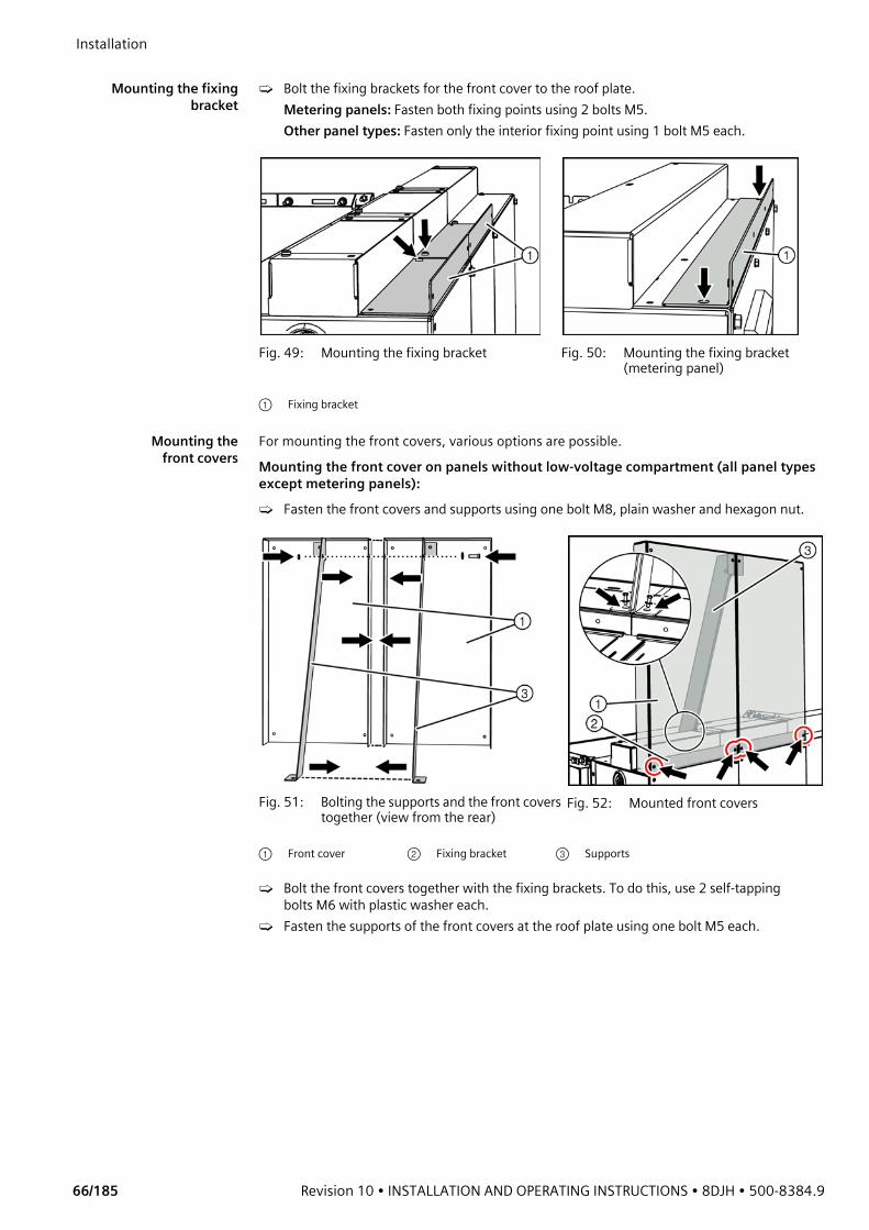
Installation
66/185 Revision 10 • INSTALLATION AND OPERATING INSTRUCTIONS • 8DJH • 500-8384.9
Mounting the fixing
bracket➭ Bolt the fixing brackets for the front cover to the roof plate.
Metering panels: Fasten both fixing points using 2 bolts M5.Other panel types: Fasten only the interior fixing point using 1 bolt M5 each.
Mounting thefront covers
For mounting the front covers, various options are possible.Mounting the front cover on panels without low-voltage compartment (all panel types except metering panels):➭ Fasten the front covers and supports using one bolt M8, plain washer and hexagon nut.
➭ Bolt the front covers together with the fixing brackets. To do this, use 2 self-tapping bolts M6 with plastic washer each.
➭ Fasten the supports of the front covers at the roof plate using one bolt M5 each.
Fig. 49: Mounting the fixing bracket Fig. 50: Mounting the fixing bracket (metering panel)
① Fixing bracket
Fig. 51: Bolting the supports and the front covers together (view from the rear)
Fig. 52: Mounted front covers
① Front cover ② Fixing bracket ③ Supports
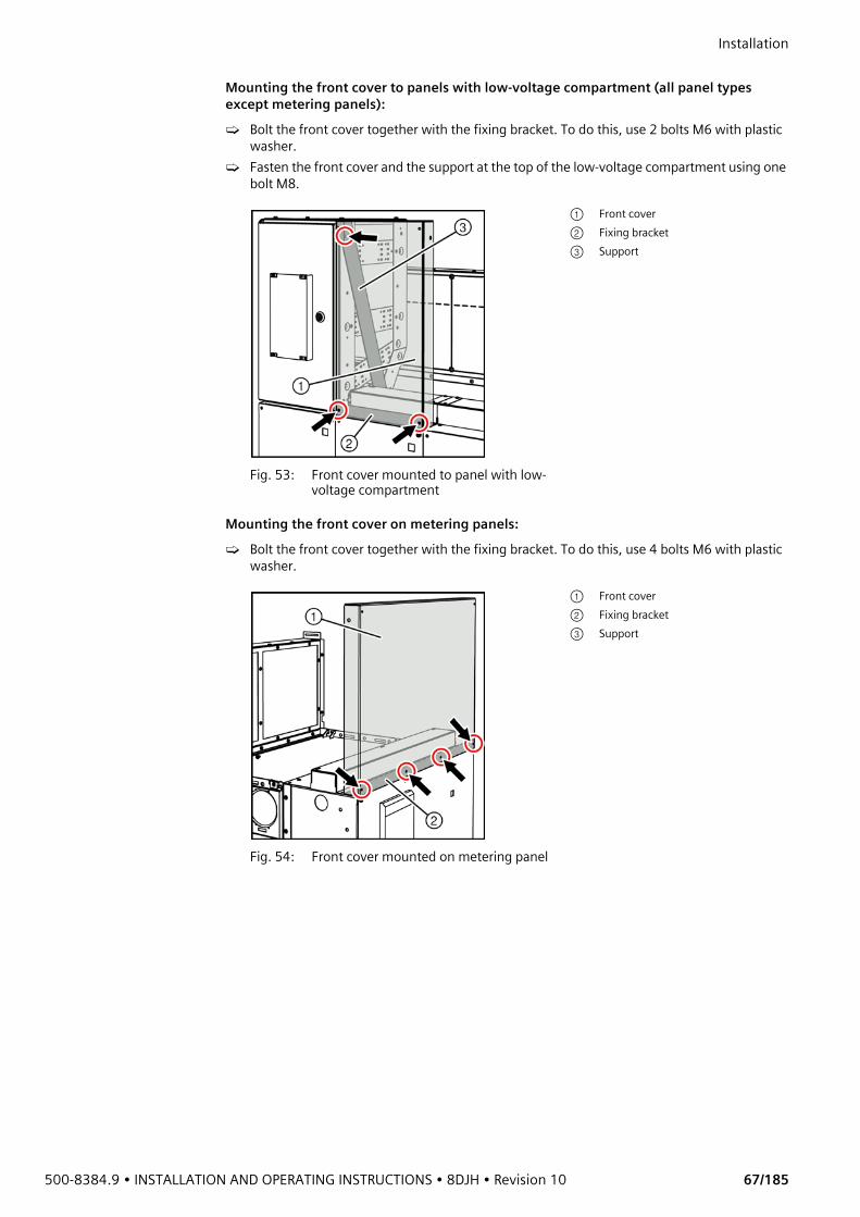
500-8384.9 • INSTALLATION AND OPERATING INSTRUCTIONS • 8DJH • Revision 10 67/185
Installation Mounting the front cover to panels with low-voltage compartment (all panel types except metering panels):➭ Bolt the front cover together with the fixing bracket. To do this, use 2 bolts M6 with plastic
washer.➭ Fasten the front cover and the support at the top of the low-voltage compartment using one
bolt M8.
Mounting the front cover on metering panels:➭ Bolt the front cover together with the fixing bracket. To do this, use 4 bolts M6 with plastic
washer.
Fig. 53: Front cover mounted to panel with low-voltage compartment
① Front cover② Fixing bracket③ Support
Fig. 54: Front cover mounted on metering panel
① Front cover② Fixing bracket③ Support
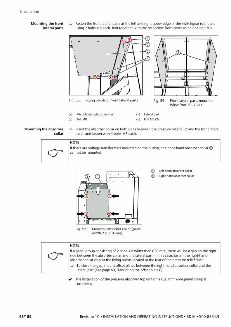
Installation
68/185 Revision 10 • INSTALLATION AND OPERATING INSTRUCTIONS • 8DJH • 500-8384.9
Mounting the front
lateral parts➭ Fasten the front lateral parts at the left and right upper edge of the switchgear roof plate
using 2 bolts M5 each. Bolt together with the respective front cover using one bolt M8.
Mounting the absorbercollar
➭ Insert the absorber collar on both sides between the pressure relief duct and the front lateral parts, and fasten with 4 bolts M6 each.
✔ The installation of the pressure absorber top unit on a 620 mm wide panel group is completed.
Fig. 55: Fixing points of front lateral parts Fig. 56: Front lateral parts mounted (view from the rear)
① M6 bolt with plastic washer ③ Lateral part② Bolt M8 ④ Bolt M5 (2x)
NOTEIf there are voltage transformers mounted on the busbar, the right-hand absorber collar ② cannot be mounted.
Fig. 57: Mounted absorber collar (panel width 2 x 310 mm)
① Left-hand absorber collar② Right-hand absorber collar
NOTEIf a panel group consisting of 2 panels is wider than 620 mm, there will be a gap on the right side between the absorber collar and the lateral part. In this case, fasten the right-hand absorber collar only at the fixing points located at the rear of the pressure relief duct.➭ To close the gap, mount offset plates between the right-hand absorber collar and the
lateral part (see page 69, "Mounting the offset plates").

500-8384.9 • INSTALLATION AND OPERATING INSTRUCTIONS • 8DJH • Revision 10 69/185
Installation Mounting the offset platesIf a panel group consisting of 2 panels is wider than 620 mm, additional offset plates must be mounted at the pressure absorber top unit. The offset plates close the gap between the front lateral part and the absorber collar.
Shortening the offsetplates
➭ Measure the installation dimension ⑤ .➭ If offset plates with an installation dimension between 120 mm and 190 mm are
required: Shorten both offset plates at the notches with a side cutter.
Fig. 58: Shortening the offset plates
Mounting the offsetplates
➭ Fasten the offset plates between the absorber collar ④ and the lateral part ① using 4 self-tapping bolts M6.
➭ Bolt the offset plates together using 2 self-tapping bolts M6.
✔ The installation of the offset plates is completed.
NOTEDo not mount the offset plates:• If a low-voltage compartment ② is mounted.• If voltage transformers ③ are mounted at the busbar.
① Front lateral part② Position of low-voltage
compartment③ Position of voltage
transformer④ Absorber collar⑤ Installation dimension of
offset plates⑥ Offset plate (2x)
Mounting the shortened offset plates Installation dimension 120 mm to 190 mm
Mounting the offset platesInstallation dimension ≥ 190 mm
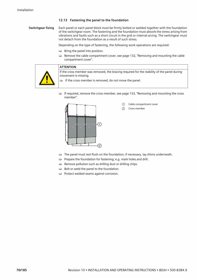
Installation
70/185 Revision 10 • INSTALLATION AND OPERATING INSTRUCTIONS • 8DJH • 500-8384.9
12.13 Fastening the panel to the foundation
Switchgear fixing Each panel or each panel block must be firmly bolted or welded together with the foundation of the switchgear room. The fastening and the foundation must absorb the stress arising from vibrations and faults such as a short circuit in the grid or internal arcing. The switchgear must not detach from the foundation as a result of such stress.Depending on the type of fastening, the following work operations are required:➭ Bring the panel into position.➭ Remove the cable compartment cover, see page 132, "Removing and mounting the cable
compartment cover".
➭ If required, remove the cross member, see page 133, "Removing and mounting the cross member".
➭ The panel must rest flush on the foundation; if necessary, lay shims underneath.➭ Prepare the foundation for fastening; e.g. mark holes and drill.➭ Remove pollution such as drilling dust or drilling chips.➭ Bolt or weld the panel to the foundation.➭ Protect welded seams against corrosion.
ATTENTIONIf the cross member was removed, the bracing required for the stability of the panel during movement is missing.➭ If the cross member is removed, do not move the panel.
① Cable compartment cover② Cross member

500-8384.9 • INSTALLATION AND OPERATING INSTRUCTIONS • 8DJH • Revision 10 71/185
Installation Fixing points The panel frames have cutouts for fastening the panels, see page 72, "Floor openings and
fixing points".➭ Fasten the panels at the following fixing points using bolts M8 :
- Fasten end panels at least at 4 fixing points; 1 x at the front, 1 x at the rear, and 2 x laterally (see example).
- Fasten intermediate panels at least at 2 fixing points; 1 x at the front and 1 x at the rear (see example).
- Fasten air-insulated metering panels at all available fixing points.- Fasten panels with floor covers at all available fixing points.
Fig. 59: Fixing points for end panels and intermediate panels (example)
Fig. 60: Fastening the panel to the foundation
① Conical spring washer M8 (DIN 6796) ④ Panel frame② 3D washer M10 (DIN EN ISO 7093) ⑤ Foundation or foundation rail③ Bolt M8
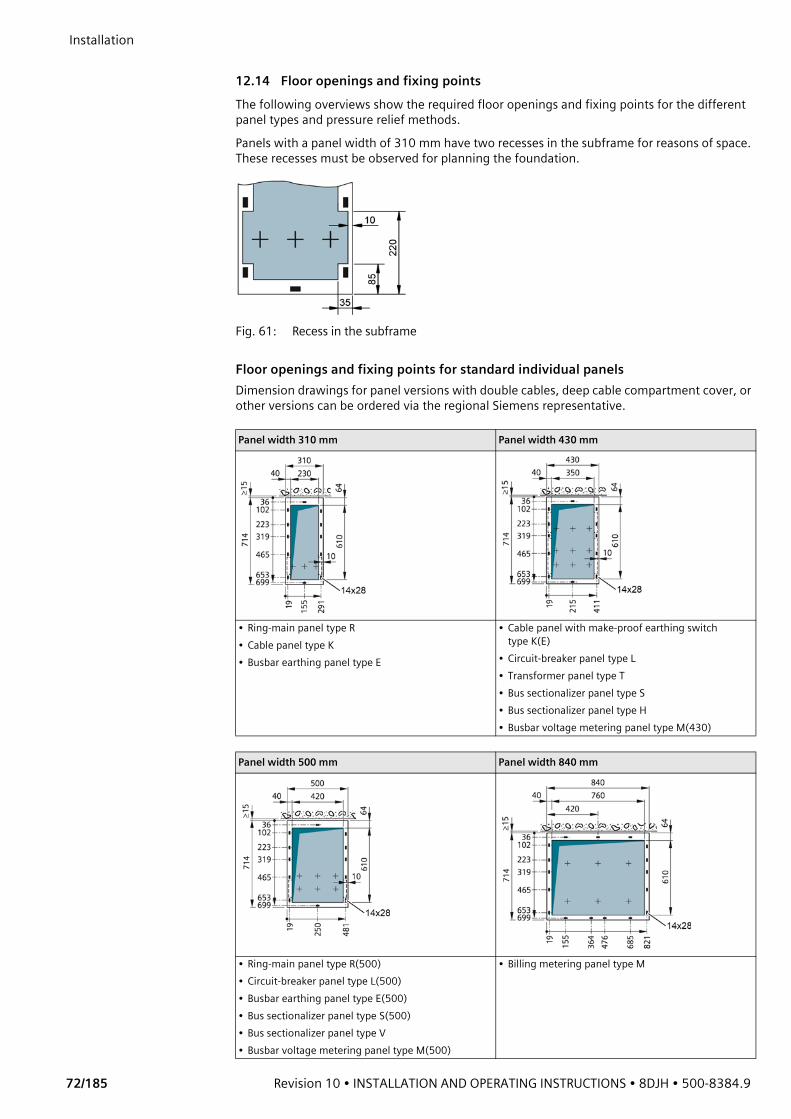
Installation
72/185 Revision 10 • INSTALLATION AND OPERATING INSTRUCTIONS • 8DJH • 500-8384.9
12.14 Floor openings and fixing pointsThe following overviews show the required floor openings and fixing points for the different panel types and pressure relief methods.Panels with a panel width of 310 mm have two recesses in the subframe for reasons of space. These recesses must be observed for planning the foundation.
Fig. 61: Recess in the subframe
Floor openings and fixing points for standard individual panelsDimension drawings for panel versions with double cables, deep cable compartment cover, or other versions can be ordered via the regional Siemens representative.
Panel width 310 mm Panel width 430 mm
• Ring-main panel type R• Cable panel type K• Busbar earthing panel type E
• Cable panel with make-proof earthing switch type K(E)
• Circuit-breaker panel type L• Transformer panel type T• Bus sectionalizer panel type S• Bus sectionalizer panel type H• Busbar voltage metering panel type M(430)
Panel width 500 mm Panel width 840 mm
• Ring-main panel type R(500)• Circuit-breaker panel type L(500)• Busbar earthing panel type E(500)• Bus sectionalizer panel type S(500)• Bus sectionalizer panel type V• Busbar voltage metering panel type M(500)
• Billing metering panel type M
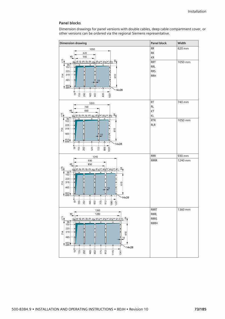
500-8384.9 • INSTALLATION AND OPERATING INSTRUCTIONS • 8DJH • Revision 10 73/185
Installation Panel blocksDimension drawings for panel versions with double cables, deep cable compartment cover, or other versions can be ordered via the regional Siemens representative.
Dimension drawing Panel block WidthRRRKKR
620 mm
RRTRRLRRSRRH
1050 mm
RTRLKTKL
740 mm
RTRRLR
1050 mm
RRR 930 mmRRRR 1240 mm
RRRTRRRLRRRSRRRH
1360 mm
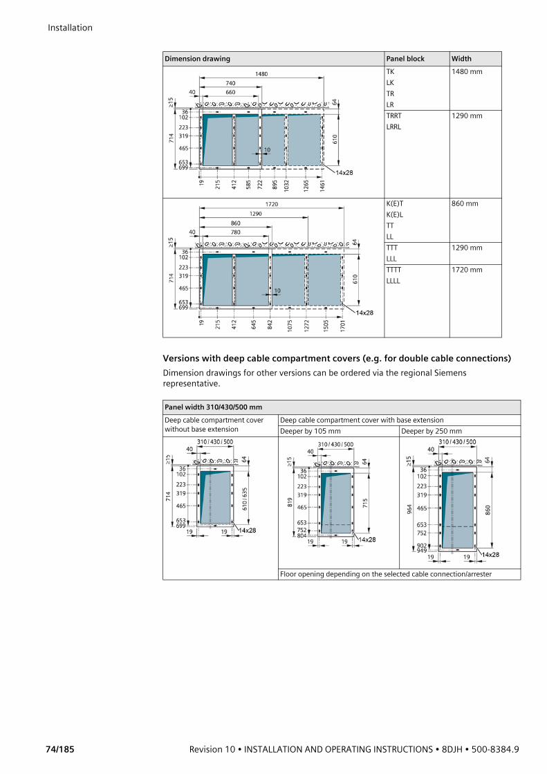
Installation
74/185 Revision 10 • INSTALLATION AND OPERATING INSTRUCTIONS • 8DJH • 500-8384.9
Versions with deep cable compartment covers (e.g. for double cable connections)Dimension drawings for other versions can be ordered via the regional Siemens representative.
TKLKTRLR
1480 mm
TRRTLRRL
1290 mm
K(E)TK(E)LTTLL
860 mm
TTTLLL
1290 mm
TTTTLLLL
1720 mm
Panel width 310/430/500 mmDeep cable compartment cover without base extension
Deep cable compartment cover with base extensionDeeper by 105 mm Deeper by 250 mm
Floor opening depending on the selected cable connection/arrester
Dimension drawing Panel block Width

500-8384.9 • INSTALLATION AND OPERATING INSTRUCTIONS • 8DJH • Revision 10 75/185
Installation Example: Position of the floor openings and fixing points for double cable connection in panel blocks
Versions combined with pressure absorbers and deep cable compartment coversDimension drawings for other versions can be ordered via the regional Siemens representative.
Panel width 1050 mmType RRT deeper by 105 mm Type RRT deeper by 250 mm
Panel width 310/430 mm
• Ring-main panel type R• Cable panel type K• Cable panel with make-proof earthing switch type K(E)• Circuit-breaker panel type L
Panel width 430 mm Panel width 310/430/500 mm
• Transformer panel type T • Panels without cable feeder, types S, H, V, M(430)/(500), E, E(500)
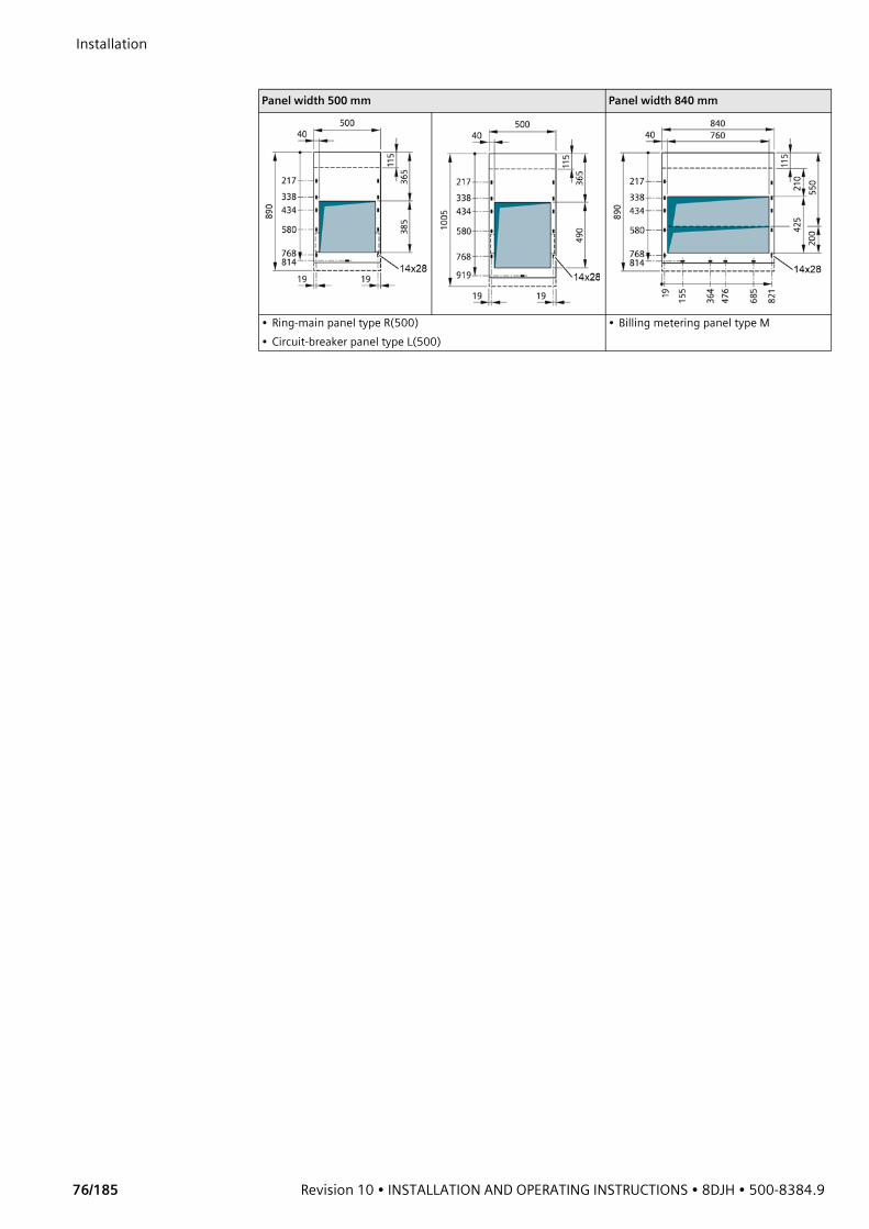
Installation
76/185 Revision 10 • INSTALLATION AND OPERATING INSTRUCTIONS • 8DJH • 500-8384.9
Panel width 500 mm Panel width 840 mm
• Ring-main panel type R(500)• Circuit-breaker panel type L(500)
• Billing metering panel type M
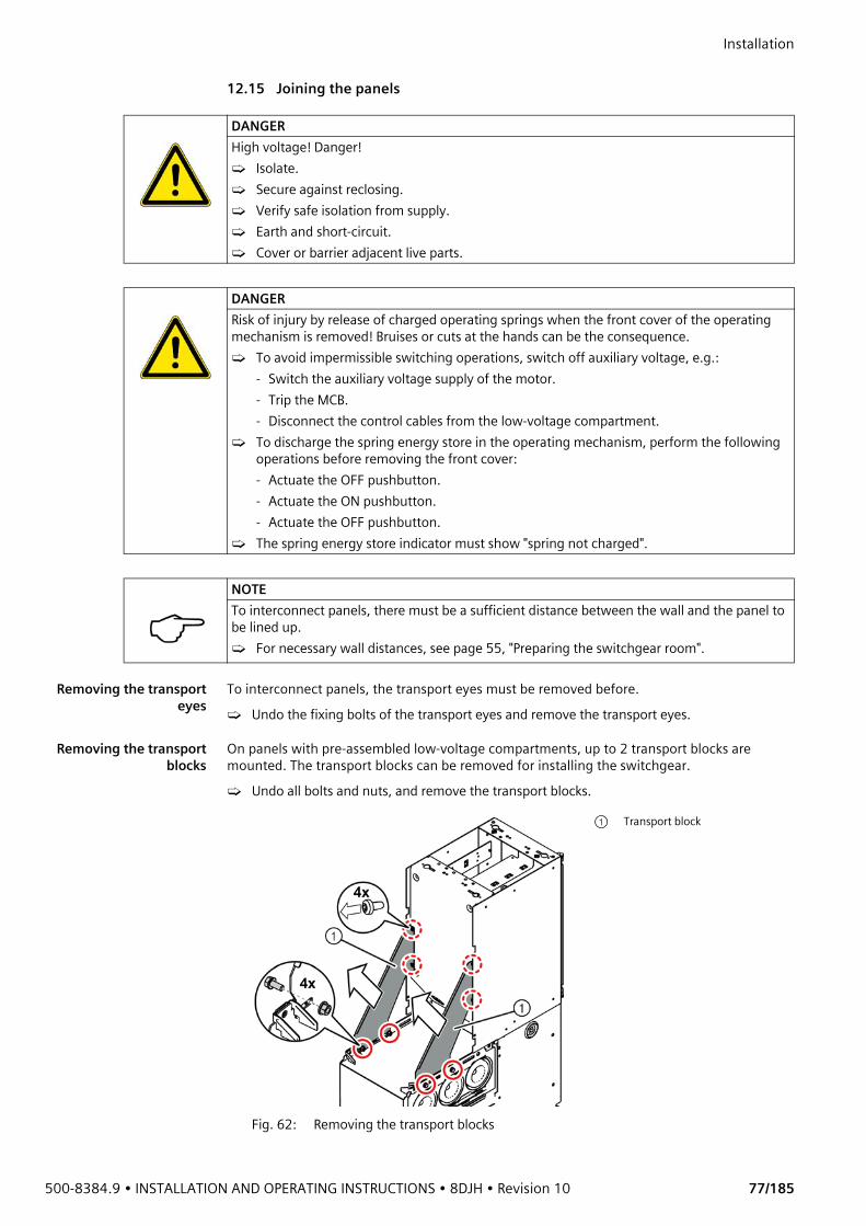
500-8384.9 • INSTALLATION AND OPERATING INSTRUCTIONS • 8DJH • Revision 10 77/185
Installation 12.15 Joining the panels
Removing the transporteyes
To interconnect panels, the transport eyes must be removed before.➭ Undo the fixing bolts of the transport eyes and remove the transport eyes.
Removing the transportblocks
On panels with pre-assembled low-voltage compartments, up to 2 transport blocks are mounted. The transport blocks can be removed for installing the switchgear.➭ Undo all bolts and nuts, and remove the transport blocks.
DANGERHigh voltage! Danger!➭ Isolate.➭ Secure against reclosing.➭ Verify safe isolation from supply.➭ Earth and short-circuit.➭ Cover or barrier adjacent live parts.
DANGERRisk of injury by release of charged operating springs when the front cover of the operating mechanism is removed! Bruises or cuts at the hands can be the consequence.➭ To avoid impermissible switching operations, switch off auxiliary voltage, e.g.:
- Switch the auxiliary voltage supply of the motor.- Trip the MCB.- Disconnect the control cables from the low-voltage compartment.
➭ To discharge the spring energy store in the operating mechanism, perform the following operations before removing the front cover:- Actuate the OFF pushbutton.- Actuate the ON pushbutton.- Actuate the OFF pushbutton.
➭ The spring energy store indicator must show "spring not charged".
NOTETo interconnect panels, there must be a sufficient distance between the wall and the panel to be lined up.➭ For necessary wall distances, see page 55, "Preparing the switchgear room".
Fig. 62: Removing the transport blocks
① Transport block
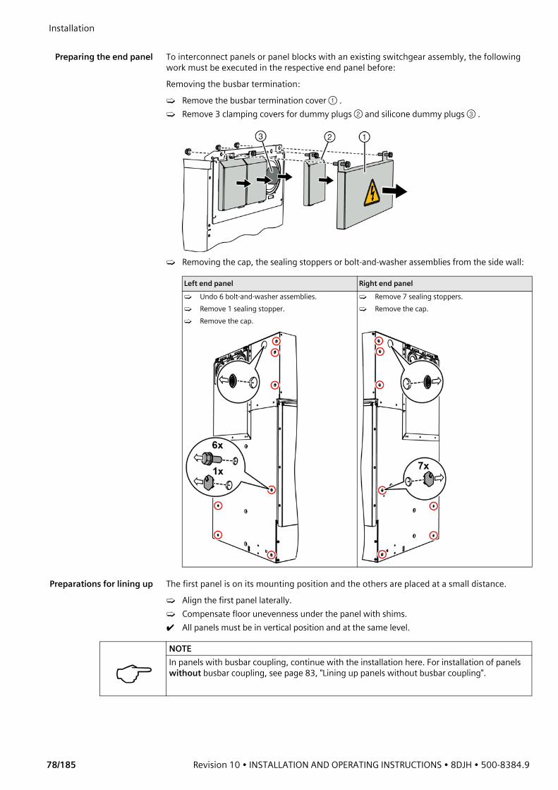
Installation
78/185 Revision 10 • INSTALLATION AND OPERATING INSTRUCTIONS • 8DJH • 500-8384.9
Preparing the end panel To interconnect panels or panel blocks with an existing switchgear assembly, the following
work must be executed in the respective end panel before:Removing the busbar termination:➭ Remove the busbar termination cover ① .➭ Remove 3 clamping covers for dummy plugs ② and silicone dummy plugs ③ .
➭ Removing the cap, the sealing stoppers or bolt-and-washer assemblies from the side wall:
Preparations for lining up The first panel is on its mounting position and the others are placed at a small distance.➭ Align the first panel laterally.➭ Compensate floor unevenness under the panel with shims.✔ All panels must be in vertical position and at the same level.
Left end panel Right end panel➭ Undo 6 bolt-and-washer assemblies.➭ Remove 1 sealing stopper.➭ Remove the cap.
➭ Remove 7 sealing stoppers.➭ Remove the cap.
NOTEIn panels with busbar coupling, continue with the installation here. For installation of panels without busbar coupling, see page 83, "Lining up panels without busbar coupling".
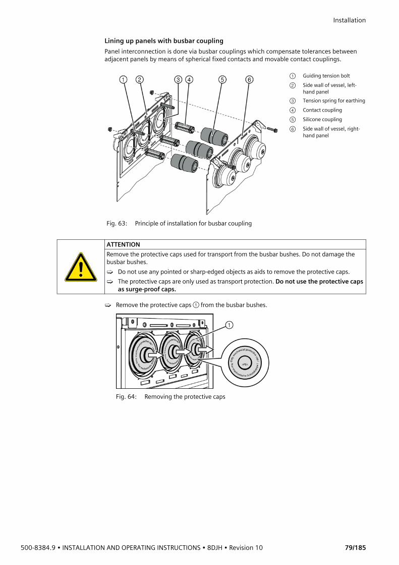
500-8384.9 • INSTALLATION AND OPERATING INSTRUCTIONS • 8DJH • Revision 10 79/185
Installation Lining up panels with busbar couplingPanel interconnection is done via busbar couplings which compensate tolerances between adjacent panels by means of spherical fixed contacts and movable contact couplings.
➭ Remove the protective caps ① from the busbar bushes.
Fig. 64: Removing the protective caps
Fig. 63: Principle of installation for busbar coupling
① Guiding tension bolt② Side wall of vessel, left-
hand panel③ Tension spring for earthing④ Contact coupling⑤ Silicone coupling⑥ Side wall of vessel, right-
hand panel
ATTENTIONRemove the protective caps used for transport from the busbar bushes. Do not damage the busbar bushes.➭ Do not use any pointed or sharp-edged objects as aids to remove the protective caps.➭ The protective caps are only used as transport protection. Do not use the protective caps
as surge-proof caps.
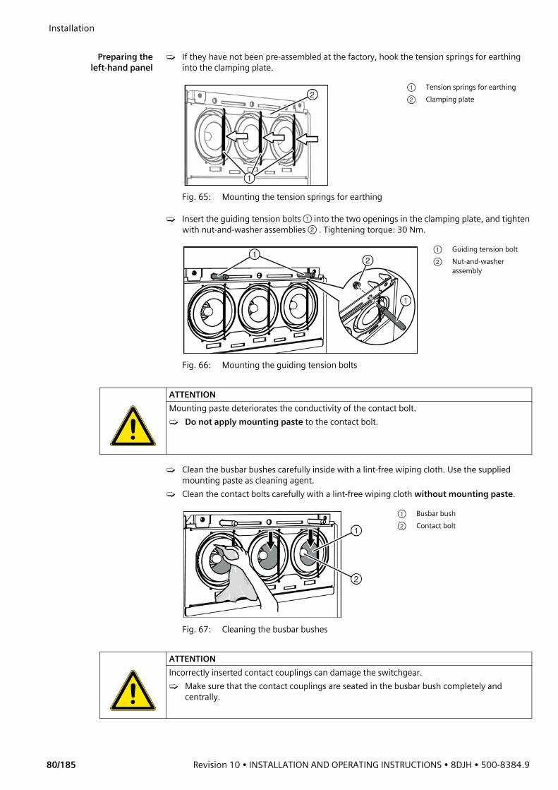
Installation
80/185 Revision 10 • INSTALLATION AND OPERATING INSTRUCTIONS • 8DJH • 500-8384.9
Preparing the
left-hand panel➭ If they have not been pre-assembled at the factory, hook the tension springs for earthing
into the clamping plate.
➭ Insert the guiding tension bolts ① into the two openings in the clamping plate, and tighten with nut-and-washer assemblies ② . Tightening torque: 30 Nm.
➭ Clean the busbar bushes carefully inside with a lint-free wiping cloth. Use the supplied mounting paste as cleaning agent.
➭ Clean the contact bolts carefully with a lint-free wiping cloth without mounting paste.
Fig. 65: Mounting the tension springs for earthing
① Tension springs for earthing② Clamping plate
Fig. 66: Mounting the guiding tension bolts
① Guiding tension bolt② Nut-and-washer
assembly
ATTENTIONMounting paste deteriorates the conductivity of the contact bolt.➭ Do not apply mounting paste to the contact bolt.
Fig. 67: Cleaning the busbar bushes
① Busbar bush② Contact bolt
ATTENTIONIncorrectly inserted contact couplings can damage the switchgear.➭ Make sure that the contact couplings are seated in the busbar bush completely and
centrally.

500-8384.9 • INSTALLATION AND OPERATING INSTRUCTIONS • 8DJH • Revision 10 81/185
Installation ➭ Push the 3 contact couplings ① completely into the busbar bushes as far as they will go. The
contact couplings must be located centrally in the busbar bushes.
Preparing the siliconecoupling
➭ The silicone couplings are equipped with insertable sleeves at the factory.
➭ Clean the surfaces of the silicone couplings carefully. ➭ Apply mounting paste evenly, thinly and all around to a high-quality joint of the silicone
coupling. Apply mounting paste only to one side of the silicone coupling.
Fig. 68: Inserting the contact couplings Fig. 69: Incorrectly inserted contact coupling
ATTENTIONObserve extreme cleanliness.➭ Make sure that the insertable sleeves and silicone couplings are free of grease and
pollution.
ATTENTIONIf the electrical contact is insufficient or the high-quality joints are dirty, the busbars will be damaged during operation.➭ Do not apply mounting paste to the external layer of conductive varnish of the silicone
coupling.
Fig. 70: Silicone coupling with mounting paste
① External layer of conductive varnish② High-quality joint with mounting paste
NOTETo simplify installation:➭ Turn the silicone coupling slightly while inserting.➭ Push the tension spring for earthing to the side.
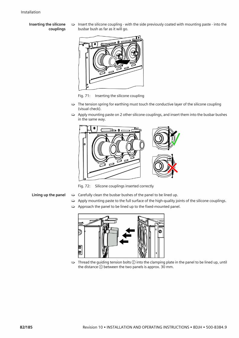
Installation
82/185 Revision 10 • INSTALLATION AND OPERATING INSTRUCTIONS • 8DJH • 500-8384.9
Inserting the silicone
couplings➭ Insert the silicone coupling - with the side previously coated with mounting paste - into the
busbar bush as far as it will go.
Fig. 71: Inserting the silicone coupling
➭ The tension spring for earthing must touch the conductive layer of the silicone coupling (visual check).
➭ Apply mounting paste on 2 other silicone couplings, and insert them into the busbar bushes in the same way.
Fig. 72: Silicone couplings inserted correctly
Lining up the panel ➭ Carefully clean the busbar bushes of the panel to be lined up.➭ Apply mounting paste to the full surface of the high-quality joints of the silicone couplings.➭ Approach the panel to be lined up to the fixed-mounted panel.
➭ Thread the guiding tension bolts ② into the clamping plate in the panel to be lined up, until the distance ④ between the two panels is approx. 30 mm.

500-8384.9 • INSTALLATION AND OPERATING INSTRUCTIONS • 8DJH • Revision 10 83/185
Installation
➭ Interconnect the two panels with 2 panel connecting bolts M8x40 at the upper panel connection, but do not bolt tight.
Lining up panels without busbar coupling
Vessel adapters For panels without busbar coupling, a gap between the side walls of the gas-filled switchgear vessels results during the interconnection. To compensate this gap, vessel adapters must be inserted between the panels. The extension kit contains 2 vessel adapters.
Fig. 75: Vessel adapters
➭ If one of the panels is equipped with a switchgear vessel, insert one vessel adapter between the panels.
➭ If both of the panels are equipped with a switchgear vessel, insert both vessel adapters between the panels.
Mounting position of the vessel adapter: The folded edge of the vessel adapter must point towards the switchgear vessel.
Fig. 73: Guiding tension bolt threaded into the clamping plate
① Left-hand panel② Guiding tension bolt③ Right-hand panel④ Distance approx. 30 mm
Fig. 74: Fitting the upper panel connecting bolts
① Panel connecting bolt (bolt-and-washer assembly M8x40)
② Nut-and-washer assembly M8
NOTEFor further installation of panels with busbar coupling, see page 84, "Bolting panels together".

Installation
84/185 Revision 10 • INSTALLATION AND OPERATING INSTRUCTIONS • 8DJH • 500-8384.9
Lining up the panel ➭ Approach the panel to be lined up to the fixed-mounted panel.
➭ Interconnect the panels with 4 panel connecting bolts (bolt-and-washer assemblies M8x40) at the upper panel connection, but do not bolt tight yet. If required, bolt the vessel adapter tight between the two panels.
Bolting panels together
➭ Tighten the 6 panel connecting bolts ① evenly together with the panel connecting bolts at the clamping plate ② until both panels are joined without any gaps (tightening torque: 30 Nm). Screw each of the panel connecting bolts from the left-hand panel to the right-hand panel into the setnuts provided for this purpose. Make sure that there is a uniform distance between the panels.
➭ If available, bolt the bases for the pressure absorber system together (see page 60, "Mounting the pressure relief duct and the base").
Fig. 76: Lining up the panel
① Right-hand panel② Vessel adapter for right-
hand panel (option)③ Nut-and-washer
assembly M8 (4x)④ Bolt-and-washer
assembly M8x40 (4x)⑤ Vessel adapter for left-
hand panel (option)⑥ Left-hand panel
ATTENTIONSetnuts may be fastened at the bolted joints in the left-hand panel.➭ Remove the setnuts before bolting the panels together.
Fig. 77: Bolted joints for the panel interconnection
Panel connecting bolts① Bolt-and-washer assemblies
M8x20 (6x)② Bolt-and-washer assemblies
M8x40 at the clamping plate (2x or 4x)
③ Only bolt together in case of circuit-breaker panel type L1.1
④ Bolt together in all panel types except for circuit-breaker panel type L1.1
Bolted joint
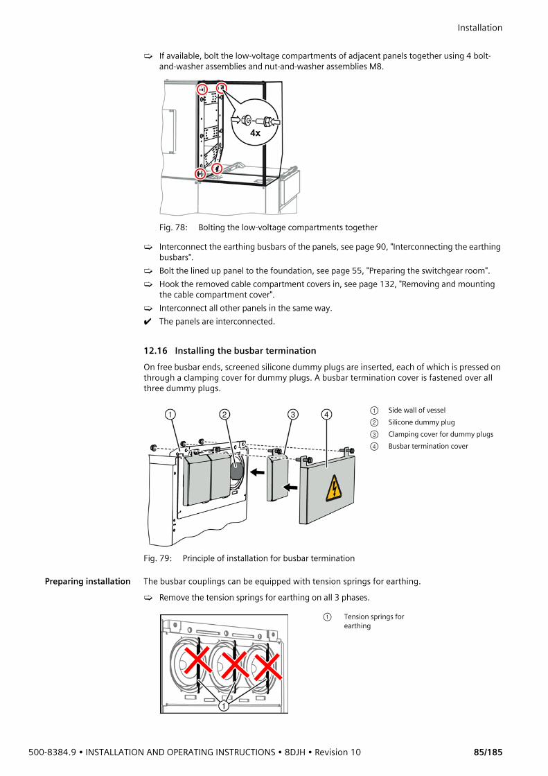
500-8384.9 • INSTALLATION AND OPERATING INSTRUCTIONS • 8DJH • Revision 10 85/185
Installation ➭ If available, bolt the low-voltage compartments of adjacent panels together using 4 bolt-
and-washer assemblies and nut-and-washer assemblies M8.
Fig. 78: Bolting the low-voltage compartments together
➭ Interconnect the earthing busbars of the panels, see page 90, "Interconnecting the earthing busbars".
➭ Bolt the lined up panel to the foundation, see page 55, "Preparing the switchgear room".➭ Hook the removed cable compartment covers in, see page 132, "Removing and mounting
the cable compartment cover".➭ Interconnect all other panels in the same way.✔ The panels are interconnected.
12.16 Installing the busbar terminationOn free busbar ends, screened silicone dummy plugs are inserted, each of which is pressed on through a clamping cover for dummy plugs. A busbar termination cover is fastened over all three dummy plugs.
Preparing installation The busbar couplings can be equipped with tension springs for earthing. ➭ Remove the tension springs for earthing on all 3 phases.
Fig. 79: Principle of installation for busbar termination
① Side wall of vessel② Silicone dummy plug③ Clamping cover for dummy plugs④ Busbar termination cover
① Tension springs for earthing
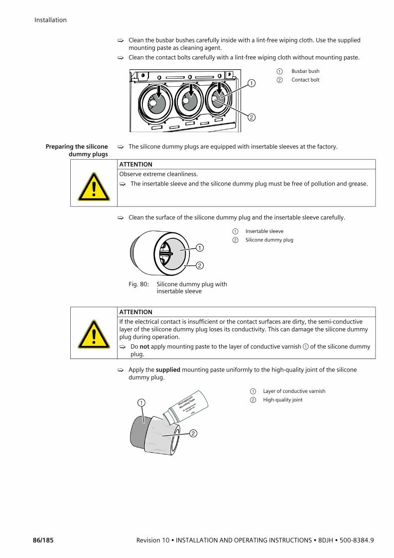
Installation
86/185 Revision 10 • INSTALLATION AND OPERATING INSTRUCTIONS • 8DJH • 500-8384.9
➭ Clean the busbar bushes carefully inside with a lint-free wiping cloth. Use the supplied
mounting paste as cleaning agent.➭ Clean the contact bolts carefully with a lint-free wiping cloth without mounting paste.
Preparing the siliconedummy plugs
➭ The silicone dummy plugs are equipped with insertable sleeves at the factory.
➭ Clean the surface of the silicone dummy plug and the insertable sleeve carefully.
➭ Apply the supplied mounting paste uniformly to the high-quality joint of the silicone dummy plug.
① Busbar bush② Contact bolt
ATTENTIONObserve extreme cleanliness.➭ The insertable sleeve and the silicone dummy plug must be free of pollution and grease.
Fig. 80: Silicone dummy plug with insertable sleeve
① Insertable sleeve② Silicone dummy plug
ATTENTIONIf the electrical contact is insufficient or the contact surfaces are dirty, the semi-conductive layer of the silicone dummy plug loses its conductivity. This can damage the silicone dummy plug during operation. ➭ Do not apply mounting paste to the layer of conductive varnish ① of the silicone dummy
plug.
① Layer of conductive varnish② High-quality joint
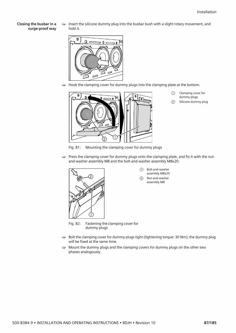
500-8384.9 • INSTALLATION AND OPERATING INSTRUCTIONS • 8DJH • Revision 10 87/185
Installation Closing the busbar in a
surge-proof way➭ Insert the silicone dummy plug into the busbar bush with a slight rotary movement, and
hold it.
➭ Hook the clamping cover for dummy plugs into the clamping plate at the bottom.
➭ Press the clamping cover for dummy plugs onto the clamping plate, and fix it with the nut-and-washer assembly M8 and the bolt-and-washer assembly M8x20.
➭ Bolt the clamping cover for dummy plugs tight (tightening torque: 30 Nm); the dummy plug will be fixed at the same time.
➭ Mount the dummy plugs and the clamping covers for dummy plugs on the other two phases analogously.
Fig. 81: Mounting the clamping cover for dummy plugs
① Clamping cover for dummy plugs
② Silicone dummy plug
Fig. 82: Fastening the clamping cover for dummy plugs
① Bolt-and-washer assembly M8x20
② Nut-and-washer assembly M8
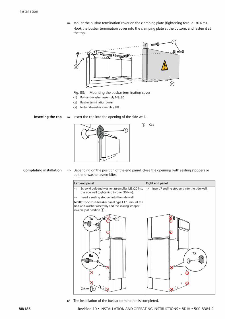
Installation
88/185 Revision 10 • INSTALLATION AND OPERATING INSTRUCTIONS • 8DJH • 500-8384.9
➭ Mount the busbar termination cover on the clamping plate (tightening torque: 30 Nm).
Hook the busbar termination cover into the clamping plate at the bottom, and fasten it at the top.
Inserting the cap ➭ Insert the cap into the opening of the side wall.
Completing installation ➭ Depending on the position of the end panel, close the openings with sealing stoppers or bolt-and-washer assemblies.
✔ The installation of the busbar termination is completed.
Fig. 83: Mounting the busbar termination cover① Bolt-and-washer assembly M8x30② Busbar termination cover③ Nut-and-washer assembly M8
① Cap
Left end panel Right end panel➭ Screw 6 bolt-and washer assemblies M8x20 into
the side wall (tightening torque: 30 Nm).➭ Insert a sealing stopper into the side wall.NOTE: For circuit-breaker panel type L1.1, mount the bolt-and-washer assembly and the sealing stopper inversely at position ① .
➭ Insert 7 sealing stoppers into the side wall.

500-8384.9 • INSTALLATION AND OPERATING INSTRUCTIONS • 8DJH • Revision 10 89/185
Installation 12.17 Earthing the switchgear
Non-extendableswitchgear
A non-extendable switchgear is connected to the substation earth through an earthing point.
Extendable switchgear In extendable switchgear assemblies, earthing is done via one of the earthing points at the earthing busbar.
➭ Connect the earthing point ① with the substation earth.➭ Connect each panel block or panel group of max. 4 panels once with the substation earth.➭ In panel groups comprising more than 4 panels, connect each fifth panel with the
substation earth.➭ Bolt together all units of the earthing busbars in the complete switchgear assembly (see
page 90, "Interconnecting the earthing busbars").
Fig. 84: Earthing point (view from outside) Fig. 85: Earthing point (view into cable compartment)
① Earthing point (earthing bolt M12)
Fig. 86: Earthing point at the earthing busbar
① Earthing point (earthing bolt M12)
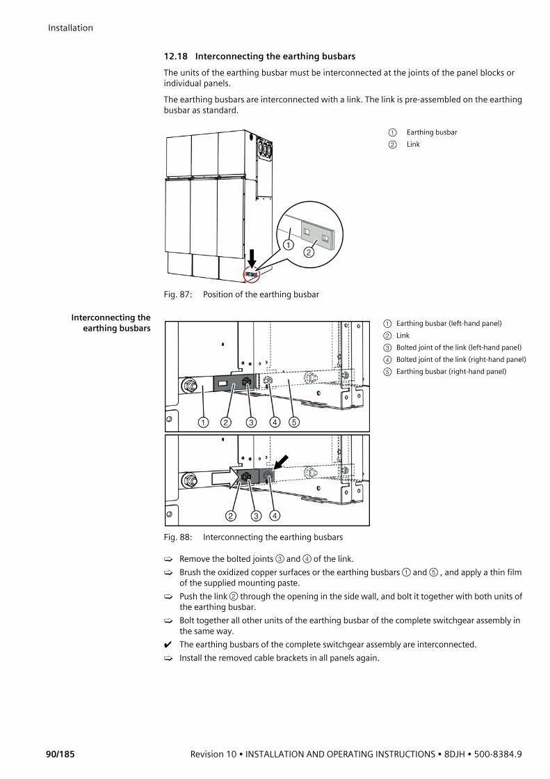
Installation
90/185 Revision 10 • INSTALLATION AND OPERATING INSTRUCTIONS • 8DJH • 500-8384.9
12.18 Interconnecting the earthing busbarsThe units of the earthing busbar must be interconnected at the joints of the panel blocks or individual panels.The earthing busbars are interconnected with a link. The link is pre-assembled on the earthing busbar as standard.
Interconnecting theearthing busbars
➭ Remove the bolted joints ③ and ④ of the link.➭ Brush the oxidized copper surfaces or the earthing busbars ① and ⑤ , and apply a thin film
of the supplied mounting paste.➭ Push the link ② through the opening in the side wall, and bolt it together with both units of
the earthing busbar.➭ Bolt together all other units of the earthing busbar of the complete switchgear assembly in
the same way.✔ The earthing busbars of the complete switchgear assembly are interconnected.➭ Install the removed cable brackets in all panels again.
Fig. 87: Position of the earthing busbar
① Earthing busbar② Link
Fig. 88: Interconnecting the earthing busbars
① Earthing busbar (left-hand panel)② Link③ Bolted joint of the link (left-hand panel)④ Bolted joint of the link (right-hand panel)⑤ Earthing busbar (right-hand panel)
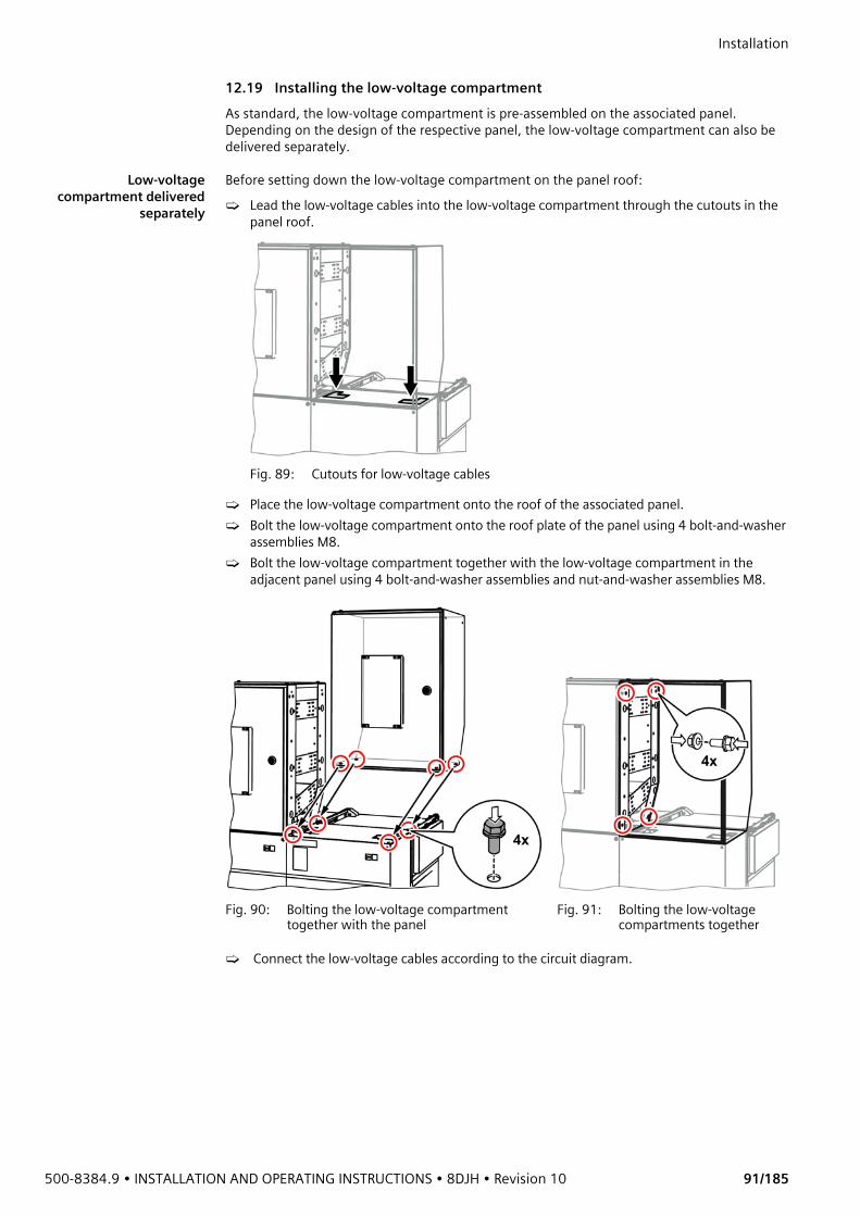
500-8384.9 • INSTALLATION AND OPERATING INSTRUCTIONS • 8DJH • Revision 10 91/185
Installation 12.19 Installing the low-voltage compartmentAs standard, the low-voltage compartment is pre-assembled on the associated panel. Depending on the design of the respective panel, the low-voltage compartment can also be delivered separately.
Low-voltagecompartment delivered
separately
Before setting down the low-voltage compartment on the panel roof:➭ Lead the low-voltage cables into the low-voltage compartment through the cutouts in the
panel roof.
Fig. 89: Cutouts for low-voltage cables
➭ Place the low-voltage compartment onto the roof of the associated panel.➭ Bolt the low-voltage compartment onto the roof plate of the panel using 4 bolt-and-washer
assemblies M8.➭ Bolt the low-voltage compartment together with the low-voltage compartment in the
adjacent panel using 4 bolt-and-washer assemblies and nut-and-washer assemblies M8.
➭ Connect the low-voltage cables according to the circuit diagram.
Fig. 90: Bolting the low-voltage compartment together with the panel
Fig. 91: Bolting the low-voltage compartments together
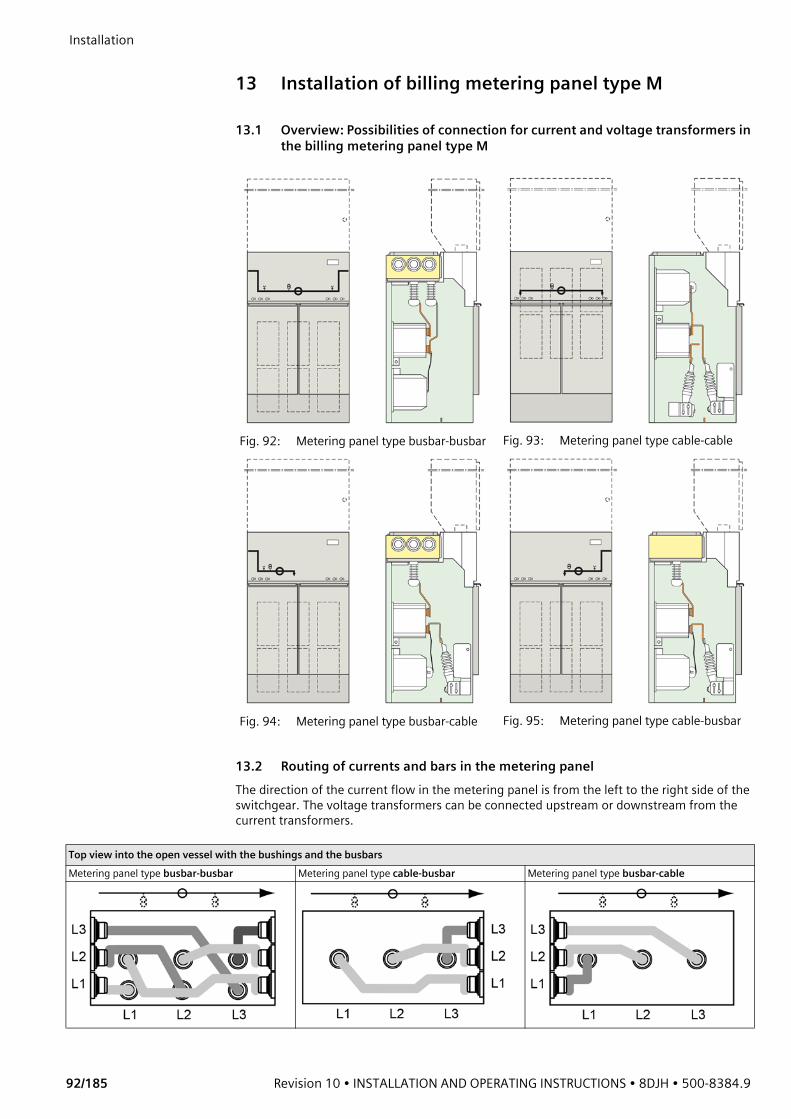
Installation
92/185 Revision 10 • INSTALLATION AND OPERATING INSTRUCTIONS • 8DJH • 500-8384.9
13 Installation of billing metering panel type M
13.1 Overview: Possibilities of connection for current and voltage transformers in the billing metering panel type M
13.2 Routing of currents and bars in the metering panelThe direction of the current flow in the metering panel is from the left to the right side of the switchgear. The voltage transformers can be connected upstream or downstream from the current transformers.
Fig. 92: Metering panel type busbar-busbar Fig. 93: Metering panel type cable-cable
Fig. 94: Metering panel type busbar-cable Fig. 95: Metering panel type cable-busbar
Top view into the open vessel with the bushings and the busbarsMetering panel type busbar-busbar Metering panel type cable-busbar Metering panel type busbar-cable
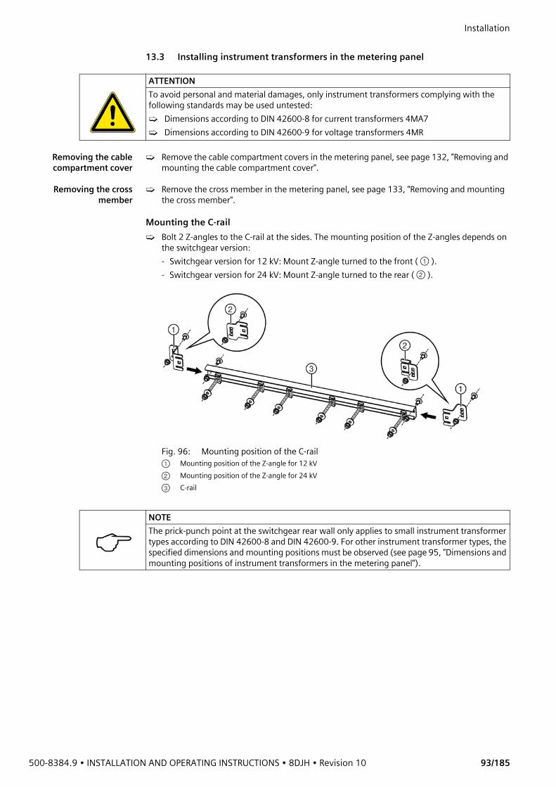
500-8384.9 • INSTALLATION AND OPERATING INSTRUCTIONS • 8DJH • Revision 10 93/185
Installation 13.3 Installing instrument transformers in the metering panel
Removing the cablecompartment cover
➭ Remove the cable compartment covers in the metering panel, see page 132, "Removing and mounting the cable compartment cover".
Removing the crossmember
➭ Remove the cross member in the metering panel, see page 133, "Removing and mounting the cross member".
Mounting the C-rail➭ Bolt 2 Z-angles to the C-rail at the sides. The mounting position of the Z-angles depends on
the switchgear version:- Switchgear version for 12 kV: Mount Z-angle turned to the front ( ① ). - Switchgear version for 24 kV: Mount Z-angle turned to the rear ( ② ).
ATTENTIONTo avoid personal and material damages, only instrument transformers complying with the following standards may be used untested:➭ Dimensions according to DIN 42600-8 for current transformers 4MA7 ➭ Dimensions according to DIN 42600-9 for voltage transformers 4MR
Fig. 96: Mounting position of the C-rail① Mounting position of the Z-angle for 12 kV② Mounting position of the Z-angle for 24 kV③ C-rail
NOTEThe prick-punch point at the switchgear rear wall only applies to small instrument transformer types according to DIN 42600-8 and DIN 42600-9. For other instrument transformer types, the specified dimensions and mounting positions must be observed (see page 95, "Dimensions and mounting positions of instrument transformers in the metering panel").

Installation
94/185 Revision 10 • INSTALLATION AND OPERATING INSTRUCTIONS • 8DJH • 500-8384.9
➭ Fasten the 4 C-rails to the rear wall of the switchgear at the sides using Z-angles. The
position of the C-rail is marked at the side of the switchgear rear wall by means of a prick-punch point.
Mounting the instrument transformers on the C-rails
Order of assembly: First, fasten the current transformer and voltage transformer for phase L2 in the center of the C-rails. Then, fasten the instrument transformers for phases L1 and L3 on the left and right at a distance of 250 ±2 mm.Fasten each transformer at 4 points, 2 times at the upper C-rail, 2 times at the lower C-rail. ➭ For each instrument transformer, insert 2 sliding nuts with setscrew into the C-rail. Insert
the sliding nuts in upright position. ➭ Fasten each instrument transformer to the C-rails using 4 hexagon nuts M10, conical spring
washers and washers (3D washers) each.
Fig. 97: Mounting the C-rails
① Cup head square neck bolt M8 ② Prick-punch point for the C-rail
position ③ Nut-and-washer assembly M8④ C-rail with Z-angle
ATTENTIONRisk of injury due to high weight of the voltage transformer.➭ Use an appropriate lifting tool for lifting the voltage transformers. ➭ If required, lift the voltage transformer together with several persons.➭ Secure the voltage transformer against falling down.
Fig. 98: Mounting the instrument transformers
① Sliding nut② Setscrew M10x60③ Plain washer
(3D washer)④ Conical spring
washer⑤ Hexagon nut M10
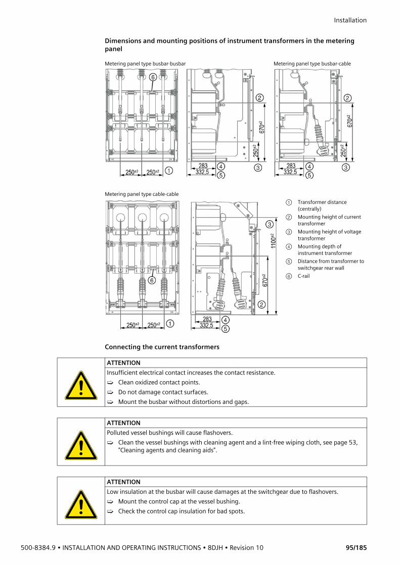
500-8384.9 • INSTALLATION AND OPERATING INSTRUCTIONS • 8DJH • Revision 10 95/185
Installation Dimensions and mounting positions of instrument transformers in the metering panel
Connecting the current transformers
Metering panel type busbar-busbar Metering panel type busbar-cable
Metering panel type cable-cable① Transformer distance
(centrally)② Mounting height of current
transformer③ Mounting height of voltage
transformer④ Mounting depth of
instrument transformer⑤ Distance from transformer to
switchgear rear wall⑥ C-rail
ATTENTIONInsufficient electrical contact increases the contact resistance.➭ Clean oxidized contact points.➭ Do not damage contact surfaces.➭ Mount the busbar without distortions and gaps.
ATTENTIONPolluted vessel bushings will cause flashovers.➭ Clean the vessel bushings with cleaning agent and a lint-free wiping cloth, see page 53,
"Cleaning agents and cleaning aids".
ATTENTIONLow insulation at the busbar will cause damages at the switchgear due to flashovers.➭ Mount the control cap at the vessel bushing.➭ Check the control cap insulation for bad spots.

Installation
96/185 Revision 10 • INSTALLATION AND OPERATING INSTRUCTIONS • 8DJH • 500-8384.9
Connecting the current
transformers in themetering panel
➭ Mount the spacers and connection bars on the current transformer (tightening torque: 40 Nm).
Connecting the busbar ➭ Clean the vessel bushing ① with cleaning agent and a lint-free wiping cloth, and rub dry.➭ Install the spacer ⑦ between the vessel bushing and the connection bar ② .➭ Push the fixing bracket ④ and the conical spring washer ⑥ onto the cheese head bolt ⑤ .➭ Bolt the connection bar and the spacer together with the cheese head bolt at the vessel
bushing of the busbar (tightening torque: 40 Nm).➭ Put the control cap ③ on the fixing bracket.➭ Verify firm seat of control cap.
➭ Perform the installation for the other two phases in the same way.✔ The transformer is connected with the busbar.
Metering panel type busbar-busbar Metering panel type busbar-cable (cable-busbar)
Metering panel type cable-cable
① Connection bar at the top ④ Hexagon head bolt M12 (4x)② Spacer* (4x) ⑤ Conical spring washer (2x)③ Connection bar at the bottom ⑥ Connecting cable with cable lug
* Depending on the current transformer used
Fig. 99: Connecting the busbar
① Vessel bushing② Connection bar of instrument transformer③ Control cap of vessel bushing④ Fixing bracket⑤ Hexagon socket head cap bolt M10⑥ Conical spring washer⑦ Spacer

500-8384.9 • INSTALLATION AND OPERATING INSTRUCTIONS • 8DJH • Revision 10 97/185
Installation Connecting the voltage transformers
In metering panels type busbar-busbar, busbar-cable and cable-busbar, the voltage transformers are pre-assembled in the metering panels below the current transformers at the factory. In the metering panel type cable-cable, the voltage transformers are pre-assembled in the metering panels above the current transformers at the factory.The voltage transformers must be connected to the current transformers on site with the connecting cables which are either pre-assembled or supplied with the supplementary equipment.The voltage transformers can be connected either at the lower or upper terminals of the current transformers, depending on the circuit diagrams.
Mounting the control cap ➭ Undo the hexagon head bolt and conical spring washer at the voltage transformer.➭ Mount the control cap together with the connecting cable onto the voltage transformer.
Connecting theconnecting cable
The deflection of the connecting cable between the current transformer and the voltage transformer may not be more than 10 mm in every direction. It is permissible for the flexible connecting cable to touch parts of the same phase.➭ Cut the connecting cable to suit the distance between the current transformer and voltage
transformer terminal.➭ Strip the insulation of the connecting cable and press the cable lug on.➭ Connect the connecting cable to the current transformer and voltage transformer according
to the circuit diagrams.
ATTENTIONRisk of flashover if the minimum distances between the connecting cables of the current and voltage transformers are too small.➭ Cut the connecting cables between the current and voltage transformers in a suitable way,
so that the requested minimum distances to live parts are guaranteed during operation.➭ The deflection of the connecting cable between the current and the voltage transformer
may not be more than 10 mm in every direction.
ATTENTIONRisk of flashover if the minimum distances between live parts and the flexible metal tubes provided for wire routing are too small.➭ If flexible metal tubes are used in the cable compartment for wire routing: Lay the flexible
metal tube keeping enough minimum distance to live parts.
Fig. 100: Mounting the control cap
① Voltage transformer② Control cap③ Nut-and-washer
assembly M8④ Fixing bracket for
control cap⑤ Plain washer⑥ Fixing bracket⑦ Threaded stud M8⑧ Connecting cable⑨ Cable lug

Installation
98/185 Revision 10 • INSTALLATION AND OPERATING INSTRUCTIONS • 8DJH • 500-8384.9
2-pole voltagetransformer
Cut the connecting cable between the 2-pole voltage transformer and the current transformer to length:
① Hexagon head bolt M12x50② Conical spring washer M12③ Cable lug④ Deflection of connecting cable ≤ 10 mm⑤ Connecting cable between voltage
transformer and current transformer⑥ Control cap
Connection possibilities for voltage transformers at the current transformersMetering panel type busbar-busbar Metering panel type busbar-cable (cable-busbar) Metering panel type cable-cable
Fig. 101: Connecting cables for 2-pole voltage transformer
① 2-pole voltage transformer② Control cap③ Connecting cable④ Cable lug⑤ Current transformer
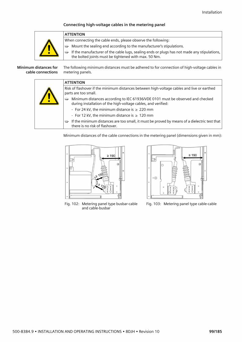
500-8384.9 • INSTALLATION AND OPERATING INSTRUCTIONS • 8DJH • Revision 10 99/185
Installation Connecting high-voltage cables in the metering panel
Minimum distances forcable connections
The following minimum distances must be adhered to for connection of high-voltage cables in metering panels.
Minimum distances of the cable connections in the metering panel (dimensions given in mm):
ATTENTIONWhen connecting the cable ends, please observe the following:➭ Mount the sealing end according to the manufacturer's stipulations.➭ If the manufacturer of the cable lugs, sealing ends or plugs has not made any stipulations,
the bolted joints must be tightened with max. 50 Nm.
ATTENTIONRisk of flashover if the minimum distances between high-voltage cables and live or earthed parts are too small.➭ Minimum distances according to IEC 61936/VDE 0101 must be observed and checked
during installation of the high-voltage cables, and verified: - For 24 kV, the minimum distance is ≥ 220 mm - For 12 kV, the minimum distance is ≥ 120 mm
➭ If the minimum distances are too small, it must be proved by means of a dielectric test that there is no risk of flashover.
Fig. 102: Metering panel type busbar-cable and cable-busbar
Fig. 103: Metering panel type cable-cable

Installation
100/185 Revision 10 • INSTALLATION AND OPERATING INSTRUCTIONS • 8DJH • 500-8384.9
Mounting the high-voltage cables➭ Mount the high-voltage cables at the current transformer connections.
Mounting the spherical connection boltsTo earth the busbars or the high-voltage cables when the current transformers are removed, spherical connection bolts must be mounted on the connection bars. The spherical connection bolts are available as accessories.➭ Mount the spherical connection bolts on the connection bars (tightening torque: 50 Nm).
Mounting positions of the spherical connection bolts
Metering panel type busbar-cable (cable-busbar)
Metering panel type cable-cable
Current transformer terminal, bottom Current transformer terminal, bottom Current transformer terminal, top
① Hexagon nut M12 ④ Connection bar of current transformer② High-voltage cable ⑤ Hexagon head bolt M12x40③ Conical spring washer M12
Fig. 104: Mounting the spherical connection bolts
① Spherical connection bolt② Connection bar (metering panel)③ Conical spring washer M12④ Hexagon head bolt M12x25
Metering panel type busbar-busbar Metering panel type busbar-cable (cable-busbar)
Metering panel type cable-cable
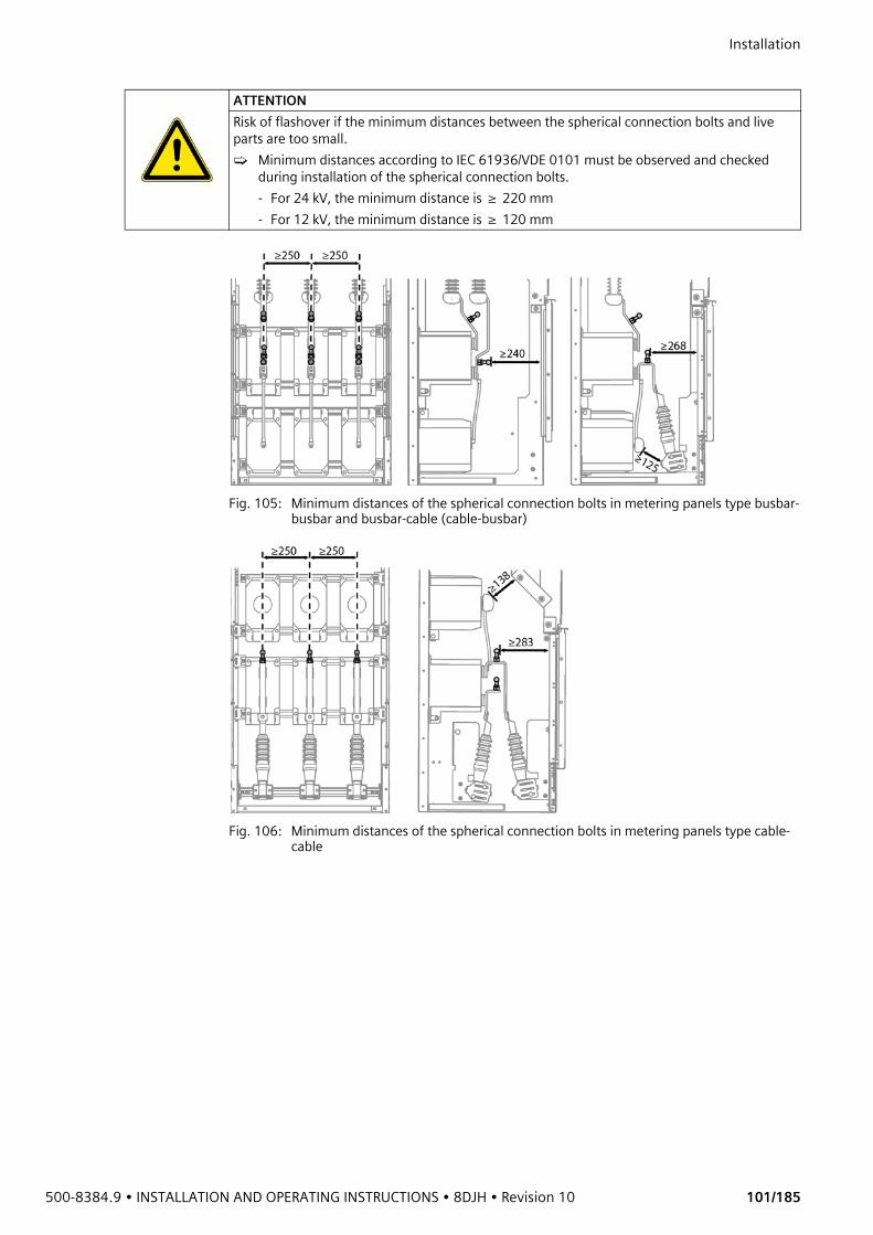
500-8384.9 • INSTALLATION AND OPERATING INSTRUCTIONS • 8DJH • Revision 10 101/185
Installation
Fig. 105: Minimum distances of the spherical connection bolts in metering panels type busbar-busbar and busbar-cable (cable-busbar)
Fig. 106: Minimum distances of the spherical connection bolts in metering panels type cable-cable
ATTENTIONRisk of flashover if the minimum distances between the spherical connection bolts and live parts are too small.➭ Minimum distances according to IEC 61936/VDE 0101 must be observed and checked
during installation of the spherical connection bolts.- For 24 kV, the minimum distance is ≥ 220 mm- For 12 kV, the minimum distance is ≥ 120 mm
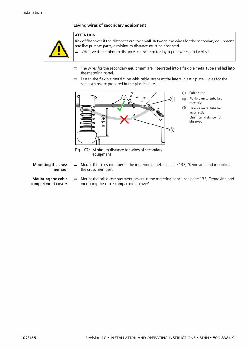
Installation
102/185 Revision 10 • INSTALLATION AND OPERATING INSTRUCTIONS • 8DJH • 500-8384.9
Laying wires of secondary equipment
➭ The wires for the secondary equipment are integrated into a flexible metal tube and led into the metering panel.
➭ Fasten the flexible metal tube with cable straps at the lateral plastic plate. Holes for the cable straps are prepared in the plastic plate.
Mounting the crossmember
➭ Mount the cross member in the metering panel, see page 133, "Removing and mounting the cross member".
Mounting the cablecompartment covers
➭ Mount the cable compartment covers in the metering panel, see page 132, "Removing and mounting the cable compartment cover".
ATTENTIONRisk of flashover if the distances are too small. Between the wires for the secondary equipment and live primary parts, a minimum distance must be observed.➭ Observe the minimum distance ≥ 190 mm for laying the wires, and verify it.
Fig. 107: Minimum distance for wires of secondary equipment
① Cable strap② Flexible metal tube laid
correctly③ Flexible metal tube laid
incorrectly: Minimum distance not observed
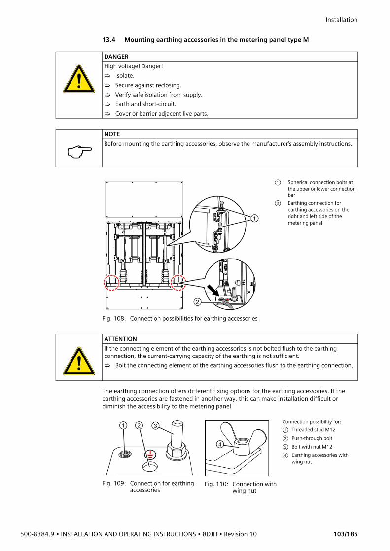
500-8384.9 • INSTALLATION AND OPERATING INSTRUCTIONS • 8DJH • Revision 10 103/185
Installation 13.4 Mounting earthing accessories in the metering panel type M
The earthing connection offers different fixing options for the earthing accessories. If the earthing accessories are fastened in another way, this can make installation difficult or diminish the accessibility to the metering panel.
DANGERHigh voltage! Danger!➭ Isolate.➭ Secure against reclosing.➭ Verify safe isolation from supply.➭ Earth and short-circuit.➭ Cover or barrier adjacent live parts.
NOTEBefore mounting the earthing accessories, observe the manufacturer's assembly instructions.
Fig. 108: Connection possibilities for earthing accessories
① Spherical connection bolts at the upper or lower connection bar
② Earthing connection for earthing accessories on the right and left side of the metering panel
ATTENTIONIf the connecting element of the earthing accessories is not bolted flush to the earthing connection, the current-carrying capacity of the earthing is not sufficient.➭ Bolt the connecting element of the earthing accessories flush to the earthing connection.
Fig. 109: Connection for earthing accessories
Fig. 110: Connection with wing nut
Connection possibility for:① Threaded stud M12② Push-through bolt③ Bolt with nut M12④ Earthing accessories with
wing nut

Installation
104/185 Revision 10 • INSTALLATION AND OPERATING INSTRUCTIONS • 8DJH • 500-8384.9
➭ Mount the earthing accessories first at the earthing connection in the metering panel.➭ Mount the earthing accessories at the spherical connection bolts (see page 100, "Mounting
the spherical connection bolts") on all 3 phases.
Type of earthingaccessories
The earthing accessories are not supplied by the factory.
At the air-insulated metering panel, the installation of earthing accessories was tested with the following components:
NOTEEarthing accessories with wing nuts ④ can be bolted to the earthing point at position ③. To do this, remove the nut M12 and the washer before.
DANGERHigh voltage, danger! Please observe the manufacturer information and suitability of the earthing accessories. ➭ The earthing accesssories must be designed for the short-circuit currents of the respective
grid configuration.➭ The connections of the earthing accesssories must be suitable for installation at the
switchgear.
No. Maximum short-circuit current/duration
Type Description
1
13.8 kA / 1 s for straight spherical connection bolt with a sphere diameter of 20/25 mmVersion number: VK6ESW91
EKV3+1 70R 3-pole earthing and short-circuiting facility according to EN/IEC 61230 (DIN VDE 0683-100)
• Cross-section of rope: 70 mm2 / 35 mm2
• Length of rope, phase side: 600 mm• Length of rope, earthing side:
1800 mmUK 25 SK Universal terminal (art. no. 773 034) • For straight spherical connection bolt
• Sphere diameter 20/25 mm• Spindle with hexagon
EAS EK FM 12 Earthing connection unit M12 (art. no. 775 621)
• With wing bolt
Accessories ES SK 1500 Earthing rod (art. no. 761 015) • Length: 1500 mm• Spindle with hexagon (SW19)
2
18.7 kA / 1 s for straight spherical connection bolt with a sphere diameter of 20 mmVersion number: V5DYR2W1
EKV3+1 95R 3-pole earthing and short-circuiting facility according to EN/IEC 61230 (DIN VDE 0683-100)
• Cross-section of rope: 95 mm2 / 35 mm2
• Length of rope, phase side: 600 mm• Length of rope, earthing side:
1800 mmKKH 20 D SK Universal terminal (art. no. 772 330) • For straight spherical connection bolt
• Sphere diameter 20 mm• Spindle with cross-pin
EAS EK FS 12 Earthing connection unit M12 (art. no. 775 626)
• With wing bolt
Accessories ES SK 1000 Earthing rod (art. no. 761 010) • Length: 1000 mm• Spindle with hexagon (SW19)
500-8384.9 • INSTALLATION AND OPERATING INSTRUCTIONS • 8DJH • Revision 10 105/185
Installation
3
18.7 kA / 1 s for straight spherical connection bolt with a sphere diameter of 25/30 mmVersion number: VSU7LDJ1
EKV3+1 95R 3-pole earthing and short-circuiting facility according to EN/IEC 61230 (DIN VDE 0683-100)
• Cross-section of rope: 95 mm2 / 35 mm2
• Length of rope, phase side: 600 mm• Length of rope, earthing side:
1800 mmUK 30 SK Universal terminal (art. no. 773 130) • For straight spherical connection bolt
• Sphere diameter 25/30 mm• Spindle with hexagon
EAS EK FS 12 Earthing connection unit M12 (art. no. 775 626)
• With wing bolt
Accessories ES SK 1500 Earthing rod (art. no. 761 015) • Length: 1500 mm• Spindle with hexagon (SW19)
4
23.7 kA / 1 s for straight spherical connection bolt with a sphere diameter of 25/30 mmVersion number: VE6X4KZ1
EKV3+1 120R 3-pole earthing and short-circuiting facility according to EN/IEC 61230 (DIN VDE 0683-100)
• Cross-section of rope: 120 mm2 / 50 mm2
• Length of rope, phase side: 600 mm• Length of rope, earthing side:
1800 mmUK 30 SQ Universal terminal (art. no. 773 330) • For straight spherical connection bolt
• Sphere diameter 25/30 mm• Spindle with cross-pin
EAS EK FS 12 Earthing connection unit M12 (art. no. 775 626)
• With wing bolt
Accessories ES SQ 1500 Earthing rod (art. no. 761 016) • Length: 1500 mm• Spindle with hexagon (SW19)
No. Maximum short-circuit current/duration
Type Description
1) Manufacturer: DEHN + SÖHNE GmbH + Co. KG, Hans Dehn-Str. 1, Postfach 1640, 92306 Neumarkt, Germany, www.dehn.de
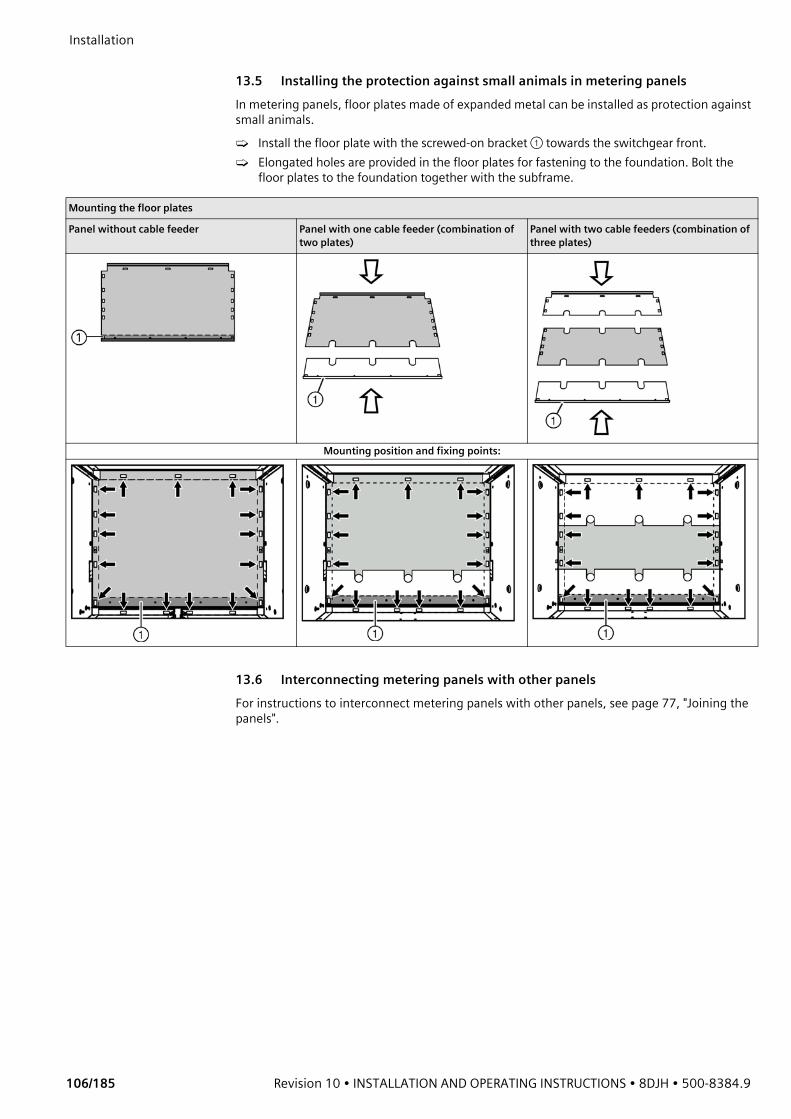
Installation
106/185 Revision 10 • INSTALLATION AND OPERATING INSTRUCTIONS • 8DJH • 500-8384.9
13.5 Installing the protection against small animals in metering panelsIn metering panels, floor plates made of expanded metal can be installed as protection against small animals.➭ Install the floor plate with the screwed-on bracket ① towards the switchgear front.➭ Elongated holes are provided in the floor plates for fastening to the foundation. Bolt the
floor plates to the foundation together with the subframe.
13.6 Interconnecting metering panels with other panelsFor instructions to interconnect metering panels with other panels, see page 77, "Joining the panels".
Mounting the floor plates
Panel without cable feeder Panel with one cable feeder (combination of two plates)
Panel with two cable feeders (combination of three plates)
Mounting position and fixing points:
500-8384.9 • INSTALLATION AND OPERATING INSTRUCTIONS • 8DJH • Revision 10 107/185
Installation 14 Electrical connectionsIn the instructions given in the following sections it is assumed that a new switchgear is being installed which has not yet been connected to the mains, and is not live.For extending or replacing parts of an existing switchgear, the Five Safety Rules must be observed:
14.1 Connecting high-voltage cablesFor common features and suitable cable plugs, see page 17, "Cable connection".
DANGERHigh voltage! Danger!➭ Isolate.➭ Secure against reclosing.➭ Verify safe isolation from supply.➭ Earth and short-circuit.➭ Cover or barrier adjacent live parts.
ATTENTIONSurfaces of high-quality joints at the bushings can be damaged by incorrect handling.➭ Observe extreme cleanliness.➭ Avoid damages caused by the threaded stud while pushing on.
ATTENTIONIn case of spare feeders without connected cables, please observe the following:➭ Switch the three-position disconnector or three-position switch-disconnector to EARTHED
position, and lock it.➭ Alternatively: Mount surge-proof caps.
ATTENTIONFor perfect installation of the cable plugs, the following must be observed:➭ Mount the cable plugs according to the manufacturer's stipulations.➭ If there are no stipulations by the cable plug manufacturer, please contact the regional
Siemens representative.
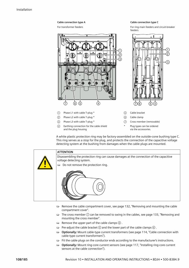
Installation
108/185 Revision 10 • INSTALLATION AND OPERATING INSTRUCTIONS • 8DJH • 500-8384.9
A white plastic protection ring may be factory-assembled on the outside-cone bushing type C. This ring serves as a stop for the plug, and protects the connection of the capacitive voltage detecting system at the bushing from damages when the cable plugs are mounted.
➭ Remove the cable compartment cover, see page 132, "Removing and mounting the cable compartment cover".
➭ The cross member ⑦ can be removed to swing in the cables, see page 133, "Removing and mounting the cross member".
➭ Remove the upper part of the cable clamps ⑥ .➭ Pre-adjust the cable bracket ⑤ and the lower part of the cable clamps ⑥ .➭ Optionally: Mount cable-type current transformers (see page 114, "Cable connection with
cable-type current transformers").➭ Fit the cable plugs on the conductor ends according to the manufacturer’s instructions.➭ Optionally: Mount ring-core current sensors (see page 117, "Installing ring-core current
sensors at the cable connection").
Cable connection type A Cable connection type C For transformer feeders For ring-main feeders and circuit-breaker
feeders
① Phase L1 with cable T-plug * ⑤ Cable bracket② Phase L2 with cable T-plug * ⑥ Cable clamp③ Phase L3 with cable T-plug * ⑦ Cross member (removable)④ Earthing connection for the cable shield
and the plug housing* Plug types can be ordered
via the accessories.
ATTENTIONDisassembling the protection ring can cause damages at the connection of the capacitive voltage detecting system.➭ Do not remove the protection ring.

500-8384.9 • INSTALLATION AND OPERATING INSTRUCTIONS • 8DJH • Revision 10 109/185
Installation ➭ Optionally: Mount voltage sensors (see page 118, "Installing voltage sensors").➭ Carefully coat the push-on surfaces (high-quality joints) of the cable plugs and the bushings
with the delivered mounting paste (see scope of supply of the cable plugs).➭ Push the cable plugs ① to ③ onto the bushings and mount them according to the
manufacturer’s instructions. Observe the phase sequence.NOTE: A too high torque can cause damage to the bushing. Tighten the cable plug with a torque according to the manufacturer's instructions (max. 50 Nm).
➭ Mount the upper part of the cable clamps ⑥ .➭ Align the cable bracket and bolt it tight.➭ Refit the cross member, see page 133, "Removing and mounting the cross member".➭ Connect the earthing cables of the plug housings and the cable shield at the cross
member ⑦ .➭ Hook the cable compartment cover in again, see page 132, "Removing and mounting the
cable compartment cover".✔ The cable connection is completed.
Double cables and surgearresters
Double cables and surge arresters can be connected to the following panel types using the corresponding plug-in cable systems:• Ring-main panel• Cable panel• Circuit-breaker panelPlease observe the following:• Depending on their type, double cable connections require a deep cable compartment cover
and larger floor openings. • Depending on their type, surge arresters also require a deep cable compartment cover.For further information, see page 17, "Cable connection".
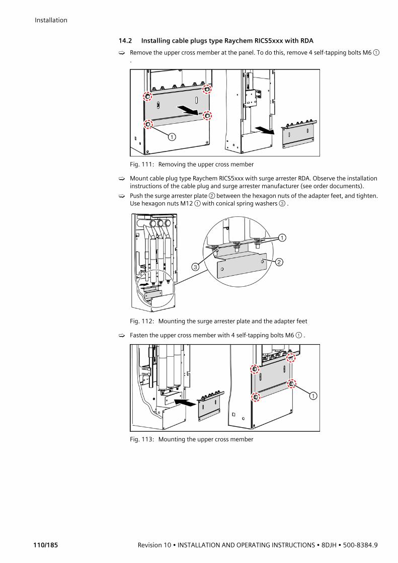
Installation
110/185 Revision 10 • INSTALLATION AND OPERATING INSTRUCTIONS • 8DJH • 500-8384.9
14.2 Installing cable plugs type Raychem RICS5xxx with RDA➭ Remove the upper cross member at the panel. To do this, remove 4 self-tapping bolts M6 ①
.
Fig. 111: Removing the upper cross member
➭ Mount cable plug type Raychem RICS5xxx with surge arrester RDA. Observe the installation instructions of the cable plug and surge arrester manufacturer (see order documents).
➭ Push the surge arrester plate ② between the hexagon nuts of the adapter feet, and tighten. Use hexagon nuts M12 ① with conical spring washers ③ .
Fig. 112: Mounting the surge arrester plate and the adapter feet
➭ Fasten the upper cross member with 4 self-tapping bolts M6 ① .
Fig. 113: Mounting the upper cross member

500-8384.9 • INSTALLATION AND OPERATING INSTRUCTIONS • 8DJH • Revision 10 111/185
Installation ➭ Fasten the surge arrester plate with 2 hexagon head bolts M8x16 ① and plain washers ② to
the upper cross member.
Fig. 114: Fastening the surge arrester plate
➭ Earth the cable shields with cable lugs and earthing bolts M10 at the upper cross member.
➭ Observe the minimum distances according to the manufacturer's instructions while connecting non-screened cable plugs or surge arresters.The use of RICS5xxx cable plugs with RDA in panels with a width of 310 mm is allowed under normal ambient conditions despite the reduced distance (according to IEC 62271-1).
✔ The installation of the Raychem RICS5xxx cable plug with RDA is completed.
Fig. 115: Earthing the cable shields
① Cable shield, phase L1② Cable shield, phase L2③ Cable shield, phase L3④ Upper cross member
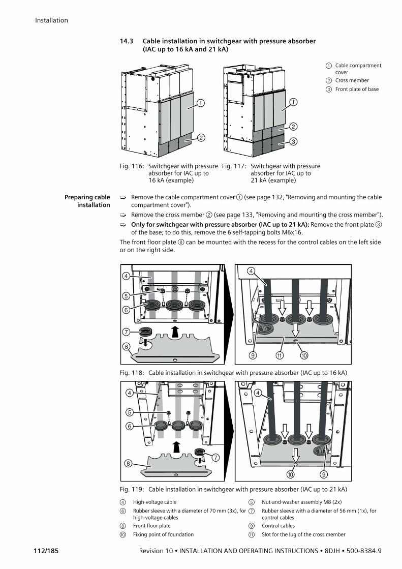
Installation
112/185 Revision 10 • INSTALLATION AND OPERATING INSTRUCTIONS • 8DJH • 500-8384.9
14.3 Cable installation in switchgear with pressure absorber
(IAC up to 16 kA and 21 kA)
Preparing cableinstallation
➭ Remove the cable compartment cover ① (see page 132, "Removing and mounting the cable compartment cover").
➭ Remove the cross member ② (see page 133, "Removing and mounting the cross member").➭ Only for switchgear with pressure absorber (IAC up to 21 kA): Remove the front plate ③
of the base; to do this, remove the 6 self-tapping bolts M6x16.The front floor plate ⑧ can be mounted with the recess for the control cables on the left side or on the right side.
Fig. 116: Switchgear with pressure absorber for IAC up to 16 kA (example)
Fig. 117: Switchgear with pressure absorber for IAC up to 21 kA (example)
① Cable compartment cover
② Cross member③ Front plate of base
Fig. 118: Cable installation in switchgear with pressure absorber (IAC up to 16 kA)
Fig. 119: Cable installation in switchgear with pressure absorber (IAC up to 21 kA)
④ High-voltage cable ⑤ Nut-and-washer assembly M8 (2x)⑥ Rubber sleeve with a diameter of 70 mm (3x), for
high-voltage cables⑦ Rubber sleeve with a diameter of 56 mm (1x), for
control cables⑧ Front floor plate ⑨ Control cables⑩ Fixing point of foundation ⑪ Slot for the lug of the cross member
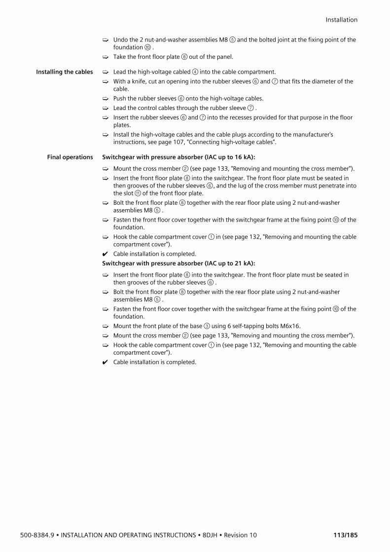
500-8384.9 • INSTALLATION AND OPERATING INSTRUCTIONS • 8DJH • Revision 10 113/185
Installation ➭ Undo the 2 nut-and-washer assemblies M8 ⑤ and the bolted joint at the fixing point of the
foundation ⑩ . ➭ Take the front floor plate ⑧ out of the panel.
Installing the cables ➭ Lead the high-voltage cabled ④ into the cable compartment.➭ With a knife, cut an opening into the rubber sleeves ⑥ and ⑦ that fits the diameter of the
cable. ➭ Push the rubber sleeves ⑥ onto the high-voltage cables.➭ Lead the control cables through the rubber sleeve ⑦ .➭ Insert the rubber sleeves ⑥ and ⑦ into the recesses provided for that purpose in the floor
plates.➭ Install the high-voltage cables and the cable plugs according to the manufacturer's
instructions, see page 107, "Connecting high-voltage cables".
Final operations Switchgear with pressure absorber (IAC up to 16 kA):➭ Mount the cross member ② (see page 133, "Removing and mounting the cross member").➭ Insert the front floor plate ⑧ into the switchgear. The front floor plate must be seated in
then grooves of the rubber sleeves ⑥, and the lug of the cross member must penetrate into the slot ⑪ of the front floor plate.
➭ Bolt the front floor plate ⑧ together with the rear floor plate using 2 nut-and-washer assemblies M8 ⑤ .
➭ Fasten the front floor cover together with the switchgear frame at the fixing point ⑩ of the foundation.
➭ Hook the cable compartment cover ① in (see page 132, "Removing and mounting the cable compartment cover").
✔ Cable installation is completed.Switchgear with pressure absorber (IAC up to 21 kA):➭ Insert the front floor plate ⑧ into the switchgear. The front floor plate must be seated in
then grooves of the rubber sleeves ⑥ .➭ Bolt the front floor plate ⑧ together with the rear floor plate using 2 nut-and-washer
assemblies M8 ⑤ . ➭ Fasten the front floor cover together with the switchgear frame at the fixing point ⑩ of the
foundation.➭ Mount the front plate of the base ③ using 6 self-tapping bolts M6x16.➭ Mount the cross member ② (see page 133, "Removing and mounting the cross member").➭ Hook the cable compartment cover ① in (see page 132, "Removing and mounting the cable
compartment cover").✔ Cable installation is completed.
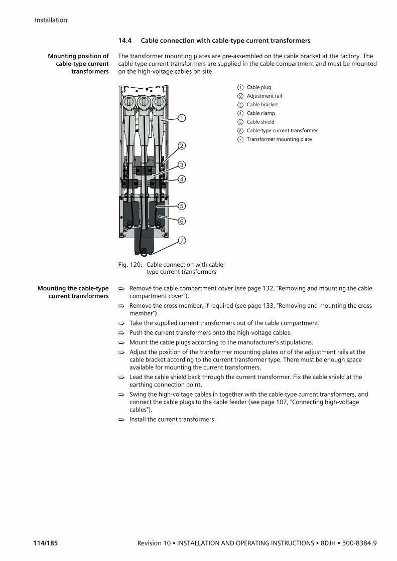
Installation
114/185 Revision 10 • INSTALLATION AND OPERATING INSTRUCTIONS • 8DJH • 500-8384.9
14.4 Cable connection with cable-type current transformers
Mounting position ofcable-type current
transformers
The transformer mounting plates are pre-assembled on the cable bracket at the factory. The cable-type current transformers are supplied in the cable compartment and must be mounted on the high-voltage cables on site.
Mounting the cable-typecurrent transformers
➭ Remove the cable compartment cover (see page 132, "Removing and mounting the cable compartment cover").
➭ Remove the cross member, if required (see page 133, "Removing and mounting the cross member").
➭ Take the supplied current transformers out of the cable compartment.➭ Push the current transformers onto the high-voltage cables.➭ Mount the cable plugs according to the manufacturer's stipulations.➭ Adjust the position of the transformer mounting plates or of the adjustment rails at the
cable bracket according to the current transformer type. There must be enough space available for mounting the current transformers.
➭ Lead the cable shield back through the current transformer. Fix the cable shield at the earthing connection point.
➭ Swing the high-voltage cables in together with the cable-type current transformers, and connect the cable plugs to the cable feeder (see page 107, "Connecting high-voltage cables").
➭ Install the current transformers.
Fig. 120: Cable connection with cable-type current transformers
① Cable plug② Adjustment rail③ Cable bracket④ Cable clamp⑤ Cable shield⑥ Cable-type current transformer⑦ Transformer mounting plate

500-8384.9 • INSTALLATION AND OPERATING INSTRUCTIONS • 8DJH • Revision 10 115/185
Installation Installation of cable-type current transformers 4MC7032 and 4MC7033
Transformer type
4MC7032 4MC7033
Panel width 310 mm 430 mm 430 mm 500 mmTransformer height
80/150 mm 65/110/170 mm 285 mm 285 mm
Mounting position
NOTE➭ To provide enough space for the transformer cables, place the current transformers slightly
turned on the transformer mounting plate.➭ Due to their height, mounted instrument transformers can reach into the cable basement.
Fig. 121: Principle of installation for 4MC7032 and 4MC7033
① Cup head bolt M8x20② Extension of adjustment rail
(optional)③ Adjustment rail④ Self-tapping Torx bolt M6x16⑤ Transformer mounting plate⑥ Current transformer⑦ Cable clamp⑧ Cable bracket⑨ Nut-and-washer assembly M8

Installation
116/185 Revision 10 • INSTALLATION AND OPERATING INSTRUCTIONS • 8DJH • 500-8384.9
Installation of cable-type current transformers 4MC7031 and WIC1
Completing theinstallation of the cable-
type current transformers
➭ Mount the cross member (see page 133, "Removing and mounting the cross member").➭ Hook the cable compartment cover in (see page 132, "Removing and mounting the cable
compartment cover").
Transformer type
4MC7031 WIC1
Panel width 310 mm 430/500 mm 430/500 mmTransformer height
89 mm 89 mm 130 mm
Mounting position
Fig. 122: Principle of installation for 4MC7031 current transformers
Fig. 123: Principle of installation for WIC1 current transformers
① Transformer mounting plate ④ Self-tapping Torx bolt M6x16② Holder for transformer mounting plate ⑤ Current transformer③ C-rail
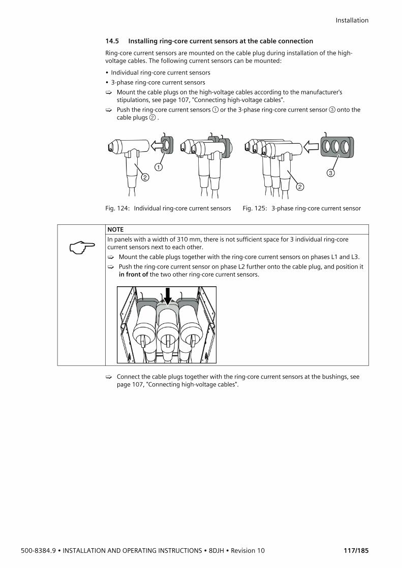
500-8384.9 • INSTALLATION AND OPERATING INSTRUCTIONS • 8DJH • Revision 10 117/185
Installation 14.5 Installing ring-core current sensors at the cable connectionRing-core current sensors are mounted on the cable plug during installation of the high-voltage cables. The following current sensors can be mounted:• Individual ring-core current sensors• 3-phase ring-core current sensors➭ Mount the cable plugs on the high-voltage cables according to the manufacturer's
stipulations, see page 107, "Connecting high-voltage cables".➭ Push the ring-core current sensors ① or the 3-phase ring-core current sensor ③ onto the
cable plugs ② .
➭ Connect the cable plugs together with the ring-core current sensors at the bushings, see page 107, "Connecting high-voltage cables".
Fig. 124: Individual ring-core current sensors Fig. 125: 3-phase ring-core current sensor
NOTEIn panels with a width of 310 mm, there is not sufficient space for 3 individual ring-core current sensors next to each other. ➭ Mount the cable plugs together with the ring-core current sensors on phases L1 and L3.➭ Push the ring-core current sensor on phase L2 further onto the cable plug, and position it
in front of the two other ring-core current sensors.
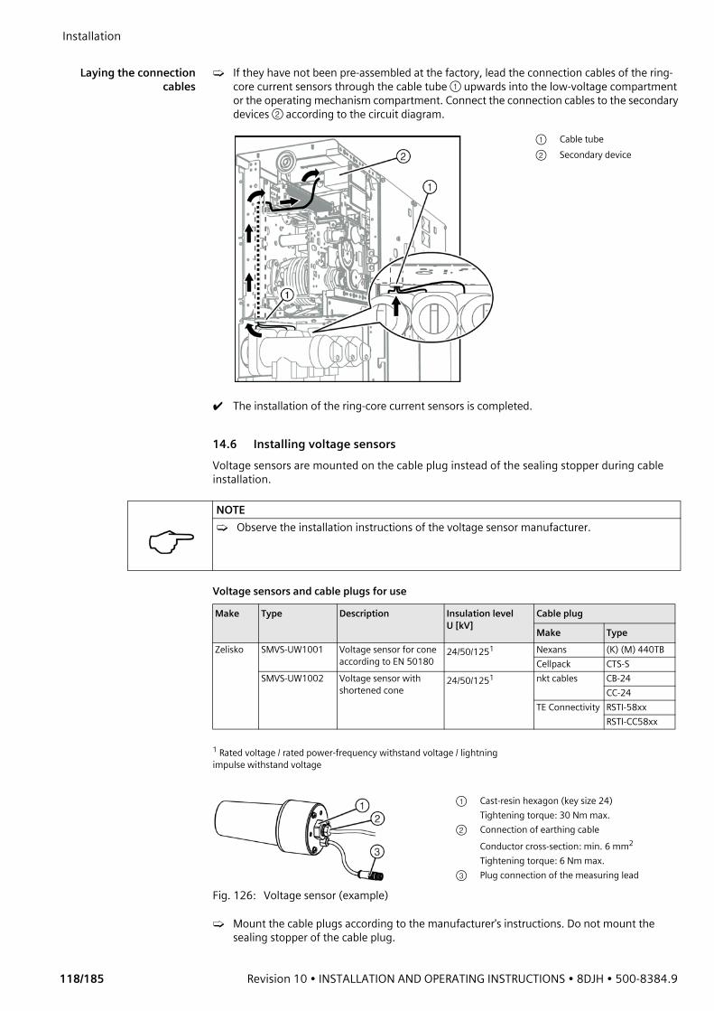
Installation
118/185 Revision 10 • INSTALLATION AND OPERATING INSTRUCTIONS • 8DJH • 500-8384.9
Laying the connection
cables➭ If they have not been pre-assembled at the factory, lead the connection cables of the ring-
core current sensors through the cable tube ① upwards into the low-voltage compartment or the operating mechanism compartment. Connect the connection cables to the secondary devices ② according to the circuit diagram.
✔ The installation of the ring-core current sensors is completed.
14.6 Installing voltage sensorsVoltage sensors are mounted on the cable plug instead of the sealing stopper during cable installation.
Voltage sensors and cable plugs for use
➭ Mount the cable plugs according to the manufacturer's instructions. Do not mount the sealing stopper of the cable plug.
① Cable tube② Secondary device
NOTE➭ Observe the installation instructions of the voltage sensor manufacturer.
Make Type Description Insulation levelU [kV]
Cable plug
Make TypeZelisko SMVS-UW1001 Voltage sensor for cone
according to EN 5018024/50/1251 Nexans (K) (M) 440TB
Cellpack CTS-SSMVS-UW1002 Voltage sensor with
shortened cone24/50/1251 nkt cables CB-24
CC-24TE Connectivity RSTI-58xx
RSTI-CC58xx
1 Rated voltage / rated power-frequency withstand voltage / lightning impulse withstand voltage
Fig. 126: Voltage sensor (example)
① Cast-resin hexagon (key size 24)Tightening torque: 30 Nm max.
② Connection of earthing cableConductor cross-section: min. 6 mm2
Tightening torque: 6 Nm max.③ Plug connection of the measuring lead
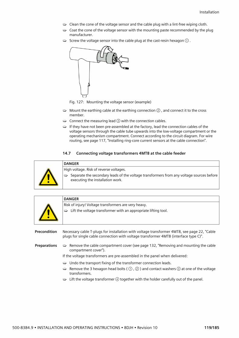
500-8384.9 • INSTALLATION AND OPERATING INSTRUCTIONS • 8DJH • Revision 10 119/185
Installation ➭ Clean the cone of the voltage sensor and the cable plug with a lint-free wiping cloth.➭ Coat the cone of the voltage sensor with the mounting paste recommended by the plug
manufacturer.➭ Screw the voltage sensor into the cable plug at the cast-resin hexagon ① .
Fig. 127: Mounting the voltage sensor (example)
➭ Mount the earthing cable at the earthing connection ② , and connect it to the cross member.
➭ Connect the measuring lead ③ with the connection cables.➭ If they have not been pre-assembled at the factory, lead the connection cables of the
voltage sensors through the cable tube upwards into the low-voltage compartment or the operating mechanism compartment. Connect according to the circuit diagram. For wire routing, see page 117, "Installing ring-core current sensors at the cable connection".
14.7 Connecting voltage transformers 4MT8 at the cable feeder
Precondition Necessary cable T-plugs for installation with voltage transformer 4MT8, see page 22, "Cable plugs for single cable connection with voltage transformer 4MT8 (interface type C)".
Preparations ➭ Remove the cable compartment cover (see page 132, "Removing and mounting the cable compartment cover").
If the voltage transformers are pre-assembled in the panel when delivered:➭ Undo the transport fixing of the transformer connection leads.➭ Remove the 3 hexagon head bolts ( ① , ② ) and contact washers ③ at one of the voltage
transformers.➭ Lift the voltage transformer ④ together with the holder carefully out of the panel.
DANGERHigh voltage. Risk of reverse voltages.➭ Separate the secondary leads of the voltage transformers from any voltage sources before
executing the installation work.
DANGERRisk of injury! Voltage transformers are very heavy.➭ Lift the voltage transformer with an appropriate lifting tool.
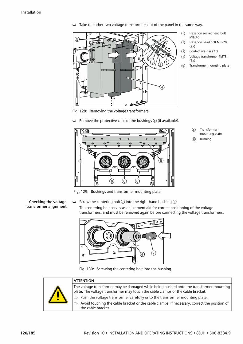
Installation
120/185 Revision 10 • INSTALLATION AND OPERATING INSTRUCTIONS • 8DJH • 500-8384.9
➭ Take the other two voltage transformers out of the panel in the same way.
➭ Remove the protective caps of the bushings ⑥ (if available).
Checking the voltagetransformer alignment
➭ Screw the centering bolt ⑦ into the right-hand bushing ⑥ . The centering bolt serves as adjustment aid for correct positioning of the voltage transformers, and must be removed again before connecting the voltage transformers.
Fig. 130: Screwing the centering bolt into the bushing
Fig. 128: Removing the voltage transformers
① Hexagon socket head bolt M8x40
② Hexagon head bolt M8x70 (2x)
③ Contact washer (2x)④ Voltage transformer 4MT8
(3x)⑤ Transformer mounting plate
Fig. 129: Bushings and transformer mounting plate
⑤ Transformer mounting plate
⑥ Bushing
ATTENTIONThe voltage transformer may be damaged while being pushed onto the transformer mounting plate. The voltage transformer may touch the cable clamps or the cable bracket.➭ Push the voltage transformer carefully onto the transformer mounting plate.➭ Avoid touching the cable bracket or the cable clamps. If necessary, correct the position of
the cable bracket.
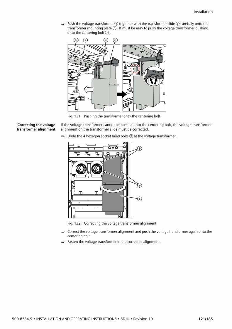
500-8384.9 • INSTALLATION AND OPERATING INSTRUCTIONS • 8DJH • Revision 10 121/185
Installation ➭ Push the voltage transformer ④ together with the transformer slide ⑧ carefully onto the
transformer mounting plate ⑤ . It must be easy to push the voltage transformer bushing onto the centering bolt ⑦ .
Fig. 131: Pushing the transformer onto the centering bolt
Correcting the voltagetransformer alignment
If the voltage transformer cannot be pushed onto the centering bolt, the voltage transformer alignment on the transformer slide must be corrected.➭ Undo the 4 hexagon socket head bolts ⑨ at the voltage transformer.
Fig. 132: Correcting the voltage transformer alignment
➭ Correct the voltage transformer alignment and push the voltage transformer again onto the centering bolt.
➭ Fasten the voltage transformer in the corrected alignment.
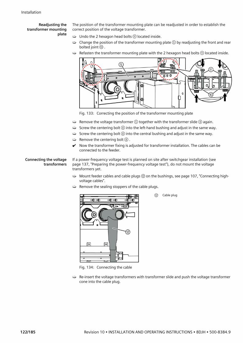
Installation
122/185 Revision 10 • INSTALLATION AND OPERATING INSTRUCTIONS • 8DJH • 500-8384.9
Readjusting the
transformer mountingplate
The position of the transformer mounting plate can be readjusted in order to establish the correct position of the voltage transformer.➭ Undo the 2 hexagon head bolts ⑪ located inside.➭ Change the position of the transformer mounting plate ⑤ by readjusting the front and rear
bolted joint ⑩ . ➭ Refasten the transformer mounting plate with the 2 hexagon head bolts ⑪ located inside.
Fig. 133: Correcting the position of the transformer mounting plate
➭ Remove the voltage transformer ⑤ together with the transformer slide ⑨ again.➭ Screw the centering bolt ⑧ into the left-hand bushing and adjust in the same way.➭ Screw the centering bolt ⑧ into the central bushing and adjust in the same way.➭ Remove the centering bolt ⑧ .✔ Now the transformer fixing is adjusted for transformer installation. The cables can be
connected to the feeder.
Connecting the voltagetransformers
If a power-frequency voltage test is planned on site after switchgear installation (see page 137, "Preparing the power-frequency voltage test"), do not mount the voltage transformers yet.➭ Mount feeder cables and cable plugs ⑫ on the bushings, see page 107, "Connecting high-
voltage cables". ➭ Remove the sealing stoppers of the cable plugs.
➭ Re-insert the voltage transformers with transformer slide and push the voltage transformer cone into the cable plug.
Fig. 134: Connecting the cable
⑫ Cable plug

500-8384.9 • INSTALLATION AND OPERATING INSTRUCTIONS • 8DJH • Revision 10 123/185
Installation ➭ The transformer cone must be completely inserted in the cable plug.
Aligning and fasteningthe voltage transformer
➭ Bolt the transformer slide ⑧ together with the transformer mounting plate ⑤ : - First bolt both exterior hexagon head bolts ② tight, until the voltage transformer begins
to incline. Then, turn the bolts back slightly.- Counter the bolted joint with the central hexagon head bolt ① .
➭ Check the vertical alignment of the voltage transformer with a water level and, if required, readjust with the hexagon head bolts:- Undo the exterior hexagon head bolts ② .- Readjust the central hexagon head bolt ① .- Tighten the exterior hexagon head bolts ② again.
Fig. 137: Fastening and aligning the voltage transformer
Fig. 135: Installing the voltage transformer at the cable plug
④ Voltage transformer⑥ Bushing⑧ Transformer slide⑫ Cable plug⑬ Transformer cone⑭ Contact spring⑮ Hexagon nut⑯ Bolt M16⑰ Feeder cable⑱ Contact washer
Fig. 136: Fastening the transformer slide
① Hexagon head bolt M8x70② Hexagon head bolt M8x70③ Contact washer④ Voltage transformer⑤ Transformer mounting plate⑧ Transformer slide
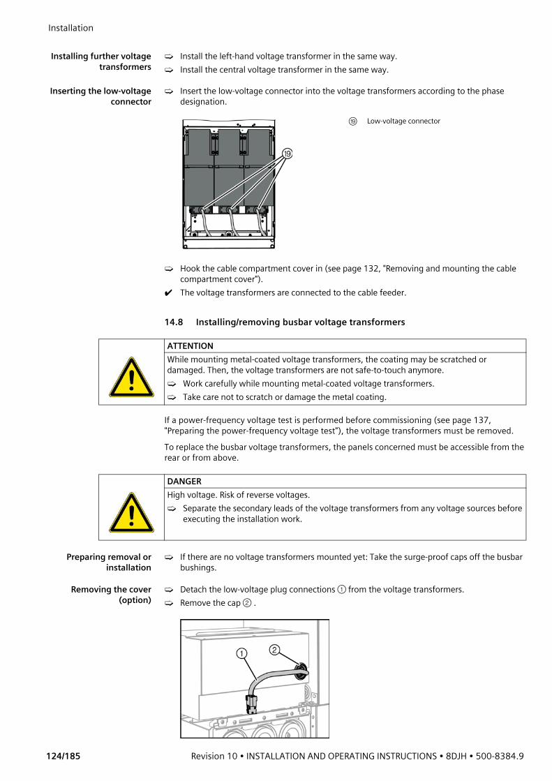
Installation
124/185 Revision 10 • INSTALLATION AND OPERATING INSTRUCTIONS • 8DJH • 500-8384.9
Installing further voltage
transformers➭ Install the left-hand voltage transformer in the same way.➭ Install the central voltage transformer in the same way.
Inserting the low-voltageconnector
➭ Insert the low-voltage connector into the voltage transformers according to the phase designation.
➭ Hook the cable compartment cover in (see page 132, "Removing and mounting the cable compartment cover").
✔ The voltage transformers are connected to the cable feeder.
14.8 Installing/removing busbar voltage transformers
If a power-frequency voltage test is performed before commissioning (see page 137, "Preparing the power-frequency voltage test"), the voltage transformers must be removed. To replace the busbar voltage transformers, the panels concerned must be accessible from the rear or from above.
Preparing removal orinstallation
➭ If there are no voltage transformers mounted yet: Take the surge-proof caps off the busbar bushings.
Removing the cover(option)
➭ Detach the low-voltage plug connections ① from the voltage transformers.➭ Remove the cap ② .
⑲ Low-voltage connector
ATTENTIONWhile mounting metal-coated voltage transformers, the coating may be scratched or damaged. Then, the voltage transformers are not safe-to-touch anymore.➭ Work carefully while mounting metal-coated voltage transformers.➭ Take care not to scratch or damage the metal coating.
DANGERHigh voltage. Risk of reverse voltages.➭ Separate the secondary leads of the voltage transformers from any voltage sources before
executing the installation work.
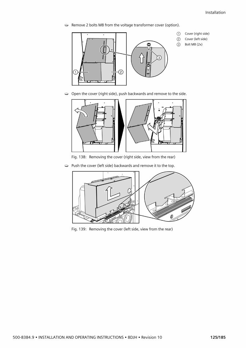
500-8384.9 • INSTALLATION AND OPERATING INSTRUCTIONS • 8DJH • Revision 10 125/185
Installation ➭ Remove 2 bolts M8 from the voltage transformer cover (option).
➭ Open the cover (right side), push backwards and remove to the side.
Fig. 138: Removing the cover (right side, view from the rear)
➭ Push the cover (left side) backwards and remove it to the top.
Fig. 139: Removing the cover (left side, view from the rear)
① Cover (right side)② Cover (left side)③ Bolt M8 (2x)
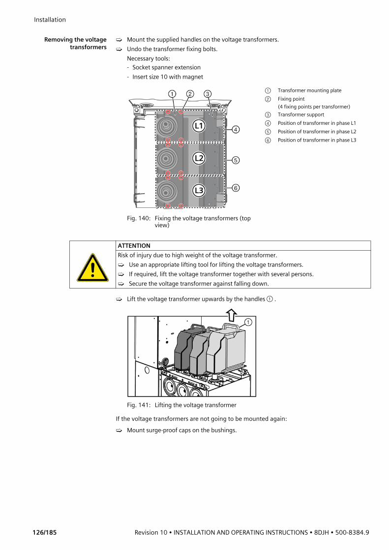
Installation
126/185 Revision 10 • INSTALLATION AND OPERATING INSTRUCTIONS • 8DJH • 500-8384.9
Removing the voltage
transformers➭ Mount the supplied handles on the voltage transformers.➭ Undo the transformer fixing bolts.
Necessary tools: - Socket spanner extension- Insert size 10 with magnet
➭ Lift the voltage transformer upwards by the handles ① .
Fig. 141: Lifting the voltage transformer
If the voltage transformers are not going to be mounted again:➭ Mount surge-proof caps on the bushings.
Fig. 140: Fixing the voltage transformers (top view)
① Transformer mounting plate② Fixing point
(4 fixing points per transformer)③ Transformer support④ Position of transformer in phase L1⑤ Position of transformer in phase L2⑥ Position of transformer in phase L3
ATTENTIONRisk of injury due to high weight of the voltage transformer.➭ Use an appropriate lifting tool for lifting the voltage transformers. ➭ If required, lift the voltage transformer together with several persons.➭ Secure the voltage transformer against falling down.

500-8384.9 • INSTALLATION AND OPERATING INSTRUCTIONS • 8DJH • Revision 10 127/185
Installation Preparing installation ofthe voltage transformer
➭ Clean the bushing in the panel carefully with a lint-free wiping cloth. ➭ Apply mounting paste evenly to the bushing.➭ Coat the transformer inside cone with the supplied mounting paste.
➭ Push the transformer inside cone onto the bushing.
Positioning andconnecting the voltage
transformer
➭ Mount the handle on the voltage transformer and remove the transformer type plate.➭ To let excess air out, apply a cable strap ① or nylon thread to the bushing.
Fig. 142: Setting the voltage transformer down on the bushing
➭ Take the voltage transformer by the handle and set it onto the bushing from above. Take care that the cable strap does not get out of place.
➭ While setting down the voltage transformer, pull out the cable strap carefully.➭ Verify intact condition of the cable strap. If the cable strap was damaged when it was pulled
out, remove the voltage transformer again and eliminate the residues of the cable strap.
ATTENTIONRisk of injury due to high weight of the voltage transformer.➭ Use an appropriate lifting tool for lifting the voltage transformers. ➭ If required, lift the voltage transformer together with several persons.➭ Secure the voltage transformer against falling down.
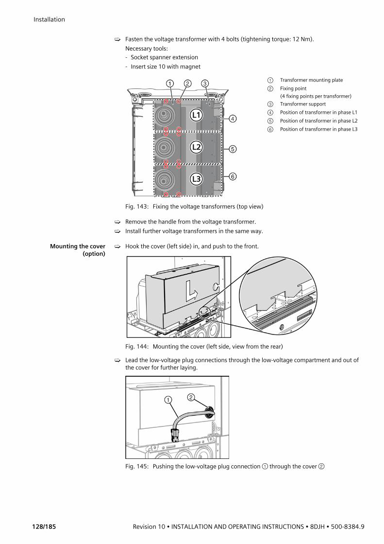
Installation
128/185 Revision 10 • INSTALLATION AND OPERATING INSTRUCTIONS • 8DJH • 500-8384.9
➭ Fasten the voltage transformer with 4 bolts (tightening torque: 12 Nm).
Necessary tools:- Socket spanner extension- Insert size 10 with magnet
➭ Remove the handle from the voltage transformer.➭ Install further voltage transformers in the same way.
Mounting the cover(option)
➭ Hook the cover (left side) in, and push to the front.
Fig. 144: Mounting the cover (left side, view from the rear)
➭ Lead the low-voltage plug connections through the low-voltage compartment and out of the cover for further laying.
Fig. 145: Pushing the low-voltage plug connection ① through the cover ②
Fig. 143: Fixing the voltage transformers (top view)
① Transformer mounting plate② Fixing point
(4 fixing points per transformer)③ Transformer support④ Position of transformer in phase L1⑤ Position of transformer in phase L2⑥ Position of transformer in phase L3
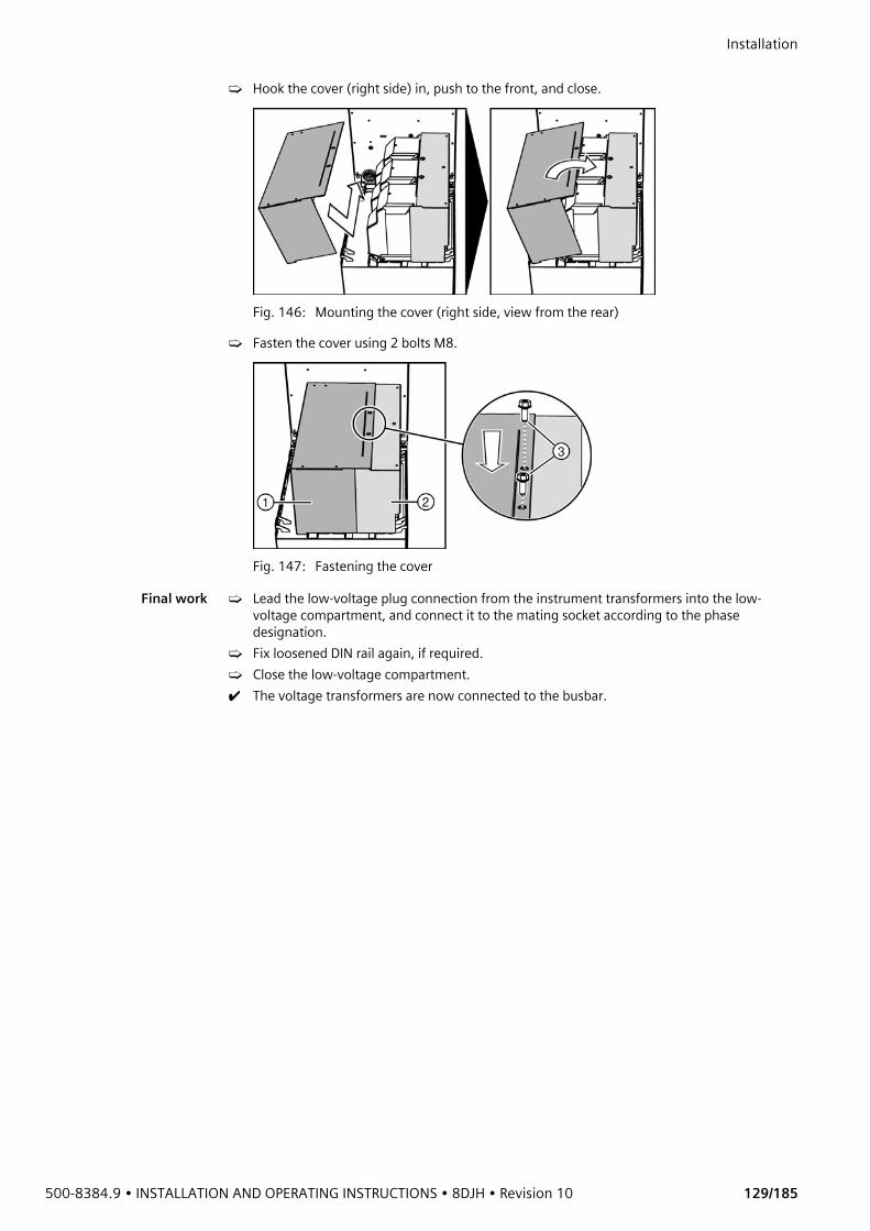
500-8384.9 • INSTALLATION AND OPERATING INSTRUCTIONS • 8DJH • Revision 10 129/185
Installation ➭ Hook the cover (right side) in, push to the front, and close.
Fig. 146: Mounting the cover (right side, view from the rear)
➭ Fasten the cover using 2 bolts M8.
Fig. 147: Fastening the cover
Final work ➭ Lead the low-voltage plug connection from the instrument transformers into the low-voltage compartment, and connect it to the mating socket according to the phase designation.
➭ Fix loosened DIN rail again, if required.➭ Close the low-voltage compartment.✔ The voltage transformers are now connected to the busbar.

Installation
130/185 Revision 10 • INSTALLATION AND OPERATING INSTRUCTIONS • 8DJH • 500-8384.9
14.9 Connecting the secondary equipment
Wire routing Wires for secondary equipment can be laid to the side, to the rear or downwards. For panel blocks, wire routing across panels is possible through the wiring duct on the operating mechanism box (option) or through the front operating mechanism box. For extendable switchgear, wire routing through the wiring ducts is recommended.
DANGERRisk of injury by release of charged operating springs when the front cover of the operating mechanism is removed! Bruises or cuts at the hands can be the consequence.➭ To avoid impermissible switching operations, switch off auxiliary voltage, e.g.:
- Switch the auxiliary voltage supply of the motor.- Trip the MCB.- Disconnect the control cables from the low-voltage compartment.
➭ To discharge the spring energy store in the operating mechanism, perform the following operations before removing the front cover:- Actuate the OFF pushbutton.- Actuate the ON pushbutton.- Actuate the OFF pushbutton.
➭ The spring energy store indicator must show "spring not charged".
ATTENTIONCables laid too close to the ready-for-service indicator can impair the function of the ready-for-service indicator.➭ When cables are laid, the transmission linkage of the ready-for-service indicator must
move freely.
Fig. 148: Wire routing with wiring duct on the front operating mechanism box
Fig. 149: Wire routing through the operating mechanism box
Fig. 150: Wire routing in the operating mechanism box
① Wiring duct on the operating mechanism box (option) ⑤ Fixing duct② Lateral wiring ducts (recommended wire routing downwards) ⑥ Terminal strip③ Wire routing through the operating mechanism box ⑦ Customer-side wiring④ Ready-for-service indicator
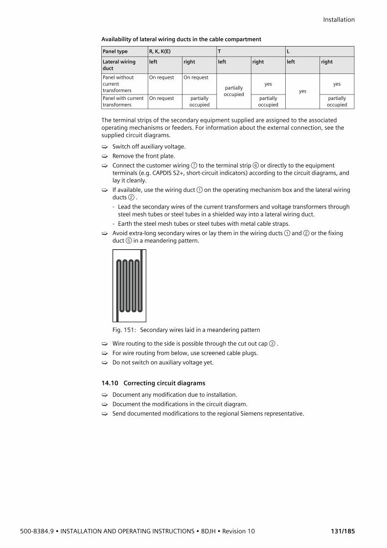
500-8384.9 • INSTALLATION AND OPERATING INSTRUCTIONS • 8DJH • Revision 10 131/185
Installation Availability of lateral wiring ducts in the cable compartment
The terminal strips of the secondary equipment supplied are assigned to the associated operating mechanisms or feeders. For information about the external connection, see the supplied circuit diagrams.➭ Switch off auxiliary voltage.➭ Remove the front plate.➭ Connect the customer wiring ⑦ to the terminal strip ⑥ or directly to the equipment
terminals (e.g. CAPDIS S2+, short-circuit indicators) according to the circuit diagrams, and lay it cleanly.
➭ If available, use the wiring duct ① on the operating mechanism box and the lateral wiring ducts ② .- Lead the secondary wires of the current transformers and voltage transformers through
steel mesh tubes or steel tubes in a shielded way into a lateral wiring duct.- Earth the steel mesh tubes or steel tubes with metal cable straps.
➭ Avoid extra-long secondary wires or lay them in the wiring ducts ① and ② or the fixing duct ⑤ in a meandering pattern.
Fig. 151: Secondary wires laid in a meandering pattern
➭ Wire routing to the side is possible through the cut out cap ③ . ➭ For wire routing from below, use screened cable plugs. ➭ Do not switch on auxiliary voltage yet.
14.10 Correcting circuit diagrams➭ Document any modification due to installation.➭ Document the modifications in the circuit diagram.➭ Send documented modifications to the regional Siemens representative.
Panel type R, K, K(E) T L
Lateral wiring duct
left right left right left right
Panel without current transformers
On request On request
partially occupied
yesyes
yes
Panel with current transformers
On request partially occupied
partially occupied
partially occupied
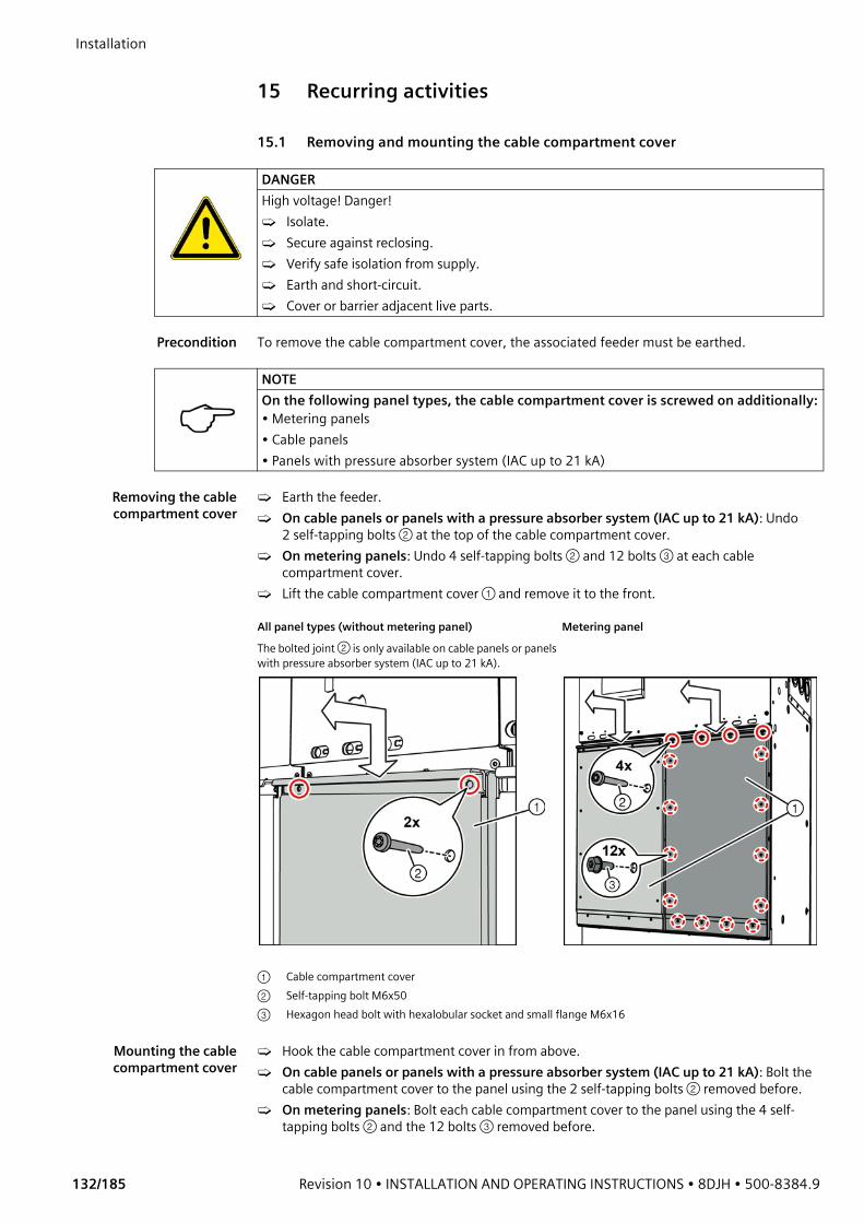
Installation
132/185 Revision 10 • INSTALLATION AND OPERATING INSTRUCTIONS • 8DJH • 500-8384.9
15 Recurring activities
15.1 Removing and mounting the cable compartment cover
Precondition To remove the cable compartment cover, the associated feeder must be earthed.
Removing the cablecompartment cover
➭ Earth the feeder.➭ On cable panels or panels with a pressure absorber system (IAC up to 21 kA): Undo
2 self-tapping bolts ② at the top of the cable compartment cover.➭ On metering panels: Undo 4 self-tapping bolts ② and 12 bolts ③ at each cable
compartment cover.➭ Lift the cable compartment cover ① and remove it to the front.
Mounting the cablecompartment cover
➭ Hook the cable compartment cover in from above.➭ On cable panels or panels with a pressure absorber system (IAC up to 21 kA): Bolt the
cable compartment cover to the panel using the 2 self-tapping bolts ② removed before.➭ On metering panels: Bolt each cable compartment cover to the panel using the 4 self-
tapping bolts ② and the 12 bolts ③ removed before.
DANGERHigh voltage! Danger!➭ Isolate.➭ Secure against reclosing.➭ Verify safe isolation from supply.➭ Earth and short-circuit.➭ Cover or barrier adjacent live parts.
NOTEOn the following panel types, the cable compartment cover is screwed on additionally:• Metering panels• Cable panels• Panels with pressure absorber system (IAC up to 21 kA)
All panel types (without metering panel) Metering panelThe bolted joint ② is only available on cable panels or panels with pressure absorber system (IAC up to 21 kA).
① Cable compartment cover② Self-tapping bolt M6x50 ③ Hexagon head bolt with hexalobular socket and small flange M6x16
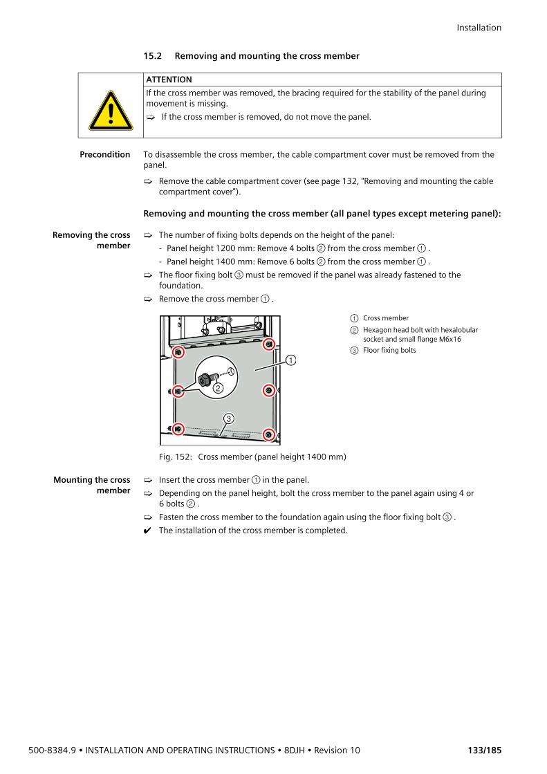
500-8384.9 • INSTALLATION AND OPERATING INSTRUCTIONS • 8DJH • Revision 10 133/185
Installation 15.2 Removing and mounting the cross member
Precondition To disassemble the cross member, the cable compartment cover must be removed from the panel.➭ Remove the cable compartment cover (see page 132, "Removing and mounting the cable
compartment cover").
Removing and mounting the cross member (all panel types except metering panel):
Removing the crossmember
➭ The number of fixing bolts depends on the height of the panel:- Panel height 1200 mm: Remove 4 bolts ② from the cross member ① .- Panel height 1400 mm: Remove 6 bolts ② from the cross member ① .
➭ The floor fixing bolt ③ must be removed if the panel was already fastened to the foundation.
➭ Remove the cross member ① .
Mounting the crossmember
➭ Insert the cross member ① in the panel.➭ Depending on the panel height, bolt the cross member to the panel again using 4 or
6 bolts ② .➭ Fasten the cross member to the foundation again using the floor fixing bolt ③ .✔ The installation of the cross member is completed.
ATTENTIONIf the cross member was removed, the bracing required for the stability of the panel during movement is missing.➭ If the cross member is removed, do not move the panel.
Fig. 152: Cross member (panel height 1400 mm)
① Cross member② Hexagon head bolt with hexalobular
socket and small flange M6x16③ Floor fixing bolts
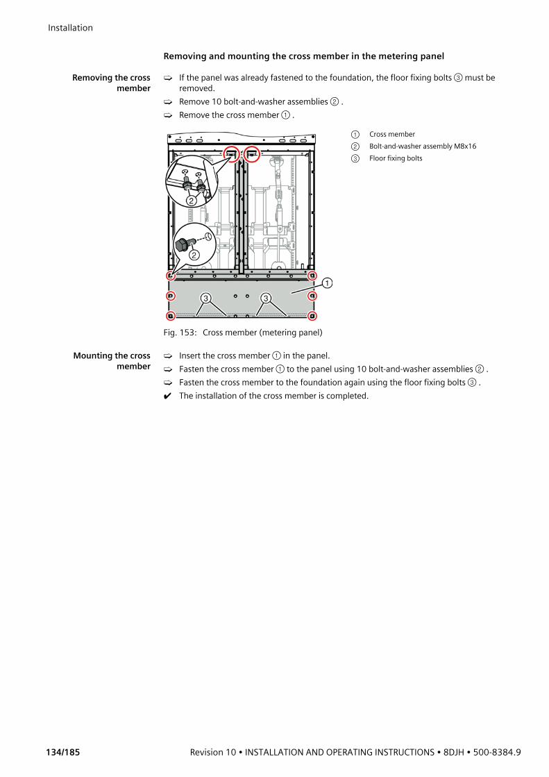
Installation
134/185 Revision 10 • INSTALLATION AND OPERATING INSTRUCTIONS • 8DJH • 500-8384.9
Removing and mounting the cross member in the metering panel
Removing the crossmember
➭ If the panel was already fastened to the foundation, the floor fixing bolts ③ must be removed.
➭ Remove 10 bolt-and-washer assemblies ② .➭ Remove the cross member ① .
Mounting the crossmember
➭ Insert the cross member ① in the panel.➭ Fasten the cross member ① to the panel using 10 bolt-and-washer assemblies ② .➭ Fasten the cross member to the foundation again using the floor fixing bolts ③ .✔ The installation of the cross member is completed.
Fig. 153: Cross member (metering panel)
① Cross member② Bolt-and-washer assembly M8x16③ Floor fixing bolts
500-8384.9 • INSTALLATION AND OPERATING INSTRUCTIONS • 8DJH • Revision 10 135/185
Installation 16 Commissioning
16.1 Final tests after installation
Rating plate ➭ Check the data on the rating plate and the auxiliary voltage of the control and end devices as against the requirements.
Service readiness ➭ Check the ready-for-service indicator (see page 58, "Checking service readiness").
Switchgear fixing /switchgear earth
➭ Check switchgear fixing.➭ Check connection to substation earth.➭ Check connection of all earthing connections.
High-voltage connections ➭ Check earthing of cable terminations on all connected high-voltage cables.➭ If provided by the customer, perform cable test (see page 176, "Cable testing")
Feeder without cables ➭ Switch the switching device to EARTHED position and lock it, or cover the bushings with surge-proof caps.
Bolted joints ➭ Check the tightening torques of the bolted joints of the low-voltage equipment at random.➭ Check all switchgear parts that have been disassembled and assembled again at site during
installation or that have been installed subsequently, in order to verify correct assembly and completeness.
Auxiliary cableconnections
➭ Check correct wiring according to the circuit diagrams.➭ Check clamping and plug connections at random (perfect contact, labels, etc.).
Final work ➭ Remove any attached instruction labels or documents that are not required anymore for operation.
➭ Remove any tools, materials etc. that are not required anymore from the area of switchgear.➭ Remove dirt from the area of the switchgear.➭ Fit all covers. ➭ Put the covers on the capacitive test sockets.➭ Touch up scratches and impacts in the surface painting. To do this, a paint pen can be
ordered optionally.
Checking protectiondevices
➭ Check the version of the firmware installed on the protection devices, and update if required, see page 9, "IT security".
Accessories ➭ Keep the following accessories ready to hand:- Operating instructions- Operating levers for switching the panel- Circuit diagrams- Warning signs- Indicators for the capacitive voltage detecting system with HR plug-in sockets or LRM
plug-in sockets (optional)- Keys for low-voltage compartment (optional)
DANGERDuring operation of electrical equipment and switchgear, parts of this equipment are under dangerous electrical voltage. Mechanical components may move quickly, even remotely controlled.➭ Do not remove covers. ➭ Do not reach into openings.
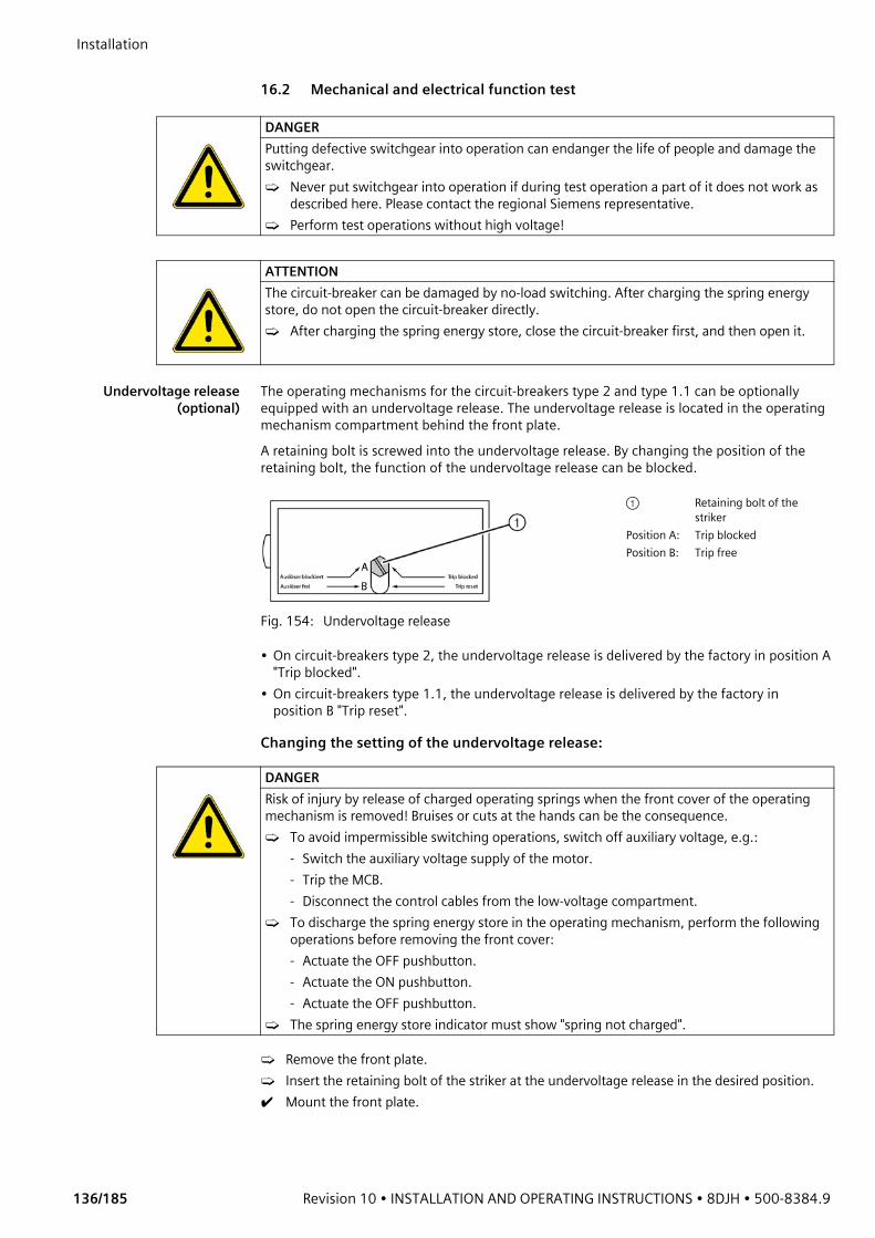
Installation
136/185 Revision 10 • INSTALLATION AND OPERATING INSTRUCTIONS • 8DJH • 500-8384.9
16.2 Mechanical and electrical function test
Undervoltage release(optional)
The operating mechanisms for the circuit-breakers type 2 and type 1.1 can be optionally equipped with an undervoltage release. The undervoltage release is located in the operating mechanism compartment behind the front plate.A retaining bolt is screwed into the undervoltage release. By changing the position of the retaining bolt, the function of the undervoltage release can be blocked.
• On circuit-breakers type 2, the undervoltage release is delivered by the factory in position A "Trip blocked".
• On circuit-breakers type 1.1, the undervoltage release is delivered by the factory in position B "Trip reset".
Changing the setting of the undervoltage release:
➭ Remove the front plate.➭ Insert the retaining bolt of the striker at the undervoltage release in the desired position.✔ Mount the front plate.
DANGERPutting defective switchgear into operation can endanger the life of people and damage the switchgear.➭ Never put switchgear into operation if during test operation a part of it does not work as
described here. Please contact the regional Siemens representative.➭ Perform test operations without high voltage!
ATTENTIONThe circuit-breaker can be damaged by no-load switching. After charging the spring energy store, do not open the circuit-breaker directly.➭ After charging the spring energy store, close the circuit-breaker first, and then open it.
Fig. 154: Undervoltage release
① Retaining bolt of the striker
Position A: Trip blockedPosition B: Trip free
DANGERRisk of injury by release of charged operating springs when the front cover of the operating mechanism is removed! Bruises or cuts at the hands can be the consequence.➭ To avoid impermissible switching operations, switch off auxiliary voltage, e.g.:
- Switch the auxiliary voltage supply of the motor.- Trip the MCB.- Disconnect the control cables from the low-voltage compartment.
➭ To discharge the spring energy store in the operating mechanism, perform the following operations before removing the front cover:- Actuate the OFF pushbutton.- Actuate the ON pushbutton.- Actuate the OFF pushbutton.
➭ The spring energy store indicator must show "spring not charged".
500-8384.9 • INSTALLATION AND OPERATING INSTRUCTIONS • 8DJH • Revision 10 137/185
Installation
Test operation andmechanical function test
Always perform test operation and mechanical function test without high voltage.➭ On circuit-breakers and switch-fuse combinations, do not perform any no-load switching
operations, i.e. opening commands without closing before.➭ Switch all switching devices several times manually to all switching positions (see page 140,
"Operation") and check the position indicators.➭ Check mechanical interlocks (see page 14, "Interlocks") with normal force. Verify smooth
operation of control gates.➭ Check the fuse tripping functionality with a test fuse.➭ Fit HV HRC fuse-links, see page 173, "Replacing HV HRC fuse-links".➭ Check service readiness, see page 143, "Ready-for-service indicator". The pointer of the
ready-for-service indicator must be in the green area.
Electrical function test ➭ Only circuit-breaker type L2: Insert the retaining bolt at the undervoltage release (option) in position B.
➭ Switch all three-position disconnectors or three-position switch-disconnectors to OPEN position.
➭ Switch on auxiliary voltage and check polarity.➭ Switch switching devices with electrical operation to all switching positions (electrically and
manually). Check position indicators and electrical interlocking conditions.➭ Only circuit-breaker type L2: While charging the spring energy store and in ready-to-close
state, auxiliary voltage must be applied without interruption at the undervoltage release (option).
➭ Check electrical indications and trippings.
16.3 Preparing the power-frequency voltage testA power-frequency voltage test can be performed at the readily installed switchgear.
Preparations ➭ Remove voltage transformers. ➭ Remove surge arresters and surge limiters. ➭ Protect bushings of voltage transformers, surge arresters and surge limiters in a surge-proof
way using suitable sealing caps.➭ Short-circuit the current transformers at the secondary terminals.➭ Earth the capacitive test sockets.✔ The power-frequency voltage test can now be performed.
16.4 Instructing the operating personnel➭ Instruct operating personnel in theory and practice of switchgear operation.
ATTENTIONCircuit-breaker type L2: To operate the circuit-breaker type 2 for test without auxiliary voltage, the undervoltage release (option) must be blocked. On circuit-breakers type 2, the undervoltage release is delivered by the factory in "Trip blocked" setting (position A), and will not function. ➭ Perform test operation with the circuit-breaker type 2.➭ After test operation, activate the undervoltage release; screw the retaining bolt in at
position B.
ATTENTIONCircuit-breaker type L1.1: If the operating mechanism is equipped with an undervoltage release (option), test operation of the circuit-breaker type 1.1 must be performed with auxiliary voltage, as the undervoltage release is delivered in "Trip reset" setting (position B).➭ Perform test operation of the circuit-breaker type 1.1 only with auxiliary voltage.
Installation
138/185 Revision 10 • INSTALLATION AND OPERATING INSTRUCTIONS • 8DJH • 500-8384.9
16.5 Applying operating voltage
Energizing incomingfeeders
➭ Energize all incoming feeders in the respective opposite substation.
Verifying correctterminal-phase
connections
Verify correct terminal-phase connections of all incoming feeders:
Preconditions • Use phase comparison test unit according to IEC 61243-5 or VDE 0682-415.• The panel of the incoming feeder to be tested must be in OPEN position.• The opposite substation must be de-earthed and live.
Performing the test ➭ Remove the covers of the capacitive test sockets from phase L1 on the incoming feeder to be tested and on an already energized incoming feeder.
✔ The plug-in sockets of the capacitive voltage detecting system on phase L1 are accessible.➭ Plug the measuring cables of the phase comparison test unit into the plug-in sockets of the
capacitive voltage detecting system according to the operating instructions. ➭ Perform phase comparison according to the operating instructions of the phase comparison
test unit and read the indication.➭ Remove the measuring cables from the plug-in sockets.➭ Refit the covers of the capacitive test sockets on both incoming feeders.
Checking further phases ➭ Perform phase comparison for the phases L2 and L3 in the same way.✔ If the phase comparison test unit has shown coincidence on all 3 phases, the phase
sequence of the tested incoming feeder is correct.✔ The incoming feeder can be energized.
Applying voltage to thebusbar
If the phase sequence of all incoming feeders is correct, the incoming feeders can be connected to the busbar: ➭ Switch the three-position switch-disconnector, three-position disconnector and circuit-
breaker to CLOSED position (see page 140, "Operation" and following chapters).✔ The busbar of the switchgear is live.
Energizing consumerfeeders
When all incoming feeders are connected to the busbar:➭ One after the other, energize all consumer feeders with connected consumers.✔ When all consumer feeders are energized, the switchgear is completely in operation.
DANGERHazardous voltage and internal arcing. Can cause death, serious injury or property damage. Do not apply operating voltage before the following instructions have been executed:➭ Observe the specifications for prevention of accidents. ➭ Observe the operating instructions and work instructions of the switchgear operator.➭ Install the switchgear according to the installation instructions and drawings supplied.➭ Perform electrical and mechanical function test successfully.➭ Instruct the operating personnel in theory and practice of switchgear operation.➭ Fit all covers and bolt them tight. ➭ Switch all circuit-breakers to OPEN position.➭ Switch the three-position disconnectors or three-position switch-disconnectors in all
panels to OPEN position. ➭ Earth feeders without connected cables. Close all bushings in a surge-proof way. ➭ Switch off the consumers connected to all outgoing feeders.➭ Short-circuit unused current transformers on the secondary side. ➭ Operate unused voltage transformers open on the secondary side.➭ Check the phase sequence in all incoming and outgoing feeders to assure a consistent
phase sequence in the entire switchgear assembly before connecting them to the busbar.

500-8384.9 • INSTALLATION AND OPERATING INSTRUCTIONS • 8DJH • Revision 10 139/185
Installation Documenting the
commissioning➭ Document the modifications occurred during installation or commissioning.➭ Document the modifications in the circuit diagram.➭ Send the modifications to the regional Siemens representative.
After commissioning ➭ Observe the Five Safety Rules for working in the switchgear:- Isolate.- Secure against reclosing.- Verify safe isolation from supply.- Earth and short-circuit.- Cover or barrier adjacent live parts.
➭ Observe the locally applicable specifications for prevention of accidents.➭ If after commissioning further work is required in the area of the switchgear, install warning
signs on the switchgear.Access for working in the area of the switchgear must only be granted to the following persons:- Electricians and persons who have been properly instructed in electrical engineering- Persons under the supervision of electricians and persons who have been properly
instructed in electrical engineering
Operation
140/185 Revision 10 • INSTALLATION AND OPERATING INSTRUCTIONS • 8DJH • 500-8384.9
OperationDANGERThe internal arc classification of the switchgear according to IEC 62271-200 has only been proved by tests for the switchgear sides with internal arc classification and with closed high-voltage compartments.➭ Determine the IAC classification of the switchgear by means of the data on the rating plate
(see page 46, "Rating plates").➭ Regulations for access to switchgear areas without internal arc classification according to
IEC 62271-200 must be defined by the entrepreneur or the switchgear operator.
DANGERHigh voltage! Danger!➭ Isolate.➭ Secure against reclosing.➭ Verify safe isolation from supply.➭ Earth and short-circuit.➭ Cover or barrier adjacent live parts.
DANGERDuring operation of electrical equipment and switchgear, parts of this equipment are under dangerous electrical voltage. Mechanical components may move quickly, even remotely controlled.➭ Do not remove covers. ➭ Do not reach into openings.
DANGERSwitching without service readiness can cause serious injury and property damage.➭ Check service readiness of the switchgear before performing any switching operation.➭ If the switchgear is not ready for service (pointer in the red area), do not operate the
switchgear, but contact the Siemens Service Hotline.
ATTENTIONEarthing a live incoming cable will result in a short circuit and trip an upstream circuit-breaker.➭ Verify safe isolation from supply of the feeder before earthing.
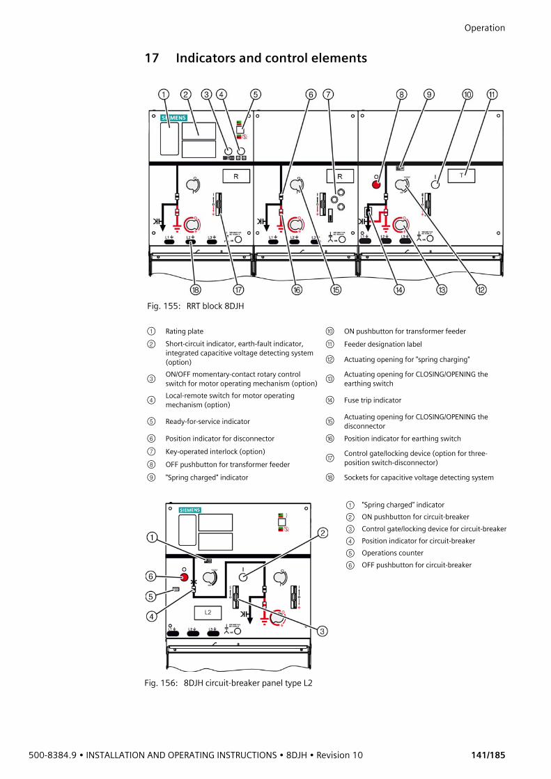
500-8384.9 • INSTALLATION AND OPERATING INSTRUCTIONS • 8DJH • Revision 10 141/185
Operation 17 Indicators and control elements
Fig. 155: RRT block 8DJH
① Rating plate ⑩ ON pushbutton for transformer feeder② Short-circuit indicator, earth-fault indicator,
integrated capacitive voltage detecting system (option)
⑪ Feeder designation label
⑫ Actuating opening for "spring charging"
③ ON/OFF momentary-contact rotary control switch for motor operating mechanism (option) ⑬ Actuating opening for CLOSING/OPENING the
earthing switch
④ Local-remote switch for motor operating mechanism (option) ⑭ Fuse trip indicator
⑤ Ready-for-service indicator ⑮ Actuating opening for CLOSING/OPENING the disconnector
⑥ Position indicator for disconnector ⑯ Position indicator for earthing switch⑦ Key-operated interlock (option)
⑰ Control gate/locking device (option for three-position switch-disconnector)⑧ OFF pushbutton for transformer feeder
⑨ "Spring charged" indicator ⑱ Sockets for capacitive voltage detecting system
Fig. 156: 8DJH circuit-breaker panel type L2
① "Spring charged" indicator② ON pushbutton for circuit-breaker③ Control gate/locking device for circuit-breaker④ Position indicator for circuit-breaker⑤ Operations counter⑥ OFF pushbutton for circuit-breaker
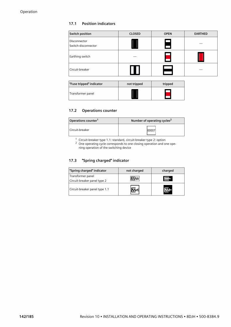
Operation
142/185 Revision 10 • INSTALLATION AND OPERATING INSTRUCTIONS • 8DJH • 500-8384.9
17.1 Position indicators
17.2 Operations counter
17.3 "Spring charged" indicator
Switch position CLOSED OPEN EARTHED
DisconnectorSwitch-disconnector —
Earthing switch —
Circuit-breaker —
"Fuse tripped" indicator not tripped tripped
Transformer panel
Operations counter1
1 Circuit-breaker type 1.1: standard, circuit-breaker type 2: option
Number of operating cycles2
2 One operating cycle corresponds to one closing operation and one ope-ning operation of the switching device
Circuit-breaker
"Spring charged" indicator not charged chargedTransformer panelCircuit-breaker panel type 2
Circuit-breaker panel type 1.1
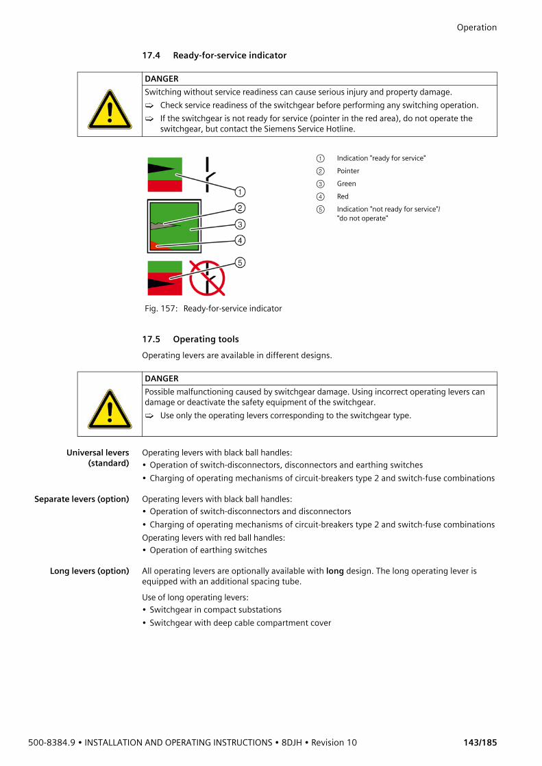
500-8384.9 • INSTALLATION AND OPERATING INSTRUCTIONS • 8DJH • Revision 10 143/185
Operation 17.4 Ready-for-service indicator
17.5 Operating toolsOperating levers are available in different designs.
Universal levers(standard)
Operating levers with black ball handles:• Operation of switch-disconnectors, disconnectors and earthing switches• Charging of operating mechanisms of circuit-breakers type 2 and switch-fuse combinations
Separate levers (option) Operating levers with black ball handles:• Operation of switch-disconnectors and disconnectors• Charging of operating mechanisms of circuit-breakers type 2 and switch-fuse combinationsOperating levers with red ball handles:• Operation of earthing switches
Long levers (option) All operating levers are optionally available with long design. The long operating lever is equipped with an additional spacing tube. Use of long operating levers:• Switchgear in compact substations• Switchgear with deep cable compartment cover
DANGERSwitching without service readiness can cause serious injury and property damage.➭ Check service readiness of the switchgear before performing any switching operation.➭ If the switchgear is not ready for service (pointer in the red area), do not operate the
switchgear, but contact the Siemens Service Hotline.
Fig. 157: Ready-for-service indicator
① Indication "ready for service"② Pointer③ Green④ Red⑤ Indication "not ready for service"/
"do not operate"
DANGERPossible malfunctioning caused by switchgear damage. Using incorrect operating levers can damage or deactivate the safety equipment of the switchgear.➭ Use only the operating levers corresponding to the switchgear type.
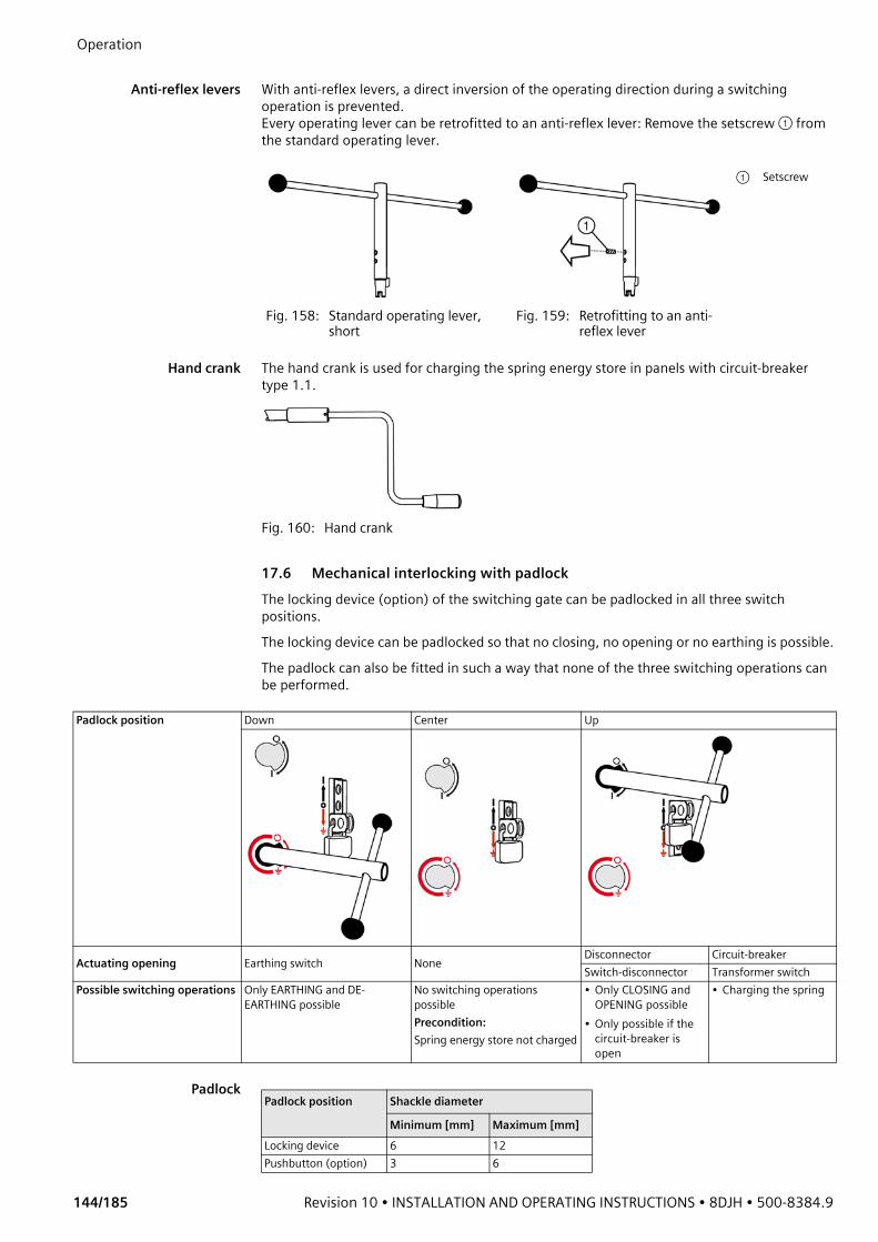
Operation
144/185 Revision 10 • INSTALLATION AND OPERATING INSTRUCTIONS • 8DJH • 500-8384.9
Anti-reflex levers With anti-reflex levers, a direct inversion of the operating direction during a switching
operation is prevented.Every operating lever can be retrofitted to an anti-reflex lever: Remove the setscrew ① from the standard operating lever.
Hand crank The hand crank is used for charging the spring energy store in panels with circuit-breaker type 1.1.
Fig. 160: Hand crank
17.6 Mechanical interlocking with padlockThe locking device (option) of the switching gate can be padlocked in all three switch positions. The locking device can be padlocked so that no closing, no opening or no earthing is possible. The padlock can also be fitted in such a way that none of the three switching operations can be performed.
Padlock
Fig. 158: Standard operating lever, short
Fig. 159: Retrofitting to an anti-reflex lever
① Setscrew
Padlock position Down Center Up
Actuating opening Earthing switch None Disconnector Circuit-breakerSwitch-disconnector Transformer switch
Possible switching operations Only EARTHING and DE-EARTHING possible
No switching operations possiblePrecondition: Spring energy store not charged
• Only CLOSING and OPENING possible
• Only possible if the circuit-breaker is open
• Charging the spring
Padlock position Shackle diameter
Minimum [mm] Maximum [mm]Locking device 6 12Pushbutton (option) 3 6
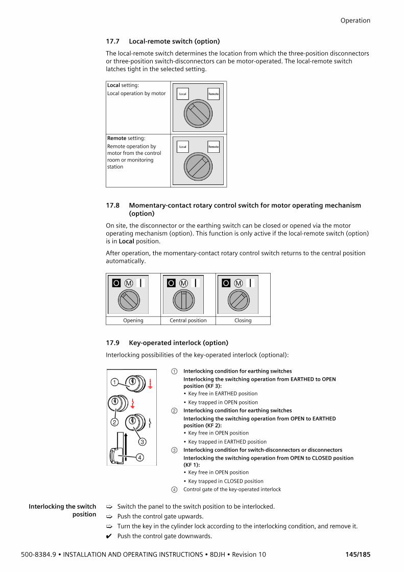
500-8384.9 • INSTALLATION AND OPERATING INSTRUCTIONS • 8DJH • Revision 10 145/185
Operation 17.7 Local-remote switch (option)The local-remote switch determines the location from which the three-position disconnectors or three-position switch-disconnectors can be motor-operated. The local-remote switch latches tight in the selected setting.
17.8 Momentary-contact rotary control switch for motor operating mechanism (option)
On site, the disconnector or the earthing switch can be closed or opened via the motor operating mechanism (option). This function is only active if the local-remote switch (option) is in Local position.After operation, the momentary-contact rotary control switch returns to the central position automatically.
17.9 Key-operated interlock (option)Interlocking possibilities of the key-operated interlock (optional):
Interlocking the switchposition
➭ Switch the panel to the switch position to be interlocked.➭ Push the control gate upwards.➭ Turn the key in the cylinder lock according to the interlocking condition, and remove it.✔ Push the control gate downwards.
Local setting: Local operation by motor
Remote setting:Remote operation by motor from the control room or monitoring station
Opening Central position Closing
① Interlocking condition for earthing switchesInterlocking the switching operation from EARTHED to OPEN position (KF 3):• Key free in EARTHED position• Key trapped in OPEN position
② Interlocking condition for earthing switchesInterlocking the switching operation from OPEN to EARTHED position (KF 2):• Key free in OPEN position• Key trapped in EARTHED position
③ Interlocking condition for switch-disconnectors or disconnectorsInterlocking the switching operation from OPEN to CLOSED position (KF 1):• Key free in OPEN position• Key trapped in CLOSED position
④ Control gate of the key-operated interlock
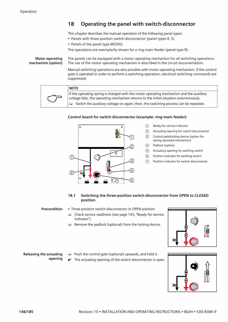
Operation
146/185 Revision 10 • INSTALLATION AND OPERATING INSTRUCTIONS • 8DJH • 500-8384.9
18 Operating the panel with switch-disconnectorThis chapter describes the manual operation of the following panel types: • Panels with three-position switch-disconnector (panel types R, S)• Panels of the panel type M(500). The operations are exemplarily shown for a ring-main feeder (panel type R).
Motor operatingmechanism (option)
The panels can be equipped with a motor operating mechanism for all switching operations. The use of the motor operating mechanism is described in the circuit documentation.Manual switching operations are also possible with motor operating mechanism. If the control gate is operated in order to perform a switching operation, electrical switching commands are suppressed.
Control board for switch-disconnector (example: ring-main feeder)
18.1 Switching the three-position switch-disconnector from OPEN to CLOSED position
Precondition • Three-position switch-disconnector in OPEN position➭ Check service readiness (see page 143, "Ready-for-service
indicator").➭ Remove the padlock (optional) from the locking device.
Releasing the actuatingopening
➭ Push the control gate (optional) upwards, and hold it.✔ The actuating opening of the switch-disconnector is open.
NOTEIf the operating spring is charged with the motor operating mechanism and the auxiliary voltage fails, the operating mechanism returns to the initial situation autonomously.➭ Switch the auxiliary voltage on again; then, the switching process can be repeated.
① Ready-for-service indicator② Actuating opening for switch-disconnector③ Control gate/locking device (option for
spring-operated mechanism)④ Padlock (option)⑤ Actuating opening for earthing switch ⑥ Position indicator for earthing switch⑦ Position indicator for switch-disconnector
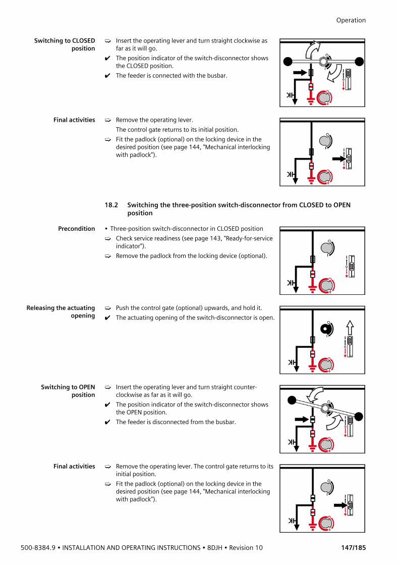
500-8384.9 • INSTALLATION AND OPERATING INSTRUCTIONS • 8DJH • Revision 10 147/185
Operation Switching to CLOSED
position➭ Insert the operating lever and turn straight clockwise as
far as it will go.✔ The position indicator of the switch-disconnector shows
the CLOSED position.✔ The feeder is connected with the busbar.
Final activities ➭ Remove the operating lever. The control gate returns to its initial position.
➭ Fit the padlock (optional) on the locking device in the desired position (see page 144, "Mechanical interlocking with padlock").
18.2 Switching the three-position switch-disconnector from CLOSED to OPEN position
Precondition • Three-position switch-disconnector in CLOSED position➭ Check service readiness (see page 143, "Ready-for-service
indicator").➭ Remove the padlock from the locking device (optional).
Releasing the actuatingopening
➭ Push the control gate (optional) upwards, and hold it.✔ The actuating opening of the switch-disconnector is open.
Switching to OPENposition
➭ Insert the operating lever and turn straight counter-clockwise as far as it will go.
✔ The position indicator of the switch-disconnector shows the OPEN position.
✔ The feeder is disconnected from the busbar.
Final activities ➭ Remove the operating lever. The control gate returns to its initial position.
➭ Fit the padlock (optional) on the locking device in the desired position (see page 144, "Mechanical interlocking with padlock").
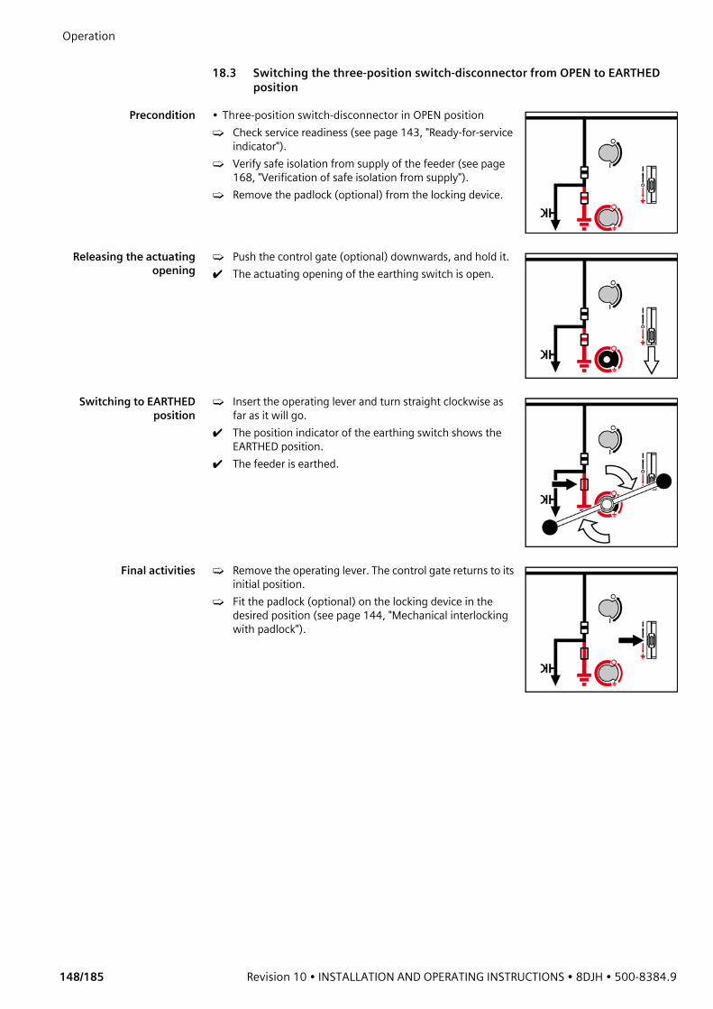
Operation
148/185 Revision 10 • INSTALLATION AND OPERATING INSTRUCTIONS • 8DJH • 500-8384.9
18.3 Switching the three-position switch-disconnector from OPEN to EARTHED
position
Precondition • Three-position switch-disconnector in OPEN position➭ Check service readiness (see page 143, "Ready-for-service
indicator").➭ Verify safe isolation from supply of the feeder (see page
168, "Verification of safe isolation from supply").➭ Remove the padlock (optional) from the locking device.
Releasing the actuatingopening
➭ Push the control gate (optional) downwards, and hold it.✔ The actuating opening of the earthing switch is open.
Switching to EARTHEDposition
➭ Insert the operating lever and turn straight clockwise as far as it will go.
✔ The position indicator of the earthing switch shows the EARTHED position.
✔ The feeder is earthed.
Final activities ➭ Remove the operating lever. The control gate returns to its initial position.
➭ Fit the padlock (optional) on the locking device in the desired position (see page 144, "Mechanical interlocking with padlock").
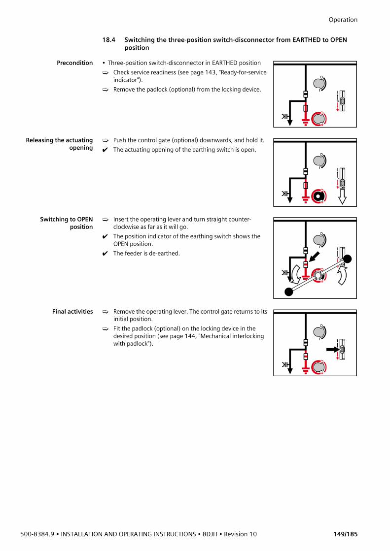
500-8384.9 • INSTALLATION AND OPERATING INSTRUCTIONS • 8DJH • Revision 10 149/185
Operation 18.4 Switching the three-position switch-disconnector from EARTHED to OPEN
position
Precondition • Three-position switch-disconnector in EARTHED position➭ Check service readiness (see page 143, "Ready-for-service
indicator").➭ Remove the padlock (optional) from the locking device.
Releasing the actuatingopening
➭ Push the control gate (optional) downwards, and hold it.✔ The actuating opening of the earthing switch is open.
Switching to OPENposition
➭ Insert the operating lever and turn straight counter-clockwise as far as it will go.
✔ The position indicator of the earthing switch shows the OPEN position.
✔ The feeder is de-earthed.
Final activities ➭ Remove the operating lever. The control gate returns to its initial position.
➭ Fit the padlock (optional) on the locking device in the desired position (see page 144, "Mechanical interlocking with padlock").
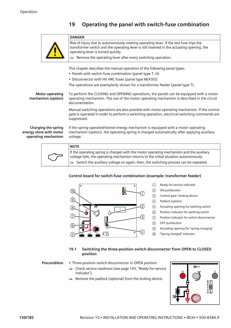
Operation
150/185 Revision 10 • INSTALLATION AND OPERATING INSTRUCTIONS • 8DJH • 500-8384.9
19 Operating the panel with switch-fuse combination
This chapter describes the manual operation of the following panel types: • Panels with switch-fuse combination (panel type T, H)• Disconnector with HV HRC fuses (panel type M(430))The operations are exemplarily shown for a transformer feeder (panel type T).
Motor operatingmechanism (option)
To perform the CLOSING and OPENING operations, the panels can be equipped with a motor operating mechanism. The use of the motor operating mechanism is described in the circuit documentation. Manual switching operations are also possible with motor operating mechanism. If the control gate is operated in order to perform a switching operation, electrical switching commands are suppressed.
Charging the springenergy store with motor
operating mechanism
If the spring-operated/stored-energy mechanism is equipped with a motor operating mechanism (option), the operating spring is charged automatically after applying auxiliary voltage.
Control board for switch-fuse combination (example: transformer feeder)
19.1 Switching the three-position switch-disconnector from OPEN to CLOSED position
Precondition • Three-position switch-disconnector in OPEN position➭ Check service readiness (see page 143, "Ready-for-service
indicator").➭ Remove the padlock (optional) from the locking device.
DANGERRisk of injury due to autonomously rotating operating lever. If the test fuse trips the transformer switch and the operating lever is still inserted in the actuating opening, the operating lever is turned quickly.➭ Remove the operating lever after every switching operation.
NOTEIf the operating spring is charged with the motor operating mechanism and the auxiliary voltage fails, the operating mechanism returns to the initial situation autonomously.➭ Switch the auxiliary voltage on again; then, the switching process can be repeated.
① Ready-for-service indicator② ON pushbutton③ Control gate / locking device④ Padlock (option)⑤ Actuating opening for earthing switch ⑥ Position indicator for earthing switch⑦ Position indicator for switch-disconnector⑧ OFF pushbutton⑨ Actuating opening for "spring charging"⑩ "Spring charged" indicator
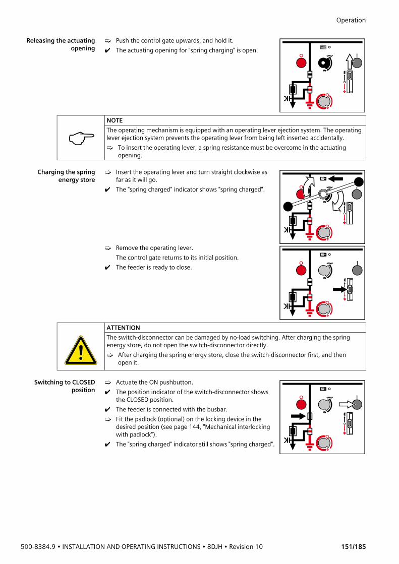
500-8384.9 • INSTALLATION AND OPERATING INSTRUCTIONS • 8DJH • Revision 10 151/185
Operation Releasing the actuating
opening➭ Push the control gate upwards, and hold it.✔ The actuating opening for "spring charging" is open.
Charging the springenergy store
➭ Insert the operating lever and turn straight clockwise as far as it will go.
✔ The "spring charged" indicator shows "spring charged".
➭ Remove the operating lever.The control gate returns to its initial position.
✔ The feeder is ready to close.
Switching to CLOSEDposition
➭ Actuate the ON pushbutton.✔ The position indicator of the switch-disconnector shows
the CLOSED position.✔ The feeder is connected with the busbar.➭ Fit the padlock (optional) on the locking device in the
desired position (see page 144, "Mechanical interlocking with padlock").
✔ The "spring charged" indicator still shows "spring charged".
NOTEThe operating mechanism is equipped with an operating lever ejection system. The operating lever ejection system prevents the operating lever from being left inserted accidentally.➭ To insert the operating lever, a spring resistance must be overcome in the actuating
opening.
ATTENTIONThe switch-disconnector can be damaged by no-load switching. After charging the spring energy store, do not open the switch-disconnector directly.➭ After charging the spring energy store, close the switch-disconnector first, and then
open it.

Operation
152/185 Revision 10 • INSTALLATION AND OPERATING INSTRUCTIONS • 8DJH • 500-8384.9
19.2 Switching the three-position switch-disconnector from CLOSED to OPEN
position
Preconditions • Three-position switch-disconnector in CLOSED position• "Spring charged" indicator shows "spring charged"➭ Check service readiness (see page 143, "Ready-for-service
indicator").
Switching to OPENposition
➭ Actuate the OFF pushbutton.✔ "Spring charged" indicator shows "spring not charged".
19.3 Switching the three-position switch-disconnector from OPEN to EARTHED position
Precondition • Three-position switch-disconnector in OPEN position➭ Check service readiness (see page 143, "Ready-for-service
indicator").➭ Verify safe isolation from supply of the feeder (see page
168, "Verification of safe isolation from supply").➭ Remove the padlock (optional) from the locking device.
Releasing the actuatingopening
➭ Push the control gate downwards, and hold it.✔ The actuating opening of the earthing switch is open.
Switching to EARTHEDposition
➭ Insert the operating lever and turn straight clockwise as far as it will go.
✔ The position indicator of the earthing switch shows the EARTHED position.
✔ The feeder is earthed.
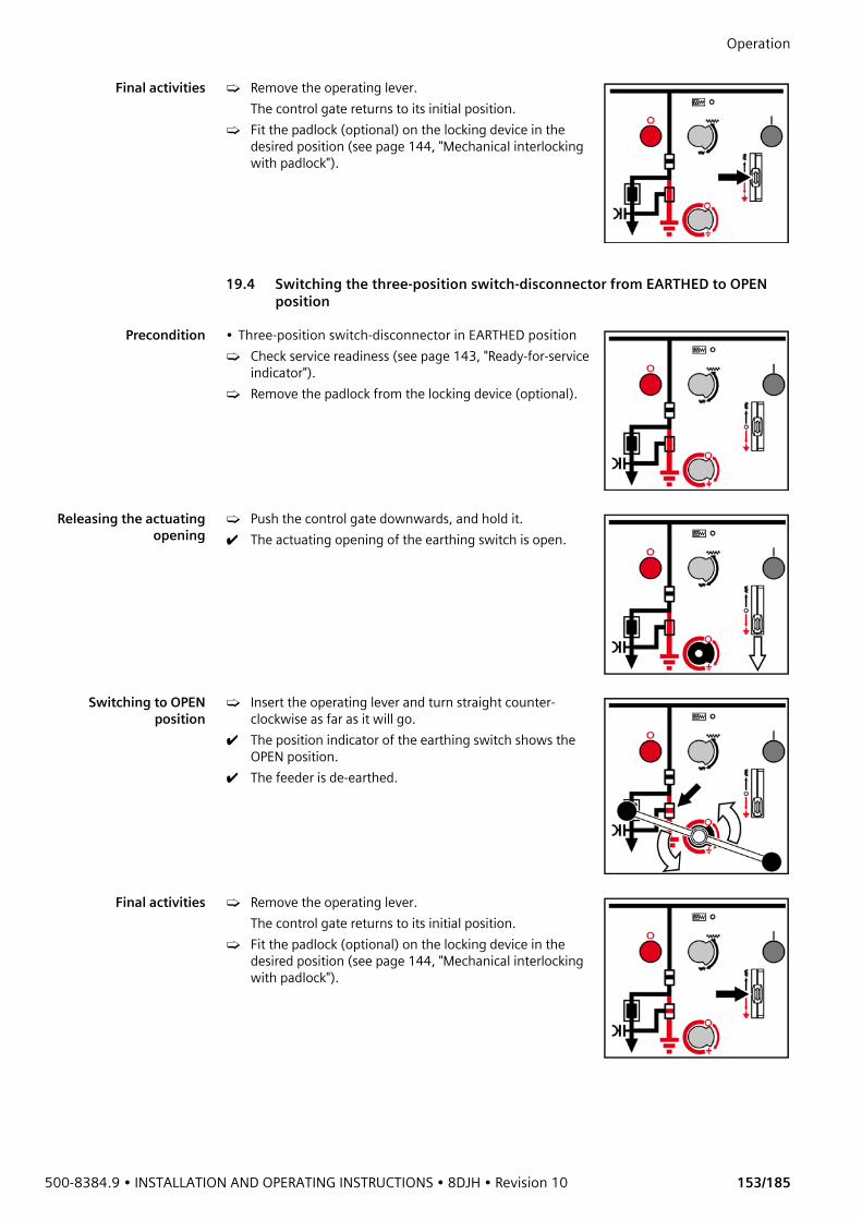
500-8384.9 • INSTALLATION AND OPERATING INSTRUCTIONS • 8DJH • Revision 10 153/185
Operation Final activities ➭ Remove the operating lever.
The control gate returns to its initial position.➭ Fit the padlock (optional) on the locking device in the
desired position (see page 144, "Mechanical interlocking with padlock").
19.4 Switching the three-position switch-disconnector from EARTHED to OPEN position
Precondition • Three-position switch-disconnector in EARTHED position➭ Check service readiness (see page 143, "Ready-for-service
indicator").➭ Remove the padlock from the locking device (optional).
Releasing the actuatingopening
➭ Push the control gate downwards, and hold it.✔ The actuating opening of the earthing switch is open.
Switching to OPENposition
➭ Insert the operating lever and turn straight counter-clockwise as far as it will go.
✔ The position indicator of the earthing switch shows the OPEN position.
✔ The feeder is de-earthed.
Final activities ➭ Remove the operating lever. The control gate returns to its initial position.
➭ Fit the padlock (optional) on the locking device in the desired position (see page 144, "Mechanical interlocking with padlock").

Operation
154/185 Revision 10 • INSTALLATION AND OPERATING INSTRUCTIONS • 8DJH • 500-8384.9
19.5 Protection tripping of the switch-fuse combination
Fig. 161: Indication: Fuse tripped
Re-establishing servicereadiness
➭ Switch the switching device to EARTHED position.➭ Replace all HV HRC fuse-links (see page 173, "Replacing HV HRC fuse-links"). The fuse-links
may also be damaged if their striker was not tripped.
NOTEIf the switch-fuse combination was tripped by a fuse-link:➭ The "fuse tripped" indicator shows a red transverse bar.➭ Electrical switching commands to the motor operating mechanism (option) are
suppressed.
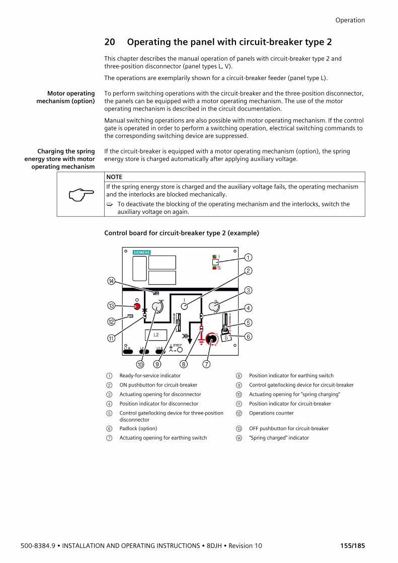
500-8384.9 • INSTALLATION AND OPERATING INSTRUCTIONS • 8DJH • Revision 10 155/185
Operation 20 Operating the panel with circuit-breaker type 2This chapter describes the manual operation of panels with circuit-breaker type 2 and three-position disconnector (panel types L, V). The operations are exemplarily shown for a circuit-breaker feeder (panel type L).
Motor operatingmechanism (option)
To perform switching operations with the circuit-breaker and the three-position disconnector, the panels can be equipped with a motor operating mechanism. The use of the motor operating mechanism is described in the circuit documentation. Manual switching operations are also possible with motor operating mechanism. If the control gate is operated in order to perform a switching operation, electrical switching commands to the corresponding switching device are suppressed.
Charging the springenergy store with motor
operating mechanism
If the circuit-breaker is equipped with a motor operating mechanism (option), the spring energy store is charged automatically after applying auxiliary voltage.
Control board for circuit-breaker type 2 (example)
NOTEIf the spring energy store is charged and the auxiliary voltage fails, the operating mechanism and the interlocks are blocked mechanically.➭ To deactivate the blocking of the operating mechanism and the interlocks, switch the
auxiliary voltage on again.
① Ready-for-service indicator ⑧ Position indicator for earthing switch② ON pushbutton for circuit-breaker ⑨ Control gate/locking device for circuit-breaker ③ Actuating opening for disconnector ⑩ Actuating opening for "spring charging"④ Position indicator for disconnector ⑪ Position indicator for circuit-breaker⑤ Control gate/locking device for three-position
disconnector⑫ Operations counter
⑥ Padlock (option) ⑬ OFF pushbutton for circuit-breaker⑦ Actuating opening for earthing switch ⑭ "Spring charged" indicator
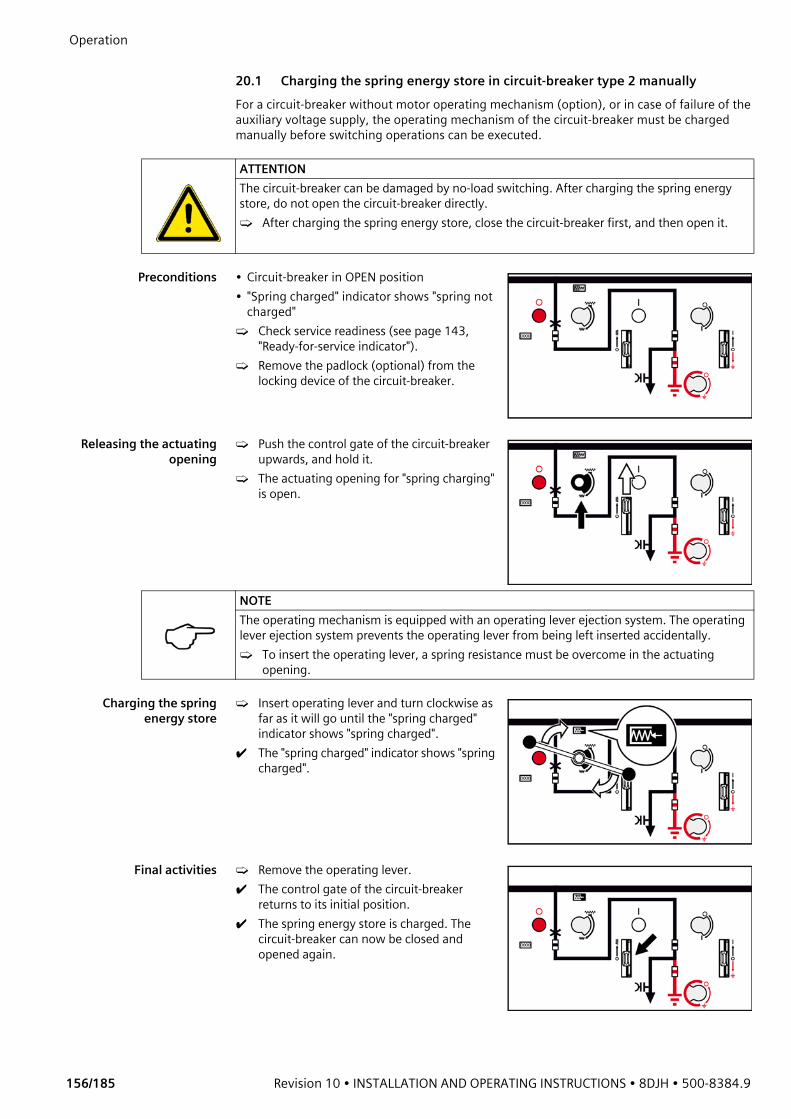
Operation
156/185 Revision 10 • INSTALLATION AND OPERATING INSTRUCTIONS • 8DJH • 500-8384.9
20.1 Charging the spring energy store in circuit-breaker type 2 manuallyFor a circuit-breaker without motor operating mechanism (option), or in case of failure of the auxiliary voltage supply, the operating mechanism of the circuit-breaker must be charged manually before switching operations can be executed.
Preconditions • Circuit-breaker in OPEN position• "Spring charged" indicator shows "spring not
charged"➭ Check service readiness (see page 143,
"Ready-for-service indicator").➭ Remove the padlock (optional) from the
locking device of the circuit-breaker.
Releasing the actuatingopening
➭ Push the control gate of the circuit-breaker upwards, and hold it.
➭ The actuating opening for "spring charging" is open.
Charging the springenergy store
➭ Insert operating lever and turn clockwise as far as it will go until the "spring charged" indicator shows "spring charged".
✔ The "spring charged" indicator shows "spring charged".
Final activities ➭ Remove the operating lever.✔ The control gate of the circuit-breaker
returns to its initial position. ✔ The spring energy store is charged. The
circuit-breaker can now be closed and opened again.
ATTENTIONThe circuit-breaker can be damaged by no-load switching. After charging the spring energy store, do not open the circuit-breaker directly.➭ After charging the spring energy store, close the circuit-breaker first, and then open it.
NOTEThe operating mechanism is equipped with an operating lever ejection system. The operating lever ejection system prevents the operating lever from being left inserted accidentally.➭ To insert the operating lever, a spring resistance must be overcome in the actuating
opening.
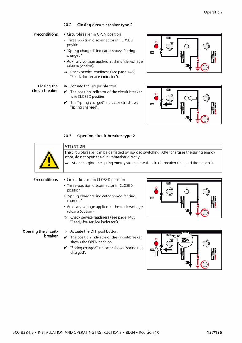
500-8384.9 • INSTALLATION AND OPERATING INSTRUCTIONS • 8DJH • Revision 10 157/185
Operation 20.2 Closing circuit-breaker type 2
Preconditions • Circuit-breaker in OPEN position• Three-position disconnector in CLOSED
position• "Spring charged" indicator shows "spring
charged" • Auxiliary voltage applied at the undervoltage
release (option)➭ Check service readiness (see page 143,
"Ready-for-service indicator").
Closing thecircuit-breaker
➭ Actuate the ON pushbutton.✔ The position indicator of the circuit-breaker
is in CLOSED position.✔ The "spring charged" indicator still shows
"spring charged".
20.3 Opening circuit-breaker type 2
Preconditions • Circuit-breaker in CLOSED position• Three-position disconnector in CLOSED
position• "Spring charged" indicator shows "spring
charged" • Auxiliary voltage applied at the undervoltage
release (option)➭ Check service readiness (see page 143,
"Ready-for-service indicator").
Opening the circuit-breaker
➭ Actuate the OFF pushbutton.✔ The position indicator of the circuit-breaker
shows the OPEN position.✔ "Spring charged" indicator shows "spring not
charged".
ATTENTIONThe circuit-breaker can be damaged by no-load switching. After charging the spring energy store, do not open the circuit-breaker directly.➭ After charging the spring energy store, close the circuit-breaker first, and then open it.
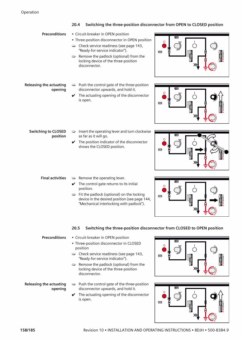
Operation
158/185 Revision 10 • INSTALLATION AND OPERATING INSTRUCTIONS • 8DJH • 500-8384.9
20.4 Switching the three-position disconnector from OPEN to CLOSED position
Preconditions • Circuit-breaker in OPEN position• Three-position disconnector in OPEN position➭ Check service readiness (see page 143,
"Ready-for-service indicator").➭ Remove the padlock (optional) from the
locking device of the three-position disconnector.
Releasing the actuatingopening
➭ Push the control gate of the three-position disconnector upwards, and hold it.
✔ The actuating opening of the disconnector is open.
Switching to CLOSEDposition
➭ Insert the operating lever and turn clockwise as far as it will go.
✔ The position indicator of the disconnector shows the CLOSED position.
Final activities ➭ Remove the operating lever. ✔ The control gate returns to its initial
position.➭ Fit the padlock (optional) on the locking
device in the desired position (see page 144, "Mechanical interlocking with padlock").
20.5 Switching the three-position disconnector from CLOSED to OPEN position
Preconditions • Circuit-breaker in OPEN position• Three-position disconnector in CLOSED
position➭ Check service readiness (see page 143,
"Ready-for-service indicator").➭ Remove the padlock (optional) from the
locking device of the three-position disconnector.
Releasing the actuatingopening
➭ Push the control gate of the three-position disconnector upwards, and hold it.
✔ The actuating opening of the disconnector is open.

500-8384.9 • INSTALLATION AND OPERATING INSTRUCTIONS • 8DJH • Revision 10 159/185
Operation Switching to OPEN
position➭ Insert the operating lever and turn counter-
clockwise as far as it will go.✔ The position indicator of the disconnector
shows the OPEN position.✔ The three-position disconnector is open.
Final activities ➭ Remove the operating lever.✔ The control gate returns to its initial
position.➭ Fit the padlock (optional) on the locking
device in the desired position (see page 144, "Mechanical interlocking with padlock").
20.6 Switching the three-position disconnector from OPEN to EARTHED position
Preconditions • Circuit-breaker in OPEN position• Three-position disconnector in OPEN position➭ Check service readiness (see page 143,
"Ready-for-service indicator").➭ Verify safe isolation from supply of the
feeder (see page 168, "Verification of safe isolation from supply").
➭ Remove the padlock (optional) from the locking device of the three-position disconnector.
Releasing the actuatingopening
➭ Push the control gate of the three-position disconnector downwards, and hold it.
✔ The actuating opening of the earthing switch is open.
Switching to EARTHEDposition
➭ Insert the operating lever and turn clockwise as far as it will go.
✔ The position indicator of the earthing switch shows the EARTHED position.
Final activities ➭ Remove the operating lever.✔ The control gate returns to its initial
position.➭ Fit the padlock (optional) on the locking
device in the desired position (see page 144, "Mechanical interlocking with padlock").

Operation
160/185 Revision 10 • INSTALLATION AND OPERATING INSTRUCTIONS • 8DJH • 500-8384.9
20.7 Switching the three-position disconnector from EARTHED to OPEN position
Preconditions • Circuit-breaker in OPEN position• Three-position disconnector in EARTHED
position➭ Check service readiness (see page 143,
"Ready-for-service indicator").➭ Remove the padlock (optional) from the
locking device of the three-position disconnector.
Releasing the actuatingopening
➭ Push the control gate of the three-position disconnector downwards, and hold it.
✔ The actuating opening of the earthing switch is open.
Switching to OPENposition
➭ Insert the operating lever and turn counter-clockwise as far as it will go.
✔ The position indicator of the earthing switch shows the OPEN position.
Final activities ➭ Remove the operating lever.✔ The control gate returns to its initial
position.➭ Fit the padlock (optional) on the locking
device in the desired position (see page 144, "Mechanical interlocking with padlock").
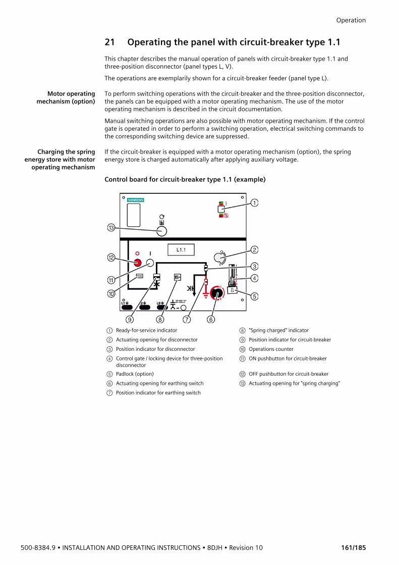
500-8384.9 • INSTALLATION AND OPERATING INSTRUCTIONS • 8DJH • Revision 10 161/185
Operation 21 Operating the panel with circuit-breaker type 1.1This chapter describes the manual operation of panels with circuit-breaker type 1.1 and three-position disconnector (panel types L, V). The operations are exemplarily shown for a circuit-breaker feeder (panel type L).
Motor operatingmechanism (option)
To perform switching operations with the circuit-breaker and the three-position disconnector, the panels can be equipped with a motor operating mechanism. The use of the motor operating mechanism is described in the circuit documentation. Manual switching operations are also possible with motor operating mechanism. If the control gate is operated in order to perform a switching operation, electrical switching commands to the corresponding switching device are suppressed.
Charging the springenergy store with motor
operating mechanism
If the circuit-breaker is equipped with a motor operating mechanism (option), the spring energy store is charged automatically after applying auxiliary voltage.
Control board for circuit-breaker type 1.1 (example)
① Ready-for-service indicator ⑧ "Spring charged" indicator② Actuating opening for disconnector ⑨ Position indicator for circuit-breaker③ Position indicator for disconnector ⑩ Operations counter④ Control gate / locking device for three-position
disconnector⑪ ON pushbutton for circuit-breaker
⑤ Padlock (option) ⑫ OFF pushbutton for circuit-breaker⑥ Actuating opening for earthing switch ⑬ Actuating opening for "spring charging"⑦ Position indicator for earthing switch

Operation
162/185 Revision 10 • INSTALLATION AND OPERATING INSTRUCTIONS • 8DJH • 500-8384.9
21.1 Charging the spring energy store in circuit-breaker type 1.1 manuallyFor a circuit-breaker without motor operating mechanism (option), or in case of failure of the auxiliary voltage supply, the operating mechanism of the circuit-breaker must be charged manually before switching operations can be executed. For charging the operating mechanism, the hand crank supplied with the accessories is used.
Preconditions • Circuit-breaker in OPEN position• "Spring charged" indicator shows "spring not
charged"➭ Check service readiness (see page 143,
"Ready-for-service indicator").
Removing theprotective cap
➭ Remove the protective cap of the actuating opening for the hand crank.
Charging the springenergy store
➭ Insert the hand crank and turn clockwise until the "spring charged" indicator shows "spring charged".
✔ The "spring charged" indicator shows "spring charged".
➭ Remove the hand crank.➭ Insert the protective cap again into the
actuating opening.
Circuit-breaker with automatic reclosing (AR):In order to ensure the operating sequence O - 0.3 s - CO for automatic reclosing of a circuit-breaker with automatic reclosing feature (AR), recharge the closing spring manually again after closing.
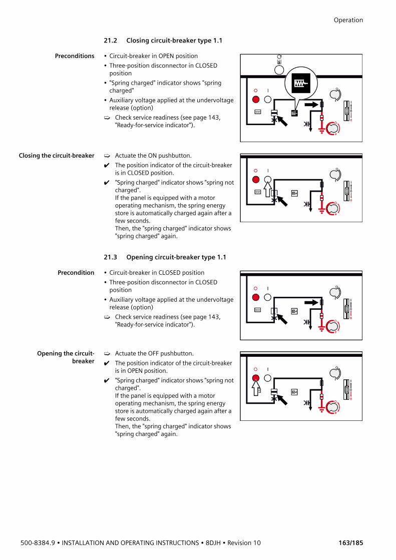
500-8384.9 • INSTALLATION AND OPERATING INSTRUCTIONS • 8DJH • Revision 10 163/185
Operation 21.2 Closing circuit-breaker type 1.1
Preconditions • Circuit-breaker in OPEN position• Three-position disconnector in CLOSED
position• "Spring charged" indicator shows "spring
charged"• Auxiliary voltage applied at the undervoltage
release (option)➭ Check service readiness (see page 143,
"Ready-for-service indicator").
Closing the circuit-breaker ➭ Actuate the ON pushbutton.✔ The position indicator of the circuit-breaker
is in CLOSED position.✔ "Spring charged" indicator shows "spring not
charged".If the panel is equipped with a motor operating mechanism, the spring energy store is automatically charged again after a few seconds. Then, the "spring charged" indicator shows "spring charged" again.
21.3 Opening circuit-breaker type 1.1
Precondition • Circuit-breaker in CLOSED position• Three-position disconnector in CLOSED
position• Auxiliary voltage applied at the undervoltage
release (option)➭ Check service readiness (see page 143,
"Ready-for-service indicator").
Opening the circuit-breaker
➭ Actuate the OFF pushbutton.✔ The position indicator of the circuit-breaker
is in OPEN position.✔ "Spring charged" indicator shows "spring not
charged". If the panel is equipped with a motor operating mechanism, the spring energy store is automatically charged again after a few seconds. Then, the "spring charged" indicator shows "spring charged" again.
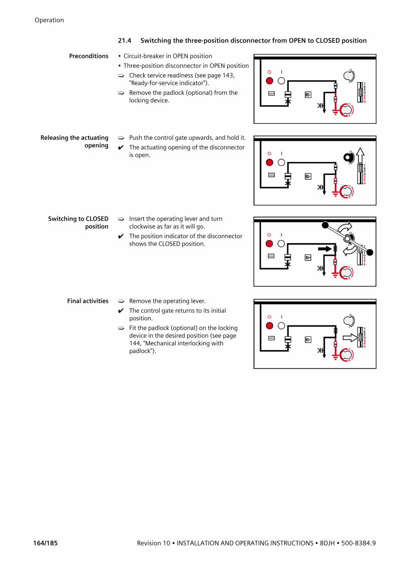
Operation
164/185 Revision 10 • INSTALLATION AND OPERATING INSTRUCTIONS • 8DJH • 500-8384.9
21.4 Switching the three-position disconnector from OPEN to CLOSED position
Preconditions • Circuit-breaker in OPEN position• Three-position disconnector in OPEN position➭ Check service readiness (see page 143,
"Ready-for-service indicator").➭ Remove the padlock (optional) from the
locking device.
Releasing the actuatingopening
➭ Push the control gate upwards, and hold it.✔ The actuating opening of the disconnector
is open.
Switching to CLOSEDposition
➭ Insert the operating lever and turn clockwise as far as it will go.
✔ The position indicator of the disconnector shows the CLOSED position.
Final activities ➭ Remove the operating lever. ✔ The control gate returns to its initial
position.➭ Fit the padlock (optional) on the locking
device in the desired position (see page 144, "Mechanical interlocking with padlock").
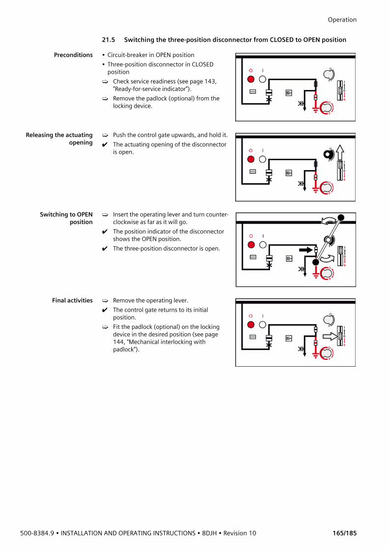
500-8384.9 • INSTALLATION AND OPERATING INSTRUCTIONS • 8DJH • Revision 10 165/185
Operation 21.5 Switching the three-position disconnector from CLOSED to OPEN position
Preconditions • Circuit-breaker in OPEN position• Three-position disconnector in CLOSED
position➭ Check service readiness (see page 143,
"Ready-for-service indicator").➭ Remove the padlock (optional) from the
locking device.
Releasing the actuatingopening
➭ Push the control gate upwards, and hold it.✔ The actuating opening of the disconnector
is open.
Switching to OPENposition
➭ Insert the operating lever and turn counter-clockwise as far as it will go.
✔ The position indicator of the disconnector shows the OPEN position.
✔ The three-position disconnector is open.
Final activities ➭ Remove the operating lever.✔ The control gate returns to its initial
position.➭ Fit the padlock (optional) on the locking
device in the desired position (see page 144, "Mechanical interlocking with padlock").
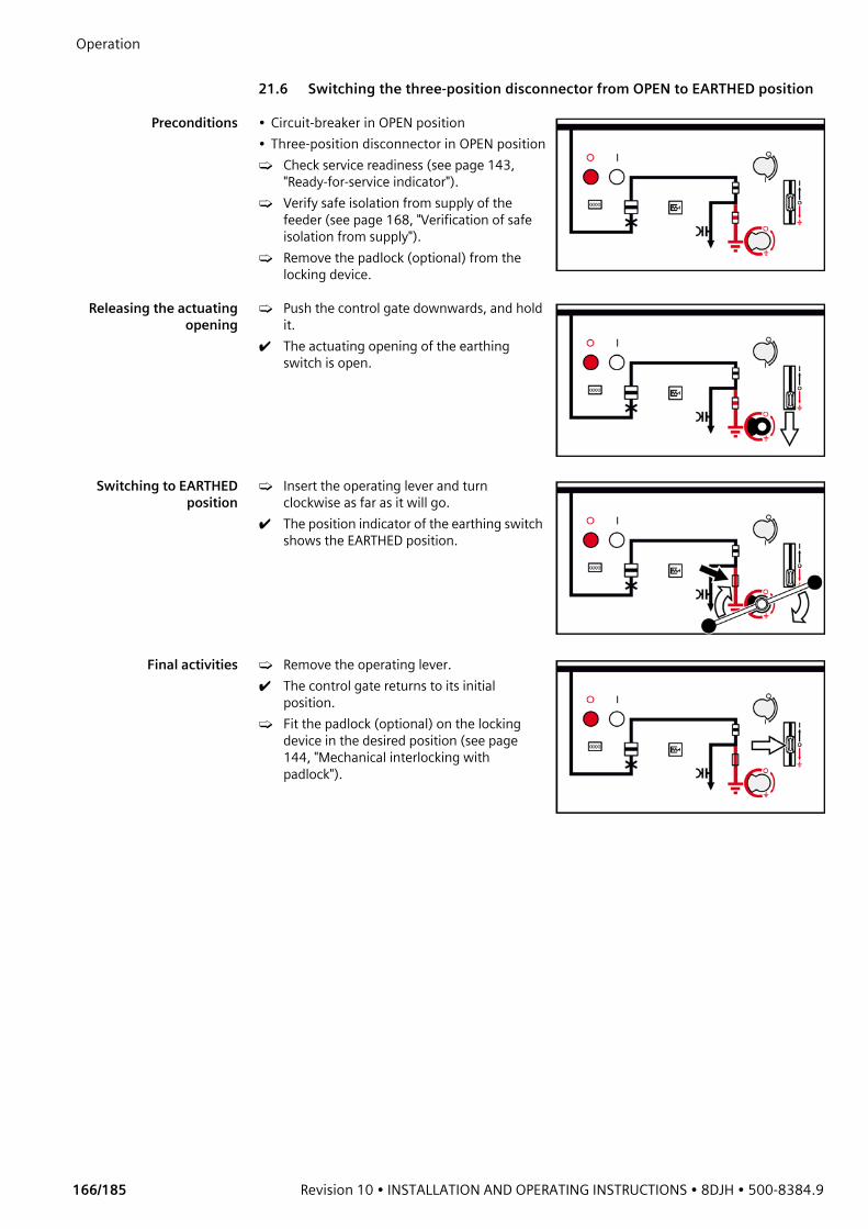
Operation
166/185 Revision 10 • INSTALLATION AND OPERATING INSTRUCTIONS • 8DJH • 500-8384.9
21.6 Switching the three-position disconnector from OPEN to EARTHED position
Preconditions • Circuit-breaker in OPEN position• Three-position disconnector in OPEN position➭ Check service readiness (see page 143,
"Ready-for-service indicator").➭ Verify safe isolation from supply of the
feeder (see page 168, "Verification of safe isolation from supply").
➭ Remove the padlock (optional) from the locking device.
Releasing the actuatingopening
➭ Push the control gate downwards, and hold it.
✔ The actuating opening of the earthing switch is open.
Switching to EARTHEDposition
➭ Insert the operating lever and turn clockwise as far as it will go.
✔ The position indicator of the earthing switch shows the EARTHED position.
Final activities ➭ Remove the operating lever.✔ The control gate returns to its initial
position.➭ Fit the padlock (optional) on the locking
device in the desired position (see page 144, "Mechanical interlocking with padlock").
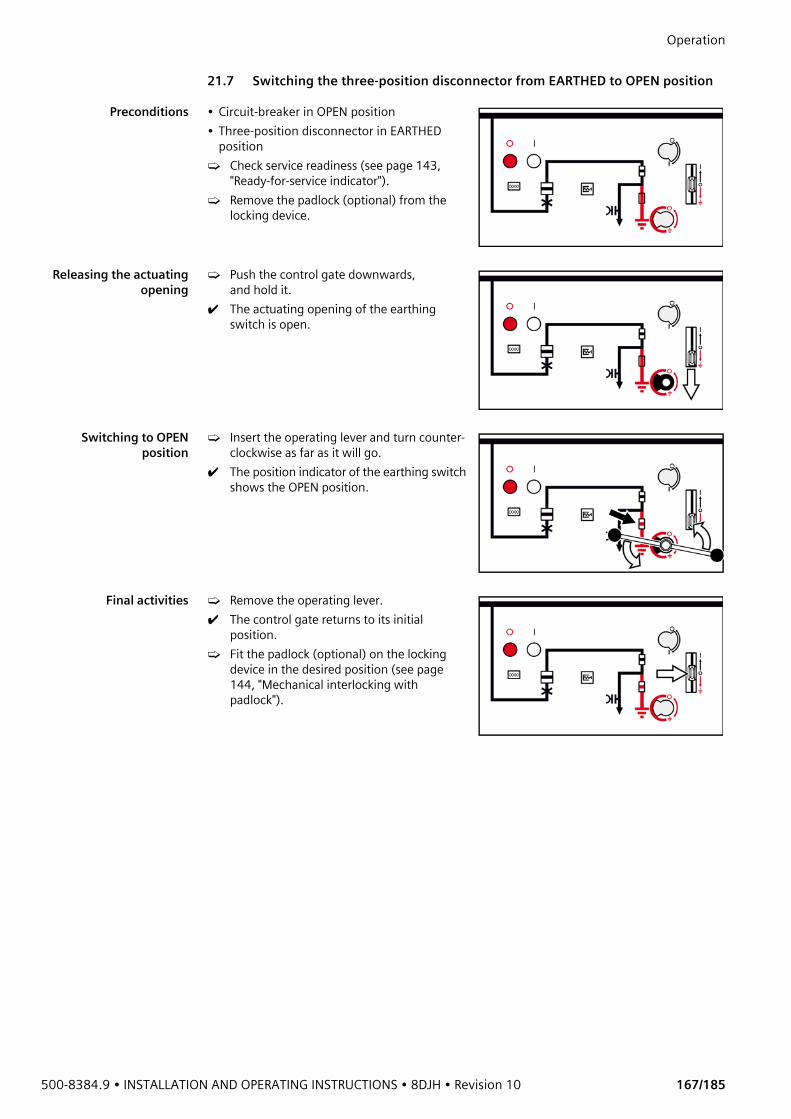
500-8384.9 • INSTALLATION AND OPERATING INSTRUCTIONS • 8DJH • Revision 10 167/185
Operation 21.7 Switching the three-position disconnector from EARTHED to OPEN position
Preconditions • Circuit-breaker in OPEN position• Three-position disconnector in EARTHED
position➭ Check service readiness (see page 143,
"Ready-for-service indicator").➭ Remove the padlock (optional) from the
locking device.
Releasing the actuatingopening
➭ Push the control gate downwards, and hold it.
✔ The actuating opening of the earthing switch is open.
Switching to OPENposition
➭ Insert the operating lever and turn counter-clockwise as far as it will go.
✔ The position indicator of the earthing switch shows the OPEN position.
Final activities ➭ Remove the operating lever.✔ The control gate returns to its initial
position.➭ Fit the padlock (optional) on the locking
device in the desired position (see page 144, "Mechanical interlocking with padlock").

Operation
168/185 Revision 10 • INSTALLATION AND OPERATING INSTRUCTIONS • 8DJH • 500-8384.9
22 Verification of safe isolation from supply
22.1 HR or LRM plug-in sockets
➭ Remove the covers from the plug-in sockets (interfaces of phases L1, L2 and L3).➭ Insert the HR or LRM voltage indicator consecutively into the plug-in sockets of the phases
L1, L2 and L3.✔ If the HR or LRM voltage indicator does not flash or light up in any of the 3 phases, the
phases are not live.➭ Refit the covers on the plug-in sockets.
DANGERHigh voltage! Danger! Verify safe isolation from supply without any doubt!➭ Possible sources of failure:
- Defective voltage indicator (or device for function testing of the coupling section)- Maloperation of the voltage indicator (or device for function testing of the coupling
section)➭ Test the perfect function of the voltage indicator and the coupling section in accordance
with national standards:- On a live panel - With a test unit according to IEC 61243-5/EN 61243-5 - On all phases
➭ Use only voltage indicators or devices according to EN 61243-5 / IEC 61243-5 / VDE 0682-415 to test the function of the coupling section. (The interface conditions have not changed as against the old standard VDE 0681 Part 7; the corresponding indicators can still be used.)
➭ Perform repeat test of interface conditions at the capacitive interfaces, as well as on the indicators according to the customer's specifications or national standards.
➭ Do not use short-circuiting jumpers as separate plugs. The function of the surge arrester installed is not guaranteed anymore if short-circuiting jumpers are used (see page 24, "Voltage detecting systems").
NOTEThe following descriptions do not substitute reading the manufacturer documentation.➭ Before using the voltage detecting systems, read the supplied manufacturer
documentation.
① Voltage indicator type HR② Capacitive test socket, phase L2③ Earth socket ④ Cover for test sockets⑤ Documentation to repeat test of
interface condition

500-8384.9 • INSTALLATION AND OPERATING INSTRUCTIONS • 8DJH • Revision 10 169/185
Operation
The marking for documentation of the repeat test of the interface condition is located next to the HR or LRM plug-in sockets:
Fig. 162: Documentation to repeat test of interface condition
Indication of HR or LRM voltage indicator Description of the indicationIndication flashes Phase not isolated from supply
Indication lights up Phase not isolated from supply
No lighting up or flashing of the indication
Phase isolated from supply

Operation
170/185 Revision 10 • INSTALLATION AND OPERATING INSTRUCTIONS • 8DJH • 500-8384.9
22.2 VOIS and CAPDIS indications
DANGERHigh voltage! Danger! Do only modify the factory setting of the C2 module in the voltage detecting system CAPDIS-S1+/S2+ after consultation with the regional Siemens representative!➭ If the setting of the C2 module was modified by mistake, re-establish the factory setting as
follows:- Pull out the C2 module ③ at the rear side of CAPDIS-S1+/S2+. Attention: Open printed
circuit board may be energized.- Plug the C2 module ③ into CAPDIS-S1+/S2+ so that the marked arrow ① on the housing
points to the marking ② on the C2 module
Fig. 163: Marking of the factory setting on the C2 module
Fig. 164: CAPDIS-S2+: Cover closed
Fig. 165: CAPDIS-S2+: Cover opened
① "Test" button② Cover③ LC display④ LEDs red and green (state of the
relay contacts)⑤ Duct for signaling cables CAPDIS-M⑥ Test socket L2⑦ Earth socket⑧ Test socket L3⑨ Test socket L1⑩ Short instructions
Fig. 166: VOIS+: Cover opened
① LC display② Test socket L2③ Earth socket④ Test socket L3⑤ Test socket L1
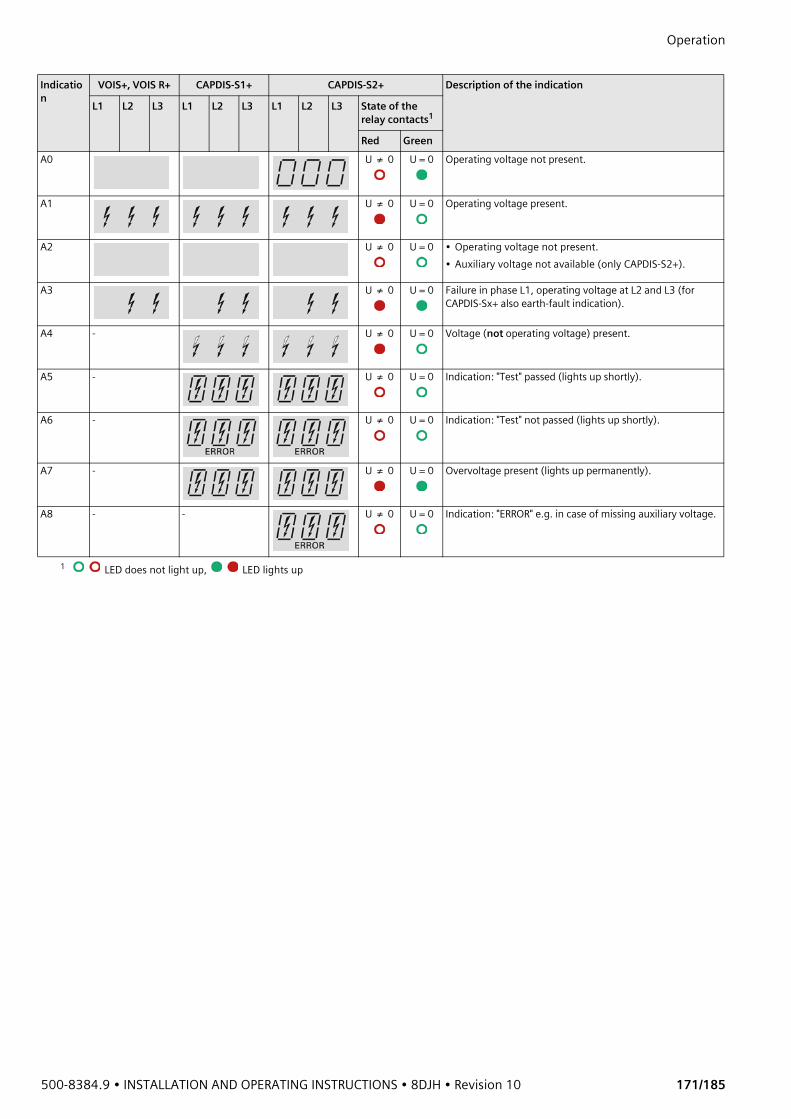
500-8384.9 • INSTALLATION AND OPERATING INSTRUCTIONS • 8DJH • Revision 10 171/185
Operation Indication
VOIS+, VOIS R+ CAPDIS-S1+ CAPDIS-S2+ Description of the indication
L1 L2 L3 L1 L2 L3 L1 L2 L3 State of the relay contacts1
Red GreenA0 U ≠ 0 U = 0 Operating voltage not present.
A1 U ≠ 0 U = 0 Operating voltage present.
A2 U ≠ 0 U = 0 • Operating voltage not present.• Auxiliary voltage not available (only CAPDIS-S2+).
A3 U ≠ 0 U = 0 Failure in phase L1, operating voltage at L2 and L3 (for CAPDIS-Sx+ also earth-fault indication).
A4 - U ≠ 0 U = 0 Voltage (not operating voltage) present.
A5 - U ≠ 0 U = 0 Indication: "Test" passed (lights up shortly).
A6 - U ≠ 0 U = 0 Indication: "Test" not passed (lights up shortly).
A7 - U ≠ 0 U = 0 Overvoltage present (lights up permanently).
A8 - - U ≠ 0 U = 0 Indication: "ERROR" e.g. in case of missing auxiliary voltage.
1 LED does not light up, LED lights up
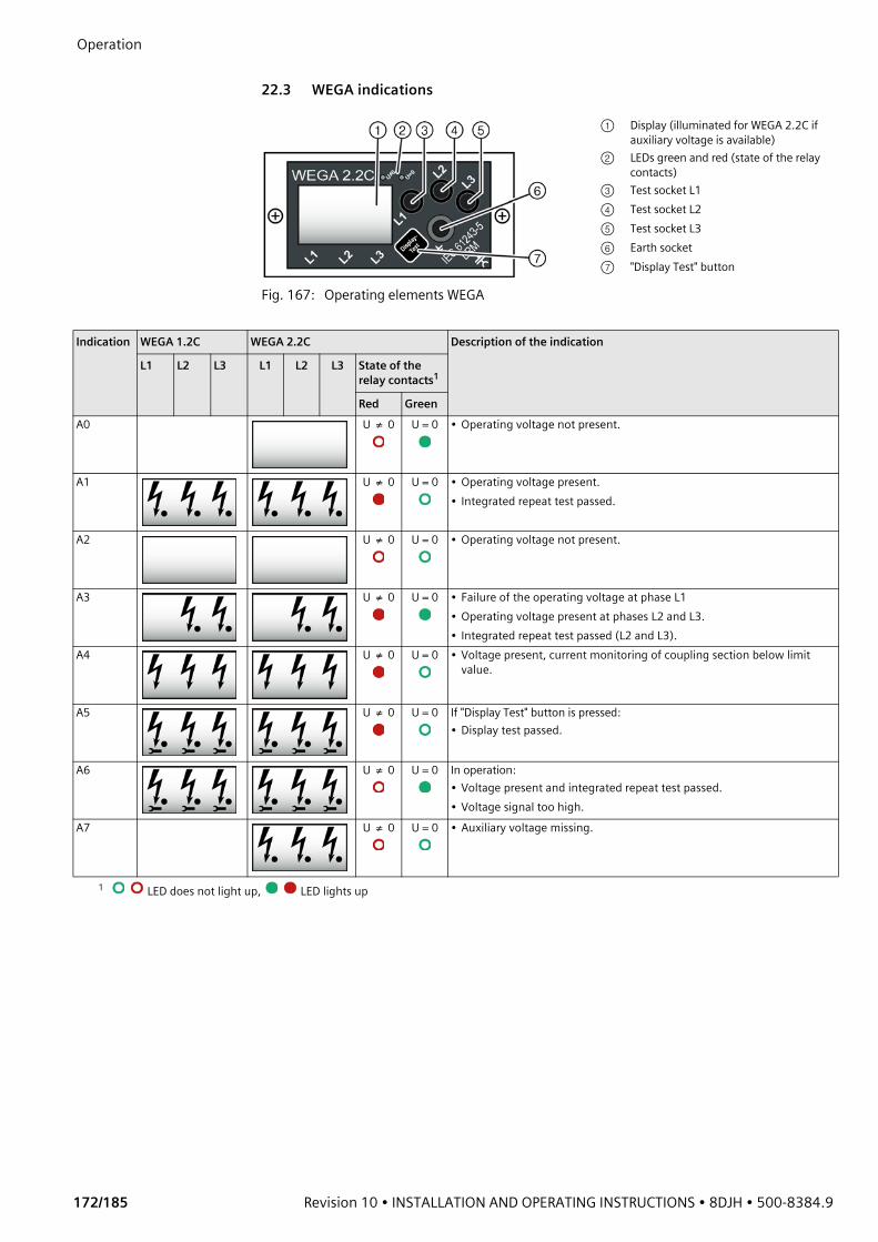
Operation
172/185 Revision 10 • INSTALLATION AND OPERATING INSTRUCTIONS • 8DJH • 500-8384.9
22.3 WEGA indications
Fig. 167: Operating elements WEGA
① Display (illuminated for WEGA 2.2C if auxiliary voltage is available)
② LEDs green and red (state of the relay contacts)
③ Test socket L1④ Test socket L2⑤ Test socket L3⑥ Earth socket⑦ "Display Test" button
Indication WEGA 1.2C WEGA 2.2C Description of the indication
L1 L2 L3 L1 L2 L3 State of the relay contacts1
Red GreenA0 U ≠ 0 U = 0 • Operating voltage not present.
A1 U ≠ 0 U = 0 • Operating voltage present.• Integrated repeat test passed.
A2 U ≠ 0 U = 0 • Operating voltage not present.
A3 U ≠ 0 U = 0 • Failure of the operating voltage at phase L1• Operating voltage present at phases L2 and L3.• Integrated repeat test passed (L2 and L3).
A4 U ≠ 0 U = 0 • Voltage present, current monitoring of coupling section below limit value.
A5 U ≠ 0 U = 0 If "Display Test" button is pressed:• Display test passed.
A6 U ≠ 0 U = 0 In operation:• Voltage present and integrated repeat test passed.• Voltage signal too high.
A7 U ≠ 0 U = 0 • Auxiliary voltage missing.
1 LED does not light up, LED lights up
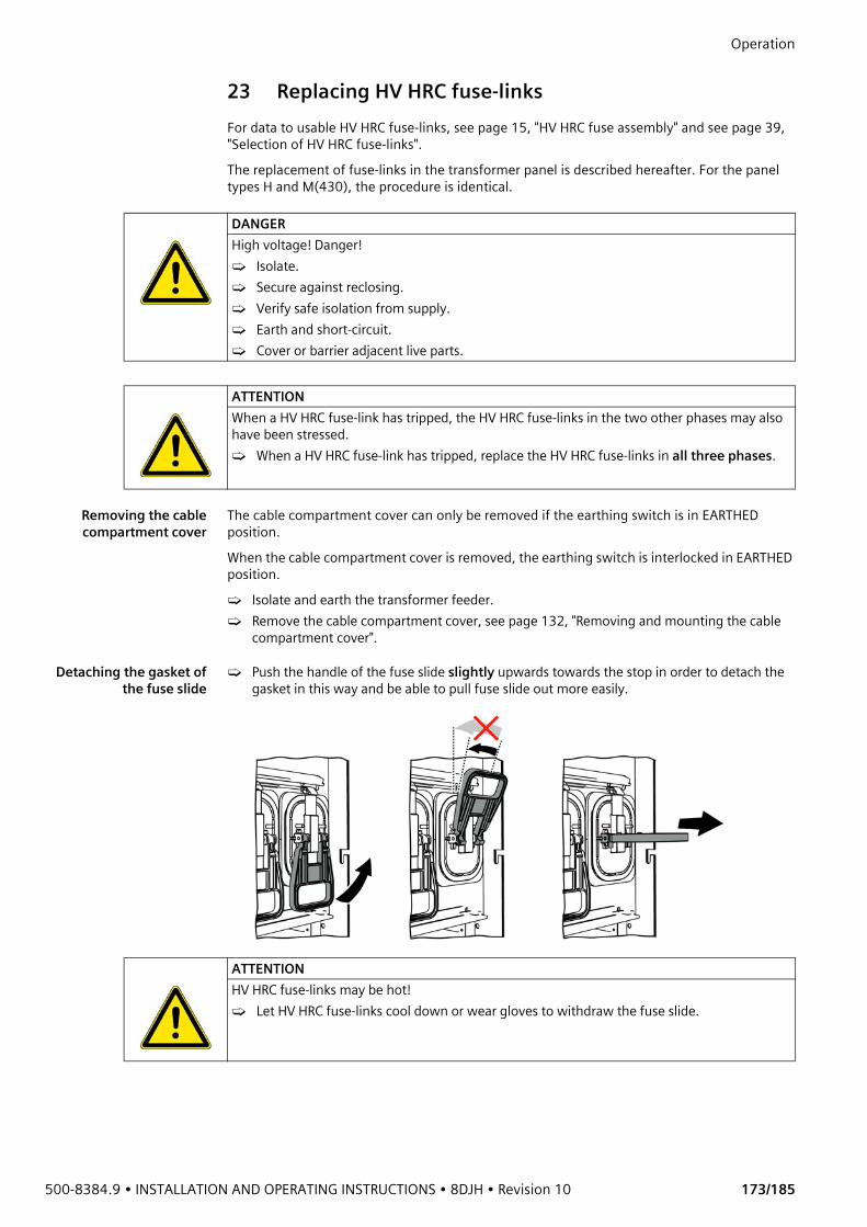
500-8384.9 • INSTALLATION AND OPERATING INSTRUCTIONS • 8DJH • Revision 10 173/185
Operation 23 Replacing HV HRC fuse-linksFor data to usable HV HRC fuse-links, see page 15, "HV HRC fuse assembly" and see page 39, "Selection of HV HRC fuse-links". The replacement of fuse-links in the transformer panel is described hereafter. For the panel types H and M(430), the procedure is identical.
Removing the cablecompartment cover
The cable compartment cover can only be removed if the earthing switch is in EARTHED position.When the cable compartment cover is removed, the earthing switch is interlocked in EARTHED position. ➭ Isolate and earth the transformer feeder.➭ Remove the cable compartment cover, see page 132, "Removing and mounting the cable
compartment cover".
Detaching the gasket ofthe fuse slide
➭ Push the handle of the fuse slide slightly upwards towards the stop in order to detach the gasket in this way and be able to pull fuse slide out more easily.
DANGERHigh voltage! Danger!➭ Isolate.➭ Secure against reclosing.➭ Verify safe isolation from supply.➭ Earth and short-circuit.➭ Cover or barrier adjacent live parts.
ATTENTIONWhen a HV HRC fuse-link has tripped, the HV HRC fuse-links in the two other phases may also have been stressed.➭ When a HV HRC fuse-link has tripped, replace the HV HRC fuse-links in all three phases.
ATTENTIONHV HRC fuse-links may be hot!➭ Let HV HRC fuse-links cool down or wear gloves to withdraw the fuse slide.

Operation
174/185 Revision 10 • INSTALLATION AND OPERATING INSTRUCTIONS • 8DJH • 500-8384.9
Removing the fuse slide ➭ Withdraw the fuse slide with the HV HRC fuse-link.
Replacing the HV HRCfuse-links
When a HV HRC fuse-link has tripped, replace the HV HRC fuse-links in all three phases.➭ Lay the HV HRC fuse-link on a flat, clean and firm underground.➭ Push the cover of the HV HRC fuse-link (on the opposite side of the housing cover) aside,
and pull the HV HRC fuse-link out of the fuse slide.
➭ Fit new HV HRC fuse-link into the contact springs and observe the striker position. The arrow on the HV HRC fuse-link must point towards the box cover.
➭ Verify correct seating of the covers and the HV HRC fuse-link.
ATTENTIONIncorrectly selected or mounted fuse-links and extension tubes can damage the fuse box or the switchgear.➭ 7.2 kV fuse-links with dimension 192 mm and 24 kV fuse-links with dimension 292 mm
are not permissible.
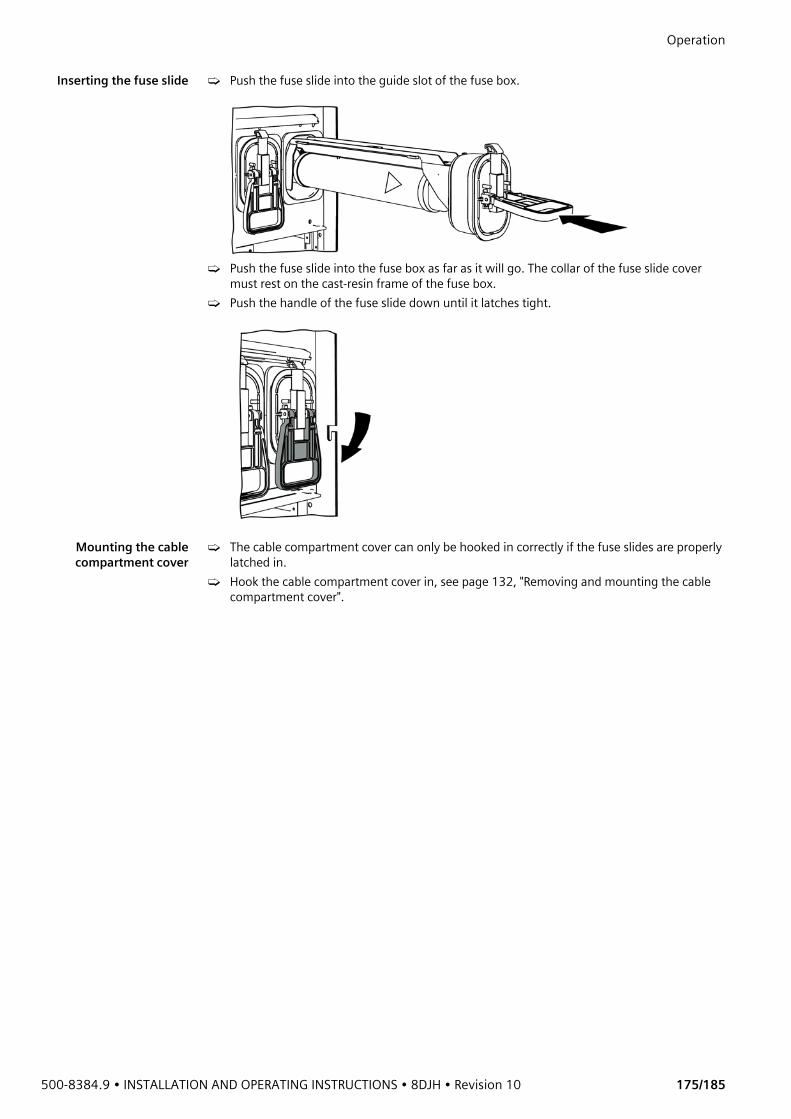
500-8384.9 • INSTALLATION AND OPERATING INSTRUCTIONS • 8DJH • Revision 10 175/185
Operation Inserting the fuse slide ➭ Push the fuse slide into the guide slot of the fuse box.
➭ Push the fuse slide into the fuse box as far as it will go. The collar of the fuse slide cover must rest on the cast-resin frame of the fuse box.
➭ Push the handle of the fuse slide down until it latches tight.
Mounting the cablecompartment cover
➭ The cable compartment cover can only be hooked in correctly if the fuse slides are properly latched in.
➭ Hook the cable compartment cover in, see page 132, "Removing and mounting the cable compartment cover".

Operation
176/185 Revision 10 • INSTALLATION AND OPERATING INSTRUCTIONS • 8DJH • 500-8384.9
24 Cable testing
24.1 Cable testing via cable plugs
Isolating and earthing thefeeder under test
➭ Disconnect the feeder under test.➭ Make sure that the feeder in the opposite substation has also been isolated and secured
against reclosing.➭ Verify safe isolation from supply.➭ Earth the feeder.
Preparations ➭ Remove the cable compartment cover, see page 132, "Removing and mounting the cable compartment cover".
➭ Remove the voltage transformers on the testing section and close the bushings in a surge-proof way.
➭ Undo the screw-type cone at the T-plug or at the adapter. ➭ Fit cable test elements (e.g. measuring bolts) according to the operating instructions of the
plug manufacturers.
DANGERHigh voltage! Danger!➭ Isolate.➭ Secure against reclosing.➭ Verify safe isolation from supply.➭ Earth and short-circuit.➭ Cover or barrier adjacent live parts.
DANGERCable testing with connected cables represents a special stress for the isolating distance. If the busbar of the switchgear under test or the opposite substation are live with operating voltage, adequate measures must be taken in order to prevent overvoltages. Normally, the switch-disconnector is not interlocked during the cable test. ➭ Fit switching prohibition signs.➭ Secure the locking device (option) with a lock.
ATTENTIONThe cables, cable plugs and voltage detecting systems may be damaged by too high test voltages.➭ Observe the specifications of the manufacturers of the cables, cable plugs and voltage
detecting systems (maximum test values).
① Bushing② Measuring bolt③ Test lead④ Earthing connection of cable
shield⑤ Earthing connection of plug⑥ T-plug

500-8384.9 • INSTALLATION AND OPERATING INSTRUCTIONS • 8DJH • Revision 10 177/185
Operation Test voltages
Testing ➭ Barrier the area around the testing place.➭ De-earth.➭ Perform the test according to the recommendations of the cable manufacturers or the
customers' specifications.
After completion of test ➭ Earth the feeder under test.➭ Remove cable test elements.➭ Clean the screw-type cone and apply the supplied mounting paste.➭ Mount the screw-type cone on the T-plug according to the manufacturer's instructions.➭ Fit and lock the cable compartment cover.➭ De-earth the panel and the opposite substation, and re-energize the feeder.
24.2 Cable sheath test
Work operations ➭ Isolate and earth the feeder under test.➭ Remove the cable compartment cover.➭ De-earth the cable shield at the cross member of the subframe as well as in the opposite
substation.➭ Perform cable sheath test following the recommendations of the cable manufacturers or
the customer's stipulation.➭ Earth the cable shield again at the cross member of the subframe as well as in the opposite
substation.➭ Refit and lock the cable compartment cover.➭ De-earth the panel and the opposite substation, and re-energize the feeder.
Rated voltage of the switchgear [kV]
DC test voltage AC test voltage VLF1 0.1 Hz
AC DC Rectangle [kV] Sinus [kV] Test duration [min]Uct [kV] Test
duration [min]
Uct [kV] Test duration [min]
Mean value Maximum value
Mean value Maximum value
7.2 11 1 22 15 22 22 15.6 22 6012 19 1 38 15 38 38 26.8 38 6015 28 1 52 15 52 52 36.8 52 6017.5 28 1 52 15 52 52 36.8 52 6024 38 1 72 15 72 72 51 72 60
1 Very low frequency
DANGERHigh voltage! Danger!➭ Isolate.➭ Secure against reclosing.➭ Verify safe isolation from supply.➭ Earth and short-circuit.➭ Cover or barrier adjacent live parts.
DANGERDuring the cable sheath test, the feeder is not interlocked . Do not switch to OPEN or CLOSED position.➭ Fit switching prohibition signs.➭ Padlock the locking device (option).➭ Closing lockout (option).
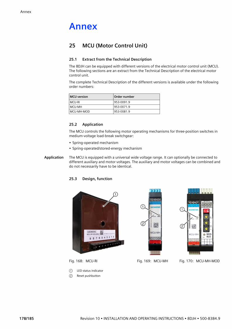
Annex
178/185 Revision 10 • INSTALLATION AND OPERATING INSTRUCTIONS • 8DJH • 500-8384.9
Annex25 MCU (Motor Control Unit)
25.1 Extract from the Technical DescriptionThe 8DJH can be equipped with different versions of the electrical motor control unit (MCU). The following sections are an extract from the Technical Description of the electrical motor control unit. The complete Technical Description of the different versions is available under the following order numbers:
25.2 ApplicationThe MCU controls the following motor operating mechanisms for three-position switches in medium-voltage load-break switchgear:• Spring-operated mechanism• Spring-operated/stored-energy mechanism
Application The MCU is equipped with a universal wide voltage range. It can optionally be connected to different auxiliary and motor voltages. The auxiliary and motor voltages can be combined and do not necessarily have to be identical.
25.3 Design, function
MCU version Order numberMCU-RI 953-0091.9MCU-MH 953-0071.9MCU-MH-MOD 953-0081.9
Fig. 168: MCU-RI Fig. 169: MCU-MH Fig. 170: MCU-MH-MOD
① LED status indicator② Reset pushbutton
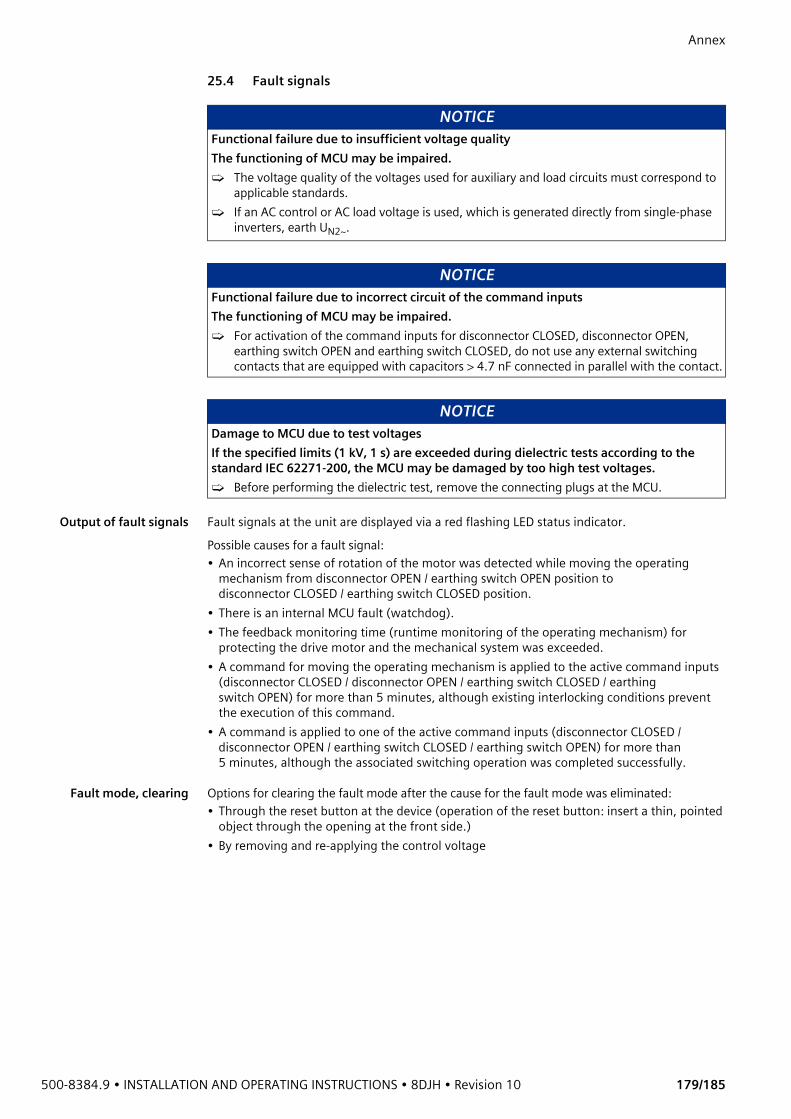
500-8384.9 • INSTALLATION AND OPERATING INSTRUCTIONS • 8DJH • Revision 10 179/185
Annex 25.4 Fault signals
Output of fault signals Fault signals at the unit are displayed via a red flashing LED status indicator.Possible causes for a fault signal:• An incorrect sense of rotation of the motor was detected while moving the operating
mechanism from disconnector OPEN / earthing switch OPEN position to disconnector CLOSED / earthing switch CLOSED position.
• There is an internal MCU fault (watchdog). • The feedback monitoring time (runtime monitoring of the operating mechanism) for
protecting the drive motor and the mechanical system was exceeded.• A command for moving the operating mechanism is applied to the active command inputs
(disconnector CLOSED / disconnector OPEN / earthing switch CLOSED / earthing switch OPEN) for more than 5 minutes, although existing interlocking conditions prevent the execution of this command.
• A command is applied to one of the active command inputs (disconnector CLOSED / disconnector OPEN / earthing switch CLOSED / earthing switch OPEN) for more than 5 minutes, although the associated switching operation was completed successfully.
Fault mode, clearing Options for clearing the fault mode after the cause for the fault mode was eliminated:• Through the reset button at the device (operation of the reset button: insert a thin, pointed
object through the opening at the front side.)• By removing and re-applying the control voltage
NOTICEFunctional failure due to insufficient voltage qualityThe functioning of MCU may be impaired.➭ The voltage quality of the voltages used for auxiliary and load circuits must correspond to
applicable standards.➭ If an AC control or AC load voltage is used, which is generated directly from single-phase
inverters, earth UN2~.
NOTICEFunctional failure due to incorrect circuit of the command inputsThe functioning of MCU may be impaired.➭ For activation of the command inputs for disconnector CLOSED, disconnector OPEN,
earthing switch OPEN and earthing switch CLOSED, do not use any external switching contacts that are equipped with capacitors > 4.7 nF connected in parallel with the contact.
NOTICEDamage to MCU due to test voltagesIf the specified limits (1 kV, 1 s) are exceeded during dielectric tests according to the standard IEC 62271-200, the MCU may be damaged by too high test voltages.➭ Before performing the dielectric test, remove the connecting plugs at the MCU.
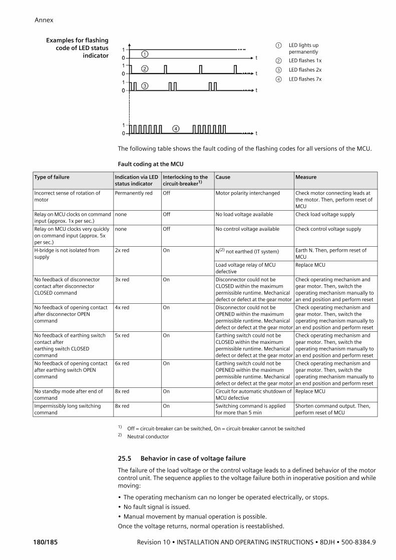
Annex
180/185 Revision 10 • INSTALLATION AND OPERATING INSTRUCTIONS • 8DJH • 500-8384.9
Examples for flashing
code of LED statusindicator
The following table shows the fault coding of the flashing codes for all versions of the MCU.
Fault coding at the MCU
25.5 Behavior in case of voltage failureThe failure of the load voltage or the control voltage leads to a defined behavior of the motor control unit. The sequence applies to the voltage failure both in inoperative position and while moving:• The operating mechanism can no longer be operated electrically, or stops.• No fault signal is issued.• Manual movement by manual operation is possible.Once the voltage returns, normal operation is reestablished.
① LED lights up permanently
② LED flashes 1x③ LED flashes 2x④ LED flashes 7x
Type of failure Indication via LED status indicator
Interlocking to the circuit-breaker1)
Cause Measure
Incorrect sense of rotation of motor
Permanently red Off Motor polarity interchanged Check motor connecting leads at the motor. Then, perform reset of MCU
Relay on MCU clocks on command input (approx. 1x per sec.)
none Off No load voltage available Check load voltage supply
Relay on MCU clocks very quickly on command input (approx. 5x per sec.)
none Off No control voltage available Check control voltage supply
H-bridge is not isolated from supply
2x red On N(2) not earthed (IT system) Earth N. Then, perform reset of MCU
Load voltage relay of MCU defective
Replace MCU
No feedback of disconnector contact after disconnector CLOSED command
3x red On Disconnector could not be CLOSED within the maximum permissible runtime. Mechanical defect or defect at the gear motor
Check operating mechanism and gear motor. Then, switch the operating mechanism manually to an end position and perform reset
No feedback of opening contact after disconnector OPEN command
4x red On Disconnector could not be OPENED within the maximum permissible runtime. Mechanical defect or defect at the gear motor
Check operating mechanism and gear motor. Then, switch the operating mechanism manually to an end position and perform reset
No feedback of earthing switch contact after earthing switch CLOSED command
5x red On Earthing switch could not be CLOSED within the maximum permissible runtime. Mechanical defect or defect at the gear motor
Check operating mechanism and gear motor. Then, switch the operating mechanism manually to an end position and perform reset
No feedback of opening contact after earthing switch OPEN command
6x red On Earthing switch could not be OPENED within the maximum permissible runtime. Mechanical defect or defect at the gear motor
Check operating mechanism and gear motor. Then, switch the operating mechanism manually to an end position and perform reset
No standby mode after end of command
8x red On Circuit for automatic shutdown of MCU defective
Replace MCU
Impermissibly long switching command
8x red On Switching command is applied for more than 5 min
Shorten command output. Then, perform reset of MCU
1) Off = circuit-breaker can be switched, On = circuit-breaker cannot be switched2) Neutral conductor

500-8384.9 • INSTALLATION AND OPERATING INSTRUCTIONS • 8DJH • Revision 10 181/185
Siemens Service Hotline
Siemens Service Hotline• Customer Support Global
- +49 180 524 7000- [email protected] 24 hours
• Customer Support Brazil (for the Brazilian market only)- +55 11 4585 8040- [email protected] Local working hours
• Customer Support India (for Indian market only)- +91 1 800 419 7477- [email protected] Local working hours

182/185 Revision 10 • INSTALLATION AND OPERATING INSTRUCTIONS • 8DJH • 500-8384.9
26 IndexAAccessories .....................................................................26Annex...........................................................................178Application ...................................................................178Applying, operating voltage ..........................................138Auxiliary switch 3SV92, breaking capacity .......................32
BBase, installation.............................................................60Base, mounting panels....................................................62Billing metering panel type M, installation.......................92Billing metering panel type M, possibilities of connection for current and voltage transformers .........92Billing metering panel type M, routing of currents and bars............................................92Busbar termination, installation ......................................85Busbar, energizing ........................................................138
CCable compartment cover, deep......................................21Cable compartment cover, mounting ............................132Cable compartment cover, removing.............................132Cable connection ............................................................17Cable installation, switchgear with pressure absorber (IAC up to 16 kA and 21 kA) ..............112Cable plug, voltage transformer 4MT8.............................22Cable sheath test ..........................................................177Cable-type current transformers, installation .................114Cables, testing ..............................................................176CAPDIS .........................................................................170Centering bolt, voltage transformer at the cable feeder..................................................................120Circuit diagrams, correcting ..........................................131Circuit-breaker type 1.1, charging the spring energy store manually ..................................................162Circuit-breaker type 1.1, closing ....................................163Circuit-breaker type 1.1, opening ..................................163Circuit-breaker type 1.1, panel operation.......................161Circuit-breaker type 2, charging the spring energy store manually ..................................................156Circuit-breaker type 2, closing .......................................157Circuit-breaker type 2, opening .....................................157Circuit-breaker type 2, panel operation..........................155Classification, switchgear ................................................33Cleaning agents and cleaning aids...................................53Comments on EMC .........................................................54Commissioning.............................................................135
Completeness of delivery, checking for ...........................51Components ...................................................................12Control elements ..........................................................141Cross member, mounting..............................................133Cross member, removing ..............................................133
DDescription .....................................................................10Dew point, checking .......................................................47Dielectric strength and site altitude .................................37Dimensions.....................................................................35Dimensions and mounting position, metering panel ........95Due application.................................................................9
EEarthing accessories......................................................103Earthing busbar, interconnection ....................................90Earthing, metering panel type M ...................................103Earthing, switchgear .......................................................89Electrical connections ...................................................107
FFault mode, clearing .....................................................179Fixing points ...................................................................72Floor openings................................................................72Foundation, fastening the panel......................................70Foundation, preparing ....................................................56Function test, electrical .................................................136Function test, mechanical .............................................136
GGas leakage rate .............................................................37Gas quality, checking ......................................................47
HHigh-voltage cables, connecting....................................107High-voltage cables, mounting in the metering panel......99HR plug-in sockets, verification of safe isolation from supply ..................................................................168HV HRC fuse assembly.....................................................15HV HRC fuse-links............................................................40HV HRC fuse-links, replacing..........................................173HV HRC fuse-links, selection ............................................39
IIndicators .....................................................................141Installation .....................................................................48Instrument transformers, installing in the metering panel ...............................................................93Insulating gas .................................................................37

500-8384.9 • INSTALLATION AND OPERATING INSTRUCTIONS • 8DJH • Revision 10 183/185
Interlocking, mechanical............................................... 144Interlocks ....................................................................... 14Intermediate storage ...................................................... 51
KKey-operated interlock.................................................. 145
LLocal-remote switch ..................................................... 145Locking devices .............................................................. 14Low-voltage compartment, installation ........................... 91LRM plug-in sockets, verification of safe isolation from supply .......................................................................... 168
MMaintenance .................................................................. 47MCU............................................................................. 178Metering panel type M, earthing accessories ................. 103Metering panel, 2-pole voltage transformer .................... 98Metering panel, connecting current transformers............ 95Metering panel, dimensions and mounting position ........ 95Metering panel, installing instrument transformers ......... 93Metering panel, mounting high-voltage cables................ 99Metering panels, interconnecting with panels ............... 106Metering panels, protection against small animals ........ 106Motor Control Unit ....................................................... 178Motor operating mechanism, momentary-contact rotary control switch..................................................... 145Motor operating mechanism, operating ........................ 145Motor operating mechanism, rated current of the protection equipment ........................................... 32Mounting paste .............................................................. 53
OOffset plates, installation ................................................ 69Operating tools............................................................. 143Operating voltage, applying.......................................... 138Operation..................................................................... 140Operation, panel with switch-disconnector ................... 146Operations counter....................................................... 142
PPacking .......................................................................... 50Padlock......................................................................... 144Padlock, shackle diameter............................................. 144Panel types..................................................................... 10Panel, fastening to the foundation .................................. 70Panels, joining ................................................................ 77Personal protection........................................................... 8Personal protective equipment (PPE)................................. 8Phase sequence.............................................................. 37
Position indicator.......................................................... 141Position indicators ........................................................ 142Power-frequency voltage test on site............................. 137PPE................................................................................... 8Pressure absorber system (IAC up to 16 kA), installation ..................................................................... 59Pressure absorber system (IAC up to 21 kA), installation ..................................................................... 60Pressure absorber top unit (IAC up to 21 kA), installation ..................................................................... 65Pressure relief................................................................. 23Protection against small animals, metering panels......... 106Protection and control equipment................................... 24Protection tripping........................................................ 154Protective equipment........................................................ 8
QQualified personnel .......................................................... 9
RRating plates................................................................... 46Raychem RICS5xxx with RDA, installation ...................... 110Ready-for-service indicator...................................... 24, 143Recycling........................................................................ 47Ring-core current sensors, installation........................... 117Room dimensions ........................................................... 55
SSafety instructions ............................................................ 6Secondary equipment, connection ............................... 130Service life, end .............................................................. 47Service readiness, checking before installation ................ 58Service-Hotline ............................................................. 181Short-circuit/earth-fault indicator .................................... 25Signal terms and definitions.............................................. 6Spherical connection bolts, installation ......................... 100Spring charged-indicator............................................... 142Spring energy store, manual charging, circuit-breaker type 1.1................................................. 162Spring energy store, manual charging, circuit-breaker type 2.................................................... 156Standards and guidelines ................................................ 34Storage .......................................................................... 48Switch-disconnector, panel operation ........................... 146Switch-fuse combination, operation.............................. 150Switch-fuse combination, protection tripping................ 154Switchgear room, preparing............................................ 55
TTechnical data ................................................................ 27Technical data, three-position disconnector .................... 29

184/185 Revision 10 • INSTALLATION AND OPERATING INSTRUCTIONS • 8DJH • 500-8384.9
Technical data, three-position switch-disconnector..........28Test operation, circuit-breaker type 1.1 .........................137Test operation, circuit-breaker type 2 ............................137Three-position disconnector, technical data.....................29Three-position switch-disconnector.................................12Three-position switch-disconnector, technical data..........28Tightening torques .........................................................53Tools ..............................................................................53Torques ..........................................................................53Transformer protection table...........................................40Transport........................................................................48Transport damage, checking for ......................................51Transport facilities ..........................................................49Transport regulations......................................................35Transport to the place of installation ...............................48
UUnloading.......................................................................48Unpacking, switchgear....................................................57
VVacuum circuit-breaker, technical data ............................30Verification of safe isolation from supply .......................168Verification of safe isolation from supply, HR/LRM plug-in sockets .................................................168VOIS .............................................................................170Voltage detecting systems ..............................................24Voltage failure ..............................................................180Voltage sensors, installation..........................................118Voltage transformer 4MT8, cable plug.............................22Voltage transformers, connecting at the cable feeder ....119
WWEGA ...........................................................................172Weights ..........................................................................35

500-8384.9 • INSTALLATION AND OPERATING INSTRUCTIONS • 8DJH • Revision 10 185/185
ImprintSiemens AGEnergy ManagementMedium Voltage & SystemsSwitchgear Factory FrankfurtCarl-Benz-Str. 22 D-60386 Frankfurt© Siemens AG 2017