
Unit Coolers - Complete Refrigeration Equipment
14
selection guide 02.2018 Unit Coolers
-
Upload
khangminh22 -
Category
Documents
-
view
2 -
download
0
Transcript of Unit Coolers - Complete Refrigeration Equipment
selection guide
02
.20
18
Unit Coolers
INTRODUCTION
A unit cooler is one of the four main components of a compression refrigerating machine. It is located inside a cold room and cools the
air passing through it in order to provide the required temperature and humidity.
Initial data for selecting a unit cooler:
• Dimensions of a cold room, location of doors, gates, beams, columns;
• Stored products;
• Packaging;
• Location of products in the cold room;
• Required temperature in the cold room;
• Required humidity in the cold room;
• Required cooling capacity.
ostrov.com
In order to select the appropriate unit cooler, carry out the following:
Step 1
Step 2
Step 3
Step 4
Step 5
Determination of the temperature diff erence Dt1(1) .......................................................................................... 3
Determination of the fi n spacing ..................................................................................................................... 4
Determination of the number and location of unit coolers ............................................................................... 5
Calculation of the required cooling capacity under standard conditions SC2 .................................................. 6
Selection of the required unit cooler model ..................................................................................................... 7
2(1) Diff erence between evaporating temperature and inlet air temperature.
ostrov.com
3
Step 1 Step 2 Step 3 Step 4 Step 5
1. Determination of the temperature diff erence DT1
Decrease of the evaporating temperature (t0), i.e. growth of the temperature diff erence, results in increased moisture content in the air.
Theoretically, this moisture can accumulate on the unit cooler’s coil in the form of condensate or frost (ice). As a result of this process, the
humidity in the cold room reaches a value corresponding to the air temperature and the evaporating temperature.
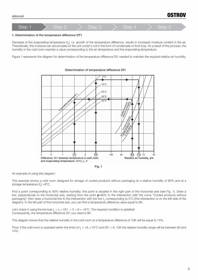
Figure 1 represents the diagram for determination of the temperature diff erence Dt1 needed to maintain the required relative air humidity.
Determination of temperature diff erence Dt1
Fig. 1
An example of using this diagram:
This example shows a cold room designed for storage of cooled products without packaging at a relative humidity of 80% and at a
storage temperature (tk) +8°С.
Find a point corresponding to 80% relative humidity; this point is situated in the right part of the horizontal axis (see Fig. 1). Draw a
line, perpendicular to the horizontal axis, starting from the point φ=80% to the intersection with the curve “Cooled products without
packaging”; then draw a horizontal line to the intersection with the line t0 corresponding to 0°C (this intersection is on the left side of the
diagram). In the left part of the horizontal axis, you can fi nd a temperature diff erence value equal to 8К.
Let’s check it using the formula tk = t
0 + Dt1 = 0 + 8 = +8°С. The required condition is satisfi ed!
Consequently, the temperature diff erence Dt1 you need is 8К.
This diagram shows that the relative humidity in the cold room at a temperature diff erence of 10К will be equal to 74%.
Thus, if the cold room is operated within the limits of tk = +8..+10°С and Dt1 = 8..10К the relative humidity range will be between 80 and
74%.
4.0mm 5.5mm 7.0mm
Dt1 6..8К 10К 8К 6..8К 7К 6..7К 6К
Relative
humidity
80..92% 70..80% 80..85% 80..95% 85..92% 90..95%
Temperature in
cold room
+5..+10оС +10..+12оС 0..+5оС +2..+5оС -10..-25оС -1..+3оС
State of products Cooled - Cooled Frozen Cooled
Packaging Without
packaging
- Packaged Without
packaging
Packaged Without packaging
Cold room
intended for
Storage Industrial air
conditioning
Storage Storage
Products Fresh
vegetables, fruit
- All Fresh
vegetables, fruit,
meat
All Meat, fi sh Meat, fi sh,
vegetables, fruit
Step 1 Step 2 Step 3 Step 4 Step 5
2. Determination of the fi n spacing
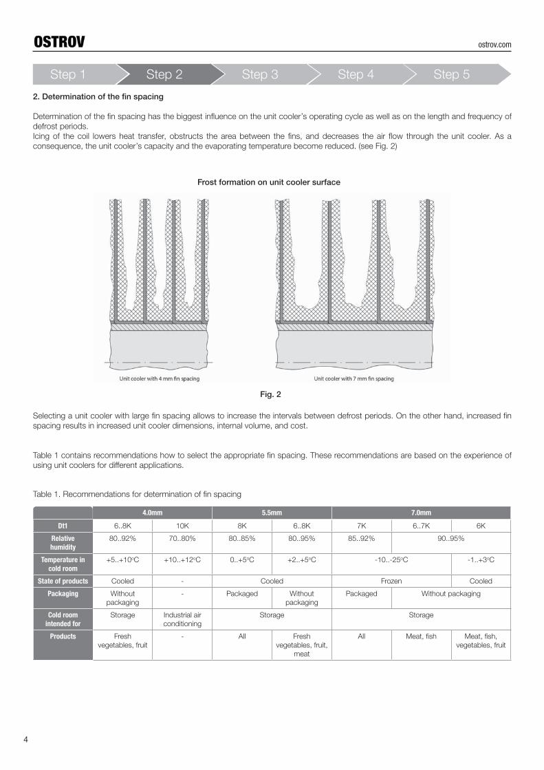
Determination of the fi n spacing has the biggest infl uence on the unit cooler’s operating cycle as well as on the length and frequency of
defrost periods.
Icing of the coil lowers heat transfer, obstructs the area between the fi ns, and decreases the air fl ow through the unit cooler. As a
consequence, the unit cooler’s capacity and the evaporating temperature become reduced. (see Fig. 2)
Frost formation on unit cooler surface
Fig. 2
Selecting a unit cooler with large fi n spacing allows to increase the intervals between defrost periods. On the other hand, increased fi n
spacing results in increased unit cooler dimensions, internal volume, and cost.
Table 1 contains recommendations how to select the appropriate fi n spacing. These recommendations are based on the experience of
using unit coolers for diff erent applications.
Table 1. Recommendations for determination of fi n spacing
4
ostrov.com

5
Step 1 Step 2 Step 3 Step 4 Step 5
3. Determination of the number and location of unit coolers
The design capacity of the unit cooler may only be reached if the air in the cold room circulates properly. The optimal air circulation means
that the air fl ow is not restricted by improperly located products or building constructions.
For each type of cold rooms, it is necessary to avoid situations when the primary air fl ow leaving the unit cooler directly faces stored
products. The best solution is when the air fl ow streams above the products, almost under the ceiling. The speed with which the primary
air fl ow comes to the opposite wall should be from 0.25 to 0.5 m/s. (see Fig. 3)
Air circulation in cold room
When determining the number and location of the unit coolers in the cold room, take into account the following:
• Air throw (the air throw of a unit cooler is the distance from this unit cooler’s fan to a point where the air velocity decreases to
avalue of 0.25 m/s);
• When the cold room has ceiling beams, locate the unit coolers between the beams and provide air fl ow along them;
• When the cold room has columns, it is desirable to locate the unit coolers in each area between them;
• When the cold room has many-tier storage racks, the unit coolers should be placed between them; the air fl ow should bedirected
along the passages;
• In order to provide even air distribution throughout the cold room, air ducts may be used;
• It is not recommended to locate unit coolers direct above doors and gates.
Fig. 3
Recommended placement of unit coolers
Fig. 4
ostrov.com
Standard
conditions
Inlet air temperature Evaporating temperatureTemperature diff erence
Dt1Relative humidity Wet conditions factor
°C °C K %
SC1 +10 0 10 85 1.35
SC2 0 -8 8 85 1.15
SC3 -18 -25 7 95 1.05
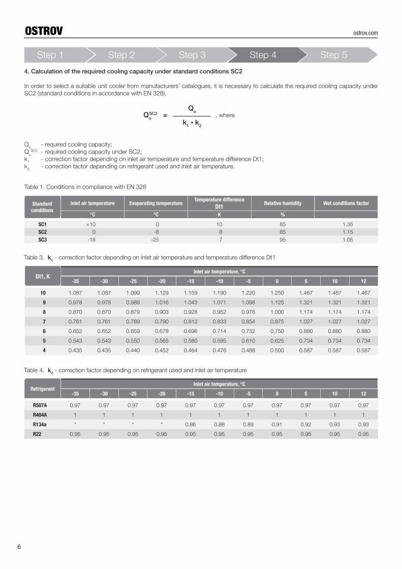
4. Calculation of the required cooling capacity under standard conditions SC2
In order to select a suitable unit cooler from manufacturers’ catalogues, it is necessary to calculate the required cooling capacity under
SC2 (standard conditions in accordance with EN 328).
, where
Qo - required cooling capacity;
Qo
SC2 - required cooling capacity under SC2;
k1 - correction factor depending on inlet air temperature and temperature diff erence Dt1;
k2 - correction factor depending on refrigerant used and inlet air temperature.
QoSC2 =
Qo
k1 * k2
Table 1. Conditions in compliance with EN 328
Dt1, КInlet air temperature, °C
-35 -30 -25 -20 -15 -10 -5 0 5 10 12
10 1.087 1.087 1.099 1.129 1.159 1.190 1.220 1.250 1.467 1.467 1.467
9 0.978 0.978 0.989 1.016 1.043 1.071 1.098 1.125 1.321 1.321 1.321
8 0.870 0.870 0.879 0.903 0.928 0.952 0.976 1.000 1.174 1.174 1.174
7 0.761 0.761 0.769 0.790 0.812 0.833 0.854 0.875 1.027 1.027 1.027
6 0.652 0.652 0.659 0.678 0.696 0.714 0.732 0.750 0.880 0.880 0.880
5 0.543 0.543 0.550 0.565 0.580 0.595 0.610 0.625 0.734 0.734 0.734
4 0.435 0.435 0.440 0.452 0.464 0.476 0.488 0.500 0.587 0.587 0.587
Table 3. k1 - correction factor depending on inlet air temperature and temperature diff erence Dt1
RefrigerantInlet air temperature, °C
-35 -30 -25 -20 -15 -10 -5 0 5 10 12
R507A 0.97 0.97 0.97 0.97 0.97 0.97 0.97 0.97 0.97 0.97 0.97
R404A 1 1 1 1 1 1 1 1 1 1 1
R134a * * * * 0.86 0.88 0.89 0.91 0.92 0.93 0.93
R22 0.95 0.95 0.95 0.95 0.95 0.95 0.95 0.95 0.95 0.95 0.95
Table 4. k2 - correction factor depending on refrigerant used and inlet air temperature
6
Step 1 Step 2 Step 3 Step 4 Step 5
ostrov.com
Models Number of fans
Capacity (SC2) (1)
Airfl ow
Air throw Heat
exchange
surface
Internal
volume
Fan data Sound
pressure
level
(3m) (2)
Electric defrost Connections
Weight
FIN SPACING
7.0 mm
Fan speedPower
consump-
tion
Rated
current Coil Drip tray Inlet Outlet
kW m3/h m m2 dm3 rpm W A dB(А) W W mm mm kg
OH201-135S1A-C70 1 3.0 2500 17 12.4 2.1 1290 174 0.8 50 1152 384 12 22 29
OH201-135S1A-E70 1 3.9 2300 16 18.6 3.3 1290 174 0.8 50 1536 384 12 22 32
OH201-235S1A-C70 2 6.1 5000 19 24.8 4.4 1290 348 1.6 53 2816 704 12 28 38
OH201-235S1A-E70 2 7.5 4500 18 37.2 6.5 1290 348 1.6 53 3520 704 12 28 46
OH201-335S1A-C70 3 9.1 7500 21 37.2 6.5 1290 522 2.3 55 4096 1024 12 28 58
OH201-335S1A-E70 3 11.7 6700 20 55.8 9.8 1290 522 2.3 55 5120 1024 16 28 62
OH201-435S1A-C70 4 12.1 9900 22 49.6 8.7 1290 696 3.1 56 5376 1344 16 35 75
OH201-435S1A-E70 4 15.2 9000 21 74.4 13.1 1290 696 3.1 56 6720 1344 16 35 86
OH201-140S1A-E70 1 5.4 3300 20 26.8 4.5 1380 219 1.0 52 3136 448 16 28 36
OH201-140S1A-G70 1 6.7 3000 19 35.7 6.0 1380 219 1.0 52 4032 448 16 28 40
OH201-240S1A-E70 2 11.5 6500 22 53.6 9.2 1380 438 2.0 55 6656 832 28 35 71
OH201-240S1A-G70 2 13.4 6000 21 71.5 12.2 1380 438 2.0 55 8320 832 28 35 79
OH201-340S1A-E70 3 16.2 9700 24 80.4 14.0 1380 657 3.0 57 8512 1216 35 42 105
OH201-340S1A-G70 3 20.2 8900 23 107.2 18.6 1380 657 3.0 57 12160 1216 35 42 116
OH201-440S1A-E70 4 23.0 13000 27 107.2 18.6 1380 876 3.9 58 12800 1600 35 42 136
OH201-440S1A-G70 4 26.8 11900 26 142.9 24.5 1380 876 3.9 58 16000 1600 35 54 152
OH201-145S1A-C70 1 5.0 5600 30 22.6 4.0 1330 479 2.3 54 2400 480 12 28 47
OH201-145S1A-E70 1 7.9 5200 28 33.9 5.9 1330 479 2.3 54 3840 480 22 28 53
OH201-145S1A-G70 1 9.5 4700 26 45.2 7.9 1330 479 2.3 54 4800 480 22 28 59
OH201-245S1A-C70 2 12.2 11100 31 45.2 7.9 1330 958 4.5 57 5376 896 22 28 78
OH201-245S1A-E70 2 15.8 10300 29 67.7 11.9 1330 958 4.5 57 7168 896 35 42 93
OH201-245S1A-G70 2 19.1 9400 27 90.3 15.9 1330 958 4.5 57 8960 896 35 42 104
OH201-345S1A-E70 3 24.6 15300 31 101.6 17.8 1330 1437 6.8 58 10752 1344 35 42 131
OH201-345S1A-G70 3 28.6 14000 29 135.5 23.8 1330 1437 6.8 58 13440 1344 35 42 147
OH201-445S1A-E70 4 32.3 20400 32 135.5 23.8 1330 1916 9.0 59 13824 1728 35 54 168
OH201-445S1A-G70 4 35.9 18600 30 180.7 31.7 1330 1916 9.0 59 19008 1728 35 54 189
OH201-150S1A-C70 1 8.3 7600 37 31.6 5.8 1330 710 3.1 54 3648 608 16 28 54
OH201-150S1A-E70 1 11.1 7100 36 47.5 8.8 1330 710 3.1 54 4864 608 28 35 61
OH201-150S1A-G70 1 13.2 6600 34 63.3 11.4 1330 710 3.1 54 6080 608 28 35 68
OH201-250S1A-C70 2 16.2 15100 38 63.3 11.8 1330 1420 6.2 57 6912 1152 16 35 95
OH201-250S1A-E70 2 22.0 14100 37 94.9 17.7 1330 1420 6.2 57 10368 1152 28 35 107
OH201-250S1A-G70 2 25.2 13200 36 126.6 22.9 1330 1420 6.2 57 12672 1152 28 42 121
OH201-350S1A-E70 3 33.8 21100 39 142.4 25.3 1330 2130 9.3 58 15552 1728 35 42 160
OH201-350S1A-G70 3 38.1 19700 38 189.8 34.6 1330 2130 9.3 58 20736 1728 35 42 180
OH201-450S1A-E70 4 42.3 28100 40 189.8 34.5 1330 2840 12.4 59 22400 2240 35 54 204
OH201-450S1A-G70 4 51.0 26300 39 253.1 45.5 1330 2840 12.4 59 29120 2240 35 54 231
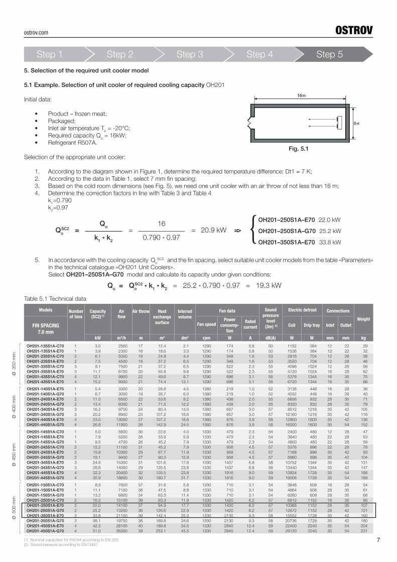
5. Selection of the required unit cooler model
5.1 Example. Selection of unit cooler of required cooling capacity OH201
Initial data:
• Product – frozen meat;
• Packaged;
• Inlet air temperature Tk = -20°С;
• Required capacity Qo = 16kW;
• Refrigerant R507A.
Selection of the appropriate unit cooler:
1. According to the diagram shown in Figure 1, determine the required temperature diff erence: Dt1 = 7 К;
2. According to the data in Table 1, select 7 mm fi n spacing;
3. Based on the cold room dimensions (see Fig. 5), we need one unit cooler with an air throw of not less than 16 m;
4. Determine the correction factors in line with Table 3 and Table 4
k1=0.790
k2=0.97
QoSC2 = = = 20.9 kW =>
Qo
16
0.790 * 0.97k1 * k2
In accordance with the cooling capacity QoSC2 and the fi n spacing, select suitable unit cooler models from the table «Parameters»
in the technical catalogue «OH201 Unit Coolers».
Select OH201–250S1A–G70 model and calculate its capacity under given conditions:
OH201–250S1A–E70 22.0 kW
OH201–250S1A–G70 25.2 kW
OH201–350S1A–E70 33.8 kW
{Q
o = Q
oSC2 * k1
* k2 = 25.2 * 0.790 * 0.97 = 19.3 kW
Table 5.1 Technical data
5.
7
Fig. 5.1
ø 500 m
mø
450 m
mø
400 m
mø
350 m
m
Step 1 Step 2 Step 3 Step 4 Step 5
(1) Nominal capacities for R404A according to EN 328.
(2) Sound pressure according to EN13487.
ostrov.com
Unit Cooler OH201-250S1A-G70
2 х
хх
х
øø
Difference between evaporation temperature and inlet air temperature, КSound pressure level at 3m distance, dB(A)
Compliance of fans with EU Ecodesign Directive (2009/125/EC )
Operating current may vary depending on air temperature and supply voltage
Demensions and weights are indicated for base models without options
Subject to technical amendments without prior notice
(1)
(2)
(3)
(4)
(5)
13.48 13.91 14.36 14.79 14.79 14.7911.39 11.69 12.00 12.30 12.60 13.0317.39 17.94 18.50 18.50 18.50
4 10.96 10.96 10.96 11.0914.62 14.99 15.37 15.75 16.30 16.865 13.68 13.68 13.68 13.86 14.24
20.21 20.87 21.52 22.18 22.18 22.1817.09 17.54 17.99 18.45 18.90 19.5624.34 25.12 25.88 25.88 25.88
6 16.43 16.43 16.43 16.6120.46 20.99 21.52 22.05 22.81 23.597 19.18 19.18 19.18 19.38 19.91
26.96 27.82 28.70 29.58 29.58 29.5822.76 23.39 23.99 24.60 25.20 26.0831.32 32.31 33.29 33.29 33.29
8 21.92 21.92 21.92 22.1526.28 26.99 27.67 28.35 29.33 30.329 24.65 24.65 24.65 24.92 25.60
33.69 34.78 35.88 36.97 36.97 36.9728.45 29.21 29.99 30.74 31.50 32.58
3 4 5 10 1210 27.39 27.39 27.39 27.69
-15 -10 -5 0 1 2
Drain G 1"1/4
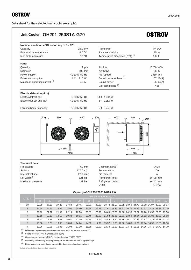
Capacity of OH201-250S1A-G70, kW
DT1, KInlet air temperature, C0
-35 -30 -27 -25 -20
Maximum pressure 31 bar Refrigerant outlet 42 mmNet weight(5) 121 kg Refrigerant inlet 28 mm
Surface 126.6 m2 Tube material CuInternal volume 22.9 dm3 Fin material Al
Technical data:Fin spacing 7.0 mm Casing material AlMg
Fan ring heater capacity ~1-230V-50 Hz 2 345 W
Electric defrost drip tray ~1-230V-50 Hz 1 1152 W
ErP compliance (3) Yes
Electric defrost (option):Electric defrost сoil ~1-230V-50 Hz 11 1152 W
Maximum operating current (4) 6.2 А Sound power 85 dB(A)Power consumption 710 W Sound pressure level (2) 57 dB(A)Power supply ~1-230V-50 Hz Fan speed 1330 rpm
m3/hDiameter 500 mm Air throw 36 m
Fans:Quantity 2 pcs. Air flow 13200
Inlet air temperature 0.0 °C Temperature difference (DT1) (1) 8.0 КEvaporation temperature -8.0 °C Relative humidity 85 %
Nominal conditions SC2 according to EN 328:Capacity 25.2 kW Refrigerant R404А
ostrov.com
Data sheet for the selected unit cooler (example):
8
ostrov.com
ø 500 м
мø
450 м
мø
400 м
мø
350 м
м
Models Number of fans
Capacity (SC2) (1)
Airfl ow
Air throw
Heat
exchange
surface
Internal
volume
Fan data Sound
pressure
level
(3m) (2)
Electric defrost Connections
Weight
FIN SPACING
7.0 mm
Fan speedPower
consump-
tion
Rated
currentTwo
coils
Two drip
traysInlet Outlet
kW m3/h m m2 dm3 rpm W A dB(А) W W mm mm kg
OH221-135S1A-C70 1 2.9 2500 2 x 7 11.9 2.2 1290 174 0.8 50 896 896 12 22 38
OH221-135S1A-E70 1 3.6 2200 2 x 6 17.9 3.2 1290 174 0.8 50 1792 896 16 22 41
OH221-235S1A-C70 2 5.9 4900 2 x 9 23.8 4.2 1290 348 1.6 53 1664 1664 16 28 60
OH221-235S1A-E70 2 7.8 4400 2 x 8 35.7 6.4 1290 348 1.6 53 3328 1664 16 28 65
OH221-335S1A-C70 3 8.9 7400 2 x 10 35.7 6.4 1290 522 2.3 55 2432 2432 16 28 82
OH221-335S1A-E70 3 11.7 6600 2 x 9 53.6 9.4 1290 522 2.3 55 4864 2432 22 35 91
OH221-435S1A-C70 4 11.9 9800 2 x 12 47.6 8.4 1290 696 3.1 56 3200 3200 22 35 104
OH221-435S1A-E70 4 15.6 8800 2 x 11 71.5 12.4 1290 696 3.1 56 6400 3200 22 35 115
OH221-140S1A-E70 1 5.2 3200 2 x 8 26.1 4.6 1380 219 1.0 51 2176 1088 16 28 53
OH221-140S1A-G70 1 6.5 3000 2 x 7 34.7 6.2 1380 219 1.0 51 3264 1088 16 28 57
OH221-240S1A-E70 2 11.4 6400 2 x 10 52.1 9.2 1380 438 2.0 54 3840 1920 16 35 85
OH221-240S1A-G70 2 13.2 5900 2 x 9 69.5 12.2 1380 438 2.0 54 5760 1920 22 35 94
OH221-340S1A-E70 3 17.1 9600 2 x 11 78.2 13.6 1380 657 3.0 56 5632 2816 28 42 118
OH221-340S1A-G70 3 18.7 8800 2 x 10 104.2 18.2 1380 657 3.0 56 8448 2816 28 42 130
OH221-440S1A-E70 4 22.4 12800 2 x 12 104.2 18.2 1380 876 3.9 57 7424 3712 28 42 151
OH221-440S1A-G70 4 24.6 11700 2 x 11 139.0 24.2 1380 876 3.9 57 11136 3712 28 54 168
OH221-145S1A-C70 1 5.9 4900 2 x 11 23.8 4.2 1345 303 1.4 53 1216 1216 16 28 55
OH221-145S1A-E70 1 7.8 4600 2 x 10 35.7 6.4 1345 303 1.4 53 2432 1216 16 28 61
OH221-245S1A-C70 2 12.0 9800 2 x 13 47.6 8.4 1345 606 2.7 56 2176 2176 16 35 91
OH221-245S1A-E70 2 15.7 9100 2 x 12 71.5 12.4 1345 606 2.7 56 4352 2176 28 42 103
OH221-345S1A-C70 3 17.9 14600 2 x 14 71.5 12.4 1345 909 4.1 57 3200 3200 22 42 128
OH221-345S1A-E70 3 23.8 13600 2 x 13 107.2 18.6 1345 909 4.1 57 6400 3200 28 54 146
OH221-445S1A-C70 4 24.0 19500 2 x 16 95.3 16.6 1345 1212 5.4 58 4224 4224 28 54 161
OH221-445S1A-E70 4 30.3 18100 2 x 15 142.9 24.8 1345 1212 5.4 58 8448 4224 28 54 184
OH221-150S1A-C70 1 8.4 6800 2 x 14 34.7 6.2 1300 530 2.4 54 2816 1408 16 28 70
OH221-150S1A-E70 1 9.8 6400 2 x 13 52.1 9.2 1300 530 2.4 54 4224 1408 35 42 79
OH221-150S1A-G70 1 12.7 6100 2 x 12 69.5 12.2 1300 530 2.4 54 5632 1408 35 42 88
OH221-250S1A-C70 2 16.6 13600 2 x 16 69.5 12.2 1300 1060 4.7 57 5376 2688 35 42 118
OH221-250S1A-E70 2 22.8 12800 2 x 16 104.2 18.2 1300 1060 4.7 57 8064 2688 35 54 135
OH221-250S1A-G70 2 26.7 12100 2 x 15 139.0 24.2 1300 1060 4.7 57 10752 2688 35 54 151
OH221-350S1A-E70 3 33.2 19100 2 x 17 156.3 27.2 1300 1590 7.0 58 11904 3968 35 54 192
OH221-350S1A-G70 3 40.5 18100 2 x 16 208.4 36.2 1300 1590 7.0 58 15872 3968 35 54 218
9
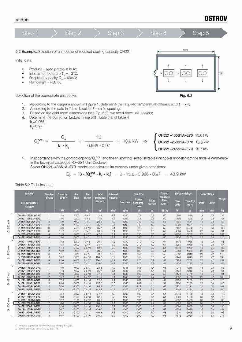
5.2 Example. Selection of unit cooler of required cooling capacity OH221
Initial data:
• Product – seed potato in bulk;
• Inlet air temperature Tk = +3°С;
• Required capacity Qo = 40kW;
• Refrigerant - R507A.
Selection of the appropriate unit cooler:
1. According to the diagram shown in Figure 1, determine the required temperature diff erence: Dt1 = 7К;
2. According to the data in Table 1, select 7 mm fi n spacing;
3. Based on the cold room dimensions (see Fig. 5.2), we need three unit coolers;
4. Determine the correction factors in line with Table 3 and Table 4
k1=0.966
k2=0.97
QoSC2 = = = 13.9 kW =>
Qo
13
0.966 * 0.97k1 * k2
In accordance with the cooling capacity QoSC2 and the fi n spacing, select suitable unit cooler models from the table «Parameters»
in the technical catalogue «OH221 Unit Coolers».
Select OH221–435S1A–Е70 model and calculate its capacity under given conditions:
OH221–435S1A–E70 15.6 kW
OH221–250S1A–С70 16.6 kW
OH221–245S1A–Е70 15.7 kW{
Qo = 3 * [Qo
SC2 * k1 * k2
] = 3 * 15.6 * 0.966 * 0.97 = 43.9 kW
Table 5.2 Technical data
5.
Fig. 5.2
Step 1 Step 2 Step 3 Step 4 Step 5
(1) Nominal capacities for R404A according to EN 328.
(2) Sound pressure according to EN13487.
ostrov.com
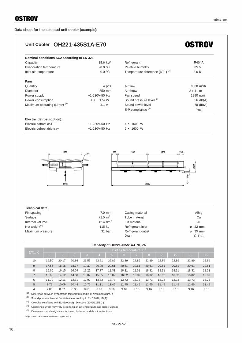
Data sheet for the selected unit cooler (example):
10
Unit Cooler OH221-435S1A-E70
4 х
хх
øø
Difference between evaporation temperature and inlet air temperature, КSound pressure level at 3m distance according to EN 13487, dB(A)
Compliance of fans with EU Ecodesign Directive (2009/125/EC )
Operating current may vary depending on air temperature and supply voltage
Demensions and weights are indicated for base models without options
Subject to technical amendments without prior notice
(1)
(2)
(3)
(4)
(5)
9.16 9.16 9.16 9.16 9.16 9.1611.45 11.45
4 7.80 8.07 8.35 8.61 8.89 9.16 9.1611.45 11.45 11.45 11.45 11.45 11.455 9.75 10.09 10.44 10.76 11.11
13.73 13.73 13.73 13.73 13.73 13.7316.02 16.02
6 11.70 12.11 12.51 12.92 13.32 13.73 13.7316.02 16.02 16.02 16.02 16.02 16.027 13.65 14.12 14.60 15.07 15.55
18.31 18.31 18.31 18.31 18.31 18.3120.61 20.61
8 15.60 16.15 16.69 17.22 17.77 18.31 18.3120.61 20.61 20.61 20.61 20.61 20.619 17.55 18.16 18.77 19.39 20.00
22.89 22.89 22.89 22.89 22.89 22.89
11 12
10 19.50 20.17 20.86 21.53 22.21 22.89 22.89
5 6 7 8 9 10
Drain G 1"1/4
Capacity of OH221-435S1A-E70, kW
DT1, KInlet air temperature, C0
0 1 2 3 4
Maximum pressure 31 bar Refrigerant outlet 35 mmNet weight(5) 115 kg Refrigerant inlet 22 mm
Surface 71.5 m2 Tube material CuInternal volume 12.4 dm3 Fin material Al
Technical data:Fin spacing 7.0 mm Casing material AlMg
Electric defrost drip tray ~1-230V-50 Hz 2 1600 W
ErP compliance (3) Yes
Electric defrost (option):Electric defrost сoil ~1-230V-50 Hz 4 1600 W
Maximum operating current (4) 3.1 А Sound power level 78 dB(A)Power consumption 174 W Sound pressure level (2) 56 dB(A)Power supply ~1-230V-50 Hz Fan speed 1290 rpm
m3/hDiameter 350 mm Air throw 2 x 11 m
Fans:Quantity 4 pcs. Air flow 8800
Inlet air temperature 0.0 °C Temperature difference (DT1) (1) 8.0 КEvaporation temperature -8.0 °C Relative humidity 85 %
Nominal conditions SC2 according to EN 328:Capacity 15.6 kW Refrigerant R404А
ostrov.com
ostrov.com
ø 500 м
мø
450 м
мø
400 м
мø
350 м
м
Models Number of fans
Capacity (SC2) (1)
Airfl ow
Air throw
Heat
exchange
surface
Internal
volume
Fan data Sound
pressure
level
(3m) (2)
Electric defrost Connections
Weight
FIN SPACING
10.0 mm
Power
supplyFan speed
Power
consump-
tion
Rated
currentTwo
coils
Two drip
traysInlet Outlet
kW m3/h m m2 dm3 φ-V-Hz rpm W A dB(А) W W mm mm kg
OH222-135S3A-C100 1 2.7 2900 2x9 8.6 2.2 3-400-50 1390 (D) 190 0.4 50 896 896 12 22 38
OH222-135S3A-E100 1 3.6 2600 2x8 12.9 3.2 3-400-50 1390 (D) 190 0.4 50 1792 896 16 22 40
OH222-235S3A-C100 2 5.4 5700 2x11 17.1 4.2 3-400-50 1390 (D) 380 0.8 52 1664 1664 16 28 62
OH222-235S3A-E100 2 7.2 5100 2x10 25.7 6.4 3-400-50 1390 (D) 380 0.8 52 3328 1664 16 28 67
OH222-335S3A-C100 3 8.2 8500 2x12 25.7 6.4 3-400-50 1390 (D) 570 1.3 54 2432 2432 16 28 87
OH222-335S3A-E100 3 10.8 7600 2x11 38.6 9.4 3-400-50 1390 (D) 570 1.3 54 4864 2432 22 35 96
OH222-435S3A-C100 4 10.7 11300 2x14 34.3 8.4 3-400-50 1390 (D) 760 1.6 55 3200 3200 22 35 111
OH222-435S3A-E100 4 14.6 10100 2x13 51.4 12.4 3-400-50 1390 (D) 760 1.6 55 6400 3200 22 35 122
OH222-140S3A-E100 1 4.7 3400 2x10 20.1 5.0 3-400-50 1360 (D) 230 0.5 44 2176 1088 16 28 51
OH222-140S3A-G100 1 6.2 3200 2x9 26.8 6.6 3-400-50 1360 (D) 230 0.5 44 3264 1088 16 28 56
OH222-240S3A-E100 2 10.4 6700 2x12 40.2 9.8 3-400-50 1360 (D) 460 1.0 47 4096 2048 16 35 88
OH222-240S3A-G100 2 12.5 6400 2x11 53.6 13.0 3-400-50 1360 (D) 460 1.0 47 6144 2048 22 35 96
OH222-340S3A-E100 3 15.7 10000 2x13 60.3 14.6 3-400-50 1360 (D) 690 1.4 49 6016 3008 28 42 124
OH222-340S3A-G100 3 18.6 9500 2x12 80.4 19.4 3-400-50 1360 (D) 690 1.4 49 9024 3008 28 42 137
OH222-440S3A-E100 4 20.6 13300 2x14 80.4 19.4 3-400-50 1360 (D) 920 1.9 50 7936 3968 28 42 162
OH222-440S3A-G100 4 25.0 12700 2x13 107.1 26.0 3-400-50 1360 (D) 920 1.9 50 11904 3968 35 54 180
OH222-145S3A-E100 1 7.9 5900 2x13 27.3 6.6 3-400-50 1350 (D) 540 1.1 50 3648 1216 16 28 63
OH222-145S3A-G100 1 9.7 5600 2x12 36.4 8.8 3-400-50 1350 (D) 540 1.1 50 4864 1216 16 28 69
OH222-245S3A-E100 2 15.9 11800 2x15 54.6 13.2 3-400-50 1350 (D) 1080 2.2 53 6912 2304 28 35 111
OH222-245S3A-G100 2 19.5 11100 2x14 72.9 17.6 3-400-50 1350 (D) 1080 2.2 53 9216 2304 28 42 123
OH222-345S3A-E100 3 23.9 17600 2x16 82.0 19.8 3-400-50 1350 (D) 1620 3.3 54 10368 3456 35 42 159
OH222-345S3A-G100 3 28.9 16600 2x15 109.3 26.4 3-400-50 1350 (D) 1620 3.3 54 13824 3456 35 54 177
OH222-445S3A-E100 4 32.3 23400 2x18 109.3 26.4 3-400-50 1350 (D) 2160 4.4 55 13440 4480 35 54 206
OH222-445S3A-G100 4 39.1 22100 2x17 145.7 35.2 3-400-50 1350 (D) 2160 4.4 55 17920 4480 35 54 229
OH222-150S3A-C100 1 7.9 8400 2x16 25.0 6.2 3-400-50 1340 (D) 840 1.5 53 4224 1408 16 28 68
OH222-150S3A-E100 1 9.0 8000 2x15 37.5 9.2 3-400-50 1340 (D) 840 1.5 53 5632 1408 35 42 78
OH222-150S3A-G100 1 12.3 7500 2x14 50.0 12.2 3-400-50 1340 (D) 840 1.5 53 7040 1408 35 42 86
OH222-250S3A-C100 2 15.4 16800 2x19 50.0 12.2 3-400-50 1340 (D) 1680 2.9 56 8064 2688 35 42 121
OH222-250S3A-E100 2 21.9 15800 2x18 75.0 18.2 3-400-50 1340 (D) 1680 2.9 56 10752 2688 35 54 137
OH222-250S3A-G100 2 26.4 15000 2x17 100.0 24.2 3-400-50 1340 (D) 1680 2.9 56 13440 2688 35 54 152
OH222-350S3A-E100 3 32.2 23700 2x19 112.5 27.2 3-400-50 1340 (D) 2520 4.4 57 15872 3968 35 54 194
OH222-350S3A-G100 3 39.8 22400 2x18 150.0 36.2 3-400-50 1340 (D) 2520 4.4 57 19840 3968 35 54 219
11
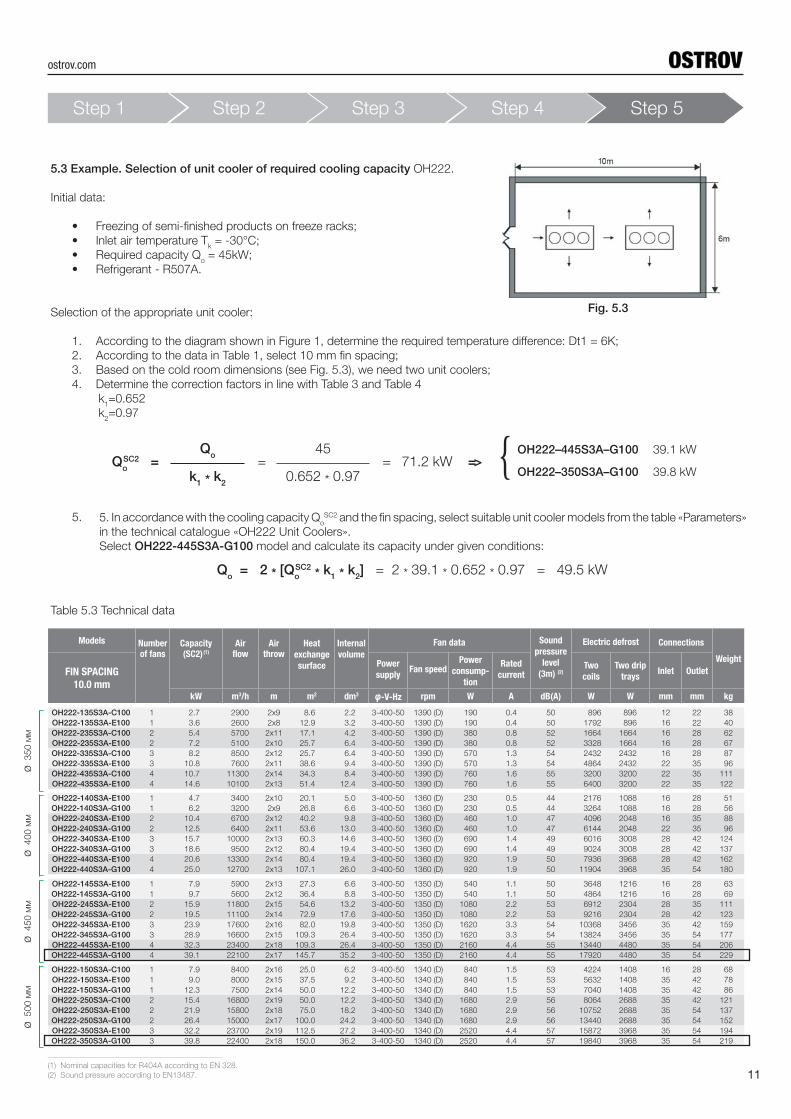
5.3 Example. Selection of unit cooler of required cooling capacity OH222.
Initial data:
• Freezing of semi-fi nished products on freeze racks;
• Inlet air temperature Tk = -30°С;
• Required capacity Qo = 45kW;
• Refrigerant - R507A.
Selection of the appropriate unit cooler:
1. According to the diagram shown in Figure 1, determine the required temperature diff erence: Dt1 = 6К;
2. According to the data in Table 1, select 10 mm fi n spacing;
3. Based on the cold room dimensions (see Fig. 5.3), we need two unit coolers;
4. Determine the correction factors in line with Table 3 and Table 4
k1=0.652
k2=0.97
QoSC2 = = = 71.2 kW =>
Qo
45
0.652 * 0.97k1 * k2
5. In accordance with the cooling capacity QoSC2 and the fi n spacing, select suitable unit cooler models from the table «Parameters»
in the technical catalogue «OH222 Unit Coolers».
Select OH222-445S3A-G100 model and calculate its capacity under given conditions:
OH222–445S3A–G100 39.1 kW
OH222–350S3A–G100 39.8 kW{
Qo = 2 * [Qo
SC2 * k1 * k2
] = 2 * 39.1 * 0.652 * 0.97 = 49.5 kW
Table 5.3 Technical data
5.
Fig. 5.3
Step 1 Step 2 Step 3 Step 4 Step 5
(1) Nominal capacities for R404A according to EN 328.
(2) Sound pressure according to EN13487.
ostrov.com
12
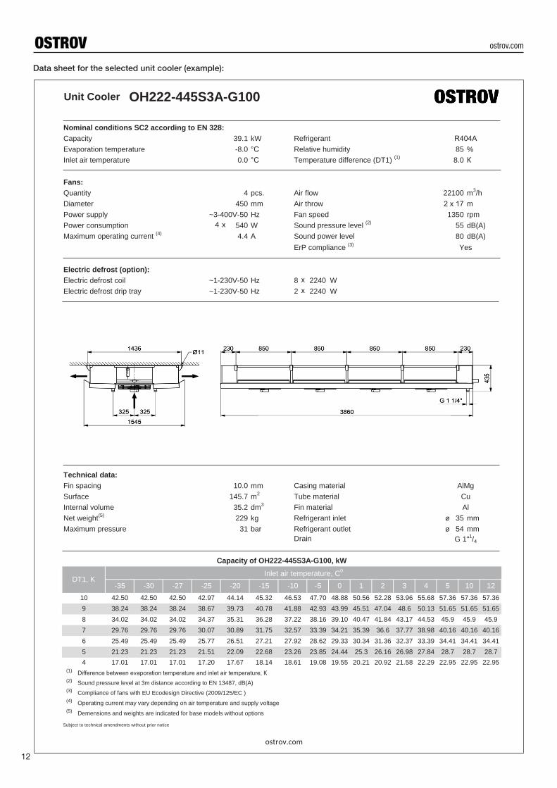
Data sheet for the selected unit cooler (example):
Unit Cooler OH222-445S3A-G100
4 х
хх
øø
Difference between evaporation temperature and inlet air temperature, КSound pressure level at 3m distance according to EN 13487, dB(A)
Compliance of fans with EU Ecodesign Directive (2009/125/EC )
Operating current may vary depending on air temperature and supply voltage
Demensions and weights are indicated for base models without options
Subject to technical amendments without prior notice
(1)
(2)
(3)
(4)
(5)
20.92 21.58 22.29 22.95 22.95 22.9517.67 18.14 18.61 19.08 19.55 20.2126.98 27.84 28.7 28.7 28.7
4 17.01 17.01 17.01 17.2022.68 23.26 23.85 24.44 25.3 26.165 21.23 21.23 21.23 21.51 22.09
31.36 32.37 33.39 34.41 34.41 34.4126.51 27.21 27.92 28.62 29.33 30.3437.77 38.98 40.16 40.16 40.16
6 25.49 25.49 25.49 25.7731.75 32.57 33.39 34.21 35.39 36.67 29.76 29.76 29.76 30.07 30.89
41.84 43.17 44.53 45.9 45.9 45.935.31 36.28 37.22 38.16 39.10 40.4748.6 50.13 51.65 51.65 51.65
8 34.02 34.02 34.02 34.3740.78 41.88 42.93 43.99 45.51 47.049 38.24 38.24 38.24 38.67 39.73
52.28 53.96 55.68 57.36 57.36 57.3644.14 45.32 46.53 47.70 48.88 50.56
3 4 5 10 1210 42.50 42.50 42.50 42.97
-15 -10 -5 0 1 2
Drain G 1"1/4
Capacity of OH222-445S3A-G100, kW
DT1, KInlet air temperature, C0
-35 -30 -27 -25 -20
Maximum pressure 31 bar Refrigerant outlet 54 mmNet weight(5) 229 kg Refrigerant inlet 35 mm
Surface 145.7 m2 Tube material CuInternal volume 35.2 dm3 Fin material Al
Technical data:Fin spacing 10.0 mm Casing material AlMg
Electric defrost drip tray ~1-230V-50 Hz 2 2240 W
ErP compliance (3) Yes
Electric defrost (option):Electric defrost сoil ~1-230V-50 Hz 8 2240 W
Maximum operating current (4) 4.4 А Sound power level 80 dB(A)Power consumption 540 W Sound pressure level (2) 55 dB(A)Power supply ~3-400V-50 Hz Fan speed 1350 rpm
m3/hDiameter 450 mm Air throw 2 х 17 m
Fans:Quantity 4 pcs. Air flow 22100
Inlet air temperature 0.0 °C Temperature difference (DT1) (1) 8.0 КEvaporation temperature -8.0 °C Relative humidity 85 %
Nominal conditions SC2 according to EN 328:Capacity 39.1 kW Refrigerant R404А
ostrov.com
ostrov.com

Data sheetsComplete technical data for each model.
CAD DrawingsGeneral view drawings. PDF & DWG format.
3D Models3D models. DWG format. 1:1 scale.
Wiring diagramsSchemes of electrical connections.
Operating instructionsDetailed instructions for installation and operation.
PackageDimensions and weights of packed products.
P&I DiagramsPiping and instrumentation diagrams.
Price listUp-to-date price list. Prices in euro without VAT.
Welcome to our website
ostrov.com
OSTROV
ostrov.com

European UnionRinghoff erova 115/1, 15521
Prague 5, Czech Republic
tel.: +420 234 252 223
fax: +420 234 252 225
Russia & CIS
6, 2nd Bakuninsky Alleyway, Mytishchi,
Moscow Region, 141011, Russia
tel.: +7 495 582 44 44
fax: +7 495 582 44 45
ostrov.com
Sub
ject
to t
echnic
al a
mend
ments
without
prior
notice