solutions in commercial refrigeration - SANDEN CDU
31
Delivering CO 2 solutions in commercial refrigeration SANDEN CO 2 RETAIL SOLUTIONS CDU-L R06A2B 3 Phases 400V installation guide 1
-
Upload
khangminh22 -
Category
Documents
-
view
3 -
download
0
Transcript of solutions in commercial refrigeration - SANDEN CDU
Delivering CO2 solutions in commercial refrigeration
SANDENCO2 RETAIL SOLUTIONS
CDU-L R06A2B 3 Phases 400V
installation guide
1
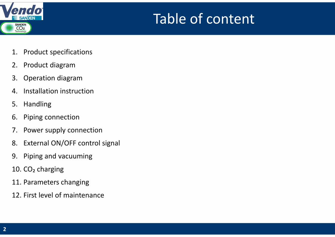
Modifiez le style du titreTable of content
1. Product specifications
2. Product diagram
3. Operation diagram
4. Installation instruction
5. Handling
6. Piping connection
7. Power supply connection
8. External ON/OFF control signal
9. Piping and vacuuming
10. CO₂ charging
11. Parameters changing
12. First level of maintenance
2
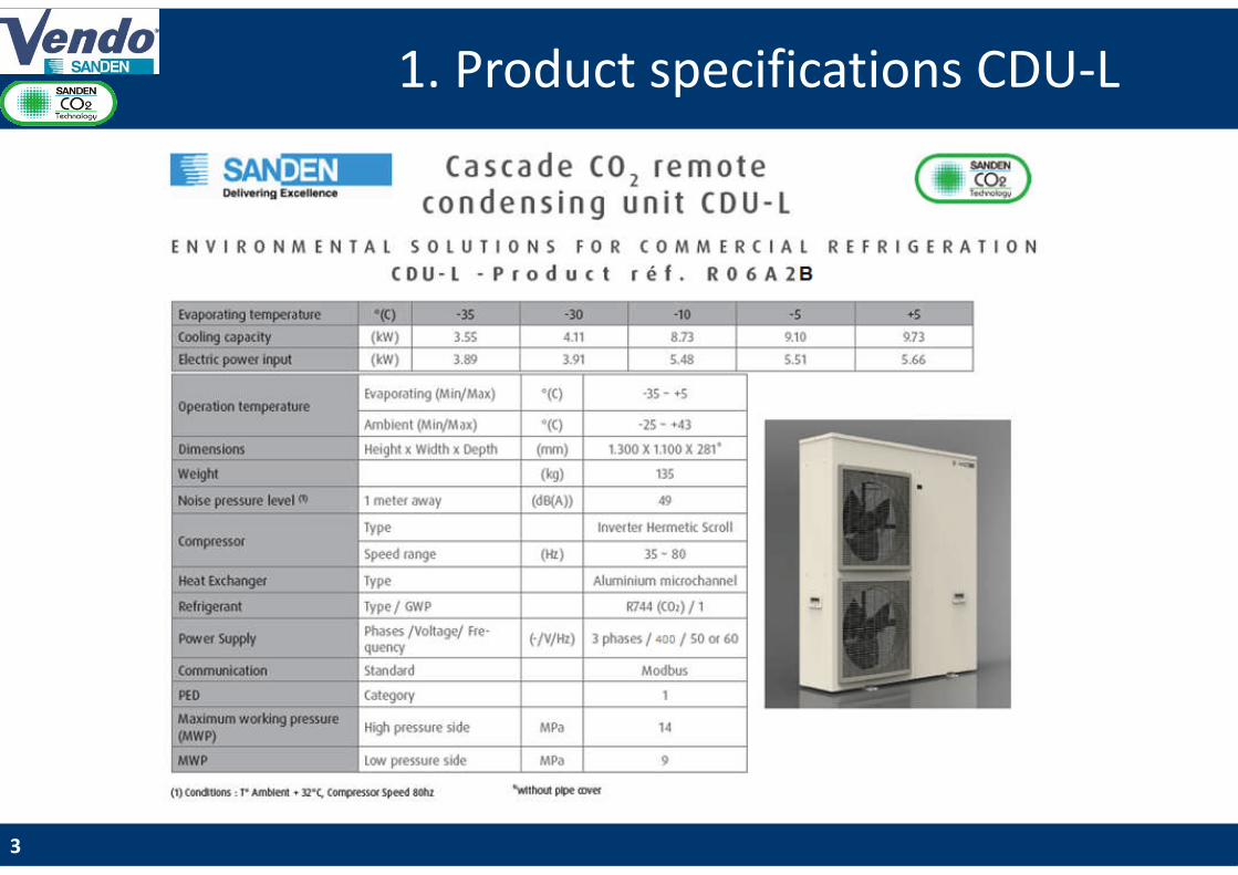
Modifiez le style du titre1. Product specifications CDU-L
3
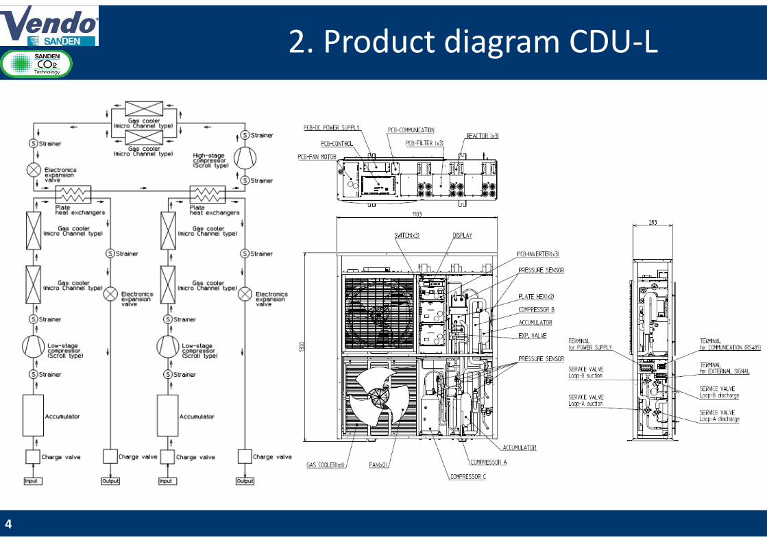
Modifiez le style du titre2. Product diagram CDU-L
4
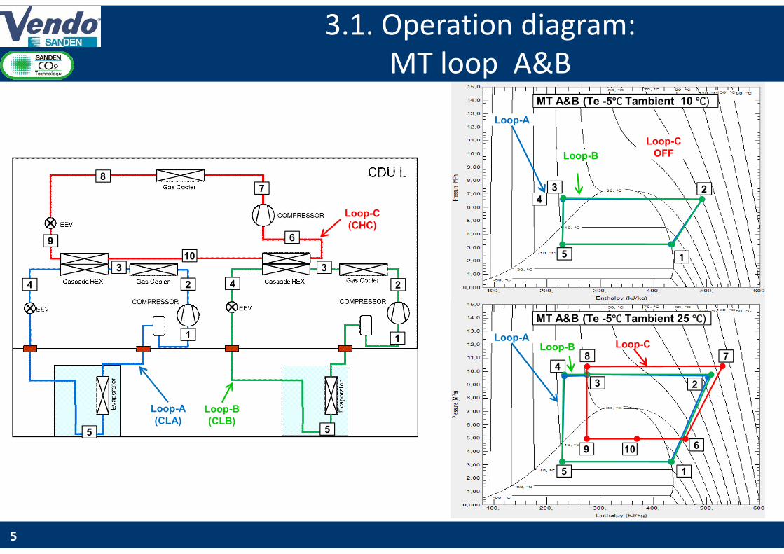
Modifiez le style du titre3.1. Operation diagram:
MT loop A&B
5
1
2
3
4
5
1
2
3
4
5
6
78
9
10 5 1
234
Loop-A
Loop-B
Loop-C OFF
MT A&B (Te -5℃ Tambient 10 ℃)
Loop-A(CLA)
Loop-B(CLB)
Loop-C(CHC)
5 1
23
4
Loop-ALoop-B
MT A&B (Te -5℃ Tambient 25 ℃)
6
78
9 10
Loop-C

Modifiez le style du titre
6
1
2
3
4
5
1
2
3
4
5
6
78
9
10
1
234
5
6
78
9 10
Loop -A Loop -B
Loop -C
LT A&B (Te -30℃ Tambient 25 ℃)
Loop-A(CLA)
Loop-B(CLB)
Loop-C(CHC)
3.2. Operation diagram: LT loop A&B
Modifiez le style du titre
7
1A
2A
3A
4A
5A
1B
2B
3B
4B
5B
6
78
9
10
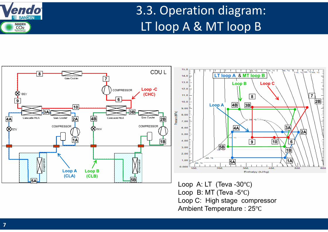
Loop A: LT (Teva -30℃)Loop B: MT (Teva -5℃)Loop C: High stage compressorAmbient Temperature : 25℃
1A
2A3A4A
5A
1B
2B3B4B
5B
6
78
9 10
Loop A
Loop B Loop C
LT loop A & MT loop B
Loop A(CLA)
Loop B(CLB)
Loop -C(CHC)
3.3. Operation diagram: LT loop A & MT loop B
Modifiez le style du titre
8
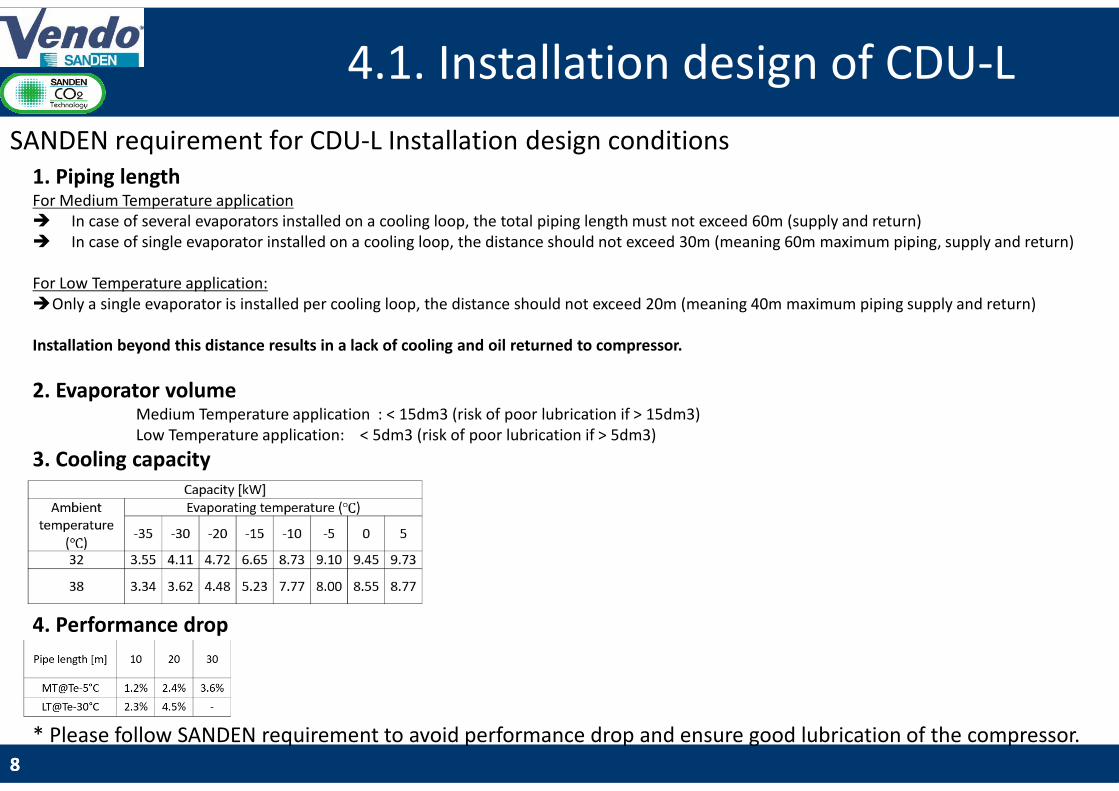
4.1. Installation design of CDU-L
8
1. Piping lengthFor Medium Temperature application In case of several evaporators installed on a cooling loop, the total piping length must not exceed 60m (supply and return) In case of single evaporator installed on a cooling loop, the distance should not exceed 30m (meaning 60m maximum piping, supply and return)
For Low Temperature application:Only a single evaporator is installed per cooling loop, the distance should not exceed 20m (meaning 40m maximum piping supply and return)
Installation beyond this distance results in a lack of cooling and oil returned to compressor.
2. Evaporator volume Medium Temperature application : < 15dm3 (risk of poor lubrication if > 15dm3)Low Temperature application: < 5dm3 (risk of poor lubrication if > 5dm3)
3. Cooling capacity
4. Performance drop
* Please follow SANDEN requirement to avoid performance drop and ensure good lubrication of the compressor.
SANDEN requirement for CDU-L Installation design conditions
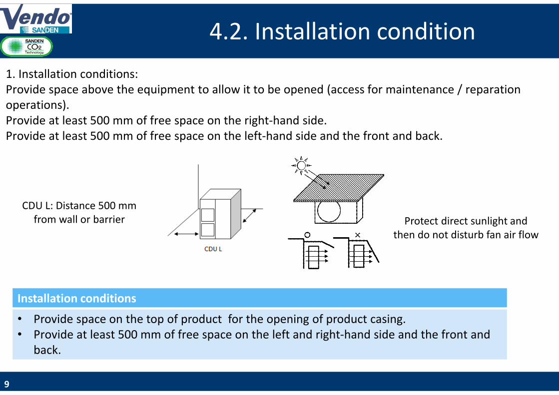
Modifiez le style du titre4.2. Installation condition
CDU L: Distance 500 mm from wall or barrier
Installation conditions
• Provide space on the top of product for the opening of product casing.• Provide at least 500 mm of free space on the left and right-hand side and the front and
back.
9
1. Installation conditions:Provide space above the equipment to allow it to be opened (access for maintenance / reparation operations).Provide at least 500 mm of free space on the right-hand side.Provide at least 500 mm of free space on the left-hand side and the front and back.
Protect direct sunlight and then do not disturb fan air flow
Modifiez le style du titre4.3. Installation condition
10
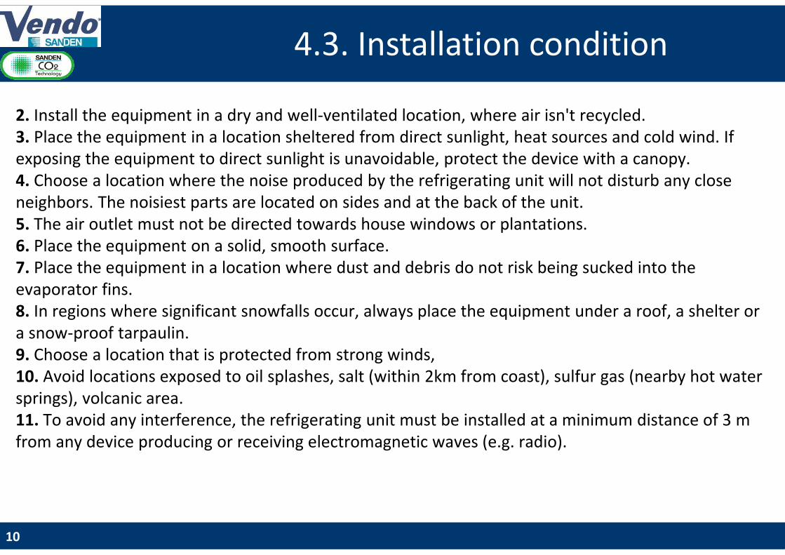
2. Install the equipment in a dry and well-ventilated location, where air isn't recycled.3. Place the equipment in a location sheltered from direct sunlight, heat sources and cold wind. If exposing the equipment to direct sunlight is unavoidable, protect the device with a canopy.4. Choose a location where the noise produced by the refrigerating unit will not disturb any close neighbors. The noisiest parts are located on sides and at the back of the unit.5. The air outlet must not be directed towards house windows or plantations. 6. Place the equipment on a solid, smooth surface.7. Place the equipment in a location where dust and debris do not risk being sucked into the evaporator fins.8. In regions where significant snowfalls occur, always place the equipment under a roof, a shelter or a snow-proof tarpaulin.9. Choose a location that is protected from strong winds, 10. Avoid locations exposed to oil splashes, salt (within 2km from coast), sulfur gas (nearby hot water springs), volcanic area.11. To avoid any interference, the refrigerating unit must be installed at a minimum distance of 3 m from any device producing or receiving electromagnetic waves (e.g. radio).
Modifiez le style du titre5. Handling
11
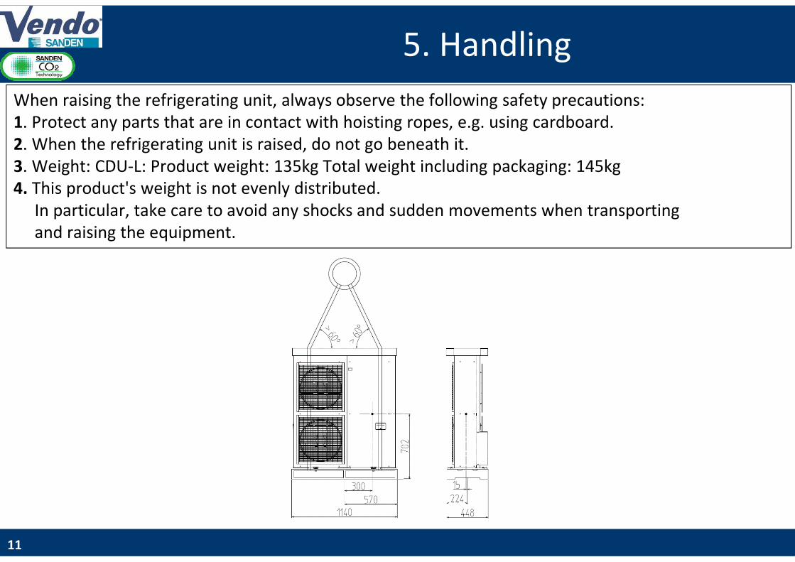
When raising the refrigerating unit, always observe the following safety precautions:1. Protect any parts that are in contact with hoisting ropes, e.g. using cardboard.2. When the refrigerating unit is raised, do not go beneath it.3. Weight: CDU-L: Product weight: 135kg Total weight including packaging: 145kg4. This product's weight is not evenly distributed.
In particular, take care to avoid any shocks and sudden movements when transportingand raising the equipment.

Modifiez le style du titre6.1. Piping connection
12
Pipe slope
1. Pipe working pressure:
2. Pipe insulation mandatory 19mm for MT application 32mm for LT application
2. Avoid CO2 pipes contact with other conducts or pipes.
3. Avoid installation in corrosive environment.
Low-pressure equipment (Evaporator)
Low-pressure equipment
(Evaporator)
Diameter MWP [bar]
Discharge side HP 1/4" à 3/8" >120 bar
Suction side LP 3/8" à 1/2" >90 bar
Modifiez le style du titre6.2. CDU-L connected to single evaporator
13
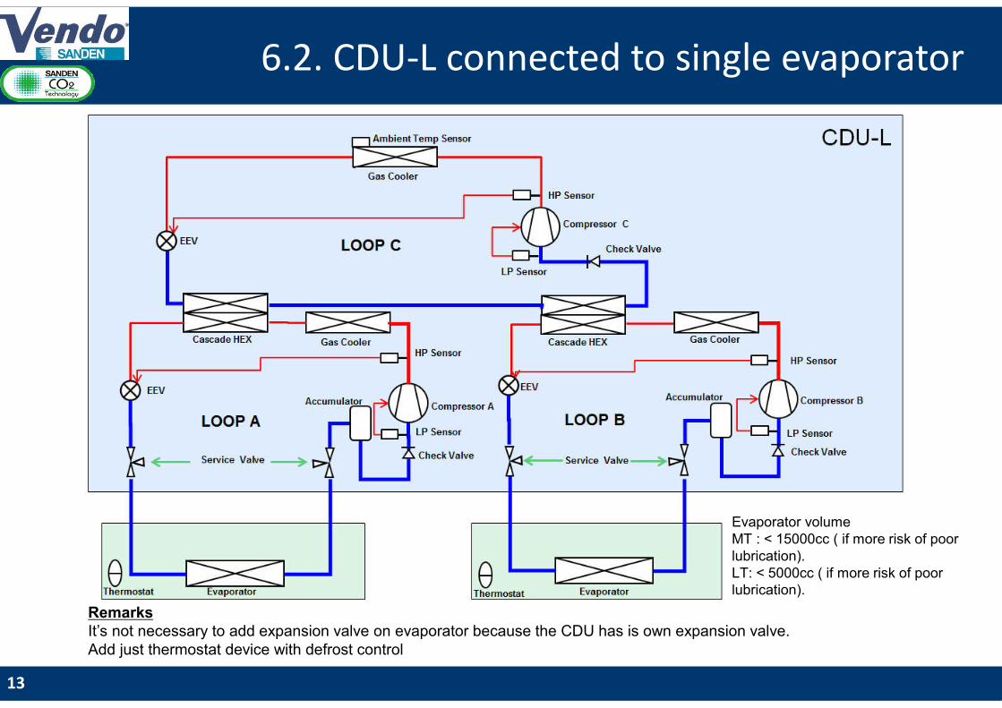
RemarksIt’s not necessary to add expansion valve on evaporator because the CDU has is own expansion valve. Add just thermostat device with defrost control
Evaporator volume MT : < 15000cc ( if more risk of poor lubrication).LT: < 5000cc ( if more risk of poor lubrication).

Modifiez le style du titre
14
6.3. CDU-L connected to several evaporators
14
Remarks:Expansion valve for each evaporator. One Pressure sensor by loop. Evaporator volume:
MT : < 15000cc ( if more risk of poor lubrication).LT: < 5000cc ( if more risk of poor lubrication).
Modifiez le style du titre7. CDU-L power supply connection
15
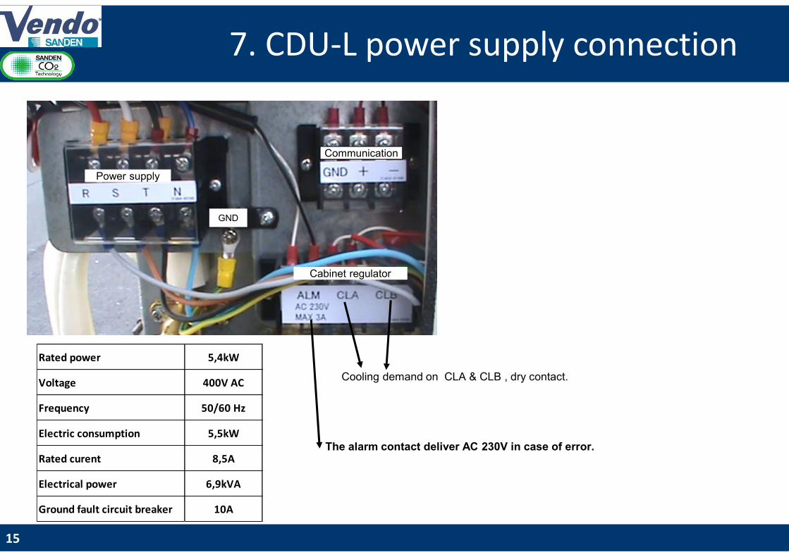
Rated power 5,4kW
Voltage 400V AC
Frequency 50/60 Hz
Electric consumption 5,5kW
Rated curent 8,5A
Electrical power 6,9kVA
Ground fault circuit breaker 10A
Power supply
Communication
Cabinet regulator
GND
Cooling demand on CLA & CLB , dry contact.
The alarm contact deliver AC 230V in case of error.

Modifiez le style du titre8.1. External ON/OFF control signal
16
System control logic1. The cooling demand is managed by dry contact sent to the CDU (terminals CLA/CLB) see page 152. The speed of compressor controls the LP to reach the set point tuned by the installer (A02/B02) see page 253. The low pressure is function of the evaporating temperature required for the showcase. (Tev = Tair_sc – T). 4. Electronic Expansion Valve (EEV) of the CDU controls the HP to reach the HP target.
This HP optimal target is calculated in accordance with ambient outside temperature and the LP set point.5. Showcase EEV controls the superheat at the evaporator side
Defrost control logic1. CDU compressors and fans should stop before the evaporator defrost. 2. Dry contact signal is sent to the CDU when defrost is requested Defrost (terminal CLA/CLB) see page 15.3. Compressors will stop gradually depending current speed.4. For installation with several evaporators, one EEV evaporators side must stay opened to avoid High Pressure
failure during stopping session. See wiring example page 18

Modifiez le style du titre8.2. Electrical connection
(Thermostat & 1 evaporator)
P
N
Supply thermostat
Contact Fan
Contact Defrost
FAN Resistance
CDU-L
CLA / CLB
Dry Contact
17
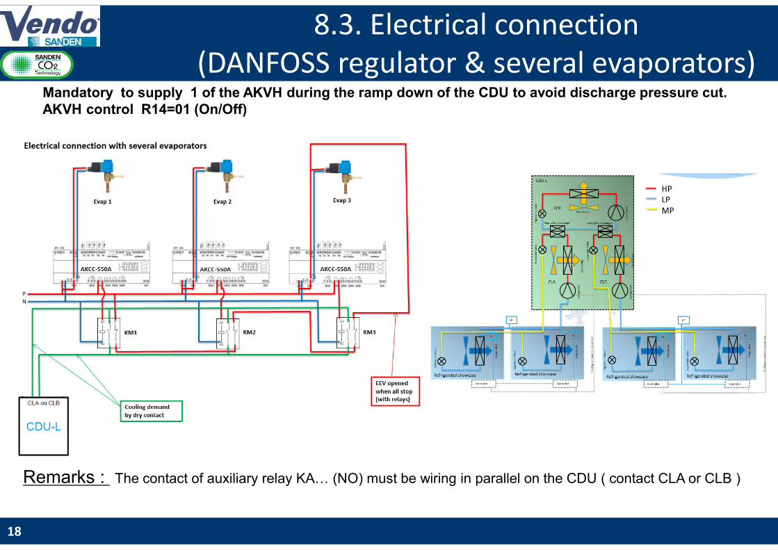
Modifiez le style du titre8.3. Electrical connection
(DANFOSS regulator & several evaporators)Mandatory to supply 1 of the AKVH during the ramp down of the CDU to avoid discharge pressure cut. AKVH control R14=01 (On/Off)
Remarks : The contact of auxiliary relay KA… (NO) must be wiring in parallel on the CDU ( contact CLA or CLB )
18

Modifiez le style du titre9.1. Piping and vacuuming process
19
1. Brazing connection pipe1-1. Check that cabinet EEV is completely opened.1-2. Before brazing, insert 2bar nitrogen gas flow into pipe for preventing deposition
of any oxide film on the inner surface of the piping, and also avoid heating up service valve by wet towel cover etc.
1-3. During brazing, be careful for burning insulation & any CDU components.
2. Leakage test2-1. Power supply on CDU & wait 20 sec for initializing system.2-2. Charge Nitrogen gas in 80bar or 55bar if using 60bar relief valve.2-3. Check brazed part using leakage detector or leakage test liquid. (formability)
3. Vacuuming3-1. Set R744(CO₂) manifold, vacuuming pump, CO₂ vessel, and CDU service port.3-2. Connect CO₂ charge tube, vacuuming tube, and each equipment.3-3. Check connector and each tube are closed tightly.3-3. Loose service valve rod in middle position (3 way opening) before vacuuming.3-4. Vacuuming for 2-3 hours inside pressure keeping -1bar(vacuuming status)
4. Setting parameter value4-1. Change each loop parameter set depending on target evaporating temperature
during vacuuming process. (suction pressure default value 3,0MPa)
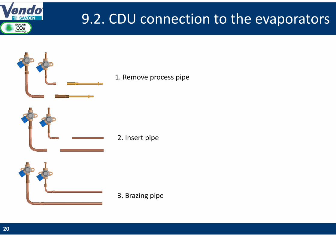
Modifiez le style du titre9.2. CDU connection to the evaporators
1. Remove process pipe
2. Insert pipe
3. Brazing pipe
20

Modifiez le style du titre9.3. Service valves connection and
handling 1.Untightened the protection caps
3.Untightened the compression packing
4.Service valve handling
2.Connect the CDU to the manifoldOutlet Male G 3/8’’
Example of connexionInlet G 3/8’’ femaleOutlet ¼’’ SAE
21
Modifiez le style du titre10.1. CO2 charging process
22
Charging CO2 procedure1. Check CO2 amount for each evaporator and piping volume from graph. (see page 23)2. Set CO2 vessel on the weight scale, purge air inside charge tube, and 0 setting scale before charging.3. Vacuum breakage (gas state)4. Charge CO2 without compressor running (liquid state) (charging from suction side service valve).5. Compressor start running(push operation SW) if CO2 charging stop before reaching target weight.6. Close service valve after CO2 weight reaching target amount.7. Keep & check cooling operation until evaporator air or cabinet temperature is reached at target temperature.8. Check low pressure until reaching target & operation conditions(both of CO2 & air side) are stable.9. Compare actual high pressure & discharge pressure from the target table. (see page 24) 10. Charge more 50g CO2 if high pressure is lower or discharge temperature is higher than table value. 11. Repeat the operation if necessary.
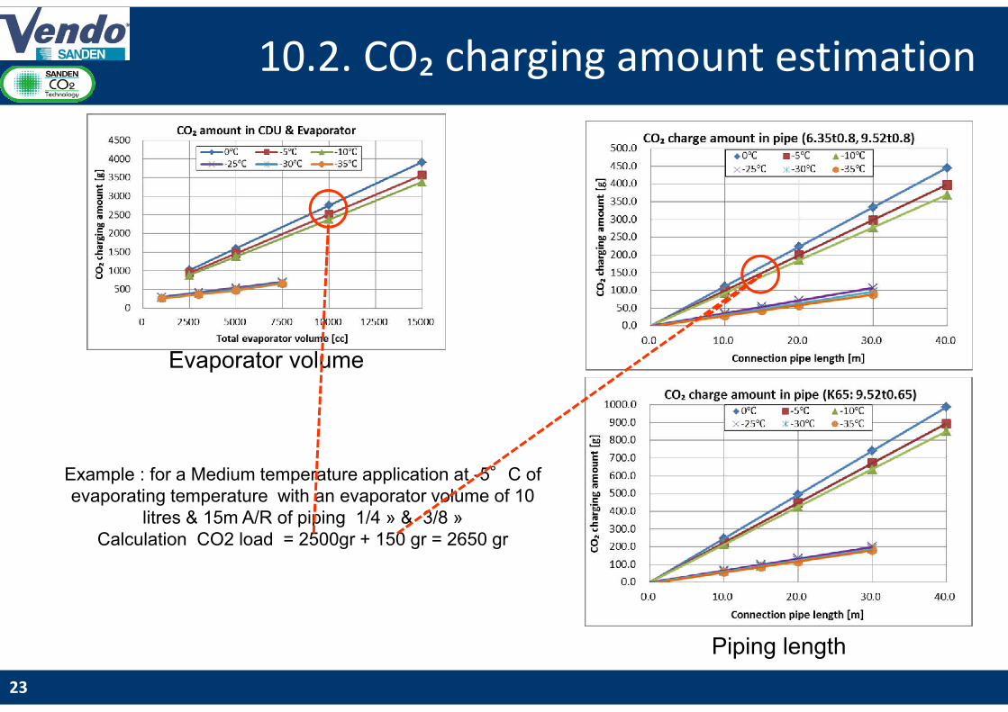
Modifiez le style du titre10.2. CO₂ charging amount estimation
23
Evaporator volume
Piping length
Example : for a Medium temperature application at -5°C of evaporating temperature with an evaporator volume of 10
litres & 15m A/R of piping 1/4 » & 3/8 »Calculation CO2 load = 2500gr + 150 gr = 2650 gr
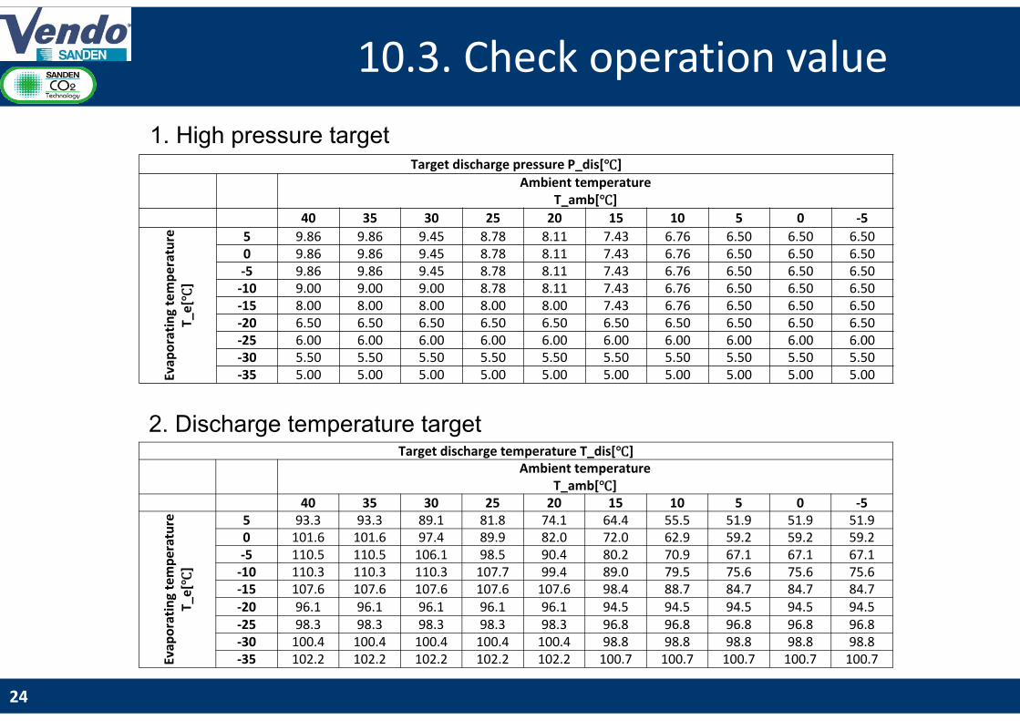
Modifiez le style du titre10.3. Check operation value
24
Target discharge pressure P_dis[℃]
Ambient temperature T_amb[℃]
40 35 30 25 20 15 10 5 0 -5
Evap
ora
tin
g te
mp
era
ture
T_
e[ ℃
]
5 9.86 9.86 9.45 8.78 8.11 7.43 6.76 6.50 6.50 6.50 0 9.86 9.86 9.45 8.78 8.11 7.43 6.76 6.50 6.50 6.50 -5 9.86 9.86 9.45 8.78 8.11 7.43 6.76 6.50 6.50 6.50
-10 9.00 9.00 9.00 8.78 8.11 7.43 6.76 6.50 6.50 6.50 -15 8.00 8.00 8.00 8.00 8.00 7.43 6.76 6.50 6.50 6.50 -20 6.50 6.50 6.50 6.50 6.50 6.50 6.50 6.50 6.50 6.50 -25 6.00 6.00 6.00 6.00 6.00 6.00 6.00 6.00 6.00 6.00 -30 5.50 5.50 5.50 5.50 5.50 5.50 5.50 5.50 5.50 5.50 -35 5.00 5.00 5.00 5.00 5.00 5.00 5.00 5.00 5.00 5.00
Target discharge temperature T_dis[℃]Ambient temperature
T_amb[℃]40 35 30 25 20 15 10 5 0 -5
Evap
ora
tin
g te
mp
era
ture
T_
e[ ℃
]
5 93.3 93.3 89.1 81.8 74.1 64.4 55.5 51.9 51.9 51.9 0 101.6 101.6 97.4 89.9 82.0 72.0 62.9 59.2 59.2 59.2 -5 110.5 110.5 106.1 98.5 90.4 80.2 70.9 67.1 67.1 67.1
-10 110.3 110.3 110.3 107.7 99.4 89.0 79.5 75.6 75.6 75.6 -15 107.6 107.6 107.6 107.6 107.6 98.4 88.7 84.7 84.7 84.7 -20 96.1 96.1 96.1 96.1 96.1 94.5 94.5 94.5 94.5 94.5 -25 98.3 98.3 98.3 98.3 98.3 96.8 96.8 96.8 96.8 96.8 -30 100.4 100.4 100.4 100.4 100.4 98.8 98.8 98.8 98.8 98.8 -35 102.2 102.2 102.2 102.2 102.2 100.7 100.7 100.7 100.7 100.7
1. High pressure target
2. Discharge temperature target
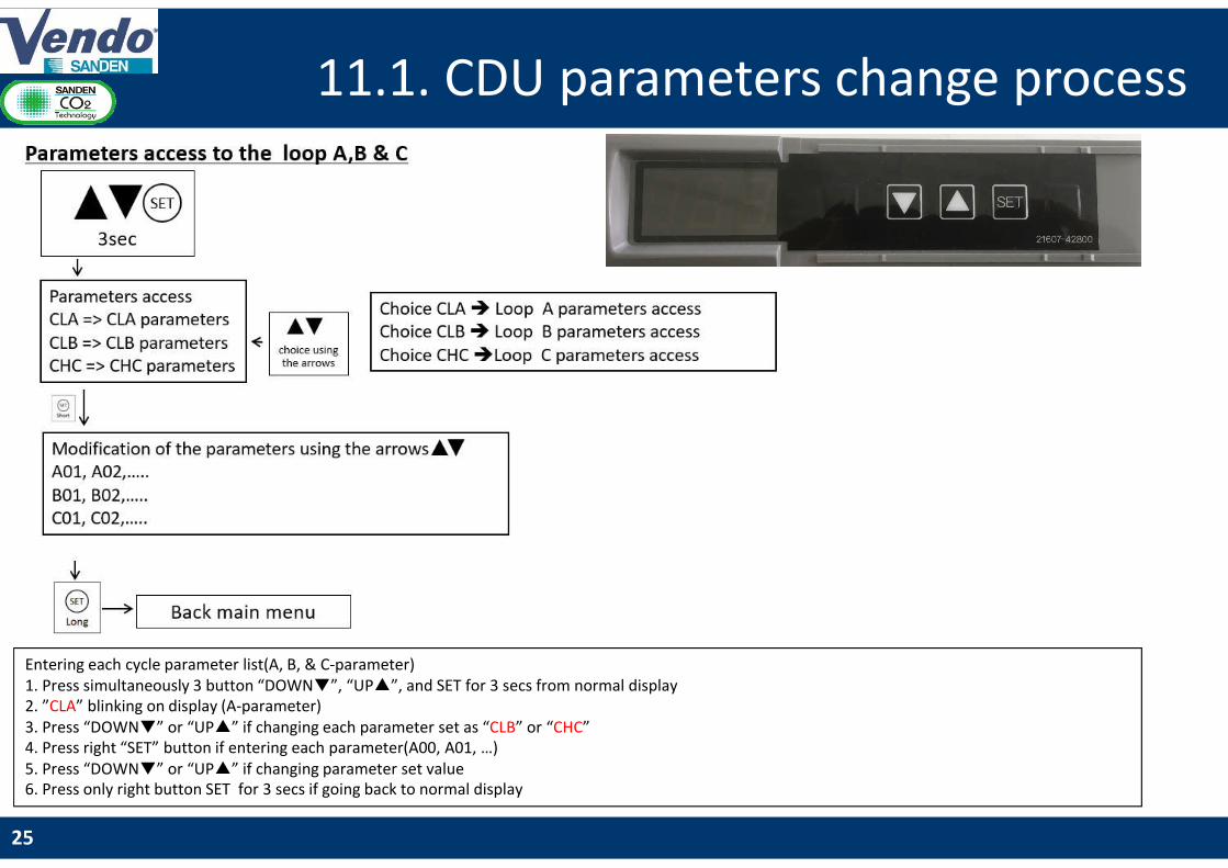
Modifiez le style du titre11.1. CDU parameters change process
25
Entering each cycle parameter list(A, B, & C-parameter)1. Press simultaneously 3 button “DOWN▼”, “UP▲”, and SET for 3 secs from normal display2. ”CLA” blinking on display (A-parameter)3. Press “DOWN▼” or “UP▲” if changing each parameter set as “CLB” or “CHC”4. Press right “SET” button if entering each parameter(A00, A01, …)5. Press “DOWN▼” or “UP▲” if changing parameter set value6. Press only right button SET for 3 secs if going back to normal display
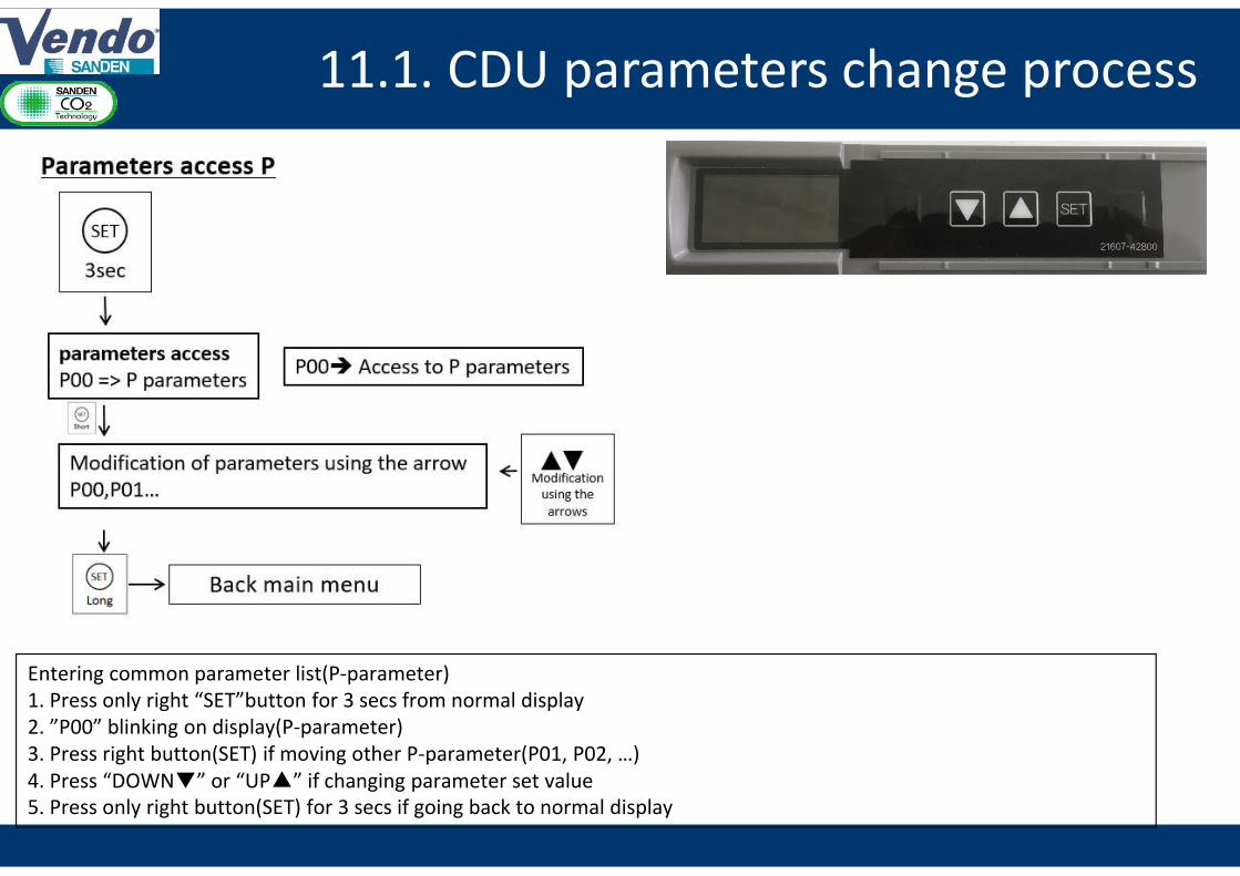
Modifiez le style du titre11.1. CDU parameters change process
Entering common parameter list(P-parameter)1. Press only right “SET”button for 3 secs from normal display2. ”P00” blinking on display(P-parameter)3. Press right button(SET) if moving other P-parameter(P01, P02, …)4. Press “DOWN▼” or “UP▲” if changing parameter set value5. Press only right button(SET) for 3 secs if going back to normal display
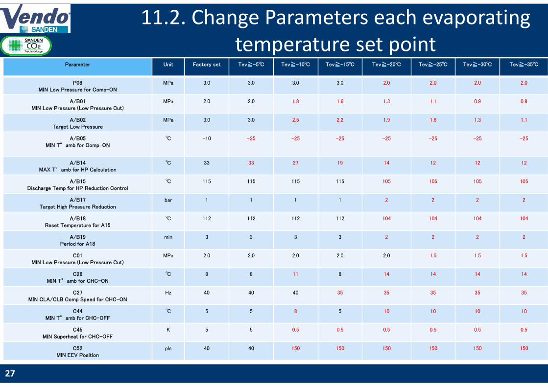
Modifiez le style du titre11.2. Change Parameters each evaporating
temperature set point
27
Parameter Unit Factory set Tev≧-5℃ Tev≧-10℃ Tev≧-15℃ Tev≧-20℃ Tev≧-25℃ Tev≧-30℃ Tev≧-35℃
P08MIN Low Pressure for Comp-ON
MPa 3.0 3.0 3.0 3.0 2.0 2.0 2.0 2.0
A/B01MIN Low Pressure (Low Pressure Cut)
MPa 2.0 2.0 1.8 1.6 1.3 1.1 0.9 0.9
A/B02Target Low Pressure
MPa 3.0 3.0 2.5 2.2 1.9 1.6 1.3 1.1
A/B05MIN T°amb for Comp-ON
℃ -10 -25 -25 -25 -25 -25 -25 -25
A/B14MAX T°amb for HP Calculation
℃ 33 33 27 19 14 12 12 12
A/B15Discharge Temp for HP Reduction Control
℃ 115 115 115 115 105 105 105 105
A/B17Target High Pressure Reduction
bar 1 1 1 1 2 2 2 2
A/B18Reset Temperature for A15
℃ 112 112 112 112 104 104 104 104
A/B19Period for A18
min 3 3 3 3 2 2 2 2
C01MIN Low Pressure (Low Pressure Cut)
MPa 2.0 2.0 2.0 2.0 2.0 1.5 1.5 1.5
C26MIN T°amb for CHC-ON
℃ 8 8 11 8 14 14 14 14
C27MIN CLA/CLB Comp Speed for CHC-ON
Hz 40 40 40 35 35 35 35 35
C44MIN T°amb for CHC-OFF
℃ 5 5 8 5 10 10 10 10
C45MIN Superheat for CHC-OFF
K 5 5 0.5 0.5 0.5 0.5 0.5 0.5
C52MIN EEV Position
pls 40 40 150 150 150 150 150 150
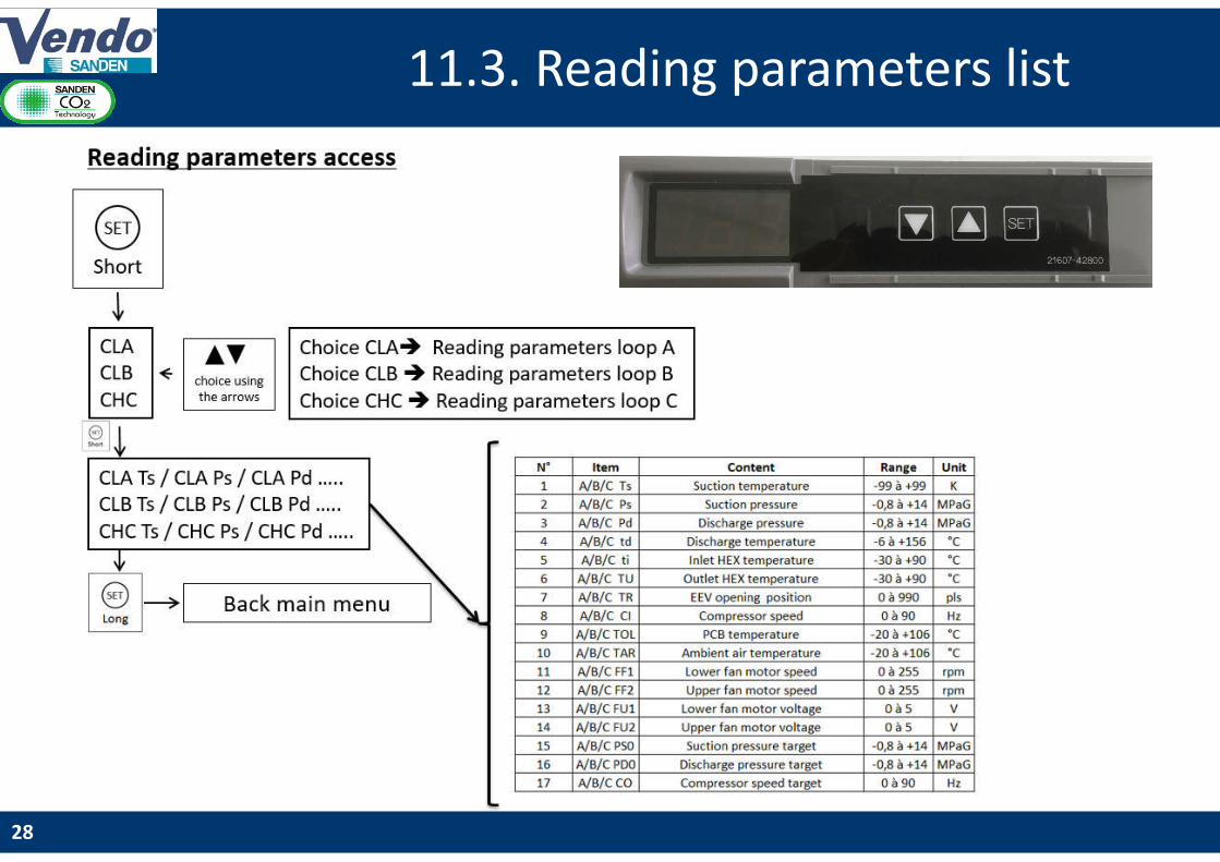
Modifiez le style du titre11.3. Reading parameters list
28

Modifiez le style du titre
P-h diagram of R744 (CO2)
11.3 Propriétés thermodynamiques du CO2
Relation entre Pression et Température d’évaporation
Densité Densité Enthalpie Enthalpie Entropie Entropie
Point Temperature Pression relative Pression absolue Liquide Vapeur Liquide Vapeur Liquide Vapeur
(C) (MpaG) (MPa) (kg/m^3) (kg/m^3) (kJ/kg) (kJ/kg) (kJ/kg-K) (kJ/kg-K
1 -35 1,1 1,2024 1096,4 31,216 123,05 436,23 0,70794 2,023
2 -34 1,1 1,2452 1092,4 32,326 125,1 436,37 0,71634 2,018
3 -33 1,2 1,2891 1088,3 33,469 127,15 436,51 0,72474 2,0129
4 -32 1,2 1,3342 1084,1 34,644 129,2 436,62 0,73311 2,0079
5 -31 1,3 1,3804 1079,9 35,854 131,27 436,73 0,74148 2,0029
6 -30 1,3 1,4278 1075,7 37,098 133,34 436,82 0,74982 1,998
7 -29 1,4 1,4763 1071,5 38,378 135,41 436,9 0,75816 1,993
8 -28 1,4 1,5261 1067,2 39,696 137,5 436,96 0,76649 1,988
9 -27 1,5 1,577 1062,9 41,051 139,59 437,01 0,77481 1,9831
10 -26 1,5 1,6293 1058,6 42,445 141,69 437,04 0,78311 1,9781
11 -25 1,6 1,6827 1054,2 43,88 143,79 437,06 0,79141 1,9732
12 -24 1,6 1,7375 1049,8 45,356 145,91 437,06 0,79971 1,9683
13 -23 1,7 1,7935 1045,3 46,875 148,03 437,04 0,80799 1,9633
14 -22 1,8 1,8509 1040,8 48,437 150,16 437,01 0,81627 1,9584
15 -21 1,8 1,9096 1036,3 50,045 152,3 436,96 0,82455 1,9535
16 -20 1,9 1,9696 1031,7 51,7 154,45 436,89 0,83283 1,9485
17 -19 1,9 2,031 1027 53,402 156,61 436,81 0,8411 1,9436
18 -18 2,0 2,0938 1022,3 55,155 158,77 436,7 0,84937 1,9386
19 -17 2,1 2,1581 1017,6 56,959 160,95 436,58 0,85765 1,9337
20 -16 2,1 2,2237 1012,8 58,816 163,14 436,44 0,86593 1,9287
21 -15 2,2 2,2908 1008 60,728 165,34 436,27 0,87421 1,9237
22 -14 2,3 2,3593 1003,1 62,697 167,55 436,09 0,88249 1,9187
23 -13 2,3 2,4294 998,14 64,725 169,78 435,89 0,89078 1,9137
24 -12 2,4 2,501 993,13 66,814 172,01 435,66 0,89908 1,9086
25 -11 2,5 2,574 988,06 68,967 174,26 435,41 0,90739 1,9036
26 -10 2,5 2,6487 982,93 71,185 176,52 435,14 0,91571 1,8985
27 -9 2,6 2,7249 977,73 73,471 178,8 434,84 0,92405 1,8934
28 -8 2,7 2,8027 972,46 75,829 181,09 434,51 0,9324 1,8882
29 -7 2,8 2,8821 967,12 78,261 183,39 434,17 0,94076 1,883
30 -6 2,9 2,9632 961,7 80,77 185,71 433,79 0,94915 1,8778
31 -5 2,9 3,0459 956,21 83,359 188,05 433,38 0,95756 1,8725
32 -4 3,0 3,1303 950,63 86,032 190,4 432,95 0,96599 1,8672
33 -3 3,1 3,2164 944,97 88,794 192,77 432,48 0,97444 1,8618
34 -2 3,2 3,3042 939,22 91,647 195,16 431,99 0,98293 1,8563
35 -1 3,3 3,3938 933,38 94,596 197,57 431,46 0,99145 1,8509
36 0 3,4 3,4851 927,43 97,647 200 430,89 1 1,8453
37 1 3,5 3,5783 921,38 100,8 202,45 430,29 1,0086 1,8397
38 2 3,6 3,6733 915,23 104,07 204,93 429,65 1,0172 1,834
39 3 3,7 3,7701 908,95 107,46 207,43 428,97 1,0259 1,8282
40 4 3,8 3,8688 902,56 110,98 209,95 428,25 1,0346 1,8223
41 5 3,9 3,9695 896,03 114,62 212,5 427,48 1,0434 1,8163
42 6 4,0 4,072 889,36 118,41 215,08 426,67 1,0523 1,8102
43 7 4,1 4,1765 882,55 122,34 217,69 425,81 1,0612 1,8041
44 8 4,2 4,2831 875,58 126,44 220,34 424,89 1,0702 1,7977
45 9 4,3 4,3916 868,44 130,71 223,01 423,92 1,0792 1,7913
46 10 4,4 4,5022 861,12 135,16 225,73 422,88 1,0884 1,7847
29
11.4. CO2 properties Pressure as function of evaporating temperature
Modifiez le style du titre12. First level of maintenance
30
1. Regular inspections2. In case of dirt inside the CDU, clean the outdoor heat exchangers with
soft brush or vacuum cleaner.3. Water can be used in case of clogged heat exchanger. (Noted: CDU
operation should be stopped when using water cleaning for heat exchanger)
Error list and diagnostic : check product guide
Delivering CO2 solutions in commercial refrigeration
THANK YOU!
31