USER'S MANUAL - HRP - refrigeration & air conditioning
22
USER’S MANUAL PACKAGED AIR CONDITIONER PSB012A001 This air-conditioner complies with following directive. Machinery 2006/42/EC Low Voltage 2014/35/EU EMC 2014/30/EU Pressure Equipment 2014/68/EU RoHS 2011/65/EU Ecodesign 2009/125/EC CE marking is applicable to the area of 50 Hz power supply. Ce climatiseur est conforme aux directives suivantes. Machines 2006/42/CE Basse tension 2014/35/UE CEM 2014/30/UE Équipements sous pression 2014/68/UE RoHS 2011/65/UE Écoconception 2009/125/CE La marque CE s’applique aux régions alimentées en courant de 50 Hz. Diese Klimaanlage erfüllt die folgende Richtlinie. Maschinen 2006/42/EC Niederspannung 2014/35/EU EMV 2014/30/EU Druckgeräte 2014/68/EU RoHS 2011/65/EU Ökodesign 2009/125/EC Die CE-Marke gilt für Bereiche mit einer Netzstromversorgung von 50 Hz. Questo condizionatore d’aria è conforme alla seguente direttiva. Macchinario 2006/42/CE Bassa tensione 2014/35/UE EMC 2014/30/UE Apparecchiature a pressione 2014/68/UE RoHS 2011/65/UE Ecodesign 2009/125/CE Il marchio CE è applicabile alla fascia di alimentazione 50 Hz. Deze airconditioner voldoet aan de volgende richtlijn. Machine 2006/42/EC Laagspanning 2014/35/EU EMC 2014/30/EU Drukapparatuur 2014/68/EU RoHS 2011/65/EU Ecodesign 2009/125/EC CE-markering is van toepassing op het gebied met een net- stroom van 50 Hz. Este aire acondicionado cumple con la siguiente directiva. Máquinas 2006/42/CE Baja tensión 2014/35/UE EMC 2014/30/UE Equipos a presión 2014/68/UE RoHS 2011/65/UE Ecodiseño 2009/125/CE La indicación CE sólo corresponde al área de suministro eléctrico de 50 Hz. Este ar condicionado está em conformidade com as seguintes directivas. Máquinas 2006/42/CE Baixa tensão 2014/35/UE EMC 2014/30/UE Equipamentos sob pressão 2014/68/UE RoHS 2011/65/UE Concessão ecológica 2009/125/CE A marca CE aplica-se à zona de fornecimento de energia a 50 Hz. Το συγκεκριμένο κλιματιστικό συμμορφώνεται προς καθεμιά από τις οδηγίες που ακολουθούν. 2006/42/ΕΚ περί μηχανημάτων 2014/35/ΕΕ περί χαμηλής τάσης 2014/30/ΕΕ περί ηλεκτρομαγνητικής συμβατότητας (EMC) 2014/68/ΕΕ περί εξοπλισμού υπό πίεση 2011/65/ΕΕ RoHS 2009/125/ΕΚ περί οικολογικού σχεδιασμού Tο σήμα CE ισχύει μόνον σε περιοχές όπου η τροφοδοσία είναι 50 Hz. FD series Inverter Packaged Air-conditioners Ceiling cassette -4 way- (FDT) Ceiling cassette -4 way Compact- (FDTC) Duct connected -High static pressure- (FDU) Duct connected -Middle static pressure- (FDUM) Ceiling suspended (FDE) KX KXR VRF inverter multi-system Air-conditioners Ceiling cassette -4 way- (FDT) Ceiling cassette -4 way Compact- (FDTC) Ceiling cassette -2 way- (FDTW) Ceiling cassette -1 way Compact- (FDTQ) Ceiling cassette -1 way- (FDTS) Duct connected -High static pressure- (FDU) Duct connected -Middle static pressure- (FDUM) Ceiling suspended (FDE) Wall mounted (FDK) Floor standing -2 way- (FDFW) Duct connected -Low static pressure- (FDUT) Duct connected -Compact&Flexible- (FDUH) Duct connected -High static pressure outdoor air processing unit (FDU -F) USER’S MANUAL ENGLISH MANUEL DE L’UTILISATEUR ANWENDERHANDBUCH DEUTSCH ISTRUZIONI PER L’USO ITALIANO MANUAL DEL PROPIETARIO ESPAÑOL GEBRUIKERSHANDLEIDING NEDERLANDS ОΔНГІЕΣ ХРНΣНΣ MANUAL DO UTILIZADOR PORTUGUÊS ЕΛΛΗNIKA РУССКИЙ FRANÇAIS РУКОВОДСТВО ПО ЭКСПЛУАТАЦИИ U KULLANIM KILAVUZU TÜRKÇE Please refer to the manual provided with WIRED REMOTE CONTROL (RC-EX series) and WIRELESS REMOTE CONTROL (RCN-E2, EK2 series) Veuillez vous référer au manuel fourni avec la TÉLÉCOMMANDE FILAIRE (série RC-EX) et la TÉLÉCOMMANDE SANS-FIL (série RCN-E2, EK2) Siehe bitte die mit KABEL-FERNBEDIENUNG (RC-EX-Serie) und DRAHTLOSE FERNBEDIENUNG (RCN-E2-, EK2-Serie) mitgelieferte Bedienungsanleitung Consultare il manuale in dotazione con TELECOMANDO CABLATO (serie RC-EX) e TELECOMANDO SENZA FILI (serie RCN-E2, EK2) Consulte el manual suministrado con el MANDO A DISTANCIA ALÁMBRICO (serie RC-EX) y el MANDO A DISTANCIA INALÁMBRICO (serie RCN-E2, EK2) Raadpleeg de handleiding die is meegeleverd met de BEDRADE AFSTANDSBEDIENING (RC-EX-reeks) en DRAADLOZE AFSTANDSBEDIENING (RCN-E2-, EK2-reeks) Consulte o manual fornecido com o CONTROLO REMOTO COM FIOS (série RC-EX) e o CONTROLO REMOTO SEM FIOS (série RCN-E2, EK2) Σας παρακαλούμε να ανατρέξετε στο εγχειρίδιο που παρέχεται μαζί με το ΕΝΣΥΡΜΑΤΟ ΤΗΛΕΧΕΙΡΙΣΤΗΡΙΟ (σειρά RC-EX) και το ΑΣΥΡΜΑΤΟ ΤΗΛΕΧΕΙΡΙΣΤΗΡΙΟ (σειρές RCN-E2, EK2) ɉɨɠɚɥɭɣɫɬɚ ɨɛɪɚɬɢɬɟɫɶ ɤ ɪɭɤɨɜɨɞɫɬɜɭ ɤɨɬɨɪɨɟ ɩɨɫɬɚɜɥɹɟɬɫɹ ɫ ɉɊɈȼɈȾɇɕɆ ɉɍɅɖɌɈɆ ȾɂɋɌȺɇɐɂɈɇɇɈȽɈ ɍɉɊȺȼɅȿɇɂə ɫɟɪɢɹ 5&(; ɢ ȻȿɋɉɊɈȼɈȾɇɕɆ ɉɍɅɖɌɈɆ ȾɂɋɌȺɇɐɂɈɇɇɈȽɈ ɍɉɊȺȼɅȿɇɂə ɫɟɪɢɹ 5&1( (. Lütfen kablolu uzaktan kumandalı olan (RC-EX serisi) ve kablosuz uzaktan kumandalı olan (RCN-E2, EK2 serisi) modelin kılavuzuna bakınız. ORIGINAL INSTRUCTIONS 202009
-
Upload
khangminh22 -
Category
Documents
-
view
0 -
download
0
Transcript of USER'S MANUAL - HRP - refrigeration & air conditioning
USER’S MANUAL
PACKAGED AIR CONDITIONER
PSB012A001
This air-conditioner complies with following directive.Machinery 2006/42/ECLow Voltage 2014/35/EUEMC 2014/30/EUPressure Equipment 2014/68/EURoHS 2011/65/EUEcodesign 2009/125/ECCE marking is applicable to the area of 50 Hz power supply.
Ce climatiseur est conforme aux directives suivantes.Machines 2006/42/CEBasse tension 2014/35/UECEM 2014/30/UEÉquipements sous pression 2014/68/UERoHS 2011/65/UEÉcoconception 2009/125/CELa marque CE s’applique aux régions alimentées en courant de 50 Hz.
Diese Klimaanlage erfüllt die folgende Richtlinie.Maschinen 2006/42/ECNiederspannung 2014/35/EUEMV 2014/30/EUDruckgeräte 2014/68/EURoHS 2011/65/EUÖkodesign 2009/125/ECDie CE-Marke gilt für Bereiche mit einer Netzstromversorgung von 50 Hz.
Questo condizionatore d’aria è conforme alla seguente direttiva.Macchinario 2006/42/CEBassa tensione 2014/35/UEEMC 2014/30/UEApparecchiature a pressione 2014/68/UERoHS 2011/65/UEEcodesign 2009/125/CEIl marchio CE è applicabile alla fascia di alimentazione 50 Hz.
Deze airconditioner voldoet aan de volgende richtlijn.Machine 2006/42/ECLaagspanning 2014/35/EUEMC 2014/30/EUDrukapparatuur 2014/68/EURoHS 2011/65/EUEcodesign 2009/125/ECCE-markering is van toepassing op het gebied met een net-stroom van 50 Hz.
Este aire acondicionado cumple con la siguiente directiva.Máquinas 2006/42/CEBaja tensión 2014/35/UEEMC 2014/30/UEEquipos a presión 2014/68/UERoHS 2011/65/UEEcodiseño 2009/125/CELa indicación CE sólo corresponde al área de suministro eléctrico de 50 Hz.
Este ar condicionado está em conformidade com as seguintes directivas.Máquinas 2006/42/CEBaixa tensão 2014/35/UEEMC 2014/30/UEEquipamentos sob pressão 2014/68/UERoHS 2011/65/UEConcessão ecológica 2009/125/CEA marca CE aplica-se à zona de fornecimento de energia a 50 Hz.
Το συγκεκριμένο κλιματιστικό συμμορφώνεται προς καθεμιά από τις οδηγίες που ακολουθούν.2006/42/ΕΚ περί μηχανημάτων2014/35/ΕΕ περί χαμηλής τάσης2014/30/ΕΕ περί ηλεκτρομαγνητικής συμβατότητας (EMC)2014/68/ΕΕ περί εξοπλισμού υπό πίεση2011/65/ΕΕ RoHS2009/125/ΕΚ περί οικολογικού σχεδιασμούTο σήμα CE ισχύει μόνον σε περιοχές όπου η τροφοδοσία είναι 50 Hz.
FD series Inverter Packaged Air-conditionersCeiling cassette -4 way- (FDT)Ceiling cassette -4 way Compact- (FDTC)Duct connected -High static pressure- (FDU)Duct connected -Middle static pressure- (FDUM)Ceiling suspended (FDE)
KX KXR VRF inverter multi-system Air-conditionersCeiling cassette -4 way- (FDT)Ceiling cassette -4 way Compact- (FDTC)Ceiling cassette -2 way- (FDTW)Ceiling cassette -1 way Compact- (FDTQ)Ceiling cassette -1 way- (FDTS)Duct connected -High static pressure- (FDU)Duct connected -Middle static pressure- (FDUM)Ceiling suspended (FDE)Wall mounted (FDK)Floor standing -2 way- (FDFW)Duct connected -Low static pressure- (FDUT)Duct connected -Compact&Flexible- (FDUH)Duct connected -High static pressure outdoor air processing unit (FDU -F)
USER’S MANUAL ENGLISH
MANUEL DE L’UTILISATEUR
ANWENDERHANDBUCH DEUTSCH
ISTRUZIONI PER L’USO ITALIANO
MANUAL DEL PROPIETARIO ESPAÑOL
GEBRUIKERSHANDLEIDING NEDERLANDS
ОΔНГІЕΣ ХРНΣНΣ
MANUAL DO UTILIZADOR PORTUGUÊS
ЕΛΛΗNIKA
РУССКИЙ
FRANÇAIS
РУКОВОДСТВО ПО ЭКСПЛУАТАЦИИ U
KULLANIM KILAVUZU TÜRKÇE
Please refer to the manual provided with WIRED REMOTE CONTROL (RC-EX series) and WIRELESS REMOTE CONTROL (RCN-E2, EK2 series)Veuillez vous référer au manuel fourni avec la TÉLÉCOMMANDE FILAIRE (série RC-EX) et la TÉLÉCOMMANDE SANS-FIL (série RCN-E2, EK2)
Siehe bitte die mit KABEL-FERNBEDIENUNG (RC-EX-Serie) und DRAHTLOSE FERNBEDIENUNG (RCN-E2-, EK2-Serie) mitgelieferte Bedienungsanleitung
Consultare il manuale in dotazione con TELECOMANDO CABLATO (serie RC-EX) e TELECOMANDO SENZA FILI (serie RCN-E2, EK2)Consulte el manual suministrado con el MANDO A DISTANCIA ALÁMBRICO (serie RC-EX) y el MANDO A DISTANCIA INALÁMBRICO (serie RCN-E2, EK2)
Raadpleeg de handleiding die is meegeleverd met de BEDRADE AFSTANDSBEDIENING (RC-EX-reeks) en DRAADLOZE AFSTANDSBEDIENING (RCN-E2-, EK2-reeks)
Consulte o manual fornecido com o CONTROLO REMOTO COM FIOS (série RC-EX) e o CONTROLO REMOTO SEM FIOS (série RCN-E2, EK2)
Σας παρακαλούμε να ανατρέξετε στο εγχειρίδιο που παρέχεται μαζί με το ΕΝΣΥΡΜΑΤΟ ΤΗΛΕΧΕΙΡΙΣΤΗΡΙΟ (σειρά RC-EX) και το ΑΣΥΡΜΑΤΟ ΤΗΛΕΧΕΙΡΙΣΤΗΡΙΟ (σειρές RCN-E2, EK2)
Lütfen kablolu uzaktan kumandalı olan (RC-EX serisi) ve kablosuz uzaktan kumandalı olan (RCN-E2, EK2 serisi) modelin kılavuzuna bakınız.
ORIGINAL INSTRUCTIONS
202009


1
Thank you very much for your purchase of this packaged air conditioning system produced by Mitsubishi Heavy Industries. Please read through this manual before using the product and use the product appropriately according to the instructions in the manual. After you have read the manual, store it with the warranty certifi cate in a safe place.
This Product contains fl uorinated greenhouse gases.Do not vent R32 into the atmosphere: R32 is a fl uorinated greenhouse gas with a Global Warming Potential (GWP) = 675.Do not vent R410A into the atmosphere: R410A is a fl uorinated greenhouse gas with a Global Warming Potential (GWP) = 2088.Refer to a label on outdoor unit for the weight of fl uorinated greenhouse gas and CO2 equivalent.
The emission sound pressure level from each Indoor and Outdoor unit is under 70 dB(A).
SAFETY PRECAUTIONS
Please read these “SAFETY PRECAUTIONS” before starting to use this product and use the product appropriately according to the instructions. The precautions provided here are classified into “ DANGER” and “ CAUTION”. The “ DANGER” sections describe potentially hazardous situations that may lead to serious outcomes such as death and serious injuries if the product is mishandled. Note, however, that depending on the situation, the items listed in the “ CAUTION” sections do also have the potential of causing serious outcomes. Both warnings and cautions provide you important information related to safety ; please make sure to observe them. The symbols used throughout the main text of this manual have the following meaning.
marks mean danger, alarm, and caution. The specified prohibited item is described in the triangle. The left mark means “Shock hazard alarm”.
marks mean prohibited items. The specified prohibited item is described in the circle or in the vicinage.
marks mean compulsory action or instruction. The specified prohibited item is described in the circle. The left mark means “Earth is needed”.The user’s manual should be read carefully.There is information included in the user’s manual and/or installation manual.A service personnel should be handing this equipment with reference to the installation manual.
After you have read the manual, always store it where other users can refer to at any time. If a new owner takes over the system, make sure to pass this manual.
SAFETY PRECAUTIONS ...................................................................................................................................................1
HOW TO USE
< WIRED REMOTE CONTROL (RC-E series) >
NAMES AND FUNCTIONS OF REMOTE CONTROL BUTTONS ......................................................................................5
HOW TO OPERATE ............................................................................................................................................................5
HOW TO PERFORM THE TIMER OPERATION .................................................................................................................6
THE SELECTION OF TIMER MODE ...............................................................................................................................6
SETTING THE TIME.........................................................................................................................................................6
SLEEP TIMER MODE ......................................................................................................................................................7
OFF TIMER MODE ...........................................................................................................................................................7
ON TIMER MODE ............................................................................................................................................................7
WEEKLY TIMER MODE ...................................................................................................................................................8
TIMER CANCELLATION MODE .....................................................................................................................................10
HOW TO OPERATE IN SILENT MODE ............................................................................................................................ 11
HOW TO ADJUST THE LOUVER ..................................................................................................................................... 11
HOW TO SET THE AIR FLOW DIRECTION .....................................................................................................................12
AIROUTLET SELECTION ................................................................................................................................................12
HOW TO OPERATE VENTILATION ..................................................................................................................................13
FOR COMFORTABLE USE ..............................................................................................................................................13
INSPECTION DISPLAY, FILTER SIGN, AIR CONDITIONER NUMBER, STANDBY, ROOM TEMPERATURE AND
BACK UP DISPLAY ..........................................................................................................................................................13
TROUBLE SHOOTING .....................................................................................................................................................14
NOTICE
PREPARATION OF HEATING ..........................................................................................................................................14
AUTO RESTART ...............................................................................................................................................................14
SETTING TO DISABLE BUTTON OPERATION ...............................................................................................................15
INSTALLATION, RELOCATION, AND INSPECTION MAINTENANCE .............................................................................15
OPERATION RANGE .......................................................................................................................................................15
MAINTENANCE AND INSPECTION GUIDELINE OF MAIN PARTS OF PACKAGED AIR CONDITIONER ....................16
ENGLISH

2
Following precaution is only for R32.This equipment uses flammable refrigerants. If the refrigerant is leaked, together with an external ignition source, there is a possibility of ignition.
DANGER
Strict compliance of the domestic laws must be observed when disposing the appliance.
Do not use means to accelerate the defrosting process or to clean, other than those recommended by the manufacturer.
The appliance shall be stored in a room without continuously operating ignition sources (for example: open flames, an operating gas appliance or an operating electric heater.
Do not pierce or burn.
Be aware that refrigerants may not contain an odour.
The appliance shall be stored in a well-ventilated area where the room size corresponds to the room area as specified for operation.
The staff in servicing operations must hold the national qualification or other relevant qualifications.
Make sure to mount a leakage breaker.
Otherwise electric shock may occur. Please consult your dealer or a specialist for the mounting.Do not mount where flammable gas leakage can happen.
If leaked gas stagnates in the unit, the gas may cause fi re.Make sure to layout the drain pipe so that the water is completely drained.
Otherwise, water may leak and wet household goods.
OPERATION PRECAUTIONS
DANGER
This appliance can be used by children aged from 8 years and above and persons with reduced physical, sensory or mental capabilities or lack of experience and knowledge if they have been given supervision or instruction concerning use of the appliance in a safe way and understand the hazards involved.
Children shall not play with the appliance.
Cleaning and user maintenance shall not be made by children without supervision.
This unit should be installed in rooms which exceed the floor space specified in installation sheets of indoor/outdoor unit.
Refer to the installation sheet.
INSTALLATION PRECAUTIONS
DANGER
Make sure to have the installation done by your dealer or a specialist.
If you install by yourself and the unit is not properly installed, water leakage, electric shock, fire and injuries caused by the drop of the unit may occur.The preventive measures that the density of leaked refrigerant does not exceed the limit is necessary in case of installing the unit in a small room.The leakage of refrigerant may cause oxygen defi ciency accident. Consult your dealer for the measures.
CAUTION
Make sure to perform grounding work.
Do not connect grounding wire to any gas pipe, water pipe, conductor rods or telephones. Incomplete grounding may cause electric shock through leakage of electricity.
Do not expose yourself directly to cooled air flow for a long time or cool too much.It may be cause of deconditioning or health disorder.Do not insert fingers or sticks into the air inlet or outlet grilles.
It may cause injuries because of the fan rotating at high speed.If the unit has been submerged under water due to a natural disaster such as flood or typhoon, consult your dealer before using it again.If you use it as it stands, it may lead to failure, electric shock or fi re.If any abnormal symptom (scorched flavor etc.) is found, cut off the power and stop the operation.
Then consult your dealer.
If you use it as it stands, it may lead to failure, electric shock or fi re.One of the causes of poor cooling or poor heating may be refrigerant leakage. Please consult your dealer.
If the repair requires additional refrigerant, determine the service with the service staff. The refrigerant of air conditioner is not toxic.

3
Normally the refrigerant does not leak. But if it leaks and contacts fi re such as fan heater, space heater or cooking heater, it may produce toxic chemicals.Do not insert fingers or sticks even if air blower does not operate.
It may suddenly operate and cause injuries.When a child or sick person who may need help uses it, nearby people should take care of them sufficiently.
When the air-conditioner is stopped by some abnormal condition, the motion sensor control, or other, it could affect health condition or cause accident.
CAUTION
Do not use for particular purpose such as the storage of food, animals and plants, precision apparatus and arts etc.
Storage goods may degrade.Do not operate the button with wet hand.
It may cause electric shock.When a burning appliance is used together with the unit, ventilate frequently.
If ventilation is not sufficient, it may cause oxygen defi ciency accident.
Before maintenance, make sure to stop operation and cut off the power.
The fan inside rotates at high speeds.When the unit isn’t used for a long-term, cut off the power.
The accumulation of dirt may lead to heat generation or fire.But, before resuming the operation, turn on the unit for six hours beforehand to save harmless.Do not place any other electric appliances or household goods below or around the air conditioner.
Dripping from the unit may lead to failure or contamination.Do not touch the aluminum fin.
Otherwise it may lead to injuries.Do not clean the inside of the indoor unit by yourself. Make sure to consult your dealer or user inquiry counter specified by our company.
If you select incorrect detergent or improper method, resin parts may be damaged and lead to water leakage. If the detergent is dropped on the electric component or motor, it may lead to failure, smoking or ignition.
Do not place a burning appliance where the air flow from the unit is directly blown.
It may cause the imperfect combustion of the equipment.Make sure that the unit installation foundation is not damaged due to long-term use.
If it is left to stand, the unit may fall down causing injury.Do not wash the unit with water, nor place a vase with water on the unit.
It may cause electric shock or ignition.Do not install the unit where the air flow is directly blown to animals and plants.
They may suffer from adverse effect.Before cleaning, make sure to stop operation and cut off the power.
The fan inside rotates at high speeds.Make sure to use proper size of fuse.
Using steel wire or copper wire may lead to failure or fi re.Do not store a flammable spray etc. near the unit, nor blow directly to the unit.
It may lead to fi re.
Do not place objects on the outdoor unit, nor mount on it.
It may lead to injuries resulting from dropping or falling.During the operation or maintenance, do not use an unstable footrest.
It may lead to injuries resulting from falling.Be careful so that the dust does not get into your eyes when removing the air filter.
Do not operate the air conditioner while the air filter is removed.
Piled up dust may lead to malfunction.During thunderstorm, stop the operation and turn off the switch.
A lightning strike may lead to failure.After several seasons of operating, inspections and maintenances are required except routine care and cleaning.
Accumulated dirt or dust inside the indoor unit may cause odor, water leakage through the clogging of water discharging pipe for dehumidifi cation. Specialized information and skills are required for inspections and maintenances. Therefore contact your dealer.
4
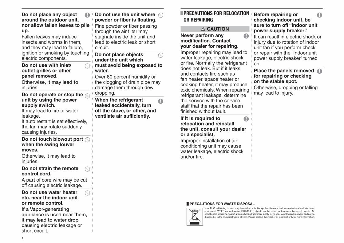
PRECAUTIONS FOR WASTE DISPOSAL
Your Air Conditioning product may be marked with this symbol. It means that waste electrical and electronic equipment (WEEE as in directive 2012/19/EU) should not be mixed with general household waste. Air conditioners should be treated at an authorized treatment facility for re-use, recycling and recovery and not be disposed of in the municipal waste stream. Please contact the installer or local authority for more information.
Do not place any object around the outdoor unit, nor allow fallen leaves to pile up.
Fallen leaves may induce insects and worms in them, and they may lead to failure, ignition or smoking by touching electric components.Do not use with inlet/outlet grilles or other panel removed.
Otherwise, it may lead to injuries.Do not operate or stop the unit by using the power supply switch. It may lead to fi re or water leakage. If auto restart is set effectively, the fan may rotate suddenly causing injuries.Do not touch blowout port when the swing louver moves.
Otherwise, it may lead to injuries.Do not strain the remote control cord.
A part of core wire may be cut off causing electric leakage.Do not use water heater etc. near the indoor unit or remote control.
If a Vapor-generating appliance is used near them, it may lead to water drop causing electric leakage or short circuit.
PRECAUTIONS FOR RELOCATION OR REPAIRING
CAUTION
Never perform any modification. Contact your dealer for repairing.
Improper repairing may lead to water leakage, electric shock or fi re. Normally the refrigerant does not leak. But if it leaks and contacts fi re such as fan heater, space heater or cooking heater, it may produce toxic chemicals. When repairing refrigerant leakage, determine the service with the service staff that the repair has been fi nished without fault.If it is required to relocation and reinstall the unit, consult your dealer or a specialist.
Improper installation of air conditioning unit may cause water leakage, electric shock and/or fi re.
Do not use the unit where powder or fiber is floating.
Fine powder or fi ber passing through the air fi lter may stagnate inside the unit and lead to electric leak or short circuit.Do not place objects under the unit which must avoid being exposed to water.
Over 80 percent humidity or the clogging of drain pipe may damage them through dew dropping.When the refrigerant leaked accidentally, turn off the stove, or other, and ventilate air sufficiently.
Before repairing or checking indoor unit, be sure to turn off “Indoor unit power supply breaker”.
It can result in electric shock or injury due to rotation of indoor unit fan if you perform check or repair with the “Indoor unit power supply breaker” turned on.Place the panels removed for repairing or checking on the stable spot.
Otherwise, dropping or falling may lead to injury.
5
HOW TO OPERATE (Dehumidifying operation is prohibited for FDU-F.) < WIRED REMOTE CONTROL (RC-E series) >
NOTICE
• There may be a case that “ ” is displayed when any button mentioned in the above is pressed, but it is not a malfunction.In that case, the operation of the button is prohibited.
• When you start to operate the unit for the fi rst time after turning the power supply on, the default settings are listed below. You can change them as
you like.Central control ......................Turned offOperation changeover .......... With auto mode : auto cooling
Without auto mode : coolingSet temperature ...................23°CFan speed ............................Louver position .....................Horizontal
ATTENTION
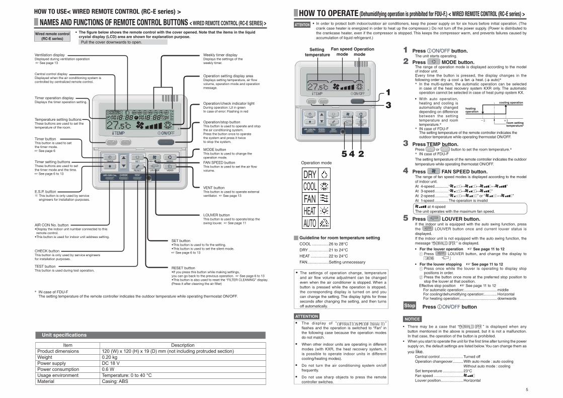
1 Press button.The unit starts operating.
2 Press MODE button.The range of operation mode is displayed according to the model of indoor unit.Every time the button is pressed, the display changes in the following order dry cool fan heat. ( auto) In the multi-system, the automatic operation can be selected
in case of the heat recovery system KXR only. The automatic operation cannot be selected in case of heat pump system KX.
• With auto operation, heating and cooling is automatically changed depending on difference between the setting temperature and room temperature.
IN case of FDU-FThe setting temperature of the remote controller indicates the outdoor temperature while operating thermostat ON/OFF.
3 Press TEMP button.Press or button to set the room temperature. IN case of FDU-F
The setting temperature of the remote controller indicates the outdoor temperature while operating thermostat ON/OFF.
4 Press FAN SPEED button.The range of fan speed modes is displayed according to the model of indoor unit.At 4-speed ............. “ ”At 3-speed ............. “ ”At 2-speed ............. “ ” or “ ”At 1-speed .............The operation is invalid
at 4-speedThe unit operates with the maximum fan speed.
5 Press LOUVER button.If the indoor unit is equipped with the auto swing function, press the LOUVER button once and current louver status is displayed.If the indoor unit is not equipped with the auto swing function, the message “ ” is displayed.
• For the louver operation ☞ See page 11 to 12
1 Press LOUVER button, and change the display to
• For the louver stopping ☞ See page 11 to 12
1 Press once while the louver is operating to display stop positions in order.
2 Press the button once more at the preferred stop position to stop the louver at that position.
Effective stop position ☞ See page 11 to 12For automatic operation: ...............................middleFor cooling/dehumidifying operation: ............HorizontalFor heating operation: ................................... downwards
Stop Press button
13
245
Setting temperature
Fan speed mode
Operation mode
Guideline for room temperature setting
COOL ...............26 to 28°C
DRY ..................21 to 24°C
HEAT ................22 to 24°C
FAN ...................Setting unnecessary
• The settings of operation change, temperature and air fl ow volume adjustment can be changed even when the air conditioner is stopped. When a button is pressed while the operation is stopped, the corresponding display is turned on and you can change the setting. The display lights for three seconds after changing the setting, and then turns off automatically.
• In order to protect both indoor/outdoor air conditioners, keep the power supply on for six hours before initial operation. (The crank case heater is energized in order to heat up the compressor.) Do not turn off the power supply. (Power is distributed to the crankcase heater, even if the compressor is stopped. This keeps the compressor warm, and prevents failures caused by accumulation of liquid refrigerant.)
Operation mode
DRYCOOLFANHEATAUTO
• The display of “ ” fl ashes and the operation is switched to “Fan” in the following case because the operation modes do not match.
• When other indoor units are operating in different modes (with KXR, the heat recovery system, it is possible to operate indoor units in different cooling/heating modes).
• Do not turn the air conditioning system on/off frequently.
• Do not use sharp objects to press the remote controller switches.
ATTENTION
cooling operation
heating operation
room setting temperature*
Ventilation displayDisplayed during ventilation operation ☞ See page 13
Weekly timer displayDisplays the settings of the weekly timer.
Operation setting display areaDisplays setting temperature, air flow volume, operation mode and operation message.
Operation/check indicator lightDuring operation: Lit in greenIn case of error: Flashing in red
Operation/stop buttonThis button is used to operate and stop the air conditioning system.Press the button once to operate the system and press it twice to stop the system.
MODE buttonThis button is used to change the operation mode.
FAN SPEED buttonThis button is used to set the air flow volume.
VENT buttonThis button is used to operate external ventilator. ☞ See page 13
LOUVER buttonThis button is used to operate/stop the swing louver. ☞ See page 11
SET button•This button is used to fix the setting. •This button is used to set the silent mode. ☞ See page 6 to 13
RESET button•If you press this button while making settings, you can go back to the previous operation. ☞ See page 6 to 13•This button is also used to reset the “FILTER CLEANING” display.(Press it after cleaning the air filter)
Central control displayDisplayed when the air conditioning system is controlled by centralized remote control.
Timer operation displayDisplays the timer operation setting.
Temperature setting buttonsThese buttons are used to set the temperature of the room.
Timer buttonThis button is used to set the timer mode. ☞ See page 6
Timer setting buttonsThese buttons are used to set the timer mode and the time.☞ See page 6 to 13
E.S.P. buttonThis button is only used by service engineers for installation purposes.
AIR CON No. button•Display the indoor unit number connected to this remote control.•This button is used for indoor unit address setting.
CHECK button This button is only used by service engineers for installation purposes.
TEST buttonThis button is used during test operation.
NAMES AND FUNCTIONS OF REMOTE CONTROL BUTTONS < WIRED REMOTE CONTROL (RC-E SERIES) >
Wired remote control
(RC-E series)
• The figure below shows the remote control with the cover opened. Note that the items in the liquid
crystal display (LCD) area are shown for explanation purpose.
Pull the cover downwards to open.
HOW TO USE< WIRED REMOTE CONTROL (RC-E series) >
IN case of FDU-FThe setting temperature of the remote controller indicates the outdoor temperature while operating thermostat ON/OFF.
°
Unit specifications

6
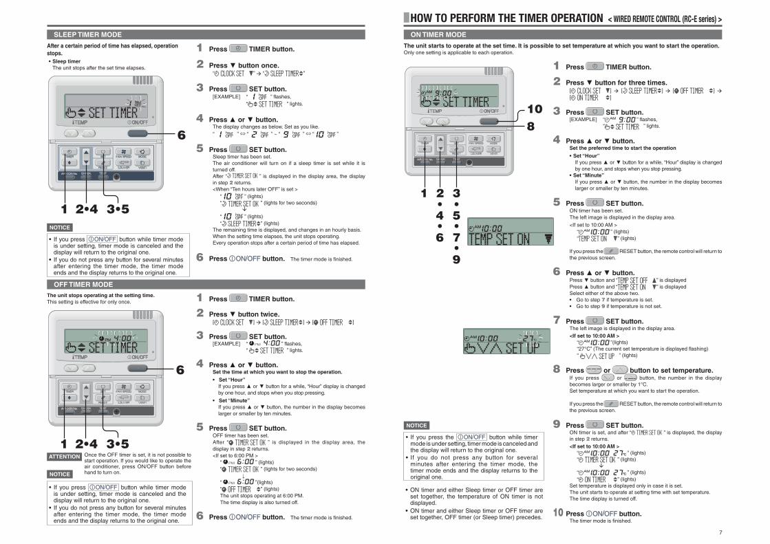
HOW TO PERFORM THE TIMER OPERATION < WIRED REMOTE CONTROL (RC-E series) >
1 Press TIMER button.The mode changes to timer mode.“Current day of the week” and “Current time” are displayed.
Display area : [ ][ ][ ]
2 Press SET button.
The display area shows : [ ] ( fl ashes)[ ] (current time)[ ]
3 Press or button.Place the “ ” mark above the day of the week to the current
day.
Press and mark to move to the right and the left respectively.
If you press the RESET button, the remote control will return to the previous screen and display “ ”.
4 Press SET button.The day of the week is fi xed, and the fl ashing of mark stops and lights.The “current time” value fl ashes, and “ ” is displayed.
5 Press or button.Set to the current time.
If you press the RESET button, the display is returned to the one in step 1.
6 Press SET button.The fl ashing for time display stops and lights, and “ ” is displayed to show that the current time is set.Two seconds later, the display in step 1 returns, and “ ” is displayed.
7 Press button.The timer mode is fi nished.
231••45•6
7
Timer operation is performed based on the time of the clock which is set by the following steps. Make sure to
set the time to the current time correctly.
SETTING THE TIME
• If you press button while timer mode is under setting, timer mode is canceled and the display will return to the original one. Note that the setting which has not been completed is canceled.
• If you do not press any button for several minutes after entering the timer mode, the timer mode ends and the display returns to the original one.
NOTICE
HOW TO PERFORM THE TIMER OPERATION < WIRED REMOTE CONTROL (RC-E series) >
1 Press TIMER button.The mode changes to timer mode.“Current day of the week” and “Current time ” are displayed.[EXAMPLE] Sunday : 1 o’clock in the afternoon
Display area : [ ][ ][ ] (lights)
2 Press or button.By pressing or button, it is possible to choose the item to set.
[ ] (set to current time)
[ ] (Every operation stops after a certain period of time has elapsed.)
[ ] (The unit stops operating at the setting time.)
[ ] (The unit starts operating at the setting time.)
[ ] (Timer set for each day of the week)
[ ] (Cancel the timer setting)
If you press the RESET button, timer mode ends and return to original status.
3 Press SET button.The selected timer mode is set.
For setting of each timer mode, see the following pages.
The possible combination of the timer function is mentioned in the following table.
Combination of modes that can be set together
( : possible ×: impossible)
• If you select a combination of modes that cannot be set together and press the SET button, the message “ (invalid operation)” is displayed for 3 seconds and then the display returns to the one selected in step 2.
321
• If you press button while timer mode is under setting, timer mode is canceled and the display will return to the original one. Note that the setting which has not completed is canceled.
• If you have set the ON timer mode and either the OFF timer or Sleep timer mode at the same time, the OFF timer (or Sleep timer) precedes the ON timer.
• If you press the Timer button and “ ” is displayed, the button can not be operated because the button operation is disabled. If you want to make the button effective , consult your dealer.
• If you do not press any button for several minutes after pressing the Timer button, Timer mode ends and the display returns to the original one.
• When the weekly timer setting recovers from power failures, the setting data (four settings per day) remain stored, but holiday settings will automatically override the settings for each day.
THE SELECTION OF TIMER MODE
Functions of each timer operation
• Sleep timer
When the specified period of time elapses, operation stops.10 settings are available, from “an hour later OFF” to “10 hours later OFF”.The unit will stop when the setting time is reached.
• OFF timer
The unit stops operating at the setting time.It will operate one time per setting.
• ON timer
The unit starts to operate at the setting time. The temperature can be set together. It will operate one time per setting.
• Weekly timer
You can set up to four ON/OFF timers per day. Once Weekly timer is set, it repeats every week.
NOTICE
OFF timer
×
×
Sleep timer
×
×
Weekly timer
×
×
×
ON timer
×
Sleep timer
OFF timer
ON timer
Weekly timer
7
HOW TO PERFORM THE TIMER OPERATION < WIRED REMOTE CONTROL (RC-E series) >
1 Press TIMER button.
2 Press button for three times.[ ] [ ] [ ] [ ]
3 Press SET button.[EXAMPLE] “ ” fl ashes,
“ ” lights.
4 Press or button.Set the preferred time to start the operation
• Set “Hour”
If you press or button for a while, “Hour” display is changed by one hour, and stops when you stop pressing.
• Set “Minute”
If you press or button, the number in the display becomes larger or smaller by ten minutes.
5 Press SET button.ON timer has been set.The left image is displayed in the display area.
<If set to 10:00 AM >“ ” (lights)“ ” (lights)
If you press the RESET button, the remote control will return to the previous screen.
6 Press or button.Press button and “ ” is displayedPress button and “ ” is displayedSelect either of the above two.• Go to step 7 if temperature is set.• Go to step 9 if temperature is not set.
7 Press SET button.The left image is displayed in the display area.<If set to 10:00 AM >
“ ”(lights)“27°C” (The current set temperature is displayed fl ashing)“ ” (lights)
8 Press or button to set temperature.If you press or button, the number in the display becomes larger or smaller by 1°C.Set temperature at which you want to start the operation.
If you press the RESET button, the remote control will return to the previous screen.
9 Press SET button.ON timer is set, and after “ ” is displayed, the display in step 2 returns.<If set to 10:00 AM >
“ ” (lights)“ ” (lights)
“ ” (lights)“ ” (lights)
Set temperature is displayed only in case it is set.The unit starts to operate at setting time with set temperature.The time display is turned off.
10 Press button.The timer mode is fi nished.
108
321••54
76•
9•
•
The unit starts to operate at the set time. It is possible to set temperature at which you want to start the operation.Only one setting is applicable to each operation.
ON TIMER MODE
• ON timer and either Sleep timer or OFF timer are set together, the temperature of ON timer is not displayed.
• ON timer and either Sleep timer or OFF timer are set together, OFF timer (or Sleep timer) precedes.
• If you press the button while timer mode is under setting, timer mode is canceled and the display will return to the original one.
• If you do not press any button for several minutes after entering the timer mode, the timer mode ends and the display returns to the original one.
NOTICE
1 Press TIMER button.
2 Press button once.“ ” “ ”
3 Press SET button.[EXAMPLE] “ ” fl ashes,
“ ” lights.
4 Press or button.The display changes as below. Set as you like.“ ” ⇔ “ ” ~ “ ” ⇔ “ ”
5 Press SET button.Sleep timer has been set.The air conditioner will turn on if a sleep timer is set while it is turned off.After “ ” is displayed in the display area, the display in step 2 returns.<When “Ten hours later OFF” is set >
“ ” (lights)“ ” (lights for two seconds)
“ ” (lights)“ ” (lights)
The remaining time is displayed, and changes in an hourly basis.When the setting time elapses, the unit stops operating.Every operation stops after a certain period of time has elapsed.
6 Press button. The timer mode is fi nished.
3•52•41
6
1 Press TIMER button.
2 Press button twice.[ ] [ ] [ ]
3 Press SET button.[EXAMPLE] “ ” fl ashes,
“ ” lights.
4 Press or button.Set the time at which you want to stop the operation.
• Set “Hour”
If you press or button for a while, “Hour” display is changed by one hour, and stops when you stop pressing.
• Set “Minute”
If you press or button, the number in the display becomes larger or smaller by ten minutes.
5 Press SET button.OFF timer has been set.After “ ” is displayed in the display area, the display in step 2 returns.<If set to 6:00 PM >
“ ” (lights)“ ” (lights for two seconds)
“ ”(lights)“ ” (lights)The unit stops operating at 6:00 PM.The time display is also turned off.
6 Press button. The timer mode is fi nished.
The unit stops operating at the setting time.
This setting is effective for only once.
3•52•41
6
Once the OFF timer is set, it is not possible to start operation. If you would like to operate the air conditioner, press ON/OFF button before hand to turn on.
SLEEP TIMER MODE
OFF TIMER MODE
• If you press button while timer mode is under setting, timer mode is canceled and the display will return to the original one.
• If you do not press any button for several minutes after entering the timer mode, the timer mode ends and the display returns to the original one.
• If you press button while timer mode is under setting, timer mode is canceled and the display will return to the original one.
• If you do not press any button for several minutes after entering the timer mode, the timer mode ends and the display returns to the original one.
ATTENTION
After a certain period of time has elapsed, operation
stops.
• Sleep timer
The unit stops after the set time elapses.
NOTICE
NOTICE

8
HOW TO PERFORM THE TIMER OPERATION < WIRED REMOTE CONTROL (RC-E series) >
5 Press SET button. mark next to a number lights.
“ ” or “ ” is displayed.The settings so far are effective and the display changes as shown on the left.
6 Press or button.Press button and “ ” is displayed.
Press button and “ ” is displayed.
Select either of the above two.
Press the RESET button to return to the display in step 3.
7 Press SET button.“ ” is displayed
8 Press or button.Set the time.
Press the RESET button to return to the display in step 5.
9 Press SET button.When time display lights, the time is fi xed.
In case of OFF timer setting, setting process is completed on
this step.
A “_” mark lights ( ) under the day of the week which you set and the display appears as the left image. Proceed to “ Next setting and Exiting Weekly timer Mode” on the right page.
In case of ON timer setting, “ ” is displayed,
proceed to step 10.
10 Press or button.Select either “ ” or “ ”.
11 Press SET button.In case “ ” has been selected, ON timer setting
process is completed.
A “_” mark lights ( ) under the day of the week which you set and the display appears as the left image. Proceed to “ Next setting and Exiting Weekly timer Mode” on the right page.
In case “ ” has been selected, “ ”
is displayed; Proceed to step 12.
12 Press the temperature setting buttons or
.Press the or the button to increase or decrease by 1°C.Set the temperature at the start of operation.
Press the reset button to return to the display “ ”.
13 Press SET button.ON timer setting with start-up temperature has been
completed.
The value of the temperature stops flashing and lights.
A “_” mark lights ( ) under the day of the week which you set and the display appears as the left image.Proceed to “ Next setting and exiting Weekly timer mode” on the right page.
<When “ ” is selected>
Selection of Weekly timer mode
You can set up to four ON/OFF timers per day.Note : Set time every month in Weekly timer mode.
1 Press TIMER button.
2 Press button for four times.[ ] [ ] [ ] [ ] [ ]
3 Press SET button.“ ”is displayed in the display area.
4 Press or button.By pressing or button, it is possible to choose the item to set.
“ ” (for setting the timer)
“ ” (for setting the selected day of the week to holiday)
“ ” (for checking the timer setting and canceling individual settings)
5 Press SET button.The selected mode is fi xed.
3•52•41
WEEKLY TIMER SETTING
1 In the Weekly timer mode, select “ ”
and press SET button to confirm. ☞ See step 1 to 5 in “Selection of Weekly timer mode” above
“ ” ( is flashing)
“ ” is displayed in the display area.
2 Press or button.Set the mark above the day of the week to the day to be set for timer setting. Press and to move to the right and left respectively, and will move fl ashing. If you press the button, the day (“SUN” to “SAT”) indicated with the fl ashing “ ” mark will change one day at a time. If you press the button when the “ ” mark is indicating “SAT”, multiple “ ” marks will appear and fl ash above “MON” to “FRI”. Press the button again, and multiple “ ” marks will appear and fl ash above “SUN” to “SAT” (every day). The same schedule can be applied to all the days indicated with the “ ” marks by using this function.Press RESET button to return to “selecting Weekly t imer mode screen”, and “ ” is d isplayed. ☞ See the above step 3.
3 Press SET button.The “ ” mark above the day stops flashing and lights, which indicates that the setting is fi xed.“ ” is displayed as the left image.
4 Press or button.Up to four schedules can be set for each day. Select the timer schedule number you want to set. Set either ON timer or OFF timer for each single operation. (See the left EXAMPLE ).Press button to make the mark next to the number fl ash and move downwards.Press the button to move the mark upwards.
1234
Press the RESET button to return to the display in step 1.
3•5•7•9•11•132•4•6•8•10
WEEKLY TIMER MODE
<In case Monday is set>
• If you press button while timer mode is under setting, timer mode is canceled and the display will return to the original one.
• If you do not press any button for several minutes after entering the timer mode, the timer mode ends and the display returns to the original one.
NOTICE
[EXAMPLE]
Number 1 :
Number 2 :
Number 3 :
Number 4 :
Four operations can be set with only ON timer or only OFF timer.

9
Canceling Holiday Setting
HOW TO PERFORM THE TIMER OPERATION < WIRED REMOTE CONTROL (RC-E series) >Weekly timer Holiday Setting
It is possible to temporarily disable each day’s timer setting by using the Holiday Setting. When the Holiday
Setting is cancelled, the timer setting is enabled again.
1 In the Weekly timer mode, select and set
“ ”.
☞ See “Selection of Weekly timer mode” step 1 to 5 on page 8.
“ ” is displayed in the display area( is flashing)
“ ” is displayed.
2 Press or button.Move the “ ” mark displayed above the days of week to the
day which you want to set as Holiday.
Press and to move to the right and left respectively.If you press the button, the day (“SUN” to “SAT”) indicated with the fl ashing “ ” mark will change one day at a time. If you press the
button when the “ ” mark is indicating “SAT”, multiple “ ” marks will appear and fl ash above “MON” to “FRI”. Press the button again, and multiple “ ” marks will appear and fl ash above “SUN” to “SAT” (every day). The same schedule can be applied to all the days indicated with the “ ” marks by using this function. This can be used in case you would like to apply Holiday setting to these days.
In case press the RESET button, the remote control will return to the previous screen and display “ ”.
3 Press SET button.The “ ” mark above the day stops fl ashing and lights, and the day set as a holiday also lights enclosed with ( ). Then, the following is displayed.
[ ] (lights)“ ” (lights for two seconds)
[ ] (lights)“ ”(lights)
After the holiday setting has been completed, the display of the remote control returns to that of step 1. Repeat step 2 and 3 to continue setting further holidays.
NOTICE
If you set a day of the week for which no timer operation is set, “ ” is displayed for two seconds and the display returns to the one shown in step 1.
4 Press button.Timer mode ends.
32
4
1 In the Weekly timer mode, select and set
“ ”.
☞ See “Selection of Weekly timer mode” step 1 to 5 on page 8.
2 Press or button.Move the “ ” mark displayed above the day of week to the
day on which you want to cancel Holiday setting.
Select the day of the week that has been set as holiday.
3 Press SET button.( ) display is turned off and the following is displayed.
[ ] (lights)“ ” (lights for two seconds)
[ ] (lights)“ ” (lights)
After the holiday setting has been completed, the display of the remote control returns to that of step 1. Repeat step 2 and 3 to continue canceling further holiday settings.
4 Press button.Timer mode ends.
• If you press button while timer mode is under setting, timer mode is canceled and the display will return to the original one.
• If you do not press any button for several minutes after entering the timer mode, the timer mode ends and the display returns to the original one.
NOTICE
• If you select a day of the week for which setting
have already been made, all the timer numbers
that have been set are displayed. And the details
of the timer setting for the number which has “ ”
mark is displayed. You can modify the selected
setting by overwriting it.
• If you set ON timer and OFF timer operating at
the same time, OFF timer will precede.
• If the same two times are set for ON timer on the
same day, the lower number precedes.
Next setting and exiting Weekly timer mode
After “ ” is displayed, “ ” is displayed.
1 Press or button.By pressing or button, it is possible to choose the item to set.
“ ” (select the next timer operation number within the same day)
“ ” (select the next day)
“ ” (Timer mode ends)
2 Press SET button.If “ ” is selected, “ ” is displayed.Repeat step 3 and the subsequent steps of Weekly timer setting on page 8.
If “ ” is selected, “ ” is displayed.Repeat step 1 and the subsequent steps of Weekly timer setting on page 8.
If “ ” is selected, timer mode ends.
21
Display after Weekly timer modes setting
• The day of the week set is underlined.
• The mark is displayed above the current day of the week.
• The display of all the timer operation numbers set for the
current day is turned on. The mark indicates the next
setting number to be activated, and the set time is displayed.
• The timer operations are executed in order, and the number
and time display are turned off when all the timer operations
for the current day are completed.
• If you press button while timer
mode is under setting, timer mode is canceled
and the display will return to the original one.
• If you do not press any button for several
minutes after entering the timer mode, the
timer mode ends and the display returns to the
original one.
NOTICE

10
HOW TO PERFORM THE TIMER OPERATION < WIRED REMOTE CONTROL (RC-E series) >
TIMER CANCELLATION MODE
2•4
71
3•5•6
In case “ ” , “ ” or “ ” was
selected.
5 Press SET button.The detailed setting of selected timer mode is displayed as shown below.(But if not set, “ ” is displayed)
<Display EXAMPLE when “ ” is selected>
If you would like to quit cancellation, press the RESET button to return to the “ ” display. (step 4 above)
6 Press SET button.The display of the detailed timer setting is turned off, and after the message “ ” is displayed for two seconds, “ ” is displayed again. (step 4 above)Repeat steps 4 to 6 to continue canceling timer mode settings.
In case “ ” was selected.
All the Weekly timer setting will be canceled if you proceed the following steps.To cancel a part of the timer setting, please see “Weekly timer mode Setting Canceling” on the left side.
5 Press SET button.The settings are displayed as shown below.(But if not set, “ ” is displayed)
If you would like to quit cancellation, press the RESET button to return to the “ ” display. (step 4 above)
6 Press SET button to confirm.The day of the week display area turns off, and after the message “ ” is displayed for two seconds, the display returns to “ ”. (step 4 above)These operation settings cancel all days of the week.
1 Press TIMER button.Timer mode begins.The current “The day of the week” and “the current time” are displayed.
[ ]“ ”“ ”
2 Press button for five times.
“ ”
“ ” ( fi rst press)
“ ” ( second press)
“ ” ( third press)
“ ” ( fourth press)
“ ” ( fi fth press)
3 Press SET button.Timer Cancellation Mode begins.
4 Press or button.By pressing or button, it is possible to choose the item to cancel.
“ ”
“ ”
“ ”
“ ” (canceling all days of the week)
If you press the RESET button, the remote control will return to the previous screen, and display “ ”. (step 2 above)
7 Press ON/OFF button.Timer mode ends.
• If you press button while timer mode is under setting, timer mode is canceled and the display will return to the original one.
• If you do not press any button for several minutes after entering the timer mode, the timer mode ends and the display returns to the original one.
NOTICE
Weekly timer Checking
1 In the Weekly timer mode, select and set
“ ”.
☞ See “Selection of Weekly timer mode” step 1 to 5 on page 8.The display shows the detailed timer operation setting information of the smallest timer operation number on the day of the week as shown on the left. (But if not set, “ ” is displayed.)
2 Press or button.Detailed timer operation settings are displayed in accordance with the timer operation you have selected.
Press button to display from Sunday and the lowest timer operation number.
Press button to display the settings in the reverse order.
3 Press button.Timer mode ends.2
3
Weekly timer mode Setting CancelingIt is possible to cancel Weekly timer mode settings of each day of the week, as well as individual timer operation number.
See “Timer Cancellation Mode” on the right side to cancel settings of all days of week.
1 In the Weekly timer mode, select and set
“ ”.
☞ See “Selection of Weekly timer mode” step 1 to 5 on page 8.The display shows the detailed timer operation setting information of the smallest timer operation number on the day of the week as shown on the left.
2 Press or button.Detailed timer operation settings are displayed in accordance with the timer operation you have selected.
Press button to display from Sunday and the lowest timer operation number.
Press button to display the settings in the reverse order.
Select the timer operation number on a day of the week you
want to cancel.
If you press the RESET button, the remote control will return to the previous screen, and display “ ”.
3 Press SET button.“ ” is displayed.
If you press the RESET button, the remote control will return to the previous screen, and display “ ”.
4 Press SET button.“ ” is displayed, and the displayed detail timer operation setting disappears and is canceled.
“ ” is displayed again.Repeat step 2 to 4 to continue canceling other settings.
5 Press button.Timer mode ends.
2
5
3•4
• If you press button while timer mode is under setting, timer mode is canceled and the display will return to the original one.
• If you do not press any button for several minutes after entering the timer mode, the timer mode ends and the display returns to the original one.
NOTICE

11
[IN CASE OF FDT, FDTC, FDE, FDK, FDFW]Press LOUVER button once, and the current status of louver is displayed.
ADJUSTING WITH LOUVER BUTTON (Indoor unit with auto swing function)
HOW TO ADJUST THE LOUVER < WIRED REMOTE CONTROL (RC-E series) >
The display during auto swing
The display with the louver position fixed
When you operate the swing louver
1. Press LOUVER button, and change the display
to “ ”.
The function of the swing louver
during the heating preparation,
heating/defrost“ ” or “Heating/Defrost” is displayed, the position of the swing louver is automatically switched to horizontal.
When the operation is switched to normal after “The heating preparation” or “Heating/Defrost” ends, the position of swing louver returns to the last setting.
When the position of the swing louver is fixed
1. Press LOUVER button once while the louver
is swinging, and 4 stop positions are displayed every
one second in order.
“ ” “ ” “ ” “ ”
2. Press LOUVER button once when the display of
the louver comes to the position you desire.
The display is switched to stop, and the position of louver is fi xed.
Recommended louver fixed position
COOL•DRY
HEAT
horizontal position
Press
Press
CAUTION
• Do not move the swing louver forcibly by hands for fear that it may be damaged.• Do not blow downwards during cooling operation for a long time for fear that dew condensation may be formed at the side panel. (In
case of FDE)
HOW TO OPERATE IN SILENT MODE < WIRED REMOTE CONTROL (RC-E series) >
1 In the timer mode, set the current day of the week
and current time.☞ See page 6 step 1 to 7
2 Press SET button for three seconds or more.The remote control goes into silent mode setting and the following is displayed.
“ ” or “ ” (lights)
3 Press or button.If button is pressed, “ ” is displayed.
If button is pressed, “ ” is displayed.
Select “ ”.
If you press the RESET button, the remote control return to the original screen.
4 Press SET button.The following setting is displayed.
“ ” (fl ashing)“ ” (lights)
5 Press or button.Set the “ON TIME”.
• Set “Hour”
If you hold or , the number in “Hour” display changes, and if you release it, the number stops changing.
• Set “Minute”
If you press or button, the number in the display becomes larger or smaller by ten minutes.
If you press the RESET button, the remote control return to the “ ” display.
6 Press SET button.The ON TIME is set and the following is displayed.
“ ” (fl ashing)“ ” (lights for two seconds)
“ ” (fl ashing)“ ” (lights)
7 Press or button to set the duration.Select OFF time.
When you press button, and the duration is increased by two hours as below, “ ” “ ” “ ” “ ”When you press button, and the duration is decreased by two hours.If you press RESET button, the “ON TIME SET” display returns.
8 Press SET button.The setting is fi xed and displayed.“ ” is displayed, and the silent mode setting ends.The setting display turns off, and returns to original display.
3•5•7
2•4•6•8
1
When the silent mode is set, the unit operates more silently reducing noise from the outdoor unit.The system applies the silent operation mode at the starting time to be set, and finish it after a certain period of time has passed.Once the system is set to operate with the silent mode, the setting is applied everyday until it is canceled.
NOTICE
• The remote control has main-sub units, silent setting cannot be operated with sub unit .
• After the silent mode is set, the following is displayed for 3 seconds at the set time and the unit returns to the original display.At the ON time : “ ”At the OFF time : “ ”
• If you select “ ”, you can continue the silent mode until it is canceled. At the fi rst ON time, the display shows “ ” for three seconds and returns to original display.
Canceling Silent Mode (Setting)
Select “ ” in step 2, press SET button and silent setting is canceled ending the silent mode.“ ” is displayed.
SILENT MODE
Silent Mode Setting
• If you press button while timer mode is under setting, timer mode is canceled and the display will return to the original one. Note that the setting which has not been completed is canceled.

12
7 Press SET button (Fixing of the upper
limit position)The upper limit position is fixed and the setting position is displayed for two seconds. Then proceed to lower limit position selection display.
[EXAMPLE]
“ ” (lights for two seconds)
“ ” (shows current setting)
8 Press or button (Selection of lower limit
position)Select the lower limit position of louver.“position 1” is the most horizontal, and “position 6” is the most downwards.“position --” is to return to the factory setting. If you need to change the setting to the factory setting, use “position --”.
“ ” (the most horizontal)
⇔ “ ”
⇔ “ ”
⇔ “ ”
⇔ “ ”
⇔ “ ” (the most downwards)
⇔ “ ” (return to the position of shipment)
9 Press SET button (Fixing of the lower limit
position)The upper limit position and lower limit position are fi xed, the set positions lights for two seconds, and then the setting is completed.• After the setting is completed, the louver which was set
moves from the original position to the lower limit position, and goes back to the original position again. (This operation is not performed if the indoor unit and/or indoor unit fan is in operation.)
[Example]
“ ” (lights for two seconds)
“ ”
“
10 Press button.Louver adjusting mode ends and returns to the original display.
HOW TO SET THE AIR FLOW DIRECTION < WIRED REMOTE CONTROL (RC-E series) >
NOTICE
(downwards)
(horizontal)
the position of the louver
[EXAMPLE] For Upper position 2, Lower position 6
Lower position
Movable range
Upper position
• When plural remote controllers are connected, louver position setting cannot be set by slave remote control.
• If you press RESET button during settings, the display will return to previous display. If you press
button during settings, the mode will end and the original display will return, and the settings that have not been
completed will become invalid.
Note : If the upper limit position number and the lower limit position number are set to the same position, the louver is fi xed at that position. And auto swing does not function.
AIROUTLET SELECTION (IN CASE OF FDFW)
It is possible to switch between the combination of upper and lower air outlets and upper air outlet.Not operable while the air conditioner is ON.When the upper air flow is selected, UPPER AIR FLOW LED on the unit display will light green only under run.
1. Stop the air conditioner.2. Set the upper land lower limit position of the louver No.1 from the wired remote control. For the method of changing the setting, refer to HOW TO SET THE AIR FLOW DIRECTION on the left side.
1 In case of selecting to upper air flow.Set the upper and lower limit position to UPPER 2 and LOWER 2. (No.1 UPPER 2 / LOWER 2)
2 In case of selecting to upper and lower air flow.Set the upper and lower limit position to UPPER 5 and LOWER 5. (No.1 UPPER 5 / LOWER 5)
1 Stop the air conditioner and press SET
button and LOUVER button simultaneously
for three seconds or more.The following is displayed if the number of the indoor units connected to the remote control is one. Go to step 4.
“ ”
“ ”
The following is displayed if the number of the indoor units connected to the remote control are more than one
“ ”
“ ”
2 Press or button.(selection of indoor unit)Select the indoor unit of which the louver is set.[EXAMPLE]
“ ”⇔“ ”⇔“ ”⇔“ ”
3 Press SET button. (determination of
indoor unit)Selected indoor unit is fi xed.[EXAMPLE]
“ ” (lights for two seconds)
“ ”
“ ”
4 Press or button. (selection of louver No.)Select the louver No. to be set according to the left fi gure.[EXAMPLE]
“ ” ⇔ “ ” ⇔ “ ” ⇔ “ ”
Note : For FDE, select “ ”. Other louver No. settings have no effect.
5 Press SET button. (Determination of
louver No.)The louver No. to be set is confi rmed and the display shows the upper limit of the movable range.
[EXAMPLE] If No.1 louver is selected,
“ ” current upper limit position
6 Press or button. (selection of upper limit
position)Select the upper limit of louver movable range.“position 1” is the most horizontal, and “position 6” is the most downwards.“position --” is to return to the factory setting. If you need to change the setting to the factory setting, use “position --”.
“ ” (The most horizontal)
⇔ “ ”
⇔ “ ”
⇔ “ ”
⇔ “ ”
⇔ “ ” (The most downward)
⇔ “ ” (Return to the position of shipment)
2•4•6•8 1
10
3•5•7•9
HOW TO SET THE AIR FLOW DIRECTION (IN CASE OF FDT, FDTC, FDE, FDK, FDFW) <WIRED REMOTE CONTROL (RC-E series) >
No. 4
No. 2
No. 1
No. 3
Control box
Piping sideDrain
hose side
Louver No.
[for FDT]
It is possible to change the movable range of the louver on the air outlet from the wired remote control. Once the top and bottom positions are set, the louver will swing within the range between the top and the bottom positions when swing operation is chosen.With Ceiling cassette −4 way − FDT and FDTC, it is also possible to apply different setting to each louver.
NOTICE
• For FDT and FDTC type, in case the louver No. to be set is uncertain, set any louver temporarily. The louver wi l l swing once when the setting is completed and it is possible to confi rm the louver No. and the position.After that, choose the correct louver No. and set the top and bottom positions.
• For FDE and FDK type, set louver No. 1.
For FDFW type, set louver No. 2.Other settings selected have no effect.
(downwards)
(horizontal)
the position of the louver
No. 4
No. 2
No. 1
No. 3
Control box
Piping sideDrain hose side
Louver No.
[for FDTC]
13
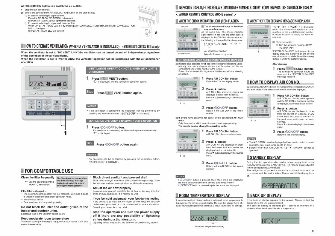
WHEN THE CHECK INDICATOR LIGHT (RED) FLASHES
INSPECTION DISPLAY, FILTER SIGN, AIR CONDITIONER NUMBER, STANDBY, ROOM TEMPERATURE AND BACK UP DISPLAY< WIRED REMOTE CONTROL (RC-E series) >
The air conditioner stops in the event
any trouble occurs.
At the same time, the check indicator light flashes in red and the error code is displayed in the ON timer display area and the following is displayed in the display area.
“ ” ⇔ “ ”
(Air conditioner number)(lights for 2 seconds by turns)
Error code
Air conditioner No.
1 Press AIR CON No. button.Enter AIR CON No. display mode.
2 Press button.AIR CON No. and error codes are displayed in order from the lowest.Press button to display in the reverse order.
3 Press button.Return to the AIR CON of the lowest number.
1 2
ERROR display when multiple indoor units are connected
If errors have occurred for all the connected air conditioning units.
Initially, the error display shows the formation of the air conditioning unit whose number is the lowest.Errors of other air conditioning unit can be checked with the following procedure.
1 Press AIR CON No. button.AIR CON No. display mode appears.
2 Press button.AIR CON No. are displayed in order from the lowest. And error codes are displayed on the unit in trouble.Press button to display in the reverse order.
3 Press button.Return to the AIR CON of the lowest number.
If errors have occurred for some of the connected AIR CON
units.
Only the units for which errors have occurred stop operating.The remote control shows the operating units.
NOTICE
• If button is pressed once while errors are displayed, the errors display is turned off, and the stop mode returns.If button is pressed again, the errors are displayed.
HOW TO DISPLAY AIR CON NO.By operating AIR CON No. button, the number of the connected AIR CON unit and error codes of the units which have the record are displayed.
1 Press AIR CON No. button.AIR CON No. display mode appears and the AIR CON of the lowest number is displayed. Other displays all turn off.
2 Press button.AIR CON No. are displayed in order from the lowest. In addition, if any errors have occurred to the unit in the past, error codes can be found here too.Press button to display in the reverse order.
3 Press button.Return to the original display.
1 2
NOTICE
• The AIR CON No. can be displayed without relation to its modes of operation, stop, forcible stop due to an error.
• Buttons other than “AIR CON No.” “ ” “ ” “ON/OFF” cannot be operated.
1 2 STANDBY DISPLAYDuring the fi rst operation after breaker power supply input or the recovery from power failure, “ ” can be displayed on the remote control for max 30 minutes.The refrigerant oil protection control is activated to protect the compressor and this isn’t a failure. Please wait till the display turns off.
WHEN THE FILTER CLEANING MESSAGE IS DISPLAYEDThe “ ” is displayed when the cumulative operation time reaches to the predetermined number of hours in order to notify the time for cleaning.
Clean the air fi lter. ☞ See the separate printing. (HOW
TO MAINTAIN)
“FILTER CLEANING” is displayed in the display area. It is displayed for one second every fi ve seconds while the unit is running. It stays lit while the system stopped.
After cleaning
1 Press RESET button.The cumulative operation hours are reset and the “FILTER CLEANING” message turns off.
1
ROOM TEMPERATURE DISPLAYIf room temperature display setting is activated, room temperature is displayed on the remote control display. Then air fl ow display turns off, but air fl ow adjusting button is operative. Consult your dealer for settings.
The room temperature display
BACK UP DISPLAYIf the back up display appears on the screen,. Please contact the dealer where the unit was purchased.The back up display is indicated per 1 second at intervals of 5 seconds when the air conditioners is in operation.
Clean the filter frequently
☞ See the separate printing. (HOW TO MAINTAIN)
If the filter is clogged…
• The cooling/heating capacity will get reduced. Moreover it leads to waste of electricity and larger operation noise.
• It may cause failure.• Dew may form and drop during cooling.
Do not block the inlet and outlet grilles of the
indoor and outdoor units.Excessive load to the unit may cause failure.
Keep moderate room temperatureToo much cooling or heating is not good for your health. It will also waste the electricity.
Block direct sunlight and prevent draftBlock direct sunlight with blinds and curtains during cooling. Close the windows and doors except when ventilation is necessary.
Adjust the air flow properlyDo not expose yourself directly to the air fl ow for too long time. For small animals and plants, it is harmful as well.
If you feel cold underneath your feet during heatingIf the ceiling is so high that the warm air fl ow does not circulate underneath your feet, it is recommended to use a circulator. Consult your dealer for more detail.
Stop the operation and turn the power supply
off if there are any possibility of lightning
strikes during a thunderstorm.Lightning strikes may lead to the failure of air-conditioning system.
FOR COMFORTABLE USEThe filter should be cleaned when
the “Filter cleaning” message
is displayed, and at the ends of
cooling and heating seasons.
HOW TO OPERATE VENTILATION (WHEN A VENTILATOR IS INSTALLED) < WIRED REMOTE CONTROL (RC-E series) >
1 Press VENTI button.“ ” is displayed, and the ventilation operation begins.
Stop Press VENTI button again.
1
When the ventilator is set to “NO VENTI LINK”, the ventilator can be turned on and off independently regardless
of the operation of the air conditioner.
When the ventilator is set to “VENTI LINK”, the ventilator operation will be interlocked with the air conditioner
operation.
NOTICE
• If no ventilator is connected, no operation can be performed by pressing the ventilation button. (“ ” is displayed).
VENTILATION OPERATION NOT LINKED WITH UNIT’S
OPERATION
1 Press button.If a ventilator is connected, ventilation will operate automatically.“ ” is displayed.
Stop Press button again.
NOTICE
• No operation can be performed by pressing the ventilation button. (“ ” is displayed).
VENTILATION OPERATION LINKED WITH UNIT’S OPERATION
AIR SELECTION button can switch the air outlets.
1. Stop the air conditioner.2. Select the air flow from AIR SELECTION button on the unit display.
1 In case of selecting to upper air flow.Press the AIR FLOW SELECTION button once.UPPER AIR FLOW LED will light for ten seconds.
2 In case of selecting to upper and lower air flow.When UPPER AIR FLOW LED is lit by pressing AIR FLOW SELECTION button, press AIR FLOW SELECTION button once again.UPPER AIR FLOW LED will turn off.

14
HEATING OPERATION
PREPARATION OF HEATING
• Heat pump type
Heat pump type heating applies the mechanism that draws the heat from the outside air to warm up the room by means of the refrigerant.• Defrost operation
During heating with a heat pump type air conditioner, frost will be formed on the outdoor unit if the temperature outside the room drops. If left alone, the heating efficiency decreases. In order to deal with this, the operation is automatically switched to defrost operation to remove the frost. During the period, the air fl ow of indoor/outdoor unit is stopped and “heating defrost” is displayed.
• Outer air temperature and heating capacity
The heating efficiency of heat pump type air conditioner decreases as the outside temperature becomes lower. If the capacity of air conditioner for heating is not sufficient, please use other heating device.
• Time required until the room temperature increases
A heat type air conditioner circulates warm air to warm the entire room, so it takes a while to rise up the room temperature. It is recommended to start operation earlier on a very cold day.
• When room temperature adjusting device operates during heating
If room temperature rises and the room temperature adjusting device is activated, the air fl ow becomes automatically low. When the room temperature drops, it switched back automatically to the normal operation.
“ (PREPARATION OF HEATING)” is displayed in the remote control display area in the following cases.
For wireless devices, the run/check display lamp on the main body display unit will fl ash green.Setting temperature and preparation of heating are displayed on the wired remote control.• At Starting Heating Operation
In order to prevent cool air from blowing out, the air fl ow into the room may be stopped depending on the room temperature at the start of heating operation. please wait for a while and the operation automatically switches to the normal heating operation.
• At defrost operation (during heating operation)
When frost may easily formed on the outdoor unit, the heating operation automatically is stopped (both indoor/outdoor unit stop fan operation) for approximately 5 to 10 minutes per hour and defrosting is operated. After the defrosting is complete, the operation automatically switches back to the normal operation.
CASES WHEN “ (PREPARATION OF HEATING)” IS DISPLAYED
NOTICE
An auto restart function, which is disabled at the factory setting, is applicable to the remote control. Consult your dealer. What is auto restart
• When a power failure occurs or the power supply is turned off, the function allows the system to automatically resume operation with the remote control setting made set before the power failure when the power supply recovers. If the system is stopped before power failure it remains stopped after the power recover.
• Note that in the following cases it is needed to set again with the remote control.1 Timer setting is cancelled. But the sleep timer recovers after power failure recovers. When recovering from a power failure, holiday setting will override
the weekly timer setting. And time setting returns to default. To return to original setting, after time setting, execute “holiday cancel”.2 Louver stops at the horizontal position.
CAUTION
Make sure to stop the operation before turning off the power supply when the auto restart function is enabled. (If the power supply is turned off while the system is operating, the indoor unit fan will start immediately when the power supply is turned on. In addition, the outdoor unit starts operating 3 minutes after the power supply is turned on.)
AUTO RESTART <WIRED REMOTE CONTROL>
TROUBLE SHOOTINGThe phenomena mentioned below is not malfunction.
The indoor-unit fan will not move for several minutes during cooling / dehumidifying operation (in case of the heat recovery system KXR).
In order to protect the compressor, the indoor-unit fan may take several minutes to begin moving after beginning cooling / dehumidifying operation.
Compressor protection control is automatically performed every few hours. Air fl ow may stop during this time; however, cooling operation will resume shortly.
Slapping sounds are heard. These sounds are generated when plastic components are expanded or shrunk by the heat and rubbed with each other.
Hissing sounds are heard when the operation is stopped or during defrost operation.
These sounds are generated when the refrigerant valve inside the air conditioning system is activated.
The air conditioner starts operation automatically as soon as the power supply is turned on.
In case the automatic restart function is enabled, and when the power supply recovers, the system restarts the operation automatically as same condition as before power supply is cut. ☞ See below
The setting temperature cannot be changed (the setting temperature display fl ashes).
If changing the set temperature is prohibited on the remote control, it is not possible to change the temperature setting even or is pressed. ☞ See page 15
In case of wireless remote control, the unit does not operate with the inspection display light on the indoor unit fl ashing even though any button on the remote control is pressed.
In case the system is controlled by the other centralized remote control and it forbids operating the system from the remote control, it is not possible to operate by the remote control.
Even if the wired remote control is operated, “central control” light only fl ashes and doesn’t operate.
Is not “central controlling” or “center” displayed?If controlled with a separately purchased center console etc., the unit cannot be operated by the remote control.
TROUBLE SHOOTINGCheck the following items before requiring service.
THE UNIT DOES NOT WORK AT ALL
Is the power supply switch
turned off?
Is there a blackout or is the
fuse blown?
Is the leakage breaker
activated?
Dangerous. Immediately turn off the power supply switch, and contact your dealer.
Is sunlight or other strong
illumination striking the
receive unit? (wireless unit)
ON
OFF
Is the air filter clogged? Is the swing louver
horizontal (during
heating)?
If the swing louver is horizontal, the air fl ow may not reach down to the fl oor.
Are there any obstacles
blocking the air inlet
and outlet grill?
• Is the direct daylight
coming into the room?
• Are there any
unexpected heat
sources in the
room?
• Are there too many
people in the room?
Is “(PREPARATION OF
HEATING)” displayed
in the remote control
display?
☞ See right
POOR COOLING OR HEATING POOR COOLING
If, after checking the items above, the air conditioner still does not operate normally or in the next cases, stop operating and contact your dealer.
• If the fuse and breaker blow frequently. • If water drips at cooling/dehumidifying operation. • If the operation or operation noise is abnormal.• If the check indicator light fl ashes.
The phenomena mentioned below is not malfunction.
NO AIR FLOW AT HEATING
The air conditioning system sounds as if water is draining from it.
Sounds of rustling or gurgling may be heard when the operation is started, when the compressor is activated/deactivated during operation, or when the operation is stopped. These are the sounds of the refrigerant fl owing through the system.
Sounds of rustling or gurgling may be heard from a stopped indoor unit.
These sounds can be heard when the air conditioning system is performing automatic control.
The supply air from the indoor unit smells bad.
The supply air from the indoor unit may smell bad if the smell of cigarettes, cosmetics and/or furniture has saturated the air conditioning system.
White vapor is generated from the indoor unit during operation.
White vapor may be generated during operation if the system is used in environment where oils and fats are frequently used, such as in restaurants. In this case, consult the dealer and clean the heat exchanger.
The operation switched to fan operation during cooling operation.
The operation may switch to fan operation automatically in order to avoid frost being built up on the surface of the heat exchanger. The operation will soon return to cooling operation.
The indoor fan does not stop even when the operation is stopped in heating mode.
The indoor unit fan may continue operating for 40 seconds in order to remove remaining heat in the indoor unit.CAUTION Do not turn off the power supply until the fan stops.
The air conditioning system cannot start operating again immediately after stopping.
During the fi rst 3 minutes after stopping operation, it is not possible to perform cooling, dehumidifying or heating operation even if the ON/OFF button is pressed to indicate “operation.” This is because a circuit for protecting the compressor is activated (the fan is operating during this period).
No air comes out during dehumidifying operation. The air fl ow volume cannot be changed.
During dehumidifying operation, the fan speed is automatically controlled in low speed/stop cycle in order to avoid both drastic temperature drop and humidity rise.
The swing louver moves without any operation.
The swing louver automatically swings twice when the power supply switch is turned on. This is not a trouble. The louver also moves automatically to the horizontal position when “PREPARATION OF HEATING” is displayed.
The outdoor unit discharges water or steam during heating operation.
Water or steam is discharge during defrosting operation which removes frost built up on the surface of the heat exchanger in the outdoor unit in heating mode.
The outdoor unit fan is not running even when the system is in operation.
The fan speed is automatically controlled according to the ambient temperature. It may be stopped in high ambient temperature in case of heating, and in low ambient temperature in case of coding. Also, the fan is stopped during defrosting operation.
CAUTION The fan will suddenly begin to operate even if it is stopped. Do not insert finger and/or stick.
The operation switched to fan operation during cooling operation.(in case of FDFW type)
In case the relative humidity is 73% or higher, the operation may alternate between fan operation and cooling operation even though the thermostat has not been activated. The objective of this operation mode is to prevent condensate dew formation and dew dropping from indoor unit air supply port.
The operation mode cannot be selected (in case of the heat recovery system KXR).
When operation mode is set to the main and sub indoor unit during the heat recovery system KXR, operation mode of the sub unit cannot be selected.(In this case, the system conforms to operation mode of the main unit.)
The air flow becomes weak if the operation mode is changed during operation (in case of the heat recovery system KXR).
When you switch the operation mode from Cool to Heat or from Heat to Cool during operation, the air flow becomes weak for 3 minutes.

15
The following button operations can be disabled. If the button is pressed, “ ” is displayed indicating that the button is disabled, and the original display returns. Consult your dealer for “ ” setting.
1 button 2 TEMP button3 LOUVER button4 MODE button5 FAN SPEED button6 TIMER button
SETTING TO DISABLE BUTTON OPERATION <Wired remote control>NOTICE
Please observe the following points in order to use the air conditioner in a safe and comfortable manner.
Make sure to request your dealer for installation, and do not attempt to do by yourself.
Is the system installed in a well-ventilated place?
Are there any obstacles? If so, it leads to the decrease of the efficiency and the increase of operation noise.
Avoid the place where cool/warm air and operation noise cause problems to your neighbors.
INSTALLATION LOCATION
Normally the efficiency of the air conditioning system will become lower after a while, because dirt accumulates inside the system. This occurs gradually in around 3 years of use, depending on the condition of use and surrounding environment. It is thus necessary to conduct inspection maintenance in addition to regular maintenance. We recommend you to consult the dealer from whom you purchased the system and make a contract for periodical inspection. (charged).
INSTALLATION, RELOCATION, AND INSPECTION MAINTENANCE
Warning : Make sure to consult a dealer or specialist if it is required to relocate and reinstall the air conditioning system.
If the air conditioning system is installed incorrectly, water leakage, electric shock and/or fi re may occur. Note that an installation fee will be charged for relocation and installation.
Caution : Make sure to perform grounding work
Do not connect the ground wire to any gas pipe, water pipe, or wires of lightning conductors and telephones. If the ground work is not good, it may lead to electric shock.
Caution : A leakage breaker is necessary depending on the installation environment.
If it is not mounted there, it may lead to electric shock.
Only qualifi ed specialists of electrical and grounding work can do these works according to “electric equipment technical standards”. Is the wiring designated for the air conditioner? Is the remote control mounted correctly?• In the case of exposed wiring, is the wiring fi xed with the attached screw?• Is the attached remote control clamps used for fi xing the remote control cord?• Is the remote control mounted at a height where children cannot reach?
ELECTRICAL WORK
RELOCATION
INSPECTION MAINTENANCE
Cooling operation
Dry operation
Heating operation
Room temperature
Approximately
21 to 32°C
Long continuous operation under approximately 21°C may lead to malfunction due to dewfall
Approximately
27°C or less
Temperature outside the room
FD series Inverter Packaged Air-Conditioners
Approximately -15 to 50°C
KX KXR VRF inverter multi-system
Air-Conditioners
Approximately -15 to 46°C
FD series Inverter Packaged Air-Conditioners
Approximately -20°C to 20°C
KX KXR VRF inverter multi-system
Air-Conditioners
Approximately -20°C to 16°C
If outside air temperature becomes low, the heating efficiency is lowed and the heating becomes difficult.
Humidity inside the room
Approximately 80% or less
Long operation under high humidity may leads to waterdrop or smoky vapor at the supply air grille.
OPERATION RANGEPlease use the system in the following operation range. If the system is operated outside this range, the protection controls may be activated to prevent malfunction.CAUTION
(Note) Operation range may differ depending on models .Please check the catalog.
ConditionOperation
Cooling operation
Heating operation
Outdoor air temperature
0 ~ 24°C Dry-bulb
ConditionOperation
20 ~ 40°C (32°C wet-bulb) Dry-bulb
FDU-F
DRED■ This air conditioner complies with DRED standards as per AS/NZS4755.3.1. It supports demand response modes 1, 2
and 3 (DRM1, 2, and 3).The outdoor unit of this air conditioner is equipped with a DRED-specifi c terminal block.It also supports ELV(Extra-Low Voltage) as per AS/NZS60335.1.Because the air conditioner is programmed to limit electrical power consumption when receiving the DRED input signal, cooling or heating capacity may be reduced. In DRED-enabled mode, a small “D” is displayed on the remote controller, as shown on the pictures below. When the defrost cycle becomes active during DRED operation, touch screen controller continue to display the DRED active “D” symbol. However, the normal controller does not ; only “DEFROST” is displayed even though DRED mode remains active.
Display in DRED mode Display in DRED mode during
Defrost operation
RC-EX Series (From RC-EX Series) RC-EX Series (From RC-EX Series)
RC-E Series (From RC-E Series) RC-E Series (From RC-E Series)

16
MAINTENANCE AND INSPECTION GUIDELINE OF MAIN PARTS OF PACKAGED AIR CONDITIONERThis table indicates the details of regular inspection items and their intervals (inspection interval), and the timing of parts replacement under a normal use condition. If the equipment falls into a certain category specifi ed by the laws and regulations of each country, conduct the maintenance and inspection according to the specifi ed rules too. As to the preventive maintenance, the regular inspection interval is indicated as the “inspection interval,” and the predicted interval of the “implementation of cleaning and adjustment” or
“implementation of parts replacement and repair” according to the result of the regular inspection is indicated as the “maintenance interval.” As to the cleaning and adjustment, the timing is set to prevent the deterioration of parts and the degradation of performance. As to the parts replacement and repair after the inspection, the timing is set by estimating the operation time or use time, when the wear-out failure period is reached.
Note 1) Random fault is an unexpected failure which occurs before the wear is progressed, within the service life of the parts and equipment. It is difficult to establish a technological measure against the random fault. At the moment, statistical handling is the only measure against the random fault.
Note 2) The elapsed year marked with * assumes the operating time as 10 hours/day and 2500 hours/year in a normal operating condition without frequent start/stop. This may vary according to the operating condition. Please check the calculation basis of the elapsed year when making a maintenance contract.
Note 3) illustrates the estimated timing when the wear-out failure starts and how the failure rate increases as the time passes.
Note 4) The inspection timing of fi lter is basically every week. However, the contamination state varies depending on the type of fi lter and the use condition. Therefore, conduct the inspection in arbitrary cycles according to the use condition.
[Mainly indoor parts and built-in components]
*The distinction between the indoor and outdoor assumes the air conditioner for a store and a multiple-air conditioner for a building. This may vary depending on the configuration of the unit, such as equipment air conditioner.
Part Name Regular Inspection Preventive Maintenance*
RemarksPart Name Details of Inspection Inspection Method Criteria <Standard> Details of Maintenance
Inspection
Interval
Maintenance Interval
(Used Hours/Duration)
Elapsed Years
1 2 3 4 5 6 7 8 9 10 11 12 13 14 15
Structural
component
Decorative panel (design part)
- Check of dirt and scratch Visual inspection - There should be no extreme dirt, scratches, or deformation
- Cleaning with neutral detergent, paintwork by repair coating
Every yearBefore the air-conditioning
season
8 years Cleaning object item
Intake/outlet grills - Visual check of dirt and scratch- Outlet grill louver operation check
Visual inspection - There should be no extreme scratches or deformation - Repair or replace it if deformed or damaged- Replace the bearing, motor, etc. when malfunctioning 8 years
Frame, bottom plate, etc.
- Check of rust and peeling off of the heat insulation material
- Check of peeling off and fl oating of paint coating
Visual inspection - There should be no extreme rust or damage of heat insulation material
- If the heat insulation material is peeled off, repair and stick it
- Paintwork by repair coating8 years Cleaning object item
Vibration-proof rubber
- Check of deterioration and hardening of rubber Visual and audible inspection
- Vibration insulation function should not be impaired - Replace it when deteriorated or hardened 10 years
Ventilation
system parts
Filter - Visual check of dirt and breakage Visual inspection - Filter material should be seen through- There should be no breakage or deformation
- Clean it if it is dirty- Replace it if it is broken
Every week Note 4 5 years Consumable
components
FanFan casing
- Visual check of vibration and balance
- Check of dust adhesion and appearance
Visual inspection
Visual inspection
- Should not be in an extremely vibrating condition
- There should be no extreme rust or deformation
- Replace it in case of vibration and extreme unbalance- Clean with a brush or wash with water in case of
extreme dust adhesion
Every yearBefore the air-conditioning
season
13 years
Fan motor- Sound audibility check- Insulation resistance measurement
Audible inspection500 V mega
- There should be no abnormal sound generation- The resistance value should be 1 MΩ or more
- When a bearing sound is loud, replace the bearing- When the resistance value is 1 MΩ or less, replace the
motor20,000 Hr
Bearing - Regular lubrication is required Audible inspection - There should be no abnormal sound generation - Replace parts regularly 15,000 Hr Consumable components
Automatic louver motor
- Insulation resistance, abnormal sound generation 500 V mega, audible inspection
- The resistance value should be 1 MΩ or more, there should be no abnormal sound
- Replace it if the resistance value is 1 MΩ or less 20,000 Hr
Drain system
parts
Drain pan
- Check the clogging of foreign matters and the fl ow of drain water
- Check of peeling off and fl oating of paint coating
Visual inspection - There should be no drainage clogging
- There should be no abnormal rust generation and hole opening
- Cleaning of drain pan, inclination check
- Repair coating or replace the drain pan depending on the problem level
8 years Cleaning object item
Drain pump
- Check the drainage condition- Check the clogging and dirt of the water supply and
drainage outlet- Insulation resistance
Visual inspectionVisual inspection
500 V mega
- Should be drained normally- There should be no clogging or dirt
- The resistance value should be 1 MΩ or more
- Replace it in case of drain defect- Clean it in case of clogging and dirt
- Replace it if the resistance value is 1 MΩ or less
20,000 Hr
Dewing preventing heater
- Insulation resistance, appearance check 500 V mega, visual inspection
- The resistance value should be 1 MΩ or more, there should be no abnormality
- Replace it if the resistance value is 1 MΩ or less 20,000 Hr
Float switch - Operation check Tester - ON-OFF should operate normally - Replace it in case of malfunction 20,000 Hr
Refrigerant
system parts
Air heat exchanger- Check the clogging and damage due to foreign
objects- Gas leakage
Visual inspection
Gas detector
- There should be no clogging or damage
- No leakage should be detected
- Wash the air infl ow side in case of clogging
- Repair or replace it when gas leakage is detected5 years
Cleaning object itemDue to atmospheric dirt
Piping in the unit
- Sympathetic vibration, contact, and corrosion of the piping in the unit
- Sympathetic vibration and contact of capillary tube
Visual inspection
Visual inspection
- There should be no abnormal sympathetic vibration, sound, or corrosion
- There should be no abnormal sympathetic vibration or contact wear
- Replace it or readjust the piping when extremely corroded
- Replace it or readjust the piping when extremely worn
20,000 Hr
Electronic expansion valve
- Operation check- Operation sound by power on/off (pressure check)
Tactile inspectionAudible and tactile inspection
- Circulation of refrigerant should be felt- There should be driving sound and temperature
change
- Replace it when locking occurs20,000 Hr
Electromagnetic valve, four way switching valve, etc.
- Operation and insulation performances of electromagnetic valve, four way switching valve, etc.
- Corrosion, abnormal sound
500 V mega
Visual and audible inspection
- The resistance value should be 1 MΩ or more
- There should be no abnormal sound or corrosion
- Replace it if the resistance value is 1 MΩ or less
20,000 Hr
Electric and
electronic parts
Electric component box(including inverter)
- Circuit insulation resistance check- Terminal part, connector looseness check
500 V megaDriver, visual inspection
- The resistance value should be 1 MΩ or more- There should be no looseness at the connecting
part- There should be no deposited foreign matter- There should be no abnormal display
- Clean with a brush in case of extreme dust adhesion- Replace it if the resistance value is 1 MΩ or less- Retighten or reinsert it if there is looseness 25,000 Hr
Switching power source transformer
- Output voltage measurement Tester - Output voltage should be within a specifi ed value - Replace it if there is voltage abnormality 10 years
Temperature sensorHumidistat
- Open, short circuit, earth, appearance check Tester, visual inspection - Should be of a specifi ed resistance value- There should be no cracking or discoloration
- Replace it in case of disconnection and short circuit 5 years
Remote control switch
- Check the controllability by the operation Visual inspection - LCD should display as operated - Replace it in case of failure of the following capability of control and the display 25,000 Hr
Explanation of symbols
: Conduct the cleaning and adjustment according to the inspection result
: In case of abnormality after inspection, replace or repair the corresponding part.
: Conduct the periodic replacement (consumable components)
: Random failure
: Wear-out failure

17
Part Name Regular Inspection Preventive Maintenance*
RemarksPart Name Details of Inspection Inspection Method Criteria <Standard> Details of Maintenance
Inspection
Interval
Maintenance Interval
(Used Hours/Duration)
Elapsed Years
1 2 3 4 5 6 7 8 9 10 11 12 13 14 15
Structural
component
Guard, etc.- Check of peeling off and fl oating of paint coating- Check of fractures and cracks of plastic parts
Visual inspection - There should be no extreme rust generation, cracks, fracture, etc.
- Paintwork by repair coating- Replace it if there is any damage, such as cracks and
fracture.
Every yearBefore the air-conditioning
season
8 years Cleaning object item
Frame, bottom plate, etc.- Check of rust and peeling off of the heat insulation
material- Check of peeling off and fl oating of paint coating
Visual inspection - There should be no extreme rust or damage of heat insulation material
- If the heat insulation material is peeled off, repair and stick it
- Paintwork by repair coating8 years Cleaning object item
Vibration-proof rubber - Check of deterioration and hardening of rubber Visual and audible inspection
- Vibration insulation function should not be impaired - Replace it when deteriorated or hardened 10 years
Ventilation
system
parts
FanFan casing
- Visual check of vibration and balance
- Check of dust adhesion and appearance
Visual inspection
Visual inspection
- Should not be in an extremely vibrating condition
- There should be no extreme rust or deformation
- Replace it in case of vibration and extreme unbalance- Clean with a brush or wash with water in case of
extreme dust adhesion10 years
Fan motor- Sound audibility check- Insulation resistance measurement
Audible inspection500 V mega
- There should be no abnormal sound generation- The resistance value should be 1 MΩ or more
- When a bearing sound is loud, replace the bearing- When the resistance value is 1 MΩ or less, replace
the motor20,000 Hr
Bearing- Regular lubrication is required Audible inspection - There should be no abnormal sound generation - Replace parts regularly
15,000 HrConsumable components
Refrigerant
system
parts
Compressor
- Sound audibility and vibration at the start-up, operation, and stop
- Insulation resistance measurement (after energizing the manufacturer designated time)
- Looseness of terminals and contact of wiring
Visual, audible, and tactile inspection500 V mega
Driver, visual inspection
- There should be no abnormal sound or vibration
- The resistance value should be 1 MΩ or more
- There should be no looseness or contact
- Replace it if abnormal
- Replace it if the resistance value is 1 MΩ or less
- Retighten. Correction of wiring path
20,000 Hr
Air heat exchanger- Check the clogging and damage due to foreign
objects- Gas leakage
Visual inspection
Gas detector
- There should be no clogging or damage
- No leakage should be detected
- Wash the air infl ow side in case of clogging
- Repair or replace it when gas leakage is detected5 years
Cleaning object itemDue to atmospheric dirt
Piping in the unit
- Sympathetic vibration, contact, and corrosion of the piping in the unit
- Sympathetic vibration and contact of capillary tube
Visual inspection
Visual inspection
- There should be no abnormal sympathetic vibration, sound, or corrosion
- There should be no abnormal sympathetic vibration or contact wear
- Replace it or readjust the piping when extremely corroded
- Replace it or readjust the piping when extremely worn
20,000 Hr
Electronic expansion valve- Operation check- Operation sound by power on/off (pressure check)
Tactile inspectionAudible and tactile inspection
- Circulation of refrigerant should be felt- There should be driving sound and temperature
change
- Replace it when locking occurs20,000 Hr
Electromagnetic valve, four way switching valve, etc.
- Operation and insulation performances of electromagnetic valve, four way switching valve, etc.
- Corrosion, abnormal sound
500 V mega
Visual and audible inspection
- The resistance value should be 1 MΩ or more
- There should be no abnormal sound or corrosion
- Replace it if the resistance value is 1 MΩ or less
20,000 Hr
Container, etc. - Corrosion of accumulator, oil separator, etc. Visual inspection - There should be no abnormal corrosion - Repair coating in case of corrosion generation 20,000 Hr
Protection device(security parts)
Pressure shutoff device
- Operation pressure, gas leakage, insulation resistance Pressure gauge, etc. - Operate it at a setting value- Observe the rules specifi ed by the laws and
regulations
- Replace it if it does not operate within the permissible range of setting values 25,000 Hr
Fusible plug - Appearance check (swelling of fusible alloy) Visual inspection - The fusible alloy should be in a normal position - Replace the device if fusible alloy is swelling out of the normal position 15,000 Hr
[Mainly outdoor parts and built-in components]
*The distinction between the indoor and outdoor assumes the air conditioner for a store and a multiple-air conditioner for a building. This may vary depending on the configuration of the unit, such as equipment air conditioner.
Explanation of symbols
: Conduct the cleaning and adjustment according to the inspection result
: In case of abnormality after inspection, replace or repair the corresponding part.
: Conduct the periodic replacement (consumable components)
: Random failure
: Wear-out failure
Note 1) Random fault is an unexpected failure which occurs before the wear is progressed, within the service life of the parts and equipment. It is difficult to establish a technological measure against the random fault. At the moment, statistical handling is the only measure against the random fault.
Note 2) The elapsed year marked with * assumes the operating time as 10 hours/day and 2500 hours/year in a normal operating condition without frequent start/stop. This may vary according to the operating condition. Please check the calculation basis of the elapsed year when making a maintenance contract.
Note 3) illustrates the estimated timing when the wear-out failure starts and how the failure rate increases as the time passes.
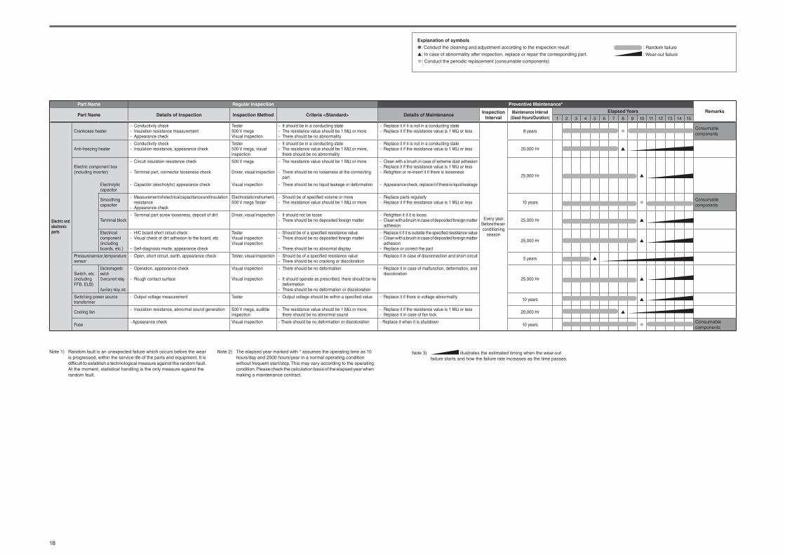
18
Explanation of symbols
: Conduct the cleaning and adjustment according to the inspection result
: In case of abnormality after inspection, replace or repair the corresponding part.
: Conduct the periodic replacement (consumable components)
: Random failure
: Wear-out failure
Part Name Regular Inspection Preventive Maintenance*
RemarksPart Name Details of Inspection Inspection Method Criteria <Standard> Details of Maintenance
Inspection
Interval
Maintenance Interval
(Used Hours/Duration)
Elapsed Years
1 2 3 4 5 6 7 8 9 10 11 12 13 14 15
Electric and
electronic
parts
Crankcase heater- Conductivity check- Insulation resistance measurement- Appearance check
Tester500 V megaVisual inspection
- It should be in a conducting state- The resistance value should be 1 MΩ or more- There should be no abnormality
- Replace it if it is not in a conducting state- Replace it if the resistance value is 1 MΩ or less
Every yearBefore the air-conditioning
season
8 yearsConsumable components
Anti-freezing heater- Conductivity check- Insulation resistance, appearance check
Tester500 V mega, visual inspection
- It should be in a conducting state- The resistance value should be 1 MΩ or more,
there should be no abnormality
- Replace it if it is not in a conducting state- Replace it if the resistance value is 1 MΩ or less 20,000 Hr
Electric component box (including inverter)
- Circuit insulation resistance check
- Terminal part, connector looseness check
500 V mega
Driver, visual inspection
- The resistance value should be 1 MΩ or more
- There should be no looseness at the connecting part
- Clean with a brush in case of extreme dust adhesion- Replace it if the resistance value is 1 MΩ or less- Retighten or re-insert it if there is looseness
25,000 Hr
Electrolytic capacitor
- Capacitor (electrolytic) appearance check Visual inspection - There should be no liquid leakage or deformation - Appearance check, replace it if there is liquid leakage
Smoothing capacitor
- Measurement of electrical capacitance and insulation resistance
- Appearance check
Electrostatic instrument, 500 V mega Tester
- Should be of specifi ed volume or more- The resistance value should be 1 MΩ or more
- Replace parts regularly- Replace it if the resistance value is 1 MΩ or less 10 years
Consumable components
Terminal block- Terminal part screw looseness, deposit of dirt Driver, visual inspection - It should not be loose
- There should be no deposited foreign matter- Retighten it if it is loose.- Clean with a brush in case of deposited foreign matter
adhesion25,000 Hr
Electrical component(including boards, etc.)
- HIC board short circuit check- Visual check of dirt adhesion to the board, etc.
- Self-diagnosis mode, appearance check
TesterVisual inspectionVisual inspection
- Should be of a specifi ed resistance value- There should be no deposited foreign matter
- There should be no abnormal display
- Replace it if it is outside the specifi ed resistance value- Clean with a brush in case of deposited foreign matter
adhesion- Replace or correct the part
25,000 Hr
Pressure sensor, temperature sensor
- Open, short circuit, earth, appearance check Tester, visual inspection - Should be of a specifi ed resistance value- There should be no cracking or discoloration
- Replace it in case of disconnection and short circuit 5 years
Switch, etc.(including FFB, ELB)
Electromagnetic switchOvercurrent relay
Auxiliary relay, etc.
- Operation, appearance check
- Rough contact surface
Visual inspection
Visual inspection
- There should be no deformation
- It should operate as prescribed, there should be no deformation
- There should be no deformation or discoloration
- Replace it in case of malfunction, deformation, and discoloration
25,000 Hr
Switching power source transformer
- Output voltage measurement Tester - Output voltage should be within a specifi ed value - Replace it if there is voltage abnormality 10 years
Cooling fan - Insulation resistance, abnormal sound generation 500 V mega, audible inspection
- The resistance value should be 1 MΩ or more, there should be no abnormal sound
- Replace it if the resistance value is 1 MΩ or less- Replace it in case of fan lock 20,000 Hr
Fuse- Appearance check Visual inspection - There should be no deformation or discoloration - Replace it when it is shutdown
10 yearsConsumable components
Note 1) Random fault is an unexpected failure which occurs before the wear is progressed, within the service life of the parts and equipment. It is difficult to establish a technological measure against the random fault. At the moment, statistical handling is the only measure against the random fault.
Note 2) The elapsed year marked with * assumes the operating time as 10 hours/day and 2500 hours/year in a normal operating condition without frequent start/stop. This may vary according to the operating condition. Please check the calculation basis of the elapsed year when making a maintenance contract.
Note 3) illustrates the estimated timing when the wear-out failure starts and how the failure rate increases as the time passes.

EU DECLARATION OF CONFORMITY
We MITSUBISHI HEAVY INDUSTRIES THERMAL SYSTEMS, LTD. 2-3, Marunouchi 3-chome, Chiyoda-ku, Tokyo, 100-8332, Japan
Description of apparatus: Split Type Air ConditionerModel name:
Relevant EU Directives : Machinery Directive 2006/42/EC
Applied Standards :EN 378-2EN 60335-1EN 60335-2-40
Authorized representative in EU :MHIAE SERVICES B.V.Herikerbergweg 238, Luna ArenA, 1101 CM Amsterdam, NetherlandsP.O.Box 23393 1100 DW Amsterdam, Netherlands
Note : About the detail of Conformity model, see EU DECLARATION OF CONFORMITY sheet included in a package
Conformity model list[Indoor Unit] [Outdoor Unit]
Category
FDC - KX6 Series
FDC - KXZ Series
FDC - KXZPE1 Series
SRC - ZSX - S Series
FDC - VN Series
FDC - VNX Series
FDC - VS Series
FDC - VSX Series
FDC - VNP Series
FDC - VSA Series
FDC - VNX- A Series
Category
FDE Series
FDFW Series
FDK Series
FDT Series
FDTC Series
FDTQ Series
FDTS Series
FDTW Series
FDU Series
FDUH Series
FDUM Series
FDUT Series
FDU-F Series

MITSUBISHI HEAVY INDUSTRIES THERMAL SYSTEMS, LTD.
MITSUBISHI HEAVY INDUSTRIES AIR-CONDITIONING EUROPE, LTD.
MHIAE SERVICES B.V.
MITSUBISHI HEAVY INDUSTRIES AIR-CONDITIONERS AUSTRALIA, PTY. LTD.
MITSUBISHI HEAVY INDUSTRIES - MAHAJAK AIR CONDITIONERS CO., LTD.