PLYWOOD SOUND BARRIERS
12
PLYWOOD SOUND BARRIERS
-
Upload
khangminh22 -
Category
Documents
-
view
4 -
download
0
Transcript of PLYWOOD SOUND BARRIERS
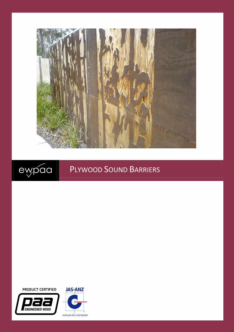
PLYWOOD SOUND BARRIERS

2
TABLE OF CONTENTS Introduction ........................................................................................................ 3 Plywood for Sound Barriers ........................................................................................................ 3 Benefits of Using EWPAA-JAS-ANZ Product Certified Plywood .................................................. 3 Sound .......................................................................................................................................... 4 Sound Attenuation ...................................................................................................................... 4 Sound Leakage ............................................................................................................................ 4
Sound Barrier Design Process ............................................................................. 5 1. Determine Sound Attenuation Requirements ........................................................................ 5 2. Determine the Path Length Difference ................................................................................... 5 3. Determine the Required Barrier Height .................................................................................. 7 4. Select a Suitable Plywood Thickness ....................................................................................... 8
Worked Examples ............................................................................................... 9 Case 1 – Determination of Noise Barrier Height ......................................................................... 9 Case 2 – Determination of Noise Barrier Thickness .................................................................. 10
Revision History ................................................................................................. 11

3
Introduction Sound barriers are barriers that provide a reduction (also known as “attenuation”) to the sound produced from road traffic noise, usually in order to satisfy various local and state requirements. Plywood is a popular material used in the construction of sound barriers as it is lightweight, strong and is commercially available in large volumes. This manual will allow the reader to determine the sound attenuation that can be achieved using plywood as a sound barrier.
Plywood for Sound Barriers As sound barriers are an external application in fully exposed conditions, designers should always specify Structural Plywood to the Australian and New Zealand standard AS/NZS 2269. Structural plywood has an ‘A’ Bond which is an adhesive that is durable in fully exposed conditions. Preservative Treated When used as sound barriers, structural plywood must always be preservative treated to protect against mould, deterioration, termites and insect attack. Treatment should always be in accordance with the Australian standard of preservative treatment of plywood - AS 1604.3. This standard specifies “Hazard Classes” which determines the types and levels of preservative chemical that must be used. For sound barriers, the following hazard classes must be used :
When the sound barrier is above the ground – H3.
When the sound barrier is in direct contact with the ground – H4.
Benefits of Using EWPAA-JAS-ANZ Product Certified Plywood
Product certification to relevant Australian and New Zealand Standards.
Product acceptance by building and lending authorities.
Deemed to satisfy product certification requirements of the Building Code of Australia (BCA).
Availability of technical data relating to product application in residential and commercial construction.
Defined and predictable physical and mechanical properties.
Availability of professional advice from qualified EWPAA technical staff.
Compliance with SAA Codes of Practice, AS 1684 Residential Timber-Framed Construction Code, AS 1720 Timber Structures Code, and AS 3610 Formwork for Concrete Code.
EWPAA-JAS-ANZ branded product is recognised by the Federal and State governments as meeting their purchasing requirements.
Readily available due to local production.
Reliability of design data.

4
Sound Sound can be defined as a travelling wave of pressure fluctuations, composed of frequencies within the range of human hearing and at a level sufficiently strong to be heard. Sound is measured using a decibel scale (dB). Since the human ear responds non-uniformly to different sound frequencies, it is normal to modify or “weight” the measurement to simulate the ear’s response. This results in the a-weighted reading or dBA. In this manual, sound coming from road traffic is of primary concern. .
Sound Attenuation Sound barriers are designed to provide road traffic noise attenuation. When sound is emitted from road traffic (the source), it can reach the person listening to the noise (the receiver) by three possible paths :
1. Diffraction – the sound bending over the top of the barrier. 2. Transmission – the sound travelling through the barrier. 3. Leakage – the sound leaking through gaps in or under the barrier
Sound Leakage When sound barriers are installed, there can be gaps between panels and gaps between the bottom of the barrier and the ground. These gaps are referred to as “Leakage” and adversely affect the performance of sound barriers. A leakage area as small as 1% of the surface area can adversely affect performance. This would correspond to a 20mm gap under a 2m high barrier. Designers must ensure that leakage is minimised, and where possible eliminated. Gaps between panels can be eliminated using lapped joints, T&G joints, or for high performance systems, using two layers of ply with the joints staggered between the layers. Gaps at the base of a barrier can be eliminated by either :
1. Burying the toe of the sheet in the ground (not preferred as this mandates the use of H4 treated
plywood); or 2. Using a concrete kerb; or 3. Using a sacrificial treated pine sleeper to seal the gap. Note that the design section of this manual assumes that there is no leakage present.

5
Sound Barrier Design Process This section will now step the reader through the process of determining the attenuation they can expect from various designs. The process is summarised as follows :
1. The designer must first determine the attenuation requirements. Please note : This manual does not attempt to assist the designer in any way with determining attenuation requirements. Its purpose is to give guidance on designing the barrier height and thickness necessary to achieve a specified level of attenuation. Nor does this manual deal with structural aspects of barrier design, which will vary from site to site depending on wind loading and local ordinances. This manual must only be used to assess if a particular design is likely to satisfy the requirements. Physical testing of individual systems is the only way to determine exact sound attenuation performance. In some cases, local regulations may require that designs are certified by a certified acoustic or structural engineer. The EWPAA cannot certify acoustical or structural designs and if required, designers must seek assistance from suitably qualified engineers. For acoustical design assistance, it is recommended that engineers belonging to the Association of Australian Acoustical Consultants (http://www.aaac.org.au) be consulted.
2. Calculate the required “Path Length Difference”. 3. Determine the barrier geometry (height) required to achieve the required path length difference. 4. Select the appropriate plywood to complement the design height.
1. Determine Sound Attenuation Requirements In order to design a sound barrier, designers must first determine the attenuation requirements in dB(A). These requirements are usually specified by Local Authorities or by State Instrumentalities. They vary from site to site and depend on factors such as traffic numbers, traffic speeds, percentage of heavy vehicles, road surface type, and geometry including the distance from the road, the topography and the nature of the intervening ground. Requirements generally range between 5dBA and 15dBA; attenuation greater than 15dBA being difficult to achieve using a barrier, unless you use extreme barrier heights.
2. Determine the Path Length Difference The path length difference is effectively the extra distance that the sound has to travel with the introduction of the barrier. Consider the following diagram :
The Path Length Difference is defined as :
B + C – A, units are in metres (m).

6
The source position is taken as the centreline of the nearest traffic lane at a height of 599mm above the road surface. Various geometrical factors affect the path length difference including the relative heights of the source and receiver, the distance from the road to the barrier and from the barrier to the receiver, and the height of the barrier. In most cases, the relative heights of the source and receiver will be set by the local topography and cannot be changed by the designer. Similarly the various distances will be fixed. The designer will only have control of the barrier height. Once the required attenuation is known from Step 1, the required path length difference can be determined from Table 1. To use this table :
1. Search the body of the table to find the cell containing the required attenuation.
2. Traverse horizontally from that cell to the left-most column which gives the required path difference with a resolution of 0.1m.
3. Then traverse vertically from the cell to the top row which gives the second decimal place.
Table 1. Attenuation dB(A) due to Diffraction
Meters Meters x 0.01
0 0.01 0.02 0.03 0.04 0.05 0.06 0.07 0.08 0.09
0 5.0 6.4 7.1 7.6 7.9 8.2 8.5 8.7 9.0 9.2
0.1 9.3 9.5 9.1 9.8 10.0 10.1 10.3 10.4 10.5 10.6
0.2 10.8 10.9 11.0 11.1 11.2 11.3 11.4 11.5 11.6 11.7
0.3 11.7 11.8 11.9 12.0 12.1 12.1 12.2 12.3 12.4 12.4
0.4 12.5 12.6 12.6 12.7 12.8 12.8 12.9 13.0 13.0 13.1
0.5 13.1 13.2 13.3 13.3 13.4 13.4 13.5 13.5 13.6 13.6
0.6 13.7 13.7 13.8 13.8 13.9 13.9 14.0 14.0 14.1 14.1
0.7 14.2 14.2 14.3 14.3 14.4 14.4 14.5 14.5 14.5 14.6
0.8 14.6 14.7 14.7 14.7 14.8 14.8 14.9 14.9 14.9 15.0
0.9 15.0 15.1 15.1 15.1 15.2 15.2 15.3 15.3 15.3 15.4
1.0 15.4 15.4 15.5 15.5 15.5 15.6 15.6 15.6 15.7 15.7
1.1 15.7 15.8 15.8 15.8 15.9 15.9 15.9 16.0 16.0 16.0
1.2 16.1 16.1 16.1 16.2 16.2 16.2 16.3 16.3 16.3 16.3
1.3 16.4 16.4 16.4 16.5 16.5 16.5 16.6 16.6 16.6 16.6
1.4 16.7 16.7 16.7 16.8 16.8 16.8 16.8 16.9 16.9 16.9
1.5 16.9 17.0 17.0 17.0 17.1 17.1 17.1 17.1 17.2 17.2
1.6 17.2 17.2 17.3 17.3 17.3 17.3 17.4 17.4 17.4 17.4
1.7 17.5 17.5 17.5 17.5 17.6 17.6 17.6 17.6 17.7 17.7
1.8 17.7 17.7 17.8 17.8 17.8 17.8 17.8 17.9 17.9 17.9
1.9 17.9 18.0 18.0 18.0 18.0 18.1 18.1 18.1 18.1 18.1
2.0 18.2 18.2 18.2 18.2 18.3 18.3 18.3 18.3 18.3 18.4
Note : The figures in the above table were generated using Fresnel Diffraction Theory as applied by the CORTN algorithms

7
Example For example, if the required attenuation is 14.1 dBA, traversing horizontally will give 0.6meters, and traversing vertically will give 0.08m. Thus, the path length difference to achieve 14.1 dBA would be 0.68m.
Meters Meters x 0.01
0 0.01 0.02 0.03 0.04 0.05 0.06 0.07 0.08 0.09
0 5.0 6.4 7.1 7.6 7.9 8.2 8.5 8.7 9.0 9.2
0.1 9.3 9.5 9.1 9.8 10.0 10.1 10.3 10.4 10.5 10.6
0.2 10.8 10.9 11.0 11.1 11.2 11.3 11.4 11.5 11.6 11.7
0.3 11.7 11.8 11.9 12.0 12.1 12.1 12.2 12.3 12.4 12.4
0.4 12.5 12.6 12.6 12.7 12.8 12.8 12.9 13.0 13.0 13.1
0.5 13.1 13.2 13.3 13.3 13.4 13.4 13.5 13.5 13.6 13.6
0.6 13.7 13.7 13.8 13.8 13.9 13.9 14.0 14.0 14.1 14.1
0.7 14.2 14.2 14.3 14.3 14.4 14.4 14.5 14.5 14.5 14.6
0.8 14.6 14.7 14.7 14.7 14.8 14.8 14.9 14.9 14.9 15.0
0.9 15.0 15.1 15.1 15.1 15.2 15.2 15.3 15.3 15.3 15.4
3. Determine the Required Barrier Height Once the path length difference has been settled, finding the required barrier height is simply an exercise in trigonometry; application of Pythagoras. If you are working from drawings, you will need distances and reference levels to plug into the cross section in Figure 1 above and you will need your calculator to calculate the squares and square roots (refer to Case 1 for a worked example). If you are working at an actual site, there is a simple practical method to translate the required path difference into the barrier height. 1. Stretch a string line from the source position to the receiver position. To avoid being struck by a car,
take your source position as being 1m from the edge of the road rather than the centreline of the near lane, and 0.5m above the ground. Take the receiver position at the approximate position of the window of the dwelling. For a lowset house, set the receiver height at 1.8m above the ground and for a highset dwelling, use a height of 4.5m. (If the house is already there, set the receiver at the centre of the window.)
2. Stretch the line taut and mark on the line the distance from the source to the receiver.
3. To this length, add a length of string equal to the path length difference and hold this point of the stringline against the receiver position. Obviously this will cause the string to go slack.
4. Move to the position of the barrier and raise the string to take up the slack. The height at which the string again becomes taut is the required barrier height.

8
4. Select a Suitable Plywood Thickness To complement the performance of the barrier from diffraction, the sound transmission through the barrier must be attenuated at least 10 dBA more than the diffraction over the barrier. The designer must select plywood that has a transmission loss of 10 dB(A) higher than the required attenuation due to diffraction. The following table can be used :
Table 2. Transmission Loss Through Plywood
Single Panel Two Panels
Plywood Thickness (mm) 13 19 21 25 10 13 25
Transmission Loss (dB) 18 21 21 23 21 24 29 Notes: 1. “Two Panels” refers to 2 panels of the indicated thickness securely fixed to one another to create one
panel. Thus for the Two Panels 10mm thickness in the above table, the combined thickness is 20mm.
2. The values in the above table were calculated using the “Insul” prediction software by Marshall Day Acoustics.
3. 250 Hz is the frequency used for calculating the above table, as this is the assumed predominant frequency of road traffic noise.

9
Worked Examples Case 1 – Determination of Noise Barrier Height Determine the height of a noise barrier using 25mm thick plywood to achieve 11 dB(A) attenuation for the following case :
Step 1. In this example, the required attenuation is stated as 11 dBA. Step 2. Determine the path length difference required :
Look up Table 1 to determine the path length difference that gives 11 dB(A) attenuation due to diffraction. We see that a path length difference of 0.22m achieves this.
Step 3. From the geometry of the design, work out the height of the noise barrier :
We know that B + C = 14.22m ………….. (1)
For a right angle triangle using Pythagorean theory, z = Square Root of (x2 + y
2)
We can now right the equations : o For the receivers side triangle, B = Square Root of (8
2 + Height
2)
o For the sources side triangle, C = Square Root of (62 + Height
2)
Form equation (1), we can now state that : Square Root of (8
2 + Height
2) + Square Root of (6
2 + Height
2) = 14.22m ………….. (2)
By solving Equation 2 for Height, the height of the sound barrier required is 1.23m. Note that there is a Microsoft Excel function called “Goal Seek” which allows this to be done.
Calculate the final height, by adding the distance that the direct line from source to receiver is above the ground – which is 1m. Therefore the sound barrier’s height needs to be 2.23m.
Step 4. Ensure that the transmission loss is at least 10 dB higher than the 11 dBA.
Using Table 2, we can confirm that 25mm thick plywood gives a transmission loss of 23 dB which is 12 dB greater than the required 11 dBA that was determined in step 1 and so is suitable for our design. Note that from Table 2, we can also see that 21mm thick plywood gives us a transmission loss of 21 dB, which means that 21mm thick plywood would also be suitable for this design.

10
Case 2 – Determination of Noise Barrier Thickness Determine the plywood thickness required for the following case :
Step 1. Not relevant in this example as we are only determining plywood thickness. Step 2. Calculate the path length difference :
6.45 + 6.51 – 12.50 = 0.46m Step 3. Using Table 1, determine the attenuation due to diffraction :
The attenuation due to diffraction is 12.9 dB(A) Step 4. Determine the plywood thickness
Using Table 2, we must select a plywood thickness that has a transmission loss of at least 10 dB higher than 12.9. From this table, we can see that 25mm plywood has a transmission loss of 23 dB. Therefore, 25mm plywood is the correct plywood for this case.
11
Revision History
Revision Changes Date Who
1 Initial Release 09/08/10 MB

12
EWPAA Members
Plywood and Laminated Veneer Lumber (LVL) Member Name Location Phone Fax Web
Ausply NSW +61 2 6926 7300 +61 2 6922 7824 www.ausply.com
Austral Plywoods Pty Ltd QLD +61 7 3426 8600 +61 7 3848 0646 www.australply.com.au
Big River Group Pty Ltd NSW +61 2 6644 0900 +61 2 6643 3328 www.bigrivergroup.com.au
Carter Holt Harvey Woodproducts Australia (Plywood) – Myrtleford
VIC +61 3 5751 9201 +61 3 5751 9296 www.chhwoodproducts.com.au
Carter Holt Harvey Woodproducts Australia – Nangwarry LVL
SA +61 8 8739 7011 www.chhwoodproducts.com.au
Carter Holt Harvey Woodproducts - Marsden Point LVL
NZ +64 9 432 8800 +64 9 432 8830 www.chhfuturebuild.co.nz
Carter Holt Harvey Woodproducts (Plywood) - Tokoroa
NZ +64 7 885 5999 +64 7 885 5614 www.chhwoodproducts.co.nz
Fiji Forest Industries FIJI +67 9 881 1088 +67 9 8813 088
IPL (West Coast) Ltd NZ +64 3 762 6759 +64 3 762 6789
Juken New Zealand Ltd (Gisborne) NZ +64 6 869 1100 +64 6 869 1130 www.jnl.co.nz
Juken New Zealand Ltd (Wairarapa) NZ +64 6 370 0650 +64 6 370 0653 www.jnl.co.nz
Nelson Pine Industries Ltd NZ +64 3 543 8800 +64 3 543 8890 www.nelsonpine.co.nz
PNG Forest Products Ltd PNG +67 5 472 4944 +67 5 472 6017 www.pngfp.com
RH (PNG) Ltd PNG +67 5 3255 600 +67 5 3256 165 www.rhpng.com.pg
Valebasoga Tropikboards Ltd FIJI +67 9 8814 286 +67 9 8814 154
Wesbeam Pty Ltd WA +61 8 9306 0400 +61 8 9306 0444 www.wesbeam.com
Particleboard and MDF Member Name Location Phone Fax Web
Alpine MDF Industries Pty Ltd VIC +613 5721 3522 +613 5721 3588 www.alpinemdf.com.au
Borg Panels Pty Ltd NSW +61 2 6339 6111 +61 2 6339 6220 www.borgs.com.au
Carter Holt Harvey Woodproducts Australia NSW 1800 891 881 +612 9468 5793 www.chhwoodlogic.com.au
D & R Henderson Pty Ltd NSW +612 4577 4033 +612 4577 4759 www.drhenderson.com.au
Laminex VIC +613 9848 4811 www.thelaminexgroup.com.au
Tasmanian Wood Panels (Aust) TAS +613 9460 7766 +613 9460 7268
Weathertex Pty Ltd NSW 1800 040 808 www.weathertex.com.au
Visit the EWPAA Website to get the latest information. www.ewp.asn.au
Visit www.ewp.asn.au/register to ensure your products carry genuine EWPAA certification