Sound & Music - Scholar@UC
380
-
Upload
khangminh22 -
Category
Documents
-
view
1 -
download
0
Transcript of Sound & Music - Scholar@UC

CHAPTER1
THEPHYSICSANDPHYSIOLOGYOFSOUND
SECTION1
HOWSOUNDPROPAGATES
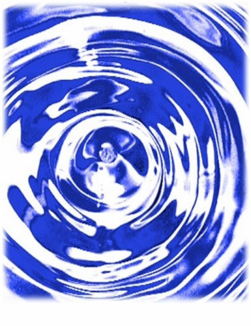
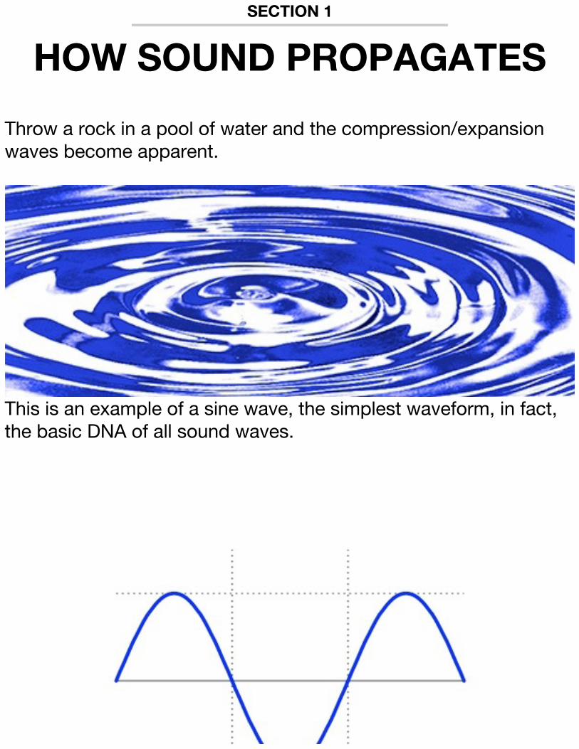
Throw a rock in a pool of water and the compression/expansion waves become apparent.
This is an example of a sine wave, the simplest waveform, in fact, the basic DNA of all sound waves.
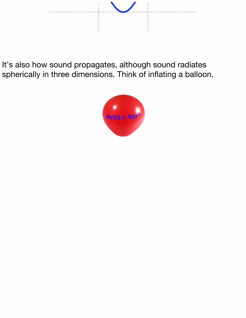
It’s also how sound propagates, although sound radiates spherically in three dimensions. Think of inflating a balloon.

SECTION2
WAVEFORMSANDTIMBRESo, since the sound pressure is constant, and it’s being spread over an ever-increasing spherical area, the intensity of the sound is inversely proportional to the square of the distance from the source. For example, if the distance doubles, the sound pressure will be one fourth the strength. At three times the distance the acoustical energy will be one ninth of the energy at the source.
Clickonthelinksbelowandthroughoutthebooktoplaythevideos.
Howenergyvarieswithdistance
When a sound is created, it radiates outward like ripples in a pool. However, it actually propagates in three physical dimensions. So it travels outward at the speed of sound as an ever-expanding sphere. The total acoustical energy remains constant as this sphere of sound gets larger. So, the energy is spread over an increasingly wider area.
It’s possible to calculate how the energy is spread by using the formula for the area of a sphere, which is 4πr2, where r is the radius, and in this case, is the distance from the sound source.
Therefore, the sound pressure at any point is proportional to the square of the distance from the source. That means that

when the distance from the sound source doubles, the sound at that point will have one fourth the original acoustical energy. And at three times the distance, it would have only one ninth of the original acoustical energy.
WaveformsandTimbreSine waves are the building blocks or the audio DNA of all other waveforms, including triangle, square, and sawtooth waves. The main frequency that humans recognize as pitch, is called the first harmonic and is the fundamental. It’s the lowest frequency in the overtone series. The strength of the other sine waves shape the audio character or the “timbre” of that sound wave.
TimbreThe term “timbre” [pronounced TAM-ber] is the tonal quality of the particular sound. It’s often mispronounced as “timber”, because the spelling of both words is similar.
What makes the tonal quality of the sound is the group of sine waves that produce the fundamental and the overtone series.
Triangle waves have the fundamental and then only the odd harmonics (the 3rd, 5th, 7th, 9th, etc.). The strength of these harmonics is inversely proportional to the square of the harmonic number. So that there’s 1/9 of the 3rd harmonic, 1/25 of the 5th harmonic, 1/49 of the 7th harmonic, and so on. Because the overtones are fairly week, the triangle wave’s timbre is only slightly more complex than the sine wave.
The square wave has the fundamental, and like the triangle
wave has only the odd harmonics, but for the square wave these harmonics are proportional to exactly the inverse of the harmonic number. That is 1/3 of the 3rd harmonic, 1/5 of the 5th harmonic, etc. So its timbre sounds more complex.
The sawtooth wave has the fundamental, but has all of the harmonics, both odd and even. The strength is equal to the inverse of the harmonic number, meaning ½ of the 2nd, 1/3 of the 3rd, ¼ of the 4th, etc. This makes the sawtooth’s timbre very complex.
Be aware that some sounds can also have harmonics that aren’t exact multiples of the fundamental, called inharmonic overtones.
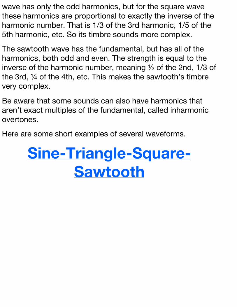
Here are some short examples of several waveforms.
Sine-Triangle-Square-Sawtooth
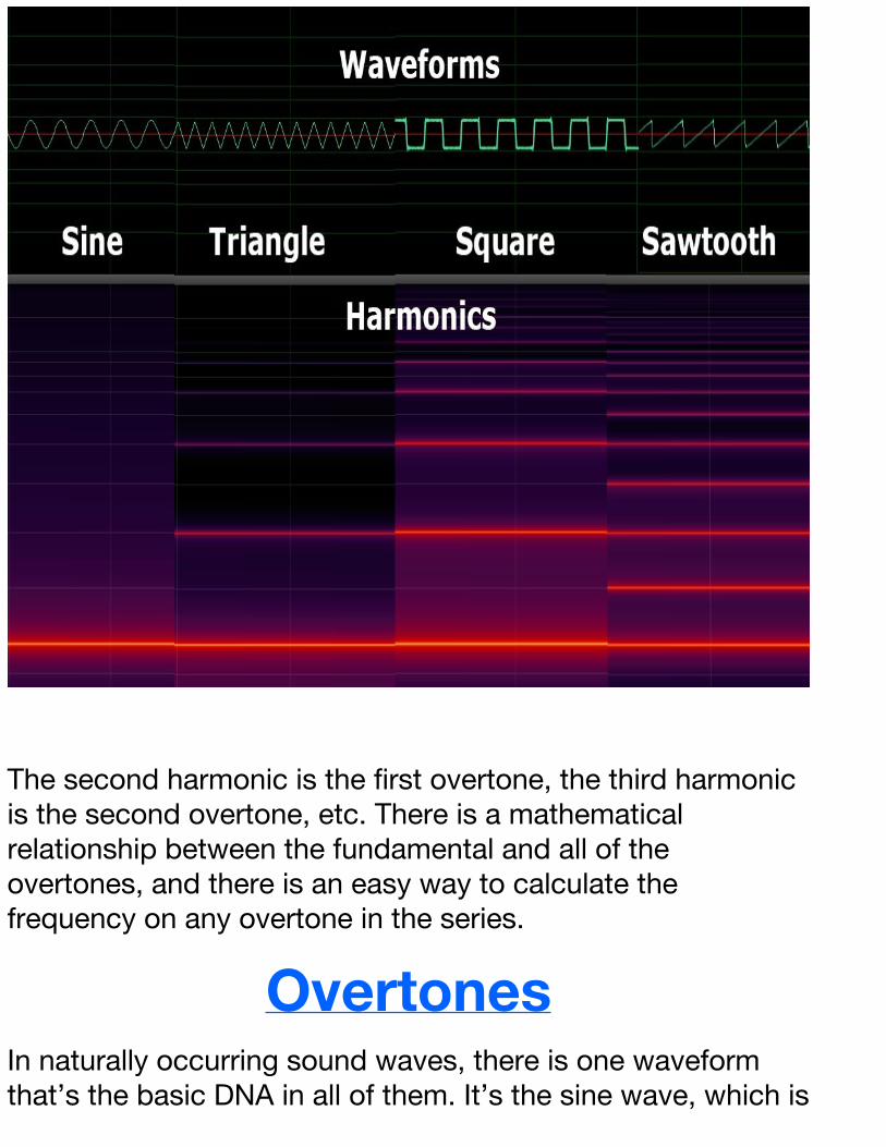
The second harmonic is the first overtone, the third harmonic is the second overtone, etc. There is a mathematical relationship between the fundamental and all of the overtones, and there is an easy way to calculate the frequency on any overtone in the series.
OvertonesIn naturally occurring sound waves, there is one waveform that’s the basic DNA in all of them. It’s the sine wave, which is

the most simple compression-expansion cycle, and how sound moves through air and other media.
Other more complicated waveforms are made up of the initial sine wave, known as both the fundamental and the first harmonic, and additionally generated sine waves, called overtones.
Since the fundamental is called the first harmonic, the first overtone is the second harmonic, the second overtone is the third harmonic, and so on.
There’s an easy way to calculate the frequency of any overtone in a harmonic overtone series. Suppose that the fundamental (the first harmonic) is 1 kHz, to find the frequency of any other harmonic, simply multiply the fundamental frequency by the harmonic number. That would make the second harmonic 2 kHz, the third harmonic 3 kHz, the 10th harmonic be 10 kHz, and so on.
The strength and number of these overtones create an audio texture called the “timbre”, and make it possible for humans and other animals to recognize and identify sounds.
OvertoneSeries(Harmonics)This second, fourth, and eight harmonics are all octaves of the fundamental. The other harmonics also have a musical relationship to the fundamental.
OctaveEvery time the frequency doubles, the pitch becomes one octave higher. So when the frequency changes from 20 Hz to
40 Hz, a difference of only 20 Hz, the pitch becomes an octave higher. When the frequency goes from 10 kHz to 20 kHz, a difference of 10 kHz the new pitch is still only an octave higher.
We tend to think of octaves within the range of human hearing, but if the frequency goes from 1 mega Hertz to 2 mega Hertz, that’s also an octave change.
In a complete harmonic overtone series, with both odd and even harmonics, the second harmonic is twice the fundamental, that’s an octave. The third harmonic, three times the fundamental, would be the musical fifth. The fourth harmonic, four times the fundamental would be the next octave. The fifth harmonic is five times the fundamental making it the musical third. The sixth harmonic, six times the fundamental and twice the third harmonic, is the octave of the musical fifth. The eighth harmonic is three octaves higher than the fundamental.
So a major chord would have the frequency relationship of either 4 to 5 to 6, or 3 to 4 to 5, or 5 to 6 to 8 depending upon the inversion.
At times the fundamental (first harmonic) can be “heard” even when it’s missing.
MissingFundamentalThe fundamental is the first harmonic. The overtones are the additional harmonics that along with the fundamental create the timbre of that sound. In most cases, overtones are exact multiples of the fundamental frequency. For example, if the fundamental frequency is 100 Hz, the second harmonic would
be 200 Hz, the third harmonic 300 Hz, the fourth harmonic 400Hz, and so on.
The work of Joseph Licklider, an American computer scientist and Internet pioneer, in 1954 first noted the phenomenon that the pitch of a sound is perceived by the listener not only by the fundamental, but also by the relationship of the harmonics.
Sometimes the fundamental may not be present, possibly because the speakers can’t reproduce a frequency that low. When this happens the fundamental is still “heard” by the listener, because of the relationship of the overtone series even though the fundamental is not actually present. This phenomenon is called “the missing or phantom fundamental.”
SECTION3
HUMANHEARING-FREQUENCYRANGE
The range of human hearing is ideally 20 Hz to 20 kHz, which is approximately 10 octaves. However, as humans age, their hearing typically diminishes, so that most people hear only about eight octaves near the end of their lives.
20/20HearingHere’s an easy mnemonic to remember what frequencies a human can hear. As perfect vision is generally considered to be 20/20, perfect hearing is also 20/20. That is, ideally a person can hear all frequencies from 20 Hz up to 20 kHz, approximately 10 octaves.
Generally, after people have operated a few power tools and been to a few rock concerts, the range becomes 35 Hz up to 16 kHz. By age 60, most people’s hearing is 35 Hz to 10 kHz, one full octave lower on the high end and nearly one octave less on the low end.
Also, within this range people don’t hear all frequencies with the same loudness.
Generally people hear mid-range frequencies louder than those at the extreme high or low end.
So it’s a great idea to protect your ears from extreme loud noises, so you can enjoy the full range of sound throughout your life.

Wearing ear protection in a noisy environment can help prevent hearing loss. Many historians believe that gunfighters in the old west had hearing issues, since they often practiced shooting and probably didn’t wear any ear protection.
Sound is represented (both as frequency and dynamic range) on a logarithmic scale. Instead of a linear scale with equal distances between every frequency, sound is typically displayed on a logarithmic scale.
LogarithmicScaleLogarithms were developed in the 17th century by Scottish mathematician John Napier, the inventor of base 10 logarithms and
German mathematician Nicholas Mercator, the inventor of base e, also called natural logarithms.
A logarithmic scale is exponential, so instead of being evenly spaced, the numbers get closer together as they go from 1 to 10, and also from 10 to 100, 100 to 1000, and so on. These blocks are known as “decades.” since they have 10 divisions.
The distance between all octaves is the same, for example the distance between 100 and 200 Hz is the same as the distance between 200 and 400 Hz, 400 and 800 Hz, 1 kHz and 2 kHz and even 10kHz and 20kHz. This works well as a display for sound, since, like a piano keyboard, each octave has equal representation.
Within the 10 octaves that humans can actually hear, the sound can be divided into three frequency ranges (bass / midrange / treble).

The first four octaves (from 20 Hz to 320 Hz) are the bass range, also known as the power range, since most of the energy in the waveform comes from these octaves.

Octaves five through eight (from 320 Hz to 5120 Hz) are the mid-range, also known as the presence range. These frequencies are the easiest for humans to hear and understand, but are also the frequencies that fatigue the ear the quickest.

The last two octaves, nine and ten (from 5120 Hz to 20 kHz), are the treble or the brilliance range. This range adds the sparkle and clarity to the sound.
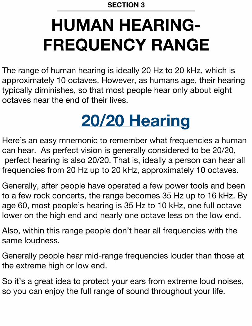
Sound frequencies below 20 Hz are “infrasonic.” Sound frequencies above 20 kHz are “ultrasonic.”
There have been attempts to weaponize infrasonic sound. The most deadly frequency is 7 Hz, as Russian-born Dr Vladimir Gavreau discovered while working in France.
SoundasaWeaponIn biblical times, the walls of Jericho were reported to have been leveled by sound.
In more recent times, loud and obnoxious sounds played at high volume have been used to disorient and annoy an enemy.
In 1957, by accident, Dr. Vladimir Gavreau and his research team discovered that sound could also become a very deadly weapon.
Gavreau’s team was working on robotics research, when they all became very ill. After an investigation, it was discovered that there was an improperly installed ventilator motor in their building, that when coupled with a long airshaft, that acted like an organ pipe, had created an inaudible 7 Hz tone.
Once the team recovered, they decided to research to see if they could repeat what had happen and possibly create a weapon. They called their weapon the “infrasonic organ.” They demonstrated it, and it almost killed them a second time.
In an attempt to make the weapon more compact and controllable, Dr Gavreau created his “infrasonic whistle,” which could be robotically guided onto a battlefield, and kill everyone on the ground…all without making a sound…at least none that anyone could hear.
Until 1964 the unit of frequency was cycles per second.
HertzHeinrich Rudolph Hertz, born 1857, was a German physicist who’s research in electromagnetic theory of light, demonstrated the existence of electromagnetic waves in 1888.
In 1930, the unit of Hertz, being one cycle per second, was adopted by the International Electrotechnical Commission (the IEC).
The human ear ideally hears about ten octaves from 20 Hz up to 20 kHz. Frequencies below this range are infrasonic, and frequencies above this range are ultrasonic.
Radio frequency, abbreviated RF, can be as low as 3 kHz, which is in the range of human hearing, all the way up to 300 billion Hertz,

that’s 300 gigaHertz.
In 1964, the unit was adopted by the General Conference of Weights and Measures. Thereafter, Hertz, abbreviated capital H lower case z, is used in every instance in place of cycles per second.
SympatheticVibrations
Strings produce sound when they’re plucked, bowed, or picked, which sets them in motion. They begin to vibrate, and produce a fundamental pitch as well as the overtones.
However, a string can also begin to vibrate when a sound wave, at or near the sting’s fundamental frequency, reaches it. This phenomenon is known as “sympathetic vibration.”
Some string instruments are designed to use sympathetic vibration, for example, a sitar. Here certain strings, which are not usually played, will resonate, when notes at that pitch are played on other strings of the sitar. However, sympathetic vibration is exhibited to some degree on all sting instruments. Guitar players will often rest their hand on the strings that are not being played, so that those strings don’t start to resonate.
Sympathetic vibration is also a factor in audio feedback. Here, the sound pressure from the speakers can cause strings to vibrate, which sets up a cycle that quickly build-up the intensity of sound at the resonant frequency.

SECTION4
HUMANHEARING-DYNAMICRANGE
As opposed to the frequency range (the highest and lowest
frequencies that humans can hear), the dynamic range refers to the
highest and lowest sound levels. Both human ears and audio
equipment have a dynamic range.DynamicRange
Dynamic range is the difference between the quietest and loudest sounds that humans can hear. Audio devices also have a working dynamic range. People often confuse it with the frequency range, which for humans is ideally 10 octaves from 20 Hz to 20 kHz. Dynamic range is measured on a decibel scale, where 0 dB is the threshold of hearing. About the only place on earth quiet enough to register 0 dB is inside an anechoic chamber, a room that is not only isolated from the real world, but also absorbs all sound that is generated within it. Typically homes and office work environments can have a sound level in the 20 – 50 dB range. Most movie theaters adjust the playback so that the dialog peaks around 85 dB, although the low-frequency effects, (the gunshots, crashes, and explosions) can be at a higher level. As sound gets even louder, it can be damaging to human ears. The Occupational Safety and Health Administration (OSHA) suggests

that more than 15 minutes of unprotected daily exposure to 115 dB (SPL) sound pressure level will result in permanent damage. Therefore, care should be taken (meaning the wearing of ear protection) whenever the sound pressure level is extreme. It’s possible with digital audio to achieve a dynamic range that’s much greater than was possible with analog audio, but how much is really necessary?
IdealDynamicRangeIdeally, a recording would have enough dynamic range so that the listener would hear all the program material without hearing any distortion in the loudest passages or noise on the quietest passages. The dynamic range of a digital audio signal can be easily calculated by simply multiplying the bit depth by six. Therefore, a 16-bit recording, like a CD, using the full 16 bits would have 96 dB dynamic range, a 24-bit recording, again using all bits would have 144-dB, and a 32-bit recording could have 192-dB dynamic range. To full appreciate the 144-dB dynamic range of a 24-bit recording, the listener would have to be in an anechoic chamber, the only place where the volume levels can be 0 dB, the threshold of human hearing. They would also need to be listening to a speaker system that could produce ear-damaging pain levels of 144 dB. However, most listening environments have a much higher noise floor that can be between to 25 - 50 dB or more. This noise floor can be lowered by about 20 dB if the listener wears headphones, but adding 144 dB more to these levels would probably kill the listener. So, even though there are many other benefits of higher bit-depths, the 96 dB of dynamic range that CDs offer is more than enough for any project. This includes classical recordings that generally have 60 dB of dynamic range, five times more than most other musical
genres. Like the frequency range, the dynamic range is also represented on a logarithmic scale. The Bel (in honor of Alexander Graham Bell) is the loss of signal strength in one mile of telephone cable. The decibel (dB), one-tenth of a Bel, is the unit used to measure sound pressure level, loudness, and volume
DecibelAfter Alexander Graham Bell invented the telephone, and telephone lines began to be strung up all over, the Bel, was the loss of signal strength in one mile of telephone line. A decibel is then one tenth of that. A microphone output is generally in the range of -65 to -85 dB. Line level, the signal level that audio devices operate is typically +4 dB for professional gear, like recording consoles, digital audio workstations, tape recorders, and outboard signal processors. For consumer gear like TVs, CD and DVD players. the line level is -10 dB, 14 dB lower. Generally any analog input or output that uses an RCA or phono connector is at the -10 dB level. Although a 14-dB difference between professional and consumer line level may not seem like that much, remember that an increase of only 6 dB doubles the volume.

SECTION5
LOUDNESSANDVOLUMEThere are two terms that are usually considered synonymous. Those terms are “loudness” and “volume.” However, there is a difference, and it depends on the definition of sound.
LoudnessandVolumeEighteenth century philosopher George Berkeley once asked, “If a tree falls in the forest and there’s no one around, does it make a sound?”
Although the question is more of a starter for philosophical discussion, it does help illustrate the difference between loudness and volume. The answer to Berkeley’s question and the difference between loudness and volume all depend on how you define sound. For instance, if you define sound in physical terms, that is, physical changes in air pressure that can be measured by audio meters. Then the falling tree does make a sound.
However, if you define sound in physiological terms, sound pressure reaching a human eardrum so that a person actually “hears” sound. Then, if no one is around, there’s no sound.
Volume is a physical measurement, whereas loudness is physiological. That is, any frequency that creates an equal sound pressure would have an equal volume. However, frequencies outside the range of human hearing, no matter what the volume, would have zero loudness.
Even though loudness is physiological, there are actually meters
that can now measure the apparent loudness. These use a loudness scale called “K-Weighting” and “True Peak.”
K-WeightingandTruePeakMany people think that loudness and volume are synonyms, since there’s usually a direct relationship between the two. However, loudness is subjective. Since television viewers all over the world have complained about the loudness of commercials, the broadcaster’s International Telecommunications Union has proposed new standards to make loudness more measurable. As opposed to volume units (VU) that are the standard for analog volume or decibels full scale (dBFS) that are the standard for digital volume, K-Weighting, expressed as LKFS (loudness K-Weighted full scale), has been proposed as a possible standard for loudness. Here, one loudness unit would equal one dB.
K-Weighting is based on perceived loudness. For example, recordings made with more presence due to good microphone placement, or recordings having more mid-range frequencies (the easiest for humans to hear), or those with more dynamic compression, so that the average volume is higher, even though the peak volume hasn’t increased, are perceived as louder than other recordings at the same volume levels.
To better measure loudness, a gate stops the meter when the level falls below -10 loudness units, so that those levels don’t pull down the average. True-peak is an algorithm developed by TC Electronic, that measures not only the actual samples, but also the peaks between the samples. The proposed standard is to have peaks at -24 LKFS, using the gated meter with the True-Peak algorithm, so that the loudness playing field will be leveled for everyone.

Most people feel that television commercials are too loud. However, the peak volume of television commercials are no higher than the peak volume of the other program material.
LoudCommercialsPeople often complain about the volume of commercials, compared to the volume of the television shows. Actually, the peak volumes of the TV shows and commercials are the same!
But even though peak volumes are the same, commercials are louder, because they have a higher average volume and far less dynamic range. (That’s the difference between the loudest and quietest sounds.)
Most TV shows and especially movies are mixed with a greater dynamic range, so that when an explosion happens it’s noticeably louder than the dialog level. However, with commercials there’s very little volume difference between the dialog level and a loud sound effect, like an explosion.
Commercials are mixed with a lot of dynamic compression, which keeps the average volume higher throughout. This makes them louder, even though the peak volumes are no higher than the program they just interrupted.
Now that you know why, maybe the loudness of commercials won’t be so annoying, but probably not.
SECTION6
RED,PINK,ANDWHITENOISEWhen all frequencies happen simultaneously. the result is called “noise.” There are several varieties of noise, including white, pink, and red.
NoiseWhen all frequencies happen simultaneously, the result is called noise. White noise is similar to white light, in that it has equal power density at all frequencies. When represented on a logarithmic scale, the way people actually hear, the energy distribution of white noise is skewed toward the high end. If you attenuate white noise at 3 dB/octave you end up with pink noise, where the strength of each frequency is inversely proportional to the frequency itself, so pink noise has equal power in every octave. This makes it perfectly flat when viewed logarithmically and also very useful for audio professionals. Attenuate white noise at 6 dB/octave and you get Red noise (also known as Brown or Brownian noise, as in Brownian motion). Here, the power of each frequency is inversely proportional to the square of the frequency, so it presents as the opposite of white noise, with more energy in the lower frequencies. Although the term “noise” has a negative connotation for most audio professionals, white noise is used to test filters and amplifiers, and pink noise is used to test the frequency response of mics, speakers, and rooms.
RedPinkWhileNoiseDemo

SECTION7
PHASERELATIONSHIPSWhen the acoustical energy from two different signals is combined, the sound pressure level will increase when both signals are either in compression or expansion at the same time. However, when two audio signals are moving in opposite directions, meaning that one is in compression while the other is in expansion, then the result is a reduction in the volume of the sound.
AcousticalPhaseRelationshipsAs sound waves interact, they can either strengthen or weaken the resultant sound. When two identical sound waves are produced simultaneously at the same location, the disturbance of the air (the compression and expansion cycles) will be in phase and the resultant sound will be reinforced. This can produce a sound wave with twice the amplitude of either of the original signals.
On the other hand, when identical sound waves originate from different locations, their phase relationship will probably not match 100 percent of the time. When these signals combine there may be portions of the signal that are reinforced. This is where the compression and expansion happen at the same time for each signal, and is known as constructive interference. There may also be portions of the signal that are out of phase, meaning that when one signal is in compression, the other is in expansion. This is known as destructive interference.
If two identical signals are completely (meaning 180 degrees) out of phase, the two signals will cancel each other.


SECTION8
SOUNDCHARACTERISTICSAnother factor that affects timbre is the amplitude envelope. The volume or amplitude is usually displayed on the Y or vertical axis, and time is displayed on the X or horizontal axis. The four segments of the amplitude envelope are the attack, decay, sustain, and release, represented by the acronym ADSR.
AmplitudeEnvelopeIn addition to the overtone series, another factor that greatly affects the timbre or the character of a sound is the amplitude envelope. An amplitude envelope is the waveform that’s typically displayed on digital audio workstations, and it’s essentially the shape of the sound over time.
The envelope can be divided into four areas. The first is the attack portion. This is how the sound starts. It’s also the portion of the envelope that most affects the timbre.
The next portion of the envelope is the decay. The decay starts where the attack portion begins to lose amplitude. It’s also known as the initial decay to differentiate it from the release, which is the decay at the very end of the amplitude envelope.
The third portion is the sustain, which is where the decay reaches a steady state and the amplitude remains fairly constant.
The fourth and final portion is the release. This is where the sound fades out.
Analog synthesizers as well as many digital and software synths all
have ADSR (attack-decay-sustain-release) envelope generators. These can be used to modify the timbre by affecting the amplitude envelopes.
Another characteristic of a sound wave is the wavelength, which is the speed of sound divided by the frequency of that particular wave. Wavelength has an inverse relationship to the frequency, so the higher the frequency, the shorter the wavelength, and the lower the frequency the longer the wavelength.
WavelengthEvery frequency, both audible and inaudible, has a distinct wavelength. The wavelength is the distance that it takes for that frequency to travel one complete cycle. The higher the frequency, the shorter the wavelength, since the wavelength of an audio signal is equal to the speed of sound, divided by the frequency.
High-frequency audio sounds have a shorter wavelength that can be absorbed more easily in carpet, wall coverings, and ceiling tile. Lower frequencies need a deeper “trap” to attenuate these longer wavelengths.
Also, because lower frequencies have a longer wavelength, rooms can often be too small to hear some low-frequency sounds. They need to be at least 20 feet in one dimension to be able to develop 60 Hz. This is why it seems so loud when your car has pulled up next to a car that has a subwoofer. The low frequency doesn’t really reach its maximum sound pressure level, until it hits your car 20 to 30 feet away!
One more factor that greatly affects the timbre is the formants.

FormantsCarl Gunnar Michael Fant, an electrical engineer and one of the pioneers in the area of speech synthesis, defined formants as “the spectral peaks in the sound spectrum of the voice.” It can also refer to an acoustical resonance in a human voice.
Formants, like harmonics, are generally present in a series, with the lowest frequency formant f1, and the next highest frequency formant f2, then f3, etc.
Formants create the timbre of a voice, a musical instrument, and other sounds. Because of this, the analysis of formants is essential for voice prints, to positively establish the identity of a voice.
Generally, the formant relationship will be shifted whenever audio is pitch-shifted, resulting in a drastic change in timbre. For example, when a voice is pitch-shifted one octave, it sounds cartoony like “the chipmunks.”
However, some signal-processing plug-ins allow pitch shifting, while maintaining the formant relationship, so that when a voice is transposed within a fairly broad range, the result still sounds like a human voice.
Formants (timbre) and the pitch (frequency) usually have a direct relationship. However, they can be manipulated independently. It’s also possible to make the pitch appear to change by modifying the timbre.
ShephardTonesNamed after Roger Shepard, a cognitive scientist who worked at Bell Labs and was also a professor at both Harvard and Stanford,
Shepard Tones are a series of sine waves, an octave apart, typically in twelve chromatic or seven diatonic steps. When the volume of each note in the series is properly adjusted and the series of notes is looped, the illusion is that the notes continually rise (or descend) in pitch, ad infinitum.
This is an audio illusion that’s analogous to an M. C. Escher print…or a barber pole, where the spinning helical stripes appear to be ever ascending.
In ascending Shepard tones the notes are arranged this way. In the first pair of the series, the highest note of the pair is the loudest. Toward the middle of the series both octaves are equally loud. Near the end of the series the lowest note of the octave pair is the loudest. The opposite is true if the tones are descending.
The Shepard-Risset Glissando is a variation of the Shepard Tone, where as opposed to discrete chromatic or diatonic steps. The notes continuously glide from one pitch to the next.
Click the link to hear a Shepard tone series of seven diatonic steps repeated four times. The illusion is that the notes continue upward for nearly four octaves.
ShepardTonesDemoThe speed of sound (the sound barrier) was exceeded by Chuck Yeager back in 1947 and centuries earlier by anyone cracking a whip.
SpeedofSoundThe speed of sound, also known as the sound barrier, for years was thought to be the theoretical limit for flight speed. Chuck

Yeager disproved that theory by flying faster than the speed of sound in 1947.
The actual speed of sound varies based on the density of medium that it’s moving through. In air, the speed of sound is most affected by temperature and barometric pressure. At 70 degrees Fahrenheit at sea level, sound travels at 1130 feet per second through the air. It travels 60 percent faster than that through water, and 600 percent faster, 18,000 feet per second, through steel.
As the temperature drops to 32 degrees Fahrenheit or 0 degrees Celsius, the speed of sound through the air drops to 1086 feet per second.
To set delay times for speakers for short distances inside a venue, a useful approximation is that it takes sound 1.1 milliseconds to travel one foot. So, if one speaker set is 60 feet closer to audience than another, the closer speakers could be delayed 66 milliseconds, so that sound from both speaker sets reaches the audience at the same time.
Speaking of speed... of all the senses, hearing is the fastest.
HearingisFasterHearing sends information to our brains faster than any of the other senses. It’s estimated that humans hear 20 to 100 times faster than they see. This is because the auditory circuitry in the brain is less-widely distributed, so that audio signals have to travel a shorter distance to reach their destination.
This may be because of evolution, in that audio information can be the most useful for survival. Since sound reaches the brain so quickly, it modifies all other sensory information and can trigger

emotions. For example, humans can hear danger and react to it faster than through the other senses.
Hearing is also not limited to the space in front of us. We can hear 360 degrees in all directions. We can hear over much greater distances than we can see, touch, taste, or smell, and we can hear through solid objects that may block visual and other sensory information.

SECTION9
ENVIRONMENTALSOUNDSThe world is a very noisy place. There are fewer places where man-made sounds aren’t present, either on land, the oceans, or in the sky with aircraft flyovers.
NoisePollutionLike other forms of pollution (air, water, and solid waste), noise can also be a pollutant.
Researchers have found man-made sounds present in some very remote places on earth. Noise pollution from the turbines of ships and their sonar signals can disrupt long-range communication of whales and other sea creatures. Noises from highways, airports, and factories can be an annoyance to humans, and noise pollution is also a problem for audio professionals as well. Sound mixers on films often have noises that come from outside the set pollute the dialog track, making it unusable. In fact, it’s becoming increasingly more difficult to record anything on location without unwanted noises becoming part of the recording.
Environment noises can have lasting physiological effects.
EnvironmentalSoundsIt doesn’t happen every time, but more often than not, when people are asked to hum a musical note in Europe they hum an A flat and people in the United States, Mexico, and Canada hum a B.

The reason for this demonstrates how much environmental sounds are both a conscious and subconscious part of our lives.The musical pitch A flat is in multiples of 51 Hz and the musical pitch B is in multiples of 61 Hz…almost identical to the 50 Hz AC line frequency in Europe and 60 Hz AC line frequency in North America.
People either consciously or subconsciously hear those pitches in lights, AC motors, and in the hum that’s often amplified in audio signals. So, just like an annoying song that gets stuck in our heads, these pitches become “earworms.” Then when we hum a note with no other reference, most people will hum that pitch.Environmental sounds fall into three categories.
Biophony,Geophony,Anthrophony
Electronic musician and sound researcher Bernie Krause coined three terms to classify the types of sounds that make up what he calls the “soundscape ecology.”Biophony includes the non-human animal sounds, like whale songs, bird calls, cricket chirps, and others. Also known as “the niche hypothesis,” biophony describes how each species finds their niche in the audio spectrum, either by using a particular frequency range or by using a particular time of the day, so that their message can be heard. Geophony includes the natural non-biological sounds, like water, wind, rain, and thunder.
Anthrophony includes all the sounds made by humans, both the sound of human voices, and the non-vocal sounds including music and mechanical noises like traffic, heavy machinery, and electrical

hum.Krause has demonstrated how his recordings of ecological soundscapes, when viewed on an audio spectrograph, can show far better than photographs, how the ecology is doing in that particular location. This is because the audio displays a full 360-degree perspective. Krause adds that, “If a picture’s worth a thousand words, a soundscape is worth a thousand pictures.”
Just as electrical waves can add or cancel depending on the phase relationship, sound in a room can add or cancel depending on the room acoustics.
DiffusersWhen sound is reflected between two parallel surfaces, a standing wave pattern is produced. The resonant frequency of the standing wave is equal to the speed of sound divided by the distance between the parallel surfaces.
Standing waves producing resonant frequencies can be an issue in recording studios. In the recording room with the musicians, they can produce strange-sounding resonances. In the control rooms they can cause the mix engineer to try to correct for a problem that may not exist. That is, the mix engineer might add EQ to help cut frequencies that are enhanced or boost frequencies that are eliminated by the standing waves in the control room.One way to eliminate the standing wave pattern is to eliminate the parallel surfaces. However, if that isn’t possible, another solution is to use a diffuser. One type of diffuser has multiple compartments that eliminate the parallel condition by varying the depth of each compartment. Since deeper ones cause the sound to be reflected later than in the shallower ones, these diffusers create time delays within the reflection and eliminate the standing wave.Another type of diffuser uses poly-cylindrical or other angled

shapes to bounce the sound in different directions to eliminate the parallel reflections. Both types of diffusers can work well to eliminate the standing wave patterns created by parallel surfaces.Sound can also be controlled by using a bass trap.
BassTrapIn order to “deaden” a room, that is to make a room less reverberant, several techniques can be employed. Making the walls non-parallel, and using diffusers to eliminate standing wave patterns is helpful. Deadening can also be achieved by addressing the wall surfaces.Materials like fiberglass and Roxul insulation placed on the wall can absorb sound and prevent it from being reflected. Anechoic foam like Sonex, Auralex, and others also are helpful in absorbing sound. However, even though applying these materials directly to the wall will absorb most frequencies, they’re usually not thick enough for the longer wavelengths, so they’re not as effective at low frequencies.
One way to absorb low frequencies, without having to extend the insulation far out into the room, like in an anechoic chamber, is to use a bass trap. It works like this. Pieces of dry wall or particle board are each surrounded by a wrap of fiberglass, Roxul, or other sound absorbing material. These “pillows” of insulation are then hung from the ceiling perpendicular to the nearest wall several inches apart. They’re suspended on wires so that they can freely move. They’re usually hidden by a soffit that’s covered by acoustical fabric. The low-frequency waves pass through the fabric and strike the sound deadening material. Then, since the panels not only have some depth, but can also actually move slightly when disturbed by the sound waves, the low frequency is nearly

completely absorbed, instead of being reflected back into the room. Diffusers can be used on an even larger scale.
NoiseBarriersAnyone who’s ever ridden on an interstate highway will have seen noise barriers lining portions of the road. The Noise Control Act of 1972 mandates them. The noise from cars comes primarily from interaction of the tires on the pavement, whereas truck noise comes primarily from the engine, and as traffic moves faster, there’s also aerodynamic noise. Research shows that the noise from highways that are below grade is the most attenuated, so earthwork berms or concrete, masonry, or metal walls are erected to contain the noise.
Sound propagates in waves through the air, but also a big component of the sound travels along the ground. Because of this, some theatrical productions use what’s called a “stage mouse,” which is a microphone cradled on the floor with the capsule directed at the floor. A PZM (pressure zone microphone) also works by picking up the sound moving along a flat surface.Farmers have noticed that the ambient sound is much quieter after a field has been plowed, since the ruts from the plow make the surface irregular, breaking-up the ground wave. This fact was used to help design a sound barrier for the Amsterdam Airport, where the ground was smooth and flat, and the noise from the air traffic was particularly bothersome to its neighbors. The airport reshaped the ground surrounding the runways and created, what appears to be from the air, a giant diffuser. These large mounds interrupt the ground wave and greatly reduce the noise pollution.When sound sources are in motion the frequency is affected.
DopplerEffectChristian Doppler was an Austrian physicist, astronomer, and mathematician born in 1803. At age 39 he published a study on colored light emanating from binary stars. Doppler suggested that the color of the light depended on the relative speed of the star to the observer.
This theory became known as the Doppler Effect, and it explains why an approaching car horn will have a higher pitch as it’s approaching and a lower pitch as it drives away. When the car is moving toward the listener the sound waves are arriving closer together, which increases the frequency, raising the pitch. As the car moves away, the sound waves arrive father apart, which decreases the frequency, lowing the pitch.Consider an organ using a speaker cabinet with a rotating speaker. As the speaker rotates toward the listener, the pitch is higher. As it rotates away, the pitch is lower.
This vibrato is being produced by the Doppler Effect.The strength and timing of sounds reaching each ear allow the brain to identify the direction and location of the sound source.
HaasEffectHumans hear the directionality of a sound by processing the time delays between audio arrivals at each ear, as opposed to hearing two separate sounds. Some researchers believe that infants, whose young brains have not yet learned how to process audio, hear all sounds separately as echoes. However, at some age, listeners perceive sound as coming from the direction of the first arrival, even if the same sound comes from other directions as well. In fact, a sound from another direction arriving within 5 to 30
milliseconds can be up to 10 dB louder than the original (over twice as loud), without the listener perceiving this as a second sound event. This is known as the Precedence Effect and also as the Law of the First Wave Front, and because of the research in 1946 by Dr. Helmut Haas, it’s also called the “Haas Effect.” Dr. Haas determined that if the arriving sounds are farther apart than 40 milliseconds, humans will perceive an echo, since the brain will have had time to process the two signals separately.
Today, acoustic designers, aware of the Haas Effect, add an additional 10 to 20 milliseconds of delay in the speaker systems of large venues, so that the listener perceives the sound to be coming from the stage, since that sound will arrive before the sound from the speakers. Sound waves are invisible, but there are ways to visualize how sound propagates.
CymaticsPeople are usually intrigued when they see what sound looks like.In 1857 Edouard-Leon Scott de Martinville invented the phonautograph, the earliest device for displaying audio waveforms on paper.The color organs that were popular in the 1960s also were a way of displaying sound. They were essentially colored light panels that would be triggered by certain frequencies. The origins of the color organ actually date back to the 16th century, but the first patent for a color organ was awarded to Bainbridge Bishop in 1877. Bishop’s invention was a light attachment for a pipe organ that would project colored lights onto a screen as notes on the organ were played.
“Cymatics” is also an attempt to visualize sound. Typically a diaphragm is coated with a thin layer of particles that display visual patterns that represent the audio vibrations. In fact, cymatics was used by August Kundt in 1886 to confirm the speed of sound that was originally determined by William Derham in 1696. Kundt noticed that that dust particles inside a tube vibrated and formed a wave when subjected to a single frequency. Since he knew the frequency, he could multiply it by the length of the wave, which he could see and measure inside the tube, and the result was the speed of sound.

SECTION10
SOUNDREPRODUCTIONHumans have two ears, so most music recordings are made in stereo. However, even though there are usually only two speakers (left and right), people perceive sound to be distributed throughout the stereo field.
PhantomCenterMixing in stereo as opposed to mono makes it easier to hear the individual sounds in the mix. It also adds a spatial dimension to the recording.
When listening to a stereo mix, the sound is typically reproduced on two speakers (left and right) or on headphones or ear buds. However, the listener can generally perceive sound coming from locations other than simply the left or right. In fact, most of the sound may appear to come from points located between the left and right speakers. Stereo images can be created naturally by recording with stereo microphones or done by using pan pots to direct the sounds to positions within the stereo field. When an audio signal is routed equally to the left and right, the perception to the listener is that the sound is actually coming from a speaker in the center, even though no center-speaker exists. This non-existent center channel speaker is called “the phantom center.”
Speakers usually do a good job of transforming electrical energy into sound. However, since they don’t always do this perfectly, they can also affect the timbre.
DampeningWhen a spring is stretched and released, it may go through one or more cycles of compression and expansion before settling back to it’s original position. When a string on a musical instrument is struck, plucked, picked, or bowed, it also goes through cycles of vibration. The string will vibrate less if it’s dampened and will produce a shorter sustain and release portion of the amplitude envelope.
Dampening can also be a factor in speakers. When a speaker is excited by a signal it can react in four ways.(1) The speaker can be overdamped, meaning that it’ll return to it’s equilibrium position without any dampening cycles.(2) The speaker can be critically damped, meaning that it will very quickly return to the equilibrium position with very few oscillations.
(3) The speaker could be underdamped, meaning that it’ll oscillate a while before returning to the equilibrium position, or…(4) The speaker could be undamped, and actually oscillate at it’s resonance frequency.Most high-quality studio audio speakers are closer to being critically damped, while many cheaper consumer speakers will tend to be closer to underdamped. This means that especially bass notes, will sound more staccato (have a shorter amplitude envelope) when heard on studio speakers, and more legato (have a longer amplitude envelope) when heard on some consumer gear.
When the entire recording process from mic to speakers very faithfully represents the recorded material, the process is said to be “transparent.”
TransparencyWhen looking through a window that’s totally transparent, objects appear as they really are, with no added color or distortion. When people describe sound as being “transparent,” they’re usually alluding to the fact that it’s not being colored or distorted.
People often use the term “transparent” when listening at higher sample rates or bit-depths, for example, 24-bit versus 16-bit, or 192 kHz as opposed to 44.1, since the higher-resolution recording better represents the original sound. Microphones and speakers that are said to be “transparent” have the flattest frequency response, meaning that they reproduce sound very evenly, across the full range of human hearing. Transient response, meaning how quickly the microphone or speaker responds to the subtle changes in the sound, is also important for transparency. It’s been said that when the recording and playback are “transparent,” the speakers disappear and it sounds like the musicians are actually in the room.
Sound effects and music have very different roles in program material.
SoundEffectsandMusicIn a film mix, sound effects add realism to the action. They make prop weapons seem very real, and they intensify explosions, crashes, punches, and other on-screen and off-screen actions. Sound effects like wind and rain, crickets and birds, can help establish time of day, season of the year, and location.
Music on the other hand, plays a very different role in the mix. It’s the emotion that the director wants you to feel at that particular point in the film. The tone of the musical underscore lets the
audience know when to feel happy or sad, when to be afraid, and when to be very afraid.The music and sound effects track together make up the sound design, a term coined by Hollywood sound editor Ben Burtt, but first awarded to Walter Murch at the 1979 Academy Awards for his work on ApocalypseNow. It’s the vision that harmonizes the various audio elements with the visual elements and creates the sonic character of the production.
To take ambient sound out of the equation, audio engineers and researchers use an anechoic chamber. These rooms are the quietest places on earth. They can get to 0 dB (the threshold of hearing) and even lower.
AnechoicChamberWhen you want to take ambient sound out of the equation, the only way to do it is to go inside an anechoic chamber. These special rooms are designed to absorb all sound reflections, so that anyone, or any microphone in the room will only hear direct sound. If you need to know how much sound a microphone picks up in all directions or how much sound a speaker is pumping out, as well as how much noise an object makes, this is where you need to be.
The way these rooms absorb sound is by lining the walls, top, and bottom of the chamber with large sound absorbing panels. Generally the working surface, what appears to be the floor, is a mesh grid that’s acoustically transparent, so that sound doesn’t reflect off it. In fact, the work surface is typically suspended above the bottom of the chamber, so that part of the room is below it, to absorb sound there too. Because so much sound is absorbed, people can become dizzy or even worse with a prolonged stay in an anechoic chamber, so it’s best not to be in one any longer than necessary to set up for the test.

By the way, the name “anechoic” literally means “without echo,” and these rooms definitely have none. Music is the specific emotion that the director wants you to feel at that moment, but all sound can create an emotional response.
EmotionalResponseMost people are aware of how music can convey emotion, but all sounds can trigger an emotional response in the listener. In radio and television commercials, sounds can help create an emotional attachment to the product being advertised. For example, in a potato chip commercial, including a crunch sound of a chip being eaten makes the ad more effective. Many researchers believe that the main reason that celery is consumed is because of the crunch sound it makes when eaten.Initially, products were marked in print and outdoor ads that featured only visual stimuli. However, with the advent of radio and later, television, advertisers realized that sound, not only the spoken word, but also the sounds of the product being advertised could make those commercials more effective.
It’s been said that when viewing footage of an event without sound, the viewer is a passive observer. However, when viewing the images and sound the viewer becomes engaged. That’s why there’s an old advertising adage that says, “Don’t sell the steak…sell the sizzle.” Music often creates earworms and music with lyrics can create mondegreens.
EarwormsandMondegreensOften a person will get a tune “stuck” in their head. It could be the melody of a jingle or a song, or the music from a movie or a TV

show. When that happens it’s known as an “earworm.” The origin is possibly German from the work “Ohrwurm,” which means catchy or memorable. In any case, earworms, as the name implies, get in our ears and remind us of a particular tune. The term “mondegreen” is the actual definition for misheard song lyrics. This is when your brain substitutes a homonym for the lyrics being sung, so that the meaning is completely changed. For example, a person could hear the lyrics “All of the other reindeer,” but think that the words being sung were “Olive, the other reindeer.”
Composers who create jingles and songs try to write melodies so that they become earworms. They also try to write and record the lyrics so that they avoid creating any mondegreens.

CHAPTER2
THEHISTORYOFSOUNDRECORDING
Timeline
Click the video below to see a short retrospective of many of the

major developments in audio recording. Click on the other links throughout the book to play the additional videos.
TheHistoryofSoundRecording

SECTION1
1820-19001820sThe term “microphone” was actually coined almost 200 years ago.
TheFirstMicrophoneThe term microphone was coined by Sir Charles Wheatstone way back in 1827. His microphone, however, was not like any microphone in use today. It resembled a physician’s stethoscope, but instead of pneumatic tubes that carried the sound to the listener’s ears, it used thin solid metal rods.
Wheatsone realized that sound traveled more quickly through dense media like metal than it did through air. He even proposed transmission of telegraph signals over fairly long distances (from London to Edinburgh) by merely mechanically coupling the telegraph to a wire and propagating the signal by acoustical energy rather than electricity. By the way, when he proposed this in 1823 he called it “the telephone.”
The “kaleidophone” was Wheatstone’s invention for visualizing sound. Similar to his microphone it was a thin metal rod that would have one end placed on the sound source. There was a silvered bead at the other end, which would reflect a 'spot' of light. Due to the phenomenon known as “persistence of vision” as the rod vibrated the in a

darkened room the spot of light would trace the sound patterns.
Even though Wheatstone’s version of a microphone had very limited applications, he was an audio pioneer, and was knighted for his work in 1868.
1850sThe very first sound recordings were made in the1850s.
PhonautographBack in 1859, almost 20 years before the Edison Cylinder, French inventor Edouard-Leon Scott de Martinville invented a device that could actually record sound. His invention was called the phonautograph, and it traced a line that represented a sound wave onto glass or paper blackened by smoke. His intent was to be able to see on paper what speech or music actually looked like.
Scott never considered that his recordings, called both phonautograms and phonoautograms, could ever be played back. Since the waveform was only a flat image, as opposed to the three-dimensional groove, like those later created on the Edison Cylinder, the technology didn’t exist at that time to be able to hear what had been recorded.
However, in 2008, using an optical scanner and a computer,
many of the phonautograph recordings could be played back, making these the earliest recorded sound.
Unfortunately, Scott’s phonautograms could not be played in the 1860s because they were only two-dimensional.
PaleophoneWhen Édouard-Léon Scott de Martinville, inspired by drawings of the human ear, invented the phonautograph in 1857, he made the first sound recordings. However, there was no way to play the recording, since it was only a two-dimensional soot-on-paper drawing of the waveform..
A few years later Charles Cros, a French poet and an amateur scientist, proposed a way to make these recordings playable. Cros suggested that the original phonautograph recordings be made on metal cylinders that could be coated with a thin layer of acid-resistant material. The stylus would etch away the coating as it made the recording. The cylinder could then be submerged in an acid bath to create a groove that would allow the sound recording to be reproduced with a needle.
Cros called this the “paleophone,” also called “voix du passé” (voice of the past). Unfortunately for Cros, he never had the funds to get a prototype made in order to secure a patent, and in 1878 news of Edison’s phonograph had reached France, making his etching process unnecessary. However, even though he never profited from it, during the first 10 years of commercial record production, Cros’ direct acid etching method was used to create the metal masters.

1870s Early recording used an all-mechanical process to capture and reproduce sound.
PhonographTalking into the tin can creates sound waves, which causes the end of the can to act as a diaphragm and vibrate. These vibrations are transmitted to the taught sting, which causes the end of the distant can to also vibrate and reproduce the voice. This simple tin can and string idea was also how sound was recorded for the first fifty years, starting with Thomas Edison.
In 1877 Edison was working on an invention to transcribe telegraph signals for retransmission. His “Edison Cylinder” used paraffin-coated paper, which could be etched by a needle. However, after Alexander Graham Bell invented the telephone, Edison modified is invention to adapt it for voice recording. He replaced the paper with tin foil and the Edison Cylinder could now record voice.
Microphones have been developed and improved over a number of years. This process continues even today.
HistoryoftheMicrophoneThe term microphone was coined by Sir Charles Wheatstone in 1827.
However, the very first microphone was invented by Emile Berliner in 1876, to be used as a voice transmitter for

Alexander Graham Bell’s new invention, the telephone.
Two years later in 1878, David Edward Hughes invented the carbon microphone. It was improved in the 1920s and was an early model for the carbon mics that are still used in telephone transmitters.
The first microphone, that would be considered useful for recording, was a wide range condenser that was developed by E. E. Wente at Bell Labs just before 1920.
n the early 1920s, Dr. Walter Schottky and Dr. Erwin Gerlach invented the first ribbon microphone. Later that decade Dr. Harry Olson’s research lead to the RCA PB-31, a ribbon mic that sounded better than any of the condenser mics of that time.
In the late 1920s Wente also helped develop the first practical omnidirectional dynamic microphone, the Western Electric 618-A. However, the patient for moving coil technology that the dynamic mic was based on, was actually the work of Ernst Siemens way back in 1874! By the 1930s Siemens’ company had developed the first cardioid dynamic microphone.
1880s Edison’s discs were being marketed as business tools, until someone had a brilliant idea.
Gramophone
The idea was that sound recordings could be used for entertainment! Popular songs were recorded on Edison Cylinders. Coin-operated phonographs were then placed in arcades, and they were wildly successful. The idea was that sound recordings could be used for entertainment! Popular songs were recorded on Edison Cylinders. Coin-operated phonographs were then placed in arcades, and they were wildly successful. Four years later German-born American inventor Emile Berliner had a brilliant idea of his own. He reasoned that in mass-producing music, rather than a cylinder, it would be faster to use a flat rubber disc that could be stamped in one operation. Working with machinist Eldridge Johnson, Berliner’s Victor Talking Machine Company started producing music on 7” flat rubber discs. The company also produced the Gramophone that later became the Victrola, the most popular record player of that era. Someone had the idea that people would pay to hear recorded music...what a concept!
JukeboxesIn November of 1889 Louis Glass and William Arnold invented the nickelodeon, a coin operated machine that would play a single Edison Cylinder after a coin was deposited and the spring was wound with a hand crank. Their first machine was installed at Palais Royale Saloon in San Francisco, where it generated $1000 in only six months, proving that people would actually pay to hear recorded music. In 1918 Holbart Niblack invented a mechanism so that multiple music selections could be played on the same device, so by 1927 Automatic Music Instruments Company AMI, introduced the first

selectable music player. Justus Seeburg developed the “Audiophone” that had eight turntables playing 78 rpm flat discs, as opposed to Edison Cylinders, and later Seeburg introduced the “Selectophone” that had ten turntables. In the 1940s these music players started to be called “jukeboxes,” derived from the term “juke joints,” a derogatory name for a venue with extremely rowdy patrons. In the late 40’s, companies like AMI, Seeburg, Wurlitzer, and others began building jukeboxes with a large menu of songs and some with neon and bubble lights. When 45s started to be produced in 1948, the jukeboxes switched from 78s to 45s. Jukeboxes also had counters that recorded how many times each song was played, so that owners could remove less popular records and replace them with more popular ones. In fact, it was the jukebox that inspired Todd Storz to develop “Top 40 Radio.” The peak of jukebox popularity was from the 1940s through the 1960s, and in the 40s, three quarters of all records pressed went into jukeboxes! 1890sEveryone at that time was recording mechanically, except for one person.
ValdemarPoulsenThe concept of magnetic recording belongs to Danish physicist Valdemar Poulsen. Born in 1869, he never graduated from a university, but in 1898 he obtained a patent for his “Magnetic Telegraphon.” It was a device similar in appearance to Edison’s cylinder, but instead of using direct sound pressure like Edison’s

invention did, the Telegraphon used a microphone and electricity, and recorded sound onto steel wire magnetically. Poulsen had prototypes of reel-to-reel magnetic wire recorders, magnetic tape recorders, and even the first magnetic disc recorder. He even suggested that a magnetic strip could be placed on the credit cards that were used in Europe at that time! Others may have developed the first commercial wire, tape, and disc recorders, but Valdemar Poulsen is the father of magnetic recording. For sound reproduction there are several types of speakers, but by far, the most popular and widely used is the cone speaker.
ConeSpeakerThe cone speaker that’s used in the majority of today’s speaker systems was invented back in the 1800s. Like the first microphone, which is essentially a speaker in reverse, development with improvements came in stages. As early as 1861 Johann Philipp Reis, who was working on a telephone prototype, had a speaker that could reproduce tones clearly, and after some tweaking could also reproduce a very muffled-sounding voice. In the 1870s Thomas Edison, Nikola Tesla, Ernst Siemens, and Alexander Graham Bell were all trying to develop a working loudspeaker that could reproduce a human voice. Bell’s speaker used a permanent magnet and an iron diaphragm and was part of the telephone that he was granted a patent for in 1876. Edison was issued a British patent for a compressed air speaker system for his cylinder phonograph, but instead opted for a diaphragm that was amplified by the metal horn, the exact reverse of the recording process. The Victor Talking Machine Company

had also developed a compressed-air loudspeaker for one of their record players, known as the “Auxetophone.”However, since there was no way to control the volume, it was too loud for homes and only used in public venues. Then, in 1898 Sir Oliver Lodge, a British physicist and writer, who was working on wireless telegraphy, invented the dynamic moving-coil speaker, which is the forerunner of all modern cone speakers.
SECTION2
1900-19301900 Many people were trying to develop a way to communicate wirelessly. Most involved using the Morse Code dots and dashes. Finally, one person developed a way to communicate wirelessly using voice.
AMRadioIn the 1890s both Marconi and Tesla were working on developing a method for wireless broadcasting. And both men were focused on transmission of Morse Code, the dots and dashes that were used for the telegraph. Marconi’s radio used a spark-gap generator that broadcasted either a long burst of noise for a dash or a short burst for a dot, as the telegraph key was pressed. These bursts were picked up some distance away by a device called a “coherer,” essentially a wireless telegraph receiver. Canadian Reginald Fessenden at that time thought that broadcasting should not be limited to the telegraph, which was a soon-to-be obsolete technology. After all, Alexander Graham Bell in 1876 had invented the telephone, which could now transmit voice over wire, and Fessenden thought that both voice and music should also be able to be broadcasted as well. Based on the research of Heinrich Hertz, Fessenden proposed using a high-frequency sine wave carrier signal to amplitude modulate the audio signal, and in doing this, invented AM radio. To receive these AM signals Fessenden used an electrolytic detector,

which was a forerunner of a crystal radio receiver. Fessenden called this the “liquid barretter,” from a French word meaning exchanger, since it changed the radio signal into sound. Fessenden helped design an alternator-transmitter that was specially built for him by General Electric. Although the frequency and the power output were both less than he had hoped for, on December 21, 1906 he was able to broadcast voice. Three days later on Christmas Eve, he read a passage from the Bible, played a phonograph recording of a Handel piece, and played “O Holy Night” on his violin, making this the first music broadcast 1910s As more recordings are being made, there are fewer sales of sheet music. Because of this, several composers decide to form a union.
ASCAPandBMIIn the 1890s after music began to be recorded and sound recordings began to be sold, music publishers and composers, who made money on the sale of sheet music saw their revenues decrease every year. So in 1914, composer Victor Herbert decided to form a union to bargain collectively with the record companies. He signed up popular composers like Irving Berlin and John Philip Sousa, and founded ASCAP, the American Society of Composers, Authors and Publishers. ASCAP negotiated fees from the record companies to help offset the loss from sheet music sales, and after radio began broadcasting in the 1920s, ASCAP negotiated rights with the broadcasters as well. Then in 1939, when ASCAP proposed a large increase in rates for

radio, the National Association of Broadcasters decided to start their own composer/publisher organization to compete with ASCAP. They formed BMI, Broadcast Music, Incorporated, and two years later, all radio stations refused to negotiate with ASCAP, preferring instead to play only music by BMI composers and publishers. Eventually ASCAP and the broadcasters reached an agreement and today almost all American composers and publishers are represented by either ASCAP or BMI. 1920s Originally, radio was a way to communicate wirelessly point-to-point. However, some visionaries saw what radio would soon become.
HowRadioBeganNo matter whether it was Marconi or Tesla who actually invented radio, both men saw radio as a simply point-to-point communication device, essentially a wireless telegraph. However, as early as 1907, American Lee De Forest saw radio for what it would eventually become, a way to broadcast news and entertainment. He proposed exactly that and began broadcasting from low-power and temporary radio stations. When World War I began, the government ordered these radio stations to cease broadcasting for national security reasons. After the war ended, a Westinghouse executive in Pittsburgh asked Frank Conrad, one of their engineers, who had been doing amateur broadcasts from his garage, to move the equipment to the Westinghouse plant. There, Conrad was able to tap into more power and greatly increase the station’s range. That station

became KDKA, the first radio station to get licensed by the Department of Commerce.. In 1921 the US government created a radio monopoly from the major players in the new medium, including American Marconi, GE, AT&T and Westinghouse. The new company was called the Radio Corporation of America, and David Sarnoff, who worked for Marconi was made RCA’s commercial manager. Radio was initially commercial-free. Since all of the broadcasters were vertically integrated (meaning that they manufactured the radio receivers as well as broadcasting the program material), their goal was to sell more radios.
TheFirstRadioCommercialRadio was commercial-free when it began. The way radio was monetized was that it encouraged people to buy radios. So, most broadcasters were also involved in the manufacturing of radio receivers. One of the largest radio manufacturers was Powel Crosley Jr. When his son asked for a radio as a gift, Crosley was appalled at the $100 price tag. So, together with his brother Lewis and two engineering co-op students from the University of Cincinnati, he began building radios. He also started broadcasting in 1922 to promote radio sales. His station WLW started with only 50 watts, but soon became a radio giant broadcasting with 500,000 watts and a clear channel, meaning that no other radio stations were on that frequency. Soon though, as almost everyone now owned a radio,broadcasters had to find another way to make money. So in 1922, what’s now WNBC in New York, then WEAF, broadcast what is purported to be

the first ever radio commercial…a ten-minute ad for an apartment complex in Jackson Heights. Almost fifty years after Edison invented the phonograph, almost all recordings were still done mechanically. Then in 1925...
ElectricalRecordingIn 1920 in addition to Victor, Edison and Columbia, there were about 150 record labels, all making records and/or record players. All of these records were being made using the non-electric technology that Edison had developed 50 years earlier. Then in 1925 a new and improved technique called “electrical recording” was developed using microphones and amplifiers, basically the same way that recording is done today. These new records had a much-improved quality over the earlier non-electric recordings. However, what made them instantly popular was that they could still be played on the gramophones and the victrolas that people already owned. A year later in 1926, Western Electric also introduced a system to synchronize sound to films. This had been attempted by others years earlier, but since those earlier soundtracks were mechanically recorded, they were not very intelligible.
SoundforFilmAs early as 1900 experimental filmmakers at an exhibition in Paris had screened short films with pre-recorded sound. As the technology for synchronization had improved, there was a screening of short films with sound in New York in 1923. However, the first feature-length film to actually have a synchronized soundtrack was the Warner Brothers film DonJuan in 1926. The film had effects, but no dialog. In 1927 Warner

premiered the first “talkie,” TheJazzSinger, that actually had several lines of dialog. The next year they released TheLightsofNewYork, the first all-dialog film. The Warner Brothers films all used the “Vitaphone” system, meaning that the sound was on 16” phonograph discs (one disc for every reel of film). The turntables were interlocked to the projectors by special motors and were therefore totally synchronized to the film. Camera operators for silent films hand-cranked the film through the camera. However, because sound and picture for “talkie” films were reproduced on separate devices (projectors and turntables), film speeds, as well as turntable speeds needed to be standardized.
FilmSpeedIn 1879 Scottish photographer Eadweard Muybridge invented the Zoopraxiscope, which could animate a series of about a dozen still pictures. He asked Thomas Edison to work with him to combine the moving pictures with Edison’s phonograph to have a total audio-video experience. Edison instead, tasked William Dickson to see if there was a better way to make moving pictures. Dickson rejected the Zoopraxiscope concept, since it only worked for a very short loop of pictures. Instead, he looked at the celluloid film that was recently invented by Hannibal Goodwin. Dickson suggested that the film could be in a long strip, 35-mm wide with sprockets holes on each side so that gears could better move the film. This would allow a much longer sequence of images to be animated. Dickson suggested a frame rate of 40 frames per second. However, early film cameras were not motorized but were actually hand-cracked by the camera operator, which caused the film

speed to vary. Most of the silent films were in the 16 frames per second range. In 1926 Warner Brothers introduced the Vitaphone system, developed by Western Electric, the company that invented electrical recording a year earlier. Warner Brothers first feature with Vitaphone was DonJuan, which had music and sound effects, but no dialog. Vitaphone was double-system, and the sound was played from a synchronized 33-1/3 rpm 16” shellac phonograph disc. It was at that time the film speed was standardized at 24 frames per second, where it remains to this day. Vitaphone was double-system, meaning that the sound and picture were on separate devices. There were also several single-system schemes for movies with sound.
DoubleSystemDouble system is when audio and video are captured on separate devices. It’s called “double system” because there are two separate pieces of equipment being used. For example, during a movie shoot, the video is captured by a camera, and the audio is usually captured on a separate audio recorder. The audio and video are then sync’ed up in post production. In the 1920s when movies were first released with a soundtrack, Vitaphone was double system, since the audio was played back from a 16” phonograph disc interlocked to the projector. On the other hand, single system is when both audio and video are recorded on the same device. Other early films with audio used either the Movietone, Photophone, or Phonofilm systems. These were all single system, where the audio was an optical soundtrack that was actually printed on the film more or less the way it is today.
Of the three popular single-system methods, RCA Photophone was the most successful. It was still used for movies in the 1970s. Photophone got it’s start with Alexander Graham Bell.
PhotophoneCell phones began popping up in the 1980s, but the first wireless phone was 100 years earlier in 1880. Invented by Alexander Graham Bell and his assistant Charles Sumner Tainter, they were able to modulate sound with a beam of light, transmit the light to a distant location, and convert it back to sound. Bell and Tainter called it the “photophone”and it lead to the development of the RCA Photophone system, which created an optical film soundtrack for movies, and was used until 1970. The first wireless phone call was made on April 1 of 1880 from the roof of the Franklin School in Washington, DC to the window of Bell’s laboratory about 700’ away. So Bell invented the first telephone and the wireless phone. Now, if Bell could have only invented texting. Recording sound effects for films was initially more difficult than it is today, since there was no way to easily edit the effects track. One person at Universal Studios was extremely good at doing all of the effects for an entire reel of film in one take.
JackFoleyJack Donovan Foley, born 1891, worked at Universal in Hollywood during the silent movie era. After Warner Brothers started releasing films with sound using the Vitaphone system, Universal followed. Since it was almost 20 years before magnetic tape would be available in America, the music and effects tracks were recorded

live to a phonograph disc, just as they would have done for a radio broadcast. The first film that Jack Foley added sound effects on was Showboat in 1929, a movie that was released as both a silent film and a “talkie.” Foley would watch the picture and duplicate what he saw the actors doing. When there were lots of effects happening all at once, Foley would get the props people to hand him what he needed at the proper moment. He would record the sound effects for an entire film reel (approximately 10 minutes) in one take. Today, because of improved recording methods, Foley recording can done in shorter segments, and can also be edited to make a cue better match the picture. There are special Foley stages that have multiple types of floor surfaces, and props available to match almost any scene. Jack Foley died in 1967, but in the film and audio vernacular his name lives on. About this time the Germany company AEG started selling the first commercial magnetic tape recorder.
TheFirstCommercialTapeRecorder
Danish physicist Valdemar Poulsen, had a working prototype of a magnetic tape recorder back in the 19th century, and Jack Mullin developed America’s first magnetic tape recorder in 1947. However, Mullin’s recorder was a modification of the AEG Magnetophon, which was invented in Germany by Austrian inventor, Fritz Pfleumer almost 20 years earlier in 1928. Magnetic wire recorders, also one of Poulsen’s inventions, were in
use in Germany and America in the 1920s, but were not selling nearly as well as the Dictaphones and Ediphones that used an Edison Cylinder to do the recording. Pfleumer, who had earlier developed a process for putting metal stripes on cigarette papers, used very thin paper coated with iron oxide powder for his magnetic tape. He used lacquer as glue to hold the particles onto the paper. A big advantage of tape over wire was that it could be repaired or edited using glue as opposed to welding the wire. At the end of World War II, Jack Mullin, with the US Army Signal Corp in Europe, sent 50 reels of magnetic paper tape, as well as a disassembled AEG Magnitophon recorder back to his sister in the United States. Once back in the US, Mullin reassembled Pfleumer’s recorder, made some improvements, and rebranded it the Ampex 200. One feature that’s found in nearly every car today was not invented until the late 1920s.
CarRadioIn the early 1920s the first radio stations began broadcasting, and later that decade the first radio networks were formed. May people owned radio, but they were generally large pieces of furniture and no more portable than the Victrola, which was a popular record player made by the Victor Corporation. By the late 20s, inventor Bill Lear, the same guy who would later develop the LearJet, decided it was time to take he radio with you when you drive. So, he invented the car radio, and it’s been a part of the automobile to this day. He called his invention “The Motorola,” combining the words “motor” and “Victrola.” Radio had been doing commercials since 1922, but in 1929 they

started singing them.
Jingles A jingle is a broadcast commercial presented as a song. It’s most often a 30 or 60-second piece of music with lyrics that sing about a particular product or service. The jingle lyrics coupled with a catchy melody help make them memorable and create the musical branding for the advertiser. The very first jingle is reported to have been for Wheaties that ran on radio in Minneapolis in 1929. General Mills was about to discontinue the brand due to poor sales, but the jingle dramatically increased sales in the Twin Cities, so much so, that the jingle was used nationally for Wheaties with great success. For the next 60 years jingles were a ubiquitous part of commercial radio and television, creating many memorable marketing impressions. In 1970, even the Carpenters hit song We’veOnlyJustBegun had been a jingle at one time for Crocker Bank in California. By the early 1990s though, jingles became less popular with advertisers and were viewed as being “old-fashioned.” Commercials at that time began featuring more underscore music without lyrics, and later advertisers began to license pop music and use either the original recordings or re-recorded versions in their advertising. However, jingles can still be heard on radio, television, and the web today, because they build an emotional connection between the brand and the consumer. As self-professed “King of Jingles” Steve Karmen once said, “Nobody hums the announcer.”

SECTION3
1930-19401930s A forerunner of the modern tape recorder was based on Poulsen’s ribbon recorder.
BlattnerphoneUntil 1925 almost all sound recording was done either on cylinders or discs, using direct sound pressure. However, Danish engineer Valdemar Poulsen thought that magnetic recording using electricity and microphones, would be a better approach. Around 1930, inspired by Poulsen, German born Ludwig Blattner licensed wire-recorder technology from German inventor Dr. Kurt Stille. Blattner, then replaced the wire with a steel tape, and created a device similar to Poulsen’s ribbon recorder, which he called the Blattnerphone. Just like Jack Mullin, who brought back two of Fritz Pfleumer’s AEG Magnetophon tape recorders to the United States after World War II, Blattner wanted to use his invention to record sound for movies. Blattner sold several to the BBC, who instead, used them to record and then time-shift programming. Jack Mullin’s initial sales came from Bing Crosby to do exactly the same thing in the United States. The Blattnerphone was also used as the first telephone answering machine and for talking books for the blind. In 1933 the BBC engaged the Marconi Company, who had bought the rights from Blattner, to modify these recorders for better performance. By 1935 the BBC had four of the new Marconi-Stille

recorders in use. These had only a 35 dB signal-to-noise radio and only slightly better frequency response than AM radio. The tungsten steel tapes, which had been 6 mm wide (about like ¼” tape) were now 3 mm wide (slightly narrower than cassette tape) and had a soldered splice every 1000 meters. They ran at 60 inches per second and could record around 32 minutes, about the same as a 2500’ reel of modern magnetic tape at 15 ips. Because there was danger of the tape breaking and injuring anyone in close proximity, the machines were operated remotely from a separate room. From a very simple beginning, drive-in theaters with a variety of different sound systems were very popular for about fifty years.
Drive-InMoviesDrive-in movies were the creation of Richard Hollingshead, who first nailed a bed sheet between trees in his backyard and mounted a movie projector to the hood of his car. Hollingshead was awarded a patent and opened his first commercial drive-in that held about 400 cars in Camden, New Jersey in 1933. For movies with sound he used loudspeakers so that everyone could hear the audio track. It was a commercial success and very convenient for people who lived in the suburbs, and no longer had to drive all the way downtown to see a film. After World War II, with the invention of the all-weather individual car speaker that could be placed in the window of each car, the popularity of drive-in theaters increased. By 1958 there were about 5000 drive-ins from coast to coast. In the late 70s as movies transitioned from mono to surround-sound, the individual car speakers were replaced by broadcasting the soundtrack to a locally unused FM stereo frequency. Each car

would then tune in to hear the movie on the car radio. Rising real estate prices, combined with cable TV, VCRs, and the ubiquitous multiplexes in the burbs led to the general demise of drive-ins, but there are still a few in business today. All recordings had been analog up to that time. However, in the 1930s one British engineer had a different approach.
PCMCommon digital audio file formats like wav, aiff, sd2, ISO, and others are all PCM, pulse code modulation files. Pulse code modulation is a sample and hold method to capture analog signals and convert them into digital signals. The sample rate (the horizontal resolution), is the sampling frequency used in the recording. The bit depth (the vertical resolution), is the number of quantized steps that capture the amplitude of that particular sample. The format was actually invented way back in 1937 by British engineer Alec Reeves for telecommunication applications. PCM was used as encryption to encode audio during World War II, in order to broadcast high-level messages without the enemy intercepting them. Then, in the 1960s, broadcasters BBC in Great Britain and NHK in Japan, as well as the Japanese record company Nippon Columbia, were all developing digital tape recorders using PCM. In 1971, in conjunction with Denon, their tape recorder division, Nippon Columbia released the first digitally recorded LP, Something by Steve Marcus. Later that decade in the US, Thomas Stockham of Soundstream developed the first 16-bit digital multi-track tape recorder and the first digital audio workstation using PCM.
All commercial radio broadcasting at the time was AM (Amplitude Modulation), but that was about to change.
FMRadioEdwin Howard Armstrong was convinced that radio could be improved by using frequency modulation (FM) as opposed to amplitude modulation (AM), which was how radio was then broadcasted. FM has several advantages over AM broadcasting. First, the broadcast bandwidth was wider, meaning both a fuller range of frequencies and also the availability of broadcasting in stereo. Second, since the wavelength was shorter, it required a smaller antenna. And third, FM was not subject to static interference from lightning and many other electrical phenomena. Armstrong obtained patents in the regenerative circuit and the super heterodyne receiver in 1914 and 1918, respectively (both necessary components of FM). In 1934 he was hired by David Sarnoff of RCA, who was interested in new radio technologies. However, Sarnoff soon became concerned that FM wasn‘t compatible with RCA’s vast AM radio empire, and saw it as possible competition. Sarnoff was also much more interested in developing television than any new radio technology, so RCA not only stopped supporting Armstrong’s research, but they also became fairly adversarial and tried to suppress it. Not to be deterred, in 1937 Armstrong was able to finance construction of the first FM radio station W2XMN in Alpine, New Jersey. FM has some definite advantages over AM.
AMandFMAM or amplitude modulation radio was invented simultaneously by Guglielmo Marconi, Karl Ferdinand Braun, Thomas Edison, and Nikola Tesla in the 1890s. All used the research of James Maxwell and Heinrich Hertz. After all four had died, Tesla was finally

awarded the patent in 1943. An AM radio receiver detects and amplifies amplitude variations of the carrier frequency (the frequency of the station, which for AM is in the 300 kilohertz to 3 megahertz range). The bandwidth of AM is fairly narrow with a range from 100 Hz to 5 kHz (only about 5 and a half octaves), and the dynamic range of AM is only about 48 dB, similar to an audiocassette player or an 8-bit digital device. Generally AM radio transmits a mono signal, although stereo is possible. AM signals can be affected by sunlight, electrical interference from lightning and florescent lights, and even buildings. FM or frequency modulation radio was invented by Edwin H. Armstrong, who received the patent in 1933. It uses a carrier frequency with a constant amplitude, where the frequency is modulated by the audio signal. FM has many advantages over AM in that it isn’t affected by electrical interferences. It’s higher in the audio spectrum, 88 megahertz to 108 megahertz, and it has nearly a 10 octave bandwidth, almost the full range of human hearing. It’s generally broadcasted in stereo and has a 70 dB dynamic range, similar to professional analog tape recorders.

SECTION4
1940-19501940sMovies all had mono soundtracks until this film in 1940. This was the first surround-sound film and the first use of VCA automation.
FantasoundIn 1938 Walt Disney was on the scoring stage when conductor Leopold Stokowski was recording TheSorcerer’sApprentice for what was to be a Disney short film. Disney was so moved by the sound of the music that he decided to expand the short film to feature length. However, as excited as Disney was about the music, he knew that the audio quality on film in those days wasn’t very good, so he asked Bill Garity and John Hawkins to solve the problem. The film was Fantasia and Disney’s two audio experts developed a system called “Fantasound,” where the film’s soundtrack was actually on a separate piece of interlocked film. There were three tracks (left, center, and right), making it the first multi-channel soundtrack, and a fourth track that would control the playback levels in the theater, so that even the quietest passages could be recorded at full volume to minimize the noise. This dramatically increased the sound quality, and the two (along with Disney) won the academy award for sound in 1941. The eight-channel recording of the orchestra for the Fantasia

soundtrack is also the first multi-channel recording.
TOGADThe automation that everyone takes for granted with digital audio workstations was modeled after the console automation that was widely used in recording studios starting in the late 1970s. However, it was invented and first used by two of Disney’s audio engineers John Hawkins and Bill Garity back in the late 1930s when they were working on the soundtrack for Fantasia. In an effort to overcome the signal to noise limitations of optical film and also to produce a soundtrack so that the audience felt that they were in the room with a live orchestra, they created Fantasound. Back when everything that had ever been recorded had been mono, the orchestra for the Fantasia soundtrack was initially recorded to eight separate tracks, using eight interlocked film recorders. The violins, violas, cellos and basses, brass, woodwinds, and tympani were close-mic’ed and recorded onto six separate tracks. Track seven was a mix of those six tracks, and track eight was the orchestra recorded with a more distant perspective. On the dubbing stage these eight music tracks along with any dialog and effects tracks were manually remixed to three stems, left, center, and right. VCAs (voltage controlled amplifiers) were the key to Fantasound, as well as later console automation systems. For Fantasound they controlled the playback dynamics of the three stems in the theater. In other words, in quiet passages, instead of being recorded at a lower-level on the film, which would have resulted in the audience hearing both the optical noise and amplifier hum, the signal was recorded at full level, and a set of control tones on a fourth audio track automatically turned the amplifiers down. This meant that as the audience was treated to an experience back in 1940 that was
not to be heard again until 1992 with Dolby Digital 5.1. Because these control tones automated the playback levels in the theater, Hawkins and Garity called their VCA automation system the tone-operated gain-adjusting device, abbreviated TOGAD. During World War II the US government created a program to provide morale-boosting music to the troops overseas.
V-DiscsIn June of 1941, six months before the United States entered World War II, Captain Howard Bronson, a musical advisor to the army, proposed the recording of military marches as well as popular music to increase the moral of the troops stationed overseas. In 1942 Lt. Robert Vincent was assigned to the Armed Forces Radio Service. After meeting with Bronson to discuss the idea, Vincent met with other Department of Defense people and obtained the funding for the program. Another obstacle was a musician’s strike, due to litigation between the union and the four major record companies, which prohibited musicians from doing any recording. In 1943 Vincent got permission from musician’s union president James Petrillo to allow these records to be made. They called these records “V-Discs,” the “V” was for victory. Many of the popular singers, big bands, and orchestras were recorded and issued on 12”-78 rpm discs that would hold up to six and a half minutes of music. However, those records were made of shellac, which was very brittle. In fact, 80 percent of the shellac records shipped overseas were broken in transit. So, Armed Forces Radio Services started issuing V-Discs on 16 inch vinyl records, which were much more durable and much-less breakable.

The V-Discs were a big hit with the troops, who were eager to hear their favorite music, and the program continued until 1949. Governments were learning the value of using radio to broadcast propaganda. To counter the threat from the Third Reich, the United States decided to join the conversation.
VoiceofAmericaPrior to World War II, the Third Reich realized the power that government controlled radio could have. They subsidized a radio called the “Volksempfanger” or “people’s receiver” to make it affordable. By 1941 those radios, which could only receive local medium and long wave (AM) broadcasts were in use throughout Europe, receiving a steady stream of German propaganda. President Roosevelt understood how powerful a weapon radio was and wanted America to have a voice in the conversation. He summoned executives from the major broadcasting companies, to see what could be done in the shortest amount of time. Crosley Broadcasting was selected, since it had been broadcasting overseas with their shortwave station WLWO, and also owned and operated the most powerful AM transmitter in the Western Hemisphere with their 500,000 watt station WLW. They were tasked to build six – 200,000 watt shortwave transmitters, something that had never been done before. They purchased 625 acres of farmland just north of Cincinnati, OH, adjacent to the WLW transmitter, and erected the building, the six transmitters, and the 26 antennas in only one year. The transmitters, known as Voice of America Bethany Station, were considered safe from a coastal attack, since it was far inland, and to be extra secure, there were no microphones at this location. All of the programming originated in New York or Washington, DC. Broadcasting began in 1944 and the radio signals were transmitted to Europe, Africa, and South America under the banner of the VOA

(Voice of America). It was evaluable in World War II and later during the cold war, when it broadcasted programs in 47 different languages to people living under oppressive authoritarian regimes. On November 14, 1995 the Bethany Station shortwave transmitters did their final broadcast, but the VOA continues today to broadcast using FM, satellite, and cellular. The American Federation of Musicians was unhappy that broadcasters were playing recordings as opposed to employing musicians. Their musician’s strike changes the way radio was programmed.
Petrillo’sWarIn 1942 band leader Fred Waring and Musician’s Union president James Petrillo sued the radio industry because musicians were not being paid royalties for radio plays on records. Prior to that time most music that was played on the radio was actually performed live by musicians, and the playing of records was eliminating those jobs. A general musicians’ strike was called, and no records were either recorded or played on radio, other than those deemed necessary for the war effort (like the “V-discs” that were distributed to the troops). However, the ban did not include records that featured a vocalist. So radio stations stopped playing instrumentals, and started playing songs with singers… a radio practice that has continued to this day. When World War II ended one US soldier brought home some very valuable souvenirs.
FirstAmericanTapeRecorderAmerican electronics engineer Jack Mullin was stationed in France

as a radio operator in World War II. As he monitored enemy broadcasts he realized that the Germans had developed a new recording technology. When the war ended he came home with two appropriated German AEG Magnetophon tape recorder and 50 reels IG Farben magnetic tape. It was Mullin’s intent to modify the machine for use in the film industry. However, when he was pitching his idea to investors, Murdo Mackenzie, Bing Crosby’s technical director, was in the crowd and hired Mullin to record Crosby’s radio show. Crosby did become an investor and Mullin, working with the Ampex Corporation, developed America’s first commercially produced tape recorder the Ampex 200, which was introduced in 1947. Mullin made many modifications to the tape recorder including the tape speed.
TapeSpeedsJust after World War II, Jack Mullin of the US Signal Corp appropriated two AEG Magnetophon tape recorders from a German radio station in Bad Nauheim (near Frankfurt), disassembled them, and sent them to San Francisco, along with manuals. These recorders ran at 100 centimeters per second, a nice round number in the metric system. Mullin later modified the Magnetophon to run with motors that worked with 60 Hz US power and slowed the tape speed from 39.4 to 30 inches per second, a nice round number in the English system. Since then, 30 inches per second has been a multiple of all standard audio tape speeds worldwide.

For example, professional multitrack tape recorders use tape speeds of both 15 and 30 inches per second. Reel-to-reel for radio and some reel–to-reel commercial recordings were at 7 ½ inches per second. Lear 8-track cartridges, 3M-Quickload cartridges, Elcasets, and other commercial releases on consumer reel-to-reel tape ran at at 3 ¾ inches per second. Compact cassette speed is 1 7/8 inches per second. Microcassettes run at 15/16 inches per second, as well as books on compact cassettes distributed by the Library of Congress for the blind and visually impaired. Microcassette also have a secondary tape speed of 15/32 inches per second. Higher multiples of 30 inches per second are used by instrumentation recorders, DASH (digital audio stationary head) recorders, and loop bin duplicators. With digital audio, the quality improves as the sample rate and bit depth increase. With analog audio, the quality improves as the tape speed increases, since as the tape moves faster, a higher number of the oxide particles pass over the head, and better define the high frequencies. For almost 65 years, every record had been recorded as a live session. Then, one person changed that.
LesPaulBy the 1940s sound had been recorded in basically the same way for almost 65 years, meaning that a live performance would be captured in real time. Then, guitarist Les Paul had the concept that one person or one group could actually record multiple parts within the same performance. This technique was done in the 1940’s with acetate discs, and no one did it as extensively (or as well) as Les Paul. He called this overdubbing technique Sound-On-Sound, and it

allowed him to layer several parts into a single recording. However working with Ross Snyder of the Ampex Corporation, Les Paul’s invention of multi-track recording in 1956, where sound was recorded separately to be remixed later, forever changed how recording is done. Bing Crosby gave Les Paul an Ampex full-track tape recorder. Les Paul immediately had Ampex add an additional head.
Sound-On-SoundLes Paul, the father of multi-track recording, also invented an early overdubbing technique, which he called sound-on-sound. He asked Ampex, the company that introduced the first American tape recorder in 1947, to modify one of their mono tape machines. Les Paul had them put a second playback head, just ahead of the erase head. Here’s how it worked. He would record the first guitar part and then rewind the tape. He would hit play and record and the tape would playback from the upstream play head, and he would mix that signal with a new part that he was playing live. Then both parts would be recorded at the record head. He would repeat this process as many times as necessary to get all of the parts recorded. Here’s the downside to this technique, and it’s a big one. If he made a mistake, or the mix wasn’t right, he’d have to start all over again on the first pass, since every time the tape was being played back, everything recorded previously was also being erased. Les Paul called it “burning bridges,” but even with the pressure to be perfect on every take, Les Paul and his wife Mary Ford recorded many hit records using his sound-on-sound technique. [It was] no wonder he wanted multi-track. Disc speeds were also changing around this time.

RecordSpeedsWhen Thomas Edison invented the phonograph in 1877, like an early film camera, it was hand cranked, so that the speed was not standardized. People would simply crank the cylinder at a speed that made the voice sound natural. The music cylinders that were reproduced with for nickelodeons were typically recorded at 120- 160 revolutions per minute, which would allow two to four minutes of recording time, depending on the width of the groove. When Eldridge Johnson and Emile Berliner invented the Gramophone disc, they allowed for five minutes of playing time, when the disc rotated at 70 – 80 RPM. In 1925, when Western Electric introduced electrical recording, the disc speed was standardized at 78.26 (nominally 78 RPM). That speed was easily reproducible using a standard 3600 RPM motor with a 46:1 gear reduction. The electrically recorded discs actually sounded as good at 33 1/3 RPM than the older non-electric discs did at 78 RPM. However, record companies at that time decided not to release records at 33 1/3, so that their discs would still be compatible with the non-electric Gramophones and Victrolas that people owned. Shortly after 1925, the Vitaphone system, also developed by Western Electric, to add sound for motion pictures, used 16 inch - 33 1/3 RPM discs that allowed for 11 minutes of recording time, enough for a 1000’ reel of film. Then in 1948, using the microgroove technology developed by Dr. Peter Goldmark, Columbia introduced a 12 inch - 33 1/3 RPM record that they called the LP for long playing. They initially marketed these discs to classical music listeners, who could now hear an entire movement of a symphony without having to change the disc. That same year [actually March of 1949] RCA introduced a 7 inch - 45 RPM record that sounded as good or better than the 33 1/3 LPs. 45s usually only had one song per side, similar to most of the old 78s. RCA

marketed the 45s as being a more convenient size for a single recording, like today’s mp3 downloads. By 1950 record companies had stopped releasing 78s, and by 1951, Columbia and most others were releasing both 33 1/3 and 45 RPM records. In the 1940s the first wireless or radio mic was used.
FirstWirelessMicrophoneThe concept of the wireless or radio mic had appeared as early as 1945 in publications of various radio magazines in the form of build-it-yourself kits. The idea was that you could transmit a signal to a nearby radio like a “Mr. Microphone.” In 1947 Royal Air Force flight engineer Reg Moores developed a working radio mic. He was also a figure skater and first used the wireless mic in a 1949 production of Aladdin on Ice at the Brighton Sports Stadium. Moores attached the wireless mic to one of the skater’s costumes and it allowed full mobility on the ice without worries of skating over a mic cable. Even though it had worked perfectly, Moores never sought a patent, since he was broadcasting on a frequency that was not licensed and therefore illegal. In 1951 Herbert “Mac” McClelland of McClelland Sound in Wichita, Kansas developed a wireless mic for baseball umpires. It was used whenever NBC would broadcast a game from Lawrence-Dumont Stadium in Wichita. In 1953 Shure introduced the Vagabond mic system, the first commercially produced wireless mic. However, it allowed the performer to work no farther than 15 feet from the receiver. In 1948 both RCA Victor and Columbia introduce new record formats.

TheAlbumIn 1948 as turntable reproduction improved, record companies like RCA Victor began producing 45 rpm records for single songs, with one song per side, and Columbia started making 33 1/3 long playing records or LPs, ushering in the Hi-Fi Era. These LPs were called albums and the term dates back to when all discs were 78 RPM. With 78’s, there was typically only one song per side for two reasons. First, there was usually not enough disc space on a 78 for more than one song. However, the most important reason was that the disc was an actual reproduction of a live session. So that to have two songs per side, assuming the songs were short enough to fit, the songs would have to be performed perfectly and recorded in real time, one right after the other, exactly the way the record would play. So to make a collection of eight to twelve songs would require that four to six 78 RPM discs to be bound together in what looked like a photo album. The name [album] continued with LPs, and even today with CDs. In 1949 a jukebox inspired a radio station owner to create a new and lasting format.
Top40RadioIn the 1940s most radio stations were programming radio dramas and variety shows. Then radio station owner Todd Storz, observing how people used jukeboxes, had an epiphany. He noticed that people would play certain songs more often than others. In fact, the most popular songs got played again and again. He felt that if radio programmed music the same way, playing the more popular songs more often, his radio audience would increase. With this belief and also the results of a study he had

commissioned the University of Omaha to do, he converted his station KOWH in Omaha, Nebraska to this new format in 1949. He called the format “Top 40,” since it concentrated the airplay on the 40 most popular songs, based on record sales in the region. Storz also created the disc jockey, the air personality who would talk into and out of the various records.. With the success of his Omaha station, Storz was able to purchase radio stations in New Orleans, Kansas City, St. Louis, Oklahoma City, and Miami, all using this new format. And soon, the rest of the country would be using it as well.

SECTION5
1950-19601950s In 1951 a Swiss company started making tape recorders for the film industry that were used to record movie dialog until the 1990s.
SoundforFilm(Nagra)Oscar-winning audio engineer Loren Ryder of Ryder Sound in Hollywood asked his friend Stefan Kudelski, an audio engineer from Poland, to help him solve a problem. The issue was that Hollywood was using an Ampex 200 tape recorder to record dialog for movies. It sounded great, but it was so large in it took two or more grips to carry it around on the movie set. Ryder asked Kudelski if he could build something a lot smaller. Kudelski’s company made robotics, and he had developed a small tape recorder to send data to the robots. So, he set about to modify his tape machine to be used for movies. His first tape recorder for film, the Nagra I, was introduced in 1951. It was light, rugged, and compact. When the Nagra III was introduced in 1957, it could also record Neo-Pilot tone, which made it possible to stay in sync with the camera. In the following years stereo and timecode models were introduced. These machines were the audio workhorses on all movies until the early 1990s when DAT and other digital recorders became available. By the way, Kudeski called his tape recorder Nagra, because Nagra in Polish means “to record.”
Recording had been done almost exclusively in mono since 1877. However, there were several notable exceptions.
StereoAs early as 1881, French inventor and engineer Clement Ader installed multiple telephone transmitters in the Paris Opera House, so people could remotely listen with one phone receiver at each ear, and hear stereo sound. He called this the “theatrophone.” The term “stereophonic” was actually coined in 1927 by Western Electric, the pioneers of electrical recording. In the 1930s, British audio engineer Alan Blumlein, the inventor of Mid-Side and X-Y recording, received patents for stereo records, stereo films, and even surround-sound. In the early 1930s there were experimental recordings using two mono turntables, one for the left and one for the right, which when cued properly, played simultaneously, and running a the same speed could create a stereo image. Also a scheme using dual grooves on the same disc, one for the left and one for the right, was used by Leopold Stokowski and the Philadelphia Orchestra in 1932 to make several stereo test recordings, which were never released, since consumers had no way to them. In 1939 the Disney movie Fantasia had a three-track playback with the “Fantasound” system. However, outside of these isolated examples, everything at that time was recorded in mono. 1953 was the year that color television was introduced and also the year that San Francisco audio engineer Emory Cook first introduced stereo at the AES convention in New York. He played stereo recordings of the Queen Mary blowing the ship’s horn and also a train approaching, which scared the audience because of the realism of the sound. Cook’s record label not only had a large catalog of stereo recordings, but his company also manufactured a
stereo record press that was smaller and used a different process than the traditional mono presses. In fact, it was often more cost effective for many record shops to buy one of Cook’s presses and make one-off discs of his stereo releases on demand, rather than paying shipping for a quantity of stereo discs. In the early 1950s many manufacturers started to introduce multi-tracks.
Multi-trackTapeRecordersWhen tape was introduced in the US after World War II, all tape recorders were full-track mono, meaning that the sound was recorded over almost the entire width of the ¼” tape. When Ampex introduced a two-track version, it allowed stereo recording. However, many engineers were slow to start using these machines, since the reduced track size also meant a reduced signal-to-noise ratio. In the 1950s, to get around this issue, Ampex introduced a ½” 3-track machine that was still not as quiet as a full-track, but was better than a ¼” 2-track. A year or so later Ampex also introduced a ½” 4-track. Believe it or not, none of these machines were capable of overdubbing, so engineers still were sill recording everything in one take. They’d usually split the ensemble into mono groups. They’d record the rhythm section on track 1, the horns and strings on track 2, and the singer on track 3. If they had a 4-track, they might split a section like the vocals into lead and background singers and record them on 2 tracks. Neither Ampex (nor any other manufacturer) thought that overdubbing was a feature that anyone would ever use! It wasn’t until Les Paul finally got delivery of his special-ordered Ampex 1” 8-track, late in 1956, that multi-track with overdubbing was finally
possible. Les Paul asked several tape recorder manufacturers to build a multi-track recorder that could overdub. Ampex finally agreed to a do it as a special order. They charged him $10,000, since they believed that no one else would ever want a tape recorder like this.
Sel-SyncIn 1956 when Les Paul and Ampex’s Ross Synder developed multi-track recording, there was a big issue that needed to be solved. The issue was, that on a standard three-head tape recorder, there’s an erase head, then a record head, and finally the playback head. The record and play heads were typically 2 to 3 inches apart. So here’s the problem. Say Les Paul recorded the first guitar part on track one, and now wanted to record another part on track two. If he monitored his first part off of the play head, and then recorded his second part at the record head, the second part would be late, when both tracks were played back. This is because, as he was recording the second part, the first part was 2 – 3 inches ahead. At 15 inches per second that would mean the parts could be as much as a fifth of a second (or 200 milliseconds) apart. This would be very noticeable and the overdub would not be usable. Les Paul and Ross Snyder devised a system called Sel Sync, short for selective synchronization. This let the recording engineer choose to make the record head act as a play head for any number of tracks. So, for example, in the previous situation, Les Paul would have put track one into sel sync and then he could monitor that part off the record head, instead of the play head. That way his second part would be perfectly in sync with the first part. This made multi-track overdubs possible, and for the next forty-five years, almost all record were made using sel-sync. The idea of learning while you sleep was too good to be true.
DormiphoneIn movies like TheMatrix the characters learn skills while they sleep, and at one time people attempted to do just that. Originally called the “Cerebrophone,” the “Dormiphone” used a continuous-loop tape player to repeatedly play a message while the person slept. The hope was that the person would retain the information when they we're awake. Although initial testing showed that people did retain some of the information, long-term studies showed that retention decreased very quickly over time, so that there was really no long-term benefit from using the Dormiphone. n the 1950s the Dormiphone was even used in CIA-funded research in an to attempt to "depattern" or deprogram brainwashed subjects. Today, the Dormiphone is both a curios audio invention and a relic of the cold war.
SECTION6
1960-19701960sRecording consoles and broadcast consoles had been identical. Then, in the early 1960s, one brilliant recording engineer changed that forever.
TomDowdandtheRecordingConsole
When recording started to be done electronically in the 1920s, recording studios used the same type of mixing consoles as broadcasters. These mixing desks had large Bakelite rotary knobs that controlled the volume level, and not many other features. Back then, records were mixed live to disc, and the large knobs made it difficult to adjust more than one or two channels at any one time, making the engineer’s job that much harder. So, in about 1960, recording engineer extraordinaire Tom Dowd, who’s discography includes just about every artist that ever made a record, thought that recording consoles should have linear sliding faders, instead of the big knobs, so that the engineer could control up to 10 faders at once. He also added signal processing like EQ, and routing. Dowd designed all of these features into a console that he built for Atlantic Records, and mixing consoles every since, both actual (pause) and virtual (pause), have had those features and that look. Two tape formats created in 1962 and 1965 were very popular.

Cassetteand8-TrackTapesIn 1962 the Philips Company introduced the Compact Cassette. However, it was the Ford Motor Company in 1965 that produced the format that would forever change how people listen to music, when they introduced the 8-track cartridge. This format was created by Bill Lear, the same guy who invented the car radio forty years earlier. In 1966 8-track players for the home started selling, and for the next five years, 8-track tapes became a very popular format. People loved them because (unlike records) you could play them both at home and in cars. In the early 70’s cassettes were improved by using Metal Particle tape and Dolby B noise reduction, and eventually replaced 8-tracks as the medium of choice. But even though the 8-track tape is no longer around, it made people realize that they wanted a music format that could be as mobile as they were. Since analog media has less dynamic range than most digital-audio devices, several noise reduction systems were widely used.
NoiseReductionA problem with analog tape arose when trying to record material that had a larger dynamic range than the tape did. So, engineers turned to noise reduction. Noise reduction systems worked by companding the signal, meaning that the signal was dynamically compressed during recording, so that it would fit within the signal-to-noise ratio of the tape. On playback, the signal would be expanded to restore its original dynamic range. There were two popular analog noise reduction systems, dbx and Dolby. Dbx was founded by David Blackmer, who formerly worked for a company that made medical testing equipment. That

company had also had a signal-to-noise issue, in that when sticking medical probes inside a human body, the voltages had to be very low so as not to kill the patient. Blackmer’s company had developed a companding system so that the measuring voltages could be low, but the data could still be usable. He saw that this technology could be adapted for audio, and stated his own company to do just that. Ray Dolby of Dolby Labs had developed both Dolby A, and later Dolby SR noise reduction. Dolby also created and licensed both Dolby B and C noise reduction for cassettes. Today noise reduction isn’t necessary with digital gear, but for those analog tapes, it made a big difference.

SECTION7
1970-19801970s A new four-channel recording format was popular for a brief time in the early 1970s.
QuadraphonicSoundIn the early 1970s some record companies released material in a four-channel format to create a surround-sound experience for the listener. This format was known as “quad” or quadraphonic. It was a 4.0 format with a left front, right front, left rear, and right rear. The speakers were usually placed in a square pattern, typically the four corners of the room.
Since compact discs wouldn’t be available until 1982, quad recordings were initially introduced on 4-track ¼ inch reel-to-reel tape.
They could also be purchased on a modified Lear 8-track cartridge, first issued by RCA, known as Quad-8 or Q8.
There were three incompatible and competing quad formats on vinyl, SQ, QS, and CD-4. They were called “compatible stereo,” meaning that they were a 4-channel mix that was matrixed to two channels. So, when they were played on a regular stereo record player, all of the music could be heard. It just wouldn’t be in quad.
SQ and QS both appeared in 1971. A year later the third format CD-4 (which stands for Compatible Discrete), also known as “quadradisc,” used a high-frequency demodulation signal
(recorded above 20 kHz on the disc) to separate the front and rear signals into the four separate stems.
The incompatibility of the three formats on vinyl meant that record buyers were limited in selection to records that were released in the specific format they owned. Because of this, quadraphonic sound soon faded into audio history.
There were two movies released in 1975 that had “quintaphonic” soundtracks.
QuintaphonicSoundQuadraphonic was a popular music format in the early 1970s. It was available on discrete four-track reel-to-reel tapes, quad 8-track cartridges, and also as matrixed four-channel sound on vinyl LPs.
In 1975 writer/director Ken Russell released a film version of the Who’s rock opera Tommy in quintaphonic sound. This format used the QS-4 matrix that Sansui had developed to matrix encode the rear speakers and had a discrete center channel for the dialog and some of the music stems as well.
The film used magnetic stripes as opposed to the typical optical soundtrack, so few theaters had the proper equipment to show the movie. The front and rear left channels were encoded on one track, the front and rear right channels were encoded on a second track and the center channel was on a third track. It predated Dolby Surround (also known as Dolby Pro Logic) and was only used on this and one other film.
A new theater sound format introduced movie-goers to the subwoofer.

Sensurround(Subwoofer)In 1974 Universal Studios released the film Earthquake. To enhance the experience, the audio equipment manufacturer Cerwin-Vega, working with Universal, developed a sound system to create low-frequency effects to simulate an actual earthquake.
The “Sensurround System” they created introduced movie audiences to the subwoofer. It worked this way. Instead of mixing the rumbles, which could be as much as 35 dB louder than the dialog, into the movie’s soundtrack, Sensurround used 25 Hz and a 35 Hz control tones, that could trigger two different effects. These tones would either be at low levels on the mono audio track or for some prints could be on separate audio tracks. The frequency and volume of the tones would trigger a pseudorandom noise generator that could, when coupled with the amplifiers and subwoofers, create an earthquake-like rumble at 120 dB.
Sensurround in some ways is similar to Fantasound, that was developed in 1939 for the Disney film Fantasia, in that tones on a control track turned the amplifiers up and down. Initially it was proposed that Sensurround might even have dust fall from the ceiling during the earthquake scenes. However, and perhaps very wisely, they chose not to do that.
Theaters had to be modified to be able to play Sensurround, and that often meant rows of seats had to be removed to accommodate the large subwoofers. Today, subwoofers are a standard part of movie theater sound systems, and low-frequency effects, like rumbles from earthquakes, explosions, gunshots, and crashes are included in almost all movie soundtracks.
Dolby Labs begins to improve the sound in movie theaters.

DolbyStereoFilm soundtracks had used the RCA Photophone system since the 1930s. At that time films only had about a 40-dB dynamic range, and the Academy of Motion Picture Arts and Sciences used a hi-end roll-off to reduce the film noise in the playback.
Dolby A noise reduction had been introduced in 1965, and was being used on analog tape recorders. Starting with the film AClockworkOrangein 1971, some movies were released using a magnetic soundtrack with Dolby A noise reduction. However, since most theaters could not play magnetic soundtracks, the Dolby system was soon modified to work with optical film soundtracks as well.
All these films were still in mono. The problem with stereo is that the center channel is a phantom center, meaning that the listener perceives the sound coming from the center only when situated approximately equidistant from left and right speakers. People in the theater who are seated on the left or the right would not perceive the dialog to be coming from the center. A technique was proposed to send a mono mix of left and right to a center channel speaker, but this was rejected since it would decrease the width of the stereo field.
Instead, working with Kodak, Dolby developed a matrix encoded stereo that was similar to the Sansui QS system. However here, instead of the standard quadraphonic arrangement, it had left, center, right, and surround speakers. Any common audio that was in-phase on the left and right (what would normally be the phantom center) was routed to the center channel speaker, and any audio that was 180 degrees out-of-phase on the left and right was routed to the surround speakers. So in the 1970s, movies went from being

mono to surround without ever going through stereo.
Most production dialog for films was mixed live on the set. However, one director introduced multi-track recording to film.
Multi-trackforFilmAfter World War II when Jack Mullin modified the German AEG Magnetophon and rebranded it the Ampex 200, that tape recorder was used to record much of the dialog for films.
In the 1950s Stefan Kudelski introduced his Nagra tape recorder, which was much smaller, and that became the industry standard for recording dialog. The Nagra as well as the Ampex 200 were either mono or stereo, so the dialog from all for the actors had to be mixed live during production. This was not a problem when the sound mixer and boom operator could follow a script. They would know which actor would be speaking and when, so that they could reposition the booms and adjust the levels of the mics accordingly.
However, in the 1970s director Robert Altman and others often worked with actors where the dialog was more extemporaneous, meaning that the actors improvised their lines. Working this way, the sound crew had no idea which actor would be speaking at any time. To be able to get good presence on all of the actors, Altman used a 1” analog 8-track, so that each actor could be recorded separately. Later the sound department would have to sort out whichever actor was speaking. It meant more work in post-production, but having a each actor on a separate track eliminated the bleed from the other mics, and the dialog presence dramatically increased.
Today, Altman’s multi-track technique is used on almost all films and television shows.

More commercials jingles were being produced by large national music companies. Because of their high volume output, they were known as “jingle mills.”
JingleMillsIn order to create the musical branding for radio and television, starting in the mid 1900s, several companies began to produce station ID packages that included musical themes, bumpers, jock shouts, and the jingles heard ubiquitously in broadcast media.
Since these companies were producing these materials in high volume, as though they were coming from a factory, they were known as “jingle mills.”
One of the more notable jingle mills was Pepper Sound Studios in Memphis, which began syndicating these materials in 1957. It began with John Pepper and Floyd Huddleston. Salesman William Tanner became a partner, and the company changed the name to Pepper-Tanner, and later became the William B. Tanner Company, which was in operation until 1988.
Dallas was another jingle mill hub, with several companies like Tom Merriman’s TM Productions, and perhaps the most famous jingle mill of all…PAMS, (Production, Advertising, Merchandising Service). PAMS not only produced ID packages for radio and television stations, but working with advertising agencies, created many commercial jingles for advertisers as well.
Unlike analog recordings, most digital recordings could not easily be edited with a razor blade.
DigitalAudioWorkstations

As early as 1976 Salt Lake City company Soundstream founded by MIT grad Dr. Thomas Stockham, Jr. had a working digital audio recorder, a 2-track that recorded at a bit depth of 16 and a sample rate of 37 kHz.
Soundstream later modified a Honeywell instrumentation tape drive to create a working 8-track recorder that would record 16-bits at 50 kHz. It recorded the digitized audio to tape running at 35 inches per second.
To edit and remix the recordings, the digital tapes were transferred to a hard disc editor that Soundstream had developed, making this the first digital audio workstation.
Soundstream partnered with audiophile record companies like Telarc as well as mainstream record companies like RCA, Philips, Warner Brothers, Decca, and others to record many of the classical releases for those companies. Even though these recordings were released on vinyl, (CDs weren’t introduced until 1982), people still noticed and appreciated the improved sound quality.
Most good ideas usually take time to gain acceptance. It took the recording industry about 25 years to see widespread use of digital audio workstations.
AcceptingDAWsEven though Soundstream’s Thomas Stockham developed the first digital audio workstation in the late 1970s, it would take another 25 years before the entire recording industry was using DAWs.
The early digital audio workstations were, for the most part, a replacement for a tape recorder. They often had few signal processing or mixing capabilities. This was one reason why it took
such a long time for the recording industry to make the switch to DAWs. However, the biggest reason at that time was the price. Since so few workstations were sold (often only a few hundred of each brand worldwide), they were prohibitively expensive, often priced from $100,000 to $200,000 each.
As computer power dramatically increased, so did the workstation’s capabilities. Gradually DAWs became a replacement for the entire recording studio control room, as they could now record, edit, mix, and master. They could eventually output audio files in every conceivable format. As this was happening, more units were sold, and the price became more affordable.
By the late 80’s-early 90s, studios that specialized in broadcast production first started making the switch, then in 2000 the film industry in Hollywood made the switch, and finally the entire music industry abandoned tape to embrace the advantages of digital audio workstations.
Thomas Stockham Jr, who invented the first DAW, was also a pioneer of forensic audio.
ForensicAudioForensic audio began in the 1970s with the investigation of the Nixon tapes. Dr. Thomas Stockham of Soundstream, who invented the first digital audio workstation, determined that the portion of the tape in question had actually been erased not once, but nine times.
In 1992, Thomas Owen of Owen Forensic Services founded the forensic chapter of the Audio Engineering Society to extend the knowledge of forensic practices worldwide, write Standards, and to identify areas requiring more research.
Forensic audio today is involved in three areas…audio enhancement, audio authenticity and voiceprint identification.
Audio enhancement involves making the audio more intelligible. The goal is not to make the dialog sound full-fidelity, but specifically to be able to determine what had been said. Audio enhancement requires highly specialized signal processing, and is always more time-consuming than is depicted in movies and television.
Audio authenticity determines if the material in question has been edited or modified.
Voiceprint analysis, can positively determine the identity of a particular voice in a recording, and like fingerprints, voiceprints are admissible as evidence in court.
In an effort to increase the dynamic range on vinyl discs, some LPs were released using dbx noise reduction.
dbxDiscsBoth Dolby and dbx noise reduction were being used in the 1970s. Dolby A had been introduced in 1965 and was more popular with professional studios. However, David Blackmer’s dbx noise reduction had a couple of advantages. Besides being cheaper than Dolby units, dbx didn’t require the calibration that Dolby did, meaning that the end user didn’t have to adjust the volume levels for the noise reduction to decode properly.
Since the dynamic range of vinyl wasn’t as good as tape, especially tape using noise reduction, some people started issuing vinyl discs that were encoded with dbx. These used the dbx type II noise reduction, the consumer version, as opposed to type I, which

was used in studios. In 1968, three years before dbx, Dolby B, a consumer noise reduction, was introduced, and it eventually ended up being used on most commercial cassette releases.
Starting in 1973 and ending in 1982, the year that CDs were first introduced, some 1100 LP issues known as dbx discs, were encoded with dbx type II noise reduction and were released. End users that had the dbx type II units, could decode the dbx discs and experience the dynamic range and surface noise-free sound that became the norm with CDs.
Most people are now familiar with active speakers (speakers that have self-contained amplifiers). Those started to become popular at this time.
ActiveSpeakersBack in 1976, Genelec, an electronics company from Finland set a goal to produce the first active monitor speaker. Their original intent was to make a speaker for the Finnish Broadcasting Company YLE. To be an active speaker, it would include the amplifier, which would be housed inside the speaker enclosure.
Two years later they were manufacturing the S30, their first active monitor speaker. Their first order actually went to Radiotelevisione Italiana, Italy’s national public broadcasting company.
Active monitor speakers have the advantage of having a self-contained amplifier that’s perfectly matched to the speaker, so there’s no need to worry about the amplifier’s power output, the impedance, crossovers, or bi-amping. One disadvantage is that each speaker enclosure requires electrical power, so there needs to be an outlet near or behind each speaker if the wiring is to be hidden.

Many different manufacturers now make active monitor speakers, and they’re used in recording studios, mastering houses, radio and television stations, sound reinforcement, and personal computers.
In the late 1970s NASA launches two gold records into space.
GoldRecordsinSpace(Voyager)
In 1977 NASA launched Voyager 2 and Voyager 1. Since CDs weren’t available until 1982, both interstellar spacecraft carried a phonograph cartridge and a 12 inch gold-plated copper phonograph record recorded at 16 2/3 RPM, half the speed of a standard LP.
The surface of the disc displayed a pictogram that directed whoever found the disc how to play it.
The disc had analog encoded photographic images and also contained an audio track that was produced by Dr. Carl Sagan of Cornell University.
Entitled MurmursofEarth the soundtrack had short, spoken greetings in over fifty different languages, environmental sounds like crickets, frogs, birds, the ocean, and others, and also excerpts of both Eastern and Western classical and pop music, including rock’n’roll.
Some equipment manufactures began to build gear to allow people to record at home.
Portastudios
At one time there was no easy way to make a good-sounding recording without going to a professional recording studio. Les Paul and few others did have professional audio recorders in their home, but professional recording equipment was generally too large and too expensive for most people.
So, in 1979 Tascam introduced what they called a “portastudio.” As the name implies it’s a tape recorder and mixing console packaged into one very portable piece of equipment. They typically recorded to a standard Philips audiocassette. However, to get better audio quality, the cassette ran at 3 ¾ inches per second as opposed to 1 7/8, and usually had built-in Dolby B or dbx noise reduction. Most portastudios are 4-track, which is the same track size as a standard cassette, if both sides play simultaneously. The original Tascam product was the Portastudio 144, and it sold for around $1000.
Many musical groups and music composers used the Tascam 144 and later versions of portastudios to record fairly good-quality demos. And some even released records made using portastudios that were very successful.
Akai introduced a high-end portastudio the MG1214 in 1986. It was priced at around $9000 and used a 1/2'” Sony Betamax tape, as opposed to a Philips cassette. It could record and mix 12 audio tracks, plus a sync and a control track that gave the user an accurate autolocator. It could record 10 minutes at 7 1/2 inches per second or 20 minutes at 3 ¾ inches per second. The Akai portastudio was used by Sun Studio in Memphis in 1987-‘88 to record U2’s platinum double-album RattleandHum.

SECTION8
1980-19901980s In 1982 Sony and Philips partner to introduce a digital music format that most users believe is superior to LPs, reel-to-reel tapes, cartridges, and cassettes.
CDsEven though compact discs wouldn‘t be commercially available until 1982, the format for CD digital audio discs (also known as CD-DA) was developed by Sony and Philips in 1980 and distributed in red binders, so it was called “Red Book” standard. It specifies the best practices for authoring CDs, including a maximum length of 74 minutes, a sample rate of 44.1 kHz, a transfer rate of 150 kilobytes per second (also known as single speed or 1X), and a maximum of 99 tracks. The data on audio CDs are organized into frames, with each frame having 24 bytes of data that includes error correction. Stereo files are interleaved into a single spiral so that error correction can restore data loss due to surface scratches. Every track’s location is stored in the table of contents section of the lead in, near the center of the disc. oday, as CDs have a larger writable surface, the red book standard length has increased to 79.8 minutes. Yellow book standard (circulated in yellow binders) was introduced in 1983 and was specific to storing computer data files. Green book standard was introduced in 1986 to address interactive CDs, like video games, and specifies how CD audio should be synchronized with CD-ROM data.

Orange book, released in 1990, is similar to yellow book, since it deals with CD-ROMs, but it adds the functionality to create a multi-session CD that can be appended. In 1983 protocols were created to allow synthesizers, sequencers, and controllers to communicate.
MIDIThe original analog sequencers for synthesizers managed only control voltages that changed the pitch of the oscillators and filters, and gates that controlled the envelope generators. They were generally simple rows of manual potentiometers that were not computer controlled. Then Dave Smith, an audio engineer and designer for the synthesizer manufacturer Sequential Circuits, thought that it should be possible for all synthesizers and sequencers to “talk” to each other. Smith was able to successfully demonstrate to the Audio Engineering Society, how his Prophet 600 synthesizer and a Roland JP-6 sequencer could interface. MIDI is an acronym for Musical Instrument Digital Interface, and based on Smith’s research, the MIDI 1.0 spec was published in 1983. It standardized synthesizer and synth peripherals, so now, many different synthesizers could be controlled from a single keyboard. Also, after the MIDI specs were adapted into software, computer sequencers could now at last, record and edit MIDI performances. Sampling synthesizers at this time were extremely expensive. Then someone discovered how to build samplers less-expensively.
DigitalSampler

Digital sampling was introduced around 1980 by Fairlight, an Australian digital instrument manufacturer, New England Digital, the makers of the Synclavier, the French company Publison, that had a sampling device that was essentially a digital delay that could capture a short incoming signal and then modulate the pitch with a keyboard, and Roger Linn, who had just introduced the LM-1, the first sampling drum machine. Although, Linn’s device could only playback pre-recorded samples, unlike the others that could actually capture samples. However, since this was cutting edge technology, the unit cost of all of the samplers was very expensive, generally in the $100,000 range. For example, the price for just one meg of RAM for the Synclavier was $10,000! Dave Rossum, the co-founder and master engineer for the musical instrument company E-Mu, had just developed some of the first scanned polyphonic keyboards for synths, and had licensed that technology to other synth manufacturers like Oberheim and Sequential Circuits. Rossum was impressed with digital sampling and felt that if it could be done affordably, it would be an industry game-changer. The big issue was the cost of the RAM, the memory chips that loaded and played the samples. Companies like Fairlight had used a different memory subsystem for each sound, which dramatically increased the cost. Rossum found a direct memory access chip that would be fast enough to handle multiple notes from one memory chip. By using five chips, he was able to simultaneously play eight notes. Rossum never patented the memory sharing that he developed, although it’s the basis for all samplers that were developed after his. Rossum called his sampler “The Emulator,” which cleverly incorporated E-Mu into the name. It was available in both four-voice and an eight-voice models. They could capture up to 17 seconds of sounds. Each sample was fixed at 2 seconds in length, but it could be looped to play longer, and was limited to just 8-Bit resolution. Because of these constraints, Emulators only

needed 128 K of RAM, keeping the cost to just under $10,000, which compared to other available samplers was very affordable. A new technique for dialog replacement in films and television (that used to be called “looping”) became known as automated dialog replacement (ADR)
ADROften there are issues with audio during filming and it’s both easier and cheaper to just replace the dialog than to reshoot the scene. The technique to re-record the dialog used to be called “looping” because a short loop of film with the problem audio would run through the projector, so that the actor could get in a rhythm and re-read the line several times until that it matched the original. In the 1980s when timecode interlock controllers became available, it was no longer necessary to make film loops. These systems had programmable buttons that could locate all of the scenes to be redone. Since the process seemed automated, they called it “Automated Dialog Replacement” or ADR. Feature films and televisions shows have a lot more dialog replacement than most people realize, which means that the ADR crew are all doing their job really well. The digital audio format that everyone now uses was created in the late 1980s.
mp3The format that we all love to use was developed, based on the research of Dr. Karlheinz Brandenburg in about 1988. He was doing his PhD dissertation on “digital audio encoding and

perceptual measurement techniques.” The results of his work set the rules for the Moving Picture Experts Group’s “mpeg compression” for the audio layer. Since the audio layer was called “layer 3,” the name for the audio format was “mp3.” This data compression is a great thing for file size, making a 128 kilobit per second mp3 less than one megabyte per minute. This is less than one tenth the file size of a CD audio file! Back in 1988 Dr. Brandenburg thought that some day in the future perhaps a million people might have listened to an mp3 file. His estimate was low by many orders of magnitude, since today not only music downloads, but even most radio programming (both music and commercials) are playbacks of mp3s. A recordable digital format was developed by Sony in 1986 to replace CDs. Although it failed as a consumer format, it became the most widely-used professional format for about ten years from 1990 to 2000.
DATIn 1982 when Sony and Philips introduced the compact disc, record companies had a new format that was perceived as superior to vinyl and cassette, and was impossible for the consumers to duplicate in a digital format, since personal computers with recordable CD drives weren’t yet available. In 1986 when Sony introduced the DAT (digital audio tape, also called R-DAT) it was supposed to be a new digital format for consumers who could use it to both play and record digital audio. Unlike the DASH (digital audio stationary head) tape recorders that were in use at that time, this was a rotary-head format like both the Nippon Columbia recorder used to make the first digital LP released in 1971...(That one used a 2 inch quad-scan videotape
deck,)… and the F-1 and Sony PCM-1600 systems in the 1980s that used a ¾ inch U-matic video recorder. The spinning heads improved the tape to head speed, but made it impossible to edit by cutting and splicing. DATs could record at a variety of sample rates from 32 kHz up to 48 kHz, but all at 16-bit. These tapes range in length from 15 minutes up to 180 minutes and even longer for DATA archival DATs, but the longest practical tape length, used by media professionals, was 125 minutes. Because there was a strong possibility that material released on DAT could be easily pirated, the DAT failed as a consumer format. However, for a decade from 1990 to 2000, almost every professional project, from broadcast production, to stereo music mixes, to production sound for movies, was recorded to DAT.

SECTION9
1990-20001990s Modular Digital Multi-tracks (MDMs) were the very affordable recorders that finally made it possible for anyone to have a home project studio.
MDMsMDM is an acronym for modular digital multitrack. The original MDM was the Alesis ADAT and it was introduced in 1991. This made digital recorders affordable for almost anyone, since prior to that time, both the open-reel DASH recorders and digital workstations all were priced in the $100,000 and up range. ADATS were available in both 16 and 20-bit versions, and used an S-VHS tape to get eight digital audio tracks on one machine. ADATs could then be ganged together to get an almost endless number of tracks. Shortly after the ADAT introduction, TASCAM, introduced their version of an MDM, the DA-88. It used an 8 mm cartridge to get eight digital audio tracks. Like the ADAT, DA-88s could also be ganged together to get as many tracks as needed. Then as digital audio workstations became more affordable, and also had the distinct advantage of being non-linear, as opposed to MDMs, which were as linear as analog tape, production of MDMs stopped. However, for several years they saw very widespread use, and were chiefly responsible for the boom in small project studios.

In 1992 Philips introduced digital format that was an answer to the Sony DAT.
DCCIn 1992, Philips, the same people who introduced the audio cassette in 1962, and in 1982 with Sony, introduced the compact disc, introduced the digital compact cassette ( the DCC). That same year Sony introduced the Mini Disc that used magneto-optical recording. Sony had introduced the DAT, digital audio tape, five years earlier. All three were meant to be consumer digital recorders to be used with the Compact Disc, which at that time could not record. The DCC looked very much like the original Philips cassette, except that it had a sliding metal door similar to a 3 ½ inch floppy computer disc. The DCC’s “cool factor” was that the player was backward compatible, meaning that it could play both the new digital cassettes and also the original analog cassettes. It used a DASH (digital audio stationary head) design, as opposed to a rotating head like the DAT. It was also one of the first devices to display text info like artist name and track title. Although many recording artists released material in this format, it was discontinued in 1996 due to poor sales. Probably the primary reason that people didn’t flock to the DCC was that they’d had a taste of non-linear access with the compact disc, and now waiting for a tape to fast forward or rewind was no longer acceptable. Also in 1992, Dolby introduced the 5.1 Dolby Digital format. However, it was not the first time that movie-goers had heard surround sound in theaters.
SurroundSoundforMoviesThe first film with the current Dolby Digital (5.1) soundtrack was

BatmanReturns in 1992. The 5.1 arrangement has three channels across the front of the screen (left, center, right), two surround channels (left and right) and one channel for low-frequency effects, abbreviated LFE, for the rumbles, gunshots, and explosions. This LFE channel is the “point one” in the 5.1, since it deals with audio in only the lowest octave, as opposed to all ten octaves like the other channels. In 1977 the original Dolby Surround, now typically called “Dolby Pro-Logic” was introduced with StarWarsEpisodeIV. Unlike Dolby Digital and other digital audio formats, it’s a stereo compatible analog format that can be decoded into four channels; left, center, right, and a mono surround. Way back in 1952, twenty-five years before StarWarsEpisodeIV, the film ThisIsCinerama had a seven-channel surround-soundtrack. However, 12 years earlier in 1940 the Disney film Fantasia, when it was originally released in Fantasound had a three channel playback and automated level controls and panning with left and right speakers in the rear corners of the theater, making it the first ever film with surround sound. In an effort to improve the audio quality and also support surround-sound mixes, the SACD format was introduced in 1999.
SACDIntroduced jointly in 1999 by Sony and Philips, (the same companies who invented the compact disc back in 1982), the Super Audio CD or SACD was intended to replace CDs. They were a big improvement in both quality and capability over the standard CD, since they not only sounded much better, but also could play
material in 5.1 surround. Unlike the other popular disc formats, they didn’t use PCM (pulse-code modulation). Instead, they used a PDM (pulse-density modulation) scheme they called DSD (direct stream digital). So instead of 44.1 kHz / 16-bit PCM files, the files on the SACD were 1-bit at a 2.8224 MegaHertz sample rate. This more than doubled the frequency range and extended the signal-to-noise ratio from 96 to 120 dB. The disc capacity was 4.7 Gigabytes (like a single-layer DVD), and it was possible to have a layer that had standard CD PCM files, so that the disc could be played on any CD player to make it backward compatible. The PCM layer could be on the same side as the PDM layer, or it could be on the other side of a dual-sided disc. Even though most listeners who heard SACDs felt that the sound quality was a vast improvement over anything they had heard before, by 2008 the bulk of music-buyers were committed to downloading mp3s to their iPods. So, cost and convenience trumped quality, and the SACD format was discontinued. Autotune was originally developed at Exxon!
Auto-TuneAuto-Tune is a trademarked product of Antares. However, it was originally created Exxon engineer Andy Hildebrand, who was researching methods of interpreting seismic data. He realized that this same technology could be adapted for audio recording to detect, analyze, and retune a musical note. In addition to subtle pitch correction, much of what people associate with Auto-Tune today is an effect that was used on Believe, a 1998 recording by Cher, and is now widely known as “The Cher Effect.”
When Auto-Tune is used this way it turns musical scoops and bends into discrete steps, and also allows only certain pitches to be reproduced. This transposes singers’ voices to these pre-determined pitches and frequency shifts those harmonics in the process, producing a mechanical, robotic-sounding vocal track. Since 1998, many rock, pop, R&B, and hip-hop artists have used this effect in their recordings. Many performers work with prerecorded elements when they’re in concert.
BuddhaMachineToday many performers work with effects pedals that can sample short passages and then play them back as a loop. At one time this was done with tape. Les Paul was probably the first person to perform using tape loops with his “Paulverizer.” Years later both Robert Fripp and Brian Eno also performed with tape loops. In 1999 the Chinese electronic music duo of Christiaan Virant and Zhang Jian, known as FM3, started performing as a “chill” band that would play in the back rooms of Beijing clubs. Inspired by sounds heard in a Buddhist temple, they created a loop device called the “Buddha Machine.” It’s a small plastic box about the size of a pack of cigarettes with a built-in speaker. It has a volume control and a toggle switch to cycle through a series of pre-recorded drones that can last from a second and a half up to 40 seconds. Over the years the Buddha Machine has evolved. The newer versions include a pitch control and have some additional loops.

In performances the group does what they call “Buddha Boxing,” where the audience is invited to participate by adding more Buddha Machines and adjusting volumes and loops to create an interactive atmospheric soundscape. Many people purchase music via downloads today, but that wasn’t always the case.
NapsterAt one time people purchased music on CDs, tape, or vinyl discs. Although people still buy music this way, many now stream or download music via an online service. That trend was started in 1999 by Napster, a peer-to-peer file transfer service that was started by Shawn Fanning and Sean Parker. By February 2001, the same month that Apple introduced iTunes, Napster had 80 million users. However, the big issue with Napster was that the recording artists were not being compensated. Lawsuits brought by various bands, most notably Dr. Dre and Metallica, forced Napster to cease operations later that year. There’s actually some evidence to support that Napster downloads increased CD sales. For example, the band Radiohead, that had never made it into Billboard’s Top 20, had one of their CD downloaded millions of times before it’s release. When it was released, it immediately became Billboard’s number one album. Other bands had success with their recordings that they attributed to Napster as well. In any case, in 2001 Napster settled many of the lawsuits and attempted to convert from a free service to subscription service, so that they could pay all copyright holders for the music being downloaded. Their plan was to restart Napster with this new business model, but in 2002 they were forced to liquidate under Chapter 11 bankruptcy.

The name and trademark were eventually acquired by Roxio and then in 2008 by Best Buy, who in 2011 merged Napster with the online music service Rhapsody.

SECTION10
2000-NOW2000s I In 2001 Apple introduces both iTunes and the iPod, and both become extremely popular.
iTunesandiPodsIn 1965 Ford Motor Company and inventor Bill Lear introduced the 8-track player. People loved it because they could now play their music at home, and also take it with them in the road. In 1978, when Sony introduced the Walkman cassette player, allowing people to listen to their music anywhere, it also was a huge-selling consumer electronics product. Then in February 2001, Apple introduced iTunes, and later that year they announced the iPod. Ten years later over 300 million iPods had been sold world-wide, making it the most popular consumer electronics music-product ever. iPods were used for more than simply playing music.
PodcastsThe term “podcast” was first used by Ben Hammersley in a 2004 article in the GuardianMagazine. The term is a hybrid of “iPod” and “broadcast.” A podcast is a type of digital media that can be streamed like a webcast, but can also be downloaded, so that the listened can play the podcast on an iPod, computer, or mobile device.
In 2005 Apple released iTunes 4.9 that had native support for podcasts, and had a podcast category that appeared in the iTunes Store. Podcasts are typically episodic, like television shows, and can be audio-only, audio with graphics, or video. At one time, lack of internet bandwidth and mp3 players without video displays, favored audio-only podcasts. However, as more users now have broadband and mobile devices with video displays, the number of video podcasts have increased. Podcasts can be posted to sites like YouTube and Vimeo for streaming, or they can be hosted by an aggregator with an RSS feed. Pandora Radio was founded in 2000 and launched in 2005.
PandoraRadioMany people today, listen to their favorite AM or FM broadcast stations via the web. However, some people choose to make their internet radio experience a bit more personal. So, many people in the United States, Australia, and New Zealand use sites like Pandora, which streams a unique music playlist to every user. Pandora was founded in 2000 by Will Glaser, Jon Kraft, and Tim Westergren. Westergren had been a music composer for films, who would audition CDs for directors to get their thumbs uo or down approval for each scene. Then he’d write music that had the same overall emotional quality, style, and sound. Pandora employees populate a 400-item spreadsheet that maps the musical taxonomy of every piece of music they stream. Westergren calls this “The Musical Genome.” This enables Pandora to fairly accurately predict that you’ll like a piece of music,

if it has a similar genomic value to other music that you like. Pandora even provides user feedback (Thumbs Up or Down), to help make adjustments to the individual user’s playlist. Because of iPods, streaming services like Pandora, SoundHound, Spotify, Amazon Music, Rhapsody, and others, digital radio, and sites like YouTube and Vimeo, listeners now have the opportunity to hear a much greater variety of music than ever before.
TheLongTailBefore the internet, most people listened to music on broadcast radio stations that typically played a Top 40 format, which limited the number of songs being played. Both the internet and satellite radio have now changed that. Services like Pandora, Spotify, and Rhapsody can stream music tailored to individual listeners. Sites like YouTube can play music videos by anyone who wants to post one. And satellite radio now plays a wide variety of music genres 24-7. All of these developments have created a much wider selection of music available to listeners. If all of the available music is displayed on the X-axis of an X-Y graph, with the Y-axis representing the number of times each song is played, this pattern is created. Here, the most frequently-played songs (the Top 40 hits) are closest to the Y-axis, and the least frequently-played songs are the farthest to the right. The graph starts high on the left and approaches, but is asymptotic, meaning that it never reaches zero on the right. This portion on the right represents a huge number of songs that actually gets a few plays each. Because the number of available songs is now much greater than at any time in history, this portion of the graph is known as “the long tail.”
The German company Celemony created a way for polyphonic audio to be manipulated like MIDI data.
MelodyneDNAMost digital audio workstations can record and mix both audio and MIDI together on the same timeline. Since MIDI appears on the timeline as data as opposed to actual audio, it can be easily manipulated after it’s been recorded. For example, notes can be moved to a different pitch, they can be lengthened or shortened, the volume of a note can be changed, and entire notes can also be added or deleted. To a degree monophonic audio signals can be manipulated the same way. However, manipulation was not so easy when the sound source was an audio recording of a polyphonic instrument like a guitar or a keyboard, as opposed to a monophonic audio source like a single vocalist or a wind instrument. There was really no way to separate a single note from the group of notes recorded as a mono or stereo audio signal. In 1997 Peter Neubäcker began experimenting with this issue. In 2000 he and two others founded the company Celemony in Munich, Germany. Their first product was Melodyne, introduced in 2001. Like Antares Auto-tune, and others, Melodyne did monophonic pitch correction.. Then in 2009, Celemony introduced Melodyne DNA (Direct Note Access). This finally made it possible to separate… and then manipulate polyphonic audio just like MIDI data. Also in 2009, television began broadcasting exclusively in high-definition with 5.1 surround-sound capability.
StereoTelevision
Television began around 1939 in black and white, and in 1953 networks began broadcasting in color. However, all television audio was mono. It’s frequency modulated (as opposed to amplitude modulated) and like FM radio, has a wide frequency bandwidth and the ability to broadcast in stereo. However, it wasn’t until 1984 that any programming was actually in stereo. In July of that year NBC broadcasted TheTonightShowStarringJohnnyCarson in stereo, but not many of the affiliates had the ability to retransmit the stereo signal. However, by 1985 most networks were broadcasting in stereo and soon after their affiliates were able to do stereo broadcasts as well. As early as 1996 some stations began simulcasting in both standard definition (analog television) and HDTV (digital television), but by June 2009 television stations were broadcasting exclusively in HDTV, which supports Dolby 5.1 surround-sound. However, many networks are still continuing to broadcast only in stereo, since the majority of the material (both programs and commercials) is delivered in stereo. Some networks make an attempt to convert stereo material to 5.1 by a process called “upmixing.” Here the audio track resembles surround, so that the decoders on the receiving televisions will indicate that the program has 5.1 audio. Some people feel that both mp3s and compact discs do not represent the full sound quality of their recordings. There are new music devices and streaming music services that play songs at higher sample rates and bit-depths than either mp3s or CDs.
PonoPlayerWhen Dr. Karlheinz Brandenburg invented the mp3 format in 1988, mp3s sounded comparable to the 44.1 / 16-bit CD files they were meant to replace. However, since most music today is recorded in studios at higher sample rates and bit depths, typically from 96 to

192 kHz and at bit-depths of 24 or 32-bits, Neil Young and other recording artists have complained about how the end user hears their music as mp3 files. So Young has proposed a new type of music player, called the pono player, “to present songs as they first sound during studio recording sessions.” The name “pono”, which rhymes with phono is actually a Hawaiian word meaning “righteousness.” The pono player will play 192 kHz / 24-bit FLAC (free lossless audio codec) files, which are about 50 - 60 percent the file size of uncompressed PCM files. Unlike mp3 and AAC files, all the data is preserved due to the lossless compression scheme. The industry had previously moved in this direction with the introduction of the Super Audio (SACD) introduced in 1999, but had lost the war to iTunes, iPods, and mp3s in 2001, since, consumers, had chosen cost and convenience over quality. It’ll be interesting to see how many people will spend an estimated $400 for the 128 Gigabyte pono player and purchase music downloads in that format, which will average about 36 Megabytes per song as opposed one eighth of that file size for a typical mp3.

CHAPTER3
MICS,SPEAKERS,CONSOLES,ANALOGRECORDING
SECTION1
MICROPHONESA transducer is a device that changes energy from one form to another. Microphones and speakers are both transducers. Microphones can be categorized by the method they use to convert the acoustical energy into electrical energy.
Dynamic,Ribbon&CondenserMics
Microphones can be classified by the method they use to convert acoustical energy in to electrical energy.
Moving coil mics, commonly called “dynamic” mics work like speakers, only in reverse. The sound pressure moves the diaphragm, which pushes a coil through a magnetic field and generates electricity.
Ribbon mics work more like a guitar string on an electric guitar, in that the vibration of the ribbon itself, over the magnet, generates the electricity.
Capacitor mics, usually called “condensers” have two diaphragms, just as capacitors do. The charge on the capacitor is determined by the distance between the diaphragms. As sound pressure deforms the flexible diaphragm, the capacitance changes and produces electricity. Since the diaphragm needs electricity to act as a capacitor, these mics all require power to operate.
Condenser (capacitor) microphones require power to operate. That

power can be provided three different ways.
PhantomPowerUnlike dynamic or ribbon mics, capacitor or condenser microphones require power to operate. Typically these mics need 48 volts, although some condenser mics will draw less power.
There are usually three ways to supply the power to the microphone. Some condenser microphones have internal batteries that provide the power. Most tube condenser mics have a dedicated external power supply that goes in between the mic and the console.
However, the most common way to supply power to these mics is called “phantom power.” This is where the console itself sends power to the mic. It’s called “phantom” because instead of a visible external power supply, the phantom power supply is invisible.
If you’re using a dynamic mic and phantom power is turned on, no worries. A dynamic mic won’t draw any power. For a ribbon mic it’s a different story. Ribbon mics can often be damage by supplying phantom power, so on that mic’s input, it’s best to make sure that the phantom power is tuned off.
Since many consoles and interfaces can supply phantom power, one device uses the phantom to boost the gain of ribbon and dynamic mics.
MicActivatorMicrophone output levels vary in the range of -85dB, for the weakest microphones, up to -65 dB, the highest output mics.

Because condenser mics are powered their outputs are typically closer to -65 dB. Ribbon and dynamic microphone outputs are usually closer to -85 dB.
The higher the mic’s output the less gain has to be added by the mic preamp, which improves the signal-to-noise ratio.
Most consoles, mixers, and interfaces can supply phantom power for condenser mics. Dynamic and ribbon mics can’t use the phantom power. In fact, phantom power at times may even damage some ribbon mics.
A recently developed device called a “mic activator” uses the phantom power that dynamic and ribbon mics don’t need to operate, to instead increase their gain. The mic activator is inserted in-line between the mic and the interface and becomes a gain-booster for these mics, thus improving their signal-to-noise ratio. They’re not used on condenser mics, since condensers don’t need the extra gain, and also those mics need the phantom power to operate.
High-quality mic preamps will achieve the same effect without a mic activator, since those have excellent low-noise gain. But, for those without access to the higher-quality mic preamps, the benefit of a mic activator may be significant.
There is a classification of condenser microphones that get their power in a different way.
There is a classification of condenser microphones that get their power in a different way.
ElectretMicrophonesAn electret microphone is a type of condenser mic that eliminates

the need for polarizing power for the capacitor by using permanently charged dielectric material. The name electret is an amalgam of electrostatic and magnet. The electret’s dielectric material has a more-or-less permanently embedded static electric charge that lasts well-beyond the life of the microphone..
Dielectric material was first proposed for condenser mics back in the 1920s, but wasn't really practical until Bell Labs invented the thin metallized electret Teflon foil in 1962. There are three types of electret mics. Some use dielectric material for the back plate (the non-moving plate) of the capacitor capsule in a condenser mic. Others use a front electret design where the back plate is eliminated and the sides of the capsule are coated with electret material. The capacitor is formed by the diaphragm and the inside surface of the capsule. A third type actually uses the electret material for the capacitor’s flexible diaphragm. Although this is the most common type of electret mic, it’s not often the best quality, since the electret material doesn’t make the best diaphragm.
Even though electret mics don’t require additional polarizing power, they usually have an integrated preamp that does require power. This power is often supplied by an internal 1.5 volt battery, like a standard AA that is often left always connected, since the electret drain on the battery is extremely low. Phantom power can also be used to supply this voltage.
Microphones can also be classified by the way they capture sound in all directions.
PolarResponsePatternsJust as cameras have close up, medium, and wide angle lenses, microphones also vary in the way that they capture sound. The

polar response pattern measures how a microphone picks up sound in all directions.
A mic that picks up uniformly in all directions has an omni-directional pattern. A mic that picks up front and back, but not the sides, has a bi-directional or “figure-8” pattern.
A microphone that picks up almost exclusively in the front has a unidirectional or “cardioid” pattern. The term cardioid comes from the word meaning “heart” as in “cardiologist,” since this pattern is heart-shaped. The majority of mics used in studios are cardioid, since engineers prefer to aim the mics at what they want to record.
Within the cardioid family, there are the subcategories of supercardioid, hypercardioid, and ultracardioid. Picking a mic with the proper polar response pattern can help get the results you want.
Presence is a quality that can separate professional and amateur recordings. It’s achieved primality by proper mic selection and placement.
PresenceWhen music was first recorded in 1889, it was done by using acoustic sound pressure on a diaphragm that etched a cylinder. Musicians would be positioned in the room with the loudest instruments farthest from the recording horn. The horn not only picked up the musicians, but also the sound of the entire room. After music started to be recorded electrically in 1925, many engineers simply replaced the acoustical recording horn with a single microphone. In doing this they still were recording what the ensemble sounded like in that room.
Les Paul, Tom Dowd, and others were early proponents of “close-miking,” where an individual microphone is placed in close proximity to every musician, and then mixed electronically using a recording console.
Doing this dramatically increases the presence, by eliminating most of the sound of the room. The spatial aspects of almost any room environment can then be added to the mix by using echo chambers, reverbs, and delays.
Today, close-miking is standard operating procedure for all but symphonic sessions and produces recordings with great presence. Presence, by the way, can be thought of as the ratio of direct sound to the total sound, and generally is what separates a professional recording from one that’s made by an amateur.
Most microphones are naturally omnidirectional. To be cardioid (unidirectional) a microphone either has to have multiple capsules or phasing ports.
PhasingPortsThey way that microphones pick up sound from all directions is called the polar response pattern. To achieve a uni-directional or “cardioid” pattern, so that they can be aimed at various instruments, mics have what’s known as phasing ports.
They work like this. Since sound radiates in all directions, whether the sound is coming from the back, front, or sides, it will have an effect on the mic’s capsule. The capsule is the transducer that converts acoustical energy into electricity. If the mic only has a grill or ports in the front side, sound from all directions will enter there and have approximately the

same effect. However, if there’s another pathway for sound to strike the capsule, say from the back, then sound coming from that direction will strike the back at the same time it strikes the front of the capsule. Since that pressure would be equal but opposite, the net result is that the sound coming from the back of the mic cancels. Therefore, cardioid mics all have phasing ports, holes along the barrel of the mic for sound to enter.
Sound coming from the front also can enter the phasing ports and strike the back, but since it has to travel a small distance past the capsule to enter the port, and then travel another distance to strike the back of the capsule, this sound is delayed. This means that it arrives too late to cancel with the sound from the front. Condenser mics can often have multiple polar patterns. In other words, they can be omnidirectional, bidirectional, or cardioid. Dynamic mics are typically either cardioid or omnidirectional. However, ribbon mics are always bidirectional.
RibbonMicsDynamic and condenser microphones can generally be either omnidirectional or cardioid (unidirectional). This is achieved either with phasing ports, or by having multiple capsules. However, ribbon mics are always bi-directional. Here’s why.
Since the element in these microphones is actually a ribbon that’s stretched between two magnets, sound coming from either the front or the back of the mic will have an identical effect on the capsule. That is, these incoming sound waves will cause the ribbon to vibrate between the magnets and produce an electrical current, much like a string on an electric guitar.

However, sound entering the mic from the sides will be facing the narrow edge of the ribbon. This sound will pass both sides of the ribbon without moving it, and therefore won’t produce any current.
In addition to the polar response pattern, microphones have eight characteristics that make them distinctive.
MicrophoneCharacteristicsIn addition to polar response pattern and capsule type, every make of microphone has eight characteristics that differentiate it from other mics.
Transient response is how well the microphone is able to capture rapid changes in the sound. In general, condenser and ribbon mics have better transient response than dynamic mics. Overload limit is how easily the microphone can be overdriven. Here, most dynamic mics are harder to overload than condensers and ribbons. Max SPL is how much energy can reach the mic capsule before it produces 3% total harmonic distortion.
Microphone output sensitivity (typically -85 dB for dynamic mics up to -65 dB for condensers) is how much signal the mic outputs. Self-noise is the amount of noise (measured in an anechoic chamber) that the mic produces with no signal present. Signal-to-noise is the usable dynamic range of the mic, basically the difference between the Max SPL and the self-noise. Proximity effect is how the low frequency response increases, (typically with a cardioid pattern), when the mic is close to the sound source.
Finally and most important is the frequency response. Most manufacturers attempt to make this as flat as possible. This means few peaks or dips between 20 Hz to 20 kHz (or an octave or more higher for some Hi-Def mics), so that the microphone faithfully
reproduces the actual sound.
Most microphones today have a male three-pin XLR connector. This is done to create what’s known as a “balanced line.”
BalancedLineProfessional gear and cables are generally balanced, meaning that the signal is carried on three wires within the cable, a high, a low, and a ground. The high and low carry the identical signal, but 180 degrees out of phase.
The idea of a balanced line works like this. Since some audio signals can be fairly week, like the low-level signal from a microphone, the cable could be susceptible to picking up electromagnetic fields. If and when this happens, the signal strength of the electromagnetic field (be it hum or RF) will be equal on both the high and the low. When the cable terminates at the console, a transformer reverses the phase of the low side, including any hum or RF that it picked up after the microphone. The positive hum or RF on the high side is added to the equal but negative hum or RF on the low side, and like matter and anti-matter, they completely cancel out. The actual signal from the microphone, which was out of phase on the cable to begin with, is added together in phase and becomes twice as loud (approximately 6-dB).
Contrast this to an unbalanced line that only has a high plus ground. An analogy could be made that the balanced line is like a dual coil humbucker guitar pickup versus an unbalanced single coil pickup, with the same results.
British audio engineer Alan Blumlein developed a technique for recording stereo with two dissimilar microphones back in the
1930s.
M-S(Mid-Side)In 1934 British electronics engineer Alan Blumlein, [pronounced BLOOM-line] who was a pioneer of stereo recording, proposed a microphone technique called mid-side, using two coincident microphones. Coincident, in this case, means that the mics are practically touching each other. Generally the “mid” mic is a cardioid pattern, but not always, and the side mic is always a bi-directional (figure 8) pattern mic that is oriented at 90 degrees to the mid mic. The two mics are recorded on separate tracks.
For monitoring or playback, the mid mic is panned in the center and the side mic is routed to two faders. One is panned left and one is panned right. The phase of the right side-mic is reversed. The two side mics should have identical gain. Lowering the level of the side mics will make the signal more mono. Raising the level of the side mics will make the stereo signal wider.
Besides not having to have a matched pair of mics to record stereo, the big advantage to using a mid-side arrangement is that the stereo signal is 100 percent mono compatible, since it uses differences in volume instead of time delays to create the left and the right channels.
Alan Blumlein also developed the coincident or X-Y mic pattern.
A-BandX-YWhen a matched pair of microphones are used to record a stereo image, the mics may be placed parallel to each other some distance apart. When this is done using two omnidirectional mics

it’s known as an A-B pattern. However, this approach is often not the best practice.
In fact, most stereo microphones have the two in-line capsules on the same axis, rotated typically 90 degrees or more apart.
These mics use what’s known as an X-Y pattern (like the X-Y axes of a graph). So, when two mono mics are arranged in an X-Y pattern, their capsules are placed very close together (almost touching), with the left mic pointing to the right and vice versa. Most hand-held digital recorders have their built-in mics use this X-Y pattern (also known as a coincident pattern).
Besides being more mono compatible, the other big advantage of an X-Y arrangement is when recording a moving target, for example, a car passing by. When recording this type of event using two mono mics set some distance apart, there’s a point when the car is equidistant between the two mics. At that point there’s an audio dropout do to phase cancellation. However, this dropout doesn’t occur when the mics are arranged in an X-Y pattern.
It’s possible to use multiple mono or stereo mics to record in surround.
FLRBArrayThere are special microphones designed to record surround-sound. These mics have multiple capsules and individual L-C-R-Ls-Rs outputs, for example, Holophone or Soundfield mics.
However, since these type mics are highly specialized, few studios have them in their mic closets.
When it is necessary to record in surround, it’s possible to simply use multiple mono or stereo mics.

For example, when four matched mono mics are arranged at 90 degrees to each other in a coincident pattern (like a stereo x-y) with the capsules nearly touching, it’s known as a FLRB array. FLRB is an acronym for Front, Left, Right, Back and is the creation of audio engineer Mike Sokol.
The left surround channel is created by combining the left and the front, the center channel is simply the front mic, the right channel is a combination of the front and the right, the left surround is the left plus the back mic, and the right surround channel is the right plus the back mic.
Films and video are generally recorded with booms, lavs, and plant mics.
Boom,Lav,andPlantMicsTypically dialog for movies is recorded with a combination of wireless lav mics and boom mics.
The advantage of a wireless lav is that it has great vocal presence, because it’s only inches away from an actor’s mouth.
The advantage of a boom (or shotgun) mic is that the microphone automatically records dialog with the proper camera perspective. With a boom mic, dialog sounds father away on wide shots and more present on close-ups, since the mic is father away on the wide shots, and closer on the close-ups.
Sometimes however, when actors aren’t moving around very much in a scene, the sound recorder might chose to use a plant mic. This is a stationary mic that can be hidden from the camera in the scenery, or behind a piece of furniture. The mic can be really close to the actors, and still not seen. In fact, some plant mics actually
look like plants.
Boom mics create perspective audio, since they capture sound at a distance that looks correct from the camera point-of-view. Wireless lavs (body mics) produce flat audio, since they have the same presence in every camera angle.
FlatandPerspectiveAudioProduction sound for television and film is recorded with booms, lavs, and plant mics. Booms are shotgun mics that have a hypercardioid pattern, meaning they are extremely directional. Because of this, they can work a bit farther from the sound source, generally just out of frame. Lavalier mics (lavs) are the radio mics that the actors wear. These are usually hidden in their costume, or behind an ear, or in their hair. Lavs can be cardioid, but most often they are omni-directional. Plant mics can be either cardioid or omnidirectional. They’re hidden on the set so that can pick up the dialog from the actors, when the actors happen to be close.
It’s fairly common today to have a wireless lav on every actor and record each voice to a separate track of a multi-track recorder. This is a technique that was pioneered by director Robert Altman. When a particular actor is speaking, only the track with that actor’s mic will be used. Doing this, greatly increases the presence. However, the actor will have the same presence, no matter how far from the camera they are. This is known as “flat” audio.
If the dialog has been recorded using a boom, the actor’s voice will sound farther away in the wide-shots, and closer in the close-ups. Since this matches the camera perspective, it’s called “perspective” audio. Dialog from plant mics can be either flat or perspective, depending on the location of the plant mics to the

camera and the actors.
Boom mics (wired and wireless) and also wireless body mics (lavs) can have issues that create problems for sound recordists.
IssueswithandLavMicsProduction dialog for film and television is generally recorded using both boom mics and wireless lav mics. Both do a great job recording the actor’s voices. However, they both can cause issues. For example, because wireless lavs are radio mics, they can be “knocked out” (meaning that their signal can be disrupted) by RF interference from a number of sources. Mics that may work perfectly in one location at one time of day, may not work in a location a short distance away, or in the same location at a different time of day.
Like wireless lavs, if a boom mic is using a wireless transmitter, then it’s also susceptible to RF interference. Since, wireless lavs are battery powered, the transmitter’s batteries could run out, and the production might have to be stopped while the batteries, which could be under many layers of an actor’s costume are replaced. If an RF transmitter is used with a boom, changing batteries is much easier. Careful placement of body mics mics in an actor’s costume is also critical, since clothing noise can be an issue, and at times when the actor makes contact (for example, in a fight scene), care needs to be taken so that the microphone doesn’t get struck.
Booms have a different set of problems. First, they have to be positioned at the end of a long fish pole, just outside the frame line. Often, because the boom operator is trying to get more presence, the boom can get into the frame and ruin the take. When multiple cameras are used to simultaneously record wide, medium, and

close-ups, the boom will be too far from the actors to sound right for the medium and close-up shots. When actors are moving too quickly or are too far apart on the set, additional booms may be needed in order to pickup all the dialog properly. This requires additional crew people. Finally, since the boom mic is usually above the actors and is often moving to follow the blocking, it can cast shadows from the overhead lighting.
Boom (shotgun) mics come in a variety of sizes and each have certain advantages and disadvantages.
Long,Medium,&ShortShotgunMics
Think of a boom or “shotgun” mic like a camera lens. A long camera lens, like a long-barreled shotgun mic allows the operator to work father away from the source. This works well for wide shots where the frame line is fairly high above the actors.
However, with a long camera lens, if the subject (or the camera) moves even slightly, the image is either out-of-focus, or out-of-frame. The same is true for long shotguns. They must be more precisely focused on the actors to keep the sound consistent.
If the actors are far apart or are moving around, and if only one mic is being used, a better choice might be to use a medium or short shotgun, since these mics are more forgiving in these situations. The talent can be more off-axis and the mic will still pick up the sound, although medium and short shotgun mics need to be closer to the actors than long shotgun mics.
The available frequency spectrum for wireless mics decreases as the FCC re-allocates the bandwidth for other uses.
WirelessSpectrumWireless mics have become essential audio tools in movies, television, and live situations, since the actors or announcers can move freely anywhere on the stage or set without having to deal with a mic cable. However, the broadcast spectrum allocated to wireless microphones has been shrinking year after year as the Federal Communications Commission, the FCC, has re-allocates portions to be used for other wireless devices.The FCC has suggested that perhaps wireless mics could more efficiently use their portion of the spectrum by multiplexing several mics on the same frequency, as cell phones and other digital devices do.
The issue with this is that this multiplexing would create latency, which may not be a problem for cell phones or other devices, but would render wireless mics unusable for many of the uses they currently fill now. For instance, the latency would cause on-camera announcers to be out of sync with the picture, or live presenters in a theatrical situation to have “ball-park or stadium-like” delay on their voices.
Users of wireless mics need to be vocal advocates to preserve their portion of the spectrum, so that wireless mics can continue to be used in the future.Wireless mics are widely used in film, television, theatrical, and other live productions.
WirelessMicsWireless mics or radio mics were first developed shortly after

World War II and were used in theatrical productions. They allowed the signal from the microphone to be transmitted to the mixing console without a mic cable.
The earliest wireless mics had several issues though. First, they had a limited range, often less than 100 yards, so the actors needed to stay within that range. Second, the frequency range and the dynamic range were both compressed, so that the audio quality wasn’t as good as a cabled mic, and third, these mics had fixed frequencies, so that interference from local broadcasting or even other wireless mics could make them unusable.
As wireless mics have been improved all these issues are no longer problems. Newer wireless mics have greater range, much improved sound quality, and come with selectable frequencies, so that if there is interference, the mic can be switched to some usable frequency.
However, with the proliferation of cell phones and other wireless devices, the available spectrum for wireless mics year after year is getting ever smaller.
There are special mics that can capture stereo sound that will be reproduced as surround-sound when monitoring on headphones. If you have an internet connection and headphones, click this link to hear an interesting binaural recording. http://www.all-about-psychology.com/media-files/virtual-barber-shop.mp3
BinauralMicrophonesUnlike a stereo recording, a binaural recording makes it possible to hear surround sound with just a standard pair of

headphones.
Binaural recordings are made using a special microphone. Originally, these mics were a life-size mannequin head with condenser mics where the ears would be. The natural structures of the outer ear on the mic, direct the sound so that the listener not only can perceive sounds that are located to the left and right, but also sounds that are located to the front and back.
Some newer binaural microphones don’t have the mannequin head appearance, but still produce the same effect, which can be quite amazing.
However, to get the surround experience you need to monitor using headphones. When monitoring on speakers, the surround information flattens into stereo.
There’s a microphone scheme that can be used to cancel unwanted background noise.
DifferentialMicrophoneWhen bands are on stage in front of a massive backline of amps, the sound pressure level at the singers’ microphones can be very high. With those high levels, the vocal mics often are re-amplifying the backline as much as they’re picking up the singers. One possible solution is to use a differential microphone arrangement.
A differential microphone is actually two identical mics that are a few inches apart, but are 180 degrees out-of-phase. This is done by reversing the phase of one of the mics at the mixing console. The idea is that the singer sings into only one
mic. Then by adjusting the level of the two mics, most of the sound that’s common to both, (the bleed from the amps and drums), cancels out, leaving only the vocal.
This arrangement works much the same way as a balance mic line that cancels hum by reversing the phase, only in this case, instead of hum, the unwanted sound is the backline.
Some headphones and other devices use noise-canceling microphones to attenuate unwanted background sound.
Noise-CancelingMicsCardioid mics have phasing ports to eliminate unwanted off-axis sound. However, some microphones go a step farther. Like the differential microphone arrangement that uses two out-of-phase microphones, most noise-canceling mics have a second capsule. This additional capsule is oriented so that it picks up the background sound, but doesn’t pick up the direct sound from the intended source.
By reversing the polarity of the capsules, these mics cancel much of the unwanted background sound. Even some mobile devices like iPads and iPhones have noise-canceling microphones that are located on the opposite side from the main microphone to help eliminate unwanted background noise.
Noise-canceling headphones work similarly. They have a diaphragm, either on the outside of the headphones or earbuds, that picks up the ambient noise. The headphone versions have a tight seal around the ears to minimize any high-frequency noise. The earbud versions have a tight seal in the ear canal to do the same thing. Then they amplify the low-

frequency noise, reverse the phase, and add this sound to the headphone speakers to cancel much of the unwanted background sound.
There are boundary layer mics that pick up the sound waves that move along a flat surface.
BoundaryLayerMicsA PZM (a trademark of Crown Audio) is a Pressure Zone Microphone, also known as a boundary layer mic. In most cases a PZM has a small omnidirectional capsule that’s a few thousandths of an inch from a flat plate that becomes part of the boundary layer when it’s connected to a surface like a floor, wall, or instrument soundboard.
PZMs can be useful in recording a piano, since the mic can be attached to the soundboard or underside of the piano lid. Then the lid can be completely closed to eliminate bleed from other instruments.
PZMs can be attached to ceilings, floors, or walls to pick up an entire musical ensemble or to capture sounds from sporting events.
Another type of boundary layer mic, called a “stage mouse” or “mic mouse,” was developed by ElectroVoice, and is often used in theatrical productions. This arrangement employs a cardioid pattern mic that sits in a shock-absorbing cradle that holds the mic’s capsule very close to the surface of the floor. As the actors sing or speak, the sound wave travels across the boundary layer on the floor, and is picked up by the stage mouse.

There are also microphones that capture sound above the range of human hearing.
Hi-DefMicsMost microphones are designed to capture sound in the 20 Hz to 20 kHz range, the nominal range of human hearing. However, there are mics that have a bandwidth that extends upward to 50 kHz, more than an octave higher than even people with perfect hearing can detect. The reason for doing this is that the harmonics of the highest frequency fundamentals, which would be lost with a conventional microphone, can now be recorded. These overtones add timbral information, and improve the definition and sound quality.
This can be especially useful when the recorded material is to be pitch-shifted down. The additional high-frequency information can make the pitch-shifted audio sound less processed, since the harmonics that would have been absent with a conventional microphone are now present.
In the 2005 Peter Jackson version of King Kong, Andy Circus, the actor playing the voice of King Kong, was recorded with a hi-def mic, so that his gorilla characterizations could be pitched down and more than an octave without losing too many of the overtones.
Conventional 20 Hz to 20 kHz mics are still used much more often, but for many applications, hi-def mics can add definition and dramatically improve the sound quality.
Often direct insertion (DI boxes) are used to capture the sound from instruments that have pickups or some form of
pre-amplification.
DIBoxesOften when recording guitars, basses, and electric keyboard instruments, the engineer might choose to use a DI or direct insertion, also called a direct box, in addition or instead of miking the amplifier. A direct box takes the signal directly from the instrument and converts it to a compatible mic level output, that can be recorded as any other microphone.
There are several advantages to using direct boxes. First, there’s no bleed from any other instrument, as might happen when using a microphone, so the signal is clean and has great presence.
Second, since the signal is comes directly from the source with no added coloration from the amplifier, it can later be routed to amplifiers in the studio and re-recorded, when no one is in the room (a process called “reamping”). That way, the engineer can get the sound coloration from the amp, with no bleed. Also, the direct box signal can be routed through amp modeling DSP to create approximately the same effect as using live amps.
And third, since the instrument is recorded without any added coloration, the decision of what amplifier to use can be decided as late as the final mix.
Some microphones operate in media other than air.
HydrophonesDynamic, ribbon, and condenser microphones work well as
transducers, capturing sound waves in the air and converting them into electrical energy. However, in a medium like water, a different approach works much better.
Much like a piezoelectric pickup on a guitar, that uses the changes in physical pressure of the string against the bridge to produce electrical energy, hydrophones (from Greek literally meaning “water sound”) use a piezoelectric element to pick up sound underwater.
Reginald Fessenden, who made the first voice and music broadcast back in 1906, created one of the first hydrophones, which he called the Fessenden Oscillator, although it was not technically an oscillator. It was used to send and receive telegraph signals under water.
Famed scientist, Ernest Rutherford received a patent for a directional hydrophone, which used piezoelectric capsules.
Until sonar was invented, underwater activity was monitored using hydrophones, and oceanic phenomena like whale songs were discovered by listening to hydrophone recordings.
Laser and infrared microphones are used primarily for espionage.
LaserMicrophoneLasers are used on audio devices like CD, DVD, and Blu-Ray players to read the data without mechanically touching the surface of the disc, as for example, a phonograph would. Laser microphones, mics that actually use a laser, are still a work in progress. They project a laser beam through a
chamber of air particles onto a photocell in order to convert sound to electricity. The laser detects the movement of the particles, which are disturbed by the incoming sound wave.
In 1947, Russian scientist and inventor of the Theremin, Leon Theremin developed the forerunner of the laser mic. It used an infrared beam (as opposed to a laser). The beam was projected onto a flat pane of glass (like a window) that would vibrate like a diaphragm from the voices in the room. Then the beam was reflected back onto a photocell.
It was developed into an espionage tool called the “Buran Eavesdropping System,” and was used to monitor conversations in rooms that had windows. There are currently few uses for laser mics other than espionage, and it’s even been reported that laser mics might possibly had been used by the CIA to help determine the presence of Osama Bin Laden in the compound in Abbottabad, Pakistan.
There’s even a technique developed that allows a camera to capture sound by photographing minute movements in inanimate objects.
VisualMicrophoneMost microphones have diaphragms that detect the subtle movements of air and translate those movements into electricity. A visual microphone works a bit differently, since it uses a camera to record the extremely subtle movements that sound waves produce in inanimate objects. It records those movements and uses a computer algorithm to recreate the original sound.
The camera used is generally high-speed, in the

neighborhood of 5000 frames per second as opposed to the standard 24 or 30 frame per second cameras. The algorithm can detect movements as small as 1/100th of a pixel. The inanimate object photographed can be a houseplant, a cellophane bag, or some other object that has a surface that is easily moved or deformed.
Both laser and infrared microphones work similarly, but they generally use a pane of glass (like a window) as the diaphragm.
The fact that video cameras scan continuously from top to bottom of the frame, can sometimes it possible, even at standard frame rates, for a visual microphone to generate a fairly close likeness of the original sound.
At one time only a single sound horn or a single microphone would have been used to record an entire ensemble. There were several early proponents of a technique that used multiple microphones that were placed close to each musician.
CloseMicsWhen music was first recorded in the 1880s, it was done using a non-electric technique that focused direct sound pressure onto a diaphragm. There was no way to adjust the volume of the various musicians, other than moving the louder ones farther away and the quieter ones closer to the recorder. The recorder not only picked up the sound of the musicians, but also the sound of the entire room.
In 1925, when electrical recording began, it was now possible to place multiple microphones at strategic positions, so that

the volumes of many musicians could be adjusted using a mixing console.
However, many recording engineers, still used to the way records had sounded previously, preferred to use only a minimal number of microphones, so that the recordings tended to sound very similar to the non-electrical recordings.
Les Paul was one of the early proponents of a new technique called “close miking.” Today almost all recordings are done that way, using multiple microphones placed closely to the instruments they’re capturing. Doing this increases both the presence and the loudness of the recording.
When multiple microphones are used there is unwanted sound that is captured by each mic. The unwanted sound is known as “bleed.”
BleedWhen multiple mics are used, each mic picks up not only the direct sound from the intended source, but also indirect sound from other sources. This indirect sound, which decreases the presence and the apparent loudness is known as “bleed.”
A good technique for recording multiple mics is to use multiple tracks. Director Robert Altman pioneered this technique for his films, since he often had actors improvise, and there was no way for the sound crew to know who was going to speak next. He initially used an 8-track analog recorder, dedicating seven of the tracks to the various actor’s mics and the eighth track was for timecode to sync with the camera. In post production all seven tracks of dialog would
be transferred, but only the track that had the direct sound from whichever actor was speaking was used. That dramatically increased the presence of the dialog.
Today, all reality TV shows and many films employ this technique. The production sound engineer generally has an 8-track digital recorder so that each mic can be recorded separately, and the mics can also be mixed live to make a reference or temp track. However, in post-production the editors will almost always go back to the individual tracks and use only the tracks that have the direct sound to minimize the bleed.
In order to isolate microphones from the stand and surroundings, shock mounts are used.
ShockMountsMicrophones are transducers that convert acoustical energy to electrical energy. This acoustical energy arrives through the air, but the mic capsule can also be stimulated through mechanical contact, for example, by tapping on the mic itself.
Even touching the cable with some of the early lavalier mics would cause the vibrations to be transferred to the capsule, but all mics will transfer any mechanical vibration that happens to reach them.
To prevent this, many microphones are physically isolated from the stand by devices called shock mounts. These use springs or elastic bands to not only support the mic, but also isolate it from any vibration reaching the stand.
In addition to microphones, devices like CD, DVD, and Blu-

Ray players have shock mounts to them protect from vibrations. Even well-designed recording studios are shock-mounted by mechanically isolating them from the buildings they’re in, so that external vibrations won’t be transferred.
Plosives and wind noises can be minimized by using wind screens and pop filters.
WindscreensandPopFiltersWindscreens (as the name suggests) prevent microphone capsules from being overdriven by wind. Windscreens are an integral part of some mics, but usually windscreens are separate items that can be added when needed. In studio situations, since there’s actually no wind, windscreens can act as a pop filter to protect the microphone capsule from plosive sounds (the Ps, Bs, and Fs).
In field recordings, like production dialog for movies that are shot outdoors, windscreens do protect mics from wind noise. Since, wind velocity is zero at ground level and increases with height, mics like booms that are often held above the actors can be more susceptible to wind noise. Often boom mics will use a more aggressive windscreen called “a blimp,” which is very effective at reducing wind noise.
In addition to windscreens, pop filters are often used in studios when recording voice. These are generally more effective at preventing the plosive sounds from overdriving the capsule. Pop filters can be fabric, or metal. The fabric pop filters work by absorbing most of the energy from a plosive blast, so that very little of it reaches the mic capsule. Metal pop filters have holes that redirect the blast away from the
mic. Both windscreens and pop filters are designed to be acoustically transparent to all the audio that isn’t a gust of wind or a blast of air, so that they have a negligible effect on the recording quality.
The “Decca Tree” is extremely useful when recording orchestras.
DeccaTreeBack in 1954 Arthur Haddy and Roy Wallace of Decca Records developed a method of recording orchestras that proved to be very effective. It was later refined by Kenneth Wilkinson and other engineers at Decca, and came to be known as the “Decca Tree.”
It works like this. Two metal crossbars are linked to form a “T” pattern. The stem of the T faces the center of the orchestra, about 10 feet above the floor, and is even with the front edge of the orchestra. The mic at the end of the stem faces the center of the strings (typically the viola section) in front of the conductor. The other two mics on the tree are about two and a half feet back and five feet apart and form a triangle. For those two mics, the left mic would be aimed at the first violins and the right mic would be focused on the cello section. Then, two outrigger mics on separate stands would be placed about 20 feet apart and 5 feet back from the front edge of the orchestra at the same height as the other three mics. Typically, all the mics are omnidirectional. Decca used Neumann M50s.
Then in the mix, the two outrigger mics would be panned hard left and hard right, the left and right mics on the T would

be panned 50% left and right, respectively, and the center mic on the stem of the T would be panned center. Since the Decca Tree is adaptable to different recording environments, is easy to set up, and produces great results, after over 60 years, it’s still being used today.
Another popular mic scheme, especially for classical recordings is called “ORTF.”
ORTFWhen recording in stereo, there are many techniques that can produce good results. Microphone schemes like M-S (mid-side), A-B, and X-Y, as well as binaural, can be used to create accurate stereo imaging.
One technique that’s very similar to X-Y is called “ORTF.” It’s also known as “Side-Other-Side.” This technique uses both the volume and timing differences as the sound arrives at two matched microphones. As opposed to the X-Y scheme that has a coincident pair of mics with the capsules pointed toward each other and almost touching at between 90 and 120 degrees, the ORTF scheme has the two matched capsules ideally 17 centimeters (about 6.7”) apart, roughly the distance between the ears on a human head. The capsules face away from each other at 110 degrees. At times the spacing between the mics is adjusted, depending on the particular situation.
ORTF is an acronym for the Radio France organization that invented it around 1960, Office de Radiodiffusion-Television Francaise.
There are some situations where speakers can be used as
microphones.
SpeakersasMicrophonesSince a dynamic microphone capsule works like a speaker in reverse, often in certain situations, a speaker can be used to capture sound like a microphone.
For example, in order to get more low-end on a bass guitar, a speaker cabinet, like the one being used for the bass amp can be placed so that the two cabinets are face-to-face. Then, using a shielded cable running from the speaker jack in the cabinet to a direct box, the sound from the bass amp’s speaker cabinet can be recorded.
To get more low-end on a kick drum, a speaker placed in front of the drum can usually pick up frequencies that are often below the lowest frequency that most kick drum mics can capture.
The sound captured by speakers when combined with the sound from the usual direct boxes and mics used to record bass guitars and bass drums, can add some additional low-end and often a bit more “punch” to the mix.
SECTION2
SPEAKERSMicrophones convert sound into electricity, but speakers convert electricity into sound. There are some advantages and disadvantages when using headphones vs, speakers.
HeadphonesandSpeakersMost audio engineers will at times monitor using speakers and other times will use headphones. The primary advantage of using headphones is that, if the listener is used to the sound of a particular set of headphones, then when working in different studios or different locations, the listener will have a good reference when using those headphones. Typically the size of the room effects signals below 300 Hz, but this isn’t a factor with phones.
Other advantages are that headphones dynamically compress the sound, so that subtle details can be heard, that might have gone unnoticed on speakers. Also, many listeners use headphones or earbuds on their iPods or other mp3 players, so mixing using phones will better replicate what the sound will be like for them.
The disadvantages of headphones include the perception that the stereo field is much wider than it actually is when played on speakers. Also, the subtle details that can be heard on headphones are often lost on speakers. Because of this, some sounds may not be loud enough in the mix. However, the biggest disadvantage is that prolonged use of

headphones, especially at high volume can permanently damage hearing.
Cone speakers are analogous to dynamic microphones. There are also electrostatic speakers which are analogous to condenser mics, and ribbon speakers that are analogous to ribbon microphones.
RibbonandElectrostaticSpeakers
Most people are familiar with cone speakers, which are analogous to dynamic microphone capsules. They have a paper, plastic or metal cone attached to a magnet that’s surrounded by a coil, which moves the cone forward and backward when electricity is applied.
Electrostatic speakers are analogous to capsules of condenser or capacitor mics. They have a thin membrane or diaphragm, which is usually a plastic sheet coated with a conductive material that sits between two electrically conductive grids.
Ribbon speakers are analogous to the capsules of ribbon mics, and have a thin metal film ribbon suspended in a magnetic field.
Like their microphone counterparts, the diaphragms of both ribbon and electrostatic speakers are lower inertia, so they reproduce transients more accurately than a cone speaker. However, also like their microphone counterparts, they’re more fragile and generally don’t reproduce low-frequency nearly as well as conespeakers.

Studios often have a pair of small single-cone speakers that are not at all flattering to the audio. The concept is that if the mix sounds good on these, it will sound good on any speakers.
AuratonesOften when mixing audio, as a reality check, engineers like to monitor on different sets of speakers. In the 1970s and 80s when car speaker systems were often not very good, engineers would play their mixes on a small set of speakers called Auratones that had one 5 ¼”speaker inside a cabinet approximately 6 ½”on each side. Whether true or not, a popular theory at the time was that if the mix sounded good on the Auratones, it would sound great on a good set of speakers.
Today, car speaker systems often sound better than studio control rooms, so it’s not usually necessary to “dumb down” the monitors, although material heard on AM radio will sound less bright, since the AM bandwidth is only 5 kHz. Still, listening to the mix on different speakers can be useful. For example, speaker systems with subwoofers can expose some low frequency artifacts that might need to be high-passed. If far-field speakers were used during the mix, near-field speakers might add a different perspective, and vice-versa. Checking the mix on headphones or earbuds (since that’s how many people listen to music) might reveal some issues as well.
Also, it can be helpful to monitor at different volumes. Which may be why the Auratones were used, since they would playback at lower levels than typical studio monitors.
Because when speakers are loud, the ear naturally compresses the sound, so that material, even at low volumes in the mix, can be easily heard. This is always the case when mixing on headphones. Monitoring at low levels, and possibly even with some steady-state noise in the room, might reveal that the vocal has been mixed too loudly or that certain tracks aren’t being heard.
Monitor speakers can be either near-field or far-field.
Near-FieldandFar-FieldWhen people listen to the playback of a recording on speakers, they can do it with either near-field or far-field monitors. Far-field monitors are typically mounted along the perimeter of the room, and are usually at least 10 feet from the listener’s position. When speakers are placed closer to the listener, say two to four feet, the monitors become near-field.
The room is the dominant factor in hearing frequencies below 300 Hz. This is because the dimensions of the room may prevent the development of some low-frequency sounds, but the room is even more of a factor in a far-field situation, since the speakers are generally louder, a larger portion of the sound arriving at the listener’s position is reflected sound that can have standing wave patterns. Standing waves can enhance or minimize certain frequencies. With near-field speakers the amount of direct sound is much greater than the reflected sound, since the speakers are much closer and generally not as loud, so standing waves are less of an issue.
Diffusers and other acoustical treatments are used in far-field

rooms to correct for any standing wave patterns. When this is done, rooms with either with near-field or far-field speakers can produce accurate monitoring environments, so that what’s being heard on the speakers is what’s actually in the recording.
Accurate monitoring in control rooms is critical to getting a great mix.
LEDEPrior to the 1980s, recording studio control rooms were tuned this way. Pink noise (noise with equal energy in every octave) was played through the control room speakers. The output was monitored with a real time analyzer, and a graphic equalizer was adjusted so that the frequency response for the room was flat. This process had some drawbacks in that the room response was dependent on the playback volume. Also, having more or fewer people in the room, changed the frequency response as well.
LEDE is an acronym for “live end dead end” room design. It doesn’t use the equalizer to tweak the room response. Instead, it presumes that any frequency response anomalies are actually produced by standing wave patterns. So the LEDE control rooms attempt to eliminate these standing waves. To do this, the end of the room with the monitor speakers has all soft panels and carpet, making it the “dead end.” The other half of the room has bare floors and hard walls, making it the “live end.”
Sound travels from the speakers to the mixer’s position and then reflects off the back wall and travels past the mix
position again and is absorbed in the soft panels of the dead end. The key to the LEDE design is to time-delay or diffuse the returning wave, so that no standing wave patterns are created. Doing this successfully means that the recording engineer hears what’s actually being recorded.
The relationship between the location of the speakers and the location of the listener is important. When both the speakers and the listeners are properly oriented, an ideal listening area is created known as “the sweet spot.”
TheSweetSpotWhen monitoring, either in stereo or surround, there is a monitoring area known as “the sweet spot,” meaning that anyone listening inside that area, will hear the mix as it actually is. Depending on the monitoring environment, the area of the sweet spot may range from quite large to very small.
For stereo, the ideal listing position is considered to be at one corner of an equilateral triangle (meaning all sides are equal and all angles are 60 degrees), with the left and right speakers on the other two corners.
For a 5.1 surround mix, there are several variations, but the most standard configuration looks like this. Starting with the same equilateral triangle, put the center channel speaker 30 degrees from both the left and the right speakers, and the left surround and right surround 80 degrees each from the left and right respectively. The location of the subwoofer or LFE (low-frequency effects) is not important, since low frequency is non-directional.
The sweet spot is usually smaller for surround mixes than for stereo, since the additional speakers create more constraints. However, recording studio control rooms attempt to create as wide a sweet spot as possible, since accurate monitoring is crucial for proper mixing.
In addition to being in the proper location to hear the speakers, it can be extremely helpful to have some reference material that can be compared with the ongoing mix.
A-BCheckSpeakers and headphones all have slightly varied characteristics that can affect sound reproduction. That is, some boost or attenuate certain frequencies more than others, and the type of dampening that some speakers exhibit can affect the amplitude envelope. Below 300 Hz the room itself primarily affects the frequency response. So, when evaluating an audio signal in different locations or on different speakers or headphones, it’s helpful to have a reference.
This reference can be a well-recorded CD, LP, cassette, or digital file that’s similar in style or genre to the material that you’re recording or mixing. It’s a plus if the reference material you’re using has won a Grammy or has been a commercial success.
The comparison of the sound characteristics… the volume, timbre, and spatial effects of the reference file to the audio that’s being recorded or mixed, produces a reality check. For example, it becomes obvious if there’s too much of a particular instrument, if the voice-to-music mix is correct, if there’s too much reverb or delay, etc.
However, be aware that the reference file being used has very-
likely been mastered and has additional compression. Mastering engineers prefer to have a bit more dynamic range in the files they receive.
One solution would be to add more compression in the monitor chain, as opposed to the program chain, or simply remove the program limiting during the final bounce. That way the new material can be monitored with compression, even though it isn’t actually being compressed, so that it sounds more like the reference.
There are a variety of sound system formats for theatrical venues.
SurroundFormatsAs early as 1952 the film ThisisCinerama had a 7-channel surround soundtrack. In the early 70’s, quad sound, a 4.0 format was available for a very short period. In 1977, StarWarsEpisodeIV was the first film to have a Dolby Pro-Logic soundtrack, with left, center, right, and surround. It was basically a 3.9, since the surround channel topped off at 7 kHz.
In 1992, BatmanReturns, had the first Dolby Digital 5.1 soundtrack with left, center, right, left surround, right surround, and low-frequency effects tracks. George Lucas developed a 6.1 system that added a center rear to the standard 5.1, so that starships flying from rear to front could be centered in the theater. This format is also known as EX or DTS ES. Omnimax and iMax films use a 6.0 speaker system that adds a high center speaker, called “top of screen” to the standard 5.1 and eliminates the dedicated low-frequency effects track. Bass management redirects low-frequency sound from all six channels to the subwoofer.
For SDDS (Sony Dynamic Digital Sound) two additional front speakers, a left-center, and right-center, are added to the standard 5.1 to produce 7.1 surround. There’s also a variation of 7.1 where the two added speakers are placed on the sides (as opposed to the front). This is known as 3 / 4.1.
THX creator Tomlinson Holman introduced 10.2 surround that includes the rear center from 6.1, two additional side speakers from the 3 / 4.1, a left and right top of screen speaker, similar to the iMax scheme, and also adds a second subwoofer.
IMax and Omnimax theaters handle sound a bit differently.
IMAXandOMNIMAXAs opposed to a typical movie theater with a 6-channel 5.1 or an 8-channel 7.1 surround system, an IMAX or OMNIMAX surround system is configured slightly differently.
Like a standard 5.1 arrangement these large screen systems have a left, center, right, left surround and right surround, but instead of a dedicate LFE channel, the low-frequency effects are handled through bass management, meaning that sounds below a certain frequency are redirected to the subwoofer. The sixth channel is called “Top of Screen.” It’s a high center channel, not too dissimilar from the center surround speaker in a 6.1 arrangement, so that sounds like rocket take-offs can be panned to this speaker as the rocket climbs into the sky.
Playback in IMAX or OMNIMAX theaters is done using three CDs with two tracks each, interlocked to the film, making it a double-system playback not unlike the early Vitaphone system. There’s also an analog backup using an interlocked
six-track 35-mm film, in case there is a problem with the CDs. And some newer IMAX and OMNIMAX theaters have a twelve-channel surround system with additional overhead speakers.
Dolby ATMOS allows sound to be extremely localized by using up to 64 additional speakers.
DolbyATMOSFor cinema sound, most theaters today use either Dolby Digital 5.1 or Sony Dynamic Digital Sound SDDS 7.1. Imax and OmniMax theaters use either a 6.0 or 12.0 surround system. All of these provide the movie-goer a realistic surround-sound experience.
However, for an even better sound-sound experience in theaters and other venues, Dolby introduced their ATMOS system in 2012. It was first used in the Dolby Theater in Hollywood for the premiere of Brave. A year later the ATMOS system had been installed in around 300 theaters worldwide.
As opposed to the standard L, C, R, Ls, Rs, and LFE in Dolby Digital 5.1, the Dolby ATMOS system can support up to 64 different speakers.
In addition to the standard speaker locations (behind the screen and along the sides of the theater), the speakers can be mounted in an overhead array, so that certain audio elements can be localized throughout the theater, making both the position and the movement of sounds very accurate.
Some home theater systems use a different type of subwoofer.

ButtkickerSome audio devices like the piezo pickups, found on most amplified acoustic guitars, capture the sound by mechanical coupling to the source of the vibration, in this case the vibrating strings. This is different from a normal microphone that picks up the sound wave as it moves through the air.
Most speakers work like microphones, but in reverse, meaning that the electricity is converted to mechanical energy that pushes a sound wave through the air.
Subwoofers (speakers designed to reproduce low-frequency) work the same way, by pushing air to create the low-frequency sound wave, and in doing so, dramatically increase the sound pressure level.
However, just like a piezo pickup, some devices, like room shakers and buttkickers, work via a mechanical coupling. In this case they couple a driver to the room itself. They operate in the 5 Hz to 200 Hz range, and create a low frequency wave in the floor and walls that can provide a more direct way to experience sound in that frequency range, without having the high sound pressure levels generally associated with subwoofers.
SECTION3
CONSOLESANDCONROLSURFACES
Consoles and control surfaces look very similar. However, they function very differently.
ConsolesandControlSurfacesConsoles and control surface can look very similar. However, the big difference is that consoles actually process and pass audio signals. The signals enter a console usually at either mic or line level. The console then amplifies (for example, increases the gain from mic to line level) modifies (using signal processing like EQ and compression), and then routes the audio signal to the desired locations (like workstation inputs, outboard effects processors, or monitor inputs).
Some mix engineers prefer to use consoles along, because of the additional functionality they brings. They will often route individual stems from the workstation to the individual inputs on a console, and use the console to sum the signals from multi-track to a stereo or surround mix.
Control surfaces don’t pass audio, except perhaps if they have mic preamps or a monitor section. They’re merely a tactile control surface for the digital audio workstation. Because they don’t pass audio or amplify, modify, or route audio signals, control surfaces can be thinner, lighter, and more compact than audio consoles. Also, because they not

only control, but are controlled by the audio workstation, they automatically reconfigure whenever a particular session is opened, which eliminates the set-up time spent reconfiguring a console.
Consoles can be classified by the number of inputs and outputs. For example, a console with 16 inputs and 4 outputs is a 16 x 4 mixer.
16x4MixerAs with digital I/O interfaces, analog mixing consoles have a fixed number of inputs and outputs. For example, a mixing console with 16 inputs and four outputs would be designated as a 16 x 4 mixer.
In addition to channel outputs, consoles may also have other outputs, such as direct outs, aux, and bus sends, that can be used for cue mixes, effects sends, and other routing, but these aren’t included in the output number. Only the channel outputs are counted.
Consoles often have additional inputs as well, such as tape and effects returns, but these inputs aren’t included either.
Here’s a quick way to determine a console’s I/O designation. As you look at a mixing console, count the number of channel faders. That’s almost always the input number. Then count the number of channel output meters. That’s generally the output number.
There are also hybrid consoles. Those are actual consoles with a control surface interfaces.

HybridConsolesConsoles amplify, modify, and route audio. Typically they take a signal from mic level to line level, modify with signal processing (either from the console itself or from outboard gear), and then route the audio to the desired destinations, or combine the signals to create a mix.
Control surfaces may look like consoles, but they typically don’t amplify, modify, or route audio. When used in conjunction with digital audio workstations they simply emulate the functions of an audio console and allow the operator to vary several parameters at once.
Hybrid consoles handle audio just as conventional consoles do. However, they have a control surface interface. Some of the earliest hybrids were made by Euphonix around 1988. These had a sleek control surface with all the faders and knobs of a typical console, but were only a couple of inches deep. All the audio was processed in a separate rack connected to the control surface by single multi-pair control cable and an RS-232 for the computer.
Today, hybrids are popular for sound reinforcement. Many of these have iPads or other portable control surfaces that are connected to the audio processors via WiFi. The operators can then walk anywhere in the venue, evaluate the sound, and make audio adjustments from those positions.
The starting point on any console is typically the mic preamps. Here, the mic level signals (-85 to -65 dB) are amplified to line level (+4 dB).

MicPreampsThere are three basic audio level ranges: microphone level, line level, and speaker level, that are all measured in dB (decibels).
Microphone level is the lowest. It’s typically -85 dB for weaker dynamic mics up to -65 dB for condenser mics that have a higher output. Speaker or amplifier level is the highest. Power amps for speakers generally produce an SPL of 85 dB for theaters up to well beyond 100 dB for rock concerts and sporting events.
However, most audio equipment, like recorders, mixers, and signal processors operate at what’s known as either line or (since it’s before the power amplifier), preamp level, which is a range that lies in-between microphone and speaker level. The audio level is typically around +4 dB for professional gear, and -10 (14 dB lower) for consumer or home audio gear.
Mic preamps, therefore, amplify the weaker microphone signals to the appropriate line level, so that the audio can be recorded, mixed, and processed.
Console automation was actually created back in the 1930s. However, it wasn’t widely used on consoles until around the 1980s.
ConsoleAutomationAutomated mixing actually began way back in 1939 with Bill Garity and John Hawkins, as they developed the Fanatasound system for Disney’s Fantasia. However, it

would be decades before automation was available on mixing consoles.
Consoles with VCA (voltage controlled amplifier) faders allowed the mix engineers to set levels and refine the mix with every pass. Engineers could “lock in” the volume levels on many of the tracks, freeing them to focus on the nuances of one or more tracks, and create a mix with more precision than ever before.
Unfortunately on most early automated consoles, the automation was limited only to volume and mute. The mix engineer, therefore, needed to make detailed notes indicating how everything else (both on board and outboard) was configured, in case the session needed to be redone in the future. As console automation improved, data was recorded for most of the console functions, although many of these features still required some manual reset, and many of these consoles could not dynamically change these settings during the mix.
With digital audio workstations almost all mixing parameters can be dynamically automated. Once the automation is written, the session can be opened in the future with all the proper settings, as easily as opening a Word document.
Most console automation is not as robust as automation on digital audio workstations. Typically only volume levels and mutes are automated. Everything else is notated using automation sheets.
AutomationSheetsMuch like opening a word-processing document, and having

not only all the text appear, but also all the formatting, when a workstation audio session is opened, not only are all the sound files in place, but also all of the automation as well. However, before workstations, early console automation was usually limited to volume levels, and mutes. Onboard console functions like EQ, panning, effects-sends and returns, and outboard effects like reverb, delays, compression, limiting, etc. were not automated. So, recording engineers needed a way to save this information in case the session ever needed to be revised.
Like track sheets and cue sheets, that allow the engineer to make detailed notes, they also use “automation sheets,” which indicate the settings of all the signal processing used in the mix. Essentially, it’s a piece of paper that displays the all of the knobs and switches on the console. The engineer uses a pencil or pen to indicate how every knob is set. All outboard gear is hand-drawn on the automation sheet, and includes the specific I/O path and all settings.
As console automation improved, some high-end consoles could remember all or most onboard settings and then either display them on a video monitor or have an audible voice prompt. But unlike workstations, the actual knobs still need to be moved manually by the engineer to match the settings.
Control room monitoring is usually done with speakers. However, the musicians in the studio generally use headphones, so that the sound from the cue mix isn’t picked up by the microphones. Cue systems have improved dramatically over the years.
CueSystems
Headphones can make an acoustically dead studio room, sound more reverberant, with the addition of reverb and other effects. These effects are not usually being recorded with the individual tracks, but do they help get a better performance, since musicians generally play better when they sound better.
When studios first stared using headphones, most were driven by a power amplifier. Each headphone or headphone group might have a passive knob that could turn the volume down.
As headphone cue systems became more sophisticated, some would have a preamp that would send a line-level signal and power over a multi-pin cable to individual amplifiers, which could each power a group of headphones.
Newer cue systems now allow each performer to adjust the mix they want. To accomplish this, the mix engineer sends the various tracks or stems to a distribution device that sends these stems, usually via an Ethernet cable, to all of the headphone controllers. Then, each musician can adjust the level of every track and get their idea cue mix.
A feature found on all consoles allows a signal to be located in the stereo field.
PanPotsWhen mono signals are mixed in stereo, as is typically done in most audio mixes, the signals can be positioned not only in the left, center, and right, but also anywhere in between. This is done by using a pan pot or pan slider. The pan pot, short for panoramic potentiometer, was invented by John Hawkins and Bill Garity, when they were creating the Fanasound

system for Disney’s Fantasia in 1939. They wanted to be able to position the sound for the first ever stereo mix.
Today, pan pots are useful for directing and also dynamically moving sounds from left to right and throughout the room in surround mix. On physical consoles these surround panners are joysticks that resemble video game controllers. On virtual consoles, like digital audio workstations, surround panners can be controlled by a mouse or by a control surface with a joystick. In any case, pan pots position the sound, and also create dramatic effects as a sound moves from point-to-point in the mix.
Solo and mute are universally found on consoles and are extremely useful.
SoloandMuteThe mute function does just what it says. It “mutes” or turns off the channel. It’s an easy way to remove a channel or track from the mix without pulling down the fader.
The solo function does just the opposite. It mutes all of the other channels or tracks, so that only the solo’ed channel is heard. Generally, solo is used when the engineer wants to listen to a particular track, out of context. This is done to possibly check for noise or distortion, or to hear how signal processing, like EQ, compression, or reverb are affecting the sound on that track.
Digital audio workstations allow solo buttons to be made inactive so that submasters and reverb returns can remain on when channels are soloed.

Both solo and mute are helpful tools, and are universally found on consoles, both real and virtual.
Consoles (and workstations) have scribble strips to help manage tracks during recording, editing, and mixing.
ScribbleStripWhen recording to multi-track tape, engineers generally keep track sheets that indicate what’s recorded on each track. These are invaluable, since with analog tape, waveforms are not displayed and there’s no other way of determining if something is occupying that particular area on the tape (other than watching the VU meters). Track sheets can be helpful, not only to know what has been recorded and exactly where, but also to know what tracks were open (meaning they contain no audio and are available for recording).
The engineers would also transfer the information from the track sheet and generally write it on a strip of white write-on tape on the console above or below each fader. That way, the engineer could simply look at the console and know what sound was being routed through what fader without having to keep referring to the track sheet. This information, when written on the console is called a scribble-strip.
Today both consoles and control surfaces often have digital scribble strips that automatically show the information electronically using an LED display. This can be very handy with non-linear workstations, since the tracks and channels can change position relative to one and other, and the scribble-strips help engineers know what particular sound they’re controlling.

In order to monitor the volume levels going in and out of the console, recorders, and outboard signal processors, VU (volume unit) meters are used.
VUMetersIn 1939 Bell Labs, NBC, and CBS together developed a meter to display the vol In 1939 Bell Labs, NBC, and CBS together developed a meter to display the volume of an audio signal. Original it was called the SVI (Standard Volume Indicator) meter, but later became known as VU an abbreviation for volume units. It works by averaging the volume over a short period of time (approximately 300 ms). These meters are found on analog tape recorders, mixing consoles, and outboard gear. Because VU meters will show an average volume level, steady-state sounds will display the volume fairly accurately. However, audio signals that have intermittent silence (like dialog or drums), will have a VU reading lower than the actual amount of peak energy in the recording.
By contrast, the dBFS (dB Full Scale) meters used to display volume on digital audio equipment have more in common with the PPM (peak power meters) that were in use even before VU meters. Peak power meters will show transient spikes that might be missed on VUs. Generally, with pro gear 0 VU is +4 dBu and with semi-pro (consumer) gear, 0 VU is -10 dBu. And that’s another big difference between VU and dbFS meters. VU meters are adjustable. Since they build in headroom, they can be adjusted to whatever operating level is being used. Whereas dBFS meters are absolute. Zero dBFS is the same on every system, everywhere, because there is no additional headroom.
VU meters are much less relevant with digital gear than they were with analog equipment, leaving some people thinking that VU actually stands for “virtually useless.”
Level differences between consumer gear (-10 dB) and pro gear (+4 dB) can be equalized using a “bump box.”
BumpBoxThere’s often a considerable difference in volume levels when connecting various audio devices. For example, most professional gear operates at a line level of +4 dBu, whereas most consumer electronics operate at a lower level of -10.
Therefore, issues can arise when trying to interface equipment at these widely different volume levels. For example, when connecting the output of a consumer device to the input of professional gear, the levels will be lower than ideal, so that additional gain will have to be made up by the pro gear, which could result in a lower signal-to-noise ratio. Conversely, trying to connect the output of a professional piece of gear to the input of a consumer device could result in overload and distortion.
One solution to better match levels is to use a device called a bump box or balance box. These usually have four inputs and four outputs. They typically have stereo left and right both -10 and +4 level in and stereo left and right both -10 and +4 level out. That way, the signal coming from consumer audio gear can get bumped up in level, and the signal from pro audio gear can get bumped down.
Signal can be routed either pre or post-fader.

PreFaderandPostFaderOn a bus send or a volume meter, post fader refers to the fact that the signal strength is proportional to the fader position, meaning that it will be louder if the fader is higher and quieter if the fader is lower. Most effects sends are post fader, so for example, the amount of reverb or delay is always proportional to the original dry signal.
However, whenever the mix engineer wants to create a totally independent mix, pre fader sends are more useful. For instance, when using pre fader sends to create a cue mix, the engineer can change the control room mix, say to check the sound of a particular track, without changing what the musicians in the room are hearing. Also, pre fade sends are sometimes used to create bizarre reverb effects, where the reverb is not proportional to the signal.
There’s usually a pre/post button on the bus send that lets the engineer select one of the two choices.
Metering can also be pre-fader or post-fader.
Pre-FaderandPost-FaderMetering
When monitoring levels on a console or digital audio workstation there are usually two choices. The meters can display the levels either pre-fader or post-fader, and there are some advantages to each method.
Pre-fader metering displays the levels of that track or
channel, independent of the fader position. This shows clearly that not only is there signal on that track or channel, but also the volume of that signal. People who mix live events often find this helpful, since they can see that the input sources are present and also approximately how loud they are, even when the fader is all the way at the bottom or that channel is muted.
Post-fader metering displays the audio levels after the fader, so the meter level changes as the fader is moved. This is helpful for mix engineers, since the meter represents the signal strength of that particular track or channel that’s getting to the mix bus.
Some audio devices display only one metering scheme, while many others will allow the user to select whichever method works best for them.
Often, when multiple pieces of gear need to be connected, a patchbay will make the process easier.
PatchbayWhenever there are multiple pieces of equipment with a variety of possible connections, a patchbay makes these connecting a lot easier to manage.
Some of the first patchbays were used by the telephone company to connect calls, when switchboard operators did this manually. Today, most audio patchbays still use either telephone connectors (also known as ¼”, phone, TS, or TRS), or they use TT connectors. TT actually stands for “tiny telephone.” The advantage of the TT bays is that there can be twice as many patch points in a single bay. If every piece of equipment has the inputs and outputs connected to a
patchbay, whenever anyone needs to interface the gear, they can simply insert a patch cord into the bay. This is far easier than crawling around the back of the racks to make the connection.
Today with digital audio workstations, patchbays and patch cords have been replaced by internal busses. Busses route audio signals to various places, just as patch cords and patchbays do. However, when connecting external gear to digital audio workstations, like mic preamps limiters, and speakers, even today patchbays can still be very useful.
There are a variety of audio connectors that are widely used.
AudioConnectorsThere are a host of connectors that are used for audio, both consumer and professional. The quarter inch connector, also known as guitar, telephone, phone, TS for tip-sleeve, and TRS for tip-ring-sleeve, was originally used for telephone switchboards, hence the names telephone and phone. The smaller version of the telephone connector is called TT, for tiny telephone.
The most recognizable consumer connector is the RCA, also known as a phono connector. The MIDI connector is a 5-pin DIN plug, which was also used on some of the earliest PCs as the keyboard connector. A very common audio interface connector today, is a DB25 named for the 25 pins. Probably because one connector can interface eight channels, it’s popular on digital audio workstation hardware and control surfaces.
The XLR connector now found on almost every microphone

was originally called a Cannon X connector, made by the Cannon Electric Company in Los Angeles. When Cannon added a lock so that the cable wouldn’t accidentally fall out, they called it a Cannon XL. They later added a resilient polychloroprene insulation to the female connectors, and changed the name to Cannon XLR.

SECTION4
VINYLRECORDSFor almost 100 years, music was primarily replicated on either hard rubber, shellac, or vinyl discs known as “records.” Unlike digital media, records have a constant rotational speed, that produces a variable data rate.
VinylSoundDisc media like CDs, DVDs, and Blu-Rays have a constant data rate. To achieve this the disc spins faster near the center and slower near the outside. However, analog discs like acetate or vinyl records have a constant rotational speed (either 33 1/3, 45, or 78 RPM), so the sound is moving faster near the outside of the disc and slower near the center. The higher speed at the outside means that the sound can have more high-frequency content than the sound near the center. At one time when recording a program to be broadcast later, radio engineers, would start the recording at the outer edge of the record. At the end of side one there would be a commercial break. Then side two would actually start near the center and be recorded outward. That way, the sound quality would be identical before and after the commercial.
When mastering vinyl LPs, some engineers have tried to compensate by adding more hi-end EQ to the tracks near the center. However, the problem with doing this is that, since the record is moving slower near the center of the disc, there’s no high-end headroom (especially with the RIAA pre-emphasis), so the additional EQ usually creates sibilance distortion.
Generally, as the listener is playing a vinyl record, the gradual and subtle change in hi-frequency from outside to the inside of the disc is unnoticeable. However, if it’s an issue, a good practice is to limit the amount of songs per side, so that the tracks don’t get that close to the center.
Just like NAB EQ standards for tape and Red Book standards for CDs, sound on vinyl needed to have a standardized EQ, so that discs would sound the same on a variety of players.
RIAAEQIn the 1940s there were as many as 100 different turntable EQs for records. So in 1954 the RIAA, the Recording Industry Association of America, established an EQ for records so that all disc recordings would be standardized.
This EQ added hi-frequency pre-emphasis to minimize the surface noise, in the same way that the NAB EQ helps minimize tape hiss. However, since music today is mixed with much more hi-frequency content than in 1954, care needs to be taken to assure that sibilance distortion doesn’t occur, due to this hi-frequency pre-emphasis.
In addition, the RIAA EQ adds a 6 dB per octave hi-pass roll off starting at 1 kHz, so that the signal at 20 Hz is reduced by 20 dB. This permits narrower grooves, allowing more time to be recorded on the disc. Without this low-end roll off, only about 5 minutes of music could be recorded on a 12” disc.
Then on playback of the disc, the highs are attenuated to match the pre-emphasis and the bass is boosted to match
the de-emphasis.
A common term used to describe library music (especially on vinyl) is “needledrop.”
Needledrop(LibraryMusic)The term “needledrop” dates back to vinyl record days with library music, when engineers would “drop the needle” to playback music from an LP.
Library music was created to be licensed for insertion in commercials, web apps, corporate presentations, and even movies.
The music libraries record every style and genre, so that several appropriate choices for any type of music can usually be found. This is a low-cost alternative to producing original music, but does come with a couple of caveats. First, the piece is already recorded, so the end client has no say as to the arrangement or the mix. Second, and most important, there’s no exclusivity, meaning the piece that you’ve used, can also be used by anyone else.
In order to minimize surface noise and avoid introducing any further surface damage, just like CDs, records can be scanned with a laser as opposed to using a needle.
LaserRecordPlayerVinyl records are played with a needle. This mechanical transmission of sound is not unlike the technique Thomas Edison first used to record and reproduce sound in 1877.
In 1925, when electrical recording began, records were recorded with microphones and amplifiers, but there was still a mechanical needle to transfer the sound. Today as with CDs, it’s possible to play vinyl records with lasers.
There are a couple of big advantages of using lasers over using needles. First, the laser can be adjusted to scan the upper portions of the groove. This is important, since that portion has the sound information, but was never touched by a needle, so that there should be no surface noise near the top of the groove. Second, playing vinyl records this way produces no degradation of the surface of the record as needles would, so you can play rare or historic records without the fear of damage. The biggest disadvantage of laser record players is the cost, which can be more than $15,000!
In the 1970s several audiophile records were made that totally bypassed tape. These were perceived to have superior sound-quality, since none of the detrimental aspects of tape (hiss, wow-and flutter, etc.) were present. These LPs were known as “direct-to-disc.”
Direct-To-DiscBefore music was recorded to tape, every record was a direct-to-disc recording. Musicians would set-up in a room, the engineer would start the lathe, the musicians would play the song, and the record was ready to be mass-produced. There was no further editing, mixing, or mastering.
When tape was introduced in the United States in the late 1940s, it was finally possible to edit, so that the best parts of several takes
could be combined into one performance. After multi-track recorders were introduced in 1951, it was possible to record various portions of the ensemble to different tracks, and then remix later. And in 1956 when Les Paul and Ross Synder developed Sel-Sync for multi-track tape recorders, it was possible to overdub.
In the 1970s, there were some records that bypassed tape completely. However, unlike the 78 RPM records with one sing per side, these direct-to-disc records were on 33 1/3 RPM vinyl LPs. So, the musicians had to perform a complete side of a record (typically 4 to 6 songs) in real time with no mistakes and no overdubbing. The recording engineers also had to mix everything perfectly and make the disc (including the spirals between the songs) as the session happened live.
If an instrument went out–of-tune, or anyone’s performance (on either side of the glass) was not perfect, everyone would have to start over. Another issue is that each performance could only generate a limited number of vinyl records, since only a few stampers could be made from each acetate.
These records were marketed only to audiophiles, but for the few people who had a chance to hear them on a good phonograph system, they sounded better than anything they had ever heard on vinyl.
Acetate discs, as well both as acetate film and tape are susceptible to vinegar syndrome.
VinegarSyndromeSince media formats are constantly evolving, and the media players for many of these older devices are becoming increasingly hard to find, there are some who believe that the
best way to archive materials may be to use less high-tech forms of media. For example, rather than archiving a movie on a DVD, Blu-Ray, or other digital media file, perhaps archiving it on acetate film itself might best assure that the movie could be preserved.
There are those who also feel that audio may be best preserved using analog media, either transcription discs, (the oldest audio technology dating back to the 1800s), or magnetic tape. However, there are issues when storing materials this way as well. Most magnetic tape manufactured after 1973 is susceptible to archival shed or “sticky tape” syndrome, where the tape gets sticky and becomes unplayable due to the moisture in the air.
With acetate-based media the big issue is vinegar syndrome, which involves autocatalytic decomposition. Here acetic acid (CH3COOH), the major chemical component of vinegar, is produced, and the media has a distinct vinegar smell. Once this decomposition begins, the presence of acetic acid accelerates it. All acetate media, including film, acetate-based magnetic tape, and even acetate discs are susceptible to vinegar syndrome.

SECTION5
ANALOGTAPEMagnetic tape was proposed by Valdemar Poulsen back in the late 1800s. Fritz Pfleumer created the first commercial magnetic tape and a tape recorder in 1928. After World War II Jack Mullin modified Pfleumer’s recorder and created America’s first commercial tape recorder the Ampex 200. Les Paul created multitrack recording with overdubbing in 1956. Almost everything that was recorded during the last half of the twentieth century was done using some form of magnetic tape.
Full-track,Half-track,Quarter-track
When recorded material ended up on quarter-inch tape, there were three common formats. If the recording was mono, for example, a dialog track or a mono mix, full-track was the logical choice. With full-track the sound is recorded across nearly the entire ¼” width of the tape. The big advantage of full-track is that, since the signal is recorded over a wider area, the energy level is greater, so the signal-to-noise ratio is better.
Half-track machines were first introduced so that two mono signals could be recorded on the same piece of tape. Each track takes up about one third of the tape width, with one track near the top edge and the other track near the bottom edge. The space between the tracks is a guard band that prevents cross-talk between the two tracks. The half-track

recorder would play the track at the top edge in one direction, and would play the track at the bottom edge when the tape was flipped over. Later, when stereo became popular, the heads were modified so that the recorder could play both tracks in one direction.
Quarter-track stereo machines were widely used by consumers. These machines have four tracks, each one taking up about 17 percent of the width of the tape. They only have two playback heads, so they would play tracks 1 and 3 as the left and right channels in one direction, and then play tracks 4 and 2 as the left and right in the other direction. Later, these recorders also were available with a four-track head-stack that could play all four tracks in one direction.
Tape recorders are linear. They can’t immediately jump to a different location like disc-based devices. To make fast-forwarding and rewinding more manageable, “autolocators” are used.
AutolocatorWhen working on tape, it’s necessary to both fast forward and rewind. For example, after every take the tape would need to rewound either to record another take or to check playback. To make these places on the tape easier to find, most professional audio tape recorders have a locator that displays the tape position in minutes and seconds. Analog recorders generally use tach pulses sent from a roller guide to change the counter displays. Modular digital multi-tracks like ADATs and DA-88s use timecode.
Autolocators can simply return to a zero point or to some
other location that’s manually entered into the counter’s display using a keypad. In addition, many autolocators are able to store and recall multiple locations, so that punch-ins, punch-outs, and loops can be automated.
One big benefit of digital audio workstations is that locations on the timeline can be indicated by markers, that can be reached instantly without fast forwarding or rewinding.
Track limits are not usually an issue with digital audio workstations, but they were always an issue with analog tape recorders.
TrackLimitsBefore most recordings were made with non-linear workstations, track limits were much more of an issue. In fact, recording studios at one time were classified by the number of tracks they had on their biggest multitrack machine. Generally, a 2 inch 24-track was the standard for most professional studios at the end of the last century. That meant that for a particular recording, there could be 24 separate stems. Often, the need for timecode to be recorded for automation or sync to either video or an additional audio machine would reduce the number of available tracks.
To get around the limit of only 24 tracks, some studios used timecode systems to interlock two or more machines. For example, two 16-track machines, with a track on each dedicated to timecode, would result in thirty available tracks. Two 24-track machines could be interlocked to produce 46 available tracks. Although not very common, some studios had very specialized analog tape machines that could record

as many as 40 tracks on a single 2 inch tape, and some DASH machines could record up to 48 tracks on ½ inch tape.
When MDMs (modular digital multi-tracks) became available, like ADATs in 1992 and DA-88s in ‘93, it was possible to easily have another eight tracks by simply adding another machine. Even workstations have track limits. In most cases, the number of available tracks seems limitless. However, at higher sample rates, track limits can still be an issue.
To account for how the limited number of tracks were being used, engineers used track sheets.
TrackSheetsAlthough digital audio workstations do have a finite number of tracks, for most projects that number is so large that it’s not an issue. However, that’s not the case with analog recorders. Professional multitrack tape machines usually have either 4, 8, 16, or 24-tracks. Therefore, some planning and organization are necessary to indicate what’s on each track and also to assure that there are enough tracks for everything that needs to be recorded.
A track sheet, is usually a piece of paper which has boxes or lines that represent the number of tracks on the tape machine. They’re necessary, so that the recording engineer knows which tracks have content and which are “open,” meaning that they’re available for recording. They also indicate other useful information, such as the recording date, the artist and track title, the tape speed, whether noise reduction was used, the producer and the recording engineer.
Often, when tracks are running low, the track sheets can

indicate, for example, that the guitar solo has been recorded on one of the vocal tracks, since there are no vocals in that part of the song. When tracking or remixing, the information from the track sheet can be transferred to the scribble strip on the console, so that these operations can be better managed as well. Track sheets are unnecessary when working with digital audio workstations, since the timeline clearly displays all the information. However, for linear tape systems, both analog and digital, they’re extremely useful.
Even today, some artists and engineers prefer the sound of analog tape, as opposed to digital audio. However, most agree that digital systems offer many editing and mixing advantages. To satisfy those people there’s a hybrid analog-digital system called “CLASP.”
CLASPMany music producers and engineers still prefer the sonic characteristics of analog recording. However, because of the many advantages of non-linear digital recording, most now use digital audio workstations.
There are plug-ins available that simulate tape saturation, but for those analog purists, there’s a hybrid system call “CLASP,” an acronym for Closed Loop Analog Signal Processor, that uses an analog tape recorder in conjunction with a digital audio workstation. It works this way.
During recording, the signal is routed to the analog tape recorder and reproduced from the play head a fraction of a second later. Then the signal is routed back to the DAW and recorded. To avoid any latency, the system monitors the
input, not the tape return. After the stop button is pressed, the tracks are automatically time adjusted based on the distance between the tape machine’s record and play heads and the tape speed used.
Analog recording on digital audio workstations can also be accomplished without the CLASP, by simply first recording to tape and then transferring to the DAW. However, the CLASP system does this very transparently in real time and makes overdubbing using tape very easy.
In addition to recording and mixing, quarter inch tape recorders were used to produce echoes and delays.
SlapbackIn the days before digital audio, tape recorders were often used to create echoes and delays. By recording a signal at the record head and playing it back a fraction of a second later at the play head, a short delay was created. Changing tape speeds, changed the delay times. Creating delays this way was known as “slapback.” It was convenient, since most studios had several ¼” machines they could use.
In addition to using tape recorders, musicians often used dedicated signal processors like “the Echoplex,” especially when performing live. These devices used a short tape loop, and had an adjustable gap between the record and play head to create a variety of echoes. By varying the spacing of the heads, the volume of the playback, and the regeneration amount, echoes could be created to match the style and tempo of any song.
Digital delay processors first appeared in the early 70’s, but
they were very expensive and could only create short delays, so “slapback,” using tape recorders, was still used in recording studios for many years after.
Very often with multi-track tape the vocals and other parts were “double-tracked” to achieve a chorused effect.
Double-TrackingA popular technique when recording both singers and instrumentalists is called “double-tracking.” For example, a singer might overdub a second lead vocal. In the mixing session, the two parts would then be blended together to produce a naturally chorused sound that can strengthen the texture of the performance.
When double-tracking, the musician attempts to duplicate the exact pitch and phrasing of the original track. This eliminates double attacks, early cut-offs, and intonation issues.
Instrumental solos, as well as background singers, and wind and string ensembles will often be double-tracked to strengthen the tonal texture, make the ensemble sound like more people, or both.
Sometimes more than one overdub is recorded. This was particularly common in the 1960s and 70s, when singers would often triple-track their vocals. Today it’s easier than ever, since with digital workstations, the number of available tracks is no longer fixed as it was with analog tape.
A technique that also began in the 1960s with tape is called “ADT” (Artificial Double-Tracking).
ADTSingers and instrumentalists often overdub a second take that can be mixed with the original to produce a chorus effect. As long as the pitch and timing differences between the two takes are subtle, double-tracking, as it’s called, will generally improve the quality of the performance.
Working with the Beatles, Abbey Road engineer Ken Townsend, thought of a way to create the sound of double-tracking without actually having to record a second take.
The Studer J37 4-track recorders they had at Abbey Road Studios were unique in that they had separate amplifiers and separate outputs for both the sync repro heads, (which were also the record heads), and playback heads. All other multi-tracks have a switch to select one or the other output, but not both at once, like these particular Studer J37s.
Ken Townsend took the sync head output, which was upstream, and therefore earlier than the playback head, ran it to a second tape recorder, recorded it, and then output the signal from that machine’s playback head. Then, by mixing this with the signal from the J37’s playback head, he was able to create a very slight delay. This delay could be adjusted, by using an oscillator that fed a power amp that was used to supply AC power to the second machine. The oscillator mimicked the 50 Hz line frequency, and by adjusting the frequency of the oscillator he was able to speed up or slow down that machine’s capstan. By slowly changing the tape speed of this second recorder, he could not only change the timing of the delay, but could also subtly modulate the pitch. Combining this with the natural speed changes, due to the
wow and flutter of the two machines, enhanced the chorus effect. This technique, that was widely used by the Beatles and many others, is known as “ADT,” Artificial Double-Tracking.
Audio and video had to be handled using a double-system approach with analog tape. That meant that one or more tape machines had to chase and then lock to a master machine before they could run in sync.
Chase-InterlockDigital recorders are precisely clocked, and therefore in most cases, recordings can be made simultaneously on different devices, which can then be imported onto a timeline, referenced to a common point, for example a slate or a 2-beep, and they’ll run in perfect sync. However, the same isn’t true for analog recorders.
When interlocking analog machines, it’s necessary to have some type of control track, like timecode, to keep multiple machines in sync. SMPTE timecode, which is a digital clock, originally developed by NASA, can be either an audio signal, or in the case of video, can be inserted in the vertical interval, between the frames. This type of code is known as VITC or vertical interval time code. In order to keep multiple machines running in sync, a chase interlock system is used, which includes one or more synchronizers and usually a controller. One machine is designated as the master, and the others are the slaves.
The synchronizer compares the incoming timecodes (one
from the master and one from that particular slave machine). It first locates the slave machine to the timecode of the master, or to the master’s timecode with a predetermined offset. This is the “chase” part of the operation. Then, during the “interlock” portion, the synchronizer keeps the two devices locked by making subtle speed adjustments to the slave machine.
SMPTE time code from various tape recorders connected to synchronizer inputs enable multiple tape machines to lock to each other and maintain sync.
SMPTETimeCodeThe Society of Motion Picture and Television Engineers (SMPTE) modified a time code that was originally developed by NASA around 1960. SMPTE adapted the time code for use in television and film.
The format of SMPTE time code is two numbers each for the hour, the minute, the second, and the frame. Even though the hours, minutes, and seconds are the same for every type of SMPTE time code, the frame rate has many variations.
For television, the frame rate is typically variations of 30 frames per second, 30, 29.97, with drop frame and non-drop frame. Film editors typically use variations of 24 frame per second code (like 24 or 23.976), since the frame rate for film is 24 frames per second.
For Europe and others using PAL, (as opposed to NTSC) the frame rate is 25 frames per second.
Today, digital audio and video workstations have made multi-

machine interlocks less necessary than they once were, because sound and picture can now be on the same computer. However, even with that, SMPTE timecode is still very useful.
In 1953 when color television was introduced, the video frame rate was pulled down 0.1 percent. To better adjust to the pull-down, drop-frame time code was created.
DropFrameTimeCodeIn 1953, when color television was introduced, the National Television System Committee (the NTSC) decided that the frame rate should be “pulled down” by 0.1 percent to make it 29.97 as opposed to the nominal 30 frames per second. This pull down meant that there were 108 fewer frames in every hour, a time discrepancy of 3 seconds and 18 frames.
When the Society of Motion Picture and Television Engineers (SMPTE) modified the NASA time code to be used for film and television, they wanted to have a frame rate that would keep the time code at the same rate as the real time displayed on clocks.
Their solution was drop frame time code, where the first two frames of every minute (the 00 and 01 frames) are discarded, except for the minutes that have a zero, as in minutes 0, 10, 20, 30, 40, and 50. This makes 54 minutes that each lose 2 frames, for a total of 108 frames per hour.
So when the 0.1 percent pull down is used, the drop frame time code on the movie and the clocks on the wall, run at the same rate.

To make sure that all video players, timecode generators, and any digital audio devices were running at the same speed, that equipment was connected to a single video sync generator to create “house sync.”
HouseSyncVideo post houses, film mixing stages, and audio studios doing audio-for-video, at one time all used a sync generator signal that was distributed to all of the video recorders, digital audio and video workstations, timecode generators, switchers, digital consoles, and other gear that had a video clock input.
This was very important in audio studios using DAWs, when the audio and video were handled as double system, meaning that the video was being displayed from a separate player as opposed to the DAW’s timeline, as it is in most situations today.
The house sync signal, which was typically NTSC or PAL black burst from a video sync generator, would insure that all devices were clocking at the same rate and therefore maintaining sync.
Today, in most audio studios house sync is probably not necessary. Although, when multiple I/O devices are being used, a digital clock signal (similar to house sync) is required to insure that these devices operate properly.
With chase interlock systems the synchronizers control the speeds of the various tape machines to keep them in sync with each other.
SynchronizersFor many years, film editors used Moviola synchronizers that would keep several reels of film (typically one picture and three sound reels with usually only one audio playback head) in sync during editing. At the mixing stage multiple sound reels were kept synchronized using selsyn motors on the dubbers and projector.
In the 1980s, when SMPTE timecode chase-interlock systems were introduced, a synchronizer was a piece of electronic hardware that could read and compare two incoming timecodes (one from the master and one from a slave machine). It would adjust the speed of the slave machine so that it would first locate to the timecode of the master, and then run synchronized with it. In the late 1980s and early 1990s, digital audio workstations were audio-only, so like the chase-interlock systems, these DAWs needed to be synchronized to picture using a double-system arrangement. However, for these workstations, the synchronizer functions were built in, so they didn’t require any external synchronizers.
Today, synchronizers are generally unnecessary, since most editing systems can handle audio and video on the same timeline. This allows the editor to see picture and hear all of the audio tracks (something that wasn’t possible with the Moviola synchronizer). It also allows the editor to jump anywhere on the timeline and instantly hear the audio in sync with the picture (something that wasn’t possible with double-system interlocks).
Unlike digital files, analog files undergo a “generation loss”

ever time they are re-recorded.
GenerationLossWith today’s digital files, people make copies of copies with no noticeable loss of quality. With digital, instead of calling the copy a “dub,” it’s generally called a “clone.” However, that was not the case with analog equipment. Every time analog material was copied it was one generation worse than the tape or vinyl disc that it was copied from, meaning that it had all of the flaws and issues of the original, plus increased wow and flutter, and a reduced signal-to-noise ratio.
This was an issue for people like Les Paul, when he overdubbed using his sound-on-sound technique, since each subsequent pass meant that the tape was one generation worse than the previous pass. Multi-track eliminated most generation losses, since material was recorded on a separate track, where it usually remained as first-generation until the remix. However, often when the tape was getting too full, some tracks would be premixed and bounced to other tracks on the multi-track in order to open up tracks for more recording. Those pre-dubbed tracks were a generation down from the original.
When the entire session would then be remixed, usually to a stereo analog master, that mix would be one generation down from the multi-track. And if a safety copy were made from the stereo master, that tape would be even one more generation removed from the multi-track. Recording engineers were skillful in preserving a good signal-to-noise ratio through many generations, but they always would prefer to work with first generation material whenever possible.
In the 1980s the Aphex Aural Exciter was a signal processor that was very popular with engineers remixing analog multi-track tape.
AuralExciterWith digital recordings the signal remains in tact, as originally recorded, throughout the entire record and mix process, unless altered by digital signal processing. However, that’s not the case with analog recordings.
With analog tape the high-frequency signals are recorded closer to the surface, while the low-frequency signals penetrate deeper into the oxide layer. After the tape has passed over the heads multiple times during the overdubbing and mixing, a portion of the high-frequency information can literally be abraded off of the tape.
In the 1970s Aphex Systems (now Aphex LLC) developed a signal processor that could restore much of the lost high-frequency information. They called this processor the “Aural Exciter,” since it enhanced the clarity and intelligibility by synthesizing some of the lost higher harmonics.
It used dynamic equalization, meaning that more harmonics were added when the signal was at a lower volume level and less were added when the signal was louder.
In addition to the high-end, the exciter also processed the low frequencies by using a low-pass filter and a dynamic compressor to limit the low-frequency range. By compressing the bass, the signal was also perceived as being louder, even though the peak levels didn’t actually increase.
Initially the Aphex Aural Exciter units were not available for purchase. Instead, users paid a license fee, typically $30 per minute of song length.
Especially with higher output tapes, “print-through” can become an issue.
Print-ThroughOver time, sound can migrate on magnetic tape from one layer of tape to another. The migrated sounds are at a much lower volume than the original audio, but can often be heard during low-level passages. This phenomenon is known as “print-through.”
Tape manufacturers offer special “low-print” tapes to minimize the issue, which usually is only a problem when recording dialog. Low-print tapes sacrifice some of the signal-to-noise of the “hi-output tapes,” but do achieve lower print-through levels.
Because of print-through and also to insure a tight and even wrap, tapes are normally stored “tails out,” meaning that they have to be rewound before playing. Print-through that occurs on tapes stored this way presents as an echo that happens after the original signal.
Storing tapes “heads out” means that they can be played without rewinding. Print-through that occurs with these tapes will present as an echo that precedes the original sound, and is generally more objectionable. By the way, it was standard practice to indicate whether a tape was stored heads out or tails out, by using either red or blue hold-down tape to fasten the end of the tape to the reel. The mnemonic for this was
“red HEADS and blue-TAIL flies.”
“Crosstalk” happens much more frequently with analog tape recorders than it does with digital recorders.
CrosstalkCrosstalk occurs anytime a signal that’s being transmitted on one circuit or one channel creates an undesirable effect in another circuit or channel.
When recording on analog tape, crosstalk can happen between adjacent tracks, for example, the saxophone on track 14 might possibly be heard faintly with the vocal on track 15 and vice versa.
Crosstalk is more undesirable though, when the two signals are very different, for instance, listening to a cassette, and hearing the other side playing faintly in reverse.
With analog multitrack tape it’s always been a good practice to not bounce to an adjacent track. So, when submixing and bouncing the three background vocal tracks on 18, 19, and 20, ideally they should not be recorded to either track 17 or track 21, since the crosstalk that would occur during the bounce could actually result in audio feedback. Depending on the amount of shielding, crosstalk can occur in cable snakes, patchbays, wiring harnesses, and other places were two or more independent signals are in close proximity.
In addition to tape hiss, drop-out, and print-through, “wow and flutter” are factors that cause generational loss on tape.
WowandFlutter
Digital audio is precisely clocked, so that sounds play back exactly as they were recorded. However, since analog machines playback from tape being pulled across a head by a mechanical shaft (called a capstan) that’s coupled with a rubber wheel called either a pinch or pressure roller, there are often subtle variations in the pitch of the sound. Phonographs also have these same variations due to mechanical issues.
Higher frequency, smaller-deviations from the true pitch are called “flutter,” and lower-frequency larger-deviations are called “wow.” Wow is generally perceived as a pitch change, while flutter is often perceived as timbral degradation, since unwanted inharmonic overtones are produced.
On tape recorders, often simply changing the diameter of the supply hub can improve the speed consistency, since the hold-back tension increases as the diameter of the supply hub decreases. Also, just like a violin bow on a string, the tape can actually bounce on the head due to the friction, and produce what’s known as “scrape flutter.” To minimize this, most tape decks have one or more rollers close to the heads called “scrape filters.” In addition, keeping the heads, guides, capstan and pressure roller clean and making sure that the tape is free of archival shed will also help decrease the wow and flutter.
Magnetic tape is subject to “archival shed syndrome.”
ArchivalShedSyndromeIn the 1970s, manufacturers changed the formulation of recording tape to achieve a better signal-to-noise ratio. This produced a tape that could record more signal, and therefore
provided a greater dynamic range.
However, an unfortunate side effect was that these new tapes were susceptible to a condition known as archival shed or sticky-tape syndrome.
What happens, is that as the tape is stored for a period of time, the binder that holds the oxide onto the tape picks up moisture from the humidity in the air. The next time the tape is played, it will slow down and eventually come to complete stop, as it becomes glued to the heads and guides.
Most people, who see this happen for the first time, are generally convinced that the tape recorder has failed, but the problem is with the tape.
The remedy for this, is to drive the moisture out of the tape with a convection oven or dehumidifier. After that, the tape will usually play with no problem. Tapes manufactured prior to 1970 don’t have this issue.
Leader tape is used with both analog tape and film.
LeaderTapeWhen segments on magnetic tape or magnetic film needed to be separated, “leader tape” was used. Leader tape could be either plastic or paper. It was generally colored white, so that it could be clearly distinguished from the recorded media, and since leader tape had no oxide layer, it was totally silent.
Leader tape visually separated the reel. This was helpful to indicate the end of a song on a multi-track or ¼” master. Since mastering for vinyl is a real-time process, the leader tape made it obvious to the mastering engineer where each

song started and ended. Also, the amount of leader tape inserted determined the length of the gap between each song on an LP or a cassette.
Plastic leader had timing marks every 7 and a half inches, so by counting the marks, it was easy to know how much time was being inserted. For example, at 15 ips, four marks would be two seconds.
As recording media has moved from analog to digital, leader tape is no longer necessary, but for linear magnetic media, leader tape of all sizes was used to indicate the start and end of recorded material.
When analog tape was edited, an “Editall Block” made the edits uniform and the process faster.
EditallBlockWhen magnetic tape was first spliced, some editors actually used scissors, so that the shear angle could be varied to create the desired crossfade length. However, for speed and standardization, editors preferred to use an Editall Block, which was similar to a carpenter’s mitre box. Blocks for ¼” tape have a 45 degree angle for the cut. This would give a 33 millisecond crossfade at 7 ½ ips, a 16 millisecond crossfade at 15 ips, and an 8 millisecond crossfade at 30 ips. The block would hold the tape and guide the razor blade so that the splice could easily be made.
The Editall Blocks for 2 inch tape have a 87 degree angle cut, which was the proper angle when they used cut 2 inch quad-scan videotape. It’s a much steeper angle than the ¼ inch block, but works well for 2 inch audio tapes, since a 45
degree angle would create too big of a timing difference between track 1 at the top of the tape and track 24 at the bottom.
Magnetic film with sprockets was generally edited with a guillotine splicer that cut straight across the frame line with no angle. Therefore, film editors would usually scrape the edits with a razor blade to flake some of the oxide off, so that the sound would fade in. This created a virtual angle for the edit so that the start of the track had a very quick fade-up, and thus prevented pops.
Analog gear is much more maintenance-intensive than computer workstations.
AnalogMaintenanceWhen audio studios were analog, they needed to have someone on staff, whose job it was (among other things) to keep the analog tape recorders properly aligned and maintained. For example, general maintenance for tape recorders would include having the heads degaussed daily, since residual magnetism could cause the heads to self-erase a portion of the recorded signal, and the heads would also need to be cleaned with alcohol and cotton swabs multiple times during the day.
Every time a different formula of tape was used, the recorder would need to be re-biased and realigned using a reference tape. And just like checking the tuning of a musical instrument to guarantee the best performance, the recorder would need to be checked periodically to assure that all tracks were recording and reproducing properly.
Engineers always included a set of three reference tones at 1 kHz, 10 kHz, and 100 Hz whenever mixes were made, so that before any dubs or mastering was done, the tape recorder could be calibrated so that it would playback the tape properly. In addition to the electronic adjustments, tape recorders would often have to have the azimuth angle of the heads adjusted, so that the heads would be exactly perpendicular to the signal path recorded on the tape. Contrast all of that to digital audio workstations that generally only need to be calibrated once, and file transfers that are simply drag and drop. So now those many hours of maintenance and set-up are no longer necessary.

CHAPTER4
DIGITALRECORDING,SIGNALPROCESSING,SOUNDFOR
MOVIESANDTV,LIVESOUND
SECTION1
DIGITALRECORDINGThe basic difference between analog and digital recorders is how the recorded signal is stored on the recording medium.
Analogvs.DigitalThe major difference between an analog and a digital recording is how sound is represented on the recording medium. In an analog recording, the electrical wave that represents the sound varies in a way that is the same or “analogous” to the actual compression-expansion cycles of sound itself. Therefore, it’s known as analog.
When this signal is reproduced, the electrical wave is converted back to acoustical energy in the headphones or speakers. Any random noise generated by the recording medium, mainly tape hiss, is reproduced along with the original sound.
In a digital recording the sound wave is sampled at a constant rate, (typically multiples of either 44.1 or 48 kHz), and these pulses are recorded at a selected bit-depth, generally 16, 24, or 32-bit. When the digital signals are reproduced, any noise generated by the recording medium is not. However, that doesn’t mean that all digital recordings are noise-free. In fact, low-level digital recordings can have noise, just as analog recordings.
Digital audio workstations can record at a variety of sample rates and bit-depths. The end use often determines the
proper sample rate to use.
SampleRatesMany digital audio workstations can now record in multiples of 44.1 and 48 kHz up to sample rates as high as 192 kHz. However, the sample rate that’s used for a particular project is often determined by the end use.
Obviously, the higher the sample rate, the better the quality, since more data is being recorded. Although, in general, if the audio is to be used for a video project, the sample rate should ideally be in multiples of 48 kHz, for example, 48, 96, or 192 kHz. The reason for this is that digital audio for video (DVDs, Blu-Rays, digital video recorders) is typically in multiples of 48 kHz.
Projects that don’t involve video, like music tracks for CDs, mp3s, and radio are typically recorded in multiples of 44.1, that is 44.1, 88.2, or 176.4 kHz, since CDs are 44.1. In both cases this is done because in sample-rate converting, it generally sounds better when the recording sample rate is an exact multiple of the final sample rate.
Fortunately, most workstations now allow recording at higher bit-depths as well, so that 32-bit recording is now possible. This provides very high-quality sound even at the lower sample rates.
As opposed to VU meters that are used for analog recording, digital meters measure dBFS (decibels full scale).
dBFS

When talking about decibel levels, it’s helpful to know what the reference is.
When working with digital audio files, levels are expressed as dBFS. The “FS” stands for full scale. In other words how does the volume of the signal compare to digital zero, the highest usable level.
In general, for audio-only projects, like materials destined for CDs, mp3s, or radio broadcast, the peak levels approach and often reach digital zero.The peak levels for this material would then be 0 dBFS, essentially, as high a volume as possible.
Audio to be used for television, movies, and DVDs are often recorded at a more conservative level. For example, most broadcasters require the peak levels to be no higher than -10 dBFS, 10 dB lower than full scale.
CD-Rs are duplicated, but most CDs with program material are replicated. The sound quality is the same for each. However, there are other differences.
DuplicatedandReplicatedDiscs
Most of the music CDs and DVD movies purchased are replicated. These discs are mass-produced in large quantity. Duplicated CDs and DVDs are made either one-at-a-time or in very small batches using recordable media.
Whether replicated or duplicated the sound quality (in the case of a CD) or the sound and picture quality (in the case of a DVD) are identical. There are, however, two major
differences between duplicated and replicated discs.
First, the readable surface of a replicated disc is silver. This provides a high-contrast for the laser, so that players have a fairly easy time reading replicated discs. The gold or blue-green surface of recordable CDs and the red surface of recordable DVDs, are not as high-contrast and can cause problems with some players, especially if the burn exposure is not correct for that particular brand of disc.
Second, because duplicated discs use an organic dye that reacts to the laser to create the data, these discs are not as long-lived as replicated discs. Also, duplicated discs are much more susceptible to damage from the heat and light.
CD players with LCD screens can display text info that’s been embedded on the CD.
CDTextInfoIn addition to the music, CDs can have text data that displays information about the track title, the artist, and the album title. The text info usually appears on an LED or an LCD screen on CD players that have this feature. Text info was added to the Red Book standard in 1996, although it was in use prior to that time. For example, when the Philips DCC was introduced in 1992, it had text info as well.
On CDs, it’s generally added during mastering and lives in the lead-in portion of the CD that has the table of contents. It should not be confused with the compact disc data base or CDDB, which is a trademarked product of Gracenote, Inc. This is similar information that appears on the monitor when a CD is inserted into the computer. CDDB was developed,

since having text embedded in the audio files was not originally considered to be necessary as part of the CD data. It can be added by anyone at any time, so that when a CD is inserted the artist info, track titles, genre, etc. appear on screen, as opposed to the generic track1, track2, etc. when this information isn’t present.
In addition to automatically naming tracks when ripping a CD to mp3s, (something that the CD text info won’t do), the compact disc data base has been helpful in identifying tracks on CDs that have been plagiarized.
Digital files may have data compression to limit the file size. There are two basic compression schemes, lossy and lossless.
LossyandLosslessWhen audio files are compressed to reduce the file size, the compression can be done two different ways, lossy and lossless.
Lossy compression, like AAC or mp3 files, permanently discard or “lose” the data. Fortunately, a large amount of data can be lost before it will be actually noticed by a listener. This is why a 128 kilobit per second mp3 can be one tenth the file size of a CD file and still sound fairly comparable. However, if a lossy file is used in other applications and recompressed, or manipulated with signal processing, for example, time compression/expansion or pitch shifting, artifacts may be produced, that would not have been heard had the original uncompressed file been used.
A lossless audio file achieves a smaller file size (typically 50-

60 percent of the original) by eliminating unnecessary data and writing the remaining data more efficiently. For example, in an uncompressed file, the file size is the same whether it’s a recording of a symphony orchestra or same length of silence. In a lossless compressed audio file, like a FLAC (free lossless audio codec), the silence would take up almost no space, and the music would also take up less room by the way the data is written in the file, meaning uncompressed PCM files are written linearly, whereas lossless files are written more like vector image files. So in a lossy file, the discarded data is permanently gone. However, in a lossless file, all the data can be reclaimed.
All media including digital media is susceptible to degradation over time. To monitor any loss of data with digital files, a metric known as “checksum” is used.
ChecksumWhen materials are archived in analog form, like magnetic tape and photographic film, they can degrade in storage. However, they can be periodically inspected to assure that the materials are still playable. Digital materials are not immune to degradation from long-term storage either. The organic dyes in CR-Rs, DVD-Rs, and Blu-Ray recordable discs can break down over time, making them unplayable. Even the replicated versions of these discs can have issues when the layers of plastic and metal separate.
People often assume that material stored on hard discs will remain in tact indefinitely, as long as the disc can still operate. However, the magnetic information on these drives is susceptible to erasure and other forms of magnetic
degradation. Most data is recorded with parody bits that can help restore the data to it's original form, but there can be degradation that exceeds the limits of the parody functions.
Often when data is written, a different type of parody check called “checksum” is used. This breaks the data into words with a fixed number of bits. Those bits are added together to produce a number, which is appended to the end of the data. This checksum number, also known as the XOR, exclusive OR [pronounced oar], or longitudinal parody check, can be read in the future and checked against a newly computed checksum value from the data to see if the sums match. If the numbers do match, it verifies that the data is in tact.
Stereo files, 5.1, 7.1, etc. are actually mono files with the various stems “interleaved.”
InterleavedFilesCD audio files, stereo mp3s, and others, like Dolby Digital files, are actually a single mono file where the data making up the left and right (or left, center, right, the surrounds, and the LFE) are mixed together as a continuous block of data. This is what’s known as an interleaved file.
Since the raw bit rate is considerably higher than the audio bit rate, meaning that digital devices can read data faster than they play audio, they are continuously filling RAM buffers so that left and right channels of a CD or the six surround stems of a Dolby Digital movie play with no noticeable breaks.
This is especially helpful with Dolby Digital, since the audio bit stream is actually printed in the spaces between the sprocket holes, so that the raw data stream has gaps that occur

regularly.
However, interleaved files do create latency, because the interleaved block must be read before the packets of data can be decoded and routed to the various outputs.
Workstations often create “latency.”
LatencySound travels at around 1100 feet per second in air, give or take a few feet depending on the temperature and barometric pressure. However, once sound is converted to electricity, it travels at the speed of light, 186,000 miles per second. So why is there latency on some digital workstations?
Latency is the delay that you hear when monitoring audio running through the digital path. It doesn’t happen because the signal has to travel an unusually far distance, or even because the signal path makes lots of iterations or loops inside your computer. The latency comes from the fact that all digital audio devices use a buffering system, so that the disc recorder has time to access the data to play seamlessly. CD players buffer as well, since a stereo interleaved file is actually a mono file with short portions of both the left and the right channels alternating throughout the file. The buffering also prevents skips and signal interruptions in case the player gets bumped or the laser momentarily is unable to read the data.
Even films with Dolby Digital soundtracks use buffering, since that file is interleaved as well. The soundtrack needs time to be split into the six stems, and also because the soundtrack is being interrupted twice every frame by sprocket holes. However, since digital devices all read faster then they play,

there is time to make all of the adjustments.
Digital audio files have a sample rate (horizontal resolution) and a bit-depth (vertical resolution).
SampleRateandBit-DepthThink of it this way, digital audio is a computerized representation of analog sound, just as a digital photo is a computerized representation of whatever the camera’s focused on. As a digital picture will be less pixilated and a better representation of the real thing at a higher resolution, so will digital audio.
In analog-to-digital conversion, the analog sound wave is cut into horizontal chunks. The smaller the chunks, the closer it approximates the real thing. This horizontal chunk size is called the “sample rate,” and is typically either 44,100 or 48,000 times per second, although it could be higher or lower.
The analog sound wave is also cut into vertical chunks. Just how many chunks, is determined by the “bit depth.” For a bit depth 8, the sound is divided into 256 vertical divisions. For a bit depth of 16, the sound is divided vertically into 65,536 chunks.
However, for a bit depth of 24, there are 16,777,216 vertical divisions, which very closely approximates the actual analog waveform, and is why 24-bit files sound so good.
Early digital samplers were 8-bit. The first digital audio workstations were only 16-bit. As computer power increased, workstations could record and process audio at 24-bit and

then later at 32-bit floating point.
FloatingPointIn addition to 16 and 24-bit recording, many digital audio workstations can now record at 32-bit floating point resolution. Floating point is a way of representing a number, where the decimal point is not fixed at the division between integers and decimals, but can move or “float.”
Scientists, engineers, and even computers use floating point (also known as “scientific notation”) because it allows numbers with vastly different orders of magnitude to be more easily used in calculations.
The format for a floating point number includes the significant figures, (the first few numbers with the decimal point after the first number), then the multiplication symbol “x,” followed by the base number (usually ten, but not always), raised to an exponent, that indicates the number of places left or right that the decimal moved.
For example, the number one thousand, written in floating point notation would be 1 x 10 to the third power, since the decimal moved three places to the left. A googol, which is an actual mathematical term for a number with 100 zeros, when written in floating point notation, simplifies from this…to this.
It’s necessary to use as much of the range of the dBFS meter as is safe and practical in order to be recording at the selected bit-depth.
GettingtheBestResolution

Just because a digital audio workstation or any digital recorder is set to a specific bit depth doesn’t mean that the recording is at that resolution. In order to be at the specified bit depth, the audio must be recorded with levels that are with 6dB of digital zero. For example, if the maximum audio level is 12 dB from digital zero, then the effective resolution of a 24-bit session is only 22 bits.
In the early days of digital recording, engineers were very conservative with audio levels, since they knew that any signal exceeding digital zero would result in an unusable recording. They would often record with 30 dB or more of headroom, using the early 16 bit recorders. This only yielded an 11-bit recording, and a signal-to-noise ratio of only 66 dB, approximately equal to analog tape.
Therefore, record as closely to digital zero as is safe and practical, will take full advantage of all the available bits.
There are several common PCM sound file formats that are used by most digital audio workstations.
SoundfileFormatsWhen considering which file format to use, know that 99+ percent of the data in a wav, aiff, or sd2 file with the same sample rate and bit depth is identical. They’re all uncompressed PCM, meaning pulse code modulation files. The difference is in the file header, which is a minuscule part of the entire file. The header contains the metadata. For example, it tells the computer the file length, the number of channels, the sample rate, the bit depth, the time stamp, and the file type.

Wav or BWF (broadcast wav files), developed by Microsoft and IBM, are probably most common.
AIFF, audio interchange file format, (using the extensions .aif and .aiff) was co-developed by Apple in 1988, and is based on the Electronic Arts IFF system.
Sound Designer 2, with the extensions .sd2 and .sdII, was originally developed by Digidesign, now Avid. It’s been used by Avid and other manufacturers, but does not support sample rates higher than 48 kHz. Because of this Avid DAWs no longer have the SD2 option. Know that any of these file types, with the same sample rate and bit depth, will have the same file size and quality.
Included in the file’s metadata is the time stamp that not only has information about the date and time of the recording, but often will include information about the original location on the timeline.
TimeStampWhen recording is done on digital workstations an important piece of the file’s metadata is the time stamp. In fact, a BWF or broadcast wave file, is a standard wav file with a time stamp.
Like the time stamp that’s recorded on most digital cameras, this data tells the computer the time the file was recorded, not only the time of day, but also the location on the project’s timeline.
It can be useful to properly locate files in a multi-track session that have been accidentally moved, or to determine when the

file was actually recorded.
Some applications also have the ability to change the time stamp. This can be helpful when a new file is created by a bounce or consolidation and the user wants to be able to automatically locate the file to a spot on the timeline. Not all applications support time stamps, but when they do, time stamps can be very helpful.
“Time division multiplexing” is a way to route many audio signals simultaneously (more or less) down the same path.
TDMTDM or time division multiplexing is a method of sending multiple signals over a single path.
The earliest use of TDM was in the 1870s to send multiple telegraph messages simultaneously over a single telegraph line.
In the 1950s RCA used TDM to transmit audio signals between their studio and the broadcast station, and in 1952 Bell Labs used TDM to carry multiple telephone conversations on one trunk line.
Time division multiplexing is also used on CDs where the left and right channels are multiplexed into a single data stream, and also on DVDs and in movie theaters where the 5.1 stems of the Dolby surround soundtrack are multiplexed into a single data stream.
Some digital audio workstations also use TDM to carry multiple audio signals on a single data bus.

Just as AUX sends route signals various places on analog consoles, BUSSES are used by workstations to send audio to various locations.
BusesMost analog mixing consoles have auxiliary or AUX sends, so that a portion of the signal can be sent to outboard gear like reverbs, or to create an independent mix to be sent to monitors, headphones, and other places.
Digital consoles and workstations use busses to do the same thing. Busses are a way to route signals to various places and also create additional mixes that differ from the main mix. Early versions of workstation software had a smaller number of available busses, but the number has increased dramatically as computers have gotten faster.
Think of a bus as a patch cord that connects two devices. Or instead think of a bus… as a bus. Signal gets on the bus at point A and travels to point B where it gets off.
“Jitter” is created by timing errors, and it degrades the audio quality.
JitterThe assumption with digital audio is that the timing between samples is constant and very accurately controlled. However, when clocking variations happen, even very slight ones, the digital audio quality can be degraded.
When converting back to analog, the digital to analog converter or DAC sometimes has an issue. The problem

occurs when there are timing errors between the clock used to record the data and the converter’s clock. These timing differences cause the correct audio values to be reproduced, but at the wrong time. This is known as “jitter.”
CDs can have jitter, since redbook standards don’t require block-accurate addressing during the reading of the data. This can cause some samples to either be omitted or played twice, and is known as “seek jitter,” which can cause audible clicks.
Jitter can be minimized by having a very accurate clock for the converters. This is one reason why digital audio workstations with extremely accurate clocking sound better. Jitter can also be minimized by storing a small amount of data in what’s called an adaptive de-jitter buffer. These buffers calculate the average clock interval for the amount of data stored, and play the data at the adjusted clock rate.
Like architectural noise, dither is added to mask the low-level discrepancies between the actual analog waveform and the sampled value.
DitherIn digital audio, dither is a form of very low-level noise that’s applied to mask the small quantization errors that occur when sampling.
It’s analogous to architectural noise, which is noise added in buildings to mask or cover other more objectionable noises like traffic from the outside.
Dither, comes from the word “didderen” meaning to tremble
or shake. It was discovered that early mechanical computers used to calculate bomb trajectories in aircraft, worked better when they were in flight, because the steady vibrations caused the gears to turn more smoothly. When these computers were not in flight, small motors were used to create vibration.
Lawrence G. Roberts, in his MIT masters thesis in 1961, first discussed dither in reducing quantization patterns.
It’s often introduced when changing sample-rate, bit depth, or both, for instance when mastering an audio signal for a CD, DVD, or mp3.
To increase the apparent signal-to-noise ratio, a noise-shaping scheme is employed to make the dither less noticeable.
Noise-ShapingDitherWhen an analog signal is converted to a digital signal, there are quantization errors, which are the differences between the sampled values and the actual analog values. To mask these errors white noise is added at low levels.
This white noise is known as dither and occurs at the low end of the dynamic range. For a 16-bit signal, the dither is 96 dB down from 0dB full scale. For a 24-bit signal, the dither is 144 dB down, and for 32-bit, the dither is 192 down from 0dB full scale.
To increase the apparent signal-to-noise ratio, noise-shaping is often used. Noise-shaping alters the spectral shape of the white noise. It spreads the dither to frequencies that the ear
can’t hear as easily at low levels. The result is that the apparent dynamic range for a 16-bit signal increases to about 100 dB.
For non-PCM devices like SACDs that use Direct Stream Digital encoding, the dither is shifted into frequencies above the range of human hearing to between 20 kHz and 1.4112 MHz. Doing this extends the nominal 6 dB dynamic range for these one-bit devices up to 105 dB.
The timeline on every workstation is an EDL (edit decision list).
EDLWith any non-linear audio or video editing system, the actual project timeline is the edit decision list or EDL. The EDL resembles a master tape with all of the elements and edits, but it’s actually only a digital representation. This is what makes the workstations non-linear, since unlike an actual tape, the audio or video are not actually recorded on the EDL, so the recorded material can be easily edited, modified, or replaced.
The EDL is specific to the application and is neither an audio nor a video file. It’s simply editing information that tells the application what portions of what files to play at what time, and with what signal processing.
Most EDLs are backwards compatible, meaning that older EDL versions are readable on newer versions of the same application, but generally newer EDL versions will not work with older versions of the same app.
Even though edit decision lists were used with linear video editing systems like CMX and others, the EDL is the basis of all non-linear systems.
Many EDLs are capable of having two different time bases (samples and ticks).
SamplesandTicksMost digital audio workstations that handle both audio and MIDI use two types of time-bases, samples and ticks. A sample is a function of time. The length of a sample is the reciprocal of the session’s sample rate. For example, the sample length could be 1/44,100th or 1/48,000th of a second, or even smaller, depending on the sample rate… the higher the sample rate, the smaller the sample. Most audio files are measured in samples, since they’re recorded that way.
With MIDI files, it’s more helpful to relate them to the tempo as opposed to a “fixed” unit of time, like a sample. So MIDI files generally use ticks as a time-base. A tick is 1/960th of a beat. Since a tick is usually much larger than a sample, each tick is not as time-accurate as a sample, but a tick time-base does have certain advantages. For example, if the tempo changes during the session, the tick-based MIDI tracks will all conform to the new tempo map, which is very helpful.
With some digital audio workstations, it’s possible to change the time-base of audio tracks from samples to ticks. Then, like the MIDI tracks, the audio track will speed up or slow down when the tempo is changed.
In addition to tracks, a factor that limits how many sounds can play simultaneously is the number of available voices.

DynamicVoiceAllocationOn digital audio workstations most people focus on track count, but in order for a track to a produce sound it needs a voice. Many early workstations had only eight tracks and could play eight mono, four stereo, or any combination adding up to eight voices. However, on some DAWs, whenever two soundfiles were crossfaded, two voices were required, one for the outgoing and one for the incoming file, which reduced the number of tracks.
Even workstations that had higher track counts could still have issues with voices. Some early DAWs would use color to indicate a particular voice. For example, all the tracks that were green were using voice 1, and all the tracks that were red were using voice 2. If the DAW had 16 voices available, then track 1 and track 17 actually would share the same voice.
The problem arose when two tracks with the same voice attempted to play audio at the same spot on the timeline. When that happened, the track that was farthest to the left or closest to the top of the screen would have priority and would play, while all others, using that same voice, would not. To get around the issue, the audio engineer would often move certain files to different tracks that didn’t have a voice conflict at that spot. With increased computer processing power, voices are now dynamically allocated, meaning that the workstation uses whatever voice is available at that moment to play the sound file on a particular track. In most cases this dynamic voice allocation eliminates the issues that arose with
fixed voices.
With sessions at higher sample rates and bit-depths it’s often advisable to evenly distribute data to several different drives.
DiscAllocationAt one time, on digital audio workstations, only certain types of disc drives like SCSI (Small Computer System Interface), firewire (IEEE 1394), or magneto optical were allowable. All other devices were simply too slow. As transfer rates improved, most digital audio workstations can now record and playback from a variety of drives (internal and external, fixed and removable), as well as from compact flash, SD cards, and even some USB sticks, and they can do this at sample rates and bit depths much higher than used by earlier workstations.
Often with sessions at higher sample rates, it’s recommended that the files be allocated to multiple devices, to better handle the data, as opposed to trying to playback all the tracks from one drive. Disc allocation is a way to manage what device is supplying the data for what track. Here, certain tracks can be assigned to certain media devices, or the tracks can use what’s called a round-robin allocation, meaning that the data will automatically be distributed evenly to all usable devices connected to the DAW.
Dividing the data this way approximates a RAID-0 condition, where the data is spread across multiple drives, allowing faster access. However, care needs to be taken not to unmount or remove any of the drives that contain the audio (and possibly video) files, so that the session won't be
missing certain tracks.
Using the parameter controls on the DAW’s timeline, mixing can actually be done without hearing the sound.
OfflineMixingAfter electrical recording was introduced by Western Electric in 1925, it was possible to make a recording using multiple microphones and adjusting those levels in real time using a mixing console. After multitrack recorders were introduced in the 1950s, the session could be recorded to tape and then remixed at a later time. The remix was done by adjusting the levels at the console as the tape was played. Generally, the mixing engineer would make several passes to “practice” the mix and make notes or marks, usually on a piece of tape next to each fader, that would indicate the proper fader position for a particular part of the song. Then, the tape would be played, the faders and other knobs would be adjusted, and the process would be repeated as many times as necessary to achieve the desired result.
When console automation with voltage-controlled faders was introduced around 1970, the mix engineer would play the tape and move the faders, just as before. However, the automation system would now reproduce those fader moves on subsequent passes, allowing the mix to be continually refined.
Digital audio workstations have this same capability, which can be helpful when using a DAW with a control surface that has multiple faders. However, one feature that’s now possible with DAWs is offline mixing. Here, adjustments to volume,
pan, aux sends, plug-ins, and other settings can be made with no sound playing. The mix engineer simply makes adjustments to a line that represents a particular mix parameter. By doing this, offline mixing can speed up the mix process, since these adjustments can be made instantly for files that might play for a long period of time.
A mix of all the tracks in a particular area of the timeline, with all of the signal processing and automation is called a “bounce.”
Ping-PongingandBouncingBefore the invention of multi-track recording, engineers, after hearing about Les Paul’s “sound-on-sound” technique, started overdubbing. However unlike Les Paul, they typically used two tape recorders, instead of just one.
They would record to the first machine. Then they would playback that tape and mix the signal with a new live performance and record that to a second machine. This process would be repeated until all the parts had been recorded. Recording this way was called “ping-ponging” or “bouncing,” since the sound was bouncing back and forth between the two tape machines.
When multi-track recorders first started appearing in studios after Les Paul received his 8-track in 1956, engineers would often submix several tracks and then either record the submix to a second machine or to an open track on the same tape recorder. This would clear tracks for more overdubbing, and was also called “ping-ponging” or “bouncing.”
Just like with tape, the first digital audio workstations also
had a fixed number of tracks, (usually only 8), so again, bouncing was used to free-up track space. Today, with DAWs having an almost unlimited amount of tracks, the term “bounce” refers to a mix of all the tracks in an area on the timeline.
Switching from linear tape to digital audio workstations gave music producers many advantages.
RecordingtoDAWsWhen it comes to recording, digital audio workstations have several advantages over linear tape. First, there’s no time wasted while the tape is fast-forwarding or rewinding. Workstations can locate to a spot instantly. Second, most workstations have a feature that permits background recording, meaning that if a track is armed and playing, it’s also recording, even before the record button is pressed. That way, if the record button is pressed too late, you can scroll back to uncover the recorded file. However, one of the biggest advantages of non-linear systems is the ability to keep every take.
Typically with linear systems there were a fixed number of tracks, and as the recording session progressed, the number of available tracks decreased. By the time the lead vocal was to be recorded, there might have only been one track available. Producers would then have to make on-the-spot decisions about which portions of the singer’s performance might need to be redone. Often even when the performance was acceptable, the producer or singer might feel that the vocal might be better on the next take. It was a big gamble, since once the record button was pushed the previous take

was permanently erased and replaced by the new recording.
Even though non-linear systems appear to act like linear tape recorders, in that the new take replaces the existing take on the timeline, all of the previous takes are still available. That way, if the new take isn’t an improvement, any of the existing takes can be used.
“Background recording” allows material to be recorded even when the record button is not activated.
BackgroundRecordingWith analog and digital tape, recording starts when the tape is rolling and the record button is pushed. What had been on the tape at that location is erased and replaced by the new audio.
However, since digital audio workstations are non-linear, they work differently. Even though this same analog behavior appears on the timeline (meaning that the old audio is replaced by the new when the record button is pushed), the old audio isn’t actually erased. It still resides in the system and can be recalled if needed. The recorded audio that exists both before and after what appears on the timeline is called the “handles.”
On most workstations, audio is being recorded on all the tracks that are armed (meaning they’re in record-ready status), whenever the transport is in play. This is known as “background recording.” So if the record button is pushed late, the take can be scrolled on the timeline to reveal the audio that was recorded in the background.

“Non-destructive editing” is a key feature found on all digital audio workstations.
Non-DestructiveEditingWhen sound recorded on tape or film is edited, portions are removed and either discarded or placed on outtakes reels or in trim bins.
Later if an edit needed to be changed, the original material may have been difficult or impossible to retrieve. This type of editing is known as “destructive,” since the original material is actually being altered.
Today, with non-linear audio and video workstations, most editing is “non-destructive,” since the original material is not actually being altered. The edits happen on a virtual timeline, known as an EDL or edit decision list. They are simply markers that tell the computer what parts to play at what time, so as the editors cut, copy, paste, and delete, the original material remains unaltered. This makes making changes much easier, since the original material is all still available.
However, be aware that even with workstations, there can be some operations that are destructive. Many workstations will permit new recordings to overwrite existing recordings, much like tape. Also, whenever editing is done on a sample level, for example, redrawing the waveform to eliminate pops and other noises, this operation is destructive as well, since the redrawing permanently changes the original sound file.
Most workstation operations are non-destructive, but not all.
DestructiveRecordingandEditing
With linear recorders like analog and digital tape, the recording functions are destructive, meaning that when the tape is rolling and the record button is punched, whatever had been on the track at that point is erased and replace with new audio.
Destructive editing happens on these machines, when the tape is cut, material is removed, and the selects are then spliced together.
Conversely, almost all operations on non-linear systems (like digital audio workstations) even though they may appear to mimic destructive recording and editing on the timeline, are usually non-destructive. That is, when recording and editing on DAWs, the original material is generally unaltered.
However, even on non-linear systems some operations can be destructive. Although “destructive” generally has a negative connotation, sometimes making permanent changes to the original material is desirable. For instance, when redrawing the samples to eliminate ticks and clicks, it’s usually preferred that these changes be permanent. Also, destructive recording on non-linear systems, where the previous material is erased on a track when the record button is pushed, might in some cases actually be desirable, if there are constraints on the available disc space.
Compositing various takes to yield the best performance is not new, but digital audio workstations make it much easier

to do.
CompingThe term “comping” can have several different meanings, depending on the context, but to an audio engineer it generally refers to the compositing of a particular performance from a series of different takes.
For example, prior to multi-track, the audio engineer would edit the best parts of several different takes together by actually splicing the tape.
When multi-track with overdubbing became available in 1956, a performer could record multiple takes on different tracks, and create a comp by submixing a complete performance from those various tracks.
Now, with non-linear workstations, comping is easier than ever. Most DAWs have a loop-record feature that will allow the musician to do an almost unlimited number of takes. Then, the best portions of each track or playlist can be “comped” together to create the desired performance.
All edits should ideally be made on zero crossings. However, that seldom happens.
ZeroCrossingandDCOffsetWhen audio is digitized, there is a portion above the zero axis and a portion below. Where the signal crosses the axis, there’s no voltage and the signal is absolutely silent at that spot. This location is called a “zero crossing.” Ideally, all edits would be made at zero crossings so that no pop or noise

surge would be produced.
But since, on most DAWs, this generally doesn’t happen, the software usually creates a small fade to eliminate any pop or noise.
With analog tape, engineers use an Editall splicing block that creates a fade by the edit angle. Also, film editor cutting magnetic film with a guillotine splicer, will usually scrape the oxide at the edit point with a razor blade to create a fade-in and eliminate any pop.
With digital audio, the average of the amplitudes (both above and below the zero axis) should theoretically be zero, with just as much signal above the horizontal axis as below. However, in some cases that doesn’t happen, and the signal is offset from the zero axis. This situation is known as DC bias, DC coefficient, or more commonly DC offset. It‘s caused by technical issues when the files were recorded, and even simply playing the file will produce a noticeable pop. To correct for this, many DAWs have a DC Offset plug-in, which removes the problem so that the mean amplitude returns to zero.
As with the channels on automated consoles, digital audio workstation tracks can also be grouped to make mixing more manageable.
TrackGroupingMixes can often be made more manageable by grouping certain tracks or channels. For example, in a typical movie mix, the soundtrack is separated into three groups; dialog, music, and effects.

Within each of these groups, called “main stems,” certain tracks can be grouped as well. Often these tracks are pre-mixed prior to the final mix, so that the mixer has only one track to deal with as opposed to several. These pre-recorded stems are call “pre-dubs.” Grouping not only makes it easier to manage the total mix, but also makes it easier to record these elements as separate stems, so that the dialog can be removed for foreign film versions, or the entire movie can be re-edited for TV and other uses.
People who mix live events find that grouping can make mixes more manageable too. For instance, for a live event or television show, certain mics (like those for the band), can be grouped and then muted, when the band isn’t playing. The group submaster can also raise and lower the volume of all the mics (or tracks) in that group with one fader. Adding a submaster for a group can also make it easier to add processing to multiple tracks, by adding the processing to the submaster fader, as opposed to adding the hardware or plug-ins to each individual track. With DAWs, when groups are created, activating the record ready, solo, or mute on any track in the group can often activate that function for all the tracks in the group. Also, moving one fader, moves all the faders in an active group.
Since the waveforms are displayed, it’s now possible to visually determine where the edit should be made without listening. However, there are times when a subtile detail of the waveform cannot be easily seen. Then, as with “reel-rocking” analog tape, “scrubbing” is used to find a specific edit point.
Reel-RockandScrub

When working with magnetic tape, audio engineers would locate edit points by grabbing the supply reel with their left hand and the take-up reel with their right hand, and moving the tape very slowly a short distance across the heads. In a music edit, they would listen for the attack portion of a beat. In a dialog or sound effects edit they would also listen for the attack portion or the leading edge of the sound. Since the reels are moved back and forth, this technique is known as “reel-rocking.”
When workstations first appeared, they often didn’t display audio waveforms, so visual editing wasn’t always an option. They also didn’t have reels, so the reel-rocking function was replaced by “scrubbing.” This was done by either by turning a control wheel or moving a mouse, so that the audio would play slowly, just as if reels were being rocked.
Today, since most workstations now display waveforms, most edits can be made visually by observing the waveform to locate the attack of the sound. However, scrubbing can still be useful if the waveform display is low-level or doesn’t clearly show where the audio starts.
In addition to analog inputs and outputs, some workstations may also have digital inputs and outputs.
DigitalI/OsIn addition to analog inputs and outputs, some digital audio equipment, including workstations often have digital I/Os. Two of the most popular types are AES/EBU and SPDIF.
AES/EBU (Audio Engineering Society/European Broadcast Union) created in 1985 is the more professional of the two.

The standard connection is a 3-pin XLR for two channels of digital audio. It’s a balanced connection where the two channels are interleaved on two of the three pins, one being 180 degrees out-of-phase with the other. The third pin is the ground.
SPDIF (the Sony/Philips Digital Interface) is a consumer format that most often uses an RCA connector, but can also use a fiber optic cable with a TOSLINK connection to transfer two channels of audio. Since it’s an unbalanced connection, it’s only recommended for short distances.
Another popular digital interface used by both consumers and professionals is the (Alesis Digital Audio Tape) ADAT Lightpipe, which uses a fiber optic cable and TOSLINK connectors like the SPDIF interface. However, unlike SPDIF, this interface can simultaneously transfer up to 8 channels of 48 kHz / 24 bit audio.
Because workstations all handle data a bit differently, moving projects between dissimilar DAWs is not always possible. Digidesign (now AVID) created OMF to make it easier to transport projects between different editing systems.
OMFandOMFIWhen DAWs (digital audio workstations) were initially introduced in the 1980s, the EDLs and file architecture were all proprietary. Essentially, there was little or no compatibility between the various DAWs, meaning that a project started on one system, could not be opened or continued on a different one. This was in stark contrast to the easy transportability of projects on analog tape.

Digidesign (now AVID), around the same time they were introducing Pro Tools 5, proposed a way to more easily convert the the audio files, and the EDLS (edit decisions lists) from one DAW format to another. They called it OMF (Open Media Framework) also known as OMFI (Open Media Framework Interchange), often pronounced as “AHM-fee.”
Opening an OMF file in a different application will produce a session with audio files appearing on the tracks, just as they did in the original application. However, any plug-ins used in the original session will not be instantiated.
Today, almost all audio and video apps support OMF, so that projects started in one app, can be transported to another.

SECTION2
SIGNALPROCESSINGAnalog signal processing happens either onboard the console or outboard, using signal processors in an equipment rack. To make sure that all gear will fit neatly in these racks, equipment dimensions are standardized.
EquipmentRacksEquipment racks look like they do because equipment manufactures all agreed to build gear to standard dimensions so that it would all fit neatly into racks.
The horizontal dimension of a rack unit (abbreviated RU) is 19 inches. All professional audio gear is built using this dimension. Although there are some pieces of equipment that are half rack width, so that two units are often bolted together to make a full rack size.
The height of a single rack unit is 1 and ¾ inches, also known as one rack space. A one rack space piece of gear is this height, a two rack space piece of equipment is 3 ½ inches high, a 3 rack space piece of equipment is 5 ¼ inches high, all multiples of 1 ¾ inches. Even the bolt locations for connecting the gear to the rack are standard.
This standardization means that any equipment can be installed in a equipment rack and look like it was made for it.
Audio on workstations is manipulated by using DSP (digital signal processing).
DSPDSP is an acronym for digital signal processing, and is how workstations modify audio signals. Typical signal modification includes EQ (tone control), compression, limiting, expanding, gating, and DeEssing (dynamic control), and reverb, and delays (spatial control).
In addition to these, DSP can produce effects like time compression-expansion, pitch shifting, flanging, modulation, and others.
There are usually two ways to add DSP to audio signals. One way is to create a new file with the desired audio processing. This is usually done on the edit window timeline. The advantage to adding DSP this way is that once the file has been processed, the computer no longer needs to work as hard to do the processing in real time.
The second way to add DSP is is to apply the desired plug-in to a track in the mixer window. The advantage of adding the DSP this way is that adjustments can be made in context with the entire mix and in real time. Also, changes can be made more easily later, if needed.
Plug-ins are software that use the processing power either on dedicated hardware or the host computer’s processors to create the signal processing.
Plug-insSignal processing that was typically done using either the circuitry that was part of the mixing console or stand-alone
“outboard” signal processors, is now is usually done with plug-ins. Plug-ins are software that can be included as part of the digital audio workstation package or can be developed by a third party.
They use the signal processing power of the host computer or the processing found on added sound cards or proprietary workstation cards. Plug-ins typically emulate the original hardware they’re designed to replace, and have three advantages over their hardware counterparts.
First, is cost. The plug-on versions are almost always cheaper than hardware processors they emulate, and a single plug-in can be instantiated on as many tracks as desired (assuming the RAM is available).
Second, plug-ins are totally automatable. Not only is every plug-in parameter automatically recalled when a session is opened, but they can be dynamically automated as well.
And third, most plug-ins have graphic displays, that visually aid the user in fine-tuning the plug-in settings.
When plug-ins are instantiated, they can cause additional latency. Delay compensation is often used to alleviate this issue.
DelayCompensationWhen signal processing plug-ins are added to tracks in digital audio workstations, the additional processing causes latency. In some cases the latency is so small that it’s virtually unnoticeable. However, sometimes either adding multiple plug-ins to a track or the addition of some “compute
intensive” plug-ins can cause noticeable latency.
Even a small amount of latency between tracks that have common material, like two sides of a stereo pair, can cause the higher frequencies to be out of phase, resulting in a duller sound. Larger amounts of latency can make the various instrumental tracks sound out-of-sync, as though the band was not playing together very well.
To fix this issue, most workstations have “delay compensation,” which works like this. The computer determines the latency of each track due to the instantiated plug-ins, and then it delays each track the appropriate amount, meaning the greater the latency the smaller the added delay, so that the net result is zero latency between any of the tracks.
Delay compensation does have limits, and it’s still possible to exceed the amount of latency that can be corrected automatically. However, when this happens the tracks can be offset manually, after the calculations are made to determine how much delay should be added. Whether manual or automatic, delay compensation adds a great deal of benefit to the sound quality of a multi-track recording.
Equalization (EQ) is perhaps the most basic signal processor.
Equalization(EQ)The term EQ is short for “equalization.” Essentially it’s a tone or frequency-adjusting processor that can help make an audio signal sound more similar or “equal” to another. An example of a typical “first order” filter would be a shelving equalizer. This type of filter is similar to a simple tone control.

The boost or cut starts at a particular frequency known as the “corner frequency” and then remains at that level.
Second order filters are the peaking-type equalizers that have a resonance or “Q” control. This resonance control determines how broad or narrow the peak is.
A parametric equalizer is a single or series of second order filters, where the user can control the amount of cut or boost, the center frequency, and the resonance or Q.
Graphic equalizers are a series second order filters, with typically three sliders for each octave. They have fixed center frequencies and fixed Q settings. The user can move the sliders up or down to graphically map out the frequency response.
The link below shows a video demo of a parametric equalizer in action.
EQDemoDynamic compression is widely used to control the dynamic range of audio signals.
CompressorsandLimitersCompressors and limiters are audio signal processing devices that help maintain a high average volume by controlling the dynamic range. Basically they keep the sound from getting either too quiet or too loud.
They do this by automatically tuning down the loudest sounds when they exceed a certain volume threshold. The amount of

attenuation, called “gain reduction” or GR, depends upon the position of the volume threshold and also a setting called the ratio or slope.
For example, with a 4 to 1 slope, for every four dB of signal that exceeds the threshold, the gain will be reduced by three dB. Turning down the volume peaks creates some headroom and allows the overall volume level to be raised.
Comparing a compressor to a limiter is like comparing a violin to a fiddle. They’re really the same instrument. It just depends on how they’re played. Generally, compressors will have lower thresholds and milder slopes compared to limiters. Compressors are usually inserted before limiters in a signal chain. Think of compressors like football linemen containing the dynamics early. Limiters are more like the defensive backs, that get the peaks the compressors miss.
Some compressors can behave differently as volume levels approach the threshold.
SoftKneeandHardKneeAll gain-reduction devices have a threshold point. How they behave when signal approaches the threshold level determines if they’re categorized as either “soft knee” or “hard knee.”
To use an analogy, the threshold point in a hard knee compressor or limiter acts like a limbo bar. All the signal that passes below it is unaffected by any processing. The signal that can’t make it under the threshold point gets the gain reduced by the slope or ratio that’s set on the limiter. For example, with a three-to-one slope, for every 3 dB that
exceeds the threshold only 1 dB of that signal reaches the output.
Soft knee compressors and limiters behave slightly differently. Even before the threshold is reached, gain reduction will begin very slightly, but with a much milder ratio or slope, and will increase gradually as the levels get higher. So that instead of an bend in the output at the threshold point, there is a smooth curve. The result is that with soft knee compressors the gain reduction in many cases is often less noticeable.
Using a compressor and/or limiter on the entire program is called “program limiting.”
ProgramLimitingCompressors and limiters can act on individual elements of a mix, and can help control the dynamics. For instance, a compressor can help keep the dialog track or the lead vocal out front in a mix.
However, whenever a compressor or limiter is placed on the mix output, it becomes a program limiter, because it’s acting on the entire program.
When records are mastered, program limiting is almost always done by the mastering engineer, who generally prefers that the mix engineer do very little or no program limiting, since once the material has been compressed, the mastering engineer has fewer options.
Radio and televisions stations also use program limiters to increase the average volume and protect the transmitter from overloads. If properly used, program limiters can make the

signal louder by maintaining a higher average volume. If overused, as with any compressor or limiter, it can make the program material sound “smashed” and lacking in dynamics. As always, the trick to using any dynamic compression is to know how much is too much.
Typically compressors act by lowering the volume of the extreme peaks, but there are also compressors that increase the volume of lower-level signals.
DownwardandUpwardCompressors
Most compressors and limiters work by reducing the signal that exceeds a particular level, known as the threshold. In other words, the highest level signals are attenuated, while the lower-level signals are unaffected. These devices are known as “downward compressors,” since they lower or move the peak levels downward at the output to reduce the dynamic range.
There are also compressors that work exactly the opposite way, meaning that they actually increase the volume as the signal falls below a particular threshold. Because they pull the level of the output signal up, these devices are called “upward compressors.”
Starting in the 1960s, Dolby Labs employed upward compression during recording with mirrored expansion on playback in their popular noise reduction systems.
And today, there are plug-ins that perform both downward and upward compression simultaneously. These can work

well to increase the presence and the loudness, by working on both ends of the dynamic range. However, care needs to be taken when using upward compressors, so that the noise floor isn’t raised when the audio signal goes to silence.
Compression is typically done as a serial process. However, when done as a parallel process, downward compressors can actually produce upward compression.
NewYorkCompressionUsually when dynamic compression is added to an audio signal, it’s done as a serial process. In other words, the “dry” or unprocessed signal is patched to the input of the compressor and the “wet” or compressed signal appears at the output.
However, as is typically done with reverb and delay, it’s also possible to add compression as a parallel process. This is usually accomplished by mixing the compressed signal with an uncompressed signal.
Even though this is done using typical downward compressors, the process mimics an upward compressor, where the dynamic range is not reduced by decreasing the volume of the loudest sounds, but by increasing the volume level of the quietest sounds.
Parallel compression is often used on bass, vocals, and drums. The technique has been called “side-chaining”, but shouldn’t be confused with the more common meaning of side chain, where a compressor is controlled by a source other than the one it’s acting on, which makes the compressor become a ducker. Since it’s been widely used by

mix engineers in New York City studios, this parallel compression technique is commonly known as “New York Compression.”
There are also compressors that can change the amplitude envelope so that sound appears to be playing backwards.
DynamicReverserIn the 1970s, Eventide Clockworks, the company that made the 910 Harmonizer, the first real-time pitch shifter, also introduced a dynamics processor called the Omnipressor.
The Omnipressor could either be a compressor or expander, depending on how the front-panel controls were set. It could also create an effect that Eventide called “dynamic reversal.” In this mode the Omnipressor would alter of the amplitude envelope so that the sound appeared to be playing backwards.
It’s possible to recreate this effect using a parallel process with a compressed and a dry or unprocessed signal. The track with the compressor is 180 degrees out-of-phase with the uncompressed signal. The attack time is usually very short and the decay time is longer. Often, the decay time is adjusted to better match the tempo of the song. Although this effect doesn’t work equally on all material, it works fairly well on audio that has a long sustain, like cymbals, making a drum kit sound like it’s playing backwards.
Another type of dynamic processor is called a DeEsser. This device acts to attenuate sibilance.

De-EsserThe sibilance range is from 2 kHz to 10 kHz, depending on the particular voice or signal. In order to eliminate issues caused when sibilant consonants (the s, z, and sh) are too loud, a device called a de-esser is often inserted in the signal chain. A de-esser is a dynamic device, as opposed to a static equalizer. De-essers allow the high-frequency signals to pass unobstructed, until a threshold is reached. High-frequency signals louder that the threshold are attenuated, in the same way a compressor/limiter would act on the entire signal.
There are three basic de-essing schemes, broadband (also known as side-chain), split band, and dynamic equalization. Broadband de-essers route the gain reduction control signal through a band-pass filter that’s centered on the peak sibilance frequency. Therefore, the de-esser reduces the level of the entire signal when there is an excessive amount of sibilance present. Split-band de-essers are similar to multi-band limiters, where the signal is divided in several frequency ranges, and in this case, only the high-frequency range is attenuated. Dynamic equalizers use a control signal that’s been band-passed in the sibilance range (like the broadband de-essers). This control signal is used to dynamically affect the gain on a voltage-controlled parametric equalizer that’s set to attenuate the sibilance.
Overuse of de-essers can cause strong sibilant sounds to appear as a lateral lisp. However, when used properly, de-essers can prevent high-frequency distortion, especially when the audio is to be exported to media that has almost no high-frequency headroom, like cassettes, vinyl, low-rez digital

signals, and AM radio.
The opposite of compression is expansion. Expanders and gates are often used to minimize background noise.
ExpandersandGatesLike compressors and limiters, expanders and gates affect the dynamic range, but expanders and gates produce the opposite effect compared to compressors and limiters. Instead of decreasing the dynamic range, the difference between the loudest and quietest sounds, they increase it.
For an expander or gate when the volume drops below a threshold level, these devices automatically attenuate, or turn down the volume.
An expander will have a higher threshold and gentler attenuation when audio levels drop below this point. A gate will have a lower threshold and a more sever attenuation that usually produces a hard mute, when the audio level drops below the threshold.
Expanders and gates are most often used to minimize noise, bleed, and increase presence by turning down or turning off tracks that are not picking up direct sound from the mic.
Echo and reverb are often thought to be synonymous. However, even though they’re both created by sound reflections, they have very different characteristics.
ReverbandEchoLike compressors and limiters, expanders and gates affect the

dynamic range, but expanders and gates produce the opposite effect compared to compressors and limiters. Instead of decreasing the dynamic range, the difference between the loudest and quietest sounds, they increase it.
For an expander or gate when the volume drops below a threshold level, these devices automatically attenuate, or turn down the volume.
An expander will have a higher threshold and gentler attenuation when audio levels drop below this point. A gate will have a lower threshold and a more sever attenuation that usually produces a hard mute, when the audio level drops below the threshold.
Expanders and gates are most often used to minimize noise, bleed, and increase presence by turning down or turning off tracks that are not picking up direct sound from the mic.
Echo and reverb are often thought to be synonymous. However, even though they’re both created by sound reflections, they have very different characteristics.
Some reverb processors can emulate a specific venue.
ConvolutionReverb“Convolution” is a mathematical process where two functions can be combined to produce a morphed version that has characteristics of both. A convolution reverb is a signal processor that can be modeled to make an audio signal sound like it’s in a specific acoustical space, for example, Carnegie Hall or the Taj Mahal.
Typically a very short duration sound is used to capture the characteristics of the room, like a balloon pop, an electrical spark,

or more often a starter pistol. The reverberation created by the room from the impulse signal is input into the convolution processor via a microphone usually placed in the center of the room. The processor then strips out the original impulse signal and what’s left is the reverberation decay envelope. This can then be used to create the sound of that space.
Another technique involves using a broadband sine wave sweep. This provides even more information, including the frequency response characteristics of the reverb. Sound designers often will use convolution to create very specific reverbs. For example, in the Lord of the Rings trilogy, Peter Jackson’s sound crew used the convolution reverb characteristics of a garbage can to create the sound inside an Orc helmet.
Gated reverb was a big part of the drum sound of the 1990s.
GatedReverbJust as clothing and hair styles can define a particular time period, the sound of the drums, more than anything else, can help identify the time period that a music recording was made. People tend to think of the drum kit as one instrument, since it’s usually played by one musician, but it’s actually several instruments with the bass or kick drum and the cymbals, respectively, being the both the lowest and highest frequency sounds in the recording.
In the 1970’s, synth drums, roto toms, and a metronomic kick drum defined the sound of disco music. Throughout the 1980’s and much of the 90s, the drum sound that was “in fashion” featured a gated reverb on the snare and toms. It added some punch and space to the drums without washing the drums with reverb. It actually was first used on David Bowie’s album Low, recorded in
1977
Initially, it was done this way. Both close mics and room mics were used to record the drums in a live reverberant room. Compressors were added on the room mics to increase the amount of reverb. Next, the outputs from these compressors were routed through gates with a side-chain key input that was controlled by the close mics. So that whenever the snare or toms were struck, the gate would open and then quickly close after about 500 milliseconds. This would allow a half-second burst of reverb to pass. In lieu of room mics, some engineers routed the signal to a reverb and then applied the same compression and gating to the output to achieve the effect. By the mid 80’s many outboard digital signal processors had a gated-reverb preset that greatly simplified the session setup.
Echo is generally added to mixes by using digital delay.
DigitalDelayDigital delay, like reverberation, can add a spatial quality and a “live feel” to a recorded track. After tape was introduced in the US in the late 1940s, engineers would use tape machines to create a delay. This was known as “slapback.”
Acoustical delays like the Cooper Time Cube were used in recording, and longer acoustic delays were used in venues like stadiums to time-delay PA announcements. These acoustical delays were simply a tube or pipe with a speaker at one end and a microphone at the other that picked up the sound after it traveled the length of the pipe.
Digital delays, that are available as both stand-alone signal processors and plug-ins for workstations, can now produce long delays at full bandwidth. The plug-in versions can also have the
delay times linked to the song’s tempo map so that the delays can be, for example, a quarter note, or an eighth note, or some other musical interval in the tempo of the song.
To achieve the biggest stadium sound, astrophysicist and also Queen’s guitarist Brian May, suggested that by making the delays prime numbers like 2, 3, 5, 7, 11, 13, 17, 19, 23 milliseconds, etc., the hand claps, stomps and vocals on their song WeWillRockYou would sound like the most people, since none of the delays would be duplications of any regenerated delays.
Flanging is a popular spacial effect that can add an unusual dimensional quality to the sound.
FlangingFlanging was first created using analog tape recorders. Here’s how. The signal from the mixing console was routed through two identical tape machines, meaning that both machines ran at the same speed, and had the same distance between the record and play heads. The signal was recorded on both recorders at the record heads and played back a fraction of a second later at the play heads. This produced a delay, but no flanging.
The flanging happened when the engineer put a thumb on the flange of the supply reel of one of the tape recorders. This is also how flanging gets its name. Lightly putting a thumb on the flange, momentarily slowed down the signal from that tape recorder and created time delays with signal from the machine that wasn’t slowed down. These time delays caused a phase cancellation that moved through the frequency spectrum and created that “jet plane” sound that people recognize as flanging.
Today, flanging can be created using a signal processor or a plug-
in and is much easier to do, but still has the sound of the original flanging using tape.
Time compression and expansion are accomplished much more easily in the digital domain then ever they were with analog equipment.
TimeCompressionWith analog audio, it was very difficult to vary pitch and tempo independently. Vari-speeding tape would produce a proportional change in both pitch and tempo. There was a mechanical rotary head mechanism called a “Zeitdehner,” meaning “time stretcher” in German, which, in conjunction with vari-speeding the tape, could achieve independent pitch and tempo changes.
Then in 1975, Eventide introduced the H910 Harmonizer. It was an outboard signal processor that was used to change the pitch of an audio signal in real time without changing the speed. And, by using the Harmonizer and vari-speeding the tape, it was possible to change the tempo without changing the pitch. In fact, it was initially used by TV stations to time compress program material, in order to insert more commercials.
With digital audio, it’s become very easy to vary pitch, tempo, and with some plug-ins, even formants (the timbral elements) independently.
Digital time compression is accomplished by discarding a number of samples (depending on the amount of change), and then cross-fading between the remaining samples to mask any discontinuities. Today, there are many plug-ins available that can produce time compression and expansion with very few artifacts.
Guitars and basses can be recorded using DI boxes and then specific amplifier sounds can be created by plug-ins.
AmpModelingLike other digital signal processing, amp modeling uses the power of the computer to run programs that emulate an analog process. In this case, the DSP is used to produce the sound of a specific guitar amp.
The first step in creating the software program is to find the actual amplifiers that are to be modeled. They need to be totally functional and a good representation of those particular amps. Signal is run through the amplifiers and the output is measured. This process is repeated using multiple settings with all of the various parameter knobs on each of the amps.
Once all the data has been collected, the software engineers write a program so that the DSP will produce an emulation of the sound of each of those amplifiers that also changes appropriately as the various knobs are adjusted by the user. The software engineers also develop a graphic user interface that has the look and feel of the actual amplifier that was modeled.
Players can simply use a DI (direct insertion box) for their guitar and let the plug-in create the sound of the desired guitar amp. The sound of the amp can then be adjusted at any time in the recording, even during the final mix.
Processors can be used to make mono signals sound more stereo.
StereoSynthesizerAs late as the 1970s, much of the materials that were distributed to

radio stations for broadcast were in mono. This included the majority of radio commercials, pre-recorded radio features, and also 45 RPM records. Just as the television industry today looks for ways to have their audio program be in 5.1 surround, the stereo FM radio stations then wanted to be able to broadcast stereo programming.
One popular solution came from the electronics manufacturer Orban. The device was called the Model 245F stereo synthesizer. It used comb filtering to enhance certain frequencies on one side while attenuating those same frequencies on the opposite side. The result was that certain frequencies were more dominant in the left while others were more dominant in the right, so the Model 245F essentially synthesized a stereo signal from a mono source.
Because the filtering was equal and opposite side-to-side, meaning that whatever was added to one side was removed from the other, when the two sides were summed in mono the result was that there was no change in sound from the original mono signal.
Today with DAWs there are plug-ins that can do this, and it can even be done using pairs of channels with EQs set to replicate the comb filtering, which can make certain tracks recorded in mono, sound more stereo.
Effects can be added either in parallel or in series.
ParallelandSerialProcessingWhen signal processing is used to modify an audio signal, it can be done by placing the plug-in or hardware processor either in parallel or in series.
When serial processing is done, the audio is connected directly to
the input of the processor or the plug-in, and the modified audio appears at the processor’s output. Patching an audio signal from one hardware processor to another, instantiating one or more plug-ins directly on a track of a digital audio workstation, or routing a guitar through a series of effects pedals are all examples of serial processing.
However, often it’s preferable to use parallel processing, where a “dry” or unprocessed signal and a “wet” or processed signal are combined in the mixer to achieve the desired effect. Generally, spatial effects like reverb and delay work better as parallel processing, where a portion of the dry signal is bussed to the processor, and then the wet signal from the processor is returned to the mixer to be blended with the dry signal.
Even though multiple instantiations of plug-ins are possible with workstations, doing this with some compute-intensive plug-ins like reverbs and delays can tax the processor. So in these situations, having fewer instantiations, and using parallel processing works better.
Some effects can be created using what’s known as a “side chain.”
SideChainTypically an audio processor or plug-in, like a compressor-limiter, is controlled by the volume of the channel that it’s on. However, there are times when a signal processor will act on one channel, but be controlled by another. This is called a “side chain.”
One very common application of a side chain is called a “ducker,” where typically a dialog track is used to control the gain reduction of the music. Then, whenever the dialog is present, the music automatically “ducks” under, so that the voice can be heard more

clearly. To make this happen, a bus sends a portion of the dialog to control the gain reduction of a compressor/limiter that controls the music.
A side chain can also be used with an expander/gate. In this case, one instrument’s amplitude envelope can be superimposed onto another. For example the kick drum could be used to control the volume of the bass guitar, so that the bass guitar is only heard whenever the bass drum is played.
Some plug-ins for workstations can also remove unwanted noises. Analog noise reduction systems like dbx or Dolby use companding. That means sound is both recorded and reproduced with processing to minimizes tape hiss. However, digital noise reduction is used only on playback to reduce unwanted noise.
Analog noise reduction devices like dbx and Dolby achieve noise reduction by companding, meaning that the audio is dynamically compressed when recorded and then dynamically expanded on playback. Digital noise reduction software, however, works more like Burwen and other analog noise reduction devices that gate the signal on playback.
Noise-ReductionSoftwareSome of the earliest available noise reduction software includes DINR (Digidesign’s Intelligent Noise Reduction) in 1994 and Sonic Solutions No Noise introduced around 1996. More recently companies like Izotope, Waves, and others have introduced plug-ins to minimize noise. In addition to software, companies like CEDAR have hardware processors (as well as plug-ins) that are effective at reducing noise and hum, surface pops and clicks, and even minimizing distortion.

After the cold war ended in 1991 former KGB agents who had developed sophisticated software for enhancing intercepted telephone conversations went into business selling their software to the private sector under the brand name of Speech Technology Center. Their software is still widely used for forensic applications. In any case, digital noise reduction software works by first establishing a threshold level, usually by capturing a small sample of the noise. Then, by using a series of up to 200 (or more) narrow band dynamic filters, each targeted to a specific frequency range, the audio signal is gated (turned off), whenever the level falls below the threshold at that particular frequency. Care needs to be taken to balance the noise against the artifacts that can be produced in the process, since noise reduction always works the best when you need it the least.
Whenever noise reduction or other digital signal processing is used, care needs to be taken to avoid excessive noise modulation.
NoiseModulationOften, when attempting to eliminate background noise, using noise reduction hardware or plug-ins, noise modulation can occur.
It sounds like this. Essentially the background noise goes away in the gaps between the audio signals and then reappears when the audio returns.
Also known as “the halo of crud,” noise modulation is often more objectionable than the noise itself, since the changing noise level will draw the listener’s attention. So care needs to be taken, not to be too aggressive when attempting to eliminate noise.
Noise modulation can also occur in editing when cutting between wide shots and close ups, when the production dialog had been

recorded using boom mics. In the wide shots, where the dialog may be more distant, any room tone (the background sound), will be proportionately louder. This will cause the background sounds to surge or “shift” on the cuts.
These shifts can be minimized by blanketing, actually adding more room tone in the close-ups, so that the background noise levels match. To totally eliminate any changes in the background noise, the production dialog can be replaced using ADR.
In the demo below the drums are routed through eight different processors (one at-a-time).
SignalProcessingRackDemoBreaths are typically removed from dialog, since it’s very easy to do using digital audio workstations. Removing breaths makes dynamic compression less obvious and can also increase the presence of the dialog.
RemovingBreathsIn studio recordings of either singing or speaking, the microphone is generally positioned in close proximity to the performer. This greatly increases the presence, but also picks up breath sounds, which would not be as obvious if the mics were father away. Although breaths are a natural human sound, they’re generally removed for three reasons.
First, digital audio workstations have made removing breaths very easy. In fact, there’re now plug-ins that can remove breaths automatically.
Second, for dialog, after the breaths have been removed, the

phrases can be moved around to adjust the timing, without having to resort to time-compression.
Third, since most vocal tracks, both speech and singing, are usually dynamically compressed, this compression is not as noticeable with the breaths removed. This is because most people are aware of dynamic compression when they hear the breaths become disproportionately loud.
However, there are times when breaths are actually added. For example, in movie scenes when an actor has a close-up shot where they’re not speaking, the sound of the actor breathing will often be recorded in ADR to make the scene sound more real.
Whenever signal processing is added, the resultant signal is distorted, meaning that it’s been altered from the original. This distortion is intentional. However, there are some forms of distortion that are unintentional.
AudioDistortionWhen audio is altered from it’s original waveform, it’s being distorted. So, technically when audio engineers or musicians add signal processing like EQ, dynamic compression, or other effects, those actions create distortion to the original signal, but they’re done to modify the timbre and they’re intentional. However, there are some types of distortion that are unintentional.
The first is clipping or amplitude distortion. This is when the audio signal exceeds the headroom of a particular amplifier or processor.
The second is harmonic distortion. Here overtones, generally in whole number multiples of the fundamental, are added to the

original signal. Usually harmonic distortion up to 3% is considered tolerable.
The third is frequency response distortion. This happens when the room acoustics, or the speakers, amplifiers, or headphones enhance certain frequencies and minimizes others.
The fourth is phase distortion. This occurs when there are timing differences between certain portions of the audio signal, which cause phase cancellations. These unintentional types of distortion degrade the quality of the audio signal, and care should be taken to avoid them.
In addition to altering the sound of audio, signal processing can be used to confirm the identity of a particular voice.
VoicePrintsLike fingerprints, everyone’s voice print is unique, and can be used to positively establish the identity of a recorded voice. Voice prints are now admissible in most court cases in the United States.
Unlike a typical amplitude envelope displayed by most non-linear editing systems, a voice print, also called a “spectrogram,” displays the frequency distribution on the vertical axis plotted against time on the horizontal axis. The device that displays this information is called an audio spectrograph or sonograph.
In order to confirm a match with a particular voice, a control sample, (a recording known to be that voice), must be obtained. As many identical words that can be found in both the recording in question and the control sample are identified. These words are analyzed on a spectrograph and are then compared in order to determine if the voice is a match or not.

Signal processing is used throughout the recording process. It’s used during tracking, remixing, and especially during mastering.
MasteringAfter a group of songs have been mixed, and before they get replicated on CD or other media, generally the material is sent to a mastering engineer. The mastering engineer looks at all of the mixes and makes adjustments to the frequency spectrum with EQ. They also adjust the volume and dynamic range of each track with compression and limiting. Both of these steps make the songs seem as though they were all recorded and mixed in the same session.
In fact, a the group of songs that might make up a CD could have been recorded over a period of time in several different recording studios, using a variety of recording engineers. Usually it’s a more pleasant experience for the listener, if the CD sounds tonally and more dynamically [and tonally] consistent from first track to last.
Mastering engineers use both their ears and technical devices like real-time analyzers to check the frequency balance of each track. They use their ears and can also look at amplitude waveforms to determine which tracks need volume adjustments and more or less dynamic compression.
Generally, mastering engineers prefer that the mix engineers do little or no program limiting, since this leaves the mastering engineer fewer options.

SECTION3
MOVIES&TELEVISIONThe film industry switched from analog magnetic film to digital audio workstations around 2000. Sound editors found that the workstations immediately gave them many advantages over magnetic film.
EditingAudioforFilmPrior to 2000, audio for movies was edited on 35 mm magnetic film. When the industry switched to digital audio workstations, sound editors had several immediate advantages.
First, editors could now see the waveforms, which is extremely helpful in placing sounds to picture.
Second, multiple tracks could now be monitored simultaneously. With the Moviola synchronizers usually only one audio track at a time could be heard.
Third, editors could now adjust the volume of the tracks and could actually create a temp mix that would be a good starting point for the mixing stage. Prior to that, the levels on the mag film were set by the transfer engineer.
Fourth, the sounds now appeared in the clip list, so that the editors can simply drag the sounds onto the timeline as needed. Before that they had to order from the transfer department the specific number of every sound they were using, for example 300 gun shots.
And finally, when picture changes are made, editors can easily
adjust the audio tracks to conform to the video edits.
Hollywood editors continue to use feet+frames for the timeline, even though films are now generally edited on non-linear workstations.
MovieFilmPrior to the switch to non-linear workstations that happened in Hollywood around 2000, picture editors worked with film work prints, and sound editors used sprocketed magnetic film to cut dialog and effects. They would crank the film forward and backward by hand, and as they were doing this, the multiple sound reels were kept in sync by a device called a “Moviola Synchronizer.”
This synchronizer had several sprocketed wheels that were all locked together, and guides that could lock the film reels to the wheels to keep them from slipping out-of-sync.
The Moviola synchronizer had a four-digit footage counter and the wheels also had divisions that indicated the frame number within that foot. Since 35 mm film was ¾ of an inch frame-to-frame, there were 16 frames in every foot.
Even though film is edited today on digital workstations, without the Moviola synchronizer, Hollywood editors continue to use feet plus frames to indicate timing on movie reels.
Although they’re not as necessary as they once were, “cue sheets” are still often used by film sound editors.
CueSheets
The film industry has several types of cue sheets that help convey information to the editors and mixers who’ll be working with the material.
The ADR supervisor prepares ADR cue sheets for the ADR recorders, sound editors, and the actors who’ll be reading those lines. These cue sheets indicate which lines need to be redone, the start and end times of each line, and generally the reason for needing to do the line.
Sound editors prepare cue sheets so that the remix engineers are aware of what sound effects are on what tracks and the start and end points for each effect.
As film mixing is now done using digital audio workstations, like Pro Tools, sound effect cue sheets are less necessary, since the workstation timeline displays the same information.
However, some remix engineers still prefer to have cue sheets, since not all mixing stages have computer monitors for every mixer, and also because some engineers like to be able to write mixing notes on the cue sheets.
When films started to be made with sound, a slate was the method used to synchronize the audio and video elements.
SlateThe slate or clapboard, also known as a clapperboard, clapper, slate board, sync slate, time slate, sticks, board, and sound marker is used in the production of films. It was first necessary when sound was introduced to films in the 1920s, since sound was recorded on a separate device. The clapboard was the idea of pioneer Hollywood soundman Leon M. Leon and also Australian
Movie studio owner Frank Thring who was the first to use two hinged sticks. Leon had the sticks separate from the slate, but found it more convenient if they were attached. Leon was also the person who added the diagonal stripes on the sticks so that the position of the sticks could be seen more clearly, even in bad lighting.
The slate contains the visual information, which usually includes the film title, the director, the scene number, the camera angle, and the take number. Typically, for every shot, the director will first call to roll sound, since tape or SD cards are cheaper than film. After the audio is at “speed,” the director will call to roll film, then the slate. At that moment a person will hold the slate displaying the scene information in front of the camera, (at the proper focal distance), and in a loud voice they’ll say the information so that it’s recorded on the sound recorder. Then hit the two sticks together on the slate. The sound of sticks hitting and the picture of the two sticks coming together provide a common sync point for the sound and picture to be synchronized.
Today, slates are typically electronic with an LED display of the audio timecode, so that editors can simply locate the audio to the timecode displayed on the slate and no longer need to listen to the audio slate.
So that sound edits are less obvious, sound recorders capture the ambient sound of the set with no dialog.
RoomToneTypically in movie production, the sound mixer also records the sound of the location without any dialog. This recording is known as “room tone.” The reason for doing this is so that the sound

editors have the background sound that can be inserted to cover discontinuities in the dialog track, caused by the shift in background sound from a close-up to a wide shot, and vice versa, or when the dialog is replaced in post production with ADR.
Background shifts generally happen when the dialog is recorded with a boom mic. In that case, the room ambience is usually louder on the wide shot, since the boom is farther away from the actors. Then when the dialog track goes from the close-up to a wide-shot, the background sound of the location surges. These surges or “shifts” as they’re called are obvious, even to people outside the movie industry.
The sound mixer will generally ask permission from the assistant director to get the set quiet, and then will record at least one minute of sound from the location with no dialog.
Obviously, care is taken to minimize unwanted noises at the location, but often every location (if not a soundstage), will have some minimal background noise. Therefore, room tone can be helpful to create a dialog track that’s free of annoying shifts and discontinuities.
Often, to achieve greater presence or to help manage the audio during editing and mixing, the dialog is checker-boarded.
CheckerBoardingChecker boarding is a technique used when sound (usually dialog) is edited for a video production. It works like this.
On the first edit, if the dialog had been mixed in the field, it would be placed on one track. If there were multiple mics recorded, like booms and separate lavs, the dialog would be placed on as many

tracks as needed. On the next video edit, a different single track, in the case of mixed dialog, or a different group of tracks would be used.
The dialog for the third edit would be back on the same track or tracks as the first edit, and the dialog for the fourth edit would be on the same track or tracks as the second. The checkerboard pattern, created by placing every other edit on a track or group of tracks, gives this technique the name “checker boarding.”
Often “handles” are also present on both the in and out of each dialog track. Handles are the audio that precedes and follows the audio for that segment. Having the overlapping audio from the handles can also make it possible to adjust the timing of the audio edits, since the video and audio might not always switch at the same time. In addition to the dialog tracks, checker boarding can also be done with sound effects and music tracks.
When working with some specific timecode rates, the clock speed of a digital audio workstation may need to be pulled-down.
Pull-DownIn 1953, when color television was first introduced, the NTSC decided to pull-down the frame rate 0.1% from 30 to 29.97 frames per second.
Most of the early digital audio workstations that needed to play in-sync with video players were always pulled-down when locked to house sync generators. This made the sample rate either 44,056 for 44.1 or 47,952 for 48k.
So, whenever editors are involved in audio post for video, they need to be aware of both the video frame rate and also whether or

not a pull-down is being used. Projects that are made for television, as opposed to the big screen, will more likely to use a pull down.
With most digital audio workstations it’s now possible to operate at a pulled-down timecode rate like 29.97 or 23.976, without also using a pulled down sample rate. However, often the sample rate is pulled down as well. So, in order for sound and picture elements to be locked to the timeline, it’s necessary for the audio editor to know whether or not to use the pull down.
The “Wilhelm Scream” is an often heard sound effect in movies and television.
TheWilhelmScreamOften sound elements for one film will end up in a film studio’s sound library and will be repurposed for other movies. One such element, a post-production looping track that was originally recorded for the 1951 film DistantDrums, found it’s way into the Warner Brothers sound library and has been used in movies and TV shows ever since.
It’s known as the “Wilhelm Scream,” because of a character in the 1953 Western TheChargeatFeatherRiver named Private Wilhelm, who gets shot with an arrow and falls off his horse.
Most people are now fairly convinced that the voice actor who did the scream was Sheb Wooley, who had the 1958 hit record PurplePeopleEater. Wooley was an uncredited actor in DistantDrums, and had been on the session to record the post-production screams. The scream was originally used for the reaction of a man who was attacked and pulled underwater by an alligator.
It’s been used in many movies and TV shows ever since. Even acclaimed Sound Designer Ben Burtt, has used the Wilhelm scream in most of the films he’s worked on, including the IndianaJones and StarWars movies.
Sound mixes can have many layers in each stem. However, at times the sound may become too complex for the audience.
TheRuleofThreeAcademy award-winning sound designer Walter Murch has discussed the phenomenon known as “the rule of three,” which states that when the number of similar simultaneous events reaches three, an audience can no longer relate those sounds to specific on-screen actions.
Murch sites an example of adding footsteps in postproduction to match an actor walking on-camera. When done properly the audience relates those steps to the actor. The same is true when there are two actors and two sets of footsteps. However, when the number of people walking at the same time reaches three, the audience can no longer match the footsteps to a particular actor. The rule of three applies to any action, like gun shots, car-bys, explosions, and others.
There is evidence that for some time people have been aware of the rule of three. Consider the Chinese character for an individual tree and the Chinese character for a forest, where you can no longer separate the individual trees from the group. The forest character is actually three of the Chinese characters for an individual tree.
As Walter Murch was creating the sound design for ApocalypseNow, he discovered that because of the rule of three, his
soundtrack needed to be simplified, so that the audience could more-easily relate the sounds to the action on screen.
Often sound effect and music elements that were recorded in production are either replaced or moved from the dialog stem to the music or effects stems.
Fully-FilledM&ETracksThere are three main stems in a film soundtrack, the dialog, music, and effects (abbreviated as the D, M, and E stems).
Films are mixed this way so that the original dialog can be eliminated for foreign language versions. Also, having separate stems makes re-editing for TV, and any re-editing for the foreign language versions much easier.
Some sound effects like doors and footsteps, and some musical sounds like an actor strumming a guitar or playing a piano may end up in the dialog stem, because the actors in production created them.
This isn’t an issue for the original film soundtrack. However, when the film is dubbed into foreign languages, the original dialog track isn’t used.
Therefore, special music and effects tracks that include all of the musical sounds and effects elements that were recorded in the production dialog need to be created. These stems are called “fully-filled M & E tracks.”
The film industry uses the academy leader for timing and synchronization.
2-BeepThe sync beep, at two seconds before first video, is part of the standard academy leader that precedes the program. The 2-beep, also called the 2-pop, the deuce, or sync beep, is one frame long at a frequency of one kilohertz. It syncs-up with the number “2” that appears for one frame in the academy leader video. There’s silence after the 2-beep until the picture starts. Often various producers will have there own version of the academy leader, but all still include the 2-beep.
It’s used by editors to sync the audio and video elements just as a clapper or slate that’s used in production. Longer videos, like movie reels will often have a 2-beep at the tail of the reel as well.
Typically, even radio spots that have a voice slate, will have a 2-beep, two seconds before the spots starts.
Because the sound and picture are located in different places on the film, it’s not possible to have any sound for the first second of a film.
SilentRoll-UpAs late as the mid 1970s, many television commercials were still being distributed on 16 mm film.
All of these commercials had the standard academy leader. The 8, 7, 6, 5, 4, 3, 2 display with a beep at the 2-second mark. After that, there was black and no sound until the first frame of video.
The optical sound reader on a 16mm projector was actually located 26 frames later than the frame where the film was projected. This was a little more than one second, since film runs at

24 frames per second.
Because of this, and because the academy leader prevented any sound from being on the film until the first frame, there was no sound for the first second of video. Therefore the maximum length of any TV audio on film for a 30-second commercial was limited to just under 29 seconds.
On TV scripts this time at the beginning of the commercial was called the “one second silent roll-up.”
There are several terms that describe certain types of audio that are used in films.
FilmJargonThe film industry has jargon for many things that are specific to movies.
VO is the acronym for “voice over,” meaning that the person is not speaking on camera, but is delivering narration. “Voice over” literally means the voice is laid over other audio elements like music and sound effects.
SOT stands for “sound on tape.” In a script this would indicate that the verbiage is coming from an audio or video recording, generally made on location.
The term B-Roll refers to cut-away clips that are used to maintain interest during on-camera dialog or narration.
Walla is a background crowd of voices where the dialog produced by the crowd is non-specific. It’s meant to be a sound effect as opposed to a dialog element, and is used in scenes with restaurants, stadiums, streets and other locations where people

are seen in the background. Originally the actors actually said the word “walla,” so that there was nothing specific that would distract the audience from the real dialog.
The term M-O-S, is an English-German hybrid term that means “mit out sound.” In other words, there is no audio for this clip.
When recording people from remote locations, ISDN codecs are often used to connect the talent and the studios in real time.
ISDNCodecsISDN is an acronym for Integrated Systems Digital Network. An ISDN codec is a signal processor that both codes and decodes audio data to transmit and receive hi-rez audio point-to-point in real time. In other words, an actor or announcer standing in a studio or radio station in one city can be connected to a studio or radio station in another city. Everyone can talk to everyone else in real time (with a small amount of latency) at full 20 kHz bandwidth.
ISDN uses special high-transfer rate phone lines, capable of transmitting data at 64 kilobits per second. To be able to transmit more data at once, the audio signal is divided (or “multiplexed”) over two or more lines, so that each line carries a portion of the signal. This is the coding stage. Then, when the codec receives the transmitted signal coming over multiple phone lines, it inverse multiplexes and recombines the audio signal. This inverse multiplexing, also called IMUXing, is the decoding stage.
To be able to communicate, both codecs must be using the identical data compression algorithms. The “Layer 2” or “L2” algorithm is perhaps the most common, where the audio data is typically compressed 10:1 on two ISDN lines. The audio quality is

similar to a 128 kilobit per second mp3 file. The audio data may be compressed less, as little as 4:1, for other codec algorithms. Less data compression can improve sound quality, but also requires more ISDN lines.
In 1995 two Danish film-makers thought that film budgets were becoming astronomically too large.
Dogme95In 1995, as a reaction to high-budget special effects movies, two Danish film directors Lars von Trier and Thomas Vinterberg wrote the “Dogme 95 Manifesto,” which set rules to create films based on traditional values of story, acting, and theme. Their goal was to produce films without having to be dependent on a large movie studio to provide the funding.
There are ten rules in the Dogme 95 manifesto. Rule #2 pertains to audio and says, “The sound must never be produced apart from the images or vice versa.” And that, “(Music must not be used unless it occurs where the scene is being shot.)” This means that any music that’s heard in a Dogme 95 film is not underscore that was added in postproduction, but instead was source music that was recorded during production, because the source of the music was in the scene. For example, the characters could be filmed in a location where music was being performed, music could be coming from a music player, radio, or television at that location, or an actor could simply pick up an instrument and start playing.
Dogme 95 also doesn’t allow for dialog replacement or added sound effects, since those sound elements were not recorded in production.
So, because of these restrictions, it almost never happens with
Hollywood films, but many indie films and some television shows still follow some or all of the Dogma 95 rules.
Source music may often be “worldized” to better match the camera perspective.
WorldizingIn a film, when musicians are playing as part of the scene, as opposed to a part of the composer’s score, the music is described as “source music,” since the source of the music comes from the action on the screen. However, often the action may take place in a location away from the music, for example, backstage or an alley behind the venue or a dressing room near to the stage. So that the sound of the music matches the camera perspective, a technique called “worldizing” is sometimes used.
It works like this. In post production, a sound crew sets up playback at the location where the musicians had played during production. But, they set up mics and they record the music in the location where the camera filmed the actors. Doing this creates a music track that sounds correct for that location, and works perfectly when mixed with the dialog from that scene.
Worldizing can often be approximated during the film mix without having done this re-recording. In those cases, EQ, reverb, and delay are added to the music track to change the music’s characteristics to match what it probably would have sounded like at that location. For instance, a low-pass (hi-cut) EQ with some reverb and delay can approximate what the music might sound like when heard from another room. However, actually having a music track that was recorded at that location makes the mixer’s job much easier and guarantees that the music will have the proper
perspective.
Television shows recorded with a live audience often need the audience reactions to be enhanced.
LaffBoxThe television industry wanted to emulate the way that comedy sounded on radio and in live theater, where there was always an audience. However, when sitcoms were filmed, the studio audience reactions were often unpredictable.
Charles Douglass was an editor who started by trying to subtlety augment the laughs on some of the early TV comedies. By the late 1950s as sitcoms started to be produced on video tape, it allowed Douglass to do more with the laughs in post-production. He spent many hours copying and cataloging laughs that happened during TheRedSkeltonShow’s mime sections (where there was no dialog) to create a huge laugh library.
He designed and built a device, that could play several laugh tracks simultaneously, by pressing the correct keys, and went from subtlety enhancing, to sound designing the audience’s reactions. He dubbed his invention the “Laff Box,” and from the late 50s to the early 70s had a monopoly in Hollywood on laugh tracks.
His invention was the model for both the Chamberlin Music Master and the Mellotron.
Music editors convey the director’s vision for the film to the composer. They also assist the composer by indicating important on-screen actions on a musical timeline and by placing “temp” (temporary) music in the video edit. This music is a guide for the composer when they create the musical score.

MusicEditorsIn movies the underscore music is the emotion that the director wants the audience to feel at that particular moment in the film. Since film directors and music composers don’t always use the same terminology, the music editor acts as a liaison and a translator to convey the director’s vision for the music to the composer.
Just as composer Carl Stalling did in the late 1920s with his “tick method,” music editors will create a tempo map that has important on-screen actions notated at the proper bar and beat. Composers can then know, for example, that there’s a big explosion at bar 34 beat 3, or that at bar 45 beat 1 there should be a hold for a reaction by one of the actors.
In addition to plotting tempo maps, music editors also find and edit the temp music (the placeholder music) that’s used in the films video edit. This music also acts as a guide. It tells the composer where the music starts and ends, the tempo, the emotional feel, and whether the music is to be underscore or featured.
When films are edited, the music editor and director will use “found music” to underscore the scenes. This music acts as a guide for the composer.
FoundMusicIn post-production, before the composer writes the score for the film, the director and the music editor will use “temp” or temporary music to underscore the film. This helps the picture editor cut the film and also makes the film sound better when previewing rough-cuts for backers, studio executives, and focus groups.

This temp music is known as “found music,” since it was found by the director or music editor. It’s helpful to the composer as well, since it indicates where each piece of music should start and end, the tempo, whether it’s underscore or a fetured piece, and most of all, the emotional tone.
Found music occasionally will end up in a final film. This happens when the music (often a hit song) is licensed for use in the picture.
Most often thought, found music never makes it to the final print. One notable exception was in the 1968 Stanley Kubrick film 2001:ASpaceOdyssey. Kubrick had hired Alex North to score his film to replace the found pieces of classical music used in the rough cut. However, after living with the classical pieces for several months, Kubrick decided not to use North’s score, and instead used the found music for the film.
Sound editors will often enhance some effects to either make them less ambiguous or “larger than life.”
Non-SpecificSoundEffectsWhenever a sound effect is used with video, as long as the sound is properly placed and fairly appropriate for the images, the audience will understand what the sound is supposed to be. However, the same isn’t true for audio-only productions like a radio broadcast, a podcast, or eBook. In those cases, low-level sounds can often be misconstrued. For example, the sound of traffic can sound like wind, ocean, or simply white noise. Often, unless the dialog does a good job of setting the scene, the listener may be confused by the effects.
To eliminate some of the ambiguity, effects editors may add other sounds that help the listener know what they’re hearing. That is,
editors may add a horn honk near the start of the traffic noise, so that it’s more easily perceived as traffic. For a beach scene, sea gulls may be added to the sound of the waves. Often, however, this ambiguity can actually be useful for effects editors. That is, if an editor needs the sound of elevator doors, they might instead use the sound of a file cabinet drawer opening and closing. A lawn mower can sound like a go-kart, and a cordless electric drill can sound like any number of motorized devices, especially when the pitch is modulated.
Sound editors will often layer and mix many effects to create a soundscape. For example, to make a gunshot sound larger-than-life, they may add a thunder clap, an explosion, or both. So, the final sound design will often use these ambiguous sounds to augment the sounds of the actual objects on screen.
Even though many visuals are now created using CGI, most sound effects are recorded in the real world.
Computer-GeneratedSoundEffects
Moviegoers are accustomed to seeing CGI (computer generated imagery) that’s both visually amazing and photo realistic. However, most sound effects in films are actually recordings of real sounds. Through layering and manipulation, skilled sound-designers can take these recordings and create the appropriate soundscapes for every scene.
But, as with CGI, it’s now possible to generate many of these sounds using computers. Computer scientists first analyze the acoustics of whatever sound they’re trying to create, and design an

algorithm. For example, to simulate the sound of water in a stream, they look at how the fluid-air interface of the many bubbles in water vibrate and radiate sound.
Currently it takes about 20 quad-core processors around four hours to create just nine seconds of a babbling brook. So, without a render farm or a super-computer, creating sounds this way is not practical or cost effective. However, in the future, as computer power increases and more acoustical algorithms are written, some or all sound effects for films may be actually generated by computers.
When interviews are done from remote locations, the people involved will often have an in-ear monitor with an interruptible fold back (IFB) system.
IFBWhen someone is doing an interview via satellite or ISDN, there is latency, which is primarily due to the delays generated by transmitting the signal between the two locations. Since this delay, which is similar to latency heard with some digital audio workstations can be annoying, the audio feed to the talent is what’s known as a mix minus, meaning that the talent’s voice is not looped back to them. This eliminates the delay in the cue mix. So now, everyone can hear everyone else, but no one hears echoes.
This monitor mix that the person being interviewed hears is called an IFB, which stands for interruptible fold back, because the feed to the talent’s earpiece can be interrupted by the director’s mic. An IFB is standard for an interview or VO recording, whenever long distance is involved.

Like digital audio workstations, digital video monitors can also have latency. This can be an issue when trying to sync audio to picture.
VideoLatencyMost people working with digital audio workstations are familiar with the minute delay caused by data buffering, known as latency. This latency can be reduced or eliminated either with TDM hardware, reducing the buffer size, or monitoring directly from the mic preamps, as some interfaces will permit.
Digital video also has latency, which usually is not an issue, since the audio is delayed by the appropriate amount, so that sound and picture remain in sync.
Smaller digital video monitors will usually have a negligible amount of latency that won’t be an issue. However, when doing audio postproduction on a workstation and viewing the video on an HDTV or some large digital video monitors, the video latency can cause the dialog and other audio to appear to be out-of-sync.
One way to eliminate this issue is to use an analog interface, like VGA (Video Graphics Array), as opposed to a digital interface like DVI (Digital Visual Interface) or HDMI (High-Definition Multimedia Interface). That way, the sound and picture will be in sync.

SECTION4
LIVESOUNDAt one time the acoustical accuracy of a venue was evaluated by a process that measured how many consonants got “lost.”
ALCONsThe term ALCON is an abbreviating for “Audio Loss of Consonants,” and prior to computer acoustical modeling programs, it was the method most often employed to evaluate the acoustical accuracy of a venue.
It worked like this. Someone would stand on stage and read a series of words. As the reader said each word, people placed strategically in seats throughout the venue, would write down the word they thought they heard. For example, the reader might say, “Number 10…the word is great. Number 11…the word is hat.”
After all the words had been read, the cards were collected and checked for accuracy. In the seats where the cards were 100 percent correct, the acoustics were considered to be good.
However, in seats where the word “great” was possibly heard as “gray” or “hat” was heard as “had,” meant that some consonant sounds were getting lost. This is why the term “audio loss of consonants” is used, and proof that the acoustical issues in the seats that had ALCONs needed to be addressed.
To lessen the possibility of acoustical feedback, live venues are “feedback-tuned.”
FeedbackTuningFor live sound reinforcement, acoustical feedback is to be avoided at all cost. So before the show, the mix engineer will spend as much time as necessary to feedback-tune or “ring-out the room.” Here’s how…
A mic is turned up until the sound takes off, in other words, starts to feedback. The mix engineer uses a device called a real time analyzer or RTA to determine the frequency of the feedback. Then that frequency is attenuated using the equalizer, until the feedback stops. The mic is turned up again until feedback. The feedback could occur at the same frequency or a different one. In any case the RTA is again used to determine the frequency, and the equalizer is notched down at that frequency until the feedback stops. This process is repeated until the sound system reaches it’s target sound pressure level.
Ideally, if there are different types of mics to be used, each different mic would be feedback tuned as well. In most cases, the mics would be grouped by type and routed to a submaster that would have a separate EQ to address the frequency issues of those specific mics. The EQ pattern that results from feedback tuning is usually the inverse of the sum of the natural resonances of the room and the non-linearity of the sound system. In any case, once the room has been tuned this way, the chances of feedback are greatly reduced.
Many live events require more than one mixer.
FrontofHouse(FOH)At live music concerts there are usually at least two sound mix
engineers. One mix engineer handles the monitor levels for the musicians on stage and the other sets the levels for the mix that the audience hears. This second sound engineer is the FOH mixer. FOH is an acronym for “Front Of House,” the mix the audience hears.
Both the monitor and front of house mixers have very important jobs, since if the mix for the stage is not right, the musicians’ performance will suffer. And also, if the Front of House mix is not right, the audience won’t be hearing the sound the way the performers intended.
Both mixers need to work as a team, since they’re sharing the same mics, DIs [direct insertion boxes], and musicians, and their mixing decisions can affect each other, especially when stage monitors are used, as opposed to in-ear monitors. For example, if the monitor mixer turns up a particular instrument for the musicians, the added volume on stage can affect the level going to the front of house.
Audio snakes carry the signals from the mics on stage to the audio consoles.
AudioSnakesOften when doing location recording or sound reinforcement, a multi-conductor cable that can carry multiple mic or line level signals is used.
This cable is called a snake, for obvious reasons. It makes the mixer’s job a bit more organized and convenient, since the stage mics can all have shorter cables running from the mics to the head of the snake on stage. After the snake is run to the mixer’s position, the mixer can then plug the tail of the snake into the

various inputs on the mixing console, instead of having to run many long microphone cables.
Often, when multiple mixers are working the same event, a split snake will allow the mics to be routed to two or more consoles, as in concerts that have a Front of House mixer, and a monitor mixer.
In recordings studios and on concert stages movable wall dividers called “gobos”are often used to increase separation.
GobosAlthough the term “gobo” can mean different things, to audio people, a gobo is a movable wall or divider to help isolate the sound of a particular individual or group of musicians or vocalists. This idea is a result of the close-miking techniques that were proposed by both Les Paul and Tom Dowd.
With acoustical recording that was invented by Edison in the 1870s, every record was a live recording done in a single take with one or more sound horns capturing the ensemble’s sound in that room. When electrical recording became available in February of 1925, many “more traditional” engineers simply replaced the sound horn with a single microphone and continued to record basically the same way they always had done, using the ensemble sound of the room to create the mix. However, some of the more progressive engineers started to use multiple microphones and place them in close proximity to certain instruments, so that where the musicians were located in the room became was less of a factor. Then, the music could be mixed, by using a console and controlling the gains of the mics.
In order to have more isolation or separation between the various mics, engineers started to use movable room dividers or gobos.
Doing this helped to contain the sound of louder instruments, and also helped control the bleed (the unwanted off-mic sound from other instruments), and thus increased the presence of the entire recording.
Sound-proofing is an attempt to isolate a space from the surroundings. Ideally, no external sound enters the space and no sound generated in the space escapes.
SoundProofingThe term soundproofing is a bit misleading, since very few places on earth are totally devoid of sound. However, soundproofing can help attenuate unwanted sound, which is very helpful when trying to record audio.
Sound propagates through liquid media like air and water, and also through solid media like steel and concrete. Therefore, in order to make a space more “sound-proof,” the transmission of sound, both through air and through hard mechanical connections, must be addressed.
Typically, the walls are multi-layered to prevent any airflow, and doors have rubber strips that seal the openings when the doors are closed. Usually, the more daunting issue is isolating the space mechanically from the surroundings. Interior walls and ceilings are often connected to the structure with spring systems, and the floors are supported by compression pads that all dampen vibrations.
Even though, in most cases, rooms that are constructed like this are not 100 percent sound-proof, they attenuate the sound more than enough, so that outside noise is not a factor inside the room or vice-versa.

CHAPTER5
MUSIC

SECTION1
PITCH,TONALITY,ANDMUSICALNOTATION
The musical notes in Western music are divided into semitones and cents. There are twelve semitones in each octave, and 100 cents in every semitone.
SemitoneandaCentIn Western tonal music, the smallest interval between two notes is a semitone. It’s the distance between F and F#, or between B and C, or any two adjacent keys on a keyboard or any two adjacent frets on a guitar.
There are twelve semitones in an octave. These would be the chromatic steps (all notes both white and black keys).
Just as there are 100 cents in every dollar, there are 100 cents in every semitone.
Often when singers are slightly sharp or flat they’re in the range of about 15 percent, or 15 cents from the true pitch. 50 cents sharp or flat would be exactly halfway in between two semitones.
Choir singers try to keep their vibrato “narrow" to about 10 cents in both directions. Whereas some singers have a much wider vibrato where the pitch might oscillate as much or more than a semitone.
However, not all music uses semitones.
Whole,Semitones,Quarter

TonesThe music that’s heard by most people living in the Western World is based on a tonality that has twelve semitones in an octave. Each semitone has 100 cents or divisions of the frequency between it and any adjacent pitch. The frequencies of these pitches that make up a scale or harmonies in that tonality all have mathematical relationships. That is, in a major chord, the frequency relationship is either 4:5:6, 3:4:5, or 5:6:8, depending on the inversion.
There are tonalities that are not based on twelve notes per octave. For example, a whole tone scale has only 6 notes per octave and a pentatonic scale has only five notes per octave.
Some music may have intervals that are smaller than a semitone. For example, quarter-tone music has 24 notes per octave, with each note being half a semitone, just 50 cents away from the adjacent notes in the scale.
Still other music may divide the notes even further. Microtonal music can divide a semitone into pitches that are as small as a 64th tone, with each note in the scale being only 3.125 cents apart.
The demo below is a chromatic scale using quarter tone intervals (as opposed to semitones).
Quarter-ToneScaleDemoUsing semitone intervals, music can sound very different when written and played in different musical modes.
MusicalModes

Imagine a musical keyboard with no black keys. Actually, there was a time when keyboards weren’t chromatic. They were designed to play only in C major or A minor.
The key of C major, with all the white keys from C to C is called Ionian mode. Playing from D to D with only the white key produces a scale known as Dorian mode.
Playing just the white keys from E to E is the Phrygian mode.
From F to F is Lydian mode, G to G is Mixolydian mode.
A to A is Aeolian mode, also the Natural minor of C major. B to B is Locrian, sometimes called Hypomixolydian mode.
Chromatic instruments can play these modes in all keys. Even though each mode in any particular key uses the same notes as all the other modes in that key, the different tonal relationships create a unique sound for each mode.However, not all music uses semitones.
The demo below plays the seven musical modes.
MusicalModesDemoSome composers in the twentieth century developed a style of music that was based on using all 12 notes equally.
12-ToneMusicIn the early 1920s in an effort to think differently about musical composition, Austrian composer Arnold Schönberg set rules for composition so that no one tonality is favored and all the notes are used equally. This composition style is called “12-tone music," also "12-tone technique," “dodecaphony," "twelve-note serialism,"

and/or "twelve-note composition."
All twelve notes in a chromatic scale are arranged in what’s called a “tone row,” where each note is used only once. This tone row is known as the “prime.” In addition, there are three transformations of the prime tone row, which follow strict mathematical rules. One transformation is the retrograde, which was simply the prime row in reverse order. Another variation is the inversion, which is like the mirror image of the prime row. Here, the first note is the same as the prime, but after that the notes move by the same interval, but in the opposite direction. For instance, if the second note in the prime row were a major third higher than the first note, the second note in the inversion would be a major third lower. The last transformation is known as the retrograde inversion, and (as the name suggests) it’s the inversion of the retrograde.
Like many experimental techniques, the concept is more interesting than the actual music it produced, but this 12-note music technique was used by many famous 20th century composers like Schönberg, Bartok, and Stravinsky.
Also, in the twentieth century some composers started to create music that would never be performed live. They composed music that was only written to be recorded.
MusiqueConcreteIn the years before sound recording, music was composed for churches, operas, royal courts, concerts, ballets, and taverns, and the music was either written in whatever was the standard notation or tablature or was passes along orally to the musicians who would eventually perform it.
In 1928 Andre Coeuroy, a French music critic, suggested that,
“Perhaps the time is not far off when a composer will be able to represent through recording, music specifically composed for the gramophone.” 20th century composer Igor Stravinsky also believed that composers would start creating music solely for recorded media.
In the 1940s French composer Pierre Schaeffer thought that rather than simply notating musical ideas on paper and entrusting them to well-known instruments, he would abstract musical value from the real world sounds he collected. He recorded works specifically for the phonograph and coined the term “musique concrete.”
Shaeffer and other musique concrete composers used the equipment typically found in the radio stations of that era, including shellac records, turntables, a mixing desk, equalizers, spring or plate reverbs, and microphones for capturing sounds. They would capture and manipulate the sounds by transposing (using different play speeds), looping (using tape devices when they became available), extracting various portions of a sound, and filtering with EQ to drastically modify the sound from it’s original form. They developed specific devices to create and modify loops like the “phonogene” and the “morphophone.” While this music was experimental and often too esoteric to be widely appreciated, it laid the groundwork for some of the music recorded today that captures and manipulates samples…music that’s composed only to be recorded.
Some people have relative pitch and some people even have perfect pitch.
RelativeandPerfectPitchMany people can recognize and identify musical intervals when
listing to music. They can see a musical interval on sheet music and know what it sounds like. They can also recognize various chords by their tonal relationships. This ability is called “relative pitch”, and most good musicians have it.
In addition to relative pitch, some people have the ability to distinguish the pitch of any musical note or group of notes they hear.
This ability is known as “perfect pitch.”
As most people can see a color and know instantly that it’s red or blue, people with perfect pitch can hear a note and instantly know the pitch. This ability isn’t limited to musical notes. These people can even hear a musical pitch in mechanical objects like kitchen appliances and motors, and in natural sounds like bird chirps, frog croaks, and even a howling wind.
Perfect pitch can be very useful to a musician, but it can also be a handicap as well. For example, if a person with perfect pitch plays an instrument that’s transposing, like a clarinet, trumpet, French Horn, tuba, English Horn, saxophone, and others, they‘ll see one note on the sheet music, but hear a different note, even when they’re playing the note correctly. It’s also a problem for musicians who play keyboards, harp, mallet percussion, and other concert pitch instruments if those instruments are not properly tuned.
Musician’s use their ears to make minute adjustments to their performance. However, there are certain conditions where this isn’t possible. In those cases musicians need to use their internalized musical image.
InternalizedMusicalImage
When musicians sing or play an instrument there’s a feedback loop. That is, when they produce a musical tone, they immediately hear that note and make subtle adjustments to pitch or timbre. Some musicians actually have perfect pitch, meaning they can recognize the pitch of a note as they hear it.
Most good musicians at least have relative pitch, meaning they can recognize the relationship of notes to the tonality of the piece. For instance, they can tell when the accompaniment moves to the five or dominant chord, and can recognize particular musical intervals.
With many instruments, it’s very helpful if the musician can hear the note in their mind, before playing it. This is known as having an internalized musical image. In other words, the player has a clear mental image of what the note or notes they’re about to produce should sound like.
It’s especially important to have an internalized musical image when time delays become an issue. For example, singing at a stadium, or playing a pipe organ, where the pipes could be over 100 feet away.
In these cases, listening to your performance usually is anything but helpful, and anyone who’s tried to record while hearing workstation latency knows this. So, instead of listening with their ears, the performer needs to listen to their internalized musical image.
Musical instruments are tuned in different ways.
TuningInstrumentsString instruments like violins, guitars, pianos, and harps, use tuning keys or pegs to loosen or tighten each string to the proper
tension that produces the correct pitch. Harps play only seven notes at any one time. Each of the seven sets of string has a three-position pedal that can adjust the pitch of all the strings in that set a half step lower or higher.
Brass instruments have tuning slides that will shorten or lengthen the air column to adjust the pitch sharp or flat.
Except for the oboe, the reed section of most woodwind instruments can be pulled out or pushed in for tuning. The oboe’s pitch can be adjusted by changing to a different reed.
Percussion instruments like drums are tuned using a set of tensioning screws that hold the head to the drum. Mallet percussion like orchestra bells, xylophones, marimbas, and vibes can be tuned sharper by removing material from the ends of the bars and flatter by removing material from the bar’s underside.
Because strings often exhibit some inharmonic characteristics, pianos are usually tuned using a method known as “stretch tuning.”
StretchTuningA vibrating string creates harmonics. Ideally the second harmonic (an octave above the fundamental) is exactly twice the fundamental in pitch and half the fundamental in length. However, materials like steel can exhibit some inharmonic characteristics. For example, the node created by the vibrating string is a point with zero amplitude, essentially a spot on the string that doesn’t vibrate, and theoretically has no length. However, since steel has some rigidity the node point also has some dimension. The result is that these nodes actually shorten the string length of the partials and cause them to be sharper than the ideal harmonic pitch.

With each higher harmonic, the number of nodes increases, and the string length of the partial is shortened even more from the ideal length, resulting in an even sharper pitch. Guitar makers take this into account when they set frets on steel-string guitars and minutely lengthen the distance between frets compared to nylon-string guitars, which have smaller nodes.
Piano tuners also account for the steel strings and often tune each successive octave to the second, third, or fourth harmonics of the lower octave. This essentially stretches the tuning sharp from middle C to the highest C on the piano, between 20 to 30 cents even as much as 40 cents (40 percent of a half step), and 15 to 20 cents flat from the A below middle C down to the lowest A on the piano. These pitch changes (from the ideal) are fairly subtle from octave to octave, but tuning a piano this way ensures that notes in one octave when played simultaneously with notes in another octave will sound perfectly in tune.
The frets on guitars can be set using a traditional method known as “rule of 18.”
Ruleof18When luthiers (guitar makers) set the frets on the fingerboard, the traditional method is known as “rule of 18”, and it works like this…
The first fret is placed 1/18th of the distance from the nut at the top of the neck, to the bridge. Then, each additional fret is placed 1/18th of the remaining distance. This method puts the 12th fret exactly halfway between the nut and the bridge, and the other frets are properly placed for an equal tempered tuning.
Today, instead of 18, most luthiers use 17.817 and a few even use 17.835. Both numbers work better than 18 for most steel string
guitars, although 18 works well with gut or nylon string guitars.
To help guitarists play more in-tune, many manufacturers offer adjustable bridges that can help compensate for some strings, which might exhibit some inharmonic characteristics. These bridges can also help correct for the stretch, when the strings are pressed against the frets, which can vary over the length of the neck.
Today the A above middle C (A4) is typically 440 Hz. However, that wasn’t always the case.
PitchInflationWhen string instruments like guitars and violins are tuned higher they actually do sound brighter. This is because as string tension increases, the harmonic amplitudes are louder. The same is true for wind instruments.
Because of this, instrument makers in the 1600s were constantly pushing the pitch higher so that their instruments sounded brighter than instruments made in the years before. This phenomenon is known as “pitch inflation.”
The pitch was getting so much higher that often the music would have to be written in two different keys, one for the organ (that didn’t change year to year) and one for the string and wind instruments that were now pitched several steps higher.
Pitch inflation created a problem for vocalists, who were straining to sing in ever-higher keys. Because of this, the French government in 1859 actually passed a law requiring that the A above middle C be set to 435 cycles per second, thus ending pitch inflation, at least in France.

So knowing this, guitar players who want a brighter tone, should use a guitar with a longer scale neck, since the increased string tension will brighten the sound.
Concert pitch is typically A440, but it can vary.
ConcertPitchWhen a group of musicians uses a particular pitch reference for a performance, the pitch they all tune to is called concert pitch. For instance, a rock group could all decide to tune their guitars down a half step in order to make the high notes less of a strain on their voices. For them, concert pitch would be A415, normally the frequency of A flat.
Most instruments today are tuned so that the A above middle C is 440 Hz, but that wasn’t always the case. A440 was first proposed in 1824 at the Stuttgart Conference in Germany, but it wasn’t until 1935 that an international conference recommended A440, and it wasn’t until 1955 that the International Standards Organization (ISO) adopted it.
Historically concert pitch varied widely. In the 1700s the A above middle C could have been as low as 320 Hz, over a fourth lower than today, and A could have also been as high as 480, almost a whole step higher. In 1859 the French government passed a law requiring concert pitch to be A435, in order to prevent injury to singers. The British still used A452 until 1896, when it was lowered to 439. Today most bands and orchestras tune to A440, although some orchestras in the US and Europe may make concert pitch slightly higher at either 442 or 443.
Many musical instruments are transposing instruments, meaning that the notes written for them are different from the notes the

instrument is actually producing.
TransposingInstrumentsFlutes, trombones, oboes, bassoons, harps, string and percussion instruments, and others are concert pitch instruments, meaning that the notes written in their music are actually that pitch. However, some instruments are transposing.
With instruments in B-flat like the trumpet, clarinet, and soprano sax, the notes in their music are a whole step higher than the actual pitch. For the tenor sax in B-flat the music is written a ninth (fourteen semitones) higher. The music is written a major sixth higher than the actual pitch for instruments in E-flat like the alto sax. For the E-flat baritone sax the music is written a major sixth plus and octave higher.
For sax players this works very well, since all saxophone music can be written in treble clef and the fingerings are almost identical for every type of saxophone. In other words any note written in the music would be played with the same fingerings on a soprano, alto, tenor or baritone sax.
Instruments in F like the French Horn, English Horn have music that’s written a fifth higher than the actual pitch. And some concert pitch instruments like the piccolo and the guitar have music written either an octave lower than the actual pitch in the case of the piccolo, or an octave higher, in the case of the guitar, so that all the notes can be written in the treble clef without having too many ledger lines.
Music for an entire ensemble (choir, band, orchestra, etc.) is typically written in a form known as a “score.”

MusicalScoreWhen a composition or an arrangement is written for multiple musicians, the composer or orchestrator generally creates what’s known as a musical score.
It’s essentially sheets of paper that display the individual musical parts. Like an edit window on a digital audio workstation, each part is displayed horizontally on a timeline, like an audio or MIDI track.
Several centuries ago though, this wasn’t the case. At that time each part was written on a new page. However, having every part on the same timeline makes both writing and conducting much easier.
Many musical instruments are transposing, meaning that their parts are written in a different key from the concert-pitch instruments. However, their parts appear on the score as written on their individual sheet music, so the performer (if they wanted to) could actually play their part directly from the score without having to transpose.
In most cases a five-line musical staff will have a clef, a key signature, and a time signature.
TimeSignatureAt the beginning of a musical staff, the first indication is the clef, which defines the relationship of the lines and spaces of the staff to the musical notes. The next indication, unless the piece is in the key of C major or A minor, is the key signature. This is expressed as one or more sharps or flats. Finally, there’s the time signature. Although some music is and as been written without bar lines, so it

is possible to have sheet music with no time signature, but it’s very rare.
The time signature is expressed as a fraction with the numerator (the top number) being the number of beats in the measure and the denominator (the bottom number) being the note value equal to one beat. So for example, in common time (4/4), often expressed with a capital “C”, there are four beats per measure and a quarter note is equal to a full beat. For ¾ time, a quarter note is still a single beat, but there are only three beats per measure. Having measures defined by a time signature gives musicians an indication how to articulate or stress the music. For example, the downbeat or the first beat of the measure is typically accented or played a bit louder than the other beats in that measure.
In additional to simple time signatures, there are also more complicated time signatures. For example, compound (9/8), complex (5/4 or 7/8), mixed and fractional. So, time signatures are helpful to musicians and conductors alike. In addition to organizing the music into bars, which makes the music easier to be read, they also give musicians a better idea how the composer wants the music to be performed.
A system that was started in Nashville presents an alternative tablature to conventional musical notation.
NashvilleNumberSystemTo bridge the gap between musicians who read standard notation and those who play by ear, Nashville players use a tablature called the “Nashville Number System” that was developed in the late 1950’s by Neal Matthews and Charlie McCoy to indicate the chord progressions of songs.

It works this way. Someone plays the song that they’re about to perform or record, as each musician writes the number that indicates the chord’s relationship to the key of the song. For example, in the key of C, if the song has two measures of C, followed by two measures of F, in the Nashville Number System, this would be written as either 1 1 4 4 or 1 / 4 / . In the later case, the slashes indicates the same chord for an additional measure.
A minor chord would have an minus sign before the chord number. A seventh chord would have the chord number with a superscript 7, and other types of chords would have similar indications.
Key transpositions are especially easy in the Nashville Number System, since all of the numbers are relative to the new key as well.
Some instruments (like most brass and woodwinds) are monophonic, meaning that they produce only one pitch at a time. Others, like most percussion and string instruments can be polyphonic, meaning that they can play several notes at once.
MonophonicandPolyphonicSome musical instruments like brass and woodwinds are monophonic, meaning that they produce one musical note at a time.
Many percussion and all string instruments are polyphonic, meaning that they are capable of producing two or more notes at a time.
For example, guitars, harps, keyboards, mallet percussion, and orchestral string instruments can play multiple notes simultaneously. These groups of notes can be called chords.

Although trumpets, clarinets, flutes, trombones, oboes and other brass and woodwinds play single notes, by using a technique known as multiphonics, it’s possible, at times, to produce multiple notes by singing, humming, or whistling while playing these instrument.
Most synthesizers today are polyphonic, but early synthesizers were monophonic. Typically the lowest note played on the keyboard controlled the pitch.
Vocalists are monophonic as well, but vocal ensembles are polyphonic. Some processors and plug-ins have user settings that can optimize the algorithms to adapt to either monophonic or polyphonic material.
Musical notes can be affected using both amplitude modulation (tremolo) and frequency modulation (vibrato).
TremoloandVibratoTremolo and vibrato are musical terms for amplitude modulation and frequency modulation, respectively. Amplitude modulation, AM, is the changing of amplitude or the volume. Frequency modulation (FM) is the changing of frequency or the pitch.
Rotating speaker cabinets can simultaneously add vibrato and tremolo to organs. The vibrato is produced by the Doppler Effect. As the speaker rotates toward the listener the pitch is higher, as it rotates away from the listener the pitch is lower.
However, because the speaker is at times facing the listener and at times facing away, it also creates a tremolo.
Tremolos, often incorrectly called vibrato, on guitar amps use a VCA, voltage controlled amplifier, circuit to pulse the guitar signal.

Orchestral musicians, as well as singers, also can produce vibrato, and tremolo. Both tremolo and vibrato can also have various modulation speeds and intensities.
When used properly, both can add a greater range of emotion to the music.
Many musical pieces, independent of genre, have a fairly common song structure.
SongStructureMost songs, independent of the genre, will have a similar structure. There’s generally a short introduction at the very beginning, followed by a verse, which is the narrative portion of the song. In other words, the verse tells the story.
The verse leads into a chorus, which reveals the underlying or main idea of the song. It’s called the chorus, because originally, everyone would join in and sing this part of the song.
There may also be a section after the verse that leads into the chorus called a “pre chorus”. In any case, this verse and chorus pattern is then repeated. Usually the lyrics of each verse are different, to reveal more of the story, but each chorus is almost always identical.
After one or more choruses, there is often a bridge section, which is approximately the length of the verse. It’s added to make the song more interesting. Following the bridge, the song usually returns to the verse-chorus structure until the end.
There may also be an instrumental section which could be the length of a verse, or chorus, or both. There can be many variations of this format. For example, instead of a verse, a song could start

with the chorus. It could end with several repeated choruses, or simply have a chorus with no verses.
Music can be edited to better fit scenes in films, commercials or live events.
EditingMusicOften music will need to be edited to fit radio and television commercials, presentations, films, web, and theatrical productions. Music is written to flow naturally from one section to another, for example, from a verse to a chorus and back to a verse. When the editor can identify the musical structure, the location of exactly where to edit will be more obvious.
Generally, cutting from the beginning of one section to the beginning of a similar musical section (for example from one chorus to another chorus) will almost always sound natural an undetectable.
When shortening a piece of music to a specific length, the editor will often identify a section of music, close to the end of the piece that also includes the ending. The section can be a long or short phrase, or possibly only the last chord. As an example, if a piece of music were to be shortened to 60 seconds, the editor would first locate a phrase near the end. If that phrase were 12 seconds long, then the editor would look for a spot around 48 second from the start of the piece to make a splice. What usually makes this work is that there’s often a long decay on the final musical note, which can be as much as 10 seconds. This gives the editor a range of several seconds to make the splice.

In some cases, other musical phrases may have to be deleted or added to make the timing work, and in all cases the edit must be on the proper beat and at a spot that works musically. In other words, “if it sounds like someone wrote the music that way, it’s probably a good edit.”
SECTION2
PERCUSSIONHere are excerpts of six keyboard instruments.
KeyboardInstrumentsDemoThe standard 12-note semitone keyboard looked very different 500 years ago.
PianoKeyboardThe idea of being able to play chromatically (all 12 steps within an octave), or even being able to play in different keys was not always as important in music as it has been for the last 300 years.
In the 1400s organ keyboards were very different. These “Short Octave Keyboards” had only C D E F G A, A#, and B. This allowed them to play both melody and accompaniment in either C major or A minor.
When keyboards became more chromatic in the 1500s, a variation of the short octave keyboard, known as the “broken octave” keyboard, started to be seen on the organs, harpsichords, and clavichords of that time. These had some split keys, where the front part of the key would play one note and the back part of the key would play another. Still these keyboards wouldn’t produce a complete chromatic scale. However, since music was still written in the key of C, it permitted prime access to the most used notes, and the accidentals (the sharps and flats that would only occasionally appear in music) were relegated to a second (or third)

row that was behind the prime row.
When the piano was invented around 1700 by Bartolomeo Cristofori, it featured the fully-chromatic keyboard that everyone is familiar with today. Composers like J.S. Bach and others became big proponents of playing music in all the keys, and also using all fingers when playing keyboards (including thumbs), which were rarely used prior to that time.
Some organs produce sound by blowing air through tuned pipes, some (like pump organs) blow air through reeds, some use electronic circuitry, and some are electro-mechanical.
HammondOrgansUnlike pipe organs that produce sound by blowing air through tuned pipes, the Hammond Organ, invented in 1935 by Laurens Hammond and John Hanert, as a cheaper alternative to the pipe organ, used an electromagnetic pickup that was not unlike the pickups that were starting to be used on guitars at that time.
Hammond Organs work like this. A motor rotates a shaft that has a series of tonewheels, that actually resemble circular saw blades. As they pass close to the pickup, the rapidly rotating teeth of the tonewheel generate an electrical current that produces a particular pitch. In addition to the fundamental pitches, Hammond Organs also have tonewheels for the higher and lower harmonics, which can be mixed together by using drawbars that work like faders on a mixing console.
Another popular Hammond feature with jazz and rock musicians is percussion. Enabling percussion adds a short duration overtone, when any key on the upper manual is played. The duration of the overtone can be adjusted and is either the second harmonic (the

octave), or the third harmonic (a fifth above the octave). This overtone enhances the attack of the note.
In the 1970s Hammond abandoned tonewheels and started to manufacture organs using electronic circuitry like the other organ makers. Hammond’s newer organs weren’t nearly as popular, and they went out-of-business in 1985. Suzuki Musical Instruments purchased the trademark, and using digital samples of the original tonewheel organs, introduced the new B3 in 2002, and workstation users now use software synths closely emulate the sound of the original Hammond B-3.
In the 1960s, smaller and more portable organs, known as combo organs were extremely popular.
ComboOrgansLarge console organs like the Hammond B-3 and C-3 were used by many rock bands. However, the big drawback to these large dual manual organs was the size and weight. Bands needed a large truck or van and several strong backs to carry these to and from gigs.
In the 1950s Vox in England, who had been manufacturing large church organs started to make smaller organs. These smaller, lighter, way more portable instruments where known as “combo organs,” since they were used by combos, another name for a band. They called their original combo organ “The Univox.” It had a three-octave keyboard, and was designed to easily fit under a piano keyboard. In addition to the standard organ sounds, it also had a good synth-banjo sound.
In 1960 Vox began making the Continental, which they called “a transistor organ,” since it was solid state, unlike the Univox, which

had tubes. It had a four-octave (49 note) keyboard and came with aluminum legs that could be easily removed for transporting. This organ was made popular by the 60’s British invasion groups, like the Animals and the Dave Clark Five. Later that decade, Vox also introduced two dual-manual versions of the Continental.
Another very popular combo organ, that first appeared in 1965, was the Farfisa, made in Italy. Like the Vox Continental, it was available in both single and dual manual versions. Sales of combo organs probably peaked in 1967, when there were around 30 different organs ranging in price from a few hundred to over $1000.
The accordion is essentially a portable pump organ.
AccordionThe accordion, also known as a squeezebox, first appeared in both Russia and German in the 1830s.
Accordions work by forcing air, created by compressing and expanding the bellows, across metal strips, which act as reeds and vibrate at a particular pitch. When a key is pressed, a valve called a pallet is opened so that the air can flow across the reed.
The right hand usually plays a piano-type chromatic keyboard, although many accordions have buttons for the right hand, and some are only diatonic. The keyboard isn’t touch-sensitive like a piano. The expression is created by the action of the bellows (the slower the movement of the bellows, the quieter the sound). Some accordions have the reeds organized into ranks like an organ, which are controlled by tabs. These tabs can be changed or used in combination to modify the sound.
The left-hand plays buttons for the accompaniment. There are

typically 120 buttons in a circle of fifths pattern that can play either bass notes or various chords (usually major, minor, 7th and diminished).
The mellotron was an adaptation of the Chamberlin Music Master. Both instruments used the technology that was invented by Charles Douglass, when he built the “laff box” to add canned laughter to television shows.
MellotronIn the early 1960s, before there were sampling synthesizers, British audio engineers copied and improved on Harry Chamberlin’s design of his Chamberlin Music Master. They created a musical instrument that could reproduce orchestral sounds better than anything that had been previously invented.
That instrument, known as the “mellotron,” uses tape recordings of various orchestral instruments. However, instead of a tape loop, these are 8-second recordings, that always start at the very beginning, so that the sounds always have a natural attack.
When a key is depressed, the tape starts to move across the playback head. A pulley system snaps the tape back to the beginning as soon as the key is released. If a group of notes needs to be held longer than 8 seconds, the mellotron musician has to be very skillful to release notes and then replay them in such a way that no detectible break is heard. There’s also a tuning knob, which is useful, since when many notes are played simultaneously, the drag of the multiple tapes often slows down the capstan and makes the pitch go slightly flat. This can be corrected by using the tuning knob.

The tapes are a non-standard 3/8 inch wide, (as opposed to ¼ inch or ½ inch), possibly because each tape had three audio tracks, for example, violin, cello and flute. In any case, mellotrons were popular in the 60s and 70s and were used by many bands both in studio and in live performances.
Percussion instruments can be classified as either “membranophones” or “idiophones.”
MembranophonesandIdiophones
Most percussion instruments can be classified as either membranophones or idiophones.
Membranophones are instruments that have membranes, for example, a drum head. The membrane produces sound by being struck, rubbed, having a string pulled through a hole, or (in the case of a kazoo) by humming. Therefore, most drums are membranophones.
Drums are usually considered to be atonal, that is, they don’t produce a recognizable pitch. However, certain drums, like timpani (kettle drums) do produce a recognizable pitch, and often toms are tuned to definite pitches to match the tonality of a particular song.
Idiophones produce sound by the instrument vibrating as a whole, instead of using strings or membranes. Many idiophones, like castanets, cymbals, wood blocks, washboards, cowbells, and others, produce no definite pitch. While xylophones, marimbas, chimes, orchestra bells, steel drums, glass harmonicas, and many others do produce definite pitches.

A tambourine with a head, is both a membranophone and an idiophone. When the hand strikes the head, the instrument behaves as a membranophone, and the metal rattles that vibrate when the tambourine is struck, cause it to behave as an idiophone.
This video plays short excerpts of four common orchestral mallet-percussion instruments.
MalletPercussionDemoThese are short excerpts of several percussion instruments.
PercussionInstrumentsDemoThe drum kits used in bands for almost every genre of music are often called “traps.”
TrapsIn the 1800s brass bands were very popular. They typically had several percussionists, one for the bass drum, one for the snare drum, and sometimes more.
However, when these groups played indoor venues, either because of stage size limitations or perhaps for financial reasons, they would often perform with only one percussionist.
Two inventions made it possible for one musician to play multiple drum parts. The first was the invention of the snare stand. Prior to that, a drummer would carry the snare using a strap, as in a marching band. The second invention was the bass-drum pedal, which was invented by William and Theodor Ludwig in 1909. The

hi-hat stand with foot pedal appeared around 1926.
To support additional drums, cymbals, cowbells, etc. drummers used a metal stand called ”the contraption.” The name was shorten to “trap,” and because of this, “trap” has been synonymous ever since with a drum kit.
The theatre organ was created specifically to add music and effects to movies.
TheatreOrganWhen movies were silent they were usually accompanied by a piano in a smaller theater, and a few larger theaters would use a small pit orchestra. The movie studios would often send sheet music with suggested themes for the various characters and certain scenes for that film. The instrumental accompaniment added the emotional element, but there were no sound effects to add the realism for the actions on screen. In a very few theaters, people either in the pit or behind the screen would play drums and percussion, and use other props to add the sound effects live during every screening.
Robert Hope-Jones, an Englishman living in the United States had the idea of incorporating some new features into an instrument, which he initially called, a “unit orchestra.” He worked with the Wurlitzer Company to make the first theatre organs, (also called cinema organs) to add both the music and the effects to films in theaters. They differed in several ways from the conventional church or concert organs.
First, instead of drawknobs that had to be pushed or pulled to enable a particular rank of pipes, they had tabs in a horseshoe arrangement that could quickly flipped on or off.

Second, theatre organs had instruments not found on traditional church organs like drums, mallet percussion, tuned sleigh bells, chimes, other percussion, and even a piano, that could all be played from the organ’s keyboard. In addition there were also sound effects like boat and bird whistles, car horns, sirens, and a cylinder with materials that sounded like rain or the ocean when it was rotated.
Third, these organs made great use of tremulants, which were devices that created a vibrato effect by mechanically varying the air speed. Until most films had sound in the late 1920s, theater organs were a vital part of the movie experience.
The glass harmonica is a percussion instrument that was invented by Benjamin Franklin.
GlassHarmonicaAnyone who’s rubbed a wet finger around the rim of a glass and produced a musical note, or has seen someone do it, will understand the idea behind the glass harmonica. As opposed to a series of tuned water glasses, known as a glass harp, the glass harmonica (also known as the glass armonica, without the “h”, and the hydrocrystalophone) was invented by Benjamin Franklin after he saw a glass harp in Cambridge, England in 1761.
Franklin mounted 37 glass bowls on a rotating shaft. The bowls were of decreasing diameter, with the larger bowls (for the lower notes) to the left and the smaller bowls (for the higher notes) to the right. On some glass harmonicas, the bowls are marked like a piano keyboards, so that the player can more easily find the proper note.
The already-ethereal quality of this instrument is enhanced by the

fact that the notes produced are in the 1 to 4 kHz range, which makes the glass harmonica sound like it’s coming from all directions. That’s because for humans, frequencies above 4 kHz are localized primarily by volume differences arriving at each ear, and frequencies below 1 kHz are localized by the phase differences. Anything in-between, like the notes from this instrument, are difficult for the brain to detect where the sound is originating.
Like the Theremin, celeste, and other unusual musical instruments, it’s been used in symphonic music. Mozart, Handel, Beethoven, and Strauss have all written for the glass harmonica.
SECTION3
BRASSThese are excerpts of five brass instruments.
BrassInstrumentsDemo
Brass instruments are a family of wind instruments that were originally made of brass.
BrassInstrumentsAs opposed to strings, percussion, and woodwinds; brass are a family of musical instruments that were originally made of brass, but can be made from other metals and even fiberglass, wood, and organic material. They produce sound by a sympathetic vibration, which causes the air in the tubing to resonate in sympathy to the vibrations of the player’s lips. Most brass instruments have valves that lengthen the air column to change the resonance and therefore the pitch of the note. Some brass instruments like a trombone have a slide to do this, however, there are valve trombones as well.
Brass instruments have either seven slide positions of seven valve combinations that can vary the pitch by a tritone, which is the interval of three whole steps or exactly half an octave. The first valve lowers the pitch a whole step. The second valve lowers the pitch a half step, the third valve lowers the pitch a step and a half. A few brass instruments have a fourth valve that is a 1+3 combination. The length of the fourth valve slide can be preset to
play some of the lower notes more in tune. Some brass instruments like bass trombones have a trigger valve to lower the pitch, and some tubas may even have up to six valves.
The bells on brass instruments are conical, meaning that the bore diameter in constantly increasing. However, the percentage of the remaining tubing that’s a constant diameter or cylindrical, effects the timbre. Instruments with a greater amount of cylindrical tubing have a brighter tone. That’s why a trumpet is brighter than a cornet, and a cornet is brighter than a flugelhorn.
Brass instruments can also be classified as either whole or half tube. Whole tube instruments, like a tuba, have a large diameter tube in relation to the tube length. They can actually play the fundamental, the lowest note, in each overtone series.
Half-tube instruments like a trumpet can only play the second harmonic, the octave of the fundamental, as the lowest note in each overtone series. More often with half-tube instruments, the third harmonic, an octave and a fifth above the fundamental is the lowest note that’s can be played without some difficulty. In fact, the third through sixth harmonics are the easily played overtones and are the notes used in all bugle calls.
The French Horn with rotary valves was actually created in Germany.
FrenchHornThe family of brass instruments, includes the Horn, commonly called the French Horn. Originally horns actually were horns, like the shofar, an instrument made from a ram’s horn. Later horns

began to be made of metal. Valves weren’t a part of horns until the early part of the 19th century, at the very end of the classical music period. The modern French Horn with rotary valves is actually German. The French version had piston valves. However, like the ram’s horn, these instruments originally didn’t have valves at all. They were 20 foot hunting horns, coiled so that they could be more easily held and played. Because they didn’t have valves, they could only play notes in one overtone series, like a bugle. The playable notes started at the second harmonic, since the tube diameter wasn’t large enough to develop the first harmonic.
In order to play in different keys, horn players used crooks, which were tube extensions that could be placed between the horn and the mouthpiece. These extensions lengthened the tubing and lowered the pitch. Some virtuoso horn players were able to play more chromatically by changing the position of their hand in the bell, which changed the effective bell diameter and the pitch. In the same way, when someone blows into a conch shell that has a hole punched in the top, they can change the pitch by adjusting their hand position.
The sound of brass instruments can be modified by using mutes.
BrassMutesEven though all families of musical instruments use mutes, mutes for brass instruments are perhaps more common and more varied. All fit either inside or over the bell. The simplest and most common mute is called the straight mute, which is a hollow cone-shaped mute. They can be metal, but are usually made from resin infused cardboard. These have cork pads to help hold the mute inside the bell. They lower the volume and increase the mid-range by attenuating the high and low frequencies.
Solotone mutes are similar to straight mutes, except that they’re somewhat longer and have baffles inside that accentuate the higher frequencies. These seal the bell and force all the air into the mute.
Cup mutes are like straight mutes with a cup portion on the front that forces the sound to bounce off the bell, which greatly reduces the overtones. Often the cup can be adjusted to change the timbre.
Buzz-wah mutes have vibrating membranes like a kazoo to add harmonics. Harmon mutes (as known as wah-wah mutes) are in two pieces. Like solo mutes, these have a seal at the base that forces all the air into the mute. There’s a center section with a hole that can be slid out, pushed in, or removed. The player can put their hand in front of the opening and articulate the sound. Typically this mute sounds very tinny, but works well for many genres.
Bucket mutes attach to the rim of the bell and create a mellow timbre. Derby or hat mutes at one time were actually hats that the players would hold in front of the bells. Now these are usually made from resin infused cardboard.
Plunger mutes at one time were rubber toilet bowl plungers with the wooden handles removed. These work especially well to articulate musical notes to mimic human speech. So like effects pedals for a guitar player, mutes can dramatically change the timbre of brass instruments to achieve interesting musical textures.
Many wind players (both brass and woodwind) have mastered a technique known as “circular breathing.”
CircularBreathing

One differentiation that separates brass and woodwind players from percussionists and string players is that musicians who play wind instruments need some way to incorporate breathing into their performance. With the exception of harmonica players who play certain notes while exhaling and others while inhaling, and bagpipe players prefill a bag with air before they start, just like singers, wind players need to find quick moments to inhale air.
Composers and orchestrators are aware of this and usually allow spaces between the musical phrases so that these players can breathe. However, some wind players have mastered a particular technique, so that they don’t need to stop playing when they inhale. It works like this.
The player begins to play and pushes air from their lung, using their diaphragm. At the same time they also fill their mouth with air, so that their cheeks are distended. When they’re about to run out of the air in their lungs, they simultaneously use their cheek mussels to push the air in their mouth into their instrument as they inhale quickly through their nose. Then the process starts over.
Players who’ve mastered the technique can do it so that there’s little or no difference in their tone at any point in the cycle. Because the process is a continuous loop, this technique is known as “circular breathing.”

SECTION4
WOODWINDSThese are short excerpts of eight orchestral woodwind instruments.
WoodwindInstrumentDemoThere are actually nine different saxophones. Here are excerpts of the four most common saxophones.
SaxophoneDemoSome woodwinds can be open pipes and some can be closed pipes.
OpenandClosedPipesConsider a flute and a clarinet, two woodwind instruments that have a similar length and a similar diameter bore. One is a closed pipe and one is an open pipe. People seeing that a flute has a capped end, world probably think it’s a closed pipe and that a clarinet with two open ends would act as an open pipe. However, the exact opposite is true. Here’s why.
Even though a flute has one end capped, it uses what’s known as an “air reed,” in other words, the player blows across the hole near one end. Air can freely move in and out of this end, so it’s actually an open pipe.
A clarinet has a single reed on one end, but since the player

effectively seals the end with their mouth, air can only move in (and not out), so it’s actually a closed pipe.
Because the air in a closed pipe instrument has to travel twice as far to produce a sound, the pitch is an octave lower than an open pipe instrument of similar size and bore. That’s why the lowest note on a clarinet, a concert D, is almost a full octave lower than a flute’s lowest note, a concert C.
Most single and double reed woodwinds have register keys that are located near the reed end. When this key is open, the closed pipe transforms to an open pipe, which produces a higher pitch.
The ocarina is a woodwind instrument that is unique in that it plays only the fundamental frequency.
OcarinaMost wind instruments (both brass and woodwinds) have a musical range that‘s well beyond the number of holes, valve combinations, or slide positions available on the instrument. The range is extended by increasing the airspeed, so that the higher harmonics actually become the fundamentals.
The “whole tube” brass instruments like the tuba, sousaphone, baritone, and euphonium, can play the fundamental in each overtone series, but other brass instruments like trumpet, French Horn, and trombone (known as “half tube”) can only play the second harmonic as the lowest note. The higher notes in each overtone series are achieved by increasing the airspeed.
With woodwinds, in addition to increasing the airspeed, there are often different fingerings for the higher octaves. Both the single and

double reed woodwinds have a register key that when opened can make the normally closed-pipe instrument behave like an open-pipe and raise the pitch. With bagpipes, since the air coming from the bag is a constant speed, it can’t play higher octaves, even though the bagpipe’s double reed produces many overtones.
There is, however, one wind instrument that’s unique in that it produces no overtones. It has a fixed musical range (generally an octave or slightly more) that can’t be extended by increasing the airspeed. That instrument is an ocarina, which in Italian literally means “little goose.” Because it’s a vessel flute, the air inside moves as one wave, and the ocarina produces only a sine wave with no overtones.
Unlike the ocarina, recorders and penny whistles do produce overtones. This allows them to play in more than one octave.
PennyWhistleA penny whistle is part of a family of woodwinds called fipple flutes.
The recorder is also part of this group. The name penny whistle started to be used when these flutes began to be mass produced and were sold for a penny. They’re also called tin whistles, Irish flutes, English flageolets, Scottish penny whistles, and other names, and they’re a big part of the sound of Celtic music.
Early versions of these flutes have been unearthed that date back to 81,000 BC, so they’ve been around for a while.
Penny whistles have six holes and play a major scale in the key of the whistle. For example, a “C” penny whistle plays a C major scale and a “D” penny whistle plays a D major scale. It‘s also possible to

bend the pitch of a note or play a note that’s not in the scale by partially uncovering a hole. Partially uncovering the top hole also makes it easier to play in higher octaves.
Penny whistles actually can play more easily in keys that are either a perfect fifth lower or a perfect fourth higher. For example, a “C” penny whistle would play more easily in either F major or D minor and a “D” penny whistle would play more easily in G major or E minor.
Harmonicas are actually related to accordions. The blues harp is a type of harmonica that’s popular with rock, country, and blues players.
BluesHarmonicaThe standard blues harp harmonica has 10 holes, and each hole can produce two different notes. Blowing air into the harmonica produces one note, and inhaling or drawing air through the harmonic produces the other.
These harmonicas have a three-octave range. Holes 1 through 3 are the lowest octave. Blowing into these holes plays a tonic or the one chord in the key of that harmonica. Drawing air in these holes produces the dominant or the five chord.
Holes 4 through 7 are the middle octave. These holes have the complete major scale in the key of the harmonica.
Holes 8 through 10 are the highest octave. Blowing into these holes produces the one chord and drawing air produces a 2 minor chord (a substitute for the four chord).
When these harmonicas are played in the actual key of the song, for example, using a “C” blues harp in the key of C, this is known

as “straight harp” or “first position.” More common though, is what’s known as “cross harp” or “second position.” Here the harmonica player uses a harmonica that’s a perfect fourth higher than the key of the song. For example, if the song is in the key of “C,” an “F” harmonica would be used.
Harmonicas, ocarinas, recorders, and penny whistles that are in one particular key, e.g., an F blues harp or a C penny whistle, often work better with the tonality of a different key.
Zero,First,andSecondPosition
Most musical instruments are chromatic, meaning that they are able to play in any key. However, some instruments are designed to play more easily in one particular key. At one time, even organs had keyboards that weren’t chromatic and could only play in C major or A minor.
Blues harmonicas are an example of an instrument designed to play in a particular key. Blues harp players will often have a series of 12 harmonicas, so they can play in every key.
Even though they can, for example, use a “C” harmonica to play in the key of C, known as straight harp or first position, it generally works better to play in a key that’s either a perfect fourth lower or perfect fifth higher. For example a “C” blues harp would be used for songs in G major or E minor. That’s known as cross harp or second position.
Recorders, ocarinas, and penny whistles can play more easily in keys that are a perfect fifth lower or a perfect fourth higher. In other words, a “C” penny whistle would play more easily in F major or D
minor. When this is done, it’s called playing in zero position.
Most people are familiar with the piccolo flute, simply called the “piccolo.
PiccoloMost people are familiar with a piccolo/flute. Piccolo is an Italian word for small, and a piccolo/flute, generally called a piccolo, is a small flute that plays an octave higher than a standard flute. It also sounds an octave higher than the music indicates.
In addition to the flute, other instruments have piccolo versions. For example, in the brass family there’s a piccolo trumpet, trombone, French Horn, and even a piccolo tuba. In the woodwinds, in addition to the flute, there’s also a piccolo clarinet, oboe, and saxophone.
In the string family, there’s the violino piccolo, which is generally tuned either a third or a fourth higher than a standard violin, and is occasionally used to play very high passages that might be difficult on a violin. Also, a viola is actually a piccolo cello, since each of the four strings on the viola are exactly one octave higher than those same strings on the cello.
There’s even a piccolo bass, which was first used by bassists Stanley Clarke and Ron Carter in the 1970s. Since a guitar is pitched one-octave higher a bass, a six-string piccolo bass is tuned as a guitar and plays the exact same notes a guitar does.

SECTION5
STRINGSThese are excerpts of the individual orchestral string instruments.
OrchestralStringInstrumentsDemo
The violin, viola, and cello all have the strings tuned a fifth apart. Because the spacing between notes on the bass is larger, those strings are tuned a fourth apart, like a guitar.
OrchestralStringInstrumentsA violin, viola, and cello all have their strings a fifth apart from the lowest to the highest. Tuned exactly like a mandolin, G, D, A, E, a violin’s lowest string is a G below middle C on the piano, and the highest is the E string, an octave above the high E string on the guitar. Violin music is written in treble clef.
The viola is tuned a fifth lower than a violin. The strings are C, G, D, A, with the C being the lowest string. Because the viola’s range is split between treble and bass clefs, the viola has its own special clef with C (an octave above the lowest note) written on the middle line of the staff.
A cello is tuned an octave lower than a viola, with the strings again being C, G, D, A. The lowest note on a cello is a third lower than the low E string on a guitar.
Because the spacing between notes is larger on an acoustic bass,

bass strings are tuned in fourths (like a guitar E, A, D, G, but an octave lower), with the lowest string being an E, although many symphonic basses have extensions on the fourth string to extend the range down to a C, an octave lower than the lowest note on a cello.
These are excerpts of various non-orchestral string instruments.
StringInstrumentsDemo
Except for instruments with solid bodies, most string instruments have holes.
InstrumentHolesString instruments usually have some type of hole or holes in the top. However, most of the sound doesn’t come from the hole. It comes from the both the top and bottom soundboards.
The hole or holes perform three functions. They allow the top soundboard to vibrate more freely. They project the sound more efficiently, and they allow the air that’s been set in motion inside the instrument to get out.
Holes come in a variety of shapes. Most flat-top guitars have a round hole that starts at the end of the neck.
Most arch-top instruments (including orchestral string instruments) have two “f” holes that are located symmetrically, on either side of the bridge.
Some guitars have a single hole that’s more of an oval. These are called “D” holes.
Some instrument makers have some specialized holes like the Ovation “leaf holes,” and others.
And some guitars even put a hole or holes in the side that faces the player. These are called “soundports,” and they let the musician hear their performance a bit louder.
Luthiers will often use a technique called “tap tuning” to test instrument piece before they’re assembled.
TapTuningLuthier is a name originally for lute makers, but now refers to people who make guitars, mandolins, etc. Before luthiers assemble their instruments, they test the quality of the individual pieces (specifically the soundboard and the backboard) by a method known as “tap tuning.” Essentially, they hold the piece without dampening it, tap it, and check the pitch with a tuner.
There’s not really one right answer for what note each piece should produce. Soundboards and backboards that produce lower notes will give the instrument better bass response, and ones that tap higher notes will produce a brighter-sounding instrument. Although, luthiers may have certain target notes for each of the pieces, so that their instruments produce a consistent tone. Also, a piece that produces a more sustained and clearer note is an indication that it’s been properly carved.
The wood’s thickness affects the pitch, although not all woods will produce the same note when carved to the same thickness. Harder woods will tune higher than softer woods.
Tap tuning can even be used to tune drums for maximum loudness. This is done by removing the heads and tapping the shell
to find the resonant pitch. Then the heads are tuned to that note.
The guitar is the icon of rock’n’roll, country and western, and many other pop music genres. However, that was not always the case.
TheGuitarIn the 1920s most guitars still had gut strings (what would now be nylon), and were being played with bare fingers. Because of this, they weren’t really loud enough to be used in the big bands of that era. So, banjos and mandolins were used instead of guitars.
Then, Nick Lucas, both an accomplished mandolin and banjo player, had the idea of using a guitar with steel strings, and using a flat pick instead of bare fingers. He was also one of the first guitar players to use a strap, so that he could stand while playing.
He made two instrumental guitar recordings in 1922 that were both hits, and his appearance in the 1929 film GoldDiggersofBroadway, where he played guitar and sang on camera, made the guitar instantly popular. More people, imitating his style, started playing steel-string guitars and using flat picks, as guitars replaced banjos and mandolins in the big bands.
Nick Lucas’ original picks were made from celluloid, but almost all guitarists have used the identical plastic version of his original pick, which is still sold today as the Fender Medium.
Electric guitars have been around since the 1930s. Magnetic pickups made electric guitars possible.
MagneticPickupThe invention of the electric guitar is generally credited to George
Beauchamp and Adolph Rickenbacker around 1931, with their electric lap steel “the Frying Pan.” However, the actual electric guitar pickup (the truly unique aspect of this invention), was initially developed by Paul Tutmarc and Art Stimson around 1930.
Using a strong horseshoe magnet wrapped with thin wire and placed inside a flat-top guitar with the pole pieces protruding through the top soundboard close to the bridge, Tutmarc and Stimson actually made the first electric guitar. They amplified the signal by connecting the pickup to the amplifier section of a radio. Their plan was to build and market them. Stimson set out for Los Angeles to find investors, but instead he sold the pickup design to Beauchamp and Rickenbacker for a mere $600.
Earlier, Tutmarc had spent $300 for a patent search for electric instruments, and at that time there were none, but Tutmarc discovered his magnetic pickup would not be patentable, since it was too similar to a patent already held by Bell Telephone. However, Beauchamp in 1934 filed and was granted a patent in 1937, since it was for the electric guitar, and not just for the pickup.
When Tutmarc learned about Beauchamp’s patent filing, he was understandably upset. However, he used the magnetic pickup technology he’d helped invent, to create the first electric bass guitar.
Since guitar pickups are susceptible to electromagnet fields (EMF), some pickups are designed to eliminate hum.
HumbuckerPickupsMost pickups for electric guitars are magnetic, and consist of a top and bottom flange connected by a magnet that’s wrapped by up to
a half mile of enamel-coated copper wire. The wire is typically .05 mm in diameter, and the enamel coating insulates the various windings. The magnet with the top and bottom flanges is called the bobbin, which is wrapped with between four thousand to ten thousand windings of the copper wire.
The pickup may have individual pole pieces for each string or it may be a solid bar. In any case the lines of flex created by the magnet react to the vibrating string. As a guitar string (which is ferrous metal) moves closer, the lines of flex contract, and as the string moves farther away, the lines expand. This expansion and contraction causes a current to be produced, which when amplified, reproduces the frequency of the vibrating string.
However, because electromagnetic fields, which can produce hum, can also be picked up in addition to the guitar strings, both Ray Butts, who later worked for Gretsch, and Seth Lover of Gibson, working independently, invented the Humbucker pickup to fix this issue.
It works like this…Humbuckers have a second magnet, which is oriented opposite to the first one, meaning if the north pole is facing the strings on one, the south pole is facing the strings on the other. The windings are also reversed, clockwise on one and counter-clockwise on the other. Any electromagnetic field is cancelled when the two pickups are summed in series, since the amplitude of these fields would be equal in both coils, but have opposite polarity. However, since the magnets are also oriented out of phase, the guitar is in-phase when the two coils are summed, and the volume is doubled.
Humbuckers have a fatter sound (meaning they have more low end) than single coil pickups. This is because a dual coil pickup has a greater inductance than a single coil. This lowers the

resonant frequency and attenuates some of the higher frequencies. Also, since dual-coil pickups are capturing the string movement in two places simultaneously, some of the higher harmonics will be out of phase, causing them to cancel when the two pickups are summed.
Most guitars (and basses) have passive pickups, but some guitars have active pickups.
ActivePickupsSince Rickenbacker and Beauchamp first invented the electric guitar in 1931, most have had passive volume and tone controls, meaning that when the guitar’s volume control was set to “10” it was passing all of the signal that the pickup was putting out. Turning the knob down attenuated the output. The same was true with the tone control. At “10” the pickup had full brightness. At anything less then “10” the pickup was being low-passed to make it sound less bright.
In 1969 San Francisco recording engineer and former Ampex design engineer Ron Wickersham and his wife Susan had a consulting company tasked with the challenge of making The Grateful Dead sound better. Their company was called Alembic and it was located adjacent to the Grateful Dead’s rehearsal space in Novato, California. They were joined a year later by Rick Turner. Together they had the idea of putting active pickups on guitars.
They first put active pickups on an electric 12-string for David Crosby of Crosby, Stills, Nash, & Young and then made guitars for both Bob Weir and Jerry Garcia of the Grateful Dead. Active pickups made possible a much greater range of tone, but also required power, typically from an internal 9-volt battery. Although,

the first Alembics used an external power supply connected to the instrument by way of a 5-pin XLR.
Even though their guitars never sold that well, Alembic basses in the 1970s were very popular. So much so, that other guitar manufacturers copied Alembic and started putting active pickups on their instruments. Today most guitar manufacturers offer both guitars and basses with active pickup systems like Alembic.
The guitar has a standard tuning. However, players will often use a variation of the standard tuning to support the material they’re playing.
GuitarTuningsThe six-string guitar has a standard tuning. Starting from the lowest to highest strings, it’s E2, A2, D3, G3, B3, and E4. Guitar music is actually written one octave higher than it sounds, so that the music can all shown be in the treble clef.
Some players, however, prefer to tune their guitar differently, since an alternative tuning they may work better with a particular song or even their playing style.
A popular tuning with some alternative rock players is known as drop D, where the low E string is tuned a whole step lower. In some cases the A sting is also lowered a whole step. Still others will lower both the 6th and 1st strings from an E to a D.
Some players prefer open tunings, where the guitar is tuned to either a major or a minor chord. This works well for many blues players, who will use a slide to bar across a fret.
Still other players, especially those who perform Celtic music, may use a tuning that emulates another instrument like a lute.
Most guitars have six strings. However, some guitars have twelve strings.
12-StringGuitarA 12-string guitar actually has six pairs of strings, normally tuned as a standard 6-string guitar. However, the lowest four pairs, the E, A, D, and G, each have a string in the pair that’s one octave higher. In other words, string 12 is an E3, an octave higher than string 11, an E2. String 10 is an A3, an octave higher than string 9 an A2. The same is true for the next two pairs, the D and the G. The last two pairs are unison B3s and unison E4s. So the highest string on the guitar is actually string 6 the octave G string.
12-string guitars started to be popular in the 1920s and 30s, and have been used extensively in both folk and rock music, since they sound harmonically very rich.
The Nashville 12-string (also known as a “high-strung” guitar) is actually a misnomer, since it only has 6-strings. Here the lowest 4 strings are replaced with the octave strings from a 12-string set, so from string 6 to string 1 it’s E3, A3, D4, G4, B3, and E4. The Nashville 12-string has been used in both country and rock to add higher harmonics into the mix of guitars.
There are guitars that have additional strings to extend the range downward.
7,8,and9-StringGuitarGuitars typically have six strings tuned E2, A2, D3, G3, B3, and E4. Some guitars however, have extended ranges. For example, the seven-string guitar, also known as a “lap piano” adds a B1 string to

extend the low end to a fifth above the lowest note on a typical four-string bass. It combines a standard six-string and baritone guitar.
A popular instrument with some heavy-metal players is an eight-string guitar, which essentially combines a guitar and bass onto one neck. These guitars usually add an F#1 as the lowest string, a just whole step higher than a four-string bass. So the strings are tuned F#1, B1, E2, A2, D3, G3, B3, and E4.
Some eight-string guitars are tuned a half step lower, so that the lowest note is only a half step higher than a standard four-string bass.
A nine-string guitar is usually an eight-string guitar with an extra string added to the high end, typically an A4. However, there are some nine-string guitars that are similar to twelve-string guitars, where some of the strings are in pairs. For example, one version has the lowest three strings with octave pairs like a twelve string and the highest three as single strings. Another version has the highest three in pairs, with the lowest three as single strings. There are several other variations of the nine-string guitar as well.
The first electric bass was introduced in the 1930s by Paul Tutmarc, the same person who first made a pickup for the electric guitar.
ElectricBassGuitarThe first appearance of a fretted electric bass instrument that could be held and played like a guitar was aound 1936, five years after Beauchamp and Rickenbacker invented the first electric guitar.
Inventor and musician Paul Tutmarc, created and marketed it as

the Audiovox Model 736 Bass Fiddle. It was a 4-string, fretted, solid-body electric bass guitar with a 30.5 inch scale neck, not unlike the bass guitars of today. The addition of frets made it easier for the bass player to play in tune, and the guitar-like size and shape made transporting a bass far easier.
Tutmarc and his son Bud, continued to market them until the late 1940s under the Serenader brand name.
However, the electric bass guitar was not a big seller until Leo Fender and George Fullerton made and marketed the Fender Precision Bass in 1951.
Capos are another way that guitar players can quickly alter the tuning.
CapoA capo is a mechanical device that clamps onto the neck of a string instrument like a guitar, mandolin, or banjo to shorten the scale of the neck and produce a higher pitch. So for example, if a guitarist places a capo at the third fret, they can position their fingers as though they were playing an E major chord, but it would produce a G major chord.
Capos were first used in the 1600s by Giovanni Battista Doni, who coined the term “capotasto,” which is Italian for “head of the fretboard.” The name was later shortened to simply “capo.” Doni used the capo on a viola da gamba, which looks and plays like a cello, but has frets and is tuned similarly to a guitar. The actual patent for the capo was filed by James Ashborn.
Capos can make it easy for musicians to switch keys to accompany a singer or simply to play the song in a different key.
Standard capos cover all strings, but partial capos only cover some of the strings, and “third hand capos” allow the musician to select which strings to bar at that fret. These latter two capos can allow musicians to quickly switch to an alternative tuning.
Today, capos are commonly used on guitars, mandolins, banjos and many other string instruments as well. In fact, some symphony and jazz bassists have a capo mechanism that can extend the range of the fourth string down to a C1.
Guitar players can also add nuance to their playing by using a vibrato tailpiece.
VibratoTailpieceSome guitars have a tailpiece mechanism that allows the player to either bend a note up or down in pitch or add vibrato. These are known as vibrato tailpieces, vibrato bars, whammy bars, twang bars, or in the case of Fender guitars, tremolo bars, which is a misnomer, since they produce vibrato not tremolo.
Some vibrato tailpieces simply use a bent piece of metal that acts like a spring, but most have actual coiled springs in either compression or tension. The amount of pitch change is controlled by a lever or bar. The guitarist with their strumming hand either pushes the bar to lower the pitch or pulls it to raise the pitch.
One of the more commercially successful vibrato tailpieces was created by Paul Bixby, who also made some of the first solid body electric guitars back in the 1940s. These use a single compression spring, and there are models for both solid-body and hollow-body guitars.

Often with the tension-spring vibrato systems, like the Fender tremolo units, some players will add a block inside the body that prevents it from going sharp, so the lever can only lower the pitch. This is done so that the guitar won’t go out-of-tune if a string breaks. In any case, many guitar players use the vibrato tailpiece to embellish their performance.
Also, some other mechanical devices are used to allow guitar and banjo players to bend the pitch of certain notes.
B-Benders,PalmLevers,HipShots
Many 6-string guitars have vibrato units that allow the player to bend the pitch up or down, and pedal steel guitars have both pedals and knee levers that will change the pitch of certain strings. A popular guitar modification with country players is called the b-bender. When the player pulls on the strap, or pushes body or neck of the guitar, the pitch of the second string (the B-string) can be pulled sharp by one to two half steps (up to a C#).
There’s also a hipshot version, that works like a steel guitar knee lever. In this case the player uses their hip, instead of their knee to raise the pitch of the B-string. A palm lever, looks like a modified vibrato unit, but works on the G or third string, and like the B-bender will raise the pitch by one or two half steps (up to an A). Many country players have both B-benders and palm levers on their guitars.
Iconic banjo player Earl Scruggs mounted two additional tuning pegs on the head of his banjo. The second and third strings ran across cams at the top of these pegs. When the banjo player

turned the pegs, the cams would add additional tension to those strings and bend the pitch sharp.
Then banjo and steel guitar player Bill Keith designed a banjo tuning peg that could be preset to allow quick changes from one open tuning to another, which eliminated the need for the two extra Scruggs pegs.
To add electronic effects, many guitar, bass, and keyboard players use effects pedals. For convenience these are typically mounted on a pedalboard.
PedalboardIn the late 1960s early 70s as guitar pedals like fuzz-tones, wah-wahs, and others became available, players often found the need to make these effects pedals more manageable on-stage, and also easier to set-up.
They would often attach their pedals to a piece of plywood, so that each pedal was in the same location relative to the others. The board also prevented the pedals from sliding on stage as they stomped on them. Soon, various companies started to market pedalboards to musicians.
Pedalboards serve several functions. First, they’re a container for all of the effects pedals. Most have a removable cover that transforms the pedalboard into a road case, making it fast and easy to both set-up and pack-up. Often pedalboards have a Velcro surface that makes attaching and removing pedals relatively easy as well.
Second, pedalboards can often act as a patchbay. In addition to a
standard serial-type cable routing from one pedal to the next, some pedalboards have a more flexible routing that allows pedals to be patched in a different order.
Third, many pedalboards have a DC power supply that can be routed to each of the pedals, eliminating the need to replace all of the 9-volt batteries for every show. Some even have high capacity rechargeable batteries so that any grounding issues between the pedals and the amp can be eliminated.
One of the earliest performers to work with recorded loops was Les Paul.
PaulverizerPre-recorded sound has often been incorporated into live music performances. Whether it’s a theatrical performance on Broadway, a theme park, a cruise ship, a corporate presentation, or a live music concert, often these performances incorporate some pre-recorded elements.
Les Paul, who had pioneered so many recording techniques, also at times used pre-recorded sound in his live performances. This was especially appropriate for him, since he had played all of the parts on his records by overdubbing.
So, to be able to control the tape recorder from his position on stage, he had a remote-control that mounted on his guitar, which he jokingly called “The Paulverizer.”
It allowed him to start and stop two tape recorders and also control the mix between the pre-recorded tracks, his live guitar, and a microphone that was attached to his guitar.
The type of strings used can also affect the sound of the
instrument.
GuitarStringsString instruments like guitars, mandolins, violins, basses, etc. and some percussion instruments like pianos produce sound from the vibration of strings, which can be made of metal, nylon, silk, Kevlar, or gut and can either be plain or wound. In general, the lower strings on an instrument will be wound, in other words, have wire wrapped around the core to add mass and lower the pitch. Even some nylon strings are wound with steel, and some steel strings, known as tapewound, are wound with nylon.
There are three categories for wound strings: roundwound, flatwound, and groundwound. With all three types of strings the central core usually has either a round or hexagonal cross-section. With roundwound strings, the central core is wrapped in a spiral with wire that has a circular cross-section.
Flatwound strings will wrap the core the same way, but the wrapping wire will have a rectangular cross-section with slightly rounded corners. The advantages of flatwound strings are that they usually feel smoother on the musician’s fingers, they don’t make noises when musicians moves their hands on the strings, and they’re less abrasive to both the frets and fretboard. Beside the fact that they’re usually more expensive, the disadvantages of flatwound strings are that because the winding makes these strings stiffer, they generally don’t produce as many higher harmonics, so they sound duller than roundwound strings. Also, there’s less sustain with these strings, and again, because they’re stiffer than roundwounds, they’re not as easy to bend.
Groundwound strings, also known as half round, start out as
roundwound, but then are either ground down or pressed, so that the surface is smooth and have all the advantages of flatwounds, but also they have much of the brightness, sustain, and bendability of roundwounds.
Steel guitars come in several varieties and all work a bit differently than standard guitars.
SteelGuitarA steel guitar is similar to a standard 6-string guitar only in that it has strings and a neck, but after that, it’s a very different instrument in both the way it’s tuned and the way that it’s played. Initially these instruments were popularized in Hawaii and at one time were known as Hawaiian guitars. There are several variations…lap steel, console steel, and pedal steel guitars.
The frying pan, the first electric guitar, invented by George Beauchamp and Adolph Rickenbacker in 1931 was a lap steel guitar. Other variations of lap steels include resonator guitars like Nationals and Dobros and square neck acoustic guitars, as well as electric lap steels.
Console steel guitars, which are the descendants of the Hawaiian guitars often come with legs that can be set-up like a table or simply set on a flat surface.
Pedal steel guitars can have up to 8 pedals and 8 knee levers that’ll change the pitch of certain strings. Pedal steels are most associated with country and western music. These instruments can have multiple necks with from 6 to 14 strings per neck. The most common tunings for pedal steels are C6 and E9.
By the way, the name “steel” comes from the bar used to fret the

instrument, since the strings are too high to be pushed against the fretboard.
Both the sonovox and the talk box used the mouth to create musical effects.
SonovoxandTalkboxIn 1939 steel guitarist Alvino Rey is the first person known to have modulated musical sounds using a voice. In this case, Rey used a carbon mic, developed for fighter pilots, that would be attached to the throat. His wife, Luise, would stand behind a curtain, presumably with her face very close to Rey’s amplifier, and would mouth the lyrics to songs as Rey played the steel guitar. The result was that it sounded like his guitar was actually singing.
A variation on the throat mic called the “sonovox” was invented by Gilbert Wright and was used to create talking cartoony effects in several movies in the 1940s including Disney’s Dumbo. The sonovox was a speaker (actually two speakers) that the performer would place against their throat. They would then stand close to a microphone and use their mouth to articulate the musical sounds and create speech.
In 1964 Pete Drake, another steel guitarist thought that it might work better to put the speaker in a separate box and use a length of surgical tubing to run the sound into his mouth. In 1969 Kustom Electronics introduced a commercial version of Drake’s talkbox that they called “The Bag.”
In the 1970s Bob Heil made the first high-powered talkbox that had 250 watts, (a big leap from the Bag’s 30 watts). That made it loud enough to be used in rock concerts. Since then, performers like Joe Walsh, Joe Perry, and Peter Frampton have all made use of

the talkbox in concert and on records.

SECTION6
SYNTHESIZERSRussian inventor Leon Theremin created an early electronic musical instrument that bares his name.
ThereminLeon Theremin was a Russian inventor, who patented the electronic musical instrument, that bears his name, in 1928. The theremin is unique in that it’s the only musical instrument that you don’t actually touch to play.
There are two antennas, one vertical that controls the pitch, and one horizontal that controls the volume. By positioning the hands close to the antennas and moving the fingers, a musician can change both the pitch and the volume of the Theremin.
It produces an eerie sound that was often heard in early sci-fi films, avant-garde 20th and 21st century music, and the Theremin occasionally added some good vibrations to rock’n’roll as well.
Bell Labs had a voice synthesizer called the Voder which was a forerunner of the Vocoder.
VocoderThe vocoder, short for voice encoder, is an offshoot of the voder (Voice Operation DEmonstratoR), originally developed at Bell Labs in 1928, by Homer Dudley. By using both a buzz-generator with ten analog band-pass filters and a hiss generator (for sibilants), all controlled by fifteen mechanical keys and a foot-pedal, a trained

operator, for the first time, could synthesize recognizable speech complete with voice inflections.
By contrast, the vocoder actually analyzes speech, by measuring how the harmonics vary over time, and converts the speech into a series of amplitude envelopes. Essentially, it splits the incoming voice signal into multiple frequency ranges, and creates amplitude envelopes for each band.
Then, to reproduce a voice, a noise generator, or some other sound source like a synthesizer is passed through a series of voltage controlled band-pass filters, whose amplitudes are effected by the modulating control voltages of the original voice. Some vocoders even include a sibilance channel for frequencies that are often higher than those typically analyzed. Doing this greatly improves the quality and intelligibility of the resulting voice effect.
Just as Autotune is used today to create robotic vocals in music recordings, the vocoder was used do that in the 1970s, 80s, and 90s. It also replaced both the sonovox and talkbox for creating robot and other voice effects in movies.
Analog synthesizers had been around for many years before they became popular in the 1960s.
AnalogSynthesizersThe earliest analog synthesizers actually appeared well before 1960. They used tubes and electro-mechanical technology. One of these was the “Trautonium,” invented by Friedrich Trautwein in Berlin around 1929. It was a monophonic instrument, like most of the early analog synths.
After magnetic tape became available in America in the late 40s,

many electronic composers would tune a note, using a dial on a test oscillator, then record the note to tape, and edit the tape to shorten the note to the desired length.
In the 1960s Dr. Robert Moog developed the Moog Synthesizer using many of the elements from lab test gear, like voltage controlled oscillators. He also added voltage controlled filters and amplifiers, plus a keyboard and modulation wheel.
Moog also decided to use the logarithmic scale one volt per octave for pitch, and a separate voltage to trigger the envelope generators. Moog’s standards were also adopted by many of the other synthesizer manufacturers at that time,including Arp, Oberheim, Roland, and Sequential Circuits.
Many of the popular synths in the 1960s and 1970s were modular.
ModularSynthesizersSome early analog synths in the 1960s were a collection of component modules that could be purchased separately. They could be installed in a frame and interfaced with each other using patch cords, or in some cases matrix switches (as in the Arp 2500). There were three types of synthesizer modules: source, processor, and logic. Many of the modules could be classified in one or more categories, depending how they were used in the signal chain.
Modules like VCOs (voltage controlled oscillators), LFOs (low-frequency oscillators), noise and envelope generators are usually source modules. These typically have only audio outputs and no audio inputs (other than those used to control pitch, timing, or modulation.
Processor modules like VCFs (voltage controlled filters), VCAs

(voltage controlled amplifiers), mixers, sample and hold, and ring modulators have both audio ins and outs and function as signal processors. Logic modules are those that control the timing, so some source modules like LFOs and envelope generators can act as logic modules to control timing parameters like tremolo or vibrato speed, sequence speed, and the attack-decay-sustain-release or attack-release speeds of the envelopes.
There were also some popular semi-modular synths, like the Mini Moog and the Arp 2600 that appeared to be modular. However, each of those had a standard fixed configuration, and modules could not be added or removed.
Modular synths were infinitely variable with every parameter, but since they were all pre-MIDI (MIDI was not introduced until 1983), the patches were difficult to recall. Also, most of these synths were monophonic, meaning that they could only play one note at-a-time.
As MIDI-controlled polyphonic synths became available, the modular analog synths soon stopped being manufactured.
A popular component in many of the early analog synthesizers is the ring modulator.
RingModulatorRing modulators use heterodyning to change the timbre of an audio signal. Heterodyning is a term coined by Reginald Fessenden around 1901, when he created the first radio transmitter to broadcast voice and music. It comes from Greek, and means “different power.”
Ring modulators get their name because their analog circuitry uses a ring of four diodes. A ring modulator has two inputs and one

output. Typically, an audio signal (like a voice or a musical instrument) is connected to the audio input and an oscillator that produces either a sine, triangle, square, or sawtooth wave is connected to the control voltage input.
The ring modulator then uses heterodyning to produce sum and difference tones. For example, if the audio signal at that moment is at 1000 Hz and the modulating oscillator frequency is 100 Hz, then both 1100 Hz and 900 Hz tones will appear at the output.
Unlike pitch-shifting that maintains a harmonic relationship, where the overtones are all whole number multiples of the fundamental, ring modulators move each overtone by the amount of the oscillator frequency to create an inharmonic overtone series. Because of that, ring modulators change the timbre of a sound and can make a human voice sound like a robot.
Prior to the creation of MIDI in 1983, synthesizers were often were connected to both sequencers and controllers.
SynthProgrammersandSequencers
The sound settings on classic analog synthesizers are called patches because they’re created by patching or routing the different modules and also by adjusting the various parameters on those modules. Those parameters are controlled using knobs or faders on each of the components, which are often continuously variable, so that tuning an oscillator, adjusting a filter, envelope generator, or amplifier can take some time.
Synth programmers are hardware devices that can store the control voltage settings for these components, so patches can be
easily recalled with the touch of a button. This makes it much easier to use vintage analog synths in live performances. The actual notes on these synths are usually programmed using an analog sequencer, which is essentially a device with a one or more rows of knobs or faders that allow the musician to adjust the pitch of each note. There’s often a gate or trigger output that can activate an envelope generator, and there’s a rate control that adjusts the tempo of the sequence.
There are also digital sequencers, which allow the musician to program a series of notes simply by playing them when the sequencer is in record mode. Then the sequence can be played back at the same or a different tempo. However, these digital sequences lack quantization and other editing capability that MIDI sequencers have.
The MIDI 1.0 spec that was created by Dave Smith in 1983 made these pre-MIDI devices obsolete. Even so, there are still many interesting effects that can be created using these devices with analog synths.
Another feature found on some early analog synths was a pitch follower.
PitchFollowerPitch and frequency are often thought of as synonymous. However, like volume and loudness, one is physical and the other is physiological. Frequency is physical and can be measured on test equipment, but pitch is a physiological sensation.
At one extreme there are people with perfect pitch who can tell the pitch of any sound they hear. On the other, there are people who are tone-deaf, and can’t distinguish between two sounds that vary

widely in pitch.
PDAs (pitch determination algorithms) are electrical circuits that can detect the frequency of a sound. Some analog synths have a component called a “pitch follower,” which uses a PDA to detect the frequency of a sound and generate a corresponding control voltage. This control voltage can then be used to modulate a voltage controlled oscillator so the synth will follow the pitch of a singer, or solo instrument like a trumpet, flute, or saxophone.
In the 1980s a variety of digital synthesizers were built and marketed.
DigitalSynthesizersAnalog synthesizers actually date back to the 1920s, but the best-known analog synth was developed by Dr. Robert Moog in the 1960s.
In the 1970s Hal Alles of Bell Labs developed the experimental Alles Machine, known as “Alice” with 72 computer controlled oscillators.
In 1981 Yamaha introduced the GS-1 FM digital synthesizer and the in 1983, the much more commercially successful DX7. Both used digital frequency modulation tone generators to produce the sounds. They were called digital operators (as opposed to oscillators). The Yamaha synths were based on the research of Dr. John Chowning of Stanford University, and was a vast improvement over analog synths in creating sounds with complex and percussive attacks.
Around 1987 Roland introduced their D50. This was a hybrid synth, using analog synthesis with digital samples. Based on research
that showed people identified sounds primarily by the information in the attack portion of the waveform, this synth used actual digital samples for the attack and analog tone generation for the sustain and decay portions.
About the same time companies like Fairlight, New England Digital, and Kurzweil developed sampling synths that used multiple digital samples of real instruments. For example, every note of a piano could be sampled at several levels of touch, from lightly hitting the key to really clobbering it. As the electronic musician played, the keyboard would sense the velocity and play the appropriate sample. This enabled these synths to sound more like the actual instruments they were emulating than ever before.
Guitarist Roger Linn built and successfully marketed several different drum machines.
DrumMachineOrgan manufacturers started marketing electronic organs that included rhythm simulators in the mid 1970s. However, these rhythm sounds were simply filtered noise that only approximated drum sounds.
Then journeyman guitarist and composer Roger Linn in 1979 built the LM-1, the first drum machine that actually used digital samples of real drums. The actual drummer that had been sampled is thought to be Art Wood, an LA session drummer.
In 1982 Linn introduced the LinnDrum, which sold for around $3000. It had 15 different samples; kick, snare, toms, cymbals, cowbell, shaker, handclaps, and other percussion sounds, and allowed short drum patterns, for example two-bar and four- bar phrases, to be sequenced to create the drum track for the entire
song.
The LinnDrum even had external triggers, so that a live or pre-recorded drummer could trigger the LinnDrum’s samples.
For the next four years until 1986, Linn sold about 5000 LinnDrums as well as the Linn 9000. Then MIDI-controlled sampling synthesizers with great sounds eliminated the need for the drum machine.
Roger Linn’s Linn Drum and most other drum machines at that time sounded fine in most situations, but none did very well with a fast repeated sequence of snare or tom hits. Because the result sounded very mechanical it was known as “machine-gunning.”
Machine-GunningThe early drum machines including Roger Linn’s LM-1 and the Linn Drum had great sounding samples that worked well in most situations. However, if the person programming a drum sequence wanted a fast series of snare hits, the result was that the decay of the previous snare was cut off as the next snare was played. This sounded very mechanical and nothing like the way a real snare drum would sound in that situation. The same thing also happened on the first electronic drums. This phenomenon became known as “machine-gunning.”
As the technology for samplers improved, this issue was addressed, and most drum sequencer programs now allow samples to decay naturally, even if there is a fast series of the same instrument, like a snare or a tom being programmed. Also, as in a video game, where there are multiple comments that can be played for a similar situation, most newer drum sequencers have multiple samples for each instrument, so that each time a snare hit
is programmed, it may be a slightly different sample, which eliminates machine-gunning and adds to the realism of the sequence.
Synthesizers evolved from the earliest analog instruments, to digital FM synthesizers, to the samplers that are in wide use today. Like people who are attempting to create sound effects by physical modeling, there are synthesizers that produce musical sound by using mathematical algorithms that mimic the way instruments generate sound.
PhysicalModelingSynthsAnalog synthesizers, started to appear back in the 1920s and peaked in popularity in the 1970s. They use voltage controlled oscillators, filters, amplifiers, and noise and envelope generators to emulate the timbre of various musical instruments.
Dr. John Chowning of Stanford University helped develop some of the first digital synthesizers that used FM digital tone generators (known as operators). The Yamaha GS1, which was introduced in 1981, and the much-more popular Yamaha DX7, introduced in 1983, did a much better job emulating more complex percussive instruments than did any analog synths.
In 1989 Yamaha again partnered with Stanford University, this time to develop VL1, the first physical modeling synthesizer, which became available in 1994.
Physical modeling uses mathematical algorithms to emulate how sound is actually created by various sources. For example, it explores the physics of how a guitar string, saxophone reed, or a drum head produces sound.
As digital samplers improved and became less expensive, they were preferred over the physical modeling synths, which were usually more expensive, had limited polyphony, and were not very user-friendly. However, equipment manufacturers like Roland, Korg, Alesis, and others all made popular musical instruments using physical modeling synthesis.
Not all electronic musical instruments use keyboards. Some have a very different user interface.
ReactableSome musical instruments are played by striking, bowing, blowing, picking, plucking, etc. The Reactable is a musical instrument developed by Sergi Jorda and his associates at the Music Technology Group at the Universitat Pompeu Fabra in Barcelona between 2003 and 2006.
It’s played by manipulating a graphic user interface, which is a circular glass tabletop. Various shaped pieces called “tangibles” with painted symbols can be placed on the glass top. As the tangibles are added, deleted, or moved a camera under the glass recognizes the symbols and sends the information to a digital synthesizer. So the Reactable is a “react-table.”
Each symbol on a tangible represents a different type of synth module, like a VCO, LFO, VCF, and others. Some tangibles can actually be sequencers, triggers, or even specialized tangibles called “tonalizers” that can limit VCOs to only notes in a particular musical scale.
The table displays graphics as the tangibles are added, deleted, or moved, showing waveforms, circles, grids, and lines. The sound is modified not only by the number and type of tangibles on the table,
but also the location, orientation, and proximity of each of the tangibles to the others.
Icelandic pop singer Bjork increased the awareness of the Reactable by using it in videos during her 2007VoltaTour, and the Reactable can be seen and actually played in numerous museums around the world. Without any instruction, anyone can walk up to a Reactable and start making sound. However, to master the full capability of the instrument takes somewhat longer. As lead inventor Sergi Jorda said, “To learn to play the Reactible, takes something between a moment and a lifetime.”
General MIDI standardizes voices so that a sequence will sound the same on any device that supports the format.
GeneralMIDIIn 1991 the MMA (MIDI Manufacturers Association) and the JMSC (Japan MIDI Standards Committee) published the specs for General MIDI, also known as GM.
General MIDI goes beyond the MIDI 1.0 spec that was published in 1983 by Dave Smith of Sequential Circuits, since it standardizes the 128 program numbers to correspond with specific instrument sounds. This assures that a MIDI sequence created with General MIDI in one device, like a computer, will sound the same when played on other devices that support General MIDI, like smart phones.
To be General MIDI compatible, a device must support the 128 instruments and be able to play 24 notes simultaneously with the appropriate velocity sensitivity. The device must also be able to support 16 MIDI channels with 10 reserved for percussion.
Program numbers 1 through 8 are pianos, harpsichord, and clavinet. Program numbers 9 through 16 are for chromatic percussion, like celeste, music box, vibes, marimba, etc. Program numbers 17 through 24 are organs, harmonica, and accordion. Program numbers 25 through 32 are guitars. Program numbers 33 through 40 are basses.
41 through 74 are symphonic instruments. 75 through 80 and 105 through 112 are ethnic instruments. Program numbers 89 through 104 are synth sounds and effects. 113 through 120 are percussion effects, like synth drum and reverse cymbal. Finally, program numbers 121 through 128 are sound effects like a gunshot, applause, helicopter, and even a telephone ring.
Both MIDI and General MIDI make it possible to quantize the rhythm patterns.
QuantizingWhen programming a MIDI performance, a musician will usually play to either a click track, previously programmed material, or both. As they play, their performance may not be perfectly in sync with the tempo map. In other words, they could be slightly early or late to the beat. In those cases, quantizing can correct the timing issues.
Just as apps like Autotune can move a note to the closest actual pitch, quantizing will move the timing of a note to the nearest beat that the user selects. That is, using quantizing, the programmer can select whole notes, half notes, quarter notes, eights, sixteenths, etc., and the MIDI notes that were played will have their timing adjusted to exactly fit to those beats on the timeline.
Quantizing can allow notes to be adjusted to match a percentage

of swing (as opposed to straight eighth notes), to fit better with certain musical genres. And most MIDI apps will even permit the programmer to allow the tempo subtly drift, so that the quantization sounds less mechanical and more like a live performance.
Just as SMPTE time code is used to interlock audio and video recorders. MIDI time code is used to synchronize MIDI tracks to audio devices.
MIDITimeCodeThe Society of Motion Picture and Television Engineers (SMPTE) in the 1960s adapted a timecode that was developed for NASA, and used it to synchronize sound and picture elements.
When Dave Smith introduced the MIDI 1.0 spec at the NAMM Show in 1983, synthesizers, sequencers, and controllers could now be interfaced. MTC or MIDI Time Code was then developed so that a control track on a tape could synchronize the various MIDI devices. This allowed the synchronization of both audio and MIDI elements as well.
MIDI Time Code is similar to SMPTE time code in that it can give a positional reference (as in the exact hour, minute, second, and frame), although MIDI Clock sync doesn’t actually require this positional information. However, one feature that MIDI time code does include, that isn’t found in SMPTE time code, is a tempo map, which provides a framework for the musical composition. This tempo map can be clearly seen on digital audio workstations, displayed as a grid, when viewing the timeline in bars and beats.
MIDI Time Code can have some latency issues due to a “clog” of the MIDI data being transmitted. MIDI rigs with lots of external
hardware synths often will have as a component, a MIDI router to distribute the MIDI data to the various devices. These MIDI routers can help minimize the “clog” of data and therefore reduce latency. Digital audio workstations using internal MIDI software synths will generally not experience any latency.
MIDI time code creates a tempo map that reflects all tempo changes throughout the piece.
TempoMapIn the late 1920s, the very early days of sound-for-film, composer Carl Stalling, working for Walt Disney, developed the “tick method.” This allowed him to work in parallel with the animators. Now, both could reference any point in the film to a particular beat in the score. In doing this, Stalling had created a “tempo map.”
Composers today still use a tempo map to relate audio to the picture. The tempo map literally maps the beats of music to the timeline and conforms to all tempo and meter changes.
When working with bars and beats on a digital audio workstation, as opposed to minutes and seconds, feet and frames, or time code; the tempo map can be displayed as a grid. Most DAWs support a snap-to-grid feature that allows audio elements to be quickly placed on a selected beat.
Tempo maps can usually be both imported into projects, and exported with the audio and MIDI, so they can be used in other apps.
Tempo maps were originally created by composer Carl Stalling.
TickMethod

Born in 1891 Carl Stalling began his career as a theater organist in the days before films had soundtracks. He would compose music for the films live at the organ several times every night.
Stalling was hired by Walt Disney to score music for Disney’s SillySymphony cartoons. There he invented the “tick method,” where a tempo map was created with a metronome so that the composer could match the on-screen action to a particular beat. With this click track, Stalling could then pre-record the soundtrack and the animators could use his tempo map to animate.
In 1930 Stalling left Disney to work exclusively for Warner Brothers, where he now had access to Warner’s vast publishing catalog and could incorporate many popular songs into the cartoons.
Because of Stalling’s tick method, almost every on-screen action had a musical punctuation. Today this is known as “mickey-mousing.” Even though film composers still use a form of Stalling’s tick method, they don’t attempt to punctuate the on-screen actions. That’s the function of the effects track. The musical score is the emotion that the director wants you to feel at that particular point in the film.
Thankyoufortakingthisjourney.Hopefully,younowhaveamuchbetterunderstandingofmanythetechniquesandmuchoftheequipmentusedtobothcreateandrecordsoundandmusic. - Jay Petach

ACKNOWLEDGEMENTSThe author would like to sincerely thank Peter Lloyd for his contribution to the formatting of the text, and also Kent Meloy, Linda Newman, and the crew at the UC eLearning Center for their help in developing this eBook.
Images and other material in this book fall under the “fair use” exception of copyright law for purposes such as criticism, comment, teaching, scholarship or research.
©2016JayPetach

DCC

DCC