Instrument Transducers
51
Chapter-1 INTRODUCTION A transducer is a device, usually electrical, electronic, electro-mechanical, electro-magnetic, photonic, or photovoltaic that converts one type of energy or physical attribute to another (generally electrical or mechanical) for various measurement purposes including measurement or information transfer. The term transducer is commonly used in two senses- the sensor used to detect a parameter as a form of energy and a translator which translates that form to an easily measurable form. 1
-
Upload
independent -
Category
Documents
-
view
0 -
download
0
Transcript of Instrument Transducers

Chapter-1
INTRODUCTION
A transducer is a device, usually electrical,
electronic, electro-mechanical, electro-magnetic, photonic,
or photovoltaic that converts one type of energy or physical
attribute to another (generally electrical or mechanical)
for various measurement purposes including measurement or
information transfer.
The term transducer is commonly used in two senses- the
sensor used to detect a parameter as a form of energy and a
translator which translates that form to an easily
measurable form.
1

Chapter-2
REQUIREMENTS OF TRANSDUCER Main objective of a transducer is to react only for
the measurement under specified limits for which it is
designed. A transducer should have the following basic
requirements:
2.1 Linearity Its input versus output characteristics should be
linear and it should produce these characteristics in a
balanced way.
2.2 Ruggedness It should be capable of withstanding overload and some
safety arrangements must be provided with it for overload
protection.
2.3 Repeatability
2

It should be capable of reproducing the same output
signal when the same input signal is applied again and again
under unchanged environmental conditions, e.g., temperature,
pressure, humidity, etc.
2.4 High Reliability and Stability The transducer should give minimum error in measurement
for temperature variations, vibrations and other various
changes in the surroundings.
2.5 High Output Signal QualityThe quality of output signal should be good, i.e., the ratio
of signal to the noise should be high and amplitude of the
output signal should be enough.
2.6 No HysteresisIt should not give any hysteresis during measurement while
input signal is varied from its low value to its high value
and vice versa.
2.7 Residual ReformationThere should not be any deformation on removal of input
signal for a long period of use.
Chapter-3
ELECTRICAL TRANSDUCERS
3

Electrical transducers are defined as the transducers which
convert one form of energy to electrical energy for
measurement purpose. The quantities which cannot be measured
directly like pressure, displacement, temperature, etc. Are
required to be sensed and changed into electrical signal for
easy measurement.
3.1 Advantages of Electrical Transducers Power requirement is very low for controlling the
electrical or electronic system.
An amplifier may be used to amplify the electrical
signal according to requirement.
Friction effect is minimized
Mass-inertia effect is also minimized, because in case
of electrical or electronics signals the inertia effect
is due to the mass of electrons, which can be
negligible.
Output can be indicated and recorded remotely from the
sensing element.
3.2 Linear Variable Differential Transformer (LVDT)
4

This is the most widely used inductive transducer to translate
the linear motion into electrical signal. The transformer consist
of a single primary winding “P” and two secondary windings “S1”
and “S2” wound on a cylindrical former. A sinusoidal voltage of
amplitude 3 to 15 volt and frequency 50 to 20,000 Hz is used to
excite the primary. The two secondary’s have equal no. of turns
and are equally placed in either side of primary winding.
A movable soft iron core is placed inside the former. The
displacement to be measured is applied to the arm attached to the
soft iron core. The core is made up of high permeability, nickel
iron. The whole assembly is placed in stainless steel housing to
provide electrostatic and electromagnetic shielding.
5

The two secondary’s are placed or connected in series to one
another but in opposition such that the output secondary voltage
is E0 = ES1 – ES2 , where ES1 and ES2 are the induced alternating
voltages of the two secondary windings S1 and S2 respectively.
3.2.1 Operation:When the core is at the normal null position then flux linking
with both the secondary winding is equal and hence ES1 = ES2 and
therefore ES1 – ES2 = 0 and hence output voltage is zero.
Now if core is moved to the left then more flux links with the
secondary S1and less with the other winding therefore the output
ES1 is greater than ES2. The magnitude of the output voltage is
thus ES1 – ES2 and in phase with the primary voltage.
Similarly when the core is moved towards the right of null
position then ES2 will be more than ES1 and the output voltage ES1
– ES2 is 180 out of phase with the primary voltage.
Therefore the amount of change in voltage in either of the
secondaries is proportional to the amount of movement of the
core. Hence, we have an indication of the linear motion of the
core. And by noticing the output voltage is increased or
decreased, we can determine the direction of motion.
3.2.2 Advantages and Disadvantages of LVDT
3.2.2.1 Advantages
6
Fig. 3.1 LVDT

Linearity is good up to 5mm of displacement.
Output is rather high and hence immediate amplification is
not required.
Output voltage is step less and hence the resolution is very
good.
Sensitivity is high (about 40 V/mm).
It does not load the measurand mechanically.
Consumes low power and has low hysteresis loss.
3.2.2.2 Disadvantages
LVDT has a large threshold.
It is affected by stray electromagnetic field. Hence copper
shielding of device is necessary.
The ac inputs generate noise.
Its sensitivity becomes low at higher temperature.
Being a first-order instrument, its dynamic response is not
instantaneous.
3.3 Strain GuagesA strain gauge is an electrical transducer; it is used to
measure the mechanical surface tension. Strain gauge can
7

detect and convert force of small mechanical displacement
into electrical signals. On the application of force a metal
conductor is stretched or compressed, its resistance changes
owing to the fact that both length and diameter of the
conductor changes. Also, there is a change in the value of
resistivity of the conductor when it is strained and this
property of the metal is known as piezoresistive effect.
Therefore resistance strain gauges are also known as
piezoresistive gauges.
Since value of resistance is R= ρ (L/A)
The change in the value of resistance by the application
of force can be explained by normal dimensional changes of
elastic material. If a positive strain occurs, its
longitudinal dimension (x-direction) will increase while
there will be a reduction in the lateral dimension (y-
dimension). The reverse happens for a negative strain. Now
since the resistance of a conductor is directly proportional
to its length and inversely to its cross sectional area,
hence the resistance changes.
3.4 Temperature Transducers
Application of heat or its withdrawal from the body produces
many primary effects on the body such as:-
8

Change in the physical or chemical state such as phase
transition.
Change in physical dimensions.
Variations in its electrical properties.
Generation of an emf at the junction of two dissimilar
metals.
Change in the intensity of emitted radiation.
Any of these effects can be used to measure the
temperature of the body.
3.5 Resistance ThermometerResistance temperature detectors or resistance thermometers
employ a sensitive element of extremely pure platinum,
copper or nickel wire that provides a definite resistance
value at each temperature within its range. The relationship
between temperature and resistance of conductors in
temperature range near 00 C can be calculated from the
equation:-
Rt = Rref ( 1 + Δt )
Where Rt= resistance of conductor at temperature t0C
Rref =resistance at reference temperature 00C
= temperature coefficient of resistance
9
Δt = difference between operating and reference
temperature.
Almost all conductors have positive temperature
coefficient of resistance, that is, resistance increases
with an increase in temperature. But some materials such as
carbon and germanium have negative temperature coefficient
of resistance that signifies that the resistance decreases
with an increase in temperature.
Table 3.1 Different MetalsType Temperature
Range
Accuracy Advantages Disadvantages
Platinu
m
-30000F to
+150000F
+/-
0.10F
Low cost,
high
stability
Wide
operating
range
Relatively
slow response
time (15 sec),
not as linear
as copper
thermometersCopper -32500 F to
+25000 F
+/-
0.500F
High
linearity,
high
accuracy
High
stability
Limited
temperature
range to 25000F
Nickel -3200F to +/- Longer life, More non
10

+15000F 0.500F high
sensitivity,
high
temperature
coefficient.
linear than
copper,
limited
temperature
range to 15000F
3.6 Thermocouple In 1871, Thomas Seeback discovered that when two
dissimilar metals comes in contact, a voltage is generated
where the voltage is a function of the temperature. The
device consisting of two dissimilar metals are joined
together is known as thermocouple and the voltage generated
is known as Seeback voltage, on the name of the discoverer.
11

Magnitude of this voltage depends on
i) Materials used for the wires
ii) Amount of temperature difference between the joined ends
For example, joining copper and constantan produces a
voltage of the order of a few milivolts with the positive
potential at the copper side. An increase in temperature
causes an increase in the voltage.
There are several methods of joining two dissimilar
metal:-
One is to weld the wires together, but this process
causes a brittle joints and may fracture on application
of stresses.
Another method is by soldering the two wires together,
which suffers from the disadvantage that a third
dissimilar metal is introduced.
3.7 Photoelectric Transducers These transducers use the properties of photo emissive
cells or phototube. The vacuum photoelectric cell consist of
a curved sheet of thin metal with its concave surface coated
with photo-emissive material, which forms the cathode and
the rod anode mounted at the center of curvature of the
cathode. The whole assembly ids mounted on an evacuated
12

glass envelope. The material, coated cathode, emits
electrons when light radiation strikes them. The emitted
electrons from the cathode are collected by the positive
electrode (anode) forming an electric current.
Chapter-4
PRESSURE MEASUREMENT The pressure or force measurement can be done by
converting the applied force or pressure into a displacement
by elastic elements which acts as a primary transducer. Now
this displacement of the primary transducer, which is the
function of the force, can be measured by a secondary
transducer. Mechanical devices that are used to convert
applied pressure or force to displacement are called force
summing devices. Some of them are:
Flat or corrugated diaphragms
Pivot torque
Straight tube
Bellows
Circular or twisted Bourdon tube.
13

Secondary transducers which are used to convert the
displacement into change of some electrical parameter are:-
Resistive transducers
Inductive transducers
Capacitive transducers
Differential transformers or LVDT
4.1 Piezoelectric Transducers
When piezoelectric crystals are under the influence of some
external force or pressure, they produce an emf. The force
or displacement or pressure to be measured is applied to the
crystal. The pressure is applied to the crystal through a
force summing device. This cause a deformation which
produces an emf which is a function of the deformation. This
output emf may be measured to know the value of applied
force and hence pressure.
4.2 Ionization TransducersIonization is the process of removing an electron from an
atom producing a free electron and a positively charged ion.
Ionization may be produced by the collision of high speed
electron from the atom.
14

Electrons are emitted from heated cathode using a
filament and are accelerated towards the grid, which is
positively charged. Some of the electrons are captured by
the grid producing grid current. Electrons having high
kinetic energy pass through and cause ionization of the gas
atoms.
The positive ions so produced are attracted to the
plate, which is at negative potential and a current is
produced in the plate circuit. It is found that the pressure
of gas is proportional to the ratio of plate to grid
current.
4.3 Oscillation TransducersThese type of transducers use force summing device to change
the capacitance, C, or inductance, L of an LC oscillation
circuit. Its output frequency is affected by the change in
the inductance of the coil. The change in the inductance is
caused by the force summing device acting upon an inductive
device. The output of the oscillator is the modulated output
and can be demodulated and calibrated in terms of the
pressure or force applied.
4.4 Measurement of pressure
15

Many techniques have been developed for the measurement of
pressure and vacuum. Instruments used to measure pressure are
called pressure gauges or vacuum gauges
A manometer is a pressure measuring instrument, usually limited
to measuring pressures near to atmospheric. It is often used to
refer specifically to liquid column hydrostatic instruments.
A vacuum gauge is used to measure the pressure in a vacuum, which
is broadly divided into two categories: high and low vacuum (and
sometimes ultra-high vacuum). Many of the different techniques
used to measure these categories have an overlap at some point in
the pressure range. By combining several different types of gauge
it is possible measure system pressure from 10 mbar down to 10e-
11 mbar.
The SI unit of pressure is the pascal (abbreviation Pa).
Atmospheric pressures are usually stated using its decimal
multiple kilopascal (kPa), where 1 kPa is close to 1.0% of
Earth's atmospheric pressure at sea level. In meteorologic
reports, hPa or mbar are the commonly used units (being by
definition 1 bar = 100 kPa). In vacuum systems, the equivalent
units torr and millimeter of mercury (mmHg) are also used, with 1
torr equaling 133.3223684 Pa above an ideal vacuum.
Other vacuum units occasionally encountered in the literature
include micrometers of mercury, the barometric scale, or as a
16

percentage of atmospheric pressure in bars or atmospheres. Low
vacuum is measured in the United States also in inches of mercury
(inHg) below atmospheric pressure. "Below atmospheric" means that
the absolute pressure is equal to the atmospheric pressure (29.92
in Hg) minus the vacuum pressure in inches of mercury. (This is
effectively a gauge pressure.)Thus a vacuum of 26 in Hg is
equivalent to an absolute pressure of 29.92 in Hg − 26 in Hg =
3.92 in Hg.
4.4.1 Bourden Tube Type Pressure GuageA Bourdon gauge uses a coiled tube which as it expands due to
pressure increase causes a rotation of an arm connected to the
tube.
A combination pressure and vacuum gauge (case and viewing
glass removed)
17

Fig.4.1 Indicator Side with
card and dial
Fig. 4.2 Mechanical Side with
Bourdon tube
The pressure sensing element is a closed coiled tube connected to
the chamber or pipe in which pressure is to be sensed. As the
gauge pressure increases the tube will tend to uncoil, while a
reduced gauge pressure will cause the tube to coil more tightly.
This motion is transferred through a linkage to a gear train
connected to an indicating needle. The needle is presented in
front of a card face inscribed with the pressure indications
associated with particular needle deflections. In a barometer,
the Bourdon tube is sealed at both ends and the absolute pressure
of the ambient atmosphere is sensed. Differential Bourdon gauges
use two Bourdon tubes and a mechanical linkage that compares the
readings.
In the following pictures the transparent cover face has been
removed and the mechanism removed from the case. This particular
gauge is a combination vacuum and pressure gauge used for
automotive diagnosis:
The left side of the face, used for measuring manifold
vacuum, is calibrated in centimetres of mercury on its inner
scale and inches of mercury on its outer scale.
18

The right portion of the face is used to measure fuel pump
pressure and is calibrated in fractions of 1 kgf/cm² on its
inner scale and pounds per square inch on its outer scale.
Mechanical details
Fig. 4.3 Mechanical Details
Stationary parts:
A: Receiver block. This joins the inlet pipe to the fixed
end of the Bourdon tube (1) and secures the chassis plate
(B). The two holes receive screws that secure the case.
B: Chassis Plate. The face card is attached to this. It
contains bearing holes for the axles.
C: Secondary Chassis Plate. It supports the outer ends of
the axles.
D: Posts to join and space the two chassis plates.
19

Moving Parts:
Stationary end of Bourdon tube. This communicates with the
inlet pipe through the receiver block.
Moving end of Bourdon tube. This end is sealed.
Pivot and pivot pin.
Link joining pivot pin to lever (5) with pins to allow joint
rotation.
Lever. This an extension of the sector gear (7).
Sector gear axle pin.
Sector gear.
Indicator needle axle. This has a spur gear that engages the
sector gear (7) and extends through the face to drive the
indicator needle. Due to the short distance between the
lever arm link boss and the pivot pin and the difference
between the effective radius of the sector gear and that of
the spur gear, any motion of the Bourdon tube is greatly
amplified. A small motion of the tube results in a large
motion of the indicator needle.
Hair spring to preload the gear train to eliminate gear lash
and hysteresis.
20

4.4.2 Diaphragm Type Pressure Gauge
Fig. 4.4 Diaphragm Type Pressure Gauge
A pile of pressure capsules with corrugated diaphragms in an
aneroid barograph.
A second type of aneroid gauge uses the deflection of a flexible
membrane that separates regions of different pressure. The amount
of deflection is repeatable for known pressures so the pressure
can be determined using by calibration. The deformation of a thin
diaphragm is dependent on the difference in pressure between its
two faces. The reference face can be open to atmosphere to
measure gauge pressure, open to a second port to measure
differential pressure, or can be sealed against a vacuum or other
fixed reference pressure to measure absolute pressure. The
deformation can be measured using mechanical, optical or
capacitive techniques. Ceramic and metallic diaphragms are used.
Useful range: above 10-2 torr [5] (roughly 1 Pa)
21

For absolute measurements, welded pressure capsules with
diaphragms on either side are often used.
Shape:
Flat
corrugated
flattened tube
capsule
4.5 Pressure Transmitter4.5.1 Operation of Pressure Transmitter:
4.5.1.1 P to F Conversion:The process fluid applied to capacitive pressure
sensor change the value of the sensor’s Cs
capacitor, thereby generating a sense frequency
Fs by the Enhanced Mode Oscillator (EMO) that is
directly proportional to the applied pressure.
4.5.1.2 F to Digital Conversion:The first of the three frequencies (Fr, Fs+r, Fs) generated by
the BMO is applied to the ASIC. When all three frequencies are
store, the micro-controller shifts the data into its serial port.
The micro-controller uses a specially developed algorithm that
cancels the effects of parasitic capacitance Cp and calculates
the true ratio Cr/Cs. When the ratio is equal to 1 the pressure
22
Fig. 4.5Pressure
Transmitter

diff between the two capacitor is known to be zero. A ratio less
than I corresponds to a +ve pressure diff. And a ratio greater
than a –ve pressure diff.
4.5.1.3 D/A Conversion and Current Signal Transmission:The pressure signal received by the micro-controller is applied
through the ASIC to a DAC. The DAC translates the digitalized
pressure signal into a PWM signal, whose PW is proportional to
the magnitude of the process pressure. The pulse are filtered and
applied to an operational amplifier, which drives V4 converter,
whose output is Darlington transistor pair acting as a pass
transistor that outputs a std. 4 to 20mA current signal to the
n/w.
A transmitter can be configured to operate in either an analog or
a digital mode, for a point-to-point or multi drops n/w res.
(A) Analog mode:A single transmitter is connected to a controller recorder or
other field device, a loop known as point to point n/w
interconnects the instruments. The transmitter `s output is the
process variable and it is sent to a controller or recorder using
astd.4-20mA analog currnt. The HART protocol is used to send all
process variable information to a HART compatible controller,
recorder or other device.
(B) Digital Mode:
23

Twisted pair cable is used to wire up to 15 parallel
connected transmitter to the multidrop ii/w. HART protocol is
used to send all process variable information to a HART
compatible controller, recorder or other device.
4.6 PRESSURE SWITCH
The device is used to control any associated parameter during the
rise or full of pressure above or below a required level. A
pressure switch turns and electric circuit “on” or at a preset
pressure. This pressure is called the “set point “of the switch.
Construction wise a bottom tube, diaphragm or bellows acts as the
sensing elements which actuates the switch, which may be a micro
switch or mercury switch. As shown in fig. There is a bellow
which receives the pressure to be measured which is in contact
with a flapper balancing spring whose tension could be adjusted
24
Fig. 4.6 PressureSwitch

with the help of range screw and its indication by a pointer on a
scale calibrated in terms of pressure. Thus, the force due to
bellows and spring tension acts against each other on the other
side of flapper there is a micro switch.
When the process pressure increase it expands the bellows which
moves the flapper end in the direction shown. When the force due
to bellows exceeds that due to the spring at the same value, the
other side of the flapper comes in contact with the micro switch
as a result of which activating the “no” or “nc” contact. The
change over to the contacts could be used to actuate a relay
which controls a final control element like a control value of
pressure switch has a “dead band” which is the range of value of
pressure during which the changing of the contacts does not take
place.
25
Chapter-5
MEASUREMENT OF TEMPERATURE
There are many instruments are used for measure ment of
temperature some of them are below.
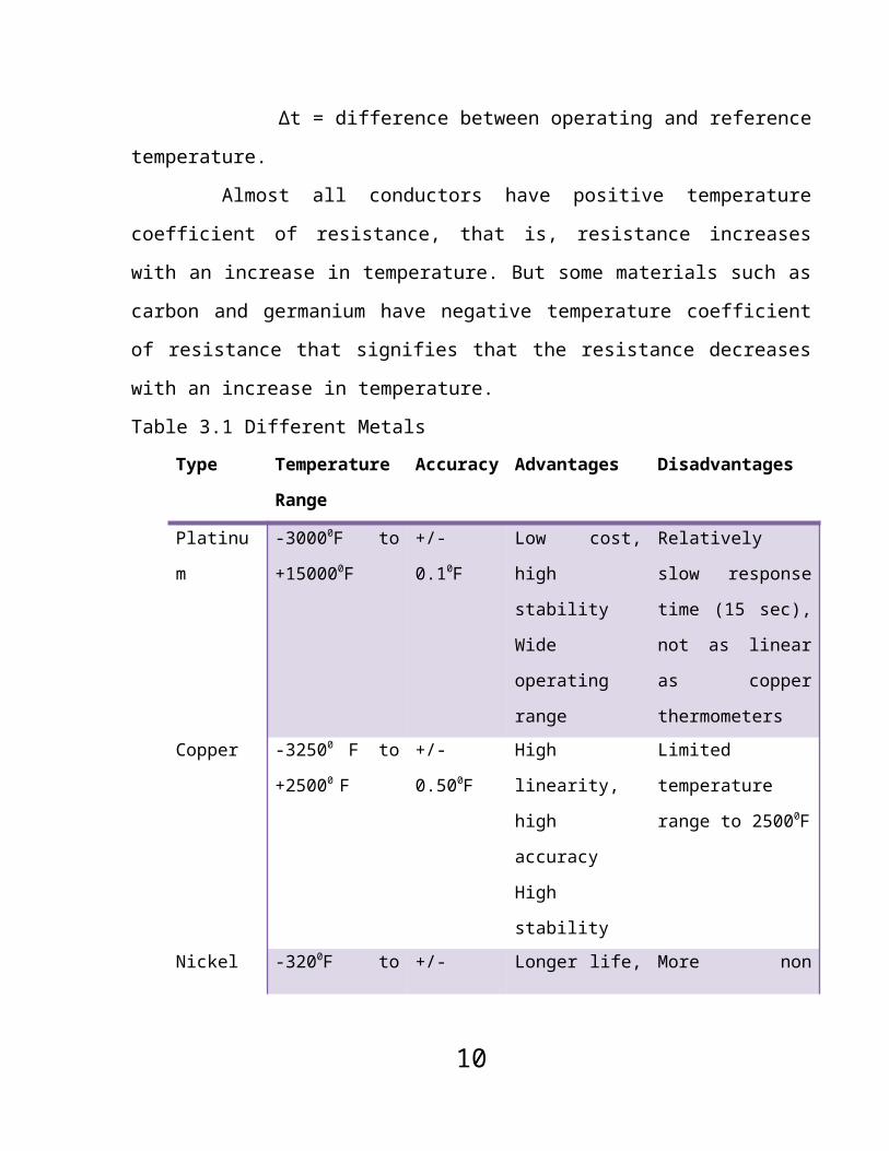
5.1 Liquid in Metal Type Temp. Guage
This is most often used
temperature gauge. In this type liquid is filled in the metal
tube. Most generally used liquids are mercury and alcohol.
5.1.1 Operation Principle:
26
Fig. 5.1 Liquid In Metal TypeTemp. Gauge

As above, the liquid filled in tube if there is any change in
tempareture occurred then the level of liquid will be increase or
decrease.
The tube connected with liquid filled bourden tube. So, as
pressure increase or decrease there will be change in the bourden
tube. As the gauge pressure increases the tube will tend to
uncoil, while a reduced gauge pressure will cause the tube to
coil more tightly. This motion is transferred through a linkage
to a gear train connected to an indicating needle. The needle is
presented in front of a card face inscribed with the pressure
indications associated with particular needle deflections.
The deflection of tube connected with pointer by link. The
movement of pointer will indicate the value of temperature. This
is easy to install, this kind of gauge has lower cost.
5.2 Thermocouple
In electronics, thermocouples are a widely used type of
temperature sensor and can also be used as a means to convert
thermal potential difference into electric potential difference.
They are cheap and interchangeable, have standard connectors, and
can measure a wide range of temperatures. The main limitation is
precision; system errors of less than 1 °C can be difficult to
achieve.
27

5.2.1 Principle of Operation
When any conductor (such as a metal) is subjected to a thermal
gradient, it will generate a voltage. This is now known as the
thermoelectric effect or Seebeck effect. Any attempt to measure
this voltage necessarily involves connecting another conductor to
the "hot" end. This additional conductor will then also
experience the temperature gradient, and develop a voltage of its
own which will oppose the original. Fortunately, the magnitude of
the effect depends on the metal in use. Using a dissimilar metal
to complete the circuit will have a different voltage generated,
leaving a small difference
voltage available for
measurement, which
increases with
temperature. This
difference can typically
be between 1 and about 70 microvolts per degree Celsius for the
modern range of available metal combinations. Certain
combinations have become popular as industry standards, driven by
cost, availability, convenience, melting point, chemical
properties, stability, and output is important to note that
thermocouples measure the temperature difference between two
points, not absolute temperature. In traditional applications,
one of the junctions — the cold junction — was maintained at a known
28
Fig. 5.2 Basic Diagram

(reference) temperature, while the other end was attached to a
probe. For example, in the image above, the cold junction will be
at copper traces on the circuit board. Another temperature sensor
will measure the temperature at this point, so that the
temperature at the probe tip can be calculated.
Thermocouples can be connected in series with each other to form
a thermopile, where all the hot junctions are exposed to the
higher temperature and all the cold junctions to a lower
temperature. Thus, the voltages of the individual thermocouple
add up, which allows for a larger voltage.
Having available a known temperature cold junction, while useful
for laboratory calibrations, is simply not convenient for most
directly connected indicating and control instruments. They
incorporate into their circuits an artificial cold junction using
some other thermally sensitive device (such as a thermistor or
diode) to measure the temperature of the input connections at the
instrument, with special care being taken to minimize any
temperature gradient between terminals. Hence, the voltage from a
known cold junction can be simulated, and the appropriate
correction applied. This is known as cold junction compensation.
Additionally, cold junction compensation can be performed by software.
Device voltages can be translated into temperatures by two
29
Fig. 5.3 Thermocouple

methods. Values can either be found in look-up tables or
approximated using polynomial coefficients.
Usually the thermocouple is attached to the indicating device by
a special wire known as the compensating or extension cable. The
terms are specific. Extension cable uses wires of nominally the same
conductors as used at the thermocouple itself. These cables are
less costly than thermocouple wire, although not cheap, and are
usually produced in a convenient form for carrying over long
distances - typically as flexible insulated wiring or multicore
cables. They are usually specified for accuracy over a more
restricted temperature range than the thermocouple wires. They
are recommended for best accuracy.
Compensating cables on the other hand, are less precise, but
cheaper. They use quite different, relatively low cost alloy
conductor materials whose net thermoelectric coefficients are
similar to those of the thermocouple in question (over a limited
range of temperatures), but which do not match them quite as
faithfully as extension cables. The combination develops similar
outputs to those of the thermocouple, but the operating
temperature range of the compensating cable is restricted to keep
the mis-match errors acceptably small.Thermocouples are most
suitable for measuring over a large temperature range, up to 1800
K. They are less suitable for applications where smaller
temperature differences need to be measured with high accuracy,
30
for example the range 0–100 °C with 0.1 °C accuracy. For such
applications, thermistors and RTDs are more suitable.
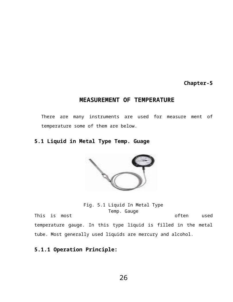
5.3 Resistance Temperature Detectors
Resistance thermometers, also called resistance temperature
detectors (RTDs), are temperature sensors that exploit the
predictable change in electrical resistance of some materials
with changing temperature. As they are almost invariably made of
platinum, they are often called platinum resistance thermometers
(PRTs). They are slowly replacing the use of thermocouples in
many industrial applications below 600 °C.
5.3.1 General Description
There are two broad categories, "film" and "wire-wound" types.
Film thermometers have a layer of platinum on a substrate; the
layer may be extremely thin, perhaps 1 micrometer. Advantages of
this type are relatively low cost and fast response. Such devices
have improved in performance although the different expansion
rates of the substrate and platinum give "strain gauge" effects
and stability problems.
Wire-wound thermometers can have greater accuracy, especially for
wide temperature ranges. The coil diameter provides a compromise
between mechanical stability and allowing expansion of the wire
to minimize strain and consequential drift.
31
The current international standard which specifies tolerance and
the temperature to electrical resistance relationship for
platinum resistance thermometers is IEC 751:1983. By far the most
common devices used in industry have a nominal resistance of 100
ohms at 0 °C, and are called Pt-100 sensors ('Pt' is the symbol
for platinum). The sensitivity of a standard 100 ohm sensor is a
nominal 0.385 ohm/°C. RTDs with a sensitivity of 0.375 and 0.392
ohm/°C are also available.
5.4 How do resistance thermometers work?
Resistance thermometers are constructed in a number of forms and
offer greater stability, accuracy and repeatability in some cases
than thermocouples. While thermocouples use the Seebeck effect to
generate a voltage, resistance thermometers use electrical
resistance and require a small power source to operate. The
resistance ideally varies linearly with temperature.
Resistance thermometers are usually made using platinum, because
of its linear resistance-temperature relationship and its
chemical inertness. The platinum detecting wire needs to be kept
free of contamination to remain stable. A platinum wire or film
is supported on a former in such a way that it gets minimal
differential expansion or other strains from its former, yet is
reasonably resistant to vibration.
32

Commercial platinum grades are produced which exhibit a change of
resistance of 0.385 ohms/°C (European Fundamental Interval) The
sensor is usually made to have a resistance of 100Ω at 0 °C. This
is defined in BS EN 60751:1996 . The American Fundamental
Interval is 0.392 Ω/°C.
Resistance thermometers require a small current to be passed
through in order to determine the resistance. This can cause
resistive heating, and manufacturers' limits should always be
followed along with heat path considerations in design. Care
should also be taken to avoid any strains on the resistance
thermometer in its application. Lead wire resistance should be
considered, and adopting three and four wire connections can
eliminate connection lead resistance effects from measurements.
Advantages of platinum resistance thermometers:
High accuracy
Low drift
Wide operating range
Suitability for precision applications
5.4.1 Resistance thermometer elements
Resistance thermometer elements are available in a number of
forms. The most common are:
33

Wire wound in a ceramic insulator - wire spiral within sealed
ceramic cylinder, works with temperatures to 850 °C
Wire encapsulated in glass - wire around glass core with glass
fused homogenously around, resists vibration, more protection to
the detecting wire but smaller usable range
Thin film - platinum film on ceramic substrate, small and
inexpensive to mass produce, fast response to temperature change
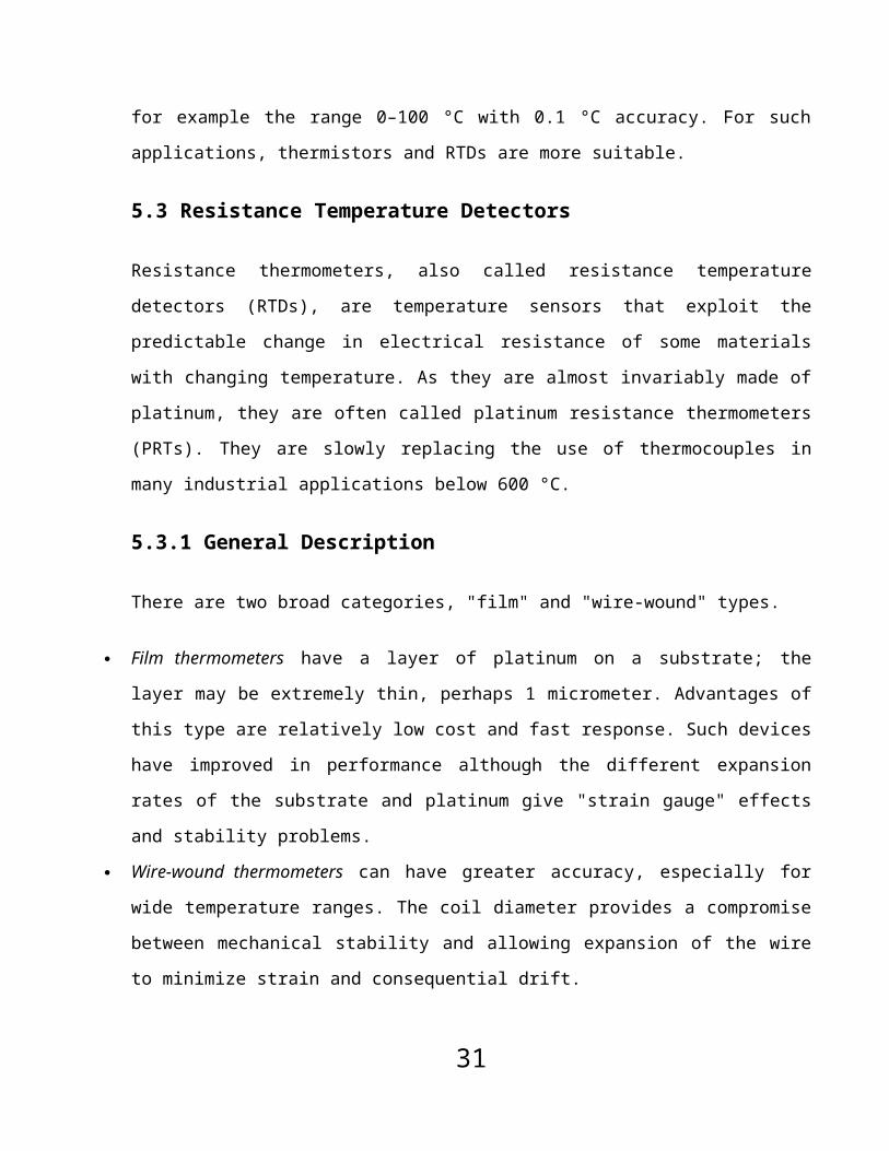
5.4.2 Resistance thermometer construction
These elements nearly
always require insulated leads attached. At low temperatures PVC,
silicon rubber or PTFE insulators are common to 250 °C. Above
this, glass fibre or ceramic are used. The measuring point and
usually most of the leads require a housing or protection sleeve.
This is often a metal alloy which is inert to a particular
process. Often more consideration goes in to selecting and
designing protection sheaths than sensors as this is the layer
34
Fig. 5.4 Resistance Thermometer Construction

that must withstand chemical or physical attack and offer
convenient process attachment points.
Chapter-6
TEMPERATURE SWITCHESTemperature switches generally operates on one of four
principles:
1. Thermal Expansion
2. Differential Thermal Expansion
3. Vapor Pressure
35

4. Thermocouple
The thermal expansion device can be mercury filled bulb
somewhat like an ordinary laboratory glass thermometer.
In the industrial temperature switch, this would normally be
mercury filled or gas filled system, consisting of a copper or
stainless steel bulb, connected to a pressure switch through a
small capillary tube. Expansion of the mercury or gas with an
increase in temperature would increase the filled system pressure
that then actuates the switch. The vapor pressure switch is a
filled system. Having the same configuration as the mercury
thermal expansion Type.
Thermal expansion and vapor pressure temperature switch cover
a wide range of temperature and provide sample force to operate a
dependable switch mechanism.
Bimetallic temperature switches are made in many
configuration. They operate on differential thermal expansion
between two metal parts that are thermally coupled to the process
stream. The motion of the differential expansion is transferred
to the switch through and adjustable mechanism. Bimetallic
switches are generally small, low cost and useful over a wide
range of temperature. Thermocouple can be used as a temperature
measurement element because they generate a minute voltage that
is a function of the temperature these sensores good for a wide
range of temperature are very rugged and inexpensive. The
measurement voltage for a thermocouple is the difference between
36

the voltage at the point of measurement and the referance
junction voltage at some other point in the circuit.
Chapter-7
FLOW MEASUREMENT
Orifice, ventures, pilot tubes, annular and nozzle are the
main primary elements. They are used to create a restriction in
the flow and create a differential pressure across them which are
sent by the secondary elements. So construction and design of
these elements are of critical importance. Orifice plates are
used frequently than other types. They are actually obstruction
within the pipe and made from stainless steel 1/8” to ½” thick.
7.1 Orifice Plate
An orifice plate is a device which measures the rate of fluid
flow. It uses the same principle as a Ventura nozzle, namely
Bernoulli's principle which says that there is a relationship
between the pressure of the fluid and the velocity of the fluid.
When the velocity increases, the pressure decreases and vice
versa.
37

An orifice plate is basically a thin plate with a hole in the
middle. It is usually placed in a pipe in which fluid flows. As
fluid flows through the pipe, it has a certain velocity and a
certain pressure. When the fluid reaches the orifice plate, with
the hole in the middle, the fluid is forced to converge to go
through the small hole; the point of maximum convergence actually
occurs shortly downstream of the physical orifice, at the so-
called vena contracta point (see drawing to the right). As it
does so, the velocity and the pressure changes. Beyond the vena
contracta, the fluid expands and the velocity and pressure change
once again. By measuring the difference in fluid pressure between
the normal pipe section and at the vena contracta, the volumetric
and mass flow rates can be obtained from Bernoulli's equation.
7.2 Venturi Tubes:
38
Fig. 7.1 Orifice Plate

The venturi tube is highly accurate instrument for measuring
pressure differential. It is used for medium and high quantity
fluid flow.
The short venturi is particularly adopted to install in
pipelines, not having long Unobstructed runs. The flow of fluid
through the venture tube, established the pressure differential,
which can then be measured and related to the flow rate.
It consist of two small hollow pipes made in the form of cone at
the one end. The cones are joined by short parallel pipe. The
smallest diameter is called the throat section. Where lower or
downstream pressure is measured. In the parallel pipe to the
upstream, the upstream cone made steeper, to give smooth approach
to the throat section. The downstream cone recovers part of the
pressure differential, thus reducing overall pressure loss. Fluid
speed at throat is faster. It is made of cast iron or steel.
39
Fig. 7.2 Venturi Tubes

Its initial cost is high but pressure loss is lower than orifice
and less wear and abrasion.
7.3 Rotameter
A Rotameter is a device that measures the flow rate of liquid or
gas in a closed tube. It is occasionally misspelled as
'rotometer'.
It belongs to a class of meters called variable area meters,
which measure flow rate by allowing the cross sectional area the
fluid travels through to vary, causing some measurable effect.
A rotameter consists of a tapered tube, typically made of glass,
with a float inside that is pushed up by flow and pulled down by
gravity. At a higher flow rate more area (between the float and
the tube) is needed to accommodate the flow, so the float rises.
Floats are made in many different shapes, with spheres and
spherical ellipses being the most common.
40

The float is shaped so that it rotates axially as the fluid
passes. This allows you to tell if the float is stuck since it
will only rotate if it is not. Readings are usually taken from
the top of the float. Some manufacturers may use a different
standard, so it is always best to check the documentation
provided with the device.
Note that the 'float' does not actually float in the fluid: it
has to have a higher density than the fluid otherwise it will
float to the top even if there is no flow.
7.3.1 Advantages:
41
Fig. 7.3 Rotameter

A rotameter requires no external power or fuel, it uses only
the inherent properties of the fluid, along with gravity, to
measure flow rate.
A rotameter is also a relatively simple device that can be
mass manufactured out of cheap materials, allowing for
widespread use in places such as third world countries.
7.3.2 Disadvantages:
Due to its use of gravity, a rotameter must always be
vertically oriented and right way up, with the fluid flowing
upwards.
Due to its reliance on the ability of the fluid or gas to
displace the float, the graduations on a given rotameter
will only be accurate for a given substance. The main
property of importance is the density of the fluid, however
viscosity may also be significant. Floats are ideally
designed to be insensitive to viscosity, however this is
seldom verifiable from manufacturer’s specs. Either separate
rotameters for different densities and viscosities may be
used, or multiple scales on the same rotameter can be
utilized.
Rotameters normally require the use of glass (or other
transparent material), otherwise the user cannot see the
float. This limits their use in many industries to benign
fluids, such as water.
42

Rotameters are not easily adapted for reading by machine:
although magnetic floats that drive a follower outside the
tube are available.
Chapter-8
MEASUREMENT OF LEVEL
8.1 Sight Glass
8.1.1 GeneralA sight glass (gauge glass) is another method of liquid level
measurement.it is used for the continuous indication of liquid
level with a tank or vessel.
8.1.2 Construction and Working
43

A sight glass instrument consist of a graduated tube of toughened
glass which is connected to the interior of a graduated tube of
bottom in which the water level is required figure shows a simple
sight matches the level of liquid in the tank. As the level of
liquid in the tank rises and falls, the level in the sight glass
the level of liquid in the tank is measured. In sight glass, it
is not necessary, to use the same liquid as in the tank. Any
other desired liquid also can be used.
Then it is desired to measure a liquid with the liquid under
pressure or vacuum, the sight glass must be connected to the tank
at the top as well at the bottom otherwise, the pressure
difference between the tank and the sight glass would cause false
reading. In this case, the glass tube is enclosed in a protective
housing, and two valves are provided for isolating the gauge from
the tank in case of breakage of the glass. The smaller valve at
the bottom is provided for blowing out the gauge for cleaning
purposes fig. Shows a high pressure sight glass. In which
measurement is made by reading the position of the level on the
calibrated scale. These safety precautions. The glass tube muses
have a small inside diameter and a thick wall
44
Fig. 8.1 Slight Glass

8.2 Differential Pressure Type Level Meter
The level also measure by measuring the upper and lower level
pressure of liquid. The
differential pressure will show
the level.
8.2.1 P to F Conversion:
The process fluid applied to capacitive pressure sensor change
the value of the sensor’s Cs capacitor, thereby generating a
sense frequency Fs by the Enhanced Mode Oscillator (EMO) that is
directly proportional to the applied pressure.
8.2.2 F to Digital Conversion:The first of the three frequencies (Fr, Fs+r, Fs) generated by the
BMO is applied to the ASIC. When all three frequencies are store,
the micro-controller shifts the data into its serial port. The
micro-controller uses a specially developed algorithm that
cancels the effects of parasitic capacitance Cp and calculates
the true ratio Cr/Cs. When the ratio is equal to 1 the pressure
45
Fig. 8.2 DifferentialPressure Type Level Meter

diff between the two capacitor is known to be zero. A ratio less
than I corresponds to a +ve pressure diff. And a ratio greater
than a –ve pressure diff.
8.2.3 D/A Conversion and Current Signal Transmission:The pressure signal received by the micro-controller is applied
through the ASIC to a DAC. The DAC translates the digitalized
pressure signal into a PWM signal, whose PW is proportional to
the magnitude of the process pressure. The pulse are filtered and
applied to an operational amplifier, which drives V4 converter,
whose output is Darlington transistor pair acting as a pass
transistor that outputs a std. 4 to 20mA current signal to the
n/w.
8.3 Level Switch
8.3.1 Operating Principle:Diagram illustrated the simple and fool proof magnetron operating
principle switching action is obtained, that the use of a
magnetic attractive sleeve, actuated by a float and switching
mechanism are separated by a non magnetic, pressure fifth
enclosing tube. Switching magnets are assembled to a switching
arm which operates on precision 35-pivot socket.
46

8.3.2 Operation Cycle:At “normal level” operating of liquid in the chamber the float
moves the magnetic attraction sleeve upward in the enclosed tube
and into the field of the switch mechanism magnet. As a result
the magnet is drawn in tightly to the enclosing tube causing the
switch to tilt,” making” on “breaking” and electric circuits. A
liquid level reduces the float pulls the magnetic attracting
sleeve downward until, at predetermined “low level “ the switch
magnet release and is drawn outward away from the enclosing tube
by a tension spring. This in turn tilts the switch in an opposite
direction, thus reversing switch action. When liquid level
returns to normal the float once again moves the magnetic sleeve
up the enclosing tube, causing the switch to assume its original
position.
8.4 Control Valves
Control valves are valves used within industrial plants and
elsewhere to control operating conditions such as temperature,
47
Fig. 8.3 Level Switch

pressure, flow, and liquid level by fully or partially opening or
closing in response to signals received from controllers that
compare a "set point" to a "process variable" whose value is
provided by sensors that monitor changes in such conditions. The
opening or closing of control valves is done by means of
electrical, hydraulic or pneumatic systems.
8.5 Globe ValveGlobe valve is a device for regulating flow in a pipeline,
consisting of a movable disk-type element and a stationary ring
seat in a generally spherical body.
Globe Valves are named for their spherical body shape with the
two halves of the body being separated by an
internal baffle. This has an opening that forms
a seat onto which a movable plug can be screwed in
to close (or shut) the valve. In
globe valves, the plug is connected to a
stem which is operated by screw action
in manual valves. Typically,
automated valves use sliding
stems. Globe valves have a smooth stem rather than threaded and
are opened and closed by an actuator assembly. When a globe valve
is manually operated, the stem is turned by a hand wheel.
48
Fig. 8.4 Globe Valve
Although globe valves in the past had the spherical bodies which
gave them their name, many modern globe valves do not have much
of a spherical shape. However, the term globe valve is still often
used for valves that have such an internal mechanism. In
plumbing, valves with such a mechanism are also often called stop
valves since they don't have the global appearance, but the term
stop valve may refer to valves which are used to stop flow even
when they have other mechanisms or designs.
Globe valves are used for applications requiring throttling and
frequent operation. For example, globe valves or valves with a
similar mechanism may be used as sampling valves, which are
normally shut except when liquid samples are being taken. Since
the baffle restricts flow, they're not recommended where full,
unobstructed flow is required.
Globe valves are typically two-port valves, although three port
valves are also produced. Ports are openings in the body for fluid
flowing in or out. The two ports may be oriented straight across
from each other on the body, or oriented at an angle such as a
90° angle. Globe valves with ports at such an angle are called
angle globe valves.
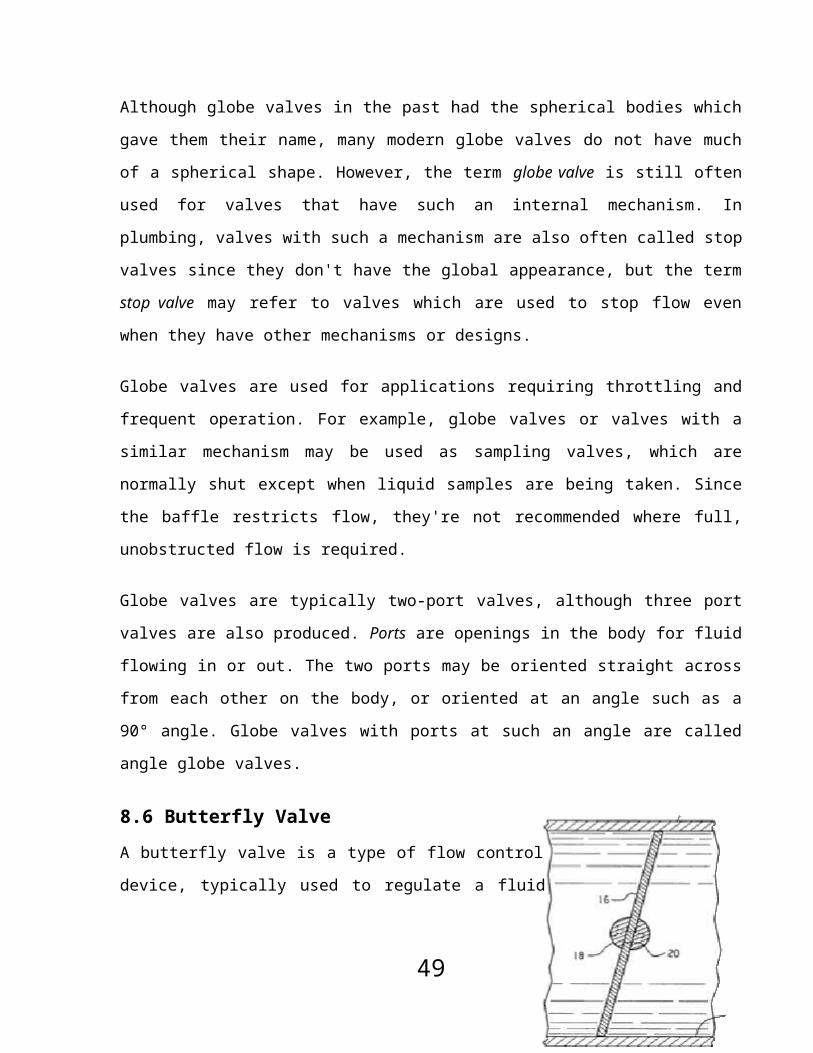
8.6 Butterfly ValveA butterfly valve is a type of flow control
device, typically used to regulate a fluid
49

flowing through a section of pipe. The valve is similar in
operation to a ball valve. A flat circular plate is positioned in
the center of the pipe. The plate has a rod through it connected
to a handle on the outside of the valve. Rotating the handle
turns the plate either parallel or perpendicular to the flow.
Unlike a ball valve, the plate is always present within the flow,
therefore a pressure drop is always induced in the flow
regardless of valve position.
There are three types of butterfly valve:
1. Resilient butterfly valve which has a flexible rubber seat.
Working pressure up to 1.6 megapascals (MPa)/232 pounds per
square inch (PSI)
2. High performance butterfly valve which is usually double
eccentric in design. Working pressure up to 5.0 MPa/725 PSI
3. Trimetric butterfly valve which is
usually with metal seated design.
Working pressure up to 10.0 MPa/1450 PSI
Butterfly valves are widely used in water distribution and waste
water processing (not recommended, as the debris may block the
operation of the disc). Butterfly valves can come in two body
types, affecting installation and maintenance: lugged or wafer.
Wafer style valves are more common. They are typically installed
between two flanges using bolts or studs and nuts. Lug style
50
Fig. 8.5Butterfly Valve

valves are also installed between two flanges but with a separate
set of bolts for each flange. The lug style setup makes it
possible to remove one side of the piping while the other remains
intact.
An additional application is found within the exhaust system of
automobiles. By incorporating a butterfly valve in the exhaust
system, it is possible to control the backpressure and noise
output from the muffler and catalytic converter. When in a closed
position, the valve increamount of back pressure produced and
suppresses noise. The angle of valve can be controlled in a
variety of ways, including manual control, vacuum control, as
well as being tired directly to the throttle.
51