
Transducers for Fishfinders - Hisse et oh
56
Transducers for Fishfinders Owner’s Handbook Document number: 81196_2 Date: August 2002
-
Upload
khangminh22 -
Category
Documents
-
view
1 -
download
0
Transcript of Transducers for Fishfinders - Hisse et oh

TransducersforFishfindersOwner’s Handbook
Document number: 81196_2
Date: August 2002

Transducers for Fishfinders iii
Transducers for FishfindersOwners Handbook
August 2002
Intended UseThe transducer units detailed in this handbook are used in con-junction with Raymarine fishfinders and are intended for recrea-tional marine depth, speed, and/or temperature measurementpurposes.
Safety NoticeThis equipment must be installed and operated in accordance withthe instructions contained in this manual. Failure to do so canresult in personal injury and/or navigational inaccuracies.
Raymarine products are supported by a network of AuthorizedService Representatives. For information on Raymarine productsand services, contact either of the following:
United StatesRaymarine, Inc.22 Cotton Road, Unit DNashua, NH 03063-4219USATelephone 603-881-5200Fax 603-864-4756www.raymarine.com
EuropeRaymarine LtdAnchorage ParkPortsmouthHampshire PO3 5TDEnglandTelephone +44 (0)23 9269 3611Fax +44 (0)23 9269 4642www.raymarine.com
© Raymarine, Inc. 2002

iv Transducers for Fishfinders
PrefaceThis handbook describes the transducers that are required for usewith Raymarine fishfinders. A list of currently available fish-finder transducers appears on page 4.
The handbook contains very important information on the instal-lation and operation of your new equipment. In order to obtain thebest results in operation and performance, please read this hand-book thoroughly.
Raymarine’s Product Support representatives or your local dealerwill be available to answer any questions you may have.
The technical and graphical information contained in this hand-book, to the best of our knowledge, was correct as it went to press.However, the Raymarine policy of continuous improvement andupdating may change product specifications without prior notice.As a result, unavoidable differences between the product andhandbook may occur from time to time, for which liability cannotbe accepted by Raymarine.
Raymarine is a registered trademark of Raymarine Limited.SeaTalk is a registered trademark of Raymarine Limited.hsb2 is a trademark of Raymarine Limited.
WarrantyYour transducer ownership warranty is registered when you fillout the warranty registration card included with your RaymarineFishfinder Owner’s Handbook. It is very important that you com-plete the owner information and return the card to the factory inorder to receive full warranty benefits.
EMC ConformanceAll Raymarine equipment and accessories are designed to the bestindustry standards for use in the leisure marine environment.
The design and manufacture of Raymarine equipment and acces-sories conform to the appropriate Electromagnetic Compatibility(EMC) standards, but correct installation is required to ensure thatperformance is not compromised.

Contents v
Contents
Chapter 1: Overview ...............................................................................11.1 Introduction ....................................................................... 1
General .............................................................................. 1EMC Installation Guidelines ............................................ 2
1.2 The Fishfinder System ...................................................... 3Selecting the Correct Type of Transducer ......................... 4Planning the Installation ................................................... 5
1.3 Unpacking and Inspecting the Components ..................... 61.4 Selecting the Equipment Location .................................... 6
Transducer Mounting Location ........................................ 6Transom Mount Transducer .............................................. 7
1.5 Cable Runs ...................................................................... 12Transducer Cable ............................................................ 12
Chapter 2: Installation ..........................................................................152.1 Installing the Transom Mount Transducer ...................... 15
Preparation ...................................................................... 15Installation ...................................................................... 16
2.2 Installing the Thru-hull Transducer ................................ 17Tools and Material Needed ............................................. 17Preparation ...................................................................... 17Installation ...................................................................... 22Installation in a Cored Fiberglass Hull ............................ 29Check for Leaks .............................................................. 30
2.3 Installing the In-hull Transducer ..................................... 31Tools and Material Needed ............................................. 31Testing the Selected Mounting Location ........................ 31Installation ...................................................................... 34Installation in a Cored Fiberglass Hull ............................ 37
2.4 Transducer Cable Connections ....................................... 39
Chapter 3: Maintenance .......................................................................43Cleaning Instructions ...................................................... 43Servicing and Safety ....................................................... 43Problem Solving ............................................................. 44Common Problems and Their Solutions ......................... 44How to Contact Raymarine ............................................. 45Worldwide Support ......................................................... 47
Index.................................................................................... 49

vi Transducers for Fishfinders

Chapter 1: Overview 1
Chapter 1: Overview
1.1 IntroductionThis handbook provides instructions to assist you in the installationand set up of the various transducers for Raymarine fishfinders. SeeTable 1-1 on page 4 for a list of the different sensor, material andmounting types available.
GeneralRaymarine fishfinders require a transducer, either thru-hull, in-hull,or transom-mount.
Transducers can measure water depth, temperature, distancetraveled, and/or speed. It is important to position your transducercorrectly, as described in Section 1.4, Selecting the EquipmentLocation.
Note: If speed and temperature are being input via SeaTalk, thesevalues are displayed instead of the speed and temperature inputsfrom the transducer.
This handbook is divided into three chapters as follows:
Chapter One provides an overview of the transducer installation. Itincludes sections on Unpacking and Inspecting the Components,Selecting the Transducer Site and a description of the Cable Runs.
Chapter Two provides detailed instructions on how to mount andconnect each type of transducer.
Chapter Three provides information on maintenance and what to doif you have problems.

2 Transducers for Fishfinders
EMC Installation GuidelinesAll Raymarine equipment and accessories are designed to the bestindustry standards for use in the leisure marine environment.
Their design and manufacture conforms to the appropriateElectromagnetic Compatibility (EMC) standards, but correctinstallation is required to ensure that performance is notcompromised. Although every effort has been taken to ensure thatthey will perform under all conditions, it is important to understandwhat factors could affect the operation of the product.
The guidelines given here describe the conditions for optimum EMCperformance, but it is recognized that it may not be possible to meetall of these conditions in all situations. To ensure the best possibleconditions for EMC performance within the constraints imposed byany location, always ensure the maximum separation possiblebetween different items of electrical equipment.
For optimum EMC performance, it is recommended that whereverpossible:
• Raymarine equipment and cables connected to it are:• At least 1 m (3 ft) from any equipment transmitting or cables
carrying radio signals, e.g., VHF radios, cables and antennas.In the case of SSB radios, the distance should be increased to2 m (7 ft).
• More than 2 m (7 ft) from the path of a radar beam. A radarbeam can normally be assumed to spread 20 degrees aboveand below the radiating element.
• The equipment is supplied from a separate battery from that usedfor engine start. Voltage drops below 10 V (20 V for 10 kW openarray scanners) in the power supply to our products, and startermotor transients, can cause the equipment to reset. This will notdamage the equipment, but may cause the loss of some informa-tion and may change the operating mode.
• Raymarine specified cables are used at all times. Cutting andrejoining these cables can compromise EMC performance and somust be avoided unless doing so is detailed in the documentation.
• If a suppression ferrite is attached to a cable, this ferrite should notbe removed. If the ferrite needs to be removed during installationit must be reassembled in the same position.

Chapter 1: Overview 3
The following illustration shows a typical range of suppressionferrites fitted to Raymarine equipment.
Connections to Other EquipmentIf your Raymarine equipment is to be connected to other equipmentusing a cablenot supplied by Raymarine, a suppression ferrite MUSTalways be attached to the cable near to the Raymarine unit.
1.2 The Fishfinder SystemTransducers enable fishfinders to display depth, water temperatureand/or speed, depending on the type of transducer(s) installed.
Before you start the installation, check that you have the correcttransducer for your application, as described below in Selecting theCorrect Type of Transducer.
D3548-3

4 Transducers for Fishfinders
Selecting the Correct Type of TransducerRaymarine Fishfinders can be used with any of the followingtransducers:
1 E66020, E66029 and E66043 thru-hull transducers must be installed with a high-speed fairing.
Note: This information was current as of the date this handbook wasprinted. New transducer models are constantly becoming available.Check with your dealer for the most current list.
Table 1-1: Transducer Types
Part No. Sensor Type Material
Mounting Method
Max. Power
E66008 Depth Plastic In-Hull 600 W
E66013 Depth Plastic Thru-Hull 600 W
E66014 Depth Bronze Thru-Hull 600 W
E66015 Depth Stainless steel
Thru-Hull 600 W
E66018 Speed, Temp Bronze Thru-Hull 600 W
E66019 Speed, Temp Plastic Transom 600 W
E66020 1 Depth, Speed, Temp
Bronze Thru-Hull 600 W
E66024 Depth, Temp Bronze Thru-Hull (high performance)
600 W or 1000 W
E66029 1 Depth, Speed, Temp
Bronze Thru-Hull(long stem)
600 W
E66030 Speed, Temp Plastic Thru-Hull 600 W
E66033 Depth, Temp Bronze Thru-Hull 600 W or 1000 W
E66035 Depth, Temp Bronze Thru-Hull 600W
E66038 Depth, Speed, Temp
Plastic Transom 600W
E66043 1 Depth, Speed, Temp
Stainless steel
Thru-Hull 600W

Chapter 1: Overview 5
WARNING:If the E66020, E66029 and E66043 thru-hull transducers are notcarefully installed and fitted to the shape of the hull, the vesselmay take on water. To ensure proper alignment and a secure fit,these transducer models MUST be installed with a fairing. Inaddition to improving fishfinder performance at all speeds, thefairing allows better fitting to the hull and dramatically increasesthe sealing surface.
ApplicationsPlastic housings are recommended for fiberglass or metal hulls.
Bronze housings are recommended for wood or fiberglass hulls.
• Installation of a bronze housing in a metal hull requires using of afairing, available from your Raymarine dealer.
• Never install a metal housing in a vessel with a positive groundsystem.
Transom Mount Transducers are recommended for personalwatercraft and powerboats with outboard, inboard-outboard and jetdrives. They are NOT recommended for large or twin screw inboardboats.
• Adjusts to transom angles from 3° – 16°. For angles greater than16°, a tapered plastic, wood or metal shim will be needed.
• Designed for operation from 5 –58 m.p.h. (4 – 50 knots).
Thru-Hull Transducers are recommended for boats with straight-shaft inboard engines.
In-Hull transducers are recommended for fiberglass hulls, especiallyin high speed power boats and racing sailboats.
Planning the InstallationBefore you install your system, plan the installation, considering:
• Location of the transducer and fishfinder, as described inSection 1.4
• Cable Runs, including cables for an integrated system (to provideheading and position data, etc.), as described in Section 1.5.

6 Transducers for Fishfinders
1.3 Unpacking and Inspecting the ComponentsUnpack your system carefully, to prevent damage to the equipment.Save the carton and packing, in case you need to return a unit forservice.
Check that you have all the correct system components. Thesedepend on your system package, as follows:
1 E66023 fairings are required for installing E66020 and E66029 bronze thru-hull transducers.2 E66045 fairings are required for installing E66043 stainless steel thru-hull transducers.
Note: This information was current as of the date this handbook wasprinted. Check with your dealer for the most current list of parts andaccessories.
1.4 Selecting the Equipment Location
Transducer Mounting LocationIt is very important that you mount the transducer correctly. Thetransducer provides the most reliable readings if it looks into waterthat is smooth and undisturbed.
Table 1-2: Parts and Accessories
ItemPart No.
Supplied with:
Optionfor:
Transducer (see Table 1-1 on page 4) — — All
Transducer cable, 10 ft (3 m) extensionTransducer cable, 18 ft (5 m) extensionTransducer Y Cable
E66009E66010E66022
——Speed/Temp Transducers
AllAllAll others
High Speed Fairing E660231
E660452
E66025E66034E26017
—————
E66020, E66029E66043E66024E66033E66035
Chapter 1: Overview 7
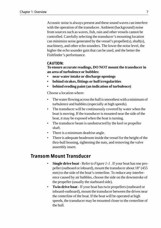
Acoustic noise is always present and these sound waves can interferewith the operation of the transducer. Ambient (background) noisefrom sources such as waves, fish, rain and other vessels cannot becontrolled. Carefully selecting the transducer’s mounting locationcan minimize noise generated by the vessel’s propeller(s), shaft(s),machinery, and other echo sounders. The lower the noise level, thehigher the echo sounder gain that can be used, and the better theFishfinder’s performance.
CAUTION:To ensure accurate readings, DO NOT mount the transducer inan area of turbulence or bubbles:• near water intake or discharge openings• behind strakes, fittings or hull irregularities• behind eroding paint (an indication of turbulence)
Choose a location where:
• Thewater flowing across the hull is smoothest with a minimum ofturbulence and bubbles (especially at high speeds).
• The transducer will be continuously covered by water when theboat is moving. If the transducer is mounted near the side of theboat, it may be exposed when the boat is turning.
• The transducer beam is unobstructed by the keel or propellershaft.
• There is a minimum deadrise angle.• There is adequate headroom inside the vessel for the height of the
thru-hull housing, tightening the nuts, and removing the valveassembly insert.
Transom Mount Transducer• Single drive boat - Refer to Figure 1-1 . If your boat has one pro-
peller (outboard or inboard), mount the transducer about 18" (455mm) to the side of the boat’s centerline. To reduce any interfer-ence caused by air bubbles, choose the side on the downstroke ofthe propeller (usually the starboard side).
• Twin drive boat - If your boat has twin propellers (outboard orinboard-outboard), mount the transducer between the drives nearthe centerline of the boat. If the boat will be operated at highspeeds, the transducer may be mounted closer to the centerline ofthe hull.

8 Transducers for Fishfinders
• If the propeller can be turned to steer the boat, allow at least 2" (50mm) beyond the swing radius of the propeller. This will preventthe propeller from damaging the transducer when it is turned.
Figure 1-1: Transom Mount Transducer Location
• Do Not mount the transducer behind any hull fittings, intakes orother parts extending from the hull that may cause turbulence orair bubbles.
• The bracket has a quick-release mechanism, shown Figure 1-2 .This allows the transducer to flip up if it hits any debris or the bot-tom. Allow enough clearance above the transducer for it to swingupwards completely – this is about 10" (254 mm), measured fromthe bottom of the transom.
Be sure to allow atleast 2 in (50 mm)beyond the swing radiusof the propeller
Approximately 18 in (457 mm) clearance
D4871-2

Chapter 1: Overview 9
Figure 1-2: Transom Mount Transducer - Quick-release Bracket
• On a boat with a fiberglass hull, the leading edge of the transducershould extend 1/8" (3.2 mm) to 1/4" (6 mm) below the bottomedge of the hull as shown in Figure 1-3 . On an aluminum hull, thetransducer should extend a bit more – 1/4" (6 mm) to 3/8" (9 mm)
• If the boat will be trailered, be sure the transducer will not hit anyrollers, bunks or fittings on the trailer.
Figure 1-3: Transom Mount Transducer - Vertical Position
D4872-2
Transducer inreleased position
Allow a clearance ofat least 254 mm (10 in)
No!No!No!
Average transom angle -no wedge necessary
Vertical transom -place wedge this way
Sloping transom -place wedge this way
2° to 5°2° to 5°
For fibreglass hull � 1/8 to 1/4 in (3.2 to 6 mm)For aluminium hull � 1/4 to 3/8 in (6 to 9 mm)
The bow of the transduceris above the bottom of thetransom, creating cavitation.
Rivets on the hull arecreating bubbles. Lowerthe transducer a bit.
The rear of the transduceris too high, creatingcavitation.
D4873-2
2° to 5°

10 Transducers for Fishfinders
Thru-hull Transducer and In-hull TransducerSimilar consideration should be given to the location of thru-hull andin-hull transducers. Figure 1-4 shows the best transducer location fordifferent hull types.
• Displacement hull powerboat – Locate at 1/3 aft load waterlinelength (LWL) and 6 - 12" (150-300 mm) off the centerline on theside of the hull where the propeller is moving downward.
• Planing hull powerboat – Mount well aft, on or near the center-line, and well inboard of the first set of lifting strakes to ensurethat it is in contact with the water at high speeds. Mount on theside of the hull where the propeller is moving downward.Outboard and I/O – Mount just forward of the engine(s).Inboard – mount well forward of the propeller(s) and shaft(s).Step-hull – Mount just ahead of the first step.Boats capable of speeds above 25 kn (29 m.p.h.) – Reviewtransducer location and operating results of similar boats beforeproceeding.
• Fin keel sailboats – Mount to the side of the centerline and for-ward of the fin keel 1 - 2 ft (300-600 mm).
• Full keel sailboats – Locate amidships and away from the keel atthe point of minimum deadrise angle.
• Fiberglass Hulls – Since the hull absorbs acoustic energy, trans-mitting through the hull reduces the sensor’s performance. Fiber-glass hulls are often reinforced in places for added strength. Thesecored areas contain balsa wood or structural foam, which are poorsound conductors. If you cannot avoid locating the sensor overcoring, follow the instructions for Installation in a Cored Fiber-glass Hull on page 29.
• Thru-hull Transducer Headroom– Allow adequate headroominside the vessel for the height of the thru-hull housing, tighteningthe nuts and removing the insert. The minimum headrooms are:With fairing: 10" (254 mm)Without fairing: 12" (305 mm)
• In-hull Transducer – Find a location where the fiberglass issolid:There are no air bubbles trapped in the fiberglass resin.There is no coring, flotation material, or dead air space sand-wiched between the inside skin and the outer skin of the hull.

Chapter 1: Overview 11
Figure 1-4: Best Location for Thru Hull Transducer
1/3 Aft
Load waterline length (LWL)
Pressure waves
6 -- 12 in(150 -- 300 mm)
Displacement hull
Planning hulls
Outboard and I/O
Inboard
Step hull Fin keel sailboat
Full keel sailboat
D4857-2

12 Transducers for Fishfinders
1.5 Cable RunsConsider the following before installing the system cables:
• You need to attach the power cable and the transducer cable.Additional cables will be required if you are installing an inte-grated system.
• All cables should be adequately secured, protected from physicaldamage and protected from exposure to heat. Avoid runningcables through bilges or doorways, or close to moving or hotobjects.
• Acute bends must be avoided• Where a cable passes through an exposed bulkhead or deckhead,
a watertight feed-through should be used.• Secure cables in place using tie-wraps or lacing twine. Coil any
extra cable and tie it out of the way.
Transducer CableA 30 ft (10m) cable is supplied with the transducer. The transducercable may be extended up to a maximum of 60 ft (20 m) usingoptional extension cables.
The transducer cable connector has a nut that has been removed to aidinstallation. To allow you to complete the installation without cuttingthe cable, ensure that any holes you drill are large enough to acceptthe connector, with the nut removed.
After the cable has been run through the holes, this nut must beattached before the cable can be connected, as described inTransducer Cable Connections on page 39.
CAUTION:Do not cut the transducer cable or remove the connector. Do nottry to shorten or splice the cable. If the cable is cut, it cannot berepaired. Cutting the cable will also void the warranty.
• For a Transom mount installation – route the cable up and over thetop edge of the transom as shown in Figure 1-5 . Secure the cableusing cable clamps (available from your local marine equipmentsupplier).

Chapter 1: Overview 13
If you do not want to expose the cable on deck, you may drill ahole 13/16" (21 mm) through the transom for the cable (with con-nector attached). To seal the opening, use a feed-thru cap wherethe cable passes through the transom.
• For either type of installation – run the cable through the interiorof the boat.
• If the 30 ft (10 m) cable is not long enough, extension cables areavailable from your Raymarine dealer. See Table 1-2 on page 6.Total cable length from the transducer to the fishfinder mustnot exceed 60 ft (20 m). When you attach the extension cable, besure that the connections are watertight. Use Dow Corning DC-4or an equivalent sealing compound to protect the connectorassemblies.
Figure 1-5: Installing the Cable on a Transom Mount Transducer
D5033-2
Cable cover
Cable clamps
2 in (50 mm)

14 Transducers for Fishfinders

Chapter 2: Installation 15
Chapter 2: Installation
This chapter gives details on how to install your transducer.Instructions are divided into the following sections:
• Transom Mount Transducers - recommended for personalwatercraft and powerboats with outboard, inboard-outboard andjet drives.
• Thru-Hull Transducers - recommended for boats with straight-shaft inboard engines.
• In-Hull transducers- recommended for fiberglass hulls, espe-cially in high speed power boats and racing sailboats.
2.1 Installing the Transom Mount Transducer
Preparation
Transducer Mounting BracketWhen installed, the lower surface of the transducer should tilt downtoward the rear at a slight angle (2° to 5°). The mounting bracketincludes a wedge; depending on the angle of the transom on yourboat, you may need to install this wedge to get the correct transducerangle.
1. To attach the transducer to the bracket, insert the transducermounting lugs into the slot in the bracket as shown in Figure 2-1 .
Figure 2-1: Fitting the Transducer to the Bracket
Correct Incorrect
Lower the transducer andsnap in the release clip
Attach the two parts Bracket is installedupside down
D4874-2

16 Transducers for Fishfinders
2. Looking at the rear of the boat, be sure the bracket is vertical (per-pendicular to the water line) and hold the bracket (plus the wedge,if used) against the transom.Trace the position of the screw slots, then mark the screw posi-tions as shown in Figure 2-2 . The outer two screws should beplaced about 1/4" (6 mm) up from the bottom of each slot, thecenter screw should be placed about 1/4" (6 mm) down from thetop. This will allow the bracket to be adjusted up or down.Remove the bracket.
Figure 2-2: Position of Screws in Mounting Bracket
Installation1. On a fiberglass hull, to minimize surface cracking of the gel coat:
Before drilling the pilot holes, use a 1/4" (6 mm) drill bit to drill ashallow hole (chamfer) at each location about 1/16" (1.5 mm)deep.Drill pilot holes 3/4" (19 mm) deep using a 9/64" (3.6 mm) drillbit.To prevent drilling too deeply, wrap masking tape around the drillbit about 7/8" (22 mm) from the tip. Drill in only as far as the tape.
2. Apply a good quality marine sealant to the pilot holes to protectthe hull from water penetration.
3. Attach the bracket to the hull using the panhead screws with flatwashers. Do not completely tighten the screws yet.
4. Move the bracket up or down so the leading edgeof the transducerhas the clearance shown in Figure 1-3 .
5. Once the bracket is in the correct position tighten the screws.
D4875-2
Insert screws 1 and 3, 6.4 mm (1/4 in)from the bottom of the slots, andscrew 2, 6.4 mm (1/4 in) from the topthe slot to allow room for adjustment.
If screws are inserted this way itwon't be possible to make theheight adjustment.
1
Correct alignment
Incorrect alignment
2 3
1 2 3
Chapter 2: Installation 17
2.2 Installing the Thru-hull Transducer
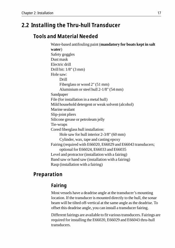
Tools and Material NeededWater-based antifouling paint (mandatory for boats kept in saltwater)Safety gogglesDust maskElectric drillDrill bit: 1/8" (3 mm)Hole saw:
DrillFiberglass or wood 2" (51 mm)Aluminium or steel hull 2-1/8" (54 mm)
SandpaperFile (for installation in a metal hull)Mild household detergent or weak solvent (alcohol)Marine sealantSlip-joint pliersSilicone grease or petroleum jellyTie-wrapsCored fiberglass hull installation:
Hole saw for hull interior 2-3/8" (60 mm)Cylinder, wax, tape and casting epoxy
Fairing (required with E66020, E66029 and E66043 transducers;optional for E66024, E66033 and E66035
Level and protractor (installation with a fairing)Band saw or hand saw (installation with a fairing)Rasp (installation with a fairing)
Preparation
FairingMost vessels have a deadrise angle at the transducer’s mountinglocation. If the transducer is mounted directly to the hull, the sonarbeam will be tilted off-vertical at the same angle as the deadrise. Tooffset this deadrise angle, you can install a transducer fairing.
Different fairings are available to fit various transducers. Fairings arerequired for installing the E66020, E66029 and E66043 thru-hulltransducers.

18 Transducers for Fishfinders
WARNING:If the E66020, E66029 and E66043 thru-hull transducers are notcarefully installed and fitted to the shape of the hull, the vesselmay take on water. To ensure proper alignment and a secure fit,these transducer models MUST be installed with a fairing. Inaddition to improving fishfinder performance at all speeds, thefairing allows better fitting to the hull and dramatically increasesthe sealing surface.
Fairings are also strongly recommended for use with other highperformance transducers. See the table that follows.
The fairing is used to:
• Vertically orient the sound beam by mounting the transducer par-allel to the water surface
• Minimize aerated water flowing over the transducer’s face bymounting it in deeper water
• Reduce drag by directing the water around the multisensor
The fairing is madeof high impact urethanewith an integrated cuttingguide. It can be shaped to accommodate a deadrise angle of up to 25°and a range of hull thicknesses as follows:
Fairing No.Used with Transducer No.
Max. Hull Thickness with Fairing
E26017 E66035 2" (50mm)
E66023 E66020 1" (26mm)
E66023 E66029 3-3/4" (87mm)
E66025 E66024 1-3/4" (45mm)
E66034 E66033 1-3/4" (45mm)
E66045 E66043 1/2" (14mm)

Chapter 2: Installation 19
Figure 2-3: Deadrise Angle and Fairing Thickness
Backing BlockA backing block is used inside the hull to provide a level surface forthe hull nut to seat against (see Figure 2-3 ). After cutting the fairing,use the remaining section with the cutting guide as the backing block(see Figure 2-4 ).
Figure 2-4: Transducer Fairing E66023
Cutting the Fairing1. Measure the deadrise angle of the hull at the selected location
using a digital level, or bubble level and protractor (see Figure 2-3 ).
2. Tilt the band saw table to the measured angle and secure the cut-ting fence (see Figure 2-5 ).
Aft View
minimum fairingthickness
Hull
Slope of hull
Parallel towater surface
Deadrise angle
Isolation sleeveD5568-1
Fairing
Backing block
⇐ Cutting guide
Triangular recessfor anti-rotation bolt
BOW
D5567-1

20 Transducers for Fishfinders
Figure 2-5: Cutting the Fairing
CAUTION:The arrow on the fairing always points forward towards the bow.Be sure to orient the fairing on the band saw so the angle cutmatches the intended side of the hull.
3. Place the fairing on the table so the cutting guide rests against thefence. The arrow/blunt end will point toward you for installationon the port side and away from you for installation on the star-board side of the boat.
WARNING:Always wear safety goggles and a dust mask when drilling.
4. Recheck steps 1 through 3, then cut the fairing.5. Shape the fairing to the hull as precisely as possible with a rasp or
power tool.
Antifouling PaintMarine growth can accumulate rapidly on the transducer’s surface,reducing performance in weeks. Surfaces exposed to salt water mustbe coated with antifouling paint.
Cutting guide
Fence
Band saw table
Bow end forinstallationon port side
Deadriseangle
D4860-2

Chapter 2: Installation 21
Use water-based antifouling paint only.Never use ketone-based paint since ketones can attack manyplastics, possibly damaging the transducer.
Reapply paint every six months or at the beginning of each boatingseason.
It is easier to apply antifouling paint before installation, but allowsufficient drying time. As illustrated in Figure 2-6 paint the followingsurfaces:
Exposed area of the housing, including the acoustic windowBore of the housing up to 1¼" (30 mm)Outside wall below lower O-ringExposed end of the paddle wheel insertPaddle wheel cavityPaddle wheelBlanking plug below the lower O-ring and the exposed end
Figure 2-6: Applying Antifouling Paint
Housing Paddlewheelinsert
Paint exposed housingand bore up to 1.1/4" (30 mm)
Lower'O' ring
Paint outside wall below the lower 'O' ring includingexposed end, paddlewheel cavity and paddlewheel
D4859-2

22 Transducers for Fishfinders
InstallationNote: To install the thru-hull transducer in a cored fiberglass hull,follow the instructions in Installation in a Cored Fiberglass Hull onpage 29.
Drilling Holes
WARNING:Always wear safety goggles and a dust mask when drilling.
1. Drill a 1/8" (3 mm) pilot hole perpendicular to the water line frominside the hull (see Figure 2-3 ).If there is a rib or strut near the mounting location, drill from theoutside.If the pilot hole is drilled in the wrong location, drill a second holein a better location. Apply masking tape to the outside of the hullover the incorrect hole and fill it with epoxy.
2. Cut a hole from outside the hull:Fiberglass or wood hull – Use a 2" (51 mm) hole saw.Aluminium or steel hull – Use a 2 1/8" (54 mm) hole saw toaccommodate the isolation sleeve used to prevent contactbetween the stainless steel housing and the metal hull.
3. Sand and clean the area around the hole, inside and outside, toensure that the sealant will adhere properly to the hull. If there isany petroleum residue inside the hull, remove it with either a mildhousehold detergent or a weak solvent (alcohol) before sanding.
4. Remove one safety ring, the retaining pin, the cap nut, and the hullnut from the transducer (see Figure 2-7 ).

Chapter 2: Installation 23
Figure 2-7: Seating
Dry Fit for Fairing
WARNING:If a fairing is used, the anti-rotation bolt must be installed toprevent the fairing from rotating when the boat is underway.
1. Dry fit the transducer to locate the hole for the anti-rotation bolt.2. Thread the transducer cable through the large hole in the fairing
and through the mounting hole in the hull. Seat the transducerfirmly in the recess in the fairing.
Note: The transducer must be flush with the fairing. If it is recessedmore than 1/64" (0.5mm) inside the fairing, you may carefully file orsand the fairing flush with the transducer.
WARNING:Always wear safety goggles and a dust mask.
3. Attach the drill bit to your drill appropriate for your fairing:
Fairing Used with Transducer Drill Size
E26017 E66035 3/8" (10mm)
E66023 E66020, E66029 3/8" (10mm)
E66025 E66024 1/2" (13mm)
E66034 E66033 1/2" (13mm)
E66045 E66043 3/8" (10mm)
Marinesealant
Retaining pin
Safety ring
Cap nut
Stem
Hull nut
Backingblock
Hull
Fairing
D5566-1

24 Transducers for Fishfinders
4. Slide the transducer’s stem with the fairing in place into themounting hole. Be sure the triangular recess in the fairing is point-ing forward toward the bow.
5. While holding the assembly in place and using the bolt hole in thefairing as your guide, drill a hole through the hull for the anti-rota-tion bolt.
6. Remove the assembly and cable from the mounting hole.7. Sand and clean the area around the hole, inside and outside, to
ensure that the sealant will adhere properly to the hull.Metal hull - Remove any burrs around both holes with a file andsandpaper.
Figure 2-8: Using a Fairing and Backing Block
Seating1. Remove the transducer from the fairing, if used.2. Stainless steel transducer in metal hull - Slide the appropriate
size isolation sleeve over the cable and onto the stem of the trans-ducer as far down as possible (see Figure 2-3 ). Be sure the top ofthe isolation sleeve will be below the top of the backing block toprevent the sleeving from interfering with tightening the hull nut.
WARNING:To prevent electrolytic corrosion, never allow direct contactbetween a stainless steel transducer and a metal hull.
Triangular plugwith curved surfacefacing outward
Anti-rotationbolt
Backingblock
Fairing
D5565-1
BOW
Nut andwasher
⇐

Chapter 2: Installation 25
3. Apply a 1/16" (2mm) thick layer of marine sealant to the sides ofthe transducer that will contact the fairing, if used, and up the stem1/4" (6mm) higher than the combined thickness of the fairing,hull, backing block, and hull nut. This will ensure there is marinesealant in the threads to seal the hull and hold the hull nut securelyin place (see Figure 2-7 ).Stainless steel transducer in metal hull - Apply the marine seal-ant to the outside of the sleeving instead of the stem itself.
4. If a fairing is used, thread the transducer cable through the fairingand seat the transducer firmly within the recess in the fairing.
5. Apply a 1/16" (2mm) thick layer of marine sealant to the surfaceof the fairing that will contact the hull, if used.
Attaching the Transducer1. From outside the hull, thread the cable through the mounting hole.2. Push the stem of the transducer (with the fairing in place) into the
mounting hole using a twisting motion to squeeze out excess seal-ant.
3. From inside the hull, slide the backing block onto the transducercable and stem, seating it firmly against the hull (Figure 2-9 ).
CAUTION:Be careful to avoid cross threading the cap nut.
4. Screw the hull nut in place and tighten it with slip-joint pliers.Stainless steel transducer in metal hull - Be sure the top of theisolation sleeve is below the top of the backing block to preventthe sleeving from interfering with tightening the hull nut.
5. Apply a 1/16" (2mm) thick layer of marine sealant to the anti-rotation bolt, 1/4" (6mm) higher than the combined thickness ofthe fairing, hull, backing block, washer, and nut. This will ensurethat there is marine sealant on the threads to seal the hull and holdthe nut securely in place (see Figure 2-8 ).
6. Push the bolt through the fairing, if used, and into the hull.7. From inside the hull, slide the washer and nut onto the bolt. Screw
the nut in place and tighten it with slip-joint pliers.Wood hull - Allow for the wood to swell.

26 Transducers for Fishfinders
Figure 2-9: Fore View of Transducer Installation
8. If a fairing is used, apply marine sealant to the flat side of the tri-angular plug. Push the plug into the triangular recess in the fair-ing. The triangular plug fits one way only. Be sure the curvedside of the plug is exposed, matching the curve on the outside ofthe fairing. Tap it into place with a mallet.
CAUTION:For smooth water flow over the transducer’s sensor, be sure thatthe external surface of the installed triangular plug is FLUSHwith the external curved surface of the fairing.
9. Being sure the valve assembly is seated firmly in the housing,carefully screw the cap nut in place. Hand tighten it only; do notover tighten.
10. Remove any excess sealant on the outside of the hull to ensuresmooth water flow over the transducer.
Cable
Safety ring
Safety chain
Pull ring
Retaining pin
Cap nut
Stem Safety wire
Hull nut
Backing block
Fairing
Hull
Transducer
D4863-2
Chapter 2: Installation 27
11. After the sealant cures, inspect and lubricate the O-rings on thepaddle wheel insert with silicone grease or petroleum jelly (seeFigure 2-10 ).
12. Slide the paddle wheel insert into the valve assembly with thearrow on the top pointing forward until it is fully seated (the insertfits one way only).Take care not to rotate the outer housing and disturb the sealant.
13. Slide the center ring of the safety chain onto the cable. Slide theretaining pin in place and reattach the safety ring (Figure 2-9 ).
WARNING:Always attach the safety wire to prevent the insert from backingout in the unlikely event that the cap nut fails or is screwed onincorrectly.
14. Wrap one end of the safety wire tightly around the stem of thehousing and twist it together with the long end. Lead the wirestraight up and through one eye in the cap nut, then through one ofthe safety rings. Loop the wire through the pull ring and twist itsecurely to itself.
15. Route the cable to the transducer, being careful not to tear thecable jacket when passing it through the bulkhead(s) and otherparts of the boat.
16. Attach the connector nut to the cable per instructions in Trans-ducer Cable Connections on page 39.
17. Attach the assembled connector cable to the transducer.18. Route the other end of the cable to the fishfinder, being careful not
to tear the cable jacket when passing it through the bulkhead(s)and other parts of the boat. To reduce electrical interference, sep-arate the transducer cable from other electrical wiring and theengine.
19. Coil any excess cable and secure it in place using tie-wraps to pre-vent damage.

28 Transducers for Fishfinders
Figure 2-10: Servicing the Paddle Wheel Insert and Valve Assembly
Notches
Top view ofpaddlewheelinsert
Paddlewheelinsert
Housingand valveassembly
Pull ring
'O' rings
Cable
Key (2)
Valve assembly
Cap nut
Housing
BOW
Flat side ofpaddlewheelblade faces bow
Paddlewheel detail
D4864-2

Chapter 2: Installation 29
Installation in a Cored Fiberglass HullThe core (wood or foam) must be cut and sealed carefully. The coremust be protected from water seepage and the hull must be reinforcedto prevent it from crushing under the hull nut, allowing the housing tobecome loose.
WARNING:Always wear safety goggles and a dust mask when drilling.
1. Drill a 1/8" (3 mm) pilot hole perpendicular to the waterline frominside the hull. If there is a rib or strut near the selected mountinglocation, drill from the outside (see Figure 2-10 ). If the hole isdrilled in the wrong location, drill a second hole in a better loca-tion. Apply masking tape to the outside of the hull over the incor-rect hole and fill it with epoxy.
2. Using a 2" (51 mm) hole saw, cut a hole from outside the hullthrough the outer skin only.
3. Using the 2 3/8" (60 mm) hole saw, cut through the inner skin andmost of the core from inside the hull. The core material can bevery soft. Apply only light pressure to the hole saw after cuttingthrough the inner skin to avoid accidentally cutting the outer skin
Note: The optimal interior hole diameter is affected by the hull’sthickness and deadrise angle. It must be large enough in diameter toallow the core to be completely sealed.
4. Remove the plug of core material so the inside of the outer skinand inner core of the hull is fully exposed. Clean and/or sand theinner skin, core, and the outer skin around the hole.
CAUTION:Completely seal the hull to prevent water seepage into the core.
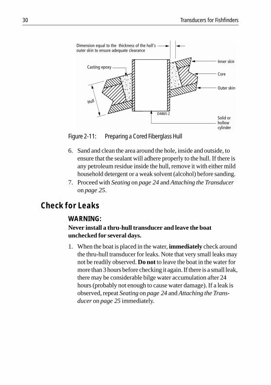
5. Coat a hollow or solid cylinder of the correct diameter with waxand tape it in place. Fill the gap between the cylinder and hull withcasting epoxy. After the epoxy has set, remove the cylinder (seeFigure 2-11 ).
30 Transducers for Fishfinders
Figure 2-11: Preparing a Cored Fiberglass Hull
6. Sand and clean the area around the hole, inside and outside, toensure that the sealant will adhere properly to the hull. If there isany petroleum residue inside the hull, remove it with either mildhousehold detergent or a weak solvent (alcohol) before sanding.
7. Proceed with Seating on page 24 and Attaching the Transduceron page 25.
Check for Leaks
WARNING:Never install a thru-hull transducer and leave the boatunchecked for several days.
1. When the boat is placed in the water, immediately check aroundthe thru-hull transducer for leaks. Note that very small leaks maynot be readily observed. Do not to leave the boat in the water formore than 3 hours before checking it again. If there is a small leak,there may be considerable bilge water accumulation after 24hours (probably not enough to cause water damage). If a leak isobserved, repeat Seating on page 24 and Attaching the Trans-ducer on page 25 immediately.
Hull
Dimension equal to the thickness of the hull'souter skin to ensure adequate clearance
Inner skin
Outer skin
Core
Solid orhollowcylinder
D4865-2
Casting epoxy

Chapter 2: Installation 31
2.3 Installing the In-hull Transducer
Tools and Material NeededTapePoleDetergentWeak solvent (alcohol)Safety gogglesDust maskDisc sanderThin, sealable plastic bag (optional)Twist-tiePetroleum jelly (Vaseline®)Level and protractorCarpenter’s squarePencilAdhesive (Loctite #5699 or 3M #4200)ScrewdriverSilicone grease (optional)Mineral oil 2.4 fl oz. (71 mil)Cored fiberglass hull installation:
DrillHole saw for hull interior 4" (100 mm)Miniature disk sanderCasting epoxy (polyproxy #7035/7040) or resinPaper cupStirrer
Testing the Selected Mounting Location
Establishing a Performance BaselineThe results of this test are used to determine the best in-hull locationfor a transducer.
1. Take the boat to the maximum depth for which your instrument israted, or the maximum depth in which you will operate the fish-finder.
2. Connect the transducer to the fishfinder. Refer to TransducerCable Connections on page 39.

32 Transducers for Fishfinders
3. Tape the transducer to a pole with the cable side up. Hold it overthe side of the boat with the active face submerged in the water(see Figure 2-12 ). Keep the active face of the transducer parallelto the surface of the water.
4. Observe the Fishfinder’s performance and depth reading.
Figure 2-12: Establishing a Performance Baseline
Testing the Mounting LocationWhile the boat is moving around the same site (and depth of water),test the transducer at your selected mounting location inside the hull.Use one of the methods below:
1. This method is recommended if the sensor willbe located near thestern and the boat has a minimum deadrise angle.i. Clean away any large build-up of dirt and/or grease using
detergent or a weak solvent such as alcohol.ii. Place thesensoragainst thehull and allowbilgewater to cover
the surface where they touch (see Figure 2-13 A).
WARNING:Always wear safety goggles and a dust mask.
2. This method can be used at all hull locations.i. If the hull surface is not smooth, grind it with a disc sander.ii. Partially fill a thin plastic bag with water, place the sensor
inside the bag and close it tightly with a twist-tie.iii. Wet the surface of the hull and press the sensor face against it
through the bag (see Figure 2-13 B).
D5000-2

Chapter 2: Installation 33
WARNING:Always wear safety goggles and a dust mask.
3. This is the least desirable testing method, as it may be difficult toremove all traces of the petroleum jelly before bonding the base tothe hull.i. If the hull surface is not smooth, grind it with a disc sander.ii. Coat the face of the sensor with petroleum jelly.iii. Press it against the hull with a twisting motion (see Figure 2-
13 C).
Figure 2-13: Testing the Transducer at the Selected Location
Observe the Fishfinder’s performance and compare it to the baseline.Look for a stable depth reading that is similar to thebaseline, comparethe thickness and intensity of the bottom trace.
If the performance is close to the baseline, this is a good mountinglocation. Remember, some energy is lost transmitting through thehull.
If the test reading differs markedly from the baseline,you need to findanother location to install the transducer.
If there is no reading or it is erratic, the sensor may be positioned overcoring which is absorbing the acoustic energy. Choose anotherlocation. If no other spot is available, check with the boatmanufacturer to be certain coring is present before proceedingwith Installation in a Cored Fiberglass Hull on page 37.
D5001-2
A B C

34 Transducers for Fishfinders
Installation1. Measure the deadrise angle of the hull at the selected location
using a level and protractor (see Figure 2-14 ). Measure carefully,since the installed transducer must be within 5 ° of vertical.
WARNING:Always wear safety goggles and a dust mask.
2. The hull surface to be bonded must be smooth and free of paint orany other finish. If the surface is rough, use a disc sander tosmooth an area 4" (100 mm) in diameter.
3. Remove any dust, grease or oil with a weak solvent, such as alco-hol, to ensure a good bond. Clean and dry both the selected areaand the underside of the base.
4. Using a carpenter’s square, draw a line on the hull perpendicularto the keel through the center of the mounting location. This willbe used as a guideline to orient the base.
Figure 2-14: Deadrise Angle
5. The numbers on the flange of the base represent deadrise angles.Identify the number that most closely corresponds to the deadriseangle of your hull. Find its match on the opposite side of theflange. Keeping the keel direction arrows on the side of the basenearest the keel, align the two raised marks indicating yourdeadrise angle with the guideline drawn on the hull (see Figure 2-15 ).
D5002-2
Deadrise angle
Flange
Base Hull
Parallel to waterline
Guidelineperpendicularto keel

Chapter 2: Installation 35
CAUTION:The base must be liquid-tight.
6. When you are satisfied that the location of the transducer is opti-mal and the orientation of the base corresponds to the deadriseangle of your boat, apply a bead of adhesive to the bottom of thebase flange. (Follow the adhesive manufacturer’s instructions foruse).Press the flange firmly in place to form a liquid-tight seal andallow the adhesive to cure.
Figure 2-15: Aligning the Base Flange with 4–12° Deadrise Angle
7. Slide the transducer housing into the locking ring.Turn the hous-ing until the rib that most closely corresponds to the deadriseangle of your hull is aligned with the angle indicator on the lock-ing ring. To secure the housing to the locking ring, insert twoscrews (see Figure 2-16 ). Do not overtighten the screws.
D5003-2
Keel direction arrow
Keel direction arrowKeel

36 Transducers for Fishfinders
Figure 2-16: Joining the Transducer Housing to the Locking Ring
8. Lubricate the O-ring with silicone grease or petroleum jelly. Slidethe O-ring onto the transducer assembly (see Figure 2-17 ).
Figure 2-17: Installing the O-ring
9. When the adhesive on the base has cured, pour 2.4 fl. oz. (71 mil)of mineral oil into the base.
10. Lock the transducer assembly into the base by inserting the keyson the locking ring in the notches in the base. Press down androtate clockwise until seated (see Figure 2-16 ).
11. Route the cable to the transducer, being careful not to tear thecable jacket when passing it through the bulkhead(s) and otherparts of the boat.
D5004-2
Transducerhousing
Lockingring
10° deadriseangle shown
Ribs
Angleindicator
D5005-2
Front view Side view'O' ring
Lockingring
Transducerhousing

Chapter 2: Installation 37
12. Attach the connector nut to the cable per instructions in Trans-ducer Cable Connections on page 39.
13. Attach the assembled connector cable to the transducer.14. Route the other end of the cable to the fishfinder, being careful not
to tear the cable jacket when passing it through the bulkhead(s)and other parts of the boat. To reduce electrical interference, sep-arate the transducer cable from other electrical wiring and theengine.
15. Coil any excess cable and secure it in place using tie-wraps to pre-vent damage.
Note: If you are using an extension cable, be sure to locate the mated3-pin connectors well above the bilge waterline. To facilitate this, usecable clamps on either side of the connection.
Installation in a Cored Fiberglass HullInstallation in a cored hull is difficult. The objective is to bond thesensor to the inside surface of the hull’s outer skin while preventingany moisture from penetrating the core.
CAUTION:There is no way to determine if the outer skin is solid (no trappedair bubbles in the fiberglass) at the selected location beforecutting the inner skin.
WARNING:Always wear safety goggles and a dust mask.
1. Using a 4" (100 mm) hole saw, cut through the inner skin and thecore at the selected location (see Figure 2-18 ). The core materialcan be very soft. Apply only light pressure to the hole saw aftercutting through the inner skin to avoid accidentally cutting theouter hull.
2. Remove the plug of core material, so the inner core of the hull isfully exposed. Sand the inside surface of the outer skin using aminiature disc sander. Slightly undercut the surrounding coring ifpossible.
3. Clean and dry both the inside surface of the outer skin and thehousing with a weak solvent, such as alcohol, to remove any dust,grease or oil.

38 Transducers for Fishfinders
CAUTION:Do notproceed if thehull temperature is below 60° F(15° C) sincethe cure time of the casting epoxy will be greatly extended.
4. If the hull temperature is above 60° F (15° C), mix a half cup ofcasting epoxy stirring carefully to avoid trapping air in the mix-ture.Pour this around the housing until the cavity is full. Allow thecasting epoxy to set for at least 1 hour.
Figure 2-18: Installation in a Cored Fiberglass Hull
5. Proceed with step 7 of Installation on page 34.
D5006-2
100 mm(4 in)
Transducer assembly
Inner skin
Core
Outer skin
Fill with casting epoxy
Hull thickness
Chapter 2: Installation 39
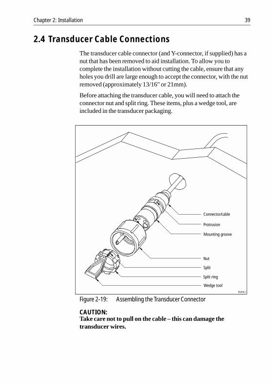
2.4 Transducer Cable Connections The transducer cable connector (and Y-connector, if supplied) has anut that has been removed to aid installation. To allow you tocomplete the installation without cutting the cable, ensure that anyholes you drill are large enough to accept the connector, with the nutremoved (approximately 13/16" or 21mm).
Before attaching the transducer cable, you will need to attach theconnector nut and split ring. These items, plus a wedge tool, areincluded in the transducer packaging.
Figure 2-19: Assembling the Transducer Connector
CAUTION:Take care not to pull on the cable – this can damage thetransducer wires.
Connector/cable
Split
Nut
Split ring
Wedge tool
Protrusion
Mounting groove
D5256-1

40 Transducers for Fishfinders
➤ To attach the transducer cable connector:
1. Slip the nut over the connector cable end. Push it past the connec-tor and over the cable.
2. Insert the wedge tool into the groove in the split of the split ringand slide the wedge tool until its squared end is flush with thelarger edge of the split ring.
3. Slip the split ring and wedge tool over the connector body untilaligned with the mounting groove on the connector.
4. Remove the wedge tool and seat the split ring in the mountinggroove, making sure the connector protrusion falls into the split.
5. Slip the nut forward until it stops. Twist until the protrusions onthe inside of the nut align with the grooves on the split ring.
6. Slip the nut forward and snap into place.
The transducer cable is attached to the 7 pin male connector markedTRANSDUCER on the fishfinder. How you connect the cable to the unitdepends on the type of transducer you have installed:
• Combined depth/speed/temp transducers have a 7 pin femaleconnector. Attach the transducer cable connector directly to thefishfinder.
• Combined speed/temperature transducers have a 3 pin femaleconnector that requires the use of an additional Y-shaped cable(Raymarine part number E66022) to attach to the 7 pin connectoron the fishfinder. This Y-cable is included with your speed/tem-perature transducer.Attach the 7 pin female connector on the Y-cable to the fishfinderunit then attach the transducer cable to the 3 pin male connectoron the Y-cable.
• Depth-only transducers have a 7 pin female connector.Attach the transducer cable connector directly to the fishfinder.or
• If being installed in conjunction with a speed/temperature trans-ducer, attach the 7 pin female connector on the Y-cable to the fish-finder then attach the transducer cable to the 7 pin male connectoron the Y-cable.
Note: If your system requires both a Y-cable and a transducer exten-sion cable, ensure that you connect the Y-cable to the fishfinder andthe extension cable to the transducer.

Chapter 2: Installation 41
CAUTION:Do not cut the transducer cable or remove the connector. Do nottry to shorten or splice the cable. If the cable is cut, it cannot berepaired. Cutting the cable will also void the warranty.

42 Transducers for Fishfinders

Chapter 3: Maintenance 43
Chapter 3: Maintenance
Cleaning Instructions
Cleaning the TransducerSea growth can collect quickly on the bottom of the transducer, thiscan reduce the performance in just a few weeks. To prevent the build-up of sea growth, coat the transducer with a thin layer of paint. Useonly a water-based antifouling paint, or a water-based paintspecifically designed for transducers. Apply the paint with a brush.
If your transducer becomes fouled or stops working because of sandor sea growth, use a stiff brush to clean it. You may sand the surfacewith a fine-grit wet or dry sandpaper (#320 grade or finer), but thiswill affect the performance of the unit when the boat is moving athigher speeds.
The paddle wheel mechanism may become jammed by dirt, grit orbarnacles. Work this out of the mechanism, then clean the unit withsoap and water or alcohol.
Cleaning the HullUse caution when sanding or cleaning the outside of the hull near thetransducer.
CAUTION:Harsh cleaning solvents such as acetone may damage thetransducer.
Servicing and Safety• Raymarine equipment should be serviced only by authorized
Raymarine service technicians. They will ensure that service pro-cedures and replacement parts used will not affect performance.There are no user serviceable parts in any Raymarine product.
• Some products generate high voltages, so never handle thecables/connectors when power is being supplied to the equip-ment.
• When powered, all electrical equipment produces electromag-netic fields. These can cause adjacent pieces of electrical equip-ment to interact with one another, with a consequent adverseeffect on operation.

44 Transducers for Fishfinders
• In order to minimize these effects and enable you to get the bestpossible performance from your Raymarine equipment, guide-lines are given in the installation instructions, to enable you toensure minimum interaction between different items of equip-ment, i.e., ensure optimum Electromagnetic Compatibility(EMC).
• Always report any EMC-related problem to your nearest Rayma-rine dealer. We use such information to improve our quality stan-dards.
• In some installations, it may not be possible to prevent the equip-ment from being affected by external influences. In general thiswill not damage the equipmentbut it can lead to spurious resettingaction, or momentarily may result in faulty operation.
Problem Solving
Common Problems and Their Solutions
Table 3-1: Common Transducer Problems
Problem Correction
Fishfinder display “freezes”
Check the transducer cable for damage. If dam-aged, the cable and transducer must be replaced as a unit.
Fishfinder does not see bottom or fish
1. If you have a transom-mount transducer, check that the transducer hasn’t kicked-up on hitting an object.2. Check that the transducer is within 10° of verti-cal.3. Check that the transducer face is not covered or fouled. If necessary clean the transducer.
Fishfinder does not display fish
Ensure the transducer is within 10 ° of vertical.
Fishfinder is unre-liable at high boat speeds
Turbulence around the transducer may be confus-ing the unit.
Fishfinder displays a lot of back-ground noise
Check that the transducer is mounted correctly and is clean.
Fishfinder speed or log readings are wrong
Check that the transducer paddle wheel is clean.
Chapter 3: Maintenance 45
How to Contact Raymarine
On the InternetVisit the Raymarine World Wide Web site for the latest informationon Raymarine electronic equipment and systems at:
www.raymarine.com
Customer SupportNavigate to the Customer Support page for links to:
• Finding Factory Service locations and Authorized Dealers nearyou
• Registering your Raymarine products• Accessing handbooks in Adobe Acrobat format• Downloading RayTech software updates• Accessing the Raymarine solution database
Clicking the Find Answers link routes you to our solution database.Search questions and answers by product, category, keywords, orphrases. If the answer you are seeking is not available, click the AskRaymarine tab to submit your own question to our technical supportstaff, who reply to you by e-mail.
In the US
Accessories and Parts
Many Raymarine accessory items and parts can be obtained directlyfrom your authorized Raymarine dealer. However, if you are in needof an item not available from the retailer, please contact RaymarineTechnical Services at:
800-539-5539 ext. 2333, or603-881-5200.
Technical Service is available Monday through Friday 4:00 AM to6:00 PM Eastern Time.
Please have the Raymarine item or part number ready when calling ifplacing an order. If you are not sure which item is appropriate for yourunit, you should first contact the Technical Support Department toverify your requirements.

46 Transducers for Fishfinders
Technical Support
For technical support, call:
800-539-5539 ext. 2444, or603-881-5200.
Our Technical Support Specialists are available to answer questionsabout installing, operating and trouble-shooting all Raymarineproducts.
Questions can be sent directly to our Technical Support Departmentvia the Internet. Point your browser to www.raymarine.com and clickon the Customer Support link. From there, select Find Answersand click the Ask Raymarine tab.
Product Repair and ServiceIn the unlikely event your Raymarine unit should develop a problem,please contact your authorized Raymarine dealer for assistance. Thedealer is best equipped to handle your service requirements and canoffer timesaving help in getting the equipment back into normaloperation.
In the event that repairs can not be obtained conveniently, productservice may also be obtained by returning the unit to:
Raymarine, Inc.Product Repair Center22 Cotton Road, Unit DNashua, NH 03063-4219
The Product Repair Center is open Monday through Friday 8:15 a.m.to 5:00 p.m. Eastern Time. All products returned to the Repair Centerare registered upon receipt. A confirmation letter will be sent to youacknowledging the repair status and the product’s reference number.Should youwish to inquireabout the repair statusofyourunit, contactthe Product Repair Center at:
800-539-5539
Please have the product reference number, or unit serial number,ready when you call. We will do everything possible to make therepair and return your unit as quickly as possible.

Chapter 3: Maintenance 47
In EuropeIn Europe, Raymarine support, service and accessories may beobtained from your authorized dealer, or contact:
Raymarine LtdAnchorage ParkPortsmouth, HampshireEngland PO3 5TDTel +44 (0) 23 9269 3611Fax +44 (0) 23 9269 4642
Technical Support
The Technical Services Department handles inquiries concerninginstallation, operation, fault diagnosis and repair. For technicalhelpdesk contact:
Tel:+44 (0) 23 9271 4713Fax: +44 (0) 23 9266 1228
Questions can be sent directly to our Technical Support Departmentvia the Internet. Point your browser to www.raymarine.com and clickon the Customer Support link. From there, select Find Answersand click the Ask Raymarine tab.
Accessories and Parts
Raymarine accessory items and parts are available through yourauthorized Raymarine dealer. Please refer to the lists of componentpart numbers and optional accessories in the Installation chapter ofthis manual, and have the Raymarine part number ready whenspeaking with your dealer.
If you are uncertain about what item to choose for your Raymarineunit, please contact our Customer Services Department prior toplacing your order.
Worldwide SupportPlease contact the authorized distributor in the country. A list ofworldwide distributors is supplied with your system.

48 Transducers for Fishfinders

Index 49
Index
AAccessories 6BBacking Block 19CCable Runs 12
Installation Considerations 5Cleaning Instructions 43Connections
Transducer 39Cored Fiberglass Hull - Transducer In-stallation 29, 37EEMC iv
Conformance ivInstallation Guidelines 2
FFairing 6, 17HHelp from Raymarine 45IIn-hull Transducer 1
Installation 31Cored Fiberglass hull 37
Location 10Installation
Cable Runs 5, 12EMC Guidelines 6In-hull Transducer 31Location 5Thru-hull Transducer 17Transom Mount Transducer 15
LLocation
In-hull Transducer 10Transducer 6
MMaintenance 43PProblem Solving 44SSafety
and Servicing 43EMC Guidelines 6
Servicing 43TThru-hull Transducer 1
Installation 17Location 10
TransducerApplications 5Cable 12Connections 39In-hull 1Installation 15, 17, 31
Cored Fiberglass Hull 29, 37Location 6Thru-hull 1Transom Mount 1, 7
Transducer Types 4Transom Mount Transducer 1, 7
Installation 15Cored Fiberglass hull 29
WWarranty iv

50 Transducers for Fishfinders