OH Network Receiver ver. 3.2.4.4 User Manual
51
1 OH Network Receiver ver. 3.2.4.4 User Manual P/N 1077801 • REV N • ISS 05DEC18
-
Upload
khangminh22 -
Category
Documents
-
view
0 -
download
0
Transcript of OH Network Receiver ver. 3.2.4.4 User Manual
1
OH Network Receiver ver. 3.2.4.4 User Manual
P/N 1077801 • REV N • ISS 05DEC18
2
Copyright © 2018 UTC Fire & Security Americas Corporation, Inc. All rights reserved.
Trademarks and
patents
Interlogix, OH Network Receiver ver. 3.2.4.4 and logo are trademarks of UTC Fire
& Security Americas Corporation, Inc.
Other trade names used in this document may be trademarks or registered
trademarks of the manufacturers or vendors of the respective products.
Manufacturer Placed on the market by:
UTC Fire & Security Americas Corporation, Inc.
3211 Progress Drive, Lincolnton, NC, 28092, USA
Authorized EU manufacturing representative:
UTC Fire & Security B.V.
Kelvinstraat 7, 6003 DH Weert, Netherlands
Version This document applies to OH Network Receiver ver. 3.2.4.4.
Warnings and
Disclaimers
THESE PRODUCTS ARE INTENDED FOR SALE TO AND INSTALLATION BY
QUALIFIED PROFESSIONALS. UTC FIRE & SECURITY CANNOT PROVIDE
ANY ASSURANCE THAT ANY PERSON OR ENTITY BUYING ITS PRODUCTS,
INCLUDING ANY “AUTHORIZED DEALER” OR “AUTHORIZED RESELLER”, IS
PROPERLY TRAINED OR EXPERIENCED TO CORRECTLY INSTALL FIRE
AND SECURITY RELATED PRODUCTS.
For more information on warranty disclaimers and product safety information,
please check https://firesecurityproducts.com/policy/product-warning/ or scan the
QR code.
Certification
This product was tested and certified to EN 50136-3:2013, EN 50136-1:2012,
SP3, SP4, DP2 and DP3 for Alarm transmission system performance by the
Dutch testing and certification body Telefication B.V.
European Union
directives
UTC Fire & Security hereby declares that this device is in compliance with the
applicable requirements and provisions of the Directive 2014/30/EU and/or
2014/35/EU. For more information see www.utcfireandsecurity.com or
www.interlogix.com.
2012/19/EU (WEEE directive): Products marked with this symbol cannot be
disposed of as unsorted municipal waste in the European Union. For proper
recycling, return this product to your local supplier upon the purchase of
equivalent new equipment, or dispose of it at designated collection points. For
more information see: www.utcfssecurityproducts.eu/recycle/
Contact information www.utcfireandsecurity.com or www.interlogix.com
Customer support www.utcfssecurityproducts.eu
3
Content
Typical system configuration 4
Recommended settings for the system installation 6
Fully redundant reporting system over IP and GPRS with
substitution functionality 8
Starting the OH Network Receiver 10
OH Network Receiver window interface 11
OH Network Receiver window 11
Menu bar 11
Active Panels List 12
Active Panels List – context menu options 15
Polling to the Alarm Monitoring Software 15
Configuring the OH Network Receiver using the window
interface 18
File menu 18
Activities menu 19
Setup menu 20
Users menu 33
Help menu 36
Availability calculation 37
Event recording 38
DoS attacks 39
OH Network Receiver web interface 40
OH webserver interface 40
Upgrading the OH Network Receiver 47
Index 49
4
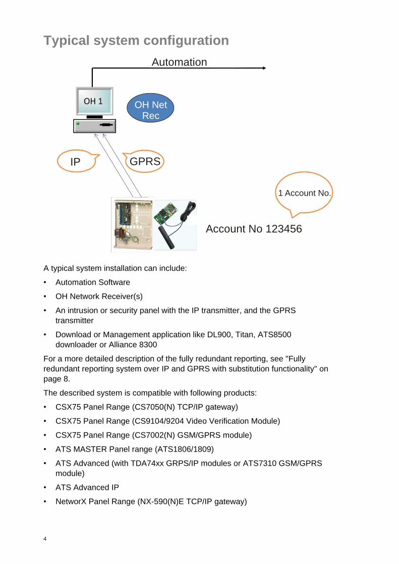
Typical system configuration
A typical system installation can include:
• Automation Software
• OH Network Receiver(s)
• An intrusion or security panel with the IP transmitter, and the GPRS
transmitter
• Download or Management application like DL900, Titan, ATS8500
downloader or Alliance 8300
For a more detailed description of the fully redundant reporting, see "Fully
redundant reporting system over IP and GPRS with substitution functionality" on
page 8.
The described system is compatible with following products:
• CSX75 Panel Range (CS7050(N) TCP/IP gateway)
• CSX75 Panel Range (CS9104/9204 Video Verification Module)
• CSX75 Panel Range (CS7002(N) GSM/GPRS module)
• ATS MASTER Panel range (ATS1806/1809)
• ATS Advanced (with TDA74xx GRPS/IP modules or ATS7310 GSM/GPRS
module)
• ATS Advanced IP
• NetworX Panel Range (NX-590(N)E TCP/IP gateway)
IP GPRS
1 Account No.
Account No 123456
OH NetRec
Automation
5
• NetworX Panel Range (NX-9104/9204 Video Verification Module)
• NetworX Panel Range (NX-7002(N) GSM/GPRS module)
• Simon Panel Range (60-938)
The following protocols are compatible.
Note: For the highest level of security, use the latest protocol version supported
after verification with the alarm central station.
• CSX75 Panel Range (CS7050(N)) Contact ID, SIA or XSIA
• CSX75 Panel Range (CS9104/9204) Contact ID, SIA or XSIA
• CSX75 Panel Range (CS7002(N)) Contact ID, SIA or XSIA
• ATS MASTER Panel range (ATS1806/1809) Contact ID, SIA or XSIA
• ATS Advanced (IP, TDA74xx, ATS7310) Contact ID, SIA or XSIA
• NetworX Panel Range (NX-590(N)E) Contact ID, SIA or XSIA
• NetworX Panel Range (NX-9104/9204) Contact ID, SIA or XSIA
• CSX75 Panel Range (NX-7002(N)) Contact ID, SIA or XSIA
• Simon Panel Range (60-938) Contact ID, SIA or XSIA
The OH Network Receiver can output to the alarm monitoring software via an
RS232 port or Ethernet (IP)
• Either the OH2000 protocol or Sur-gard MLR protocol can be used to
communicate over an RS232 port.
• Only the OH2000 protocol can be used to communicate to the Automation
software over Ethernet (IP).
Alarms and arm/disarm (open/close) events are sent over the network using
TCP/IP protocol to the OH Network Receiver and on to the Automation software.
All events sent from the Panel to the OH Network Receiver are Triple-DES
encrypted. The Triple-DES encryption used is NIST certified (Certificate No. 206)
and can be viewed on NIST official WEB site,
http://csrc.nist.gov/cryptval/des/tripledesval.html.
In the ATS1806/1809 version 04.06.14 and later there are 3 different methods of
protocols which can be used which are all supported in OH NETREC V2.0 and
later.
In the Advisor Advanced, Advisor Advanced-IP supports the 2 latest protocol
versions (V1.9.3 and V2) which are all supported in OH NETREC V2.0 and later.
The TDA74xx in combination with ATS MASTER or Advisor Advanced supports
the 2 latest protocol versions (V1.9.3 and V2) which are all supported in OH
NETREC V2.0 and later.
Always use the latest protocol versions.
The DL900 or UDX75 software can be used to configure the NX/CSX75 panels
This includes adding/removing user codes, and arming/disarming the panel. This
6
is done over the network using TCP/IP protocol. All communication between the
Panel and the downloader are Triple-DES encrypted. The Triple-DES encryption
used is NIST certified (Certificate No. 206) and can be viewed on NIST official
WEB site, http://csrc.nist.gov/cryptval/des/tripledesval.html.
Recommended settings for the system installation
The minimum requirements for the software are:
• 2-core processor, 2.6 GHz
• 2 GB RAM
• Windows XP, Windows Vista, Windows 2008 Server, Windows 7
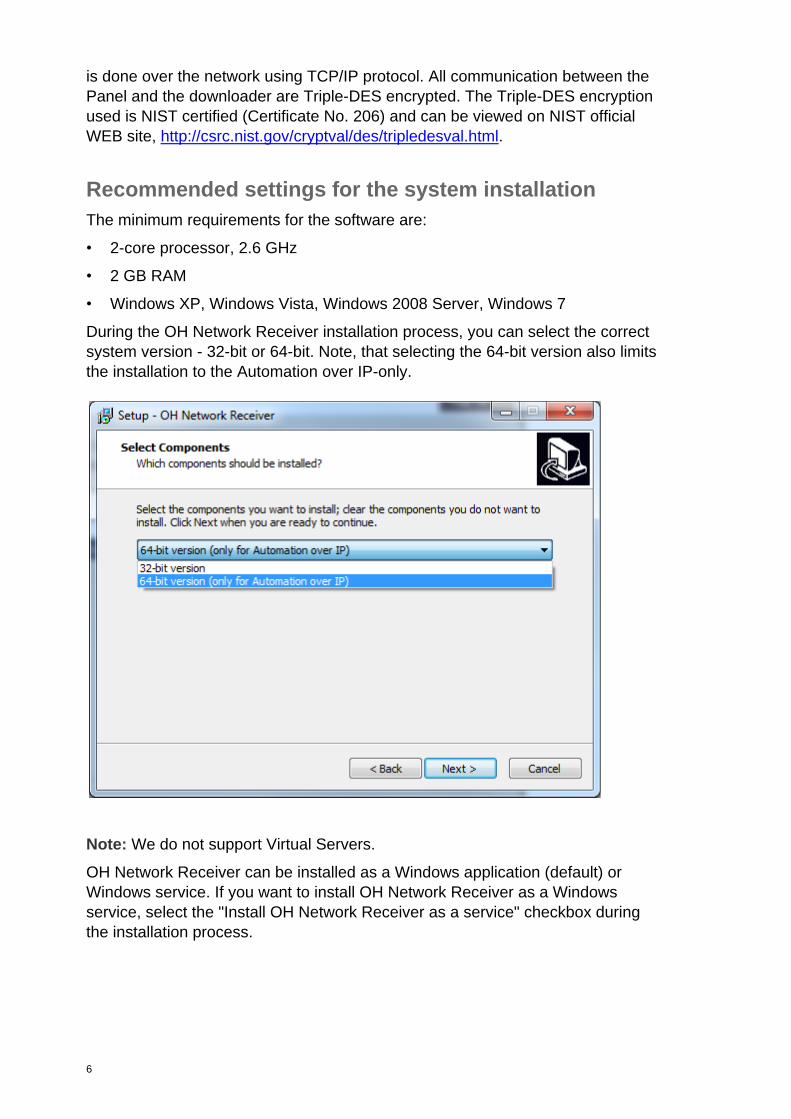
During the OH Network Receiver installation process, you can select the correct
system version - 32-bit or 64-bit. Note, that selecting the 64-bit version also limits
the installation to the Automation over IP-only.
Note: We do not support Virtual Servers.
OH Network Receiver can be installed as a Windows application (default) or
Windows service. If you want to install OH Network Receiver as a Windows
service, select the "Install OH Network Receiver as a service" checkbox during
the installation process.

7
Note: If you install OH Network Receiver as a Windows service, it can be
configured using the web interface (see "OH Network Receiver web interface" on
page 40). After first login to the web server, you must change a default
administrator password to finish the installation process.
Note: You cannot run two instances of the OH Network Receiver at a time (e.g.,
you cannot run OH Network Receiver windows service and OH Network
Receiver standalone application at the same time).
The application is oriented to make use of multi-core processors, so it is
recommended to have the most powerful hardware available for this purpose.
Dependency between the number of panels, polling and line-cut timeouts is the
subject of the particular installation. General rule is to set the line-cut timeout to a
value at least 3 times larger than the polling interval.
There are two ways to connect OHNetRec with Automation software - RS232
and the IP connection. There are the following bottlenecks in case of both
connections:
RS232 is able to receive not more than about 6 messages per second including
heartbeats, so the system should be designed the way which will guarantee not
to exceed this value for a long time period. This is the bandwidth limitation and
doesn't depend on the receiver hardware.
IP connection is much more efficient and it’s only limited by PC or server
hardware.
8
Performance sample:
Intel Xeon CPU E5-2620@2,4 Ghz (2 processors) 16 GB ram 64-Bit Win7 (RAM
speed 12000 MB/s) (drive speed 134 MB/s). Local area network. Standard
Ethernet network card. No latency from automation.
Average performance with 10 000 accounts registered:
700 SIA encrypted message received, forwarded and acknowledged to
automation per second,
or
3000 heartbeats received and acknowledged to panel per second.
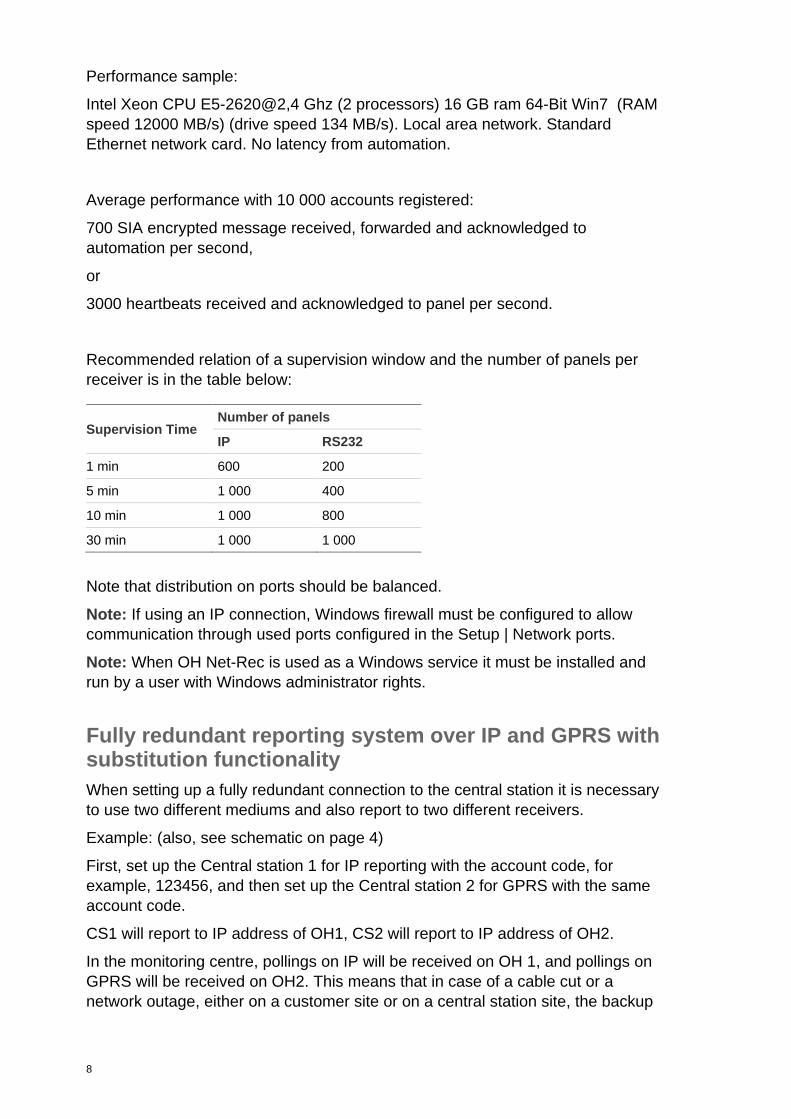
Recommended relation of a supervision window and the number of panels per
receiver is in the table below:
Supervision Time Number of panels
IP RS232
1 min 600 200
5 min 1 000 400
10 min 1 000 800
30 min 1 000 1 000
Note that distribution on ports should be balanced.
Note: If using an IP connection, Windows firewall must be configured to allow
communication through used ports configured in the Setup | Network ports.
Note: When OH Net-Rec is used as a Windows service it must be installed and
run by a user with Windows administrator rights.
Fully redundant reporting system over IP and GPRS with substitution functionality
When setting up a fully redundant connection to the central station it is necessary
to use two different mediums and also report to two different receivers.
Example: (also, see schematic on page 4)
First, set up the Central station 1 for IP reporting with the account code, for
example, 123456, and then set up the Central station 2 for GPRS with the same
account code.
CS1 will report to IP address of OH1, CS2 will report to IP address of OH2.
In the monitoring centre, pollings on IP will be received on OH 1, and pollings on
GPRS will be received on OH2. This means that in case of a cable cut or a
network outage, either on a customer site or on a central station site, the backup

9
path will still be fully operational. In case the GPRS connection is gone, the IP
connection will still be on.
In the OH you will need to setup the R and L override. For OH 1 this will be the
receiver 1 and for OH 2 this will be the receiver 2.
By doing this, the automation software will combine all signals coming from one
account code (in this case 123456), and can distinguish from which receiver an
alarm is coming and subsequently also see on which path a line trouble has
occurred.
In case somebody reports to the same central station with the same account
code, a substitution message will be shown “AA000” and also the IP address of
the sender will be stored in the active panel list.
10
Starting the OH Network Receiver When the application is installed as a service, it starts automatically after running
the operating system.
To start the OH Network Receiver manually, click the Windows Start button and
select Programs | UTC F&S | OH Network Receiver.
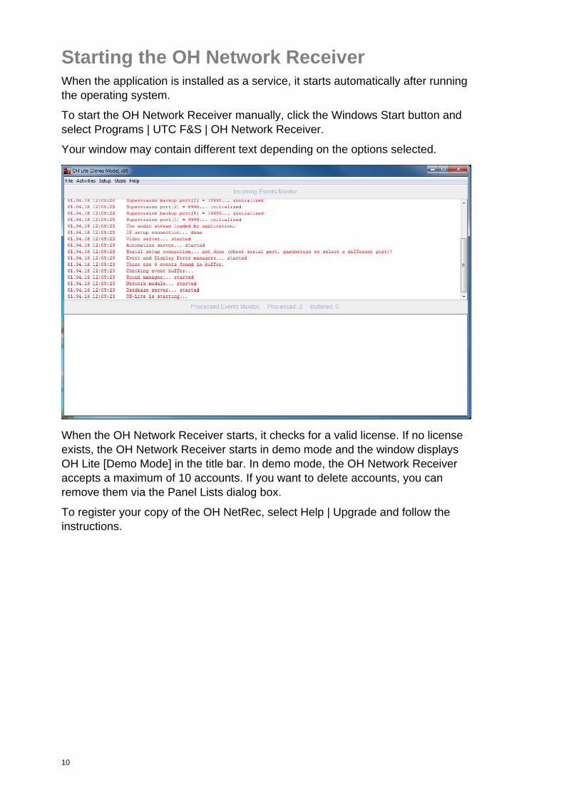
Your window may contain different text depending on the options selected.
When the OH Network Receiver starts, it checks for a valid license. If no license
exists, the OH Network Receiver starts in demo mode and the window displays
OH Lite [Demo Mode] in the title bar. In demo mode, the OH Network Receiver
accepts a maximum of 10 accounts. If you want to delete accounts, you can
remove them via the Panel Lists dialog box.
To register your copy of the OH NetRec, select Help | Upgrade and follow the
instructions.
11
OH Network Receiver window interface
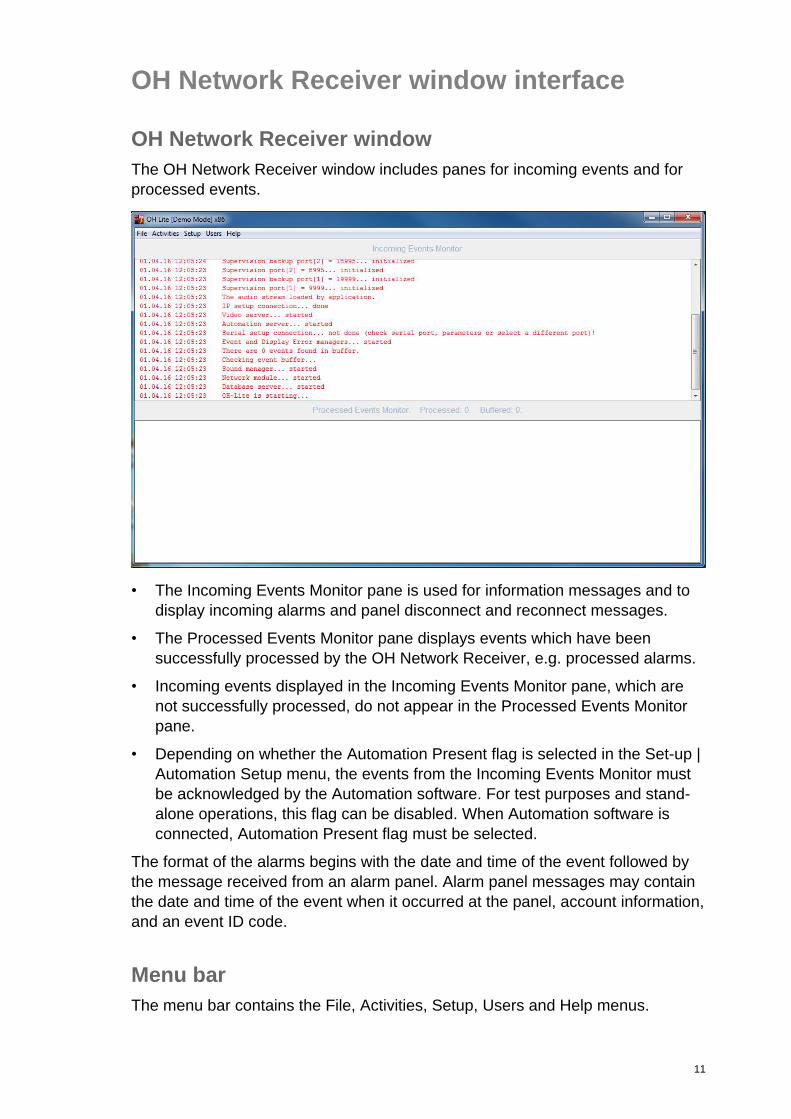
OH Network Receiver window
The OH Network Receiver window includes panes for incoming events and for
processed events.
• The Incoming Events Monitor pane is used for information messages and to
display incoming alarms and panel disconnect and reconnect messages.
• The Processed Events Monitor pane displays events which have been
successfully processed by the OH Network Receiver, e.g. processed alarms.
• Incoming events displayed in the Incoming Events Monitor pane, which are
not successfully processed, do not appear in the Processed Events Monitor
pane.
• Depending on whether the Automation Present flag is selected in the Set-up |
Automation Setup menu, the events from the Incoming Events Monitor must
be acknowledged by the Automation software. For test purposes and stand-
alone operations, this flag can be disabled. When Automation software is
connected, Automation Present flag must be selected.
The format of the alarms begins with the date and time of the event followed by
the message received from an alarm panel. Alarm panel messages may contain
the date and time of the event when it occurred at the panel, account information,
and an event ID code.
Menu bar
The menu bar contains the File, Activities, Setup, Users and Help menus.
12
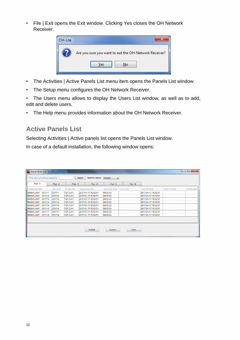
• File | Exit opens the Exit window. Clicking Yes closes the OH Network
Receiver.
• The Activities | Active Panels List menu item opens the Panels List window.
• The Setup menu configures the OH Network Receiver.
• The Users menu allows to display the Users List window, as well as to add,
edit and delete users.
• The Help menu provides information about the OH Network Receiver.
Active Panels List
Selecting Activities | Active panels list opens the Panels List window.
In case of a default installation, the following window opens:
13
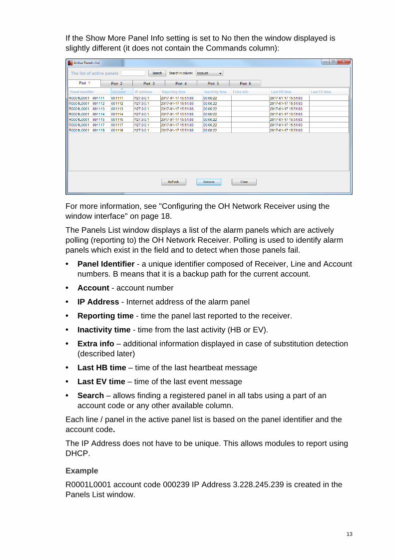
If the Show More Panel Info setting is set to No then the window displayed is
slightly different (it does not contain the Commands column):
For more information, see "Configuring the OH Network Receiver using the
window interface" on page 18.
The Panels List window displays a list of the alarm panels which are actively
polling (reporting to) the OH Network Receiver. Polling is used to identify alarm
panels which exist in the field and to detect when those panels fail.
• Panel Identifier - a unique identifier composed of Receiver, Line and Account
numbers. B means that it is a backup path for the current account.
• Account - account number
• IP Address - Internet address of the alarm panel
• Reporting time - time the panel last reported to the receiver.
• Inactivity time - time from the last activity (HB or EV).
• Extra info – additional information displayed in case of substitution detection
(described later)
• Last HB time – time of the last heartbeat message
• Last EV time – time of the last event message
• Search – allows finding a registered panel in all tabs using a part of an
account code or any other available column.
Each line / panel in the active panel list is based on the panel identifier and the
account code.
The IP Address does not have to be unique. This allows modules to report using
DHCP.
Example
R0001L0001 account code 000239 IP Address 3.228.245.239 is created in the
Panels List window.
14
Due to changes in the DHCP lease, the IP address of this panel is changed, and
the panel is given a new IP address from a DHCP server.
The next time a polling from the same panel comes in, the line in the Panels List
window changes to
R0001L0001 account code 000239 IP Address 3.228.245.255
It is still considered to be the same panel reporting to the OH Network Receiver.
• To update a list, click on Refresh. This updates the date and time of last
report.
• To remove a panel, select its row in the display, and then click Remove.
Note: If the panel is still actively polling, clicking Refresh restores it to the
display. Remove is intended to remove panel(s) from the display which are no
longer part of the system.
• When panels are no longer reporting, an ‘R’ is displayed behind their entry in
the active panel list and the whole line is highlighted in red. Also, if the port is
working in a dual path mode, and a connection to one of the panels in the pair
is lost, rows for both panels are marked in yellow. Each time a panel polls, a
timer starts. When this timer value is greater than the value in the Line Cut
Timeout window, a message LT079 (SIA) is sent to the Automation
software, to indicate a line fault. When a panel polls the OH Receiver again,
the ‘R’ disappears, and an LR079 (SIA) message is sent to the Automation
Software.
In case of dual path configuration, LT079 and LR079 messages will be
generated from a primary path and LT080 and LR080 messages will be
generated from a backup path. After a critical failure (all paths unavailable)
the additional YS079 event is sent to automation. After a critical restore the
YK079 message is generated. YS079 and YK079 messages are generated
only if “FTC Report” option is enabled.
• Depending on the format of the last message (SIA or CID) from the specific
account, the message sent to the Automation software, will be either
LT079 (SIA) or 1356 (CID) for a line fault, and LR079 (SIA) or 3356 (CID) for
a line fault restore.
SIA - CID mapping:
LT079 - CID message E356 Zone 079
LT080 - CID message E356 Zone 080
YS079 - CID message E354 Zone 079
LR079 - CID message R356 Zone 079
LR080 - CID message R356 Zone 080
YK079 - CID message R354 Zone 079
RX079 - CID message E602 Zone 079
15
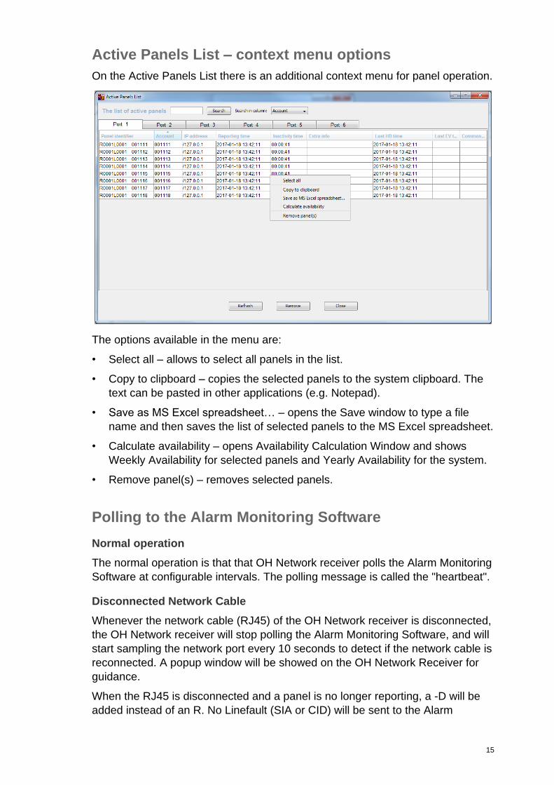
Active Panels List – context menu options
On the Active Panels List there is an additional context menu for panel operation.
The options available in the menu are:
• Select all – allows to select all panels in the list.
• Copy to clipboard – copies the selected panels to the system clipboard. The
text can be pasted in other applications (e.g. Notepad).
• Save as MS Excel spreadsheet… – opens the Save window to type a file
name and then saves the list of selected panels to the MS Excel spreadsheet.
• Calculate availability – opens Availability Calculation Window and shows
Weekly Availability for selected panels and Yearly Availability for the system.
• Remove panel(s) – removes selected panels.
Polling to the Alarm Monitoring Software
Normal operation
The normal operation is that that OH Network receiver polls the Alarm Monitoring
Software at configurable intervals. The polling message is called the "heartbeat".
Disconnected Network Cable
Whenever the network cable (RJ45) of the OH Network receiver is disconnected,
the OH Network receiver will stop polling the Alarm Monitoring Software, and will
start sampling the network port every 10 seconds to detect if the network cable is
reconnected. A popup window will be showed on the OH Network Receiver for
guidance.
When the RJ45 is disconnected and a panel is no longer reporting, a -D will be
added instead of an R. No Linefault (SIA or CID) will be sent to the Alarm
16
Monitoring Software. This –D will allow the operator to identify the panels that
lost polling due to the disconnected network cable. And the fact of stopping the
polling towards the Alarm Monitoring Software will generate an alarm for the
operators.
Whenever the network cable is reconnected, a recovery period will start. The
Recovery time can be configured in the application properties file in the OH
program directory. This will give the panels the time to recover their polling
messages. During this recovery time, the polling to the Alarm Monitoring
Software will be started. For all panels that report again, the –D will be removed.
After the recovery time, the active panel list will be checked, and all panels which
still have a –D will be exchanged for a –R and a Linefault (CID or CID) will be
generated.
Substitution detection
With the Enhanced protocol version 1.9.4 or higher, a new substitution detection
mechanism has been introduced. It is intended to detect situations where an
attempt is being made to impersonate a known account and alarm transmitter
with the same account and an alternative alarm transmitter. The OH Network
Receiver transmits the following messages to the automation software.
• Using SIA and XSIA: AA
30.04.12 14:26:40 Y043013 14:26:40 001111 bbbb AA000 ri01 N |
30
• Using CID: 369
30.04.12 14:32:11 C043013 14:32:11 1111 bbbb 1 369 G00 Z000 |
&5
In case of substitution, the Extra info column in the Active Panels List shows
additional details:
S [001111 IP=/155.245.21.117]
The above data shows that the substitution occurred where the account number
is 001111 and the substituting transmitter IP address is 155.245.21.117. This
situation should be verified by the Installer to confirm that the proper account
code and alarm transmitter is configured on the customer’s side. If this is
confirmed, the line showing the substituted account must be manually removed
from the Active Panels List to allow the account to start reporting again.
Notes:
For substitution to be detected, the OH Network Receiver has to be in version
1.9.4, V2, V3 or later and the alarm transmitter has to be configured to use
V1.9.4, V2 or later. An alarm transmitter that is configured to support substitution
detection but is changed to an earlier protocol version (V1.9.3, Enhanced or
Standard) will also activate a substitution event.
17
The substitution is not detected when the IP address of the transmitter changes.
This is important i.e. in case of the networks, where the IP address changes
periodically.
Disk Space Monitor
Disk Space Monitor watches and warns about getting low disk space. The low
disk space threshold is adjustable in the OH Network Receiver settings, which
says below what value (in megabytes) the warning message should be
displayed. By default the value is 100 MB. When the disk space becomes less
than this value, the warning message is displayed in the main window area.
ATS8550 OH callback functionality
The ATS8550 and ATS8500 software can connect to ATS Advanced panels
using a callback performed via the OH Network Receiver.
To do this, the ATS8550 sends a message via TCP/IP to the OH Network
Receiver with a callback request (using port 9996) to a specific panel (the panel
is addressed using the Area Account Code).
If OH has this panel on its list then during the panel heartbeat massage this
request is sent to the panel.
Panel gets it and tries to connects to the ATS8550 using the PC callback setting
stored in its configuration.
For example, the message AC CR R0001L0001 123456 contains the
following information:
AC CR – callback command for the OH Network Receiver
R0001 – receiver number
L0001 – receiver line
123456 – Area Account code
18
Configuring the OH Network Receiver using the window interface
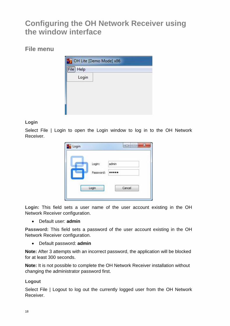
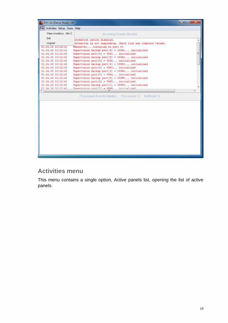
File menu
Login
Select File | Login to open the Login window to log in to the OH Network
Receiver.
Login: This field sets a user name of the user account existing in the OH
Network Receiver configuration.
Default user: admin
Password: This field sets a password of the user account existing in the OH
Network Receiver configuration.
Default password: admin
Note: After 3 attempts with an incorrect password, the application will be blocked
for at least 300 seconds.
Note: It is not possible to complete the OH Network Receiver installation without
changing the administrator password first.
Logout
Select File | Logout to log out the currently logged user from the OH Network
Receiver.
19
Activities menu
This menu contains a single option, Active panels list, opening the list of active
panels.
20
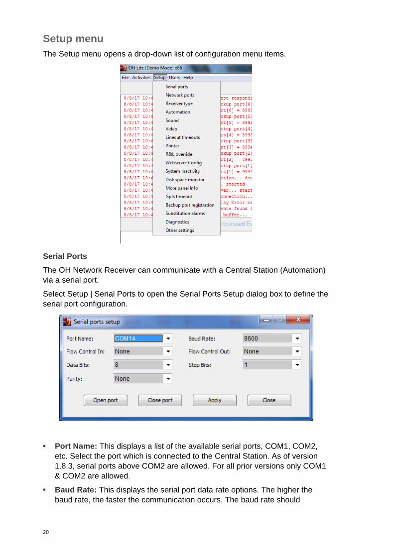
Setup menu
The Setup menu opens a drop-down list of configuration menu items.
Serial Ports
The OH Network Receiver can communicate with a Central Station (Automation)
via a serial port.
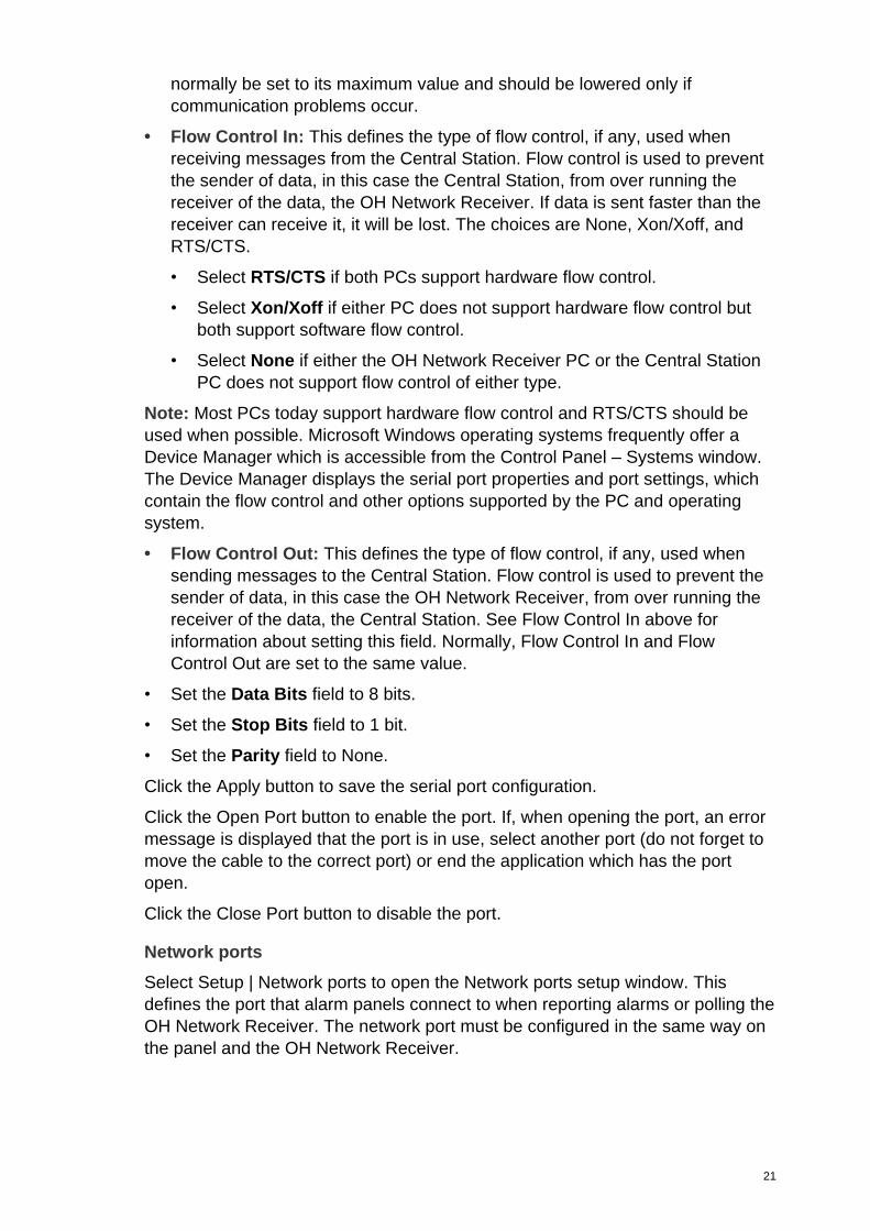
Select Setup | Serial Ports to open the Serial Ports Setup dialog box to define the
serial port configuration.
• Port Name: This displays a list of the available serial ports, COM1, COM2,
etc. Select the port which is connected to the Central Station. As of version
1.8.3, serial ports above COM2 are allowed. For all prior versions only COM1
& COM2 are allowed.
• Baud Rate: This displays the serial port data rate options. The higher the
baud rate, the faster the communication occurs. The baud rate should
21
normally be set to its maximum value and should be lowered only if
communication problems occur.
• Flow Control In: This defines the type of flow control, if any, used when
receiving messages from the Central Station. Flow control is used to prevent
the sender of data, in this case the Central Station, from over running the
receiver of the data, the OH Network Receiver. If data is sent faster than the
receiver can receive it, it will be lost. The choices are None, Xon/Xoff, and
RTS/CTS.
• Select RTS/CTS if both PCs support hardware flow control.
• Select Xon/Xoff if either PC does not support hardware flow control but
both support software flow control.
• Select None if either the OH Network Receiver PC or the Central Station
PC does not support flow control of either type.
Note: Most PCs today support hardware flow control and RTS/CTS should be
used when possible. Microsoft Windows operating systems frequently offer a
Device Manager which is accessible from the Control Panel – Systems window.
The Device Manager displays the serial port properties and port settings, which
contain the flow control and other options supported by the PC and operating
system.
• Flow Control Out: This defines the type of flow control, if any, used when
sending messages to the Central Station. Flow control is used to prevent the
sender of data, in this case the OH Network Receiver, from over running the
receiver of the data, the Central Station. See Flow Control In above for
information about setting this field. Normally, Flow Control In and Flow
Control Out are set to the same value.
• Set the Data Bits field to 8 bits.
• Set the Stop Bits field to 1 bit.
• Set the Parity field to None.
Click the Apply button to save the serial port configuration.
Click the Open Port button to enable the port. If, when opening the port, an error
message is displayed that the port is in use, select another port (do not forget to
move the cable to the correct port) or end the application which has the port
open.
Click the Close Port button to disable the port.
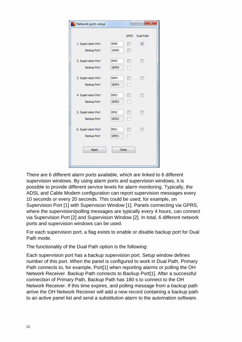
Network ports
Select Setup | Network ports to open the Network ports setup window. This
defines the port that alarm panels connect to when reporting alarms or polling the
OH Network Receiver. The network port must be configured in the same way on
the panel and the OH Network Receiver.
22
There are 6 different alarm ports available, which are linked to 6 different
supervision windows. By using alarm ports and supervision windows, it is
possible to provide different service levels for alarm monitoring. Typically, the
ADSL and Cable Modem configuration can report supervision messages every
10 seconds or every 20 seconds. This could be used, for example, on
Supervision Port [1] with Supervision Window [1]. Panels connecting via GPRS,
where the supervision/polling messages are typically every 4 hours, can connect
via Supervision Port [2] and Supervision Window [2]. In total, 6 different network
ports and supervision windows can be used.
For each supervision port, a flag exists to enable or disable backup port for Dual
Path mode.
The functionality of the Dual Path option is the following:
Each supervision port has a backup supervision port. Setup window defines
number of this port. When the panel is configured to work in Dual Path, Primary
Path connects to, for example, Port[1] when reporting alarms or polling the OH
Network Receiver. Backup Path connects to Backup Port[1]. After a successful
connection of Primary Path, Backup Path has 180 s to connect to the OH
Network Receiver. If this time expires, and polling message from a backup path
arrive the OH Network Receiver will add a new record containing a backup path
to an active panel list and send a substitution alarm to the automation software.
23
When a Dual Path flag on a Network Ports is set to false, the OH Network
Receiver deletes all collected information about the Backup Path for all panels
from active panel lists reporting on this port.
For each supervision port, a flag exists to enable or disable this alarm port for
GPRS communication. The functionality for GPRS enabled and disabled is the
following:
Each time an alarm message is being sent, the alarm transmitter builds up the IP
communication with the OH Alarm Receiver. After the alarm message has been
sent, the IP sockets are closed by the alarm transmitter. This means that for
every new alarm, there is additional IP communication overhead. However for
GSM/GPRS communication (GPRS Enabled = Selected), this principle is
different: after the alarm transmission, the communication path needs to stay
open. The purpose is to reduce bandwidth as GSM/GPRS communication is
more expensive and paid per amount of data.
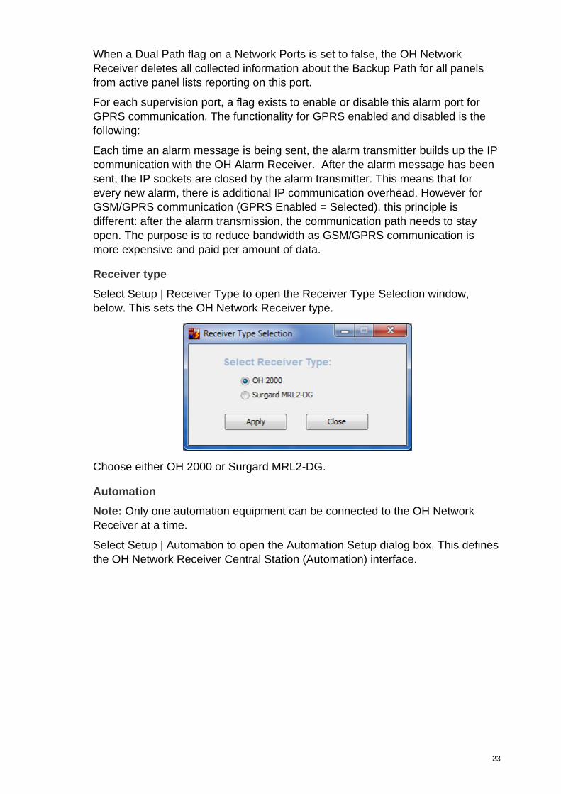
Receiver type
Select Setup | Receiver Type to open the Receiver Type Selection window,
below. This sets the OH Network Receiver type.
Choose either OH 2000 or Surgard MRL2-DG.
Automation
Note: Only one automation equipment can be connected to the OH Network
Receiver at a time.
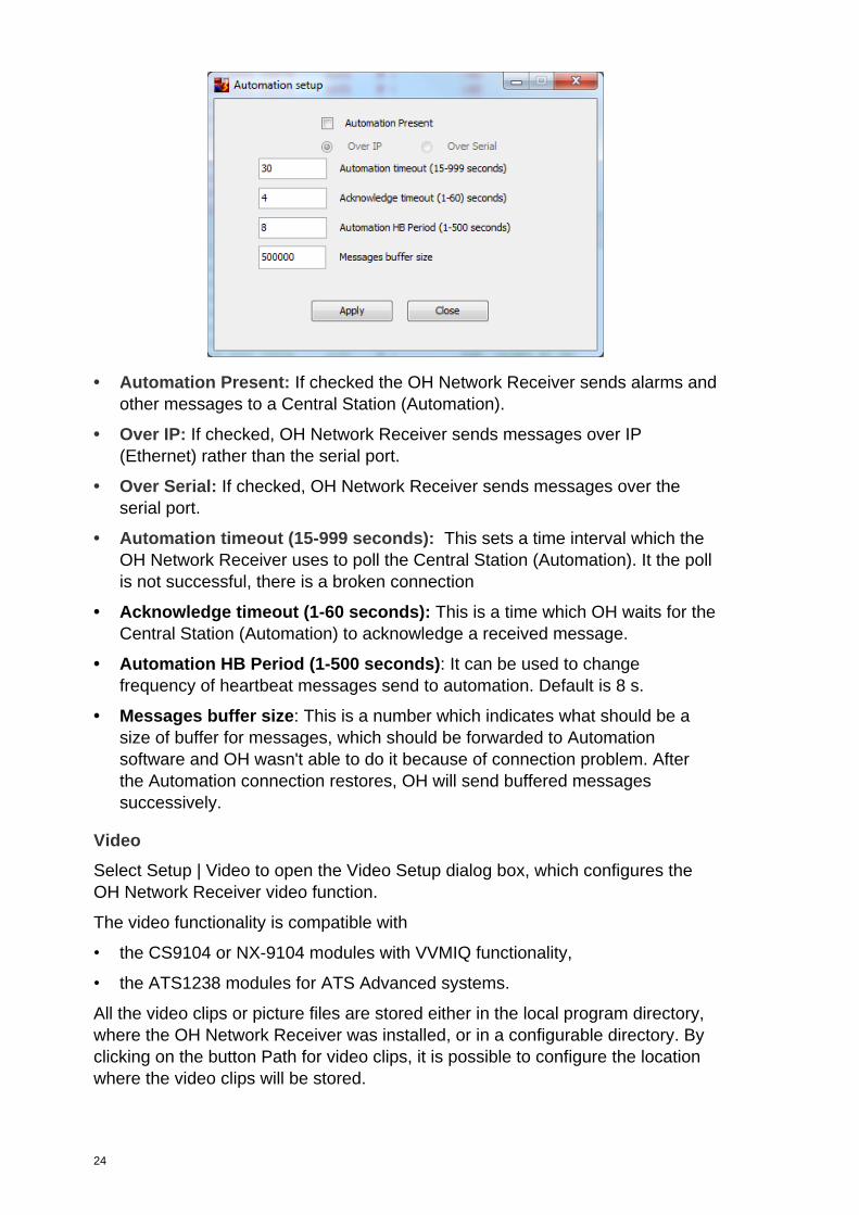
Select Setup | Automation to open the Automation Setup dialog box. This defines
the OH Network Receiver Central Station (Automation) interface.
24
• Automation Present: If checked the OH Network Receiver sends alarms and
other messages to a Central Station (Automation).
• Over IP: If checked, OH Network Receiver sends messages over IP
(Ethernet) rather than the serial port.
• Over Serial: If checked, OH Network Receiver sends messages over the
serial port.
• Automation timeout (15-999 seconds): This sets a time interval which the
OH Network Receiver uses to poll the Central Station (Automation). It the poll
is not successful, there is a broken connection
• Acknowledge timeout (1-60 seconds): This is a time which OH waits for the
Central Station (Automation) to acknowledge a received message.
• Automation HB Period (1-500 seconds): It can be used to change
frequency of heartbeat messages send to automation. Default is 8 s.
• Messages buffer size: This is a number which indicates what should be a
size of buffer for messages, which should be forwarded to Automation
software and OH wasn't able to do it because of connection problem. After
the Automation connection restores, OH will send buffered messages
successively.
Video
Select Setup | Video to open the Video Setup dialog box, which configures the
OH Network Receiver video function.
The video functionality is compatible with
• the CS9104 or NX-9104 modules with VVMIQ functionality,
• the ATS1238 modules for ATS Advanced systems.
All the video clips or picture files are stored either in the local program directory,
where the OH Network Receiver was installed, or in a configurable directory. By
clicking on the button Path for video clips, it is possible to configure the location
where the video clips will be stored.
25
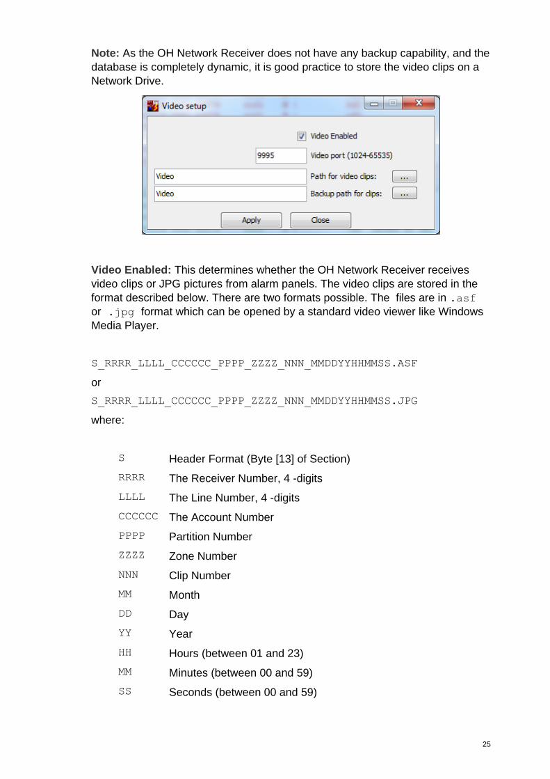
Note: As the OH Network Receiver does not have any backup capability, and the
database is completely dynamic, it is good practice to store the video clips on a
Network Drive.
Video Enabled: This determines whether the OH Network Receiver receives
video clips or JPG pictures from alarm panels. The video clips are stored in the
format described below. There are two formats possible. The files are in .asf
or .jpg format which can be opened by a standard video viewer like Windows
Media Player.
S_RRRR_LLLL_CCCCCC_PPPP_ZZZZ_NNN_MMDDYYHHMMSS.ASF
or
S_RRRR_LLLL_CCCCCC_PPPP_ZZZZ_NNN_MMDDYYHHMMSS.JPG
where:
S Header Format (Byte [13] of Section)
RRRR The Receiver Number, 4 -digits
LLLL The Line Number, 4 -digits
CCCCCC The Account Number
PPPP Partition Number
ZZZZ Zone Number
NNN Clip Number
MM Month
DD Day
YY Year
HH Hours (between 01 and 23)
MM Minutes (between 00 and 59)
SS Seconds (between 00 and 59)
26
Example
Video Alarm: Y101513 11:10:31 0003EE 0007 BR009 ri01 N |
VID:2_0001_0001_000001_0001_0003_0_020706025425.asf
SIA Event Format: Ymmddyy hh:nn:ss aaaaaa llll eeeee ripp N |
VID:VIDEO-FILE-NAME ckE
Where:
• Y indicates a SIA format message
• mm is the month
• dd is the day
• yy is the year
• hh is the hour
• nn is the minute
• ss is the second
• aaaaaa is a 3 to 6 digit account number
• llll is the line number
• eeeee is the SIA event code
• ri indicates a partition number is to follow
• pp is a 2 digit partition number
• N indicates new
• | is the “|” character
• VID: is the “VID:” string
• VIDEO-FILE-NAME: file name used to save image
• ck is the 2 character message checksum computed as described above.
• E is an EOT character (04h)
If a clip is reported from VVMIQ then the first letter of the file name can be ‘0’, ‘1’
or ‘2’, and the extension is ‘asf’.
Video File Name: 2_0001_0001_000001_0001_0003_0_020706025425.asf
When a picture from PIRCAM is reported to OH, the first letter of the file name is
always '3' and the extension is ‘jpg’, for example,
3_0001_0001_000001_0001_0003_0_020706025425.jpg.
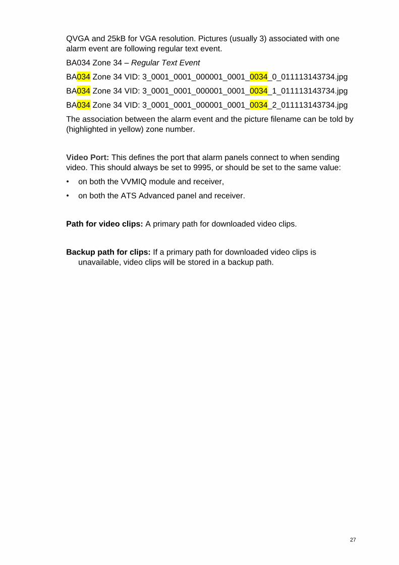
The events received from ATS Advanced system contain reference to associated
set of still pictures in JPG format. The average size of single picture is 8kB for
27
QVGA and 25kB for VGA resolution. Pictures (usually 3) associated with one
alarm event are following regular text event.
BA034 Zone 34 – Regular Text Event
BA034 Zone 34 VID: 3_0001_0001_000001_0001_0034_0_011113143734.jpg
BA034 Zone 34 VID: 3_0001_0001_000001_0001_0034_1_011113143734.jpg
BA034 Zone 34 VID: 3_0001_0001_000001_0001_0034_2_011113143734.jpg
The association between the alarm event and the picture filename can be told by
(highlighted in yellow) zone number.
Video Port: This defines the port that alarm panels connect to when sending
video. This should always be set to 9995, or should be set to the same value:
• on both the VVMIQ module and receiver,
• on both the ATS Advanced panel and receiver.
Path for video clips: A primary path for downloaded video clips.
Backup path for clips: If a primary path for downloaded video clips is
unavailable, video clips will be stored in a backup path.
28
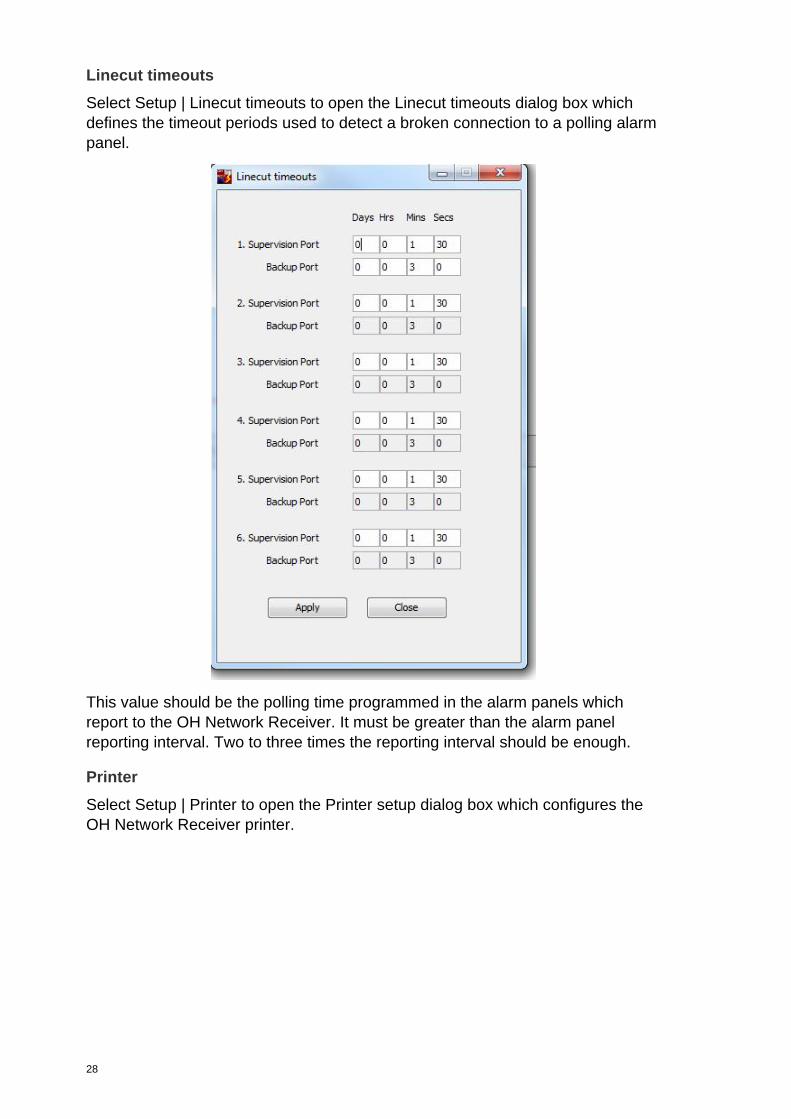
Linecut timeouts
Select Setup | Linecut timeouts to open the Linecut timeouts dialog box which
defines the timeout periods used to detect a broken connection to a polling alarm
panel.
This value should be the polling time programmed in the alarm panels which
report to the OH Network Receiver. It must be greater than the alarm panel
reporting interval. Two to three times the reporting interval should be enough.
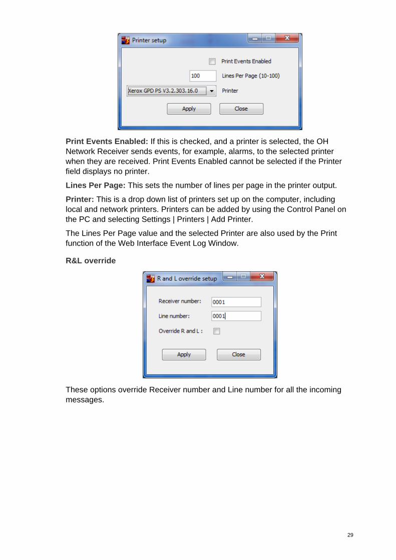
Printer
Select Setup | Printer to open the Printer setup dialog box which configures the
OH Network Receiver printer.
29
Print Events Enabled: If this is checked, and a printer is selected, the OH
Network Receiver sends events, for example, alarms, to the selected printer
when they are received. Print Events Enabled cannot be selected if the Printer
field displays no printer.
Lines Per Page: This sets the number of lines per page in the printer output.
Printer: This is a drop down list of printers set up on the computer, including
local and network printers. Printers can be added by using the Control Panel on
the PC and selecting Settings | Printers | Add Printer.
The Lines Per Page value and the selected Printer are also used by the Print
function of the Web Interface Event Log Window.
R&L override
These options override Receiver number and Line number for all the incoming
messages.
30
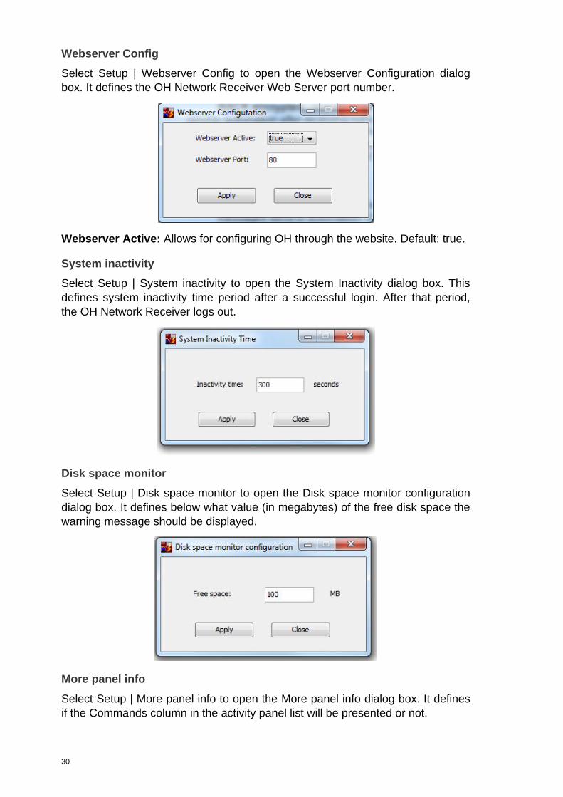
Webserver Config
Select Setup | Webserver Config to open the Webserver Configuration dialog
box. It defines the OH Network Receiver Web Server port number.
Webserver Active: Allows for configuring OH through the website. Default: true.
System inactivity
Select Setup | System inactivity to open the System Inactivity dialog box. This
defines system inactivity time period after a successful login. After that period,
the OH Network Receiver logs out.
Disk space monitor
Select Setup | Disk space monitor to open the Disk space monitor configuration
dialog box. It defines below what value (in megabytes) of the free disk space the
warning message should be displayed.
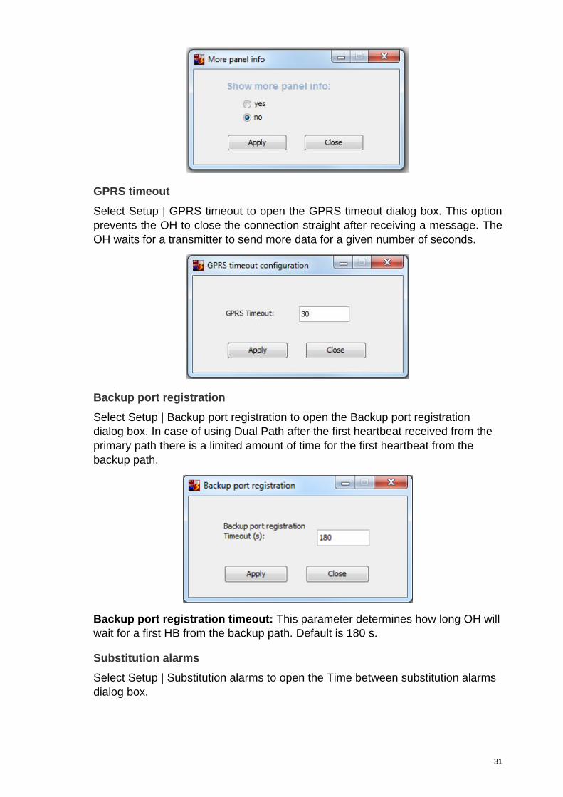
More panel info
Select Setup | More panel info to open the More panel info dialog box. It defines
if the Commands column in the activity panel list will be presented or not.
31
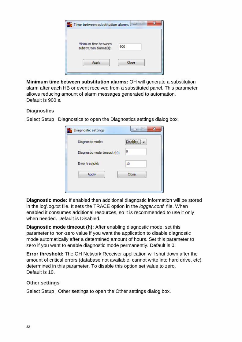
GPRS timeout
Select Setup | GPRS timeout to open the GPRS timeout dialog box. This option
prevents the OH to close the connection straight after receiving a message. The
OH waits for a transmitter to send more data for a given number of seconds.
Backup port registration
Select Setup | Backup port registration to open the Backup port registration
dialog box. In case of using Dual Path after the first heartbeat received from the
primary path there is a limited amount of time for the first heartbeat from the
backup path.
Backup port registration timeout: This parameter determines how long OH will
wait for a first HB from the backup path. Default is 180 s.
Substitution alarms
Select Setup | Substitution alarms to open the Time between substitution alarms
dialog box.
32
Minimum time between substitution alarms: OH will generate a substitution
alarm after each HB or event received from a substituted panel. This parameter
allows reducing amount of alarm messages generated to automation.
Default is 900 s.
Diagnostics
Select Setup | Diagnostics to open the Diagnostics settings dialog box.
Diagnostic mode: If enabled then additional diagnostic information will be stored
in the log\log.txt file. It sets the TRACE option in the logger.conf file. When
enabled it consumes additional resources, so it is recommended to use it only
when needed. Default is Disabled.
Diagnostic mode timeout (h): After enabling diagnostic mode, set this
parameter to non-zero value if you want the application to disable diagnostic
mode automatically after a determined amount of hours. Set this parameter to
zero if you want to enable diagnostic mode permanently. Default is 0.
Error threshold: The OH Network Receiver application will shut down after the
amount of critical errors (database not available, cannot write into hard drive, etc)
determined in this parameter. To disable this option set value to zero.
Default is 10.
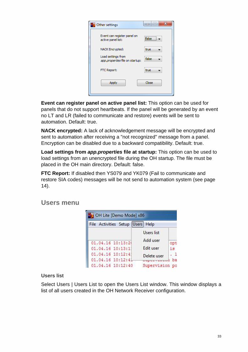
Other settings
Select Setup | Other settings to open the Other settings dialog box.
33
Event can register panel on active panel list: This option can be used for
panels that do not support heartbeats. If the panel will be generated by an event
no LT and LR (failed to communicate and restore) events will be sent to
automation. Default: true.
NACK encrypted: A lack of acknowledgement message will be encrypted and
sent to automation after receiving a "not recognized" message from a panel.
Encryption can be disabled due to a backward compatibility. Default: true.
Load settings from app.properties file at startup: This option can be used to
load settings from an unencrypted file during the OH startup. The file must be
placed in the OH main directory. Default: false.
FTC Report: If disabled then YS079 and YK079 (Fail to communicate and
restore SIA codes) messages will be not send to automation system (see page
14).
Users menu
Users list
Select Users | Users List to open the Users List window. This window displays a
list of all users created in the OH Network Receiver configuration.
34
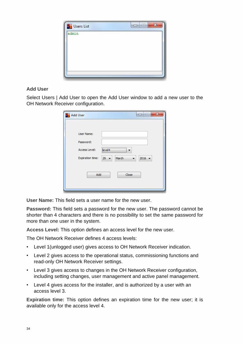
Add User
Select Users | Add User to open the Add User window to add a new user to the
OH Network Receiver configuration.
User Name: This field sets a user name for the new user.
Password: This field sets a password for the new user. The password cannot be
shorter than 4 characters and there is no possibility to set the same password for
more than one user in the system.
Access Level: This option defines an access level for the new user.
The OH Network Receiver defines 4 access levels:
• Level 1(unlogged user) gives access to OH Network Receiver indication.
• Level 2 gives access to the operational status, commissioning functions and
read-only OH Network Receiver settings.
• Level 3 gives access to changes in the OH Network Receiver configuration,
including setting changes, user management and active panel management.
• Level 4 gives access for the installer, and is authorized by a user with an
access level 3.
Expiration time: This option defines an expiration time for the new user; it is
available only for the access level 4.
35
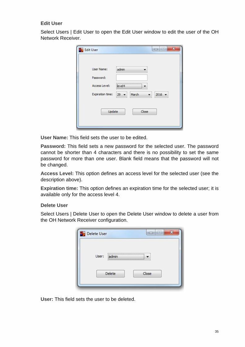
Edit User
Select Users | Edit User to open the Edit User window to edit the user of the OH
Network Receiver.
User Name: This field sets the user to be edited.
Password: This field sets a new password for the selected user. The password
cannot be shorter than 4 characters and there is no possibility to set the same
password for more than one user. Blank field means that the password will not
be changed.
Access Level: This option defines an access level for the selected user (see the
description above).
Expiration time: This option defines an expiration time for the selected user; it is
available only for the access level 4.
Delete User
Select Users | Delete User to open the Delete User window to delete a user from
the OH Network Receiver configuration.
User: This field sets the user to be deleted.

36
Help menu
Help - Upgrade
Note: You must be logged as a user with access level 4 to use the upgrade
function.
Select Help | Upgrade to convert the OH Network Receiver software from demo
mode to a full working version.
Starting from the Version 3.2.2.2, there are 4 different sizes of a database
available: 100 accounts, 500 accounts, 1000 accounts and 10000 accounts.
The System Code is linked to the first network card in the PC that the OH
Network Receiver software is running on. This is the code that needs to be
provided, together with the MAC address of the PC and the Max Accounts, in
order to obtain the Cipher Code. The Cipher Code (or Unlock Code) can be
obtained via the Local Sales Office or via the Order Processor. This happens
after the order has been placed for the corresponding size of receiver. Unlocking
the number of accounts is done by copying and pasting the Cipher Code and
clicking on the Submit button.
37
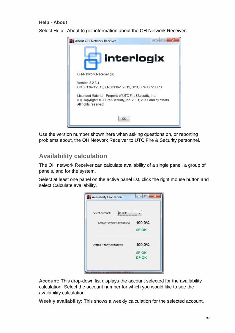
Help - About
Select Help | About to get information about the OH Network Receiver.
Use the version number shown here when asking questions on, or reporting
problems about, the OH Network Receiver to UTC Fire & Security personnel.
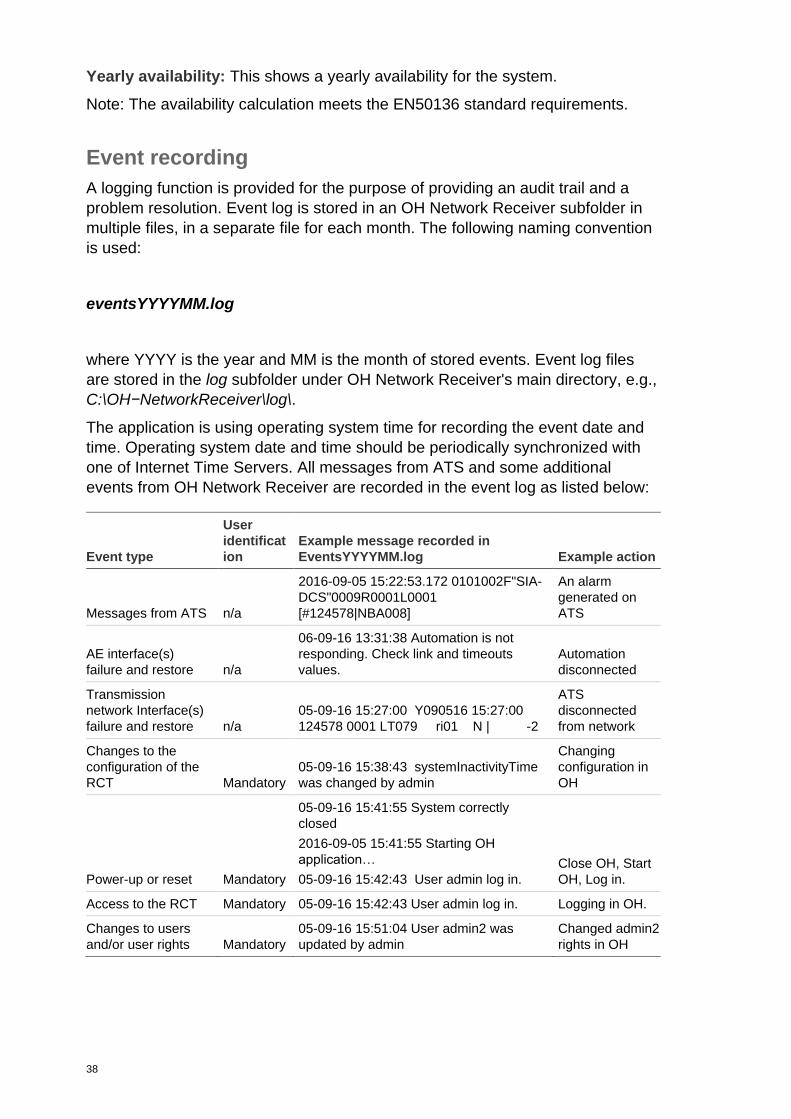
Availability calculation
The OH network Receiver can calculate availability of a single panel, a group of
panels, and for the system.
Select at least one panel on the active panel list, click the right mouse button and
select Calculate availability.
Account: This drop-down list displays the account selected for the availability
calculation. Select the account number for which you would like to see the
availability calculation.
Weekly availability: This shows a weekly calculation for the selected account.
38
Yearly availability: This shows a yearly availability for the system.
Note: The availability calculation meets the EN50136 standard requirements.
Event recording
A logging function is provided for the purpose of providing an audit trail and a
problem resolution. Event log is stored in an OH Network Receiver subfolder in
multiple files, in a separate file for each month. The following naming convention
is used:
eventsYYYYMM.log
where YYYY is the year and MM is the month of stored events. Event log files
are stored in the log subfolder under OH Network Receiver's main directory, e.g.,
C:\OH−NetworkReceiver\log\.
The application is using operating system time for recording the event date and
time. Operating system date and time should be periodically synchronized with
one of Internet Time Servers. All messages from ATS and some additional
events from OH Network Receiver are recorded in the event log as listed below:
Event type
User
identificat
ion
Example message recorded in
EventsYYYYMM.log Example action
Messages from ATS n/a
2016-09-05 15:22:53.172 0101002F"SIA-
DCS"0009R0001L0001
[#124578|NBA008]
An alarm
generated on
ATS
AE interface(s)
failure and restore n/a
06-09-16 13:31:38 Automation is not
responding. Check link and timeouts
values.
Automation
disconnected
Transmission
network Interface(s)
failure and restore n/a
05-09-16 15:27:00 Y090516 15:27:00
124578 0001 LT079 ri01 N | -2
ATS
disconnected
from network
Changes to the
configuration of the
RCT Mandatory
05-09-16 15:38:43 systemInactivityTime
was changed by admin
Changing
configuration in
OH
Power-up or reset Mandatory
05-09-16 15:41:55 System correctly
closed
2016-09-05 15:41:55 Starting OH
application…
05-09-16 15:42:43 User admin log in.
Close OH, Start
OH, Log in.
Access to the RCT Mandatory 05-09-16 15:42:43 User admin log in. Logging in OH.
Changes to users
and/or user rights Mandatory
05-09-16 15:51:04 User admin2 was
updated by admin
Changed admin2
rights in OH

39
Note: It is recommended to secure at least 20 GB of disk space for log recording.
Disk Space Monitor is included in the application and it will warn if free hard disk
space is lower than desired space (see "Disk Space Monitor" on page 17).
Important: Event logs will be stored on a disk for 3 years. Log entries older than
3 years will be automatically deleted.
DoS attacks
A DoS attack on one transmission network interface of the OH receiver does not
adversely affect the operation of the RCT or the operation of any other OH RCT
transmission network interface.
40
OH Network Receiver web interface The OH Network Receiver has its own web server included. The Web server
starts working after the OH Network Receiver installation process is finished.
The OH Network Receiver web interface includes menus with the same
functionality as the Network Receiver window interface.
The link to access the menus is:
• from the computer where the OH Network Receiver is installed:
https://localhost:port
• from other computers: https://IP_address:port
port: Port number set up in the OH Network Receiver configuration.
IP_address: IP address of the computer where the OH Network Receiver is
installed.
Note: Communication with the web interface is encrypted with the TLS 1.2 SSL
standard.
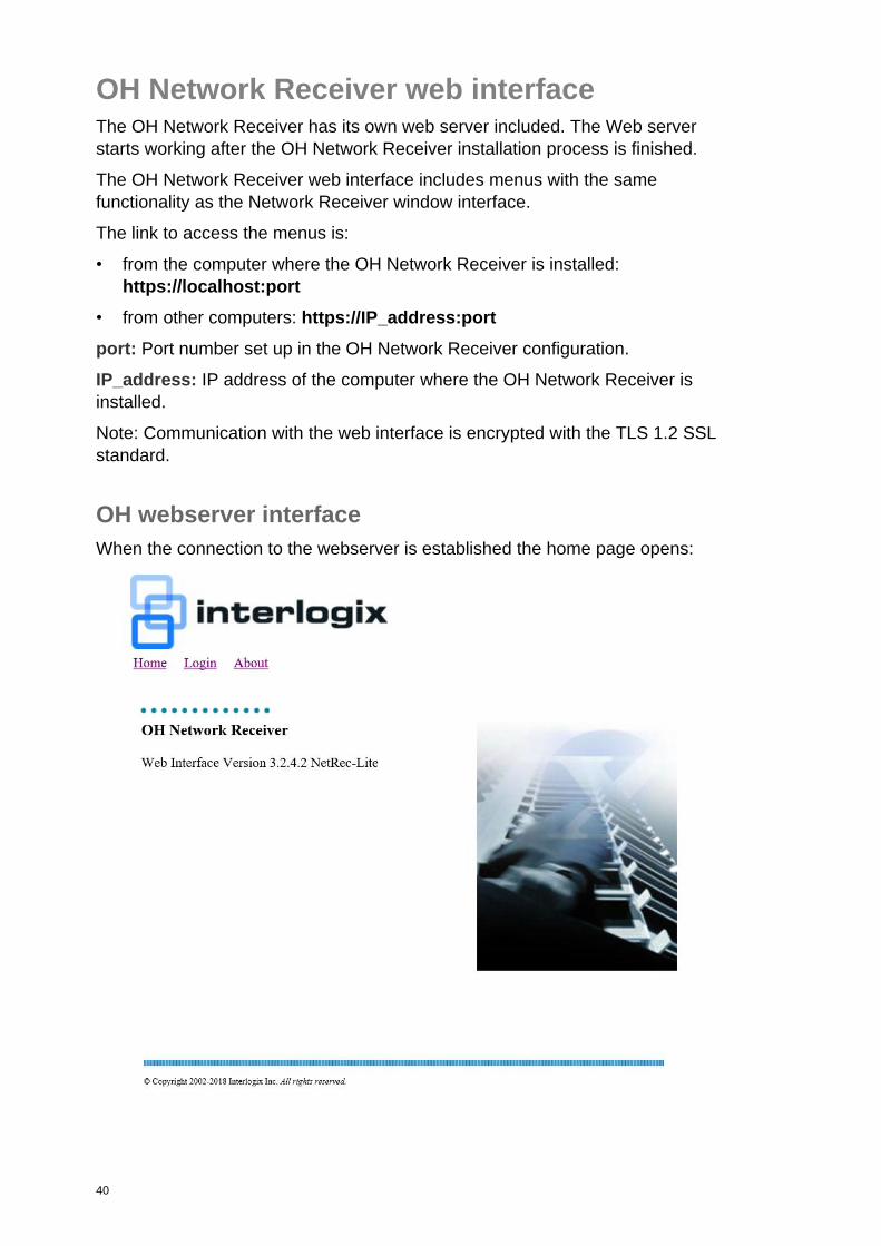
OH webserver interface
When the connection to the webserver is established the home page opens:
41
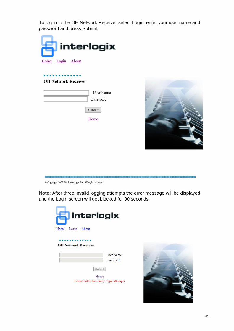
To log in to the OH Network Receiver select Login, enter your user name and
password and press Submit.
Note: After three invalid logging attempts the error message will be displayed
and the Login screen will get blocked for 90 seconds.
42
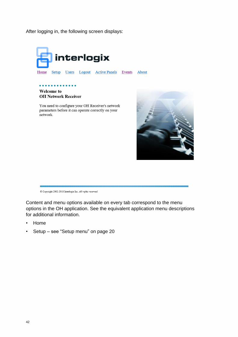
After logging in, the following screen displays:
Content and menu options available on every tab correspond to the menu
options in the OH application. See the equivalent application menu descriptions
for additional information.
• Home
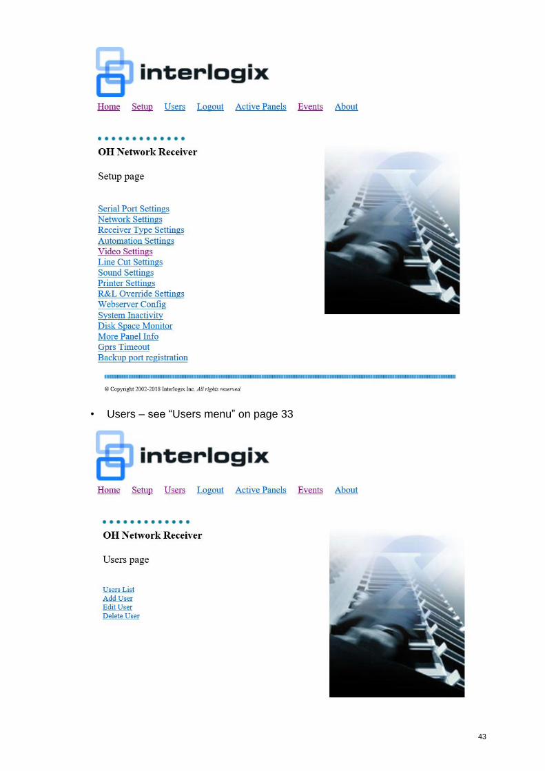
• Setup – see “Setup menu” on page 20
43
• Users – see “Users menu” on page 33
44
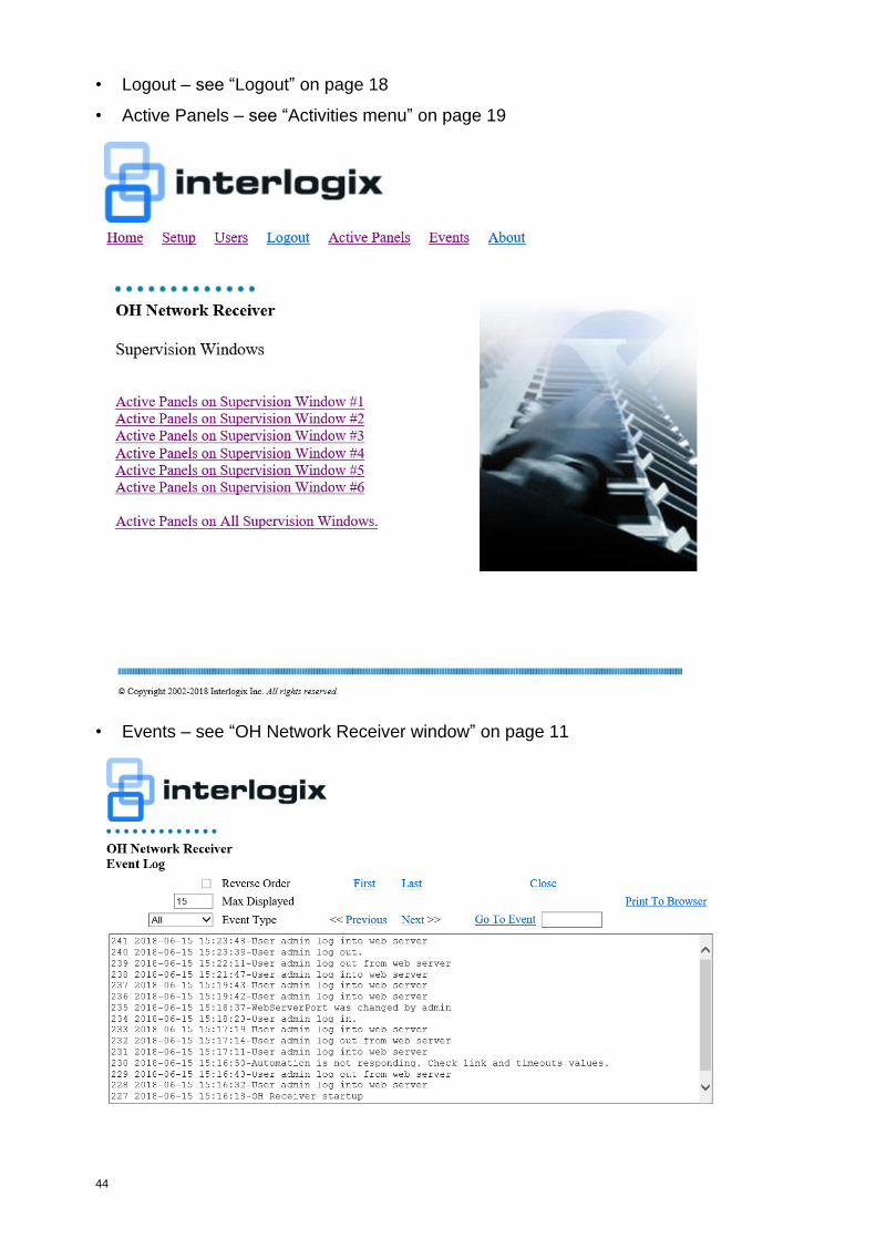
• Logout – see “Logout” on page 18
• Active Panels – see “Activities menu” on page 19
• Events – see “OH Network Receiver window” on page 11
45
• About – see “Help - About” on page 37
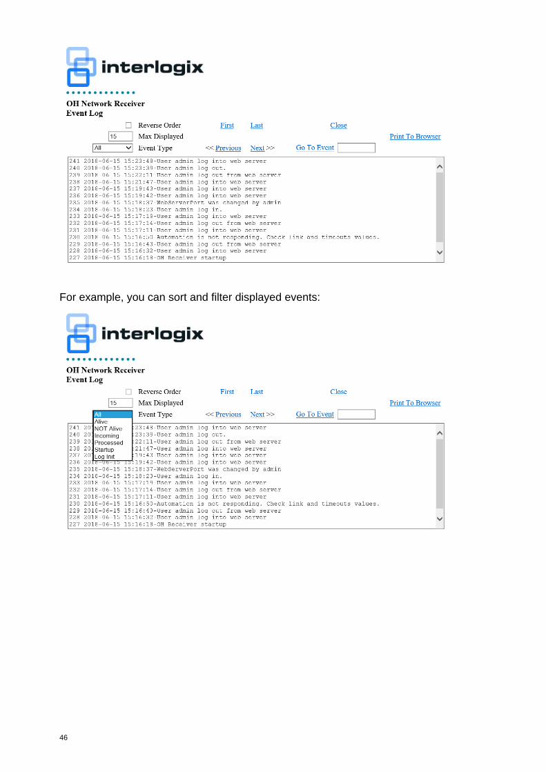
Events window
The webserver Events window is slightly different than the application window,
and includes additional view and navigation options.
46
For example, you can sort and filter displayed events:
47
Upgrading the OH Network Receiver
Before the 3.2.1 version
In order to complete the update, the OH Network Receiver must be stopped. This
applies both to the standard installation and the OH service installation.
During the upgrade all files are overwritten (including configuration files). It
means that all settings will be defaulted after the upgrade, and the Active Panels
List will be cleared. To prevent losing the configuration and the panel list, the
appropriate files (app.properties and ohdb.script respectively) need to be backed
up after the OH is stopped, and before installing the new version.
The app.properties file from version 2.5.5 is compatible with version 3.1.1. The
only difference are the optional NoSpaceAlarmThreshInMB=100 setting and the
AutomationHBPeriod=8 setting, both added in the 3.1.0 version. They can be set
up after the upgrade.
In order to upgrade the OH Network Receiver software to the 3.1.1 version,
follow these steps:
1. Stop the OH Network Receiver application.
2. Backup the app.properties and ohdb.script files, present in the OH Network
Receiver home folder (for example, C:\OH-NetworkReceiver\app.properties,
C:\OH-NetworkReceiver\data\ohdb.script)
3. Run the OH Network Receiver 3.1.1 installer.
4. When the installation is complete, copy the files backed up in the step 2 to the
appropriate directories.
3.2.1 version
Since the 3.2.1 version, all settings of the OH Network Receiver are kept in a
database and the old app.properties file will be removed during the upgrade
process. To upgrade the OH Network Receiver, install the new version in the
same location as the current version. During the upgrade all settings from the
app.properties file will be imported to a database and the Active Panels List will
be cleared. After the upgrade, the app.properties file will be deleted.
3.2.2 – 3.2.4.2 version
Important: For versions 3.2.2 -3.2.4.2, always uninstall a previous version of the
OH Network Receiver before installing a newer version. After uninstallation make
sure that all files from the OH Network Receiver directory (e.g. C:\OH-
NetworkReceiver) are removed.
3.2.4.4 version and greater
Since the 3.2.4.4 version, the application migrates data from a previous database
structure to the new one, so there is no need to uninstall the previous version of
the OH Network Receiver.
In order to upgrade the OH Network Receiver software, follow these steps:
48
1. Stop the OH Network Receiver application.
2. Install a new version in the same location as the old one (for example, C:\OH-
NetworkReceiver).
3. Run the new application and log into it with the same login and password as
used for the old version of the application.
4. In the installation folder (for example, C:\OH-NetworkReceiver\data) there are
files and folders with names containing the “ohdb.bak” string. These files and
folders are a backup of the old database and should be removed after
verifying that all data is migrated without an error.
5. To load data from “app.properties” file (versions 3.1 and lower) set Load
settings from app.properties file at startup option to true and after a restart
of the OH Network Receiver set it again to false (data should be migrated on
application start).

49
Index
A
Active alarm panels, 12
Active panels list, 12
Activities menu, 19
Add user menu, 34
Automation menu, 23
Availability calculation, 38
B
Backup port registration menu, 31
C
Callback functionality, 17
Configuring
using the window interface, 18
Context menu options, 15
D
Delete user menu, 36
Diagnostics menu, 32
Disk space monitor, 17
Disk space monitor menu, 30
DoS attacks, 40
E
Edit user menu, 35
Event recording, 39
F
File menu, 18
G
GPRS timeout menu, 31
H
Help menu, 37
L
Linecut timeouts menu, 28
logging, 39
Login menu, 18
Logout menu, 19
M
Menu
Activities, 19
Add user, 34
Automation, 23
Backup port registration, 31
Context menu options, 15
Delete user, 36
Diagnostics, 32
Disk space monitor, 30
Edit user, 35
File, 18
GPRS timeout, 31
Linecut timeouts, 28
Login, 18
Logout, 19
More panel info, 31
Network ports, 21
Other settings, 33
Printer, 28
R&L override, 29
Receiver type, 23
Serial ports, 20
Setup, 20
Substitution alarms, 32
System inactivity, 30
Users, 34
Users list, 34
Video, 24
Webserver Config, 30
Menu bar, 12
More panel info menu, 31
N
Network ports menu, 21
O
OH Network Receiver window, 11
OH Web interface, 41
Other settings menu, 33
P
Polling to the Alarm Monitoring Software, 15
Printer menu, 28
R
R&L override, 29
Receiver type menu, 23
Recommended settings, 6
recording
events, 39
Redundancy, 8
S
Serial ports menu, 20
Settings
recommended, 6
Setup menu, 20
Starting the OH-Network Receiver, 10
Substitution alarms menu, 32
System inactivity menu, 30

50
T
Typical system configuration, 4
U
Upgrading OH, 48
Users list menu, 34
Users menu, 34
V
Video menu, 24
W
Web interface, 41
Webserver Config menu, 30
Window interface, 11
Window interface menu options, 18