
JUMO Wtrans receiver
104
90293100T90Z001K000 V1.00/EN/00488966 JUMO Wtrans receiver Universal receiver for JUMO wireless measuring probes Operating Manual
-
Upload
khangminh22 -
Category
Documents
-
view
7 -
download
0
Transcript of JUMO Wtrans receiver

90293100T90Z001K000
V1.00/EN/00488966
JUMO Wtrans receiverUniversal receiver
for JUMO wireless measuring probes
Operating Manual

Note for FCC:This device complies with Part 15 of the FCC Rules and with RSS-210 of Industry Canada. Op-eration is subject to the following two conditions:• this device may not cause harmful interference, and • this device must accept any interference received, including interference that maycause un-
desired operation.This equipment has been tested and found to comply with the limits for a Class A digital device,pursuant to Part 15 of the FCC Rules. These limits are designed to provide reasonable protec-tion against harmful interference when the equipment is operated in a commercial environ-ment. This equipment generates, uses, and can radiate radio frequency energy and, if notinstalled and used in accordance with the instruction manual, may cause harmful interferenceto radio communications. Operation of this equipment in a residential area is likely to causeharmful interference in which case the user will be required to correct the interference at hisown expense.
This Class A digital apparatus complies with Canadian ICES-003.
Changes or modifications made to this equipment not expressly approved by the manufacturermay void the FCC authorization to operate this equipment.
Remarque pour IC:Cet appareil numérique de la classe [A] est conforme à la norme NMB-003 du Canada.Avis de conformité insérés dans le manuel d'utilisation des appareils radio exempts de licence.Le présent appareil est conforme aux CNR d‘Industrie Canada applicables aux appareils radioexempts de licence. L'exploitation est autorisée aux deux conditions suivantes:• l'appareil ne doit pas produire de brouillage, et• l'utilisateur de l'appareil doit accepter tout brouillage radioélectrique subi, même si le brouil-
lage est susceptible d'en compromettre le fonctionnement.
Approvals/Homologations
USA FCC ID VT4-WTRANST01VT4-WTRANST01-02
Canada IC 7472A-WTRANST017472A-WTRANST0102

Contents
Contents1 Introduction . . . . . . . . . . . . . . . . . . . . . . . . . . . . . . . . . . . . . . . . . . . . . . . . . . . . 71.1 Safety information . . . . . . . . . . . . . . . . . . . . . . . . . . . . . . . . . . . . . . . . . . . . . . . . . . . . . . . . . . . . 71.2 Description . . . . . . . . . . . . . . . . . . . . . . . . . . . . . . . . . . . . . . . . . . . . . . . . . . . . . . . . . . . . . . . . . 81.3 Block diagram . . . . . . . . . . . . . . . . . . . . . . . . . . . . . . . . . . . . . . . . . . . . . . . . . . . . . . . . . . . . . . . 81.4 Declaration of conformity . . . . . . . . . . . . . . . . . . . . . . . . . . . . . . . . . . . . . . . . . . . . . . . . . . . . . . 8
2 Identifying the device version . . . . . . . . . . . . . . . . . . . . . . . . . . . . . . . . . . . . . 92.1 Nameplate. . . . . . . . . . . . . . . . . . . . . . . . . . . . . . . . . . . . . . . . . . . . . . . . . . . . . . . . . . . . . . . . . . 92.2 Order details . . . . . . . . . . . . . . . . . . . . . . . . . . . . . . . . . . . . . . . . . . . . . . . . . . . . . . . . . . . . . . . 102.3 Scope of delivery . . . . . . . . . . . . . . . . . . . . . . . . . . . . . . . . . . . . . . . . . . . . . . . . . . . . . . . . . . . 112.4 Accessories. . . . . . . . . . . . . . . . . . . . . . . . . . . . . . . . . . . . . . . . . . . . . . . . . . . . . . . . . . . . . . . . 12
3 Basic principles. . . . . . . . . . . . . . . . . . . . . . . . . . . . . . . . . . . . . . . . . . . . . . . . 133.1 Radio technology . . . . . . . . . . . . . . . . . . . . . . . . . . . . . . . . . . . . . . . . . . . . . . . . . . . . . . . . . . . 133.2 General information about wireless transmission . . . . . . . . . . . . . . . . . . . . . . . . . . . . . . . . . . . 143.3 Reception characteristic of the lambda/4 antenna . . . . . . . . . . . . . . . . . . . . . . . . . . . . . . . . . . 153.4 Interferences . . . . . . . . . . . . . . . . . . . . . . . . . . . . . . . . . . . . . . . . . . . . . . . . . . . . . . . . . . . . . . . 163.5 Function overview . . . . . . . . . . . . . . . . . . . . . . . . . . . . . . . . . . . . . . . . . . . . . . . . . . . . . . . . . . . 183.6 Data flow diagram . . . . . . . . . . . . . . . . . . . . . . . . . . . . . . . . . . . . . . . . . . . . . . . . . . . . . . . . . . . 21
4 Installation . . . . . . . . . . . . . . . . . . . . . . . . . . . . . . . . . . . . . . . . . . . . . . . . . . . . 234.1 Mounting site and climatic conditions . . . . . . . . . . . . . . . . . . . . . . . . . . . . . . . . . . . . . . . . . . . . 234.1.1 Receiver . . . . . . . . . . . . . . . . . . . . . . . . . . . . . . . . . . . . . . . . . . . . . . . . . . . . . . . . . . . . . . . . . . 234.1.2 Antenna. . . . . . . . . . . . . . . . . . . . . . . . . . . . . . . . . . . . . . . . . . . . . . . . . . . . . . . . . . . . . . . . . . . 234.2 Dimensions . . . . . . . . . . . . . . . . . . . . . . . . . . . . . . . . . . . . . . . . . . . . . . . . . . . . . . . . . . . . . . . . 244.2.1 Receiver . . . . . . . . . . . . . . . . . . . . . . . . . . . . . . . . . . . . . . . . . . . . . . . . . . . . . . . . . . . . . . . . . . 244.2.2 Lambda/4 antenna . . . . . . . . . . . . . . . . . . . . . . . . . . . . . . . . . . . . . . . . . . . . . . . . . . . . . . . . . . 244.2.3 Antenna wall holder for lambda/4 antenna . . . . . . . . . . . . . . . . . . . . . . . . . . . . . . . . . . . . . . . . 254.3 Installing the receiver . . . . . . . . . . . . . . . . . . . . . . . . . . . . . . . . . . . . . . . . . . . . . . . . . . . . . . . . 264.4 Installing the antenna . . . . . . . . . . . . . . . . . . . . . . . . . . . . . . . . . . . . . . . . . . . . . . . . . . . . . . . . 274.4.1 Antenna installation directly on the receiver . . . . . . . . . . . . . . . . . . . . . . . . . . . . . . . . . . . . . . . 274.4.2 Antenna installation on the antenna wall holder . . . . . . . . . . . . . . . . . . . . . . . . . . . . . . . . . . . . 28
5 Electrical connection . . . . . . . . . . . . . . . . . . . . . . . . . . . . . . . . . . . . . . . . . . . 315.1 Installation notes . . . . . . . . . . . . . . . . . . . . . . . . . . . . . . . . . . . . . . . . . . . . . . . . . . . . . . . . . . . . 315.2 Connection diagram . . . . . . . . . . . . . . . . . . . . . . . . . . . . . . . . . . . . . . . . . . . . . . . . . . . . . . . . . 32
6 Display and key functions . . . . . . . . . . . . . . . . . . . . . . . . . . . . . . . . . . . . . . . 356.1 Normal display (NA) (displaying measured values and signal quality) . . . . . . . . . . . . . . . . . . . 356.2 Startup level (In) (allocating the transmitter ID to a channel) . . . . . . . . . . . . . . . . . . . . . . . . . . 376.3 Parameter level (PA) (configuring parameters). . . . . . . . . . . . . . . . . . . . . . . . . . . . . . . . . . . . . 396.4 Light diodes (independent of level) . . . . . . . . . . . . . . . . . . . . . . . . . . . . . . . . . . . . . . . . . . . . . . 41

Contents
7 Receiver operation . . . . . . . . . . . . . . . . . . . . . . . . . . . . . . . . . . . . . . . . . . . . . 437.1 Normal display (NA) . . . . . . . . . . . . . . . . . . . . . . . . . . . . . . . . . . . . . . . . . . . . . . . . . . . . . . . . . 447.2 Displaying channels and their measured values. . . . . . . . . . . . . . . . . . . . . . . . . . . . . . . . . . . . 447.3 Display signal quality of the transmitters received . . . . . . . . . . . . . . . . . . . . . . . . . . . . . . . . . . 457.4 Changing to different levels . . . . . . . . . . . . . . . . . . . . . . . . . . . . . . . . . . . . . . . . . . . . . . . . . . . 467.5 Code request . . . . . . . . . . . . . . . . . . . . . . . . . . . . . . . . . . . . . . . . . . . . . . . . . . . . . . . . . . . . . . 47
8 Configuration of the receiver . . . . . . . . . . . . . . . . . . . . . . . . . . . . . . . . . . . . . 498.1 Startup level (In) . . . . . . . . . . . . . . . . . . . . . . . . . . . . . . . . . . . . . . . . . . . . . . . . . . . . . . . . . . . . 498.1.1 Convenient selection of a received transmitter ID from the link list and assignment to a chan-
nel . . . . . . . . . . . . . . . . . . . . . . . . . . . . . . . . . . . . . . . . . . . . . . . . . . . . . . . . . . . . . . . . . . . . . . . 508.1.2 Manual assignment of a transmitter ID to a channel. . . . . . . . . . . . . . . . . . . . . . . . . . . . . . . . . 528.1.3 Assignment of a transmitter ID to a channel via interface. . . . . . . . . . . . . . . . . . . . . . . . . . . . . 538.1.4 Pre-configuration of all transmitter ID's using the setup program . . . . . . . . . . . . . . . . . . . . . . . 538.1.5 Configuration of customized transmitter ID's on the transmitter side . . . . . . . . . . . . . . . . . . . . 538.2 Parameter level (PA). . . . . . . . . . . . . . . . . . . . . . . . . . . . . . . . . . . . . . . . . . . . . . . . . . . . . . . . . 548.2.1 Editing parameters . . . . . . . . . . . . . . . . . . . . . . . . . . . . . . . . . . . . . . . . . . . . . . . . . . . . . . . . . . 568.2.2 General parameters . . . . . . . . . . . . . . . . . . . . . . . . . . . . . . . . . . . . . . . . . . . . . . . . . . . . . . . . . 578.2.3 Channel-specific parameters . . . . . . . . . . . . . . . . . . . . . . . . . . . . . . . . . . . . . . . . . . . . . . . . . . 60
9 Term definition. . . . . . . . . . . . . . . . . . . . . . . . . . . . . . . . . . . . . . . . . . . . . . . . . 639.1 General parameters . . . . . . . . . . . . . . . . . . . . . . . . . . . . . . . . . . . . . . . . . . . . . . . . . . . . . . . . . 639.1.1 Device information . . . . . . . . . . . . . . . . . . . . . . . . . . . . . . . . . . . . . . . . . . . . . . . . . . . . . . . . . . 639.1.2 Device data . . . . . . . . . . . . . . . . . . . . . . . . . . . . . . . . . . . . . . . . . . . . . . . . . . . . . . . . . . . . . . . . 649.1.3 RS485 interface . . . . . . . . . . . . . . . . . . . . . . . . . . . . . . . . . . . . . . . . . . . . . . . . . . . . . . . . . . . . 659.1.4 Analog outputs 1 to 4 . . . . . . . . . . . . . . . . . . . . . . . . . . . . . . . . . . . . . . . . . . . . . . . . . . . . . . . . 669.1.5 Relay outputs 1 to 2 . . . . . . . . . . . . . . . . . . . . . . . . . . . . . . . . . . . . . . . . . . . . . . . . . . . . . . . . . 689.1.6 Modbus remote control values FLOAT 1 to 4 . . . . . . . . . . . . . . . . . . . . . . . . . . . . . . . . . . . . . . 709.2 Channel-specific parameters . . . . . . . . . . . . . . . . . . . . . . . . . . . . . . . . . . . . . . . . . . . . . . . . . . 71
10 Display and reset drag indicator . . . . . . . . . . . . . . . . . . . . . . . . . . . . . . . . . . 75
11 Setup program. . . . . . . . . . . . . . . . . . . . . . . . . . . . . . . . . . . . . . . . . . . . . . . . . 7911.1 General information about the setup program . . . . . . . . . . . . . . . . . . . . . . . . . . . . . . . . . . . . . 7911.2 Hardware and software requirements . . . . . . . . . . . . . . . . . . . . . . . . . . . . . . . . . . . . . . . . . . . . 8011.3 Establishing the connection between the PC and receiver. . . . . . . . . . . . . . . . . . . . . . . . . . . . 8111.4 Configuration of the receiver. . . . . . . . . . . . . . . . . . . . . . . . . . . . . . . . . . . . . . . . . . . . . . . . . . . 8311.4.1 Establishing the communication . . . . . . . . . . . . . . . . . . . . . . . . . . . . . . . . . . . . . . . . . . . . . . . . 8311.4.2 Reading out the current receiver parameters . . . . . . . . . . . . . . . . . . . . . . . . . . . . . . . . . . . . . . 8411.4.3 Editing receiver parameters . . . . . . . . . . . . . . . . . . . . . . . . . . . . . . . . . . . . . . . . . . . . . . . . . . . 8511.4.4 Transmit new parameters to the receiver . . . . . . . . . . . . . . . . . . . . . . . . . . . . . . . . . . . . . . . . . 8511.5 Customized linearization. . . . . . . . . . . . . . . . . . . . . . . . . . . . . . . . . . . . . . . . . . . . . . . . . . . . . . 8511.6 OnlineChart. . . . . . . . . . . . . . . . . . . . . . . . . . . . . . . . . . . . . . . . . . . . . . . . . . . . . . . . . . . . . . . . 88

Contents
12 Detect and remedy errors. . . . . . . . . . . . . . . . . . . . . . . . . . . . . . . . . . . . . . . . 91
13 Annex . . . . . . . . . . . . . . . . . . . . . . . . . . . . . . . . . . . . . . . . . . . . . . . . . . . . . . . . 9313.1 Table: Assignment of transmitters to the receiver channels . . . . . . . . . . . . . . . . . . . . . . . . . . . 93
14 Technical data . . . . . . . . . . . . . . . . . . . . . . . . . . . . . . . . . . . . . . . . . . . . . . . . . 95
15 China RoHS . . . . . . . . . . . . . . . . . . . . . . . . . . . . . . . . . . . . . . . . . . . . . . . . . . . 99

Contents

1 Introduction
1 Introduction
1.1 Safety informationGeneralThis manual contains information that must be observed in the interest of your own safety and to avoidmaterial damage. This information is supported by symbols which are used in this manual as indicated.Please read this manual before starting up the device. Store this manual in a place that is accessible toall users at all times. If difficulties occur during startup, please do not intervene in any way that could jeopardize your warrantyrights!
Warning symbols
DANGER!This symbol indicates that personal injury from electrocution may occur if the appropriate precaution-ary measures are not taken.
CAUTION!This symbol in connection with the signal word indicates that material damage or data loss will occurif the respective precautionary measures are not taken.
Note symbols
NOTE!This symbol refers to important information about the product, its handling, or additional benefits.
REFERENCE!This symbol refers to additional information in other sections, chapters, or other manuals.
7

1 Introduction
1.2 DescriptionThe Wtrans receiver T01 in combination with suitable Wtrans transmitters are used for mobile or station-ary measurements of physical measurands. A significant reduction of the installation work is achieveddue to the use of trendsetting wireless technology found in the industrial radio frequency 868.4 MHz or915 MHz. Cable connections are not required. The radio-based sensor technology also functions in arough industrial environment. The supplied lambda/four-antenna with an impedance of 50 ohm can bedirectly screwed on or mounted externally. If the antenna wall holder with a 3 m antenna cable is usedthen the open air range is 300 m. In the receiver the received measured values are converted, displayed,and are available as linear current or voltage signals (0(4) to 20 mA, 0 to 10 V) and via the digital inter-face RS485. All receiver outputs are galvanically isolated.Linkage to higher-ranking systems (e.g. theplant visualization software JUMO SVS3000 or the Modbus master compatible JUMO LOGOSCREENnt paperless recorder) is possible via the digital interface with Modbus protocol.Operation and configuration can be performed via the keypad in conjunction with a 2-line LCD displayor with a setup program for greater convenience. This way, parameters such as filter constants, offset,alarms, and drag indicators (minimum and maximum value memory) can be set separately for eachchannel. For this purpose, a connector is provided on the front for a PC interface with USB/TTL converterfor connecting the receiver and the PC.The receiver in the mounting rail case is intended for installation on a DIN rail 35 × 7.5 mm according toDIN EN 60715.The screw terminals for the electrical connection are located at different levels. The conductor cross sec-tion should not be bigger than 2.5 mm2.
1.3 Block diagram
Fig. 1-1 Function review of the receiver
1.4 Declaration of conformityNOTE!Hereby JUMO GmbH & Co. KG declares that the radio equipment type Wtrans is in compliance with Di-rective 2014/53/EU. The full text of the EU declaration of conformity is available at the following Internetaddress: www.jumo.net
Wtr
an
s r
ec
eiv
er
Interfaces
1× RS4851× setup
Outputs
4× 0(4) to 20 mA or 0 to 10 Vor2× 0(4) to 20 mA or 0 to 10 V,2× relays max. 3 A, AC 230 V
Receiver
Radio frequency868,4 MHzor 915 MHz
Voltage supply
AC 110 to 240 V +10/-15 %48 to 63 HzorAC/DC 20 to 30 V, 48 to 63 Hz
Keypad
4 keys for operationand configuration
Display
Two-line LCD displayfor measured value displayand configuration as well as2 LEDs as status displays
8

2 Identifying the device version
2 Identifying the device version
2.1 NameplatePositionThe nameplate is glued to the unit.
ContentsThe specifications contain important information. This includes:
TypePlease check the type supplied against your order document. To identify the type, use chapter 2.2 "Orderdetails", page 10.
TNThe part no. uniquely identifies an article in the catalog. It is used in communication between the salesdepartment and the customer.
F-no.The fabrication number is used by the manufacturer to identify the device.The date of manufacture (year/calendar week) and the version number is specified in the fabricationnumber.
Date of manufactureThe figures used for this are 12, 13, 14, 15.Example: F-no. = 0139741001115060005The device was produced in the 6th calendar week of 2015.
Version numberExample: F-no. = 0139741001115060005The receiver is equipped with the following functions, if the number 1 or higher stands at the eleventhposition (counted from the left):• Receipt of the input variables RTD temperature probe, thermocouple, potentiometer and voltage• Customized linearization• Scaling for the input variables potentiometer or voltageIf 0 stands at the eleventh position (counted from the left), it is a predecessor version which can onlyprocess the input variable RTD temperature probe "Pt1000“!
Description Designationon the nameplate
Example
Device type Type 902931/10-8-10-23/000Part no. TN 00123456Serial number F-no. 0139741001115060005Voltage supply AC 110 to 240 V +10/-15 %,
48 to 63 Hz
9

2 Identifying the device version
2.2 Order details(1) Basic type902931/10 Wtrans receiver T01.EC1
C rail case, protection type IP20,4 analog outputs 0(4) to 20 mA or 0 to 10 V,RS485 interface with Modbus protocol
902931/30 Wtrans receiver T01.EC3C rail case, protection type IP20,2 analog outputs 0(4) to 20 mA or 0 to 10 Vand 2 relay outputs AC 230 V/5 A potential free,RS485 interface with Modbus protocol
(2) Versionx x 8 Standard with default settingsx x 9 Customer-specific configuration (specifications in plain text)
(3) Radio frequencyx x 10 868.4 MHz (Europe)x 20 915 MHz (America, Australia, Canada, and New Zealand)
(not in connection with AC/DC 20 to 30 V)Ten frequencies can be configured in the 915 MHz frequency band.
(4) Voltage supplyx x 23 AC 110 to 240 V +10/-15 %, 48 to 63 Hzx x 25 AC/DC 20 to 30 V, 48 to 63 Hz
(5) Extra codex x 000 None
(1) (2) (3) (4) (5)Order code - - - /Order example 902931/10 - 8 - 10 - 23 / 000
10

2 Identifying the device version
2.3 Scope of deliveryOur scope of delivery includes:• 1 device in the ordered version• 1 lambda/4 antenna, impedance 50 ohm, 868.4 MHz, Tmax. 125 °C or• 1 lambda/4-antenna, impedance 50 ohm, 915 MHz, Tmax. 125 °C• 1 operating manualIf you have any questions, please contact your supplier.
11

2 Identifying the device version
2.4 AccessoriesThe following articles are subject to charge and must be ordered separately:
Description Part no.Setup program on CD-ROM, multilinguala
a Configuration using a laptop/PC is only possible with an interface (PC interface with USB/TTL conver-tor or RS485) and one of the two setup programs.
00488887Setup program incl. OnlineChart on CD-ROM, multilinguala 00549067OnlineChart activation 00549188additional lambda/4 antenna,impedance 50 ohm, 868.4 MHz, Tmax. 125 °C
00503151
additional lambda/4 antenna,impedance 50 ohm, 915 MHz, Tmax. 125 °C
00503152
Antenna holder for wall mounting with antipole for lambda/4 antenna 00482648Lambda/4 antenna with waterproof, permanently connected cable,length 10 m, 868.4 MHz, Tmax. 125 °C
00523293
Lambda/4 antenna with waterproof, permanently connected cable,length 20 m, 868.4 MHz, Tmax. 125 °C
00523294
Antenna cable, length 3 m, impedance 50 ohmwith pre-assembled screw-type connection, Tmax. 85 °C
00482646
Antenna cable, length 5 m, impedance 50 ohmwith pre-assembled screw-type connection, Tmax. 85 °C
00490066
Antenna cable, length 10 m, impedance 50 ohmwith pre-assembled screw-type connection, Tmax. 85 °C
00490068
Antenna cable, length 10 m, impedance 50 ohmwith pre-assembled screw-type connection, Tmax. 125 °C
00511870
PC interface with USB/TTL converter, adapter (socket)and adapter (pins)
00456352
Interface converter I-7520A – RS232 to RS422/485 00376969Plug-in power supply unit for interface converter (serial) 00365933Interface card MOXA CP-132i – 2 × RS422/485 00397804Modbus interface description(The Modbus interface description is available as a free download on the Internet at www.jumo.net.)
-
Plant visualization software JUMO SVS3000(data sheet 700755)
-
Paperless recorder JUMO LOGOSCREEN nt(data sheet 706581)
-
12

3 Basic principles
3 Basic principles
3.1 Radio technologyThe characteristic framework conditions for each transmission system include the available band widthin the electro-magnetic spectrum and the maximum permissible transmission capacity. These parame-ters define the channel capacity.The main selection criteria for the frequency range to be used include the requirement of a long range,interference resistance as well as the possibility to be able to apply a customized transmission protocolin public spectrum band. The focus when selecting the possible communication technologies is placedon miniaturizing the transmitting and receiving circuit as well as the power consumption, on enhancingthe transmission safety and the transmission stability as well as on saving costs of the technology in-volved. Using a wireless connection essentially promises lower costs, higher flexibility and mobility aswell as easier handling.Taking into account the current applicable legislative texts and the available standards and industry stan-dards, a wireless solution without a generally specified protocol has been selected for use of the Wtranssystem on the 868.4 MHz radio frequency (Europe) or 915 MHz radio frequency (America, Canada, Aus-tralia, and New Zealand).Certain areas have strict regulations that apply for this industrial radio frequency with regard to duty cy-cle, channel distribution, and transmission power. The various subdivisions within this frequency bandare shown in Fig. 3-1.
Fig. 3-1 Subdivision of the 868 MHz frequency band
The ERP power value (ERP: equivalent radiated power) value, which is plotted on the Y-axis, representsthe permitted transmission capacity related to a Lambda/2 dipole gain. When utilizing the duty cycleduring the transmission pulse at a small pulse width, the transmission impulse is only generated for avery short period.Duty cycle in percentage designates the duration of a transmitter's transmissions based on a 1 hour. Theentire transmission time can be distributed to several transmission intervals. Duty cycle thus specifiesthe ratio between the transmission time and the overall time and is specified in percent.The duty cycle is also called the pulse-to-pause ratio or mark-to-space ratio.If, for example, the transmission duration of a signal is 5 ms followed by a 995 ms transmission pause,the duty cycle is derived from the following calculation:
tS =5 ms
= 0.005 = 0.5 %tG 1000 ms
500
f (MHz)
10
5
ERP(mW) x
25
868.
00
868.
6086
8.70
869.
20
869.
40
869.
6586
9.70
870.
00
< 1 % < 0.1 % < 10 % Up to 100 %
Non-specific Short Range DevicesDevices in the industrial radiofrequency industry
Duty cycle
13
3 Basic principles
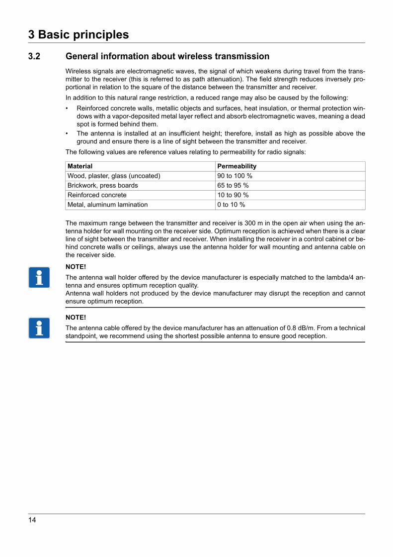
3.2 General information about wireless transmissionWireless signals are electromagnetic waves, the signal of which weakens during travel from the trans-mitter to the receiver (this is referred to as path attenuation). The field strength reduces inversely pro-portional in relation to the square of the distance between the transmitter and receiver.In addition to this natural range restriction, a reduced range may also be caused by the following:• Reinforced concrete walls, metallic objects and surfaces, heat insulation, or thermal protection win-
dows with a vapor-deposited metal layer reflect and absorb electromagnetic waves, meaning a deadspot is formed behind them.
• The antenna is installed at an insufficient height; therefore, install as high as possible above theground and ensure there is a line of sight between the transmitter and receiver.
The following values are reference values relating to permeability for radio signals:
The maximum range between the transmitter and receiver is 300 m in the open air when using the an-tenna holder for wall mounting on the receiver side. Optimum reception is achieved when there is a clearline of sight between the transmitter and receiver. When installing the receiver in a control cabinet or be-hind concrete walls or ceilings, always use the antenna holder for wall mounting and antenna cable onthe receiver side.
NOTE!The antenna wall holder offered by the device manufacturer is especially matched to the lambda/4 an-tenna and ensures optimum reception quality.Antenna wall holders not produced by the device manufacturer may disrupt the reception and cannotensure optimum reception.
NOTE!The antenna cable offered by the device manufacturer has an attenuation of 0.8 dB/m. From a technicalstandpoint, we recommend using the shortest possible antenna to ensure good reception.
Material PermeabilityWood, plaster, glass (uncoated) 90 to 100 %Brickwork, press boards 65 to 95 %Reinforced concrete 10 to 90 %Metal, aluminum lamination 0 to 10 %
14

3 Basic principles
3.3 Reception characteristic of the lambda/4 antennaAlignment of the lambda/4 antenna
Fig. 3-2 Spatial directional response pattern of the lambda/4 antenna
From the spatial directional response pattern of the lambda/4 antenna you can derive that optimum re-ception can only be achieved when the antenna is vertically aligned.From the vertical rod, the reception is nearly identical in all directions. The range and the top and bottom,however, is very limited.The antenna holder for wall mounting can be mounted with the antenna in a vertical position orientatedupward or downward, but horizontal antenna installation is not recommended.
NOTE!To ensure that the reception antennas do not influence each other, adhere to a minimum distance of500 mm for an optimum reception.
15

3 Basic principles
3.4 InterferencesCollisions in case of too many transmittersWhen using a large number of transmitters, do not select a transmission interval which is too low, other-wise the transmission frequency will be unnecessarily occupied. A transmission interval that is too lowleads to a very high data volume on the selected frequency, which can lead to collisions with other trans-mitters. The collisions can cause datagrams to be destroyed during wireless transmission.
Fig. 3-3 The datagrams of a transmitter reach the receiver without collisions
Fig. 3-4 The datagrams of several transmitters can collide
Fig. 3-5 Collisions depending on the number of transmitters with a transmission interval of 1 s
Radio telegram
ID, measuringvalue
ReceiverTransmitter
Radio telegramsTransmitters
ID, measuringvalue
ID, measuringvalue
ID, measuringvalue
ID, measuringvalueID, measuring
value
Receiver
16 18 20 22 24 26 28 30
Number of transmitters
Faul
t in
crea
se
16

3 Basic principles
As Fig. 3-5 shows, the error curve increases sharply once there are 24 transmitters.For this reason, we recommend using a maximum of 16 transmitters for the smallest transmission inter-val of 1 s.For the factory setting of 10 s, a considerably larger number of transmitters is possible.Estimating the maximum number of transmittersIf more than the recommended 16 transmitters are to be used with a transmission interval of 1 s, selecta higher transmission interval to prevent an increased error quota.Example:
The calculation displayed in the next example applies when the number of transmitters is to be increasedfurther.
Example:
However, from a transmission interval of ≥ 3 s, the telegram is transmitted twice. This means the numberof transmitters that can be used is halved.
The identical behavior occurs from a transmission interval of ≥ 60 s.From this transmission interval, the telegram is transmitted three times.
External transmittersExternal transmitters can transmit on the same frequency. If, for example, the transmitter and an externaltransmitter transmit their radio telegrams at the same time then the telegram is destroyed. No error isdetected because the transmitters cannot check their own transmission while transmitting.
Electrical devicesIn a harsh industrial environment, wireless telegrams can be destroyed by such things as frequency con-verters, electrical welding equipment, poorly shielded PCs, audio/video devices, electronic transformers,electronic ballasts, etc.
Error fade-outLost datagrams (caused either by external interference sources or by collisions when using a large num-ber of transmitters) can be ignored on the receiving side by the wireless timeout parameter and do notcause error messages. The value received last is retained over 2 to 20 transmission intervals and onlythen is the wireless timeout alarm activated (display "----").
NOTE!In the event of collisions caused by an excessive number of transmitters, observe and, if necessary, cor-rect the factors "number of transmitters", "transmission intervals", and, on the receiver, "wireless time-out".
16 transmitters with a transmission interval of 1 s = 32 transmitters with a transmission interval of 2 s
16 transmitters with a transmission interval of 1 s = 48 transmitters with a transmission interval of 3 s (in theory)
16 transmitters with a transmission interval of 1 s = 24 transmitters with a transmission interval of 3 s (effective)
17

3 Basic principles
3.5 Function overviewFig. 3-6 Function overview of the receiver
or
MU
XM
UX
MU
XM
UX
5 V
Mains
5 V
5 V
5V15V
11.1
5 V
5 V15 V
15 V
15 V
15 V
5 V5 V
Display
Setup
Key pad
RS485
ControllerHF-
receiver
Antenna
11.2
11.3
11.4
11.5
11.6
Output0 to 10 V
0(4) to 20 mA
1 68
9
9
107
2
3
4
5
11
8
8
8
Relayoutput
Relayoutput
Basicinsulation
Reinforcedinsulation
Reinforcedinsulation
50 V-
50 V-
50 V-
50 V-
50 V-
Output0 to 10 V
0(4) to 20 mA
Output0 to 10 V
0(4) to 20 mA
Output0 to 10 V
0(4) to 20 mA
18

3 Basic principles
(1) Wireless receiver(2) Keypad(3) LCD display(4) Light diodes(5) Setup interface(6) Actual value calculation of the analog channels(7) automatic changeover of the interfaces(8) Analog outputs(9) Relay outputs(10)RS485 interface(11)Voltage supplyWireless receiverThe receiver is constantly active to receive the radio telegrams of the active transmitters. It checks thecompleteness of each radio telegram received.If the radio telegram is valid, it is transferred to the processor for further processing, in the same manneras the demodulated measured data.
KeypadThe function keys permit the operation and configuration of the receiver without the setup program. chapter 6 "Display and key functions", page 35
LCD displayIn the normal display, the two rows of the LCD display show the current values. In the startup and pa-rameter levels, they facilitate the operation and configuration dialog. chapter 6 "Display and key functions", page 35
Light diodesThe top bicolor light diode is green when voltage is applied, i.e. the unit is operative. It flashes red in theevent of an impending collective alarm. The bottom yellow light diode flashes with every valid radio tele-gram (data package) of the transmitter. The flash frequency increases with the number of transmitters. chapter 6 "Display and key functions", page 35
Setup interfaceThe device is equipped with a setup interface to allow configuration via the setup program. For this pur-pose, the front features a connector for interface lines with USB/TTL converters for connection to a PC.The setup interface is set with the following values by default:Baud rate: 9600 bit/s, data format: 8 data bits, 1 stop bit, no parity,minimum response time: 0 ms, device address: 1. chapter 9.1.3 "RS485 interface", page 65 chapter 11 "Setup program", page 79
Actual value calculation of the analog channelsGeneral informationThe radio telegram detected by the receiver is transmitted to the controller for process value calculation.Here the individual measured values are processed.Now the controller calculates the respective measured value from the transmitter counting values. Lin-earization and temperature calculation automatically follow the probe characteristic line. Each measuredvalue can be checked for overrange and underrange by means of two limit values. The minimum andmaximum measured values are saved in drag indicators.Radio timeout function
19

3 Basic principles
The measured values of the transmitter are monitored via a radio timeout function. Should an individualradio telegram be missing, the value received last will be frozen. If no new radio telegram is receivedthroughout the entire timeout duration, the measured value is set to "no input value“ with the top LEDflashing red.Automatic changeover of the interfacesBoth interfaces are operated via the same communication module (UART = Universal Asynchronous Re-ceiver Transmitter). The device interrupts communication via the RS485, i.e. the setup connector haspriority, when an interface cable is connected to the front setup plug.
Analog outputsA maximum of four analog outputs (current or voltage) are available. The measured value is scaled tothe set values for zero point and end value. Measured values outside of these limits are detected as mea-suring overrange or underrange. In this case, the value set here in the parameter level (value for mea-suring overrange and underrange) is applied. chapter 5.2 "Connection diagram", page 32 chapter 8 "Configuration of the receiver", page 49
Relay outputsDepending on the design, the device has a maximum of two relay outputs. The status switching relayoutput 1 or 2 is determined by different control signals. The desired control signal and the output signal(n/c or n/o contact) for each relay can be set in the parameter level. chapter 5.2 "Connection diagram", page 32 chapter 8 "Configuration of the receiver", page 49
RS485 interfaceThe unit is equipped with an RS485 interface with Modbus protocol to permit connection to higher rank-ing systems. Baud rate, data format, minimum response time and device address can be set via the key-board or the setup program. chapter 5.2 "Connection diagram", page 32 chapter 8 "Configuration of the receiver", page 49
Voltage supplyThe voltage supply of the receiver is generated with a switch-mode PSU from the mains voltageAC 110 to 240 V.For the galvanic isolation of the output signals, further galvanically isolated voltages for the analog andrelay outputs (11.1 to 11.4), the supply for the electronics (11.5), and the interface (11.6) are generatedfrom the secondary voltage of the switch-mode PSU. chapter 5.2 "Connection diagram", page 32
20

3 Basic principles
3.6 Data flow diagramFig. 3-7 Data flow diagram in the receiver
List 2:non-linked transmitter-ID12to25
4× analog outputs
Functions:- Input
Analog selector- Scaling- Error handling
Serial transmissionof the telegram includingtransmitter-ID and value
Power supply unit,Potential separation
Parameter
Calibration constant
: 101: 102
: 0
9:23 min6:58 min
0:00 min
Radio reception unit
16× Actual value calculation chain
Input:- value- alarms- timingsignal
Lineari-sation,C-/F-conver-sion
Off-setAlarm
Frictionpointer
Filter
: ID: 12345: 22
: 99
List 1:linked transmitter-IDChannel12to16
2× Relay output
Functions:- Input
Binary selector- Inverting
Parameter
Remote control values:- 4× Float- 4× Binary
General data:- collective alarm- software versions- statistics
InterfaceDriver
Parameter
Keypad and display
Parameters 2 LED 4 Keys
Setup-pin RS485
If IDis notlinked
If ID is linked Parameter
21

3 Basic principles
22

4 Installation
4 Installation
4.1 Mounting site and climatic conditions4.1.1 Receiver
Mounting site and climatic conditionsThe conditions at the installation site must meet the requirements specified in the technical data.• The mounting site should be vibration-free as much as possible to prevent the screw-connections
from working loose.• The mounting site should be free from aggressive media, e.g. acids and lye, and, if possible, free
from dust, flour, and other suspended matter to prevent the cooling slots from being blocked.• At the installation site, ensure a minimum spacing of 100 mm above the device to allow access to
the unlocking slot required for dismantling with a screw driver. Keep a minimum spacing of 150 mm,if the antenna is directly fitted on the receiver. Several receivers can be fitted next to each other with-out spacing. (Attention: When several antennas are fitted directly, they can influence each other).
The ambient temperature range at the mounting site may be -20 to +50 °C with a relative humidity of≤ 85 % without condensation.
4.1.2 AntennaThe conditions at the installation site must meet the requirements specified in the technical data. chapter 3.1 "Radio technology", page 13 chapter 3.2 "General information about wireless transmission", page 14 chapter 4.4 "Installing the antenna", page 27
23

4 Installation
4.2 Dimensions4.2.1 Receiver
Basic type 902931/10 and 902931/30
Fig. 4-1 Receiver dimensions
4.2.2 Lambda/4 antenna
Fig. 4-2 Lambda/4 antenna dimensions
1 2 3 4
5 6 7 8
9 10 11 12
L1 N 15 16(L+) (L-)
Ø 9
91
SW 8
91~
24

4 Installation
4.2.3 Antenna wall holder for lambda/4 antennaFig. 4-3 Dimensions of antenna wall holder for lambda/4 antenna
25

4 Installation
4.3 Installing the receiverFig. 4-4 Installation (left) and disassembly (right) of the receiver
Fastening the receiver on the DIN railThe receiver is intended for installation on a 35 mm DIN rail according to DIN EN 60715. Installation/disassembly is performed as follows:
Installation
Dismounting
NOTE!At the installation site, ensure a minimum spacing of 100 mm above the device to allow access to theunlocking slot required for dismantling with a screw driver. Keep a minimum spacing of 150 mm, if theantenna is directly fitted on the receiver. Several receivers can be fitted next to each other.
Step Action1 Hook the housing into the DIN rail from above.2 Swing the housing downwards until it engages.
Step Action1 Insert a suitable screw driver in the unlocking slot
and press towards the device.2 Swing the device out of the DIN rail from below and remove.
26

4 Installation
4.4 Installing the antennaThe maximum operating distance between transmitter and receiver is 300 m in the open air.The antenna used and its correct positioning is a determining factor for both operating distance and re-liability of the wireless connection. In practice, the most varied influences affect the wireless transmit dis-tance. For this reason, careful thought should be given to the conditions prevailing at the installation sitewhen selecting the type of antenna installation. chapter 3.1 "Radio technology", page 13
4.4.1 Antenna installation directly on the receiverThe lambda/4 antenna supplied as standard can be directly screw-fitted clockwise on the receiver.
Fig. 4-5 Antenna installation directly on the receiver
27

4 Installation
4.4.2 Antenna installation on the antenna wall holderFig. 4-6 Antenna installation on the antenna wall holder
(1) Drilled holes for wall holder fastening(2) Screw-connector for the antenna cable(3) Antenna antipole(4) Counter nut M10(5) Lambda/4 antenna(6) Cable guide for antenna cable(7) SMA angled connector of the antenna cable
28

4 Installation
Best results for data transmission can be achieved with the optional antenna wall holder. The lambda/4antenna supplied as standard (length 85 mm) is simply screw-fitted to this antenna wall holder. An an-tenna cable with pre-assembled screw-type connections of 3 m, 5 m or 10 m length is available to con-nect the lambda/4 antenna to the receiver.The procedure for mounting the antenna holder for wall mounting and the lambda/4 antenna is describedbelow.Step Action1 Fit the antenna wall holder to the wall using the two half-round slotted wood screws
M4 × 35 mm supplied and the attendant dowels UV 6 × 35 R.2 Push the screw-type connection through the bore hole into the antenna wall holder from be-
low.3 Fit the antipole at a right angle in relation to the antenna wall holder from above onto the
thread of the screw-type connection.4 Use nut M10 to fasten the screw-type connection and the antipole clockwise to the antenna
wall holder.5 Screw-fit the antenna clockwise.6 Suspend the antenna cable into the cable guide provided for this purpose.7 Route the antenna cable to the switch cabinet, then screw the angled connector clockwise
onto the receiver from above.
29

4 Installation
30

5 Electrical connection
5 Electrical connection
5.1 Installation notes• The choice of cable material, the installation, and the electrical connection of the device must con-form to the requirements of VDE 0100 "Regulations on the Installation of Power Circuits with NominalVoltages below 1000 V" or the appropriate local regulations.
• The electrical connection must only be carried out by qualified personnel.• The device is intended to be installed in switch cabinets, machines, or plants. Ensure that the cus-
tomer's fuse protection does not exceed 20 A. Disconnect the device from the mains voltage on allpoles prior to starting service or repair work.
• The load circuit must be fused for the maximum relay current, in order to prevent the output relaycontacts becoming welded in the event of a short circuit occurring at that point.
• The electromagnetic compatibility meets the standards and regulations cited in the technical data.• Run input, output and supply cables separately and not in parallel with one another.• Probe and interface cables should be shielded cables with twisted conductors. Do not run cables
close to current-carrying components or cables. Ground the shielding on one side.• No other consumers can be connected to the power terminals of the instrument.• The device is not suitable for installation in potentially explosive areas.• In addition to a faulty installation, incorrectly set parameters may also impair the proper function of
the following process or lead to damage.
31

5 Electrical connection
5.2 Connection diagramFig. 5-1 Front view with terminal designation
DANGER!
The electrical installation may carry voltage.This poses the risk of electrocution. The electrical connection must only be carried out by qualified personnel.
Voltage supply
Outputs
Voltage supplyaccording to nameplate:L1 and Nat AC 110 to 240 VL+ and L-at AC/DC 20 to 30 V
L1(L+)
N(L-)
L1(L+)
N(L-)
Basic type 902931/10 Analogoutput 1
Analogoutput 2
Analogoutput 3
Analogoutput 4
Voltage 0 to 10 V or current 0(4) to 20 mA
Basic type 902931/30 Relayoutput 1
Relayoutput 2
Analogoutput 3
Analogoutput 4
Voltage 0 to 10 V or current 0(4) to 20 mA
Relay N/O,configurable as an N/C
1 2
–+
32

5 Electrical connection
Digital interfaceRS485 9 TxD+/RxD+10 GND11 TxD-/RxD-
Transmission/receiving data +MassTransmission/receiving data -
33

5 Electrical connection
34

6 Display and key functions
6 Display and key functions
6.1 Normal display (NA) (displaying measured values and signal quality)Fig. 6-1 Partial front view of the receiver in the normal display
(1) 7-segment LCD display, 4.5 mm, 4-digit(2) 16-segment LCD display, 4.0 mm, 5-digit(3) Setup interface(4) Function keys and key combinations(5) Bicolor LED
- green light = Operating display- red flashing light = collective alarm
(6) Yellow LED briefly flashing- Receipt control for each radio telegram from the transmitter
Top line, 4 digit
Display FunctionMeasured value without/with decimal point(s).
Overrange.
Underrange.
Only with thermocouple:Terminal temperature of the internal Pt1000 exceeds the valid range or internal Pt1000 is defective.Radio timeout of the channel.
Display of the transmitter signal quality of the current channel (key ),Display range: 0 to 100 % in increments,Increments displayed: 0/20/40/60/80/100 %,0 % = no transmission signal, 20 to 40 % = insufficient transmitter signal,60 to 100 % = transmitter signal OK.Flashing (alternating with measured value):Configurable alarm limit 1 or 2 or both are reached. chapter 8.2.3 "Channel-specific parameters", page 60
35

6 Display and key functions
chapter 12 "Detect and remedy errors", page 91Bottom line, 5 digit
Top line and bottom line
Keys and key combinations
Display FunctionDisplay of the current channel C01 to C16.
Display of unit, e.g. °C. In cases of longer unit texts, the display switches automatically to ticker display.Flashing (alternating with C01 to C16):The transmitter of this channel signals Battery low.Replace battery immediately.
Display FunctionNo linked channel available.Only channels are displayed that are linked with transmitters.If no channel is linked, the display shows this information.
Keys Function or Selection of channels C01 to C16.
Display of the signal quality of the current channeland automatic return to the normal display.
> 2 s Change to the startup level. > 2 s Change-over to the parameter level.
36

6 Display and key functions
6.2 Startup level (In) (allocating the transmitter ID to a channel)Fig. 6-2 Partial front view of the receiver in the startup level
(1) 7-segment LCD display, 4.5 mm, 4-digit(2) 16-segment LCD display, 4.0 mm, 5-digit(3) Setup interface(4) Function keys and key combinations(5) Bicolor LED
- green light = Operating display- red flashing light = Collective alarm
(6) Yellow LED briefly flashing- Receipt control for each radio telegram from the transmitter
Top line, 4 digit
Bottom line, 5 digit
Display FunctionDisplay of the current channel C01 to C16.
Display FunctionDisplay of the transmitter ID linked to the current channel.
Position display with a default transmitter ID by editing digit by digit.
(flashing) Display of the transmitter ID from the list of ID's received but not yet linked.
Display when the transmitter ID list is empty or when no transmitter on the channel is linked.
37

6 Display and key functions
Keys and key combinationsKeys Function or Selection of channels C01 to C16.
Change to the next transmitter ID from the transmitter ID listof non-linked IDs, application following digit-by-digit editingor deletion of transmitter ID = 0.
> 2 s Linking currently displayed ID with channel.Direct input of the transmitter ID to be linkedby editing the desired transmitter ID digit by digit.
> 2 s Return to the normal display (NA).
38

6 Display and key functions
6.3 Parameter level (PA) (configuring parameters)Fig. 6-3 Partial front view of the receiver in the parameter level
(1) 7-segment LCD display, 4.5 mm, 4-digit(2) 16-segment LCD display, 4.0 mm, 5-digit(3) Setup interface(4) Function keys and key combinations(5) Bicolor LED
- green light = Operating display- red flashing light = Collective alarm
(6) Yellow LED briefly flashing- Receipt control for each radio telegram from the transmitter
Top line, 4 digit
Bottom line, 5 digit
chapter 8.2 "Parameter level (PA)", page 54
Display FunctionDisplay of the current parameter level, e.g. °C.
Display FunctionDesignation of the current parameter level.
39

6 Display and key functions
Keys and key combinationsKeys Function or Change to the next or previous parameter. > 2 s Change to the first parameter of the next group (large step). > 2 s Change to the first parameter of the previous current group (large step). > 2 s Return to the normal display (NA).
For editing, select the currently displayed parameter value. > 2 s If parameter editing is selected:
Save the currently displayed value in Parameters. or If parameter editing is selected:
Select possible parameter settings,in case of number values, change these digit by digit.If parameter editing is selected:Direct entry of the parameter value through digit by digit editing of the desired param-eter values (only possible with number values!).
40

6 Display and key functions
6.4 Light diodes (independent of level)Fig. 6-4 Partial front view of the receiver in all levels
(1) 7-segment LCD display, 4.5 mm, 4-digit(2) 16-segment LCD display, 4.0 mm, 5-digit(3) Setup interface(4) Function keys and key combinations(5) Bicolor LED
- green light = Operating display- red flashing light = Collective alarm
(6) Yellow LED briefly flashing- Receipt control for each radio telegram from the transmitter
Top bicolor LED
chapter 8.2 "Parameter level (PA)", page 54
Bottom yellow LED
Display FunctionGreen Operating display:
• Voltage applied• No alarm
Flashing red Collective alarmThe collective alarm accepts the following error types:• OR link of all individual alarms• Wireless timeout, channel 1 to 16• Analog alarms 1, channel 1 to 16• Analog alarms 2, channel 1 to 16• Low battery, channel 1 to 16• Save errors detected with power ON
Display Functionyellowbriefly lighting up
Receipt control for each (radio telegram) data packet from the transmitter. The more transmissions received the higher the flashing speed.
41

6 Display and key functions
42

7 Receiver operation
7 Receiver operation
At the receiverOperation and configuration of the receiver require four keys located at the front. These have variousfunctions depending on the menu. The dialog is supported by a 2-line LCD display. Two light emittingdiodes (LEDs) signal various operating statuses. The operation and configuration of the parameters areorganized into three different levels:• Normal display (display of measured values and signal quality) chapter 7.1 "Normal display (NA)", page 44• Startup level (channel linking to transmitter ID) chapter 8.1 "Startup level (In)", page 49• Parameter level (editing configuration parameters) chapter 8.2 "Parameter level (PA)", page 54Each of the two levels can be protected against unauthorized access by a code.
Via setup program for PCConfiguration via the setup program is more comfortable than using the receiver keypad. The configu-ration data can be archived on data carriers and printed. chapter 11 "Setup program", page 79
43

7 Receiver operation
7.1 Normal display (NA)The normal display is active when the receiver is connected and the voltage supply activated.The measured value of the first transmitter is visible in the top line of the LCD display.The channel designation is visible on the left and the selected unit is on the right in the bottom line of theLCD display. If more than five characters have to be displayed, the display automatically switches to theticker mode.In the normal display, a maximum of 16 channels and their measured values or the signal quality of thetransmitter signal received can be displayed.
7.2 Displaying channels and their measured valuesLinked channels available:
Fig. 7-1 Display of all linked channels
The and keys can be used to display in succession all channels linked to transmitters and theirmeasured values either in an ascending or descending order.
No linked channels available:
Fig. 7-2 Display when no linked channels are available
The „no Link“ note signals that there are no channels linked to transmitters.
Indicate all additionallinked channels
NA
Indicate all additionallinked channels
44

7 Receiver operation
7.3 Display signal quality of the transmitters receivedFig. 7-3 Display of signal quality
The key is used to show the signal quality value of the current channel in percent in the normal dis-play (NA) (see Fig. 7-3, 100 %).The display range between 0 and 100 % is displayed in increments.
chapter 4 "Installation", page 23
NOTE!The displayed signal quality is calculated from the last five transmission intervals to be expected.
If a telegram is received in all five transmission intervals, the signal quality is 100 %. If only four tele-grams are received, the signal quality is reduced to 80 %, etc.
Tab. 7-1 Number of telegrams received and signal quality display
For an optimum positioning of transmitter and reception antenna, we recommend to set a very smalltransmission interval as a test. This reduces the waiting period until the signal quality display is updated.
Steps: 0/20/40/60/80/100 %Display 0: No transmission signal.Remedy: Check transmitter battery, optimize wireless transmit distance.Display 20 to 40: Insufficient transmission signal.Remedy: Check receiver antenna mounting site.Display 60 to 100: The signal quality is sufficient for reliable system operation.
0.25 s
= 100 % signal quality
NA
Number of telegrams receivedin the last 5 transmission intervals
Display of signal quality
5 100 %4 80 %3 60 %2 40 %1 20 %0 0 %
45

7 Receiver operation
7.4 Changing to different levelsFig. 7-4 Changing to different levels
Hold the key for > 2 s to change to the startup level (In). The receiving channels of the unit are linkedwith the transmitter ID here.Hold the key for > 2 s to change to the parameter level (PA). All functions of the receiver and thecorresponding parameters are defined here.
Key timeoutIf no key is pressed in these two levels for a period of 40 s the receiver automatically returns to the normaldisplay (NA).
Code requestThe receiver features one code request for each changeover to the startup level or the parameter level.This code request, however, is not active when delivered. In the parameter level (PA), a code (minimum1 digit, maximum 4 digits) can be assigned separately for each level (In and PA). chapter 7.5 "Code request", page 47
Normal display (NA) Startup level (In)
Parameter level (PA)
> 2 s (PA) (code inquiry)
> 2 s (In) (code inquiry)
> 2 s or timeout 40 s
> 2 s or timeout 40 s
46

7 Receiver operation
7.5 Code requestFig. 7-5 Code request for the startup level or parameter level
The code for changing from the normal display (NA) to the startup level or parameter level can be editedeither directly or digit by digit.
Direct editingThis approach is selected if short codes are generally sufficient (see path II in Fig. 7-5).
> 2 s
yes
no
Codecorrect? in In (PA)
0.25 s
0.25 s
Field for customer notes
Code for In: .............
Code for PA: ............
> 2 s (PA)
> 2 s (In)
from NAto NA
I II
Step Action1 To change from the normal display (NA) to the startup level (In), hold the key for > 2 s or
to change to the parameter level (PA), hold the key for > 2 s.When a code is assigned for the selected level, "CodE" appears on the display.The device waits for a code to be entered (min. 1 digit, max. 4 digits).
2 Edit code using keys and .3 Confirm the code entry by pressing the key for > 2 s.
When the code is correct, "CodE OK" appears for 0.25 s.The receiver changes over to the desired level.In case the code is incorrect, "CodE Error" appears for 0.25 s.The receiver returns to the normal display.
47

7 Receiver operation
Editing digit by digitThis approach is practical if longer codes are generally required (see path I in Fig. 7-5).
NOTE!To deactivate, set the code for the startup or parameter level to 0.
chapter 8.2.2 "General parameters", page 57
Step Action1 To change from the normal display to the startup level (In), hold the key for > 2 s
orto change to the parameter level (PA), hold the key for > 2 s.When a code is assigned for the selected level, "CodE" appears on the display.The device waits for a code to be entered (min. 1 digit, max. 4 digits).
2 Initiate code editing by pressing the key.The bottom segments of the right digit are flashing.
3 Edit digits using keys and .4 To confirm the first digit, press the key.
The bottom segments of the second digit from the right are flashing.5 Repeat steps 3 and 4 until all digits are edited
(min. 1 digit, max. 4 digits).6 To confirm the code, press the key.
The bottom segments of the digits entered last have stopped flashing.7 Confirm the code entry by pressing the key for > 2 s.
When the code is correct, "CodE OK" appears for 0.25 s.The receiver changes over to the desired level.In case the code is incorrect, "CodE Error" appears for 0.25 s.The receiver returns to the normal display.
48

8 Configuration of the receiver
8 Configuration of the receiver
8.1 Startup level (In)The receiver channels are assigned to the transmitters in this level (linked). This can be done conve-niently using the setup program, or manually via the keypad. The options are described below.Please note the following, independent of the method adopted:• Assign each transmitter ID to a transmitter only once, as the receivers cannot differentiate between
several transmitters having the same ID.• A transmitter ID must also be linked to each individual receiver only once! After receiving a radio tele-
gram, the receiver checks the channels 1 to 16, until it finds a coinciding link. As such, a secondchannel with the same link would not receive any input values.If for some reason the process value of a channel is emitted on two analog outputs simultaneously,the same channel has to be configured in two analog outputs with a selector.
• For the transmitter Wtrans E01, the assignment of the transmitter ID to the receiver channel is notsufficient for the startup level, since each transmitter Wtrans E01 can transmit up to 4 measured val-ues. Here, the desired Wtrans E01 measured value no. can also be configured in the channel-spe-cific parameters.
chapter 3.6 "Data flow diagram", page 21
49

8 Configuration of the receiver
8.1.1 Convenient selection of a received transmitter ID from the link list and assign-ment to a channel
Fig. 8-1 Selection of a received transmitter ID from the link list and assignment to a channel
NOTE!The link list contains the non-linked ID's received in the last ten minutes.Transmitter ID's already linked are no longer displayed in the link list.
NOTE!Received transmitter IDs from transmitters Wtrans E01 are entered into the list of unlinked IDs eventhough these IDs are linked, because for transmitters Wtrans E01, one may wish to link several mea-sured values from one transmitter ID.
50

8 Configuration of the receiver
This way of proceeding is selected when both the transmitters and the receiver are active. Each receiverregisters all transmitters received but not linked by itself in a link list allowing a maximum of 25 entries.This list is automatically generated. New transmitters are added automatically. If a transmitter does notsignal for a period of 10 minutes, it is removed from the list. When opened, this list is „frozen“. The IDreceived last is offered first. It can be used to link the transmitter ID received with the individual receiverchannels in the following manner.All channels can be linked with the received transmitter ID's in the manner explained above.
Step Action1 Hold the key for > 2 s to change from the normal display to the startup level (In).2 Select the channel of the receiver to be linked using the or keys
(in Fig. 8-1, channel 3).3 Call up the link list with the key.
The link list is frozen and the transmitter ID's sorted in the order reflecting the timethey are received. The channel is displayed in the top line of the display (in the example 3). The currently assigned transmitter ID flashes in the bottom line.
4 Use the key to select the transmitter ID to be linked.The selected transmitter ID flashes.
5 Hold the key for > 2 s to link the transmitter ID to channel 3.The selected transmitter ID no longer flashes.The "Link" information appears for 0.25 s in the bottom line of the display.
6 To return to the normal display, hold the key for > 2 s or use the 40 s key timeout.The display returns to the channel displayed last in the normal display.
51

8 Configuration of the receiver
8.1.2 Manual assignment of a transmitter ID to a channelFig. 8-2 Manual assignment of a transmitter ID to a channel
This way of proceeding is selected when the receiver is to be prepared prior to putting the transmittersinto operation. The transmitter ID (max. 5 digits) on the transmitter can be manually entered for a receiverchannel. The function keys of the receiver can be used to assign the individual transmitter to a receiverchannel. This guarantees unambiguous assignment of a transmitter (the measured value) to the select-ed receiving channel. Link the transmitters as follows:
All other transmitter ID's can be directly assigned to the desired channel in the manner explained above.
Step Action1 Hold the key for > 2 s to change from the normal display to the startup level (In).
The display changes to the startup level.2 Select the channel of the receiver to be linked using the or
keys (in Fig. 8-2, channel 2).0 appears on the right in the bottom line of the display.
3 Initiate editing with the key.The bottom segments of the RH digit 0 are flashing.
4 Use the or keys to edit the digits.5 To confirm the first digit, press the key.
The bottom segments of the second digit from the right are flashing.6 Repeat steps 3 and 4 until all digits are edited
(minimum 1 digit, maximum 5 digits).7 Confirm the transmitter ID to be linked with the key.
The entered transmitter ID completely flashes.8 Hold the key for > 2 s to link the transmitter ID to channel 2 (see Fig. 8-2).
The entered transmitter ID no longer flashes.The "Link" information appears for 0.25 s in the bottom line of the display.
9 To return to the normal display, hold the key for > 2 s or use the 40 s key timeout.The measured value of the transmitter linked to channel 1 is displayed in the top line of the display. Channel designation 1 and the unit re-appear in the bottom line.
52

8 Configuration of the receiver
8.1.3 Assignment of a transmitter ID to a channel via interfaceSelect this way of proceeding if receiving channels are to be linked with permanently changing transmit-ters.This could be necessary, for instance, for continuous furnaces or production lines that require a largenumber of throughfeeding transmitters to be read out at one single channel of a stationary receiver. Link-ing can then be carried out, e.g., by a PLC that has information on the currently throughfeeding product. Interface description Modbus, section "Modbus address table", entry "Linked transmitter ID"
8.1.4 Pre-configuration of all transmitter ID's using the setup programThis way of proceeding can be selected when the receiver is to be prepared prior to putting the transmit-ters into operation.To do this, tick "Channel active" in the receiver channels of the setup program and insert the ID specifiedon the transmitter for "Transmitter ID".The setup data can be transmitted to the receiver in a block and as a file.
8.1.5 Configuration of customized transmitter ID's on the transmitter sideThis method is selected when there are good reasons not to use the factory-provided transmitter ID's.Instead of the factory transmitter ID's, the transmitter can be assigned a customized transmitter ID. Thisrequires the use of the setup program, knowing that the customized transmitter ID has to be stored inthe transmitter beforehand via the setup interface. It should be clearly visible and durably affixed to thetransmitter, or noted and kept at a different place.The customized transmitter ID is linked on the receiver side in the same manner as the factory-providedtransmitter ID's. chapter 8.1.1 "Convenient selection of a received transmitter ID from the link list and assignment to achannel", page 50 chapter 8.1.2 "Manual assignment of a transmitter ID to a channel", page 52The difference in the way of proceeding is that the ID assignment in pairs can also be changed on thetransmitter side, which permits the use of, e.g., low, easy to remember ID's 1 to 16. However, it must beensured that IDs are not assigned twice, as otherwise the receiver cannot differentiate between thetransmitters that have the same ID.
53

8 Configuration of the receiver
8.2 Parameter level (PA)Fig. 8-3 Browsing in steps and jumping in groups
The parameter level comprises an extensive list of editable parameters that are grouped in a user-friend-ly manner. The key functions shown permit quick browsing up and down or jumping from one group toanother.In this level, the receiver is adapted to its task. Settings can be selected for the individual parameters orvalues can be entered within the default limits. All parameters are described in chapter 9 "Term defini-tion", page 63 to keep instructive and descriptive texts in the following tables separate from each other.
NOTE!Default settings are shown in bold.
54

8 Configuration of the receiver
CAUTION!
Following each parameter change, wait at least 15 s prior to switching the receiver off, otherwisethe change will not yet be saved.This automatically takes place in the background. Premature deactivation will entail a checksumerror of the configuration data when switching the system on the next time.The bit 0 of Parameters Error is set, the top LED flashes red due to the collective alarm and theparameters will be changed to their factory-setting!
Step Action1 Read the parameter descriptions contained in chapter 9 "Term definition", page 63.2 Enter the desired settings/values in the right column ! of the following tables.3 Individually select and edit the parameters one after the other.
This is the only way to ensure parameter entry within the factory-set key timeout of 40 s, after the elapse of which the receiver automatically returns to the normal display.The selections/settings carried out so far remain unchanged.
55

8 Configuration of the receiver
8.2.1 Editing parametersFig. 8-4 Editing parameters
56

8 Configuration of the receiver
8.2.2 General parametersDevice information
CAUTION!
Error (system error bit) means:With bit 0 (0x01) the receiver has initialized the configuration data with their factory-setting.Please check the settings and reconfigure, if necessary!With bit 1 (0x02) the receiver has initialized the calibration data with their factory-setting.Recalibrate the receiver!
Device data
NOTE!The radio frequency change is only valid once the device has been restarted (power on/off).
Parameter Bottomlinedisplay
Toplinedisplay
Value range/selection
Software version SWVER 01.01 Display only, cannot be edited!Hardware identification HArdw 0 to 15 Display only, cannot be edited!Error(system error bits)
Error 0 to 3 Display only, cannot be edited!= Save errors detected withpower ON
Parameter Bottomlinedisplay
Toplinedisplay
Value range/selection
Temperature Unit T-Uni °C °C°F
Code forstartup level
Cod.In 0 0 to 9999with 0 no password request
Code forparameter level
Cod.PA 0 0 to 9999with 0 no password request
Radio frequency RF.FrQ 868.4 868.4 MHzDisplay only, cannot be edited!
912.6913.0913.6914.0914.6915.4916.0916.4917.0917.4
915 MHzIn the 915 MHz frequency band, ten frequencies are configurable.
57

8 Configuration of the receiver
RS485 interfaceThe following table displays the parameters of interface RS485 to be set. The setup connector is oper-ated with fixed parameters independent of these parameters.
Analog outputs 1 to 4The following table shows the parameters of analog output 1 that are to be set. Identical setting optionsapply for analog outputs 2 to 4 (for type T01.EC3 analog outputs 3 and 4).
Parameter Bottomlinedisplay
Toplinedisplay
Value range/selection
Baud rate 485.Bd 960019.238.4
9600 bit/s19200 bit/s38400 bit/s
Data format(data bits/parity/stop bits)
485.Fo 8n18o18E18n2
8/none/18/odd/18/even/18/none/2
Min. response time 485.tA 30 0 to 500 msDevice address 485.Ad 1 1 to 254Customer replacement actual valuesin the event of an error
485.Er 0 -9999 to +9999
Parameter Bottomlinedisplay
Toplinedisplay
Value range/selection
Output signal type A1.Mod 0-204-200-10
0 to 20 mA4 to 20 mA0 to 10 V
Output size(analog selector)
A1.SEL 1 01 to 16
17 to 20
No analog valueActual value channel 1 to 16Modbus remote con-trol values analog 1 to 4
Zero point A1.Zer -30 -9999 to +9999End point A1.End +260 -9999 to +9999Error behavior A1.Err ErLo
ErHi
Negative signaling:< -0.1 mA/< 3.6 mA/< -0.1 VPositive signaling:> 21 mA/> 21 mA/> 10.5 V(depending on the output signal type)
58

8 Configuration of the receiver
Relay outputs 1 to 2The following table shows the parameters of relay output 1 to be set. Identical setting possibilities applyto relay output 2 (relay outputs exist with type T01.EC3).
Parameter Bottomlinedisplay
Toplinedisplay
Value range/selection
Pulse K1.Mod nonc
Normally openNormally closed
Control signal(binary selector)
K1.SEL 0 0 not assigned1 to 16 Wireless timeout,
channel 1 to 1617 to 32 Analog alarm 1,
channel 1 to 1633 to 48 Analog alarm 2,
channel 1 to 1649 to 64 Low battery,
channel 1 to 1665 to 66 Relay status 1 to 267 Collective alarm68 Collective alarm
Wireless timeout,channel 1 to 16
69 Collective alarmAnalog alarms 1,channel 1 to 16
70 Collective alarmAnalog alarms 2,channel 1 to 16
71 Collective alarmLow battery,channel 1 to 16
72 Collective alarmAnalog alarms 1/2,channel 1 to 16
73 to 76 Modbusremote control values,binary 1 to 4
77 Fixed value ON78 Fixed value OFF
59

8 Configuration of the receiver
Modbus remote control values8.2.3 Channel-specific parameters
Channels 1 to 16The following table shows the parameters of channel 1 that are to be set. The next table contains thesame setting options for channels 2 to 16.
Parameter Bottomlinedisplay
Toplinedisplay
Value range/selection
Remote control value Float 1Remote control value Float 2Remote control value Float 3Remote control value Float 4
FVAL1
FVAL2
FVAL3
FVAL4
0
0
0
0
Float Value 1 (-9999 to +9999)
Float Value 2 (-9999 to +9999)
Float Value 3 (-9999 to +9999)
Float Value 4 (-9999 to +9999)
Parameter Bottomlinedisplay
Toplinedisplay
Value range/selection
Radio telegramtimeout(Radio timeout)
01.Tmo 3 2 to 20 transmission intervals
Offset(process value correc-tion)
01.OFF 0.00 -99.99 to +99.99
Filter Time Constant 01.dF 0 0 to 100 sDecimal place 01.dP Auto
012
Automatic pointxxxx.xxx.xxx.xx
E01 measured value no. 01.ENr 1 1 to 4Customized linearization 01.Lin Lin
tAb1tAb2tAb3tAb4
LinearTable 1Table 2Table 3Table 4
Unitfor resistance transmitter types, potentiometer or voltage
01.Un1 0 0 to 16(0 = none, mm, cm, m, ml, liters, hl, m3, %, °C, °F, ohm, k ohm, mV, kg, tonnes, free text entry)
Unitfor pressure transmitter types
01.Un2 1 0 to 6(0 = mbar, bar, kPa, MPa, psi, %, free text entry)
Scaling active 01.Sca OFF OFF, onScale start 01.SLo 0 -9999 to +9999Scale end 01.SHi 100 -9999 to +9999Limit value alarm 1
60

8 Configuration of the receiver
NOTE!The parameter "E01 measured value no." is only meaningful for transmitter types Wtrans E01!
NOTE!The parameter "customized linearization, unit, scaling active, scale start and scale end" are only signif-icant for the transmitter types resistance transmitter, potentiometer, voltage and pressure!
NOTE!If the "free text entry" is configured for the "unit" parameter, the corresponding text must be entered withthe setup program!
Alarm type 1 01.A1m OFFLoALHiAL
No alarmMin. alarm(actual value < limit value 1)Max. alarm(actual value > limit value 1)
Limit value 1for alarm type 1
01.A1L 0 -9999 to +9999
Limit value alarm 2Alarm type 2 01.A2m OFF
LoALHiAL
No alarmMin. alarm(actual value < limit value 2)Max. alarm(actual value > limit value 2)
Limit value 2for alarm type 2
01.A2L 0 -9999 to +9999
Hysteresisfor alarm Min.+Max.
01.HYS 0 0.00 to 99.99Difference from the limit valuesfor alarm deactivation
Alarm delay 01.ALd 0 0 to 999 sDrag indicator, bottom 01.Min -9999 to +9999 Display only, cannot be edited!
Minimum value drag indicator,with automatic decimal point.
Drag indicator, top 01.MAX -9999 to +9999 Display only, cannot be edited!Maximum value drag indicator,with automatic decimal point.
Resetdrag indicator
01.RES 01
do not resetreset
Parameter Bottomlinedisplay
Toplinedisplay
Value range/selection
61

8 Configuration of the receiver
62

9 Term definition
9 Term definition
9.1 General parameters9.1.1 Device information
Software versionThe software version indicates the current device software (firmware) version. This information may berequired for servicing.The various Wtrans transmitters are shown in the following table.For correct wireless operation, the Wtrans receiver must have the same or higher software version asthe minimum requirement for the respective Wtrans transmitter!
Hardware versionThe hardware version contains information about the installed receiver hardware (e.g. the reception fre-quency).15 = 868.4 MHz reception frequency, 4 analog outputs14 = 915 MHz reception frequency, 4 analog outputs13 = 868.4 MHz reception frequency, 2 analog outputs and 2 relay outputs12 = 915 MHz reception frequency, 2 analog outputs and 2 relay outputs
Wtrans transmitter
type T01.G1type T02.G1type T03.G1 Ex
Food insertion RTD temperature probe(for Wtrans receivers as of software version 01.01)Ambient temperature for the case: -30 to +85 °CAmbient temperature for the case: -25 to +125 °CAmbient temperature for the case: -30 to +85 °C
Detailed informa-tion in the type sheet 902930
Wtrans transmitter
type T01.G1type T02.G1type T03.G1 Ex
Mineral-insulated RTD temperature probe with flexible protection tube(for Wtrans receivers as of software version 01.01)Ambient temperature for the case: -30 to +85 °CAmbient temperature for the case: -25 to +125 °CAmbient temperature for the case: -30 to +85 °C
902930
Wtrans transmitter
type T01.G2type T02.G2
With M12 × 1 plug connection for RTD temperature probes(for Wtrans receivers as of software version 01.01)Ambient temperature for the case: -30 to +85 °CAmbient temperature for the case: -25 to +125 °C
902930
Wtrans transmitter
type T03.G2 Ex
With M12 × 1 plug connection and RTD temperature probe with PTFE connecting cable(for Wtrans receivers as of software version 01.01)Ambient temperature for the case: -30 to +85 °C
902930
Wtrans B Programmable head transducer with wireless data trans-mission(for Wtrans receivers as of software version 03.01)
707060
Wtrans p Pressure transmitter with wireless data transmission(for Wtrans receivers as of software version 04.01)
402060
Wtrans E01 Measuring probe for humidity, temperature, and CO2with wireless data transmission(for Wtrans receivers as of software version 05.01)
902928
63

9 Term definition
Error (system error bit)Error (system error bit) means:With bit 0 (0x01) the receiver has initialized the configuration data with their factory-setting.Please check the settings and reconfigure, if necessary!With bit 1 (0x02) the receiver has initialized the calibration data with their factory-setting.Recalibrate the receiver!
9.1.2 Device data
Temperature UnitUnit (°C or °F) of the measured temperature displayed. The unit appears on the right in the bottom lineof the normal display.
CAUTION!
The following is recommended after a change-over:1. reset the drag indicator.2. check the scaling of the analog outputs.3. check the settings of the limit value alarms.
Code for the startup level or parameter levelThe startup level and the parameter level can be protected with a code request. A code of a differentlength (min. 1 digit, max. 4 digits) in the range of 0 to 9999 can be assigned to each level. If you select0 for the code, the code request will be inactive for the selected level.
Radio frequency868.4 MHz (Europe) or915 MHz (America, Australia, Canada, and New Zealand)In the 915 MHz frequency band, ten frequencies can be configured.
64

9 Term definition
9.1.3 RS485 interfaceNOTE!Modbus interface description(The Modbus interface description is available as a free download on the Internet at www.jumo.net.)
Baud rateRS485 interface transmission speed.If a master (PC or PLC) is connected to the interface, select the same baud rate on the master side.
Data bits/Parity/Stop bitsRS485 interface data formatIf a master (PC or PLC) is connected to the interface, select the same dataformat at the master side.
Min. response timeThe minimum response time is adhered to by the receiver prior to sending a response following a datarequest. The response time is required by the RS485 interface in the master, to be able to switch overthe interface drivers from transmit to receive.
Device addressThe receiver can be accessed with the set unit address via the RS485 interface. For this interface, thedevice address of the receiver may only appear once within a connection (several devices on one bus).
CAUTION!
These settings only refer to the RS485 interface.Independent of these parameters, the setup plug is operated with fixed parameters for transmis-sion speed: 9600 baud, data format: 8n1, minimum response time: 0 ms and device address: 1.
Customer replacement actual valuesThe current display values can be read out from a receiver by a Modbus master via the addresses (hex)00E7 to 0105.In the event of an error (timeout, overrange, underrange, etc.) it reads a very large value (e.g. 9.0 × 1037
for wireless timeout – see chapter 2.9.2 in the "Modbus interface description") via these addresses.The new customer replacement actual values for the addresses (hex) 0407 to 0425 are intended for allusers who are unable to evaluate these large values with their Modbus masters.In a normal case (no errors present), the customer replacement actual values contain the same valuesas the display values. In the event of an error, the customer replacement actual value programmed inthe receiver is transmitted. This allows the user to identify errors.
65

9 Term definition
9.1.4 Analog outputs 1 to 4Fig. 9-1 Analog outputs 1 to 4
Output signal type (Ax.Mod)This function defines how the output is operated (see Fig. 9-1, item 5). Current and voltage outputs canbe used. Depending on the receiver type, two or four analog outputs are available. chapter 2.2 "Order details", page 10
Output value (Ax.SEL)The actual value to be issued at the selected output is defined here (see Fig. 9-1, item 6). In addition tothe actual values of the 16 wireless inputs, four Modbus remote control values are available in the analogselector.
Zero point (Ax.Zer) and end point (Ax.End)The zero point and the end point (see Fig. 9-1, item 3 and item 4) permit the entire measuring range orpart of it to be displayed at the output (e.g. 0 to 200 °C).
Error behavior (Ax.Err)The type of error message to become active under the following conditions is set here (see Fig. 9-1, item7):• Underrange / overrange• Probe short circuit• Probe/cable break and• AlarmsErHi (positive signals) and ErLo (negative signals) are possible.The performance of the output signal in the event of underrange or overrange is shown in the followingtable.
1 Limit value alarm 1(xx.A1L)(Min.-/Max.-alarm)
2 Limit value alarm 2(xx.A2L)(Min.-/Max.-alarm)
3 End point(Ax.End)
4 Zero point(Ax.Zer)
6 Output value (Ax.SEL)
5 Type of output signal(Ax.Mod)0(4) to 20 mA, 0 to 10 V
7 Errorperformance(Ax.Err)
Indicationof measuringoverrange
Performanceaccording toactivatedfunction
260 °C
Indicationof measuringunderrange
200 °C
-30 °C
0 °C
200 °C
0 °C
20 mA
4 mA
20.5 mA
3.8 mA
Analog selector 1 to 20
or
or
figure 26�
66

9 Term definition
Measuring circuit monitoring of the analog outputsUnderrange:- Current output 4 to 20 mA
- Current output 0 to 20 mA
- Voltage output 0 to 10 V
dropping to 3.8 mA,then jump to the configured signalsdropping to -0.1 mA,then jump to the configured signalsdropping to -0.1 V,then jump to the configured signals
Overrange:- Current output 4 to 20 mA
- Current output 0 to 20 mA
- Voltage output 0 to 10 V
rising to 20.5 mA,then jump to the configured signalsrising to 20.5 mA,then jump to the configured signalsrising to 10.25 V,then jump to the configured signals
Probe short circuit orprobe/cable breakand alarms:- Current output 4 to 20 mA
- Current output 0 to 20 mA
- Voltage output 0 to 10 V
Positive signaling: > 21.6 mANegative signaling: < 3.6 mAPositive signaling: > 21.6 mANegative signaling: < -0.1 mAPositive signaling: > 10.5 VNegative signaling: < -0.1 V
Output behavior The output behavior (positive or negative signaling) can be con-figured.
67

9 Term definition
9.1.5 Relay outputs 1 to 2Fig. 9-2 Behavior of the relay outputs 1 to 2
Performance (Kx.Mod)This function defines the manner in which the relay output is operated. N/C and N/O contacts are avail-able (see Fig. 9-2, item 2). Not every receiver type provides relay outputs. chapter 2.2 "Order details", page 10
Control signal (Kx.SEL)The control signal (see Fig. 9-2, item 1) defines the status used to switch relay output 1 or 2.The following conditions can be set in the binary selector:Relay inactive (not assigned)The relays remain in their configured basic position (no/nc).Wireless timeout, channel 1 to 16A relay is switched when the radio timeout is exceeded.Radio timeout is a configurable alarm bit which is set when the radio signal of a linked transmitter wasnot received for a long time.Analog alarm 1 and 2, channel 1 to 16A relay is switched when the limit value alarm 1 or 2 is activated.Low battery, channel 1 to 16A relay is switched when a transmitter battery has to be replaced.Relay status 1 and 2A relay is switched when it is accessed by another relay.Due to the fact that the relay outputs in the receiver have only two pins, it is possible to get one change-over contact out of two relays: e.g. relay 2 is configured as a logical inverter (N/C).
68

9 Term definition
Collective alarmsA relay is switched when an alarm is activated.Collective alarms can be:• OR link of all individual alarms• Wireless timeout, channel 1 to 16• Analog alarms 1, channel 1 to 16• Analog alarms 2, channel 1 to 16• Low battery, channel 1 to 16• Save errors detected with power ON chapter 8.2 "Parameter level (PA)", page 54Remote control values BOOLEAN 1 to 4A relay is switched when the remote control value is set to ON.Remote control values are controlled via interface.Fixed value ON/OFFDepending on the selection, a relay is activated or deactivated.
69

9 Term definition
9.1.6 Modbus remote control values FLOAT 1 to 4Radio control values can be transmitted via the interface by a Modbus master (e.g. PLC) and displayedand processed by a receiver. Operating manual "Modbus interface description"If the analog outputs are guided to these control variables via selector, the Wtrans receiver can also beused as a 4-channel analog output module.This means that control variables calculated by a PC program can be supplied in the process. Even asimultaneous operation as a 16-channel radio reception module and 4-channel analog output module ispossible (see Fig. 9-3).
Fig. 9-3 PC with visualization/control software
16-channel-processing ofactual value
4-channel-analog-output
Wtrans-receiver
4 × 0 to 20 mA4 to 20 mA0 to 10 V
Interface
70

9 Term definition
9.2 Channel-specific parametersWireless telegram timeout [Wireless timeout (xx.Tmo)]Number of transmitter intervals during which one new probe value must have arrived. The set transmis-sion interval of the transmitter is transmitted with the radio telegram. When the first telegram is received,this value is saved in the receiver and the wireless timeout monitoring function is activated.If no new value from the transmitter is received throughout the entire timeout period, the measured valueis set to "no input value", the alarm bit "Wireless timeout" of the channel is set, and the top LED flashesred.
Offset (xx.OFF)This offset value (actual value correction) is added to the measured input value with the correct sign.This permits a correction in the "+" as well as the "-" direction.Examples:
CAUTION!
The following is recommended after an offset is changed:1. reset the drag indicator.2. check the scaling of the analog outputs.3. check the settings of the limit value alarms.
Filter time constant (xx.dF)This parameter is used to adapt the digital input filter to the task. 63 % of the alterations are acquiredafter 2× filter time constant at a step change. If the filter time is long, it means:• high damping of interference signals• slow reaction of the process value display to process value changes• low limit frequency (2nd order low-pass filter)
Decimal point format (xx.dP)Here the position of the decimal point is selected. No to max. 2 digits behind the decimal point are pos-sible or the automatic display (one digit behind the decimal point as standard).If the process value exceeds the dimension which can be displayed with the decimal point format, dec-imal place(s) are discarded after the decimal point.
Measured value no. (xx.ENo)Here, the no. of the desired measured value from the transmitter Wtrans E01 is selected. The measuredvalue 1 to 4 is possible (in series, measured value 1).This parameter is only effective for transmitters E01.The parameter is only available for device software version 05.01 or above.
Customer specific linearizationFour customer specific linearizations are available in addition to the linear linearization. The correspond-ing linearization tables must be created with the setup program.To be able to use the customer specific linearization, a suitable transmitter must be linked and the probetype of the transmitter must be configured to Resistance transmitter, Potentiometer, Voltage or Pressure.
Measured value Offset (Process value correc-tion)
Displayed value
294.7 +0.3 295.0295.3 -0.3 295.0
71

9 Term definition
The parameter is only available for receivers with a hardware version of 1 or above, or with a device soft-ware version equivalent to 03.01 or above. chapter 2.1 "Nameplate", page 9 "Software version", page 63 chapter 11.5 "Customized linearization", page 85CAUTION!
After an customer-specific linearization change, you should perform the following steps if nec-essary:1. Reset the drag indicator.2. Check the scaling of the analog outputs.3. Check the settings of the limit value alarms.
Unit for resistance transmitter types, potentiometer or voltageHere, the one of 16 units (17 units as of device software version 04.01 and higher) can be selected. Theunit is shown in the receiver display.The parameter is only available for receivers with a hardware version of 1 or above, or with a device soft-ware version equivalent to 03.01 or above. chapter 2.1 "Nameplate", page 9 "Software version", page 63
Unit for pressure transmitter typesHere, the one of 7 units can be selected. The unit is shown in the receiver display. The numerical valuealong with this unit is automatically converted here (except for "free text entry").The parameter is only available for receivers with a hardware version of 1 or above, or with a device soft-ware version equivalent to 04.01 or above. chapter 2.1 "Nameplate", page 9 "Software version", page 63
CAUTION!
After an pressure unit change, you should perform the following steps if necessary:1. Reset the drag indicator.2. Check the scaling of the analog outputs.3. Check the settings of the limit value alarms.
Scaling activeA scaling procedure is carried out if the parameter is at On. The parameter is only available for as ofdevice software version 04.01 or higher.
Scaling start, scaling endFor transmitters, the probe type of which is configured to Potentiometer, Voltage, or Pressure the inputmeasuring range (e.g. 0 to 50 mV) can be scaled to a range defined by the user (e.g. 0 to 250). The cor-responding unit is configured by the Unit parameter.The parameter is only available for receivers with a hardware version of 1 or above, or with a device soft-ware version equivalent to 03.01 or above. chapter 2.1 "Nameplate", page 9 "Software version", page 63
72

9 Term definition
CAUTION!
After a scaling change, you should perform the following steps if necessary:1. Reset the drag indicator.2. Check the scaling of the analog outputs.3. Check the settings of the limit value alarms.
Alarm type 1/2 (xx.A1m/xx.A2m)
Fig. 9-4 Setting the alarm functions
High alarm (HiAL)An alarm is issued when the positive limit value is exceeded (after the alarm delay time has elapsed),not taking the hysteresis into account (see Fig. 9-4, item 1).Reset conditions: return to a value below the positive limit value minus hysteresis.Low alarm (LoAL)An alarm is issued when the negative limit value is not met (after the alarm delay time has elapsed), nottaking the hysteresis into account (see Fig. 9-4, item 3).Reset conditions: return to a value above the negative limit value plus hysteresis.
Limit value alarm 1/2 (xx.A1L/xx.A2L)The limit value for the selected alarm type 1 and 2 is set here (see Fig. 9-4, item 4 and item 6).
Hysteresis (xx.HYS)The hysteresis is the difference between the set limit value alarms. 1 or 2 is always set as a positive valuefor the Max. alarm and Min. alarm (see Fig. 9-4, item 5).
Alarm delay (xx.ALd)This parameter is used to suppress short-term faults (see Fig. 9-4, item 2). The alarm signal is only ac-tivated after the set time has elapsed and the limit value overrange or underrange is still pending.
NOTE!The alarms can be configured as window function (min/max) or as pre-alarm or main alarm (min/min ormax/max).
t
y
1 Max.-alarm (HiAL)(alarm for actual value limit value)>
3 Min.-alarm (LoAL)(alarm for actual value limit value)<
Actual value
2 2 Alarm delay (xx.ALd)(0 to 999 s)
5 Hysteresis (xx.HYS)
5 Hysteresis (xx.HYS)
4 Limit value alarm 1 (xx.A1L)
6 Limit value alarm 2 (xx.A2L)
73

9 Term definition
CAUTION!
Alarm in the event of probe break or short-circuit:Even the guaranteed faulty values probe break (display "oooo“) or short-circuit (display "uuuu“)only lead to a set alarm bit and, thus, to a multi-input alarm with the LED flashing red when atleast one alarm (regardless whether LoAL or HiAL) was configured!If you only want to receive probe break / short-circuit alarms without any other limit value moni-toring, activate an alarm using a limit value outside of the range of occurring actual values.Example:Your actual value can be between -10 to +200 °C.Pure probe break / short-circuit alarms can be achieved, e.g. by a HiAL configuration with a limitvalue of 300 °C or a LoAL configuration with a limit value of -100 °C.
Drag indicator down/up (xx.Min) and up (xx.MAX)The minimum and maximum values for each channel are saved and shown on the display when request-ed. In this context, overrange and underrange are not taken into account. These values can be resetusing the keyboard or via interface. Having reset the drag indicator, the current value is taken over andthe drag indicator function restarts. chapter 8.2.3 "Channel-specific parameters", page 60 chapter 10 "Display and reset drag indicator", page 75
Fig. 9-5 Time sequence of the drag indicator functions
Fig. 9-5 shows the time sequence of the drag indicator functions down (xx.Min) and up (xx.MAX). TheValue Max.1 is saved in the first positive half-wave of the process value curve, value Min.1 in the firstnegative half-wave. The keyboard can be used to reset these values, for instance, at time tReset.Once the drag indicator is reset, the current value is taken over (Max.2 = Min.2). The drag indicator func-tion restarts. The next saved values are Max.3 and Min.3.
74

10 Display and reset drag indicator
10 Display and reset drag indicator
The drag indicator values of channels 1 to 16 cannot be shown in the normal display. For this purpose,change to the parameter level and therein to 'channel-specific parameters'. At the end of the selectionlist of groups 1 to 16 (channels 1 to 16) three parameters (see table) relevant for the drag indicator func-tion are shown.NOTE!To use this function, you must know how to jump between groups 1 to 16 (channels 1 to 16) and how tobrowse step-by-step between parameters in these groups.
chapter 8.2 "Parameter level (PA)", page 54The display shows the two drag indicator values at the top and bottom in two lines. The bottom line hasthe drag indicator type xx.Min or xx.MAX. In the display of the device, xx is replaced by the numbers 1/2/3/ to 16 indicating the selected channel. The measured value of the first transmitter is visible in the topline.For the „Reset drag indicator“ parameter, the bottom display shows xx.RES (for Reset).This parameter offers the following setting possibilities:• no reset, i.e. the drag indicator function of the selected channels remains.• reset, i.e. both drag indicator values (Min. and Max.) are deleted.The next two pages describe how to display and reset the drag indicator values of channels 1 to 16.
Parameter Bottomline display
Top linedisplay
Value range/Selection
Drag indicator, bottom xx.Min -9999 to +9999 Display only, cannot be edited!Minimum value drag indicatorwith automatic decimal point.
Drag indicator, top xx.MAX -9999 to +9999 Display only, cannot be edited!Maximum value drag indicatorwith automatic decimal point.
Resetdrag indicator
xx.RES 01
do not resetreset
75

10 Display and reset drag indicator
Fig. 10-1 Drag indicator functions
76

10 Display and reset drag indicator
Step Action1 Hold the key for > 2 s to leave the normal display (NA) and move to the parameter level
(PA).In the bottom line, the display shows the first General Parameter Software version (SWVER).
2 Hold the key for > 2 s to jump to a channel-specific parameter.In the bottom line, the display shows the 1st parameter for the 1st channel timeout of the wireless telegram [wireless timeout (01.Tmo)].
3 Use the key to browse to the lower drag indicator parameter (01.Min) of the 1st channel.In the top line, the display shows the minimum value of the 1st channel.
4 Use the key to browse to the upper drag indicator parameter (01.MAX) of the 1st channel.In the top line, the display shows the maximum value of the 1st channel.
5 Use the key to browse to the "reset drag indicator" parameter (01.RES) of the 1st channel.The display shows "0", i.e. the drag indicator is active.
6 Use the key to select the "reset drag indicator" parameter.The display "0" flashes.
7 Use the key to select the "reset drag indicator" parameter.The display shows a flashing "1" in the top line.This selection can be reversed using step 8.
8 Use the key to select the "do not reset drag indicator" parameter.The display shows a flashing "0" in the top line.
9 Hold the key for > 2 s to apply the "reset drag indicator" function as in step 7 (or "do not reset drag indicator" function as in step 8).The display shows Stor (storage) for 0.25 s and then jumps to Reset drag indicator (01.RES).
77

10 Display and reset drag indicator
78

11 Setup program
11 Setup program
11.1 General information about the setup programThe configuration data from the receiver and transmitters can be archived in a single file on data carriers,printed, and documented.The setup program can be used to overwrite changed parameters with the default settings at any time.The connection between the receiver and PC is established via a PC interface (USB/TTL convertor).
Fig. 11-1 Setup program
The setup program permits a comfortable and clearly structured setting of the large number of deviceparameters. Settings made once can be saved on a data carrier as a file and transmitted one to one toseveral devices.With an online connection to the device, the bottom screen section, the „Diagnosis window“, shows pro-cess values and further informative values of all channels in parallel.
NOTE!For configuration, the receiver must be connected to the voltage supply (exception: transmitter Wtransp).
chapter 5.2 "Connection diagram", page 32
79

11 Setup program
11.2 Hardware and software requirementsThe hardware and software requirements can be obtained from the manufacturer's website.
NOTE!If no connection can be established with the transmitter or receiver using the setup program, the setupprogram must be updated. The latest version of the setup program can be downloaded from the manu-facturer's website.
80

11 Setup program
11.3 Establishing the connection between the PC and receiverThe connection between the transmitter and PC is established via a PC interface (USB/TTL converter)and adapter (socket).
CAUTION!
Continuous operation of the interface!The TTL interface is not meant for configuring the device, and continuous operation is not per-missible.Please ensure that the interface connection is disconnected after the setup data transfer.
NOTE!The device interrupts communication via the RS485, i.e. the setup connector has priority, when an inter-face cable is connected to the front setup plug.
USB/TTL
Fig. 11-2 Establishing the connection between the PC and receiver via USB/TTL converter and adapter socket
(1) PC(2) USB connector(3) USB socket(4) USB/TTL converter(5) Modular jack RJ-45(6) Modular line adapter(7) Adapter socket, 4-pin(8) Receiver interface
81

11 Setup program
Step Action1 Plug the USB plug of the USB cable (2) to the PC (1).2 Insert the USB bush of the USB cable (3) into the plug of the USB/TTL converter (4).3 Connect the RJ-45 plug (5) of the modular line to the RJ-45 socket of the USB/TTL convert-
er (4).4 Connect the 4-pin adapter socket (7) to the adapter of modular line (6).5 Connect the 4-pin adapter socket (7) to the interface of the receiver (8).
82

11 Setup program
11.4 Configuration of the receiverThis chapter explains the configuration of a receiver via the setup program. Prerequisite being that thereceiver and the PC are connected via an interface.
11.4.1 Establishing the communicationA differentiation is made between two different way of proceeding when establishing the communicationbetween receiver and setup program:• Establish the communication with "Device settings assistant".
This is used if the setup program is being used for the first time (device list is empty).• Establish the communication without "Device settings assistant".
This is the case when receiver/transmitter and setup program have already communicated (list ofdevices with entries).
Establishing the communication using the assistant
Prerequisite for the procedure described above being the communication of the PC executed via a COMinterface (virtual COM interface for USB/TTL).
Step Action1 Start the setup program.2 Select the "Establish connection" function in the "Data transfer" menu.
Once the setup program is started, the "Assistant for the device settings" appears.3 Select the receiver in "Device version" and confirm with "Next".4 Confirm the PC communication interface "Serial interface" by pressing "Next".5 Select the COM interface (e.g. COM1) and confirm with "Next".6 Select the device address (e.g. 1) and confirm with "Next".7 Exit the assistant by clicking "Finish".
The device list with the selected receiver appears.8 Click the "Connect" button.
The device list is closed, the assistant terminated and the communication between receiver and setup program established.
83

11 Setup program
When using the USB/TTL converter, the additional possibility exists to establish the connection via aUSB interface.
Establishing the communication without using the assistant
11.4.2 Reading out the current receiver parameters
Step Action1 Start the setup program.2 Select the "Establish connection" function in the "Data transfer" menu.
Once the setup program is started, the "Assistant for the device settings" appears.3 Select the receiver in "Device version" and confirm with "Next".4 Select the PC communication interface "USB-TTL converter" and confirm with "Next".5 Select the connected converter (e.g. USB <-> Serial (LID:...)) and confirm with "Next".6 Select the device address (e.g. 1) and confirm with "Next".7 Exit the assistant by clicking "Finish".
The device list with the selected receiver appears.8 Click the "Connect" button.
The device list is closed, the assistant terminated and the communication between receiver and setup program established.
Step Action1 Start the setup program.2 Select the "Establish connection" function in the "Data transfer" menu.
The device list containing all devices entered is displayed.3 Select the desired receiver by clicking with the left mouse key.4 Click the "Connect" button.
The device list is closed, the assistant terminated and the communication between receiver and setup program established.
Step Action1 In the "File" menu, select the "New" function.
The "Device assistant" starts.2 Select "Automatic detection and data transfer from the device" and confirm with "Next".3 Exit the overview of the read out settings by pressing "Finish".
The current settings are imported into the setup program.
84

11 Setup program
11.4.3 Editing receiver parameters11.4.4 Transmit new parameters to the receiver
11.5 Customized linearizationDue to the customer specific linearization (max. 40 grid points or polynomial of fourth order), probes canbe connected, which are not defined by the ex-factory linearization.To activate the customer-specific linearization, ensure that "Potentiometer" or "Voltage" is configured asthe sensor type on the transmitter. The customer-specific linearization parameter must be configured as"tAb1 to tAb4" in the channel-specific parameters on the receiver.In the Edit > Customer specific linearization menu the user can define the linearization.
Step Action1 Use the navigation tree to select the desired main parameter of the receiver (e.g. channels)
by a double click with the left mouse key.The channel parameters are mapped in.
2 Edit the desired parameters.3 Exit the editing procedure with "OK".4 Save the parameters in the "File" menu with the "Save" function.
Step Action1 In the "Data transfer" menu, select the "Data transfer to device" function.
The current parameters are transmitted to the receiver.2 Finish communication between setup program and receiver in the "Data transfer" menu with
the "Disconnect connection" function.
Step Action1 Select one of the tables 1 to 4.2 Select the linearization method, table (grid points) or formula (polynomial).3 Edit parameters.4 Exit the entry by pressing OK.
85

11 Setup program
TableFig. 11-3 Customer-specific linearization - Table
• The user enters the X and Y value pairs of the grid points in area (1).• When actuating button (2), the user can display the linearization curve graphically and check it.• The user can convert the entered grid points to a polynomial when using button (3). The view auto-
matically changes from table to formula and can be toggled by the user. Both curves appear in thegraphic display.
NOTE!The linearization set when actuating the OK button is used by the device.
(1)
(2) (3)
86

11 Setup program
FormulaFig. 11-4 Customer-specific linearization - Formula
• The user enters the coefficients and the polynomial formula in area (1).• When actuating button (2), the user can display the linearization curve graphically and check it.
NOTE!The manual entry of coefficients has no influence to the X and Y value pairs in the table.
(1)
(2)
87

11 Setup program
11.6 OnlineChartThe OnlineChart function is available as an option for the setup program (from version 216.03.xx). Youcan use this function to plot a maximum of 8 analog and 4 binary channels (sampling rate of 5 seconds)and record them over period of 14 days. The recorded data is saved together with the setup file.OnlineChart is activated by the user, e.g. via the menu View > OnlineChart.
Fig. 11-5 OnlineChart after the first start
88

11 Setup program
Start OnlineChartFig. 11-6 OnlineChart with active recording
Exit OnlineChart
Step Action1 Establish connection to the receiver
(e.g. via the menu Data transfer > Establish connection).2 Start recording
(e.g. via the menu Visualization > Start).
Step Action1 Stop recording
(e.g. via the menu Visualization > Exit).2 Disconnect connection to the receiver
(e.g. via the menu Data transfer > Exit connection).
89

11 Setup program
OnlineChart evaluationFig. 11-7 Evaluation functions
You can use the symbols displayed in Fig. 11-7 to analyze the recorded measured values. You can alsoright-click anywhere on the chart to change the display properties.
90

12 Detect and remedy errors
12 Detect and remedy errors
Top lineNOTE!When a code was entered in the parameter level, keep this code in a safe place for future level access.This operating manual includes a field for a customer entry for this purpose.If you have lost the code, please contact our customer service.
chapter 7.4 "Changing to different levels", page 46
Display Error and remedyOverrangeRemedy: Check transmitter for probe break.
UnderrangeRemedy: Check transmitter for short-circuit.
Incorrect terminal temperatureRemedy: Cool down the terminals of the thermocouple transmitter to the ad-missible temperature range.Radio timeout of the channel.Remedy: Optimize wireless transmission path and, if necessary, increase wireless timeout parameter and change transmitter battery.No transmitter signals are available when the signal quality of the current channel ( key) is displayed.Remedy: Optimize wireless transmission path and, if necessary, increase wireless timeout parameter and change transmitter battery.Code interrogation for changing to the commissioning/startup level or pa-rameter level is active.Remedy: Enter code.This function is not active when delivered.The parameter level allows the assignment of a code (minimum 1 digit, maximum four digits) individually for each level (In and PA).
Display Error and remedyDisplay dark Device does not start.
Remedy: Check voltage supply/cabling.yellow LED does not light up
Device will not receive wireless telegrams.Remedy: Check the battery status of all existing transmitters.Do the set radio frequencies of transmitters and receivers correspond to each other? Is the antenna screw-fitted to the receiver or connected by ca-ble? Are the locations of transmitter and receiver antennas suitable for wire-less transmission (not enclosed in metal, etc.)?Interface RS485 does not function or is faulty.Remedy: Check cabling including polarity, use a screened cable for longer connection/interference source distances. With RS485 question and an-swer are on the same line. Especially with several slaves, set the minimum response time for all stations sufficiently high, so that even the slowest sta-tion will not discard telegrams directed to it.
91

12 Detect and remedy errors
Top line and bottom linechapter 8.1.1 "Convenient selection of a received transmitter ID from the link list and assignment to achannel", page 50 chapter 8.1.2 "Manual assignment of a transmitter ID to a channel", page 52
Top bicolor LED
Display Error and remedyNo linked transmitter available.Remedy: Link active transmitter.
Display Error and remedyError (system error bit) means:At bit 0 (0x01) the receiver has initialized the configuration to the factory set-ting.Please check and, if necessary, reconfigure the settings! At bit 1 (0x02) the receiver has initialized the calibration data to the factory setting.The receiver needs to be recalibrated.
Display Error and remedyflashing red Collective alarm
The collective alarm accepts the following error types:OR link of all individual alarmsRemedy: Check the following alarms:• Wireless timeout, channel 1 to 16• Analog alarm 1, channel 1 to 16• Analog alarm 2, channel 1 to 16Wireless timeout, channel 1 to 16Remedy: Optimize wireless transmission path, increase wireless timeout parameter, change transmitter battery.Analog alarms 1, channel 1 to 16Remedy: Check measured value or entry of the channel sending the alarm.Analog alarms 2, channel 1 to 16Remedy: Check measured value or entry of the channel sending the alarm.Low battery signal of transmitters 1 to 16.Remedy: Change battery.Save errors detected with power ON.Remedy: see „Error“ parameter above.
92

13 Annex
13 Annex
13.1 Table: Assignment of transmitters to the receiver channelsPossibility to enter in this table, which transmitter is assigned with transmitter ID or transmitter color cod-ing to which receiver channel.For the transmitter Wtrans E01, the assignment of the transmitter ID to the receiver channel is not suffi-cient for the startup level, since each transmitter Wtrans E01 can transmit up to 4 measured values.Here, the desired Wtrans E01 measured value no. can also be configured in the channel-specific param-eters. chapter 8.1.1 "Convenient selection of a received transmitter ID from the link list and assignment to achannel", page 50 chapter 8.1.2 "Manual assignment of a transmitter ID to a channel", page 52 chapter 8.1.5 "Configuration of customized transmitter ID's on the transmitter side", page 53
Receiver-channel
Transmitter ID Transmitter color coding
12345678910111213141516
93

13 Annex
94

14 Technical data
14 Technical data
InputAnalog outputs
Number of transmitters Up to 16 measured values can be received per receiver.Radio frequency 868.4 MHz (Europe);
915 MHz (America, Australia, Canada, and New Zealand);10 frequencies can be configured in the 915 MHz frequency band.
Open air range Max. 300 m when using the antenna wall holder and the 3 meter long antenna cable.When installing the antenna directly onto the receiver, a reduced range of approx. 40 % must be taken into account.
Measuring range limits Dependent on the set sensorconfiguration Using the keys on the device or with the setup programUnit The units for temperature, pressure, potentiometer, and voltage
are configurable on the device or with the setup program.
Number 4 analog outputs for basic type 902931/102 analog outputs for basic type 902931/30
Output signal:
- current- voltage
Configurable with the keys on the deviceor with the setup programLoad-independent direct current 0 to 20 mA or 4 to 20 mADirect current 0 to 10 V
Transmission behavior Linear, freely scalableBurden (at current output) ≤ 500 OhmLoad (at voltage output) ≥ 10 kOhmSetting timefor temperature changes
The setting time depends on the transmission interval that is set in the transmitter.
Setting time after switch-onor reset ≤ 5 sCalibration conditions AC 230 V/22 °C (±3 K) or DC 24 V/22 °C (±3 K)Accuracy ≤ ±0.1 %a
(accuracy includes calibration, linearization, burden influence, load error, and voltage supply error)
a All accuracy specifications in % from the measuring range end value of 20 mA or 10 V.
Residual ripple ≤ ±0.2 %a
Galvanic isolation The analog outputs are galvanically isolated from each other and the interfaces.
Isolation voltage 50 V
95

14 Technical data
Measuring circuit monitoring of the analog outputsRelay outputs
Underrange:- Current output 4 to 20 mA
- Current output 0 to 20 mA
- Voltage output 0 to 10 V
dropping to 3.8mA,then jump to the configured signalsdropping to -0.1mA,then jump to the configured signalsdropping to -0.1V,then jump to the configured signals
Overrange:- Current output 4 to 20 mA
- Current output 0 to 20 mA
- Voltage output 0 to 10 V
rising to 20.5mA,then jump to the configured signalsrising to 20.5mA,then jump to the configured signalsrising to 10.25V,then jump to the configured signals
Probe short circuit orprobe/cable breakand alarms:- Current output 4 to 20 mA
- Current output 0 to 20 mA
- Voltage output 0 to 10 V
Positive signaling: > 21 mANegative signaling: < 3.6 mAPositive signaling: > 21 mANegative signaling: < -0.1 mAPositive signaling: > 10.5 VNegative signaling: < -0.1 V
Output behavior The output behavior (positive or negative signaling) is configu-rable.
Number 2 relay outputs for basic type 902931/30Relay N/O contact configurable as N/C contactSwitching capacity Up to 3 A at AC 230 V resistive loadContact life 150 000 operations at 3 A / AC 230 V resistive load
350 000 operations at 1 A / AC 230 V resistive load 310 000 operations at 1 A / AC 230 V and cos phi > 0.7
Galvanic isolation Relay to analog outputs and interface;Test voltage AC 3700 V (reinforced insulation)Relay to relay;Test voltage AC 2300 V (basic insulation)Mixed switching of mains voltage AC 230 V and SELV or PELV voltage is not admissible due to the basic insulation between the relays.
96

14 Technical data
Electrical dataEnvironmental influences
Housing
Interfaces
Voltage supply AC 110 to 240 V +10/-15 %, 48 to 63 Hz or AC/DC 20 to 30 V, 48 to 63 Hz
Power consumption 12 VAElectrical connection Screw terminals up to 2.5 mm2
Electrical safety According to DIN EN 61010, part 1overvoltage category III,pollution degree 2,for installation into a control cabinet according to DIN EN 50178
Galvanic isolation The voltage supply is electrically isolated from the analog outputs, relays, and interfaces.
Test voltage AC 3700 V
Ambient temperature range -20 to +50 °C without condensation(even with close mounting)
Storage temperature range -30 to +70 °CTemperature influence ≤ ±0.005 %a/K;
per K deviation from the reference temperature of 22 °C (±3 K)
a All accuracy specifications in % from the measuring range end value of 20 mA or 10 V.
Resistance to climatic conditions Rel. humidity ≤ 85 % without condensationaccording to DIN EN 60721-3-3 3K3
Vibration resistance Max. 1 g at 10 to 55 Hz according to DIN IEC 60068-2-6EMC- Interference emission- Interference immunity- Radio frequency spectrum
DIN EN 61326-1Class A – for industrial applications only –industrial requirementsETSI EN 300 220-1 and ETSI EN 300 220-2
Material PolyamideFlammability class UL 94 V-2Dimensions withantenna screw connection(W × H × D)
22.5 × 115.0 × 117.8 mm
Installation DIN-rail 35 × 7.5 mm according to EN 60715Protection type IP20 according to DIN EN 60529Installation position Vertical Weight Approx. 200 g
Setup interface- Baud rate- PC interface
9600with TTL/RS232 or with USB/TTL converter
RS485 interface- Protocol- Baud rate- Device address- minimum response time
Modbus9600, 19200, 384001 to 2540 to 500 ms
97

14 Technical data
LCD displayApprovals / approval marks
Top line 4-digit, 7-segment display, 4.5 mm highBottom line 5-digit, 16-segment display, 4.0 mm high
Approval mark
Test facility Certificates/Certification numbers
Inspection basis Valid for
c UL us UnderwritersLaboratories
E201387 UL 61010-1CAN/CSA-C22.2 No. 61010-1
915 MHz, 230 V,Basic type 902931/10
IC Industry Canada 7472A-WTRANST01
7472A-WTRANST0102
RSS-210 Issue 7
RSS-210 Issue 8RSS-GEN Issue 3RSS-102 Issue 4
915 MHz, 230 V,Basic type 902931/10
FCC FederalCommunicationsCommission
VT4-WTRANST01
VT4-WTRANST01-02
FCC Rule Part 15C
FCC Rule Part 15C
915 MHz, 230 V,Basic type 902931/10
98

15 China RoHS
15 China RoHS
������������ �� ��
��
��
��
��
��
��
��
��
��
�
�������������������
���
��
������
���
���
����!�
�"�#$����
��������������!��
������������#%����
� &��
�'������
(���)
�(�#������
��
��
�
����
����
��
� ��
����
�����
�����
����
����
����
����
����
����
����
�����
����
�����
������
����
��
���
�� !
"#$
����
%&�
��"
'�(��
�����
�����
�����
����
)���
�*���
*���
����
�����
����
����
�����
�����
����
+�,
����
*��+
����
�����
�����
�����
����
�����
����
�����
��+���
��-*
���+
�����
��#$�
���
%&�
!.
#$��
��%
&��
�.'�(
�����
�����
�����
����
��)�
���*
���*�
����
�����
����
����
����
����
�����
���+
�,��
��*�
�+��
����
����*
����
�����
�����
�����
�����
�����
����+
�����
-*���
+��
�����#
$���
�%&
� !
99

15 China RoHS
100


JUMO GmbH & Co. KG JUMO Instrument Co. Ltd. JUMO Process Control, Inc.Street address: Moritz-Juchheim-Straße 136039 Fulda, Germany
JUMO HouseTemple Bank, RiverwayHarlow, Essex CM 20 2DY, UK
6733 Myers RoadEast Syracuse, NY 13057, USA
Delivery address: Mackenrodtstraße 1436039 Fulda, Germany
Phone:Fax:Email:Internet:
+44 1279 63 55 33+44 1279 62 50 [email protected]
Phone:Fax:Email:Internet:
+1 315 437 5866+1 315 437 [email protected] address:
36035 Fulda, GermanyPhone:Fax:Email:Internet:
+49 661 6003-0+49 661 [email protected]