FM Stereo/ FM-AM Receiver - Sony
139
©2005 Sony Corporation Sony Corporation Printed in Malaysia 2-320-745-14 (3) FM Stereo/ FM-AM Receiver Operating Instructions Owner’s Record The model and serial numbers are located on the rear of the unit. Record the serial number in the space provided below. Refer to them whenever you call upon your Sony dealer regarding this product. Model No. Serial No. STR-DA7100ES
-
Upload
khangminh22 -
Category
Documents
-
view
1 -
download
0
Transcript of FM Stereo/ FM-AM Receiver - Sony

Sony Corporation Printed in Malaysia
2-320-745-14 (3)
FM Stereo/FM-AM Receiver
Operating InstructionsOwner’s RecordThe model and serial numbers are located on the rear of the unit. Record the serial number in the space provided below. Refer to them whenever you call upon your Sony dealer regarding this product.
Model No. Serial No.
STR-DA7100ES
©2005 Sony Corporation

E:\STR-DA7100ES\2320745143\2320745143STRDA7100ESUC\01GB-STRDA7100ESUC\020REG.fm2-320-745-14 (3)
masterpage: Left
To reduce the risk of fire or electric shock, do not expose this apparatus to rain or moisture.To prevent fire, do not cover the ventilation of the apparatus with news papers, table-cloths, curtains, etc. And don’t place lighted candles on the apparatus.To prevent fire or shock hazard, do not place objects filled with liquids, such as vases, on the apparatus.
Don’t throw away batteries with general house waste; dispose of them correctly as chemical waste.
For customers in the United States
This symbol is intended to alert the user to the presence of uninsulated “dangerous voltage” within the product’s enclosure that may be of sufficient magnitude to constitute a risk of electric shock to persons.This symbol is intended to alert the user to the presence of important operating and maintenance (servicing) instructions in the literature accompanying the appliance.
WARNINGThis equipment has been tested and found to comply with the limits for a Class B digital device, pursuant to Part 15 of the FCC Rules. These limits are designed to provide reasonable protection against harmful interference in a residential installation. This equipment generates, uses, and can radiate radio frequency energy and, if not installed and used in accordance with the instructions, may cause harmful interference to radio communications. However, there is no guarantee that interference will not occur in a particular installation. If this equipment does cause harmful interference to radio or television reception, which can be determined by turning the equipment off and on, the user is encouraged to try to correct the interference by one or more of the following measures:– Reorient or relocate the receiving antenna.– Increase the separation between the equipment
and receiver.– Connect the equipment into an outlet on a circuit
different from that to which the receiver is connected.
– Consult the dealer or an experienced radio/TV technician for help.
CAUTIONYou are cautioned that any changes or modification not expressly approved in this manual could void your authority to operate this equipment.
Important Safety Instruction1 Read these instructions.2 Keep these instructions.3 Heed all warnings.4 Follow all instructions.5 Do not use this apparatus near water.6 Clean only with dry cloth.7 Do not block any ventilation openings. Install in
accordance with the manufacturer’s instructions.8 Do not install near any heat sources such as
radiators, heat registers, stoves, or other apparatus (including amplifiers) that produce heat.
9 Do not defeat the safety purpose of the polarized or grounding-type plug. A polarized plug has two blades with one wider than the other. A grounding type plug has two blades and a third grounding prong. The wide blade or the third prong are provided for your safety. If the provided plug does not fit into your outlet, consult an electrician for replacement of the obsolete outlet.
WARNING
Do not install the appliance in a confined space, such as a bookcase or built-in cabinet.
2GB
STR-DA7100ES2-320-745-14 (3)

E:\STR-DA7100ES\2320745143\2320745143STRDA7100ESUC\01GB-STRDA7100ESUC\020REG.fm
masterpage: Right
10 Protect the power cord from being walked on or pinched particularly at plugs, convenience receptacles, and the point where they exit from the apparatus.
11 Only use attachments/accessories specified by the manufacturer.
12 Use only with the cart, stand, tripod, bracket, or table specified by the manufacturer, or sold with the apparatus. When a cart is used, use caution when moving the cart/apparatus combination to avoid injury from tip-over.
13 Unplug this apparatus during lightning storms or when unused for long periods of time.
14 Refer all servicing to qualified service personnel. Servicing is required when the apparatus has been damaged in any way, such as power-supply cord or plug is damaged, liquid has been spilled or objects have fallen into the apparatus, the apparatus has been exposed to rain or moisture, does not operate normally, or has been dropped.
Note to CATV system installer:This reminder is provided to call CATV system installer’s attention to Article 820-40 of the NEC that provides guidelines for proper grounding and, in particular, specifies that the cable ground shall be connected to the grounding system of the building, as close to the point of cable entry as practical.
For customer in Canada
CAUTIONTO PREVENT ELECTRIC SHOCK, MATCH WIDE BLADE OF PLUG TO WIDE SLOT, FULLY INSERT.
Except for European modelENERGY STAR® is a U.S. registered mark. As an ENERGY STAR® partner, Sony Corporation has determined that this product meets the ENERGY STAR® guidelines for energy efficiency.
European model only
Disposal of Old Electrical & Electronic Equipment (Applicable in the European Union and other European countries with separate collection systems)
For customers in ChinaRISK OF ELECTRIC SHOCK DO NOT OPENNo operator serviceable parts inside. Refer serving to qualified personnel.To avoid electrical shock, do not open the cabinet. Refer servicing to qualified personnel only.
INDOOR USE ONLY
This symbol on the product or on its packaging indicates that this product shall not be treated as household waste. Instead it shall be handed over to the applicable collection point for the recycling of electrical and electronic equipment. By ensuring this product is disposed of correctly, you will help prevent potential negative consequences for the environment and human health, which could otherwise be caused by inappropriate waste handling of this product. The recycling of materials will help to conserve natural resources. For more detailed information about recycling of this product, please contact your local city office, your household waste disposal service or the shop where you purchased the product.
3GB
STR-DA7100ES2-320-745-14 (3)

E:\STR-DA7100ES\2320745143\2320745143STRDA7100ESUC\01GB-STRDA7100ESUC\020REG.fm2-320-745-14 (3)
masterpage: Left
About This Manual• The instructions in this manual are for model STR-
DA7100ES. Check your model number by looking at the lower right corner of the front panel. In this manual, model of area code UC is used for illustration purposes unless stated otherwise. Any difference in operation is clearly indicated in the text, for example, “Models of area code CEL only.”
• The instructions in this manual describe the controls on the supplied remote. You can also use the controls on the receiver if they have the same or similar names as those on the remote.
This receiver incorporates Dolby* Digital and Pro Logic Surround and the DTS** Digital Surround System.* Manufactured under license from Dolby
Laboratories.“Dolby”, “Pro Logic”, “Surround EX”, and the double-D symbol are trademarks of Dolby Laboratories.
** Manufactured under license from Digital Theater Systems, Inc. U.S. Pat.No’s. 5,451,942; 5,956,674; 5,974,380; 5,978,762; 6,226,616; 6,487,535 and other U.S. and world-wide patents issued and pending. “DTS”, “DTS-ES”, “Neo:6”, and “DTS 96/24” are trademarks of Digital Theater Systems, Inc. Copyright 1996, 2003 Digital Theater Systems, Inc. All Rights Reserved.
This receiver incorporates High-Definition Multimedia Interface (HDMI™) technology.
HDMI, the HDMI logo and High-Definition Multimedia Interface are trademarks or registered trademarks of HDMI Licensing LLC.
About area codesThe area code of the receiver you purchased is shown on the upper right portion of the rear panel (see the illustration below).
Any differences in operation, according to the area code, are clearly indicated in the text, for example, “Models of area code AA only.”
Area code
4GB
STR-DA7100ES2-320-745-14 (3)

E:\STR-DA7100ES\2320745143\2320745143STRDA7100ESUC\01GB-STRDA7100ESUC\020REG.fm
masterpage: Right
5GB
STR-DA7100ES2-320-745-14 (3)

E:\STR-DA7100ES\2320745143\2320745143STRDA7100ESUC\01GB-STRDA7100ESUC\010COVTOC.fm
masterpage: Left
Table of Contents
Getting StartedDescription and location of parts ..................81: Installing speakers ..................................202: Connecting speakers ...............................223a: Connecting the audio components ........243b: Connecting the video components .......324: Connecting the antennas .........................435: Connecting the AC power cord ..............446: Preparing the remote ..............................457: Setting up the speakers ...........................47Selecting the speaker system ......................528: Adjusting the speaker levels and balance
(TEST TONE) .......................................52
PlaybackListening to a Super Audio CD/CD ............54Watching a DVD .........................................55Enjoying TV games ....................................56Watching video ...........................................57
Amplifier OperationSelecting a component ................................58Switching the audio input mode
(INPUT MODE) ....................................59Naming inputs ............................................60Listening to digital sound from other inputs
(DIGITAL ASSIGN) .............................61Watching component images from other
inputs(COMPONENT VIDEO ASSIGN) .......63
Watching HDMI image from other inputs(HDMI VIDEO ASSIGN) .....................64
Storing the adjusted settings(USER PRESET) ...................................65
Changing the menu setting .........................66Changing the display ..................................73Using the Sleep Timer ................................74Recording with other components ..............74Listening to FM/AM radio .........................76
Storing FM stations automatically(AUTOBETICAL)(Models of area code CEL only) ........... 77
Presetting radio stations ............................. 78Using the Radio Data System (RDS)
(Models of area code CEL only) ........... 80Custom install mode .................................. 82Listening to the sound in another zone (2nd
(3rd) zone operations) ........................... 84Operating Sony components ...................... 87
Enjoying Surround SoundUsing only the front speakers
(2CH STEREO) .................................... 89Detecting the type of audio signal
automatically(AUTO FORMAT DIRECT) ................ 89
Selecting a sound field ............................... 92Using the surround back decoding mode
(SURR BACK DECODING) ................ 95Customizing sound fields ........................... 97
Advanced Speakers Set UpAdvanced settings .................................... 102Adjusting the equalizer
(Level of Bass/Midrange/Treble) ........ 104
6GB
STR-DA7100ES2-320-745-14 (3)

E:\STR-DA7100ES\2320745143\2320745143STRDA7100ESUC\01GB-STRDA7100ESUC\010COVTOC.fm
masterpage: Right
Using the RemoteMenu list of the remote
(Operating the receiver) ...................... 106Selecting a component ............................. 108Operate each component using the
remote ................................................. 109Programming the remote .......................... 113Performing several commands in sequence
automatically (Macro Play) ................. 115Setting remote control codes that are not
stored in the commander ..................... 116Clearing all the contents of the remote’s
memory ............................................... 118Other operations ....................................... 118Changing button assignments (RM-US106A
only) .................................................... 120
Additional InformationMenu list
(LEVEL/SURR SET UP/EQUALIZER/TUNER/SPEAKER SET UP/CUSTOMIZE/CIS/STREAM INFO) ................................. 122
Glossary ................................................... 126Technical terms ........................................ 128Precautions ............................................... 130Troubleshooting ....................................... 131Specifications ........................................... 135Index ......................................................... 138
7GB
STR-DA7100ES2-320-745-14 (3)

E:\STR-DA7100ES\2320745143\2320745143STRDA7100ESUC\01GB-STRDA7100ESUC\030CON.fm
masterpage: Left
Description and location of parts
Getting Started
Front panel
Open the front cover.
8GB
STR-DA7100ES2-320-745-14 (3)

E:\STR-DA7100ES\2320745143\2320745143STRDA7100ESUC\01GB-STRDA7100ESUC\030CON.fm
masterpage: Right
Gettin
g S
tarted
Name FunctionA ?/1 Press to turn the receiver on or off (page 44, 54, 55, 56, 57, 101).
BHDMI/i.LINK lamp
Lights up in green when HDMI, in blue when i.LINK is selected as a input source to playback (page 58).
CDisplay window
The current status of the selected component or a list of selectable items appears here (page 11).
D 2CH Press to select 2CH STEREO mode (page 89, 94).
EA.F.D. Press to select A.F.D. mode (page 89, 90, 94).
FMOVIE,MUSIC
Press to select sound fields (MOVIE, MUSIC) (page 92, 93).
GMASTER VOLUME
Turn to adjust the volume level of all speakers at the same time (page 54, 55, 56, 57, 59).
H INPUT SELECTOR
Turn to select the input source to play back (page 54, 55, 56, 57, 58, 59, 60, 75).
IHDMI Press to select input of the component connected to HDMI jack (page 39).
JMULTI CHANNEL DECODING lamp
Lights up when multi channel audio is decoded (page 55).
K Input lamps The lamp of the input source chosen lights up (page 58).
L Remote receiver
Receives signals from remote commander.
M PHONES jack Connects to a headphone (page 93).
N SPEAKERS switch
Switch to OFF, A+B, A, B of the front speakers (page 52).
O PRESETTUNING+/–
Press to select a preset number (page 78, 79).
P TUNING+/– Press to scan a station (page 76).
Q FM/AM Press to select “FM” or “AM” (page 76, 78).
R MEMORY/ENTER
Press to store a station or enter the selection when selecting the settings (page 44, 65).
S USER PRESET Press to store the adjusted sound field settings, etc., (page 65).
T DISPLAY Press to select information displayed on the display window (page 73).
U SURR BACK DECODING
Press to select the decoding mode for the surround back signals (page 95).
V INPUT MODE Press to select the input mode when the same components are connected to of both digital and analog jacks (page 59).
W MULTI CH IN Press to select the audio directly from the components connected to the MULTI CHANNEL INPUT jacks (page 58).
Name Function
continued
9GBSTR-DA7100ES2-320-745-14 (3)

E:\STR-DA7100ES\2320745143\2320745143STRDA7100ESUC\01GB-STRDA7100ESUC\030CON.fm
masterpage: Left
X i.LINK Press to select input of the component connected to the i.LINK jack (page 29, 58).
Y VIDEO 3 INPUT To connect a video camera or TV game (page 42, 56).
Z +/–, MENU, MAIN MENU
Adjust to select and enter menu and parameter settings (page 62, 65, 80, 97, 98, 102).
wj TREBLE, BASS
Adjust the tonal quality (bass, treble level) of each speaker (page 105).
Name Function
10GB
STR-DA7100ES2-320-745-14 (3)

E:\STR-DA7100ES\2320745143\2320745143STRDA7100ESUC\01GB-STRDA7100ESUC\030CON.fm
masterpage: Right
Gettin
g S
tarted
About the indicators on the display
Name Function
A SW Lights up when sub woofer selection is set to “YES” (page 49). While this indicator lights up, the receiver creates a sub woofer signal based on the L.F.E. signal in the disc being played back or the low frequency components of the front channels. This indicator does not light during the 2CH STEREO mode or when a 2 channel signal is input while [A.F.D. AUTO] is selected and [A.F.D. 2CH SW] in the SURR SET UP menu is set to “OFF.”
B Playback channel indicators
LRCSLSRS
SBLSBRSB
The letters (L, C, R, etc.) indicate the channels being played back. The boxes around the letters vary to show how the receiver downmixes the source sound (based on the speaker settings). “ ” lights up when the 9.1 channel speaker system is activated.Front LeftFront RightCenter (monaural)Surround LeftSurround RightSurround (monaural or the surround components obtained by Pro Logic processing)Surround back leftSurround back rightSurround back (the surround back components obtained by 6.1 channel decoding)Example:Recording format (Front/Surround): 3/2.1Output channel: Surround speakers absentSound Field: A.F.D. AUTO
Name Function
LSW
SL SR
C R
continued
11GBSTR-DA7100ES2-320-745-14 (3)

E:\STR-DA7100ES\2320745143\2320745143STRDA7100ESUC\01GB-STRDA7100ESUC\030CON.fm
masterpage: Left
C ;DIGITAL (EX)
Lights up when Dolby Digital signals are input. “EX” lights up when Dolby Digital Surround EX signals are decoded.
D INPUT Lights up constantly. One of the input indicators also lights up according to the current input.
E AUTO Lights up when INPUT MODE is set to “AUTO 2CH” (page 60).
F HDMI 1 2 Lights up when a playback component or a playback component and TV monitor is connected this receiver using an HDMI jack (page 39).
G DTS (-ES) Lights up when DTS signals are input. “-ES” lights up when DTS-ES signals are input. When playing a DTS format disc, be sure that you have made digital connections and that INPUT MODE is not set to “ANALOG 2CH FIXED” (page 60).
H i.LINK Lights up when an i.LINK component is connected (page 29).
I COAX Lights up when INPUT MODE is set to “AUTO” and the source signal is a digital signal being input through the COAXIAL jack, or when INPUT MODE is set to “COAXIAL FIXED” (page 60).
Name Function
J OPT Lights up when INPUT MODE is set to “AUTO” and the source signal is a digital signal being input through the OPTICAL jack, or when INPUT MODE is set to “OPTICAL FIXED” (page 60).
K 96/24 Lights up when the receiver is decoding DTS 96 kHz/24 bit signals.
L ANALOG Lights up when INPUT MODE is set to “AUTO” and no digital signal being input through the COAXIAL or OPTICAL jacks, or when INPUT MODE is set to “ANALOG 2CH FIXED” (page 60).
M MULTI IN Lights up when “MULTI CH IN” is selected (page 58).
N SB DEC Lights up when surround back sound decoding is activated (page 95).
O D.RANGE Lights up when dynamic range compression is activated (page 101).
P SLEEP Lights up when the sleep timer is activated (page 74).
Q VOLUME Displays the current volume.
R EQ Lights up when the equalizer is activated (page 104).
S MEMORY Lights up when a memory function, such as Name Input (page 60), Preset Memory (page 65), etc., is activated.
T Tuner indicators
Lights up when using thereceiver to tune in radio stations (page 76–81), etc.
Name Function
12GB
STR-DA7100ES2-320-745-14 (3)

E:\STR-DA7100ES\2320745143\2320745143STRDA7100ESUC\01GB-STRDA7100ESUC\030CON.fm
masterpage: Right
Gettin
g S
tarted
U H.A.T.S. Lights up when an H.A.T.S. signal is input from a component connected to the i.LINK jack (page 69).
V DISCRETE Lights up when DTS-ES Discrete decoding is activated (page 96).
W MATRIX Lights up when DTS-ES Matrix decoding is activated (page 96).
X CINEMA Lights up when DTS Neo:6 Cinema decoding is activated (page 91).
Y MUSIC Lights up when Pro Logic II, Pro Logic IIx Music, or DTS Neo:6 Music decoding is activated (page 91).
Z NEO:6 Lights up when DTS Neo:6 Cinema/Music decoding is activated (page 91).
wj MOVIE Lights up when Pro Logic II, or Pro Logic IIx Movie decoding is activated (page 91).
wk GAME Lights up when Pro Logic II, or Pro Logic IIx Game decoding is activated (page 91).
wl ;PRO LOGIC (II/IIx)
Lights up when the receiver applies Pro Logic processing to 2 channel signals in order to output the center and surround channel signals. This indicator also lights when the Pro Logic II, or Pro Logic IIx Movie/Music decoder is activated (page 91). However, this indicator does not light if both the center and surround speakers are set to “NO” (page 49)
Name Function
e; L.F.E. Lights up when the disc being played back contains an L.F.E. (Low Frequency Effect) channel. When the sound of the L.F.E. channel signal is actually being reproduced, the bars underneath the letters lights up to indicate the level. Since the L.F.E. signal is not recorded in all parts of the input signal the bar indication will fluctuate (and may turn off) during playback.
Name Function
13GB
STR-DA7100ES2-320-745-14 (3)

E:\STR-DA7100ES\2320745143\2320745143STRDA7100ESUC\01GB-STRDA7100ESUC\030CON.fm
masterpage: Left
Rear panel
A DIGITAL INPUT/OUTPUT section
OPTICAL IN/OUT jack
Connects to a DVD player, Super Audio CD player, etc. The COAXIAL jack provides a better quality of loud sound (page 25, 26, 37).
COAXIAL IN jack
HDMI IN/MONITOR OUT jack
Connects to a DVD player, or a tuner. An image and the sound are output to TV or a projector (page 39).
i.LINK jack Connects to Sony Super Audio CD player: SCD-XA9000ES (page 29).
BAUDIO INPUT/OUTPUT section
AUDIO IN/OUT jack
Connects to a tape deck or MD/DAT player, etc (page 25, 31).
MULTI CHANNEL INPUT jack
Connects to a Super Audio CD player or DVD player which has an analog audio jack for 7.1 channel or 5.1 channel sound (page 25, 28).
PRE OUT jack Connects to an external power amplifier.
W(L)/R(R)
W/R/B
W/R/B
14GB
STR-DA7100ES2-320-745-14 (3)

E:\STR-DA7100ES\2320745143\2320745143STRDA7100ESUC\01GB-STRDA7100ESUC\030CON.fm
masterpage: Right
Gettin
g S
tarted
a)You can watch the selected input image when you connect the MONITOR OUT jack to a TV (page 36, 48). You can also display certain menu settings and the sound field on the monitor when you press ON SCREEN.
CANTENNA section
FM ANTENNA Connects to the FM wire antenna supplied with this receiver (page 43).
AM ANTENNA
Connects to the AM loop antenna supplied with this receiver (page 43).
DRS-232C jack
Used for maintenance and service.
EControl jack for Sony equipment and other external components
CTRL A1II Connects to a Sony CD player and amplifier, tape deck etc., which has a CONTROL A1II jack (page 87).
CTRL S Connects to a Sony TV and DVD player, VCR, etc., which has a CONTROL S jack (page 88).
TRIGGER OUT
Connects to interlock ON/OFF of the power supply of other 12V TRIGGER compliant components, or the amplifier/receiver of the 2nd/3rd zone (page 82).
IR REMOTE Connects to an IR repeater (page 84, 85).
FCOMPONENT VIDEO INPUT/OUTPUT section
COMPONENT VIDEO INPUT/OUTPUT jacka)
Connects to a DVD player, TV, or a tuner. You can enjoy high quality image (page 33, 35, 38).
G/B/R
G VIDEO/AUDIO INPUT/OUT section
AUDIO IN/OUT jack
Connects the video and audio jacks of a VCR or a DVD player (page 33, 37, 38, 41, 42).VIDEO IN/
OUT jack
S-VIDEO IN/OUT jack a)
H SPEAKER section
Connects to speakers (page 22).
W(L)/R(R)
Y
15GB
STR-DA7100ES2-320-745-14 (3)

E:\STR-DA7100ES\2320745143\2320745143STRDA7100ESUC\01GB-STRDA7100ESUC\030CON.fm
masterpage: Left
You can operate the receiver with the remote supplied with this receiver.
RM-AAE003
Remote commander
Name Function
A ?/1 Press to turn the receiver on or off (page 47, 121).If 2ND ZONE or 3rd ZONE is selected, only the main receiver is turned on or off with this button. To turn off all components including an amplifier in the 2nd zone or 3rd zone, press ?/1 and AV ?/1 (B) at the same time (SYSTEM STANDBY).
B AV ?/1 Press to turn on or off the components that the remote is programmed to operate on or off (page 113).If you press the ?/1 switch (A) at the same time, it will turn off the main component and other Sony audio/video components (SYSTEM STANDBY).NoteThe function of the AV ?/1 switch changes automatically each time you press INPUT SELECTOR (D). Depending on the component, the above operation may not be possible or may operate differently than described.
C Display window
The current status of the selected component or a list of selectable items appears here.NoteCharacters other than letters of the alphabet or numbers may be displayed incorrectly on the remote, even if they appear correctly on the display window on the receiver.
D INPUT SELECTOR
Press to display the input (component) list (page 58).
E RM SET UP Press to display the set up list.
F </> Press to change the information displayed on the display. Press the < button repeatedly to display the RECEIVER menu, press the > button repeatedly to display the SUB menu (page 110) or the NUM menu (page 76).
G m/M*x*X*H* **./>*
Press to operate the tape deck or the CD player, etc.
H MUTING Press to mute the sound (page 59).
I MASTER VOL +**/–
Press to adjust the volume level of all speakers at the same time (page 53, 59).
Name Function
16GB
STR-DA7100ES2-320-745-14 (3)

E:\STR-DA7100ES\2320745143\2320745143STRDA7100ESUC\01GB-STRDA7100ESUC\030CON.fm
masterpage: Right
Gettin
g S
tarted
* See the table on page 109 for information on the buttons that you can use to control each component.
** The tactile dot is attached to these buttons (H, TV VOL+, TV CH+, MASTER VOL+). Use as a mark of operation.JMAIN MENU Press repeatedly to select a
menu (LEVEL, SPEAKER SET UP, SURR SET UP, EQUALIZER, TUNER, CUSTOMIZE, CIS) for the receiver.
KON SCREEN Press to display the menus of the receiver on the TV screen.
L TV VOL +**/–,TV CH +**/–,TV/VIDEO,WIDE
Press to operate the TV.
MRETURN/EXIT O
Press to return to the previous menu or exit the menu while the menu or on-screen guide of the VCR, DVD player, or satellite tuner is displayed on the TV screen (page 113).
NDISPLAY Press to change the display of preset input components.
OControl key After pressing MAIN MENU (J), TOP MENU/GUIDE (P), or AV MENU (Q), move the control key up, down, left or right to select the settings. When you press TOP MENU/GUIDE or AV MENU, press this key to enter the selection.
P TOP MENU/GUIDE
Press to display the menu or on-screen guide of the DVD player or satellite tuner on the TV screen. Then use the control key to perform menu operations.
QAV MENU Press to display the menus of the VCR, DVD player, or satellite tuner on the TV screen. Then use the control button to perform a menu operations (page 113).
REasy scroll key
While displaying a list, move up or down to select an item from the list, and then press to enter the selection.
SSOUND FIELD
Press to display the sound field list (page 92).
T TV ?/1 Press to turn the TV on or off.
Name Function
continued
17GBSTR-DA7100ES2-320-745-14 (3)

E:\STR-DA7100ES\2320745143\2320745143STRDA7100ESUC\01GB-STRDA7100ESUC\030CON.fm
masterpage: Left
RM-US106AThis remote is only for 2ND ZONE out and 3RD ZONE out operations (page 84). You cannot control the main receiver directly with this remote.
Operating the main receiver from the 2nd (or 3rd) zone
Name Function
A ?/1 Press to turn a receiver in the 2nd (or 3rd) zone on or off.
B Command mode buttons
Press to select the command mode of the remote.
C Input buttons
Press one of the buttons to select the component you want to use. When you press any of the input buttons, the receiver turns on. The buttons are factory assigned to control Sony components as follows. You can change the button assignments following the steps in “Changing button assignments (RM-US106A only)” on page 120.
D SHIFT When the tuner is selected, press repeatedly to select a memory page for presetting radio stations or tuning to preset stations.
E MUTING Press to mute the sound.
F MASTER VOL +/–
Press to adjust the volume level for 2ND ZONE or 3RD ZONE output.
G RM SET UP indicator
Lights up when data is being sent.
H RM SET UP Press to change the category of the buttons.
Name Function
* The setting cannot be changed.
Button Assigned Sony component
VIDEO 1 VCR (VTR mode 3)
VIDEO 2 VCR (VTR mode 1)
VIDEO 3 VCR (VTR mode 2)
DVD DVD player
TV/SAT TV tuner
TAPE Tape deck B
MD/DAT MD deck
SA-CD/CD Super Audio CD/CD player
TUNER* Built-in tuner
SOURCE The current input selected for the main receiver
18GB
STR-DA7100ES2-320-745-14 (3)

E:\STR-DA7100ES\2320745143\2320745143STRDA7100ESUC\01GB-STRDA7100ESUC\030CON.fm
masterpage: Right
Gettin
g S
tarted
Operating the components connected to the main receiver from the 2nd (or 3rd) zone* The function of these buttons switches automatically each time you press the input buttons C. The above explanation is intended to serve as an example only. Therefore, depending on the component, the above operation may not be possible or may operate differently than described.
Name Function
IOperation buttons*
The following table describes the function of the buttons.
JCH/PRESET/D.SKIP +/–*
Press repeatedly to select a preset station or channel. When using a multi-disc changer, press to skip a disc.
Button(s) Function
N Starts play. (Starts play on the front side of the cassette.)
n Starts play on the reverse side of the cassette.
X Pauses play or recording, and starts recording when the component is in recording standby.
x Stops play.
./> Skips tracks.
19GB
STR-DA7100ES2-320-745-14 (3)

E:\STR-DA7100ES\2320745143\2320745143STRDA7100ESUC\01GB-STRDA7100ESUC\030CON.fm
masterpage: Left
1: Installing speakersThis receiver allows you to use a 9.1 channel system (9 speakers and one sub woofer).Refer to “Quick Setup Guide” supplied with this operating instruction for speaker systems other than 5.1/7.1/9.1 channel systems.
To fully enjoy theater-like multi channel surround sound requires five speakers (two front speakers, a center speaker, and two surround speakers) and a sub woofer (5.1 channel).
Example of a 5.1 channel speaker system configuration
AFront speaker (L)BFront speaker (R)CCenter speakerDSurround speaker (L)ESurround speaker (R)HSub woofer
You can enjoy high fidelity reproduction of DVD software recorded sound in the Surround EX format if you connect one additional surround back speaker (6.1 channel) or two surround back speakers (7.1 channel.) (see “Using the surround back decoding mode (SURR BACK DECODING)” on page 95).
Example of a 7.1 channel speaker system configuration
AFront speaker (L)BFront speaker (R)CCenter speakerDSurround speaker (L)ESurround speaker (R)FSurround back speaker (L)GSurround back speaker (R)HSub woofer
Tips• When you connect a 6.1 channel speaker system,
place the surround back speaker behind the listening position.
• Since the sub woofer does not emit highly directional signals, you can place it wherever you want.
Enjoying a 5.1/7.1/9.1 channel system
20GB
STR-DA7100ES2-320-745-14 (3)

E:\STR-DA7100ES\2320745143\2320745143STRDA7100ESUC\01GB-STRDA7100ESUC\030CON.fm
masterpage: Right
Gettin
g S
tarted
Enjoying a 9.1 channel systemThis receiver allows you to enjoy a 9.1 channel system.Example of a 9.1 channel speaker system configuration
AFront speaker (L)BFront speaker (R)CCenter speakerDSurround speaker 2 (L)ESurround speaker 2 (R)FSurround back speaker (L)GSurround back speaker (R)HSub wooferISurround speaker 1 (L)JSurround speaker 1 (R)
Placing speakersArrange the speakers around the center of the room based on the angles shown in the illustration as follows. If you are unable to position the speakers according to the angles shown, place one set of surround speakers slightly forward of the listening position (toward the front speakers).Adjusting the position of these speakers improves the connection between the front and surround sound stage.
Although the center of the room is used as an axis for determining speaker placement, you can enjoy excellent sound from anywhere in the room behind the central point.
When using the CINEMA STUDIO EX modes with a 9.1 channel systemBe sure to set Virtual Speaker to OFF in SURR SET UP (page 99). You can enjoy the surround effects of movies even without the use of virtual speakers since so many real speakers are used.In addition, unlike virtual speakers, the expressive capability of real speakers will vary depending on the speaker. Adjust the effect level so that the actor’s lines sound natural and the impact of sound effects is nicely balanced.
To listen to the pure audio of a Super Audio CDPlease note that in most cases you can use the 9.1 channel setting for a Super Audio CD and other pure audio sources without any adjustments. However, depending on the type of speakers you have, and the way the music software was recorded, you may want to switch to 7.1 channel or 5.1 channel playback.
21GB
STR-DA7100ES2-320-745-14 (3)

E:\STR-DA7100ES\2320745143\2320745143STRDA7100ESUC\01GB-STRDA7100ESUC\030CON.fm
masterpage: Left
2: Connecting speakers
AFront speaker A (L)BFront speaker A (R)CCenter speakerDSurround speaker (L)ESurround speaker (R)FSurround back speaker (L)c)
GSurround back speaker (R)c)
HSub wooferd)
a) • Be sure to turn the power off before adjusting the IMPEDANCE SELECTOR.
• To enjoy the best possible multi channel surround sound, connect speakers with a nominal impedance of 8 ohms or higher to the FRONT, CENTER, SURROUND and SURROUND BACK terminals, and set the IMPEDANCE SELECTOR to “8 Ω.” Refer to the operating instructions supplied with your speakers if you are not
H G F
B ADE C
A B
FRONT SPEAKERS B b)IMPEDANCE SELECTORa)
AMonaural audio cord (not supplied)BSpeaker cords (not supplied)
22GB
STR-DA7100ES2-320-745-14 (3)

E:\STR-DA7100ES\2320745143\2320745143STRDA7100ESUC\01GB-STRDA7100ESUC\030CON.fm
masterpage: Right
Gettin
g S
tarted
sure of their impedance. (This information is often on the back of the speaker.)Alternatively, you may connect speakers with nominal impedances between 4 and 8 ohms to any or all of the speaker terminals. However, be sure to set the IMPEDANCE SELECTOR to “4 Ω” if you connect even one speaker with a nominal impedance between 4 and 8 ohms.b) You can select the front speakers you want to use with the SPEAKERS switch. For details, see “Selecting the speaker system” (page 52).
c) If you connect only one surround back speaker, connect it to the SURROUND BACK SPEAKERS L terminal.
d) When you connect a sub woofer with an auto standby function, turn off the function when watching movies. If the auto standby function is set to ON, it turns to standby mode automatically based on the level of the input signal to a sub woofer, then sound may stop coming out.
TipTo connect certain speakers to another power amplifier, use the PRE OUT jacks. The same signal is output from both the SPEAKERS jacks and the PRE OUT jacks. For example, if you want to connect just the front speakers to another amplifier, connect that amplifier to the PRE OUT FRONT L and R jacks.
Connecting a 9.1 channel systemConnect each speaker to the appropriate SURROUND SPEAKER L/R jack when you set up a 9.1 speaker channel system. You can use each part of speakers as surround speakers 1 (L/R), and surround speakers 2 (L/R) (page 21).Set 9.1 CH SP SYSTEM to “YES” in the CUSTOMIZE menu when you use 9.1 channel system (page 68).
NoteWhen the IMPEDANCE SELECTOR is set to “8Ω,” connect the speakers with a nominal impedance of
16 ohm or higher. When the IMPEDANCE SELECTOR is set to “4Ω,” connect the speakers with a nominal impedance of 8 ohms or higher. For details, see page 22.
2nd zone connectionYou can assign the SURROUND BACK SPEAKER jacks F and G to the speakers of the 2nd zone. Set the surround back speaker settings (page 49) to “2ND ZONE.”See “Listening to the sound in another zone (2nd (3rd) zone operations)” (page 84) for details of on connection and operation in the 2nd zone.
Surroundspeaker
1 (R)
Surroundspeaker
2 (R)
Surroundspeaker
2 (L)
Surroundspeaker
1 (L)
23GB
STR-DA7100ES2-320-745-14 (3)

E:\STR-DA7100ES\2320745143\2320745143STRDA7100ESUC\01GB-STRDA7100ESUC\030CON.fm
masterpage: Left
3a: Connecting the audio components
This section describes how to hook up your components to this receiver. Before you begin, refer to “Component to be connected” below for the pages which describe how to connect each component.
After hooking up all your components, proceed to “4: Connecting the antennas” (page 43).
a)Model with a DIGITAL OPTICAL OUTPUT or DIGITAL COAXIAL OUTPUT jack, etc.b)Model with MULTI CH OUTPUT jacks, etc. This connection is used to output audio decoded by the
component’s internal multi-channel decoder through this receiver.c)Model equipped only with AUDIO OUT L/R jacks, etc.
If you have Sony components with CONTROL A1II/CONTROL S jacksSee “Operating Sony components” on page 87.
How to hook up your components
Component to be connected
Super Audio CD player/ CD player
With digital audio outputa) page 26
With multi-channel audio outputb) page 28
With i.LINK jack page 29
With analog audio output onlyc) page 31
MD/DAT With digital audio outputa) page 26
With analog audio output onlyc) page 31
Tape deck, Analog disc turntable page 31
24GB
STR-DA7100ES2-320-745-14 (3)

E:\STR-DA7100ES\2320745143\2320745143STRDA7100ESUC\01GB-STRDA7100ESUC\030CON.fm
masterpage: Right
Gettin
g S
tarted
The sound quality depends on the connecting jack. Refer to the illustration that follows. Select the connection according to the jacks of your components.
Audio input/output jack to be connected
High quality sound
Digital Analog
25GB
STR-DA7100ES2-320-745-14 (3)

E:\STR-DA7100ES\2320745143\2320745143STRDA7100ESUC\01GB-STRDA7100ESUC\030CON.fm
masterpage: Left
The following illustration shows how to connect a Super Audio CD player/CD player and an MD/DAT deck.
Component with digital audio input/output jacks
Super Audio CD player/CD player
MD/DAT deck
A B
C
D
AOptical digital cord (not supplied)BAudio cord (not supplied)CCoaxial digital cord (not supplied)DAudio cord (not supplied)
A
26GB
STR-DA7100ES2-320-745-14 (3)

E:\STR-DA7100ES\2320745143\2320745143STRDA7100ESUC\01GB-STRDA7100ESUC\030CON.fm
masterpage: Right
Gettin
g S
tarted
Notes on playing a Super Audio CD disc on a Super Audio CD player• No sound is output when playing a SuperAudio CD disc on a Super Audio CD player connected to only the SA-CD/CD OPTICAL or SA-CD/CD COAXIAL IN jack on this receiver. When you play a Super Audio CD disc, connect the player to the MULTI CHANNEL INPUT or SA-CD/CD IN jack. Refer to the operating instructions supplied with the Super Audio CD player.
• You cannot make digital recordings of a Super Audio CD disc. Use the analog jack for recording in this case.
• When connecting optical digital cords, insert the plugs straight in until they click into place.
• Do not bend or tie optical digital cords.
If you want to connect several digital components, but cannot find an unused inputSee “Listening to digital sound from other inputs (DIGITAL ASSIGN)” (page 61).
Tips• All the digital audio jacks are compatible with 32
kHz, 44.1 kHz, 48 kHz, and 96 kHz sampling frequencies.
• You can also connect an LD player with a DOLBY DIGITAL RF OUT jack via an RF demodulator (You cannot connect an LD player’s DOLBY DIGITAL RF OUT jack directly to this unit’s digital input jacks). Refer to the operating instructions supplied with the RF demodulator.
27GB
STR-DA7100ES2-320-745-14 (3)

E:\STR-DA7100ES\2320745143\2320745143STRDA7100ESUC\01GB-STRDA7100ESUC\030CON.fm
masterpage: Left
If your DVD or Super Audio CD player is equipped with multi channel output jacks, you can connect it to the MULTI CHANNEL INPUT jacks of this receiver to enjoy multi channel sound. Alternatively, the multi channel input jacks can be used to connect an external multi channel decoder.
Notes• DVD and Super Audio CD players do not have the
SURR BACK jacks.• Set MULTI IN5.1 t 7.1 to “NO” in the
CUSTOMIZE menu when the receiver and the player are connected using the 7.1 channel system
(The SURR BACK jacks of the MULTI CHANNEL INPUT are connected) (page 68).
• When SURR BACK SP is set to “2ND ZONE,” the input to the SURR BACK jacks is invalid (page 49).
Connecting components with multi channel output jacks
DVD player, Super Audio CD player, etc.
A B
AAudio cord (not supplied)BMonaural audio cord (not supplied)
28GB
STR-DA7100ES2-320-745-14 (3)

E:\STR-DA7100ES\2320745143\2320745143STRDA7100ESUC\01GB-STRDA7100ESUC\030CON.fm
masterpage: Right
Gettin
g S
tarted
If you have a Sony SCD-XA9000ES Super Audio CD Player, use the i.LINK cable supplied with the player.As of the date when this manual was published, this receiver is only compatible with i.LINK connections to the SCD-XA9000ES. For details on i.LINK connections for future Sony components with i.LINK jacks, please refer to the Operating Instructions supplied with each component.
1 Connecting one player to an i.LINK jack
2 Connecting players to each i.LINK jack
3 Connecting players to an i.LINK jack
Components with i.LINK jacks
i.LINK cable (supplied with a player) (not supplied with this receiver)
Player
(AUDIO)
i.LINK cable (supplied with a player) (not supplied with this receiver)
Player 2
(AUDIO)
Player 1
(AUDIO)
Player 2
(AUDIO)
Player 1
(AUDIO)
i.LINK cable (supplied with a player) (not supplied with this receiver)
continued
29GBSTR-DA7100ES2-320-745-14 (3)

E:\STR-DA7100ES\2320745143\2320745143STRDA7100ESUC\01GB-STRDA7100ESUC\030CON.fm
masterpage: Left
Notes• Connect the cable so that the connection does not
form a loop between components.
• Even if you try to play back during i.LINK connection processing, sound does not come out. After a component name is displayed, sound comes out.
• When you using the 2 or 3 connection, the sound may not output when you operate two or more players. In this case, stop the player, which is not selected, then select the player you want to play again by pressing the i.LINK button. See “BUSFULL” in Error message on page 135.
• Only component which outputs an audio signal using an i.LINK jack can be connected. Components using a video signal, PC component, and other AV amplifier cannot be connected to this receiver.
• An audio signal of IEEE1394 components without the i.LINK mark cannot be used.
• Use an i.LINK cable of less than 1.5 meter (5 feet) in length.
• We do not guarantee playability when you connect a DVD player, Super Audio CD/CD player, etc., from another company with i.LINK audio output jack.
• If a metal object should fall into the i.LINK jack, short-circuiting may occur and damage the components.
• Be sure to insert the plug firmly to prevent malfunction.
• For details about compatible signals, see page 137. This receiver cannot process incompatible signals such as DV, MICROMV, or MPEG-TS.
• Some i.LINK components conform to copy protection technology standards and handle encrypted signals. This receiver conforms to the copy protection technology of DTLA (Revision 1.3).
• Sound fields and the A/V SYNC, Surround back decoding function are not activated when DSD signals are input to this receiver.
• i.LINK is a designation referring to IEEE 1394-1995 and IEEE 1394a-2000. i.LINK and “ ” are trademarks of Sony Corporation.
Player
(AUDIO)
Player 1
(AUDIO)
Player 2
(AUDIO)
30GB
STR-DA7100ES2-320-745-14 (3)
E:\STR-DA7100ES\2320745143\2320745143STRDA7100ESUC\01GB-STRDA7100ESUC\030CON.fm
masterpage: Right
Gettin
g S
tarted
The following illustration shows how to connect a component such as tape deck, turntable, etc., with analog jacks.
NoteIf your turntable has a ground wire, connect it to the (U) SIGNAL GND terminal.
Components with analog audio jacks
Super Audio CD player/CD player
Tape deck
Turntable
A
MD/DAT deck
A
AAudio cord (not supplied)
A A
31GB
STR-DA7100ES2-320-745-14 (3)

E:\STR-DA7100ES\2320745143\2320745143STRDA7100ESUC\01GB-STRDA7100ESUC\030CON.fm
masterpage: Left
3b: Connecting the video components
This section describes how to hook up your components to this receiver. Before you begin, refer to “Component to be connected” below for the pages which describe how to connect each component.After hooking up all your components, proceed to “4: Connecting the antennas” (page 43).
If you have Sony components with CONTROL A1II/CONTROL S jacksSee “Operating Sony components” on page 87.
How to hook up your components
Component to be connected
TV monitor page 35
DVD player page 37-38
Satellite tuner page 41
With HDMI jack page 39
VCR page 42
Video camera, TV game, etc. page 42
32GB
STR-DA7100ES2-320-745-14 (3)

E:\STR-DA7100ES\2320745143\2320745143STRDA7100ESUC\01GB-STRDA7100ESUC\030CON.fm
masterpage: Right
Gettin
g S
tarted
The image quality depends on the connecting jack. Refer to the illustration that follows. Select the connection according to the jacks on your components.
* When VIDEO CONVERT is set to “ON” in the CUSTOMIZE menu (page 71), only 480i/576i component video input signals are output. Component input video signals of 480p/576p, 720p and 1080i are not output correctly. The component video input signals output from the COMPONENT VIDEO MONITOR OUT jack will be output as is when VIDEO CONVERT is set to “OFF”.
Notes• Connect image display components such as a TV
monitor or a projector to the MONITOR OUT jack on the receiver. You may not be able to record, even if you connect the recording components.
• Turn on the receiver when the video and audio of a playback component are being output to a TV through the receiver. If the power supply of the receiver is not on, neither video nor audio is transmitted.
Function for conversion of video signalsThis receiver is equipped with a function for converting video signals. You can output the video signal after connecting this receiver via
the MONITOR OUT jack as shown in the illustration.• Video signals can be output as HDMI video,
component video and S-video signals.• S-video signals can be output as HDMI
video, component video and video signals.• Component video signals can be output as
HDMI video, S-video and video signals.
You can switch the function for converting video signals in VIDEO CONVERT (page 71). The initial setting is “ON.” When VIDEO CONVERT is set to “OFF,” the video signals are not converted.
Video INPUT/OUTPUT jack to be connected
TV monitor etc., INPUT jack
HDMI
Receiver MONITOR OUT jack
Receiver INPUT jack
Video component OUTPUT jack
Signal processing
High quality image
COMPONENT VIDEO S-VIDEO VIDEO
HDMICOMPONENT VIDEO S-VIDEO VIDEO
HDMICOMPONENT VIDEO* S-VIDEO VIDEO
HDMICOMPONENT VIDEO S-VIDEO VIDEO
continued
33GBSTR-DA7100ES2-320-745-14 (3)

E:\STR-DA7100ES\2320745143\2320745143STRDA7100ESUC\01GB-STRDA7100ESUC\030CON.fm
masterpage: Left
Notes on converting video signals• You can convert only the 480i of component
video signals into HDMI signals, S-VIDEO signals, or VIDEO signals. Signals are converted from 480i interlace scanning to 480p progressive scanning, then the signals are output.
• When video or S-video signals from a VCR, etc., are converted on this receiver and then output to your TV, depending on the status of the video signal output, the image on the TV screen may appear distorted horizontally or no image may be output.
• An HDMI video signal cannot be converted to a component signal, an S-video signals and video signal.
• REC OUT does not have an up convertion function.
• S2 information (aspect information for the images) included in S-video signals is effective only when S-video input signals are output from the S-video MONITOR OUT jack. An aspect ratio of images may not be displayed correctly when video signals and component video signals are converted and are output from the S-video MONITOR OUT jack.
• (Models of area code CEL only)SECAM video signals are converted to PAL signals and output when VIDEO CONVERT is “ON.” Set VIDEO CONVERT to “OFF,” when you output signals in SECAM system.
Closed Caption display• Set VIDEO CONVERT to “OFF” when
receiving a signal that supports Closed Captions. If VIDEO CONVERT is set to “ON,” you cannot display Closed Captions.
• Only component video input signals of 480i are accepted when “PROGRESSIVE OUT” is set to “ON.”
Assigning video input signals to other inputComponent video input signals and HDMI input signals can be assigned to other input (page 63, 64, 70).
34GB
STR-DA7100ES2-320-745-14 (3)
E:\STR-DA7100ES\2320745143\2320745143STRDA7100ESUC\01GB-STRDA7100ESUC\030CON.fm
masterpage: Right
Gettin
g S
tarted
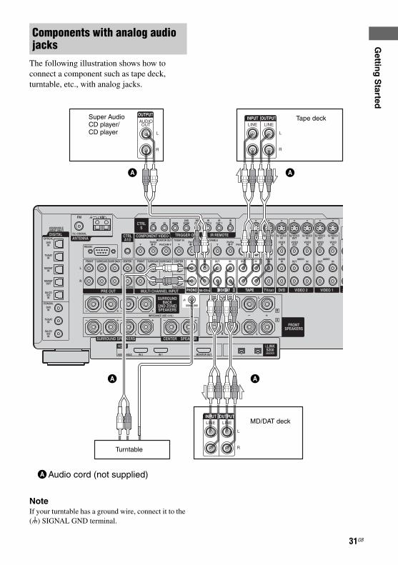
The image from a visual component connected to this receiver and the menu of this receiver can be displayed on a TV screen.It is not necessary to connect all the cables. Connect audio and video cords according to the jacks of your components.
Hooking up a TV monitor
TV monitor
A B C D E
AAudio cord (not supplied)BOptical digital cord (not supplied)CComponent video cord (not supplied)DS-video cord (not supplied)EVideo cord (not supplied)
continued
35GBSTR-DA7100ES2-320-745-14 (3)

E:\STR-DA7100ES\2320745143\2320745143STRDA7100ESUC\01GB-STRDA7100ESUC\030CON.fm
masterpage: Left
Notes• Connect image display components such as a TV
monitor or a projector to the MONITOR OUT jack on the receiver. You may not be able to record, even if you connect recording components.
• The sound is output from the TV speaker only when a playback component and this receiver, as well as this receiver and the TV are connected by an HDMI.
• Check the HDMI AUDIO setting, if the sound is not output from the TV or you cannot play back multi channel software with HDMI connected (page 70).
• Turn on the receiver when the video and audio of a playback component are being output to a TV via the receiver. If the power supply of the receiver is not turned on, neither video nor audio is transmitted.
TipYou can watch the selected input image when you connect the MONITOR OUT jack to a TV monitor (page 48). You can also display certain menu settings and the sound field on the monitor when you press ON SCREEN.
36GB
STR-DA7100ES2-320-745-14 (3)

E:\STR-DA7100ES\2320745143\2320745143STRDA7100ESUC\01GB-STRDA7100ESUC\030CON.fm
masterpage: Right
Gettin
g S
tarted
The following illustration shows how to connect a DVD player.It is not necessary to connect all the cables. Connect audio and video cords according to the jacks of your components.
1 Connecting audioTo output multi channel digital audio, set the digital audio output setting on the DVD player. Refer to the operating instructions supplied with the DVD player.
Hooking up a DVD player
DVD player
A B C
AOptical digital cord (not supplied)BCoaxial digital cord (not supplied)CAudio cord (not supplied)
continued
37GBSTR-DA7100ES2-320-745-14 (3)

E:\STR-DA7100ES\2320745143\2320745143STRDA7100ESUC\01GB-STRDA7100ESUC\030CON.fm
masterpage: Left
2 Connecting video
DVD player
AB C
AComponent video cord (not supplied)BS-video cord (not supplied)CVideo cord (not supplied)
38GB
STR-DA7100ES2-320-745-14 (3)
E:\STR-DA7100ES\2320745143\2320745143STRDA7100ESUC\01GB-STRDA7100ESUC\030CON.fm
masterpage: Right
Gettin
g S
tarted
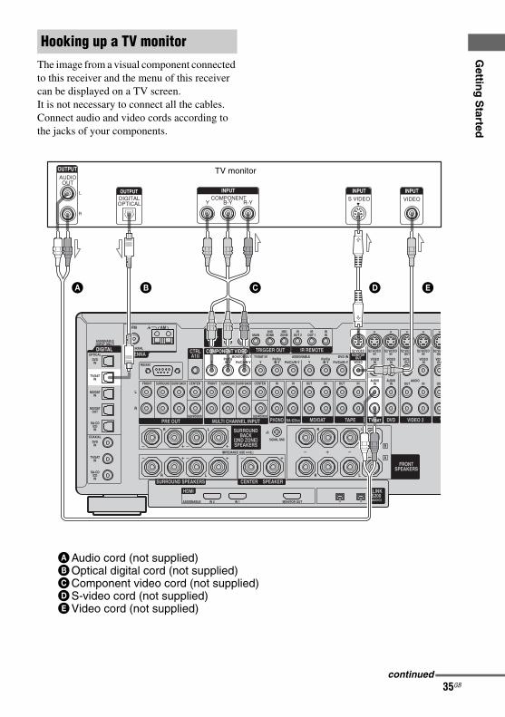
HDMI is the abbreviated name for High-Definition Multimedia Interface. It is an interface which transmits video and audio signals in digital format.
NoteCheck the HDMI AUDIO setting in the menu, if the sound is not output from the TV speaker or you cannot play back multi channel software with HDMI connected (page 70). To listen from the TV speaker, set “HDMI AUDIO” to “TV+AMP” in the CUSTOMIZE menu.
Components with HDMI jacks
DVD player Satellite tuner TV monitor, projector, etc.
A A A
AHDMI cable (not supplied)We recommend that you use a Sony HDMI cable.
continued
39GBSTR-DA7100ES2-320-745-14 (3)

E:\STR-DA7100ES\2320745143\2320745143STRDA7100ESUC\01GB-STRDA7100ESUC\030CON.fm
masterpage: Left
HDMI features• A digital audio signals transmitted by HDMI
can be output from the speakers and the PRE OUT jack on this receiver. This signal supports Dolby Digital, DTS, and linear PCM.
• Analog video signals input to the video jack, S-video jack, or component video jack can be output as HDMI signals. Audio signals are not output from an HDMI jack when the image is converted.
HDMI connections• Use an HDMI cable with the HDMI logo
(made by Sony).• Check the setup of the connected component
if an image is poor or the sound does not come out of a component connected via the HDMI cable.
Notes on HDMI connections• An audio signal input to the HDMI IN jack
is output from the speaker output jack, HDMI OUT jack and PRE OUT jack. It is not output from any other audio jack.
• A video signal input to the HDMI IN jack is only output from the HDMI OUT jack. The video input is not output from the VIDEO OUT jack, S VIDEO OUT jack, or MONITOR OUT jack.
• Check the HDMI AUDIO setting (page 70) if the sound is not output from the TV or you cannot play back multi channel software. When you want to listen to audio from the TV speaker, set HDMI AUDIO to TV+AMP in the CUSTOMIZE menu.
• The multi/stereo area audio signals of a Super Audio CD are not output.
• Be sure to turn on the receiver when video and audio signals of a playback component are being output to a TV through this receiver. Unless the power is on, neither video nor audio signals will be transmitted.
• Audio signals (sampling frequency, bit length, etc.) transmitted from an HDMI jack may be suppressed by the connected component. Check the setup of the
connected component if an image is poor or the sound does not come out of a component connected via the HDMI cable.
• Set the resolution of the image of the playback component to 720p or 1080i when you output 96kHz multi channel sound over an HDMI connection.
• Refer to the operating instructions of each component connected for details.
• We don’t recommend using an HDMI-DVI conversion cable. When you connect an HDMI-DVI conversion cable to a DVI-D component, the sound and/or the image may not be output. Connect other audio codes or digital connecting cords, then set HDMI VIDEO ASSIGN (page 64) when the sound is not output correctly.
40GB
STR-DA7100ES2-320-745-14 (3)

E:\STR-DA7100ES\2320745143\2320745143STRDA7100ESUC\01GB-STRDA7100ESUC\030CON.fm
masterpage: Right
Gettin
g S
tarted
The following illustration shows how to connect a satellite tuner.It is not necessary to connect all the cables. Connect audio and video cords according to the jacks of your components.
Connecting a satellite tuner
Satellite tuner
A B C D E F
AAudio cord (not supplied)BOptical digital cord (not supplied)CCoaxial digital cord (not supplied)DComponent video cord (not supplied)ES-video cord (not supplied)FVideo cord (not supplied)
41GB
STR-DA7100ES2-320-745-14 (3)

E:\STR-DA7100ES\2320745143\2320745143STRDA7100ESUC\01GB-STRDA7100ESUC\030CON.fm
masterpage: Left
The following illustration shows how to connect a component which has analog jacks such as a VCR, etc.
Components with analog video and audio jack
VCR
A
To the VIDEO 3 INPUT jacks(Front panel)
B
Camcorder/TV game
B
A
AAudio/video cord (not supplied)BS-video cord (not supplied)
42GB
STR-DA7100ES2-320-745-14 (3)

E:\STR-DA7100ES\2320745143\2320745143STRDA7100ESUC\01GB-STRDA7100ESUC\030CON.fm
masterpage: Right
Gettin
g S
tarted
4: Connecting the antennasConnect the supplied AM loop antenna and FM wire antenna.
* The shape of the connector varies depending on the area code of this receiver.
Notes• To prevent noise pickup, keep the AM loop antenna
away from the receiver and other components.• Be sure to fully extend the FM wire antenna.• After connecting the FM wire antenna, keep it as
horizontal as possible.• Do not use the U SIGNAL GND terminal for
grounding the receiver.
FM wire antenna (supplied)
AM loop antenna (supplied)
43GB
STR-DA7100ES2-320-745-14 (3)

E:\STR-DA7100ES\2320745143\2320745143STRDA7100ESUC\01GB-STRDA7100ESUC\030CON.fm
masterpage: Left
5: Connecting the AC power cordConnect the supplied AC power cord to the AC IN terminal on the receiver, then connect the AC power cord to a wall outlet.
* A several space is left between the plug and the rear panel even when the power cord is inserted firmly. The cord is supposed be connected this way. This is not malfunction.
** The configuration, shape, and number of AC outlets will vary according to the area code of receiver’s you purchased.
Notes• The AC OUTLET(s) on the rear of the receiver is a
switched outlet, which supplies power to the connected component only while the receiver is turned on.
• Make sure that the total power consumption of the component(s) connected to the receiver’s AC OUTLET(s) does not exceed the wattage stated on the rear panel. Do not connect high-wattage electrical home appliances such as electric irons, fans, or TVs to this outlet. This may cause a malfunction.
Before using the receiver for the first time, initialize the receiver by performing the following procedure. This procedure can also be used to return settings you have made to their factory defaults.
1 Press ?/1 to turn off the receiver.
2 Hold down ?/1 for 5 seconds.“ENTER to Clear ALL” appears on the display for 10 seconds.
AC power cord (supplied)
*
AC OUTLET**AC IN terminal
To the wall outlet
Performing initial setup operations
1,2
3
44GB
STR-DA7100ES2-320-745-14 (3)

E:\STR-DA7100ES\2320745143\2320745143STRDA7100ESUC\01GB-STRDA7100ESUC\030CON.fm
masterpage: Right
Gettin
g S
tarted
3 Press MEMORY/ENTER while“ENTER to Clear ALL” appears on the display.After “MEMORY CLEARING...” appears on the display for a while, “MEMORY CLEARED!” appears.The following items are reset to their factory settings.• All settings in the SPEAKER SET UP,
LEVEL, SURR SET UP, EQUALIZER, CUSTOMIZE, TUNER and CIS menus.
• The sound field memorized for each input and preset station.
• All preset stations.• All index names for inputs and preset.
6: Preparing the remote
Insert three LR6 (size-AA) batteries in the RM-AAE003 remote control.Insert two R6 (size-AA) batteries in the RM-US106A remote control.Observe the correct polarity when installing batteries.
Notes• Do not leave the remote in an extremely hot or
humid place.• Do not use a new battery with old ones.• Do not mix alkaline batteries and other kinds of
batteries.• Do not expose the remote sensor of the receiver to
direct sunlight or lighting apparatuses. Doing so may cause a malfunction.
• If you do not intend to use the remote for an extended period of time, remove the batteries to avoid possible damage from battery leakage and corrosion.
TipUnder normal conditions, the batteries should last for about 3 months. When the remote no longer operates the receiver, replace all the batteries with new ones.
Inserting batteries into the remote
RM-AAE003 RM-US106A
45GB
STR-DA7100ES2-320-745-14 (3)

E:\STR-DA7100ES\2320745143\2320745143STRDA7100ESUC\01GB-STRDA7100ESUC\030CON.fm
masterpage: Left
If the command modes of the receiver and the remote are different, you cannot use the remote to operate the receiver.If the command modes of both this receiver and the remote are the initial setting, it is not necessary to reset up them.
You can switch the command mode (AV SYSTEM 1 or AV SYSTEM 2) of the receiver and the remote. If the command mode of the receiver and the remote is different, you cannot use the remote to operate the receiver.
To set up the remote for the receiver
1 Press RM SET UP.The set up list appears.
2 Move the easy scroll key to select “COMMAND MODE,” then press the key to enter the selection.The COMMAND MODE list appears.
3 To select the command mode for the main receiverMove the easy scroll key to select “MAIN,” then press the key to enter the selection. The MAIN list appears.Move the easy scroll key to select “AV SYSTEM 1” or “AV SYSTEM 2,” then press the key to enter the selection.
TipThe COMMAND MODE appears in the first line of the display only when the remote is turned on by pressing SOUND FIELD or INPUT SELECTOR.
To set the remote for the receiver on the receiverTurn on the receiver while pressing 2CH.“COMMAND MODE [AV2]” appears on the display. Check that the command mode is set to AV SYSTEM2.If you repeat the same operation again, the setting will change to AV SYSTEM1 from AV SYSTEM2.
When the Sony equipments are operated by remote of the receiverChange the setting of the receiver and remote to AV SYSTEM1.
About the command mode
Switching the COMMAND MODE
12
46GB
STR-DA7100ES2-320-745-14 (3)

E:\STR-DA7100ES\2320745143\2320745143STRDA7100ESUC\01GB-STRDA7100ESUC\030CON.fm
masterpage: Right
Gettin
g S
tarted
7: Setting up the speakersYou can use the SPEAKER SET UP menu to set the size and distance of the speakers connected to this system.
1 Press ?/1 to turn on the receiver.
2 Press MAIN MENU repeatedly to select “SPEAKER SET UP,” then press the control key.You can also use MAIN MENU on the receiver.
3 Move the control key V/v to select the menu item.You can also use MENU on the receiver.For more information, see “SPEAKER SET UP parameters” (page 48).
NoteCertain setup parameters may be dimmed in the display. This means that the selected parameter is either unavailable or fixed and
unchangeable due to sound field (pages 89-94) or other settings.
4 Move the control key B/b to select the parameter.You can also use +/– on the receiver.
5 Repeat steps 3 and 4 until you have set all of the items that follow.1
2,3,4
2
47GB
STR-DA7100ES2-320-745-14 (3)
E:\STR-DA7100ES\2320745143\2320745143STRDA7100ESUC\01GB-STRDA7100ESUC\030CON.fm
masterpage: Left
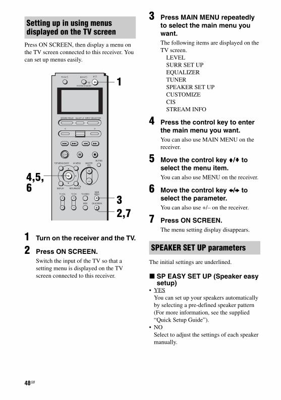
Press ON SCREEN, then display a menu on the TV screen connected to this receiver. You can set up menus easily.
1 Turn on the receiver and the TV.
2 Press ON SCREEN.Switch the input of the TV so that a setting menu is displayed on the TV screen connected to this receiver.
3 Press MAIN MENU repeatedly to select the main menu you want.The following items are displayed on the TV screen.
LEVELSURR SET UPEQUALIZERTUNERSPEAKER SET UPCUSTOMIZECISSTREAM INFO
4 Press the control key to enter the main menu you want.You can also use MAIN MENU on the receiver.
5 Move the control key V/v to select the menu item.You can also use MENU on the receiver.
6 Move the control key B/b to select the parameter.You can also use +/– on the receiver.
7 Press ON SCREEN.The menu setting display disappears.
The initial settings are underlined.
x SP EASY SET UP (Speaker easy setup)
• YESYou can set up your speakers automatically by selecting a pre-defined speaker pattern (For more information, see the supplied “Quick Setup Guide”).
• NOSelect to adjust the settings of each speaker manually.
Setting up in using menus displayed on the TV screen
4,5,6
32,7
1
SPEAKER SET UP parameters
48GB
STR-DA7100ES2-320-745-14 (3)

E:\STR-DA7100ES\2320745143\2320745143STRDA7100ESUC\01GB-STRDA7100ESUC\030CON.fm
masterpage: Right
Gettin
g S
tarted
x SPEAKER PATTERN (Speakersetup pattern)When “SP EASY SET UP” is set to “YES,” select the speaker setup pattern by moving and pressing the control key (You can also use +/– and MEMORY/ENTER on the receiver).Check your speaker pattern using the supplied “Quick Setup Guide.”
x SUB WOOFER (Sub woofer)• YES
If you have connected a sub woofer, select “YES.”
• NOIf you have not connected a sub woofer, select “NO.” This activates the bass redirection circuitry and outputs the L.F.E. signals from other speakers.
TipIn order to take full advantage of the Dolby Digital bass redirection circuitry, we recommend setting the sub woofer’s cut off frequency as high as possible.
x FRONT SP (Front speakers)• LARGE
If you connect large speakers that will effectively reproduce bass frequencies, select “LARGE.” Normally, select “LARGE.” When the sub woofer is set to “NO,” front speakers are automatically set to “LARGE.”
• SMALLIf the sound is distorted, or you feel a lack of surround effects when using multi channel surround sound, select “SMALL” to activate the bass redirection circuitry and output the front channel bass frequencies from the sub woofer. When the front speakers are set to “SMALL,” the center, surround, and surround back speakers are also automatically set to “SMALL” (unless previously set to “NO”).
x CENTER SP (Center speaker)• LARGE
If you connect a large speaker that will effectively reproduce bass frequencies, select “LARGE.” Normally, select
“LARGE.” However, if the front speakers are set to “SMALL,” you cannot set the center speaker to “LARGE.”
• SMALLIf the sound is distorted, or you feel a lack of surround effects when using multi channel surround sound, select “SMALL” to activate the bass redirection circuitry and output the center channel bass frequencies from the front speakers (if set to “LARGE”) or sub woofer.
• NO If you have not connected a center speaker, select “NO,” the sound of the center channel will be output from the front speakers.
x SURROUND SP (Surround speaker)
The surround back speakers are all set to the same setting.• LARGE
If you connect large speakers that will effectively reproduce bass frequencies, select “LARGE.” Normally, select “LARGE.” However, if the front speakers are set to “SMALL,” you cannot set the surround speakers to “LARGE.”
• SMALLIf the sound is distorted, or you feel a lack of surround effects when using multi channel surround sound, select “SMALL” to activate the bass redirection circuitry and output the surround channel bass frequencies from the sub woofer or other “LARGE” speakers.
• NOIf you have not connected surround speakers, select “NO.”
x SURR BACK SP (Surround back speakers)
When the surround speakers are set to “NO,” the surround back speakers are also automatically set to “NO” and the setting cannot be changed.• DUAL
If you connect two surround back speakers, select “DUAL.” The sound will be output to a maximum of 7.1 channels.
continued
49GBSTR-DA7100ES2-320-745-14 (3)

E:\STR-DA7100ES\2320745143\2320745143STRDA7100ESUC\01GB-STRDA7100ESUC\030CON.fm
masterpage: Left
• SINGLEIf you connect only one surround back speaker, select “SINGLE.” The sound will be output to a maximum of 6.1 channels.
• NOIf you have not connected surround back speakers, select “NO.”
• 2ND ZONE If you use the surround back speaker in the 2nd zone, select “2ND ZONE.” When you select “2ND ZONE,” the input to the SURR BACK jacks of the MULTI CHANNEL INPUT is invalid (page 28).
TipThe “LARGE” and “SMALL” settings for each speaker determine whether or not the internal sound processor will cut the bass signal from that channel.When the bass is cut from a channel, the bass redirection circuitry sends the corresponding bass frequencies to the sub woofer or other “LARGE” speakers.However, it is best not to cut them, if possible. Therefore, even when using small speakers, you can set them to “LARGE” if you want to output the bass frequencies from that speaker. On the other hand, if you are using a large speaker, but prefer not to have bass frequencies output from that speaker, set it to “SMALL.”If the overall sound level is lower than you prefer, set all speakers to “LARGE.” If there is not enough bass, you can use the equalizer to boost the bass levels. For details on how to adjust the equalizer, see page 104.
x FRONT xx meter (Front speaker distance)
Initial setting: 3.0 meter (10 feet)Lets you set the distance from your listening position to the front speakers (A). You can adjust this distance from 1.0 meter to 7.0 meters (3 to 23 feet) in 0.1 meter (1 foot) steps.If both front speakers are not placed an equal distance from your listening position, set the distance to the closest speaker.
With only one surround back speaker
With two surround back speakers (The angle B should be the same)
x CENTER xx meter (Center speaker distance)
Initial setting: 3.0 meter (10 feet)Lets you set the distance from your listening position to the center speaker. You can adjust this distance from 1.0 meter to 7.0 meters (3 to 23 feet) in 0.1 meter (1 foot) steps.
x SURROUND xx meter (Surround speaker distance)
Initial setting: 3.0 meter (10 feet)Lets you set the distance from your listening position to the surround speakers. You can adjust this distance from 1.0 meter to 7.0 meters (3 to 23 feet) in 0.1 meter (1 foot) steps.If both surround speakers are not placed an equal distance from your listening position, set the distance to the closest speaker.
50GB
STR-DA7100ES2-320-745-14 (3)

E:\STR-DA7100ES\2320745143\2320745143STRDA7100ESUC\01GB-STRDA7100ESUC\030CON.fm
masterpage: Right
Gettin
g S
tarted
x SURR BACK xx meter(Surround back speaker distance)
Initial setting: 3.0 meter (10 feet)Lets you set the distance from your listening position to the surround back speaker. You can adjust this distance from 1.0 meter to 7.0 meters (3 to 23 feet) in 0.1 meter (1 foot) steps.If you connect two surround back speakers and both surround back speakers are not placed an equal distance from your listening position, set the distance to the closest speaker.
x SUB WOOFER xx meter (Sub woofer distance)
Initial setting: 3.0 meter (10 feet)Lets you set the distance from your listening position to the sub woofer. You can adjust this distance from 1.0 meter to 7.0 meters (3 to 23 feet) in 0.1 meter (1 foot) steps.
TipThe distance between the center speaker and the listening position B cannot be more than 1.5 meters (5 feet) shorter than the one between the listening position and the front speaker A. Place the speakers so that the difference in the length of B in the diagram below is no more than 1.5 meters (5 feet) shorter than the length of A.Example: Adjust the distance B to 4.5 meters (15 feet) or more when the distance A is 6 meters (20 feet).Also, the distance between the surround speakers/surround back speakers and the listening position C cannot be more than 4.5 meters (15 feet) shorter than the distance between the listening position and the front speakers A. Place the speakers so that the difference in the length of C in the diagram below is no more than 4.5 meters (15 feet) shorter than the length of A.Example: Adjust the distance C to 1.5 meters (5 feet) or more when the distance A is 6 meters (20 feet).This is important because incorrect speaker placement is not conductive to the enjoyment of surround sound. Place note that placing the speakers closer than the required will cause a delay in the output of the sound from that speaker. In other words, the speaker will sound like it is farther away.
For advanced speaker setupUse the CUSTOMIZE menu and set “MENU EXPAND” to “ON.” This enables advanced setup including positioning. For details on “MENU EXPAND,” see page 67. For details on how to set the items, see page 102.
51GB
STR-DA7100ES2-320-745-14 (3)

E:\STR-DA7100ES\2320745143\2320745143STRDA7100ESUC\01GB-STRDA7100ESUC\030CON.fm
masterpage: Left
Selecting the speaker systemSet the SPEAKERS switch according to the front speakers you want to drive.
8: Adjusting the speaker levels and balance(TEST TONE)
Adjust the speaker levels and balance while listening the test tone from your listening position. Use the remote for the operation.
TipThe receiver employs a test tone with a frequency centered at 800 Hz.
1 Turn on the receiver and TV.
2 Press ON SCREEN.Switch the input of the TV so that the setting menu is displayed on the TV screen connected to this receiver.
3 Press MAIN MENU repeatedly to select “LEVEL,” then press the control key.
Set to To select
A The speakers connected to the FRONT SPEAKERS A terminals.
B The speakers connected to the FRONT SPEAKERS B terminals.
A+B The speakers connected to both the FRONT SPEAKERS A and B terminals (parallel connection).
OFF No speaker output.
SPEAKERS switch
3,4,6,7
1
2,8
3
52GB
STR-DA7100ES2-320-745-14 (3)

E:\STR-DA7100ES\2320745143\2320745143STRDA7100ESUC\01GB-STRDA7100ESUC\030CON.fm
masterpage: Right
Gettin
g S
tarted
4 Move the control key b to select“AUTO.”The test tone is output from each speaker in sequence.Also, if you press b, the pattern will become the “FIX” pattern in, which the test tone is output from the selected speaker only.
5 Adjust the speaker level and balance using the LEVEL menu so that the level of the test tone sounds the same from each speaker.For details on the LEVEL menu settings, see page 99.
Tips• To adjust the level of all speakers at the same
time, press MASTER VOL +/– on the remote or turn MASTER VOLUME on the receiver.
• You can also use +/– on the receiver for the adjustment.
6 Press the control key V/v repeatedly to select “TEST TONE.”
7 Move the control key B to select “OFF.”The test tone turns off.
8 Press ON SCREEN.The menu setting display disappears.
For more precise adjustmentYou can output the test tone or sound source from two adjacent speakers to adjust their balance and level. Set “MENU EXPAND” in the CUSTOMIZE menu to “ON” (page 67). Then select the two speakers you want to adjust using “PHASE NOISE” or “PHASE AUDIO” on the LEVEL menu (page 100).
To operate on the receiverWhen you operate using the receiver, be sure to perform the following procedure.
1 Turn on this receiver.
2 Turn MAIN MENU to select “LEVEL.”
3 Turn MENU to select “TEST TONE.”
4 Turn +/– clockwise to select “AUTO.”The test tone is output from each speaker.
5 Turn MENU to select a speaker you want to adjust.
6 Turn +/– to adjust the parameter.Adjust the speaker level and balance so that the level (volume) of the test tone sounds the same from each speaker.Repeat step 5 and 6 to adjust the volume of each speaker.
7 Turn MENU to select “TEST TONE.”
8 Turn +/– counter-clockwise to select “OFF.”
1
2
3,5,7
4,6,8
53GB
STR-DA7100ES2-320-745-14 (3)

E:\STR-DA7100ES\2320745143\2320745143STRDA7100ESUC\01GB-STRDA7100ESUC\040PLA.fm
masterpage: L
Listening to a Super Audio CD/CD
Playback
2
3
553
• The operation is described for a Sony Super Audio CD.
• Refer to the operating instructions supplied with the Super Audio CD player or CD player.
zYou can select the sound field to suit the music. Refer to page 93 for details.Recommended sound fieldsClassical: D.CONCERT HALLJazz: JAZZ CLUBLive concert: LIVE CONCERT, STADIUM
zYou can listen to the sound that was recorded in the 2 channel format from all speakers (multi channel).Refer to page 90 for details.
54GB
1 Turn on the Super Audio CD player /CD player, then set the disc in the tray.
2 Turn on the receiver.
3 Press INPUT SELECTOR, then select SA-CD/CD by moving and pressing the easy scroll key.You can also use INPUT SELECTOR on the receiver to select SA-CD/CD.
An example of the display
4 Play back the disc.
5 Adjust to a suitable volume.
6 Eject the disc and turn off the receiver and CD player.
STR-DA7100ES2-320-745-14 (3)

E:\STR-DA7100ES\2320745143\2320745143STRDA7100ESUC\01GB-STRDA7100ESUC\040PLA.fm
masterpage: R-2
Playb
ack
Watching a DVD
MULTI CHANNEL DECODING lamp
2
3
773
• Refer to the operating instructions supplied with the TV and DVD player.
zSelect the sound format of the disc to be played, if necessary.
zYou can select the sound field to suit the music. Refer to page 93 for details.Recommended sound fieldsMovie: CINEMA STUDIO EXLive image: LIVE CONCERTSport: SPORTS
Check the following if you cannot listen to in multi channel sound.• Be sure the sound source
corresponds to the multi channel format (the MULTI CHANNEL DECODING lamp on the front panel lights up during playback).
• Be sure this receiver is connected to the DVD player via a digital connection.
• Be sure the digital audio output of the DVD player is set up properly.
55GB
1 Turn on the TV and DVD player.
2 Turn on the receiver.
3 Press INPUT SELECTOR, move the easy scroll key to select DVD from the list, then press the key to enter the selection.You can also use INPUT SELECTOR on this receiver to select DVD.
An example of the display
4 Switch the input of the TV so that an image of the DVD is displayed.
5 Set up the DVD player.Refer to “Quick Setup Guide” supplied with the receiver.
6 Play back the disc.
7 Adjust to a suitable volume.
8 Eject the disc and turn off the receiver and DVD player.
STR-DA7100ES2-320-745-14 (3)

E:\STR-DA7100ES\2320745143\2320745143STRDA7100ESUC\01GB-STRDA7100ESUC\040PLA.fm
masterpage: L-2
Enjoying TV games
VIDEO 3 INPUT
2
3
773
56GB
• Refer to the operating instructions supplied with the TV and TV game.
zYou can select the sound field to suit the music. Refer to page 91 for details.Recommend sound field: GAME
1 Turn on the TV and TV game.
2 Turn on the receiver.
3 Press INPUT SELECTOR, move the easy scroll key to select VIDEO 3* from the list, then press the key to enter the selection.You can also use INPUT SELECTOR on this receiver to select VIDEO 3*.* When you connect a TV game to the VIDEO 3 INPUT jack on
the front panel.
An example of the display
4 Switch the input of the TV so that an image of the TV game is displayed.
5 Set up the TV game.
6 Set the disc in the tray and play it back on the TV game.
7 Adjust to a suitable volume.
8 Eject the disc and turn off the receiver and the player.
STR-DA7100ES2-320-745-14 (3)

E:\STR-DA7100ES\2320745143\2320745143STRDA7100ESUC\01GB-STRDA7100ESUC\040PLA.fm
masterpage: R-2
Playb
ack
Watching video
2
3
663
• Refer to the operating instructions supplied with the TV and VCR.
zYou can listen to sound recorded in the 2 channel format from all speakers (multi channel).Refer to page 90 for details.
57GB
1 Turn on the VCR.
2 Turn on the receiver.
3 Press INPUT SELECTOR, move the easy scroll key to select VIDEO 1* from the list, then press the key to enter the selection.You can also use INPUT SELECTOR on this receiver to select VIDEO 1*.* When you connect VCR to the VIDEO 1 jack.
An example of the display
4 Switch the input of the TV so that an image of the VCR is displayed.
5 Play back the tape on the VCR.
6 Adjust to a suitable volume.
7 Eject the tape and turn off the receiver and VCR.
STR-DA7100ES2-320-745-14 (3)

E:\STR-DA7100ES\2320745143\2320745143STRDA7100ESUC\01GB-STRDA7100ESUC\050AMP.fm
masterpage: Left
Selecting a component
1 Press INPUT SELECTOR, then select a component by moving and pressing the easy scroll key.You can also use INPUT SELECTOR on the receiver. To select a component connected to the i.LINK, HDMI or MULTI CH IN jack, press the appropriate button on the receiver.The selected input appears on the display.
*When you select i.LINK, the connected component name displayed (ex:SCD-XA9000ES). The power supply is turned on and the completion of an i.LINK setup of the component is necessary at this time. Refer to the operating instructions of the component for details.
Amplifier Operation
1
1
3MUTING
Selected input and display
Components that can be played back
VIDEO1, 2 VCR, etc., connected to the VIDEO 1 or VIDEO 2 jack
VIDEO3 Video camera and TV game, etc., connected to the VIDEO 3 jack
DVD DVD player, etc., connected to DVD jack
TV/SAT Satellite tuner, etc., connected to the TV/SAT jack
TAPE Tape deck, etc., connected to the TAPE jack
MD/DAT MD/DAT deck, etc., connected to the MD/DAT jack
SA-CD/CD Super Audio CD/CD player, etc., connected to the SA-CD/CD jack
TUNER Built-in radio tuner
PHONO Turntable, etc., connected to the PHONO jack
i.LINK* i.LINK components connected to the i.LINK jack
HDMI 1, 2 HDMI components connected to the HDMI jack
MULTI CH IN Component connected to the MULTI CHANNEL INPUT jack
58GB
STR-DA7100ES2-320-745-14 (3)

E:\STR-DA7100ES\2320745143\2320745143STRDA7100ESUC\01GB-STRDA7100ESUC\050AMP.fm
masterpage: Right
Am
plifier O
peratio
n
Notes• The surround effect does not work whenMULTI CH IN is selected (page 92).• When you select an input other than “i.LINK”
the receiver is set such that the power to the i.LINK circuits is off as the initial setting. (“i.POWER” is set to “AUTO” in the CUSTOMIZE menu setting. Refer to page 68 for details.) When you select “i.LINK” as the input, the power of the i.LINK circuits turns on. “i.LINK Connecting” appears on the display, but sound may not yet be output. Make sure to operate the player only after the “i.LINK Connecting” indicator turns off.
2 Turn on the component and start playback.
3 Press MASTER VOL +/– to adjust the volume.You can also use MASTER VOLUME on the receiver.
To mute the soundPress MUTING on the remote. To cancel, press MUTING on the remote again or turn MASTER VOLUME clockwise to raise the volume. Even if you turn off the receiver, the muting function works when you turn the receiver on again.
Switching the audio input mode(INPUT MODE)
You can select the audio input mode by setting the audio input mode when you connect components to both digital and analog audio input jacks on the receiver.
1 Press INPUT SELECTOR, then select a component by moving and pressing the easy scroll key.You can also use INPUT SELECTOR on the receiver.
2 Press < repeatedly until the RECEIVER MENU appears.
3 Select “INPUT MODE” by moving and pressing easy scroll key.The selected audio input mode appears on the display window on the receiver.You can also use INPUT MODE on the receiver.
21
1,3
continued
59GBSTR-DA7100ES2-320-745-14 (3)

E:\STR-DA7100ES\2320745143\2320745143STRDA7100ESUC\01GB-STRDA7100ESUC\050AMP.fm
masterpage: Left
Audio input modes• AUTO 2CH
When there are no digital audio signals, the analog audio signals input to the AUDIO IN (L/R) jacks are selected.
• COAXIAL FIXEDSpecifies the digital audio signals input to the DIGITAL COAXIAL jack.
• OPTICAL FIXEDSpecifies the digital audio signals input to the DIGITAL OPTICAL jack.
• ANALOG 2CH FIXEDSpecifies the analog audio signals input to the AUDIO IN (L/R) jacks.
• i.LINK FIXEDSpecifies the audio input to the i.LINK jacks.
• HDMI FIXEDSpecifies the audio input to the HDMI jacks.
Notes• You cannot select the digital audio input assigned
to another function using the DIGITAL ASSIGN function (page 61).
• Some audio input modes may not be set up depending on the input.
• A INPUT MODE button does not work when i.LINK or HDMI input are selected.
Naming inputsYou can enter a name of up to 8 characters for inputs and display it on the receiver’s display.This is convenient for attaching component names. It will tell you which component is connected to which jack.
1 Press INPUT SELECTOR to select an input you want to create an index name for.You can also use INPUT SELECTOR on the receiver.
2 Press MAIN MENU repeatedly to select “CUSTOMIZE,” then press the control key.You can also use MAIN MENU on the receiver.
3 Move the control key to V/v select “NAME IN?.”You can also use MENU on the receiver.
4 Press the control key.The cursor flashes and you can select a character. Follow the procedure given in “To create an index name.”
1
2
2,3,4
60GB
STR-DA7100ES2-320-745-14 (3)

E:\STR-DA7100ES\2320745143\2320745143STRDA7100ESUC\01GB-STRDA7100ESUC\050AMP.fm
masterpage: Right
Am
plifier O
peratio
n
To create an index name1 Move the control key V/v to create an index name.Turn +/– on the receiver to select a character, then turn MENU to move the cursor to the next position.
To enter a blank spaceMove the control key B/b without inputting a character. You can also turn +/– on the receiver until a blank space appears on the display.
If you made a mistakeMove the control key B/b until the character you want to change flashes, then turn +/– on the receiver to select the correct character.
TipYou can select the character type as follows by rotating +/–.Alphabet (upper case) t Alphabet (lower case) t Numbers t Symbols
2 Press the control key.The entered name is registered.
Note (Models of area code CEL only)When you name an RDS station and tune in that station, the Program Service (PS) name appears instead of the name you entered. (You cannot change the Program Service (PS) name. The name you entered will be overwritten by the Program Service (PS) name.)
Listening to digital sound from other inputs(DIGITAL ASSIGN)
You can assign digital audio input to other input which can be heard only analog sound (VIDEO 1, 2 IN etc.). For example, when you connect two DVD players and the first DVD player is connected to the OPTICAL IN jack then:• The first DVD player
Should be connected to the DVD IN jack on this receiver. Connect it to the OPTICAL IN jack only when you want to listen to it as digital sound. When you select DVD as the input source, the sound becomes digital sound via the OPTICAL IN jack automatically.
• The second DVD playerShould be connected to the VIDEO 1 IN jack, etc., on this receiver, but the sound is still an analog signal. In this case, you can assign a COAXIAL IN jack, which is not currently being used for the first DVD player on VIDEO 1 IN as the audio input. The procedure is carried out as follows.
1
1,2,3,4,5
continued
61GBSTR-DA7100ES2-320-745-14 (3)

E:\STR-DA7100ES\2320745143\2320745143STRDA7100ESUC\01GB-STRDA7100ESUC\050AMP.fm
masterpage: Left
1 Press MAIN MENU repeatedly to select “CUSTOMIZE,” then press the control key.You can also use MAIN MENU on the receiver to select “CUSTOMIZE.”
2 Move the control key V/v to select “DIGITAL ASSIGN ?.”You can also use MENU on the receiver.
3 Press the control key.You can also use MEMORY/ENTER on the receiver.
4 Move the control key V/v to select a vacant digital audio input (DVD COAX in the example).You can also use MENU on the receiver.
5 Move the control key B/b to select the input (VIDEO 1 in the example) you want to assign to the digital audio input jack selected in step 4.You can also use +/– on the receiver.If an input is switched to “VIDEO 1,” the sound of the second DVD player will also become a digital sound through a COAXIAL jack.The input you can assign varies for each audio input. For details, see “Assignable inputs for digital audio input,” below.
Assignable inputs for digital audio inputThe initial setting is marked with an underscore.
Notes• You cannot assign several digital audio inputs to
the same input.• You cannot use the digital audio input as the
original input when it is assigned to another input.• When you assign the digital audio input, the
INPUT MODE setting may change automatically (page 59).
Digital audio input Assignable inputs
VIDEO 3 OPT VIDEO 1, VIDEO 2,VIDEO 3, TAPE
DVD COAX, DVD OPT
VIDEO 1, VIDEO 2,DVD, TAPE
TV/SAT COAX, TV/SAT OPT
VIDEO 1, VIDEO 2,TV/SAT, TAPE
MD/DAT OPT VIDEO 1, VIDEO 2,TAPE, MD/DAT
SA-CD/CD COAX, SA-CD/CD OPT
VIDEO 1, VIDEO 2,TAPE, SA-CD/CD
Digital audio input Assignable inputs
62GB
STR-DA7100ES2-320-745-14 (3)
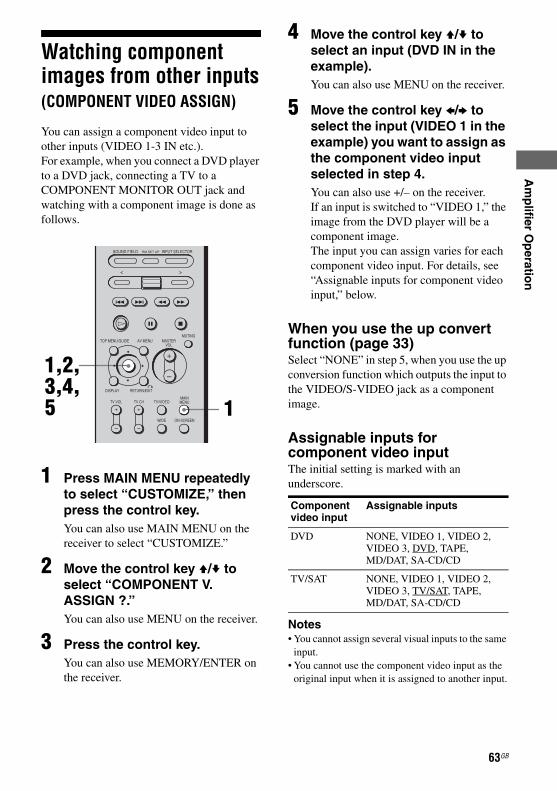
E:\STR-DA7100ES\2320745143\2320745143STRDA7100ESUC\01GB-STRDA7100ESUC\050AMP.fm
masterpage: Right
Am
plifier O
peratio
n
Watching component images from other inputs(COMPONENT VIDEO ASSIGN)
You can assign a component video input to other inputs (VIDEO 1-3 IN etc.).For example, when you connect a DVD player to a DVD jack, connecting a TV to a COMPONENT MONITOR OUT jack and watching with a component image is done as follows.
1 Press MAIN MENU repeatedly to select “CUSTOMIZE,” then press the control key.You can also use MAIN MENU on the receiver to select “CUSTOMIZE.”
2 Move the control key V/v to select “COMPONENT V. ASSIGN ?.”You can also use MENU on the receiver.
3 Press the control key.You can also use MEMORY/ENTER on the receiver.
4 Move the control key V/v to select an input (DVD IN in the example).You can also use MENU on the receiver.
5 Move the control key B/b to select the input (VIDEO 1 in the example) you want to assign as the component video input selected in step 4.You can also use +/– on the receiver.If an input is switched to “VIDEO 1,” the image from the DVD player will be a component image.The input you can assign varies for each component video input. For details, see “Assignable inputs for component video input,” below.
When you use the up convert function (page 33)Select “NONE” in step 5, when you use the up conversion function which outputs the input to the VIDEO/S-VIDEO jack as a component image.
Assignable inputs for component video inputThe initial setting is marked with an underscore.
Notes• You cannot assign several visual inputs to the same
input.• You cannot use the component video input as the
original input when it is assigned to another input.
1
1,2,3,4,5
Component video input
Assignable inputs
DVD NONE, VIDEO 1, VIDEO 2, VIDEO 3, DVD, TAPE,MD/DAT, SA-CD/CD
TV/SAT NONE, VIDEO 1, VIDEO 2, VIDEO 3, TV/SAT, TAPE,MD/DAT, SA-CD/CD
63GB
STR-DA7100ES2-320-745-14 (3)

E:\STR-DA7100ES\2320745143\2320745143STRDA7100ESUC\01GB-STRDA7100ESUC\050AMP.fm
masterpage: Left
Watching HDMI image from other inputs(HDMI VIDEO ASSIGN)
You can assign an HDMI video input to other input.
1 Press MAIN MENU repeatedly to select “CUSTOMIZE,” then press the control key.You can also use MAIN MENU on the receiver to select “CUSTOMIZE.”
2 Move the control key V/v to select “HDMI VIDEO ASSIGN ?.”You can also use MENU on the receiver.
3 Press the control key.You can also use MEMORY/ENTER on the receiver.
4 Move the control key V/v to select an input.You can also use MENU on the receiver.
5 Move the control key B/b to select the input you want to
assign as an HDMI video input selected in step 4.You can also use +/– on the receiver.The input you can assign varies for each component video input. For details, see “Assignable inputs for an HDMI video input.”
Assignable inputs for an HDMI video inputThe initial setting is marked with an underscore.
1
1,2,3,4,5
HDMI video input
Assignable inputs
HDMI 1 NONE, VIDEO 1, VIDEO 2, VIDEO 3, DVD, TV/SAT, TAPE, MD/DAT, SA-CD/CD
HDMI 2 NONE, VIDEO 1, VIDEO 2, VIDEO 3, DVD, TV/SAT, TAPE, MD/DAT, SA-CD/CD
64GB
STR-DA7100ES2-320-745-14 (3)

E:\STR-DA7100ES\2320745143\2320745143STRDA7100ESUC\01GB-STRDA7100ESUC\050AMP.fm
masterpage: Right
Am
plifier O
peratio
n
Storing the adjusted settings(USER PRESET)
You can store the adjusted sound field settings, etc., as up to 3 USER PRESET settings, and then you can apply them easily.
1 Adjust the menu you want to store, for example, sound field, etc.
Settings that can be stored in USER PRESET• Input selected by the INPUT
SELECTOR (page 58)• INPUT MODE setting (page 59)• Sound field selected (page 92)• NIGHT MODE setting (page 94)• EFFECT LEVEL setting (page 98)• C.WIDTH setting (page 98)• DIMENSION setting (page 98)• PANORAMA MODE setting (page 98)• SCREEN DEPTH setting (page 98)• VIR.SPEAKERS setting (page 99)• Tuner settings (band, frequency, stereo/
mono setting, preset number)
2 Press MAIN MENU repeatedly to select “CUSTOMIZE,” then press the control key.You can also use MAIN MENU on the receiver to select “CUSTOMIZE.”
3 Move the control key V/v to select “USER PRESET MEM.?.”You can also use MENU on the receiver.
4 Move the control key B/b to select the number in which you want to store the settings.You can also use +/– on the receiver.
5 Press the control key.
6 To store other settings, repeat steps 1 to 5.
1 Press USER PRESET repeatedly to select the USER PRESET you want.
2 Press MEMORY/ENTER.
Setting the USER PRESET
2
2,3,4,5
To use the USER PRESET
12
continued
65GBSTR-DA7100ES2-320-745-14 (3)

E:\STR-DA7100ES\2320745143\2320745143STRDA7100ESUC\01GB-STRDA7100ESUC\050AMP.fm
masterpage: Left
NoteWhen the DIGITAL ASSIGN setting is changed after you store a USER PRESET and if the stored INPUT MODE setting cannot be used, a selectable setting is applied automatically (page 61).Example:1) Use the DIGITAL ASSIGN function to assign
“DVD OPT” to “TAPE.”2) Set the INPUT MODE of TAPE to “AUTO 2CH”
or “OPTICAL FIXED,” then store this in the USER PRESET.
3) Use the DIGITAL ASSIGN function to assign “DVD OPT” to “DVD.”
4) Select the USER PRESET stored in example 2). The INPUT MODE of TAPE is automatically set to “ANALOG 2CH FIXED.” You cannot select “AUTO 2CH” or “OPTICAL FIXED.”
Changing the menu setting
1 Press MAIN MENU repeatedly to select “CUSTOMIZE,” then press the control key.You can also use MAIN MENU on the receiver to select “CUSTOMIZE.”
2 Move the control key V/v to select the menu item you want, then press the key.You can also use MENU on the receiver.See “Menu item and parameter” on page 67 for details.
3 Move the control key B/b to select the setting item you want.You can also use +/– on the receiver.
4 Repeat steps 2 and 3 to adjust other menus.
1
1,2,3
66GB
STR-DA7100ES2-320-745-14 (3)

E:\STR-DA7100ES\2320745143\2320745143STRDA7100ESUC\01GB-STRDA7100ESUC\050AMP.fm
masterpage: Right
Am
plifier O
peratio
n
Menu item and parameterThe initial setting is marked with an underscore.Menu item Parameter Explanation
MENU EXPAND(Menu expanding)
ON The advanced parameters for the SPEAKER SET UP, SURR SET UP and LEVEL menus are displayed and can be adjusted. For details on each setup menu, see pages 97 to 100 and the following pages.
OFF The advanced parameters are not displayed.
SB DECODING(Surround back decoding)
AUTO You can set up the surround back decoding function, see “Types of the surround back decoding functions” on page 95.
ON
OFF
SB DEC MODE(Surround back decoding mode)
DDEX You can set up the surround back decoding mode, see page 96 for details of the mode type.
NoteA setup of SB DECODING/SB DEC MODE becomes invalid when Dolby Pro Logic IIx is selected in the A.F.D. mode. The optimal decoding mode is set up automatically.
PLIIx MV
PLIIx MS
DEC. PRIORITY(Digital audio input decoding priority)
Lets you specify the input mode for the digital signal input to the DIGITAL IN and HDMI IN jacks.
AUTO Automatically switches the input mode between DTS, Dolby Digital, or PCM.
PCM PCM signals are given priority (to prevent interruption when playback starts). When set to “AUTO” and the sound from the digital audio jacks (for a CD, etc.) is interrupted when playback starts, set to “PCM.” However, when other signals are input, there may be no sound depending on the format. In this case, set to “AUTO.”
DUAL MONO(Digital broadcast language selection)
Lets you select the language you want to listen to during a digital broadcast. This feature only functions for Dolby Digital sources.
MAIN/SUB Sound of the main language will be output through the front left speaker, and simultaneously sound of the sub language will be output through the front right speaker.
MAIN Sound of the main language will be output.
SUB Sound of the sub language will be output.
MAIN+SUB Mixed sound of both the main and sub languages will be output.
continued
67GBSTR-DA7100ES2-320-745-14 (3)

E:\STR-DA7100ES\2320745143\2320745143STRDA7100ESUC\01GB-STRDA7100ESUC\050AMP.fm
masterpage: Left
A/V SYNC 0 ms Lets you delay the output of audio to adjust the gap between video and audio. You can adjust this delay from 0 ms to 200 ms in 10 ms steps. However, this feature does not function when a DSD signal is input from the i.LINK component.
9.1 CH SP SYSTEM(9.1 ch speaker system)
YES Set to “YES” when you use the 9.1 channel system. See page 20-23 for details on the connection and the settings of the 9.1 channel system.
Notes• This function is valid when surround back speakers are set
to DUAL only (page 49).• When the IMPEDANCE SELECTOR is set to “8Ω,”
connect the speakers with a nominal impedance of 16 ohm or higher. When the IMPEDANCE SELECTOR is set to “4Ω,” connect the speakers with a nominal impedance of 8 ohms or higher. For details, see page 22.
NO
MULTI IN5.1 t 7.1(Multi channel input 5.1ch t 7.1ch)
YES Lets you output the 5.1 channel signals, which are input to the MULTI CHANNEL INPUT jack as 7.1 channel signals.
NO Set to “NO” when the receiver and the player are connected using the 7.1 channel system (The SURR BACK jack of the MULTI CHANNEL INPUT are connected).
DC PHASE L.(DC Phase Linearizer)
Lets you approximate the low frequency phase characteristics of a traditional analog amplifier.
OFF The bass is not enhanced.
LOW-A,STD-A,HIGH-A,LOW-B,STD-B,HIGH-B
The bandwidth range of the phase correction increases in the order of “LOW,” “STD,” “HIGH.”“B” parameter phase correction provides more enhanced bass characteristics.
i POWER(i.LINK power management)
AUTO Lets you turn off the power of the unnecessary i.LINK circuits automatically. You can enjoy high quality digital or analog audio without the influence of the i.LINK circuits. When set to “AUTO,” it takes some time to output the sound. See page 59 for a tip on switching the input when the setting is “AUTO.”
EVER ON Lets you keep the power of the i.LINK circuits. Select this setting if you do not like the time lag that occurs with the “AUTO” setting. It may be ineffective depending on the component.
Menu item Parameter Explanation
68GB
STR-DA7100ES2-320-745-14 (3)

E:\STR-DA7100ES\2320745143\2320745143STRDA7100ESUC\01GB-STRDA7100ESUC\050AMP.fm
masterpage: Right
Am
plifier O
peratio
n
H.A.T.S.(H.A.T.S. (High quality digital Audio Transmission System) function)
ON The digital audio signals input from the i.LINK component are stored in a buffer temporarily, then retrieved from the buffer and converted to analog audio signals at the proper timing. The sound quality is enhanced because there is no jitter (timing gaps when reading signals) when transmitting the digital audio signals. If you do not want to use this function, select “OFF.”
OFF This function is not activated.
NoteIt takes some time to output the sound after a playback operation is performed on the connected component (ex., pressing the PLAY button, pressing the STOP button, pressing the PAUSE button) due to limitations of the H.A.T.S. system. The time lag depends on the sound source. This feature may be ineffective depending on the component and the sound source, even if you set to ON.
i.LINK VIDEO ASSIGN ? (i.LINK video input assignment)
You can assign video input to an i.LINK input. i.LINK is selected as input and the i.LINK component to set up needs to be recognized when you do this operation (page 58).Move the control key V/v to select an i.LINK component.Move the control key B/b to select a number you want to memory ([1]-[5]), then press the key.Move the control key B/b to select the video input which is to be assigned to the i.LINK input, then press the key to enter.
NONE Video output signal has not sended from this receiver when the i.LINK input is selected.
VIDEO 1,VIDEO 2,VIDEO 3,DVD,TV/SAT,HDMI 1,HDMI 2
An image of the selected input is on the monitor when the i.LINK input is selected.
DIGITAL ASSIGN ?(Digital audio input assignment)
Lets you assign the digital audio input to other input source. For details, see “Listening to digital sound from other inputs (DIGITAL ASSIGN)” on page 61.
Menu item Parameter Explanation
continued
69GBSTR-DA7100ES2-320-745-14 (3)

E:\STR-DA7100ES\2320745143\2320745143STRDA7100ESUC\01GB-STRDA7100ESUC\050AMP.fm
masterpage: Left
COMPONENT V. ASSIGN?(Component Video Assign)
DVD,TV/SAT,NONE,VIDEO 1,VIDEO 2,VIDEO 3,DVD or TV/SAT,TAPE,MD/DAT,SA-CD/CD
Lets you assign the component video input of DVD and TV/SAT to another visual input. For details, see “Watching component images from other inputs (COMPONENT VIDEO ASSIGN)” on page 63.
HDMI VIDEO ASSIGN ?(HMDI Video Assign)
NONE,VIDEO 1,VIDEO 2,VIDEO 3,DVD,TV/SAT,TAPE,MD/DAT,SA-CD/CD
Lets you assign the HDMI video input to another visual input. For details, see “Watching HDMI image from other inputs (HDMI VIDEO ASSIGN)” on page 64.
HDMI AUDIO Let you set the audio output place of the playback component made HDMI connection with this receiver.
AMP The sound of the playback component is only output to speakers connected to this receiver. Multi channel content can be played back as it is.
NoteSound is not output from the TV’s speakers if HDMI AUDIO is set to “AMP.”
TV+AMP The sound is output from TV’s speaker and the speakers connected to the receiver.
NoteThe sound quality of the playback component depends on the TV’s sound quality, the number of channels, and the sampling frequency, etc. When the TV has stereo speakers, the sound of this receiver is the same quality stereo as that of the TV, even if you play multi channel software.
Menu item Parameter Explanation
70GB
STR-DA7100ES2-320-745-14 (3)

E:\STR-DA7100ES\2320745143\2320745143STRDA7100ESUC\01GB-STRDA7100ESUC\050AMP.fm
masterpage: Right
Am
plifier O
peratio
n
HDMI POWER AUTO Lets you turn off the power of unnecessary HDMI circuits automatically. You can enjoy high quality digital or analog audio without the influence of the HDMI circuits. When set to “AUTO,” it takes some time to output the sound.
EVER ON Lets you keep the power of the HDMI circuits. Select this setting if you do not like the time lag that occurs with the “AUTO” setting. It may be disable depending on the component.
VIDEO CONVERT* ** ON Lets you convert video signals (page 34).
OFF This function is not activated.
PROGRESSIVE OUT* **
ON Lets you output a video signal, which is converted 480p when the video signal is output as component video signals.
NoteOnly component video input signals of 480i are accepted.
OFF This function is not activated.
VIDEO BRIGHTNESS(Video brightness level)**
4 You can adjust the brightness from 1 to 7. You cannot adjust the VIDEO BRIGHTNESS when VIDEO CONVERT is set to “OFF.”
VIDEO COLOR(Video chroma level)**
4 You can adjust the chroma from 1 to 7. You cannot adjust the VIDEO COLOR when VIDEO CONVERT is set to “OFF.”
VIDEO HUE(Video hue level)**
4 You can adjust the hue from 1 to 7. You cannot adjust the VIDEO HUE when VIDEO CONVERT is set to “OFF.”
COLOR SYSTEM(OSD color system) (Models of area code CEL only)
Lets you select the color system to used.
NTSC The OSD color system is NTSC.
PAL The OSD color system is PAL.
OSD H.POSITION(OSD horizontal position)
4 Lets you adjust the position of the on-screen display horizontally. You can adjust the position from 0 to 64.
OSD V.POSITION(OSD vertical position)
4 Lets you adjust the position of the on-screen display vertically. You can adjust the position from 0 to 32.
DIMMER(Brightness of the display)
Lets you adjust the brightness of the display in 3 steps. When you choose setting such that you turn off the display completely, the MULTI CHANNEL DECODING indicator is also turned off.
USER PRESET MEM.?(User preset memory)
Lets you store the adjusted sound field settings, etc. For details, see “Storing the adjusted settings (USER PRESET)” on page 65.
Menu item Parameter Explanation
continued
71GBSTR-DA7100ES2-320-745-14 (3)

E:\STR-DA7100ES\2320745143\2320745143STRDA7100ESUC\01GB-STRDA7100ESUC\050AMP.fm
masterpage: Left
* Refer to the following table.
The video input/output conversion table classified by menu setup of VIDEO CONVERT, PROGRESSIVE OUT
a : BRIGHTNESS/COLOR/HUE adjustment is possible.f : Video signals are not converted and are output directly.X : Video signals are not output correctly.
Note for models of area code CEL onlyA video conversion circuit is not compatible with component video signals of more than 480i/576i.
** Each video input can be adjusted independently for every INPUT SELECTOR. The adjusted value is held until the memory of this receiver is cleared. The adjusted value is retained, even if the power is turned off or the power cord is pulled out.
NAME IN?(Naming inputs)
Lets you set the name of inputs selected. For details, see “Naming inputs” on page 60.
Menu item Parameter Explanation
CUSTOMIZE menu setting
Input signal MONITOR OUT
VIDEO S-VIDEO COMPONENT VIDEO
VIDEO CONVERT: ON / PROGRESSIVE OUT: ON
VIDEO/S-VIDEO a a a (480p/576p)
COMPONENT VIDEO(480i/576i)
a a a (480p/576p)
COMPONENT VIDEO(Other than 480i/576i)
X X X
CUSTOMIZE menu setting
Input signal MONITOR OUT
VIDEO S-VIDEO COMPONENT VIDEO
VIDEO CONVERT: ON / PROGRESSIVE OUT: OFF
VIDEO/S-VIDEO a a a (480i/576i)
COMPONENT VIDEO(480i/576i)
a a f
COMPONENT VIDEO(Other than 480i/576i)
X X X
CUSTOMIZE menu setting
Input signal MONITOR OUT
VIDEO S-VIDEO COMPONENT VIDEO
VIDEO CONVERT: OFF / PROGRESSIVE OUT: Dimmed in the display
VIDEO f X X
S-VIDEO X f X
COMPONENT VIDEO(480i/576i)
X X f
COMPONENT VIDEO(Other than 480i/576i)
X X f
72GB
STR-DA7100ES2-320-745-14 (3)

E:\STR-DA7100ES\2320745143\2320745143STRDA7100ESUC\01GB-STRDA7100ESUC\050AMP.fm
masterpage: Right
Am
plifier O
peratio
n
Changing the displayYou can check the sound field, etc., by changing the information on the display.
Press DISPLAY repeatedly.Each time you press DISPLAY, the display will change as follows.
All inputs except “FM” and “AM”Index name and sound field name* y Input name and sound field name
“FM” and “AM”Preset station name and sound field name* y Frequency name and sound field name
* Index name appears only when you have assigned one to the input or preset station (page 60, 79). Index name does not appear when only blank spaces have been entered, or it is the same as the input name.
You can check the input stream information (a format, channel, etc.) of digital input signals. The input stream information also appears for 4 seconds when the receiver detects any changes in the digital input signal.
1 Press MAIN MENU repeatedly to select “STREAM INFO.”You can also use MAIN MENU on the receiver.
2 Press the control key.You can also use MENU on the receiver.The input stream information appears.
3 Move the control key B/b for more information.You can also use +/– on the receiver.
DISPLAY
Displaying the input stream information
1
2,3
73GB
STR-DA7100ES2-320-745-14 (3)

E:\STR-DA7100ES\2320745143\2320745143STRDA7100ESUC\01GB-STRDA7100ESUC\050AMP.fm
masterpage: Left
Using the Sleep TimerYou can set the receiver to turn off automatically at a specified time by using the remote.
1 Press the < button repeatedly to display the RECEIVER menu.
2 Move the easy scroll key to select SLEEP, then press the key repeatedly.
Each time you press the easy scroll key, the display changes cyclically as follows:
When Sleep Timer is being used, “SLEEP” lights up on the display.
TipTo check the remaining time before the receiver turns off, select SLEEP from the RECEIVER menu. The remaining time appears on the display.
Recording with other components
You can record on a MiniDisc or cassette tape using the receiver. See the operating instructions supplied with your cassette deck or MD deck.
1 Press INPUT SELECTOR, then select the playback component by moving and pressing the easy scroll key.You can also use INPUT SELECTOR on the receiver.
2 Prepare the playback component for playing.For example, insert a CD into the CD player.
3 Prepare the recording component.Insert a blank tape or MD into the recording deck and adjust the recording level.
4 Start recording on the recording deck, then start playback on the playback component.
1 2
Recording on an audio tape or MiniDisc
1
74GB
STR-DA7100ES2-320-745-14 (3)

E:\STR-DA7100ES\2320745143\2320745143STRDA7100ESUC\01GB-STRDA7100ESUC\050AMP.fm
masterpage: Right
Am
plifier O
peratio
n
Notes• Sound adjustments do not affect the signal outputfrom the TAPE OUT or MD/DAT OUT jacks.• The audio signals input to the MULTI CHANNEL
INPUT jacks are output only from the L/R sound of FRONT.
To record digital soundConnect a component for playback to the digital audio input (OPTICAL IN) jack, and connect the recording component to the OPTICAL MD/DAT jack.
You can record from a video component using the receiver. See the operating instructions supplied with your recording component.
1 Press INPUT SELECTOR, then select the playback component by moving and pressing the easy scroll key.You can also use INPUT SELECTOR on the receiver.
2 Prepare the component for playing.For example, insert the video tape you want to copy into the VCR.
3 Prepare the recording component.Insert a blank video tape, etc. into the recording component (VIDEO 1 or VIDEO 2) for recording.
4 Start recording on the recording component, then start playback on the playback component.
Notes• Some sources contain copy guards to prevent
recording. In this case, you may not be able to record from the sources component.
• The audio signals input to the MULTI CHANNEL INPUT jacks are output only from the L/R sound of FRONT.
Recording on recording media
1
75GB
STR-DA7100ES2-320-745-14 (3)
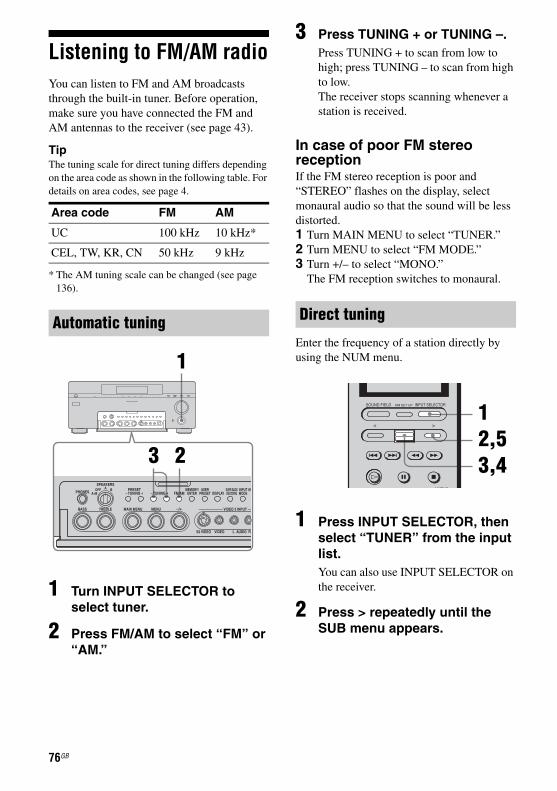
E:\STR-DA7100ES\2320745143\2320745143STRDA7100ESUC\01GB-STRDA7100ESUC\050AMP.fm
masterpage: Left
Listening to FM/AM radioYou can listen to FM and AM broadcasts through the built-in tuner. Before operation, make sure you have connected the FM and AM antennas to the receiver (see page 43).
TipThe tuning scale for direct tuning differs depending on the area code as shown in the following table. For details on area codes, see page 4.
* The AM tuning scale can be changed (see page 136).
1 Turn INPUT SELECTOR to select tuner.
2 Press FM/AM to select “FM” or “AM.”
3 Press TUNING + or TUNING –.Press TUNING + to scan from low to high; press TUNING – to scan from high to low.The receiver stops scanning whenever a station is received.
In case of poor FM stereo receptionIf the FM stereo reception is poor and “STEREO” flashes on the display, select monaural audio so that the sound will be less distorted.1 Turn MAIN MENU to select “TUNER.”2 Turn MENU to select “FM MODE.”3 Turn +/– to select “MONO.”
The FM reception switches to monaural.
Enter the frequency of a station directly by using the NUM menu.
1 Press INPUT SELECTOR, then select “TUNER” from the input list.You can also use INPUT SELECTOR on the receiver.
2 Press > repeatedly until the SUB menu appears.
Area code FM AM
UC 100 kHz 10 kHz*
CEL, TW, KR, CN 50 kHz 9 kHz
Automatic tuning
23
1
Direct tuning
12,53,4
76GB
STR-DA7100ES2-320-745-14 (3)

E:\STR-DA7100ES\2320745143\2320745143STRDA7100ESUC\01GB-STRDA7100ESUC\050AMP.fm
masterpage: Right
Am
plifier O
peratio
n
3 Move the easy scroll key toselect “FM/AM,” then select FM or AM by pressing the key.Each time you press the easy scroll key, the band switches to FM or AM.You can also use FM/AM on the receiver.
4 Move the easy scroll key to select “DIRECT TUNING” from the SUB menu, then press the key.“0” flashes on the display window.
5 Press > on the remote repeatedly until the NUM menu appears, then select the numbers for the frequency, then press the key.Example 1: FM 102.50 MHzSelect 1 b 0 b 2 b 5 b 0(You do not have to enter the last “0” when the tuning scale is set to 100 kHz.)Example 2: AM 1,350 kHzSelect 1 b 3 b 5 b 0(You do not have to enter the last “0” when the tuning scale is set to 10 kHz.)If you have tuned in an AM station, adjust the direction of the AM loop antenna for optimum reception.
If you cannot tune in a station and the entered numbers flashMake sure you have entered the right frequency. If not, repeat step 4. If the entered numbers still flash, the frequency is not used in your area.
Storing FM stations automatically(AUTOBETICAL)
(Models of area code CEL only)This function lets you store up to 30 FM and FM RDS stations in alphabetical order without redundancy. Additionally, it only stores the stations with the clearest signals. If you want to store FM or AM stations one by one, see “Presetting radio stations.”
1 Press ?/1 to turn off the receiver.
MEMORY/ENTER
1,2
continued
77GBSTR-DA7100ES2-320-745-14 (3)

E:\STR-DA7100ES\2320745143\2320745143STRDA7100ESUC\01GB-STRDA7100ESUC\050AMP.fm
masterpage: Left
2 Hold down MEMORY/ENTER and press ?/1 to turn the receiver back on. “Autobetical select” appears on the display and the receiver scans and stores all the FM and FM RDS stations in the broadcast area. For RDS stations, the tuner first checks for stations broadcasting the same program, then stores only the ones with the clearest signal. The selected RDS stations are sorted alphabetically by their Program Service name, then assigned a 2-character preset code. For more details on RDS, see page 80.Regular FM stations are assigned 2-character preset codes and stored after the RDS stations.When this process is finished, “Autobetical finished” appears on the display momentarily and the receiver returns to normal operation.
Notes• Do not press any button on the receiver or supplied
remote during autobetical operation, except ?/1.• If you move to another area, repeat this procedure
to store stations in your new area.• For details on tuning the stored stations, see
“Tuning to preset stations” on page 79. • If you move the antenna after storing stations with
this procedure, the stored settings may no longer be valid. If this happens, repeat this procedure to store the stations again.
Presetting radio stationsYou can preset up to 30 FM or AM stations. Then you can easily tune in the stations you often listen to.
1 Turn INPUT SELECTOR to select tuner.
2 Press FM/AM to select “FM” or “AM.”
3 Tune in the station that you want to preset using Automatic Tuning (page 76) or Direct Tuning (page 76).Switch the FM reception mode, if necessary (page 76).
4 Press MEMORY/ENTER.“MEMORY” appears on the display for a few seconds. Perform steps 5 and 6 before the display goes out.
Presetting radio stations
1
25 4,6
78GB
STR-DA7100ES2-320-745-14 (3)

E:\STR-DA7100ES\2320745143\2320745143STRDA7100ESUC\01GB-STRDA7100ESUC\050AMP.fm
masterpage: Right
Am
plifier O
peratio
n
5 Press PRESET TUNING + orPRESET TUNING – to select a preset number.If you want to switch the memory page, press SHIFT on the remote.If “MEMORY” goes out before you select the preset number, start again from step 4.
6 Press MEMORY/ENTER again.The station is stored as the selected preset number. If “MEMORY” goes out before you press MEMORY/ENTER, start again from step 4.
7 Repeat steps 2 to 6 to preset another station.
1 Turn INPUT SELECTOR to select tuner.
2 Press PRESET TUNING +/– repeatedly to select the preset station you want.Each time you press the button, you can select a preset station as follows:
Using the remote1 Press INPUT SELECTOR, then move the
easy scroll key to select “TUNER” from the input list.
2 Move the easy scroll key to select the preset number you want, then press the key to enter the selection.
1 Press INPUT SELECTOR, then select “TUNER” from the input list.You can also use INPUT SELECTOR on the receiver.
Tuning to preset stations
1
2
Naming preset stations
tA1yA2y...yA0yB1yB2y...yB0T
tC0y...yC2yC1T
12
4
5,6
3
continued
79GBSTR-DA7100ES2-320-745-14 (3)

E:\STR-DA7100ES\2320745143\2320745143STRDA7100ESUC\01GB-STRDA7100ESUC\050AMP.fm
masterpage: Left
2 Press > repeatedly until the SUB menu appears.
3 Move the easy scroll key to select “PRESET +” or “PRESET –,” then press the key repeatedly to tune in the preset station you want to create an index name for (page 76).
4 Press MAIN MENU repeatedly to select “TUNER,” then press the control key.You can also use MAIN MENU on the receiver.
5 Move the control key V/v to select “NAME IN.”You can also use MENU on the receiver.
6 Press the control key.You can also use MEMORY/ENTER on the receiver.The cursor flashes and you can select a character. Follow the procedure given in “To create an index name” (page 61).
Using the Radio Data System (RDS)(Models of area code CEL only)This receiver also allows you to use RDS (Radio Data System), which enables radio stations to send additional information along with the regular program signal. You can display RDS information.
Simply select a station on the FM band using direct tuning (page 76), automatic tuning (page 76), or preset tuning (page 78).When you tune in a station that provides RDS services, the RDS indicator lights up and the program service name appears on the display.
NoteRDS may not work properly if the station you tuned to is not transmitting the RDS signal properly or if the signal strength is weak.
While receiving an RDS station, press DISPLAY. Each time you press the button, RDS information on the display changes cyclically as follows:
Top levelOne of the followings items, as well as band, and preset number are displayed:• PS (Program Service name)a)
• Present station nameb)
• Frequency
Lower levelPTY (Program Type) indicationc) t RT (Radio Text) indicationd) t CT (Time) indication (in 24-hour system mode) t Sound field currently applied
Receiving RDS broadcasts
Displaying RDS information
80GB
STR-DA7100ES2-320-745-14 (3)

E:\STR-DA7100ES\2320745143\2320745143STRDA7100ESUC\01GB-STRDA7100ESUC\050AMP.fm
masterpage: Right
Am
plifier O
peratio
n
a)This information also appears for non-RDS FMstations.b)Appears only when the preset station is indexed.c)Type of program being broadcast.d)Text messages sent by the RDS station.
Notes• If there is an emergency announcement by
government authorities, “Alarm-Alarm!” flashes in the display.
• If a station does not provide a particular RDS service, “No XX” (such as “No Clock Time”) appears on the display.
• When a station broadcasts radio text data, it is displayed at the same rate at which it is sent from the station. Any change in this rate is reflected in the display rate of the data.
Description of program types
Program type indication
Description
News News programs
Current Affairs Topical programs that expand on current news
Information Programs offering information on a wide spectrum of subjects, including consumer affairs and medical advice
Sport Sports programs
Education Educational programs, such as “how-to” and advice programs
Drama Radio plays and serials
Cultures Programs about national or regional culture, such as language and social concerns
Science Programs about the natural sciences and technology
Varied Speech Other types of programs such as celebrity interviews, panel games, and comedy
Pop Music Popular music programs
Rock Music Rock music programs
M.o.R. Music Easy Listening
Light Classics M Instrumental, vocal, and choral music
Serious Classics Performances of major orchestras, chamber music, opera, etc.
Other Music Music that does not fit into any categories above, such as Rhythm & Blues and Reggae
Wether & Metr Weather information
Finance Stock market reports and trading, etc.
Children’s Progs Programs for children
Social Affairs Programs about people and the things that affect them
Religion Programs of religious content
Phone In Programs where members of the public express their views by phone or in a public forum
Travel & Touring Programs about travel. Not for announcements that are located by TP/TA.
Leisure & Hobby
Programs on recreational activities such as gardening, fishing, cooking, etc.
Jazz Music Jazz programs
Country Music Country music programs
National Music Programs featuring the popular music of the country or region
Oldies Music Programs featuring oldies music
Folk Music Folk music programs
Documentary Investigative features
None Any programs not defined above
Program type indication
Description
81GB
STR-DA7100ES2-320-745-14 (3)

E:\STR-DA7100ES\2320745143\2320745143STRDA7100ESUC\01GB-STRDA7100ESUC\050AMP.fm
masterpage: Left
Custom install modeThis receiver features the custom install modes described below. Depending on how you intend to use these features, use of these modes may require additional equipment (available separately) or modification of your listening environment. Please consult the retailer where you purchased this receiver for more information.
1 Press MAIN MENU repeatedly to select “CIS,” then press the control key.You can also use MAIN MENU on the receiver.
2 Move the control key V/v to select the menu item.You can also use MENU on the receiver.For details, see “CIS menu item and parameters.”
3 Move the control key B/b to select the parameter you want.You can also use +/– on the receiver.
4 Repeat steps 2 and 3 to adjust other items.
CIS menu item and parametersInitial settings are underlined.
x 2ND ZONE (2nd zone source)
x 3RD ZONE (3rd zone source)Lets you select the source signals (analog audio and video signals for 2nd zone; only analog audio signals for 3rd zone) you want to output in the 2nd zone or 3rd zone (except PHONO, MULTI CHANNEL INPUT, i.LINK and HDMI). When you select “SOURCE,” the signals of the current input are output.
Notes• Connect video signals to 2ND ZONE using the
VIDEO jack.• Connect audio signals to 2ND ZONE or 3RD
ZONE using the AUDIO L/R jack.
Tips• Only signals from components connected to the
analog input jacks are output through the 2ND ZONE or 3RD ZONE jacks. No signal is output from components connected to only the digital input jacks.
• When “SOURCE” is selected, the signals input to the MULTI CHANNEL INPUT jacks are not output from the 2ND ZONE or 3RD ZONE jacks even when the MULTI CH IN function is used. The 2 channel analog audio signals of the current input are output.
x INSTALLER MODE (RS232C control)
• ONThe receiver can receive commands from the RS232C port even when the power is off (standby mode).
• OFFThe receiver does not receive commands from the RS232C port when the power is off (standby mode).
x 12V TRIG. MAIN (12 V trigger for the main receiver)
x 12V TRIG. 2ND (12 V trigger for the 2nd zone)
1,2,3
1
82GB
STR-DA7100ES2-320-745-14 (3)

E:\STR-DA7100ES\2320745143\2320745143STRDA7100ESUC\01GB-STRDA7100ESUC\050AMP.fm
masterpage: Right
Am
plifier O
peratio
n
x 12V TRIG. 3RD (12 V trigger forthe 3rd zone)Lets you turn the external equipment on or off by outputting 12V triggers when the receiver is turned on or off. For example, you can automatically unroll your video screen when you turn on the receiver.• OFF
Lets you turn off output of 12V triggers even when the main receiver is turned on.
• CTRLLets you turn the output of 12V triggers on or off manually using the CIS command of the IR remote or RS232C control.
• ZONELets you turn on output of 12V triggers when the main receiver or the receiver in each zone is turned on.
• INPUT (for “12V TRIG. MAIN” only)Lets you turn on output of 12V triggers when the main receiver is turned on, depending on the setting of each input. See “To set the 12V trigger setting for each input.”
• MAIN (for “12V TRIG. 2ND” and “12V TRIG. 3RD” only)Lets you link 2nd or 3rd zone trigger operation to the main receiver.
To set the 12V trigger setting for each inputThe initial setting of TAPE, MD/DAT, SA-CD/CD, TUNER, PHONO and i.LINK is “OFF.”The initial setting of VIDEO 1-3, DVD, TV/SAT, and HDMI 1 and 2 is “ON.”1 Select “INPUT” in “12V TRIG. MAIN.”2 Press MEMORY/ENTER.3 Turn MENU to select the input.4 Turn +/– to select “ON” to activate the 12V
trigger or select “OFF” to deactivate it.5 Press MEMORY/ENTER.
83GB
STR-DA7100ES2-320-745-14 (3)

E:\STR-DA7100ES\2320745143\2320745143STRDA7100ESUC\01GB-STRDA7100ESUC\050AMP.fm
masterpage: Left
Listening to the sound in another zone (2nd (3rd) zone operations)You can enjoy images and sounds from a component connected to the receiver in a room (2nd (3rd) zone) other than the main room. For example, you can listen to the CD in the main room and watch the DVD in the 2nd zone.
When using an IR repeater (not supplied), you can also operate both a component in main room and Sony receiver in the 2nd (or 3rd) zone from the 2nd (or 3rd) zone.Use the RM-US106A remote for the operation.
• Switching the output source for the 2ND (or 3RD) ZONE OUT jacks.
• Switching the Sony receiver’s power on or off in the 2nd (or 3rd) zone.
• Adjusting the volume of the Sony receiver in the 2nd (or 3rd) zone.
1:2nd zone connections
1 2ND ZONE VIDEO/AUDIO OUT jack
Main room 2nd zone
VIDEO OUT
TVmonitor
A
AUDIO OUT
B
C
E E
D
RM-US106A
STR-DA7100ES
C
AAudio componentBVideo componentC IR repeater (not supplied)DSony’s Amplifier/ReceiverESpeaker
84GB
STR-DA7100ES2-320-745-14 (3)

E:\STR-DA7100ES\2320745143\2320745143STRDA7100ESUC\01GB-STRDA7100ESUC\050AMP.fm
masterpage: Right
Am
plifier O
peratio
n
2 SURROUND BACK SPEAKERS/2ND ZONE jacks2:3rd zone connections
Main room 2nd zone
TVmonitor
A
VIDEO OUT
B
D
STR-DA7100ES
D
SURROUND BACK SPEAKERS
AAudio componentBVideo componentC IR repeater (not supplied)DSpeaker
RM-US106AC
A
AUDIO OUT
B
C
E E
D
RM-US106A
STR-DA7100ES
C
Main room 3rd zone
AAudio componentBVideo componentC IR repeater (not supplied)DSony’s Amplifier/ReceiverESpeaker
continued
85GBSTR-DA7100ES2-320-745-14 (3)

E:\STR-DA7100ES\2320745143\2320745143STRDA7100ESUC\01GB-STRDA7100ESUC\050AMP.fm
masterpage: Left
The following operations are described for connecting an IR repeater and operating the receiver in 2nd zone or 3rd zone. When an IR repeater is not connected, use this receiver in the main room.
1 On the remote, press 2ND ZONE or 3RD ZONE.The remote switches to the 2nd zone or 3rd zone mode.
2 Turn on the main receiver (this receiver).
3 Turn on the amplifier in the 2nd or 3rd zone.
4 Press one of the input buttons on the remote to select the source signals you want to output.For the 2nd zone, analog video and audio signals are output. For the 3rd zone, only analog audio signals are output. When you select “SOURCE,” the signals of the current input are output. Refer to page 82 for details.
5 Adjust to a suitable volume.• In the case of illustration 1-1 or 2 (page
84, 85), adjust the volume using the receiver of the 2nd/3rd zone.
• In the case of illustration 1-2 (page 85), you can only adjust the surround back speaker volume in 2ND ZONE.
1 Set to “2ND ZONE” on the SURR BACK SP setting (page 49).
2 Adjust the volume using MASTER VOL+/– on the remote.
The initial setting of the volume is –∞ dB (no sound output).
Example of controlling an amplifier in the 2nd room
Tips• Even when this receiver is turned off, the receiver
in the 2nd zone or 3rd zone remains turned on. To turn off all receivers, press ?/1 and AV ?/1 on the RM-AAE003 remote at the same time (SYSTEM STANDBY).
• Only signals from components connected to the analog input jacks are output through the 2ND ZONE OUT or 3RD ZONE OUT jacks. No signals are output from components connected to only the digital input jacks.
• When “SOURCE” is selected, the signals input to the MULTI CH IN jacks are not output from the 2ND ZONE OUT or 3RD ZONE OUT jacks even when MULTI CH IN is selected. The analog audio signals of the current function are output.
To operate with RM-AAE003
1 Press RM SET UP.The set up list appears.
2 Select “COMMAND MODE” by moving and pressing the easy scroll key.
3 Select “2ND ZONE” (or “3RD ZONE”) by moving and pressing the easy scroll key.
To Do the following
Turn the power on or off Press ?/1.
Listen to the sound of the CD player connected to the CD input jacks
Press SA-CD/CD, then press H.
Adjust the volume Press MASTER VOL +/–.
86GB
STR-DA7100ES2-320-745-14 (3)
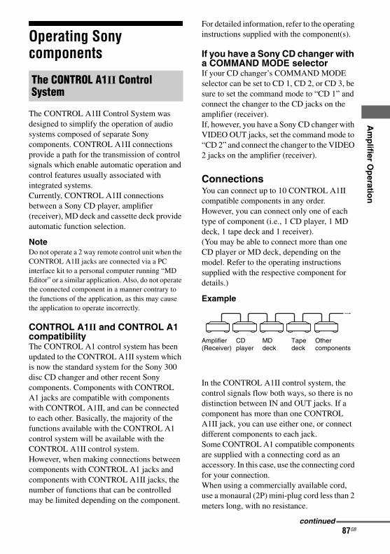
E:\STR-DA7100ES\2320745143\2320745143STRDA7100ESUC\01GB-STRDA7100ESUC\050AMP.fm
masterpage: Right
Am
plifier O
peratio
n
Operating Sony components
The CONTROL A1II Control System was designed to simplify the operation of audio systems composed of separate Sony components. CONTROL A1II connections provide a path for the transmission of control signals which enable automatic operation and control features usually associated with integrated systems.Currently, CONTROL A1II connections between a Sony CD player, amplifier (receiver), MD deck and cassette deck provide automatic function selection.
NoteDo not operate a 2 way remote control unit when the CONTROL A1II jacks are connected via a PC interface kit to a personal computer running “MD Editor” or a similar application. Also, do not operate the connected component in a manner contrary to the functions of the application, as this may cause the application to operate incorrectly.
CONTROL A1II and CONTROL A1 compatibilityThe CONTROL A1 control system has been updated to the CONTROL A1II system which is now the standard system for the Sony 300 disc CD changer and other recent Sony components. Components with CONTROL A1 jacks are compatible with components with CONTROL A1II, and can be connected to each other. Basically, the majority of the functions available with the CONTROL A1 control system will be available with the CONTROL A1II control system.However, when making connections between components with CONTROL A1 jacks and components with CONTROL A1II jacks, the number of functions that can be controlled may be limited depending on the component.
For detailed information, refer to the operating instructions supplied with the component(s).
If you have a Sony CD changer with a COMMAND MODE selectorIf your CD changer’s COMMAND MODE selector can be set to CD 1, CD 2, or CD 3, be sure to set the command mode to “CD 1” and connect the changer to the CD jacks on the amplifier (receiver).If, however, you have a Sony CD changer with VIDEO OUT jacks, set the command mode to “CD 2” and connect the changer to the VIDEO 2 jacks on the amplifier (receiver).
ConnectionsYou can connect up to 10 CONTROL A1II compatible components in any order. However, you can connect only one of each type of component (i.e., 1 CD player, 1 MD deck, 1 tape deck and 1 receiver).(You may be able to connect more than one CD player or MD deck, depending on the model. Refer to the operating instructions supplied with the respective component for details.)
Example
In the CONTROL A1II control system, the control signals flow both ways, so there is no distinction between IN and OUT jacks. If a component has more than one CONTROL A1II jack, you can use either one, or connect different components to each jack.Some CONTROL A1 compatible components are supplied with a connecting cord as an accessory. In this case, use the connecting cord for your connection.When using a commercially available cord, use a monaural (2P) mini-plug cord less than 2 meters long, with no resistance.
The CONTROL A1II Control System
CD player
MD deck
Tape deck
Other components
Amplifier (Receiver)
continued
87GBSTR-DA7100ES2-320-745-14 (3)
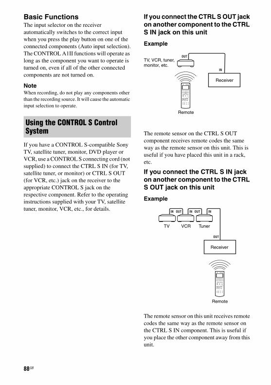
E:\STR-DA7100ES\2320745143\2320745143STRDA7100ESUC\01GB-STRDA7100ESUC\050AMP.fm
masterpage: Left
Basic FunctionsThe input selector on the receiver automatically switches to the correct input when you press the play button on one of the connected components (Auto input selection).The CONTROL A1II functions will operate as long as the component you want to operate is turned on, even if all of the other connected components are not turned on.
NoteWhen recording, do not play any components other than the recording source. It will cause the automatic input selection to operate.
If you have a CONTROL S-compatible Sony TV, satellite tuner, monitor, DVD player or VCR, use a CONTROL S connecting cord (not supplied) to connect the CTRL S IN (for TV, satellite tuner, or monitor) or CTRL S OUT (for VCR, etc.) jack on the receiver to the appropriate CONTROL S jack on the respective component. Refer to the operating instructions supplied with your TV, satellite tuner, monitor, VCR, etc., for details.
If you connect the CTRL S OUT jack on another component to the CTRL S IN jack on this unit
Example
The remote sensor on the CTRL S OUT component receives remote codes the same way as the remote sensor on this unit. This is useful if you have placed this unit in a rack, etc.
If you connect the CTRL S IN jack on another component to the CTRL S OUT jack on this unit
Example
The remote sensor on this unit receives remote codes the same way as the remote sensor on the CTRL S IN component. This is useful if you place the other component away from this unit.
Using the CONTROL S Control System
OUT
IN
+
–
+
–
+
–O
I i
H X x
. > m M
TV, VCR, tuner, monitor, etc.
Receiver
Remote
IN ININOUT OUT
OUT
+
–
+
–
+
–O
I i
H X x
. > m M
Receiver
TV VCR Tuner
Remote
88GB
STR-DA7100ES2-320-745-14 (3)

E:\STR-DA7100ES\2320745143\2320745143STRDA7100ESUC\01GB-STRDA7100ESUC\060SUR.fm
masterpage: Right
En
joying
Su
rrou
nd
So
un
d
Using only the front speakers(2CH STEREO)
In this mode, the receiver outputs the sound from the front L/R speakers only. There is no sound from the sub woofer. Standard 2 channel stereo sources completely bypass the sound field processing and multi channel surround formats are downmixed to 2 channel.
1 Press SOUND FIELD.The sound field list appears.
2 Move the easy scroll key to select “2CH STEREO,” then press the key to enter the selection.You can also use 2CH on the receiver.
NoteNo sound is output from the sub woofer in the 2CH STEREO mode. To listen to 2 channel stereo sources using the front L/R speakers and a sub woofer, select “A.F.D. AUTO” and set “A.F.D. 2CH SW” on the SURR SET UP menu to “CREATE” (page 99).This receiver will generate a low frequency signal for output to the sub woofer when there is no L.F.E. signal, which is a low-pass sound effect output from a sub woofer to a 2 channel signal.
Detecting the type of audio signal automatically(AUTO FORMAT DIRECT)
The Auto Format Direct (A.F.D.) mode allows you to listen to higher fidelity sound and select the decoding mode for listening to a 2 channel stereo sound as multi channel sound.
In this mode, the receiver automatically detects the type of audio signal being input (Dolby Digital, DTS, standard 2 channel stereo, etc.) and performs the proper decoding, if necessary.This mode presents the sound as it was recorded/encoded, without adding any surround effects.We usually recommend AUTO, however sometimes it may be better to use SURR BACK DECODING (page 95) to match the input stream to the mode you prefer.
1 Press SOUND FIELD.The sound field list appears.
2 Move the easy scroll key to select “A.F.D. AUTO,” then press the key to enter the selection.You can also use A.F.D. on the receiver.
Enjoying Surround Sound
12
Enjoying higher fidelity sound
12
89GB
STR-DA7100ES2-320-745-14 (3)

E:\STR-DA7100ES\2320745143\2320745143STRDA7100ESUC\01GB-STRDA7100ESUC\060SUR.fm
masterpage: Left
This mode lets you specify the type of decoding for 2 channel audio sources.
1 Press SOUND FIELD.The sound field list appears.
2 Move the easy scroll key to select an A.F.D. mode, then press the key to enter the selection.You can also use A.F.D. on the receiver.
Enjoying stereo sound in multi channel
12
90GB
STR-DA7100ES2-320-745-14 (3)

E:\STR-DA7100ES\2320745143\2320745143STRDA7100ESUC\01GB-STRDA7100ESUC\060SUR.fm
masterpage: Right
En
joying
Su
rrou
nd
So
un
d
Type of A.F.D. modeDecoding mode
A.F.D. mode[Display]
Multi channel audio after decoding
Effect
(Detecting automatically)
A.F.D. AUTO[AUTO]
(Detecting automatically)
(Detecting automatically)
Dolby PRO LOGIC
A.F.D. PRO LOGIC[PRO LOGIC]
4 channel Performs Dolby Pro Logic decoding. The source recorded in 2 channel format is decoded into 4.1 channels.
Dolby Pro Logic II
A.F.D. PRO LOGIC II MOVIE[PRO LOGIC II MOVIE]
5 channel Performs Dolby Pro Logic II Movie mode decoding. This setting is ideal for movies encoded in Dolby Surround. In Addition, this mode can reproduce sound in 5.1 channel for watching videos of overdubbed or old movies.
A.F.D. PRO LOGIC II MUSIC[PRO LOGIC II MUSIC]
5 channel Performs Dolby Pro Logic II Music mode decoding. This setting is ideal for normal stereo sources such as CDs.
A.F.D. PRO LOGIC II GAME[PRO LOGIC II GAME]
5 channel Performs Dolby Pro Logic II Game mode decoding.
Dolby Pro Logic IIx
A.F.D. PRO LOGIC IIx MOVIE[PRO LOGIC IIx MOVIE]
7 channel Performs Dolby Pro Logic IIx Movie mode decoding. This setting is ideal for movies encoded in Dolby Surround. In addition, this mode can reproduce sound in 7.1 channel for watching videos of overdubbed or old movies.
A.F.D. PRO LOGIC IIx MUSIC[PRO LOGIC IIx MUSIC]
7 channel Performs Dolby Pro Logic IIx Music mode decoding. This setting is ideal for normal stereo sources such as CDs.
A.F.D. PRO LOGIC IIx GAME[PRO LOGIC IIx GAME]
7 channel Performs Dolby Pro Logic IIx Game mode decoding.
Neo:6 Cinema A.F.D. Neo:6 Cinema[Neo:6 Cinema]
6 channel Performs DTS Neo:6 Cinema mode decoding.
A.F.D. Neo:6 Music[Neo:6 Music]
6 channel Performs DTS Neo:6 Music mode decoding. This setting is ideal for normal stereo sources such as CDs.
(Multi Stereo) A.F.D. MULTI STEREO[MULTI STEREO]
(Multi Stereo) Outputs 2 channel L/R signals from all speakers.
continued
91GBSTR-DA7100ES2-320-745-14 (3)

E:\STR-DA7100ES\2320745143\2320745143STRDA7100ESUC\01GB-STRDA7100ESUC\060SUR.fm
masterpage: Left
If you connect a sub wooferThis receiver will generate a low frequency signal for output to the sub woofer when there is no L.F.E. signal, which is a low-pass sound effect output from a sub woofer to a 2 channel signal. However the low frequency signal is not generated for “Neo:6 Cinema” or “Neo:6 Music” when all speakers are set to “LARGE.”
Notes• This function does not work in the following cases.
– MULTI CH IN is selected– The DSD signal is received via i.LINK
• DTS Neo:6 does not work for DTS 2CH audio, the sound is played as 2 channel.
• If you set up the sound field during DTS 96/24 signal reception, it will play back only at 48kHz.
TipOnly Dolby prologic IIx decoding is effective, when a multi channel signal is input.At this time, the setup of SB DECODING/SB DEC MODE in CUSTOMIZE menu becomes invalid. When you select decoding modes other than Dolby prologic IIx, multi channel sound (being encoded) is output.
Selecting a sound fieldYou can take advantage of surround sound simply by selecting one of the receiver’s preprogrammed sound fields. They bring the exciting and powerful sound of movie theaters and concert halls into your home.
Press MOVIE repeatedly to select the sound field you want.The sound field list appears.
Types of sound field available
x CINEMA STUDIO EX A DCSReproduces the sound characteristics of the Sony Pictures Entertainment “Cary Grant Theater” cinema production studio. This is a standard mode, great for watching almost any type of movie.
x CINEMA STUDIO EX B DCSReproduces the sound characteristics of the Sony Pictures Entertainment “Kim Novak Theater” cinema production studio. This mode is ideal for watching science-fiction or action movies with lots of sound effects.
x CINEMA STUDIO EX C DCSReproduces the sound characteristics of the Sony Pictures Entertainment scoring stage. This mode is ideal for watching musicals or
Selecting a sound field for movies
MOVIE
92GB
STR-DA7100ES2-320-745-14 (3)

E:\STR-DA7100ES\2320745143\2320745143STRDA7100ESUC\01GB-STRDA7100ESUC\060SUR.fm
masterpage: Right
En
joying
Su
rrou
nd
So
un
d
films where orchestra music is featured in the soundtrack.x V.MULTI DIMENSION DCSCreates 5 sets of virtual speakers from a single pair of actual surround speakers.
Notes• This function does not work in following cases.
– MULTI CH IN is selected– The DSD signal is received via i.LINK– The sampling frequency has received the signal
at a frequency higher than 48kHz.• If you set up the sound field during DTS 96/24
signal reception, it will play back only at 48kHz.• The effects provided by the virtual speakers may
cause increased noise in the playback signal.• When listening with sound fields that employ the
virtual speakers, you will not be able to hear any sound coming directly from the surround speakers.
TipYou can identify the encoding format of DVD software, etc., by looking at the logo on the package.• : Dolby Digital discs• : Dolby Surround
encoded programs• : DTS Digital Surround encoded programs• Sound fields with DCS marks use DCS
technology. See “Technical terms” on page 128.• When the sound field’s DCS mark is selected,
the Digital Cinema Sound lamp lights up.
Press MUSIC repeatedly to select the sound field you want.The sound field list appears.
Types of sound field available
x D.CONCERT HALL AUses 3D sound imaging to reproduce the sound characteristics of a concert hall, which simulates a large sound stage produced by reflectivity.
x D.CONCERT HALL BUses 3D sound imaging to reproduce the sound characteristics of a concert hall, which simulates resonant and unique reverberative sound.
x CHURCHReproduces the acoustics of a stone church.
x JAZZ CLUBReproduces the acoustics of a jazz club.
x LIVE CONCERTReproduces the acoustics of a 300-seat live house.
x STADIUMReproduces the feeling of a large open-air stadium.
x SPORTSReproduces the feeling of sports broadcasting.
NoteThe surround back decoding mode does not function while a sound field for music is selected (page 95).
Sound fields when headphones are connectedYou can select only from the following sound fields.
x HEADPHONE THEATER DCSThis mode is selected automatically when you use headphone when sound field is selected for movie/music. It allows you to experience a theater-like environment while listening through a pair of headphones.
Selecting a sound field for music
MUSIC
continued
93GBSTR-DA7100ES2-320-745-14 (3)

E:\STR-DA7100ES\2320745143\2320745143STRDA7100ESUC\01GB-STRDA7100ESUC\060SUR.fm
masterpage: Left
x HEADPHONE (2CH)This mode is selected automatically when you use headphones when 2 channels mode (page 89)/A.F.D. mode (page 91) is selected. Standard 2 channel stereo sources completely bypass the sound field processing and multi channel surround formats are downmixed to 2 channels.
x HEADPHONE (MULTI)This mode is selected automatically when you use headphones during MULTI CH IN is selected. Outputs the analog signals input to the MULTI CHANNEL INPUT jacks that are downmixed to 2 channels.
NoteHeadphone (2ch) mode is selected when the sound field does not work.• The DSD signal is received via i.LINK.• The sampling frequency has received a signal
higher than 48kHz.
To turn off the surround effect for MOVIE/MUSICMove the easy scroll key to select either “A.F.D. AUTO” or “2CH STEREO” in the sound field list on the display.
This function allows you to retain a theater like environment at low volume levels. This function can be used with other sound fields.When watching a movie late at night, you will be able to hear the dialog clearly even at a low volume level.
1 Press < repeatedly to select the RECEIVER menu.
2 Move the easy scroll key to select “NIGHT MODE,” then press the key to enter the selection.The NIGHT MODE function is activated.Repeat steps 1 and 2 when NIGHT MODE is set to OFF.
TipWhile this function is on, the BASS, TREBLE, and EFFECT levels increase, and “D.RANGE COMP.” is automatically set to “MAX” (page 101).
Enjoying the surround effect at low volume levels (NIGHT MODE)
1 2
94GB
STR-DA7100ES2-320-745-14 (3)

E:\STR-DA7100ES\2320745143\2320745143STRDA7100ESUC\01GB-STRDA7100ESUC\060SUR.fm
masterpage: Right
En
joying
Su
rrou
nd
So
un
d
Using the surround back decoding mode(SURR BACK DECODING)
By decoding the surround back signal of DVD software (etc.) recorded in Dolby Digital Surround EX, DTS-ES Matrix, DTS-ES Discrete 6.1, etc., format, you can enjoy the surround sound intended by the filmmakers.
Press SURR BACK DECODING repeatedly to select the surround back decoding mode.The SB DEC lamp lights up when the surround back signal is being decoded.
TipYou can select the surround back decoding mode using “SB DECODING” on the CUSTOMIZE menu (page 67).
Types of the surround back decoding functions
x “AUTO”When the input stream contains the 6.1 channel decode flaga), the appropriate decoding is performed on the surround back signal.
x ONThe SB DEC MODE setting is applied to 5.1 channel and 6.1 channel decoding in the input stream (page 96).
x OFFSurround back decoding is not performed.
a)A 6.1 channel decode flag is information recorded in software like DVDs.
b)A Dolby Digital DVD that includes a Surround EX flag. The Dolby Corporation web page can help you distinguish Surround EX films.
c)Software encoded with a flag to denote it has both DTS-ES Matrix and 5.1 channel signals.
d)Software encoded with both 5.1 channel signals and an extension stream designed for returning those signals to 6.1 discrete channels. Discrete 6.1 channel signals are DVD specific signals not used in movie theaters.
e)When two surround back speakers are connected, the output channel will be 7.1 channel.
SURR BACK DECODING
Input stream Output channel
Surround back decoding
Dolby Digital 5.1
5.1e) —
Dolby Digital Surround EXb)
6.1e) Decoding for the decoding mode set up by SB DEC MODE (page 96)
DTS 5.1 5.1e) —
DTS-ESMatrix 6.1c)
6.1e) DTS Matrix decoding
DTS-ES Discrete 6.1d)
6.1e) DTS Discrete decoding
continued
95GBSTR-DA7100ES2-320-745-14 (3)
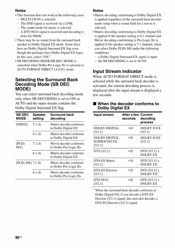
E:\STR-DA7100ES\2320745143\2320745143STRDA7100ESUC\01GB-STRDA7100ESUC\060SUR.fm
masterpage: Left
Notes• This function does not work in the following cases.
– MULTI CH IN is selected– The DSD signal is received via i.LINK – The sound mode for music is selected– A DTS 96/24 signal is received and decoding is
done for 96kHz• There may be no sound from the surround back
speaker in Dolby Digital EX mode. Some discs have no Dolby Digital Surround EX flag even though the packages have Dolby Digital EX logos. In this case, select “ON.”
• SB DECODING MODE/SB DEC MODE is cancelled when Dolby Pro Logic IIx is selected in AUTO FORMAT DIRECT (A.F.D.) mode.
Selecting the Surround Back Decoding Mode (SB DEC MODE)You can select surround back decoding mode only when SB DECODING is set to ON or AUTO and the input stream contains the Dolby Digital Surround EX flag.
Notes• Matrix decoding conforming to Dolby Digital EX
is applied regardless of the surround back decoder mode setup when a sound field for a movie is selected.
• Matrix decoding conforming to Dolby Digital EX is applied if the speaker setting is 6.1 channel and Movie decoding conforming to Pro Logic IIx is applied if the speaker setting is 7.1 channel, when you select Dolby PLIIx MS under the following conditions:– a Dolby Digital Surround EX signal is input– the SB DECODING is set to AUTO
Input Stream indicatorWhen AUTO FORMAT DIRECT mode is selected while the surround back decoder is activated, the current decoding process is displayed after the input stream is displayed a few seconds.
x When the decoder conforms to Dolby Digital EX
* When the surround back decoder conforms to Dolby Digital EX, if you decode a DTS-ES Discrete [3/3.1] signal, this unit also decodes a DTS-ES Discrete [3/2.1] signal.
SB DEC MODE
Speaker setting
Surround back decoding
[DDEX] 7.1 ch Matrix decoder conforms to Dolby Digital EX
6.1 ch Matrix decoder conforms to Dolby Digital EX
[PLIIx MV]
7.1 ch Movie decoder conforms to Dolby Pro Logic IIx
6.1 ch Matrix decoder conforms to Dolby Digital EX
[PLIIx MS] 7.1 ch Music decoder conforms to Dolby Pro Logic IIx
6.1 ch Music decoder conforms to Dolby Pro Logic IIx
Input stream After a few seconds
Current decoding process
DOLBY DIGITAL[3/2.1]
k DOLBY D EX[3/2.1]
DOLBY DIGITAL SURROUND EX[3/2.1]
k DOLBY D EX[3/2.1]
DTS [3/2.1] k DTS [3/2.1] + DOLBY EX
DTS-ES Matrix[3/2.1]
k DTS [3/2.1] + DOLBY EX
DTS-ES Discrete[3/3.1]
k DTS [3/2.1] + DOLBY EX*
DTS 96/24[3/2.1]
k DTS [3/2.1] + DOLBY EX
96GB
STR-DA7100ES2-320-745-14 (3)

E:\STR-DA7100ES\2320745143\2320745143STRDA7100ESUC\01GB-STRDA7100ESUC\060SUR.fm
masterpage: Right
En
joying
Su
rrou
nd
So
un
d
x When the current decoderconforms to Dolby Pro Logic IIx
**When the surround back decoder conforms to Dolby Pro Logic IIx, if you decode a DTS-ES Discrete [3/3.1] signal, this unit also decodes a DTS-ES Discrete [3/2.1] signal.
Customizing sound fields
The settings are stored individually for each sound field.
1 Start playing a source encoded with multi channel surround effects (DVD, etc.).
2 Press MAIN MENU repeatedly to select “SURR SET UP,” then press the control key.You can also use MAIN MENU on the receiver to select “SURR SET UP.”
3 Move the control key V/v to select the parameter you want, then press the key.You can also use MENU on the receiver.For details, see “SURR SET UP menu parameters,” below.
Input stream After a few seconds
Current decoding process
DOLBY DIGITAL[3/2.1]
k DOLBY D[3/2.1] + PLIIx
DOLBY DIGITAL SURROUND EX[3/2.1]
k DOLBY D[3/2.1] + PLIIx
DTS [3/2.1] k DTS [3/2.1] + PLIIx
DTS-ES Matrix[3/2.1]
k DTS [3/2.1] + PLIIx
DTS-ES Discrete[3/3.1]
k DTS [3/2.1] + PLIIx**
DTS 96/24[3/2.1]
k DTS [3/2.1] + PLIIx
Adjusting the sound effect
2,3,4
2
continued
97GBSTR-DA7100ES2-320-745-14 (3)

E:\STR-DA7100ES\2320745143\2320745143STRDA7100ESUC\01GB-STRDA7100ESUC\060SUR.fm
masterpage: Left
4 While monitoring the sound, adjust the selected parameter by moving the control key B/b.You can also use +/– to adjust the selected parameter.
5 Repeat steps 3 and 4 to adjust the other parameters.
Note The setup items you can adjust on each menu vary depending on the sound field. Certain setup parameters may be dimmed in the display.
SURR SET UP menu parameters
x EFFECT LEVEL _ _ _ % (Effect level)
Initial setting: 100%Higher settings apply more surround effect. You can adjust the level from 20 % to 120 % in 5 % steps.
Advanced SURR SET UP menu parametersUse the CUSTOMIZE menu and set “MENU EXPAND” to “ON” to enable display and setup as follows (page 67).
x C. WIDTH L_C_R (Center width control)
Initial setting: (3)Lets you perform further adjustments for Dolby Pro Logic II and IIx Music mode decoding. You can set this parameter only when A.F.D. mode is set to “PRO LOGIC II MUSIC” or “PRO LOGIC IIx MUSIC” (page 91).You can adjust the distribution of the center channel signal, generated through the Dolby Pro Logic II decoding, to the L/R speakers.
x DIMENSION F_ _S (Dimension control)
Initial setting: midpoint (0)Lets you perform further adjustments for Dolby Pro Logic II and IIx Music mode decoding. You can set this parameter only when A.F.D. mode is set to “PRO LOGIC II MUSIC” or “PRO LOGIC IIx MUSIC” (page 91).You can adjust the difference between the front channels and the surround channels.
x PANORAMA MODE (Panorama mode)
Lets you perform further adjustments for Dolby Pro Logic II and IIx Music mode decoding. You can set this parameter only when A.F.D. mode is set to “PRO LOGIC II MUSIC” or “PRO LOGIC IIx MUSIC” (page 91).• ONLets you enjoy surround sound by spreading the sound field of the front speakers to the left and right of the listening position (panorama mode).• OFFPanorama mode is not activated.
x SCREEN DEPTH (Screen depth)This parameter is provided especially for Cinema Studio EX modes (page 92).Lets you create the sensation that the sound of the front speakers comes from inside the screen in your listening room, just like in theatres.• ONLets you create the sensation that the sound comes from a very large screen with a great amount of screen depth.• OFFThis function is not activated.
98GB
STR-DA7100ES2-320-745-14 (3)

E:\STR-DA7100ES\2320745143\2320745143STRDA7100ESUC\01GB-STRDA7100ESUC\060SUR.fm
masterpage: Right
En
joying
Su
rrou
nd
So
un
d
x VIR.SPEAKERS (Virtualspeakers)This parameter is provided especially for Cinema Studio EX modes (page 92).• ONVirtual speakers are created.• OFFVirtual speakers are not created.
x A.F.D. 2CH SW (Creating, low frequency signals)
This parameter is only available when A.F.D. mode is set to “AUTO.”• CREATELets you create low frequency signals for output to the sub woofer when “A.F.D. AUTO” is selected.• OFFLow frequency signals are not created.
These settings are applied to all sound fields.
1 Start playing a source encoded with multi channel surround effects (DVD, etc.).
2 Press MAIN MENU repeatedly to select “LEVEL,” then press the control key.You can also use MAIN MENU on the receiver to select “LEVEL.”
3 Move the control key V/v to select the parameter you want.You can also use MENU on the receiver.For details, see “LEVEL menu parameters.”
4 While monitoring the sound, adjust the selected parameter by moving control key B/b.You can also use +/– to adjust the selected parameter.
5 Repeat steps 3 and 4 to adjust the other parameters.
LEVEL menu parameters
x TEST TONE (Test Tone)Initial setting: OFFLets you output the test tone sequentially from each speaker. When set to “AUTO,” the test tone is output from each speaker automatically. When set to “FIX,” you can select which speaker will output the test tone.
x FRONT L_ _R (Front speaker balance)
Initial setting: center (0)Lets you adjust the balance between front left and right speakers. You can adjust the balance from –8 dB to +8 dB in 0.5 dB steps.
x CENTER xxx.x dB (Center speaker level)
Initial setting: 0 dBYou can adjust the level from –20 dB to +10 dB in 0.5 dB steps.
Adjusting the level and balance of each speaker
2,3,4
2
continued
99GBSTR-DA7100ES2-320-745-14 (3)

E:\STR-DA7100ES\2320745143\2320745143STRDA7100ESUC\01GB-STRDA7100ESUC\060SUR.fm
masterpage: Left
x SURROUND L xxx.x dB (Surround speaker (L) level)
Initial setting: 0 dBYou can adjust the level from –20 dB to +10 dB in 0.5 dB steps.
x SURROUND R xxx.x dB (Surround speaker (R) level)
Initial setting: 0 dBYou can adjust the level from –20 dB to +10 dB in 0.5 dB steps.
x SURR BACK xxx.x dB (Surround back speaker level)*
Initial setting: 0 dBYou can adjust the level from –20 dB to +10 dB in 0.5 dB steps.
x SURR BACK L xxx.x dB (Surround back (L) level)**
Initial setting: 0 dBYou can adjust the level from –20 dB to +10 dB in 0.5 dB steps.
x SURR BACK R xxx.x dB (Surround back (R) level)**
Initial setting: 0 dBYou can adjust the level from –20 dB to +10 dB in 0.5 dB steps.
x SUB WOOFER xxx.x dBInitial setting: 0 dBYou can adjust the level from –20 dB to +10 dB in 0.5 dB steps.
x MULTI CH SW xxx dB (Multi channel sub woofer level)
Initial setting: 0 dBLets you increase the level of the MULTI CHANNEL INPUT sub woofer channel by +10 dB. This adjustment may be necessary when connecting a DVD player to the MULTICHANNEL INPUT jacks. The sub woofer level from DVD players is 10 dB lower than that of Super Audio CD players.
* Only when the surround back speakers are set to “SINGLE” on the SPEAKER SET UP menu (page 49).
**Only when the surround back speakers are set to “DUAL” on the SPEAKER SET UP menu (page 49).
NoteWhen one of the following sound fields is selected, no sound is output from the sub woofer if all the speakers are set to “LARGE” on the SPEAKER SET UP menu. However, the sound will be output from the sub woofer if the digital input signal contains L.F.E. signals, or if the front or surround speakers are set to “SMALL.”• D.CONCERT HALL A• D.CONCERT HALL B• CHURCH• JAZZ CLUB• LIVE CONCERT• STADIUM• SPORTS
Advanced LEVEL menu parametersUse the CUSTOMIZE menu and set “MENU EXPAND” to “ON” to enable display and setup as follows. The initial setting is marked with an underscore.
x PHASE AUDIO (Phase audio)• ONLets you output front 2 channel source sound (instead of the test tone) sequentially from adjacent speakers.• OFF
NoteThe HDMI sound is not output when you display the receiver’s menu on the TV monitor.
x PHASE NOISE (Phase noise)• ONLets you output the test tone sequentially from adjacent speakers.• OFF
100GB
STR-DA7100ES2-320-745-14 (3)

E:\STR-DA7100ES\2320745143\2320745143STRDA7100ESUC\01GB-STRDA7100ESUC\060SUR.fm
masterpage: Right
En
joying
Su
rrou
nd
So
un
d
x D.RANGE COMP. (Dynamicrange compressor)Lets you compress the dynamic range of the sound track. This may be useful when you want to watch movies at low volumes late at night. Dynamic range compression is possible with Dolby Digital sources only.• OFFThe dynamic range is not compressed.• STDThe dynamic range is compressed as intended by the recording engineer.• MAXThe dynamic range is compressed dramatically.
TipDynamic range compressor lets you compress the dynamic range of the soundtrack based on the dynamic range information included in the Dolby Digital signal. “STD” is the standard setting, but it only enacts light compression.Therefore, we recommend using the “MAX” setting. This greatly compresses the dynamic range and lets you view movies late at night at low volumes. Unlike analog limiters, the levels are predetermined and provide a very natural compression.
1 Press ?/1 to turn off the power.
2 While holding down MUSIC, press ?/1.“S.F. Initialize” appears on the display and all sound fields are reset to their initial setting.
Resetting sound fields to the initial settings
1,2 2
101GB
STR-DA7100ES2-320-745-14 (3)

E:\STR-DA7100ES\2320745143\2320745143STRDA7100ESUC\01GB-STRDA7100ESUC\070SET.fm2-320-745-14 (3)
masterpage: Left
Advanced settingsUse the CUSTOMIZE menu and set “MENU EXPAND” to “ON” to enable advancedadjustments.
1 Press MAIN MENU repeatedly to select “SPEAKER SET UP,” then press the control key.You can also use MAIN MENU on the receiver to select “SPEAKER SET UP.”
2 Move the control key V/v to select the menu item you want.You can also use MENU on the receiver.For details, see “SPEAKER SET UP parameters” on page 48.
3 Move the control key B/b to select the parameter you want.You can also use +/– on the receiver.
4 Repeat steps 2 and 3 to adjust the other parameters.
x DISTANCE UNIT (Distance unit)Lets you select the unit of measure for setting distances.• feet (default for models of area code UC)The distance is displayed in feet.• meters (default for models of other area
codes)The distance is displayed in meters.
Advanced Speakers Set Up
1,2,3
1
102GB
STR-DA7100ES2-320-745-14 (3)

E:\STR-DA7100ES\2320745143\2320745143STRDA7100ESUC\01GB-STRDA7100ESUC\070SET.fm
masterpage: Right
Ad
vanced
Sp
eakers Set U
p
x SP POSI. (Surround speakerposition)Lets you specify the location of your surround speakers for proper implementation of the surround effects in the Cinema Studio EX modes (page 92). This setup item is not available when the surround speaker parameter is set to “NO” (page 49).
• SIDE/LOWSelect if the location of your surround speakers corresponds to sections A and C.• SIDE/HIGHSelect if the location of your surround speakers corresponds to sections A and D.• BEHD/LOWSelect if the location of your surround speakers corresponds to sections B and C.• BEHD/HIGHSelect if the location of your surround speakers corresponds to sections B and D.
TipSurround speaker position is designed specifically for implementation of the Cinema Studio EX modes. For other sound fields, speaker position is not so critical.Those sound fields were designed under the premise that the surround speakers would be located behind the listening position, but presentation remains fairly consistent even with the surround speakers positioned at a rather wide angle. However, if the speakers are pointing toward the listener from the immediate left and right of the listening position, the surround effects become unclear unless set to “SIDE.”Nevertheless, each listening environment has many variables, like wall reflections, and you may obtain better results using “BEHD” if your speakers are located high above the listening position, even if they are located to the immediate left and right.Therefore, although it may result in a setting contrary to the above explanation, we recommend that you playback multi channel surround encoded software and select the setting that provides a good sense of spaciousness and that best succeeds in forming a cohesive space between the surround sound from the surround speakers and the sound of the front speakers. If you are not sure which sounds best, select “BEHD” and then use the speaker distance parameter and speaker level adjustments to obtain proper balance.
x SP CROSSOVER > _ _ _ Hz (Speaker crossover frequency)
Initial setting: 100 HzLets you set the bass crossover frequency of speakers set to “SMALL” on the SPEAKER SET UP menu. You can adjust the frequency from 40 Hz to 200 Hz in 10 Hz steps.
103GB
STR-DA7100ES2-320-745-14 (3)

E:\STR-DA7100ES\2320745143\2320745143STRDA7100ESUC\01GB-STRDA7100ESUC\070SET.fm2-320-745-14 (3)
masterpage: Left
Adjusting the equalizer(Level of Bass/Midrange/Treble)
You can store up to 5 different equalizer settings in the equalizer bank (EQ PRESET [1]-[5]) and apply them. You can set this up for each speaker.
1 Start playing a source encoded with multi channel surround effects (DVD, etc.).
2 Press MAIN MENU repeatedly to select “EQUALIZER,” then press the control key.You can also use MAIN MENU on the receiver to select “EQUALIZER.”
3 Move the control key V/v to select “EQ PRESET.”You can also use MENU on the receiver.
4 Move the control key B/b to select the equalizer bank you want to adjust (EQ PRESET [1]-[5]).You can also use +/– on the receiver.
5 Move the control key V/v to select the parameter.You can also use MENU on the receiver.For details, see “EQUALIZER menu parameters,” below.
6 While monitoring the sound, adjust the selected parameter by moving control key B/b.You can also use +/– to adjust the selected parameter.
7 Repeat steps 5 and 6 to adjust the other items.
EQUALIZER menu parameters
x EQ PRESET (Preset equalizer selection)
Lets you select the equalizer bank ([1]-[5]). When you select “OFF,” the equalizer is cancelled.
x FRONT BASS xxx dB (Front speaker bass level)
Initial setting: 0 dBYou can adjust the level from –10 dB to +10 dB in 1 dB steps.
x FRONT TREBLE xxx dB (Front speaker treble level)
Initial setting: 0 dBYou can adjust the level from –10 dB to +10 dB in 1 dB steps.
Level (dB)
Bass Midrange Treble
Frequency (Hz)
Frequency (Hz)
Frequency (Hz)
2,3,4,5,6 2
104GB
STR-DA7100ES2-320-745-14 (3)

E:\STR-DA7100ES\2320745143\2320745143STRDA7100ESUC\01GB-STRDA7100ESUC\070SET.fm
masterpage: Right
Ad
vanced
Sp
eakers Set U
p
x CENTER BASS xxx dB (Centerspeaker bass level)Initial setting: 0 dBYou can adjust the level from –10 dB to +10 dB in 1 dB steps.
x CENTER MID xxx dB (Center speaker midrange level)
Initial setting: 0 dBYou can adjust the level from –10 dB to +10 dB in 1 dB steps.
x CENTER MID xxx Hz (Center speaker midrange frequency)
Initial setting: 1 kHzYou can adjust the frequency from 100 Hz to 10 kHz in 5 steps.
x CENTER TREBLE xxx dB (Center speaker treble level)
Initial setting: 0 dBYou can adjust the level from –10 dB to +10 dB in 1 dB steps.
x SURR/SB BASS xxx dB (Surround/surround back speaker bass level)
Initial setting: 0 dBYou can adjust the level from –10 dB to +10 dB in 1 dB steps.
x SURR/SB TRE. xxx dB (Surround/surround back speaker treble level)
Initial setting: 0 dBYou can adjust the level from –10 dB to +10 dB in 1 dB steps.
x PRESET x CLEAR (Equalizer bank clear)
You can reset the adjusted equalizer settings to the initial setting. For details, see “Clearing stored equalizer settings.”
TipYou can adjust the front speaker bass and treble level with BASS control and TREBLE control on the receiver.
To apply the stored equalizer1 Perform step1 to 3 in “Adjusting the
equalizer” on page 104.
2 Move the control key B/b to select (EQ PRESET [1]-[5]).You can also use +/– on the receiver.
To turn off the equalizerSelect “EQ BANK [OFF]” in step 4 in “Adjusting the equalizer” on page 104.
Clearing stored equalizer settings1 Perform step1 to 3 in “Adjusting the
equalizer” on page 104.
2 Move the control key B/b to select the equalizer (EQ PRESET [1]-[5]) you want to clear.You can also use +/– on the receiver.
3 Move the control key V/v to select “PRESET x CLEAR.”You can also use MENU on the receiver.“x” is the number of the selected equalizer bank.
4 Move the control key B/b to select “YES,” then press the key.You can also use +/– and MEMORY/ENTER on the receiver.“Are you sure?” appears on the display.
5 Move the control key B/b to select “YES,” then press the key.You can also use +/– and MEMORY/ENTER on the receiver.“PRESET x CLEARED!” appears on the display and the adjusted contents of the selected equalizer bank are cleared.
105GB
STR-DA7100ES2-320-745-14 (3)

E:\STR-DA7100ES\2320745143\2320745143STRDA7100ESUC\01GB-STRDA7100ESUC\080REM.fm2-320-745-14 (3)
masterpage: Left
Menu list of the remote(Operating the receiver)See the treelike chart below for the list hierarchy. Details on how to access each list are given from page 58. Some items have sub-lists that appear when you press > (page 110).
Using the Remote
Deck A/B status information
2nd zone input list3rd zone input list
Press
(page 58)
Press
* When COMMAND MODE is set to 2ND ZONE, only the 2nd zone list appears.
** When COMMAND MODE is set to 3RD ZONE, only the 3rd zone list appears.
(RECEIVER menu)
106GB
STR-DA7100ES2-320-745-14 (3)

E:\STR-DA7100ES\2320745143\2320745143STRDA7100ESUC\01GB-STRDA7100ESUC\080REM.fm
masterpage: Right
Usin
g th
e Rem
ote
Sound field list
IR SET listCATEGORY
listMAKER
list
BUTTONlist
MACRO 1/2 list
PROGRAM list
CATEGORY list
COMMONlist
LEARNING list
BUTTONlist
MAKERlist
FUNCTION list
TV INPUTlist
Press
Press
(page 92)
107GB
STR-DA7100ES2-320-745-14 (3)

E:\STR-DA7100ES\2320745143\2320745143STRDA7100ESUC\01GB-STRDA7100ESUC\080REM.fm2-320-745-14 (3)
masterpage: Left
Selecting a component
Do the procedure below to select a component from the input list.
1 Press INPUT SELECTOR.The input list appears. The items in the list correspond with the jacks on the receiver.
2 Move the easy scroll key to select a component from the list, then press the key to enter the selection.Information about the component appears in the display window.
Tips• You can modify the category indication. The
category indication tells you what component is actually connected to the jacks on the receiver. If a component is connected to jacks for which they are not originally meant, you can modify the category indication to match the component. For details, see “Programming the remote” on page 113.
• You can set the remote to automatically turn on a component when it is selected from the function list. For details, see “Using the auto power function” on page 119.
• You can customize the input list.
If you selected the tape deckMove the easy scroll key to select deck A or B.
NoteWhen the remote is programmed to control a non-Sony tape deck, tape deck A and B may not switch.
Basic procedure for selecting a component
108GB
STR-DA7100ES2-320-745-14 (3)

E:\STR-DA7100ES\2320745143\2320745143STRDA7100ESUC\01GB-STRDA7100ESUC\080REM.fm
masterpage: Right
Usin
g th
e Rem
ote
Operate each component using the remoteWhen you program the remote to control the following Sony or non-Sony components, you can use the buttons on the remote that are marked with circles. Note, however, that some buttons may not operate your component.
* Deck B only.**Not available depending on the component.
If you want to change the contents of the input list to match your particular components, see “Programming the remote,” on page 113.
Table of buttons used to control each component
Component
Button
VCR TV LD player
DVD player
Video CD player
CD player
MD deck Tapedeck
(A and B)
DAT deck
Tuner Cable box
Satellite tuner
Projector
AV ?/1 z z z z z z z z z z
H z z z z z z z z
X z z z z z z z z
x z z z z z z z z
./> z z z z z z z* z
m/M z z z z z z z z
Control key z z z z
TOP MENU/GUIDE
z z
AV MENU z z z z
DISPLAY z z z z z z z z
EXIT z**
RETURN/EXIT O
z z z
continued
109GBSTR-DA7100ES2-320-745-14 (3)

E:\STR-DA7100ES\2320745143\2320745143STRDA7100ESUC\01GB-STRDA7100ESUC\080REM.fm2-320-745-14 (3)
masterpage: Left
Table of SUB menu operationsPress the > button repeatedly to display a list of operations (SUB menu) for which the corresponding buttons are not found on the remote. The contents of the lists will vary according to the currently selected component. The following table shows the items on each list and the function of each item.
Component Item(s) Function
VCR CH + Selects preset channels.
CH –
INPUT SELECT
Changes the input mode of the VCR.
AUDIO Changes the sounds.
ANT TV/VIDEO
Selects the signal to be output from the antenna terminal of the VCR (TV signal or video signal).
SP/LP Selects the playback speed.
REC Starts recording.
COUNTER/REMAIN
Displays the playing or remaining time.
TV CH + Selects preset channels.
CH –
MUTING Mutes the sound.
VOL + Raises the volume.
VOL – Lowers the volume.
JUMP Toggles between the previous and current channels.
TV/VIDEO Changes the input mode of the TV.
MPX/DUAL Changes the audio setting.
WIDE Selects the wide-picture mode.a)
P IN P Activates the picture-in picture function.b)
POSITION Changes the position of the small picture.b)
SWAP Swaps the small and large pictures.b)
SUB CH + Selects preset channels for the small picture.b)SUB CH –
SLEEP Activates the sleep timer.
LD player SIDE Ac) Selects side A of the disc.
SIDE Bc) Selects side B of the disc.
PROGRAM Programs the tracks.
REPEAT Repeats the current track or programmed tracks.
Component Item(s) Function
110GB
STR-DA7100ES2-320-745-14 (3)

E:\STR-DA7100ES\2320745143\2320745143STRDA7100ESUC\01GB-STRDA7100ESUC\080REM.fm
masterpage: Right
Usin
g th
e Rem
ote
DVD player AUDIO Changes the sounds.
ANGLE Changes the angles.
SUBTITLE Changes the Subtitle Language.
SUBTITLE ON OFF
Turns the Subtitles on or off.
TIME Changes the time information.
SEARCH MODE
Changes the search mode.
CLEAR Returns to Continuous Play, etc.
INDEX + Selects an index.
INDEX –
DISC SKIP + Selects a disc.
DISC SKIP –
SET UP Displays the Set up menu.
Video CD player
DISC SKIP + Selects an disc.
DISC SKIP –
TIME Changes the time information.
INDEX + Selects a index.
INDEX –
DISC Selects a disc.
CD Player DISC Selects a disc.d)
TRACK Selects a track.
CONTINUE Selects Continuous Play.
SHUFFLE Selects Shuffle Play.
PROGRAM Selects Program Play.
REPEAT Selects Repeat Play.
TIME Changes the time information.
DISC SKIP + Selects a disc.
DISC SKIP –
Component Item(s) Function
MD deck DISC SKIP + Selects a disc.
DISC SKIP –
TIME Changes the time information.
CONTINUE Selects Continuous Play.
SHUFFLE Selects Shuffle Play.
PROGRAM Selects Program Play.
REPEAT Selects Repeat Play.
MENU/NO Selects an editing operation or cancels editing.
YES Performs an editing operation.
CLEAR Erases a track in the program, etc.
REC Pauses for recording.
Tape deck REVERSE PLAY
Plays the reverse side.
A-REC Makes deck A pause for recording.
B-REC Makes deck B pause for recording.
PROGRAM/START
Selects Program Play.
DAT deck REPEAT Starts Repeat Play.
CLEAR Erases a track in the program, etc.
REC Pauses for recording.
Tuner PRESET + Selects a preset station.
PRESET –
DIRECT TUNING
Enters Direct Tuning mode.
FM/AM Selects the FM or AM band.
SHIFT Switches the memory page.
Cable box
Component Item(s) Function
continued
111GBSTR-DA7100ES2-320-745-14 (3)

E:\STR-DA7100ES\2320745143\2320745143STRDA7100ESUC\01GB-STRDA7100ESUC\080REM.fm2-320-745-14 (3)
masterpage: Left
a)Only with Sony TVs that supports the wide-picture mode.
b)Only with Sony TVs with the picture-in-picture function.
c)“DISC A/B” appears for non-Sony LD players.d)Only with the Sony CD changer.
NoteIf you have programmed the remote to control non-Sony components, note the following:
– All the items may not appear when you select a component.
– All the items displayed may not function.
Satellite tuner (DSS)
CH + Selects preset channels.
CH –
JUMP Toggles between the previous and current channels.
FAVORITE Displays the Favorite Station Guides.
CATEGORY Displays the Guide Category list.
INDEX Displays the Station Index.
Satellite tuner (BST)
CH + Selects preset channels.
CH –
-/-- Selects the channel of eleven or higher.
MAIN/SUB Switched the main or sub language.
TV/RADIO Switches the TV or radio input.
Component Item(s) Function
Projector POWER ON Turns on the projector.
POWER OFF Turns off the projector.
INPUT A Switches to the input from INPUT A jacks.
INPUT B Switches to the input from INPUT B jacks.
INPUT VIDEO
Switches to the input from VIDEO jacks.
INPUT SELECT
Switches to the input from VIDEO IN or S-VIDEO IN jacks.
MEMORY Stores the adjusted data in memory.
BRIGHT + Adjusts the brightness.
BRIGHT –
CONTRAST +
Adjusts the contrast.
CONTRAST –
ZOOM + Adjusts the zoom of the picture.
ZOOM –
SHIFT + Adjusts the lens shift of the picture.
SHIFT –
FOCUS + Adjusts the lens focus of the picture.
FOCUS –
Component Item(s) Function
112GB
STR-DA7100ES2-320-745-14 (3)

E:\STR-DA7100ES\2320745143\2320745143STRDA7100ESUC\01GB-STRDA7100ESUC\080REM.fm
masterpage: Right
Usin
g th
e Rem
ote
TipYou can freely assign codes to SUB1 through SUB5. Select when you transmit learned codes. For details, see “Setting remote control codes that are not stored in the commander” on page 116.
To perform set up menu operations on the DVD player or satellite tuner1 Select the DVD player from the input
list.
2 Press the > button repeatedly to display the SUB menu.
3 Use the control key to perform menu operations on the DVD player.Make sure that “DVD” is selected in the CURSOR TYPE list.
To exit the menu operation, press RETURN/EXIT O. To display the DVD menu, use the AV MENU button (page 17).
Programming the remoteYou can customize the remote to match the components connected to your receiver. You can even program the remote to control non-Sony components and also Sony components that the remote is normally unable to control.The procedure below uses as an example a case in which an Aiwa VCR is connected to the VIDEO 2 jacks on the receiver.Before you begin, note that:– You cannot change the settings of PHONO.– The remote can control only components
that accept infrared wireless control signals.
Be sure to turn on the receiver and point the remote towards the receiver when performing the following procedure.
1 Press RM SET UP.The set up list appears.
2 Move the easy scroll key to select “IR SET,” then press the key to enter the selection.The IR SET list appears.
3 Move the easy scroll key to select the input (i.e, the jack name on the rear panel of the receiver; in this case, “VIDEO 2”), then press the key to enter the selection.The category list appears.
To display Do this
TOP MENU Press TOP MENU button.
DVD MENU Press AV MENU button.
SET UP Select “SET UP” in the SUB menu.
12,3,4,5
continued
113GBSTR-DA7100ES2-320-745-14 (3)
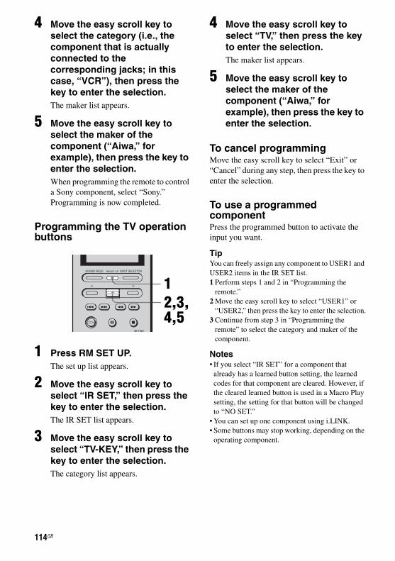
E:\STR-DA7100ES\2320745143\2320745143STRDA7100ESUC\01GB-STRDA7100ESUC\080REM.fm2-320-745-14 (3)
masterpage: Left
4 Move the easy scroll key to select the category (i.e., the component that is actually connected to the corresponding jacks; in this case, “VCR”), then press the key to enter the selection.The maker list appears.
5 Move the easy scroll key to select the maker of the component (“Aiwa,” for example), then press the key to enter the selection.When programming the remote to control a Sony component, select “Sony.”Programming is now completed.
Programming the TV operation buttons
1 Press RM SET UP.The set up list appears.
2 Move the easy scroll key to select “IR SET,” then press the key to enter the selection.The IR SET list appears.
3 Move the easy scroll key to select “TV-KEY,” then press the key to enter the selection.The category list appears.
4 Move the easy scroll key to select “TV,” then press the key to enter the selection.The maker list appears.
5 Move the easy scroll key to select the maker of the component (“Aiwa,” for example), then press the key to enter the selection.
To cancel programmingMove the easy scroll key to select “Exit” or “Cancel” during any step, then press the key to enter the selection.
To use a programmed componentPress the programmed button to activate the input you want.
TipYou can freely assign any component to USER1 and USER2 items in the IR SET list.1 Perform steps 1 and 2 in “Programming the
remote.”2 Move the easy scroll key to select “USER1” or
“USER2,” then press the key to enter the selection.3 Continue from step 3 in “Programming the
remote” to select the category and maker of the component.
Notes• If you select “IR SET” for a component that
already has a learned button setting, the learned codes for that component are cleared. However, if the cleared learned button is used in a Macro Play setting, the setting for that button will be changed to “NO SET.”
• You can set up one component using i.LINK.• Some buttons may stop working, depending on the
operating component.
12,3,4,5
114GB
STR-DA7100ES2-320-745-14 (3)
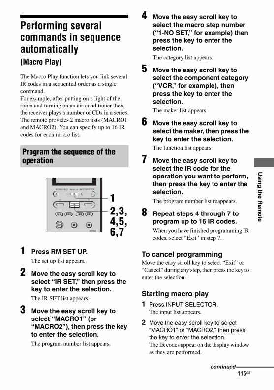
E:\STR-DA7100ES\2320745143\2320745143STRDA7100ESUC\01GB-STRDA7100ESUC\080REM.fm
masterpage: Right
Usin
g th
e Rem
ote
Performing several commands in sequence automatically(Macro Play)
The Macro Play function lets you link several IR codes in a sequential order as a single command.For example, after putting on a light of the room and turning on an air-conditioner then, the receiver plays a number of CDs in a series.The remote provides 2 macro lists (MACRO1 and MACRO2). You can specify up to 16 IR codes for each macro list.
1 Press RM SET UP.The set up list appears.
2 Move the easy scroll key to select “IR SET,” then press the key to enter the selection.The IR SET list appears.
3 Move the easy scroll key to select “MACRO1” (or “MACRO2”), then press the key to enter the selection.The program number list appears.
4 Move the easy scroll key to select the macro step number (“1-NO SET,” for example) then press the key to enter the selection.The category list appears.
5 Move the easy scroll key to select the component category (“VCR,” for example), then press the key to enter the selection.The maker list appears.
6 Move the easy scroll key to select the maker, then press the key to enter the selection. The function list appears.
7 Move the easy scroll key to select the IR code for the operation you want to perform, then press the key to enter the selection.The program number list reappears.
8 Repeat steps 4 through 7 to program up to 16 IR codes.When you have finished programming IR codes, select “Exit” in step 7.
To cancel programmingMove the easy scroll key to select “Exit” or “Cancel” during any step, then press the key to enter the selection.
Starting macro play1 Press INPUT SELECTOR.
The input list appears.
2 Move the easy scroll key to select “MACRO1” or “MACRO2,” then press the key to enter the selection.The IR codes appear on the display window as they are performed.
Program the sequence of the operation
12,3,4,5,6,7
continued
115GBSTR-DA7100ES2-320-745-14 (3)

E:\STR-DA7100ES\2320745143\2320745143STRDA7100ESUC\01GB-STRDA7100ESUC\080REM.fm2-320-745-14 (3)
masterpage: Left
To erase a programmed IR code1 In step 5, move the easy scroll key to
select “Common,” then press the key to enter the selection.
2 Move the easy scroll key to select “NO SET,” then press the key to enter the selection.
To delay the output of an IR code1 In step 5, move the easy scroll key to
select “Common,” then press the key to enter the selection.
2 Move the easy scroll key to select “WAIT TIME,” then press the key to enter the selection.
3 Move the easy scroll key to select the time to delay the output of an IR code, then press the key to enter the selection. You can specify a delay of from 1 to 10 seconds (in 1 second increments).
Notes• Pressing any of the following buttons during a
macro play operation will cancel the macro play sequence before it is complete. – AV ?/1– ?/1– SYSTEM STANDBY– SOUND FIELD– INPUT SELECTOR– RM SET UP
• When the Macro Play function does not work properly, set “WAIT TIME” between each operation.
Setting remote control codes that are not stored in the commanderWhen a remote control code is not one of the presets stored in the commander, it is possible for the commander to learn the code using the Learning function.
1 Press RM SET UP.The set up list appears.
2 Move the easy scroll key to select “LEARNING,” then press the key to enter the selection.The input list appears.
3 Move the easy scroll key to select the function for which you want to use the Learning input, then press the key to enter the selection.The button list appears.
4 Move the easy scroll key to select the button you want to use for the Learning function, then press the key to enter the selection.The display for the learning function appears.
12,3,4,6
116GB
STR-DA7100ES2-320-745-14 (3)

E:\STR-DA7100ES\2320745143\2320745143STRDA7100ESUC\01GB-STRDA7100ESUC\080REM.fm
masterpage: Right
Usin
g th
e Rem
ote
5 Point the remote code receiver section of the commander toward the receiver/transmitter on the remote control to be learned from.
6 Move the easy scroll key to select “Learning Start,” then press the key to enter the selection.“Learning Now!!” is displayed.
7 Press the appropriate button on the remote control to send the remote control code.Lightly pressing the button once should be sufficient. In about 3 to 5 seconds, the display shows whether learning was successful or not. When the learning process completes successfully, “Learning OK!,” the number of keys, and the capacity used for learning are displayed.When the learning process does not complete successfully, the cause is displayed on the third line.Move the easy scroll key to return to step 3, then repeat the above procedure.
To cancel learningMove the easy scroll key to select “Exit” or “Cancel” during any step, then press the key to enter the selection.
Using a command that has been learnedWhen selecting a learned input, press the button used to learn that function.
To erase the learned code1 In step 6 above, move the easy scroll
key to select “Clear,” then press the key to enter the selection. “Clear?” appears.
2 Move the easy scroll key to select “Yes,” then press the key to enter the selection. “Cleared!!” appears.
Notes• The symbols that are displayed in front of the
button name indicate the following.x: already learned*: pre-programmed
• In step 4, learned buttons can be selected directly. If you press the button you want to use for the Learning function, the list will jump to the same button.
• The Learning function can be applied to the SUB menus. SUB1–SUB5 can be learned.
• You can set input names for SUB1–SUB5.1 In step 6, move the easy scroll key to select
“NAME,” then press the key to enter the selection.
2 Move the easy scroll key to create a name, then press the key to enter the selection (up to 8 characters).+/–: Select a character</>: Move the cursorInsert: Insert a spaceDelete: Delete a character
• You can program up to 80 buttons for the Learning function. In some cases, you may not be able to program even if you have not programmed 80 buttons.
• If you select “IR SET” for a component that already has a learned button setting, the learned codes for that component are cleared. However, if the cleared learned button is used in a Macro Play setting, the setting for that button will be reset to the initial setting.
About 5 cm - 10 cm (2" - 4")
117GB
STR-DA7100ES2-320-745-14 (3)

E:\STR-DA7100ES\2320745143\2320745143STRDA7100ESUC\01GB-STRDA7100ESUC\080REM.fm2-320-745-14 (3)
masterpage: Left
Clearing all the contents of the remote’s memory
1 Press RM SET UP.The set up list appears.
2 Move the easy scroll key to select “ALL CLEAR,” then press the key to enter the selection.The ALL CLEAR list appears.
3 Move the easy scroll key to select “Yes,” then press the key to enter the selection.“CLEAR OK?!” appears.
4 Move the easy scroll key to select “Yes” again, then press the key.All the contents of the remote’s memory (i.e., all the programmed data) are cleared.
Other operations
You can set the remote to display only the inputs you use in the input list.
1 Press RM SET UP.The set up list appears.
2 Move the easy scroll key to select “INPUT LIST,” then press the key to enter the selection.The INPUT LIST list appears.A “*” in front of the input name means that the input is displayed in the input list.
3 Move the easy scroll key to select an input that will not be displayed in the input list, then press the key to enter the selection.“*” disappears for the selected input.
To display the input in the input listIn step 3, press the key repeatedly until “*” appears again.
12,3,4
Customizing the input list
12,3
118GB
STR-DA7100ES2-320-745-14 (3)

E:\STR-DA7100ES\2320745143\2320745143STRDA7100ESUC\01GB-STRDA7100ESUC\080REM.fm
masterpage: Right
Usin
g th
e Rem
ote
With the auto power function turned on, Sony AV and TV components automatically turn on and the TV switches to the selected input mode. This function works for Sony components only.
1 Press RM SET UP.The set up list appears.
2 Move the easy scroll key to select “AUTO POWER,” then press the key to enter the selection.The AUTO POWER list appears.
3 Move the easy scroll key to select “On” or “Off,” then press the key to enter the selection.When you select “On,” the TV INPUT list appears.
4 Move the easy scroll key to select the video input of the TV, then press the key to enter the selection.When you want to select component video input, select TV-COMPO1 or 2.
Notes• Switching to VIDEO1–6 input may not be
automatic on all Sony TVs. This is because some TVs cannot receive remote control codes immediately after being turned on.
• If you select “(Off)” in step 3, the TV input does not switch.
Each time you press a button on the remote, the backlight turns on. If you follow the procedure below to turn off the backlight, you can make the batteries last longer.
1 Press RM SET UP.The set up list appears.
2 Move the easy scroll key to select “BACK LIGHT,” then press the key to enter the selection.The BACK LIGHT list appears.
3 Move the easy scroll key to select “On” or “Off,” then press the key to enter the selection.
You can adjust the contrast of the display.
1 Press RM SET UP.The set up list appears.
Using the auto power function
12,3,4
Turning the backlight on or off
Adjusting the contrast of the display
12,3
12,3
continued
119GBSTR-DA7100ES2-320-745-14 (3)

E:\STR-DA7100ES\2320745143\2320745143STRDA7100ESUC\01GB-STRDA7100ESUC\080REM.fm2-320-745-14 (3)
masterpage: Left
2 Move the easy scroll key to select “CONTRAST,” then press the key to enter the selection.
3 Move the easy scroll key to select “+” or “–,” then press the key to enter the selection.Each time you press the key, the contrast of the display changes. To exit adjusting, move the easy scroll key to select “Exit,” then press the key to enter the selection.
Changing button assignments (RM-US106A only)You can change the factory settings of the input buttons to suit the components in your system. For example, if you connect an LD player to the VIDEO 2 jacks on the receiver, you can set the VIDEO 2 button on this remote to control the LD player.Note, however, that the settings of the TUNER button cannot be changed.
1 Press RM SET UP for more than 2 seconds.The indicator lights up.
2 Press the input button of which you want to change the assignment.The indicator turns off once and turns on again when a valid button is pressed. Only the first input button that is pressed will be registered.Example: Press VIDEO 2.
1
2,3
4
120GB
STR-DA7100ES2-320-745-14 (3)

E:\STR-DA7100ES\2320745143\2320745143STRDA7100ESUC\01GB-STRDA7100ESUC\080REM.fm
masterpage: Right
Usin
g th
e Rem
ote
3 Referring to the table below, press the input button for the category you want.The indicator turns off when a valid button is pressed. Example: Press DVD twice.
4 Press SOURCE.The new assignment is registered.The indicator slowly lights up twice, then goes off.
To cancelPress RM SET UP during any step.
TipIf the operation is unsuccessful, the indicator flashes four times and the remote automatically exits the button assignment mode. In this case, the new assignment is not registered and the previous setting remains.
Notes• If you do not press a button during step 2 through 4
within 60 seconds, the remote automatically exits the button assignment mode. Start again from step 1.
• In step 3, if you press the same button more than the possible number of categories that can be selected, only the last category is registered for the new assignment.
Valid buttons and the corresponding categories
To clear all remote button assignmentsHold down RM SET UP, then press ?/1.The remote is reset to its factory-settings.
Corresponding categories
Press
VTR-1 VIDEO 1 once
VTR-2 VIDEO 2 once
VTR-3 VIDEO 3 once
VTR-4 VIDEO 1 twice
VTR-5 VIDEO 2 twice
VTR-6 VIDEO 3 twice
DVD player DVD once
LD player DVD twice
TV TV/SAT once
SAT TV/SAT twice
Tape deck-A TAPE once
Tape deck-B TAPE twice
MD deck MD/DAT once
DAT deck MD/DAT twice
CD player-1 SA-CD/CD once
CD player-2 SA-CD/CD twice
CD player-3 SA-CD/CD three times
VIDEO CD player VIDEO 1, then SA-CD/CD
Corresponding categories
Press
121GB
STR-DA7100ES2-320-745-14 (3)

E:\STR-DA7100ES\2320745143\2320745143STRDA7100ESUC\01GB-STRDA7100ESUC\090ADD.fm
masterpage: Left
Menu list (LEVEL/SURR SET UP/EQUALIZER/TUNER/SPEAKER SET UP/
CUSTOMIZE/CIS/STREAM INFO)
Various configuration are possible using the menu list. The menu list is displayed by pressing MENU.
Additional Information
Menu Item Parameter Initial setting
Refer page
LEVEL TEST TONE [xxx] OFF, AUTO, FIX OFF page 52, 99 - 101
*PHASE NOISE [xxx] OFF, L/C, C/R, R/SL, R/SR, SR/SL, SL/L, SR/L
OFF
*PHASE AUDIO OFF, L/C, C/R, R/SL, R/SR, SR/SL, SL/L, SR/L
OFF
FRONT L--- ---R 8.0dB (0.5dB step) 0dB
CENTER [xxx.x dB] –20.0dB to +10.0dB (0.5dB step) 0dB
SURROUND L [xxx.x dB] –20.0dB to +10.0dB (0.5dB step) 0dB
SURROUND R [xxx.x dB] –20.0dB to +10.0dB (0.5dB step) 0dB
SURR BACK [xxx.x dB] –20.0dB to +10.0dB (0.5dB step) 0dB
SURR BACK L [xxx.x dB] –20.0dB to +10.0dB (0.5dB step) 0dB
SURR BACK R [xxx.x dB] –20.0dB to +10.0dB (0.5dB step) 0dB
SUB WOOFER [xxx.x dB] –20.0dB to +10.0dB (0.5dB step) 0dB
MULTI CH SW [xxx] 0dB, +10.0dB 0dB
D. RANGE COMP. [xxx] OFF, STD, MAX OFF
SURR SET UP
*C.WIDTH L----C----R 8 step 3 page 98 - 99
*DIMENSION F------S 7 step Center
*PANORAMA MODE [_ _ _] OFF, ON OFF
EFFECT LEVEL _ _ _% 20% to 120% (5% step) 100%
*SCREEN DEPTH [_ _ _] ON, OFF ON
*VIR. SPEAKERS [_ _ _] ON, OFF ON
*A. F. D. 2CH SW [xxx] CREATE, OFF OFF
EQUALIZER EQ PRESET [x] 1, 2, 3, 4, 5, OFF 1 page 104
FRONT BASS [xxx.x dB] –10.0dB to +10.0dB (1dB step) 0dB
FRONT TREBLE [xxx.x dB]
–10.0dB to +10.0dB (1dB step) 0dB
CENTER BASS [xxx.x dB] –10.0dB to +10.0dB (1dB step) 0dB
CENTER MID [xxx.x dB] –10.0dB to +10.0dB (1dB step) 0dB
122GB
STR-DA7100ES2-320-745-14 (3)

E:\STR-DA7100ES\2320745143\2320745143STRDA7100ESUC\01GB-STRDA7100ESUC\090ADD.fm
masterpage: Right
Ad
ditio
nal In
form
ation
CENTER MID [xxx.x kHz] 100Hz, 300Hz, 1.0kHz, 3.0kHz, 10kHz
1.0kHz
CENTER TREBLE [xxx.x dB]
–10.0dB to +10.0dB (1dB step) 0dB
SURR/SB BASS [xxx.x dB]
–10.0dB to +10.0dB (1dB step) 0dB
SURR/SB TRE. [xxx.x dB] –10.0dB to +10.0dB (1dB step) 0dB
PRESET x CLEAR [xxx] YES, NO NO
TUNER FM MODE MONO, STEREO STEREO page 76 - 80
NAME IN? [xxx]
SPEAKER SET UP
SP EASY SET UP [xxx] YES, NO YES page 48 - 51
SPEAKER PATTERN [xxx] 2-0, 2-1, 3-0, 3-1, 4-0, 4-1, 5C0, 5C1, 5-0, 5-1, 6C0, 6C1, 6-0, 6-1, 7-0, 7-1
SUB WOOFER [xxx] NO, YES YES
FRONT SP [xxx] SMALL, LARGE LARGE
CENTER SP [xxx] NO, SMALL, LARGE LARGE
SURROUND SP [xxx] NO, SMALL, LARGE LARGE
SURR BACK SP [xxx] 2ND ZONE, NO, SINGLE, DUAL DUAL
FRONT x.xmeter 1.0m to 7.0m (0.1m step) 3.0 meter
CENTER x.xmeter 1.0m to 7.0m (0.1m step) 3.0 meter
SURROUND x.xmeter 1.0m to 7.0m (0.1m step) 3.0 meter
SURR BACK x.xmeter 1.0m to 7.0m (0.1m step) 3.0 meter
SUB WOOFER x.xmeter 1.0m to 7.0m (0.1m step) 3.0 meter
*DISTANCE UNIT [xxx] meter, feet meter page 102 - 103*SP POSI [xxx] SIDE/LOW, SIDE/HIGH, BEHD/
LOW, BEHD/HIGHSIDE/LOW
*SP CROSSOVER > xxxHz 40Hz to 200Hz (10Hz step) 100Hz
CUSTOMIZE MENU EXPAND [xxx] OFF, ON OFF page 67 - 72
SB DECODING [xxx] OFF, AUTO, ON AUTO
SB DEC MODE [xxx] DDEX, PLIIx MV, PLIIx MS PLIIx MV
DEC. PRIORITY [xxx] PCM, AUTO AUTO
DUAL MONO [xxx] MAIN/SUB, MAIN, SUB, MAIN+SUB
MAIN
A/V SYNC [xxxms] 0ms to 200ms 0ms
9.1 CH SP SYSTEM YES, NO NO
MULTI IN5.1 t 7.1 [xxx] YES, NO YES
DC PHASE L. [xxx] OFF, LOW-A, STD-A, HIGH A, LOW-B, STD-B, HIGH-B
STD-A
Menu Item Parameter Initial setting
Refer page
continued
123GBSTR-DA7100ES2-320-745-14 (3)
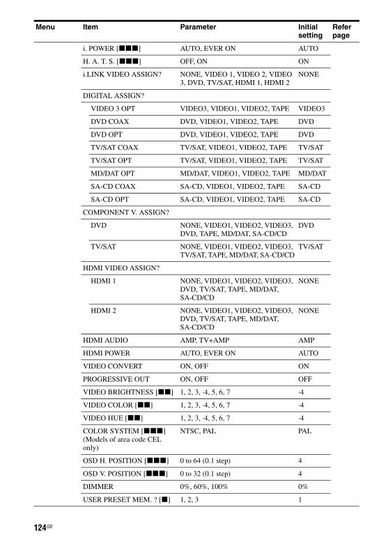
E:\STR-DA7100ES\2320745143\2320745143STRDA7100ESUC\01GB-STRDA7100ESUC\090ADD.fm
masterpage: Left
i. POWER [xxx] AUTO, EVER ON AUTO
H. A. T. S. [xxx] OFF, ON ON
i.LINK VIDEO ASSIGN? NONE, VIDEO 1, VIDEO 2, VIDEO 3, DVD, TV/SAT, HDMI 1, HDMI 2
NONE
DIGITAL ASSIGN?
VIDEO 3 OPT VIDEO3, VIDEO1, VIDEO2, TAPE VIDEO3
DVD COAX DVD, VIDEO1, VIDEO2, TAPE DVD
DVD OPT DVD, VIDEO1, VIDEO2, TAPE DVD
TV/SAT COAX TV/SAT, VIDEO1, VIDEO2, TAPE TV/SAT
TV/SAT OPT TV/SAT, VIDEO1, VIDEO2, TAPE TV/SAT
MD/DAT OPT MD/DAT, VIDEO1, VIDEO2, TAPE MD/DAT
SA-CD COAX SA-CD, VIDEO1, VIDEO2, TAPE SA-CD
SA-CD OPT SA-CD, VIDEO1, VIDEO2, TAPE SA-CD
COMPONENT V. ASSIGN?
DVD NONE, VIDEO1, VIDEO2, VIDEO3, DVD, TAPE, MD/DAT, SA-CD/CD
DVD
TV/SAT NONE, VIDEO1, VIDEO2, VIDEO3, TV/SAT, TAPE, MD/DAT, SA-CD/CD
TV/SAT
HDMI VIDEO ASSIGN?
HDMI 1 NONE, VIDEO1, VIDEO2, VIDEO3, DVD, TV/SAT, TAPE, MD/DAT, SA-CD/CD
NONE
HDMI 2 NONE, VIDEO1, VIDEO2, VIDEO3, DVD, TV/SAT, TAPE, MD/DAT, SA-CD/CD
NONE
HDMI AUDIO AMP, TV+AMP AMP
HDMI POWER AUTO, EVER ON AUTO
VIDEO CONVERT ON, OFF ON
PROGRESSIVE OUT ON, OFF OFF
VIDEO BRIGHTNESS [xx] 1, 2, 3, ·4, 5, 6, 7 ·4
VIDEO COLOR [xx] 1, 2, 3, ·4, 5, 6, 7 ·4
VIDEO HUE [xx] 1, 2, 3, ·4, 5, 6, 7 ·4
COLOR SYSTEM [xxx](Models of area code CEL only)
NTSC, PAL PAL
OSD H. POSITION [xxx] 0 to 64 (0.1 step) 4
OSD V. POSITION [xxx] 0 to 32 (0.1 step) 4
DIMMER 0%, 60%, 100% 0%
USER PRESET MEM. ? [x] 1, 2, 3 1
Menu Item Parameter Initial setting
Refer page
124GB
STR-DA7100ES2-320-745-14 (3)
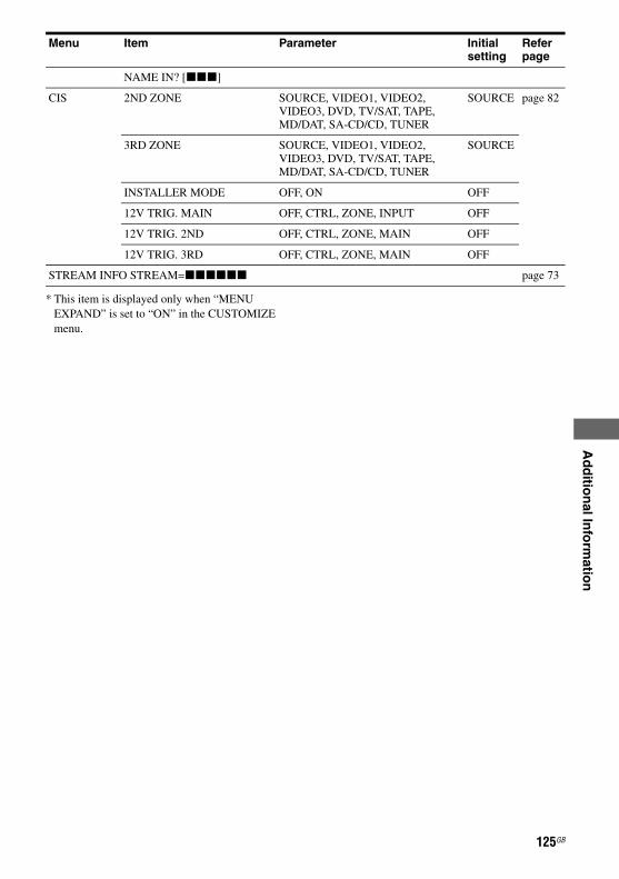
E:\STR-DA7100ES\2320745143\2320745143STRDA7100ESUC\01GB-STRDA7100ESUC\090ADD.fm
masterpage: Right
Ad
ditio
nal In
form
ation
* This item is displayed only when “MENU EXPAND” is set to “ON” in the CUSTOMIZE menu.
NAME IN? [xxx]
CIS 2ND ZONE SOURCE, VIDEO1, VIDEO2, VIDEO3, DVD, TV/SAT, TAPE,MD/DAT, SA-CD/CD, TUNER
SOURCE page 82
3RD ZONE SOURCE, VIDEO1, VIDEO2, VIDEO3, DVD, TV/SAT, TAPE,MD/DAT, SA-CD/CD, TUNER
SOURCE
INSTALLER MODE OFF, ON OFF
12V TRIG. MAIN OFF, CTRL, ZONE, INPUT OFF
12V TRIG. 2ND OFF, CTRL, ZONE, MAIN OFF
12V TRIG. 3RD OFF, CTRL, ZONE, MAIN OFF
STREAM INFO STREAM=xxxxxx page 73
Menu Item Parameter Initial setting
Refer page
125GB
STR-DA7100ES2-320-745-14 (3)

E:\STR-DA7100ES\2320745143\2320745143STRDA7100ESUC\01GB-STRDA7100ESUC\090ADD.fm
masterpage: Left
Glossaryx A.F.D. (Auto Format Direct)A function that automatically detects the input audio signal format for optimal processing. Recorded or encoded sound is faithfully reproduced without added sound effects such as reverb, etc.
x A/V SYNCWhen the video lags behind the audio signal, this function can be used to delay the audio for synchronizing the audio and video.
x Component videoA format for transmitting video signal information consisting of three separate signals: luminance Y, chrominance Pb, and chrominance Pr. High quality pictures, such as DVD video or HDTV pictures, are transmitted more faithfully. The three jacks are color-coded green, blue, and red.
x Composite videoA standard format for transmitting video signal information. The luminance signal Y and chrominance signal C are combined and transmitted together.
x Crossover frequencyThe frequency at which two speaker’s frequencies intersect.
x Dolby DigitalDigital audio encoding/decoding technology developed by Dolby Laboratories, Inc. It consists of front (L/R), center, surround (L/R) and sub-woofer channels. It is a designated audio standard for DVD-video and also known as 5.1ch surround. Since surround information is recorded and reproduced in stereo, more realistic sound with fuller presence is delivered than with Dolby surround.
x Dolby Digital Surround EXAcoustic technology developed by Dolby Laboratories, Inc. Surround back information
is matrixed into regular left and right surround channels so that the sound can be reproduced in 6.1ch. Active scenes, especially, are recreated with a more dynamic and realistic sound field.
x Dolby Pro Logic IIThis technology converts 2ch stereo recorded audio into 5.1ch for playback. There is a MOVIE mode for movies and MUSIC mode for stereo sources such as music. Old movies encoded in the traditional stereo format can be enhanced with 5.1ch surround sound.
x Dolby Pro Logic IIxTechnology for 7.1ch (or 6.1ch) playback. Along with audio encoded in Dolby Digital Surround EX, 5.1ch Dolby Digital encoded audio can be reproduced in 7.1ch (or 6.1ch). Furthermore, existing stereo recorded content can also be reproduced in 7.1ch (or 6.1ch).
x Dolby Surround (Dolby Pro Logic)
Audio processing technology developed by Dolby Laboratories, Inc. Center and mono surround information is matrixed into two stereo channels. When reproduced, audio is decoded and output in 4ch surround sound. This is the most common audio processing method for DVD-video.
x DownmixA method to output multi-channel audio such as 5.1ch, encoded into two channels.
x DSD (Direct Stream Digital)Audio format used for a Super Audio CD. DSD converts analog signals to digital and records them directly, without adding any processing, so that no information is omitted. Recording and playback of high fidelity, quality sound is achieved.
x DTS 96/24A high sound quality digital signal format. It records audio at a sampling frequency and bit rate of 96kHz/24bit which is the highest possible for DVD-video. The number of
126GB
STR-DA7100ES2-320-745-14 (3)

E:\STR-DA7100ES\2320745143\2320745143STRDA7100ESUC\01GB-STRDA7100ESUC\090ADD.fm
masterpage: Right
Ad
ditio
nal In
form
ation
playback channels varies depending on the software.
x DTS Neo:6This technology converts 2ch stereo recorded audio for 6.1ch playback. There are two modes to select according to the playback source or your preference, CINEMA for movies, and MUSIC for stereo sources such as music.
x DTS Digital SurroundDigital audio encoding/decoding technology for theaters developed by Digital Theater Systems, Inc. It compresses audio less than Dolby Digital, delivering a higher quality sound reproduction.
x DTS-ESFormat for 6.1ch playback with surround back information. There are two modes, “Discrete 6.1” which records all channels independently, and “Matrix 6.1” which matrixes surround back channel into LS and RS channels. It is ideal for playback of motion picture soundtracks.
x Dynamic RangeThe reproductive capacity of audio signals. The difference between the minimum (quietest) and the maximum (loudest) sound that can be reproduced is expressed by a number value of dB. A larger number value means a greater degree of quietness or loudness can be reproduced.
x HDMI (High-Definition Multimedia Interface)
Technology developed by modifying the display connecting technology, DVI (Digital Visual Interface), for AV equipment. This interface can transmit video, audio, and control signals in digital format.
x i.LINKAnother term for IEEE 1394, a data transfer method used between personal computers and peripherals. This is a new interface that enables a simple connection with a single cable between a player and an amplifier. 5.1ch
information is transmitted digitally so that clear sound reproduction is possible.
x Input streamA digital input signal that includes additional information about the format or channel, such as Dolby Digital 5.1 or DTS 5.1 data, etc.
x InterlaceA scanning method which completes a picture by displaying half of the lines on a tube surface of a TV or monitor each 1/60 second. First, all the odd-numbered lines are drawn, leaving spaces between each line, then all the even-numbered lines are drawn to fill the spaces.
x L.F.E. (Low Frequency Effects)Sound effects of low frequencies which are output from a sub woofer in Dolby Digital or DTS, etc. By adding a deep bass with a frequency between 20 to 120 Hz, audio becomes more powerful.
x LINCThe acronym of Logical Interface Connection.
x PCM (Pulse Code Modulation)A method of converting analog audio to digital audio for easy enjoyment of digital sound.
x ProgressiveA scanning method that draws all scanning lines sequentially, as opposed to interlaced scanning where all the odd and then all the even lines are drawn.
x Sampling frequencyTo convert analog audio to digital, analog data should be quantified. This process is called sampling, and the number of times per second the analog data is quantified is called the sampling frequency. A standard music CD stores data quantified at 44,100 times per second, which is expressed as a sampling frequency of 44.1 kHz. Generally speaking, a higher sampling frequency means better sound quality.
continued
127GBSTR-DA7100ES2-320-745-14 (3)

E:\STR-DA7100ES\2320745143\2320745143STRDA7100ESUC\01GB-STRDA7100ESUC\090ADD.fm
masterpage: Left
x S-VIDEO signalA format for transmitting video signal information. S-video uses a single cable and two channels, one for the Luminance signal Y and another for the chrominance signal C. Better picture quality for recording and playback than that of Composite signal is achieved.
Technical termsx Cinema Studio EXA surround sound mode that can be regarded as the compilation of Digital Cinema Sound technology, delivers the sound of a dubbing theater using three technologies: “Virtual Multi Dimensions,” “Screen Depth Matching,” and “Cinema Studio Reverberation.”“Virtual Multi Dimensions,” the virtual speaker technology, creates a virtual multi-surround environment with actual speakers up to 7.1ch (with 9.1ch speakers, “Virtual Multi Dimensions” will automatically be switched off), and brings the surround sound experience of a theater with the latest facilities into your home.“Screen Depth Matching” reproduces treble attenuation, fullness, and depth of sound usually created in a theater using sound emission from behind the screen. This is then added to the front and center channels.“Cinema Studio Reverberation” reproduces the sound characteristics of state-of-the-art dubbing theaters and recording studios, including Sony Pictures Entertainment’s dubbing studios. There are three modes, A/B/C, available according to the studio type.
x DC Phase LinearizerWith analog power amplifiers, phase shifts take place at frequencies lower than several tens of Hz. But with digital power amplifiers, phase does not shift so the phase characteristic is flat. Speakers available on the market are designed for analog amplifiers and therefore the performance at low frequencies does not match the characteristics of digital amplifiers. S-Master PRO reproduces the phase characteristics of analog amplifiers by digital processing to deliver familiar low frequency sounds.
x Digital Cinema Sound (DCS)Unique sound reproduction technology for home theater developed by Sony, in cooperation with Sony Pictures Entertainment,
128GB
STR-DA7100ES2-320-745-14 (3)

E:\STR-DA7100ES\2320745143\2320745143STRDA7100ESUC\01GB-STRDA7100ESUC\090ADD.fm
masterpage: Right
Ad
ditio
nal In
form
ation
for enjoying the exciting and powerful sound of movie theaters at home. With this “Digital Cinema Sound” developed by integrating a DSP (Digital signal processor) and measured data, the ideal sound field intended by filmmakers can be experienced at home.
x Digital Concert Hall“Digital Concert Hall” delivers richer sound for 2ch stereo sources such as CDs, etc. With the use of 5.1ch or 7.1ch speakers and virtual speaker technology, stereoscopic reverberation and reflected sound are reproduced, and music software can be enjoyed with richer sound and presence. The sound field in a concert hall is recreated by a geometrical analysis of the concert hall and precise modeling of reflected and reverberant sounds based on actual measured data. Tonal qualities such as sound strength and frequency response are taken into account and calculated on the DSP (Digital Signal Processor) to bring reverberation in. Sound is enjoyed with natural and comfortable resonance, as if listening to music in a concert hall.
x Pulse Height VolumePulse Height Volume, one feature of the S-Master PRO technology. adjusts the sound volume by controlling the pulse height. This method loses no information and reproduces higher quality sound than adjusting the sound volume by digital processing.
x “S-Master”This receiver is equipped with an “S-Master” full digital amplifier - a unique digital amplifier developed by Sony with the following features.
1:Full digital processingThe signals are processed fully in digital, and never go through the analog domain at any time. As a result, the signal process is always clean and accurate, and is not affected by noise interference at signal paths which is often the case with analog processing. In addition, S-Master processing is both simple and high-speed, thus providing high fidelity sound even
with vast information signals, like Super Audio CDs.
2:Low heat emissionAnother advantage to S-Master technology is its low heat emission. The S-Master process does not generate the same level of heat as analog amplification does. This means that not only is the S-Master more efficient, the sound quality is not affected because there is no heat to distort the final formation of the sound waves.
129GB
STR-DA7100ES2-320-745-14 (3)
E:\STR-DA7100ES\2320745143\2320745143STRDA7100ESUC\01GB-STRDA7100ESUC\090ADD.fm
masterpage: Left
Precautions
On safetyShould any solid object or liquid fall into the cabinet, unplug the receiver and have it checked by qualified personnel before operating it any further.
On power sources• Before operating the unit, check that the
operating voltage is identical with your local power supply.The operating voltage is indicated on the nameplate on the back of the receiver.
• The unit is not disconnected from the AC power source (mains) as long as it is connected to the wall outlet, even if the unit itself has been turned off.
• If you are not going to use the receiver for a long time, be sure to disconnect the receiver from the wall outlet. To disconnect the AC power cord, grasp the plug itself; never pull the cord.
• (Models of area code UC only)One blade of the plug is wider than the other for the purpose of safety and will fit into the wall outlet only one way. If you are unable to insert the plug fully into the outlet, contact your dealer.
• The AC power cord must be changed only at a qualified service shop.
On heat buildupAlthough the unit heats up during operation, this is not a malfunction. If you continuously use this unit at a large volume, the cabinet temperature of the top, side and bottom rises considerably. To avoid burning yourself, do not touch the cabinet.
On placement• Place the receiver in a location with adequate
ventilation to prevent heat buildup and prolong the life of the receiver.
• Do not place the receiver near heat sources, or in a place subject to direct sunlight, excessive dust, or mechanical shock.
• Do not place anything on top of the cabinet that might block the ventilation holes and cause malfunctions.
• Do not place the receiver near equipment such as a television, video deck, or cassette deck. (If the receiver is being used in combination with a television, video deck, or cassette deck, and is placed too close to that equipment, noise may result, and picture quality may suffer. This is especially likely when using an indoor antenna. Therefore, we recommend using an outdoor antenna.)
On operationBefore connecting other components, be sure to turn off and unplug the receiver.
On cleaningClean the cabinet, panel, and controls with a soft cloth slightly moistened with a mild detergent solution. Do not use any type of abrasive pad, scouring powder, or solvent, such as alcohol or benzine.
If you have any questions or problems concerning your receiver, please consult your nearest Sony dealer.
130GB
STR-DA7100ES2-320-745-14 (3)

E:\STR-DA7100ES\2320745143\2320745143STRDA7100ESUC\01GB-STRDA7100ESUC\090ADD.fm
masterpage: Right
Ad
ditio
nal In
form
ation
TroubleshootingIf you experience any of the following difficulties while using the receiver, use this troubleshooting guide to help you remedy the problem. Should any problem persist, consult your nearest Sony dealer.
There is no sound, no matter which component is selected.
• Check that both the receiver and all components are turned on.
• Check that MASTER VOLUME control is not set at –∞ dB.
• Check that SPEAKERS is not set to “OFF” (page 52).
• Check that all speaker cords are connected correctly.
• Press MUTING on the remote to cancel the muting function.
There is no sound from a specific component.
• Check that the component is connected correctly to the audio input jacks for that component.
• Check that the cord(s) used for the connection is (are) fully inserted into the jacks on both the receiver and the component.
There is no sound from one of the front speakers.
• Connect a pair of headphones to the PHONES jack to verify that sound is output from the headphones. If only one channel is output from the headphones, the component may not be connected to the receiver correctly. Check that all the cords are fully inserted into the jacks on both the receiver and the component. If both channels are output from the headphones, the front speaker may not be connected to the receiver correctly. Check the connection of the front speaker which is not outputting any sound.
• Make sure you have not connected only the L or R jack to a monaural component. Use a monaural-stereo cable (not supplied) and connect it to both the L and R jacks. However, there will be no sound from the center speaker when a sound field (PRO LOGIC, etc.) is selected. When the center speaker is set to “NO,” sound is output only from the front L/R speakers.
There is no sound, or only a very low-level sound is heard.
• Check that the speakers and components are connected securely.
• Check that you have selected the correct component with INPUT SELECTOR.
• Check that SPEAKERS is not set to “OFF” (page 52).
• Check that headphones are not connected.• Press MUTING on the remote to cancel
the muting function.• When only a very low-level sound is
heard, check to see if NIGHT MODE is activated (page 94).
• The protective device on the receiver has been activated. Turn off the receiver, eliminate the short-circuit problem, and turn on the power again.
There is no sound from analog 2 channel sources.
• Check that the DIGITAL ASSIGN function is not used to assign the audio input of another source to the selected input (page 61).
• Check that the INPUT MODE is not set to “COAXIAL FIXED” nor “OPTICAL FIXED” for the selected input (page 60).
• Check that the MULTI CH IN function is not selected.
There is no sound from digital sources (from COAXIAL or OPTICAL input jack).
• Check that the DIGITAL ASSIGN function is not used to assign the audio input of another source to the selected input (page 61).
• Check that the INPUT MODE is not set to “ANALOG 2CH FIXED” (page 60).
continued
131GBSTR-DA7100ES2-320-745-14 (3)
E:\STR-DA7100ES\2320745143\2320745143STRDA7100ESUC\01GB-STRDA7100ESUC\090ADD.fm
masterpage: Left
Check that the INPUT MODE is not set to “COAXIAL FIXED” for the sources from the OPTICAL input jack, nor set to “OPTICAL FIXED” for the sources from the COAXIAL input jack.
• Check that the MULTI CH IN function is not selected.
There is no sound when i.LINK is selected.
• Check that the i.LINK component is connected correctly.
• Check that using SCD-XA9000ES is set to output signals from the i.LINK jack.
• The sound may not output when you operate two or more players. In this case, stop the player, which is not selected, then select the player you want to play again by pressing the i.LINK button.
The source sound input from the HDMI jack is not output from an amplifier or the TV speaker connected to the receiver.
• Check the setting of HDMI AUDIO in the CUSTOMIZE menu (page 70).
• Check the HDMI connection.• The sound is not output when you display
the receiver’s menu on the TV monitor. Press ON SCREEN to turn off the display.
• You cannot listen to the Super Audio CD by connecting HDMI.
• Depending on the playback component, component side may need to be set up. Refer to the operating instructions supplied with the each component.
The left and right sounds are unbalanced or reversed.
• Check that the speakers and components are connected correctly and securely.
• Adjust the balance parameters using the LEVEL menu.
There is severe hum or noise.• Check that the speakers and components
are connected securely.• Check that the connecting cords are away
from a transformer or motor, and at least 3
m (10 feet) away from a TV set or fluorescent light.
• Move your TV away from the audio components.
• Make sure you have grounded the U SIGNAL GND terminal (only when a turntable is connected).
• The plugs and jacks are dirty. Wipe them with a cloth slightly moistened with alcohol.
There is no sound from the center speaker.
• Make sure the sound field function is on (press A.F.D., MOVIE, or MUSIC).
• Select the CINEMA STUDIO EX mode (page 92).
• Adjust the speaker level (page 52).• Make sure the center speaker is set to
either “SMALL” or “LARGE” (page 49).
There is no sound, or only a very low-level sound is heard from the surround/surround back speakers.
• Make sure the sound field function is on (press A.F.D., MOVIE, or MUSIC).
• Select a CINEMA STUDIO EX mode (page 92).
• Adjust the speaker level (page 52).• Make sure the surround speakers are set to
either “SMALL” or “LARGE” (page 49).
There is no sound from the surround back speakers.
• Some discs have no Dolby Digital Surround EX flag even though the packages have Dolby Digital Surround EX logos. In this case, select “ON” (page 95).
There is no sound from the sub woofer.• When all speakers are set to “LARGE”
and “Neo:6 Cinema,” or “Neo:6 Music” is selected, there is no sound from the sub woofer.
The surround effect cannot be obtained.
• Make sure the sound field function is on (press A.F.D., MOVIE, or MUSIC).
132GB
STR-DA7100ES2-320-745-14 (3)

E:\STR-DA7100ES\2320745143\2320745143STRDA7100ESUC\01GB-STRDA7100ESUC\090ADD.fm
masterpage: Right
Ad
ditio
nal In
form
ation
• Sound fields do not function for signals with a sampling frequency of more than 48 kHz.
Dolby Digital or DTS multi channel sound is not reproduced.
• Check that the DVD, etc. you are playing is recorded in Dolby Digital or DTS format.
• When connecting the DVD player, etc., to the digital input jacks of this receiver, check the audio setting (the settings for the audio output) of the connected component.
Recording cannot be carried out.• Check that the components are connected
correctly.• Select the source component using INPUT
SELECTOR.
The FM reception is poor.• Use a 75-ohm coaxial cable (not supplied)
to connect the receiver to an outdoor FM antenna as shown below. If you connect the receiver to an outdoor antenna, ground it against lightning. To prevent a gas explosion, do not connect the ground wire to a gas pipe.
Radio stations cannot be tuned in.• Check that the antennas are connected
securely. Adjust the antennas and connect an external antenna, if necessary.
• The signal strength of the stations is too weak (when tuning in with automatic tuning). Use direct tuning.
• Make sure you set the tuning interval correctly (when tuning in AM stations with direct tuning).
• No stations have been preset or the preset stations have been cleared (when tuning by scanning preset stations). Preset the stations (page 78).
• Press DISPLAY so that the frequency appears on the display.
RDS does not work.*• Make sure that you’re tuned to an FM RDS
station.• Select a stronger FM station.
The RDS information that you want does not appear.*
• Contact the radio station and find out whether or not they actually provide the service in question. If so, the service may be temporarily out of order.
There is no picture or an unclear picture appears on the TV screen or monitor.
• Select the appropriate input on the receiver.
• Set your TV to the appropriate input mode.• Move your TV away from the audio
components.• Assign the component video input
correctly.• The input signal should be same as input
when you are up-converting an input signal with this receiver.
The image of the COMPONENT VIDEO OUT is corrupted.
• If PROGRESSIVE OUT is set to “ON,” the image of the signal, which is more than 480i is corrupted when the signals are output from the COMPONENT VIDEO OUT jack. Set PROGRESSIVE OUT to “OFF.”
Receiver
To ground
Ground wire(not supplied)
Outdoor FM antenna
continued
133GBSTR-DA7100ES2-320-745-14 (3)

E:\STR-DA7100ES\2320745143\2320745143STRDA7100ESUC\01GB-STRDA7100ESUC\090ADD.fm
masterpage: Left
• Input signals that are more than 480i of the COMPONENT VIDEO are not received when signals are output from the HDMI jack, S-VIDEO jack or VIDEO jack. (In other words, the receiver cannot convert the component video signals.) Input the 480i of the component video signal.
• Use a video jack as the component jack, and set PROGRESSIVE OUT to “OFF” when you output more than 480i input component signals.
The source image input from the HDMI jack is not output from an amplifier or the TV speaker connected to the receiver.
• Check the cable connection.• Depending on the playback component,
component side may need to be set up. Refer to the operating instructions supplied with the each component.
The MULTI CHANNNEL DECODING lamp does not light up in blue.
• Check that the playback component is connected on a digital jack and the input is selected properly on this receiver.
• Check whether the digital audio output of selected input is not assigned to another component input using DIGITAL ASSIGN function (page 61).
• Check whether the input source of the software being played back corresponds to the multi channel format.
• Check whether the setup on the playback component is set to multi channel sound.
Remote control
The remote does not function.• Point the remote at the remote sensor on
the receiver.• Remove any obstacles in the path between
the remote and the receiver.• Replace all the batteries in the remote with
new ones, if they are weak.
• Check if the command modes of the receiver and the remote are the same. If the command mode of the receiver and the remote are different, you cannot operate the receiver with the remote (page 46).
• Make sure you select the correct input on the remote.
• When “2ND ZONE” or “3RD ZONE” appears, or when the sound fields are not fully displayed, check if the remote is registered for the receiver correctly (RM-AAE003 only).
• When you operate a programmed non-Sony component, the remote may not function properly depending on the model and the maker of the component (RM-AAE003 only).
* Models of area code CEL only.
Error messagesIf there is a malfunction, the display shows a code of two numbers and a message. You can check the condition of the system by the message. Refer to the following table to solve the problem. If any problem persists, consult your nearest Sony dealer.
DECODE ERROR/CHECK CODE 01Appears when a signal the receiver cannot decode (ex. DTS-CD) is input when “DEC. PRIORITY” on the CUSTOMIZE menu is set to “PCM.” Set it to “AUTO” (page 67).
PROTECTOR/CHECK CODE 11Irregular current is output from the speakers. Turn off the receiver, check the central core of a speaker cord is not touching the receiver or other speakers, and turn on again.
PROTECTOR/CHECK CODE 12The amplifier section is overheated. Check that the ventilation hole is not covered. Turn off the receiver, leave the receiver for a while, and turn on the power again.
134GB
STR-DA7100ES2-320-745-14 (3)

E:\STR-DA7100ES\2320745143\2320745143STRDA7100ESUC\01GB-STRDA7100ESUC\090ADD.fm
masterpage: Right
Ad
ditio
nal In
form
ation
PROTECTOR/CHECK CODE 13The power section is overheated. Check that the ventilation hole is not covered. Turn off the receiver, leave the receiver for a while, and turn on the power again.
PROTECTOR/CHECK CODE 14Turn off the receiver, check the central core of a speaker cord is not touching the receiver or other speakers, and turn on again.
PROTECTOR/CHECK CODE 21Turn off the receiver and consult your nearest Sony dealer.
PROHIBITED/CHECK CODE 71The receiver cannot output the sound due to the copyright protection.
UNKNOWN SIGNAL/CHECK CODE 72The receiver is not compatible with the format of the input signal.
BUSFULL/CHECK CODE 73Since the i.LINK bus is busy with other connected component’s output signals, audio signals cannot be connected.• Stop sending output signals from
connected components (Turn off the component or press the STOP button, etc.). Press i.LINK on the receiver, then select the player again.
LOOP CONNECT/CHECK CODE 74• i.LINK connection is caught in a loop.• Check the connection (page 29).
Reference sections for clearing the memory
Specifications
AUDIO POWER SPECIFICATIONSPOWER OUTPUT AND TOTAL HARMONIC DISTORTION:(Models of area code UC only)With 8 ohm loads, both channels driven, from 20 – 20,000 Hz; rated 170 watts per channel minimum RMS power, with no more than 0.15% total harmonic distortion from 250 milliwatts to rated output.
Amplifier sectionModels of area code UC, TW:POWER OUTPUTRated Power Output at Stereo Mode1)
(8 ohms 20 Hz – 20 kHz, THD 0.15%):170 W + 170 W
Reference Power Output at Stereo Mode(4 ohms 20 Hz – 20 kHz, THD 0.15%):170 W + 170 W
Reference Power Output(8 ohms 20 Hz – 20 kHz, THD 0.15%)FRONT2): 170 W + 170 WCENTER2): 170 WSURR2): 170 W + 170 WSURR BACK2): 170 W + 170 W
Reference Power Output(4 ohms 20 Hz – 20 kHz, THD 0.15%)FRONT2): 170 W + 170 WCENTER2): 170 WSURR2): 170 W + 170 WSURR BACK2): 170 W + 170 W
Models of area code CEL, KR, CN:POWER OUTPUTRated Power Output in Stereo Mode1) 2)
(8 ohms 1 kHz, THD 0.7%):170 W + 170 W
To clear See
All memorized settings page 44
Customized sound fields page 101
continued
135GBSTR-DA7100ES2-320-745-14 (3)

E:\STR-DA7100ES\2320745143\2320745143STRDA7100ESUC\01GB-STRDA7100ESUC\090ADD.fm
masterpage: Left
Reference Power Output in Stereo Mode2)
(4 ohms 1 kHz, THD 0.7%):170 W + 170 W
Reference Power Output(8 ohms 1 kHz, THD 0.7%):FRONT2): 170 W + 170 WCENTER2): 170 WSURR2): 170 W + 170 WSURR BACK2): 170 W + 170 W
Reference Power Output(4 ohms 1 kHz, THD 0.7%):FRONT2): 170 W + 170 WCENTER2): 170 WSURR2): 170 W + 170 WSURR BACK2): 170 W + 170 W
1)Depending on the sound field settings and the source, there may be no sound output.
2)Measured under the following conditions:
Frequency response
Inputs (Analog)
Inputs (Digital)
Outputs
EQUALIZER
FM tuner sectionTuning range 87.5 - 108.0 MHzAntenna FM wire antennaAntenna terminals 75 ohms, unbalancedSensitivity
Mono: 18.3 dBf, 2.2 µV/75 ohmsStereo: 38.3 dBf, 22.5 µV/75 ohms Usable sensitivity 11.2 dBf, 1 µV/75 ohms
S/NMono: 76 dBStereo: 70 dB
Harmonic distortion at 1 kHzMono: 0.3%Stereo: 0.5%
Separation 45 dB at 1 kHzFrequency response 30 Hz – 15 kHz, +0.5/–2
dBSelectivity 60 dB at 400 kHz
AM tuner sectionTuning range
Models of area code UC:530 – 1,710 kHz3)
(With 10-kHz tuning scale)531 – 1,710 kHz3)
(With 9-kHz tuning scale)
Area code Power requirements
UC 120 V AC, 60 Hz
TW 110 V AC, 60 Hz
CEL 230 V AC, 50/60 Hz
KR 230 V AC, 60 Hz
CN 230 V AC, 50 Hz
PHONO RIAA equalization curve ± 0.5 dB
Power Amp Block 10 Hz – 50 kHz± 3 dB (8 ohms)
PHONO Sensitivity: 2.5mVImpedance: 50kohmsS/N: 86dB (A, 20 kHz LPF)
MULTI CHANNELINPUT1/2, SA-CD/CD, TAPE, MD/DAT, DVD, TV/SAT, VIDEO1/2/3
Sensitivity: 150mVImpedance: 50kohmsS/N: 96dB (A, 20 kHz LPF)
SA-CD/CD, DVD (Coaxial)
Impedance: 75ohmsS/N: 96dB (A, 20 kHz LPF)
SA-CD/CD, DVD,TV/SAT, MD/DAT,VIDEO 3 (Optical)
S/N: 96 dB(A, 20 kHz LPF)
TAPE, MD/DAT(REC OUT),VIDEO1/2 (AUDIO OUT)
Voltage:150mVImpedance: 1kohms
FRONT L/R, CENTER, SURROUND L/R, SURROUND BACK L/R, SUB WOOFER
Voltage: 2VImpedance: 1kohms
Gain levels ±10 dB, 1 dB step
136GB
STR-DA7100ES2-320-745-14 (3)

E:\STR-DA7100ES\2320745143\2320745143STRDA7100ESUC\01GB-STRDA7100ESUC\090ADD.fm
masterpage: Right
Ad
ditio
nal In
form
ation
Models of other area codes:531 – 1,602 kHz(With 9-kHz tuning scale)
Antenna Loop antennaUsable sensitivity 50 dB µ/m (at 1,000 kHz or
999 kHz)S/N 54 dB (at 50 mV/m)Harmonic distortion 0.5% (50 mV/m, 400 Hz)Selectivity
At 9 kHz: 35 dBAt 10 kHz: 40 dB
3)You can change the AM tuning scale to either 9 kHz or 10 kHz. After tuning in any AM station, turn off the receiver. While holding down PRESET TUNING + or TUNING +, press ?/1. All preset stations will be erased when you change the tuning scale. To reset the scale to 10 kHz (or 9 kHz), repeat the procedure.
Video sectionInputs/Outputs
Video: 1 Vp-p, 75 ohmsS-video: Y: 1 Vp-p, 75 ohms
C: 0.286 Vp-p, 75 ohmsCOMPONENT VIDEO:
Y: 1 Vp-p, 75 ohmsPB/CB/B-Y: 0.7 Vp-p, 75 ohmsPR/CR/R-Y: 0.7 Vp-p, 75 ohms80 MHz HD Pass Through (When PROGRESSIVE OUT is set to “OFF”)
i.LINK sectionPin 4 pinsTransmission speed S200 (Maximum data
transmission speed 200 Mbps)
Transmission protocolA/M transmission protocol
Format (input) Super Audio CD* (DSD PLAIN)2 channel linear PCM (IEC-60958-3)Sampling frequency: 44.1 kHz
* Conforms to the copy protection technology of DTLA (Revision 1.3).
GeneralPower requirements
Power consumption
Power consumption (during standby mode)1 W
AC outlets
Dimensions 430 × 175 × 470 mm(17 × 7 × 18 5/8 in.)including projecting parts and controls
Mass (Approx.) 23.5 kg (51 lb. 13 oz.)
Supplied accessoriesFM wire antenna (1)AM loop antenna (1)AC power cord (1)Remote commander RM-AAE003 (1)LR6 (size-AA) batteries (3)Remote commander RM-US106A (1)R6 (size-AA) batteries (2)
Design and specifications are subject to change without notice.
Area code Power requirements
UC 120 V AC, 60 Hz
CEL 230 V AC, 50/60 Hz
TW 110 V AC, 60 Hz
KR 220 V AC, 60 Hz
CN 220 V AC, 50 Hz
Area code Power consumption
UC, CEL, TW, KR, CN
250 W
UC 300 VA
Area code AC outlets
UC 2 switched, 120 W/1A MAX
CEL 1 switched, 100 W MAX
KR, TW, CN – (no AC outlet)
For details on the area code of the component you are using, see page 4.
137GB
STR-DA7100ES2-320-745-14 (3)

E:\STR-DA7100ES\2320745143\2320745143STRDA7100ESUC\01GB-STRDA7100ESUC\010COVIX.fm
masterpage: Left
Index
SymbolsU SIGNAL GND terminal 31, 43
Numerics2 channel 892CH STEREO 892nd (3rd) zone operations 845.1 channel 207.1 channel 209.1 channel 21
AA.F.D. 91AC power cord 44Adjusting
CIS 82CUSTOMIZE 66EQUALIZER 104LEVEL 99level and balance 99sound effect 97–101sound field 97SPEAKER SET UP 48SURR SET UP 98
Advanced Speakers Set Up 102Assignable input signal 34AUTO FORMAT DIRECT 89AUTOBETICAL 77
CCD
CD player 27Playback 54
Center frequency 52Changing the display 73COMPONENT VIDEO ASSIGN 63CONTROL A1II 87CONTROL S 88Conversion 33
DDCS 92–93DIGITAL ASSIGN 61Display window 11Dolby 91, 95–97Downmix 89DTS 95–97DVD
hooking up 37–38Playback 55
EError messages 134
HHDMI
connecting 39HDMI AUDIO 70HDMI POWER 71HDMI VIDEO ASSIGN? 70
HDMI VIDEO ASSIGN 64
Ii.LINK 29IMPEDANCE SELECTOR 22Initial setup 44INPUT MODE 59INPUT SELECTOR 58
Audio signal 59Input Stream 73, 96
LL.F.E. 13, 49
138GB
STR-DA7100ES2-320-745-14 (3)

E:\STR-DA7100ES\2320745143\2320745143STRDA7100ESUC\01GB-STRDA7100ESUC\010COVIX.fm
masterpage: Right
Ad
ditio
nal In
form
ation
MMD/DAT deck 26Menu
CIS 82, 125CUSTOMIZE 66, 123EQUALIZER 104, 122LEVEL 99, 122SPEAKER SET UP 102, 123STREAM INFO 125SURR SET UP 97, 122TUNER 123
Menu list 122Muting 59
NNaming 60NIGHT MODE 94
OON SCREEN 48, 52
RRDS 80Recording
on a video tape 75on an audio tape or MiniDisc 74
Remoteall clear 118Before Use 45learning 116Lists 106Macro Play 115operating each component 109programming 113RM-AAE003 16RM-US106A 18SUB menu 110
Resetting 135
SSatellite tuner 41SB DEC MODE 96Sleep Timer 74Sound fields
customizing 97–101resetting 101selecting 92
SpeakersConnecting 22Levels and balance 52–53Set the distance 50Setup 47–52
SPEAKERS switch 52Storing the adjusted settings 65STREAM INFO 73Super Audio CD 27
Connecting 28Playback 54
SURR BACK DECODING 95Surround Sound 89
TTEST TONE 52, 99Tuner
AM 76antennas 43FM 76
Tuningautomatically 76directly 76preset stations 78
TVhooking up 35
TV game 56
UUSER PRESET 65
VVCR
hooking up 42Playback 57
139GB
STR-DA7100ES2-320-745-14 (3)