TELEVISION RECEIVER CONSTRUCTION
84
ROUTING OF PAT LIBRARY PERIODICALS BELL TELEPHONE LAP ±IES 'J RPORA PATE' _EP!' JAN. 1947 s1,H 15 TELEVISION RECEIVER CONSTRUCTION Vol. LIII. No. www.americanradiohistory.com
-
Upload
khangminh22 -
Category
Documents
-
view
3 -
download
0
Transcript of TELEVISION RECEIVER CONSTRUCTION

ROUTING OF PAT LIBRARY PERIODICALS
BELL TELEPHONE LAP ±IES
'J RPORA
PATE' _EP!'
JAN. 1947
s1,H 15 TELEVISION RECEIVER CONSTRUCTION Vol. LIII. No.
www.americanradiohistory.com

Advertisements Wireless World January, 1947
Fully insulated from earth
this Soo feet aerial mast,
designed and erected by
B.I.Callender's for the S.B.C., is typical
of the work we are doing on radio masts
and towers in all parts of the World.
BRITISH INSULATED CAILLENDER'S CABLES LIMITED NORFOLK HOUSE, NORFOLK STREET, LONDON W.C.2
www.americanradiohistory.com

znuary, 1947 Wireless World Advertisements i
UNIYEFSaL'°'
AvoUl_T_R `'
TE ST BRIDC=
THE F VALVE TFRER
,tait w4a.E O`lt..ATO3
THE world -wide use of " A YO"
Electrical Testing Instruments is striking
testimony to their outstanding versatiiity,
precision, and reliability. In every sphere
of electrical test work they are maintain-
ing the AVO" reputation for dependable
accuracy, which is often used as a
standar3 by which other instruments are
-udged.
THI .aUTOvIATI0 COIL WINDER & ELECTRICAL EQUIPMENT CO., LTD. W I N) E R F O U S: D C U G_ 4 S` 5 T R E : T L Ca N D O J S W I TELEPHONE. V/CTOR/A 34fí-V7
#.):3i
www.americanradiohistory.com

2 Advertisements Wireless
LET US BRING
Made in Three Principal Materials FREQUELEX
An insulating material of Low DI- electric Loss, for Coil Formers, Aerial Insulators, Valve Holders, etc.
PERM ALEX A High Permittivity Material. For the construction of Condensers of the smallest possible dimensions.
TEMPLE X A Condenser material of med- ium permittivity. For the construction of Condensers having a constant capacity at all temperatures.
the most difficult problems solved by .. .
Bullers BULLERS LOW LOSS CERAMICS
World January, tv
THEM TO
/FE/
BULLERS LTD., 6, LAURENCE POUNTNEY HILL, LONDON, Telephone : Mansion House 9971 (3 lines) Telegrams : " Bailers, Cannon, London "
We don't sell Transformers
"OFF THE SHELF :' There is nothing
ready- made " about SAVAGE Transformers. We build any model up to 5kVA to suit your exact requirements. This may mean a little extra trouble at first, but it is your guarantee that the finished article will fit into your pro- duction with the great- est possible efficiency.
LTD. ) SI. NORTHGATE STREET. DEVIZES. Phon; 536
E. C.4
\VhArfedAk W12-
Ratios : 45, 22 and 15 to I, 80 m'amps. Inductance 50 Henrys, no D. Inductance 20 Henrys, 25 m/a Inductance 8 Henrys, 50 m/a Inductance 5 Henrys, 75 m/a Leakage Inductance .07 Henry.
WEIGHT 2 lbs. - PRICE 21/- Special Ratios to order at 4,- extra.
Made and Guaranteed by
WHARFEDALE WIRELESS WORKS BRADFORD ROAD, IDLE, BRADFORD
'Phone : Idle 461 'Gram; 'Wharfdel, Idle, Bradford.
TRANSFORMER Designed for use wit speakers, up to 15 ohm impedance where the out put does not exceed I
watts.
all centre tapped. Max. D.C.
C. Fixing Holes 31in. Centres.
www.americanradiohistory.com

a9 uary, 1947 Wireless World Advertisements 3
THE STANDARD OF TECHNICAL EXCELLENCE QUALITY AND RELIABILIITY Dubiller Capacitors have been known and selected by Radio Engineers since the early days of radio. The development and extension of their range daring the years has proceeded step by step with, and often in anticipation of, the progress of radio and electronics. The result is that today Dubiher Capacitors cover, with the highest degree of efficiency, the entire field in which Capacitors are used
With the rapid growth of scientific knowledge during the past few years, important internal improvements have been effected in the Dubi her range of Capacitors. Many of these improvements are not always apparent until the Capacitors are actually in use, but their excellent performance gives final proof.of the essential quality of these improvements.
MAKERS OF THE WORLD'S FINEST CAPACITORS UBILIER
CONDENSER CO. (1525) UV.
DUSILIJ:R CONDENSER CC. 11925) LTD., DUCON WORKS, VICTORIA ROAD NORTH ACTON, W.á Phone: Acorn 2241 Grams: Hh o tcon, Phone, London. C.,bles: H / /voltcon, London. Marconi International Code. DA
www.americanradiohistory.com

r
4 . Advertisements
TYPE 5080 TAKES A HOT SPOT IN THE SOUTH PACIFIC . .
If you have been exporting equipment to the Tropics you will know the immense difficu- lties in producing Transformer to operate efficiently under such conditions of heat and damp and you may give a sigh of
relief when we tell you that those troubles are now a thing of the past. We are now produc= ing Transformers vacuum impreg- nated with a specially developed compound which will withstand the most adverse tropical climates. A typical member of our 5080 series is shown above, wound for outputs of 400- 0 -400V at 150m /a 6.3V at 5a and 5V at 2a.
X PARMEKO LTD. OF LEICESTER. MAKERS OF TRANSFORMERS. P..
Wirele%s World January, 1947
SENS'lT V E VALVE
PRINCIPAL FEATURES
VOLTAGE RANGE
mV to 100 volts.
FREQUENCY RANGE
50 c/s to 250 kc,'s.
ACCURACY
±5% of the actual reading.
INPUT IMPEDANCE 2 megohms.
ZERO SETTING
Stable and remains set on all ranges.
Type 378A
This instrument is now available from stock. Write for full particulars and
specification. PRICE E75
F I?RZEHII.L LABORATORIES LTD
E L E P H O N E
L S T R E E
1 1 3 7
B O R E H A M W O O D
H E R T S
Ir4 Aia %'% SOUND SYSTEMS USED
THROUGHOUT THE WORLD
BIRMINGHAM SOUND REPRODUCERS LT CLAREMONT WORKS, OLD HILL, STAFFS. TEL: CRADLEY HEATH 6212
LONDON OFFICE: 115 GOWER STREET; W.C.I. TEL: EUSTON 751
www.americanradiohistory.com
January, 1947 Wireless World
w E!BS Adverttsements 5
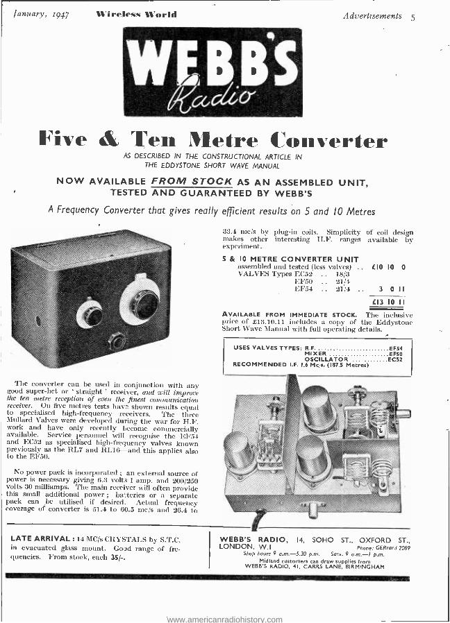
Five & Tell Metre Converter AS DESCRIBED IN THE CONSTRUCTIONAL ARTICLE IN
THE EDDYSTONE SHORT WAVE MANUAL
NOW AVAILABLE FROM STOCK AS AN ASSEMBLED UNIT, TESTED AND GUARANTEED BY WEBB'S
A Frequency Converter that gives really efficient results on 5 and IO Metres
The converter can be used in eonjunction with any good super -het or ' straight ' receiver, and will improve the ten metre reception of even the finest communication receiver. On five metres tests have shown results equal to specialised high- frequency receivers. The three Mullard Valves were developed during the war for H.F. work and have only recently become commercially available. Service personnel will recognise the EF54 and EC52 as specialised high- frequency valves known previously as the RL7 and RL16 -and this applies also to the EF5O.
No power pack is incorporated ; an external source of power is necessary giving 6.3 volts 1 amp. and 200 /250 volts 30 milliamps. The main receiver will often provide this small additional power ; batteries or a separate pack can be utilised if desired. Actual frequency coverage of converter is 51.4 to 60.5 mc/s and 26.4 to
33.4 mc/s by plug -in coils. Simplicity of coil design makes other interesting H.F. ranges available by experiment.
5 & IO METRE CONVERTER UNIT assembled and tested (less valves) .. 410 10 0 VALVES Types EC52 .. 18/3
FF50 .. 21/4 EF54 .. 21/4 .. 3 0
413 IO II AVAILABLE FROM IMMEDIATE STOCK. The inclusive price of £13.10.11 includes a copy of the Eddystone Short Wave Manual with full operating details.
LATE ARRIVAL : 14 MC /s CRYSTALS by S.T.C. in evacuated glass mount. Good range of fre- quencies. From stock, each 35/-,
USES VALVES TYPES: R.F. EF54 MIXER EMI OSCILLATOR EC52
RECOMMENDED I.F. 1.6 Mc,s. (187.5 Metres)
WEBB'S RADIO, 14, SOHO ST., OXFORD ST., LONDON, W.I Phone: GERrard 2089
Shop hours 9 a.m. S.30 p.m. Sots. 9 a.m. -I p.m. Midland customers can draw supplies from
WEBB'S RADIO, 41, CARRS LANE, BIRMINGHAM
www.americanradiohistory.com

6 Adz'ertisement U'irelenti World :nilal . I() F7
VOCÒ A`.IN'ONE
Rpp10METER
feete ewytiu;iq eke-fetid RADIO, HOUSEHOLD APPLIANCES
& MOTOR CAR LIGHTING ETC/
TYPE TRMSS Max. Capacity
30 + 30 pF
List Price
LI 7 : 6 each
60 + 60 LI :10:0 80 + 80 LI :12:0
100 +100 LI :17:6 Air Gap 082e
SYDNEY S. BIRD & SONS, LTD. Cambridge Arterial Road, Enfield, Middlesex.
Phone: ENField 2071 -2. Telegrams: "Capacity, Enfield.'
Ask your local Factor to show you one of these remarkable instruments and to put
your name down on his waiting list.
cELESI1ON
LOUDSPEAKERS Chassis Diameters range from
2" to 18'
Power Handling Capacities range from 25 Watt to 40 Watt.
Celestlon Lip head Kingston- upon -Thames
Telephone : KiNgston 5656 -7 -8
www.americanradiohistory.com

fan nary, 1(47 Wireless World . cl ..."rty,rements 7
CAPACITORS PAPER ELECTROLYTIC MICA
SILVERED MICA CERAMIC
aaa 40 ream
HODRAsr, cAPAC I TOR
0`1 vo.c.wt,c, y,OC.SIKG
IVE CI? 5c;
O\0
NORTH ACTON LONDO W 3 Telephone, ACORK(0061
www.americanradiohistory.com

8 Advertisements
PERTRIX REDRESSED FOR PEACE
PERTRIX BATTERIES have
emerged from the testing ground
of war as more reliable, more
'efficient than ever before. You
will soon see them in the smart
new post -war pack shown above.
It denotes the finest battery for radio use yet made.
HOLSUN BATTERIES LIMITED 137 Victoria Street, London, S.W.I.
P.l.d
Wireless World
a
January, 1947
Let .911/0&sle.fottic*ados
ttritams
Si
REPRODUCERS &LIFIERS LTD. WOLVERHAMPTON. ENGLAND.
fAM RADIO
SERVICING DA `TEST SET TypeaT
Designed with the latest movement this 3I" simplified test set has clear scale reading and 12
D.C. ranges: 100 mV (with ext. shunts) 2,
6, 120 and 300 volts, 1, 6, 600 mA, 6 amper- res, 50,000 ohms, with 2000 at centre. PRICE 16 0 0
12 D.C. ranges
No switches to go wrong
Long clear scales
Positive push button selection
Easily serviced
Designed to stand heavy overloads
Accurate in any position
1000 r per voit
SIFAM ELECTRICAL INSTRUMEN'
CO. LTD., TORQUAY,
DEVON
www.americanradiohistory.com

January, 1947 Wireless World Advertisements 9
kí Pen. 45
Filament Voltage 4.0V g Filament Current 1.75A Maximum Anode Voltage 250V Maximum Screen Voltage 250V Mutual Conductance 9.0mA/V
AIL 4111k Ak 4111. Pen. 383
Filament Voltage 38.0V ill Filament Current 0.2A Maximum Anode Voltage 200V Maximum Screen Voltage 200V Mutual Conductance I2mAIV
The Pen. 45 designed for use in A.C. Mains Receivers,
and the Pen. 383 in AC /DC Receivers, are Beam Power
Amplifiers.
Under normal operating conditions the Pen. 45 will give a
Power Output of 4.85 watts and the Pen. 383 of 4.3 watts for
5% Third Harmonic Content and with the Second Harmonic
not exceeding 5 %.
MAZDA RADIO VALVES AND CATHODE RAY TUBES
THE EDISON SWAN ELECTRIC CO. LTD., 155, CHARING CROSS ROAD, LONDON, W.C.2
H
www.americanradiohistory.com

10 Advertisements Wireless World January, 1947
GIVES STABILITY
IN INSULATION
I%are 5nc more 'lead;ng r:antfactarers rely MEG....
tYE whit dtací/y
A copy of the recently printed Broct.ure " Stability in Insulation " wi1 gladly be sert to nose applying on Fusicess Heading or Card and enclos ng 2d. to comply Tith the Coctrd of Paper (No. 43) Oder, 5942 - -,
LEWIS BERGER & SONS LTD. (Established 1760) 35 BERKELEY SQUARE, LONDON, W.l Ts ephone : MAYfair 9171
M A N U F A C T U R E R S O F I N S U L A T I N G V A R N I S H E S A N D E N A M E L S
EARTH F R E E
rleftt ad the ,5-tars
Afaitetadi., VIBRATOR PACKS
PROMPT DELIVERY NOW ASSURED
ASTERt)I® LTD VIBRANT WORKS WATFORD - HERTS
fIEWTYPES FOR MIDGET RECEaVEitS
HEARING AIDE METEOROLOGICAL
INSTRUMENTS ETC.
THE SCIENTIFIC VALVE
$8.ITISli MADE
LI I JA( U I T, D Greenhill Crescent. Phone H,AR
L Harrow on the IHill.Mi3dr. 08
www.americanradiohistory.com
January, 1947 Wireless World Advertisements ii
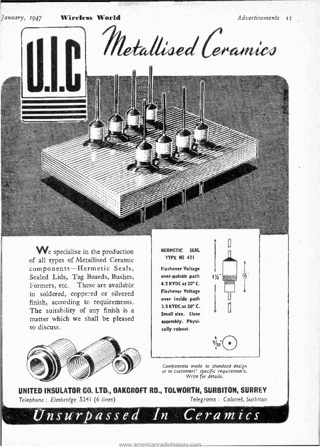
We specialise in the production of all types of Metallised Ceramic components- Hermetic Seals, Sealed Lids, Tag Boards, Bushes, Formers, etc. These are available in soldered, coppered or silvered finish, according to requirements. The suitability of any finish is a
matter which we shall be pleased to discuss.
HERMETIC SEAL
TYPE HS 421
Flashover Voltage
overtoutside path
4.5 KVDC at 20° C.
Flashover Voltage
over inside path
3.5 KVDC at 20° C.
Small size. Close
assembly. Physi-
cally robust.
Components made to standard design or to customers' specific requirements.
Write for details.
UNITED INSULATOR CO. LTD., OAKCROFT RD., TOLWORTH, SURBITON, SURREY
Telephone : Elmbridge 5241 (6 lines) Telegrams Colonel, Surbiton
Unsurpassed In Ceramics www.americanradiohistory.com
I2 .9dvcrtiNt'rliC711s
De La Rue Insulating Sleevings protect electrically,
mechanically and methodically. Produced in diam-
eters from o5 mm., in four types to British Admiralty
and Air Ministry specifications - Varnished Cotton,
Varnished Rayon and Rolled Silk. Wide range of
single colours, stripes and multiple colours
takes care of the most elaborate coding.
A
it4/ y
f l
FFk /pGf
De La Rue Insulation Limited IMPERIAL HOUSE REGENT STREET LONDON WA ENGLAND Lela: REGent 2901. Cables: Delinsul, Piety, London
D.A.IOD (q6)
%Wireless World January, 1947
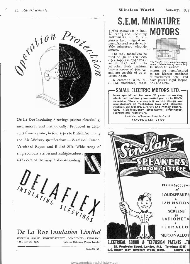
S.E.M. MINIATURE FOR special use in Indi- MOTORS cating and Recording Instruments, S.E.M. en- gineers have designed and manufactured very depend- able miniature electric motors. - -
The A.C. model can be used on 5o or 200 -1,000 c.p.s. supply at 25 -3o volts, and the D.C. model up to 24 volts. Both machines have a torque of 4 -in. oz. and are capable of up to to,000 r.p.m.
In common with all S.E.M. machines, these
The S.E.M. A.C. miniature electric motor. Dimensions of motor body I #" long by I }" diameter.
motors are manufactured to the highest standards of mechanical detail and have passed rigid inspec- tion and tests.
SMALL ELECTRIC MOTORS LTD. have specialized for over 30 years in making electrical machinery and switchgear up to IO kW capacity. They are experts in the design and manufacture of ventilating fans and blowers, motors, generators, aircraft and motor genera- tors, high- frequency alternators, switchgear, starters and regulators.
A subsidiary of Broadcast Relay Service Ltd.
BECKENHAM KENT
Manufacture of
LOUDSPEAKE
LAMINATION
SCREENS In
RADIO META
PERMALLO
SILICON ALLO
ELECTRICAL SOUND & TELEVISION PATENTS LT 12, Pembroke Street, London, R.I. Terminus 4355
2/4, Manor Way, Boreham Wood, Herts. El*ee 21
www.americanradiohistory.com

Jranraarv, 1947 ireleto, World aticcrtiscrracnts T3
POINTERS FOR DE5IGNERS
THE X6IM An indirectly heated 6.3v. frequency changer of the Triode -Hexode type, the OSRAM X6IM is suitable for operation up to 60 megacycles per sec. (5 metres). Outstanding features include :-
High conversion conductance for comparatively low cathode current, improving signal to noise ratio. Signal handling capacity is such that negligible distortion is apparent up to 5 volts R.M.S. on the signal grid. Negligible pulling " when tuned anode oscillator is used, making ganging of tuned circuits easy.
Control characteristic is designed to work in combination with KTW6I as IF amplifier, giving maximum control on both valves with negligible distortion.
A detailed technical data sheet is available on request.
Osram , ; Osram PHOTO CELLS CATHODE RAY TUBES VALVES
Advt. of The Genera Electric Co. L:d., A ;.-c House, Kinysway, London, W.C.2.
www.americanradiohistory.com

14 Advertisements Wireless World
r1oworrow begn yeSiepda
Quality reproduction is the Goodmans' tradition established in a yesterday when a pioneering spir it
and a policy of " best only " in craft and material brought achievements outstanding in Sound Repro-
duction. Tnily a firm foundation for confidence that Goodmans will assuredly maintain their tradition in developments yet to come.
The 12 ins., illustrated, handles 15 watts of undistorted power.
ERRATUM : The IS -inch Speaker illustrated in our advertisement in the December issue: is
No. TIO /I501/1S, and not as stated in the advertisement.
GOODMANS zouisp
January, 1947
FIDELITY
EFFICIENCY -
GOODMANS INDUSTRIES LIMITED, Lancelot Road, Wembley, Middx.
The Peak of Perfection! in Radio Reception has been attained by the latest S. G. BROWN, Type K
De.cr ;ptive Brochure " W.W.K." will be sent
free on request.
Telephone : ACOrn 5021
VICTORIA
MOVING COIL HEADPHONES Where High Fidelity Re- production is required such as for DX work, Monitoring and Laboratory purposes, etc., these precision -built Moving Coil Headphones will be highly appreciated
Technical Details :
D.C. RESISTANCE - 94 ohms per pair
IMPEDANCE - 104 ohms Q 1,000 c.p.s.
SENSITIVITY - BDbs. above I microwatt per bar ® 1,000 c.p.s.
PRICE £5 . 5 . U PER PAIR
ROAD, NORTH ACTON, LONDON, W.3
-M.R. SUPPLIES Ltd.- give immediate delivery from stock of the following high-class and brand new RADIO AND ELECTRICAL MATERIAL. All prices nett. CURRENT FED MICROPHONES, by prominent maker. Require no amplifier. Feed directly Into 15 -ohms speaker via aeeoeiated transformer, in conjunction with 12 -volt battery. Ideal for intercom., alarm and calling systems, etc. Hand type, with transformer, £4110/ -. MOVING COIL MICROPHONES, special limited offer of Reelo Senior model on reed - lent mount, very One reepon,e, 15 -ohms coil, 6 /16th inch mount, £4/101- (5 /16th inch to i inch adaptors, 1 /6). ROTHERMEL PIEZO -CRYSTAL MICROPHONES (exclusive offer) D.104 specially housed with knuckle -joint for angle adjustment. fin. mt., Oft. screened lead. ttached, 75/ -. Also same make P.C. deaf -aid inserte, lien., din., 29/6.
HIGH -FIDELITY LOUDSPEAKERS. We give immediate delivery of the fine Vitavos P.M. Speakers, %12 /10 (10 -watt) £7, $12/20 (20- watt), £11, despatch either 5 /.. Both have 15 -ohm, coil and Tieonal magnet. Also in stock, the new Vltavos Bl -Tone, with 12 -inch P.M. Speaker and Tweeter Unit with 6 -cell Horn and Filter, now in Ilse walnut polished cabinet with louvred speaker grille, 16 -ohms imp., handling up to 20- watts, £31/10/- (despatch 6 /.). VIBRATOR PACKS. Input 6 v. D.O. Fully smoothed output 200 v. 100 ma. In steel cabinet 81k,. by 611n. by 5in., with fusee, switch, etc., very efficient unit,. 25/101- (despatch 2/6). ROTHERMEL PIEZO- CRYSTAL PICKUPS. Senior ball -bearing model with stream- lined arm, 56/3. Same make replacement Crystal P/U Heads for Garrard and Collar, arms, 48/11. Rothermel SAPPHIRE NEEDLES, beat permanent needle, 12 /8. STROBOSCOPES for gramo -speed teat under 60 o. lighting, 78, 79 and 80 r.p.m. (on cardboard), 1 / -. P.O. Type RELAYS (Brand new goods). Large selec- tion available. Examples: -Coll 250 ohms, switching 2 -pole make, 5/ -. Con 250 ohms, 4 makes, 6/ -. Con 2,000 ohms, 1 -pole C.O. and 1 make, 6/6. GRAMPIAN OUTFIT TRANSFORMERS. best replacement type providing 8 ratios- ell matching. 9/6. HEAVY DUTY OUTPUT TRANSFORMERS. Our improved " W.W." model is still supreme. Adequate anppllee again in stock. Handle. 25- watts, 11 ratios from 12/1 to 75/1 with C.T. for P.P. wt. 91 lb., 59/6 (despatch 1/6). PRECISION MEASURING INSTRUMENTS of highest spec. by B.P.L. Panel Meters (Ouch 3l in.) 0/1 ma., 59/6, 0/500 microempe 65/- (Square type 67/6). 0 /100 micro amp., 75/ -. Combined Instruments, new portable model, 17 range,. In moulded housing 6lln. by 411n. by 3in. with range switching. D.C. volts : -0 ¡75 mV, A.C. /D.C. volts: -0 /10, 50, 100, 500 and 1,000. D.C. miliamps. -O, 1rO, and 600. Reeietance: 0 /1,000 ohms and 0/100,000 obme (0 /1 megohm with ext. battery). With test prods, £8/15/ -. CAPACITY BRIDGES, in lacquered steel cabinet 81ín. by 6115. by 4fin. A.C. mains operated. Measurements: -Capacity -10 pf. to 110 ,ofd,. Reeietance -1 ohm to 11 megohme. Ineufatlon- 60,000 to 500 megohmx. Power Factor-0 to 60 per cent., £18/15/ -. SIGNAL GENERATORS, A.O. main, operation. A.C. Frequencies: 100/250, 250/650, 650 /1,600 Ke /e. 1.6/4.5, 4.5/12 .
12/30 Me /e. Accuracy 1 per cent. 1 v. In 10 ohms. All rangea mod. to depth of :SO per cent. by internal 400 c. oscillator. din. illuminated scale. £21(deepatch 2/6). STEP -DOWN MAINS TRANSFORMERS, suiting recttlkre (below). Primaries at 200/250 v. (tapper). Sec.: -7, 11 and 15 v. 2 amps, 21 / -. Sec.: -6,8 and 14 s. at 4 amp.. 32/6. Sec.: -5, 12 and 17 v. 6 amps, 49/6. Sec. :-7 and 15 v. 1., amps, 75/- (despatch 2 16). STC METAL RECTIFIERS Selenium). 12 v. 1.5 amp, 12/6. 12 v. 4 amps, 22/6. 12 v. 6/8 amps, 39/6. 12 v. 10/12 amps, 06. 30 v. 8 amps, 24/17/6. 26 r 6 cmps, 82/6.
Please include sufficient for packing and despatch. M.R. SUPPLIES Ltd., 68, New Oxford Street, London,W.C.1.
Telephone: MUSeum 2958
www.americanradiohistory.com

ttn lit ery, 7947 irr.le%y VVerld Advertise77cents 15
BEHIND THE SCENES AT GARDNERS' FACTORY
The Soo- 800watt Redifon G.4o transmitter
REDIFON G.40 A new transmitter of exceptional
adaptability THE Redifon G.4o transmitter is a post -war design
available with alternative R.F. and Modulatoi units, enabling the user to select exactly those services which fit each individual requirement. Maximum out- put power is over 80o watts on C.W., or 500 watts for Telephony or M.C.W.
In its simplest form, the Redifon G.4o is a C.W. transmitter for medium or shortwave communication. A frequency range of 137 Kc /s to 25 Mc /s is covered by 4 alternative R.F. units, any two of which can be fitted into one set, operating simultaneously or on instantaneous switch -over.
As a telephony' station, the G.4o can be fitted with one R.F. unit and a Modulator to give 50o watts for broadcast or communication purposes.
The G.4o is ideal for medium -sized airports, where an M.F., C.W. beacon is required for navigation, and S.W. telephony for ground -to -plane communication. For this role a special model is available with a 500 - watt telegraphy channel and an independent 25o -watt telephony service.
For full details of the Redifon G.4o write to our Communications Sales Division.
Rediffusion Ltd. Designers and Manufacturers of Radio Communication
and Industrial Electronic Equipment
BROOMHILL ROAD, LONDON, S.W.18
. . . &sae emdg t Gardners' reputation for complete dependability is no accident. It results from a combination of first -class design, highly trained operatives, and
high -efficiency machines in a modern factory. Precision is the keynote in every operation.
CARONE RS S ourer f ord
TRANSFORMERS and CHOKES for immediate delivery
PLEASE SEND, WITHOUT OBLIGATION, COMPLETE LISTS OF SOMERFORD TRANSFORMERS & CHOKES
Name Address
GARDNERS RADIO LTD., BOMERFORD, CHRISTCHURCH, HANTS.
FOR RADIO INDUSTRY LABORATORY
www.americanradiohistory.com

6 /1 (1/ rtiseiiicil I.
THE PROBLEM - OF THE LABORATORY BATTERY . e
solve it simply and easily by installing a
w E STAT FULLY AUTOMATIC
RECTIFIER EQUIPMENT
250 -watt* equip- ment with cover removed to show internal con- struction. No gas
discharge tubes, barreters, D.C. saturated chokes or relays.
Battery automatically maintained in a charg- ed and healthycondition despite erratic loads.
Battery cannot be overcharged even if left unattended for very long pericds. Maximum cell voltage is accurately controlled.
Battery cannot gas and, therefore, will not give off corrosive spray. " Topping -up " is
seldom required.
Battery cannot be overdischarged - the " Westat " automatically provides a heavy charge when battery voltage is low.
Battery life prolonged without any added attention.
Fully compensated for mains voltage variation.
* Made in a range of sizes with outputs from 40 to 1800 watts
Write for descriptive pamphlet No I I L to Dept. W.W.
WESTINGHOUSE BRAKE & SIGNAL CO. LTD. 82, YORK WAY, KING'S CROSS, LONDON, N.I
Wireless World Ja !War . 1947
Whether the building of your receiver is a hobby or to provide entertainment in the home, selec- tion of the final component demands the same attention as
other details of the circuits. Stentorian Speakers are designed to match any desired impedance.
They give such a faithful repro- duction that you will at once appreciate the aifference.
WHITELEY
PRICES Minor Type NIX (for Low Impedance Extension) 39, 6. Minor Type MO (with Universal Transformer) 45i6. Baby Type BX (for Low Impedance Extension) 53/6. Baby Type BO (with Universal Transformer) 59/6.
ELECTRICAL RADIO CO. LTD., Mansfield, Notts.
s uz: n¡r ror
lieciagiummatto
,4.(411"/
R4DIO select few Manu-
facturers AMBASSA00enfoothe
their
BRITAIN AMBAS-
SADOR
I Tr not surpbe can
ure to Broch WORKS
ANIBASSADOHÚTCHIN LANE,
SE, BRIG YORKS.
Va\\N.\\\\\\\ \ www.americanradiohistory.com

Juralr-r y, 1947 Wireless World
Tfllí lS Till 8,8, SRV f,
1 dvertisements 17
PLOTTING THE COURSE
SATUMPAY
Thearmi,, YOU WILL
BE SITTING IN
THE STALLS
IF YOU'RE
USING...
The perfect pair for battery Radio sets
THE CHLORIDE ELECTRICAL STORAGE CO. LTD
CLIFTON JUNCTION, NR. MANCHESTER
sD86D
IN TOMORROW'S WORLD
In the world of to- morrow, as in the world of
yesterday and to -day, Marconi's will carry forward
the tradition of meticulous workmanship in com-
munications apparatus.
New problems have been met as they have arisen
by a team of experts with all the experience of a
pioneer organisation behind them. Still newer
problems are now arising in a post -war world.
These too will be handled with the same
resourceful skill. Whatever the demands of a
new age -you know where you are with Marconi.
MARCONI l 1ated ylaor mildew
MARCONI'S WIRELESS TELEGRAPH COMPANY LTD
THE MARCONI INTERNATIONAL MARINE C O M M U N I C A T I O N C O M P A N Y L T D
MARCONI HOUSE, CHELMSFORD, ESSEX
www.americanradiohistory.com

i8 Advertisements Wireless World januar)' IO-fi
METALLISED CERAMICS Two new S.P. metallised bushes
one at either end of the range
For full information and prices please write to:
STEATITE & PORCELAIN PRODUCTS LTD. STOURPORT -ON- SEVERN, WORCS. Telephone: Stourport III. Telegrams: Steatain, Stourport.
P 42
www.americanradiohistory.com

Wireless World Proprietors:
ILIFFE & SONS LTD.
Managing Editor: HUGH S. POCOCK,
M.I.E.E.
Editor: H. F. SMITH
Editorial, Advertising and Publishing Offices:
DORSET HOUSE, STAMFORD STREET,
LONDON, S.E.I. Telephone
Waterloo 3333 (50 lines). Telegrams :
" Ethasorld,Sedist,London."
Lb
PUBLISHED MONTHLY
Price: 1/6
(Publication date 26th of preceding month)
Subscription Rate: Home and Abroad 20/- per annum.
Radio and Electronics 36th YEAR OF PUBLICATION
JANUARY 1947 MONTHLY COMMENTARY .. TELEVISION RECEIVER CONSTRUCTION -I ..
NAVAL RADIO EXPANSION By G. M. Bennett
SHORT -WAVE CONDITIONS By T. W. Bennington
SIMPLE VALVE VOLTMETER By H. W. Baxter
NOISE FACTOR -2 By L. A. Moxon . .
FIRST STEPS IN V.H.F. EXPLORATION By " Cathode Ray " .. . .
WORLD OF WIRELESS .. .. LETTERS TO THE EDITOR
VACUUM CONDENSERS By H. A. H. Griffiths
DESIGN DATA (so) : Wide -Band Amplifiers
THE RADIO INDUSTRY By D. A. Bell .. " MAGIC EYE " INDICATORS By G. O. Thacker
and R. Y. Walker .. .. .. SOCIETIES AND CLUBS .. UNBIASED By Free Grid.. .. RANDOM RADIATIONS By " Diallist "
RECENT INVENTIONS
I
2
6
8
9
II
IS
18
2I 23
2
27
3o
32
34
35
38
Branch Offices: COVENTRY:
8 -I0, Corporation Street. Telephone : Coventry 5 =1o.
Telegrams :
Au t,. car, Coventry.,.
BIRMINGHAM :
King Edward House, New Street.
Telephone :
Midland 71y? (7 lines). Telegrams :
" Autopress, Birmingham."
MANCHESTER :
260, Deansgate, 3. Telephone :
Blackfriars 441.2 (4 lines). Telegrams :
" Iliffe, Manchester."
GLASGOW :
26B, Renfield Street, C.2. T,iephonr: Central 4567.
Telegrams: " Riffe, Glasgow.'
A As mans' of the citaiits and apparatus described in these pages are covered by patents, readers are advised, before making use of them, to satisfy themselves that they i.o..ld
not be infringing patents.
A NEW ADVENTURE FOR
NOW AVAILABLE FROM Premier Radio LONDON Webb's Radio LONDON Brighton Trades Services BRIGH FON Amateur Radio BUkNLEY Clydesdale Supply Company GLASGOW F. J. Ansel! IPSWICH Jack Bryant NORFOLK Southern Radio SALISBURY
YOU CAN NOW GET CERAMIC SWITCHES IN A NUMBER OF USEFUL COMBINATIONS FROM
YOUR DEALER Wearite Ceramic Switches, hitherto restricted to Government and other priority uses, are now released. See your dealer and have your Ceramic Switches built to your specification from his kit of Wearite Switch Components. The finished job will be robust, trouble - free, and backed by the famous Wright & Weaire reputation. If any difficulty is encountered, please contact us.
W E A R I T E - -7- CERAMIC SWITCHES
.4eyou2aial`a,6-y WRIGHT & WEAIRE Ltd., High Road, Tottenham, London, N.17. Tel. : Tottenham 3847,9, and Simonside Works,South Shields,Co. Durham
www.americanradiohistory.com

20 Advertisements Wireless World fanNarV. 1917
VALVES AND THEIR APPLICATIONS By M. G. SCROGGIE, B.Sc., A.M.I.E.E.
' No. 1: Mullard 15 WATT PENTODE EL31.
HE Mullard EL37, even more than most valves, 1 resembles a human employee in that the output
obtainable from it depends very much on the care one is prepared to take to see that its working con- ditions are right. If one is content with, say, 10 watts, a good deal of latitude is allowable. A single valve will do, and there is not much point in exceeding 250 volts on anode and screen. Self -bias and a touch of negative feedback help to compensate for any variations in load, power supply and so forth. In this role, however, the EL37 is under -employed. A pair of them in a Class AB 1 circuit is capable ideally of delivering as much as 70 watts audio with less than 3% total harmonic distortion, the anode plus screen efficiency being 50 %. This, it should be noted, is without running into grid current; so the driver stage is straightforward. But special care
- should be taken over these points : .
1. The grid bias (nominally - 35V) must be con- stant, and preferably separately adjustable for the two valves.
2. Anode and screen supplies must be practically constant at 400V over a range of 100 -276mA and 12 -73mA respectively.
3. Load matching must be good. The optimum is 3250 ohms anode -to- anode; and power - handling capacity falls off rapidly outside the limits 2400 -5000 ohms.
4. The output transformer must be well designed. Low efficiency runs away with many of the watts; and excessive leakage inductance accentuates variations in load impedance.
5. If negative feedback is used, 7% is sufficient to give a 1 : 1 speaker -to -valve impedance ratio, and raises the dri ve required from 34 + 34 to about 60 + 60 ` /'Peak. To avoid magnifying hum, feedback is best taken from the trans- former secondary.
6. Anti -parasitic stoppers should be used (33Q for anodes and screens; 1000Q for control grids).
7. The pair of valves should not be driven so that the mean power per anode exceeds 25 watts for many seconds at a time. In other words, it is all right on speech or music, but the screens would object to maximum watts of continuous tone.
8. Even with all due care, it is too much to expect perfect supply stabilization valve matching, load matching and output transformer; so 50 -60 watts would be a wiser maximum power rating.
If you want a substantial output, but are worried about meeting the above conditions, there is a com- promise that yields 35 watts and is practically overload -proof. Thanks to self -bias, it demands much less of the supply voltage regulation. These are the working conditions for a pair of valves :
Va 400 V No signal 125 mA
1a l 225 V Max. signal 140 mA
Ig2 I 11052 No signal 13 mA
1 Ra -a 7000Q Max. signal 25 mA Grid rive at 35 W output : 18 + 18 peak Total harmonic distortion at 35 W out-
put: <2.5 %.
Vgl
Rk
This is the first of a series written for us by M. G. Scroggie, B.Sc., A.M.LE.E., the well - known Consulting Radio Engineer. Reprints for schools and technical colleges may be obtained free of charge from : THE MULLARD WIRELESS SERVICE CO., LTD., TECHNICAL PUBLICATIONS DEPARTMENT, CENTURY HOUSE, SHAFTESBURY AVE., W.C.2
www.americanradiohistory.com

Wireless World Radio and Electronics
Vol. LIII. No. 1 JANUARY, 1947 Price Is. 6d.
Monthly Commentary B.B.C. : 1947 -1952
WHEN the White Paper on Broadcasting Policy was issued a few months ago we criticized it on the grounds that it showed
too much timidity. Naturally enough, the new B.B.C. Charter, of which the general terms were foreshadowed in the White Paper, contains equally little of the spirit of adventure. Changes intro- duced are trivial ; indeed, some of them seem to us so trivial that they might well have been omitted altogether. Although we have never pressed for any sweeping changes in the constitution of
British broadcasting we regret that an opportunity has been missed for giving a trial to some of the measures that have been put forward for curing - the admitted weaknesses of the present service.
Barring any major upheaval, we are thus com- mitted to the status quo for a further period of
five years. In that fact Wireless World, though admitting to some regrets, sees no cause for des- pondency. The existing system though often criti- cized, suits the British temperament, and has great achievements to its credit. Proposals for changes in the basic concept of our system have seldom been backed by plausible arguments, and have generally failed to secure any widespread sup- port. But some of the major reforms that seem
worthy of trial, though not running contrary to
the real basis of the system, could hardly be given effect inside the framework of the Charter, and so must be postponed for five years. However, lesser changes could certainly be introduced with- out new legislation, and there is no reason why the B.B.C. should rest on its oars for five years.
Broadcast Licence Changes WE were recently impelled to criticize the
terms of the broadcast receiving licence as unnecessarily restrictive. Our main com-
plaints were that provision was not made for the
reception of telegraphic messages addressed to all stations and that the restriction of broadcast tele- phony listening to "authorized " stations gave an impression that the Postmaster General was assum- ing the rights of censorship ; grounds for sus- pecting that this was so were given by a gratuitous statement by a Post Office spokesman that listen- ing to the " Voice of Israel " station was not covered by the licence. Wireless World ascribed the P.O. attitude in these matters to over- cautiousness and excess of zeal in guarding its monopoly, rather than to " totalitarian " ten- dencies, as has been suggested in the lay Press.
Our first protest elicited the information that a form of licence permitting the reception of both telegraphic and telephonic broadcast and multi - destination wireless press messages was being pre- pared. This new licence, for which the royalty fee is £20, is now ready for issue. We are now informed that the ordinary broadcast receiving licence is being re- worded to allow the reception of both telegraphy and telephony from amateur stations. It is all to the good that the reception of telegraphy has thus to some extent been regularized.
We have been asked by the Post Office to correct a possible misconception of the term " authorized broadcasting stations," which appears on the licence. This should be defined as " all broad- casting stations in any part of the world which are operated under the authority of an Administration in accordance with the International Radio - Communication regulations." We gladly give this explanation, though probably few of our readers are under the false impression that " authorized " means " authorized by the G.P.O." We sym- pathize with the Post Office's efforts to discourage lawlessness in the ether, but this insistence on " authorized " seems to be unfortunate ; the restric- tion is bad because it cannot be enforced, it creates the impression- fostered elsewhere in the licence - of autocratic control and might also involve the need for some very awkward rulings.
www.americanradiohistory.com

roirti% '111 oriel /;/iteNary, ryfi
TELEVISION RECEIVER. 1.- Deflector Coils: CONSTRUCTION General Principles IN a television receiver in which
the electron beam of the cathode -ray tube is deflected
electromagnetically the recti- linearity of the picture, and the attainment of a good and even focus over its surface, depend very largely upon the deflector coils. Their design and construction are thus matters of the first import- ance, and it is unfortunate that hitherto very little useful informa- tion about them has been pub- lished.
This is undoubtedly because of the extreme difficulty of any quantitative analysis, for in such an analysis it is necessary to cal- culate the three -dimensional mag- netic field produced by the pas- sage of a current through coils of known physical shape. Such a calculation can only be readily performed when the coils have certain very simple geometrical shapes and it is found experi- mentally that such simple shapes do not give a performance which is adequate for television.
In general, therefore, design is carried out on an experimental basis, bearing in mind the general theoretical principles involved. The form of coil adopted must not only conform to these principles,
FOCUS COIL
U
rEFLECTOR COI
Fig. t. The deflection sensitivity is proportional to the length i of the deflector -coils and to the distance D between their centre
and the screen.
but it must also be such that it is possible to construct it without undue labour and without elabor-
As announced in the November issue of " Wireless World " construc- tional details of a television receiver, and of special components for it, are to be published. No previous practical experience of television should be needed for its construction, but it is assumed that the builder has good practical experience of ordinary sound -set construction and a knowledge of television circuit principles. Theoretical articles have appeared during the last year, and will be continued concurrently with the constructional ones.
ate tools. Because of this definite limitation it is very desirable to consider principles and construc- tion together.
In view of the lack of pub- lished informa- tion and the fact that pos- sible forms of coil are limited by mechanical feasibility, this article on the construction of scanning coil Is n e c e ssarily opens with a discussion of the principles. This is desirable in order that the reasons for the form of con- struction finally adopted, and Fig. 2. When the deflector coils described later are too long (a) the beam strikes in the article, the tube shoulder at A and is cut may be fully off, but with the correct length understood. (b) it just misses the shoulder.
The first step is to consider the general deflec- tion problem. The basic arrange- ment of cathode -ray tube, focus coil, and deflector coil is sketched in Fig. r with the path of the elec- tron beam shown dotted. The de- flection sensitivity, i g n o r in g second -order effects, is directly proportional to the distance D be- tween the screen and the centre of the deflection system and to the length i of the deflection system itself. It is always desirable to keep the sensitivity as high as pos- sible to economize in scanning power.
With a given tube the distance
from the screen to the front ends of the deflector coils is fixed, for the coils cannot normally come
further forward than the start of the tube
B flare. This is the distance D -1 /2.
The first fac- tor limiting the length of the deflection sys- tem is the need f o r avoiding beam cut -off on the tube shoulder. This can be seen in Fig. 2(a), which shows the path of a beam through a long deflector hav- ing a current such that, in the absence of the shoulder A, the beam would strike the screen towards its edge
at B. It is, however, intercepted by the shoulder at A.
With a given tube this can be avoided by reducing the length of the deflector coils and increasing the current to produce a stronger field and bend the beam more sharply, as shown in Fig. 2(b). It can be seen that with the shorter deflector the beam at maximum deflection just clears the shoulder at A.
The second factor affecting the length is the necessity for provid- ing a focus coil between the back of the deflector coil and the elec- tron gun. In general, a smaller
www.americanradiohistory.com

January, 1947 Wireless World
spot size can be obtained when the focus coil is moved towards the screen but the focusing cur- rent increases and there is more danger of deflection defocusing through overlapping of the focus- ing and deflection fields. A com- promise is often necessary and in general with modern ` short " tubes the length of the deflection system is more often limited by the requirements of focusing than by beam cut -off.
The deflection of an electron beam through a magnetic field is proportional to the strength of the field and in a direction at right angles to the field. A vertical field is thus needed for horizontal deflection and a horizontal field for vertical deflection. For a uni- form scan, the field must clearly be of constant strength and direc- tion across the area through which the beam passes.
If two large diameter coils are mounted horizontally in parallel planes, as shown in Fig. 3(a) and connected in series -aiding, the field between them depends on their separation, d. With circular coils, it is shown in elementary text -books of electricity and mag- netism that the field in the centre becomes most uniform when the spacing of the coils is equal to their radii.
When the coils are too widely spaced the field tends to bow out-
(a)
1
(b)
wards at the sides as at (b) and when they are too close it tends to bow inwards (c). When they
3
weaker because it is further from the coils.
Flat circular coils cannot be
(c)
Fig. 4. A thin slab coil bent to lie around the neck of the tube is
shown at (a) and a similar coil with the ends bent up at (b). A greater
effective length is secured with the latter. The way in which two pairs
of such coils are interleaved for the two deflections is shown at (c).
are correctly spaced the field is
substantially uniform (d), over a
large area. In order to obtain a uniform
field the two coils must be correctly spaced and the coils must be as large as possible. The size is usually limited by the need for interlacing two pairs of coils for the two deflections and also by considerations of deflection sensi- tivity, since if the coils are large the uniform field in the centre is
(c) (d)
\e
Fig. 3. The field between two parallel coils (a) depends on their separation
d. The dots in (b, c and d) indicate the cross -sections of the windings
and the general shapes of-the fields are shown when the separation is
too great (h), too small (c) and optimum (d).
placed closely enough for a uni- form field unless they are of pro- hibitively large diameter, because .they must be separated by at least the diameter of the tube neck. If
is usual, therefore, to adopt rect- angular coils with the " sides " lying parallel to the tube neck and the " ends " bent around it. The shape of the coil then has the basic form sketched in Fig. 4(a).
The shape of the field can then be controlled not only by the spacing of the two coils, but by the cross -sectional- shape of the winding, which can be circular, square or rectangular.
The required deflection field is produced chiefly by the straight sides of the coil lying parallel to the neck of the tube, and it is this part which must be as long as pos- sible. The simplest method of construction is to wind a rectangu- lar slab coil, in a suitable former, tie it up, remove it from the former and bend it around a cylin- der of the same diameter as the tube neck to form a coil of the shape sketched in Fig. 4(a). Al-
www.americanradiohistory.com

elevision Receiver Construction - though it is simple to make, such 3 coil does not give the maximum useful field, for the effective length of a side is the distance l between the centres of the end parts.
If the coil is of square section, so that a = b = c, the loss of length is small, but if a is greater than c, it can be appreciable and a greater effective length can be secured by so winding the coil that the dimen- sion a is about the same as c. When the overall length is 2lin, the sec- tion of the side limbs might well be ¡in for b and }in for c. With a coil like Fig. 4(a), the effective
( e )
length l would be 2i -I = i kin when a is also ¡in. By making the coil in the form of Fig. 4(b), the effec- tive length can be increased to 21- -1-= z *in, for the part a be- comes }in only. This represents an increase of 13 per cent in the sensitivity.
As line deflection is usually con- sidered more difficult than frame and as the deflection amplitude is greater it is usual to make the line coils of the full available length and with a shape like that shown n Fig. 4(b). The second pair of
coils for the frame deflection is frequently made of the same shape, but with the dimension l
Wireless World January, 1947
shorter so that they will just fit inside the line coils as shown in Fig. 4 (c) .
This is a very satisfactory de- flection system. It is usually pro- vided with an iron " core," which is better termed a ring, since it lies outside the coils. Sometimes it consists of a stack of circular - shaped laminations around the coils, but in the writer's experi- ence this is unnecessarily elabor- ate. He has found that it is suffi- cient to bend a few strips of sili- con -steel around the coils. The purpose of the iron ring is to re- duce the reluctance of the mag-
(d) Fig. 5. One way of making coils similar to Fig. 4 (b) is shown here. A flat slab coil with rounded ends (a) is wound, and the ends are bent up (h) and the sides are twisted (c). The twisting is done by holding a side between two strips of wood and applying pressure in the direction of the arrows (d), so that the sides are twisted as in (c), which is more clearly shown in the end view (e).
netic path external to the coils and by so doing to increase the useful field inside.
As the complete magnetic cir- cuit necessarily contains as an air gap the whole distance across the neck of the tube, the reluctance of the total magnetic circuit is con- trolled largely by this air gap. As a result variations in the shape, quantity and kind of iron used for the external ring have a very small effect on the performance. Practically speaking it is sufficient
if there is some external iron. It was said earlier that the re-
quired field is produced chiefly by the straight sides of the coils. However, the ends must neces- sarily produce fields as well and it is through these that most of the troubles of magnetic deflection arise. If the coils were of flat rectangular shape the effects of the ends would not be serious. The fields produced by the ends would be substantially uniform and that produced outside the coil would tend to cancel that pro- duced inside. The cancellation would not be complete for the fields produced by the ends would lie at different distances along the tube and so exercise different ' ` leverages " on the electron
beam. However, in practice, the coils
are not flat bu dent, and in the simplest form are like Fig 4(a). The end fields then have a large radial component and are equiva- lent to very non -uniform fields, one acting across the tube parallel to the field produced by the side limbs and the other acting across the tube at right angles to this.
This seriously affects the recti- linearity of the picture. This could be corrected by adjusting the separation of the side limbs, but in addition there are compo- nents of the field which act length- wise along the tube and which thus have a focusing rather than a deflection action. Such fields are always present in some degree and their importance depends on their magnitude, their position and the deflection angle of the beam.
It can be said at once that the simple bent coils like Fig. 4(a) are satisfactory only for small angles of deflection. If the coils fit closely around the tube neck, as they must for efficiency, very seri- ous defocusing and picture distor- tion occurs with the large deflec- tion angles of modern " short " tubes.
This trouble is avoided by using the form of construction shown in Fig. 4(b) ; for by bending up the ends in the manner shown the field produced by the ends is moved further from the electron beam and so weakened over the volume where it is harmful. There is also a further point, without bent -up ends, the outer iron ring increases the " end " field nearly
www.americanradiohistory.com

January, 1947 Wireless World
as much as the wanted " side " field, but with bent -up ends it has relatively little' effect on the " end " field. This is because the ring then lies closer to the tube than the ends of the coil.
For good deflection the use of bent -up end coils is a necessity and the fact that they also tend to be rather longer, and so give greater efficiency, is really a minor point. Even if they were less effi- cient they would have to be used.
It is now necessary to consider how coils of this bent -up end type can be constructed. There are two methods -winding directly to shape or bending a flat -wound coil to shape.
Coils of the shape of Fig. 4(b) can be wound directly to the re- quired final shape on a special former. The wire needs manipu- lation around. four separate corners in each turn, however, so that the method is too laborious for anything but low- inductance coils. Practically speaking, it is limited to coils of less than about 200 turns apiece. For such coils, however, it is a very satisfactory method of construction.
Coil Bending
An approach to this shape can be obtained by a bending process illustrated in Fig. 5. For a start, a slab coil with rounded ends (a) is wound on a former comprising a core piece and side cheeks. The cheeks are slotted at intervals, so that after winding the coil can be tied up before removing it from the former.
It is taken off the former and the ends bent up as in Fig. 5(b) and the sides are then twisted (c) to bring the coil to the shape (e). The twisting is done by gripping a side between two strips of wood and applying pressure in the direct tions, shown by the arrows in (d).
The merits of this scheme are that there is no limit to the num- ber of turns that can be used and the winding itself is easy. Its great drawback is that quite a little skill is needed to carry out the bending and twisting process without ruining the coil. It can be done and, in fact, it is not nearly as difficult as it seems. However, the final shape is not quite what is wanted, for the ends do not start off away from the
tube along a diameter. It is a usable compromise, however.
The main difficulties of bending are brought about by the fact that the lengths of wire needed on the inside and outside of the bends are different. If the wire were rigidly held on both sides of a bend, the outside turns would necessarily be stretched ; with fine gauge wires there would inevitably be break- ages. However, if the wire is held rigidly on one side of the bend only, the necessary adjustment is obtained by the displacement of the turns in the unclamped part of the coil.
Now with bent -up ends, the whole purpose of the bend -up is to remove the end from the tube so that its field is of neglible im- portance. Therefore, the uni- formity of winding over the ends is itself of no importance. We thus conclude that during the bending process it is necessary to clamp rigidly those parts of the coil which will form the side limbs, but not the rest of the coil.
When bending, the wire sprays out horribly over the unclamped part, but can afterwards be. bunched neatly together. The result is a neat coil which is by no means difficult to make. For success in bending the coils it is essential to make a simple jig for holding the different parts.
There are thus two ways of making coils. Winding to shape is practicable only for low- induc- tance types, but bending can be used for either. However, bend- ing is actually slightly more suited to the many turns of fine wire of high -inductance coils than to the few turns of thick wire of low- inductance types, because the fine wire is rather more tractable.
Low -inductance coils must be fed from a transformer but high - inductance can be resistance - capacitance fed. In the case of the line deflection low- inductance
5
coils are a necessity because it is not practicable to make the coils with insulation adequate to withstand the several thousand volts which would be developed across high- inductance coils on the line fly -back.
For the line scan, therefore, a pair of coils of about 15o turns apiece and former wound to the shape of Fig. 4(b) is practicable and efficient, and the labour of construction is not excessive.
For the frame scan, high -in- ductance coils are electrically satisfactory and the transformer needed for low- inductance coils is, because of the low frequency, rather a difficult component. It must have a high primary induc- tance and it demands a large iron core and a considérable quantity of fine gauge wire. The primary turns needed are at least zo,000. Because of the labour of winding if no machine is available and be- cause both wire and laminations are not too readily available now, it is well to avoid the use of a transformer if possible.
It is thus desiíable to use high - inductance coils for the frame scan and this means some 1,50o- 2,50o turns per coil. Coils having the shape of Fig. 4(b) are a neces- sity, however, and there is con- sequently no alternative to the bending process.
Taking into account the electri- cal requirements of efficiency and performance, together with the need for economy of labour and materials, we conclude that for the line scan a pair of low- induct- ance coils is needed and that they are most readily constructed by winding directly to the required shape. On the other hand, for the frame scan high -inductance coils are more suitable and are most easily made by bending flat - wound coils to shape.
In a further article full construc- tional details will be given.
OUR COVER A FEEDER selector switch in the aerial switching tower at the B.B.C.'s high -power short -wave station at Skelton, near Carlisle, is illustrated on our front cover. Six of these switches, which are electrically rotated from the transmitter building, permits the output from each of the six transmitters to be connected to any one of six aerial arrays.
c
www.americanradiohistory.com

6 Wireless World January, 1947
NAVAL RADIO EXPANSION
PRIOR to the recent war wire- less equipment in the Navy was limited to installations
used for communication between ships, and between ships and the shore, plus ancillary equipment such as direction finders. The technical maintenance of this radio equipment, which was relati'ely simple compared with present -day gear, was in the hands of the Signal Branch. Naval executive officers who specialized in signals, com- missioned and warrant tele- graphists and telegraphist ratings -from Chief Petty Officer down to Boy Telegraphist -were re- sponsible both for the mainten- ance of wireless equipment and for its use.
Around 1935 it began to be- come apparent that the ever in- creasing technical complication of wireless equipment was making it difficult to train a single type of rating both to operate it effi- ciently and to maintain it adequately. The suggestion that a separate type of rating was necessary for technical mainten- ance duties, leaving telegraphists free to carry out their operating duties, was put forward. No great change had, however, been made when war broke out in 1939.
Then two new factors necessi- tated action. First, a vast ex- pansion in the number of tele- graphist ratings necessitated
Petty Officer Radio Mechanics working on the display panel of
a naval radar set
shortening training courses. This made it impracticable to turn the vast number of " hostilities only " telegraphist ratings into tech- nicians as well as operators. Secondly, radar was born. From its very inception into the Navy it was decided that it was out of the question, in view of its complications, to train the same men both to operate and main- tain radar gear. As a result the new rating of Radio Mechanic was introduced in 1940.
The necessary numbers could not be recruited and trained ex- cept over a period of years. The war was nearly over by the time responsibility for the maintenance of wireless equipment had been transferred to these new ratings, although they undertook radar maintenance from their inception.
Radio Mechanics
Space will not allow me to trace the vicissitudes through which the Radio Mechanic Branch has passed during the last six years. In view of the difficult circumstances in which this im- portant new branch was started, it is to the Navy's credit that they were successfully overcome. To cite but one example : Be- cause training courses had to be
Formation of
Navy's New
Electrical Branch
By G. M. BENNETT
limited in length specialization had to be accepted. Thus there were Radio Mechanics (R) who dealt with radar, (W /T) who dealt with wireless, and (WR) who dealt with the limited range of both wireless and radar in small ships.
In the beginning a certain num- ber of radio mechanics were entered direct from civil life with experience gained, for example, in the radio industry, whilst a fur- ther number were transferred from other branches of the Ser- vice. But the large majority were entered direct from every walk of life and trained from scratch by the Navy. They were first given a six months' course in basic radio theory and elementary workshop practice at a technical school. They then passed either to the Navy's Radar Technical School, H.M.S. Collingwood, at Fareham, or the Navy's Signal School, H.M.S. Mercury, near Petersfield, for their actual tech- nical training on Naval radar or wireless equipment. After some six months at one of these schools they went to sea, or to a shore radio station, as Leading Radio Mechanics. Subject to satisfac- tory service and recommendation they were rated Petty Officer Radio Mechanics after one year at sea, and Chief Petty Officer Radio Mechanic after a further three years.
So far as officers are concerned, Warrant and Commissioned Tele- graphists and Signal Officers re- mained responsible for the tech- nical maintenance of wireless equipment, though the enormous technical developments made in radio during the war indicated the desirability of relieving these officers of their technical respon- sibilities in order that they could devote their time to their execu-
www.americanradiohistory.com

January, 1947 Wireless World 7
tive " user " duties. With radar it was decided to recruit special technical officers as early as 1940. These were R.N.V.R. officers whose ranks ranged from Mid- shipman to Commander, the majority belonging to the Special Branch. They wore the distin- guishing mark of light green cloth between their stripes. Some en- tered direct from civil life, others were promoted from radio mechanic, but the majority were young men entered from the Uni- versities under the Hankey scheme. Some of the Dominions, notably Canada, provided a con- siderable quota. The actual length of training given to these officers in H.M.S. Collingwood varied. It started as a course of some two months and ended with one as long as a year.
In 1945, as a first step towards relieving Signal Officers and Warrant and Commissioned Tele- graphists of their technical duties with respect to wireless equip- ment, W / T Officers were intro- duced. They were in all respects comparable with the aforemen- tioned radar officers except that their training consisted of six months at the Signal School, H.M.S. Mercury.
It is of interest to record that on V.E. -day the following numbers of officers and ratings entered purely for radio maintenance duties, were serving in the Navy :- Radar and W/ T Officers
(including s o m e W.R.N.S. Officers) .. 800
Radio Mechanics' .. 5,000 W.R.N.S. Radio Mech-
anics .. .. 65o It should, perhaps, be added at
this point that none of the above was concerned with radio equip- ment fitted in aircraft of the Royal Navy. For its mainten- ance 33o Air Radio Officers, com- parable to the Radar and W / T Officers already mentioned, and some 4,700 Radio Mechanics and boo W.R.N.S. Radio Mec- hanics specialized 'to deal with airborne radio equipment were introduced. Thus on V.E. -day the Navy was using something over 1,1oo officers and 11,000 rat- ings for the maintenance of the radio equipment fitted in its ships, aircraft and shore stations in addi- tion to those officers and ratings
of the long -established Signal Branch who were partially em- ployed on such work.
By the time V.E. -day came the Navy was actively considering the future of radio maintenance in the Navy under peacetime conditions when, among other things, economy is essential. It was de- cided to combine radar and W / T officers into a single category to be called Radio Officers. The entry and training of radio mech- anics continued at a reduced rate. Applications were accepted from R.N.V.R. Radio, Radar and W /T Officers and from radio mechanics, practically all of whom were " hostilities only " ratings, to transfer to the R.N. on regular service engagements.
Formation of Electrical Branch But parallel with all these
changes the Navy had been giving a great deal of thought to the question of maintaining not only its radio but all its electrical equipment. Technical responsi- bility for non - radio electrical equipment rested with the Tor-
This resulted in a decision to create a new branch to be called the Electrical Branch. Its forma- tion has just been announced. It will be several years before it is in a position to take over its full re- sponsibilities from all the existing branches now concerned, for these extend to the technical aspects of all types of electrical and elec- tronic equipment in use ashore and afloat. Its officers will be Midshipman (LI, up to Captain (L). To start the Branch off con! siderable numbers of R.N.V.R. (Special Branch) Radio, Radar and W/T Officers, as well as officers from non -radio branches, have, and are being, transferred with appropriate rank and seniority. In future the large majority of officers will be ob- tained by the established Special Entry Scheme already in force for other branches of the Navy and by promotion from the Lower Deck. Their training, lasting some six years, will include a year at sea in a training cruiser, three years at Cambridge Univer- sity and two years in workshops and at H.M.S. Collingwood, now
Receiving portion of a naval long -range aircraft warning radar set being adjusted by a Petty Officer Radio Mechanic
pedo Branch. But, as in the case of the 'Signal Branch, it had be- come apparent that Torpedo Branch officers and men could not be adequate technicians and sea- men at the same time.
the Navy's principal Electrical School. Whilst all will receive a common training in all electrical equipment, a number will specialize in tadio.
As regards ratings electrical
www.americanradiohistory.com

8 Wireless World January, 1947
Naval Radio Expansion- artificers, electrical mechanics and radio mechanics already serving, or who volunteer to serve for, regular engagements are being transferred to the new Branch. In addition many seaman ratings who now hold non -substantive ratings in the Torpedo Branch and are consequently qualified to deal with electrical maintenance, will likewise be transferred together with a number of telegraphist rat - ifigs who have acquired a suffi- cient technical knowledge. They will be graded as Electrical Arti- ficers who will specialize in either radio or general electrical equip- ment, and as Electricians or Radio Electricians. For each type there will be the usual naval substantive rates up to Chief Petty Officer. Promotion both to Commissioned and to Warrant rank will be open to selected rat-
ings as in other branches of the Service.
There can be no doubt that the introduction of this new electrical branch is an important develop, ment in the history of the Navy and an important step towards en- suring that its vast amount of elec- trical and radio equipment is al- ways maintained in the highest state of efficiency. There can also be no doubt that it will offer an electrical and radio career second to none in the country.
Readers of this journal whose inclinations lean towards a life which, whilst taking them to sea and all over the world, enables them to exercise their bent to- wards radio, will be interested to note that the Admiralty is already calling for volunteers to be trained as both Officers and ratings for this new branch of the Navy.
SHORT -WAVE Expectations for January
By T. W. BENNINGTON (Engineering Division, B.B.C.
DURING November maximum usable frequencies for this
latitude continued to increase during the daytime and to decrease during the night, in accordance with the normal seasonal trend in the atmospheric ionization. There was not a great deal of ionosphere storminess, and exceptionally high frequencies were often usable over daylight routes. In order to give an idea of the very high frequencies which were oçcasionally propagated by the normal ionosphere layers it may be mentioned that reception from this country on frequencies above 40 Mc / s was several times reported from the West Indies and South Africa, while on one occasion an amateur U.S.A. transmitter in the 56 -Mc / s band was heard in this country. Long- distance propagation on such a very high frequency should not, however, be expected to become a frequent occurrence in these latitudes, unless indeed future sunspot activity far exceeds that of the last sunspot maximum. It should therefore be regarded as something in the nature of a " freak " effect, and only to be ex- pected on days of abnormally high ionization. As to normal reception
CONDITIONS on high frequencies during Novem- ber, the B.B.C.'s 26 -Mc / s trans- mission was regularly well received in many parts of the world, includ- ing New Zealand.
Though no very severe ionosphere storms occurred during November, there were several of moderate or slight intensity. These took place during the periods Ist -2nd, loth -11th, 16th, 19th -22nd and 24th -26th.
Forecast. -There should be very little change in either daytime or night -time M.U.F.s as between December and January : if anything, both will tend to become a little higher. In January, therefore, com- munication on the higher frequencies should be good for considerable periods, though the duration of such periods will be smaller than during later months of the year. Night- time M.U.F.s will be relatively low, and will remain operative for relatively long periods. At this stage of the sunspot cycle, however, it is not expected that frequencies lower than about 7 Mc /s will be neces- sary for night -time use over most circuits.
Below are given, in terms of the broadcast bands, the working fre- quencies which should be regularly usable during January for four long - distance circuits running in different directions from this country. In addition, a figure in brackets is given, which indicates the highest frequency likely to be usable for about 25 per cent of the time during
the month for communication by way of the regular layers :- Montreal : 0000 9 Mc /s (13 Mc /s)'
0100 7 1100 11 1200 17 or 21 Mc /s (28 ' ) 1400 28 (35 )
1700 21 , (29 )
1900 17 or 15 Mc /s (21 , )
2100 2200
11 9 ( ) (14
Buenos Aires :0000 9 (14 ) 0400 7 (12 )
0800 11 16 )
0900 17 or 21 Mc /s 28 ,, ) 1100 26 (34 1800 21 or 17 Mc /s(28 2000 11 (16 )
2200 9 (15 ,, )
Caps Town : 0000 9 (14 )
0600 11 (17 )
w 0700 21 (30 )
0800 26 05'. )
1600 21 or 17 Mc /s (28 ) 1800 15 (18 , 1900 11 (16 , 2000 9 (15
Chungking : 0000 7 (11 )
0400 9 or 11 Mc /s (14 )
0600 15 or 17 Mc /s (20 )
0800 21 1100 17 (26 )
1200 11 1300 9 (14 )
2000 7 (11 )
January is not usually a particu- larly disturbed month, though such ionosphere storms as do occur are likely to be particularly troublesome at this time of year over dark trans- mission paths. At the time of writing it would appear that storms are more likely to occur during the periods 3rd -4th, 9th, 13th -16th, 2oth -23rd and 31st than on the other days of the month.
Manufacturers' Literature
ILLUSTRATED list and technical
description of electrolytic capaci- tors with all aluminium " construc- tion, from the Telegraph Condenser Co., Wales Farm Road, North Acton, Lon- don, W.3.
A direct -reading pH meter making use of an interesting constant -grid- current electrometer circuit is described in Bulletin B -569 -B issued by Muirhead & Co., Elmers End, Beckenham, Kent.
Production test equipment including Limit Resistance Bridge, Type 3oIA, A.C./D.C.. Flash Test, Type 4oIA, and Turns Count and Pressure Test for Coils, Type 25o2A are described in leaflets issued by Dawe Instruments, Harlequin Avenue, Great West Road, Brentford, Middlesex.
A comprehensive survey of R.F. heating technique is given in an illus- trated booklet " Process Heating by High Frequency Valve Generators," issued by the General Electric Co., Magnet House, Kingsway, London, W.C.2. Representative industrial ap- plications are described with process time curves and details are given of G.E.C. generators ranging from reo watts to 25 kW.
www.americanradiohistory.com

January, 7947 Wïrelcis World
SIMPLE VALVE VOLTMETER Stable Calebration with Operation from Batteries
By H. W. BAXTER, B.Sc., A.M.1.E.E.
ONE of the drawbacks of the direct reading valve volt- meter is the necessity of
maintaining the supply voltages within fairly close limits if the accuracy of the readings is not to be impaired. It is true that there are reliable mains -operated models on the market, usually of the reflex tgpe, but these are generally impracticable for field tests where batteries have to be used. One is therefore faced with the desirability, or even the neces- sity, of frequent calibration unless one uses the Moüllin type of " anode bend " voltmeter where the current from an accumulator (usually of 6 volts) is adjusted to give a predetermined scale read- ing on the instrument. This type; however, reads up to only two or three volts and if readings up to, say, roo volts are to be covered, and the reflex type of valve volt- meter is used, an H.T. supply of some 200 volts must be provided.
In the valve voltmeter to be described the calibration is inde- pendent of the H.T. voltage and a range of 5o volts or more can
ci
General view of battery valve voltmeter removed from its case.
strument operates will be under- stood from Fig. r. The voltage to be measured is applied to the diode valve V, so that the con- denser C, is charged to nearly the peak voltage. This voltage,
which appears across the resist- ance R,, is applied to the grid of valve V, and causes a re- duction in the
I anode current. If B, an equal and oppo- i site voltage is
applied to the valve from the potential divider P the anode current will be restored to its original value. The reading on the
voltmeter V is then a measure of the peak voltage applied to the input terminals.
If the range switch is moved from the position S, to position S2, only a fraction of the voltage appearing across R, is applied to the grid of the valve V2. If S, is connected to a point, say, one-
Fig. t. Basic circuit. The rectified output from the diode is balanced by a F_! D.C. voltage from a potential divider, the second valve acting as a balance indicator.
be covered with an H.T. supply of only 9 or ro volts. Satisfac- tory operation is obtained over a range of frequency from 5o cycles to several megacycles per second.
The principle on which the in-
tenth the way along the resistance R, then the maximum peak volt- age which can be measured will be ten times the voltage of the bat- tery B, .
It will be appreciated that the calibration of the instrument is independent of the voltage of the battery B,. A seeming disadvan- tage, however, is that four bat- teries are used, viz., two filament and two H.T. batteries. This is not really serious as cycle lamp batteries are used for the filament supplies and 9 -volt grid bias bat- teries for B, and B2, the total cost of which is much less than would be the cost of a single H.T. battery for a reflex valve volt- meter of similar range.
As the negative terminals of batteries B, and B. are common, the potential divider can be con- nected to the battery B, and the battery B, can be dispensed with. This is generally satisfactory, but as the potential divider represents a variable load it is important that this should not cause any noticeable variation in the battery voltage as this might lead to a
www.americanradiohistory.com

Io
Simple Valve Voltmeter - slight error due to the balance point on the meter mA changing slightly during the measurement. The error is usually negligible if the current taken by the volt- meter is not more than, say, a milliampere. (The meter used by the author takes 0.5 mA for full - scale reading.) Where the load taken by the voltmeter is not negligible the initial reading on the meter mA with no input volt- age can be checked, after balance has been obtained, by moving the switch in Fig. 2 from position S, to S,, when the true balance position on the meter mA will be found. It will be noticed that this meter is also made to serve as the voltmeter, the resistance R, being substituted for the meter in order not to vary the load. After balance has been obtained the meter is switched to the potential divider and its reading noted.
As already men- tioned, the reading on the voltmeter is slightly less than the peak voltage across C, (or the portion thereof selected by the range switch). For high accu- racy a calibration curve may be drawn or the meter can be scaled to read volts directly. The calibration curve is substan- tially linear apart from a slight initial bend on the low range. The higher the resistance R, the closer will the voltmeter reading be to the peak voltage and, what is also important, the smaller the load taken by the instrument. The components R2 and C2 form a low -pass filter to reduce the high- frequency voltage appearing on the grid of the valve V2. Suit- able values for the various com- ponents are shown on the dia- gram. With the range switch on position S, the instrument measures from o.r to 9 volts peak and with the switch on S2 the range is from r to 90 volts peak. If higher voltages are to be measured one can either use a higher voltage battery in place of B2 or use a lower tapping on R1.
0
Wireless World January, 1947
The upper limit is set by the diode Valve V, and is usually not less than about 200 volts peak and may be much higher if a special valve is used.
An additional refinement is to have a coarse and fine adjustment on the potential divider. This has not been found necessary as the voltage can be adjusted to within about 0.05 volt using a single resistance, which is ade- quate for most purposes.
It is important that the con- denser C, should have a high insu- lation resistance if the reading is not to be affected by D.C. poten- tials in the circuit to which the voltmeter is connected.
The construction of the experi- mental model (with cover re-
Fig. 2. Simplified practical circuit using only one meter. Resistances R3 are made
equal to the meter resistance. op,F
S4°-
0
S aMR
The author has found this type of voltmeter very convenient in cases where it is used only infre- quently as the cost of a set of bat- teries is only 3s. Moreover, owing to their small weight the instrument is very convenient for field tests as it can be easily carried in one hand.
SENSITIVE PICKUP AHIGH output is given by the
" S.E.I." moving -coil pickup made by Southern Electronic In- dustries, Leigh -on -Sea, Essex. In conjunction with the coupling trans- former supplied we found it capable of fully loading the output stage of a normal table model receiver when connected to the pick -up terminals.
Examination of the movement showed that the former upon which
X-
"BALANCE"
05mA
"METER" f 20k11
002µ' = C
moved) is shown in the photo- graph. R is the combined range switch and on -off switch ; Z is the " check zero " switch and P is the potential divider. When balance is obtained the switch B -M is turned from " Balance " to " Meter " and the meter then shows the input voltage. The in- put terminals are shown at the left ; those on the right are not normally used, being connected to the meter so that it may be used for other purposes.
V, is a 2 -volt diode but a triode will serve quite well, the anode and grid being connected to- gether. V2 is a 2 -volt valve of the small power class as a steep slope (i.e., high mutual conductance) is desirable for maximum sensi- tivity.
The cycle lamp batteries will comfortably supply o. r amp fila- ment current for lengthy periods but o.o5 amp filament valves are, of course, preferable.
.2-s k!1
the coil was wound consisted of a long strip of magnetic material which could act as a flux -modulating armature. This would appear to be the main source of E.M.F. and it is debatable whether the output due to movement of the pickup coil itself justifies the addition of its mass to the movement. It is also debatable whether the description " moving - coil," already well defined by usage, is strictly applicable to this pickup. But the facts are that the coil does move, the output is com- parable with that of a good moving - iron pickup, and no fault could be found with quality as judged by ear.
The tone arm is of cast aluminium mounted on plain bearings in which a distinct roughness could be de- tected in the particular model tested. A lug on the pivot pedestal acts as a rest when the pickup is withdrawn from the record turn- table.
The price including transformer is
¡3 5s 3d plus 14s 6d purchase tax, and the distributors are Hamilton Marketing Supply Co., 59, Queens Road, Southend -on -Sea.
www.americanradiohistory.com
anuan 194_7 Wireless World Advertisements 21
Bantam Range
STANDARD TELEPHONES AND CABLES LIMITED, FOOTSCRAY, SIDCUR KENT
www.americanradiohistory.com

22 Advertisements
llV
Wireless World January, 1947
THE GRAMOPHONE COMPANY LIMITED
BY APPOINTMENT TO HIS MAJESTY THE KING
SUPPLIERS OF GRAMOPHONES, RECORDS AND RADIO APPARATUS
lIAD I II tbat is
PIIIUAIIILY III1AL INSTRUMENT
" HIS MASTER'S VOICE " radio combines unique qualities - primarily a musical instrument steeped in the finest musical tradition
of " His Master's Voice ", yet engineered with the skill that has
produced wonders like the Emitron Television Camera and the
electronic miracles of the " H.M.V." war programme. Good things
like " H.M.V." sets take time to make so you may have to wait a
little for some of the new models. In the meantime, keep touch
with your local " H.M.V." Radio dealer. He is usually the most
reliable dealer in your district, and he
will tell you when he has some new "His
Master's Voice " models to show you. fi
RADIO SERVICE
THE GRAMOPHONE COMPANY LIMITED, HAYES, MIDDX.
www.americanradiohistory.com

January, 1947 Wireless World
NOISE FACTOR 2.- Methods of Measurement : Sources of Test Sicjnals
N the first part of this article I (Dec. 1946 issue) theoretical justification was given for re-
vision of established ideas of signal /noise ratio when de? ling with very weak signals. It was shown that " noise factor," or the number of times by which the available signal power from the aerial must exceed the available thermal noise power (KTB) of the aerial to give unity signal /noise power ratio at the input to the detector, gives a more fundamental basis for compar- ing receiver per- formance than the older methods of ` expressing sensitivity as " x milli volts input for y milliwatts out- put." We now come to the question of measurement.
Possible methods of measuring noise factor fall into two groups, (a) those using a continuous -wave signal generator, and (b) those using noise sources.
In C.W. methods a signal of known available power Ps, is fed into .the receiver from an impe- dance equal to that of the aerial from which the set is intended to work. The detector of the receiver must be replaced bv, or in some way converted into, a device for measuring power ratios.
The required procedure is to adjust the gait. of the receiver, with the signal generator off, so that a convenient level of noise power is indicated. If the signal generator is now switched on and P$ adjusted so that the total power indicated is doubled, the noise factor, by definition, is equal to PS /KTB. Where K = Bolzmann's constant, T = absolute tempera- ture, and B = energy bandwidth. It is not of course essential to make the signal power equal to the noise power at the detector ;
if it is m times the noise power, the following rather more general expression obtains :
Na = Ps /mKTB .. . (3) So much for the principle of
the method. Two aspects require further discussion, namely the
determination of m (whether unity or otherwise), and the calibration of the signal generator.
No difficulty arises in deter- mining m if the detector is re- placed by a thermocouple or a bolometer bridge, which can be easily calibrated at low frequency, or even D.C., in terms of relative power. This is often rather in- convenient and it is tempting to try and " make do " with the de- tector itself as the power indicating
device. If the de- tector is a diode, a milliammeter can be connected in series with the load, and in the
case of a leaky -grid or anode -bend rectifier a backed -off meter can be used to detect small changes in anode current. Provided the detector is accurately " square law," i.e. if the current change is proportional to the square of the input voltage, no difficulty arises ;
a certain meter reading is obtained from noise alone, and (m + 1) times this reading is obtained from noise plus signal. With other detector laws however, the detec- tor may behave a little differently according to whether it is fed with C.W. or noise, and this is likely to cause appreciable errors even if the law itself is accurately known. At pre- sent the rated â 40
accuracy of signal generators, at the low levels ¢ 50
required, usually leaves scope for ó uncertainty t o 20 the extent of at least 4 to 1, or
By L. A. B.Sc., A
MOXON, M.I E.E.
50
Fig. 1. Typical family of charac- teristics for a temperature -
limited diode.
10
IT
sensitivity as reasonable, although comparable variations at the transmitting end are condemned as serious faults. In the case of a radar set, and for communica- tion in the absence of interference, receiver noise factor is just as important as transmitter power output and there is a clear need for much greater measuring ac- curacy than ± 6 db. In achieving a high degree of accuracy with a C.W. signal generator, there are three main problems involved ;
(a) the signal is necessarily generated at a high level and elaborate screening and filtering is necessary to prevent stray radiation which can causé appre- ciable errors, even if not otherwise detectable, by combining in phase or antiphase with the wanted signal ;
(b) measurement of signal power must be taken at high level because of the insensitivity of measuring devices and the measured power attenuated, by a large amount say 8o to roo db, which must be known to the nearest db even for an accuracy of + 26% ;
(c) the power measuring device must be calibrated at low fre- quency and designed so that the
FIL. VOLTS 70
FIL. VOLTS 6'5
FIL. VOLTS 60
FIL. VOLTS 5.5
20
6 db, in power output. It has been customary to accept a corres- ponding variation of receiver
1 1
40 60 8O
ANODE VOLTAGE
I I
100 120
frequency error is either negligible or calculable.
Enough has been said to indicate
www.americanradiohistory.com

Noise Factor - that the problem is rather for- midable, at any frequency. It is not insoluble, and even at centi- metre wavelengths a fairly high degree of consistency has been obtained between signal generators having different sorts of power measuring device and different
R.F. CHOKES CONCENTRIC LINE OUTPUT
5-7V A.C.
Fig. 2. Basic circuit of typical diode noise source.
forms of attenuator.5 It can be inferred from this that the degree of absolute accuracy achieved must be fairly high.
If the C.W. signal generator is replaced by a device which gener- ates a known amount of noise, all the difficulties listed above dis- appear. In addition there is no need to know the energy band- width, and no difficulty arises in allowing for the characteristics of the detector.
The Noise Diode The noise source in most general
use is the temperature -limited diode. If sufficient voltage is applied to the anode of a diode to draw all available electrons away from the cathode, any further increase of anode voltage has no effect on ourrent, no space charge is formed, and the diode is said to be temperature- limited. The anode current then has a random or " noise " component in given by i2n = 2eIB where e is the charge on an electron (equal to 1.59 x ro -19 coulombs) and I is the anode current in amps. If in flows through a resistance of R ohms, the noise power available from the terminals of the resis- tance, additional to its thermal noise is therefore eIBR. The impedance of the diode is in
" Ultra -High-Frequency Measurements," by C. W. Oatley, I.E.E. Radar Convention Paper.
Wireless. World January, 1947
parallel with R but is usually at least 20,000 ohms in normal circumstances. If R corresponds to the aerial impedance, 4eIBR can be substituted for PS in equation (3), and we find that NR =
2m K
T. Taking T = 293 °K
and making m = i, the noise factor is given accurately by
NR = 20IR .. . (4) Alternatively, expressed in deci- bels,
NR = io log,0 2oIR .. (5) The hotter the cathode, the more
electrons are available and the greater the anode current, so that adjustment of I is made by varying the filament current ;
Fig. r is a typical family of diode characteristics, and an important practical point to be noted from this is that the anode voltage must be sufficient to ensure that the saturation level, or tempera- ture- limited region, is reached at the highest anode current re- quired. Failure to attend to this
000lµF oomµF
R.F. CHOKES S -7V A.C. ' -H.T.
Fig. 3. Noise diode arranged td feed balanced line. Valve capa-
city is tuned out by L.
point usually reveals itself by a decrease of noise with increase of anode current, because when space -charge is present it exerts a smoothing action on the noise. The extent of the smoothing is difficult to calculate accurately and the space- charge limited region, i.e. that part of the characteristic below the " knee," is therefore unsatisfactory for noise generation.
In selecting a valve for use as a noise diode, two points require to be borne in mind
(r) Oxide -coated cathodes are unsatisfactory under temperature - limited conditions. Thoriated filaments have been used success-
fully, but to be safe a pure tungsten filament is desirable.
(2) The upper frequency limit for satisfactory operation is set by inter -electrode capacity, in- ternal lead lengths, and electron transit -time, as explained below. The valve recommended for the purpose is the CV172 which was specially developed for it, but if this is not available any valve with a suitable filament can be connected as a diode and used subject to frequency limitation.
A typical noise diode assembly using the CV172 is illustrated ht the photographs and its circuit diagram is shown in Fig. 2. An alternative circuit suitable for testing a receiver designed to work from a 400 ohm balanced feeder is shown in Fig. 3 ; in this case valve capacity is important be- cause of the higher load impedance, and is tuned out by the inductance L. Other arrangements are likely to suggest themselves to the reader as required. It has been found most convenient to use a compact diode assembly, separate from its power pack, and to incorporate in the latter the anode current meter and the filament rheostats. It is useful to have two rheostats one for coarse and one for fine control. The rated maximum anode current of the CV172 is 3o mA, and this gives an available power of 24 KTB from 40 ohms which is the smallest resistance likely to be used. A safe voltage, to ensure saturation, is zoo V.
To determine m, a meter can be used to read detector current, or any other convenient indication of noise power may be used. If the maximum noise power avail- able from the diode is large corn-
Fig. 4.
L
Equ'valent circuit of diode.
OUTPUT
noise
pared with the receiver noise, the gain may be turned down so that the latter is negligible, and the noise diode can be used to find two readings of the meter
www.americanradiohistory.com

January, 1947 Wireless World
or other noise indicator which correspond to a 2 : I change of noise power. In practice it is only possible to obtain sufficient diode noise for this very simple procedure if NR is small, R large, and the required degree of accuracy not very high ; for other cases it is necessary to use a slightly more elaborate procedure as follows. With zero noise diode current, the receiver is adjusted to give a convenient meter reading, M1 due to noise. From the defini- tion of noise factor it is clear that this noise level is the same as if the receiver was perfect and the noise power available from the aerial was NRKTB instead of KTB. The next step is to adjust the noise diode current to any convenient valve I1, making available an additional noise power 2oI3R x KTB, and increas- ing the meter reading to some value M2 substantially greater than M1 but taking care to avoid saturation of the receiver. The gain is now turned down appre- ciably and the diode currents I2 and 13 required to give the meter readings M1 and M2 respectively are observed. In the first case M1 and M2 correspond to a noise
R power ratio
N and in
R N oI1R R NR+2oI2
the second case to and NR+ 2oI3R'
since these two ratios must be equal we find that
NR - 2oIlI2R .. . (6) I3 - IZ - I1
It is to be observed that if I1 + I2 is nearly equal to I3i a small error in readings will make a large error in NR, and this condition should be avoided as far as possible.
An equivalent circuit for the noise diode is shown in Fig. 4, in which Cv and Lv represent the inter -electrode capacity and lead inductance. Provided the opera- ting frequency is well on the low frequency side of the resonance of Lv and C so that L can be ignored, no difficulty arises ; it is true that with a large value of R, the capacity may exert a shunting effect, but this can be removed by tuning it to resonance with an external inductance such as L in Fig. 3.
At the resonance, if R is small compared with c,L, the volts
across R are increased by coL /R, i.e. by the " Q " of the circuit. Since L, and C constitute a series resonant circuit in parallel with R, the output impedance is merely the series resistance associ- ated with and Cv which may be very small ; this means that the receiver is badly mismatched, but the available power is greatly increased. The net result is riot amenable to calculation, since I, and Cv are usually distributed in an obscure manner and not concentrated as shown. The
13
had been placed over the valve. By adopting a skeleton construc- tion with connections attached directly to the valve pins and with the assembly attached to and supported by a short length of the 40 ohms cable connecting it to the receiver the expected 2 db difference was obtained. It was later found permissible to replace the valve holder provided that metal was kept away from the valve and the leads to the resis- tance and blocking condenser kept as short as possible.
The other source of error which requires discussion is the effect of the transit time of electrons from cathode to anode, which re- daces the noise power available at very high frequencies. A test to
Screened noise diode assembly using the CVx72. Filter chokes and condensers in supply leads are fitted close to the underside
of the valveholder.
practical importance of the effect is illustrated by the following ex- perience. A CV r 72 noise diode was being used in the fre- quency range 200 -220 Mc /s with a resistance of 4o ohms, and after a time it was suspected that measure- ments were optimistic to the extent of about 2 db. By adding an inch of wire in series with the resistance, thus increasing Lv, a further error of 6 or 8 db in the same direction resulted and the effect described was suspected. Measurement of the total capacity showed it to be i8-pF ; this was reduced to 5 pF by removing the valve holder, the metal base of the valve, and a screen which
find out whether this is serious can be made very easily, since the higher the anode voltage the more quickly the electrons are accelera- ted and the shorter their transit time. It is only necessary, there - fore, to change the anode voltage and see what happens; if in- creased voltage gives increased noise, then the effect is present. With the CV172, no trace of transit -time effect has been observed even at frequencies of over 30o Mc/ s and the frequency limit for accurate measurements appears to be determined entirely
www.americanradiohistory.com

I4
Noise Factor - by the resonance effect, which puts it in the region of 250 -300 Mc /s.
As an alternative to the noise diode, it is possible to use a metal filament raised to a high temperature.° It is necessary to arrange that this has the resistance value from which the receiver to be tested is designed to work, and the noise factor is then given by (T' - T) T where Tl is the temperature of the filament re- quired to double the noise power at the input to the detector.
This method is attractive, but in comparison with the noise diode it has the disadvantages of much less available noise power, and the inconvenience of tempera- ture measurement as compared with measurement of diode cur- rent. There is also a problem due to the variation of R with tempera- ture, and although this can be overcome by the use of a suitable filament the 'temperature attain- able may be further restricted in consequence.
Measurement of Aerial Noise Temperature
It has already been mentioned that the temperature correspond- ing to the noise power available from an aerial may be widely different from the 290° assumed in the definition of noise factor. It may be very simply measured with a noise diode, as follows ;
with the aerial connected, a note is made of the output noise reading. The aerial is then re- placed by the equivalent resis- tance and noise diode, and the diode. current I required to make the noise level the same as before is observed. By simple reasoning, the amount by which the aerial " noise temperature " Ta exceeds room temperature Td is given by 2oItRTd. It is convenient to calibrate the output meter in terms of aerial noise temperature using the relation Ta = (20ItR'- i) Td .. (7) and it will be observed that there is no need to have any other know- ledge of the detector characteristics.
The method is applicable pro- vided Ta is greater than Td. It is easily modified for the case when Ta is less than Td, but this
Method due to Standard Telephones and Cables.
Wireless World January, 1949
is of relatively little practical importance since the effect of the value of Ta on the receiver noise output power cannot then be greater than the ratio (Na - 1)/NR, and at the frequencies to which this applies NR tends to be relatively large.
Unless Ta is fairly large com- pared with Td, care must be taken to ensure that R is accur- ately equivalent to the aerial impedance, unless it can be verified that the receiver noise level is not critically dependent on input impedance, otherwise the change of noise level due to any mismatching will be recorded as a " temperature."
Noise Sources for Microwaves Use has been made both of
klystrons and specially -designed noise diodes for, measuring noise factor in the region of 3,000- 50,000 Mc /s. So far it has been necessary to calibrate these devices against some other form of signal generator, but the outlook for making absolute measurements with the noise diode up to 3,000 Mc /s or so is extremely promising.? The diodes used take the form of a tungsten filament mounted centrally in a narrow -bore copper tube about io cm. long, and transit time and other correction factors are amenable to calcula- tion.
An alternative method is to use an I.F. noise source followed by a mixer which converts it to R.F. noise. If this mixer is identical with that in the receiver under test, and if the reciprocity condition holds, i.e. if the con- version losses from R.F. to I.F. and I.F. to R.F. are the same, then the total loss can be measured at I.F. and divided by two to get the loss in the first mixer. Pre- cautions must be taken to get rid of image- frequency noise e.g. by tuning the local oscillators of the two mixers to opposite sides of the signal frequency, and sufficient accurately -known atten- uation must be provided between the mixers to avoid undesirable interactions. A low -gain I.F. amplifier is required after the diode to make up for some of the losses in the above process.
7 Statement based on the work of Kompfner, Hatton, Schneider and Dresel, to be published in Proceedings at the Radiolocation Conven- tion, J.I.E.E.
This method has given good agreement with signal generators at frequencies up to xo,000 Mc /s and retains some, though not all, of the advantages offered by noise sources at lower frequencies.
Use has also been made of the hot -wire method at frequencies of the order of 3,000 Mc /s with some degree of success.
The development of noise sources has made it possible to measure noise -limited sensitivity with much greater accuracy than is usually obtainable with C.W. signal generators, and with very little trouble or expense. Apart from the value of the new methods to the professional engineer, it is felt that they are likely to make a special appeal to the amateur who is anxious to keep his receiver at the " top notch " of perform- ance, but has hitherto been denied the necessary facilities.
Much of the substance of this article is the result of work carried out in the Admiralty Signal Establishment and in this con- nection the author wishes to acknowledge the help and en- couragement of his colleagues. Publication is with the approval of the Board of Admiralty.
A.F. MILLIVOLTMETER FULL -SCALE ranges of 15, 50,
15o and 500 mV and I.5, 5, 15, 5o and r5o V are provided in the new audio -frequency millivolt - meter made by the General Electric Co., Magnet House, Kingsway, Lon- don, W.C.z.
The instrument consists of a two - stage amplifier with a gain of Ioo, stabilised by negative feedback, fol- lowed by a diode rectifier and a D.C. amplifier with degenerative action designed to eliminate errors due to change of valve parameters. The amplifier is arranged as a bridge cir- cuit, and out -of- balance is indicated on a meter. The highest overload which can be applied to the meter is roo per cent, and this can be safely carried by the moving coil.
Frequencies from 20 c/s to 20 kc /s can be measured with an accuracy of 3 per cent (full scale) on the assumption of a pure sine -wave in- put. The instrument indicates peak voltage, but is calibrated in R.M.S. It is A.C. operated and the consump- tion is about 5o watts at zoo -25o V, 40 -roo c /s.
The input capacitance is 20 µµF, and the resistive component of the input impedance is 1 megohm.
www.americanradiohistory.com

January, 1947 Wireless World 15
FIRST STEPS IN V.H.F. EXPLORATION A Practical
Super - regenerative Receiver
By " CATHODE RAY
N case anyone is thinking of telling " Cathode Ray " that he has become nothing more
than an armchair philosopher, he hastens to say that he is quite aware that the intellectual delight of studying modern radio develop- ments is not fair compensation for the loss of practical experience. So here, for a change, is some- thing to do at home. Something not too difficult as a knock -up after being out of the game for years and years.
And it is in re- sponse, too, to the interest shown by so many readers in my notes on the super - regener- ative receiver (June r946). As I pointed out then, the great merit of the super - regen is that it gives so much for so little. Most people no doubt realize how. much the focus of interest has shifted to the very high fre- quencies, and may want to ex- plore them, but hesitate to em- bark on constructing elaborate equipment with very meagre
practical infor- mation. T h e super - regen is just the thing. The valve re- quirements could hardly be less - one solitary tri- ode, of almost any reasonable type. And the
rest -a handful of components obtainable with almost equal ease from the pre -war junk box or the post -war dealer.
It has other advantages besides cheapness and ease of construc- tion. The sensitivity is extremely high ; yet there are no critical ad-
Fig. i. Circuit diagram of the receiver shown above.
An extempor- ized V.H.F. superre- generative
receiver.
justments or setting -up. The selectivity is so low that tuning is quite as easy as on the medium broadcast band. Fortunately high selectivity of V.H.F. is seldom needed- yet -on most of the bands. The unfairly maligned background noise not only indi- cates when the set is working properly, but simplifies tuning to unmodulated carrier waves, which show up as " holes " of silence. Finally -and this may be news to some -it works with either amplitude modulation or frequency modulation, and indi- cates which is which. So alto- gether it is just about ideal for a preliminary survey of the V.H.F. band.
To forestall scornful merriment, may I explain that the particular embodiment of the super - regenerative principle shown is of rough bread -board construction, lashed up from a few scraps of
www.americanradiohistory.com

1b
First Steps in V.H.F. Exploration - wood and components that hap- pened to be around. There is no reason why anybody who wants a more finished looking job should not enclose it in a taste- fully designed case ; in fact, if it is to be used out of doors, or in a car, that would be the sensible thing to do. There is plenty of latitude as regards the circuit and the component values, and es-
+HT
O zSMil
H.T O
Wireless World January, 1947
more restricted. An acorn will do, of course ; and so will the Mullard EC5z, which is the type shown in the photograph.
The circuit is a self- quenching Colpitts oscillator. The optimum quenching frequency is not criti- cal, but increases with the radio frequency. Taking the grid leak to + H.T. raises the Q.F. and at the same time encourages quench- ing. In fact, with a high -slope
WESTINGHOUSE
25kfl HT .5
Wnn - N
Fig. 2. A power unit for the re- ceiver, composed of oddments, including a disused Class B driver
transformer for " H.T."
pecially the power supply. For this particular set, with a con- sumption of o.43 A at 6.3 V and about 0.5 mA at 8o V, an A.C. mains unit was rigged up from spare components (including an old Class B driver transformer) to the circuit shown in Fig. 2. Possible alternatives, according to the sphere of action and the triode used, are : -
(i) Battery L.T. and vibrator Convenient H.T. in a
(ii) Battery L.T. car. and H.T.
(iii) A.C.L.T. and battery H.T. (iv) Tappings off the power
supply of a broadcast re- ceiver or A.F. amplifier used to obtain loudspeaker repro- duction.
In the last case the super - regenerative receiver can be re- garded as a V.H.F. adapter, its output being suitably connected to the gramophone terminals of the main set.
Fig. 1 is the circuit diagram of the receiver. The meter is not essential, of course, but is very useful for calibration and for tuning the aerial. Most triodes can be made to work over the low- frequency half of the V.H.F. band, but if one wants to pursue the exploration up to or beyond the Soo -Mc /s. limit the choice is
H
H
valve, like the EC5z, quenching may be rather excessive, as shown by the anode current falling to perhaps only o. r mA.. So the small pre -set condenser C3 is used to control oscillation.
Although a geared tuning' drive is shown, it is not really essential. But it is necessary to use a non- conducting extension spindle, since neither side of the tuning condenser is earthy.
Tuning inductors, Li, are pieces of bent wire held in screw connectors on the supports of the variable condenser. Examples :
37 -57 Mc /s : 9 turns 2 cm dia, 3.5 cm long.
Fig. 3. Aerial coupling coil, connected between camera tripod legs forming adjustable
dipole aerial.
45 Mc /s respectively) and the second the B.B.C. experimental F.M. on about 90 Mc /s and police transmitters (which, of course, on identifying, one will, in accor- dance with the terms of one's licence, immediately tune out !) .
For higher frequencies, the policy to adopt is to eliminate leads in the tuning circuit, to re- move C3, and, if necessary, to cut out Cr altogether, tuning by means of a variable C2.
The choke L2 is not critical ;
the one used here has about 7o turns of 4o S.W.G. on a I -in tube. If moving the phone and power leads about provokes signs of affecting the tuning, another choke may be inserted at X.
Aerial Arrangements The most satisfactory dipole
aerial is one constructed of a pair of tubular metal telescopic camera tripod legs. Not only do they contract to a reasonable size when out of use, but their length can be adjusted to resonate at any frequency over a wide band. The top ends are provided with lugs through which screws can be passed to serve as terminals for a coupling coil of one or two turns and also to hold strips of insu- lating material as a mechanical support (Fig. 3). The legs are attached to the baseboard by blocks of wood with holes that are a tight enough fit to be secure, but allow the dipole to be twisted in them so as to vary the coup- ling with the tuning coil.
When the set is switched on,
tin 1j1
%//////%/////. f.7 A
65 -roo Mc /s: 4 turns r.7 cm dia, 2.3 cm long.
90 -140 Mc /s : r turn 4 cm dia. rro -17o Mc /s: Short circuit. The first includes the Alexandra
Palace sound and vision (41.5 and
the anode current first rises ; then drops once at the start of oscillation, and again at the start of quenching. T h e charac- teristic rushing sound can then be heard. If only
one drop occurs, oscillation is not fierce enough to quench itself and appropriate action -such as rais- ing the H.T. or reducing C3 -- must be taken.
The easiest way to calibrate the
www.americanradiohistory.com

January, 1947 Wireless World
tuning scale is with an absorption wavemeter, held no closer to Li than is necessary for the meter to show a perceptible flicker when the wavemeter is tuned through resonance. Lacking a wavemeter covering the desired band, one can make one by mounting a pair of parallel wires, say i in apart, and bridging them at two places separated by a distance equal to 0.48 A. One end of this long rec- tangular- shaped loop of wire is brought near Li, and Cr is varied until absorption is shown. But remember that this sort of wave - meter responds to harmonics of its fundamental wavelength.
The aerial is tuned in the same way, as if it were an absorption wavemeter, by noting the setting of Cr at which maximum absorp- tion is indicated by the rise in anode current; and then shorten- ing or lengthening the aerial rods as required. One can make sure that it is the aerial that is absorb- ing by touching one or both of its ends and seeing that the meter responds. If no meter is avail- able, aerial resonance can gener- ally be detected by a rise in noise. The aerial effectively covers a baud of at least several Mc /s each side of spot tune, and brings in any but weak signals outside that band.
Aerial Exploration
The advantages of a tiny set that can be connected to its power source by long flexes, or direct to portable batteries, is that one can examine the polar- ization and direction of incoming waves by turning the aerial around in all directions. Alter- natively, the aerial can be con- ,
nected to an 8o -ohm flexible V.H.F. twin -wire feeder, allowing the set to be-fixed. In which case it is convenient for listening pur- poses to couple its output to the " Gram." socket of a broadcast receiver, through a transformer. A step -down of several -to -one is advisable. And, of course, when one is not interested in exploring fields (electromagnetic) the re- ceiver can be connected by feeder to a fixed aerial on the roof or other elevated spot. But it is only fair to point out that such an arrangement is likely to radi- ate perceptibly over a sufficient
radius for it to be deemed by the G.P.O. (and perhaps by neigh- bouring V.H.F. explorers) to be a transmitter.
This simple set demonstrates very effectively the relative im- munity of the super- regenerative receiver from ignition interfer- ence, especially if a television re- ceiver is available for compari- son ; and also its A.G.C. proper- ties at all signal strengths great enough to suppress the back- ground noise.
F.M. transmitters can be dis- tinguished from A.M. because the modulation becomes almost or entirely inaudible when the re-
17
a super- regenerative stage has been found very effective as an amplifier. *. I have not actually tried it in this rôle, but suggest it as an interesting line of experi- ment to follow the set just de- scribed when its possibilities have been exhausted. The theory, briefly, is that a super-regenera- tive oscillator is synchronized by an incoming signal of as little as Io microvolts. Being modulated by the quenching, the oscillator has a series of sidebands spaced at intervals of f, (the quenching frequency), so each of these is fre- quency- modulated by an incom- ing F.M. carrier. If fg is consider-
ably higher than the frequency deviation of the carrier - say zoo kc / s -so that any one sideband can be selected to
(a) the exclusion of all others, it can be applied to the usual F.M. dis- criminator (Fig. 4). In practice it appears t o b e necessary to use a frequency - changer to lower the frequency of the super -re- generative o u t - put. And a buffer stage is desirable in front to pre- vent radiation. So it begins to ap- proach the ortho- dox superhet in complexity., But
with an equivalent - amount of gear it seems likely to have a higher sensitivity and freedom from ignition - interference. (The ordinary F.M. receiver is not too good at coping with the latter; but a super- regenerative stage in front ought to reduce it to manageable proportions.)
Whether you ultimately go, in for this fancy hybrid or stick to the plain superhet, however, the single -valve super -regen. is a good introduction to the V.H.F. band.
By no other means is it possible so easily and so cheaply to obtain first -hand knowledge of what is still terra incognita to many wireless men.
SELECTED SIDEBAND
QUENCH FREQUENCY TO
NOT LESS THAN 200kc/s
FILTER CHARACTERISTIC
DISCRIMINATOR CHARACTERISTIC
(b)
(e)
Fig. 4. In a super- regenerative F.M. amplifier, its frequency -modulated output sidebands (a)
' are transposed to a much lower frequency and passed into a filter (b) which selects one for
applying to a F.M. discriminator (c).
ceiver is tuned exactly to the car- rier frequency. To hear it,- the receiver has to be mistuned slightly either way, when the variations in transmitter fre- quency on the slope of the re -- ceiver response curve give ampli- tude variations. This ancient method may seem rather crude, and it is true that either the effi- ciency is small or the distortion is large (by very- high -fidelity stan- dards). But the super -regen. is sensitive enough to stand some loss of efficiency, and makes no claim to high fidelity in any case.
While on the subject of F.M., it may be worth mentioning that "Henry P. Kalmus, Proc. I.R.E. Vol. 32
No. to (Oct. 1944), PP. 592-600.
www.americanradiohistory.com

18 Wireless World January, 1947
World of Wireless VALVE PRICES
WHEN announcing the publica- tion of the Report of the
Central Price and Regulation Corn- mittee's investigation into the prices of valves, Sir Stafford Cripps stated
" ' that the findings did not disclose a case for special action to control prices at present; but they would be kept under review.
This report, which is published by the Stationery Office, price 2d, was made in response to a question in Parliament in November, 1945, as to whether the prices at present be- ing charged for valves were fair or whether excessive prices were being maintained by restrictive practices.
The report, dealing with the struc- ture of the valve industry and the functions of the British Radio Valve Manufacturers' Association, states that, before the war, 8o per cent of the valves manufactured by the nine member firms of the B.V.A. were sold direct to set manufacturers and that " the prices at which these sales are made do not cover in most cases their factory costs." The investiga- tions show that " the public, through the prices they pay for re- placement valves, are subsidizing the loss made by the manufacturers on sales to set makers."
The conclusion is drawn in the report that " If the level of profits earned by the manufacturers of any product is to be regarded as the ob- jective test to be applied in consider- ing whether the prices paid by consumers are fair prices, then we are of opinion that the prices at present charged for valves are fair."
AIR NAVIGATION
DISCUSSIONS were concluded in
Móntrealon November 23rd by the Radio Technical Division of the Provisional International Civil Avia- tion Organization (P.I.C.A.O.) on the various air navigational aids previously demonstrated by the U.K. and the U.S.A.
It was recommended that the American blind approach system, SCS-5i, should be installed at all in- ternational airports as soon as pos- siblë, at the latest by the end of 1950. This system, of which the Pye '
` ABAS " is a modified version, employs independent beams to give horizontal and vertical approach planes and shows the pilot by cross - pointer meters his landing path.
American " Loran " was con- sidered to meet most of the require- ments for long -range navigation and it was recommended that existing
Loran stations should be retained with all other long -range systems at present in use until such time as a standard system is adopted. Loran is to be installed for the N. Atlantic region by January, 1949, and in four other regions by 1951.
Both the U.K. and U.S.A. have undertaken to oppose the standard- ization of equipment which would give national or commercial mono- polistic control over production.
A correspondent who was present at the meeting sends us his personal impressions. He writes :-
It was obvious before the meet- ing that the relative merits of Gee and American V.H.F. omni- direc- tional radio range, with associated distance - measuring equipment, would be the principal bone of con- tention. Part of the U.K. delega- tion were in favour of Gee, but the support they hoped to have from Commonwealth and Empire dele- gates was conspicuously unenthusi- astic. Perhaps through internal dis- sentions. The British supporters of Gee failed to present a convincing case to the meeting. They were un- able to give many worthwhile and highly relevant facts about the system, such as number of stations required, cost, availability of gear.
As the conference progressed it became obvious that there was not to be any world -wide demand for the high degree of accuracy obtain- able from Gee. Except for the U.K., every other country repre- sented stated in open session that a lesser degree of accuracy was fully acceptable for meeting any reason- able operational need.
RADIOLYMPIA THE Radio Industry Council an-
nounces that the proposed 1947 National Radio Exhibition will be held at Olympia from October 1st to 11th. This exhibition will pro- vide the first opportunity for the industry to display to the public its achievements in overcoming the difficulties of reconversion.
MIDLAND TELEVISION STATION THE recent announcement by
H. L. Kirke, head of the B.B.C.'s Engineering Research De- partment, that a site had been selected just north of Birmingham for a Midland television station has been described by the B.B.C. as a little premature. It is, however, stated that a number of sites is being considered, but no decision has yet been reached.
B.B.C. CHARTER THE Government has renewed the
B.B.C.'s Charter for a further five years and, as stated in the Edi- torial, the changes introduced are trivial. They concern largely finance and administration.
Whilst the B.B.C. will receive 85 per cent of the revenue from licence fees for " the conduct of the Home and Television Services," it will re- ceive each year " such sums as the Treasury shall authorize " for the overseas services and may borrow up to ZI,000,000 for the extension of its services.
The B.B.C.'s annual report shows that its revenue from publications amounted to 2687,836 -7.64 per cent of the total. Over 29 per cent (Z2,63g,00x) of the year's expendi- ture concerned engineering.
With the renewal of the Charter a new Chairman of the Board of Governors -Lord Inman -has been appointed.
TRANSATLANTIC 6 METRES WHAT is thought to be the first
6 -metre amateur signals to span bhe Atlantic were heard by H. O'Heffernan at his station, G5BY, in South Devon on Sunday, November 24th, at 16.16 G.M.T.
Contact had been established on the ro -metre band with WIHDQ operated by E. P. Tilton, West Hartford, Conn., who is on the staff of the A.R.R.L., and as conditions seemed propitious for 5o -Mc /s com- munication the American station changed to that frequency. Signals were peaking at R8 /9 and remained audible up, to 17.20 hrs. Later another British amateur; D. W. Heightman, G6DH, of Essex, also heard WIHDQ.
As a result of this test arrange- ments have been made for the A.R.R.L. station, WIAW, to trans- mit daily from 13.00 G.M.T. on 5o -52 Mc /s using C.W. telegraphy.
COMPONENT EXPORTS
COMPONENT manufacturers are
to be congratulated on their effort to bring British radio com- ponents to the notice of overseas buyers by the publication of an elaborately produced comprehensive and informative reference book of manufacturers and their products.
The catalogue has been prepared as a joint endeavour through the Radio Component Manufacturers' Federation by whom it is issued from its offices at 22, Surrey Street, London, W.C.2.
www.americanradiohistory.com

January, 1947 Wireless World
BROADCAST STATION LIST
A LONG-FELT need is met by the publication of a 48 -page
booklet giving details of well over r,000 long- medium- and short-wave broadcasting stations.
Compiled by Wireless World this booklet, entitled " Broadcasting Stations of the World," contains frequency and geographical lists of some 240 medium- and long -wave stations in Europe and of some 800 short -wave stations of the world.
Issued by our Publishers, Iliffe & Sons Ltd., it .is obtainable from booksellers or direct from Dorset House, Stamford Street, London, S.E.r, price 1s (postage rd).
E.M.I. GIFT TO R.S.G.B. IN the presence of many well -
known personalities connected with telecommunications and the amateur movement a presenta- tion was made recently of a wire- less transmitter and auxiliary equip- ment by Sir Ernest Fisk, managing director of Electric and Musical In- dustries, to the Radio Society of Great Britain.
The transmitter is similar in design to one produced for the Ser- vices, but it has been modified to meet the particular needs of amateur communication. It is capable of giv- ing 300 watts R.F. output on any frequency between 1.5 and 20 Mc /s, either by crystal control or by use of a frequency stabilized V.F.O.
E.M.I. 300 -watt transmitter pre- sented to the R.S.G.B.
PERSONALITIES
Sir Robert Watson -Watt, C.B., F.R.S., has been awarded the Valdemar Poulsen gold medal by the Danish Academy of Technical Science.
Air Commodore W. C. Cooper, C.B.E., M.A., who recently retired from the R.A.F. after 24 years' service, has been appointed manager of the Beeston and Sunderland factories of Ericsson Telephones, Ltd. He has held various appointments in the Radio Department of the Royal Aircraft Establishment, Farnborough, and the Ministry of Air- craft Production. From July, 1945, until his retirement he was Director of Communication Equipment, M.A.P. Air Commodore Cooper is a member of the I.E.E. and is on the council of the Brit.I.R.E.
Professor C. L. Fortescue, who retired from the position of head of the Elec- trical Engineering Department of the Imperial College of Science and Tech- nology in September, has had the title of Professor Emeritus conferred on him by the University of London.
Dr. W. R. G. Baker, vice -president of the General Electric Company, Schenectady, has been elected president of the American Institute of Radio En- gineers in succession to Dr. F. B. Llewellyn.
Dr. F. C. Williams, O.B.E., D.Sc., D.Phil.', has been appointed successor to Prof. Willis Jackson as Edward Stocks Massey Professor of Electrotech- nics and Director of the Electrotech- nical Laboratories in Manchester University, where he was lecturer prior to the war. He was a member of the Scientific Civil Service from 1939 to 1946, during which time he was con- cerned with the development of radar. His researches include work on fluctua- tion noise in amplifiers and diode rectifiers.
J. W. Murray has been appointed to the Colonial Service as a broadcasting engineer in Northern Rhodesia. He joined the B.B.C. in 1939 and had pre- viously held appointments with Inter- national Marine Radio Co., Kolster- Brandes and Marconi's.
G. S. Miller, B.Sc.(Eng.), who has been with the B.B.C. since 1934, prior to which date he was with Westing- house, has been appointed to the Colonial Service as a senior broadcast- ing engineer in the Malayan Broadcast- ing Department.
K. Richards, who has been associated with Cossor's instrument department for twelve years, has left to take up the position of manager of the scientific in- struments division of Bartle and Co., of Johannesburg, South Africa, who are Cossor agents.
IN BRIEF British Standards. -A synopsis of
each of the current 1,300 British Standards, together with a subject index, is given in the 1946 Year Book of the British Standards Institution which is obtainable from the B.S.I. Publication Sales Department, 28, Vic- toria Street, London, S.W.r, price 2s, including postage.
ig
Physical Society's Exhibition. -The Physical Society has planned to hold the 3rst Exhibition of Scientific Instru- ments and Apparatus from April 9th to r2th, in the Physics and Chemistry Departments of Imperial College, South Kensington, London, S.W.7.
Practical War Memorial. -An eight - acre estate at New Malden, Surrey, has been given to the I.E.E. Benevolent Fund by C. W. Speirs, J.P., a member of the Institution for nearly 5o years, and will be used in the Institution's scheme to provide homes for bene- ficiaries of the Fund as a War Memorial. Some ¿Io,000 has already been promised or subscribed to the Fund.
Scientific Journals. -Preparations are being made for the publication of the third edition of the " World List of Scientific Periodicals," the last edition of which, covering the period 1900 -1933, included the titles of over 33,000 journals, and the holdings of some 18o, libraries in Great Britain and Ireland. Further information can be obtained from the Secretary, World List of Scientific Periodicals, c/o The Zoo- logical Society of London, Regent's Park, London, N.W.8.
German Patents. -Over 70,o00 specifi- cations covering wartime developments in German industry and research are now available for inspection at the Patent Office Library, 25, Southampton Buildings, Chancery Lane, London, W.C.2. Photographic copies of specifi- cations and drawings may be obtained at the rate of 6d per page.
Electron Jubilee. -To mark the fiftieth annf ,ersary of the discovery of the electron by Sir Joseph Thomson, O.M., next year the Institute of Physics and the Physical Society are arranging a series of meetings in London on September 25th and 26th, 1947. An exhibition, which will remain open to the public for several weeks will be held at the Science Museum, South Kensington.
Foire de Paris. -The radio section of this year's Paris Fair, which is to be held from May loth to 26th, is to occupy more space than hitherto. No details are as yet available regarding allocations of space. Particulars are available from the Fair's London Representative, Miss E. Lambert, II -13, Rugby Chambers, 2, Rugby Street, W.C.I. Tel. : CHA 6794.
Marine Navigation. -The first of two booklets recording the work of the International Meeting on Radio Aids to Marine Navigation, held in London in May, 1946, has been published by the Stationery Office, price 25 6d. It gives a verbatim report on the discus- sions and demonstrations. The chief scientific and technical papers presented to the Meeting will be published separately.
Official prices to be allowed for re- ceivers taken in part exchange for new sets are given in the little booklet " Official Used Radio Set Values, 1946-1947 Season," compiled by the Radio and Television Retailers' Asso- ciation and its affiliated associations in Scotland and Northern Ireland, which is published by The Wireless and Electrical Trader. Members of these orga;frations car), °WJtáWA copies from
www.americanradiohistory.com

20
World of Wireless - the R.T.R.A., but non -members should apply to The Trader. Distribution of the book, which costs 2s, including postage, is confined to bona -fide mem- bers of the trade.
L.C.C. Television Course. -The South - East London Technical Institute, Lewisham Way, S.E.4, has arranged a course of twelve lecture- demonstra- tions on Television Practice, com- mencing on January 16th, the fee for which is L1. A syllabus is obtainable from the Institute's Electrical Dept.
Export figures for October show that the 54.500 receivers exported from this country was the highest number ever recorded. Compared with the 1938 figure, it is an increase of 950 per cent.
Shipwrights' Exhibition.- Wireless World and a number of associated journals will be displayed on the stand of our Publishers, Iliffe and Sons, at the Shipwrights' Exhibition to be held in the Hall of the Royal Horticultural Society, Westminster, S.W.I, from January 28th to February 8th.
Wireless for the Blind. -The Christ- mas Day appeal for the British Wireless for the Blind Fund will be made by Anthony Eden, M.P. Manufacturers are now able . to supply the receivers ordered by the Fund and the number issued since its inception is 74,148.
INDUSTRIAL NEWS Allender Industries, Ltd., has moved
to a new factory with a floor area of 65,000 sq ft at 48, Avenue Street, Bridgeton, Glasgow. Tel.: Bridgeton 2117.
Vidor. -Export enquiries regarding Vidor products should now be made to 9 -ro, Pancras Lane, Queen Victoria Street, London, E.C.4. Tel.: CEN 4592.
AN UNUSUAL cabinet design in wood and plastic has been adopted for the Ever Ready Model " C " all - dry transportable. Dimensions are rz }in x loin x 71in and the 4 -valve superhet circuit covers the medium and long wavebands. The set is made by The Ever Ready Co. (Gt. Britain), Hercules Place, Holloway, London, N.7, and the price is £rr ris.
plus £z 135. 9d, purchase tax.
Wireless World January, 1947
Frank Murphy of London, Ltd., is to establish a radio factory on a site at Fazakerley, Liverpool, instead of at Hitchin, Herts. The change in location has resulted from the Government's re- quest for the diversion of industry to the Development Areas.
Dale Electronics : A Correction. -In the advertisement of Dale Electronics, Ltd., in our December issue, the price of " The Radio Handbook " should have been given as 12s 6d; not r2s as printed.
" The Circle " is the name of the new magazine published by Pye, Ltd., of Cambridge. The choice of the title of the magazine has been influenced by the Pye circular trade mark.
CLUBS
Exeter.- Readers in, and around, the City who are interested in the formation of a short -wave club are invited by E. G. Wheatcroft to get in touch With him at 7, Mount Pleasant Road, Exeter.
Farnborough.- Details of the recently formed R.A,E. and Farnborough Dis- trict Radio Society are obtainable from the secretary, P. R. Burkett, G4PS, Park View, Priory Street, Farnborough, Hants. The next meeting will be on January 6th at 7 in the R.A.E. Assembly Hall.
Harrow. -The recently formed 'Radio Society of Harrow meets on alternate Tuesdays at 7.3o at the Northwick Tea Rooms, 206 -208, Kenton Road, Harrow. Sec.: J. F. A. Lavender, G2KA, 29, Crofts Road, Harrow, Middx.
Leeds. -Originally formed in Febru- ary, 1945, by ex- signallers of the 30th Battalion, Duke of Wellington's Home Guard, the Benton Radio Club is now open,to interested amateurs. The club meets on Thursdays at 8.o at its new headquarters in Benton Park, Rawdon. Its call sign is GSQQ. Secretary, D. N. Freeman, Deristan, Harrogate Road, Rawdon, Leeds.
Maidstone. -Meetings of the re- formed Maidstone Amateur Radio Society are held in the club's headquarters at the rear of 244, Upper Fant Road, Maid- stone, on Wednesdays. The club's station, G3WM, is expected to be operating very shortly. Secretary, T. D. Eaves, G3AGV, Ashmore, Ash- ford Road, Maidstone, Kent.
Portsmouth. -The South Hants Radio Transmitting Society, which was re- organized a year ago, now meets on the first Thursday of the month at the Cosham Civic Centre at 7.30. Secretary, J. S. K. Stephens, G8WC, 65, Ebery Grove, Copnor, Portsmouth, Hants.
Thames Valley.- Meetings of the Thames Valley Amateur Radio Trans- mitters' Society have restarted and will be held on the first Wednesday of the month at the Carnarvon Castle Hotel, Hampton Court, at 8. The January meeting, however, will be held on the 8th. Secretary, D. R. Spearing, G3JG, Thurston, Orchard Way, Esher.
Watford. -The Watford and District Radio and Television Society's 4o mem- bers now meet twice a month -on the first and third Tuesday -at the Carlton Tea Rooms, 77a, Queens Road, Wat- ford, at 7.30. Sec.: J. C. Warren, 29, Market Street, Watford, Herts.
Wigan. -A series of lectures and dis- cussions has been arranged for the coming months by the Wigan and Dis- trict Amateur Radio Club which meets alternate weeks at its headquarters, 30, Darlington Street, Wigan. Sec.: H. King, 2, Derby Street, Wigan, Lancs.
York. -At the first meeting of the York and District Short-wave Club in November eight members were present. Enquiries from prosPective members should be sent to tfïe secretary, G. W. Kelley, G5KC, 146, . Melrosegate, York.
MEETINGS Institution of Electrical Engineers
Radio Section. -" Crystal Valves," by Dr. B. Bleaney, J. W. Ryde and T. H. Kinman, on January 15th.
" Radio Versus Line," discussion to be opened by A. H. Mumford on January 21st.
Ordinary Meeting. -" Industrial Ap- plications of Electronic Techniques," by Dr. H. A. Thomas, on January 16th.
The above meetings will be held at 5.3o at Savoy Place, London, W.C.2.
Cambridge Radio Group. -" A Stan- dard of Frequency and Its Applica- tions," by C. F. Booth and F. J. M. Laver, on January 7th.
" Ultra - High - Frequency Measure- ments," by C. W. Oatley, on January .
28th. Both Cambridge Group meetings will
be at 6.3o at the University Engineer- ing Laboratory.
London Students' Section. -" Radio Transmitting Valves," by A. Mason, on ,January 8th at 7 at Savoy Place, London, W.C.2. British Institution of Radio Engineers
North -East Section. -" The Boundary between Sinusoidal and Relaxation Oscillation," by Dr. E. Williams, on January 8th at 6.o at Neville Hall, Westgate Road, Newcastle -on -Tyne.
Scottish Section. -" Modern Receivei Design," a discussion to be opened by C. F. Lines on January 15th at 6.3o at the Heriot -Watt College, Edinburgh.
London Section. -" Pulse Tech- nique," by M. M. Levy, on January 16th at 6.o at the London School of Hygiene and Tropical Medicine, Keppel Street, London, W.C.I.
Midlands Section. -" Pulse Tech nique," by M. M. Levy on January 23rd at 6.45 at the Coventry Technical College. British Sound Recording Association
The annual general meeting, followed by a conference and exhibition, on January 25th at 2.3o at the Royal Society of Arts, John Adam Street, London, W.C.2. A limited number of tickets is available for non -members from R. W. Lowden, 3A, Pembroke Buildings, Camberley, Surrey. British Kinematograph Society
" New Developments in Sound Tech- nique and Equipment," by B. C. Sewell, on January 22nd at 7.15 at the Gaumont- British Theatre, Film House, Wardour Street, London, W.I. Institute of Physics
Electronics Group. -" Semi- conduc- tors," by Prof. H. S. W. Massey, of London University, on January 28th at 5.30 in the Rooms of the Royal Society, Burlington House, London, W.r.
www.americanradiohistory.com

January, 1947 Wireless World 21
LETTERS TO THE EDITOR
Long -range Super -regen. + "Le Self
de Choc " + B.B.C. Transmission Quality
Super - regen. in St. Helena RESULTS from the super -regen.
set described by O. J. Russell in your December, 1944, issue, have been so surprisingly good that per- haps you may be interested to hear of such a set being constructed in this remote corner of the South Atlantic.
Here one has to rely quite a lot on the junk -box. Fortunately I had an Eddystone " Microdenser " and some Fiequentite valveholders and a standard Eddystone 6 -pin coil former was cut down for the induc- tance. The detector (or should it be squegger ?) is a Tungsram P215 and is mounted in a horizontal posi- tion right up against the tuning con- denser and coil to keep leads as short as possible. The L.F. trans- former coupling the P215 to the output Osram KT2 was built up from scrap. The tuning range is roughly 10 to 12 metres and the B.B.C. u -metre transmission is well received as well as amateur 'phone on 10 metres.
Now that the B.B.C.. are using the rr -metre band all sets for over- seas should tune down to at least 3o Mc /s.
J. H. JAMESON. St. Helena, S. Atlantic.
French Terms of English Origin IWAS interested to read the para-
graph devoted by my friend "Diallist " in your December num- ber to the words borrowed by French technicians from the radio - electrical vocabulary of English. As this question is of some concern to me, may I clear up a few points?
Since science and technology are international, the English and the French have naturally had to borrow terms from one ancther. That we may describe as ac ex- change of politeness. Bit a dis- tinction must be made between legitimate borrowings and those which are reprehensible.
" Diallist " mentions the word "self." This hateful word belongs actually to technicians' slang (the correct French is bobine, bobinage, enroulement), as do voltage, instead of tension, force électromotrice or différence de potentiel; broadcast- ing for radiodiffusion, or- horrible
to relate ! -self de choc, for bobine d'arrêt. This last expression is an adaptation of choke coil ; but choc means "clash " or " shock."
Equally to be deprecated are such French expressions as contrôle de volume, contrôle de tonalité (tone), or grille (grid) de contrôle. Unlike the English verb "to control," the French verb contrôler does not mean to regulate or to take charge of ; it means to check or to verify. Words of similar appearance but different meanings are unreliable friends I
On the other hand there are English terms which have acquired full rights of citizenship in France. Fading, pick -up and push -pull are examples.
Insufficient knowledge of English and of the resources of French is sometimes responsible for useless and even absurd borrowings. An instance is that of the journalist who some time ago spoke quite seriously of " Courants de Eddy" -from the name of the English physicist who discovered them ! l
Now, the French for eddy currents is courants de Foucault. This time we really are concerned with the celebrated French physicist who demonstrated the rotation of the earth by his pendulum experiment.
That calls to mind the other writer who spoke of fil de Litz, from the name of the German scientist who had invented it ! This free translation of the German litzen- draht is rather too free; litze means " strand " and draht " wire."
Paris. E. AISBERG.
The Calculus and Decency IHAVE been following with appro-
val and profit the excellent series of articles by " Cathode Ray." It is most important that points such as he raises should be thrashed out and thoroughly understood. I am therefore rather dismayed to find such an arch " debunker" giving support, even by implication, to what should by now be a hoary fal- lacy. Let me quote from his Octo- ber article. Apropos of finding the mean value of a sine wave he writes: " One way is . by measuring the area between it [the curve] and the baseline, and then dividing by the length of the base. Unless one has a planimeter, that is so tedious that it may be less trouble to learn
the integral calculus and do it the proper way .. " (my italics).
This is the ancient and fallacious belief, come down from the Greeks, that it is much more gentlemanly to obtain one's answer by nice clean intellectual processes than by manual toil or the use of a machine. However intellectually satisfying, an answer obtained by exact alge- braic methods is no more " proper " than one obtained by numerical methods, provided these methods are sufficiently accurate to give that answer within the limits of experi- mental error. The only factors which should decide between them are those of convenience and expediency in any given case. Where the " exact " solution is straightfor- ward, there is usually no call for numerical methods. But when the exact solution is unwieldy or does not exist there is no excuse for the refusal to resort to numerical solu- tions.
The persistence of teachers in per- petuating the belief among their students that there is something not quite " nice " about a numerical solution, that it is a device no honest worker uses unless it is absolutely forced upon him, involves many a man in the unnecessarily' tedious use of clumsy " exact " solutions. What is worse, it has held up the develop- ment of the necessary macThnes. These prejudices are being slowly overcome, but if "' debunkers " of the calibre of " Cathode Ray " would join the battle, progress would become more rapid.
E. M. CROOK. Harpenden, Herts.
[ "Cathode Ray" writes: - MAY I venture to suggest that
my remark about ' doing it the proper way " was somewhat Shavian in character? At least, it seems to have provoked an anti - Shavian reaction.
And E. M. Crook himself answers his own criticism of me by saying that " where an exact solution is straightforward there is usually no call for numerical methods," so there seems no need for me to defend myself. Nevertheless, on the general question of the propriety of different methods of doing things, the ques- tion of a fallacy hardly arises. It is not a fallacy either to assert or deny that the proper way. for an invited guest to enter a house is through the front doorway. In the case under discussion, preference for the calcu- lus could be defended on the follow- ing grounds:
(1) Brains are much more com- monly available than measuring in- struments; everybody has one.
(2) It is vastly quicker to get an exact solution using the calculus
www.americanradiohistory.com

22
Letters to the Editor - than an approximate one by measur- ing areas.
(3) Time spent on learning the calculus is much more worth while in the long run.
But I use numerical methods so much in the pages of Wireless World that I would hate to disagree with E. M. Crook's argument that no moral stigma should attach to any- one who uses them whenever they are convenient. -ED.]
Standard Valves IT is not without interest one notes
there is to be a "standard" range of valves. It is difficult, however, to appreciate what purpose another complete new range of valves, added to the multitudinous types already existing, is to serve.
It has long been an ardently felt need drastically to reduce the num- ber of existing types and all their stupid alternatives (the nomencla- ture of which, in many cases, is meaningless), but how yet another range is to achieve this is bard to see.
Surely, what is needed is a stan- dard range of valves, on a brand new base if you will (but why not the octal ?) to be direct substitutes for most of the existing types. It cannot be beyond the wit of man, to devise adaptors converting side - contact, 5- and 7 -pin UX bases to the standard base as, for instance, has been done in the case of the obso- lete " all -dry " side contact range, to permit direct substitution of the new range without recourse to valve - base changing?
It would appear that the new con- templated range of valves instead of improving matters makes confusion worse confounded.
J. SPARROW. Woodbridge, Suffolk.
Quality of B.B.C. Transmission Dti
RING the past two or three months I have had personal
discussions with some hundred or more readers of Wireless World on the never -failing topic of high - fidelity reproduction. It is very encouraging to find how enthusiastic your readers continue to be for this honoured cause, in spite of the diffi- culties under which they have to work. The overwhelming difficulty is the wretched quality of the B.B.C. transmissions. Your corre- spondence pages have many times drawn attention to the deplorable. distortion often present, but one hoped that the end of the war would see the end of it. Not so. There is no audible improvement whatever,
Wireless World
and no grounds for hoping for an improvement, since I have dis- covered that the all- pervading smug- ness within the Corporation itself, presumably attributable to the absence of competition, smothers in- dividual protests from the technical staff. '
As I am economically interested in high -quality transmissions, since my living depends on being able to supply apparatus which could re- produce them without distortion, I felt it desirable to endeavour to estimate how bad this raw material of my trade really was.
. Ignoring recorded programmes, which are beneath the notice of any serious engineer, I have found that an exact copy of the average B.B.C. news bulletin or talk can be pro- vided when the amplifier is arranged to give a cut of ro db at 3,000 c/s and 3o db at 5,000 c/ s. On speech from a studio where a play is being broadcast, conditions are much bet- ter, there being a sensibly level out- put up to about 6,000 c / s. This test was taken with a radio receiver which was certainly not more than 2db down at 1o,000c /s, and in London. I understand that condi- tions in the provinces are much worse.
To check harmonic distortion con- tent, I introduced distortion into the amplifier to an extent equal, in sound output, to that of the majority of distorted transmissions (about 90
January, 1947
per cent of the whole). Measure- ment of this distortion afterwards, in the usual way with a sine -wave input checked on a C.R.O., showed the distortion to be of the order of 15 to 18 per cent znd and 3rd.
The B.B.C. did remarkably well before the war, and showed a real interest when well- supported com- plaints reached them. They could even do well some two years ago, as witness the remarkable broadcasts from the Bedford Corn Exchange. Even now, a tiny proportion of the broadcasts are very good. Why, then, must we put up with so much muck?
The old excuse that commercial sets are so bad that it doesn't matter is unjustified, as several manufac- turers are now seriously interested in high -fidelity reproduction as a commercial proposition. I am quite sure that I am not the only person who can produce much more realistic music from records than I can from an average B.B.C. transmission, but it seems to me that when a public monopolistic corporation is so lost to all sense of its duty to the public, it is time that the public started hitting back. All we seem to be in prospect of receiving for the exor- bitant increase in licence fee is a broadcasting service of which the technical shortcomings are on a par with the efforts of a third -rate sub- urban cinema. H. A. HARTLEY.
London, W.6.
PREVENTING CORROSION IN STEEL CHASSIS Advantages of Electro- plating with Tin -Zinc Alloys
RESEARCH into methods of pre- venting corrosion in mild steel
chassis for radio equipment used under " tropical " conditions, has confirmed the superiority of electro- deposited tin -zinc alloys over either of the constituent metals. Cad- mium, which gives excellent protec- tion against humidity alone, cannot compete with tin -zinc alloys in salt spray tests or in polluted industrial atmospheres.
The results of extensive corrosion tests are given in Tin and Its Uses, October, 1946, the review issued by the Tin Research Institute, Fraser Road, Greenford, Middlesex. Alloys with between 5o and 8o per cent tin show the highest resistance, and 8o /2o tin -zinc are recommended for coating radio chassis. Where the coating is required to withstand mechanical damage a 5o /5o alloy is recommended, as it is found that this can be scratched through to the bare steel without provoking rust.
It is known that a zinc coating is
active chemically and protects the underlying metal by a kind of sacrificial action. Tin, on the other hand, has high intrinsic resistance to corrosion but cannot prevent the initiation of rusting at pin holes or scratches in the coating. Alloys of the two metals appear to combine the advantages of both constituents.
Details of the plating process are given and it would appear that a fairly wide latitude is permissible in the control of working conditions and the composition of the bath. Anodes of the same composition as the required deposit are used. For most purposes a coating o.0005in thick is adequate and this is de- posited in about half an hour at a current density of 15 amps /sq ft.
The coating takes solder easily and can also be " filmed " to give increased resistance to severe corro- sion conditions by dipping in chemical solutions which impart a transparent layer of metal oxide or chromate.
www.americanradiohistory.com

January, 1947 Wireless World
VACUUM CONDENSERS Their Mechanical Design and
Electrical Characteristics By H. A. H. GRIFFITHS, A.M.I.E.E., M.Brit.I.R.E.
T HE principle of using vacuum as the dielectric for electrical condensers is
not new, but it is only during the last few years that condensers of this type have been manufac- tured on a large scale.
The development of high-alti- tude aircraft has given rise to many problems, one of them be- ing the design of associated elec- tronic equipment which will maintain its efficiency under low atmospheric pressures and with wide variations of temperature and humidity. Aircraft operating at altitudes above 4o,000ft, and in all climates, will experience temperatures ranging from +6o° C to -50° C. With the rapid descent of aircraft from a high altitude into ,a humid atmo- sphere condensation will occur which may cover the surface of all equipment with a heavy film of moisture.
A correctly designed vacuum condenser will maintain its char- acteristics under these conditions, and at the same time will display the following advantages.
(1) A much smaller size than any other type of condenser (a vacuum condenser will occupy about one -tenth of the volume of a mica condenser having the same capacity and kVA rating).
2.000
1.800
1600
1,400
á 1,200
1.000
e0e
m 600
400
200
11 MM 1111.....Y 11MEMM MM.MEE 1MMMM 11I11 IIIEEE MMM1111.11 EMM
ME MiEMME EME 11111111111 \1EMMEE MEN \1111Mí 11MUMMEMEEMMMEMMEíMME \RP!GíEE ::C:=:::: : :::::: M:: ::::::::.::CCC
2 4 6 8 10 12 14 16 18 20
AIR PRESSURE (mm.o merlu y
Fig. r. Variation of breakdown voltage with air pressure. Elec-
trode spacing i cm.
(2) A loss factor at least as good as the best air -dielectric condenser.
(3) Exceptional mechanical rigidity resulting in stable elec- trical characteristics.
Gaseous Dielectrics. -The poten- tial necessary to cause breakdown in a gaseous dielectric is a function of gas pressure, and varies in the manner indicated in Fig. r. The shape of this curve is explained by the fact that breakdown in a gaseous dielectric is due to. ioniza- tion of the neutral gas particles by collision with electrons moving under the influence of the electric field, the tendency to ionization depending upon the mean free electron path. As gas pressure is reduced the
Fig. 2. Section of vacuum con- denser showing large - diameter glass - to - metal seals and hol- low cylindrical connecting
leads.
mean free elec- tron path is lengthened, giv- ing greater velocity to the electrons, and so increas'ng the tendency to ionization. It is found that a certain pressure is reached, however, beyond which further reduction in pressure re- duces the tendency to ionization due to the scarcity of gas molecules. The voltage at which breakdown occurs therefore de- creases to a minimum as pressure is reduced, and then, as pressure is still further reduced, increases. The minimum breakdown voltage is independent of electrode spac- ing, and has a very definite value for any particular gas. In the case of air it is 342 volts.
23
Typical vacuum condenser de- signed for use in radio heating equipment, and made by Vacuum
Physical Laboratories.
Varying the electrode spacing only results in the minimum breakdown voltage occurring at a different pressure, but does not alter its value. If the pressure is reduced to a very low value where the gas particles are so few that ionization by collision is vir- tually impossible, extremely high voltages may be applied to the electrodes without causing break- down. It is interesting to note experimental spark -overs have been made requiring a potential gradient of 6,000,000 volts /cm.
In the case of a practical vacuum condenser of the type shown in Fig 2, an operating potential of 25 kV peak is obtain- able with an electrode spacing of o.oóinch, and an air pressure of 0.001 mm of mercury.
To maintain this high vacuum it is essential that any metals employed for the electrodes or electrode supports, or, in fact, any metal included w it h in the evacuated bulb, be of a type which does not give off occluded gas during the life of the con- denser. In this respect tantalum is particularly suitable because of its property, after degassing, of absorbing rather than emitting further gas. The degassing pro- cess for vacuum condensers is similar to that employed in valve manufacture, except that due to the rather larger volume of metal in a condenser the process occupies
www.americanradiohistory.com

24
Vacuum Condensers - a greater time. Breakdown poten- tial is also a function of the elec- trode surfaces, which should be polished, and all edges should be well rounded, in accordance with normal high -voltage technique.
Power Factor. -There are two main factors which contribute to power loss in a condenser -(i) loss due to series resistance in the elec- trode structures, known as con- ductor loss, and (z) loss due to leakage across the surface and though the volume of the dielectric separating the electrode structures, and dielectric absorption, the combination of these being known as dielectric loss. Conductor loss is of greater importance at the higher frequencies, while dielectric loss has greater effect at lower fre- quencies. If the power factor due to any cause is other than zero, a current component in phase with the applied voltage will exist, the product of this in -phase current and the applied voltage giving the power loss, which must, of course, be dissipated as heat. This power dissipation will cause a tempera- ture rise in the electrode structure if the power factor is due mainly to conductor loss, and in those parts of the dielectric which are subject to the greatest electrical stress if it is due mainly to dielec- tric loss. Any heat thus generated must be radiated or conducted away if the condenser is to remain at a safe temperature under operating conditions, and it may well be that this factor, rather than the minimum electrode spacing for a given operating potential, will ultimately deter- mine the size of the condenser. If, to stress this point, an example is taken of a condenser having a capacity value of 5o pF, and a power factor of o.oi per cent, it is found, from the expression, Power Factor = R.C, where R is equiva- lent series resistance, that at a fre- quency of IMc /s, R= o.318û.
If then at z Mc / s the con- denser passes a current of 8 amperes, power dissipation will be over 20 watts. Thus it is seen that in order to avoid an excessive tem- perature rise, care must be taken to reduce power factor to the lowest possible value.
Referring to Fig. 2, which is a sectional view of a typical vacuum condenser, it will be seen that the
Wireless World January, 1947
question of power factor has re- ceived careful consideration. Con- ductor loss has been reduced to a minimum by providing ample cross -sectional area for the elec- trodes and their terminations, and the large surface area provided limits the increase in resistance at high frequencies due to skin effect. The only dielectric, other than the residual gas, used in the condenser is the glass bulb, and by arranging the terminations at opposite ends, the dielectric path through the glass is as long as possible, and is of small cross -sectional area ;
consequently, dielectric loss is ex- tremely low. One of the danger points of any R.F. high -current de- vice of this nature is the metal -to- glass seal if, as is usually the case, the seal is, also a current- carrying member. The seal is likely to fail if subjected to excessive tempera- ture rise. It will be noticed that
Fig. 3. Tung- sten - glass seal in an early type of vacuum con- denser. The small physical dimensions limit the rating of the con-
denser.
the terminations on the condenser illustrated are hollow. This feature is primarily for the pur- pose of accurate electrode align- ment during manufacture, but it also provides a means of cooling the seals by means of an air blast, and so increasing the rating of the condenser.
Stability.=- Capacitance stability is a function of mechanical rigidity, and it is for this reason that in the majority of vacuum condenser designs the electrodes take the form of concentric cylinders. This form also renders the condenser least susceptible to capacitance variation due to tem- perature change. The capacitance of two concentric cylinders is given by the expression.
Kl C_
log
where K = a constant d= effective length of cylinders,
D =inner diameter of outer cylinder,
d= outer diameter of inner cylinder.
It is evident from this expression that if both cylinders are made of the same material so that all dimensions vary in proportion due to any change in temperature, then any change in C due to this cause will be proportional to change in l only. Also, this change in l will be compensated in some measure by the change in dimensions of the glass bulb. It is, in fact, possible by a suitable selection of materials and dimen- sions to obtain a condenser with zero temperature coefficient.
Referring again to Fig. z, it will be seen that the metal is sealed into the glass on a large diameter. This type of seal is rather more difficult to manufacture than the more usual tungsten rod type of seal shown in Fig. 3, but it pro- vides a much more rigid construc- tion, and its advantages are particularly evident when the condenser is subject to vibration.
The end caps of condensers are arranged to fit standard fuse clips, making replacement a very simple matter, and enabling series or parallel combinations for higher potentials or for larger capacities to be easily built up. Their small dimensions and weight make it possible to mount condensers physically in the position in a circuit which theory demands.
The characteristics of the con- denser shown in the photograph are :-
Capacity values -5, io, 25, 50 and ioo pF.
Maximum rating (without air blast on seals) -6o kVA.
Maximum R.F. current -3o amperes, peak.
Maximum R.F. voltage -2 kV, peak.
Power factor at 5o kc / s-o. o per cent.
Power factor at 5o Mc / s -(Too low to measure).
The particular application of vacuum condensers is, of course, in equipment for use under vary- ing conditions of atmospheric pressure, humidity and tempera- ture, quoted earlier, and their convenient design and small dimensions make them eminently suitable also for use in portable transmitters, high- frequency therapeutical apparatus, high - frequency heating equipment, and for many H.F. industrial applica- tidns.
www.americanradiohistory.com

January, 1947 Wireless World
BELLING -LEE QUIZ (No 7)
Answers to questions we are continually
receiving by letter and telephone
Q. 28. Is there a reasonably priced co -axial plug and socket for domestic use, one that is easily loaded without tricky tools ?
A. 28. Yes. A new sensible co- axial plug and socket has been developed by Belling -Lee and is now available. It is known as L.6o4, the price complete is 3/ -, can be quickly loaded without sóldering metal shield of cable, thereby avoiding damage to poly- thene insulant. Plug and socket members snap together. It can take cables from tin. to +in. over shield and central conductor up to 0.04 in. The plug and socket together has a capacitance of 1.3 µµF. at 45 Mc /s. This plug is one of a range complying with a tentative specification of the Radio Component Manufacturers Federation for domestic television aerial connections, car radio, elec- tronic test equipments, etc. The complete range will include socket on chassis, continuity of screen be- hind chassis and twin junction, etc.
The new co -axial plug and socket manufac-
tured by Belling & Lee Ltd. Capacitance
of plug and socket together is 1.3 µµF at 45 Mc s. Price 31-.
Q. 29. If I decide to have a good aerial either for broadcast reception or television, who will put it up for me ? I have already discussed this with my dealer, who has not the
necessary labour or facilities.
A. 29. If you live within 25 miles of Charing Cross the Belling -Lee installation service will erect the aerial for you at a flat rate. Your dealer can get the full information on application to us. If you live further out, say, within fifty miles,
the installation may still be carried out from London, but will be subject to a special charge. It would, of course, be of benefit to everyone if two or more installations can be arranged in the same district.
Q. 30. Why will my dealer not undertake the erection of a high efficient aerial I
A. 30. (I) Labour difficulties are very real (it is not a serviceman's job to clamber on roofs -it is a rigger's job, a man good at heights). (2) Your dealer may not have the necessary long ladders, and even if he has ordered them, he may not get delivery for a very long time owing to their being taken on building priority. (3) Long ladders need a car with special ladder racks. Your dealer may be unable to get delivery of such a car.
Q. 31. Is there any likelihood of objections to the erection of a con- spicuous aerial ?
A. 31. Very unlikely, but certain factors are well worth consideration.
(I) If you live in a semi- detached house and share a chimney stack, you should discuss the matter with your neighbour. If either of you are renting the house, the landlord's or agent's permission may be desirable, but we believe this is seldom asked for and hardly ever refused.
(2) If you live in a block of flats, you may have to obtain permission from the agent to have access to the roof.
(3) In certain unusual sites in the business area of London and other cities it is wise to discuss the matter with the District Surveyor. We are prepared to arrange such negotiations.
Q. 32. Can you supply poles ?
A. 32. We are still unable to supply poles for all installations, but carry a small reserve which will be employed in certain cases and charged direct to the instal- lation cost. When poles are in good supply they will again be- come a standard component of the aerial kits supplied.
Advertisements 23
PANEL FUSEHOLDER
FOR SAFETY
Off the
SHELF
DELIVERY
The body is moulded bakelite, taking up fin. diameter on front of the panel from which it is Insulated. It is one -hole fixing, non -rotating, spring loaded, and fitted with solder spills. The fuse carrier has moulded bakelite head with insert and is also spring loaded, all metal parts being silver -plated. Coin slot to facilitate withdrawal of fuse.
I jin. I amp. fuse, or as required.
L.356. Price each 3'6 Complies with
B.S.S. 646 up to 5 amps., at 250 volts A.C.
Known to be used with 20 amps. at 25 volts.
OTHER TYPES L.575 Miniature panel fuseholder,
without fuse. 2/4.
L.1045/C3 Single Safety fuse box, with clip and fuse. 4/3.
L.I033 /C3 Twin Safety fuse box, with insulated back connections. 6/9.
L.510 Single open fuseholder, with fuse. 1/8.
L.I037 Flex fuseholder, with fuse. 2/6.
Delivery from Stock
BELLING & LEE LTD CAMBRIDGE ARTERIAL ROAD, ENFIELD, MIDDX
www.americanradiohistory.com

2 4 Adveqisemsn.ts Wireless World January, 1947
At phíìse with every musical mood tirW ©FEE(' Dian
BY THE PIONEERS OF
WIDE RANGE REPRODUCTION
POLYPF:ONIC CONSOLE CS5
AGENTS:- LEEDS
VALLANCE/ DAVIEGON L7D 144, RHIGGATE,.LEEDS
BRISTOL MERRIOTTS LTD 13, GLOUCESTER RD.BRISTOL
57, ST. MARTIN'S LANE LONDON, W.C.2
'Phone: TEMPLE BAR 4284 N4EWQUAY
C. C. GERRY.
36,3ANR ST. NEWQUAY
AARNSTAPLE IR. SMITH: 306. HILF ST. BARNS !APSE
HAZEL GROVE G. E. SAM W AYS LTD.. 181,LONDON RD., HAZEL G'VE
NORWICH PANK'S RADIO, IL. ORFORD PLACE, NORWICH
SHEFFIELD _... NEEDHAM ENG. CO.. LTD TOWNHEAD ST. SHEFFIELD PHASE 1NVERTOR
SANDOWN, I.O.W. SPEAKER C12. 10.0 C. CLARK A SONS, 103. HIGH ST SANOOWN
WORKS : -WEST STREET, FARNHAM, SURREY
Study television at its source! *
* read about
this new
opportunity {
E.M.I. Research and Development Laboratories were largely responsible for the Marconi- E.M.l. system of television transmission used by the B.B.C. Service -the first in the world.
E.M.I. Factories produce the finest television receivers in the world.
E.M.I. Service department is the largest and most expertly equipped in the country.
NOW - E.M.I. have set up a TRAINING ORGANISATION to provide Im- mediatecourses on practical TELEVISION (Postal and College Courses.)
SOON this new Training College will extend its syllabus to cover all branches of Electronic Science.
This is your opportunity to secure. a thorough training in Television from the very pioneers of the Science.
Ask your local H.M.V. dealer for further details or send for our free pamphlet which gives full details of this and other courses.
E.M.I. INSTITUTES, LTD. Dept. W.W.3 43 GROVE PARK ROAD CHISWICK LONDON W.4
Associated Company of: THE GRAMOPHONE CO. LTD.
C" HIS MASTER'S VOICE ") THE MARCONIPHONE CO. I.TD. MARCONI -E.M.I. TELEVISION CO. LTD. RADIOMOBILE LTD., ETC. ETC.
www.americanradiohistory.com
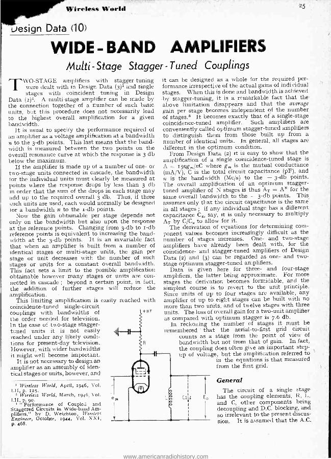
Wireless World
vesign Data (10)
WIDE - BAND AMPLIFIERS multi-Stage Stagger - Tuned Couplings
TWO -STAGE amplifiers with stagger- tuning 1 were dealt with in Design Data (3)' and single
stages with coincident tuning in Design Data (2)2. A multi -stage amplifier can be made by the connection together of a number of such basic units, but this procedure does not necessarily lead to the highest overall amplification for a given bandwidth.
It is usual to specify the performance required of an amplifier as a voltage amplification at a bandwidth n to the 3 -db points. This last means that the band - width is measured between the two points on the overall resonance curve at which the response is 3 db below the maximum.
If the amplifier is made up of a number of one- or two -stage units connected in cascade, the bandwidth for the individual units must clearly be measured at points where the response drops by less than 3 db in order that the sum of the drops in each stage may add up to the required overall 3 db. Thus, if three such units are used, each would normally be designed for a bandwidth n to the i -db points.
Now the gain obtainable per stage depends not only on the bandwidth but also upon the response at the reference points. Changing from 3 -db to i-db reference points is equivalent to increasing the band- width at the 3 -db points. It is an invariable fact that when an amplifier is built from a number of identical stages or multi -stage units, the gain per stage or unit decreases with the number of such stages or units for a constant overall bandwidth. This fact sets a limit to the possible amplification obtainable however many stages or units are con- nected in cascade ; beyond a certain point, in fact, the addition of further stages will reduce the amplification.
This limiting amplification is easily reached with coincidence -tuned single- circuit couplings with bandwidths of +HT
the order needed for television. I n the case of two -stage stagger - tuned units it is not easily reached under any likely condi- tions for present -day television. However, with wider bandwidths it might well become important.
It is not necessary to design an amplifier as an assembly of iden- tical stages or units, however, and
Wireless World, April, 1946, Vol. p. 125.
2 Wireless World, March, 1946, Vol. I.II, p. 90.
3 " Performance of Coupled and Staggered Circuits in Wide -band Am- plifiers,' by D. Weighton, Wirelesc Engineer, October, 1944, Vol. XXI, P. 468.
25
it can be designed as a whole for the required per- formance irrespective of the actual gains of individual stages. When this is done and bandwidth is achieved by stagger -tuning, it is a remarkable fact that the above limitation disappears and that the average gain per stage becomes independent of the number of stages.8 It becomes exactly that of a single -stage coincidence -tuned amplifier. Such amplifiers are conveniently called optimum stagger -tuned amplifiers to distinguish them from those built up from a number of identical units. In general, all stages are different in the optimum condition.
From Design Data (2) it is easy to show that the amplification of a single coincidence -tuned stage is A = 159g,,, /nC where g is the mutual conductance (mA /V), C is the total circuit capacitance (pF), and n is the bandwidth (Mc /s) to the - 3 -db points. The overall amplification of an optimum stagger - tuned amplifier of N stages is thus AT = AN for the same overall bandwidth to the - 3 -db points. This assumes only that the circuit capacitance is the same' in all stages ; if any individual stage has a different capacitance Co, say, it is only necessary to multiply AT by C /C, to allow for it.
The derivation of equations for determining com- ponent values becomes increasingly difficult as the number of stages increases. One - and two -stage amplifiers have already been dealt with, for the coincidence- and stagger -tuned amplifiers of Design Data (2) and (3) can be regarded as one - and two - stage optimum stagger -tuned amplifiers.
Data is given here for three- and four -stage amplifiers, the latter being approximate. For more stages the derivation becomes formidable, and the simplest course is to revert to the unit principle. Since units of up to four stages are available, any amplifier of up to eight stages can be built with no more than two units, and of twelve stages with three units. The loss of overall gain for a two -unit amplifier as compared with optimum stagger is 7.6 db.
In reckoning the number of stages it must be remembered -that the aerial -to -first grid circuit
counts as a stage from the point of view of bandwidth but not from that of gain. In fact, the coupling does often give an important step - up of voltage, but the amplification referred to
in the equations is that measured from the first grid.
eiN C
General The circuit of a single stage
has the coupling elements, R, L, and C, other components being decoupling and D.C. blocking, and so irrelevant to the present discus- sion. It is assumed that the A.C.
www.americanradiohistory.com

Wide -Band Amplifiers - resistance of the valve is very large compared with R and that the coupling capacitance is, large enough to be ignored.
The amplifier has identical circuits in each stage but different values of L, C, R and g,--the valve mutual conductance. The component values in the different stages are differentiated by subscripts 1, s. s, 4' Thus, gm1, L1, C1, R1 refer to the values of one stage, while g,a, L2, C2, R2 refer to the values of a second stage, and so on. The stages need not be used in any particular order.
Formulae for Three -stage Amplifier
C' R,-3188(Sna-I)
knC fr = fm 1/(1 - n2l4.42)
Y = nl(2fr eSna - I)
a$-I+1.73Y+0.5y2 I - y2
3nalfra k = I 88(S2 -I)
L = 24,400 /fr2 C' L1 = L C' /C1 ; R1 = C'R' /2C1 ; L2 = La2C' /Ca; R2 = C'R'a /Ca; Ls = L C' /a2C3 ; Ra = C'R' /aC3 ;
a 159 AT = gm gma gms ( C) VS -
In most cases the correction factor different from unity.
(1)
(2)
(3)
(4)
(5)
.. (6)
frl = fr ; l fra =fr /a; ¡(7) frs =fra;1
k is negligibly
Formulae for Four-stage Amplifier
C' = vC1Ca
R'=4168,,/(Sa-1) nC'
fr = fm V(1 /- nal4fra) . .
Yl = n/(2fr aNSea - 1) .. ala I + 1.207 Y12 + 1.414-Y1 - Y2/4
I - 1.707 Yla
a22 - 1- 1.207 Yla + Yl 1/I - 2.9 Y12 I - I.7o7 Yla L' = 24,400/fr2C'
L'a12C' - L1 - c1 = frl = fr/a1 L' C' R' C'
I-a = Czala ; R2 = a ; fra = fral ;
L'a92C' ;:;fr3=frIa!;
(8) =
C' La=Ca; R4= a a 2.414a2C4
AT = glg2g3g4 (nC')4 VS2 - I
Examples Consider a four-stage amplifier with identical
valves and capacitances (gm1 = gma = g,,,3 = gma =
/r4 =fsa2,
(9)
Wireless World
6 mA /V ; C1 = Ca = Cs = C4 - 3o pF) to operate 45 Mc /s with a bandwidth of 6 Mc /s at - 3 db. Then C' = 3o pF ; R' = 416/(6 X 30) = 2.31 ka ;
fr = 45 Mc /s ; y1 = 0.066 ; a12 = I.1°6 ; a1 = 1.053; a22 = 1.068 ; as = 1.034 ; L' = 0.4 H. Then from (8), we have L1 = 0.442 µH ; La = 0.363 µH ;
La = 0.427µH ; L4 = 0.375 µH ; R1 = z.43 ka ; R2 = 2.19ka; Ra =1ka; .R4= 0.93ka; f,- 42.6 Mc /s ; .42 = 47.5 Mc /s ; fr, = 43.6 Mc /s ; f,, = 46.5 Mc /s. From (9) the overall amplification is [6 x 159/(6 x 30)]4 = 5.34 = 78o times.
Suppose now that a gain of 5,000 times is required under the same conditions. How many stages will be needed ? With the bandwidth, capacitance, response and valve specified, the stage gain is 5.3 times irrespective of the number of stages. Ideally, there- fore, 5.3x = 5,b00 where N is the number of stages.
It is easier to work in decibels. An amplification of 5.3 times is 14.5 db and the required gain of 5,000 times is 74 db. Therefore N = 74/14.5 = 5.1 stages.
Five stages give 72.5 db, only 2.5 db below the requirement. We have no method of determining the component values for five ideal stages, but we can use one two -stage and one three -stage amplifier in cascade each designed for - 1.5 db response at the edges of the band. This causes a loss of 3.8 db from the ideal in each amplifier reducing the gain by 7.6 db to 64.9 db, or 9.1 below the requirement.
It is, therefore, advisable to use six stages in the form of two three -stage amplifiers in cascade, each being designed for - 1.5 db response at the edges of the pass -band. The gain will then be 6 X 4.5 - 7.6 ='79.4 db ; nearly 6 db more than is needed. If this is excessive it can easily be reduced by slightly overbiasing the valves.
Symbols R' = equivalent circuit resistance C' = equivalent circuit capacitance. n = bandwidth = fa -A
response at f, S = ratio of response at fl and fa
f, = frequency of maximum. response resonance frequency of stage
fm = mid -band frequency f, = lower limit of pass -band = fm - 22/2 f s = upper limit of pass -band = f m + n /2.
(frl = I, etc.)
AMATEUR CALL BOOK THE " Radio Amateur Call Book," the publication of
which was discontinued during the war, is again being issued quarterly. The contents of the latest issue (autumn, 1946) includes the calls, names and addresses of the amateurs in the ten districts of the U.S.A. - occupying 189 pages (81in by irlin) -and those of trans- mitters in some seventy other countries. About 1,800 British stations are included in the current issue of 276 pages. A map showing amateur prefixes throughout the world and a tabulated list of prefixes are also included.
Copies of the Call Book can be ordered from Dale Elec- tronics, Ltd., 105, Bolsover Street, London, W.1, who will arrange for them to be sent direct from the United States. The annual subscription for the four issues is 3os. Individual copies cost 8s 9d. Prices include postage.
www.americanradiohistory.com

riy. 1947 Wireless World
Advertisements 25
MORGAN ÍTE RESISTORS
MORGAN product
www.americanradiohistory.com

26 Advertisements Wireless World
Hear the
Because the Decola is unique in technical and constructional concept, and sets a new standard for electric record reproduc- tion, we have pleasure in inviting readers of the " Wireless World " to examine and hear this revolutionary new instrument at any of the following Showrooms, where, by arrangement with the Decca Record Co., we shall display circuit and general lay- out details, which, together with the results of the demonstra- tion, will, we believe, give the discriminating wireless technician full confidence to recommend the Decola to his music loving relatives and friends.
BARNSLEY Joshua Marshall & Co. Ltd., 9/13, The Arcade.
BIRMINGHAM Murdoch, 155, Corporation Street.
BLACKBURN Pickering & Sons, 77, Darwen Street.
BRADFORD Murdoch, 37, Market Street, Swan Arcade.
BRIGHTON Murdoch, 137, Western Road.
CAMBRIDGE Murdoch, 20, Regent Street.
CHATHAM Murdoch, 86 -88, High Street.
COLCHESTER Murdoch, 1, Headgate.
DONCASTER Archibald Ramsden, York House, Cleveland Street.
DOVER Murdoch, 27, Biggin Street.
FOLKESTONE Murdoch, 20, Sandgate Road.
IPSWICH Murdoch, 22, Butter Market.
KING'S LYNN Murdoch, 19, High Street.
LEEDS Hopkinsons' Successors, Ltd., 5 -6, Commercial Street. Archibald Ramsden, 38a, Boar Lane.
YORK
LONDON Murdoch, 461-3, 'Oxford Street, W.I.
MAIDSTONE Murdoch, 7, High Street.
MANCHESTER Vivian Grant, Ltd., Tudor Galleries, 69, Deansgate.
MIDDLESBROUGH Waddington & Sons, Ltd., 108, Linthorpe Road.
NEWCASTLE Waddington & Sons, Ltd., Metrovick House,
Northumberland Road. NEWPORT (I.o.W.)
Murdoch, 31, High Street. PORTSMOUTH
Murdoch, 218, Commercial Road. PRESTON
Murdoch, 81, Fishergate. ST. ANNES
Murdoch, 48, St. Annes Road West. SOUTHAMPTON
Murdoch, 180, Above Bar. SOUTHSEA
Murdoch, 92, Palmerston Road. STOURBRIDGE
Murdoch, Town Hall Buildings, Market Street. TUNBRIDGE WELLS
Murdoch, 46, High Street. WOLVERHAMPTON
Murdoch, 63, Victoria Street.
Waddington & Sons, Ltd., Lendal.
at any of these showrooms
www.americanradiohistory.com

January, 1947 Wireless World 27
THE RADIO INDUSTRY This survey of the part played by
radio in the national economy is
based, it should perhaps be stressed, on pre -war figures and estimates. Its potential importance is greatly increased by war -time advances ; for instance, industrial applications of radio technique were insignificant in 1939. Actual post -war exports of broadcast receivers show, accord- ing to recent figures, a large increase over pre -war levels.
IT should be useful to those who intend to make a living out of radio to know how this in-
dustry fits into the general picture of the production of wealth in Britain. The collection of econo- mic data is not as easy as a search of technical literature (at any rate to the amateur in economics) and the author therefore thought it worth while to put on record the
*composite picture built up from scraps of information gleaned over a period of years. Some of the figures quoted here will be exact figures (e.g., Government statistics of imports and exports), others will be previously published estimates, and the residue will have been estimated by the author from various data. All alike are stated here without qualification, but if any reader has evidence to support different values the author will gladly detail the basis of the relevant figures given here.
Size of Pre -War Radio Indus - try.-It may come as a shock to the radio enthusiast to see how small a contribution the radio in- dustry made to the national eco- nomy before the war : and in fact the 1938 contribution was so small that it could not be illustrated graphically on a linear scale but only by comparing areas, as in diagram (a). (As we are familiar with megawatts and megavolts it is convenient to coin a new unit, the ' ` megapound " with symbol LM, to represent a million pounds sterling.) The output of the radio industry in 1938 was ¿M25, com- pared with LM13o for all kinds of electrical engineering, and about LM4,5oo for the total output of goods and services in the U.K. The position in the import / export balance (b) was similar,
From an Economic Viewpoint By D. A.
but by comparison with the aver- age state of all branches of U.K. trade in 1938 the radio industry was doing well with a greater volume of exports than of im- ports. But neither the actual magnitude of exports nor the ratio of exports to home production in 1938 would suggest that the radio industry will become a key indus- try in the " export drive " ; and this in spite of the fact that radio is manufactured only in the highly industrialized countries (such as U.S.A., Britain, Holland, Ger- many) and therefore has in the
RADIO INDUSTRY
/LM 25
TOTAL OUTPUT OF
GOODS AND
SERVICES
£M 4.500
(a)
RADIO IMPORTS
LMJ
TOTAL IMPORTS
£M 850
BELL, M.A.
valves over the value of the parts, it is probable that twice as many valves were assembled from im- ported parts as were imported complete. In fact, it appears that there must have been a substan- tial valve -assembling industry, with an output of perhaps several million valves a year, which relied on imported electrodes. The other surprise is that the import of complete wireless receivers was so much less than that of parts and accessories. The import duties would have a deterrent effect on both alike, so was it the long -wave band which hindered the sale of American sets here, or was it the British mains voltages around 230 instead of the Ameri-
can sto? There is little doubt that taking each set in its home market
RADIO EXPORTS
£M 2
TOTAL EXPORTS
£M 470
(b)
past been prominent in the world average of electrical engineering exports. In 1935, for example, radio equipment accounted for 25.3 per cent of world export trade in electrical engineering, but only 13.6 per cent of the corre- sponding British exports.
Import/ Export Details. -With regard to the 1938 imports and exports (Table I), there are two surprising points. The first is that the value of component parts of valves imported was 'roughly t h e same as that of complete valves im- ported; a n d allowing f o r the increase in value of the assembled
How radio fitted into the pre -war economic
picture.
the American Set was considerably cheaper than the British set.
Production Costs. -This brings us to the question whether Britain should attempt to compete with America in mass- production in- dustries, for there are engineers who suggest that British export trade should be based solely on our traditional craftsmanship and
TABLE I (1938).
Type of Product Imports Exports
£ £
Wireless Receiving Sets .. ... 121,771 441,065 Wireless Valves (complete) ... 130,707 495,270
Wireless Valve Parts .. 124,206 - Other wireless parts and accessor-
ies... ... ... ... ... 490,692 519,226
Radiograms, gramophone motors and parts 14,393 321,767
Total for receiving apparatus ... 881,769 1,777,328
Wireless transmitting apparatus... 34,525 339,558
Total for all wireless apparatus ... 916.294 ' 2,116,886
www.americanradiohistory.com
28 Wireless World January, 1947
Th e Radio Industry- the production of high- quality goods, leaving the cheap mass-
, production lines of goods to the Americans or anyone else who cares to produce them. This sug- gestion can be countered as fol- lows -
(i) Mass -production is the way to lower the cost of consumer t goods. In support of this, every impartial pre -war estimate arrived a at the conclusion that the average standard of living, in terms of goods purchased, was higher (per- o haps 5o per cent higher) in U.S.A. t than in Britain. d
(ii) With our present need for s imports of food and raw materials s and our shortage of foreign cur- c rency, we cannot afford to set off the import of semi -luxury goods s such as radio receivers against t whatever exports we may achieve o in other branches of engineering. w The choice for the home market 1 is therefore between efficient mass - production of radio sets and high f prices for less efficiently manu- t factured sets that are not neces- b sarily better. ju
(iii) But if we can make sets g cheaply for the home market, we in can also export cheap sets. h It is important to realize that a the set which is expensive simply
because it is less efficiently manu- co factured is of no greater value to th the user than a mass -produced set be would be. There is a tendency p to differentiate between " en- holesale " and " mass- produc- to tion," to the detriment of the ha latter ; but if we accept the de- tu finition of an engineer as a man er
can do for zs 6d what any att fool can do for 5s, then surely the su mass -production expert practises ne engineering in excelsis. ha Wartime Expansion. -The war co led to an inflation of both the m British and American radio indus- pu tries to something like six times of their pre -war size, as illustrated Ra by the following figures for cal Britain : from 1935 to 1945 the for Government spent 11lr,000 on an radio (ro9 pounds) ; during the me war, 5,000 men went through six- tri term university training courses eq for radio work ; 70,00o men had ca four -month polytechnic training ton
of peacetime trade, the radio dustry has some special pr lems : -
(i) There is a shortage of n specialized labour, because competition with other light dustries in a time of gene labour . shortage, which together with shortage of materials tends o restrict the volume of produc-
tion below the level set by prob- ble average demand over, say,
the next three years. (ii) The broadcast receiver side
f the industry is changing back o the comparatively simple omestic receivers which require mailer scientific and technical toffs than did the Government - ontract work.
(iii) The policy of spreading econdary industry into parts of he country which in 1938 had my primary industries is one hich affects the choice of factory
ocation. The general effect of these
actors, coupled with the wartime raining programme, is liable. to e the production of a surplus of nior engineers, technicians and
eneral " indirect labour " in the dustry, which at the same time
as a shortage of direct labour and n inadequate output. Alternative Production. - Some ntraction of the industry after e war was inevitable, but it has en proposed that to avoid tern-
orary unemployment through w olesale closing down of fac-
ries the radio industry should ve embarked on the manufac- re of other articles. As a gen- al proposition, this should be ractive to any firm which has fficient capital to finance the w enterprises, and it might ve the long -term advantage of mbating the seasonal unemploy- ent which used to occur in some rely radio factories as a result the influence of the annual
dio Show on retail sales ; typi- alternative products are radar civil transport (both marine
d aircraft), electronic instru- nts for medical and for indus- al use, and domestic electrical uipment. All of these are pable of occupying spare fac-
es, but for combating seasonal employment the great difficulty to find products which can be t along the same assembly cks and assembled by the same
in- non -specialized labour as the ob- broadcast receivers. The most
promising line is domestic elec- on- trical equipment, but at the
of moment this appears impractic- in- able owing to the shortage of por- ral celain insulators, which are very
widely used in this type of pro- duct.
Electronic instruments are attractive to engineers, but the volume of work available is un- certain. The electronic scientific industry has not achieved re- cognition in Board of Trade statistics, either in the Census of Production (1935) or in the export statistics (up to 1945) ; and the number of firms seriously involved is so small that any unofficial esti- mate might appear to be directed at individual firms to an embar- rassing degree. On general grounds of social welfare there is a case for greater development effort on both electro-medical equipment and electronic aids to industrial production ; but this has no economic significance until someone can be persuaded to spend some money on it.
Future Policy. -The main pur- pose of this article is to present the facts from which policy can be built up, but the author cannot leave it without putting up an " Aunt Sally " or two on policy. The case for more efficient mass - production has already been men- tioned, and the next obvious point is more efficient distribution from manufacturer to final purchaser. At the present time the retail price of a radio receiver is com- monly around double the price at which it leaves the factory, and although this factor is common to many other articles besides radio sets, it is still unsatisfactory. One reason offered for having many retailers, each selling a small number of receivers at the present conventional price margins, is the need to have " service " imme- diately available when the set goes wrong ; but is it not time that broadcast receivers were well enough engineered to make that unnecessary?
In the export market, standard- ization of components and espe- cially of valves is essential. Let us here be realists and admit that the American standard will nor- mally be the world standard by sheer weight of numbers : any
courses as radio mechanics. With- un in the general question of contrat- is tion of size from wartime condi- sen tion to suit the probable volume tra
www.americanradiohistory.com
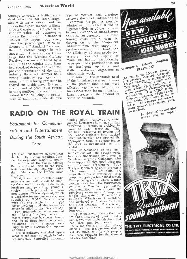
January, 1947 T ireles% World
attempt to create a British stan- dard which is nót interchange- able with the American, and use this in the export market, is likely to be a Canute act. Coupled with standardization of components there is the question of a standard receiver for export, but apart from the psychological sales re- sistance to a " standard " receiver there is another danger in this suggestion. It is common know- ledge that the Wartime Civilian Receiver was manufactured by a number of the regular radio firms to a standard design, and with the present organization of the radio industry there will always be a strong tendency for any com- munal manufacturing project to be shared out in this way. But such sharing out of production results in the quantities produced in indi- vidual factories being no greater than if each firm made its own
type of receiver, and therefore destroys the whole advantage of a common design. A possible solution of this problem would be a greater division of the industry between component manufacture and receiver assembly : the main tooling costs would then be thrown on to the component manufacturers, who supply all receiver -manufacturing firms, and the efficiency of mass -production assembly does not depend so much on having exceptionally large quantities, provided that one has intelligent operators and skilled production organizers to direct their work.
To sum up, the economic need of the broadcast receiver industry at the present time is for more efficient organization of produc- tion rather than for an immediate large increase in the amount of scientific research.
RADIO ON THE ROYAL TRAIN
Equipment for Communi-
cation and Entertainment
During the South African
Tour
THE new coaches which have been built by the Metropolitan-Cam -
mell Carriage and Wagon Company to the order of the South African Railways for addition to the royal train are liberally equipped with the products of the British radio industry.
First, there is a complete radio relay system, with about 6o loud- speakers unobtrusively installed in furniture and panelling, giving a choice at each point of two radio programmes. This equipment, which is used also for announcements, was supplied by E.M.I. Service, who were also responsible for the Type RR2o medium- and short-wave re- ceiver installed in the King's study.
For gramophone entertainment the " Decola " wide -range electric record reproducer has been chosen, and six of these instruments with automatic record changers were supplied by the Decca Gramophone Company.
The complicated electrical equip- ment of the coaches, which includes automatically controlled air -condi-
29
tioning plant, refrigerators, water pumps, fluorescent lighting, etc., has presented a formidable problem in noise -free radio reception. This has been entrusted to Belling and Lee, whose engineers have tracked down interference and applied the appropriate form of suppression as the work of installation has pro- ceeded.
The co- ordination of the com- munications with the outside world has been undertaken by Marconi's Wireless Telegraph Company, who have supplied a high -speed telegraph and telephone transmitter (Type TGS57IB) delivering up to 500 watts R.F. power to a roof aerial, or, when the train is stationary, to a temporary Soft portable mast aerial. The operating coach, which is three coaches away from the transmitter, contains a Marconi Type CRt5o communication receiver (and the broadcast receivers and amplifiers for the relay system). There are also duplicate Wheatstone transmitters and keyboard perforators for Press and other messages. Power is sup- plied by a 3kVA diesel- driven generator.
A pilot train will precede the royal train at a distance of about to miles, and a two -way radio telephone link has been provided between the trains for the use of the railway officials. The frequency -modulated V.H.F. equipment for this purpose has been supplied by the General Electric Company.
pmPliFer
hone Cabinet
B MC)
(As
GramoP TP
illustrated), 30-watts
output,
incorporating
arr a ÿu utomat c
Record Changer,
of
i range.
models With
u30. Watts, with
e h
without Atoma icRec r
Changer,
are available.
A I
Deer rial cabinets,
in light
types. natural
v finish,
access to
aly e All controls
o-
itrouped in
cessed
FLIT of this
other onthe front.
models sent on egUest.
THE TRIX ELECTRICAL CO. LTD.
1 -5 MAPLE PLACETOTTENNAM COURT ROADLONDON, W.1
,,LAE:Afa/M5E104.13817 CRAW ECA& /S:TPIEADI0, WESOD.LONDOR.
www.americanradiohistory.com
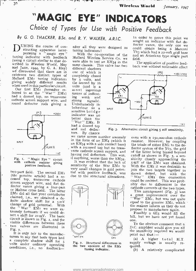
.30 Wireless World January, 1949
"MAGIC EYE" INDICATORS Choice of Types for Use with Positive Feedback
By G. O. THACKER, B.Sc.
DURING the course of con- structing apparatus incor- porating a magic eye "
tuning indicator with feedback (using a circuit similar to that de- scribed in Wireless World, May and June, 1944, by G. A. Hay) we discovered that there are in existence two distinct types of Mullard EMI tuning indicators giving widely different results when used in this particular circuit.
Our first EMI (hereafter re- ferred to as the " War " EMI) had a domed top, no transverse cathode screen support wire, and round deflector rods giving a
Fig. r. " Magic Eye " circuit with cathode resistor giving
positive feedback.
two -part field. The second EMI (the genuine article) had a re- cessed top, transverse cathode Screen support wire, and flat de- flector vanes giving a four -part or Maltese cross field. The latter EMI did all that your contributor claimed, i.e., we obtained a de- finite shadow shift for a 5 mV change of grid potential. With the ` War " EMI we were ex- tremely fortunate if we could de- tect a shift for 20 mV. The basic circuit is 'shown in Fig. r, and the visible differences between these two valves are illustrated in Fig. 2.
It is only fair to the manufac - turers to say that both types had a complete shadow shift for 5 volts under ordinary operating conditions, i.e., no feedback-
and R. Y. WALKER, A.R.I.C.
after all they were designed as tuning indicators !
With the co-operation of the Mullard Wireless Service Co. we were able to test an EM34 in the same chassis: This valve has two different shadows one of which is completely closed by 5 volts, and the second by 16 volts (and is a most ingenious means of indicat- ing weak and strong signals). Unfortunately its behaviour as a sensitive bridge indicator was no better than the " War " EMI. It had a domed top and rod deflec- tors. By chance we came across another anomaly in the form of an EM4 (which is an EM34 with a side contact base) with a recessed top but no trans- verse cathode screen support, and having rod deflectors. This was, if anything, worse than the EM34.
It was evident that the lack of sensitivity of the War EMI to very small changes in grid poten- tial with positive feedback, was due to the structural alterations.
In order to prove this point we sought an indicator with flat de- flector vanes, the only one we could obtain being a Marconi Y63 which had a 22 -volt grid base and an American type single part field.
The application of positive feed- back was without noticeable effect
2M11 +180/250V
INPUT
Fig. 3. Alte
" WA R "EMI E M I
Fig. 2. Structural differences in the two versions of the EMI
tuning indicator.
10,000 n
-H.T
rnative circuit giving 5 mV sensitivity.
even with a 15o,000 -ohm cathode resistor. However, by coupling the triode of either EMI to the de- flector system of the Y63, the grid of the latter being biased beyond cutoff as shown in Fig. 3, a sen- sitivity closely approaching the 5 mV of the EMI was obtained. With the EMI it was desirable to join the two targets together as shown dotted, but with the " War " EMI this connection could be omitted. This was prob- ably due to differences in the cathode currents of the two types.
This arrangement (Fig. 3) was a great improvement over the " War " EMI, but was not quite equal to the genuine EMI, which the makers inform us they do not propose to manufacture again.
Possibly a 6E5 would fill the bill, but we have not yet found one.
To the obvious comment that a D.C. amplifier would give you all the sensitivity required we would point out that: -
(a) A higher total H.T. supply voltage is usually re- quired.
(b) A relatively complicated
www.americanradiohistory.com

January, 1947 Wireless World 31
"Magic Eye" Indicators - circuit is required with adjust- able potentiometers, etc.
(c) Such a circuit tends to be less stable than a simple single - valve arrangement.
(d) The apparatus would be more bulky and expensive. In conclusion, we take our hats
off to G, A. Hay for producing
such a simple and sensitive indi- cator circuit, which we can thoroughly recommend. To any- one interested we would add that the choice of a valve requires considerable care as it appears to us that extreme sensitivity will not be obtained unless it has a short grid base and flat deflector vanes.
WIRE BROADCASTING A New Carrier -frequency
Distribution System
AWIRED -WIRELESS broadcast relay system for the distributicn
of radio programmes has been in operation in Rugby for some time past on an experimental basis. The installation was planned and en- gineered by Multi- Broadcast (En- gineering), Ltd., of Rugby, and provides four alternative pro- grammes, using a single pair of overhead transmission wires. The installation has now been placed on a fully operational footing and a few details are available.
In a carefully chosen locality, where the electrical noise is suffi- ciently low, there has been erected a radio receiving station for recep- tion of the B.B.C. and foreign pro- grammes selected for re- broadcast. Separate aerials are used for each receiver and these are designed and
Multi- Broadcast subscriber's reproducer unit.
sited to give the best reception in each case.
So far only four re- broadcast pro- grammes are provided, but the in- stallation is easily extended when the time arrives to take in the two additional ones planned.
Two of the present receivers are o[ the pre -tuned type, operating on 296
metres and 1,500 metres respec- tively ; the other two are communi- cation -type receivers covering a wide frequency range. A direct wire circuit to the B.B.C. studios at Birmingham is also available.
The A.F. outputs from the four radio receivers are amplified and then used to modulate the four carrier frequencies. These are then fed through a suitable matching net- work to the overhead 50o -ohm feeder lines. The lines are air - spaced and carried on insulators affixed to the chimney stacks of the houses and dwellings taking the relay service.
All the carrier frequencies used are below 200 kc / s and a channel separation of about zo kc / s is allowed. The low radio frequency, coupled with the relatively high signal level on the line,, enables a comparatively simple receiver, de- scribed as a reproducer unit, to be used in the subscriber's home.
In appearance this is very similar to an extension loudspeaker, but has the addition of two controls. On the left -hand side below the loud- speaker grill is the six -way pro- gramme selector switch, while to the right of it is the volume control, with which is combined the on -off switch.'
An A.C. /D.C. circuit is employed having one carrier frequency ampli- fier, a push -pull detector, using Westectors, transformer coupled to a pentode output stage. The A.F. output available is about 3 watts.
BOOK RECEIVED
Reference Data for Radio Engineers (2nd Edition). -Compiled by W. L. McPherson, B.Sc., M.I.E.E., S.M.I.R.E. This book contains a very wide range of information valuable to radio en- gineers. It covers materials, rectifiers, amplifiers, propagation, aerials and waveguides among its data, which ranges from engineering tables to mathematical formule and tables. Originally pre- pared for the use of the staff of Standard Telephones and Cables, it is now generally available. Pp. 175. Pub- lished by Standard Telephones and Cables, Ltd., Connaught House, 63, Aldwych, London, W.C.2. Price gs (postage 6d).
A
`SOUN' PROPOSITIOND!
ARE YOU A
TANNOY STOCKIST?
A restricted number of qualified dealers and P.A. specialists are being appointed as approved stockists for the main trade distribution of Tannoy Sound Equipment.
Having declined to Jeopardise the reputation of TANNOY by the intro- duction of Interim equipment to meet insistent demandsfor "anythingatany price ", the extensive post -war range of TANNOY Sound Equipment which is now becoming available, embodies all the latest technical developments in design and the highest quality of manufacture. The trade mark "TANNOY" remains a guarantee of reliability to you and your customer.
Write for the qualifications re- quired of stockists and for complete details of the full range of TANNOY Equipment.
\TANNOY/ -SOUND EQUIPMENT-
GUY R. FOUNTAIN LTD., -THE SOUND PEOPLE "
"TANNOY" is the registered trade mark of equipment manu-
factured by
GUY R. FOUNTAIN LTD., WEST NORWOOD, S.E.27.
GIPSY HILL 1131.
The largest Organisation in Grat Britain specialising SOLELY in Sound Equipment-
Branches throughout the British Isles.
www.americanradiohistory.com

32 Wireless World January, 1947
SOCIETIES AND CLUBS List of Radio Groups in the British Isles
IN the following list, arranged in alphabetical order under towns, the name of the club is followed by that of the secretary, from whom details of the society's activities may be obtained. Clubs which are
affiliated to the Radio Society of Great Britain are indicated by an asterisk. The list has been compiled from details supplied by the secretaries and from other sources. We shall be pleased to receive details from the secretaries of active societies which have inadver- tently been omitted from this list.
ABERDEEN Aberdeen Amateur Radio Society.-A. G.
Anderson, 87, Braemar Place, Aberdeen, Scotland. A LTR I NCH AM
Altrincham and District Radio Club. -J. G. Barnes, WAGS, 4, Victoria Road, Hale, Cheshire. BATH
Admiralty (Bath) Electronics Society. -D. Houston, D.E.E. Dept., Admiralty, ¡lath, Som. B ELFAST
City of Belfast Y.M.C.A. Radio Club'. - F, A. Robb, GISTK, 60 Victoria Avenue, Sydenham, Belfast, N. Ireland.
Radio Society of Northern Ireland'. -A. Kennedy, GISKN, 3s, Donaghadee Road, Bangor, Co. Down, N. Ireland.
B IRKENHEAD Wirral Amateur Transmitting and Short -
Wave Club. -B. O'Brien, G2AMV, 26,
Coombe Road, Irby, Heswall, Cheshire.
B IRMINGHAM Birmingham and District Short -Wave
Society. -C. W. Thompson, 8, Caldwell Road, Birmingham, 9, Warwicks.
Midland Amateur Radio Society. -W. J. Vincent, 040I, The Grange, Warwick Road, Solihull, Birmingham, W arwicks.
Slade Iton Coldfleld Bir-
mingham, Warwicks. BLACKPOOL
Blackpool and Fylde Amateur Radio Society. -H. D. Ashworth, (.4PY, 5.
Albion Avenue, Blackpool, Lancs.
BOGNOR West Sussex Short -Wave and Television
Society.-L. Frost, G5PF, Pixies West Parade, Bognor, Sussex. BOLTON
Bolton and District Radio Society. -N. Moorcroft, 3, Beaconsfield Street, Bolton, Lancs. BOURNEMOUTH
Bournemouth and District Amateur Radio Club'. -J. F. Squires, M.B.E., G2DBF, so. Victoria Road, Bournemouth, Hants. BRADFORD
Bradford Amateur Radio Society. -J. H. Macdonald, G4CJ, Mayfield, Waggon Lane, Bangley, Yorks.
Bradford Short -Wave Club'. -V. W. Sowen, G2BYC, Rushwood, Grange Park Drive. Cottingley, Yorks.
BURTON -ON -TRENT Burton -on -Trent and District Radio
Society. - S. E. Whiteley, G2DAN, " Dalbrae," Beacon Hill, Rolleston, nr. Burton -on- Trent, Staffs. CAMBRIDGE
Cambridge University Wireless Sooiety,- K. E. Machin, Queeen's College, Cam- bridge. CHATHAM
Medway Amateur Transmitters' Society. -8. J. Coombe, Stanvie, Longhill Road. Chatham, Rent.
CHELTENHAM Cheltenham and District Amateur Radio
Society. -H. Brialin, 62, Cleevemount Road, Cheltenham, Glos.
COVENTRY Coventry Amateur Radio Society'.-J. W.
Swinnerton, G2YS, 118, Moor Street, Coventry, Warwicks. CRANWELL
Royal Air Force Amateur Radio Society'. -N. Davis, R.A.F., Cranwell, Lines. DONCASTER
Doncaster and District Amateur Radio Societe.-H. Flintham, 50, Burton Avenue, Baiby, Doncaster, Yorks. DUBLIN
Practical Amateur Radio Constructors' Club.-T. Keogh, 8, New Ireland Road. Rialto. Dublin, Eire. DUMFRIES
Dumfries and Galloway Amateur Radio Society. -D. F. Halliday, GM2AHD, Cresswell House, Dumfries, Scotland. EAST GRINSTEAD
East Grinstead Radio and Television Society.-E1 C. Cooper, Heatherlea. Cranston Road, East Grinstead, Sussex. FARNBOROUGH
R.A.E. and Farnborough District Radio Society.-P. R. Burkett, G4PS, Park View, Priory Street. Farnborough, Hants. GLASGOW
NO Club, GifInock'. J. D. Gillies. G312FZT, 3. Berridale Avenue, Glasgow S.4, Lanark. GLOUCESTER
Gloucester and District Amateur Radio Society. -J. W. Dean, G2AZT, 100, Stan- ley Road, Gloucester. GRAYS
Grays and District Amateur Radio Club'. -E. F. Read, 26, Hillside, Little Thurrock, Grays, Essex. GRIMSBY
Grimsby Amateur Radio Society. S. Stocks, GSKH, 60, Tunnard Street, Grimsby, Lanes. HALIFAX
Halifax Experimental Radio Society.-L. Blagbrough, 39. Fountain Street. Sowerby Bridge, Yorks. JERSEY
Jersey Radio Society. -E. Banks, GC2CNC, Fort Rock. Tabor Lane, Ronte de Genets. St. Brelade, Jersey, C.f. KETTERING
Kettering Radio and Photographic Society. -I. L. Holmes, Miami, The Close, Head- lands, Kettering, Northants. LEEDS
Leeds Radio and Television Society. -P. Stork, 1, Brudenell View, Leeds, 6, Yorks.
Benton Radio Ciub'. -D. Freeman, Denis - ton, Harrowgate Road, Rawdon, nr. Leeds, Yorks, LEICESTER
Leicester Radio Society.-Owen D. Knight, 16, Berners Street, Leicester.
LIVERPOOL Liverpool and District Short -Wave Club. -
T. W. Carney, G4QC, 9, Gladeville Road, Aigburth, Liverpool, 17, Lancs. LONDON AND DISTRICT
Edgware and District Radio Society. -R. H. Newland, G3VW, 3, Albany Court, Montrose Avenue, Edgware, Middlesex.
Grafton Radio Society. -W. H. C. Jennings, G2AHB, 82, Craven Park Road, N.H.
Hounslow and District Radio Sooiety.- A. H. Pottle, B.Sc., 11, Abinger Gardens. Isleworth, Middlesex.
Ilford and District Radio Society. -C. E. Largen 44, Trelawney Road, Barking - side, Ilford, Essex.
Islington Radio Club.-G. E. Lazell, 49, Hungerford Road, Islington, 14.7.
Kingston and District Amateur Radio Society. -J. Hughes, 12, Hillingdon Avenue, Ashford, Middlesex. -
North West Kent Amateur Radio Society. -L. Gregory, G2AVI, 18, Upper Park Road, Bromley, Kent.
Radio Society of Harrow. -J. F. A. Lavender, G2KA, 29, Crofts Road, Har- row, Middlesex.
St. Pancras Radio Society. -H. Brown, 84, Blenheim Gardens, N.W.2.
Surrey Radio Contact Club'.-L. C. B. Blanchard, 122, St. Andrew's Road, Coulsdon, Surrey.
Thames Valley Amateur Radio Trans- mitting Society'. -D. R. Spearing, G3JG, Thurston, Orchard Way, Esher, Surrey.
Wanstead and Woodford Radio Society, - F. C. Judd, G2BCX, 111, Mayhank Road, South Woodford, E.18.
Watford and District Radio and Tele- vision Societe.-J. C. Warren, 29. Market Street, Watford, Herts.
West Middlesex Amateur Radio Club'. - N.S.C. Priest, 7, Grange Road, Hayes End, Middlesex. LONDONDERRY
North-W est Ireland Amateur 'Radio Society.-D. R. J. Adair, Cosy Lodge, Culmore Road, Londonderry, N. Ireland. LOUGHBOROUGH
Beaumanor Amateur Radio Society.-E. Pethers, Beaumanor Park, Loughborough. Leicester. MAIDENHEAD
Maidenhead Amateur Radio Club'. -R. F. Woodruff, Oaklands, College Road, Maidenhead, Berks. MAIDSTONE
Maidstone Amateur Radio Society'. -T. D. Eaves, Ashmore. Ashford Road. Maid- stone, Kent. MALVERN
T. R. E. Amateur Radio Societe.-B. H. Briggs, House 5. T.R.E., Great Malvern, Wores. MANCHESTER
Whitefletd and District Radio Society.-E. Fearn, 4, Partington Street, Newton Heath, Manchester, 10, Lanes. MIDDLESBROUGH
South Bank and District Amateur Radio Society. -H. Stubbings, 11, Station Road, South Bank, Middlesbrough, Yorks. NEAT
Neath, Port Talbot and District Short - Wave Club. -S. Roberts, GW4NZ, 29, Che-tnut Road, Cimla, Neath. Glam. NE W CASTLE
Northern Radio Club'. -A. Robson, 522, Denton Road, Newcastle -on -Tyne, 5, Northumb. OS W ESTRY
Oswestry and District Radio Society. -A. D. Narraway, Lamorna, Pant, nr. Oswestry, Salop. OXFORD
Oxford and District Amateur Radio So- -ciety,-R. H. Farmery, 99, Stanway Rond. Headington, Oxford.
www.americanradiohistory.com

January, 1947 V írele-vx World
Societies and Clubs - PENZANCE
W est Cornwall Radio Clubs. -R. V. A. Allbright, G2JL, Greenacre, Lidden, Pen- zance, Cornwall.
PORTSMOUTH South Hante Radio Transmitting Society*. -J. S. K. Stephens, GBWC, 65, Ebery
Grove, Copuor, Portsmouth, Hants.
PRESTON Preston Radio Society.-J. Hamilton, 48,
Queen's Road, Preston, Lancs.
READING Reading and District Amateur Radio
Society*. -L. A. Hensford, B.E.M., G2BRS, 30, Boston Avenue, Reading, Berks.
ROMFORD Romford and District Amateur Radio
Society*. -R. C. E. Beardow, G3FT, 3, Geneva Gardens, Whalebone Lane North. Chadwell Heath, Essex.
ST. HELENS St. Helens and District Radio Society. -
J. K. Birch, G2FOS, 19, Knowsley Road, Rainhill, St. Helens, Lancs.
SALISBURY Salisbury and District Short -Wave Club.
-C. A. Harley, 85, Fisherton Street, Salisbury, Wilts.
SHEERNESS Sheppey Amateur Radio Club.-F. G. May-
nard, 040U, 160, Invicta Road, Sheer- ness, Kent.
SOUTH SHIELDS South Shields Amateur Radio Club. -W.
Dennell, 12, South Frederick Street. South Shields, Northumb.
South Shields Short -Wave Radio Chub.- - J. J. Monaghan, G5SB, 60, Lemon Street, Tyne Dock, South Shields, Northumb. SOUTHAMPTON
Southampton Radio Club. -A. Ward, 50, Onibury Road, Bitterne, Southampton, Hante. SOUTHEND
Southend and District Radio and Scientific Society*. -K. F. Crispin, G6MH, 21, Thurston Avenue, Southend -on -Sea, Essex. SOUTHPORT
Southport Amateur Transmitters' Associ. ation.-J. R. Fennessy. 05ZI, 65, Bal- moral Drive, Southport, Lanes.
STOCKPORT Stockport Amateur Short-Wave Radio
Society*. -L. Chappell, G2AAY, Heath - field, Buxton Road, Disley, Cheshire. STOKE -ON -TRENT
Stoke -on -Trent and District Amateur Radio Society.-D. Poole 13, Oldfleld Avenue, Norton -le- Moors, Staffs.
Cheadle and District Amateur Radio So- ciety.-V. E. Hughes, G3AVG, Abbots - Haye, Cheadle, Stoke -on- Trent, Staffs. STOURBRIDGE
Stourbridge and District Radio Society. - D. Rock, G8PR, Flat 1, Block 1, Summer - field, Kidderminster, Worcs.
SUNDERLAND Sunderland and District Amateur Radio
Club. -W. Stockburn, G2TG, 40. Nether - burn Road, Sunderland, Durham.
SWINDON Swindon and District Short -Wave Society. -P. Greenwood, 02BUJ, 40, Western Street, Swindon, Wilts. TIVERTON
Blundell's School Radio Club*. Tiverton, Devon.
WARRINGTON Warrington and District Radio Society. -
S. Allen, 26, Bruche Drive, Padgate, Lancs. WIGAN
Wigan and District Amateur Radio Club. - H. King, 2, Derby Street, Wigan, Lanes.
WELLINGTON Wrekin Amateur Radio Society. -T. L.
Stevens, G3 %V, Sunny Cottage,. Don - nington Wood, Wellington, Salop.
WEST BROMWICH West Bromwich and District Radio
Society. -R. G. Coubens, 38, Collins Road, Wednesbury, Staffs.
WEST HARTLEPOOL West Hartlepool and District Radio Club.
-A. R. Donald, G3TO, 18, Stockton Road, W. Hartlepool, Durham. WOLVERHAMPTON
Wolverhampton Amateur Radio Society. - W. O. Sturmey, G8KL, 3, Broome Road, Wolverhampton, Staffs. YEOVIL
Yeovil Amateur Radio Club. -D. Hover, 67, Everton Road, Yeovil, Som.
YORK York and District Short -Wave Club. -G.
Kelley, G5KC, 146, Melrosegate, York.
Books issued in conjunction with " Wireless World"
FOUNDATIONS OF WIRELESS. Fourth revised Edition, by
Net Price
Post- age
M. G. Scroggie, B.Sc., A.M.I.E.E. 7/6 (4d.) TELEVISION RECEIVING EQUIPMENT, by W. T. Cocking,
M.I.E.E., 2nd edition in preparation ... ... ... ... 12/6 (4d.) RADIO LABORATORY HANDBOOK, by M. G. Scroggie, B.Sc.,
A.M.I.E.E., 3rd Edition ... 12/6 (5d.) WIRELESS SERVICING MANUAL, by W. T. Cocking, M.I.E.E.,
Seventh Edition ... ... ... ... ... ... ... 10/6 (4d.) HANDBOOK OF TECHNICAL INSTRUCTION FOR WIRELESS
TELEGRAPHISTS, by H. M. Dowsett, M.I.E.E., F.Inst.P., and L. E. Q. Walker, A.R.C.S., Eighth Edition ... 30/- (7d.)
BASIC MATHEMATICS FOR RADIO STUDENTS, by F. M. Colebrook, B.Sc., D.I.C., A.C.G.I. 10/6 (5d.)
RADIO DATA CHARTS. Fourth Edition, Revised by J. McG. Sowerby, B.A., Grad. I.E.E. 7/6 (4d.)
LEARNING MORSE. 335th thousand ... ... ... ... 6d. (1}d.) RADIO WAVES AND THE IONOSPHERE, by T. W. Bennington 6/- (3d.)
Obtainable from booksellers everywhere or direct (cash with order) from the publishers
ILIFFE & SONS LTD., Dorset House, Stamford Street, London, S.E.1
,4
PREMIER RADIO MORRIS & CO. (RADIO) LTD.
ALL POST ORDERS TO :
JUBILEE WORKS, 167 LOWER CLAPTON RD., LONDON, E.5 (Amherst 4723)
CALLERS TO: 169 FLEET STREET, E.C.4
(Central 2833) OUR 1946 LIST IS NOW AVAILABLE All enquiries muse be accompanied by a 2 1.d. stamp.
WIDGET RADIO KIT. Build your own Midget Radio. A complete set of part,, including valves, loudspeaker and Instructions. In fact, everything except cabinet necessary to build 4 -valve Medium and Long Wave T.R.F. Radio operating on 200-250 v. Mains, A/C or D /C. Valve line -up, 6K7, 6J7, 25A8, 25y5. Wave- lengths covered 200.557 and 700. 2,000. Size 10 x 6 x sin. Completely drilled chassis. Price, including tax, 28 17a. et. An attractive bakelite cabinet can be supplied at 25/- extra.
SUPEEHET MIDGET RADIO KIT. A complete kit of parts for a 5 -valve superhet. Covers 16 -50 and 200-557 metres. AC /DC 200.250 v. 6E8, 6117, 6J7, 25A6, 25Y5. Size 10 x 6 x Sin. Completely drilled chassis. Price, including tax, 28 Sa.
An attractive bakelite cabinet can be supplied at 25/- extra.
COLLARD PORTABLE RECORD PLAYERS. Consist of a super quality Induction type gramophone motor 200 -250 v. A/C with autostop and high -grade magnetic pickup. Mounted in a leatherette carrying case. Price 1111 Sa A few only. Delivery from stock.
OUTPUT TRANSFORMERS. A super production. By means of ingenious aeries- parallel arrangements, all windbags are used at all times. Match any tube, single or push -pull to any voice coil 2-30 ohms. 7 watt,, 22/8: 15 watt, 30 /- ; 30 watt, 49/8 ; 60 watt, 59/8.
ALUMINIUM CHASSIS. Substantially made of bright aluminium, with four sides. 7 x31x21n. .... 4/6 91 x41 x215..... 5/8 10x8 x2Iln. .. 7/- loxaxaiin. .. 7/9 14x9x2ifn. .. 8/3 16x8x211n..... B/8 20 x 8 x 29m .. 10 /8 22 x 10 x 2iln... 13/6
2 -VALVE SHORT -WAVE BATTERY KIT. A com- plete kit of parts for a 2 -valve receiver, covering 15 -600 metres, Including valves, coils, drilled chassis, H.T. and L.T. dry batteries to last approximately 8 to 12 months. A pair of double headphones and full instructions. Price fó 10x. An extra coil can be supplied, covering 600.1,900 metres at 4/ -. B.P.L. SIGNAL GENERATOR. 100 kc /a to 30 me /s. Mains operated. 221. Send for descriptive leaflet.
MOVING IRON METERS. Plush mounting, 2in. dia- meter, available for D10 only in the following ranges: 10. 25, 50, 100, 250 and 500 m /a, 1, 2, 3, 5 and 10 amps., 10 /6 each.
FERRANTI MOVING COIL METERS. 2iin. diameter flush mounting, calibrated 0 -500 nacroamps. 21/ -. 5-WATT AC /DC AMPLIFIER. For use as gramophone pick -up amplifier. Push /pull, excellent quality. 28 Bs.
BATTERY CHARGER KITS. All incorporate metal rectifiers, input 200.250 v. AC. 40 /100 cycles.
Price To charge 2 v. accumulator at I amp. 15/. To charge a v. accumulator at 1 amp. 17/6 To charge 12 v. accumulator at 1 amp 22/6 To charge 6 or 12 v. accumulator at 4 amps.
Complete with variable resistance and meter £3/lb1-
To charge 6 or 12 v. accumulator at 8 amps. ditto 261-1 -
MAINSBEIDGE TYPE CONDENSERS. of Military Surplus Paper Condensers. o0 filled.
Huge purchase Super quality,
Working Size Price Per Capacity Voltage H Each Doz.
2 ml. 1,000 41 o 15 0. 2/6 20 /- 2 mi. 600 31 x 11 x 1 1/3 10 /- 5ml. 600 25311 x 1/- 81-
KIT OFPARTS FOE H.T. ELIMmATO B AND TRICKLE tatAROER. Output 150 v. 30 m/a 2 v. half amp. Metal Rectification. Amazing value, at 30/ -.
RADIOGRAM CABINETS. Excellent appearance and workmanship. Size 3411n. high, lain. deep, 36in. wide, light mahogany finish. Cabinet only 226. With motor and pickup, 232 16a.
www.americanradiohistory.com

34 Wireless World January, 1947
UNBIASED By FREE GRID
Radarecording JUDGING by the things one reads
in the newspapers nowadays most people don't seem to have much faith in the future of civiliza- tion. It appears that we have either got to face the perpetual menace of the atom bomb or put up with a lot of prying international customs officers poking about among the silk stockings and wrist watches in our
"Poking in our suitcases."
suitcases when we return from a Continental holiday in order to see that we have no hidden hoards of uranium.
1 did think, however, that readers of Wireless, World would be a little above all this jitterbug business. I was all the more surprised to learn from one of them, who has been a faithful follower of this journal's fortunes for the better part of forty years, that he is so convinced that .the days of our present civil- ization are numbered he is taking active steps to put on record the history of our times. His intention is to preserve it for generations countless centuries hence when a new civilization has arisen to whom Hiroshima will have no more signi- ficance than has Ur of the Chaldees to the average man of to -day.
As he rightly pointed out to me, it is quite useless burying copies of
` our leading newspapers and such- like things as, for instance, were placed under Cleopatra's Needle when it was erected on the Em- bankment by our Victorian fore- fathers. It is obvious such records will either be blasted away by atom bombs in future wars or destroyed by the Government of the totali- tarian one -state world which some people seem to envisage as our only hope of avoiding future conflicts.
The recordings, therefore, must be made and hidden in such a manner that they will be utterly beyond the power of either atom bombs or a neo- Hitler to destroy and yet be readily accessible to future generations. There is only one recording medium which full filled these conditions, said my friend, and that is radio. His idea is to broadcast accounts of con- temporary history on a wavelength sufficiently short for it to penetrate the various ionized layers as do the still shorter wavelengths that bring the sun's light and heat to us.
These broadcasts will eventually reach the stars, and by normal radar reflection, come bouncing back over and over again through- out the centuries as star after star is reached so that they will be per- manently on tap for future genera- tions after the passing of the threatened intellectual ice age when civilization will be in eclipse as it was after the destruction of the Babylonian and other ancient civil- izations.
The only real difficulty to my mind is to design a receiver suffi- ciently sensitive to discount the tremendous spatial attenuation and yet give a good signal/ noise ratio -but that is a problem for our re- mote descendants. We shall have our hands quite full enough, design- ing a layer -piercing U.S.W. trans- mitter.
Mozart Mangled AS one who has always been a
believer in what Carlyle de- scribed as the " Oneness of Beauty," it surprised me in pre -war years to see the utter lack of imagin- ation displayed by cer- tain receiver manufac- turers, most of whom used to make a point of stressing, among other virtues, the reproduction qualities of their particu- lar products. Yet, almost without exception, the instrument was housed in an ugly brown box which, by the offence it gave to the eye, more than offset any beauty which it conveyed to the ear.
In fact I felt so strongly about it
that I made it an invariable custom to have the blinds drawn or the lights out, according to the time of day, and listen in complete dark- ness at home. I finally had to abandon this course after very strong representations from Mrs. Free Grid concerning its effect on the behaviour of some of the adolescent Grid Leaks who seemed to regard it as a heaven -sent oppor- tunity to . bring in their friends of the opposite sex and indulge in an orgy of osculation.
Worst of all offenders in the matter of the " Oneness of Beauty " business were the " super -quality " merchants, some of whom expected me in all seriousness to clutter up my home with monstrous baffles or gargantuan horns suspended from the ceiling. The truth of the matter is, of course, that no real thought has ever been given to the question of harmonizing beauty of sight with beauty of sound. Now we are fast approaching the days of normality, when once again the word " queue " will be associated in our minds only with the Manchu dynasty, set manufacturers will certainly have to do something about it if they are to continue to keep the wolf from the door, and I don't mind giving them a hint which will bring a lot of grist to their mills.
I contend that the style of cabinet which will convey to the eye the same sense of restful beauty which the music of Mozart brings to the ear will be utterly unsuitable for the restless turmoil of an Itma programme. One cannot enjoy a choice vintage wine if it is served up in a cocoa mug, and, what is equally important, vice versa. In other words, different types of pro- gramme call for different styles of cabinet and, since, in effect, differ- ent cabinets mean different re- ceivers, the plan obviously opens the way to the sale of at least six sets to every family.
At the moment, of course, beauty lovers, who possess a more dis-
" Strong representations from Mrs. Free Grid."
ciplined family than I do, can switch off the lights and so save Mr. Shinwell the trouble of doing it for them.
www.americanradiohistory.com

f JIfuua'rY, 1947 Wireles World
RANDOM RADIATIONS By "DIALLIST"
eproduction Problems T was a little surprising to find
the music critic of The Times vriting the other day that hg pre - erred the reproduction of the echanical gramophone to that of
n electrical instrument " with its issing treble and booming bass." o electrical instrument can, of .)urse, provide perfect reproduc- on, for the simple reason that it
<tn't bring out what isn't on the ecord ; but a really well -designed dectric gramophone is surely a vastly better performer than any
., urely mechanical instrument. ['here should not be any boominess n the bass- though it must be ad- mitted that far too many instru- ments display this revolting quality. The hiss alluded to is, I imagine, that due to surface scratch, and there are ways, though not completely satisfactory ones, of dealing with that. But where, to my mind, the high -class electrical reproducer can be outstanding is in the matter of contrast expansion, or contrast restoration, as I prefer to call it. This, again, is not perfect; but it an be exceedingly good and it does
add enormously to the pleasure ob- tainable from the playing of almost any good orchestral record. One feels that if the critic were to hear L record of his choice reproduced first by the best of mechanical gramophones and then by a first- rate electric gramophone with auto- matic contrast restoration, he might become a convert to electrical methods.
` Carbon Tet. DO you know the virtues of
carbon tetra -chloride in the radio lab and workshop ? It is one ni the very best of all cleaners of moving electrical contacts. During the war every radar cabin was pro- vided with a fire extinguisher charged with carbon tet. One of the first things I used to look at when I was inspecting was this ex- tinguisher -and the odds were that it was empty. The reason why? Well, the A.T.S. knew that carbon tet. was admirable for removing grease spots from their uniforms, and the radio mechs knew equally well that it was just what the doctor ordered for dealing with moving contacts which had become noisy and " chancy." If you are not
familiar with its action (which can produce miracles of healing at times) I can wholeheartedly recommend you to try it next time you have a scratchy volume control, a jumpy potentiometer, or a temperamental wave -change switch. Defects of these kinds often develop as the result of an invisible coating of grease or dirt at the contact points. Carbon tet. removes both with the greatest of ease. Apply a little with a fine, clean paintbrush to the track of a volume- control contact arm, twiddle the knob rapidly to and fro a few times and you may be sur- prised at the improvement. In the G.L. Mark II radar receiver there was a motor -driven switch, running at about 1,40o r.p.m., whose job in every revolution was (a) to deliver the output of the bearing aerial array in phase with that of the range aerial, (b) to do the same with the output of the elevation array, (c) to deliver the bearing output out of phase with that of the range aerial, and (d) to do likewise with that of the elevation array. You might have thought that with signal fre- quencies of the order of 55-84 Mc /s a mechanical switch would have given trouble. Actually, it seldom did so, provided that it was kept clean -and carbon tet. was the answer to that one.
Records of the Future Iis hardly to be imagined that we IT
shall continue to be content in- definitely with the wax gramophone record, with its contrast compres- sion, its limited frequency range, its needle scratch and its continual deterioration through the wearing away of its surface by the needle. The fact that we haven't got away from the wax record already is due simply to the millions of gramo- phones, mechanical or electric, and the vast numbers of records owned by men and women the world over. To change over to magnetophon tape or sound track film would be a complicated and expensive busi- ness. It would probably be a long time before the new recordings could be made to pay their way and for years both wax and metal or celluloid records would have to be made side by side. Nevertheless, the change is bound to be made in time. My own forecast is that the magnetophon, or a development of this principle, will eventually win the day and that the records of the future will be made on metal- coated plastic tape. And what a boon
35
SUPER .
50 -WATT
AMPLIFIER
30 cps. to 25,000 cps. within } db. under 2% distortion at 4O watts and
1% at 15 watts, including noise and distortion of pre- amplifier and micro- phone transformer. Electronic mix- ing for microphone [and/ gramophone of either high or low impedance, with top and bass controls. Output for 15 -240 ohms, with generous voice coil feedback to minimise speaker distortion. New style easy access steel case gives recessed controls, making transport safe and easy. Exceedingly well ventilated for long life. Amplifier complete in steel case, as illustrated, with built -in 15 ohms mu -metal shielded microphone transformer, tropical finish. Price 36Igns. C.P. 20A 15 Watt AMPLIFIER for 12 -volt battery and A.C. mains operation. This improved version has switch change-over from A.C. to D.C. and " stand -by " positions, and only consumes 54 amperes from 12 -volt battery. Fitted mu -metal shielded microphone transformer for I5-ohm microphone, and provision for crystal and moving iron pick -up with tone control for bass and top and outputs for 7.5 and 15 ohms. Complete in steal case, with valves. E28 0 O.
40.21) AMPLIFIER. -This well -known model has been retained and has response 80- 15,000 cps., mixing arranged for aryiMl pick -up and microphone, lare output transformer for 4-7.6 and 15 ohms to deliver 15 watt at less than 6 per cent. total barmonlo distortion to the ¡pesters Price 221 0 0. Ogee for above model. nice ils 0 O
RECORD REPRODUCER. -This in a development of the A.0.2O amplifier with special attention to low noise level, good response (90 -18,000 cps.) and low harmonic distortion (1 per cent. at 10 watts). Suitable for any type of pick -up with switch for record compen- sation, double negative feedback circuit to minimise distortion generated by speaker. Rae fitted plug to supply 6.3 v. 8 amp. L.T. and 300 v. 30 Ms. H.T. to a mixer or feeder emit . Price 221 O O. Case for above model. Price 88 0 O.
Dealers and Export Agents should write for special terms to :- VORTEXION LTD.
257 -261, THE BROADWAY, WIMBLEDON, LONDON, 8.W.19
Telephones: LIBerty 2814 and 6242/3. Telegrams r "VORTEXION. WIMBLE., LO NDON.'
www.americanradiohistory.com

Random Radiations - they will be ! Their frequency range will be wide enough to satisfy the most critical ear; there will be no scratch or other surface noises; no matter how often they are played the quality of their reproduction won't deteriorate; they will make it possible to play through a whole opera without interruption.
Radar or Radiolocation S " Cathode Ray " says, I am beginning to weaken (if, indeed,
I haven't thrown up the sponge al- .together) in my championship of " radiolocation " in preference to " radar" as the name of the new
N'1rPIe%ti World Jantrary, 1947
war -born offspring of electronics. At one time it did seem that the longer name was the better, as being the more descriptive. Well, one must move with the times. No doubt there were half a century ago well- meaning folk who strenu- ously opposed the then new word " bicycle " on the grounds that (a) ' ` velocipede " said what it meant -a contrivance which enabled you to attain speed by working with your feet, (b) that " bicycle," meaning nothing more than " two - wheeled," could apply equally well to a gig or a hand -cart and (c) that there was no need to drag in Greek when honest Latin would do ! Like Mr. Jorrocks's foxes I cry " capevi." Radar it shall he hence- forward.
V55R COMMUNICATION RECEIVER
BASICALLY this is the R.A.F. type Rr155 receiver very con-
siderably modified and fitted with a new front panel and enclosed in a redesigned case. Both are black crackle finished thus preserving something of the original appear- ance.
Of the many controls fitted to the R1155 only five are retained in their original rôles, these being the tuning control, waveband switch, volume control, B.F.O. on -off and heterodyne adjustment.
New controls added comprise a mains on -off switch, tone control and send -receive switch; this merely cuts the H.T. supply. There is also a telephone jack, which is in the secondary circuit of the output transformer.
By removing the two D.F. switching oscillator valves (VR99), master switch and all associated components, also the three plugs and wiring, space has been made on the right -hand side of the chassis for
Commercial
Modification of
an Ex- R.A.F.
Set
Radiovision V55R receiver removed from its case. The mains trans- former and recti- fier are visible on the extreme right
of the chassis. Note the neat layout of the new front panel.
a mains transformer and rectifier above deck and for a smoothing choke and a pair of electrolytic
condensers underneath the chassis. The valveholder on the left of thr
B.F.O. box, which originally help d
the VRroz double triode, has bees_ rewired for a KT63 and its output transformer is accommodated imme- diately behind the tuning dial below the chassis. The ratio is chosen tr suit a 3 -ohm loudspeaker.
Removal of the master switch in its entirety and rewiring so that A.V.C. is always operative has con -
verted'a somewhat complicated sy- tern of alternative gain controls into an A.F. control only.
Apart from clearing away sonic redundant R.F. chokes in the aerial input leads, the R.F. and I.F. cir- cuits remain unchanged. There it no occasion for modification here so that the true sensitivity and selec- tivity of the receiver is virtually that of the original. And this i, quite adequate for all the require- ments of a communications receiver.
Matching the receiver in height and back to front dimensions, also in finish, is a complementary unit containing a 5- and In -metre con- verter. It includes an R.F. stage fitted with an EF5o valve, and one of the same type is used also in the mixer position. There is a separate oscillator valve, also a built -iii power supply. Ceramic waveband switches are employed.
Housed in a similar case is aloud - speaker, and the three units to- gether form a most imposing receiv- ing installation, covering all but the longest amateur waveband in general use.
The price of the Radiovision V55R receiver is now £29 los ; the fre- quency expander is priced at ß18 zs rod inclusive, and a matched moving coil loudspeaker costs £2 14s 6d.
This equipment is obtainable from Radiovision (Leicester), Ltd., 58 -6o, Rutland Street, Leicester.
BOOK REVIEWS The Gas -Filled Triode. By G.
Windred, A.M.I.E.E. Pp. 72, with 40 diagrams. Hulton Press, Ltd., 43, Shoe Lane, London, E.C.4. Price zs 6d. THIS is the fourth of a series of
monographs published in con- nection with Electronic Engineer- ing, to " enable radio engineers and students to acquire at reasonable cost information which could only be otherwise obtained from a num- ber of books and periodicals." This intention it undoubtedly fulfils.
" Triode" in the title should not be taken too literally, for the book also describes in some detail and
discusses the advantages and appli- cations of gas -filled tetrodes, Its scope can be judged from the chap- ter headings -General Principles, Construction and Physical Proper- ties, Load Ratings and Characteris- tics, Methods of Control, Cathode Protection, Methods of Testing, and General Applications.
The treatment is simple and prac- tical, and quite an elementary knowledge of valves and electrical circuit technique is sufficient back- ground. The author obviously bears in mind that gas -filled tubes are likely to be used in a great variety of applications requiring
www.americanradiohistory.com

January, 1947 Wireless World
continuous reliable operation, with a minimum of specialist attention ;
and he therefore stresses the condi- tions necessary to success in these respects. The chapter on testing, too, is chiefly to assist users to check that the proposed tubes are ade- quate for the working conditions, or vice versa.
The final chapter comprises a re-
presentative selection of applica- tions, illustrating the very varied duties. these tubes can perform. Summarized data on 15 types are given in tabular form, plus two others in the text (in repeating the data on one of these, one of the few
misprints - " µF ' ' for " pF " - o. curs).
A table of contents and/or index would have been helpful, but even as it is the book is good value and can be heartily recomniended.
M. G. S.
Plastics for Electrical and Radio Engineers. By W. J. Tucker and R. S. Roberts. Pp. 148 +xi. The Technical Press, Ltd., " Piccan- cot," Gloucester Road, Kingston Hill, Surrey. Price 12s. -
THIS is an excellent example of a 1- technical data book on a com-
plex subject, the presentation of
which is acceptable and accurate in matters of fact. It can be recom- mended as a practical reference book to designers, engineers and students whose work necessitates essential data for applications in the electrical and radio fields.
The chemical, mechanical and electrical properties of the various plastic materials are discussed. A
valuable section explains terms and definitions, while the many sub- stances to which trade names have been given are classified with their essential data. Detailed and prac- tical guidance on the application of
plastics to various purposes is given in later chapters.
In dealing with the chemistry of
plastics, it is felt that the authors would have been well advised to link the plastics with materials'with which they will be associated under service conditions ; particularly with liquid dielectrics and metals.
The tables in the " Materials Available " chapter provide an ex- cellent survey of the field, and form a valuable guide to the choice of materials at the design stage. Syn- thetic rubbers, silicones, and mela- mine plastics are among the sub - stances dealt with, but the treat- ment of silicones merits expansion.
On the choice of materials, infor- mation is given from both the elec- trical and mechanical points of
%-iew, and it is presented in such a
gray that the designer can quickly lecide on the generic class of plastic for a specific purpose. G. \C. I.
37
ellínq a lowit
OUT OF A PINT POT Despite every effort on our part to maintain a
steady output of high -grade components and,
what is more important, to deliver the goods,
we find materials and labour inadequate to meet
,with your demands. It is the old story of trying
to do The impossible.
We therefore tell you of our difficulties so that
ou will have patience and understanding. For
the future two things are certain. First, you
may expect a slow but steady increase in
deliveries of Bulgin Components. Second, you
will find that every Bulgin product conforms
to the precision standards we have maintained
for a quarter of a century.
BULGIN (REGD Tit ADEFAIAPEI
7(4/10-11/i Ji/Vii611( A. F. BULGIN & CO., LTD.
BYE PASS ROAD - BARKING - ESSEX
RIPpb:woy 3474 (5 lines)
www.americanradiohistory.com

38
RECENT INVENTIONS A Selection of the More Interesting
Radio Developments
RADIATING SYSTEMS ULTRA -SHORT waves are radiated
from an aerial which is located completely below ground level. As shown in cross- section, the mid -point O of the dipole AB coincides with the centre of a spherical reflector S, and
/
B
Underground V.H.F. aerial system.
with one focus of an elliptical reflec- tor E. The radiation from the dipole is split into two parts, that emanating from the half OB being " folded over " by the reflector S and superposed, in phase, on the radiation from the half OA, the combined fields being brought to convergence at the conjugate focus P. In the case of a vertical dipole, this brings the horizontally polarized waves to the boundary of the beam at P, which is at ground level, thus pre- venting the formation of secondary lobes.
A lantern or dome DLL protects the installation from the weather, and may be made transparent to the rays only at the parts marked L. The system can also be used, in an inverted posi- tion, for radiating television signals from an elevated aerial, or for micro- wave signalling from an aircraft to ground.
H. M. Dowsett. Application date, January 27th, 194I. No. 576342.
LEAKAGE OF CENTIMETRE WAVES
STEEL wool, such as is used for cleaning cooking utensils, is found
to prevent the escape of energy through
The British abstracts published here are prepared with the permission of the Controller of H.M. Stationery Office, from specifications obtainable at the Patent Office, 25, Southampton Buildings, ,London, W. C. 2, price
1/- each.
Wireless World January, 1947
any small aperture in the screening case of apparatus for generating centi- metre waves. In one application, a tuning- control shaft is passed through a plain bearing in the wall of the case into a tube of larger diameter. One end of the tube is soldered to the internal face of the wall, and the other end forms a second plan bearing for the shaft. The space between the shaft and the tube is then packed with the metal wool, which prevents leakage by attenuating the waves that would otherwise escape. It will serve th same purpose when used as a packing, or washer, for the screws which fasten down the cover, say, of an inspection aperture.
The General Electric Co., Ltd.; E. G. James; and A. O. E. Lindell. Applica- tion date, August loth, 1943. No. 57440r.
DETECTING BURIED METALS THE presence of a land -mine or
booby trap is indicated by the change of inductance which the buried metal produces in a search -coil forming one of the arms of a balanced bridge circuit. The bridge is energized by a valve oscillator or small alternator, a signal being given as soon as the cir- cuit balance is up- set.
To offset the effect of temperature changes, the search - coil is mounted in close physical prox- imity to a non -in- ductive coil, which has identical resist- ance characteristics, but which is electri- cally in circuit with the balancing coil of the second arm of the bridge.
At sea, the de- gaussing coil, nor- mally used to pro- tect a ship against the magnetic type of mine, is further utilized as the search -coil of a balanced bridge circuit, for indicating the prox- imity of any type of sea -mine, or of a su bmarine.
Cinema -Television, Ltd., and S. S. West. Application date March 29th, 1943. No. 575443.
PERMEABILITY TUNING IT has already been proposed, for the
purpose of opening out the tuning near the short -wave end of the scale, to replace the movable powdered -iron core, which is usually cylindrical, by one which is tapered along its length. However, it is then found that the taper tends to produce a slight tilt or " wobble," which is liable to jam the
N
movement of the core through the hollow former of the coil, particularly when the tuning -control is of the cord - and -pulley type.
To avoid this difficulty, the core is made cylindrical, but is formed with longitudinal grooves, of selected width, and of a depth which decreases pro-. gressively from the leading end. Suffi- cient of the circular periphery is left intact to provide a substantially smooth bearing -contact along the inside of the hollow coil former, thus preventing any tendency to wobble. Trimming adjust- ments can be made by loading onL or more of the grooves with a mixture of magnetite and an adhesive carrier.
Marconi s Wireless Telegraph Co., Ltd. (assignees of W. E. Newman). Convention date (U.S.A.), March 24th, 1943. No. 576787.
WAVE GUIDE CONTROLS SIGNALS flowing through a wave
guide W are attenuated by moving a dielectric plate P, parallel to the short wall, through rack- and -pinion gearing G. The knob of the device carries a dial D, which is calibrated in decibels. The attenuation varies smoothly from zero, when the plate is in contact with the inner surface of the wall, to a maximum of, say, 40 decibels when it is halfway between the two walls. The plate is preferably made of phenol fibre, coated with finely divided graphite.
As shown separately, notches N are cut in each end of the plate in order to reduce reflection effects when the section containing the attenuator is inserted in series with the main guide.
Constructional details of wave guide attenuator.
The centre aperture A for the driving spindle is similarly recessed, for the purpose of off -setting any variation of the attenuation with frequency. The dimensions are best found by trial.
Western Electric Co., Inc. Conven- tion date (U.S.A.), May 711:, 1943. No. 576145.
www.americanradiohistory.com

January, 1947 Wireless World Adv,ertisemetcls 27
RESISTORS CERAMICONS Iii- KCERAMICONS
SUPPRESSORS POTENTIOMETERS
VITREOUS ENAMELLED WIRE-WOUND RESISTORS
ERIE RESISTOR LIMITED CARLISLE ROAD THE HYDE LONDON N.W.9 ENGLAND TELEPHONE : COLINDALE 8011 -4 TELEGRAMS : RESISTOR, PHONE, LONDON CABLES : RESISTOR, LONDON FACTORIES : LONDON, ENGLAND . TORONTO, CANADA . ERIE, PA., U.S.A.
www.americanradiohistory.com

.1 rlrtrurrrl;
(%flfl(dg lt-
OLIVER PELL CONTROL LTD 7elep4owe- WOOLWICH 1422 CAMBRIDGE ROW WOOLWICH S-E-18
MICRO- VARIABLE CONDENSERS Finest quality, as made for the Air Ministry. All have ceramic insulation, silver plated vanes, and have standard 4" spindles.
STRATTON MICRODENSERS (Eddystone) Code E18. 18 mmfd double spaced, 3, 9. E40. 40 mmfd double spaced, 4/3 Code E60. 60 mmfd single spaced, 4,3. E100. 100 mmfd single spaced,4, 6
Code E160. 160 mmfd single spaced, 5 -
MIDGET POLAR CERAMIC Baseboard mounting with double end plate, bar type, ball bearing. Code BB25, 25 pf, 29. BB50. 50 pf, 3 BB100. 100 pf, 3.3
Ditto panel mounting type. Code P25. 25 pf, Z9. P50. 50 pf, 3¡ -. P100. 100 p1,33 Ditto but 2 Gang or Split Stator. The ideal band spread condenser, both double spaced. Code 2P6.4. 2 x 6.4 mmfd, 3 9. 2P3.5. 2 3.5 mmfd, 3 9
Baseboard 2 Gang or Split Stator. Code 28825. 2 ;: 25 mmfd, 4 / -. 288100. 2 . 100 mmfd, 4/9 Midget 2 Gang or Split Stator. All ceramic end plates, ball ;bearing, panel mounting. Code 2C5. 2 x 5 mmfd single spaced, 3/9. 2C25. 2 x 25 mmfd, 4 3
Code 2C I OD. 2 x 10 mmfd double spaced, 4,3. 2C ISD. 2 x 15 mmfd, 4 3
SINGLE MIDGET SILVER MICROVARIABLES Smallest air -spaced condenser made. Panel mounting. Code TI00. 100 pf, single spaced, 3 3. T20. 20 pf, double spaced, 2,4
SORRY! All Slow Motion Drive Dials advertised on p. 16 December issue are
Sold Out." Send for List W 3.
48 HOLLOWAY HEAD, BIRMINGHAM, 1
RADIOMART
Wireless N'orld ./all/terry. lrj4;
NOW IN 1=1"
THE "Q -MAX" CHASSIS CI "ITER No more scraping or filing. Cuts holes easily and cleanly.
Size of hole Size of hole
II" . . . 12/6 IA" (octal) 10'6 Post 9d. extra. Pat. Applied for
)'4 l r -j rE BEEN W. INTlNG "Q -MAX' "R" METER
Calibrated 0 -9. Specifically designed for AR88 receivers and includes back plate for direct fitting. Full scale deflection 5mA. .. .. .. 54 6
813 CERAMIC VALVE HOLDERS Large silver plated contacts .. .. .. 8/9
"Q -MAX" RTS UNIVERSAL MODI'- LATION TRANSFORMER. 100 watts audio to modulate 200 watts RF. .. 6GNS. "Q -MAX" SLOW MOTION DIALS for Individual Calibration. 8-1 (Dial 6¡ x 3) 15/6. 50-I (Dial 10 x 61) 66!-
Obtainable from your "Q -MAX" Dealer, or direct from:-
ILLUSTRATED
CATALOGUE 6D.
Post Free 25, HIGH HOLBORN, LONDON, W.C.l (Opp. Chancery Lane) Tel. : HOLborn 6231
FOR THE RADIO SERVICEMAI DEALER AND OWNE The man who enrols for an I.C. Radio Course learns radio thorough i
completely, practically. When I
earns his Diploma, he will KNOT radio. We are not content merely teach the principles of radio, we wa to show our students how to app that training in practical, every-d radio service work. We train the n FP e,'rr -e-";t I
Write to the I.C.8. Advisory Dept. stating yt
requirements. Our advice is free and places I under no obligation.
You may use this Coupon INTERNATIONAL CORRESPONDENCE SCHOOLS Lt DEPT. 3e, INTERNATIONAL BUILDINGS, KINGBWAY, LONDON, W.
Please explain fully about your Instruction in the subject marked X Complete Radio Engineering Radio Service Engineering
Elementary Radio And the following Radio Examinations: -
British Institution of Radio Engineers. P.M.G. Certificates for Wireless Operators.
City and Guilds Telecommunications. Wireless Operator and Wireless Mechanic, R.A.F.
Name, Age
Address
www.americanradiohistory.com

January, 1947 WIRELESS WORLD CLASSIFIED ADVERTISEMENTS 29
Sate 8/- for 2 lines or less and 3/- for every additional line or part thereof, average lines 5-6 words. Box Numbers 2 words, plus 1/ -. Press Day : February 1947 dune, first post Wednesday, January 8th. No responsibility accepted for errors.
WARNING Headers . re wc;rned that Government surplus
components which may be offered for sale through our columns carry no manufacturer's guarantee. Many of these components will have been designed for special purposes making them unsuitable for civilian use, or may have de- teriorated as a result of the conditions under which they have been stored. We canno' undertake to deal with any complaints regarding
ny such components purchased.
NEW RECEIVERS AND AMPLIFIERS JEW amplifier, 6V6's, 12ín spkr., Imhof b\ case; £17/10. -23, Wellington Rd.,
Hatch End, Middx. [6610 T.R.F. ac /dc midget kit of parts : 200 -250v
wkg. £4, valves £2/9/6, speaker £1/7/6. robinet £1/7/6, list prices; send for lists; aah with order or c.o.d. HENRY'S. 5, Harrow Rd., Edgware Rd., W.2. ÇtOMMUNICATION receivers. - "Dale" 'Ll will have them as soon as trading con- ditions allow,- Remember -Dale Electronics, Ltd. , 1.05, Bolsover St., W.I. Mus. 1023.
FERGUSON model 909 universal ac /dc 5-
valve superhet, 100.250volts walnut cabinet, new; 12gns, plus purchase tas £2 /14 /3.-West Central Radio Supplies, 259, Grays Inn Rd., London, W.C.I. Tel. Ter. 6777. 1(146 -7 new radios. -Brand new Universal
e1 Midgets, a.c. -d.c. mains, med.-long waves, 4v, perfect goods, in makers' sealed cartons with guarantees; £12/17/6; cash with order; executed rotation; send s.a.e. for list leading makes sets. -Radio Bargains, 261 -3 -5, Lich-
eld Rd., Aston, Birmingham, 6. [6545
1 A watt amplifiers for mike or gramo opera - `f tion, low intermodulation distortion,
5gns; transformers (bakelite impregnation, special stalloy), from £1/2/6; castings, turn - 'ng, duralum;nium cases and decks to cus- omere specification. -R.R. Development
.aboratories (consulting engineers), Barnard r d., Bradford. [5801
TELERADIO. - Replacement radiogram chassis, model 50A, ready for immediate
delivery, 7 -stage all -wave superhet, with nega- tive feed back, size 135 /x51/2x ", factory as- sembled and tested, £12112, plus P.T. £2/14; amplifier for mike or records, a.c. /d.c., 4.5 watts output, assembled and tested, £5 /15; all - dry midget superhet for car radio, etc., corn- plete in aluminium case, size 10x6x6, £10/10, plus P,T. 45/ -; all above and many others available for home construction with consider- able cash saving; stamp will bring full lists.- Teleradio (Dept. W.W. , 157, Fore St., N.18. Tottenham 3386. [6627
BRIERLEY "Ribbon" and " Armature " pick -ups. Please write your name and
-ddress in block letters and include 3d. for booklet containing illustrations, responsive curves, technical details, delivery and prices. These booklets explain aspects of pick -up de- ign, developments. including the " float-
ing element design leading to the use of and ié oz downward pressures; the im-
,ortance of adequate and constant point pressure and its practical achievement; cor -
vet point shape; the relation of pick -up eight, point pressure and vertical motion,
te., etc. -J. H. Brierley, Ltd., 46, Tithebarn 't., Liverpool, 2. [5701
CHARLES AMPLIFIERS.- Announcing a new version of their famous HFA1 ampli-
er -the IIFA3 incorporating a pre -amplifier o enable the use of moving coil pick -ups lirect; this amplifier in conjunction with the .exington moving coil pick -up and the .A.E.C. twin cone speaker provides the
highest obtainable fidelity of reproduction; he complete range now comprises amplifier
Al 7watt cathode follower output for ;rystal pick -ups; HFA2 single -ended for ;rystal pick -up; the HFA3 for moving coil pick -ups; tuner unit TU2 combination super - et t.r.f. feeder unit; Lull constructional blue. rints 2/6 each; full kits or separate com- onents available or supplied ready assembled; tamp for comprehensive catalogue. -Charles mplifiers, le, Palace Gate, Kensington, Lon.
on, W.8. [6641 ECEIVERS, AMPLIFIERS -SECOND -HAND
OR sale, Hallicrafters Radio S20R; price £40. -Box 4659. [6540
OR sale, Hallicrafter radio rec.- transmitter, Super Skyrider model. -Box 4662. [6551
e .1155 R.A.F. revu., excel. cond.; £12110. - Lindow, 23, Panmure. St., Dundee.
ARCONI 707 television. all -wave radio. lin tube, overhauled; £35. -Box 5038.
PARTRIDGE Precision Built
TRANSFORMERS
Incorporating the following features :-
Silver plated turret ter- minals giving a low poten- tial drop and carrying up to 15 amps. Adequate room on each for easy soldering of several ex- ternal circuit wires.
Permanent indelible mark- ing of terminals by mean; of a transfer.
Laminated plastic panel of the highest electrical grade.
Firm clamping of the lam- inations by means of scientifically designed pre. cision steel pressings with a large margin of strength.
All metal fittings pro- tected by cadmium or nickel plating.
Bobbin with flanges of optimum shape for the protection of windings and location of the outleads.
It should be noted that accurate fixing centres and overall dimen- sions are ensured by close manu - 'acturing toi
le%phone: Abbey 2244
PART RID TRANSFORMERS LTD 76 -8, PETTY FRANCE, LONDON. S.W.I
SPECIAL Offer.
A CHANCE to secure a first-class communi- cation receiver at less than half the price of this type of set. WE have for disposal a very limited number of factory converted ex- R.A.F. model 1155 re- ceivers. These have had a power pack, out- put stage and headphone jack included in the standard chassis. The wave range is 18.5 Mes to 75 Kcs, and the whole receiver is priced at 30 guineas. ALSO the famous model 58 Walkie- Talkie. complete with valves, aerials, 'phones and batteries as originally issued at 10 guineas. Or with spare set of valves extra (£5/10 in value) complete at 14 guineas, ALL above prices are carriage paid to your address. Terms cash with order. To avoid disappointment early ordering is essential. TUE Radio, Ltd., - 491, London Rd., High Wycombe. [6670
HALLICRAFTERS 8X24 & spkr.- Parties., Brackendale, Etching 1Iill, Rugeley, Staffs.
PRESELECTOR RME DB20. 6 bande, 550 - 32,000kcs, 230 ac; beet offer over £15.-
Box 5019. [6609 COMMUNICATIONS receiver 7v superhet,
brand new, £20.- Burgess, 119, Wemb- ley Pk. Drive, Wembley. [6672
SALE 1155 receiver, internal rower pack, 6V6 output valve, plugs for 'phones or
speaker; £18110. -Box 4898. [6563 HALLICRAFTER CHL -46130 27.8 to 143
mels, 110/230v a.c.. £40; also R1155, good order, £10. -Box 5071. [6631
C.S. RADIO, 44, Widmore Rd., Bromley. - Kent, offer small selection corn. sets,
radio receivers and amplifiers; list free. AC /DC Rees -Mace 6 -valve amplifier for
radio, mie., or gram., unused, new 1946; £22. -Ager, 56, Cambridge Rd., Colchester.
HALL ICRAFTERS 520, pert. cond., a.c., stored during war, recently overhauled, orig-
inal packing, booklet; £25.- Details Box 4894. COMMUNICATION receiver, 2 R.F., F.0
with separate ose., 3 I.F., X'tal gate and variable band width; details given; £38.- Box 5076. [6639
OUAL. amplifiers, an 8 watts P.P., 10in bL sp., also P.P. neg. feedback, big output, Avominor; do £3. -43, Northwood Gdns., Greenford. ` Middx. [6607
MARCONI G.R. 100 /2 communications 11 valve receiver, 2 r.f., 3 1.1., b.f.o., crystal
filter, 60kc -30me cont., a.c. or batt. operation, circuit, etc.; £40 or best offer- -Box 5075.
HALLICRAFTERS' Skyrider Marine S22R, 110/125 a- c. /d.c., 8v, 4 bands covering
110 ke to 18 mc, as new, original carton; best offer over £30 (thirty poundsl. -Box 5074.
HAMMARLUND Sc -499A 9 valve, 2RF, 3IF, BFO, X, TAL, send -rec., 3watt
LS- phone, O /P, 1.5 -18mc, 6 range; £37110: as new.-1 Lilleshall Rd., Birmingham, 26.
30 watt Trix amplifier, double turntable. pick -ups, complete in oak cabinet, ac
brand new, proof, demonstrate; genuine reason for sale; £68.- Bailey, 25, Foxfield Rd.. Orpington, Kent. [6552
R MM.
Radio 7 -valve hand -built de luxe set, h.f. det. paraphase amplifier, large
transformer, each stage screened, recently re- moved from storage, believed good order.- -
Apply Monarch 1722. [6531 SALE, H.R.O. Senior, perfect, £60; R.C.A.
77E, perfect, £50; both with spares; Garrard motor and pick -up, £4/10; 807', 20/ -, 955 22/6, 954, 956 27/6, unused; s.a.e. for other spares. -Box 5013. [6608
NATIONAL TIRO-MX, complete coils. 50kcs to 30mcs, mains power unit, 6volt
battery power unit with spare 0Z4 rectifier; best offer above £60 secures; excellent condi Lion, 35 hours' use only. -Box 4895. [6557
VALVE communication receiver, Ameri- 1 k7 can built, but modified for 230v ac-dc mains, coverage 1.5 to 18 me in six bands, calibrated in frequency, superb condition; first £30 secures.-Griffiths, 62, Lynn Rd.. Ilford, Essex. Tel. Val. 7593. [6612
R1155 R.A.F. receivers as described in Wire less World, July. excellent condition,
£15; can be supplied modified for civilian use. receivers already purchased expertly modi- fied to your requirements, and amplifier /power packs supplied. -R.T.B.. Ltd., 8, Gladstone Rd.. Wimbledon, S W.19. Tel. Lib. 3303 `,5659 SPECIAL offer. -3,000 Govt. surplus wire
leas control units, each containing 30 high -grade components, including 3 telephone type switches, microphone transformer, tune able buzzer, Morse. key, 4mfd, 2mfd con densers, etc., etc.; price in quantity 12/6 ea, or E1.500 the lot. -H. S. E., 587. Bearwood Rd., Smethwick, Staffs. [6524
TEST EQUIPMENT WESTON model E772 analyser, perfect.
£15; Hunts' all -wave signal generator. £6; offers considered. -Box 5123 r665r
www.americanradiohistory.com

30 Advertisements Wireless
RELIANCE POTENTIOMETERS
TYPE T.W. Continuous Wire -Wound
(as illustrated)
Rating : 5 watts (linear) 3 watts (graded)
Ranges : 10- 100,000 D linear Max 100 -50,000 A graded ,
100 -10,000 (I Non -Inductive
Characteristics :
Linear, tapered, graded, log., semi -log. Inverse log., non -Inductive, etc.
Write for full details to :
RELIANCE Manufacturing Go. (Southwark) Ltd.
Sutherland Road, Higham Hill, Walthamstow, E. 17
Telephone : Larkswood 3245
LASKY'S RADIO NEW YEAR'S SPECIALS
All Orders Post Free EX GOVERNMENT B.F. PACKS. BRAND NEW! MIDGET COMPONENTS f AMAZING VALUE! Consiatng of : -Two Midget Valves, IT4 and IS5.
Two Button Valveholdera (Ceramic). Approx 24 Midget size condensers and resistances, double potentiometer, 3 -way, 4 pole Yaxley type switch, Midget transformer, trimmer, nets, bolts, group boards. Price 25/ -. Limited quantity only. I.F. UNITS IN METAL CASE. Size 4t' o or x W. Consisting of : -One Midget valve IT4, Midget Ceramic vsiveholder, Midget I.F. transformer 466 Kc /e, resistances and condensers, group boards. Price 15) -. A FEW ITEMS FROM OUR EXTENSIVE STOCKS. VALVE SCREENING CANS, BEST QUALITY, 2/3 each. WEARITE P " COILS, All types, 3/- each. WEARITE MIDGET I.F. TRANSFORMERS, 465 Kc /e, 10 /6 each, LONG & MEDIUM WAVE COILS, High gain, 8/6 per pr. A.E. & H.F. I.F. TRANSFORMERS. 485 Kc /e, air spaced trimmers, 7/6 each, 14/- pr. MICROPACK ELECTROLYTIC CONDENSERS, 8 DIM 450 v.w., 4/8 ; 750 v.w., II- 16 mid, 600 s.w., 4,6. 8 x 8 mid. 500 v.w 516. 4 mfd. 600 v.w. OIL FILLED CONDENSERS, 4/9 each, 4 mid. 800 v.w. OIL FILLED CONDENSERS, 15 9 each. 250 mfd. 12 v.w., MICRO- PACK CONDENSERS, 2/6 each. ALL SIZES P.M. MOVING COIL SPEAKERS, or, 51 °, 5 ", 61', 8'. 10" & 12'. ALL POPULAR MAKES, BOLA. GOODMAN& CELES- 7ION, PLESSEY, PAGE, TROVOX, R. AND A. EX ADMIRALTY MAINS TRANSFORMERS. Heavy Duty, 1,000 volts (500 -0 -500) secondary 170 rn/a and 4 volt, 4 amps. Primary 230 volts. The Very Beet Quality. Price, 55 / -. Limited Quantity Only. We carry large stocks of all Radio Components. High Voltage Condensers, Radio Valves, Mains Transformers, Coils, Chokes, Output Transformers, Speakers, Tubular Condensers of all types, Resistances, etc., etc. Our unconditional guarantee covers all goods. Satis- faction or money refunded. Send ld. for Our Current List and Bulletin. TERMS : Cash with order, pro 'orme, or C.O.D. No C.O.D. under £1.
LASKY'S RAD 1 O 370, Harrow Road. Paddington, W.9
Paddington lioapital.)'Phone _ l'unn)nuh o 1078
TAYLOR meter, 83a. a.c. /d.c., 4,000ohuts per volt, new, unused; £12. -Box 5070.
MULLARD cathode ray oscillograph GM- 3152 little used; offers? -Write Latham.
Little Hill, Much Hadham, Herts. (6584 P.L. ruodel R.S.600 all -wave signal generator, practically unused; £16. --
Beevers, 7, Richmond Rd., Coulsdon, Surrey.
LABGEAR latest electronic fault tracer, comprising oscillator, signal tracer, R.
& C. bridge, insulation test, etc., new, unused; 30gns.- N.R.S., 66, Parkhill Rd., Ldn., N.W.3.
PORTABLE lab., fundamentally a high -im- pedance valve voltmeter (20 megohm on
dc), this versatile instrument also gives 6 rangea each capacity and resistance, to 500 mtds. and 500 megohm. COMPLETE range of test equipment, includ ing above, is described in our new 10 -page lists. -Please note address of our new and enlarged premises, Maclachlan & Co., 16, Thistle St., Stirling. [6591 IXTAVEMETERS, ex- Govt., class 13 No. 1
Mark II, ranges 1,900 -4,000 kc /s, 4,000- 8,000 kc /e, check frequencies at intervals of 1 me up to 25 me /s, oscillator crystal check, battery operated, supplied with spare vibrator. spare valve, and instruction book, brand new; £6/15, carriage paid; send for fully descrip- tive leaflet. -U E.I. Corpo., 32, St. Gabriels ltd., London, N.W.2. [5910 A LL-WAVE signal generator, non -drift coil "A turret (pat. pending), 400 ope. anode modulation, cathode stabilised oscillator, scale calibrated 30 me /s- 100kc /s, 10.3,000m, rug. gedly constructed for tine in vertical or hori- zontal position, self- contained handle, integral storage for mains and output leads; 101(2gns; orders in rotation. -R.R. Development Labora- tories, Ltd., 26, Hawes Rd., Bradford. [5929
VALVES 9 -INCH television tubes, new, immediate de-
livery; focus and Scanning coil units and rubber masks. -G. R. Ross, 113, Sutherland Ave., Maida Vale. Cun. 1717. [6581
CLEARING out.- Hammarlund BC342N, 10v Xtal BFO, 1.5 -18 me /s in 5 bands,
Meissner freq. (out of order) ; 61 valves, incl. 807s, 1625s, 815, 832, 1619, 3E24/240s, 6V6s, 9003s, 9002s, 055s, 1825s, Loctals, etc., also H.V. Dubilier capacitors, lOmfd, 1,000v, and other values; ganged condensers, transmitting and RX, with geared drives. -Enquiries and offers, s.a.e., to Kerr, 271, Eldon St., Greenock, Renfrewohire. [6599
NEW LOUDSPEAKERS LTIGH quality, precision -built speakers.
11 Ticonal magnets, detachable dia- phragms, die -cast chassis, twin cone.- Broad- cast & Acoustio Equipment Co., Ltd., Broad- cast House, Tombland, Norwich 26970. [6435
LOUDSPEAKERS. SECOND -NAND T.H. R.K. 12in energised rectifier; 85/ -, offer; snip. -Box 5124. [6651
HARTLEY -TURNER model 215 loud speaker, unused; £8/5. -Box 4457. [6526
VITAVOX K12/10, new cond.; seen S.E. London; £6 or nearest oiler. -Box 4893.
HARTLEY -TURNER twin cone a.c. model with rectifier; £5.- Beevers 7, Richmond
Rd., Coulsdon, Surrey. [6633
l0 -INCH Goodman auditorium speaker, £9; Ad 9 -inch Columbia electro magnet super quality loudspeaker, £4 /10.- Clarke, Wilcot
House, Bisley. [6605 VITAVOX K12/20 Goodman Infinite baffle
for corner, 20 watt distortionless ampli- fier; table and floor radiogram cabinets; (Lon- don I.-Box 4939. [6583
EIGHT Vitavox 4 -cell projector speakers, fitted car mounting, in pert. cond., with
20 -watt pots; will sell separately at £12 each, or £90 the lot; list price £21 ea. -Box 4656.
LABORATORY -MADE Ddpleec corner horn, consisting of separate bass & treble horn
loaded units, with frequency allocating net- work, output transformers for push -pull PX4 or PX25 valves, adjustable bal., superb qual., smooth response & freedom from focusing & harmonic distortion; (London). -Box 4938.
DYNAMOS, MOTORS, ETC. ROTARY convertor, 230 d.c. to 115 a.c.,
750v.a. 60cy., with 470watt auto trans. tapped 90 to 250volt ; offers. -Box 5073. [6636 ROTARY convertor, E.D.C., 220 -volt D.C.
to 230 -volt A.C., 90 watts, smoothed and silenced. good condition; offers. -B. & S. Elec- trical Contractors, Ltd., 1, Bridge St., Guild- ford, Surrey. [6604 BATTERY chargers for home and export,
4 models, 2- 6 -12v, 1, 2, or 4amp dc. any mains voltage; generous trade terms. Write for catalogue. Tel. Hoddesdon 2659. -The Banner Electric Co., Ltd.. Hoddesdon, Herts. GRAMOPHONE AND SOUND EQUIPMENT
NEW mica m.c. microphone; £3 /10.- Field, 130, Florence Rd., Parkstone, Dorset.
S.S. studio disc -recording machine, brand new, never used; Surbiton district; £200
(s.a.e.). -BM /SINE, London, W.C.1. íF525
World January, 1947
PUBLIC ADORES by
CUSTICA for the very best in
REPRODUCTION DESIGN
WORKMANSHIP SERVICE
We mil gladly send you full details and specifzcatzons of the full range of ACOUSTICAL P. A. Equipment on request.
4cvuSTiCa MANUFACTURING CO. LTD. HUNTINGDON. TEL : 361.
There's no corrosion of the connections in
the Solon Electric Sol- dering Iron. Tucked
neatly sway at the end of the handle, the heat
can't get at them. Effi- cient rubber sleeve cord
grip prevents ,harp bend- ing of the flexible. The
heating element is INSIDE the copper bit- giviag ma-
sted heat ; no waste of current I Features that make
Solon soldering quicker, cleaner, safer I AU Solon irons
are supplied with Mt. of Henley 1 3 -core flexible. Made for the
following standard voltages- ', 200i220. 230/250.
l ilw tea t fon shows standard 240 wait model. Other types aree sises for wrath, spesialisediobr. W. T. HENLEY'S TELEGRAPH WORKS CO. LTD Engineering Dept., 61 -63, Hatton Garden, London, E.C.1
Made in England.
OLOti SOLDERING IRON MR INDUSTRIAL USE
www.americanradiohistory.com

January, 1947 Wireless World RADIOGRAMS! Radiograms! Radiograms!
Superb new 1947 all -wave. MODELS- R.G.D. auto., £179/14/4; 1947 Sound Sales Polyphonic, £82/0/3; £100/7/9 automatic, 7- valve, all -wave. Post orders and genuine enquiries welcomed safe delivery guaranteed (rotational); a pleasure to send full details; large s.a.e. speeds reply.- Snell, Arcade, Swansea. Est. 1900. Tel. 3784. [6510
BELL and HOWELL /G.13.. H16 projector, perfect condition, as new; £350. -
Burgess, 119, Wembley Park Drive, Wembley. COILS for " W.W." tone control and filter
circuits (Brierley & Hartley spec.), high fidelity, mic. line and output transformers; s.a.e. full list. -R. Clark, 30, Langland Cres.. Stanmore, Middx. Wor. 5321. [6403
MAKE your radio or gram. live with the Holmer " treble- bass " tone control unit;
lifts treble or bass independently; gain suffi- cient for low output pick -ups; built on chassis 10inx 6inx3r/zin price £6/15. -Box 3401. INFINITE Baffle corner deflectors, scienti-
fically designed acoustic chambers as re- viewed " Wireless World," June; send for catalogue.- Broadcast & Acoustic Equipment Co., Ltd., Broadcast House, Tombland, Nor- wich 26970. [6434
TECHNIFON first-class direct recording ma- chines, cutter heads, discs and sapphires,
precision equipment for the professional and amateur; inexpensive home recorders soon! - Technifon, Ltd., 99, Belgrave Rd., London, S.W.1. Tel. 8814. [6613
EXPERT non -metallic needles. -We have over twenty -five years' experience in the
selection, grading and special treating of Thorn needles; for use in pick -ups, type A thick, type B thin. 3/- per 10, including purchase tax; sharpener, 7/4; guaranteed harmless to the record. EXPERT GRAMOPHONE & RADIO, Ltd., Ingerthorpe, Great North Rd., London, N.2.
PROFESSIONAL recording equipment, MSS. recording machine, 20watt amplifier, com-
plete, £100, new, from stock; blank discs etc.; full range Sound Sales equipment available; Garrard transcription motors and playing desks.- Liverpool Sound Studios, 83a, Bold St., Liverpool. [5348
VALRADIO moving coil pick -up, response
25- 12,000es, £6110, plus £1/10/6 P.T.; high gain quality amplifier, 2 PX4s in push - pull, 2 inputs, 2 output impedances, £18; sapphire needles for Valradio ppick -up, 15/ -; for standard pick -ups, 12 /6.- ̀ 'alradio, 57, Fortess Rd., London, N.W.5. [6397
BRITISH Sound Recording Association covers all interests of the professional
and amateur recording engineer and quality reproduction enthusiast. -Details of informa- tion bureau, meetings, publications and membership application form from Hon. Secretary, BCM /BSRA, London, W.C.1.
DYNATRON supreme reproducer, new 1947
12- valve, all -wave, a.c. Ether Conqueror u utoradiogram, fitted with revolutionary pick- up, with sapphire point, variable selectivity, push -pull output triodes, 9watts undistorted output, 12in speaker, separate bass and treble tone controls; £195/11/3, including tax; those genuinely interested in purchasing an instrument of this calibre are invited to write for illustrated folder; production limited, early application respectfully advised. SNELL Arcade, Swansea. Est. 1900. [6511
DFCOLA full frequency range recording re-
producer by Decca, frequency response 30- 14,000 cycles per second, three 12in speakers, 4 pairs matched triodes, distortion - less reproduction, mixed automatic changer, revolutionary pick -op, sapphire point, storage space for 350 records; £216 /11/3, including tax; in -built radio available; those genuinely interested in purchasing an instrument of this calibre are invited to write for illustrated folder in colour; production limited, early application respectfully advised. SNELL, Arcade, Swansea. Est. 1900. [6512
TRANSMITTING EQUIPMENT
PRE -WAR 120 -watt transmitter, in four unit panels in 4ft 6in rack, on wheels,
complete with all valves, etc., in working order. Power pack 2 half -wave M/V rectifiers. Full -wave rectifier, 3 transformers, etc. Tritet C.O. buffer doubler for 7, 14, 28 metres. 50- watt modulator with class B 4,300 A's (in- complete). P.A. with class B STC 4,033 A's, Eddystone condenser coils, etc.; quantity spares; seen Byflest. £25 or offer. -Box 4900.
OR sale, Marconi medium frequency `, apparatus, comprising one combined
transmitter (type T.P.8) and receiver (type R.P.42/1), complete with valves, control panel, speaker and microphone, separate power unit for 230v an; transmitter two -position, crystal controlled, using two 807 valves; receiver has pre -set tuning; two other similar receivers for use with above, one for 12v operation and one for 230v ac supply.- Offers to Chief Constable, (last Suffolk Police, County Hall, Ipswich.
Advertisements 31
More Quality Bargains by
ELECTRADIX RADIOS LABORATORY INSTRUMENTS. Port- able Weston Substandards. Model 155, A.C. Ammeter, 0 -100 amps, mirror scale, zero adjuster, in polished case, 7in. x 611in., with carrying handle. Weston Model I, multi- range, D.C. meter, 3 -13- 75-300 -1,500 m /a, 5 -15 -150 amps., mirror scale, zero adjuster meter, mounted on polished wood base, and in carrying case. Wesson Model 1, voltmeter to match, reading 3 and 150 volts, with external resistance for 750 volts. FERRANTI Multi -range D.C. Meter, 75 m.v., 3 volts, 30 volts external shunt for 30 amps. and 600 amps., in leather carrying case. ELLIOTT D.C. moving coil, dual range volt- meters, 2 ¡in. flush panel type, 10 volts and 40 volts, 45/ -. Milli- ammeters, 20 and 80 m /a, 40/ -. Ammeters 0 -2.5 amps., 35, -. SWITCHBOARD METERS. Iron -clad 4in. to 7in. dia. Amps. and volts. Send us your enquiries. CALVOS. D.C. Moving Coil Mirror Gnlvo, reflecting beam by Tinsley, 100 ohms resistance, sensitivity 21 microamps. per l in. of scale at I metre, in polished wood case with glass front door. E8 10s. G.P.O. vertical circuit testing galvos, 15/ -. MEGGERS. Evershed Bridge Megger, with decade resistance box, E35. 500 volt Evershed Wee Merger. MOTORS, D.C. 230 volt, 1.6 h.p. Newton shunt wound, 2,500 r.p.m., E12. 100 volt 1 /100 H.P.K.B.B, shunt, protected type, 2,000 revs., with 20/1 reduction gear on C.l. base, 45/ -. MOTORS, A.C. 1/3 h.p., 4,000 revs., 230 volts A.C., 50 cycles, E9. DYNAMOS, D.C. 6- 12 -24 -30 volts. Send for special leaflet. ROTARY CONVERTERS, D.C. /A.C., with smoothing filter and cabinet, E.D.C. make, sizes from 50 to 230 watts, in stock. Send for list. MOTOR PUMPS for Caravan or Bungalow. 12 volt D.C. motor pump, the S.T. model, handle 120 gallons per hour, E6 6s., A.C., 230 volt type, E6 6s. and E7 10s. BATTERY CHARGERS. The Nitnday Charger will keep your battery fit without atten- tion ; any A.C. mains voltage to 2- 4-6 -12 volts. Send for leaflet. PETROL ELECTRIC Generating Sets for lighting and charging, 500 watts, single -cylinder 2- stroke, water cooled, self -oiling Stuart Turner engine, mag. ign., coupled to a 50/70 volt 10 amp. shunt dynamo, 1,000 r.p.m., E45. 3 K.W. Aster 4 -cyl., 110'150 volt, 20/30 amps., E55. CONSTRUCTORS PARTS for making your own wall telephones, ex- G.P.O. stock. Bracket mike, transformer and condenser, magneto bell, switchhook and contacts, hand magneto ringer, single receiver, cabinet Bin. x 6in. x 3in., fitted terminals and connection diagram for completing, 30.'- each, or 50/- the pair, crg. paid. CABINETS. The celebrated Mark ill, ¡in. mahog. cabinet, canvas covered, 13ín. x 12ín. x 7j:in., with hinged lid and carrying handle, 15/ -. METERS. D.C. moving coil micro -ammeters, new, tin. flush panel, zero adjustment, 500 ohms rests., 500 micro -amps., 60/- ; D.C. moving coil, Milli- ammeters, 0 -I m /a, 2 }in. dia., 55/. ; 4in. dia., 70/- ; double range, first grade m.c. voltmeters, 0-10 v. and 0 -40 v., by Elliott, 55 /- ; D.C. moving coil ammeters. Elliott, 21 in. dia., 2.5 amps, 55/- ;
delivery from stock. VIBRATORS and Transformer. Mallory 12 volt 60 m /a. New, in metal can, 15/ -, Special transformer, 37/6. Transformers for small welding jobs or soil heating, 230 volts 50 cy. to 12 volts 250/300 watts, totally enclosed, 75/ -. Transformers double wound for Model work, 230/12 v. 3 amps., 32/6, 20 volts 2 amps., 30/ -. BELLS. Large Tangent ironclad bells, 6in. gong, 230/250 volts, A.C., new condition, 42/ -. Circular A.C. Bells, 5/8 volts, 31in. diam., bakelite base, 2 }in. diam. metal gong, 6/6. House bells, bakelite base, with 2 }in. gong, 6/9. Bell transformer, 230/3 -5 -8 volts, 7/6. SMALL MOTORS for model work, 3 -8 volts, work off battery or transformer, 17/6 each. FANS. D.C. table fans, 110 volts, 12ín. blade and guard, 45/ -, Oscillating type, 55 / -, Few 220 volt D.C., 12ín., 55 /- each. Fan motors only, bulkhead type 1101220 volts, 35 - each.
ELECTRADIX RADIOS 214, QUEENSTOWN ROAD, LONDON, S.W.8
Telephone MACaulay 2159
COMPONENTS -SECOND -NAND, SURPLUS HENRY'S RADIO
OFFER the following outstanding lines :- MIDGET H.F. unit. Comprising 155, 1T4 aleea , 4 pole 3 -way switch, twin volume con- trol, 500mfd 12v wkg 0/trans and 20 midget resistors and condensers, 25/ -; new and un- used. MIDGET IF unit in aluminium can. Size 4 .1in x 2%in x lin, comprising 465kcs midget IF transformer, iron cored, 1T4 valve and 8 midget resistors and condensers, 15/ -; new and unused. Also B.F.O. unit with 195 valve. iron cored, DSC and resistors, 12/6. Sin P.M. speaker, less trans., 19/ -; 61/2in P.M. speaker, less trans, 27/6; Pico -Packs 20mfd 12v wkg, 2/6; lOmfd 25v wkg, 2/6; 5 m/a meter rectifiers, 7/6; WE and WX6 Westectors 4/ -; 6 and 12v vibrators, 4 pin, 9/6; 6v car radio trans, 15/ -; telescopic 4 section aerial with screened lead, 25/ -; headphones with plug, 1,000ohms, 7/6. Cash with order or c.o.d. (over £1). Send stamp, for price list. Wholesale and retail, 5, HARROW Rd., W.2. Paddington 2194 SUPIIEME RADIO,
746B, ROMFORD RD., Manor Park, London, E.12. Est. 15 years. NEW lines for the service engineer : 2 -gang 0005 condensers with fixing feet, 11 / -, 3 -gang 13/ -; line cord, 3 -way 60 -70 f2 /ft, 15/- doz yds; dials, all -wave leonine, 3i /inx 4in 1 /6. 6inx6in 2/ -, M. & L. 1 /6; midget chokes, 60 mils 6 / -, 100 mils 10 / -; 0.3 droppers fixing feet, 3/9; v /cs with sw., best makes 4/ -, less sw. 3/9, wire wound, 10,000 less sw. 5/ -; 2,000 0 vies, job line to clear, 18/- doz; cardboard 8mfd condensers, 30/- doz, 25 -25 18/- doz. 50 -12 18/- doz; 0.1 tubular conden- sers, 500v working 4/- doz, 0.01 4/- doz, 0.25 metal wire ends fixing clip, 9/- doz (carbon resistances, i /watt, 200 SI 470, 1,000, 10,000, 20,000, 27,000, 100,000, 220,000, 250,000, 270,000, 560,000, 1 meg 1.5 2.2 meg 3/- doz) 11 watt 47 II 12,000, 20,000, 75,000, 100.000, 150,000, 4/- doz) 12 watt 10,000, 23,000, 56,000, 5/6 doz; all known makes, wire wound, 5/2-1 -2 watt assorted 500 12 1,000, 1,400, 1,500, 1,700, 2,500, 3,500, 5,000, 6.000, 12,000, 13,000. 14,000, 15,000, 45.000, 60,000, 65,000. 80,000, 90,000, 100,000, 120.000, 2/6 doz. MIDGET speaker trans., 4/6; sleeving, 3/- doz yds; screen caps, 8/- doz; non -ring valves equivalents 80. 5Y3, 6J5, 7/6; " Airmaster" radio console table or chassis, delivered from stock. S.A.E. all enquiries; terms, cash with order, no c.o.d.; send 6d., extra for postage and pack- ing all orders under £5. [6366 VALUE! Matt has it!
SPEAKERS : 5in L /T., 15/6; 6in L /T., 17/8; Bin L/ T., 22/6: all P.M. RO'rHERMEL crystal pick -ups, de luxe £2/16/3, including purchase tax. VOLUME controls : Centralab, all values, 2/6 LIS; 3/6 W /S. CONDENSERS : all 500v working, 8mfd, 2/10; 8 +8, 4/9; 0.01, 0.05- 0.1mfd, 6/- per doz.; 4 +4 100mid 350 working, 2/6 ea. IN'T'ERNATIONAL Octal valve holders, 3/- per doz, 30/- gross lots; 4 -, 5- and 7 -pin, 6/- doz. LINE CORD, 2 -way, 1/- per yard; 3 -way, 2/- per yard; 0.3amp 60ohms per ft. 100 YD. coils 3mm flex, 12/6 a coil; 5amp 3 -pin flush shuttered switch plugs, 8/6 each. LARGEST stock of B.V.A. and U.S. valves in England. We supply anything in radio. MATT RADIO SERVICE (Kin. 48811 152. Richmond Rd., Kingston -on- Thames, Surrey D ADIOGRAPHIC, Ltd., 66, Osborne St.. 1L Glasgow, OFFER the following:- Transmitting valves and components: T200, 189/ -; RK20A, 94/6; 813, 110/ -; 0P30 /600 (T20), 21/ -; 866/866A
HY51B 45/2; TZ4O. 55/ 40 830E. 25F// -; 4801 21/-; 802, 20/ -; 805, 110 / -; 808, 40/ -; 809 25/ -; 829, 82/6; 830B, 25/ -; 832 (VT118), 45/- 838, 40/ -; RK25, 40/ -; DET19 (RK34), 37/6 DA41, 55/ - VT104 (PT15), 25/ -; HY60, 30/- HY61, 26) -; HY65, 42/ -; 201HD, 40/- UX874 30/ -; 1123, 26/ -; KT8C, 25/ -; PX25 24/ -; U52, 18/3; 100TH, 125/ -; RK28, 94/6 4274A (WE274), 20/-; 5C /100A (813), 155/ - 4356A (356A), 122/6; 5B /250A (807), 30/6 22V310A (83), 15 / -; 4304CA í304B), 82/6 90D3, 25/-; 1LN5, 17/6; 1299, 17/6; lmfd 1,000v, 2/8; 4mfd 2.000v condensers, 15 / -: 5w pots 2,000, 1,000, 500, 20.000 ohms, 3/9; air spaced trimmers, 5/50 pfd, 2/ -; cera- mic ribbed coil formers 6/5, etc. Labgear. agents, s.a.e. for lists, orders over £1 p.p. RADIOGRAPHIC, Ltd., Mail Order Special ists, 66, Osborne St., Glasgow, C.1. [6688
www.americanradiohistory.com

32 Advertisements Wireless World
Summary of
g. Equipments
I. AC /Gram. 4 valve, 6 watts Home reproducer for records only. Chassis built, complete with valves 6 gns.
2. AC /I8. 12/15 watts P.P. Concert gramo. amplifier, in case with cover 11 gns,
3. AC /I8HG. Small P.A. Outfit. As No. 2, but with mic. stage E13 5 0
4. SOF /I8. Cine Amplifier. As above plus P.E.C. input IS gns
S. AC /24. General P.A., 20 watts P.P. with mic. stage. Electronic mixing, master gain control EI6 5 0
6. TRF /AC Unit, in steel case with large tuning dial, for adding to any A.C. amplifier 5 gns.
Fully illustrated leaflets available on each. All equipments are wired and tested.
Microphones, stands, speakers, and all accessories to suit above equipments.
Transformers, chokes and outputs, for those who prefer to build their own designs -the finest
range you could wish for.
FOR SERVICE ON SOUND LINES, CONTACT-
General Lamination Products 294, BROADWAY, BEXLEYHEATH,
Kent.
'ASTRONIC' HERMETICALLY SEALEL-
TRANSFORMERS
Direct fixing to component structure -no strain on container to cause distortion or leaks.
No unsightly fixing lugs external to container.
Male or female threads, 'or upright or inverted mounting at will.
ASSOCIATED ELECTRONIC ENGINEERS Ltd. DALSTON GDNS. STANMORE MIDDX.
Wordsworth 4474 -5 -6,
e. h. W.S.
SOUTHERN RADIO'S wireless bargains
LATEST radio publications. RADIO Valve Manual," equivalent and
alternative American and British types with all data, 3/6; " Radio Circuits," folly illus- trated receivers, power packs, etc., 2/ -; " Am- plifiers," fully descriptive circuits, 2 /-;
Ratio Coil and Transformer Manual," 2/ -; " Short -Wave Handbook," 2/ -; " Manual of Direct Disc Recording," 2/-; " Test Gear Con- struction Manual," 1/6; " Radio Pocket Book," formulas, tables, colour code, etc. 1 / -; " Ten Hews for Radio Constructors," I I.; " Radio Reference Handbook," cloth bound, compre- heflsive and up -to -date, covering all branches of radio, 12/6; " American Service Manuals," Sparton- Emerson, Crosley- Belmont (Parts 1 & 2), Stewart -Warner -Fads, Emerson, 12/6 per volume; " Radio Resistor Chart," colour codes at a flick, 1/. each; " Bulgin Radio Service Manual,' 2/6; " Radio Constructor's Manual,"
YAX gt extra.
type 11 -way rotary switches, 5/ -; tubular condensers, 0.1 +0.1 +0.1 (cans), 2/6; resistances, brand new wire -ended, 1/4, t /.1 and 1 watt, assorted values, 30/- per 100; t/, -watt only, assorted values, 20/- per 100; i62-watt, 22/6 per 100. ACE P.O." microphones, complete with transformer, usable with any receiver, 7/6; permanent crystal detector, 2/6; insulated push back wire, 25 yards, 5/ -; insulated sleev- ing, assorted sizes and colours, 3/6 per doz yard lengths; single screened wire, 7/6 per doz yards; twin screened, 15/- per doz yards; aluminium panels, undrilled 16 gauge. 18inx7in, 3/6; . 18inx9in, 4/6; ceramic and paroline postage stamp trimmers, 30pf, sin- gle, 1/3 ea, double bank 2/ -; Cutler Harmer power rheostats, 30ohms, 4/6; power rheostats. 10ohms, 4/6. LUFBRA adjustable hole cutter, use on metal. wood and plastics, etc., 5/- ea, including post- age; a large assortment of ex- Government material in stock. R.A.F. 1155 receivers available from stock, these have been pre -tested and guaranteed, complete with plug, £15/15 (carriage and packing 7/6 extra); spare 1155 plugs, 8/6 ea. SOUTHERN RADIO SUPPLY Co., 46, Lisle St., London, W.C. Gerrard 6653. [6411 SCOTLAND'S largest stockists. -Anything
radio we have it. EDDYSTON E- agents -Raym art. SEND for parts and kits list. BUCCLEUCH RADIO MANUFACTURERS. Melville 'l'err., Edinburgh. 'l'el. Edinburgh 42803. Grams, Therm, Edin. 15139
CHARLES BRITAIN RADIO offers new bargains in radio spares.
MAINS transformers, fully shrouded, with feet, 350 -0 -350, 80ma, 4v and 6v types, 27/6; ditto, heavy duty, 120ma, for 2v, 4, and 6v heaters, and 4 -5v rectifier, winding, 35/ -; tuning condensers, 3 -gang 0005 ceramic in- sulation, 10/ -; 2 -gang ditto, 10/ -; 2 -gang, with feet, standard. type, 11/6; coils, super - het Ae and Ose, all -wave with diagram, 14/ -; t.r.f. coils, dual band with reaction and diagram, 8/6 pr; i.f. transformers, 465 kc /s, air cored 12/6, iron cored 14/ pr; wave - change switches, 4 -pole 3 -way, 4 -pole 2 -way, 3/6 ea; 2 -pole 2 -way, 2/9 ea. LOUDSPEAKERS, -8in, less trans, P.M., 24/6, with trans. 30/ -; 6in Goodmans, less trans, 25/ -; 5in, less trans, 21/ -; 12fn Good - mans, £6/15. 12ín Vitavox, £7; speaker trans- formers, Midget for pentode or power, 5/ -; standard type pentode, 6/6' multi ratio 10- watt, 7/6; heavy duty multi ratio, 30 -watt, 18 ratios, 25/ -; 6L6 type, 27/; chokes, 360 ohms 60ma, midget, 5/ -; 360 ohms 80ma standard, 6/-; heavy duty choke 450 ohms 200ma, £1; Electrolytics, 8 -16 mid can 450v wkg, 6/6; 8 -8 mfd, 6/ -; 16 mfd can, 4/6; 8 mfd can, 3/ -; B.I. blocks, 8 mfd, 450v wkg, 3/ -; 25 mfd 25v, 50 mfd 12v, 75 mfd 12v, 1/9 ea; line cord, 3 -way 0.3 amp, best quality, 60 -70 ohms per foot, 1/6 per yd; droppers with fixing feet and slider, 0.2 amp, 1,000 ohms, 4/6; 0.3 amp 850 ohms, 5/ -: midget chassis, drilled 5 valves, 9x4', in, 2/6 ea. SPECIAL offers moving coil mikes, undam- aged, in metal case with grille, 5/- ea; dam- aged 1/6; parcel of 36 assorted tubular con- densers from 0.001 to 0.1 mfd, 10/6; parcel of assorted 72 1, 142 and I4 -watt resistors, from 100 ohms to 1 meg, 12/6; special parcel con- taining chassis, valve holders, coils, i.f. trans- formers tag bars and 24 new condensers, £1; splendid value NUMEROUS other lines in stock, including amplifiers, pick -ups, etc.; callers always wel- come; trade supplied; terms, c.w.o. or c.o.d. £1.- Charles Britain (Radio), Ltd., Radio House, 2, Wilson St., London, E.C.2. Tel. Bis. 2966. (6624
5 1'R PLUS of all 1 pas new radio components f for sale; great opportunity. -Box 3521.
January, ¡947
RADIO SPARES MAINS TRANSFORMERS. Primaries 2001250 volts. Secondaries 300 -0.350 volte. TYPE O. 100 ma. 4v. ba., 4v. 34. 34/6 TYPE D. 100 ma. 6.3v. 5a.. 5v. 3a. 34/6 TYPE E. 120 ma. I..T.s as Type O 37/6 TYPE F. 120 ma. L.'P.s as Type D. 87/6 TYPE IL 200 ma. Three L.T.s of 4v. fia.+
4v. 3a. Rectifier 47/6 TYPE I. 200 ma. Three L.T.s of 0.3v. 6s.+
bv. 3a. Rectifier 4716 Secondaries 500 -0-600
TYPE J. 200 ma. Three LT., of 6.3v. ea. b 5v. 3a. Rectifier 56 -
TYPE K. 200 ma. Three L.T.s of 4v. ta.+ 4v. 3a. Rectifier 56 -
TYPE L. 260 ma. Three L.T.s of 6.3v. Ws.i- 5v. 30. Rectifier 19.-
TYPE M. " 50 ma. Three L.T.s of 4v. Ga.+ 4v. :la. Rectifier 59/-
Secondaries 400 -0-400 TYPE R. 120 ma. 4v. 5e., 4v. 3a. 42/6 TYPE S. 120 ma. 63.v ba., 5v, 3. 42/6
SPECIAL UNITS MANUFACTURED TO FRIENDS' REQUIREMENTS
Please note Types H to M have 2 of the L.T.s centre -tapp I. Owing to dimensions and weights of these types, kindly add 2/6 for carriage and packing.
HEAVY DUTY MULTI -RATIO OUTPUT TRANSFORMER
120 ma. 15 watts, tapping for 61.6s in push -pull, PX4s in push -pull, low impedance triode, low impedance pentode. high impedance triode, 27'6 ; complete instructions with each unit. OUTPUT TRANSFORMERS. Special oser. Multi Ratio, 20:1, 45 : 1, 60 : 1, 90 : 1, 7/6. SMOOTHING CHOKES, 20 henrys, 100 or 120 ma., 14;6 :
20 henrys, 150 ma., 16/6 ; 30, 35 or 40 hem -ye, 200 mn. or 250 ma., 27/6. Orders accepted by post only. Please help as to eliminate clerical work by sending cash with order. Please include postage with order.
WOULD FRIENDS PLEASE NOTE THAT (MIN,. TO DEMAND FOR OUR TRANSFORMERS i\ .
CHOKES WE HAVE CEASED TO STOCK OT III:I; R{11IO COMPo EXTS.
H. W. FIELD & SON, Cable Works
STATION ROAD HAROLD WOOD, ESSEX
YOU can become a first-cl as%
RADIO ENGINEER We are specialists in Home - Study Tuition in Radio, Television and Mathematics. Post coupon now for free booklet and learn how you can qualify for well -paid employment or profitable spare -time work.
T. & C. RADIO COLLEGE North Road, Parkstone, Dorset
!Post iii wisenied e ndopr, Id. stamp)
Please send me free details of your Home Study Mathematics and Radio course,.
NAME
ADDRESS W.W.55
www.americanradiohistory.com

January, 1947 N'i World ALIGNED INSTRUMENTS SERVICES, 1,
Colworth Rd., Leytonstone, ALL -WAVE H.F. stage coil pack. -The model 40 coil pack has been developed in response to the many requests for an all - wave coil pack having aerial, H.F. and oscil- lator stages; the coils used have extremely high Q, and are fitted with adjustable iron cores; they are of the same type as are fitted to our famous model 30 series of coil packs; the pack consists of 3 aerial coils, 3 H.F. coils, and 3 oscillator coils, wavechauge switch, all padders and trimmers, 3 wave bands covered, 16 -50, 200 -550 and 750 -2,000 metres; the model 40 is completely aligned and gain tested before despatch; a blue print showing the model 40 in a recommended circuit is supplied; for use with 465 kc /s, I.F., price £3/3 high "Q " 1.F. transformers to match model 40 coil pack, iron cored and perme- ability tuned, aligned and gain tested, price 17/6 per pair; 3 -gang tuning condenser to match model 40, price 17/6; send Id stamp for comprehensive price list of kits, coil packs and quality components. (6654
AATEUR selling up, EX. and T.X. tubes, ' Mtransfmre.,
components, etc.; s.a.e. list. - Box 5040. t [6619
UNIVERSAL ELECTRONIC PRODUCTS (GBUQ), 36, Marylebone High St., Lon-
don, W.1. Tel. Wel. 4058. WE can supply from stock those compc.nents which aro essential to the requirements of the amateur transmitter and experimenter, including polystrene sheet and tubes, paxolin. meters, Denco coils, i.f. transformers, etc.; we stock and thoroughly recommend Gardners transformers and chokes; send s.a.e. for lists. WEYMOUTH 3 waveband coil pack, £111716; complete kit of parts for ac /dc superhet, £7/10 (valves extra). OUR works, which are under the personal supervision of G8UQ, have recently been en- larged and we are now in a position to offer speedier deliveries on constructional work of all types; no job is too small and, we trust, none too large; if you require anything from an extension spindle or small chassis to a complete 500 -watt transmitter, why not con- sult us first? [6622
.T.'s, 3in é static in case, with H.T. net- work, , 2 controls; £3; packing, etc., 4/6.-
Houlgrave, 178, Highgate Rd., B'ham, 11. rpELERADIO. -See last month's issue for 1 details of outstanding new coil pack for only 32/6; full lists available-Send stamp to Teleradio (Dept. W.W.), 157, Fore St., Ed- monton, N.18. [6628
COULPHONE RADIO, Station Rd., New Longton, Nr. Preston. -The return of
Post Mail Order Service. New goods only. C.O.D. or cash with order. Orders over 5/- post free. Note prices. EDDYSTONE Model 504 communications re- ceiver. Rotational deliveries now commenced. SW Manual 2/6. ALL 'l`ungsram and B.V.A. valves; list prices. WEYMOUTH 3W.B. superhet coil packs, 38/6. Midget iron cored I.F.T.s, 465 kc /s, matched pr., 19/6. 0.0005 two gangs with 2 -speed drive, 16/6. LINE Cord .3 amp, 600 per toot. 2 -way 1/6 yd. 3 -way 1/9 yd.; mains droppers, Feet, 2 sliders, .2 amp 4/3, 3 amp 4/6. GOODMANS T2/1205/15 12ín P.M. quality speakers, £6/15; Moreton Cheyney super quality 8 -valve gram amplifiers, £22/10; battery chargers 6 and 12e at 3 amp, £6; Plessey Bin P.M. speakers, 10,000 lines, with nentode tranfs., 29/6; T.R.F. tuning coils,
- M. & L., with reaction, A. and H.F., 9/6 Pair; superhet coils, Ae. and Ose., S.M.L.. 11/6 pair; " P " type coils, all types, 2/6 ea.; aluminium chassis, 4 sides, 16 gauge, 3in deep. 10inx8in 8/6, 12inx9in 9/6, 14inx9in 10 /6, 16inx8in 1'0/6, 201nx8in 12/6; Pyrobit instrument soldering irons. 21/-- MAINS transformers, highest quality. primaries tapped. 200/250 volts. 300/0/300. 60 m.a. 4v 3a, 4v 2e or 6.3v 2a, 5v 2a. 17/6; 350/0/350 100 m.a., 4v 6a, 4v 2.5a or 6.3v 3a, 5v 2a, 24/ -; bobbins 15/6; 450/0/450 200 ni.a., 4v 8a, 4v 4a. 4v 4a or 6.3v 4e. 6.3v 4a, 5v 3a. 42/6; or 6.3v 6e. 4v 2a, 4v 2a. 5v 3a. 45/ -. EDDYSTONE shortwave components. BPL Test Sets, 17 range, latest type, £818/8. SEND 21,2d. stamp for new 16 -page catalogue.
CIRCUITS, -" Dorset " series, new battery superhet 4 -valve all dry 3-wave; AC 5-
valve 3 -wave superhet; AC /DC 5 -valve 3 -wave sunerhet; AC /DC amplifier, 6 -8 watts; AC/ DC 4 -valve t.r.f. medium wave with Lw. con- version. MANUSCRIPTS containing 5 or 6 pages of drawings, point to point wiring instructions, etc., 5/- each, post free. Theoretical circuit of superhets with price list, 21/2d. each. WELTIOVA Radio Accessories, Ltd., Sw arrn-
age.
Advertisements 33
Model 83 As announced last month, we have developed an 8 -valve Universal Chassis on the lines of our now popular EXP83. This was in response to many requests for a good quality receiver for use on either D.C. or A.C. mains. This new chassis is our
Model UNI -83 ALL -WAVE 8 -VALVE SUPERHET
CHASSIS incorporating wave - band expansion, e.g. the 16-50 m.
band covers lust over 20 inches on the large glass scale,treble boost control, gram switching, all controls work on both radio and gram, high quality push -pull output giving 6 watts audio. For 200 -250 v. D.C. or A.C. mains. Provisional Price 14 gns. plus tax.
Model EXP83
ALL -WAVE 8 -VALVE SUPERHET
CHASSIS incorporating wave band expansion. Large glass scale
treble boost control. Gram. switching., High quality push -pull outputgives IOwatts audio. For 100 -250 v. A.C. mains.
Price 14 gns. plus tax
Model EXP53
ALL -WAVE 1 -STAGE RADIOGRAM
CHASSIS incorpo atesadwaveband chases
on all bands. Volume and tone controls work on both Radio and Gram. 41. watts R.C. coupled output. Supplied complete with full size loudspeaker. This chassis has a lively performance, good quality reproduction, and represents ex- cellent value. Fo- 200-250 v. A.C. mains.
Price' 13 gns. plus tax. with speaker
Model EXP43
ALL - WAVE SUPERHET FEEDER UNITincorporating wave band expan- sion manual I.F. gain control, etc.
Price 11 gns. plus tax.
We very much regret that, owing to the continual rise in cost of materials, it may be necessary to increase the above prices slightly by the time this advertise- ment appears. Demonstration Sets are now available for interested callers to hear and illustrated technical specifications are now ready.
ARMSTRONG TELEVII ON CO . LTD WARLTERS ROAD, HOLLOWAY. LONDON, N
'Phone : NORth 3213
A. RYALL, 65, Nightingale Lane, Lon- don, , S.W.12. Mail order only. No c.o.d.
under £1 please; postages extra. Retailers. set manufacturers. Those engaged in radic service work are invited to send for oui special list. SPECIAL value in assorted resistances, new delivery, over 24 sizes, (watt, /watt., [ %watt even quantities sent, from 82 to 2meg, 1/6 doz 15/- gross, all best makes; 2watt type. 31- dozen to clear, sizes, 6,800, 36,000, 43,000, 140,000, 150,000, 220,000, 470,000. 82,000. Resistances, %watt sizes, 100. 180. 220, 270. 1,000, 2,000, 3,000, 4.300. 11,000, 500. 50.000. 100,000. 330,000, 470,000, 1 meg, 2 meg, 2/6 dozen; also 82 ohms, (watt, 2/- dozen; 33,000, 3watt. 2/- dozen; 1,800, wire wound, 1/- dozen; and 20 ohm vitreous, 4i- dozen; vitreous 4,700 20watt, with clips. 2/- each: new delivery of best make 0.002 and 0.005 mica condensers. wire ends, 3/- dozen, or 24/- per gross, perfect condition; Mansbridge 4mf high insulation, to clear at 1/3 each, 250v U.S.A. make, 0.1mf 500v tubular metal cased condensers, 5/. dozen; 0.5mí, 3 2/ -; 0.002 tubular, wax dipped, 450v, 3/6 doz.; panels. with. screened 0.1mí and 12 1/2watt resistances. 2/3 ea; panels with paire of 0.1mf 530v con- densers, wax dipped, 4/- per 6 pairs; twin trimmers, 30mm on bar, separate, 3 2/ -; Octal plugs with metal caps, with chassis -type sockets, 3 2/6; with solder tags, 3 3' -; valve -
holders, British 7 -pin, U.S.A. 4 -, 5 -. 6 -Pin. all 4/- doz; volume controls less switches. 1 meg short spindle, 1/6; % meg, bakelite cased, slotted for pre -set, 1/6; t meg. metal cased, 1/6; Yaxley type switches, single bank short spindle, 9 -way, 2/3; three -bank 4 -way, 2- pole with middle screen. 3/9, post 7d on singles; double phone and mike transformers. secondaries 175.45.10 ohms, 5/- each; power microphones, unused, work direct into loud- speaker, 20/- each; a few single type control boxes available, containing 2 Yaxley switches and distribution blocks, etc., new, 2/6 each; c.o.d. only this line. [6653
ALUMINIUM chassis, . panels, cabinets. melt - -.work for the amateur by precision
engineers; trade enquiries invited; s.a.e. lists. -G.L.G. Radio, Mordhard Bishop, nr, Crediton. 100 coil packs, Wright & Weaire type 1 605, at £2/2 each; 100 pairs i.f. transformers, Wright & Weaire type No. 501- 502, at 20/- per pair; new, manufactured 1946, in maker's packing.- Melody House. Camborne. [6589
NEW components suitable modern a /het or pre -tuner, also G.12 me. 2,500 p.u., etc.;
stamp for list. -129, Sutton Rd., Kirkby -in- Ashfield, Notts. [6647 SURPLUS Wire.- Rubbet and rubber cotton
covered flexes, screened flexes; one to six core insulated bell wires and many others; list and prices -Mc & B. Heat Control, Ltd., Mill St., Harlow Common, Essex. (6485
NEW boxed STC metal recta., makers' rats. and list prices; 12v 0/P la 11/1, 1.5e
12/9, 2.5e 16/ -, 4a 20/8, 5a 28/6, 8 -10a 34/2; post and pack. 1/- over 2.5e; trade supp.- Pearce, 66, Gt. Percy St., W.C.1.
BIG display of Government surplus material offered at fraction of original cost. -Cen-
tral showrooms situated top of Tottenham Ct. Rd., Norn -an Rose, Norman House, 53. Hemp stead Rd., London, N.W.1. Eus. 6886 -7. [6013
U S.A. volume controls( -5,000 and lmee with d.p. switch, 5/6; dual 2meg and
50k with switch, 7/6; midget 100k and 200k less switch, 2/ -; lk, 50k, and 75k less switch, 2/6; postage extra. -M.O.S. 24, New Rd., London, El. [6553
VORTEXION transformers and chokes, etc., supplied to B.B.C., G.P.O., L.P.T.B.; why
not you?; wound to any specification; imi- tated but unequalled.- Vortexion Ltd., 257- 261, The Broadway, Wimbledon, I.W.19. Tel. Liberty 2814 -6128. [4536
IONG and medium Midget superhet, coils J mounted with trimmers, padders and
switch, etc., boxed with full circuit diagram and instructions; quote Type Ml, 22/6: manufacturers' and dealers' enquiries invited -Douglas Electronic Industries, Ltd., Brink low, If ugh-v. [6663
RDIO kits. -4v ac /dc T.R.F. M. and L. Awave, complete with valves and speaker,
£6; less valves £4; complete kits in lots of 6
£33; less valves £22; 5v ac /dc superhet. hits, complete with valves and sneaker, £8; cabinets extra. -Cook, Old Barn Rd., Christ- church, Hants. POWER packs by Philips or Pye, wonder- -I. ful offer of ex- Government stock com pieta with mains lead, spare fuses and pilot lamps, for a.c. 100- 250volts, 40- 100cycles, output 12volts a.c., 6volts a.c., 275volts d.c., rectifier valve OAR cold cathode or 6x5C
. indirectly heated cathode, size of case 6x8x loin. -1,000 only at 42/ -, carriage 4/ -, from
Gamages, -Holborn, F.C.1. 1.8551,1
www.americanradiohistory.com
34 Advertisements
Cabinets by
Lockwood Once again we can make a limited quantity of Radiogram Cabinets, at first only for manu- facturers holding a timber permit, but soon we hope to deal with some of the many individual enquiries received. Our first model will be suitable for housing a large receiver, amplifier and speaker, also record changer, and we shall continue to alter our standard design to suit individual require- ments, where necessary. We believe this cabinet to be exclusive and with acoustic fea- tures not found in ordinary commercial cabinets. Like all good things it will be expensive, but we would rather produce something good or not manu- facture at all. We shall be pleased to place your name on our lists for details as soon as these are available.
& COMPANY 67, Lowlands Road, Harrow, Mdx.
Phone: BYRon 3704
V DJ" A for all purposes GREENFORD. MIDDx. WAXLOW 2300
THESE ARE IN STOCK Time Bases, by O. S. Puckle, 16s. Postage Sd Electronics for Engineers, Markus &
Zeluff, 30s. Postage 8d. Testing Radio Sets, by J. H. Rayner, ISs.
Postage 6d. Practical Wireless Circuits, by F. J. Camm,
6s. Postage 4d. Problems in Radio Engineering, by E. T.
Rapson, Ss. Postage 4d. The Practical Wireless Encyclopaedia,
by F. J. Camm, ICs. 6d. Postage 6d. Short Wave Radio, by J. H. Rey nei,
10s. 6d. Postage 4d. Pulsed Linear Networks, by Ernest Frank,
ISs. Postage 7d. The " Wireless World" Valve Data, 2s.
Postage 2d. An Introduction to the Theory and
Design of Electric Wave Filters, by F. Scowen, ISs. Postage 4d.
WE HAVE THE FINEST STOCK OF BRITISH AND AMERICAN RADIO BOOKS. WRITE OR CALL FOR
COMPLETE LIST.
THE MODERN BOOK CO. (Dept. W.18), 19 -21, PRAED STREET,
LONDON, W.2.
Wircics World COILS; high gain t.r.f. combined med. and
long wave, 2'yin long, a really first -class Job; aerial and h.f. 7/- pair post paid, 2- colour station scale, 1 /3.- Aneloy Radio (new and spacious showrooms), 15, Upland Rd., E. Dul- wich, London, S.E.22. 16301
OSMOR Radio Heart equals complete first class 5 -valve snperhet, positively only
small condensers and resistances to find, super efficient components, building instructions; £5/ 16 ; cabinets; trade invited,- Morgan Osborne, Ltd., Sonthview Rd., Upper Watling- ham 2560, Surrey. 16226 VAST Anglian Hams.- Components for trans-
mitters, receivers, etc., in stock; agents for Hamrad, Raymart, Eddystone, Labgear; if you cannot call send your order by post; de- livery against cash with order or c.o.d. s.a.e. with all enquiries.- Newson, G3GY ex -G2GF, 28, Market Place, N. Walsham, Norfolk. Tel. 219. (6550
SELECT RADIO, 151, Ley St., Ilford, Essex. Tel. Ili. 2685, for component
parts, line cord, 70ohms per ft., 3 -way, 17/- doz yda; heavy duty U.S. or Mazda valve holders. octal, 4/- doz; .3 droppers with feet, 3/9; all other component parts in stock; send s.a.e. for list 21d send 6d extra postage and pack- ing; no c.o.d.; see last month's advert. [6640
MAINS transformers, first grade and brand new, still the finest value in the trade
350 -0 -350 80mA, 4v 4a and 4v 2.5a, or 6.3v 3a and 5v 2a, 22/8, post 1/ -; 120mA type, 6.3v tapped, 4v and 5v tapped 4v, 27/6, post 1 / -. Similar quality 30w output, multi -ratio 20/ , post 1/ -; s.a.e. for list of other bargains. -Aneloy Radio (new and spacious showrooms), 15, Upland Rd., E. Dulwich, London, 8.E.22. SANGAMO synchronous motors, self- start-
ing, exceptionally good torque, rotor speed 200 r.p.m., 200 -250v ac. 50c, consump- tion 2'h watts, size 2%x2, geared 1 rev 60 min, can be reset to zero by friction drive from front or back, shaft %in x 1/10, to run clockwise, ideal movements for making elec- rie slocka, time switches, etc., nickel plated
finish; price 22/6 each. 12 TO 1 dial trains to fit above spindle; per set, 2/6 MAKE your own dark room clock. -Sangamo synchronous motor, self- starting, 200 -260 ac, 50e, geared 1 rev. 60 seconds, can be reset to zero by friction drive from front or back, shaft %in x 1/10, to run clockwise; 22/6 each. 15AMP mercury switches, enclosed bakelite tubular cases, 2 %inx 3/4fn, fitted swivel saddle. connector block, etc.; 5/6 each. CASH with order post paid on all above goods. TO callers only. -A comprehensive stock of scientific instruments, meters, gears, relays. H. FRANKS, Scientific Stores, 58, New Oxford St., London, W.C.1. Tel. Museum 9594. HARRY JAMES PRODUCTIONS, 270, Leith Walk, Edinburgh, 6. Mail order only, c.o.d. or cash with order. Condensers: Bmfds 500e, 2/10; 8- 1 -8mfda 5/6; 16mfds, 4/9; 0.lmfd 500v 7d, 0.05 6d. Volume con- trols; WS % and 1/ meg, 4/6. Valve holders 5, 7 pin and octal 6d each. Dropper resist- ances with feet. 0.2 and 0.3 amp, 4/6. Eng- lish and American valves in stock at list prices. Give us your enquiries. [6669
TRANSFORMERS for every purpose, high- est grade workmanship, competitive
prices, immediate delivery; microphone, inter- valve and P.P. driver trans, O.P. trans, 1 to 60 watts; chokes, all sizes, fluorescent, light chokes; mains trans to 2kva auto -trans, 60va to 2kva (200 -230v, 115v and 24v at max. cur- rent) ; tcst gear trans for bridges, oscilloscopes, valve testers, etc.; list ld. -Radio Services, Field St. Works, Blackpool. Tel. 1250. [5602
COPPER wire, large stocks, enquiries in- vited; cotton covered r /,Ib reels. 18, 20,
22. 24g, 1/6; 26, 28g, 1/9; 30, 32g, 2/ -; 34g. 2/3; enamelled, same prices, including 36g, 2/3; 38, 40g, 2/6; silk covered, 16g, llb 5/ -; 18g, llb 7/ 22g, %lb 2/6; 2oz reels, 24, 26, 28g, 1/6; 30, 32, 34, 36g, 1/9; 38, 40g, 2/ -; 42g, 2/3; 44, 45g, loz 2/ -. Laminated bakelite panels. r /sin thick, 6inx 4in, 1/3; 6inx6in, 1/9; 8inx6in¡ 2/3; 10inx bin, 2/9' 10inx8in, 3/6; 12inx8tn, 4/ -; ditto, %sin thick, same sizes, 10d, 1/2, 1/6, 1/10, 2/4, 2/8; polished ebonite panels, %sin thick, sizes as above, 1/9, 2/9, 3/6. 4/6, 6 / -, 7/ -.; B.A. screws, gross useful sizes, 2/8; ditto, nuts, 2/6 gr.; assorted gross screws and nuts, 2/6; brass washers, 1/6 gr; fibre washers, 1/6 gr; assorted soldering tags, 2/- gr; assorted small eyelets and riveta, 1/3 gr; quality stranded and single push -back wire, 12 yda 2/3; resin-cored solder, %lb 1/ -; new ex- G.P.O. hand telephones with micro- phone, switch and cord, 12/6; used ex- R.A.F. low resistance earphone with switch, bargain, 2/6; all postage extra; trade supplied. -Post E.4. R Radio Supplies, 33, Bourne Gdns., London,
(6623
18' and 12' P.M. QUALITY SPEAKERS
8 and 15 WATT AMPLIFIERS
TICONAL MAGNET
Triple Cone
PIONEERS OF MOVING COIL SPEAKERS
Improved 1946 MODELS available. CINEMA Model - - - - £8 19 6 AUDITORIUM Model - - - £5 18 6
Fend 21d. stamp for Iliuslrated List ta:
BAKERS 'SELHURST' RADIO 75 -77 Sussex Road, South Croydon, Surrey
Teleyeon, : OROedon 4226.
THE COIL PICKUP of all meta; construction
IS IDEAL FOR TROPICAL USE
WILKINS & WRIGHT LTD., " Utility Works," Holyhead Road,
BIRMINGHAM, 21.
AMATEUR CRYSTALS IN MINIATURE
.02% calibration accuracy, 2 in 1 million 1% temperature coefficient.
7 megacycles 27/8 each 14 megacycles 85/ß each
Hermetically sealed In glass button based envelop standard B7G base.
(Small stocks at present, but delivery improving)
AMERICAN VALVES (NEW) Button Base, Acorn, Metal and O.T. types. Availeb,e
from Stock. 9001, 9002, 9003. 15 /- ea. 6AG6, 6AK6, 6C4, 646, 15/- ea 966, 25! , 866, 38 / -, 0Z4, 15/3. 68K7, 6537, 65G7 12/10 ea. 6ÁC7/1852, 21/4. 6AG7, 21/4. 6C5, 636. 9/2 ea. eH6, 8 /9. 6F6, 6L7 fige, 12/10 ea. 65A7 14/ , 6E6, 15 / -. 6L6, 68N7, 681.7, G5C7, 18/3 ea. 125K7 12537, 12507, 12Ae, 12/10 ea. 12K8, 141 -. International Octal Bases (Ceramic), 2/8. R.C.A. Button Bases for 9001, 6AK6 etc. (Ceramic), 1/8. Button Basco with shield cane, 8 / -. American Acorn Bases (Ceramic). 2/ -. American Loktal Bases (Bakelite). 1 / -. EP60 Bas, - Ceramic or sirconised polystyrene -, 3 -.
TELE -RADIO (1943) LTD 177, Edgware Road, London, W.2
Telephone : PADdington 61/6 PLEASE NOTE : Above is oar only address -we are m no
way associated with any other compaay of similar same.
www.americanradiohistory.com

January, 1947 Wireless World MIDGET superhet kits, complete with five
A.T. valves, line cord, electrolytics, all coils, etc., only £10 each; bargain parcels at £1 or £3, £5 and £10, money refunded if not delighted; Acorns, triodes 25/ -, pens 35/ -; meters, moving coil, 2in, 5ma, 40/ -, 10ma 35/ -, 25ma 30/ -, 40- -l20ma 35/.-; steel cases, black crackle, 12/6 and 7/6; send s.a.e. for list; more bargains for callers-Brown, 63. Salisbury Av., Farnham Rd., Slough, Bucks.
LIMITED quantity ex- R.A.F. throat micro- phones, 5 /11 pair, post free; G.P.O. jack
plugs, 6d each, post free; rev counters (0 to 1,000), 1/- each, post free; new 4 -way flexible telephone leads, tagged ende, 2yds long, 6d. each, postage 2d., 5/- per doz.; new 2ft twin leads, tagged ends, 1/- doz., postage 43.: Government surplus, headphone with head-
band, 2/6, post free; Post Office type carbon microphones (as new), 2/6 ca., post free. -Hay & Son, 129, North St., Brighton. [6568
ELECTROLYTICS 500v working, 8mfd 2/10. 8x8mfd 5/6. 16mfd 4/9; mains trans
formers 500 -0 -500, 200ma, 6.3v 4a, 6.3v 21/7a,
5v 3a, 45/ -; 350 -0 -350 80ma. 6.3v 3a, 5v 21s, 4v 4a, 4v 2%a, 32/6; vibrator units 2v input 180v output, LT. and G.B., easily adaptable for any use, with 2 accumulators, £4- 102in telescopic aerials, 17/6; ex- R.A.F. " Identification Friend or Foe " re- ceiving and transmitting units, complete with valves and containing components worth over £20, a few only, 75/ -; sae. for component lists.- U.E.I. Corp., 32, St. Gabriel's Rd., Lon don, N.W.2. [6296
SELENIUM metal rectifiers, charger kits, rectifier conversions, all new goods, no
surplus stocks; selenium metal rectifiers, latest type, with circuit diagram and inter- esting " Notes, 12v 3 amp type, 21/ -, post 83.; 12v 2 amp, 15/-; 12v 1.5 amp, 10 /6, post 6d; 12v 4 amp, 27/6; 12v 5' amp, 32/6, post 9d.; selenium type h.t. rectifiers, 250v 50 ma, for ac /dc receivers, 12/6, post 6d; 120v 20 ma, for eliminators, 7/3, post 43; also a range of rectifiers for converting valve type chargers to metal rectification, from stock; instrument rectifiers, 1 ma and 5 ma, 12/6; 2 mfds 1,000v condensers, 7/6; guaran- teed charger kits, metal rectifier, 12v 3 amp type, with 50 watt transformer and ballast bulb for 2v to 12v charger, 47/6, post 1/ -; ditto 12v 2 amp, 38/6; ditto 1.5 amp, 35/6; ditto 2v, 6v only at 2 amp, 32/6, post 1Od. METAL rectifier, 12v 4 amp type, with 75 watt transformer and ballast bulb for 2v to 12v charger, £3, post 1/.; metal rectifier, 12v 5 amp type, -with 120 watt transformer for 6v, 12v charger, weight 121b, £4; trickle charger rectifier, 2v 0.5 amp, with trans former, makes ideal trickle charger for 2v cell, 13/6, post 7d. SMALL commercial type charger kits, trans- former, rectifier, ballast bulb for 1 to 20 cells in series at one amp, £515; ditto 2 circuit type, 1 to 20 cells at 2 amps, £715, handles up to 80 cells per week; eliminator kit, trans- former, metal rectifier, two 8mfds condensers, for 120v 20 ma eliminator, 35/ -; ditto with 2v 0.4 amp trickle charging, 39/6, post 8d. CHAMPION, 43, Uplands Way, London, N.21. Tel. Lab. 4457. [6656
ROTARY transformers, brand new, ex -Govt. stock, with 6v input, output 200v at
50ma continuous, or 150v at 80ma up to 3 hours, with 12v input, output 480v at 40ma continuous or 400v at 80ma up to 3 hours, size, length 7i /sin, height 3%in, weight 61/4lb, original price £717, each 25/ -; midget m. wave t.r.f. coils, high gain, 5/ -; m.l. wave, with reaction, circuit, 7/6; m.l. wave, iron cored, adjustable cores, circuit, 10 /6; s.m.l. aer. and osc. coils, circuit, 10/6; Weymouth midget f.f.s, iron core, 465kcs, per pr., 19/6, standard i.f.s., 465kcs, per pr., 15 / ; Weymouth all -wave coil pack, 38/6; coloured ivorine dials, s.m.l. wave, 4x3' /2in, 2/ -; 5x5%in. 2/6; 6x5in, m.l. wave, 1/6; slow motion drum drive. 3/ -;. epicycle drives, 3/3; Rothermel Senior peizo crystal pick -ups, 56/3; midget cabinets, green and cream, 13inx7inx6in, 40/ -; amplifier cases, undrilled with per- forated cover, 171/inx8'/in x91/2in, 35/ -; tubu- lar electrolytics, 8mfd 150v 2/6, 200mfd 12v 2/ -; miniature rotary switches 4p 3w, 4/ -; chokes, midget Soma, 5/6; standard soma, 8/6 heavy 150ma, 12/6; Simplex chassis, 11 x4i%2x2in, at 6 / -; W5V chassis for coil packs, 11'/2x51/2x2'/tin, at 6/6; all chassis with bin speaker cut -out and fully drilled all component holes; nuts -screws, 6 BA, 4 BA, per gross (2 gross in all), 6 / -; heavy duty output P.P. trans, 6.600, A to A load, tapped output, 7.5 and 15ohms, each 21/ -; monthly comprehen- sive lists, well worth having, 2%d stamp; postage all orders. O. GREENLICK, Ltd., 34, Bancroft Rd.. Cam- bridge Heath Rd., London, E.1. Tel. Stepney Green 1334. [6463
Advertisements 35
ONDON CENT-RA RADIO STORES
EX- R.A.F. R1155 COMMUNICATION RECEIVERS
These sets are equal to new, need only a power pack for Immediate use (see " W.W.,' July, 1946). Freq. range, 7.5 mcs. to 1,500 kes., complete with 10 valves including magic eye. Enclosed in strong 15 G ns. metal box. Lath receiver is aerial tested.
POWER PACK 220 -250 v. AC for above is available to CALLERS ONLY.
EX -ARMY No. 58 Mk.1 Self- contained 8 v. Short Wave TRANS -RECEIVER Frequency Range 6 -9 me /e with Rod Aerials, 3úL.10 Panel Test. óieter. x V: lve,, Wire, etc. .
iriU
PORTABLE UNIVERSAL AMPLIFIERS '200-250 voit input, 5 valves, P -pull output. 6 -8 watts in Rexine covered carrying cane. Complete with mike and floor stand, loudspeaker, etc., size when le' 9.1 0 closed 13ín. x 15in. x 10 #m. Bargain offer ski
EX -GOVT. HEADPHONES with Microphone on metal desk -stand. Self -energising. No battery or excl. CC /- tati n needed. 2 Complete Sets for intercom. was
EX -GOVT. HIGH SPEED RELAY with platinum con- tacte, D.C. resist- ance of coil 600 ohms., enclosed in dustproof brase box, size Sin. x
1 #In. x lin. 6/6 New.... V
SMALL FRACTIONAL H.P. MOTORS. 24c. DC /AC Universal and Reversible. Weight '20 oz.. 1 fk /6 Size 25x26 x2in. a V D.C. MICHOAMMETER. central accu £,3.0.0 0 -100. 4ín. Dial panel mounting MOVING COIL MICROPHONE INSERTS DC C res. 30 ohms so/- each SINGLE ALUMINIUM TUNING CONDENSERS, 4/6 Cap., .00045. tin. spindle 12 VOLT VIBRATORS, 4 pin UX base
7 f /6
New HAND MICROPEtONES. Ex -Govt. By Tannoy and Truvox. Heavy- dutymulti carbon type, heavy elAA
. metal case, with on/off switch in handle .. dr . P.M. LOUDSPEAKERS. New 8in. with 27/6 output transformer V
EX -ARMY REFLECTOR TYPE P.M. LOUDSPEAKERS
TO CALLERS
By Tannoy and Truvox. Suitable foremall P.A. work, factories, etc. Voice Coil 7.6 ohms. A robust job In heavy wooden case, 91n. x Sin, x lin. Bargain price
£2.17.6
We have a varied selection of Meters, Microphones, Amplifiers, Radar and Ex- Government Radio and Electrical equipment.
23 LISLE ST. ,GERrard 29691 LONDON, W.C.2
USE the best components in your Weymouth receiver, we can supply them, Summersby
i.f. transformers, Litz wound permeability tuned, high Q, 15/- per pair; Weymouth con pack, 2 -gang condensers, from 10 / -; 8in speakers with transformera, 25/ -; special high fidelity 8in speakers, with transformera, 35/ -; Weymouth constructional diagrams, 2/6 per set; 3 -wave dials, 3/6; Electrolytic conden- sera, 8mfd 3/ -, 16mfd 4/6; condensers of all values, resistors of all values, t.r.f. coils, etc.; immediate delivery. -Castle Radio, 101, Pove- rest Rd., Orpington, Kent. [6629
RELAYS.- Unrepeatable offer of new, boxed Post Office type relays, at a fraction of
coat price; type A, coil 500 ohms, contacts, 1 changeover, 1 make, 3/- each; type B, coil 200 ohms, with slug, 1 changeover, break, 3/- each; type C, coil 200 ohms, with slug, 1 changeover, 1 make, 3/- each; type D, all sold; type E, two independent wind- ings, 500 and 1,000 ohms, 2 makes, 1 change- over, 4/- each; type F, coils 500 and 1,000 ohms, 3 makes, 1 break, 4/- each; type G, thermal delay unit, 100 ohms, 1 changeover, 2/- each; type H, special high sensitivity, coil 10,000 ohms, 1 adjustable changeover, 6/- each; a few are available with coils as type A, B or E, and contacts as H, 3/- each; also with coils as H, and contacts as A, B, E or F, 6/- each; send s.a.e. for descriptive leaflet; minimum order £1 post free, no c.o.d.- BM /RXBF, London, W.C.1. [6571
FENWICK for aluminium panels, 18itix8in, 14 gauge 4/ -, 18inx12in 4/6, 18inx8in 3/ -,
18inx6in 2/6, 18 gauge, post paid. Speaker gauze, bin sq. 1/3, 12in 2/9, 18ín 4/3, Perspex 18inx13r/.inx%,,in 21/ -, or half size 10/6. Westinghouse instrument rectifiers 1 or 5mA 10/6, also H.T. and L.T. units. Weymouth A/ wave S/H coil packs 38/6, or coils only 11 /6 pr., miniature I.Fs, 465 k/cs. 19/6 pr., M/L TRF coils with reaction 9/6 pr., circuits included, postage 6d. extra; J.B. 0.0005 twin gang 13/6. Huge stocks of valves, enquiries invited. Eddystone appointed agents. Pickups, trans- formers, chokes, mikes, linecord, speakers, 2%in to 12in; we carry the largest and most varied stocks of components in the Midlands. Circuits 8d. each, 2v A.C., 5v A.C. S /H, multirange testmeter. Radio Reference Handbook, 13/ -. Whatever your radio requirements write to Fenwick, Dept. P., Gt. Brickkiln St., and Snowhill, Wolverhampton. [6241
RADIO CLEARANCE, Ltd., 27, Tottenham Ct Rd . W.1. Mus. 9188. -Mains trans.,
350- 0 -350v, 80ma, 6.3v 3a, 5v 2a, 21/ -; P.M. speakers, all well -known makes, 2'/2in 25/ -, 3i/in 25/ -, 8in, with trans., 30/ -; 8in, less trans., 25/ -; 10in, with trans., 42/6; less trans., 40/-; tuning condensers, 2-gang, 0.00035 short spindle, 6 /11; 0.0005, 3 gang, 7/6; sunerhet. coils, M.W., A.E. and M.W. osc., L.W. A.F.., L.W. osc., 2/6 each; former size i /%in x 17,e,in; iron -cored 465 Ws trap, 2/9; set of 5 coils, 11 /6; volume controls with switch, 10K, 50K, 100K, 500E 1M 4/6; less switch, 10K, 20K, 50K, 1001;x, 2M, 2/6; miniature 1K, 20K. 100K, 250K, 500E, 2/ -; wirewound, 3w, 1000, 20011, 5000, IK, 2K, 3K, 5K, 10K, 20K, 2/6; electrolytics, 8mf 500v can, 3/3; 20m1 50v, 1/9; 250mí 25v, 2/ -; Manabridge condensers, lmf 350v, 9d.; lmf 1,000v, 1/3; 2m1 300v, 1/ -; 4mf 600v, 4/6; 4mf 1.500v, 5/ -; all wkg. v; switches, 1p 3w, 1/9; 1p 12w, 3/ -; 2p 4w, 2/9; 4p 3w, 3/ -; tubular conds., 0.001, 0.002, 0.005, 0.01, 0.02, 0.05, 6d; 0.1 350v, 7d.; 0.1 500v, 9d.; mica coads., 0.0001- 0.0005, 43.; 0.001 -0.005, 53.; 0.01, 6d.; silver micas, 5pt to 6.000mí, 6d.; re- sistora,'i /4w 3d., r /2w 4d, lw 6d, 2w 1Od, 3w 1/3; all valves; 3w wire- wound, 50, 450. 4700, 3.9K, 6.8K, 47K, 1 / -; vitreous. 10w, 500, 2500, 5000, 1K, 1 /6; 20w with clips, 1200, 2000, 2K, 8K, 2/-; 25w, 3500, 5K, 2/6' 40w, 14K, tapped at 2K, 3/ -; ceramic conch, 2pf, lOpf, 20pf, 50pf, 100pf, 6d.; Baker - lised tubular condensers, 0.17 250v, 3d; 0.1 600v, 6d; 0.5 400v, 6d; 100mfd 12v elec- trolytic, 1 / -; Ally chassis, part drilled, 10' /iin x10r /2inx2%in, 3/6; mains droppers, 0.3a, 8000, with 2 sliders, 4/ -; H.F. chokes, 1/6; ceramic trimmers, 1 -1Spf or 3 -50pf, 9d; padders, 600pf, 1 / -; valve holders, 4 -pin Brit., ld; Amph 5 -pin Brit., 4 -pin UX, Mazda or Int. octal, 6d; ceramic 5 -pin UX, 7 -pin UX, EF50, 1/6; television line trans., 12/-; flat 10w P.O. type res., 3500, 1K, 2K, 4K, 1/ -; screened wire, rubber Ins., single 8d,
VD stranded. [6655 MISCELLANEOUS
IME Recorders. -Write for particulars. - MIME Brook Time Recorders, Ltd., 84.
Empire Works, #uddersfleld. [2419 CHASSIS and panels in aluminium from
3/9 each; immediate delivery, any size plain
Bence Darton, Barnsley. 65 5
www.americanradiohistory.com
36 Advertisements
CILSON Co all rearcr.z
we seng
Oreetín 3s anl oll,'
kest 'Wishes for the
'new War
1 30Z HIGH -HOLBORN, tOMDON M.Q.I. Phene.A0A0i17 463/.
Be WISE and PATIENT
WE APOLOGISE to those who have been waiting
months for replies. Our post -war plans have been frustrated so far. Sorry !
VOIGT PATENTS LTD.
-SERVICING AND EXPERIMENTING - U.H.F. Wave Meter and Oscillator
Laboratory instrument mude originally for testing Services' Radar sets. Comprising absorption type wave meter with separate oscillator both of variable frequency, variable between 150 and 220 mega -cycles. Mains operated and complete in copper-lined instru- ment case with removable lid and hand cali- brated chart. Services' reference number, VV1310. £8 8a. each.
Sensitive Coil Tester " Every progressive firm which makes or
tests coils will have one of these instruments before very long " is what a prominent American firm said when they received this coil tester.
Coils can be tested for short circuits and for open circuits almost as fast as they can be picked up, and by an inexperienced operator. A positive indication is given even where only one turn is short circuited. Mains operated.
later indication. £12 12$. each
List of Spares and Instruments Our list details over one thousand instru-
ments and spare parts. Servicemen and experimenters are invited to send for a copy.
V.S. co., RADIO HOUSE, RUISLIP, MIDDLESEX
WireIeti% World SPARKS' data sheets offer the widest lane
of tested and guaranteed designs, in full - size data sheet form, obtainable in this country. TINY Two, just released, a 2 -valve all -dry self -contained portable, med. waves. DESIGNED for individual listening to local stations on speaker, size 5ÿtx5yzx51/ain. 18- volt HT; 2/6. THREE -valve all -dry portable, m/1 waves, 9x6x4in, a most popular set; 2/6. Send a stamp for full list (W). SPARKS' Data Sheets (W), 9, Phoebeth Rd., Brockley, S.E.4. Tel. Lee Green 0220. [6509 ELECTRIC open and tubular heaters, etc., supplied to stores and shops. -Write, Matthias Rivlin, 69, Albion St., Leeds. I. Tel. 25972. [5947 CIRCUIT diagrams (individual designs) order; technical points explained; chacen assembled from parts supplied (London area . -R. G. Young, 3a, Bridges Rd., Wimbledon MATHEW Bros. offer very large quantity brand new, Tiny Tim 12v 20 amp petrol charging sets, in maker's boxes; £25 each, plus 10/- carriage; reduction for quantities. MATBRO Works, Sandy Lane North, Wal- lington. Tel. Wallington 4050. . [6341 AN exhibition of plant, materials and equipment will be held by the Relay Services Association of Great Britain, in con - unction with its Associate Members in Lon- don, during May, 1947, manufacturers of receivers, amplifiers, loudspeakers and their component parts and of test and measuring instruments used in conjunctiqn therewith, desiring to exhibit are invited to write with- in 14 days to : The Secretary, Relay Services Association of Great Britain, 25, High St., Tunbridge Wells, Kent. [6671
WANTED, EXCHANGE, ETC. WANTED, radiogram cabinet, any style.- - Particulars to Box 3037. [6171 ANY number service sheets required. -Price and condition to Box 5039. [6618 Q ER VICE sheets, all makes, from 1936.- kJ Condition and price to Box 1860. 15855 MULLARD PM3D and PM24X wanted. -
H. L. 42, North Cres., Finchley, N,3. GOODMAN's infinite -baffle speaker wanted. -7, Cranbourne Rd., Manchester, 21. HARTLEY- TURNER 12watt amplifier. -
Jones, St. Aubins, Devonshire Rd., S. W.19 ROLA G.12 speaker required, new or second- hand.- Offers should be sent to Box 4977. WANTED, service sheets, all makes, 1936 onwards; highest price paid. -Box 5126. WTD., magnetic scanning and focus coils. - Hillcrest, Beehive Lane, Chelmsford. [6648
AVO all -wave batt. osc., £13; 14jhpd.c. motor. £5; want Uni Avominor. -Box 5041. [6620 WANTED, " W.W.," May, August, Decem-
ber, 1940; February, 1941. -G. Hobbs, 20, Perrymead St., Fulham, S.W.6. [6543
WE offer cash for good modern communica- tion and all -wave receivers. -A.C.S.
Radio, 44, Widmore Rd. Bromley, Kent. WTD. for cash, Quality meters, Westons,
Ayes, etc, coed. unimportant; exchanges, sales, repairs. -BCM /METERS, London, W.C.1
REQUIRED, valves, types 6K7, 6J7, 6E117, 6SJ7, 6Q7, 6SQ7, 6F6, 6V6; state quan-
tities and prices. -Enham, Old Barn Rd., Christchurch, Hants. [6661
WANTED, Cosset. ganging oscillator; 24v motor genny giving 1,250v 240mA, and
6v or 24v receiver -type vibrator unit. -Cram- pin, High St., Waltham. (Tel. 2265.) [6566
W. SMITH & Co (RADIO), Ltd., require the following : new or 'econd -hand radio
receivers and radiograms; all classes of radio test equipment; highest cash prices paid. G. W. SMITH & Co. (RADIO), Ltd., 2, Cecil Rd., Southgate, London, N.14. Tel. Enter- prise 5463. [5116
WANTED, 1,000 cycle single phase dc/ac rotary converter, input 200 -230 volts dc, output not less than 20 watts at any normal voltage; would consider an alternator as alter- native. -Box 4896. . [6558 WE buy for cash, new, used, radio, elctri-
cal equipment, all especially wanted, radios, radiograms test equipment, motors, chargers, recording gear, etc. -It you want to sell at the maximum price call, write or 'phone to University Radio, Ltd., 22, Lisle St.. Leicester Sq., W.C.2. Ger. 4447.
WANTED for export, supplies of small (midget) size radio sets suitable for all
Africa, Palestine. Egypt, India, Ceylon, Burma, Malaya, Hong Kong; five valve, superhetro- dine, three wave bands, tropicalised, ac /dc, size about 9!n x 7in x 6fn; price about £8, in cartons. -Box 552, c/o Pool's, Aldwych House, London, W.E.2. [6590
REPAIRS AND SERVICE LOUDSPEAKER repairs, British, American.
any make; moderate prices. -Sinclair Speakers, 12, Pembroke St., London, N.1. Terminus 4355. [3308
Jtf,711C11_V, 1947
Specialists in
HIGH POWER - HIGH QUALITY
PUBLIC ADDRESS
SYSTEMS
AMPLIFIERS from ISOW to IkW
W. Bryan Savage Ltd WESTMORELAND ROAD, LONDON, N.W.9
Telephone : Colindale 7131
BATTERY CHARGERS and TRICKLE CHARGERS Troume -tree chargers ,tied wills seien mm all -met rectit estios. Good allow atee on your old Charger. Thir yearn experience behind every Bnabak> tromict. Booklet B.lb deseriomg 1t Models en request.
RUNBAKENMANCNEfrER/
UARTZ CRYSTAL UNITS
Foy your TRANSMITTE
1-i I GH ER ACCURACY
COMPETITIVE PRICES
Odiúery AROM STOCK
For your FREQUENCY STANDARD
SALFORD ELECTRICAL INSTRUMENTS LTD. PF, WORKS, SALFORD )
r''e e,i.,.: í11r 6LNLRAI ELECTRIC Co. Ltd.,., England
www.americanradiohistory.com

January, .,47 Wireless World
THE "FLUXITE QUINS " AT WORK
" Don't worry. There's no need to bawl.
' feel none the worse for the fall, The Aerial's all right Fixed tight with FLUXITE
Pity, ivy isn't an' all I "
See that FLUX ITE is always by
you - in the house - garage - workshop - wherever speedy
soldering is needed. Used for
over 30 years in Government works and by leading engineers
and manufacturers. Of all Iron -
mongers-in tins, 10d., 1/6 & 3/ -.
Ask to see the FLUXITE POCKET BLOW LAMP,
price 2/6.
TO CYCLISTS ! Your wheels will
NOT keep round and true unless the
spokes are tied with fine wire at the cnss-
ings AND SOLDERED. This makes a
much stronger wheel. It's simple -with FLUXITE -but IMPORTANT.
The FLUXITE GUN puts FLUXITE
where you want it
by a simple pressure.
Price 1/6, or filled.
2/6.
ALL MECHANICS Will VII
'FLUX'
MAINS transformers rewound, new trans formers to any specification.
MOTOR rewinds and complete overhauls; first - class workmanship, hilly guaranteed. F. M. ELECTRIC Co., Ltd., Potters Bides., Warser Gate. Nottingham. Est 1917. 7'el. 3855.
AINB transformer rewound and con- structed to any specification; prompt de-
livery.- Brown, 3, Bede Burn Rd., Jarrow. [3460 WE magnetise P.M. speaker units for the
trade, large or small quantities, present delivery within 7 days; consult us with your magnetising problems. A. J. PRATT & SONS, Ltd., 7, Woodbridge St., London, E.C.1. [6419
REWINDS and conversions to mains and output transformers, fields, etc., from 4/6:
4. Breckno ck Rd., N.7. Tel
speciality.-N.L. n Arnold 3390.ín [6'283 ELECTRICAL measuring instruments skil-
fully repaired and recalibrated, imme- diate delivery. -Electrical Instrument Repair Service, 329, Kilburn Lane, London, W.9.
REPAIRS to moving coil speaker; cones, coils fitted, field rewound or altered:
speaker transformers, clock coils rewound, guaranteed satisfaction, prompt service. L.S. REPAIR SERVICE. 49. Trinity Rd., Upper Tooting. London, ß.W.17 [4819
TRANSFORMER rewinding, all types power, television & output, pick -ups repaired;
prompt service; write for trade list.- North- West Electrical Co., 21a, Goldhurst Terr., N.W.6 " SERVICE with a Smile. " -Repairers of all
/0 types of British and American receivers; coil rewinds; American valves, spares, line cord. -F.R.I., Ltd., 22, Howland St., W.I. Museum 5675. [1575
COIL specialists.- Tuning and oscillator coils, i.f. transformers, etc., rewound or
wound to specification.- Electronic Services (R.T.R.A. Service Section), 17, Arwenack St., Falmouth, Cornwall. L6586 STURDY rewinds, mains transformers,
chokes and fields; we give prompt delivery and guarantee satisfaction; 14 years' experi- ence; prices on request. -Sturdy Electric Co.. Ltd., Dipton. Newcastle-on-Tyne. [4316
LOUDSPEAKER repairs, any make reason- able prices, prompt delivery, to the trade
and quality fans; 25 years' combined experi- ence with Rola, Magnavox, Goodmans, Celes- tion,rSound Service Radio, 80, Richmond Rd., Kingston-on-Thames. Kin. 8008. [4977
REWINDS, mains transformers, speaker, field coil- chokes, high -grade workmanship 7-
day delivery; new transformers constructer? to customers' specification, singly or in quanti- ties.- Metropolitan Radio Service Co., 1021, Finchley Rd., N.W.11. Speedwell 3000. [3719
IT SIMPLIFIES ALL SOLDERING
Write for Book on the ART OF " .SOFT
SOLDERING and for Leaflets on CASE-
HARDENING STEEL and TEMPERING TOOLS with FLUXITE." Price ld, cack.
FLU XITE LTD. (Dept. W.WJ, Bermondsey Street, S.E.I
Advertisements 37
GALF'1NS ELECTRICAL STORES
408 High St., Lewisham, London, 8.E.13 Terms strictly cash with order (no C.O.D.)
Telephone : Lee Green 0809. Nr. Lewisham Hospital
ELECTRIC LIGHT CHECK METERS, 200/250 volts 50 cycle I phase, 5 amp load 12;6 each, 10 amp 15/ -, 20 amp 25/ -. Carriage I/6 on each meter. Useful for garages, subletting, etc. D.C. MOTORS. Approx. 1/8 h.p., series wound 230 volts 20/- each, 110 volts 17/6 each. Post 1/6. Guaranteed electrically. Small Universal Motors, useful for sewing machines, cines and a variety of other useful things. 100 volts A.C. or D.C., 25/- each. Post 1 / , A.C. INDUCTION MOTORS. Approx. 1/16 h.p. Condition as new. Ideal for gramophone motors, etc. 100 volts 50 cycle I phase. Price 27/6 each, post 1 / -. Both motors above will work off 200/230 volts by using an external series resistance.
WESTON " Moving Coil Meters, edge type. 21in. scale, 0 to .3 amps, 30/- ; 0 to 2 amps, 27/6 ;
0 to 60 volts, 27/6 ; 0 to 150 volts, 27/6 ; all have F.S.D. of 2 m /amps ; 0 to 1 volt, I m /a. F.S.D., 35j- ; another 3 1in. scale reading decibels 50 microamps, F.S.D., 70/- ; another 301 model 0 to 3 m /a., 40/- ; 0 to 50 m /a., 35/- ; 0 to 200 m /a., 35/ -. ERNEST TURNER, moving coil m /amp. meters 2in. scale, 0 to IO m /a., 0 to 20 m /a., 0 to 50 m /a.. 27/6 each ; all fully guaranteed. Standard Tele- phone Sin. scale m /coil meters, calibrated to read 0 to 25, 100 volts movement, I m /a., incorporating metal rectifier, 45/- each. VOLTAGE CHANGER TRANSFORMERS, Auto wound, fully guaranteed. Immediate delivery from stock. 250 watts, 45/- ; 500 watts, 70/- ; 1,000 watts, 115/. ; 2,000 watts, 175/- ;
3,000 watts, 235/- ; all tapped at 110, 200, 220, 240 volts. MAINS TRANSFORMERS, for 200/250 volts 50 cy. 1 ph., input 6, 12, and 24 volts at 6/8 amps, 40/- each, post 2/ -. Ditto, 3/4 amps output, 30. -, post 1/6. Another 12 volts at 20 amps output. 50' -, post 2/ -. Another 12 volts at 30/35 amps output, 75/- each, post 3/6 each. FERRANTI VOLTAGE REGULATION TRANSFORMERS, with automatic regulator, 71 kilowatts, oil cooled, 200;260 volts 50 cycles
1 phase, regulation input 80/88 per cent., output 100 per cent., price E22/ -/- each. Carriage paid. Ditto, II kilowatts air cooled, E10 / -/ -. Carriage and packing 10 / -. LARGE TYPE METAL RECTIFIERS. 12 volts 2 amps, 30/. ; 12 volts 4 amps, 45/- ; 12 volts 6j8 amps, 55/- ; 50 volts I amp, 35/- ; 50 volts 2 amps, 45/ -. EX- G.P.O. PRE- UNISELECTORS, 3 ohm automatic relay operating a 4 -way Yaxley switch, fitted with 2 condensers .01, I} M.F., new, boxed, 5/- each. G.P.O. Polarised Telegraph Sounders in new condition, 10 /- each. G.P.O. Polarised Relays, operating on 10/20 m /amps. coil resistance 230 ohms, 10 /- each, as new. SHORT WAVE H.F. CHOKES, 1/6 ; H.F.
chokes, 1/- ; .01 condensers, 4/- per doz. R.I. 3 to I L.F. transformers, 6/- ; condensers, 1 MF,
I/3 ; 2 MF, 2/- ; 4 MF, 3/6 ; IO MF, 5/6 each ;
smoothing chokes, 20/30 henrys, 80 /100 m /amps, 8/6 ; electrolytic condensers, 80 MF 350 v. wkg., 5/6 each 500 MF 50 v. wkg., 8/6. EX -GOVT. ROTARY CONVERTERS, input 12 to 18 volts D.C. at 3} amps. output 450 volts 60 m /amps. fitted with automatic switching and smoothing, 32/6 each. 2/6 carriage. A few only to clear with brushes and brush caps missing, but otherwise electrically guaranteed, 22/6 each, carriage paid. LARGE MAINS TRANSFORMERS, by well known makers. Input 110/260 volts, output 0 to 36 volts at 13 amps, with 9 intermediate tappings and 0 to 165 volts at 800 m /amps, with 9 inter- mediate tappings, ES /10 /- each, carriage 7/6.
Ñ4HOUR service, 6 months' guarantee, any transformer rewind, mains outputs
and i.f.s., etc.. all types of new transf., etc., supplied to specification; business heading or service card for trade prices.- Majestic Wind- ing Co., 180. Windham Rd., Bournemouth.
LOUDSPEAKER repairs. - A.W.F. give prompt service on most types of loud
speakers and horn units, at reasonable charges, to the trade. -Don't write, send con plete speakers and horn units only to A.W.F Radio Products, Borough Mills, Bradford Yorks Tel. 11926. [5455
TRANSFORMERS, chokes, etc. rewound,
quick service; any type of etc.,
constructed to specification, any type of fit- ting or mounting supplied; for all types of winding consult : Radio & Transformer Ser- vices, 570 Manchester Rd., Hollinwood, Lancs. Tel. Fai. 2507. [6573
REWINDS, mains transformers, layer
wound wax impregnated, O/P trans- formers, chokes, fields, clock coils. pick -ups, fractional hp motors, competitive prices; prompt delivery; guaranteed work. -W. Groves, Manufacturing Electrical Engineer. 154 Irk - Meld Port Rd., Birmingham, 16. 4547
ALL makes and kinds of electrical and radio measuring instruments repaired by skilled
technicians. A.I.D. approved; all work quoted by return without charge. Also for sale, large variety of voltmeters, ammeters, milli- ammeters, 2in and 21/2in dial, reconditioned ex -Air Minis- try stock. -W. O. Prescott, Ltd., Dept. D., 29- 31, Cowcross Bt., E.C.1. Tel. Cle. 6783. [6205
TRANSFORMER rewinds, trans. replacement coils, machine layer wound on bakelite
former, interleaved, impregnated and clearly marked; rewinds £1, standard windings to 70watts, coils 15/E ; extra secondaries and larger types pro rata; new transformers or chokes to specification singly or in quantity; trade list on application; delivery by return of post most types; state model and iron sizes when ordering coils, pick -up coils, O/P trans., field coils etc rewound or replaced fully guaranteed. -Radio Services, Field St. Works. Blackpool R T.R A Service members Ph 1250
EX- R.A.F. 10 -VALVE CHASSIS (sold for components only). Consisting of : 2, 150 ohm Mutt. Contact Relays, 9 British type Octal Base Valve Holders, 30 Tubular Condensers, ranging from IO P.F. to I M.F. 25/30 Resistances }, $, I and 2 watts all mounted on chassis, size 12in. x 8in. X 2in. Components all in good condition. " A real bargain " at 12/6 each,
relays, 8/6 each, carriage paid to clear without the
G.E.C. MILLIAMP METERS. Moving coil centre, zero reading, 15/0/15 m /amps, 25/- each. Ditto, 30/0/30 m /amps, 25j- each.
www.americanradiohistory.com

38 Advertisements Wireless World
HILL & CHURCHILL LTD BOOKSELLERS
SWANAGE, DORSET Available from stock :-
Humphrey-" Fundamental Principles of Radio " -
Witts -" Thermionic Valves in Modern Radio Receivers " _
Williams - " Thermionic Valve Cir- cuits
Hague -" A.C. Bridge Methods " - - Cohen-" Handbook of Telecommuni- cation " - - - - - _ _ _
Herbert -" Telegraphy " -
Herbert & Procter -" Telephony Vol.
Herbert & Procter -" Telephony Vol. 2 and Supplement " reprinting.
12/6
1016
12/6 30/-
30/- 30/-
25/-
We have a large selection of English and American Books on RADIO and TELECOMMUNICATION.
CATALOGUE ON APPLICATION
REWINDS Armatures, Fields, Transformers, Pick- ups, Vacuum Cleaners, Gram. Motors. Speakers Refitted New Cones & Speech Coils.
All Guaranteed and promptly executed. Valves, B.V.A. and Amerioan, good stocks. Send stamped addressed envelope for list of Radio Spares,
n and C.O.D. Service.
A.D.S. CO. ASTON, BIRMINGHAM, Road,
MORSE CODE TRAINING
There are Candler Morse Code Courses
for BEGINNERS AND
OPERATORS. Send for this Free " BOOK OF FACTS " It gives full details con-
cerning all Courses. THE CANDLER SYSTEM CO.. (Room 55W). 121 Kingsway, London, W.0 2
Candler System Co., Denver, Colorado, U.S.A.
COVENTRY RADIO
COMPONENT SPECIALISTS SINCE 1925
"NAPP" L.F. Chokes, 80 m /a., Standard 6, 9 L.F. Chokes, 180 m /a., Super 21 - Auto Transformer, 90 watt 21 - Mainm Transformer, 350 -0 -350 volt 80
m /a., 4 volt 4 amp., C.T., 4 volt 2} amp., shrouded 27 6
Ditto, but unshrouded 24 -
Mains Transformer. 350 -0 -350 volt 80 ma/a. 6.3 volt 3 amp., C.T., 5 volt 21 amp. shrouded 27 6
Ditto, but unshrouded 24 -
COVENTRY RADIO 191, DUNSTABLE ROAD, LUTON
T OIIDSPEAKER repairs. -Our repairs are
renowned for quality jobs and satisfac- tion at keen competitive prices. -Send yours to L. Cottenham, loudspeaker repair factory. 113, Whetley Lane, Bradford, Vorita. [6387
DEGALLIER'S, Ltd. -Service with a guar- antee; it you cannot get your receiver
serviced, let American specialists do the job; first -class workmanship only; specialising in Air -King, Belmont, Challenger, Delco, Detrola, de Wald, Emerson, Ferguson, Gared, Halli- crafter, Hammerlund, Lucille, McMurdo Silver, Midwest, Majestic, Pilot, Philco, Scott, Spar - ton, Stromberg Carlson, R.C.A., etc., also any British or Continental set; due to lack of accommodation our service branches are still dispersed; therefore apply for forwarding in- structions before despatching sets; s.a.e. with all enquiries. DEGALLIER'S, Ltd., 9, Westbourne Court, London, W.2. [6410
WORK WANTED. RADIOGRAMS and wireless cabinets made
to order for home and export- -Box 3033. ARTIST - DESIGNER, experienced in modern
interior design, seeks contact with manu. facturers interested in new ideas for cabinet design, -Box 4406. [6513
FOXWINDERS, 74A, East Hill, Wands- worth, S.W.18, are now able to quote you
for your light press work, blank form or pierc- ings, also capstan work, milling, turning and guillotining. [6211a
THE name to note for all kinds of radio and electrical metal work to specification,
modern rustproof, all shapes and sizes under- taken, and for tropical use; components and sub -assemblies executed to meet recognised wiring and material standards; consultation, advice without obligation. -Write Dept. 23, Sea Rescue Equipment, Ltd., Chiltern Works, Clarendon Rd., Watford, Herts. [5977
TUITION ENGINEERING careers and qualifications.
BOTH Government and industry have announced and emphasised that young men with technical knowledge and qualifications must receive every chance to rise to the highest positions within their capacity, in post -war engineering and allied industry; write to-day for " The Engineer's Guide to Success " -200 courses free -which shows you how you can become A.M.I.E -E., A.M.I.A.E., A.M- I.Mech.E., A.F.R.Ae.S., etc., and covers all branches in radio, automobile, mechanical. electrical production, aeronautical, etc. THE Technological Institute of Great Britain, 82, Temple Bar House, London, E.C.4. [4918
SITUATIONS VACANT RADIO (Meteorological) mechanics.
VACANCIES exist in the Meteorological Office, Air Ministry, for radio (meteorologi- cal) mechanics to maintain radio and radar equipment. APPLICANTS must possess a knowledge of the fundamental principles of radio and radar and have had practical experience in the use of tools, filing, drilling, hard and soft solder- ing. wiring and in the maintenance and use of electrical, radio and radar instruments, including cathode ray oscilloscopes, COMMENCING weekly wages are £6/5 for ap- pointees aged 21 years or over. APPLICATIONS for appointment should be addressed to the local Employment Exchange or to the Air Ministry (S.2.b.), Cornwall House, Stamford St., London, S.E.1. [6601 APPLICATIONS are invited for the fol- lowing appointments in an engineering company manufacturing electro /mechanical precision instruments on a batch basis: - (a) Production engineer to take charge of a department comprising process engineering, jig and tool design, rate fixing, and tool manufacture; salary grade, £900- £1,200 per annum. (b) Production engineer, to determine and control production methods (machining and assembly) on small precision electro-mechani- cal instruments; salary grade, £650 -£850 per .annum. (c) Production engineer, to determine and control production methods on precision elec- trical components (e.g., coils, chokes, trans- formers, motors, generators, etc.); salary grade £750- E1,000 per annum. The Company is situated in the London area and empldys about 1,500 people. A Pension Scheme is available, and the above appoint- ments are eligible for participation after 12 months' service with the company. Apply by letter to Box AC.14336, Samson Clarks, 57 -61, Mortimer St., London, W.1. WTD., highly qualified elec. engr., primarily for research into audiometry & allied field; also hearing aid design -Box 5010
January, 1947
AN EXTENSIVE RANGE OF
HIGH GRADE TRANSFORMERS. MAINS TRANSFORMERS 60 and 100 watt, 350- 0 -350v. 0 -4-5v. 0- 4 -6.3v. Totally enclosed in Metal Shell.
UNIVERSAL OUTPUT TRANSFORMERS. Suitable for Triode, Pentode, Class B and Q.P.R. Output Stages Fully Tropicallised. PRECISION TRANSFORMERS AND CHOKES (LAB RANGE.) Transformers and Chokes in this range are precision built components with a guaranteed tolerance of 2% of rated values. First Grade Materials only are used in their manufacture- Lab range components can be made to indi- vidual specifications or supplied from our comprehensive Catalogue.
SOYND iRV\cE RECORDER HOUSE, 48 -50, GEORGE ST.,
PORTMAN SQUARE, LONDON, W.1. Cobtes: SIMSALE, LONDON.
Te'egrame: SDaSALE, WESDO, LONDON.
BEETHOVEN ELECTRIC EQUIPMENT LIMITED
BEETHOVEN WORKS. CHOSE ROAD, ONDON N.W.10
HARTLEY - TURNER HIGHEST FIDELITY SPEAKER We much regret that persistent advances in raw materials have compelled us to raise the price of our new speaker to £9. Even .so it is remarkable value for money, for those who have already bought it say it is far too cheap. This does not affect our policy. which is always to provide the highest possible quality at the lowest possible cost. The new price is an honest reflection of the cost of manufacture. The new reproduction is an honest reflection of the original performance. Send for the descriptive leaflet now.
MODEL 2I5 High -grade Push -Pull O.P. Transformer 33
H. A. HARTLEY CO. LTD 132 HAMMERSMITH RD., LONDON,W.6
LONDEX for RELAYS AERIAL
CHANGE -OVER RELAY
Jor Radio Frequency Type A.E.C.O. 4.
3 V.A. Coil Consumption, especially designed for Trans- mitters, High Frequency Heating, Amateur Stations, experimenta' purposes, etc.
Ask for leaflet 112 'WW
LONpEXLTp MANUFACTURERS Of RELAYS
207 ANERLEY ROAD LONDON S.E.20
SYD
6258 -9
www.americanradiohistory.com

January, 1947 Wireless World Advertisements 39
VALLANCE'S INTRODUCE:-
to Newcomers to the Ham Bands the W.F.25D C.W. Transmitter. Efficient, dependable and ready for immediate C.W. operation. Can be supplied with modulator for phone operation. SPECIFICATION :
.Power Input -25 watts C.W. Fq. Range -Plug -in coils for 10 to 160 metre Bands.
Complete with link output. Valves-Metal 6L6 stal controlled oscillator feeding 807.
5U40 Power Supply. Metering -Grid and Anode of 807. Separate Meters. Controls -Maine switch with pilot lamp. Stand -by
Transmit Switch with indicator lamps. P.A. Tuning Control. Oie. Tuning ControL Jacks for keying in C.O. or 807.
The equipment is complete In beautifully finished grey cellulose case with chromium carrying handles. All com- ponente and insulation are of the highest quality, and each instrument Is fully tested on the air before delivery. Tb, WF25D is the first of a series of unite now in course of production. An outstanding feature of its design le that not only is it a moat efficient C.W. Transmitter, but it may ultimately be need as a Driver Unit for the WF150F, 150 watt Power Amplifier, without any alteration. 11
can, therefore, form the Bret unit of a high power trans- mitting outfit, thereby considerably cutting down cost when High Power is required. From Stock. £39110/ -. The WF15OF Power Amplifier, complete in finished grey cellulose double shelf case, with chrome carrying handles. Consists of power supply and P.A. on separate chassis. In conjunction with the WF25D an efficient 150 watt C.W. Transmitter of excellent quality, and pleasing appearance ;
can be used on the major bands. The P.A. unit is easily disconnected enabling the WF25D to be worked on bands where lower power is necessary. Delivery 0 -8 weeks from receipt of order. Price on application.
Specialists in Radio Components and Equipment of Guaranteed Quality.
VALLANCE'S 144, BRIGGATE, LEEDS, I.
DALY ELECTROLYTICS
Tube -size 21' xx'
El PCIC 05.1'1%C CONOeNSER .n ..,.
iPM 4.0 p1
The DALY range covers all requirements
DALY (CONDENSERS) LTD Condenser Specialists for over 20 years
West Lodge Works, The Green, Ealing, W5
EXPERIENCED radio and television service engineer required, East Anglian district;
good references essential; salary £6 per week. -Box 5127. f6643
ELECTRONIC technician for development laboratory in West Country; experience
with television and allied circuits essential. - Apply Box 4940. [6585
SALES management; a deputy sales man- ager is required by an engineering com-
pany, near London, manufacturing and sell- ing precision instruments; essential qualifica- tions are: - (1) Engineering training, experience and qualifications. (2) Experience in controlling a technical sales department and service department operating on a budgetary control basis. (3) Previous personal association with Govern- ment technical and production branches.
(4) Experience in export procedure and foreign markets. (5) Age 30-40 years. The initial salary is between £1,000 and £1,500 per annum, and, subject to satisfac- tory service, the successful candidate will be eligible for a higher executive appointment. Apply by letter to Box AC.14337, Samson Clark, 57 -61, Mortimer St., London, W.1.
RADIO engineer with experience of ampli- Ser' installations and maintenance, age
25 to 30 commencing salary £5110 p.w.- Apply British Relay Wireless, Ltd., Aldwych House, W.C.2. [6630 SERVICE and constructional engineer
wanted for radio firm in S.E. London; salary £260 -£280, depending upon ability. - Apply, giving full details of age and experi- ence, to Box 5137. f6657
RADIO service engineer, unmarried, re-
quired for distributor in Ecuador, 4 -year contract offered in first instance; salary £40 per month, passage paid.-Applications to Service Manager, Murphy Radio, Ltd., Welwyn Garden City, Herts. [6569
OUALIFIED telecommunications engineer oL required with experience in 11 ampli- fication, magnetic receivers, etc., to take charge of research and design of hearing aids; permanent position with excellent pros- pects for right man. -Box 4897. [6562 SENIOR and junior radio engineers with ex-
perience of electrical and mechanical de- velopment factory production of domestic re ceivers; salary according to qualifications and experience. -Apply to Personnel Manager, Air tnec, Ltd.. Wadsworth Rd.. Perivale. [6186
RDIAO instructor required for telecom-
munication mechanic's course; qualified City and Guilda final in radiocommunication or equivalent; lecture, laboratory and work- shop experience essential. -Apply School of Radio, University College, Southampton. [6577
LABORATORY assistants required; must
have thorough knowledge of radio and electrical teat equipment.- Write, giving full particulars of experience and salary required, to Taylor Electrical Instruments, Ltd., 419, Montrose Ave., Slough, Bucks. [6593
ASSISTANT sales manager for old- estab- lished firm of radio component makers;
position calls for energy, tact and initiative; previous experience in a similar capacity necessary. -Send details of past career, age end salary required, to Box 5138. [6659
PRODUC'TION foreman required for small
scale acoustic instrument assembly; high- class work, similar experience essential. - Write in first instance, giving age, experience, salary required, Amplivox, Ltd., Abbey Estate Mount Pleasant, Alperton, Middx. [6541
NATIONAL Company require radio service engineers of proved technical ability for
permanent situations in various parts of coun- try ; opportunities for promotion; write, giving full parties., area preferred, or whether will- ing to move elsewhere, to Box 5022. [6611
DEVELOPMENT engineer required, West
London area; must have industrial ex- perience, preferably of audio frequency ampli- fiers, and education to at least Inter.B.Sc. standard. -Write, stating age, experience, edu- cation and salary required, to Box 4937. [6578
DESIGNER of communications receiver.,
transmitters, etc., wanted for small lab.; must be able to work right through on own initiative; applicants must give full details of practical experience, state age and salary re quired; good prospects. -Box 143, Parra, 121, Kingsway, London, W.C.2. [6596
RADIO engineer. -Large radio firm in Lon-
don area requires a deputy to the head of its radio laboratory; the engineer concerned should have both theoretical and practical experience, preferably of radio equipment for the Services. -Write. stating age, experience,
and salary required. to Box 4654. [6533
FIVE STANDARD INSTRUMENT CASES
BY
1. Type 1022A. 21i" w. x 101' d. X loi" h. . . £2 9 1,
Type 12B. 211' w. x 101" d. x15' h.. . . . £3 5 0
Type 1022C. 211' w. x 101' d, x 22' h..... £4 15 0
Tie 1022D. 211" w. x 101' d. x 81Y h.... . 16 10 0
2. Type 1053A. 161" w. x 8' d. x 9' h. £4 15 0
Type 1053B. 171' w. x 9' d. x lOf' h ----- f6 15 0
Type 10536. 24' w. x lE" d. x 15" h £g 17 t
3. Tripe 1007. 211" w. x 91" d. x 101" h. 26 0 C
4. Type 1956A. 18' w. x 7' d. x 80' h. £4 15 0
5. Vim 1023. 14" w. x 7" d. x 91' h f2 15 0
All thane standard canee are made in highest quality ehest
steel, strongly welded and beautifully finished in light grey,
brown. yellow, red or black. Adequate ventilation, pressed
feet and twat panels fixed by screws in hank bushes are
some at the special features. Handles -mom our standard can be type 1022.
ALFRED IM
H O F LTD 1121...16. NEW OXFORD ST.. w.e.1 MUSEUM 5944
www.americanradiohistory.com

1
RADIOGRAPHIC LIMITED 66 OSBORNE ST. GLASGOW
40 Advertisements Wireless World January, 1947
RADIOGRAPHIC The Mail Order Specialists
HAVE GOT THE STUFF
LABGEAR AGENTS Ray mart, Q.C.C., Demco and Ham. rod Stockists. Transcei vers, Wavemeters, al Components.
* Radio Metal Work Specialists.
RE- DESIGNED
"Lowther -Voigt" RADIOGRAMOPHONES
and
QUALITY UNITS will be available soon
The
LOWTHER MANUFACTURING COMPANY
BROMLEY KENT
"VIBRO -ARC "Engraving Pen
Post Free
For rapid engraving any metal -hard or soft.
Operates from 4-6v. Battery or &C. Trans- ormer giving 6 -IO amps.
HOLBOROW & CO., 8, Mossley Avenue, Wallisdown, Bournemouth.
TRANSFORMERS & COILS
TO SPECIFICATION. MANUFACTURED OR REWOUND.
STANLEY CATTELL LTD. 9-11 East Street, TORQUAY, Devon
'Phone: Tormiav 2182.
"ENGINEERING OPPORTUNITIES" Phis unique handbook shows the easy way to s e cu r e A.M.I.Mech.E., A.M.Brit.LR.E., A.M.I.E.E., City and Guilds, etc. WE GUARANTEE - "NO PASS -NO FEE." Details are given of over 150 Diploma courses in all branches of Girl l,Mech., Elec., Motor, Aero., Radio, Television and Production Engineering, Tracing, Building, Govt. Employment, R.A.F. Maths., Matriculation, etc. Think of the future and send for your copy at once -FREE.
B.I.E.T., 387, SHAKESPEARE HOUSE, 17, STRATFORD PLACE, LONDON, W.1.
AA PPLTOAPIONB are invited by a firm near
London for the position of television engineer; good up -to -date knowledge of design & development essential; consideration will be given to a qualified television engineer at present an assistant who has the qualifica- tions to take charge of department. -Box 4657.
ENGINEER required to take charge of re- search and development laboratory en-
gaged in the design of radio test equipment; applicants should have first-class degrees in electrical engineering and at least five years' laboratory experience. -Write, giving full par- ticulars of experience & salary req., Box 4978.
RADIO service engineer required by manu- facturer for maintenance work in various
parts of the country -only experienced men with good practical and theoretical knowledge should apply ; must hold clean driving licence; salary £6, plus bonus, allowances and ex- penses.- Write, stating age, experience and area preferred. -Box 4660. [6542 D engineers reqd. by firm in
West London area; applicants must have requisite technical knowledge combined with practical ability to develop communication & test equipment to specifications; pensionable posts, with salary up to £400 p.a.- Apply, stating particulars of age, qualifications and previous experience to Box 5012. [6606
WEST Africa. -A radio service engineer with wide experience of domestio re-
ceivers and preferably with electrical wiring and contracting knowledge, age not over 30; commencing salary from £500 to £600 per annum, according to age and experience; tour of 21 months with leave on full pay; free passages, furnished quarters, medical attend- ance, separation and children's allowances and membership to pension fund. -Write full par- ticulars to Box 1422, c/o Charles Barker & Norse, Ltd., 31, Budge Row, London, E.C.4.
WORKSHOP assistant wanted for research laboratory of radio firm in S.W. London
area, for construction of electronic apparatus good mechanical and electrical experience essential.- Write, giving full detalle of past experience, to Box 374; L.P.E. 110, St. Mar- tin's Lane, W.C.2, quoting reference M.1."
DRAUGHTSMEN. -A large North London undertaking require draughtsmen and
designer-draughtsmen for their radio depart- ment; workshop experience desirable, and pre- ference will be given to men with experience in mechanical design.- Write, stating age, experience & salary req., to Box D6738, -A.K. Advertising, 212a. Shaftesbury Av. W.C.2.
CENTRAL REDIFFUSION SERVICES, Ltd., have vacancy for an engineer in
London; City and Guilds final in radio com- munication or equivalent qualification essen- tial; experience of public address work an advantage; commencing salary £375 upwards. according to qualifications. -Apply to Chief Engineer, Carlton House, Lower Regent
[6580 St.,
London, S.W.1. LARGE radio manufacturing firm in S.W.
London area have vacancies for technical supervisors (electrical assistant foremen); must have passed grade III of City and Guilds in radio or equivalent, plus good practical experience in the industry. -Reply, giving full details and stating salary required, to Box 345. L.P.E., 110, St. Martin's Lane, W.C.2, quoting reference Zl. [6432 RADIO test engineer required for inspection
dept. of important electrical communica- tion company in North London; must be cap- able of fitting up test gear and carrying out complete tests on commercial receivers and on airborne transmitter -receiver equipments; a sound knowledge of radio engineering and recognised qualifications essential ; inclusive commencing salary £6/10 p.w., with good prospects of advancement for keen man. -Write Box D6906, A. K. King, 212a, Shaftesbury Av., W.C.2. [6625 VIPs BROADCASTING CORPORA - TION.- Applications are invited from men (British) for two senior posts in the Television Section of Research Department, based near Oxford in first instance. Appli- cants must be qualified engineers or physicists and must have specialised in telecommunica- tions during their university training; experi- ence in practical television problems, together with a sound theoretical knowledge of the principles involved is essential; preference will be given to those who have themselves contributed in the field of television research or development; commencing salary will be dependent on qualifications and experience and, subject to favourable report, will rise by annual increments, in one case to £1,360 per annum, and in the other to £1,100 ner annum.- Applications, stating age, qualifica- tions and experience, should reach the en- gineering Establishment Officer, Broadcasting House, London. W.I. not later than January 8th. 1947. [6602
eReSI TEST M ERS A.C. /D.C. Universal E8 10 O
D.0 E4 4 0 Regd. Poet 10d.
CYLDON ELECTRIC DOOR CHIMES Beautifully made. Far more pleasant than buzzer or bell. Front door push operates double chimes, back door only single. Universal model for battery or mains with bell transformer (extra). Postage 10d. £2 9 6 H 10H-GRADE 15 JEWEL GENTS
WRIST WATCHES Swiss movement, modern case, best quality leather strap. Regd. Post 9d. E9 14 6
List of Chimes Id. ANY OF THE ABOVE SUPPLIED ON EASY TER )I.+
The LONDON RADIO SUPPLY Co. (Est. (925) BALCOMBE, SUSSEX
A.F. WINDING &
RE- WINDING TRANSFORMERS, CHOKES,
FIELD COILS AND LOUD SPEAKERS
SOUTHERN TRADE SERVICES, 297/299, HIGH ST., CROYDON
Tel.: 4870 Manufacturers of
"TELECRAFT " PRODUCTS
Use " Quixo " method of battery testing.
Reliable results. Guaranteed. Send for interesting Leaflet
R115 on battery testing.
!m\O ̀ s,0 CJO R D SPECIALISTS IN AMATEUR AND EXPERI-
MENTAL SHORT -WAVE EQUIPMENT, Communications Receivers, 'Television High qualit.) Amplifiers, 01,,alcers, Aerials, Receiving and Transmitting
Valves and Meters, etc. List " W " free on request to :-
A.C.S. RADIO, 44, Widmore Rd., BROMLEY Kent. 'Phone : RAV 0156
WARD ROTARY CONVERTERS
For Radio, Neon Signs, Tele- vision, Fluorescent Lighting, X -ray, Cinema Equipment and innumerable other applications
We also manufacture: - Petrol Electric Generating Plants, H.T Generators, D.C. Motors, Frequency Changers, etc., up to 25 K.V.A.
CHAS. F. WARD 37, WHITE POST LANE, HACKNEY WICK, E.9
Phone: Amherst 1393
www.americanradiohistory.com

January, 1947 Wireless World
RADIO CORNER (Proprietor, T. R. WILLIAMS)
138 GRAY'S INN RD., LONDON. W.C.1 Terminus 7937
MAIL ORDER. Delivery by return. THE BANNER CHARGER. Type I /I, I amp, ideal for Motorists, a really first -class lob. Input 240 v A.0 Output 2, 6 or 12 a D.C., at E3. Designed for the motorist who. likes to keep his batteries kn tip- top condition. RADIO VALVE MANUAL, giving American and British Valve Equivalents and Data Price 3!6. Radio Constructors Manual. Price 3/ -. Radio Tuner Unit Manual. Price 2/6. Engineers and Electricians Handbook. Price I / -. Cathode Ray Oscilliscope Manual. Price 2/ -. Radio Reference Book. Price 12/6. American Radio Valves. Types as under at controlled prices. 45ZSGT, 5Y3G, IA5GT, IC5GT, IQ5GT, IT5GT, 80G, 35Z5, at I1 /- each. 6J5GT I2J5GT, IH5GT, 12SF5GT, at 9/2 each. 6Q7GT, I2Q7GT, I25Q7GT, 75G, at 11/7 each. 12SK7GT, 6K7GT, 6K6GT, 6V6GT, 42G, 43G, at 12/10 each. 6A7G, 6A8GT, 6K8GT, a: 14/- each. Postage paid. Other types as they become available for distribution.
AMERICAN RADIO SERVICE MANUALS Volume I. Spartan Emerson.
II. Crosley Belmont. Part!. III. Crosley Belmont. Part II.. V. Emerson. Part H.
VI. Stewart Warren. FADA. At 12/6 per Volume, or complete set of six manuals E3 I2s. 6d. These Manuals cover th-, complete range of American Radio Receivers as given and are invaluable and contain all the technical data necessary. Terms. Cash with Order only. We regret that
we are unable to send goods C.O.D.
POST -WAR TELEVISION The advance in Radio Technique offers unlimited opportunities of high pay and secure posts for those Radio Engineers who have had the foresight to become technically qualified. How you can do this' quickly and easily In your sparo time is fully explained In our unique handbook.
Full details are given of A.M.I.E.E., A.M.Brit.LR.E. City @ Guilds Exams., and particulars of up -to -date courses in Wireless Engineering, Radio Servicing, Short Waves, Television, Mathematics, etc., etc.
We Guarantee" NO PASS -NO FEE " Prepare for to-morrow's opportunities and post -war competition by rending for your copy of ibis verY Informative 112 -page guide NOW -FREE. BRITISH INSTITUTE OF ENGINEERING
TECHNOLOGY (Dept. 388) 17, Stratford Place, London, W.1
3 IMPORTANT AMERICAN BOOKS- - GHIRADI'S MODERN RADIO
SERVICING GHIRADI'S RADIO TROUBLE-
SHOOTER'S HANDBOOK
RADIO HANDBOOK (Published by Editors & Engineers of Lcis Angeles)
We are importing a limited number of the above. Enquiries to :- AMERICAN TECHNICAL BOOK CO,
37a, Kensington High Street, London, W.8
WEStern 0781.
BOURNE & HOLLINGSWORTH, Ltd., Ox- ford St., W.1, in their post -war expan-
sion programme will very shortly have a vacancy for a radio engineer with sound know- ledge of servicing present-day sets and with showroom experience. -Apply by lettey to the Staff Manager, giving full details - of age, qualifications, etc., and if possible enclosing photograph, which will be returned. [6662 SUDAN GOVERNMENT POSTS AND TELE-
GRAPHS require one assistant engineer (aeradio) and two engineering inspectors (wireless) for service in the Sudan, aged 28- 35, to supervise installation and maintenance of radio transmitters up to 20 kW aerial power, receivers (including high and low -fre- quency direction finding apparatus), studio gear and diesel- alternators, and to take part in the training of Sudanese. APPLICANTS must have had wide practical experience of modern high and medium power radio transmitting and receiving apparatus, test equipment, studio gear and modern aerial arrays; knowledge of diesel- generating sets and ac distribution advantageous; City and Guilda certificates in radio -communications desirable. APPLICANTS for the post of assistant en- gineer (aeradio) will also be required to have had wide practical experience of modern high - frequency direction finding equipment and radio aids to navigation (radar, etc.). THE pensionable salary scale applicable is £E. 252 -276- 300 -324- 360 -396 -480- 540 -600 (all biennial increases) 660 (triennial increase). Efficiency bar at £E.480. If efficiency bar passed, scale extended by two biennial and one triennial increases of £E.60 to £E.780 maximum. APPOINTMENT will either be on probation for permanent pensionable service or on pro- vident fund contract (with security for 7 years after satisfactory completion of proba- tionary period of 2 years) at a starting rate according to age experience and qualifica- tions; starting salaries proposed : £E.396 for engineering inspectors (wireless) and £E.432 for assistant engineer (aeradio) but higher starting salaries might be offered to specially well qualified candidates; if appointment is on provident fund contract the above rates will be increased by about 17%5. OUTFIT allowance of £E.40 is payable when contract is signed, provided appointment is at a salary not exceeding £E.600 per annum, or £E.700 on provident fund contract. COST of living allowance equal to 35% of salary, subject to a maximum of £E.15 per month, is now payable (£E.1 = £1 Os. 6d.); strict medical examination; free passage on appointment. AT present there is no income tax in the Sudan. FULLER information,- Papers containing fuller information for candidates are obtain- able from the Sudan Agent in London, Wel- lington House, Buckingham Gate, S.W.1. Mark envelopes " Aeradio " or " Wireless," CONSULTING service, in course of forma- tion, invites applications from experi- enced radio and electronic engineers willing to undertake spare time consulting work at home, remuneration by agreement; fullest con-
, fidence guaranteed. Applicants should have special knowledge of some branch of radio or electronics.-Write for further details, giving brief summary of qualifications, to Technical Advisory Bureau, 42, Barn Lane, Golborne, Nr. Warrington. [6664
SITUATIONS WANTED SERVICE engineer 29, Assoc. (Brit.),
I.R.E., C. and G., ex -Radar instructor, own car, seeks better situation; pref. Cheshire. -Box 4655. [6534
RADIO engineer, 29. C. & G. III, exp serving., keen, seeks position anywh.,
home, abrd.; fluent French, Spanish, some Germ.. Russ.- avail. soon. -Box 4661. [6546 EX -FLT. LT. R.A.F., 34 11 years ranks,
W.E.M., 4 years signal officer, seeks re- ponsible post radio, engineerin or- commnni- cations; sat Brit.I.R.E. exam. Nov., 1946. -Box 5125. [6649
RADIO officer, 1st Class P.M.O. and air- craft tickets, 11 years' marine experience,
4 years radio superintendent and 3 years flying, -seeks position on ground, preferably abroad. -Reply Box 4899, [6565
EX -SGT. technician (34), single, 12 yrs.' pre- war industrial and retail technical exp.,
desires responsible managerial position, inti- mate with all branches of retail radio, includ- ing go -ahead ideas for enlarging service trade. -Box 5072. [6635
X -RADAR officer, aged 29, married, licensed amateur, A.M.Brit.I.R.E., desires
technical- executive position where comprehen- sive audio and microwave experience can be usefully applied; over 12 years' experience. Box 5122 - (6652
Advertisements 41
RESOURCEFUL --OF COURSE ULL_
RADIO VALVES, British & Americanfrom 5 10. ALL AT OFFICIAL LIST PRICES.
BEIMAR 201)2, 111)3, 111)5, 101)1, 9D2, 71)5, 1Dß, 42, so 5ß/250A, 7A8, 7B5, 71st, 797, 7B8, 705, 7C6, 6AG0. 6K7, 6K8, ßVe, 8D2. COSSOR 220 -1P7, 319pen, MSpen13, \tVSPenB, 13SPA, 210DC. 220P, 4THA, 0N0, 41MRC, 014111, 0314, 2101.F. 41MP, MP /Pen, 42MP /Pen, 42 -0, TDD, 246QP, 506111'. 49TP, 41MPT, 42P113, DDL4, 41511I. MOLLARD DK32, DF33, DAC32, ]1L35, TH2, VP2B, P311231, TDD2A, PM'2111., PM2A, PM202, PM22A. EMI, EM34, ECH3, ECH35, EK2, EEG, EEO, EFa:., 11E50, ERC3, EBC:13. EOO:fl, 1:1.2, b:1.:32, 111,3. RL33, EL's6,EL50, KL35, KK: 2,KK35, KBC32,T114li. VP4, VP4A, 5T41, 5e4, 9E413, 21,4A, 324V, Pen4V: \. PenA4, Pen428, (3.31-135, TH21C, 11130C, FCI:: VI'1:3A, ßP13, 2D13c, HL13e, C1.3:3, 1)52, 1W4 /a5u, FW4 /500, CY1, CY31, 11113c, AZ1, AZ31. MARCONI -OSRAM Z21, Z22, W21, 111L2, 11D24, LP2, P2, KT2, QP21, X41, M154B, VATS4B, MSP4, \'31P4á, W42, KTZ41. M1141, 31L4, 1)41, KT41, 2'X25, 1310, U14, U18/2o. GU50, X65, KTW61, KTW63, ]11'563, D63, D136:.. DL63, 1163, HA2, L63, KTlìl, K163, IKT66, KT33e, Use, U52, U31, DL7411, U17, 074, KT74, X7131. MAZDA 1)1)41, DD620, 1)1;_4113, 11RP= 41, AC /P AC /HL, SP D.O.P., P41, VP23, ACVP1, VP41, SP41, VP1:33, TP22, TP25, TP26, TH41, TP2620, TH2321, T1123:3, HL23DD,AC /HLDD, HL$DP, HL42DD, HLDD1320, HL133D1), Pen25, Pen45, QP230, QP25, AC2penDD, AC6pen,AC6pen,Pen4511D,Pt n45, Pen383,PenDD4020, Pen453DD, UU5, UU(i, UU7, UUB, 0403. BIVAC. Xßá, XII, XD, XL, XP. TIINGSRAM APP4e, APP4G, APV4, A84120, Cß2153, DD13, EF12, P..M4, EZ4, 1{1.1:3, HP13, HP1018, HP1118, HP2018, 56P2118, 314H1ß, MH41e5, P2018, 15P4S. SP4B, HBZ10, LDZIO, 807, PPOE. AMERICAN 024, 1A4, 1A5, 1A7, 1B4, 185, 105, 1D7, 1E5, 1E7. 1F4, 1F5, 1F6, 1F7, 106, 1114, 145, 1110, 135, 136, 11A4, 1315, 1R5, 195, 114, 1T5, 2A6, 2A7, 2116, 2B7, 5134, 5V4, 5Z3, 5Z4, 6A8, 6AE6, 6B7, 6B8, 606, 61)6, 6DA, 6E6, 6F5, 6F6, 606, 698, 6116, 6J7, 6J8, 6K6, 6K7, 6K8, 61.5, 6L6, 61.7, 6117, 6P5, 6Q7, 6117, 68C7, 68E7, 6T7, 6U5 -605, 6V6, 6X6, 7A7, 7115, 7B6, 7B7, 7B8, 705, 706, 7117, 7Y4, 10, 12A, 12.15, 12Q7, 125A7, 128F5, 129.17, 14, 15, 18, 20, 22, 2554, 26, 31, 32, 33, 34, 3626, 37, 38, 42, 46, 48, 49, 50, 53, 55, 57, 59, 71A, 75, 77, 79, 80, 81, 82, 83, 89, 117Z2, 807, 954, 955, 956, 1299A, 9001, 9002, 9003, 9004, 0005, sed 101 more tows. Order C.O.D. above listed
.uere or equivalvats (subièct to stock). Please enquire for any valve you require, even if not listed. We may have it. Old and new types are arriving daily. For Spares, Components, Meters, etc., we refer you to our advert. on page 47 of " Wireless World,' December issue. There, please note two corrections. 'the price for the I:exingtan Pick -up should be £6 Bs.Od. And the line fort should read of course, ZEAL to serve you. Which reminds on also to wish you
A HAPPY NEW YEAR 1
] f not yet on our Mailing List, please send a postcard with your name and address in block letters. This will ensure a regular receipt of our lists. SPECIAL OFFERS :
Resistance and Capacity Test Box, a device which facilitates the simple and speedy insertion of a con- denser or resistor across another whose goodness is suspected. Price complete, ready for immediate use. £3 175. fid. Rome Electro-plating Kit, enables you to nickel plate any article which is electroplatable. Operates from 1.5 volt dry battery. Complete £1 9s. 6d. Onlcr C.O.D. or remit with order pins postage.
246, HIGH STREET, g HARLESDEN, N.W.10 J. & SONS (W.W.)
A Mine of INFORMATION .
Everything you need in Radio and Electronics r.
shown in our III -page catalogue- packed with interesting items by well -known manufacturers including a complete valve range. No job clear - anceulines whatsoever. A shilling postal order
will bring you this catalogue post free.
SEND TO -DAY
BRIGHTON TRADE SERVICES LTD.
63, London Road, Brighton t, Sussex.
Tel. : Brighton 1555
www.americanradiohistory.com

42 Advertisements Wireless World January, 1947 EX- R.A.F. radar medi. (30), 2 yrs. civilian
wireless servicing, Matriculation student, good refs., seeks progressive post ra- dio or electronics; travel anywhere. -Box 4652.
EXPERIENCED electronic, radio, television, research development and circuit designer
seeks post with prospects, fully quali- fied engineer, first-class references.-Box 947, Aldridges, 1, Whitefriars St., London, E.C.4.
SIGNALS officer (R.A.F.), 26 yrs., mar- ried, requires remunerative and progres-
sive post, ex -app. (R.A.F.), 10 yrs.' experience all R.A.F. radio comme., C. & G. Final sta dard, first -class administrator and organiser, available March-Box 4901. [6570
TECHNICAL TRAINING M.I.E.E., City and Guilds, etc., on " No
Pass -No Fee" terms; over 95% successes; for full details of modern courses in all branches of electrical technology aerie. for our 112-page handbook, free and post free. - B.I.E.7. (Dept. 388A), 17, Stratford Place, London, W.I. [6270
PATEN f AGENTS AE HILL chartered patent agent, 27, Chancery lane, London, W.C.2. [4368
BUSINESSES FOR SALE OR WANTED RADIO and service eng., est. 17 years, main
road N. London, accom. avail. 4 rooms, owner now arthritic cripple; £750 all at; genuine offer for good man, personal only; no agents, etc. -Box 5023. [6616
MIDLAND INSTRUMENT CO. Offer the following es -0 ov. Surplus :- Rectifiers, H.16, 9d. ; H.1.D., 9d. ; MBH4, l' -. Slydlok fases, 1 -. Signal lamps (red), 1 /8. Group boards, 1.' -. Conde., 4 mid., 1,6 : 8 mfd., 21- ; 25 v., 25 mid., 1 / -. Pots, 400 -ohm., 1,- ; .1-meg., 1/8 ; 4 -meg., 1 /6. Plugs fitted jacks, 1 9. Parley switches, 1/8. Mains, 0-amp. switches, 1 / -. Mike trans., 2/8. A.C. relays, 2/8. Sample parcel one of each above, 20 /- (postage 1' -l. Hundreds of other Radio and Electronic items ; lists, 2d., with e.e.e. 18, BARBORNE PARE ROAD, BIRMINGHAM, 17
Tel. HARborae 1308 or 2684.
WANTED, wireless, cycle, electrical or simi- lar business, cash waiting. -W., 52, St.
Peter's Rd., Earley, Berks. [6658 WANTED to purchase, small, well estab-
lished electronic instruments or radio components manufacturing company, as going concern. -Box 4663. [6554
PATENTS, ETC. THE proprietor of British Patent ' No.
556320, entitled Improvements in Tele vision System and Method, offers same for licence or otherwise to ensure its practical working in Great Britain. -Inquiries to Singer, Ehlert, Stern & Carlberg, Chrysler Bldg., New York, 17, N.Y., U.S.A. [6408
BOOKS, INSTRUCTIONS. ETC. RADIO amateur call book (winter edition).
8/9, post paid; subscription for one year, 30/ -, post paid; copies are posted direct from America.- Orders with payment to authorised distributors, Dale Electronics, Ltd., 105, Bol cover St., London, W.1. [6597
4030 CONDENSERS
ARE MADE FOR
WALTE
ERG'S HAVE THE URGE TO GO ABROAD
S P E A K E N G
EXPORTLY... r
IINSTRUMENTS. LTD.1 GARTH RD., LOWER NIOROEN, SURREY DERWENT 4421. Grams: WALINST, MORDEN, SURREY
owl's up ;°
assort 7a
Resistors produced by the cracked car- bon process remain stable to ± x% of initial value.
* Tolerances ± 1", +2 % ±5% L o w temperature co- efficient.
%%Iuyii guibi oiD resistor WELWYN ELECTR CAL LABORATORIES LTD.
Welwyn Garden City, Herts. Telephone : Welwyn Garden 3816 -8
BASICALLY BETTER AfR -SPA CEO
@oDLM1ow1offsga 3 a12g TRANSRADIO LTD. 16 THE HIGHWAY BEACONSFIELD 4 BUCKS.
ERG Resistors have an exceptional
electrical specifica- tion and perform-
ance, with mechanical strength. High -grade Vitreous Enamels used on our
Tropical Resistors give long life, and definite- ly assist in the trouble -free manufacture and performance of Radio Receivers, Tele- vision and Test Equipment. ERG Resistors are processed up to the highest Service Standards at a competitive Price.
ERG INDUSTRIAL CORPORATION LTD. E R G SALES OFFICE 10 PORTMAN SQUARE, LONDON. W-1 TEL.E. WEL BECK $11415
RADIO -AID
`,1 ; A Sign of the times ! MODERN ELECTRONIC TEST EQUIPMENT
FOR MODERN ENGINEERS
Full details on request :
RADIO -AID LTD. 29 Market Street, Watford, Herts.
Telephone: Watford 5988.
ef erspeed OII SPEC /AL MIN / / / / S P E C I f A L I CORED
SOLDER A.I.D. APPROVED
H. J. ENTHOVEN & SONS LTD. 230 THORNTON ROAD, WEST CROYDON, SURREY
THOrnton Heath 2462
Printed In Great Brits lr f''r the Puldi.berx, h rro. AN o 005v Ltn., Dorset House, Stamford Street, L,.ndon, S.E. I, by Ton CoaswAL,t. l'iosos Lw'., Parie (garden, Stand trd Street. London, 0,0.1, " Wireless World " can be obtained abroad from the following- Atiexs.t a and Naw Zr.r ANN : Gordon R Goteh, Ltd. Bore : A. B. Wheeler S Co. CANADA : Imperial News Co.; Gordon S Goteh, Ltd. florae AFRICA : Centrai Newe Agency, Ltd.; William Dawson S Soue (S.A.), Ltd. Unira, Swans,, The Intern attoaalNew. Cu
www.americanradiohistory.com

January, 1947 Wireless World
Look inside most of today's receivers to see the industry's choice for capacitor dependability
Facts are inescapable
where capacitors are con-
cerned it pays to go with the
crowd -especially when good-
will is so easily dependent on
trouble -free long life. Follow
the industry . . . use always
Hunt Capacitors -the reliable
tested product of the special-
ists in nothing but capacitors - in every form, type and price.
A. H. HUNT LTD
Advertisements
LONDON. S.W.18 Established 1901
www.americanradiohistory.com

V ` (Th "
NOTE THESE ADVANTAGE'S
1 Ersin Multicore Solder wire pulls out as re -
quired without becoming tangled. Can be carried easily in service engin- eer's kit.
n. Windows enable user to see when contents
are nearly exhausted.
Available in four speci- fications at fixed prices.
Sold by length instead of weight.
Only Ersin Multicore Solder contains 3 cores of extra active non -corrosive Ersin Flux. No extra flux required. Ensures extra rapid soldering with free - dom from dry or H.R. joints.
Available from leading radio shops. In case of difficulty write to
NEW SIZE I CARTON Worksnop Size
Catalogue Ref No.
Alloy Tin Lead S.W.G Approx. length
per carton
C 16014 60 40 14 56 feet
C 16018 60,40 18 151 feet
C 14013 40 60 13 36 feet
C 14016 40 60 16 83 feet
J,4N 21 e 194 arc 7
(subje
s. 4Ty`,4i 0 6
6 9
4 10
5 3
-4111111111111111111 MULTICORE SOLDERS LIMITED
MELLIER HOUSE, ALBEMARLE STREET, LONDON, W.1. Tel.: REGent 1411
www.americanradiohistory.com