The Herschel-Heterodyne Instrument for the Far-Infrared (HIFI): instrument and pre-launch testing
Upload
independentCategory
view
1download
0
A PRESENTATIONA PRESENTATION
ON ON
FIELD INSTRUMENTATIONFIELD INSTRUMENTATION
MEASUREMENTMEASUREMENT
MONITORINGMONITORING
CONTROLCONTROL

MEASUREMENTMEASUREMENTMAJOR PROCESS VARIABLESMAJOR PROCESS VARIABLES
• FLOWFLOW• PRESSUREPRESSURE• TEMPERATURETEMPERATURE• LEVELLEVEL
FLOW MEASUREMENTFLOW MEASUREMENT• DP TYPEDP TYPE• ROTAMETERROTAMETER• MAGNETICMAGNETIC• VORTEXVORTEX• ULTRASONICULTRASONIC• MASS FLOWMASS FLOW

INTRODUCTIONMeasuring fluid flow is one of the most important aspects of process control. In fact, it may well be the most frequently measured process variable. This section describes the nature of flow and factors affecting it. Devices commonly used to measure flow are presented, as is a discussion on accuracy and how it is typically specified. For quick reference, a table listing the primary characteristics of flow metering devices is included along with a conversion chart for the various measurement units encountered in dealing with flow.Flow is generally measured inferentially by measuring velocity through a known area. With this indirect method, the flow measured is the volume flow rate, Qv, stated in its simplest terms:Qv = A * VIn this equation, A is the cross-sectional area of the pipe and V is the fluid velocity.A reliable flow indication is dependent upon the correct measurement of A and V. If, for example, air bubbles are present in the fluid, the area term .A. of the equation would be artificially high. Likewise, if the velocity is measured as a point velocity at the center of the pipe, and it is used as the velocity term .V. of the equation, a greater Qv than actual would be calculated because V must reflect the average velocity of the flow as it passes a cross-section of the pipe.

MEASUREMENT OF FLUID FLOW IN PIPES
Of the many devices available for measuring fluid flow, the type of device used often depends on the nature of the fluid and the process conditions under which it is measured. Flow is usually measured indirectly by first measuring a differential pressure or a fluid velocity. This measurement is then related to the volume rate electronically. Flowmeters can be grouped into four generic types: positive displacement meters, head meters, velocity meters, and mass meters.

Positive Displacement MetersPositive displacement meters measure the volume flow rate (QV) directly by repeatedly trapping a sample of the fluid. The total volume of liquid passing through the meter in a given period of time is the product of the volume of the sample and the number of samples. Positive displacement meters frequently totalize flow directly on an integral counter, but they can also generate a pulse output which may be read on a local display counter or by transmission to a control room. Because each pulse represents a discrete volume of fluid, they are ideally suited for automatic batching and accounting. Positive displacement meters can be less accurate than other meters because of leakage past the internal sealing surfaces. Three common types of displacement meters are the piston, oval gear, and nutating disc.
INSTALLATION OF POSITIVE INSTALLATION OF POSITIVE DISPLACEMENT METERDISPLACEMENT METER
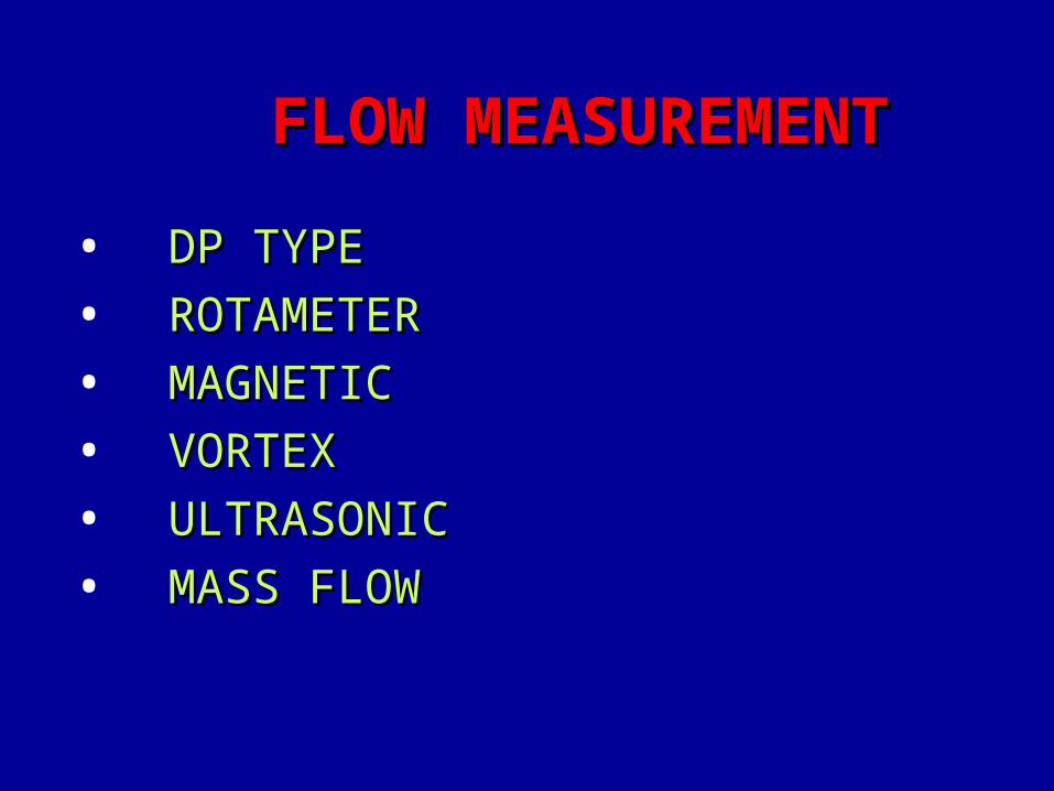
ADVANTAGESADVANTAGES• HIGH RANGEABILITY-30:1 FOR SOME TYPESHIGH RANGEABILITY-30:1 FOR SOME TYPES• EASE OF CALIBRATIONEASE OF CALIBRATION• LINEAR READOUT AND FLEXIBILITY OF READ OUT DEVICESLINEAR READOUT AND FLEXIBILITY OF READ OUT DEVICES• GOOD TO EXCELLENT ACCURACYGOOD TO EXCELLENT ACCURACY
DISADVANTAGEDISADVANTAGE• RELATIVELY HIGH PRESSURE DROPRELATIVELY HIGH PRESSURE DROP• VERY LITTLE OVER RANGE PROTECTIONVERY LITTLE OVER RANGE PROTECTION• IN-LINE MOUNTINGIN-LINE MOUNTING• RELATIVELY HIGH COST ,ESPECIALLY FOR HIGH FLOW RATE RELATIVELY HIGH COST ,ESPECIALLY FOR HIGH FLOW RATE
APPLICATIONAPPLICATION• SUSCEPTIBLE TO DAMAGES FROM GAS OR LIQUID SLUGS AND FROM SUSCEPTIBLE TO DAMAGES FROM GAS OR LIQUID SLUGS AND FROM
DIRTY FLUIDSDIRTY FLUIDS
Head MetersHead meters are the most common types of meter used to measure fluid flow rates. They measure fluid flow indirectly by creating and measuring a differential pressure by means of an obstruction to the fluid flow. Using well-established conversion coefficients which depend on the type of head meter used and the diameter of the pipe, a measurement of the differential pressure may be translated into a volume rate. Head meters are generally simple, reliable, and offer more flexibility than other flow measurement methods. The head-type flowmeter almost always consists of two components: the primary device and the secondary device. The primary device is placed in the pipe to restrict the flow and develop a differential pressure. The secondary device measures the differential pressure and provides a readout or signal for transmission to a control system. With head meters, calibration of a primary measuring device is not required in the field. The primary device can be selected for compatibility with the specific fluid or application and the secondary device can be selected for the type or readout of signal transmission desired.
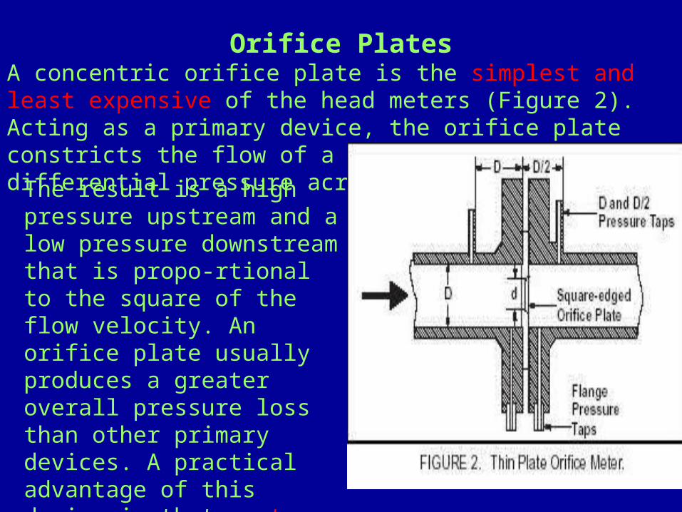
The result is a high pressure upstream and a low pressure downstream that is propo-rtional to the square of the flow velocity. An orifice plate usually produces a greater overall pressure loss than other primary devices. A practical advantage of this device is that cost does not increase significantly with pipe size.
Orifice PlatesA concentric orifice plate is the simplest and least expensive of the head meters (Figure 2). Acting as a primary device, the orifice plate constricts the flow of a fluid to produce a differential pressure across the plate.

ORIFICE INSTALLATION
ADVANTAGES
RELATIVELY LOW COST PROVEN ACCURACY & RELIABILITY EASILY REMOVABLE
SECONDARY DEVICE CAN BE CALIBRATED
DISADVANTAGES
FLOW RANGEBILITY LIMITED
RELATIVELY HIGH PERMANENT PRESSURE LOSS
DIFFICULT TO USE FOR SLURRY/PULSATING FLOW
SQUARE ROOT RATHER THAN LINEAR CHARACHTERISTICS
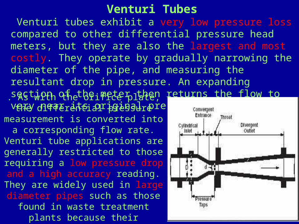
. As with the orifice plate, the differential pressure
measurement is converted into a corresponding flow rate.
Venturi tube applications are generally restricted to those requiring a low pressure drop and a high accuracy reading. They are widely used in large diameter pipes such as those found in waste treatment plants because their
gradually sloping shape will allow solids to flow through.
Venturi Tubes Venturi tubes exhibit a very low pressure loss compared to other differential pressure head meters, but they are also the largest and most costly. They operate by gradually narrowing the diameter of the pipe, and measuring the resultant drop in pressure. An expanding section of the meter then returns the flow to very near its original pressure

Venturi tube Venturi tube installationinstallation
ADVANTAGESADVANTAGESLOW PRESSURE LOSSLOW PRESSURE LOSSHANDLE SUSPENDED SOLIDSHANDLE SUSPENDED SOLIDSUSED FOR HIGH FLOW RATESUSED FOR HIGH FLOW RATESMORE ACCURATE OVER WIDE FLOW RANGES THEN ORIFICE OR NOZZLEMORE ACCURATE OVER WIDE FLOW RANGES THEN ORIFICE OR NOZZLE
DISADVANTAGESDISADVANTAGESHIGH COSTHIGH COSTNOT NORMALLY AVALIABLE IN PIPE SIZES BELOW 6 INCHESNOT NORMALLY AVALIABLE IN PIPE SIZES BELOW 6 INCHES

Flow NozzleFlow nozzles may be thought of as a variation on the venturi tube. The nozzle opening is an elliptical restriction in the flow but with no outlet area for pressure recovery (Figure 4). Pressure taps are located approximately 1/2 pipe diameter downstream and 1 pipe diameter upstream.
The flow nozzle is a high velocity flow meter used where turbulence is high (Reynolds numbers above 50,000) such as in steam flow at high temperatures. The pressure drop of a flow nozzle falls between that of the venturi tube and the orifice plate (30 to 95 percent).
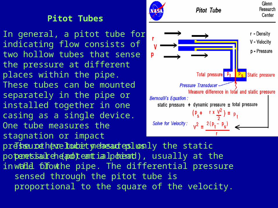
Pitot TubesIn general, a pitot tube for indicating flow consists of two hollow tubes that sense the pressure at different places within the pipe. These tubes can be mounted separately in the pipe or installed together in one casing as a single device. One tube measures the stagnation or impact pressure (velocity head plus potential head) at a point in the flow.
The other tube measures only the static pressure (potential head), usually at the wall of the pipe. The differential pressure sensed through the pitot tube is proportional to the square of the velocity.
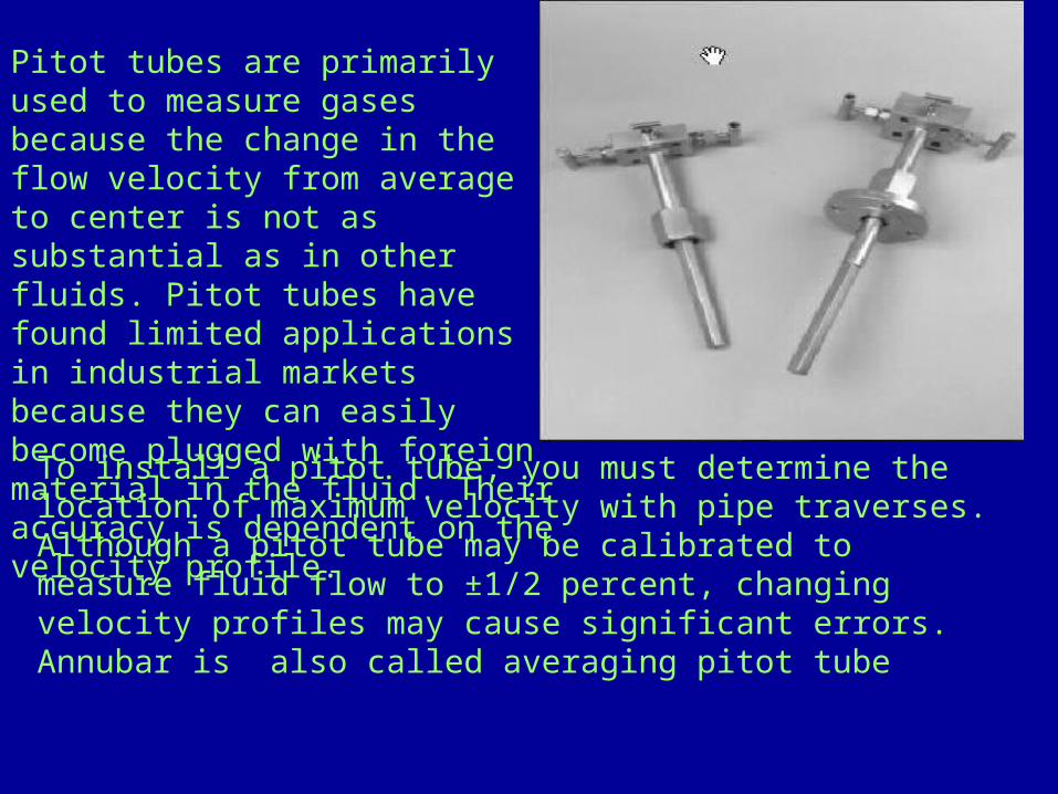
Pitot tubes are primarily used to measure gases because the change in the flow velocity from average to center is not as substantial as in other fluids. Pitot tubes have found limited applications in industrial markets because they can easily become plugged with foreign material in the fluid. Their accuracy is dependent on the velocity profile.
To install a pitot tube, you must determine the location of maximum velocity with pipe traverses. Although a pitot tube may be calibrated to measure fluid flow to ±1/2 percent, changing velocity profiles may cause significant errors. Annubar is also called averaging pitot tube

INSTALLAYION OF PITOT TUBEINSTALLAYION OF PITOT TUBE
• ADVANTAGESADVANTAGES• ESSENTIALLY NO PRESSURE LOSSESSENTIALLY NO PRESSURE LOSS• ECONOMICAL TO INSTALLECONOMICAL TO INSTALL• SOME TYPES CAN BE REMOVED FROM LINESSOME TYPES CAN BE REMOVED FROM LINES
• DISADVANTAGESDISADVANTAGES• POOR ACCURACYPOOR ACCURACY• CALIBRATION DATA NEEDS TO BE SUPPLIED FROM THE CALIBRATION DATA NEEDS TO BE SUPPLIED FROM THE
MANUFACTUREMANUFACTURE• NOT RECCOMDED FOR DIRTY OR STICKY FLUIDSNOT RECCOMDED FOR DIRTY OR STICKY FLUIDS• SENSITIVE TO UP STREAM DISTURBANCESENSITIVE TO UP STREAM DISTURBANCE
Rotameters
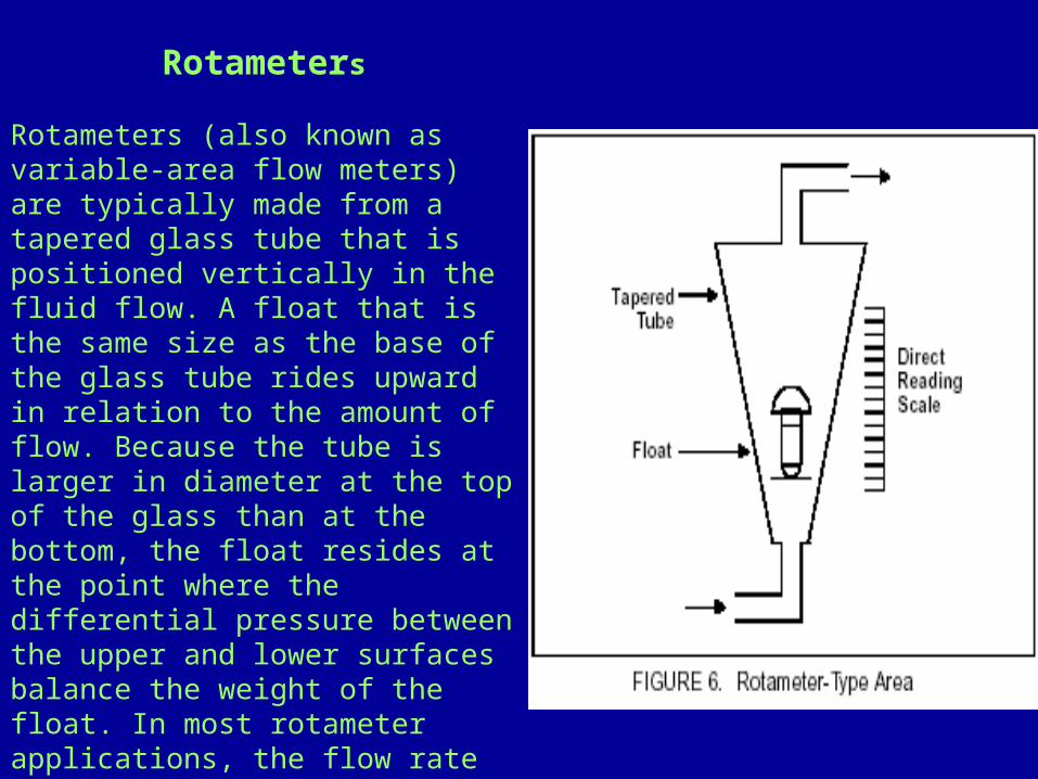
Rotameters (also known as variable-area flow meters) are typically made from a tapered glass tube that is positioned vertically in the fluid flow. A float that is the same size as the base of the glass tube rides upward in relation to the amount of flow. Because the tube is larger in diameter at the top of the glass than at the bottom, the float resides at the point where the differential pressure between the upper and lower surfaces balance the weight of the float. In most rotameter applications, the flow rate is read directly from a scale inscribed on the glass; in some cases, an automatic sensing device is used to the float and transmit a flow signal.

These transmitting rotameters are often made from stainless steel or other materials for various fluid applications and higher pressures. Rotameters may range in size from 1/4 inch to greater then 6 inches. They measure a wider band of flow (10 to 1) than an orifice plate with an accuracy of ± 2 percent, and a maximum operating pressure of 300 psig when constructed of glass. Rotameters are commonly.used for purge flows and levels.
INSTALLATION OF ROTAMETERINSTALLATION OF ROTAMETERADVANTAGESADVANTAGES
• GOOD RAGEABILITY AND LOW COSTGOOD RAGEABILITY AND LOW COST• GOOD FOR METERING SMALL FLOWGOOD FOR METERING SMALL FLOW• EASILY EQUIPPED WITH ALARM SWITCHESEASILY EQUIPPED WITH ALARM SWITCHES• NO RESTRICTION IN REGARD TO INLET AND OUTLET PIPING REQUIREDNO RESTRICTION IN REGARD TO INLET AND OUTLET PIPING REQUIRED• LOW PRESSURE DROP REQUIREDLOW PRESSURE DROP REQUIRED• VISCOSITY-IMMUNEVISCOSITY-IMMUNE DESIGNS AVALIABLE DESIGNS AVALIABLE
DISADVANTAGESDISADVANTAGES
• GLASS TUBE TYPE SUBJECTED TO BREAKAGEGLASS TUBE TYPE SUBJECTED TO BREAKAGE• NOT GOOD IN PULSATING SERVICESNOT GOOD IN PULSATING SERVICES• MUST BE MOUNTED VERTICALLYMUST BE MOUNTED VERTICALLY• GENERALLY LIMITED TO THE SMALL PIPE SIZESGENERALLY LIMITED TO THE SMALL PIPE SIZES• LOW TEMPERATURE RANGELOW TEMPERATURE RANGE

Velocity Meters
When using velocity to measure a fluid flow rate, the primary device generates a signal proportional to fluid velocity. The equation QV = A * V illustrates that the generated signal is linear with respect to the volume flow rate. Velocity meters are usually less sensitive than head meters to velocity profile, some are obstruction less, and because they provide linear output with respect to flow, there is no square-root relationship as with differential pressure meters. This eliminates the potential inaccuracies associated with square-root extraction and explains the greater rangeability of velocity meters in comparison to most head meters.
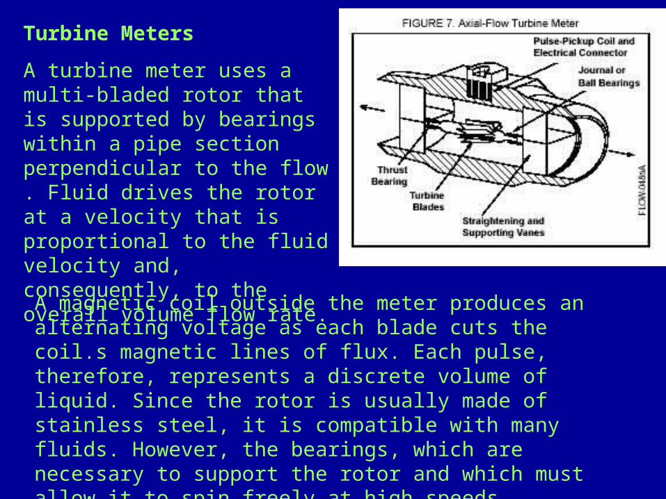
Turbine MetersA turbine meter uses a multi-bladed rotor that is supported by bearings within a pipe section perpendicular to the flow . Fluid drives the rotor at a velocity that is proportional to the fluid velocity and, consequently, to the overall volume flow rate. A magnetic coil outside the meter produces an alternating voltage as each blade cuts the coil.s magnetic lines of flux. Each pulse, therefore, represents a discrete volume of liquid. Since the rotor is usually made of stainless steel, it is compatible with many fluids. However, the bearings, which are necessary to support the rotor and which must allow it to spin freely at high speeds, require a fairly clean process.

INSTALLATION OF TURBINE METERINSTALLATION OF TURBINE METER
• ADVANTAGESADVANTAGES• GOOD ACCURACYGOOD ACCURACY• EXCELLENT RAGEABILITY AND REPEATABILITYEXCELLENT RAGEABILITY AND REPEATABILITY• LOW PRESSURE DROPLOW PRESSURE DROP• EASY TO INSTALL AND MAINTAINEASY TO INSTALL AND MAINTAIN• CAN BE COMPANSATED FOR VISCOSITY CAN BE COMPANSATED FOR VISCOSITY VARIATIONVARIATION• ADAPTABLE TO FLOW TOTALIZING ANDADAPTABLE TO FLOW TOTALIZING AND DIGITAL BLENDING SYSTEMDIGITAL BLENDING SYSTEM
• DISADVANTAGESDISADVANTAGES• IN-LINE MOUNTING REQUIREDIN-LINE MOUNTING REQUIRED• RELATIVELY HIGH COSTRELATIVELY HIGH COST• LIMITED USE FOR SLURRY APPLICATIONLIMITED USE FOR SLURRY APPLICATION• NONLUBRICATING FLUIDS SOMETIMES NONLUBRICATING FLUIDS SOMETIMES PRESENT PROBLEMPRESENT PROBLEM• STRAINERS RECOMMENDED, EXCEPT STRAINERS RECOMMENDED, EXCEPT FOR SPECIAL SLURRY METER.FOR SPECIAL SLURRY METER.
Turbine meters are typically available in pipeline sizes from less than 1/2 inch through 12 inches. They have fast response and good accuracy

Electromagnetic Flow meters
The operating principle of magnetic flow meter system is base upon Faraday.s Law of electromagnetic induction, which states that a voltage will be induced in a conductor moving through a magnetic field. Faraday.s Law: The magnitude of the induced voltage E is directly proportional to the velocity of the conductor V, conductor width D, and the strength of the magnetic field B. Figure 8 illustrates the relationship between the physical components of the magnetic flow meter and Faraday.s Law..
E=K b d v

. An insulating liner prevents the signal from shorting to the pipe wall. The only variable in this application of Faraday.s law is the velocity of the conductive liquid V because field strength is controlled constant and electrode spacing is fixed. Therefore, the output voltage E is directly proportional to liquid velocity, resulting in the linear output of a magnetic flow meter
Magnetic field coils placed on opposite sides of the pipe generate a magnetic field. As the conductive process liquid moves through the field with average velocity V, electrodes sense the induced voltage. The width of the conductor is represented by the distance between electrodes
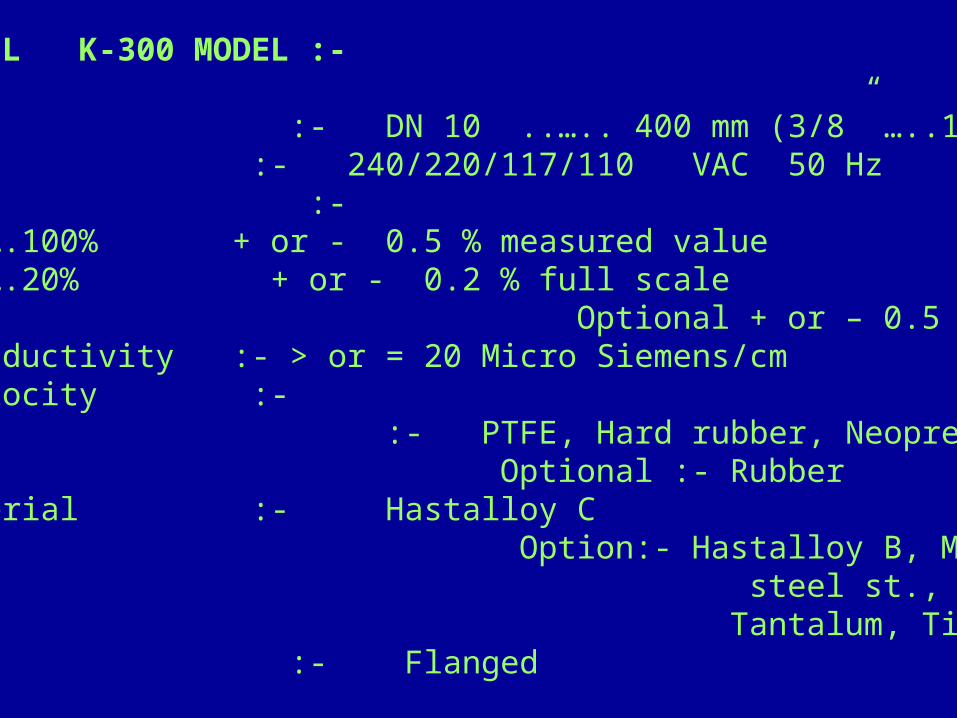
KROHNE MARSHALL K-300 MODEL :- Meter Size :- DN 10 ..….. 400 mm (3/8” …..16”) Power supply :- 240/220/117/110 VAC 50 HzAccuracy :- Between 20….100% + or - 0.5 % measured value Between 0….20% + or - 0.2 % full scale Optional + or – 0.5 %Electrical conductivity :- > or = 20 Micro Siemens/cmFull Scale Velocity :- Lining :- PTFE, Hard rubber, Neoprene Optional :- Rubber Electrode Material :- Hastalloy C Option:- Hastalloy B, Monel, CrNi- steel st., st.316 Ti Tantalum, Titanium.PlatinumMounting :- Flanged

MAGNETIC FLOWMETERS
ADVANTAGES
-GOOD ACCURACY , CAN HANDLE SLURRIES & CORROSIVE FLUID -LOW PRESSURE DROP & NO OBSTRUCTION IN PIPE-ADAPTABLE FOR MANY MATERIALS-BIDIRECTIONAL FLOW MEASURMENT POSSIBLE-UNAFFECTED BY VISCIOSITY DENSITY TEMPERATURE OR PRESSURE-CAN MEASURE TURBULENT OR LAMINAR FLOW
DISADVANTAGES
-CONDUCTIVITY MUST BE > 20 MICROMHOS-METER MUST BE FULL AT ALL TIMES-RELATIVELY HIGH COST-IN LINE MOUNTING REQUIRED-ELECTRONIC FOULING OCCURS

Vortex Meters
The operating principle of a vortex flow meter is based on the phenomenon of vortex shedding known as the von Karman effect. As fluid passes a bluff body, it separates and generates small eddies or vortices that are shed alternately along and behind each side of the bluff body (Figure 9). These vortices cause areas of fluctuating pressure that are detected by a sensor. The frequency of vortex generation is directly proportional to fluid velocity.

The output of a vortex flow meter depends on the K-factor. The K-factor relates the frequency of generated vortices to the fluid velocity. The formula for fluid velocity is as follows:The K-factor varies with Reynolds number, but it is virtually constant over a broad flow range Vortex flow meters provide highly accurate linear flow rates when operated within this flat region
Vortex Meters

INSTALLATION OF VORTEX METERINSTALLATION OF VORTEX METER
ADVANTAGESADVANTAGES• EXCELLENT RANGEABILITYEXCELLENT RANGEABILITY• NO MOVING PARTSNO MOVING PARTS• DIGITAL READOUT LENDS ITSELF TO BLENDING APPLICATION AND DIGITAL READOUT LENDS ITSELF TO BLENDING APPLICATION AND
FLOW TOTALIZATIONFLOW TOTALIZATION• VERY LOW PREESURE DROPVERY LOW PREESURE DROP
DISADVANTAGEDISADVANTAGE
• LIMITED APPLICATION DATALIMITED APPLICATION DATA• IN-LINE MOUNTING REQUIREDIN-LINE MOUNTING REQUIRED• LIMITATION IMPOSED ON UPSTREAM AND DOWNSTREAM PIPING LIMITATION IMPOSED ON UPSTREAM AND DOWNSTREAM PIPING
REQUIREMENTSREQUIREMENTS• RELATIVELY HIGH COSTRELATIVELY HIGH COST
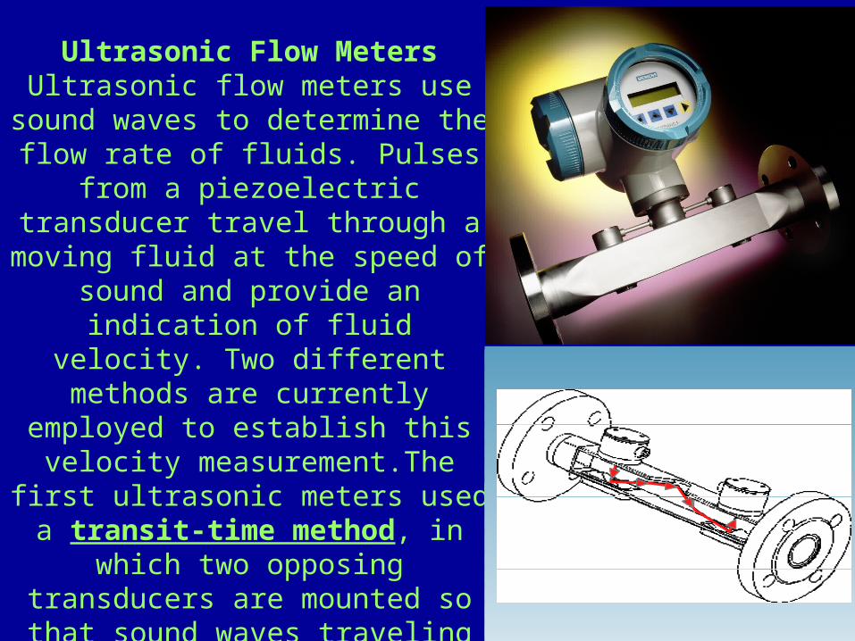
Ultrasonic Flow MetersUltrasonic flow meters use sound waves to determine the flow rate of fluids. Pulses
from a piezoelectric transducer travel through a moving fluid at the speed of
sound and provide an indication of fluid
velocity. Two different methods are currently
employed to establish this velocity measurement.The
first ultrasonic meters used a transit-time method, in
which two opposing transducers are mounted so that sound waves traveling between them are at a 45
degree angle to the direction of flow within a
pipe.
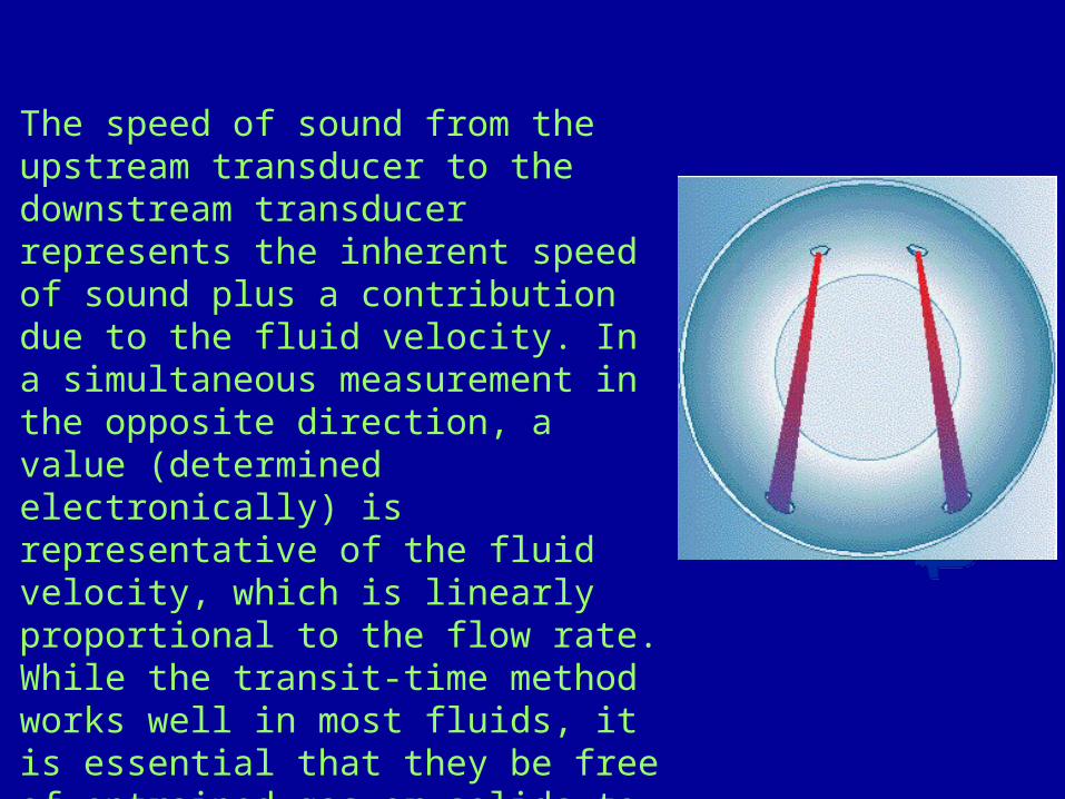
The speed of sound from the upstream transducer to the downstream transducer represents the inherent speed of sound plus a contribution due to the fluid velocity. In a simultaneous measurement in the opposite direction, a value (determined electronically) is representative of the fluid velocity, which is linearly proportional to the flow rate. While the transit-time method works well in most fluids, it is essential that they be free of entrained gas or solids to prevent scattering of the sound waves between transducers.
today
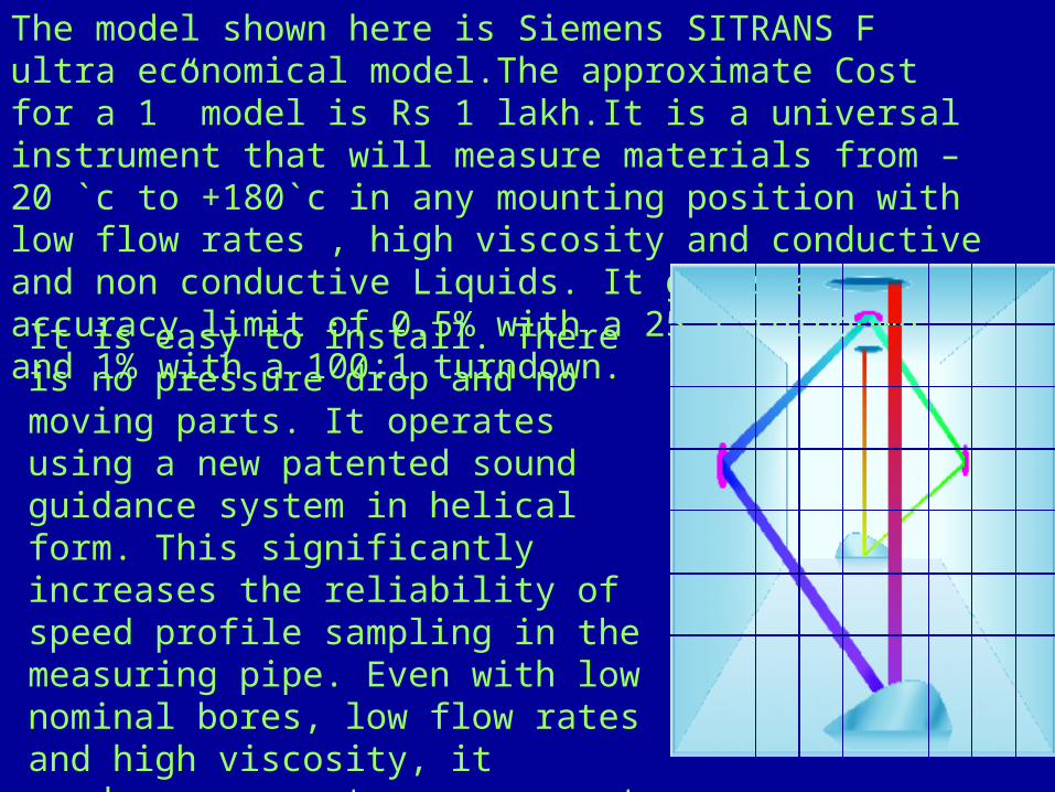
The model shown here is Siemens SITRANS F ultra economical model.The approximate Cost for a 1” model is Rs 1 lakh.It is a universal instrument that will measure materials from –20 `c to +180`c in any mounting position with low flow rates , high viscosity and conductive and non conductive Liquids. It gives an accuracy limit of 0.5% with a 25:1 turndown and 1% with a 100:1 turndown.It is easy to install. There is no pressure drop and no moving parts. It operates using a new patented sound guidance system in helical form. This significantly increases the reliability of speed profile sampling in the measuring pipe. Even with low nominal bores, low flow rates and high viscosity, it produces accurate measurement results, both with laminar and Turbulent flows and in transitional region.

two probes A & B are mounted as shown in figure.the time between up stream and down stream propagation can be written as follows
TAB = L / ( C + v Cos Ø)T BA = L / ( C – v Cos Ø )
v = velocity of fluidL = length of acoustic pathd = axial dist. of L through flow dirnC = speed of sound in fluid at rest
T = T BA - TAB
1/ TAB - 1/ T BA = 2v Cos Ø /L = 2vd / L2
v = L2 / 2d (1/ TAB - 1/ T BA ) IF
THEN v = L2
2dT
TAB - T BA
Fluid velocity v can be found by accurate propagation times measurements , once parameters L & d are accurately known.The method as described above is also known as “time-of-flight” Measurement of ultrasound.
A
B
L
Ø
y
d
v Cos Ø
Ultrasonic Flow Meters ( Doppler Effect )Another type of ultrasonic meter uses the Doppler effect. This type of ultrasonic meter uses two transducer elements as well, but each is mounted in the same case on one side of the pipe. An ultrasonic sound wave of constant frequency is transmitted into the fluid by one of the elements. Solids or bubbles within the fluid reflect the sound back to the receiver element. The Doppler principle states that there will be a shift in apparent frequency or wavelength when there is relative motion between transmitter and receiver. Within the Doppler flow meter, the relative motion of the reflecting bodies suspended within the fluid tends to compress the sound into a shorter wavelength (high frequency). This new frequency measured at the receiving element is electronically compared with the transmitted frequency to provide a frequency difference that is directly proportional to the flow velocity in the pipe. In contrast to the transit-time method, Doppler ultrasonic meters require entrained gases or suspended solids within the flow to function correctly.While ultrasonic meters have several advantages, including freedom from obstruction in the pipe and negligible cost-sensitivity with respect to pipe diameter, their performance is very dependent on flow conditions. A fair accuracy is attainable with ultrasonic flow meters when properly applied to appropriate fluids.

Mass Flow Meters
True mass flow meters measure the mass rate of flow directly as opposed to the volumetric flow rate. As a result, entrained air does not affect the accuracy of their measurement. Many so-called mass flow meters, however, infer the mass flow rate via the equation:
QM = QV *
In this equation, QM is the mass flow rate, QV is the volume flow rate, and is fluid density. Such mass flow meter instruments essentially combine two devices, one to measure fluid velocity and the other to measure density. These inputs are typically combined in a microprocessor, along with additional data, to provide an output indicative of the mass flow rate. In contrast, the following meters measure mass flow directly without the intermediate calculation from volume and density.
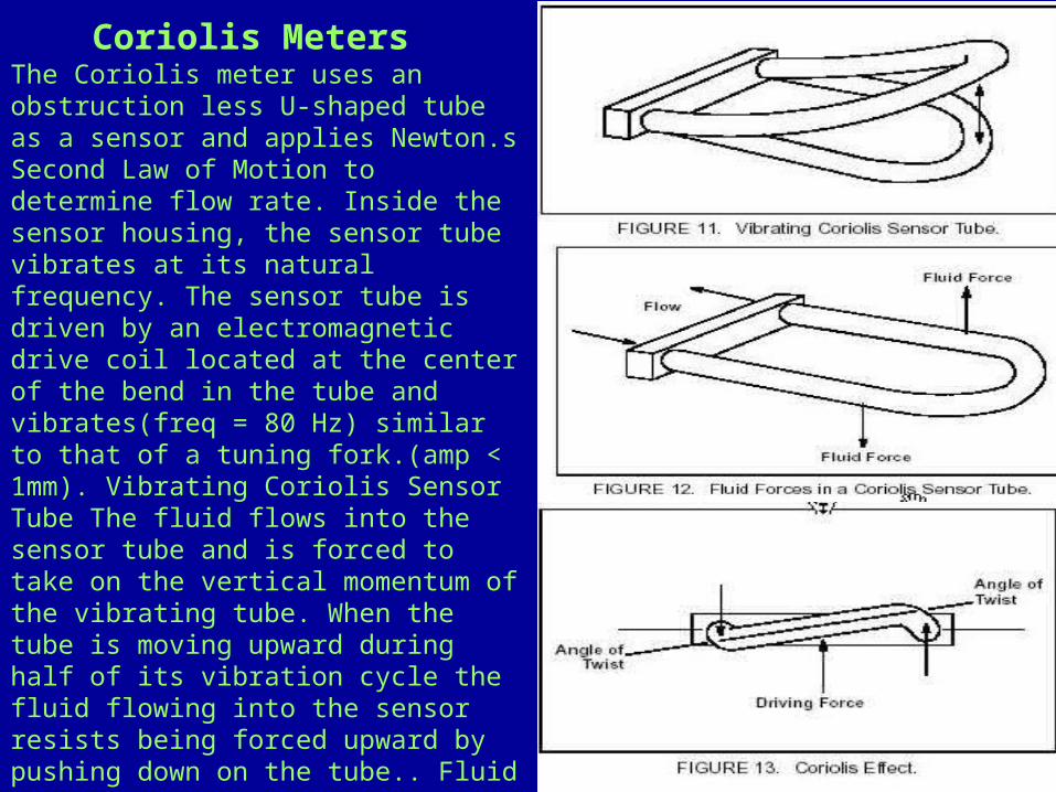
The Coriolis meter uses an obstruction less U-shaped tube as a sensor and applies Newton.s Second Law of Motion to determine flow rate. Inside the sensor housing, the sensor tube vibrates at its natural frequency. The sensor tube is driven by an electromagnetic drive coil located at the center of the bend in the tube and vibrates(freq = 80 Hz) similar to that of a tuning fork.(amp < 1mm). Vibrating Coriolis Sensor Tube The fluid flows into the sensor tube and is forced to take on the vertical momentum of the vibrating tube. When the tube is moving upward during half of its vibration cycle the fluid flowing into the sensor resists being forced upward by pushing down on the tube.. Fluid Forces in a Coriolis Sensor Tube The fluid flowing out of the sensor has an upward momentum from the motion of the tube. As it travels around the tube bend, the fluid resists changes in its vertical motion by pushing up on the tube.
Coriolis Meters
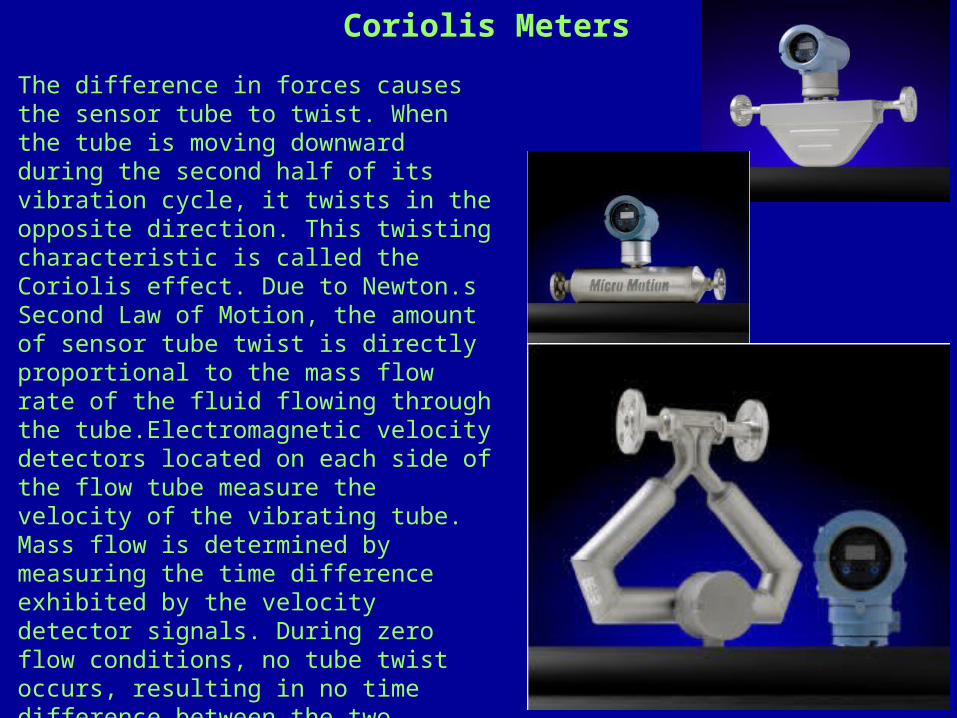
The difference in forces causes the sensor tube to twist. When the tube is moving downward during the second half of its vibration cycle, it twists in the opposite direction. This twisting characteristic is called the Coriolis effect. Due to Newton.s Second Law of Motion, the amount of sensor tube twist is directly proportional to the mass flow rate of the fluid flowing through the tube.Electromagnetic velocity detectors located on each side of the flow tube measure the velocity of the vibrating tube. Mass flow is determined by measuring the time difference exhibited by the velocity detector signals. During zero flow conditions, no tube twist occurs, resulting in no time difference between the two velocity signals. With flow, a twist occurs with a resulting time difference between the two velocity signals. This time difference is directly proportional to mass flow.
Coriolis Meters
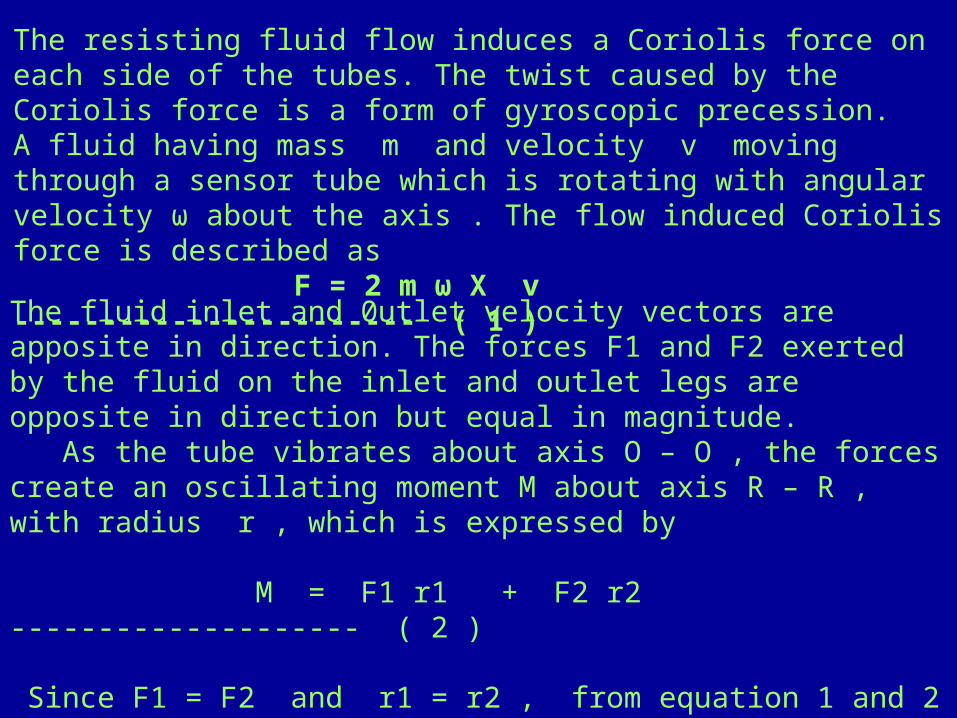
The resisting fluid flow induces a Coriolis force on each side of the tubes. The twist caused by the Coriolis force is a form of gyroscopic precession. A fluid having mass m and velocity v moving through a sensor tube which is rotating with angular velocity ω about the axis . The flow induced Coriolis force is described as F = 2 m ω X v ----------------------- ( 1 ) The fluid inlet and 0utlet velocity vectors are apposite in direction. The forces F1 and F2 exerted by the fluid on the inlet and outlet legs are opposite in direction but equal in magnitude. As the tube vibrates about axis O – O , the forces create an oscillating moment M about axis R – R , with radius r , which is expressed by
M = F1 r1 + F2 r2 -------------------- ( 2 )
Since F1 = F2 and r1 = r2 , from equation 1 and 2
M = 2 F r = 4 m V ω r -------------------- ( 3 )
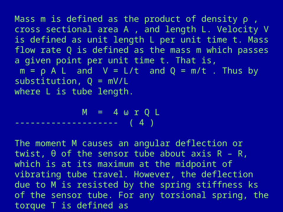
Mass m is defined as the product of density ρ , cross sectional area A , and length L. Velocity V is defined as unit length L per unit time t. Mass flow rate Q is defined as the mass m which passes a given point per unit time t. That is, m = ρ A L and V = L/t and Q = m/t . Thus by substitution, Q = mV/Lwhere L is tube length. M = 4 ω r Q L -------------------- ( 4 ) The moment M causes an angular deflection or twist, θ of the sensor tube about axis R – R, which is at its maximum at the midpoint of vibrating tube travel. However, the deflection due to M is resisted by the spring stiffness ks of the sensor tube. For any torsional spring, the torque T is defined as T = ks θ -------------------- ( 5 )

Since T = M, the mass flow rate Q can now be related to the deflection angle θ By combining equation 4 and 5 Q = ks θ -------------------- ( 5 ) 4 ω r L The mass flow rate can be derived by measuring the deflection angle θ with two position detectors. Each detector measures θ as a function of the time at which each tube legs crosses the midpoint of tube travel. The time difference between the right and left legs on the up and down stroke crossing is zero when there is no flow. But as flow increases, causing an increase in θ, the time difference Δt between the up and down stroke signals also increases. The velocity Vt of the tube at the midpoint of travel, multiplied by the time interval Δt is related to θ by geometry: Sin θ = Vt/2r Δt --------------------- ( 7 )

if θ is small, it is nearly equal to sin θ . And for small rotation angle Vt is the product of ω and the tube length L . That is θ = sin θ and Vt = ω L ω L Δt θ = --------------------- ( 8 ) 2r Combining equation 6 and 8 Ks ω L Δt Ks Q = = Δt ( 9 ) 8 r² ω L 8 r² The mass flow rate Q is therefore proportional only to the time interval Δt and geometric constants. Q is independent of ω , and therefore independent of the vibrational frequency of the sensor tubes.
LEVEL MEASUREMENTLEVEL MEASUREMENT• DP TYPEDP TYPE• CAPACITANCE CAPACITANCE • ULTRASONICULTRASONIC• RADAR RADAR • LEVELTROLSLEVELTROLS• RADIATIONRADIATION

MEASUREMENT OF LEVEL MEASUREMENT OF LEVEL
IN MANY INDUSTRIAL PROCESSES IT IS VERY IN MANY INDUSTRIAL PROCESSES IT IS VERY IMPORTANT TO KNOW LEVEL OF LIQUID IN A TANK OR VESSEL. IMPORTANT TO KNOW LEVEL OF LIQUID IN A TANK OR VESSEL. IT IS ESSENTIAL TO KNOW THE LEVEL OF THE WATER IN THE IT IS ESSENTIAL TO KNOW THE LEVEL OF THE WATER IN THE BOILER WHILE IT IS IN USE AND UNDER PRESSURE,BUT IT IS BOILER WHILE IT IS IN USE AND UNDER PRESSURE,BUT IT IS IMPOSSIBLE TO VIEW IT DIRECTLY.IMPOSSIBLE TO VIEW IT DIRECTLY.
LEVEL MEASUREMENT IS THEREFORE DESCRIBED UNDER LEVEL MEASUREMENT IS THEREFORE DESCRIBED UNDER THE FOLLOWING HEADINGTHE FOLLOWING HEADING
1) DIRECT METHODS – a) HOOK TYPE1) DIRECT METHODS – a) HOOK TYPE b) SIGHT b) SIGHT GLASSGLASS
c) c) FLOAT GAUGINGFLOAT GAUGING
2) SERVO – LEVEL GAUGING2) SERVO – LEVEL GAUGING 3) CAPACITIVE PROBES3) CAPACITIVE PROBES 4) PRESSURE OPERATED GAUGING4) PRESSURE OPERATED GAUGING 5) NUCLEONIC GAUGING5) NUCLEONIC GAUGING 6) ULTRASONIC GAUGING6) ULTRASONIC GAUGING
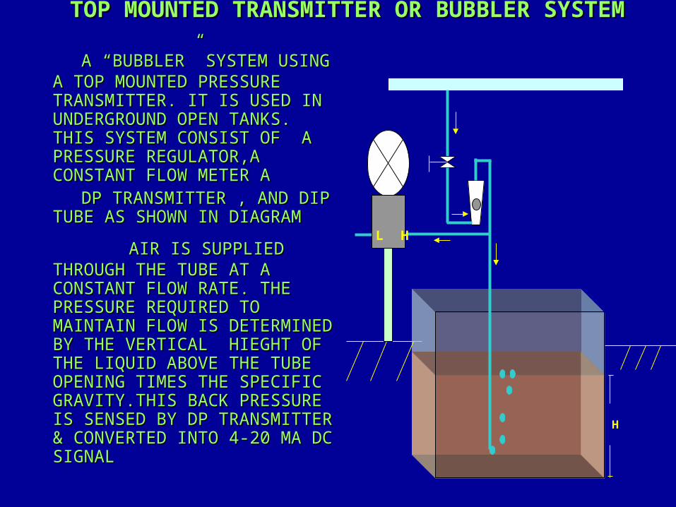
TOP MOUNTED TRANSMITTER OR BUBBLER SYSTEMTOP MOUNTED TRANSMITTER OR BUBBLER SYSTEM
A “BUBBLER” SYSTEM USINGA “BUBBLER” SYSTEM USING A TOP MOUNTED PRESSURE A TOP MOUNTED PRESSURE TRANSMITTER. IT IS USED IN TRANSMITTER. IT IS USED IN UNDERGROUND OPEN TANKS. UNDERGROUND OPEN TANKS. THIS SYSTEM CONSIST OF A THIS SYSTEM CONSIST OF A PRESSURE REGULATOR,A PRESSURE REGULATOR,A CONSTANT FLOW METER ACONSTANT FLOW METER A
DP TRANSMITTER , AND DIP DP TRANSMITTER , AND DIP TUBE AS SHOWN IN DIAGRAMTUBE AS SHOWN IN DIAGRAM
AIR IS SUPPLIED AIR IS SUPPLIED THROUGH THE TUBE AT A THROUGH THE TUBE AT A CONSTANT FLOW RATE. THE CONSTANT FLOW RATE. THE PRESSURE REQUIRED TO PRESSURE REQUIRED TO MAINTAIN FLOW IS DETERMINED MAINTAIN FLOW IS DETERMINED BY THE VERTICAL HIEGHT OF BY THE VERTICAL HIEGHT OF THE LIQUID ABOVE THE TUBE THE LIQUID ABOVE THE TUBE OPENING TIMES THE SPECIFIC OPENING TIMES THE SPECIFIC GRAVITY.THIS BACK PRESSURE GRAVITY.THIS BACK PRESSURE IS SENSED BY DP TRANSMITTER IS SENSED BY DP TRANSMITTER & CONVERTED INTO 4-20 MA DC & CONVERTED INTO 4-20 MA DC SIGNALSIGNAL
H
HL

OPEN VESSEL BOTTOM MOUNTED OPEN VESSEL BOTTOM MOUNTED TRANSMITTERTRANSMITTER
• IN OPEN VESSELS A PRESSURE IN OPEN VESSELS A PRESSURE TRANSMITTER MOUNTED NEAR TRANSMITTER MOUNTED NEAR THE BOTTOM OF THE TANK THE BOTTOM OF THE TANK WILL MEASURE THE PRESSURE WILL MEASURE THE PRESSURE CORRESPONDING TO THE HIGHT CORRESPONDING TO THE HIGHT OF THE FLUID ABOVE IT.OF THE FLUID ABOVE IT.
• THE CONNECTION IS MADE TO THE CONNECTION IS MADE TO THE HIGH PRESSURE SIDE OF THE HIGH PRESSURE SIDE OF THE TRANSMITTER. THE LOW THE TRANSMITTER. THE LOW PRESSURE SIDE IS VENTED TO PRESSURE SIDE IS VENTED TO ATMOSPHERE.ATMOSPHERE.
• IF ZERO POINT OF THE IF ZERO POINT OF THE DESIRED LEVEL RANGE IS DESIRED LEVEL RANGE IS ABOVE THE TRANSMITTER,ZERO ABOVE THE TRANSMITTER,ZERO SUPPRESSION OF THE RANGE SUPPRESSION OF THE RANGE MUST BE MADE.MUST BE MADE.
L H
+_
4 – 20 mA
Open to Atm.
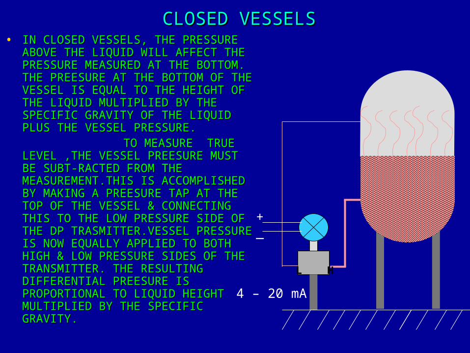
CLOSED VESSELSCLOSED VESSELS• IN CLOSED VESSELS, THE PRESSURE IN CLOSED VESSELS, THE PRESSURE
ABOVE THE LIQUID WILL AFFECT THE ABOVE THE LIQUID WILL AFFECT THE PRESSURE MEASURED AT THE BOTTOM. PRESSURE MEASURED AT THE BOTTOM. THE PREESURE AT THE BOTTOM OF THE THE PREESURE AT THE BOTTOM OF THE VESSEL IS EQUAL TO THE HEIGHT OF VESSEL IS EQUAL TO THE HEIGHT OF THE LIQUID MULTIPLIED BY THE THE LIQUID MULTIPLIED BY THE SPECIFIC GRAVITY OF THE LIQUID SPECIFIC GRAVITY OF THE LIQUID PLUS THE VESSEL PRESSURE.PLUS THE VESSEL PRESSURE.
TO MEASURE TRUE TO MEASURE TRUE LEVEL ,THE VESSEL PREESURE MUST LEVEL ,THE VESSEL PREESURE MUST BE SUBT-RACTED FROM THE BE SUBT-RACTED FROM THE MEASUREMENT.THIS IS ACCOMPLISHED MEASUREMENT.THIS IS ACCOMPLISHED BY MAKING A PREESURE TAP AT THE BY MAKING A PREESURE TAP AT THE TOP OF THE VESSEL & CONNECTING TOP OF THE VESSEL & CONNECTING THIS TO THE LOW PRESSURE SIDE OF THIS TO THE LOW PRESSURE SIDE OF THE DP TRASMITTER.VESSEL PRESSURE THE DP TRASMITTER.VESSEL PRESSURE IS NOW EQUALLY APPLIED TO BOTH IS NOW EQUALLY APPLIED TO BOTH HIGH & LOW PRESSURE SIDES OF THE HIGH & LOW PRESSURE SIDES OF THE TRANSMITTER. THE RESULTING TRANSMITTER. THE RESULTING DIFFERENTIAL PREESURE IS DIFFERENTIAL PREESURE IS PROPORTIONAL TO LIQUID HEIGHT PROPORTIONAL TO LIQUID HEIGHT MULTIPLIED BY THE SPECIFIC MULTIPLIED BY THE SPECIFIC GRAVITY.GRAVITY.
L H
+_
4 – 20 mA

DRY LEG, WET LEG DRY LEG, WET LEG CONDITIONCONDITIONDRY LEG -
IF THE GAS ABOVE THE LIQUID DOSE NOT CONDENSE,THE PIPING FOR THE LOW SIDE OF THE TRANSMITTER WILL REMAIN EMPTY.CALCULATION FOR DETERMINIMG THE RANGE WILL BE THE SAME AS THOSE SHOWN FOR OPEN VESSEL BOTTOM MOUNTED TRANMITTER.
WET LEG - IF THE GAS ABOVE THE LIQUID CONDENSES, THE PIPING
FOR THE LOW SIDE OF THE TRANSMITTER WILL SLOWLY FILL UP YHE LIQUID. TO ELIMINATE THIS POTENTIAL ERROR,THE PIPE IS CONVENIENTLY FILLED WITH A REFERENCE FLUID.
THE REFERENCE FLUID WILL EXERT A HEAD PREESURE ON THE LOW SIDE OF THE TRANSMITTER,& ZERO ELEVATION OF THE RANGE MUST BE MADE.
THIS ADJUSTMENT IS LIMITED TO 600% OF THE SPAN ON THE 1151 DP.
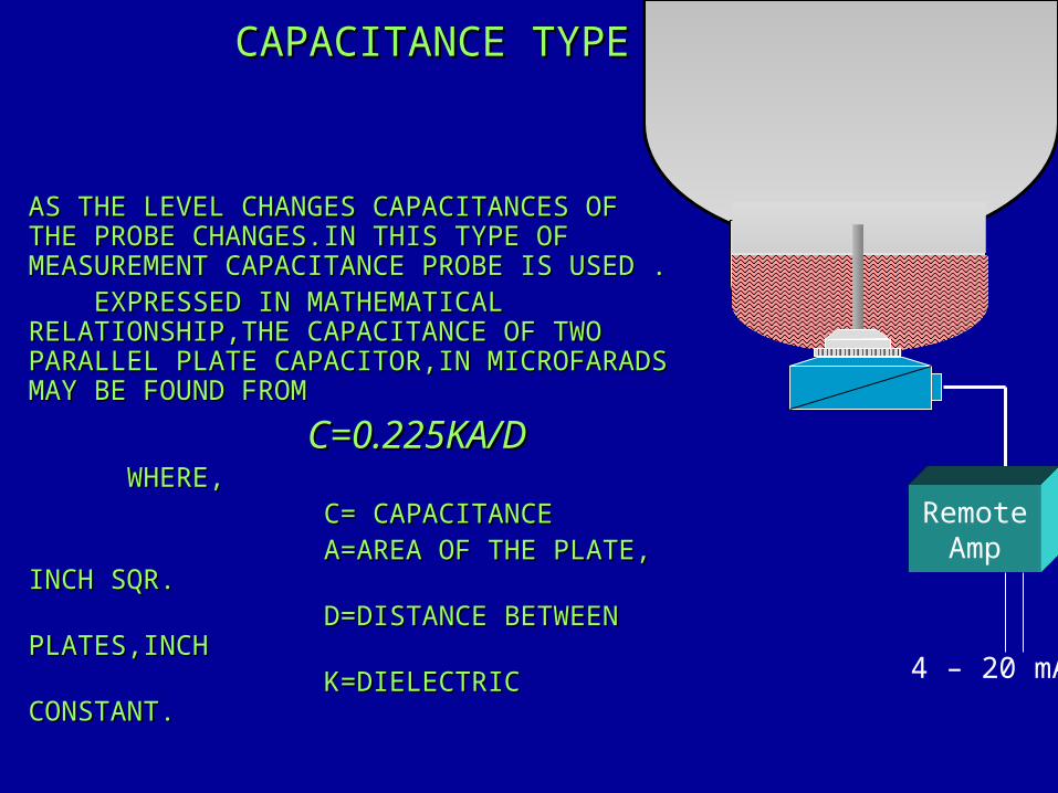
CAPACITANCE TYPECAPACITANCE TYPE
AS THE LEVEL CHANGES CAPACITANCES OF AS THE LEVEL CHANGES CAPACITANCES OF THE PROBE CHANGES.IN THIS TYPE OF THE PROBE CHANGES.IN THIS TYPE OF MEASUREMENT CAPACITANCE PROBE IS USED .MEASUREMENT CAPACITANCE PROBE IS USED . EXPRESSED IN MATHEMATICAL EXPRESSED IN MATHEMATICAL RELATIONSHIP,THE CAPACITANCE OF TWO RELATIONSHIP,THE CAPACITANCE OF TWO PARALLEL PLATE CAPACITOR,IN MICROFARADS PARALLEL PLATE CAPACITOR,IN MICROFARADS MAY BE FOUND FROMMAY BE FOUND FROM C=0.225KA/DC=0.225KA/D WHERE,WHERE, C= CAPACITANCEC= CAPACITANCE A=AREA OF THE PLATE, A=AREA OF THE PLATE, INCH SQR.INCH SQR. D=DISTANCE BETWEEN D=DISTANCE BETWEEN PLATES,INCHPLATES,INCH K=DIELECTRIC K=DIELECTRIC CONSTANT. CONSTANT.
RemoteAmp
4 – 20 mA
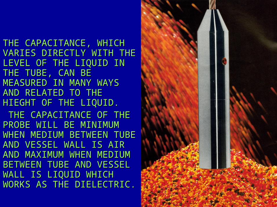
THE CAPACITANCE, WHICH THE CAPACITANCE, WHICH VARIES DIRECTLY WITH THE VARIES DIRECTLY WITH THE LEVEL OF THE LIQUID IN LEVEL OF THE LIQUID IN THE TUBE, CAN BE THE TUBE, CAN BE MEASURED IN MANY WAYS MEASURED IN MANY WAYS AND RELATED TO THE AND RELATED TO THE HIEGHT OF THE LIQUID.HIEGHT OF THE LIQUID. THE CAPACITANCE OF THE THE CAPACITANCE OF THE PROBE WILL BE MINIMUM PROBE WILL BE MINIMUM WHEN MEDIUM BETWEEN TUBE WHEN MEDIUM BETWEEN TUBE AND VESSEL WALL IS AIR AND VESSEL WALL IS AIR AND MAXIMUM WHEN MEDIUM AND MAXIMUM WHEN MEDIUM BETWEEN TUBE AND VESSEL BETWEEN TUBE AND VESSEL WALL IS LIQUID WHICH WALL IS LIQUID WHICH WORKS AS THE DIELECTRIC.WORKS AS THE DIELECTRIC.
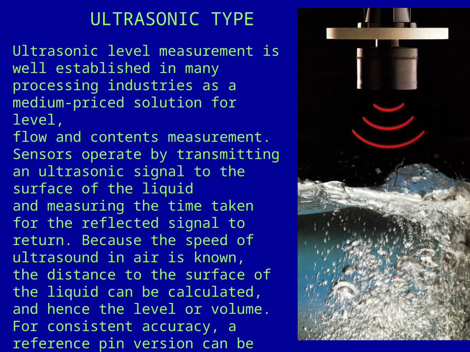
Ultrasonic level measurement is well established in many processing industries as a medium-priced solution for level,flow and contents measurement. Sensors operate by transmitting an ultrasonic signal to the surface of the liquidand measuring the time taken for the reflected signal to return. Because the speed of ultrasound in air is known,the distance to the surface of the liquid can be calculated, and hence the level or volume. For consistent accuracy, areference pin version can be used to measure the actual speed of the signal from the sensor to a known reference point, so that the effects of ullage conditions can be minimised.
ULTRASONIC TYPE

Ultrasonic technology is often chosen as a solution for multi tank level monitoring in tank farms or other storage applications because the sensors are easy to install in the tank lid, and easy to maintain.Measurement is not affected by media variables eg.. Dielectrics, pressure, density, pH, viscosity. Limitations are really only to do with extreme surface disturbance such as froth and foam which prevent the signal reaching the true liquid surface, and with extreme variable vaporous conditions in the ullage which affect the speed of ultrasound signal.There are pressure and temperature limits for this technology too;it generally recognized as not viable for pressures above two bar or temperatures above 130°C.
Minim Minimum measuring distance ( Xm ) :- is determined by the design of the unit within which the measurement is not possible ( dead zone or dead band ) . This distance can be extended by programming in order to avoid disturbing effects of possible disturbing echoes coming from fixed objects.

Maximum measuring distance ( XM ) :- is the greatest distance ( determine by the design of the unit ) which can be measured by the unit under ideal conditions. The maximum measuring distance of the actual application ( H ) must not be grater than XM.
FLOWLINE MODEL LU 20 :- Range :- 0.5 to 18 ft ( 15 cm to 5.4 cm )Accuracy :- + or – 0.25 % of span in airFrequency :- 50 kHzPulse Rate :- 2 pulses per secondBeam width :- 8° conicalDeadband :- 0.5’ ( 15 cm ) minimumBlocking distance :- 0.5 to 18 feet ( 15 cm to 5.4 m)Supply voltage :- GP : 12 – 36 VDC IS : 12 – 32 VDC

Radar Gauge is non contact method of measuring level.The gauge provides an attractive alternative in processes where a standard insertion device becomes fouled or corroded. It works well in turbulent, aerated, solids-laden, viscous, or corrosive fluids, as well as thick pastes and slurries.The APEX Radar Gauge is insensitive to manyproblematic liquid characteristics such as changing density, dielectric, or conductivity.The advanced radar technology of the APEX Radar Gauge provides accurate level measurement not found in other level technologies, while emitting safe signals in the microwave range
RADAR TYPE
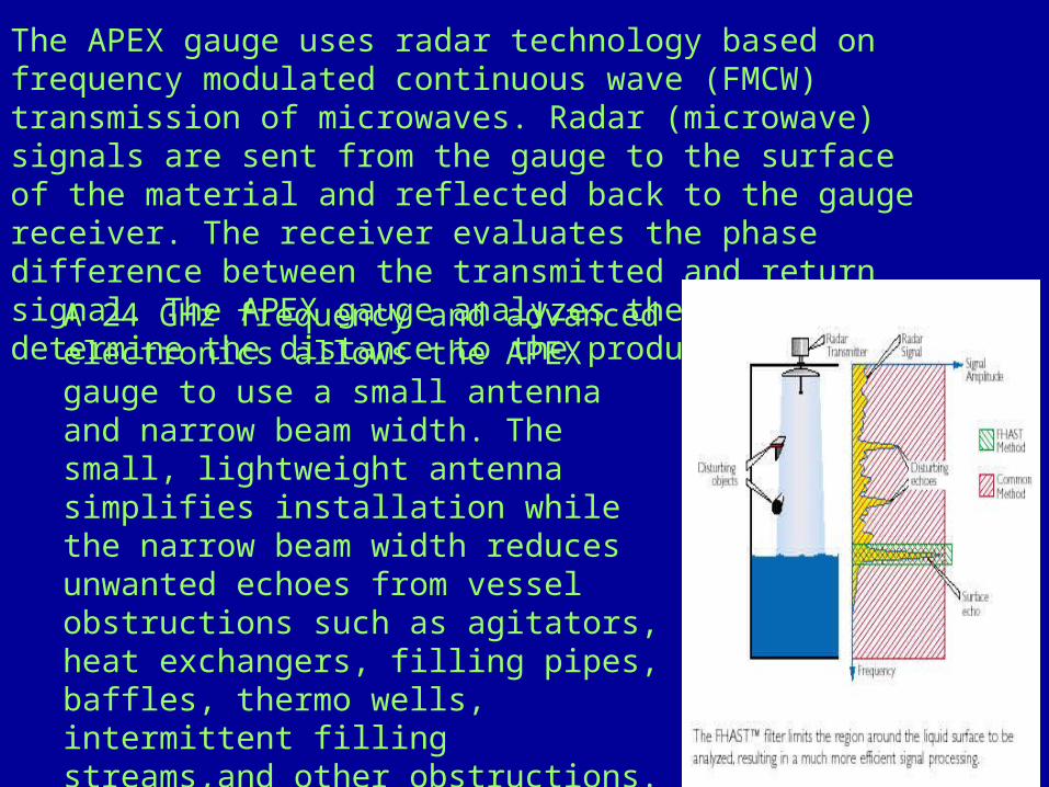
The APEX gauge uses radar technology based on frequency modulated continuous wave (FMCW) transmission of microwaves. Radar (microwave) signals are sent from the gauge to the surface of the material and reflected back to the gauge receiver. The receiver evaluates the phase difference between the transmitted and return signal. The APEX gauge analyzes the signals to determine the distance to the product surface.
A 24 GHz frequency and advanced electronics allows the APEX gauge to use a small antenna and narrow beam width. The small, lightweight antenna simplifies installation while the narrow beam width reduces unwanted echoes from vessel obstructions such as agitators, heat exchangers, filling pipes, baffles, thermo wells, intermittent filling streams,and other obstructions. The narrow beam also increases mounting flexibility because the gauge can be mounted on existing flanges located close to tank walls.
The cost of this highly accurate technology has fallen considerably in the last few years, with latest generation instruments offering excellent price/performance in a wide range of applications, at pressures from full vacuum to 40 bar and temperatures up to 150°C.
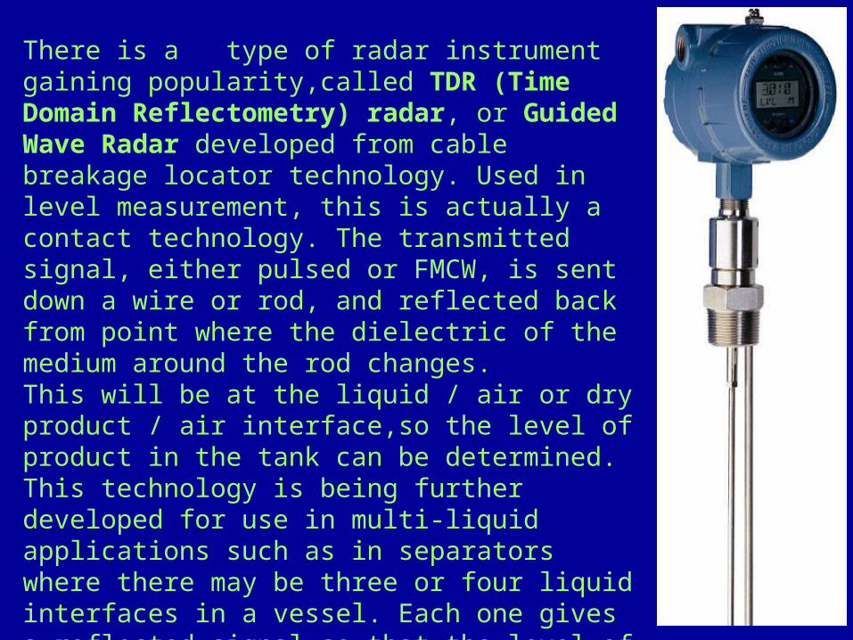
There is a type of radar instrument gaining popularity,called TDR (Time Domain Reflectometry) radar, or Guided Wave Radar developed from cable breakage locator technology. Used in level measurement, this is actually a contact technology. The transmitted signal, either pulsed or FMCW, is sent down a wire or rod, and reflected back from point where the dielectric of the medium around the rod changes.This will be at the liquid / air or dry product / air interface,so the level of product in the tank can be determined. This technology is being further developed for use in multi-liquid applications such as in separators where there may be three or four liquid interfaces in a vessel. Each one gives a reflected signal so that the level of each liquid can be calculated.

Principle of Operation:The variation in
buoyancy resulting from a change in liquid level varies the net weight of the displacer, increasing or decreasing the load on the torque arm. This change is directly proportional to the change in level of the fluid. The resulting torque tube movement varies the angular position of the rotor in the RVDT (Rotary Variable Differential Transformer) providing a voltage change proportional to the rotor displacement, which is converted and amplified to a direct current.
Electronic Level-troll
50 %
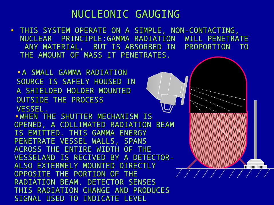
NUCLEONIC GAUGINGNUCLEONIC GAUGING• THIS SYSTEM OPERATE ON A SIMPLE, NON-CONTACTING, THIS SYSTEM OPERATE ON A SIMPLE, NON-CONTACTING,
NUCLEAR PRINCIPLE:GAMMA RADIATION WILL PENETRATE NUCLEAR PRINCIPLE:GAMMA RADIATION WILL PENETRATE ANY MATERIAL, BUT IS ABSORBED IN PROPORTION TO ANY MATERIAL, BUT IS ABSORBED IN PROPORTION TO THE AMOUNT OF MASS IT PENETRATES.THE AMOUNT OF MASS IT PENETRATES.
•A SMALL GAMMA RADIATION A SMALL GAMMA RADIATION SOURCE IS SAFELY HOUSED IN SOURCE IS SAFELY HOUSED IN A SHIELDED HOLDER MOUNTED A SHIELDED HOLDER MOUNTED OUTSIDE THE PROCESS OUTSIDE THE PROCESS VESSEL.VESSEL.•WHEN THE SHUTTER MECHANISM IS WHEN THE SHUTTER MECHANISM IS OPENED, A COLLIMATED RADIATION BEAM OPENED, A COLLIMATED RADIATION BEAM IS EMITTED. THIS GAMMA ENERGY IS EMITTED. THIS GAMMA ENERGY PENETRATE VESSEL WALLS, SPANS PENETRATE VESSEL WALLS, SPANS ACROSS THE ENTIRE WIDTH OF THE ACROSS THE ENTIRE WIDTH OF THE VESSELAND IS RECIVED BY A DETECTOR- VESSELAND IS RECIVED BY A DETECTOR- ALSO EXTERMELY MOUNTED DIRECTLY ALSO EXTERMELY MOUNTED DIRECTLY OPPOSITE THE PORTION OF THE OPPOSITE THE PORTION OF THE RADIATION BEAM. DETECTOR SENSES RADIATION BEAM. DETECTOR SENSES THIS RADIATION CHANGE AND PRODUCES THIS RADIATION CHANGE AND PRODUCES SIGNAL USED TO INDICATE LEVELSIGNAL USED TO INDICATE LEVEL

MEASUREMENT IS TRULY ”NON-MEASUREMENT IS TRULY ”NON-ONTACTING” AND NON INTRUSIVE, ONTACTING” AND NON INTRUSIVE, SO THAT THE SYSTEM IS NOT SO THAT THE SYSTEM IS NOT AFFECTED BY PRODUCT TEMP., AFFECTED BY PRODUCT TEMP., PRESSURE, CORROSIVENESS.PRESSURE, CORROSIVENESS.
TYPICAL APPLICATIONS WOULD INCLUDE LOW LEVEL DETECTION OF COARSE SOLIDS IN SILOS, OR PARTICULARLY OBNOXIOUS CHEMICALS IN STORAGE TANKS.
A COMPLETE MEASURING SYSTEM COMPRISES OF RADIOACTIVE SOURCEA SENSITIVE DETECTOR EITHER GEIEGER-MULLER TUBE OR SCINTILLATION DETECTOR AND APPROPRIATE REMOTE ELECTRONICS ACTING AS ANALOGUE TRANSMITTER
NUCLEONIC GAUGINGNUCLEONIC GAUGING

The technology uses a piezo-electric crystal system to excite a tuning-fork type wetside to vibrate at it’s natural frequency.By monitoring the actual frequency of the forks, the presence of liquid can be detected; as the forks are submerged the frequency of vibration drops. This simple principle is unaffected by liquid conditions. All that is required is that the liquid has enough mass to change the frequency enough to cause switching, which most common liquids do very well.
Vibrating forks

The low cost of vibrating fork technology and its robust versatility make it ideal for a wide range of high- and low alarm duties, pump control and proces level switching applications for both liquids and dry products. The latest ‘short-fork’ designs are easy to install, quick to commission and require no maintenance, and are probably the closest to the float switch in terms of range of application in liquids.The range of products has grown dramatically over the last few years and there is now a switch for almost every conceivable application. Stainless steel forks are standard with Hastelloy and coated forks optional for corrosive liquids. Applications in the food and beverage processing industries, on drinks, yoghurts and flavourings, are satisfied with hygienic flanged models. The demanding requirements of the pharmaceutical industry are met with highly polished wetside models.

PRESSURE MEASUREMENTPRESSURE MEASUREMENT MANOMETERSMANOMETERS MECHANICAL TRANSDUCERSMECHANICAL TRANSDUCERS BOURDON ELEMENTBOURDON ELEMENT BELLOW ELEMENTSBELLOW ELEMENTS DIAPHRAGM ELEMENTSDIAPHRAGM ELEMENTS ELECTRONIC TRANSDUCER ELECTRONIC TRANSDUCER STRAIN GAUGESSTRAIN GAUGES VARIABLE RELUCTANCEVARIABLE RELUCTANCE VARIABLE CAPACITANCEVARIABLE CAPACITANCE
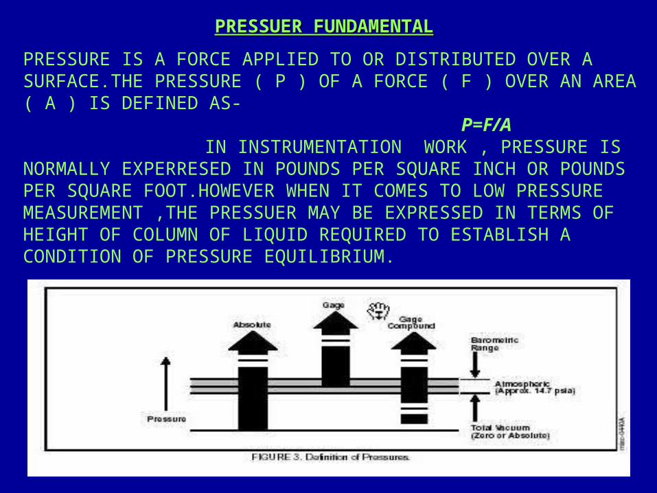
PRESSUER FUNDAMENTALPRESSUER FUNDAMENTALPRESSURE IS A FORCE APPLIED TO OR DISTRIBUTED OVER A SURFACE.THE PRESSURE ( P ) OF A FORCE ( F ) OVER AN AREA ( A ) IS DEFINED AS- P=F/A IN INSTRUMENTATION WORK , PRESSURE IS NORMALLY EXPERRESED IN POUNDS PER SQUARE INCH OR POUNDS PER SQUARE FOOT.HOWEVER WHEN IT COMES TO LOW PRESSURE MEASUREMENT ,THE PRESSUER MAY BE EXPRESSED IN TERMS OF HEIGHT OF COLUMN OF LIQUID REQUIRED TO ESTABLISH A CONDITION OF PRESSURE EQUILIBRIUM.
MANOMETER MANOMETER
MANOMETER ARE OFTEN USED FOR PROCESS PRESSURE APPLICATION MANOMETER ARE OFTEN USED FOR PROCESS PRESSURE APPLICATION EXCEPT OCCASIONALLY FOR LOW PRESSURE SERVICES WHERE EXCEPT OCCASIONALLY FOR LOW PRESSURE SERVICES WHERE MEASUREMENT ARE IN LOW PRESSURE RANGE.MEASUREMENT ARE IN LOW PRESSURE RANGE.
PRINCIPLE OF MANOMETER IS GIVEN AS PRINCIPLE OF MANOMETER IS GIVEN AS
P= HEIGHT * DENSITY
WHERE “P”IN PER SQ.FOOT/INCHWHERE “P”IN PER SQ.FOOT/INCH “ “HEIGHT” IN FEET/ INCHHEIGHT” IN FEET/ INCH “ “ DENSITY” IN POUND`S/CUBIC FOOT/INCHDENSITY” IN POUND`S/CUBIC FOOT/INCHTYPES-TYPES-U-TUBE MANOMETERU-TUBE MANOMETERWELL MANOMETERWELL MANOMETERINCLINED MANOMETERINCLINED MANOMETERMERCURY FLOAT MANOMETERMERCURY FLOAT MANOMETERBELL MANOMETERBELL MANOMETER

INSTALLATION OF MANOMETERSINSTALLATION OF MANOMETERS• ADVANTAGESADVANTAGES• FLUIDS SIMPLE &TIME PROVENFLUIDS SIMPLE &TIME PROVEN• HIGH ACCURACY & SENSITIVITYHIGH ACCURACY & SENSITIVITY• WIDE RANGE OF FILLING WIDE RANGE OF FILLING
• DISADVANTAGESDISADVANTAGES• NO OVERRANGE PROTECTIONNO OVERRANGE PROTECTION• LARGE & BULKYLARGE & BULKY• MEASURED FLUIDS MUST BE COMPATIBLE WITH THE MEASURED FLUIDS MUST BE COMPATIBLE WITH THE
MANOMETER FLUIDSMANOMETER FLUIDS• NEED OF LEVELINGSSNEED OF LEVELINGSS

BOURDON TUBE IT IS THE TWISTED TUBE IT IS THE TWISTED TUBE WHOSE CROSSSECTIONAL ISN`T WHOSE CROSSSECTIONAL ISN`T CIRCULAR.THE APPLICANTION OF CIRCULAR.THE APPLICANTION OF INTERNAL PRESSURE CAUSES THE INTERNAL PRESSURE CAUSES THE TUBE TO UNWIND OR STRAIGHTEN TUBE TO UNWIND OR STRAIGHTEN OUT.THE MOVEMENT OF FREE END OUT.THE MOVEMENT OF FREE END ISTRANMITTED TO A POINTER OR ISTRANMITTED TO A POINTER OR OTHER INDICATING ELEMENT. OTHER INDICATING ELEMENT. PHOSPHOR BRONZE,BERYLLIUM PHOSPHOR BRONZE,BERYLLIUM COPPER, STEEL, CHROME ALLOY & COPPER, STEEL, CHROME ALLOY & STAINLESS STEEL ARE COMMONLY STAINLESS STEEL ARE COMMONLY USED.USED. THEY ARE THE MOST WIDELY THEY ARE THE MOST WIDELY USED TYPE OF PRESSURE GAUGE.USED TYPE OF PRESSURE GAUGE. THEY ARE THE C-THEY ARE THE C-TYPE,HELICAL & SPIRAL TYPE.TYPE,HELICAL & SPIRAL TYPE. THEY SHOULD BE FILLED THEY SHOULD BE FILLED WITH OIL TO LIMIT THE DAMAGE WITH OIL TO LIMIT THE DAMAGE CAUSED BY VIBRATION.CAUSED BY VIBRATION.
0
12 3
45
6Pr
InletKg/cm2
INSTALLATIUON OF BOURDEN ELEMENTINSTALLATIUON OF BOURDEN ELEMENT
• ADVANTAGESADVANTAGES• LOW COST & SIMPLE CONSTRUCTIONLOW COST & SIMPLE CONSTRUCTION• WIDE RANGEABILITYWIDE RANGEABILITY• GOOD ACCURACYGOOD ACCURACY• ADAPTABLE TO TRANDUCER DESINGSADAPTABLE TO TRANDUCER DESINGS
• DISADVANTAGESDISADVANTAGES• LOW SPRING GRADIENT BELOW LOW SPRING GRADIENT BELOW
50PSIG50PSIG• SUBJECT TO HYSTERESISSUBJECT TO HYSTERESIS• SUSCEPTIBLE TO SHOCK & SUSCEPTIBLE TO SHOCK &
VIBRATIONVIBRATION
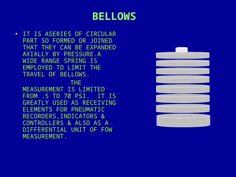
BELLOWS• IT IS ASERIES OF CIRCULAR IT IS ASERIES OF CIRCULAR
PART SO FORMED OR JOINED PART SO FORMED OR JOINED THAT THEY CAN BE EXPANDED THAT THEY CAN BE EXPANDED AXIALLY BY PRESSURE.A AXIALLY BY PRESSURE.A WIDE RANGE SPRING IS WIDE RANGE SPRING IS EMPLOYED TO LIMIT THE EMPLOYED TO LIMIT THE TRAVEL OF BELLOWS.TRAVEL OF BELLOWS.
THE THE MEASUREMENT IS LIMITED MEASUREMENT IS LIMITED FROM .5 TO 70 PSI. IT IS FROM .5 TO 70 PSI. IT IS GREATLY USED AS RECEIVING GREATLY USED AS RECEIVING ELEMENTS FOR PNEUMATIC ELEMENTS FOR PNEUMATIC RECORDERS,INDICATORS & RECORDERS,INDICATORS & CONTROLLERS & ALSO AS A CONTROLLERS & ALSO AS A DIFFERENTIAL UNIT OF FOW DIFFERENTIAL UNIT OF FOW MEASUREMENT. MEASUREMENT.

INSTALLATION OF BELLOWS ELEMENT
• ADVANTAGES• HIGH FORCE DELIVERED• MODERATE COST• GOOD IN THE LOW TO MODERATE PRESSURE
GUAGE
• DISADVANTAGES• NEED AMBEINT TEMERATURE PRESSURE
COMPENSATION• REQUIRE SPRING FOR ACCURATE
CHARACTERISTICS• LIMITED AVAILABILITY
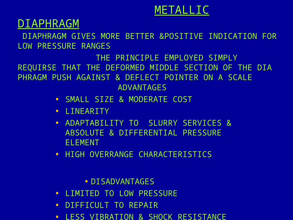
METALLIC METALLIC DIAPHRAGMDIAPHRAGM DIAPHRAGM GIVES MORE BETTER &POSITIVE INDICATION FOR DIAPHRAGM GIVES MORE BETTER &POSITIVE INDICATION FOR LOW PRESSURE RANGESLOW PRESSURE RANGES THE PRINCIPLE EMPLOYED SIMPLY THE PRINCIPLE EMPLOYED SIMPLY REQUIRSE THAT THE DEFORMED MIDDLE SECTION OF THE DIA REQUIRSE THAT THE DEFORMED MIDDLE SECTION OF THE DIA PHRAGM PUSH AGAINST & DEFLECT POINTER ON A SCALEPHRAGM PUSH AGAINST & DEFLECT POINTER ON A SCALE
ADVANTAGESADVANTAGES• SMALL SIZE & MODERATE COSTSMALL SIZE & MODERATE COST• LINEARITYLINEARITY• ADAPTABILITY TO SLURRY SERVICES & ADAPTABILITY TO SLURRY SERVICES &
ABSOLUTE & DIFFERENTIAL PRESSURE ABSOLUTE & DIFFERENTIAL PRESSURE ELEMENTELEMENT
• HIGH OVERRANGE CHARACTERISTICSHIGH OVERRANGE CHARACTERISTICS
• DISADVANTAGESDISADVANTAGES• LIMITED TO LOW PRESSURELIMITED TO LOW PRESSURE• DIFFICULT TO REPAIRDIFFICULT TO REPAIR• LESS VIBRATION & SHOCK RESISTANCELESS VIBRATION & SHOCK RESISTANCE
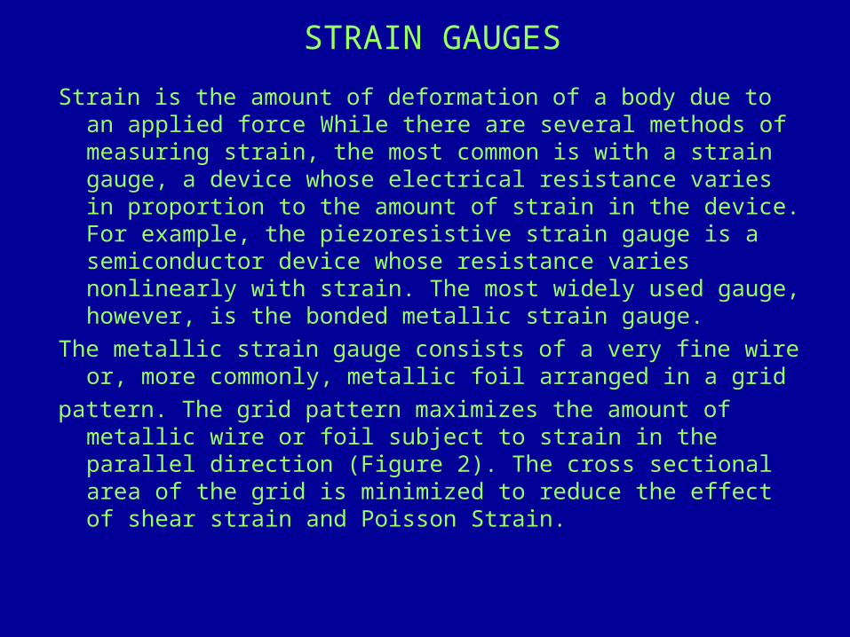
STRAIN GAUGESStrain is the amount of deformation of a body due to
an applied force While there are several methods of measuring strain, the most common is with a strain gauge, a device whose electrical resistance varies in proportion to the amount of strain in the device. For example, the piezoresistive strain gauge is a semiconductor device whose resistance varies nonlinearly with strain. The most widely used gauge, however, is the bonded metallic strain gauge.
The metallic strain gauge consists of a very fine wire or, more commonly, metallic foil arranged in a grid
pattern. The grid pattern maximizes the amount of metallic wire or foil subject to strain in the parallel direction (Figure 2). The cross sectional area of the grid is minimized to reduce the effect of shear strain and Poisson Strain.
The grid is bonded to a thin backing, called the carrier, which is attached directly to the test specimen. Therefore, the strain experienced by the test specimen is transferred directly to the strain gauge, which responds with a linear change in electrical resistance. Strain gauges are available commercially with nominal resistance values from 30 to 3000 W, with 120, 350, and 1000 W being the most common values. It is very important that the strain gauge be properly mounted onto the test specimen so that the strain is accurately transferred from the test specimen, though the adhesive and strain gauge backing, to the foil itself. Manufacturers of strain gauges are the best source of information on proper mounting of strain gauges. A fundamental parameter of the strain gauge is its sensitivity to strain, expressed quantitatively as the gauge factor (GF). Gauge factor is defined as the ratio of fractional change in electrical resistance to the fractional change in length (strain)

Transmitter for Pressure, Absolute-Pressure, Differential Pressure, Flow and Liquid Level
•Conventional and smart -all in one device
•PROFIBUS-PA Can be configured on site•High accuracy 0.1%(incl. hysteresis + repeatability)
•High long-term stability of 0.25%over 5 years
•Measuring spans of 1 mbar to 400 bar
•Also applicable in applications withaggressive media
•Types of protection:intrinsically safe EEx ia,flameproof EEx d(CENELEC, FM and CSA)

The Measuring Principle•Pressure acts on the separating diaphragm•Silicone liquid (or an inert liquid) transmits the pressure to the sensor•Four piezoelectric resistors in the measuring diaphragm in bridge connection change their resistance value -the bridge output voltage is therefore proportional to the pressure•With overload from one side the separating diaphragm closes up
Measuring cellfor pressure
Measuring cell fordifferential pressure
Separating diaphragmCentral diaphragm
Sensor
+_
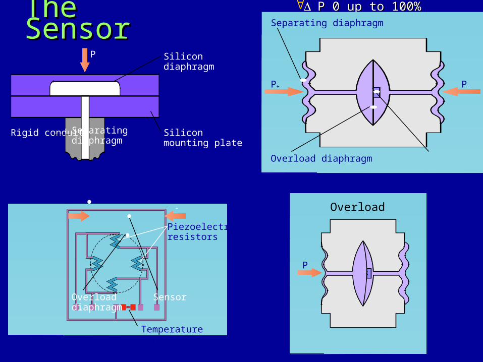
The The SensorSensorSilicon diaphragm
Silicon mounting plate
Rigid conduit
P
Temperature sensor
Piezoelectric resistors
P 0 up to 100%P 0 up to 100%
Separating diaphragm
Overload diaphragm
Sensor
-
P
Separating diaphragm
Overload diaphragm
P+ P-
Overload

Block Diagram Block Diagram
+
LCD
Keyboard
ADtransformer
Micro-controller
Digital-analogconverter
Measuring amplifier
Sensor
+_
INSTALLATION OF STRAIN GAUGES
• ADVANTAGES• GOOD ACCURACY,STABILITY & SHOCK & VIBRATION
CHARACTERISTICS• HIGH OUTPUT SIGNAL STRENGTH OVERRANGE CAPACITY &
SPEED OF RESPONSE• WIDE RANGEABILITY –VACCUM TO 200,00 PSIG• SMALL & EASY TO INSTALL
• DISADVANTAGES• ELECTRICAL READ OUT NECESSARY• REQUIRE CONSTANT VOLTAGE SUPPLY• TEMP COMPENSATION

VARIABLE VARIABLE RELUCTANCERELUCTANCE
• THIS TRANSMITTERS OPERATE ON THE PRINCIPLE OF A MOVEABLE ELEMENT CHANGING POSITION WITHIN A MAGNETIC FIELD. AS A RESULT,INDUCTANCE CHANGES TO PRODUCE AN OUTPUT VOLTAGE THAT IS PROPORTIONAL TO THE OPRESSURE APPLIED TO THE MOVABLE ELEMENT. THE TRANMITTERS ARE SMALL & ACCURATE BUT THEY HAVE COMPLICATED CIRCUITRY & MECHANICAL OVERPRESSURE PROTECTION IS REQUIRED.
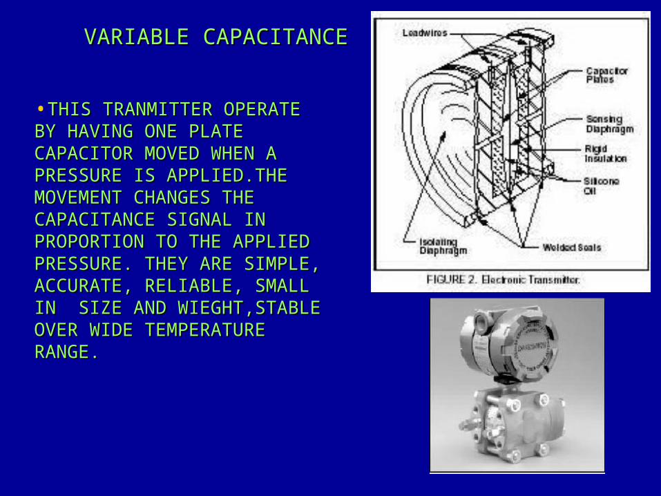
•THIS TRANMITTER OPERATE THIS TRANMITTER OPERATE BY HAVING ONE PLATE BY HAVING ONE PLATE CAPACITOR MOVED WHEN A CAPACITOR MOVED WHEN A PRESSURE IS APPLIED.THE PRESSURE IS APPLIED.THE MOVEMENT CHANGES THE MOVEMENT CHANGES THE CAPACITANCE SIGNAL IN CAPACITANCE SIGNAL IN PROPORTION TO THE APPLIED PROPORTION TO THE APPLIED PRESSURE. THEY ARE SIMPLE, PRESSURE. THEY ARE SIMPLE, ACCURATE, RELIABLE, SMALL ACCURATE, RELIABLE, SMALL IN SIZE AND WIEGHT,STABLE IN SIZE AND WIEGHT,STABLE OVER WIDE TEMPERATURE OVER WIDE TEMPERATURE RANGE.RANGE.
VARIABLE CAPACITANCEVARIABLE CAPACITANCE
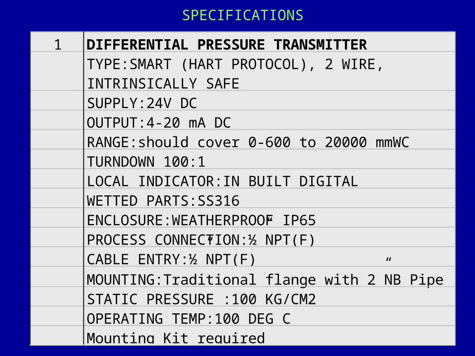
1 DIFFERENTIAL PRESSURE TRANSMITTERTYPE:SMART (HART PROTOCOL), 2 WIRE, INTRINSICALLY SAFESUPPLY:24V DCOUTPUT:4-20 mA DCRANGE:should cover 0-600 to 20000 mmWCTURNDOWN 100:1LOCAL INDICATOR:IN BUILT DIGITALWETTED PARTS:SS316ENCLOSURE:WEATHERPROOF IP65PROCESS CONNECTION:½”NPT(F)CABLE ENTRY:½”NPT(F)MOUNTING:Traditional flange with 2”NB Pipe STATIC PRESSURE :100 KG/CM2OPERATING TEMP:100 DEG CMounting Kit required
SPECIFICATIONS
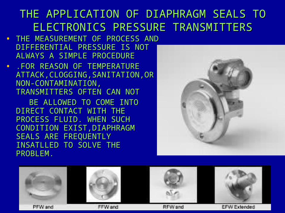
THE APPLICATION OF DIAPHRAGM SEALS TO THE APPLICATION OF DIAPHRAGM SEALS TO ELECTRONICS PRESSURE TRANSMITTERSELECTRONICS PRESSURE TRANSMITTERS
• THE MEASUREMENT OF PROCESS AND THE MEASUREMENT OF PROCESS AND DIFFERENTIAL PRESSURE IS NOT DIFFERENTIAL PRESSURE IS NOT ALWAYS A SIMPLE PROCEDUREALWAYS A SIMPLE PROCEDURE
• .FOR REASON OF TEMPERATURE .FOR REASON OF TEMPERATURE ATTACK,CLOGGING,SANITATION,OR ATTACK,CLOGGING,SANITATION,OR NON-CONTAMINATION, NON-CONTAMINATION, TRANSMITTERS OFTEN CAN NOTTRANSMITTERS OFTEN CAN NOT
BE ALLOWED TO COME INTO BE ALLOWED TO COME INTO DIRECT CONTACT WITH THE DIRECT CONTACT WITH THE PROCESS FLUID. WHEN SUCH PROCESS FLUID. WHEN SUCH CONDITION EXIST,DIAPHRAGM CONDITION EXIST,DIAPHRAGM SEALS ARE FREQUENTLY SEALS ARE FREQUENTLY INSATLLED TO SOLVE THE INSATLLED TO SOLVE THE PROBLEM.PROBLEM.

• WHILE THE ADDITION OF A DIAPHRAGM WHILE THE ADDITION OF A DIAPHRAGM SEAL SEAL DOES DOES NOT AFFECTS TRANSMITTER ACCURACY NOT AFFECTS TRANSMITTER ACCURACY DIRECTLY, DIRECTLY, FACTORS SUCH AS CAPILLARY LENGTH, MOUNTING FACTORS SUCH AS CAPILLARY LENGTH, MOUNTING
POSITION,AND FILL FLUID INTRODUCE VARIABLE THAT POSITION,AND FILL FLUID INTRODUCE VARIABLE THAT INTER WITH EACH OTHER.INTER WITH EACH OTHER.
• IN IN ELECTRONIC TRANSMITTER APPLICATION, SEALS TRANSMITTER APPLICATION, SEALS WITH WITH METAL DIAPHRAGMS METAL DIAPHRAGMS SHOULD BE USED.SHOULD BE USED.• REPLACEABLE,NON-WELDED DIAPHRAGMS ARE REPLACEABLE,NON-WELDED DIAPHRAGMS ARE UNDESIRABLE.UNDESIRABLE.• TEFLON DIAPHRAGM SHOULD NEVER BE USED WITH TEFLON DIAPHRAGM SHOULD NEVER BE USED WITH ELECTRONIC ELECTRONIC TRANSMITTER TRANSMITTER
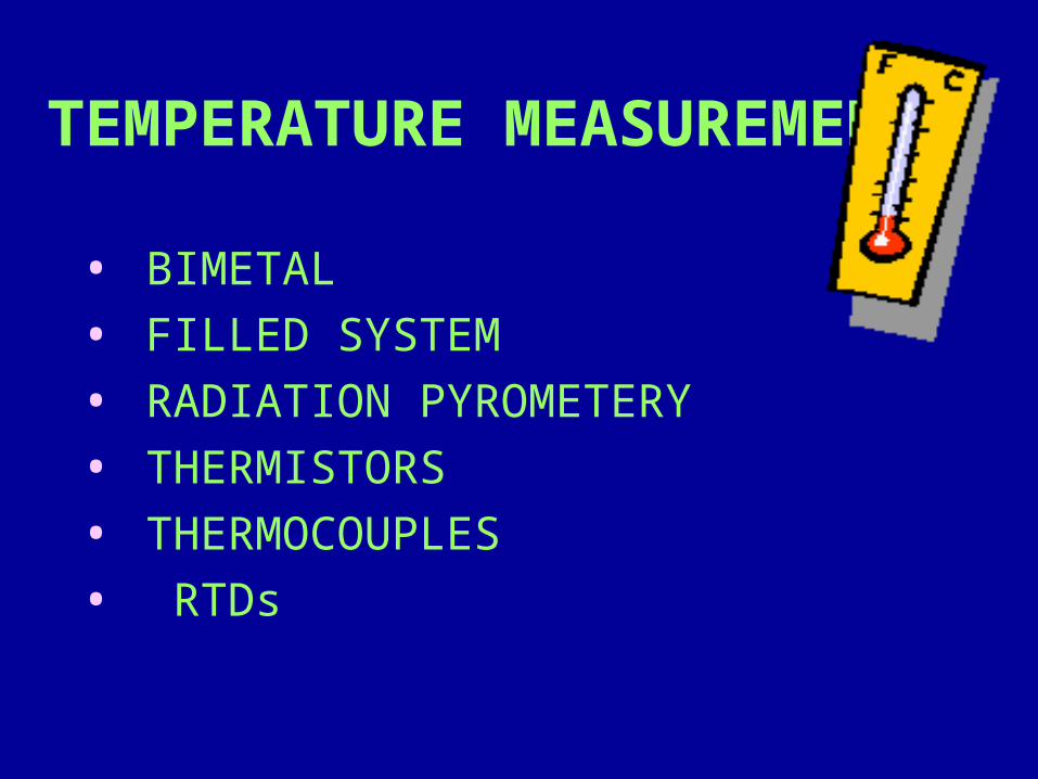
TEMPERATURE MEASUREMENT
• BIMETAL• FILLED SYSTEM• RADIATION PYROMETERY • THERMISTORS • THERMOCOUPLES• RTDs

BIMETALLIC THERMOMETERS THE BIMETALLIC THERMOMETER IS
BASED ON TWO PRINCIPLES- 1)METAL CHANGES IN VOLUME IN RESPONSE TO A CHANGE IN TEMPERATURE. 2)THE COEFFICIENT OF CHANGE IS DIFFERENT FOR ALLTHE METALS. IF TWO DISSIMILAR METAL STRIPS ARE BONDED TOGETHER AND THEN HEATED THE RESULTANT STRIP WILL TEND TO BEND IN THE DIRECTION OF METAL WITH LOWER COEFFICIENT OF EXPANTION.THE DEGREE OF DEFLECTION IS PROPORTIONAL TO THE CHANGE IN TEMPERATURE. THE MOVEMENT OF BIMETALLICS ARE AMPLIFIED BY USING A LONG STRIP OF MATERIALWOUND INTO A HELIX OR SPIRAL. ONE END OF THE SPIRAL IS IMMERSED IN THE MEDIUM TO BE MEASURED AND THE OTHER END IS ATTACHED TO A POINTER.THE BIMETALLIC THERMOMETERS MAY BE RIGGED TO ACTUATE A RECORDER PEN
0
2550100125
150
200 0 C

INSTALLATIONOF BIMETALLIC THERMOMETERS
• ADVANTAGES• LOW COST AND GOOD ACCURACY• NOT EASILY BROKEN• WIDE RANGE TEMPERATURE• EASY TO INSTALL AND MAINTAIN
• DISADVANTAGES• LOCAL MOUNTING• CALIBRATION CHANGES IF HANDLED ROUGHLY• ONLY FOR INDICATION

FILLED THERMAL ELEMENTSFILLED THERMAL ELEMENTS THE FILLED THE FILLED
THERMAL ELEMENT CONSISIT OF THERMAL ELEMENT CONSISIT OF A BULB CONNECTED TO A SMALL A BULB CONNECTED TO A SMALL BORE CAPILLARY WHICH IS BORE CAPILLARY WHICH IS CONNECTED TO AN APPROPRIATE CONNECTED TO AN APPROPRIATE INDICATING DEVICE.THE SYSTEM INDICATING DEVICE.THE SYSTEM ACT AS A TRANSDUCER WHICH ACT AS A TRANSDUCER WHICH CONVERTS PRESSURE AT NEARLY CONVERTS PRESSURE AT NEARLY CONSTANT VOLUME TO A CONSTANT VOLUME TO A MECHANICAL MOVEMENT WHICH IN MECHANICAL MOVEMENT WHICH IN TURN IS CONVERTED TO TURN IS CONVERTED TO TEMPERATUEREBY USE OF AN TEMPERATUEREBY USE OF AN INDICATING SCALE. THE ENTIRE INDICATING SCALE. THE ENTIRE MECHANISM IS GAS TIGHT WHICH MECHANISM IS GAS TIGHT WHICH EXPANDS AND CONTRACTS WITH A EXPANDS AND CONTRACTS WITH A CHANGE IN TEMPERATURE CHANGE IN TEMPERATURE CAUSING THE SPIRAL BOURDON CAUSING THE SPIRAL BOURDON GAUGE TO MOVEGAUGE TO MOVE

INSTALLATION OF FILLED SYSTEM
ADVANTAGES• SIMPLE ,TIME-PROVEN MEASUREMENT METHOD• RELATIVELY LOW COST• ACTIVE DEVICE• NARROW SPAN AVALIABLE• RUGGEDLY CONSTRUCTED• GOOD SELECTION OF CALIBRATED CHARTS AVALIABLE
DISADVANTAGES• LIMITED TO MEASUREMENT BELOW 1500 DEGREE FARAD• RELATIVELY LOW RESPONSE• BULB FAILURE REQUIRES REPLACEMENT OF ENTIRE
THERMAL SYSTEM

THERMISTORS THERMISTORS ARE SEMI-CONDUCTERS MADE FROM SPECIFIC
MIXTURES OF PURE OXIDES OF NICKEL,MANGANESE,COPPER COBALT, MAGNESIUM AND OTHER METAL SINTERED AT HIGH TEMPERATURE.THEY ARE CHARACTERISED BY HAVING VERY TEMPERATURE COEFFICIENTS WHICH PRODUCES LARGE CHANGE IN RESISTANCE IN RESPONSE TO A CHANGE IN TEMPERATURE. THE MOST COMMON CONFIGURATION ARE SIMPLE BEED TYPE.
A MAIN ADVANTAGE OF THERMISTORS FOR TEMPERATURE MEASUREMENT IS THEIR EXTREMELY HIGH SENSITIVITY. FOR EXAMPLE, A 2252 W THERMISTOR HAS A SENSITIVITY OF -100 W/°C AT ROOM TEMPERATURE. HIGHER RESISTANCE THERMISTORS CAN EXHIBIT TEMPERATURE COEFFICIENTS OF -10 KW/°C OR MORE. IN COMPARISON, A 100 W PLATINUM RTD HAS A SENSITIVITY OF ONLY 0.4 W/°C. THE PHYSICALLY SMALL SIZE OF THE THERMISTOR BEAD ALSO YIELDS A VERY FAST RESPONSE TO TEMPERATURE CHANGES. THE THERMISTOR HAS BEEN USED PRIMARILY FOR HIGH-RESOLUTION MEASUREMENTS OVER LIMITED TEMPERATURE RANGES. THE CLASSIC EXAMPLE OF THIS TYPE OF APPLICATION IS MOTOR WINDING TEMPERATURE AND IN MEDICAL THERMOMETRY.
ANOTHER ADVANTAGE OF THE THERMISTOR IS ITS RELATIVELY HIGH RESISTANCE. THERMISTORS ARE AVAILABLE WITH BASE RESISTANCES (AT 25° C) RANGING FROM HUNDREDS TO MILLIONS OF OHMS. THIS HIGH RESISTANCE DIMINISHES THE EFFECT OF INHERENT RESISTANCES IN THE LEAD WIRES, WHICH CAN CAUSE SIGNIFICANT ERRORS WITH LOW RESISTANCE DEVICES SUCH AS RTDS. FOR EXAMPLE, WHILE RTD MEASUREMENTS TYPICALLY REQUIRE 3-WIRE OR 4-WIRE CONNECTIONS TO REDUCE ERRORS CAUSED BY LEAD WIRE RESISTANCES, 2-WIRE CONNECTIONS TO THERMISTORS ARE USUALLY ADEQUATE.THE MAJOR TRADEOFF FOR THE HIGH RESISTANCE AND SENSITIVITY OF THE THERMISTOR IS ITS HIGHLY NONLINEAR OUTPUT AND RELATIVELY LIMITED OPERATING RANGE. DEPENDING ON THE TYPE OF THERMISTORS, UPPER RANGES ARE TYPICALLY LIMITED TO AROUND 300° C. FIGURE 1 SHOWS THE RESISTANCE-TEMPERATURE CURVE FOR A 2252 W THERMISTOR. THE CURVE OF A 100 W RTD IS ALSO SHOWN FOR COMPARISON.
INSTALLATION OF THERMISTORSADVANTAGES• FAST RESPONSE AND GOOD FOR NARROW SPAN• COLD JUNCTION COMPENSATION NOT NECESSARY• NEGLIGIBLE LEADWIRE RESISTANCE• LOW COST AND AVALIABLE IN SMALL SIZE• STABILITY INCREASES WITH AGE
DISADVANTAGES• NONLINEAR TEMPERATURE VERSUS RESISTANCE
CURVE• NOT SUITABLE FOR WIDE TEMPERATURE SPAN• EXPERIENCE LIMITED FOR PROCESS APPLICATION• THE RESISTANCE-TEMPERATURE BEHAVIOR OF
THERMISTORS IS HIGHLY DEPENDENT UPON THE MANUFACTURING PROCESS

THERMOCOUPLE A THERMOCOUPLE IS A THERMOELECTRIC
TEMPERATURE MEASURING DEVICE. IT IS FORMED BY WELDING SOLDERING OR MERELY PRESSING TWO DISSIMILAR METALS TOGETHER IN SERIES TO PRODUCE THE THERMAL ELECROMAGNETIC FORCE(E), WHEN THE JUNCTION ARE AT THE DIFFERENT TEMPERATURES. THE MEASURING OR HOT JUNCTION IS INSERTED INTO A MEDIUM WHERE THE TEMPERATURE IS TO BE MEASURED . THE REFERENCE , OR COLD JUNCTION IS THE OPEN END THAT IS NORMALLY CONNECTED TO THE MEASURING INSTRUMENT`S TERMINAL.
THE MAGNITUDE OF THIS VOLTAGE (E) DEPENDS ON THE PAIR OF MATERIALS A+B ,AND THE DIFFERENCE BETWEEN THE HOT AND COLD JUNCTIONS T1 ANDT2. THEREFORE, TEMPERATURE CAN BE READ DIRECTLY BY USING A SENSITIVE CALIBRATED ELETROMAGNATIC FORCE(EMF) MEASURING DEVICE.
INSTALLATION OF THERMOCOUPLE
• ADVANTAGES• GOOD ACCURACY AND REPRODUCIBILITY• SMALL UNITS THAT CAN BE MOUNTED CONVENIENTLY• LOW COST• WIDE TEMPERATURE RANGE AND LONG TRANMISSION DISTANCE• WIDE VARIETY OF DESIGNS FOR STANDARD AND SPECIAL
APPLICATION.• HIGH SPEED OF RESPONSE• • DISADVANTAGES• TEMPERATURE-VOLTAGE RELATIONSHIP NOT FULLY LINEAR• ACCURACY LESS THAN THAT OF RESISTANCE BULB• STRAY VOLTAGE PICKSUP MUST BE CONSIDERED• REQUIRE AN AMPLIFIER FOR MANY MEASUREMENTS
RESISTANCE TEMPERATURE DETECTORS SIR HUMPHREY DAVY ANNOUNCED
THAT THE RESISTIVITY OF METALS SHOW A MARKED DEPENDENCE.IN 1871 SIR WILLIAM SIEMENS SUGGESTED THE USE OF PLATINUM IN A RESISTANCE THERMOMETER.
RTD`S UNLIKE THERMOCOUPLES ARE PASSIVE SENSORS REQURING AN “EXCITATION” CURRENT TO BE PASSED THROUGH THEM.THE RTD IS NORMALLY MANUFACTURED THROUGH A KNOWN RESISTANCE TYPICALLY 100 OHMS AT ICE POINT. IT HAS POSITIVE TEMPERATURE OF RESISTANCE. COMMONLY PT-100 IS USED.
THE HEART OF THE RTD IS THE SENSING ELEMENT.THE SMALL DIAMETER WIRE IS WOUND IN A BIFILAR MANNER ONTO A CYLINDRICAL MANDREL,USUALLY MADE OF CERAMIC.LEAD WIRES RUN THROUGH THE MANDREL AND ARE CONNECTED TO THE ELEMENT WIRE.THE MANDREL ASSEMBLY IS USUALLY COVERED WITH A COATING OR GLAZE TO PROTECT THE ELEMENT WIRE.THIS SENSING ELEMENT IS FURTHER CONNECTED AS ONE OF THE ARM OF THE WHEATSTONE BRIDGE.
INSTALLATION OF RTD
• ADVANTAGES• HIGH ACCURACY AND FAST RESPONCE• NARROW SPAN AND GOOD REPRODUCIBILITY• REMAINS STABLE AND ACCURATE FOR MANY YEARS• TEMPERATURE COMPENSATION NOT NECESSARY
• DISADVANTAGES• HIGH COST AS COMPARED TO THE THERMOCOUPLE• LARGE BULB SIZE IN COMPARISON TO THERMOCOUPLE• SELF HEATING CAN BE A PROBLEM

Head mounted temperature transmitter
• The most important features
– for all industries i.e. chemical, energy, machine builder
– online communication via standard protokoll HART 5.x
– for all common temperature sensors– compact design allows mounting in small housings – explosion protection Ex n for zone 2 and EEx ia IIC– galvanic isolation 500 V– also suitable for potentiometer or mV-signals– easy setup and service with PC or Hand Held Communicator
– suitable for SIMATIC link via PROFIBUS / HART interface
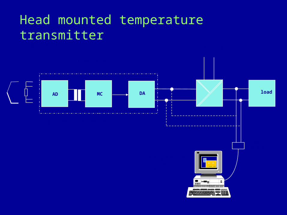
Head mounted temperature transmitter
AD MC
Sensor SITRANS TK-H
TC RTD
power supply
HARTModem
configuration&
service
galvanic isolation
Block diagram
loadDA

RADIATION PYROMETRY
RADIATION PYROMETRY INFER TEMPERATURE BY COLLECTING THE THERMAL RADIATION FROM AN OBJECT AND FOCUSING IT ON A SENSOR.THE SENSOR OR DETECTOR IS TYPICALLY A PJOTON DETECTER WHICH PRODUCES AN OUTPUT AS THE RADIENT ENERGY STRIKING IT RELEASES ELECTRICAL CHARGES. THEY ARE USEFUL IN APPLICATION WHERE THE TEMPERATURE OF A CONTINUOUSLY MOVING SHEET OF MATERIAL MUST BE MONITERED.THEY ARE SUSCEPTIBLE TO AMBIENT TEMPERATURE FLUCTUATIONS AND OFTEN REQUIRE WATER COOLING.

INSTALLATION OF RADIATION PYROMETERS
• ADVANTAGES• ABILITY TO MEASURE HIGH TEMPERATURE• NON-CONTACT TYPE MEASUREMENT• FAST RESPONSE AND HIGH OUTPUT• MODERATE COST
• DISADVANTAGES• NONLINEAR SCALE• MEASUREMENT AFFECTED BY EMISSIVITY OF TARGET
MATERIAL• ERRORS DUE TO INTERVENING GASES OR VAPOURS THAT
ABSORBS RADIATING FREQUENCIES
MISCELLANEOUS MEASUREMENT
• GAS ANALYSIS• LIQUID ANALYSIS• WEIGHT MEASUREMENT• VIBRATION MEASUREMENT• AXIAL DISPLACEMENT
MEASUREMENT • SPEED MEASUREMENT

MONITORINGMONITORING
OPEN LOOP :
TRANSMITTERSENSOR INDICATION

CONTROLCONTROLCLOSED LOOP :
CONTROLLER PROCESS
DISTURBANCE
TRANSMITTER
PV
SP e CONTROLVALVE
•Never flush a steam transmitter for long duration. •Don’t disturb purging.•Whenever taking a Rota meter in line open downstream valve first.•In case of Rota meter don’t hammer on indicating part.•For pad type transmitter try to wash the pad.•Always keep the electronics away from heat and moisture.
TIPS

THANK YOUTHANK YOU..
Copyright © 2022 FDOKUMEN