Siemens WT 10 - Process Instrument Sales
394
Process Automation www.siemens.com/weighing-technology Products for Weighing Technology Catalog WT 10 Edition 2020 © Siemens 2020
-
Upload
khangminh22 -
Category
Documents
-
view
5 -
download
0
Transcript of Siemens WT 10 - Process Instrument Sales

Process Automation
www.siemens.com/weighing-technology
Products for Weighing Technology
CatalogWT 10
Edition 2020
© Siemens 2020

Related catalogs
Catalogs for Process Automation
www.siemens.com/pa-catalogs
Process Automation MP 20Display RecordersSIREC D
PDF (E86060-K6020-E101-A5-7600)
Process Automation MP 31SIPART Controllers and Software
PDF (E86060-K6031-A100-B7-7600)
Process Automation FI 01Field Instruments for Process Automation
PDF (E86060-K6201-A101-C3-7600)
Process Automation AP 01Process Analytical Instruments
PDF (E86060-K3501-A101-B4-7600)
Process Automation AP 11Components for Continuous Emission Monitoring
PDF (E86060-K3511-A100-B4-7600)
SIMATIC ST PCS 7SIMATIC PCS 7 Process Control SystemVol. 1: System components
E86060-K4678-A111-C6-7600
SIMATIC ST PCS 7 AOSIMATIC PCS 7Process Control SystemVol. 3: Add-ons for SIMATIC PCS 7
PDF (E86060-K4678-A121-B4-7600)
SIMATIC ST PCS 7 TSIMATIC PCS 7 Process Control SystemVol. 2: Technology components
PDF (E86060-K4678-A141-A4-7600)
SIMATIC ST 70Products forTotally Integrated Automation
PDF (E86060-K4670-A101-B7-7600)
SIMATIC ST 70 NProducts forTotally Integrated Automation
E86060-K4670-A151-A9-7600
Industrial Communication IK PISIMATIC NET
E86060-K6710-A101-B8-7600
SITOP KT 10.1SITOP Power supply
E86060-D4001-A510-D8
SIMATIC Ident ID 10Industrial Identification Systems
E86060-K8310-A101-B1-7600
SITRAINDigital Industry Academy
www.siemens.com/sitrain
Products for Automation and Drives CA 01Interactive CatalogDownload
www.siemens.com/automation/ca01
Industry Mall Information and Ordering Platformon the Internet:
www.siemens.com/industrymall
ContactYour personal contact can be found in our Contacts Database at:
www.siemens.com/automation-contact
© Siemens 2020

Introduction Weighing Technology 1
Weighing Electronics 2
Load Cells 3
Belt Weighing 4
Weighfeeders 5
Solid Flowmeters 6
Appendix 7
Products for Weighing Technology
Process Automation
Catalog WT 10 · 2020
Supersedes:Catalog WT 10 · 2018
Refer to the Industry Mall for current updates of this catalog:www.siemens.com/industrymall
For comfortable, fast and error free product selection you will get support in our PIA Life Cycle Portal: www.siemens.com/pia-portal
The products contained in this catalog can also be found in the Interactive Catalog CA 01.Article No.: E86060-D4001-A500-D9
Please contact your local Siemens branch.
© Siemens 2020
The products and systems described in this catalog are manufactured/distributed under application of a certified quality management system in accordance with DIN EN ISO 9001. The certificate is recog-nized by all IQNet countries.
© Siemens 2020
z002cfep
Notiz
Completed festgelegt von z002cfep
z002cfep
Notiz
Completed festgelegt von z002cfep
z002cfep
Notiz
None festgelegt von z002cfep
z002cfep
Notiz
None festgelegt von z002cfep
z002cfep
Notiz
Completed festgelegt von z002cfep
z002cfep
Notiz
Completed festgelegt von z002cfep

2 Siemens WT 10 · 2020
Digital EnterpriseThe building blocks that ensure everything works together perfectly in the digital enterpriseDigitalization is already changing all areas of life and existing business models. It is placing greater pressure on industry while at the same time creating new business opportunities. Today, thanks to scalable solutions from Siemens, companies can already become a digital enterprise and ensure their competitiveness.
Industry faces tremendous challenges
Reduce time-to-market
Boost flexibility
Improve quality
Boost efficiency
Increase security
Today manufacturers have to bring products to market at an ever-increas-ing pace despite the growing complexity of these products. In the past, a major manufac-turer would push aside a small one, but now it is a fast manufacturer that overtakes a slow one.
Consumers want cus-tomized products, but at a price they would pay for a mass-produced item. That only works if production is more flexible than ever before.
To ensure a high level of quality while meeting legal requirements, companies have to establish closed quality loops and enable the traceability of products.
Today the product itself needs to be sustainable and environmentally friendly, while energy efficiency in production has become a competi-tive advantage.
Increasing networking escalates the threat to production facilities of cyberattacks. Today more than ever, com-panies need suitable security measures.
© Siemens 2020

3Siemens WT 10 · 2020
The digital enterprise has already become a realityTo fully benefit from all the advantages of digitalization, companies first have to achieve complete consistency of their data. Fully digitally integrated business processes, including those of suppliers, can help to create a digital representation of the entire value chain. This requires• the integration of industrial software
and automation,• expansion of the communication net-
works,• security in automation,• and the use of business-specific
industrial services.
MindSphereThe cloud-based open IoT operating system from SiemensWith MindSphere, Siemens offers a cost-effective and scalable cloud platform as a service (PaaS) for the development of appli-cations. The platform, designed as an open operating system for the Internet of Things, makes it possible to improve the efficiency of plants by collecting and analyzing large volumes of production data.
Totally Integrated Automation (TIA)Where digitalization becomes realityTotally Integrated Automation (TIA) ensures the seamless transition from the virtual to the real world. It already encompasses all the necessary conditions for transforming the benefits of digitalization into true added value. The data that will form the digital twin for actual production is generated from a common base.
Digital PlantLearn more about the digital enterprise for the process industrywww.siemens.com/digitalplant
Digital Enterprise SuiteLearn more about the digital enterprise for the discrete industrywww.siemens.com/digital-enterprise-suite
© Siemens 2020

4 Siemens WT 10 · 2020
TIA Selection ToolThe smart configurator for the entire Siemens automation portfolio
Prime reasons for the TIA Selection Tool
Quick, easy and secure Intelligent Clear Time-saving
Components can be selected, configured and ordered quickly, easily and securely from the Siemens automation portfolio
Intelligent selection wizards check the compatibility of the configured components and enable error-free ordering
Required modules, devices and networks are automatically generated and clearly compared to one another
Time savings of 80% in design – thanks to ease of use and intelligent support
The TIA Selection Tool is a completely paperless solution.Download it now:www.siemens.com/tst
For more information, scan the QR code
© Siemens 2020

Siemens WT 10 · 2020
11/2 Introduction
1/4 Available for all requirements:Electronic weighing systems
1/6 Load cells1/6 Weighing terminals1/7 Integrators for dynamic weighing systems
1/8 Products and solutions1/8 Platform scales1/8 Hopper scales1/8 Conveyor belt scales1/9 Dosing1/9 Filling and bagging1/9 Checking scales1/10 Solids flowmeters1/10 Loss-in-weight scales1/10 Weighfeeders
Weighing Technology
© Siemens 2020

Siemens WT 10 · 20201/2
How to meet all your weighing and dosing requirements
Weighing and dosing processes are of great significance in manyareas of industrial production. Whether for filling food and beverage containers or preparing recipes for chemicals and pharmaceutical products: With our solutions, you can count on absolute reliability and highest precision.
Weighing Technology© Siemens 2020

1/3Siemens WT 10 · 2020
© Siemens 2020

Available for all requirementsThe flexible design of our products makes it possible to implement weighing solutions from simple platform scales and gravimetric level measurement up to highly complex automatic scales with minimal conversion costs. Using SIWAREX load cells and electronic modules for weighing systems together with Siemens Milltronics belt scales and SITRANS weigh feeders and solids flowmeters, you can design an optimal system for practically every task.
Weighing Technology | Electronic Weighing Systems
SIWAREX WP351the ultra-compact weighing electronic for maximum precision
• ultra-compact: 20 mm wide, 65 mm high• Precise: Resolution ± 20,000,000 increments• Seamlessly integrated in ET 200SP system, works with
S7-300, 400, 1200 and 1500 controllers• fast: 1,000 Hz sampling rate, Digital output response
time < 1 ms• Intelligent firmware enables the weighing process to
be controlled and optimized entirely from the weighing module
SIWAREX WP35he ultra-compa
ultra-compact: Precise: Resolu Seamlessly intS7-300, 400, 1 fast: 1,000 Hz time < 1 ms Intelligent firmbe controlled amodule
Sth
•••
•
•
NEW
© Siemens 2020
z002cfep
Notiz
Completed festgelegt von z002cfep
z002cfep
Notiz
None festgelegt von z002cfep

End-to-end automationWhether central or distributed: our electronic weighing systems set stan-dards. We offer integrated solutions for seamless integration into the SIMATIC automation system under the name SIWAREX. The weighing system can be easily adapted to meet your individual requirements with the SIMATIC standard components. Moreover, standar dized interfaces, integrated functions, and uniform tools allow for cost-effective configuration. Whatever your choice, you can count on a high degree of precision with SIWAREX and benefit from certifications according to OIML as well as a finely graded range of functions.
SIWAREX WP231• Weighing module for level monitor-ing
of silos and bunkers, use in platform scales as well as for weigh ing in hazardous areas
• Can be fully integrated into SIMATIC S7-1200 and therefore also programmed in the TIA Portal
• Can be operated without SIMATIC CPU• Certified according to OIML R-76 –
legal for trade as NAWI
SIWAREX WP241• Electronic weighing system espe cially
designed for belt scale applications • Simulation mode allows for a full
function test even without a connect-ed belt scale
• Full integration into SIMATIC S7-1200 and TIA Portal, stand-alone operation without SIMATIC CPU is possible
• Factory-provided interfaces such as Modbus TCP/IP and Modbus RTU as well as digital and analog interfaces
SIWAREX WP251• Electronic weighing system for com-
pletely independent control of dosing and filling tasks
• Trace function: All saved process values and corresponding states can be displayed, analyzed and, if required, edited in spreadsheet programs with SIWATOOL V7
• Full integration into SIMATIC S7-1200 and TIA Portal, stand-alone operation without SIMATIC CPU is possible
• Factory-provided interfaces such as Modbus TCP/IP and Modbus RTU as well as digital and analog interfaces
• Certified according to OIML R-51,R-61, R-76, and R-107 – legal for trade as NAWI, AGFI, ACI, DTI
SIWAREX WP321• For level measurements in silos and
bunkers; convenient and seamless integration of platform scales direct ly into the automation environment
• Up to 600 Hz sample rate• Technology module for the SIMATIC ET
200SP distributed I/O system• Easy commissioning by HMI or by
SIWATOOL (no prior knowledge of SIMATIC required)
• The ready-to-use sample application enables fast development and implementation of customer- and industry-specific solutions
• Seamless integration into PCS 7 via dedicated add-on package
SIWAREX WP521 ST/WP522 ST• Optimal for use in platform scales as
well as for level monitoring of silos and bunkers and in hazardous areas
• Technology module for the SIMATIC S7-1500 Advanced Controller family
• Two versions: the single-channel design SIWAREX WP521 ST for one-scale systems, and the SIWAREX WP522 ST two-channel design for two-scale systems
1/5Siemens WT 10 · 2020
© Siemens 2020

Siemens WT 10 · 20201/6
Load cellsThe field-proven SIWAREX WL200 load cells are the perfect choice for reliable weight measurements. A wide range of designs, capacities, and certificates guarantee a perfect fit for all require-ments.
SIWAREX WL200 load cells• Suitable for operation in hazardous
areas• Large measuring range from 0.3 kg to
500 t• Hermetically sealed for maximum
service life• Options with redundant design and for
high temperature ranges are available• Smart-design fastening parts for simple
and safe installation• High degrees of protection (IP)• Certified in accordance with OIML R-60
Digital junction box
SIWAREX DB • Simplification of service via remote
diagnostics for individual load cell• Connection to SIMATIC automation
system via SIWAREX WP weighing electronics
• comprehensive monitoring of the weighing process down to the single load cells
• Access to specific error states such as wire break, overload etc.
• Connection of up to four standard strain gauge load cells per scale
• Digitalization of proven strain gauge technology
• Rugged due to IP66• Retrofit of existing plants easily pos-
sible by exchanging analog junction box against SIWAREX DB
SIWAREX WT241• Combination of flexible, high-resolu-
tion belt scale weighing module and Touch Panel with application-specific user interface
• Stand-alone solution independent of automation system and therefore ready to use
• Simulation mode allows for complete application test – even without a connected belt scale or speed sensor
• Flexible parameterization of digital inputs and outputs for a wide range of functions
• Diverse factory-provided interfaces such as Modbus TCP/IP and Modbus RTU as well as digital and analog interfaces
Weighing Technology | Load Cells, Weighing Terminals, and Dynamic Weighing Systems
Weighing terminals
SIWAREX WT231• Combination of powerful SIWAREX
WP231 weighing electronics and Touch Panel with application-specific user interface in one product
• Stand-alone solution independent of automation solution and therefore ready to use
• All settings and parameters for applica-tions in the areas of level measurement and platform weighing machines can be made via the Touch Panel
• Comprehensive diagnostics options, such as checking the weight course and monitoring and reporting limits
• Diverse factory-provided interfaces such as Modbus TCP/IP and Modbus RTU as well as digital and analog interfaces
NEW
© Siemens 2020
z002cfep
Notiz
Completed festgelegt von z002cfep

1/7Siemens WT 10 · 2020
Integrators for dynamic weighing systemsOur electronic transmitters process the sensor signals into operating data for continuous in-line weighing and material flow measurements.
• BW500/L and SIWAREX WT241 offer economical and basic operation for belt scales, including display of flow rate, load, speed, and totalized material for belt scales and weighfee-ders. Easy and comfortable operating and programming can be performed by the integrated keypad.
• BW500 and SF500 (for solids flowme-ter) are advanced integrators with additional control functions such as PID or batch controllers. BW500 also offers legal-for-trade options for belt scales like MID or NTEP.
• SIWAREX FTC is a SIMATIC based integrator for belt scales and solids flowmeter with high functionality, fully integrated into SIMATIC and PCS 7 by S7-300 or ET 200M. Programming and visualization can be done by existing HMIs of the PLC or by Notebook.
• SIWAREX WP241 is a SIMATIC S7-1200 based integrator with high functionali-ty for belt scales, fully integrated into PLC. Programming and visualization can be done by existing HMIs of the PLC or by Notebook.
Belt scalesMilltronics MSI is an extremely robust, single-idler precision belt scale that provides continuous weighing of a variety of products in both the primary and secondary industries.
• Milltronics belt scales weigh raw materials, check inventories and monitor production processes
• Market-leading performance under harsh conditions
• Easy installation and low mainte nance overhead (no moving parts)
• Repeatable accuracy in productive operation, as well as minimal hyster-esis and maximum linearity indepen-dent of horizontal forces thanks to unique parallelogram design of the load cells
• Integrated overload protection for the load cells
• More approvals than any other belt scale in the world
Weighfeeders• Highest weighing accuracy ensures
optimization of mixing, process se-quences, and balance calculations
• Reliable and continuous performance• Virtually maintenance-free• Various designs engineered to cus-
tomer requirements
Solids flowmeters• Dust tight inline-weighing• For continuous measurement of the
throughput of dry bulk materials, free-flowing powders, or granulates
• Also for critical functions such as batch loading processes and mixing processes
© Siemens 2020

Siemens WT 10 · 20201/8
Platform scalesPlatform scales are seen frequently in all branches of industry. Irrespective of the load to be weighed, whether trucks, containers or loose goods, Siemens offers a comprehensive range of load cells and electronic weighing systems to set up platform scales in an inexpensive way.The weighing data can be processed simply with the SIWAREX weighing processors. The SIWAREX U, CS, WP521 ST, WP522 ST or WP321 electronic systems are suitable for simple applica-tions. SIWAREX WP231, SIWAREX WP351 or SIWAREX FTA are recommended for use in legal-for-trade plants.
• SIWAREX load cells and mounting units
• SIWAREX WT231 weighing electronics• SIWAREX WP231 weighing electronics• SIWAREX WP321 weighing electronics• SIWAREX WP521 ST / WP522 ST
weighing electronics• SIWAREX WP351 weighing electronics• SIWAREX CS weighing electronics• SIWAREX U weighing electronics• SIWAREX FTA weighing electronics
Hopper scalesLiquids, powders, bulk goods or gases are usually produced and stored in tanks or containers. To guarantee the availability of these goods, it is necessary to know the exact fill level of the container.Independent of the type of the measured goods – corrosive, foamy, high/low dielectric constants or dusty – the use of weighing solutions from Siemens enables reliable measurement of the level.To avoid sources of error caused by lateral force inclusions (e.g. pipe connections), the use of SIWAREX mounting units is recommended. In this way, the load cells can be installed quickly and easily.
Conveyor belt scalesBelt scales contribute to optimal use of raw materials, control of inventory, monitoring of production processes and manufacture of high-quality products. Siemens conveyor belt scales combine simple installation and low maintenance costs (no moving parts) with high repro-ducibility for productive operation. With minimum hysteresis and high linearity, lateral forces have no influence on measuring accuracy.All load cells are protected against over-load. Approvals for hazardous areas and trade requiring official calibration mean that the Siemens belt scales can be used in practically every industrial environment or application. In conjunction with a Milltronics BW500 transmitter or a SIWAREX WP241 or FTC weighing modu-le, Siemens conveyor belt scales, with their tried-and-tested technology, enable reliable performance. Versions for high accuracy, light loads and high load rating are available.
• SIWAREX load cells and mounting units
• SIWAREX WT231 weighing electronics• SIWAREX WP231 weighing electronics• SIWAREX WP321 weighing electronics• SIWAREX WP521 ST / WP522 ST
weighing electronics• SIWAREX WP351 weighing electronics• SIWAREX CS weighing electronics• SIWAREX U weighing electronics• SIWAREX FTA weighing electronics
• Milltronics belt scales• Belt speed sensors• Milltronics BW500 and BW500/L
transmitters• SIWAREX WT241 weighing electronics• SIWAREX WP241 weighing electronics• SIWAREX FTC weighing electronics
Weighing Technology | Products and solutions
Noot jjusst pprrooduuctts ...
© Siemens 2020
z002cfep
Notiz
Completed festgelegt von z002cfep
z002cfep
Notiz
Completed festgelegt von z002cfep
z002cfep
Notiz
Completed festgelegt von z002cfep
z002cfep
Notiz
None festgelegt von z002cfep
z002cfep
Notiz
None festgelegt von z002cfep
z002cfep
Notiz
None festgelegt von z002cfep
z002cfep
Notiz
Accepted festgelegt von z002cfep
z002cfep
Notiz
Completed festgelegt von z002cfep
z002cfep
Notiz
Completed festgelegt von z002cfep

1/9Siemens WT 10 · 2020
DosingSuccessful, high-quality products require exact dosing of their components. Precise and reliable measuring devices meet these requirements.With SIWAREX electronic weighing sys-tems and load cells, you can achieve optimum results for the precise and fast control of coarse and fine flows as well as for filling and emptying. Because SI-WAREX is very scalable and integrated in SIMATIC, single-component and multi-component systems can be automated easily with just one SIMATIC automatic station.
• SIWAREX load cells and mounting units
• SIWAREX WP251 weighing electronics• SIWAREX WP351 weighing electronics• SIWAREX FTA weighing electronics
Filling and baggingFilling, bagging and big bag systems are used in a wide variety of production processes. Filling of solid or liquid subs-tances must be precise and fast. SIWAREX is an excellent choice here. These electro-nic weighing systems offer high resoluti-on and high accuracy, as well as being legal-for-trade.Furthermore, the seamless integration in the SIMATIC automation systems enables optimum communication of the weighing system with the automation environ-ment.
Checking scalesThe checking scale checks the correct weight of the package contents. In addition to the mechanical design, the electronic weighing system is of key importance for the functionality of the checking scale.Modern SIWAREX electronic weighing systems provide high resolution and high precision. They can be configured for a wide variety of applications with checking scales. SIWAREX electronic systems enable seamless integration in the SIMA-TIC automation system. With SIWAREX electronic systems, complete control stations for controlling the checking scales, including image processing, proximity switches or motion control, can be formed easily based on the weighing module.
• SIWAREX load cells and mounting units
• SIWAREX WP251 weighing electronics• SIWAREX WP351 weighing electronics• SIWAREX FTA weighing electronics
• SIWAREX load cells and mounting units
• SIWAREX WP251 weighing electronics• SIWAREX WP351 weighing electronics• SIWAREX FTA weighing electronics
... buuut ssoluuttionns.
© Siemens 2020

Siemens WT 10 · 20201/10
Solids flowmetersSolids flowmeters optimize control of your process and ensure excellent pro-duct quality. The heavy-duty, low-mainte-nance Siemens solids flowmeters (with baffle plates) enable continuous through-put measurement of free-flowing bulk goods, powders or granules. The system is completed by a stand-alone SF500 transmitter or SIWAREX FTC weighing module for processing the sensor signals and calculating throughput capacity and total quantity.All versions guarantee precise, reproduci-ble results and can be used for difficult tasks, such as loading and mixing proces-ses. Overload protection for the fuse is available as standard. All versions are constructed encapsulated and dust-proof from painted, mild steel. Versions in stainless steel and for installation in hazardous areas can also be provided.
• SITRANS WF100 solids flowmeters• SITRANS WF200 solids flowmeters• SITRANS WF300 solids flowmeters• SITRANS WFS300 sensor heads• Milltronics SF500 transmitters• SIWAREX FTC weighing electronics
Loss-in-weight scalesA loss-in-weight system contributes to fulfilling the accuracy requirements called for in continuous dosing processes. With the SIWAREX FTC weighing modules, it is easy to set and integrate the loss-in-weight scale. The auto-setup function facilitates commissioning of the scale. The module determines the most impor-tant parameters such as dosing perfor-mance and PID and stability parameters. During operation, the parameters are continuously optimized by SIWAREX FTC.SIWAREX FTC allows for high measure-ment resolution, real-time signal proces-sing, recording and filtering of signals, and thus very high dosing accuracy. Via HMI, PC connection or the control system, the operator has the option to control the system manually.
WeighfeedersA weighfeeder is a customer-specific belt conveyor that integrates a weighbridge and a speed sensor. The material flow is controlled by a servo-drive based on a setpoint specification made in the Milltro-nics BW500 transmitter or with a PLC via SIWAREX electronics. In this way, the weighfeeder supplies high accuracy in weighing and optimizes mixing, process sequences and balance calculations.Weighfeeders are essential in automated production processes that require conti-nuous weighing and dosing. Their practi-cally maintenance-free design is a gua-rantee of high performance. The belt width and belt conveyor length are tailored to the requirements of the application.
• SIWAREX load cells and mounting units
• SIWAREX FTC weighing electronics
• SITRANS weighfeeders• Milltronics BW500 transmitters• SIWAREX FTC weighing electronics• SIWAREX WP241 weighing electronics
Weighing Technology | Products and solutions
With oppptimmal coostt/beenefifi t ratio..
© Siemens 2020

Siemens WT 10 · 2020
22/2 Introduction
2/7 SIWAREX weighing electronics for SIMATIC
2/7 Plattform and hopper scales2/7 Introduction2/8 SIWAREX WP521 / WP522 ST2/12 SIWAREX WP2312/17 SIWAREX WP3212/21 SIWAREX CS2/24 SIWAREX U2/28 Dosing/filling/bagging and checking scales2/28 Introduction2/29 SIWAREX WP3512/32 SIWAREX WP2512/36 SIWAREX FTA2/42 Belt scales2/42 Introduction2/43 SIWAREX WP2412/47 SIWAREX FTC2/53 Loss-in-weight scales2/53 Introduction2/54 SIWAREX FTC2/60 Force/torque measurements2/60 Introduction2/61 SIWAREX CF2/64 AI 2xSG 4/6-wire HS2/66 Ex-Interfaces2/66 Introduction2/67 SIWAREX IS
2/69 Stand-alone electronics2/69 Platform and hopper scales2/69 Introduction2/70 SIWAREX WP2312/75 SIWAREX WT2312/78 Belt scales2/78 Introduction2/79 SIWAREX WP2412/83 SIWAREX WT2412/87 Milltronics BW500 and BW500/L2/93 SmartLinx module2/95 Dosing/filling/bagging and checking scales2/95 Introduction2/96 SIWAREX WP2512/100 Solids flowmeters2/100 Milltronics SF500
2/106 Supplementary components2/106 Displays2/106 SITRANS RD1002/109 SITRANS RD1502/113 SITRANS RD2002/117 SITRANS RD3002/121 Remote data manager2/121 SITRANS RD500
2/127 Software2/127 Introduction2/128 SIMATIC PCS 7 Add-ons2/131 SIWATOOL
Weighing Electronics
© Siemens 2020

2/2 Siemens WT10 · 2020
2
Weighing ElectronicsIntroduction
■ Overview
Automation with integral weighing and proportioning technology
In addition to the accuracy when weighing and proportioning, in-corporation of weighing technology into modern automation sys-tems serves to increase the sustained success of a company.
Requirements on scales in industrial processes
The weighing and proportioning system is of significant impor-tance in many industrial processes, where many different weigh-ing tasks have to be handled. Both programmable controllers (PLC) and process control systems (PCS) are used to automate production processes.
There are many different types of scales that work together with automation systems, depending on requirements.
Production automation places the following demands on weighing technology: • Flexibility with respect to typical scale functions• Simple expansion of the weighing system• Adaptability to the automation task, and• Integrated communications concept
Scales that are able to satisfy these demands can be classified as part of the automation system. In this sense, the scale is an intelligent automation object comprising:• Sensor technology• Closed-loop control• Actuator technology
The scale carries out its tasks according to the definitions of the control system.
SIWAREX WP321 electronic weighing system in the SIMATIC ET 200SP system
Distribution of weighing functions within automation system
The distribution of weighing functions within automation systems has been subject to constant change in recent years. The rea-sons for this can be found in the search for an efficient solution for weighing tasks in the automation environment. The perfor-mance of hardware components is no longer the only reason for deciding to use a specific solution architecture. The demands placed on a modern weighing solution include the following scale-related requirements:• High operational reliability• Simple operation• Very good reproducibility• High accuracy
as well as the requirements associated with the following automation properties:• Integration (hardware/software)• Flexibility• Standardization
Hardware configuration in the TIA Portal with SIWAREX WP321 weighing electronics
Application-compatible implementation leads to the following three aspects:• The demands for accuracy and reproducibility require the use
of special, high-quality function units for signal recording, signal conditioning, A/D conversion and preprocessing, as well as open-loop and closed-loop control functions. The task means that the weighing signals must be resolved in up to 16 million digitization steps. During proportioning and filling, material flows must be controlled over binary scale signals with a time resolution of up to less than one millisecond.
© Siemens 2020

2/3Siemens WT10 · 2020
■ Overview (continued)
2
Weighing ElectronicsIntroduction
• A whole range of other application-specific functions are also required to perform the overall task. It is therefore essential to take into account the complete value chain in the production process. These might include the automatic filling of supply hoppers or the unloading of the final product - so that a system is required that supports simple implementation of the necessary functions.
• It is also necessary to ensure full integration of the weighing systems into the total automation technology wherever possible. This covers not only communication, but also requires functional integration and the engineering of all automation functions using standard tools.
These aspects result in the following solution, which easily satisfies all requirements:• Function or technology modules for weighing systems that
contain the required hardware and firmware as standard, in order to satisfy the high accuracy requirements and time-critical tasks. These modules feature all the characteristics of the standard automation system and are therefore completely compatible.
• Use of standard automation systems for the implementation of application-specific tasks. This not only enables the use of the standards already generally applied for engineering, visual-ization, archiving etc., but also supports full integration into the total automation technology without the need for any further adaptation. Sector-specific and application-specific solutions can be implemented particularly flexibly in this case. Special weighing and process methods or recipes can be protected from access by third-parties by means of software protection (know-how protected).
• This concept sees the weighing system as an automation object integrated in the total automation solution. The afore-mentioned total compatibility means that the standard automation functions and the weighing functions combine to form an homogeneous entity for the user. and meet the demands for uniformity, ease of use and flexibility on the basis of existing standards.
• This solution means that the component architecture can be central or distributed. In a distributed network configuration, i.e. components are integrated into the scale, the weighing system is easily transformed into an autonomous "field device", connected to the automation technology through the open PROFIBUS or PROFINET.
Curve display of proportioning, recorded over the weighing electronics using SIWAREX FTA
SIWAREX weighing systems in automation
Totally Integrated Automation plays an essential role in SIWAREX weighing systems.
A key feature is the total integration of SIWAREX into the SIMATIC world.
This means:• Implementation of central automation concepts by direct
integration in SIMATIC S7• Implementation of distributed automation concepts by means
of connection to SIMATIC ET 200• Integration in the SIMATIC PCS 7 process control system• Operator control and monitoring through SIMATIC HMI • Uniform configuring and programming through SIMATIC
software
Dosing control
Visualization of dosing with SIMATIC HMI
SIWAREX - weighing electronics - uniform SIMATIC system basis
By investing in SIWAREX weighing modules, you are investing in the uniform SIMATIC system basis on which the automation components of the entire production process can build – from incoming goods (upstream area) to the production process (mainstream area) down to the filling machine at the end of the production chain (downstream area) – a system basis which encompasses all hierarchic levels from the human-machine interface to the PROFIBUS DP or PROFINET fieldbus. Why use specialized technology for each weighing or proportioning prob-lem when a uniform basis is available for all individual problem solutions? With SIWAREX, Siemens has created this uniform basis.
© Siemens 2020

2/4 Siemens WT10 · 2020
■ Overview (continued)
2
Weighing ElectronicsIntroduction
Applications of SIWAREX weighing technology in the production process
Integrated automation solutions with weighing technology
SIWAREX weighing modules are ideally suited to integrated au-tomation solutions using weighing technology. SIWAREX can be used for every SIMATIC solution regardless of whether it is inte-grated into the SIMATIC S7 automation system in the form of a module or used as a distributed I/O with the SIMATIC S7.
The highlight: SIWAREX modules are integrated into the automa-tion system with the same engineering tools as all other automa-tion components. This is an excellent solution which reduces en-gineering costs and training expenses!
The ET 200 I/O station is designed as a modular system. The weighing electronics are selected from the module catalog and placed in the rack of the modular I/O station. The software ad-dresses the weighing electronics as if they were modules plugged into the central controller of an automation system.
By using standard hardware (SIMATIC components) and standard software (STEP 7/TIA Portal), freely programmable, modular weighing systems are available which can be inexpen-sively adapted to specific plant requirements, e.g. by means of:• Additional SIMATIC digital outputs for controlling a mixer,
heater, agitator, etc.• Additional functions implemented in STEP 7 for determining
and controlling the material flow or for correcting the setpoint based on material moisture.
The advantages of direct integration at a glance:• Low-cost system integration because no additional coupling
modules are required• Low configuration costs due to the integrated system design• System-compatible module behavior (diagnostics interrupts,
hardware interrupts, command output disables, etc.)• Tailor-made, low-cost weighing systems due to expansion with
standard SIMATIC components• High plant availability• Easy installation thanks to snap-on technique• Low space requirements due to compact design
Receiving scaleSIWAREX FTA
SIWAREX WP351
Stock SIWAREX CS SIWAREX U
SIWAREX WP231SIWAREX WP321
Batching scaleSIWAREX FTA
SIWAREX WP351
Incoming goods Batching plant Process Storage Delivery
Conti processesSIWAREX FTC
SIWAREX WP241
Hopper scaleSIWAREX CS SIWAREX U
SIWAREX WP231SIWAREX WP321
Filling machine Loadout scaleSIWAREX FTA
SIWAREX WP251SIWAREX WP351
© Siemens 2020

2/5Siemens WT10 · 2020
■ Overview (continued)
2
Weighing ElectronicsIntroduction
Scales can also be adjusted without an automation system.
High plant availability – to ensure that production does not come to a halt
Apart from the advantage that configuration know-how is only re-quired for a single system, there are also enormous advantages in terms of plant availability.
In the SIMATIC S7, for example, faults (measuring range ex-ceeded, proportioning fault, sensor fault, etc.) are reported to the automation system via diagnostic interrupts without the need to input a single line of programming code.
Error messages from the weighing electronics are automatically transferred to the automation system. The diagnostic information enables easy location of the module from which the message originated.
Additional diagnostic options are available when the load cells are connected via SIWAREX DB. The single channel monitoring that is thus possible identifies wire breaks, impedances and the current utilization of each and every load cell in a targeted man-ner.
Using a programmer or the plant visualization, operating person-nel are then able to localize the fault, display its cause and, if necessary, replace the defective module.
A replaced module is automatically detected by the automation system. Thanks to the transparent data management, the scales parameters saved in the automation system can then be trans-ferred to the new weighing electronics. The scales are immedi-ately available again for weighing tasks – no need to readjust with control weights (except applications requiring official cali-bration).
Since SIWAREX weighing systems are comprised solely of stan-dard components (e.g. SIWAREX weighing modules, SIMATIC digital input/outputs, etc.), spare parts inventories are very easy to handle.
Standard programming in the SIMATIC PCS 7 process control system as in the SIMATIC S7 automation system
While the weighing modules used with the SIMATIC S7 automa-tion system are usually integrated into the system with the typical PLC programming languages STL (Statement List), LAD (Ladder diagram), FBD (Function Block Diagram) or SCL, the configura-tion in the SIMATIC PCS 7 process control system is usually implemented by means of graphic interconnection in the CFC (Continuous Function Chart). Configuration is used instead of programming.
The scales are displayed in the ES (engineering system) as "technology blocks" in the CFC. At the OS (operator station), however, faceplates are used to display the scales in the WinCC visualization system.
The faceplates can be used to monitor the weight values and operate the scales.
Scales displayed in the ES engineering system (on the left) and on the OS operator station (on the right)
© Siemens 2020

2/6 Siemens WT10 · 2020
■ Overview (continued)
2
Weighing ElectronicsIntroduction
SIWAREX application table
* Certificates in preparation.
Application Examples Selection For PLC See page
Static weight measurements Platform scales, hopper scales, vehicle scales, silos
SIWAREX WP321 ET 200SP 2/17
SIWAREX WP231 (OIML R-76) S7-1200 2/12 2/70
SIWAREX WP521 ST S7-1500 and ET 200MP 2/8
SIWAREX WP522 ST S7-1500 and ET 200MP 2/8
SIWAREX U S7-300 and ET 200M 2/24
SIWAREX FTA (OIML R-76) S7-300 and ET 200M 2/36
SIWAREX WP351 (OIML R-76)* ET 200SP 2/29
Force measurement Rolling mills, monitoring of loads and belt tensions, overload protec-tion, torque measurements
AI 2xGS 4/6-wire HS ET 200SP 2/64
SIWAREX WP231 S7-1200 2/12 2/70
SIWAREX WP521 ST S7-1500 and ET 200MP 2/8
SIWAREX WP522 ST S7-1500 and ET 200MP 2/8
SIWAREX FTC S7-300 and ET 200M 2/47 2/54
Proportioning Batching plants, batch processes, proportioning recipes, single-scale and multi-scale systems
SIWAREX WP251 (OIML R-51) S7-1200 2/32 2/96
SIWAREX FTA (OIML R-51) S7-300 and ET 200M 2/36
SIWAREX WP351 (OIML R-51)* ET 200SP 2/29
Dosing (continuous) Batching plants, in continuous operation
SIWAREX FTC (loss-in-weight scale operating mode)
S7-300 and ET 200M 2/47 2/54
Filling, bagging Filling machines, weighing and sack filling machines, big bag
SIWAREX WP251 (OIML R-51/R-61) S7-1200 2/32 2/96
SIWAREX FTA (OIML R-51/R-61) S7-300 and ET 200M 2/36
SIWAREX WP351 (OIML R-51/R-61)* ET 200SP 2/29
Loading Loading scales for receiving and load operations
SIWAREX FTA (OIML R-107) S7-300 and ET 200M 2/36
SIWAREX WP251 (OIML R-107) S7-1200 2/32 2/96
SIWAREX WP351 (OIML R-107)* ET 200SP 2/29
Check weighers (static) Automatic weight control in static mode, e.g. following filling
SIWAREX FTA (OIML R-51) S7-300 and ET 200M 2/36
SIWAREX WP351 (OIML R-51)* ET 200SP 2/29
Flow measurement Solids flowmeter (baffle plate) SIWAREX FTC (solids flowmeter operating mode)
S7-300 and ET 200M 2/47 2/54
Belt scales Measurement of belt load, conveyed quantity, loading according to setpoint
SIWAREX WP241 S7-1200 2/43 2/79
SIWAREX FTC (belt scale operating mode)
S7-300 and ET 200M 2/47 2/54
© Siemens 2020
z002cfep
Notiz
Completed festgelegt von z002cfep
z002cfep
Notiz
None festgelegt von z002cfep
z002cfep
Notiz
Completed festgelegt von z002cfep

2/7Siemens WT10 · 2020
2
Weighing ElectronicsSIWAREX weighing electronics for SIMATIC
Plattform and hopper scales
Introduction
■ Overview
Platform and hopper scales
Weighing silos, vessels or platforms is a standard task in indus-try. The comprehensive SIWAREX electronics properties and functions can fulfil all requirements.
Platform scales
In the various branches of industry the use of platform scales is bound to very different requirements, in particular with regard to the load classes.
While platform scales are also used for small loads, road vehicle and track scales are especially suited for heavy loads.
Hopper scales
In almost every industry, liquids, powders, bulk goods or gases are produced and stored in funnels or vessels. To ensure their availability, the exact fill levels of these vessels must be known.
© Siemens 2020

2/8 Siemens WT10 · 2020
2
Weighing ElectronicsSIWAREX weighing electronics for SIMATICPlattform and hopper scales
SIWAREX WP521 / WP522 ST
■ Overview
Weighing electronics SIWAREX WP521 ST (left) and SIWAREX WP522 ST
SIWAREX WP521 ST / WP522 ST (ST = Standard) are versatile weighing modules for the SIMATIC S7-1500 Advanced Control-ler family. With these electronic weighing systems, simple weigh-ing applications, such as platform or hopper scales, can be seamlessly integrated into the S7-1500 automation environment.
■ Benefits
SIWAREX WP521 ST and WP522 ST offer the following key advantages:• Uniform design technology and consistent communication
in SIMATIC S7-1500• Uniform configuration with TIA Portal• Single (WP521 ST) and dual-channel (WP522 ST) variants are
available• Operation possible without or with failed SIMATIC CPU• Optional direct connection of an operator panel via Ethernet
port (Modbus TCP/IP)• Optional direct connection of a remote display via RS485
interface• Modbus TCP/IP interface• Modbus RTU interface• Three digital inputs and four digital outputs• Measurement of weight or force with a high resolution of up to
± 4 million parts and a measurement rate of 100/120 Hz• Simple commissioning by means of HMI/CPU or PC software
SIWATOOL V7 via the Ethernet interface• Recovery point for simple restoration of all parameters• Automatic calibration is possible without the need for
calibration weights• Module can be replaced without renewed adjustment of scale• Automatic impedance monitoring of the connected load cells• Direct use in hazardous area zone 2• Up to eight 350-ohm load cells can be connected per channel• High EMC resistance
■ Application
SIWAREX WP521 ST and WP522 ST are the optimum solution for the integration of non-automatic scales, such as platform or hop-per scales, into the SIMATIC S7-1500 automation environment. The two modules have the basic weighing functions: zeroing, taring and tare specification. Three limit values can also be freely defined and, if required, also output via the digital outputs. All further available status information can also be flexibly linked to the outputs. The digital inputs can be used for the direct wiring of pushbuttons, for example. All weighing functions (e.g. zero-ing) can be freely and flexibly assigned to each input.
■ Design
SIWAREX WP521 ST and WP522 ST are technology modules of the SIMATIC S7-1500 Advanced Controller family and therefore communicate directly with the SIMATIC S7-1500 controller via the system bus. Additional expensive communication cards are therefore not required when using SIWAREX weighing technol-ogy.
The compact, 35 mm wide weighing modules can be mounted directly on the SIMATIC standard mounting rail. Assembly is therefore extremely easy and consistent with the remaining au-tomation.
The modules are delivered ex works with a shielding set, com-prising a shield clamp, shielding bracket and 24 V DC supply el-ement with screw-type terminals. This set is assembled with an appropriate front connector (must be ordered separately, see accessories and ordering data) and therefore guarantees opti-mum hardware design and EMC immunity.
The power supply, load cells, RS 485 interface and the digital in-puts/outputs are also connected via the removable front connec-tor. An RJ45 port is available on the bottom of the module for the Ethernet connection (SIWATOOL and Modbus TCP/IP).
■ Function
SIWAREX WP521 ST and WP522 ST provide simple weighing applications such as platform or hopper scales (ST = Standard). The basic functions zeroing, taring and tare specification can easily be issued by the CPU/HMI via the ready-made function block or alternatively via a 24 V signal at one of the three digital inputs.
The ready-made function block provides full access to all parameters. Commissioning, maintenance and operation of the scales can be performed fully from the CPU or HMI – without additional programming work. The free "ready-for-use" software (can be downloaded in the Siemens Online Support) also con-tains fully fledged HMI configuration, which can be transferred to your own project as you wish and freely edited. Customer and plat-specific weighing applications can therefore be realized in an instant. In addition, languages can be added easily and quickly with the help of the corresponding functions of the TIA Portal.
As an alternative to the CPU/HMI, the module can also be put into operation and maintained conveniently and without a knowl-edge of SIMATIC via the PC software SIWATOOL V7. This simpli-fies work considerably for the service staff as no interventions in the controller are required.
© Siemens 2020
z002cfep
Notiz
Completed festgelegt von z002cfep

2/9Siemens WT10 · 2020
■ Function (continued)
2
Weighing ElectronicsSIWAREX weighing electronics for SIMATIC
Plattform and hopper scales
SIWAREX WP521 / WP522 ST
The automatic impedance monitoring of the module also increases plant safety and availability. The total impedance of the connected cells is determined as the reference value during commissioning. You can also freely define from which percentage deviation from the reference value a corresponding status bit is to be set. In the event of an error (e.g. severing of a load cell cable), this bit can generate corresponding alarms in the controller and initiate measures. The impedance is continu-ously monitored every 100 ms.
Up to eight 350-ohm load cells switched in parallel can be con-nected per scale (per channel).
The modules can be integrated into the plant network via the Ethernet interface of the modules, so that during servicing, remote access is easily possibly worldwide by means of SIWATOOL . Please refer to the information at http://www.siemens.com/industrialsecurity
A firmware update of the modules can be performed via the TIA Portal (MMC card or by file selection) or SIWATOOL V7.
Software SIWATOOL V7
The software SIWATOOL V7 for Windows operating systems is optionally available for commissioning and servicing. The soft-ware is free of charge and part of the configuration package (see accessories).
The program enables the scales to be parameterized and com-missioned without the need for prior knowledge of the automa-tion system. During servicing, the technician can use a PC to analyze and test the procedures in the scale. Reading the power fail-safe diagnostics buffer is also a useful feature for trouble-shooting. A trace can also be started and read. This trace records all the weight values and status information in 10 ms intervals. The data can be read out using SIWATOOL V7 and ex-ported to spreadsheet programs, thus enabling highly granular investigation and optimization.
The following are just some of the tasks that can be carried out using SIWATOOL V7:• Parameter assignment and calibration of the scale • Testing of scale properties • Recording and analysis of weighing sequence (trace) • Firmware update• Creation/loading of external backup files
SIWATOOL V7, layout of the program windows
© Siemens 2020

2/10 Siemens WT10 · 2020
2
Weighing ElectronicsSIWAREX weighing electronics for SIMATICPlattform and hopper scales
SIWAREX WP521 / WP522 ST
■ Technical specifications
SIWAREX WP521 ST / WP522 ST
Weighing modes • Non-automatic scales, e.g. platform and hopper scales
Ports • 1 × SIMATIC S7-1500 system bus• 1 × Ethernet (SIWATOOL, Modbus
TCP/IP)• 1 × RS 485 per channel (Modbus
RTU or remote display)• 3 × digital inputs per channel
(24 V DC)• 4 x digital outputs (24 V DC short-
circuit proof) per channel
Functions • 3 limits• Zeroing• Tare• Tare specification• Zero adjustment• Trace function for signal analysis• Internal restore point• SIMATIC S7-1500 integrated and/or
stand-alone operation
Parameter assignment • Using function block in SIMATIC S7-1500 and HMI
• Using SIWATOOL V7• Using Modbus TCP/IP• Using Modbus RTU
Remote display (see accessories)
Connection Via RS 485
Display Additional display for weight value
Measuring accuracy
Error limit according to DIN 1319-1 of full-scale value at 20 °C ± 10 K (68 °F ± 10 K)
0.05%
Internal resolution Up to ± 4 million parts
Number of measurements/second 100 or 120 (selectable)
Filter • Low-pass filter 0.05 ... 50 Hz• Average value filter
Weighing functions
Weight values • Gross• Net• Tare
Limit values • 2 × min/max• 1 × empty
Zeroing Per command
Tare Per command
Tare specification Per command
Compatible sensors Analog load cells / full-bridge strain gauges (1-4 mV/V) in 4-wire or 6-wire system
Load cell powering
Supply voltage (regulated via feedback)
4.85 V DC
Permissible load resistance• RLmin > 40 • RLmax < 4 100
With SIWAREX IS Ex interface• RLmin > 50 • RLmax < 4 100
Load cell characteristic 1 ... 4 mV/V
Permissible range of the measure-ment signal (with 4 mV/V sensors)
-21.3 ... +21.3 mV
Max. distance of load cells 800 m (2 624 ft)
Connection to load cellsin Ex zone 1
Optionally via SIWAREX IS Ex interface
Certificates • ATEX Zone 2• UL• KCC• EAC• RCM• FM• IECEx
Auxiliary power supply
Rated voltage 24 V DC
Max. power consumption WP521 ST / WP522 ST
120 mA / 200 mA
Max. power consumption SIMATIC Bus
35 mA @ 15 V
IP degree of protection to DIN EN 60529; IEC 60529
IP20
Climatic requirements
Tmin(IND) ... Tmax(IND) (operating temperature)• Horizontal installation -10 ... +60 °C (14 ... 140 °F)• Vertical installation -10 ... +40 °C (14 ... 104 °F)
EMC requirements According to IEC 61000-6-2:2004; IEC 61000-6-4:2007+A1:2011
Dimensions (W × H × D) 35 × 147 × 129 mm (1.38 × 5.79 × 5.08 inch)
SIWAREX WP521 ST / WP522 ST
© Siemens 2020

2/11Siemens WT10 · 2020
2
Weighing ElectronicsSIWAREX weighing electronics for SIMATIC
Plattform and hopper scales
SIWAREX WP521 / WP522 ST
■ Selection and ordering data Article No. Article No.
Weighing module TM SIWAREX WP521 ST
7MH4980-1AA01
Single-channel, for platform scales or hopper scales with analog load cells (1 - 4 mV/V), 1 x LC, 4 × DQ, 3 × DI, 1 × RS 485, Ethernet port, including shielding set.
Weighing module TM SIWAREX WP522 ST
7MH4980-2AA01
Two-channel, for two separate plat-form scales or hopper scales with analog load cells (1 - 4 mV/V), per channel 1 × LC, 4 × DQ, 3 × DI, 1 × RS 485, Ethernet port, including shielding set.
SIMATIC S7-1500, front connector with screw-type terminals
6ES7592-1AM00-0XB0
40-pin, for 35 mm wide modules, including 4 jumper links and cable ties
SIMATIC S7-1500, front connector with push-in technology
6ES7592-1BM00-0XB0
40-pin, for 35 mm wide modules, including 4 jumper links and cable ties
SIWATOOL V4 & V7 7MH4900-1AK01
Service and commissioning software for SIWAREX weighing modules
Ethernet cable patch cord 2 m (7 ft)
6XV1850-2GH20
For connecting SIWAREX WP52x ST to a PC (SIWATOOL V7 or Mod-bus TCP/IP)
Remote display (optional)
The digital remote displays can be connected directly to the SIWAREX WP231 via the RS 485 interface.
Suitable remote display: S102
Siebert Industrieelektronik GmbHPO Box 1180D-66565 EppelbornTel.: +49 6806/980-0Fax: +49 6806/980-999
https://www.siebert-group.com/en/
Detailed information is available from the manufacturer.
Accessories
SIWAREX JB junction box, aluminum housing
7MH5001-0AA20
For connecting up to 4 load cells in parallel, and for connecting multiple junction boxes.
SIWAREX JB junction box, stainless steel housing
7MH5001-0AA00
For connecting up to 4 load cells in parallel.
SIWAREX JB junction box, stainless steel housing (ATEX)
7MH5001-0AA01
For parallel connection of up to 4 load cells (for zone allocation, see manual or type-examination certifi-cate).
SIWAREX IS Ex interface
For intrinsically-safe connection of load cells. With ATEX approval (not UL/FM). Suitable for SIWAREX elec-tronic weighing systems. Compati-bility of load cells must be checked separately.• Short-circuit current < 199 mA DC 7MH4710-5BA• Short-circuit current < 137 mA DC 7MH4710-5CA
Cable (optional)
Cable Li2Y 1 × 2 × 0.75 ST + 2 × (2 × 0.34 ST) – CY
For connecting SIWAREX electronic weighing systems to junction box (JB), extension box (EB) and Ex interface or between two EBs. For permanent installation. Occasional bending is possible.
External diameter: approx. 10.8 mm (0.43 inch)
Permissible ambient temperature -40 ... +80 °C (-40 ... +176 °F)
Sold by the meter.• Sheath color: orange 7MH4702-8AG• For hazardous atmospheres.
Sheath color: blue.7MH4702-8AF
Commissioning
Commissioning charge for one static scale with SIWAREX module
(Flat charge for travel and setup must be ordered separately)
9LA1110-8SN50-0AA0
Scope:• Recording of data• Checking of mechanical installa-
tion of the scale• Checking of electrical wiring and
function• Static adjustment of the scale
Requirements:• Mechanical design functional• Modules electrically wired and
tested• Calibration weights available• Free access to scale
Flat charge for travel and setup in Germany
9LA1110-8RA10-0AA0
© Siemens 2020

2/12 Siemens WT10 · 2020
2
Weighing ElectronicsSIWAREX weighing electronics for SIMATICPlattform and hopper scales
SIWAREX WP231
■ Overview
SIWAREX WP231 is a versatile, legal for trade weighing module for all simple weighing and force measuring tasks. The compact module is easy to install in the SIMATIC S7-1200 automation system. It can also be operated without a SIMATIC CPU.
■ Benefits
SIWAREX WP231 offers the following key advantages:• Uniform design technology and consistent communication in
SIMATIC S7-1200• Uniform configuration with TIA Portal • Legal-for-trade according to OIML R-76 / NTEP Class III / III L• Operation without SIMATIC CPU possible• Direct connection of an operator panel via Ethernet• Direct connection of a remote display via RS 485 interface • Modbus TCP/IP interface• Modbus RTU interface• Four digital inputs and outputs, one analog output• Measurement of weight or force with a high resolution of up to
±4 million parts and an accuracy of 0.05%• Simple adjustment of scale using the SIWATOOL V7 program
via the Ethernet interface • Recovery point for simple restoration of all parameters• Automatic calibration is possible without the need for
calibration weights • Supports replacement of module without recalibration of
scales • Use in hazardous area zone 2• Connection of digital force compensation load cells from
WIPOTEC and Mettler-Toledo (type WM and PBK)
■ Application
SIWAREX WP231 is the optimum solution wherever load cells are used for measuring tasks. The following are typical SIWAREX WP231 applications:• Non-automatic weighing instruments, also legal for trade • Fill level monitoring of silos and bunkers • Measuring of crane and cable loads • Load measuring for industrial lifts and rolling mills • Scales in zone 2 hazardous areas • Force measuring, hopper scales, platform scales and crane
scales
■ Design
SIWAREX WP231 is a compact technology module in the SIMATIC S7-1200 and can be connected directly via the system bus with S7-1200 components. The rail mounting of the 70 mm (2.76 inch) wide weighing module means that it is extremely easy to mount/wire.
The power supply, load cells, the RS 485, digital input/outputs and the analog output are connected via the screw connector of the weighing module. An RJ45 plug is used for the Ethernet con-nection.
■ Function
The primary task of SIWAREX WP231 is the measurement and conversion of sensor voltage into a weight value. Up to three in-terpolation points are used for the weight calculation. The signal can also be digitally filtered if required.
Weighing functions
There are commands available for zeroing and taring. Up to three different tare default values can be activated for this.SIWAREX WP231 is factory-calibrated. This means the scale can be automatically adjusted without adjustment weights, and modules can be replaced without the need to readjust the scale.
Monitoring and control of the scale signals and states
In addition to weight determination, the SIWAREX WP231 moni-tors two freely programmable limits (optionally min/max) as well as the empty range. It signals violations of the limits.Consistent and uniform communication between all system components enables fast, reliable and cost-effective integration and diagnostics in process plants.
© Siemens 2020
2/13Siemens WT10 · 2020
■ Function (continued)
2
Weighing ElectronicsSIWAREX weighing electronics for SIMATIC
Plattform and hopper scales
SIWAREX WP231
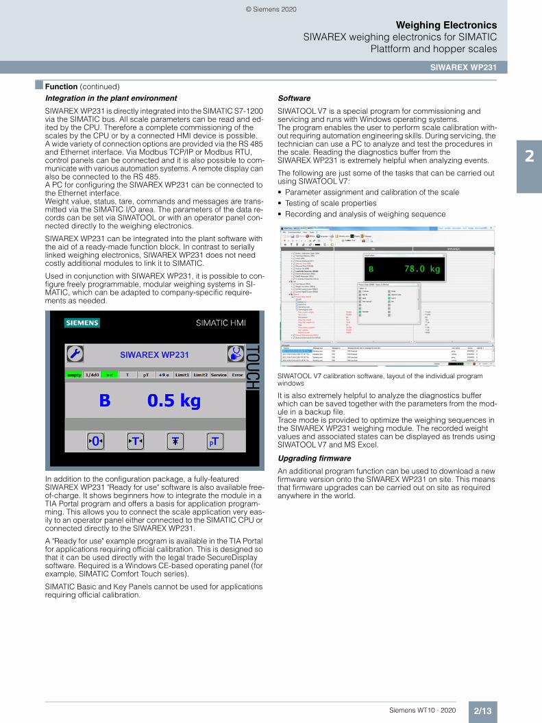
Integration in the plant environment
SIWAREX WP231 is directly integrated into the SIMATIC S7-1200 via the SIMATIC bus. All scale parameters can be read and ed-ited by the CPU. Therefore a complete commissioning of the scales by the CPU or by a connected HMI device is possible. A wide variety of connection options are provided via the RS 485 and Ethernet interface. Via Modbus TCP/IP or Modbus RTU, control panels can be connected and it is also possible to com-municate with various automation systems. A remote display can also be connected to the RS 485.A PC for configuring the SIWAREX WP231 can be connected to the Ethernet interface.Weight value, status, tare, commands and messages are trans-mitted via the SIMATIC I/O area. The parameters of the data re-cords can be set via SIWATOOL or with an operator panel con-nected directly to the weighing electronics.
SIWAREX WP231 can be integrated into the plant software with the aid of a ready-made function block. In contrast to serially linked weighing electronics, SIWAREX WP231 does not need costly additional modules to link it to SIMATIC.
Used in conjunction with SIWAREX WP231, it is possible to con-figure freely programmable, modular weighing systems in SI-MATIC, which can be adapted to company-specific require-ments as needed.
In addition to the configuration package, a fully-featured SIWAREX WP231 "Ready for use" software is also available free-of-charge. It shows beginners how to integrate the module in a TIA Portal program and offers a basis for application program-ming. This allows you to connect the scale application very eas-ily to an operator panel either connected to the SIMATIC CPU or connected directly to the SIWAREX WP231.
A "Ready for use" example program is available in the TIA Portal for applications requiring official calibration. This is designed so that it can be used directly with the legal trade SecureDisplay software. Required is a Windows CE-based operating panel (for example, SIMATIC Comfort Touch series).
SIMATIC Basic and Key Panels cannot be used for applications requiring official calibration.
Software
SIWATOOL V7 is a special program for commissioning and servicing and runs with Windows operating systems.The program enables the user to perform scale calibration with-out requiring automation engineering skills. During servicing, the technician can use a PC to analyze and test the procedures in the scale. Reading the diagnostics buffer from the SIWAREX WP231 is extremely helpful when analyzing events.
The following are just some of the tasks that can be carried out using SIWATOOL V7:• Parameter assignment and calibration of the scale • Testing of scale properties • Recording and analysis of weighing sequence
SIWATOOL V7 calibration software, layout of the individual program windows
It is also extremely helpful to analyze the diagnostics buffer which can be saved together with the parameters from the mod-ule in a backup file.Trace mode is provided to optimize the weighing sequences in the SIWAREX WP231 weighing module. The recorded weight values and associated states can be displayed as trends using SIWATOOL V7 and MS Excel.
Upgrading firmware
An additional program function can be used to download a new firmware version onto the SIWAREX WP231 on site. This means that firmware upgrades can be carried out on site as required anywhere in the world.
© Siemens 2020

2/14 Siemens WT10 · 2020
2
Weighing ElectronicsSIWAREX weighing electronics for SIMATICPlattform and hopper scales
SIWAREX WP231
■ Technical specifications
SIWAREX WP231
Integration in automation systems
S7-1200 SIMATIC S7-1200 system bus
Operator panel and/or automation systems from other vendors
Via Ethernet (Modbus TCP/IP) or RS 485 (Modbus RTU)
Communication interfaces • SIMATIC S7-1200 backplane bus • RS 485 (Modbus RTU, Siebert
remote display)• Ethernet
(SIWATOOL V7, Modbus TCP/IP)• Analog output 0/4 - 20 mA• 4 × digital outputs 24 V DC,
floating, short-circuit proof• 4 × digital inputs 24 V DC, floating
Commissioning options • Using SIWATOOL V7• Using function block in
SIMATIC S7-1200 CPU / Touch Panel
• Using Modbus TCP/IP• Using Modbus RTU
Measuring accuracy
EU type approval as non-automatic weighing instrument, trade class III
3000 d 0.5 V/e
Error limit according to DIN 1319-1 of full-scale value at 20 °C ± 10 K (68 °F ± 10 K)
0.05%
Internal resolution Up to ± 4 million parts
Measuring frequency 100 / 120 Hz
Digital filter Variable adjustable low-pass and average filter
Typical applications • Non-automatic weighing instruments
• Force measurements• Fill-level monitoring• Belt tension monitors
Weighing functions
Weight values • Gross• Net• Tare
Limit values • 2 × min/max• Empty
Zeroing Per command
Tare Per command
Tare specification Per command
Load cells Full-bridge strain gauges in 4-wire or 6-wire system
Load cell powering
Supply voltage (regulated via feedback)
4.85 V DC
Permissible load resistance• RLmin > 40 • RLmax < 4 100
With SIWAREX IS Ex interface• RLmin > 50 • RLmax < 4 100
Load cell characteristic 1 … 4 mV/V
Permissible range of the measure-ment signal (with 4 mV/V sensors)
-21.3 ... +21.3 mV
Max. distance of load cells 500 m (229.66 ft)
Connection to load cells in Ex zone 1
Optionally via SIWAREX IS Ex inter-face (compatibility of the load cells must be checked)
Approvals/certificates • ATEX Zone 2• UL• EAC• KCC• RCM• OIML R-76• Design approval 2009/23/EC
(NAWI)• NTEP Class III / III L
Auxiliary power supply
Rated voltage 24 V DC
Max. power consumption 200 mA
Max. power consumption SIMATIC Bus
3 mA
IP degree of protection to DIN EN 60529; IEC 60529
IP20
Climatic requirements
Tmin(IND) ... Tmax(IND) (operating temperature)• Vertical installation -10 ... +40 °C (14 ... 104 °F)• Horizontal installation -10 ... +55 °C (14 ... 131 °F)
EMC requirements According to EN 45501
Dimensions 70 × 75 × 100 mm (2.76 × 2.95 × 3.94 inch)
SIWAREX WP231
© Siemens 2020

2/15Siemens WT10 · 2020
2
Weighing ElectronicsSIWAREX weighing electronics for SIMATIC
Plattform and hopper scales
SIWAREX WP231
■ Selection and ordering data Article No. Article No.
SIWAREX WP231 weighing module
Single-channel, legal-for-trade, for NAWI non-automatic weighing instruments (e.g. platform scales or hopper scales) with analog load cells (1–4 mV/V), 1 x LC, 4 × DQ, 4 × DI, 1 × AQ, 1 RS 485, Ethernet port.
7MH4960-2AA01
SIWAREX S7-1200 Equipment Manual
Available in a range of languages
Free download on the Internet at:
http://www.siemens.com/weighing/documentation
SIWAREX WP231 "Ready for use"
Complete software package for non-automatic weighing instrument (for S7-1200 and a directly con-nected operator panel).
Free download on the Internet at:
http://www.siemens.com/weighing/documentation
SIWAREX WP231 "Ready for use - legal-for-trade"
Software package for non-auto-matic weighing instruments for S7-1200 requiring official calibration.
Free download on the Internet at:
http://www.siemens.com/weighing/documentation
Software SecureDisplay
Software for a legal trade display on Windows CE-based Panel. SIMATIC Basic and Key Panels are excluded.
Free download on the Internet at:
http://www.siemens.com/weighing/documentation
SIWATOOL V4 & V7 7MH4900-1AK01
Service and commissioning software for SIWAREX weighing modules
Calibration set for SIWAREX WP2xx
7MH4960-0AY10
Valid for SIWAREX WP231 and SIWAREX WP251.
For verification of up to 3 scales, comprising:• 3 × inscription foils for ID label
• 1 × protective film
• 3 × calibration protection plates
• Guidelines for verification, certifi-cates and approvals, editable la-bel, SIWAREX WP
Ethernet cable patch cord 2 m (7 ft)
6XV1850-2GH20
For connecting SIWAREX WP231 to a PC (SIWATOOL), SIMATIC CPU, panel, etc.
Remote display (optional)
The digital remote displays can be connected directly to the SIWAREX WP231 via the RS 485 interface.
Suitable remote display: S102
Siebert Industrieelektronik GmbHPO Box 1180D-66565 EppelbornTel.: +49 6806/980-0Fax: +49 6806/980-999
https://www.siebert-group.com/en/
Detailed information is available from the manufacturer.
Accessories
SIWAREX JB junction box, aluminum housing
7MH5001-0AA20
For connecting up to 4 load cells in parallel, and for connecting multiple junction boxes.
SIWAREX JB junction box, stainless steel housing
7MH5001-0AA00
For connecting up to 4 load cells in parallel.
SIWAREX JB junction box, stainless steel housing (ATEX)
7MH5001-0AA01
For parallel connection of up to 4 load cells (for zone allocation, see manual or type-examination certifi-cate).
SIWAREX DB digital junction box 7MH5001-0AD20
For enhanced diagnostics and monitoring options in conjunction with SIWAREX WP electronics.
SIWAREX IS Ex interface
For intrinsically-safe connection of load cells. With ATEX approval (not UL/FM). Suitable for SIWAREX elec-tronic weighing systems. Compati-bility of load cells must be checked separately.• Short-circuit current < 199 mA DC 7MH4710-5BA• Short-circuit current < 137 mA DC 7MH4710-5CA
Cable (optional)
Cable Li2Y 1 × 2 × 0.75 ST + 2 × (2 × 0.34 ST) – CY
For connecting SIWAREX electronic weighing systems to junction box (JB), extension box (EB) and Ex interface or between two EBs. For permanent installation. Occasional bending is possible.
External diameter: approx. 10.8 mm (0.43 inch)
Permissible ambient temperature -40 ... +80 °C (-40 ... +176 °F)
Sold by the meter.• Sheath color: orange 7MH4702-8AG• For hazardous atmospheres.
Sheath color: blue.7MH4702-8AF
Ground terminal for connecting the load cell cable shield to the grounded DIN rail
6ES5728-8MA11
© Siemens 2020

2/16 Siemens WT10 · 2020
■ Selection and ordering data Article No.
2
Weighing ElectronicsSIWAREX weighing electronics for SIMATICPlattform and hopper scales
SIWAREX WP231
Commissioning
Commissioning charge for one static scale with SIWAREX module
(Flat charge for travel and setup must be ordered separately)
9LA1110-8SN50-0AA0
Scope:• Recording of data• Checking of mechanical installa-
tion of the scale• Checking of electrical wiring and
function• Static adjustment of the scale
Requirements:• Mechanical design functional• Modules electrically wired and
tested• Calibration weights available• Free access to scale
Flat charge for travel and setup in Germany
9LA1110-8RA10-0AA0
© Siemens 2020

2/17Siemens WT10 · 2020
2
Weighing ElectronicsSIWAREX weighing electronics for SIMATIC
Plattform and hopper scales
SIWAREX WP321
■ Overview
SIWAREX WP321 is a versatile and flexible weighing module for the seamless integration of a static scale into the SIMATIC automation environment.
The electronic weighing system is integrated in the SIMATIC ET 200SP series and uses all the features of a modern automation system, such as integrated communication, operator control and monitoring, diagnostic system and configuration tools in the TIA Portal, SIMATIC STEP 7, WinCC flexible and PCS 7.
■ Benefits
The electronic weighing system described here is characterized by decisive advantages:• Uniform design technology and consistent communication in
SIMATIC ET 200SP• Compact design with only 15 mm module width• Parameterization of the scales via the control panel, CPU or
PC• Flexible configuration options in SIMATIC TIA Portal,
SIMATIC STEP 7 and PCS7• Measuring of weights and forces with a resolution of up to
+/- 2 million parts• 100 / 120 / 600 Hz measurement rate• Internal scale monitoring of freely definable limit values• Easy commissioning using the SIWATOOL software• Automatic calibration is possible without the need for
calibration weights• Modules can be replaced without recalibrating the scale• Direct use in ATEX Zone 2 possible• Wide range of status and diagnostic information• "Ready-for-use" sample program
■ Application
SIWAREX WP321 is the optimum solution wherever analog load cells are used for measuring tasks.
The SIWAREX WP321 is suitable for the following applications:• Non-automatic weighing instrument (NAWI), e.g. platform and
hopper scales• Fill-level monitoring of silos and hoppers• Measuring of crane and cable loads• Force measurements• Monitoring of belt tensions• Setup of scales in hazardous areas
■ Design
SIWAREX WP321 is a technology module (TM) of the SIMATIC ET 200SP series and is thus linked to the controller in a distributed manner by means of an ET 200SP interface module (Profibus/Profinet).
The following BaseUnits (Type A0) can be used for integration:
For opening a new potential group:
BU15P-16+A10+2D (6ES7193-6BP20-0DA0)
BU15P-16+A0+2D (6ES7193-6BP00-0DA0)
For continuing the potential group:
BU15P-16+A10+2B (6ES7193-6BP20-0BA0)
BU15P-16+A0+2B (6ES7193-6BP00-0BA0)
The load cells or force sensors are connected to the terminals of the BaseUnits. This means that modules can be replaced quickly, easily and without any wiring work.
© Siemens 2020

2/18 Siemens WT10 · 2020
2
Weighing ElectronicsSIWAREX weighing electronics for SIMATICPlattform and hopper scales
SIWAREX WP321
■ Function
The primary task of the weighing electronics is to determine the current weight and force values on the basis of signals supplied by the connected sensors. Thanks to the seamless integration into the SIMATIC environment, values can be processed directly and in any available programming language of the CPU. If the freely selectable and internally monitored values are exceeded or undershot, this is reported directly to the controller. A variety of status and diagnostic information can also be read out and evaluated in the CPU without difficulty.
The SIWAREX WP321 is calibrated in the factory. This not only permits automatic calibration of the scales (without the need for calibration weights), but also the replacement of modules with-out the need for recalibration.
Via the integral RS 485 interface, a PC can be connected for setting the parameters of the weighing electronics using the "SIWATOOL" software. A USB-RS 485 interface converter is required for this purpose.
Thanks to its seamless integration into the SIMATIC environment, the use of SIWAREX weighing electronics does not require any complicated or expensive communication drivers for the scales.
Programmable weighing applications tailored to any situation can be created and then adapted or extended at any time in combination with the functionalities of the TIA Portal and of the SIMATIC Manager and WinCC flexible.
Likewise, WP321 enables scales to be set up in hazardous areas. Depending on the zone and the load cells used, the use of the SIWAREX IS Ex interface may also be necessary.
SIWAREX WP321 Ready for use
For an easy introduction to the integration of the module into the TIA Portal and SIMATIC Manager, a "Ready for use" sample proj-ect is available free of charge. This project demonstrates the in-tegration of the module into the hardware configuration and con-tains the function block for communication between the CPU and SIWAREX. It also contains a ready-made data block that contains all the parameters for the scales. The "Ready for use" project is rounded off with a touch panel configuration feature, which not only permits complete commissioning of the scales from the panel, but also includes an "operator view" that can be used to show the normal operation of the scales.
SIWAREX WP321 SIWATOOL
SIWATOOL is a service software tool which enables you to cali-brate the module quickly and efficiently on site, set or reset pa-rameters, or perform diagnostics in the event of a fault. Further-more, complete backup files can be created for the scales, which can be uploaded to a new module with a few mouse clicks, so that the module continues to operate exactly as it did before the backup, without the need for any recalibration. It is even possible to upload configuration files that were created of-fline, or to read out the error buffer. No special SIMATIC knowl-edge is required to use SIWATOOL. It is connected via the RS 485 port of the module which requires the use of a USB RS 485 interface converter. Please refer to the SIWAREX WP321 Equipment Manual for further recommendations.
© Siemens 2020

2/19Siemens WT10 · 2020
2
Weighing ElectronicsSIWAREX weighing electronics for SIMATIC
Plattform and hopper scales
SIWAREX WP321
■ Technical specifications
1) The S7 standard modules may not be operated at temperatures below 0 °C (32 °F). For operating conditions below 0 °C (32 °F), SIMATIC modules from the SIPLUS series must be used.
SIWAREX WP321
Integration in automation systems
SIMATIC S7-300, S7-400, S7-1200 and S7-1500
Via SIMATIC ET 200SP interface module (PROFIBUS or PROFINET)
Other manufacturers (with restrictions) Via SIMATIC ET 200SP interface mod-ule (PROFIBUS or PROFINET)
Communication interfaces • SIMATIC ET 200SP backplane bus• RS 485 (SIWATOOL, Siebert remote
display)
Commissioning options • Using SIWATOOL V7• Using function block in SIMATIC
CPU / Touch Panel
Measuring accuracy
According to DIN 1319-1 of full-scale value at 20 °C ± 10 K (68 °F ± 10 K)
0.05%
Internal resolution ± 2 million parts
Measuring frequency 100 / 120 / 600 Hz
Digital filter Variable adjustable low-pass and average filter
Typical applications • Non-automatic weighing instruments
• Force measurements• Fill-level monitoring• Belt tension monitors
Weighing functions
Weight values • Gross• Net• Tare
Limit values • 2 × min/max• Empty
Zeroing Via command by controller or HMI
Tare Via command by controller or HMI
External tare specification Via command by controller or HMI
Calibration commands Via command by controller or HMI
Load cells Full-bridge strain gauges in 4-wire or 6-wire system
Load cell powering
Supply voltage (value applies at sen-sor, cable-related voltage drops of up to 5 V are controlled)
4.85 V DC ±2%
Permissible load resistance• RLmin > 40 • RLmax < 4 100
With SIWAREX IS Ex interface• RLmin > 50 • RLmax < 4 100
Load cell characteristic 1 … 4 mV/V
Permissible range of measuring signal (at greatest set characteristic value)
-21.3 ... +21.3 mV
Max. distance of load cells 1000 m (459.32 ft)
Connection to load cells in Ex zone 1
Optionally via SIWAREX IS Ex inter-face (compatibility of the load cells must be checked)
Approvals/certificates • ATEX Zone 2• UL• FM• EAC• KCC• IECEx• RCM
Auxiliary power supply
Rated voltage 24 V DC
Max. power consumption Typ. 0.1 A @ 24 V DC (0.2 A max.)
Max. power consumption SIMATIC Bus
30 mA
IP degree of protection to DIN EN 60529; IEC 60529
IP20
Climatic requirements
Tmin(IND) ... Tmax(IND) (operating temperature)• Vertical installation
in SIMATIC S7 1)-25 ... +50 °C (-13 ... 122 °F)
• Horizontal installation in SIMATIC S7 1)
-25 ... +60 °C (-13 ... 140 °F)
EMC requirements According to IEC 61000-6-2, IEC 61000-6-4, OIML R76-1
Dimensions (width) 15 mm (0.6 inch)
SIWAREX WP321
© Siemens 2020

2/20 Siemens WT10 · 2020
2
Weighing ElectronicsSIWAREX weighing electronics for SIMATICPlattform and hopper scales
SIWAREX WP321
■ Selection and ordering data Article No. Article No.
TM SIWAREX WP321 weighing module
Single-channel, for platform scales or hopper scales with analog load cells (1 - 4 mV/V), 1 x LC, 1 x RS 485.
7MH4138-6AA00-0BA0
SIWAREX WP321 Equipment Manual
Available in a range of languages
Free download on the Internet at:
http://www.siemens.com/weighing/documentation
SIWAREX WP321 "Ready for use"
TIA Portal and SIMATIC Manager sample configuration
Free download on the Internet at:
http://www.siemens.com/weighing/documentation
SIWATOOL V4 & V7 7MH4900-1AK01
Service and commissioning soft-ware for SIWAREX weighing mod-ules
SIWAREX PCS 7 AddOn Library for PCS7 V8.x and V9.0• Supports PROFINET
APL faceplates and function blocks for: • SIWAREX U• SIWAREX FTA• SIWAREX FTC_B (belt scale)• SIWAREX WP321
Classic faceplate and function block for:• SIWAREX FTC_L (Loss-in-weight)
7MH4900-1AK61
Accessories (mandatory requirement)
BaseUnit (Type A0 – one BaseUnit required for each WP321)• For opening a new potential group
- BU15P-16+A0+2D 6ES7193-6BP00-0DA0- BU15P-16+A10+2D 6ES7193-6BP20-0DA0
• For continuing the potential group
- BU15P-16+A0+2B 6ES7193-6BP00-0BA0- BU15P-16+A10+2B 6ES7193-6BP20-0BA0
Shielded connection for BaseUnit (5 units / for 5 scales)
For laying the load cell cable
6ES7193-6SC00-1AM0
Accessories (optional)
SIWAREX JB junction box, aluminum housing
7MH5001-0AA20
For connecting up to 4 load cells in parallel, and for connecting multiple junction boxes.
SIWAREX JB junction box, stainless steel housing
7MH5001-0AA00
For connecting up to 4 load cells in parallel.
SIWAREX JB junction box, stainless steel housing (ATEX)
7MH5001-0AA01
For parallel connection of up to 4 load cells(for zone allocation, see manual or type-examination certificate).
SIWAREX DB digital junction box 7MH5001-0AD20
For enhanced diagnostics and monitoring options in conjunction with SIWAREX WP electronics.
SIWAREX IS Ex interface
For intrinsically-safe connection of load cells. With ATEX approval (not UL/FM). Suitable for SIWAREX elec-tronic weighing systems. Compati-bility of load cells must be checked separately.
Approved for use in the EU• Short-circuit current < 199 mA DC 7MH4710-5BA• Short-circuit current < 137 mA DC 7MH4710-5CA
Cable (optional)
Cable Li2Y 1 × 2 × 0.75 ST + 2 × (2 × 0.34 ST) – CY
For connecting SIWAREX electronic weighing systems to junction box (JB), extension box (EB) and Ex interface or between two EBs. For permanent installation. Occasional bending is possible.
External diameter: approx. 10.8 mm (0.43 inch)
Permissible ambient temperature-40 ... +80 °C (-40 ... +176 °F)
Sold by the meter.• Sheath color: orange 7MH4702-8AG• For hazardous atmospheres.
Sheath color: blue.7MH4702-8AF
RS485/USB interface converter
Commercially available interface converter with FTDI chip, e.g. USB-Nano from CTI
http://www.cti-shop.com/RS485-Konverter/USB-Nano-485
Remote display
The Siebert S102 and S302 remote digital displays can be directly con-nected to the SIWAREX FTA via an RS 485 interface.
Siebert Industrieelektronik GmbHPO Box 1180D-65565 Eppelborn, GermanyTel: +49 6806/980-9Fax: +49 6806/980-999
Internet:https://www.siebert-group.com/en/
Detailed information is available from the manufacturer.
Commissioning
Commissioning charge for one static scale with SIWAREX module
(Flat charge for travel and setup must be ordered separately)
9LA1110-8SN50-0AA0
Scope:• Recording of data• Checking of mechanical installa-
tion of the scale• Checking of electrical wiring and
function• Static adjustment of the scale
Requirements:• Mechanical design functional• Modules electrically wired and
tested• Calibration weights available• Free access to scale
Flat charge for travel and setup in Germany
9LA1110-8RA10-0AA0
© Siemens 2020

2/21Siemens WT10 · 2020
2
Weighing ElectronicsSIWAREX weighing electronics for SIMATIC
Plattform and hopper scales
SIWAREX CS
■ Overview
SIWAREX CS is a versatile weighing module for all simple weighing and force measuring tasks. The compact module is easy to install in all SIMATIC automation systems. Data can be accessed directly in the SIMATIC.
■ Benefits
SIWAREX CS offers the following key advantages:• Uniform design technology and consistent communication in
SIMATIC• Uniform configuration with SIMATIC• Use in distributed plant concept through connection to
PROFIBUS DP or PROFINET via ET 200S• Measurement of weight or force with a high resolution of
65 000 parts and an accuracy of 0.05%• Direct connection of a remote display to the TTY interface• Simple adjustment of the scale using the SIWATOOL CS
program via the RS 232 interface• Supports theoretical adjustment without calibration weights• Supports replacement of module without recalibration of
scales• For use in Ex zone 2, intrinsically-safe load cell powering for
zone 1 over Ex interface
■ Application
SIWAREX CS is the optimum solution wherever strain gauge sensors, such as load cells, force sensors or torque measuring shafts, are used for measuring tasks. The following are typical SIWAREX CS applications:• Non-automatic weighing instruments• Fill level monitoring of silos and hoppers• Measuring of crane and cable loads• Load measuring for industrial elevators and rolling mills• Weighing in potentially explosive areas (Zone 2 direct, Zone 1
using Ex interface SIWAREX IS)• Monitoring of belt tension• Force measuring, hopper scales, platform scales and crane
scales
■ Design
SIWAREX CS is a compact function module (FM) in the SIMATIC ET 200S and can be plugged directly into a terminal module. The power supply is connected through a power mod-ule and the internal power rail.
The load cells and serial interfaces are connected via the ports of the terminal module. Using the terminal module means it can be replaced without detaching the connecting cables.
■ Function
The primary task of SIWAREX CS is the measurement of sensor voltage and the conversion of this measurement into a weight value. Up to 3 interpolation points are used for the weight calcu-lation. The signal can also be digitally filtered if required.
As well as determining weights, the SIWAREX CS monitors two freely programmable limits (min./max. as required) and notifies SIMATIC if these values are exceeded.
The SIWAREX CS comes factory-calibrated. This means that theoretical adjustment of the scale is possible without adjust-ment weights, and that modules can be replaced without the need to readjust the scale.
Consistent and uniform communication between all system components enables fast, reliable and cost-effective integration and diagnostics in industrial processes.
Reading of the process data from the SIWAREX CS via the distributed I/O is possible with all head modules. In the case of PROFIBUS head modules that support the DP V1 protocol and PROFINET head modules, the data record communication can additionally be used for reading out the data and making settings.
Group diagnostics and hardware interrupts are possible with all PROFIBUS head modules with DP V1 and PROFINET modules. Head modules with DP V0 support group diagnostics, but not the hardware interrupts.
The SIWAREX CS has two serial interfaces. The TTY interface serves to connect digital remote displays. The remote displays can show the weight value with status information.
To parameterize the SIWAREX CS, a PC can be connected over the RS 232 interface.
SIWAREX CS can be integrated in the plant software using the classic PLC programming languages STL (Statement List), LAD (Ladder Diagram), FBD (Function Block Diagram) or SCL (Struc-tured Control Language).
© Siemens 2020

2/22 Siemens WT10 · 2020
■ Function (continued)
2
Weighing ElectronicsSIWAREX weighing electronics for SIMATICPlattform and hopper scales
SIWAREX CS
In contrast to serially linked electronic weighing systems, SIWAREX CS does not need costly additional modules to link it to SIMATIC.
With SIWAREX CS, it is possible to configure freely programma-ble, modular weighing systems in SIMATIC that can be adapted as desired according to company-internal requirements.
Scale faceplate in the SIWAREX CS "Getting Started" software
In addition to the configuration package, the ready-made SIWAREX CS "Getting Started" software is available free-of-charge. It shows beginners how to integrate the module into a STEP 7 program and offers a basis for application programming. This allows you to implement the scale very easily with an oper-ator panel connected directly to the SIMATIC CPU.
Using the SIWATOOL CS software, the SIWAREX weighing modules offer Windows convenience and are quick to get into operation. Screen forms allow all user-definable parameters of the weighing modules to be specified, saved and printed for plant documentation.
The diverse diagnostics options provided by SIWATOOL CS ensure fast fault locating in online mode.
The SIWAREX CS weighing module can be used in hazardous areas (zone 2). It can also be used in zone 1 by implementing an optional Ex interface, whereby SIWAREX CS must be installed in a safe area.
■ Technical specifications
SIWAREX CS
Integration in automation systems• S7-400, S7-300, C7 Through ET 200S• IM151-7 CPU Through backplane bus• Automation systems from other man-
ufacturers (possible with limitations)Through ET 200S
Communication interfaces SIMATIC S7 (ET 200S backplane bus), RS 232, TTY
Connection of remote display(via serial TTY interface)
Display for weight value
Scale adjustment Using SIMATIC S7 IM151-7 CPU or SIWATOOL CS PC parameter assign-ment software (RS 232)
Measuring accuracy
Error limit according to DIN 1319-1 of full-scale value at 20 °C ± 10 K (68 °F ± 10 K)
0.05%
Internal resolutionData format of weight values
65 535 2 byte (fixed-point)
Number of measurements/second 50
Digital filter 0.05 ... 5 Hz (in 7 steps), mean value filter
Weighing functions
Weight values Gross, net
Limit values 2 (min./max.)
Zero-setting function Per command
Tare function Per command
Tare specification Per command
Load cells Strain gauges in 4-wire or 6-wire system
Load cell powering
Supply voltage Us (rated value) 6 V DC typ.
Max. supply current 68 mA
Permissible load resistance• RLmin > 87 • RLmax < 4 010
With SIWAREX IS Ex interface:• RLmin > 87 • RLmax < 4 010
Load cell characteristic 1 mV/V bis 4 mV/V
Permissible range of measuring signal (at greatest set characteristic value)
-2.4 ... +26.4 mV
Max. distance of load cells 1 000 m
Intrinsically-safe load cell powering Optional (SIWAREX IS Ex interface)
External load cell powering Possible up to 24 V
Connection to load cells in Ex zone 1
Optionally via SIWAREX IS Ex interface
Ex approvals zone 2 and safety ATEX 95, FM, cULUS Haz. Loc.
Auxiliary power supply
Rated voltage 24 V DC
Max. power consumption 150 mA
IP degree of protection to DIN EN 60529; IEC 60529
IP20
Climatic requirements
Tmin (IND) ... Tmax (IND) (operating temperature)• Horizontal installation -10 ... +60 °C (14 … 140 °F)• Vertical installation -10 ... +40 °C (14 … 104 °F)
EMC requirements According to EN 61326, EN 45501, NAMUR NE21, Part 1
Dimensions 80 × 125 × 130 mm (3.15 × 4.92 × 5.12 inch)
© Siemens 2020

2/23Siemens WT10 · 2020
2
Weighing ElectronicsSIWAREX weighing electronics for SIMATIC
Plattform and hopper scales
SIWAREX CS
■ Selection and ordering data Article No. Article No.
SIWAREX CS
Weighing electronics for scales in SIMATIC ET 200S
7MH4910-0AA01
SIWAREX CS Equipment Manual
Available in a range of languages
Free download on the Internet at:
http://www.siemens.com/weighing/documentation
SIWAREX CS "Getting Started"
Sample software shows beginners how to program the scales in STEP 7.
Free download on the Internet at:
http://www.siemens.com/weighing/documentation
SIWATOOL V4 & V7 7MH4900-1AK01
Service and commissioning soft-ware for SIWAREX weighing mod-ules
SIWATOOL connection cable from SIWAREX U/CS with serial PC interface, for 9-pin PC interfaces (RS 232), length 3 m (9.84 ft)
7MH4607-8CA
Installation material (mandatory)
Terminal module 6ES7193-4CG20-0AA0
TM-E 30 mm (1.18 inch) wide (required for each SIWAREX module)
Or compatible
Shield connection element 6ES7193-4GA00-0AA0
Contents 5 units, sufficient for 5 cables
Shield connection clamp 6ES7193-4GB00-0AA0
Contents: 5 units, sufficient for 5 cables
Note: one shield connection clamp is required each for the• scales connection and
• TTY interface or
• RS 232 interface
N busbar, zinc-plated 8WA2842
3 × 10 mm (0.12 × 0.39 inch), 1.0 m (3.28 ft) long
Feeder terminal for N busbar 8WA2868
Remote displays (option)
The digital remote displays can be connected directly to the SIWAREX CS through the TTY interface.
Suitable remote display: S102
Siebert Industrieelektronik GmbHPO Box 1180D-66565 EppelbornTel.: +49 6806/980-0Fax: +49 6806/980-999
Internet:https://www.siebert-group.com/en/
Detailed information is available from the manufacturer.
Accessories
SIWAREX JB junction box, aluminum housing
For connecting up to 4 load cells in parallel, and for connecting multiple junction boxes.
7MH5001-0AA20
SIWAREX JB junction box, stainless steel housing
For connecting up to 4 load cells in parallel.
7MH5001-0AA00
SIWAREX JB junction box, stainless steel housing (ATEX)
For parallel connection of up to 4 load cells (for zone allocation, see manual or type-examination certifi-cate).
7MH5001-0AA01
Ex interface SIWAREX IS
For intrinsically-safe connection of load cells. With ATEX approval (not UL/FM). Suitable for SIWAREX elec-tronic weighing systems. Compati-bility of load cells must be checked separately.• With short-circuit current
< 199 mA DC7MH4710-5BA
• With short-circuit current < 137 mA DC
7MH4710-5CA
Cable (optional)
Cable Li2Y 1 x 2 x 0.75 ST + 2 x (2 x 0.34 ST) – CY
For connecting SIWAREX electronic weighing systems to junction box (JB), extension box (EB) and Ex interface or between two EBs. For permanent installation. Occasional bending is possible.
External diameter: approx. 10.8 mm (0.43 inch)
Permissible ambient temperature -40 ... +80 °C (-40 ... +176 °F)
Sold by the meter.• Sheath color: orange 7MH4702-8AG• For hazardous atmospheres.
Sheath color: blue.7MH4702-8AF
© Siemens 2020

2/24 Siemens WT10 · 2020
2
Weighing ElectronicsSIWAREX weighing electronics for SIMATICPlattform and hopper scales
SIWAREX U
■ Overview
SIWAREX U is a versatile weighing module for all simple weighing and force measuring tasks. The compact module can be integrated into SIMATIC automation systems without any problems. Complete data access is then possible via the SIMATIC.
■ Benefits
SIWAREX U offers the following key advantages:• Uniform design technology and consistent communication in
SIMATIC• Implementation in a distributed system concept thanks to
connection to PROFIBUS DB/PROFINET via ET 200M• Measurement of weight or force with a high resolution of
65 000 parts and 0.05% accuracy• Space saving through use of two-channel version for two
scales• Direct connection of a remote display to the TTY interface• Simple adjustment of scale using the SIWATOOL U program• Supports theoretical adjustment without adjustment weights• Supports replacement of module without recalibration of
scales• Can be used in Ex applications
■ Application
SIWAREX U is the optimum solution wherever strain gage sen-sors, such as load cells, force sensors or torque measuring shafts, are used for measuring tasks. The typical applications of SIWAREX U are:• Fill level monitoring of silos and bunkers• Monitoring of loads on cranes and cables• Measuring the loading on conveyor belts• Overload protection of industrial elevators or rolling mills• Balances in hazardous areas (using an Ex interface)• Monitoring of belt tension
■ Design
SIWAREX U is a compact SIMATIC S7-300 function module (FM) and can be directly snapped onto the SIMATIC S7-300 or ET 200M backplane bus. The snap-on system for DIN rails greatly simplifies the installation/cabling work.
The load cells, power supply and serial interfaces are connected via the 20-pin standard front connector.
Operation of SIWAREX U in SIMATIC ensures that the weighing system is completely integrated into the automation system.
■ Function
SIWAREX U is available with either one or two measuring chan-nels. One measuring channel is required for each set of scales.
The primary task of SIWAREX U is the measurement of sensor voltage and the conversion of this measurement into a weight value. The signal can also be digitally filtered if required.
As well as determining weights, the SIWAREX MS monitors two freely programmable limits (min./max. as required).
The SIWAREX U comes factory-calibrated. This means that the-oretical adjustment of the scale is possible without adjustment weights, and that modules can be replaced without the need to readjust the scale. When using "active bus modules", replace-ment is also possible during operation.
Consistent and uniform communication between all system components enables fast, reliable and cost-effective integration and diagnosis in industrial processes.
The SIWAREX U has two serial interfaces. The TTY interface serves to connect up to four digital remote displays. In addition to the two weight values of weighing channels 1 and 2, another two values can be set via SIMATIC and indicated on the remote displays.
A PC for adjusting the scale can be connected through the RS 232 interface.
SIWAREX U can not only be integrated in the plant software us-ing the classic PLC programming languages; STL (Statement List), LD (Ladder Diagram) SFC (Sequential Function Chart) or SCL (Structured Control Language), it can also be integrated by means of graphical configuration with CFCs (Continuous Func-tion Chart), where faceplates are provided in PCS 7 for visualiza-tion of the scales.
In contrast to serially linked weighing electronics, SIWAREX U does not need costly additional modules to link it to SIMATIC.
Integration in SIMATIC produces freely-programmable, modular weighing systems which can be modified according to opera-tional requirements.
Using the SIWATOOL U software, the SIWAREX weighing modules can be set up with the convenience of Windows independently of the automation system. Input masks allow all parameters for the weighing modules to be specified, saved and printed for plant documentation.
The diverse diagnostic options provided by SIWATOOL U ensure fast fault locating in online mode.
The SIWAREX U weighing module can be used for hazardous ar-eas (zone 2). The load cells can be provided with an intrinsically-safe power supply through an optional Ex interface.
© Siemens 2020

2/25Siemens WT10 · 2020
2
Weighing ElectronicsSIWAREX weighing electronics for SIMATIC
Plattform and hopper scales
SIWAREX U
■ Technical specifications
1) Load cell supply changed to 6 V DC as compared to 7MH4601-1AA01 and 7MH4601-1BA01.
2) Possible up to 1 000 m under certain conditions when using the recommended cable (accessories).
SIWAREX U
Integration in automation systems• S7-300 Direct integration• S7-1500 Through ET 200M• S7-400 (H) Through ET 200M• PCS 7 (H) Through ET 200M• Automation systems from other
vendorsThrough ET 200M
• Stand-alone (without SIMATIC CPU)
Possible with IM 153-1
Communication interfaces • SIMATIC S7 (P bus)• RS 232• TTY
Connection of remote display(via serial TTY interface)
Gross, channel 1, 2 or default value 1, 2
Scale adjustment Through SIMATIC (P bus) or PC using SIWATOOL U (RS 232)
Measuring properties
Error limit according to DIN 1319-1 of full-scale value at 20 °C ± 10 K (68 °F ± 10 K)
0.05%
Internal resolution ADC 65 535
Data format weight values 2 bytes (fixed-point)
Number of measurements/second 50
Digital filter 0.05 ... 5 Hz (in 7 steps), mean value filter
Weighing functions
Weight values Gross
Limit values 2 (min./max.)
Zero-setting function Per command
Load cells Strain gauges in 4-wire or 6-wire sys-tem
Load cell powering
Supply voltage Us (rated value) 6 V DC1)
Max. supply current 150 mA per channel
Permissible load resistance • RLmin > 40 per channel• RLmax < 4 010
With Ex(i) interface• RLmin > 87 per channel• RLmax < 4 010
Permissible load cell characteristic
Up to 4 mV/V
Max. distance of load cells • 500 m2)
• 150/500 m for gas group IIC• 500 m2) for gas group IIB
(see SIWAREX IS Manual)
Intrinsically-safe load cell powering
Optional (Ex interface) with SIWAREX IS
Auxiliary power supply
Rated voltage 24 V DC
Max. power consumption 150 mA (single-channel) / 240 mA (dual-channel)
Current consumption on backplane bus
100 mA
Certification ATEX 95, FM, cULUS Haz. Loc.
IP degree of protection to DIN EN 60529; IEC 60529
IP20
Climatic requirements
Tmin (IND) ... Tmax (IND) (operating temperature)• Horizontal installation 0 ... +60 °C (32 ... 140 °F)• Vertical installation 0 ... +40 °C (32 ... 104 °F)
EMC requirements according to According to NAMUR NE21, Part 1; EN 61326
Dimensions 40 × 125 × 130 mm (1.58 × 4.92 × 5.12 inch)
SIWAREX U
© Siemens 2020

2/26 Siemens WT10 · 2020
2
Weighing ElectronicsSIWAREX weighing electronics for SIMATICPlattform and hopper scales
SIWAREX U
■ Selection and ordering data Article No. Article No.
SIWAREX UFor SIMATIC S7 and ET 200M, incl. bus connector, weight 0.3 kg (0.661 lb)
Single-channel version1)
for connecting one scale7MH4950-1AA01
Two-channel version2) for connecting two scales
7MH4950-2AA01
SIWATOOL V4 & V7
Service and commissioning soft-ware for SIWAREX weighing mod-ules
7MH4900-1AK01
SIWAREX U configuration pack-age for PCS 7, version 8.0
Suitable for 7MH4950-xAA01• Function block for CFC• Faceplate• Manual
7MH4950-3AK62
SIWAREX PCS 7 AddOn Library for PCS 7 V8.x and V9.0• Supports PROFINET
APL faceplates and function blocks for: • SIWAREX U• SIWAREX FTA• SIWAREX FTC_B (belt scale)• SIWAREX WP321
Classic faceplate and function block for:• SIWAREX FTC_L (Loss-in-weight)
7MH4900-1AK61
SIWATOOL connection cable
From SIWAREX U/CS with serial PC interface, for 9-pin PC interfaces (RS 232), length 3 m (9.84 ft)
7MH4607-8CA
Installation material (mandatory)
20-pin front connector with screw contactsRequired for each SIWAREX module
6ES7392-1AJ00-0AA0
Shield connection elementSufficient for two SIWAREX U mod-ules
6ES7390-5AA00-0AA0
Shield connection clamp
Contents: 2 units (suitable for cable with diameter 4 ... 13 mm / 0.16 ... 0.51 inch)
Note:
One shield connection clamp is required for each of the following:• Scale connection• RS 485 interface• RS 232 interface
6ES7390-5CA00-0AA0
S7 DIN rail• 160 mm (6.30 inch) 6ES7390-1AB60-0AA0• 480 mm (18.90 inch) 6ES7390-1AE80-0AA0• 530 mm (20.87 inch) 6ES7390-1AF30-0AA0• 830 mm (32.68 inch) 6ES7390-1AJ30-0AA0• 2 000 mm (78.74 inch) 6ES7390-1BC00-0AA0
Accessories (optional)
Labeling strips(10 units, spare part)
6ES7392-2XX00-0AA0
Remote displays (option)
The digital remote displays can be connected directly to SIWAREX U through a TTY interface.
The following remote displays can be used: S102, S302
Siebert Industrieelektronik GmbHPO Box 1180D-66565 EppelbornTel.: +49 6806/980-0Fax: +49 6806/980-999
Internet:https://www.siebert-group.com/en/
Detailed information is available from the manufacturer.
SIWAREX JB junction box, aluminum housing
For connecting up to 4 load cells in parallel, and for connecting multiple junction boxes.
7MH5001-0AA20
SIWAREX JB junction box, stainless steel housing
For connecting up to 4 load cells in parallel.
7MH5001-0AA00
SIWAREX JB junction box, stainless steel housing (ATEX)
For parallel connection of up to 4 load cells (for zone allocation, see manual or type-examination certifi-cate).
7MH5001-0AA01
SIWAREX IS Ex interfaceFor intrinsically-safe connection of load cells. With ATEX approval (not UL/FM). Suitable for SIWAREX elec-tronic weighing systems. Compati-bility of load cells must be checked separately.• With short-circuit current
< 199 mA DC7MH4710-5BA
• With short-circuit current < 137 mA DC
7MH4710-5CA
Cable (optional)
Cable Li2Y 1 x 2 x 0.75 ST + 2 x (2 x 0.34 ST) – CY
For connecting SIWAREX electronic weighing systems to junction box (JB), extension box (EB) and Ex interface or between two EBs. For permanent installation. Occasional bending is possible.
External diameter: approx. 10.8 mm (0.43 inch)
Permissible ambient temperature-40 ... +80 °C (-40 ... +176 °F)
Sold by the meter.• Sheath color: orange 7MH4702-8AG• For hazardous atmospheres.
Sheath color: blue.7MH4702-8AF
© Siemens 2020

2/27Siemens WT10 · 2020
■ Selection and ordering data Article No.
2
Weighing ElectronicsSIWAREX weighing electronics for SIMATIC
Plattform and hopper scales
SIWAREX U
1) Compatible with 7MH4601-1AA01; supply of load cells changed to 6 V DC.
2) Compatible with 7MH4601-1BA01; supply of load cells changed to 6 V DC.
Commissioning
Commissioning charge for one static scale with SIWAREX module
(Flat charge for travel and setup must be ordered separately)
9LA1110-8SN50-0AA0
Scope:• Recording of data• Checking of mechanical installa-
tion of the scale• Checking of electrical wiring and
function• Static adjustment of the scale
Requirements:• Mechanical design functional• Modules electrically wired and
tested• Calibration weights available• Free access to scale
Flat charge for travel and setup in Germany
9LA1110-8RA10-0AA0
© Siemens 2020

2/28 Siemens WT10 · 2020
2
Weighing ElectronicsSIWAREX weighing electronics for SIMATICDosing/filling/bagging and checking scales
Introduction
■ Overview
Dosing, filling, bagging scales and check weighers
Typical requirements in many industries are high-precision mix-ing and dosing, and packing and filling at high speed. The cor-responding SIWAREX electronics offer comprehensive proper-ties and functions that fulfill all requirements - including for legal-for-trade operation.
The dosing process used in production operations depends on a variety of factors: Depending on the type and quantity of ma-terials weighed, different dosing systems and weighing pro-cesses are required. It must be possible to fill liquid or solid goods quickly and precisely.
© Siemens 2020

2/29Siemens WT10 · 2020
2
Weighing ElectronicsSIWAREX weighing electronics for SIMATICDosing/filling/bagging and checking scales
SIWAREX WP351
■ Overview
The SIWAREX WP351 is a compact, precise weighing module in the SIMATIC ET 200SP format.
With a width of just 20 mm it is one of the slimmest weighing modules on the market, yet its firmware includes the functional-ities of an automatic totalizing weighing instrument, check weigher, bagging and filling scale.
All operating modes are part of the firmware and certified ac-cording to OIML R-51, R-61, R-76 and R-107*. This means the WP351 can be used in both scales requiring official calibration and those that do not, where demands are high regarding speed and accuracy.
■ Benefits
• Low space requirements with only 20 mm module width• Seamless integration into SIMATIC ET 200SP• 1 000 Hz sampling rate und processing time• Installation of legal-for-trade multi-interval/multi-range scales
with up to 3 × 6 000 d• Operation with SIMATIC S7-300, S7-400, S7-1200 and
S7-1500 controllers• Operation in Ethernet IP or Modbus TCP-based systems using
ET 200SP multi-field bus IM• Three digital inputs and outputs each ex works• High degree of scalability in connection with all available
SIMATIC standard components• Open SIWAREX concept – all settings and parameters acces-
sible, no encapsulated black box in the field• Unrestricted access to all scale parameters and functions
from the SIMATIC S7 Controller / HMI• Internal, legal-for-trade protocol memory for up to 1 000 000
entries• Commissioning and maintenance from HMI or module-internal
web server• Legal-for-trade main display integrated in the SIMATIC HMI
■ Application
SIWAREX WP351 offers a compact and extremely versatile solu-tion for automatic and non-automatic scale applications with high requirements for accuracy and performance.
Typical areas of application include:• Silo, hopper and platform scales, requiring official calibration*/
not requiring official calibration• Totalizing automatic weighing instruments, requiring official
calibration*/not requiring official calibration• Filling scales, requiring official calibration*/not requiring
official calibration• Static check weighers, requiring official calibration*/not
requiring official calibration• Automatic dynamic check weighers, not requiring official
calibration• Recipe-controlled batch/mixing scales
■ Design
The SIWAREX WP351 is a technology module of the SIMATIC ET 200SP distributed I/O system.
Installation is on a type U0 BaseUnit. The load cells, serial RS 485 interface and digital inputs/outputs are wired directly on the BaseUnit with user-friendly push-in terminals. This makes is quick and easy to replace modules without any wiring effort.
The web server is addressed via an Ethernet interface in the module. Should more interfaces and I/O be required, they can be added with the ET 200SP system components.
■ Function
The weighing module controls automatic proportioning, check-ing and loading processes completely autonomously. The intel-ligence required is contained in the module firmware, thus rep-resenting a standard. Dosing signals can be controlled directly via the three digital outputs – typically coarse flow/fine flow and emptying. Internal control algorithms and signal filters continu-ally optimize and adjust the weighing process.
The controller only transfers the desired setpoint, as well as other material-specific parameters, to the module via the WP351 func-tion block. A start command initiates the dosing process, which is executed by the weighing module independently of the cycle time of the main controller with maximum accuracy. Finally the WP351 carries out a tolerance check and signals the result to the controller. In addition, the result is included in the statistics cal-culated in the background, which can be called up at any time from the controller. Depending on the operating mode, a log is generated in the internal protocol memory, either automatically or initiated by the user. If the scales are calibrated, the log con-forms to the requirements of the Weights and Measures Act.
The open and standardized SIWAREX concept means that the plant operator can service the scales themselves if necessary.
* Certificates in preparation.
© Siemens 2020

2/30 Siemens WT10 · 2020
2
Weighing ElectronicsSIWAREX weighing electronics for SIMATICDosing/filling/bagging and checking scales
SIWAREX WP351
■ Technical specifications
* At a height of more than 2 000 meters above sea level, a derating of the ambient temperature of -1°C / 100 m has to be adhered to. The maximum permissible height is 5 000 meters above sea level. At over 0.6 A total current of the digital outputs DQ, a derating of the ambient temperature of -1 °C per 100 mA has to be adhered to. The max. permissible total current is 1.5 A.
SIWAREX WP351
Firmware version V1.0• FW update possible Yes
Usable BaseUnits BU type U0
Reliability
Mean time between failures (MTBF) 62 years @ TA = 40 °C
Product function
I&M data Yes, I&M0 to I&M3
Engineering with• STEP 7 TIA Portal can be configured/
integratedConfigurable as of V15 using HSP0281
• PROFIBUS as of GSD version/GSD revision
GSD V04.02.41
• PROFINET as of GSD version/GSD revision
GSDML V2.34
Supply voltage
Load voltage L+• Rated value (DC) 24 V• Permissible range, low limit,
static (DC)19.2 V
• Permissible range, high limit, static (DC)
28.8 V
• Permissible range, low limit, dynamic (DC)
18.5 V
• Permissible range, high limit, dynamic (DC)
30.2 V
• Reverse polarity protection Yes• Non-periodic overvoltages 35 V DC for 500 ms with a recovery
time of 50 s
Input current
Current consumption, max. Max. 140 mA @ 24 V DC + [DQ 3 × 0.5 A]
Power loss
Typical power loss 1.7 W
Address range
Assigned address range• Inputs 32 bytes• Outputs 32 bytes
Power supply from SIMATIC S7 backplane bus
Current consumption from ET 200SP backplane bus
Max. 27 mA @ 3.5 V (SBK4)
Analog load cell interface connection
Error limit according to DIN 1319-1 at 20 °C (-4 °F) +/-10 K
Relative accuracy (absolute accuracy can only be achieved with local calibration using calibration standards)
0.002% v.E.
Measuring accuracy in accordance with OIML R76-1:2006/EN 45501:2015• Class III• Resolution (d=e) 3 x 6000 d• Error percentage pi 0.4• Step voltage 0.5 µV/e
Accuracy delivery state
The accuracy is relevant for module exchange or theoretical adjustment
Typ. 0.1% v.E.
Sampling rate 1.024 ms
Input signal resolution ± 20 000 000
Measuring ranges 0 ... ±1 mV/V
0 ... ±2 mV/V
0 ... ±4 mV/V
Common mode voltage range +2.8 … 7.7 V
Strain gauge supply (constant voltage)
10 V DC (+1 % / -3 %) at the EXC terminals
Short-circuit and overload protection Yes
Connection 6-wire or 4-wire (parameterizable)
Sensor voltage monitoring Typ. 5.0 V
Min. strain gauge input resistance per channel• Without SIWAREX IS Ex-i interface 56
Lower impedance by means of exter-nal supply possible
• With SIWAREX IS Ex-i interface 87 @ type 7MH4710-5BA
180 @ type 7MH4710-5CA
Max. DMS resistance 4 100
Temperature coefficient range ±5 ppm/K
Temperature coefficient zero point ±0.015 V/K
Linearity error 0.0025%
Measured value filtering Low-pass and average value filter configurable (DR3)
Galvanic isolation 500 V AC
50 Hz / 60 Hz noise suppression CMRR
> 80 dB
Input resistance• Signal line Typ. 8*106 • Sense line Typ. 300*106
Cable length• When using SIWAREX cable
7MH4702-8AGMax. 500 m
Ambient conditions
Ambient temperature in operation• Horizontal mounting position * Min. -30 °C
Max. +60 °C• Vertical mounting position * Min. -30 °C
Max. +50 °C
Storage and transport temperature -40 ... +70 °C (-40 ... +158 °F)
SIWAREX WP351
© Siemens 2020

2/31Siemens WT10 · 2020
2
Weighing ElectronicsSIWAREX weighing electronics for SIMATICDosing/filling/bagging and checking scales
SIWAREX WP351
■ Selection and ordering data Article No. Article No.
TM SIWAREX WP351 weighing module
SIMATIC ET 200SP, TM SIWAREX WP351 HF, legal-for-trade weighing module for automatic dosing and filling scales, check weighers and totalizing weighing instruments
7MH4138-6BA00-0CU0
SIWAREX WP351 Equipment Manual
Available in a range of languages
Free download on the Internet at:
http://www.siemens.com/weighing/documentation
SIWAREX WP351 "Getting Started" sample project
Sample software shows beginners how to program the scales in TIA Por-tal V15.1
Free download on the Internet at:
http://www.siemens.com/weighing/documentation
ET 200SP BaseUnit type U0• For constructing a new potential
group (white)6ES7193-6BP00-0DU0
• For continuing an existing potential group (gray)
6ES7193-6BP00-0BU0
Shield connection for ET 200SP
Includes 5 shield connections
6ES7193-6SC00-1AM0
SIWAREX JB junction box, aluminum housing
For connecting up to 4 load cells in parallel, and for connecting multiple junction boxes.
7MH5001-0AA20
SIWAREX JB junction box, stainless steel housing
For connecting up to 4 load cells in parallel.
7MH5001-0AA00
SIWAREX JB junction box, stainless steel housing (ATEX)
For parallel connection of up to 4 load cells (for zone allocation, see manual or type-examination certificate).
7MH5001-0AA01
SIWAREX IS Ex interface
For intrinsically-safe connection of load cells. With ATEX approval (not UL/FM). Suitable for SIWAREX elec-tronic weighing systems. Compatibil-ity of load cells must be checked separately.• With short-circuit current
< 199 mA DC7MH4710-5BA
• With short-circuit current < 137 mA DC
7MH4710-5CA
Cable (optional)
Cable Li2Y 1 x 2 x 0.75 ST + 2 x (2 x 0.34 ST) – CY
For connecting SIWAREX electronic weighing systems to junction box (JB), extension box (EB) and Ex inter-face or between two EBs. For perma-nent installation. Occasional bending is possible.
External diameter: approx. 10.8 mm (0.43 inch)
Permissible ambient temperature -40 ... +80 °C (-40 ... +176 °F)
Sold by the meter.• Sheath color: orange 7MH4702-8AG• For hazardous atmospheres.
Sheath color: blue.7MH4702-8AF
Commissioning
Commissioning charge for one static scale with SIWAREX module
(Flat charge for travel and setup must be ordered separately)
9LA1110-8SN50-0AA0
Scope:• Recording of data• Checking of mechanical installation
of the scale• Checking of electrical wiring and
function• Static adjustment of the scale
Requirements:• Mechanical design functional• Modules electrically wired and
tested• Calibration weights available• Free access to scale
Flat charge for travel and setup in Germany
9LA1110-8RA10-0AA0
© Siemens 2020

2/32 Siemens WT10 · 2020
2
Weighing ElectronicsSIWAREX weighing electronics for SIMATICDosing/filling/bagging and checking scales
SIWAREX WP251
■ Overview
SIWAREX WP251 is a flexible weighing module for dosing and filling processes. The compact module can be installed seamlessly in the SIMATIC S7-1200 automation system. It can also be used without a SIMATIC CPU in stand-alone mode.
■ Benefits
SIWAREX WP251 offers the following key advantages:• Uniform design technology and consistent communication in
SIMATIC S7-1200• Uniform configuration with TIA Portal• Legal-for-trade according to OIML R-76, R-51, R-61
and R-107• Internal alibi memory for up to 550 000 entries• Operation without SIMATIC CPU possible• Ethernet port ex works (Modbus TCP/IP / SIWATOOL)• RS 485 interface ex works (Modbus RTU / remote display)• Four digital inputs and outputs, one analog output ex works• Measurement of weight and force with a high resolution of up
to ± 4 million parts and an accuracy of 0.05%• Simple adjustment of scale using the SIWATOOL V7 program
via the Ethernet interface• Recovery point for simple restoration of all parameters• Automatic calibration is possible without the need for
calibration weights• Supports replacement of module without recalibration of
scales• Direct use in hazardous area zone 2
■ Application
SIWAREX WP251 is the optimum solution wherever fast and pre-cise dosing and filling are required. The following are typical SIWAREX WP251 applications:• Automatic catchweighing instruments (ACI) — legal-for-trade
in accordance with OIML R-51• Automatic gravimetric filling instruments (AGFI) — legal-for-
trade in accordance with OIML R-61• Non-automatic weighing instruments (NAWI) — legal-for-trade
in accordance with OIML R-76• Discontinuous totalizing automatic weighing instruments
(DTAWI) — legal-for-trade in accordance with OIML R-107
■ Design
SIWAREX WP251 is a compact technology module in the SIMATIC S7-1200, and communicates directly via the system bus with the SIMATIC S7-1200 controller.
The compact weighing module has a width of 70 mm (2.76 inch) and is installed using a DIN rail. This is extremely user-friendly.
The connections for the power supply, load cells, RS 485 inter-face, digital inputs/outputs, and the analog outputs are located on removable screw connector blocks. An RJ45 port is available for the Ethernet connection (SIWATOOL and Modbus TCP/IP).
■ Function
SIWAREX WP251 controls dosing and filling processes com-pletely autonomously. The dosing valves (coarse/fine flow) can be controlled directly via the four digital outputs of the module. This achieves maximum accuracy since the weighing process is controlled completely independently of the CPU and its cycle time.
The CPU can be used to manage recipes and material parame-ters. These parameters and the desired setpoint are then trans-ferred to SIWAREX WP251 by function block, and the dosing process is started. SIWAREX WP251 automatically optimizes the shut-off points, generates statistics, and logs every dosing task in the internal protocol memory that is also accessible from the CPU and can be read out by the CPU.
Diverse options are available for commissioning. The SIWAREX WP251 function block enables full access to all parameters of the SIWAREX WP251. The downloadable exam-ple application "ready-for-use" provides full data access to the weighing module, calibration options and operation of the scale - without any additional programming effort. Further, the PC ser-vice software SIWATOOL V7 that communicates via Ethernet with the SIWAREX module can be used for commissioning. Ac-cess using W-LAN is thus also possible by means of a WIFI ac-cess point. Consequently, remote access via the Internet is also no problem. For servicing purposes, centralized access to all scales from a single location is possible – worldwide. In addition, there is full access to all parameters and commands, via both the RS 485 interface (Modbus RTU) and the Ethernet interface (Modbus TCP/IP), meaning that full commissioning and opera-tion can also take place via these channels.
© Siemens 2020
z002cfep
Notiz
Completed festgelegt von z002cfep
z002cfep
Notiz
Completed festgelegt von z002cfep
z002cfep
Notiz
Completed festgelegt von z002cfep
z002cfep
Notiz
Completed festgelegt von z002cfep
z002cfep
Notiz
None festgelegt von z002cfep
z002cfep
Notiz
None festgelegt von z002cfep
z002cfep
Notiz
None festgelegt von z002cfep
z002cfep
Notiz
None festgelegt von z002cfep
z002cfep
Notiz
Completed festgelegt von z002cfep
z002cfep
Notiz
Completed festgelegt von z002cfep
z002cfep
Notiz
Completed festgelegt von z002cfep
z002cfep
Notiz
Completed festgelegt von z002cfep

2/33Siemens WT10 · 2020
■ Function (continued)
2
Weighing ElectronicsSIWAREX weighing electronics for SIMATICDosing/filling/bagging and checking scales
SIWAREX WP251
Weighing functions
SIWAREX WP251 provides the weighing modes NAWI (non-au-tomatic weighing instrument), ACI (automatic catchweighing in-strument) and AGFI (automatic gravimetric filling instrument).
In the operating modes NAWI and ACI, there is a choice be-tween filling mode and emptying mode. The entire filling or dos-ing process is fully controlled from SIWAREX WP251. It is only necessary to transfer a setpoint and a start command to the module. The coarse flow, fine flow and empty signals can be switched directly via the digital outputs of the module.
Data regarding the weight, as well as all scale and dosing status bits, are available cyclically in the program code in the PLC for further evaluation. If stand-alone mode of the module is acti-vated, there is an additional guarantee that dosing and opera-tion of the scales can continue even in the event of a CPU stop.
Software
SIWATOOL V7 is a special program for commissioning and ser-vicing and runs with Windows operating systems.The program enables the user to perform scale calibration with-out requiring automation engineering skills. During servicing, the technician can use a PC to analyze and test the procedures in the scale. Reading the diagnostics buffer from SIWAREX WP251 is extremely helpful when analyzing events.
The following are just some of the tasks that can be carried out using SIWATOOL V7:• Parameter assignment and calibration of the scale • Testing of scale properties • Recording and analysis of weighing sequence
Software SIWATOOL V7, layout of the program windows
It is also extremely helpful to analyze the diagnostics buffer which can be saved together with the parameters from the mod-ule in a backup file.Trace mode is provided to optimize the weighing sequences in the SIWAREX WP251 weighing module. The recorded weight values and associated states can be displayed as trends using SIWATOOL V7 and MS Excel.
Upgrading firmware
An additional program function can be used to download a new firmware version onto the SIWAREX WP251 on site. This means that firmware upgrades can be carried out on site as required anywhere in the world.
■ Integration
Integration into the automation environment
SIWAREX WP251 is part of the SIMATIC S7-1200 Basic Control-ler range, and is integrated seamlessly into the TIA Portal. The free function block enables full access to all parameters, actual values, setpoints, weight values and status information (e.g. lim-its, coarse flow signal, fine flow signal, empty signal) conve-niently and without programming effort. Customized operator in-terfaces can thus be created in conjunction with SIMATIC HMI touch panels. Management of several languages can also be easily implemented and organized.
The example project "Ready-for-use SIWAREX WP251" is avail-able free of charge to help you to get started quickly and simply. This TIA Portal project contains both the function block and a fully fledged visualization system for operating and monitoring the SIWAREX WP251. The visualization can be freely edited and adapted, or transferred completely into an existing HMI project.
Stand-alone mode
Alternatively, SIWAREX WP251 can also be used without a SIMATIC CPU. In this case, the module is connected with a supply voltage of 24 V DC only. In this case, a PC (using an OPC server, for example) or a Modbus-enabled operator panel can be used for operator input. Both Modbus interfaces of SIWAREX WP251 (TCP/IP and RTU) enable access to all param-eters, actual values, setpoints, weight values and status informa-tion. A customized and plant-specific operator interface can thus be created on the PC or the Modbus-enabled operator panel. Integration into third-party systems is also no problem via the Modbus interfaces.
© Siemens 2020
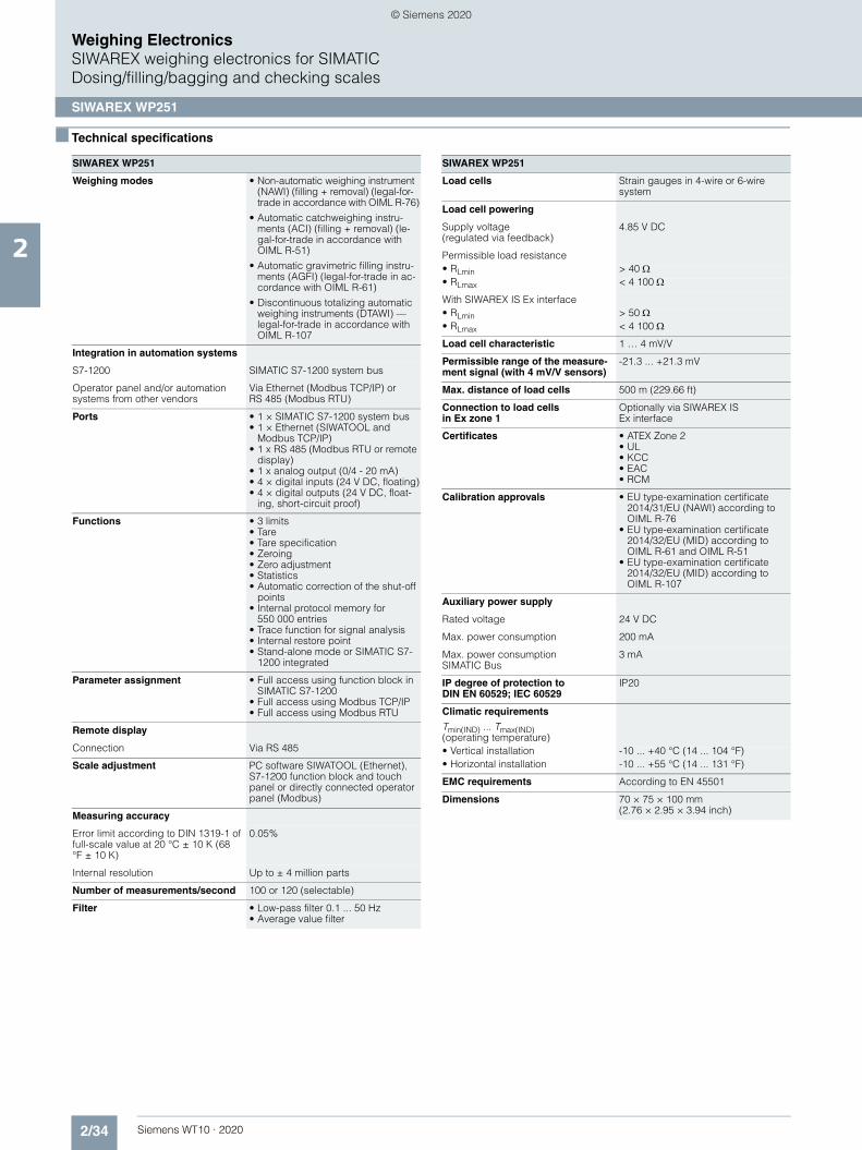
2/34 Siemens WT10 · 2020
2
Weighing ElectronicsSIWAREX weighing electronics for SIMATICDosing/filling/bagging and checking scales
SIWAREX WP251
■ Technical specifications
SIWAREX WP251
Weighing modes • Non-automatic weighing instrument (NAWI) (filling + removal) (legal-for-trade in accordance with OIML R-76)
• Automatic catchweighing instru-ments (ACI) (filling + removal) (le-gal-for-trade in accordance with OIML R-51)
• Automatic gravimetric filling instru-ments (AGFI) (legal-for-trade in ac-cordance with OIML R-61)
• Discontinuous totalizing automatic weighing instruments (DTAWI) — legal-for-trade in accordance with OIML R-107
Integration in automation systems
S7-1200 SIMATIC S7-1200 system bus
Operator panel and/or automation systems from other vendors
Via Ethernet (Modbus TCP/IP) or RS 485 (Modbus RTU)
Ports • 1 × SIMATIC S7-1200 system bus• 1 × Ethernet (SIWATOOL and
Modbus TCP/IP)• 1 x RS 485 (Modbus RTU or remote
display)• 1 x analog output (0/4 - 20 mA)• 4 × digital inputs (24 V DC, floating)• 4 × digital outputs (24 V DC, float-
ing, short-circuit proof)
Functions • 3 limits• Tare• Tare specification• Zeroing• Zero adjustment• Statistics• Automatic correction of the shut-off
points• Internal protocol memory for
550 000 entries• Trace function for signal analysis • Internal restore point• Stand-alone mode or SIMATIC S7-
1200 integrated
Parameter assignment • Full access using function block in SIMATIC S7-1200
• Full access using Modbus TCP/IP• Full access using Modbus RTU
Remote display
Connection Via RS 485
Scale adjustment PC software SIWATOOL (Ethernet), S7-1200 function block and touch panel or directly connected operator panel (Modbus)
Measuring accuracy
Error limit according to DIN 1319-1 of full-scale value at 20 °C ± 10 K (68 °F ± 10 K)
0.05%
Internal resolution Up to ± 4 million parts
Number of measurements/second 100 or 120 (selectable)
Filter • Low-pass filter 0.1 ... 50 Hz• Average value filter
Load cells Strain gauges in 4-wire or 6-wire system
Load cell powering
Supply voltage (regulated via feedback)
4.85 V DC
Permissible load resistance• RLmin > 40 • RLmax < 4 100
With SIWAREX IS Ex interface• RLmin > 50 • RLmax < 4 100
Load cell characteristic 1 … 4 mV/V
Permissible range of the measure-ment signal (with 4 mV/V sensors)
-21.3 ... +21.3 mV
Max. distance of load cells 500 m (229.66 ft)
Connection to load cells in Ex zone 1
Optionally via SIWAREX IS Ex interface
Certificates • ATEX Zone 2• UL• KCC• EAC• RCM
Calibration approvals • EU type-examination certificate 2014/31/EU (NAWI) according to OIML R-76
• EU type-examination certificate 2014/32/EU (MID) according to OIML R-61 and OIML R-51
• EU type-examination certificate 2014/32/EU (MID) according to OIML R-107
Auxiliary power supply
Rated voltage 24 V DC
Max. power consumption 200 mA
Max. power consumption SIMATIC Bus
3 mA
IP degree of protection to DIN EN 60529; IEC 60529
IP20
Climatic requirements
Tmin(IND) ... Tmax(IND) (operating temperature)• Vertical installation -10 ... +40 °C (14 ... 104 °F)• Horizontal installation -10 ... +55 °C (14 ... 131 °F)
EMC requirements According to EN 45501
Dimensions 70 × 75 × 100 mm (2.76 × 2.95 × 3.94 inch)
SIWAREX WP251
© Siemens 2020
z002cfep
Notiz
Completed festgelegt von z002cfep
z002cfep
Notiz
Completed festgelegt von z002cfep
z002cfep
Notiz
None festgelegt von z002cfep
z002cfep
Notiz
None festgelegt von z002cfep
z002cfep
Notiz
Completed festgelegt von z002cfep
z002cfep
Notiz
Completed festgelegt von z002cfep

2/35Siemens WT10 · 2020
2
Weighing ElectronicsSIWAREX weighing electronics for SIMATICDosing/filling/bagging and checking scales
SIWAREX WP251
■ Selection and ordering data Article No. Article No.
SIWAREX WP251 weighing module
Single-channel, legal-for-trade, for automatic dosing and filling scales (AGFI, ACI, NAWI) with analog load cells / full-bridge strain gauges (1 - 4 mV/V), 1 × LC, 4 × DQ, 4 × DI, 1 × AQ, 1 × RS 485, Ethernet port.
7MH4960-6AA01
SIWAREX WP251 Equipment Manual
Available in a range of languages
Free download on the Internet at:
http://www.siemens.com/weighing/documentation
SIWAREX WP251"Ready for use"
Free download on the Internet at:
http://www.siemens.com/weighing/documentation
SIWATOOL V4 & V7 7MH4900-1AK01
Service and commissioning software for SIWAREX weighing modules
Calibration set for SIWAREX WP2xx
7MH4960-0AY10
Valid for SIWAREX WP231 and SIWAREX WP251.
For verification of up to 3 scales, comprising:• 3 × inscription foils for ID label
• 1 × protective film
• 3 × calibration protection plates
• Guidelines for verification, certifi-cates and approvals, editable la-bel, SIWAREX WP
Ethernet cable patch cord 2 m (7 ft)
6XV1850-2GH20
For connecting SIWAREX WP251 to a PC (SIWATOOL), SIMATIC CPU, panel, etc.
Remote display (optional)
The digital remote displays can be connected directly to the SIWAREX WP251 via the RS 485 interface
Suitable remote display: S102
Siebert Industrieelektronik GmbHPO Box 1180D-66565 EppelbornTel.: +49 6806/980-0Fax: +49 6806/980-999
Internet:https://www.siebert-group.com/en/
Detailed information is available from the manufacturer.
Accessories
SIWAREX JB junction box, aluminum housing
7MH5001-0AA20
For connecting up to 4 load cells in parallel, and for connecting multi-ple junction boxes.
SIWAREX JB junction box, stainless steel housing
7MH5001-0AA00
For connecting up to 4 load cells in parallel.
SIWAREX JB junction box, stainless steel housing (ATEX)
7MH5001-0AA01
For parallel connection of up to 4 load cells (for zone allocation, see manual or type-examination certifi-cate).
SIWAREX IS Ex interface
For intrinsically-safe connection of load cells. With ATEX approval (not UL/FM). Suitable for SIWAREX electronic weighing systems. Com-patibility of load cells must be checked separately. • Short-circuit current
< 199 mA DC7MH4710-5BA
• Short-circuit current < 137 mA DC
7MH4710-5CA
Cable (optional)
Cable Li2Y 1 × 2 × 0.75 ST + 2 × (2 × 0.34 ST) – CY
For connecting SIWAREX elec-tronic weighing systems to junc-tion box (JB), extension box (EB) and Ex interface or between two EBs. For permanent installation. Occasional bending is possible.
External diameter: approx. 10.8 mm (0.43 inch)
Permissible ambient temperature -40 ... +80 °C (-40 ... +176 °F)
Sold by the meter.• Sheath color: orange 7MH4702-8AG• For hazardous atmospheres.
Sheath color: blue.7MH4702-8AF
Ground terminal for connecting the load cell cable shield to the grounded DIN rail
6ES5728-8MA11
Commissioning
Commissioning charge for one static scale with SIWAREX module
(Flat charge for travel and setup must be ordered separately)
9LA1110-8SN50-0AA0
Scope:• Recording of data• Checking of mechanical installa-
tion of the scale• Checking of electrical wiring and
function• Static adjustment of the scale
Requirements:• Mechanical design functional• Modules electrically wired and
tested• Calibration weights available• Free access to scale
Flat charge for travel and setup in Germany
9LA1110-8RA10-0AA0
© Siemens 2020

2/36 Siemens WT10 · 2020
2
Weighing ElectronicsSIWAREX weighing electronics for SIMATICDosing/filling/bagging and checking scales
SIWAREX FTA
■ Overview
SIWAREX FTA (Flexible Technology, Automatic Weighing Instrument) is a versatile and flexible weighing module for indus-trial use. It can be used in both non-automatic and automatic weighing operation, for example the production of mixtures, and for filling, loading, monitoring and bag filling.
It has the corresponding scale approvals and is also suitable for weighing systems requiring official calibration.
The SIWAREX FTA function module is integrated in SIMATIC S7/PCS 7 and uses the features of this modern automation system, such as integrated communication, diagnostics and configura-tion tools.
■ Benefits
SIWAREX FTA is characterized by the following features:• Uniform design and totally integrated communication in
SIMATIC S7 and SIMATIC PCS 7• Uniform configuration with SIMATIC• Direct use in the SIMATIC automation system• Use in distributed plant concept through connection to
PROFIBUS DP/PROFINET using ET 200M• Measurement of weight or force with high resolution of
16 million intervals• High accuracy 3 x 6 000d, legal-for-trade according to
OIML R-76, R-51, R-61 and R-107• Use with analog strain gauge load cells of types SIWAREX R
and SIWAREX WL200• Alternative option of connecting individual load cells from the
manufacturers METTLER TOLEDO, Wipotec and PESA• Legal-for-trade display with Windows-based Panels, e.g.
SIMATIC Comfort Panels• Stepless or stepped dosing control • Exact switching of dosing signals (< 1 ms)• Parameterizable inputs and outputs • Parameterizable for highly versatile applications • Flexible adaptation to different requirements with SIMATIC• Simple adjustment of scale using the SIWATOOL FTA program• Theoretical adjustment without calibration weights• Replacement of module without renewed adjustment of scale• Recording of weighing sequence• Alibi memory with calibration capability• Can be used in Ex applications
© Siemens 2020

2/37Siemens WT10 · 2020
2
Weighing ElectronicsSIWAREX weighing electronics for SIMATICDosing/filling/bagging and checking scales
SIWAREX FTA
■ Application
The SIWAREX FTA weighing module is the optimum solution wherever high demands are placed on accuracy and speed.
Thanks to its outstanding measuring properties, weights can be measured with extreme accuracy in up to three ranges.
SIWAREX FTA can be used to design legal-for-trade dosing sys-tems, such as filling plants, loading stations, bagging stations, rotopackers, mixers or test stations.
Typical fields of application include:• Filling of liquids• Bagging of solid matter (also big bag)• Proportioning as deduction weighing or fill weighing• Checking of individual quantities• Loading or receiving of materials• Static checking scale• Check weigher (in combination with Wipotec load cells)
■ Design
SIWAREX FTA is a function module of SIMATIC S7-300 which can be directly snapped onto the SIMATIC S7-300 or ET 200M backplane bus. The rail mounting of the 80 mm wide weighing module means that it is extremely easy to mount/wire.
The load cells, the RS 485 serial interface, the analog output and the digital inputs and outputs are connected by means of the 40-pin standard front connector, the PC (RS 232) by means of a 9-pin SUB-D connector and the power supply by means of a separate 2-pin connector.
Operation of SIWAREX FTA in SIMATIC enables the weighing system to be completely integrated into the automation system.
■ Function
The main tasks of the SIWAREX FTA are the high-precision mea-surement of the current weight in up to three measuring ranges, and exact control of the weighing procedures.
The weighing module controls the weighing procedures fully au-tomatically. However, integration in SIMATIC means that it is also possible to directly influence the weighing procedures using a PLC program. This means that the tasks can be sensibly di-vided: The very fast weighing functions are implemented in the SIWAREX FTA, the interlocking and logic functions in the SI-MATIC CPU.
Weighing functions
The SIWAREX FTA is easy to parameterize for the various automatic weighing functions.
The following legal-for-trade weighing functions can be parame-terized:• NAWI (non-automatic weighing instrument) according to
OIML R-76• AGFI (automaticgravimetric filling instrument) according to
OIML R-61• ACI (automaticcatchweighing instrument) according to
OIML R-51• DTAWI (discontinuous totalizing automatic weighing
instrument (Totalizing Hopper Weigher)) according to OIML R-107
Monitoring and control of the load cell signals and statuses
During the weighing procedure, the SIWAREX FTA weighing module monitors and controls the load cell signals and statuses. The optimized exchange of data within SIMATIC permits direct evaluation of the load cell signals and statuses in the PLC pro-gram.
The SIWAREX FTA can easily be adapted to changes in the sys-tem technology thanks to the PLC's influence on the weighing process.
The SIWAREX FTA is already factory-calibrated. This means that the theoretical adjustment of the scale is possible without cali-bration weights, and that modules can be replaced without read-justment of the scale. When using "active bus modules", replace-ment is also possible during operation.
Integration in SIMATIC
SIWAREX FTA is completely integrated into the SIMATIC S7 and SIMATIC PCS 7. Users can freely configure their automation solution – including the weighing application.
The right combination of SIMATIC components can produce op-timum solutions for small, medium-size and large plants. The scales are operated and monitored using SIMATIC standard op-erator panels. Needless to say, these operator panels can also be simultaneously used for the operator control and monitoring of the plant.
Customized or sector-specific solutions can be developed ex-tremely quickly using the configuration package and example applications for SIMATIC. The following Figure shows a typical configuration of a medium-size plant.
The ready-to-use function blocks for the automation system and the faceplates for the operator station are used for the configu-ration in SIMATIC PCS 7.
SIMATIC S7/PCS 7 configuration with SIWAREX FTA
SIWAREX in ET 200M
SIWAREX in SIMATIC S7-300
SIWAREX in ET 200M
Operator Station
Engineering Station
SIMATIC S7/SIMATIC PCS 7 SIWAREX FTA
Industrial Ethernet
SIMATIC S7-400
PROFIBUS DP
SIMATIC S7-400
© Siemens 2020

2/38 Siemens WT10 · 2020
■ Function (continued)
2
Weighing ElectronicsSIWAREX weighing electronics for SIMATICDosing/filling/bagging and checking scales
SIWAREX FTA
Software
SIWATOOL FTA commissioning software
SIWATOOL FTA is a special program for commissioning and servicing and runs with Windows operating systems.
The program enables the scales to be set without the need for prior knowledge of the automation system. During servicing, the technician can use a PC to analyze and test the procedures in the scale. Reading out the diagnostics buffer from the SIWAREX FTA is extremely helpful when analyzing events.
The following are just some of the tasks that can be carried out using SIWATOOL FTA:• Parameter assignment and calibration of the scale• Testing of scale properties• Saving and printing scale data• Recording and analysis of weighing sequence
Settings in SIWAREX FTA software
It is extremely helpful to analyze the diagnostics buffer, which can be saved together with the parameters from the module in a backup file.
The SIWAREX FTA weighing module includes a trace mode for optimization of weighing sequences. The recorded weight val-ues and associated statuses can be displayed as traces using SIWATOOL FTA and MS Excel.
Upgrading firmware
A further program function can be used to download a new firm-ware version onto the SIWAREX FTA on site. This means that firmware upgrades can be carried out on site as required any-where in the world.
Reading out of weighing reports
The weighing reports are saved on an MMC (Micro Memory Card) inserted in the SIWAREX FTA for the duration specified by the Weights and Measures Act. If complaints are received con-cerning a particular weighing procedure, the associated data can be read out of the MMC using SIWATOOL.
SIWAREX FTA – simple configuration
Integration in SIMATIC results in freely-programmable, modular weighing systems which can be modified according to opera-tional requirements.
The ready-to-use SIWAREX FTA software "Getting Started" is also available free-of-charge. It shows beginners how to inte-grate the module into a STEP 7 program and offers a basis for application programming. This allows you to connect the scale very easily to an operator panel connected directly to the SI-MATIC CPU.
Configuring the legal trade display on the panel
The software SecureOCX is available in systems running WinCC flexible. It provides a function for configuration of the legal trade display directly in WinCC flexible. In the TIA Portal, the Secure-Display software is used. This is installed directly on a Windows CE-based panel (for example, SIMATIC Comfort Touch series). There is a separate "Getting Started" for using this soft-ware in the TIA Portal. This solution requires a SIMATIC CPU with an Ethernet port. SIMATIC Basic and Key Panels cannot be used.
Scale faceplate in the SIWAREX FTA "Getting Started" software
In addition, the STEP 7 program SIWAREX FTA Multiscale pro-vides a professional basis for the implementation of batching or filling plants.
© Siemens 2020

2/39Siemens WT10 · 2020
2
Weighing ElectronicsSIWAREX weighing electronics for SIMATICDosing/filling/bagging and checking scales
SIWAREX FTA
■ Technical specifications
1) For further details, see Ex interface, type SIWAREX IS
SIWAREX FTA
Use in automation systems
S7-300 Directly or via ET 200M
S7-1500 Through ET 200M
S7-400 (H) Through ET 200M
PCS 7 (H) Through ET 200M
Communication interfaces
S7 Through backplane bus
RS 232 For SIWATOOL or printer connection
RS 485 For remote display or digital load cell
Module parameterization Using SIMATIC S7
Using SIWATOOL FTA software (RS 232)
Measuring properties
EU type approval as non-automatic weighing instrument, trade class III
3 x 6 000 d 0.5 V/e
Internal resolution 16 million parts
Internal/external updating rate 400/100 Hz
Several parameterizable digital filters
Critically dampened, Bessel, Butter-worth (0.05 ... 20 Hz), mean-value filter
Weighing functions
Non-automatic weighing machine OIML R-76
Automatic weighing machine OIML R-51, R-61, R-107
Load cells Strain gages in 4-wire or 6-wire system
3 characteristic value ranges 1, 2 or 4 mV/V
Load cell powering
Supply voltage US (rated value) 10.3 V DC
Max. supply current 184 mA
Permissible load cell resistance• RLmin > 56
> 87 with Ex interface• RLmax 4 010
Max. distance of load cells
When using the recommended cable:
Standard 1 000 m (3 280 ft)
In hazardous area 1)
• For gases of group IIC 300 m (984 ft)• For gases of group IIB 1000 m (3 280 ft)
Connection to load cells in Ex zone 1
Optionally via SIWAREX IS Ex interface
Ex approvals zone 2 and safety ATEX 95, FM, cULUS Haz. Loc.
Auxiliary power supply
Rated voltage 24 V DC
Max. power consumption 500 mA
Current consumption on backplane bus
Typ. 55 mA
Inputs/outputs
Digital inputs 7 DI electrically isolated
Digital outputs 8 DO electrically isolated
Counter input Up to 10 kHz
Analog output• Current range 0/4 ... 20 mA• Updating rate 100 Hz
Approvals EU type approval (CE, OIML R-76)
EU prototype test according to MID (OIML R-51, R-61, R-107)
Degree of protection according to EN 60529; IEC 60529
IP20
Climatic requirements
Tmin (IND) ... Tmax (IND) (operating temperature)• Horizontal installation -10 ... 60 °C (14 ... 140 °F)• Vertical installation -10 ... 40 °C (14 ... 104 °F)
EMC requirements EN 61326, EN 45501, NAMUR NE21, Part 1
Dimensions 80 × 125 × 130 mm (3.15 × 4.92 × 5.12 inch)
Weight 600 g (0.44 lb)
SIWAREX FTA
© Siemens 2020

2/40 Siemens WT10 · 2020
2
Weighing ElectronicsSIWAREX weighing electronics for SIMATICDosing/filling/bagging and checking scales
SIWAREX FTA
■ Selection and ordering data Article No. Article No.
SIWAREX FTA Legal-for-trade weighing electron-ics for automatic scales for S7-300 and ET 200M.EU type approval 3 x 6000 d Applications: proportioning, filling, bagging, loading.Note: Observe approval conditions for applications requiring official calibration. We recommend using our calibration set and contacting our SIWAREX hotline.
7MH4900-2AA01
SIWAREX FTA Equipment Manual
Available in a range of languages
Free download on the Internet at:
http://www.siemens.com/weighing/documentation
SIWAREX FTA "Getting Started"
Sample software shows beginners how to program the scales in STEP 7.
Free download on the Internet at:
http://www.siemens.com/weighing/documentation
SIWATOOL V4 & V7
Service and commissioning soft-ware for SIWAREX weighing mod-ules
7MH4900-1AK01
Configuration package SIWAREX FTA for SIMATIC PCS 7, Version 8.0 on CD-ROM• HSP hardware support package
for integrating SIWAREX FTA/FTC in STEP 7
• Function block for CFC• Faceplate• Manual
7MH4900-2AK63
SIWAREX PCS 7 AddOn Library for PCS 7 V8.x and V9.0• Supports PROFINET
APL faceplates and function blocks for: • SIWAREX U• SIWAREX FTA• SIWAREX FTC_B (belt scale)• SIWAREX WP321
Classic faceplate and function block for:• SIWAREX FTC_L (Loss-in-weight)
7MH4900-1AK61
Calibration set for SIWAREX FTA
For verification of up to 5 scales comprising:• 3 × inscription foils for ID label• 1 × protective film• Guidelines for verification, verifi-
cation certificates and approvals, editable label, SIWAREX FTA Equipment Manual on CD-ROM
7MH4900-2AY10
SIWATOOL connection cable
From SIWAREX FTA with serial PC interface, for 9-pin PC interfaces (RS 232)• 2 m long (6.56 ft) 7MH4702-8CA• 5 m long (16.40 ft) 7MH4702-8CB
Front connector, 40-pinRequired for each SIWAREX module • With screw contacts 6ES7392-1AM00-0AA0• With spring-loaded terminals 6ES7392-1BM01-0AA0
Shield connection element
Sufficient for one SIWAREX FTA module
6ES7390-5AA00-0AA0
Shield connection clamp
Contents: 2 units (suitable for cable with diameter 4 ... 13 mm / 0.16 ... 0.51 inch)
Note:
One shield connection clamp is required for each of the following:• Scale connection• RS 485 interface• RS 232 interface
6ES7390-5CA00-0AA0
S7 DIN rail• 160 mm (6.30 inch) 6ES7390-1AB60-0AA0• 480 mm (18.90 inch) 6ES7390-1AE80-0AA0• 530 mm (20.87 inch) 6ES7390-1AF30-0AA0• 830 mm (32.68 inch) 6ES7390-1AJ30-0AA0• 2 000 mm (78.74 inch) 6ES7390-1BC00-0AA0
MMC memoryFor data recording up to 32 MB, only for legal-for-trade applications R76, R51 and R107
7MH4900-2AY21
Remote displays (option)
The Siebert S102 and S302 remote digital displays can be directly con-nected to the SIWAREX FTA via an RS 485 interface.
Siebert Industrieelektronik GmbHPO Box 1180D-66565 EppelbornTel.: +49 6806/980-0Fax: +49 6806/980-999
Internet: https://www.siebert-group.com/en/
Detailed information is available from the manufacturer.
SIWAREX JB junction box, aluminum housing
For connecting up to 4 load cells in parallel, and for connecting several junction boxes
7MH5001-0AA20
SIWAREX JB junction box, stainless steel housing
For connecting up to 4 load cells in parallel.
7MH5001-0AA00
SIWAREX JB junction box, stainless steel housing (ATEX)
For parallel connection of up to 4 load cells (for zone allocation, see manual or type-examination certifi-cate).
7MH5001-0AA01
Ex interface SIWAREX IS
For intrinsically-safe connection of load cells. With ATEX approval (not UL/FM). Suitable for SIWAREX elec-tronic weighing systems. Compati-bility of load cells must be checked separately.• With short-circuit current
< 199 mA DC7MH4710-5BA
• With short-circuit current < 137 mA DC
7MH4710-5CA
© Siemens 2020

2/41Siemens WT10 · 2020
■ Selection and ordering data Article No.
2
Weighing ElectronicsSIWAREX weighing electronics for SIMATICDosing/filling/bagging and checking scales
SIWAREX FTA
Cable (optional)
Cable Li2Y 1 x 2 x 0.75 ST + 2 x (2 x 0.34 ST) – CY
For connecting SIWAREX electronic weighing systems to junction box (JB), extension box (EB) and Ex interface or between two EBs. For permanent installation. Occasional bending is possible.
External diameter: approx. 10.8 mm (0.43 inch)
Permissible ambient temperature-40 ... +80 °C (-40 ... +176 °F)
Sold by the meter.• Sheath color: orange 7MH4702-8AG• For hazardous atmospheres.
Sheath color: blue.7MH4702-8AF
Commissioning
Commissioning charge for one static scale with SIWAREX module
(Flat charge for travel and setup must be ordered separately)
9LA1110-8SN50-0AA0
Scope:• Recording of data• Checking of mechanical installa-
tion of the scale• Checking of electrical wiring and
function• Static adjustment of the scale
Requirements:• Mechanical design functional• Modules electrically wired and
tested• Calibration weights available• Free access to scale
Flat charge for travel and setup in Germany
9LA1110-8RA10-0AA0
© Siemens 2020

2/42 Siemens WT10 · 2020
2
Weighing ElectronicsSIWAREX weighing electronics for SIMATICBelt scales
Introduction
■ Overview
Belt scales
The gravel, cement, coal, recycling and mining industries re-quire exact weight measurement of the material to be conveyed using belt scales. The comprehensive SIWAREX electronics properties and functions can fulfil all requirements.
The Milltronics belt scales from Siemens combine simple instal-lation and low maintenance costs (no moving parts) with higher reproducibility. This results in high productivity. With minimum hysteresis and maximum linearity, lateral forces have no influ-ence on measuring accuracy. All load cells are equipped with overload protection.
The installation of belt scales in danger zones is also available as option. Various versions are available for high accuracy, small loads and heavy loads.
© Siemens 2020

2/43Siemens WT10 · 2020
2
Weighing ElectronicsSIWAREX weighing electronics for SIMATIC
Belt scales
SIWAREX WP241
■ Overview
SIWAREX WP241 is a flexible weighing module for belt scales. The compact module is easy to install in the SIMATIC S7-1200 automation system. It can also be operated as a stand-alone module, i.e. without a SIMATIC CPU.
■ Benefits
SIWAREX WP241 offers the following key advantages:• Uniform design technology and consistent communication in
SIMATIC S7-1200• Uniform configuration with TIA Portal • Operation without SIMATIC CPU possible• Direct connection of an operator panel via Ethernet• Four digital inputs and outputs, one analog output• Measurement of weight with a high resolution of ± 4 million
parts• Simple adjustment of belt scales using the SIWATOOL V7
program via the Ethernet interface - even without knowledge of SIMATIC
• Replacement of module possible without renewed calibration of the scale
• Use in hazardous area zone 2• Different calibration methods: With test weights, test chain,
automatically or via material batch.• Specification of belt inclination angle• 6 totalization memories• Simulation of speed and belt load for test purposes• Comprehensive diagnostics functions
■ Application
SIWAREX WP241 is the optimal solution wherever belt scales are used that demand high accuracy, high user-friendliness, and flexible system integration. The typical applications of the SIWAREX WP241 are determining the current material flow rate, belt load, and belt speed. Furthermore, 6 totalizers are available for evaluating the amount of material conveyed.
■ Design
SIWAREX WP241 is a compact technology module in the SIMATIC S7-1200, and it allows direct connection to S7-1200 components via a sliding connector. The rail mounting of the 70 mm (2.76 inch) wide weighing module means that it is ex-tremely easy to mount/wire.
The power supply, load cells, RS 485 interface, digital input/out-puts and the analog output are connected via the screw plug of the weighing module. An RJ45 plug is used for the Ethernet con-nection.
■ Function
The primary task of the SIWAREX WP241 is to measure the speed of the belt, to measure and convert the sensor voltage to a weight value, and to precisely calculate the amount of material conveyed or material flow rate. The volume of material conveyed can be recorded in 6 totaliza-tion memories: The accumulated totalization memory deter-mines the conveyed material over the entire operating time of the scale (can only be reset by loading the factory settings). The overall total and the four remaining totalization memories are available for use as required. For example, for recording the daily or weekly totals.
Four different options are available for rapid commissioning:• Automatic calibration
The calibration is calculated automatically using the load cell parameters entered. Only the zero point has to be calculated at the actual plant.
• Calibration with calibration weights or test weightsTest weights are secured to the weighing equipment and the conveyor belt is started. The calibration values are deter-mined while the belt is running. The zero point must also be calculated.
• Calibration with test chainInstead of test weights, a chain of a known weight can be placed on the measuring points of the belt. The calibration values are calculated as for calibration with test weights.
• Calibration via material batchThis method can be used if a volume of material is available, but neither test weights nor a chain are available. The material can either be preweighed or weighed afterwards. It is conveyed over the belt scale. Then the weighing module calculates the calibration characteristic automatically.
If "Automatic set to zero" is active, the electronic weighing sys-tem automatically executes a "set to zero" procedure when the belt reaches the "set to zero" area.
© Siemens 2020

2/44 Siemens WT10 · 2020
■ Function (continued)
2
Weighing ElectronicsSIWAREX weighing electronics for SIMATICBelt scales
SIWAREX WP241
Extensive diagnostics functions are available. Diagnostic messages are output to the different interfaces. In simulation mode, both the speed and the belt load can be specified by the user. This makes it possible to test many functions in advance without operating belt scales. Both the digital inputs/outputs and the analog output can also be simulated for test purposes. The "Trace" function is extremely helpful for optimizing the plant or when troubleshooting. It records the weighing history stored in the internal module memory (e.g. material flow rate, belt load, speed) and exports it to Excel in a graphical format.
Monitoring the scale signals and states
The SIWAREX WP241 monitors the belt load, the material flow rate, and the belt speed, and it signals if the limits are exceeded. The respective limits can be parameterized as required.
Consistent and uniform communication between all system components enables fast, reliable and cost-effective integration and diagnosis in industrial processes.
Integration in the plant environment
SIWAREX WP241 can be directly integrated into the SIMATIC S7-1200 via the SIMATIC bus. Standalone operation without SIMATIC is also possible.
A wide variety of connection options are provided via the RS 485 and Ethernet interface. Via Modbus TCP/IP or Modbus RTU, control panels can be connected and it is also possible to com-municate with various automation systems. A PC for program-ming the SIWAREX WP241 via SIWATOOL can be connected to the Ethernet interface.
SIWAREX WP241 can be integrated into the system software us-ing all standard PLC programming languages from the TIA Por-tal. In contrast to serially linked electronic weighing systems, SIWAREX WP241 does not need costly additional modules to link it to SIMATIC.
Used in conjunction with SIWAREX WP241, it is possible to con-figure freely programmable, modular weighing systems in SI-MATIC, which can be adapted to company-specific require-ments as needed.
SIWAREX WP241 "Ready for use"
In addition to the configuration package, fully-featured SIWAREX WP241 "Ready for use" software is also available free-of-charge. It shows beginners how to integrate the module in a STEP 7 program and offers a basis for application programming. This allows you to connect the scale to an operator panel either connected to the SIMATIC CPU or connected directly to the SIWAREX WP241.
Software
There is also the option of using a Windows PC for commission-ing and servicing. The program SIWATOOL enables the belt scales to be set without prior knowledge of the automation sys-tem, as required. During servicing, the technician can use a PC to quickly and simply analyze and test the procedures in the scale.
The following are just some of the tasks that can be carried out using SIWATOOL V7:• Parameterization and calibration of the scale• Testing/Simulation of scale properties• Recording, analysis and export of scale traces ("Trace")• Creation of backup files for rapidly replacing modules without
calibration
SIWAREX WP241 SIWATOOL
It is also extremely helpful to analyze the diagnostics buffer which can be saved together with the parameters following reading out from the module.
The SIWAREX WP241 weighing module includes a trace mode for optimization of weighing sequences. The recorded weight values and associated states can be displayed as trends using SIWATOOL V7 and MS Excel.
Upgrading firmware
An additional program function can be used to download a new firmware version onto the SIWAREX WP241 on site. This means that firmware upgrades can be carried out on site as required anywhere in the world.
© Siemens 2020

2/45Siemens WT10 · 2020
2
Weighing ElectronicsSIWAREX weighing electronics for SIMATIC
Belt scales
SIWAREX WP241
■ Technical specifications
SIWAREX WP241
Integration in automation systems
S7-1200 SIMATIC S7-1200 system bus
Operator panel and/or automation systems from other vendors
Via Ethernet (Modbus TCP/IP) or RS 485 (Modbus RTU)
Communication interfaces • SIMATIC S7-1200 backplane bus• RS 485 (Modbus RTU)• Ethernet (SIWATOOL V7,
Modbus TCP/IP)• Analog output 0/4 - 20 mA• 4 × digital outputs, 24 V DC,
floating, short-circuit proof• 4 × digital inputs 24 V DC, floating
Commissioning options • Using SIWATOOL V7• Using function block in
SIMATIC S7-1200 CPU / Touch Panel
• Using Modbus TCP/IP• Using Modbus RTU
Measuring accuracy
Error limit according to DIN 1319-1 of full-scale value at 20 °C ± 10 K (68 °F ± 10 K)
0.05%
Internal resolution Up to ± 4 million parts
Measuring frequency 100 / 120 Hz
Digital filter Separate, variable adjustable low-pass and average filter for load-ing and speed
Filter for conveyor load Low-pass filter (limit frequency 0.05 ... 50 Hz)
Filter for belt speed Low-pass filter (limit frequency 0.05 ... 50 Hz)
Weighing functions
Readout data • Weight• Belt load• Material flow rate• Accumulated total• Main total• Free totals 1 … 4• Belt speed
Limits (min/max) • Belt load• Material flow rate• Belt speed
Load cells Full-bridge strain gauges in 4-wire or 6-wire system
Load cell powering
Supply voltage (regulated via feedback)
4.85 V DC
Permissible load resistance• RLmin > 40 • RLmax < 4 100
With SIWAREX IS Ex interface• RLmin > 50 • RLmax < 4 100
Load cell characteristic 1 … 4 mV/V
Permissible measurement signal range
-21.3 ... +21.3 mV
Max. distance of load cells 500 m (229.66 ft)
Connection to load cells in Ex zone 1
Optionally via SIWAREX IS Ex inter-face (compatibility of the load cells must be checked)
Approvals/certificates • ATEX Zone 2• UL• EAC• KCC• RCM
Auxiliary power supply
Rated voltage 24 V DC
Max. power consumption 200 mA
Max. power consumption SIMATIC Bus
3 mA
IP degree of protection to DIN EN 60529; IEC 60529
IP20
Climatic requirements
Tmin(IND) ... Tmax(IND) (operating temperature)• Vertical installation -10 ... +40 °C (14 ... 104 °F)• Horizontal installation -10 ... +55 °C (14 ... 131 °F)
EMC requirements According to EN 45501
Dimensions 70 × 75 × 100 mm (2.76 × 2.95 × 3.94 inch)
SIWAREX WP241
© Siemens 2020

2/46 Siemens WT10 · 2020
2
Weighing ElectronicsSIWAREX weighing electronics for SIMATICBelt scales
SIWAREX WP241
■ Selection and ordering data Article No. Article No.
SIWAREX WP241 weighing module
Single-channel, legal-for-trade, for automatic proportioning and filling scales (GFI, CWI, NAWI) with ana-log load cells / full-bridge strain gauge (1 - 4 mV/V), 1 × LC, 4 × DQ, 4 × DI, 1 × AQ, 1 × RS 485, Ethernet port.
7MH4960-4AA01
SIWAREX S7-1200 Equipment Manual
Available in a range of languages
Free download on the Internet at:
http://www.siemens.com/weighing/documentation
SIWAREX WP241"Ready for use"
Complete software package for belt scale (for S7-1200 and a directly connected operator panel)
Free download on the Internet at:
http://www.siemens.com/weighing/documentation
SIWATOOL V4 & V7 7MH4900-1AK01
Service and commissioning software for SIWAREX weighing modules
Ethernet cable patch cord 2 m (7 ft)
6XV1850-2GH20
For connecting SIWAREX WP241 to a PC (SIWATOOL), SIMATIC CPU, panel, etc.
Accessories
SIWAREX JB junction box, aluminum housing
7MH5001-0AA20
For connecting up to 4 load cells in parallel, and for connecting multi-ple junction boxes.
SIWAREX JB junction box, stainless steel housing
7MH5001-0AA00
For connecting up to 4 load cells in parallel.
SIWAREX JB junction box, stainless steel housing (ATEX)
7MH5001-0AA01
For parallel connection of up to 4 load cells (for zone allocation, see manual or type-examination certifi-cate).
SIWAREX IS Ex interface
For intrinsically-safe connection of load cells. With ATEX approval (not UL/FM). Suitable for SIWAREX electronic weighing systems. Com-patibility of load cells must be checked separately.• Short-circuit current
< 199 mA DC7MH4710-5BA
• Short-circuit current < 137 mA DC
7MH4710-5CA
Cable (optional)
Cable Li2Y 1 × 2 × 0.75 ST + 2 × (2 × 0.34 ST) – CY
For connecting SIWAREX elec-tronic weighing systems to junc-tion box (JB), extension box (EB) and Ex interface or between two EBs. For permanent installation. Occasional bending is possible.
External diameter: approx. 10.8 mm (0.43 inch)
Permissible ambient temperature -40 ... +80 °C (-40 ... +176 °F)
Sold by the meter.• Sheath color: orange 7MH4702-8AG• For hazardous atmospheres.
Sheath color: blue.7MH4702-8AF
Ground terminal for connecting the load cell cable shield to the grounded DIN rail
6ES5728-8MA11
Commissioning
Commissioning charge for one belt scale with SIWAREX module
(Flat charge for travel and setup must be ordered separately)
9LA1110-8SM50-0AA0
Scope:• Recording of data• Checking of mechanical installa-
tion of the scale• Checking of electrical wiring and
function• Dynamic adjustment of the scale
Requirements:• Mechanical design functional• Modules electrically wired and
tested• Calibration weights available• Free access to scale
Flat charge for travel and setup in Germany
9LA1110-8RA10-0AA0
© Siemens 2020

2/47Siemens WT10 · 2020
2
Weighing ElectronicsSIWAREX weighing electronics for SIMATIC
Belt scales
SIWAREX FTC
■ Overview
The SIWAREX FTC (Flexible Technology for Continuous Weighing) is a versatile and flexible weighing module for belt scales, loss-in-weight feeders and solids flowmeters. It can also be used to record weights and measure force. The SIWAREX FTC function module is integrated in SIMATIC S7/PCS 7 and uses the features of this modern automation system, such as integrated communication, diagnostics and configu-ration tools.
■ Benefits
SIWAREX FTC is characterized by the following features: • Uniform design and totally integrated communication in
SIMATIC S7 and SIMATIC PCS 7• Uniform configuration with SIMATIC• Direct use in the SIMATIC automation system• Use in distributed plant concept through connection to
PROFIBUS DP/PROFINET using ET 200M• Measurement of weight or force with high resolution of
16 million intervals • High accuracy 3 x 6 000 d• Use with analog strain gauge load cells of types SIWAREX R
and SIWAREX WL200• Alternative option of connecting individual load cells from the
manufacturers METTLER TOLEDO, WIPOTEC and PESA• Display with SIMATIC standard operator panels• Parameterizable inputs and outputs • Parameterizable for highly versatile applications• Flexible adaptation to different requirements with SIMATIC• Simple adjustment of scale using the SIWATOOL FTC
program• Theoretical adjustment without calibration weights• Replacement of module without renewed adjustment of scale• Recording of weighing sequence• 8 totalization memories with different digit intervals• Can be used in Ex applications
■ Application
The SIWAREX FTC weighing module is the optimum solution wherever high demands are placed on continuous weighing pro-cedures. Thanks to its outstanding measuring properties, weights can be measured with extreme accuracy in up to three ranges. In the case of force measurements, the value can be measured bidirectionally.
Typical applications for SIWAREX FTC include:• Flowrate/flow measurement• Belt volume measurement• Material loading, summation• Flowrate/flow control• Belt load measurement• Belt scale / weighfeeder• Loss-in-weight scale• Force measurement
■ Design
SIWAREX FTC is a function module of SIMATIC S7-300 which can be directly snapped onto the SIMATIC S7-300 or ET 200M backplane bus. The rail mounting of the 80 mm wide weighing module means that it is extremely easy to mount/wire.
The load cells, the RS 485 serial interface, the analog output and the digital inputs and outputs are connected by means of the 40-pin standard front connector, the PC (RS 232) by means of a 9-pin SUB-D connector and the power supply by means of a separate 2-pin connector.
Operation of SIWAREX FTC in SIMATIC enables the belt scale to be completely integrated into the automation system.
■ Function
The main tasks of SIWAREX FTC are the high-precision mea-surement of the current weight, and the exact calculation of the conveyed quantity or flow. In "Force measurement" mode, SIWAREX FTC measures the force in both directions.
The conveyed quantity can be recorded in 8 totalization memo-ries. Through integration in SIMATIC it is also possible to directly control scale operation by means of a PLC program. This means that the tasks can be sensibly divided: The weighing functions are implemented in the SIWAREX FTC and the interlocking and logic functions for the plant control in the SIMATIC CPU.
Weighing functions
The following operating modes can be set:
Weight measurement and force measurement
In this operating mode, the weight value or the force is deter-mined, processed in the PLC and then displayed. For this purpose, the configuration package can be selected.
Belt scale / weighfeeder
The functions of a belt scale are implemented in this operating mode. Calculations are performed for the typical process values; belt load, flowrate and belt speed. Commands can be used to control the belt and display the required values. A weighfeeder can be implemented by activating the SIMATIC PID controller.
© Siemens 2020

2/48 Siemens WT10 · 2020
■ Function (continued)
2
Weighing ElectronicsSIWAREX weighing electronics for SIMATICBelt scales
SIWAREX FTC
Scale faceplate of a belt scale
Loss-in-weight scale
The typical functions of a loss-in-weight scale are implemented in this operating mode. The actual weight of the container is measured and the flowrate is regulated according to the preset setpoint.
Application-specific parameters, such as proportioning param-eters, device and material characteristics, can be set directly in SIWAREX FTC. Various commands are available that have been fine-tuned to the requirements of the loss-in-weight scales, such as proportioning (manual, automatic, gravimetric, volumetric), filling and emptying.
The high measurement resolution, real-time signal processing, detection and filtering of signals in the weighing electronics en-able extremely high proportioning accuracy.
Scale faceplate of a loss-in-weight scale
Solids flowmeter
The functions of a solids flowmeter are implemented in this op-erating mode. The calculations for the typical process values; flow and conveyed quantity, are performed in the SIWAREX module. Application-specific parameters for setting the scales and commands for their operation are also available.
View of a solids flowmeter
Monitoring and control of the load cell signals and statuses
The SIWAREX FTC weighing module monitors the statuses during the weighing process, and informs the operator of any ir-regularities. The optimized exchange of data within SIMATIC permits direct evaluation of the load cell signals in the PLC pro-gram.
Influencing of the weighing sequences by the PLC means that the SIWAREX FTC can be easily adapted to any modifications in system technology.
A module can be replaced without recalibrating the scales. When using "active bus modules", replacement is also possible during operation.
Applications of SIWAREX FTC
Integration in SIMATIC
SIWAREX FTC is completely integrated into the SIMATIC S7 and SIMATIC PCS 7. Users can freely configure their automation solution – including the weighing application.
The right combination of SIMATIC components can produce op-timum solutions for small, medium-size and large plants. The scales are operated and monitored using SIMATIC standard op-erator panels. Needless to say, these operator panels can also be simultaneously used for the operator control and monitoring of the plant.
© Siemens 2020
z002cfep
Notiz
Completed festgelegt von z002cfep
z002cfep
Notiz
None festgelegt von z002cfep
z002cfep
Notiz
Completed festgelegt von z002cfep

2/49Siemens WT10 · 2020
■ Function Article No.
2
Weighing ElectronicsSIWAREX weighing electronics for SIMATIC
Belt scales
SIWAREX FTC
Customized or sector-specific solutions can be developed ex-tremely quickly using the configuration package and example applications for SIMATIC.
SIMATIC S7/PCS 7 configuration with SIWAREX FTC (medium-sized plants)
Software
Adjustment of the scale using SIWATOOL FTC
SIWATOOL FTC is a special program for adjusting and servicing the scale and runs with Windows operating systems.
The program enables the scales to be commissioned without the need for prior knowledge of the automation system. During ser-vicing, the technician can use a PC to analyze and test the pro-cedures in the scale. Reading out the diagnostics buffer from the SIWAREX FTC is extremely helpful when analyzing events.
The following are just some of the tasks that can be carried out using SIWATOOL FTC:• Parameter assignment and calibration of the scale • Testing of scale properties • Saving and printing scale data • Recording and analysis of weighing sequence
Settings in SIWAREX FTC software
It is also extremely helpful to analyze the diagnostics buffer which can be saved together with the parameters following reading out from the module.
The SIWAREX FTC weighing module includes a trace mode for checking of weighing sequences. The recorded weight values and associated statuses can be displayed as traces using SI-WATOOL FTC and MS Excel.
Upgrading firmware
A further program function can be used to download a new firm-ware version onto the SIWAREX FTC on site. This means that firmware upgrades can be carried out on site as required any-where in the world.
Reading out of weighing reports
The totalization memories can be saved on a MMC (Micro Mem-ory Card) inserted into the SIWAREX FTC.
SIWAREX FTC – simple configuring
Integration in SIMATIC means that freely-programmable, modu-lar weighing systems for belt scales, solids flowmeters and loss-in-weight scales can be created and modified to meet individual operational requirements.
A free version of the ready-to-use SIWAREX FTC "Getting Started" software is also available for the belt scale, solids flow-meter and loss-in-weight scale modes. It shows beginners how to integrate the module into the STEP 7 program and provides a basis for application programming. This allows you to implement the belt scale very easily with an operator panel connected di-rectly to the SIMATIC CPU.
Scale faceplate in the SIWAREX FTC "Getting Started" software
SIWAREX in ET 200M
SIWAREX in SIMATIC S7-300
SIWAREX in ET 200M
Operator Station
Engineering Station
SIMATIC S7/SIMATIC PCS 7 SIWAREX FTC
Industrial Ethernet
SIMATIC S7-400
PROFIBUS DP
SIMATIC S7-400
© Siemens 2020

2/50 Siemens WT10 · 2020
2
Weighing ElectronicsSIWAREX weighing electronics for SIMATICBelt scales
SIWAREX FTC
■ Technical specifications
1) For further details, see Ex interface, type SIWAREX IS
SIWAREX FTC
Use in automation systems
S7-300 Directly or via ET 200M
S7-1500 Through ET 200M
S7-400 (H) Through ET 200M
PCS 7 (H) Through ET 200M
Communication interfaces
S7 Through backplane bus
RS 232 For SIWATOOL or printer connection
RS 485 For remote display or digital load cell
Module parameterization
Using SIMATIC S7
Using SIWATOOL FTC software (RS 232)
Measuring properties
Accuracy according to EN 45501 3 x 6 000 d 0.5 V/e
Internal resolution +/- 8 million parts
Internal/external updating rate 400/100 Hz
Several parameterizable digital fil-ters
Critically dampened, Bessel, Butter-worth (0.05 ... 20 Hz), mean-value fil-ter
Weighing functions • Non-automatic weighing machine, force measurement
• Belt scale
• Loss-in-weight scale
• Solids flowmeter
Load cells Strain gages in 4-wire or 6-wire sys-tem
3 characteristic value ranges 1, 2 or 4 mV/V
Load cell powering
Supply voltage US (rated value) 10.3 V DC
Max. supply current 184 mA
Permissible load cell resistance• RLmin > 56
> 87 with Ex interface• RLmax 4 010
Max. distance of load cells
When using the recommended cable:
Standard 1 000 m (3 280 ft)
In hazardous area 1)
• For gases of group IIC 300 m (984 ft)• For gases of group IIB 1 000 m (3 280 ft)
Connection to load cells in Ex zone 1
Optionally via SIWAREX IS Ex interface
Ex approvals zone 2 and safety ATEX 95, FM, cULUS Haz. Loc.
Auxiliary power supply
Rated voltage 24 V DC
Max. power consumption 500 mA
Current consumption on backplane bus
Typ. 55 mA
Inputs/outputs
Digital inputs 7, electrically isolated
Digital outputs 8, electrically isolated
Counter input Up to 10 kHz
Analog output• Current range 0/4 ... 20 mA• Updating rate 100 Hz
Degree of protection according to EN 60529; IEC 60529
IP20
Climatic requirements
Tmin (IND) ... Tmax (IND) (operating temperature)• Horizontal installation -10 ... 60 °C (14 ... 140 °F)• Vertical installation -10 ... 40 °C (14 ... 104 °F)
EMC requirements EN 61326, EN 45501, NAMUR NE21, Part 1
Dimensions 80 × 125 × 130 mm (3.15 × 4.92 × 5.12 inch)
Weight 600 g (0.44 lb)
SIWAREX FTC
© Siemens 2020

2/51Siemens WT10 · 2020
2
Weighing ElectronicsSIWAREX weighing electronics for SIMATIC
Belt scales
SIWAREX FTC
■ Selection and ordering data Article No. Article No.
SIWAREX FTC
Electronic weighing system for S7-300 and ET 200M.
Applications: Belt scales, force measurement, loss-in-weight scales and solids flowmeters
7MH4900-3AA01
SIWAREX FTC_B Equipment Manual for belt scales
Available in a range of languages
Free download on the Internet at:
http://www.siemens.com/weighing/documentation
SIWAREX FTC_L Equipment Manual for solids flowmeters and loss-in-weight scales
Available in a range of languages
Free download on the Internet at:
http://www.siemens.com/weighing/documentation
SIWAREX FTC "Getting Started" for belt scales
Sample software shows beginners how to program the scales in STEP 7 for belt scale mode
Free download on the Internet at:
http://www.siemens.com/weighing/documentation
SIWAREX FTC "Getting Started" for solids flowmeters
Sample software shows beginners how to program the scales in STEP 7 for solids flowmeter mode
Free download on the Internet at:
http://www.siemens.com/weighing/documentation
SIWAREX FTC "Getting Started" for loss-in-weight scales
Sample software shows beginners how to program the scales in STEP 7 for loss-in-weight scale mode
Free download on the Internet at:
http://www.siemens.com/weighing/documentation
SIWATOOL V4 & V7
Service and commissioning soft-ware for SIWAREX weighing mod-ules
7MH4900-1AK01
SIWAREX PCS 7 AddOn Library for PCS7 V8.x and V9.0• Supports PROFINET
APL faceplates and function blocks for: • SIWAREX U• SIWAREX FTA• SIWAREX FTC_B (belt scale)• SIWAREX WP321
Classic faceplate and function block for:• SIWAREX FTC_L (Loss-in-weight)
7MH4900-1AK61
SIWATOOL connection cable from SIWAREX FTC with serial PC interface, for 9-pin PC interfaces (RS 232)• 2 m long (6.56 ft) 7MH4702-8CA• 5 m long (16.40 ft) 7MH4702-8CB
40-pin front connector with screw contacts
Required for each SIWAREX mod-ule• With screw contacts 6ES7392-1AM00-0AA0• With spring-loaded terminals 6ES7392-1BM01-0AA0
Shield connection element
Sufficient for one SIWAREX FTC module
6ES7390-5AA00-0AA0
Shield connection clamp
Contents: 2 units (suitable for cable with diameter 4 ... 13 mm / 0.16 ... 0.51 inch)
Note:
One shield connection clamp is required for each of the following:• Scale connection• RS 485 interface• RS 232 interface
6ES7390-5CA00-0AA0
S7 DIN rail• 160 mm (6.30 inch) 6ES7390-1AB60-0AA0• 480 mm (18.90 inch) 6ES7390-1AE80-0AA0• 530 mm (20.87 inch) 6ES7390-1AF30-0AA0• 830 mm (32.68 inch) 6ES7390-1AJ30-0AA0• 2 000 mm (78.74 inch) 6ES7390-1BC00-0AA0
MMC memoryFor data recording up to 16 MB
7MH4900-2AY20
Remote display (optional)
The Siebert S102 and S302 remote digital displays can be directly con-nected to the SIWAREX FTC via an RS 485 interface. (not suitable for belt scale mode)
Siebert Industrieelektronik GmbHPO Box 1180D-66565 EppelbornTel.: +49 6806/980-0Fax: +49 6806/980-999
Internet:https://www.siebert-group.com/en/
Detailed information is available from the manufacturer.
SIWAREX JB junction box, aluminum housing
For connecting up to 4 load cells in parallel, and for connecting multiple junction boxes.
7MH5001-0AA20
SIWAREX JB junction box, stainless steel housing
For connecting up to 4 load cells in parallel.
7MH5001-0AA00
© Siemens 2020

2/52 Siemens WT10 · 2020
■ Selection and ordering data Article No.
2
Weighing ElectronicsSIWAREX weighing electronics for SIMATICBelt scales
SIWAREX FTC
SIWAREX JB junction box, stain-less steel housing (ATEX)
For parallel connection of up to 4 load cells (for zone allocation, see manual or type-examination certifi-cate).
7MH5001-0AA01
Ex interface SIWAREX IS
For intrinsically-safe connection of load cells. With ATEX approval (not UL/FM). Suitable for SIWAREX elec-tronic weighing systems. Compati-bility of load cells must be checked separately.• With short-circuit current
< 199 mA DC7MH4710-5BA
• With short-circuit current < 137 mA DC
7MH4710-5CA
Cable (optional)
Cable Li2Y 1 x 2 x 0.75 ST + 2 x (2 x 0.34 ST) – CY
For connecting SIWAREX electronic weighing systems to junction box (JB), extension box (EB) and Ex interface or between two EBs. For permanent installation. Occasional bending is possible.
External diameter: approx. 10.8 mm (0.43 inch)
Permissible ambient temperature-40 ... +80 °C (-40 ... +176 °F)
Sold by the meter.• Sheath color: orange 7MH4702-8AG• For hazardous atmospheres.
Sheath color: blue.7MH4702-8AF
Commissioning
Commissioning charge for one belt scale with SIWAREX module
(Flat charge for travel and setup must be ordered separately)
9LA1110-8SM50-0AA0
Scope:• Recording of data• Checking of mechanical installa-
tion of the scale• Checking of electrical wiring and
function• Dynamic adjustment of the scale
Requirements:• Mechanical design functional• Modules electrically wired and
tested• Calibration weights available• Free access to scale
Flat charge for travel and setup in Germany
9LA1110-8RA10-0AA0
© Siemens 2020

2/53Siemens WT10 · 2020
2
Weighing ElectronicsSIWAREX weighing electronics for SIMATIC
Loss-in-weight scales
Introduction
■ Overview
SIWAREX FTC weighing module
The very demanding task of differential dosing can be mastered without difficulty using SIWAREX FTC. The electronic weighing system provides extensive functionalities and can be commis-sioned in only 15 minutes using the auto setup function. The module automatically determines the most important parame-ters, such as dosing power, measurement time, stability and PID parameters and saves them. The parameters are continuously optimized during operation. The standard operator control and monitoring components from Siemens provide options for oper-ating and calibrating the scales, as well as for error diagnostics.
Both single components and applications for multi-component dosing can be implemented in relation to one another.
■ Benefits
• High metering accuracy• High reproducibility• Real-time signal processing• Openness and user freedom enable individual optimization by
the company's own personnel or specialists
© Siemens 2020

2/54 Siemens WT10 · 2020
2
Weighing ElectronicsSIWAREX weighing electronics for SIMATICLoss-in-weight scales
SIWAREX FTC
■ Overview
The SIWAREX FTC (Flexible Technology for Continuous Weighing) is a versatile and flexible weighing module for belt scales, loss-in-weight feeders and solids flowmeters. It can also be used to record weights and measure force. The SIWAREX FTC function module is integrated in SIMATIC S7/PCS 7 and uses the features of this modern automation system, such as integrated communication, diagnostics and configu-ration tools.
■ Benefits
SIWAREX FTC is characterized by the following features: • Uniform design and totally integrated communication in
SIMATIC S7 and SIMATIC PCS 7• Uniform configuration with SIMATIC• Direct use in the SIMATIC automation system• Use in distributed plant concept through connection to
PROFIBUS DP/PROFINET using ET 200M• Measurement of weight or force with high resolution of
16 million intervals • High accuracy 3 x 6 000 d• Use with analog strain gauge load cells of types SIWAREX R
and SIWAREX WL200• Alternative option of connecting individual load cells from the
manufacturers METTLER TOLEDO, WIPOTEC and PESA• Display with SIMATIC standard operator panels• Parameterizable inputs and outputs • Parameterizable for highly versatile applications• Flexible adaptation to different requirements with SIMATIC• Simple adjustment of scale using the SIWATOOL FTC
program• Theoretical adjustment without calibration weights• Replacement of module without renewed adjustment of scale• Recording of weighing sequence• 8 totalization memories with different digit intervals• Can be used in Ex applications
■ Application
The SIWAREX FTC weighing module is the optimum solution wherever high demands are placed on continuous weighing pro-cedures. Thanks to its outstanding measuring properties, weights can be measured with extreme accuracy in up to three ranges. In the case of force measurements, the value can be measured bidirectionally.
Typical applications for SIWAREX FTC include:• Flowrate/flow measurement• Belt volume measurement• Material loading, summation• Flowrate/flow control• Belt load measurement• Belt scale / weighfeeder• Loss-in-weight scale• Force measurement
■ Design
SIWAREX FTC is a function module of SIMATIC S7-300 which can be directly snapped onto the SIMATIC S7-300 or ET 200M backplane bus. The rail mounting of the 80 mm wide weighing module means that it is extremely easy to mount/wire.
The load cells, the RS 485 serial interface, the analog output and the digital inputs and outputs are connected by means of the 40-pin standard front connector, the PC (RS 232) by means of a 9-pin SUB-D connector and the power supply by means of a separate 2-pin connector.
Operation of SIWAREX FTC in SIMATIC enables the belt scale to be completely integrated into the automation system.
■ Function
The main tasks of SIWAREX FTC are the high-precision mea-surement of the current weight, and the exact calculation of the conveyed quantity or flow. In "Force measurement" mode, SIWAREX FTC measures the force in both directions.
The conveyed quantity can be recorded in 8 totalization memo-ries. Through integration in SIMATIC it is also possible to directly control scale operation by means of a PLC program. This means that the tasks can be sensibly divided: The weighing functions are implemented in the SIWAREX FTC and the interlocking and logic functions for the plant control in the SIMATIC CPU.
Weighing functions
The following operating modes can be set:
Weight measurement and force measurement
In this operating mode, the weight value or the force is deter-mined, processed in the PLC and then displayed. For this purpose, the configuration package can be selected.
Belt scale / weighfeeder
The functions of a belt scale are implemented in this operating mode. Calculations are performed for the typical process values; belt load, flowrate and belt speed. Commands can be used to control the belt and display the required values. A weighfeeder can be implemented by activating the SIMATIC PID controller.
© Siemens 2020

2/55Siemens WT10 · 2020
■ Function (continued)
2
Weighing ElectronicsSIWAREX weighing electronics for SIMATIC
Loss-in-weight scales
SIWAREX FTC
Scale faceplate of a belt scale
Loss-in-weight scale
The typical functions of a loss-in-weight scale are implemented in this operating mode. The actual weight of the container is measured and the flowrate is regulated according to the preset setpoint.
Application-specific parameters, such as proportioning param-eters, device and material characteristics, can be set directly in SIWAREX FTC. Various commands are available that have been fine-tuned to the requirements of the loss-in-weight scales, such as proportioning (manual, automatic, gravimetric, volumetric), filling and emptying.
The high measurement resolution, real-time signal processing, detection and filtering of signals in the weighing electronics en-able extremely high proportioning accuracy.
Scale faceplate of a loss-in-weight scale
Solids flowmeter
The functions of a solids flowmeter are implemented in this op-erating mode. The calculations for the typical process values; flow and conveyed quantity, are performed in the SIWAREX module. Application-specific parameters for setting the scales and commands for their operation are also available.
View of a solids flowmeter
Monitoring and control of the load cell signals and statuses
The SIWAREX FTC weighing module monitors the statuses during the weighing process, and informs the operator of any ir-regularities. The optimized exchange of data within SIMATIC permits direct evaluation of the load cell signals in the PLC pro-gram.
Influencing of the weighing sequences by the PLC means that the SIWAREX FTC can be easily adapted to any modifications in system technology.
A module can be replaced without recalibrating the scales. When using "active bus modules", replacement is also possible during operation.
Applications of SIWAREX FTC
Integration in SIMATIC
SIWAREX FTC is completely integrated into the SIMATIC S7 and SIMATIC PCS 7. Users can freely configure their automation solution – including the weighing application.
The right combination of SIMATIC components can produce op-timum solutions for small, medium-size and large plants. The scales are operated and monitored using SIMATIC standard op-erator panels. Needless to say, these operator panels can also be simultaneously used for the operator control and monitoring of the plant.
© Siemens 2020

2/56 Siemens WT10 · 2020
■ Function (continued)
2
Weighing ElectronicsSIWAREX weighing electronics for SIMATICLoss-in-weight scales
SIWAREX FTC
Customized or sector-specific solutions can be developed ex-tremely quickly using the configuration package and example applications for SIMATIC.
SIMATIC S7/PCS 7 configuration with SIWAREX FTC (medium-sized plants)
Software
Adjustment of the scale using SIWATOOL FTC
SIWATOOL FTC is a special program for adjusting and servicing the scale and runs with Windows operating systems.
The program enables the scales to be commissioned without the need for prior knowledge of the automation system. During ser-vicing, the technician can use a PC to analyze and test the pro-cedures in the scale. Reading out the diagnostics buffer from the SIWAREX FTC is extremely helpful when analyzing events.
The following are just some of the tasks that can be carried out using SIWATOOL FTC:• Parameter assignment and calibration of the scale • Testing of scale properties • Saving and printing scale data • Recording and analysis of weighing sequence
Settings in SIWAREX FTC software
It is also extremely helpful to analyze the diagnostics buffer which can be saved together with the parameters following reading out from the module.
The SIWAREX FTC weighing module includes a trace mode for checking of weighing sequences. The recorded weight values and associated statuses can be displayed as traces using SI-WATOOL FTC and MS Excel.
Upgrading firmware
A further program function can be used to download a new firm-ware version onto the SIWAREX FTC on site. This means that firmware upgrades can be carried out on site as required any-where in the world.
Reading out of weighing reports
The totalization memories can be saved on a MMC (Micro Mem-ory Card) inserted into the SIWAREX FTC.
SIWAREX FTC – simple configuring
Integration in SIMATIC means that freely-programmable, modu-lar weighing systems for belt scales, solids flowmeters and loss-in-weight scales can be created and modified to meet individual operational requirements.
A free version of the ready-to-use SIWAREX FTC "Getting Started" software is also available for the belt scale, solids flow-meter and loss-in-weight scale modes. It shows beginners how to integrate the module into the STEP 7 program and provides a basis for application programming. This allows you to implement the belt scale very easily with an operator panel connected di-rectly to the SIMATIC CPU.
Scale faceplate in the SIWAREX FTC "Getting Started" software
SIWAREX in ET 200M
SIWAREX in SIMATIC S7-300
SIWAREX in ET 200M
Operator Station
Engineering Station
SIMATIC S7/SIMATIC PCS 7 SIWAREX FTC
Industrial Ethernet
SIMATIC S7-400
PROFIBUS DP
SIMATIC S7-400
© Siemens 2020

2/57Siemens WT10 · 2020
2
Weighing ElectronicsSIWAREX weighing electronics for SIMATIC
Loss-in-weight scales
SIWAREX FTC
■ Technical specifications
1) For further details, see Ex interface, type SIWAREX IS.
SIWAREX FTC
Use in automation systems
S7-300 Directly or via ET 200M
S7-1500 Through ET 200M
S7-400 (H) Through ET 200M
PCS 7 (H) Through ET 200M
Communication interfaces
S7 Through backplane bus
RS 232 For SIWATOOL or printer connection
RS 485 For remote display or digital load cell
Module parameterization
Using SIMATIC S7
Using SIWATOOL FTC software (RS 232)
Measuring properties
Accuracy according to EN 45501 3 x 6 000 d 0.5 V/e
Internal resolution +/- 8 million parts
Internal/external updating rate 400/100 Hz
Several parameterizable digital filters
Critically dampened, Bessel, Butter-worth (0.05 ... 20 Hz), mean-value fil-ter
Weighing functions • Non-automatic weighing machine, force measurement
• Belt scale
• Loss-in-weight scale
• Solids flowmeter
Load cells Strain gages in 4-wire or 6-wire sys-tem
3 characteristic value ranges 1, 2 or 4 mV/V
Load cell powering
Supply voltage US (rated value) 10.3 V DC
Max. supply current 184 mA
Permissible load cell resistance• RLmin > 56
> 87 with Ex interface• RLmax 4 010
Max. distance of load cells
When using the recommended cable:
Standard 1 000 m (3 280 ft)
In hazardous area 1)
• For gases of group IIC 300 m (984 ft)• For gases of group IIB 1 000 m (3 280 ft)
Connection to load cellsin Ex zone 1
Optionally via SIWAREX IS Ex interface
Ex approvals zone 2 and safety ATEX 95, FM, cULUS Haz. Loc.
Auxiliary power supply
Rated voltage 24 V DC
Max. power consumption 500 mA
Current consumption on backplane bus
Typ. 55 mA
Inputs/outputs
Digital inputs 7, electrically isolated
Digital outputs 8, electrically isolated
Counter input Up to 10 kHz
Analog output• Current range 0/4 ... 20 mA• Updating rate 100 Hz
Degree of protection according to EN 60529; IEC 60529
IP20
Climatic requirements
Tmin (IND) ... Tmax (IND) (operating temperature)• Horizontal installation -10 ... 60 °C (14 ... 140 °F)• Vertical installation -10 ... 40 °C (14 ... 104 °F)
EMC requirements EN 61326, EN 45501, NAMUR NE21, Part 1
Dimensions 80 × 125 × 130 mm (3.15 × 4.92 × 5.12 inch)
Weight 600 g (0.44 lb)
SIWAREX FTC
© Siemens 2020

2/58 Siemens WT10 · 2020
2
Weighing ElectronicsSIWAREX weighing electronics for SIMATICLoss-in-weight scales
SIWAREX FTC
■ Selection and ordering data Article No. Article No.
SIWAREX FTC
Electronic weighing system for S7-300 and ET 200M.
Applications: Belt scales, force measurement, loss-in-weight scales and solids flowmeters
7MH4900-3AA01
SIWAREX FTC_B Equipment Manual for belt scales
Available in a range of languages
Free download on the Internet at:
http://www.siemens.com/weighing/documentation
SIWAREX FTC_L Equipment Manual for solids flowmeters and loss-in-weight scales
Available in a range of languages
Free download on the Internet at:
http://www.siemens.com/weighing/documentation
SIWAREX FTC "Getting Started" for belt scales
Sample software shows beginners how to program the scales in STEP 7 for belt scale mode
Free download on the Internet at:
http://www.siemens.com/weighing/documentation
SIWAREX FTC "Getting Started" for solids flowmeters
Sample software shows beginners how to program the scales in STEP 7 for solids flowmeter mode
Free download on the Internet at:
http://www.siemens.com/weighing/documentation
SIWAREX FTC "Getting Started" for loss-in-weight scales
Sample software shows beginners how to program the scales in STEP 7 for loss-in-weight scale mode
Free download on the Internet at:
http://www.siemens.com/weighing/documentation
SIWATOOL V4 & V7
Service and commissioning soft-ware for SIWAREX weighing mod-ules
7MH4900-1AK01
SIWAREX PCS 7 AddOn Library for PCS7 V8.x and V9.0• Supports PROFINET
APL faceplates and function blocks for: • SIWAREX U• SIWAREX FTA• SIWAREX FTC_B (belt scale)• SIWAREX WP321
Classic faceplate and function block for:• SIWAREX FTC_L (Loss-in-weight)
7MH4900-1AK61
SIWATOOL connection cable from SIWAREX FTC with serial PC interface, for 9-pin PC interfaces (RS 232)• 2 m long (6.56 ft) 7MH4702-8CA• 5 m long (16.40 ft) 7MH4702-8CB
40-pin front connector with screw contacts
Required for each SIWAREX module• With screw contacts 6ES7392-1AM00-0AA0• With spring-loaded terminals 6ES7392-1BM01-0AA0
Shield connection element
Sufficient for one SIWAREX FTC module
6ES7390-5AA00-0AA0
Shield connection clamp
Contents: 2 units (suitable for cable with diameter 4 ... 13 mm / 0.16 ... 0.51 inch)
Note:
One shield connection clamp is required for each of the following:• Scale connection• RS 485 interface• RS 232 interface
6ES7390-5CA00-0AA0
S7 DIN rail• 160 mm (6.30 inch) 6ES7390-1AB60-0AA0• 480 mm (18.90 inch) 6ES7390-1AE80-0AA0• 530 mm (20.87 inch) 6ES7390-1AF30-0AA0• 830 mm (32.68 inch) 6ES7390-1AJ30-0AA0• 2 000 mm (78.74 inch) 6ES7390-1BC00-0AA0
MMC memoryFor data recording up to 16 MB
7MH4900-2AY20
Remote display (optional)
The Siebert S102 and S302 remote digital displays can be directly con-nected to the SIWAREX FTC via an RS 485 interface. (not suitable for belt scale mode)
Siebert Industrieelektronik GmbHPO Box 1180D-66565 EppelbornTel.: +49 6806/980-0Fax: +49 6806/980-999
Internet:https://www.siebert-group.com/en/
Detailed information is available from the manufacturer.
SIWAREX JB junction box, aluminum housing
For connecting up to 4 load cells in parallel, and for connecting multiple junction boxes.
7MH5001-0AA20
SIWAREX JB junction box, stainless steel housing
For connecting up to 4 load cells in parallel.
7MH5001-0AA00
© Siemens 2020

2/59Siemens WT10 · 2020
■ Selection and ordering data Article No.
2
Weighing ElectronicsSIWAREX weighing electronics for SIMATIC
Loss-in-weight scales
SIWAREX FTC
SIWAREX JB junction box, stain-less steel housing (ATEX)
For parallel connection of up to 4 load cells (for zone allocation, see manual or type-examination certifi-cate).
7MH5001-0AA01
Ex interface SIWAREX IS
For intrinsically-safe connection of load cells. With ATEX approval (not UL/FM). Suitable for SIWAREX elec-tronic weighing systems. Compati-bility of load cells must be checked separately.• With short-circuit current
< 199 mA DC7MH4710-5BA
• With short-circuit current < 137 mA DC
7MH4710-5CA
Cable (optional)
Cable Li2Y 1 x 2 x 0.75 ST + 2 x (2 x 0.34 ST) – CY
For connecting SIWAREX electronic weighing systems to junction box (JB), extension box (EB) and Ex interface or between two EBs. For permanent installation. Occasional bending is possible.
External diameter: approx. 10.8 mm (0.43 inch)
Permissible ambient temperature-40 ... +80 °C (-40 ... +176 °F)
Sold by the meter.• Sheath color: orange 7MH4702-8AG• For hazardous atmospheres.
Sheath color: blue.7MH4702-8AF
Commissioning
Commissioning charge for one belt scale with SIWAREX module
(Flat charge for travel and setup must be ordered separately)
9LA1110-8SM50-0AA0
Scope:• Recording of data• Checking of mechanical installa-
tion of the scale• Checking of electrical wiring and
function• Dynamic adjustment of the scale
Requirements:• Mechanical design functional• Modules electrically wired and
tested• Calibration weights available• Free access to scale
Flat charge for travel and setup in Germany
9LA1110-8RA10-0AA0
© Siemens 2020

2/60 Siemens WT10 · 2020
2
Weighing ElectronicsSIWAREX weighing electronics for SIMATICForce/torque measurements
Introduction
■ Overview
AI 2xSG 4-/6-wire HS, ET 200SP analog input module for force and torque sensors
Automation with integral force measuring technology
In addition to accuracy when measuring force, incorporating force measuring technology in modern automation systems is also a significant feature.
Due to the direct connection of the force sensor to the SIMATIC-integrated evaluation electronics, there is no need for costly, dif-ficult-to-integrate external interface converters. In addition, the measuring accuracy of SIMATIC-based solutions is increased enormously, because only one A/D conversion takes place be-fore the measured value is available in the automation system. These properties facilitate the integration of a final product test and other tests into the SIMATIC environment.
© Siemens 2020

2/61Siemens WT10 · 2020
2
Weighing ElectronicsSIWAREX weighing electronics for SIMATIC
Force/torque measurements
SIWAREX CF
■ Overview
When measuring force, the designed incorporation of force measuring technology is a significant feature in modern automation systems in addition to the accuracy.
The force measuring modules are based on the same concept for measuring technology incorporation on the automation as the weighing modules. The description concerning this is found in the "Weighing electronics” chapter.
SIWAREX CF is a transmitter for connecting strain-gauge sen-sors for tasks such as measuring force and torque. The compact module is easy to install in all SIMATIC automation systems. Complete data access to the current measured values is then possible via the SIMATIC.
■ Benefits
SIWAREX CF offers the following key advantages:• Uniform design technology and consistent communication
thanks to integration in SIMATIC• Uniform configuration with SIMATIC• Use in distributed plant concept through connection to
PROFIBUS DP/PROFINET using ET 200S• Bidirectional measurement with a resolution of 16 000 parts
and an accuracy of 0.15%
■ Application
SIWAREX CF is the optimum solution wherever strain gauge sensors, such as force sensors or torque measuring shafts, are used for measuring tasks. The following are typical SIWAREX CF applications:• Monitoring of crane and cable loads• Measuring the loading on conveyor belts• Overload protection in rolling mills• Monitoring of belt tension• Force measurement in testing machines• Torque and pressure measurement
■ Design
SIWAREX CF is a compact function module (FM) of the SIMATIC S7 and can be directly snapped onto the ET 200S backplane bus. Assembly and wiring are also greatly simplified by using rails with snap-on technology.
The sensors and the power supply are connected via the stan-dard connection block.
© Siemens 2020

2/62 Siemens WT10 · 2020
2
Weighing ElectronicsSIWAREX weighing electronics for SIMATICForce/torque measurements
SIWAREX CF
■ Function
SIWAREX CF provides the voltage supply required to operate the EMS. The force produces a corresponding measuring signal, which is then further processed in the SIWAREX CF module.
The signal is amplified, coarse-filtered, and then converted to a digital value. A connectable digital filter can additionally reduce noise on the measuring signal.
The digital value is available to the user internally in SIMATIC and can be processed in the control program. For example, the user could further suppress noise through averaging in the SIMATIC CPU or perform a conversion to physical units. The result can be displayed on an operator panel according to re-quirements.
Consistent and uniform communication between all system components enables fast, reliable and cost-effective integration and diagnosis in industrial processes.
SIWAREX CF can be integrated into the plant software using the classic PLC programming languages STL (Statement List), LAD (Ladder Diagram), FBD (Function Block Diagram) or SCL (Structured Control Language).
Integration into SIMATIC can result in freely-programmable, modular force measuring systems which can be modified ac-cording to operational requirements. The ready-to-use SIWAREX CF software "Getting Started" is available free-of-charge and shows beginners how to integrate the module into a STEP 7 program and offers a basis for application programming. This supports the display of the measured values in a SIMATIC panel.
Measured values from three modules in the SIWAREX CF "Getting Started" software
In contrast to analog or digitally connected transmitters, SIWAREX CF does not need costly additional modules to link it to SIMATIC.
After the module has been configured in SIMATIC and installed, it is ready for immediate operation. An additional parameteriza-tion tool is not required.
The current data are read into the SIMATIC via the I/O area.
■ Technical specifications
SIWAREX CF
Integration in automation systems
S7-400, S7-300, C7 Through ET 200S
Automation systems from other vendors
Possible through ET 200S with IM 151-1
Communication interfaces SIMATIC S7 (ET 200S backplane bus), 8 bytes, I/O area
Module parameterization Not required (module is pre-parame-terized)
Measuring properties
Error limit to DIN 1319-1 of full-scale value at 20 °C ± 10 K (68 °F ± 10 K)
0.15%
Signal resolution 14 bitsplus 1 bit sign
Number of measurements/second 50
Low-pass filter Without or 2 Hz
Sensors In accordance with the principle of expansion measurement (full bridge)4-wire connection
Sensor feed
Supply voltage, short-circuit-proof 6 V DC ± 5%
Permissible sensor resistance• RLmin > 250 • RLmax < 4 010
Permissible sensor cell coefficient Up to 4 mV/V
Permissible measurement signal range
-25.2 ... +25.2 mV
Auxiliary power supply
Rated voltage 24 V DC
Max. power consumption 150 mA
Current consumption on backplane bus
Typ. 10 mA
Connection to sensors in Ex zone 1 Optionally via SIWAREX IS Ex interface
Ex approval zone 2 and safety ATEX 95, cULus Haz. Loc.
IP degree of protection to DIN EN 60529; IEC 60529
IP20
Climatic requirements
Tmin(IND) ... Tmax(IND) (operating temperature)• Vertical installation 0 ... +60 °C (32 ... +140 °F)• Horizontal installation 0 ... +40 °C (32 ... 104 °F)
EMC requirements according to NAMUR NE21, Part 189/386/EEC
Dimensions 30 × 80 × 50 mm (1.18 × 3.15 × 1.97 inch)
© Siemens 2020

2/63Siemens WT10 · 2020
2
Weighing ElectronicsSIWAREX weighing electronics for SIMATIC
Force/torque measurements
SIWAREX CF
■ Selection and ordering data Article No. Article No.
SIWAREX CF 7MH4920-0AA01
Weighing module for strain gauge sensors in SIMATIC ET 200S
(SIWAREX CF configuration pack-age not required)
SIWAREX CF Equipment Manual• German• English
Free download on the Internet at:
http://www.siemens.com/weighing/documentation
SIWAREX CF "Getting Started"
Sample software shows beginners how to program in STEP 7.
Free download on the Internet at:
http://www.siemens.com/weighing/documentation
Installation material (mandatory)
Terminal module 6ES7193-4CG20-0AA0
TM-E 30 mm (1.18 inch) wide (required for each SIWAREX mod-ule)
Or compatible
Shield connection element 6ES7193-4GA00-0AA0
Contents 5 units, sufficient for 5 cables
Shield connection clamp 6ES7193-4GB00-0AA0
Contents: 5 units, sufficient for 5 cables
One shield connection clamp is required per sensor cable
N busbar, zinc-plated 8WA2842
3 x 10 mm (0.12 x 0.39 inch), 1.5 m (4.92 ft) long
Feeder terminal for N busbar 8WA2868
Accessories
SIWAREX EB extension box
For extending sensor cables
7MH4710-2AA
SIWAREX JB junction box, aluminum housing
For connecting up to 4 load cells in parallel, and for connecting multiple junction boxes.
7MH5001-0AA20
SIWAREX JB junction box, stainless steel housing
For connecting up to 4 load cells in parallel.
7MH5001-0AA00
SIWAREX JB junction box, stainless steel housing (ATEX)
For parallel connection of up to 4 load cells (for zone allocation, see manual or type-examination certifi-cate).
7MH5001-0AA01
Ex interface SIWAREX IS
For intrinsically-safe connection of load cells. With ATEX approval (not UL/FM). Suitable for SIWAREX elec-tronic weighing systems. Compati-bility of load cells must be checked separately.• With short-circuit current
< 199 mA DC7MH4710-5BA
• With short-circuit current < 137 mA DC
7MH4710-5CA
Cable (optional)
Cable Li2Y 1 x 2 x 0.75 ST + 2 x (2 x 0.34 ST) – CY
For connecting SIWAREX electronic weighing systems to junction box (JB), extension box (EB) and Ex interface or between two EBs. For permanent installation. Occasional bending is possible.
External diameter: approx. 10.8 mm (0.43 inch)
Permissible ambient temperature -40 ... +80 °C (-40 ... +176 °F)
Sold by the meter.• Sheath color: orange 7MH4702-8AG• For hazardous atmospheres.
Sheath color: blue.7MH4702-8AF
© Siemens 2020

2/64 Siemens WT10 · 2020
2
Weighing ElectronicsSIWAREX weighing electronics for SIMATICForce/torque measurements
AI 2xSG 4/6-wire HS
■ Overview
ET 200SP analog input module for force and torque sensors
■ Technical specifications
SIMATIC ET 200SP, analog input module, AI 2xSG 4-, 6-wire high speed
General information
Product type designation AI 2xSG 4-/6-wire HS
Product function• I&M data Yes, I&M0 to I&M3• Measuring range scalable Yes• Measured values scalable No• Measuring range adaptation Yes; ± 0.5 ... 320 mV/V
Engineering with• STEP 7 TIA Portal can be configured/
integrated as of versionV14 SP1
• STEP 7 can be configured/integrated as of version
V5.6
• PROFIBUS as of GSD version/GSD revision
V03.01.105
• PROFINET as of GSD version/GSD revision
GSDML V2.33
Operating mode• Oversampling Yes; 2 channels per module• MSI No
CiR – Configuration in RUN
Parameter reassignment possible in RUN
Yes
Calibration possible in RUN No
Supply voltage
Rated value (DC) 24 V
Reverse polarity protection Yes
Analog inputs
No. of analog inputs 2; differential inputs
Cycle time (all channels), min. 100 µs
Analog input with oversampling Yes• Values per cycle, max. 14• Resolution, min. 100 µs
Input ranges• Strain gauge (full bridge) Yes
Cable length• Shielded, max. 500 m
Generation of analog input values
Measuring principle Sigma delta
Integration and conversion time/res-olution per channel• Resolution with overrange
(bits including sign), max.28 bits; 16 bits with oversampling
• Configurable integration time Yes• Interference voltage suppression for
interference frequency f1 in Hz60 / 50 Hz / no
• Conversion time (per channel) 100 µs
Measured value smoothing• IIR low-pass filter frequency 0.01 ... 600 Hz• IIR low-pass filter ordinal number 1 ... 4• Notch filter frequency 0.1 ... 1 000 Hz• Notch filter quality 5.00 ... 250.00• Average value filter 0.1 ... 655.3 ms
EncodersConnection of sensors• For strain gauge (full bridge)
with 4-wire connectionYes
• For strain gauge (full bridge) with 6-wire connection
Yes
• Resistance of full bridge min. 80 W• Resistance of full bridge max. 5 000 W
Errors/accuracies
Temperature coefficient zero point ±0.25 mV/K
Temperature coefficient, span
4-wire connection (in relation to end value)
±5 ppm/K
Temperature coefficient, span
6-wire connection (in relation to end value)
±10 ppm/K
Basic error limit (operational limit at 25 °C)• Voltage, related to input range, (+/-) 0.05%; see manual for details
SIMATIC ET 200SP, analog input module, AI 2xSG 4-, 6-wire high speed
© Siemens 2020

2/65Siemens WT10 · 2020
■ Technical specifications (continued)
2
Weighing ElectronicsSIWAREX weighing electronics for SIMATIC
Force/torque measurements
AI 2xSG 4/6-wire HS
Isochronous mode
Isochronous mode (application syn-chronized up to terminal)
Yes
Filter and processing (TWE), min. 87 µs
Bus cycle time (TDP), min. 125 µs
Interrupts/diagnostics/status infor-mation
Diagnostic function Yes
Interrupts• Diagnostic interrupt Yes• Limit alarms Yes, two high and two low limits
Diagnostic messages• Monitoring of supply voltage Yes• Wire break Yes• Short circuit Yes• Group error Yes• Overflow/underflow Yes
Diagnostics LED• Monitoring of supply voltage (PWR
LED)Yes; green PWR LED
• Channel status display Yes; green LED• For channel diagnostics Yes; red LED• For module diagnostics Yes; green/red DIAG LED
Galvanic isolation
Galvanic isolation of channels• Between the channels and back-
plane busYes
Insulation
Insulation tested with 707 V DC (type test)
Standards, approvals, certificates
Suitable for safety functions No
Ambient conditions
Ambient temperature in operation• Horizontal mounting, min. -25 °C• Horizontal mounting, max. 60 °C• Vertical mounting, min. -25 °C• Vertical mounting, max. 50 °C
Operating height in relation to sea level• With reference to ambient tempera-
ture, air pressure and altitudeTmin ... Tmax at 1 140 hPa ... 795 hPa (-1 000 m ... +2 000 m)
Tmin ... (Tmax - 1 K/100 m) at 795 hPa ... 701 hPa (+2 000 m ... +3 000 m)
Dimensions
Width 15 mm
Height 73 mm
Depth 58 mm
Weight
Weight, approx. 45 g
SIMATIC ET 200SP, analog input module, AI 2xSG 4-, 6-wire high speed
■ Selection and ordering data Article No.
SIMATIC ET 200SP analog input module, AI 2xSG 4-, 6-wire high speed
Suitable for BU type A0 color code CC00, channel diagnostics, 28/16-bit, +/- 0.05% for full-bridge strain gauges
7MH4134-6LB00-0DA0
Accessories
SIMATIC ET 200SP, BaseUnit BU15-P16+A0+2B, BU type A0, push-in terminals, without AUX terminals, bridged to the left, W x H: 15 × 117 mm (1.57 x 7.09 in)
6ES7193-6BP00-0BA0
SIMATIC ET 200SP, BaseUnit BU15-P16+A0+2D, BU type A0, push-in terminals, without AUX terminals, new load group, W x H: 15 × 117 mm (1.57 x 7.09 in)
6ES7193-6BP00-0DA0
SIMATIC ET 200SP, BaseUnit BU15-P16+A10+2B, BU type A0, push-in terminals, with 10 AUX terminals, bridged to the left, W x H: 15 × 141 mm (1.57 x 7.09 in)
6ES7193-6BP20-0BA0
SIMATIC ET 200SP, BaseUnit BU15-P16+A10+2D, BU type A0, push-in terminals, with 10 AUX terminals, new load group, W x H: 15 × 141 mm (1.57 x 7.09 in)
6ES7193-6BP20-0DA0
SIMATIC ET 200SP, 5 shield connection clamps and 5 shield supports, for direct connection
6ES7193-6SC00-1AM0
© Siemens 2020

2/66 Siemens WT10 · 2020
2
Weighing ElectronicsSIWAREX weighing electronics for SIMATICEx-Interfaces
Introduction
■ Overview
SIWAREX IS, Ex interface
Additional parts are required aside from the weighing modules in order to construct scales. Special interface modules are used for scales in hazardous areas.
The recommended cable and connection lengths are listed together with the weighing modules.
© Siemens 2020

2/67Siemens WT10 · 2020
2
Weighing ElectronicsSIWAREX weighing electronics for SIMATIC
Ex-Interfaces
SIWAREX IS
■ Overview
SIWAREX IS New Generation
The Ex interface SIWAREX IS can be used for SIWAREX weigh-ing modules. It comprises six safety barriers and has been granted the approvals stated in the technical data. The Ex inter-face must be installed outside the potentially explosive area. It is installed inside the control cabinet, preferably under the elec-tronic weighing system, and fixed using a 35 mm mounting rail.
The SIWAREX IS only interferes with the load cell signal to a very small extent and is therefore approved for scales requiring offi-cial calibration.
The connection is made at the front using two clamp-type plugs. A separate screw terminal is available for connection of the equi-potential bonding conductor (EBC).
■ Function
Operating principle
The safety barriers limit current and voltage in the supply, sensor and measured signal cables of load cells that are installed in hazardous areas.
Function diagram
■ Technical specifications
Feedback lines
Signallines
Supplylines
Input
Shield
Voltage limitation
Voltage limitation
Voltage limitation
Equipment grounding (PE)
Potential equalisation line (PAL)
Instrinsically safe area
Output
Current limitation (active)
Current limitation (passive)
Current limitation (passive)
Signal +Signal +
Signal -Signal -
Shield
Sense +
Sense -
Sense +
Sense -
Exc +
Exc -
Exc +
Exc -
Ex interface, type SIWAREX IS
Standard Low-current version
Non-intrinsically-safe circuits
Load cell powering
Rated voltage Un1 10 V DC
Permissible error voltage 250 V AC
Internal resistance of load cells depending on input voltage
8.7 /V 18 /V
Total < 4 010
Sensor line
Rated voltage Un2 10 V DC
Permissible error voltage 250 V AC
Measuring signal line
Rated voltage Un3 10 ... 40 mV DC
Permissible error voltage 250 V AC
Intrinsically safe circuits
Load cell powering
No-load voltage U01 13.1 V DC
Voltage against equipo-tential bonding cond.
6.6 V DC
Short-circuit current IK1 120 mA 58 mA
Sensor line
No-load voltage U02 14.4 V DC
Voltage against equipo-tential bonding cond.
7.2 V DC
Short-circuit current IK2 25 mA
Measuring signal line
No-load voltage U03 12.8 V DC
Voltage against equipo-tential bonding cond.
6.4 V DC
Short-circuit current IK3 54 mA
Total connection load
(when circuits are connected together)
No-load voltage U0 14.4 V DC
Short-circuit current IK 199 mA 137 mA
Power PO 1.835 W 1.025 W
For gas group II C
Max. permissible exter-nal capacitance Ca3
500 nF 450 nF
Max. permissible exter-nal inductance La
0.15 mH 0.5 mH
For gas group II B
Max. permissible exter-nal capacitance Ca3
2 000 nF
Max. permissible exter-nal inductance La
1 mH 2 mH
© Siemens 2020

2/68 Siemens WT10 · 2020
■ Technical specifications (continued)
2
Weighing ElectronicsSIWAREX weighing electronics for SIMATICEx-Interfaces
SIWAREX IS
■ Selection and ordering data Article No.
General data
Weight, approx. 500 g
Permissible ambient temperature• During operation -10 ... +60 °C (14 ... 140 °F) (for vertical mounting)• During operation for
legal-for-trade medium accuracy weighing machines
-10 ... +40 °C (14 ... 104 °F) (for vertical mounting)
• During transportation and storage
-40 ... +85 °C (-40 ... +185 °F)
Permissible relative humidity
95%
Degree of protection IP20
Approvals
EC type test certificates No.
TÜV 01 ATEX 1722 X
Type of explosion protection
Intrinsic safety "i"
II (2) G [Ex ibGb] IIC
or
II (2) D [EX ib Db] IIIC
IEC certification IECEx TUN 06.0002 X
[Ex ib Gb] IIC
or
[Ex ib Db] IIIC
Calibration approval (German Testing Labora-tory test certificate) according to
EN 45501, OIML R76-1, 90/384/EEC
Ex interface SIWAREX IS
For intrinsically-safe connection of load cells. Suitable for SIWAREX electronic weighing systems. The compatibility of the load cells must be checked.• With short-circuit current
< 199 mA DC7MH4710-5BA
• With short-circuit current < 137 mA DC
7MH4710-5CA
Cable (optional)
Cable Li2Y 1 x 2 x 0.75 ST + 2 x (2 x 0.34 ST) – CY
For connecting SIWAREX electronic weighing systems to junction box (JB), extension box (EB) and Ex interface or between two EBs. For permanent installation. Occasional bending is possible.
External diameter: approx. 10.8 mm (0.43 inch)
Permissible ambient temperature -40 ... +80 °C (-40 ... +176 °F)
Sold by the meter.• Sheath color orange. 7MH4702-8AG• For hazardous atmospheres.
Sheath color: blue.7MH4702-8AF
Ex interface, type SIWAREX IS
Standard Low-current version
■ Dimensional drawings
SIWAREX IS Ex interface, dimensions in mm (inch)
PAL connection
123 (4.84)75 (2.95)
105
(4.1
3)
© Siemens 2020

2/69Siemens WT10 · 2020
2
Weighing ElectronicsStand-alone electronics
Platform and hopper scales
Introduction
■ Overview
Stand-alone platform and hopper scales
Weighing silos, vessels or platforms is a standard task in indus-try. The comprehensive SIWAREX electronics properties and functions can fulfil all requirements.
Platform scales
In the various branches of industry the use of platform scales is bound to very different requirements, in particular with regard to the load classes.
While platform scales can also be used for small loads, road vehicle and track scales are especially suitable for heavy loads.
Hopper scales
In almost every industry, liquids, powders, bulk goods or gases are produced and stored in vessels. To ensure their availability, the exact fill levels of these vessels must be known.
© Siemens 2020

2/70 Siemens WT10 · 2020
2
Weighing ElectronicsStand-alone electronicsPlatform and hopper scales
SIWAREX WP231
■ Overview
SIWAREX WP231 is a versatile, legal for trade weighing module for all simple weighing and force measuring tasks. The compact module is easy to install in the SIMATIC S7-1200 automation system. It can also be operated without a SIMATIC CPU.
■ Benefits
SIWAREX WP231 offers the following key advantages:• Uniform design technology and consistent communication in
SIMATIC S7-1200• Uniform configuration with TIA Portal • Legal-for-trade according to OIML R-76 / NTEP Class III / III L• Operation without SIMATIC CPU possible• Direct connection of an operator panel via Ethernet• Direct connection of a remote display via RS 485 interface • Modbus TCP/IP interface• Modbus RTU interface• Four digital inputs and outputs, one analog output• Measurement of weight or force with a high resolution of up to
±4 million parts and an accuracy of 0.05%• Simple adjustment of scale using the SIWATOOL V7 program
via the Ethernet interface • Recovery point for simple restoration of all parameters• Automatic calibration is possible without the need for
calibration weights • Supports replacement of module without recalibration of
scales • Use in hazardous area zone 2• Connection of digital force compensation load cells from
WIPOTEC and Mettler-Toledo (type WM and PBK)
■ Application
SIWAREX WP231 is the optimum solution wherever load cells are used for measuring tasks. The following are typical SIWAREX WP231 applications:• Non-automatic weighing instruments, also legal for trade • Fill level monitoring of silos and bunkers • Measuring of crane and cable loads • Load measuring for industrial lifts and rolling mills • Scales in zone 2 hazardous areas • Force measuring, hopper scales, platform scales and crane
scales
■ Design
SIWAREX WP231 is a compact technology module in the SIMATIC S7-1200 and can be connected directly via the system bus with S7-1200 components. The rail mounting of the 70 mm (2.76 inch) wide weighing module means that it is extremely easy to mount/wire.
The power supply, load cells, the RS 485, digital input/outputs and the analog output are connected via the screw connector of the weighing module. An RJ45 plug is used for the Ethernet con-nection.
■ Function
The primary task of SIWAREX WP231 is the measurement and conversion of sensor voltage into a weight value. Up to three in-terpolation points are used for the weight calculation. The signal can also be digitally filtered if required.
Weighing functions
There are commands available for zeroing and taring. Up to three different tare default values can be activated for this.SIWAREX WP231 is factory-calibrated. This means the scale can be automatically adjusted without adjustment weights, and modules can be replaced without the need to readjust the scale.
Monitoring and control of the scale signals and states
In addition to weight determination, the SIWAREX WP231 moni-tors two freely programmable limits (optionally min/max) as well as the empty range. It signals violations of the limits.Consistent and uniform communication between all system components enables fast, reliable and cost-effective integration and diagnostics in process plants.
© Siemens 2020

2/71Siemens WT10 · 2020
■ Function (continued)
2
Weighing ElectronicsStand-alone electronics
Platform and hopper scales
SIWAREX WP231
Integration in the plant environment
SIWAREX WP231 is directly integrated into the SIMATIC S7-1200 via the SIMATIC bus. All scale parameters can be read and ed-ited by the CPU. Therefore a complete commissioning of the scales by the CPU or by a connected HMI device is possible. A wide variety of connection options are provided via the RS 485 and Ethernet interface. Via Modbus TCP/IP or Modbus RTU, control panels can be connected and it is also possible to com-municate with various automation systems. A remote display can also be connected to the RS 485.A PC for configuring the SIWAREX WP231 can be connected to the Ethernet interface.Weight value, status, tare, commands and messages are trans-mitted via the SIMATIC I/O area. The parameters of the data re-cords can be set via SIWATOOL or with an operator panel con-nected directly to the weighing electronics.
SIWAREX WP231 can be integrated into the plant software with the aid of a ready-made function block. In contrast to serially linked weighing electronics, SIWAREX WP231 does not need costly additional modules to link it to SIMATIC.
Used in conjunction with SIWAREX WP231, it is possible to con-figure freely programmable, modular weighing systems in SI-MATIC, which can be adapted to company-specific require-ments as needed.
In addition to the configuration package, a fully-featured SIWAREX WP231 "Ready for use" software is also available free-of-charge. It shows beginners how to integrate the module in a TIA Portal program and offers a basis for application program-ming. This allows you to connect the scale application very eas-ily to an operator panel either connected to the SIMATIC CPU or connected directly to the SIWAREX WP231.
A "Ready for use" example program is available in the TIA Portal for applications requiring official calibration. This is designed so that it can be used directly with the legal trade SecureDisplay software. Required is a Windows CE-based operating panel (for example, SIMATIC Comfort Touch series).
SIMATIC Basic and Key Panels cannot be used for applications requiring official calibration.
Software
SIWATOOL V7 is a special program for commissioning and servicing and runs with Windows operating systems.The program enables the user to perform scale calibration with-out requiring automation engineering skills. During servicing, the technician can use a PC to analyze and test the procedures in the scale. Reading the diagnostics buffer from the SIWAREX WP231 is extremely helpful when analyzing events.
The following are just some of the tasks that can be carried out using SIWATOOL V7:• Parameter assignment and calibration of the scale • Testing of scale properties • Recording and analysis of weighing sequence
SIWATOOL V7 calibration software, layout of the individual program windows
It is also extremely helpful to analyze the diagnostics buffer which can be saved together with the parameters from the mod-ule in a backup file.Trace mode is provided to optimize the weighing sequences in the SIWAREX WP231 weighing module. The recorded weight values and associated states can be displayed as trends using SIWATOOL V7 and MS Excel.
Upgrading firmware
An additional program function can be used to download a new firmware version onto the SIWAREX WP231 on site. This means that firmware upgrades can be carried out on site as required anywhere in the world.
© Siemens 2020

2/72 Siemens WT10 · 2020
2
Weighing ElectronicsStand-alone electronicsPlatform and hopper scales
SIWAREX WP231
■ Technical specifications
SIWAREX WP231
Integration in automation systems
S7-1200 SIMATIC S7-1200 system bus
Operator panel and/or automation systems from other vendors
Via Ethernet (Modbus TCP/IP) or RS 485 (Modbus RTU)
Communication interfaces • SIMATIC S7-1200 backplane bus • RS 485 (Modbus RTU, Siebert
remote display)• Ethernet
(SIWATOOL V7, Modbus TCP/IP)• Analog output 0/4 - 20 mA• 4 × digital outputs 24 V DC,
floating, short-circuit proof• 4 × digital inputs 24 V DC, floating
Commissioning options • Using SIWATOOL V7• Using function block in
SIMATIC S7-1200 CPU / Touch Panel
• Using Modbus TCP/IP• Using Modbus RTU
Measuring accuracy
EU type approval as non-automatic weighing instrument, trade class III
3000 d 0.5 V/e
Error limit according to DIN 1319-1 of full-scale value at 20 °C ± 10 K (68 °F ± 10 K)
0.05%
Internal resolution Up to ± 4 million parts
Measuring frequency 100 / 120 Hz
Digital filter Variable adjustable low-pass and average filter
Typical applications • Non-automatic weighing instruments
• Force measurements• Fill-level monitoring• Belt tension monitors
Weighing functions
Weight values • Gross• Net• Tare
Limit values • 2 × min/max• Empty
Zeroing Per command
Tare Per command
Tare specification Per command
Load cells Full-bridge strain gauges in 4-wire or 6-wire system
Load cell powering
Supply voltage (regulated via feedback)
4.85 V DC
Permissible load resistance• RLmin > 40 • RLmax < 4 100
With SIWAREX IS Ex interface• RLmin > 50 • RLmax < 4 100
Load cell characteristic 1 … 4 mV/V
Permissible range of the measure-ment signal (with 4 mV/V sensors)
-21.3 ... +21.3 mV
Max. distance of load cells 500 m (229.66 ft)
Connection to load cells in Ex zone 1
Optionally via SIWAREX IS Ex inter-face (compatibility of the load cells must be checked)
Approvals/certificates • ATEX Zone 2• UL• EAC• KCC• RCM• OIML R-76• Design approval 2009/23/EC
(NAWI)• NTEP Class III / III L
Auxiliary power supply
Rated voltage 24 V DC
Max. power consumption 200 mA
Max. power consumption SIMATIC Bus
3 mA
IP degree of protection to DIN EN 60529; IEC 60529
IP20
Climatic requirements
Tmin(IND) ... Tmax(IND) (operating temperature)• Vertical installation -10 ... +40 °C (14 ... 104 °F)• Horizontal installation -10 ... +55 °C (14 ... 131 °F)
EMC requirements According to EN 45501
Dimensions 70 × 75 × 100 mm (2.76 × 2.95 × 3.94 inch)
SIWAREX WP231
© Siemens 2020

2/73Siemens WT10 · 2020
2
Weighing ElectronicsStand-alone electronics
Platform and hopper scales
SIWAREX WP231
■ Selection and ordering data Article No. Article No.
SIWAREX WP231 weighing module
Single-channel, legal-for-trade, for NAWI non-automatic weighing instruments (e.g. platform scales or hopper scales) with analog load cells (1–4 mV/V), 1 x LC, 4 × DQ, 4 × DI, 1 × AQ, 1 RS 485, Ethernet port.
7MH4960-2AA01
SIWAREX S7-1200 Equipment Manual
Available in a range of languages
Free download on the Internet at:
http://www.siemens.com/weighing/documentation
SIWAREX WP231 "Ready for use"
Complete software package for non-automatic weighing instrument (for S7-1200 and a directly con-nected operator panel).
Free download on the Internet at:
http://www.siemens.com/weighing/documentation
SIWAREX WP231 "Ready for use - legal-for-trade"
Software package for non-auto-matic weighing instruments for S7-1200 requiring official calibra-tion.
Free download on the Internet at:
http://www.siemens.com/weighing/documentation
Software SecureDisplay
Software for a legal trade display on Windows CE-based Panel. SIMATIC Basic and Key Panels are excluded.
Free download on the Internet at:
http://www.siemens.com/weighing/documentation
SIWATOOL V4 & V7 7MH4900-1AK01
Service and commissioning software for SIWAREX weighing modules
Calibration set for SIWAREX WP2xx
7MH4960-0AY10
Valid for SIWAREX WP231 and SIWAREX WP251.
For verification of up to 3 scales, comprising:• 3 × inscription foils for ID label
• 1 × protective film
• 3 × calibration protection plates
• Guidelines for verification, certifi-cates and approvals, editable la-bel, SIWAREX WP
Ethernet cable patch cord 2 m (7 ft)
6XV1850-2GH20
For connecting SIWAREX WP231 to a PC (SIWATOOL), SIMATIC CPU, panel, etc.
Remote display (optional)
The digital remote displays can be connected directly to the SIWAREX WP231 via the RS 485 interface.
Suitable remote display: S102
Siebert Industrieelektronik GmbHPO Box 1180D-66565 EppelbornTel.: +49 6806/980-0Fax: +49 6806/980-999
https://www.siebert-group.com/en/
Detailed information is available from the manufacturer.
Accessories
SIWAREX JB junction box, aluminum housing
7MH5001-0AA20
For connecting up to 4 load cells in parallel, and for connecting multiple junction boxes.
SIWAREX JB junction box, stainless steel housing
7MH5001-0AA00
For connecting up to 4 load cells in parallel.
SIWAREX JB junction box, stainless steel housing (ATEX)
7MH5001-0AA01
For parallel connection of up to 4 load cells (for zone allocation, see manual or type-examination certifi-cate).
SIWAREX DB digital junction box 7MH5001-0AD20
For enhanced diagnostics and monitoring options in conjunction with SIWAREX WP electronics.
SIWAREX IS Ex interface
For intrinsically-safe connection of load cells. With ATEX approval (not UL/FM). Suitable for SIWAREX elec-tronic weighing systems. Compati-bility of load cells must be checked separately.• Short-circuit current < 199 mA DC 7MH4710-5BA• Short-circuit current < 137 mA DC 7MH4710-5CA
Cable (optional)
Cable Li2Y 1 × 2 × 0.75 ST + 2 × (2 × 0.34 ST) – CY
For connecting SIWAREX electronic weighing systems to junction box (JB), extension box (EB) and Ex interface or between two EBs. For permanent installation. Occasional bending is possible.
External diameter: approx. 10.8 mm (0.43 inch)
Permissible ambient temperature -40 ... +80 °C (-40 ... +176 °F)
Sold by the meter.• Sheath color: orange 7MH4702-8AG• For hazardous atmospheres.
Sheath color: blue.7MH4702-8AF
Ground terminal for connecting the load cell cable shield to the grounded DIN rail
6ES5728-8MA11
© Siemens 2020

2/74 Siemens WT10 · 2020
■ Selection and ordering data Article No.
2
Weighing ElectronicsStand-alone electronicsPlatform and hopper scales
SIWAREX WP231
Commissioning
Commissioning charge for one static scale with SIWAREX module
(Flat charge for travel and setup must be ordered separately)
9LA1110-8SN50-0AA0
Scope:• Recording of data• Checking of mechanical installa-
tion of the scale• Checking of electrical wiring and
function• Static adjustment of the scale
Requirements:• Mechanical design functional• Modules electrically wired and
tested• Calibration weights available• Free access to scale
Flat charge for travel and setup in Germany
9LA1110-8RA10-0AA0
© Siemens 2020

2/75Siemens WT10 · 2020
2
Weighing ElectronicsStand-alone electronics
Platform and hopper scales
SIWAREX WT231
■ Overview
SIWAREX WT231 weighing module
The SIWAREX WT231 is a weighing terminal for industrial use. Siemens standard components are installed in a stainless steel enclosure with numerous connection options. This ensures the tried and tested SIWAREX quality for stand-alone solutions and is also ideal for hopper scales and platform scales.
■ Benefits
SIWAREX WT231 offers the following key advantages:• Complete solution – no configuration in SIMATIC required• Fast and easy commissioning due to intuitive operating
concept• Stainless steel enclosure permits applications in many diverse
environments• Integrated terminals for up to 4 load cells (1 … 4 mV/V)• Flexible connection to different systems through diverse
choice of interfaces:- Four digital inputs (24 V DC)- Four digital outputs (24 V DC)- One analog output (0/4 … 20 mA)- RS 485 interface and Modbus RTU
• High resolution of load cell signal of up to ± 4 million parts• Comprehensive diagnostics functions• All diagnostic and error messages, as well as all scale param-
eters, in plain text• Recovery point for simple restoration of all parameters• Automatic calibration is possible without the need for
calibration weights• Simulation mode• Three freely programmable limit values
■ Application
SIWAREX WT231 is the optimum solution wherever strain gauge sensors, such as load cells, force sensors or torque measuring shafts, are used for measuring tasks. The following are typical SIWAREX WT231 applications:• Non-automatic weighing instruments• Fill level monitoring of silos and hoppers• Measuring of crane and cable loads• Load measuring for industrial elevators and rolling mills• Force measuring, hopper scales, platform scales and crane
scales
■ Design
SIWAREX WT231 is a stand-alone weighing terminal based on the tried and tested Siemens SIWAREX WP231 products and the Siemens SIMATIC KTP 400 touch display. Along with a connec-tion board and a wide-range power supply, these components are preinstalled in a compact, stainless steel enclosure.
The enclosure can be wall mounted and has 9 cable entries, of which 5 are equipped with cable glands at the factory. A variety of interfaces support the integration into the plant environment.
The SIWAREX WT231 is preconfigured with the SIWAREX "Ready for use" software. This means that no further commission-ing is required in SIMATIC.
■ Function
The primary task of SIWAREX WT231 is the measurement and conversion of sensor voltage into a weight value. Up to three in-terpolation points are used for the weight calculation. The signal can also be digitally filtered if required.
Weighing functions
There are commands available for zeroing and taring. Up to three different tare default values can be activated. The SI-WAREX WT231 is calibrated at the factory. This means the scale can be automatically adjusted without adjustment weights, and modules can be replaced without the need to readjust the scale.
Monitoring and control of the scale signals and states
In addition to weight determination, the SIWAREX WT231 moni-tors two freely programmable limits (optionally min/max) as well as the empty range. A violation of the limit values is signaled.
SIWAREX WT231 operating view "Limit values"
© Siemens 2020

2/76 Siemens WT10 · 2020
2
Weighing ElectronicsStand-alone electronicsPlatform and hopper scales
SIWAREX WT231
■ Function (continued)
Software
The touch panel is preconfigured with the SIWAREX "Ready for use" software. This gives the user interface a clear structure and makes it intuitive to operate: English, German, French and Chi-nese versions are available. The structured menu-based opera-tion facilitates the operation of the scale and supports the user through guided commissioning.
A variety of diagnostics options is also offered: Using the trace function, weighing histories can be recorded and exported. A further option also makes it possible to simulate the behavior of the scale.
The service tool "SIWATOOL V7", which is included in the op-tional configuration package, is required for reading out this trace data. In addition, using SIWATOOL a scale backup can be created and reimported whenever required. This means that in the event of a fault, the WT231 can be replaced within seconds, without the need for recalibration.
■ Integration
Integration in the plant environment
Using the onboard RS 485 interface and the Modbus RTU proto-col, the SIWAREX WT231 can be connected to a wide range of different automation systems or to a PC.
Four digital inputs, four digital outputs und one analog output are also available. Direct, straightforward further processing of alarms or status messages is thus made possible.
■ Technical specifications
SIWAREX WT231
Enclosure Stainless steel enclosure (1.4301) with the interfaces:
• 1 × wall bushing for power supply
• 4 × wall bushing for load cell con-nection with EMC screw connection
• 4 x wall bushing with blanking plugs
• Ground connection bolt
Connection board Internal connection board• Connection of up to 4 load cells• Device version of analog output• 24 V direct voltage design
Integration in automation systems
Any automation systems Via RS 485 (Modbus RTU)
Communication interfaces • RS 485 (Modbus RTU)• 4 digital outputs (24 V DC)• 4 digital inputs (24 V DC)• 1 analog output (0/4 ... 20 mA)
Commissioning options for the scale
Directly via the color touch panel and the preinstalled "Ready for use" oper-ating software
Calibration approval No
Internal resolution Up to ± 4 million parts
Number of measurements/second (internal)
100 Hz
Filter • Low-pass filter 0.1 ... 50 Hz• Average value filter
Weighing functions
Weight values • Gross• Net• Tare
Limit values • Min/max• Empty
Zero-setting function Per command
Tare function Per command
Tare specification Per command
Load cells Strain gauges in 4-wire or 6-wire system
Load cell powering
Supply voltage (regulated via feed-back)
4.85 V DC
Permissible load resistance• RLmin > 40 • RLmax < 4 100
With SIWAREX IS Ex interface• RLmin > 50 • RLmax < 4 100
Load cell characteristic 1 … 4 mV/V
Permissible range of measuring signal (at greatest set characteristic value)
-21.3 ... +21.3 mV
Max. distance of load cells 500 m (229.66 ft)
Auxiliary power supply
Rated voltage 100 ... 240 V AC
Line frequency 50 ... 60 Hz
Max. power consumption 0.12 A
IP degree of protection to DIN EN 60529; IEC 60529
IP65
Climatic requirements
Tmin(IND) ... Tmax(IND) (operating temperature)• Vertical installation 0 ... +40 °C (32 ... 104 °F)
EMC requirements according to EN 45501
Dimensions 264 × 185 × 97 mm (10.39 × 7.28 × 3.82 inch)
Weight 4 kg (8.82 lb)
SIWAREX WT231
© Siemens 2020

2/77Siemens WT10 · 2020
2
Weighing ElectronicsStand-alone electronics
Platform and hopper scales
SIWAREX WT231
■ Selection and ordering data Article No. Article No.
SIWAREX WT231Weighing terminal for industrial scales
7MH4965-2AA01
SIWAREX WT231 Equipment Manual
In various languages.
Free download on the Internet at:
http://www.siemens.com/weighing/documentation
Accessories
SIWATOOL V4 & V7 7MH4900-1AK01
Service and commissioning software for SIWAREX weighing modules
Ethernet cable patch cord 2 m (7 ft)
6XV1850-2GH20
For connecting SIWAREX WT231 to a PC (SIWATOOL), SIMATIC CPU, panel, etc.
Spare parts
Connection board SIWAREX WT2x1
A5E46650277
Connection board for connection of load cells and speed sensor in SIWAREX WT2x1 as spare part
Cable (optional)
Cable Li2Y 1 x 2 x 0.75 ST + 2 x (2 x 0.34 ST) – CY
For connecting SIWAREX electronic weighing systems to junction box (JB), extension box (EB) and Ex interface or between two EBs. For permanent installation. Occasional bending is possible.
External diameter:approx. 10.8 mm (0.43 inch)
Permissible ambient temperature -40 ... +80 °C (-40 ... +176 °F)
Sold by the meter.• Sheath color: orange 7MH4702-8AG• For hazardous atmospheres.
Sheath color: blue.7MH4702-8AF
Commissioning
Commissioning charge for one static scale with SIWAREX module
(Flat charge for travel and setup must be ordered separately)
9LA1110-8SN50-0AA0
Scope:• Recording of data• Checking of mechanical installa-
tion of the scale• Checking of electrical wiring and
function• Static adjustment of the scale
Requirements:• Mechanical design functional• Modules electrically wired and
tested• Calibration weights available• Free access to scale
Flat charge for travel and setup in Germany
9LA1110-8RA10-0AA0
© Siemens 2020

2/78 Siemens WT10 · 2020
2
Weighing ElectronicsStand-alone electronicsBelt scales
Introduction
■ Overview
Stand-alone belt scales
The gravel, cement, coal, recycling and mining industries require exact weight measurement of the material to be conveyed using belt scales. The comprehensive SIWAREX elec-tronics properties and functions can fulfil all requirements.
The Milltronics belt scales from Siemens combine simple instal-lation and low maintenance costs (no moving parts) with higher reproducibility. This results in high productivity. With minimum hysteresis and maximum linearity, lateral forces have no influence on measuring accuracy. All load cells are equipped with overload protection.
The installation of belt scales in danger zones is also available as option. Various versions are available for high accuracy, small loads and heavy loads.
© Siemens 2020

2/79Siemens WT10 · 2020
2
Weighing ElectronicsStand-alone electronics
Belt scales
SIWAREX WP241
■ Overview
SIWAREX WP241 is a flexible weighing module for belt scales. The compact module is easy to install in the SIMATIC S7-1200 automation system. It can also be operated as a stand-alone module, i.e. without a SIMATIC CPU.
■ Benefits
SIWAREX WP241 offers the following key advantages:• Uniform design technology and consistent communication in
SIMATIC S7-1200• Uniform configuration with TIA Portal • Operation without SIMATIC CPU possible• Direct connection of an operator panel via Ethernet• Four digital inputs and outputs, one analog output• Measurement of weight with a high resolution of ± 4 million
parts• Simple adjustment of belt scales using the SIWATOOL V7
program via the Ethernet interface - even without knowledge of SIMATIC
• Replacement of module possible without renewed calibration of the scale
• Use in hazardous area zone 2• Different calibration methods: With test weights, test chain,
automatically or via material batch.• Specification of belt inclination angle• 6 totalization memories• Simulation of speed and belt load for test purposes• Comprehensive diagnostics functions
■ Application
SIWAREX WP241 is the optimal solution wherever belt scales are used that demand high accuracy, high user-friendliness, and flexible system integration. The typical applications of the SIWAREX WP241 are determining the current material flow rate, belt load, and belt speed. Furthermore, 6 totalizers are available for evaluating the amount of material conveyed.
■ Design
SIWAREX WP241 is a compact technology module in the SIMATIC S7-1200, and it allows direct connection to S7-1200 components via a sliding connector. The rail mounting of the 70 mm (2.76 inch) wide weighing module means that it is extremely easy to mount/wire.
The power supply, load cells, RS 485 interface, digital input/outputs and the analog output are connected via the screw plug of the weighing module. An RJ45 plug is used for the Ethernet connection.
■ Function
The primary task of the SIWAREX WP241 is to measure the speed of the belt, to measure and convert the sensor voltage to a weight value, and to precisely calculate the amount of material conveyed or material flow rate. The volume of material conveyed can be recorded in 6 totaliza-tion memories: The accumulated totalization memory deter-mines the conveyed material over the entire operating time of the scale (can only be reset by loading the factory settings). The overall total and the four remaining totalization memories are available for use as required. For example, for recording the daily or weekly totals.
Four different options are available for rapid commissioning:• Automatic calibration
The calibration is calculated automatically using the load cell parameters entered. Only the zero point has to be calculated at the actual plant.
• Calibration with calibration weights or test weightsTest weights are secured to the weighing equipment and the conveyor belt is started. The calibration values are deter-mined while the belt is running. The zero point must also be calculated.
• Calibration with test chainInstead of test weights, a chain of a known weight can be placed on the measuring points of the belt. The calibration values are calculated as for calibration with test weights.
• Calibration via material batchThis method can be used if a volume of material is available, but neither test weights nor a chain are available. The material can either be preweighed or weighed afterwards. It is conveyed over the belt scale. Then the weighing module calculates the calibration characteristic automatically.
If "Automatic set to zero" is active, the electronic weighing sys-tem automatically executes a "set to zero" procedure when the belt reaches the "set to zero" area.
© Siemens 2020

2/80 Siemens WT10 · 2020
■ Function (continued)
2
Weighing ElectronicsStand-alone electronicsBelt scales
SIWAREX WP241
Extensive diagnostics functions are available. Diagnostic messages are output to the different interfaces. In simulation mode, both the speed and the belt load can be specified by the user. This makes it possible to test many functions in advance without operating belt scales. Both the digital inputs/outputs and the analog output can also be simulated for test purposes. The "Trace" function is extremely helpful for optimizing the plant or when troubleshooting. It records the weighing history stored in the internal module memory (e.g. material flow rate, belt load, speed) and exports it to Excel in a graphical format.
Monitoring the scale signals and states
The SIWAREX WP241 monitors the belt load, the material flow rate, and the belt speed, and it signals if the limits are exceeded. The respective limits can be parameterized as required.
Consistent and uniform communication between all system components enables fast, reliable and cost-effective integration and diagnosis in industrial processes.
Integration in the plant environment
SIWAREX WP241 can be directly integrated into the SIMATIC S7-1200 via the SIMATIC bus. Standalone operation without SIMATIC is also possible.
A wide variety of connection options are provided via the RS 485 and Ethernet interface. Via Modbus TCP/IP or Modbus RTU, control panels can be connected and it is also possible to com-municate with various automation systems. A PC for program-ming the SIWAREX WP241 via SIWATOOL can be connected to the Ethernet interface.
SIWAREX WP241 can be integrated into the system software us-ing all standard PLC programming languages from the TIA Por-tal. In contrast to serially linked electronic weighing systems, SIWAREX WP241 does not need costly additional modules to link it to SIMATIC.
Used in conjunction with SIWAREX WP241, it is possible to configure freely programmable, modular weighing systems in SIMATIC, which can be adapted to company-specific require-ments as needed.
SIWAREX WP241 "Ready for use"
In addition to the configuration package, fully-featured SIWAREX WP241 "Ready for use" software is also available free-of-charge. It shows beginners how to integrate the module in a STEP 7 program and offers a basis for application programming. This allows you to connect the scale to an operator panel either connected to the SIMATIC CPU or connected directly to the SIWAREX WP241.
Software
There is also the option of using a Windows PC for commission-ing and servicing. The program SIWATOOL enables the belt scales to be set without prior knowledge of the automation sys-tem, as required. During servicing, the technician can use a PC to quickly and simply analyze and test the procedures in the scale.
The following are just some of the tasks that can be carried out using SIWATOOL V7:• Parameterization and calibration of the scale• Testing/Simulation of scale properties• Recording, analysis and export of scale traces ("Trace")• Creation of backup files for rapidly replacing modules without
calibration
SIWAREX WP241 SIWATOOL
It is also extremely helpful to analyze the diagnostics buffer which can be saved together with the parameters following reading out from the module.
The SIWAREX WP241 weighing module includes a trace mode for optimization of weighing sequences. The recorded weight values and associated states can be displayed as trends using SIWATOOL V7 and MS Excel.
Upgrading firmware
An additional program function can be used to download a new firmware version onto the SIWAREX WP241 on site. This means that firmware upgrades can be carried out on site as required anywhere in the world.
© Siemens 2020

2/81Siemens WT10 · 2020
2
Weighing ElectronicsStand-alone electronics
Belt scales
SIWAREX WP241
■ Technical specifications
SIWAREX WP241
Integration in automation systems
S7-1200 SIMATIC S7-1200 system bus
Operator panel and/or automation systems from other vendors
Via Ethernet (Modbus TCP/IP) or RS 485 (Modbus RTU)
Communication interfaces • SIMATIC S7-1200 backplane bus• RS 485 (Modbus RTU)• Ethernet (SIWATOOL V7,
Modbus TCP/IP)• Analog output 0/4 - 20 mA• 4 × digital outputs, 24 V DC,
floating, short-circuit proof• 4 × digital inputs 24 V DC, floating
Commissioning options • Using SIWATOOL V7• Using function block in
SIMATIC S7-1200 CPU / Touch Panel
• Using Modbus TCP/IP• Using Modbus RTU
Measuring accuracy
Error limit according to DIN 1319-1 of full-scale value at 20 °C ± 10 K (68 °F ± 10 K)
0.05%
Internal resolution Up to ± 4 million parts
Measuring frequency 100 / 120 Hz
Digital filter Separate, variable adjustable low-pass and average filter for load-ing and speed
Filter for conveyor load Low-pass filter (limit frequency 0.05 ... 50 Hz)
Filter for belt speed Low-pass filter (limit frequency 0.05 ... 50 Hz)
Weighing functions
Readout data • Weight• Belt load• Material flow rate• Accumulated total• Main total• Free totals 1 … 4• Belt speed
Limits (min/max) • Belt load• Material flow rate• Belt speed
Load cells Full-bridge strain gauges in 4-wire or 6-wire system
Load cell powering
Supply voltage (regulated via feedback)
4.85 V DC
Permissible load resistance• RLmin > 40 • RLmax < 4 100
With SIWAREX IS Ex interface• RLmin > 50 • RLmax < 4 100
Load cell characteristic 1 … 4 mV/V
Permissible measurement signal range
-21.3 ... +21.3 mV
Max. distance of load cells 500 m (229.66 ft)
Connection to load cells in Ex zone 1
Optionally via SIWAREX IS Ex inter-face (compatibility of the load cells must be checked)
Approvals/certificates • ATEX Zone 2• UL• EAC• KCC• RCM
Auxiliary power supply
Rated voltage 24 V DC
Max. power consumption 200 mA
Max. power consumption SIMATIC Bus
3 mA
IP degree of protection to DIN EN 60529; IEC 60529
IP20
Climatic requirements
Tmin(IND) ... Tmax(IND) (operating temperature)• Vertical installation -10 ... +40 °C (14 ... 104 °F)• Horizontal installation -10 ... +55 °C (14 ... 131 °F)
EMC requirements According to EN 45501
Dimensions 70 × 75 × 100 mm (2.76 × 2.95 × 3.94 inch)
SIWAREX WP241
© Siemens 2020

2/82 Siemens WT10 · 2020
2
Weighing ElectronicsStand-alone electronicsBelt scales
SIWAREX WP241
■ Selection and ordering data Article No. Article No.
SIWAREX WP241 weighing module
Single-channel, legal-for-trade, for automatic proportioning and filling scales (GFI, CWI, NAWI) with ana-log load cells / full-bridge strain gauge (1 - 4 mV/V), 1 × LC, 4 × DQ, 4 × DI, 1 × AQ, 1 × RS 485, Ethernet port.
7MH4960-4AA01
SIWAREX S7-1200 Equipment Manual
Available in a range of languages
Free download on the Internet at:
http://www.siemens.com/weighing/documentation
SIWAREX WP241"Ready for use"
Complete software package for belt scale (for S7-1200 and a directly connected operator panel)
Free download on the Internet at:
http://www.siemens.com/weighing/documentation
SIWATOOL V4 & V7 7MH4900-1AK01
Service and commissioning software for SIWAREX weighing modules
Ethernet cable patch cord 2 m (7 ft)
6XV1850-2GH20
For connecting SIWAREX WP241 to a PC (SIWATOOL), SIMATIC CPU, panel, etc.
Accessories
SIWAREX JB junction box, aluminum housing
7MH5001-0AA20
For connecting up to 4 load cells in parallel, and for connecting multi-ple junction boxes.
SIWAREX JB junction box, stainless steel housing
7MH5001-0AA00
For connecting up to 4 load cells in parallel.
SIWAREX JB junction box, stainless steel housing (ATEX)
7MH5001-0AA01
For parallel connection of up to 4 load cells (for zone allocation, see manual or type-examination certifi-cate).
SIWAREX IS Ex interface
For intrinsically-safe connection of load cells. With ATEX approval (not UL/FM). Suitable for SIWAREX electronic weighing systems. Com-patibility of load cells must be checked separately.• Short-circuit current
< 199 mA DC7MH4710-5BA
• Short-circuit current < 137 mA DC
7MH4710-5CA
Cable (optional)
Cable Li2Y 1 × 2 × 0.75 ST + 2 × (2 × 0.34 ST) – CY
For connecting SIWAREX elec-tronic weighing systems to junc-tion box (JB), extension box (EB) and Ex interface or between two EBs. For permanent installation. Occasional bending is possible.
External diameter: approx. 10.8 mm (0.43 inch)
Permissible ambient temperature -40 ... +80 °C (-40 ... +176 °F)
Sold by the meter.• Sheath color: orange 7MH4702-8AG• For hazardous atmospheres.
Sheath color: blue.7MH4702-8AF
Ground terminal for connecting the load cell cable shield to the grounded DIN rail
6ES5728-8MA11
Commissioning
Commissioning charge for one belt scale with SIWAREX module
(Flat charge for travel and setup must be ordered separately)
9LA1110-8SM50-0AA0
Scope:• Recording of data• Checking of mechanical installa-
tion of the scale• Checking of electrical wiring and
function• Dynamic adjustment of the scale
Requirements:• Mechanical design functional• Modules electrically wired and
tested• Calibration weights available• Free access to scale
Flat charge for travel and setup in Germany
9LA1110-8RA10-0AA0
© Siemens 2020

2/83Siemens WT10 · 2020
2
Weighing ElectronicsStand-alone electronics
Belt scales
SIWAREX WT241
■ Overview
The SIWAREX WT241 is a weighing terminal for belt scales. Siemens standard components are installed in a stainless steel enclosure with numerous connection options. This ensures the tried and tested SIWAREX quality as standalone solution and is ideal for belt scales.
■ Benefits
SIWAREX WT241 offers the following key advantages:• Complete solution – no configuration in SIMATIC required• Fast and easy commissioning due to intuitive operating
concept• Stainless steel enclosure permits applications in many diverse
environments• Integrated terminals for up to 4 load cells (1 … 4 mV/V)• Flexible connection to different systems through diverse inter-
faces- Four digital inputs (24 V DC)- Four digital outputs (24 V DC)- One analog output (0/4 … 20 mA)- RS 485 interface and Modbus RTU
• High resolution of load cell signal of up to ± 4 million parts• Comprehensive diagnostics functions• All diagnostic and error messages, as well as all scale param-
eters, in plain text• Recovery point for simple restoration of all parameters• Multiple calibration methods: using test weights, test chain,
automatically or via material batch• Specification of belt inclination angle• 6 separately resettable totalization memories• Simulation of speed and belt load for test purposes• Parameterizable pulse signal (24 V DC) for external totalizer• Correction of material flow rate by means of correction factor
■ Application
SIWAREX WT241 is the optimal solution wherever belt scales are used that demand high accuracy, high user-friendliness, and comprehensive adjustment options.
The typical applications of the SIWAREX WT241 are determining the current material flow rate, belt load, and belt speed. Further-more, 6 totalizers are available for evaluating the amount of ma-terial conveyed.
■ Design
SIWAREX WT241 is a stand-alone weighing terminal based on the tried and tested Siemens SIWAREX WP241 products and the Siemens SIMATIC KTP 400 touch display. Supplemented with a connection board and a wide-range power supply, these com-ponents are preinstalled in a compact stainless steel enclosure. The enclosure can be wall mounted and has nine cable entries, of which five are equipped with cable glands at the factory. A va-riety of interfaces support the integration into the plant environ-ment.
The integrated connection board permits the direct connection of the belt scales and of the speed sensor.
The SIWAREX WT241 is preconfigured with the SIWAREX "Ready for use" software. This means that no further commission-ing is required in SIMATIC.
■ Function
The main tasks of the SIWAREX WT241 are: • To measure the belt speed• To measure and convert the sensor voltage into a weight value • To calculate material quantities and flow rates.
The volume of material conveyed can be recorded in 6 totaliza-tion memories.
Four different options are available for rapid commissioning:• Automatic calibration
The calibration is calculated automatically using the load cell parameters entered. Only the zero point has to be calculated at the actual plant.
• Calibration with calibration weights or test weightsTest weights are secured to the weighing equipment and the conveyor belt is started. The calibration values are deter-mined while the belt is running. The zero point must also be calculated.
• Calibration with test chainInstead of test weights, a chain of a known weight can be placed on the measuring points of the belt. The calibration values are calculated as for calibration with test weights.
• Calibration via material batchThis method can be used if a volume of material is available, but neither test weights nor a chain are available. The material can either be preweighed or weighed afterwards. It is conveyed over the belt scale. Then the weighing module calculates the calibration characteristic automatically.
If "Automatic set to zero" is active, the electronic weighing sys-tem automatically executes a "set to zero" procedure when the belt reaches the "set to zero" area.
Extensive diagnostics functions are available. Diagnostic mes-sages are output to the different interfaces. In simulation mode, both the speed and the belt load can be specified by the user. This makes it possible to test many functions in advance without operating belt scales. Both the digital inputs/outputs and the an-alog output can also be simulated for test purposes. The "Trace" function is extremely helpful for optimizing the plant or when troubleshooting. It records the weighing history stored in the in-ternal module memory (e.g. material flow rate, belt load, speed) and exports it to Excel in a graphical format.
© Siemens 2020
z002cfep
Notiz
Completed festgelegt von z002cfep
z002cfep
Notiz
Completed festgelegt von z002cfep
z002cfep
Notiz
Completed festgelegt von z002cfep
z002cfep
Notiz
None festgelegt von z002cfep
z002cfep
Notiz
None festgelegt von z002cfep
z002cfep
Notiz
None festgelegt von z002cfep
z002cfep
Notiz
Completed festgelegt von z002cfep
z002cfep
Notiz
Completed festgelegt von z002cfep
z002cfep
Notiz
Completed festgelegt von z002cfep

2/84 Siemens WT10 · 2020
■ Function (continued)
2
Weighing ElectronicsStand-alone electronicsBelt scales
SIWAREX WT241
operating belt scales. Both the digital inputs/outputs and the an-alog output can also be simulated for test purposes. The "Trace" function is extremely helpful for optimizing the plant or when troubleshooting. It records the weighing history stored in the in-ternal module memory (e.g. material flow rate, belt load, speed) and exports it to Excel in a graphical format.
The service tool "SIWATOOL V7", which is included in the op-tional configuration package, is required for reading out this trace data. In addition, using SIWATOOL a scale backup can be created and reimported whenever required. This means that in the event of a fault, the WT241 can be replaced within seconds, without the need for recalibration.
SIWAREX WT241 weighing terminal operating view
Monitoring the scale signals and states
Using the onboard RS 485 interface and the Modbus RTU proto-col, the SIWAREX WT241 can be connected to a wide range of different automation systems or to a PC.
Furthermore, 4 digital inputs, 4 digital outputs, and an analog output are available. Direct, straightforward further processing of alarms or status messages is thus made possible.
Software
The touch panel is preconfigured with the SIWAREX "Ready for use" software. This gives the user interface a clear structure and makes it intuitive to operate: English, German, French and Chi-nese versions are available. The structured menu-based opera-tion facilitates the operation of the scale and supports the user through guided commissioning.
Furthermore, a variety of diagnostics options are offered. Using the trace function, weighing histories can be recorded and ex-ported, for example. It is also possible to simulate the behavior of the scale.
© Siemens 2020

2/85Siemens WT10 · 2020
2
Weighing ElectronicsStand-alone electronics
Belt scales
SIWAREX WT241
■ Technical specifications
SIWAREX WT241
Enclosure Stainless steel enclosure (1.4301) with the interfaces:
• 1 × wall bushing for power supply
• 4 × wall bushing for load cell con-nection with EMC screw connection
• 4 x wall bushing with blanking plugs
• Ground connection bolt
Connection board Internal connection board• Connection of up to 4 load cells• Device version of analog output• Connection of speed sensor• 24 V direct voltage design
Integration in automation systems
Any automation systems Via RS 485 (Modbus RTU)
Communication interfaces • RS 485 (Modbus RTU)• 4 digital outputs (24 V DC)• 3 digital inputs (24 V DC)• 1 speed sensor input (24 V DC, up
to 5 kHz)• 1 analog output (0/4 ... 20 mA)
Commissioning options for the scale
Directly via the color touch panel and the preinstalled "Ready for use" oper-ating software
Calibration approval No
Internal resolution Up to ± 4 million parts
Number of measurements/second (internal)
100 Hz
Updating time for material flow rate 100 ms
Filter
Filter for material flow rate Low-pass filter 0.1 ... 50 Hz
Filter for weight values Low-pass filter 0.1 ... 50 Hz
Filter for belt speed Low-pass filter 0.1 ... 50 Hz
Weighing functions
Readout data • Weight• Belt load• Material flow rate• Accumulated total• Main total• Free totals 1 … 4• Belt speed
Limits (min./max.) • Belt load• Material flow rate• Belt speed
Zero-setting function On command or automatic set to zero
Load cells Strain gauges in 4-wire or 6-wire system
Load cell powering
Supply voltage (regulated via feedback)
4.85 V DC
Permissible load resistance• RLmin > 40 • RLmax < 4 100
With SIWAREX IS Ex interface• RLmin > 50 • RLmax < 4 100
Load cell characteristic 1 … 4 mV/V
Permissible range of measuring signal (at greatest set characteristic value)
-21.3 ... +21.3 mV
Max. distance of load cells 500 m (229.66 ft)
Auxiliary power supply
Rated voltage 100 ... 240 V AC
Line frequency 50 ... 60 Hz
Max. power consumption 0.12 A
IP degree of protection to DIN EN 60529; IEC 60529
IP65
Climatic requirements
Tmin(IND) ... Tmax(IND) (operating temperature)• Vertical installation 0 ... +40 °C (32 ... 104 °F)
EMC requirements according to EN 45501
Dimensions 264 × 185 × 97 mm (10.39 × 7.28 × 3.82 inch)
Weight 4 kg (8.82 lb)
SIWAREX WT241
© Siemens 2020

2/86 Siemens WT10 · 2020
2
Weighing ElectronicsStand-alone electronicsBelt scales
SIWAREX WT241
■ Selection and ordering data Article No. Article No.
SIWAREX WT241Weighing terminal for belt scales
7MH4965-4AA01
SIWAREX WT241Equipment Manual
In various languages.
Free download on the Internet at:
http://www.siemens.com/weighing/documentation
Accessories
SIWATOOL V4 & V7 7MH4900-1AK01
Service and commissioning software for SIWAREX weighing modules
Ethernet cable patch cord 2 m (7 ft)
6XV1850-2GH20
For connecting SIWAREX WT241 to a PC (SIWATOOL), SIMATIC CPU, panel, etc.
Spare parts
Connection board SIWAREX WT2x1
A5E46650277
Connection board for connection of load cells and speed sensor in SIWAREX WT2x1 as spare part
Cable (optional)
Cable Li2Y 1 x 2 x 0.75 ST + 2 x (2 x 0.34 ST) – CY
For connecting SIWAREX electronic weighing systems to junction box (JB), extension box (EB) and Ex interface or between two EBs. For permanent installation. Occa-sional bending is possible.
External diameter: approx. 10.8 mm (0.43 inch)
Permissible ambient temperature -40 ... +80 °C (-40 ... +176 °F)
Sold by the meter.• Sheath color: orange 7MH4702-8AG• For hazardous atmospheres.
Sheath color: blue.7MH4702-8AF
Commissioning
Commissioning charge for one belt scale with SIWAREX module
(Flat charge for travel and setup must be ordered separately)
9LA1110-8SM50-0AA0
Scope:• Recording of data• Checking of mechanical installa-
tion of the scale• Checking of electrical wiring and
function• Dynamic adjustment of the scale
Requirements:• Mechanical design functional• Modules electrically wired and
tested• Calibration weights available• Free access to scale
Flat charge for travel and setup in Germany
9LA1110-8RA10-0AA0
© Siemens 2020

2/87Siemens WT10 · 2020
2
Weighing ElectronicsStand-alone electronics
Belt scales
Milltronics BW500 and BW500/L
■ Overview
Milltronics BW500 is a full feature integrator for use with both belt scales and weighfeeders.Milltronics BW500/L is an integrator for use in basic belt scale or weighbelt applications.
■ Benefits
• Automatic zero and electronic span calibration• Alarms for rate, load, speed, or diagnostic error• On-board Modbus and optional: PROFIBUS DP,
Modbus TCP/IP, PROFINET, EtherNet/IP, and DeviceNet• Comprehensive weighfeeder control functions• PID control and on-line calibration with optional analog
I/O card • Differential speed detection with second speed sensor• Moisture meter input with optional analog I/O card for calcu-
lation of dry weight• Inclinometer input with optional analog I/O card to
compensate for conveyor slope• Suitable for belt scale custody approval• Measurement Canada, OIML, MID, EAC, and NTEP approved
■ Application
Milltronics BW500 and BW500/L operate with a belt scale and a speed sensor. Belt load and speed signals are processed for ac-curate flow rate and totalized weight of bulk solids.
BW500 can take on lower level control functions traditionally handled by other devices, and it supports popular industrial communication buses. Its proven load cell balance function eliminates matching of load cells.
The PID function may be used for rate control on shearing weigh-feeders - where belt loading is constant - but can also control pre-feeding devices. Operating in tandem with two or more weighfeeders, the BW500 may be used for ratio blending and controlling additives. Batching, load out, and alarm functions are also provided by the BW500.
Integrator selection guide
1) mA input/output for BW500 is based on I/O card
BW500(advanced feature set)
BW500/L(basic feature set)
PID control With optional I/O card N/A
Differential speed detection Standard N/A
Online calibration Standard N/A
Trade approval (OIML, MID, Measurement Canada, GOST, NTEP) Optional N/A
SmartLinx communications(DeviceNet, PROFINET, Modbus, TCP/IP, EtherNet/IP, and PROFIBUS DP)
Optional Optional
Modbus Standard Standard
Ratio blending and batching Standard N/A
Moisture and incline compensation • With optional I/O card, or • Parameter set
Parameter set
Multi Span Standard N/A
RD500 connectivity Standard Standard
Relay output 5 2
Time/date stamped printing Standard N/A
mA output 31) 1
mA input 21) 0
© Siemens 2020

2/88 Siemens WT10 · 2020
2
Weighing ElectronicsStand-alone electronicsBelt scales
Milltronics BW500 and BW500/L
■ Technical specifications
1) BW500 only.
Milltronics BW500 and BW500/L
Mode of operation
Measuring principle Belt scale integrator
Typical application • Compatible with Milltronics belt scales or equivalent 1, 2, 41), or 61) load cell scales
• Compatible with LVDT equipped scales, with use of optional interface board (remotely mounted)
Inputs
Load cell 0 ... 45 mV DC per load cell
Speed sensor• Pulse train • 0 ... 5 V low, 5 ... 15 V high
1 ... 3 000 Hz, or • Open collector switch, or• Relay dry contact
Auto zero Dry contact from external device
mA See optional mA I/O board1)
Auxiliary 5 discrete inputs for external con-tacts, each programmable for either: display scrolling, totalizer 1 reset, zero, span, multi-span, print, batch reset, PID function or online calibra-tion, 2nd speed sensor
Outputs (load and speed)
mA Programmable 0/4 ... 20 mA, for rate, optically isolated, 0.1 % of 20 mA res-olution, 750 load max. (see optional mA I/O board)
Load cell 10 V DC compensated excitation for strain gauge type, 6 cells max, 150 mA max.
Speed sensor(s) 12 V DC, 150 mA max. excitation
Remote totalizer 1 • Contact closure 10 ... 300 ms duration
• Solid state relay contact 30 V DC, 100 mA max.
• Max. contact on-resistance = 36 ohms
• Max. off-state leakage = 1 uA
Remote totalizer 2 • Contact closure 10 ... 300 ms duration
• Solid state relay contact rated 240 V AC/DC, 100 mA max.
• Max. contact on-resistance = 36 ohms
• Max. off-state leakage = 1 uA
Relay output 5 alarm/control relays, 1 SPST Form A relay contact per relay, rated 5 A at 250 V AC, non-inductive or 30 V DC
Measuring accuracy
Resolution 0.02 % of full scale
Accuracy 0.1 % of full scale
Rated operating conditions
Ambient conditions
Location Indoor/outdoor
Ambient temperature -20 ... +50 °C (-5 … +122 °F)
Relative humidity/ingress protection Suitable for outdoor/Type 4X/NEMA 4X/IP65
Installation category II
Pollution degree 4
Design
Material (enclosure) Polycarbonate
Dimensions 209 W x 285 H x 92 D mm (8.2 W x 11.2 H x 3.6 D inch)
Weight 2.6 kg (5.7 lb)
Power supply
Standard AC version• 100 ... 240 V AC, ± 10 %, 50/60 Hz,
55 VA max.• Fuse FU3 = 2AG, 2 AMP,
250 V Slo Blo
DC version• 10 ... 30 V DC, 26 W max.• Fuse FU2 = 3.75 A resettable
(not user replaceable)
Controls and displays
Displays Illuminated 5 x 7 dot matrix liquid crystal display with 2 lines of 40 characters each
Programming Via local keypad
Memory Program and parameters stored in non-volatile Flash memory
Communications • Two RS 232 ports• One RS 485 port• SmartLinx compatible
mA I/O board
Inputs 2 programmable 0/4 … 20 mA for PID control and on-line calibration, opti-cally isolated, 0.1 % of 20 mA resolu-tion, 200 input impedance
Outputs 2 programmable 0/4 … 20 mA for PID control, rate, load, and speed output, optically isolated, 0.1 % of 20 mA res-olution, 750 load max
Output supply Isolated 24 V DC at 50 mA, short cir-cuit protected
Approvals
BW500 CE, CSAUS/C, FM, Measurement Can-ada, NTEP, MID, OIML, GOST, RCM, EAC, SABS, STAMEQ, KCC
BW500/L CE, CSAUS/C, FM, RCM, EAC, KCC
Options • Speed sensor: MD-36/36A, MD-256, SITRANS WS300, TASS, or RBSS, or compatible
• SmartLinx Modules: protocol specif-ic modules for interface with popular industrial communications systems. Refer to product documentation.
• LVDT interface card: for interface with LVDT based scales
Milltronics BW500 and BW500/L
© Siemens 2020

2/89Siemens WT10 · 2020
2
Weighing ElectronicsStand-alone electronics
Belt scales
Milltronics BW500 and BW500/L
■ Selection and ordering data Article No. Order code
Milltronics BW500 and BW500/L Integrator
Full-feature, powerful integrator designed for use with both belt scales and weighfeeders.
7MH7152-
7 7 7 7 7 - 7 7 7
Click on the Article No. for the online configuration in the PIA Life Cycle Portal.
Input voltage
AC voltage 2
DC voltage 3
Auxiliary input/output board
None A
Board with 2 analog inputs and 2 analog outputs1) B
Feature software
BW500, 1 ... 6 load cell input (advanced feature set) A
BW500/L, 1 ... 2 load cell input2) (basic feature set) B
Auxiliary memory
None 0
Data communications3)
SmartLinx ready 0
SmartLinx PROFIBUS DP module 2
SmartLinx DeviceNet module 3
SmartLinx PROFINET module 4
SmartLinx EtherNet/IP module 5
SmartLinx Modbus TCP/IP module 6
Enclosures
Standard enclosure, no entry holes 1
Standard enclosure, 4 entries, for M20 glands 2
Trade approval stickers
No trade approval sticker A
Not legal for Canadian and EU trade sticker B
Legal for Canadian trade4)5)6) C
Legal for U.S. trade (NTEP)4)5)6) D
Legal for World trade (OIML), European trade (MID)4)5)6)
E
Approvals
CE, CSAUS/C, FM, RCM, EAC, KCC A
Further designs
Please add "-Z" to article no. and specify order code(s).
Stainless steel tag (69 x 50 mm), Measuring-point number/identification (max 27 characters), specify in plain text.
Y15
Manufacturer's test certificate: According to EN 10204-2.2
C11
OIML/MID approval additional nameplate (submit application data with order)
Y77
NTEP approval additional nameplate (submit application data with order)
Y78
LVDT conditioner card mounted and connected for use with LVDT belt scales
G21
Stainless steel, sun/weather shield 357 x 305 x 203 mm (14 x 12 x 8 inch) (finished unit is field mounted with enclosure)
S50
Stainless steel enclosure, 304 (1.4301), [406 x 305 x 152 mm (16 x 12 x 6 inch), Nema/Type 4X, IP66; (finished unit is mounted inside enclosure)]• With window A11• Without window A12
Painted mild steel, [406 x 305 x 152 mm (16 x 12 x 6 inch), Nema/Type 4, IP65; (finished unit is mounted inside enclosure)]• With window A13• Without window A14
Painted mild steel, anti-vibration enclosure with view-ing window [406 x 305 x 203 mm (16 x 12 x 8 inch), Nema/Type 4, IP66; (finished unit is mounted inside enclosure)]
A15
Painted mild steel, heated enclosure with viewing win-dow for use down to -50 °C (-58 °F); finished unit is mounted inside enclosure 483 x 584 x 203 mm (19 x 23 x 8 inch)
A35
Instruction manuals
All literature is available to download for free, in a range of languages, at
http://www.siemens.com/weighing/documentation
© Siemens 2020

2/90 Siemens WT10 · 2020
■ Selection and ordering data Article No.
2
Weighing ElectronicsStand-alone electronicsBelt scales
Milltronics BW500 and BW500/L
1) Required for PID control and online calibration, available with feature software option A only.
2) Available with auxiliary I/O option A, and trade approval stickers A, B only.3) Required for industrial communications. SmartLinx PROFINET module is
certified per standard V2.2.4.4) Requires use with applicable certified MSI or MMI.5) Complete specification data sheet and submit with order
(see Application Questionnaire at http://www.siemens.com/weighing/application-questionnaires)
6) Available with feature software option A only.
Optional equipment
Auxiliary I/O card spare 7MH7723-1BJ
LVDT Conditioners in Nema 4 enclosure (to interface LVDT Flowmeter/Belt scale without internal pre-amplifier)
7MH7723-1AJ
Supply voltage regulators, 120 V AC, 60 Hz 7MH7726-1AN
Cables to connect BW500, BW500/L, and SF500 keypad to -motherboard
7MH7723-1CB
SIMATIC Touch panel 277, 6 inch 6AV6643-0AA01-1AX0
SIMATIC Touch panel TP277B, 6 inch 6AV6642-0BA01-1AX1
SIMATIC Multi-panel MP277, 8 inch 6AV6643-0CB01-1AX1
Programmed MMC for SIMATIC panel TP277 7MH7726-1AW
Programmed MMC for SIMATIC panel TP177B 7MH7726-1AX
Programmed MMC for SIMATIC panel MP277 7MH7726-1AY
SITRANS RD100 Remote displays, see RD100 on page 2/106
7ML5741-.....-.
SITRANS RD150 Remote displays, see RD150 on page 2/109
7ML5742-.....-....
SITRANS RD200 Remote displays, see RD200 on page 2/113
7ML5740-.....-....
SITRANS RD300 Remote displays, see RD300 on page 2/117
7ML5744-.....-..
SITRANS RD500 web, datalogging, alarming, Ethernet, and modem support for instrumentation, see page 2/121
7ML5750-1AA00-0
Large LED display, 150 mm (6 inch) high characters A5E31871009
Spare parts
Display card 7MH7723-1AF
BW500 motherboard, AC A5E34320772
BW500/L motherboard, AC A5E34320773
BW500 motherboard, DC A5E34320774
BW500/L motherboard, DC A5E34320775
Fuse, 2 A, 250 V, BW500, BW500/L, and SF500, spare 7MH7723-1DG
Lid with overlay and keypad for BW500 7MH7723-1AK
Lid with overlay and keypad for trade approved BW500
7MH7723-1HN
Lid with overlay and keypad for BW500/L A5E34699647
Keypads spare for BW500, BW500/L, and SF500 7MH7723-1CD
LVDT card spare, internal to BW500 A5E34699664
Modbus TCP/IP, EtherNet/IP module 7ML1830-1PN
PROFINET IO module 7ML1830-1PM
PROFIBUS DP module 7ML1830-1HR
DeviceNet module 7ML1830-1HT
© Siemens 2020
z002cfep
Notiz
Completed festgelegt von z002cfep
z002cfep
Notiz
Completed festgelegt von z002cfep
z002cfep
Notiz
Completed festgelegt von z002cfep
z002cfep
Notiz
Completed festgelegt von z002cfep
z002cfep
Notiz
None festgelegt von z002cfep
z002cfep
Notiz
None festgelegt von z002cfep
z002cfep
Notiz
None festgelegt von z002cfep
z002cfep
Notiz
None festgelegt von z002cfep
z002cfep
Notiz
None festgelegt von z002cfep
z002cfep
Notiz
Completed festgelegt von z002cfep
z002cfep
Notiz
Completed festgelegt von z002cfep
z002cfep
Notiz
Completed festgelegt von z002cfep
z002cfep
Notiz
Completed festgelegt von z002cfep
z002cfep
Notiz
Completed festgelegt von z002cfep
z002cfep
Notiz
Completed festgelegt von z002cfep
z002cfep
Notiz
Completed festgelegt von z002cfep
z002cfep
Notiz
Completed festgelegt von z002cfep

2/91Siemens WT10 · 2020
2
Weighing ElectronicsStand-alone electronics
Belt scales
Milltronics BW500 and BW500/L
■ Dimensional drawings
Milltronics BW500 and BW500/L, dimensions in mm (inch)
Conduit entry
Non-metallic enclosure does not provide grounding between connections. Use grounding type bushings and jumpers.
LidEnclosure
Customer supplied mounting screws
Mounting hole (4 places)
Lid screws (6 places) 92 (3.6)172 (6.8)
209 (8.2)16 (0.6)
285
(11.
2)26
7 (1
0.5)
© Siemens 2020

2/92 Siemens WT10 · 2020
2
Weighing ElectronicsStand-alone electronicsBelt scales
Milltronics BW500 and BW500/L
■ Circuit diagrams
Milltronics BW500 and BW500/L connections
Non-sensing: Belden 8404, 4 wire shielded, 20 AWG (0.5 mm2) or equivalent, 150 m (500 ft) max.One load cell:•-
Sensing: Belden 9260, 6 wire shielded, 20 AWG (0.5 mm2) or equivalent, 300 m (1 000 ft) max.-
Non-sensing: Belden 9260, 6 wire shielded, 20 AWG (0.5 mm2) or equivalent, 150 m (500 ft) max.Two/four/six1) load cells:•
Speed sensor: Belden 8770, 3 wire shielded, 18 AWG (0.75 mm2) or equivalent, 300 m (1 000 ft)•Auto zero: Belden 8760, 1 pair, twisted/shielded, 18 AWG (0.75 mm2) or equivalent, 300 m (1 000 ft) max.•Remote total: Belden 8760, 1 pair, twisted/shielded, 18 AWG (0.75 mm2) or equivalent, 300 m (1 000 ft) max.•
For four/six load cell scale, run two separate cables of two load cell configuration1)
-Sensing: Belden 8418, 8 wire shielded, 20 AWG (0.5 mm2) or equivalent, 300 m (1 000 ft) max.-
Cable
Spe
ed s
enso
r
Load
cel
l inp
uts Lo
ad c
ell
exci
tatio
n
Speed sensorsignal level
DC version
LCA+
LCA-
10
9
8
7
6
5
4
3
2
1
SHLD
LCD+
LCD-
LCC-
LCC+
SHLD
LCB-
LCB+
A - Z
COM
AUX5
AUX4
AUX3
AUX2
AUX1
SHLD
MA-
MA+
30
29
28
27
26
25
24
23
22
21
SHLD
+EXC
CNST
COM
SHLD
V-
S-
S+
V+
20
19
18
17
16
15
14
13
12
11
SHLD
COM
A(-)
B(+)
SHLD
RX
COM
RS
232
TX
40
39
38
37
36
35
34
33
32
31
50
49
48
47
46
45
44
43
42
41
SIG
RLY5
RLY4
RLY3
60
59
58
57
56
55
54
53
52
51
SHLD
L1
L2/N
B(+)
A(-)
RS
485
RLY1
RLY2SHLD
SHLD
T1 +
T1 -
T2 +
T2 -
SHLD
60
59
58
57
© Siemens 2020

2/93Siemens WT10 · 2020
2
Weighing ElectronicsStand-alone electronics
Belt scales
SmartLinx module
■ Overview
SmartLinx modules provide direct digital connection to popular industrial communications buses with true plug-and-play compatibility with products manufactured by Siemens.
■ Benefits
• Fast, easy installation • Direct connection: no additional installation required • Scaleable application layer allows for optimized network
bandwidth and memory requirements (for PROFIBUS DP-V0 and DeviceNet only)
• Modules available for PROFIBUS DP-V0, PROFIBUS DP-V1, PROFINET, DeviceNet, Modbus TCP/IP, and EtherNet/IP
■ Application
With the addition of a SmartLinx module, Siemens instruments can be connected to a variety of industrial communications net-works.
They’re fast and easy to install, and can be added at any time. The module simply plugs into the socket on any SmartLinx en-abled product. They require no secondary private buses or gate-ways and no separate wiring. There are no extra boxes to con-nect to your network so there’s a minimum load on engineering and maintenance staff.
SmartLinx provides all data from the instrument, including mea-surement and status, and allows changes to operation parame-ters to be done over the bus or telemetry link. The user can se-lect which data in the application layer to transfer over the bus. This selection saves bandwidth and memory and optimizes data throughput and speeds up the network, enabling you to connect more instruments to your network.
Selecting a communications module: PROFIBUS DP-V0 versus PROFIBUS DP-V1
The PROFIBUS DP-V1 card was added to MultiRanger 200 HMI and HydroRanger 200 HMI to provide acyclic communication and SIMATIC PDM support over PROFIBUS and PROFINET. For backward compatibility, the PROFIBUS DP-V0 card can also be used with MultiRanger 200 HMI and HydroRanger 200 HMI.
MultiRanger 100/200, HydroRanger 200, BW500/L, and SF500 are compatible only with the PROFIBUS DP-V0 module.
© Siemens 2020

2/94 Siemens WT10 · 2020
2
Weighing ElectronicsStand-alone electronicsBelt scales
SmartLinx module
■ Technical specifications ■ Selection and ordering data Article No.
1) SmartLinx PROFINET module is certified per standard V2.2.4.
Module type PROFIBUS DP-V0
Interface RS 485 (PROFIBUS standard)
Transmission rate All valid PROFIBUS DP rates from 9 600 Kbps ... 12 Mbps
Slave address 0 ... 99
Connection Slave
SmartLinx module compatibility • MultiRanger 200 HMI• MultiRanger 100/200 • HydroRanger 200 HMI• HydroRanger 200 • Milltronics BW500, BW500/L• Milltronics SF500
Module type PROFIBUS DP-V1
Interface RS 485 (PROFIBUS standard)
Transmission rate All valid PROFIBUS DP rates from 9 600 Kbps ... 12 Mbps
Slave address 0 ... 99
Connection Slave
SmartLinx module compatibility • MultiRanger 200 HMI• HydroRanger 200 HMI
Module type PROFINET IO module
Interface RJ 45 female
Transmission rate 10/100 Mbits/s
Address IP address though dip switches or via DCP or DHCP
Connection Slave/server
SmartLinx module compatibility • MultiRanger 200 HMI• HydroRanger 200 HMI• Milltronics BW500, BW500/L• Milltronics SF500
Module type Modbus TCP/IP, EtherNet/IP
Interface RJ 45 female
Transmission rate 10/100 Mbits/s
Address IP address though dip switches or via DCP or DHCP
Connection Slave/server
SmartLinx module compatibility • MultiRanger 200 HMI• HydroRanger 200 HMI• Milltronics BW500, BW500/L• Milltronics SF500
Module type DeviceNet
Interface DeviceNet physical layer
Transmission rate 125, 250, 500
MAC address 0 ... 63
Connection Slave (group 2)
SmartLinx module compatibility • MultiRanger 200 HMI• MultiRanger 100/200 • HydroRanger 200 HMI• HydroRanger 200
SmartLinx modules provide direct digital connection to popular industrial communications buses with true plug-and-play compatibility with products manufac-tured by Siemens.SmartLinx PROFIBUS DP-V0 module 7ML1830-1HRSmartLinx PROFIBUS DP-V1 module A5E35778741SmartLinx DeviceNet module 7ML1830-1HTSmartlinx PROFINET IO module1) 7ML1830-1PMSmartLinx Modbus TCP/IP, EtherNet/IP module 7ML1830-1PN
Operating Instructions
All literature is available to download for free, in a range of languages, at
http://www.siemens.com/weighing/documentation
© Siemens 2020

2/95Siemens WT10 · 2020
2
Weighing ElectronicsStand-alone electronics
Dosing/filling/bagging and checking scales
Introduction
■ Overview
SIWAREX WP251 electronic weighing module
Typical requirements in many industries are high-precision mixing and dosing, and packing and filling at high speed. The comprehensive SIWAREX electronics properties and func-tions can fulfil all requirements.
The dosing process used in production operations depends on a variety of factors: Depending on the type and quantity of ma-terials weighed, different dosing systems and weighing pro-cesses are required. It must be possible to fill liquid or solid goods, such as cement, quickly and precisely.
© Siemens 2020

2/96 Siemens WT10 · 2020
2
Weighing ElectronicsStand-alone electronicsDosing/filling/bagging and checking scales
SIWAREX WP251
■ Overview
SIWAREX WP251 is a flexible weighing module for dosing and filling processes. The compact module can be installed seamlessly in the SIMATIC S7-1200 automation system. It can also be used without a SIMATIC CPU in stand-alone mode.
■ Benefits
SIWAREX WP251 offers the following key advantages:• Uniform design technology and consistent communication in
SIMATIC S7-1200• Uniform configuration with TIA Portal• Legal-for-trade according to OIML R-76, R-51, R-61
and R-107• Internal alibi memory for up to 550 000 entries• Operation without SIMATIC CPU possible• Ethernet port ex works (Modbus TCP/IP / SIWATOOL)• RS 485 interface ex works (Modbus RTU / remote display)• Four digital inputs and outputs, one analog output ex works• Measurement of weight and force with a high resolution of up
to ± 4 million parts and an accuracy of 0.05%• Simple adjustment of scale using the SIWATOOL V7 program
via the Ethernet interface• Recovery point for simple restoration of all parameters• Automatic calibration is possible without the need for
calibration weights• Supports replacement of module without recalibration of
scales• Direct use in hazardous area zone 2
■ Application
SIWAREX WP251 is the optimum solution wherever fast and precise dosing and filling are required. The following are typical SIWAREX WP251 applications:• Automatic catchweighing instruments (ACI) — legal-for-trade
in accordance with OIML R-51• Automatic gravimetric filling instruments (AGFI) — legal-for-
trade in accordance with OIML R-61• Non-automatic weighing instruments (NAWI) — legal-for-trade
in accordance with OIML R-76• Discontinuous totalizing automatic weighing instruments
(DTAWI) — legal-for-trade in accordance with OIML R-107
■ Design
SIWAREX WP251 is a compact technology module in the SIMATIC S7-1200, and communicates directly via the system bus with the SIMATIC S7-1200 controller.
The compact weighing module has a width of 70 mm (2.76 inch) and is installed using a DIN rail. This is extremely user-friendly.
The connections for the power supply, load cells, RS 485 inter-face, digital inputs/outputs, and the analog outputs are located on removable screw connector blocks. An RJ45 port is available for the Ethernet connection (SIWATOOL and Modbus TCP/IP).
■ Function
SIWAREX WP251 controls dosing and filling processes com-pletely autonomously. The dosing valves (coarse/fine flow) can be controlled directly via the four digital outputs of the module. This achieves maximum accuracy since the weighing process is controlled completely independently of the CPU and its cycle time.
The CPU can be used to manage recipes and material parame-ters. These parameters and the desired setpoint are then trans-ferred to SIWAREX WP251 by function block, and the dosing process is started. SIWAREX WP251 automatically optimizes the shut-off points, generates statistics, and logs every dosing task in the internal protocol memory that is also accessible from the CPU and can be read out by the CPU.
Diverse options are available for commissioning. The SIWAREX WP251 function block enables full access to all parameters of the SIWAREX WP251. The downloadable example application "ready-for-use" provides full data access to the weighing mod-ule, calibration options and operation of the scale - without any additional programming effort. Further, the PC service software SIWATOOL V7 that communicates via Ethernet with the SI-WAREX module can be used for commissioning. Access using W-LAN is thus also possible by means of a WIFI access point. Consequently, remote access via the Internet is also no problem. For servicing purposes, centralized access to all scales from a single location is possible – worldwide. In addition, there is full access to all parameters and commands, via both the RS 485 in-terface (Modbus RTU) and the Ethernet interface (Modbus TCP/IP), meaning that full commissioning and operation can also take place via these channels.
© Siemens 2020
z002cfep
Notiz
Completed festgelegt von z002cfep
z002cfep
Notiz
Completed festgelegt von z002cfep
z002cfep
Notiz
Completed festgelegt von z002cfep
z002cfep
Notiz
Completed festgelegt von z002cfep
z002cfep
Notiz
None festgelegt von z002cfep
z002cfep
Notiz
None festgelegt von z002cfep
z002cfep
Notiz
None festgelegt von z002cfep
z002cfep
Notiz
None festgelegt von z002cfep
z002cfep
Notiz
Completed festgelegt von z002cfep
z002cfep
Notiz
Completed festgelegt von z002cfep
z002cfep
Notiz
Completed festgelegt von z002cfep
z002cfep
Notiz
Completed festgelegt von z002cfep

2/97Siemens WT10 · 2020
■ Function (continued)
2
Weighing ElectronicsStand-alone electronics
Dosing/filling/bagging and checking scales
SIWAREX WP251
Weighing functions
SIWAREX WP251 provides the weighing modes NAWI (non-au-tomatic weighing instrument), ACI (automatic catchweighing in-strument) and AGFI (automatic gravimetric filling instrument).
In the operating modes NAWI and ACI, there is a choice be-tween filling mode and emptying mode. The entire filling or dos-ing process is fully controlled from SIWAREX WP251. It is only necessary to transfer a setpoint and a start command to the module. The coarse flow, fine flow and empty signals can be switched directly via the digital outputs of the module.
Data regarding the weight, as well as all scale and dosing status bits, are available cyclically in the program code in the PLC for further evaluation. If stand-alone mode of the module is acti-vated, there is an additional guarantee that dosing and opera-tion of the scales can continue even in the event of a CPU stop.
Software
SIWATOOL V7 is a special program for commissioning and ser-vicing and runs with Windows operating systems.The program enables the user to perform scale calibration with-out requiring automation engineering skills. During servicing, the technician can use a PC to analyze and test the procedures in the scale. Reading the diagnostics buffer from SIWAREX WP251 is extremely helpful when analyzing events.
The following are just some of the tasks that can be carried out using SIWATOOL V7:• Parameter assignment and calibration of the scale • Testing of scale properties • Recording and analysis of weighing sequence
Software SIWATOOL V7, layout of the program windows
It is also extremely helpful to analyze the diagnostics buffer which can be saved together with the parameters from the mod-ule in a backup file.Trace mode is provided to optimize the weighing sequences in the SIWAREX WP251 weighing module. The recorded weight values and associated states can be displayed as trends using SIWATOOL V7 and MS Excel.
Upgrading firmware
An additional program function can be used to download a new firmware version onto the SIWAREX WP251 on site. This means that firmware upgrades can be carried out on site as required anywhere in the world.
■ Integration
Integration into the automation environment
SIWAREX WP251 is part of the SIMATIC S7-1200 Basic Control-ler range, and is integrated seamlessly into the TIA Portal. The free function block enables full access to all parameters, actual values, setpoints, weight values and status information (e.g. lim-its, coarse flow signal, fine flow signal, empty signal) conve-niently and without programming effort. Customized operator in-terfaces can thus be created in conjunction with SIMATIC HMI touch panels. Management of several languages can also be easily implemented and organized.
The example project "Ready-for-use SIWAREX WP251" is avail-able free of charge to help you to get started quickly and simply. This TIA Portal project contains both the function block and a fully fledged visualization system for operating and monitoring the SIWAREX WP251. The visualization can be freely edited and adapted, or transferred completely into an existing HMI project.
Stand-alone mode
Alternatively, SIWAREX WP251 can also be used without a SIMATIC CPU. In this case, the module is connected with a supply voltage of 24 V DC only. In this case, a PC (using an OPC server, for example) or a Modbus-enabled operator panel can be used for operator input. Both Modbus interfaces of SIWAREX WP251 (TCP/IP and RTU) enable access to all param-eters, actual values, setpoints, weight values and status informa-tion. A customized and plant-specific operator interface can thus be created on the PC or the Modbus-enabled operator panel. Integration into third-party systems is also no problem via the Modbus interfaces.
© Siemens 2020

2/98 Siemens WT10 · 2020
2
Weighing ElectronicsStand-alone electronicsDosing/filling/bagging and checking scales
SIWAREX WP251
■ Technical specifications
SIWAREX WP251
Weighing modes • Non-automatic weighing instrument (NAWI) (filling + removal) (legal-for-trade in accordance with OIML R-76)
• Automatic catchweighing instru-ments (ACI) (filling + removal) (le-gal-for-trade in accordance with OIML R-51)
• Automatic gravimetric filling instru-ments (AGFI) (legal-for-trade in ac-cordance with OIML R-61)
• Discontinuous totalizing automatic weighing instruments (DTAWI) — legal-for-trade in accordance with OIML R-107
Integration in automation systems
S7-1200 SIMATIC S7-1200 system bus
Operator panel and/or automation systems from other vendors
Via Ethernet (Modbus TCP/IP) or RS 485 (Modbus RTU)
Ports • 1 × SIMATIC S7-1200 system bus• 1 × Ethernet (SIWATOOL and
Modbus TCP/IP)• 1 x RS 485 (Modbus RTU or remote
display)• 1 x analog output (0/4 - 20 mA)• 4 × digital inputs (24 V DC, floating)• 4 × digital outputs (24 V DC, float-
ing, short-circuit proof)
Functions • 3 limits• Tare• Tare specification• Zeroing• Zero adjustment• Statistics• Automatic correction of the shut-off
points• Internal protocol memory for
550 000 entries• Trace function for signal analysis • Internal restore point• Stand-alone mode or SIMATIC S7-
1200 integrated
Parameter assignment • Full access using function block in SIMATIC S7-1200
• Full access using Modbus TCP/IP• Full access using Modbus RTU
Remote display
Connection Via RS 485
Scale adjustment PC software SIWATOOL (Ethernet), S7-1200 function block and touch panel or directly connected operator panel (Modbus)
Measuring accuracy
Error limit according to DIN 1319-1 of full-scale value at 20 °C ± 10 K (68 °F ± 10 K)
0.05%
Internal resolution Up to ± 4 million parts
Number of measurements/second 100 or 120 (selectable)
Filter • Low-pass filter 0.1 ... 50 Hz• Average value filter
Load cells Strain gauges in 4-wire or 6-wire system
Load cell powering
Supply voltage (regulated via feedback)
4.85 V DC
Permissible load resistance• RLmin > 40 • RLmax < 4 100
With SIWAREX IS Ex interface• RLmin > 50 • RLmax < 4 100
Load cell characteristic 1 … 4 mV/V
Permissible range of the measure-ment signal (with 4 mV/V sensors)
-21.3 ... +21.3 mV
Max. distance of load cells 500 m (229.66 ft)
Connection to load cells in Ex zone 1
Optionally via SIWAREX IS Ex interface
Certificates • ATEX Zone 2• UL• KCC• EAC• RCM
Calibration approvals • EU type-examination certificate 2014/31/EU (NAWI) according to OIML R-76
• EU type-examination certificate 2014/32/EU (MID) according to OIML R-61 and OIML R-51
• EU type-examination certificate 2014/32/EU (MID) according to OIML R-107
Auxiliary power supply
Rated voltage 24 V DC
Max. power consumption 200 mA
Max. power consumption SIMATIC Bus
3 mA
IP degree of protection to DIN EN 60529; IEC 60529
IP20
Climatic requirements
Tmin(IND) ... Tmax(IND) (operating temperature)• Vertical installation -10 ... +40 °C (14 ... 104 °F)• Horizontal installation -10 ... +55 °C (14 ... 131 °F)
EMC requirements According to EN 45501
Dimensions 70 × 75 × 100 mm (2.76 × 2.95 × 3.94 inch)
SIWAREX WP251
© Siemens 2020
z002cfep
Notiz
Completed festgelegt von z002cfep
z002cfep
Notiz
Completed festgelegt von z002cfep
z002cfep
Notiz
None festgelegt von z002cfep
z002cfep
Notiz
None festgelegt von z002cfep
z002cfep
Notiz
Completed festgelegt von z002cfep
z002cfep
Notiz
Completed festgelegt von z002cfep

2/99Siemens WT10 · 2020
2
Weighing ElectronicsStand-alone electronics
Dosing/filling/bagging and checking scales
SIWAREX WP251
■ Selection and ordering data Article No. Article No.
SIWAREX WP251 weighing module
Single-channel, legal-for-trade, for automatic dosing and filling scales (AGFI, ACI, NAWI) with analog load cells / full-bridge strain gauges (1 - 4 mV/V), 1 × LC, 4 × DQ, 4 × DI, 1 × AQ, 1 × RS 485, Ethernet port.
7MH4960-6AA01
SIWAREX WP251 Equipment Manual
Available in a range of languages
Free download on the Internet at:
http://www.siemens.com/weighing/documentation
SIWAREX WP251"Ready for use"
Free download on the Internet at:
http://www.siemens.com/weighing/documentation
SIWATOOL V4 & V7 7MH4900-1AK01
Service and commissioning software for SIWAREX weighing modules
Calibration set for SIWAREX WP2xx
7MH4960-0AY10
Valid for SIWAREX WP231 and SIWAREX WP251.
For verification of up to 3 scales, comprising:• 3 × inscription foils for ID label
• 1 × protective film
• 3 × calibration protection plates
• Guidelines for verification, certifi-cates and approvals, editable la-bel, SIWAREX WP
Ethernet cable patch cord 2 m (7 ft)
6XV1850-2GH20
For connecting SIWAREX WP251 to a PC (SIWATOOL), SIMATIC CPU, panel, etc.
Remote display (optional)
The digital remote displays can be connected directly to the SIWAREX WP251 via the RS 485 interface
Suitable remote display: S102
Siebert Industrieelektronik GmbHPO Box 1180D-66565 EppelbornTel.: +49 6806/980-0Fax: +49 6806/980-999
Internet:https://www.siebert-group.com/en/
Detailed information is available from the manufacturer.
Accessories
SIWAREX JB junction box, aluminum housing
7MH5001-0AA20
For connecting up to 4 load cells in parallel, and for connecting multi-ple junction boxes.
SIWAREX JB junction box, stainless steel housing
7MH5001-0AA00
For connecting up to 4 load cells in parallel.
SIWAREX JB junction box, stainless steel housing (ATEX)
7MH5001-0AA01
For parallel connection of up to 4 load cells (for zone allocation, see manual or type-examination certifi-cate).
SIWAREX IS Ex interface
For intrinsically-safe connection of load cells. With ATEX approval (not UL/FM). Suitable for SIWAREX electronic weighing systems. Com-patibility of load cells must be checked separately. • Short-circuit current
< 199 mA DC7MH4710-5BA
• Short-circuit current < 137 mA DC
7MH4710-5CA
Cable (optional)
Cable Li2Y 1 × 2 × 0.75 ST + 2 × (2 × 0.34 ST) – CY
For connecting SIWAREX elec-tronic weighing systems to junc-tion box (JB), extension box (EB) and Ex interface or between two EBs. For permanent installation. Occasional bending is possible.
External diameter: approx. 10.8 mm (0.43 inch)
Permissible ambient temperature -40 ... +80 °C (-40 ... +176 °F)
Sold by the meter.• Sheath color: orange 7MH4702-8AG• For hazardous atmospheres.
Sheath color: blue.7MH4702-8AF
Ground terminal for connecting the load cell cable shield to the grounded DIN rail
6ES5728-8MA11
Commissioning
Commissioning charge for one static scale with SIWAREX module
(Flat charge for travel and setup must be ordered separately)
9LA1110-8SN50-0AA0
Scope:• Recording of data• Checking of mechanical installa-
tion of the scale• Checking of electrical wiring and
function• Static adjustment of the scale
Requirements:• Mechanical design functional• Modules electrically wired and
tested• Calibration weights available• Free access to scale
Flat charge for travel and setup in Germany
9LA1110-8RA10-0AA0
© Siemens 2020

2/100 Siemens WT10 · 2020
2
Weighing ElectronicsStand-alone electronicsSolids flowmeters
Milltronics SF500
■ Overview
Milltronics SF500 is a full feature integrator for use with solids flowmeters.
■ Benefits
• Automatic zero and electronic span calibration • Alarms for rate or diagnostic error • On-board Modbus and optional: PROFIBUS DP, PROFINET,
Modbus TCP/IP, EtherNet/IP, and DeviceNet• On-line calibration and dual PID control with optional analog
I/O card • Multi-point linearizer for high turn down accuracy • Up to 8 multi-spans for application of more than one flow
condition and/or material • Moisture meter input with optional analog I/O card for
calculation of dry weight
■ Application
Milltronics SF500 operates with any solids flowmeter with up to two strain gauge load cells or LVDT sensor. The SF500 pro-cesses sensor signals for accurate flow rate and totalized weight of bulk solids. It can take on lower level control functions tradi-tionally handled by other devices, and it supports popular indus-trial communication buses. Its proven load cell balance function eliminates matching of load cells.
The PID function may be used for rate control of pre-feeding de-vices and/or control of additives with two internal PID controllers. Operating in tandem with two or more solids flowmeters or weighfeeders, the SF500 may be used for ratio blending and controlling additives. Batching, load out, and alarm functions are also provided by the SF500.
© Siemens 2020

2/101Siemens WT10 · 2020
2
Weighing ElectronicsStand-alone electronics
Solids flowmeters
Milltronics SF500
■ Technical specifications
Milltronics SF500
Mode of operation
Measuring principle Flowmeter integrator
Typical application • Compatible with SITRANS solids flowmeters or equivalent 1 or 2 load cell models
• Compatible with LVDT equipped solids flowmeters, with use of optional interface board (remotely mounted)
Input
Load cell/LVDT 0 … 45 mV DC per load cell or LVDT interface card
Auto zero Dry contact from external device
mA See optional mA I/O board
Auxiliary 5 discrete inputs for external con-tacts, each programmable for either: display scrolling, totalizer 1 reset, zero, span, multi-span, print, batch reset, PID function, or on-line calibra-tion
Output
mA Programmable 0/4 ... 20 mA, for rate, optically isolated, 0.1 % of 20 mA res-olution, 750 load max. (see optional mA I/O board)
Load cell/LVDT conditioner card 10 V DC compensated excitation for strain gauge type, 2 cells max., 150 mA max.
Remote totalizer 1 • Contact closure 10 ... 300 ms dura-tion
• Solid state relay contact 30 V DC, 100 mA max.
• Max. contact on-resistance = 36 ohms
• Max. off-state leakage = 1 uA
Remote totalizer 2 • Contact closure 10 ... 300 ms dura-tion
• Solid state relay contact rated 240 V AC/DC, 100 mA max.
• Max. contact on-resistance = 36 ohms
• Max. off-state leakage = 1 uA
Relay output 5 alarm/control relays, 1 SPST Form A relay contact per relay, rated 5 A at 250 V AC, non-inductive or 30 V DC
Measuring accuracy
Resolution 0.02 % of full scale
Accuracy 0.1 % of full scale
Rated operating conditions
Ambient conditions
Location Indoor/outdoor
Ambient temperature -20 … +50 °C (-5 … +122 °F)
Relative humidity/ingress protection Suitable for outdoor/Type 4X/NEMA 4X/IP65
Installation category II
Pollution degree 4
Design
Material (enclosure) Polycarbonate
Dimensions 209 W x 285 H x 92 D mm (8.2 W x 11.2 H x 3.6 D inch)
Weight 2.6 kg (5.7 lb)
Power supply
Standard AC version• 100 ... 240 V AC ± 10 %, 50/60 Hz,
55 VA max.• Fuse FU3 = 2AG, 2 AMP, 250 V
Slo Blo
DC version• 10 ... 30 V DC, 26 W max.• Fuse FU2 = 3.75 A resettable
(not user replaceable)
Controls and displays
Display Illuminated 5 x 7 dot matrix liquid crystal display with 2 lines of 40 characters each
Programming Via local keypad
Memory • Program stored in non-volatile FLASH ROM
• Parameters stored in battery backed RAM, 3 V NEDA 5003LC or equivalent, 10 year life
Communications Two RS 232 ports
One RS 485 port
SmartLinx compatible
Approvals CE, CSAUS/C, FM, RCM, EAC, KCC
Options • SmartLinx modules: protocol specif-ic modules for interface with popular industrial communications systems. Refer to associated product docu-mentation.
• LVDT interface card: for interface with LVDT based solids flowmeters
• mA I/O board - Inputs: 2 programmable 0/
4 … 20 mA for PID control or on-line calibration, optically isolated, 0.1 % … 20 mA resolution, 200 input impedance
- Outputs: 2 programmable 0/4 … 20 mA for PID control or rate output, optically isolated, 0.1 % of 20 mA resolution, 750 load max
- Output supply: isolated 24 V DC at 50 mA, short circuit protected
Milltronics SF500
© Siemens 2020

2/102 Siemens WT10 · 2020
2
Weighing ElectronicsStand-alone electronicsSolids flowmeters
Milltronics SF500
■ Selection and ordering data Article No. Order code
1) Required for PID control and online calibration.2) Required for industrial communications. SmartLinx PROFINET module is
certified per standard V2.2.4.
Milltronics SF500 Integrator
Full feature, powerful integrator designed for use with solids flowmeters.
7MH7156-
7 7 7 7 7 - 7 7 7
Click on the Article No. for the online configuration in the PIA Life Cycle Portal.
Input voltageAC voltage 2DC voltage 3
Auxiliary input/output boards1)
None A
Board with 2 analog inputs and 2 analog outputs B
Feature software
Standard A
Auxiliary memory
None 0
Data communications2)
SmartLinx Ready 0
SmartLinx PROFIBUS DP module 2
SmartLinx DeviceNet module 3
SmartLinx PROFINET module 4
SmartLinx EtherNet/IP module 5
SmartLinx Modbus TCP/IP module 6
Enclosures
Standard enclosure, no entry holes 1
Standard enclosure, 4 entries, for M20 glands 2
Trade approval stickers
No trade approval sticker A
Not legal for Canadian and EU trade sticker B
Approvals
CE, CSAUS/C, FM, RCM, EAC, KCC A
Further designs
Please add "-Z" to article no. and specify order code(s).
Stainless steel tag (69 x 50 mm), Measuring-point number/identification (max 27 characters), specify in plain text.
Y15
Stainless steel, sun/weather shield 357 x 305 x 203 mm (14 x 12 x 8 inch) (finished unit is field mounted with enclosure)
S50
Manufacturer's test certificate: According to EN 10204-2.2
C11
LVDT conditioner card mounted and connected for use with LVDT flowmeters
G21
Stainless steel enclosure, 304 (1.4301), [406 x 305 x 152 mm (16 x 12 x 6 inch), Type 4X, IP66; (finished unit is mounted inside enclosure)]• With window A11• Without window A12
Painted mild steel, [406 x 305 x 152 mm (16 x 12 x 6 inch), Type 4, IP65; (finished unit is mounted inside enclosure)]• With window A13• Without window A14
Painted mild steel, anti-vibration enclosure with -view-ing window [406 x 305 x 203 mm (16 x 12 x 8 inch), Nema/Type 4, IP66; (finished unit is mounted inside enclosure)]
A15
Painted mild steel, heated enclosure with viewing win-dow for use down to -50 °C (-58 °F) (finished unit is mounted inside enclosure) 483 x 584 x 203 mm (19 x 23 x 8 inch)
A35
Instruction manuals
All literature is available to download for free, in a range of languages, at
http://www.siemens.com/weighing/documentation
© Siemens 2020

2/103Siemens WT10 · 2020
■ Selection and ordering data Article No.
2
Weighing ElectronicsStand-alone electronics
Solids flowmeters
Milltronics SF500
Optional equipment
Auxiliary I/O card spare 7MH7723-1BJ
LVDT Conditioners in NEMA 4 enclosure (to interface LVDT Flowmeter/Belt scale without internal pre-amplifier)
7MH7723-1AJ
Cables to connect BW500/SF500 keypad to motherboard
7MH7723-1CB
SITRANS RD100 Remote displays, see RD100 on page 2/106
7ML5741-.....-.
SITRANS RD150 Remote displays, see RD150 on page 2/109
7ML5742-.....-....
SITRANS RD200 Remote displays, see RD200 on page 2/113
7ML5740-.....-..
SITRANS RD300 Remote displays, see RD300 on page 2/117
7ML5744-.....-..
SITRANS RD500 web, datalogging, alarming, Ethernet, and modem support for instrumentation, see on page 2/121
7ML5750-1AA00-0
Spare parts
Display card 7MH7723-1AF
Lid with overlay and keypad 7MH7723-1AG
SF500 motherboard, AC A5E34320776
SF500 motherboard, DC A5E34320778
Fuse, 2 A, 250 V, BW500, BW500/L, and SF500, spare 7MH7723-1DG
Keypad spare for BW500, BW500/L, and SF500 7MH7723-1CD
LVDT card spare, internal to SF500 A5E34699664
PROFINET IO module 7ML1830-1PM
Modbus TCP/IP, EtherNet/IP module 7ML1830-1PN
PROFIBUS DP module 7ML1830-1HR
DeviceNet module 7ML1830-1HT
© Siemens 2020
z002cfep
Notiz
None festgelegt von z002cfep
z002cfep
Notiz
Completed festgelegt von z002cfep
z002cfep
Notiz
Completed festgelegt von z002cfep

2/104 Siemens WT10 · 2020
2
Weighing ElectronicsStand-alone electronicsSolids flowmeters
Milltronics SF500
■ Dimensional drawings
Milltronics SF500, dimensions in mm (inch)
Conduit entry
Non-metallic enclosure does not provide grounding between connections. Use grounding type bushings and jumpers.
LidEnclosure
Customer supplied mounting screws
Mounting hole (4 places)
Lid screws (6 places) 92 (3.6)172 (6.8)
209 (8.2)16 (0.6)
285
(11.
2)26
7 (1
0.5)
© Siemens 2020

2/105Siemens WT10 · 2020
2
Weighing ElectronicsStand-alone electronics
Solids flowmeters
Milltronics SF500
■ Circuit diagrams
Milltronics SF500 connections
Speed sensorsignal level
Load
cel
l ex
cita
tion
Spe
ed s
enso
r
Load
cel
l inp
uts
Non-sensing: Belden 8404, 4 wire shielded, 20 AWG (0.5 mm2) or equivalent, 150 m (500 ft) max.One load cell:•-
Sensing: Belden 9260, 6 wire shielded, 20 AWG (0.5 mm2) or equivalent, 300 m (1 000 ft) max.-
Non-sensing: Belden 9260, 6 wire shielded, 20 AWG (0.5 mm2) or equivalent, 150 m (500 ft) max.Two load cells:•
Auto zero: Belden 8760, 1 pair, twisted/shielded, 18 AWG (0.75 mm2) or equivalent, 300 m (1 000 ft) max.•Remote total: Belden 8760, 1 pair, twisted/shielded, 18 AWG (0.75 mm2) or equivalent, 300 m (1 000 ft) max.•
-Sensing: Belden 8418, 8 wire shielded, 20 AWG (0.5 mm2) or equivalent, 300 m (1 000 ft) max.-
Cable
DC version
LCA+
LCA-
10
9
8
7
6
5
4
3
2
1
SHLD
LCD+
LCD-
LCC-
LCC+
SHLDLCB-
LCB+
A - Z
COM
AUX5
AUX4
AUX3
AUX2
AUX1
SHLD
MA-
MA+
30
29
28
27
26
25
24
23
22
21
SHLD
+EXC
CNST
COM
SHLD
V-
S-
S+
V+
20
19
18
17
16
15
14
13
12
11
SHLD
COM
A(-)
B(+)
SHLD
RX
COM
RS
232
TX
40
39
38
37
36
35
34
33
32
31
50
49
48
47
46
45
44
43
42
41
SIG
RLY5
RLY4
RLY3
60
59
58
57
56
55
54
53
52
51
SHLD
L1
L2/N
B(+)
A(-)
RS
485
RLY1
RLY2SHLD
SHLD
T1 +
T1 -
T2 +
T2 -
SHLD
60
59
58
57
© Siemens 2020

2/106 Siemens WT10 · 2020
2
Weighing ElectronicsSupplementary componentsDisplays
SITRANS RD100
■ Overview
The SITRANS RD100 is a 2-wire loop powered, NEMA 4X enclosed remote digital display for process instrumentation.
■ Benefits
• Easy setup• Approved for hazardous locations• NEMA 4X, IP67 impact-resistant enclosure• Simple two-step calibration• Two modes of input allow for easy servicing, with no
interruption of loop required
■ Application
The RD100 is very versatile. It can be installed indoors or out-doors, in hot or cold environments, and in safe or hazardous ar-eas.It has been approved by FM and CSA as Intrinsically Safe and non-incendive, and operates from -40 to +85 ºC (-40 to +185 ºF), adding only 1 V to the loop.
Calibration consists of a quick two-step process involving the adjustment of only two non-interacting potentiometers.• Key Applications: remotely displays process variables in level,
flow, pressure, temperature, and weighing applications, in a 4 to 20 mA loop.
■ Technical specifications
SITRANS RD100
Mode of operation
Measuring principle Analog to digital conversion
Measuring range 4 … 20 mA
Measuring points 1 instrument only
Accuracy ± 0.1 % of span ± 1 count
Rated operating conditions
Ambient conditions• Operating temperature range -40 … +85 ºC (-40 … +185 ºF)
Design
Weight 340 g (12 oz)
Material (enclosure) Impact-resistant glass filled polycar-bonate body and clear polycarbonate cover
Degree of protection NEMA 4X, IP67
Power supply
External loop power supply 30 V DC max.
Display • 1.0 inch (2.54 cm) high LCD
• Numeric range from -1 000 … +1 999
Certificates and approvals
Non-hazardous CE
Hazardous• Intrinsically Safe • CSA/FM Class I, II, III, Div. 1,
Groups A, B, C, D, E, F, G T4
• CSA/FM Class I, Zone 0, Group IIC • Non-incendive • CSA/FM Class I, Div. 2, Groups A,
B, C, D
• CSA/FM Class II and III, Div. 2, Groups F and G
Options
Mounting • 2 inch (5.08 cm) pipe mounting kit (zinc plated or stainless steel)
• Panel mounting kit
© Siemens 2020

2/107Siemens WT10 · 2020
2
Weighing ElectronicsSupplementary components
Displays
SITRANS RD100
■ Selection and ordering data Article No.
■ Dimensional drawings
SITRANS RD100, dimensions in mm (inch)
SITRANS RD100 Display
Remote digital display for process instruments. 2-wire, loop powered, NEMA 4X enclosure.
7ML5741-
7 7 A 0 0 - 0
Click on the Article No. for the online configuration in the PIA Life Cycle Portal.
Conduit hole location (½ inch)
None 1
Bottom 2
Rear 3
Top 4
Approvals
FM/CSA A
CE B
Operating Instructions
All literature is available to download for free, in a range of languages, at
http://www.siemens.com/weighing/documentation
Accessories
Panel mount kit 7ML1930-1BN
2 inch (5.08 cm) pipe mounting kit (zinc plated seal) 7ML1930-1BP
2 inch (5.08 cm) pipe mounting kit (stainless steel, Type 304, EN 1.4301)
7ML1930-1BQ
RD100 - front view RD100 - side view
Wall mounting holes beneath cover screws
C: 60 (2.36) E: 65 (2.56)D: 120 (4.72) F: 20 (0.79)B: 140 (5.51)
A: 80 (3.15)
D
A
B
C
EF
WT10_2020_en_Chap02.book Seite 107 Montag, 20. April 2020 4:08 16
© Siemens 2020
z002cfep
Notiz
Completed festgelegt von z002cfep
z002cfep
Notiz
None festgelegt von z002cfep
z002cfep
Notiz
Completed festgelegt von z002cfep

2/108 Siemens WT10 · 2020
2
Weighing ElectronicsSupplementary componentsDisplays
SITRANS RD100
■ Circuit diagrams
SITRANS RD100 connections
The display PCB may be removed from the enclosure for bench calibration. Loop jumper must be installed on input signal PCB to maintain loop. Refer to RD100 instruction manual for more details.
Calibrated current source
Display PCB component side
Field wiring is made to the Input Signal PCB which is mounted to the base of the enclosure.
Transmitter
Power supply
Loop jumper
Input signal PCB
Input signal PCB(mounted to base of enclosure)
Red
Black
LO calibration control
Balance control (factory adjust only)
HI calibration control
Display PCB component side (may be removed for bench calibration)
Control loop connected to input signal PCB
Calibrator connected to display PCB
Calibrator connected to input signal PCB
Loop jumper(remove when display PCB is connected)
Calibrated current source
Main board back side
Calibratedcurrent source
Figure 1: Calibrator connected to main board with no backlight
Calibratedcurrent source
J2 - Decimal Point Location SelectionR4 - HI Calibration Coarse ControlR5 - HI Calibration Fine ControlR6 - LO Calibration Coarse ControlR7 - LO Calibration Fine Control
S+ Signal Positive ConnectionS- Signal Negative ConnectionB- Signal Negative Connection if Using Backlight
Transmitter
Hazardous areaNon-hazardous area
Powersupply
Field wiring ismade to the back side of the main board which is mounted inthe enclosure.
Figure 2: Control loop connected to main board with backlight
S+ Signal positive connectionS- Signal negative connectionB- Signal negative connection if Using Backlight
CE version
Main board front side Main board back side
+ -
+ +-
-
DP2DP3
DP1
S-S+S+S-
DP2DP3
DP1S+ S+S- S-
4...20 mA
S+
S+
S-
S-
+ - +- ++ -
-4 ... 20 mA
© Siemens 2020

2/109Siemens WT10 · 2020
2
Weighing ElectronicsSupplementary components
Displays
SITRANS RD150
■ Overview
The SITRANS RD150 is a remote display for 4 to 20 mA and HART devices.
■ Benefits
• Ease of use through 4 button menu driven display• Backlit display• HART communications• Flexible mounting options• Plastic, stainless steel or aluminum housings up to IP68• Full configuration of connected sensors with optional USB
Communicator and PC• Support for multiple HART sensors with HART Multi-drop
■ Application
The versatile SITRANS RD150 can be installed remotely from your instrument, providing 4/20 mA or multiple HART variable readings in a safe and convenient location.
Easy to use, 4 button, menu driven, display for configuration of HART instruments via standard HART commands and full con-figuration of connected instruments via USB and computer.• Key Applications: remotely displays process variables in level,
flow, pressure, temperature, and weighing applications, in a 4 to 20 mA HART loop.
■ Technical specifications
SITRANS RD150
Mode of operation
Measuring principle Analog to digital conversion
Measuring range 3.5 … 22.5 mA
Measuring points HART multi-drop support
Accuracy ± 0.1 % of 20 mA
Rated operating conditions
Without display and adjustment module
-40 … +80 °C (-40 … +176 °F)
With display and adjustment module -20 … +70 °C (-4 … +158 °F)
Design
Weight• Plastic housing 0.35 kg (0.772 lb)• Aluminum housing 0.7 kg (1.543 lb)• Stainless steel housing 2.0 kg (4.409 lb)
Material (enclosure)• Plastic housing Plastic PBT (Polyester)• Aluminum housing Aluminum die-casting AlSi10Mg,
powder-coated (basis: Polyester)• Stainless steel housing 316L precision casting, blasted
Degree of protection• Plastic housing IEC 60529 IP66/IP 67, NEMA Type 4X• Housing for panel mounting
(mounted)IEC 60529 IP40, NEMA Type 1
• Aluminum/stainless steel housing IEC 0529 IP66/IP68 (0.2 bar), NEMA Type 6P
Power supply
External loop power supply 35 V DC max.
Display
Number of digits 5
Digit size 7 x 13 mm (0.28 x 0.51 inch)
Certificates and approvals See the online PIA configuration tool for details.
Options
Mounting • Panel Mounting• Carrier rail mounting• Pipe mounting
© Siemens 2020

2/110 Siemens WT10 · 2020
2
Weighing ElectronicsSupplementary componentsDisplays
SITRANS RD150
■ Selection and ordering data Article No. Article No.
1) Available only with Housing protection option 0.2) Available only with Housing protection option 1.3) Available only with Housing protection option 2.4) Available only with Cable entry options 0, 2, 4, and 5.5) Available only without Cable entry option 8.6) Available only with Carrier rail and Tube mount Mounting options.7) Available only with Wall mount, Carrier rail with aluminum or stainless steel
housing, and Tube mount Mounting options.8) Available only with Panel mounting option.9) Available only with Housing options 1 and 2.10)Available only with Cable entry options 2, 3, 4, and 7.11)Available only with Cable entry options 2, 3, 4, 6 and 7.12)Not available with Cable entry option 1.
SITRANS RD150 Display 7ML5742-
Remote digital display with configuration for process instruments. HART or 4 to 20 mA loop display, metal and plastic field mount enclosures.
7 7 A 7 7 - 7 7 7 7
Click on the Article No. for the online configuration in the PIA Life Cycle Portal.
Approvals
For Ex-free area 0 A
ATEX II 1G, 2G Ex ia IIC T6 Ga, Gb4) 0 C
ATEX II 2G Ex db IIC T6 Gb9)10) 0 F
IEC Ex ia IIC T6 Ga, Gb4) 0 J
IEC Ex db IIC T6 Gb9)10) 0 M
CCSAUS (IS) Class I, Div. 1, Groups A, B, C, D 12) 0 N
CCSAUS (XS) Class I, Div. 1, Groups A, B, C, D 9)11) 0 R
Electronics
Two-wire 4 ... 20 mA/HART
Housing
Plastic1)4)6) 0
Aluminum2)4)7) 1
Stainless steel (precision casting)2)4)7) 2
For panel mounting (72 x 72 mm)3)5)8) 3
Housing protection
IP66/IP67 NEMA 4X 0
IP66/IP68 NEMA 6P (0.2 bar) 1
IP40 NEMA 2 2
IP40 Type 1 3
Cable entry
M20 x 1.5/Cable gland PA black (ø5 ... 9 mm), standard
0
M20 x 1.5/Cable gland brass nickel plated (ø6 ... 12 mm)
1
M20 x 1.5/Blind plug 2
M20 x 1.5/Threaded fitting brass nickel-plated; for shielded cable (ø9 ... 13 mm)
3
½" NPT/Blind plug 4
½" NPT/Cable gland PA black (ø5 ... 9 mm) 5
½" NPT/Threaded fitting brass nickel plated (ø6 ... 12 mm)
6
½" NPT/Threaded fitting brass nickel plated; for shielded cable (ø9 ... 13 mm)
7
Without 8
Display
Without A
Mounted B
Mounting
For wall mounting with aluminum or stainless steel housing
A
For carrier rail and wall mounting with plastic housing
B
For carrier rail with aluminum or stainless steel housing
C
For tube mounting (29 ... 60 mm) incl. mounting material
D
For panel mounting E
Certificates
None 0
3.1 Certificate/Instrument with test data 1
Quality and Test plan 2
Operating Instructions
All literature is available to download for free, in a range of languages, at
http://www.siemens.com/weighing/documentation
Accessories
USB communicator
SITRANS RD150 Display 7ML5742-
Remote digital display with configuration for process instruments. HART or 4 to 20 mA loop display, metal and plastic field mount enclosures.
7 7 A 7 7 - 7 7 7 7
WT10_2020_en_Chap02.book Seite 110 Montag, 20. April 2020 4:11 16
© Siemens 2020
z002cfep
Notiz
Completed festgelegt von z002cfep
z002cfep
Notiz
Completed festgelegt von z002cfep
z002cfep
Notiz
Completed festgelegt von z002cfep
z002cfep
Notiz
None festgelegt von z002cfep
z002cfep
Notiz
None festgelegt von z002cfep
z002cfep
Notiz
None festgelegt von z002cfep

2/111Siemens WT10 · 2020
2
Weighing ElectronicsSupplementary components
Displays
SITRANS RD150
■ Dimensional drawings
SITRANS RD150, dimensions in mm (inch)
USB Communicator, dimensions in mm (inch)
Ø 77 (3.03)
97 (3.82)
97 (3.82)
82 (3.23)
82 (3.23)
86 (3.39)
97 (3.82)
Ø 86 (3.39)
97(3.82)
82 (3.23)
82 (3.23)
~ 69 (2.72)
SITRANS RD150, aluminum/stainless steel housing
SITRANS RD150, plastic housing
~ 75.2 (2.95)
6.5 (0.26)
87 (3.43),aluminum89 (3.50),stainlesssteel
2(0.5)
ø 66.3 (2.61)
9.7 (0.38)
TWIST
USBCommunicator
© Siemens 2020

2/112 Siemens WT10 · 2020
2
Weighing ElectronicsSupplementary componentsDisplays
SITRANS RD150
■ Circuit diagrams
SITRANS RD150 connections
To the sensor
Switch for communication resistor (on = activated, off = deactivated)
Terminal for connection of the cable screen
For power supply
To the sensor
Groundterminal in theswitchingcabinet forconnection ofthe cablescreen
For power supply
Panel mount
Standard housing with 2 wire device
© Siemens 2020

2/113Siemens WT10 · 2020
2
Weighing ElectronicsSupplementary components
Displays
SITRANS RD200
■ Overview
The SITRANS RD200 is a universal input, panel mount remote digital display for process instrumentation.
■ Benefits
• Easy setup and programming via front panel buttons or remotely using RD software
• Display readable in sunlight • Universal input: accepts current, voltage, thermocouple, and
RTD signals • Single or dual 24 V DC transmitter power supply • Serial communication using built in protocol or Modbus RTU• Two optional relays for alarm indication or process control
applications • Linear or square root function supported • Meter Copy feature to reduce setup time, cost, and errors • RD software supports remote configuration, monitoring, and
logging for up to 100 displays • Other features include: 4 to 20 mA analog output option,
pump alternation control, and optional NEMA 4 and 4X field enclosures
• 2X option for 30.5 mm (1.2 inch) high, red LED display
■ Application
The RD200 is a universal remote display for level, flow, pressure, temperature, weighing, and other process instruments.
Data can be remotely collected, logged and presented from as many as 100 displays on your local computer using the free downloadable RD Software.
The display accepts a single input of current, voltage, thermo-couple, and RTD. This makes the RD200 an ideal fit for use with most field instruments.
The RD200 can be set up as a standard panel mount, or com-bined with optional enclosures to allow it to house up to 6 displays.• Key Applications: tank farms, pump alternation control, local
or remote display of level, temperature, flow, pressure and weighing instrument values, PC monitoring, and data logging with RD Software.
© Siemens 2020

2/114 Siemens WT10 · 2020
2
Weighing ElectronicsSupplementary componentsDisplays
SITRANS RD200
■ Technical specifications
SITRANS RD200
Mode of operation
Measuring principle Analog to digital conversion
Measuring points • 1 instrument • Remote monitoring of
100 instruments with PC and RD software
Input
Measuring range • Current • 4 … 20 mA, 0 … 20 mA• Voltage • 0 V DC … 10 V DC, 1 … 5 V,
0 … 5 V• Thermocouple temperature • Type J: -50 … +750 °C
(-58 … +1 382 °F)• Type K: -50 … +1 260 °C
(-58 … +2 300 °F)• Type E: -50 … +870 °C
(-58 … +1 578 °F)• Type T: -180 … +371 °C
(-292 … +700 °F)• Type T, 0.1° resolution:
-180.0 … +371 °C (-199.9 … +700 °F)
• RTD temperature • 100 RTD: -200 … +750 ºC (-328 … +1 382 ºF)
Output signal
Output • 4 … 20 mA (optional) • Modbus RTU
Relays 2 SPDT Form C relays, rated 3 A at 30 V DC or 3 A at 250 V AC, non-inductive, auto-initializing (optional)
Communications • RS 232 with PDC or Modbus RTU • RS 422/485 with PDC or
Modbus RTU
Accuracy
4 … 20 mA optional output ± 0.1 % FS ± 0.004 mA
Process input ± 0.05 % of span ± 1 count, square root: 10 … 100 % FS
Thermocouple temperature input • Type J: ± 1 °C (± 2 °F) • Type K: ± 1 °C (± 2 °F) • Type E: ± 1 °C (± 2 °F) • Type T: ± 1 °C (± 2 °F) • Type T, 0.1° resolution:
± 1 °C (± 1.8 °F)
RTD temperature input • 100 RTD: ± 1 °C (± 1 °F)
Rated operating conditions
Ambient conditions • Storage temperature range -40 … +85 °C (-40 … +185 °F)• Operating temperature range -40 … +65 °C (-40 … +149 °F)
Design
Weight 269 g (9.5 oz) (including options)
Material (enclosure) • 1/8 DIN, high impact plastic, UL94V-0, color: gray
• Optional plastic, steel and stainless steel (Type 304, EN 1.4301) NEMA 4 enclosures
Degree of protection Type 4X, NEMA 4X, IP65 (front cover); panel gasket provided
Electrical connection
mA output signal 2-core copper conductor, twisted, shielded, 0.82 … 3.30 mm² (18 … 12 AWG), Belden 8 760 or equivalent is acceptable
Electrical connection and relay connection
Copper conductor according to local requirements, rated 3 A at 250 V AC
Power supply
Input voltage option 1 85 … 265 V AC, 50/60 Hz; 90 … 265 V DC, 20 W max.
Input voltage option 2 12 … 36 V DC; 12 … 24 V AC, 6 W max.
Transmitter power supply One or two isolated transmitter power supplies (optional)
• Single power supply One 24 V DC ± 10 % at 200 mA max.• Dual power supplies Two 24 V DC ± 10 % at 200 mA and
40 mA max.
External loop power supply 35 V DC max.
Output loop resistance • 24 V DC, 10 … 700 max. • 35 V DC (external),
100 … 1 200 max.
Displays and controls
Display • 14 mm (0.56 inch) high LED• 2X option for 30.5 mm (1.2 inch)
high, red LED• Numeric range from -
1 999 … +9 999• Four digits, automatic lead zero
blanking • Eight intensity levels
Memory • Non-volatile • Stores settings for minimum of
10 years if power is lost
Programming • Primary: front panel • Secondary: meter copy or PC with
SITRANS RD software
Certificates and approvals CE, UL, CUL
Options
Enclosures Plastic, steel, and stainless steel (Type 304, EN 1.4301) NEMA 4 and 4X enclosures
Mounting • 2 inch (5.08 cm) pipe mounting kit (zinc plated seal)
• 2 inch (5.08 cm) pipe mounting kit (stainless steel, Type 304, EN 1.4301)
SITRANS RD200
© Siemens 2020

2/115Siemens WT10 · 2020
2
Weighing ElectronicsSupplementary components
Displays
SITRANS RD200
■ Selection and ordering data Article No. Article No.
1) Available with input voltage option 1 only.2) Available with output option C only.
SITRANS RD200 Display 7ML5740-
Remote digital display for process instruments. With 4 to 20 mA, 0 to 10 V, RTD, and TC inputs and pump control. Panel mount with field mount enclosure options.
7 7 7 7 7 - 7 A
Click on the Article No. for the online configuration in the PIA Life Cycle Portal.
Input voltage
85 ... 265 V AC, 50/60 Hz; 90 ... 265 V DC, 20 W max. 1
12 ... 36 V DC; 12 ... 24 V AC, 6 W max. 2
Transmitter supply
None A
Single 24 V DC transmitter supply1) B
Dual 24 V DC transmitter supply1)2) C
Output
None A
2 relays B
4 ... 20 mA output C
Communication
Modbus RTU 0
Approvals
CE, UL, CUL 1
Display Size
Standard 0
2X option for 30.5 mm (1.2 inch) high, red LED 1
Operating Instructions
All literature is available to download for free, in a range of languages, at
http://www.siemens.com/weighing/documentation
Accessories
SITRANS RD200 copy cable 2.1 m (7 ft) 7ML1930-1BR
SITRANS RD200 RS 232 serial adapter (copy cable included)
7ML1930-1BS
SITRANS RD200 RS 422/485 serial adapter (copy cable included)
7ML1930-1BT
RS 232 to RS 422/485 isolated converter 7ML1930-1BU
RS 232 to RS 422/485 non-isolated converter 7ML1930-1BV
SITRANS RD200 RS 232 and RS 485 isolated multi-input adapter board
7ML1930-1BW
USB to RS 422/485 isolated converter 7ML1930-1BX
USB to RS 422/485 non-isolated converter 7ML1930-1BY
RD200 USB serial adapter 7ML1930-6AH
USB to RS 232 converter 7ML1930-6AK
RD Software CD for 1 ... 100 displays 7ML1930-1CC
Low cost polycarbonate plastic enclosure for 1 display
7ML1930-1CF
2 inch (5.08 cm) pipe mounting kit (zinc plated seal) only available with 7ML1930-1CF
7ML1930-1BP
2 inch (5.08 cm) pipe mounting kit (stainless steel, Type 304, EN 1.4301) only available with 7ML1930-1CF
7ML1930-1BQ
Thermoplastic enclosureFor use with 1 display 7ML1930-1CGFor use with 2 displays 7ML1930-1CHFor use with 3 displays 7ML1930-1CJFor use with 4 displays 7ML1930-1CKFor use with 5 displays 7ML1930-1CLFor use with 6 displays 7ML1930-1CM
Stainless steel enclosure (Type 304, EN 1.4301)For use with 1 display 7ML1930-1CNFor use with 2 displays 7ML1930-1CPFor use with 3 displays 7ML1930-1CQFor use with 4 displays 7ML1930-1CRFor use with 5 displays 7ML1930-1CSFor use with 6 displays 7ML1930-1CT
Steel enclosureFor use with 1 display 7ML1930-1CUFor use with 2 displays 7ML1930-1CVFor use with 3 displays 7ML1930-1CWFor use with 4 displays 7ML1930-1CXFor use with 5 displays 7ML1930-1CYFor use with 6 displays 7ML1930-1DA
© Siemens 2020

2/116 Siemens WT10 · 2020
2
Weighing ElectronicsSupplementary componentsDisplays
SITRANS RD200
■ Dimensional drawings
SITRANS RD200, dimensions in mm (inch)
■ Circuit diagrams
SITRANS RD200 connections
Screw terminalconnector[0.5 Nm (4.5 lb/in)tightening torque]
RD200 - top viewRD200 - side view
64 (2
.5)
119 (4.68)
92(3.61)
91 (3.6)
62 (2
.45)
15(0.59)
81 (3.2)
45(1.76)
RD200 connector labeling
2-wire 4 ... 20 mA transmitter
P2+P1+ P1- P2-1+234 156
1-
SERIALSIGNAL
P-P+
12Relay 2 Relay 1
COMNCNCNO NOCOM
POWER24V OUT
Remote display, chart recorder
24 V outmA out
RTDsensorSwitch
positionSwitch position
Signal connector Signal connector Signal connector
4 ... 20 mA output and input signal powered by meterThree-wire RTD input connections
Thermocouple input connections
RTD TC RTD TC
54321 54321
TC
COMT+EXCmA+V+ COMT+EXCmA+V+
54321COMT+EXCmA+V+
54321COMT+EXCmA+V+
+ -
+
- + -
+ -
RTD TC
121256 34
RTDTC
SWITCH
© Siemens 2020

2/117Siemens WT10 · 2020
2
Weighing ElectronicsSupplementary components
Displays
SITRANS RD300
■ Overview
The SITRANS RD300 is a panel mount remote digital display for process instrumentation and acts as a multi-purpose, easy to use, rate/totalizer ideal for flow rate, total, and control applica-tions.
■ Benefits
• Easy setup and programming via front panel buttons or using free RD software available via USB drive
• Display readable in sunlight • Input: accepts current and voltage• Single or dual 24 V DC transmitter power supply• Serial communication using built in protocol or Modbus RTU• Supports up to 8 relays and 8 digital I/O for process control
and alarming• 32-Point linearization, square root or exponential linearization• Multi-pump alternation control• Supports total, grand total or non-resettable grand total• 9-digit totalizer with total overflow feature• Large dual-line, 6-digit display• Configure, monitor, and datalog from a PC• Dual-input option with math functions: addition, difference,
average, multiplication, division, minimum, maximum, weighted average, ratio, concentration
■ Application
The RD300 is a remote display for level, flow, pressure, weigh-ing, and other process instruments. This display also acts as a multi-purpose, easy to use rate/totalizer ideal for flow rate, total, and control applications.
Data can be remotely collected, logged and presented on your local computer using the free RD software available via USB drive.
The display accepts a single or dual input of current and voltage. This makes the RD300 an ideal fit for use with most field instru-ments.
The RD300 can be set up as a standard panel mount, or com-bined with optional enclosures to allow it to house up to 6 dis-plays.• Key Applications: tank farms, pump alternation control, local
or remote display of level, flow, pressure and weighing instrument values, PC monitoring and data logging with RD Software.
© Siemens 2020

2/118 Siemens WT10 · 2020
2
Weighing ElectronicsSupplementary componentsDisplays
SITRANS RD300
■ Technical specifications
SITRANS RD300
Mode of operation
Measuring principle Analog to digital conversion
Measuring points 1 or 2 instruments
Input
Measuring range
• Current 4 ... 20 mA, 0 ... 20 mA
• Voltage 0 V DC ... +10 V DC, 1 ... 5 V, 0 ... 5 V
Output signal
Output • 4 ... 20 mA (optional)• Modbus RTU
Relays 2 or 4 SPDT (Form C) internal and/or 4 SPST (Form A) external; rated 3 A at 30 V DC and 125/250 V AC resis-tive load; 1/14 HP (50 W) at 125/250 V AC for inductive loads (optional)
Communications • RS 232 with Modbus RTU • RS 422/485 with Modbus RTU • USB configuration and monitoring
port
Accuracy
4 ... 20 mA optional output ± 0.1 % FS
± 0.004 mA
Process input ± 0.05 % of span ± 1 count, square root: 10 ... 100 % FS
Rated operating conditions
Ambient conditions• Storage temperature range -40 ... +85 °C (-40 ... +185 °F)• Operating temperature range -40 ... +65 °C (-40 ... +149 ºF)
Design
Weight 269 g (9.5 oz) (including options)
Material (enclosure) • 1/8 DIN, high impact plastic, UL94V-0, color: gray
• Optional plastic, steel and stainless steel (Type 304, EN 1.4301)NEMA 4 enclosures
Degree of protection Type 4X, NEMA 4X, IP65 (front cover); panel gasket provided
Electrical connection
mA output signal 2-core copper conductor, twisted, shielded, 0.82 ... 3.30 mm² (18 ... 12 AWG), Belden 8 760 or equivalent is acceptable
Electrical connection and relay connection
Copper conductor according to local requirements, rated 3 A at 250 V AC
Power supply
Input voltage option 85 ... 265 V AC, 50/60 Hz; 90 ... 265 V DC, 20 W max. or jumper selectable 12/24 V DC ± 10 %, 15 W max.
Transmitter power supply Terminals P+ & P-: 24 V DC ± 10 %, 12/24 V DC powered models select-able for 24, 10, or 5 V DC supply (internal jumper J4), 85 ... 265 V AC models rated at 200 mA max, 12/24 V DC powered models rated at 100 mA max., at 50 mA max. for 5 or 10 V DC supply.
External loop power supply 35 V DC max.
Output loop resistance • 24 V DC, 10 ... 700 max.• 35 V DC (external),
100 ... 1 200 max.
Displays and controls
Main display 0.6 inch (15 mm) high, red LEDs
Second display 0.46 inch (12 mm) high, red LEDs, 6-digits: each (-99 999 ... 999 999)
Memory • Non-volatile • Stores settings for minimum of
10 years if power is lost
Programming • Primary: front panel • Secondary: Meter Copy or PC with
SITRANS RD Software
Certificates and approvals CE, UL, CUL
Options
Enclosures Plastic, steel and stainless steel (Type 304, EN 1.4301) NEMA 4 and 4X enclosures
SITRANS RD300
© Siemens 2020

2/119Siemens WT10 · 2020
2
Weighing ElectronicsSupplementary components
Displays
SITRANS RD300
■ Selection and ordering data Article No. Article No.
■ Dimensional drawings
SITRANS RD300, dimensions in mm (inch)
SITRANS RD300 Display 7ML5744-
Remote digital panel mount process display with cur-rent or voltage inputs. Two input, multi-line display, totalizer and pump control.
7 7 7 7 7 - 0 A
Click on the Article No. for the online configuration in the PIA Life Cycle Portal.
Input voltage
85 ... 265 V AC, 50/60 Hz; 90 ... 265 V DC, 20 W max. 1
12 ... 36 V DC; 12 ... 24 V AC, 6 W max. 2
Output
None A
2 Relays B
4 Relays C
4 ... 20 mA output D
2 Relays and 4 ... 20 mA output E
4 Relays and 4 ... 20 mA output F
Type
Single input process and flow rate/totalizer Mtr A
Dual input process Mtr B
Display
Standard 0
SunBright 1
Approvals
UL, C-UL and CE 0
Operating Instructions
All literature is available to download for free, in a range of languages, at
http://www.siemens.com/weighing/documentation
Accessories
DIN-Rail Mounting Kit 7ML1930-6AB
4 Relays Expansion Module 7ML1930-6AC
4 Digital I/O Module 7ML1930-6AD
Dual output 4 ... 20 mA expansion module for dual input meter
7ML1930-6AP
Meter Copy Cable 7ML1930-6AE
RD300 RS 232 Serial Adapter 7ML1930-6AF
RD300 RS 422/485 Serial Adapter 7ML1930-6AG
RD300 USB Serial Adapter 7ML1930-6AJ
USB to RS 232 Converter 7ML1930-6AK
RS 232 to RS 422/485 isolated converter 7ML1930-1BU
RS 232 to RS 422/485 non-isolated converter 7ML1930-1BV
USB to RS 422/485 isolated converter 7ML1930-1BX
USB to RS 422/485 non-isolated converter 7ML1930-1BY
Snubber 7ML1930-6AL
Plastic enclosureFor 1 meter 7ML1930-6AMFor 2 meters 7ML1930-6ANFor 4 meters 7ML1930-1CKFor 5 meters 7ML1930-1CLFor 6 meters 7ML1930-1CM
NO NCNCC NOCNO NCNCC NOC+ -R
152 (6) Clearance
44.5(1.76)
91.5 (3.61)
Optional connectors
installed
15(0.59)
121(4.77)
(5.05)128
106(4.17)
119 (4.68)
(2.45)62
© Siemens 2020

2/120 Siemens WT10 · 2020
2
Weighing ElectronicsSupplementary componentsDisplays
SITRANS RD300
■ Circuit diagrams
SITRANS RD300 connections
DW1815
RI- I+
13 2
+ -P- COMP+ V+ mA+3 41 2 5
C NO NC C
4 36 5 2 1
C NONO NC NC C
4 36 5 2 1
1 2 3 4 5 6 7 8
21
F46
+ -
-
+ - +
P- COMP+ V+ mA+3 41 2 5
F46
P- COMP+ V+ mA+3 41 2 5
F46
-++ -
P- COMP+ V+ mA+3 41 2 5
F46
P- COMP+ V+ mA+3 41 2 5
F46
-++-
P- COMP+ V+ mA+3 41 2 5
F46
P- COMP+ V+ mA+3 41 2 5
F46
Externalpowersupply
2-Wire4 ... 20 mAtransmitter
2-Wire 4 ... 20 mA self-powered
transmitter
3-Wire 4 ... 20 mA
transmitter
2-Wire4 ... 20 mAtransmitter
Voltagesignal
3-Wire voltage transducer
Connector labeling for fully loaded single input meter
Transmitter powered by external supply or self-powered
Transmitter powered by internal supply
Voltage Input Connections
INPUT SIGNAL INPUT SIGNAL
INPUT SIGNALINPUT SIGNAL
INPUT SIGNAL INPUT SIGNAL
MA OUT
POWERSIGNAL M-LINK
RELAY4 RELAY3 RELAY2 RELAY1
NO NC
Signal
Signal
© Siemens 2020

2/121Siemens WT10 · 2020
2
Weighing ElectronicsSupplementary components
Remote data manager
SITRANS RD500
■ Overview
The SITRANS RD500 is a remote data manager providing remote monitoring through integrated web access, alarm event handling, and data capture for instrumentation and other devices.
■ Benefits
• RD500 supports report and alarm events via email, SMS, and FTP transfer
• Web provides worldwide access to instrument data and RD500 configuration and setup
• Simple configuration using a standard web browser, no programming or additional software required.
• Offers scalability with optional I/O modules for current (4 to 20 mA), voltage (0 to 10 V), thermocouple (TC), resis-tance temperature detector (RTD), and digital input, output and counter
• 10 base-TI 100 Base-TX Ethernet and support for GSM, GPRS, 3G, and PSTN provide flexible remote communications options
• Supports up to 128 devices with the flexible I/O modules and supports addressing for Modbus serial devices via RS 232 and RS 485 serial ports
• Integrated FTP server and client support FTP data synchroni-zation to central servers
• Compact flash slot supports up to 2 gigabytes of expandable memory for data capture and storage, 1 gigabyte industrial compact flash card included
• Log files formats are CSV (comma separated values) for data files and HTML for report files
• Supports Modbus TCP via Ethernet and GPRS for easy integration into control systems
• Optional cellular modem offers VPN support
■ Application
The RD500 is an easy-to-use remote data monitoring solution, using a web-based application and hardware modules. The unique modular approach allows a variety of process signals to be monitored, while the serial ports allow data to be collected from Modbus RTU devices and Modbus TCP via EtherNet.
The RD500 comprises a master communications module, and up to 16 slave modules. Various module types are available, al-lowing up to a maximum of 128 conventional inputs and outputs. The RD500’s serial ports can support addressing for Modbus RTU slave devices including field instruments.
The RD500's built-in web server, FTP, and email client allows the process to be monitored remotely. Alarm notifications are com-municated through email and SMS text messages to one or more recipients to ensure that appropriate actions are taken by per-sonnel.
The RD500 supports modems, providing flexibility for applica-tions in which cellular or landline connectivity is desired.
The RD500 is configured via a web-based interface - a standard browser is all the software you need to configure your system.• Key Applications: remote monitoring of inventory, process,
and maintenance applications, with web access to field instrumentation
With SITRANS RD500, monitor inventory levels, process, environmental, and remote maintenance applications, and get web access to most types of field instrumentation, including flow, level, pressure, temperature measurement, and weighing
WWW
© Siemens 2020

2/122 Siemens WT10 · 2020
2
Weighing ElectronicsSupplementary componentsRemote data manager
SITRANS RD500
■ Technical specifications
SITRANS RD500
Mode of operation
Measuring principle Remote data monitor
Measuring points • Up to 128 standard inputs (conven-tional IO, see optional IO modules)
• Addressing for Modbus devices (Modbus RTU and Modbus TCP)
Input See SITRANS RD500 module specifi-cations table
Output See SITRANS RD500 module specifi-cations table
Accuracy See SITRANS RD500 module specifi-cations table
Rated operating conditions
Storage temperature range -30 … +70 ºC (-22 … +158 ºF)
Operating temperature 0 … 50 ºC (32 … 122 ºF)
Operating and storage humidity 80 % max relative humidity, non-condensing, from 0 … 50 °C (32 … 122 °F)
Design
Material (enclosure) High impact plastic and stainless steel
Installation category I
Pollution degree 2
Weight 456.4 g (15.1 oz)
Mounting Snaps onto standard DIN style top hat (T) profile mounting rails accord-ing to EN 50022 – 35 x 7.5 and –35 x 15
Power 24 V DC ± 10 %
400 mA min. (1 module)
3.5 amps max. (16 modules)
Must use Class 2 or SELV-rated power supply
Display
Status LEDs • STS - status LED indicates condition of master
• TX/RX - transmit/receive LEDs show serial activity
• Ethernet - link and activity LEDs • CF - CompactFlash LED indicates
card status and read/write activity
Memory
On-board user memory 4 MB of non-volatile Flash memory
On-board SDRAM 2 MB
Memory card CompactFlash Type II slot for Type I and Type II cards; 1 GB (optional 2 GB)
Certificates and approvals
Safety • UL listed to U.S. and Canadian safe-ty standards for use in Class I, II, and III, Division 1 and 2 hazardous locations
• CE, RCM
Communication
USB/PG port Adheres to USB specifications 1.1. Device only using Type B connection.
Serial ports Format and baud rates for each port are individually software programma-ble up to 115, 200 baud
RS232/PG port RS 232 port via RJ12
Comms ports RS 422/485 port via RJ45 and RS 232 port via RJ12
Ethernet port 10 BASE-T/100 BASE-TX; RJ45 jack is wired as a NIC (Network Interface Card)
SITRANS RD500
© Siemens 2020

2/123Siemens WT10 · 2020
■ Technical specifications (continued)
2
Weighing ElectronicsSupplementary components
Remote data manager
SITRANS RD500
SITRANS RD500 Module Specifications
Note: In order to protect plants, systems, machines and networks against cyber threats, it is necessary to implement – and contin-uously maintain – a holistic, state-of-the-art industrial security concept. Siemens’ products and solutions only form one ele-ment of such a concept. For more information about industrial security, http://www.siemens.com/industrialsecurity
8 inputs, 6 solid state outputs
8 inputs, 6 relay outputs
8 channel, 4 … 20 mA
8 channel ± 10 V 6 channel, RTD 8 channel thermo-couple module
Order number 7ML1930-1ES 7ML1930-1ER 7ML1930-1EP 7ML1930-1EQ 7ML1930-1ET 7ML1930-1EU
Application 8 inputs, 6 outputs used to monitor con-tact or sensor inputs
8 inputs, 6 outputs used to monitor con-tact or sensor inputs
16 bit analog input module provides high density signal mea-surement for data monitoring applica-tions and accepts 0/4 … 20 mA process signals
16 bit analog input module provides high density signal mea-surement for data monitoring applica-tions and accepts ± 10 V process sig-nals
16 bit analog input module provides high-density signal measurement for data acquisition applications and accepts various RTD inputs
16 bit thermocouple input module pro-vides high density signal measurement for data acquisition applications and accepts wide range of thermocouple types
Accuracy Not applicable Not applicable ± 0.1 % of span ± 0.1 % of span ± (0.2 % of span, 1 °C) 0 … 50 °C (32 … 122 °F); ± (0.1 % of span, 1 °C) 18 … 28 °C (64 … 82 °F); includes NIST confor-mity, A/D conversion errors, temperature coefficient and linear-ization conformity at 23 °C after 20 minutes warm-up
± (0.3 % of span, 1 °C); includes NIST conformity, cold junc-tion effect, A/D con-version errors, temperature coeffi-cient and lineariza-tion conformity at 23 °C after 20 minute warm-up
Mounting Snaps onto standard DIN style top hat (T) profile mounting rails according to EN 50022 – 35 x 7.5 and - 35 x 15
Inputs Dip switch select-able for sink or source
• Dip switch select-able for sink or sourcemax. voltage: 30 V DC, reverse polarity protectedOff voltage: < 1.2 VOn voltage: > 3.8 V
• Input frequency:- Filter switch on: 50 Hz- Filter switch off: 300 Hz
• 8 single-endedranges: 0 … 20 mA or 4 … 20 mAresolution: full 16-bit
• Sample time: 50 … 400 ms de-pending on number of enabled inputs
• 8 single-endedranges: 0 … 10 V DC or ± 10 V DCresolution: full 16-bit
• Sample time: 50 … 400 ms de-pending on number of enabled inputs
• 6 single-endedresolution: full 16-bit
• Sample time: 67 … 400 ms de-pending on number of enabled inputs
• 8 single-endedresolution: full 16-bit
• Sample time: 50 … 400 ms de-pending on number of enabled inputs
Outputs Solid state output, switched DC, con-tact rating 1 A DC max.
Form A, NOpairs share common terminals: 1&2, 3&4, 5&6Current rating by pair: 3 Amps at 30 V DC/125 V AC resistive1/10 HP at 125 V AC
Not applicable Not applicable Not applicable Not applicable
© Siemens 2020

2/124 Siemens WT10 · 2020
2
Weighing ElectronicsSupplementary componentsRemote data manager
SITRANS RD500
■ Selection and ordering data Article No. Article No.
1) Configuration limited to 16 modules.
SITRANS RD500 Remote data manager 7ML5750-
Provides integrated web server, alarm event handling with email, and data logging for 4 to 20 mA, digital, RTD, TC, and Modbus instrumentation. Ethernet and Cellular with FTP and Modbus TCP communications.
7 7 A 0 0 - 0
Click on the Article No. for the online configuration in the PIA Life Cycle Portal.
Communications Connection
Ethernet1) 1
Digital Communications to Instruments
RS 485 Modbus RTU and Modbus TCP A
Input configuration modules
Note: one RD500 supports 16 input modules maximum
RD500 8 channel 0 (4) ... 20 mA input module 7ML1930-1EP
RD500 8 channel ± 10 V input module 7ML1930-1EQ
RD500 8 digital inputs/pulse counters, 6 relay outputs module
7ML1930-1ER
RD500 8 digital inputs/pulse counters, 6 solid state outputs module1)
7ML1930-1ES
RD500 6 channel input, RTD module 7ML1930-1ET
RD500 8 channel thermocouple module 7ML1930-1EU
Optional equipment
External cellular modem 7ML1930-1GJ
Internal modem card with antenna 7ML1930-1EY
Industrial CompactFlash card, 2 GB 7ML1930-1FB
Industrial CompactFlash card, 1 GB 7ML1930-1FC
RJ11 serial to terminal block RS 232 7ML1930-1FD
RJ45 serial to terminal block RS 485 7ML1930-1FE
Modem antenna 7ML1930-1FF
RD500 Spare Module base 7ML1930-1FG
RD500 Spare End terminator 7ML1930-1FH
Ethernet Cat 5e Red X/O cable for configuration, 1.52 m (5 ft)
7ML1930-1FM
USB cable type A/B 7ML1930-1FN
Remote mount external antenna 17 ft (5 m) 7ML1930-1FY
Operating Instructions
All literature is available to download for free, in a range of languages, at
http://www.siemens.com/weighing/documentation
Accessories
SITRANS RD100, loop powered display - see page 2/106
7ML5741-...
SITRANS RD200, universal input display with Modbus conversion - see page 2/113
7ML5740-...
SITRANS RD300, dual line display with totalizer and linearization curve and Modbus conversion - see page 2/117
7ML5744-...
© Siemens 2020
z002cfep
Notiz
Completed festgelegt von z002cfep
z002cfep
Notiz
None festgelegt von z002cfep
z002cfep
Notiz
Completed festgelegt von z002cfep

2/125Siemens WT10 · 2020
2
Weighing ElectronicsSupplementary components
Remote data manager
SITRANS RD500
■ Dimensional drawings
SITRANS RD500, dimensions in mm (inch)
Dimensions
Mounting
DIN rail
Depress
24.5 (1) min. clearance
24.5 (1) min. clearance
105.4 (4.15)13
4.7
(5.3
0)78.5 (3.09)
3
4
4
© Siemens 2020

2/126 Siemens WT10 · 2020
2
Weighing ElectronicsSupplementary componentsRemote data manager
SITRANS RD500
■ Circuit diagrams
SITRANS RD500 connections
MILLTRONICS BW500
or
Standard ethernet cable
Power connection
Communication ports Configuration ports
Ethernet connection (Port 3)
RD500 port pin outs RS 422/485 4-wire connections
RS 485 2-wire connections
Common +24 V DC
green/amber LED
yellow LED
green/amber LED
yellow LED
Expansion port
Power connector
GREEN/AMBER LEDYELLOWLED
RS232/PG PORT
COMMS PORT
COMMS PORT
COMMON
RS 232
RS 485
TxB
5V
TxA
GND
TxEN (OC)
130K
130K
Tx/RxTx
Rx
TxB
TxA
TxEN (OC)
GND
RxB
RxA
5V
130K
130K
5V
130K
130K
71
82
4
3
6
5
7
1
8
2
5
6COMM+24N/C
USB/PGCOMM
TxRTS
RxCOMM
CTS
COMM
TxATxB
RxA
RS
232
RS
485
RxB
TxATxB
12 24 VDC ± 10 %3 N/C
COMMRxCTS (PIN 1)
TxCOMM
RTS (PIN 6)
USB/PG
RxA
TxB (PIN 1)TxA
COMM
RS
232
RS
485
RxB
TxBTxA (PIN 8)
COMMRxCTS (PIN 1)
TxCOMM
RTS (PIN 6)
RS
232
ETHERNET (NIC)
TxEN
Ethernet (crossover)
© Siemens 2020

2/127Siemens WT 10 · 2020
2
Weighing ElectronicsSoftware
Introduction
■ Overview
Configuration software for easy integration
For fast, simple integration of our weighing modules, we offer configuration packages for the SIMATIC S7 automation system and the SIMATIC PCS 7 process control system.
As well as the operating tools, both PCS 7 faceplates and func-tion blocks make the commissioning and control of the SIWAREX electronic weighing system as easy and convenient as conceiv-ably possible.
Tools and add-ons for Siemens weighing components
Our configuration packages enable straightforward data exchange between the SIMATIC S7 or SIMATIC PCS 7 automa-tion system and our weighing modules. Integrated signaling behavior and maintenance functions such as the reading or writ-ing of all weighing parameters enable high plant availability and correspondingly low downtimes.
© Siemens 2020

2/128 Siemens WT10 · 2020
2
Weighing ElectronicsSoftware
SIMATIC PCS 7 Add-ons
■ Overview
Level, proportioning, belt, and loss-in-weight scales in process engineering applications can be quickly and efficiently configured using pre-configured weighing blocks. The uniform design of the SIWAREX weighing controllers matching that of SIMATIC ET 200M or ET 200SP also enables easy and consistent wiring in the control cabinet.
For the SIMATIC PCS 7 process control system, Siemens offers the SIWAREX PCS 7 AddOn Library with function blocks for the SIWAREX U, SIWAREX FTA, SIWAREX FTC and SIWAREX WP321 weighing controllers. These weighing blocks are suitable for both standard and fault-tolerant automation sys-tems. In high-availability automation systems, the singularly in-stalled SIWAREX U/FTA/FTC/WP321 can be accessed via both subsystems.
The weighing blocks supplied with the faceplate not only allow the rational integration of the SIWAREX U/FTA/FTC/WP321 weighing controllers into the engineering system, they also enable user-friendly operation and commissioning of the scales via the SIMATIC PCS 7 operator stations. Integrated signaling behavior and maintenance functions such as the reading or writing of all scale parameters ensure short standstill times and help to increase the availability.
The pixel-graphics engineering with the CFC editor is very clear and easy to use. The use of prepared blocks also eliminates possible sources of errors and reduces the configuration costs.
The SIWAREX PCS 7 AddOn Library also supports communica-tion via PROFINET.
Note:
The function blocks and faceplates for the weighing controllers can be used together with SIMATIC PCS 7 V8.x and V9.0.
For SIMATIC PCS 7 V8.x, configuration packages are still avail-able in the style of the PCS 7 Standard Library for SIWAREX U and SIWAREX FTA.
G_P
CS7
_XX
_003
74
© Siemens 2020

2/129Siemens WT10 · 2020
2
Weighing ElectronicsSoftware
SIMATIC PCS 7 Add-ons
■ Design
Product overview SIWAREX configuration packages for SIMATIC PCS 7 and the associated weighing controller
Configuration packages, variants Associated hardware (SIWAREX weighing controller)
Article number
SIWAREX U (platform scales / level measurements)
• SIWAREX PCS 7 AddOn Library for SIMATIC PCS 7 V8.x and V9.0, PCS 7 Advanced Process Library (APL) design
• Configuration package SIWAREX U for SIMATIC PCS 7 V8.x, PCS 7 Standard Library design
SIWAREX U (1-channel), in design of ET 200M
7MH4950-1AA01
SIWAREX U (2-channel), in design of ET 200M
7MH4950-2AA01
SIWAREX FTA(automatic dosing and filling scales)
• SIWAREX PCS 7 AddOn Library for SIMATIC PCS 7 V8.x and V9.0, PCS 7 Advanced Process Library (APL) design
• SIWAREX FTA configuration package for SIMATIC PCS 7 V8.x, PCS 7 Standard Library design
SIWAREX FTA, in design of ET 200M 7MH4900-2AA01
SIWAREX FTC_B (belt scales)
• SIWAREX PCS 7 AddOn Library for SIMATIC PCS 7 V8.x and V9.0, PCS 7 Advanced Process Library (APL) design
SIWAREX FTC, with ET 200M design 7MH4900-3AA01
SIWAREX FTC_L (loss-in-weight scales)
• SIWAREX PCS 7 AddOn Library for SIMATIC PCS 7 V8.x and V9.0, PCS 7 Advanced Process Library (APL) design
SIWAREX WP321 (platform scales / level measurements)
• SIWAREX PCS 7 AddOn Library for SIMATIC PCS 7 V8.x and V9.0, PCS 7 Advanced Process Library (APL) design
SIWAREX WP321, in design of ET 200SP 7MH4138-6AA00-0BA0
© Siemens 2020

2/130 Siemens WT10 · 2020
2
Weighing ElectronicsSoftware
SIMATIC PCS 7 Add-ons
■ Selection and ordering data Article No.
1) For further accessories (ground terminal, etc.), refer to the corresponding Equipment Manual.
■ More information
Siemens AGProcess Industries and DrivesProcess AutomationProcess Instrumentation, Weighing Technology
Tel.: +49 721 595-2811Fax: +49 721 595-2901
E-mail: [email protected]
You can find additional information on the Internet at:http://www.siemens.com/weighing-technology
SIWAREX PCS 7 AddOn Library
SIWAREX PCS 7 AddOn Library for SIMATIC PCS 7 V8.x and V9.0Consisting of function blocks, face-plates and manual, 2 languages (English, German), engineering license for SIWAREX weighing modules, single license for 1 installation• APL faceplates and function
blocks for- SIWAREX U- SIWAREX FTA- SIWAREX FTC_B
(conveyor scales)- SIWAREX WP321
• Classic faceplate and function block for- SIWAREX FTC_L (loss in weight)
Engineering and runtime software, software class A
Type of delivery: Software and elec-tronic documentation on CD, engi-neering license (certificate of license)
7MH4900-1AK61
Associated hardware
SIWAREX U weighing controller• SIWAREX U (1-channel)1) 7MH4950-1AA01• SIWAREX U (2-channel)1) 7MH4950-2AA01
SIWAREX FTAweighing controller
SIWAREX FTA1) 7MH4900-2AA01
SIWAREX FTC weighing controller
SIWAREX FTC1) 7MH4900-3AA01
SIWAREX WP321 weighing controller
SIWAREX WP3211) 7MH4138-6AA00-0BA0
Configuration packages in PCS 7 Standard Library design for SIMATIC PCS 7 V8.x
Configuration package SIWAREX FTA for SIMATIC PCS 7 V8.xConsisting of function block, face-plate and manual, 2 languages (English, German), engineering license for SIWAREX FTA, single license for 1 installation
Engineering and runtime software, software class A
Type of delivery: Software and elec-tronic documentation on CD, engi-neering license (certificate of license)
7MH4900-2AK63
© Siemens 2020

2/131Siemens WT10 · 2020
2
Weighing ElectronicsSoftware
SIWATOOL
■ Overview
SIWATOOL is a service software tool which enables you to calibrate the module quickly and efficiently on site, set or reset parameters, and perform diagnostics in the event of a fault. Furthermore, complete backup files can be created for the scales before module replacement. These can be uploaded to the new module with a few mouse clicks, so that it operates ex-actly the same as at the point of backup of the old module with-out the need for any recalibration. It is even possible to upload configuration files that were created offline and to read out the error buffer. No special SIMATIC knowledge is required to use SIWATOOL.
■ Benefits
• No special SIMATIC knowledge is required • Fast adjustment and definition of parameters
■ Selection and ordering data Article No.
SIWATOOL V4 & V7
Service and commissioning software for SIWAREX weighing modules
7MH4900-1AK01
Ethernet cable patch cord 2 m (7 ft)
For connection of SIWAREX WP2xx and 5xx to a PC
6XV1850-2GH20
SIWATOOL connection cable
For connecting SIWAREX U/CS to a PC (RS 232), length 3 m (9.84 ft)
7MH4607-8CA
SIWATOOL connection cable
For connection of SIWAREX FTx to a PC (RS 232)• Length: 2 m (6.56 ft) 7MH4702-8CA• Length: 5 m (16.40 ft) 7MH4702-8CB
© Siemens 2020

2/132 Siemens WT10 · 2020
2
Weighing Electronics
Notes
© Siemens 2020

Siemens WT 10 · 2020
33/2 Introduction
3/3 Mounting components3/3 Introduction
3/4 Single point load cells3/4 Product overview3/5 SIWAREX WL260 SP-S AA3/5 - Load cell3/6 SIWAREX WL260 SP-S AB3/6 - Load cell3/7 SIWAREX WL260 SP-S AE3/7 - Load cell3/8 SIWAREX WL260 SP-S SA3/8 - Load cell3/9 SIWAREX WL260 SP-S SB3/9 - Load cell3/10 SIWAREX WL260 SP-S SC3/10 - Load cell
3/12 Bending beam load cells3/12 Product overview3/13 SIWAREX WL230 BB-S SA3/13 - Load cell3/15 - Mounting unit3/17 - Elastomer bearing3/20 - Base plate
3/21 Shear beam load cells3/21 Product overview3/22 SIWAREX WL230 SB-S SA3/22 - Load cell3/24 - Mounting unit3/26 - Base plate with elastomer bearing3/28 - Load foot3/29 SIWAREX WL230 SB-S CA3/29 - Load cell3/31 - Load foot
3/32 Double shear beam load cells3/32 Product overview3/33 SIWAREX WL290 DB-S CA3/33 - Load cell3/35 - Silo-mounting unit3/37 - Mounting unit for vehicles
3/38 S-Type load cells3/38 Product overview3/39 SIWAREX WL250 ST-S SA3/39 - Load cell
3/41 Compression load cells3/41 Product overview3/42 SIWAREX WL270 CP-S SA3/42 - Load cell3/44 - Mounting unit with guide element3/47 - Pressure piece set with adapter plates3/48 SIWAREX WL270 CP-S SB3/48 - Load cell3/50 - Mounting unit3/51 - Pressure piece set3/52 SIWAREX WL270 K-S CA3/52 - Load cell3/57 - Self-centering bearing unit
3/59 Ring torsion load cells3/59 Product overview3/60 SIWAREX WL280 RN-S SA3/60 - Load cell3/69 - Self-aligning bearing3/71 - Elastomer bearing3/73 - Mounting unit with guide element
3/75 Load cell accessories3/75 SIWAREX DB junction box3/78 SIWAREX JB junction box3/80 SIWAREX EB extension boxes3/82 Cable
3/83 Configuration examples3/83 Introduction3/84 Configuration example 13/85 Configuration example 23/86 Configuration example 3
Load Cells
© Siemens 2020

3/2 Siemens WT10 · 2020
3
Load CellsIntroduction
■ Overview
Siemens offers load cells in the SIWAREX WL200 series. All load cells are equipped with strain gauges. They are used for static and dynamic weight measurements.
The wide range of different designs available enables SIWAREX load cells to be used in a variety of applications: from single
point load cells to bending and shear beams, up to S-type, compression and ring-torsion load cells.
The different load cell series cover rated load ranges from 0.3 kg (0.66 lb) to 500 t (492.10 tn. l.).
The variety of modules available and their characteristics, including:
• predominantly stainless steel for high anti-corrosion protection
• predominantly hermetically sealed housing enabling use even in hostile or corrosive environments
• compact modules for easy installation
make SIWAREX load cells suitable for virtually all applications in industrial weighing, e.g. hopper scales and bin weighing equipment, platform scales, vehicle scales, hybrid weighing machines etc.
Almost all series have been approved for use with Class III me-dium accuracy weighing machines requiring official calibration in accordance with EN 45501 and conform to OIML R-60.
Of course, load cells can also be supplied for other rated loads, higher accuracy, and/or Ex approval, depending on require-ments.
■ Design
Load cells are sensors that convert a mechanical variable (i.e. weight) into an electrical signal, usually a voltage.
They work according to different measuring principles. Siemens SIWAREX WL200 load cells utilize so-called strain gauges. These are specially formed electrical conductors which are insulated by means of a suitable material. The strain gauges are attached to the basic element, a specially formed spring body, by friction locking.
Under the influence of a weight force F, the spring body is de-formed (see schematic presentation) and as a result the strain gauge deforms elastically. Due to the change in the external shape of the strain gauge, the ohmic resistance of its conductor also changes. The top left and bottom right strain gauges are compressed, their resistance films are shortened and the ohmic resistance is reduced accordingly. The top right and bottom left strain gauges are stretched, their resistance films are extended and the ohmic resistance is increased.
For each load cell, at least four strain gauges are connected together to form a complete Wheatstone bridge. The stretched or compressed strain gauges are connected so that the positive or negative resistance changes are added together to form a total imbalance in the bridge.
On one bridge diagonal, the power voltage is applied (with 6-conductor technique, also the sensor voltage, SENSE) and on the other diagonal, the measured voltage is tapped.
With a constant power voltage (EXC), the measured voltage (SIG) changes proportionally to the introduced load.
Principle of a bending load cell, loaded
Principle of a Wheatstone bridge
compressed SG
stretched SG
compressed SG
stretched SG
F
SG stretched
SG compressed
SG compressed
SG stretched
G_W
T01_
XX
_100
91
EXC+
SIG- SIG+
SENSE+
SENSE-EXC-
© Siemens 2020

3/3Siemens WT10 · 2020
3
Load CellsMounting components
Introduction
■ Overview
The use of SIWAREX WL200 installation accessories avoids incorrect loading such as eccentric load introduction, torsion torques etc. on the load cells. enables full exploitation of the measuring accuracy of the load cells.
The standardized SIWAREX WL200 installation components are always coordinated precisely to the requirements of the respec-tive load cell design. This ensures that the force to be measured is directed to the load cells in the best possible way.
At the same time the mounting elements simplify the installation of the load cells and increase safety during installation work. The wide variety of mounting components permits implementation of all key applications used with industrial weighing technology. In addition to the mounting components listed below, a wide range of special accessories is available for special requirements.
© Siemens 2020

3/4 Siemens WT10 · 2020
Load CellsSingle point load cells
Product overview
3
■ Overview
1) Available in C4 with Y = 20 000 upon request.2) SIWAREX WL260 SP-S AB is not approved for legal-for-trade operation.
Type Rated load Accuracy class Features Material
SIWAREX WL260 SP-S AA 3 ...100 kg (6.61 ... 220.46 lb)
• C31)
• Legal-for-trade
• Small platform scales with one load cell
• Small belt scales
• Class III medium accuracy weighing machines
Aluminum
SIWAREX WL260 SP-S AB 50 ... 500 kg (110.23 ... 1 102.31 lb)
• C32) • Small to medium-size platform scales with one load cell
• Belt scales
Aluminum
SIWAREX WL260 SP-S AE 0.3 ... 3 kg (0.66 ... 6.61 lb)
• Fcomb = ± 0.015 % Cn • Miniature loads and high-resolution scales
• Small belt scales
Aluminum
SIWAREX WL260 SP-S SA 5 ... 200 kg (11.02 ... 440.92 lb)
• C3
• Legal-for-trade
• Small to medium-size platform scales with one load cell
• Small belt scales
• Class III medium accuracy weighing machines
• Available with or without explosion protection
Stainless steel EN 1.4542
SIWAREX WL260 SP-S SB 6 ... 60 kg (13.23 ... 132.28 lb)
• C3
• Legal-for-trade
• Small platform scales
• Small belt scales
• Class III medium accuracy weighing machines
Stainless steel EN 1.4542
SIWAREX WL260 SP-S SC 10 ... 500 kg (22.05 ... 1 102.31 lb)
• C3
• C3 MR
• C4 MR (high-precision)
• Legal-for-trade
• Platform scales
• Belt scales
• Class III medium accuracy weighing machines
• Suitable for food and beverages industry, or pharmaceuticals
Stainless steel EN 1.4542
© Siemens 2020
z002cfep
Notiz
Completed festgelegt von z002cfep
z002cfep
Notiz
Completed festgelegt von z002cfep
z002cfep
Notiz
None festgelegt von z002cfep
z002cfep
Notiz
None festgelegt von z002cfep
z002cfep
Notiz
Completed festgelegt von z002cfep
z002cfep
Notiz
Completed festgelegt von z002cfep

3/5Siemens WT10 · 2020
3
Load CellsSingle point load cells
SIWAREX WL260 SP-S AA
Load cell
■ Overview
The load cell is suitable for small platform scales with one load cell and a max. platform size 400 x 400 mm (15.75 x 15.75 inch) as well as for use in medium accuracy weighing machines of Class III with a max. scale verification intervals nmax = 3 000d.
■ Design
The load cell is hermetically sealed.
■ Technical specifications
■ Selection and ordering data Article No.
■ Dimensional drawings
SIWAREX WL 260 SP-S AA load cell, dimensions in mm (inch)
SIWAREX WL260 SP-S AA
Possible applications • Platform scales
• Small belt scales
Type of construction Single point load cell
Loads
Rated load Emax. • 3 kg (6.61 lb)• 5 kg (11.02 lb)• 10 kg (22.05 lb)• 20 kg (44.09 lb)• 50 kg (110.23 lb)• 100 kg (220.46 lb)
Minimum initial loading Emin 0% Emax
Maximum working load LU 150% Emax
Breaking load LD 300% Emax
Safe side load Llq 100% Emax
Measurement characteristic values
Deflection hn at Emax < 0.6 mm (0.024 inch)
Rated characteristic value Cn 2.0 ± 0.2 mV/V
Tolerance D0 of zero signal < ± 2 % Cn
Maximum scale interval nlc 3 000
Minimum scale interval Vmin Emax/12 000
Combined error Fcomb ± 0.02% Cn
Repeatability Fv ± 0.017 % Cn
Creep error Fcr• 30 min ± 0.02% Cn
Temperature coefficient• Zero signal TKo 0.017% Cn/5 K• Characteristic value TKc 0.014% Cn/5 K
Electrical characteristic values
Recommended reference voltage Uref 5 ... 12 V DC
Input resistance Re 409 ± 6
Output resistance Ra 350 ± 3
Insulation resistance Ris 5 000 M at 50 V DC
Connection and environmental conditions
Rated temperature range Btn -10 ... +40 °C (14 ... 104 °F)
Operating temperature range Btu -35 ... +65 °C (-31 ... 149 °F)
Storage temperature range Bts -35 ... +65 °C (-31 ... 149 °F)
Sensor material (DIN) Aluminum
Maximum tightening torque of the fixing screws
15 ... 20 Nm
Degree of protection to EN 60529; IEC 60529
IP65
Cable connection
Function Color• EXC + (supply +) Red• EXC – (supply -) Black• SIG + (measured signal +) Green• SIG – (measured signal -) White• Sense + (sensor cable +) Blue• Sense - (sensor cable -) Brown• Shield (not connected to the load
cell body)Transparent
Certificates and approvals
Accuracy class according to OIML R-60
C3
Load cell, type WL 260 SP-S AA
Legal-for-trade according to OIML R-60 up to 3 000d, connecting cable 3 m (9.84 ft)
7MH5102-
■ ■ D 0 0
Click on the Article No. for the online configuration in the PIA Life Cycle Portal.
Rated load
• 3 kg (6.61 lb) 1 K
• 5 kg (11.02 lb) 1 P
• 10 kg (22.05 lb) 2 A
• 20 kg (44.09 lb) 2 G
• 50 kg (110.23 lb) 2 P
• 100 kg (220.46 lb) 3 A
SIWAREX WL260 SP-S AA
1
1
1
Threaded hole M6, depth 15 (0.59)1
5.8 (0.23)
5.8 (0.23)
38.6
(1.5
2)
34 (1.34)
150 (5.91)19
(0.75)
25 (0
.98)
11
(0.4
3)
40 (1
.57)
31 (1.22)
19 (0.75)
19
(0.7
5)
© Siemens 2020

3/6 Siemens WT10 · 2020
3
Load CellsSingle point load cellsSIWAREX WL260 SP-S AB
Load cell
■ Overview
The load cell is suitable for small to medium platform scales with one load cell and platform size up to 600 x 600 mm (23.62 x 23.62 inch) as well as for use in medium accuracy weighing machines of Class III with a max. division nmax = 3 000d.
■ Design
The load cell is hermetically sealed.
■ Technical specifications
1) SIWAREX WL260 SP-S AB is not approved for legal-for-trade operation.
■ Selection and ordering data Article No.
■ Dimensional drawings
SIWAREX WL 260 SP-S AB load cell, dimensions in mm (inch)
SIWAREX WL260 SP-S AB
Possible applications • Platform scales
• Belt scales
Type of construction Single point load cell
Loads
Rated load Emax. • 50 kg (110.23 lb)• 75 kg (165.35 lb)• 100 kg (220.46 lb)• 150 kg (330.69 lb)• 200 kg (440.92 lb)• 300 kg (661.37 lb)• 500 kg (1 102.31 lb)
Minimum initial loading Emin 0 kg
Maximum working load Lu 150% Emax
Breaking load Ld 300% Emax
Safe side load Llq 100% Emax
Measurement characteristic values
Deflection hn at Emax < 1.22 mm (0.048 inch)
Rated characteristic value Cn 2.0 ± 0.2 mV/V
Tolerance D0 of zero signal < ± 2 % Cn
Maximum scale interval nlc 3 000
Minimum scale interval Vmin Emax/10 000
Combined error Fcomb ± 0.02% Cn
Repeatability Fv ± 0.017 % Cn
Creep error Fcr• 30 min ± 0.02% Cn
Temperature coefficient• Zero signal TKo 0.017% Cn/5 K• Characteristic value TKc 0.014% Cn/5 K
Electrical characteristic values
Recommended input voltage 5 ... 12 V DC
Input resistance Re 409 ± 6
Output resistance Ra 350 ± 3
Insulation resistance Ris 5 000 M at 50 V DC
Connection and ambient conditions
Sensor material (DIN) Aluminum
Maximum tightening torque of the fixing screws
35 ... 40 Nm
Rated temperature range Btn -10 ... +40 °C (14 ... 104 °F)
Operating temperature range Btu -35 ... +65 °C (-31 ... +149 °F)
Storage temperature range Bts -35 ... +65 °C (-31 ... +149 °F)
Degree of protection according to EN 60529, IEC 60529
IP65
Cable connection
Function Color• EXC + (supply +) Red• EXC – (supply -) Black• SIG + (measured signal +) Green• SIG – (measured signal -) White• Sense + (sensor cable +) Blue• Sense - (sensor cable -) Brown• Shield (not connected to the load
cell body)Transparent
Certificates and approvals
Accuracy class according to OIML R-60
C3 1)
Load cell, type WL260 SP-S AB
Connecting cable 3 m (9.84 ft)
7MH5103-
■ ■ D 0 0
Click on the Article No. for the online configuration in the PIA Life Cycle Portal.
Rated load
• 50 kg (110.23 lb) 2 P
• 75 kg (165.35 lb) 2 S
• 100 kg (220.46 lb) 3 A
• 150 kg (330.69 lb) 3 E
• 200 kg (440.92 lb) 3 G
• 300 kg (661.37 lb) 3 K
• 500 kg (1102.31 lb) 3 P
SIWAREX WL260 SP-S AB
1
1
Threaded hole M8, depth 151
7.8 (0.31)
7.8 (0.31)
40 (1.57)
76 (2
.99)
60 (2
.36)
75 (2
.95)
191 (7.52)
25 (0.98)
40 (1.57) 25 (0.98)
© Siemens 2020

3/7Siemens WT10 · 2020
3
Load CellsSingle point load cells
SIWAREX WL260 SP-S AE
Load cell
■ Overview
The SIWAREX WL260 SP-S AE single point load cell is suitable for the smallest load ranges from 0.3 kg to 3 kg and platform sizes up to 200 mm x 200 mm (7.87 × 7.87 inch). The load cell can be used in high resolution scales. The error amounts to a maximum of 0.015% in relation to the rated characteristic value.
■ Design
The measurement element is a spring body made of aluminum. Due to IP65 degree of protection, the load cell is suitable for cleaning with water jets.
■ Technical specifications
■ Selection and ordering data Article No.
■ Dimensional drawings
SIWAREX WL260 SP-S AE load cell, dimensions in mm (inch)
SIWAREX WL260 SP-S AE
Possible applications • Small platform scales
• Small belt scales
Type of construction Platform load cell
Loads
Rated load Emax. • 0.3 kg (0.66 lb)• 0.6 kg (1.32 lb)• 1 kg (2.20 lb)• 1.2 kg (2.64 lb)• 1.5 kg (3.31 lb)• 3 kg (6.61 lb)
Measurement characteristic values
Deflection hn at Emax• Emax = 0.3 kg (0.66 lb) and 0.6 kg
(1.32 lb)0.25 mm (0.01 inch)
• Emax = 1.2, 3 kg (2.64 ... 6.61 lb) 0.22 mm (0.009 inch)
Rated characteristic value Cn 0.9 ± 0.1 mV/V
Combined error Fcomb ± 0.015 % Cn
Repeatability Fv ± 0.017 % Cn
Creep error Fcr• 30 min ± 0.015 % Cn
Temperature coefficient• Zero signal TKo 0.03% Cn/10 K• Characteristic value TKc 0.03% Cn/10 K
Electrical characteristic values
Recommended reference voltage Uref 6 ... 12 V DC
Input resistance Re 383 ± 6
Output resistance Ra 351 ± 3
Insulation resistance Ris 5 000 M at 50 V DC
Connection and environmental conditions
Rated temperature range Btn -10 ... +40 °C (14 ... 104 °F)
Operating temperature range Btu -20 ... +50 °C (-4 ... 122 °F)
Storage temperature range Bts -20 ... +50 °C (-4 ... 122 °F)
Sensor material (DIN) Aluminum
Degree of protection acc. to EN 60529
IP65
Cable connection
Function Color• EXC + (supply +) Red• EXC – (supply -) Black• SIG + (measured signal +) Green• SIG – (measured signal -) White• Shield (not connected to the load
cell body)Transparent
Load cell of the type WL260 SP-S AE
Connecting cable 0.4 m (14.4 inch), accuracy class 0.015 %
7MH5120-
■ ■ Q 0 0
Click on the Article No. for the online configuration in the PIA Life Cycle Portal.
Rated load
• 0.3 kg (0.66 lb) 0 K
• 0.6 kg (1.32 lb) 0 Q
• 1 kg (2.20 lb) 1 A
• 1.2 kg (2.64 lb) 1 B
• 1.5 kg (3.31 lb) 1 E
• 3 kg (6.61 lb) 1 K
SIWAREX WL260 SP-S AE
110 (4.33)
M3 (4x)
7 (0.28) 5 (0.2)
10 (0
.39)
10 (0
.39)
G_W
T01_
XX
_101
4233
(1.3
)
© Siemens 2020

3/8 Siemens WT10 · 2020
3
Load CellsSingle point load cellsSIWAREX WL260 SP-S SA
Load cell
■ Overview
The load cell is suitable for small to medium platform scales with one load cell and platform size up to 400 x 400 mm (15.75 x 15.75 inch) as well as for use in medium accuracy weighing machines of Class III with a max. division nmax = 3 000d.
It is made of stainless steel and therefore also suitable for use in harsh environments.
■ Design
The load cell is hermetically sealed.
■ Technical specifications1) SIWAREX WL260 SP-S SA 5 kg (11.02 lb) is not approved for legal-for-
trade operation.
■ Selection and ordering data Article No.
■ Dimensional drawings
SIWAREX WL 260 SP-S SA load cell, dimensions in mm (inch)
SIWAREX WL260 SP-S SA
Possible applications • Platform scales
• Small belt scales
Type of construction Single point load cell
Loads
Rated load Emax. • 5 kg (11.02 lb)• 10 kg (22.05 lb)• 20 kg (44.09 lb)• 50 kg (110.23 lb)• 100 kg (220.46 lb)• 200 kg (440.92 lb)
Minimum initial loading Emin 0% Emax
Maximum working load Lu 150% Emax
Breaking load Ld 300% Emax
Safe side load Llq 100% Emax
Measurement characteristic values
Deflection hn at Emax 0.27 ± 0.05 mm (0.01 ± 0.002 inch)
Rated characteristic value Cn 2.0 ± 0.2 mV/V
Tolerance D0 of zero signal < ± 1% Cn
Maximum scale interval nlc 3 000
Minimum scale interval Vmin Emax/9 000
Combined error Fcomb ± 0.02% Cn
Repeatability Fv ± 0.017 % Cn
Creep error Fcr• 30 min ± 0.02% Cn
Temperature coefficient• Zero signal TKo 0.017% Cn/5 K• Characteristic value TKc 0.014% Cn/5 K
Electrical characteristic values
Recommended input voltage 5 ... 12 V DC
Input resistance Re 383 ± 6
Output resistance Ra 351 ± 3
Insulation resistance Ris 5 000 M at 50 V DC
Connection and ambient conditions
Sensor material (DIN) Stainless steel EN 1.4542
Maximum tightening torque of the fixing screws• Emax = 3 ... 100 kg
(6.61 ... 220.46 lb)14 Nm
• Emax = 200 kg (440.92 lb) 16 Nm
Rated temperature range Btn -10 ... +40 °C (14 ... 104 °F)
Operating temperature range Btu -35 ... +65 °C (-31 ... +149 °F)
Storage temperature range Bts -40 ... +70 °C (-40 ... +158 °F)
Degree of protection according to EN 60529, IEC 60529
IP67
Cable connection
Function Color• EXC + (supply +) Green• EXC – (supply -) Black• SIG + (measured signal +) White• SIG – (measured signal -) Red• Sense + (sensor cable +) Blue• Sense - (sensor cable -) Yellow• Shield (not connected to the load
cell body)Transparent
Certificates and approvals
Accuracy class according to OIML R-60
C31)
Load cell, type WL260 SP-S SA
Legal-for-trade according to OIML R-60 up to 3 000d, 1 m connecting cable (3.28 ft)
7MH5104-
■ ■ D 0 ■
Click on the Article No. for the online configuration in the PIA Life Cycle Portal.
Rated load
• 5 kg (11.02 lb) 1 P
• 10 kg (22.05 lb) 2 A
• 20 kg (44.09 lb) 2 G
• 50 kg (110.23 lb) 2 P
• 100 kg (220.46 lb) 3 A
• 200 kg (440.92 lb) 3 G
Explosion protection
Without 0
Explosion protection for zones 0, 1, 2, 20, 21, 22 1
SIWAREX WL260 SP-S SA
1
1
Threaded hole M6, thread depth 15, hole depth 181
150 (5.91)
19 (0.75)
40 (1
.57)
31 (1
.22)
38 (1
.50)
38 (1
.50)
25
(0.9
8)
25 (0.98) 25 (0.98)19 (0.75)
34 (1.34)
© Siemens 2020

3/9Siemens WT10 · 2020
3
Load CellsSingle point load cells
SIWAREX WL260 SP-S SB
Load cell
■ Overview
The SIWAREX WL260 SP-S SB platform load cell is excellently suited for use in platform scales with dimensions up to and including 350 x 350 mm (13.78 x 13.78 inch). It is approved for use in Class III commercial scales with maximum divisions of nmax to 3 000d.
■ Design
The load cell is made of stainless steel and is hermetically sealed. The load cell meets the IP68 degree of protection.
■ Technical specifications
■ Selection and ordering data Article No.
■ Dimensional drawings
SIWAREX WL260 SP-S SB load cell, dimensions in mm (inch)
SIWAREX WL260 SP-S SB
Possible applications • Platform scales
• Small belt scales
Type of construction Single point load cell
Loads
Rated load Emax • 6 kg (13.23 lb)• 12 kg (26.46 lb)• 30 kg (66.14 lb)• 60 kg (132.28 lb)
Minimum initial loading Emin 0% Emax
Maximum working load Lu 150% Emax
Breaking load Ld 300% Emax
Safe side load Llq 100% Emax
Measurement characteristic values
Deflection hn at Emax• Emax = 6 kg (13.23 lb) 0.24 ± 0.02 mm (0.009 ± 0.0008 in)• Emax = 12 kg (26.46 lb) 0.19 ± 0.01 mm (0.008 ± 0.0004 in)• Emax = 30 kg (66.14 lb) 0.15 ± 0.01 mm (0.006 ± 0.0004 in)• Emax = 60 kg (123.28 lb) 0.22 ± 0.03 mm (0.009 ± 0.0011 in)
Rated characteristic value Cn 2.0 ± 0.2 mV/V
Tolerance DO of zero signal < ± 2.0% Cn
Maximum scale interval nlc 3 000
Minimum scale interval Vmin• At Emax = 6 ... 60 kg
(13.23 ... 132.28 lb)Emax/15 000
Combined error Fcomb ± 0.02% Cn
Repeatability Fv ± 0.02% Cn
Creep error Fcr• 30 min ± 0.025% Cn
Temperature coefficient• Zero signal TKo 0.009% Cn/10 °C (50 °F)• Characteristic value TKc 0.009% Cn/10 °C (50 °F)
Electrical characteristic values
Recommended reference voltage Uref 5 … 12 V DC
Input resistance Re 400 ± 20
Output resistance Ra 350 ± 3.5
Insulation resistance Ris 5 000 M at 50 V DC
Connection and environmental conditions
Sensor material (DIN) Stainless steel EN 1.4542
Maximum tightening torque of the fixing screws
10 Nm
Cable connection
Function Color• EXC + (supply +) Green• EXC – (supply -) Black• SIG + (measured signal +) White• SIG – (measured signal -) Red• Sense + (sensor cable +) Yellow• Sense - (sensor cable -) Blue• Shield (not connected to the load
cell body)Transparent
Rated temperature range Btn -10 ... +40 °C (14 ... 104 °F)
Operating temperature range Btu -35 ... +65 °C (-31 ... +149 °F)
Storage temperature range Bts -35 ... +65 °C (-31 ... +149 °F)
Degree of protection according to EN 60529; IEC 60529
IP68
Certificates and approvals
Accuracy class according to OIML R-60
C3
Load cell, type WL260 SP-S SB
Legal-for-trade according to OIML R-60 up to 3 000d, connecting cable 6 m (19.69 ft)
7MH5117-
■ ■ D 0 0
Click on the Article No. for the online configuration in the PIA Life Cycle Portal.
Rated load
• 6 kg (13.23 lb) 1 Q
• 12 kg (26.45 lb) 2 B
• 30 kg (66.14 lb) 2 K
• 60 kg (132.28 lb) 2 Q
SIWAREX WL260 SP-S SB
M6 depth 8 (0.31)(10x)
107.5 (4.23)
13.5 (0.53)
22.5 (0.89)
97.5 (3.84)
116.5 (4.59)
Central load axis
18.5 (0.73) 18.5 (0.73) 18.5 (0.73) 23.5 (0.93)
Rated load[kg (lb)]
50 (1
.97)
24
(0.9
5)
A
20
(0.7
9)
32,5(1.28)
13
(0.5
1) 1
3 (0
.51)
25(0.98)
130 (5.12)
6 (13.23) 12 (26.46) 30 (66.14) 60 (132.28)
A [mm (inch)]
© Siemens 2020

3/10 Siemens WT10 · 2020
3
Load CellsSingle point load cellsSIWAREX WL260 SP-S SC
Load cell
■ Overview
The SIWAREX WL260 SP-S SC load cells are designed for use in legal-for-trade platform scales. It is approved for use in Class III medium accuracy weighing machines with maximum divisions of nmax to 4 000d. A C4 MR variant with a Y = 40 000 is available for high-precision applications.
The use of stainless steel and the high IP68/IP69K degree of protection make the SIWAREX WL260 SP-S SC highly suitable for use in the food, beverages and tobacco industries or phar-maceutical industry.
■ Design
The load cell is made of stainless steel and is hermetically sealed.
The platform size can be up to 400 x 400 mm (15.75 x 15.75 inches) for load cells rated for 10 ... 50 kg (22.05 ... 110.23 lb). The platform size can be up to 800 x 800 mm (31.50 x 31.50 inches) for load cells rated for 100 ... 500 kg (220.46 ... 1102.31 lb).
■ Technical specifications
1) Only with 10, 20 and 50 kg (22.05, 44.09 lb and 110.23 lb) variants.
SIWAREX WL260 SP-S SC
Possible applications • Platform scales
• Small belt scales
Type of construction Single point load cell
Loads
Rated load Emax. • 10 kg (22.05 lb)• 20 kg (44.09 lb)• 50 kg (110.23 lb)• 100 kg (220.46 lb)• 200 kg (440.92 lb)• 300 kg (661.39 lb)• 400 kg (881.85 lb)• 500 kg (1102.31 lb)
Minimum initial loading Emin 0% Emax
Maximum working load Lu 150% Emax
Breaking load Ld 300% Emax
Safe side load Llq 100% Emax
Measurement characteristic values
Deflection snom for• 10 kg (22.05 lb) 0.03 mm (0.001 inch)• 20 kg (44.09 lb) 0.08 mm (0.003 inch)• 50 kg (110.23 lb) 0.15 mm (0.006 inch)• 100 kg (220.46 lb) 0.12 mm (0.005 inch)• 200 kg (440.92 lb) 0.15 mm (0.006 inch)• 300 kg (661.39 lb) 0.18 mm (0.007 inch)• 400 kg (881.85 lb) 0.17 mm (0.007 inch)• 500 kg (1 102.31 lb) 0.19 mm (0.008 inch)
Rated characteristic value Cn 2.0 ± 0.2 mV/V
Tolerance DO of zero signal < ± 2.0% Cn
Maximum scale interval nlc• At Emax = 10 ... 500 kg
(22.05 ... 1 102.31 lb) and accuracy classes C3, C3 MR
3 000
• At Emax = 10 ... 50 kg (22.05 ... 110.23 lb) and accuracy class C4 MR
4 000
Minimum scale interval Vmin• At Emax = 10 ... 500 kg
(22.05 ... 1 102.31 lb)C3: Emax/10 000
C3 MR: Emax/20 000• At Emax = 10 ... 50 kg
(22.05 ... 110.23 lb)C4 MR: Emax/40 000
Combined error Fcomb ± 0.02% Cn
Repeatability Fv ± 0.02% Cn
Creep error Fcr• 30 min ± 0.025% Cn
Temperature coefficient• Zero signal TKo 0.014% Cn/10 °C (50 °F)• Characteristic value TKc 0.01% Cn/10 °C (50 °F)
Electrical characteristic values
Recommended reference voltage Uref 5 … 12 V DC
Input resistance Re with• 10 ... 50 kg (22.05 ... 110.23 lb) 380 ± 15 • 100 ... 500 kg
(220.46 ... 1 102.31 lb)350 ± 3.5
Output resistance Ra 350 ± 3.5
Insulation resistance Ris 5 000 M at 50 V DC
Connection and environmental conditions
Material of the load cell (DIN) Stainless steel EN 1.4542
Maximum tightening torque of the fixing screws with• 10 ... 50 kg (22.05 ... 110.23 lb) 10 Nm• 100 ... 500 kg
(220.46 ... 1 102.31 lb)20 Nm
Rated temperature range Btn -10 ... +40 °C (14 ... 104 °F)
Operating temperature range Btu -35 ... +65 °C (-31 ... +149 °F)
Storage temperature range Bts -35 ... +65 °C (-31 ... +149 °F)
Degree of protection according to EN 60529; IEC 60529
IP68, IP69K
Cable connection
Function Color• EXC + (supply +) Red• EXC – (supply -) Black• SIG + (measured signal +) Green• SIG – (measured signal -) White• Sense + (sensor cable +) Blue1)
• Sense - (sensor cable -) Yellow1)
• Shield (not connected to the load cell body)
Transparent
Certificates and approvals
Available accuracy classes acc. to OIML R-60 at rated load• 10 ... 500 kg (22.05 ... 110.23 lb) C3, C3 MR• 10 ... 50 kg (220.46 ... 1 102.31 lb) C4 MR
SIWAREX WL260 SP-S SC
© Siemens 2020

3/11Siemens WT10 · 2020
3
Load CellsSingle point load cells
SIWAREX WL260 SP-S SC
Load cell
■ Selection and ordering data Article No. ■ Dimensional drawings
SIWAREX WL260 SP-S SC load cell, 10 … 50 kg (22.05 … 110.23 lb), dimensions in mm (inch)
SIWAREX WL260 SP-S SC load cell 100 … 500 kg (220.46 … 1102.31 lb), dimensions in mm (inch)
Load cell, type WL260 SP-S SC
Legal-for-trade according to OIML R-60 up to 3 000d, connecting cable 3 m (9.84 ft)
7MH5118-
■ ■ ■ ■ 0
Click on the Article No. for the online configuration in the PIA Life Cycle Portal.
Rated load
In accuracy class C3
• 10 kg (22.05 lb) 2 A D 0
• 20 kg (44.09 lb) 2 G D 0
• 50 kg (110.23 lb) 2 P D 0
• 100 kg (220.46 lb) 3 A D 0
• 200 kg (440.92 lb) 3 G D 0
• 300 kg (661.91 lb) 3 K D 0
• 400 kg (881.85 lb) 3 M D 0
• 500 kg (1102.31 lb) 3 P D 0
Options
In accuracy class C3 MR D 5
Legal-for-trade according to OIML R-60 up to 3 000d and Vmin = Emax/20 000
In accuracy class C4 MR E 5
Legal-for-trade according to OIML R-60 up to 4 000d and Vmin = Emax/40 000; only for Emax = 10, 20, 50 kg (22.05, 44.09, 110.23 lb)
19.
1(0
.75)
M6 x 0.5
M6 depth 12 (0.47) (7x)
20 (0
.79)
40 (1
.57)
150 (5.91)
6(0.27)
19 (0.75)
6(0.27)
19 (0.75)
25
(0.9
8)
G_W
T01_
XX
_101
27
62 (2
.44)
G_W
T01_
XX
_101
28
30 (1
.18)
64 (2
.52)
18 (0.71)174 (6.85)
45 (1
.77)
62 (2
.44)
32
(1.2
6)
43 (1.69) (2x)
19 (0.75)7 (0.28)
22
(0.8
7)
M8 depth 22 (0.87) (8x)
© Siemens 2020

3/12 Siemens WT10 · 2020
3
Load CellsBending beam load cells
Product overview
■ Overview
Type Rated load Accuracy Features Material
SIWAREX WL230 BB-S SA 10 ... 500 kg (22.05 ... 1 102.3 lb)
• C3
• Legal-for-trade
• Small hopper and platform scales
• Class III medium accuracy weighing machines
• Available with or without explosion protection
Stainless steel EN 1.4542
© Siemens 2020
z002cfep
Notiz
Completed festgelegt von z002cfep
z002cfep
Notiz
Completed festgelegt von z002cfep
z002cfep
Notiz
None festgelegt von z002cfep
z002cfep
Notiz
None festgelegt von z002cfep
z002cfep
Notiz
Completed festgelegt von z002cfep
z002cfep
Notiz
Completed festgelegt von z002cfep

3/13Siemens WT10 · 2020
Load CellsBending beam load cells
SIWAREX WL230 BB-S SA
Load cell
3
■ Overview
The bending beam load cell is particularly suitable for use in small hopper and platform scales.
■ Design
The measuring element is a double bending beam made of stainless steel to which 4 strain gauges are applied.
The strain gauges are arranged so that two are stretched and two are compressed.
Under the influence of the load acting in the measuring direction, the spring bodies and therefore the friction-locked strain gauges are elastically deformed. This generates a measuring signal voltage that is proportional to the load.
■ Technical specifications
1) Higher accuracy class available on request.2) The tightening torque is to be selected according to the strength class
of the screws.
■ Selection and ordering data Article No.
SIWAREX WL230 BB-S SA
Possible applications • Hopper scales
• Belt scales
• Platform scales
Type of construction Bending beam load cell
Loads
Rated load Emax • 10 kg (22.05 lb)• 20 kg (44.09 lb)• 50 kg (110.23 lb)• 100 kg (220.46 lb)• 200 kg (440.92 lb)• 350 kg (771.62 lb)• 500 kg (1 102.3 lb)
Minimum initial loading Emin 0% Emax
Maximum working load Lu 150% Emax
Breaking load Ld 300% Emax
Safe side load LIq 100% Emax
Measurement characteristic values
Deflection hn at Emax 0.3 mm
Rated characteristic value Cn 2.0 ± 0.02% mV/V
Tolerance DO of zero signal < ± 1.0% Cn
Maximum scale interval nLC 3 0001)
Minimum scale interval Vmin Emax/15 000
Minimum application range Rmin(LC) 20%
Combined error Fcomb 0.02% Cn
Repeatability Fv 0.017% Cn
Creep error Fcr• 30 min ± 0.02% Cn
Temperature coefficient• Zero signal TKo ± 0.017% Cn/5 K• Characteristic value TKc ± 0.014% Cn/5 K
Electrical characteristic values
Recommended reference voltage Uref 5 ... 10 V DC
Input resistance Re 460 ± 50
Output resistance Ra 350 ± 3.5
Insulation resistance Ris 5 000 M at 50 V DC
Current calibration Standard
Connection and environmental conditions
Sensor material (DIN) Stainless steel EN 1.4542
Max. tightening torque of the fixing screws• Emax = 10, 200 kg
(22.05 ... 440.92 lb)23 Nm2)
• Emax = 350, 500 kg (771.62, 1 102.31 lb)
70 Nm2)
Function Color• EXC + (supply +) Green• EXC - (supply -) Black• SIG + (measured signal +) White• SIG - (measured signal -) Red• Shield (not connected to the load
cell body)Transparent
Rated temperature range Btn -10 ... +40 °C (14 ... 104 °F)
Operating temperature range Btu -35 ... +65 °C (-31 ... +149 °F)
Storage temperature range Bts -35 ... +65 °C (-31 ... +149 °F)
Degree of protection according to EN 60529; IEC 60529
IP68
Certificates and approvals
Accuracy class according to OIML R-60
C3
Load cell, type WL230 BB-S SA
Legal-for-trade according to OIML R-60 up to 3 000d, connecting cable 3 m (9.84 ft)
7MH5106-
■ ■ D 0 ■
Click on the Article No. for the online configuration in the PIA Life Cycle Portal.
Rated load
• 10 kg (22.05 lb) 2 A
• 20 kg (44.09 lb) 2 G
• 50 kg (110.23 lb) 2 P
• 100 kg (220.46 lb) 3 A
• 200 kg (440.92 lb) 3 G
• 350 kg (771.62 lb) 3 L
• 500 kg (1102.31 lb) 3 P
Explosion protection
Without 0
Explosion protection for zones 0, 1, 2, 20, 21, 22 1
SIWAREX WL230 BB-S SA
© Siemens 2020

3/14 Siemens WT10 · 2020
Load CellsBending beam load cellsSIWAREX WL230 BB-S SA
Load cell
3
■ Dimensional drawings
SIWAREX WL230 BB-S SA load cell, dimensions in mm (inch)
Rated load [kg]10, 20, 50, 100, 200
350, 500
Ød 8.2 (0.32)
10.3 (0.41)
ØD 23 (0.91)
24 (0.95)
H20 (0.79)
19 (0.75)
HØ
D
ØdØd
10 (0.39)
82 (3.23)18 (0.71)
39 (1
.54)
20
(0.7
9)
120 (4.72)42 (1.65) 21
(0.83)
© Siemens 2020

3/15Siemens WT10 · 2020
3
Load CellsBending beam load cells
SIWAREX WL230 BB-S SA
Mounting unit
■ Overview
The self-centering mounting unit for SIWAREX WL230 BB-S SA load cells is particularly suitable for implementation in small-scale container, platform and roller table scales.
■ Design
The mounting unit comprises a base plate and a top plate, a pendulum bolt, two countersunk screws and overload protec-tion.
A highly flexible grounding cable between the top and base plate conducts any fault currents past the load cell. On both sides of the base and top plate there are threaded holes for the later flange-fitting of guide elements.
The top plate is aligned and fixed above the base plate with the two countersunk screws. This results in a stable unit. The height of the top plate can be adjusted so that it is two millimeters above the installation height with load cell.
In this state, the mounting unit serves as an installation aid and can be used as a dummy for light installation jobs.
The load cell is inserted with the pendulum bolt into the mounting unit. The load cell can be inserted in the scale before mounting the mounting unit. It is also possible to insert the load cell in the mounting unit after mounting. After the mounting unit has been mounted in the scale, the load bearing implement is ideally aligned. The load cells are not yet loaded.
Finally, the load bearing implement is lowered by loosening the two hexagon nuts under the top plate. The weight now rests on the load cells.
In this state the load cell and the pressure pieces together form a self-centering unit. The mounting unit permits sideways displacement of the top plate, and hence of the load bearing implement, by up to 2 mm (0.079 inch). The countersunk head screws prevent the load bearing implement from being lifted off or tipping.
The overload protection is set so that the load cell cannot be loaded beyond the limit load.
Using the mounting unit as an installation aid results in optimum alignment of the load cells. This is essential to enable the load cells to perform at their best in terms of accuracy. For mainte-nance or troubleshooting purposes, the load cell can be relieved again by tightening the hexagon nuts. After loosening the clamp-ing washers, it can then easily be replaced. Guide elements are used if the lateral movement of a load bearing implement is to be prevented. Lateral movements can be initiated by agitator start-up in a container, by braking or accelerating forces in a roller conveyor, or though forces exerted by the wind on outdoor silos. A guide element consists of two flanges and one clamping screw. The clamping screw is adjusted to the correct length. The guide element is attached to the operational mounting unit. A guide element can be mounted on the front or rear of the mounting unit. If necessary, two guide elements can be used in
parallel in order to double the transferrable lateral force. In the case of scales with four load cells, only three mounting units may be equipped with guide elements. Shims are used to compen-sate for angular errors and delays in the lug plates. If more than three load cells are used, the shims are also used to adjust the height of the lugs
Guide element for mounting units of the SIWAREX WL230 BB-S SA series
■ Technical specifications
1) The values apply to one guide element.
■ Selection and ordering data Article No.
1) The load cell is not included in the scope of delivery.
Mounting unit for load cells of the SIWAREX WL230 BB-S SA series
Rated load 10 ... 200 kg (22.01 ... 440.92 lb)
350, 500 kg (771.62, 1 102.31 lb)
Permissible lateral deflection:
± 2 mm (0.08 inch) ± 2 mm (0.08 inch)
Lifting path of the top plate
2 ... 2.5 mm (0.08 ... 0.10 inch)
2 ... 2.5 mm (0.12 ... 0.14 inch)
Max. lateral force 1.7 kN 2.5 kN
Max. lifting force 2.5 kN 2.5 kN
Stainless steel guide element
Size Values with rated load
10 ... 500 kg (22.01 ... 1 102.31 inch)
Permissible lateral force1) 2,5 kN
Compact mounting units
For load cells of the SIWAREX WL230 BB-S SA series
Material: Stainless steel EN 1.4301 and EN 1.4112
For load cells with a rated load of
• 10 ... 200 kg (22.05 ... 440.92 lb)1) 7MH5706-3GA00
• 350, 500 kg (771.61, 1 102.3 lb)1) 7MH5706-3PA00
Guide elements (optional)
For mounting units of the SIWAREX WL230 BB-S SA series
Material: Stainless steel EN 1.4301
For load cells with a rated load of1)
10 ... 500 kg (22.01 ... 1 102.31 lb); permissible lateral force: 2,5 kN
7MH5706-3PE00
Shims (accessories)
For compact mounting units of the SIWAREX WL230 BB-S SA series
Material: Stainless steel EN 1.4301
For load cells with a rated load of1)
• 10 ... 200 kg (22.05 ... 440.92 lb);Contents: 16 units, each 0.5 mm thick
7MH5713-3JG00
© Siemens 2020

3/16 Siemens WT10 · 2020
3
Load CellsBending beam load cellsSIWAREX WL230 BB-S SA
Mounting unit
■ Dimensional drawings
Mounting unit for SIWAREX WL230 BB-S SA, 10 ... 200 kg (22.05 ... 440.92 lb), dimensions in mm (inch)
Mounting unit for SIWAREX WL230 BB-S SA, 350 and 500 kg (771.62 and 1 102.31 lb), dimensions in mm (inch)
Guide element for load cells SIWAREX WL230 BB-S SA, 10 ... 500 kg (22.01 ... 1 102.31 lb), dimensions in mm (inch)
12 (0
.47)
80 (3
.15)
55 (2.17)
90 (3
.54)
60 (2
.36)
17,5(0.69) 130 (5.12)
100 (3.94)
12 (0
.47)
28 (1
.10)
48 (1
.89)
8xM6
6x Ø9 THRU.
75 (2.95)
55 (2.17)75 (2.95)
12 (0
.47)
80 (3
.15)
28.6
(1
.13)
48.6
(1.9
1)
55 (2.17) 8xM6
6x Ø9 THRU.
90 (3
.54)
60 (2
.36)
17.5(0.69) 130 (5.12)
100 (3.94)
12 (0
.47)
55 (2.17)
© Siemens 2020

3/17Siemens WT10 · 2020
3
Load CellsBending beam load cells
SIWAREX WL230 BB-S SA
Elastomer bearing
■ Overview
Elastomer bearings for load cells of the SIWAREX WL230 BB-S SA series, 10 ... 200 kg (22.05 ... 440.93 lb)
Elastomer bearings for load cells of the SIWAREX WL230 BB-S SA series, 350 and 500 kg (771.62 and 1 102.31 lb)
The self-centering elastomer bearing for load cells of the SIWAREX WL230 BB-S SA series is the ideal load introduction element for scales without guide elements. It serves to damp vibrations and shocks.
■ Design
Elastomer bearings are rubber-metal composites made of neo-prene and stainless steel. They ensure large spring excursions (i.e. a high degree of damping) despite small dimensions.
If the load bearing implement is displaced by more than 4 mm (0.16 inch) in the horizontal direction, measures for restricting sideways play (e.g. in the form of guide elements) must be provided in the construction of the load bearing implement.
In combination with the base plate and integral overload protec-tion, it is ensured that the load cell is not damaged by static over-loading with vertical forces of up to 5 kN.
The load cell and the base plate are not included in the scope of delivery of the elastomer bearing.
■ Technical specifications
Elastomer bearings for load cells of the SIWAREX WL230 BB-S SA series
Rated load 10 kg (22.05 lb)
20 kg(44.09 lb)
50 kg(110.23 lb)
100 kg(220.46 lb)
200 kg(440.93 lb)
350 kg(771.62 lb)
500 kg(1 102.31 lb)
Maximum permissible lateral deflection
± 4 mm (0.16 inch)
± 4 mm (0.16 inch)
± 4 mm (0.16 inch)
± 4 mm (0.16 inch)
± 4 mm (0.16 inch)
± 4 mm (0.16 inch)
± 4 mm (0.16 inch)
Vertical rigidity 0.89 kN/mm 0.89 kN/mm 0.89 kN/mm 0.89 kN/mm 0.89 kN/mm 3.8 kN/mm 3.8 kN/mm
Horizontal rigidity 0.16 kN/mm 0.16 kN/mm 0.16 kN/mm 0.16 kN/mm 0.16 kN/mm 0.1 kN/mm 0.1 kN/mm
Spring compression at rated load
0.10 mm 0.20 mm 0.50 mm 1.10 mm 2.10 mm 0.68 mm 1.28 mm
© Siemens 2020

3/18 Siemens WT10 · 2020
3
Load CellsBending beam load cellsSIWAREX WL230 BB-S SA
Elastomer bearing
■ Selection and ordering data Article No.
1) The load cell is not included in the scope of delivery.2) It is highly recommendable to use a grounding cable (7MH3701-1AA1)
in order to protect the load cell.
■ Dimensional drawings
Elastomer bearings for SIWAREX WL230 BB S SA load cells, 10 ... 200 kg (22.05 lb … 440.92 lb), dimensions in mm (inch)
Elastomer bearings
For load cells of the SIWAREX WL230 BB-S SA series
Material: Neoprene, Stainless steel EN 1.4301
For load cells with a rated load of1)2)
• 10 ... 200 kg (22.05 ... 440.92 lb) 7MH4133-3DE11
• 350, 500 kg (771.61, 1 102.31 lb) 7MH5706-0PC00
Ø8.5 (3.35) (4x)
10 (0.39)
100
(3.9
4)
59 (2
.32)
30 (1
.18)
30 (1
.18)
80 (3
.15)
60 (2
.36)
10 (0
.39)
M10Ø50 (1.97)
100 (3.94)
120 (4.72)
10 (0
.39)
© Siemens 2020

3/19Siemens WT10 · 2020
■ Dimensional drawings (continued)
3
Load CellsBending beam load cells
SIWAREX WL230 BB-S SA
Elastomer bearing
Elastomer bearings for SIWAREX WL230 BB S SA load cells, 350 und 500 kg (771.61 and 1 102.31 lb), dimensions in mm (inch)
© Siemens 2020

3/20 Siemens WT10 · 2020
3
Load CellsBending beam load cellsSIWAREX WL230 BB-S SA
Base plate
■ Overview
The base plate with integral overload protection for load cells of the SIWAREX WL230 BB-S SA series ensures easy, correct installation of the load cell.
■ Design
The integrated overload protection ensures that the load cell is not damaged by static overloading with vertical forces of up to 5 kN.
The load cells can be installed on the base plate and aligned even before final installation of the scales. This ensures that the permissible spring excursion of the load cell is precisely set, up to contact with the overload protection.
The load cell is not included in the scope of delivery of the base plate with overload protection.
■ Selection and ordering data Article No.
1) The load cell is not included in the scope of delivery.2) It is highly recommendable to use a grounding cable (7MH3701-1AA1)
in order to protect the load cell.
■ Dimensional drawings
Elastomer bearing and base plate with overload protection for SIWAREX WL230 BB-S SA load cells, 10 ... 200 kg (22.05 … 440.92 lb), dimensions in mm (inch)
Base plate with overload protection
For load cells of the SIWAREX WL230 BB-S SA series
Material: Stainless steel EN 1.4301
For load cells with a rated load of1)2)
• 10 ... 200 kg (22.05 ... 440.92 lb) 7MH4133-3DG11
• 350, 500 kg (771.62, 1 102.31 lb) 7MH4133-3KG11
Ø8.5 (0.33) (4x)
10(0.39)
80 (3
.15)
60 (2
.36)
100 (3.94)120 (4.72)
30 (1
.18)
(59)
(2.3
2)
10(0
.39)
© Siemens 2020

3/21Siemens WT10 · 2020
3
Load CellsShear beam load cells
Product overview
■ Overview
1) The 100 kg and 250 kg load classes are bending beams.
Type Rated load Accuracy Features Material
SIWAREX WL230 SB-S SA 500 kg ... 5 t (1 102.31 lb ... 4.92 tn. L.)
• C3
• Legal-for-trade
• Hopper, overhead rail and platform scales.
• Available with or without explosion protection
Stainless steel EN 1.4542
SIWAREX WL230 SB-S CA 100 kg ... 10 t (220.46 lb ... 9.84 tn. L.)1)
• C3
• C4
• C5
• Legal-for-trade
• Platform scales
• Hopper scales
Nickel-plated steel
© Siemens 2020
z002cfep
Notiz
Completed festgelegt von z002cfep
z002cfep
Notiz
Completed festgelegt von z002cfep
z002cfep
Notiz
None festgelegt von z002cfep
z002cfep
Notiz
None festgelegt von z002cfep
z002cfep
Notiz
Completed festgelegt von z002cfep
z002cfep
Notiz
Completed festgelegt von z002cfep

3/22 Siemens WT10 · 2020
3
Load CellsShear beam load cellsSIWAREX WL230 SB-S SA
Load cell
■ Overview
The shear beam load cell is particularly suitable for use in hopper, overhead rail and platform scales.
■ Design
The measuring element is a shear tension spring made of stain-less steel to which the strain gauges are applied. The strain gauges are arranged at 45° to the longitudinal axis on the side of the spring body and are therefore subject to shear forces. Under the influence of the load acting in the measuring direction, the spring bodies and therefore the friction-locked strain gauges are elastically deformed. This generates a measuring signal voltage that is proportional to the load.
■ Technical specifications
1) The tightening torque is to be selected according to the strength class of the screws.
■ Selection and ordering data Article No.
SIWAREX WL230 SB-S SA
Possible applications • Hopper scales
• Belt scales
• Overhead rail scales
• Platform scales
Type of construction Shear beam load cell
Loads
Rated load/maximum load Emax. • 500 kg (1 102.31 lb)• 1 t (0.98 tn. l.)• 2 t (1.97 tn. l.)• 5 t (4.92 tn. l.)
Minimum initial loading Emin 0 kg
Max. working load Lu 150% Emax.
Breaking load Ld 300% Emax.
Safe side load LIq 100% Emax
Measurement characteristic values
Deflection hn at.• Emax = 500 kg (1 102.31 lb) 0.13 mm• Emax = 1 t (0.98 tn. l.) 0.21 mm• Emax = 2 t (1.97 tn. l.) 0.29 mm• Emax = 5 t (4.92 tn. l.) 0.38 mm
Rated characteristic value Cn 2.0 ± 0.002 mV/V
Tolerance Do of zero signal ± 1.0% Cn
Max. scale interval nLC 3 000
Min. scale interval Vmin at• Emax = 500 kg (1 102.31 lb) Emax/10 000• Emax = 1 ... 5 t (0.98 ... 4.92 tn. l.) Emax/15 000
Minimum application range Rmin(LC) at• Emax = 500 kg (1 102.31 lb) 30%• Emax = 1 ... 5 t (0.98 ... 4.92 tn. l.) 20%
Combined error Fcomb ± 0.02% Cn
Repeatability Fv ± 0.02% Cn
Creep error Fcr• 30 min ± 0.02% Cn
Temperature coefficient• Zero signal tKo 0.023% Cn/5 K• Characteristic value tKc 0.017% Cn/5 K
Electrical characteristic values
Recommended reference voltage Uref 5 ... 12 V DC
Input resistance Re 1 000 ± 10
Output resistance Ra 1 004 ± 5
Insulation resistance Ris 5 000 M at 50 V DC
Connection and environmental conditions
Rated temperature range Btn -10 ... +40 °C (14 ... 104 °F)
Operating temperature range Btu -35 ... +65 °C (-31 ... +149 °F)
Storage temperature range Bts -35 ... +65 °C (-31 ... +149 °F)
Sensor material (DIN) Stainless steel EN 1.4542
Degree of protection according to EN 60529; IEC 60529
IP68
Recommended tightening torque of the fixing screws• Emax = 500 kg ... 2 t
(1 102.31 lb ... 1.97 tn. l.)150 Nm1)
• Emax = 5 t (4.92 tn. l.) 550 Nm1)
Cable connection
Function Color• EXC + (supply +) Green• EXC - (supply -) Black• SIG + (measured signal +) White• SIG – (measured signal -) Red• Shield (not connected to the load
cell body)Transparent
Certificates and approvals
Accuracy class according to OIML R-60
C3
Load cell, type WL230 SB-S SA
Legal-for-trade according to OIML R-60 up to 3 000d, connecting cable 3 m (9.84 ft) at 500 kg (1 102.31 lb) up to 1 t (0.98 tn. l.), connecting cable 6 m (19.68 ft) at 2 t (1.97 tn. l.) up to 5 t (4.92 tn. l.).
7MH5107-
■ ■ D 0 ■
Click on the Article No. for the online configuration in the PIA Life Cycle Portal.
Rated load
• 500 kg (1 102.31 lb) 3 P
• 1 t (0.98 tn. l.) 4 A
• 2 t (1.97 tn. l.) 4 G
• 5 t (4.92 tn. l.) 4 P
Explosion protection
Without 0
Explosion protection for zones 0, 1, 2, 20, 21, 22 1
SIWAREX WL230 SB-S SA
© Siemens 2020

3/23Siemens WT10 · 2020
3
Load CellsShear beam load cells
SIWAREX WL230 SB-S SA
Load cell
■ Dimensional drawings
SIWAREX WL230 SB-S SA load cell, dimensions in mm (inch)
Rated load[t]
Rated load[t]
2.8
(0.1
1) Ø3.2 (0.13)
25.4(1.00)25.4(1.00)25.4(1.00)38.1(1.50)
13(0.51)13(0.51)13(0.51)20.5(0.81)
0.5
1
2
5
20.5(0.81)20.5(0.81)20.5(0.81)30.2(1.89)
0.5
1
2
5
E
B C D
K
ØG
A
JH
ML
ØF
A
130(5.12)130(5.12)130(5.12)172(6.77)
B
16(0.63)16(0.63)16(0.63)19(0.63)
C D
76(2.99)76(2.99)76(2.99)95(3.74)
ØFE
32(1.26)32(1.26)32(1.26)38(1.50)
ØG H
14(0.55)14(0.55)14(0.55)20(0.79)
J
26(1.02)28(1.10)32(1.26)40(1.57)
K
32(1.26)32(1.26)36(1.42)44(1.73)
M
M12
M12
M12
M20
L
57(2.24)57(2.24)57(2.24)76(2.99)
© Siemens 2020

3/24 Siemens WT10 · 2020
3
Load CellsShear beam load cellsSIWAREX WL230 SB-S SA
Mounting unit
■ Overview
The self-centering mounting unit for SIWAREX WL230 SB-S SA load cells is particularly suitable for implementation in container, platform and roller table scales.
■ Design
The mounting unit comprises a base plate and a top plate, a pendulum bolt and two countersunk screws.
The top plate is aligned and fixed above the base plate with the two countersunk screws. This results in a stable unit. The height of the top plate is adjusted so that it is three millimeters above the installation height with load cell.
In this state, the mounting unit serves as an installation aid and can be used as a dummy for light installation jobs.
Prior to installation, the load cell is inserted with the pendulum bolt into the mounting unit. Then the complete unit is installed in the scales. As a result, the load bearing implement and the mounting units are aligned. The load cells are not yet loaded.
Finally, the load bearing implement is lowered by loosening the two hexagon nuts under the top plate. The weight now rests on the load cells.
In this state the load cell and the pressure pieces together form a self-centering unit. The mounting unit permits sideways displacement of the top plate, and hence of the load bearing implement, by up to three millimeters.
■ Technical specifications
■ Selection and ordering data Article No.
1) The load cell is not included in the scope of delivery.2) It is highly recommendable to use a grounding cable (7MH3701-1AA1)
in order to protect the load cell.
Mounting unit for load cells of the SIWAREX WL230 SB-S SA series
Rated load 0.5 ... 2 t (0.49 ... 1.97 tn. l.)
5 t (4.92 tn. l.)
Maximum lateral deflection with load cell
± 3 mm (0.12 inch) ± 3 mm (0.12 inch)
Lifting path of the top plate
3 mm (0.12 inch) 3 mm (0.12 inch)
Restoring force per milli-meter of lateral deflection of the top plate in % of the applied load with load cell
13%/mm 10%/mm
Permissible supporting load with fixed top plate
25 kN 35 kN
Permissible lifting force on the top plate
25 kN 50 kN
Permissible lateral force on the top plate with fixed top plate
3 kN 5 kN
Mounting unit
For load cells of the SIWAREX WL230 SB-S SA series
Material: Stainless steel EN 1.4301 and EN 1.4112
7MH5707-
4 ■ A 0 0
Click on the Article No. for the online configuration in the PIA Life Cycle Portal.
For load cells with a rated load of1)2)
• 500 kg, 1 t (1 102.31 lb, 0.98 tn. l.) A
• 2 t (1.97 tn. l.) G
• 5 t (4.92 tn. l.) P
Shims (accessories)
For mounting units of the SIWAREX WL230 SB-S SA series
Material: Stainless steel EN 1.4301
For load cells with a rated load of1)
• 500 kg, 1 t, 2 t (1 102.31 lb, 0.98 tn. l., 1.97 tn. l.)Content: 16 units, each 0.5 mm thick
7MH5713-3JG00
• 5 t (4.92 tn. l.)Content: 4 units, each 0.5 mm thick, 16 units each 1 mm thick
7MH5713-4PG00
© Siemens 2020

3/25Siemens WT10 · 2020
3
Load CellsShear beam load cells
SIWAREX WL230 SB-S SA
Mounting unit
■ Dimensional drawings
Mounting unit for SIWAREX WL230 SB-S SA load cells, dimensions in mm (inch)
Rated load[t]
Rated load[t]
22.4(0.88)31.6(1.24)
11(4.33)13.5(0.53) G
_WT0
1_X
X_1
0092
B
F
H
MLK
JI
A
DE
CØG (6x)
A
80(3.15)105(4.13)
B C
15(0.59)20(0.79)
D
76(2.99)108(4.25)
F
60(2.36)80(3.15)
E
15(0.59)25(0.98)
ØG H
120(4.72)150(5.91)
I
80(3.14)100(3.94)
J
90(3.54)110(4.33)
s
3(0.12)3 (0.12)
M
140(5.51)185(7.28)
K
110(4.33)145(5.71)
L
15(0.59)20(0.79)
0.5 ... 2
5
0.5 ... 2
5
© Siemens 2020

3/26 Siemens WT10 · 2020
3
Load CellsShear beam load cellsSIWAREX WL230 SB-S SA
Base plate with elastomer bearing
■ Overview
The base plate and the elastomer bearing form a self-centering bearing unit together with the load cells of the SIWAREX WL230 SB-S SA series. It suppresses oscillations and shocks to a certain extent.
■ Design
Elastomer bearings are rubber-metal composites made of neoprene and stainless steel. Their special design means that lateral movement of the load bearing implement does not result in high transverse force on the load cell.
If the load bearing implement is displaced by more than 4 mm (0.16 inch) in the horizontal direction, measures for restricting sideways play (e.g. stops) must be provided in the construction of the load bearing implement.
The base plate of stainless steel is used for suitable fixing of the load cell on the base.
The load cell is not included in the scope of delivery of the base plate or elastomer bearing.
■ Selection and ordering data Article No.
1) The load cell is not included in the scope of delivery.2) It is highly recommendable to use a grounding cable (7MH3701-1AA1)
in order to protect the load cell.
■ Technical specifications
Base plate
For load cells of the SIWAREX WL230 SB-S SA series
Material: Stainless steel EN 1.4301
7MH5707-
4 ■ ■ 0 0
Click on the Article No. for the online configuration in the PIA Life Cycle Portal.
For load cells with a rated load of1)2)
• 500 kg, 1 t (1 102.31 lb, 0.98 tn l.) A B
• 2 t (1.97 tn l.) G B
• 5 t (4.92 tn. l.) P B
Elastomer bearings
For load cells of the SIWAREX WL230 SB-S SA series
Material: neoprene, stainless steel EN 1.4301
For load cells with a rated load of1)2)
• 500 kg, 1 t (1 102.31 lb, 0.98 tn l.) A C
• 2 t (1.97 tn l.) G C
• 5 t (4.92 tn. l.) P C
Base plate with elastomer bearing for SIWAREX WL230 SB-S SA load cells
Rated load 500 kg (1 102.31 lb) 1 t (0.98 tn. l.) 2 t (1.97 tn. l.) 5 t (4.92 tn. l.)
Maximum permissible lateral deflection
± 4 mm (0.16 inch) ± 4 mm (0.16 inch) ± 4 mm (0.16 inch) ± 4 mm (0.16 inch)
Vertical rigidity 5.9 kN/mm 5.9 kN/mm 29.98 kN/mm 29.98 kN/mm
Horizontal rigidity 0.16 kN/mm 0.16 kN/mm 0.54 kN/mm 0.54 kN/mm
Compression at rated load 0.68 mm (0.037 inch) 1.28 mm (0.050 inch) 0.62 mm (0.024 inch) 1.46 mm (0.057 inch)
© Siemens 2020

3/27Siemens WT10 · 2020
3
Load CellsShear beam load cells
SIWAREX WL230 SB-S SA
Base plate with elastomer bearing
■ Dimensional drawings
Base plate with elastomer bearing for SIWAREX WL230 SB-S SA load cells, dimensions in mm (inch)
Rated load [t]
Rated load [t]
11 (0.43)
11 (0.43)
13.5 (0.53)
117.4 (4.62)
117.4 (4.62)
153.1 (6.03)
K
LH
G
M
D
F
E
6 (0
.24)
50 (1
.97)
ØC
ØJØ11 (0.43)
NA B
75 (2.95)
90 (3.54)
90 (3.54)
100 (3.94)
120 (4.72)
120 (4.72)
0.5, 1
2
5
A øC
85 (3.35)
100 (3.94)
100 (3.94)
D F
140 (5.51)
140 (5.51)
185 (7.28)
E
120 (4.72)
120 (4.72)
150 (5.91)
15 (0.59)
15 (0.59)
20 (0.79)
G
110 (4.33)
110 (4.33)
145 (5.71)
B
90 (3.54)
90 (3.54)
110 (4.33)
0.5, 1
2
5
H øJ
15 (0.59)
15 (0.59)
25 (0.98)
K M
47 (1.85)
51 (2.01)
69 (2.72)
L
108 (4.25)
112 (4.41)
134 (5.28)
N
G_W
T01_
XX
_101
33
© Siemens 2020

3/28 Siemens WT10 · 2020
3
Load CellsShear beam load cellsSIWAREX WL230 SB-S SA
Load foot
■ Overview
Load foot for SIWAREX WL230 SB-S SA load cells
This self-aligning load foot for SIWAREX WL230 SB-S SA load cells can be used for the quick and easy construction of platform and hopper scales.
The load foot transmits the force directly into the load cell.
The load foot is designed for rated load cell ranges from 500 kg to 5 t (0.49 ... 4.92 tn. l.).
■ Design
Height compensation is possible using the screw thread.
Together with the pressure piece which is screwed into the load cell, this facilitates an oscillation function which prevents stresses in the load cells. Stresses can arise during installation or when the length of the load bearing implement changes due to thermal expansion.
The rubber cap prevents the load foot from slipping.
■ Technical specifications
■ Selection and ordering data Article No.
1) The load cell is not included in the scope of delivery.
■ Dimensional drawings
SIWAREX WL230 SB-S SA load foot, 0.5 ... 2 t (0.49 ... 1.97 tn. l.), dimensions in mm (inch)
SIWAREX WL230 SB-S SA load foot, 5 t (4.92 tn. l.), dimensions in mm (inch)
Load foot for SIWAREX WL230 SB-S SA load cells
Rated load 500 kg ... 2 t (1 102.31 lb ... 1.97 tn l.)
5 t (4.92 tn. l.)
Maximum permissible lateral deflection
± 1 mm (0.04 inch) ± 1 mm (0.04 inch)
Maximum vertical load 30 kN 70 kN
Torques
• Tightening torques of pressure piece for load cell
100 ... 110 Nm 100 ... 110 Nm
• Tightening torques of fixing screws for load cell
M12: 100 Nm M20: 450 Nm
• Tightening torques of locknut for load foot
10 ... 15 Nm 10 ... 15 Nm
Load foot
For load cells of the SIWAREX WL230 SB-S SA series
Material: Stainless steel EN 1.4542, NBR: Nitrile rubber
7MH5707-
4 ■ H 0 0
Click on the Article No. for the online configuration in the PIA Life Cycle Portal.
For load cells with a rated load of1)
• 0.5 … 2 t (0.49 ... 1.97 tn. l.) G
• 5 t (4.92 tn. l.) P
35 ..
. 44,
2 (1
.38
... 1
.74)
12
(0.4
7)
16
(0.6
3)
M12
80 (3.15)
66 ..
. 77.
65 (2
.60
... 3
.06)
15
(0.5
9)
37 (1
.46)
M20
80 (3.15)
© Siemens 2020

3/29Siemens WT10 · 2020
3
Load CellsShear beam load cells
SIWAREX WL230 SB-S CA
Load cell
■ Overview
The SIWAREX WL230 SB-S CA shear beam load cell is made of special nickel-plated steel. The 100 kg (220.46 lb) and 250 kg (551.16 lb) load classes are implemented as bending beams.
The WL230 SB-S CA load cells are especially suited for platform scales and hopper scales where it is easy to introduce the load into the load cell by means of an adjustable foot. The load cell is available in rated loads from 100 kg to 10 t (220.46 lb ...0.98 tn l.). This means that scales with multiple weighing ranges can be equipped with a single cell type.
The load cells are legal-for-trade according to OIML R-60. They are available in accuracy classes C3, C4 and 5.
■ Design
The measuring element is a spring body made of special steel. Due to the galvanic coating of nickel and the IP67 degree of protection it is suitable for use in harsh environments.
■ Technical specifications
SIWAREX WL230 SB-S CA
Possible applications • Platform scales
• Hopper scales
Type of construction • Bending beam up to rated load 250 kg (551.16 lb)
• Shear beam from rated load 500 kg (1 102.31 lb)
Loads
Rated load Emax. • 100 kg (220.46 lb)• 250 kg (551.16 lb)• 500 kg (1 102.31 lb)• 1 t (0.98 tn. l.)• 2 t (1.97 tn. l.)• 3 t (2.95 tn. l.)• 5 t (4.92 tn. l.)• 10 t (9.84 tn. l.)
Minimum initial loading Emin 0 kg
Max. working load Lu 150% Emax.
Breaking load Ld 300% Emax.
Safe side load LIq 100% Emax
Measurement characteristic values
Deflection hn at Emax• Emax = 100 kg (220.46 lb) 0.17 mm• Emax = 250 kg (551.16 lb) 0.15 mm• Emax = 500 kg (1 102.31 lb) 0.32 mm• Emax = 1 t (0.98 tn. l.) 0.63 mm• Emax = 2 t (1.97 tn. l.) 1.2 mm• Emax = 3 t (2.95 tn. l.) 0.9 mm• Emax = 5 t (4.92 tn. l.) 0.6 mm• Emax = 10 t (9.84 tn. l.) 0.8 mm
Rated characteristic value Cn 3.0 ± 0.003 mV/V
Tolerance Do of zero signal ± 1.0% Cn
Max. scale interval nLC• For accuracy class OIML C3 3 000• For accuracy class OIML C4 4 000• For accuracy class OIML C5 5 000
Min. scale interval Vmin• At Emax 100 kg ... 10 t
(220.46 lb ... 9.84 tn. l.) and accuracy class OIML C3
Emax/10 000
• At Emax 100 kg ... 10 t (220.46 lb ... 9.84 tn. l.) and accuracy class OIML C4
Emax/15 000
• At Emax 100 kg ... 2 t (220.46 lb ... 1.97 tn. l.) and accuracy class OIML C5
Emax/20 000
• At Emax 3 t ... 10 t (2.95 ... 9.84 tn. l.)and accuracy class OIML C5
Emax/18 000
Combined error Fcomb• For accuracy class OIML C3 ± 0.023% Cn• For accuracy class OIML C4 ± 0.018 % Cn• For accuracy class OIML C5 ± 0.014 % Cn
Creep error Fcr• 30 min ± 0.015% Cn
Electrical characteristic values
Recommended supply voltage 5 ... 12 V DC
Maximum supply voltage 18 V DC
Input resistance Re 350 ± 3.5
Output resistance Ra 350 ± 3.5
Insulation resistance Ris 5 000 M at 50 V DC
Connection and ambient conditions
Rated temperature range Btn -10 ... +40 °C
Operating temperature range Btu -35 ... +65 °C
Storage temperature range Bts -40 ... +80 °C
Sensor material (DIN) Steel, nickel-plated
Degree of protection acc. to EN 60529
IP67
Recommended tightening torque of the fixing screws• For M12 75 Nm• For M18 500 Nm• For M24 750 Nm
Length of the connecting cable (four-core)• For rated loads up to 2 t Length 4 m (13.1 ft)• For rated loads more than 2 t Length 6 m (19.7 ft)
Diameter of the connecting cable 5 mm
Degree of protection acc. to EN 60529
IP67
Cable connection
Function Color• EXC + (supply +) Red• EXC - (supply -) Black• SIG + (measured signal +) Green• SIG – (measured signal -) White• Shield (not connected to the load
cell body)Transparent
ATEX -
Certificates and approvals
Accuracy class according toOIML R-60
C3, C4, C5
SIWAREX WL230 SB-S CA
© Siemens 2020

3/30 Siemens WT10 · 2020
3
Load CellsShear beam load cellsSIWAREX WL230 SB-S CA
Load cell
■ Selection and ordering data Article No. ■ Dimensional drawings
SIWAREX WL230 SB-S CA load cell, dimensions in mm (inch)
Load cell, type SIWAREX WL230 SB-S CA
Material: Steel, nickel-plated
Length of the connecting cable: 4 m at rated load up to 2 t, 6 m from rated load 3 t
7MH5121-
■ ■ ■ 0 0
Click on the Article No. for the online configuration in the PIA Life Cycle Portal.
Rated load
• 100 kg (220.46 lb) 3 A
• 250 kg (551.16 lb) 3 H
• 500 kg (1 102.31 lb) 3 P
• 1 t (0.98 tn. l.) 4 A
• 2 t (1.97 tn. l.) 4 G
• 3 t (2.95 tn. l.) 4 K
• 5 t (4.92 tn. l.) 4 P
• 10 t (9.84 tn. l.) 5 A
Accuracy class according to OIML R-60
• C3 D
• C4 E
• C5 F
M
B
ØF
L
A
C D
H
K
E G
A–A
A A
A130171.5222.3
0.1t - 2t3t - 5t10t
B15.819.125.4
C25.438.150.8
D76.295.3120.7
E31.838.150.8
ØF13.519.826
G344052.4
H15.818.825.4
K31.838.150.8
L54.277.2101.6
MM12M18x1.5M24x2
© Siemens 2020

3/31Siemens WT10 · 2020
3
Load CellsShear beam load cells
SIWAREX WL230 SB-S CA
Load foot
■ Overview
Load foot for SIWAREX WL230 SB-S CA
The self-centering load foot for SIWAREX WL230 SB-S CA load cells can be used for the quick and easy assembly of platform and hopper scales. Together with the load cell it forms a self-centering bearing unit. The load foot transmits the force directly into the load cell. The load foot is suitable for rated load cell ranges from 100 kg up to 10 t (220.46 lb up to 9.84 tn. l).
■ Design
SIWAREX WL230 SB-S CA with load foot
The load foot is screwed into the load cell. The foot element possesses a ball joint with an oscillation function
which prevents stresses in the load cells. Stresses can arise during installation or when the length of the load bearing implement changes due to thermal expansion.
The rubber cap prevents the load foot from slipping.
■ Technical specifications
■ Selection and ordering data Article No.
1) The load cell is not included in the scope of delivery.
■ Dimensional drawings
SIWAREX WL230 SB-S CA load foot
Load foot for SIWAREX WL230 SB-S CA load cells
Rated load 100 kg ... 2 t (220.46 lb ... 1.97 tn. l.)
3 ... 5 t (2.95 ... 4.92 tn. l.)
10 t(9.842 tn. l.)
Maximum lateral deflection
± 1 mm (0.04 inch) ± 1 mm (0.04 inch) ± 1 mm (0.04 inch)
Maximum vertical load
30 kN 70 kN 130 kN
Load foot
For SIWAREX WL230 SB-S CA load cells
Material: Steel, nickel-plated, NBR (nitrile butadiene rubber)
For load cells with a rated load of1)
• 100 kg ... 2 t (220.46 lb ... 1.97 tn. l) 7MH5721-4GH10
• 3 ... 5 t (2.95 ... 4.92 tn. l.) 7MH5721-4PH10
• 10 t (9.842 tn. l.) 7MH5721-5AH10
D
~ C
Ø A
B
Ø A608086
0.1t - 2t3t - 5t10t
B92105112
C567386
DM12M18x1.5M24x2
© Siemens 2020

3/32 Siemens WT10 · 2020
3
Load CellsDouble shear beam load cells
Product overview
■ Overview
Type Rated load Accuracy Features Material
SIWAREX WL290 DB-S CA 2.3 ... 113 t(2.26 ... 111.22 tn. L.)
• C3
• Legal-for-trade
• Large platform and hopper scales
• Scales in vehicles
Nickel-plated steel
© Siemens 2020
z002cfep
Notiz
Completed festgelegt von z002cfep
z002cfep
Notiz
Completed festgelegt von z002cfep
z002cfep
Notiz
None festgelegt von z002cfep
z002cfep
Notiz
None festgelegt von z002cfep
z002cfep
Notiz
Completed festgelegt von z002cfep
z002cfep
Notiz
Completed festgelegt von z002cfep

3/33Siemens WT10 · 2020
3
Load CellsDouble shear beam load cells
SIWAREX WL290 DB-S CA
Load cell
■ Overview
The SIWAREX WL290 DB-S CA double shear beam load cell is made of nickel-plated specialty steel.
WL290 DB-S CA load cells are especially suited for large plat-form and hopper scales. A special mounting unit makes them particularly suitable for assembling scales in vehicles. The double shear beam load cell is installed without oscillation or elastomer force-transmitting mechanisms since transverse forces do not result in the otherwise usual oscillating or deflec-tion effects in the load cell.
The load cells are legal-for-trade according to OIML R-60. They are available in accuracy class C3.
■ Design
The measuring element is a spring body made of special steel. Due to the galvanic coating of nickel and the IP67 degree of protection it is suitable for use in harsh environments.
■ Technical specifications
SIWAREX WL290 DB-S CA
Possible applications • Platform scales
• Hopper scales
• Vehicle scales
Type of construction Double cutter
Loads
Rated load/maximum load Emax. • 2.3 t (2.26 tn. l.)• 4.5 t (4.43 tn. l.)• 9.1 t (8.96 tn. l.)• 13.6 t (13.39 tn. l.)• 18 t (17.81 tn. l.)• 23 t (22.24 tn. l.)• 27 t (26.77 tn. l.)• 34 t (33.46 tn. l.)• 45 t (44.29 tn. l.)• 68 t (66.93 tn. l.)• 91 t (89.56 tn. l.)• 113 t (111.22 tn. l.)
Min. dead load Emin 0 kg
Max. working load Lu 150% Emax
Breaking load Ld 300% Emax
Measurement characteristic values
Deflection hn at Emax• Emax = 2.3 t (2.26 tn. l.) 0.5 mm• Emax = 4.5 t (4.43 tn. l.) 0.6 mm• Emax = 9.1 t (8.96 tn. l.) 1.1 mm• Emax = 13.6 ... 23 t
(13.39 ... 22.24 tn. l.)0.5 mm
• Emax = 27 t (26.77 tn. l.) 0.6 mm• Emax = 34 ...68 t
(33.46 ... 66.93 tn. l.)0.5 mm
• Emax = 91, 113 t (89.56, 111.22 tn. l.)
0.9 mm
Rated characteristic value Cn 3.0 ± 0.008 mV/V
Tolerance Do of zero signal ± 1.0% Cn
Max. scale interval nLC 3 000
Min. scale interval Vmin Emax/10 000
Combined error Fcomb ± 0.023% Cn
Creep error 30 min Fcr ± 0.015% Cn
Electrical characteristic values
Recommended supply voltage 5 … 12 V DC
Maximum supply voltage 18 V DC
Input resistance Re 700 ± 7
Output resistance Ra 700 ± 7
Insulation resistance Ris 5 000 M at 50 V DC
Connection and environmental conditions
Rated temperature range Btn -10 … +40 °C (14 ... 104 °F)
Operating temperature range Btu -35 … +60 °C (-31 ... 140 °F)
Storage temperature range Bts -40 … +80 °C (-40 ... 176 °F)
Sensor material (DIN) Steel, nickel-plated
Degree of protection according to EN 60529; IEC 60529
IP67
Cable connection
Length of the connecting cable (four-core)
9 m
Diameter of the connecting cable• 2.3 ... 9.1 t (2.26 ... 8.96 tn. l.) 5 mm• 13.6 ... 113 t (13.39 ... 111.22 tn. l.) 8 mm
Function Color• EXC + Red• EXC - Black• SIG + Green• SIG - White• Shield (not connected to the
load cell body)Transparent
ATEX -
Certificates and approvals
Accuracy class according toOIML R-60
C3
SIWAREX WL290 DB-S CA
© Siemens 2020

3/34 Siemens WT10 · 2020
3
Load CellsDouble shear beam load cellsSIWAREX WL290 DB-S CA
Load cell
■ Selection and ordering data Article No.
■ Dimensional drawings
SIWAREX WL290 DB-S CA load cell, dimensions in mm (inch)
SIWAREX WL290 DB-S CA load cell
Material: Steel, nickel-plated
Length of the connecting cable: 9 m
Accuracy class C3 according to OIML R-60
7MH5122-
■ ■ D 0 0
Click on the Article No. for the online configuration in the PIA Life Cycle Portal.
Rated load
• 2.3 t (2.26 tn. l.) 4 G
• 4.5 t (4.43 tn. l.) 4 N
• 9.1 t (8.96 tn. l.) 4 U
• 13.6 t (13.39 tn. l.) 5 D
• 18 t (17.81 tn. l.) 5 F
• 23 t (22.24 tn. l.) 5 G
• 27 t (26.77 tn. l.) 5 J
• 34 t (33.46 tn. l.) 5 L
• 45 t (44.29 tn. l.) 5 N
• 68 t (66.93 tn. l.) 5 R
• 91 t (89.56 tn. l.) 5 U
• 113 t (111.22 tn. l.) 6 A
Rated load t (tn. l.) A B C Ød ØD E F G ØH
2.3 ... 4.5 (2.26 ... 4.43) 206.2 (8.12) 174.6 (6.87) 133.1 (5.24) 16.7 (0.66) 43.2 (1.70) 15.7 (0.62) 28.4 (1.12) 12.7 (0.50) 5 (0.20)
9.1 (8.96) 206.2 (8.12) 174.6 (6.87) 133.1 (5.24) 16.7 (0.66) 49.5 (1.95) 21.3 (0.84) 28.4 (1.12) 12.7 (0.50) 5 (0.20)
13.6 ... 34 (13.39 ... 33.46) 260.4 (10.25) 215.9 (8.50) 165.1 (6.50) 26.9 (1.06) 76.2 (3.00) 25.4 (1.00) 60.2 (2.37) 25.4 (1.00) 8 (0.31)
45 (44.29) 285.8 (11.25) 241.3 (9.50) 190.2 (7.49) 26.9 (1.06) 88.9 (3.50) 31.0 (1.22) 63.5 (2.50) 38.1 (1.50) 8 (0.31)
68 (66.93) 285.8 (11.25) 241.3 (9.50) 190.2 (7.49) 26.9 (1.06) 99.1 (3.90) 31.0 (1.22) 71.1 (2.80) 38.1 (1.50) 8 (0.31)
91 … 113 (89.56 ... 111.22) 408.9 (16.10) 330.3 (13.00) 254 (10.00) 39.6 (1.56) 136.6 (5.38) 31.7 (1.25) 116.8 (4.60) 50.8 (2.00) 8 (0.31)
A
B
C
G
Ød
ØD
ØH
F
EØd
© Siemens 2020

3/35Siemens WT10 · 2020
3
Load CellsDouble shear beam load cells
SIWAREX WL290 DB-S CA
Silo mounting unit
■ Overview
Silo mounting unit for SIWAREX WL290 DB-S CA load cells
This self-centering mounting unit for SIWAREX WL290 DB-S CA load cells is particularly suitable for implementation in hopper, platform, vehicle and roller conveyor scales. It was specially developed for installation in silos.
The mounting unit transmits the force directly into the load cell and is designed for load cell rated loads from 2.3 t to 113 t.
■ Design
It comprises a base plate onto which the load cell is attached with the help of a support and two screws, and a top plate which ensures the force is directed into the load cell. A highly flexible grounding cable between the top and base plate conducts any fault currents past the load cell. Specially designed blocks fix the top plate over the base plate. In this state, the mounting unit serves as an installation aid and can be used as a dummy for light installation jobs. The load cell can be inserted in the scale before mounting the mounting unit. It is also possible to insert the load cell in the mounting unit after mounting.
After the mounting unit has been mounted in the scale, the load bearing implement is ideally aligned. The load cells are not yet loaded.
The weight only rests on the load cells once the dummy blocks have been removed. The dummy blocks can be mounted onto the base plate to limit the pendulum movements. This also means they are safely stored for later use in servicing jobs.
Together with the load cell, the mounting unit ensures lift-off protection.
Another benefit is that the mounting unit and load cell adapt to the circumstances during thermal expansion.
■ Technical specifications
■ Selection and ordering data Article No.
1) The load cell is not included in the scope of delivery.
Silo mounting unit for load cells of the SIWAREX WL290 DB-S CA series
Rated load 2.3 … 4.5 t (2.26 ... 4.43 tn. l)
9.1 t(8.96 tn. l.)
13.6 … 34 t(13.39 ... 33.46 tn.l.)
45 t(44.29 tn. l.)
68 t (66.93 tn. l.)
91 … 113 t (88.58 ... 111.22 tn. l.)
Maximum lateral deflection +/- 5 mm (0.2 inch)
Lifting path of top plate 1.43 mm (0.056 inch)
1.26 mm (0.050 inch)
1.07 mm (0.042 inch)
1.69 mm (0.06 inch)
1.69 mm (0.067 inch)
0.97 mm (0.038 inch)
Permissible lateral force with load cell 18 kN 18 kN 68 kN 90 kN 136 kN 226 kN
Permissible lateral force as dummy 10 kN 10 kN 21 kN 41 kN 41 kN 68 kN
Permissible lifting force 15 kN 15 kN 50 kN 75 kN 75 kN 310 kN
Tightening torque of mounting bolts for load cells
20 Nm 20 Nm 25 Nm 25 Nm 25 Nm 30 Nm
Material Steel, nickel-plated
Silo mounting unit
For load cells of the SIWAREX WL290 DB-S CA series
Material: Steel, nickel-plated
7MH5722-
■ ■ A 1 0
Click on the Article No. for the online configuration in the PIA Life Cycle Portal.
For load cells with a rated load of1)
• 2.3 … 9.1 t (2.26 ... 8.96 tn. l.) 4 U
• 13.6 ... 34 t (13.39 ... 33.46 tn. l.) 5 L
• 45 t (44.29 tn. l.) 5 N
• 68 t (66.93 tn. l.) 5 R
• 91 … 113 t (88.58 ... 111.22 tn. l.) 6 A
© Siemens 2020

3/36 Siemens WT10 · 2020
3
Load CellsDouble shear beam load cellsSIWAREX WL290 DB-S CA
Silo mounting unit
■ Dimensional drawings
Silo mounting unit for SIWAREX WL290 DB-S CA load cell (dimensions in mm)
Rated load t (tn. l.) H H1 H2 L L1 L2 L3 W W1 W2 W3 ØD1 ØD2
2.3 ... 9.1 (2.26 ... 8.96)
148 13 19 280 140 200 80 205 140 100 80 27 16
13.6 ... 34 (13.39 ... 33.46)
219 19 25 380 205 290 130 255 205 150 130 31 19
45 (44.29) 257 32 32 460 255 355 190 305 255 230 190 36 21
68 (66.93) 269 32 32 460 255 355 190 305 255 230 190 36 21
90 ... 113 (88.58 ... 111.22)
412 51 51 660 305 510 230 455 305 280 230 48 28
W1
Ø D
1
WH
H1
H2
W3
W2
L1
Ø D2
L3
L2
L
© Siemens 2020
z002cfep
Notiz
Completed festgelegt von z002cfep
z002cfep
Notiz
None festgelegt von z002cfep
z002cfep
Notiz
Completed festgelegt von z002cfep

3/37Siemens WT10 · 2020
3
Load CellsDouble shear beam load cells
SIWAREX WL290 DB-S CA
Mounting unit for vehicles
■ Overview
SIWAREX WL290 DB-S CA load cell with mounting unit
The mounting unit for the SIWAREX WL290 DB-S CA load cells makes setting up platform and hopper scales easy and safe. Since the load cell is securely bolted onto the bearing plates, it is particularly suitable for use in scales in vehicles. The mounting unit transmits the force directly into the load cell and absorbs any lateral and lifting forces which occur. The mounting unit cov-ers load cell rated loads from 13.6 to 34 t (13.39 to 33.46 tn. l.).
■ Design
The load cell is bolted onto the bearing plates. By using a two-part bearing collar, the load bearing implement is also firmly connected to the load cell and without play. The bearing collar transfers the weight force centered into the load cell.
Since all connections are tight, possible acceleration forces, caused for example by a container on a vehicle, are directed to the chassis from the load cell and mounting unit. Additional latching mechanisms are not required. Due to the zero play mounting of the load cell no wear can occur, making any maintenance measures superfluous.
■ Technical specifications
■ Selection and ordering data Article No.
1) The load cell is not included in the scope of delivery.
■ Dimensional drawings
Mounting unit for SIWAREX WL290 DB-S CA load cell, dimensions in mm
Mounting unit for load cells of the SIWAREX WL290 DB-S CA series
Rated load 13.6 ... 34 t (13.39 ... 33.46 tn. l.)
Maximum lateral deflection 0 mm
Lifting path of top plate 0 mm
Permissible lateral force 20 kN
Permissible lifting force 35 kN
Tightening torque of mounting bolts for load cells
650 Nm
Tightening torque of mounting bolts for clamp collars
650 Nm
Material Steel, nickel-plated
Mounting unit
For load cells of the SIWAREX WL290 DB-S CA series
Material: Steel, nickel-plated
For load cells with a rated load of1)
• 13.6 ... 34 t (13.39 ... 33.46 tn. l.) 7MH5722-5LA11
M24 x 1.5
44
R100
M24 x 1.5 x 150
121.
3
68.1
3016
011
8
50172259305
Ø20
150110
150
110
G_W
T01_
XX
_101
45
© Siemens 2020

3/38 Siemens WT10 · 2020
3
Load CellsS-Type load cells
Product overview
■ Overview
Type Rated load Accuracy Features Material
SIWAREX WL250 ST-S SA 50 kg ... 10 t (110.23 lb ... 9.84 tn. L.)
• C3
• Legal-for-trade
• Voltage and pressure applications
• Suspended scales
• Hopper scales
• Hybrid weighing machines
• Available with or without explosion protection
Stainless steel EN 1.4542
© Siemens 2020
z002cfep
Notiz
Completed festgelegt von z002cfep
z002cfep
Notiz
Completed festgelegt von z002cfep
z002cfep
Notiz
Completed festgelegt von z002cfep
z002cfep
Notiz
None festgelegt von z002cfep
z002cfep
Notiz
None festgelegt von z002cfep
z002cfep
Notiz
None festgelegt von z002cfep
z002cfep
Notiz
Completed festgelegt von z002cfep
z002cfep
Notiz
Completed festgelegt von z002cfep
z002cfep
Notiz
Completed festgelegt von z002cfep

3/39Siemens WT10 · 2020
3
Load CellsS-Type load cells
SIWAREX WL250 ST-S SA
Load cell
■ Overview
The load cell is ideal for use in tank weighing, hybrid weighing machines or suspended container weighing. It is made of stainless steel and therefore also suitable for use in harsh environments.
The SIWAREX WL250 ST-S SA is suitable for both s-type tension and compression loads. The preferred direction of measurement is tension, with factory calibration for the load cells. For com-pression applications, adherence to the characteristic values and error limits cannot be guaranteed.
■ Design
The measuring element is hermetically encapsulated and has a calibrated output current.
■ Technical specifications
SIWAREX WL 250 ST-S SA
Possible applications • Voltage and pressure applications
• Suspended scales
• Hopper scales
• Hybrid weighing machines
Type of construction S-type load cell
Rated load Emax • 50 kg (110.23 lb)• 100 kg (220.46 lb) • 250 kg (551.16 lb)• 500 kg (1 102.31 lb)• 1 t (0.98 tn. l.)• 2.5 t (2.46 tn. l.)• 5 t (4.92 tn. l.) • 10 t (9.84 tn. l.)
Accuracy class according to OIML R-60 C3
Max. scale interval nlc 3 000
Min. scale interval Vmin• Emax = 50, 100 kg (110.23 lb, 220.46 lb) Emax/7 000• Emax = 0.25, 0.5, 1, 2.5 t Emax/10 000• Emax = 5, 10 t Emax/12 000
Combined error Fcomb ± 0.02% Cn
Repeatability Fv ± 0.02% Cn
Creep error Fcr• 30 min ± 0.02% Cn
Temperature coefficient• Zero signal tK0 0.017% Cn/5 K• Characteristic value tKc 0.014% Cn/5 K
Min. dead load Emin 0 kg
Max. working load Lu 150% Emax
Breaking load Ld 300% Emax
Safe side load LIq 100% Emax
Deflection hn• Emax = 50, 100 kg (110.23 lb, 220.46 lb) 0.18 mm• Emax = 250, 500 kg
(551.16 lb, 1 102.31 lb)0.24 mm
• Emax = 1 t 0.37 mm• Emax = 2.5, 5 t 0.8 mm• Emax = 10 t 0.57 mm
Rated characteristic value Cn 3.0 ± 0.008 mV/V
Tolerance D0 of zero signal ± 1.0% Cn
Input resistance Re 430 ± 4
Output resistance Ra 350 ± 3.5
Insulation resistance Ris 5 000 M at 50 V DC
Rated temperature range Btn -10 ... +40 °C (14 ... 104 °F)
Operating temperature range Btu -35 ... +65 °C (-31 ... +149 °F)
Storage temperature range Bts -35 ... +65 °C (-31 ... +149 °F)
Sensor material (DIN) Stainless steel EN 1.4542
Maximum tightening torque of the fixing screws• Emax = 50, 100 kg (110.23 lb, 220.46 lb) 25 Nm• Emax = 250, 500 kg, 1 t
(551.16 lb, 1 102.31 lb, 0.98 tn. l.)75 Nm
• Emax = 2.5, 5 t 450 Nm• Emax = 10 t 1 450 Nm
Degree of protection to EN 60529; IEC 60529
IP67
Cable connection
Function Color• EXC + (supply +) Red• EXC – (supply -) Black• SIG + (measured signal +) Green• SIG – (measured signal -) White• Shield (not connected to the load cell
body)Transparent
© Siemens 2020

3/40 Siemens WT10 · 2020
3
Load CellsS-Type load cellsSIWAREX WL250 ST-S SA
Load cell
■ Selection and ordering data Article No. ■ Dimensional drawings
SIWAREX WL 250 ST-S SA load cell, dimensions in mm (inch)
Load cell, type WL250 ST-S SA
Legal-for-trade according to OIML R-60 up to 3 000d, connecting cable 6 m (19.69 ft)
7MH5105-
■ ■ D 0 ■
Click on the Article No. for the online configuration in the PIA Life Cycle Portal.
Rated load
• 50 kg (110.23 lb) 2 P
• 100 kg (220.46 lb) 3 A
• 250 kg (551.16 lb) 3 H
• 500 kg (1 102.31 lb) 3 P
• 1 t (0.98 tn. l.) 4 A
• 2.5 t (2.46 tn. l.) 4 H
• 5 t (4.92 tn. l.) 4 P
• 10 t (9.84 tn. l.) 5 A
Explosion protection
• Without 0
• Explosion protection for zones 0, 1, 2, 20, 21, 22 1
Rated load[kg]
Rated load[t]
50.8(2.00)50.8(2.00)
1
2.5
5.0
10
M12
M20 x 1.5
M20 x 1.5
M30 x 2
60.96(2.40)60.96(2.40)
11.68(0.46)18.03(0.71)
15.06(0.59)21.41(0.84)
50.8(2.00)76.2(3.00)74.68(2.94)112.78(4.44)
60.96(2.40)99.06(3.90)99.06(3.90)177.8(7.00)
24.38(0.96)24.38(0.96)30.74(1.21)42.93(1.69)
27.76(1.09)27.76(1.09)34.12(1.34)46.31(1.82)
B
bM
H
L
M
50 … 100
250 … 500
L H b B M
M8
M12
L H b B M
© Siemens 2020

3/41Siemens WT10 · 2020
3
Load CellsCompression load cells
Product overview
■ Overview
Type Rated load Accuracy Features Material
SIWAREX WL270 CP-S SA 500 kg ... 50 t(1 102.3 lb ... 49.21 tn. L.)
• C3
• Legal-for-trade
• Vehicle scales
• Overhead rail scales
• Hopper scales
• Available with or without explosion protection
Stainless steel EN 1.4542
SIWAREX WL270 CP-S SB 100 t (98.42 tn. l.)
• C3
• Legal-for-trade
• Hopper scales
• Bin weighing equipment
• Vehicle scales
• Available with or without explosion protection
Stainless steel EN 1.4542
SIWAREX WL270 K-S CA 2.8 ... 500 t(2.76 ... 492.10 tn. L.)
• 0.1% of rated load • Hopper scales
• Bin weighing equipment
• For high temperature range (optional)
• With double bridge (optional)
Painted steel
© Siemens 2020
z002cfep
Notiz
Completed festgelegt von z002cfep
z002cfep
Notiz
Completed festgelegt von z002cfep
z002cfep
Notiz
None festgelegt von z002cfep
z002cfep
Notiz
None festgelegt von z002cfep
z002cfep
Notiz
Completed festgelegt von z002cfep
z002cfep
Notiz
Completed festgelegt von z002cfep

3/42 Siemens WT10 · 2020
3
Load CellsCompression load cellsSIWAREX WL270 CP-S SA
Load cell
■ Overview
The can compression cell is particularly suitable for implemen-tation in hopper scales, bin weighing equipment and vehicle scales.
■ Design
The measuring element is a solid cylinder made of stainless steel to which 4 strain gauges are applied.
The load which acts centrally in the measuring direction causes the spring bodies and therefore the friction-locked strain gauges to be elastically deformed. This generates a measuring signal voltage that is proportional to the load.
■ Technical specifications
1) SIWAREX WL270 CP-S SA 0.5 ... 5 t (0.49 ... 4.42 tn. l.) are not approved for legal-for-trade operation.
SIWAREX WL270 CP-S SA
Possible applications Vehicle scales, overhead rail scales, hopper scales
Type of construction Can compression cell
Rated load/maximum load Emax. • 0.5 t (0.49 tn. l.)• 1 t (0.98 tn. l.)• 2 t (1.97 tn. l.)• 5 t (4.42 tn. l.)• 10 t (9.84 tn. l.)• 20 t (19.68 tn. l.)• 30 t (29.53 tn. l.)• 50 t (49.21 tn. l.)
Accuracy class according to OIML R-60
C31)
Max. scale interval nlc 3 000
Min. scale interval Vmin Emax/10 000
Minimum application range Rmin(lc) 30%
Combined error Fcomb ± 0.02% Cn
Repeatability Fv Not applicable
Creep error Fcr• 30 min ± 0.023% Cn
Temperature coefficient• Zero signal TKo 0.023% Cn/5 K• Characteristic value TKc 0.017% Cn/5 K
Min. dead load Emin 0 kg
Max. working load Lu 150% Emax
Breaking load Ld 300% Emax
Safe side load LIq 75% Emax
Deflection hn at Emax 0.5 mm
Recommended supply voltage (range)
5 … 12 V DC
Rated characteristic value Cn 2.0 ± 0.02 mV/V
Tolerance DO of zero signal ± 1.0% Cn
Input resistance Re 700 ± 7
Output resistance Ra 700 ± 7
Insulation resistance Ris 5 000 M at 50 V DC
Rated temperature range Btn -10 ... +40 °C (-14 ... 104 °F)
Operating temperature range Btu -35 ... +65 °C (-31 ... 149 °F)
Storage temperature range Bts -35 ... +65 °C (-31 ... 149 °F)
Sensor material Stainless steel EN 1.4542
Degree of protection according to EN 60529; IEC 60529
IP68
Cable connection
Function Color• EXC + (supply +) Red• EXC – (supply -) Black• SIG + (measured signal +) Green• SIG – (measured signal -) White• Shield (not connected to the load
cell body)Transparent
© Siemens 2020

3/43Siemens WT10 · 2020
3
Load CellsCompression load cells
SIWAREX WL270 CP-S SA
Load cell
■ Selection and ordering data Article No.
1) SIWAREX WL270 CP-S SA 0.5 ... 5 t (0.49 ... 4.42 tn. l.) are not approved for legal-for-trade operation.
■ Dimensional drawings
SIWAREX WL270 CP-S SA load cell, dimensions in mm (inch)
Load cell, type WL270 CP-S SA
Legal-for-trade according to OIML R-60 up to 3 000d, 15 m connecting cable (49.21 ft)
7MH5108-
■ ■ D 0 ■
Click on the Article No. for the online configuration in the PIA Life Cycle Portal.
Rated load
• 0.5 t (0.49 tn. l.) 1) 3 P
• 1 t (0.98 tn. l.) 1) 4 A
• 2 t (1.97 tn. l.) 1) 4 G
• 5 t (4.92 tn. l.) 1) 4 P
• 10 t (9.84 tn. l.) 5 A
• 20 t (19.68 tn. l.) 5 G
• 30 t (29.63 tn. l.) 5 K
• 50 t (49.21 tn. l.) 5 P
Explosion protection
• Without 0
• Explosion protection for zones 0, 1, 2, 20, 21, 22 1
Rated load[t]
H
ØD
Ø89 (3.50)ØE 16
(0
.63)
119
(4.6
9)33
(1
.30)
Ø50
(1.9
7)35
(1.3
8)
49 (1.93)
R5 (0.20)
70 (2.76)
SR
F
SR
G
ØD
40(1.57)50(1.97)
ØE
40(1.57)50(1.97)
F
38(1.50)200(7.87)
G
150(5.91)200(7.87)
H
22(8.67)27(1.06)
0.5, 1, 2, 5, 10, 20, 30
50
© Siemens 2020

3/44 Siemens WT10 · 2020
3
Load CellsCompression load cellsSIWAREX WL270 CP-S SA
Mounting unit with guide element
■ Overview
The self-centering mounting unit for SIWAREX WL270 CP-S SA load cells is particularly suitable for implementation in container, platform, vehicle and roller table scales. The guide elements prevent containers, for example, from moving sideways due to an external lateral force. The guide elements can be mounted on one or both sides of the compact mounting unit.
■ Design
The mounting unit comprises a base plate and a top plate, two pressure pieces and two countersunk screws. A highly flexible grounding cable between the top and base plate conducts any fault currents past the load cell. On both sides of the base and top plate there are threaded holes for the later flange-fitting of guide elements.
The top plate is aligned and fixed above the base plate with the two countersunk screws. This results in a stable unit. The height of the top plate is adjusted so that it is three millimeters above the installation height with load cell.
In this state, the mounting unit serves as an installation aid and can be used as a dummy for light installation jobs.
The load cell can be inserted into the mounting unit together with the two pressure pieces. Load cell and pressure piece are secured with clamping washers.
The load cell can be inserted in the scale before mounting the mounting unit. It is also possible to insert the load cell in the mounting unit after mounting.
After the mounting unit has been mounted in the scale, the load bearing implement is ideally aligned. The load cells are not yet loaded.
Finally, the load bearing implement is lowered by loosening the two hexagon nuts under the top plate. The weight now rests on the load cells.
In this state the load cell and the pressure pieces together form a self-centering unit. The mounting unit permits sideways displacement of the top plate, and hence of the load bearing implement, by up to three millimeters in all directions. The coun-tersunk head screws prevent the load bearing implement from being lifted off or tipping.
Using the mounting unit as an installation aid results in optimum alignment of the load cells. This is essential to enable the load cells to perform at their best in terms of accuracy.
For maintenance or troubleshooting purposes, the load cell can be relieved again by tightening the hexagon nuts. After loosen-ing the clamping washers, it can then easily be replaced.
Guide elements are used if the lateral movement of a load bear-ing implement is to be prevented. Lateral movements can be initiated by agitator start-up in a container, by braking or accel-erating forces in a roller conveyor, or though forces exerted by the wind on outdoor silos.
A guide element consists of two flanges and one clamping screw. The clamping screw is adjusted to the correct length.The guide element is attached to the operational mounting unit. A guide element can be mounted on the front or rear of the mounting unit. If necessary, two guide elements can be used in parallel in order to double the transferrable lateral force.
In the case of scales with four load cells, only three mounting units may be equipped with guide elements.
Shims are used to compensate for angular errors and delays in the lug plates. If more than three load cells are used, the shims are also used to adjust the height of the lugs.
© Siemens 2020

3/45Siemens WT10 · 2020
3
Load CellsCompression load cells
SIWAREX WL270 CP-S SA
Mounting unit with guide element
■ Technical specifications
1) The values apply to one guide element.
■ Selection and ordering data Article No.
1) The load cell and guide elements are not included in the scope of delivery.
Mounting unit for load cells of the SIWAREX WL270 CP-S SA series
Rated load 0.5, 1, 2, 5, 10, 20, 30 t (0.49, 0.98, 1.97, 4.92, 9.84, 19.68, 29.53 tn. l.)
50 t (49.21 tn. l.)
Maximum lateral deflection with load cell ± 3 mm (0.12 inch) ± 3 mm (0.12 inch)
Lifting path of the top plate 3 mm (0.12 inch) 3 mm (0.12 inch)
Restoring force per millimeter of lateral deflection of the top plate in % of the applied load with load cell
0.5%/mm 2%/mm
Permissible supporting load with fixed top plate 70 kN 70 kN
Permissible lifting force on the top plate 70 kN 70 kN
Permissible lateral force on the top plate with fixed top plate
30 kN 30 kN
Stainless steel guide element
Size Values with rated load
0.5, 1 t(0.49, 0.98 tn. l.)
2, 5 t(1.97, 4.92 tn. L.)
10, 20 t(9.84, 19.68 tn. l.)
30 t(29.53 tn. l.)
50 t(49.21 tn. l.)
Permissible lateral force1) 2.5 kN 5 kN 10 kN 15 kN 25 kN
Mounting unit
For load cells of the SIWAREX WL270 CP-S SA series
Material: Stainless steel EN 1.4301 and EN 1.4112
7MH5708-
5 ■ A 0 1
Click on the Article No. for the online configuration in the PIA Life Cycle Portal.
For load cells with a rated load of1)
• 0.5, 1, 2, 5, 10, 20, 30 t (0.49, 0.98, 1.97, 5.92, 9.84, 19.68, 29.53 tn. l.)
K
• 50 t (49.21 tn. l.) P
Guide elements (optional)
For mounting units of the SIWAREX WL270 CP-S SA series
Material: Stainless steel EN 1.4301
For load cells with a rated load of1)
• 0.5 ... 1 t (0.49 ... 0.98 tn. l.);Permissible lateral force: 2.5 kN
7MH5708-4AE00
• 2 ... 5 t (1.97 ... 5.92 tn. l.);Permissible lateral force: 5 kN
7MH5708-4PE00
• 10 ... 13 t (9.84 ... 19.68 tn. l.);Permissible lateral force: 10 kN
7MH5708-5GE00
• 30 t (29.53 tn. l.)Permissible lateral force: 15 kN
7MH5708-5KE00
• 50 t (49.21 tn. l.)Permissible lateral force: 25 kN
7MH5708-5PE00
Shims (accessories)
For mounting units of the SIWAREX WL270 CP-S SA series
Material: Stainless steel EN 1.4301
For load cells with a rated load of1)
• 0.5 ... 50 t (1.97 ... 29.53 tn. l.);Content: 4 units, each 0.5 mm; 20 units, each 1 mm
7MH5708-5PG00
© Siemens 2020

3/46 Siemens WT10 · 2020
3
Load CellsCompression load cellsSIWAREX WL270 CP-S SA
Mounting unit with guide element
■ Dimensional drawings
Mounting unit for SIWAREX WL270 CP-S SA load cells, dimensions in mm (in)
Guide element for SIWAREX WL270 CP-S SA load cells, dimensions in mm (in)
20 (0
.79)
Ø22
240 ( 9.45)
145
(5.7
)
160 (6.3)
100
(3.9
4)20
2 ±
1 (7
.95
±0.0
4)20
(0.7
9)
BD
C
A
0.5 t ~ 1 t(0.49 ~ 0.98 tn.L)
240 (9.45)205 (8.07)12 (0.47)
≈35.6 (≈1.4)
2 t ~ 5 t(1.97 ~ 4.92 tn.L)
240 (9.45)205 (8.07)18 (0.71)
≈45.5 (≈1.79)
10 t ~ 20 t(9.84 ~ 19.68 tn.L)
240 (9.45)205 (8.07)18 (0.71)
≈54.4 (≈2.14)
30 t(29.53 tn.L)
240 (9.45)205 (8.07)27 (1.06)
≈70.5 (≈2.78)
50 t(49.21 tn.L)
270 (10.63)205 (8.07)30 (1.18)
≈84 (≈3.31)
ABCD
© Siemens 2020

3/47Siemens WT10 · 2020
3
Load CellsCompression load cells
SIWAREX WL270 CP-S SA
Pressure piece set with adapter plates
■ Overview
In combination with a pressure piece set and adapter plate, the SIWAREX WL270 CP-S SA load cell produces a self-aligning bearing. This unit is particularly suitable for installation in hopper scales, bin weighing equipment and vehicle scales.
■ Design
The pressure piece set consists of an upper and lower pressure piece. Together with the load cell the pressure piece set forms a self-centering unit with integrated torsion guard. Two adapter plates serve to hold the pressure pieces and complete the unit to form a self-aligning bearing. The adapter plates can be screwed directly to the load bearing implement using the exist-ing holes.
The self-centering, self-aligning bearing thus formed allows the load bearing element to follow horizontal displacements (e.g. due to temperature fluctuations) In this case the construction of the self-aligning bearing creates a restoring force which is de-pendent on the size of the displacement and the applied load.
If the load bearing implement is displaced by more than 3 mm in the horizontal direction, measures for restricting sideways play (e.g. in the form of endstops or guide elements) must be pro-vided in the construction of the load bearing implement. Lifting of the load support must be prevented by suitable measures provided in the construction of the load bearing implement.
The load cell must be ordered separately.
The delivery unit of the adapter plate consists of one unit.
■ Technical specifications
■ Selection and ordering data Article No.
1) The principles of general mechanical engineering and safety must be observed.
2) It is highly recommendable to use a grounding cable (7MH3701-1AA1) in order to protect the load cell.
3) The load cell is not included in the scope of delivery.
■ Dimensional drawings
Pressure piece set and adapter plates for SIWAREX WL270 CP-S SA load cells (installation state), dimensions in mm (inch)
Pressure piece set for the individual installation of load cells of the SIWAREX WL270 CP-S SA series
Rated load 0.5, 1, 2, 5, 10, 20, 30 t (0.49, 0.98, 1.97, 5.92, 9.84, 19.68, 29.53 tn. l)
50 t (49.21 tn. l)
Maximum lateral deflection with load cell
± 3 mm (0.12 inch) ± 3 mm (0.12 inch)
Restoring force per millimeter of lateral deflection of the top plate in % of the applied load with load cell
0.5%/mm 2%/mm
Pressure piece sets1)
For the individual installation of load cells of the SIWAREX WL270 CP-S SA series
Material: Stainless steel EN 1.4112
7MH5708-
5 ■ D 0 0
Click on the Article No. for the online configuration in the PIA Life Cycle Portal.
For load cells with a rated load of2)3)
• 0.5, 1, 2, 5, 10, 20, 30 t (0.49, 0.98, 1.97, 5.92, 9.84, 19.68, 29.53 tn. l.)
K
• 50 t (49.21 tn. l.) P
Adapter plate
For adapting the SIWAREX WL270 CP-S SA
The package item consists of plate.
Material: Stainless steel EN 1.4301
7MH5708-
5 ■ B 0 0
For load cells with a rated load of2)3)
• 0.5 ... 50 t (0.49 ... 49.21 tn. l.) P
Ø22
(0.8
7)
120
(4.7
2)20
3 ±
1 (7
.99
± 0.
04)
160 (6.30)
© Siemens 2020

3/48 Siemens WT10 · 2020
3
Load CellsCompression load cellsSIWAREX WL270 CP-S SB
Load cell
■ Overview
The compression load cell is particularly suitable for implemen-tation in container, hopper and vehicle scales.
■ Design
The measuring element is a solid cylinder made of stainless steel to which 4 strain gauges are applied.
The load which acts centrally in the measuring direction causes the spring bodies and therefore the friction-locked strain gauges to be elastically deformed. This generates a measuring signal voltage that is proportional to the load.
■ Technical specifications
■ Selection and ordering data
SIWAREX WL270 CP-S SB
Possible applications Hopper scales
Type of construction Can compression cell
Rated load/maximum load Emax. 100 t
Accuracy class according to OIML R-60
C3
Max. scale interval nLC 3 000
Min. scale interval Vmin• Emax = 100 t Emax/9 000
Minimum application range Rmin(LC) 33%
Combined error Fcomb ± 0.02% Cn
Repeatability Fv ± 0.02% Cn
Creep error Fcr• 30 min ± 0.023% Cn
Temperature coefficient• Zero signal TKo 0.023% Cn/5 K• Characteristic value TKc 0.017% Cn/5 K
Min. dead load Emin 0 kg
Max. working load Lu 150% Emax
Breaking load LD 300% Emax
Safe side load LIq 10% Emax
Deflection hn at Emax 0.36 mm
Recommended supply voltage (range)
5 … 12 V DC
Rated characteristic value Cn 2.0 ± 0.02 mV/V
Tolerance D0 of zero signal ± 1.0% Cn
Input resistance Re 700 ± 7
Output resistance Ra 700 ± 7
Insulation resistance Ris 5 000 M at 50 V DC
Rated temperature range Btn -10 ... +40 °C (14 ... 104 °F)
Operating temperature range Btu -35 ... +65 °C (-31 ... 149 °F)
Storage temperature range Bts -35 ... +65 °C (-31 ... 149 °F)
Sensor material Stainless steel EN 1.4542
Degree of protection according to EN 60529; IEC 60529
IP68
Cable connection
Function Color• EXC + (supply +) Green• EXC – (supply -) Black• SIG + (measured signal +) White• SIG – (measured signal -) Red• Sense + (sensor cable +) Yellow• Sense – (sensor cable -) Blue• Shield (not connected to the load
cell body)Transparent
Load cell, type WL270 CP-S SB 7MH5710-
Legal-for-trade according to OIML R-60 up to 3 000d, 20 m connecting cable
■ ■ D 0 ■
Click on the Article No. for the online configuration in the PIA Life Cycle Portal.
Rated load
• 100 t (98.42 tn. l.) 6 A
Explosion protection
• Without 0
• Explosion protection for zones 0, 1, 2, 20, 21, 22 1
© Siemens 2020
z002cfep
Notiz
Completed festgelegt von z002cfep
z002cfep
Notiz
None festgelegt von z002cfep
z002cfep
Notiz
Completed festgelegt von z002cfep

3/49Siemens WT10 · 2020
3
Load CellsCompression load cells
SIWAREX WL270 CP-S SB
Load cell
■ Dimensional drawings
SIWAREX WL 270 CP-S SB load cell, dimensions in mm (inch)
260
(10.
24)
31
(1.2
2)
SR
400
(15.
75)
76 (2.99)
32 (1.26)
R6 (0.24)
Ø50
(1
.97)
Ø68 (2.68)Ø64 (2.52)
Ø93 (3.66)
Ø68 (2.68)
Ø64 (2.52)
SR
400
(15.
75)
12
(0.4
7)
4 (0
.16)
66 (2
.60)
120
(4.7
2)
128
(5.0
4)
© Siemens 2020

3/50 Siemens WT10 · 2020
3
Load CellsCompression load cellsSIWAREX WL270 CP-S SB
Mounting unit
■ Overview
The self-centering mounting unit for SIWAREX WL270 CP-S SA load cells is particularly suitable for implementation in container scales.
■ Design
The mounting unit comprises a base plate and a top plate, two pressure pieces, two clamping pieces and two centering sleeves. There are threaded holes in the base plate and top plate for the subsequent flange-fitting of guide elements.
The top plate is aligned and fixed above the base plate with the two centering sleeves. This results in a stable unit. The height of the top plate is adjusted so that it is five millimeters above the installation height with load cell.
Two pressure pieces are used to mount the load cell. They are fastened flush with the head plate and base plate using the clamping pieces.
In this state, the mounting unit serves as an installation aid and can be used as a dummy for light installation jobs.
Prior to installation, the load cell is inserted into the mounting unit. Then the complete unit is installed in the scales. As a result, the load bearing implement and the mounting units are aligned. The load cells are not yet loaded.
Finally, the load bearing implement is lowered by loosening the two hexagon nuts under the centering sleeves. The weight now rests on the load cells.
In this state the load cell and the pressure pieces together form a self-centering unit. The mounting unit permits sideways displacement of the top plate, and hence of the load bearing implement, by up to eight millimeters in all directions. Two coun-tersunk screws prevent the load bearing implement from being lifted off or toppling off.
Using the mounting unit as an installation aid results in optimum alignment of the load cells. This is essential to enable the load cells to perform at their best in terms of accuracy.
For maintenance or troubleshooting purposes, the load cell can be relieved again by tightening the hexagon nuts. Replacement of the load cell is then easy after the clamping pieces are released.
■ Technical specifications
■ Selection and ordering data Article No.
1) The load cell is not included in the scope of delivery.2) It is highly recommendable to use a grounding cable (7MH3701-1AA1)
in order to protect the load cell.
■ Dimensional drawings
Mounting unit for SIWAREX WL270 CP-S SB load cells (installation state), dimensions in mm (inch)
Mounting unit for load cells of the SIWAREX WL270 CP-S SB series
Rated load 100 t (98.42 tn. l)
Maximum lateral deflection with load cell
± 8 mm (0.12 inch)
Lifting path of the top plate 3 ... 5 mm (0.12 ... 0.20 inch)
Restoring force per millimeter of lateral deflection of the top plate in % of the applied load with load cell
0.5%/mm
Permissible supporting load with fixed top plate
140 kN
Permissible lifting force on the top plate
140 kN
Permissible lateral force on the top plate with fixed top plate
50 kN
Mounting unit
For load cells of the SIWAREX WL270 CP-S SB series
Material: Stainless steel EN 1.4301 and EN 1.4112
For load cells with a rated load of1)2)
• 100 t (98.42 tn. l.) 7MH5710-6AA00
27.5
±1
(1.0
8 ±0
.04)
37.5
±1
(1.4
8 ±0
.04)
Ø22 (0.87)
30 (1
.18)
345
± 1
(13.
58 ±
0.0
4)
30 (1
.18)
380 (14.96)340 (13.39)
160 (6.30)
145
(6.3
0)
100
(6.3
0)
© Siemens 2020

3/51Siemens WT10 · 2020
3
Load CellsCompression load cells
SIWAREX WL270 CP-S SB
Pressure piece set
■ Overview
In combination with a pressure piece set, the SIWAREX WL270 CP-S SA load cell produces a self-centering self-aligning bearing. This unit is particularly suitable for instal-lation in container, hopper and vehicle scales.
■ Design
The pressure piece set consists of an upper and lower pressure piece. Together with the load cell the pressure piece set forms a self-centering unit with integrated torsion guard.
The self-centering, self-aligning bearing thus formed allows the load bearing element to follow horizontal displacements (e.g. due to temperature fluctuations) In this case the construction of the self-aligning bearing creates a restoring force which is dependent on the size of the displacement and the applied load.
If the load bearing implement is displaced by more than 8 mm (0.32 inch) in the horizontal direction, measures for restricting sideways play (e.g. in the form of endstops or guide elements) must be provided in the construction of the load bearing imple-ment. Lifting of the load support must be prevented by suitable measures provided in the construction of the load bearing imple-ment.
The load cell must be ordered separately.
■ Technical specifications
■ Selection and ordering data Article No.
1) The principles of general mechanical engineering and safety must be observed.
2) It is highly recommendable to use a grounding cable (7MH3701-1AA1) in order to protect the load cell.
3) The load cell is not included in the scope of delivery.
■ Dimensional drawings
Pressure piece for SIWAREX WL270 CP-S SB load cells, dimensions in mm (inch)
Pressure piece set for the individual installation of load cells of the type SIWAREX WL270 CP-S SB
Rated load 100 t (98.42 tn. l)
Maximum lateral deflection with load cell
± 8 mm (0.12 inch)
Restoring force per millimeter of lateral deflection of the top plate in % of the applied load with load cell
0.5%/mm
Pressure piece sets1)
For the individual installation of load cells from the SIWAREX WL270 CP-S SB series
Material: Stainless steel EN 1.4112
For load cells with a rated load of1)2)
• 100 t (98.42 tn. l.) 7MH5710-6AD00
ø90 (3.54)
340
± 1
(13.
39 ±
0.0
3)
© Siemens 2020

3/52 Siemens WT10 · 2020
3
Load CellsCompression load cellsSIWAREX WL270 K-S CA
Load cell
■ Overview
This can compression cell is particularly suitable for use in hopper scales and bin weighing equipment.
■ Design
The measuring element is a cylinder made of stainless steel to which 4 strain gauges are applied.
The load which acts centrally in the measuring direction elasti-cally deforms the spring body and thus the force-fitted strain gauges. This generates a measuring signal voltage that is proportional to the load. The load cell's rated measuring path depends on the rated load and is between 0.23 and 3.11 mm (0.01 and 0.12 in).
An enclosure made from painted steel protects the strain gauge from environmental influences. The load cell is fitted with a heat-resistant cable as standard.
Heavy load versions
Heavy load versions with a rated load of 350 and 500 t (344.47 and 492.10 tn. l.) are available for extreme require-ments.
Option: Two measuring circuits for your plant safety
In especially sensitive applications such as cranes, enhanced safety is required. This is also true of measurement plants. Using double bridges in load cells achieves the equivalent of a redun-dant configuration. Both measuring bridges supply consistent measured values. If one bridge fails, the other takes over.
This option can be ordered for all load classes from 13 t (12.79 tn. l.).
■ Technical specifications
SIWAREX WL270 K-S CA
Possible applications • Hopper scales
• Bin weighing equipment
Type of construction Can compression cell
Loads
Rated load Emax • 2.8 t (2.76 tn. l.)• 6 t (5.91 tn. l.)• 13 t (12.79 tn. l.)• 28 t (27.56 tn. l.)• 60 t (59.05 tn. l.)• 130 t (127.95 tn. l.)• 280 t (275.58 tn. l.)• 350 t (344.47 tn. l.)• 500 t (492.10 tn. l.)
Minimum initial loading Emin 0% Emax
Maximum working load Lu 120% Emax
Breaking load Ld 300% Emax
Safe side load Llq 10% Emax
Measurement characteristic values
Deflection hn at Emax• 2.8 t (2.76 tn. l.) 0.23 mm (0.009 inch)• 6 t (5.91 tn. l.) 0.38 mm (0.015 inch)• 13 t (12.79 tn. l.) 0.54 mm (0.02 inch)• 28 t (27.56 tn. l.) 0.82 mm (0.03 inch)• 60 t (59.05 tn. l.) 1.19 mm (0.05 inch)• 130 t (127.95 tn. l.) 1.81 mm (0.07 inch)• 280 t (275.58 tn. l.) 2.66 mm (0.10 inch)• 350 t (344.47 tn. l.) 2.73 mm (0.11 inch)• 500 t (492.10 tn. l.) 3.11 mm (0.12 inch)
Rated characteristic value Cn 1.5 mV/V
Tolerance Do of zero signal ± 1.5% Cn
Tolerance Dc of characteristic value ± 0.5%
Combined error Fcomb ± 0.1%
Repeatability Fv ± 0.1%
Creep error FCR
30 min ± 0.06%
Temperature coefficient• Zero signal TKo ± 0.25% Cn/5 K• Characteristic value TKc ± 0.25% Cn/5 K
SIWAREX WL270 K-S CA
© Siemens 2020

3/53Siemens WT10 · 2020
■ Technical specifications (continued)
3
Load CellsCompression load cells
SIWAREX WL270 K-S CA
Load cell
High temperature versions
Some technical data of the high temperature versions change according to the temperature range. For this reason, values are given for three different temperature ranges.
Electrical characteristic values
Recommended reference voltage Uref 6 ... 12 V DC
Supply voltage Usr (reference value) 6 V
Input resistance Re• 2.8, 6, 13, 28, 60, 130, 280 t
(2.76, 5.91, 12.79, 27.56, 59.05, 127.95, 275.58 tn. l.)
275 ± 50
• 350, 500 t(344.47, 492.10 tn. l.)
840 ± 30
Output resistance Ra• 2.8, 6, 13, 28, 60, 130, 280 t
(2.76, 5.91, 12.79, 27.56, 59.05, 127.95, 275.58 tn. l.)
245 ± 0.2
• 350, 500 t(344.47, 492.10 tn. l.)
703 ± 5
Insulation resistance Ris 5 000 M
SIWAREX WL270 K-S CA
Connection and environmental conditions
Sensor material (DIN) Steel, painted
Function Color• EXC + (supply +) Red• EXC - (supply -) White• SIG + (measured signal +) Black• SIG - (measured signal -) Blue• Shield
(not connected to the load cell body)Transparent
Rated temperature range Btn -10 ... +40 °C (14 ... 104 °F)
Operating temperature range Btu -20 ... +70 °C (-4 ... +158 °F)
Storage temperature range Bts -30 … +70 °C (-22 ... +158 °F)
Degree of protection according to EN 60529; IEC 60529
IP66
Accuracy class 0.1%
SIWAREX WL270 K-S CA
SIWAREX WL270 K-S CA, high temperature versions -30 ... +150 °C (-22 ... +238 °F)
150 ... 180 °C (238 ... 356 °F)
180 ... 250 °C (356 ... 482 °F)
Rated characteristic value Cn• 2.8 ... 13; 130 ... 500 t (2.76 ... 12.79; 127.95 ... 492.10 tn. l.) 1.5 ± 0.02 mV/V 1.5 ± 0.1 mV/V 1.5 ± 0.1 mV/V• 28 t (27.56 tn. l.) 1.9 ± 0.02 mV/V 1.9 ± 0.2 mV/V 1.9 ± 0.2 mV/V• 60 t (59.05 tn. l.) 1.8 ± 0.02 mV/V 1.8 ± 0.2 mV/V 1.8 ± 0.2 mV/V
Tolerance Do of zero signal ± 1.0% Cn ± 1.5% Cn ± 3% Cn
Measurement characteristic values
Combined error Fcomb ± 0.3% ± 0.5% ± 5 %
Repeatability Fv ± 0.3% ± 0.5% ± 5 %
Creep error FCR
30 min ± 0.3% ± 0.4% ± 4 %
Temperature coefficient• Zero signal TKo ± 0.25% Cn/5 K ± 0.25% Cn/5 K ± 0.5% Cn/5 K• Characteristic value TKc ± 0.25% Cn/5 K ± 0.5% Cn/5 K ± 0.5% Cn/5 K
Electrical characteristic values
Input resistance Re• 2.8, 6, 13, 28, 60, 130, 280 t
(2.76, 5.91, 12.79, 27.56, 59.05, 127.95, 275.58 tn. l.)275 ± 7 275 ± 15 275 ± 15
• 350, 500 t(344.47, 492.10 tn. l.)
840 ± 30 840 ± 30 840 ± 30
Output resistance Ra• 2.8, 6, 13, 28, 60, 130, 280 t
(2.76, 5.91, 12.79, 27.56, 59.05, 127.95, 275.58 tn. l.)245 ± 0.5 245 ± 1 245 ± 1
• 350, 500 t(344.47, 492.10 tn. l.)
703 ± 5 703 ± 5 703 ± 5
Insulation resistance Ris 5 000 M
Connection and environmental conditions
Rated temperature range Btn -30 ... +180 °C (-22 ... +356 °F)
Operating temperature range Btu -30 ... +250 °C (-22 ... +482 °F)
Storage temperature range Bts -30 ... +250 °C (-22 ... +482 °F)
© Siemens 2020

3/54 Siemens WT10 · 2020
3
Load CellsCompression load cellsSIWAREX WL270 K-S CA
Load cell
■ Selection and ordering data Article No.
1) Heat-resistant cable: -60 … +180 °C (-76 … +356 °F) The cable for high temperatures versions is heat resistant to 250 °C (238 °F).
2) Can be ordered from 13 t (12.79 tn. l.).
SIWAREX WL270 K-S CA load cell
Accuracy class 0.1%
Heat-resistant connecting cable1)
7MH5114-
■ ■ L ■ ■
Click on the Article No. for the online configuration in the PIA Life Cycle Portal.
Rated load Cable length
• 2.8 t (2.76 tn. l.) 6 m (19.68 ft) 4 J
• 6 t (5.91 tn. l.) 6 m (19.68 ft) 4 Q
• 13 t (12.79 tn. l.) 15 m (49.21 ft) 5 D
• 28 t (27.56 tn. l.) 15 m (49.21 ft) 5 J
• 60 t (59.05 tn. l.) 15 m (49.21 ft) 5 Q
• 130 t (127.95 tn. l.) 20 m (65.62 ft) 6 D
• 280 t (275.58 tn. l.) 20 m (65.62 ft) 6 J
• 350 t (244.47 tn. l.) 25 m (82.02 ft) 6 L
• 500 t (492.10 tn. l.) 25 m (82.02 ft) 6 P
Explosion protection
• Without 0 0
• Explosion protection for zones 2, 22 0 1
Options
Double bridge2)
Load cell, redundant design, without explosion protection
6 0
High temperature2)
Temperature range -30 °C … +250 °C (-22 °F … +482 °F), accuracy varies over temperature range, cables and components designed for temperature range, without explosion protection.
7 0
Double bridge and high temperature2)
Redundant design load cell, temperature range -30 °C … +250 °C (-22 °F … +482 °F), accuracy varies over temperature range, cables and components designed for temperature range, without explosion protection.
8 0
© Siemens 2020

3/55Siemens WT10 · 2020
3
Load CellsCompression load cells
SIWAREX WL270 K-S CA
Load cell
■ Dimensional drawings
SIWAREX WL270 K-S CA load cell, dimensions in mm (inch)
Rated load [t (tn. L.)]
k
F
aa
HL
ØD
Ød
2xR
8(0.31)12(0.47)14(0.55)20(0.78)26(1.02)45(1.77)40(1.58)47(1.85)
2.8, 6 (2.76, 5.91)13 (12.79)28 (27.56)60 (59.05)130 (127.95)280 (275.58)350 (344.47)500 (492.10)
a ød øD
45(1.77)55(2.16)64(2.51)90(3.54)121(4.76)165(6.5)192(7.95)236(9.29)
H
40(1.57)44(1.73)46(1.81)50(1.96)64(2.51)90(3.14)139(6.30)164(7.13)
F
20(0.59)20(0.59)20(0.59)20(0.59)20(0.59)20(0.59)50.5(1.97)99.5(1.97)
L
56(2.2)68(2.67)74(2.91)90(3.54)116(4.56)170(6.7)240(9.45)275(10.83)
R
50(1.96)66(2.6)72(2.83)100(3.93)125(4.92)183(7.2)325(12.80)450(17.72)
k
16.7(0.65)24.5(0.96)36(1.41)52.7(2.07)77.5(3.05)114(4.48)132(5.20)155(6.10)
40.5(1.59)45.5(1.79)50(1.89)63(2.48)78.5(3.09)100.5(3.96)124(5.00)1465.67)
© Siemens 2020

3/56 Siemens WT10 · 2020
■ Dimensional drawings (continued)
3
Load CellsCompression load cellsSIWAREX WL270 K-S CA
Load cell
SIWAREX WL270 K-S CA load cell, with double bridge, dimensions in mm (inch)
Rated load [t (tn.L.)]
12(0.47)14(0.55)20(0.78)26(1.02)45(1.77)40(1.58)47(1.85)
13 (12.79)
28 (27.56)
60 (59.05)
130 (127.95)
280 (275.58)
350 (344.47)
500( 492.10)
a ød øD
55(2.16)64(2.51)90(3.54)121(4.76)165(6.5)192(7.95)236(9.29)
H
44(1.73)46(1.81)50(1.96)64(2.51)90(3.14)139(6.30)164(7.13)
F
20(0.79)20(0.79)20(0.79)20(0.79)20(0.79)50.5(1.97)99.5(1.97)
k
45.5(1.79)50(1.88)63(2.48)78.5(3.09)100.5(3.96)124(5.00)146(5.67)
L
68(2.67)74(2.91)90(3.54)116(4.56)170(6.7)240(9.45)275(10.83)
R
66(2.6)72(2.83)100(3.93)125(4.92)183(7.2)325(12.80)450(17.72)
Ø18
(0.7
1)
2xR
Ød
ØD
L Ha
a
F
k
24.5(0.96)36(1.41)52.7(2.07)77.5(3.05)114(4.48)132(5.20)155(6.10)
© Siemens 2020

3/57Siemens WT10 · 2020
3
Load CellsCompression load cells
SIWAREX WL270 K-S CA
Self-centering bearing unit
■ Overview
The self-centering self-aligning bearing for SIWAREX WL270 K-S CA load cells is particularly suitable for use in container and hopper scales.
■ Design
The self-aligning bearing comprises two pressure plates.
Together with the load cell, the pressure plates form a self-cen-tering unit. This allows the top plate, and thus the load bearing implement, to accommodate horizontal displacements (e.g. due to temperature fluctuations). The design of the self-aligning bearing creates a restoring force which is dependent on the size of the displacement and the applied load.
If the load bearing implement is displaced by more than value s (see dimensional drawing table) in the horizontal direction, mea-sures for restricting sideways play (e.g. stops) must be provided in the construction of the load bearing implement. Lifting of the load bearing implement must be prevented by suitable mea-sures provided in the construction of the load bearing imple-ment.
The load cell is not included in the scope of delivery of the self-aligning bearing.
Heavy load versions
Suitable mounting units are also available for heavy load cells with 350 and 500 t (344.47 and 492.10 tn. l.) rated loads. These are also designed as self-centering, self-aligning bearings.
■ Technical specifications
Pressure plate for load cell type SIWAREX WL270 K-S CA
Rated load t (tn. l.) 2.8 (2.76) 6 (5.91) 13 (12.80) 28 (27.56) 60 (59.10) 130 (127.95) 280 (275.88)
Permissible lateral deflection in mm (inch):
2 (0.08) 2 (0.08) 2.5 (0.10) 2.5 (0.10) 3 (0.12) 4 (0.16) 6 (0.24)
Rated measuring path hn at Emax mm (inch)
0.23 (0.009) 0.35 (0.014) 0.53 (0.021) 0.80 (0.032) 1.22 (0.048) 1.85 (0.073) 2.67 (0.11)
© Siemens 2020

3/58 Siemens WT10 · 2020
3
Load CellsCompression load cellsSIWAREX WL270 K-S CA
Self-centering bearing unit
■ Selection and ordering data Article No.
1) The load cell is not included in the scope of delivery.2) It is highly recommendable to use a grounding cable (7MH3701-1AA1)
in order to protect the load cell.
■ Dimensional drawings
Self-aligning bearing for SIWAREX WL270 K-S CA load cells, dimensions in mm (")
Pressure plate1)2)
For SIWAREX WL270 K-S CA load cells
For constructing a self-aligning bearing, two pressure plates are required, one at the top and one at the bottom
Material: Steel, painted
For load cells with a rated load of
• 2.8 ... 6 t (2.76 ... 5.91 tn. l.) 7MH3115-3AA1
• 13 t (12.79 tn. l.) 7MH3115-1BA1
• 28 t (27.56 tn. l.) 7MH3115-2BA1
• 60 t (59.05 tn. l.) 7MH3115-3BA1
• 130 t (127.95 tn. l.) 7MH3115-1CA1
• 280 t (275.58 tn. l.) 7MH3115-2CA1
• 350 t (344.47 tn. l.) 7MH5714-6LD10
• 500 t (492.10 tn. l.) 7MH5714-6PD10
Ø6,5
100 ± 0.5/-1
120 ± 0.5/-1
136 ± 0.5/-1
174 ± 0.5/-1
220 ± 0.5/-1
300 ± 0.6/-1.2
390 (15.35)
490 (19.29)
2 (0.08)
2.5 (0.98)
2.5 (0.98)
3 (0.12)
4 (0.16)
6 (0.24)
6 (0.24)
6 (0.24)
Rated load [t]
Rated load [t]
s (allowed sideways displacement)
Øa
Øc
de
h
Øg
k
Øb
63 (2.48)
73 (2.87)
84 (3.31)
112 (4.41)
148 (5.83)
190 (7.48)
200 (7.87)
240 (9.45)
87 (3.43)
97 (3.82)
108 (4.25)
137 (5.39)
176 (6.93)
226 (8.90)
240 (9.45)
280 (11.02)
2.8, 6
13
28
60
130
280
350
500
øa øc
11 (0.43)
11 (0.43)
11 (0.43)
11 (0.43)
11 (0.43)
14 (0.55)
26 (1.02)
26 (1.02)
d
14 (0.55)
21 (0.83)
-
-
-
-
-
-
e
25 (0.98)
32 (1.26)
28 (1.10)
42 (1.65)
52 (2.05)
65 (2.56)
30 (1.18)
45 (1.77)
18 (0.71)
18 0.71)
-
-
-
-
-
-
2.8, 6
13
28
60
130
280
350
500
øg h k
øb
2 x 180°
2 x 180°
2 x 180°
4 x 90°
4 x 90°
2 x 180°
2 x 180°
2 x 180°
© Siemens 2020

3/59Siemens WT10 · 2020
Load CellsRing torsion load cells
Product overview
3
■ Overview
Type Rated load Accuracy Features Material
SIWAREX WL280 RN-S SA 60 kg ... 60 t (132.28 lb ... 59.05 tn. L)
• C3
• Legal-for-trade
• Hopper, belt, platform and roller table scales
• Available with or without explosion protection
• Low mounting height
• Integrated overload protec-tion (up to 13 t rated load)
Stainless steel EN 1.4542
© Siemens 2020

3/60 Siemens WT10 · 2020
3
Load CellsRing torsion load cellsSIWAREX WL280 RN-S SA
Load cell
■ Overview
The ring torsion load cell is particularly suitable for use in hopper, belt, platform and roller conveyor scales.
■ Design
The measurement element is a ring torsion spring made of stain-less steel. Two strain gauge spirals (DMS) are applied to the up-per and lower faces of the ring respectively. The spring element is deformed by the load acting centrically in the measurement direction. This compresses the strain gauge of the upper face of the ring and extends the strain gauge on the lower face of the ring. This causes a change in the electrical resistance of the force-locked strain gauge, which is detected by means of a bridge circuit.
All load cells with a rated load of up to 13 t (12.79 tn. l.) are equipped with integrated overload protection.
© Siemens 2020

3/61Siemens WT10 · 2020
3
Load CellsRing torsion load cells
SIWAREX WL280 RN-S SA
Load cell
■ Technical specifications
1) For rated temperature -10 ... +40 °C (14 ... 104 °F)2) Current calibration: rated characteristic value and output resistance are adjusted so that the output current is calibrated within 0.05 % of a reference value.
This makes it easier to connect several load cells in parallel.
SIWAREX WL280 RN-S SA load cells
Possible applications Hopper, belt, platform and roller conveyor scales
Type of construction Ring torsion load cell
Rated load/maximum load Emax. • 60 kg (132.28 lb)• 130 kg (286.60 lb)• 280 kg (617.29 lb)
• 0.5 t (0.49 tn. l.)• 1 t (0.98 tn. l.)• 2 t (1.97 tn. l.)• 3.5 t (3.45 tn. L.)• 5 t (4.92 tn. l.)• 10 t (9.84 tn. l.)
• 13 t (12.80 tn. l.)• 28 t (27.56 tn. l.)• 60 t (59.05 tn. l.)
Accuracy class according to OIML R-60 C3
Max. scale interval nLC 3 000
Min. scale interval Vmin Emax/16 000 Emax/17 500
Minimum application range Rmin(LC) 19 % 17 %
Combined error Fcomb ± 0.023% Cn
Repeatability Fv ± 0.01 % Cn
Return of zero signal ± 0.0167 % Cn1)
Creep error Fcr• 30 min ± 0.0245 % Cn
1)
• 20 … 30 min ± 0.0053 % Cn1)
Temperature coefficient• Zero signal TKo ± 0.004 % Cn/5K • Characteristic value TKc ± 0.004 % Cn/5K
Min. dead load Emin ± 0 % Emax
Max. working load Lu 200 % Emax 150% Emax
Breaking load Ld 500 % Emax 300% Emax 300% Emax
Safe side load LIq 75 % Emax 100% Emax 75 % Emax
Deflection hn at Emax 0.07 mm 0.1 ± 0.02 mm 0.11 … 0.2 mm
Overload protection Integrated Integrated Integrated at 13 t
Supply voltage Usr (reference value) 15 V 10 V 15 V
Supply voltage (range) 5 … 30 V+
Rated characteristic value Cn 1 mV/V 2 mV/V 2 mV/V
Tolerance Dc of characteristic value Up to 500 kg (1 102.31 lb): 0.01 mV/V
From 500 kg (1 102.31 lb): 0.1 mV/V
Tolerance Do of zero signal ± 1.0% Cn
Input resistance Re 60 kg (132.28 lb): 1 260 ± 100 130 kg (286.60 lb): 1 260 ± 100 280 kg (617.29 lb): 1260 ± 250
1 100 ± 100 13 t: 1 200 ± 100 28 t: 1 075 ± 100 60 t: 1 350 ± 200
Output resistance Ra 1 020 ± 0.5 1 025 ± 25 13 t: 1 000 ± 0.5 28 t: 930 ± 0.5 60 t: 1 175 ± 0.5
Insulation resistance Ris 5 000 M 5 000 M 5 000 M
Rated temperature range Btn -10 … +40 °C (14 ... 104 °F)
Operating temperature range Btu -35 … +70 °C (-31 ... 158 °F)
Storage temperature range Bts -50 … +90 °C (-58 ... 194 °F)
Sensor material (DIN) Stainless steel EN 1.4542
Degree of protection according to EN 60529; IEC 60529 IP66/68
Recommended tightening torque of the fixing screws 8 Nm 14 Nm (0.5 … 5 t)
10 Nm (10 t)
-
Current calibration2) Standard
Ex protection to ATEX (optional) II 1 G Ex ia IIC T4 Ga
II 1 D Ex ia IIIC T73 °C Da
II 3 G Ex ic IIC T4 Gc
II 3 G Ex nA IIC T4 Gc
II 3 G Ex tc IIIC T63 °C Dc
Cable connection
Function Color• EXC + Pink• EXC - Gray• SIG + Brown• SIG - White• Shield (not connected to the load cell body) Transparent
© Siemens 2020

3/62 Siemens WT10 · 2020
3
Load CellsRing torsion load cellsSIWAREX WL280 RN-S SA
Load cell
■ Selection and ordering data Article No.
SIWAREX WL280 RN-S SA load cell
Stainless steel EN 1.4542, low mounting height, IP66/68
Accuracy class C3 according to OIML R-60
7MH5113-
■ ■ D 0 ■
Click on the Article No. for the online configuration in the PIA Life Cycle Portal.
Rated load Cable length
• 60 kg (132.28 lb) 3 m (9.84 ft) 2 Q
• 130 kg (286.60 lb) 3 m (9.84 ft) 3 D
• 280 kg (617.29 lb) 3 m (9.84 ft) 3 J
• 500 kg (1 102.31 lb) 3 m (9.84 ft) 3 P
• 1 t (0.98 tn. l.) 3 m (9.84 ft) 4 A
• 2 t (1.97 tn. l.) 6 m (19.68 ft) 4 G
• 3.5 t (3.44 tn. l.) 6 m (19.68 ft) 4 L
• 5 t (4.92 tn. l.) 6 m (19.68 ft) 4 P
• 10 t (9.84 tn. l.) 15 m (49.21 ft) 5 A
• 13 t (12.79 tn. l.) 15 m (49.21 ft) 5 D
• 28 t (27.56 tn. l.) 15 m (49.21 ft) 5 J
• 60 t (59.05 tn. l.) 15 m (49.21 ft) 5 Q
Explosion protection
• Without 0
• Explosion protection for zones 1, 2, 20, 21, 22 1
© Siemens 2020

3/63Siemens WT10 · 2020
3
Load CellsRing torsion load cells
SIWAREX WL280 RN-S SA
Load cell
■ Dimensional drawings
SIWAREX WL280 RN-S SA load cell 60 ... 280 kg (132.28 ... 617.29 lb), dimensions in mm (inch)
Ø15.1 (0.59)
3.2 (1.2)
Ø55.5 (2.18)
Ø54 (2.12)
Ø53 (2.08)
Ø63
(2.4
8)
60 (2.36)A
A
3xM5 8 (0.32)
8 (0.31)
M6 45°
3x120°
10
(0.3
9)
11
(0.4
3)22 (0
.86)
6 (0
.23)
© Siemens 2020

3/64 Siemens WT10 · 2020
■ Dimensional drawings (continued)
3
Load CellsRing torsion load cellsSIWAREX WL280 RN-S SA
Load cell
SIWAREX WL280 RN-S SA load cell, 0.5 and 1 t (0.49 and 0.98 tn. l.), dimensions in mm (inch)
12.5
(0.4
9)
10
(0.4
)
3 x M6 8 (0.32)
Ø70 (2.75)
3 x
120°
Ø69
(2.7
1)
Ø71
(2.8
)
Ø80
(3.1
5)
25 (0
.98)
A
A
65 (2.56)
1 (0
.04)
18 (0
.7)
24 (0
.94)
M10
Ø25 (0.98)
Ø19 (0.75)
© Siemens 2020

3/65Siemens WT10 · 2020
■ Dimensional drawings (continued)
3
Load CellsRing torsion load cells
SIWAREX WL280 RN-S SA
Load cell
SIWAREX WL280 RN-S SA load cell, 2 ... 5 t (1.97 ... 4.92 tn. l.), dimensions in mm (inch)
12.5
(0.4
9)
10
(0.3
9)
Ø71
(2.8
0)
Ø69
(2.7
2)
Ø80
(3.1
5)
65 (2.56)
18
(0.7
1)
24 (0
.94)
Ø25 (0.98)
Ø19 (0.75)
3 x M6 8 (0.32)
3 x
120°
30 (1
.18)
A
A
6 (0
.23)
Ø15(0.59)
© Siemens 2020

3/66 Siemens WT10 · 2020
■ Dimensional drawings (continued)
3
Load CellsRing torsion load cellsSIWAREX WL280 RN-S SA
Load cell
SIWAREX WL280 RN-S SA load cell 10 t (9.84 tn. l.), dimensions in mm (inch)
12.5
(0.4
9)
31.2
(1.2
)
20.7
(0.8
2)40 (1
.57)
Ø26 (1.02)
Ø29 (1.14)
3 x M6 8 (0.32)
Ø83 (3.27)
3 x
120°
Ø75
(2.9
5)
Ø72
(2.8
4)
Ø95
(3.7
4)
35 (1
.38)
A
A
72 (2.83)
© Siemens 2020

3/67Siemens WT10 · 2020
■ Dimensional drawings (continued)
3
Load CellsRing torsion load cells
SIWAREX WL280 RN-S SA
Load cell
SIWAREX WL280 RN-S SA load cell 13 t (12.79 tn. l.), dimensions in mm (inch)
31.2
(1.2
2)
Ø79.5 (3.12)
Ø24.9 (0.98)
Ø76.5 (3)
A
A
20
(0.7
8)
35 (1
.37)
20 (0
.78)
40 (1
.57)
45°
M6
Ø95 (3.74)
Ø29 (1.14)
Ø26 (1.02)
85 (3.35)
8 (0.31)
© Siemens 2020

3/68 Siemens WT10 · 2020
■ Dimensional drawings (continued)
3
Load CellsRing torsion load cellsSIWAREX WL280 RN-S SA
Load cell
SIWAREX WL280 RN-S SA load cell, 28 and 60 t (27.56 and 59.05 tn. l.), dimensions in mm (inch)
Rated load[t]
35.9(1.41)47.9(1.88)
C
A
A
ØF
8(3.14)
M6
40°
D
E
B
ØG
ØH7
(0.2
7)
ØA
28
60
øA B
25(0.98)34(1.33)
C
94(3.7)105(4.13)
D
46(1.8)62(2.44)
E
53(2.08)69(2.71)
øF
120(4.72)140(5.5)
øG
102(4)124(4.88)
øH
98(3.85)120(4.72)
R
R400
R600
© Siemens 2020

3/69Siemens WT10 · 2020
3
Load CellsRing torsion load cells
SIWAREX WL280 RN-S SA
Self-aligning bearing
■ Overview
The self-centering self-aligning bearing for SIWAREX WL280 RN-S SA load cells is particularly suitable for container and platform scales due to its low mounting height.
■ Design
The self-aligning bearing comprises a pendulum bolt, a top plate (self-aligning bearing, top part) and a base plate (self-aligning bearing, base part).
The self-aligning pendulum bolt enables the top plate, and thus the load bearing implement, to follow horizontal displacements (e.g. due to temperature fluctuations). The design of the pendu-lum bolt creates a restoring force, which is dependent on the size of the displacement and the applied load.
Measures for restricting sideways play must be provided in the load bearing implement (e.g. in the form of guide elements) if the load bearing implement is displaced in the horizontal direction by:• > 4 mm (0.16 inch) to 5 t (4.92 tn. l.) Rated load• > 7 mm (0.28 inch) to 13 t (12.80 tn. l.) Rated load• > 10 mm (0.39 inch) to 60 t (59.05 tn. l.) Rated load
Lifting of the load support must be prevented by suitable mea-sures provided in the construction of the load bearing imple-ment.
The load cell is not included in the scope of delivery of the self-aligning bearing.
■ Technical specifications
■ Selection and ordering data Article No.
1) The load cell is not included in the scope of delivery.2) The self-aligning bearing base part is not included in the scope of delivery.
Self-aligning bearing for SIWAREX WL280 RN-S SA load cells
Rated load t (tn. l.) 0.06 ... 5 (0.06 ... 4.92)
10 ... 13 (9.84 ... 12.80)
28 ... 60 (27.56 ... 59.02)
Permissible lateral deflection in mm (inch):
± 4 (0.16) ± 7 (0.28) ± 10 (0.39)
Self-aligning bearing top part1)2)
For SIWAREX WL280 RN-S SA load cells comprising: Top plate with seal holder and sealing ring, top plate pressure piece, pendulum bolt, cell pressure piece (not for 28 t and 60 t)
Material: Stainless steel EN 1.4301 and EN 1.4112
For load cells with a rated load of
• 60 ... 280 kg (132.28 ... 617.29 lb) 7MH4115-3DB11
• 500 kg, 1 t (1 102.31 lb, 0.98 tn. l.) 7MH4132-4AK11
• 2 ... 5 t (1.97 ... 4.92 tn. l.) 7MH4132-4KK11
• 10, 13 t (9.84, 12.80 tn. l.) 7MH4115-5BB11
• 28 t (27.56 tn. l.) 7MH4115-5DB11
• 60 t (59.05 tn. l.) 7MH4115-5GB11
Self-aligning bearing base part1)
For SIWAREX WL280 RN-S SA load cells comprising: Base plate, 3 tension pins
Material: Stainless steel EN 1.4301
For load cells with a rated load of
• 60 ... 280 kg (132.28 ... 617.29 lb) 7MH4115-3DC11
• 500 kg, 5 t (1 102.31 lb, 4.92 tn. l.) 7MH4132-4AG11
• 10, 13 t (9.84, 12.80 tn. l.) 7MH4115-5BC11
• 28 t (27.56 tn. l.) 7MH4115-5DC11
• 60 t (59.05 tn. l.) 7MH4115-5GC11
Accessories
Pressure piece set
For SIWAREX WL280 RN-S SA load cells.
Comprising pressure piece and pendulum support. The pressure piece set enables customer-specific installation requirements to be implemented.
Material: Stainless steel EN 1.4112
For load cells with a rated load of1)
• 60 ... kg (132.28 ... 617.29 lb) 7MH5713-3JD00
• 500 kg, 1 t (1 102.31 lb, 0.98 tn. l.) 7MH5713-4AD00
Shims (accessories)
For self-aligning bearing base parts
Material: Stainless steel EN 1.4301
For load cells with a rated load of1)
• 10, 13 t (9.84, 12.80 tn. l.)Content: 16 units, each 0.5 mm thick
7MH5713-3JG00
• 28, 60 t (27.56, 59.05 tn. ll.)Content: 4 units each 0.5 mm thick, 20 units each 1 mm thick
7MH5713-5DG00
© Siemens 2020

3/70 Siemens WT10 · 2020
3
Load CellsRing torsion load cellsSIWAREX WL280 RN-S SA
Self-aligning bearing
■ Dimensional drawings
Self-aligning bearing for SIWAREX WL280 RN-S SA load cells, for 0.06 … 13 t (0.07 … 14.33 tn. l.), dimensions in mm (inch)
Self-aligning bearing for SIWAREX WL280 RN-S SA load cells, for 28 … 60 t (27.56 … 59.05 tn. l.), dimensions in mm (inch)
Pressure piece set for SIWAREX WL280 RN-S SA,for 0.5, 1 t (0.49 … 0.98 tn. l.), dimensions in mm (inch)
Pressure piece set for SIWAREX WL280 RN-S SA, for 60 ... 280 kg (132.28 ... 617.29 lb), dimensions in mm (inch)
60 ... 280 kg
0.5 t, 1 t
2 t, 3.5 t, 5 t
10 t, 13 t
28 t
60 t
60 ... 280 kg
0.5 t, 1 t
2 t, 3.5 t, 5 t
10 t, 13 t
28 t
60 t
11(0.43)10(0.39)8.5(0.33)20(0.79)25(0.98)34(1.34)
52(2.05)79(3.11)79(3.11)121.2(4.77)203(7.99)254(10.00)
Rated load
Rated load
*s = permissible lateral deflection
Front view60 kg ... 13 t
Front view 28 t / 60 t
Plan view60 kg ... 13 t
C
M
EK
F
ØL
ØL
ØD
A
AB
B
ØD
80(3.15)100(3.94)100(3.94)120(4.72)160(6.30)200(7.87)
A B C E
8(0.31)15(0.59)15(0.59)20(0.79)30(1.18)36(1.42)
F K
9(0.35)11(0.43)11(0.43)14(0.55)22(0.87)28(1.10)
M
12(0.47)25(0.98)25(0.98)40(1.57)40(1.57)50(1.97)
60(2.36)75(2.95)75(2.95)90(3.54)120(4.72)140(5.51)
63(2.48)80(3.15)80(3.15)95(3.74)40(1.57)50(1.97)
22(0.87)25(0.98)30(1.18)35(1.97)46(1.81)62(2.44)
ØL
G_W
T01_
XX
_101
22
4(0.16)4(0.16)4(0.16)7(0.28)10(0.39)10(0.39)
A
C
B
s*
Rated load[t]
G_W
T01_
XX
_101
18
A
C
B
160(6.30)200(7.87)
28
60
A B
120(4.72)140(5.51)
s
10(0.39)10(0.39)
C
203(7.99)254(10.00)
G_W
T01_
XX
_101
38
2x45
°16
25.2
55
0.2
Ø19 D10
G_W
T01_
XX
_101
39
22.2
39
7
0.2
Ø15 D10
© Siemens 2020

3/71Siemens WT10 · 2020
3
Load CellsRing torsion load cells
SIWAREX WL280 RN-S SA
Elastomer bearing
■ Overview
Elastomer bearings for SIWAREX WL280 RN-S SA load cells, 60 ... 280 kg (132.28 … 617.29 lb)
Elastomer bearing for SIWAREX WL280 RN-S SA load cells, 0.5 ... 13 t (0.49 … 12.80 lb)
Used in combination with the self-aligning bearing base part, the self-centering elastomer bearing for SIWAREX WL280 RN-S SA load cells is the ideal load introduction element for scales with-out guide elements. It is used in container, platform and roller table scales and dampens vibrations and shocks.
■ Design
Elastomer bearings are rubber-metal composites made of neo-prene and stainless steel. They ensure large spring excursions (i.e. a high degree of damping) despite small dimensions.
If the load bearing implement is displaced by more than 4 mm (0.16 inch) in the horizontal direction 1), measures for restricting sideways play (e.g. in the form of guide elements) must be provided in the construction of the load bearing implement.
Lifting of the load support must be prevented by suitable mea-sures provided in the construction of the load bearing imple-ment.
The load cell and the self-aligning bearing base part are not included in the scope of delivery of the elastomer bearing.
1) 6 mm (0.24 inch) with a rated load of 10 t (9.84 tn. l.) or 13 t (12.80 tn. l.).
■ Technical specifications
■ Selection and ordering data Article No.
1) The load cell and the self-aligning bearing base part are not included in the scope of delivery.
Elastomer bearings for load cells of the type SIWAREX WL280 RN-S SA
Rated load 60 kg (132.28 lb)
130 kg (286.60 lb)
280 kg (617.29 lb)
500 kg (1 102.31 lb)
1 t (0.98 tn. L.)
2 t (1.97 tn. L.)
3,5 t (3.44 tn. L.)
5 t (4.92 tn. L.)
10 t (9.84 tn. L.)
13 t (12.79 tn. L.)
Maximum permissible lateral deflection
± 4 mm (0.16 inch)
± 4 mm (0.16 inch)
± 4 mm (0.16 inch)
± 4 mm (0.16 inch)
± 4 mm (0.16 inch)
± 4 mm (0.16 inch)
± 4 mm (0.16 inch)
± 4 mm (0.16 inch)
± 6 mm (0.24 inch)
± 6 mm (0.24 inch)
Vertical rigidity 0,89 kN/mm 0,89 kN/mm 0,89 kN/mm 5,9 kN/mm 5,9 kN/mm 27,3 kN/mm 27,3 kN/mm 27,3 kN/mm 58,07 kN/mm
58,07 kN/mm
Horizontal rigidity 0,16 kN/mm 0,16 kN/mm 0,16 kN/mm 0,16 kN/mm 0,16 kN/mm 0,57 kN/mm 0,57 kN/mm 0,57 kN/mm 0,62 kN/mm 0,62 kN/mm
Spring compres-sion at rated load
0,65 mm 1,40 mm 2,85 mm 0,68 mm 1,28 mm 0,62 mm 1,04 mm 1,46 mm 1,72 mm 2,24 mm
Elastomer bearings1)
For SIWAREX WL280 RN-S SA load cells
Comprising: Elastomer package with fixing plate, force transfer, seal
Material: Neoprene, stainless steel EN 1.4301
For load cells with a rated load of
• 60 ... 280 kg (132.28 ... 617.29 lb) 7MH4130-3EE11
• 500 kg, 1 t (1 102.31 lb, 0.98 tn. l.) 7MH4130-4AE11
• 2 ... 5 t (1.97 ... 4.92 tn. l.) 7MH4130-4KE11
• 10, 13 t (9.84, 12.80 tn. l.) 7MH4130-5CE11
© Siemens 2020

3/72 Siemens WT10 · 2020
3
Load CellsRing torsion load cellsSIWAREX WL280 RN-S SA
Elastomer bearing
■ Dimensional drawings
Elastomer bearing for SIWAREX WL280 RN-S SA load cells, 60 … 280 kg (132.28 … 617.30 lb), dimensions in mm (inch)
Elastomer bearing for SIWAREX WL280 RN-S SA load cells, 0.5 … 13 t (0.49 … 12.80 tn. L.), dimensions in mm (inch)
60 (2.36)80 (3.15)
60 (2
.36)
80 (3
.15)
8 (0
.32)
67 (2
.64)
Ø9
(0.35
)
Ø50 (1.97)M10 10
(0.3
9)30
(1.1
8)22
(0.8
7)
Rated load[t]
Rated load [t]
9.5(0.37)
8.5(0.34)
G_W
T01_
XX
_101
20
50(1
.97)
N
FBA HK
BA
CG
ØD
ØM
ØL
HK
E
10, 13
2, 3.5, 5
0.5, 1
E F
100(3.94)
75(2.95)
97(3.82)
85(3.35)
25(0.98)
15(0.59)
120(4.72)
90(3.54)
102(4.02)
100(3.94)
30(1.18)
15(0.59)
120(4.72)
90(3.54)
120(4.72)
100(3.94)
35(1.38)
20(0.79)
A B C ØD
10, 13
2, 3.5, 5
0.5, 1
sN
6(0.24)
100(3.94)
75(2.95)
11(0.43)
11(0.43)
6(0.24)
100(3.94)
75(2.95)
11(0.43)
11(0.43)
6(0.24)
120(4.72)
90(3.54)
11(0.43)
14(0.55)
20(0.79)
G H K ØMØL
4(0.16)
4(0.16)
6(0.24)
© Siemens 2020

3/73Siemens WT10 · 2020
3
Load CellsRing torsion load cells
SIWAREX WL280 RN-S SA
Mounting unit with guide element
■ Overview
SIWAREX WL280 RN-S SA mounting unit with guide element, front
SIWAREX WL280 RN-S SA mounting unit with guide element, rear
The mounting unit, together with the load cells of the SIWAREX WL280 RN-S SA series, forms a self-centering unit. The guide elements prevent containers, for example, from moving sideways due to an external lateral force. The guide ele-ments can be mounted on one or both sides of the mounting unit.
■ Design
The mounting unit comprises a base plate and a top plate, a pressure piece with a flat gasket and a pendulum support. A highly flexible grounding cable between the top and base plate conducts any fault currents past the load cell. The top plate is connected to the base plate by means of two countersunk head screws. On both sides of the base and top plate there are threaded holes for the later flange-fitting of guide elements.
The top plate is fixed above the base plate by means of two countersunk head screws. This results in a single unit that is eas-ily handled. The top plate must be precisely aligned above the base plate. The height of the top plate is set so that it is 2 mm (for 60 ... 280 kg versions) or 3 mm (for 0.5 ... 13 t versions) above the installation height with load cell.
In this state, the mounting unit serves as an installation aid and can be used as a dummy for light installation jobs.
The load cell, together with the pendulum support and the pres-sure piece, can be inserted into the mounting unit. Load cell and pressure piece are secured with clamping washers.
The load cell can be inserted in the scale before mounting the mounting unit. It is also possible to insert the load cell in the mounting unit after mounting.
The fixing holes of the mounting unit are 6 mm wider in diameter than the necessary fixing screws. This means that a greater tolerance error is permissible in the connection measurements. The mounting unit is clamped tightly using the washers supplied.
After the mounting units have been installed in the scale, the load bearing implement is ideally aligned. The load cells are not yet loaded. Finally, the load bearing implement is lowered by loosening the hexagon nuts under the top plate. The weight now rests on the load cells.
In this state, the load cell and the mounting unit together form a self-centering bearing unit. The mounting unit allows the top plate (and thus the load bearing implement) to be displaced up to 2 mm (for the 60 ... 280 kg (132.28 ... 617.29 lb) versions) or 3 mm (for the 0.5 ... 13 t (1 102.31 lb, 0.98 tn. l.) versions) to the side in all directions. The countersunk head screws prevent the load bearing implement from being lifted off or tipping. The countersunk head screws secure the load bearing implement against sharp lateral movement on the occurrence of sporadic lateral forces.
Using the mounting unit as an installation aid results in optimum alignment of the load cells. This is essential to enable the load cells to perform at their best in terms of accuracy. For mainte-nance or troubleshooting purposes, the load cell can be relieved again by tightening the hexagon nuts. After loosening the clamp-ing washers, it can then easily be replaced.
Guide elements are used if the lateral movement of a load bear-ing implement is to be prevented. Lateral movements can be ini-tiated by agitator start-up in a container, by braking or acceler-ating forces in a roller conveyor, or though forces exerted by the wind on outdoor silos.
A guide element consists of two flanges and one clamping screw. The clamping screw is adjusted to the correct length. The guide element is attached to the operational mounting unit. A guide element can be mounted on the front or rear of the mount-ing unit. If necessary, two guide elements can be used in parallel in order to double the transferrable lateral force.
In the case of scales with four load cells, only three mounting units may be equipped with guide elements.
Shims are used to compensate for angular errors and delays in the lug plates. If more than three load cells are used, the shims are also used to adjust the height of the lugs.
© Siemens 2020

3/74 Siemens WT10 · 2020
3
Load CellsRing torsion load cellsSIWAREX WL280 RN-S SA
Mounting unit with guide element
■ Selection and ordering data Article No.
1) The load cell and guide elements are not included in the scope of delivery.
■ Dimensional drawings
SIWAREX WL280 RN-S SA mounting unit, dimensions in mm
SIWAREX WL280 RN-S SA guide element, dimensions in mm
Mounting unit
For SIWAREX WL280 RN-S SA load cells
Material: Stainless steel EN 1.4301 and EN 1.4112
For load cells with a rated load of1)
• 60 ... 280 kg (132.28 ... 617.29 lb) 7MH5713-3JA00
• 500 kg, 1 t (1 102.31 lb, 0.98 tn. l.) 7MH5713-4AA00
• 2 ... 5 t (1.97 ... 4.92 tn. l.) 7MH5713-4PA00
• 10, 13 t (9.84, 12.80 tn. l.) 7MH5713-5DA00
Guide elements (optional)
For mounting units of the SIWAREX WL280 RN-S SA series
Material: Stainless steel EN 1.4301
For load cells with a rated load of1)
• 60 ... 280 kg (132.28 ... 617.29 lb);Permissible lateral force: 1.5 kN
7MH5713-3JE00
• 500 kg, 1 t (1 102.31 lb, 0.98 tn. l.);Permissible lateral force: 2.5 kN
7MH5713-4AE00
• 2 ... 5 t (1.97 ... 4.92 tn. l.);Permissible lateral force: 5 kN
7MH5713-4PE00
• 10, 13 t (9.84, 12.80 tn. l.);Permissible lateral force: 10 kN
7MH5713-5DE00
Shims (accessories)
For mounting units of the SIWAREX WL280 RN-S SA series
Material: Stainless steel EN 1.4301
For load cells with a rated load of1)
• 60 ... 280 kg (132.28 ... 617.29 lb);Content: 16 units, each 0.5 mm thick
7MH5713-3JG00
• 500 kg ... 1 t (1 102.31 lb ... 0.98 tn l.);Content: 24 units, each 0.5 mm thick
7MH5713-4AG00
• 2 ... 5 t (1.97 ... 4.92 tn. l.);Content: 4 units each 0.5 mm thick, 16 units each 1 mm thick
7MH5713-4PG00
• 10, 13 t (9.84, 12.80 tn. l.)Content: 4 units each 0.5 mm thick, 20 units each 1 mm thick
7MH5713-5DG00
EE
GG
FØ H
ØJ
DB
A
C
G_W
T01_
XX
_101
40
60 ... 280 kg1366016690126014.5913.5
ABCDEFGØ HØ J
0.5 t / 1 t165752001101585181117.5
2 t ... 5 t185752201102095231117.5
10 t / 13 t2009024013020127.22413.520
A
BC
D
G_W
T01_
XX
_101
41
60 ... 280 kg1666010~30.5
ABCD
0,5 t / 1 t2008512~35
2 t ... 5 t2209518~45.5
10 t / 13 t240127.218~54.4
© Siemens 2020

3/75Siemens WT10 · 2020
3
Load CellsLoad cell accessories
SIWAREX DB junction box
■ Overview
SIWAREX DB is a digital junction box for enhanced diagnostics and monitoring options in conjunction with SIWAREX WP electronics.
Thanks to individual channel monitoring, error states such as wire break and overload can be identified in a targeted manner. Connecting SIWAREX DB to a SIWAREX WP electronic weighing system ensures seamless integration in the SIMATIC world.
■ Benefits
SIWAREX DB offers the following key advantages:• Additional diagnostics options due to evaluation of individual
load cells• Integration in SIMATIC by connection to SIWAREX WP
electronic weighing system• Seamless communication between control and field levels
supports retention of order number and location designation• Easy replacement of analog junction boxes• Suitable for use in harsh environments thanks to IP66• Simplified service: multimeter no longer required• Rapid initial diagnostics with LEDs
Advantages of single channel evaluation:• Wire break signal: Load cell no longer correctly connected• Impedance monitoring: Change in load cell resistance• Monitoring of overload/underload• Current utilization of individual load cells:
Change of focus possible
■ Application
SIWAREX DB is the optimum solution wherever strain-gauge sensors such as load cells, force sensors and torque measuring shafts are used for measuring in the SIMATIC environment and optimum diagnostics options are needed.
SIWAREX DB is suitable for all weighing applications, particu-larly level measurement, platform weighing and proportioning.
SIWAREX DB can be connected to the following SIWAREX WP electronic weighing systems:• SIWAREX WP231 (7MH4960-2AA01)• SIWAREX WP321 (7MH4138-6AA00-0BA0)
■ Design
Internal view of SIWAREX DB
The SIWAREX DB is a digital junction box with a die-cast alumi-num housing. The enclosure is dust-protected and splashproof according to IP66 degree of protection.
Cables are fed in through metric cable glands. Plug-in terminals reduce wiring effort during commissioning. Connection to SIWAREX WP electronic weighing systems is via the RS 485 interface.
■ Function
In order to avoid incorrect measurements, such as for filling levels, weighing modules must work precisely. A prerequisite is complete transparency about the device states. With SIWAREX DB it is possible to connect scales with up to four load cells, offering maximum versatility for system planning.
A special feature is the individual channel monitoring. Wire break, impedances as well as the current utilization of each and every load cell can be identified in a targeted manner and rectified if required.
For direct connection to a SIMATIC S7 CPU, the SIWAREX WP231 is available for the SIMATIC S7-1200 system. SIWAREX WP321 should be selected for the SIMATIC ET 200SP distributed I/O system. Seamless communication between SIWAREX und SIMATIC ensure reduced overhead during commissioning.
The SIWAREX DB can also replace the structurally identical analog SIWAREX JB junction box in existing installations. This enables older systems to be retained and given a digital retrofit with a minimum of effort.
SIWAREX DB supplies diagnostic data which can be completely integrated in the SIMATIC world. Error messages are displayed centrally on the SIMATIC Controller and the HMI. The seamless connection between the control unit and the SIWAREX modules enables instant diagnostics, thereby simplifying and accelerat-ing servicing and minimizing downtimes.
© Siemens 2020

3/76 Siemens WT10 · 2020
3
Load CellsLoad cell accessories
SIWAREX DB junction box
■ Technical specifications ■ Selection and ordering data Article No.
SIWAREX DB digital junction box
Integration in SIMATIC S7-1200 and S7-1500 automation systems
SIWAREX WP electronic weighing system
• SIWAREX WP231 (7MH4960-2AA01)
• SIWAREX WP321 (7MH4138-6AA00-0BA0)
Communication interfaces RS 485 (connection to SIWAREX WP electronic weighing system)
Measuring accuracy See SIWAREX WP electronic weighing system
Measuring frequency 100 / 120 Hz
Load cells Full-bridge strain gauges in 4-wire or 6-wire system
Load cell powering
Supply voltage 4.85 V DC
Permissible load resistance
• RLmin > 330
• RLmax < 4 100
Load cell characteristic 1 … 4 mV/V
IP degree of protection to EN 60529 IP66
Permissible ambient temperature -20 … 80 °C
Cable glands
• For load cells 4 × M16
• For signal cables / power supplies 1 × M20
Auxiliary power supply
Nominal voltage 24 V DC
Max. power consumption 100 mA at 24 V DC
SIWAREX DB digital junction box
For enhanced diagnostics and monitoring options in conjunction with SIWAREX WP electronics.
7MH5001-0AD20
Accessories
EMC gland
For SIWAREX junction boxes
Contents:• 4 × EMC cable glands M16• 2 × blanking plugs M16
7MH5002-0AA30
Cable Li2Y 1 × 2 × 0.75 ST + 2 × (2 × 0.34 ST) – CY
For connecting SIWAREX electronic weighing systems to junction box (JB), extension box (EB) and Ex interface or between two EBs.
For permanent installation. Occasional bending is possible.
External diameter: approx. 10.8 mm (0.43 inch)
Permissible ambient temperature: -40 ... +80 °C (-104 ... +176 °F).
Sold by the meter.
7MH4702-8AG
© Siemens 2020

3/77Siemens WT10 · 2020
3
Load CellsLoad cell accessories
SIWAREX DB junction box
■ Dimensional drawings
SIWAREX DB digital junction box (7MH5001-0AD20), dimensions in mm (inch)
81 (3
.19)
66 (2
.60)
27.5
(1
.08)
12 (0
.47)
5 (0
.20)
8 (0.31)
6.9 (0.27)
6 (0.24)
160 (6.30)
146 (5.75)
23
(0.9
1)
100
(3.9
4)
© Siemens 2020

3/78 Siemens WT10 · 2020
3
Load CellsLoad cell accessories
SIWAREX JB junction box
■ Overview
SIWAREX JB junction box, in aluminum
SIWAREX JB junction box, in stainless steel
The JB junction box in aluminum or in stainless steel is required for parallel connection of load cells. A maximum of 4 load cells can be connected in parallel in one junction box.
Only for junction boxes in aluminum:
If more than 4 load cells are to be connected, a second junction box must be connected in parallel via a cross connection. An expansion set is required for this purpose. The cross-connection can be used to connect up to three load cells in the first junction box. Up to four load cells can be connected in the second junc-tion box.
■ Design
The junction box of die-cast aluminum consists of a lower sec-tion and cover. The enclosure is dust-protected and splashproof according to IP66 degree of protection. The cables are fed in through metric cable glands. In the enclosure, screw terminals are fixed onto a connection board.
The internal resistance, characteristic value and rated load of all parallel-switched load cells must be identical. The value of these variables is not limited by the junction box. Load cells can be connected in 4-wire or 6-wire systems.
For 6-wire systems, two jumpers must also be separated.
Connection examples
4 load cells
LC: Load cell
JB: Junction box in aluminum or stainless steel
7 load cells
LC: Load cell
JB: Only for junction boxes in aluminum
SIWAREX weighing system
Max. cable length: see technical specifications of weighing module
LC
LC
LC
LC
6
4/6
JB
SIWAREX weighing system
LC
LC
LC
LC
LC
LC
LC
6
6
4/6
JB
JB
© Siemens 2020

3/79Siemens WT10 · 2020
3
Load CellsLoad cell accessories
SIWAREX JB junction box
■ Technical specifications
■ Selection and ordering data Article No.
■ Dimensional drawings
SIWAREX JB junction box in aluminum (7MH5001-0AA20), dimensions in mm (inches)
SIWAREX JB junction box in stainless steel (7MH5001-0AA00), dimensions in mm (inches)
SIWAREX JB junction box, aluminum and stainless steel enclosure
Cable glands• Of load cells 4 × M16• Of signal cable 1 × M20
Permissible ambient temperature• During operation -50 ... +80 °C (-58 ... 176 °F)• During operation for legal-for-trade
medium accuracy weighing machines
-10 ... +40 °C (14 ... 104 °F)
• During transportation and storage -50 ... +100 °C (-58 ... +212 °F)
Degree of protection IP66 to EN 60529
Vibration resistance of terminals according to DIN VDE 0611 11/77
10 Hz and 150 Hz, amplitude 0.35 mm
SIWAREX JB junction box, aluminum housing
For connecting up to 4 load cells in parallel, and for connecting several junction boxes
7MH5001-0AA20
SIWAREX JB junction box, stainless steel housing
For connecting up to 4 load cells in parallel
Material: Stainless steel EN 1.4301
7MH5001-0AA00
SIWAREX JB junction box, stainless steel housing (ATEX)
For connecting up to 4 load cells in parallel
Material: Stainless steel EN 1.4301
(For zone allocation, see manual or type examination certificate)
7MH5001-0AA01
Accessories (optional)
Cable Li2Y 1 x 2 x 0.75 ST + 2 x (2 x 0.34 ST) – CY
For connecting SIWAREX electronic weighing systems to junction box (JB), extension box (EB) and Ex interface or between two extension boxes.
For permanent installation. Occasional bending is possible.
External diameter: approx. 10.8 mm (0.43 inch)
Permissible ambient temperature -40 ... +80 °C (-40 ... +176 °F)
Sold by the meter.
• Sheath color: orange 7MH4702-8AG
• For hazardous atmospheres. Sheath color: blue. 7MH4702-8AF
EMC cable glands for SIWAREX JB, aluminum
Contents:
4 × EMC cable glands M16
2 × blanking plugs M16
7MH5002-0AA30
Extension set for SIWAREX JB, aluminum
Contents:
1 × EMC cable gland M20
1 × adapter, M16 to M20
7MH5002-0AB30
81 (3
.19)
66 (2
.6)
100
(3.9
4)
160 (6.3)136 (5.75)
28.5
(1.1
2)
Ø5
(0.2
)12
(0.4
7)23
(0.9
1)
8 (0.31)
6.9 (0.27)
6(0.24)
194 (7.64)
M6
54 (2
.13)
65 (2
.56)
Ø10
(0.3
9)
72 (2
.83)
100
(3.9
4)
176 (6.93)150 (5.91)
© Siemens 2020

3/80 Siemens WT10 · 2020
3
Load CellsLoad cell accessories
SIWAREX EB extension boxes
■ Overview
The EB extension box is used to lengthen load cell connecting cables.
Load cells can be connected in 4-wire or 6-wire systems. The cable connection to the weighing module or to the JB junction box must always be implemented in 6-wire systems. The 7MH4 702-8AG or ...-8AF SIWAREX connection cable is recommended for this purpose.
If load cell cables are extended to a JB junction box, the M16 x 1.5 cable glands on the box must be replaced. The following is required for each load cell:• 1 EMC cable gland M20 x 1.5• 1 extension M16 x 1.5 male thread to M20 x 1.5 female thread.
■ Design
The EB extension box consists of a housing made of die-cast aluminum. It is protected against dust and spray water accord-ing to IP66. The cables are fed in through metric EMC cable glands and laid in spring-loaded terminals. A vibration-resistant and maintenance-free connection is achieved through the use of spring-loaded terminals.
For connecting load cells in a 4-wire system, two bridge elements are inserted for feedback of the sense signal.
Connection examples
Connecting one load cell
LC: Load cell
EB Extension box
Connecting multiple load cells
LC: Load cell
EB Extension box
JB: Junction box
■ Technical specifications
Cable glands
• Of load cell cable M16 × 1.5• Of signal cable M20 × 1.5
Permissible ambient temperature• During operation -30 ... +85 °C (-22 ... 185 °F)• During operation for legal-for-trade
medium accuracy weighing machines
-10 ... +40 °C (14 ... 104 °F)
• During transportation and storage -40 ... +90 °C (-40 ... 194 °F)
Degree of protection acc. to EN 60529
IP66
Vibration resistance of terminals to DIN VDE 0611 11/77
12 Hz and 50 Hz, amplitude 1 mm
Insulation resistance of the terminals 1012
Dimensions (W × H × D) in mm 80 × 75 × 57
SIWAREX Weighing system
LC64/6
EB
SIWAREX Weighing system
LC
LC
LC
LC
6
4/6EB
EB
EB
EB
JB
© Siemens 2020

3/81Siemens WT10 · 2020
3
Load CellsLoad cell accessories
SIWAREX EB extension boxes
■ Selection and ordering data Article No. ■ Dimensional drawings
SIWAREX EB extension box (7MH4 710-2AA), dimensions in mm (inch)
Accessories
SIWAREX EB extension box, aluminum enclosure
For extending the connecting cable of load cells
7MH4710-2AA
Cable (optional)
Cable Li2Y 1 x 2 x 0.75 ST + 2 x (2 x 0.34 ST) – CY
For connecting SIWAREX electronic weighing systems to junction box (JB), extension box (EB) and Ex interface or between two extension boxes.
For permanent installation. Occasional bending is possible.
External diameter: approx. 10.8 mm (0.43 inch)
Permissible ambient temperature -40 ... +80 °C (-40 ... +176 °F)
Sold by the meter.
• Sheath color: orange 7MH4702-8AG
• For hazardous atmospheres. Sheath color: blue. 7MH4702-8AF
1
Fastening hole1
Ø4.8 (0.19)
57 (2
.24)
25 (0
.98)
10
(0.3
9)
52 (2.05)
63 (2
.48)
80 (3.15)
Ø8 (0.31)
23 ± 2 (0.91 ± 0.08)
24 (0
.94)
29 (1
.14)
75 (2
.95)
© Siemens 2020

3/82 Siemens WT10 · 2020
3
Load CellsLoad cell accessories
Cable
■ Overview
The ultra-flexible grounding cable is for discharging parasitic currents.
■ Design
The grounding cable is 400 mm long and is an electrical shunt.
It protects the load cell from undesired voltages such as those that occur during welding or lightning strikes.
We recommend using one grounding cable per load cell.
The load cell and/or other mounting components are not included in the scope of delivery of the grounding cable.
■ Selection and ordering data Article No.
■ Dimensional drawings
Grounding cable , dimensions in mm (inch)
Grounding cable made of copper
For discharging parasitic currents
400 mm long 7MH3701-1AA1
Ø10.6 (0.42)
2 (0.08) thick
400 (15.75)
© Siemens 2020

3/83Siemens WT10 · 2020
3
Load CellsConfiguration examples
Introduction
■ Overview
Number of load cells
The three-point bearing is statically determined and offers a stable setup for any application.
If there are more than three bearing points, the load is likely to be unevenly positioned and, in extreme cases, that two diagonally positioned load cells would have to accommodate the entire load. Three-point bearing should therefore be used wherever possible.
To exclude the possibility of an uneven base, in the case of a bearing with more than three load cells, the prevailing weight distribution on the relevant load cells should be checked and a height adjustment performed if necessary. This can be achieved by using a suitable support to raise the load cells which are carrying less weight.
Force bypass
Force bypasses are produced if a partial load is transferred past the load cells into the base.
There are various reasons for a force bypass (e.g. third-party supports, frictional forces, stresses, etc.).
Force bypasses must be avoided at all costs as they lead to measuring errors.
Rated load of load cells
The rated load is selected under maximum load, taking into account centers of gravity and load distribution on the individual load cells. The rated load is generally selected according to the most heavily loaded load cell. A check also needs to be per-formed to see if any dynamic forces are superimposed on the static load of the load cell. In this case, the rated load of the load cell must be calculated from the sum of the static load and the peak dynamic force.
The 4 load cells are each loaded with 0.75 t (0.74 tn. l.) in order to ensure even load distribution. During configuration and selection of load cells, approx. 20% should be added to the calculated rated load for safety reasons. This produces a required load cell rated load of 0.75 t × 1.2 = 0.9 t (0.74 tn. l. x 1.2 = 0.89 tn. l.).
It therefore follows that it is necessary to select the next highest rated load level, with 1 t (0.98 tn. l.).
Example (please also refer to configuration example 1)
Even load distribution, without dynamic influences
Number of load cells:
Container empty weight:
Maximum capacity:
4
1.2 t (1.18 tn. l.)
1.8 t (1.77 tn. l.)
Total load: 3 t (2.95 tn. l.)
© Siemens 2020

3/84 Siemens WT10 · 2020
3
Load CellsConfiguration examples
Configuration example 1
■ More information
Example 1: Container weighing
The total center of gravity S of the suspended container lies above the level of the load cells.
It is supported on 4 lugs (container manufacturer specification), has an empty weight (dead load) of 1.2 t (1.18 tn. l.), and a max-imum capacity of 1.8 t (1.77 tn. l.). The load is evenly distributed across all 4 load cells.
Note
The three-point bearing of the container is statically determined and represents a stable state (see comment in the introduction).
Selection of load cells and mounting components
The determination of the rated load, as described in the intro-duction, results in a rated load of 1 t (0.98 tn. l.).
For the example above, 4 SIWAREX WL280 RN-S SA load cells were used with a rated load of 1 t (0.98 tn. l.) since the construc-tion height of the high-quality WL280 RN-S SA precision load cells is extremely low.
Self-centering compact mounting units are used as mounting components because, in addition to their oscillation function and oscillation limitation, they are also fitted with anti-lift protection. The anti-lift protection can absorb a maximum vertical force of 4.2 kN. In the event of greater lifting forces (e.g due to wind load), the container must be safeguarded with additional catastrophe protection. Container on SIWAREX WL280 RN-S SA load cells and compact
mounting units
Configurator for container weighing (basic configuration)
FG
S
Z 3 : 1
Z
Item Description Article No. Selection criterion Number in example
1 SIWAREX WL280 RN-S SA, rated load 1 t (0.98 tn. l.), C3
7MH5113-4AD00 High-quality ring-torsion load cells with low structure height, ideal for container weighing.
4
2 Compact mounting unit for SIWAREX WL280 RN-S SA load cell, rated load 0.5 / 1 t (0.49 / 0.98 tn. l.)Material: Stainless steel
7MH5713-4AA00 Ensures anti-lift functionality in addition to the oscillation function with oscillation limitation.
Incl. grounding cable for dissipation of unwanted electrical current.
4
© Siemens 2020

3/85Siemens WT10 · 2020
3
Load CellsConfiguration examples
Configuration example 2
■ More information
Example 2: Container weighing
The combined center of gravity S of the suspended container lies below the level of the load cells.
It is mounted on three lugs, has an empty weight (total load) of 1.2 t and a maximum capacity of 1.8 t. The container has a diameter of 1 m (3.3 ft). Weighing of the individual components produces a chemical reaction that raises the temperature of the container with contents from approx. 18 °C to approx. 55 °C (131 °C).
Selection of load cells and mounting components
We recommend using 3 SIWAREX WL280 RN-S SA load cells with a rated load of 2 t (1.97 tn. l.) (for determination of the rated load: please refer to introduction). Due to its low constructional height, the WL280 RN load cell was selected.
Self-centering self-aligning bearings are used as mounting com-ponents as the container is suspended and cannot lift up from the self-aligning bearing.
The 37 K temperature rise will cause the diameter of the container to increase by 0.4 mm (0.02 inch).
The self-aligning bearing permits a maximum oscillation path of ± 4 mm (0.16 inch) and is therefore able to accommodate the temperature expansion of the container.
An oscillation limitation is not necessary because there is a small gap of b = 3 mm (0.12 inch) between the container and the plat-form. In this case, the platform acts as an oscillation limitation.
For wider gaps in other applications, either compact mounting units have to be used (instead of the self-aligning bearings) or external pendulum limiters must be provided as an alternative.
Container weighing with SIWAREX WL280 RN-S SA load cells and self-aligning bearing
Configurator for container weighing (basic configuration)
FG
S
Z
Z 3 : 1
b
Item Description Article No. Selection criterion Number in example
1 SIWAREX WL280 RN-S SA, rated load 2 t (1.97 tn. l.), C3
7MH5113-4GD00 High-quality ring-torsion load cells with low structure height, ideal for container weighing.
3
2 Self-aligning bearing base part for SIWAREX WL280 RN-S SA load cell, rated load 2 t (1.97 tn. l.)
Material: Stainless steel
7MH4132-4AG11 Allows the load cells to follow tempera-ture expansions without conducting disruptive reaction forces into the load cells.
3
3 Self-aligning bearing top part for SIWAREX WL280 RN-S SA load cell, rated load 2 t (1.97 tn. l.)
Material: Stainless steel
7MH4132-4KK11 3
4 Grounding cable 7MH3701-1AA1 For diverting unwanted currents. 3
© Siemens 2020

3/86 Siemens WT10 · 2020
3
Load CellsConfiguration examples
Configuration example 3
■ More information
Example 3: Mixer weighing
The combined center of gravity S of the suspended container lies below the level of the load cells.
It is supported on 3 brackets, has an empty weight (dead load) of 2.8 t (2.76 tn. l.) and a maximum capacity of 4.5 t (4.43 tn. l.). To improve mixing of the individual components, an agitator is mounted on the container, which also operates during the weighing process.
To improve mixing of the individual components, an agitator is mounted on the container which also operates during the weighing process.
Selection of load cells and mounting components
We recommend using 3 SIWAREX WL280 RN-S SA load cells with a rated load of 3.5 t (3.45 tn. l.) because the high-quality WL280 RN-S SA precision load cell has an extremely low con-structional height (for determination of rated load, please refer to introduction).
Self-centering elastomer bearings are used as the mounting components to minimize the vibrations caused by the mixer.
The elastomer bearing permits a maximum oscillation path of ± 4 mm (0.16 inch).
An oscillation limitation is not necessary because there is a small gap of b = 3 mm (0.12 inch) between the container and the platform.
For wider gaps in other applications, endstops or external pendulum limiters must be provided.
Container with agitator on SIWAREX WL280 RN-S SA load cell and elastomer bearing
Mixed weighing processes configurator (basic configuration)
FG
S
Z
Z 3 : 1
b
Item Description Article No. Selection criterion Number in example
1 SIWAREX WL280 RN-S SA, rated load 3.5 t, C3, without EEx
7MH5113-4LD00 High-quality ring-torsion load cells with low structure height, ideal for container weighing.
3
2 Self-aligning bearing base part for SIWAREX WL280 RN-S SA load cell, rated load 2 t (1.97 tn. l.)
Material: Stainless steel
7MH4132-4AG11 3
3 Elastomeric bearing for SIWAREX WL280 RN-S SA load cell, rated load 2 t (1.97 tn. l.)
Material: neoprene and stainless steel
7MH4130-4KE11 Enables the damping of vibrations, thereby minimizing the influences on the load cells.
3
4 Grounding cable 7MH3701-1AA1 For diverting unwanted currents. 3
© Siemens 2020

Siemens WT 10 · 2020
44/2 Introduction
4/4 Belt scales4/4 Milltronics MLC4/9 Milltronics MUS4/14 Milltronics MCS4/19 Milltronics MSI and MMI4/28 Milltronics WD600
4/31 Speed sensors4/31 Milltronics TASS4/33 Milltronics RBSS4/36 SITRANS WS300
4/41 Accessories4/41 Calibration weight lifter Milltronics MWL4/46 Milltronics flat bar calibration weights4/47 Test chain4/51 Test chain storage reel4/54 Bend pulleys4/58 Belt scale peripherals
Belt Weighing
© Siemens 2020

4/2 Siemens WT 10 · 2020
Belt WeighingIntroduction
4
■ Overview
Belt scales help maximize the use of raw materials, control in-ventories, and aid in the manufacturing of a consistent product. Belt scales from Siemens are easy to install and require little maintenance. They produce repeatable, accurate results. These belt scales show minimal hysteresis and superior linearity, and ignore side loading. Load cell overload protection is a feature of the belt scale design.
Typical system
A typical belt scale system has a weigh bridge structure sup-ported on load cells, an electronic integrator, and a belt speed sensor. The load cells measure the material weight on the belt, and send a signal to the integrator. The integrator also receives input in the form of electrical pulses from a belt speed sensor connected to a tail or bend pulley. Using these two sources of data, the integrator calculates the rate of material transferred along the belt using the equation weight x speed = rate.
Belt scale operation
■ Mode of operation
Siemens belt scales only measure the vertical component of the applied force. As material moves down the conveyor belt and travels over the belt scale, it exerts a force proportional to the material load through the suspended idler directly to the load cells. The resulting force applied in each load cell is sensed by its strain gauges. When the strain gauges are excited by voltage from the electronic integrator, they produce an electrical signal proportional to belt loading, which is then applied to the integra-tor.
The vertical movement of the load cells is limited by the positive overload stop incorporated into the design of the belt scale or load cells. The stops protect the load cells from failure in the event of extreme overload forces.
Installation tips
Position the scale
Locate the scale close to the tail section of the conveyor belt where tension is minimal and more consistent. Mount the scale on rigid mountings, away from equipment that may produce measurement disturbing vibrations. Avoid variable tension points, transition points, or slope change. The ideal location is a horizontal, even belt section, but you can achieve good results on slopes if the idlers are properly aligned. If the conveyor curves, locate the scale a proper distance from the tangent points of the curve. For concave curved conveyors, the recom-mended minimum distance is 12 m (40 ft) from the tangent points of the curve. With convex conveyors, the minimum dis-tance is 6 m (20 ft) on the approach side, and 12 m (40 ft) on the retreat side. Be sure to install the scale a sufficient distance from the infeed section (at least one idler space) so the material has time to settle properly on the belt.
Reduce variable belt tension
With temperature variations, load, and other circumstances, the belt tension will change. To maintain proper tension, a gravity take-up is recommended. This is a weight designed to take up slack on the belt. A gravity take-up should move freely and place consistent tension on the belt. The use of screw take-ups should be limited to conveyors with pulley centers to 18.3 m (60 ft) or less. The amount of weight should conform to the conveyor design specifications.
1
2
3
3
1
2
Speed sensor
Belt scale
Weighing idler
Material load
Belt travel
Remotetotaloutput
Analogoutput
SpeedLoadTotalRate
Speed
Load
Integrator
© Siemens 2020
z002cfep
Notiz
Completed festgelegt von z002cfep
z002cfep
Notiz
Completed festgelegt von z002cfep
z002cfep
Notiz
Completed festgelegt von z002cfep
z002cfep
Notiz
None festgelegt von z002cfep
z002cfep
Notiz
None festgelegt von z002cfep
z002cfep
Notiz
None festgelegt von z002cfep
z002cfep
Notiz
Completed festgelegt von z002cfep
z002cfep
Notiz
Completed festgelegt von z002cfep
z002cfep
Notiz
Completed festgelegt von z002cfep

4/3Siemens WT 10 · 2020
■ Mode of operation (continued)
Belt WeighingIntroduction
4
Align the idlers
Precise idler alignment is essential. At least two idlers on each side of the scale should be aligned with the belt scale; use three or more for high accuracy applications. To check alignment, use wire, string, or fishing line across the top outer edges of the roll-ers and tighten enough to eliminate sag. Adjust the height of the rollers with shims until they are all even, or at least within ± 0.8 mm (1/32 inch). All of the scale-area idlers should be the same type (size, diameter, style, trough angle, and manufacture) and should be spaced at equal distances. Locate training idlers a minimum of 9 m (30 ft) from the belt scale idler.
Install speed sensors
The speed sensor should be attached to the tail pulley or bend pulley shaft so the connection does not slip. It is important that the speed sensor be properly mounted as described in the Operating Instructions and free of excessive vibration. When-ever possible, mount the speed sensor on a solid face pulley. The use of wing- or beater-type pulleys is not recommended.
Wheel driven speed sensors, that are applied to the return strand of the belt, should be located close to a return idler to ensure a stable drive surface.
Wire the scale
Follow good instrumentation wiring practices to protect the load cell and speed sensor signals from radio frequency interference and induction. Use terminal blocks, shielded cable, and grounded metal conduit for all wiring.
■ Technical specifications
1) Accuracy subject to: on factory approved installations the belt scale system's totalized weight will be within the specified accuracy when compared to a known weighed material test sample. The test rate must be within the specified range of the design capacity and held constant for the duration of the test. The minimum material test sample must be equivalent to a sample obtained at the test flow rate for three revolutions of the belt or at least ten minutes running time, whichever is greater.
Accuracy1)
Criteria Typical industries
Typical applications
Maximum capacity
Maximum belt speed
Loading range Value Specified range Approvals
MilltronicsMLC
• Animal feed• Fertilizers• Food
processing• Tobacco
Secondary industries
50 t/h (55 STPH) at max. belt speed
2.0 m/s (400 fpm)
Light ± 0.5 ... 1 % 25 ... 100 % CE, RCM,EAC
MilltronicsMUS
• Aggregates• Agricultural• Mining• Cement
• Aggregates• Medium- to
heavy-duty
5 000 t/h (5 500 STPH) at max. belt speed
3.0 m/s (600 fpm)
Light to heavy ± 0.5 ... 1 % 25 ... 100 % CE, RCM, EAC
MilltronicsMCS
Aggregates • Mobile crushers
• Aggregates• Screening
plants• Heavy-duty
2 400 t/h (2 640 STPH) at max. belt speed
3.0 m/s (600 fpm)
Light to heavy ± 0.5 ... 1 % 25 ... 100 % CE, CSA/FM, ATEX, IECEx,RCM, EAC
MilltronicsMSI
• Cement• Chemicals• Coal• Food
processing• Mineral
processing• Mining
• Industrial heavy-duty
• Custody transfer
12 000 t/h (13 200 STPH) at max. belt speed
5.0 m/s (984 fpm)
Moderate to heavy
± 0.5 % or better
20 ... 100 % SABS, MID,OIML, MeasurementCanada, CE,CSA/FM, ATEX, IECEx, RCM, EAC
MilltronicsMMI
• Cement• Chemicals• Coal• Food
processing• Mineral
processing• Mining
• Industrial heavy-duty
• Custody transfer
12 000 t/h (13 200 STPH) at max. belt speed
5.0 m/s (984 fpm)
Moderate to heavy
MMI-2 (2 idler):± 0.25 % or better
MMI-3 (3 idler):± 0.125 % or better
20 ... 100 %
25 ... 10 %
NTEP, MID,OIML, MeasurementCanada,CE, CSA/FM,ATEX, IECEx,RCM, EAC
Milltronics WD600
• Food• Pharmaceuti-
cal and tobacco industries
• Process and load-out control
• Light- to medium-duty
Up to 100 t/h 2.0 m/s (400 fpm) maximum
Light to moderate
± 0.5 … 1 % 25 ... 100 % CE, meets FDA/USDA requirements for food proces-sors, RCM, EAC
© Siemens 2020

4/4 Siemens WT 10 · 2020
Belt WeighingBelt scales
Milltronics MLC
4
■ Overview
Milltronics MLC is a low-capacity scale for light belt loading.
■ Benefits
• Unique parallelogram style load cell design • Designed for light product loading • Compact and easy to install • System includes weighing idler • Stainless steel option • Low cost of ownership
■ Application
The MLC is suitable for monitoring such products as fertilizer, tobacco, animal feed pellets, or sugar.
The MLC’s proven use of parallelogram style load cells results in fast reaction to vertical forces, ensuring instant response to product loading. This enables it to provide outstanding accuracy and repeatability even with very light loading. The MLC may be easily installed in existing flat belt conveyors or belt feeders.
Operating with Milltronics BW500, SIWAREX WT241, WP241, or FTC microprocessor-based integrators, the MLC provides indi-cation of flow rate, total weight, belt load and belt speed of bulk solids materials on a belt conveyor. A speed sensor monitors conveyor belt speed for input to the integrator. When used in conjunction with Milltronics BW500 integrator with PID controller, the MLC may also be used in the food industry as part of a pre-feed control system for extruders, cookers and de-hydrators.
© Siemens 2020

4/5Siemens WT 10 · 2020
Belt WeighingBelt scales
Milltronics MLC
4
■ Technical specifications
1) Accuracy subject to: on factory approved installations the belt scale system’s totalized weight will be within the specified accuracy when compared to a known weighed material test sample. The test rate must be within the specified range of the design capacity and held constant for the duration of the test. The minimum material test sample must be equivalent to a sample obtained at the test flow rate for three revolutions of the belt or at least ten minutes running time, whichever is greater.
2) Contact Siemens (http://www.automation.siemens.com/aspa_appe) ration of higher values.
Milltronics MLC
Mode of operation
Measuring principle Strain gauge load cell measuring load on flat belt conveyor idler
Typical application Monitor fertilizer, tobacco, animal feed pellets, sugar, cereal
Performance
Accuracy1) ± 0.5 … 1.0 % of totalization over 25 … 100 % operating range
Repeatability ± 0.1 %
Medium conditions
Max. material temperature 85 °C (185 °F)
Belt design
Belt width • 450 … 1 200 mm • 18 … 48 inch
Belt speed 2.0 m/s (400 fpm) maximum2)
Capacity Up to 50 t/h (55 STPH)2)
Conveyor incline • ± 20° from horizontal, fixed incline • Up to ± 30° with reduced accuracy
Idlers
Conveyor idler Horizontal
Idler diameter 50 or 60 mm (1.90 or 2.30 inch)
Idler spacing 0.5 … 1.5 m (1.6 … 5.0 ft)
Load cell
Construction 17-4 PH (1.4568) stainless steel construction with 304 (1.4301) stainless steel cover
Strain gauge protection: polybutadiene
Degree of protection IP67
Cable length 3 m (10 ft)
Excitation 10 V DC nominal, 15 V DC maximum
Output 2 mV/V excitation at rated load cell capacity
Non-linearity 0.03 % of rated output
Hysteresis 0.05 % of rated output
Non-repeatability 0.03 % of rated output
Capacity 10 or 20 lb
Overload 150 % of rated capacity, ultimate 300 % of rated capacity
Temperature • -40 … +85 °C (-40 ... +185 °F) operating range
• -10 … +60 °C (14 … 140 °F) compensated
Mounting dimensions Identical for all capacities
Hazardous locations Consult the factory
Approvals CE, RCM, EAC, KCC
Milltronics MLC
© Siemens 2020

4/6 Siemens WT 10 · 2020
Belt WeighingBelt scales
Milltronics MLC
4
■ Selection and ordering data Article No. Order Code
1) Only for quotation purposes, not a valid ordering option.2) Available with Belt width/Scale construction options
1G ... 1M and 2G ... 2M only.3) Available with Belt width/Scale construction options 1G ... 1M only.4) Available with Belt width/Scale construction options
1A ... 1F and 2A ... 2F only.
Milltronics MLC Belt scale
Accuracy is ± 0.5 … 1.0 % of totalization over 25 … 100 % operating range with capacity up to 50 t/h (55 STPH).
7MH7126-
7 7 7 7
Click on the Article No. for the online configuration in the PIA Life Cycle Portal.
Belt width/Scale construction
C5-M rated polyester painted mild steel
18 inch (457 mm) 1 A
24 inch (610 mm) 1 B
30 inch (762 mm) 1 C
36 inch (914 mm) 1 D
42 inch (1 067 mm) 1 E
48 inch (1 219 mm) 1 F
500 mm (20 inch) 1 G
650 mm (26 inch) 1 H
800 mm (32 inch) 1 J
1 000 mm (39 inch) 1 K
1 200 mm (47 inch) 1 L
450 mm (18 inch) 1 M
Stainless steel 304 (1.4301), bead blast finish (1 ... 6 µm, 40 ... 240 µin)
18 inch (457 mm) 2 A
24 inch (610 mm) 2 B
30 inch (762 mm) 2 C
36 inch (914 mm) 2 D
42 inch (1 067 mm) 2 E
48 inch (1 219 mm) 2 F
500 mm (20 inch) 2 G
650 mm (26 inch) 2 H
800 mm (32 inch) 2 J
1 000 mm (39 inch) 2 K
1 200 mm (47 inch) 2 L
450 mm (18 inch) 2 M
Load cell capacity
10 lb (4.55 kg) A
20 lb (9.09 kg) B
Not specified1) X
Weighing idler dimensions
50 mm (1.96 inch)2) 1
60 mm (2.40 inch)3) 2
1.90 inch (48.2 mm)4) 5
Further designs
Please add "-Z" to article no. and specify order code(s).
Stainless steel tag [69 x 38 mm (2.7 x 1.5 inch)], Measuring-point number/ identification (max 27 characters), specify in plain text.
Y15
Application Eng. reference number (max. 15 characters), specify in plain text.
Y31
Manufacturer's test certificate: according to EN 10204-2.2
C11
FDA compliant version. Conduit and fittings designed for food applications conforming to FDA/USDA standards
K01
Operating instructions
All literature is available to download for free, in a range of languages, at http://www.siemens.com/weighing/documentation
Spare parts Article No.
Load cell, 10 lb (4.55 kg), 17-4 PH (1.4568) stainless steel construction with 304 (1.4301) stainless steel cover, includes hardware
PBD-23900244
Load cell, 20 lb (9.09 kg), 17-4 PH (1.4568) stainless steel construction with 304 (1.4301) stainless steel cover, includes hardware
PBD-23900245
Conduit replacement kit 7MH7723-1NA
FDA conduit replacement kit 7MH7723-1QL
Spare load cell hardware kit A5E44809390
Milltronics MLC calibration weight [Stainless Steel 304 (1.4301)]
For scales with belt width of 18 inch or 500 mm or 450 mm1.05 lb (0.47 kg) 7MH7724-1AL1.63 lb (0.73 kg) 7MH7724-1AM2.35 lb (1.06 kg) 7MH7724-1AN3.21 lb (1.45 kg) 7MH7724-1AP
For scales with belt width of 24 inch or 650 mm1.38 lb (0.62 kg) 7MH7724-1AQ2.15 lb (0.97 kg) 7MH7724-1AR3.11 lb (1.41 kg) 7MH7724-1AS4.24 lb (1.91 kg) 7MH7724-1AT
For scales with belt width of 30 inch or 800 mm1.72 lb (0.77 kg) 7MH7724-1AU2.67 lb (1.21 kg) 7MH7724-1AV3.85 lb (1.73 kg) 7MH7724-1AW5.26 lb (2.37 kg) 7MH7724-1AX
For scales with belt width of 36 inch or 1 000 mm2.05 lb (0.92 kg) 7MH7724-1AY3.19 lb (1.44 kg) 7MH7724-1BA4.56 lb (2.07 kg) 7MH7724-1BB6.29 lb (2.83 kg) 7MH7724-1BC
For scales with belt width of 42 inch or 1 000 mm2.38 lb (1.07 kg) 7MH7724-1BD3.71 lb (1.67 kg) 7MH7724-1BE5.35 lb (2.41 kg) 7MH7724-1BF7.31 lb (3.29 kg) 7MH7724-1BG
For scales with belt width of 48 inch or 1 200 mm2.72 lb (1.22 kg) 7MH7724-1BH4.23 lb (1.92 kg) 7MH7724-1BJ6.06 lb (2.75 kg) 7MH7724-1BK8.34 lb (3.75 kg) 7MH7724-1BL
Note: calibration accessories should be ordered as a separate item on the order.
© Siemens 2020
z002cfep
Notiz
Completed festgelegt von z002cfep
z002cfep
Notiz
None festgelegt von z002cfep
z002cfep
Notiz
Completed festgelegt von z002cfep

4/7Siemens WT 10 · 2020
Belt WeighingBelt scales
Milltronics MLC
4
■ Dimensional drawings
MLC, dimensions in mm (inch)
For pan supported belts, the belt should be cut out to allow the MLC and at least two (preferably four) other idlers to be installed.
'E' dimension'D' dimension'C' dimension'B' dimension'A' roller widthScale sizeMetric designs [dimensions in mm (inch)]
'E' dimension'D' dimension'C' dimension'B' dimension'A' roller widthScale sizeImperial designs [dimensions in inch (mm)]
Front View
Plan View
Installation
20.6
(0
.81)
Idler diameter C (location of removed idler)
MLC belt scale
1.90 (48.3)1.90 (48.3)1.90 (48.3)1.90 (48.3)1.90 (48.3)1.90 (48.3)
6.19 (157)6.19 (157)6.19 (157)
6.19 (157)6.19 (157)6.19 (157)
3.5 (89)3.5 (89)3.5 (89)
3.5 (89)3.5 (89)3.5 (89)
1)
B
A
E
96 (3.78)158 (6.22)60 (2.36)1 250 (49.21)1 200 (47.24)1 200 (47.24)96 (3.78)158 (6.22)60 (2.36)1 050 (41.34)1 000 (39.37)1 000 (39.37)96 (3.78)158 (6.22)50 (1.97)850 (33.46)
D
800 (31.50)800 (31.50)96 (3.78)158 (6.22)50 (1.97)700 (27.56)650 (25.59)650 (25.59)96 (3.78)158 (6.22)50 (1.97)550 (21.65)500 (19.69)
1)
500 (19.69)96 (3.78)158 (6.22)50 (1.97)500 (19.69)450 (17.72)450 (17.72)
49 (1 245)48 (1 219)48 (1 219)43 (1 092)
64 (2.5)
42 (1 067)42 (1 067)37 (940)36 (914)36 (914)31 (787)30 (762)30 (762)25 (635)24 (610)24 (610)19 (483)18 (457)18 (457)
4 x Ø11 (0.44)
© Siemens 2020

4/8 Siemens WT 10 · 2020
Belt WeighingBelt scales
Milltronics MLC
4
■ Circuit diagrams
MLC connections
Customer junction box
To integrator
Shi
eld
'B'
Shi
eld
'A'
Gre
en 'B
'
Gre
en 'A
'
Red
'B'
Red
'A'
Whi
te 'B
'
Whi
te 'A
'
Bla
ck 'B
'B
lack
'A'
Shi
eld
Load cell 'A'
Load cell 'B'
Note:Conduit and cable arrangement may differ from example shown.
Conduit and box connector
A 5 : 1
A
+ S
IG 'A
'
- SIG
'A'
+ S
IG 'B
'
- SIG
'B'
+ E
XC
- EX
C
© Siemens 2020

4/9Siemens WT 10 · 2020
Belt WeighingBelt scales
Milltronics MUS
4
■ Overview
Milltronics MUS is a modular designed, medium- to heavy-duty belt scale for process indication.
Idler not included with belt scale.
■ Benefits
• Unique modular design • Simple installation • Low cost • Easy retrofit
■ Application
Milltronics MUS operates with products like aggregates, sand, or minerals, providing continuous in-line weighing at a minimal cost. With no cross bridge, this versatile unit will fit most con-veyor widths and standard idlers, and product build-up is reduced.
The construction and easy assembly of the MUS ensures quick delivery to meet even the tightest of schedules. Where scales are moved from conveyor to conveyor, the MUS also provides unmatched flexibility.
Operating with Milltronics BW500, SIWAREX WT241, WP241, or FTC microprocessor-based integrators, the MUS provides indication of flow rate, total weight, belt load, and speed of bulk solids materials on a belt conveyor. A speed sensor monitors conveyor belt speed for input to the integrator.
© Siemens 2020

4/10 Siemens WT 10 · 2020
Belt WeighingBelt scales
Milltronics MUS
4
■ Technical specifications
1) Accuracy subject to: on factory approved installations the belt scale system’s totalized weight will be within the specified accuracy when compared to a known weighed material test sample. The test rate must be within the specified range of the design capacity and held constant for the duration of the test. The minimum material test sample must be equivalent to a sample obtained at the test flow rate for three revolutions of the belt or at least ten minutes running time, whichever is greater.
2) Contact Siemens (http://www.automation.siemens.com/aspa_app) for consideration of higher values.
3) Review by Siemens required (http://www.automation.siemens.com/aspa_app).
Milltronics MUS
Mode of operation
Measuring principle Heavy duty strain gauge load cells measuring load on belt conveyor idlers
Typical applications • Monitor fractionated stone on secondary surge belts and recirculating loads
• Track daily production totals
Measurement accuracy
Accuracy1) ± 0.5 … 1 % of totalization over 25 … 100 % operating range, application dependent
Repeatability ± 0.1 %
Medium conditions
Max. material temperature 65 °C (150 °F)
Belt design
Belt width • Standard duty up to 1 000 mm (CEMA width up to 42 inch)
• Heavy-duty up to 1 524 mm (CEMA width up to 60 inch)
• Refer to dimensional drawing
Belt speed Up to 3.0 m/s (600 fpm)2)
Capacity Up to 5 000 t/h at maximum belt speed2)
Conveyor incline • ± 20° from horizontal, fixed incline • Up to ± 30° with reduced
accuracy3)
Idlers
Idler profile • Flat to 35° • To 45° with reduced accuracy3)
Idler diameter 50 … 180 mm (2 … 7 inch)
Idler spacing 0.6 … 1.5 m (2.0 … 5.0 ft)
Load cell
Construction Nickel plated alloy steel
Strain gauge protection: silicon
Degree of protection IP66
Cable length 3 m (10 ft)
Excitation 10 V DC nominal, 15 V DC max.
Output 2 mV/V excitation at rated load cell capacity
Non-linearity and hysteresis 0.02 % of rated output
Non-repeatability 0.01 % of rated output
Capacity• Standard duty ranges 20, 30, 50, 75, 100 kg
(44, 66, 110, 165, 220 lb)• Heavy-duty ranges 50, 100, 150, 200, 500 kg
(110, 220, 330, 440, 1 100 lb)
Overload 150 % of rated capacity, ultimate 200 % of rated capacity
Temperature • -40 … +65 °C (-40 … +150 °F) operating range
• -10 … +40 °C (15 … 105 °F) compensated
Weight Standard duty up to 44 lb (20 kg), 22 lb (10 kg) per side
Heavy-duty up to 64 lb (30 kg), 32 lb (15 kg) per side
Interconnection wiring (to integrator)
• < 150 m (500 ft) 18 AWG (0.75 mm²) 6 conductor shielded cable
• > 150 m … 300 m (500 … 1 000 ft) 18 … 22 AWG (0.75 … 0.34 mm²) 8 conductor shielded cable
Hazardous locations Consult the factory
Approvals CE, RCM, EAC, CMC, KCC
Milltronics MUS
© Siemens 2020
z002cfep
Notiz
Completed festgelegt von z002cfep
z002cfep
Notiz
Completed festgelegt von z002cfep
z002cfep
Notiz
None festgelegt von z002cfep
z002cfep
Notiz
None festgelegt von z002cfep
z002cfep
Notiz
Completed festgelegt von z002cfep
z002cfep
Notiz
Completed festgelegt von z002cfep

4/11Siemens WT 10 · 2020
Belt WeighingBelt scales
Milltronics MUS
4
■ Selection and ordering data Article No. Article No.
1) For use with scale construction option 1 only.2) Only for quotation purposes, not a valid ordering option.3) For use with scale construction option 2 only.
Milltronics MUS Belt scale
Accuracy is ± 2 % of totalization over 25 … 100 % operating range with capacity up to 5 000 t/h (5 512 STPH).
7MH7123-
7 7 7 7 0
Click on the Article No. for the online configuration in the PIA Life Cycle Portal.
Scale construction
Standard for belt width up to 1 000 mm (42 inch), nickel plated steel load cells
1
Heavy-duty for belt width up to 1 524 mm (60 inch), nickel plated steel load cells
2
Load cell capacity
Standard Duty Scale Load Cell
20 kg (44.1 lb)1) A A
30 kg (66.1 lb)1) A B
50 kg (110.2 lb)1) A C
75 kg (165.3 lb)1) A D
100 kg (220.4 lb)1) A E
Not specified2) X X
Heavy-Duty Scale Load Cell
50 kg (110.2 lb)3) B A
100 kg (220.4 lb)3) B B
150 kg (330.7 lb)3) B C
200 kg (440.9 lb)3) B D
300 kg (661.4 lb)3) B E
500 kg (1 102.3 lb)3) B F
Fabrication
C5-M rated polyester painted mild steel 1
Further designs Order Code
Please add "-Z" to article no. and specify order code(s).
Y15
Stainless steel tag [69 x 38 mm (2.7 x 1.5 inch)], Measuring-point number / identification (max. 27 characters), specify in plain text.
Y31
Application Eng. reference number (max. 15 characters), specify in plain text.
C11
Operating instructions
All literature is available to download for free, in a range of languages, athttp://www.siemens.com/weighing/documentation
Spare parts
Standard Duty Scale Load Cell20 kg (44.1 lb) A5E0082693430 kg (66.1 lb) A5E0082693550 kg (110.2 lb) A5E0082693675 kg (165.3 lb) A5E00826938100 kg (220.5 lb) A5E00826939
Heavy-Duty Scale Load Cell50 kg (110.2 lb) A5E00826941100 kg (220.5 lb) A5E00826942150 kg (330.7 lb) A5E00826943200 kg (440.9 lb) A5E00826944300 kg (661.4 lb) A5E00826945500 kg (1 120.3 lb) A5E00826946
Rock Guard, MUS Standard Duty Scale, spare 7MH7723-1DM
Conduit replacement kit 7MH7723-1NA
Spare load cell hardware kit A5E44809390
Calibration weights
Milltronics flat bar calibration weights, see page 4/53.
Note: calibration accessories should be ordered as a separate item on the order.
© Siemens 2020
z002cfep
Notiz
Completed festgelegt von z002cfep
z002cfep
Notiz
None festgelegt von z002cfep
z002cfep
Notiz
Completed festgelegt von z002cfep

4/12 Siemens WT 10 · 2020
Belt WeighingBelt scales
Milltronics MUS
4
■ Dimensional drawings
MUS, dimensions in mm (inch)
Side view Side view
Standard duty
Front view Front view
Note:(2) approach and (2) retreat idlers should be aligned withthe weigh idler to within 0.8 (+1/3) to 0 (0).
M12 (½")mounting bolts
Belt direction for all flat or inclined conveyors
Shippingbrackets
Calibrationbar support(test weight)
Shipping brackets
Standard base CEMAidler or equivalent
(customer supplied)
Existing conveyor stringers
Belt width + 230 (9)(or to suit)
Heavy duty
Note:(2) approach and (2) retreat idlers should be aligned withthe weigh idler to within 0.8 (+1/3) to 0 (0).
Shipping brackets
Weigh idler
Calibrationbar support
(test weight)ShippingbracketsM12 (½")
mounting bolts
Standard base CEMAidler or equivalent
(customer supplied)
Existing conveyor stringers
Belt width + 230 (9)(or to suit)
Weigh idler
Belt direction for all flat or inclined conveyors
122(4.81)
76(3.00)
19 (0.75)
203(8.00)
159(6.25)
616(24.25)
143(5.62)
89(3.50)
184 (7.25)
186 (7.310)
19(0.75)
168(6.63)
140(5.50)
522(20.56)
© Siemens 2020

4/13Siemens WT 10 · 2020
Belt WeighingBelt scales
Milltronics MUS
4
■ Circuit diagrams
MUS connections
Belt travel
Load cells, complete with 3 m (10 ft) cablein flexible conduit with M20 panel connector
Customer junction boxShield
Shield'A'
Shield'B'
R e d'A'
R e d'B'
B l k 'B'
B l k 'A'
G r n 'B'
W h t 'A'
G r n 'A'
W h t 'B'
'B' 'A'
+SIG
'A'
-SIG
'A'
+SIG
'B'
-SIG
'B'
-EX
C
+EX
C
'A''B'
© Siemens 2020

4/14 Siemens WT 10 · 2020
Belt WeighingBelt scales
Milltronics MCS
4
■ Overview
Milltronics MCS is a compact, rugged, modular, heavy-duty belt scale for use in mobile crushers and aggregate screening plants.
Idler not included with belt scale.
■ Benefits
• Rugged design • Low profile • Easy retrofit • Low cost • Stainless steel load cells
■ Application
Milltronics MCS provides continuous, in-line weighing at minimal cost. The stainless steel load cells ensure long-term, consistent, reliable measurement. The modular construction and easy assembly of the MCS ensures quick delivery to meet even the tightest of schedules.
Operating with Milltronics BW500, SIWAREX WT241, WP241, or FTC microprocessor-based integrators, the MCS provides indication of flow rate, total weight, belt load, and belt speed of bulk solids materials on a belt conveyor.
To complete the weighing system, include a speed sensor to monitor conveyor belt speed for input to the integrator. On mo-bile crushing equipment, the TASS speed sensor is a compact, rugged speed sensor designed for use with the MCS.
© Siemens 2020

4/15Siemens WT 10 · 2020
Belt WeighingBelt scales
Milltronics MCS
4
■ Technical specifications
1) Accuracy subject to: on factory approved installations the belt scale system’s totalized weight will be within the specified accuracy when compared to a known weighed material test sample. The test rate must be within the specified range of the design capacity and held constant for the duration of the test. The minimum material test sample must be equivalent to a sample obtained at the test flow rate for three revolutions of the belt or at least ten minutes running time, whichever is greater.
2) Contact Siemens (http://www.automation.siemens.com/aspa_app) for consideration of higher values.
3) Review by Siemens required (http://www.automation.siemens.com/aspa_app).
Milltronics MCS
Mode of operation
Measuring principle Strain gauge load cells measuring load on belt conveyor idlers
Typical application Mobile crusher systems
Measurement accuracy
Accuracy1) • ± 0.5 … 1 % of totalization over 25 … 100 % operating range, application dependent
• ± 2 % of totalization over 25 … 100 % operating range on mobile crusher applications
Repeatability ± 0.1 %
Belt design
Belt width • Up to 1 600 mm (60 inch CEMA) width
• Refer to the outline dimension section
Belt speed Up to 4 m/s (800 fpm)2)
Capacity Up to 2 400 t/h (2 640 STPH) at maximum belt speed2)
Conveyor incline • ± 20° from horizontal, fixed incline • Up to ± 30° with reduced
accuracy3)
Idlers
Idler profile • Flat to 35°• To 45° with reduced accuracy3)
Idler diameter 100 … 150 mm (4 … 6 inch)
Idler spacing 0.6 … 1.2 m (2.0 … 4.0 ft)
Load cell
Construction 17-4 PH (1.4568) stainless steel construction with 304 (1.4301) stainless steel cover
Strain gauge protection: polybutadiene
Degree of protection IP67, IP65 on hazardous approved models
Cable length 3 m (10 ft)
Excitation 10 V DC nominal, 15 V maximum
Output 2 mV/V excitation at rated load cell capacity
Non-linearity and hysteresis 0.02 % of rated output
Non-repeatability 0.01 % of rated output
Capacity 25, 50, 100, 250, 500 lb stainless steel
Overload 150 % of rated capacity, ultimate 300 % of rated capacity
Temperature • -50 … +75 °C (-58 … +167 °F) operating range
• -40 … +65 °C (-40 … +150 °F) compensated
Weight Up to 20 kg (44 lb), 10 kg (22 lb) per side
Interconnection wiring (to integrator)
• < 150 m (500 ft) 18 AWG (0.75 mm²) 6 conductor shielded cable
• > 150 m (500 ft) to 300 m (1 000 ft) 18 … 22 AWG (0.75 … 0.34 mm²), 8 conductor shielded cable
Approvals • CSA/FM Class II, Div. 1, Groups E, F, G and Class III
• ATEX II 2D, Ex tD A21 IP65 T90 ºC • EAC Ex • IEC Ex, Ex tD A21 IP65 T90 ºC • CE, RCM, EAC, KCC, RTN
Milltronics MCS
© Siemens 2020

4/16 Siemens WT 10 · 2020
Belt WeighingBelt scales
Milltronics MCS
4
■ Selection and ordering data Article No. Article No.
1) Only for quotation purposes, not a valid ordering option.
Milltronics MCS Belt scale
Accuracy is ± 0.5 … 1 % of totalization over 25 … 100 % operating range with capacity up to 2 400 t/h (2 640 STPH).
7MH7125-
7 7 7 7 0
Click on the Article No. for the online configuration in the PIA Life Cycle Portal.
Scale construction
Standard duty, CE, RCM, EAC, KCC 1
Hazardous Duty CSA/FM Class II, Div. 1, Groups E, F, G and Class III, ATEX II 2D, IECEx, EAC Ex, CE, RCM, EAC, KCC
2
Load cell capacity
50 lb (22.7 kg) (use not recommended for mobile crushers)
A A
100 lb (45.5 kg) (use not recommended for mobile crushers)
A B
250 lb (113.6 kg) A C
500 lb (226.8 kg) A D
25 lb (11.3 kg) (use not recommended for mobile crushers)
A E
Not specified1) B B
Fabrication
C5-M rated polyester painted mild steel 1
C5-M rated polyester painted mild steel,for use with flat bar or MWL calibration
2
Further designs Order Code
Please add "-Z" to article no. and specify order code(s).
Stainless steel tag [69 x 38 mm (2.7 x 1.5 inch)], Measuring-point number / identification (max 27 characters), specify in plain text.
Y15
Application Eng. reference number (max. 15 characters), specify in plain text.
Y31
Manufacturer's test certificate: According to EN 10204-2.2
C11
Operating instructions
All literature is available to download for free, in a range of languages, at: http://www.siemens.com/weighing/documentation
Spare parts
Stainless steel load cell
[17-4 PH (1.4568) stainless steel construction with 304 (1.4301) stainless steel cover]25 lb (11.3 kg) A5E0167304750 lb (22.7 kg) A5E01135823100 lb (45.4 kg) A5E01135824250 lb (113.4 kg) A5E01135825500 lb (226.8 kg) A5E01135826Spare load cell hardware kit A5E44809390
Calibration weights
Flat bar/MWL retrofit kit 7MH7723-1HA
Calibration test arm assembly, c/w one 8.2 kg (18 lb) calibration weight
7MH7723-1FR
Calibration test arm assembly, c/w two 8.2 kg (18 lb) calibration weights
7MH7723-1FS
MCS calibration arm c/w idler clip [holds up to two 8.2 kg (18 lb) weights]
7MH7726-1AD
Calibration weight, 18 lb (8.2 kg) 7MH7724-1AA
Calibration weight, 6 lb (2.7 kg) 7MH7724-1AB
Milltronics flat bar calibration weights, see page 4/53.
Note: calibration accessories should be ordered as a separate item on the order.
© Siemens 2020
z002cfep
Notiz
Completed festgelegt von z002cfep
z002cfep
Notiz
None festgelegt von z002cfep
z002cfep
Notiz
Completed festgelegt von z002cfep

4/17Siemens WT 10 · 2020
Belt WeighingBelt scales
Milltronics MCS
4
■ Dimensional drawings
MCS, dimensions in mm (inch)
Belt direction
View A-AView A-A
Mounting flangeIdler clamp
to suitup to 1 600 (60) belt width
Shipping brackets
Customersuppliedstringer
Standard base CEMA idler orequivalent (customer supplied)
Plan View
Side View
Front View
1) Not recommended for inclined conveyor applications
Note:A minimum of 2 approach and 2 retreat idlersshould be aligned with the weigh idler to within0.75 (+1/32) to 0 (0).
Apply optionalflat bar weight
Optional flat barweigh arm1)
146.05(5.75)
75(2.95)
150 (5.91)
AA
16(0.63)
101(3.98)
300(11.81)
124(4.9)
75(2.95)
160(6.30)
150(5.91)
© Siemens 2020

4/18 Siemens WT 10 · 2020
Belt WeighingBelt scales
Milltronics MCS
4
■ Circuit diagrams
MCS connections
Belt travel
Load cell A Load cell B
Load cell BLoad cell A
See detail A
Stringer mounted junction box(by customer)
Conduit and boxconnector
Detail A
Note:Conduit and connector not provided on hazardous approved option
Red
Red
Bla
ckW
hite
Gre
en
Bla
ckW
hite
Gre
en
Shi
eld
Shi
eld
+ EX
C- E
XC
+ SIG
A- S
IG B
+ SIG
BS
hield
- SIG
A
© Siemens 2020

4/19Siemens WT 10 · 2020
Belt WeighingBelt scales
Milltronics MSI and MMI
4
■ Overview
Milltronics MSI is a heavy-duty, high accuracy full-frame single idler belt scale used for process and load-out control. Idler not included with belt scale.
Milltronics MMI is a heavy-duty, high accuracy multiple idler belt scale used for critical process and load-out control. Idler not included with belt scale.
■ Benefits
Milltronics MSI belt scale• Outstanding accuracy and repeatability • Unique parallelogram style load cell design • Fast reaction to product loading; capable of monitoring fast
moving belts • Rugged construction • SABS approval (South Africa), OIML, MID, and Measurement
Canada
Milltronics MMI belt scale• Exceptional accuracy and repeatability • Unique parallelogram style load cell design • Suitable for uneven or light product loading • Capable of monitoring fast moving belts • Low cost of ownership • NTEP, OIML, MID, and Measurement Canada approved
■ Application
Milltronics MSI belt scale
Milltronics MSI belt scale provides continuous in-line weighing on a variety of products in primary and secondary industries. It is proven in a wide range of tough applications from extraction (in mines, quarries and pits), to power generation, iron and steel, food processing and chemicals. The MSI is suitable for monitor-ing such diverse products as sand, flour, coal, or sugar.
The MSI’s proven use of parallelogram-style load cells results in fast reaction to vertical forces, ensuring instant response to product loading. This enables it to provide outstanding accuracy and repeatability even with uneven loading and fast belt speeds.
Operating with Milltronics BW500, SIWAREX WT241, WP241, or FTC microprocessor-based integrators, the MSI provides indica-tion of flow rate, totalized weight, belt load, and belt speed of bulk solid materials. A speed sensor monitors conveyor belt speed for input to the integrator.
The MSI is installed in a simple drop-in operation and may be se-cured with just four bolts. An existing idler is then attached to the MSI dynamic beam. With no moving parts, maintenance is kept to a minimum, with just periodic calibration checks required.
Milltronics MMI belt scale
Milltronics MMI belt scale consists of two or more MSI single idler belt scales installed in series. It provides high accuracy continuous in-line weighing on a variety of products in primary and secondary industries. The MMI system is proven in a wide range of tough applications from extraction to power generation, iron and steel, food processing and chemicals. The MMI is suit-able for monitoring such diverse products as fertilizer, sand, grain, flour, coal, or sugar.
The MMI’s proven use of parallelogram-style load cells results in fast reaction to vertical forces, ensuring instant response to product loading. This enables it to provide outstanding accuracy and repeatability even with uneven or light loading, short idler spacing and fast belt speeds. Operating with Milltronics BW500 integrator (for custody transfer applications), the MMI provides indication of flow rate, total weight, belt load and belt speed of bulk solids materials on a belt conveyor. A speed sensor moni-tors conveyor belt speed for input to the integrator.
The MMI is installed in a simple drop-in operation and may be secured with just eight bolts and existing idler sets, secured to the dynamic beam. With no moving parts, maintenance is kept to a minimum, with just periodic calibration checks required.
© Siemens 2020

4/20 Siemens WT 10 · 2020
Belt WeighingBelt scales
Milltronics MSI and MMI
4
■ Design
Mounting
MSI/MMI mounting
Mounting (two or more MSI units)
Note:Conduit and cable arrangement may differ from example shown
Idler mounting bracket Test weigh bar
Idler clip
Force
Idler frameScale mountingbracket
Dynamic beamStatic beam
Weighbridge}
Applications with 2 MSIs (MMI-2)450 ... 1 525 mm (18 ... 60 inch) idler spacing
Belt travel
450 ... 1 525 mm (18 ... 60 inch) idler spacing
Belt travel
Applications with 3 MSIs (MMI-3)
© Siemens 2020

4/21Siemens WT 10 · 2020
Belt WeighingBelt scales
Milltronics MSI and MMI
4
■ Technical specifications
1) Accuracy subject to: on factory approved installations the belt scale system’s totalized weight will be within the specified accuracy when compared to a known weighed material test sample. The test rate must be within the specified range of the design capacity and held constant for the duration of the test. The minimum material test sample must be equivalent to a sample obtained at the test flow rate for three revolutions of the belt or at least ten minutes running time, whichever is greater.
2) Contact Siemens (http://www.automation.siemens.com/aspa_app) for consideration of higher values.
3) Review by Siemens required (http://www.automation.siemens.com/aspa_app).
4) MSI only.5) MMI only.
Milltronics MSI/MMI
Mode of operation
Measuring principle Strain gauge load cells measuring load on belt conveyor idler(s)
Typical application• MSI Control in fractionated stone blending
tunnels• MMI Custody transfer
Measurement accuracy
Accuracy1)
• MSI ± 0.5 % or better of totalization over 20 … 100 % operating range
• MMI-2 (2 idler) ± 0.25 % or better of totalization over 20 … 100 % operating range
• MMI-3 (3 idler)
Note: available with system specification option D only
± 0.125 % or better of totalization over 25 … 100 % operating range
Repeatability ± 0.1 %
Medium conditions
Material temperature -50 … +200 °C (-58 … +392 °F)
Belt design
Belt width • 18 … 96 inch in CEMA sizes • Equivalent to 500 … 2 000 mm in
metric size • Refer to dimensions section
Belt speed Up to 5 m/s (1 000 fpm)2)
Capacity Up to 12 000 t/h (13 200 STPH) at maximum belt speed. Please contact a Siemens representative for higher rates.2)
Conveyor incline • ± 20° from horizontal, fixed incline • Up to ± 30° with reduced
accuracy3)
Idlers
Idler profile • Flat to 35° • Up to 45° with reduced accuracy3)
Idler diameter 50 … 180 mm (2 … 7 inch)
Idler spacing 0.5 … 1.5 m (1.5 … 5.0 ft)
Load cell
Construction Stainless steel construction with 304 (1.4301) stainless steel cover
Strain gauge protection: polybutadiene
Degree of protection IP67, IP65 on hazardous approved models
Cable length 3 m (10 ft)
Note: to calculate installation cable length subtract 3 048 mm (120 inch) from the "A" dimension
Excitation 10 V DC nominal, 15 V DC maximum
Output 2 ± 0.002 mV/V excitation (nominal) at rated load cell capacity
Non-linearity and hysteresis 0.02 % of rated output
Non-repeatability 0.01 % of rated output
Capacity• Maximum ranges 25, 50, 100, 250, 500, 750, 1 000,
1 250, 1 500, 2 000 lb
Overload 150 % of rated capacity, ultimate 300 % of rated capacity
Temperature • -50 … +75 °C (-58 … +167 °F) operating range, optional -50 ... +175 °C (-58 ... 347 °F)
• -40 … +65 °C (-40 … +150 °F) compensated
• -10 ... +40 °C (14 ... 104 °F) compensated on trade approved versions
Weight See dimensions section
Interconnection wiring (to integrator, per MSI)
< 150 m (500 ft) 18 AWG (0.75 mm²) 6 conductor shielded cable
> 150 m … 300 m (500 ft … 1 000 ft) 18 … 22 AWG (0.75 … 0.34 mm²), 8 conductor shielded cable
Approvals • CSA/FM Class 1, Div. 1, Groups A, B, C, Class II, Div. 1, Groups E, F, G, and Class III
• ATEX II 1GD, Ex ia IIC T4 Ga, Ex ia IIIC T135 ºC Da, ATEX I M1, Ex ia I Ma
• ATEX II 2D Ex tD A21 IP65 T90 ºC• EAC Ex• IEC Ex 1G Ex ia IIC T4 Ga,
Ex ia IIIC T135 ºC Da M1, Ex ia I Ma
• MSHA• CE, RCM, EAC, KCC, CMC, RTN
Metrology approvals Measurement Canada, MID, OIML, SABS4), NTEP5), STAMEQ, GOST
Milltronics MSI/MMI
© Siemens 2020

4/22 Siemens WT 10 · 2020
Belt WeighingBelt scales
Milltronics MSI and MMI
4
■ Selection and ordering data Article No. Article No.
Milltronics MSI Belt scale
Accuracy is ± 0.5 % or better of totalization over 20 … 100 % operating range with capacity up to 12 000 t/h (13 200 STPH).
7MH7122-
7 7 7 7 7 - 7 7 7 7 7
Click on the Article No. for the online configuration in the PIA Life Cycle Portal.
Scale construction
Standard duty, CE, RCM, EAC, KCC 1
Hazardous Duty CSA/FM Class II, Div. 1, Groups E, F, G and Class III, ATEX II 2D, EAC Ex, IECEx, CE, RCM
2
CSA/FM Class I, Div. 1, Groups A, B, C, D, Class II, Div. 1, Groups E, F, G and Class III, ATEX II 1GD IEC Ex 1GD
3
MSHA, ATEX I M1, IEC Ex I M1 4
Belt width and 'A' dimension
18 inch, 'A' = 27 inch (686 mm) A A
19 inch, 'A' = 28 inch (711 mm) A B
20 inch, 'A' = 29 inch (737 mm) A C
21 inch, 'A' = 30 inch (762 mm) A D
22 inch, 'A' = 31 inch (787 mm) A E
23 inch, 'A' = 32 inch (813 mm) A F
24 inch, 'A' = 33 inch (838 mm) A G
25 inch, 'A' = 34 inch (864 mm) A H
26 inch, 'A' = 35 inch (889 mm) A J
27 inch, 'A' = 36 inch (914 mm) A K
28 inch, 'A' = 37 inch (940 mm) A L
29 inch, 'A' = 38 inch (965 mm) A M
30 inch, 'A' = 39 inch (991 mm) A N
31 inch, 'A' = 40 inch (1 016 mm) A P
32 inch, 'A' = 41 inch (1 041 mm) A Q
33 inch, 'A' = 42 inch (1 067 mm) A R
34 inch, 'A' = 43 inch (1 092 mm) A S
35 inch, 'A' = 44 inch (1 118 mm) A T
36 inch, 'A' = 45 inch (1 143 mm) A U
37 inch, 'A' = 46 inch (1 168 mm) A V
38 inch, 'A' = 47 inch (1 194 mm) A W
39 inch, 'A' = 48 inch (1 219 mm) B A
40 inch, 'A' = 49 inch (1 245 mm) B B
41 inch, 'A' = 50 inch (1 270 mm) B C
42 inch, 'A' = 51 inch (1 295 mm) B D
43 inch, 'A' = 52 inch (1 321 mm) B E
44 inch, 'A' = 53 inch (1 346 mm) B F
45 inch, 'A' = 54 inch (1 372 mm) B G
46 inch, 'A' = 55 inch (1 397 mm) B H
47 inch, 'A' = 56 inch (1 422 mm) B J
48 inch, 'A' = 57 inch (1 448 mm) B K
49 inch, 'A' = 58 inch (1 473 mm) B L
50 inch, 'A' = 59 inch (1 499 mm) B M
51 inch, 'A' = 60 inch (1 524 mm) B N
52 inch, 'A' = 61 inch (1 549 mm) B P
53 inch, 'A' = 62 inch (1 575 mm) B Q
54 inch, 'A' = 63 inch (1 600 mm) B R
55 inch, 'A' = 64 inch (1 626 mm) B S
56 inch, 'A' = 65 inch (1 651 mm) B T
57 inch, 'A' = 66 inch (1 676 mm) B U
58 inch, 'A' = 67 inch (1 702 mm) B V
59 inch, 'A' = 68 inch (1 727 mm) B W
60 inch, 'A' = 69 inch (1 753 mm) C A
61 inch, 'A' = 70 inch (1 778 mm) C B
62 inch, 'A' = 71 inch (1 803 mm) C C
63 inch, 'A' = 72 inch (1 829 mm) C D
64 inch, 'A' = 73 inch (1 854 mm) C E
65 inch, 'A' = 74 inch (1 880 mm) C F
66 inch, 'A' = 75 inch (1 905 mm) C G
67 inch, 'A' = 76 inch (1 930 mm) C H
68 inch, 'A' = 77 inch (1 956 mm) C J
69 inch, 'A' = 78 inch (1 981 mm) C K
70 inch, 'A' = 79 inch (2 007 mm) C L
71 inch, 'A' = 80 inch (2 032 mm) C M
72 inch, 'A' = 81 inch (2 057 mm) C N
73 inch, 'A' = 82 inch (2 083 mm) C P
74 inch, 'A' = 83 inch (2 108 mm) C Q
75 inch, 'A' = 84 inch (2 134 mm) C R
76 inch, 'A' = 85 inch (2 159 mm) C S
77 inch, 'A' = 86 inch (2 184 mm) C T
78 inch, 'A' = 87 inch (2 210 mm) C U
79 inch, 'A' = 88 inch (2 235 mm) C V
80 inch, 'A' = 89 inch (2 261 mm) C W
81 inch, 'A' = 90 inch (2 286 mm) D A
82 inch, 'A' = 91 inch (2 311 mm) D B
83 inch, 'A' = 92 inch (2 337 mm) D C
84 inch, 'A' = 93 inch (2 362 mm) D D
85 inch, 'A' = 94 inch (2 388 mm) D E
86 inch, 'A' = 95 inch (2 413 mm) D F
87 inch, 'A' = 96 inch (2 438 mm) D G
88 inch, 'A' = 97 inch (2 464 mm) D H
89 inch, 'A' = 98 inch (2 489 mm) D J
90 inch, 'A' = 99 inch (2 515 mm) D K
91 inch, 'A' = 100 inch (2 540 mm) D L
92 inch, 'A' = 101 inch (2 565 mm) D M
93 inch, 'A' = 102 inch (2 591 mm) D N
94 inch, 'A' = 103 inch (2 616 mm) D P
95 inch, 'A' = 104 inch (2 642 mm) D Q
96 inch, 'A' = 105 inch (2 667 mm) D R
Milltronics MSI Belt scale
Accuracy is ± 0.5 % or better of totalization over 20 … 100 % operating range with capacity up to 12 000 t/h (13 200 STPH).
7MH7122-
7 7 7 7 7 - 7 7 7 7 7
© Siemens 2020

4/23Siemens WT 10 · 2020
■ Selection and ordering data Article No. Article No.
Belt WeighingBelt scales
Milltronics MSI and MMI
4
Load cell capacity
Not specified1) 0
25 lb (11.3 kg) 9 L 1 A
50 lb (22.7 kg) 1
100 lb (45.4 kg) 2
250 lb (113.4 kg) 3
500 lb (226.8 kg) 4
750 lb (340.2 kg) 5
1 000 lb (453.6 kg) 6
1 250 lb (567 kg)2) 7
1 500 lb (680.4 kg)2) 8
2 000 lb (907.2 kg) 9 L 1 B
Fabrication
C5-M rated polyester painted mild steel 1 1
Electro-galvanized mild steel:
18 ... 29 inch (457.2 ... 736.6 mm) 1 2
30 ... 41 inch (762 ... 1 041.4 mm) 1 3
42 ... 53 inch (1 066.8 ... 1 346.2 mm) 1 4
54 ... 65 inch (1 371.6 ... 1 651 mm) 1 5
66 ... 77 inch (1 676.4 ... 1 955.8 mm) 1 6
78 ... 89 inch (1 981.2 ... 2 260.6 mm) 1 7
90 ... 96 inch (2 286 ... 2 438.4 mm) 1 8
Stainless steel 304 (1.4301), bead blast finish (1 ... 6 µm, 40 ... 240 µin) for belt width scales:
18 ... 29 inch (457.2 ... 736.6 mm) 2 1
30 ... 41 inch (762 ... 1 041.4 mm) 2 2
42 ... 53 inch (1 066.8 ... 1 346.2 mm) 2 3
54 ... 65 inch (1 371.6 ... 1 651 mm) 2 4
66 ... 77 inch (1 676.4 ... 1 955.8 mm) 2 5
78 ... 89 inch (1 981.2 ... 2 260.6 mm) 2 6
90 ... 96 inch (2 786 ... 2 438.4 mm) 2 7
Stainless steel 316 (1.4401), bead blast finish (1 ... 6 µm, 40 ... 240 µin) for belt width scales:
18 ... 29 inch (457.2 ... 736.6 mm) 3 1
30 ... 41 inch (762 ... 1 041.4 mm) 3 2
42 ... 53 inch (1 066.8 ... 1 346.2 mm) 3 3
54 ... 65 inch (1 371.6 ... 1 651 mm) 3 4
66 ... 77 inch (1 676.4 ... 1 955.8 mm) 3 5
78 ... 89 inch (1 981.2 ... 2 260.6 mm) 3 6
90 ... 96 inch (2 786 ... 2 438.4 mm) 3 7
C5-M rated polyester painted mild steel (compati-ble with MWL or flat bar weight calibration system)
4 1
Milltronics MSI Belt scale
Accuracy is ± 0.5 % or better of totalization over 20 … 100 % operating range with capacity up to 12 000 t/h (13 200 STPH).
7MH7122-
7 7 7 7 7 - 7 7 7 7 7
Galvanized, for belt width scales:
(compatible with MWL or flat bar weight system)
18 ... 29 inch (457.2 ... 736.6 mm) 4 2
30 ... 41 inch (762 ... 1 041.4 mm) 4 3
42 ... 53 inch (1 066.8 ... 1 346.2 mm) 4 4
54 ... 65 inch (1 371.6 ... 1 651 mm) 4 5
66 ... 77 inch (1 676.4 ... 1 955.8 mm) 4 6
78 ... 89 inch (1 981.2 ... 2 260.6 mm) 4 7
90 ... 96 inch (2 786 ... 2 438.4 mm) 4 8
System specification
Standard MSI and MMI A
NTEP Certified MMI3)4)5) B
OIML/MID Certified4)5) C
MSI for MMI-3 ± 0.125 % accuracy6) D
Further designs Order Code
Please add "-Z" to article no. and specify order code(s).
Stainless steel tag [69 x 38 mm (2.7 x 1.5 inch)], Measuring-point number / identification (max 27 characters), specify in plain text.
Y15
Application Eng. reference number (max. 15 characters), specify in plain text.
Y31
Manufacturer's test certificate: According to EN 10204-2.2
C11
Factory calibration certificate Y33
OIML/MID approval additional nameplate (submit application data with order)5)
Y77
NTEP approval additional nameplate (submit application data with order)5)
Y78
Extended cable length (For spare part pricing and part number consult factory) Load cell with 15 m (49.2 ft) cable length [standard is 3 m (9.8 ft)]
A08
High temp load cell (For spare part pricing and part number consult factory) Load cell suitable for high temp up to 175 °C (347 °F) [standard is 75 °C (167 °F)]7)
T50
Load cell with 316 (1.4401) cover (For spare part pricing and part number consult factory) Load cell cover is constructed from 316 (1.4401) -stainless steel [standard is 304 (1.4301)]
H53
FDA compliant version Conduit and fittings designed for food applications -conforming to FDA/USDA standards
K01
Operating instructions Article No.
MSI Manuals
• English 7ML1998-5CY04
Note: the operating instructions should be ordered as a separate item on the order.
All literature is available to download for free, in a range of languages, athttp://www.siemens.com/weighing/documentation
Milltronics MSI Belt scale
Accuracy is ± 0.5 % or better of totalization over 20 … 100 % operating range with capacity up to 12 000 t/h (13 200 STPH).
7MH7122-
7 7 7 7 7 - 7 7 7 7 7
© Siemens 2020
z002cfep
Notiz
Completed festgelegt von z002cfep
z002cfep
Notiz
None festgelegt von z002cfep
z002cfep
Notiz
Completed festgelegt von z002cfep

4/24 Siemens WT 10 · 2020
■ Selection and ordering data Article No. Article No.
Belt WeighingBelt scales
Milltronics MSI and MMI
4
Spare parts
Flat bar/MWL retrofit kit 7MH7723-1FW
Conduit replacement kit 7MH7723-1NA
FDA conduit replacement kit 7MH7723-1QL
MWL calibration weight support brackets -galva-nized
7MH7723-1JT
Ground cable 7MH3701-1AA1
Stainless steel load cells
Standard load cell with 304 (1.4301) stainless steel cover
25 lb (11.3 kg) A5E35801457
50 lb (22.7 kg) PBD-23900246
100 lb (45.4 kg) PBD-23900247
250 lb (113.4 kg) PBD-23900248
500 lb (226.8 kg) PBD-23900249
750 lb (340.2 kg) PBD-23900250
1 000 lb (453.6 kg) PBD-23900251
1 250 lb (567 kg) A5E02235671
1 500 lb (680.4 kg) A5E02239623
2 000 lb (907.2 kg) A5E35801460
25 lb (11.3 kg), NTEP, OIML/MID A5E35801462
50 lb (22.7 kg), NTEP, OIML/MID A5E03324790
100 lb (45.4 kg), NTEP, OIML/MID PBD-23900261
250 lb (113.4 kg), NTEP, OIML/MID PBD-23900262
500 lb (226.8 kg), NTEP, OIML/MID PBD-23900263
750 lb (340.2 kg), NTEP, OIML/MID PBD-23900264
1 000 lb (453.6 kg), NTEP, OIML/MID PBD-23900265
1 250 lb (567 kg), NTEP, OIML/MID A5E02235672
1 500 lb (680.4 kg), NTEP, OIML/MID A5E02239620
2 000 lb (907.2 kg), NTEP, OIML/MID A5E35801463
Load cell with 316 (1.4401) stainless steel cover
25 lb (11.3 kg) PBD-25851-A8H53
50 lb (22.7 kg) PBD-25851-A0H53
100 lb (45.4 kg) PBD-25851-A1H53
250 lb (113.4 kg) PBD-25851-A2H53
500 lb (226.8 kg) PBD-25851-A3H53
750 lb (340.2 kg) PBD-25851-A4H53
1 000 lb (453.6 kg) PBD-25851-A5H53
1 250 lb (567 kg) PBD-25851-A6H53
1 500 lb (680.4 kg) PBD-25851-A7H53
2 000 lb (907.2 kg) PBD-25851-A9H53
100 lb (45.4 kg), NTEP, OIML/MID PBD-25851-B1H53
250 lb (113.4 kg), NTEP, OIML/MID PBD-25851-B2H53
500 lb (226.8 kg), NTEP, OIML/MID PBD-25851-B3H53
750 lb (340.2 kg), NTEP, OIML/MID PBD-25851-B4H53
1 000 lb (453.6 kg), NTEP, OIML/MID PBD-25851-B5H53
Load cell, high temperature up to 175 °C (347 °F)
25 lb (11.3 kg) PBD-25851-A8T50
50 lb (22.7 kg) PBD-25851-A0T50
100 lb (45.4 kg) PBD-25851-A1T50
250 lb (113.4 kg) PBD-25851-A2T50
500 lb (226.8 kg) PBD-25851-A3T50
750 lb (340.2 kg) PBD-25851-A4T50
1 000 lb (453.6 kg) PBD-25851-A5T50
1 250 lb (567 kg) PBD-25851-A6T50
1 500 lb (680.4 kg) PBD-25851-A7T50
2 000 lb (907.2 kg) PBD-25851-A9T50
Load cell, high temperature up to 175 °C (347 °F) with 316 (1.4401) stainless steel cover
25 lb (11.3 kg) PBD-25851-A8TH
50 lb (22.7 kg) PBD-25851-A0TH
100 lb (45.4 kg) PBD-25851-A1TH
250 lb (113.4 kg) PBD-25851-A2TH
500 lb (226.8 kg) PBD-25851-A3TH
750 lb (340.2 kg) PBD-25851-A4TH
1 000 lb (453.6 kg) PBD-25851-A5TH
1 250 lb (567 kg) PBD-25851-A6TH
1 500 lb (680.4 kg) PBD-25851-A7TH
2 000 lb (907.2 kg) PBH-25851-A9TH
Load cell with 15 m (49.2 ft) cable length
25 lb (11.3 kg) PBD-25851-A8A08
50 lb (22.7 kg) PBD-25851-A0A08
100 lb (45.4 kg) PBD-25851-A1A08
250 lb (113.4 kg) PBD-25851-A2A08
500 lb (226.8 kg) PBD-25851-A3A08
750 lb (340.2 kg) PBD-25851-A4A08
1 000 lb (453.6 kg) PBD-25851-A5A08
1 250 lb (567 kg) PBD-25851-A6A08
1 500 lb (680.4 kg) PBD-25851-A7A08
2 000 lb (907.2 kg) PBD-25851-A9A08
100 lb (45.4 kg), NTEP, OIML/MID PBD-25851-B1A08
250 lb (113.4 kg), NTEP, OIML/MID PBD-25851-B2A08
500 lb (226.8 kg), NTEP, OIML/MID PBD-25851-B3A08
750 lb (340.2 kg), NTEP, OIML/MID PBD-25851-B4A08
1 000 lb (45.4 kg), NTEP, OIML/MID PBD-25851-B5A08
© Siemens 2020

4/25Siemens WT 10 · 2020
■ Selection and ordering data Article No. Article No.
Belt WeighingBelt scales
Milltronics MSI and MMI
41) Only for quotation purposes, not a valid ordering option.2) Available with Fabrication options 11 ... 18 and 41 ... 48 only,
and with -System specification option A only.3) Two MSI are required to make the NTEP approved MMI.4) Approval available with load cell options 2 ... 6 only and applicable
BW500.5) Complete specification data sheet and submit with order "legal for trade"
version (see Application Questionnaire at http://www.siemens.com/weighing/application-questionnaires)
6) Includes metrological approved load cells.7) Not available with construction option 2, or system specification
options B, C, D.8) Barrier contains connections for MMI-2 and speed sensor.
Load cell with 15 m (49.2 ft) cable length and 316 (1.4401) stainless steel cover
25 lb (11.3 kg) PBD-25851-A8AH
50 lb (22.7 kg) PBD-25851-A0AH
100 lb (45.4 kg) PBD-25851-A1AH
250 lb (113.4 kg) PBD-25851-A2AH
500 lb (226.8 kg) PBD-25851-A3AH
750 lb (340.2 kg) PBD-25851-A4AH
1 000 lb (453.6 kg) PBD-25851-A5AH
1 250 lb (567 kg) PBD-25851-A6AH
1 500 lb (680.4 kg) PBD-25851-A7AH
2 000 lb (907.2 kg) PBD-25851-A9AH
100 lb (45.4 kg), NTEP, OIML/MID PBD-25851-B1AH
250 lb (113.4 kg), NTEP, OIML/MID PBD-25851-B2AH
500 lb (226.8 kg), NTEP, OIML/MID PBD-25851-B3AH
750 lb (340.2 kg), NTEP, OIML/MID PBD-25851-B4AH
1 000 lb (453.6 kg), NTEP, OIML/MID PBD-25851-B5AH
Load cell, high temperature up to 175 °C (347 °F) with 15 m (49.2 ft) cable length
25 lb (11.3 kg) PBD-25851-A8TA
50 lb (22.7 kg) PBD-25851-A0TA
100 lb (45.4 kg) PBD-25851-A1TA
250 lb (113.4 kg) PBD-25851-A2TA
500 lb (226.8 kg) PBD-25851-A3TA
750 lb (340.2 kg) PBD-25851-A4TA
1 000 lb (453.6 kg) PBD-25851-A5TA
1 250 lb (567 kg) PBD-25851-A6TA
1 500 lb (680.4 kg) PBD-25851-A7TA
2 000 lb (907.2 kg) PBD-25851-A9TA
Load cell, high temperature up to 175 °C (347 °F) with 15 m (49.2 ft) cable length and 316 (1.4401) stainless steel cover
25 lb (11.3 kg) PBD-25851-A8AHT
50 lb (22.7 kg) PBD-25851-A0AHT
100 lb (45.4 kg) PBD-25851-A1AHT
250 lb (113.4 kg) PBD-25851-A2AHT
500 lb (226.8 kg) PBD-25851-A3AHT
750 lb (340.2 kg) PBD-25851-A4AHT
1 000 lb (453.6 kg) PBD-25851-A5AHT
1 250 lb (567 kg) PBD-25851-A6AHT
1 500 lb (680.4 kg) PBD-25851-A7AHT
2 000 lb (907.2 kg) PBD-25851-A9AHT
Spare load cell hardware kit A5E44809390
Idler clips
5 inch (127 mm) for 27 ... 62 inch (686 ... 1 575 mm) "A" dimensions
7MH7723-1BT
7 inch (178 mm) for 63 ... 74 inch (1 600 ... 1 880 mm) "A" dimensions
7MH7723-1DF
Calibration weights
6.0 lb/ 2.7 kg 7MH7724-1AB
18 lb/ 8.2 kg 7MH7724-1AA
18 lb/ 8.2 kg certified weight A5E32423812
Milltronics flat bar calibration weights, see page 4/53
Note: calibration accessories should be ordered as a separate line order
Intrinsically safe barriers for use with IS mining approvals8)
Mild steel enclosure 115 V AC P+F barrier A5E39271483
Mild steel enclosure 230 V AC P+F barrier A5E39271487
Stainless steel enclosure 115 V AC P+F barrier A5E39271485
Stainless steel enclosure 230 V AC P+F barrier A5E39271489
© Siemens 2020
z002cfep
Notiz
None festgelegt von z002cfep
z002cfep
Notiz
None festgelegt von z002cfep
z002cfep
Notiz
Completed festgelegt von z002cfep
z002cfep
Notiz
Completed festgelegt von z002cfep

4/26 Siemens WT 10 · 2020
Belt WeighingBelt scales
Milltronics MSI and MMI
4
■ Dimensional drawings
MSI dimensions
Other widths available - check configuration information. Sizes are from 18 inch (457 mm) to 96 inch (2 438 mm) in 1 inch (25.4 mm) increments. All sizes are nominal.
Note: dimension B must be approx. 3/8 inch or 10 mm less than Y dimension of the conveyor (see Application Questionnaire at http://www.siemens.com/weighing/application-questionnaires).
Note: Conduit and cable
arrangement may differ
from example shown
Conveyor belt width Mounting scale width
A
Minimumdrop-inwidth B
C D E Weight (approx.)
18 inch (457 mm)
27 inch (686 mm)
23.25 inch (591 mm)
9.5 inch(241 mm)
5.5 inch (140 mm)
7 inch (178 mm)
82 lb(37 kg)
20 inch(508 mm)
29 inch(737 mm)
25.25 inch(641 mm)
9.5 inch(241 mm)
5.5 inch (140 mm)
7 inch (178 mm)
85 lb(39 kg)
24 inch (610 mm)
33 inch(838 mm)
29.25 inch (743 mm)
9.5 inch(241 mm)
5.5 inch (140 mm)
7 inch (178 mm)
90 lb(41 kg)
30 inch(762 mm)
39 inch (991 mm)
35.25 inch(895 mm)
9.5 inch(241 mm)
5.5 inch(140 mm)
7 inch (178 mm)
99 lb(45 kg)
36 inch (914 mm)
45 inch (1 143 mm)
41.25 inch (1 048 mm)
9.5 inch(241 mm)
5.5 inch(140 mm)
7 inch (178 mm)
107 lb(49 kg)
42 inch (1 067 mm)
51 inch (1 295 mm)
47.25 inch (1 200 mm)
9.5 inch(241 mm)
5.5 inch(140 mm)
7 inch (178 mm)
116 lb(53 kg)
48 inch (1 219 mm)
57 inch (1 448 mm)
53.25 inch (1 353 mm)
9.5 inch(241 mm)
5.5 inch(140 mm)
7 inch (178 mm)
125 lb(57 kg)
54 inch (1 372 mm)
63 inch (1 600 mm)
59.25 inch (1 505 mm)
12 inch (305 mm)
8 inch (203 mm)
7 inch(178 mm)
175 lb(79 kg)
60 inch (1 524 mm)
69 inch (1 753 mm)
65.25 inch (1 657 mm)
12 inch (305 mm)
8 inch(203 mm)
7 inch(178 mm)
193 lb (88 kg)
66 inch (1 676 mm)
75 inch (1 905 mm)
71.25 inch (1 810 mm)
12 inch (305 mm)
8 inch(203 mm)
8 inch(203 mm)
229 lb(104 kg)
72 inch (1 829 mm)
81 inch (2 057 mm)
77.25 inch (1 962 mm)
12 inch (305 mm)
8 inch(203 mm)
8 inch (203 mm)
247 lb (112 kg)
© Siemens 2020

4/27Siemens WT 10 · 2020
Belt WeighingBelt scales
Milltronics MSI and MMI
4
■ Circuit diagrams
MSI/MMI connections
■ More information
NTEP/Measurement Canada/OIML & MID Specification Data
Load cell A
Load cell A
Load cell B
Load cell B
Belt direction
Conduit and boxconnector
See detail A
Detail A
Customerjunction box
Notes:Conduit and cable arrangement maydiffer from example shown.
To maintain NEMA or IP rating, useonly approved conduit and conduit fittings or cable glands.
For hazardous area installations, useonly approved junction boxes, metalconduit and conduit fittings or cableglands.
Conduit and connector not provided on hazardous approved versions.
To integrator
Red
AR
ed B
Blk
AB
lk B
Grn
A
Grn
B
Wht
A
Wht
B
Shl
d A
Shl
d B
+ E
XC
- EXC
- SIG
A
- SIG
B
+ S
IG B
Shl
d
+ S
IG A
Please complete and submit the relevant details listed below when ordering NTEP, Measurement Canada, or OIML & MID approval options
Value
NTEP
Maximum rated capacity (TPH)
Minimum rated capacity (TPH)
Belt speed (FPM)
Scale division (tons)
Maximum loading (lb/ft)
Measurement Canada
Rate
Speed (min/max m/s, FPM)
Test load (kg/m, lb/ft)
OIML & MID
Totalization scale interval (tonnes)
Belt speed max/min (m/s)
Maximum flow rate (MTPH)
Minimum flow rate (MTPH)
Minimum totalized load (tonnes)
Product to be weighed
Maximum capacity (tonnes)
Weigh length (m)
Ratio between minimum net load and maximum capacity
Zero testing should have a duration of at least (____) revolutions
Please complete and submit the relevant details listed below when ordering NTEP, Measurement Canada, or OIML & MID approval options
Value
© Siemens 2020

4/28 Siemens WT 10 · 2020
Belt WeighingBelt scales
Milltronics WD600
4
■ Overview
Milltronics WD600 is a light- to medium-duty slider bed belt scale used for process and load-out control in manufacturing, including the food, pharmaceutical and tobacco industries.
■ Benefits
• Simple installation • Long weigh span for more retention time on load cells
■ Application
WD600 works with an existing flat belt conveyor and the selected Siemens integrator. As material is moving along the conveyor belt and travels over the belt scale, it exerts a force proportional to the material load through the suspended weighbridge to the load cells.
WD600 reacts only to the vertical component of the applied force. The resulting movement in each load cell is sensed by its strain gauges. When the strain gauges are excited by voltage from the electronic integrator, they produce an electrical signal proportional to weight, which is then applied to the integrator.
The vertical movement of the load cells is limited by the positive overload stop incorporated into the design of the load cell mount.
■ Technical specifications
1) Accuracy subject to: on factory approved installations the belt scale system’s totalized weight will be within the specified accuracy when compared to a known weighed material test sample. The test rate must be within the specified range of the design capacity and held constant for the duration of the test. The minimum material test sample must be equivalent to a sample obtained at the test flow rate for three revolutions of the belt or at least ten minutes running time, whichever is greater.
2) Contact Siemens (http://www.automation.siemens.com/aspa_app) for consideration of higher values.
3) Review by Siemens required (http://www.automation.siemens.com/aspa_app).
Milltronics WD600
Accuracy1) ± 0.5 … 1 % totalization over 25 … 100 % operating range, application dependent
Repeatability ± 0.1 %
Belt width 12, 18, 24, 30, 36, 42, 48 inch (300, 450, 600, 750, 900, 1 000, 1 200 mm)
Belt speed 2.0 m/s (400 fpm) maximum2)
Capacity Up to 100 t/h2)
Conveyor incline • ± 20° from horizontal, fixed incline • Up to ± 30° with reduced
accuracy3)
Conveyor idler/slider profile Horizontal
Loading • Minimum 1.0 kg/m (0.6 lb/ft) • Maximum 76 kg/m (51 lb/ft)
Load cell
Construction 17-4 PH (1.4568) stainless steel or nickel plated alloy steel
Strain gauge protection: silicon (nickel plated version only)
Degree of protection • Stainless steel: IP68 • Nickel plated alloy steel: IP66
Cable length 3 m (10 ft)
Excitation 10 V DC nominal, 15 V DC maximum
Output 2 mV/V
Non-linearity 0.02 % of rated output
Non-repeatability 0.01 % of rated output
Capacity Stainless steel range: 6, 12, 30 kg
Nickel-plated range: 10, 15, 20, 30, 50 kg
Overload 150 % of rated capacity
Temperature • -40 … +65 °C (-40 … +149 °F) operating range
• -10 … +40 °C (14 … 104 °F) compensated
Scale construction • Stainless steel construction, bead blast finish (1 ... 6 µm, 40 ... 240 µin)
• Acetal sliders
Hazardous locations Consult the factory
Approvals CE, meets FDA/USDA requirements for food processing, RCM, EAC, KCC
© Siemens 2020

4/29Siemens WT 10 · 2020
Belt WeighingBelt scales
Milltronics WD600
4
■ Selection and ordering data Article No. Article No.
Milltronics WD600
Belt scale: accuracy is ± 0.5 … 1 % totalization over 25 … 100 % operating range with capacity up to 100 t/h (110 STPH).
7MH7185-
7 7 A 0
Click on the Article No. for the online configuration in the PIA Life Cycle Portal.
Belt width
12 inch (300 mm) 1
18 inch (450 mm) 2
24 inch (600 mm) 3
30 inch (750 mm) 4
36 inch (900 mm) 5
42 inch (1 000 mm) 6
48 inch (1 200 mm) 7
Load cell capacity
Nickel plated
10 kg (22 lb) D
15 kg (33.1 lb) E
20 kg (44 lb) F
30 kg (66.2 lb) G
50 kg (110 lb) L
Stainless steel
6 kg (13.2 lb) H
12 kg (26.4 lb) J
30 kg (66.2 lb) K
Further designs Order Code
Please add "-Z" to article no. and specify order code(s).
Stainless steel tag [69 x 38 mm (2.7 x 1.5 inch)]. Measuring-point number/identification (max 27 characters), specify in plain text.
Y15
Application Eng. reference number (max. 15 characters), specify in plain text.
Y31
Manufacturer's test certificate: According to EN 10204-2.2
C11
Operating instructions
All literature is available to download for free, in a range of languages, athttp://www.siemens.com/weighing/documentation
Spare parts
Load cells
Stainless steel
6 kg (13.2 lb) 7MH7725-1EG
12 kg (26.4 lb) 7MH7725-1EH
30 kg (66.2 lb) 7MH7725-1EJ
Nickel plated
10 kg (22 lb) 7MH7725-1EK
15 kg (33.1 lb) 7MH7725-1EL
20 kg (44 lb) 7MH7725-1EM
30 kg (66.2 lb) 7MH7725-1EN
50 kg (110 lb) 7MH7725-1EP
Slider bar middle UHMW PE (for old style WD600) 7MH7723-1KF
Slider bar side UHMW PE (for old style WD600) 7MH7723-1KE
Slider bar acetal 7MH7723-1KG
Test chain 1.62 lb/ft (2.41 kg/m), 60 inch 7MH7723-1NF
Spare load cell hardware kit A5E44809390
Calibration Hanger Weights
200 g (0.4 lb) 7MH7724-1AF
500 g (1.1 lb) 7MH7724-1AG
1 000 g (2.2 lb) 7MH7724-1AH
2 000 g (4.4 lb) 7MH7724-1AJ
3 500 g (7.7 lb) 7MH7724-1BQ
5 000 g (11 lb) 7MH7724-1AK
7 500 g (16.5 lb) 7MH7724-1BR
8 500 g (18.7 lb) 7MH7724-1BS
10 000 g (22 lb) 7MH7724-1BT
12 000 g (26.5 lb) 7MH7724-1BU
15 000 g (33.1 lb) 7MH7724-1BV
Note: calibration accessories should be ordered as a separate item on the order.
© Siemens 2020
z002cfep
Notiz
Completed festgelegt von z002cfep
z002cfep
Notiz
None festgelegt von z002cfep
z002cfep
Notiz
Completed festgelegt von z002cfep

4/30 Siemens WT 10 · 2020
Belt WeighingBelt scales
Milltronics WD600
4
■ Dimensional drawings
WD600, dimensions in inch (mm)
■ Circuit diagrams
WD600 connections
A
B
Belt width A B (min.) B (max.)
12 (300) 14.25 (362) 15 (381) 16.5 (419)
18 (450) 20.25 (514) 21 (533) 22.5 (572)
24 (600) 26.25 (667) 27 (686) 28.5 (724)
30 (750) 32.25 (819) 33 (838) 34.5 (876)
36 (900) 38.25 (972) 39 (991) 40.5 (1 029)
42 (1 000) 44.25 (1 124) 45 (1 143) 46.5 (1 181)
48 (1 200) 50.25 (1 276) 51 (1 295) 52.5 (1 334)
Belt travel
Customer junction box
To integrator
Shi
eld
'B'
Shi
eld
'A'
Gre
en 'B
'
Gre
en 'A
'
Red
'B'
Red
'A'
Whi
te 'B
'
Whi
te 'A
'
Bla
ck 'B
'B
lack
'A'
Shi
eld
Load cell 'A'
Load cell 'B'
Load cell 'A'Load cell 'B'
+ S
IG 'B
'
- SIG
'B'
+ S
IG 'A
'
- SIG
'A'
+ E
XC
- EX
C
© Siemens 2020

4/31Siemens WT 10 · 2020
Belt WeighingSpeed sensors
Milltronics TASS
4
■ Overview
Milltronics TASS is a compact low-profile, wheel-driven return belt speed sensor, ideal for use on mobile crushers and in constricted spaces.
■ Benefits
• Rugged design • Easy, low cost installation • Compact, low-profile speed sensor • IP67 rated
■ Application
Milltronics TASS speed sensor operates in conjunction with a conveyor belt scale, providing signals to an integrator (Milltronics BW500, or SIWAREX FTC) which computes the rate of material being conveyed. The trailing arm speed sensor monitors conveyor belt speed, with the output signal transmitted by cable connection to the integrator.
Easily installed close to the belt scale assembly, the TASS provides a signal generated as the wheel rotates on the return belt. Pulses are generated by the internal proximity switch detecting the rotation of the five spoked wheel. The TASS is mounted to the static beam of the belt scale or to a structural cross member via a pivoting bracket assembly.
The TASS is a compact, low-profile, rugged speed sensor, most often used on mobile crusher applications where space is lim-ited. The TASS output can be applied to any Milltronics belt scale integrator.
■ Design
TASS Installation
■ Technical specifications
Milltronics TASS
Mode of operation
Measuring principle Inductive proximity sensor provides pulse to integrator
Typical application Mobile crusher
Input • Bi-directional wheel rotation • 25 … 350 rpm
Output • Inductive proximity sensor • Open collector, NPN, sinking output,
max. 200 mA • Pulses: 5 per revolution • 9.947 pulses/m, 3.03 pulses/ft
Rated operating conditions
Operating temperature -25 … +70 °C (-13 … +158 °F)
Max. belt speed 3 m/s (590 fpm)
Degree of protection IP67
Design
Trailing arm assembly Painted mild steel
Wheel 160 mm (6.3 inch) diameter cast aluminum with polyurethane tread
Power supply 10 … 35 V DC, 15 mA at 24 V DC maximum
Wiring
Brown + Excitation (10 … 35 V DC)
Black + Signal
Blue - Common
Interconnection wiring (to integrator)
• 5 m, 3 conductor shielded PVC cable, 3 x 0.25 mm² (23 AWG), protected with 1 000 mm of flexible conduit
• 300 m (1 000 ft) maximum cable run
Approvals CE, RCM, EAC, KCC
Note:The TASS can be mounted to a conveyor cross member or to a non-weighing idler frame.
TASS
© Siemens 2020

4/32 Siemens WT 10 · 2020
Belt WeighingSpeed sensors
Milltronics TASS
4
■ Selection and ordering data Article No. Order Code
■ Dimensional drawings
TASS, dimensions in mm (inch)
Milltronics TASS Speed sensor
Return belt mounted, 25 … 350 rpm, with 9.947 pulses/m (3.03 pulses/ft).
7MH7131-
7 7 7 7 0
Click on the Article No. for the online configuration in the PIA Life Cycle Portal.
Model
5 pulses per revolution 1
Fabrication
Standard, C5-M rated polyester painted mild steel A
Stainless steel 304 (1.4301), bead blast finish (1 ... 6 µm, 40 ... 240 µin)
B
Note: wheel is aluminum for all versions
Mounting options
Complete with standard mounting kit A
Approvals
CE, RCM, EAC, KCC 1
Further designs
Please add "-Z" to article no. and specify order code(s).
Stainless steel tag [69 x 38 mm (2.7 x 1.5 inch)]. Measuring-point number/identification (max 27 characters), specify in plain text.
Y15
Manufacturer's test certificate: According to EN 10204-2.2
C11
Operating instructions
All literature is available to download for free, in a range of languages, athttp://www.siemens.com/weighing/documentation
Spare parts Article No.
TASS wheel 7MH7723-1AN
TASS proximity switch 7MH7723-1AP
TASS wheel, stainless steel sealed bearing 7MH7723-1GW
Conduit replacement kit 7MH7723-1NA
Mounting Bracket
12 (0.48), 2 places
9 (0.35), 2 places
Conduit fitting 1/2" NPT
120 (4.72)
105 (4.13)
40 (1.57)
25 (0.89)
20 (0.79)
60 (2.36)48 (1.89)
53 (2
.09)
66 (2
.6)
158
(6.2
2)
508
(20)
50 (1.97)
534
(21.
02)
567
(22.
32)
TASS
40 (1
.57)
6 (0.24)
Ø160 (6.3)
© Siemens 2020
z002cfep
Notiz
Completed festgelegt von z002cfep
z002cfep
Notiz
None festgelegt von z002cfep
z002cfep
Notiz
Completed festgelegt von z002cfep

4/33Siemens WT 10 · 2020
Belt WeighingSpeed sensors
Milltronics RBSS
4
■ Overview
Milltronics RBSS is a high resolution, wheel-driven return belt speed sensor.
■ Benefits
• Rugged design• IP67 rated• Easy, low cost installation• Accurate belt speed detection
■ Application
Milltronics RBSS monitors conveyor belt speed, with the output signal transmitted by cable connection to the integrator (Milltronics BW500, or SIWAREX FTC).
Easily installed close to the belt scale assembly, the RBSS pro-vides a signal generated as the wheel on the sensor rotates on the return belt. To secure this cost-effective unit in place, position a cross bar between stringers - either just before or after a return belt idler, or use the optional mounting bracket. The weight of the RBSS ensures positive rotation of the wheel in the middle of the return belt, and pulses from the magnetic sensor are generated by the rotation of the 60 toothed speed sprocket driven by the wheel.
The RBSS output can be applied to any belt scale integrator.
■ Design
RBSS installation, dimensions in mm (inch)
Pin clip
RBSS Standard Mounting
Return belt travel
24 (1) washers, 2 places (customer-supplied)
24 (1) dia. cross bar (customer-supplied)
Stringer
Wheel Belt
CableStringer
RBSS
RBSS
© Siemens 2020

4/34 Siemens WT 10 · 2020
Belt WeighingSpeed sensors
Milltronics RBSS
4
■ Technical specifications
1) EMC performance available upon request.2) Approvals for RBSS IS are based on internally mounted NAMUR slotted
proximity switch (Pepperl+Fuchs #NJ0.8-5GM-N) and use of suitable IS switch isolator (amplifier). Please see RBSS operating Instructions for more information.
3) Approval ratings for the proximity switch and IS switch isolator are the property of Pepperl+Fuchs. Copies of these Approval Certificates may be obtained at http://www.siemens.com/processautomation.
■ Selection and ordering data Article No.
4) Required with RBSS IS.5) For use with old style RBSS PBD-51033452.6) Switch isolator required.
Milltronics RBSS
Mode of operation
Measuring principle Magnetic proximity sensor provides pulse to integrator
Typical application Aggregate belt conveyors
Input Wheel rotation 2 … 450 rpm, bi-directional
Output • 60 pulses per revolution, 2 … 450 Hz, 150.4 pulses/m (4.58 pulses/ft)
• RBSS: open collector, NPN sinking output, max. 17 mA
• RBSS IS: NAMUR NC, load current, 0 … 15 mA
Rated operating conditions
Ambient temperature • RBSS: -40 … +105 °C (-40 … +220 °F)
• RBSS IS: -25 … +100 °C (-14 … +212 °F)
Max. belt speed 3 m/s (590 fpm)
Degree of protection IP67
Design
Trailing arm Painted mild steel
Sensor wheel 127 mm (5 inch) diameter, polyurethane tread
Power supply • RBSS: 4.5 … 28 V DC, 16 mA • RBSS IS: 5 … 25 V DC from IS
switch isolator
Interconnection wiring (to integrator)
• RBSS: 3 m, 3 conductor 22 AWG shielded cable - 300 m (1 000 ft) maximum cable
run • RBSS IS: 2 m, 2 conductor
26 AWG PVC covered cable - 300 m (1 000 ft) maximum cable
run to IS switch isolator - 300 m (1 000 ft) maximum cable
run from IS switch isolator and integrator
Approvals
RBSS CE, RCM, EAC, KCC1)
RBSS IS (with suitable IS switch isolator or switch amplifier)2)
• ATEX II 1G Eex ia IIC T6 • ATEX II 1D Ex iaD 20 T 108 °C • CSA/UL: Class I, Div. 1,
Groups A, B, C, and D; Class II, Div. 1, Groups E, F, and G; Class III, Div. 1, EAC Ex
• CE, RCM, EAC, KCC2)
Proximity switch approval ratings (Pepperl+Fuchs #NJ0.8-5GM-N)
• ATEX II 1G EEx ia IIC T6 • ATEX II 1D Ex iaD 20 T 108 °C • CE, CSA, UL2)
Optional switch isolator (required for RBSS IS)3)
• Pepperl+Fuchs #KFA5-SOT2-Ex2 or #KFA6-SOT2-Ex2
• ATEX II (1) G [EEX ia] IIC • CSA/UL: Class 1, Div. 1, Groups A,
B, C, and D. Class II, Div. 1, Groups E, F, and G, Class III, EAC Ex
• CE, RCM, EAC, KCC2)
Milltronics RBSS Speed sensor
Return belt mounted, 2 … 450 rpm, with 150.4 pulses/m (4.58 pulses/ft).
7MH7134-
7 7 7 7 7
Click on the Article No. for the online configuration in the PIA Life Cycle Portal.
Model
60 pulses per revolution 2
Fabrication
Standard, C5-M rated polyester painted mild steel A
Mounting options
With mounting kit B
Approvals
CE, RCM, KCC, ATEX II 1G, Ex ia IIC T6, ATEX II 1D Ex iaD 20 T108 °C, CSA/UL Class I, Div. 1, Groups A, B, C, and D; Class II, Div. 1, Groups E, F, and G; Class III, Div. 1, EAC Ex6)
2
CE, RCM, EAC, KCC 3
Switch isolator
Not required 0
115 V AC4) 1
230 V AC4) 2
Further designs Order Code
Please add "-Z" to article no. and specify order code(s).
Stainless steel tag [69 x 38 mm (2.7 x 1.5 inch)]. Measuring-point number/identification (max 27 characters), specify in plain text.
Y15
Manufacturer's test certificate: According to EN 10204-2.2
C11
Operating instructions
All literature is available to download for free, in a range of languages, at:
http://www.siemens.com/weighing/documentation
Spare parts Article No.
Wheel, 127 diapolyurethane, sealed bearing 7MH7723-1FX
Magnetic proximity switch 7MH7723-1GA
Switch, inductive, NJ0.8-5GM-N (approvals option 2)4)
7MH7723-1AS
P & F switch isolator, 115 V AC4) 7MH7723-1EB
P & F switch isolator, 230 V AC4) 7MH7723-1EC
Wheel and shaft, 152 mm dia.5) 7MH7723-1EN
60 tooth gear5) 7MH7723-1EQ
Bearing (two required)5) 7MH7723-1ER
Accessories
Conduit kit 7MH7723-1NA
© Siemens 2020
z002cfep
Notiz
Completed festgelegt von z002cfep
z002cfep
Notiz
None festgelegt von z002cfep
z002cfep
Notiz
Completed festgelegt von z002cfep

4/35Siemens WT 10 · 2020
Belt WeighingSpeed sensors
Milltronics RBSS
4
■ Dimensional drawings
RBSS, dimensions in mm (inch)
Cable for RBSS (IS, 5 ... 25 V) and RBSS (CE, 10 ... 30 V) is 2 m (6.5 ft).Dimension equals 102 (4) if manufactured in Canada.Dimension equals 51 (2) if manufactured in Canada.
1)
2)
3)
60 tooth gear
3 m (10 ft) shielded cable1)
Sensor
Ø11 (0.44), 2 places
Ø25 (1) Through both sides
Mounting Bracket
114 (4.5) ref.
Ø25 (1) Through both walls
Through hole for cable gland 22 (0.88)
RBSS
51 (2)
114
(4.5
)
29 (1.13)
57 (2.25)
25
(1)
648
(25.
5)
100 (3.94)2)
50 (1.97)3)
Ø127 (5)
105 (4.13) 5 (0.19)
610
(24)
38
(1
.5)
25
(1)
25 (1)
© Siemens 2020

4/36 Siemens WT 10 · 2020
Belt WeighingSpeed sensors
SITRANS WS300
4
■ Overview
SITRANS WS300 is a low- to high-resolution shaft-driven speed sensor.
■ Benefits
• Compact and economical • Easy, low-cost installation • Accurate belt speed detection • Optional resolutions for measurement over a range of belt
speeds • Corrosion resistant
■ Application
SITRANS WS300 speed sensor operates in conjunction with a conveyor belt scale, providing a signal to an integrator which computes the rate of material being conveyed. At only 1.22 kg (2.68 lb), it is one of the lightest and most durable units ever developed for monitoring conveyor belt speed. With its rugged cast aluminum housing, it is suitable for outdoor installation, and its low weight prolongs bearing life.
It is directly coupled to a rotating tail or bend pulley shaft to en-sure accurate belt-travel readout, eliminating problems caused by belt slippage or material build-up. The WS300 converts shaft rotation into a pulse train of 32, 256, 1 000, or 2 000 pulses per revolution using a high precision rotary optical encoder. The dig-ital signal is transmitted as speed input to any Siemens integra-tor for calculation of belt speed, flow rate and totalized weight.
This low- to high-resolution speed sensor provides a frequency signal proportional to the shaft speed, enabling a range of speeds to be read accurately. The quadrature type shaft en-coder prevents erroneous speed signals due to vibration or shaft oscillation. The WS300 is easily mounted and is bi-directional for either clockwise or counter-clockwise belt travel.
The IS version uses an inductive proximity switch detecting rotating targets.
© Siemens 2020

4/37Siemens WT 10 · 2020
Belt WeighingSpeed sensors
SITRANS WS300
4
■ Design
Mounting
SITRANS WS300, dimensions in mm (inch)
Mounting using optional threaded shaft coupling
WS300 mounting using threaded shaft coupling, dimensions in mm (inch)
When mounting to a bend or a snub pulley only, a 10 mm (0.39 inch) drilled hole is required for the arrestor rod.
Distance ‘d’ is the take-up travel on the tail pulley.When adjusting the belt take-up, ensure that there is play on the arrestor rod. If the arrestor rod is pushed against the end of its travel slot, premature bearing wear may result.
Notes:
Notes:
Pulley bearing
Bend or snub pulley
10 (0.39) drilled hole
Arrestor rod (cut to suit)
Arrestor rod (cut to suit)
Flexible conduit
Flexible conduit
Belt
belt
Tension spring (supplied)
Tension spring (supplied)Tension spring (supplied)
Tension spring (supplied)
Stringer
Mounting to a Bend or Snub Pulley
Mounting to a Tail Pulley
Angle bracket slotted for
arrestor rod
Stringer
Angle bracket slotted for
arrestor rod
WS300
WS30089
(3
.5)
≥ 10
(0.3
9)
d
89
(3.5
)
1) Use adhesive when installing threaded shaft coupling (e.g. Loctite).
0.254 (0.01)
M12
x 1
.75 M12
x 1
.751)
Set screw
25 (1.0)25 (1.0)95 (3.75)
A
A
© Siemens 2020

4/38 Siemens WT 10 · 2020
Belt WeighingSpeed sensors
SITRANS WS300
4
■ Technical specifications
1) Approvals for WS300 IS are based on internally mounted NAMUR proxim-ity switch (Pepperl+Fuchs #NJ0.8-5GM-N) and use of suitable IS switch isolator (amplifier). Please see WS300 operating instructions for more information.
2) Approvals for WS300 IS are based on internally mounted NAMUR slotted proximity switch (Pepperl+Fuchs #NJ0.8-5GM-N) and use of suitable IS switch isolator (amplifier). Please see WS300 operating instructions for more information.
3) Approval ratings for the proximity switch and IS switch isolator are the property of Pepperl+Fuchs. Copies of these approval certificates may be obtained at http://www.siemens.com/processautomation.
SITRANS WS300
Mode of operation
Measuring principle Standard: pulse from shaft rotation using high precision rotary optical encoder
IS: pulse from inductive proximity switch
Typical application When a low- to high-resolution speed sensor is required
Input Shaft rotation 0.3 … 2 000 rpm, bi-directional, resolution dependent
Output • Unidirectional open collector, NPN, sinking output
• Standard: 10 … 30 V DC, 25 mA max.
• IS: NAMUR NC, load current, 0 … 15 mA
• 32, 256, 1 000, or 2 000 pulses per revolution (ppr)
• 32 ppr: 2 000 max. rpm, 1 066 Hz • 256 ppr: 2 000 max. rpm, 8 530 Hz • 1 000 ppr: 900 max. rpm,
15 000 Hz • 2 000 ppr: 450 max. rpm,
15 000 Hz
Rated operating conditions
Ambient temperature Standard:-40 … +70 °C (-40 … +158 °F)
IS:-25 … +100 °C (-13 … +212 °F)
Degree of protection NEMA 4X, Type 4X, IP65
Design
Enclosure • Rated NEMA 4X, Type 4X, IP65 • Painted aluminum • Stainless steel (optional)
Power supply • Standard: 10 … 30 V DC, 60 mA max.
• IS: 5 … 16 V DC, 25 mA max. (from IS switch isolator)
Cable
Recommended • Standard: 3-wire shielded, 0.82 mm² (18 AWG)
• IS: 2-wire shielded 0.324 mm² (22 AWG)
• Max. run 305 m (1 000 ft)
Approvals
WS300 Standard• General • CE, RCM, EAC, KCC
Hazardous • CSA/FM Class II, Div. 1, Groups E, F, G; Class III
• ATEX I M1, ATEX II 2D Ex tD A21 IP65 T70 °C
• MSHA• EAC Ex, RTN • IEC Ex, Ex tD A21 IP65 T70 °C
WS300 IS (with suitable IS switch isolator or switch amplifier)1)
• ATEX II 1G EEx ia IIC T6 • ATEX II 1D Ex iaD 20 T 108 °C • CSA/UL: Class I, Div. 1,
Groups A, B, C, and D; Class II, Div. 1, Groups E, F, and G; Class III, Div. 1
• CE, RCM2)
Proximity switch approval ratings (Pepperl+Fuchs #NJ0.8-5GM-N)
• ATEX II 1G EEx ia IIC T6 • ATEX II 1D Ex iaD 20 T 108 °C • CSA, UL• CE2)
Optional switch isolator (required for WS300 IS)3)
• Pepperl+Fuchs #KFA5-SOT2-Ex2 or #KFA6-SOT2-Ex2
• ATEX II (1) G [EEX ia] IIC • CSA/UL: Class 1, Div. 1,
Groups A, B, C, and D. Class II, Div. 1, Groups E, F, and G, Class III
• CE2)
SITRANS WS300
© Siemens 2020

4/39Siemens WT 10 · 2020
Belt WeighingSpeed sensors
SITRANS WS300
4
■ Selection and ordering data Article No. Article No.
1) The Approval Ratings for the Proximity Switch and the IS switch isolator are the property of Pepperl+Fuchs. For current approvals, go to: https://intranet.entry.siemens.com.
2) Approval option B and E requires use of switch isolator to interface with the belt scale integrator, and is available with Resolution option 1, and Connections option 1 only.
3) For use with IS approval option B and E.4) Cable length orders exceeding 150 m (500 ft) may not be supplied as a
continuous length.
SITRANS WS300 Speed sensor
Shaft mounted, 0.3 … 2 000 rpm, with up to 2 000 pulses per revolution.
7MH7177-
7 7 7 7 7 0
Click on the Article No. for the online configuration in the PIA Life Cycle Portal.
Resolution (pulses per revolution)
32 1
256 2
1 000 3
2 000 4
Enclosure
C5-M rated polyester painted aluminum, NEMA 4X A
304 (1.4301) stainless steel, vibra finish NEMA 4X B
Approvals
CSA/FM Class II, Div. 1, Groups E, F, G Class IIIATEX II 2D, Ex tD A21 IP65 T70 °C, EAC ExCE, RCM, IEC Ex, Ex tD A21 IP65 T70 °C
A
CSA/UL Class I, Div. 1, Groups A, B, C, and D; Class II, Div. 1, Groups E, F, and G; Class III, Div. 1ATEX II 1G, EEx ia IIC T6, ATEX II 1D Ex iaD 20 T108 °C, CE, RCM1)2)
B
CE, RCM, EAC, KCC D
ATEX I, II M1,1GD, Ex ia I Ma, Ex ia IIC T4 Ga, Ex ia IIIC T135 °C Da, Ex h I Ma, Ex h IIC T4 Ga, Ex h IIIC T135 °C Da ATEX I M1, IEC Ex M1, MSHA 42)
E
Connections
Standard, up to 2 integrators 1
Multiple, up to 10 integrators 2
Switch isolator
Not required 0
115 V AC3) 1
230 V AC3) 2
Further designs Order Code
Please add "-Z" to article no. and specify order code(s).
Acrylic coated, stainless steel tag [13 x 45 mm (0.5 x 1.75 inch)]: measuring-point number/identifi-cation (max. 16 characters), specify in plain text
Y17
Manufacturer's test certificate: According to EN 10204-2.2
C11
Operating instructions
English 7ML1998-5ML01
Note: the operating instructions should be ordered as a separate item on the order.
All literature is available to download for free, in a range of languages, at https://www.siemens.com/weighing/documentation
Spare parts
Circuit card 32 PPR, up to 2 integrators 7MH7723-1GL
Circuit card 32 PPR, up to 10 integrators 7MH7723-1GK
Circuit card 256 PPR, up to 2 integrators 7MH7723-1GM
Circuit card 256 PPR, up to 10 integrators 7MH7723-1GN
Circuit card 1 000 PPR, up to 2 integrators 7MH7723-1GP
Circuit card 1 000 PPR, up to 10 integrators 7MH7723-1GQ
Circuit card 2 000 PPR, up to 2 integrators 7MH7723-1JL
Circuit card 2 000 PPR, up to 10 integrators 7MH7723-1JM
Circuit card 32 PPR, IS 7MH7723-1HC
Rubber coupling 7MH7723-1CM
Coupling hub for 32, 256 PPR versions 7MH7723-1CN
Coupling hub for 1 000, 2 000 PPR versions 7MH7723-1GR
Enclosure cover 7MH7723-1CJ
Enclosure cover, stainless steel 7MH7723-1GS
Enclosure bearing assembly, stainless steel 7MH7723-1GT
Threaded shaft coupling 7MH7723-1GH
Arrestor rod 7MH7723-1FV
Arrester rod tension spring 7MH7723-1CP
WS300 mounting bracket for MD-36 retrofit 7MH7723-1NB
WS300 mounting bracket SS for MD-36 retrofit 7MH7723-1NC
Cable for speed sensor connection to termination box 3 cond, 18G (order per meter)4)
7MH7723-1JP
Cable for IS speed sensor connection to termination box 3 cond, 22G (order per meter)4)
7MH7723-1JQ
Pepperl+Fuchs IS switch isolator, 115 V AC 7MH7723-1EB
Pepperl+Fuchs IS switch isolator, 230 V AC 7MH7723-1EC
© Siemens 2020
z002cfep
Notiz
Completed festgelegt von z002cfep
z002cfep
Notiz
None festgelegt von z002cfep
z002cfep
Notiz
Completed festgelegt von z002cfep

4/40 Siemens WT 10 · 2020
Belt WeighingSpeed sensors
SITRANS WS300
4
■ Dimensional drawings
WS300, dimensions in mm (inch)
■ Circuit diagrams
Connections (Standard)
• Determine the pulley shaft rotation on the end of the pulley shaft to which the WS300 is attached.
• If the pulley shaft is rotating clockwise, connect the appropriate wire to terminal 2. If the pulley shaft is rotating counter-clockwise, connect the appropriate wire to terminal 3.
• Do not connect terminals 2 and 3 at the same time. • Connection between the WS300 standard unit and the
integrator should be made with three-wire shielded, 0.82 mm2
(18 AWG) cable. • Ground shield of cable at integrator only. • Connect shield to appropriate terminal at the integrator.
Terminal Connections to integrator
Connections (IS)
• Only terminals 1 and 2 are required; rotation in a clockwise or counter-clockwise direction is not required.
• To connect the switch isolator, use two-wire shielded 0.324 mm2 (22 AWG) cable. Use the same cable to connect the switch isolator to the integrator.
• Ground shield of cable at integrator only. • Connect shield to appropriate terminal at the integrator.
Terminal Connections to integrator
Connect CI- to Common
½" NPT conduit entrance(optional M20 adapter available)
Rod
Shaft
15.9
(0.6
3)
89 (3
.5)
60 (2
.38)
8 (0
.31)
305 (12)131 (5.16)
102 (4.00)
50 (1.96)
102
(4.0
0)11
1 (4
.36)
159
(6.2
5)
Description Terminal
10 ... 30 V DC 1
Speed out-CW 2
Speed out-CCW 3
Common 4
Ground GND
WS300 1
+V
2
CW
3
CCW
4
Cmn
GND
Milltronics BW500
19 16 16 17 N/C
SIWAREX FTC
CI+, 1L+ CI- CI- 1M N/C
SIWAREX WP241
1L+ DI.0 DI.0 2M, 1M N/C
Description Terminal
5 ... 16 V DC, 25 mA max.(from IS Switch Isolator)
1
Speed out 2
Ground GND
W300 IS IS Switch Iso-latorTerminal
Milltronics BW500
SIWAREX FTC
SIWAREX WP241
1 3
2 1
7 16 1L+ 1L+
8 17 CI+ CI+
© Siemens 2020

4/41Siemens WT 10 · 2020
Belt WeighingAccessories
Calibration weight lifter Milltronics MWL
4
■ Overview
Milltronics MWL weight lifter is a mechanical calibration weight lifter for MCS, MSI, MMI, and MUS belt scales.
■ Benefits
• Safe and easy application of belt scale reference weights with the operator remaining external to the conveyor
• Modular construction, easily adaptable to different conveyor widths
• Low profile allowing easy fit into belt conveyor• Easy to install and apply• Easy to store drive handle that can be applied to left or right
side of MWL• Security pin used to ensure safe storage of weight• Can be used with new and existing applications
■ Application
Milltronics MWL mechanically raises and lowers the static weights and then stores the weights securely above the belt scale calibration arms, and allows the operator to lower and apply them safely without having to lean into the conveyor. The MWL is manually operated, and uses a high mechanical advan-tage to enable weights up to 340 kg (750 lb) to be applied with very limited effort. The crank handle uses twelve rotations for full range of motion, and can be removed and stored for safety with the locking ball-pin which secures the MWL when it is not in use.
Two lifting arms support a base-bar weight above the calibration (test) weight brackets of the belt scale: either flat bar or round bar style calibration weights are applicable. Locating notches in the base-bar weight engage the calibration weights securely on the lifting arms in the stored position, and the gear drive locks the lifting arms in place.
Installation is easy, just four bolt holes to drill after locating the MWL gear modules (LH and RH) on the conveyor with respect to the belt scale. After running the MWL empty to ensure proper alignment, and then tightening mounting bolts, you are ready for the loading of the calibration weights. This is the last time that they will have to be lifted by hand.
■ Technical specifications
Milltronics MWL weight lifter
Mode of operation
Principle of operation Mechanical gear drive
Typical application Belt scale calibration
Medium conditions
Max. ambient temperature 75 °C (167 °F)
Belt design
Belt width • MCS: up to 1 600 mm (60 inch) CEMA width
• MUS-STD standard duty: up to 1 000 mm (42 inch) CEMA width
• MUS-HD heavy-duty: up to 1 600 mm (60 inch) CEMA width
• MSI: 18 … 96 inch CEMA belt width
Conveyor incline ± 15° from horizontal
Idlers 20° or more troughed idlers
Idler spacing Minimum of 610 mm (24 inch)
Calibration weight capacity Up to 340 kg (750 lb)
Crank arm
Mechanical advantage 20:1
Number of revolutions required for raising or lowering
12
Mounting dimensions See reverse for standard and heavy-duty MUS, MCS, andMSI/MMI belt scales
Approvals The MWL is in compliance with directive 98/37/EC, CE, RCM
Motorized option CE, RCM, EAC, KCC, CSAC/US
© Siemens 2020

4/42 Siemens WT 10 · 2020
Belt WeighingAccessories
Calibration weight lifter Milltronics MWL
4
■ Selection and ordering data Article No. Article No.
Milltronics MWL Calibration weight lifter
Mechanical calibration weight lifter designed for use with MSI, MMI, MCS, and MUS belt scales
7MH7218-
7 7 7 7 7 - 7
Click on the Article No. for the online configuration in the PIA Life Cycle Portal.
Actuation
Manually 1
Belt width and 'A' dimension
18 inch, ’A’=27 inch (686 mm) A A
19 inch, ’A’=28 inch (711 mm) A B
20 inch, ’A’=29 inch (737 mm) A C
21 inch, ’A’=30 inch (762 mm) A D
22 inch, ’A’=31 inch (787 mm) A E
23 inch, ’A’=32 inch (813 mm) A F
24 inch, ’A’=33 inch (838 mm) A G
25 inch, ’A’=34 inch (864 mm) A H
26 inch, ’A’=35 inch (889 mm) A J
27 inch, ’A’=36 inch (914 mm) A K
28 inch, ’A’=37 inch (940 mm) A L
29 inch, ’A’=38 inch (965 mm) A M
30 inch, ’A’=39 inch (991 mm) A N
31 inch, ’A’=40 inch (1 016 mm) A P
32 inch, ’A’=41 inch (1 041 mm) A Q
33 inch, ’A’=42 inch (1 067 mm) A R
34 inch, ’A’=43 inch (1 092 mm) A S
35 inch, ’A’=44 inch (1 118 mm) A T
36 inch, ’A’=45 inch (1 143 mm) A U
37 inch, ’A’=46 inch (1 168 mm) A V
38 inch, ’A’=47 inch (1 194 mm) A W
39 inch, ’A’=48 inch (1 219 mm) B A
40 inch, ’A’=49 inch (1 245 mm) B B
41 inch, ’A’=50 inch (1 270 mm) B C
42 inch, ’A’=51 inch (1 295 mm) B D
43 inch, ’A’=52 inch (1 321 mm) B E
44 inch, ’A’=53 inch (1 346 mm) B F
45 inch, ’A’=54 inch (1 372 mm) B G
46 inch, ’A’=55 inch (1 397 mm) B H
47 inch, ’A’=56 inch (1 422 mm) B J
48 inch, ’A’=57 inch (1 448 mm) B K
49 inch, ’A’=58 inch (1 473 mm) B L
50 inch, ’A’=59 inch (1 499 mm) B M
51 inch, ’A’=60 inch (1 524 mm) B N
52 inch, ’A’=61 inch (1 549 mm) B P
53 inch, ’A’=62 inch (1 575 mm) B Q
54 inch, ’A’=63 inch (1 600 mm) B R
55 inch, ’A’=64 inch (1 626 mm) B S
56 inch, ’A’=65 inch (1 651 mm) B T
57 inch, ’A’=66 inch (1 676 mm) B U
58 inch, ’A’=67 inch (1 702 mm) B V
59 inch, ’A’=68 inch (1 727 mm) B W
60 inch, ’A’=69 inch (1 753 mm) C A
61 inch, ’A’=70 inch (1 778 mm) C B
62 inch, ’A’=71 inch (1 803 mm) C C
63 inch, ’A’=72 inch (1 829 mm) C D
64 inch, ’A’=73 inch (1 854 mm) C E
65 inch, ’A’=74 inch (1 880 mm) C F
66 inch, ’A’=75 inch (1 905 mm) C G
67 inch, ’A’=76 inch (1 930 mm) C H
68 inch, ’A’=77 inch (1 956 mm) C J
69 inch, ’A’=78 inch (1 981 mm) C K
70 inch, ’A’=79 inch (2 007 mm) C L
71 inch, ’A’=80 inch (2 032 mm) C M
72 inch, ’A’=81 inch (2 057 mm) C N
73 inch, ’A’=82 inch (2 083 mm) C P
74 inch, ’A’=83 inch (2 108 mm) C Q
75 inch, ’A’=84 inch (2 134 mm) C R
76 inch, ’A’=85 inch (2 159 mm) C S
77 inch, ’A’=86 inch (2 184 mm) C T
78 inch, ’A’=87 inch (2 210 mm) C U
79 inch, ’A’=88 inch (2 235 mm) C V
80 inch, ’A’=89 inch (2 261 mm) C W
81 inch, ’A’=90 inch (2 286 mm) D A
82 inch, ’A’=91 inch (2 311 mm) D B
83 inch, ’A’=92 inch (2 337 mm) D C
84 inch, ’A’=93 inch (2 362 mm) D D
85 inch, ’A’=94 inch (2 388 mm) D E
86 inch, ’A’=95 inch (2 413 mm) D F
87 inch, ’A’=96 inch (2 438 mm) D G
88 inch, ’A’=97 inch (2 464 mm) D H
89 inch, ’A’=98 inch (2 489 mm) D J
90 inch, ’A’=99 inch (2 515 mm) D K
91 inch, ’A’=100 inch (2 540 mm) D L
92 inch, ’A’=101 inch (2 565 mm) D M
93 inch, ’A’=102 inch (2 591 mm) D N
94 inch, ’A’=103 inch (2 616 mm) D P
95 inch, ’A’=104 inch (2 642 mm) D Q
96 inch, ’A’=105 inch (2 667 mm) D R
No width parts3) X X
Weight type
None 0 0
For use with flat bar weights (weights not ncluded) 1 1
Width based on belt width
3 inch integrated round bar weight (18 ... 29 inch, 15.9 ... 22.7 kg)
3 1
3 inch integrated round bar weight (30 ... 41 inch, 26.8 ... 33.6 kg)
3 2
3 inch integrated round bar weight (42 ... 53 inch, 37.7 ... 44.5 kg)
3 3
3 inch integrated round bar weight (54 ... 65 inch, 48.6 ... 58.6 kg)
3 4
3 inch integrated round bar weight (66 ... 77 inch, 59.5 ... 69.5 kg)
3 5
3 inch integrated round bar weight (78 ... 89 inch, 70.4 ... 80.4 kg)
3 6
3 inch integrated round bar weight (90 ... 96 inch, 81.3 ... 86.8 kg)
3 7
4 inch integrated round bar weight (18 ... 29 inch, 23.3 ... 34.3 kg)
4 1
Milltronics MWL Calibration weight lifter
Mechanical calibration weight lifter designed for use with MSI, MMI, MCS, and MUS belt scales
7MH7218-
7 7 7 7 7 - 7
© Siemens 2020

4/43Siemens WT 10 · 2020
■ Selection and ordering data Article No. Order Code
Belt WeighingAccessories
Calibration weight lifter Milltronics MWL
4
1) One MWL is required for each scale (MMI-2 requires 2 MWL).2) Select motor mounting, order code options M30 or M31.3) Available with weight type option 00 only.
Milltronics MWL Calibration weight lifter
Mechanical calibration weight lifter designed for use with MSI, MMI, MCS, and MUS belt scales
7MH7218-
7 7 7 7 7 - 7
4 inch integrated round bar weight (30 ... 41 inch, 42.7 ... 53.7 kg)
4 2
4 inch integrated round bar weight (42 ... 53 inch, 62.1 ... 73.1 kg)
4 3
4 inch integrated round bar weight (54 ... 65 inch, 81.5 ... 99.3 kg)
4 4
4 inch integrated round bar weight (66 ... 77 inch, 100.9 ... 118.6 kg)
4 5
4 inch integrated round bar weight (78 ... 89 inch, 120.3 ... 138.0 kg)
4 6
4 inch integrated round bar weight (90 ... 96 inch, 139.6 ... 149.3 kg)
4 7
5 inch integrated round bar weight (18 ... 29 inch, 32.9 ... 49.3 kg)
5 1
5 inch integrated round bar weight (30 ... 41 inch, 63.2 ... 79.6 kg)
5 2
5 inch integrated round bar weight (42 ... 53 inch, 93.5 ... 109.9 kg)
5 3
5 inch integrated round bar weight (54 ... 65 inch, 123.7 ... 151.5 kg)
5 4
5 inch integrated round bar weight (66 ... 77 inch, 154.0 ... 181.8 kg)
5 5
5 inch integrated round bar weight (78 ... 89 inch, 184.3 ... 212.1 kg)
5 6
5 inch integrated round bar weight (90 ... 96 inch, 214.6 ... 229.7 kg)
5 7
6 inch integrated round bar weight (18 ... 29 inch, 44.5 ... 67.6 kg)
6 1
6 inch integrated round bar weight (30 ... 41 inch, 88.2 ... 111.2 kg)
6 2
6 inch integrated round bar weight (42 ... 53 inch, 131.8 ... 154.8 kg)
6 3
6 inch integrated round bar weight (54 ... 65 inch, 175.4 ... 215.3 kg)
6 4
6 inch integrated round bar weight (66 ... 77 inch, 219.0 ... 258.9 kg)
6 5
6 inch integrated round bar weight (78 ... 89 inch, 262.6 ... 302.5 kg)
6 6
6 inch integrated round bar weight (90 ... 96 inch, 306.2 ... 328.0 kg)
6 7
Fabrication
Standard, C5-M rated polyester painted mild steel 1
Electro galvanized mild steel 2
Other materials available upon request.
Further designs
Please add "-Z" to article no. and specify order code(s).
Stainless steel tag [69 x 38 mm (2.7 x 1.5 inch)]: measuring-point number/identification (max 27 characters), specify in plain text.
Y15
Manufacturer's test certificate: According to EN 10204-2.2
C11
Operating instruction
All literature is available to download for free, in a range of languages, at https://www.siemens.com/weighing/documentation
Spare parts Article No.
MWL handle shaft extension, 3.75 inch (95 mm) 7MH7726-1AM
MWL module LH unit 7MH7723-1GU
MWL module RH unit 7MH7723-1GV
MWL handle 7MH7723-1GX
MWL retrofit kit (for Milltronics MSI, MMI belt scales) 7MH7723-1FW
MWL retrofit kit galvanized (for Milltronics MSI, MMI belt scales)
7MH7723-1JT
MWL retrofit kit (for Milltronics MCS belt scales) 7MH7723-1HA
MWL handle shaft extension galvanized [3.75 inch (95 mm)]
7MH7223-1JS
MWL module LH unit galvanized 7MH7723-1HK
MWL module RH unit galvanized 7MH7723-1HL
MWL handle galvanized 7MH7723-1HM
© Siemens 2020
z002cfep
Notiz
Completed festgelegt von z002cfep
z002cfep
Notiz
None festgelegt von z002cfep
z002cfep
Notiz
Completed festgelegt von z002cfep

4/44 Siemens WT 10 · 2020
Belt WeighingAccessories
Calibration weight lifter Milltronics MWL
4
■ Dimensional drawings
MWL, dimensions in mm (inch)
Base-bar weight centered on lifting arm
Bel
t wid
th +
229
(9)
or to
sui
t (A
dim
ensi
on)
Belt Belt
MWL with MUS - HD Heavy Duty Belt Scale
10 (0.38) minimum clearance from vertical
arm to weights
Bel
t wid
th +
229
(9)
or to
sui
t (A
dim
ensi
on)
Bel
t wid
th +
229
(9)
or to
sui
t (A
dim
ensi
on)
Bel
t wid
th +
229
(9)
or to
sui
t (A
dim
ensi
on)
14 (0.56) dia. holes (typ.)
14 (0.56) dia. holes (typ.)
MWL with MUS - STD Standard Duty Belt Scale
BeltBase-bar weight centered on lifting arm
10 (0.38) minimum clearance from vertical
arm to weights
Belt
608 (23.92)
246 (9.67)
133 (5.22)
214 (8.43)
522 (20.55)
133 (5.22)
© Siemens 2020

4/45Siemens WT 10 · 2020
■ Dimensional drawings (continued)
Belt WeighingAccessories
Calibration weight lifter Milltronics MWL
4
MWL, dimensions in mm (inch)
14 (0.56) dia.holes (typ.)
Base-bar weight centered on lifting arm
Belt
Belt
Base-bar weight centered on lifting arm
12.5 (0.5) minimum clearancefrom vertical arm to base bar
MWL with MCS belt scale MWL with MSI/MMI belt scale
14 (0.56) dia.holes (typ.)
Belt
Belt
10 (0.38) minimum clearancefrom vertical arm to weights
Belt width + 229 (9) or to suit
(A dimension)
Belt width + 229 (9) or to suit
(A dimension)Belt width + 229 (9) or to suit(A dimension)
Belt width + 229 (9) or to suit
(A dimension)
133 (5.22)
265 (10.42)
133 (5.22)
214 (8.43)
© Siemens 2020
z002cfep
Notiz
Completed festgelegt von z002cfep
z002cfep
Notiz
None festgelegt von z002cfep
z002cfep
Notiz
Completed festgelegt von z002cfep

4/46 Siemens WT 10 · 2020
Belt WeighingAccessories
Milltronics flat bar calibration weights
4
■ Overview
Roller test chains are used for belt scale calibration when material tests are not practical. All test chains are bushed. Minimum length is 4 feet (1.2 m).
■ Selection and ordering data Article No.
Milltronics Flat bar calibration weights.
Designed for use with Milltronics belt scales.
7MH7127-
7 7 7 7
Click on the Article No. for the online configuration in the PIA Life Cycle Portal.
Bar width, belt width and A dimension, weight
3 inch, 18 inch, A=27 inch (686 mm), 4.63 kg 1 A A
3 inch, 24 inch, A=33 inch (838 mm), 5.78 kg 1 A G
3 inch, 30 inch, A=39 inch (991 mm), 6.94 kg 1 A N
3 inch, 36 inch, A=45 inch (1 143 mm), 8.10 kg 1 A U
3 inch, 42 inch, A=51 inch (1 295 mm), 9.25 kg 1 B D
3 inch, 48 inch, A=57 inch (1 448 mm), 10.41 kg 1 B K
3 inch, 54 inch, A=63 inch (1 600 mm), 11.57 kg 1 B R
3 inch, 60 inch, A=69 inch (1 753 mm), 12.73 kg 1 C A
3 inch, 66 inch, A=75 inch (1 905 mm), 13.89 kg 1 C G
3 inch, 72 inch, A=81 inch (2 057 mm), 15.05 kg 1 C N
3 inch, 78 inch, A=87 inch (2 210 mm), 16.21 kg 1 C U
3 inch, 84 inch, A=93 inch (2 362 mm), 17.37 kg 1 D D
3 inch, 90 inch, A=99 inch (2 515 mm), 18.53 kg 1 D K
3 inch, 96 inch, A=105 inch (2 667 mm), 19.69 kg 1 D R
4 inch, 18 inch, A=27 inch (686 mm), 6.17 kg 2 A A
4 inch, 24 inch, A=33 inch (838 mm), 7.71 kg 2 A G
4 inch, 30 inch, A=39 inch (991 mm), 9.26 kg 2 A N
4 inch, 36 inch, A=45 inch (1 143 mm), 10.80 kg 2 A U
4 inch, 42 inch, A=51 inch (1 295 mm), 12.34 kg 2 B D
4 inch, 48 inch, A=57 inch (1 448 mm), 13.89 kg 2 B K
4 inch, 54 inch, A=63 inch (1 600 mm), 15.42 kg 2 B R
4 inch, 60 inch, A=69 inch (1 753 mm), 16.97 kg 2 C A
4 inch, 66 inch, A=75 inch (1 905 mm), 18.52 kg 2 C G
4 inch, 72 inch, A=81 inch (2 057 mm), 20.07 kg 2 C N
4 inch, 78 inch, A=87 inch (2 210 mm), 21.62 kg 2 C U
4 inch, 84 inch, A=93 inch (2 362 mm), 23.17 kg 2 D D
4 inch, 90 inch, A=99 inch (2 515 mm), 24.72 kg 2 D K
4 inch, 96 inch, A=105 inch (2 667 mm), 26.27 kg 2 D R
Fabrication
Standard, C5-M rated polyester painted mild steel 1
© Siemens 2020

4/47Siemens WT 10 · 2020
Belt WeighingAccessories
Test chain
4
■ Overview
Roller test chains are used for belt scale calibration when material tests are not practical. All test chains are bushed. Minimum length is 4 feet (1.2 m).
■ Benefits
• Heavy-duty design for rugged applications and long life• Precision machined components for accurate calibration• Bushed rollers to ensure rotation during calibration• Alternative to material tests when they are not possible
■ Application
Milltronics calibration test chains provide simulated material flow on a conveyor belt for use with belt scale calibration. Designed for use in environments where material tests cannot be per-formed, test chains come in a variety of capacity options for use in any application. They ensure constant and uniform belt load-ing similar to material being conveyed, and can be stored on a storage reel for quick and easy application. The use of a calibra-tion test chain ensures that production totals are guaranteed.
■ Technical specifications
Test chain
Mode of operation
Principle of operation Rides on carrying side of belt to simulate material loading
Medium conditions
Max. ambient temperature 65 °C (150 °F)
Design
Belt loading to meet any application 5 lb/ft (7.4 kg/m) … 100 lb/ft (148.8 kg/m)
Length Made to suit conveyor design
Idler Flat to 45° troughed idlers
Max belt speed 5 m/s 1 000 fpm
Mounting Connected to conveyor at start and end of chain at both sides for uniform loading.
Storage and application with test chain storage reel.
Approvals CE, RCM, EAC, KCC
© Siemens 2020

4/48 Siemens WT 10 · 2020
Belt WeighingAccessories
Test chain
4
■ Selection and ordering data Article No. Article No.
Test chain
Roller test chains are used for belt scale calibration when material tests are not practical.
7MH7161-
0 7 7 7 0
Click on the Article No. for the online configuration in the PIA Life Cycle Portal.
5 lb/ft (7.4 kg/m), 6 inch pitch
4 ... 7 ft (1.2 ... 2.1 m) A A 1
8 ... 11 ft (2.4 ... 3.4 m) A A 2
12 ... 15 ft (3.7 ... 4.6 m) A A 3
16 ... 19 ft (4.9 ... 5.8 m) A A 4
20 ... 23 ft (6.1 ... 7.0 m) A A 5
24 ... 27 ft (7.3 ... 8.2 m) A A 6
28 ... 31 ft (8.5 ... 9.4 m) A A 7
32 ... 35 ft (9.8 ... 10.7 m) A A 8
7.5 lb/ft (11.2 kg/m), 6 inch pitch
4 ... 7 ft (1.2 ... 2.1 m) B B 1
8 ... 11 ft (2.4 ... 3.4 m) B B 2
12 ... 15 ft (3.7 ... 4.6 m) B B 3
16 ... 19 ft (4.9 ... 5.8 m) B B 4
20 ... 23 ft (6.1 ... 7.0 m) B B 5
24 ... 27 ft (7.3 ... 8.2 m) B B 6
28 ... 31 ft (8.5 ... 9.4 m) B B 7
32 ... 35 ft (9.8 ... 10.7 m) B B 8
10 lb/ft (14.9 kg/m), 4 inch pitch
4 ... 7 ft (1.2 ... 2.1 m) C C 1
8 ... 11 ft (2.4 ... 3.4 m) C C 2
12 ... 15 ft (3.7 ... 4.6 m) C C 3
16 ... 19 ft (4.9 ... 5.8 m) C C 4
20 ... 23 ft (6.1 ... 7.0 m) C C 5
24 ... 27 ft (7.3 ... 8.2 m) C C 6
28 ... 31 ft (8.5 ... 9.4 m) C C 7
32 ... 35 ft (9.8 ... 10.7 m) C C 8
15 lb/ft (22.3 kg/m), 4 inch pitch
4 ... 7 ft (1.2 ... 2.1 m) D D 1
8 ... 11 ft (2.4 ... 3.4 m) D D 2
12 ... 15 ft (3.7 ... 4.6 m) D D 3
16 ... 19 ft (4.9 ... 5.8 m) D D 4
20 ... 23 ft (6.1 ... 7.0 m) D D 5
24 ... 27 ft (7.3 ... 8.2 m) D D 6
28 ... 31 ft (8.5 ... 9.4 m) D D 7
32 ... 35 ft (9.8 ... 10.7 m) D D 8
20 lb/ft (29.8 kg/m), 4 inch pitch
4 ... 7 ft (1.2 ... 2.1 m) E E 1
8 ... 11 ft (2.4 ... 3.4 m) E E 2
12 ... 15 ft (3.7 ... 4.6 m) E E 3
16 ... 19 ft (4.9 ... 5.8 m) E E 4
20 ... 23 ft (6.1 ... 7.0 m) E E 5
24 ... 27 ft (7.3 ... 8.2 m) E E 6
28 ... 31 ft (8.5 ... 9.4 m) E E 7
32 ... 35 ft (9.8 ... 10.7 m) E E 8
25 lb/ft (37.2 kg/m), 4 inch pitch
4 ... 7 ft (1.2 ... 2.1 m) F F 1
8 ... 11 ft (2.4 ... 3.4 m) F F 2
12 ... 15 ft (3.7 ... 4.6 m) F F 3
16 ... 19 ft (4.9 ... 5.8 m) F F 4
20 ... 23 ft (6.1 ... 7.0 m) F F 5
24 ... 27 ft (7.3 ... 8.2 m) F F 6
28 ... 31 ft (8.5 ... 9.4 m) F F 7
32 ... 35 ft (9.8 ... 10.7 m) F F 8
30 lb/ft (44.6 kg/m), 4 inch pitch
4 ... 7 ft (1.2 ... 2.1 m) G G 1
8 ... 11 ft (2.4 ... 3.4 m) G G 2
12 ... 15 ft (3.7 ... 4.6 m) G G 3
16 ... 19 ft (4.9 ... 5.8 m) G G 4
20 ... 23 ft (6.1 ... 7.0 m) G G 5
24 ... 27 ft (7.3 ... 8.2 m) G G 6
28 ... 31 ft (8.5 ... 9.4 m) G G 7
32 ... 35 ft (9.8 ... 10.7 m) G G 8
35 lb/ft (52.1 kg/m), 4 inch pitch
4 ... 7 ft (1.2 ... 2.1 m) H H 1
8 ... 11 ft (2.4 ... 3.4 m) H H 2
12 ... 15 ft (3.7 ... 4.6 m) H H 3
16 ... 19 ft (4.8 ... 5.8 m) H H 4
20 ... 23 ft (6.1 ... 7.0 m) H H 5
24 ... 27 ft (7.3 ... 8.2 m) H H 6
28 ... 31 ft (8.5 ... 9.4 m) H H 7
32 ... 35 ft (9.8 ... 10.7 m) H H 8
40 lb/ft (59.5 kg/m), 4 inch pitch
4 ... 7 ft (1.2 ... 2.1 m) J J 1
8 ... 11 ft (2.4 ... 3.4 m) J J 2
12 ... 15 ft (3.7 ... 4.6 m) J J 3
16 ... 19 ft (4.9 ... 5.8 m) J J 4
20 ... 23 ft (6.1 ... 7.0 m) J J 5
24 ... 27 ft (7.3 ... 8.2 m) J J 6
28 ... 31 ft (8.5 ... 9.4 m) J J 7
32 ... 35 ft (9.8 ... 10.7 m) J J 8
45 lb/ft (67.0 kg/m), 4 inch pitch
4 ... 7 ft (1.2 ... 2.1 m) K K 1
8 ... 11 ft (2.4 ... 3.4 m) K K 2
12 ... 15 ft (3.7 ... 4.6 m) K K 3
16 ... 19 ft (4.9 ... 5.8 m) K K 4
20 ... 23 ft (6.1 ... 7.0 m) K K 5
24 ... 27 ft (7.3 ... 8.2 m) K K 6
28 ... 31 ft (8.5 ... 9.4 m) K K 7
32 ... 35 ft (9.8 ... 10.7 m) K K 8
Test chain
Roller test chains are used for belt scale calibration when material tests are not practical.
7MH7161-
0 7 7 7 0
© Siemens 2020

4/49Siemens WT 10 · 2020
■ Selection and ordering data Article No. Article No.
Belt WeighingAccessories
Test chain
4
Test chain
Roller test chains are used for belt scale calibration when material tests are not practical.
7MH7161-
0 7 7 7 0
Click on the Article No. for the online configuration in the PIA Life Cycle Portal.
50 lb/ft (74.4 kg/m), 4 inch pitch
4 ... 7 ft (1.2 ... 2.1 m) L L 1
8 ... 11 ft (2.4 ... 3.4 m) L L 2
12 ... 15 ft (3.7 ... 4.6 m) L L 3
16 ... 19 ft (4.9 ... 5.8 m) L L 4
20 ... 23 ft (6.1 ... 7.0 m) L L 5
24 ... 27 ft (7.3 ... 8.2 m) L L 6
28 ... 31 ft (8.5 ... 9.4 m) L L 7
32 ... 35 ft (9.8 ... 10.7 m) L L 8
60 lb/ft (89.3 kg/m), 6 inch pitch
4 ... 7 ft (1.2 ... 2.1 m) N N 1
8 ... 11 ft (2.4 ... 3.4 m) N N 2
12 ... 15 ft (3.7 ... 4.6 m) N N 3
16 ... 19 ft (4.9 ... 5.8 m) N N 4
20 ... 23 ft (6.1 ... 7.0 m) N N 5
24 ... 27 ft (7.3 ... 8.2 m) N N 6
28 ... 31 ft (8.5 ... 9.4 m) N N 7
32 ... 35 ft (9.8 ... 10.7 m) N N 8
70 lb/ft (104.2 kg/m), 6 inch pitch
4 ... 7 ft (1.2 ... 2.1 m) P P 1
8 ... 11 ft (2.4 ... 3.4 m) P P 2
12 ... 15 ft (3.7 ... 4.6 m) P P 3
16 ... 19 ft (4.9 ... 5.8 m) P P 4
20 ... 23 ft (6.1 ... 7.0 m) P P 5
24 ... 27 ft (7.3 ... 8.2 m) P P 6
28 ... 31 ft (8.5 ... 9.4 m) P P 7
32 ... 35 ft (9.8 ... 10.7 m) P P 8
80 lb/ft (119.1 kg/m), 6 inch pitch
4 ... 7 ft (1.2 ... 2.1 m) Q Q 1
8 ... 11 ft (2.4 ... 3.4 m) Q Q 2
12 ... 15 ft (3.7 ... 4.6 m) Q Q 3
16 ... 19 ft (4.9 ... 5.8 m) Q Q 4
20 ... 23 ft (6.1 ... 7.0 m) Q Q 5
24 ... 27 ft (7.3 ... 8.2 m) Q Q 6
28 ... 31 ft (8.5 ... 9.4 m) Q Q 7
32 ... 35 ft (9.8 ... 10.7 m) Q Q 8
90 lb/ft (133.9 kg/m), 6 inch pitch
4 ... 7 ft (1.2 ... 2.1 m) R R 1
8 ... 11 ft (2.4 ... 3.4 m) R R 2
12 ... 15 ft (3.7 ... 4.6 m) R R 3
16 ... 19 ft (4.9 ... 5.8 m) R R 4
20 ... 23 ft (6.1 ... 7.0 m) R R 5
24 ... 27 ft (7.3 ... 8.2 m) R R 6
28 ... 31 ft (8.5 ... 9.4 m) R R 7
32 ... 35 ft (9.8 ... 10.7 m) R R 8
100 lb/ft (148.8 kg/m), 6 inch pitch
4 ... 7 ft (1.2 ... 2.1 m) S S 1
8 ... 11 ft (2.4 ... 3.4 m) S S 2
12 ... 15 ft (3.7 ... 4.6 m) S S 3
16 ... 19 ft (4.9 ... 5.8 m) S S 4
20 ... 23 ft (6.1 ... 7.0 m) S S 5
24 ... 27 ft (7.3 ... 8.2 m) S S 6
28 ... 31 ft (8.5 ... 9.4 m) S S 7
32 ... 35 ft (9.8 ... 10.7 m) S S 8
Further models Order Code
Please add "-Z" to article no. and specify order codes(s)
Total length
Enter the total length in plain text description:Y01: Total length ... mm (must be equivalent to whole feet, e.g. 1 ft = 304.8 mm)
Y01
Operating instructions
All literature is available to download for free, in a range of languages, at https://www.siemens.com/weighing/documentation
Test chain
Roller test chains are used for belt scale calibration when material tests are not practical.
7MH7161-
0 7 7 7 0
© Siemens 2020

4/50 Siemens WT 10 · 2020
Belt WeighingAccessories
Test chain
4
■ Dimensional drawings
Milltronics test chain dimensions
Chain length to center line of last roller
Chain length to center line of last roller
Rol
ler d
iam
eter
Rol
ler d
iam
eter
Sha
ft le
ngth
Sha
ft le
ngth
Roller pin ST. STL.
Washer
Roller shaft (removable)
Roller pin ST. STL.Roller shaft (removable)
Pitch
Pitch
Test chain link
WasherTest chain link
Test chain shackle
Test chain roller
Test chain shackle
Test chain roller
Single roller
Double roller
© Siemens 2020

4/51Siemens WT 10 · 2020
Belt WeighingAccessories
Test chain storage reel
4
■ Overview
Test chain storage reels are used to store roller test chains. All test chain storage reels come with a geared brake motor.
■ Benefits
• Mounts to existing conveyor structure above belt• Motorized application and retraction of test chains for
calibration• Fast and easy calibration
■ Application
Milltronics calibration test chain storage reels provide motorized application and retraction of test chains. Complete with an AC motorized storage reel, test chain reels ensure safe and quick use of calibration test chains. Designed for use in environments where material tests cannot be performed, test chain storage reels are available in any belt width to meet existing customer conveyor geometry. For linearity tests dual compartment reels are available for different chain weight calibration. Test chain storage reels have a brake integral to the motor ensuring that test chains do not un-reel during power outages or material running.
■ Technical specifications
■ Selection and ordering data Article No.
Test chain storage reel
Medium conditions
Operating temperature -10 ... +60 °C (14 ... 140 °F)
Design • C5-M rated polyester painted structural steel
• 10 mm (3/8 inch) galvanized rope provided for chain spooling
• Self-aligning pillow block bearings
Reel Up to 1 524 mm (60 inch)Chain application at 7 ... 10 RPM
Drive motor TEFC, AC, three phase motor with shaft mounted helical bevel gear reducer
Approvals CE, RCM, EAC, KCC
Test chain storage reels
Test chain storage reels are used to store roller test chains.
7MH7163-
7 7 7 7 7 - 7 7
Click on the Article No. for the online configuration in the PIA Life Cycle Portal.
Compartment size
5 inch (127 mm) for chain sizes: 5 lb/ft (7.4 kg/m), 10 lb/ft (14.9 kg/m)
0
6 inch (152 mm) for chain sizes: 7.5 lb/ft (11.2 kg/m) 1
7 inch (178 mm) for chain sizes: 15 lb/ft (22.3 kg/m), 20 lb/ft (29.8 kg/m), 25 lb/ft (37.2 kg/m)
2
8 inch (203 mm) for chain sizes: 30 lb/ft (44.6 kg/m), 35 lb/ft (52.1 kg/m)
3
11 inch (279 mm) for chain sizes: 40 lb/ft (59.5 kg/m), 45 lb/ft (67.0 kg/m), 50 lb/ft (74.4 kg/m)
4
12 inch (305 mm) for chain sizes:55 lb/ft (81.9 kg/m), 60 lb/ft (89.3 kg/m)
5
13 inch (330 mm) for chain sizes: 70 lb/ft (104.2 kg/m)
6
14 inch (356 mm) for chain sizes: 80 lb/ft (119.1 kg/m), 100 lb/ft (148.8 kg/m)
7
16 inch (406 mm) for chain sizes: 90 lb/ft (133.9 kg/m)
8
C dimension
25 inch (635 mm) A A
26 inch (660 mm) A B
27 inch (686 mm) A C
28 inch (711 mm) A D
29 inch (737 mm) A E
30 inch (762 mm) A F
31 inch (787 mm) A G
32 inch (813 mm) A H
33 inch (838 mm) A J
34 inch (864 mm) A K
35 inch (889 mm) A L
36 inch (914 mm) A M
37 inch (940 mm) A N
38 inch (965 mm) A P
39 inch (991 mm) A Q
40 inch (1 016 mm) A R
41 inch (1 041 mm) A S
42 inch (1 067 mm) A T
43 inch (1 092 mm) A U
44 inch (1 118 mm) A V
45 inch (1 143 mm) A W
46 inch (1 168 mm) B A
47 inch (1 194 mm) B B
48 inch (1 219 mm) B C
49 inch (1 245 mm) B D
50 inch (1 270 mm) B E
51 inch (1 295 mm) B F
52 inch (1 321 mm) B G
53 inch (1 346 mm) B H
54 inch (1 372 mm) B J
55 inch (1 397 mm) B K
© Siemens 2020

4/52 Siemens WT 10 · 2020
■ Selection and ordering data Article No. Article No.
Belt WeighingAccessories
Test chain storage reel
4
Test chain storage reels
Test chain storage reels are used to store roller test chains.
7MH7163-
7 7 7 7 7 - 7 7
56 inch (1 422 mm) B L
57 inch (1 448 mm) B M
58 inch (1 473 mm) B N
59 inch (1 499 mm) B P
60 inch (1 524 mm) B Q
61 inch (1 549 mm) B R
62 inch (1 575 mm) B S
63 inch (1 600 mm) B T
64 inch (1 626 mm) B U
65 inch (1 651 mm) B V
66 inch (1 676 mm) B W
67 inch (1 702 mm) C A
68 inch (1 727 mm) C B
69 inch (1 753 mm) C C
70 inch (1 778 mm) C D
71 inch (1 803 mm) C E
72 inch (1 829 mm) C F
73 inch (1 854 mm) C G
74 inch (1 880 mm) C H
75 inch (1 905 mm) C J
76 inch (1 930 mm) C K
77 inch (1 956 mm) C L
78 inch (1 981 mm) C M
79 inch (2 007 mm) C N
80 inch (2 032 mm) C P
81 inch (2 057 mm) C Q
82 inch (2 083 mm) C R
83 inch (2 108 mm) C S
84 inch (2 134 mm) C T
85 inch (2 159 mm) C U
86 inch (2 184 mm) C V
87 inch (2 210 mm) C W
88 inch (2 235 mm) D A
89 inch (2 261 mm) D B
90 inch (2 286 mm) D C
91 inch (2 311 mm) D D
92 inch (2 337 mm) D E
93 inch (2 362 mm) D F
94 inch (2 388 mm) D G
95 inch (2 413 mm) D H
96 inch (2 438 mm) D J
97 inch (2 464 mm) D K
98 inch (2 489 mm) D L
99 inch (2 515 mm) D M
100 inch (2 540 mm) D N
101 inch (2 565 mm) D P
102 inch (2 591 mm) D Q
103 inch (2 616 mm) D R
104 inch (2 642 mm) D S
105 inch (2 667 mm) D T
3 Phase motor voltage
230/460 V 60 Hz 1
200/400 V 50 Hz 2
575 V 60 Hz 3
Reel type
Single compartment for 1 calibration test chain 0
Double compartment for 2 calibration test chains 1
Reel diameter/motor mount location
36 inch (914 mm) / right hand access 0
42 inch (1 067 mm) / right hand access 1
48 inch (1 219 mm) / right hand access 2
60 inch (1 372 mm) / right hand access 3
36 inch (914 mm) / left hand access 4
42 inch (1 067 mm) / left hand access 5
48 inch (1 219 mm) / left hand access 6
60 inch (1 372 mm) / left hand access 7
Motor power
0.75 HP (0.56 kW) A
1 HP (0.75 kW) B
1.5 HP (1.12 kW) C
2 HP (1.5 kW) D
3 HP (2.24 kW) E
5 HP (3.73 kW) F
7.5 HP (5.59 kW) G
10 HP (7.5 kW) H
15 HP (11.19 kW) J
20 HP (14.91 kW) K
Operating instructions
All literature is available to download for free, in a range of languages, at https://www.siemens.com/weighing/documentation
Accessories
Local operator station: forward, reverse, e-stop, off/on
Note: motor starter and voltage transformer required for use with controller, 120 V AC required for controller
7MH7723-1JY
Test chain storage reels
Test chain storage reels are used to store roller test chains.
7MH7163-
7 7 7 7 7 - 7 7
© Siemens 2020
z002cfep
Notiz
Completed festgelegt von z002cfep
z002cfep
Notiz
None festgelegt von z002cfep
z002cfep
Notiz
Completed festgelegt von z002cfep

4/53Siemens WT 10 · 2020
Belt WeighingAccessories
Test chain storage reel
4
■ Dimensional drawings
Milltronics test chain storage reel, dimension in mm (inch)
Reel Ø B E915 (36) 520 (20.5) 340 (13.25)1 070 (42) 600 (23.5) 340 (13.25)1 220 (48) 670 (26.5) 340 (13.25)1 520 (60) 830 (32.5) 450 (17.75)
By Siemens
By customer
Belt line
D dimension to
center line of belt scale
Reel Ø
Eyebolt for chain restraint
Gusset (by customer)
To suit
By Siemens
By customer
Conveyor
Conveyor stringer
Connecting bracket by customer
Pillow block bearings
Structural angle frame
254 (10) x 320.4 kg/m (20 lb/ft)
101.5 (4) shed 40 pipe
Motor mounted for right hand access based on belt scale
location
View Z
Compartment width
Z
C
BB
E
© Siemens 2020

4/54 Siemens WT 10 · 2020
Belt WeighingAccessories
Bend pulleys
4
■ Overview
Return belt driven pulley provides rotation for shaft-driven speed sensors. 4.5 inch size is self-cleaning.
■ Benefits
• Heavy-duty design for high belt tension• Self-cleaning 114 mm (4.5 inch) diameter option• Steel drum 152 mm (6 inch) diameter option• Steel drum 152 mm (6 inch) with 6 mm (¼ inch) rubber lagged
option• Spherical self-aligning pillow block bearings• Fast installation, easy maintenance
■ Application
Milltronics bend pulleys provide constant belt contact for use with Siemens speed sensors. Designed for use in rugged oper-ating environments common to mining, aggregates, cement, minerals, and other process industries. They ensure concentric speed sensor rotation to reduce pre-mature bearing failure. The use of a bend pulley driven speed sensor ensures no modifica-tion is required on any existing conveyor shaft. Options include stainless steel construction, epoxy painting, polymer bearings, self-cleaning style, and lagged style.
■ Technical specifications
Milltronics bend pulleys
Typical application Mining, aggregates, cement, miner-als, and other process industries
Medium conditions
Operating temperature -40 … +110 °C (-40 … +230 °F)
Shaft material Mild steel 316 (1.44) stainless steel, option
Pulleys
Self-cleaning rubber disc style 114 mm (4.5 inch) diameter
Steel drum 152 mm (6 inch) diameter
Steel drum 152 mm (6 inch) diameter with 6 mm (¼ inch) rubber lagged option
Bearings • Heavy-duty self-aligning pillow block bearings, standard
• Polymer self-aligning pillow block bearings option
Belt speed
Self-cleaning 1.79 m/s (350 fpm) max.
Drum 3 m/s (600 fpm)
Approvals CE, RCM, EAC, KCC
© Siemens 2020

4/55Siemens WT 10 · 2020
Belt WeighingAccessories
Bend pulleys
4
■ Selection and ordering data Article No. Article No.
1) Available with belt width and "A" dimension options A ... H and N ... T only.2) Not painted with 4.5 inch diameter model.3) 316 (1.4401) stainless steel shaft on 4.5 inch diameter models only.4) With corrosion resistant bearings, 316 (1.4401) stainless steel shaft on
4.5 inch diameter models only.5) For 6 inch diameter models only.
Bend pulleys, 4.5/6 inch design
Return belt driven pulley provides rotation for shaft-driven speed sensors. Available in 4.5 inch or 6 inch diameter.
7MH7170-
7 7 7 7 0
Click on the Article No. for the online configuration in the PIA Life Cycle Portal.
Size
4.5 inch diameter self cleaning1) 1
6 inch diameter 2
Belt width and 'A' dimension
18 inch, A=27 ... 29.5 inch (686 ... 749 mm), 20 inch, A=29 inch (737 mm)
A
24 inch, A=33 ... 35.5 inch (838 ... 901 mm) B
30 inch, A=39 ... 41.5 inch (991 ... 1 054 mm) C
36 inch, A=45 ... 47.5 inch (1 143 ... 1 206 mm) E
42 inch, A=51 inch (1 295 mm) G
48 inch, A=57 ... 59.5 inch (1 448 ... 1 511 mm) H
54 inch, A=63 ... 65.5 inch (1 600 ... 1 663 mm) K
60 inch, A=69 ... 71.5 inch (1 753 ... 1 816 mm) L
66 inch, A=75 ... 77.5 inch (1 905 ... 1 968 mm) M
500 mm, A=29 ... 31.5 inch (740 ... 800 mm) N
650 mm, A=35 ... 37.6 inch (890 ... 954 mm) P
800 mm, A=41 ... 43.5 inch (1 040 ... 1 104 mm) Q
800 mm, A=43 ... 45.4 inch (1 090 ... 1 154 mm) R
1 000 mm, A=48.8 ... 51.3 inch (1 240 ... 1 304 mm) S
1 200 mm, A=56.6 ... 59.2 inch (1 440 ... 1 504 mm) T
1 400 mm, A=64.6 ... 67.1 inch (1 640 ... 1 704 mm) U
1 450 mm, A=66.5 ... 69.0 inch (1 690 ... 1 754 mm) V
1 600 mm, A=72.4 ... 74.9 inch (1 840 ... 1 904 mm) W
Finish
Standard, C5-M rated polyester painted mild steel2) A
316 (1.4401) stainless steel3) B
316 (1.4401) stainless steel4) C
Epoxy painted5) D
Epoxy painted, with corrosion resistant bearings5) E
Bearings
Imperial size 0
Metric size 1
No bearings 2
Operating instructions
All literature is available to download for free, in a range of languages, at https://www.siemens.com/weighing/documentation
Bend pulleys, 6.5 inch design
Return belt driven pulley provides rotation for shaft-driven speed sensors. Available in 6.5 inch diameter.
7MH7171-
7 7 7 7 0
Click on the Article No. for the online configuration in the PIA Life Cycle Portal.
Size
6 inch diameter with 1/4 inch lagging 3
Belt width and 'A' dimension
18 inch, A=27 ... 29.5 inch (686 ... 749 mm), 20 inch, A=29 inch (737 mm)
A
24 inch, A=33 ... 35.5 inch (838 ... 901 mm) B
30 inch, A=39 ... 41.5 inch (991 ... 1 054 mm) C
36 inch, A=45 ... 47.5 inch (1 143 ... 1 206 mm) E
42 inch, A=51... 53.5 inch (1 295 ... 1 358 mm) G
48 inch, A=57 ... 59.5 inch (1 448 ... 1 511 mm) H
54 inch, A=63 ... 65.5 inch (1 600 ... 1 663 mm) K
60 inch, A=69 ... 71.5 inch (1 753 ... 1 816 mm) L
66 inch, A=75 ... 77.5 inch (1 905 ... 1 968 mm) M
500 mm, A=29 ... 31.5 inch (740 ... 800 mm) N
650 mm, A=35 ... 37.6 inch (890 ... 954 mm) P
800 mm, A=41 ... 43.5 inch (1 040 ... 1 104 mm) Q
800 mm, A=43 ... 45.4 inch (1 090 ... 1 154 mm) R
1 000 mm, A=48.8 ... 51.3 inch (1 240 ... 1 304 mm) S
1 200 mm, A=56.6 ... 59.2 inch (1 440 ... 1 504 mm) T
1 400 mm, A=64.6 ... 67.1 inch (1 640 ... 1 704 mm) U
1 450 mm, A=66.5 ... 69.0 inch (1 690 ... 1 754 mm) V
1 600 mm, A=72.4 ... 74.9 inch (1 840 ... 1 904 mm) W
Finish
Standard, C5-M rated polyester painted mild steel A
316 (1.4401) stainless steel B
316 (1.4401) stainless steel with corrosion resistant bearings
C
Bearings
Imperial size 0
Metric size 1
No bearings 2
Operating instructions
All literature is available to download for free, in a range of languages, at https://www.siemens.com/weighing/documentation
© Siemens 2020
z002cfep
Notiz
Completed festgelegt von z002cfep
z002cfep
Notiz
Completed festgelegt von z002cfep
z002cfep
Notiz
None festgelegt von z002cfep
z002cfep
Notiz
None festgelegt von z002cfep
z002cfep
Notiz
Completed festgelegt von z002cfep
z002cfep
Notiz
Completed festgelegt von z002cfep

4/56 Siemens WT 10 · 2020
■ Selection and ordering data Article No. Article No.
Belt WeighingAccessories
Bend pulleys
4
Bend pulleys, 8 inch design
Return belt driven pulley provides rotation for shaft-driven speed sensors. Available in 8 inch diameter.
7MH7187-
7 7 7 7 0
Click on the Article No. for the online configuration in the PIA Life Cycle Portal.
Size
8 inch diameter 4
Belt width and 'A' dimension
48 inch, A=57 ... 59.5 inch (1 447.8 ... 1 511 mm) A
54 inch, A=63 ... 65.5 inch (1 600.2 ... 1 663 mm) B
60 inch, A=69 ... 71.5 inch (1 752.6 ... 1 816 mm) C
66 inch, A=75 ... 77.5 inch (1 905 ... 1 968 mm) E
72 inch, A=81 ... 83.5 inch (2 057 ... 2 121 mm) G
78 inch, A=87 ... 89.5 inch (2 210 ... 2 273 mm) H
84 inch, A=93 ... 95.5 inch (2 362 ... 2 426 mm) J
90 inch, A=99 ... 101.5 inch (2 515 ... 2 578 mm) K
96 inch, A=105 ... 107.5 inch (2 667 ... 2 731 mm) L
1 200 mm, A=56.6 ... 59.2 inch (1 440 ... 1 504 mm) M
1 400 mm, A=64.6 ... 67.1 inch (1 640 ... 1 704 mm) N
1 450 mm, A=66.5 ... 69.0 inch (1 690 ... 1 754 mm) P
1 600 mm, A=72.4 ... 74.9 inch (1 840 ... 1 904 mm) Q
1 800 mm, A=80.3 ... 82.8 inch (2 040 ... 2 104 mm) R
2 000 mm, A=88.2 ... 90.7 inch (2 240 ... 2 304 mm) S
2 200 mm, A=96.1 ... 98.6 inch (2 440 ... 2 504 mm) T
2 400 mm, A=103.9 ... 106.4 inch (2 640 ... 2 704 mm)
U
2 500 mm, A=107.9 ... 110.4 inch (2 740 ... 2 804 mm)
V
Finish
Standard, C5-M rated polyester painted mild steel A
316 (1.4401) stainless steel B
316 (1.4401) stainless steel with corrosion resistant bearings
C
Epoxy painted D
Epoxy painted with corrosion resistant bearings E
Bearings
Imperial size 0
Metric size 1
No bearings 2
Operating instructions
All literature is available to download for free, in a range of languages, at https://www.siemens.com/weighing/documentation
Bend pulleys, 8.5 inch design
Return belt driven pulley provides rotation for shaft-driven speed sensors. Available in 8.5 inch diameter.
7MH7188-
7 7 7 7 0
Click on the Article No. for the online configuration in the PIA Life Cycle Portal.
Size
8 inch diameter with ¼ inch lagging 5
Belt width and 'A' dimension
48 inch, A=57 ... 59.5 inch (1 447.8 ...1 511 mm) A
54 inch, A=63 ... 65.5 inch (1 600.2 ... 1 663 mm) B
60 inch, A=69 ... 71.5 inch (1 752.6 ... 1 816 mm) C
66 inch, A=75 ... 77.5 inch (1 905 ... 1 968 mm) E
72 inch, A=81 ... 83.5 inch (2 057 ... 2 121 mm) G
78 inch, A=87 ... 89.5 inch (2 210 ... 2 273 mm) H
84 inch, A=93 ... 95.5 inch (2 362 ... 2 426 mm) J
90 inch, A=99 ... 101.5 inch (2 515 ... 2 578 mm) K
96 inch, A=105 ... 107.5 inch (2 667 ... 2 731 mm) L
1 200 mm, A=56.6 ... 59.2 inch (1 440 ... 1 504 mm) M
1 400 mm, A=64.6 ... 67.1 inch (1 640 ... 1 704 mm) N
1 450 mm, A=66.5 ... 69.0 inch (1 690 ... 1 754 mm) P
1 600 mm, A=72.4 ... 74.9 inch (1 840 ... 1 904 mm) Q
1 800 mm, A=80.3 ... 82.8 inch (2 040 ... 2 104 mm) R
2 000 mm, A=88.2 ... 90.7 inch (2 240 ... 2 304 mm) S
2 200 mm, A=96.1 ... 98.6 inch (2 440 ... 2 504 mm) T
2 400 mm, A=103.9 ... 106.4 inch (2 640 ... 2 704 mm)
U
2 500 mm, A=107.9 ... 110.4 inch (2 740 ... 2 804 mm)
V
Finish
Standard, C5-M rated polyester painted mild steel A
316 (1.4401) stainless steel B
316 (1.4401) stainless steel with corrosion resistant bearings
C
Bearings
Imperial size 0
Metric size 1
No bearings 2
Operating instructions
All literature is available to download for free, in a range of languages, at https://www.siemens.com/weighing/documentation
© Siemens 2020
z002cfep
Notiz
Completed festgelegt von z002cfep
z002cfep
Notiz
Completed festgelegt von z002cfep
z002cfep
Notiz
None festgelegt von z002cfep
z002cfep
Notiz
None festgelegt von z002cfep
z002cfep
Notiz
Completed festgelegt von z002cfep
z002cfep
Notiz
Completed festgelegt von z002cfep

4/57Siemens WT 10 · 2020
Belt WeighingAccessories
Bend pulleys
4
■ Dimensional drawings
Bend pulley, dimensions in mm (inch)
2 000 mm (78.7 inch)
2 400 mm (94.5 inch)2 500 mm (94.2 inch)
Belt size
Standard
Version
Lagged
Ø16.0 (0.630)Ø16.1 (0.634)
M8 x 1.25 thru to hole
Ø16.0 (0.630)Ø16.1 (0.634)
M8 x 1.25 thru to hole
Ø152 (6.0) or 203 (8.0)Ø165 (6.5) or 216 (8.50)
E ± 6 (0.25)AL
114 (4.5)
F
L
A 114 (4.5)
B
B
69 inch (1 752 mm)82.5 inch (2 096 mm)75 inch (1 905 mm)66 inch63 inch (1 600 mm)76.5 inch (1 943 mm)69 inch (1 753 mm)60 inch57 inch (1 448 mm)70.5 inch (1 791 mm)63 inch (1 600 mm)54 inch51 inch (1 296 mm)64.5 inch (1 638 mm)57 inch (1 448 mm)48 inch (1 220 mm)48 inch
44 inch (1 118 mm)58.5 inch (1 486 mm)51 inch (1 295 mm)42 inch (1 066 mm)42 inch
38 inch (965 mm)52.5 inch (1 334 mm)45 inch (1 143 mm)36 inch (915 mm)36 inch32 inch (812 mm)46.5 inch (1 181 mm)39 inch (991 mm)30 inch (762 mm)30 inch
26 inch (660 mm)40.5 inch (1 029 mm)33 inch (838 mm)24 inch (610 mm)24 inch
20 inch (508 mm)34.5 inch (876 mm)27 inch (686 mm), 29 inch (737 mm)
18 inch (460 mm), 20 inch (508 mm)
18 inch, 20 inch
1 676 mm (66 inch)79.9 inch (2 030 mm)1 940 mm (76.4 inch)1 600 mm1 527 mm (60.1 inch)74.0 inch (1 880 mm)1 702 mm (67 inch)1 450 mm1 476 mm (58.1 inch)72.0 inch (1 830 mm)1 650 mm (65 inch)1 400 mm1 275 mm (50.2 inch)64.2 inch (1630 mm)1 540 mm (60.6 inch)1 200 mm (47.2 inch)1 200 mm1 052 mm (41.4 inch)56.3 inch (1 430 mm)1 240 mm (48.8 inch)1 000 mm (39.4 inch)1 000 mm851 mm (33.5 inch)48.6 inch (1 234 mm)1 090 mm (43 inch)800 mm (31.5 inch)800 mm
851 mm (33.5 inch)46.6 inch (1 184 mm)1 040 mm (41 inch)800 mm (31.5 inch)800 mm701 mm (27.6 inch)40.7 inch (1 034 mm)890 mm (35 inch)650 mm (25.6 inch)650 mm
551 mm (21.7 inch)34.8 inch (884 inch)737 mm (29 inch)500 mm (19.7 inch)500 mm
101.4 inch (2 575 mm)115.4 inch (2 930 mm)107.9 inch (2 740 mm)2 500 mm97.4 inch (2 475 mm)111.9 inch (2 830 mm)103.9 inch (2 640 mm)2 400 mm89.6 inch (2 275 mm)103.5 inch (2 630 mm)96.1 inch (2 440 mm)2 200 mm81.7 inch (2 075 mm)95.7 inch (2 430 mm)88.2 inch (2 240 mm)2 000 mm73.8 inch (1 875 mm)87.8 inch (2 230 mm)80.3 inch (2 040 mm)1 800 mm
54 inch (1 371 mm) 60 inch (1 524 mm)66 inch (1 676 mm)
72 inch78 inch84 inch90 inch96 inch
FLAE
1 400 mm (55.1 inch)1 450 mm (57.1 inch)
1 600 mm (63.0 inch)
1 800 mm (70.7 inch)
2 200 mm (86.6 inch)
81 inch (2 057 mm)87 inch (2 210 mm)93 inch (2 362 mm)99 inch (2 515 mm)105 inch (2 667 mm)
72 inch (1 828 mm)78 inch (1 981 mm)84 inch (2 133 mm)
90 inch (2 286 mm)
96 inch (2 438 mm)
98.5 inch (2 502 mm)94.4 inch (2 400 mm)100.5 inch (2 553 mm)
106.5 inch (2 705 mm)112.5 inch (2 858 mm)
75 inch (1 905 mm) 81 inch (2 057 mm)87 inch (2 210 mm)93 inch (2 362 mm)
99 inch (2 515 mm)
© Siemens 2020

4/58 Siemens WT 10 · 2020
Belt WeighingAccessories
Belt scale peripherals
4
■ Selection and ordering data
Description Article No.
Totalizer
150 x 150 x 100DNEMA 4 /IP65 enclosure
7MH7723-1GG
Panel mount totalizer 7MH7726-1AU
Ticket printers
Ticket printer, TM-U295, 100 … 240 V
7MH7726-1AK
Ribbon Ink EPSON TM-U295
7MH7723-1GE
Printer cables
Printer cables for TM-U295 and TMU220B, RS 232, DB25 … open end
7MH7726-1AH
RS 485 … RS 232 DB25 male converters for TMU295 and TMU220B printer
7MH7726-1AJ
Portable Printer
FastMark M4DT, USB/BT A5E36716278
Roll printer
Roll printer, TMU220B, 100 … 240 V (required for German and Spanish printing)
7MH7726-1AT
Chart recorder
Totalizer with Hi/Low alarm lights, 584 x 483 x 203D NEMA 4 /IP65 enclosure
7MH7726-1AL
SIREC D200 display recorder
7ND41211AA011AA2
Terminal box 1, 2, or 4 load cell(s) / speed sensor, 150 x 200 x 100 NEMA 4 /IP65 enclosure
Mild steel 7MH7723-1ND
Stainless steel 7MH7723-1NE
Termination board spare A5E03623963
Note: For MMI-3, 2 terminal boxes are required
Belt scale connection cable
6 cond, 20 G (order per meter)
Note: For use with 1 or 2 load cell belt scales, for 4 or 6 load cell belt scales use 2 cables. This cable is intended for less than 150 m (500 ft).
Cable length orders exceeding 150 m (500 ft) may not be supplied as a continuous length.
7MH7723-1JR
Belt scale installation kit
Note:Comes with idler shims, alignment wire, and spacer blocks for idler alignment
7MH7723-1KC
Inclinometer
Celesco model IT9420
7MH7726-1AP
Description Article No.
© Siemens 2020

4/59Siemens WT 10 · 2020
■ Selection and ordering data
Belt WeighingAccessories
Belt scale peripherals
4
Belt scale spare load cells
For Milltronics Torque shaft belt scale (MTS), model CD or CFT, mounting hardware included
50 lb (22.7 kg) 7MH7725-1BA
75 lb (34 kg) 7MH7725-1BB
100 lb (45.4 kg) 7MH7725-1BC
150 lb (68 kg) 7MH7725-1BD
300 lb (136.1 kg) 7MH7725-1BE
500 lb (226.8 kg) 7MH7725-1BF
750 lb (340.2 kg) 7MH7725-1BG
1 000 lb (453.6 kg) 7MH7725-1BH
1 500 lb (680.4 kg) 7MH7725-1BJ
For MSI belt scale with round static beam, low-profile, mounting hardware included,model 60048-XXX-0137 or 60048-XXX-0129
25 lb (11.3 kg) 7MH7725-1AJ
50 lb (22.7 kg) 7MH7725-1AK
100 lb (45.4 kg) 7MH7725-1AL
200 lb (90.7 kg) 7MH7725-1AM
400 lb (181.4 kg) 7MH7725-1AN
500 lb (226.8 kg) 7MH7725-1AP
1 000 lb (453.6 kg) 7MH7725-1AQ
For retrofitting current and older version of MSI with Group 4, mounting hardware included, sensortronics60048-xxx-0138, or RTI. Model 6500
50 lb (22.7 kg) 7MH7725-1AC
100 lb (45.4 kg) 7MH7725-1AD
250 lb (113.4 kg) 7MH7725-1AE
500 lb (226.8 kg) 7MH7725-1AF
750 lb (340.2 kg) 7MH7725-1AG
1 000 lb (453.6 kg) 7MH7725-1AH
For retrofitting older version of MSI C462 (transducers incorporated), mounting hardware included
50 lb (22.7 kg) PBD-23900005
100 lb (45.4 kg) PBD-23900010
250 lb (113.4 kg) PBD-23900012
Description Article No.
For retrofitting older MMW & MCS belt scales that do not have a conduit adaptor, belt scale mounting hardware included
50 lb 7MH7725-1BN
100 lb 7MH7725-1BP
250 lb 7MH7725-1BQ
For retrofitting older MIC belt scale, mounting hardware included
25 lb Replace with 50 lb
50 lb (22.7 kg) PBD-61009735
100 lb (45.4 kg) PBD-61009731
250 lb (113.4 kg) PBD-61009732
500 lb (226.8 kg) PBD-61009733
1 000 lb (453.6 kg) PBD-61009734
Kit, 2 idler cable suspension
PBD-61010081
Kit, 2 idler cable suspension, heavy duty
PBD-61010082
Kit, 4 idler cable suspension, heavy duty
PBD-61010742
Kit, 4 idler cable suspension, magnum
PBD-61010743
Kit, 4 idler cable suspension, standard
PBD-61010741
Shock washers PBD-54000161
Bearing flange 1 3/16 PBD-20250015
For MUS HD aluminum model 7MH71202, mounting hardware included
50 kg (110.2 lb) 7MH7725-1BW
100 kg (220.4 lb) 7MH7725-1BX
150 kg (330.7 lb) 7MH7725-1BY
200 kg (440.9 lb) 7MH7725-1CA
300 kg (661.4 lb) 7MH7725-1CB
500 kg (1 102.3 lb) 7MH7725-1CC
For WD600 model 7MH7185
25 lb (11.3 kg) PBD-23900224
50 lb (22.7 kg) PBD-23900225
Description Article No.
© Siemens 2020
z002cfep
Notiz
Completed festgelegt von z002cfep
z002cfep
Notiz
None festgelegt von z002cfep
z002cfep
Notiz
Completed festgelegt von z002cfep

4/60 Siemens WT 10 · 2020
Belt Weighing
Notes
4
© Siemens 2020

Siemens WT 10 · 2020
55/2 Introduction
5/4 SITRANS WW1005/4 Introduction5/6 Ordering data5/9 Dimensional drawings and schematics
5/11 SITRANS WW2005/11 Introduction5/13 Open style5/22 Enclosed style5/40 Accessories and spare parts5/44 Dimensional drawings and schematics
5/46 Weighfeeder accessories5/46 Weighfeeder peripherals
Weighfeeders
© Siemens 2020

5/2 Siemens WT 10 · 2020
WeighfeedersIntroduction
5
■ Overview
SITRANS weighfeeders from Siemens can improve the accuracy of processing, blend consistencies, accountability, and record keeping. All weighfeeders come standard with a belt weigh bridge and speed sensor. An integrator is required to complete the system.
■ Mode of operation
The weighfeeder is used to deliver an accurate mass flow rate of material. In the majority of applications, material is profiled by an adjustable mechanical shear gate, which fixes the correct mate-rial bed depth for a given particle size.
The feed rate is then maintained and adjusted by varying the speed of the belt. However, in some cases the belt speed is constant with rate control (if any) done by a pre-feeding device.
The system consists of three components: weight and speed sensing, integration and control, and the mechanical conveying system. Using the belt load and the belt speed signals, small incremental totals of weight per time are measured by the integrator and then the flow rate is calculated. The measured flowrate is compared against the desired flowrate and the on-board PID controller makes necessary corrections to the belt speed.
Weighfeeder operation
■ Design and Applications
SITRANS WW100
The platform weigh bridge mounts directly to a corrosion-resis-tant platform load cell. The direct load design eliminates all inter-mediate mechanical suspension and allows material weight to be directly applied to the load cell.
This design minimizes zero drift normally caused by intermedi-ary suspension components and allows for the use of a very sensitive precision platform load cell. Load cell size and construction are chosen for each specific application.
SITRANS WW200
A stainless steel platform weighdeck with a PD-HD slider bar assembly mounts directly to two corrosion-resistant, sealed platform load cells. The direct load design eliminates all interme-diate mechanical suspension and allows material weight to be directly applied to the load cells. The frame of the WW200 is sturdy and rigid, ensuring stable and repeatable results, maximizing resolution and weighing accuracy.
M
Display
Motor speed controller (optional)
TotalRate
LoadSpeedAnalog outputPID inputRemote total output
PID outputTail
pulley
Speed sensor
Head pulleyShear gate
Infeed
Belt travel
Speed
Load
Integrator
Belt scale or weighbridge
© Siemens 2020

5/3Siemens WT 10 · 2020
WeighfeedersIntroduction
5
■ Technical specifications
1) Accuracy subject to: On factory approved installations the weigh feeder system’s totalized weight will be within the specified accuracy when compared to a known weighed material test sample. The test rate must be within the specified range of the design capacity and held constant for the duration of the test. The minimum material test sample must be equivalent to a sample obtained at the test flow rate for three revolutions of the belt or at least ten minutes running time, whichever is greater.
Criteria
See page
SITRANS WW100
5/4
SITRANS WW200
5/11
Typical industries Bulk chemicals, tobacco, food, water treatment Bulk chemicals, tobacco, food, recycling
Typical applications High-accuracy, low-capacity for minor ingredient additives
Low- to medium-capacity for minor ingredient additives
Design rate range 45 kg/h ... 18 t/h (100 lb/h ... 20 STPH)
0.45 ... 100 t/h (1 000 lb/h ... 110 STPH)
Belt speed 0.005 ... 0.36 m/s (1 ... 70 fpm)
0.005 ... 0.36 m/s(1 ... 70 fpm)
Accuracy1) ± 0.5 % or better ± 0.5 % or better
Specified range 10 ... 100 % based on speed 10 ... 100 % based on speed
Sensing element Long length platform weigh bridgeSingle load cell
Platform weigh bridgeDual load cells
Approvals • Declaration of incorporation of partly completed machinery acc. directive 2006/42/EC.• Stainless steel options meet FDA requirements for food processing.• Hazardous approvals per configuration options (WW200 only).
© Siemens 2020

5/4 Siemens WT 10 · 2020
WeighfeedersSITRANS WW100
Introduction
5
■ Overview
SITRANS WW100 is a high-accuracy, low-capacity weighfeeder used for minor ingredient additives.
■ Benefits
• High accuracy • High turn down ratio; 100 to 10 % of capacity • Corrosion resistant components • Fast and easy belt removal for replacement or cleaning • Simple installation, easy to clean and maintain • Available with gear or servomotor
■ Application
SITRANS WW100 is one of the most accurate in-motion weighing systems on the market. It is specially designed for high accuracy on light loading processes. The design eliminates material buildup to ensure accurate, reliable measurement.
The unique long length platform weigh bridge mounts directly to a corrosion-resistant platform load cell. An adjustable mechani-cal shear gate profiles the material and fixes the correct material bed depth for a given material particle size. The belt speed can be automatically adjusted to attain the correct feed rate.
Standard components include an anti-static food grade belt, gravity tensioned roller, tail pulley driven belt for maximum weighing accuracy, belt tracking rollers, belt scraper and plow for self-cleaning.
© Siemens 2020

5/5Siemens WT 10 · 2020
WeighfeedersSITRANS WW100
Introduction
5
■ Technical specifications
1) Accuracy subject to: on factory approved installations the weigh feeder system’s totalized weight will be within the specified accuracy when compared to a known weighed material test sample. The test rate must be within the specified range of the design capacity and held constant for the duration of the test. The minimum material test sample must be equivalent to a sample obtained at the test flow rate for three revolutions of the belt or at least ten minutes running time, whichever is greater.
SITRANS WW100
Mode of operation
Measuring principle Strain gauge load cell and digital speed sensor
Typical application Control and monitor feed rates and blending in bulk chemicals, tobacco, food, and water treatment
Measuring accuracy
Accuracy1) ± 0.25 … 0.5 %
Repeatability ± 0.1 %
Specified range 10 … 100 % based on speed
Design rate range 45 kg/h … 18 t/h (100 lb/h … 20 STPH)
Max volumetric flow 25 m3/h (880 ft3/h)
Medium conditions
Operating temperature -10 … +55 °C (10 … 131 °F)
Material Stainless steel [304 (1.4301) or 316L (1.4404)], bead blast finish (1 ... 6 µm, 40 ... 240 µin)
Load cells
Construction 17-4 PH (1.4568) stainless steel
Degree of protection IP68
Excitation 10 V DC nominal, 15 V DC maximum
Output 2 mV/V• Non-linearity ± 0.02 % of rated output• Non-repeatability ± 0.01 % of rated output
Capacity Stainless steel range: 6, 12, 30 kg
Overload 150 % of rated capacity
Temperature • Operating range: -40 … +65 °C (-40 … +149 °F)
• Compensated: -10 … +40 °C (14 … 104 °F)
Speed sensors
Optical encoder output • RS 422 (TTL) 5 V DC, 150 mA max.• 1 000 or 2 500 pulses per revolution
(ppr)
Degree of protection • Standard: IP64• Stainless steel: IP66
Temperature -10 … +70 °C (14 … 158 °F)
Framework • Precision machined, stainless [304 (1.4301) or 316L (1.4404)] or mild steel
• Cantilevered design for easy belt replacement
Pulleys 115 mm (4.5 inch) diameter, crowned and lagged
Bearings • 4-bolt flange mount on drive pulley• 2-bolt threaded base pillow block on
driven pulley
Belt speed 0.005 … 0.36 m/s (1 … 70 fpm)
Belt support Slider bed frame
Belting • Polyester carcass with polyurethane top cover and static control with vulcanized endless finger splice for max. weighing consistency (stan-dard); optionally available in blue and as low capacity belt; product temperature up to 100 °C (212 °C)
• Belt properties in compliance with food safety regulation (EU) 10/2011 and (EC) 1935/2004
• Meets FDA 21CFR and Halal • HACCP concept supported:
resistant to hot water and ideal for frequent cleaning cycles
• Silicone high temp belt for hot material applications [product temperature up to 177 °C (350 °F)], in compliance with (EU) 10/2011 and (EC) 1935/2004, meets FDA 21CFR
Belt tension • Counter-weighted stainless steel [304 (1.4301) or 316L (1.4404)] ten-sioning idler for consistent tension, required for high accuracy weighing
• Screw type, telescoper module with 25 mm (1 inch) travel, stainless steel 304 (1.4301)
Belt cleaning • PE-HD blade type with counter-weight at the head pulley for cleaning product side of belt
• Return plow
Servomotor SIMOTICS Servomotor; optionally including SINAMICS S120 drive, PROFIBUS DP or ProfiNet option, length of motor and communication cables customizable.
Standard gearmotor Helical-worm geared motor, AC, Efficiency class IE1, IEC or UL-R/CSA, IP55, incl. PTC, RAL7031, C2 coating acc. EN12944.
Food grade gearmotor Helical-worm geared motor, AC, Efficiency class IE3, IEC or UL-R/CSA, IP66, including PTC, corrosion resistant Aluminium housing, sealed surface treatment nsd tupH, complies with FDA.
Variable frequency drive: SINAMICS S120 servomotor controller (included with supply of WW100 based on ordering options)
• 1 ph, 200 … 240 V or 3 ph, 380 … 480 V
• BOP for local control• External 24 V DC power supply• RS 232 connection port• 4 DI, D0• PROFIBUS DP, optionally ProfiNet
Shipping weight 91 kg (200 lb) … 181 kg (400 lb) maximum
Approvals • Declaration of incorporation of partly completed machinery acc. directive 2006/42/EC.
• Meets FDA requirements for food processing
SITRANS WW100
© Siemens 2020

5/6 Siemens WT 10 · 2020
WeighfeedersSITRANS WW100
Ordering data
5
■ Selection and ordering data Article No. Article No.
SITRANS WW100 Weighfeeder
Accuracy is ± 0.25 … 0.5 %, with capacity up to 25 m³/h (880 ft³/h).
7MH7180-
7 7 7 7 7 - 7 7 7 7
Click on the Article No. for the online configuration in the PIA Life Cycle Portal.
Add order code Y71 … Y73 for all models to specify design data.
Frame and enclosure construction
304 stainless steel open style 0 B
316L stainless steel open style 0 D
304 stainless steel enclosed style with painted mild steel enclosure
1 B
304 stainless steel enclosed style with 304 stainless steel enclosure
1 D
316L stainless steel enclosed style with painted mild steel enclosure
1 G
316L stainless steel enclosed style with 304 stainless steel enclosure
1 J
316L stainless steel enclosed style with 316L stainless steel enclosure
1 M
Material containment construction
Add order code Y74 and plain text: "Arc radius in inches … XX.XXX inch" for options A … H
Shear gate inlet and skirtboards 304 stainless steel A
Shear gate inlet and skirtboards 304 stainless steel with cover
B
Shear gate inlet and skirtboards 304 stainless steel, #4 polished
C
Shear gate inlet and skirtboards 304 stainless steel, #4 polished with cover
D
Shear gate inlet and skirtboards 316L stainless steel E
Shear gate inlet and skirtboards 316L stainless steel with cover
F
Shear gate inlet and skirtboards 316L stainless steel, #4 polished
G
Shear gate inlet and skirtboards 316L stainless steel, #4 polished with cover
H
Horseshoe inlet 304 stainless steel1) J
Horseshoe inlet 304 stainless steel, #4 polished1) K
Horseshoe inlet 316L stainless steel1) L
Horseshoe inlet 316L stainless steel, #4 polished1) M
Load cell
6 kg (13.2 lb) stainless steel, hermetically sealed 4
12 kg (26.5 lb) stainless steel, hermetically sealed 5
30 kg (66.1 lb) stainless steel, hermetically sealed 6
Speed sensor
1 000 PPR shaft mounted optical encoder 1
2 500 PPR shaft mounted optical encoder 2
1 000 PPR shaft mounted optical encoder, stainless steel
4
2 500 PPR shaft mounted optical encoder, stainless steel
5
SITRANS WW100 Weighfeeder
Accuracy is ± 0.25 … 0.5 %, with capacity up to 25 m³/h (880 ft³/h).
7MH7180-
7 7 7 7 7 - 7 7 7 7
Drive configuration
SIMOTICS Servomotor incl. SINAMICS control unit with PROFIBUS DP, BOP and power module
200 … 240 V 1 ph2) 0 A
380 ... 480 V 3 ph2) 0 B
200 … 240 V 1 ph, with 5 m (16.4 ft) communication and power cables
1 A
380 … 480 V 3 ph, with 5 m (16.4 ft) communication and power cables
1 B
200 … 240 V 1 ph, with 10 m (33 ft) communication and power cables
2 A
380 … 480 V 3 ph, with 10 m (33 ft) communication and power cables
2 B
200 … 240 V 1 ph, with 25 m (82 ft) communication and power cables
3 A
380 … 480 V 3 ph, with 25 m (82 ft) communication and power cables
3 B
200 … 240 V 1 ph, with 50 m (164 ft) communication and power cables
4 A
380 … 480 V 3 ph, with 50 m (164 ft) communication and power cables
4 B
200 … 240 V 1 ph, with 100 m (328 ft) communication and power cables
5 A
380 … 480 V 3 ph, with 100 m (328 ft) communication and power cables
5 B
Standard AC gearmotor without drive (Drive required for desired belt speed)
Add order code Y76 for electrical style: IEC, UL-R/CSA or CCC. Add order code Y75 reduction ratio in plain text: "X:1".
220 … 240/380 … 480 V 3 ph 50/60 Hz AC 6 A
575 V 3 ph 60 Hz AC 6 B
Food grade AC gearmotor without drive (Drive required for desired belt speed)
Add order code Y76 for electrical style: IEC, UL-R/CSA or CCC.Add order code Y75 reduction ratio in plain text: "X:1".
220 … 240/380 … 480 V 3 ph 50/60 Hz AC food grade gearmotor
7 A
575 V 3 ph 60 Hz AC food grade gearmotor 7 B
SIMOTICS servomotor without accessories
Control unit, BOP, power module and input choke as well as power and communication cables should be ordered separately.
8 A
Calibration Method
None A
1 calibration chain strand approx. 2.41 kg/m (1.62 lb/ft)
B
2 calibration chain strands approx. 4.82 kg/m (3.24 lb/ft)
C
3 calibration chain strands approx. 7.23 kg/m (4.86 lb/ft)
D
Belt change access side (looking from inlet to discharge)
Left hand 0
Right hand 1
© Siemens 2020

5/7Siemens WT 10 · 2020
■ Selection and ordering data Order Code Article No.
WeighfeedersSITRANS WW100
Ordering data
5
Further Designs
Please add "-Z" to article no. and specify order code(s).
Application Eng. reference number (max. 15 characters), specify in plain text.
Y31
Shear gate arc radius: Enter shear gate arc radius in inches (xxx.xx inch)3)
Y74
Enter design units (TPH, MTPH, lb/h, kg/h) Y71
Enter design speed (ft/m, m/s) Y72
Enter design capacity/rate Y73
AC gearmotor reduction ratio: Enter reduction ratio in plain text (X:1).
Y75
AC gearmotor electrical style: IEC, UL-R/CSA or CCC
Y76
Manufacturer's test certificate: according to EN 10204-2.2
C11
Stainless steel tag [69 x 50 mm (2.71 x 1.97 inch)]: measuring-point number/identification (max. 27 characters) specify in plain text.
Y15
Plastic shear curtain to control dust at the infeed for floodable materials and dusty applications3)
G11
Pointek CLS100 Capacitance switch for plugged discharge chute detection
G12
Belt cleaner, stainless steel, nylon brush, mounted under belt plow, cleaning dirty side of belt
G14
Low weight belt for light loading, low rate applications (recommended for under 1 t/h). Anti-static, FDA approved.
G15
High temp belt for hot material applications (product temp up to 177 °C (350 °F).High temp silicone, FDA approved.
G17
SINAMICS control unit with ProfiNet(only available with drive configuration options 0A ... 5B)
G21
Food grade Polyurethane sealing at infeed area G22
Discharge dust hood, painted mild steel with de-dust port1)
H50
Discharge dust hood, 304 stainless steel with de-dust port1)
H51
Discharge dust hood, 316L stainless steel with de-dust port1)
H52
Operating instructions
All literature is available to download for free, in a range of languages, at https://www.siemens.com/weighing/documentation
Spare parts
6 kg (13.2 lb) stainless steel load cell 7MH5117-1QD00
12 kg (26.4 lb) stainless steel load cell 7MH5117-2BD00
30 kg (66.2 lb) stainless steel load cell 7MH5117-2KD00
10 kg (22 lb) nickel plated steel load cell 7MH7725-1EK
15 kg (33.1 lb) nickel plated steel load cell 7MH7725-1EL
20 kg (44 lb) nickel plated steel load cell 7MH7725-1EM
500 PPR optical encoder4) 6FX2001-2PA50
1 000 PPR optical encoder4) 6FX2001-2PB00
2 500 PPR optical encoder4) 6FX2001-2PC50
30 kg (66.2 lb) nickel plated steel load cell 7MH7725-1EN
500 PPR optical encoder 6FX2001-4QA50
1 000 PPR optical encoder 6FX2001-4QB00
2 500 PPR optical encoder 6FX2001-4QC50
Optical encoder connector 6FX2003-0SU12
Speed encoder plug-in with 3 m cable5) 7MH7723-1KM
Optical encoder connector with 20 ft (6 m) of cable6)
7MH7723-1KD
Speed Encoder, 1 000 PPR, stainless steel 7MH7723-1HH
Speed Encoder, 2 500 PPR, stainless steel 7MH7723-1HJ
Polyurethane sealing, white 7MH7723-1SF
Polyurethane sealing, blue 7MH7723-1SG
Calibration chain, approx. 2.41 kg/m (1.62 lb/ft) 7MH7723-1HP
Calibration chain, approx. 4.82 kg/m (3.24 lb/ft) 7MH7723-1HQ
Calibration chain, approx. 7.23 kg/m (4.86 lb/ft) 7MH7723-1HR
Customers interested in servomotor and drive spares and peripherals should consult a local sales person. For more information, please visithttp://www.automation.siemens.com/aspa_app
© Siemens 2020
z002cfep
Notiz
Completed festgelegt von z002cfep
z002cfep
Notiz
Completed festgelegt von z002cfep
z002cfep
Notiz
None festgelegt von z002cfep
z002cfep
Notiz
None festgelegt von z002cfep
z002cfep
Notiz
Completed festgelegt von z002cfep
z002cfep
Notiz
Completed festgelegt von z002cfep

5/8 Siemens WT 10 · 2020
■ Selection and ordering data Article No.
WeighfeedersSITRANS WW100
Ordering data
5
1) Available with Frame Construction options 0B ... 0D only.2) Communication and power cables required.3) Available with Material Containment options A ... H only.4) For use with 5 V DC supply from RS 422 circuit card.5) For use with PPR optical encoders: 6FX20012PA50, 6FX20012PB00,
6FX20012PC50.6) For use with PPR optical encoders: 6FX20014QA50, 6FX20014QB00,
6FX20014QC5.7) Available for WW100 weighfeeder, made in Canada prior to 2016;
specify Y75 reduction ratio on the order.
Standard belt, white 7MH7723-1SA
Standard belt, blue 7MH7723-1SB
Low capacity belt, white 7MH7723-1SC
Low capacity belt, blue 7MH7723-1SD
High temperature belt, white 7MH7723-1SE
Skirtboard sealing 7MH7723-1SG
Guide rollers 7MH7723-1SH
Gravimetric tensioning device 7MH7723-1SJ
Telescopers for WW100, stainless steel 7MH7723-1SY
Circuit board for termination box A5E03623963
Bearing replacement kit, 2 bearings each for headpulley and tailpulley
7MH7723-1HV
Pulley replacement kit, for head and tailpulley, crowned, with lagging
7MH7723-1HY
Belt cleaning kit 7MH7723-1HW
Spare brush, 12 inch belt width 7MH7723-1SN
Accessories
Start, Stop, Hand/Off/Auto, speed pot local operator station
7MH7723-1JA
CLS100 plugged discharge chute retrofit kit (includes CLS100, material hood)
7MH7723-1JE
© Siemens 2020

5/9Siemens WT 10 · 2020
WeighfeedersSITRANS WW100
Dimensional drawings and schematics
5
■ Dimensional drawings
SITRANS WW100, dimensions in mm (inch)
Open Horseshoe Inlet
Open Construction
Inlet
Discharge
Inlet
Discharge
368 (14.5)216 (8.5)172 (6.8) 406 (16)
450
(17.
7)
838 (33)
368 (14.5)216 (8.5)172 (6.8) 406 (16)
838 (33)
416.
6 (1
6)
317.5 (12.5)
917.5 (36.1)1 056.5 (41.6)
317.5 (12.5)
917.5 (36.1)1 056.5 (41.6)
© Siemens 2020

5/10 Siemens WT 10 · 2020
■ Dimensional drawings
WeighfeedersSITRANS WW100
Dimensional drawings and schematics
5SITRANS WW100, dimensions in mm (inch)
■ Circuit diagrams
SITRANS WW100 connections
Enclosed Construction
Open Dust Hood
InletDischarge
516.6 (20.3)
406.4 (16)86.5 (3.4)
108.8 (4.3)1 225.6 (48.3)
368.
3 (1
4.5)
838 (33)
813 (32)
610 (24)810 (32)
838 (33)
387 (15.25)127 (5)
482
(19.
0)
438
(17.
3)
1 12 23 34 45 56 67 7 11 22 33 44 55
1 12 23 34 45 56 67 7 1 12 23 34 45 56 7TB5
SHIE
LDS
HIE
LD
HIE
LDSH
IELD
TO INTEGRATOR
TO INTEGRATOR
S
LOAD CELL SPEED SENSOR
TB2
+EX
C
EXC
+SI
G A
-SIG
A
-
TB1
+EX
C
E
+SI
G A
+IG
B
SIG
A
XC
S- -SIG
B
-
+EX
C
OM
C
"A"
TB6
TB8
TB7
TB3
TB4
S
IG C
CW
SIG
CW
EXC
+
EXC
-
CH
A
CH
/A
CH
B
CH
/B
© Siemens 2020

5/11Siemens WT 10 · 2020
WeighfeedersSITRANS WW200
Introduction
5
■ Overview
SITRANS WW200 is a low- to medium-capacity weighfeeder used for minor ingredient additives.
■ Benefits
• High accuracy • Ideal for low- to medium-capacity loads • Fast installation, easy to clean and maintain • Flexible, rugged design allows configurations to suit many
applications • Quick delivery on standard units • Outboard mounted load cells with protective cover
■ Application
SITRANS WW200 has been field tested and proven in hundreds of applications.
The unit can be customized to meet exact application needs. Stainless or mild steel units are available in open or enclosed styles. Custom lengths, belt types, inlet configurations, drives, and other options are available to meet your requirements.
Its cantilevered mechanical design provides for quick belt removal and easy maintenance. It is designed to eliminate material build-up, ensuring high accuracy and reliability. The unique weigh system reduces dead load and applies live load directly to two platform load cells. Load cells are externally mounted for easy access and maintenance.
Standard components include an anti-static food grade belt op-tion, horizontal slider bars for self-cleaning and minimal product build up, belt tracking rollers, belt scraper, and plow for self-cleaning.
© Siemens 2020

5/12 Siemens WT 10 · 2020
WeighfeedersSITRANS WW200
Introduction
5
■ Technical specifications
1) Accuracy subject to: on factory approved installations the weigh feeder system’s totalized weight will be within the specified accuracy when compared to a known weighed material test sample. The test rate must be within the specified range of the design capacity and held constant for the duration of the test. The minimum material test sample must be equivalent to a sample obtained at the test flow rate for three revolutions of the belt or at least ten minutes running time, whichever is greater.
SITRANS WW200
Mode of operation
Measuring principle Strain gauge load cells and digital speed sensor
Typical application Control and monitor feed rates and blending of minerals or powdered additives into a process
Measuring accuracy
Accuracy1) ± 0.5 % or better
Repeatability ± 0.1 %
Specified range 10 … 100 % based on speed
Design rate range 0.45 … 100 t/h (1 000 lb/h … 110 STPH)
Max volumetric flow 120 m3/h (4 237 ft3/h)
Medium conditions
Operating temperature -10 … +55 °C ( 14 … 131 °F)
Material Mild steel or stainless steel [304 (1.4301) or 316L (1.4404)], bead blast finish (1 ... 6 m, 40 ... 240 in)
Load cells
Construction 17-4 PH (1.4568) stainless steel or nickel plated alloy steel
Degree of protection • Stainless steel: IP68• Nickel plated alloy steel: IP66
Excitation 10 V DC nominal, 15 V DC maximum
Output 2 mV/V• Non-linearity ± 0.02 % of rated output• Non-repeatability ± 0.01 % of rated output
Capacity • Stainless steel range: 6, 12, 30 kg• Nickel-plated range: 10, 15, 20, 30,
50 kg
Overload 150 % of rated capacity
Temperature • Operating range: -40 … +65 °C (-40 … +150 °F)
• Compensated: -10 … +40 °C (15 … 105 °F)
Speed sensor
Optical encoder output RS 422 (TTL) 5 V DC, 150 mAmax. 1 000 or 2 000 ppr
Temperature -10 … +70 °C (14 … 158 °F)
Degree of protection • Standard: IP64• Stainless steel: IP67
Belt tracking switch
Aluminum spring rod (un-wired) • 1 NO, 1 NC switch blocks• Rated operating voltage 600 V AC
max.
Temperature -30 ... +85 °C (-22 ... +185 °F)
Degree of protection IP67
Framework • Precision machined, stainless [304 (1.4301) or 316L (1.4404)] or mild steel
• Cantilevered design for easy belt replacement
Pulleys 152 mm (6 inch) diameter with 6 mm (¼ inch) neoprene lagging
Belt speed 0.005 … 0.36 m/s (1 … 70 fpm)
Belt support Edge of flat bar eliminates material buildup
Bearings • 2-bolt flange mount on drive pulley• 2-bolt threaded base pillow block on
driven pulley
Belting • Polyester carcass with polyurethane top cover and static control with vulcanized endless finger splice for maximum weighing consistency (standard); optionally available in blue
• Maximum rated material tempera-ture 82 °C (180 °F)
• Silicone HT belt rated for max. material temp. of 177 °C (350 °F)
Belt tension Screw type, telescoper module with 150 mm (6 inch) travel - mild or stainless steel 304 (1.4301)
Belt cleaning • PE-HD blade type with spring tensioning at head pulley
• Return plow • Cleaning brush, optional
Drive motor • AC gearmotor: helical-worm geared motor, IE1, IP55, C2 coating.
• Optional food grade style: helical-worm geared motor, IE3, IP66, sealed surface treatment, meets FDA requirements.
Shipping weight 280 kg (600 lb) minimum
Approvals • Declaration of incorporation of partly completed machinery acc. directive 2006/42/EC.
• Stainless steel options meet FDA requirements for food processing.
• Belt properties in compliance with food safety regulation (EU) 10/2011 and (EC) 1935/2004.
• Meets FDA 21CFR and Halal.• HACCP concept supported:
resistant to hot water and ideal for frequent cleaning cycles.
• Hazardous approvals per configuration options.
Note: weighfeeder as a whole is not approved for hazardous locations only electrical components.
SITRANS WW200
© Siemens 2020

5/13Siemens WT 10 · 2020
WeighfeedersSITRANS WW200
Open style
5
■ Selection and ordering data Article No. Article No.
SITRANS WW200 Weighfeeder, painted mild steel, open style
Accuracy is ± 0.5 % or better, with capacity up to 120 m³/h (4 237 ft³/h).
7MH7300-
7 7 7 7 7 - 7 7 7 7
Click on the Article No. for the online configuration in the PIA Life Cycle Portal.
Add order code Y71 … Y76 for all models to specify design data.
Painted mild steel, open style, with C/L infeed to C/L discharge
12 inch (305 mm) belt width
52 inch (1 321 mm) 0 A
60 inch (1 524 mm) 0 B
68 inch (1 727 mm) 0 C
76 inch (1 930 mm) 0 D
84 inch (2 134 mm) 0 E
92 inch (2 337 mm) 0 F
100 inch (2 540 mm) 0 G
108 inch (2 743 mm) 0 H
116 inch (2 946 mm) 0 J
18 inch (457 mm) belt width
52 inch (1 321 mm) 1 A
60 inch (1 524 mm) 1 B
68 inch (1 727 mm) 1 C
76 inch (1 930 mm) 1 D
84 inch (2 134 mm) 1 E
92 inch (2 337 mm) 1 F
100 inch (2 540 mm) 1 G
108 inch (2 743 mm) 1 H
116 inch (2 946 mm) 1 J
24 inch (610 mm) belt width
52 inch (1 321 mm) 2 A
60 inch (1 524 mm) 2 B
68 inch (1 727 mm) 2 C
76 inch (1 930 mm) 2 D
84 inch (2 134 mm) 2 E
92 inch (2 337 mm) 2 F
100 inch (2 540 mm) 2 G
108 inch (2 743 mm) 2 H
116 inch (2 946 mm) 2 J
30 inch (762 mm) belt width
52 inch (1 321 mm) 3 A
60 inch (1 524 mm) 3 B
68 inch (1 727 mm) 3 C
76 inch (1 930 mm) 3 D
84 inch (2 134 mm) 3 E
92 inch (2 337 mm) 3 F
100 inch (2 540 mm) 3 G
108 inch (2 743 mm) 3 H
116 inch (2 946 mm) 3 J
36 inch (914 mm) belt width
52 inch (1 321 mm) 4 A
60 inch (1 524 mm) 4 B
68 inch (1 727 mm) 4 C
76 inch (1 930 mm) 4 D
84 inch (2 134 mm) 4 E
92 inch (2 337 mm) 4 F
100 inch (2 540 mm) 4 G
108 inch (2 743 mm) 4 H
116 inch (2 946 mm) 4 J
42 inch (1 067 mm) belt width
52 inch (1 321 mm) 5 A
60 inch (1 524 mm) 5 B
68 inch (1 727 mm) 5 C
76 inch (1 930 mm) 5 D
84 inch (2 134 mm) 5 E
92 inch (2 337 mm) 5 F
100 inch (2 540 mm) 5 G
108 inch (2 743 mm) 5 H
116 inch (2 946 mm) 5 J
48 inch (1 219 mm) belt width
52 inch (1 321 mm) 6 A
60 inch (1 524 mm) 6 B
68 inch (1 727 mm) 6 C
76 inch (1 930 mm) 6 D
84 inch (2 134 mm) 6 E
92 inch (2 337 mm) 6 F
100 inch (2 540 mm) 6 G
108 inch (2 743 mm) 6 H
116 inch (2 946 mm) 6 J
SITRANS WW200 Weighfeeder, painted mild steel, open style
Accuracy is ± 0.5 % or better, with capacity up to 120 m³/h (4 237 ft³/h).
7MH7300-
7 7 7 7 7 - 7 7 7 7
© Siemens 2020

5/14 Siemens WT 10 · 2020
■ Selection and ordering data Article No. Article No.
WeighfeedersSITRANS WW200
Open style
5
SITRANS WW200 Weighfeeder, painted mild steel, open style
Accuracy is ± 0.5 % or better, with capacity up to 120 m³/h (4 237 ft³/h).
7MH7300-
7 7 7 7 7 - 7 7 7 7
Material containment construction
None A
Add order code Y74 and plain text: "Arc radius in inches … XX.XXX inch" for options D … L.
Shear gate inlet
Skirtboards 304 stainless steel D
Skirtboards 304 stainless steel, with cover E
Skirtboards 304 stainless steel, #4 polished F
Skirtboards 304 stainless steel, #4 polished with cover
G
Skirtboards 316L stainless steel H
Skirtboards 316L stainless steel, with cover J
Skirtboards 316L stainless steel, #4 polished K
Skirtboards 316L stainless steel, #4 polished with cover
L
Horseshoe inlet
304 stainless steel M
304 stainless steel, #4 polished N
316L stainless steel P
316L stainless steel, #4 polished Q
Load cell
Nickel plated steel
10 kg (22 lb) 0
15 kg (33 lb) 1
20 kg (44 lb) 2
30 kg (66 lb) 3
50 kg (110 lb) 4
Stainless steel, hermetically sealed
6 kg (13.2 lb) 5
12 kg (26.5 lb) 6
30 kg (66.1 lb) 7
Speed sensor
Shaft mounted
1 000 PPR optical encoder 1
2 500 PPR optical encoder 2
1 000 PPR optical encoder, stainless steel 4
2 500 PPR optical encoder, stainless steel 5
Drive configuration
Add order code Y75 (reduction ratio) and Y76 (electrical style).
Standard AC motor
0.5 HP (0.37 kW) 220 … 240/380 … 480 V 3 ph 50/60 Hz
0 C
0.5 HP (0.37 kW) 575 V 3 ph 60 Hz 0 D
1 HP (0.75 kW) 220 … 240/380 … 480 V 3 ph 50/60 Hz
0 G
1 HP (0.75 kW) 575 V 3 ph 60 Hz 0 H
Food grade AC motor
0.25 HP (0.18 kW) 220 ... 240/380 ... 480 V 3 ph 50/60 Hz
4 A
0.25 HP (0.18 kW) 575 V 3 ph 60 Hz 4 B
0.5 HP (0.37 kW) 220 ... 240/380 ... 480 V 3 ph 50/60 Hz
4 C
0.5 HP (0.37 kW) 575 V 3 ph 60 Hz 4 D
0.75 HP (0.55 kW) 220 ... 240/380 ... 480 V 3 ph 50/60 Hz
4 E
0.75 HP (0.55 kW) 575 V 3 ph 60 Hz 4 F
1 HP (0.75 kW) 220 ... 240/380 ... 480 V 3 ph 50/60 Hz
4 G
1 HP (0.75 kW) 575 V 3 ph 60 Hz 4 H
Belting
Polyurethane, 1.35 mm, anti-static, 2 ply, FDA approved
A
Polyurethane, 1.35 mm, anti-static, 2 ply, FDA approved, with B-section flange walls
B
Polyurethane, 1.35 mm, anti-static, 2 ply, FDA approved, with 2 inch (50 mm) corrugated side walls
C
Silicone, HT 177 °C (350 °F), anti-static 45 PIW, 2 ply, FDA approved
D
Polyurethane, 2.9 mm, anti-static, 2 ply, FDA approved
K
Polyurethane, 2.9 mm, anti-static, 2 ply, FDA approved, with B-section flange walls
L
Polyurethane, 2.9 mm, anti-static, 2 ply, FDA approved, with 2 inch (50 mm) corrugated side walls
M
Belt change access side (looking from inlet to discharge)
Left hand 0
Right hand 1
SITRANS WW200 Weighfeeder, painted mild steel, open style
Accuracy is ± 0.5 % or better, with capacity up to 120 m³/h (4 237 ft³/h).
7MH7300-
7 7 7 7 7 - 7 7 7 7
© Siemens 2020

5/15Siemens WT 10 · 2020
■ Selection and ordering data Order Code Order Code
WeighfeedersSITRANS WW200
Open style
5
1) Available with material containment options D ... L only.2) 575 V versions meet 4:1 ct inverter rating, all other voltages meet 10:1.3) Available with drive configuration standard motor options only, all motors
suitable for 400 V operation only.4) Available only with Belting options A, B, and C.
Further Designs
Please add "-Z" to article no. and specify order code(s).
Application Eng. reference number (max. 15 characters), specify in plain text
Y31
Shear gate arc radius: Enter shear gate arc radius in inches (xxx.xx inch)1)
Y74
Enter design units (TPH, MTPH, lb/h, kg/h) Y71
Enter design speed (ft/m, m/s) Y72
Enter design capacity/rate Y73
AC gearmotor reduction ratio: Enter reduction ratio in plain text (X:1)
Y75
AC gearmotor electrical style: enter IEC, UL-R/CSA or CCC style
Y76
Center material bed depth Y77
Custom length: Select next longest option and specify infeed CL to discharge CL in plain text (indicated inches or millimeters)
Y01
Manufacturer's test certificate: according to EN 10204-2.2
C11
Stainless steel tag [69 x 50 mm (2.71 x 1.97 inch)]: Measuring-point number/identification (max. 27 characters) specify in plain text
Y15
Class I, Div. 1, Groups C and D; Class II, Div. 1, Groups F and G, approved electrical components; without junction boxes
E90
ATEX II 2D approved electrical components; only available with speed encoder option 1 and 2; with Aluminum junction boxes
E91
ATEX II 2D approved electrical components; only available with speed encoder option 4 and 5; with Stainless steel junction boxes
E92
ATEX II 3D approved electrical components; only available with speed encoder option 1 and 2; with Aluminum junction boxes
E93
Note: weighfeeder does not carry hazardous approval, only motor, loadcells, speed encoder, and tracking switches; approval not available with load cell options 0 ... 4 or motor options 4C … 4H3)
Further Designs
Please add "-Z" to article no. and specify order code(s).
Plastic shear curtain to control dust at the infeed for floodable materials and dusty applications1)
G11
Pointek CLS100 Capacitance switch for plugged discharge chute detection
G12
Belt cleaner, stainless steel, nylon brush, mounted under belt plow, cleaning dirty side of belt
G14
Blue colored belt, anti-static, 2 ply, FDA approved4) G18
Secondary speed encoder at motor (not for hazardous areas; not suitable for use with integrator)
G19
Motor corrosion protection C5 acc. EN 12944 (available with standard AC motor)
G20
Food grade Polyurethane sealing at infeed area G22
Discharge dust hood, painted mild steel with de-dust port
H50
Discharge dust hood, 304 stainless steel with de-dust port
H51
Discharge dust hood, 316L stainless steel with de-dust port
H52
Custom designSpecify quote reference when ordering
Y99
Operating instructions
All literature is available to download for free, in a range of languages, at https://www.siemens.com/weighing/documentation
WT10_2020_EN_Kap05.book Seite 15 Dienstag, 21. April 2020 11:35 11
© Siemens 2020
z002cfep
Notiz
Completed festgelegt von z002cfep
z002cfep
Notiz
None festgelegt von z002cfep
z002cfep
Notiz
Completed festgelegt von z002cfep

5/16 Siemens WT 10 · 2020
■ Selection and ordering data Article No. Article No.
WeighfeedersSITRANS WW200
Open style
5
SITRANS WW200 Weighfeeder, 304 stainless steel, open style
Accuracy is ± 0.5 % or better, with capacity up to 120 m³/h (4 237 ft³/h).
7MH7301-
7 7 7 7 7 - 7 7 7 7
Click on the Article No. for the online configuration in the PIA Life Cycle Portal.
Add order code Y71 … Y76 for all models to specify design data.
304 stainless steel, open style, with C/L infeed to C/L discharge
12 inch (305 mm) belt width
52 inch (1 321 mm) 0 A
60 inch (1 524 mm) 0 B
68 inch (1 727 mm) 0 C
76 inch (1 930 mm) 0 D
84 inch (2 134 mm) 0 E
92 inch (2 337 mm) 0 F
100 inch (2 540 mm) 0 G
108 inch (2 743 mm) 0 H
116 inch (2 946 mm) 0 J
18 inch (457 mm) belt width
52 inch (1 321 mm) 1 A
60 inch (1 524 mm) 1 B
68 inch (1 727 mm) 1 C
76 inch (1 930 mm) 1 D
84 inch (2 134 mm) 1 E
92 inch (2 337 mm) 1 F
100 inch (2 540 mm) 1 G
108 inch (2 743 mm) 1 H
116 inch (2 946 mm) 1 J
24 inch (610 mm) belt width
52 inch (1 321 mm) 2 A
60 inch (1 524 mm) 2 B
68 inch (1 727 mm) 2 C
76 inch (1 930 mm) 2 D
84 inch (2 134 mm) 2 E
92 inch (2 337 mm) 2 F
100 inch (2 540 mm) 2 G
108 inch (2 743 mm) 2 H
116 inch (2 946 mm) 2 J
30 inch (762 mm) belt width
52 inch (1 321 mm) 3 A
60 inch (1 524 mm) 3 B
68 inch (1 727 mm) 3 C
76 inch (1 930 mm) 3 D
84 inch (2 134 mm) 3 E
92 inch (2 337 mm) 3 F
100 inch (2 540 mm) 3 G
108 inch (2 743 mm) 3 H
116 inch (2 946 mm) 3 J
36 inch (914 mm) belt width
52 inch (1 321 mm) 4 A
60 inch (1 524 mm) 4 B
68 inch (1 727 mm) 4 C
76 inch (1 930 mm) 4 D
84 inch (2 134 mm) 4 E
92 inch (2 337 mm) 4 F
100 inch (2 540 mm) 4 G
108 inch (2 743 mm) 4 H
116 inch (2 946 mm) 4 J
42 inch (1 067 mm) belt width
52 inch (1 321 mm) 5 A
60 inch (1 524 mm) 5 B
68 inch (1 727 mm) 5 C
76 inch (1 930 mm) 5 D
84 inch (2 134 mm) 5 E
92 inch (2 337 mm) 5 F
100 inch (2 540 mm) 5 G
108 inch (2 743 mm) 5 H
116 inch (2 946 mm) 5 J
48 inch (1 219 mm) belt width
52 inch (1 321 mm) 6 A
60 inch (1 524 mm) 6 B
68 inch (1 727 mm) 6 C
76 inch (1 930 mm) 6 D
84 inch (2 134 mm) 6 E
92 inch (2 337 mm) 6 F
100 inch (2 540 mm) 6 G
108 inch (2 743 mm) 6 H
116 inch (2 946 mm) 6 J
SITRANS WW200 Weighfeeder, 304 stainless steel, open style
Accuracy is ± 0.5 % or better, with capacity up to 120 m³/h (4 237 ft³/h).
7MH7301-
7 7 7 7 7 - 7 7 7 7
© Siemens 2020

5/17Siemens WT 10 · 2020
■ Selection and ordering data Article No. Article No.
WeighfeedersSITRANS WW200
Open style
5
SITRANS WW200 Weighfeeder, 304 stainless steel, open style
Accuracy is ± 0.5 % or better, with capacity up to 120 m³/h (4 237 ft³/h).
7MH7301-
7 7 7 7 7 - 7 7 7 7
Material containment construction
None A
Add order code Y74 and plain text: "Arc radius in inches … XX.XXX" for options D … L
Shear gate inlet
Skirtboards 304 stainless steel D
Skirtboards 304 stainless steel, with cover E
Skirtboards 304 stainless steel, #4 polished F
Skirtboards 304 stainless steel, #4 polished with cover
G
Skirtboards 316L stainless steel H
Skirtboards 316L stainless steel, with cover J
Skirtboards 316L stainless steel, #4 polished K
Skirtboards 316L stainless steel, #4 polished with cover
L
Horseshoe inlet
304 stainless steel M
304 stainless steel, #4 polished N
316L stainless steel P
316L stainless steel, #4 polished Q
Load cell
6 kg (13.2 lb) stainless steel, hermetically sealed 5
12 kg (26.5 lb) stainless steel, hermetically sealed 6
30 kg (66.1 lb) stainless steel, hermetically sealed 7
Speed sensor
Shaft mounted
1 000 PPR optical encoder 1
2 500 PPR optical encoder 2
1 000 PPR optical encoder, stainless steel 4
2 500 PPR optical encoder, stainless steel 5
Drive configuration
Add order code Y75 (reduction ratio) and Y76 (electrical style).
Standard AC motor
0.5 HP (0.37 kW) 220 … 240/380 … 480 V 3 ph 50/60 Hz
0 C
0.5 HP (0.37 kW) 575 V 3 ph 60 Hz 0 D
1 HP (0.75 kW) 220 … 240/380 … 480 V 3 ph 50/60 Hz
0 G
1 HP (0.75 kW) 575 V 3 ph 60 Hz 0 H
Food grade AC motor
0.25 HP (0.18 kW) 220 ... 240/380 ... 480 V 3 ph 50/60 Hz
4 A
0.25 HP (0.18 kW) 575 V 3 ph 60 Hz 4 B
0.5 HP (0.37 kW) 220 ... 240/380 ... 480 V 3 ph 50/60 Hz
4 C
0.5 HP (0.37 kW) 575 V 3 ph 60 Hz 4 D
0.75 HP (0.55 kW) 220 ... 240/380 ... 480 V 3 ph 50/60 Hz
4 E
0.75 HP (0.55 kW) 575 V 3 ph 60 Hz 4 F
1 HP (0.75 kW) 220 ... 240/380 ... 480 V 3 ph 50/60 Hz
4 G
1 HP (0.75 kW) 575 V 3 ph 60 Hz 4 H
Belting
Polyurethane, 1.35 mm, anti-static, 2 ply, FDA approved
A
Polyurethane, 1.35 mm, anti-static, 2 ply, FDA approved, with B-section flange walls
B
Polyurethane, 1.35 mm, anti-static, 2 ply, FDA approved, with 2 inch (50 mm) corrugated side walls
C
Silicone, HT 177 °C (350 °F), anti-static 45 PIW, 2 ply, FDA approved
D
Polyurethane, 2.9 mm, anti-static, 2 ply, FDA approved
K
Polyurethane, 2.9 mm, anti-static, 2 ply, FDA approved, with B-section flange walls
L
Polyurethane, 2.9 mm, anti-static, 2 ply, FDA approved, with 2 inch (50 mm) corrugated side walls
M
Belt change access side (looking from inlet to discharge)
Left hand 0
Right hand 1
SITRANS WW200 Weighfeeder, 304 stainless steel, open style
Accuracy is ± 0.5 % or better, with capacity up to 120 m³/h (4 237 ft³/h).
7MH7301-
7 7 7 7 7 - 7 7 7 7
© Siemens 2020

5/18 Siemens WT 10 · 2020
■ Selection and ordering data Order Code Order Code
WeighfeedersSITRANS WW200
Open style
5
1) Available with material containment options D ... L only.2) 575 V versions meet 4:1 ct inverter rating, all other voltages meet 10:1.3) Available with Drive Configuration standard motor options only, all motors.
suitable for 400 V operation only.4) Available only with Belting options A, B, and C.
Further designs
Please add "-Z" to article no. and specify order code(s).
Application Eng. reference number (max. 15 characters), specify in plain text.
Y31
Shear gate arc radius: Enter shear gate arc radius in inches (xxx.xx inch)
Y74
Enter design units (TPH, MTPH, lb/h, kg/h) Y71
Enter design speed (ft/m, m/s) Y72
Enter design capacity/rate Y73
AC gearmotor reduction ratio: Enter reduction ratio in plain text (X:1)
Y75
AC gearmotor electrical style: enter IEC, UL-R/CSA or CCC style
Y76
Center material bed depth Y77
Custom length: Select next longest option and specify infeed CL to discharge CL in plain text (indicated inches or millimeters)
Y01
Manufacturer's test certificate: According to EN 10204-2.2
C11
Stainless steel tag [69 x 50 mm (2.71 x 1.97 inch)]: Measuring-point number/identification (max. 27 characters) specify in plain text
Y15
Class I, Div. 1, Groups C and D; Class II, Div. 1, Groups F and G, approved electrical components; without junction boxes
E90
ATEX II 2D approved electrical components; only available with speed encoder option 1 and 2; with Aluminum junction boxes
E91
ATEX II 2D approved electrical components; only available with speed encoder option 4 and 5; with Stainless steel junction boxes
E92
ATEX II 3D approved electrical components; only available with speed encoder option 1 and 2; with Aluminum junction boxes
E93
Note: weighfeeder does not carry hazardous approval, only motor, loadcells, speed encoder, and tracking switches; approval not available with load cell options 0 ... 4 or motor options 4C … 4H3)
Please add "-Z" to article no. and specify order code(s).
Plastic shear curtain to control dust at the infeed for floodable materials and dusty applications1)
Pointek CLS100 Capacitance switch for plugged discharge chute detection
G12
Belt cleaner, stainless steel, nylon brush, mounted under belt plow, cleaning dirty side of belt
G11
Blue colored belt, anti-static, 2 ply, FDA approved4) G18
Secondary speed encoder at motor (not for hazardous areas; not suitable for use with integrator)
G19
Motor corrosion protection C5 acc. EN 12944 (available with standard AC motor)
G20
Food grade Polyurethane sealing at infeed area G22
Discharge dust hood, painted mild steel with de-dust port
H50
Discharge dust hood, 304 stainless steel with de-dust port
H51
Discharge dust hood, 316L stainless steel with de-dust port
H52
Custom design Specify quote reference when ordering
Y99
Operating instructions
All literature is available to download for free, in a range of languages, athttps://www.siemens.com/weighing/documentation
Further designs
WT10_2020_EN_Kap05.book Seite 18 Dienstag, 21. April 2020 11:39 11
© Siemens 2020
z002cfep
Notiz
Completed festgelegt von z002cfep
z002cfep
Notiz
None festgelegt von z002cfep
z002cfep
Notiz
Completed festgelegt von z002cfep

5/19Siemens WT 10 · 2020
■ Selection and ordering data Article No. Article No.
WeighfeedersSITRANS WW200
Open style
5
SITRANS WW200 Weighfeeder, 316L stainless steel, open style
Accuracy is ± 0.5 % or better, with capacity up to 120 m³/h (4 237 ft³/h)
7MH7302-
7 7 7 7 7 - 7 7 7 7
Click on the Article No. for the online configuration in the PIA Life Cycle Portal.
Add order code Y71 … Y76 for all models to specify design data.
316L stainless steel, open style, with C/L infeed to C/L discharge
12 inch (305 mm) belt width
52 inch (1 321 mm) 0 A
60 inch (1 524 mm) 0 B
68 inch (1 727 mm) 0 C
76 inch (1 930 mm) 0 D
84 inch (2 134 mm) 0 E
92 inch (2 337 mm) 0 F
100 inch (2 540 mm) 0 G
108 inch (2 743 mm) 0 H
116 inch (2 946 mm) 0 J
18 inch (457 mm) belt width
52 inch (1 321 mm) 1 A
60 inch (1 524 mm) 1 B
68 inch (1 727 mm) 1 C
76 inch (1 930 mm) 1 D
84 inch (2 134 mm) 1 E
92 inch (2 337 mm) 1 F
100 inch (2 540 mm) 1 G
108 inch (2 743 mm) 1 H
116 inch (2 946 mm) 1 J
24 inch (610 mm) belt width
52 inch (1 321 mm) 2 A
60 inch (1 524 mm) 2 B
68 inch (1 727 mm) 2 C
76 inch (1 930 mm) 2 D
84 inch (2 134 mm) 2 E
92 inch (2 337 mm) 2 F
100 inch (2 540 mm) 2 G
108 inch (2 743 mm) 2 H
116 inch (2 946 mm) 2 J
30 inch (762 mm) belt width
52 inch (1 321 mm) 3 A
60 inch (1 524 mm) 3 B
68 inch (1 727 mm) 3 C
76 inch (1 930 mm) 3 D
84 inch (2 134 mm) 3 E
92 inch (2 337 mm) 3 F
100 inch (2 540 mm) 3 G
108 inch (2 743 mm) 3 H
116 inch (2 946 mm) 3 J
36 inch (914 mm) belt width
52 inch (1 321 mm) 4 A
60 inch (1 524 mm) 4 B
68 inch (1 727 mm) 4 C
76 inch (1 930 mm) 4 D
84 inch (2 134 mm) 4 E
92 inch (2 337 mm) 4 F
100 inch (2 540 mm) 4 G
108 inch (2 743 mm) 4 H
116 inch (2 946 mm) 4 J
42 inch (1 067 mm) belt width
52 inch (1 321 mm) 5 A
60 inch (1 524 mm) 5 B
68 inch (1 727 mm) 5 C
76 inch (1 930 mm) 5 D
84 inch (2 134 mm) 5 E
92 inch (2 337 mm) 5 F
100 inch (2 540 mm) 5 G
108 inch (2 743 mm) 5 H
116 inch (2 946 mm) 5 J
48 inch (1 219 mm) belt width
52 inch (1 321 mm) 6 A
60 inch (1 524 mm) 6 B
68 inch (1 727 mm) 6 C
76 inch (1 930 mm) 6 D
84 inch (2 134 mm) 6 E
92 inch (2 337 mm) 6 F
100 inch (2 540 mm) 6 G
108 inch (2 743 mm) 6 H
116 inch (2 946 mm) 6 J
SITRANS WW200 Weighfeeder, 316L stainless steel, open style
Accuracy is ± 0.5 % or better, with capacity up to 120 m³/h (4 237 ft³/h)
7MH7302-
7 7 7 7 7 - 7 7 7 7
© Siemens 2020

5/20 Siemens WT 10 · 2020
■ Selection and ordering data Article No. Article No.
WeighfeedersSITRANS WW200
Open style
5
SITRANS WW200 Weighfeeder, 316L stainless steel, open style
Accuracy is ± 0.5 % or better, with capacity up to 120 m³/h (4 237 ft³/h)
7MH7302-
7 7 7 7 7 - 7 7 7 7
Material containment construction
None A
Add order code Y74 and plain text: "Arc radius in inches … XX.XXX inch" for options H … L
Shear gate inlet
Skirtboards 316L stainless steel H
Skirtboards 316L stainless steel, with cover J
Skirtboards 316L stainless steel, #4 polished K
Skirtboards 316L stainless steel, #4 polished with cover
L
Horseshoe inlet
316L stainless steel P
316L stainless steel, #4 polished Q
Load cell
6 kg (13.2 lb) stainless steel, hermetically sealed 5
12 kg (26.5 lb) stainless steel, hermetically sealed 6
30 kg (66.1 lb) stainless steel, hermetically sealed 7
Speed sensor
Shaft mounted
1 000 PPR optical encoder 1
2 500 PPR optical encoder 2
1 000 PPR optical encoder, stainless steel 4
2 500 PPR optical encoder, stainless steel 5
Drive configuration
Add order code Y75 (reduction ratio) and Y76 (electrical style).
Standard AC motor
0.5 HP (0.37 kW) 220 … 240/380 … 480 V 3 ph 50/60 Hz
0 C
0.5 HP (0.37 kW) 575 V 3 ph 60 Hz 0 D
1 HP (0.75 kW) 220 … 240/380 … 480 V 3 ph 50/60 Hz
0 G
1 HP (0.75 kW) 575 V 3 ph 60 Hz 0 H
Food grade AC motor
0.25 HP (0.18 kW) 220 ... 240/380 ... 480 V 3 ph 50/60 Hz
4 A
0.25 HP (0.18 kW) 575 V 3 ph 60 Hz 4 B
0.5 HP (0.37 kW) 220 ... 240/380 ... 480 V 3 ph 50/60 Hz
4 C
0.5 HP (0.37 kW) 575 V 3 ph 60 Hz 4 D
0.75 HP (0.55 kW) 220 ... 240/380 ... 480 V 3 ph 50/60 Hz
4 E
0.75 HP (0.55 kW) 575 V 3 ph 60 Hz 4 F
1 HP (0.75 kW) 220 ... 240/380 ... 480 V 3 ph 50/60 Hz
4 G
1 HP (0.75 kW) 575 V 3 ph 60 Hz 4 H
Belting
Polyurethane, 1.35 mm, anti-static, 2 ply, FDA approved
A
Polyurethane, 1.35 mm, anti-static, 2 ply, FDA approved, with B-section flange walls
B
Polyurethane, 1.35 mm, anti-static, 2 ply, FDA approved, with 2 inch (50 mm) corrugated side walls
C
Silicone, HT 177 °C (350 °F), anti-static 45 PIW, 2 ply, FDA approved
D
Polyurethane, 2.9 mm, anti-static, 2 ply, FDA approved
K
Polyurethane, 2.9 mm, anti-static, 2 ply, FDA approved, with B-section flange walls
L
Polyurethane, 2.9 mm, anti-static, 2 ply, FDA approved, with 2 inch (50 mm) corrugated side walls
M
Belt change access side (looking from inlet to discharge)
Left hand 0
Right hand 1
SITRANS WW200 Weighfeeder, 316L stainless steel, open style
Accuracy is ± 0.5 % or better, with capacity up to 120 m³/h (4 237 ft³/h)
7MH7302-
7 7 7 7 7 - 7 7 7 7
© Siemens 2020

5/21Siemens WT 10 · 2020
■ Selection and ordering data Order Code Order Code
WeighfeedersSITRANS WW200
Open style
5
1) Available with material containment options H ... L only.2) 575 V versions meet 4:1 ct inverter rating, all other voltages meet 10:1.3) Available with Drive Configuration standard motor options only, all motors
suitable for 400 V operation only.4) Available only with Belting options A, B, and C.
Further designs
Please add "-Z" to article no. and specify order code(s).
Application Eng. reference number (max. 15 characters), specify in plain text.
Y31
Shear gate arc radius: Enter shear gate arc radius in inches (xxx.xx inch)1)
Y74
Enter design units (TPH, MTPH, lb/h, kg/h) Y71
Enter design speed (ft/m, m/s) Y72
Enter design capacity/rate Y73
AC gearmotor reduction ratio: Enter reduction ratio in plain text (X:1)
Y75
AC gearmotor electrical style: enter IEC, UL-R/CSA or CCC style
Y76
Center material bed depth Y77
Custom length: Select next longest option and specify infeed CL to discharge CL in plain text (indicated inches or millimeters)
Y01
Manufacturer's test certificate: According to EN 10204-2.2
C11
Stainless steel tag [69 x 50 mm (2.71 x 1.97 inch)]: Measuring-point number/identification (max. 27 characters) specify in plain text
Y15
Class I, Div. 1, Groups C and D; Class II, Div. 1, Groups F and G, approved electrical components; without junction boxes
E90
ATEX II 2D approved electrical components; only available with speed encoder option 1 and 2; with Aluminum junction boxes
E91
ATEX II 2D approved electrical components; only available with speed encoder option 4 and 5; with Stainless steel junction boxes
E92
ATEX II 3D approved electrical components; only available with speed encoder option 1 and 2; with Aluminum junction boxes
E93
Note: weighfeeder does not carry hazardous approval, only motor, loadcells, speed encoder, and tracking switches; approval not available with load cell options 0 ... 4 or motor options 4C … 4H3)
Please add "-Z" to article no. and specify order code(s).
Plastic shear curtain to control dust at the infeed for floodable materials and dusty applications1)
G11
Pointek CLS100 Capacitance switch for plugged discharge chute detection
G12
Belt cleaner, stainless steel, nylon brush, mounted under belt plow, cleaning dirty side of belt
G14
Blue colored belt, anti-static, 2 ply, FDA approved4) G18
Secondary speed encoder at motor (not for hazardous areas; not suitable for use with integrator)
G19
Motor corrosion protection C5 acc. EN 12944 (available with standard AC motor)
G20
Food grade Polyurethane sealing at infeed area G22
Discharge dust hood, painted mild steel with de-dust port
H50
Discharge dust hood, 304 stainless steel with de-dust port
H51
Discharge dust hood, 316L stainless steel with de-dust port
H52
Custom designSpecify quote reference when ordering
Y99
Operating instructions
All literature is available to download for free, in a range of languages, at https://www.siemens.com/weighing/documentation
Further designs
© Siemens 2020

5/22 Siemens WT 10 · 2020
■ Selection and ordering data Article No. Article No.
WeighfeedersSITRANS WW200
Enclosed style
5
SITRANS WW200 Weighfeeder, painted mild steel, enclosed style
Accuracy is ± 0.5 % or better, with capacity up to 120 m³/h (4 237 ft³/h)
7MH7303-
7 7 7 7 7 - 7 7 7 7
Click on the Article No. for the online configuration in the PIA Life Cycle Portal.
Add order code Y71 … Y76 for all models to specify design data.
Painted mild steel frame with painted mild steel enclosure style with C/L infeed to C/L discharge
12 inch (305 mm) belt width
52 inch (1 321 mm) 0 A
60 inch (1 524 mm) 0 B
68 inch (1 727 mm) 0 C
76 inch (1 930 mm) 0 D
84 inch (2 134 mm) 0 E
92 inch (2 337 mm) 0 F
100 inch (2 540 mm) 0 G
108 inch (2 743 mm) 0 H
116 inch (2 946 mm) 0 J
18 inch (457 mm) belt width
52 inch (1 321 mm) 1 A
60 inch (1 524 mm) 1 B
68 inch (1 727 mm) 1 C
76 inch (1 930 mm) 1 D
84 inch (2 134 mm) 1 E
92 inch (2 337 mm) 1 F
100 inch (2 540 mm) 1 G
108 inch (2 743 mm) 1 H
116 inch (2 946 mm) 1 J
24 inch (610 mm) belt width
52 inch (1 321 mm) 2 A
60 inch (1 524 mm) 2 B
68 inch (1 727 mm) 2 C
76 inch (1 930 mm) 2 D
84 inch (2 134 mm) 2 E
92 inch (2 337 mm) 2 F
100 inch (2 540 mm) 2 G
108 inch (2 743 mm) 2 H
116 inch (2 946 mm) 2 J
30 inch (762 mm) belt width
52 inch (1 321 mm) 3 A
60 inch (1 524 mm) 3 B
68 inch (1 727 mm) 3 C
76 inch (1 930 mm) 3 D
84 inch (2 134 mm) 3 E
92 inch (2 337 mm) 3 F
100 inch (2 540 mm) 3 G
108 inch (2 743 mm) 3 H
36 inch (914 mm) belt width
52 inch (1 321 mm) 4 A
60 inch (1 524 mm) 4 B
68 inch (1 727 mm) 4 C
76 inch (1 930 mm) 4 D
84 inch (2 134 mm) 4 E
92 inch (2 337 mm) 4 F
100 inch (2 540 mm) 4 G
108 inch (2 743 mm) 4 H
116 inch (2 946 mm) 4 J
42 inch (1 067 mm) belt width
52 inch (1 321 mm) 5 A
60 inch (1 524 mm) 5 B
68 inch (1 727 mm) 5 C
76 inch (1 930 mm) 5 D
84 inch (2 134 mm) 5 E
92 inch (2 337 mm) 5 F
100 inch (2 540 mm) 5 G
108 inch (2 743 mm) 5 H
116 inch (2 946 mm) 5 J
48 inch (1 219 mm) belt width
52 inch (1 321 mm) 6 A
60 inch (1 524 mm) 6 B
68 inch (1 727 mm) 6 C
76 inch (1 930 mm) 6 D
84 inch (2 134 mm) 6 E
92 inch (2 337 mm) 6 F
100 inch (2 540 mm) 6 G
108 inch (2 743 mm) 6 H
116 inch (2 946 mm) 6 J
SITRANS WW200 Weighfeeder, painted mild steel, enclosed style
Accuracy is ± 0.5 % or better, with capacity up to 120 m³/h (4 237 ft³/h)
7MH7303-
7 7 7 7 7 - 7 7 7 7
© Siemens 2020

5/23Siemens WT 10 · 2020
■ Selection and ordering data Article No. Article No.
WeighfeedersSITRANS WW200
Enclosed style
5
SITRANS WW200 Weighfeeder, painted mild steel, enclosed style
Accuracy is ± 0.5 % or better, with capacity up to 120 m³/h (4 237 ft³/h)
7MH7303-
7 7 7 7 7 - 7 7 7 7
Material containment construction
Add order code Y74 and plain text: "Arc radius in inches … XX.XXX inch" for options D … L
Shear gate inlet
Skirtboards 304 stainless steel D
Skirtboards 304 stainless steel, with cover E
Skirtboards 304 stainless steel, #4 polished F
Skirtboards 304 stainless steel, #4 polished with cover
G
Skirtboards 316L stainless steel H
Skirtboards 316L stainless steel, with cover J
Skirtboards 316L stainless steel, #4 polished K
Skirtboards 316L stainless steel, #4 polished with cover
L
Load cell
Nickel plated steel
10 kg (22 lb) 0
15 kg (33 lb) 1
20 kg (44 lb) 2
30 kg (66 lb) 3
50 kg (110 lb) 4
Stainless steel
6 kg (13.2 lb) hermetically sealed 5
12 kg (26.5 lb) hermetically sealed 6
30 kg (66.1 lb) hermetically sealed 7
Speed sensor
Shaft mounted
1 000 PPR optical encoder 1
2 500 PPR optical encoder 2
1 000 PPR optical encoder, stainless steel 4
2 500 PPR optical encoder, stainless steel 5
Drive configuration
Add order code Y75 (reduction ratio) and Y76 (electrical style).
Standard AC motor
0.5 HP (0.37 kW) 220 … 240/380 … 480 V 3 ph 50/60 Hz
0 C
0.5 HP (0.37 kW) 575 V 3 ph 60 Hz 0 D
1 HP (0.75 kW) 220 … 240/380 … 480 V 3 ph 50/60 Hz
0 G
1 HP (0.75 kW) 575 V 3 ph 60 Hz 0 H
Food grade AC motor
0.25 HP (0.18 kW) 220 ... 240/380 ... 480 V 3 ph 50/60 Hz
4 A
0.25 HP (0.18 kW) 575 V 3 ph 60 Hz 4 B
0.5 HP (0.37 kW) 220 ... 240/380 ... 480 V 3 ph 50/60 Hz
4 C
0.5 HP (0.37 kW) 575 V 3 ph 60 Hz 4 D
0.75 HP (0.55 kW) 220 ... 240/380 ... 480 V 3 ph 50/60 Hz
4 E
0.75 HP (0.55 kW) 575 V 3 ph 60 Hz 4 F
1 HP (0.75 kW) 220 ... 240/380 ... 480 V 3 ph 50/60 Hz
4 G
1 HP (0.75 kW) 575 V 3 ph 60 Hz 4 H
Belting
Polyurethane, 1.35 mm, anti-static, 2 ply, FDA approved
A
Polyurethane, 1.35 mm, anti-static, 2 ply, FDA approved, with B-section flange walls
B
Polyurethane, 1.35 mm, anti-static, 2 ply, FDA approved, with 2 inch (50 mm) corrugated side walls
C
Silicone, HT 177 °C (350 °F), anti-static 45 PIW, 2 ply, FDA approved
D
Polyurethane, 2.9 mm, anti-static, 2 ply, FDA approved
K
Polyurethane, 2.9 mm, anti-static, 2 ply, FDA approved, with B-section flange walls
L
Polyurethane, 2.9 mm, anti-static, 2 ply, FDA approved, with 2 inch (50 mm) corrugated side walls
M
Belt change access side(looking from inlet to discharge)
Left hand 0
Right hand 1
SITRANS WW200 Weighfeeder, painted mild steel, enclosed style
Accuracy is ± 0.5 % or better, with capacity up to 120 m³/h (4 237 ft³/h)
7MH7303-
7 7 7 7 7 - 7 7 7 7
© Siemens 2020

5/24 Siemens WT 10 · 2020
■ Selection and ordering data Order Code Order Code
WeighfeedersSITRANS WW200
Enclosed style
5
1) Available with material containment options D ... L only.2) 575 V versions meet 4:1 ct inverter rating, all other voltages meet 10:1.3) Available with Drive Configuration standard motor options only, all motors
suitable for 400 V operation only.4) Available only with Belting options A, B, and C.
Further designs
Please add "-Z" to article no. and specify order code(s).
Application eng. reference number (max. 15 characters), specify in plain text.
Y31
Shear gate arc radius: Enter shear gate arc radius in inches (xxx.xx inch)1)
Y74
Enter design units (TPH, MTPH, lb/h, kg/h) Y71
Enter design speed (ft/m, m/s) Y72
Enter design capacity/rate Y73
AC gearmotor reduction ratio: Enter reduction ratio in plain text (X:1)
Y75
AC gearmotor electrical style: enter IEC, UL-R/CSA or CCC style
Y76
Center material bed depth Y77
Custom length: Select next longest option and specify infeed CL to discharge CL in plain text (indicated inches or millimeters)
Y01
Manufacturer's test certificate: according to EN 10204-2.2
C11
Stainless steel tag [69 x 50 mm (2.71 x 1.97 inch)]: Measuring-point number/identification (max. 27 characters) specify in plain text
Y15
Class I, Div. 1, Groups C and D; Class II, Div. 1, Groups F and G, approved electrical components; without junction boxes
E90
ATEX II 2D approved electrical components; only available with speed encoder option 1 and 2; with Aluminum junction boxes
E91
ATEX II 2D approved electrical components; only available with speed encoder option 4 and 5; with Stainless steel junction boxes
E92
ATEX II 3D approved electrical components; only available with speed encoder option 1 and 2; with Aluminum junction boxes
E93
Note: weighfeeder does not carry hazardous approval, only motor, loadcells, speed encoder, and tracking switches; approval not available with load cell options 0 ... 4 or motor options 4C … 4H3)
Please add "-Z" to article no. and specify order code(s).
Plastic shear curtain to control dust at the infeed for floodable materials and dusty applications1)
G11
Pointek CLS100 Capacitance switch for plugged discharge chute detection
G12
Belt cleaner, stainless steel, nylon brush, mounted under belt plow, cleaning dirty side of belt
G14
Blue colored belt, anti-static, 2 ply, FDA approved4) G18
Secondary speed encoder at motor (not for hazardous areas; not suitable for use with integrator)
G19
Motor corrosion protection C5 acc. EN 12944 (available with standard AC motor)
G20
Food grade Polyurethane sealing at infeed area G22
Custom designSpecify quote reference when ordering
Y99
Operating instructions
All literature is available to download for free, in a range of languages, athttps://www.siemens.com/weighing/documentation
Further designs
© Siemens 2020

5/25Siemens WT 10 · 2020
■ Selection and ordering data Article No. Article No.
WeighfeedersSITRANS WW200
Enclosed style
5
SITRANS WW200 Weighfeeder, 304 stainless steel frame with painted mild steel enclosure
Accuracy is ± 0.5 % or better, with capacity up to 120 m³/h (4 237 ft³/h).
7MH7304-
7 7 7 7 7 - 7 7 7 7
Click on the Article No. for the online configuration in the PIA Life Cycle Portal.
Add order code Y71 … Y76 for all models to specify design data.
304 stainless steel frame with painted mild steel enclosure style with C/L infeed to C/L discharge
12 inch (305 mm) belt width
52 inch (1 321 mm) 0 A
60 inch (1 524 mm) 0 B
68 inch (1 727 mm) 0 C
76 inch (1 930 mm) 0 D
184 inch (2 134 mm) 0 E
92 inch (2 337 mm) 0 F
100 inch (2 540 mm) 0 G
108 inch (2 743 mm) 0 H
116 inch (2 946 mm) 0 J
18 inch (457 mm) belt width
52 inch (1 321 mm) 1 A
60 inch (1 524 mm) 1 B
68 inch (1 727 mm) 1 C
76 inch (1 930 mm) 1 D
84 inch (2 134 mm) 1 E
92 inch (2 337 mm) 1 F
100 inch (2 540 mm) 1 G
108 inch (2 743 mm) 1 H
116 inch (2 946 mm) 1 J
24 inch (610 mm) belt width
52 inch (1 321 mm) 2 A
60 inch (1 524 mm) 2 B
68 inch (1 727 mm) 2 C
76 inch (1 930 mm) 2 D
84 inch (2 134 mm) 2 E
92 inch (2 337 mm) 2 F
100 inch (2 540 mm) 2 G
108 inch (2 743 mm) 2 H
116 inch (2 946 mm) 2 J
30 inch (762 mm) belt width
52 inch (1 321 mm) 3 A
60 inch (1 524 mm) 3 B
68 inch (1 727 mm) 3 C
76 inch (1 930 mm) 3 D
84 inch (2 134 mm) 3 E
92 inch (2 337 mm) 3 F
100 inch (2 540 mm) 3 G
108 inch (2 743 mm) 3 H
116 inch (2 946 mm) 3 J
36 inch (91 mm) belt width
52 inch (1 321 mm) 4 A
60 inch (1 524 mm) 4 B
68 inch (1 727 mm) 4 C
76 inch (1 930 mm) 4 D
84 inch (2 134 mm) 4 E
92 inch (2 337 mm) 4 F
100 inch (2 540 mm) 4 G
108 inch (2 743 mm) 4 H
116 inch (2 946 mm) 4 J
42 inch (1 067 mm) belt width
52 inch (1 321 mm) 5 A
60 inch (1 524 mm) 5 B
68 inch (1 727 mm) 5 C
76 inch (1 930 mm) 5 D
84 inch (2 134 mm) 5 E
92 inch (2 337 mm) 5 F
100 inch (2 540 mm) 5 G
108 inch (2 743 mm) 5 H
116 inch (2 946 mm) 5 J
48 inch (1 219 mm) belt width
52 inch (1 321 mm) 6 A
60 inch (1 524 mm) 6 B
68 inch (1 727 mm) 6 C
76 inch (1 930 mm) 6 D
84 inch (2 134 mm) 6 E
92 inch (2 337 mm) 6 F
100 inch (2 540 mm) 6 G
108 inch (2 743 mm) 6 H
116 inch (2 946 mm) 6 J
SITRANS WW200 Weighfeeder, 304 stainless steel frame with painted mild steel enclosure
Accuracy is ± 0.5 % or better, with capacity up to 120 m³/h (4 237 ft³/h).
7MH7304-
7 7 7 7 7 - 7 7 7 7
© Siemens 2020

5/26 Siemens WT 10 · 2020
■ Selection and ordering data Article No. Article No.
WeighfeedersSITRANS WW200
Enclosed style
5
SITRANS WW200 Weighfeeder, 304 stainless steel frame with painted mild steel enclosure
Accuracy is ± 0.5 % or better, with capacity up to 120 m³/h (4 237 ft³/h).
7MH7304-
7 7 7 7 7 - 7 7 7 7
Material containment construction
Add order code Y74 and plain text: "Arc radius in inches … XX.XXX inch" for options D … L
Shear gate inlet
Skirtboards 304 stainless steel D
Skirtboards 304 stainless steel, with cover E
Skirtboards 304 stainless steel, #4 polished F
Skirtboards 304 stainless steel, #4 polished with cover
G
Skirtboards 316L stainless steel H
Skirtboards 316L stainless steel, with cover J
Skirtboards 316L stainless steel, #4 polished K
Skirtboards 316L stainless steel, #4 polished with cover
L
Load cell
6 kg (13.2 lb) stainless steel, hermetically sealed 5
12 kg (26.5 lb) stainless steel, hermetically sealed 6
30 kg (66.1 lb) stainless steel, hermetically sealed 7
Speed sensor
Shaft mounted
1 000 PPR optical encoder 1
2 500 PPR optical encoder 2
1 000 PPR optical encoder, stainless steel 4
2 500 PPR optical encoder, stainless steel 5
Drive configuration
Add order code Y75 (reduction ratio) and Y76 (electrical style).
Standard AC motor
0.5 HP (0.37 kW) 220 … 240/380 … 480 V 3 ph 50/60 Hz
0 C
0.5 HP (0.37 kW) 575 V 3 ph 60 Hz 0 D
1 HP (0.75 kW) 220 … 240/380 … 480 V 3 ph 50/60 Hz
0 G
1 HP (0.75 kW) 575 V 3 ph 60 Hz 0 H
Food grade AC motor
0.25 HP (0.18 kW) 220 ... 240/380 ... 480 V 3 ph 50/60 Hz
4 A
0.25 HP (0.18 kW) 575 V 3 ph 60 Hz 4 B
0.5 HP (0.37 kW) 220 ... 240/380 ... 480 V 3 ph 50/60 Hz
4 C
0.5 HP (0.37 kW) 575 V 3 ph 60 Hz 4 D
0.75 HP (0.55 kW) 220 ... 240/380 ... 480 V 3 ph 50/60 Hz
4 E
0.75 HP (0.55 kW) 575 V 3 ph 60 Hz 4 F
1 HP (0.75 kW) 220 ... 240/380 ... 480 V 3 ph 50/60 Hz
4 G
1 HP (0.75 kW) 575 V 3 ph 60 Hz 4 H
Belting
Polyurethane, 1.35 mm, anti-static, 2 ply, FDA approved
A
Polyurethane, 1.35 mm, anti-static, 2 ply, FDA approved, with B-section flange walls
B
Polyurethane, 1.35 mm, anti-static, 2 ply, FDA approved, with 2 inch (50 mm) corrugated side walls
C
Silicone, HT 177 °C (350 °F), anti-static 45 PIW, 2 ply, FDA approved
D
Polyurethane, 2.9 mm, anti-static, 2 ply, FDA approved
K
Polyurethane, 2.9 mm, anti-static, 2 ply, FDA approved, with B-section flange walls
L
Polyurethane, 2.9 mm, anti-static, 2 ply, FDA approved, with 2 inch (50 mm) corrugated side walls
M
Belt change access side (looking from inlet to discharge)
Left hand 0
Right hand 1
SITRANS WW200 Weighfeeder, 304 stainless steel frame with painted mild steel enclosure
Accuracy is ± 0.5 % or better, with capacity up to 120 m³/h (4 237 ft³/h).
7MH7304-
7 7 7 7 7 - 7 7 7 7
© Siemens 2020

5/27Siemens WT 10 · 2020
■ Selection and ordering data Order Code Order Code
WeighfeedersSITRANS WW200
Enclosed style
5
1) Available with material containment options D ... L only.2) 575 V versions meet 4:1 ct inverter rating, all other voltages meet 10:1.3) Available with Drive Configuration standard motor options only; all motors
suitable for 400 V operation only.4) Available only with Belting options A, B, and C.
Further designs
Please add "-Z" to article no. and specify order code(s).
Application Eng. reference number (max. 15 characters), specify in plain text.
Y31
Shear gate arc radius: Enter shear gate arc radius in inches (xxx.xx inch)1)
Y74
Enter design units (TPH, MTPH, lb/h, kg/h) Y71
Enter design speed (ft/m, m/s) Y72
Enter design capacity/rate Y73
AC gearmotor reduction ratio: Enter reduction ratio in plain text (X:1)
Y75
AC gearmotor electrical style: enter IEC, UL-R/CSA or CCC style
Y76
Center material bed depth Y77
Custom length: Select next longest option and specify infeed CL to discharge CL in plain text (indicated inches or millimeters)
Y01
Manufacturer's test certificate: according to EN 10204-2.2
C11
Stainless steel tag [69 x 50 mm (2.71 x 1.97 inch)]: Measuring-point number/identification (max. 27 characters) specify in plain text
Y15
Class I, Div. 1, Groups C and D; Class II, Div. 1, Groups F and G, approved electrical components; without junction boxes
E90
ATEX II 2D approved electrical components; only available with speed encoder option 1 and 2; with Aluminum junction boxes
E91
ATEX II 2D approved electrical components; only available with speed encoder option 4 and 5; with Stainless steel junction boxes
E92
ATEX II 3D approved electrical components; only available with speed encoder option 1 and 2; with Aluminum junction boxes
E93
Note: weighfeeder does not carry hazardous approval, only motor, loadcells, speed encoder, and tracking switches; approval not available with load cell options 0 ... 4 or motor options 4C … 4H3)
Please add "-Z" to article no. and specify order code(s).
Plastic shear curtain to control dust at the infeed for floodable materials and dusty applications1)
G11
Pointek CLS100 Capacitance switch for plugged discharge chute detection
G12
Belt cleaner, stainless steel, nylon brush, mounted under belt plow, cleaning dirty side of belt
G14
Blue colored belt, anti-static, 2 ply, FDA approved4) G18
Secondary speed encoder at motor (not for hazardous areas; not suitable for use with integrator)
G19
Motor corrosion protection C5 acc. EN 12944 (available with standard AC motor)
G20
Food grade Polyurethane sealing at infeed area G22
Custom designSpecify quote reference when ordering
Y99
Operating instructions
All literature is available to download for free, in a range of languages, athttps://www.siemens.com/weighing/documentation
Further designs
© Siemens 2020

5/28 Siemens WT 10 · 2020
■ Selection and ordering data Article No. Article No.
WeighfeedersSITRANS WW200
Enclosed style
5
SITRANS WW200 Weighfeeder, 304 stainless steel frame and enclosure
Accuracy is ± 0.5 % or better, with capacity up to 120 m³/h (4 237 ft³/h).
7MH7305-
7 7 7 7 7 - 7 7 7 7
Click on the Article No. for the online configuration in the PIA Life Cycle Portal.
Add order code Y71 … Y76 for all models to specify design data.
304 stainless steel frame with 304 stainless steel enclosure style with C/L infeed to C/L -discharge
12 inch (305 mm) belt width
52 inch (1 321 mm) 0 A
60 inch (1 524 mm) 0 B
68 inch (1 727 mm) 0 C
76 inch (1 930 mm) 0 D
84 inch (2 134 mm) 0 E
92 inch (2 337 mm) 0 F
100 inch (2 540 mm) 0 G
108 inch (2 743 mm) 0 H
116 inch (2 946 mm) 0 J
18 inch (457 mm) belt width
52 inch (1 321 mm) 1 A
60 inch (1 524 mm) 1 B
68 inch (1 727 mm) 1 C
76 inch (1 930 mm) 1 D
84 inch (2 134 mm) 1 E
92 inch (2 337 mm) 1 F
100 inch (2 540 mm) 1 G
108 inch (2 743 mm) 1 H
116 inch (2 946 mm) 1 J
24 inch (610 mm) belt width
52 inch (1 321 mm) 2 A
60 inch (1 524 mm) 2 B
68 inch (1 727 mm) 2 C
76 inch (1 930 mm) 2 D
84 inch (2 134 mm) 2 E
92 inch (2 337 mm) 2 F
100 inch (2 540 mm) 2 G
108 inch (2 743 mm) 2 H
116 inch (2 946 mm) 2 J
30 inch (762 mm) belt width
52 inch (1 321 mm) 3 A
60 inch (1 524 mm) 3 B
68 inch (1 727 mm) 3 C
76 inch (1 930 mm) 3 D
84 inch (2 134 mm) 3 E
92 inch (2 337 mm) 3 F
100 inch (2 540 mm) 3 G
108 inch (2 743 mm) 3 H
116 inch (2 946 mm) 3 J
36 inch (914 mm) belt width
52 inch (1 321 mm) 4 A
60 inch (1 524 mm) 4 B
68 inch (1 727 mm) 4 C
76 inch (1 930 mm) 4 D
84 inch (2 134 mm) 4 E
92 inch (2 337 mm) 4 F
100 inch (2 540 mm) 4 G
108 inch (2 743 mm) 4 H
116 inch (2 946 mm) 4 J
42 inch (1 067 mm) belt width
52 inch (1 321 mm) 5 A
60 inch (1 524 mm) 5 B
68 inch (1 727 mm) 5 C
76 inch (1 930 mm) 5 D
84 inch (2 134 mm) 5 E
92 inch (2 337 mm) 5 F
100 inch (2 540 mm) 5 G
108 inch (2 743 mm) 5 H
116 inch (2 946 mm) 5 J
48 inch (1 219 mm) belt width
52 inch (1 321 mm) 6 A
60 inch (1 524 mm) 6 B
68 inch (1 727 mm) 6 C
76 inch (1 930 mm) 6 D
84 inch (2 134 mm) 6 E
92 inch (2 337 mm) 6 F
100 inch (2 540 mm) 6 G
108 inch (2 743 mm) 6 H
116 inch (2 946 mm) 6 J
SITRANS WW200 Weighfeeder, 304 stainless steel frame and enclosure
Accuracy is ± 0.5 % or better, with capacity up to 120 m³/h (4 237 ft³/h).
7MH7305-
7 7 7 7 7 - 7 7 7 7
© Siemens 2020

5/29Siemens WT 10 · 2020
■ Selection and ordering data Article No. Article No.
WeighfeedersSITRANS WW200
Enclosed style
5
SITRANS WW200 Weighfeeder, 304 stainless steel frame and enclosure
Accuracy is ± 0.5 % or better, with capacity up to 120 m³/h (4 237 ft³/h).
7MH7305-
7 7 7 7 7 - 7 7 7 7
Material containment construction
Add order code Y74 and plain text: "Arc radius in inches … XX.XXX inch" for options D … L
Shear gate inlet
Skirtboards 304 stainless steel D
Skirtboards 304 stainless steel, with cover E
Skirtboards 304 stainless steel, #4 polished F
Skirtboards 304 stainless steel, #4 polished with cover
G
Skirtboards 316L stainless steel H
Skirtboards 316L stainless steel, with cover J
Skirtboards 316L stainless steel, #4 polished K
Skirtboards 316L stainless steel, #4 polished with cover
L
Load cell
6 kg (13.2 lb) stainless steel, hermetically sealed 5
12 kg (26.5 lb) stainless steel, hermetically sealed 6
30 kg (66.1 lb) stainless steel, hermetically sealed 7
Speed sensor
Shaft mounted
1 000 PPR optical encoder 1
2 500 PPR optical encoder 2
1 000 PPR optical encoder, stainless steel 4
2 500 PPR optical encoder, stainless steel 5
Drive configuration
Add order code Y75 (reduction ratio) and Y76 (electrical style).
Standard AC motor
0.5 HP (0.37 kW) 220 … 240/380 … 480 V 3 ph 50/60 Hz
0 C
0.5 HP (0.37 kW) 575 V 3 ph 60 Hz 0 D
1 HP (0.75 kW) 220 … 240/380 … 480 V 3 ph 50/60 Hz
0 G
1 HP (0.75 kW) 575 V 3 ph 60 Hz 0 H
Food grade AC motor
0.25 HP (0.18 kW) 220 ... 240/380 ... 480 V 3 ph 50/60 Hz
4 A
0.25 HP (0.18 kW) 575 V 3 ph 60 Hz 4 B
0.5 HP (0.37 kW) 220 ... 240/380 ... 480 V 3 ph 50/60 Hz
4 C
0.5 HP (0.37 kW) 575 V 3 ph 60 Hz 4 D
0.75 HP (0.55 kW) 220 ... 240/380 ... 480 V 3 ph 50/60 Hz
4 E
0.75 HP (0.55 kW) 575 V 3 ph 60 Hz 4 F
1 HP (0.75 kW) 220 ... 240/380 ... 480 V 3 ph 50/60 Hz
4 G
1 HP (0.75 kW) 575 V 3 ph 60 Hz 4 H
SITRANS WW200 Weighfeeder, 304 stainless steel frame and enclosure
Accuracy is ± 0.5 % or better, with capacity up to 120 m³/h (4 237 ft³/h).
7MH7305-
7 7 7 7 7 - 7 7 7 7
Belting
Polyurethane, 1.35 mm, anti-static, 2 ply, FDA approved
A
Polyurethane, 1.35 mm, anti-static, 2 ply, FDA approved, with B-section flange walls
B
Polyurethane, 1.35 mm, anti-static, 2 ply, FDA approved, with 2 inch (50 mm) corrugated side walls
C
Silicone, HT 177 °C (350 °F), anti-static 45 PIW, 2 ply, FDA approved
D
Polyurethane, 2.9 mm, anti-static, 2 ply, FDA approved
K
Polyurethane, 2.9 mm, anti-static, 2 ply, FDA approved, with B-section flange walls
L
Polyurethane, 2.9 mm, anti-static, 2 ply, FDA approved, with 2 inch (50 mm) corrugated side walls
M
Belt change access side (looking from inlet to discharge)
Left hand 0
Right hand 1
© Siemens 2020

5/30 Siemens WT 10 · 2020
■ Selection and ordering data Order Code Order Code
WeighfeedersSITRANS WW200
Enclosed style
5
1) Available with material containment options D ... L only.2) 575 V versions meet 4:1 ct inverter rating, all other voltages meet 10:1.3) Available with Drive Configuration standard motor options only, all motors
suitable for 400 V operation only.4) Available only with Belting options A, B, and C.
Further designs
Please add "-Z" to article no. and specify order code(s).
Application Eng. reference number (max. 15 characters), specify in plain text.
Y31
Shear gate arc radius: Enter shear gate arc radius in inches (xxx.xx inch)1)
Y74
Enter design units (TPH, MTPH, lb/h, kg/h) Y71
Enter design speed (ft/m, m/s) Y72
Enter design capacity/rate Y73
AC gearmotor reduction ratio: Enter reduction ratio in plain text (X:1)
Y75
AC gearmotor electrical style: enter IEC, UL-R/CSA or CCC style
Y76
Center material bed depth Y77
Custom length: Select next longest option and specify infeed CL to discharge CL in plain text (indicated inches or millimeters)
Y01
Manufacturer's test certificate: according to EN 10204-2.2
C11
Stainless steel tag [69 x 50 mm (2.71 x 1.97 inch)]: Measuring-point number/identification (max. 27 characters) specify in plain text
Y15
Class I, Div. 1, Groups C and D; Class II, Div. 1, Groups F and G, approved electrical components; without junction boxes
E90
ATEX II 2D approved electrical components; only available with speed encoder option 1 and 2; with Aluminum junction boxes
E91
ATEX II 2D approved electrical components; only available with speed encoder option 4 and 5; with Stainless steel junction boxes
E92
ATEX II 3D approved electrical components; only available with speed encoder option 1 and 2; with Aluminum junction boxes
E93
Note: weighfeeder does not carry hazardous approval, only motor, loadcells, speed encoder, and tracking switches; approval not available with load cell options 0 ... 4 or motor options 4C … 4H3)
Please add "-Z" to article no. and specify order code(s).
Plastic shear curtain to control dust at the infeed for floodable materials and dusty applications1)
G11
Pointek CLS100 Capacitance switch for plugged discharge chute detection
G12
Siemens start/stop, auto/manual, speed control, hand held operator
G13
Belt cleaner, stainless steel, nylon brush, mounted under belt plow, cleaning dirty side of belt
G14
Blue colored belt, anti-static, 2 ply, FDA approved4) G18
Secondary speed encoder at motor (not for hazardous areas; not suitable for use with integrator)
G19
Motor corrosion protection C5 acc. EN 12944 (available with standard AC motor)
G20
Food grade Polyurethane sealing at infeed area G22
Custom designSpecify quote reference when ordering
Y99
Operating instructions
All literature is available to download for free, in a range of languages, athttps://www.siemens.com/weighing/documentation
Further designs
© Siemens 2020

5/31Siemens WT 10 · 2020
■ Selection and ordering data Article No. Article No.
WeighfeedersSITRANS WW200
Enclosed style
5
SITRANS WW200 Weighfeeder, 316L stainless steel frame with painted mild steel enclosure
Accuracy is ± 0.5 % or better, with capacity up to 120 m³/h (4 237 ft³/h).
7MH7306-
7 7 7 7 7 - 7 7 7 7
Click on the Article No. for the online configuration in the PIA Life Cycle Portal.
Add order code Y71 … Y76 for all models to specify design data.
316L stainless steel frame with painted mild steel enclosure style with C/L infeed to C/L discharge
12 inch (305 mm) belt width
52 inch (1 321 mm) 0 A
60 inch (1 524 mm) 0 B
68 inch (1 727 mm) 0 C
76 inch (1 930 mm) 0 D
84 inch (2 134 mm) 0 E
92 inch (2 337 mm) 0 F
100 inch (2 540 mm) 0 G
108 inch (2 743 mm) 0 H
116 inch (2 946 mm) 0 J
18 inch (457 mm) belt width
52 inch (1 321 mm) 1 A
60 inch (1 524 mm) 1 B
68 inch (1 727 mm) 1 C
76 inch (1 930 mm) 1 D
84 inch (2 134 mm) 1 E
92 inch (2 337 mm) 1 F
100 inch (2 540 mm) 1 G
108 inch (2 743 mm) 1 H
116 inch (2 946 mm) 1 J
24 inch (610 mm) belt width
52 inch (1 321 mm) 2 A
60 inch (1 524 mm) 2 B
68 inch (1 727 mm) 2 C
76 inch (1 930 mm) 2 D
84 inch (2 134 mm) 2 E
92 inch (2 337 mm) 2 F
100 inch (2 540 mm) 2 G
108 inch (2 743 mm) 2 H
116 inch (2 946 mm) 2 J
30 inch (762 mm) belt width
52 inch (1 321 mm) 3 A
60 inch (1 524 mm) 3 B
68 inch (1 727 mm) 3 C
76 inch (1 930 mm) 3 D
84 inch (2 134 mm) 3 E
92 inch (2 337 mm) 3 F
100 inch (2 540 mm) 3 G
108 inch (2 743 mm) 3 H
116 inch (2 946 mm) 3 J
36 inch (914 mm) belt width
52 inch (1 321 mm) 4 A
60 inch (1 524 mm) 4 B
68 inch (1 727 mm) 4 C
76 inch (1 930 mm) 4 D
84 inch (2 134 mm) 4 E
92 inch (2 337 mm) 4 F
100 inch (2 540 mm) 4 G
108 inch (2 743 mm) 4 H
116 inch (2 946 mm) 4 J
42 inch (1 067 mm) belt width
52 inch (1 321 mm) 5 A
60 inch (1 524 mm) 5 B
68 inch (1 727 mm) 5 C
76 inch (1 930 mm) 5 D
84 inch (2 134 mm) 5 E
92 inch (2 337 mm) 5 F
100 inch (2 540 mm) 5 G
108 inch (2 743 mm) 5 H
116 inch (2 946 mm) 5 J
48 inch (1 219 mm) belt width
52 inch (1 321 mm) 6 A
60 inch (1 524 mm) 6 B
68 inch (1 727 mm) 6 C
76 inch (1 930 mm) 6 D
84 inch (2 134 mm) 6 E
92 inch (2 337 mm) 6 F
100 inch (2 540 mm) 6 G
108 inch (2 743 mm) 6 H
116 inch (2 946 mm) 6 J
SITRANS WW200 Weighfeeder, 316L stainless steel frame with painted mild steel enclosure
Accuracy is ± 0.5 % or better, with capacity up to 120 m³/h (4 237 ft³/h).
7MH7306-
7 7 7 7 7 - 7 7 7 7
© Siemens 2020

5/32 Siemens WT 10 · 2020
■ Selection and ordering data Article No. Article No.
WeighfeedersSITRANS WW200
Enclosed style
5
SITRANS WW200 Weighfeeder, 316L stainless steel frame with painted mild steel enclosure
Accuracy is ± 0.5 % or better, with capacity up to 120 m³/h (4 237 ft³/h).
7MH7306-
7 7 7 7 7 - 7 7 7 7
Add order code Y74 and plain text: "Arc radius in inches … XX.XXX" for options H … L
Shear gate inlet
Skirtboards 316L stainless steel H
Skirtboards 316L stainless steel, with cover J
Skirtboards 316L stainless steel, #4 polished K
Skirtboards 316L stainless steel, #4 polished with cover
L
Load cell
6 kg (13.2 lb) stainless steel, hermetically sealed 5
12 kg (26.5 lb) stainless steel, hermetically sealed 6
30 kg (66.1 lb) stainless steel, hermetically sealed 7
Speed sensor
Shaft mounted
1 000 PPR optical encoder 1
2 500 PPR optical encoder 2
1 000 PPR optical encoder, stainless steel 4
2 500 PPR optical encoder, stainless steel 5
Drive configuration
Add order code Y75 (reduction ratio) and Y76 (electrical style).
Standard AC motor
0.5 HP (0.37 kW) 220 … 240/380 … 480 V 3 ph 50/60 Hz
0 C
0.5 HP (0.37 kW) 575 V 3 ph 60 Hz 0 D
1 HP (0.75 kW) 220 … 240/380 … 480 V 3 ph 50/60 Hz
0 G
1 HP (0.75 kW) 575 V 3 ph 60 Hz 0 H
Food grade AC motor
0.25 HP (0.18 kW) 220 ... 240/380 ... 480 V 3 ph 50/60 Hz
4 A
0.25 HP (0.18 kW) 575 V 3 ph 60 Hz 4 B
0.5 HP (0.37 kW) 220 ... 240/380 ... 480 V 3 ph 50/60 Hz
4 C
0.5 HP (0.37 kW) 575 V 3 ph 60 Hz 4 D
0.75 HP (0.55 kW) 220 ... 240/380 ... 480 V 3 ph 50/60 Hz
4 E
0.75 HP (0.55 kW) 575 V 3 ph 60 Hz 4 F
1 HP (0.75 kW) 220 ... 240/380 ... 480 V 3 ph 50/60 Hz
4 G
1 HP (0.75 kW) 575 V 3 ph 60 Hz 4 H
Belting
Polyurethane, 1.35 mm, anti-static, 2 ply, FDA approved
A
Polyurethane, 1.35 mm, anti-static, 2 ply, FDA approved, with B-section flange walls
B
Polyurethane, 1.35 mm, anti-static, 2 ply, FDA approved, with 2 inch (50 mm) corrugated side walls
C
Silicone, HT 177 °C (350 °F), anti-static 45 PIW, 2 ply, FDA approved
D
Polyurethane, 2.9 mm, anti-static, 2 ply, FDA approved
K
Polyurethane, 2.9 mm, anti-static, 2 ply, FDA approved, with B-section flange walls
L
Polyurethane, 2.9 mm, anti-static, 2 ply, FDA approved, with 2 inch (50 mm) corrugated side walls
M
Belt change access side (looking from inlet to discharge)
Left hand 0
Right hand 1
SITRANS WW200 Weighfeeder, 316L stainless steel frame with painted mild steel enclosure
Accuracy is ± 0.5 % or better, with capacity up to 120 m³/h (4 237 ft³/h).
7MH7306-
7 7 7 7 7 - 7 7 7 7
© Siemens 2020

5/33Siemens WT 10 · 2020
■ Selection and ordering data Order Code Order Code
WeighfeedersSITRANS WW200
Enclosed style
5
1) Available with material containment options H ... L only.2) 575 V versions meet 4:1 ct inverter rating, all other voltages meet 10:1.3) Available with Drive Configuration standard motor options only, all motors
suitable for 400 V operation only.4) Available only with Belting options A, B, and C.
Further designs
Please add "-Z" to article no. and specify order code(s).
Application Eng. reference number (max. 15 characters), specify in plain text.
Y31
Shear gate arc radius: Enter shear gate arc radius in inches (xxx.xx inch)1)
Y74
Enter design units (TPH, MTPH, lb/h, kg/h) Y71
Enter design speed (ft/m, m/s) Y72
Enter design capacity/rate Y73
AC gearmotor reduction ratio: Enter reduction ratio in plain text (X:1)
Y75
AC gearmotor electrical style: enter IEC, UL-R/CSA or CCC style
Y76
Center material bed depth Y77
Custom length: Select next longest option and specify infeed CL to discharge CL in plain text (indicated inches or millimeters)
Y01
Manufacturer's test certificate: According to EN 10204-2.2
C11
Stainless steel tag [69 x 50 mm (2.71 x 1.97 inch)]: Measuring-point number/identification (max. 27 characters) specify in plain text
Y15
Class I, Div. 1, Groups C and D; Class II, Div. 1, Groups F and G, approved electrical components; without junction boxes
E90
ATEX II 2D approved electrical components; only available with speed encoder option 1 and 2; with Aluminum junction boxes
E91
ATEX II 2D approved electrical components; only available with speed encoder option 4 and 5; with Stainless steel junction boxes
E92
ATEX II 3D approved electrical components; only available with speed encoder option 1 and 2; with Aluminum junction boxes
E93
Note: weighfeeder does not carry hazardous approval, only motor, loadcells, speed encoder, and tracking switches; approval not available with load cell options 0 ... 4 or motor options 4C … 4H3)
Please add "-Z" to article no. and specify order code(s).
Plastic shear curtain to control dust at the infeed for floodable materials and dusty applications1)
G11
Pointek CLS100 Capacitance switch for plugged discharge chute detection
G12
Belt cleaner, stainless steel, nylon brush, mounted under belt plow, cleaning dirty side of belt
G14
Blue colored belt, anti-static, 2 ply, FDA approved4) G18
Secondary speed encoder at motor (not for hazardous areas; not suitable for use with integrator)
G19
Motor corrosion protection C5 acc. EN 12944 (available with standard AC motor)
G20
Food grade Polyurethane sealing at infeed area G22
Custom designSpecify quote reference when ordering
Y99
Operating instructions
All literature is available to download for free, in a range of languages, at https://www.siemens.com/weighing/documentation
Further designs
© Siemens 2020

5/34 Siemens WT 10 · 2020
■ Selection and ordering data Article No. Article No.
WeighfeedersSITRANS WW200
Enclosed style
5
SITRANS WW200 Weighfeeder, 316L stainless steel frame with 304 stainless steel enclosure
Accuracy is ± 0.5 % or better, with capacity up to 120 m³/h (4 237 ft³/h).
7MH7307-
7 7 7 7 7 - 7 7 7 7
Click on the Article No. for the online configuration in the PIA Life Cycle Portal.
Add order code Y71 … Y76 for all models to specify design data.
316L stainless steel frame with 304 stainless steel enclosure style with C/L infeed to C/L discharge
12 inch (305 mm) belt width
52 inch (1 321 mm) 0 A
60 inch (1 524 mm) 0 B
68 inch (1 727 mm) 0 C
76 inch (1 930 mm) 0 D
84 inch (2 134 mm) 0 E
92 inch (2 337 mm) 0 F
100 inch (2 540 mm) 0 G
108 inch (2 743 mm) 0 H
116 inch (2 946 mm) 0 J
18 inch (457 mm) belt width
52 inch (1 321 mm) 1 A
60 inch (1 524 mm) 1 B
68 inch (1 727 mm) 1 C
76 inch (1 930 mm) 1 D
84 inch (2 134 mm) 1 E
92 inch (2 337 mm) 1 F
100 inch (2 540 mm) 1 G
108 inch (2 743 mm) 1 H
116 inch (2 946 mm) 1 J
24 inch (610 mm) belt width
52 inch (1 321 mm) 2 A
60 inch (1 524 mm) 2 B
68 inch (1 727 mm) 2 C
76 inch (1 930 mm) 2 D
84 inch (2 134 mm) 2 E
92 inch (2 337 mm) 2 F
100 inch (2 540 mm) 2 G
108 inch (2 743 mm) 2 H
116 inch (2 946 mm) 2 J
30 inch (762 mm) belt width
52 inch (1 321 mm) 3 A
60 inch (1 524 mm) 3 B
68 inch (1 727 mm) 3 C
76 inch (1 930 mm) 3 D
84 inch (2 134 mm) 3 E
92 inch (2 337 mm) 3 F
100 inch (2 540 mm) 3 G
108 inch (2 743 mm) 3 H
116 inch (2 946 mm) 3 J
36 inch (914 mm) belt width
52 inch (1 321 mm) 4 A
60 inch (1 524 mm) 4 B
68 inch (1 727 mm) 4 C
76 inch (1 930 mm) 4 D
84 inch (2 134 mm) 4 E
92 inch (2 337 mm) 4 F
100 inch (2 540 mm) 4 G
108 inch (2 743 mm) 4 H
116 inch (2 946 mm) 4 J
42 inch (1 067 mm) belt width
52 inch (1 321 mm) 5 A
60 inch (1 524 mm) 5 B
68 inch (1 727 mm) 5 C
76 inch (1 930 mm) 5 D
84 inch (2 134 mm) 5 E
92 inch (2 337 mm) 5 F
100 inch (2 540 mm) 5 G
108 inch (2 743 mm) 5 H
116 inch (2 946 mm) 5 J
48 inch (1 219 mm) belt width
52 inch (1 321 mm) 6 A
60 inch (1 524 mm) 6 B
68 inch (1 727 mm) 6 C
76 inch (1 930 mm) 6 D
84 inch (2 134 mm) 6 E
92 inch (2 337 mm) 6 F
100 inch (2 540 mm) 6 G
108 inch (2 743 mm) 6 H
116 inch (2 946 mm) 6 J
SITRANS WW200 Weighfeeder, 316L stainless steel frame with 304 stainless steel enclosure
Accuracy is ± 0.5 % or better, with capacity up to 120 m³/h (4 237 ft³/h).
7MH7307-
7 7 7 7 7 - 7 7 7 7
© Siemens 2020

5/35Siemens WT 10 · 2020
■ Selection and ordering data Article No. Article No.
WeighfeedersSITRANS WW200
Enclosed style
5
SITRANS WW200 Weighfeeder, 316L stainless steel frame with 304 stainless steel enclosure
Accuracy is ± 0.5 % or better, with capacity up to 120 m³/h (4 237 ft³/h).
7MH7307-
7 7 7 7 7 - 7 7 7 7
Material containment construction
Add order code Y74 and plain text: "Arc radius in inches … XX.XXX inch" for options H … L
Shear gate inlet and skirtboards 316L stainless steel H
Shear gate inlet and skirtboards 316L stainless steel, with cover
J
Shear gate inlet and skirtboards 316L stainless steel, #4 polished
K
Shear gate inlet and skirtboards 316L stainless steel, #4 polished with cover
L
Load cell
6 kg (13.2 lb) stainless steel, hermetically sealed 5
12 kg (26.5 lb) stainless steel, hermetically sealed 6
30 kg (66.1 lb) stainless steel, hermetically sealed 7
Speed sensor
1 000 PPR shaft mounted optical encoder 1
2 500 PPR shaft mounted optical encoder 2
1 000 PPR shaft mounted optical encoder, stainless steel
4
2 500 PPR shaft mounted optical encoder, stainless steel
5
Drive configuration
Add order code Y75 (reduction ratio) and Y76 (electrical style).
Standard AC motor
0.5 HP (0.37 kW) 220 … 240/380 … 480 V 3 ph 50/60 Hz
0 C
0.5 HP (0.37 kW) 575 V 3 ph 60 Hz 0 D
1 HP (0.75 kW) 220 … 240/380 … 480 V 3 ph 50/60 Hz
0 G
1 HP (0.75 kW) 575 V 3 ph 60 Hz 0 H
Food grade AC motor
0.25 HP (0.18 kW) 220 ... 240/380 ... 480 V 3 ph 50/60 Hz
4 A
0.25 HP (0.18 kW) 575 V 3 ph 60 Hz 4 B
0.5 HP (0.37 kW) 220 ... 240/380 ... 480 V 3 ph 50/60 Hz
4 C
0.5 HP (0.37 kW) 575 V 3 ph 60 Hz 4 D
0.75 HP (0.55 kW) 220 ... 240/380 ... 480 V 3 ph 50/60 Hz
4 E
0.75 HP (0.55 kW) 575 V 3 ph 60 Hz 4 F
1 HP (0.75 kW) 220 ... 240/380 ... 480 V 3 ph 50/60 Hz
4 G
1 HP (0.75 kW) 575 V 3 ph 60 Hz 4 H
Belting
Polyurethane, 1.35 mm, anti-static, 2 ply, FDA approved
A
Polyurethane, 1.35 mm, anti-static, 2 ply, FDA approved, with B-section flange walls
B
Polyurethane, 1.35 mm, anti-static, 2 ply, FDA approved, with 2 inch (5 mm) corrugated side walls
C
Silicone, HT 177 °C (350 °F), anti-static 45 PIW, 2 ply, FDA approved
D
Polyurethane, 2.9 mm, anti-static, 2 ply, FDA approved
K
Polyurethane, 2.9 mm, anti-static, 2 ply, FDA approved, with B-section flange walls
L
Polyurethane, 2.9 mm, anti-static, 2 ply, FDA approved, with 2 inch (50 mm) corrugated side walls
M
Belt change access side (looking from inlet to discharge)
Left hand 0
Right hand 1
SITRANS WW200 Weighfeeder, 316L stainless steel frame with 304 stainless steel enclosure
Accuracy is ± 0.5 % or better, with capacity up to 120 m³/h (4 237 ft³/h).
7MH7307-
7 7 7 7 7 - 7 7 7 7
© Siemens 2020

5/36 Siemens WT 10 · 2020
■ Selection and ordering data Order Code Order Code
WeighfeedersSITRANS WW200
Enclosed style
5
1) Available with material containment options H ... L only.2) 575 V versions meet 4:1 ct inverter rating, all other voltages meet 10:1.3) Available with Drive Configuration standard motor options only, all motors
suitable for 400 V operation only.4) Available only with Belting options A, B, and C.
Further designs
Please add "-Z" to article no. and specify order code(s).
Application Eng. reference number (max. 15 characters), specify in plain text.
Y31
Shear gate arc radius: Enter shear gate arc radius in inches (xxx.xx inch)1)
Y74
Enter design units (TPH, MTPH, lb/h, kg/h) Y71
Enter design speed (ft/m, m/s) Y72
Enter design capacity/rate Y73
AC gearmotor reduction ratio: Enter reduction ratio in plain text (X:1)
Y75
AC gearmotor electrical style: enter IEC, UL-R/CSA or CCC style
Y76
Center material bed depth Y77
Custom length: Select next longest option and specify infeed CL to discharge CL in plain text (indicated inches or millimeters)
Y01
Manufacturer's test certificate: according to EN 10204-2.2
C11
Stainless steel tag [69 x 50 mm (2.71 x 1.97 inch)]: Measuring-point number/identification (max. 27 characters) specify in plain text
Y15
Class I, Div. 1, Groups C and D; Class II, Div. 1, Groups F and G, approved electrical components; without junction boxes
E90
ATEX II 2D approved electrical components; only available with speed encoder option 1 and 2; with Aluminum junction boxes
E91
ATEX II 2D approved electrical components; only available with speed encoder option 4 and 5; with Stainless steel junction boxes
E92
ATEX II 3D approved electrical components; only available with speed encoder option 1 and 2; with Aluminum junction boxes
E93
Note: weighfeeder does not carry hazardous approval, only motor, loadcells, speed encoder, and tracking switches; approval not available with load cell options 0 ... 4 or motor options 4C … 4H3)
Please add "-Z" to article no. and specify order code(s).
Plastic shear curtain to control dust at the infeed for floodable materials and dusty applications1)
G11
Pointek CLS100 Capacitance switch for plugged discharge chute detection
G12
Belt cleaner, stainless steel, nylon brush, mounted under belt plow, cleaning dirty side of belt
G14
Blue colored belt, anti-static, 2 ply, FDA approved4) G18
Secondary speed encoder at motor (not for hazardous areas; not suitable for use with integrator)
G19
Motor corrosion protection C5 acc. EN 12944 (available with standard AC motor)
G20
Food grade Polyurethane sealing at infeed area G22
Custom designSpecify quote reference when ordering
Y99
Operating instructions
All literature is available to download for free, in a range of languages, at http://www.siemens.com/weighing/documentation
Further designs
© Siemens 2020

5/37Siemens WT 10 · 2020
■ Selection and ordering data Article No. Article No.
WeighfeedersSITRANS WW200
Enclosed style
5
SITRANS WW200 Weighfeeder, 316L stainless steel frame and enclosure
Accuracy is ± 0.5 % or better, with capacity up to 120 m³/h (4 237 ft³/h).
7MH7308-
7 7 7 7 7 - 7 7 7 7
Click on the Article No. for the online configuration in the PIA Life Cycle Portal.
Add order code Y71 … Y76 for all models to specify design data.
316L stainless steel frame with 316L stainless steel enclosure style with C/L infeed to C/L discharge
12 inch (305 mm) belt width
52 inch (1 321 mm) 0 A
60 inch (1 524 mm) 0 B
68 inch (1 727 mm) 0 C
76 inch (1 930 mm) 0 D
84 inch (2 134 mm) 0 E
92 inch (2 337 mm) 0 F
100 inch (2 540 mm) 0 G
108 inch (2 743 mm) 0 H
116 inch (2 946 mm) 0 J
18 inch (457 mm) belt width
52 inch (1 321 mm) 1 A
60 inch (1 524 mm) 1 B
68 inch (1 727 mm) 1 C
76 inch (1 930 mm) 1 D
84 inch (2 134 mm) 1 E
92 inch (2 337 mm) 1 F
100 inch (2 540 mm) 1 G
108 inch (2 743 mm) 1 H
116 inch (2 946 mm) 1 J
24 inch (610 mm) belt width
52 inch (1 321 mm) 2 A
60 inch (1 524 mm) 2 B
68 inch (1 727 mm) 2 C
76 inch (1 930 mm) 2 D
84 inch (2 134 mm) 2 E
92 inch (2 337 mm) 2 F
100 inch (2 540 mm) 2 G
108 inch (2 743 mm) 2 H
116 inch (2 946 mm) 2 J
30 inch (762 mm) belt width
52 inch (1 321 mm) 3 A
60 inch (1 524 mm) 3 B
68 inch (1 727 mm) 3 C
76 inch (1 930 mm) 3 D
84 inch (2 134 mm) 3 E
92 inch (2 337 mm) 3 F
100 inch (2 540 mm) 3 G
108 inch (2 743 mm) 3 H
116 inch (2 946 mm) 3 J
36 inch (914 mm) belt width
52 inch (1 321 mm) 4 A
60 inch (1 524 mm) 4 B
68 inch (1 727 mm) 4 C
76 inch (1 930 mm) 4 D
84 inch (2 134 mm) 4 E
92 inch (2 337 mm) 4 F
100 inch (2 540 mm) 4 G
108 inch (2 743 mm) 4 H
116 inch (2 946 mm) 4 J
42 inch (1 067 mm) belt width
52 inch (1 321 mm) 5 A
60 inch (1 524 mm) 5 B
68 inch (1 727 mm) 5 C
76 inch (1 930 mm) 5 D
84 inch (2 134 mm) 5 E
92 inch (2 337 mm) 5 F
100 inch (2 540 mm) 5 G
108 inch (2 743 mm) 5 H
116 inch (2 946 mm) 5 J
48 inch (1 219 mm) belt width
52 inch (1 321 mm) 6 A
60 inch (1 524 mm) 6 B
68 inch (1 727 mm) 6 C
76 inch (1 930 mm) 6 D
84 inch (2 134 mm) 6 E
92 inch (2 337 mm) 6 F
100 inch (2 540 mm) 6 G
108 inch (2 743 mm) 6 H
116 inch (2 946 mm) 6 J
SITRANS WW200 Weighfeeder, 316L stainless steel frame and enclosure
Accuracy is ± 0.5 % or better, with capacity up to 120 m³/h (4 237 ft³/h).
7MH7308-
7 7 7 7 7 - 7 7 7 7
© Siemens 2020

5/38 Siemens WT 10 · 2020
■ Selection and ordering data Article No. Article No.
WeighfeedersSITRANS WW200
Enclosed style
5
SITRANS WW200 Weighfeeder, 316L stainless steel frame and enclosure
Accuracy is ± 0.5 % or better, with capacity up to 120 m³/h (4 237 ft³/h).
7MH7308-
7 7 7 7 7 - 7 7 7 7
Material containment construction
Add order code Y74 and plain text: "Arc radius in inches … XX.XXX inch" for options H … L
Shear gate inlet
Skirtboards 316L stainless steel H
Skirtboards 316L stainless steel, with cover J
Skirtboards 316L stainless steel, #4 polished K
Skirtboards 316L stainless steel, #4 polished with cover
L
Load cell
6 kg (13.2 lb) stainless steel, hermetically sealed 5
12 kg (26.5 lb) stainless steel, hermetically sealed 6
30 kg (66.1 lb) stainless steel, hermetically sealed 7
Speed sensor
Shaft mounted
1 000 PPR optical encoder 1
2 500 PPR optical encoder 2
1 000 PPR optical encoder, stainless steel 4
2 500 PPR optical encoder, stainless steel 5
Drive configuration
Add order code Y75 (reduction ratio) and Y76 (electrical style).
Standard AC motor
0.5 HP (0.37 kW) 220 … 240/380 … 480 V 3 ph 50/60 Hz
0 C
0.5 HP (0.37 kW) 575 V 3 ph 60 Hz 0 D
1 HP (0.75 kW) 220 … 240/380 … 480 V 3 ph 50/60 Hz
0 G
1 HP (0.75 kW) 575 V 3 ph 60 Hz 0 H
Food grade AC motor
0.25 HP (0.18 kW) 220 ... 240/380 ... 480 V 3 ph 50/60 Hz
4 A
0.25 HP (0.18 kW) 575 V 3 ph 60 Hz 4 B
0.5 HP (0.37 kW) 220 ... 240/380 ... 480 V 3 ph 50/60 Hz
4 C
0.5 HP (0.37 kW) 575 V 3 ph 60 Hz 4 D
0.75 HP (0.55 kW) 220 ... 240/380 ... 480 V 3 ph 50/60 Hz
4 E
0.75 HP (0.55 kW) 575 V 3 ph 60 Hz 4 F
1 HP (0.75 kW) 220 ... 240/380 ... 480 V 3 ph 50/60 Hz
4 G
1 HP (0.75 kW) 575 V 3 ph 60 Hz 4 H
Belting
Polyurethane, 1.35 mm, anti-static, 2 ply, FDA approved
A
Polyurethane, 1.35 mm, anti-static, 2 ply, FDA approved, with B-section flange walls
B
Polyurethane, 1.35 mm, anti-static, 2 ply, FDA approved, with 2 inch (50 mm) corrugated side walls
C
Silicone, HT 177 °C (350 °F), anti-static 45 PIW, 2 ply, FDA approved
D
Polyurethane, 2.9 mm, anti-static, 2 ply, FDA approved
K
Polyurethane, 2.9 mm, anti-static, 2 ply, FDA approved, with B-section flange walls
L
Polyurethane, 2.9 mm, anti-static, 2 ply, FDA approved, with 2 inch (50 mm) corrugated side walls
M
Belt change access side (looking from inlet to discharge)
Left hand 0
Right hand 1
SITRANS WW200 Weighfeeder, 316L stainless steel frame and enclosure
Accuracy is ± 0.5 % or better, with capacity up to 120 m³/h (4 237 ft³/h).
7MH7308-
7 7 7 7 7 - 7 7 7 7
© Siemens 2020

5/39Siemens WT 10 · 2020
■ Selection and ordering data Order Code Order Code
WeighfeedersSITRANS WW200
Enclosed style
5
1) Available with material containment options H ... L only.2) 575 V versions meet 4:1 ct inverter rating, all other voltages meet 10:1.3) Available with Drive Configuration standard motor options only, all motors
suitable for 400 V operation only.4) Available only with Belting options A, B, and C.
Further designs
Please add "-Z" to article no. and specify order code(s).
Application Eng. reference number (max. 15 characters), specify in plain text.
Y31
Shear gate arc radius: Enter shear gate arc radius in inches (xxx.xx inch)1)
Y74
Enter design units (TPH, MTPH, lb/h, kg/h) Y71
Enter design speed (ft/m, m/s) Y72
Enter design capacity/rate Y73
AC gearmotor reduction ratio: Enter reduction ratio in plain text (X:1)
Y75
AC gearmotor electrical style: enter IEC, UL-R/CSA or CCC style
Y76
Center material bed depth Y77
Custom length: Select next longest option and specify infeed CL to discharge CL in plain text (indicated inches or millimeters)
Y01
Manufacturer's test certificate: according to EN 10204-2.2
C11
Stainless steel tag [69 x 50 mm (2.71 x 1.97 inch)]: Measuring-point number/identification (max. 27 characters) specify in plain text
Y15
Class I, Div. 1, Groups C and D; Class II, Div. 1, Groups F and G, approved electrical components; without junction boxes
E90
ATEX II 2D approved electrical components; only available with speed encoder option 1 and 2; with Aluminum junction boxes
E91
ATEX II 2D approved electrical components; only available with speed encoder option 4 and 5; with Stainless steel junction boxes
E92
ATEX II 3D approved electrical components; only available with speed encoder option 1 and 2; with Aluminum junction boxes
E93
Note: weighfeeder does not carry hazardous approval, only motor, loadcells, speed encoder, and tracking switches; approval not available with load cell options 0 ... 4 or motor options 4C … 4H3)
Please add "-Z" to article no. and specify order code(s).
Plastic shear curtain to control dust at the infeed for floodable materials and dusty applications1)
G11
Pointek CLS100 Capacitance switch for plugged discharge chute detection
G12
Belt cleaner, stainless steel, nylon brush, mounted under belt plow, cleaning dirty side of belt
G14
Blue colored belt, anti-static, 2 ply, FDA approved4) G18
Secondary speed encoder at motor (not for hazardous areas; not suitable for use with integrator)
G19
Motor corrosion protection C5 acc. EN 12944 (available with standard AC motor)
G20
Food grade Polyurethane sealing at infeed area G22
Custom designSpecify quote reference when ordering
Y99
Operating instructions
All literature is available to download for free, in a range of languages, at https://www.siemens.com/weighing/documentation
Further designs
© Siemens 2020
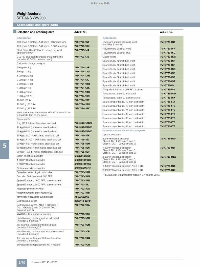
5/40 Siemens WT 10 · 2020
■ Selection and ordering data Article No. Article No.
WeighfeedersSITRANS WW200
Accessories and spare parts
5
1) Suitable for weighfeeders made in CA prior to 2016.
Accessories
Test chain 1.62 lb/ft, 2.41 kg/m - 60 inches long 7MH7723-1NF
Test chain 1.62 lb/ft, 2.41 kg/m - 1 000 mm long 7MH7723-1SK
Start, Stop, Hand/Off/Auto, speed pot local operator station
7MH7723-1JA
CLS100 plugged discharge chute retrofit kit (includes CLS100, material hood)
7MH7723-1JE
Calibration hanger weights
200 g (0.4 lb) 7MH7724-1AF
500 g (1.1 lb) 7MH7724-1AG
1 000 g (2.2 lb) 7MH7724-1AH
2 000 g (4.4 lb) 7MH7724-1AJ
3 500 g (7.7 lb) 7MH7724-1BQ
5 000 g (11 lb) 7MH7724-1AK
7 500 g (16.5 lb) 7MH7724-1BR
8 500 g (18.7 lb) 7MH7724-1BS
10 000 (22 lb) 7MH7724-1BT
12 000 g (26.5 lb) 7MH7724-1BU
15 000 g (33.1 lb) 7MH7724-1BV
Note: calibration accessories should be ordered as a separate item on the order.
Spare parts
6 kg (13.2 lb) stainless steel load cell 7MH5117-1QD00
12 kg (26.4 lb) stainless steel load cell 7MH5117-2BD00
30 kg (66.2 lb) stainless steel load cell 7MH5117-2KD00
10 kg (22 lb) nickel plated steel load cell 7MH7725-1EK
15 kg (33.1 lb) nickel plated steel load cell 7MH7725-1EL
20 kg (44 lb) nickel plated steel load cell 7MH7725-1EM
30 kg (66.2 lb) nickel plated steel load cell 7MH7725-1EN
50 kg (110.2 lb) nickel plated steel load cell 7MH7725-1EP
500 PPR optical encoder 6FX20012PA50
1 000 PPR optical encoder 6FX20012PB00
2 500 PPR optical encoder 6FX20012PC50
Optical encoder connector 6FX20030SU12
Speed encoder plug-in with cable 7MH7723-1KM
Encoder, Stainless steel, 500 PPR 7MH7723-1HG
Speed Encoder, 1 000 PPR, stainless steel 7MH7723-1HH
Speed Encoder, 2 500 PPR, stainless steel 7MH7723-1HJ
Magnetic proximity switch 7MH7723-1GA
Motor mounted sensor flange 56C 7MH7723-1RB
Termination board for Junction Box A5E03623963
Belt tracking switch 3SE5112-0CR01
Belt tracking switch, ATEX II 2D/Class I, Div. 1,Groups C and D, Class II, Div. 1, Groups F and G
7MH7723-1RA
WW200 outline approval drawing 7MH7726-1BU
Head bearing replacement kit mild steel (includes 2 bearings)1)
7MH7723-1QM
Tail bearing replacement kit mild steel (includes 2 bearings)1)
7MH7723-1QN
Head bearing replacement kit stainless steel (includes 2 bearings)
7MH7723-1QP
Tail bearing replacement kit stainless steel (includes 2 bearings)
7MH7723-1QQ
Skirtboard seal replacement kit, 7 meters 7MH7723-1QR
Enclosure latches stainless steel (includes 5 latches)
7MH7723-1QT
Polyurethane sealing, white 7MH7723-1SF
Polyurethane sealing, blue 7MH7723-1SG
Guide rollers 7MH7723-1SM
Spare Brush, 12 inch belt width 7MH7723-1SN
Spare Brush, 18 inch belt width 7MH7723-1SP
Spare Brush, 24 inch belt width 7MH7723-1SQ
Spare Brush, 30 inch belt width 7MH7723-1SR
Spare Brush, 36 inch belt width 7MH7723-1SS
Spare Brush, 42 inch belt width 7MH7723-1ST
Spare Brush, 48 inch belt width 7MH7723-1SU
Weighdeck Slider bar, PE-HD, 1 piece 7MH7723-1SV
Telescopers, set of 2, mild steel 7MH7723-1SW
Telescopers, set of 2, stainless steel 7MH7723-1SX
Spare scraper blade, 12 inch belt width 7MH7726-1TA
Spare scraper blade, 18 inch belt width 7MH7726-1TB
Spare scraper blade, 24 inch belt width 7MH7726-1TC
Spare scraper blade, 30 inch belt width 7MH7726-1TD
Spare scraper blade, 36 inch belt width 7MH7726-1TE
Spare scraper blade, 42 inch belt width 7MH7726-1TF
Spare scraper blade, 48 inch belt width 7MH7726-1TG
Hazardous rated electrical spare parts
Optical encoders
500 PPR optical encoder, Class I, Div. 1, Groups C and D, Class II, Div. 1, Groups F and G
7MH7723-1QU
1 000 PPR optical encoder, Class I, Div. 1, Groups C and D, Class II, Div. 1, Groups F and G
7MH7723-1QV
2 500 PPR optical encoder, Class I, Div. 1, Groups C and D, Class II, Div. 1, Groups F and G
7MH7723-1QW
1 000 PPR optical encoder, ATEX II 2D 7MH7723-1QX
2 000 PPR optical encoder, ATEX II 2D 7MH7723-1QY
Accessories
© Siemens 2020

5/41Siemens WT 10 · 2020
■ Selection and ordering data Article No. Article No.
WeighfeedersSITRANS WW200
Accessories and spare parts
5
SITRANS WW200 Spare Belts
Endless belt for use with WW200 weighfeeders 7MH7300 to 7MH7308; pulley CL data based on telescoper in fully retracted position
7MH7204- 7 7 7 7
Click on the Article No. for the online configuration in the PIA Life Cycle Portal.
Belt size
12 inch (305 mm) belt width
52 inch (1 321 mm) C/L Infeed to C/L Discharge, 54.5 inch (1 384 mm) pulley C/L to C/L per weighfeeder; total belt length 3 305 mm (130.1 inch)
0 A
60 inch (1 524 mm) C/L Infeed to C/L Discharge, 62.5 inch (1 588 mm) pulley C/L to C/L per weighfeeder; total belt length 3 715 mm (146.3 inch)
0 B
68 inch (1 727 mm) C/L Infeed to C/L Discharge, 70.5 inch (1 791 mm) pulley C/L to C/L per weighfeeder, total belt length 4 120 mm (162.2 inch)
0 C
76 inch (1 930 mm) C/L Infeed to C/L Discharge, 78.5 inch (1 994 mm) pulley C/L to C/L per weighfeeder; total belt length 4 525 mm (178.2 inch)
0 D
84 inch (2 134 mm) C/L Infeed to C/L Discharge, 86.5 inch (2 197 mm) pulley C/L to C/L per weighfeeder; total belt length 4 935 mm (194.3 inch)
0 E
92 inch (2 337 mm) C/L Infeed to C/L Discharge, 94.5 inch (2 400 mm) pulley C/L to C/L per weighfeeder; total belt length 5 340 mm (210.2 inch)
0 F
100 inch (2 540 mm) C/L Infeed to C/L Discharge, 102.5 inch (2 604 mm) pulley C/L to C/L per weighfeeder; total belt length 5 745 mm (226.2 inch)
0 G
108 inch (2 743 mm) C/L Infeed to C/L Discharge, 110.5 inch (2 807 mm) pulley C/L to C/L per weighfeeder; total belt length 6 150 mm (242.1 inch)
0 H
116 inch (2 946 mm) C/L Infeed to C/L Discharge, 118.5 inch (3 010 mm) pulley C/L to C/L per weighfeeder; total belt length 6 560 mm (258.3 inch)
0 J
18 inch (610 mm) belt width
52 inch (1 321 mm) C/L Infeed to C/L Discharge, 54.5 inch (1 384 mm) pulley C/L to C/L per weighfeeder
1 A
60 inch (1 524 mm) C/L Infeed to C/L Discharge, 62.5 inch (1 588 mm) pulley C/L to C/L per weighfeeder
1 B
68 inch (1 727 mm) C/L Infeed to C/L Discharge, 70.5 inch (1 791 mm) pulley C/L to C/L per weighfeeder
1 C
76 inch (1 930 mm) C/L Infeed to C/L Discharge, 78.5 inch (1 994 mm) pulley C/L to C/L per weighfeeder
1 D
84 inch (2 134 mm) C/L Infeed to C/L Discharge, 86.5 inch (2 197 mm) pulley C/L to C/L per weighfeeder
1 E
92 inch (2 337 mm) C/L Infeed to C/L Discharge, 94.5 inch (2 400 mm) pulley C/L to C/L per weighfeeder
1 F
100 inch (2 540 mm) C/L Infeed to C/L Discharge, 102.5 inch (2 604 mm) pulley C/L to C/L per weighfeeder
1 G
108 inch (2 743 mm) C/L Infeed to C/L Discharge, 110.5 inch (2 807 mm) pulley C/L to C/L per weighfeeder
1 H
116 inch (2 946 mm) C/L Infeed to C/L Discharge, 118.5 inch (3 010 mm) pulley C/L to C/L per weighfeeder
1 J
24 inch (610 mm) belt width
52 inch (1 321 mm) C/L Infeed to C/L Discharge, 54.5 inch (1 384 mm) pulley C/L to C/L per weighfeeder
2 A
60 inch (1 524 mm) C/L Infeed to C/L Discharge, 62.5 inch (1 588 mm) pulley C/L to C/L per weighfeeder
2 B
68 inch (1 727 mm) C/L Infeed to C/L Discharge, 70.5 inch (1 791 mm) pulley C/L to C/L per weighfeeder
2 C
76 inch (1 930 mm) C/L Infeed to C/L Discharge, 78.5 inch (1 994 mm) pulley C/L to C/L per weighfeeder
2 D
84 inch (2 134 mm) C/L Infeed to C/L Discharge, 86.5 inch (2 197 mm) pulley C/L to C/L per weighfeeder
2 E
92 inch (2 337 mm) C/L Infeed to C/L Discharge, 94.5 inch (2 400 mm) pulley C/L to C/L per weighfeeder
2 F
100 inch (2 540 mm) C/L Infeed to C/L Discharge, 102.5 inch (2 604 mm) pulley C/L to C/L per weighfeeder
2 G
108 inch (2 743 mm) C/L Infeed to C/L Discharge, 110.5 inch (2 807 mm) pulley C/L to C/L per weighfeeder
2 H
116 inch (2 946 mm) C/L Infeed to C/L Discharge, 118.5 inch (3 010 mm) pulley C/L to C/L per weighfeeder
2 J
SITRANS WW200 Spare Belts
Endless belt for use with WW200 weighfeeders 7MH7300 to 7MH7308; pulley CL data based on telescoper in fully retracted position
7MH7204- 7 7 7 7
© Siemens 2020

5/42 Siemens WT 10 · 2020
■ Selection and ordering data Article No. Article No.
WeighfeedersSITRANS WW200
Accessories and spare parts
5
30 inch (762 mm) belt width
52 inch (1 321 mm) C/L Infeed to C/L Discharge, 54.5 inch (1 384 mm) pulley C/L to C/L per weighfeeder
3 A
60 inch (1 524 mm) C/L Infeed to C/L Discharge, 62.5 inch (1 588 mm) pulley C/L to C/L per weighfeeder
3 B
68 inch (1 727 mm) C/L Infeed to C/L Discharge, 70.5 inch (1 791 mm) pulley C/L to C/L per weighfeeder
3 C
76 inch (1 930 mm) C/L Infeed to C/L Discharge, 78.5 inch (1 994 mm) pulley C/L to C/L per weighfeeder
3 D
84 inch (2 134 mm) C/L Infeed to C/L Discharge, 86.5 inch (2 197 mm) pulley C/L to C/L per weighfeeder
3 E
92 inch (2 337 mm) C/L Infeed to C/L Discharge, 94.5 inch (2 400 mm) pulley C/L to C/L per weighfeeder
3 F
100 inch (2 540 mm) C/L Infeed to C/L Discharge, 102.5 inch (2 604 mm) pulley C/L to C/L per weighfeeder
3 G
108 inch (2 743 mm) C/L Infeed to C/L Discharge, 110.5 inch (2 807 mm) pulley C/L to C/L per weighfeeder
3 H
116 inch (2 946 mm) C/L Infeed to C/L Discharge, 118.5 inch (3 010 mm) pulley C/L to C/L per weighfeeder
3 J
36 inch (914 mm) belt width
52 inch (1 321 mm) C/L Infeed to C/L Discharge, 54.5 inch (1 384 mm) pulley C/L to C/L per weighfeeder
4 A
60 inch (1 524 mm) C/L Infeed to C/L Discharge, 62.5 inch (1 588 mm) pulley C/L to C/L per weighfeeder
4 B
68 inch (1 727 mm) C/L Infeed to C/L Discharge, 70.5 inch (1 791 mm) pulley C/L to C/L per weighfeeder
4 C
76 inch (1 930 mm) C/L Infeed to C/L Discharge, 78.5 inch (1 994 mm) pulley C/L to C/L per weighfeeder
4 D
84 inch (2 134 mm) C/L Infeed to C/L Discharge, 86.5 inch (2 197 mm) pulley C/L to C/L per weighfeeder
4 E
92 inch (2 337 mm) C/L Infeed to C/L Discharge, 94.5 inch (2 400 mm) pulley C/L to C/L per weighfeeder
4 F
100 inch (2 540 mm) C/L Infeed to C/L Discharge, 102.5 inch (2 604 mm) pulley C/L to C/L per weighfeeder
4 G
108 inch (2 743 mm) C/L Infeed to C/L Discharge, 110.5 inch (2 807 mm) pulley C/L to C/L per weighfeeder
4 H
116 inch (2 946 mm) C/L Infeed to C/L Discharge, 118.5 inch (3 010 mm) pulley C/L to C/L per weighfeeder
4 J
SITRANS WW200 Spare Belts
Endless belt for use with WW200 weighfeeders 7MH7300 to 7MH7308; pulley CL data based on telescoper in fully retracted position
7MH7204- 7 7 7 7
42 inch (1 067 mm) belt width
52 inch (1 321 mm) C/L Infeed to C/L Discharge, 54.5 inch (1 384 mm) pulley C/L to C/L per weighfeeder
5 A
60 inch (1 524 mm) C/L Infeed to C/L Discharge, 62.5 inch (1 588 mm) pulley C/L to C/L per weighfeeder
5 B
68 inch (1 727 mm) C/L Infeed to C/L Discharge, 70.5 inch (1 791 mm) pulley C/L to C/L per weighfeeder
5 C
76 inch (1 930 mm) C/L Infeed to C/L Discharge, 78.5 inch (1 994 mm) pulley C/L to C/L per weighfeeder
5 D
84 inch (2 134 mm) C/L Infeed to C/L Discharge, 86.5 inch (2 197 mm) pulley C/L to C/L per weighfeeder
5 E
92 inch (2 337 mm) C/L Infeed to C/L Discharge, 94.5 inch (2 400 mm) pulley C/L to C/L per weighfeeder
5 F
100 inch (2 540 mm) C/L Infeed to C/L Discharge, 102.5 inch (2 604 mm) pulley C/L to C/L per weighfeeder
5 G
108 inch (2 743 mm) C/L Infeed to C/L Discharge, 110.5 inch (2 807 mm) pulley C/L to C/L per weighfeeder
5 H
116 inch (2 946 mm) C/L Infeed to C/L Discharge, 118.5 inch (3 010 mm) pulley C/L to C/L per weighfeeder
5 J
SITRANS WW200 Spare Belts
Endless belt for use with WW200 weighfeeders 7MH7300 to 7MH7308; pulley CL data based on telescoper in fully retracted position
7MH7204- 7 7 7 7
© Siemens 2020

5/43Siemens WT 10 · 2020
■ Selection and ordering data Article No.
WeighfeedersSITRANS WW200
Accessories and spare parts
5
48 inch (1 219 mm) belt width
52 inch (1 321 mm) C/L Infeed to C/L Discharge, 54.5 inch (1 384 mm) pulley C/L to C/L per weighfeeder
6 A
60 inch (1 524 mm) C/L Infeed to C/L Discharge, 62.5 inch (1 588 mm) pulley C/L to C/L per weighfeeder
6 B
68 inch (1 727 mm) C/L Infeed to C/L Discharge, 70.5 inch (1 791 mm) pulley C/L to C/L per weighfeeder
6 C
76 inch (1 930 mm) C/L Infeed to C/L Discharge, 78.5 inch (1 994 mm) pulley C/L to C/L per weighfeeder
6 D
84 inch (2 134 mm) C/L Infeed to C/L Discharge, 86.5 inch (2 197 mm) pulley C/L to C/L per weighfeeder
6 E
92 inch (2 337 mm) C/L Infeed to C/L Discharge, 94.5 inch (2 400 mm) pulley C/L to C/L per weighfeeder
6 F
100 inch (2 540 mm) C/L Infeed to C/L Discharge, 102.5 inch (2 604 mm) pulley C/L to C/L per weighfeeder
6 G
108 inch (2 743 mm) C/L Infeed to C/L Discharge, 110.5 inch (2 807 mm) pulley C/L to C/L per weighfeeder
6 H
116 inch (2 946 mm) C/L Infeed to C/L Discharge, 118.5 inch (3 010 mm) pulley C/L to C/L per weighfeeder
6 J
Belt type
Polyurethane anti static, 1,35 mm thick, FDA approved, white
A
Polyurethane anti static, 1,35 mm thick, FDA approved, blue
B
Polyurethane anti static, 2.9 mm thick, 2 ply FDA approved, white
C
Silicone, High temp. belt 180 °C (350 °F); 2 ply, antistatic, FDA approved
E
Belt design
Standard 1
6 mm B-section flange walls 2
50 mm (2 inch) corrugated side walls 3
Further designs Order Code
Please add "-Z" to article no. and specify order code(s).
Select next longest option and specify infeed CL to Discharge CL per weighfeeder in plain text (indicated inches or millimeters)
Note: Y01 order code info indicates special length on weighfeeder.
Y01
Operating instructions
All literature is available to download for free, in a range of languages, at https://www.siemens.com/weighing/documentation
SITRANS WW200 Spare Belts
Endless belt for use with WW200 weighfeeders 7MH7300 to 7MH7308; pulley CL data based on telescoper in fully retracted position
7MH7204- 7 7 7 7
© Siemens 2020
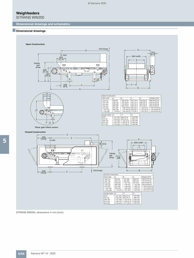
5/44 Siemens WT 10 · 2020
WeighfeedersSITRANS WW200
Dimensional drawings and schematics
5
■ Dimensional drawings
SITRANS WW200, dimensions in mm (inch)
Open Construction
Discharge
Inlet Belt width
Inlet
Shear gate infeed version
Closed Construction
Discharge
Inlet
Open ConstructionBelt width Weight (STD)
Length adder
Varies per
drive
Varies per drive
Length adder
Belt widthClosed Construction
Weight (STD)
Belt width
711.2 (28)
257 (10.1)333 (13.1)409 (16.1)486 (19.1)562 (22.1)638 (25.1)714 (28.1)
540 (21.2)
381(15.0)
229 (9.0)
133 (5.3)
533 (21.0)
E
F
G
D
A
CB
298(11.8) 248
(9.8)
724(28.5)
229(9.0)
A B C
E F G
D305 (12)457 (18)610 (24)762 (30)915 (36)1 067 (42)1 219 (48)
203 (8)356 (14)508 (20)660 (26)813 (32)965 (38)1 118 (44)
425 (16.8)578 (22.8)730 (28.8)883 (34.8)1 035 (40.8)1 187 (46.8)1 340 (52.8)
516 (20.3)668 (26.3)820 (32.3)973 (38.3)1 125 (44.3)1 278 (50.3)1 430 (56.3)
600 lb/272 kg700 lb/318 kg800 lb/363 kg900 lb/408 kg1 000 lb/453 kg1 100 lb/499 kg1 200 lb/544 kg
STD203 (8)406 (16)610 (24)813 (32)
1 321 (52)1 524 (60)1 727 (68)1 930 (76)2 134 (84)
698 (27.5)902 (35.5)1 105 (43.5)1 308 (51.5)1 511 (59.5)
1 676 (66)1 880 (74)2 083 (82)2 286 (90)2 489 (98)
425(16.8)
GE
76 (3.0)
F 425(16.8)
E
A
B
686 (27)838 (33)991 (39)1 143 (45)1 295 (51)1 448 (57)1 600 (63)
A B C
E F G
305 (12)457 (18)610 (24)762 (30)915 (36)1 067 (42)1 219 (48)
203 (8)356 (14)508 (20)660 (26)813 (32)965 (38)1 118 (44)
737 (29)864 (89)1 041 (41)1 194 (47)1 346 (53)1 499 (59)1 651 (65)
600 lb/272 kg700 lb/318 kg800 lb/363 kg900 lb/408 kg1 000 lb/453 kg1 100 lb/499 kg1 200 lb/544 kg
STD203 (8)406 (16)610 (24)813 (32)
1 321 (52)1 524 (60)1 727 (68)1 930 (76)2 134 (84)
698 (27.5)902 (35.5)1 105 (43.5)1 308 (51.5)1 511 (59.5)
1 676 (66)1 880 (74)2 083 (82)2 286 (90)2 489 (98)
© Siemens 2020

5/45Siemens WT 10 · 2020
WeighfeedersSITRANS WW200
Dimensional drawings and schematics
5
■ Circuit diagrams
SITRANS WW200 connections
1
1 1
1
1
12
2 2
2
2
23
3 3
3
3
34
4 4
4
4
45
5 5
5
5
56
6 6
667
7 7
77
1
1
2
2
3
3
4
4
5
5
SHIE
LDSH
IELD
SHIE
LDS
HIE
LDLOAD CELL LOAD CELL
TOINTEGRATOR
TOINTEGRATOR
SPEED SENSOR
Note: termination box not supplied on hazardous rated options.
TB1
TB5
TB6
"A" "B"
+EX
C
SIG
A
SIG
B
SIG
A
TB2
-EXC
+ +- -SIG
B
+ EXC
+ + SIG
A
SIG
B
EXC
- SIG
B
- -SIG
A
TB4
+EX
C
CO
M
SI
CW
SG
CW
G IC
TB7
TB3
TB8
EXC
-
CH
/B
EXC
+
CH
B
CH
/A
CH
A
© Siemens 2020

5/46 Siemens WT 10 · 2020
WeighfeedersWeighfeeder accessories
Weighfeeder peripherals
5
■ Selection and ordering data
Milltronics Weighfeeder 400, 600, and 800
Article No.
For aluminum model, use nickel plated alloy steel
Nickel plated, standard duty
10 kg (22 lb) 7MH7725-1EK
15 kg (33.1 lb) 7MH7725-1EL
20 kg (44 lb) 7MH7725-1EM
30 kg (66.2 lb) 7MH7725-1EN
Stainless steel
6 kg (13.2 lb) 7MH7725-1EG
12 kg (26.4 lb) 7MH7725-1EH
30 kg (66.2 lb) 7MH7725-1EJ
11.3 kg (25 lb) PBD-23900224
22.7 kg (50 lb) PBD-23900225
45.4 kg (100 lb) PBD-23900242
Milltronics Weighfeeder 1200, SITRANS WW300 and WW310 spare load cells
Article No.
Nickel plated, standard duty
10 kg (22 lb) 7MH7725-1EK
15 kg (33.1 lb) 7MH7725-1EL
20 kg (44 lb) 7MH7725-1EM
30 kg (66.2 lb) 7MH7725-1EN
50 kg (110.2 lb) 7MH7725-1EP
75 kg (165 lb) 7MH7725-1CS
100 kg (220 lb) 7MH7725-1CT
Nickel plated, heavy duty
50 kg (110.2 lb) 7MH7725-1CU
100 kg (220.5 lb) 7MH7725-1CV
150 kg (330.7 lb) 7MH7725-1CW
200 kg (440.9 lb) 7MH7725-1CX
Stainless steel
Stainless steel load cell [17-4 PH (1.4568) stainless steel construction with 304 (1.4301) stainless steel cover
22.7 kg (50 lb) 7MH7725-1AC
45.4 kg (100 lb) 7MH7725-1AD
113.4 kg (250 lb) 7MH7725-1AE
226.8 kg (500 lb) 7MH7725-1AF
11 kg (25 lb), CSA/FM/ATEX/IEC EX 7MH7725-1DQ
23 kg (50 lb), CSA/FM/ATEX/IEC EX 7MH7725-1DL
45 kg (100 lb), CSA/FM/ATEX/IEC EX
7MH7725-1DM
113 kg (250 lb), CSA/FM/ATEX/IEC EX
7MH7725-1DN
227 kg (500 lb), CSA/FM/ATEX/IEC EX
7MH7725-1DP
6 kg (13.2 lb) 7MH7725-1EG
12 kg (26.5 lb) 7MH7725-1EH
30 kg (66.1 lb) 7MH7725-1EJ
24 kg (50 lb), CSA/FM/ATEX/IEC EX
7MH7725-1DT
45 kg (100 lb), CSA/FM/ATEX/IEC EX
7MH7725-1DU
113 kg (250 lb), CSA/FM/ATEX/IEC EX
7MH7725-1DV
Calibration hanger weights
Article No.
200 g (0.4 lb) 7MH7724-1AF
500 g (1.1 lb) 7MH7724-1AG
1 000 g (2.2 lb) 7MH7724-1AH
2 000 g (4.4 lb) 7MH7724-1AJ
3 500 g (7.7 lb) 7MH7724-1BQ
5 000 g (11 lb) 7MH7724-1AK
7 500 g (16.5 lb) 7MH7724-1BR
8 500 g (18.7 lb) 7MH7724-1BS
10 000 g (22 lb) 7MH7724-1BT
12 000 g (26.5 lb) 7MH7724-1BU
15 000 g (33.1 lb) 7MH7724-1BV
SITRANS WW300 and WW310 spare parts and accessories
Article No.
Start, Stop, Hand/Off/Auto, speed pot local operator station
7MH7723-1JA
500 PPR optical encoder 6FX2001-2PA50
1 000 PPR optical encoder 6FX2001-2PB00
2 500 PPR optical encoder 6FX2001-2PC50
Optical encoder connector 6FX2003-0SU12
Siemens encoder connector with 20 ft cable
7MH7723-1KM
Belt tracking switch 3SE5112-0CR01
Belt tracking switch, ATEX II 2D/Class I, Div. 1, Groups C and D, Class II, Div. 1, Groups F and G
7MH7723-1RA
Pull cord switch 3SE7120-2DD01
Pull cord switch cable 3SE7910-3AA
Pull cord switch cable clamp 3SE7941-1AC
Termination box 1, 2, 4 load cell and speed sensor, mild steel
7MH7723-1ND
Termination box 1, 2, 4 load cell and speed sensor, stainless steel
7MH7723-1NE
Bearing, flange, NTN, UCF2, 1 … 15/16 inch, 4-bolt
A5E01213250
Bearing, flange, NTN, UCF2, 2 … 15/16 inch, 4-bolt
A5E03856041
Bearing, PB, UCP, 1 … 7/16 inch
A5E01213243
Bearing, PB, UCP, 2 … 7/16 inch
PBD-24191273
© Siemens 2020

Siemens WT 10 · 2020
66/2 Introduction
6/5 LVDT flowmeters6/5 SITRANS WF1006/10 SITRANS WF200 series6/16 SITRANS WF300 series
6/26 Sensing heads6/26 SITRANS WFS300 series sensing heads
6/33 Sensing plates6/33 SITRANS flowmeter sensing plates
6/34 Solids flowmeters accessories6/34 Solids flowmeter peripherals
Solid Flowmeters
© Siemens 2020

6/2 Siemens WT 10 · 2020
Solid FlowmetersIntroduction
6
■ Overview
SITRANS WF solids flowmeters monitor the rate of bulk material flow in a process. They continuously measure the impact force of the material under gravity feed conditions, and convert this signal into a flow rate used to control the rate into a process or blending operation. Solids flowmeters can function in stand-alone measuring operations, or they can interface to a facility’s process control system using industry standard protocols.
Applications
SITRANS WF flowmeters measure any dry material from pow-ders to granulates. Material densities range from puffed wheat to iron ore, while fluidity covers the spectrum from fluidized powder, such as fly-ash, to sluggish flowing material such as lathe turn-ings. Typical materials monitored include cement, gravel, coke, coal, minerals, wood chips, cereals, seeds, grains, soybean and rice hulls, unshelled peanuts, starch, sugar, potato flakes, grain tailings and screenings, and plastic pellets.
Solids flowmeter with sensing plate detail
■ Mode of operation
Flowmeters are installed in a gravity fed process. Entering the flowmeter through the flowguide, the material flow produces a mechanical deflection as it strikes the flowmeter’s sensing plate. The SITRANS WF flowmeter converts the deflection into an elec-trical signal that feeds into an accompanying integrator, which instantaneously provides the flow rate and totalizes the weight.
SITRANS WF flowmeters measure only the horizontal force com-ponent of material flow striking the sensing plate. The horizontal force is dependent on particle mass and velocity, angle of parti-cle impact against the plate, and the energy absorbing charac-teristics of the particle. The flowmeters respond to the mass or weight of the material striking the plate.
Because SITRANS WF flowmeter measures only the horizontal force, they are unaffected by vertical force changes caused by material buildup on the non-impact area of the sensing plate. Consequently, there is no zero drift, which in turn eliminates the need for frequent recalibration.
Siemens SITRANS WF product portfolio includes two basic types of impact flowmeters: the linear variable differential trans-former (LVDT), and the strain gauge load cell. Each uses a dif-ferent sensor to convert the horizontal force on the sensing plate to flow rate.
The totally enclosed design of SITRANS WF heavy-duty solids flowmeters eliminates product waste or contamination, and reduces plant maintenance. The dust-tight design creates a healthier work environment, especially when monitoring hazard-ous substances.
Mode of operation
Material flow
Flowguide Sensing plate
Impact force
© Siemens 2020

6/3Siemens WT 10 · 2020
Solid FlowmetersIntroduction
6
■ Technical specifications
Solids flowmeter selection guide
1) Accuracy subject to: on factory approved installations the flowmeter system’s totalized weight will be within the specified accuracy when compared to a known weighed material test sample. The test rate must be within the specified range of the design capacity and held constant for the duration of the test. The minimum material test sample must be equivalent to a sample obtained at the test flow rate for at least ten minutes running time.
Criteria SITRANS WF100 SITRANS WF200 SITRANS WF250 SITRANS WF330 SITRANS WF340 SITRANS WF350
Typical industries Food, grain, milling, animal feed, plastics, glass
Aggregates, grain, cement
Cement, mineral processing
Food, grain, milling, animal feed, chemicals, plastics, glass, cement, mineral processing
Food, grain, milling, animal feed, chemi-cals, plastics, glass, cement, mineral processing
Cement, mineral processing, mining
Typical applications Monitoring offood ingredients,pet food blending, plastic pellet produc-tion, silica sand in glass making
Grinding mill rejects in cement, load-out of grains and seeds
Cement in aerated gravity conveyor
Fly-ash, lime dosing, cement flow and control in mining, flour stream monitoring
Fly-ash load-out, lime dosing, gypsum flow
Powders and granulates conveyed by aerated gravity conveyors, fly-ash load-out, precipitator dust
Typical capacity 1 … 200 t/h(4 … 220 STPH)
200 … 900 t/h(220 … 990 STPH)
200 … 900 t/h(220 … 990 STPH)
Sensing element dependent, see 'Sensing element' chart, page 6/4.
Sensing element dependent, see 'Sensing element' chart, page 6/4.
Sensing element dependent, see 'Sensing element' chart, page 6/4.
Volumetric capacity 90 m3/h (3 178 ft3/h)
500 m3/h (17 657 ft3/h)
600 m3/h (21 189 ft3/h)
40 t/h: 90 m3/h (3 178 ft3/h)300 t/h: 290 m3/h (10 241 ft3/h)
40 t/h: 96 m3/h (3 390 ft3/h)300 t/h: 230 m3/h (8 122 ft3/h)
40 t/h: 178 m3/h (6 286 ft3/h)300 t/h: 545 m3/h (19 246 ft3/h)
Maximum particle size
13 mm (0.5 inch) 25 mm (1 inch) 25 mm (1 inch) Sensing element dependent, see 'Sensing element' chart, page 6/4.
Sensing element dependent, see 'Sensing element' chart, page 6/4.
Sensing element dependent, see 'Sensing element' chart, page 6/4.
Ambient temperature
-20 ... +65 ºC (-4 ... +150 ºF)
-40 ... +65 ºC (-40 ... +150 ºF)
-40 ... +65 ºC (-40 ... +150 ºF)
-40 ... +60 ºC (-40 ... +140 ºF)
-40 ... +60 ºC (-40 ... +140 ºF)
-40 ... +60 ºC (-40 ... +140 ºF)
Maximum process temperature
65 ºC (150 ºF) 100 ºC (212 ºF) 100 ºC (212 ºF) 232 °C (450 °F) 232 °C (450 °F) 232 °C (450 °F)
Inlet sizes 100 … 250 mm (4 … 10 inch) in universal ANSI/DIN flanges
305 x 533 mm(12 x 21 inch)305 x 635 mm(12 x 26 inch)
406 x 635 mm(16 x 25 inch)508 x 940 mm(20 x 37 inch)
Sensing element dependent, see 'Sensing element' chart, page 6/4.
Sensing element dependent, see 'Sensing element' chart, page 6/4.
Sensing element dependent, see 'Sensing element' chart, page 6/4.
Accuracy1) ± 1 % (33 … 100 % of rate)
± 1 % (33 … 100 % of rate)
± 1 % (33 … 100 % of rate)
± 1 % (33 … 100 % of rate)
± 1 % (33 … 100 % of rate)
± 1 % (33 … 100 % of rate)
Repeatability ± 0.2 % ± 0.2 % ± 0.2 % ± 0.2 % ± 0.2 % ± 0.2 %
Options 304 or 316 stainless steel, bead blast finish (1 ... 6 in, 4 ... 240 in) construction (meets FDA and USDA requirements for food processing)
304 or 316 stainless steel, bead blast finish (1 ... 6 in, 4 ... 240 in) construction (meets FDA and USDA requirements for food processing)
304 or 316 stainless steel, bead blast finish (1 ... 6 in, 4 ... 240 in) construction (meets FDA and USDA requirements for food processing)
• 304 or 316 stainless steel, bead blast finish (1 ... 6 in, 4 ... 240 in) construction (meets FDA and USDA requirements for food processing)
• Food grade epoxy coating on sensing head
• 304 or 316 stainless steel, bead blast finish (1 ... 6 in, 4 ... 240 in) construction (meets FDA and USDA requirements for food processing)
• Food grade epoxy coating on sensing head
• 304 or 316 stainless steel, bead blast finish (1 ... 6 in,4 ... 240 in) construction (meets FDA and USDA requirements for food processing)
• Food grade epoxy coating on sensing head
Sensingelement
One triple beamparallelogramstyle, stainlesssteel, straingauge load cell
Two triple beamparallelogramstyle, stainlesssteel, straingauge load cells
Two triple beamparallelogramstyle, stainlesssteel, straingauge load cells
Deflection measure-ment using LVDT (linear variable differential trans-former)
Deflection measure-ment using LVDT (linear variable differential trans-former)
Deflection measure-ment using LVDT (linear variable differential trans-former)
Sensing plate • 304 stainless steel • Option:
316 stainless steel
• 304 stainless steel • Option:
316 stainless steel
• 304 stainless steel • Option:
316 stainless steel
• 304 stainless steel • Option:
316 stainless steel
• 304 stainless steel • Option:
316 stainless steel
• 304 stainless steel • Option:
316 stainless steel
Liners • PTFE • Polyurethane
• Polyurethane • Alumina ceramic
• Polyurethane • Alumina ceramic
• Plasma A/R • PTFE • Polyurethane • Alumina ceramic
• Plasma A/R • PTFE • Polyurethane • Alumina ceramic
• Plasma A/R • PTFE • Polyurethane • Alumina ceramic
Approvals CE , RCM, CSA, FM, ATEX, IEC Ex, EAC
CE , RCM, CSA, FM, ATEX, IEC Ex, EAC
CE , RCM, CSA, FM, ATEX, IEC Ex, EAC
CE , RCM, EAC CE , RCM, EAC CE , RCM, EAC
© Siemens 2020
z002cfep
Notiz
None festgelegt von z002cfep
z002cfep
Notiz
None festgelegt von z002cfep
z002cfep
Notiz
None festgelegt von z002cfep
z002cfep
Notiz
Completed festgelegt von z002cfep
z002cfep
Notiz
Completed festgelegt von z002cfep
z002cfep
Notiz
Completed festgelegt von z002cfep

6/4 Siemens WT 10 · 2020
■ Technical specifications
Solid FlowmetersIntroduction
6
Sensing element
Common flowmeter infeed types
A solids flowmeter’s performance will be as repeatable and consistent as the flow of material it is measuring. The following arrangements are typical of pre-feed chute configurations used to ensure consistent flow patterns. Arrangements will vary de-pending on the upstream equipment or chute work. Applications should be reviewed by a Siemens solids flowmeter specialist to achieve best results. During initial setup, use pre-weighing or post-weighing of material samples to calibrate the flowmeter and verify accuracy using the material sample weights.
Solids Flowmeters, dimensions in mm (inch)
SITRANS WF330 SITRANS WF340 SITRANS WF350
Capacity range- SITRANS WFS300 0.2 … 40 t/h (0.2 … 44 STPH) 0.2 … 40 t/h (0.2 … 44 STPH) 0.2 … 40 t/h (0.2 … 44 STPH)- SITRANS WFS320 20 … 300 t/h (22 … 330 STPH) 20 … 300 t/h (22 … 330 STPH) 20 … 300 t/h (22 … 330 STPH)
Particle size (max.)- SITRANS WFS300 12 mm (0.5 inch) 12 mm (0.5 inch) 3 mm (0.13 inch)- SITRANS WFS320 25 mm (1 inch) 25 mm (1 inch) 3 mm (0.13 inch)
Inlet sizes- SITRANS WFS300 50 … 250 mm (2 … 10 inch)
(ASME or DIN flanges)• 76 x 152 mm (3 x 6 inch) • 102 x 254 mm (4 x 10 inch) • 127 x 305 mm (5 x 12 inch)
• 203 x 203 mm (8 x 8 inch) • 203 x 305 mm (8 x 12 inch)
- SITRANS WFS320 150 … 400 mm (6 … 16 inch)(ASME or DIN flanges)
• 127 x 406 mm (5 x 16 inch) • 152 x 508 mm (6 x 20 inch)
• 305 x 254 mm (12 x 10 inch) • 305 x 356 mm (12 x 14 inch) • 305 x 508 mm (12 x 20 inch)
Bucket Elevator
Max
. 1 0
00 (3
9)
Baffle plate
Material discharge
baffle
Feeder / Flowguide Transition
DoglegShort Fall Chute
Dead Box
Conveyor Belts
© Siemens 2020

6/5Siemens WT 10 · 2020
Solid FlowmetersLVDT flowmeters
SITRANS WF100
6
■ Overview
SITRANS WF100 flowmeter is a low to medium capacity flowme-ter for various product sizes, densities, and fluidities in restricted spaces.
■ Benefits
• Flowrates from 3 to 200 t/h (4 to 220 STPH) • Continuous monitoring of the material flow without interrupting
the process • Dust-tight construction: suitable for use in hazardous areas
and in washdown applications that require frequent cleaning • Minimal maintenance or recalibration after the initial installa-
tion and material tests
■ Application
WF100 is unaffected by corrosive, abrasive, or hot materials. Handling various product sizes, densities, and fluidities includ-ing fine powders such as sugar, the WF100 helps to improve fi-nal product, increase operating efficiency, and realize significant cost savings.
Dry bulk solids enter the flow guide producing a mechanical deflection as they strike the flowmeter sensing plate before con-tinuing through the process un-hindered. The WF100 converts the deflection into an electrical signal that feeds into an accom-panying integrator, which instantaneously displays the flow rate and totalizes the weight.• Key applications: cement, wood chips, cereals, seeds, grains,
soybean and rice hulls, unshelled peanuts, starch, sugar, po-tato flakes, grain tailings and screenings, and plastic pellets
© Siemens 2020

6/6 Siemens WT 10 · 2020
Solid FlowmetersLVDT flowmeters
SITRANS WF100
6
■ Selection and ordering data Article No. Article No.
SITRANS WF100 Solids flowmeter
Impact solids flowmeter for low to medium capacity applications. Accuracy is ± 1 % or better, with capacity up to 200 t/h (220 STPH).
7MH7186-
7 7 7 7 7 - 7 A
Click on the Article No. for the online configuration in the PIA Life Cycle Portal.
Flowguide size (Universal flat-faced flange fits ASME/DIN flanges)
4 inch (100 mm) Available with fabrication options A ... E and sensing plate options 10 ... 15 only
1
6 inch (150 mm) Available with fabrication options F ... K and sensing plate options 20 ... 25 only
2
8 inch (200 mm) Available with fabrication options L ... Q and sensing plate options 30 ... 35 only
3
10 inch (250 mm) Available with fabrication options R ... V and sensing plate options 40 ... 45 only
4
Fabrication
Mild steel, painted 4 inch (100 mm) flowguide A
AISI 304 stainless steel 4 inch (100 mm) flowguide B
AISI 304 stainless steel with PTFE coated infeed 4 inch (100 mm) flowguide
C
AISI 316 stainless steel 4 inch (100 mm) flowguide D
AISI 316 stainless steel with PTFE coated infeed 4 inch (100 mm) flowguide
E
Mild steel, painted 6 inch (150 mm) flowguide F
AISI 304 stainless steel 6 inch (150 mm) flowguide G
AISI 304 stainless steel with PTFE coated infeed 6 inch (150 mm) flowguide
H
AISI 316 stainless steel 6 inch (150 mm) flowguide J
AISI 316 stainless steel with PTFE coated infeed 6 inch (150 mm) flowguide
K
Mild steel, painted 8 inch (200 mm) flowguide L
AISI 304 stainless steel 8 inch (200 mm) flowguide M
AISI 304 stainless steel with PTFE coated infeed 8 inch (200 mm) flowguide
N
AISI 316 stainless steel 8 inch (200 mm) flowguide P
AISI 316 stainless steel with PTFE coated infeed 8 inch (200 mm) flowguide
Q
Mild steel, painted 10 inch (250 mm) flowguide R
AISI 304 stainless steel 10 inch (250 mm) flowguide S
AISI 304 stainless steel with PTFE coated infeed 10 inch (250 mm) flowguide
T
AISI 316 stainless steel 10 inch (250 mm) flowguide U
AISI 316 stainless steel with PTFE coated infeed 10 inch (250 mm) flowguide
V
Load cell, stainless steel [17-4 PH (1.4568) construction with 304 (1.4301) stainless steel cover]
2 Ib (0.9 kg) A
5 Ib (2.3 kg) B
10 Ib (4.5 kg) C
20 Ib (9.1 kg) D
Not specified (Only for quotation purposes, not a valid ordering option)
X
Sensing plate fabrication
4 inch (100 mm) AISI 304 stainless steel 1 0
4 inch (100 mm) AISI 304 stainless steel with PTFE coating
1 1
4 inch (100 mm) AISI 304 stainless steel with polyurethane coating
1 2
4 inch (100 mm) AISI 316 stainless steel 1 3
4 inch (100 mm) AISI 316 stainless steel with PTFE coating
1 4
4 inch (100 mm) AISI 316 stainless steel with polyurethane coating
1 5
6 inch (150 mm) AISI 304 stainless steel 2 0
6 inch (150 mm) AISI 304 stainless steel with PTFE coating
2 1
6 inch (150 mm) AISI 304 stainless steel with polyurethane coating
2 2
6 inch (150 mm) AISI 316 stainless steel 2 3
6 inch (150 mm) AISI 316 stainless steel with PTFE coating
2 4
6 inch (150 mm) AISI 316 stainless steel with polyurethane coating
2 5
8 inch (200 mm) AISI 304 stainless steel 3 0
8 inch (200 mm) AISI 304 stainless steel with PTFE coating
3 1
8 inch (200 mm) AISI 304 stainless steel with polyurethane coating
3 2
8 inch (200 mm) AISI 316 stainless steel 3 3
8 inch (200 mm) AISI 316 stainless steel with PTFE coating
3 4
8 inch (200 mm) AISI 316 stainless steel with polyurethane coating
3 5
10 inch (250 mm) AISI 304 stainless steel 4 0
10 inch (250 mm) AISI 304 stainless steel with PTFE coating
4 1
10 inch (250 mm) AISI 304 stainless steel with polyurethane coating
4 2
10 inch (250 mm) AISI 316 stainless steel 4 3
10 inch (250 mm) AISI 316 stainless steel with PTFE coating
4 4
10 inch (250 mm) AISI 316 stainless steel with polyurethane coating
4 5
Approvals
Standard: CE, RCM, EAC, KCC 0
CSA/FM Class II, Div. 1, Groups E, F, G and Class III, ATEX II 2D, Ex tD A21 IP65 T70 °C, CE, RCM, IECEx, Ex tD A21 IP65 T70 °C, EAC Ex
1
SITRANS WF100 Solids flowmeter
Impact solids flowmeter for low to medium capacity applications. Accuracy is ± 1 % or better, with capacity up to 200 t/h (220 STPH).
7MH7186-
7 7 7 7 7 - 7 A
© Siemens 2020

6/7Siemens WT 10 · 2020
■ Selection and ordering data Order Code Article No.
Solid FlowmetersLVDT flowmeters
SITRANS WF100
6
Further designs
Please add "-Z" to article no. and specify order code(s).
Stainless steel tag [69 x 38 mm (2.7 x 1.5 inch)], Measuring-point number/identification (max 27 characters), specify in plain text.
Y15
Application Eng. reference number (max. 15 characters), specify in plain text.
Y31
Manufacturer's test certificate: According to EN 10204-2.2
C11
Inspection certificate type 3.1 per EN 10204 Not available with fabrication options A, F, L, R
C12
Instruction manuals
All literature is available to download for free, in a range of languages, at https://www.siemens.com/weighing/documentation
Calibration hanger weights Article No.
20 g (0.04 lb) 7MH7724-1AC
50 g (0.1 lb) 7MH7724-1AD
100 g (0.2 lb) 7MH7724-1AE
200 g (0.4 lb) 7MH7724-1AF
500 g (1.1 lb) 7MH7724-1AG
1 000 g (2.2 lb) 7MH7724-1AH
2 000 g (4.4 lb) 7MH7724-1AJ
5 000 g (11 lb) 7MH7724-1AK
Note: calibration accessories should be ordered as a separate item on the order.
Spare parts
WF100 4 inch (100 mm) sensing plate 304 standard 7MH7723-1KN
WF100 6 inch (150 mm) sensing plate 304 standard 7MH7723-1KP
WF100 8 inch (200 mm) sensing plate 304 standard 7MH7723-1KQ
WF100 10 inch (250 mm) sensing plate 304 standard 7MH7723-1KR
WF100 4 inch (100 mm) sensing plate 316 standard 7MH7723-1KS
WF100 6 inch (150 mm) sensing plate 316 standard 7MH7723-1KT
WF100 8 inch (200 mm) sensing plate 316 standard 7MH7723-1KU
WF100 10 inch (250 mm) sensing plate 316 standard 7MH7723-1KV
WF100 4 inch (100 mm) sensing plate 304 PTFE lined 7MH7723-1KW
WF100 6 inch (150 mm) sensing plate 304 PTFE lined 7MH7723-1KX
WF100 8 inch (200 mm) sensing plate 304 PTFE lined 7MH7723-1KY
WF100 10 inch (250 mm) sensing plate 304 PTFE lined
7MH7723-1LA
WF100 4 inch (100 mm) sensing plate 316 PTFE lined
7MH7723-1LB
WF100 6 inch (150 mm) sensing plate 316 PTFE lined
7MH7723-1LC
WF100 8 inch (200 mm) sensing plate 316 PTFE lined
7MH7723-1LD
WF100 10 inch (250 mm) sensing plate 316 PTFE lined
7MH7723-1LE
WF100 4 inch (100 mm) sensing plate 304 polyurethane lined
7MH7723-1LF
WF100 6 inch (150 mm) sensing plate 304 polyurethane lined
7MH7723-1LG
WF100 8 inch (200 mm) sensing plate 304 polyurethane lined
7MH7723-1LH
WF100 10 inch (250 mm) sensing plate 304 polyurethane lined
7MH7723-1LJ
WF100 4 inch (100 mm) sensing plate 316 polyurethane lined
7MH7723-1LK
WF100 6 inch (150 mm) sensing plate 316 polyurethane lined
7MH7723-1LL
WF100 8 inch (200 mm) sensing plate 316 polyurethane lined
7MH7723-1LM
WF100 10 inch (250 mm) sensing plate 316 polyurethane lined
7MH7723-1LN
WF100 load cell spare 2 lb PBD-23900176
WF100 load cell spare 5 lb PBD-23900177
WF100 load cell spare 10 lb PBD-23900244
WF100 load cell spare 20 lb PBD-23900245
WF calibration pulley with hardware and cable spare 7MH7723-1LT
Spare load cell hardware kit A5E44809390
© Siemens 2020

6/8 Siemens WT 10 · 2020
Solid FlowmetersLVDT flowmeters
SITRANS WF100
6
■ Dimensional drawings
SITRANS WF100, dimensions
D
8 inch (203.2 mm)
14 inch (355.6 mm)16 inch (406.4 mm)
23.5 inch(596.9 mm)33 inch(838.2 mm)46 inch(1 168.4 mm)52 inch(1 320.8 mm)
21.87 inch(555.5 mm)31.12 inch(790.4 mm)42.62 inch(1 082.5 mm)
(flange)
48.74 inch(1 238.1 mm)
11.25 inch(285.8 mm)13.35 inch(339.1 mm)16.5 inch(419.1 mm)19 inch(482.6 mm)
4 inch (100 mm)6 inch (150 mm)8 inch (200 mm)10 inch (250 mm)
10 inch (254 mm)
Ø ASME 4 inchDIN 100 mmØ ASME 6 inchDIN 150 mmØ ASME 8 inchDIN 200 mmØ ASME 10 inchDIN 250 mm
Ø 0.43 inch(11 mm)Ø 0.43 inch(11 mm)Ø 0.43 inch(11 mm)Ø 0.43 inch(11 mm)
60°
A
BC
A B C E F (x 8)D
E
E
© Siemens 2020

6/9Siemens WT 10 · 2020
Solid FlowmetersLVDT flowmeters
SITRANS WF100
6
■ Circuit diagrams
SITRANS WF100 connections
Load cell
Customerjunctionbox
To integrator
Conduit and boxconnector
Note: Conduit and cable arrangementmay differ from example shown. Conduit and connector not provided on hazardous option
Shld
Shld
Red
Blk
Wht
Grn
+EXC
-EXC
-SIG
+SI
G
© Siemens 2020

6/10 Siemens WT 10 · 2020
Solid FlowmetersLVDT flowmeters
SITRANS WF200 series
6
■ Overview
SITRANS WF200 and WF250 flowmeters are medium to high capacity flowmeters for various product sizes, densities, and fluidities.
■ Benefits
• For specialized pre-feed applications • Sensing element mounted outside process • Flowrates from 200 to 900 t/h (220 to 990 STPH) • Continuously monitoring of the material flow without in-
terrupting the process • Dust-tight construction: suitable for use in hazardous areas
and in washdown applications that require frequent cleaning • Minimal maintenance or recalibration after the initial inst-
allation and material tests
■ Application
Operating with a microprocessor based integrator package, the WF200 series flowmeters display flow rate, totalized flow, and rate alarms. Outputs are 0/4 to 20 mA proportional to rate and contact closure for remote totalization. Dry bulk solids enter the flowmeter before continuing through the process unhindered. The load cells convert the horizontal force of the deflection into an electrical signal. The integrator processes this into flowrate and integrated total weight. The sensing process is immune to the effect of product build-up as only the horizontal force is mea-sured.
With load cells located externally to the process, the WF200 se-ries flowmeters measure high capacities with a maximum rate of 900 t/h (990 STPH). For high capacity aerated gravity conveyor pre-feed, the WF250 has a maximum rate of 900 t/h (990 STPH).• Key applications: aggregates, grain, cement, mineral
processing
© Siemens 2020

6/11Siemens WT 10 · 2020
Solid FlowmetersLVDT flowmeters
SITRANS WF200 series
6
■ Selection and ordering data Article No. Order Code
1) Not available with construction option A.
SITRANS WF200 series Solids flowmeters
Impact solids flowmeter for medium to high capacity applications. Accuracy is ± 1 % or better, with capacity up to 900 t/h (990 STPH).
7MH7115-
7 7 7 7 7 - 0
Click on the Article No. for the online configuration in the PIA Life Cycle Portal.
Model
SITRANS WF200
500 t/h maximum design capacity 1
900 t/h maximum design capacity 2
SITRANS WF250, aerated style
500 t/h maximum design capacity 3
900 t/h maximum design capacity 4
Construction
Painted mild steel A
Sensing plate liner
None (standard 304 stainless steel) A
Polyurethane
For model options 1 and 3 B
For model options 2 and 4 C
Alumina ceramic tiles
For model options 1 and 3 D
For model options 2 and 4 E
Load cell
50 lb 1
100 lb 2
Not specified (for quotation purposes only, not a valid ordering option)
0
Approvals
CE, RCM, EAC, KCC 1
CE, RCM, CSA/FM Class II, Div. 1, Groups E, F, G and Class III ATEX II 2D, Ex tD A21 IP65 T70 °C, CE, RCM, IECEx, Ex tD A21 IP65 T70 °C, EAC Ex
2
Further designs
Please add "-Z" to article no. and specify order code(s).
Stainless steel tag [69 x 38 mm (2.7 x 1.5 inch)], Measuring-point number/identification (max 27 characters), specify in plain text.
Y15
Application Eng. reference number (max.15 characters), specify in plain text.
Y31
Manufacturer's test certificate: According to EN 10204-2.2
C11
Inspection certificate type 3.1 per EN 102041) C12
Instruction manuals
All literature is available to download for free, in a range of languages, at https://www.siemens.com/weighing/documentation
Calibration hanger weights Article No.
20 g (0.04 lb) 7MH7724-1AC
50 g (0.1 lb) 7MH7724-1AD
100 g (0.2 lb) 7MH7724-1AE
200 g (0.4 lb) 7MH7724-1AF
500 g (1.1 lb) 7MH7724-1AG
1 000 g (2.2 lb) 7MH7724-1AH
2 000 g (4.4 lb) 7MH7724-1AJ
5 000 g (11 lb) 7MH7724-1AK
Note: calibration accessories should be ordered as a separate item on the order.
© Siemens 2020

6/12 Siemens WT 10 · 2020
■ Selection and ordering data Article No.
Solid FlowmetersLVDT flowmeters
SITRANS WF200 series
6
Spare parts
Load cell, 50 lb, stainless steel PBD-23900246
Load cell, 100 lb, stainless steel PBD-23900247
WF calibration pulley with hardware and cable spare 7MH7723-1LT
WF200 series bearing with plate mount shaft, standard, spare
7MH7723-1LU
WF200 series bearing with plate mount shaft, stainless steel, spare
7MH7723-1LV
WF200 series sensing plate support cables, spare 7MH7723-1LW
WF250 series sensing plate support cables, spare 7MH7723-1LX
WF200 sensing plate 500 TPH 304, standard 7MH7723-1LY
WF200 sensing plate 900 TPH 304, standard 7MH7723-1MA
WF250 sensing plate 500 TPH 304, standard 7MH7723-1MB
WF250 sensing plate 900 TPH 304, standard 7MH7723-1MC
WF200 sensing plate 500 TPH 304, polyurethane lined 7MH7723-1MD
WF200 sensing plate 900 TPH 304, polyurethane lined 7MH7723-1ME
WF250 sensing plate 500 TPH 304, polyurethane lined 7MH7723-1MF
WF250 sensing plate 900 TPH 304, polyurethane lined 7MH7723-1MG
WF200 sensing plate 500 TPH 304, ceramic lined 7MH7723-1MH
WF200 sensing plate 900 TPH 304, ceramic lined 7MH7723-1MJ
WF250 sensing plate 500 TPH 304, ceramic lined 7MH7723-1MK
WF250 sensing plate 900 TPH 304, ceramic lined 7MH7723-1ML
Spare load cell hardware kit A5E44809390
© Siemens 2020

6/13Siemens WT 10 · 2020
Solid FlowmetersLVDT flowmeters
SITRANS WF200 series
6
■ Dimensional drawings
SITRANS WF200, dimensions in inch (mm)
25.0 (635.0)
44.6
8 (1
134
.9)
1.00
(25.
4) 41.5 (1 054.1)
0.88 (22.2)
23.0 (584.2)
16.5
0(4
19.1
)
12.0
(304
.8)
Ø 0.47 (11.9)
Ø 0.56 (14.2)
1.0 (25.4)2.0 (50.8)
1.25
(31.
8)2.
25 (2
7.15)
0.88
(22.
2)2.
18 (5
5.37
)
2.18 (55.37)37.50 (952.5)33.14 (841.8)
7.13 (181.0)
21.0 (533.4)
5.75 (146.1), × 4
12.0 (304.8) 12.0 (304.8)
64.0 (1 625.6)
11.97 (304.1) 14.86 (377.4)
59.0 (1498.6)
35.13 (892.2)29.13 (739.8)
40.68 (1 033.3) 46.68 (1 185.7)
6.63 (168.3), × 6
6.75 (171.5),× 5
31.14 (791.0) 37.14 (943.4)
41.5 (1 054.1)35.5 (901.7)
30.0 (762.0)
26.0 (660.4)
7.0 (177.8), × 4
16.5 (419.1)16.5 (419.1)
500 t/h 900 t/h
A
B
C
D
E
F
I
J
K
L
H
G
A
B
C
C D EI
JK L
H
F
G
60º
© Siemens 2020

6/14 Siemens WT 10 · 2020
■ Dimensional drawings (continued)
Solid FlowmetersLVDT flowmeters
SITRANS WF200 series
6
SITRANS WF250, dimensions in inch (mm)
45º
39.7
5 (1
009
.65)
4.0
(101
.6)
42.5 (1 079.5)
23.0 (584.2)
1.0 (25.4)2.14 (54.36)
14.5 (368.3)
Ø 0.56 (14.2)
Ø 0.56 (14.22)
2.19 (55.63)
40.0
(1 0
16.0
)
0.88
(22.
2)
0.88 (22.2)
2.19
(55.
63)
35.6
3 (9
04.9
)
6.31
(1 6
0.3)
29.37 (746.0) 41.27 (1 048.2)
25.10 (637.5) 37.0 (939.8)
4.56 (115.9), × 6
6.56 (166.62), × 6
0.74 (18.8) 0.94 (23.8)
3.13 (79.5) 3.19 (81.03)
22.38 (568.3) 26.38 (669.9)
16.13 (409.8) 20.0 (508.0)
5.13 (130.2), × 4
6.13 (155.6), × 4
Ø 0.75 (19.1),× 8
Ø 0.88 (22.2),× 8
Ø 4.07 (103.4) Ø 6.07 (154.1)
Ø 9.0 (228.6) Ø 11.0 (279.4)
40.0 (1 016.0) 52.0 (1 320.8)
35.63 (904.9) 47.63 (1 209.7)
6.31 (160.3), × 6
7.13 (181.0),× 7
45.18 (1 147.6) 57.18 (1 452.4)
33.0 (838.2) 45.0 (1 143.0)
81.88 (2 079.75) 91.0 (2 311.4)
1.0
(25.
4)
A
A
I
I
J
J
K
K
B
B
C
C
H
H
D
D
G
G
E
E
F
F
L
L
M
M
N
N
P
PQ
Q
R
R
900 t/h900 t/h500 t/h 500 t/h
© Siemens 2020
z002cfep
Notiz
Completed festgelegt von z002cfep
z002cfep
Notiz
None festgelegt von z002cfep
z002cfep
Notiz
Completed festgelegt von z002cfep

6/15Siemens WT 10 · 2020
Solid FlowmetersLVDT flowmeters
SITRANS WF200 series
6
■ Circuit diagrams
SITRANS WF200 series connections
Load cellA
Load cellB
Junctionbox
To integrator
Note: conduit and cable arrangementmay differ from example shown. Conduit and connector not provided on hazardous option
Red
AR
ed B
Bla
ck A
Bla
ck B
Whi
te A
Whi
te B
Gre
en B
Gre
en A
Shi
eld
BS
hiel
d A
Shi
eld
+ EX
C
- EXC
- SIG
A
- SIG
B
+ SI
G A
+ SI
G B
© Siemens 2020

6/16 Siemens WT 10 · 2020
Solid FlowmetersLVDT flowmeters
SITRANS WF300 series
6
■ Overview
SITRANS WF300 series are low to medium capacity flowmeters for various product sizes, densities, and fluidities.
■ Benefits
• For specialized pre-feed applications• Sensing element mounted outside process• Flowrates from 0.2 to 300 t/h (0.2 to 330 STPH)• Continuously monitoring of the material flow without
interrupting the process• Dust-tight construction: suitable for use in hazardous areas
and in washdown applications that require frequent cleaning• Minimal maintenance or recalibration after the initial ins-
tallation and material tests
■ Application
With weighing mechanics located externally, the WF300 series solids flowmeters are unaffected by corrosive, abrasive, or hot materials. Handling a wide range of product sizes, densities, and fluidities including fine powders such as cement, they oper-ate at process temperatures to 230 °C (450 °F). The flowmeters help to improve final product, increase operating efficiency, and realize significant cost savings.
Operating with the appropriate SITRANS WFS sensing head and a micro-processor-based integrator package, the WF300 series flowmeters provide a display of the flow rate, totalized flow, and alarms. Outputs are 0/4 to 20 mA proportional to rate, and open collector output for remote totalization.
Dry bulk solids enter the flow guide producing a mechanical deflection as they strike the flowmeter sensing plate before continuing through the process unhindered. The LVDT in the sensing head converts the deflection of the horizontal force into an electrical signal. The integrator processes this signal into a display of flowrate and integrated total weight. The weighing process is immune to the effect of product build-up as only the horizontal force is measured.
SITRANS WF330 flowmeters are totally enclosed, with external weighing mechanics, operating with corrosive, abrasive or hot materials. SITRANS WF350 series operates with aerated gravity conveyors, and includes integral vents and baffles for air sepa-ration. For applications with little available headroom, the SITRANS WF340 series flowmeters provide the answer.
© Siemens 2020

6/17Siemens WT 10 · 2020
Solid FlowmetersLVDT flowmeters
SITRANS WF300 series
6
■ Characteristic curves
SITRANS WF330 flowguide capacity chart
SITRANS WF340 flowguide capacity chart
Flowrate in STPH or t/h (use highest applicable flowrate for size selection)Example: 25 t/h of material at 1.4 t/m3, the selection is a 150 mm flowguide.Dimensions are provided as examples only.
Flowrate in STPH or t/h
Bulk
Den
sity
Bulk
Den
sity
WF330 Flowguide Capacity ChartWF330 Flowguide Capacity Chart
2.24
1.92
1.60
1.28
0.96
0.64
0.32
2.56
lb/ft
3
t/m3
140
120
100
80
60
40
20
0
160
1 10 100 4000
400
(16)
305
(14)
300
(12)
250
(10)
200
(8)
150 (6)50 (2) 100 (4)
Should the material bulk density and flowrate be near a flowguide upper limit, choose the next larger flowguide.
Flowrate in tons per hour
Bulk
den
sity
Bulk
den
sity
WF340 Flowguide Capacity Chart
2.24
1.92
1.60
1.28
0.96
0.64
0.32
2.56
lb/ft
3
t/m3
140
120
100
80
60
40
20
0
160
1 10 100 4000
3x6
6x20
5x12
4x10
5x16
© Siemens 2020

6/18 Siemens WT 10 · 2020
Solid FlowmetersLVDT flowmeters
SITRANS WF300 series
6
■ Selection and ordering data Article No. Order Code
1) For versions 1 and 2 only.2) For versions 1, 2 or 3.3) For version 3 only.4) Not available with cabinet construction options 1, 2, 3.
SITRANS WF330 Solids flowmeter, general purpose design
Impact solids flowmeter for low to medium capacity applications. Accuracy is ± 1 % or better, with capacity up to 300 t/h (330 STPH).
7MH7102-
7 7 7 7 0
Click on the Article No. for the online configuration in the PIA Life Cycle Portal.
Model
Base mount, 40 t/h (44 STPH) maximum design capacity
1
Side mount, 40 t/h (44 STPH) maximum design capacity
2
Base mount, 300 t/h (330 STPH) maximum design capacity
3
Flowguide size
No flowguide A
2 inch ASME flange pattern1) B
4 inch ASME flange pattern1) C
6 inch ASME flange pattern2) D
8 inch ASME flange pattern2) E
10 inch ASME flange pattern2) F
12 inch ASME flange pattern3) G
14 inch ASME flange pattern3) H
16 inch ASME flange pattern3) J
DN 50 flange pattern1) K
DN 100 flange pattern1) L
DN 150 flange pattern2) M
DN 200 flange pattern2) N
DN 250 flange pattern2) P
DN 300 flange pattern3) Q
DN 350 flange pattern3) R
DN 400 flange pattern3) S
Flowguide construction
No flowguide A
Mild steel, C5-M rated polyester painted B
Mild steel, epoxy painted with zinc primer1) C
Mild steel, epoxy painted with zinc primer3) D
304 (1.4301) stainless steel1) E
304 (1.4301) stainless steel3) F
316 (1.4401) stainless steel1) G
316 (1.4401) stainless steel3) H
Cabinet construction
Mild steel, C5-M rated polyester painted 1
Mild steel, epoxy painted with zinc primer1) 2
Mild steel, epoxy painted with zinc primer3) 3
304 (1.4301) stainless steel1) 4
304 (1.4301) stainless steel3) 5
316 (1.4401) stainless steel1) 6
316 (1.4401) stainless steel3) 7
Further designs
Please add "-Z" to Article No. and specify order code(s).
Stainless steel tag [69 x 38 mm (2.7 x 1.5 inch)], Measuring-point number/identification (max. 27 characters), specify in plain text.
Y15
Application Eng. reference number (max.15 characters), specify in plain text.
Y31
Manufacturer's test certificate: According to EN 10204-2.2
C11
Inspection certificate type 3.1 per EN 102044) C12
Note: not available with cabinet construction option 1
Instruction manuals
All literature is available to download for free, in a range of languages, at https://www.siemens.com/weighing/documentation
© Siemens 2020

6/19Siemens WT 10 · 2020
■ Selection and ordering data Article No. Article No.
Solid FlowmetersLVDT flowmeters
SITRANS WF300 series
6
Spare parts
40 TPH, mild steel flowguide
2 inch ASME PBD:20377-111
4 inch ASME PBD:20377-211
6 inch ASME PBD:20377-311
8 inch ASME PBD:20377-411
10 inch ASME PBD:20377-511
40 TPH, mild steel-epoxy flowguide
2 inch ASME PBD:20377-112
4 inch ASME PBD:20377-212
6 inch ASME PBD:20377-312
8 inch ASME PBD:20377-412
10 inch ASME PBD:20377-512
40 TPH, 304 (1.4301) stainless steel flowguide
2 inch ASME PBD:20377-114
4 inch ASME PBD:20377-214
6 inch ASME PBD:20377-314
8 inch ASME PBD:20377-414
10 inch ASME PBD:20377-514
40 TPH, 316 (1.4401) stainless steel flowguide
2 inch ASME PBD:20377-115
4 inch ASME PBD:20377-215
6 inch ASME PBD:20377-315
8 inch ASME PBD:20377-415
10 inch ASME PBD:20377-515
300 TPH, mild steel flowguide
6 inch ASME PBD:20388-111
8 inch ASME PBD:20388-211
10 inch ASME PBD:20388-311
12 inch ASME PBD:20388-411
14 inch ASME PBD:20388-511
16 inch ASME PBD:20388-611
300 TPH, mild steel-epoxy flowguide
6 inch ASME PBD:20388-112
8 inch ASME PBD:20388-212
10 inch ASME PBD:20388-312
12 inch ASME PBD:20388-412
14 inch ASME PBD:20388-512
16 inch ASME PBD:20388-612
300 TPH, 304 (1.4301) stainless steel flowguide
6 inch ASME PBD:20388-114
8 inch ASME PBD:20388-214
10 inch ASME PBD:20388-314
12 inch ASME PBD:20388-414
14 inch ASME PBD:20388-514
16 inch ASME PBD:20388-614
300 TPH, 316 (1.4401) stainless steel flowguide
6 inch ASME PBD:20388-115
8 inch ASME PBD:20388-215
10 inch ASME PBD:20388-315
12 inch ASME PBD:20388-415
14 inch ASME PBD:20388-515
16 inch ASME PBD:20388-615
40 TPH, mild steel flowguide
2 inch DIN PBD:20377-121
4 inch DIN PBD:20377-221
6 inch DIN PBD:20377-321
8 inch DIN PBD:20377-421
10 inch DIN PBD:20377-521
40 TPH, mild steel-epoxy flowguide
2 inch DIN PBD:20377-122
4 inch DIN PBD:20377-222
6 inch DIN PBD:20377-322
8 inch DIN PBD:20377-422
10 inch DIN PBD:20377-522
40 TPH, 304 (1.4301) stainless steel flowguide
2 inch DIN PBD:20377-124
4 inch DIN PBD:20377-224
6 inch DIN PBD:20377-324
8 inch DIN PBD:20377-424
10 inch DIN PBD:20377-524
40 TPH, 316 (1.4401) stainless steel flowguide
2 inch DIN PBD:20377-125
4 inch DIN PBD:20377-225
6 inch DIN PBD:20377-325
8 inch DIN PBD:20377-425
10 inch DIN PBD:20377-525
300 TPH, mild steel flowguide
6 inch DIN PBD:20388-121
8 inch DIN PBD:20388-221
10 inch DIN PBD:20388-321
12 inch DIN PBD:20388-421
14 inch DIN PBD:20388-521
16 inch DIN PBD:20388-621
300 TPH, mild steel-epoxy flowguide
6 inch DIN PBD:20388-122
8 inch DIN PBD:20388-222
10 inch DIN PBD:20388-322
12 inch DIN PBD:20388-422
14 inch DIN PBD:20388-522
16 inch DIN PBD:20388-622
300 TPH, 304 (1.4301) stainless steel flowguide
6 inch DIN PBD:20388-124
8 inch DIN PBD:20388-224
10 inch DIN PBD:20388-324
12 inch DIN PBD:20388-424
14 inch DIN PBD:20388-524
16 inch DIN PBD:20388-624
300 TPH, 316 (1.4401) stainless steel flowguide
6 inch DIN PBD:20388-125
8 inch DIN PBD:20388-225
10 inch DIN PBD:20388-325
12 inch DIN PBD:20388-425
14 inch DIN PBD:20388-525
16 inch DIN PBD:20388-625
Spare parts
© Siemens 2020

6/20 Siemens WT 10 · 2020
■ Selection and ordering data Article No. Order Code
Solid FlowmetersLVDT flowmeters
SITRANS WF300 series
6
1) For versions 1 and 2 only.2) For version 3 only.3) Not available with cabinet construction option 1.
SITRANS WF340 Solids flowmeter, compact design
Impact solids flowmeter for low to medium capacity applications. Accuracy is ± 1 % or better, with capacity up to 300 t/h (330 STPH).
7MH7104-
7 7 7 7 0
Click on the Article No. for the online configuration in the PIA Life Cycle Portal.
Version
Base mount, 40 t/h (44 STPH) max. design capacity 1
Side mount, 40 t/h (44 STPH) max. design capacity 2
Base mount, 300 t/h (330 STPH) max. design capacity
3
Flowguide size
No flowguide (5 x 16 inch model) A
3 x 6 inch (76 x 152 mm)1) B
4 x 10 inch (102 x 254 mm)1) C
5 x 12 inch (127 x 305 mm)1) D
5 x 16 inch (127 x 406 mm)2) E
6 x 20 inch (152 x 508 mm)2) F
No flowguide (WF340-300 6 x 20 inch model) G
Flowguide construction
No flowguide A
Mild steel, C5-M rated polyester painted B
304 (1.4301) stainless steel1) C
304 (1.4301) stainless steel2) D
316 (1.4401) stainless steel1) E
316 (1.4401) stainless steel2) F
Mild steel, C5-M rated polyester painted with PTFE liner
G
Mild steel, C5-M rated polyester painted with abrasion resistant liner
H
304 (1.4301) stainless steel, with PTFE liner1) J
304 (1.4301) stainless steel, with PTFE liner2) K
Mild steel, epoxy paint with zinc primer1) L
Mild steel, epoxy paint with zinc primer2)
Other flowguide materials available upon request
M
Cabinet construction
Mild steel, painted 1
304 (1.4301) stainless steel1) 2
304 (1.4301) stainless steel2) 3
316 (1.4401) stainless steel1) 4
316 (1.4401) stainless steel2) 5
Mild steel, epoxy paint with zinc primer1) 6
Mild steel, epoxy paint with zinc primer2) 7
Further designs
Please add "-Z" to article no. and specify order code(s).
Stainless steel tag [69 x 38 mm (2.7 x 1.5 inch)], Measuring-point number/identification (max. 27 characters), specify in plain text.
Y15
Application Eng. reference number (max.15 characters), specify in plain text.
Y31
Manufacturer's test certificate: According to EN 10204-2.2
C11
Inspection certificate type 3.1 per EN 102043) C12
Instruction manuals
All literature is available to download for free, in a range of languages, at https://www.siemens.com/weighing/documentation
© Siemens 2020

6/21Siemens WT 10 · 2020
■ Selection and ordering data Article No. Order Code
Solid FlowmetersLVDT flowmeters
SITRANS WF300 series
6
Spare parts
40 TPH, mild steel flowguide
3 x 6 inch PBD:20401-100
4 x 10 inch PBD:20395-100
5 x 12 inch PBD:20405-100
40 TPH, mild steel-epoxy flowguide
3 x 6 inch PBD:20401-200
4 x 10 inch PBD:20395-200
5 x 12 inch PBD:20405-200
40 TPH, 304 (1.4301) stainless steel flowguide
3 x 6 inch PBD:20401-300
4 x 10 inch PBD:20395-300
5 x 12 inch PBD:20405-300
40 TPH, 316 (1.4401) stainless steel flowguide
3 x 6 inch PBD:20401-400
4 x 10 inch PBD:20395-400
5 x 12 inch PBD:20405-400
40 TPH, mild steel-PTFE flowguide
3 x 6 inch PBD:20401-500
4 x 10 inch PBD:20395-500
5 x 12 inch PBD:20405-500
40 TPH, 304 (1.4301) stainless steel-PTFE flowguide
3 x 6 inch PBD:20401-600
4 x 10 inch PBD:20395-600
5 x 12 inch PBD:20405-600
40 TPH, mild steel-AR flowguide
3 x 6 inch PBD:20401-700
4 x 10 inch PBD:20395-700
5 x 12 inch PBD:20405-700
300 TPH, mild steel flowguide
5 x 16 inch PBD:20455-10
6 x 20 inch PBD:20458-10
300 TPH, mild steel-epoxy flowguide
5 x 16 inch PBD:20455-20
6 x 20 inch PBD:20458-20
300 TPH, 304 (1.4301) stainless steel flowguide
5 x 16 inch PBD:20455-30
6 x 20 inch PBD:20458-30
300 TPH, 304 (1.4301) stainless steel-PTFE flowguide
5 x 16 inch PBD:20455-40
6 x 20 inch PBD:20458-40
300 TPH, 316 (1.4401) stainless steel flowguide
5 x 16 inch PBD:20455-50
6 x 20 inch PBD:20458-50
300 TPH, mild steel-PTFE flowguide
5 x 16 inch PBD:20455-60
6 x 20 inch PBD:20458-60
300 TPH, mild steel-AR flowguide
5 x 16 inch PBD:20455-70
6 x 20 inch PBD:20458-70
Spare parts
© Siemens 2020

6/22 Siemens WT 10 · 2020
■ Selection and ordering data Article No. Order Code
Solid FlowmetersLVDT flowmeters
SITRANS WF300 series
6
SITRANS WF350 Solids flowmeter, aerated infeed design
Impact solids flowmeter for low to medium capacity applications. Accuracy is ± 1 % or better, with capacity up to 300 t/h (330 STPH).
7MH7106-
7 7 7 7 7
Click on the Article No. for the online configuration in the PIA Life Cycle Portal.
Version
40 t/h (44 STPH) maximum design capacity 1
300 t/h (330 STPH) maximum design capacity 2
Flowguide size
8 inch (203 mm), 40 t/h (0.2 to 44 STPH) version B
10 inch (254 mm), 300 t/h C
12 inch (305 mm), 40 t/h (0.2 to 44 STPH) version D
14 inch (356 mm), 300 t/h E
20 inch (508 mm), 300 t/h F
Flowguide construction
Mild steel, C5-M rated polyester painted B
304 (1.4301) stainless steel D
316 (1.4401) stainless steel E
Cabinet construction
Mild steel, C5-M rated polyester painted 1
304 (1.4301) stainless steel 3
316 (1.4401) stainless steel 4
Venting flange
ASME flange pattern 1
DIN flange pattern 2
Further designs
Please add "-Z" to article no. and specify order code(s).
Stainless steel tag [69 x 38 mm (2.7 x 1.5 inch)], Measuring-point number/identification (max. 27 characters), specify in plain text.
Y15
Application Eng. reference number (max.15 characters), specify in plain text.
Y31
Manufacturer's test certificate: According to EN 10204-2.2
C11
Inspection certificate type 3.1 per EN 10204 Not available with cabinet construction option 1
C12
Instruction manuals
All literature is available to download for free, in a range of languages, at https://www.siemens.com/weighing/documentation
Spare parts Article No.
40 TPH, mild steel flowguide
8 inch PBD:22520-1A0
12 inch PBD:22520-2A0
40 TPH, 304 (1.4301) stainless steel flowguide
8 inch PBD:22520-1B0
12 inch PBD:22520-2B0
40 TPH, 316 (1.4401) stainless steel flowguide
8 inch PBD:22520-1C0
12 inch PBD:22520-2C0
300 TPH, mild steel flowguide
10 inch PBD:22519-1A0
14 inch PBD:22519-2A0
20 inch PBD:22519-3A0
300 TPH, 304 (1.4301) stainless steel flowguide
10 inch PBD:22519-1B0
14 inch PBD:22519-2B0
20 inch PBD:22519-3B0
40 TPH, 316 (1.4401) stainless steel flowguide
10 inch PBD:22519-1C0
14 inch PBD:22519-2C0
20 inch PBD:22519-3C0
© Siemens 2020

6/23Siemens WT 10 · 2020
Solid FlowmetersLVDT flowmeters
SITRANS WF300 series
6
■ Dimensional drawings
SITRANS WF330, dimensions in mm (inch)
Model
40 t/h version inlet sizes
300 t/h version inlet sizes
Discharge
Sensing head
Infeed flange
Flowguide
Housing
Removable access door
Sensing head
Min. allowance for sensing plate
Min. allowance for sensing head installation
F
G
H
JED
C
B
A
40 t/h(44 STPH)
A B C D E F G H J686 (27) 457 (18)914 (36)25 (1)279 (11)610 (24)457 (18)254 (10)356 (14)
254 (10)51 (2) 203 (8)152 (6)102 (4)
300 t/h(330 STPH)
1 042 (41) 610 (24)1 270 (50)38 (1.5)330 (13)610 (24)610 (24)305 (12)457 (18)
356 (14)152 (6) 305 (12)254 (10)203 (8) 406 (16)
© Siemens 2020

6/24 Siemens WT 10 · 2020
■ Dimensional drawings (continued)
Solid FlowmetersLVDT flowmeters
SITRANS WF300 series
6
SITRANS WF340, dimensions in mm (inch)
Size
DischargeSensing head
Flowguide
Housing
Sensing head
Min. allowance for sensing plate
Access and bolt holes to suit sensing head
Access door
SQ.E
C
D
G
HJ
KF
A
B
25 (1)
40 t/h (44 STPH)
40 t/h (44 STPH)
40 t/h (44 STPH)
A B C D E F G H J
152 (6) 508 (20)203 (8)76 (3)457 (18)508 (20)254 (10)304 (12)686 (27)
254 (10) 508 (20)
K
254 (10)
254 (10)203 (8)102 (4)457 (18)508 (20)254 (10)304 (12)686 (27)
305 (12) 508 (20) 254 (10)203 (8)127 (5)457 (18)508 (20)254 (10)304 (12)686 (27)
300 t/h (330 STPH)
300 t/h (330 STPH)
406 (16) 610 (24) 330 (13)254 (10)127 (5)762 (30)610 (24)305 (12)343 (13.5)1 041 (41)
508 (20) 610 (24) 381 (15)254 (10)152 (6)762 (30)711 (28)356 (14)343 (13.5)1 041 (41)
© Siemens 2020

6/25Siemens WT 10 · 2020
■ Dimensional drawings (continued)
Solid FlowmetersLVDT flowmeters
SITRANS WF300 series
6
SITRANS WF350, dimensions in mm (inch)
Size
Size
Sensing head
Flowguide
Housing
Sensing head
Min. allowance forsensing plate
installation
Removable access door
Min. allowance forsensing plate
installation
K
A
J
F GØH
L
MN
PRQ
D EC
B
40 t/h (44 STPH)40 t/h (44 STPH)
A B C D E F G H203 (8) 102 (4)203 (8)127 (5)711 (28)254 (10)305 (12)686 (27)305 (12) 102 (4)203 (8)127 (5)711 (28)254 (10)305 (12)686 (27)
300 t/h (330 STPH) 254 (10) 152 (6)229 (9)191 (7.5)889 (35)356 (14)406 (16)1 041 (41)300 t/h (330 STPH) 356 (14) 152 (6)229 (9)191 (7.5)889 (35)356 (14)406 (16)1 041 (41)300 t/h (330 STPH) 508 (20) 152 (6)229 (9)191 (7.5)889 (35)356 (14)406 (16)1 041 (41)
40 t/h (44 STPH)40 t/h (44 STPH)
J K L M N P Q R229 (9) 330 (13)229 (9)229 (9)305 (12)914 (36)76 (3)203 (8)229 (9) 330 (13)229 (9)229 (9)305 (12)914 (36)102 (4)203 (8)
300 t/h (330 STPH) 254 (10) 406 (16)356 (14)330 (13)419 (16.5)1 168 (46)127 (5)305 (12)300 t/h (330 STPH) 254 (10) 406 (16)356 (14)330 (13)419 (16.5)1 168 (46)152 (6)305 (12)300 t/h (330 STPH) 254 (10) 406 (16)356 (14)330 (13)419 (16.5)1 168 (46)178 (7)305 (12)
© Siemens 2020

6/26 Siemens WT 10 · 2020
Solid FlowmetersSensing heads
SITRANS WFS300 series sensing heads
6
■ Overview
SITRANS WFS300 and WFS320 sensing heads are out-of-the process sensing elements for SITRANS WF300 series solids flowmeters.
■ Benefits
• Easy installation with modular assembly• ± 1 % accuracy (or better) with high repeatability• Totally enclosed, dust-tight, flow metering of bulk solids• Sensing mechanism is outside the process, protected from
contamination• No zero drift, due to unique sensing mechanism• Low maintenance; only the sensing plate is in the process• No restriction of product flow
■ Application
SITRANS WFS300 and WFS320 sensing heads are used in applications such as product rationing, batch load-out, and process feed rate control, the WFS series of sensing heads has been field-proven in thousands of applications with some units providing over a quarter century of reliable performance.The WFS sensing heads use only the horizontal force created by impact of product upon the sensing plate and then apply the horizontal deflection to a highly reliable linear variable differential transformer (LVDT).
Friction-less pivots exclude the vertical force from the sensing process and the LVDT travel range is controlled by a coil spring selected for the specified full-scale flow rate. A viscous fluid damper provides mechanical damping in the event of pulsating flows.
The LVDT converts the horizontal movement, proportional to the impact forces into an electrical signal, which is converted by the integrator to time-based flow rate indication and totaling. This method of sensing material flow has been proven best in thou-sands of applications all over the world.
© Siemens 2020

6/27Siemens WT 10 · 2020
Solid FlowmetersSensing heads
SITRANS WFS300 series sensing heads
6
■ Technical specifications
1) Accuracy subject to: On factory approved installations the flowmeter system’s totalized weight will be within the specified accuracy when compared to a known weighed material test sample. The test rate must be within the specified range of the design capacity and held constant for the duration of the test. The minimum material test sample must be equivalent to a sample obtained at the test flow rate for at least ten minutes running time.
Sensing heads WFS300 WFS320
Mode of operation
Measuring principle Deflection measurement using LVDT (linear variable differential transformer)
Typical application For use in all WF300 series flowmeters
Flow input
Maximum particle size 13 mm (0.5 inch) 25 mm (1 inch)
Minimum flow rate 0 … 0.2 t/h (0 … 0.2 STPH) 0 … 20 t/h (0 … 22 STPH)
Maximum flow rate 0 … 40 t/h (0 … 44 STPH) 0 … 300 t/h (0 … 330 STPH)
Performance
Accuracy1) ± 1 % or better of full scale, higher accuracy with linearizing features offered by integrators
Repeatability ± 0.2 %
Specified range 33 … 100 %
Medium conditions
Ambient temperature• Without internally mounted LVDT card -40 … +60 °C (-40 … +140 °F) -40 … +60 °C (-40 … +140 °F)• With optional internally mounted LVDT card -40 … +50 °C (-40 … +122 °F) -40 … +50 °C (-40 … +122 °F)
Maximum product temperature 232 °C ( 450 °F) 232 °C (450 °F)
Design IP64 Aluminum body, fiberglass cover, 304 (1.4306) stainless steel sensing plate
Options • Epoxy paint coating of external aluminum casting surfaces• Internally mounted LVDT conditioner card for use with SF500 integrator• Externally mounted LVDT conditioner card in NEMA 4 (IP65) enclosure for use with Milltronics SF500 or
SIWAREX FTC integrator when sensing head is mounted in hazardous areas or with high ambient temperatures
Approvals CE, RCM, CSA, FM, EAC, KCC, ATEX, IEC Ex, EAC Ex
CE, RCM, CSA, FM, EAC, KCC, ATEX, IEC Ex, EAC Ex
© Siemens 2020

6/28 Siemens WT 10 · 2020
Solid FlowmetersSensing heads
SITRANS WFS300 series sensing heads
6
■ Selection and ordering data Article No. Order Code
1) For use with Compu Series integrators or when externally mounted LVDT conditioner required.
2) Applicable for mounting options 0 and 1 only.
SITRANS WFS300 Sensing head
Impact solids flowmeter for low to medium capacity applications. Accuracy is ± 1 % or better, with capacity up to 40 t/h (44 STPH).
7MH7110-
7 7 7 7 7
Click on the Article No. for the online configuration in the PIA Life Cycle Portal.
Mounting
Base 0
Side 1
Base, explosion proof, CSA/FM Class I, Div.1, Groups C and D; Class II, Div. 1, Groups E, F and G, ATEX II 2D - Ex tb IIIC T70 ºC Db IP64, ATEX II 3D, Ex tc IIIB T70 °C Dc IP5X, IECEx FMG 13.0016X, Ex nA IIC T6 Gc, Ex tb IIIC T70 ºC Db IP64, EAC Ex, RCM, EAC, KCC
3
Side, explosion proof, CSA/FM Class I, Div. 1 Groups C and D; Class II, Div. 1, Groups E, F, and G, ATEX II 2D - Ex tb IIIC T70 ºC Db IP64, ATEX II 3D, Ex tc IIIB T70 °C Dc IP5X, IECEx FMG 13.0016X, Ex nA IIC T6 Gc, Ex tb IIIC T70 ºC Db IP64, EAC Ex, RCM, EAC, KCC
4
Note: Externally mounted LVDT Conditioner in NEMA 4 enclosure required for use with SF500 or SIWAREX FTC and mounting options 3 and 4. See optional equipment.
Range (Range spring size/leaf spring thickness/ viscosity of damping fluid)
C2/A2/1 000 A
C3/A2/1 000 B
C4/A2/1 000 C
C5/A2/1 000 D
C6/A2/1 000 E
C7/A2/1 000 F
C8/A2/3 000 G
C9/A2/3 000 H
C10/A2/3 000 J
C11/A3/5 000 K
C12/A3/5 000 L
C13/A3/5 000 M
C14/A3/5 000 N
C0/A2/500 P
C0/A3/500 Q
C10/A3/3 000 R
Gasketing
Silicone A
Silicone, light duty B
PTFE E
Coating (process side only)
None, standard aluminum 0
Epoxy - white/aluminum, external castings only 1
Sensing head mounted LVDT conditioner
None1) 0
Included, required for use with SF500 or SIWAREX FTC integrator2)
1
Further designs
Please add "-Z" to article no. and specify order code(s).
Stainless steel tag [69 x 38 mm (2.7 x 1.5 inch)], Measuring-point number/identification (max. 27 characters), specify in plain text.
Y15
Application Eng. reference number (max.15 characters), specify in plain text.
Y31
Manufacturer's test certificate: According to EN 10204-2.2
C11
Instruction manuals
All literature is available to download for free, in a range of languages, at https://www.siemens.com/weighing/documentation
Calibration hanger weights Article No.
20 g (0.04 lb) 7MH7724-1AC
50 g (0.1 lb) 7MH7724-1AD
100 g (0.2 lb) 7MH7724-1AE
200 g (0.4 lb) 7MH7724-1AF
500 g (1.1 lb) 7MH7724-1AG
1 000 g (2.2 lb) 7MH7724-1AH
2 000 g (4.4 lb) 7MH7724-1AJ
5 000 g (11 lb) 7MH7724-1AK
Note: calibration accessories should be ordered as a separate item on the order.
© Siemens 2020

6/29Siemens WT 10 · 2020
■ Selection and ordering data Article No.
Solid FlowmetersSensing heads
SITRANS WFS300 series sensing heads
6
Spare parts
LDVT conditioner in NEMA 4 enclosure (to interface SF500 or SIWAREX FTC and LVDT sensor)
7MH7723-1AJ
Silicone inner diaphragm 7MH7723-1DN
Silicone outer diaphragm 7MH7723-1DP
PTFE inner diaphragm 7MH7723-1AL
PTFE outer diaphragm 7MH7723-1AM
LVDT transformer and core, standard spare 7MH7723-1DS
Encapsulated LVDT replacement kit 7MH7723-1DE
Damping fluid, 1 000 CS, 1 lb bottle 7MH7723-1EU
Damping fluid, 3 000 CS, 1 lb bottle 7MH7723-1EV
Damping fluid, 5 000 CS, 1 lb bottle 7MH7723-1EW
Range spring assembly, C2 7MH7723-1EX
Range spring assembly, C3 7MH7723-1EY
Range spring assembly, C4 7MH7723-1FA
Range spring assembly, C5 7MH7723-1FB
Range spring assembly, C6 7MH7723-1FC
Range spring assembly, C7 7MH7723-1FD
Range spring assembly, C8 7MH7723-1FE
Range spring assembly, C9 7MH7723-1FF
Range spring assembly, C10 7MH7723-1FG
Range spring assembly, C11 7MH7723-1FH
Range spring assembly, C12 7MH7723-1FJ
Range spring assembly, C13 7MH7723-1FK
Range spring assembly, C14 7MH7723-1FL
Leaf spring, A2, kit 7MH7723-1BN
Leaf spring, A3, kit 7MH7723-1BP
WFS300 calibration wheel kit 7MH7723-1KB
Circuit card, LVDT, conditioner, internal to sensing head
7MH7723-1ET
WFS300 replacement O-ring kit 7MH7723-1DC
Side mount gasket replacement 7MH7723-1FT
© Siemens 2020

6/30 Siemens WT 10 · 2020
■ Selection and ordering data Article No. Order Code
Solid FlowmetersSensing heads
SITRANS WFS300 series sensing heads
6
1) For use with Compu series integrators or when externally mounted LVDT conditioner required. See Note under Classification.
2) Available with classification option 1 only.
SITRANS WFS320 Sensing head
Impact solids flowmeter for medium capacity applications. Accuracy is ± 1 % or better, with capacity up to 300 t/h (330 STPH).
7MH7112-
7 7 7 7 7
Click on the Article No. for the online configuration in the PIA Life Cycle Portal.
Classification
Non-hazardous 1
Hazardous, CSA/FM Class I, Div.1, Groups C and D; Class II, Div. 1, Groups E, F and G, ATEX II 2D - Ex tb IIIC T70 ºC Db IP64, ATEX II 3D, Ex tc IIIB T70 °C Dc IP5X, IECEx FMG 13.0016X, Ex nA IIC T6 Gc, Ex tb IIIC T70 ºC Db IP64, EAC Ex
2
Note: Externally mounted LVDT conditioner in NEMA 4 enclosure required for use with SF500 or SIWAREX FTC and classification option 2. See calibration hanger weights.
Range (range spring size/viscosity of damping fluid)
D1/1 000 Position 1 A
D1/1 000 Position 2 B
D1/1 000 Position 3 C
D2/1 000 Position 1 D
D2/1 000 Position 2 E
D2/1 000 Position 3 F
D3/3 000 Position 1 G
D3/3 000 Position 2 H
D3/3 000 Position 3 J
D4/5 000 Position 1 K
D4/5 000 Position 2 L
D4/5 000 Position 3 M
D5/5 000 Position 1 N
D5/5 000 Position 2 P
D5/5 000 Position 3 Q
Gasketing
Silicone A
PTFEOther gasketing available upon request
D
Coating (process side only)
None, standard aluminum 0
Epoxy - white/aluminum, external castings only Other coatings available upon request.
1
Sensing head mounted LVDT conditioner
None1) 0
Included, required for use with SF500 or SIWAREX FTC integrator2)
1
Further designs
Please add "-Z" to article no. and specify order code(s).
Stainless steel tag [69 x 38 mm (2.7 x 1.5 inch)], Measuring-point number/identification (max. 27 characters), specify in plain text.
Y15
Application Eng. reference number (max.15 characters), specify in plain text.
Y31
Manufacturer's test certificate: According to EN 10204-2.2
C11
Instruction manuals
All literature is available to download for free, in a range of languages, at https://www.siemens.com/weighing/documentation
Calibration hanger weights Article No.
20 g (0.04 lb) 7MH7724-1AC
50 g (0.1 lb) 7MH7724-1AD
100 g (0.2 lb) 7MH7724-1AE
200 g (0.4 lb) 7MH7724-1AF
500 g (1.1 lb) 7MH7724-1AG
1 000 g (2.2 lb) 7MH7724-1AH
2 000 g (4.4 lb) 7MH7724-1AJ
5 000 g (11 lb) 7MH7724-1AK
Note: calibration accessories should be ordered as a separate item on the order.
Spare parts
LVDT conditioner in NEMA 4 enclosure to interface SF500 and LVDT sensor
7MH7723-1AJ
Silicone inner diaphragm 7MH7723-1DQ
Silicone outer diaphragm 7MH7723-1DR
PTFE inner diaphragm 7MH7723-1BA
PTFE outer diaphragm 7MH7723-1BB
LVDT transformer and core, standard spare 7MH7723-1DS
Encapsulated LVDT replacement kit 7MH7723-1DE
Damping fluid, 1 000 CS, 1 lb bottle 7MH7723-1EU
Damping fluid, 3 000 CS, 1 lb bottle 7MH7723-1EV
Damping fluid, 5 000 CS, 1 lb bottle 7MH7723-1EW
Range spring assembly, D1 7MH7723-1FM
Range spring assembly, D2 7MH7723-1FN
Range spring assembly, D3 7MH7723-1FP
Range spring assembly, D4 7MH7723-1FQ
Range spring assembly, D5 7MH7723-1GJ
Leaf spring kit 7MH7723-1BQ
Circuit card, LVDT, conditioner, internal to sensing head
7MH7723-1ET
WFS320 calibration wheel kit 7MH7723-1KA
WFS320 replacement o-ring kit 7MH7723-1DD
WFS320 Taper Pin, spare 7MH7723-1GD
© Siemens 2020

6/31Siemens WT 10 · 2020
Solid FlowmetersSensing heads
SITRANS WFS300 series sensing heads
6
■ Dimensional drawings
SITRANS WFS300 sensing heads, dimensions in mm (inch)
Ensure outer gasket seals dust tight to flowmeter housing wall.Sensing head support plate should be rigid and independent of flowmeter housing.Refer to flowmeter drawing for sensing head mounting hole to flowguide centerline dimension.
Notes:1)
2)
3)
As required
Outer gasket
Fiberglass cover
16 (0.63) dia. (4 levelling rods)
10 (0.38) dia.(4 levelling rods)
Support plate (by customer)
Support plate (by customer)
As requiredSee note
Outer gasketConduit entry
1/2" NPT (internal)
WFS320 Sensing Head
8 (0.31) dia., 18 bolts on 360 (14.17) B.C.D
Sensing plate
Sensing plate
Fiberglass cover
WFS300 Sensing Head
1)
See note
Conduit entry1/2" NPT (internal)
8 (0.31) dia.,18 bolts on
460 (18.11) B.C.D1)
490
(19.
29)
340
(13.
34)
380 (14.96)
40 (1
.57)
560 (22.05)500 (19.64)70 (2.76)
420 (16.54)300 (11.81)
60 (2
.36)
318
(12.
52)
180 (7.09)
260
(10.
25)
385
(15.
12)
560
(22.
05)
70 (2.76)
30 (1.18)
90 (3.54)
290 (11.5)
280
(11)
256
(10.
06)
50 (1
.97)
© Siemens 2020

6/32 Siemens WT 10 · 2020
Solid FlowmetersSensing heads
SITRANS WFS300 series sensing heads
6
■ Circuit diagrams
SITRANS WFS300 sensing heads connections
To the LVDT conditioner card (internally or externally mounted) and Milltronics SF500/SIWAREX FTC integrator
Consult Siemens representative for hazardous rated versions.
To LVDT
Flowmeter terminal
Collar
© Siemens 2020

6/33Siemens WT 10 · 2020
Solid FlowmetersSensing plates
SITRANS flowmeter sensing plates
6
■ Overview
The sensing plate transfers the impact force to the sensing head of the flowmeter.
■ Selection and ordering data Article No.
■ Selection and ordering data Article No.
1) See 7MH7102, page 6/18.2) See 7MH7106, page 6/23.3) See 7MH7104, page 6/21.4) Available as spare part only.5) Available with flowmeter version 1 ... 4 and 8 only.6) Available with flowmeter version 5 ... 7 only.7) Available with flowmeter version 1 ... 4 only.8) Available with flowmeter version 1, 2 and 3 only.9) Maximum material temperature: 85 °C (185 °F).
SITRANS Flowmeter sensing plates
Sensing plates transfer the impact force to the sensing head of the flowmeter.
7MH7114-
7 7 7 7 0
Click on the Article No. for the online configuration in the PIA Life Cycle Portal.
Version
WF330, 40 t/h, base mount or side mount 1
WF340, 40 t/h, base mount or side mount 3
WF350, 40 t/h, base mount or side mount 4
WF330, 300 t/h 5
WF340, 300 t/h 6
WF350, 300 t/h 7
C-40 8
Plate size
18 x 10 inch (457.2 x 254 mm), for version option 1 with 2, 4 or 6 inch (50.8, 101.6 or 152.4 mm) flowguide1)
A
20 x 12 inch (508 x 304.8 mm), for version option 1 with 8 inch (203.2 mm) flowguide1)
B
20 x 14 inch (508 x 355.6 mm), for version option 1 with 10 inch (254 mm) flowguide1)
C
22 x 12 inch (558.8 x 304.8 mm), for version option 5 with 6 or 8 inch (152.4 or 203.2 mm) flowguide1)
D
24 x 16 inch (609.6 x 406.4 mm), for version option 5 with 10 or 12 inch (254 or 304.8 mm) flowguide1)
E
24 x 20 inch (609.6 x 508 mm), for version option 5 with 14 or 16 inch (355.6 or 406.4 mm) flowguide1)
F
12 x 12 inch (304.8 x 304.8 mm), for version option 4 with 8 inch (203.2 mm) flowguide2)
G
16 x 14 inch (406.4 x 355.6 mm), for version option 4 with 12 inch (304.8 mm) flowguide2)
H
14 x 18 inch (355.6 x 457.2 mm), for version option 7 with 10 inch (254 mm) flowguide2)
J
18 x 20 inch (457.2 x 508 mm), for version option 7 with 14 inch (355.6 mm) flowguide2)
K
SITRANS Flowmeter sensing plates
Sensing plates transfer the impact force to the sensing head of the flowmeter.
7MH7114-
7 7 7 7 0
24 x 22 inch (609.6 x 558.8 mm), for version option 7 with 20 inch (508 mm) flowguide2)
L
12 x 10 inch (304.8 x 254 mm), for version option 3 with 3 x 6 inch (76.2 x 152.4 mm) flowguide3)
M
14 x 14 inch (355.6 x 355.6 mm), for version option 3 with 4 x 10 inch (101.6 x 254 mm) flowguide3)
N
16 x 16 inch (406.4 x 406.4 mm), for version option 3 with 5 x 12 inch (127 x 304.8 mm) flowguide3)
P
18 x 20 inch (457.2 x 508 mm), for version option 6 with 5 x 16 inch (127 x 406.4 mm) flowguide3)
Q
20 x 24 inch (508 x 609.6 mm), for version option 6 with 6 x 20 inch (152.4 x 508 mm) flowguide3)
R
12 x 12 inch (304.8 x 304.8 mm), for C-40 with 6 inch (152.4 mm) flowguide4)
S
12 x 14 inch (304.8 x 355.6 mm), for C-40 with 10 inch (254 mm) flowguide4)
T
Plate material
304 (1.4301) stainless steel5) A
304 (1.4301) stainless steel6) B
316 (1.4401) stainless steel7) C
316 (1.4401) stainless steel6) D
304 (1.4301) stainless steel, heavy-duty7) E
304 (1.4301) stainless steel, heavy-duty6) F
316 (1.4401) stainless steel, light-duty8) G
316 (1.4401) stainless steel, heavy-duty7) H
316 (1.4401) stainless steel, heavy-duty6) J
Plate liner
No liner 1
Polyurethane7) 2
Polyurethane6) 9) 3
PTFE7) 4
PTFE6) 5
Alumina ceramic tiles7) 6
Alumina ceramic tiles6) 7
Plasma A/R7) 8
Plasma A/R6) 0
Further designs Order Code
Please add "-Z" to article no. and specify order code(s).
Inspection certificate type 3.1 per EN 10204 C12
Instruction manuals .
All literature is available to download for free, in a range of languages, at https://www.siemens.com/weighing/documentation
© Siemens 2020
z002cfep
Notiz
None festgelegt von z002cfep
z002cfep
Notiz
None festgelegt von z002cfep
z002cfep
Notiz
Completed festgelegt von z002cfep
z002cfep
Notiz
Completed festgelegt von z002cfep

6/34 Siemens WT 10 · 2020
■ Selection and ordering data
Solid FlowmetersSolids flowmeters accessories
Solids flowmeters peripherals
6
Flowmeter spare load cells
Millflo flowmeters stainless steel, with hardware
Article No.
1 lb (0.5 kg) Replace with 2 lb
2 lb (0.9 kg) PBD-23900176
5 lb (2.3 kg) PBD-23900177
10 lb (4.6 kg) 7MH7725-1AA
20 lb (9.2 kg) 7MH7725-1AB
Millflo L, M, and MA series flowmeters stainless steel, with hardware
50 lb (22.7 kg) 7MH7725-1AC
100 lb (45.4 kg) 7MH7725-1AD
© Siemens 2020

Siemens WT 10 · 2020
77/2 PIA Life Cycle Portal7/2 Engineering, Ordering, Installation and
Operation Tool
7/3 Partner at Siemens7/4 Siemens Partner Program
7/5 Product documentation7/5 Product documentation on SIOS
7/6 Industry Services7/7 Industry Services – Portfolio overview7/9 Online Support
7/10 Siemens Automation Cooperates with Education (SCE)
7/10 Teaching made easy - Comprehensive support on the way to Industry 4.0
7/13 SITRAIN – Digital Industry Academy7/14 Course offer for Process Instrumentation
7/15 Software licenses
7/17 Conditions of sale and delivery
Appendix
© Siemens 2020

AppendixPIA Life Cycle Portal
Engineering, Ordering, Installation and Operation Tool
nality ess
logy.
ion, ion for
cted ami-
l to ther in-ort.
ation
plica-
tion ith the .
at a ical ents
© Siemens 2020
7
■ Overview
The PIA Life Cycle Portal provides the appropriate functioin all stages of the Product Life Cycle for products of ProcInstrumentation, Process Analytics and Weighing Techno
The application guides you through Engineering & Selectsupports you at the Order and provides tools and informatInstallation and Operation.
• Phase 1: Selection & Planning• Phase 2: Ordering• Phase 3: Installation & Operation• Additional features: e. g. PIA Mobile
Phase 1: Selection & Planning
Selection
Achieve product solutions that meet your requirements by specifying relevant param-eters according to the measuring point by using the guided selection or select the product directly in the product and acces-sories tree.
Configuration
Configure a selected product step by step and use the integrated configuration knowl-edge to avoid errors.Product configurations which cannot be ordered are blocked.
Sizing & calculation
Sizing & calculation tools for Gas Analyzers, Weighing and Batching Systems and Flow measurement instruments.
Phase 2: Ordering
Bulk upload
Verify several part numbers in one step by uploading a simple text file.
Watchlist & projects
Collect products in a watch list and save it as a project for later use.
Interface to the Industry Mall
Order the selected products with the order-ing system for Siemens' automation and drive solutions.
Phase 3: Installation & Operation
Spare parts
Find appropriate spare parts for seleproducts or corresponding product flies.
After sales support
Go to the Service and Support Portaaccess manuals, certificates and furformation concerning service & supp
Device information and history
Serial number specific product informfor installed devices
Additional features
Personalize
Register in order to customize the aption to your personal needs.
PIA Mobile
Use the product selection, configuraand device information and history wversion optimized for mobile deviceswww.siemens.com/piamobile
Product details
Find all relevant product information single glance: commercial and techndata, certificates, images and documetc.
■ More information
PIA Life Cycle PortalOstliche Rheinbrückenstraße 5076187 Karlsruhe, GermanyTel.: +49 (721) 595 2114E-Mail: [email protected]/pia-portal
7/2 Siemens WT 10 · 2020

AppendixPartner at Siemens
7
ales, lio of
ase at:
© Siemens 2020
■ Overview
Partner at Siemens
At your service locally, around the globe for consulting, straining, service, support, spare parts on the entire portfoDigital Industries.
Your partner can be found in our Personal Contacts Databwww.siemens.com/automation-contact
You start by selecting • the required competence, • products and branches, • a country and a city
or by a• location search or free text search.
7/3Siemens WT 10 · 2020

AppendixPartners at Siemens
Siemens Partner Program
f an be
ability
!
rs are ire-lly a ll our
ia that of an
y par-
is
© Siemens 2020
7
■ Overview
Siemens Solution and Approved Partner – Partners for your success
Highest competence in automation and drive technology
Siemens works closely together with selected partner compa-nies around the world in order to ensure that customer require-ments for all aspects of automation and drives are fulfilled as best as possible wherever you are, and whatever the time.
We place great value on our customers acting in accordance with the same ideals which characterize Siemens as a whole: Competence, professionalism and quality. That is why continu-ous development through qualification and certification mea-sures in line with global standards is a central aspect of our Partner Program. This means that with our partners, you benefit from the same high quality standards all over the world. The partner emblem is the symbol for tried and tested quality.
The partner network for industry
The Siemens Partner Program offers you expertise and experience close at hand.
Within our global network, we distinguish between Solution Partners and Approved Partners. We currently work with more than 1,500 Solution Partners around the world. Our network of over 150 Approved Partners continues to grow. In more than 80 countries worldwide
Siemens Solution Partner – Automation Drives
At present we are working with more than 1,500 Solution Partners worldwide. They are characterized by extensive application, system and sector knowledge, as well as proven project experience, and are able to implement future-proof tailored solutions of the highest quality, based on our product and system portfolio.
Siemens Approved Partner – Value Added Reseller
With their detailed technical knowledge, Siemens Approved Partners – Value Added Resellers offer a combination of products and services that range from specialist technologies and customized modifications to the provision of high-quality system and product packages. They also provide qualified technical support and assistance.
Siemens Approved Partner – Industry Services
Siemens Approved Partner – Industry Services put their uniqueexpertise entirely at the service oenhancing your productivity and cinstrumental in ensuring the availof your plants.
Partner Finder
The ideal partner for your task is just a mouse click away
In the Siemens global Solution Partner program, customecertain to find the optimum partner for their specific requments – with no great effort. The Partner Finder is basicacomprehensive database that showcases the profiles of apartners.
Easy selection: Set filters in the search screen form according to the criterare relevant to you. You can also directly enter the name existing partner.
Skills at a glance: Gain a quick insight into the specific competencies of anticular partner with the reference reports.
Direct contact option: Use our electronic query form:
www.siemens.com/partnerfinder
Additional information of the Siemens Parners for industryavailable online at:
www.siemens.com/partnerprogram
7/4 Siemens WT 10 · 2020

AppendixProduct documentation
Product documentation on SIOS
7
uct
tation
cting s, ware infor-
© Siemens 2020
■ Siemens Industry Online Support Portal (SIOS)
For the complete portfolio, customers can download proddocumentation for free using the following links to our Siemens Industry Online Support Portal (SIOS):
http://www.siemens.com/processinstrumentation/documen
By entering the product names as Search term and selethe field Entry type, you can find all operating instructioncurrent catalogs and brochures, certificates, product soft(EDDs, calculation tools), product notes and other usefulmation.
7/5Siemens WT 10 · 2020
z002cfep
Notiz
Completed festgelegt von z002cfep
z002cfep
Notiz
Completed festgelegt von z002cfep
z002cfep
Notiz
None festgelegt von z002cfep
z002cfep
Notiz
None festgelegt von z002cfep

AppendixIndustry Services
techni-afely, are
72b
© Siemens 2020
7
■ Overview
Keep your business running and shaping your digital future – with Industry Services
Optimizing the productivity of your equipment and operations can be a challenge, especially with constantly changing market conditions. Working with our service experts makes it easier. We understand your industry's unique processes and provide the services needed so that you can better achieve your busi-ness goals.
You can count on us to maximize your uptime and minimize your downtime, increasing your operations' productivity and reliabil-ity. When your operations have to be changed quickly to meet a new demand or business opportunity, our services give you the flexibility to adapt. Of course, we take care that your production is protected against cyber threats. We assist in keeping your operations as energy and resource efficient as possible and re-ducing your total cost of ownership. As a trendsetter, we ensure that you can capitalize on the opportunities of digitalization and by applying data analytics to enhance decision making: You can be sure that your plant reaches its full potential and retains this over the longer lifespan.
You can rely on our highly dedicated team of engineers, cians and specialists to deliver the services you need – sprofessionally and in compliance with all regulations. Wethere for you, where you need us, when you need us.
www.siemens.com/industryservices
TrainingServices
ServicePrograms andAgreements
Retrofit andModernizationServices
G_DA65_XX_002
RepairServices
Field andMaintenanceServices
Spare PartsServices
Digital IndustryServices
Support andConsultingServices
7/6 Siemens WT 10 · 2020
z002cfep
Notiz
Completed festgelegt von z002cfep
z002cfep
Notiz
Completed festgelegt von z002cfep
z002cfep
Notiz
None festgelegt von z002cfep

AppendixIndustry Services
Industry Services – Portfolio overview
7
tion,
wers
dded offers
m r auto-rency
and bility. istic
rance, ses d.
, ision-
rts ve risk
for re
© Siemens 2020
■ Overview
Digital Industry Services make your industrial processes trans-parent to gain improvements in productivity, asset availability, and energy efficiency.
Production data is generated, filtered and translated with intelli-gent analytics to enhance decision-making.
This is done whilst taking data security into consideration and with continuous protection against cyber-attack threats.
www.siemens.com/global/en/products/services/industry/digital-industry-services.html
From the basics and advanced to specialist skills, SITRAIN courses provide expertise right from the manufacturer – and encompass the entire spectrum of Siemens products and systems for the industry.
Worldwide, SITRAIN courses are available wherever you need a training course in more than 170 locations in over 60 countries.
https://support.industry.siemens.com/cs/ww/en/sc/2226
Industry Online Support site for comprehensive informaapplication examples, FAQs and support requests.
Technical and Engineering Support for advice and ansfor all inquiries about functionality, handling, and fault clearance. The Service Card as prepaid support for value aservices such as Priority Call Back or Extended Support the clear advantage of quick and easy purchasing.
Information & Consulting Services, e.g. SIMATIC SysteAudit; clarity about the state and service capability of youmation system or Lifecycle Information Services; transpaon the lifecycle of the products in your plants.
https://support.industry.siemens.com/cs/ww/en/sc/2235
Spare Parts Services are available worldwide for smooth fast supply of spare parts – and thus optimal plant availaGenuine spare parts are available for up to ten years. Logexperts take care of procurement, transport, custom cleastorage and order management. Reliable logistics procesensure that components reach their destination as neede
Since not all spare parts can be kept in stock at all timesSiemens offers a preventive measure for spare parts proving on the customer's premises with optimized Spare PaPackages for individual products, custom-assembled dricomponents and entire integrated drive trains – includingconsulting.
Asset Optimization Services help you design a strategyparts supply where your investment and carrying costs areduced and the risk of obsolescence is avoided.
https://support.industry.siemens.com/cs/ww/en/sc/2110
Digital IndustryServices
TrainingServices
Support andConsultingServices
Spare PartsServices
7/7Siemens WT 10 · 2020

AppendixIndustry Services
Industry Services – Portfolio overview
e ducts es for
mmis-e.g. ime of
easily ulti-
uire-a-
sed
© Siemens 2020
7
■ Overview (continued)
Repair Services are offered on-site and in regional repair centers for fast restoration of faulty devices’ functionality.
Also available are extended repair services, which include addi-tional diagnostic and repair measures, as well as emergency services.
https://support.industry.siemens.com/cs/ww/en/sc/2154
Siemens specialists are available globally to provide expert field and maintenance services, including commissioning, functional testing, preventive maintenance and fault clearance. All services can be included in customized service agreements with defined reaction times or fixed maintenance intervals.
https://support.industry.siemens.com/cs/ww/en/sc/2265
Provide a cost-effective solution for the expansion of entirplants, optimization of systems or upgrading existing proto the latest technology and software, e.g. migration servicautomation systems.
Service experts support projects from planning through cosioning and, if desired over the entire extended lifespan, Retrofit for Integrated Drive Systems for an extended lifetyour machines and plants.
https://support.industry.siemens.com/cs/ww/en/sc/2286
A technical Service Program or Agreement enables you tobundle a wide range of services into a single annual or myear agreement.
You pick the services you need to match your unique reqments or fill gaps in your organization’s maintenance capbilities.
Programs and agreements can be customized as KPI-baand/or performance-based contracts.
https://support.industry.siemens.com/cs/ww/en/sc/2275
RepairServices
Field andMaintenanceServices
Retrofit andModernizationServices
ServicePrograms andAgreements
7/8 Siemens WT 10 · 2020

AppendixIndustry Services
Online Support
7
ed to ith
© Siemens 2020
■ Overview
Siemens Industry and Online Support with some 1.7 million visi-tors per month is one of the most popular web services provided by Siemens. It is the central access point for comprehensive technical know-how about products, systems and services for automation and drives applications as well as for process industries.
In connection with the challenges and opportunities relatdigitalization you can look forward to continued support winnovative offerings.
Online Support – fast, intuitive, whenever you want, wherever you need
Online Support for Siemens Industry Products
Exchange information and experience with other users and experts
Forum
Videos, documentation, manuals, updates, product notes, compatibility tool, certificates, planning data such as dimensional drawings, product data, 3D models
Technical information
Information about industrial products, programming and configuration as well as application examples
FAQ / Application examples
App
support.industry.siemens.com
Web
Scan the QR code for information on our Online Support app.
7/9Siemens WT 10 · 2020

AppendixSiemens Automation Cooperates with Education (SCE)
Teaching made easy - Comprehensive support on the way to Industry 4.0
s is ield of
-how s are s part
d asics ation
l
© Siemens 2020
7
■ Knowledge & technology – the keystones to success in digitalization
Digitalization is quickly and radically changing our world. What does this mean for education?
In the world of Industry 4.0, companies can expect a host of new opportunities and challenges. New systems are verified on the spot through simulations. Automated mass production processes can make every product on the conveyor belt a unique product.
New products are now market-ready much faster. Siemenshaping this transformation as a technology leader in the fautomation and process lifecycle management (PLM).
These new digitalization processes are changing the knowrequirements for employees. Many educational institutionfacing the challenge of conveying Industry 4.0 know-how aof their teaching and training. The Siemens Automation Cooperates with Education (SCE) program is supporting educators on the way to Industry 4.0.
■ The SCE digitalization concept for educators
The SCE digitalization concept presented here shows how digitalization can be implemented in educational institutions – from vocational schools to universities.
Digitalization (or Industry 4.0) know-how is now introducethrough CAx and cloud technologies. It is founded on the bof automation, such as digital technologies, PLC and informtechnologies, and on advanced automation and industriacommunication technologies.
The level of digitalization knowledge can be weighted, depending on the vocational field or branch of study – e.g. mechanical engineering, automation engineering or computer science.
7/10 Siemens WT 10 · 2020

AppendixSiemens Automation Cooperates with Education (SCE)
Teaching made easy - Comprehensive support on the way to Industry 4.0
7
ol 2 in of the
was es fast . with
uction ing
d kages and e ls,
tance
intain
© Siemens 2020
■ The SCE digitalization concept for educators (continued)
As part of their project work, students at Vocational SchoWolfsburg, Germany, have implemented the three levels SCE Industry 4.0 concept. A virtual twin created with the Siemens NX Mechatronics Designer (MCD) CAD softwareused for the design and virtual commissioning. This enabland efficient assembly of the real automation system, e.gSIMATIC S7-1500/ET 200SP/RFID, for use in classes. Production data, such as the number of bottles filled, proddate and system parameters, are uploaded to a cloud usSIMATIC IOT2000.
siemens.com/iot2020
siemens.com/nx
The SCE offers
Learning and training documents
More than 100 didactically prepared learning and training documents are available through SCE and incorporate the digitalization concept. They are designed for use in classes, but can also be customized or used for individual study. These documents are available for free download, most of them in 7 languages.
siemens.com/sce/documents
Educator courses
Excellent teaching content is needed to introduce students to digitalization. For this purpose, SCE holds educator courses in certain regions. Based on our learning and training documents and through practical exercises, educators acquire the latest Industry 4.0 know-how.
siemens.com/sce/courses
Trainer packages
The 90 SCE trainer packages help educators teaching animplementing the SCE digitalization concept. Trainer paccomprise specially compiled, genuine Siemens hardwaresoftware products. The trainer packages are based on thlearning and training documents and are offered to schoocolleges and universities at special terms.
siemens.com/sce/tp
Support for your projects / textbooks
We support you on selected projects with advice and assisfrom SCE contact partners.
As a special service, we support textbook authors. We maa list of textbooks on the SCE website.
siemens.com/sce/contact
siemens.com/sce/books
7/11Siemens WT 10 · 2020

AppendixSiemens Automation Cooperates with Education (SCE)
Teaching made easy - Comprehensive support on the way to Industry 4.0
ing of d with fy this
is to w how th and world
cts, indus-ation
r
l
ations rtners
plete
y, we ation
s, e.g. ing
© Siemens 2020
7
■ Partnerships for proliferation of Industry 4.0 in education
Partnership with WorldSkills
As a technology powerhouse, we support vocational trainstudents around the world. Since 2010, we have partnereWorldSkills as a Global Industry Partner in order to amplicause.
WorldSkills is an international organization whose missionraise the profile and recognition of skilled people, and shoimportant vocational skills are in achieving economic growpersonal success. Every two years, WorldSkills hosts thechampionships of skills.
Siemens provides the competitors with automation produsuch as SIMATIC S7-1500 and LOGO!, for the disciplines:trial control, electrical installations, Polymechanics/Automand manufacturing technology.
The next international skill competitions are scheduled foKazan/Russia, in 2019 and Shanghai/China, in 2021. Additionally, we support selected continental and regionacompetitions.
siemens.com/worldskills
Partnerships with educators
We provide support to educators and educational organizin the form of one-on-one advice through SCE contact paand Siemens experts as well as long-term cooperation.
siemens.com/sce/contact
Partnerships with producers of learning systems
For practical training in classrooms and labs, numerous producers of learning systems offer a wide range of comdidactic solutions based on SCE trainer packages.
siemens.com/sce/partner
■ Information portal
To facilitate your teaching assignment and/or for selfstudoffer educators and students a comprehensive SCE informportal. At this portal you have quick access to all SCE offerlearning and training documents including projects, GettStarted information, videos, manuals, trial software and newsletters.
siemens.com/sce
7/12 Siemens WT 10 · 2020

AppendixSITRAIN – Digital Industry Academy
7
longer bsorb ytime
a and r e right
to inable rs, or to.
l’s iners’
g hether
© Siemens 2020
Time for learning
Today’s demands on our knowledge are every bit as diverse and dynamic as our profession itself. We keep learning more and – for our work, for our career and for ourselves. Advancing digitalization entails new topics and is also changing the way we aand process knowledge. SITRAIN – Digital Industry Academy offers the right source of knowledge here, which we can use anin just the way we need it. The time for learning is now.
Knowledge for every need
With its three areas – SITRAIN open, SITRAIN access and SITRAIN personal – SITRAIN offers you an all-encompassing range of options for an ongoing expansion of your knowledge and skills, suited for every type of learner. And SITRAIN uses advancing digitalization to continuously expand content and offer new training methods.
SITRAIN – Digital Industry Academy Customer Support Germany
Tel.: +49 911 895-7575Email: [email protected]
Knowledge you can always find
SITRAIN open bundles useful information, worthwhile datup-to-date expert knowledge about Siemens products foindustry. Search it anytime, find anything – and always thstuff.
Knowledge that gets you ahead
SITRAIN access is learning in the digital age. It offers youindividualized ways to build your knowledge and accessexclusive digital training courses. Take advantage of sustalearning success with a wide range of learning methods.Improve your skills – whether working in groups with otheby yourself. Whenever, wherever and however you need
Knowledge you can experience
We all want to learn from the best. And SITRAIN personatraining courses let you benefit from our well-practiced traexpert knowledge, along with direct access to our traininequipment. That’s the best way to convey knowledge – wat your company or in our training classrooms.
Findyour localoffer here
SITRAIN – Digital Industry Academy
www.siemens.com/sitrain• SITRAIN open:
www.siemens.com/sitrain-open• SITRAIN access:
www.siemens.com/sitrain-access• SITRAIN personal:
www.siemens.com/sitrain-personal
7/13Siemens WT 10 · 2020

AppendixSITRAIN – Digital Industry Academy
Course offer for Process Instrumentation
/Pro-
g-ID
BELE
DOSE
MECE
FTCE
STAE
CWS
g-ID
WS
T1E
T1E
SPI
T1E
CO
XBAS
XUSE
XMEC
XELC
© Siemens 2020
7
■ Overview
Course offer for Weighing Technology
Course offer for Process Instrumentation
■ Custom and tailor-made training
Additionally to our standard technical, industry and sales train-ing we offer our customers the possibility of custom and tailor-made training out of our broad range of options.
We deliver training worldwide either in one of our training centers around the world or at a custom location on-site.
Be it a service training delivering the needed skills for commis-sioning, diagnosing, or repairing parts of our product portfolio, a general introduction into our portfolio including showcasing ap-plications, use cases and serviced industries, or a deep dive into specific technologies with experts that know every nut, bolt and screw of our products and their applications - it is your wishes and needs we want to serve!
Feel free to contact us with your wishes!
■ More information
You will find further informationen on the Internet at:
https://www.sitrain-learning.siemens.com/DE/en/rw27322cess-Instrumentation
Name Internet Lenght Trainin
Weighing and Dosing System
Weighing Technologies, Belt Scales, Weighfeeder
https://www.sitrain-learning.siemens.com/DE/en/rw31444/Weighing-Technologies-Belt-Scales-Weighfeeder
2 days SC-WT-
Weighing Technology for Dosing Scales https://www.sitrain-learning.siemens.com/DE/en/rw45256/Weighing-Technology-for-Dosing-Scales
3 days SC-WT-
Mechanical Weighing Technology https://www.sitrain-learning.siemens.com/DE/en/rw11059/Mechanical-Weighing-Technology
1 day SC-WT-
SIWAREX Sensor System and Electronics FTC-L
https://www.sitrain-learning.siemens.com/DE/en/rw13953/SIWAREX-Sen-sor-System-and-Electronics-FTC-L
2 days SC-WT-
Static Weighing Technology https://www.sitrain-learning.siemens.com/DE/en/rw56700/Static-Weigh-ing-Technology
3 days SC-WT-
Weighing Technology Overview and Certification (only for Siemens employees)
https://www.sitrain-learning.siemens.com/DE/en/rw51009/Weighing-Technology-Overview-and-Certification
4 days SC-WT-
Name Internet Lenght Trainin
Fundamentals and Service
Process Instrumentation Overview and Certification (only for Siemens employees)
https://www.sitrain-learning.siemens.com/DE/en/rw70579/Process-Instru-mentation-Overview-and-Certification
4 days SC-PI-C
Pressure- / Temperature Measurement / Positioner
Pressure, Temperature and Positioners - Technology
https://www.sitrain-learning.siemens.com/DE/en/rw41169/Pressure-Tem-perature-and-Positioners-Technology
4 days SC-PI1-
Level Measurement
Level Measurement - Technology and Sales https://www.sitrain-learning.siemens.com/DE/en/rw98538/Level-Mea-surement-Technology-and-Sales
4 days SC-PI2-
Use of Sonic- and Process Intelligence in Practice
https://www.sitrain-learning.siemens.com/DE/en/rw3461/Use-of-Sonic-and-Process-Intelligence-in-Practice
2 days SC-PI2-
Flow Measurement
Flow Measurement - Technology https://www.sitrain-learning.siemens.com/DE/en/rw61730/Flow-Measure-ment-Technology
4 days SC-PI3-
Clamp-on Ultrasonic Flow Measurements https://www.sitrain-learning.siemens.com/DE/en/rw83148/Clamp-on-Ultrasonic-Flow-Measurements
2 days SC-PI3-
Ex Protection
Fundamentals of explosion protection https://www.sitrain-learning.siemens.com/DE/en/rw64352/Fundamentals-of-explosion-protection
3 hours SC-S-E
Explosion protection for users https://www.sitrain-learning.siemens.com/DE/en/rw92471/Explosion-pro-tection-for-users
3 hours SC-S-E
Explosion protection for mechanic (only on German)
https://www.sitrain-learning.siemens.com/DE/de/rw39573/Explosionss-chutz-f%C3%BCr-Mechaniker
3 hours SC-S-E
Explosion protection for electrician (only on German)
https://www.sitrain-learning.siemens.com/DE/en/rw2869/Explosionss-chutz-f%C3%BCr-Elektriker
3 hours SC-S-E
7/14 Siemens WT 10 · 2020
https://www.sitrain-learning.siemens.com/DE/en/rw31444/Weighing-Technologies-Belt-Scales-Weighfeeder

AppendixSoftware licenses
7
se, f the mple,
a non-es.
g soft-ting re can an be
se, f the mple,
e has pe of
r ver-ns
ion.
ftware. ether
soft-
nal
are on roduct
with ious
cense
© Siemens 2020
■ Overview
Software typesSoftware requiring a license is categorized into types.The following software types have been defined:• Engineering software• Runtime software
Engineering softwareThis includes all software products for creating (engineering) user software, e.g. for configuring, programming, parameteriz-ing, testing, commissioning or servicing. Data generated with engineering software and executable programs can be duplicated for your own use or for use by third-parties free-of-charge.
Runtime softwareThis includes all software products required for plant/machine operation, e.g. operating system, basic system, system expan-sions, drivers, etc.The duplication of the runtime software and executable pro-grams created with the runtime software for your own use or for use by third-parties is subject to a charge. You can find information about license fees according to use in the ordering data (e.g. in the catalog). Examples of categories of use include per CPU, per installation, per channel, per instance, per axis, per control loop, per variable, etc.Information about extended rights of use for parameteriza-tion/configuration tools supplied as integral components of the scope of supply can be found in the readme file supplied with the relevant product(s).
License typesSiemens Industry Automation & Drive Technologies offers vari-ous types of software license:• Floating license• Single license• Rental license• Rental floating license• Trial license• Demo license• Demo floating license
Floating licenseThe software may be installed for internal use on any number of devices by the licensee. Only the concurrent user is licensed. The concurrent user is the person using the program. Use begins when the software is started. A license is required for each concurrent user.
Single licenseUnlike the floating license, a single license permits only one installation of the software per license. The type of use licensed is specified in the ordering data and in the Certificate of License (CoL). Types of use include for example per instance, per axis, per channel, etc. One single license is required for each type of use defined.
Rental licenseA rental license supports the "sporadic use" of engineering software. Once the license key has been installed, the software can be used for a specific period of time (the operating hours do not have to be consecutive). One license is required for each installation of the software.
Rental floating licenseThe rental floating license corresponds to the rental licenexcept that a license is not required for each installation osoftware. Rather, one license is required per object (for exauser or device).
Trial licenseA trial license supports "short-term use" of the software inproductive context, e.g. for testing and evaluation purposIt can be transferred to another license.
Demo licenseThe demo license support the "sporadic use" of engineerinware in a non-productive context, for example, use for tesand evaluation purposes. It can be transferred to anotherlicense. After the installation of the license key, the softwabe operated for a specific period of time, whereby usage cinterrupted as often as required.One license is required per installation of the software.
Demo floating licenseThe demo floating license corresponds to the demo licenexcept that a license is not required for each installation osoftware. Rather, one license is required per object (for exauser or device).
Certificate of License (CoL)The CoL is the licensee's proof that the use of the softwarbeen licensed by Siemens. A CoL is required for every tyuse and must be kept in a safe place.
DowngradingThe licensee is permitted to use the software or an earliesion/release of the software, provided that the licensee owsuch a version/release and its use is technically feasible.
Delivery versionsSoftware is constantly being updated.The following delivery versions• PowerPack• Upgradecan be used to access updates.Existing bug fixes are supplied with the ServicePack vers
PowerPackPowerPacks can be used to upgrade to more powerful soThe licensee receives a new license agreement and CoL(Certificate of License) with the PowerPack. This CoL, togwith the CoL for the original product, proves that the newware is licensed. A separate PowerPack must be purchased for each origilicense of the software to be replaced.
UpgradeAn upgrade permits the use of a new version of the softwthe condition that a license for a previous version of the pis already held.The licensee receives a new license agreement and CoLthe upgrade. This CoL, together with the CoL for the prevproduct, proves that the new version is licensed.A separate upgrade must be purchased for each original liof the software to be upgraded.
7/15Siemens WT 10 · 2020

AppendixSoftware licenses
espec-period tically s
ftware
om.pdf
© Siemens 2020
7
■ Overview
ServicePackServicePacks are used to debug existing products. ServicePacks may be duplicated for use as prescribed accord-ing to the number of existing original licenses.
License keySiemens Industry Automation & Drive Technologies supplies software products with and without license keys.The license key serves as an electronic license stamp and is also the "switch" for activating the software (floating license, rental license, etc.).The complete installation of software products requiring license keys includes the program to be licensed (the software) and the license key (which represents the license).
Software Update Service (SUS)As part of the SUS contract, all software updates for the rtive product are made available to you free of charge for a of one year from the invoice date. The contract will automabe extended for one year if it is not canceled three monthbefore it expires.The possession of the current version of the respective sois a basic condition for entering into an SUS contract.
You can download explanations concerning license conditions frhttps://mall.industry.siemens.com/legal/ww/en/terms_of_trade_en
7/16 Siemens WT 10 · 2020

AppendixConditions of sale and delivery
7
f
es. It ing to
harge
(e.g. dym), alled A a rice of
rice arges hod of
ed at:
sium which used. asic r was
one-e
hes
f this eights
© Siemens 2020
■ 1. General Provisions
By using this catalog you can purchase products (hardware, software and services) described therein from Siemens Aktien-gesellschaft subject to the following Terms and Conditions of Sale and Delivery (hereinafter referred to as "T&C"). Please note that the scope, the quality and the conditions for supplies and services, including software products, by any Siemens entity having a registered office outside Germany, shall be subject exclusively to the General Terms and Conditions of the respective Siemens entity. The following T&C apply exclusively for orders placed with Siemens Aktiengesellschaft, Germany.
1.1 For customers with a seat or registered office in GermanyFor customers with a seat or registered office in Germany, the following terms and conditions apply subordinate to T&C:• for products, which include specific terms and conditions in
the description text, these specific terms and conditions shall apply and subordinate thereto,
• for installation work the "General Conditions for Erection Works Germany"1) ("Allgemeine Montagebedingungen Deutschland" (currently only available in German)) and/or
• for stand-alone software products and software products forming a part of a product or project, the "General License Conditions for Software Products for Automation and Drives for Customers with a Seat or registered Office in Germany"1) and/or
• for consulting services the "General Terms and Conditions for Consulting Services of the Division DF Germany"1) and/or
• for other supplies and/or services the "General Conditions for the Supply of Products and Services of the Electrical and Electronics Industry"1). In case such supplies and/or services should contain Open Source Software, the conditions of which shall prevail over the "General Conditions for the Supply of Products and Services of the Electrical and Electronics Industry"1), a notice will be contained in the scope of delivery in which the applicable conditions for Open Source Software are specified. This shall apply mutatis mutandis for notices referring to other third party software components.
1.2 For customers with a seat or registered office outside GermanyFor customers with a seat or registered office outside Germany, the following terms and conditions apply subordinate to T&C:• for products, which include specific terms and conditions in
the description text, these specific terms and conditions shall apply and subordinate thereto,
• for services the "International Terms & Conditions for Services"1) supplemented by "Software Licensing Conditions"1) and/or
• for consulting services the "General Terms and Conditions for Consulting Services of the Division DF Germany"1) and/or
• for other supplies of hard- and software the "International Terms & Conditions for Products"1) supplemented by "Software Licensing Conditions"1)
1.3 For customers with master or framework agreementTo the extent our supplies and/or services offered are covered by an existing master or framework agreement, the terms and conditions of that agreement shall apply instead of T&C.
■ 2. Prices
The prices are in € (Euro) ex point of delivery, exclusive opackaging.The sales tax (value added tax) is not included in the pricshall be charged separately at the respective rate accordthe applicable statutory legal regulations.Prices are subject to change without prior notice. We will cthe prices valid at the time of delivery.To compensate for variations in the price of raw materialssilver, copper, aluminum, lead, gold, dysprosium and neosurcharges are calculated on a daily basis using the so-cmetal factor for products containing these raw materials. surcharge for the respective raw material is calculated assupplement to the price of a product if the basic official pthe raw material in question is exceeded.The metal factor of a product indicates the basic official p(for those raw materials concerned) as of which the surchon the price of the product are applied, and with what metcalculation. An exact explanation of the metal factor can be downloadhttps://mall.industry.siemens.com/legal/ww/en/terms_of_trade_en.pdfTo calculate the surcharge (except in the cases of dysproand neodym), the official price from the day prior to that onthe order was received or the release order was effected isTo calculate the surcharge applicable to dysprosium andneodym ("rare earths"), the corresponding three-month baverage price in the quarter prior to that in which the ordereceived or the release order was effected is used with amonth buffer (details on the calculation can be found in thexplanation of the metal factor).
■ 3. Additional Terms and Conditions
The dimensions are in mm. In Germany, according to theGerman law on units in measuring technology, data in incapply only to devices for export.Illustrations are not binding.Insofar as there are no remarks on the individual pages ocatalog – especially with regard to data, dimensions and wgiven – these are subject to change without prior notice.
1) The text of the Terms and Conditions of Siemens AG can be downloaded athttps://mall.industry.siemens.com/legal/ww/en/terms_of_trade_en.pdf
7/17Siemens WT 10 · 2020

AppendixConditions of sale and delivery
rdless rvices to a
e na-
ecks, ll infor-po-ively ort
ort the
e.
© Siemens 2020
7
■ 4. Export Regulations
We shall not be obligated to fulfill any agreement if such fulfillment is prevented by any impediments arising out of national or international foreign trade or customs requirements or any embargoes and/or other sanctions.Export may be subject to license. We shall indicate in the delivery details whether licenses are required under German, European and US export lists.Our products are controlled by the U.S. Government (when labeled with "ECCN" unequal "N") and authorized for export only to the country of ultimate destination for use by the ultimate consignee or end-user(s) herein identified. They may not be resold, transferred, or otherwise disposed of, to any other country or to any person other than the authorized ultimate consignee or end-user(s), either in their original form or after being incorporated into other items, without first obtaining approval from the U.S. Government or as otherwise authorized by U.S. law and regulations. The export indications can be viewed in advance in the description of the respective goods on the Industry Mall, our online catalog system. Only the export labels "AL" and "ECCN" indicated on order confirmations, delivery notes and invoices are authoritative.Products labeled with "AL" unequal "N" are subject to European / national export authorization. Products without label, with label "AL:N" / "ECCN:N", or label "AL:9X9999" / "ECCN: 9X9999" may require authorization from responsible authorities depending on the final end-use, or the destination.
If you transfer goods (hardware and/or software and/or technology as well as corresponding documentation, regaof the mode of provision) delivered by us or works and se(including all kinds of technical support) performed by usthird party worldwide, you must comply with all applicabltional and international (re-)export control regulations.If required for the purpose of conducting export control chyou (upon request by us) shall promptly provide us with amation pertaining to the particular end customer, final dissition and intended use of goods delivered by us respectworks and services provided by us, as well as to any expcontrol restrictions existing in this relation.The products listed in this catalog may be subject to European/German and/or US export regulations. Any exprequiring approval is therefore subject to authorization byrelevant authorities.Errors excepted and subject to change without prior notic
7/18 Siemens WT 10 · 2020

Selection and ordering at SiemensIndustry Mall, Catalog CA 01, downloading and ordering catalogs
Easy product selection and ordering: Industry Mall and Interactive Catalog CA 01
Industry Mall
The Industry Mall is a Siemens AG Internet ordering platform. It provides you with online access to a comprehensive product spectrum that is presented in an informative, well-organized way.
Powerful search functions help you select the required products, while configurators enable you to configure complex product and system components quickly and easily. CAx data are also available for you to use.
Data transfer allows the entire procedure, from selection through ordering to tracking and tracing, to be carried out online. Availability checks, individual customer discounting, and quotation preparation are also possible.
www.siemens.com/industrymall
Interactive Catalog CA 01 – Products for automation and drives
The Interactive Catalog CA 01 combined with the Siemens Industry Mall unites the benefits of offline and online media in one application – the performance of an offline catalog with the availability of a wide range of up-to-date information on the Internet. Select products and assemble orders using the CA 01, determine the availability of the selected products, and track and trace them via the Industry Mall.
Information and download: www.siemens.com/automation/ca01
Downloading catalogsSiemens Industry Online Support
You can download catalogs and brochures in PDF format from Siemens Industry Online Support without having to register.
The filter box makes it possible to perform targeted searches.
www.siemens.com/industry-catalogs
Ordering printed catalogs
Please contact your local Siemens branch if you are interested in ordering printed catalogs. Addresses can be found at www.siemens.com/automation-contact
© Siemens 2020

www.siemens.com/automation
Security informationSiemens provides products and solutions with industrial security functions that support the secure operation of plants, systems, machines and networks.
In order to protect plants, systems, machines and networks against cyber threats, it is necessary to implement – and continuously maintain – a holistic, state-of-the-art indus-trial security concept. Siemens’ products and solutions constitute one element of such a concept.
Customers are responsible for preventing unauthorized access to their plants, systems, machines and networks. Such systems, machines and components should only be connected to an enterprise network or the internet if and to the extent such a connection is necessary and only when appropriate security measures (e.g. firewalls and/or network segmentation) are in place.
For additional information on industrial security measures that may be implemented, please visit https://www.siemens.com/industrialsecurity
Siemens’ products and solutions undergo continuous development to make them more secure. Siemens strongly recommends that product updates are applied as soon as they are available and that the latest product versions are used. Use of product versions that are no longer supported, and failure to apply the latest updates may increase customer’s exposure to cyber threats.
To stay informed about product updates, subscribe to the Siemens Industrial Security RSS Feed under https://www.siemens.com/industrialsecurity
Get more informationTechnical Support:www.siemens.com/automation/support-request
or:SIWAREX ComponentsTel.: +49 (721) 667 1200
Siemens AGDigital IndustriesProcess AutomationÖstliche Rheinbrückenstr. 5076187 Karlsruhe, Germany
PDF (E86060-K6410-A101-A7-7600)KG 0420 PDF 390 EnProduced in Germany© Siemens 2020
Subject to changes and errors. The information given in this document only contains general descriptions and/or performance features which may not always specifically reflect those described, or which may undergo modification in the course of further development of the products. The requested performance features are binding only when they are expressly agreed upon in the concluded contract.
All product designations may be trademarks or other rights of Siemens AG, its affiliated companies or other companies whose use by third parties for their own purposes could violate the rights of the respective owner.
© Siemens 2020