7XV5653 - Manual - Siemens
21
s Two-channel Binary Signal Transducer 7XV5653-0BA00 Operating Instructions
-
Upload
khangminh22 -
Category
Documents
-
view
3 -
download
0
Transcript of 7XV5653 - Manual - Siemens

sTwo-channel Binary Signal Transducer7XV5653-0BA00
Operating Instructions

A 01/13 2-channel Binary Signal Transducer Page 3 of 40
s
Page 2 of 40 2-channel Binary Signal Transducer A 01/13
s
0 General Notes
This manual includes all information required for the intended use of theproducts described therein. It is intended for technically qualifiedpersonnel who are especially trained or have special knowledge on thefields of instrumentation, control and automatic control engineering (inthe following called automation). The knowledge and the technicallycorrect interpretation of the safety instructions and warnings includedin this manual are prerequisite for safe installation and commissioning,as well as for the safety during operation and maintenance of the productdescribed. Only qualified personnel as defined overleaf have the technicalknowledge required to interpret and apply the general safety notes andwarnings correctly in the individual cases. This manual is an integral partof the delivery. For reasons of better overview, however, it cannot takeinto account every detail for all design types of the product describedand cannot consider every conceivable situation with regard to installation,operation or maintenance. For further information or if special problemsshould arise, which are not treated precisely enough in this document,please contact your local Siemens office or send your request directly tothe address stated on the last page of this manual.Furthermore, we wish to point out that the contents of this productdocumentation are neither part of any previous or current agreement,promise or legal relationship, nor do they imply any modifications thereto..
Table of Contents0 General Notes ............................................................................... 31 Operating instructions .............................................................. 10
1.1 Scope of application .................................................................. 101.2 Applications .................................................................................14
1.2.1 Example of applications ........................................................... 141.2.2 Binary signal transmission via leased line ..................................
modem LOGEM928 and LGH28.8D (firmware 4.13) ............ 161.2.3 Binary signal transmission via leased line ..................................
modem MT2834BLG (firmware 3.16d) ...................................201.3 Technical data .............................................................................221.4 Description of the functional units ........................................26
1.4.1 Position and assignment of the terminals ..............................261.4.2 Switch positions and RS232 interface ....................................281.4.3 Dimensional drawings ..............................................................33
1.5 Ordering data ..............................................................................341.6 Installation and commissioning ..............................................351.7 Settings .........................................................................................371.8 Maintenance ................................................................................37
List of IllustrationsFig. 1: Example of application ........................................................................ 14Fig. 2: Assignment of connecting cable modem - binary signal tranformer ...... 18Fig. 3: Postion and assignment of terminals ................................................... 26Fig. 4: Position of the switches ...................................................................... 28Fig. 5: Switching threshold of the binary inputs .............................................. 32
List of TablesTab. 1: Binary inputs ...................................................................................... 13Tab. 2: Connector and cable for two-wire leased line operation ........................ 17Tab. 3: Connector and cable for four-wire leased line operation ....................... 21Tab. 4: Screw-type terminals ......................................................................... 27Tab. 5: RS232 interface, 9-pole sub-D socket .................................................. 29Tab. 6: S1, DIP switch (2) ............................................................................... 29Tab. 7: S2, DIP switch (8) ............................................................................... 30Tab. 8: Switching threshold of the binary inputs ............................................. 32

A 01/13 2-channel Binary Signal Transducer Page 5 of 40
s
Page 4 of 40 2-channel Binary Signal Transducer A 01/13
s
QUALIFIED PERSONNEL
In case of tampering with the device/system or disregard of the warningsgiven in this manual severe bodily injuries or considerable propertydamage can occur. Only appropriately qualified personnel may meshwith this device/system. Qualified personnel as defined in the safetynotes of these operating instructions or on the product itself are personswho
• are either personnel involved in planning and configuration activitiesand thus accustomed with the safety concepts of automation andprotection relaying;
• operating personnel instructed in operating automation deviceswho know the contents of these operating instructions that relateto operation;
• or commissioning and service personnel who are qualified forrepairing this kind of automation devices or authorized to performcommissioning, grounding and labelling of circuitries and devices/systems in accordance with the relevant standards for technicalsafety.
Explanation of the symbols:
V Read the documentation.
To be operated only by qualified personnel.
Double insulation
V Warning!
It is inevitable during the operation of electrical devices that parts ofthese devices are under dangerous voltage. If the warning notes arenot observed severe bodily injuries or considerable property damagescan therefore occur. Only appropriately qualified personnel shouldoperate this device. The faultless and safe operation of this devicerequires proper transport, storage, mounting and installation as wellas careful operation and maintenance. Modules and devices are testedwith 3.7 dVAC and 5.2 kVDC with regard to their dielectric strength.

A 01/13 2-channel Binary Signal Transducer Page 7 of 40
s
Page 6 of 40 2-channel Binary Signal Transducer A 01/13
s
Safety Notes
These operating instructions contain notes that are to be complied withfor your personal safety as well as to avoid property damages. Thesenotes are marked by a triangular warning symbol and the different degreesof danger are categorized as follows:
V Danger
Disregard of the corresponding precautionary measures will cause death,severe bodiliy injury or considerable property damage.
V Warning
Disregard of the corresponding precautionary measures may cause death,severe bodiliy injury or considerable property damage.
V Attention
Disregard of the corresponding precautionary measures may lead toslight bodiliy injury or minor property damage.
NoteShall draw your attention to special information on the product, producthandling or the corresponding section of the documentation.
Qualified personnelCommissioning and operation of the equipment is to be performed byqualified personnel only. In the context of safety notes in this manual,the term qualified personnel refers to persons authorized to performcommissioning, grounding and labelling of devices, systems and electricalcircuitries.
Intended UsePlease observe the following:
V Warning
The device must be operated only within the scope of its intended useaccording to these operating instructions and in connection with third-party equipment or compounds recommended or accepted by Siemens.Faultless and safe operation of the product require proper transport,storage, mounting and installation as well as careful operation andmaintenance.
Exclusion of liabilityThe contents of this document have been reviewed on their compliancewith the hardware and software described therein. Yet, deviations cannotbe excluded, so that we cannot guarantee full compliance. Thespecifications in this document are, however, reviewed at regular intervals.Necessary corrections will be included in the next edition. You are invitedto send us your suggestions for improvement.
CopyrightCopyright Siemens AG 1999. All rights reserved.Transmission or reproduction of this document, as well as the use andforwarding of its contents is not permitted without express writtenauthority. Offenders will be liable for damages. All rights, including rightscreated by patent grant or registration of a utility model or design, arereserved.
Subject to technical changes without notice.

A 01/13 2-channel Binary Signal Transducer Page 9 of 40
s
Page 8 of 40 2-channel Binary Signal Transducer A 01/13
s
Notes concerning CE labelling
• EU guideline EMC 89/336/EWG
For the interface connection as described in these operating instructionsthe following is valid: Products with the CE label comply with therequirements of EU guideline 89/336/EWG "electromagneticcompatibility" and the harmonised European norms (EN) stated therein.
The EU conformity declarations are available according to abovementioned EU guideline, paragraph 10, for competent authorities at:
Siemens AGIndustrial and Building Systems GroupATD TD STG 32PO Box 1448D-71243 Ditzingen
• Scope of application
• Observe the installation guidelines
The binary signal transducer meets the requirements if you1. follow the installation guidelines for installation and operation as
described in the operating instructions.
2. observe also the following rules concerning the installation of thedevice and the operation of the control cabinets.
• Installation of the device
Interface modules are to be installed inside electrical operating areas orin a closed housing (e.g. metal or plastic switch boxes). In addition thedevice and the switch box (metal box) or at least the top-hat rail (plasticbox) on which the module is clipped on are to be grounded.
• Operating the control cabinets
To protect the modules from discharge of static electricity personnelmust discharge themselves before opening the control cabinets or switchboxes.
Notes for the producer of machines
• General
The binary signal transducer is not a machine as defined in the EUguideline "machines". Therefore there is no conformity declarationregarding the EU guideline machines 89/392/EWG.
• EU guideline machines 89/392/EWG
The EU guideline machines 89/392/EWG determins the requirementson a machine. Here a machine is seen as an totality of connected partsor devices (also see EN292-1, chapter 3.1).The binary signal transducer is part of the electrical equipment of amachine and therefore to be integrated in the procedure concerning theconformity declaration by the producer.
The binary signal transducer is designed for industr ial use andmeets the fo l lowing requirements:
Scope ofappl icat ion
Requirements on
Interference emission Interferenceimmunity
Industry EN 50081-2 : 1993 EN 50082-2 : 1995
The binary s ignal t ransducer can also be used in the resident ia lf ie ld (housing, commerce and trade, smal l businesses):
Scope ofappl icat ion
Requirements on
Interferenceemiss ion
Interferenceimmunity
Residential f ield EN 50081-1 : 1992 EN 50082-1 : 1992
A 01/13 2-channel Binary Signal Transducer Page 11 of 40
s
Page 10 of 40 2-channel Binary Signal Transducer A 01/13
s
Full duplex operation
Binary information is transmitted bidirectional at the same time, e.g.for direction comparison or signal comparison (condition as delivered).
• Alarm relay M1 drops if voltage supply fails.• If no signal is received from the remote converter an LED indication
is done (red LED: ERR) and alarm relay M1 drops.When operated via modem the binary signal transducer sends furt-her data only after 15 s in order to avoid overstrain of the modems,if the data connection is interrupted by any reason.Exception: A change of signal at a binary input of the binary
transducer is transmitted instantly.
Half duplex operation
Both binary information are transmitted only in one direction viaoptical fibre. Therefore only one fibre cable is necessary from theinput device to the output device.
Transmitter:(Setting "transmitter only" with S2 / DIP 7 (see table 7))
• Alarm relay M1 drops if voltage supply breaks down.• No monitoring of the transmission link from the transmitter.
Receiver:(Setting"send/receive" with S2 / DIP 7 (see table 7))
• Alarm relay drops if voltage supply breaks down.• If no signal is received from the transmitter steady light lights up as
fault indicator (red LED: ERR) and alarm relay M1 drops.
1 Operating instructions
1.1 Scope of application
The two-channel bidirectional binary signal transducer converts binarysignals with a wide-range input and sends their state serially via aduplex optical fibre to a similar remote converter. In the remoteconverter the information is instantly put out command contacts. Theconverter is dimensioned for the application in switchgears and allowsan interference-free transfer of signals with fibre optic cables. Faultyoperation or transmission failures are safely detected and signaled viaan alarm relay. The factory setting of the binary transducer is preparedfor direct FO connection via multimode fibre cables.
Technical data
• 2 isolated binary inputs with a wide input voltage range(18V..250VDC).
• 2 isolated command relays with high switching capacity.• Short operation time due to point-to-point connection (12..118ms),
depending on the data speed.• Interference-free due to FO connection even in an environment
with high electromagnetic interference.• Safe transmission due to protocol communication with monitoring
functions.• Distance up to 3 km via multimode fibre 62,5/125µm.• Up to 170 km with a monomode fibre if cascaded with the 820/
1300nm converter 7XV5461-0BA00.• Integrated wide-range power supply unit with alarm contact.

A 01/13 2-channel Binary Signal Transducer Page 13 of 40
s
Page 12 of 40 2-channel Binary Signal Transducer A 01/13
s
General data
Auxiliary DC or AC power is connected by 2 terminals (N/L-, L1/L-). Thewide range of auxiliary supply (24 - 250V DC and 60 - 230V AC) allowsthe connection to all common substation batteries or AC mains voltages(without jumpers in the device).An LED display for the operating voltage (green LED: RUN) is attachedto the front, to indicate correct operation.
Data transfer
The optical interface works in positive logic (light OFF in idle state),incoming light is treated as active = 1 (high). For the adaption to systemswith negative logic a switch is integrated which allows the negativelogic setting (FO interface).Position as delivered is positive logic (lights OFF in idle state).Both convertes must operate in the same logic. It is recommended toremain the factory setting.
FO connection
The optical fibre cables are connected to the converter via
ST-connectors.
Connecting to the serial RS232 interface
Connecting to the RS232 interface disconnect the FO-transmitting andset the communication to seriell interface.The Connection to the serial interface of the converter can be done viaa serial 7XV5100-4 cable.For use with an other cable, Pins 7 and 8 of this cable must be bridgedand Pin 1 and 4 (X1 at BST) has no assignment.
Binary inputs
Both binary inputs BI-1 and BI-2 operate with a wide range of inputvoltage. Logic high "1" is a voltage level of 24V-250V DC / -15% +20%with polarity reversal protection and a pick up threshold at 18V. Thethreshold can be raised in exceptional cases (e.g. long and unshieldedlines and high electrical interference, see table 8 and fig. 7).Logic low "0" is a voltage level below the threshold. The associated yellowLEDs (BI-1, BI-2) light up if the corresponding binary input is activated (ifit is in a logic high state).
Binary input 1BI-1
Binary input 2BI-2
LED BI-1 LED BI-2 LED K1 LED K2
Activ Lights upActiv Lights up
Table 1: Binary inputs
The LEDs K1, K2 show the state of the outputs contacts wich are set bythe binary inputs from the remote converter via a serial telegrammtransmitted via fibre optic cables or RS232 connection (e.g. modemwith RS232 interface).

A 01/13 2-channel Binary Signal Transducer Page 15 of 40
s
Page 14 of 40 2-channel Binary Signal Transducer A 01/13
s
1.2 Applications
1.2.1 Example of applications
With the help of the binary signal transducer 2 binary signals can bedetected and directly transmitted over FO distances up to 3 km viamultimode cables and can be put out in the remote station via relaycontacts. A repeater 7XV5461 is available for transmission with mono-mode fibres up to 170 km (fig. 2a).Transmission can, however, also be carried out via modem or PCMdevices (fig. 2b) after connecting the equipment to the RS232 interface.
L2 402,1A Max450.1AL3 402,1A Max450.1A
L2 402,1A Max450.1AL3 402,1A Max450.1A
K1
FO
Binary signal transformer
BE1 BE2 K2
RS232
L2 402,1A Max450.1AL3 402,1A Max450.1A
L2 402,1A Max450.1AL3 402,1A Max450.1A
K1
FO
BE1 BE2 K2
RS232
Modemor
PCM-device
Modemor
PCM-deviceDigital
communication networksor 2 pilot pairs
Binary signal transformer
Fig. 1a: Example of application for direct fibre connections withmultimode or single mode fibre.
Fig. 1b: Example of application for a serial connection via modemor a comms-device.
L2 402,1A Max450.1AL3 402,1A Max450.1A
L2 402,1A Max450.1AL3 402,1A Max450.1A
K1
FO
Binary signal transformer
BE1 BE2 K2
RS232
Binary signal transformer
L2 402,1A Max450.1AL3 402,1A Max450.1A
L2 402,1A Max450.1AL3 402,1A Max450.1A
K1
FO
BE1 BE2 K2
RS232
Binary signal transformer
FO 820
FO 1300
Repeater
FO 820
FO 1300
Repeater
Monomode fibre up to 170 km
Multimode fibre up to 3 km

A 01/13 2-channel Binary Signal Transducer Page 17 of 40
s
Page 16 of 40 2-channel Binary Signal Transducer A 01/13
s
1.2.2 Binary signal transmission via leased linemodem LOGEM928 and LGH28.8D (firmware 4.13)in two-pilot wire operation
• Setting the DIP switches at the modemBefore the modem is initialized the DIP switches are to be set as follows:
S1 S2off ¦¦ ¦¦ ¦¦ ¦¦ ¦¦ ¦¦ ¦¦ ¦¦ ¦¦ ¦¦ ¦¦ ¦¦ ¦¦ ¦¦ ¦¦ ¦¦ ¦¦ ¦¦ ¦¦ ¦¦on
1 2 3 4 5 6 7 8 9 10 1 2 3 4 5 6 7 8 9 10
Attention! Switch off the modem for this setting.The changed settings are request only with the switching on of themodem.
• Initialization of the modems
The modems are to be initialized before commissioning.This is best be done with the help of a terminal program, e.g. Hyper-terminal.- A null modem cable is needed for the connection between PC and
modem where the terminal program runs.- Reset the modem before initializing the modem (press the switch
when connecting the auxiliary supply until LED "A/O" flashes).- Put in the following text string into Hyperterminal and press ↵ to
send them to the modem. Then the modem answers with OK.- Than you can disconnect the modem from the PC interface and
connect the serial interface of the modem with the serial interfaceof the converter.
Explanation of the commands:&F0 = Load factory setting\N0 = Normal mode (without data compression,
no error correction)\Q0 = No flow control&D0 = Control cable S1/108 is ignoredF40 = Transmission mode V.34S51=11 = Fixed baud rate to terminal device (RS232 interface)%C0 = No Data compressionS20=0 = Ignore signs in the command phase&L2 = Calling modem&L3 = Accepting modemE0 = No echoeQ1 = Switch off result codes&W = Save settings in the EEPROM of the modem
For 19200 baud:
Modem A: AT &F0 \N0 \Q0 &D0 F40 S51=11 %C0 S20=0 &L2 E0 Q1 &W↵
Modem B: AT &F0 \N0 \Q0 &D0 F40 S51=11 %C0 S20=0 &L3 E0 Q1 &W ↵
Note:Two-wire operated transmission was tested successfully with thesesettings.The baud rate chosen must also be adjusted at the two binary signaltransducers (also see setting at binary transducer 7XV5653).
Connector and cable for two-wire leased line operation
For two-wire leased line operation use the supplied cables with theimprint leased line. The RJ-11 connector is to be connected to the socketmarked with LEASED.The other end of the cable is to be connected to a TAE-N coded telephoneoutlet box as follows.
Tab.2: Connector and cable for two-wire leased line operation
TAE-N 1 TAE-N 212
12

A 01/13 2-channel Binary Signal Transducer Page 19 of 40
s
Page 18 of 40 2-channel Binary Signal Transducer A 01/13
s
Example for testing the modem communication:
The modems can not be connected directly via a short pilot pair intesting/laboratory mode. In this case the connecting cable shouldhave a small resistance transmission errors otherwise the receiverof the modem is disturbed by a to high transmission level. For thisreason we recommend to install a resistor of 470 Ω in each of theconnections (also see figure below).
• Settings at the binary signal transducer 7XV5653
When binary signals are transmitted baud rates and data formats ofboth RS232 are to be set as equal.The baud rate of the RS232 interface should not be higher than the rateof the transmission link. If settings are chosen as shown in theseinstructions the modems are connected at a rate of 28800 baud. Stan-dard setting 8N1 was chosen as data format between the converter andthe modem.
For 19200 bd:
UP ¦¦ ¦¦ ¦¦ ¦¦ ¦¦ ¦¦ offDOWN ¦¦ ¦¦ on
1 2 3 4 5 6 7 8
• Connecting cable modem - binary signal transducer 7XV5653
The cable from the modem (25-pole pin) to the binary signal transducer(9 pole pin) has the following connections and bridges:
237
620
Housing
32
TxDRxDGND
Modem25pole pin Length max. 3 m
45
Binary signal-transformer.9pole pin
5
Housing
78
Fig. 2: Assignment of connecting cable modem - binary signaltransducer
1.2.3 Binary signal transmission via leased linemodem MT2834BLG by company MultiTech in four-wire operation (firmware 3.16d)
• Setting the DIP switches at the modemBefore the modem is initialized the DIP switches are to be set as follows:
off Up¦¦ ¦¦ ¦¦ ¦¦on Down
1 2 3 4 5**
116 127 138
*) modem-1 DIP switch 5 off, modem-2 DIP switch 5 on
149 1510 16
Attention! Switch off modem for setting.The changed settings are adopted only with the switching on of themodem.

A 01/13 2-channel Binary Signal Transducer Page 21 of 40
s
Page 20 of 40 2-channel Binary Signal Transducer A 01/13
s
Explanation of the commands:AT = If connected correctly the modem answers with
OK&F = load factory settings\E0 = No echoe#F0 = Stabilization of performance speed$SB19200 = Fixed baud rate to terminal device (RS232
interface)$MB19200 = Fixed baud rate between modem-1 and modem-2&E14 = Data compression deactivated&E3 = Switch off flow control&W0 = Save settings
Note:Four-wire operated transmission was tested successfully with thesesettings.The baud rate chosen must also be adjusted at the two binary signaltransducers (also see setting at binary transducer 7XV5653).
Connector and cable for four-wire leased line operation
For four-wire leased line operation use the supplied cables with theimprint leased line. The RJ-11 connector is to be connected to the socketmarked with LEASED.The other end of the cable is to be connected to a TAE-N coded telephoneoutlet box as follows.
TAE-N 1 TAE-N 21
52
6
6
25
1
Tab.3: Connector and cable for four-wire leased line operation
• Initialization of the modems
The modems are to be initialized before commissioning.This is best be done with the help of a terminal program, e.g. Hyper-terminal.- A null modem is needed for the connection between PC and
modem.- Put in the following data into Hyperterminal and press ↵ to send
them to the modem. The modem will reply with OK.
For 19200 baud:
AT&FE0#F0$SB19200MB19200&E14&E3&W0↵

A 01/13 2-channel Binary Signal Transducer Page 23 of 40
s
Page 22 of 40 2-channel Binary Signal Transducer A 01/13
s
Optical interfaceOptical inputs/outputs
Optical connectionData display
Wave lengthLaunched power
SensitivityOptical budgetMaximum distance that canbe spannedMaximum baud rateMinimum baud rate
1 transmitter, 1 receiveras-delivered position: light off in idlestateTransmitter ST : HFBR 1404Receiver ST : HFBR 2402ST (protective caps made of plastic)None
820 nm50/125µm:-19dBm multimode fibre62,5/125µm:-15dBm multimode fibre200µm; -6,2dBm HCS fibre-30dBm10dB (+3 dB system budget)3 km mit 62,5/125µm FO
115200 baud(recomm. for fibre conn.)1200 baud
2 binary inputsConnectionSwitching voltagePower consumption (notdepending on voltage)Status display
2-pole connector Phoenix isolated24-250 V DC –15 %, +20%approx. 2,5mA
1 yellow LED indic. per input (BI-1, BI-2)
1.3 Technical data
Mechanical designHousingDimensionsWeightDegree of protectionaccorging to EN60529
HousingTerminals
Plastic EG90see dimensional drawingsapprox. 250g
IP 20 plasticIP 20
Auxiliary power UH
ConnectionRated input voltage- DC voltage- AC voltage
Degree of protection
Power consumption- DC voltage- AC voltageInternal fuse, notexchangableStatus display
2-pole connector Phoenix
24 V - 250 V DC ± 20 %60 V - 230 V AC ± 20 % / 45-65 Hz
II
at UH = UHN; typical value3 W3,5 VA1,25 AT
1 green operating LED (RUN)RS232 connectionConnectionMaximum baud rateMinimum baud rate
9-pole sub-D, socket115200 baud1200 baud

A 01/13 2-channel Binary Signal Transducer Page 25 of 40
s
Page 24 of 40 2-channel Binary Signal Transducer A 01/13
s
SafetyAccording to DIN EN 61010 part1Overvoltage categoryDegree of pollutionFire resistance classificationaccording to UL 94
III (3,7kVAC / 5,2kVDC)2V0
Dielectric testsEN61010
Voltage test(routine test)- Power to relay to binary inputs- Power to RS232- RS232 to relay to binary inputs
3,1 kV DC / 1s(with by-pass capacitors)2,0 kV AC / 50Hz / 1s(without by-pass capacitors)
Electromagnetic immunity testsEN 50082-2
Electromagnetic emission testsEN 50081-1
Admissible environmentalconditions
Operating temperatureStorage temperatur
with factory packingTransport temperature
with factory packingHumidity
Air pressure
-5°C to +55°C-25°C to +70°C
-25°C to +70°C
10% to 93%(moisture condensation notadmissible)0 to 3000 asl
2 command outputsRelayConnectionSwitching voltage(nominal voltage)Switching capacitySwitching current
Status display
Response time in FO operation(event binary input transformer A toreaction binary output at transformerB)
1200 baud2400 baud4800 baud9600 baud
19200 baud38400 baud57600 baud
115200 baud
Response time in modemoperation(modem MT2843BLG)(event binary signal transformer A toreaction binary signal transformer B)
9600 baud19200 baud
MSR relay (K1,K2) 1 floating make relay2-pole terminal Phoenix250 V AC/DC
50..270W (voltage dependent),1000 VA5 A permanently30 A for 0,5seach 1 yellow LED (K1,K2)if relay displayed
118 ms63 ms34 ms20 ms17 ms15 ms14 ms12 ms *(recomm. for direct
fibre optic connections)
102 ms71 ms
Fault indicatior output relayRelayConnectionSwitching voltage(nominal voltage)Switching capacitySwitching currentFault indicator
MSR relay (M1) 1 normally closed contact2-pole terminal Phoenix250 V AC/DC
30 W/VA1 A permanentlyLED (ERR) permanently red in case offaulty data transmission or if datacannot be used.
A 01/13 2-channel Binary Signal Transducer Page 27 of 40
s
Page 26 of 40 2-channel Binary Signal Transducer A 01/13
s
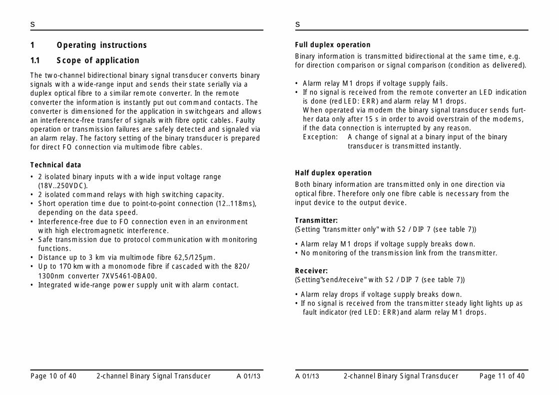
Terminal assignment
Pin Meaning AbbreviationL+ Voltage supply L+ AC: L1 DC: L+L- Voltage supply L- AC: N DC: L-Pin 1 Fault signal relay contact M1 1 (NC contact)Pin 2 Fault signal relay contact M1 2 (NC contact)Pin 3 Command relay K1 3 (NO contact)Pin 4 Command relay K1 4 (NO contact)Pin 5- Binary input 1- BI-1-Pin 6+ Binary input 1+ BI-1+Pin 7- Binary input 2- BI-2-Pin 8+ Binary input 2+ BI-2+Pin 9 Command relay K2 9 (NO contact)Pin 10 Command relay K2 10 (NO contact)
Tab. 4: Screw-type terminals
1.4 Description of the functional units
The signal converters inside the housing are hard-wired and testedfunctional units. They are provided with a clip-on mounting for a DIN EN50022 top-hat rail 35 mm. Auxiliary power supply can be safely connectedat the screw-type terminals. The FO channels are adapted via the ST-terminals. The RS232 interface is connected via a 9-pole sub-Dsocket. The devices are free of silicone and halogen as well asflame-retardant.
1.4.1 Position and assignment of the terminals
Fig. 3: Position and assignment of the terminals
8+ 46+ 27- 35- 1 L1/L+
10K2
9
Binärsignalübertrager7XV565 3-0BA0 0
SERIES: TDD-M2-450085
UH:
UH:5
RU
N
Bl-1
Bl-1Bl-2
Bl-2
K1
K1 M1
24-250 VDC/5W60-230 VAC/5VA(45-60 Hz)
K2
ERR

A 01/13 2-channel Binary Signal Transducer Page 29 of 40
s
Page 28 of 40 2-channel Binary Signal Transducer A 01/13
s
Explanation
DIP switch (S1, S2)
Table 6: S1, DIP switch (2)
Bold type = factory setting
1.4.2 Switch positions and RS232 interface
The DIP switches can be operated from outside.Position of the DIP-Schalter: View from the front
1 2 S1
FO receiver ST input •
FO transmitter ST output •
87654321
S2
X1
ON OFF
OFF ON
Fig. 4: Positions of the switches
Pin Description Abbreviation Direction asD T E
1 - - No connect ion2 Receive data RxD In ←3 Transmit data TxD Out →4 - - No connect ion5 Signal ground G N D -6 - - -7 Signal ground G N D -8 Active interface
selectionBridge Input
9 - - -
Switch Meaning RemarkNot connected FO connection active Pin 8 openFactory setting isFO connection
RS232 connectionactive
Bridge pin 8 – 7At the converter input
Switch Position Meaning1 Open = off
Closed = onLight off in idle state: FO receivingLight on in idle state: FO receiving
2 Open = offClosed = on
Light off in idle state: FOtransmittingLight on in idle state: FO transmitting
Table 5: RS232 interface, 9-pole sub-D socket

A 01/13 2-channel Binary Signal Transducer Page 31 of 40
s
Page 30 of 40 2-channel Binary Signal Transducer A 01/13
s
Table 7: S2, DIP switches (8)
bold type = factory setting
Explanation:
8E1 = 8 data, even parity, 1 stop bit8N1 = 8 data, no parity, 1 stop bit
Testmode on:
The binary signal transducer runs a self-test. If the binary input is activated(voltage impressed) the binary LED lights up (BI-1 or BI-2) and thecorresponding relay (K1 or K2) with associated LED (K1 or K2) is activated.The diagnosis of the memory test and the position of the DIP switchesare put out on the serial interface (RS232) and can be displayed with aterminal programm, running on a PC.
DIP 8 DIP 7 DIP 6 DIP 5 DIP 4 DIP 3 DIP 2 DIP 1 Meaning
- - - - - ON ON ON 1200 baud- - - - - ON ON OFF 2400 baud- - - - - ON OFF ON 4800 baud- - - - - ON OFF OFF 9600 baud- - - - - OFF ON ON 19200 baud- - - - - OFF ON OFF 38400 baud- - - - - OFF OFF ON 57600 baud- - - - - OFF OFF OFF 115200 baud- - - - ON - - - 8E1- - - - OFF - - - 8N1- - - ON - - - - Block MA- - - OFF - - - - Enable MA- - ON - - - - - Testmode on- - OFF - - - - - Testmode off- ON - - - - - - Transmitter only- OFF - - - - - - Transmit/receive
ON - - - - - - - Bootloader onOFF - - - - - - - Bootloader off
Setting of the baud rate via S2:
The baud rate (position of the DIP switches) is queried once after theswitching on. During active testmode the baud rate is queriedcontinuously and set anew.Baud rate during operation: set baud rate via DIP switch 0..2, shortlyswitch on and off DIP switch 6 (testmode).
Pitch up threshold of the binary inputs
Testmode off: The binary signal transducer is ready for normal operation.Block MA: Block message outputs, the relays are not controlled.Enable MA: Normal operation, message outputs are not put out.Transmitter only:The binary signal transducer acts as transmitter only.
Missing incoming signals are not reported as comm. errors.
THE DEVICE MUST NOT BE OPERATED WHEN OPEN.Remove Powersupply in this case!
Warning !
To change the threshold of the binary inputs the binary signal transducerhas to be opened and jumpers have to be changed.
A 01/13 2-channel Binary Signal Transducer Page 33 of 40
s
Page 32 of 40 2-channel Binary Signal Transducer A 01/13
s
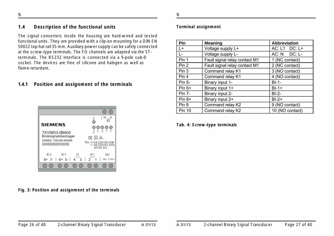
Fig. 5: Switching threshold of the binary inputsTo change the jumper positions, the following instructions must beobserved:• Disconnect the device• Remove the cover of the housing• with a small screwdriver, force the clips of the cover carefully
toward inside of the device• change the jumper positions as shown in table 8• snap the cover back into its position
Jumper Position Pick upthreshold
Binary inputs
X100 1-2 17 V 1 (BI-1)X100 2-3 70 V 1 (BI-1)X200 1-2 17 V 2 (BI-2)X200 2-3 70 V 2 (BI-2)
Table 8: Switching threshold of the binary inputsbold type = factory setting
X200
X100
1
1
105
95
8+ 46+ 27- 35- 1 L1/L+
10K2
9
Binärsignalübertrager7XV5653-0BA00
SERIES: TDD-M2-450085
UH:
UH:
90
95
5
RU
N
Bl-1
Bl-1Bl-2
Bl-2
K1
K1 M1
24-250 VDC/5W60-230 VAC/5VA(45-60 Hz)
K2
ER
R
clips(see page 32)
1.4.3 Dimensional drawings

A 01/13 2-channel Binary Signal Transducer Page 35 of 40
s
Page 34 of 40 2-channel Binary Signal Transducer A 01/13
s
Name Order No.
Binary signal transducer7XV two-channel
2 binary inputs,2 command inputs,1 fault signal output via terminals
1.5 Ordering data
5 6 5 B03
Code
A 0 0
1.6 Installation and commissioning
Warning!
When operating electrical devices, certain parts of these devices arenecessarily under dangerous voltage. Therefore, disregard of theoperating notes may cause severe bodily injury or property damage.Installation and electrical connection of the device should be performedby adequately qualified personnel only.In particular, all warnings must be strictly observed.
Do not look directly into the FO transmission diodes whenwearing optical aids !!!
Warning !
THE DEVICE MUST NOT BE OPERATED WHEN OPEN.
Warning !

A 01/13 2-channel Binary Signal Transducer Page 37 of 40
s
Page 36 of 40 2-channel Binary Signal Transducer A 01/13
s
Connection
• For the electrical connection the regulations on the erection ofheavy-current installations are to be observed.
• The connection of the device is to be carried out according toVDE0100 and VDE0160.
• The auxiliary supply of the device is to be provided with an externaldisconnector (switch) for the safety isolation of the power supplyand with a safety device (fuse), 2AT or 4AT.The external disconnector is to be labelled accordingly. A safety cut-out can possibly act in both functions.
• Cable cross section (single-core cable or litz wire):0,5mm² - 2,5mm²
• Recommended stripping length: 5mm.
Installation
• The installation location should be free of vibrations.The admissible ambient temperature (operation or functionaltemperature) is to be observed (see technical data).
• Disregard of the temperature range required for proper functionmay cause malfunction of the device and failure of the signalconverter.
• Plastic housing, overvoltage categorey III according to DIN EN61010 part 1.
• The signal transducer can be clipped on a 35 mm top-hat rail(according to DIN EN 50022).
• The devices are permitted only for operation within enclosedhousing or cabinets and the places of installation are to beaccessible only for qualified personnel.
Any connections with litz wire are to be realised with thehelp of wire end ferrules with isolation (this avoids fraying).
Warning !
1.7 Settings
All settings of the binary signal transducer can be carried out from outsidevia DIP switches (except pick up voltage of binary inputs). The housingdoes not have to be opened for this. Exception: Setting of the switchingthreshold (see chapter 1.4.2).Description see chapter 1.2.2.
1.8 Maintenance
The binary signal transducer requires no maintenance.Do not use any liquid agents or substances for cleaning.
Commissioning
• Check whether the operation data comply with the values on therating plate.
• Do not make any changes at the device.• Clip the binary signal transducer on the top-hat rail with the help of
the clip-on mounting.• Connect auxiliary power to terminals UH (DC:L+ / AC:L1) and (DC:L-
/ AC:N).• Connect FO cable to FO receiver and FO transmitter with the help
of ST-type terminals.• Or connect RS232 cable.• The binary signal transducer is ready for use after switching on
auxiliary power. The green LED 'RUN' lights up.
• Only optical fibres prepared according to the regulations are to beused.
• FO types: see technical data.• The admissibla optical budget is to be observed
(see technical data).• When installing optical fibres the prescribed bending radius is to be
observed!

empty page

s
If you have any notes or questions on this productplease contact us under the following address:
Siemens AGPower transmission und distribution,Secondary systemsPO Box 4806D-90026 Nuremberg
Phone +49 (0)180 524 7000
Order-No.:Order location: G340BPrinted in Germay