GAS CHROMATOGRAPHY - Siemens Industry Online Support
598
GAS CHROMATOGRAPHY p process MAXUM TM edition II Process Gas Chromatograph Maintenance Manual Edition 6/2008
-
Upload
khangminh22 -
Category
Documents
-
view
1 -
download
0
Transcript of GAS CHROMATOGRAPHY - Siemens Industry Online Support

GAS CHROMATOGRAPHY p process
MAXUMTM edition IIProcess Gas Chromatograph
Maintenance Manual Edition 6/2008

Maxum edition II Process Gas Chromatograph

Copyright Notice
2002-2008 by Siemens
All rights reserved.
This publication is for information only. The contents are subject to change without notice and should not be construed as a commitment, representation, warranty, or guarantee of any method, product, or device by Siemens.
Reproduction or translation of any part of this publication beyond that permitted by Sections 107 and 109 of the United States Copyright Act without the written consent of the copyright owner is unlawful.
To Contact Us:
Siemens AG I IA SC PA PM Process Analytics Oestliche Rheinbrueckenstr. 50 76187 Karlsruhe Germany Tel: +49 721 595 3829 Fax: +49 721 595 5211 E-mail: [email protected] www.siemens.com/processanalytics Training Tel: +49 721 595 4035 E-mail: [email protected] Spares Tel: +49 721 595 4288 E-mail: [email protected] Support Tel: +49 721 595 7216 E-mail: [email protected]
Siemens Energy & Automation, Inc. 7101 Hollister Road Houston, TX 77040 USA Tel: +1 713 939 7400 Fax: +1 713 939 9050 E-mail: [email protected] www.usa.siemens.com/ia Training Tel: +1 800 448 8224 (USA) Tel. +1 918 662 7030 (International) E-mail: [email protected] Spares Tel: +1 800 448 8224 (USA) Tel: +1 918 662 7030 (International) Fax: +1 918 662 7482 E-mail: [email protected] Support Tel: +1 800 448 8224 (USA) Tel: +1 918 662 7030 (International) E-mail: [email protected]
Siemens Pte. Limited A&D PI 2 Regional Headquarters The Siemens Center 60 MacPherson Road Singapore 348615 Tel: +65 6490 8702 Fax: +65 6490 8703 E-mail: [email protected] www.siemens.com/processanalytics
Siemens Industrial Automation Shanghai Siemens Process Analytics Ltd., Shanghai PI and Analytics Technical Service Center12 workshops, 175 XiMaoJing Road Export Processing Zone, SongJiang Shanghai, 201611 Peoples Republic of China Tel: +86-21-5774 9977 Fax: +86-21-6774 7181 E-mail: [email protected] www.ad.siemens.com.cn
Trademarks
Maxum and Maxum edition II are trademarks of Siemens
ii 2000596-001

Safety Practices and Precautions
This product has been designed and tested in accordance with IEC Publication 1010-1, Safety Requirements for Electronic Measuring Apparatus, and has been supplied in a safe condition. This manual contains information and warnings which have to be followed by the user to ensure safe operation and to retain the product in a safe condition.
WARNING statements identify conditions or practices that could result in personal injury or loss of life.
CAUTION statements identify conditions or practices that could result in damage to the equipment or other property.
DANGER indicates a personal injury hazard immediately accessible as one reads the markings.
CAUTION indicates a personal injury hazard not immediately accessible as one reads the markings, or a hazard to property, including the equipment itself.
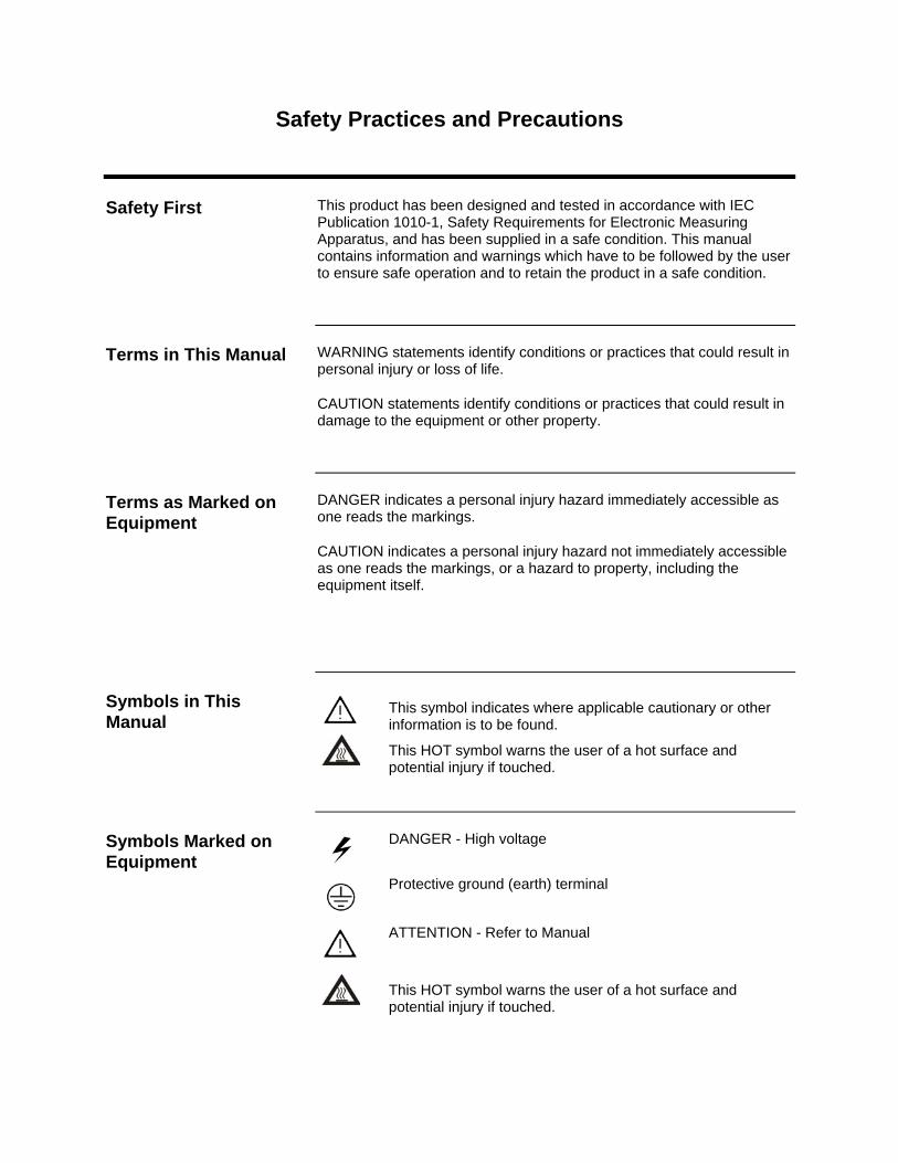
This symbol indicates where applicable cautionary or other information is to be found.
This HOT symbol warns the user of a hot surface and potential injury if touched.
DANGER - High voltage
Protective ground (earth) terminal
ATTENTION - Refer to Manual
This HOT symbol warns the user of a hot surface and potential injury if touched.
Safety First
Terms in This Manual
Terms as Marked on Equipment
Symbols in This Manual
Symbols Marked on Equipment
Safety Practices and Precautions, Continued
A grounding conductor should be connected to the grounding terminal before any other connections are made.
Before switching on the power, check that the operating voltage listed on the equipment agrees with the available line voltage.
Any interruption of the grounding conductor inside or outside the equipment or loose connection of the grounding conductor can result in a dangerous unit. Intentional interruption of the grounding conductor is not permitted.
If it is determined that the equipment cannot be operated safely, it should be taken out of operation and secured against unintentional usage.
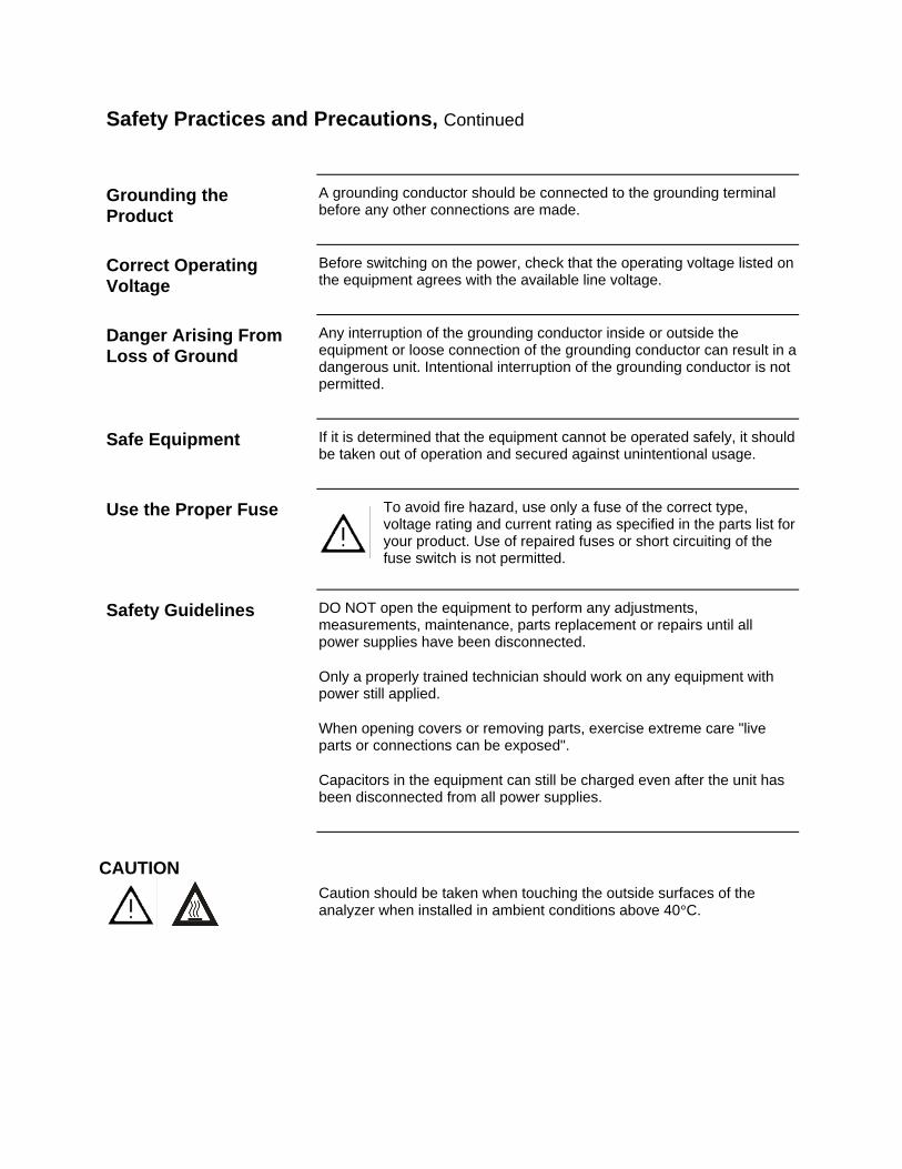
To avoid fire hazard, use only a fuse of the correct type, voltage rating and current rating as specified in the parts list for your product. Use of repaired fuses or short circuiting of the fuse switch is not permitted.
DO NOT open the equipment to perform any adjustments, measurements, maintenance, parts replacement or repairs until all power supplies have been disconnected.
Only a properly trained technician should work on any equipment with power still applied.
When opening covers or removing parts, exercise extreme care "live parts or connections can be exposed".
Capacitors in the equipment can still be charged even after the unit has been disconnected from all power supplies.
Caution should be taken when touching the outside surfaces of the analyzer when installed in ambient conditions above 40°C.
Grounding the Product
Correct Operating Voltage
Danger Arising From Loss of Ground
Safe Equipment
Use the Proper Fuse
Safety Guidelines
CAUTION
Chapter 1
Knowing Your System
Introduction
Overview The Maxum edition II system, hereafter referred to as Maxum II, represents a significant advance in process chromatography. This was accomplished by combining the best of the Siemen’s Advance Maxum and PGC 302 gas chromatographs into a single platform analyzer. From oven and electronic components to software and communication networks, the system is modular. Pre-configured application modules are available for many common measurements.
A Maxum II system offers a wide range of detector modules including Thermal Conductivity, Flame Ionization, Flame Photometric, and the Pulsed Discharge Detector (which can operate in Helium Ionization, Photoionization, and Electron Capture modes). All detector modules are available for both air bath and airless ovens. The Maxum II oven is designed so it can be divided into two independently heated isothermal ovens for parallel chromatrography applications. A single air bath oven can accommodate up to 3 detector modules, and an airless oven can house a single detector module in each oven.
The Advance Maxum II Maintenance Panel provides maintenance personnel with access to all maintenance functions and data. In addition, the Maintenance Panel will display both real time and archived chromatograms. A PC based network workstation incorporates EZChrom industry specific software. This laboratory quality application builder includes custom features designed particularly for the Maxum II.
This chapter covers the following topics: In this chapter
Topic Page
Introduction 1-1
Maxum II Specifications 1-3
About the Maxum II 1-8
Advance Maxum II Operation Overview 1-17
Functional Tasks 1-21
Analyzer Internal Communications 1-24
Maxum II Hardware Identification 1-27
Advance Communication System 1-29
Advance Data Hiway Communications 1-30
2000596-001 Knowing Your System 1-1
Introduction, Continued
Included with each analyzer is a custom documentation-drawing package. This package provides drawings and information pertinent only to a specific analyzer. Contents of this package are application dependent and will vary for each analyzer. Typical drawings included are:
Important Information
System Block and Utility Requirements System Outline and Dimensional Drawings Sampling System - Plumbing and Spare Parts List Sampling System Dimensional Diagram Sampling Probe Electronic Enclosure Section - Internal Layout Applicable Wiring Diagrams Oven Plumbing Diagram - Sensor Near Electronics Recommended Spare Parts - Analyzer Manufacturing Test Charts Stream Composition Data Data Base
1-2 Knowing Your System 2000596-001
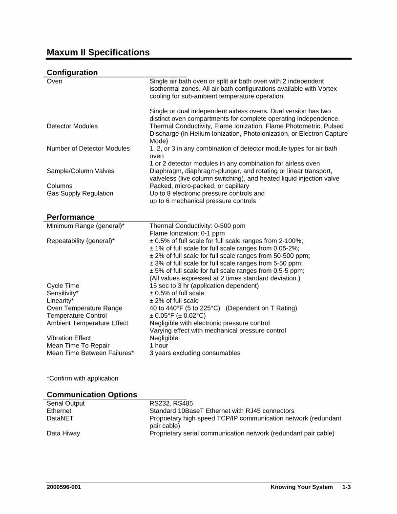
Maxum II Specifications
Configuration Oven Single air bath oven or split air bath oven with 2 independent
isothermal zones. All air bath configurations available with Vortex cooling for sub-ambient temperature operation. Single or dual independent airless ovens. Dual version has two distinct oven compartments for complete operating independence.
Detector Modules Thermal Conductivity, Flame Ionization, Flame Photometric, Pulsed Discharge (in Helium Ionization, Photoionization, or Electron Capture Mode)
Number of Detector Modules 1, 2, or 3 in any combination of detector module types for air bath oven 1 or 2 detector modules in any combination for airless oven
Sample/Column Valves Diaphragm, diaphragm-plunger, and rotating or linear transport, valveless (live column switching), and heated liquid injection valve
Columns Packed, micro-packed, or capillary Gas Supply Regulation Up to 8 electronic pressure controls and
up to 6 mechanical pressure controls
Performance Minimum Range (general)* Thermal Conductivity: 0-500 ppm
Flame Ionization: 0-1 ppm Repeatability (general)* ± 0.5% of full scale for full scale ranges from 2-100%;
± 1% of full scale for full scale ranges from 0.05-2%; ± 2% of full scale for full scale ranges from 50-500 ppm; ± 3% of full scale for full scale ranges from 5-50 ppm; ± 5% of full scale for full scale ranges from 0.5-5 ppm; (All values expressed at 2 times standard deviation.)
Cycle Time 15 sec to 3 hr (application dependent) Sensitivity* ± 0.5% of full scale Linearity* ± 2% of full scale Oven Temperature Range 40 to 440°F (5 to 225°C) (Dependent on T Rating) Temperature Control ± 0.05°F (± 0.02°C) Ambient Temperature Effect Negligible with electronic pressure control
Varying effect with mechanical pressure control Vibration Effect Negligible Mean Time To Repair 1 hour Mean Time Between Failures* 3 years excluding consumables *Confirm with application
Communication Options Serial Output RS232, RS485 Ethernet Standard 10BaseT Ethernet with RJ45 connectors DataNET Proprietary high speed TCP/IP communication network (redundant
pair cable) Data Hiway Proprietary serial communication network (redundant pair cable)
2000596-001 Knowing Your System 1-3
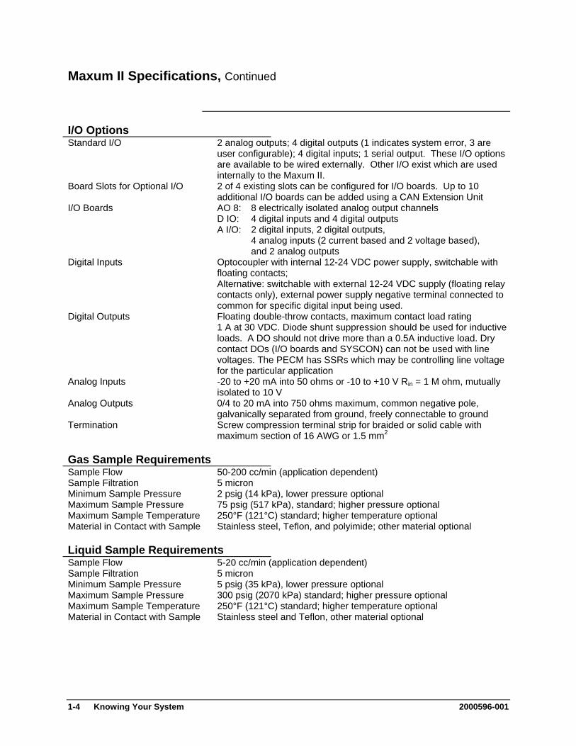
Maxum II Specifications, Continued
I/O Options Standard I/O 2 analog outputs; 4 digital outputs (1 indicates system error, 3 are
user configurable); 4 digital inputs; 1 serial output. These I/O options are available to be wired externally. Other I/O exist which are used internally to the Maxum II.
Board Slots for Optional I/O 2 of 4 existing slots can be configured for I/O boards. Up to 10 additional I/O boards can be added using a CAN Extension Unit
I/O Boards AO 8: 8 electrically isolated analog output channels D IO: 4 digital inputs and 4 digital outputs A I/O: 2 digital inputs, 2 digital outputs, 4 analog inputs (2 current based and 2 voltage based), and 2 analog outputs
Digital Inputs Optocoupler with internal 12-24 VDC power supply, switchable with floating contacts; Alternative: switchable with external 12-24 VDC supply (floating relay contacts only), external power supply negative terminal connected to common for specific digital input being used.
Digital Outputs Floating double-throw contacts, maximum contact load rating 1 A at 30 VDC. Diode shunt suppression should be used for inductive loads. A DO should not drive more than a 0.5A inductive load. Dry contact DOs (I/O boards and SYSCON) can not be used with line voltages. The PECM has SSRs which may be controlling line voltage for the particular application
Analog Inputs -20 to +20 mA into 50 ohms or -10 to +10 V Rin = 1 M ohm, mutually isolated to 10 V
Analog Outputs 0/4 to 20 mA into 750 ohms maximum, common negative pole, galvanically separated from ground, freely connectable to ground
Termination Screw compression terminal strip for braided or solid cable with maximum section of 16 AWG or 1.5 mm2
Gas Sample Requirements Sample Flow 50-200 cc/min (application dependent) Sample Filtration 5 micron Minimum Sample Pressure 2 psig (14 kPa), lower pressure optional Maximum Sample Pressure 75 psig (517 kPa), standard; higher pressure optional Maximum Sample Temperature 250°F (121°C) standard; higher temperature optional Material in Contact with Sample Stainless steel, Teflon, and polyimide; other material optional
Liquid Sample Requirements Sample Flow 5-20 cc/min (application dependent) Sample Filtration 5 micron Minimum Sample Pressure 5 psig (35 kPa), lower pressure optional Maximum Sample Pressure 300 psig (2070 kPa) standard; higher pressure optional Maximum Sample Temperature 250°F (121°C) standard; higher temperature optional Material in Contact with Sample Stainless steel and Teflon, other material optional
1-4 Knowing Your System 2000596-001
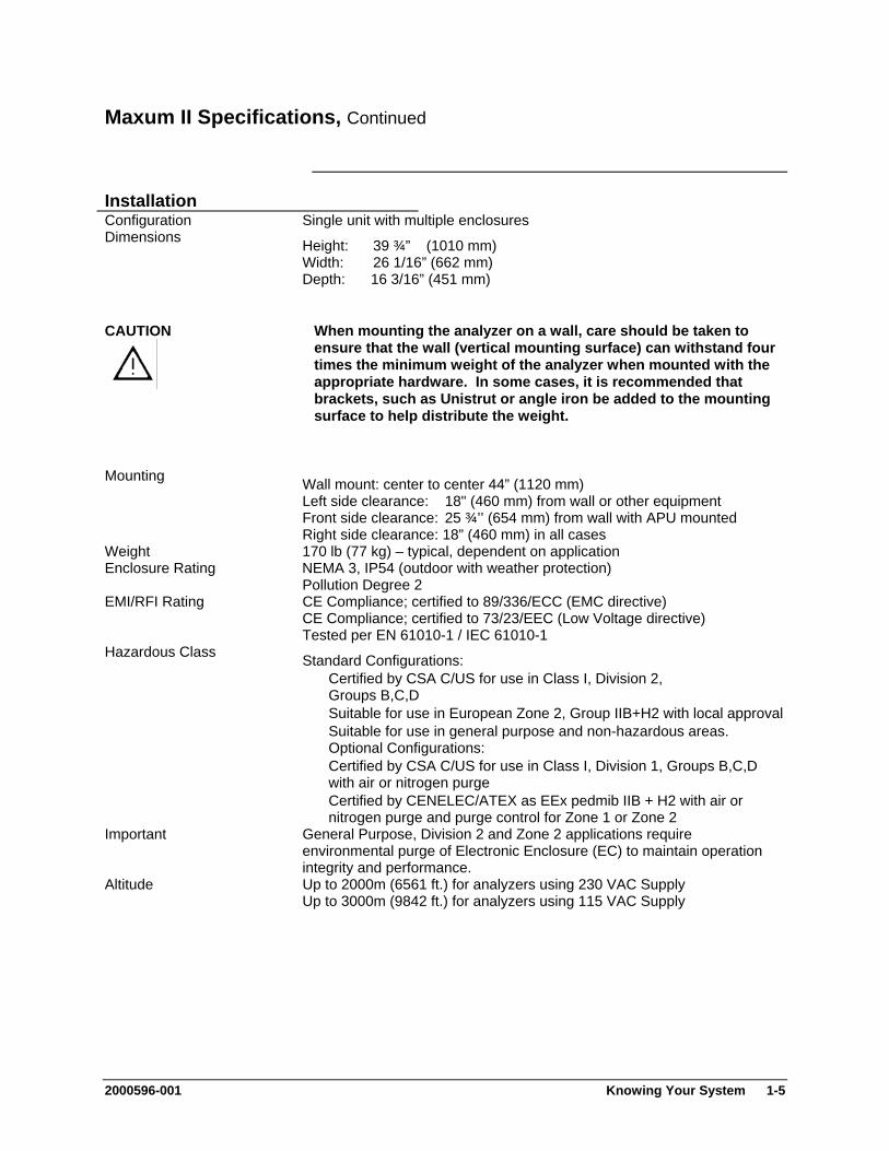
Maxum II Specifications, Continued
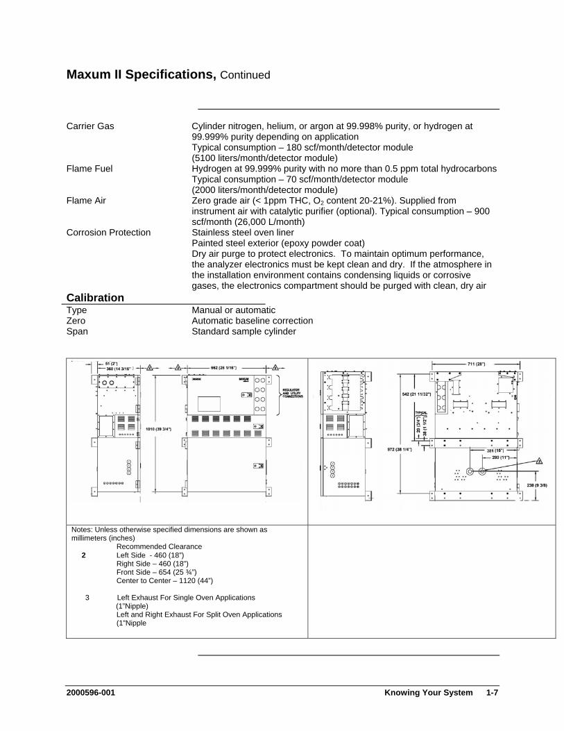
Installation Configuration Single unit with multiple enclosures Dimensions Height: 39 ¾” (1010 mm)
Width: 26 1/16” (662 mm) Depth: 16 3/16” (451 mm)
When mounting the analyzer on a wall, care should be taken to ensure that the wall (vertical mounting surface) can withstand four times the minimum weight of the analyzer when mounted with the appropriate hardware. In some cases, it is recommended that brackets, such as Unistrut or angle iron be added to the mounting surface to help distribute the weight.
CAUTION
Mounting Wall mount: center to center 44” (1120 mm)
Left side clearance: 18" (460 mm) from wall or other equipment Front side clearance: 25 ¾’’ (654 mm) from wall with APU mounted Right side clearance: 18” (460 mm) in all cases
Weight 170 lb (77 kg) – typical, dependent on application Enclosure Rating NEMA 3, IP54 (outdoor with weather protection)
Pollution Degree 2 EMI/RFI Rating CE Compliance; certified to 89/336/ECC (EMC directive)
CE Compliance; certified to 73/23/EEC (Low Voltage directive) Tested per EN 61010-1 / IEC 61010-1
Hazardous Class Standard Configurations: Certified by CSA C/US for use in Class I, Division 2,
Groups B,C,D Suitable for use in European Zone 2, Group IIB+H2 with local approval Suitable for use in general purpose and non-hazardous areas.
Optional Configurations: Certified by CSA C/US for use in Class I, Division 1, Groups B,C,D
with air or nitrogen purge Certified by CENELEC/ATEX as EEx pedmib IIB + H2 with air or
nitrogen purge and purge control for Zone 1 or Zone 2 Important General Purpose, Division 2 and Zone 2 applications require
environmental purge of Electronic Enclosure (EC) to maintain operation integrity and performance.
Altitude Up to 2000m (6561 ft.) for analyzers using 230 VAC Supply Up to 3000m (9842 ft.) for analyzers using 115 VAC Supply
2000596-001 Knowing Your System 1-5
Maxum II Specifications, Continued
Ambient Temperature and Humidity (for Normal Operation, Storage, and Transport)
Minimums - 0°F (-18°C) and 0% Humidity Maximums - Up to 104°F (40°C) at 50% relative humidity Up to 86°F (30°C) at 80% relative humidity Operational Maximums – The Maxum II may be operated at ambient conditions of up to 122°F (50°C) and 95% relative humidity provided the electronic doors are not opened and the electronics compartment is purged with clean, dry instrument air. The instrument air must be dry enough to prevent humidity condensation inside the electronics enclosure. Note: If the Maxum II is exposed to high condensing humidity with the electronics open or without dry purge air applied, then it must be allowed to re-stabilize at the above stated conditions for at least 8 hours before electrical power is applied.
AC Power 100-130 VAC or 187-264 VAC (configuration dependent); 47-63 Hz., single phase Transient Overvoltage – Category II (IEC 60364-4-443) Single oven: 14 A maximum (at 115 V or 7 A at 230 V) Dual oven: 2 circuits, 14 A maximum per oven
To meet European Standards, customer provided power cables should be double insulated (unless both power and signal wiring are rated for 600 volts, in which case basic insulation is sufficient) Wiring should be rated for 80°C or higher.
AC Power Consumption for Common Components
The maximum expected power consumption for an analyzer can be estimated by adding the maximum consumption of the components that are equipped. Ovens: Airbath Heater Oven (High Wattage) 1400 W per heater (One heater equipped per oven side) Airbath Heater Oven (Medium Wattage) 650 W per heater (One heater equipped per oven side) Airless Heater Oven 500 W per oven side (Two 250 W heaters equipped per oven side) Other components: FID/FPD Heater Element – 80 W SLIV Heater Element – 100 W MAT Valve Heater Element – 200 W Methanator (Purged) Heater Element – 200 W Electronics Enclosure Devices – 100 W
Instrument Air 50 psig (350kPa) minimum for units using Model 11 or Valco valves 120 psig (825 kPa) minimum for units using Model 50 valves Airbath Oven: 25 psig (175 kPa) minimum; 3 scfm (85 Lpm)/ oven Airless Oven: No instrument air for heating (may be used for electronics purge).
1-6 Knowing Your System 2000596-001
Maxum II Specifications, Continued
Carrier Gas Cylinder nitrogen, helium, or argon at 99.998% purity, or hydrogen at 99.999% purity depending on application Typical consumption – 180 scf/month/detector module (5100 liters/month/detector module)
Flame Fuel Hydrogen at 99.999% purity with no more than 0.5 ppm total hydrocarbons Typical consumption – 70 scf/month/detector module (2000 liters/month/detector module)
Flame Air Zero grade air (< 1ppm THC, O2 content 20-21%). Supplied from instrument air with catalytic purifier (optional). Typical consumption – 900 scf/month (26,000 L/month)
Corrosion Protection Stainless steel oven liner Painted steel exterior (epoxy powder coat) Dry air purge to protect electronics. To maintain optimum performance, the analyzer electronics must be kept clean and dry. If the atmosphere in the installation environment contains condensing liquids or corrosive gases, the electronics compartment should be purged with clean, dry air
Calibration Type Manual or automatic Zero Automatic baseline correction Span Standard sample cylinder
Notes: Unless otherwise specified dimensions are shown as millimeters (inches) Recommended Clearance 2 Left Side - 460 (18”) Right Side – 460 (18”) Front Side – 654 (25 ¾”) Center to Center – 1120 (44”)
3 Left Exhaust For Single Oven Applications (1”Nipple)
Left and Right Exhaust For Split Oven Applications (1”Nipple
2000596-001 Knowing Your System 1-7
About The Maxum II
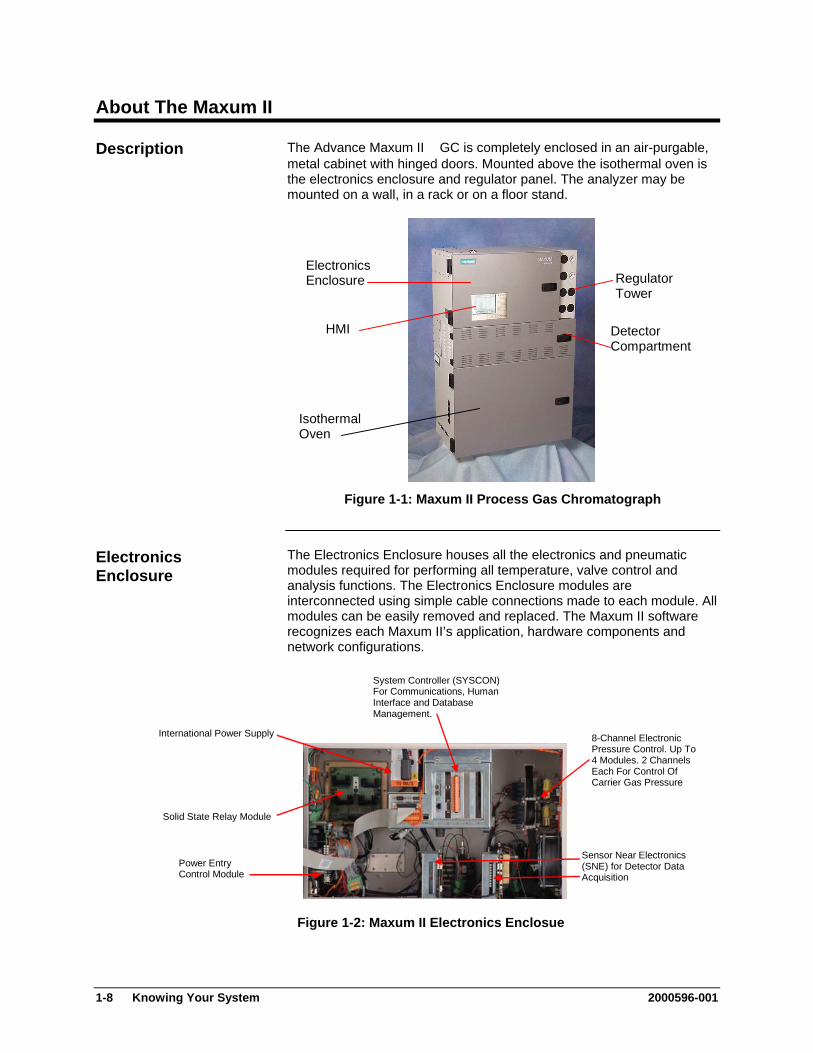
Description The Advance Maxum II GC is completely enclosed in an air-purgable, metal cabinet with hinged doors. Mounted above the isothermal oven is the electronics enclosure and regulator panel. The analyzer may be mounted on a wall, in a rack or on a floor stand.
Electronics Enclosure
Isothermal Oven
Regulator Tower
Detector Compartment
HMI
Figure 1-1: Maxum II Process Gas Chromatograph
The Electronics Enclosure houses all the electronics and pneumatic modules required for performing all temperature, valve control and analysis functions. The Electronics Enclosure modules are interconnected using simple cable connections made to each module. All modules can be easily removed and replaced. The Maxum II software recognizes each Maxum II’s application, hardware components and network configurations.
Electronics Enclosure
System Controller (SYSCON) For Communications, Human Interface and Database Management.
International Power Supply
Sensor Near Electronics (SNE) for Detector Data Acquisition
Power Entry Control Module
8-Channel Electronic Pressure Control. Up To 4 Modules. 2 Channels Each For Control Of Carrier Gas Pressure
Solid State Relay Module
Figure 1-2: Maxum II Electronics Enclosue
1-8 Knowing Your System 2000596-001
About The Maxum II, Continued
The regulator panel contains space for seven gauges and regulators. The base Maxum II comes with two standard regulators and an electronics enclosure fast purge. See the custom documentation drawing package that was shipped with the analyzer to see which gauges and regulators are mounted on the analyzer.
Regulator Panel
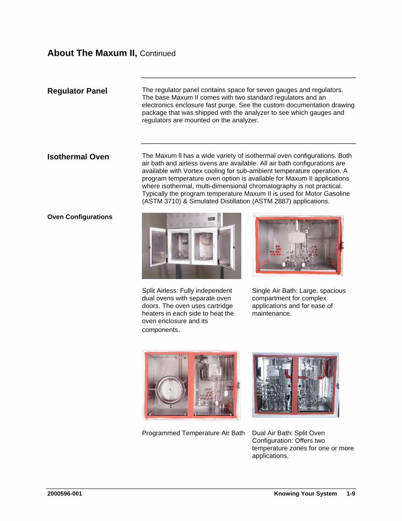
The Maxum ll has a wide variety of isothermal oven configurations. Both air bath and airless ovens are available. All air bath configurations are available with Vortex cooling for sub-ambient temperature operation. A program temperature oven option is available for Maxum II applications where isothermal, multi-dimensional chromatography is not practical. Typically the program temperature Maxum II is used for Motor Gasoline (ASTM 3710) & Simulated Distillation (ASTM 2887) applications.
Isothermal Oven
Oven Configurations
Split Airless: Fully independent dual ovens with separate oven doors. The oven uses cartridge heaters in each side to heat the oven enclosure and its components.
Single Air Bath: Large, spacious compartment for complex applications and for ease of maintenance.
Programmed Temperature Air Bath Dual Air Bath: Split Oven Configuration: Offers two temperature zones for one or more applications.
2000596-001 Knowing Your System 1-9
About The Maxum II, Continued
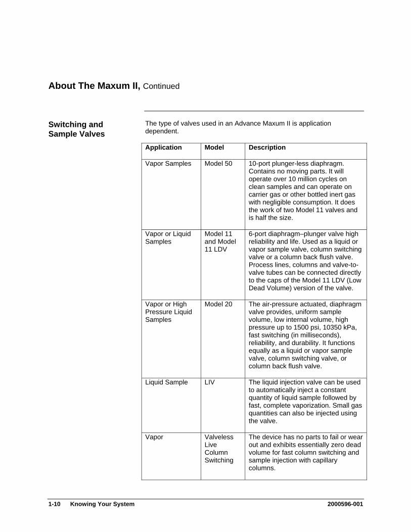
The type of valves used in an Advance Maxum II is application dependent.
Switching and Sample Valves
Application Model Description
Vapor Samples Model 50 10-port plunger-less diaphragm. Contains no moving parts. It will operate over 10 million cycles on clean samples and can operate on carrier gas or other bottled inert gas with negligible consumption. It does the work of two Model 11 valves and is half the size.
Vapor or Liquid Samples
Model 11 and Model 11 LDV
6-port diaphragm–plunger valve high reliability and life. Used as a liquid or vapor sample valve, column switching valve or a column back flush valve. Process lines, columns and valve-to-valve tubes can be connected directly to the caps of the Model 11 LDV (Low Dead Volume) version of the valve.
Vapor or High Pressure Liquid Samples
Model 20 The air-pressure actuated, diaphragm valve provides, uniform sample volume, low internal volume, high pressure up to 1500 psi, 10350 kPa, fast switching (in milliseconds), reliability, and durability. It functions equally as a liquid or vapor sample valve, column switching valve, or column back flush valve.
Liquid Sample LIV The liquid injection valve can be used to automatically inject a constant quantity of liquid sample followed by fast, complete vaporization. Small gas quantities can also be injected using the valve.
Vapor Valveless Live Column Switching
The device has no parts to fail or wear out and exhibits essentially zero dead volume for fast column switching and sample injection with capillary columns.
1-10 Knowing Your System 2000596-001
About The Maxum II, Continued
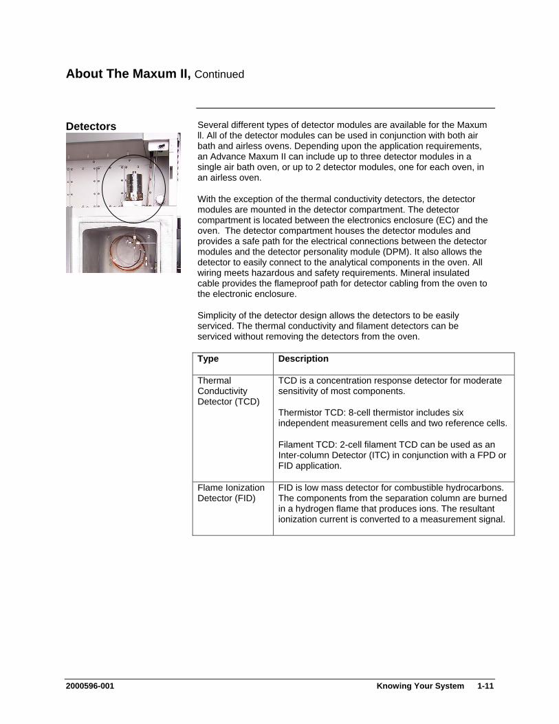
Several different types of detector modules are available for the Maxum ll. All of the detector modules can be used in conjunction with both air bath and airless ovens. Depending upon the application requirements, an Advance Maxum II can include up to three detector modules in a single air bath oven, or up to 2 detector modules, one for each oven, in an airless oven.
Detectors
With the exception of the thermal conductivity detectors, the detector modules are mounted in the detector compartment. The detector compartment is located between the electronics enclosure (EC) and the oven. The detector compartment houses the detector modules and provides a safe path for the electrical connections between the detector modules and the detector personality module (DPM). It also allows the detector to easily connect to the analytical components in the oven. All wiring meets hazardous and safety requirements. Mineral insulated cable provides the flameproof path for detector cabling from the oven to the electronic enclosure.
Simplicity of the detector design allows the detectors to be easily serviced. The thermal conductivity and filament detectors can be serviced without removing the detectors from the oven.
Type Description
Thermal Conductivity Detector (TCD)
TCD is a concentration response detector for moderate sensitivity of most components.
Thermistor TCD: 8-cell thermistor includes six independent measurement cells and two reference cells.
Filament TCD: 2-cell filament TCD can be used as an Inter-column Detector (ITC) in conjunction with a FPD or FID application.
Flame Ionization Detector (FID)
FID is low mass detector for combustible hydrocarbons. The components from the separation column are burned in a hydrogen flame that produces ions. The resultant ionization current is converted to a measurement signal.
2000596-001 Knowing Your System 1-11
About The Maxum II, Continued
Detectors, cont’d Type Description
Flame Photometric Detector (FPD)
FPD is a selective detector used to detect substances containing sulfur. The column effluent is fed to a fuel rich hydrogen flame. Optical emissions are generated with wavelengths specific to the sulfur. An optical filter passes only these wavelengths characteristic for sulfur to a photomultiplier where the measurement signal is generated.
Valco Pulsed Discharge Detector
The Valco Model D-2 Pulsed Discharge Detector (PDD) is manufactured by Valco Instrument Co. Inc. The PDD uses a stable, low powered, pulsed DC discharge in helium as an ionization source. This provides the advantage that the need for a radioactive source is eliminated. However, performance of the PDD is comparable to detectors with conventional radioactive sources.
Three variations of the PDD are available for use in the Maxum II Process Chromatograph. These are Helium Ionization (PDHID), Photoionization (PDPID), and Electron Capture (PDECD).
For more information regarding this detector and its applicable operating modes refer to the Pulsed Discharge Detector Models D-2 and D-2-I Instruction Manual available from Valco Instruments Co. Inc.
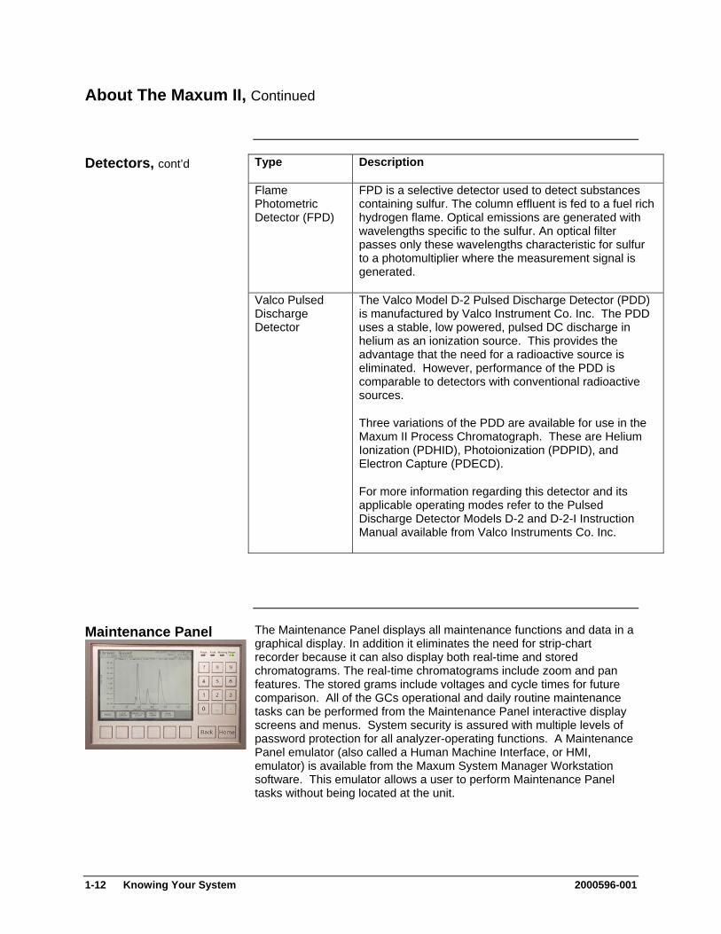
The Maintenance Panel displays all maintenance functions and data in a graphical display. In addition it eliminates the need for strip-chart recorder because it can also display both real-time and stored chromatograms. The real-time chromatograms include zoom and pan features. The stored grams include voltages and cycle times for future comparison. All of the GCs operational and daily routine maintenance tasks can be performed from the Maintenance Panel interactive display screens and menus. System security is assured with multiple levels of password protection for all analyzer-operating functions. A Maintenance Panel emulator (also called a Human Machine Interface, or HMI, emulator) is available from the Maxum System Manager Workstation software. This emulator allows a user to perform Maintenance Panel tasks without being located at the unit.
Maintenance Panel
1-12 Knowing Your System 2000596-001
About The Maxum II, Continued
The Maxum II uses a PC based network workstation for programming and data processing. Analyzers can be programmed and monitored from a single location, and, like the Maintenance Panel, the workstation includes graphical displays for operation, maintenance, and diagnostics. It also supports PC printers to print chromatograms and alarm logs in order to meet record keeping requirements.
Work Station
The Maxum II workstation software is designed for PC’s with Microsoft Windows XP (SP1 or SP2) or Windows 2000. PC workstations can be connected through existing LANs for wide access to monitoring or maintenance tasks. The graphical interface recognizes and displays all network hardware. The system monitors the alarm status of all analyzers connected to the network to centralize system maintenance. More information can be found in the Release Notes file supplied with the Maxum System Manager Software (under the Maxum System Manager directory).
System security is assured with multiple levels of password protection for all analyzer-operating functions.
Chromatography Software EZChrom industry specific software is incorporated in the workstation program. This is a laboratory quality application builder developed by Scientific Software, Inc. and includes custom features for the Maxum II. Using EZChrom, it is possible to set up methods and component peak identification. More information can be found in the Release Notes file supplied with the EZChrom software (under the Maxum EZChrom directory).
EZChrom allows a user to choose the best peak gating and basing methods automatically. It is also possible to:
Re-process captured chromatograms with different methods Measure unknown component peaks automatically Record multiple detector measurements simultaneously.
2000596-001 Knowing Your System 1-13
About The Maxum II, Continued
The following are new terms that are used in this manual. Terms
Application refers to the supporting hardware and software required to perform the analysis. Supporting hardware consists of hardware channels: detector channel (AI), Solenoid Valve Control Module channel (AO), Electronic Pressure Control channel (DI), Temperature Controller (DO). Streams are defined to applications. If there are 3 or 4 simultaneous streams, they are defined as a single group called a Method. Applications can run only one Method at a time. Two applications can run if there are have two cycle clocks in the Maxum II.
Method is the part of the application that contains the parameters for controlling the hardware. Methods control the hardware associated with an Application. The method tells the hardware what to do, and include all cycle clock timed events. Methods are defined to streams. That is, several stream sequences can make up one Method. Methods also control the integration and calculations of the chromatogram. There is one cycle clock per method.
Applet refers to pre-engineered chromatographic segments of common applications, which have been optimized and standardized.
Applet Module refers to a complete assembly including Model 50 valve(s), detector and interconnecting tubing all mounted as a single module. The module includes columns and restrictors
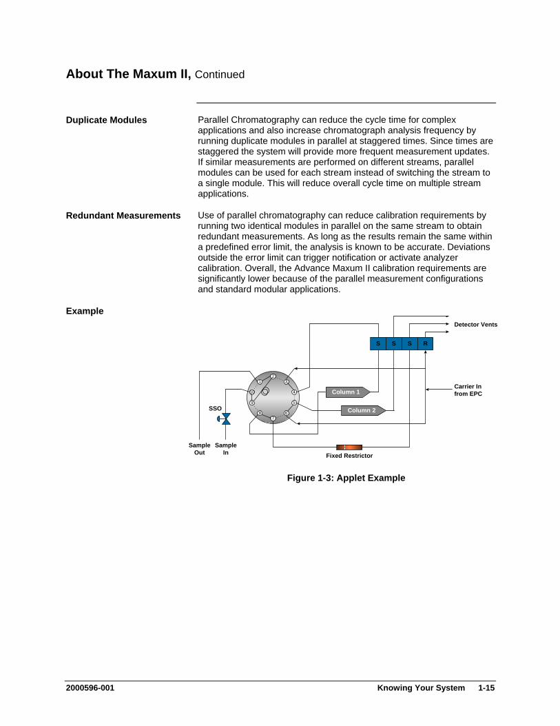
With the Advance Maxum II hardware and software, it is possible to take a complex single-train chromatograph analysis and break it into multiple simple trains. Each simple train is then run simultaneously – in parallel. Not only does this procedure simplify the overall analysis, but also it is performed faster and more reliably.
Parallel Chromatography
Since the chromatography is broken into parallel operating modules, it is possible to use standard configurations for common applications. For example, 95% of the vapor thermal conductivity detector applications in a typical olefins plan can be done with various combinations of fewer than 12 standard mini-applications. Many of these measurements can be performed in less than two minutes. Standard applications modules and methods can be taken off-the-shelf and installed in the analyzer. These mini-applications are referred to as “applets”. Applets can be configured alone or in any combination of parallel groups, depending on the measurement requirements. By using parallel chromatography and applets, it is possible to significantly reduce application development.
Standard Configurations
1-14 Knowing Your System 2000596-001
About The Maxum II, Continued
Parallel Chromatography can reduce the cycle time for complex applications and also increase chromatograph analysis frequency by running duplicate modules in parallel at staggered times. Since times are staggered the system will provide more frequent measurement updates. If similar measurements are performed on different streams, parallel modules can be used for each stream instead of switching the stream to a single module. This will reduce overall cycle time on multiple stream applications.
Duplicate Modules
Use of parallel chromatography can reduce calibration requirements by running two identical modules in parallel on the same stream to obtain redundant measurements. As long as the results remain the same within a predefined error limit, the analysis is known to be accurate. Deviations outside the error limit can trigger notification or activate analyzer calibration. Overall, the Advance Maxum II calibration requirements are significantly lower because of the parallel measurement configurations and standard modular applications.
Redundant Measurements
Example
S S S R
Column 1
Column 2
12
10
9
8
3
4
5
76
Carrier Infrom EPC
SampleOut
SampleIn
SSO
Detector Vents
Fixed Restrictor
Figure 1-3: Applet Example
2000596-001 Knowing Your System 1-15
About The Maxum II, Continued
The Maxum edition II gas chromatograph is primarily used in all branches of the fine chemicals, refining and hydrocarbon processing industries. It performs chemical composition analysis of gases and liquids that are present in all phases of production. The Maxum II is built for installation in harsh environments either directly or nearby in at-line process measurement laboratories. Its application flexibility allows it to analyze samples of feedstock, partially processed streams, final products and process byproducts including wastes and environmental hazards.
Intended Use
This product is intended to be used only in conjunction with other devices and components which have been recommended and approved by Siemens. Appropriate safety standards were used in the development, manufacture, testing, and documentation of the Maxum II. Under normal operation, this product is safe for use providing that all safety and handling guidelines are observed with respect to configuration, assembly, approved use, and maintenance. This device has been designed such that safe isolation is guaranteed between high and low voltage circuits. Low voltages which are connected must also be generated using safe isolation.
If any part of the Maxum II is opened, certain parts of the device are accessible which may carry dangerous voltages. Therefore, only suitably qualified personnel may work on this device as indicated below in the section titled “Qualified Personnel”.
Only suitably qualified personnel may operate or perform maintenance on the Maxum II. For the purposes of safety, qualified personnel are defined as follows:
Qualified Personnel
1. Those who have been appropriately trained for the tasks which
they are performing (for example, commissioning, maintenance, or operation).
2. Those who have been appropriately trained in the operation of automation technology equipment and are sufficiently acquainted with Maxum II documentation.
3. Those who are familiar with the safety concepts of automation technology and are sufficiently acquainted with Maxum II documentation.
4. Those who are authorized to energize, ground and tag circuits and devices in accordance with established safety practices may perform the tasks for which they are trained.
Operation or Maintenance of the Maxum II by unqualified personnel or failure to observe the warnings in this manual or on the device may lead to severe personal injury and/or extensive property damage.
WARNING
1-16 Knowing Your System 2000596-001

Advance Maxum II Operation Overview
This section provides an overview of the operation of the Advance Maxum II Analyzer. Figure 1-4 is an operational block diagram showing how a sample is processed within the analyzer. For simplicity the block diagram only depicts a single stream and one detector. The accompanying narrative traces the sample through the Advance Maxum II and how the various modules interact during the analysis.
Description
Figure 1-4: Operational Block Diagram
See Chapter 2. Advance Maxum II Modules. More Information
2000596-001 Knowing Your System 1-17
Advance Maxum II Operation Overview, Continued
Refer to Figure 1-4 for the following narrative. Analyzer Operation
The Power Entry Control Module (PECM), in response to commands on Internal bus, accepts system primary power and provides switching and control of AC power for oven heaters and other AC powered devices.
Power On
Before being piped to the analyzer, the sample from the process is sent to a sample conditioner system. The sample conditioner ensures that the process sample is compatible with the requirements of the analyzer. That is, it assures that the phase, pressure, temperature and flow rate to the analyzer are suitable, that the sample is filtered, that condensates are removed and other treatments are carried out. The resultant conditioned sample is piped via 1/8-inch stainless steel tubing to the sample valve(s) located in the oven of the Advance Maxum II.
Sample Conditioning
The type of sample valve used in an Advance Maxum II is application dependent. Five primary types of sample valves are available. The first is the 10-port Model 50 valve that is designed for vapor sample only. The second is the Model 11 valve for vapor or liquid samples. Third is the Model 20 valve for liquid high-pressure samples. The fourth type the set of Valco valves that are designed for high temperatures and very low sample volumes, and the fifth is the independently heated Siemens Liquid Injection Valve. The sample valve(s) and any column valves are controlled by a Solenoid Valve Control Module located in the Maxum II’s electronic enclosure section. There can be up to three SVCMs installed in an electronics enclosure (EC).
Sample Valve
The Solenoid Valve Control Module (SVCM) provides pneumatic on/off control for both sampling and oven systems functions. The SVCM manifolds are connected as a group of four 4-way and four 3-way solenoids. The (SVCM) receives commands from the I2C bus. Solenoid commands are received from the SNE. Solenoid relay status is read back to the SNE to indicate whether a selected solenoid is to be deactivated or activated. Timing is controlled by SNE timing. There is no time base in SVCM.
Solenoid Valve Control Module
Commands from I2C bus control the deactivation or activation of solenoid valves. If fault or warning conditions have occurred, pressure control and SVCM status information is returned to the SNE and SYSCON database.
The sample is injected by the sample valve(s) into the chromatograph columns where the sample is separated into individual components. Many different types of columns may be used including 1/16-inch micro-packed, 1/8-inch packed and fused silica or metal capillaries. The columns used are dependent on the requirements of the application.
Columns
1-18 Knowing Your System 2000596-001

Advance Maxum II Operation Overview, Continued
In most applications, there are multiple columns in use that are typically switched by column valves located in between them. These column valves are not shown in the illustration, but like the sample valves described above they are also controlled by the Solenoid Valve Control Module and Sensor Near Electronics Module located in the electronics control section.
Column Valves
The carrier gas pressure that is used to push the sample through the columns is controlled by an Electronic Pressure Control Module(s) (EPCM) or in some applications by mechanical regulators. The EPCM is mounted on manifolds located on the EC right-side wall. The pneumatics for the EPCM is digitally controlled by the Sensor Near Electronics (SNE) module. Up to four EPCMs can be mounted in an EC. Each EPCM contains two channels, and each channel can use a different gas at a different pressure. EPCMs are also used to control the fuels for some of the detector modules. Each Electronic Pressure Control Module (EPCM) communicates the actual pressure back to the SNE. Information may then be displayed on the Maintenance Panel.
Electronic Pressure Control
For the columns and detectors to work correctly, they must usually be operated at elevated temperatures. The Advance Maxum II uses electrical heater(s) to elevate the temperature. These heaters (not shown in block diagram) are connected to relays in the Electronic Enclosure section and, like the valves and the Electronic Pressure Control Module(s), are controlled by the Sensor Near Electronics.
Oven Heaters
The sample eluted from the columns is transported to the associated detector that senses the presence of the sample and converts it to an electrical signal. Depending upon the application, the Advance Maxum II can include up to three detector modules. Each detector module can have multiple detector sensor elements. Several detector module types are available including Thermistor, Filament, Flame Ionization, Flame Photometric, and Pulsed Discharge.
Detector
The resulting electrical signal from the detector is then coupled through the feed-through assembly to the Sensor Near Electronics (SNE) module located in the EC. The detector is assembled as part of the Feed-Through-Module. The Feed-Through-Module electrically connects the oven to the EC and provides electrical safety between the oven and the EC.
2000596-001 Knowing Your System 1-19
Advance Maxum II Operation Overview, Continued
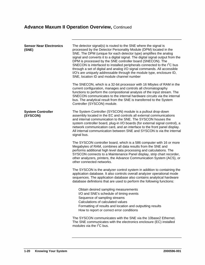
The detector signal(s) is routed to the SNE where the signal is processed by the Detector Personality Module (DPM) located in the SNE. The DPM (unique for each detector type) amplifies the analog signal and converts it to a digital signal. The digital signal output from the DPM is processed by the SNE controller board (SNECON). The SNECON is interfaced to installed peripherals connected to the I2C bus through a set of digital and analog I/O signal commands. All accessible I/O's are uniquely addressable through the module type, enclosure ID, SNE, location ID and module channel number
Sensor Near Electronics (SNE)
The SNECON, which is a 32-bit processor with 16 Mbytes of RAM in the current configuration, manages and controls all chromatography functions to perform the compositional analysis of the input stream. The SNECON communicates to the internal hardware circuits via the internal bus. The analytical result from the SNE is transferred to the System Controller (SYSCON) module.
The System Controller (SYSCON) module is a pullout drop-down assembly located in the EC and controls all external communications and internal communication to the SNE. The SYSCON houses the system controller board, plug-in I/O boards (for external signal control), a network communication card, and an interface to the front panel display. All internal communication between SNE and SYSCON is via the internal signal bus.
System Controller (SYSCON)
The SYSCON controller board, which is a 586 computer with 16 or more Megabytes of RAM, combines all data results from the SNE and performs additional high level data processing and calculations. The SYSCON connects to a Maintenance Panel display, strip chart recorder, other analyzers, printers, the Advance Communication System (ACS), or other connected networks.
The SYSCON is the analyzer control system in addition to containing the application database. It also controls overall analyzer operational mode sequences. The application database also contains analytical hardware database definitions that are used to perform the following functions:
Obtain desired sampling measurements I/O and SNE's schedule of timing events Sequence of sampling streams Calculations of calculated values Formatting of results and location and outputting results How to report or correct error conditions
The SYSCON communicates with the SNE via the 10base2 Ethernet. The SNE communicates with the electronics enclosure (EC) installed modules via the I2C bus.
1-20 Knowing Your System 2000596-001

Functional Tasks
This section provides an operational overview of the Advance Maxum II's Real-Time functional tasks.
Overview
Startup Tasks Applying Power Valid Database Oven Temperature Cycle Control Flag
Timed Event Scheduling Time-Of-Day Clock Schedule of Events
Frequency Events Analysis Cycle Clock
Accessing SYSCON Analysis Cycle Clock SYSCON Cycle Clock Valve Events
Manual Operations User Interface
On start-up, when primary AC power is applied to the analyzer, the analyzer first processes whatever electronic self-tests and diagnostics are required (for example, PROM, RAM, A/D, communication ports, etc.). The processing occurs within 5 seconds.
Startup Tasks
System related initial messages are generated and output to the network ports. Appropriate initial messages are then displayed on the Maintenance Panel and completed within 20 to 25 seconds. If the analyzer cycle clock is in RUN or CAL mode, an appropriate alarm may be generated during this internal test and the following startup period.
After the self-test, the following conditions occur: Self Test
Installed hardware is initialized Interrupts enabled Oven temperatures and carrier pressure default set points are output Analog input system(s), associated with detector inputs, are
initialized and begin scanning.
The SYSCON checks to be certain a valid database is resident. If it is, the appropriate temperature and carrier set points are output. If not, default set points are left in place.
The oven temperature is monitored to check for being at set point and stable before automatically proceeding. Depending on how long primary AC power has been off, this may take from 2 seconds to 45 minutes.
Oven Temperature
2000596-001 Knowing Your System 1-21
Functional Tasks, Continued
A check is made to see if the analyzer is to run a diagnostic type cycle. This is for the purpose of validating the analytical hardware, such as solenoid valves, detectors, carrier regulators, etc. This is optional based on a custom application being initiated per the power fail alarm.
Cycle Control Flag
Cycle control flags are checked to see if any analyzer cycle clocks are to be in RUN mode. If they are not, the analyzer remains in the HOLD mode until operator intervention. If the cycle clock is in RUN mode, based on having been in that mode prior to powering down, then that mode should be started in progress without waiting for intervention.
The TOD (Time of Day) clock schedules events on a second, minute, hourly, daily or weekly basis. The clock is maintained on the SYSCON and schedules events from the residing SYSCON database.
Event Scheduling
The TOD clock has one-second resolution that is maintained and generated by a hardware device that maintains accurate time independent of analyzer power. This allows a power recovery event to determine duration of power down state.
Certain events are scheduled on a frequency basis, which are independent of the TOD or analysis cycle clocks. The frequency clock has a resolution of 1 second, which is used to schedule repetitive events, such as reading DI and AI signals for alarm purposes. Scheduling of events typically occur at a frequency of every 5 or 10 seconds. They occur regardless of whether the analyzer is in Run or Hold.
A schedule event can be for instrument calibration and special calibrations. Special calibrations include daily or shift averages, report logging to a printer or Host computer. When these tasks are scheduled by TOD clock, they are put on queue. This allows them to be performed at the next appropriate time. Typically, this is after completion of current analysis cycle.
Description
If a calibration is scheduled, it will be put in queue. The calibration is then initiated after completion of current cycle and appropriate time has been allotted for calibration blend to flow through the sampling valve. If shift average reports are to be calculated and printed, the report should include all cycles, which started, or sampled, during the specified shift. To have data available for calculation, a wait period may occur for completion of the current sample analysis.
1-22 Knowing Your System 2000596-001
Functional Tasks, Continued
The Analysis Cycle Clock (ACC) is another clock that provides the time base for all events associated with the actual chromatograph analysis cycle. SYSCON cycle clocks can be configured to provide timed event resolutions of 0.1 second, 0.01 second, 0.01 minute, or 0.001 minute. This is the SNE Event Table Scan Rate, which is independent of detector scan rates.
Analysis Cycle Clock
All SYSCON cycle clocks and associated Sensor Near Electronics (SNE) MUST BE of the same second or minute time units. This clock works in conjunction with the Stream Sequence Table and associated sample stream enable and skip flags. This controls sampling order and analysis of process streams connected to the analyzer.
The clock cycle RUN mode is controlled by the SYSCON upon command from SNE. When a clock cycle is started, the associated SNE's, for that method, initiate a mirror of the cycle clock.
Accessing SYSCON
The SNE clock is the true basis of timed events relating to the Gas Chromatograph oven valve timing, detector digitization and peak integration.
The SNE cycle clock is used to schedule the following events. SNE Cycle Clock Analysis valve timing Detector balances Temperature set points start
and stop for PTGC Cycle Reset
Pressure set point timing for pressure programming
Analysis result calculations and reporting
Scheduled solenoid valve events cause Solenoid Valve Control Module (SVCM) hardware to be activated within 5 milliseconds of stated cycle time. Any scheduled pressure set point adjustments are transferred to the actual Electronic Pressure Control Module (EPCM) hardware within 5 milliseconds.
Important
Manually controlled functions can be initiated through the Maintenance Panel. A manual controlled event can occur asynchronously with any event and control some of the analyzer operations. Controlled items include:
Manual Operations
Activation of solenoid valves Balancing detectors Changing a pressure or temperature set point Initiating a calculation Report logging event Change the cycle time of an event Initiate a calibration
2000596-001 Knowing Your System 1-23
Analyzer Internal Communications
Several internal communication links are used to provide the communication paths from the SYSCON to the SNE's and from the SNE's to the SVCM, EPC, PECM and from SYSCON to the I/O bus.
Description
10Base2 Internal Bus I2C Internal Bus CAN Internal Bus
The Advance Communication System (ACS) Ethernet is accessed via the SYSCON Peripheral Control Interface (PCI) board 10base2 port. The SNE's are accessed internally via the SYSCON controller plug-in PCI board, which provides a 10base2 Internal bus.
Physical Connections
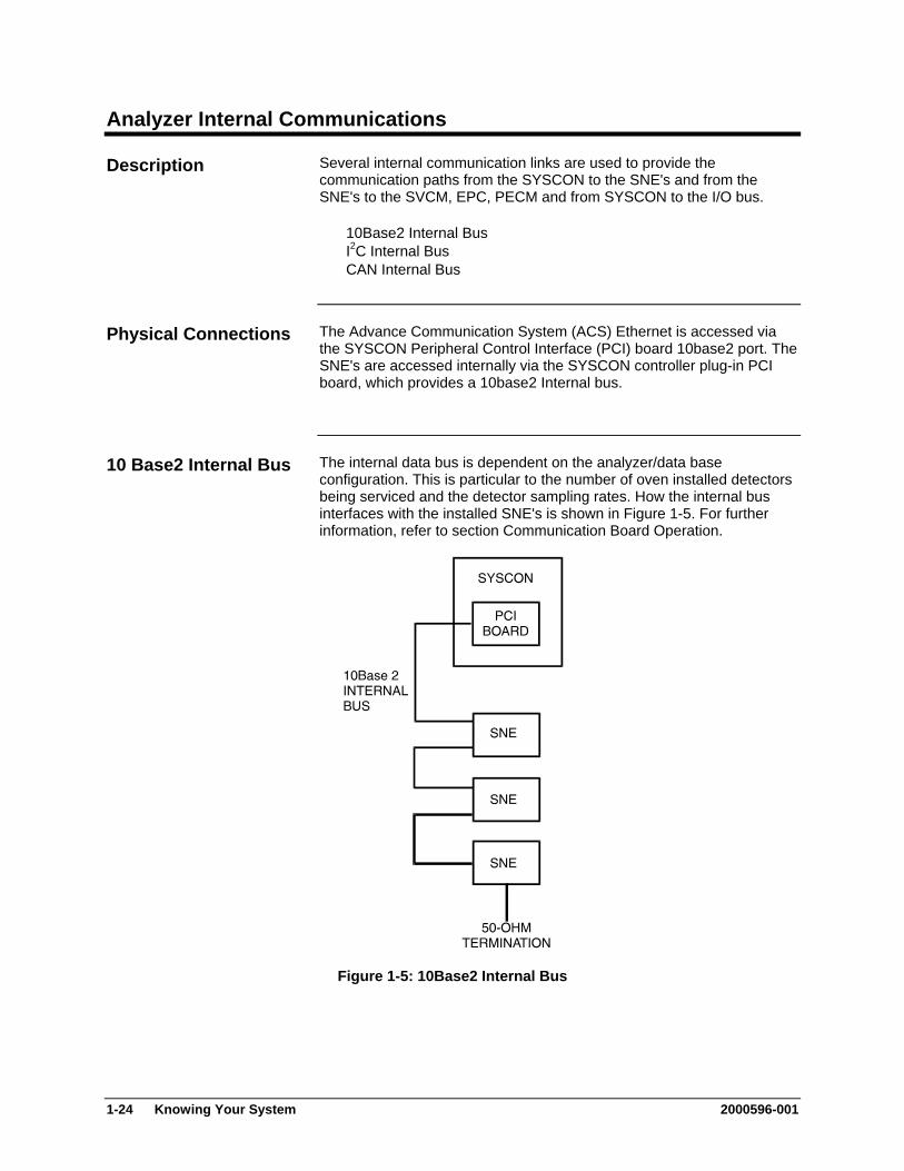
The internal data bus is dependent on the analyzer/data base configuration. This is particular to the number of oven installed detectors being serviced and the detector sampling rates. How the internal bus interfaces with the installed SNE's is shown in Figure 1-5. For further information, refer to section Communication Board Operation.
10 Base2 Internal Bus
Figure 1-5: 10Base2 Internal Bus
1-24 Knowing Your System 2000596-001
Analyzer Internal Communications, Continued
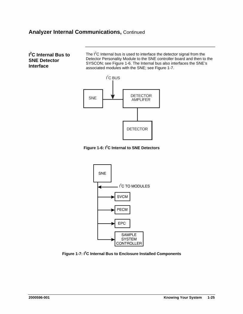
The I2C Internal bus is used to interface the detector signal from the Detector Personality Module to the SNE controller board and then to the SYSCON; see Figure 1-6. The Internal bus also interfaces the SNE’s associated modules with the SNE; see Figure 1-7.
I2C Internal Bus to SNE Detector Interface
I C BUS2
SNE DETECTORAMPLIFER
DETECTOR
Figure 1-6: I2C Internal to SNE Detectors
Figure 1-7: I2C Internal Bus to Enclosure Installed Components
2000596-001 Knowing Your System 1-25

Analyzer Internal Communications, Continued
The CAN Bus interfaces the CAN Extension Unit with the SYSCON; see Figure 1-8.
CAN Bus
Figure 1-8: CAN Bus
Installed CAN Modules are identified by physical address which consist of module type, serial number and I/O channel number.
A serial number must be entered when adding or replacing (changing) system modules; see Chapter 3 Maintenance Panel Operation; Setting up CAN I/O modules page 3-142. The serial number is indicated on the module.
The entire 14-digit serial number must be entered (for example):
00200000012301 Always 01 Serial number per tag on module Always 0000 002 Analog I/O Board 003 Digital I/O Board 004 Analyzer Module
CAN Module Addressing
1-26 Knowing Your System 2000596-001
Maxum II Hardware Identification
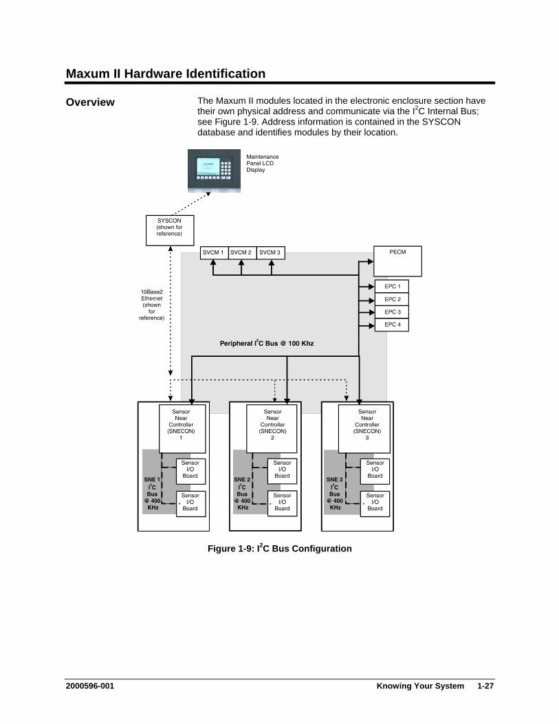
The Maxum II modules located in the electronic enclosure section have their own physical address and communicate via the I2C Internal Bus; see Figure 1-9. Address information is contained in the SYSCON database and identifies modules by their location.
Overview
Figure 1-9: I2C Bus Configuration
2000596-001 Knowing Your System 1-27
Maxum II Hardware Identification, Continued
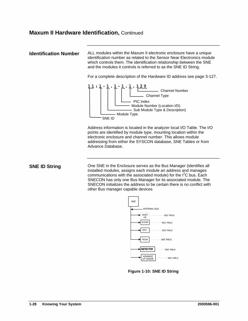
ALL modules within the Maxum II electronic enclosure have a unique identification number as related to the Sensor Near Electronics module which controls them. The identification relationship between the SNE and the modules it controls is referred to as the SNE ID String.
Identification Number
For a complete description of the Hardware ID address see page 3-127.
11:1-1.1-1.1.129 Channel Number Channel Type PIC Index Module Number (Location I/D) Sub Module Type & Description) Module Type SNE ID
Address information is located in the analyzer local I/O Table. The I/O points are identified by module type, mounting location within the electronic enclosure and channel number. This allows module addressing from either the SYSCON database, SNE Tables or from Advance Database.
One SNE in the Enclosure serves as the Bus Manager (identifies all installed modules, assigns each module an address and manages communications with the associated module) for the I2C bus. Each SNECON has only one Bus Manager for its associated module. The SNECON initializes the address to be certain there is no conflict with other Bus manager capable devices
SNE ID String
Figure 1-10: SNE ID String
1-28 Knowing Your System 2000596-001

Advance Communication System
The Advance Communication System (ACS) uses industry standard protocols and provides high-speed communication among all devices. The ACS can function alone or may be connected to a Distributed Control System (DCS) or plant-wide Local Area Network (LAN). As with other Siemens systems, the network has complete backward compatibility with existing Advance Data Hiway systems.
Network Connectivity
The network supports the following Advance products:
Maxum II and Optichrom GCs
Flexible high speed peer-to-peer communication
Open TCP/IP connectivity to industry standard networks for large, open systems.
Single Ethernet or redundant DataNET implement in any combination.
Interconnection to Advance Data Hiway and Advance Optichrom Chromatographs for backward compatibility.
Network Access Unit Maintenance Panel availability
Remote Maintenance Panel access (optional) to any GC attached to the ACS
Slots for optional analog and digital I/O boards which can be used by any GC attached to the ACS
Multiple units can be attached anywhere in one ACS
CAN Extension (CEU) Additional I/O board slots allows for expansion of I/O capability
Hub Redundant version of ACS
DataNET Twisted pair wire or fiber optics
True message confirmation
Hazardous area hardware ratings
Advance Network Gateway (ANG)
Interface high speed Ethernet or DataNET to existing Advance Data Hiway for backwards compatibility
Work Station User interface for maintenance
Programming interface for engineering changes
Real time network status monitoring
2000596-001 Knowing Your System 1-29
Advance Data Hiway Communications
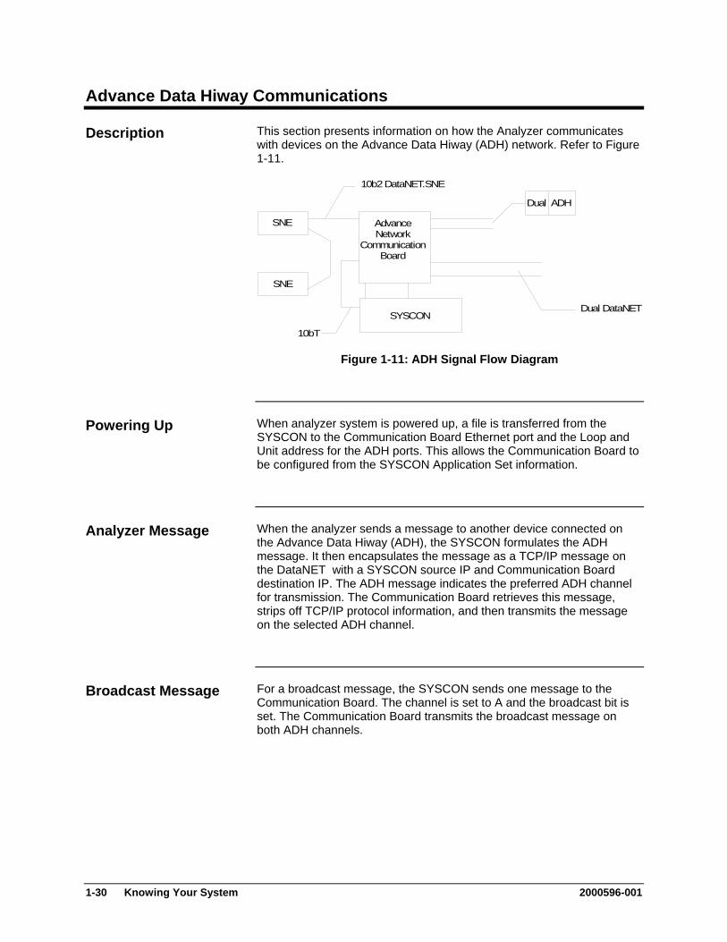
This section presents information on how the Analyzer communicates with devices on the Advance Data Hiway (ADH) network. Refer to Figure 1-11.
Description
SNE
SNE
AdvanceNetwork
CommunicationBoard
SYSCON
Dual ADH
Dual DataNET
10b2 DataNET.SNE
10bT
Figure 1-11: ADH Signal Flow Diagram
When analyzer system is powered up, a file is transferred from the SYSCON to the Communication Board Ethernet port and the Loop and Unit address for the ADH ports. This allows the Communication Board to be configured from the SYSCON Application Set information.
Powering Up
When the analyzer sends a message to another device connected on the Advance Data Hiway (ADH), the SYSCON formulates the ADH message. It then encapsulates the message as a TCP/IP message on the DataNET with a SYSCON source IP and Communication Board destination IP. The ADH message indicates the preferred ADH channel for transmission. The Communication Board retrieves this message, strips off TCP/IP protocol information, and then transmits the message on the selected ADH channel.
Analyzer Message
For a broadcast message, the SYSCON sends one message to the Communication Board. The channel is set to A and the broadcast bit is set. The Communication Board transmits the broadcast message on both ADH channels.
Broadcast Message
1-30 Knowing Your System 2000596-001
Advance Data Hiway Communications, Continued
For messages directed to the analyzer, from another installed ADH device, the message will have the destination Loop and Unit address as those of the Communication Board ADH ports. The Communication Board retrieves this message, encapsulates the ADH message in TCP/IP protocol, and then transmits it to the SYSCON with the destination IP.
Another ADH Device
When the analyzer receives a broadcast signal on the ADH network, the Communication Board treats it as any other message. Typically the SYSCON receives two messages for each ADH broadcast set. One is from channel A and the other from channel B.
Receiving Broadcast Signal
2000596-001 Knowing Your System 1-31

2000596-001 2-1
Chapter 2
Advance Maxum II Modules
Overview
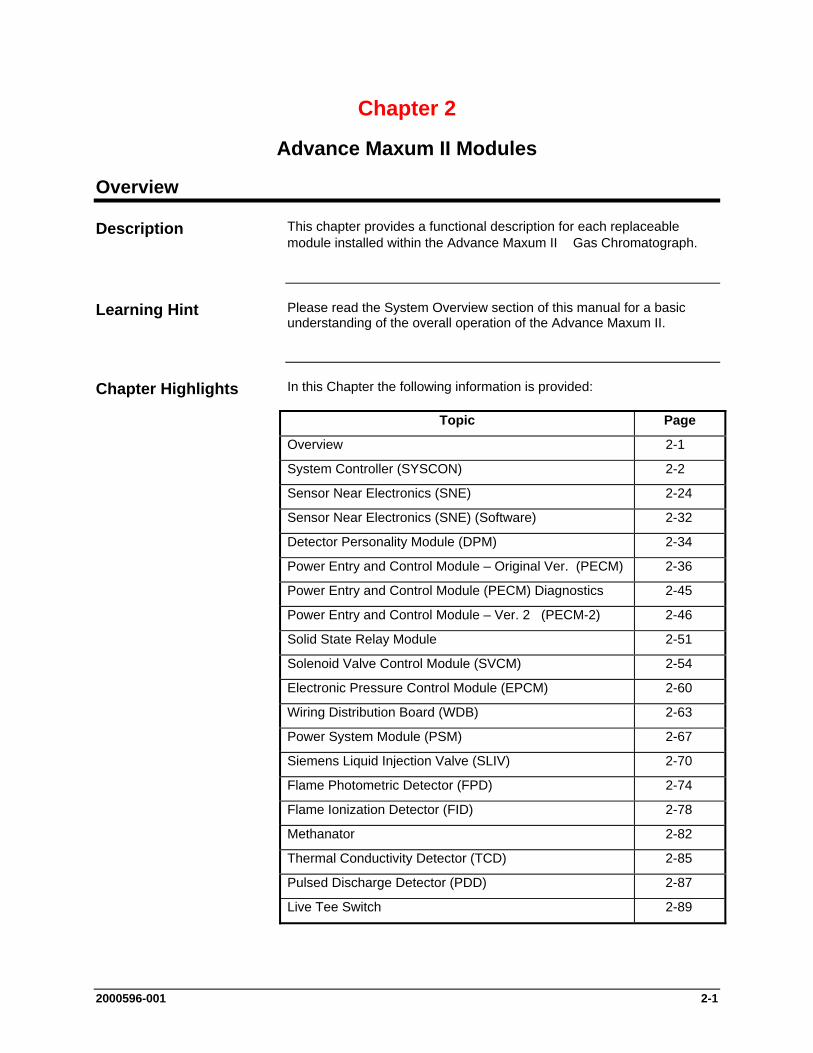
This chapter provides a functional description for each replaceable module installed within the Advance Maxum II Gas Chromatograph.
Please read the System Overview section of this manual for a basic understanding of the overall operation of the Advance Maxum II.
In this Chapter the following information is provided:
Topic Page
Overview 2-1
System Controller (SYSCON) 2-2
Sensor Near Electronics (SNE) 2-24
Sensor Near Electronics (SNE) (Software) 2-32
Detector Personality Module (DPM) 2-34
Power Entry and Control Module – Original Ver. (PECM) 2-36
Power Entry and Control Module (PECM) Diagnostics 2-45
Power Entry and Control Module – Ver. 2 (PECM-2) 2-46
Solid State Relay Module 2-51
Solenoid Valve Control Module (SVCM) 2-54
Electronic Pressure Control Module (EPCM) 2-60
Wiring Distribution Board (WDB) 2-63
Power System Module (PSM) 2-67
Siemens Liquid Injection Valve (SLIV) 2-70
Flame Photometric Detector (FPD) 2-74
Flame Ionization Detector (FID) 2-78
Methanator 2-82
Thermal Conductivity Detector (TCD) 2-85
Pulsed Discharge Detector (PDD) 2-87
Live Tee Switch 2-89
Description
Learning Hint
Chapter Highlights
2-2 2000596-001
System Controller (SYSCON)
The System Controller (SYSCON) has a high-speed 32-bit microprocessor, a PROM chip for long term security, and battery back-up to save data in short term memory. The SYSCON stores the analyzer application database, combines all data results from the SNE and performs additional high-level data processing and calculations. All network communications, maintenance panel and analyzer functions are also coordinated by the SYSCON. The SYSCON provides communications between the Controller Board, I/O Boards and the EC operating modules; see Figure 2-3.
More information and details pertaining to the SYSCON can be found in the System Controller (SYSCON) Assembly Installation Manual (Siemens part number 2000686-001).
Processing and communicating the measurement values supplied by the SNE
Controlling system functions, e.g. calibration Display and operator control Controlling associated systems, e.g. gas supply Generates reports
The System Controller (SYSCON) assembly is a pullout, drop-down drawer located on a slide rail assembly mounted to the upper wall of the Electronic Enclosure. The SYSCON consists of a card cage that houses the system controller board. The system controller board acts as the motherboard with on board expansion slots to accommodate Analog and Digital I/O boards for external signal control, an Advance network communication board and a 10BASE Ethernet board.
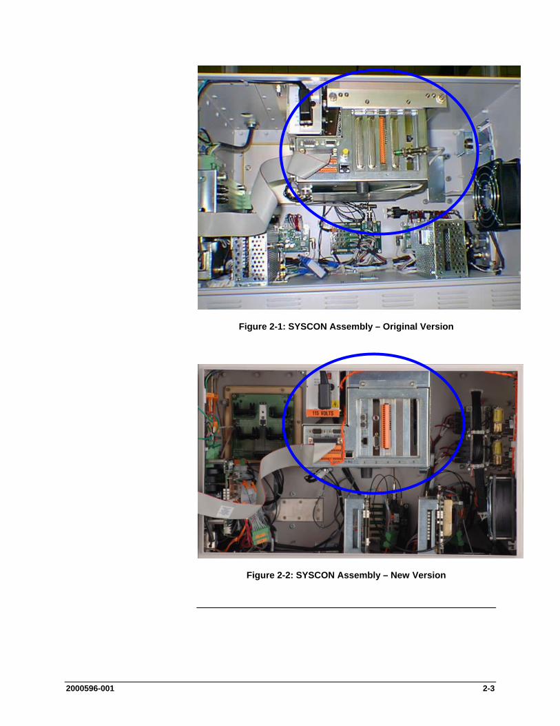
Two versions of the SYSCON assembly have been available. In the original version, the power connectors are on the side and there is a 10BaseT connector on the front of the assembly. In the newer version, the power connectors have been moved to the bottom and the location for the 10BaseT connector, which is now optional, is on the side. Views of the two different assemblies are shown in the figures on the next page.
All PC boards are visible through the front of the drawer for making all I/O connections. Interface connectors to the front panel display, and communication connectors are also located and labeled on the front of the drawer.
Description
Additional Functions
Mechanical
2000596-001 2-3
Figure 2-1: SYSCON Assembly – Original Version
Figure 2-2: SYSCON Assembly – New Version
2-4 2000596-001
System Controller (SYSCON), Continued
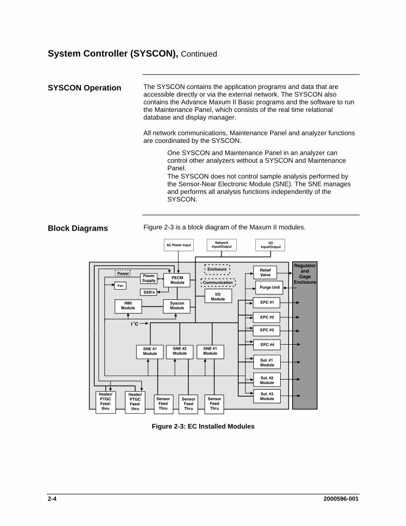
The SYSCON contains the application programs and data that are accessible directly or via the external network. The SYSCON also contains the Advance Maxum II Basic programs and the software to run the Maintenance Panel, which consists of the real time relational database and display manager.
All network communications, Maintenance Panel and analyzer functions are coordinated by the SYSCON.
One SYSCON and Maintenance Panel in an analyzer can control other analyzers without a SYSCON and Maintenance Panel.
The SYSCON does not control sample analysis performed by the Sensor-Near Electronic Module (SNE). The SNE manages and performs all analysis functions independently of the SYSCON.
Figure 2-3 is a block diagram of the Maxum II modules.
Figure 2-3: EC Installed Modules
SYSCON Operation
Block Diagrams
2000596-001 2-5
System Controller (SYSCON), Continued
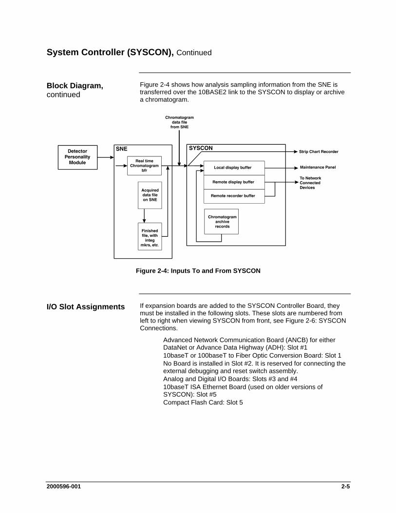
Figure 2-4 shows how analysis sampling information from the SNE is transferred over the 10BASE2 link to the SYSCON to display or archive a chromatogram.
Figure 2-4: Inputs To and From SYSCON
If expansion boards are added to the SYSCON Controller Board, they must be installed in the following slots. These slots are numbered from left to right when viewing SYSCON from front, see Figure 2-6: SYSCON Connections.
Advanced Network Communication Board (ANCB) for either DataNet or Advance Data Highway (ADH): Slot #1
10baseT or 100baseT to Fiber Optic Conversion Board: Slot 1 No Board is installed in Slot #2. It is reserved for connecting the
external debugging and reset switch assembly. Analog and Digital I/O Boards: Slots #3 and #4 10baseT ISA Ethernet Board (used on older versions of
SYSCON): Slot #5 Compact Flash Card: Slot 5
Block Diagram, continued
I/O Slot Assignments

2-6 2000596-001
System Controller (SYSCON), Continued
See System Controller Connections, Figure 2-8 through 2-10, for connection diagrams.
Analog I/O board (AO8): has eight channels of analog fully isolated output channels.
Digital I/O board (DIO-8): has 4-digital inputs and 4-digital outputs
Input/Output board: has 2-digital inputs, 2-digital outputs, 2-analog outputs,.and 4-analog inputs (2 for current and 2 for voltage)
The DOs are rated for 1A resistive load. Inductive loads are different. A DO should not drive an inductive load greater than 0.5A. An example is the typical block and bleed application which uses two parallel solenoids at 0.4A each. Separate DOs should be used to drive each solenoid. Each DO connected to a solenoid should have a diode to suppress the solenoid load.
If an application needs more than two I/O boards, a CAN Extension Unit can be installed. This allows installation of up to 10 additional I/O boards. The CAN Extension Unit connects to the Advance Maxum II Gas Chromatograph via a Serial Link (CAN Bus).
Slot 1 of the SYSCON Assembly can support a Fiber Optic Converter board. Both 100 Mb and 10 Mb versions of this board are available. The type of module used depends on the network configuration. The 100Base module is recommended. However, the 10Base module is also offered since some fiber optic switches may not support the 100Base version.
Note that although installation in slot 1 of the SYSCON Assembly is standard, the Fiber Optic Converter board can install in any unused slot in the SYSCON Assembly (provided the crossover Ethernet Cable is long enough).
10Base FX Board 100Base FX Board Wavelength 850 nm 1300 nm Nominal
(1270-1380 nm Range) Minimum Output Power -16.0 dBm -20.0 dBm Maximum Output Power -10.0 dBm -14.0 dBm Sensitivity -32.5 dBm -33.0 dBm Maximum Input Power -8.0 dBm -8.0 dBm Link Power Budget 16.5 dB 13.0 dB FO Connector Type ST (Stab & Twist) ST
Fiber Optic cables should be Multimode (MM), with 62.5 micrometer diameter fiber core and 125 micrometer clad.
Analog & Digital I/O Boards
Additional I/O Boards
10BaseT or 100BaseT to Fiber Optic Converter Board
Fiber Optic Converter Board Specifications
2000596-001 2-7
System Controller (SYSCON), Continued
10Base FX Version * 100Base FX Version (Stab and Twist Connectors Not Shown)
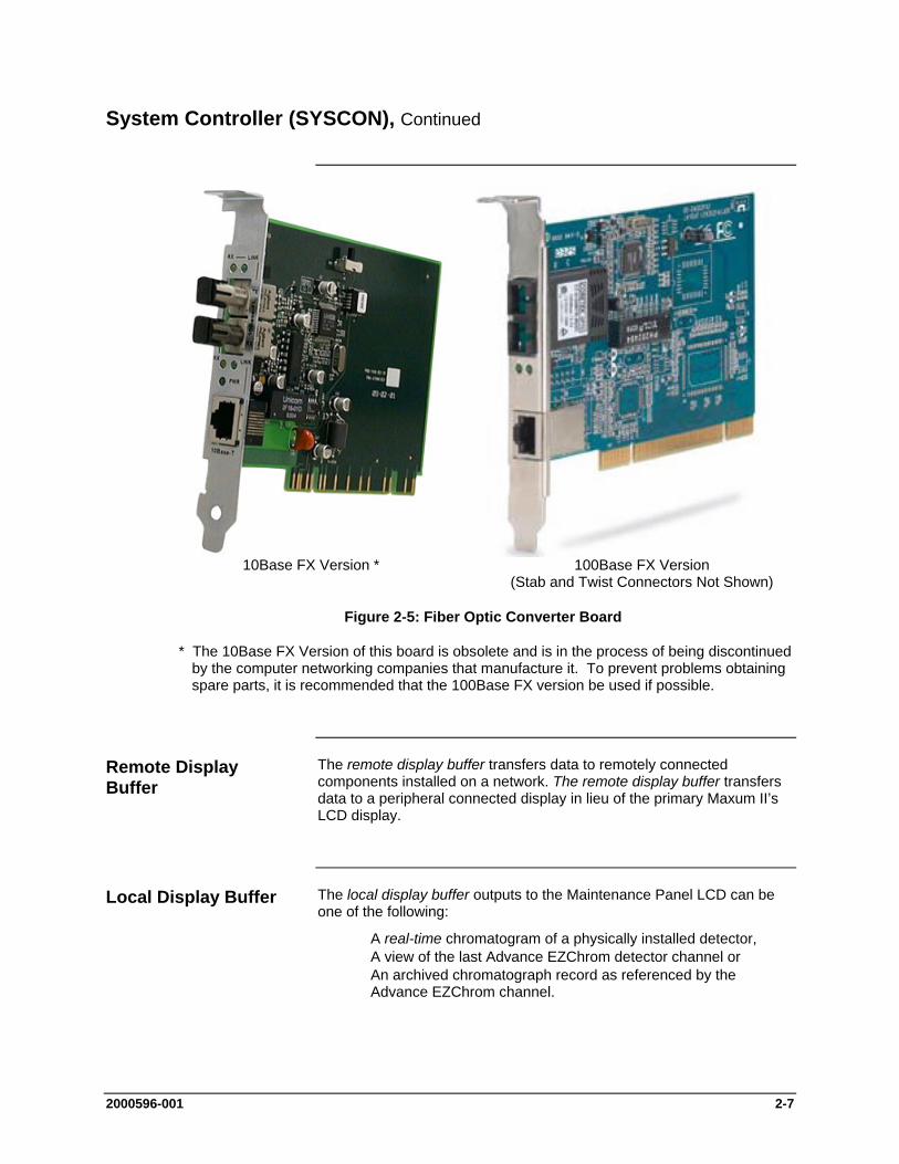
Figure 2-5: Fiber Optic Converter Board
* The 10Base FX Version of this board is obsolete and is in the process of being discontinued by the computer networking companies that manufacture it. To prevent problems obtaining spare parts, it is recommended that the 100Base FX version be used if possible.
The remote display buffer transfers data to remotely connected components installed on a network. The remote display buffer transfers data to a peripheral connected display in lieu of the primary Maxum II’s LCD display.
The local display buffer outputs to the Maintenance Panel LCD can be one of the following:
A real-time chromatogram of a physically installed detector, A view of the last Advance EZChrom detector channel or An archived chromatograph record as referenced by the
Advance EZChrom channel.
Remote Display Buffer
Local Display Buffer

2-8 2000596-001
System Controller (SYSCON), Continued
Figure 2-6 shows the SYSCON connections. The second Ethernet connector on SYSCON is a 10BaseT connector. This connector will connect this GCEE to the outside world.
The Maintenance Panel connects to the front of SYSCON via a 60-pin connector (X03). Power enters SYSCON on the back left-hand side through a six-pin connector.
A 2-conductor cable from the PECM plugs into the back left hand side of SYSCON. This cable is for Maxum II purge. This plug is located directly behind the power cable plug.
An RS-485 (X01) and RS-232 (X02) port are also available on the front of SYSCON. The RS-485 port will be used for Modbus communication. The RS-232 serial port may be used to interface to a printer. There are 2 additional connectors on the front of SYSCON that are used for on board I/O. These connectors are orange in color. The on board user I/O consists of 4 DI, 4 DO, and 2 AO channels. There is also a Can Bus connector which can be used for a Can Extension Unit. This connector is on the front of the original SYSCON assembly. On the new assembly it is optional and is located on the left side of the assembly (if equipped).
-X01 RS-232C Port -X02 RS-485 -X03 Maintenance Panel
Connector -X04 Digital Outputs (System
Controller) -X05 Analog & Digital Inputs -X06 CAN Bus Connector -X07– Ethernet 10Base T -X08 Communication Board
(NetCom or Ethernet to Fiber Optic Converter) Slot 1
-X09 not used -X10 Analog and Digital I/O Board -X11 Analog and Digital
I/O Board -X12 10BaseT Ethernet
Board
Figure 2-6: SYSCON Connections
SYSCON Connections
New Assembly
Original Assembly

2000596-001 2-9
System Controller (SYSCON), Continued
Figures 2-7 to 2-10 show standard input and output pin layouts for the system controller and analog/digital boards. Relays are shown in a de-energized state, equivalent to their failure mode status.
The actual pin layout with input and output signals in a delivered system will be shown in the System Documentation package.
DO1–DO4 4 digital outputs: floating double-throw contacts, max. contact load rating 30 V/ 1 A
AO1–AO2 2 analog outputs: 0/4–20 mA, common negative pole, galvanically separated from ground, freely connectable to ground, max. gain vs. local protective ground potential 50 V, max. working resistance 750
DI1–DI4 4 digital inputs: Optocoupler with internal 12–24 VDC power supply, switchable with floating contacts; alternative: switchable with external 12–24 VDC supply, common negative pole
Design: Two 12-pin terminal strips for braided or solid cable with max. section of 1.5 mm2 or 16 AWG.
Figure 2-7: System Controller Connection Diagram -X04, -X05
Analog & Digital Connections

2-10 2000596-001
System Controller (SYSCON), Continued
12345678910111213141516171819202122
+-+-
+-+-
+-+-
+-+-
-AO1 +
-AO2 +
-AO3 +
-AO4 +
-Chassis
-AO5 +
-AO6 +
-AO7 +
-AO* +
-Chassis
InternalCircuitry
(representation)
ExpectedExternal Load
(representation)
AO1-AO8 Analog Outputs: 0/4-20 mA. Common negative pole, galvanically separated from ground, freely connectable to ground, max. gain vs. local protective ground potential 50B, max. working resistance 750 ohms.
Design One 22-pin terminal strips for braided or solid conductors with a maximum diameter of 1.5 mm or 16 AWG.
Figure 2-8: Analog Output Board Connection Diagram -X10 - -X11
2000596-001 2-11
System Controller (SYSCON), Continued
123456789
10111213141516171819202122
+ / -
+ / -
+ / -
+ / -
+ / -12-24vdc-OR-
+ / -12-24vdc-OR-
+ / -12-24vdc-OR-
+ / -12-24vdc-OR-
DO1 NOC
NCDO2 NO
CNC
DO3 NOC
NCDO4 NO
CNC
DI1 +-
DI2 +-
DI3 +-
DI4 +-
InternalCircuitry
(representation)
ExpectedExternal Load(representation
123456789
10111213141516171819202122
123456789
10111213141516171819202122
+ / -
+ / -
+ / -
+ / -
+ / -12-24vdc-OR-
+ / -12-24vdc-OR-
+ / -12-24vdc-OR-
+ / -12-24vdc-OR-
DO1 NOC
NCDO2 NO
CNC
DO3 NOC
NCDO4 NO
CNC
DI1 +-
DI2 +-
DI3 +-
DI4 +-
InternalCircuitry
(representation)
ExpectedExternal Load(representation
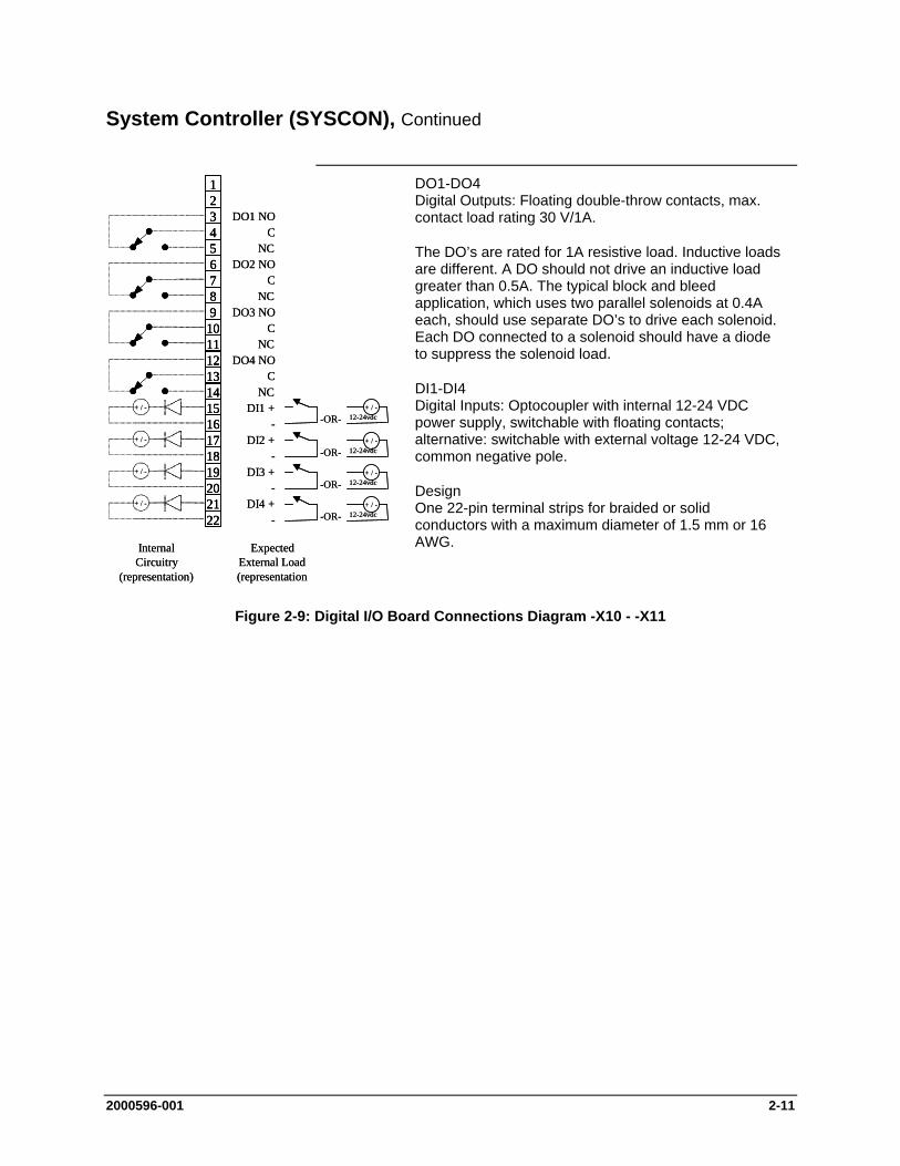
DO1-DO4 Digital Outputs: Floating double-throw contacts, max. contact load rating 30 V/1A.
The DO’s are rated for 1A resistive load. Inductive loads are different. A DO should not drive an inductive load greater than 0.5A. The typical block and bleed application, which uses two parallel solenoids at 0.4A each, should use separate DO’s to drive each solenoid. Each DO connected to a solenoid should have a diode to suppress the solenoid load.
DI1-DI4 Digital Inputs: Optocoupler with internal 12-24 VDC power supply, switchable with floating contacts; alternative: switchable with external voltage 12-24 VDC, common negative pole.
Design One 22-pin terminal strips for braided or solid conductors with a maximum diameter of 1.5 mm or 16 AWG.
Figure 2-9: Digital I/O Board Connections Diagram -X10 - -X11
2-12 2000596-001
System Controller (SYSCON), Continued
50 ohms
+-
123456789
10111213141516171819202122
+ / -
+ / -
-+
50 ohms
-+
+-
+ / -12-24vdc-OR-
+ / -12-24vdc-OR-
DO1 NCC
NODO2 NC
CNO
DI1 +-
DI2 +-
AI1 voltageAI1 current
-AI2 voltageAI2 current
-AO1 +
-AO2 +
-
InternalCircuitry
(representation)
ExpectedExternal Load(representation
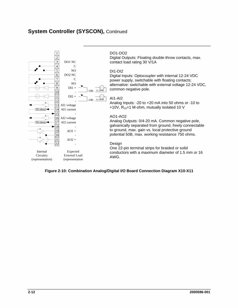
DO1-DO2 Digital Outputs: Floating double-throw contacts, max. contact load rating 30 V/1A
DI1-DI2 Digital Inputs: Optocoupler with internal 12-24 VDC power supply, switchable with floating contacts; alternative: switchable with external voltage 12-24 VDC, common negative pole.
AI1-AI2 Analog Inputs: -20 to +20 mA into 50 ohms or -10 to +10V, R10=1 M-ohm, mutually isolated 10 V
AO1-AO2 Analog Outputs: 0/4-20 mA. Common negative pole, galvanically separated from ground, freely connectable to ground, max. gain vs. local protective ground potential 50B, max. working resistance 750 ohms.
Design One 22-pin terminal strips for braided or solid conductors with a maximum diameter of 1.5 mm or 16 AWG.
Figure 2-10: Combination Analog/Digital I/O Board Connection Diagram X10-X11
2000596-001 2-13
System Controller (SYSCON), Continued
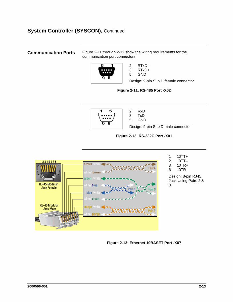
Figure 2-11 through 2-12 show the wiring requirements for the communication port connectors.
2 RTxD– 3 RTxD+ 5 GND Design: 9-pin Sub D female connector
Figure 2-11: RS-485 Port -X02
2 RxD 3 TxD 5 GND Design: 9-pin Sub D male connector
Figure 2-12: RS-232C Port -X01
1 10TT+ 2 10TT– 3 10TR+ 6 10TR–
Design: 8-pin RJ45 Jack Using Pairs 2 & 3
Figure 2-13: Ethernet 10BASET Port -X07
Communication Ports
2-14 2000596-001
System Controller (SYSCON), Continued
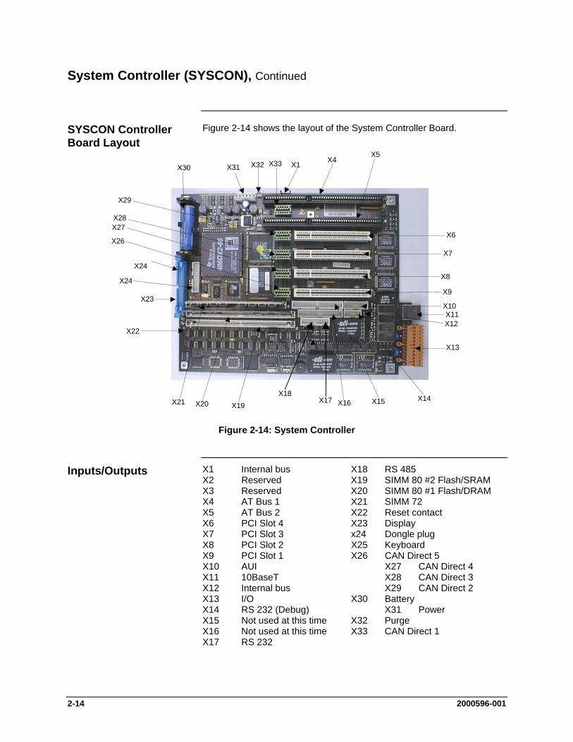
Figure 2-14 shows the layout of the System Controller Board.
X29
X31 X32 X33 X1X4
X5
X6
X7
X8
X9
X10X11X12
X13
X14X15X16X17X18
X19X20X21
X22
X24
X24
X23
X26
X27X28
Figure 2-14: System Controller
X1 Internal bus X18 RS 485 X2 Reserved X19 SIMM 80 #2 Flash/SRAM X3 Reserved X20 SIMM 80 #1 Flash/DRAM X4 AT Bus 1 X21 SIMM 72 X5 AT Bus 2 X22 Reset contact X6 PCI Slot 4 X23 Display X7 PCI Slot 3 x24 Dongle plug X8 PCI Slot 2 X25 Keyboard X9 PCI Slot 1 X26 CAN Direct 5 X10 AUI X27 CAN Direct 4 X11 10BaseT X28 CAN Direct 3 X12 Internal bus X29 CAN Direct 2 X13 I/O X30 Battery X14 RS 232 (Debug) X31 Power X15 Not used at this time X32 Purge X16 Not used at this time X33 CAN Direct 1 X17 RS 232
SYSCON Controller Board Layout
Inputs/Outputs
2000596-001 2-15
System Controller (SYSCON), Continued
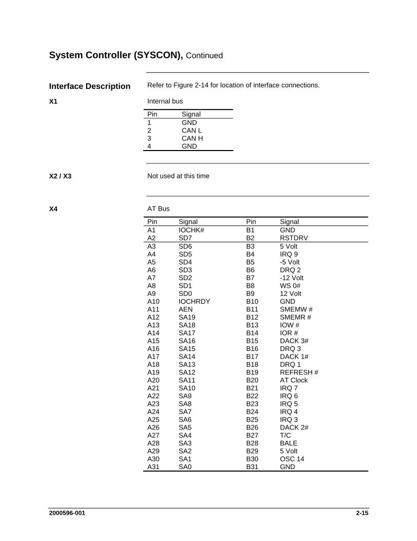
Refer to Figure 2-14 for location of interface connections.
Internal bus
Pin Signal 1 GND 2 CAN L 3 CAN H 4 GND
Not used at this time
AT Bus
Pin Signal Pin Signal A1 IOCHK# B1 GND A2 SD7 B2 RSTDRV A3 SD6 B3 5 Volt A4 SD5 B4 IRQ 9 A5 SD4 B5 -5 Volt A6 SD3 B6 DRQ 2 A7 SD2 B7 -12 Volt A8 SD1 B8 WS 0# A9 SD0 B9 12 Volt A10 IOCHRDY B10 GND A11 AEN B11 SMEMW # A12 SA19 B12 SMEMR # A13 SA18 B13 IOW # A14 SA17 B14 IOR # A15 SA16 B15 DACK 3# A16 SA15 B16 DRQ 3 A17 SA14 B17 DACK 1# A18 SA13 B18 DRQ 1 A19 SA12 B19 REFRESH # A20 SA11 B20 AT Clock A21 SA10 B21 IRQ 7 A22 SA9 B22 IRQ 6 A23 SA8 B23 IRQ 5 A24 SA7 B24 IRQ 4 A25 SA6 B25 IRQ 3 A26 SA5 B26 DACK 2# A27 SA4 B27 T/C A28 SA3 B28 BALE A29 SA2 B29 5 Volt A30 SA1 B30 OSC 14 A31 SA0 B31 GND
Interface Description
X1
X2 / X3
X4
2-16 2000596-001
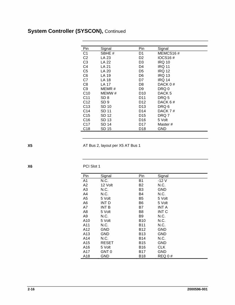
System Controller (SYSCON), Continued
Pin Signal Pin Signal C1 SBHE # D1 MEMCS16 # C2 LA 23 D2 IOCS16 # C3 LA 22 D3 IRQ 10 C4 LA 21 D4 IRQ 11 C5 LA 20 D5 IRQ 12 C6 LA 19 D6 IRQ 13 C7 LA 18 D7 IRQ 14 C8 LA 17 D8 DACK 0 # C9 MEMR # D9 DRQ 0 C10 MEMW # D10 DACK 5 C11 SD 8 D11 DRQ 5 C12 SD 9 D12 DACK 6 # C13 SD 10 D13 DRQ 6 C14 SD 11 D14 DACK 7 # C15 SD 12 D15 DRQ 7 C16 SD 13 D16 5 Volt C17 SD 14 D17 Master # C18 SD 15 D18 GND
AT Bus 2, layout per X5 AT Bus 1
PCI Slot 1
Pin Signal Pin Signal A1 N.C. B1 -12 V A2 12 Volt B2 N.C. A3 N.C. B3 GND A4 N.C. B4 N.C. A5 5 Volt B5 5 Volt A6 INT D B6 5 Volt A7 INT B B7 INT A A8 5 Volt B8 INT C A9 N.C. B9 N.C. A10 5 Volt B10 N.C. A11 N.C. B11 N.C. A12 GND B12 GND A13 GND B13 GND A14 N.C. B14 N.C. A15 RESET B15 GND A16 5 Volt B16 CLK A17 GNT 0 B17 GND A18 GND B18 REQ 0 #
X5
X6
2000596-001 2-17
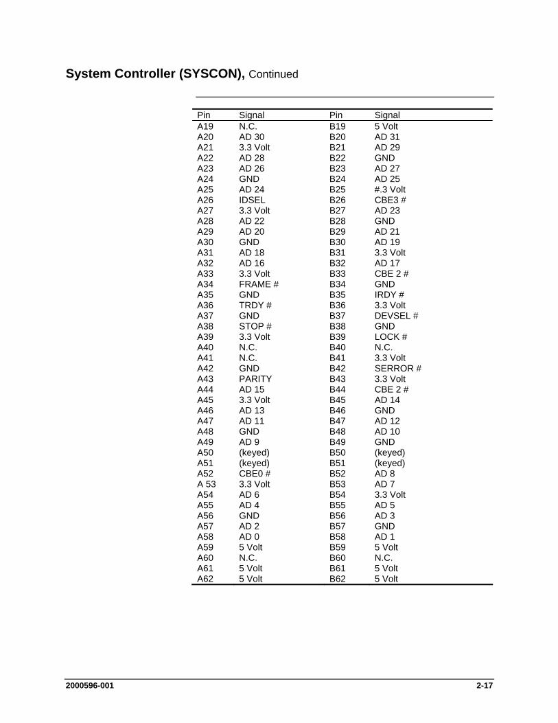
System Controller (SYSCON), Continued
Pin Signal Pin Signal A19 N.C. B19 5 Volt A20 AD 30 B20 AD 31 A21 3.3 Volt B21 AD 29 A22 AD 28 B22 GND A23 AD 26 B23 AD 27 A24 GND B24 AD 25 A25 AD 24 B25 #.3 Volt A26 IDSEL B26 CBE3 # A27 3.3 Volt B27 AD 23 A28 AD 22 B28 GND A29 AD 20 B29 AD 21 A30 GND B30 AD 19 A31 AD 18 B31 3.3 Volt A32 AD 16 B32 AD 17 A33 3.3 Volt B33 CBE 2 # A34 FRAME # B34 GND A35 GND B35 IRDY # A36 TRDY # B36 3.3 Volt A37 GND B37 DEVSEL # A38 STOP # B38 GND A39 3.3 Volt B39 LOCK # A40 N.C. B40 N.C. A41 N.C. B41 3.3 Volt A42 GND B42 SERROR # A43 PARITY B43 3.3 Volt A44 AD 15 B44 CBE 2 # A45 3.3 Volt B45 AD 14 A46 AD 13 B46 GND A47 AD 11 B47 AD 12 A48 GND B48 AD 10 A49 AD 9 B49 GND A50 (keyed) B50 (keyed) A51 (keyed) B51 (keyed) A52 CBE0 # B52 AD 8 A 53 3.3 Volt B53 AD 7 A54 AD 6 B54 3.3 Volt A55 AD 4 B55 AD 5 A56 GND B56 AD 3 A57 AD 2 B57 GND A58 AD 0 B58 AD 1 A59 5 Volt B59 5 Volt A60 N.C. B60 N.C. A61 5 Volt B61 5 Volt A62 5 Volt B62 5 Volt
2-18 2000596-001
System Controller (SYSCON), Continued
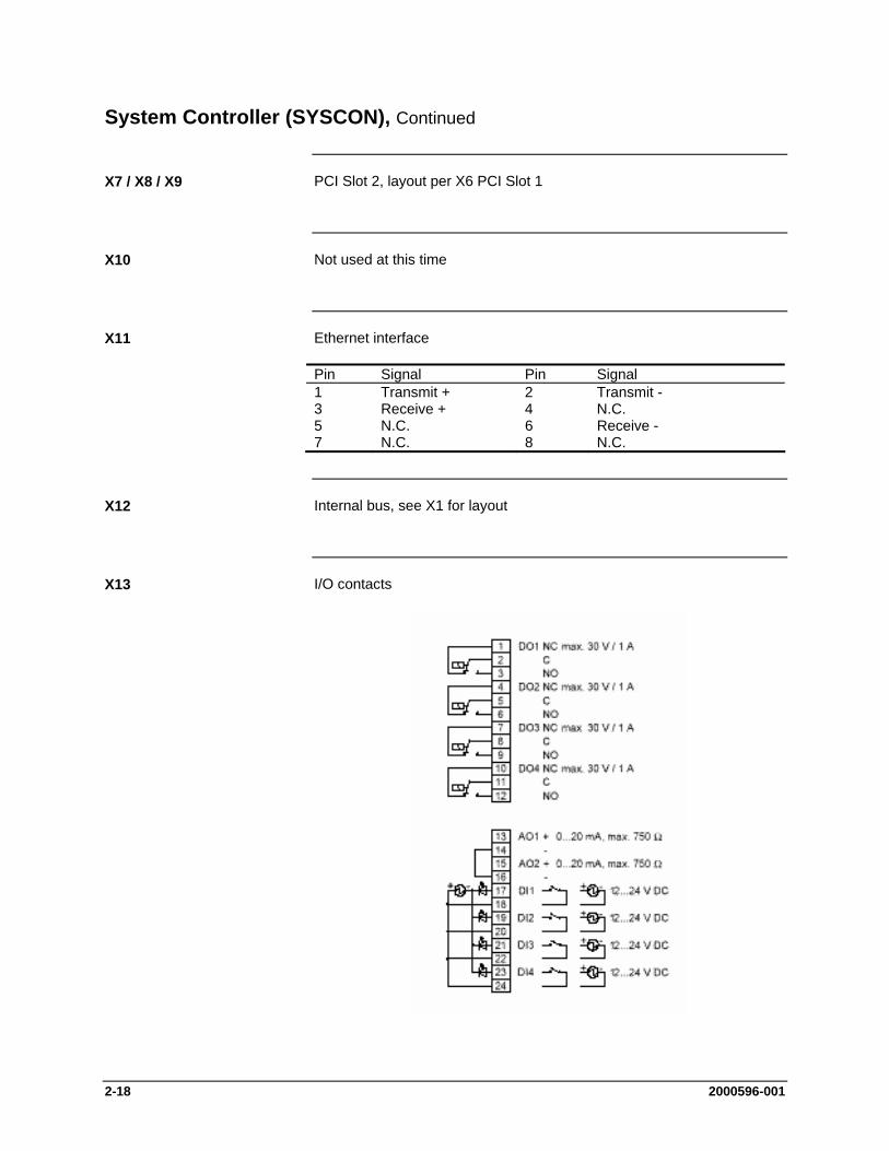
PCI Slot 2, layout per X6 PCI Slot 1
Not used at this time
Ethernet interface
Pin Signal Pin Signal 1 Transmit + 2 Transmit - 3 Receive + 4 N.C. 5 N.C. 6 Receive - 7 N.C. 8 N.C.
Internal bus, see X1 for layout
I/O contacts
X7 / X8 / X9
X10
X11
X12
X13
2000596-001 2-19
System Controller (SYSCON), Continued
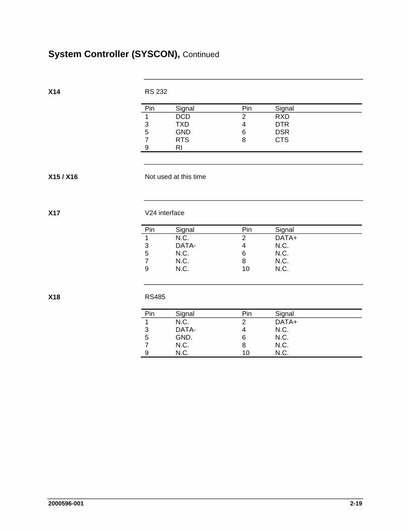
RS 232
Pin Signal Pin Signal 1 DCD 2 RXD 3 TXD 4 DTR 5 GND 6 DSR 7 RTS 8 CTS 9 RI
Not used at this time
V24 interface
Pin Signal Pin Signal 1 N.C. 2 DATA+ 3 DATA- 4 N.C. 5 N.C. 6 N.C. 7 N.C. 8 N.C. 9 N.C. 10 N.C.
RS485
Pin Signal Pin Signal 1 N.C. 2 DATA+ 3 DATA- 4 N.C. 5 GND. 6 N.C. 7 N.C. 8 N.C. 9 N.C. 10 N.C.
X14
X15 / X16
X17
X18
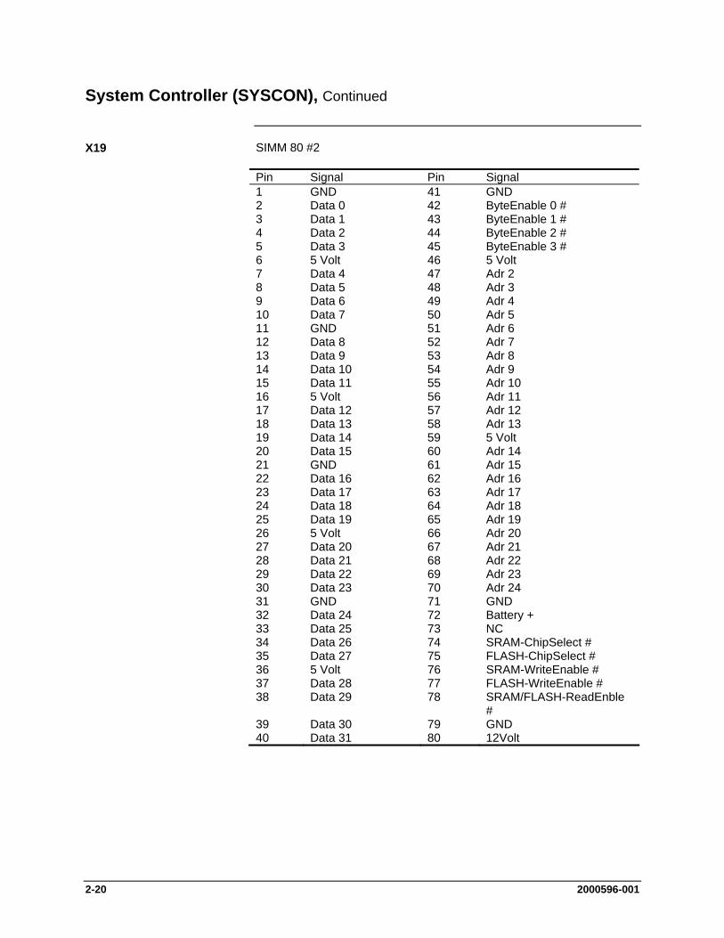
2-20 2000596-001
System Controller (SYSCON), Continued
SIMM 80 #2
Pin Signal Pin Signal 1 GND 41 GND 2 Data 0 42 ByteEnable 0 # 3 Data 1 43 ByteEnable 1 # 4 Data 2 44 ByteEnable 2 # 5 Data 3 45 ByteEnable 3 # 6 5 Volt 46 5 Volt 7 Data 4 47 Adr 2 8 Data 5 48 Adr 3 9 Data 6 49 Adr 4 10 Data 7 50 Adr 5 11 GND 51 Adr 6 12 Data 8 52 Adr 7 13 Data 9 53 Adr 8 14 Data 10 54 Adr 9 15 Data 11 55 Adr 10 16 5 Volt 56 Adr 11 17 Data 12 57 Adr 12 18 Data 13 58 Adr 13 19 Data 14 59 5 Volt 20 Data 15 60 Adr 14 21 GND 61 Adr 15 22 Data 16 62 Adr 16 23 Data 17 63 Adr 17 24 Data 18 64 Adr 18 25 Data 19 65 Adr 19 26 5 Volt 66 Adr 20 27 Data 20 67 Adr 21 28 Data 21 68 Adr 22 29 Data 22 69 Adr 23 30 Data 23 70 Adr 24 31 GND 71 GND 32 Data 24 72 Battery + 33 Data 25 73 NC 34 Data 26 74 SRAM-ChipSelect # 35 Data 27 75 FLASH-ChipSelect # 36 5 Volt 76 SRAM-WriteEnable # 37 Data 28 77 FLASH-WriteEnable # 38 Data 29 78 SRAM/FLASH-ReadEnble
# 39 Data 30 79 GND 40 Data 31 80 12Volt
X19
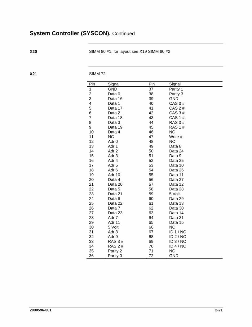
2000596-001 2-21
System Controller (SYSCON), Continued
SIMM 80 #1, for layout see X19 SIMM 80 #2
SIMM 72
Pin Signal Pin Signal 1 GND 37 Parity 1 2 Data 0 38 Parity 3 3 Data 16 39 GND 4 Data 1 40 CAS 0 # 5 Data 17 41 CAS 2 # 6 Data 2 42 CAS 3 # 7 Data 18 43 CAS 1 # 8 Data 3 44 RAS 0 # 9 Data 19 45 RAS 1 # 10 Data 4 46 NC 11 NC 47 Write # 12 Adr 0 48 NC 13 Adr 1 49 Data 8 14 Adr 2 50 Data 24 15 Adr 3 51 Data 9 16 Adr 4 52 Data 25 17 Adr 5 53 Data 10 18 Adr 6 54 Data 26 19 Adr 10 55 Data 11 20 Data 4 56 Data 27 21 Data 20 57 Data 12 22 Data 5 58 Data 28 23 Data 21 59 5 Volt 24 Data 6 60 Data 29 25 Data 22 61 Data 13 26 Data 7 62 Data 30 27 Data 23 63 Data 14 28 Adr 7 64 Data 31 29 Adr 11 65 Data 15 30 5 Volt 66 NC 31 Adr 8 67 ID 1 / NC 32 Adr 9 68 ID 2 / NC 33 RAS 3 # 69 ID 3 / NC 34 RAS 2 # 70 ID 4 / NC 35 Parity 2 71 NC 36 Parity 0 72 GND
X20
X21

2-22 2000596-001
System Controller (SYSCON), Continued
Control/display unit plug (Maintenance Panel (also called HMI))
Pin Signal Pin Signal 1 GND 2 GND 3 Address 0 4 Address 1 5 Address 2 6 Address 3 7 Address 4 8 Address 5 9 Address 6 10 Address 7 11 Address 8 12 Address 9 13 Address 10 14 Address 1 15 Address 12 16 Address 13 17 Address 14 18 Address 15 19 5 Volt 20 HMI-ChipSelect # 21 5 Volt 22 Data 0 23 Data 1 24 Data 2 25 Data 3 26 Data 4 27 Data 5 28 Data 6 29 Data 7 30 5 Volt 31 GND 32 ISA-System Clock 33 GND 34 5 Volt 35 N.C. 36 Memory Write # 37 MemoryRead # 38 Reset # 39 5 Volt 40 IO-Channel Ready 41 5 Volt 42 RXD 43 TXD 44 RTS 45 CTS 46 DTR 47 DSR 48 DCD 49 RI 50 HMI GPO 0 53 N.C. 54 Interrupt 55 HMI Purge LED 56 HMI_MNT-LED 57 Failure LED 58 GND 59 GND 60 GND
Dongle plug
Keyboard connector
Pin Signal 1 5 Volt 2 Keyboard Clock 3 Keyboard Data 4 (keyed) 5 GND
X23
X24
X25
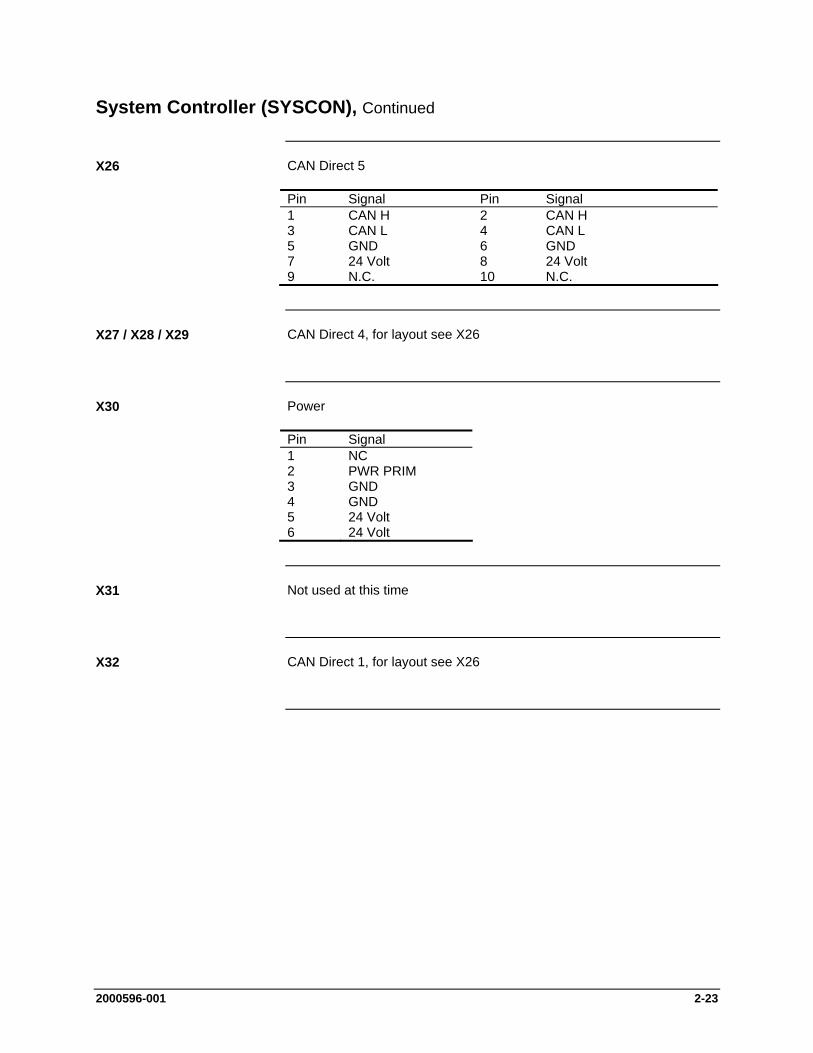
2000596-001 2-23
System Controller (SYSCON), Continued
CAN Direct 5
Pin Signal Pin Signal 1 CAN H 2 CAN H 3 CAN L 4 CAN L 5 GND 6 GND 7 24 Volt 8 24 Volt 9 N.C. 10 N.C.
CAN Direct 4, for layout see X26
Power
Pin Signal 1 NC 2 PWR PRIM 3 GND 4 GND 5 24 Volt 6 24 Volt
Not used at this time
CAN Direct 1, for layout see X26
X26
X27 / X28 / X29
X30
X31
X32
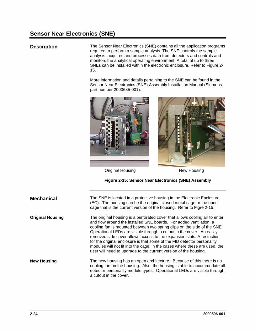
2-24 2000596-001
Sensor Near Electronics (SNE)
The Sensor Near Electronics (SNE) contains all the application programs required to perform a sample analysis. The SNE controls the sample analysis, acquires and processes data from detectors and controls and monitors the analytical operating environment. A total of up to three SNEs can be installed within the electronic enclosure. Refer to Figure 2-15.
More information and details pertaining to the SNE can be found in the Sensor Near Electronics (SNE) Assembly Installation Manual (Siemens part number 2000685-001).
Original Housing New Housing
Figure 2-15: Sensor Near Electronics (SNE) Assembly
The SNE is located in a protective housing in the Electronic Enclosure (EC). The housing can be the original closed metal cage or the open cage that is the current version of the housing. Refer to Figre 2-15.
The original housing is a perforated cover that allows cooling air to enter and flow around the installed SNE boards. For added ventilation, a cooling fan is mounted between two spring clips on the side of the SNE. Operational LEDs are visible through a cutout in the cover. An easily removed side cover allows access to the expansion slots. A restriction for the original enclosure is that some of the FID detector personality modules will not fit into the cage; in the cases where these are used, the user will need to upgrade to the current version of the housing.
The new housing has an open architecture. Because of this there is no cooling fan on the housing. Also, the housing is able to accommodate all detector personality module types. Operational LEDs are visible through a cutout in the cover.
Description
Mechanical
Original Housing
New Housing
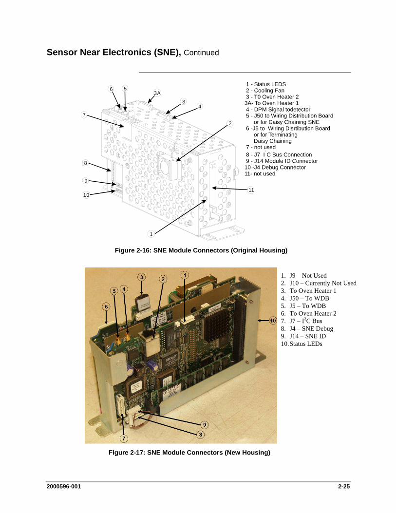
2000596-001 2-25
Sensor Near Electronics (SNE), Continued
3A56
7
8
9
1011
3
2
1 - Status LEDS2 - Cooling Fan
3 - T0 Oven Heater 23A- To Oven Heater 14 - DPM Signal todetector5 - J50 to Wiring Distribution Board
or for Daisy Chaining SNE 6 -J5 to Wiring Disrtibution Board or for Terminating Daisy Chaining 7 - not used 8 - J7 I C Bus Connection 9 - J14 Module ID Connector10 -J4 Debug Connector11- not used
2
4
1
Figure 2-16: SNE Module Connectors (Original Housing)
Figure 2-17: SNE Module Connectors (New Housing)
1. J9 – Not Used 2. J10 – Currently Not Used 3. To Oven Heater 1 4. J50 – To WDB 5. J5 – To WDB 6. To Oven Heater 2 7. J7 – I2C Bus 8. J4 – SNE Debug 9. J14 – SNE ID 10. Status LEDs

2-26 2000596-001
Sensor Near Electronics (SNE), Continued
The SNE houses the SNE Controller board and the Detector Personality Module. As an alternative, the SNE can house a Temperature Controller Board that provides two additional temperature controller channels in addition to the two provided for on the SNE Controller board; refer to Figures 2-18 thorugh 2-20.
The SNECON is a 486 Processor CPU running on the pSOS+ operating system with 4 to 16 Mbytes of RAM. The CPU manages and controls all chromatography functions to perform the compositional analysis of the input stream. The SNECON communicates to the internal hardware circuits via I2C internal bus. The SNECON transmits finished analysis results and alarm information to the SYSCON. The analysis data is then routed either to the maintenance panel for display, to the PC Workstation, to DSS system or to any other output devices. The SNECON also contains circuits to control and monitor the analytical operating environment via the electronic pressure and control sensors, barometric pressure sensors, flow sensors, or temperature control sensors. The SNECON also controls the 24V solenoid valve drivers and high-voltage power switching circuits (heaters, solenoids, etc.) as needed.
Status LEDs visible on the front of the SNE indicate the operational status of Advance Maxum II Gas Chromatograph; see SNE Status LED meanings in Table 2-1 later in this section.
At least one SNECON module is required in the Maxum II. The Maxum GC may have from one to three SNE assemblies – corresponding to the possibility of one to three detector assemblies in the chromatograph oven. It is possible to put a SNECON into each of the three SNEs. This may be required in certain very stringent application situations such as a large number of detectors operating at very fast detector scan rates. However, multiple SNECONs are very rarely used. The SNECON module can handle a combined sampling rate of over 200 points per second. This means that a single SNECON can easily accommodate a Maxum oven loaded with up to eighteen Thermistor Detectors scanning at up to ten points per second (for a combined scan rate of 180 points per second). Or, it can accommodate fewer detectors scanning at much higher scan rates.
Electrical
SNE Controller Board
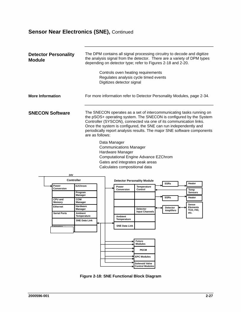
2000596-001 2-27
Sensor Near Electronics (SNE), Continued
The DPM contains all signal processing circuitry to decode and digitize the analysis signal from the detector. There are a variety of DPM types depending on detector type; refer to Figures 2-18 and 2-20.
Controls oven heating requirements Regulates analysis cycle timed events Digitizes detector signal
For more information refer to Detector Personality Modules, page 2-34.
The SNECON operates as a set of intercommunicating tasks running on the pSOS+ operating system. The SNECON is configured by the System Controller (SYSCON), connected via one of its communication links. Once the system is configured, the SNE can run independently and periodically report analysis results. The major SNE software components are as follows:
Data Manager Communications Manager Hardware Manager Computational Engine Advance EZChrom Gates and integrates peak areas Calculates compositional data
PowerConversion
EZChrom
ProgramManager
CPU andMemory
COMManager
Ethernet HardwareManager
Serial Ports AmbientTemperature
SNE Data Link
PCMCIAInterface
PowerConversion
AmbientTemperature
SNE Data Link
TemperatureControl
DetectorInput Channels
SSRs Heater
TempSensors
SSRs Heater
SenseElementsTCD, FID,etc.
DetectorAmplifers
24V
Controller Detector Personality Module
FutureModules
PECM
EPC Modules
Solenoid ValveControl Modules
Figure 2-18: SNE Functional Block Diagram
Detector Personality Module
More Information
SNECON Software
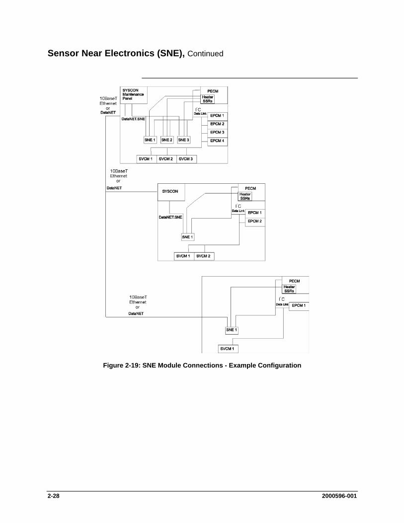
2-28 2000596-001
Sensor Near Electronics (SNE), Continued
Figure 2-19: SNE Module Connections - Example Configuration
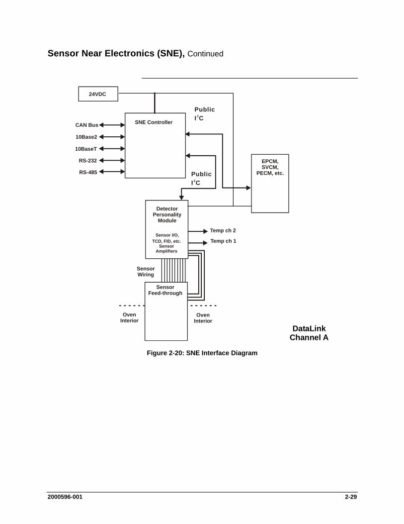
2000596-001 2-29
Sensor Near Electronics (SNE), Continued
24VDC
SNE ControllerCAN Bus
10Base2
10BaseT
RS-232
RS-485
EPCM,SVCM,
PECM, etc.
Sensor I/O,TCD, FID, etc.
SensorAmplifiers
Temp ch 1
Temp ch 2
SensorWiring
SensorFeed-through
OvenInterior
OvenInterior
DetectorPersonality
Module
PublicI C2
PublicI C2
DataLinkChannel A
Figure 2-20: SNE Interface Diagram

2-30 2000596-001
Sensor Near Electronics (SNE), Continued
All SNECONs equipped in the analyzer must be daisy chained together via the Internal Ethernet bus. Up to 3 SNECONs can be daisy chained together within a single enclosure; refer to How to Daisy Chain in the Wiring Distribution Board (WDB) section of this chapter on page 2-65
The SNECON has 2 miniature Coax Connectors on the top of the SNE, see Figures 2-16 and 2-17. These connectors are 10Base2. The connectors (J5 & J50) are interchangeable. One of these connectors will connect to one of the two mini-coax ethernet connectors on the Wiring Distribution Board (WDB). If only one SNE is used, the second connector on the SNE simply returns and plugs into the second connector on the WDB. If more than one SNE is equipped in a GC, these SNEs must be daisy chained together using the second mini-coax connector. The end of the daisy chain will return to the WDB; refer to Figure 2-41 in the WDB section of this chapter.
In a future version of the Wiring Distribution Board (WDB), the miniature Coax connectors will be replaced by RJ45 ethernet connectors. These connections will be 10BaseT. When this version of the WDB is available, connection to the SNECON will utilize the RJ45 connector on the SNECON (J10). The miniature coax connectors will be phased out.
The internal bus connector J7 is located on the lower left of the SNE near the back of the module. The internal bus plugs in here and terminates at the Wiring Distribution Board (WDB).
The ID Key connector J14 is located on the lower left of the SNE near the back of the module. Since multiple SNEs can be located into one Maxum II, it is necessary to identify the individual SNEs. This is done by installing an identification plug on the SNECON at the connector labeled J14. This will be pre-configured at the factory.
The Debug connector J4 is located lower left of the SNE near the back of the module. This connection is only for use by trained Siemens factory technicians.
Daisy Chaining
Connectors
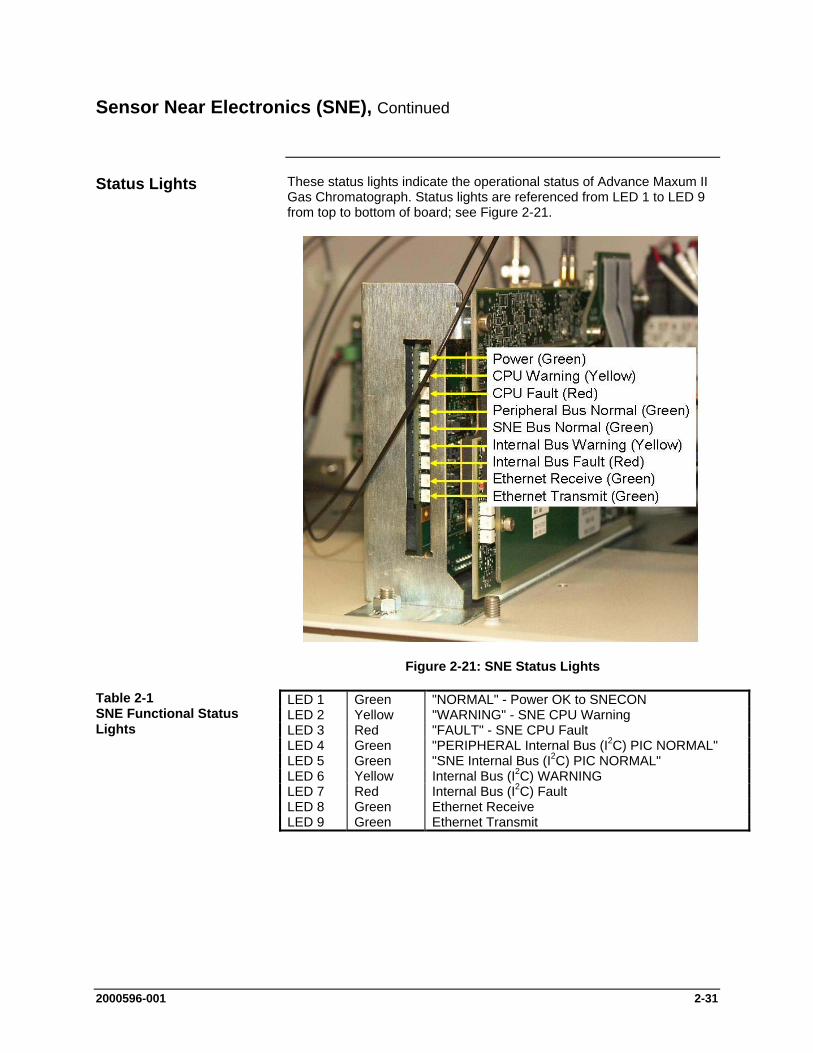
2000596-001 2-31
Sensor Near Electronics (SNE), Continued
These status lights indicate the operational status of Advance Maxum II Gas Chromatograph. Status lights are referenced from LED 1 to LED 9 from top to bottom of board; see Figure 2-21.
Figure 2-21: SNE Status Lights
LED 1 Green "NORMAL" - Power OK to SNECON LED 2 Yellow "WARNING" - SNE CPU Warning LED 3 Red "FAULT" - SNE CPU Fault LED 4 Green "PERIPHERAL Internal Bus (I2C) PIC NORMAL" LED 5 Green "SNE Internal Bus (I2C) PIC NORMAL" LED 6 Yellow Internal Bus (I2C) WARNING LED 7 Red Internal Bus (I2C) Fault LED 8 Green Ethernet Receive LED 9 Green Ethernet Transmit
Status Lights
Table 2-1 SNE Functional Status Lights
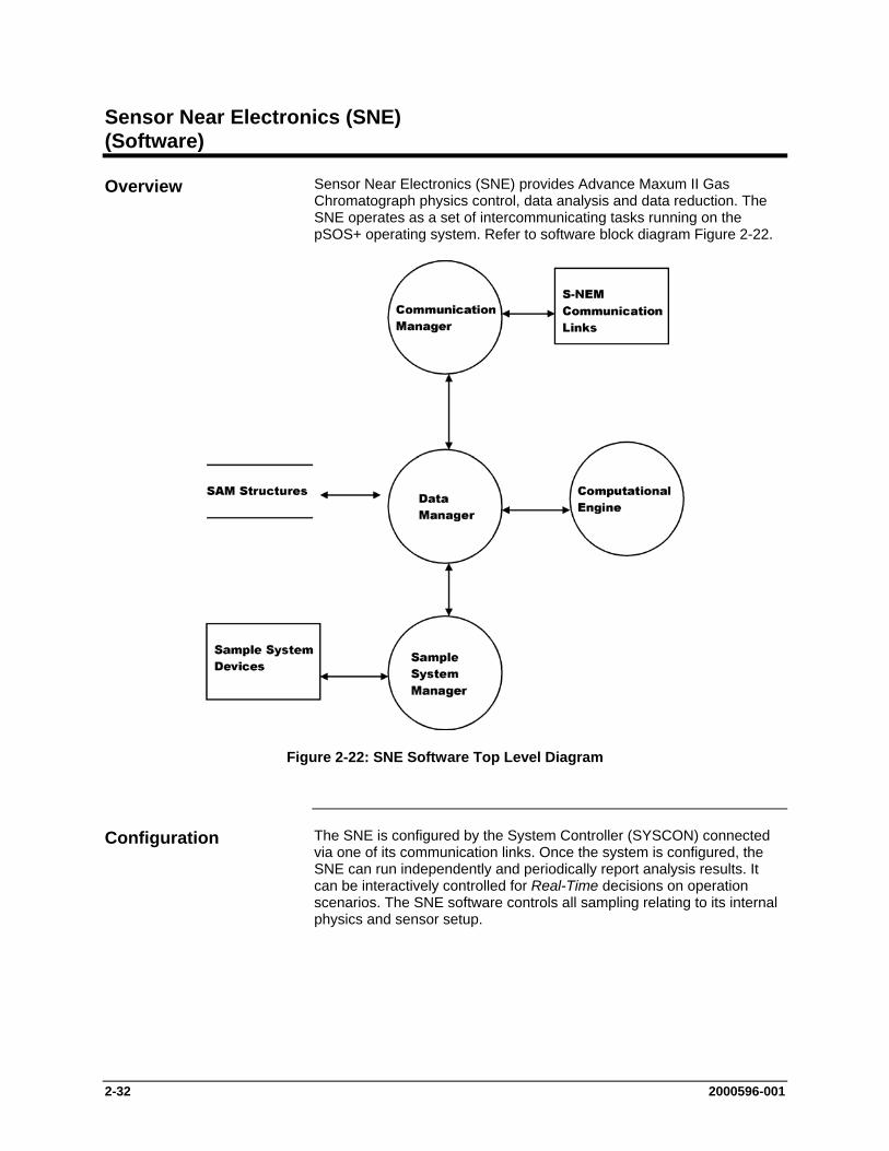
2-32 2000596-001
Sensor Near Electronics (SNE) (Software)
Sensor Near Electronics (SNE) provides Advance Maxum II Gas Chromatograph physics control, data analysis and data reduction. The SNE operates as a set of intercommunicating tasks running on the pSOS+ operating system. Refer to software block diagram Figure 2-22.
Figure 2-22: SNE Software Top Level Diagram
The SNE is configured by the System Controller (SYSCON) connected via one of its communication links. Once the system is configured, the SNE can run independently and periodically report analysis results. It can be interactively controlled for Real-Time decisions on operation scenarios. The SNE software controls all sampling relating to its internal physics and sensor setup.
Overview
Configuration
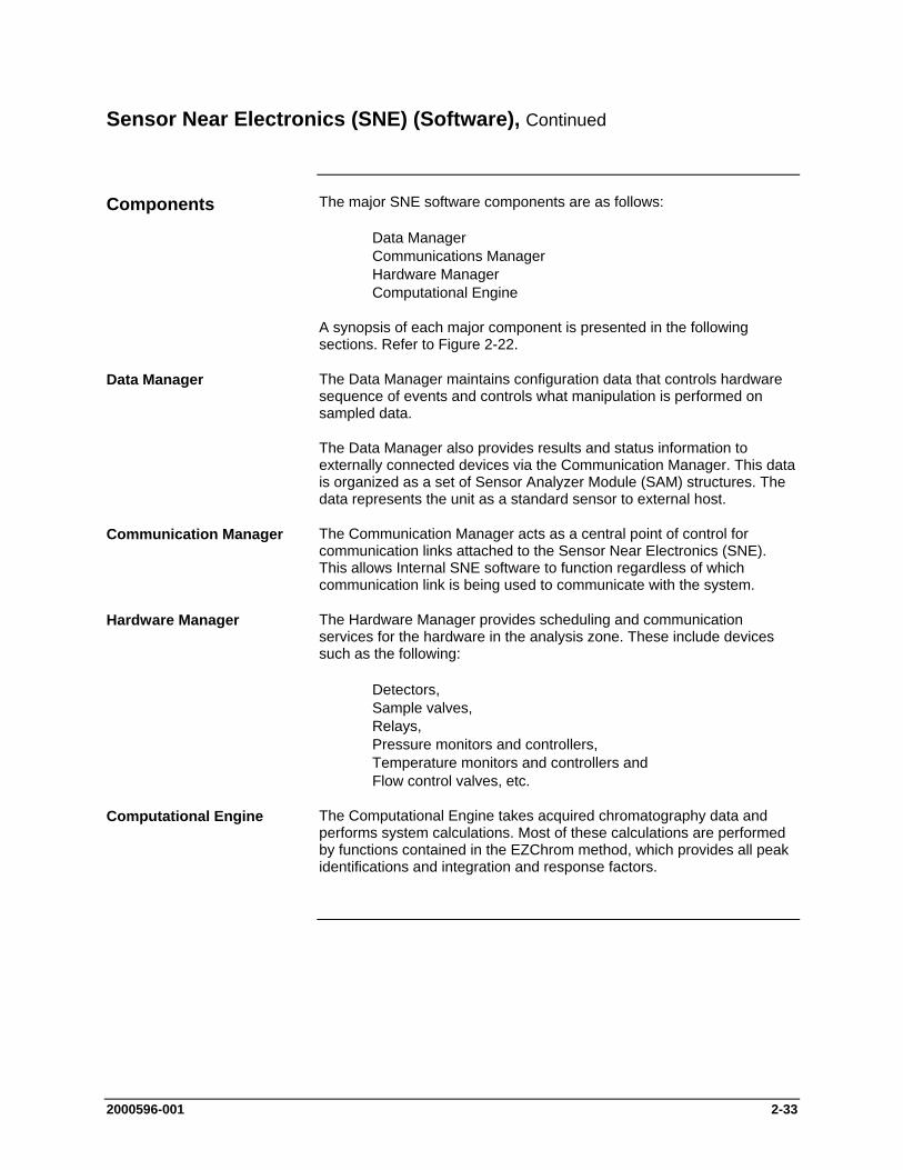
2000596-001 2-33
Sensor Near Electronics (SNE) (Software), Continued
The major SNE software components are as follows:
Data Manager Communications Manager Hardware Manager Computational Engine
A synopsis of each major component is presented in the following sections. Refer to Figure 2-22.
The Data Manager maintains configuration data that controls hardware sequence of events and controls what manipulation is performed on sampled data.
The Data Manager also provides results and status information to externally connected devices via the Communication Manager. This data is organized as a set of Sensor Analyzer Module (SAM) structures. The data represents the unit as a standard sensor to external host.
The Communication Manager acts as a central point of control for communication links attached to the Sensor Near Electronics (SNE). This allows Internal SNE software to function regardless of which communication link is being used to communicate with the system.
The Hardware Manager provides scheduling and communication services for the hardware in the analysis zone. These include devices such as the following:
Detectors, Sample valves, Relays, Pressure monitors and controllers, Temperature monitors and controllers and Flow control valves, etc.
The Computational Engine takes acquired chromatography data and performs system calculations. Most of these calculations are performed by functions contained in the EZChrom method, which provides all peak identifications and integration and response factors.
Components
Data Manager
Communication Manager
Hardware Manager
Computational Engine

2-34 2000596-001
Detector Personality Module (DPM)
Output signals from any of the detectors are inputted to each associated Detector Personality Module (DPM). This Module is mounted within SNE Assembly. The transfer of detector data is based on the database method transferred to the SNE from the SYSCON. The DPM digitizes the data and then passes it to the SNECON via an I2C port. The resulting data is then processed by the SNE and the results are transferred to the SYSCON database via the Ethernet bus. Resulting data can then be viewed on the Maintenance Panel LCD or the workstation. The DPM controls the oven heating requirements and oven heater temperature. It also regulates and digitizes the detector signal. Refer to Figure 2-23.
More information and details pertaining to the DPM can be found in the Sensor Near Electronics (SNE) Assembly Installation Manual (Siemens part number 2000685-001).
The method is the part of the application that contains the parameters for controlling the hardware used by one cycle clock on one or more SNEs. It provides peak areas and component concentrations and ncludes all cycle clock timed events. There is one cycle clock per method.
Figure 2-23: DPM with Attached Mezzanine Board
There are three primary types of DPM module. The TCD DPM is the personality module for the (TCD). The Filament DPM is available for the Filament Detector version of the TCD. For all other supported detector types, there is a Base DPM that is used in conjuction with an attached mezzanine module, described on the next page.
Description
Definition
Types of DPMs
Mezzanine Board
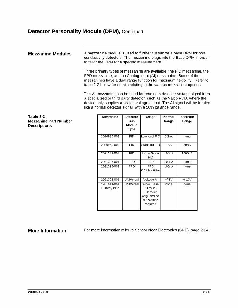
2000596-001 2-35
Detector Personality Module (DPM), Continued
A mezzanine module is used to further customize a base DPM for non conductivity detectors. The mezzanine plugs into the Base DPM in order to tailor the DPM for a specific measurement.
Three primary types of mezzanine are available, the FID mezzanine, the FPD mezzanine, and an Analog Input (AI) mezzanine. Some of the mezzanines have a dual range function for maximum flexibility. Refer to table 2-2 below for details relating to the various mezzanine options.
The AI mezzanine can be used for reading a detector voltage signal from a specialized or third party detector, such as the Valco PDD, where the device only supplies a scaled voltage output. The AI signal will be treated like a normal detector signal, with a 50% balance range.
Mezzanine Detector Sub
Module Type
Usage Normal Range
Alternate Range
2020960-001 FID Low level FID 0.2nA none
2020960-003 FID Standard FID 1nA 20nA
2021328-002 FID Large Scale FID
100nA 1000nA
2021328-001 FPD FPD 100nA none2021328-001 FPD FPD
0.18 Hz Filter100nA none
2021326-001 UNIVersal Voltage AI +/-1V +/-10V1901614-001 Dummy Plug
UNIVersal When Base DPM is
Filament only, and no mezzanine
required
none none
For more information refer to Sensor Near Electronics (SNE), page 2-24.
Mezzanine Modules
Table 2-2 Mezzanine Part Number Descriptions
More Information
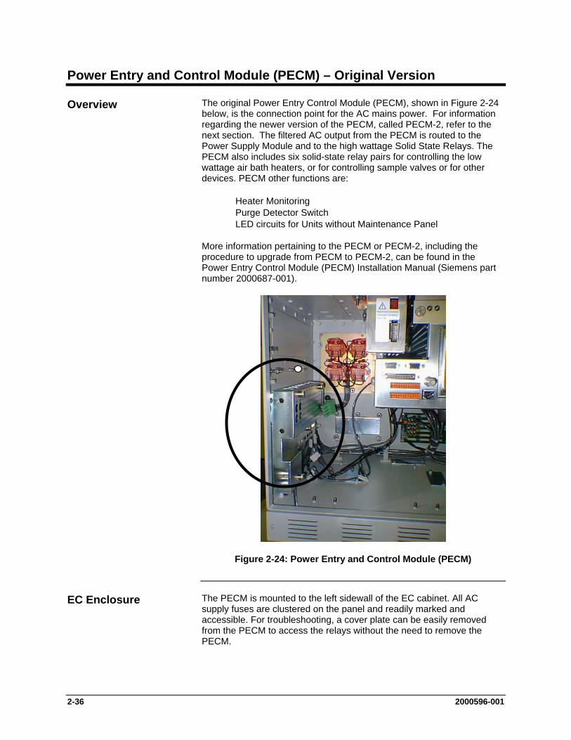
2-36 2000596-001
Power Entry and Control Module (PECM) – Original Version
The original Power Entry Control Module (PECM), shown in Figure 2-24 below, is the connection point for the AC mains power. For information regarding the newer version of the PECM, called PECM-2, refer to the next section. The filtered AC output from the PECM is routed to the Power Supply Module and to the high wattage Solid State Relays. The PECM also includes six solid-state relay pairs for controlling the low wattage air bath heaters, or for controlling sample valves or for other devices. PECM other functions are:
Heater Monitoring Purge Detector Switch LED circuits for Units without Maintenance Panel
More information pertaining to the PECM or PECM-2, including the procedure to upgrade from PECM to PECM-2, can be found in the Power Entry Control Module (PECM) Installation Manual (Siemens part number 2000687-001).
Figure 2-24: Power Entry and Control Module (PECM)
The PECM is mounted to the left sidewall of the EC cabinet. All AC supply fuses are clustered on the panel and readily marked and accessible. For troubleshooting, a cover plate can be easily removed from the PECM to access the relays without the need to remove the PECM.
Overview
EC Enclosure
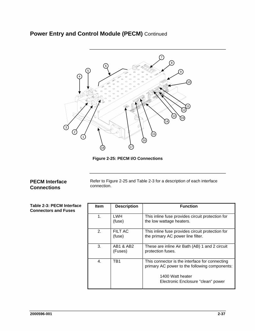
2000596-001 2-37
Power Entry and Control Module (PECM) Continued
1718
16
15
14
1211
10
9
8
7
65
4
12
3
1319
Figure 2-25: PECM I/O Connections
Refer to Figure 2-25 and Table 2-3 for a description of each interface connection.
Item Description Function
1. LWH (fuse)
This inline fuse provides circuit protection for the low wattage heaters.
2. FILT AC (fuse)
This inline fuse provides circuit protection for the primary AC power line filter.
3. AB1 & AB2 (Fuses)
These are inline Air Bath (AB) 1 and 2 circuit protection fuses.
4. TB1 This connector is the interface for connecting primary AC power to the following components:
1400 Watt heater Electronic Enclosure "clean" power
PECM Interface Connections
Table 2-3: PECM Interface Connectors and Fuses
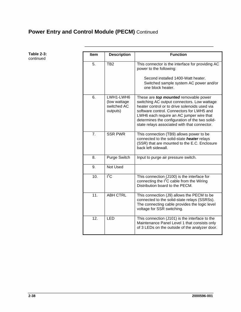
2-38 2000596-001
Power Entry and Control Module (PECM) Continued
Item Description Function
5. TB2 This connector is the interface for providing AC power to the following:
Second installed 1400-Watt heater. Switched sample system AC power and/or
one block heater.
6. LWH1-LWH6 (low wattage switched AC outputs)
These are top mounted removable power switching AC output connectors. Low wattage heater control or to drive solenoids used via software control. Connectors for LWH5 and LWH6 each require an AC jumper wire that determines the configuration of the two solid-state relays associated with that connector.
7. SSR PWR This connection (TB9) allows power to be connected to the solid-state heater relays (SSR) that are mounted to the E.C. Enclosure back left sidewall.
8. Purge Switch Input to purge air pressure switch.
9. Not Used
10. I2C This connection (J100) is the interface for connecting the I2C cable from the Wiring Distribution board to the PECM.
11. ABH CTRL This connection (J9) allows the PECM to be connected to the solid-state relays (SSRSs). The connecting cable provides the logic level voltage for SSR switching.
12. LED This connection (J101) is the interface to the Maintenance Panel Level 1 that consists only of 3 LEDs on the outside of the analyzer door.
Table 2-3: continued

2000596-001 2-39
Power Entry and Control Module (PECM) Continued
Item Description Function
13. PURGE SYSCON
This connection (J1302) interfaces to the SYSCON.
14. LWH1-LWH6 (switched inputs)
These are bottom mounted connectors used for controlling the associated top mounted low wattage device outputs. Input power at these connectors is 5 VDC. Installed jumper wire connectors for internal control must be installed or replaced with external control wiring connectors. Examples of a low wattage device are methanator, vaporizing regulator, FID heater or sample system stream switching solenoid.
15. ABH2 This connection (J92) allows interfacing of the Detector Personality Module (DPM) heater control wiring to the PECM. This cable allows switching of solid-state relays used for temperature control of the first air bath heater.
16. ABH1 If two air bath heaters are required, the additional air bath cable is interfaced to the PECM via this connection.
17. DEBUG (not used)
This connection (J102) allows a diagnostic device to be interfaced to the PECM.
18. Power Cord Filtered AC output to Power Supply.
19. HTR PRESS This connection (J7) is the interface for the heater air pressure switch cable to the PECM.
The original version of the PECM is no longer available for order. It it must be replaced then upgrade to PECM-2 is necessary. Refer to the Power Entry Control Module (PECM) Installation Manual (Siemens part number 2000687-001) for the procedure to replace the original PECM with PECM-2.
Table 2-3: continued
Replacement
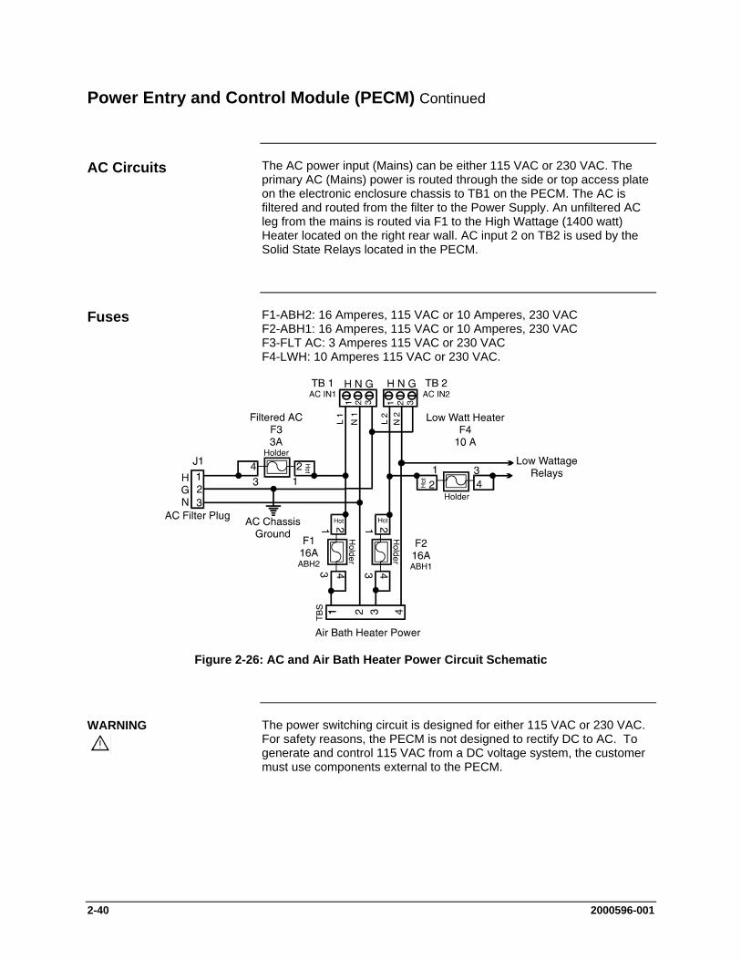
2-40 2000596-001
Power Entry and Control Module (PECM) Continued
The AC power input (Mains) can be either 115 VAC or 230 VAC. The primary AC (Mains) power is routed through the side or top access plate on the electronic enclosure chassis to TB1 on the PECM. The AC is filtered and routed from the filter to the Power Supply. An unfiltered AC leg from the mains is routed via F1 to the High Wattage (1400 watt) Heater located on the right rear wall. AC input 2 on TB2 is used by the Solid State Relays located in the PECM.
F1-ABH2: 16 Amperes, 115 VAC or 10 Amperes, 230 VAC F2-ABH1: 16 Amperes, 115 VAC or 10 Amperes, 230 VAC F3-FLT AC: 3 Amperes 115 VAC or 230 VAC F4-LWH: 10 Amperes 115 VAC or 230 VAC.
Figure 2-26: AC and Air Bath Heater Power Circuit Schematic
The power switching circuit is designed for either 115 VAC or 230 VAC. For safety reasons, the PECM is not designed to rectify DC to AC. To generate and control 115 VAC from a DC voltage system, the customer must use components external to the PECM.
AC Circuits
Fuses
WARNING
2000596-001 2-41
Power Entry and Control Module (PECM) Continued
The PECM provides the voltage to the two pairs of 1400-Watt AC Air Bath heater power switching circuits located on the rear wall of the EC. Connection to the heaters is made through a special cable. Each circuit consists of two series connected solid-state relays.
One series connected relay controls the 1400-Watt AC heater to maintain the set point temperature. Monitoring the air bath RTD and heater pressure switch accomplish this. The second series connected relay is used for safety purposes. It performs an emergency analyzer heater shutdown if an over-temperature condition is detected. Both relay circuits are completely independent of each other. However; in order for the power switching to occur both relays must be enabled. Temperature controls are monitored by the Detector Personality Module located in the SNE and routed to the PECM via a dedicated cable and connector. No other functions are connected to the temperature control circuit. The connections are EMC filtered. When over temperature is detected the PECM over temperature circuit inhibits the SSR from firing.
High Wattage Air Bath Heater Control
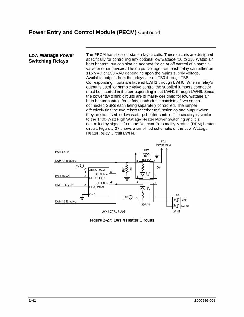
2-42 2000596-001
Power Entry and Control Module (PECM) Continued
The PECM has six solid-state relay circuits. These circuits are designed specifically for controlling any optional low wattage (10 to 250 Watts) air bath heaters, but can also be adapted for on or off control of a sample valve or other devices. The output voltage from each relay can either be 115 VAC or 230 VAC depending upon the mains supply voltage. Available outputs from the relays are on TB3 through TB8. Corresponding inputs are labeled LWH1 through LWH6. When a relay’s output is used for sample valve control the supplied jumpers connector must be inserted in the corresponding input LWH1 through LWH6. Since the power switching circuits are primarily designed for low wattage air bath heater control, for safety, each circuit consists of two series connected SSRs each being separately controlled. The jumper effectively ties the two relays together to function as one output when they are not used for low wattage heater control. The circuitry is similar to the 1400-Watt High Wattage Heater Power Switching and it is controlled by signals from the Detector Personality Module (DPM) heater circuit. Figure 2-27 shows a simplified schematic of the Low Wattage Heater Relay Circuit LWH4.
Figure 2-27: LWH4 Heater Circuits
Low Wattage Power Switching Relays
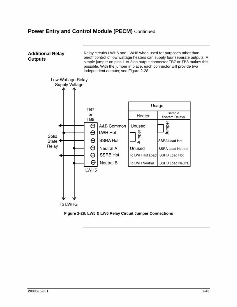
2000596-001 2-43
Power Entry and Control Module (PECM) Continued
Relay circuits LWH5 and LWH6 when used for purposes other than on/off control of low wattage heaters can supply four separate outputs. A simple jumper on pins 1 to 2 on output connector TB7 or TB8 makes this possible. With the jumper in place, each connector will provide two independent outputs; see Figure 2-28.
Figure 2-28: LW5 & LW6 Relay Circuit Jumper Connections
Additional Relay Outputs

2-44 2000596-001
Power Entry and Control Module (PECM) Continued
The monitoring of the purge condition is a safety related function of the PECM. A loss of purge sets the PURGE_LOSS flag and turns on the purge LED on the front panel display.
Air bath heater control switches, located externally to the PECM, monitor the air bath heater air supply for air bath heater 1 and air bath heater 2. If a loss of air is detected in either oven, the air bath heater disables the heater SSR; thereby, preventing destruction of the heating element.
For units that are not equipped with a Maintenance Panel, the PECM provides LED control signals to the three status and 1 purge LEDs on the door. The LED status are set to all “ON” during the power-up sequence and remain that way until a DO command has been received to set the LED to a defined state. From then on, the “Normal”, “Warning” and “Fault” LED output are set according to the status of the corresponding DO (even if the LED connector is not connected). The Purge LED is hardware controlled.
Purge Circuit
Air Bath Heater Air Monitoring
Maintenance LEDs

2000596-001 2-45
Power Entry and Control Module (PECM) Diagnostics
The Operating diagnostic functions, provided by the PECM are:
Power Read-back of SSR Controls Purge
This PECM diagnostic is a customer specified option. Primary AC power is fed to the SSRs and the diagnostic checks the resulting 5 VDC SSR energizing voltage is within 5 V 5 .
If a loss of purge is detected the purge switch is enabled. This results in the Purge LED to light. The purge LED light is located on the door mounted Maintenance Display panel, or as a separate LED on the door for those units not equipped with the panel. The purge control alarm signal is controlled by the SYSCON.
The operating SNE Internal Bus diagnostics are as follows:
This diagnostic monitors data transmission errors. The error data rate should be less than one bit error per 100,000 packets. This is less than one error per day. If error limit is exceeded a yellow diagnostic LED light on the SNE illuminates for approximately 0.5 seconds.
When transmission errors occur and a retry fails, the red diagnostic LED light illuminates for approximately 0.5 seconds. If retry fails, wait 0.5 seconds and then reset the communication interface.
The temperature of I2C modules in the EC can be monitored and compared to low and high limits set by the user from the Maintenance Panel. If a limit is exceeded, an alarm message can be issued and an appropriate error code stored in non-volatile flash memory. This function is not commonly used in normal operation, but it is occasionally used for troubleshooting.
Overview
Power
Purge
SNE Internal Bus
Data Transmission
Temperature Sense
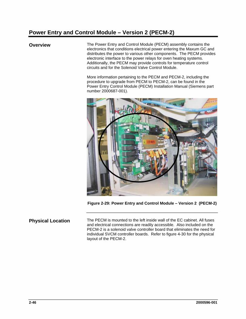
2-46 2000596-001
Power Entry and Control Module – Version 2 (PECM-2)
The Power Entry and Control Module (PECM) assembly contains the electronics that conditions electrical power entering the Maxum GC and distributes the power to various other components. The PECM provides electronic interface to the power relays for oven heating systems. Additionally, the PECM may provide controls for temperature control circuits and for the Solenoid Valve Control Module.
More information pertaining to the PECM and PECM-2, including the procedure to upgrade from PECM to PECM-2, can be found in the Power Entry Control Module (PECM) Installation Manual (Siemens part number 2000687-001).
Figure 2-29: Power Entry and Control Module – Version 2 (PECM-2)
The PECM is mounted to the left inside wall of the EC cabinet. All fuses and electrical connections are readily accessible. Also included on the PECM-2 is a solenoid valve controller board that eliminates the need for individual SVCM controller boards. Refer to figure 4-30 for the physical layout of the PECM-2.
Overview
Physical Location

2000596-001 2-47
Power Entry and Control Module (PECM-2) Continued
The PECM has been changed in its design since its original release. The newest version of this part is also used as the spare part replacement for the previous version. The original PECM was a single electronic circuit board with a metal protective shield. It provided connection points for the electrical power coming into the Maxum GC and mounted low power electrical relays which could switch power to any electrical heater smaller than 200 watts.
The newest version of the module, PECM-2, is a two part circuit board. One part connects the electrical power. The other part includes certain electronic circuits. Key features of the newer design are:
Easy access (no cover) Two on-board temperature control circuits that can allow use of
a lower cost Thermistor Detector Personality Module (TCD DPM): in some cases the less costly 2021797-002 can be used instead of full-featured 2021797-001.
Additional medium-wattage heater circuit. May allow elimination of additional DPM when it is used for
temperature control only, such as for heated valves and the methanator.
Includes solenoid valve control which eliminates the need for individual SVCM controller boards. When converting older design and eliminating original SVCM controller boards, additional long cables are required.
Improved low-profile fuse holders LED indicators for air pressure switch on air-bath heater circuits Built-in provision for connection of Uninterruptible Power Supply
(UPS) for 24vdc circuits. The heaters are powered through different connectors to minimize the loading of the AC power needed for running the 24vdc circuits.
Maintenance Panel Level 1 consists of LEDs on the outside of the analyzer door. It is intended for use in GCs that are not equipped with the full feature Maintenance Panel. The PECM supplies the control signals for Maintenance Panel Level 1, if equipped. For PECM-1, the Maintenance Panel Level 1 connects to position J17. See Figure 2-30 for the location of connector J17.
Changes from PECM to PECM-2
Maintenance LEDs
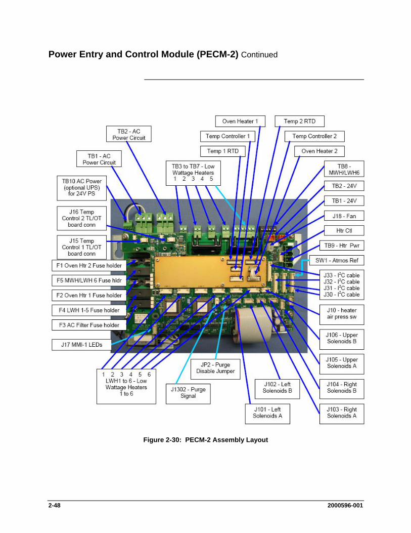
2-48 2000596-001
Power Entry and Control Module (PECM-2) Continued
Figure 2-30: PECM-2 Assembly Layout
2000596-001 2-49
Power Entry and Control Module (PECM-2) Continued
Table 2-4 below gives the designations for each PECM-2 fuse. Note that the fuse numbers are out of order in the table. This matches the way the fuses are positioned on the PECM-2 (looking from top to bottom). Refer back to Figure 2-30 for fuse locations.
Fuse Function Fuses for 115VAC
Fuses for 230VAC
F1 AC Power Circuit 1
16A (1901693-001)
10A (1901694-001)
F5 Heater Channel 6
6.3A (1901695-001)
6.3A (1901695-001)
F2 AC Power Circuit 2
16A (1901693-001)
10A (1901694-001)
F4 LWH 1-5 (low wattage heaters)
10A (1901694-001)
10A (1901694-001)
F3 Power Supply (24V out)
3.15A (1302004-033)
3.15A (1302004-033)
Table 2-4: PECM-2 Fuse Assignments
One function of the PECM is to monitor the state of the purge condition for the analyzer. If a loss of purge is detected the purge switch is enabled. The purge control alarm signal is controlled by the SYSCON. The purge signal cable from SYSCON to PECM plugs into connector J1302 on the PECM-2. Connection SW1 on the PECM-2 is used to connect atmospheric reference for the purge switch.
When a purged enclosure is not required per the safety codes, connector J2 on the PECM-2 can be used to disable the purge alarm. Refer to Figure 4-30 for connector locations.
Fuses
Purge

2-50 2000596-001
Power Entry and Control Module (PECM-2) Continued
The original PECM design provided for only one type of heater assembly for its air bath configurations (single isothermal; dual isothermal; or Programmed Temperature Control). This was a 1400 watt heater assembly. A single heater was used for the single isothermal configuration and two heaters were used in the other configurations. Now, a second air bath heater assembly has been introduced. It is a 500 watt heater and can be used in single isothermal configurations where the controlled oven temperature is 70°C or less. In all other air bath configurations, the original heater is required.
Additionally, with the introduction of the PECM-2, a new “medium power” Solid State Relay Module (temperature control relay module) is available. The original assembly included four large relays suitable for switching two of the 1400 watt air bath oven heater elements. However, many Maxum GCs do not require that much power. Therefore, a new SSR Module has been added to the Maxum spare part offering which can lower spare parts costs. The newer board provides smaller relays which are capable of controlling the new 500 watt air bath heater assembly (described above). In addition, the “medium power” SSR Module can be used to control the two 250 watt heaters used in the Maxum airless oven configurations. The newer board can also be used to control the low wattage heaters in the heated Flame Ionization and Flame Photometric detector housings or in heated sample injection valves.
The PECM has six solid-state relay circuits which can be used to contol heated valves, detector heaters, etc.. Each circuit has a 2 Amp/250 Watt maximum. Available outputs from the relays are on TB3 through TB8. Corresponding inputs are labeled LWH1 through LWH6.
Heater Control for Air Bath Ovens
Low Wattage Heater Circuits
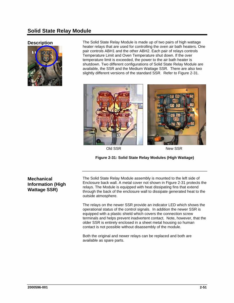
2000596-001 2-51
Solid State Relay Module
The Solid State Relay Module is made up of two pairs of high wattage heater relays that are used for controlling the oven air bath heaters. One pair controls ABH1 and the other ABH2. Each pair of relays controls Temperature Limit and Oven Temperature shut down. If the over temperature limit is exceeded, the power to the air bath heater is shutdown. Two different configurations of Solid State Relay Module are available, the SSR and the Medium Wattage SSR. There are also two slightly different versions of the standard SSR. Refer to Figure 2-31.
Old SSR New SSR
Figure 2-31: Solid State Relay Modules (High Wattage)
The Solid State Relay Module assembly is mounted to the left side of Enclosure back wall. A metal cover not shown in Figure 2-31 protects the relays. The Module is equipped with heat dissipating fins that extend through the back of the enclosure wall to dissipate generated heat to the outside atmosphere.
The relays on the newer SSR provide an indicator LED which shows the operational status of the control signals. In addition the newer SSR is equipped with a plastic shield which covers the connection screw terminals and helps prevent inadvertent contact. Note, however, that the older SSR is entirely enclosed in a sheet metal housing so human contact is not possible without disassembly of the module.
Both the original and newer relays can be replaced and both are available as spare parts.
Description
Mechanical Information (High Wattage SSR)
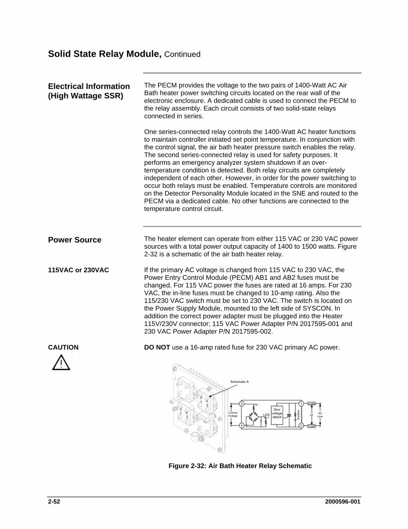
2-52 2000596-001
Solid State Relay Module, Continued
The PECM provides the voltage to the two pairs of 1400-Watt AC Air Bath heater power switching circuits located on the rear wall of the electronic enclosure. A dedicated cable is used to connect the PECM to the relay assembly. Each circuit consists of two solid-state relays connected in series.
One series-connected relay controls the 1400-Watt AC heater functions to maintain controller initiated set point temperature. In conjunction with the control signal, the air bath heater pressure switch enables the relay. The second series-connected relay is used for safety purposes. It performs an emergency analyzer system shutdown if an over-temperature condition is detected. Both relay circuits are completely independent of each other. However, in order for the power switching to occur both relays must be enabled. Temperature controls are monitored on the Detector Personality Module located in the SNE and routed to the PECM via a dedicated cable. No other functions are connected to the temperature control circuit.
The heater element can operate from either 115 VAC or 230 VAC power sources with a total power output capacity of 1400 to 1500 watts. Figure 2-32 is a schematic of the air bath heater relay.
If the primary AC voltage is changed from 115 VAC to 230 VAC, the Power Entry Control Module (PECM) AB1 and AB2 fuses must be changed. For 115 VAC power the fuses are rated at 16 amps. For 230 VAC, the in-line fuses must be changed to 10-amp rating. Also the 115/230 VAC switch must be set to 230 VAC. The switch is located on the Power Supply Module, mounted to the left side of SYSCON. In addition the correct power adapter must be plugged into the Heater 115V/230V connector; 115 VAC Power Adapter P/N 2017595-001 and 230 VAC Power Adapter P/N 2017595-002.
DO NOT use a 16-amp rated fuse for 230 VAC primary AC power.
Figure 2-32: Air Bath Heater Relay Schematic
Electrical Information (High Wattage SSR)
Power Source
115VAC or 230VAC
CAUTION
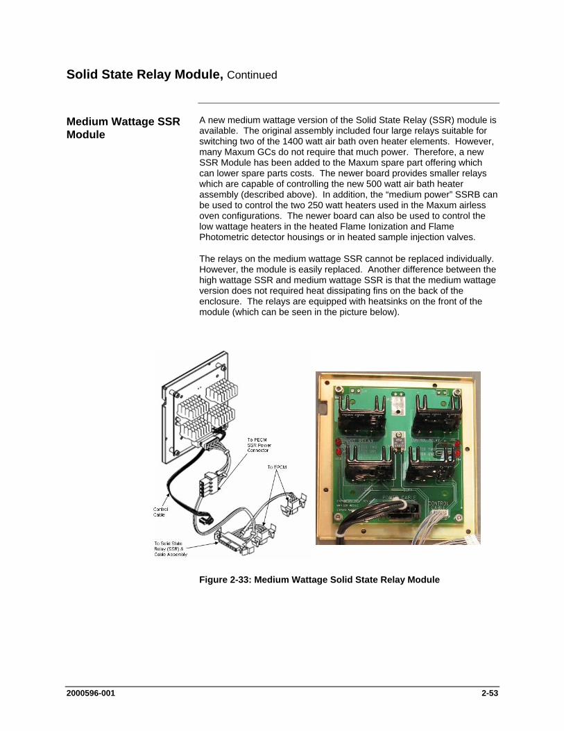
2000596-001 2-53
Solid State Relay Module, Continued
A new medium wattage version of the Solid State Relay (SSR) module is available. The original assembly included four large relays suitable for switching two of the 1400 watt air bath oven heater elements. However, many Maxum GCs do not require that much power. Therefore, a new SSR Module has been added to the Maxum spare part offering which can lower spare parts costs. The newer board provides smaller relays which are capable of controlling the new 500 watt air bath heater assembly (described above). In addition, the “medium power” SSRB can be used to control the two 250 watt heaters used in the Maxum airless oven configurations. The newer board can also be used to control the low wattage heaters in the heated Flame Ionization and Flame Photometric detector housings or in heated sample injection valves.
The relays on the medium wattage SSR cannot be replaced individually. However, the module is easily replaced. Another difference between the high wattage SSR and medium wattage SSR is that the medium wattage version does not required heat dissipating fins on the back of the enclosure. The relays are equipped with heatsinks on the front of the module (which can be seen in the picture below).
Figure 2-33: Medium Wattage Solid State Relay Module
Medium Wattage SSR Module
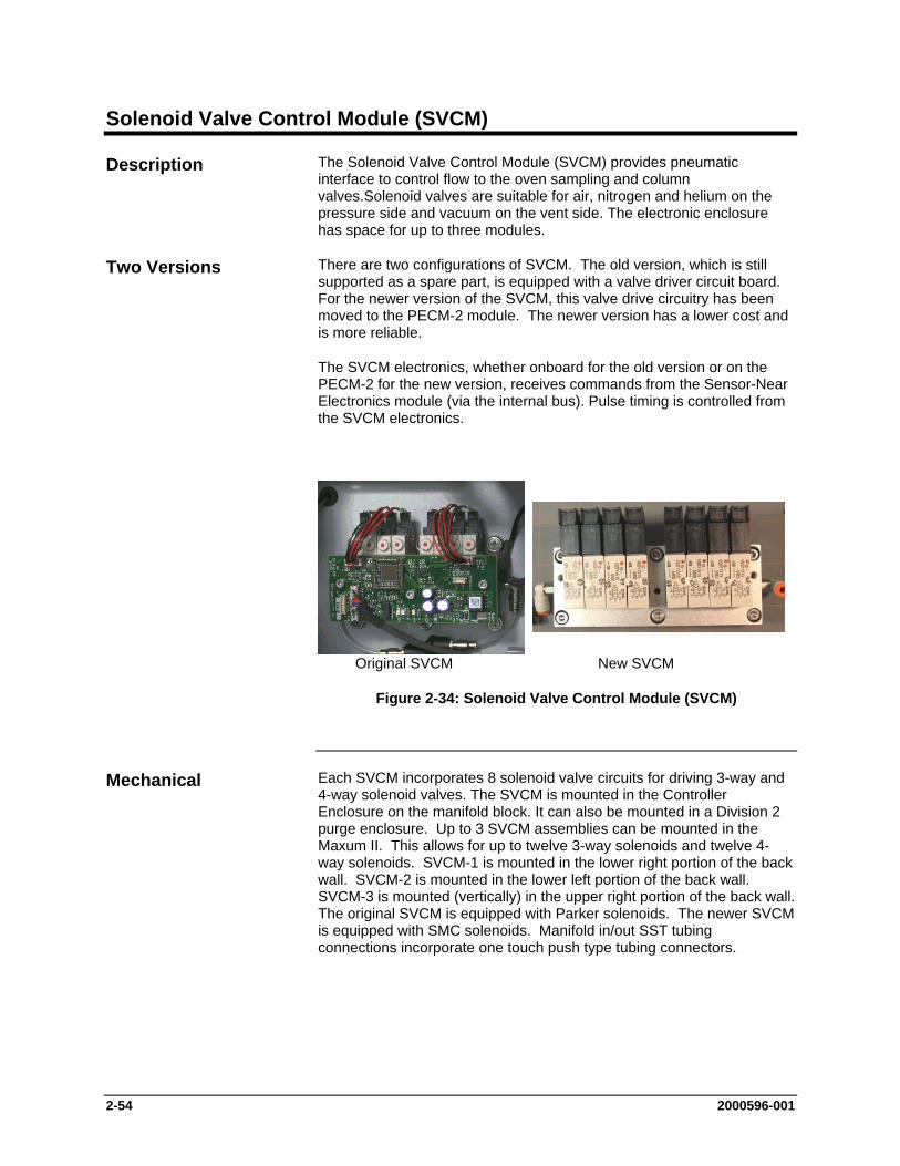
2-54 2000596-001
Solenoid Valve Control Module (SVCM)
The Solenoid Valve Control Module (SVCM) provides pneumatic interface to control flow to the oven sampling and column valves.Solenoid valves are suitable for air, nitrogen and helium on the pressure side and vacuum on the vent side. The electronic enclosure has space for up to three modules.
There are two configurations of SVCM. The old version, which is still supported as a spare part, is equipped with a valve driver circuit board. For the newer version of the SVCM, this valve drive circuitry has been moved to the PECM-2 module. The newer version has a lower cost and is more reliable.
The SVCM electronics, whether onboard for the old version or on the PECM-2 for the new version, receives commands from the Sensor-Near Electronics module (via the internal bus). Pulse timing is controlled from the SVCM electronics.
Original SVCM New SVCM
Figure 2-34: Solenoid Valve Control Module (SVCM)
Each SVCM incorporates 8 solenoid valve circuits for driving 3-way and 4-way solenoid valves. The SVCM is mounted in the Controller Enclosure on the manifold block. It can also be mounted in a Division 2 purge enclosure. Up to 3 SVCM assemblies can be mounted in the Maxum II. This allows for up to twelve 3-way solenoids and twelve 4-way solenoids. SVCM-1 is mounted in the lower right portion of the back wall. SVCM-2 is mounted in the lower left portion of the back wall. SVCM-3 is mounted (vertically) in the upper right portion of the back wall. The original SVCM is equipped with Parker solenoids. The newer SVCM is equipped with SMC solenoids. Manifold in/out SST tubing connections incorporate one touch push type tubing connectors.
Description
Two Versions
Mechanical
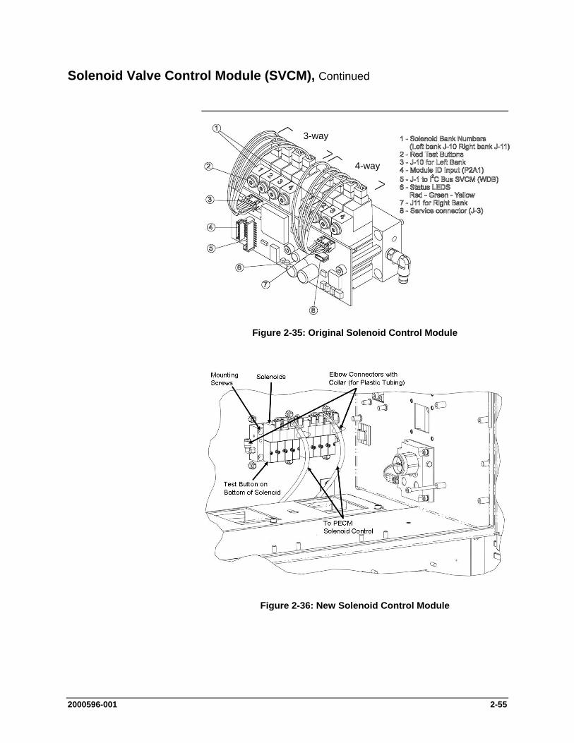
2000596-001 2-55
Solenoid Valve Control Module (SVCM), Continued
Figure 2-35: Original Solenoid Control Module
Figure 2-36: New Solenoid Control Module
4-way
3-way

2-56 2000596-001
Solenoid Valve Control Module (SVCM), Continued
Digital outputs assigned to each solenoid valve are shown in Table 2-6. If a digital output is 0 the valve is OFF and if output is a 1 the valve is ON. Each group of four valves is identified as being left or right. There are no digital inputs. Refer to Table 2-5 for the numbering pattern of solenoid valves (same for original and newer versions). Each solenoid valve can be manually set to the ON or OFF conditions by manually depressing the red button on each solenoid. This button is on the top front of each Parker (original) solenoid and on the bottom of each SMC (new) solenoid. Refer to Figures 2-35 and 2-36 for the button location.
Group Solenoid Valve
Left Valve 1 Left Valve 2 Left Valve 3 Left Valve 4
Right Valve 1 Right Valve 2 Right Valve 3 Right Valve 4
Table 2-6 shows the specific digital output I/O assignment summary. For location of solenoid valves, refer to Figure 2-35. There are no analog inputs or outputs.
Signal Type
SYSCON Channel
#
I/O Name Group #
Channel #
DO 1 LEFT_GROUP_VALVE_1 1 80h DO 2 LEFT_GROUP_VALVE_2 1 40h DO 3 LEFT_GROUP_VALVE_3 1 20h DO 4 LEFT_GROUP_VALVE_4 1 10h DO 5 RIGHT_GROUP_VALVE_1 1 08h DO 6 RIGHT_GROUP_VALVE_2 1 04h DO 7 RIGHT_GROUP_VALVE_3 1 02h DO 8 RIGHT_GROUP_VALVE_4 1 01h
Digital Outputs
Table 2-5: DO Solenoid Valve Groups
SVCM I/O Assignments
Table 2-6: SVCM I/O Assignments
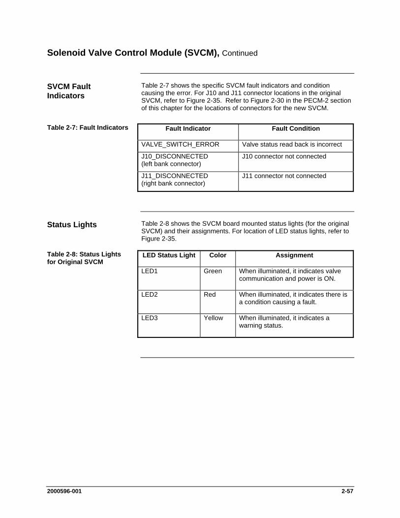
2000596-001 2-57
Solenoid Valve Control Module (SVCM), Continued
Table 2-7 shows the specific SVCM fault indicators and condition causing the error. For J10 and J11 connector locations in the original SVCM, refer to Figure 2-35. Refer to Figure 2-30 in the PECM-2 section of this chapter for the locations of connectors for the new SVCM.
Fault Indicator Fault Condition
VALVE_SWITCH_ERROR Valve status read back is incorrect
J10_DISCONNECTED (left bank connector)
J10 connector not connected
J11_DISCONNECTED (right bank connector)
J11 connector not connected
Table 2-8 shows the SVCM board mounted status lights (for the original SVCM) and their assignments. For location of LED status lights, refer to Figure 2-35.
LED Status Light Color Assignment
LED1 Green When illuminated, it indicates valve communication and power is ON.
LED2 Red When illuminated, it indicates there is a condition causing a fault.
LED3 Yellow When illuminated, it indicates a warning status.
SVCM Fault Indicators
Table 2-7: Fault Indicators
Status Lights
Table 2-8: Status Lights for Original SVCM
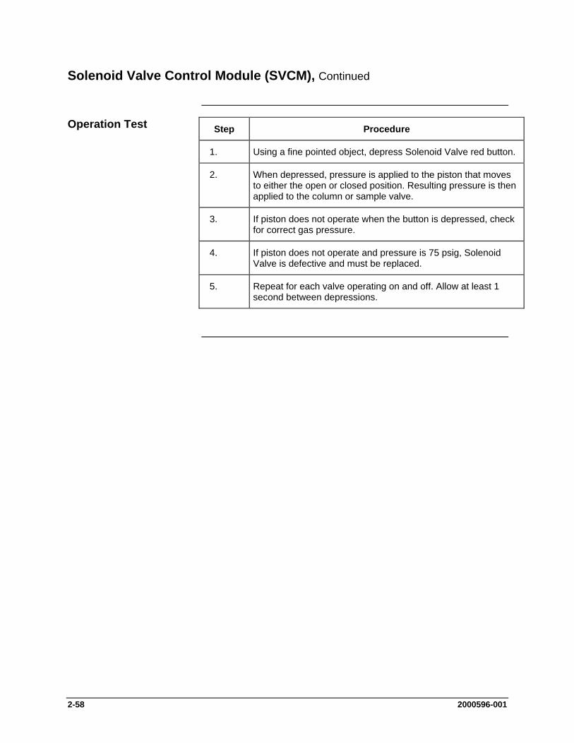
2-58 2000596-001
Solenoid Valve Control Module (SVCM), Continued
Step Procedure
1. Using a fine pointed object, depress Solenoid Valve red button.
2. When depressed, pressure is applied to the piston that moves to either the open or closed position. Resulting pressure is then applied to the column or sample valve.
3. If piston does not operate when the button is depressed, check for correct gas pressure.
4. If piston does not operate and pressure is 75 psig, Solenoid Valve is defective and must be replaced.
5. Repeat for each valve operating on and off. Allow at least 1 second between depressions.
Operation Test
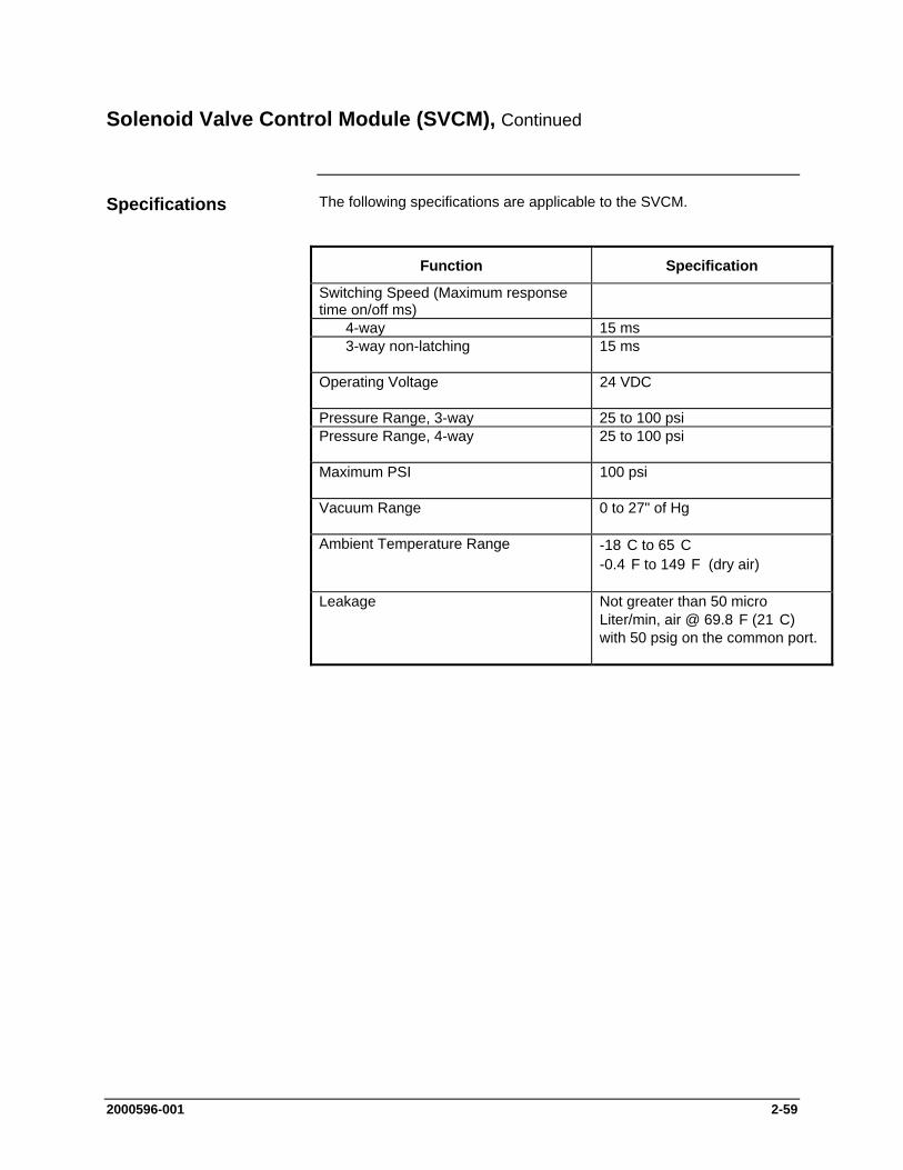
2000596-001 2-59
Solenoid Valve Control Module (SVCM), Continued
The following specifications are applicable to the SVCM.
Function Specification
Switching Speed (Maximum response time on/off ms)
4-way 15 ms 3-way non-latching 15 ms
Operating Voltage 24 VDC
Pressure Range, 3-way 25 to 100 psi Pressure Range, 4-way 25 to 100 psi
Maximum PSI 100 psi
Vacuum Range 0 to 27" of Hg
Ambient Temperature Range -18 C to 65 C -0.4 F to 149 F (dry air)
Leakage Not greater than 50 micro Liter/min, air @ 69.8 F (21 C) with 50 psig on the common port.
Specifications
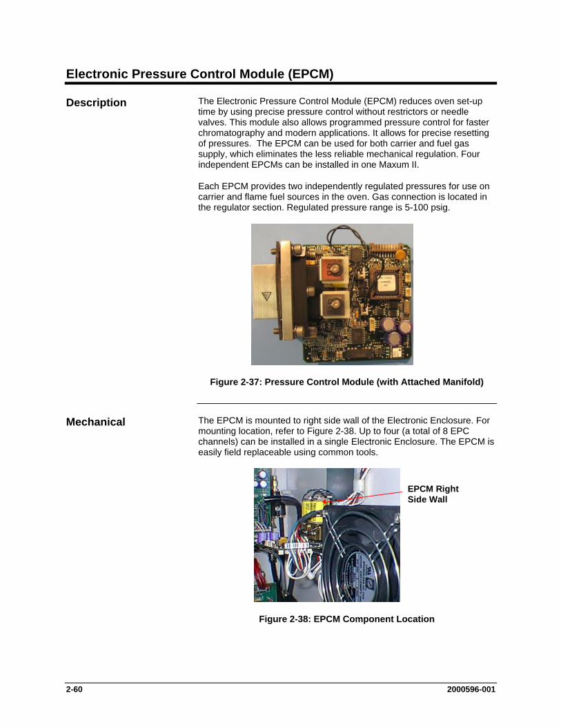
2-60 2000596-001
Electronic Pressure Control Module (EPCM)
The Electronic Pressure Control Module (EPCM) reduces oven set-up time by using precise pressure control without restrictors or needle valves. This module also allows programmed pressure control for faster chromatography and modern applications. It allows for precise resetting of pressures. The EPCM can be used for both carrier and fuel gas supply, which eliminates the less reliable mechanical regulation. Four independent EPCMs can be installed in one Maxum II.
Each EPCM provides two independently regulated pressures for use on carrier and flame fuel sources in the oven. Gas connection is located in the regulator section. Regulated pressure range is 5-100 psig.
Figure 2-37: Pressure Control Module (with Attached Manifold)
The EPCM is mounted to right side wall of the Electronic Enclosure. For mounting location, refer to Figure 2-38. Up to four (a total of 8 EPC channels) can be installed in a single Electronic Enclosure. The EPCM is easily field replaceable using common tools.
EPCM RightSide Wall
Figure 2-38: EPCM Component Location
Description
Mechanical
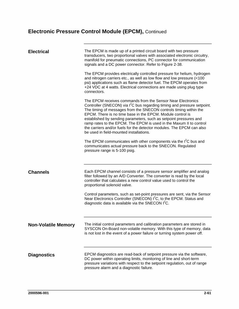
2000596-001 2-61
Electronic Pressure Control Module (EPCM), Continued
The EPCM is made up of a printed circuit board with two pressure transducers, two proportional valves with associated electronic circuitry, manifold for pneumatic connections, PC connector for communication signals and a DC power connector. Refer to Figure 2-38.
The EPCM provides electrically controlled pressure for helium, hydrogen and nitrogen carriers etc., as well as low flow and low pressure (<100 psi) applications such as flame detector fuel. The EPCM operates from +24 VDC at 4 watts. Electrical connections are made using plug type connectors.
The EPCM receives commands from the Sensor Near Electronics Controller (SNECON) via I2C bus regarding timing and pressure setpoint. The timing of messages from the SNECON controls timing within the EPCM. There is no time base in the EPCM. Module control is established by sending parameters, such as setpoint pressures and ramp rates to the EPCM. The EPCM is used in the Maxum II to control the carriers and/or fuels for the detector modules. The EPCM can also be used in field-mounted installations.
The EPCM communicates with other components via the I2C bus and communicates actual pressure back to the SNECON. Regulated pressure range is 5-100 psig.
Each EPCM channel consists of a pressure sensor amplifier and analog filter followed by an A/D Converter. The converter is read by the local controller that calculates a new control value used to control the proportional solenoid valve.
Control parameters, such as set-point pressures are sent, via the Sensor Near Electronics Controller (SNECON) I2C, to the EPCM. Status and diagnostic data is available via the SNECON I2C.
The initial control parameters and calibration parameters are stored in SYSCON On-Board non-volatile memory. With this type of memory, data is not lost in the event of a power failure or turning system power off.
EPCM diagnostics are read-back of setpoint pressure via the software, DC power within operating limits, monitoring of line and short-term pressure variations with respect to the setpoint regulation, out of range pressure alarm and a diagnostic failure.
Electrical
Channels
Non-Volatile Memory
Diagnostics

2-62 2000596-001
Electronic Pressure Control Module (EPCM), Continued
The following specifications are applicable to the Electronic Pressure Control Module (EPCM):
Topic Specification
Maximum inlet pressure 120 psig
Pressure output range 5-100 psig
Minimum differential between EPC inlet and outlet
5 psi
Flow range from EPC 5-500 sccm (see note below)
Controlled pressure stability over temperature range
0.5% of setpoint
Short-term pressure stability 0.0005 psi over 30 seconds
Typical response time for step change in setpoint.
Stable to within 0.1% of final value within 0.5 seconds*
* (For hydrogen the response time is ~ 1 second).
Note: When running applications with column flow rates of less than 5 sccm, a separate bleed flow path is recommended in order to reduce the time required to achieve pressure stability when variable setpoints are used. Depending on the volume involved, a bleed flow rate of 5-10 sccm is recommended.
Specifications

2000596-001 2-63
Wiring Distribution Board (WDB)
The Wiring Distribution Board (WDB) is the central connecting point for the internal bus wiring to the Modules as well as to the power supply and circulating fan wiring harnesses.
Figure 2-39: Wiring Distribution Board
The WDB is mounted on the lower back wall of the electronic enclosure. The board has connectors for interfacing PECM, SVCM, EPC and SNEs over the internal bus. The WDB has a eight-position selector switch that is no longer used. This switch was originally intended for identifying an analyzer in configurations involving more than one analyzer being controlled by a single System Controller (SYSCON). In new analyzers this switch is not functional.
There are no fuses or active electronics on the WDB. The board provides +24 VDC to operate the air-circulating fan.
Description
Mechanical
Electrical
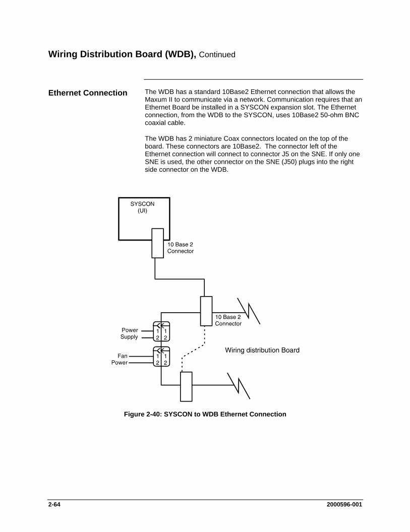
2-64 2000596-001
Wiring Distribution Board (WDB), Continued
The WDB has a standard 10Base2 Ethernet connection that allows the Maxum II to communicate via a network. Communication requires that an Ethernet Board be installed in a SYSCON expansion slot. The Ethernet connection, from the WDB to the SYSCON, uses 10Base2 50-ohm BNC coaxial cable.
The WDB has 2 miniature Coax connectors located on the top of the board. These connectors are 10Base2. The connector left of the Ethernet connection will connect to connector J5 on the SNE. If only one SNE is used, the other connector on the SNE (J50) plugs into the right side connector on the WDB.
Figure 2-40: SYSCON to WDB Ethernet Connection
Ethernet Connection
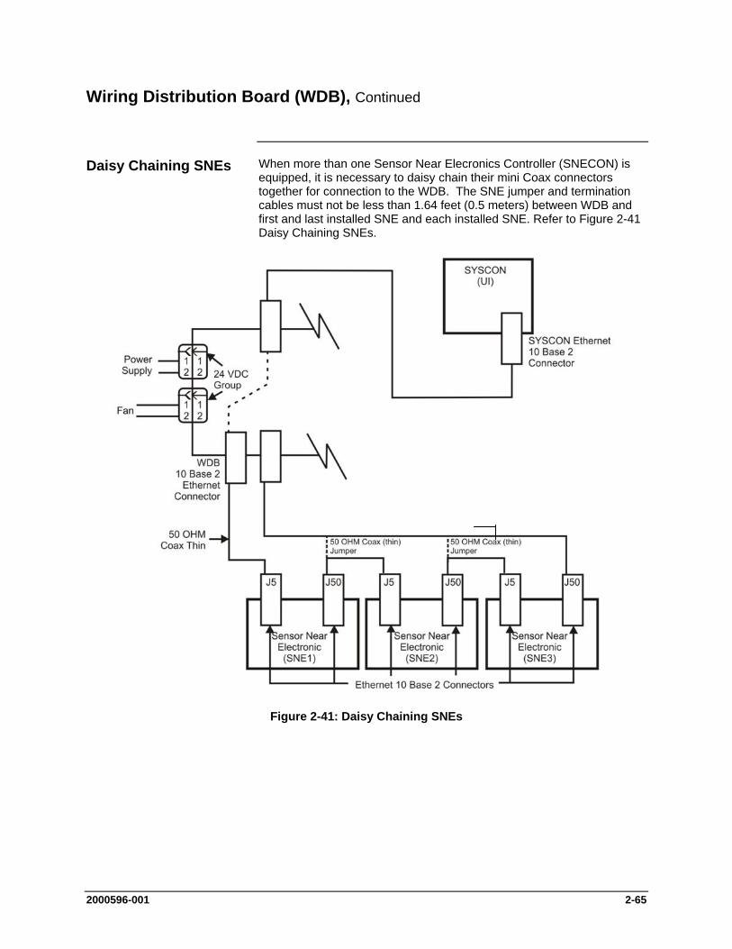
2000596-001 2-65
Wiring Distribution Board (WDB), Continued
When more than one Sensor Near Elecronics Controller (SNECON) is equipped, it is necessary to daisy chain their mini Coax connectors together for connection to the WDB. The SNE jumper and termination cables must not be less than 1.64 feet (0.5 meters) between WDB and first and last installed SNE and each installed SNE. Refer to Figure 2-41 Daisy Chaining SNEs.
Figure 2-41: Daisy Chaining SNEs
Daisy Chaining SNEs

2-66 2000596-001
Wiring Distribution Board (WDB), Continued
A new Wiring Distribution Board (WDB) is being designed. Expected to be available in 2008, this new board will be capable of communicating with the Sensor Near Electronics Controller (SNECON) via 10BaseT connection. This module will be equipped with RJ-45 connectors which will interface directly with the currently unused RJ-45 connector (J10) on the SNECON. With three RJ-45 connectors equipped on the new WDB and one RJ-45 on each SNECON, there will be no need to daisy chain as described earlier in this section.
The new WDB will still be equipped with 10Base2 miniature Coax connectors to allow it to be used as a replacement for the original WDB.
New WDB Design
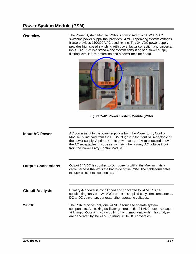
2000596-001 2-67
Power System Module (PSM)
The Power System Module (PSM) is comprised of a 110/230 VAC switching power supply that provides 24 VDC operating system voltages. It also provides 110/220 VAC conditioning. The 24 VDC power supply provides high speed switching with power factor correction and universal input. The PSM is a stand-alone system consisting of a power supply, filtering, circuit fuse protection and a power monitor board.
Figure 2-42: Power System Module (PSM)
AC power input to the power supply is from the Power Entry Control Module. A line cord from the PECM plugs into the front AC receptacle of the power supply. A primary input power selector switch (located above the AC receptacle) must be set to match the primary AC voltage input from the Power Entry Control Module.
Output 24 VDC is supplied to components within the Maxum II via a cable harness that exits the backside of the PSM. The cable terminates in quick disconnect connectors.
Primary AC power is conditioned and converted to 24 VDC. After conditioning; only one 24 VDC source is supplied to system components. DC to DC converters generate other operating voltages.
The PSM provides only one 24 VDC source to operate system components. A blocking oscillator generates the 24 VDC output voltages at 6 amps. Operating voltages for other components within the analyzer are generated by the 24 VDC using DC to DC conversion.
Overview
Input AC Power
Output Connections
Circuit Analysis
24 VDC
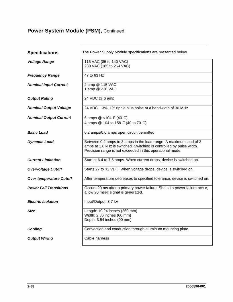
2-68 2000596-001
Power System Module (PSM), Continued
The Power Supply Module specifications are presented below.
Voltage Range 115 VAC (85 to 140 VAC) 230 VAC (185 to 264 VAC)
Frequency Range 47 to 63 Hz
Nominal Input Current 2 amp @ 115 VAC 1 amp @ 230 VAC
Output Rating 24 VDC @ 6 amp
Nominal Output Voltage 24 VDC 3%, 1% ripple plus noise at a bandwidth of 30 MHz
Nominal Output Current 6 amps @ <104 F (40 C) 4 amps @ 104 to 158 F (40 to 70 C)
Basic Load 0.2 amps/0.0 amps open circuit permitted
Dynamic Load Between 0.2 amps to 3 amps in the load range. A maximum load of 2 amps at 1.8 kHz is switched. Switching is controlled by pulse width. Precision range is not exceeded in this operational mode.
Current Limitation Start at 6.4 to 7.5 amps. When current drops, device is switched on.
Overvoltage Cutoff Starts 27 to 31 VDC. When voltage drops, device is switched on.
Over-temperature Cutoff After temperature decreases to specified tolerance, device is switched on.
Power Fail Transitions Occurs 20 ms after a primary power failure. Should a power failure occur, a low 20 msec signal is generated.
Electric Isolation Input/Output: 3.7 kV
Size Length: 10.24 inches (260 mm) Width: 2.36 inches (60 mm) Depth: 3.54 inches (90 mm)
Cooling Convection and conduction through aluminum mounting plate.
Output Wiring Cable harness
Specifications
2000596-001 2-69
Power System Module (PSM), Continued
The Power System Module is equipped with a fuse (Siemens Part Number A6X19905350). This fuse is located on the front of the PSM just above the power cord plug. The fuse is a 250V, 4.0 Amp, “slow-acting” type. Although this fuse rarely fails, replacement is simple (disconnect power to the analyzer first). To remove the fuse, unplug the power cable that comes from the PECM. Access the fuse by removing the fuse cap with a large blunt screwdriver.
PSM Fuse Replacement
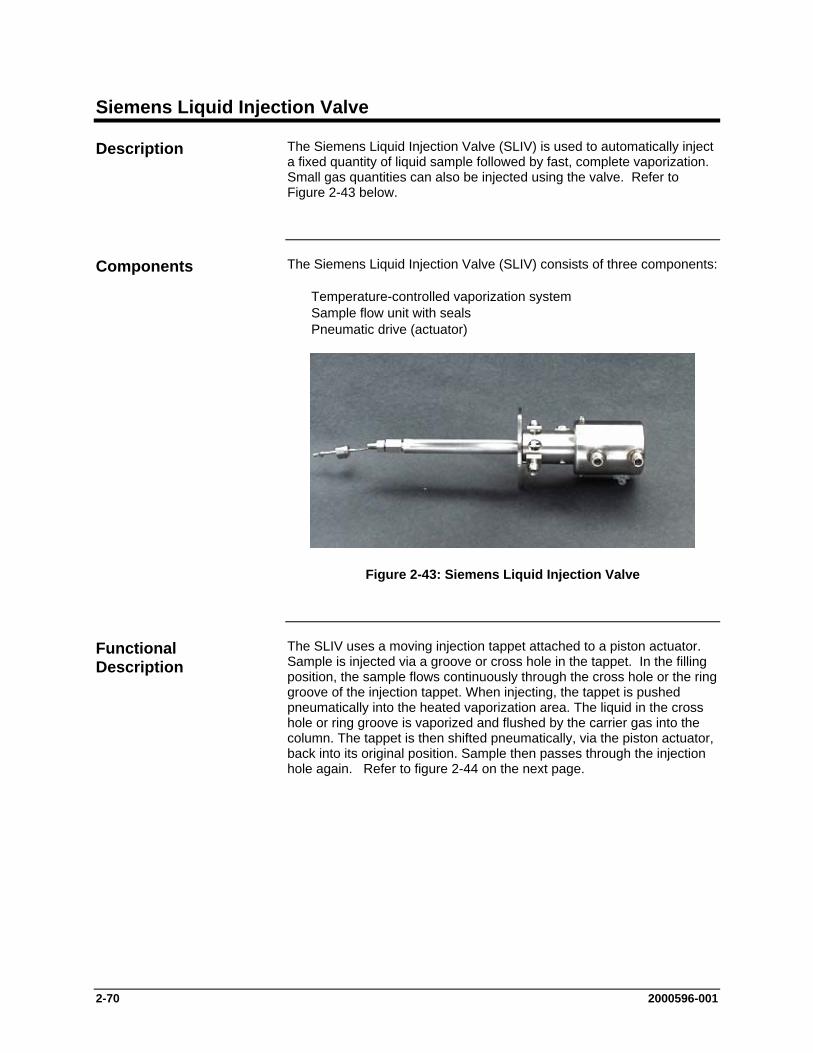
2-70 2000596-001
Siemens Liquid Injection Valve
The Siemens Liquid Injection Valve (SLIV) is used to automatically inject a fixed quantity of liquid sample followed by fast, complete vaporization. Small gas quantities can also be injected using the valve. Refer to Figure 2-43 below.
The Siemens Liquid Injection Valve (SLIV) consists of three components:
Temperature-controlled vaporization system Sample flow unit with seals Pneumatic drive (actuator)
Figure 2-43: Siemens Liquid Injection Valve
The SLIV uses a moving injection tappet attached to a piston actuator. Sample is injected via a groove or cross hole in the tappet. In the filling position, the sample flows continuously through the cross hole or the ring groove of the injection tappet. When injecting, the tappet is pushed pneumatically into the heated vaporization area. The liquid in the cross hole or ring groove is vaporized and flushed by the carrier gas into the column. The tappet is then shifted pneumatically, via the piston actuator, back into its original position. Sample then passes through the injection hole again. Refer to figure 2-44 on the next page.
Description
Components
Functional Description
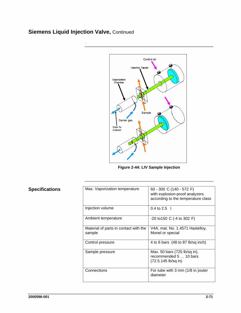
2000596-001 2-71
Siemens Liquid Injection Valve, Continued
.
Figure 2-44: LIV Sample Injection
Max. Vaporization temperature 60 - 300 C (140 - 572 F) with explosion-proof analyzers according to the temperature class
Injection volume 0.4 to 2.5 l
Ambient temperature -20 to150 C (-4 to 302 F)
Material of parts in contact with the sample
V4A, mat. No. 1.4571 Hastelloy, Monel or special
Control pressure 4 to 6 bars (48 to 87 lb/sq inch)
Sample pressure Max. 50 bars (725 lb/sq in), recommended 5 … 10 bars (72.5.145 lb/sq in)
Connections For tube with 3 mm (1/8 in.)outer diameter
Specifications

2-72 2000596-001
Siemens Liquid Injection Valve, Continued
.
The vaporization tube is inserted with an aluminum sleeve into the heating mushroom plate whose temperature is regulated by a heating cartridge. In addition to the standard vaporization tube, a version of the SLIV is offered with a glass lined vaporization tube.
The carrier gas is routed via tube into the vaporizer and heated up to the vaporization temperature in the process.
The sample flow unit (Figure 2-45 below) is located in the middle section (body) of the valve between the vaporizer and the actuator piston. It is isolated from the vaporizer and actuator by lens shaped Teflon gaskets. An adjustable adapter and Belleville washers position the Teflon gaskets with a constant pressure and compensate for temperature expansion effects and gasket wear.
Figure 2-45: Sample Flow Unit
The vaporization temperature can be set independent of the oven temperature. It is selected according to the sample and the sample’s boiling point. The optimum vaporization temperature must be determined experimentally. The amount by which the vaporization temperature should be above the sample’s boiling point depends on the heat of vaporization of the sample. Samples with a high heat of vaporization, such as aqueous samples, only vaporize sufficiently fast for chromatographic purposes at high temperatures (above 200 C), as shown in Figure 2-46.
Vaporization system
Sample flow unit
Vaporization Temperature
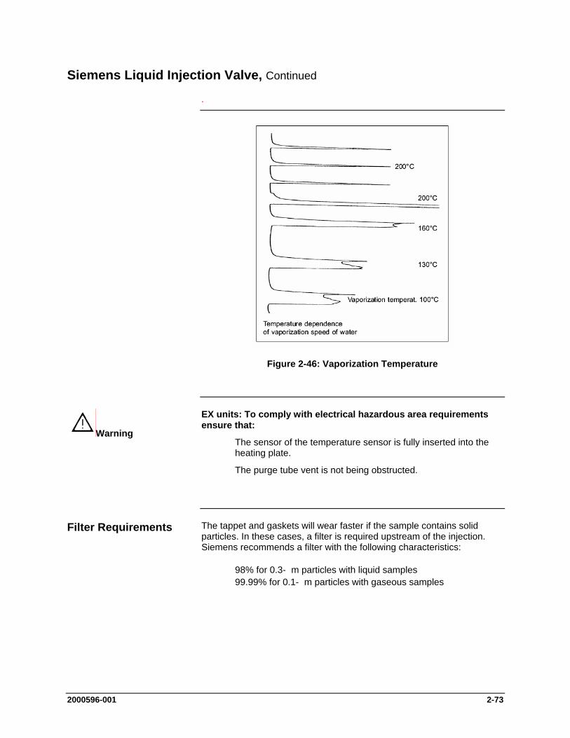
2000596-001 2-73
Siemens Liquid Injection Valve, Continued
.
Figure 2-46: Vaporization Temperature
EX units: To comply with electrical hazardous area requirements ensure that:
The sensor of the temperature sensor is fully inserted into the heating plate.
The purge tube vent is not being obstructed.
The tappet and gaskets will wear faster if the sample contains solid particles. In these cases, a filter is required upstream of the injection. Siemens recommends a filter with the following characteristics:
98% for 0.3- m particles with liquid samples 99.99% for 0.1- m particles with gaseous samples
Warning
Filter Requirements
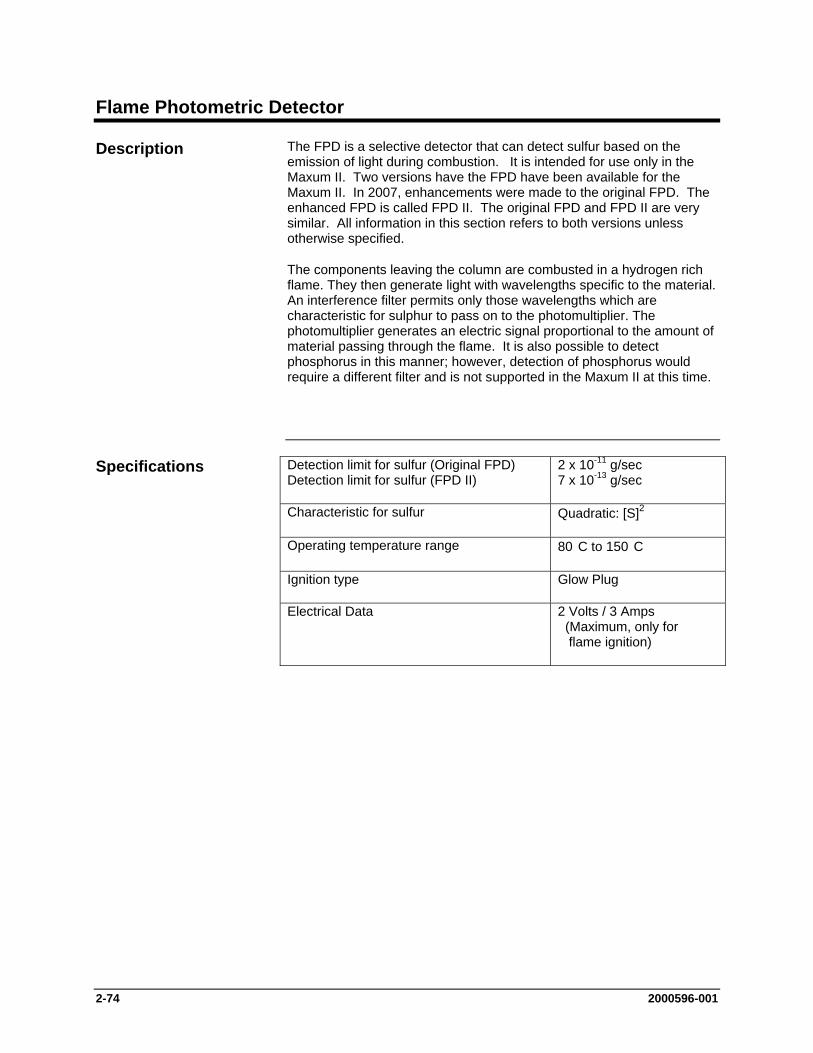
2-74 2000596-001
Flame Photometric Detector
The FPD is a selective detector that can detect sulfur based on the emission of light during combustion. It is intended for use only in the Maxum II. Two versions have the FPD have been available for the Maxum II. In 2007, enhancements were made to the original FPD. The enhanced FPD is called FPD II. The original FPD and FPD II are very similar. All information in this section refers to both versions unless otherwise specified.
The components leaving the column are combusted in a hydrogen rich flame. They then generate light with wavelengths specific to the material. An interference filter permits only those wavelengths which are characteristic for sulphur to pass on to the photomultiplier. The photomultiplier generates an electric signal proportional to the amount of material passing through the flame. It is also possible to detect phosphorus in this manner; however, detection of phosphorus would require a different filter and is not supported in the Maxum II at this time.
Detection limit for sulfur (Original FPD) Detection limit for sulfur (FPD II)
2 x 10-11 g/sec 7 x 10-13 g/sec
Characteristic for sulfur Quadratic: [S]2
Operating temperature range 80 C to 150 C
Ignition type Glow Plug
Electrical Data 2 Volts / 3 Amps (Maximum, only for flame ignition)
Description
Specifications
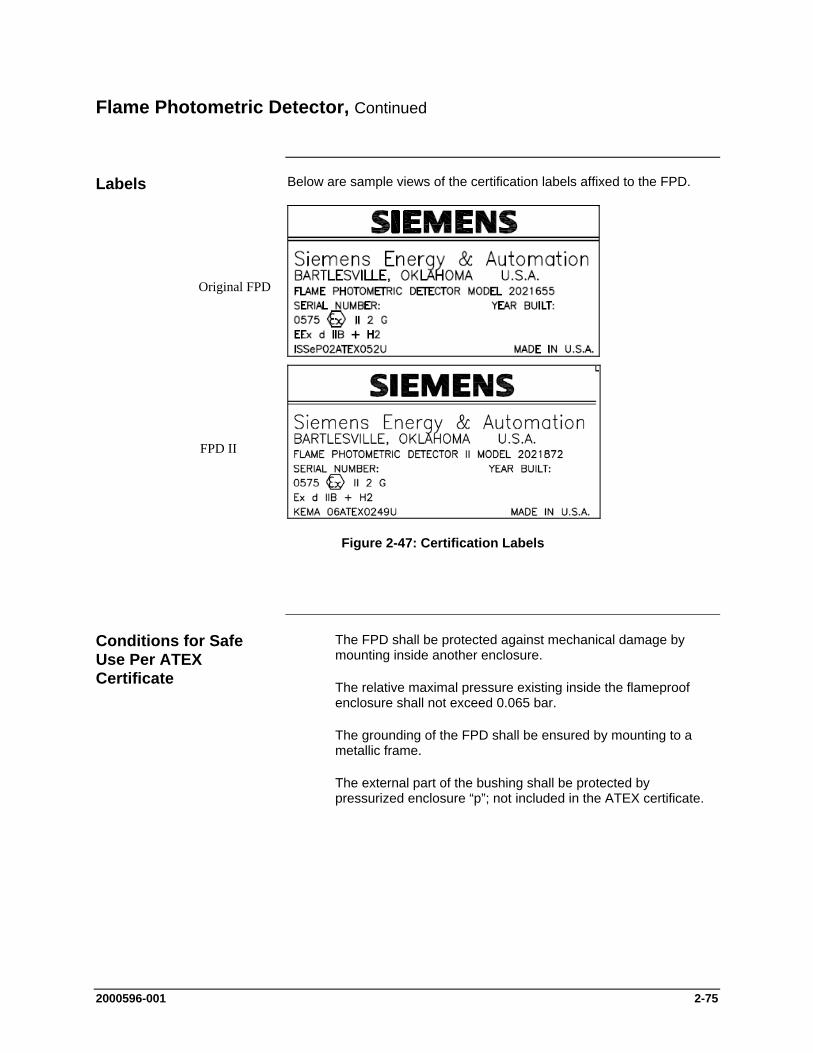
2000596-001 2-75
Flame Photometric Detector, Continued
Below are sample views of the certification labels affixed to the FPD.
Figure 2-47: Certification Labels
The FPD shall be protected against mechanical damage by mounting inside another enclosure.
The relative maximal pressure existing inside the flameproof enclosure shall not exceed 0.065 bar.
The grounding of the FPD shall be ensured by mounting to a metallic frame.
The external part of the bushing shall be protected by pressurized enclosure “p”; not included in the ATEX certificate.
Labels
Conditions for Safe Use Per ATEX Certificate
Original FPD
FPD II
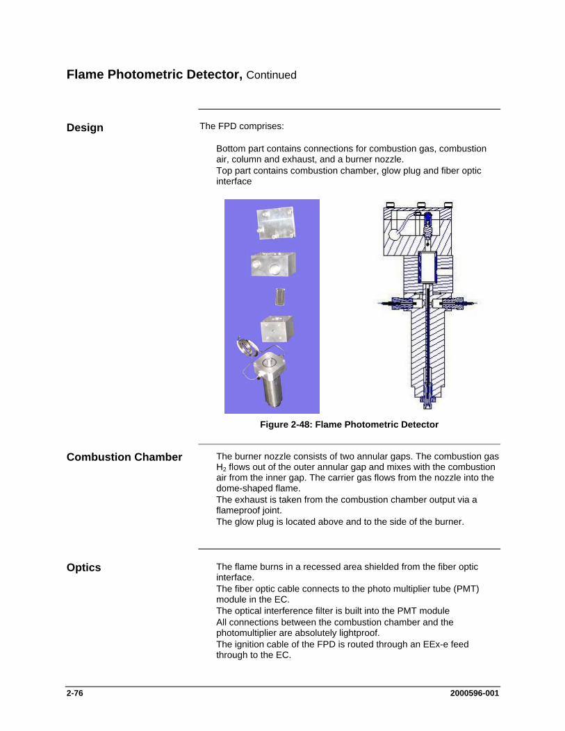
2-76 2000596-001
Flame Photometric Detector, Continued
The FPD comprises:
Bottom part contains connections for combustion gas, combustion air, column and exhaust, and a burner nozzle.
Top part contains combustion chamber, glow plug and fiber optic interface
Figure 2-48: Flame Photometric Detector
The burner nozzle consists of two annular gaps. The combustion gas H2 flows out of the outer annular gap and mixes with the combustion air from the inner gap. The carrier gas flows from the nozzle into the dome-shaped flame.
The exhaust is taken from the combustion chamber output via a flameproof joint.
The glow plug is located above and to the side of the burner.
The flame burns in a recessed area shielded from the fiber optic interface.
The fiber optic cable connects to the photo multiplier tube (PMT) module in the EC.
The optical interference filter is built into the PMT module All connections between the combustion chamber and the
photomultiplier are absolutely lightproof. The ignition cable of the FPD is routed through an EEx-e feed
through to the EC.
Design
Combustion Chamber
Optics
2000596-001 2-77
Flame Photometric Detector, Continued
The FPD is supplied with an external heater. Condensation would be formed in the FPD at temperatures below 80 C and have a negative influence on the measuring properties. The detector is insulated to prevent moisture from entering it.
The detector temperature is factory set depending upon the application. The temperature is normally set equal to or higher than the oven temperature and at minimum 80 C.
The FPD requires the following gases:
Type of Gas Gas Quantity
Combustion Gas Hydrogen (Original FPD) Combustion Gas Hydrogen (FPD II)
75-85 ml/min. 60- 130 ml/min.
Combustion Air (Original FPD) Combustion Air (FPD II)
110-130 ml/min. 50-135 ml/min.
The FPD is a very sensitive detector. The gases and their supply lines must be extremely clean and sulfur free to achieve a high signal/noise ratio.
Nitrogen, helium, argon or hydrogen can be used as the carrier gas. If hydrogen carrier is used, the required flow of hydrogen flame fuel will be reduced. For the FPD II, the total hydrogen flow (combined flame fuel and carrier) will be ~100-130 mL/min.
The sensitivity of the FPD can be increased by reducing the flow of combustion air. Most of the time, the FPD cannot be ignited with a normal air/hydrogen ratio. If an electronic pressure controller (EPC) is used for the combustion gasses an event will be written at the factory, which will automatically adjust the flows during the ignition sequence. To obtain the recommended flow settings for an analyzer, refer to the custom documentation supplied with that analyzer.
Heater
Detector Gas Supply
IMPORTANT
Selection of Carrier Gas
Increasing the Sensitivity
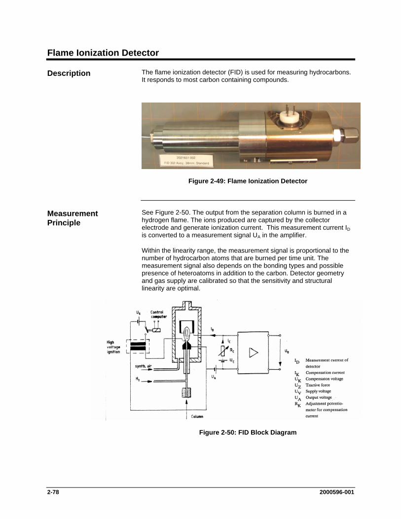
2-78 2000596-001
Flame Ionization Detector
The flame ionization detector (FID) is used for measuring hydrocarbons. It responds to most carbon containing compounds.
Figure 2-49: Flame Ionization Detector
See Figure 2-50. The output from the separation column is burned in a hydrogen flame. The ions produced are captured by the collector electrode and generate ionization current. This measurement current ID is converted to a measurement signal UA in the amplifier.
Within the linearity range, the measurement signal is proportional to the number of hydrocarbon atoms that are burned per time unit. The measurement signal also depends on the bonding types and possible presence of heteroatoms in addition to the carbon. Detector geometry and gas supply are calibrated so that the sensitivity and structural linearity are optimal.
Figure 2-50: FID Block Diagram
Description
Measurement Principle
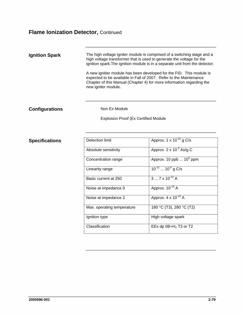
2000596-001 2-79
Flame Ionization Detector, Continued
The high voltage igniter module is comprised of a switching stage and a high voltage transformer that is used to generate the voltage for the ignition spark.The ignition module is in a separate unit from the detector.
A new ignitier module has been developed for the FID. This module is expected to be available in Fall of 2007. Refer to the Maintenance Chapter of this Manual (Chapter 4) for more information regarding the new igniter module.
Non Ex Module
Explosion Proof (Ex Certified Module
Detection limit Approx. 1 x 10-12 g C/s
Absolute sensitivity Approx. 2 x 10⁻³ As/g C
Concentration range Approx. 10 ppb ... 104 ppm
Linearity range 10-12 ... 10-5 g C/s
Basic current at 250 3 ... 7 x 10-12 A
Noise at impedance 0 Approx. 10-13 A
Noise at impedance 2 Approx. 4 x 10-14 A
Max. operating temperature 180 °C (T3), 280 °C (T2)
Ignition type High voltage spark
Classification EEx dp IIB+H2 T3 or T2
Ignition Spark
Configurations
Specifications

2-80 2000596-001
Flame Ionization Detector, Continued
Reaction Gas The FID requires both hydrogen and combustion air (synthetic air or purified air).
Carrier Gas Hydrogen, nitrogen, argon or helium are suitable carrier gases.
Additive/Make-up-Gas To increase the sensitivity of the FID and to improve the structural linearity, air is added to the combustion gas via R02. When operating with Nitrogen as carrier gas this additive is not required. If the Hydrogen carrier gas stream is below 20 ml/min Siemens recommends the addition of Hydrogen combustion gas to achieve a stable flame and, if necessary, air to increase the sensitivity.
Pressure reducers R01 to R03 are installed in the combustion gas inputs on the side of the detector.
Figure 2-51: FID Gas Supply
The FID is very sensitive to all types of hydrocarbons and to any contaminates in gases or supply lines. For a high signal/noise ratio ensure that the gases have a purity of 99.995 % and a hydrocarbon content below 2 vpm. For special detection sensitivity filter all supply gases using a molecular sieve filter. If plant air is used a catalytic air treater is strongly recommended to reduce the possible hydrocarbon content of the air.
Detector Gas Supply
Maintain a Clean Supply Gas
2000596-001 2-81
Flame Ionization Detector, Continued
The temperature of the detector flame and the size of the combustion zone determine the sensitivity of an FID as do the composition and the flow speed of the gas mixture. For an optimum signal/noise ratio use following gas flow rates:
Combustion gas 20 to 45 ml/min Combustion air 300 to 500 ml/min Additive air 20 to 40 ml/min
The electronic pressure control modules control the gas flow rate to the detectors. The flow rates can be adjusted. The carrier gas flow rate can be ~20 to 40 ml/min, but it should never exceed 60 ml/min including the additive.
Sensitivity
Pressure Regulators
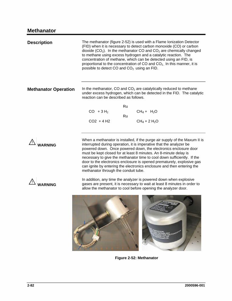
2-82 2000596-001
Methanator
The methanator (figure 2-52) is used with a Flame Ionization Detector (FID) when it is necessary to detect carbon monoxide (CO) or carbon dioxide (CO2). In the methanator CO and CO2 are chemically changed to methane using excess hydrogen and a catalytic reaction. The concentration of methane, which can be detected using an FID, is proportional to the concentration of CO and CO2.. In this manner, it is possible to detect CO and CO2 using an FID.
In the methanator, CO and CO2 are catalytically reduced to methane under excess hydrogen, which can be detected in the FID. The catalytic reaction can be described as follows.
Ru CO + 3 H2 CH4 + H2O
Ru CO2 + 4 H2 CH4 + 2 H2O
When a methanator is installed, if the purge air supply of the Maxum II is interrupted during operation, it is imperative that the analyzer be powered down. Once powered down, the electronics enclosure door must be kept closed for at least 8 minutes. An 8-minute delay is necessary to give the methanator time to cool down sufficiently. If the door to the electronics enclosure is opened prematurely, explosive gas can ignite by entering the electronics enclosure and then entering the methanator through the conduit tube.
In addition, any time the analyzer is powered down when explosive gases are present, it is necessary to wait at least 8 minutes in order to allow the methanator to cool before opening the analyzer door.
Figure 2-52: Methanator
Description
Methanator Operation
WARNING
WARNING
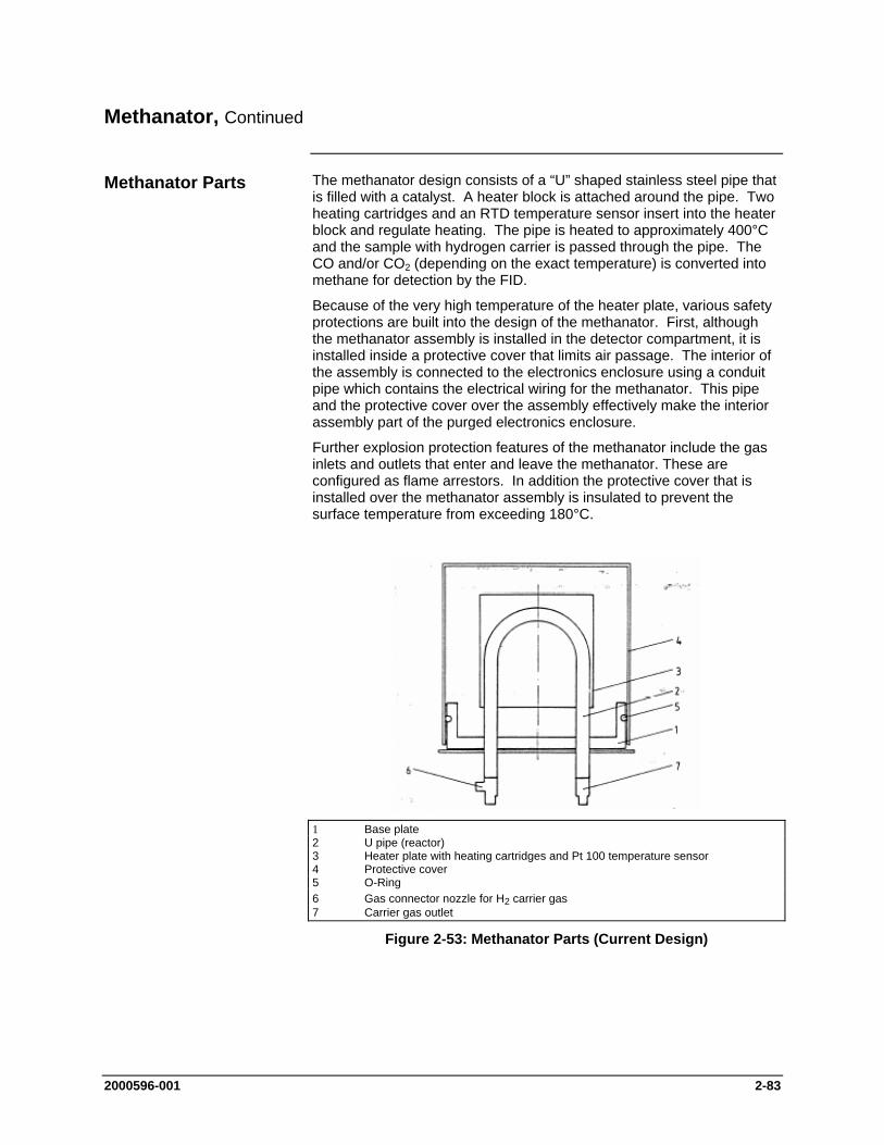
2000596-001 2-83
Methanator, Continued
The methanator design consists of a “U” shaped stainless steel pipe that is filled with a catalyst. A heater block is attached around the pipe. Two heating cartridges and an RTD temperature sensor insert into the heater block and regulate heating. The pipe is heated to approximately 400°C and the sample with hydrogen carrier is passed through the pipe. The CO and/or CO2 (depending on the exact temperature) is converted into methane for detection by the FID.
Because of the very high temperature of the heater plate, various safety protections are built into the design of the methanator. First, although the methanator assembly is installed in the detector compartment, it is installed inside a protective cover that limits air passage. The interior of the assembly is connected to the electronics enclosure using a conduit pipe which contains the electrical wiring for the methanator. This pipe and the protective cover over the assembly effectively make the interior assembly part of the purged electronics enclosure.
Further explosion protection features of the methanator include the gas inlets and outlets that enter and leave the methanator. These are configured as flame arrestors. In addition the protective cover that is installed over the methanator assembly is insulated to prevent the surface temperature from exceeding 180°C.
Figure 2-53: Methanator Parts (Current Design)
Methanator Parts
1 Base plate 2 U pipe (reactor) 3 Heater plate with heating cartridges and Pt 100 temperature sensor 4 Protective cover 5 O-Ring 6 Gas connector nozzle for H2 carrier gas 7 Carrier gas outlet
2-84 2000596-001
Methanator, Continued
max. Operation Temperature 400 °C
Heater 2 cartridges 115 V each
Classification EEx dp IIB+H2 T3
Use H2 (35 to 45 ml/min) as carrier gas. It is used as reaction gas in the methanator and as combustion gas in the FID. Combustion air and additive are adjusted the same as with the FID without methanator.
Specifications
Gas Supply
2000596-001 2-85
Thermal Conductivity Detector
The Thermal Conductivity Detector (TCD) is a concentration responsive detector of moderate sensitivity. The detector cell, containing the sensing element, is an explosion-proof unit located in the chromatograph oven. The electronic circuits are located on a Detector Personality Module (DPM) that is located in the SNE.
The detector works on the principle that the thermal conductivity of the carrier gas is different (conducts more heat or less from the heated element) than the thermal conductivity of the sample components. The electronic circuits sense the change in heat flow and produce a proportional analog voltage signal.
For varied applications the TCD can use either filaments or thermistors for its sensing element
8-cell Thermistor TCD: The detector includes six independent measurement cells and two reference cells
For higher temperature requirements a 2-cell Filament TCD is available. The 2-Cell Filament TCD can be used as an Inter-column Detector (ITC) in conjunction with a FPD or FID application.
The TCD is operated in a constant temperature mode. The TCD compares the power required to maintain the measurement element (either thermistor or filament) at a specific temperature versus the power required to maintain the reference element at that same temperature. Thermistor detector beads are run at approximately 135 °C and filaments are run at approximstely 325 °C.
Description
Sensing Elements
Thermistor Model
Filament Model
Measurement Principle

2-86 2000596-001
Thermal Conductivity Detector, Continued
Hydrogen, helium, nitrogen or argon are suitable carrier gases. In this sequence the thermal conductivity of the gases decreases. The TCD is most sensitive when the gas with the highest thermal conductivity difference is used. Table 2-9 below shows the thermal conductivity (at 300 0C) of various gases with reference to nitrogen.
Gas Type Relative Thermal Conductivity at 300 C
H2 675 He 560 CH4 170 O2 105 N2 100
CO2 90 Ar 70
The flow rates through the reference branch and the measurement branch should be 1 to 40 mL/min each. For trace analyses the carrier gas should be selected such that the thermal conductivity difference is highest between the gas and the component of lowest concentration.
.
Detector Gas Supply
Carrier Gas
Table 2-9: Relative Thermal Conductivity
Flow Rates
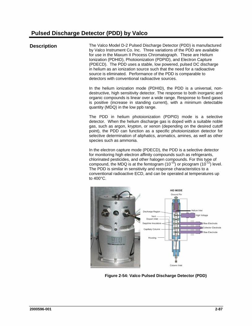
2000596-001 2-87
Pulsed Discharge Detector (PDD) by Valco
The Valco Model D-2 Pulsed Discharge Detector (PDD) is manufactured by Valco Instrument Co. Inc. Three variations of the PDD are available for use in the Maxum II Process Chromatograph. These are Helium Ionization (PDHID), Photoionization (PDPID), and Electron Capture (PDECD). The PDD uses a stable, low powered, pulsed DC discharge in helium as an ionization source such that the need for a radioactive source is eliminated. Performance of the PDD is comparable to detectors with conventional radioactive sources.
In the helium ionization mode (PDHID), the PDD is a universal, non-destructive, high sensitivity detector. The response to both inorganic and organic compounds is linear over a wide range. Response to fixed gases is positive (increase in standing current), with a minimum detectable quantity (MDQ) in the low ppb range. The PDD in helium photoionization (PDPID) mode is a selective detector. When the helium discharge gas is doped with a suitable noble gas, such as argon, krypton, or xenon (depending on the desired cutoff point), the PDD can function as a specific photoionization detector for selective determination of aliphatics, aromatics, amines, as well as other species such as ammonia. In the electron capture mode (PDECD), the PDD is a selective detector for monitoring high electron affinity compounds such as refrigerants, chlorinated pesticides, and other halogen compounds. For this type of compound, the MDQ is at the femtogram (10-15) or picogram (10-12) level. The PDD is similar in sensitivity and response characteristics to a conventional radioactive ECD, and can be operated at temperatures up to 400°C.
Figure 2-54: Valco Pulsed Discharge Detector (PDD)
Description
2-88 2000596-001
Pulsed Discharge Detector, Continued
Refer to the Pulsed Discharge Detector (Models D-2 and D-2-I) Instruction Manual available from Valco Instruments Co. Inc. for information regarding the measurement principles of the Valco PDD in its different operating modes.
Refer to the Pulsed Discharge Detector Instruction Manual for complete specification information associated with the Valco PDD.
The electronics (Pulsed Discharge Controller) of the Valco detector are used to control the pulsed discharge and the detector temperature. The Valco electronics is also used to amplify the detector signal. The output of the Valco detector electronics is connected to the Maxum via a Base Detector Personality Module equipped with an Analog Input Mezzanine board. The processing of the Valco detector signal is then handled by the Maxum II electronics.
The Valco PDD should be operated in on the 1X range with the Maxum detector board set on “low sensitivity”. The PDD 0-10V (un-attenuated) output from the Valco electronics is used.
The connection to the detector is critical. The column or a capillary tube must be inserted in the detector as noted in the Column Connection section of the Valco manual.
High purity gases together with a high quality gas purification device are required for proper use of the PDD. The quality of the gases is dependent upon the specific application. Refer to the Valco manual for general gas requirements and your custom documentation for specific requirements for your application. Normally an SAES Getters gas purifier is supplied with the system.
Refer to the Pulsed Discharge Detector Instruction Manual for additional information regarding installation and operation of the Valco PDD.
Service of the detector is limited to replacement of the electronics module or the replacement of the detector itself. Repair of these parts requires return to Siemens or Valco.
Measurement Principles
Specifications
Operation and Installation
Service
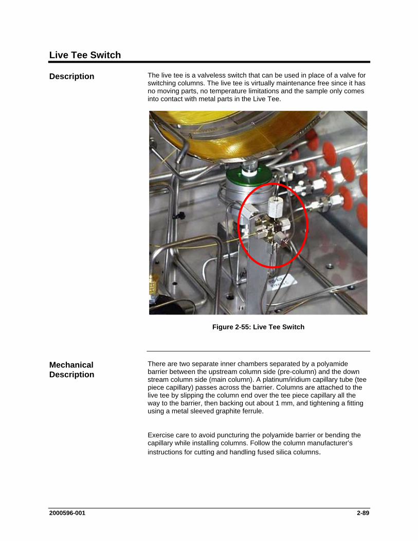
2000596-001 2-89
Live Tee Switch
The live tee is a valveless switch that can be used in place of a valve for switching columns. The live tee is virtually maintenance free since it has no moving parts, no temperature limitations and the sample only comes into contact with metal parts in the Live Tee.
Figure 2-55: Live Tee Switch
There are two separate inner chambers separated by a polyamide barrier between the upstream column side (pre-column) and the down stream column side (main column). A platinum/iridium capillary tube (tee piece capillary) passes across the barrier. Columns are attached to the live tee by slipping the column end over the tee piece capillary all the way to the barrier, then backing out about 1 mm, and tightening a fitting using a metal sleeved graphite ferrule.
Exercise care to avoid puncturing the polyamide barrier or bending the capillary while installing columns. Follow the column manufacturer’s instructions for cutting and handling fused silica columns.
Description
Mechanical Description

2-90 2000596-001
Live Tee Switch, Continued
Figure 2-56: Live Tee Switch for Capillary Columns
Figure 2-57: Live Tee Switch for Packed Columns
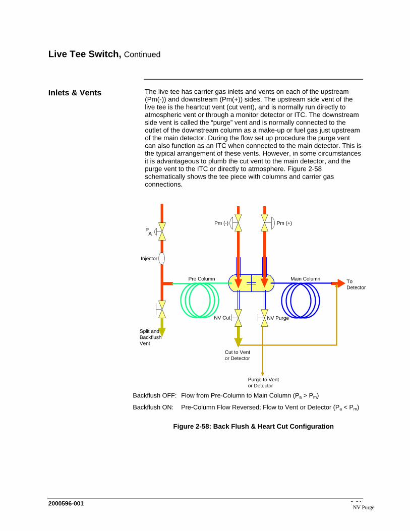
2000596-001 2-91
Live Tee Switch, Continued
The live tee has carrier gas inlets and vents on each of the upstream (Pm(-)) and downstream (Pm(+)) sides. The upstream side vent of the live tee is the heartcut vent (cut vent), and is normally run directly to atmospheric vent or through a monitor detector or ITC. The downstream side vent is called the “purge” vent and is normally connected to the outlet of the downstream column as a make-up or fuel gas just upstream of the main detector. During the flow set up procedure the purge vent can also function as an ITC when connected to the main detector. This is the typical arrangement of these vents. However, in some circumstances it is advantageous to plumb the cut vent to the main detector, and the purge vent to the ITC or directly to atmosphere. Figure 2-58 schematically shows the tee piece with columns and carrier gas connections.
Pm (-)
Split andBackflushVent
NV PurgeNV Cut
Cut to Vent or Detector
Purge to Vent or Detector
To Detector
PA
Injector
Pre Column Main Column
Pm (+)
Backflush OFF: Flow from Pre-Column to Main Column (Pa > Pm)
Backflush ON: Pre-Column Flow Reversed; Flow to Vent or Detector (Pa < Pm)
Figure 2-58: Back Flush & Heart Cut Configuration
Inlets & Vents
NV Purge
2-92 2000596-001
Live Tee Switch, Continued
The following is a list of common terminology and abbreviations used in the following narrative.
Pa Column Inlet Pressure
Pm (-) Midpoint pressure (at the end of the first column, inlet of the tee piece)
Pm (+) Midpoint pressure (at the inlet of the main column, outlet of the tee piece)
Cut Vent Vent on the column inlet side of the tee piece, controlled by needle valve 1 (NV1)
Purge Vent Vent on the column outlet side of the tee piece, controlled by NV2
Cut On Straight run flow pre column to main column (heartcut on)
Cut Off Pre column to cut vent (heartcut off)
Back Flush Off Injector to pre column (opposite of the terminology used with valves)
Back Flush On Pre column to backflush vent
The operation of the Live tee takes advantage of the pressure drop across the tee piece capillary and the annular spaces between the outside diameter of the capillary and the inside diameter of the column ends.
The heartcut and backflush functions of the tee piece are achieved by varying the pressures Pa, Pm(-) and Pm(+).To function in the cut on or straight through column mode, pressure on the upstream carrier gas inlet (Pm(-)) of the live tee is adjusted slightly higher than the outlet pressure of the upstream column.
Operation
How It Works
Varying Pressure
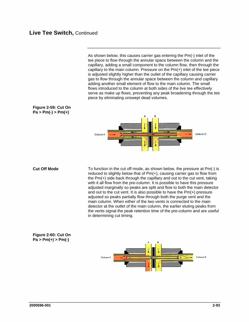
2000596-001 2-93
Live Tee Switch, Continued
As shown below, this causes carrier gas entering the Pm(-) inlet of the tee piece to flow through the annular space between the column and the capillary, adding a small component to the column flow, then through the capillary to the main column. Pressure on the Pm(+) inlet of the tee piece is adjusted slightly higher than the outlet of the capillary causing carrier gas to flow through the annular space between the column and capillary adding another small element of flow to the main column. The small flows introduced to the column at both sides of the live tee effectively serve as make up flows, preventing any peak broadening through the tee piece by eliminating unswept dead volumes.
To function in the cut off mode, as shown below, the pressure at Pm(-) is reduced to slightly below that of Pm(+), causing carrier gas to flow from the Pm(+) side back through the capillary and out to the cut vent, taking with it all flow from the pre-column. It is possible to have this pressure adjusted marginally so peaks are split and flow to both the main detector and out to the cut vent. It is also possible to have the Pm(+) pressure adjusted so peaks partially flow through both the purge vent and the main column. When either of the two vents is connected to the main detector at the outlet of the main column, the earlier eluting peaks from the vents signal the peak retention time of the pre-column and are useful in determining cut timing.
Figure 2-59: Cut On Pa > Pm(-) > Pm(+)
Cut Off Mode
Figure 2-60: Cut On Pa > Pm(+) > Pm(-)
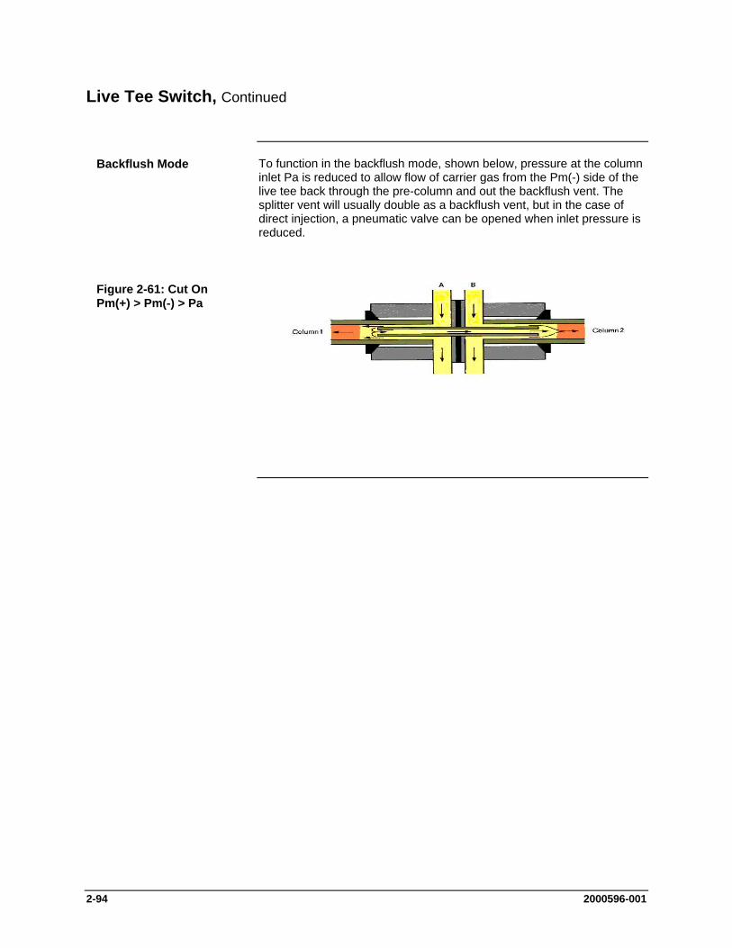
2-94 2000596-001
Live Tee Switch, Continued
To function in the backflush mode, shown below, pressure at the column inlet Pa is reduced to allow flow of carrier gas from the Pm(-) side of the live tee back through the pre-column and out the backflush vent. The splitter vent will usually double as a backflush vent, but in the case of direct injection, a pneumatic valve can be opened when inlet pressure is reduced.
Backflush Mode
Figure 2-61: Cut On Pm(+) > Pm(-) > Pa
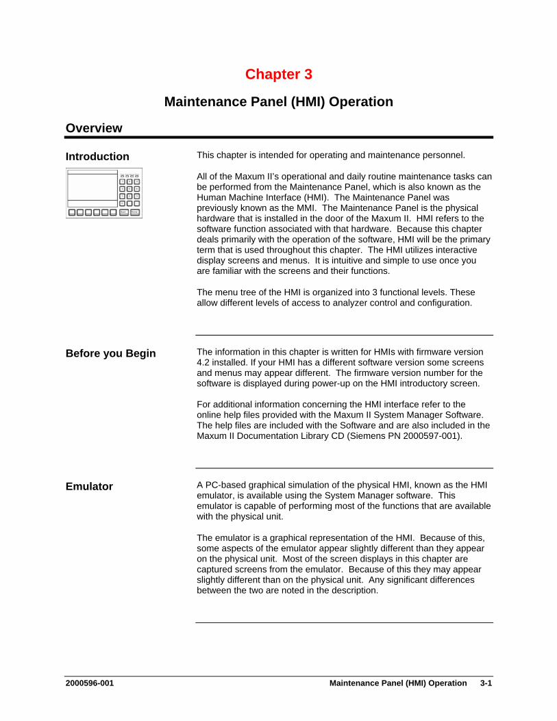
2000596-001 Maintenance Panel (HMI) Operation 3-1
Chapter 3
Maintenance Panel (HMI) Operation
Overview
This chapter is intended for operating and maintenance personnel.
All of the Maxum II’s operational and daily routine maintenance tasks can be performed from the Maintenance Panel, which is also known as the Human Machine Interface (HMI). The Maintenance Panel was previously known as the MMI. The Maintenance Panel is the physical hardware that is installed in the door of the Maxum II. HMI refers to the software function associated with that hardware. Because this chapter deals primarily with the operation of the software, HMI will be the primary term that is used throughout this chapter. The HMI utilizes interactive display screens and menus. It is intuitive and simple to use once you are familiar with the screens and their functions.
The menu tree of the HMI is organized into 3 functional levels. These allow different levels of access to analyzer control and configuration.
The information in this chapter is written for HMIs with firmware version 4.2 installed. If your HMI has a different software version some screens and menus may appear different. The firmware version number for the software is displayed during power-up on the HMI introductory screen. For additional information concerning the HMI interface refer to the online help files provided with the Maxum II System Manager Software. The help files are included with the Software and are also included in the Maxum II Documentation Library CD (Siemens PN 2000597-001).
A PC-based graphical simulation of the physical HMI, known as the HMI emulator, is available using the System Manager software. This emulator is capable of performing most of the functions that are available with the physical unit.
The emulator is a graphical representation of the HMI. Because of this, some aspects of the emulator appear slightly different than they appear on the physical unit. Most of the screen displays in this chapter are captured screens from the emulator. Because of this they may appear slightly different than on the physical unit. Any significant differences between the two are noted in the description.
Introduction
Before you Begin
Emulator
3-2 Maintenance Panel (HMI) Operation 2000596-001
Overview, Continued
Topic Page
Overview 3-1
Display and Control Unit 3-4
Screen Characteristics 3-5
Status LEDs & Alarms 3-6
Numeric Keypad 3-7
Softkeys 3-8
Password Restrictions 3-10
Menu Tree 3-13
“Select Analyzer” Monitor and Maintenance Menu Item 3-15
”View and Clear Alarms” Monitor Menu Item 3-17
”Alarms” Maintenance and Configure Menu Item 3-19
”View Streams” Monitor Menu Item 3-21
”Stream Sequences” Maintenance Menu Item 3-23
”View Detectors & Realtime Chroms” Monitor Menu Item 3-26
”Detectors & Realtime Chroms” Maintenance Menu Item 3-28
”View Results & Chromatograms” Monitor Menu Item 3-31
”Results & Chromatograms” Maintenance Menu Item 3-39
”Validation” Monitor Menu Item 3-46
”Calibration” Monitor Menu Item 3-48
“Applications” Maintenance Menu Item 3-50
“Method, Calibration & Validation” Maintenance Menu Item 3-54
“Calibration & Validation” 3-57
“Results & Chromatograms” 3-69
“Adjust Peaks, Blends, & Factors” 3-70
“Adjust Valve & Event Times” 3-71
“Adjust Flows” 3-73
“Adjust Integration Events” 3-76
“Adjust Temperature Program” 3-78
“Adjust Channel & Cycle” 3-80
“View Event Summary” 3-82
Chapter Highlights
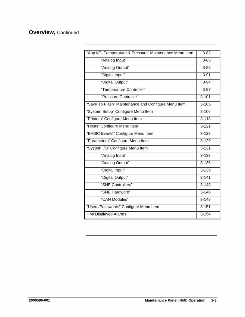
2000596-001 Maintenance Panel (HMI) Operation 3-3
Overview, Continued
“App I/O, Temperature & Pressure” Maintenance Menu Item 3-83
“Analog Input” 3-85
“Analog Output” 3-88
“Digital Input” 3-91
“Digital Output” 3-94
“Temperature Controller” 3-97
“Pressure Controller” 3-101
“Save To Flash” Maintenance and Configure Menu Item 3-105
“System Setup” Configure Menu Item 3-106
“Printers” Configure Menu Item 3-118
“Hosts” Configure Menu Item 3-121
“BASIC Events” Configure Menu Item 3-123
“Parameters” Configure Menu Item 3-129
“System I/O” Configure Menu Item 3-131
“Analog Input” 3-133
“Analog Output” 3-136
“Digital Input” 3-139
“Digital Output” 3-141
“SNE Controllers” 3-143
“SNE Hardware” 3-146
“CAN Modules” 3-148
“Users/Passwords” Configure Menu Item 3-151
HMI Displayed Alarms 3-154
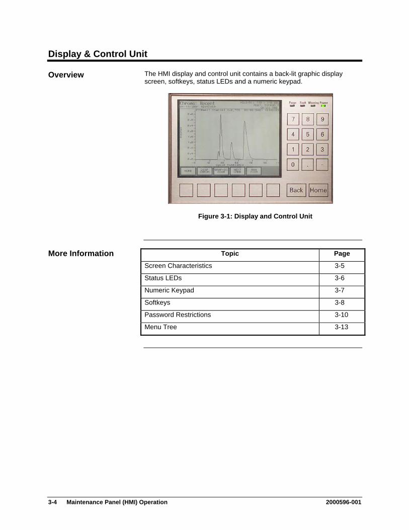
3-4 Maintenance Panel (HMI) Operation 2000596-001
Display & Control Unit
The HMI display and control unit contains a back-lit graphic display screen, softkeys, status LEDs and a numeric keypad.
Figure 3-1: Display and Control Unit
Topic Page
Screen Characteristics 3-5
Status LEDs 3-6
Numeric Keypad 3-7
Softkeys 3-8
Password Restrictions 3-10
Menu Tree 3-13
Overview
More Information
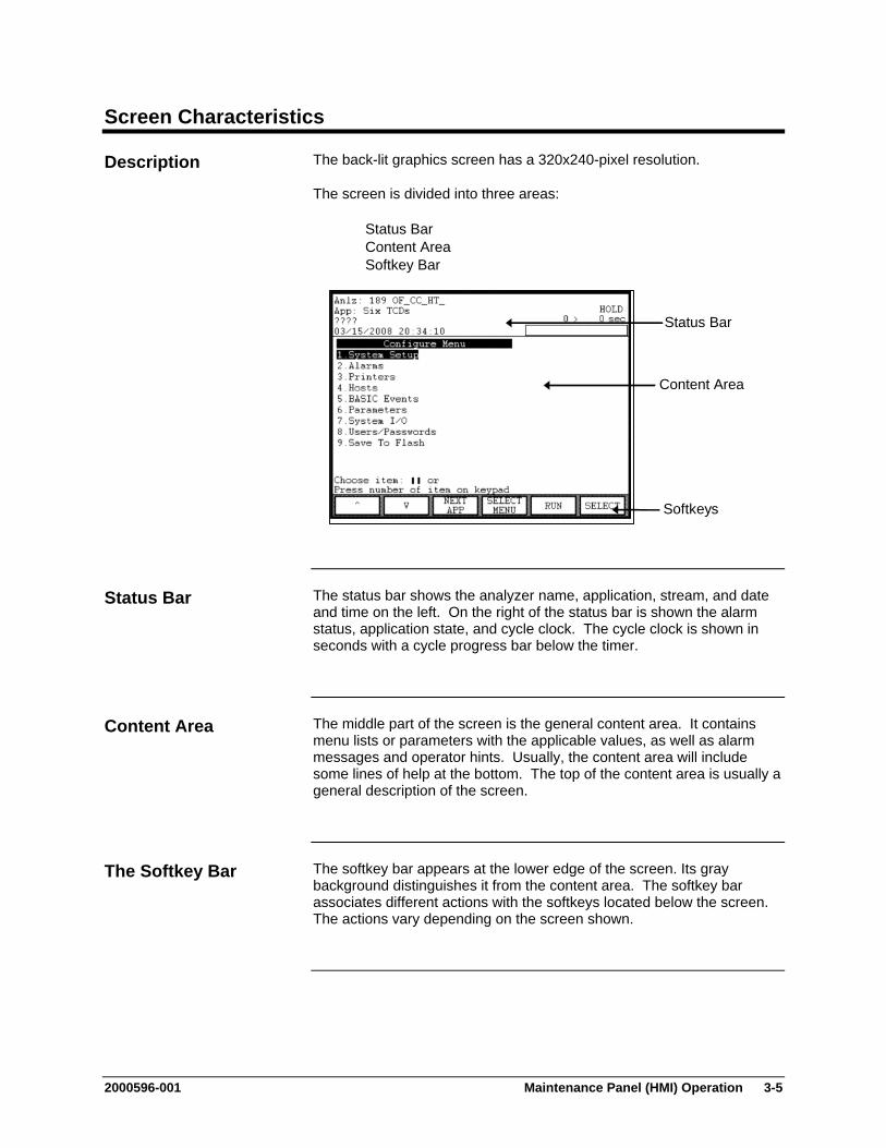
2000596-001 Maintenance Panel (HMI) Operation 3-5
Screen Characteristics
The back-lit graphics screen has a 320x240-pixel resolution.
The screen is divided into three areas:
Status Bar Content Area Softkey Bar
Status Bar
Content Area
Softkeys
The status bar shows the analyzer name, application, stream, and date and time on the left. On the right of the status bar is shown the alarm status, application state, and cycle clock. The cycle clock is shown in seconds with a cycle progress bar below the timer.
The middle part of the screen is the general content area. It contains menu lists or parameters with the applicable values, as well as alarm messages and operator hints. Usually, the content area will include some lines of help at the bottom. The top of the content area is usually a general description of the screen.
The softkey bar appears at the lower edge of the screen. Its gray background distinguishes it from the content area. The softkey bar associates different actions with the softkeys located below the screen. The actions vary depending on the screen shown.
Description
Status Bar
Content Area
The Softkey Bar

3-6 Maintenance Panel (HMI) Operation 2000596-001
Status LEDs & Alarms
The four LEDs next to the screen indicate the analyzer systems status.
Green “Power” LED
Yellow “Warning” LED
Red “Fault” LED
Red “Purge” LED
The green "Power" LED lights when the power supply is on.
The yellow "Warning" LED lights when the "Maintenance request" status signal is active.
The red "Fault" LED lights when the "Failure" status signal is active.
The red "Purge" LED lights when purge pressure is lost as detected by the PECM.
For a list and description of HMI displayed alarm codes and messages see Page 3-154, HMI Displayed Alarms.
Status LEDs
Alarm Messages

2000596-001 Maintenance Panel (HMI) Operation 3-7
Numeric Keypad
The numeric keypad is located to the right of the screen, below the status LEDs.
The operator can enter values directly with the:
numeric keys "0" through "9" Decimal point "." minus sign "-"
The numeric keys can be used to select any menu field by simply pushing the numeric key associated with that field.
Numeric Keypad
... ,
,
Operating Hint
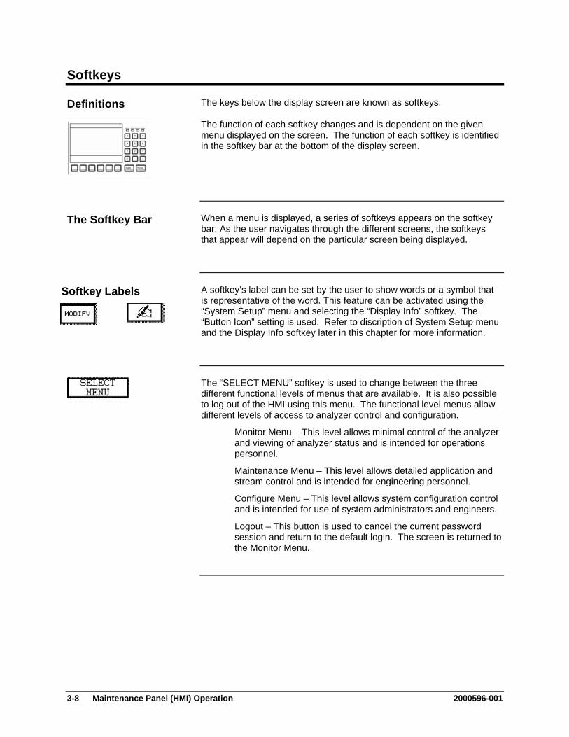
3-8 Maintenance Panel (HMI) Operation 2000596-001
Softkeys
The keys below the display screen are known as softkeys.
The function of each softkey changes and is dependent on the given menu displayed on the screen. The function of each softkey is identified in the softkey bar at the bottom of the display screen.
When a menu is displayed, a series of softkeys appears on the softkey bar. As the user navigates through the different screens, the softkeys that appear will depend on the particular screen being displayed.
A softkey’s label can be set by the user to show words or a symbol that is representative of the word. This feature can be activated using the “System Setup” menu and selecting the “Display Info” softkey. The “Button Icon” setting is used. Refer to discription of System Setup menu and the Display Info softkey later in this chapter for more information.
The “SELECT MENU” softkey is used to change between the three different functional levels of menus that are available. It is also possible to log out of the HMI using this menu. The functional level menus allow different levels of access to analyzer control and configuration.
Monitor Menu – This level allows minimal control of the analyzer and viewing of analyzer status and is intended for operations personnel.
Maintenance Menu – This level allows detailed application and stream control and is intended for engineering personnel.
Configure Menu – This level allows system configuration control and is intended for use of system administrators and engineers.
Logout – This button is used to cancel the current password session and return to the default login. The screen is returned to the Monitor Menu.
Definitions
The Softkey Bar
Softkey Labels

2000596-001 Maintenance Panel (HMI) Operation 3-9
Softkeys, Continued
The two arrow softkeys are used to move the selection cursor up or down in a menu or list to select menu items. The arrows keys are available for most screens and are always located on the left side of the softkey bar. The two symbols shown to the left are the arrow keys as they appear on the physical HMI. These softkeys appear slightly different on the HMI emulator (although they are in the same locations). On the HMI emulator the ( ^ ) and the ( V ) characters are used to represent the up and down arrows.
When a menu or list item is selected the text is reversed, i.e. appearing as bright characters on a dark background.
In this manual, entries to be made on the HMI by the operator will not be identified by key symbols but by showing the entry information (softkey, number entries, etc.) enclosed in quotes:
Press softkeys: “SELECT MENU”, “SELECT”, “BACKSPACE”
Select menu items: “Select Analyzer”, “Setup”
Enter numbers: “1” … “9”
The “Back” key is located below the numeric keypad. It allows the user to cancel a function or menu item and return to the previous menu level.
The “Back” key also allows the operator to clear analyzer system help text and messages.
The “Home” softkey returns the user back to the Starting Menu of the functional level menu tree that is currently in use (Monitor Menu, Maintenance Menu, or Configure Menu).
Arrow Softkeys
Note:
Back Softkey
Home Softkey Home
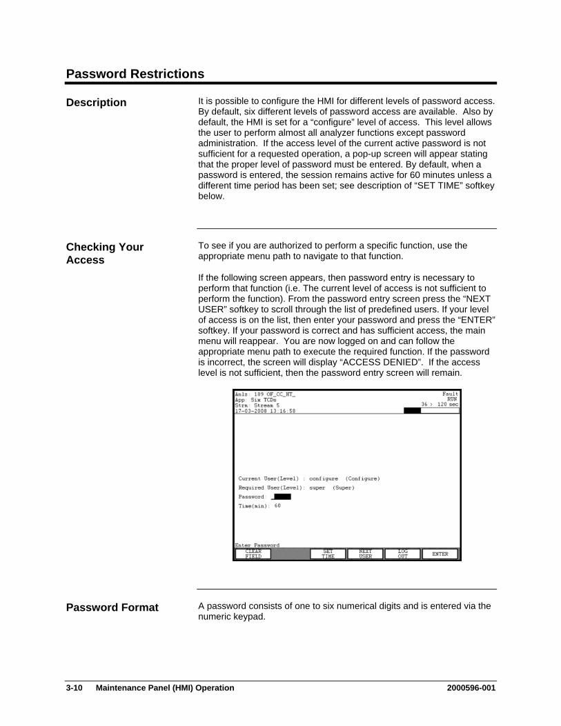
3-10 Maintenance Panel (HMI) Operation 2000596-001
Password Restrictions
It is possible to configure the HMI for different levels of password access. By default, six different levels of password access are available. Also by default, the HMI is set for a “configure” level of access. This level allows the user to perform almost all analyzer functions except password administration. If the access level of the current active password is not sufficient for a requested operation, a pop-up screen will appear stating that the proper level of password must be entered. By default, when a password is entered, the session remains active for 60 minutes unless a different time period has been set; see description of “SET TIME” softkey below.
To see if you are authorized to perform a specific function, use the appropriate menu path to navigate to that function.
If the following screen appears, then password entry is necessary to perform that function (i.e. The current level of access is not sufficient to perform the function). From the password entry screen press the “NEXT USER” softkey to scroll through the list of predefined users. If your level of access is on the list, then enter your password and press the “ENTER” softkey. If your password is correct and has sufficient access, the main menu will reappear. You are now logged on and can follow the appropriate menu path to execute the required function. If the password is incorrect, the screen will display “ACCESS DENIED”. If the access level is not sufficient, then the password entry screen will remain.
A password consists of one to six numerical digits and is entered via the numeric keypad.
Description
Checking Your Access
Password Format
2000596-001 Maintenance Panel (HMI) Operation 3-11
Password Restrictions, Continued
Passwords can be modified from the User’s Passwords screen. Refer to the section “Users/Passwords (on Configure Menu)” later in this chapter.
If your password is accepted you can modify any menu items or parameters assigned to your user level (or lower user levels). There are six predefined user levels (levels 0-4 and 99). The items that can be modified at these user levels are predefined and cannot be changed by the user.
By default six users are defined. These are “public”, “operate”, “calibrate”, “maintain”, “configure”, and “super”. The default access level for each of these users matches their names. In addition, multiple individual users may be defined. These users must have unique names and they can be created with either “operate”, “calibrate”, “maintain”, or “configure” access levels. Creation and deletion of users must be performed in System Manager. (Refer to the System Manager chapter of this manual for instructions on creating and deleting users).
The change privilege remains in effect if the user presses any key before the timeout limit (default 60 minutes). In this manner the user does not have to re-enter a password repeatedly while browsing through menu screens.
However, the analyzer automatically logs out (back to the default user), if the user has not pressed a key within the timeout limit.
For security purposes it is important to log off when work on the analyzer is finished. You can log out by pressing the “Home” softkey to return to the main menu. Then press the “SELECT MENU” softkey and select item 4 to log off. Typically analyzers are not in a fully restricted area, and unauthorized people may pose a security risk if a password is left active.
The “SET TIME” softkey is used to change the expiration time for a session. The default for this parameter is 60 minutes and applies to all passwords. A different timeout period may be set using the “SET TIME” softkey. Note that a “configure” or “super” level password is necessary to modify the timeout period.
Obtaining/Changing a Password
Privilege
Duration of the Privilege
Reminder
SET TIME Softkey
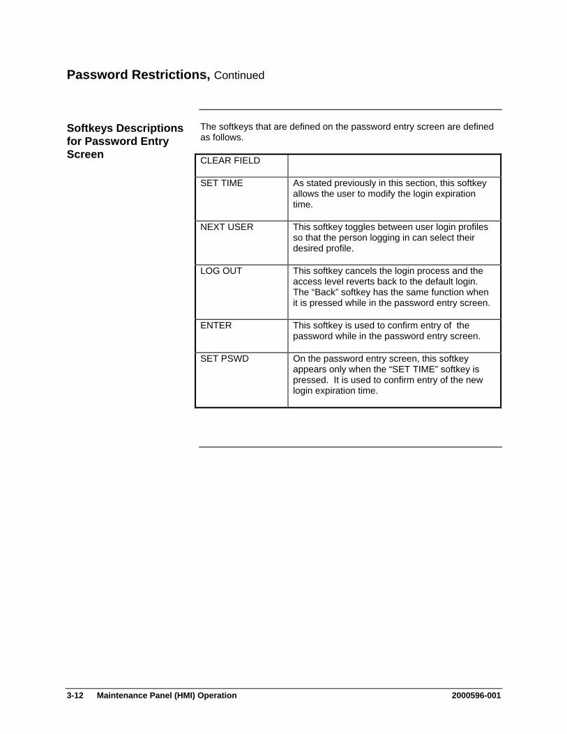
3-12 Maintenance Panel (HMI) Operation 2000596-001
Password Restrictions, Continued
The softkeys that are defined on the password entry screen are defined as follows.
CLEAR FIELD
SET TIME As stated previously in this section, this softkey allows the user to modify the login expiration time.
NEXT USER This softkey toggles between user login profiles so that the person logging in can select their desired profile.
LOG OUT This softkey cancels the login process and the access level reverts back to the default login. The “Back” softkey has the same function when it is pressed while in the password entry screen.
ENTER This softkey is used to confirm entry of the password while in the password entry screen.
SET PSWD On the password entry screen, this softkey appears only when the “SET TIME” softkey is pressed. It is used to confirm entry of the new login expiration time.
Softkeys Descriptions for Password Entry Screen
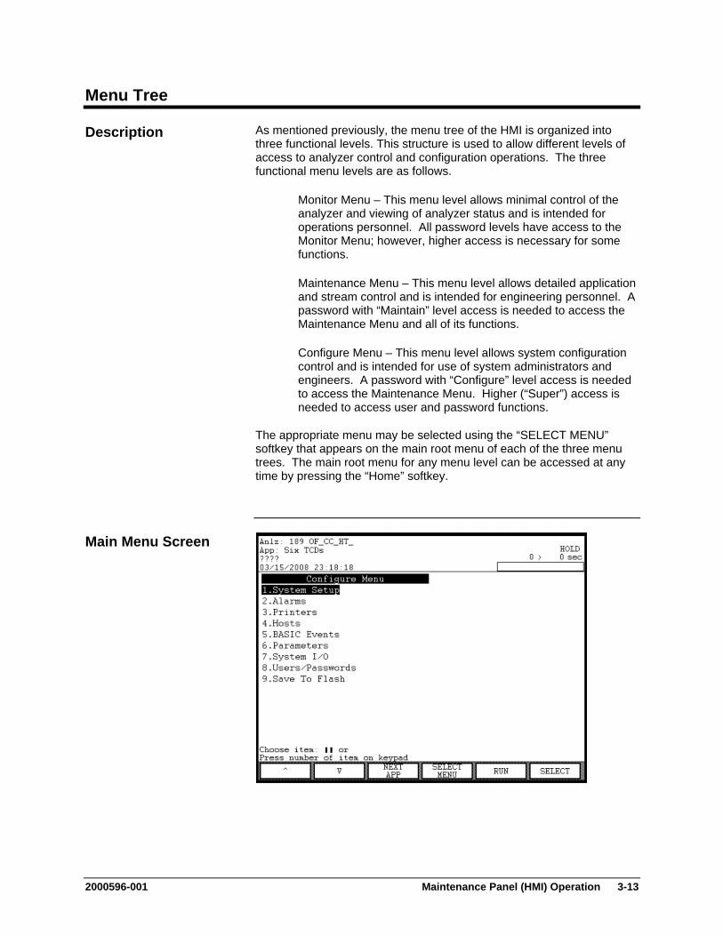
2000596-001 Maintenance Panel (HMI) Operation 3-13
Menu Tree
As mentioned previously, the menu tree of the HMI is organized into three functional levels. This structure is used to allow different levels of access to analyzer control and configuration operations. The three functional menu levels are as follows.
Monitor Menu – This menu level allows minimal control of the analyzer and viewing of analyzer status and is intended for operations personnel. All password levels have access to the Monitor Menu; however, higher access is necessary for some functions.
Maintenance Menu – This menu level allows detailed application and stream control and is intended for engineering personnel. A password with “Maintain” level access is needed to access the Maintenance Menu and all of its functions.
Configure Menu – This menu level allows system configuration control and is intended for use of system administrators and engineers. A password with “Configure” level access is needed to access the Maintenance Menu. Higher (“Super”) access is needed to access user and password functions.
The appropriate menu may be selected using the “SELECT MENU” softkey that appears on the main root menu of each of the three menu trees. The main root menu for any menu level can be accessed at any time by pressing the “Home” softkey.
Description
Main Menu Screen

3-14 Maintenance Panel (HMI) Operation 2000596-001
Menu Tree, Continued
To select any item from a menu you can use the arrow softkeys on the left of the menu bar highlight the item and then press the “Select” softkey. Alternatively, you may select a numbered item by simply pressing the corresponding number on the numeric keypad.
The following chart lists selections from the each of the three main menu levels. Only the top-level menu items are shown; the menu branches more extensively at most menu items. Refer to the referenced page for more detail on each item.
Monitor Menu Page Select Analyzer 3-15 View and Clear Alarms 3-17 View Streams 3-21 View Detectors & Realtime Chroms 3-26 View Results & Chromatograms 3-31 Validation 3-46 Calibration 3-48
Maintenance Menu Page Select Analyzer 3-15 Alarms 3-19 Applications 3-50 Stream Sequences 3-23 Detectors & Realtime Chroms 3-28 Results & Chromatograms 3-39 Method, Calibration & Validation 3-54 App I/O, Temperature & Pressure 3-83 Save To Flash 3-105
Configure Menu Page System Setup 3-106 Alarms 3-19 Printers 3-118 Hosts 3-121 BASIC Events 3-123 Parameters 3-129 System I/O 3-131 Users/Passwords 3-151 Save To Flash 3-105
Navigating the Menu
Top Level Menu Items
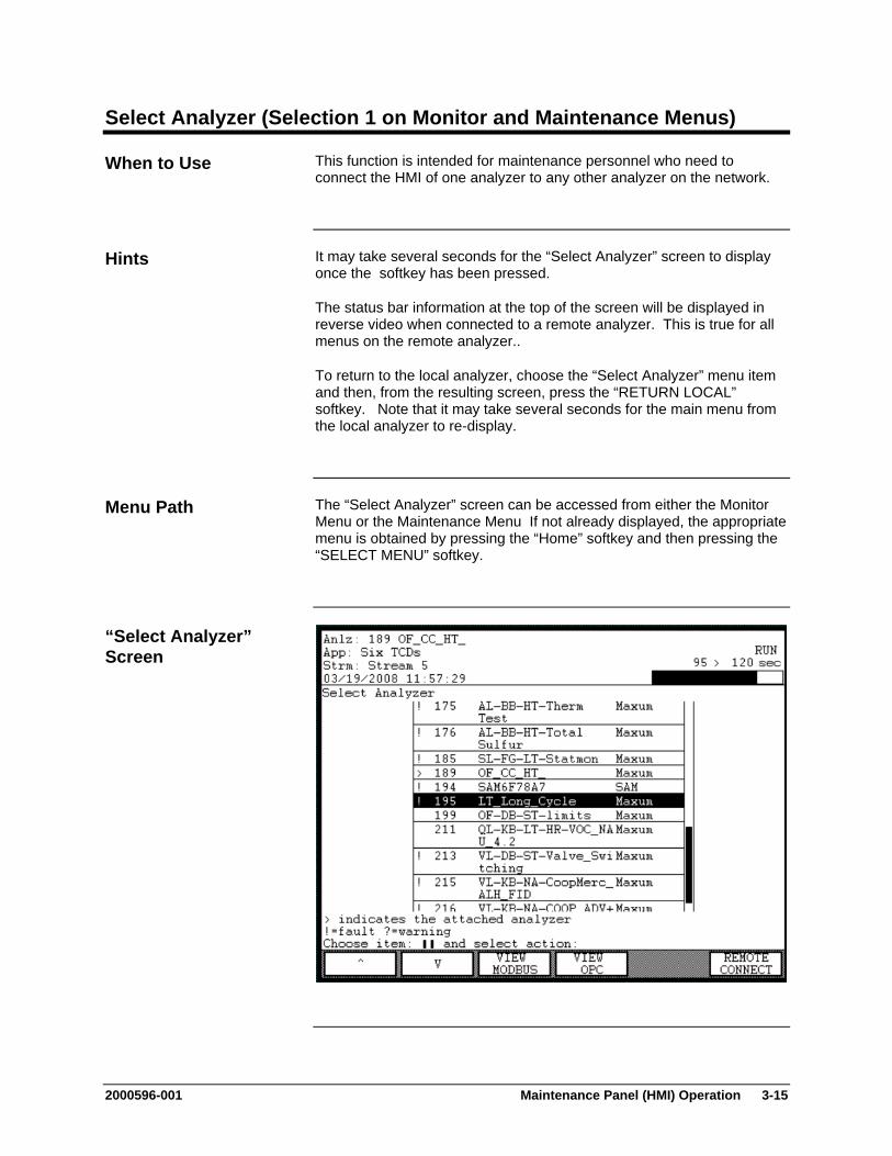
2000596-001 Maintenance Panel (HMI) Operation 3-15
Select Analyzer (Selection 1 on Monitor and Maintenance Menus)
This function is intended for maintenance personnel who need to connect the HMI of one analyzer to any other analyzer on the network.
It may take several seconds for the “Select Analyzer” screen to display once the softkey has been pressed.
The status bar information at the top of the screen will be displayed in reverse video when connected to a remote analyzer. This is true for all menus on the remote analyzer..
To return to the local analyzer, choose the “Select Analyzer” menu item and then, from the resulting screen, press the “RETURN LOCAL” softkey. Note that it may take several seconds for the main menu from the local analyzer to re-display.
The “Select Analyzer” screen can be accessed from either the Monitor Menu or the Maintenance Menu If not already displayed, the appropriate menu is obtained by pressing the “Home” softkey and then pressing the “SELECT MENU” softkey.
When to Use
Hints
Menu Path
“Select Analyzer” Screen

3-16 Maintenance Panel (HMI) Operation 2000596-001
Select Analyzer, Continued
Step Procedure
1. From either the Monitor Menu or the Maintenance menu, select the first menu item, “Select Analyzer”. On the resulting screen, the local analyzer should be highlighted.
2. Use the softkeys to scroll up or down through the list of analyzers and select the desired analyzer.
3. Press the “REMOTE CONNECT” softkey to connect to the desired analyzer. Within a few seconds the Monitor Menu of the remote analyzer should be displayed. The status bar at the top of the screen should appear black with white lettering.
4. To return to the local analyzer choose the “Select Analyzer” menu item from either the Monitor Menu or the Maintenance menu. Then, select the “Return Local” softkey.
It is important to remember that all the screens viewed while connected to a remote analyzer will be associated with that analyzer.
Some additional information, such as IP address and Loop/Unit, is shown in the analyzer table when displayed using the Maintenance Menu. This information is not available on the Monitor Menu version of the “Select Analyzer” screen.
This softkey displays all MODBUS addresses for the analyzer that was highlighted on the screen when the softkey was pressed. This softkey is not available on the “Select Analyzer” screen when connected to a remote analyzer. In the resulting screen, the “SORT ADDRESS”, “SORT TYPE”, and “SORT STREAM” softkeys are used to sort the table information in different ways.
This softkey will display all OPC (OLE for Process Control) table entries. This softkey is not available on the “Select Analyzer” screen when connected to a remote analyzer.
Instructions
Hints
“VIEW MODBUS” Softkey
“VIEW OPC” Softkey
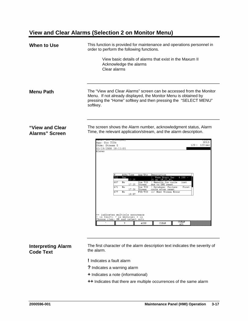
2000596-001 Maintenance Panel (HMI) Operation 3-17
View and Clear Alarms (Selection 2 on Monitor Menu)
This function is provided for maintenance and operations personnel in order to perform the following functions.
View basic details of alarms that exist in the Maxum II Acknowledge the alarms Clear alarms
The “View and Clear Alarms” screen can be accessed from the Monitor Menu. If not already displayed, the Monitor Menu is obtained by pressing the “Home” softkey and then pressing the “SELECT MENU” softkey.
The screen shows the Alarm number, acknowledgment status, Alarm Time, the relevant application/stream, and the alarm description.
The first character of the alarm description text indicates the severity of the alarm.
! Indicates a fault alarm
? Indicates a warning alarm
+ Indicates a note (informational)
++ Indicates that there are multiple occurrences of the same alarm
When to Use
Menu Path
“View and Clear Alarms” Screen
Interpreting Alarm Code Text
3-18 Maintenance Panel (HMI) Operation 2000596-001
View and Clear Alarms (Monitor Menu), Continued
Softkey Use
“ACKN” This softkey acknowledges the alarm by setting the “Ackn” parameter for the highlighted alarm to “Yes”. The current value for this parameter can be seen in the “Ackn” column in the alarm table.
“CLEAR” This softkey clears the alarm that is highlighted in the alarm table.
“CLEAR ALL” This softkey clears all alarms in the alarm table.
Softkey Descriptions
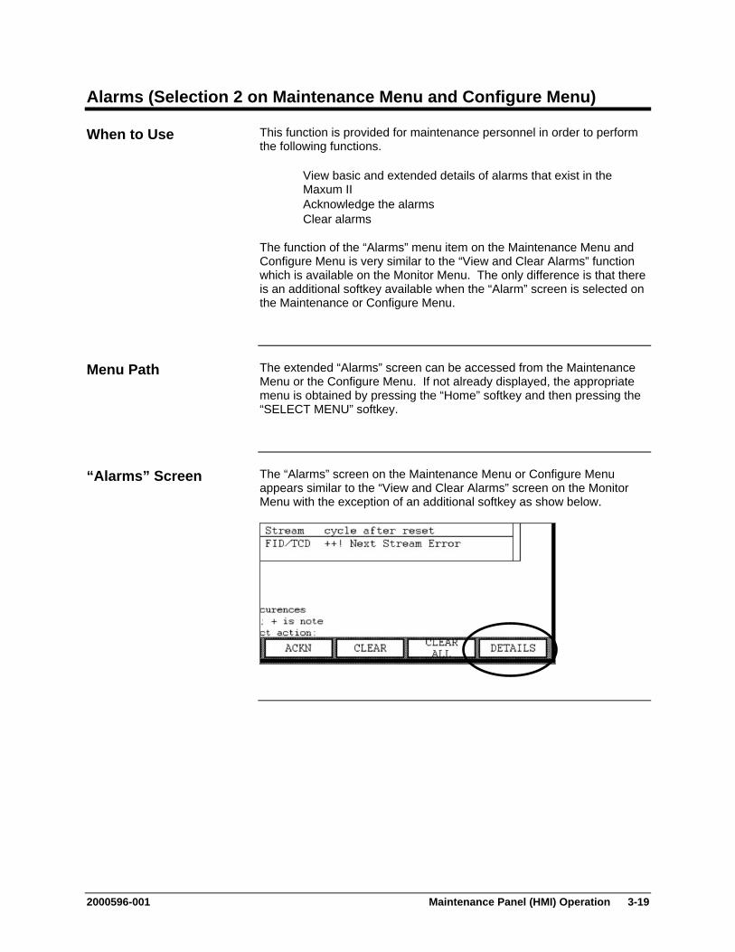
2000596-001 Maintenance Panel (HMI) Operation 3-19
Alarms (Selection 2 on Maintenance Menu and Configure Menu)
This function is provided for maintenance personnel in order to perform the following functions.
View basic and extended details of alarms that exist in the Maxum II
Acknowledge the alarms Clear alarms
The function of the “Alarms” menu item on the Maintenance Menu and Configure Menu is very similar to the “View and Clear Alarms” function which is available on the Monitor Menu. The only difference is that there is an additional softkey available when the “Alarm” screen is selected on the Maintenance or Configure Menu.
The extended “Alarms” screen can be accessed from the Maintenance Menu or the Configure Menu. If not already displayed, the appropriate menu is obtained by pressing the “Home” softkey and then pressing the “SELECT MENU” softkey.
The “Alarms” screen on the Maintenance Menu or Configure Menu appears similar to the “View and Clear Alarms” screen on the Monitor Menu with the exception of an additional softkey as show below.
When to Use
Menu Path
“Alarms” Screen

3-20 Maintenance Panel (HMI) Operation 2000596-001
Alarms (Maintenance Menu and Configure Menu), Continued
The “DETAILS” softkey displays a screen with extended information concerning the selected alarm. From this screen you can acknowledge the alarm or clear the alarm from the list. To exit the “Details” screen and return to the “Alarms” screen, press the “Back” softkey.
“DETAILS” Softkey

2000596-001 Maintenance Panel (HMI) Operation 3-21
View Streams (Selection 3 on Monitor Menu)
This function is provided for maintenance and operations personnel in order to perform the following functions.
Display basic stream data Select the active stream sequence Disable and enable streams within a stream sequence
The “View Streams” screen can be accessed from the Monitor Menu. If not already displayed, the Monitor Menu is obtained by pressing the “Home” softkey and then pressing the “SELECT MENU” softkey.
The screen shows the stream sequence name, stream/method names, and the status of each stream.
When to Use
Menu Path
“View Streams” Screen

3-22 Maintenance Panel (HMI) Operation 2000596-001
View Streams (Monitor Menu), Continued
In the upper left corner of the information section of the screen is the name of the stream sequence. For the active stream sequence the word “Active” appears just below the name.
The table contains the stream number and method name. The “Status” column indicates whether a stream is currently running, set to run next, or set to run always. A stream that has been disabled will have an asterisk (*) on the left next to the stream number.
Softkey Use
“NEXT SEQNCE”
An application may have multiple stream sequences. The “NEXT SEQNCE” softkey is used to toggle through the different defined sequences.
“SET ACTIVE” This softkey is used to force a different sequence to run. The sequence will begin running after the next stream step.
“DISABLE” & “ENABLE
This softkey enables/disables the stream that is highlighted in the table. Streams within the table are selected using the arrow keys.
Interpreting the Display
Softkey Descriptions
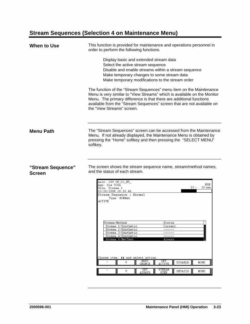
2000596-001 Maintenance Panel (HMI) Operation 3-23
Stream Sequences (Selection 4 on Maintenance Menu)
This function is provided for maintenance and operations personnel in order to perform the following functions.
Display basic and extended stream data Select the active stream sequence Disable and enable streams within a stream sequence Make temporary changes to some stream data Make temporary modifications to the stream order
The function of the “Stream Sequences” menu item on the Maintenance Menu is very similar to “View Streams” which is available on the Monitor Menu. The primary difference is that there are additional functions available from the “Stream Sequences” screen that are not available on the “View Streams” screen.
The “Stream Sequences” screen can be accessed from the Maintenance Menu. If not already displayed, the Maintenance Menu is obtained by pressing the “Home” softkey and then pressing the “SELECT MENU” softkey.
The screen shows the stream sequence name, stream/method names, and the status of each stream.
When to Use
Menu Path
“Stream Sequence” Screen
3-24 Maintenance Panel (HMI) Operation 2000596-001
Stream Sequences (Maintenance Menu), Continued
In the upper left corner of the information section of the screen is the name of the stream sequence. The type of sequence (normal, calibration, validation, or mixed) is displayed just below the name. For the active stream sequence the word “Active” appears just below the sequence type.
The sequence table contains the stream number and method name. The “Status” column indicates whether a stream is currently running, set to run next, or set to run always. A stream that has been disabled will have an asterisk (*) on the left next to the stream number.
The following softkeys are available from the “Stream Sequences” screen.
Softkey Use
“NEXT SEQNCE”
An application may have multiple stream sequences. The “NEXT SEQNCE” softkey is used to toggle through the different defined sequences.
“SET ACTIVE” This softkey is used to force a different sequence to run. The sequence will begin running after the next stream step.
“DISABLE” & “ENABLE
This softkey enables/disables the stream that is highlighted in the table. Streams within the table are selected using the arrow keys.
“MORE” This softkey toggles between two sets of available softkeys.
“SET ALWAYS” & “RESUME SEQ”
The “SET ALWAYS” softkey sets the selected stream to run continuously, disregarding the rest of the sequence. The “RESUME SEQ” softkey will remove the “ALWAYS” designation.
“STREAM STEP”
This softkey advances the “Next” stream once down the sequence list. This has the effect of allowing the user to temporarily skip a stream.
“DETAILS” This softkey displays a detailed information screen for a stream within the sequence. Information is displayed for the stream that is highlighted when the softkey is pressed.
Interpreting the Display
Softkey Descriptions
Softkey Descriptions

2000596-001 Maintenance Panel (HMI) Operation 3-25
Stream Sequences (Maintenance Menu), Continued
The “DETAILS” softkey displays a screen with extended information concerning the selected stream. From this screen it is possible to temporarily modify the highlighted parameters. However, changes made to the stream sequence should be made in EZChrom. To exit the “Details” screen and return to the “Stream Sequences” screen, press the “Back” softkey.
“DETAILS” Screen
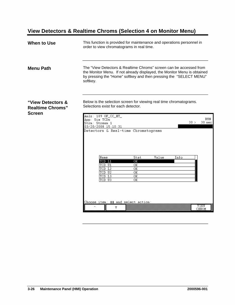
3-26 Maintenance Panel (HMI) Operation 2000596-001
View Detectors & Realtime Chroms (Selection 4 on Monitor Menu)
This function is provided for maintenance and operations personnel in order to view chromatograms in real time.
The “View Detectors & Realtime Chroms” screen can be accessed from the Monitor Menu. If not already displayed, the Monitor Menu is obtained by pressing the “Home” softkey and then pressing the “SELECT MENU” softkey.
Below is the selection screen for viewing real time chromatograms. Selections exist for each detector.
When to Use
Menu Path
“View Detectors & Realtime Chroms” Screen
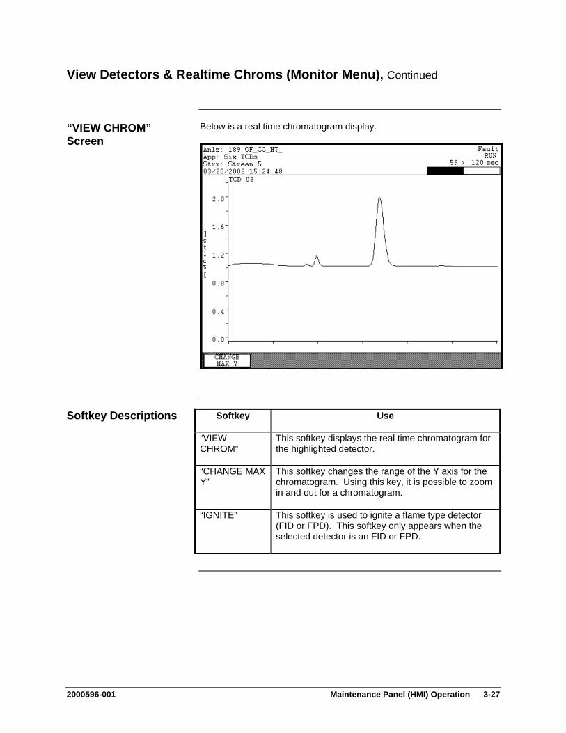
2000596-001 Maintenance Panel (HMI) Operation 3-27
View Detectors & Realtime Chroms (Monitor Menu), Continued
Below is a real time chromatogram display.
Softkey Use
“VIEW CHROM”
This softkey displays the real time chromatogram for the highlighted detector.
“CHANGE MAX Y”
This softkey changes the range of the Y axis for the chromatogram. Using this key, it is possible to zoom in and out for a chromatogram.
“IGNITE” This softkey is used to ignite a flame type detector (FID or FPD). This softkey only appears when the selected detector is an FID or FPD.
“VIEW CHROM” Screen
Softkey Descriptions

3-28 Maintenance Panel (HMI) Operation 2000596-001
Detectors & Realtime Chroms (Selection 5 on Maintenance Menu)
This function is provided for maintenance and operations personnel in order to view chromatograms in real time.
The function of the “Detectors & Realtime Chroms” menu item on the Maintenance Menu is very similar to the similar selection which is available on the Monitor Menu. The primary difference is that there are additional functions available from the Maintenance Menu version of the screen that are not available on the Monitor Menu version.
The “Detectors & Realtime Chroms” screen can be accessed from the Maintenance Menu. If not already displayed, the Maintenance Menu is obtained by pressing the “Home” softkey and then pressing the “SELECT MENU” softkey.
Below is the selection screen for viewing real time chromatograms. Selections exist for each detector.
When to Use
Menu Path
“Detectors & Realtime Chroms” Screen
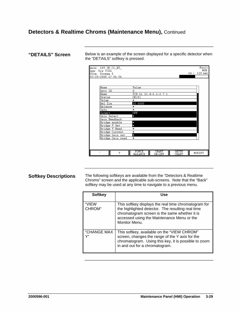
2000596-001 Maintenance Panel (HMI) Operation 3-29
Detectors & Realtime Chroms (Maintenance Menu), Continued
Below is an example of the screen displayed for a specific detector when the “DETAILS” softkey is pressed.
The following softkeys are available from the “Detectors & Realtime Chroms” screen and the applicable sub-screens. Note that the “Back” softkey may be used at any time to navigate to a previous menu.
Softkey Use
“VIEW CHROM”
This softkey displays the real time chromatogram for the highlighted detector. The resulting real time chromatogram screen is the same whether it is accessed using the Maintenance Menu or the Monitor Menu.
“CHANGE MAX Y”
This softkey, available on the “VIEW CHROM” screen, changes the range of the Y axis for the chromatogram. Using this key, it is possible to zoom in and out for a chromatogram.
“DETAILS” Screen
Softkey Descriptions
3-30 Maintenance Panel (HMI) Operation 2000596-001
Detectors & Realtime Chroms (Maintenance Menu), Continued
Softkey Use
“FORCE BALANCE”
This softkey balances the selected detector.
“IGNITE” This softkey is used to ignite a flame type detector (FID or FPD). This softkey only appears when the selected detector is an FID or FPD.
“CHART ON-OFF”
This softkey turns the chart recorder output on and off.
“SETUP CHART”
This softkey allows the user to modify the scale and offset of the chart recorder output signal.
“BACK SPACE” This softkey, available on the “SETUP CHART” and “MODIFY” screens, allows the user to back space while entering data in a field.
“NEXT FIELD” This softkey, available on the “SETUP CHART” screen, toggles between parameter entry fields.
“DONE” This softkey, available on the “SETUP CHART” and “MODIFY” screens, confirms changes that have been entered and returns the user to the previous screen. It is similar to an “ACCEPT CHANGES” softkey.
“MODIFY” This softkey, when displayed, allows the user to change certain details for the detector that affect the display of real time chromatograms. Only parameters which have values shown in reverse video (black background with white lettering) may be modified. A separate data entry screen will be displayed when modifying certain parameters.
“NEXT ITEM” This softkey produces unpredictable results. DO NOT USE.
The “NEXT ITEM” softkey is known to produce unpredictable results. Do not use this softkey when modifying details.
Softkey Descriptions (continued)
Note:
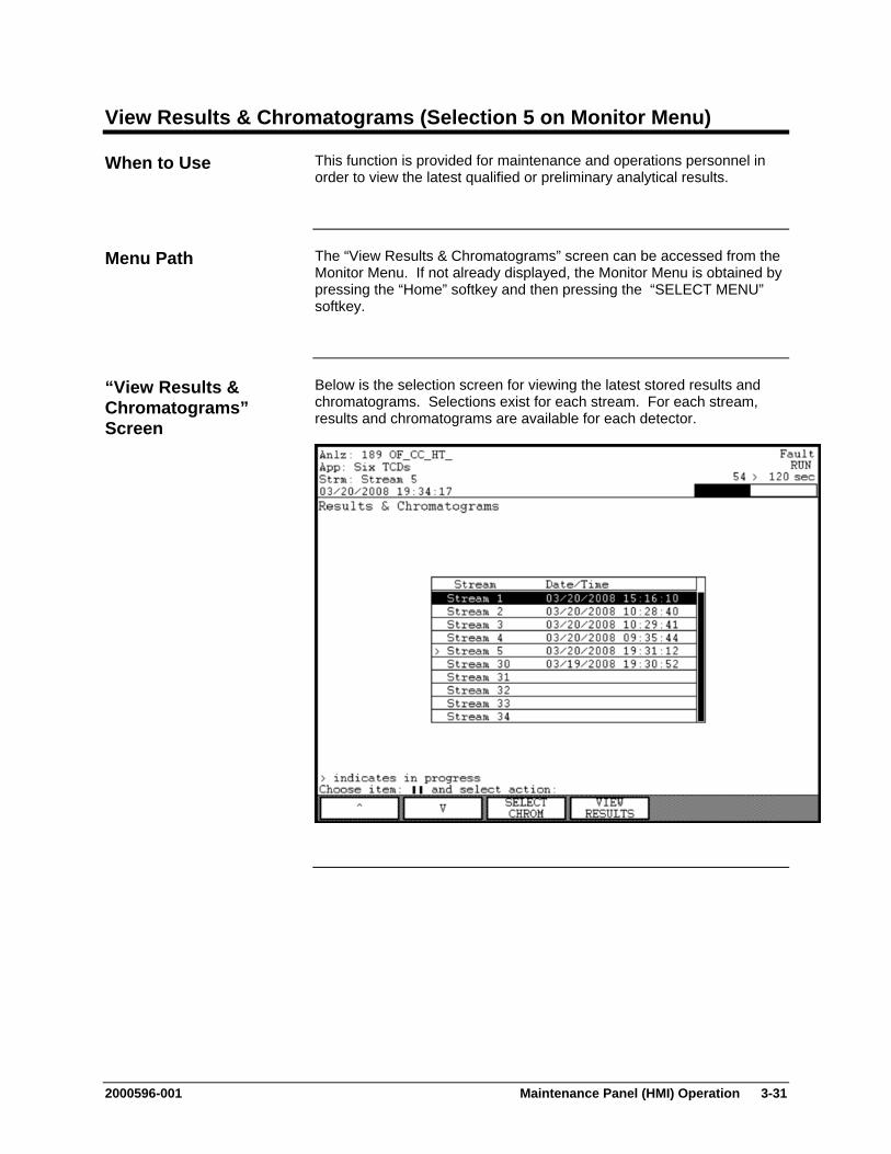
2000596-001 Maintenance Panel (HMI) Operation 3-31
View Results & Chromatograms (Selection 5 on Monitor Menu)
This function is provided for maintenance and operations personnel in order to view the latest qualified or preliminary analytical results.
The “View Results & Chromatograms” screen can be accessed from the Monitor Menu. If not already displayed, the Monitor Menu is obtained by pressing the “Home” softkey and then pressing the “SELECT MENU” softkey.
Below is the selection screen for viewing the latest stored results and chromatograms. Selections exist for each stream. For each stream, results and chromatograms are available for each detector.
When to Use
Menu Path
“View Results & Chromatograms” Screen
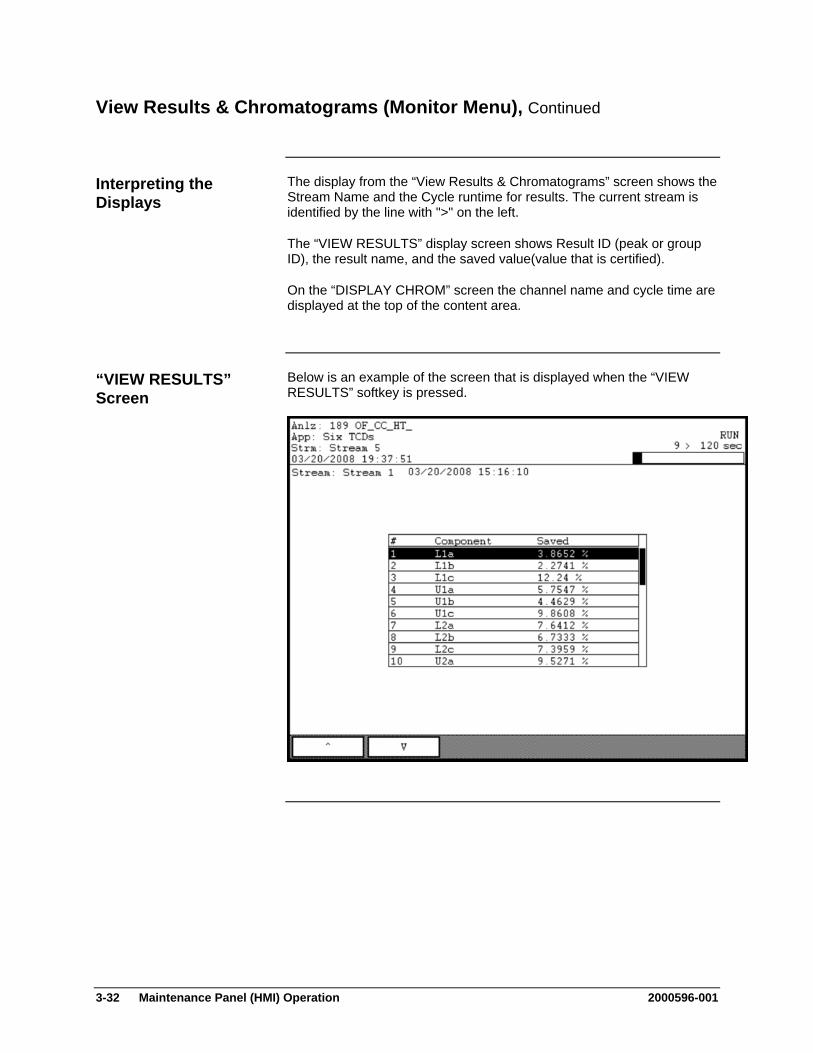
3-32 Maintenance Panel (HMI) Operation 2000596-001
View Results & Chromatograms (Monitor Menu), Continued
The display from the “View Results & Chromatograms” screen shows the Stream Name and the Cycle runtime for results. The current stream is identified by the line with ">" on the left.
The “VIEW RESULTS” display screen shows Result ID (peak or group ID), the result name, and the saved value(value that is certified).
On the “DISPLAY CHROM” screen the channel name and cycle time are displayed at the top of the content area.
Below is an example of the screen that is displayed when the “VIEW RESULTS” softkey is pressed.
Interpreting the Displays
“VIEW RESULTS” Screen

2000596-001 Maintenance Panel (HMI) Operation 3-33
View Results & Chromatograms (Monitor Menu), Continued
To display a chromatogram, press the “SELECT CHROM” softkey and then press the “DISPLAY CHROM” softkey. Below is an example of the resulting screen.
The display above is taken from the HMI software emulator (refer to the description of the emulator at the beginning of this chapter). There is an additional softkey available on the physical HMI that is not seen on the emulator. The “GRAPHIC ZOOM” softkey is located on the far left side of the softkey bar. The function of this softkey is described later in this section.
“SELECT CHROM” Screen
Note:
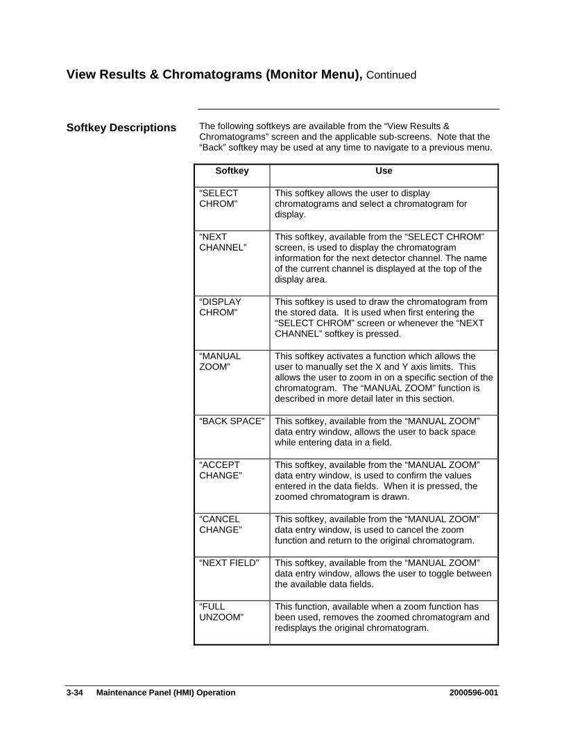
3-34 Maintenance Panel (HMI) Operation 2000596-001
View Results & Chromatograms (Monitor Menu), Continued
The following softkeys are available from the “View Results & Chromatograms” screen and the applicable sub-screens. Note that the “Back” softkey may be used at any time to navigate to a previous menu.
Softkey Use
“SELECT CHROM”
This softkey allows the user to display chromatograms and select a chromatogram for display.
“NEXT CHANNEL”
This softkey, available from the “SELECT CHROM” screen, is used to display the chromatogram information for the next detector channel. The name of the current channel is displayed at the top of the display area.
“DISPLAY CHROM”
This softkey is used to draw the chromatogram from the stored data. It is used when first entering the “SELECT CHROM” screen or whenever the “NEXT CHANNEL” softkey is pressed.
“MANUAL ZOOM”
This softkey activates a function which allows the user to manually set the X and Y axis limits. This allows the user to zoom in on a specific section of the chromatogram. The “MANUAL ZOOM” function is described in more detail later in this section.
“BACK SPACE” This softkey, available from the “MANUAL ZOOM” data entry window, allows the user to back space while entering data in a field.
“ACCEPT CHANGE”
This softkey, available from the “MANUAL ZOOM” data entry window, is used to confirm the values entered in the data fields. When it is pressed, the zoomed chromatogram is drawn.
“CANCEL CHANGE”
This softkey, available from the “MANUAL ZOOM” data entry window, is used to cancel the zoom function and return to the original chromatogram.
“NEXT FIELD” This softkey, available from the “MANUAL ZOOM” data entry window, allows the user to toggle between the available data fields.
“FULL UNZOOM”
This function, available when a zoom function has been used, removes the zoomed chromatogram and redisplays the original chromatogram.
Softkey Descriptions

2000596-001 Maintenance Panel (HMI) Operation 3-35
View Results & Chromatograms (Monitor Menu), Continued
Softkey Use
“GRAPHIC ZOOM”
This softkey activates a function which allows the user to graphically set the X and Y axis limits by defining points on the chromatogram. This allows the user to zoom in on a specific section of the chromatogram. The “GRAPHIC ZOOM” function is described in more detail later in this section.
“HELP” and “REMOVE HELP”
When using “GRAPHIC ZOOM”, the numeric keypad is used to move around the screen and select point. The “HELP” softkey, displays a description of the graphical functions of the numerical keypad. The “REMOVE HELP” softkey removes the help display.
“MORE” This softkey displays the next set of available softkeys.
“SHOW/HIDE ACTL PK”
This softkey displays actual peak annotations on the chromatogram.
“SHOW/HIDE ACTL GP”
This softkey displays actual group annotations on the chromatogram.
“SHOW/HIDE RT WIN”
When this softkey is pressed, lines indicating the retention time window information are shown on the chromatogram.
“VIEW RESULTS”
This softkey displays a screen that shows the numerical results that are stored for the stream.
Softkey Descriptions (continued)
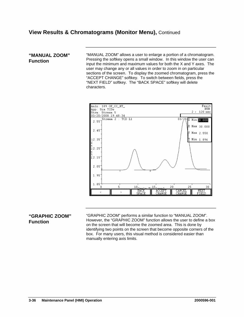
3-36 Maintenance Panel (HMI) Operation 2000596-001
View Results & Chromatograms (Monitor Menu), Continued
“MANUAL ZOOM” allows a user to enlarge a portion of a chromatogram. Pressing the softkey opens a small window. In this window the user can input the minimum and maximum values for both the X and Y axes. The user may change any or all values in order to zoom in on particular sections of the screen. To display the zoomed chromatogram, press the “ACCEPT CHANGE” softkey. To switch between fields, press the “NEXT FIELD” softkey. The “BACK SPACE” softkey will delete characters.
“GRAPHIC ZOOM” performs a similar function to “MANUAL ZOOM”. However, the “GRAPHIC ZOOM” function allows the user to define a box on the screen that will become the zoomed area. This is done by identifying two points on the screen that become opposite corners of the box. For many users, this visual method is considered easier than manually entering axis limits.
“MANUAL ZOOM” Function
“GRAPHIC ZOOM” Function

2000596-001 Maintenance Panel (HMI) Operation 3-37
View Results & Chromatograms (Monitor Menu), Continued
Step Procedure
1. Press the “GRAPHIC ZOOM” softkey. Dotted “crosshair” lines will appear in the chromatogram, and the softkey bar will change.
2. Two points are required to define the zoom area. The first point defined should be the top left corner of the area. The second point defined should be the bottom right corner.
The “crosshairs” indicate the location where the points are to be defined for the zoom. The location of a point is changed by using the numeric keypad. The functions of the keys on the keypad are as follows.
The arrow keys move the location of the point (as identified by the crosshairs). Once an arrow key is pressed, the point continues to move until a different key is pressed.
The “STOP” key stops movement of the crosshair.
The “Checkmark” key confirms the selection of a point.
The “X” key cancels the “GRAPHIC ZOOM” function.
The “100” key is used when the chromatogram is already zoomed. It fully unzooms the chromatogram so that a different zoom area can be defined.
“GRAPHIC ZOOM” Instructions

3-38 Maintenance Panel (HMI) Operation 2000596-001
View Results & Chromatograms (Monitor Menu), Continued
Step Procedure
3. Locate and confirm the first point. This should be the top left corner of the desired zoom area. When the point is confirmed (using the checkmark or “.” key), the crosshairs switch from dashed lines to solid lines.
4. Once the first point is defined, crosshairs should appear for the second point. Locate and confirm the second point. This will become the bottom right corner of the desired zoom area. As soon as the second point has been confirmed, the screen will change and the zoomed area will be shown.
Note: Defining points other than “top left/bottom right” will result in the zoomed area being changed (reversed or flipped).
5. A zoomed chromatogram can be restored to the original by pressing the “FULL UNZOOM” softkey.
“GRAPHIC ZOOM” Instructions - Continued
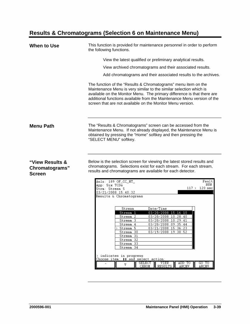
2000596-001 Maintenance Panel (HMI) Operation 3-39
Results & Chromatograms (Selection 6 on Maintenance Menu)
This function is provided for maintenance personnel in order to perform the following functions.
View the latest qualified or preliminary analytical results.
View archived chromatograms and their associated results.
Add chromatograms and their associated results to the archives.
The function of the “Results & Chromatograms” menu item on the Maintenance Menu is very similar to the similar selection which is available on the Monitor Menu. The primary difference is that there are additional functions available from the Maintenance Menu version of the screen that are not available on the Monitor Menu version.
The “Results & Chromatograms” screen can be accessed from the Maintenance Menu. If not already displayed, the Maintenance Menu is obtained by pressing the “Home” softkey and then pressing the “SELECT MENU” softkey.
Below is the selection screen for viewing the latest stored results and chromatograms. Selections exist for each stream. For each stream, results and chromatograms are available for each detector.
When to Use
Menu Path
“View Results & Chromatograms” Screen
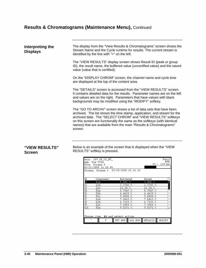
3-40 Maintenance Panel (HMI) Operation 2000596-001
Results & Chromatograms (Maintenance Menu), Continued
The display from the “View Results & Chromatograms” screen shows the Stream Name and the Cycle runtime for results. The current stream is identified by the line with ">" on the left.
The “VIEW RESULTS” display screen shows Result ID (peak or group ID), the result name, the buffered value (uncertified value) and the saved value (value that is certified).
On the “DISPLAY CHROM” screen, the channel name and cycle time are displayed at the top of the content area.
The “DETAILS” screen is accessed from the “VIEW RESULTS” screen. It contains detailed data for the results. Parameter names are on the left and values are on the right. Parameters that have values with black backgrounds may be modified using the “MODIFY” softkey.
The “GO TO ARCHV” screen shows a list of data sets that have been archived. The list shows the time stamp, application, and stream for the archived data. The “SELECT CHROM” and “VIEW RESULTS” softkeys on this screen are functionally the same as the softkeys (with identical names) that are available from the main “Results & Chromatograms” screen.
Below is an example of the screen that is displayed when the “VIEW RESULTS” softkey is pressed.
Interpreting the Displays
“VIEW RESULTS” Screen
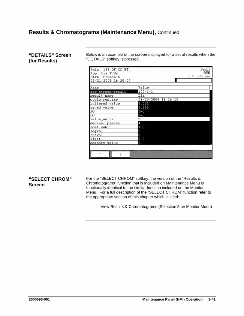
2000596-001 Maintenance Panel (HMI) Operation 3-41
Results & Chromatograms (Maintenance Menu), Continued
Below is an example of the screen displayed for a set of results when the “DETAILS” softkey is pressed.
For the “SELECT CHROM” softkey, the version of the “Results & Chromatograms” function that is included on Maintenance Menu is functionally identical to the similar function included on the Monitor Menu. For a full description of the “SELECT CHROM” function refer to the appropriate section of this chapter which is titled:
View Results & Chromatograms (Selection 5 on Monitor Menu)
“DETAILS” Screen (for Results)
“SELECT CHROM” Screen

3-42 Maintenance Panel (HMI) Operation 2000596-001
Results & Chromatograms (Maintenance Menu), Continued
Below is an example of the screen that is displayed when the “GO TO ARCHV” softkey is pressed.
On the “GO TO ARCHV” screen there are softkeys named “SELECT CHROM” and “VIEW RESULTS”. These two softkeys do not have the same level of function as similar softkeys found on the main screen for “Results & Chromatograms” (Maintenance Menu). However, they are functionally identical to the similar softkeys which are available on the “View Results & Chromatograms” screen on the Monitor Menu.
“GO TO ARCHV” Screen
Note:
2000596-001 Maintenance Panel (HMI) Operation 3-43
Results & Chromatograms (Maintenance Menu), Continued
The following softkeys are available from the “Results & Chromatograms” screen and the applicable sub-screens. Note that the “Back” softkey may be used at any time to navigate to a previous menu.
Softkey Use
“SELECT CHROM”
This softkey allows the user to display chromatograms and select a chromatogram for display.
“NEXT CHANNEL”
This softkey, available from the “SELECT CHROM” screen, is used to display the chromatogram information for the next detector channel. The name of the current channel is displayed at the top of the display area.
“DISPLAY CHROM”
This softkey is used to draw the chromatogram from the stored data. It is used when first entering the “SELECT CHROM” screen or whenever the “NEXT CHANNEL” softkey is pressed.
“MANUAL ZOOM”
This softkey activates a function which allows the user to manually set the X and Y axis limits. This allows the user to zoom in on a specific section of the chromatogram. The “MANUAL ZOOM” function is described in more detail in the previous section, View Results & Chromatograms (Selection 5 on Monitor Menu).
“BACK SPACE” This softkey, when available, allows the user to back space while entering data in a field.
“ACCEPT CHANGE”
This softkey, when available, is used to confirm the values entered in the data fields. When it is pressed, the zoomed chromatogram is drawn.
“CANCEL CHANGE”
This softkey, when available, is used to cancel the zoom function and return to the original chromatogram.
“NEXT FIELD” This softkey, when available, allows the user to toggle between the available data fields.
“FULL UNZOOM”
This function, available when a zoom function has been used, removes the zoomed chromatogram and redisplays the original chromatogram.
Softkey Descriptions

3-44 Maintenance Panel (HMI) Operation 2000596-001
Results & Chromatograms (Maintenance Menu), Continued
Softkey Use
“GRAPHIC ZOOM”
This softkey activates a function which allows the user to graphically set the X and Y axis limits by defining points on the chromatogram. This allows the user to zoom in on a specific section of the chromatogram. The “GRAPHIC ZOOM” function is described in more detail in the previous section, View Results & Chromatograms (Selection 5 on Monitor Menu).
“HELP” and “REMOVE HELP”
When using “GRAPHIC ZOOM”, the numeric keypad is used to move around the screen and select points. The “HELP” softkey displays a description of the graphical functions of the numerical keypad. The “REMOVE HELP” softkey removes the help display.
“MORE” This softkey, when available, displays the next set of available softkeys.
“SHOW/HIDE ACTL PK”
This softkey displays actual peak annotations on the chromatogram.
“SHOW/HIDE ACTL GP”
This softkey displays actual group annotations on the chromatogram.
“SHOW/HIDE RT WIN”
When this softkey is pressed, lines indicating the retention time window information are shown on the chromatogram.
“VIEW RESULTS”
This softkey displays a screen that shows the numerical results that are stored for the stream. Two versions of this softkey are available under “Results & Chromatograms” (Maintenance Menu).
The first version is found under the main screen and is the full version of the “VIEW RESULTS” function. In this version values can be modified and details can be viewed and changed.
The second version is found under the “GO TO ARCHV” screen and is a limited version that provides only a display of the basic saved results.
Softkey Descriptions (continued)

2000596-001 Maintenance Panel (HMI) Operation 3-45
Results & Chromatograms (Maintenance Menu), Continued
Softkey Use
“TRT NOW” This softkey (Transmit Trigger) is used to transmit data for the selected stream to Modbus or OPC, as configured in the Host table of the analyzer.
“LOG NOW” This softkey is used to print a standard log report for the selected stream to printers configured in the analyzer’s Printer table.
“DETAILS” This softkey displays a detailed information screen for a specific result in the results table. Details which have their values shown against a black background may be modified using the “MODIFY” softkey.
“MODIFY” This softkey, when displayed, allows the user to change certain details or values on the results table.
“NEXT ITEM” This softkey produces unpredictable results. DO NOT USE.
“DONE” This softkey is used to confirm the input of a parameter change and return to the previous menu. It is similar to an “ACCEPT CHANGES” softkey.
“ADD TO ARCHV”
This softkey is used to save the selected results and chromatogram to an archive table. This archived data may be saved permanently or temporarily and may be loaded to EZChrom workstation software as needed.
“GO TO ARCHV”
This softkey is used to display and manage data that is saved using the “ADD TO ARCHV” function. Results and chromatograms can be displayed and archived data can be deleted.
“DELETE” Available on the “GO TO ARCHV” screen, this softkey deletes the currently selected archived data.
The “NEXT ITEM” softkey is known to produce unpredictable results. Do not use this softkey when modifying details.
Softkey Descriptions (continued)
Note:
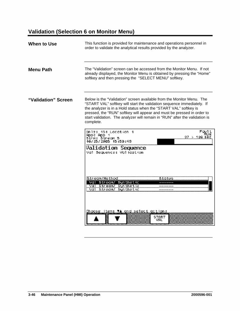
3-46 Maintenance Panel (HMI) Operation 2000596-001
Validation (Selection 6 on Monitor Menu)
This function is provided for maintenance and operations personnel in order to validate the analytical results provided by the analyzer.
The “Validation” screen can be accessed from the Monitor Menu. If not already displayed, the Monitor Menu is obtained by pressing the “Home” softkey and then pressing the “SELECT MENU” softkey.
Below is the “Validation” screen available from the Monitor Menu. The “START VAL” softkey will start the validation sequence immediately. If the analyzer is in a Hold status when the “START VAL” softkey is pressed, the “RUN” softkey will appear and must be pressed in order to start validation. The analyzer will remain in “RUN” after the validation is complete.
When to Use
Menu Path
“Validation” Screen
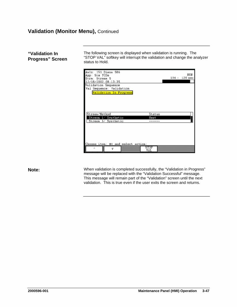
2000596-001 Maintenance Panel (HMI) Operation 3-47
Validation (Monitor Menu), Continued
The following screen is displayed when validation is running. The “STOP VAL” softkey will interrupt the validation and change the analyzer status to Hold.
When validation is completed successfully, the “Validation in Progress” message will be replaced with the “Validation Successful” message. This message will remain part of the “Validation” screen until the next validation. This is true even if the user exits the screen and returns.
“Validation In Progress” Screen
Note:
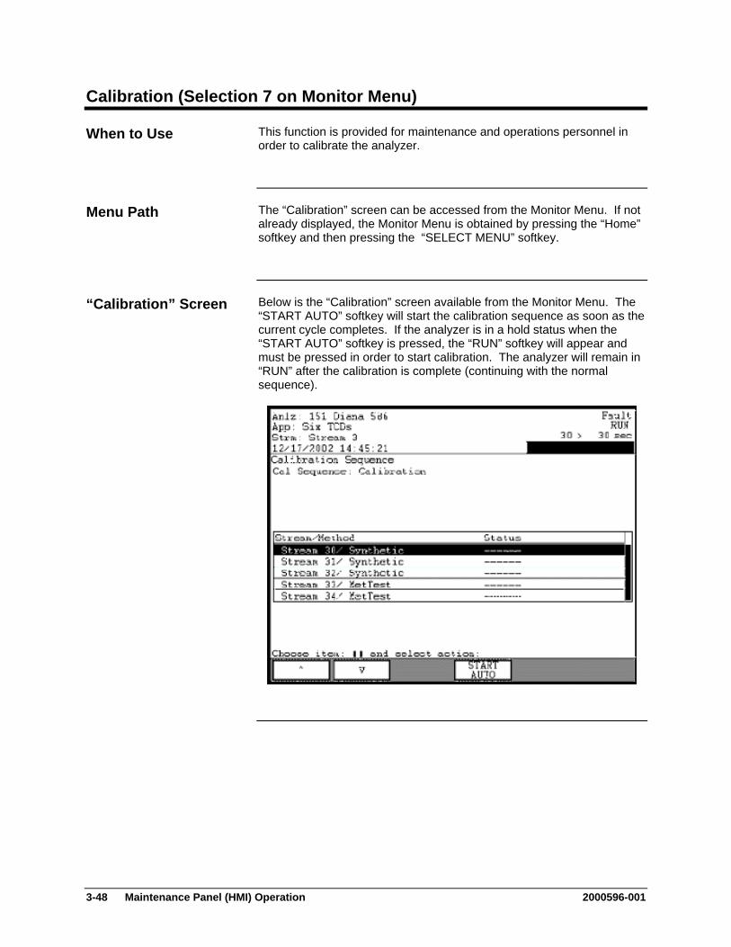
3-48 Maintenance Panel (HMI) Operation 2000596-001
Calibration (Selection 7 on Monitor Menu)
This function is provided for maintenance and operations personnel in order to calibrate the analyzer.
The “Calibration” screen can be accessed from the Monitor Menu. If not already displayed, the Monitor Menu is obtained by pressing the “Home” softkey and then pressing the “SELECT MENU” softkey.
Below is the “Calibration” screen available from the Monitor Menu. The “START AUTO” softkey will start the calibration sequence as soon as the current cycle completes. If the analyzer is in a hold status when the “START AUTO” softkey is pressed, the “RUN” softkey will appear and must be pressed in order to start calibration. The analyzer will remain in “RUN” after the calibration is complete (continuing with the normal sequence).
When to Use
Menu Path
“Calibration” Screen

2000596-001 Maintenance Panel (HMI) Operation 3-49
Calibration (Monitor Menu), Continued
The following screen is displayed when calibration is running. The “STOP CALIB” softkey will interrupt the calibration and change the analyzer status to Hold.
When calibration is completed successfully, the “Calibration in Progress” message will be replaced with the “Calibration Successful” message. This message will remain part of the “Calibration” screen until the next calibration. This is true even if the user exits the screen and returns.
“Calibration In Progress” Screen
Note:

3-50 Maintenance Panel (HMI) Operation 2000596-001
Applications (Selection 3 on Maintenance Menu)
This function is provided for maintenance personnel in order to perform the following functions.
View basic and extended details for applications
View sequences for an application
Place an application in or out of service
Place an application in Run or Hold
Disable an application
Halt an application
The “Applications” screen can be accessed from the Maintenance Menu. If not already displayed, the Maintenance Menu is obtained by pressing the “Home” softkey and then pressing the “SELECT MENU” softkey.
Below is the main screen that is displayed when “Applications” is selected from the Maintenance Menu. A selection exists for each available application.
When to Use
Menu Path
“Applications” Main Screen
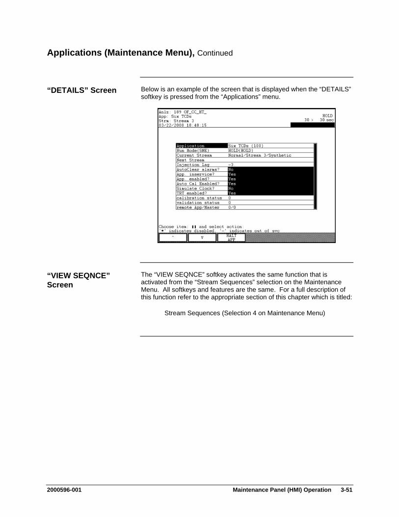
2000596-001 Maintenance Panel (HMI) Operation 3-51
Applications (Maintenance Menu), Continued
Below is an example of the screen that is displayed when the “DETAILS” softkey is pressed from the “Applications” menu.
The “VIEW SEQNCE” softkey activates the same function that is activated from the “Stream Sequences” selection on the Maintenance Menu. All softkeys and features are the same. For a full description of this function refer to the appropriate section of this chapter which is titled:
Stream Sequences (Selection 4 on Maintenance Menu)
“DETAILS” Screen
“VIEW SEQNCE” Screen
3-52 Maintenance Panel (HMI) Operation 2000596-001
Applications (Maintenance Menu), Continued
At the top of the “Applications” screen is the temperature/pressure information bar. This bar shows a simple view of current temperature and pressure for the selected application. To scroll the bar to the left and right, use the numeric keypad keys 8 and 9.
The middle section of the screen is the table of applications. Included on this table for each application is the application name, the Status/Run mode, the current and next stream, and the cycle clock.
The run mode is indicated by letters (“R” for run and “H” for hold). The state “H(H)” indicates that the application is in “Hold”. The display “R(R)” indicates that the application is in run. The display “H(R)” indicates that the application has been placed in hold but that a cycle is completing. An exclamation point next to the mode indicates that there is an active fault alarm associated with the application. A question mark next to the mode indicates that there is an active warning alarm associated with the application.
At the bottom of the content area is the valve information bar. This bar shows a simple view of DOs defined for the selected application. Scrolling of the valve bar to the left and right, if possible, is accomplished using the period ( . ) and dash ( - ) numeric keypad keys. To toggle the value of the DO, use keypad numeric keypad keys which match the `numbers appearing next to the DO in the bar.
The “DETAILS” screen contains detailed data for the results. Parameter names are on the left and values are on the right. Parameters that have values with black backgrounds may be modified using the “MODIFY” softkey. For the “Applications” screen, all details that can be changed are “Yes/No”
Interpreting the Displays

2000596-001 Maintenance Panel (HMI) Operation 3-53
Applications (Maintenance Menu), Continued
The following softkeys are available from the “Applications” screen and the applicable sub-screens. Note that the “Back” softkey may be used at any time to navigate to a previous menu.
Softkey Use
“IN SERVICE” & OUT SERVICE”
This softkey places the selected application either in service or out of service. An application that is out of service will not move or transmit results, but will continue to cycle.
“RUN” & “HOLD” This softkey allows the user to place the currently selected application into either a run or hold mode.
“VIEW SEQNCE”
This softkey activates the “Stream Sequence” screen. This is the same screen which can be accessed by selecting the “Stream Sequence” selection from the Maintenance Menu (selection 4).
“DETAILS” This softkey displays a detailed information screen for a selected application. Details which have their values shown against a black background may be modified using the “MODIFY” softkey.
“HALT APP” This softkey halts the selected application. Halting an application will cause immediate cessation of the cycle and will place the application into a hold mode. In addition, a fault alarm is generated which invalidates the results for the current cycle.
“MODIFY” This softkey, when displayed, allows the user to change certain details or values on the results table. For the “Applications” screen, all details which can be changed are “Yes/No”. The “MODIFY” softkey toggles between the “Yes” and “No” values.
An application may be enabled or disabled by selecting the “Details” screen and modifying the “App. enabled?” parameter. A disabled application cannot be put in the run mode.
Softkey Descriptions
Note:
3-54 Maintenance Panel (HMI) Operation 2000596-001
Method, Calibration & Validation (Selection 7 on Maintenance Menu)
The “Method, Calibration & Validation” function provides a menu of functions related to the selected method. The following functions are listed on the menu.
Calibration and Validation
View and Manage Results and Chromatograms
Adjust Peaks, Blends, and Factors
Adjust Flows (Pressure Program)
Adjust Integration Events
Adjust the Temperature Program
Adjust the Channel and Cycle
View the Event Summary
Each of the selections on the “Method, Calibration & Validation” menu opens a different sub-screen. For the purposes of this manual, descriptions for each of the sub-screens are contained in separate sections within this chapter.
The “Method, Calibration & Validation” screen can be accessed from the Maintenance Menu. If not already displayed, the Maintenance Menu is obtained by pressing the “Home” softkey and then pressing the “SELECT MENU” softkey.
Description
Note:
Menu Path
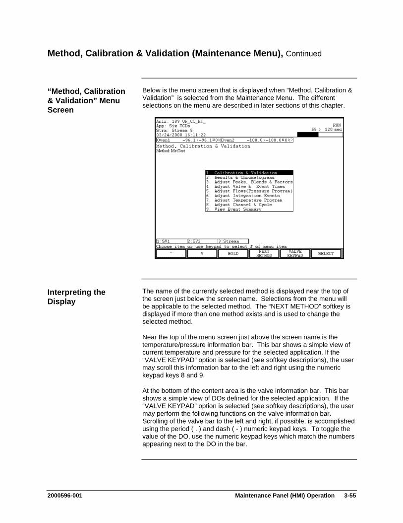
2000596-001 Maintenance Panel (HMI) Operation 3-55
Method, Calibration & Validation (Maintenance Menu), Continued
Below is the menu screen that is displayed when “Method, Calibration & Validation” is selected from the Maintenance Menu. The different selections on the menu are described in later sections of this chapter.
The name of the currently selected method is displayed near the top of the screen just below the screen name. Selections from the menu will be applicable to the selected method. The “NEXT METHOD” softkey is displayed if more than one method exists and is used to change the selected method.
Near the top of the menu screen just above the screen name is the temperature/pressure information bar. This bar shows a simple view of current temperature and pressure for the selected application. If the “VALVE KEYPAD” option is selected (see softkey descriptions), the user may scroll this information bar to the left and right using the numeric keypad keys 8 and 9.
At the bottom of the content area is the valve information bar. This bar shows a simple view of DOs defined for the selected application. If the “VALVE KEYPAD” option is selected (see softkey descriptions), the user may perform the following functions on the valve information bar. Scrolling of the valve bar to the left and right, if possible, is accomplished using the period ( . ) and dash ( - ) numeric keypad keys. To toggle the value of the DO, use the numeric keypad keys which match the numbers appearing next to the DO in the bar.
“Method, Calibration & Validation” Menu Screen
Interpreting the Display
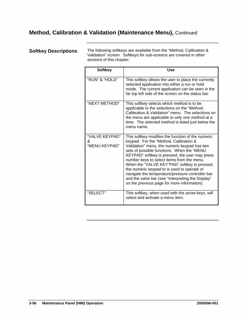
3-56 Maintenance Panel (HMI) Operation 2000596-001
Method, Calibration & Validation (Maintenance Menu), Continued
The following softkeys are available from the “Method, Calibration & Validation” screen. Softkeys for sub-screens are covered in other sections of this chapter.
Softkey Use
“RUN” & “HOLD” This softkey allows the user to place the currently selected application into either a run or hold mode. The current application can be seen in the far top left side of the screen on the status bar.
“NEXT METHOD” This softkey selects which method is to be applicable to the selections on the “Method, Calibration & Validation” menu. The selections on the menu are applicable to only one method at a time. The selected method is listed just below the menu name.
“VALVE KEYPAD” & “MENU KEYPAD”
This softkey modifies the function of the numeric keypad. For the “Method, Calibration & Validation” menu, the numeric keypad has two sets of possible functions. When the “MENU KEYPAD” softkey is pressed, the user may press number keys to select items from the menu. When the “VALVE KEY”PAD” softkey is pressed, the numeric keypad to is used to operate or navigate the temperature/pressure controller bar and the valve bar (see “Interpreting the Display” on the previous page for more information).
“SELECT” This softkey, when used with the arrow keys, will select and activate a menu item.
Softkey Descriptions

2000596-001 Maintenance Panel (HMI) Operation 3-57
Calibration & Validation (on Method, Calibration & Validation Menu)
“Calibration & Validation” which is selection 1 on the “Method, Calibration & Validation” menu is designed to allow maintenance personnel to perform the following functions.
Perform Manual or Automatic Calibration
Start a Validation Sequence
View Validation Results
View and/or Modify Calibration Response Factors, Times, and Blends
The functions of the “Calibration & Validation” screen are similar to the functions for the “Validation” and “Calibration” screens that are accessible from the Monitor Menu. However, there are a few additional features available on the “Calibration and Validation” screen that is available through the Maintenance Menu.
The “Calibration & Validation” screen may be accessed from the “Method, Calibration & Validation” menu. The “Method, Calibration & Validation” menu is accessed from the Maintenance Menu. If not already displayed, the Maintenance Menu is obtained by pressing the “Home” softkey and then pressing the “SELECT MENU” softkey.
The type and name of the stream sequence is displayed just below the name of the screen. The type is either calibration or validation. The normal stream sequence does not display from this screen.
The user can toggle from the calibration sequence to the validation sequence using the “NEXT SEQNCE” softkey.
Description
Note:
Menu Path
Interpreting the Display
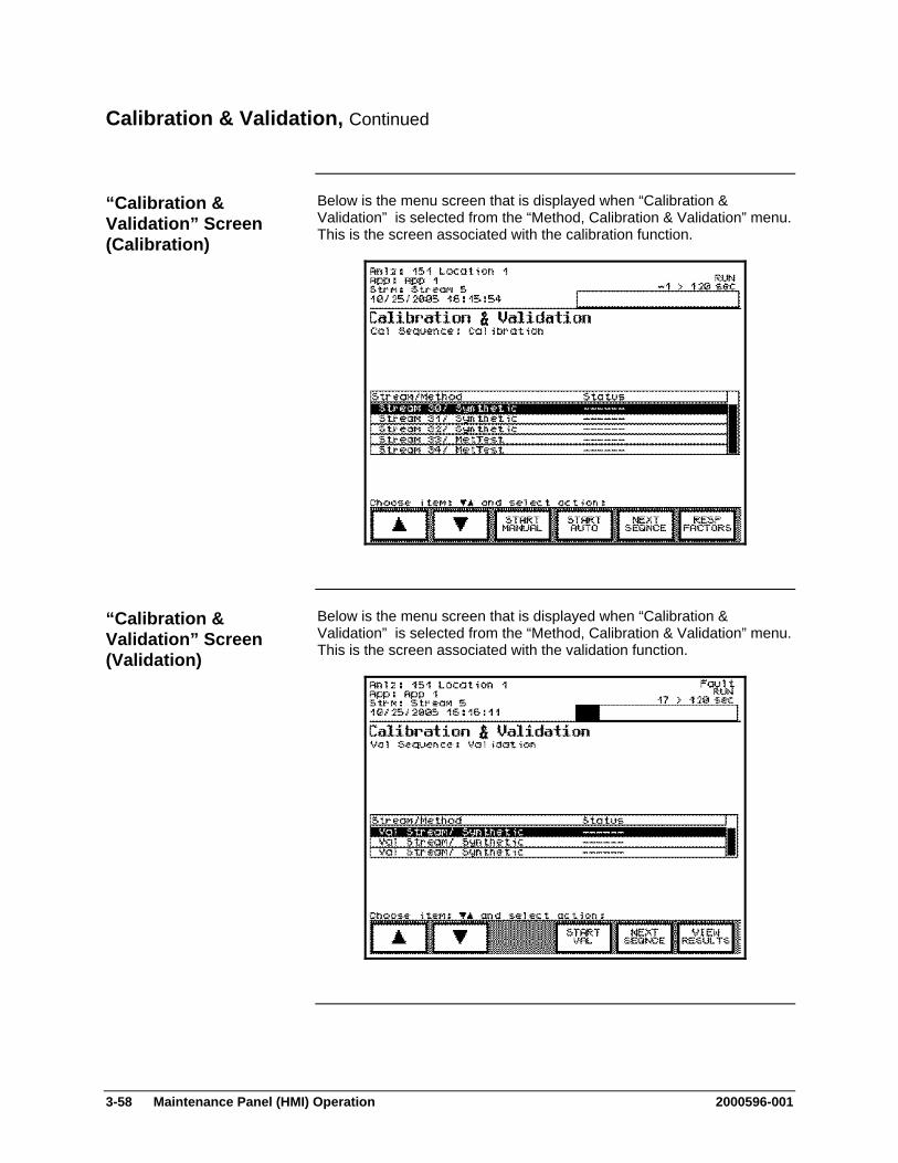
3-58 Maintenance Panel (HMI) Operation 2000596-001
Calibration & Validation, Continued
Below is the menu screen that is displayed when “Calibration & Validation” is selected from the “Method, Calibration & Validation” menu. This is the screen associated with the calibration function.
Below is the menu screen that is displayed when “Calibration & Validation” is selected from the “Method, Calibration & Validation” menu. This is the screen associated with the validation function.
“Calibration & Validation” Screen (Calibration)
“Calibration & Validation” Screen (Validation)
2000596-001 Maintenance Panel (HMI) Operation 3-59
Calibration & Validation, Continued
Calibration is used within the analyzer to establish and adjust the relationships between peak sizes and sample content. Two types of calibration are available in the Maxum II, manual calibration and autocalibration.
When the “Calibration & Validation” option is selected from the “Method, Calibration & Validation” menu, the initial screen is the screen for the calibration sequence. It is possible to navigate back and forth between the validation sequence and the calibration sequence using the “NEXT SEQNCE” softkey.
From the calibration screen and sub-screens, it is possible to start and stop manual calibration or autocalibration. It is also possible to manually change peak settings for response factors, times, and blends.
Autocalibration operates as follows: When the “START AUTO” softkey is pressed, the entire
calibration sequence displayed will be run (except for disabled streams)
After automatic calibration is finished the analyzer will revert back to the original sequence.
If calibration margins have been entered (refer to the “Blends” screen”) and if the measured values are within the margins then the calibration will be accepted and the response factors will be automatically adjusted.
Pressing the “STOP CALIB” softkey during autocalibration will immediately interrupt the calibration sequence.
Manual calibration operates as follows: The user selects a specific calibration stream from the table. The “START MANUAL” softkey is pressed. At this point, the
analyzer will be automatically placed in hold and the selected stream will automatically be set to always run.
The “RUN” button must be pressed to start calibration. At this point the stream will begin to run continuously until it is manually stopped.
If the “HOLD” softkey is pressed, the calibration will remain active but will be put in a hold status. At this point the user may view the response factors using the “RESP FACTORS” softkey and accept the response factors, if they are satisfactory.
If the “STOP CALIB” softkey is pressed, the calibration will stop and the active sequence will be set back to the normal process sequence.
Calibration Function
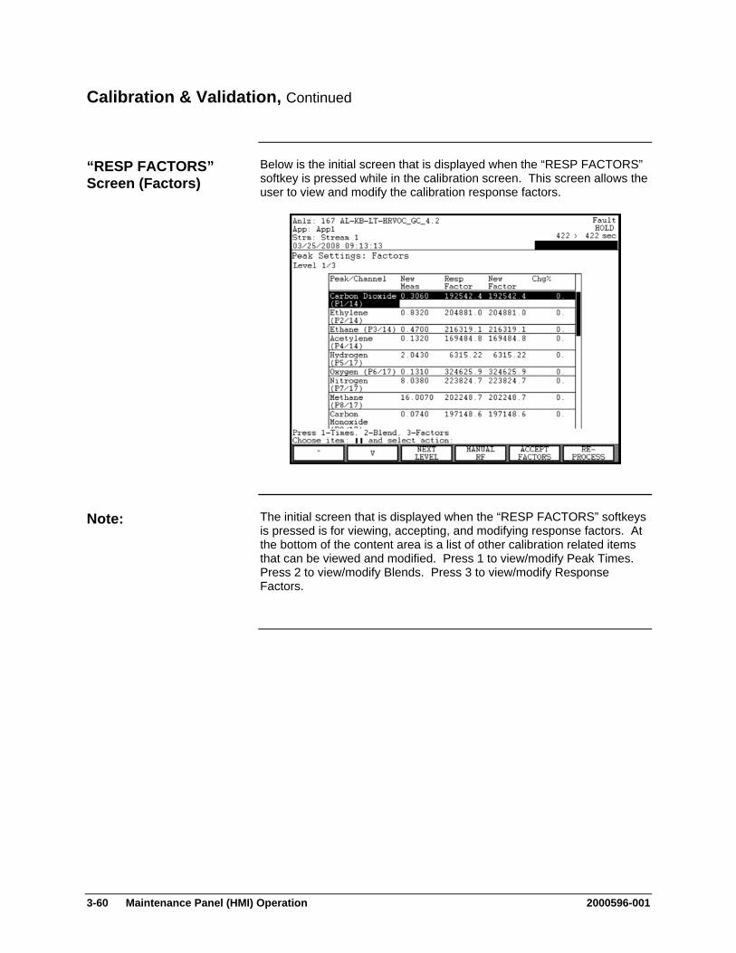
3-60 Maintenance Panel (HMI) Operation 2000596-001
Calibration & Validation, Continued
Below is the initial screen that is displayed when the “RESP FACTORS” softkey is pressed while in the calibration screen. This screen allows the user to view and modify the calibration response factors.
The initial screen that is displayed when the “RESP FACTORS” softkeys is pressed is for viewing, accepting, and modifying response factors. At the bottom of the content area is a list of other calibration related items that can be viewed and modified. Press 1 to view/modify Peak Times. Press 2 to view/modify Blends. Press 3 to view/modify Response Factors.
“RESP FACTORS” Screen (Factors)
Note:

2000596-001 Maintenance Panel (HMI) Operation 3-61
Calibration & Validation, Continued
Below is the screen that is displayed when keypad number 2 (“Blend”) is pressed from the “RESP FACTORS” screen. This screen allows the user to change the known concentration (“Blend”). From this screen the user is also able to change the acceptable margin for autocalibration.
Below is the screen that is displayed when keypad number 1 (“Times”) is pressed from the “RESP FACTORS” screen. This screen allows the user to modify the expected peak retention times. From this screen the user is also able to accept the new peak times.
“RESP FACTORS” Screen (Blends)
“RESP FACTORS” Screen (Times)

3-62 Maintenance Panel (HMI) Operation 2000596-001
Calibration & Validation, Continued
The following softkeys are available from the “Calibration & Validation” screen under the “Method, Calibration & Validation” menu. The following softkeys are for the calibration portion of the menu function. The softkeys for the validation portion are defined later.
Softkey Use
“START MANUAL” This softkey starts the manual calibration function as defined earlier in this section.
“RUN/HOLD” This softkey toggles the analyzer between the Run and Hold statuses.
“START AUTO” This softkey starts the autocalibration sequence as defined earlier in this section.
“STOP CALIB” This softkey stops a currently running calibration sequence and places the analyzer in the Hold status.
“NEXT SEQNCE” This softkey is used to switch from the calibration sequence to the validation sequence. The validation sequence is described later in this section.
“RESP FACTORS” This softkey allows the user to modify peak data for the calibration. The initial screen is for viewing, accepting, or modifying response factors. The numerical keypad can be used for activating screens to view, modify, or accept changes to other data. Numerical keys are assigned as follows:
1. Peak Times 2. Blend and Margin 3. Response Factors (default screen)
“MANUAL RF” This softkey allows the user to define a manual response factor. The manual response factor overrides the calculated response factor. When a manual response factor is entered, it will be preceded by an asterisk(*) in the table. To remove a manual response factor, press the “MANUAL RF” button again and then press “REMOVE”.
Softkey Descriptions for Calibration

2000596-001 Maintenance Panel (HMI) Operation 3-63
Calibration & Validation, Continued
Softkey Use
“BACK SPACE” This softkey, when available, allows the user to back space while entering data in a field.
“ACCEPT CHANGE”
This softkey, when available, is used to confirm the values entered in the data fields. When it is pressed the data entry fields disappear and the data is stored.
“CANCEL CHANGE”
This softkey, when available, is used to cancel a change. When it is pressed the data entry fields disappear and any modified entries remain at their original value.
“REMOVE” This softkey removes a changed parameter (such as a manual response factor or blend) after the data has been changed. The value reverts back to the original value.
“ACCEPT FACTORS”
This softkey accepts the new response factors from the table of response factors. Usually this step is done during manual calibration.
“RE-PROCESS” If there is a reprocess step configured in the sequence, this softkey will cause the last chromatogram to be reprocessed. Changes made to the peak setup will be applied to the reprocess.
“CHANGE MARGIN”
This softkey is used to change the margin that is used during autocalibration. If the values measured during autocalibration are within the expected margin, then the measured values are automatically accepted and the response factors are adjusted.
“CHANGE BLEND”
This softkey is used to change the blend locally in a temporary location. This new blend will be used in autocalibration, but does not become permanent until new response factors are accepted. To revert to the previous blend value press the “CHANGE BLEND” softkey again and then press the “REMOVE” softkey.
Softkey Descriptions for Calibration (continued)
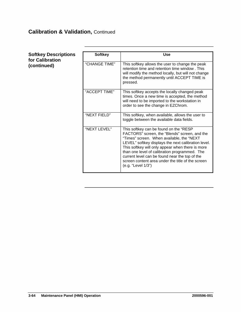
3-64 Maintenance Panel (HMI) Operation 2000596-001
Calibration & Validation, Continued
Softkey Use
“CHANGE TIME” This softkey allows the user to change the peak retention time and retention time window . This will modify the method locally, but will not change the method permanently until ACCEPT TIME is pressed.
“ACCEPT TIME” This softkey accepts the locally changed peak times. Once a new time is accepted, the method will need to be imported to the workstation in order to see the change in EZChrom.
“NEXT FIELD” This softkey, when available, allows the user to toggle between the available data fields.
“NEXT LEVEL” This softkey can be found on the “RESP FACTORS” screen, the “Blends” screen, and the “Times” screen. When available, the “NEXT LEVEL” softkey displays the next calibration level. This softkey will only appear when there is more than one level of calibration programmed. The current level can be found near the top of the screen content area under the title of the screen (e.g. “Level 1/3”)
Softkey Descriptions for Calibration (continued)
2000596-001 Maintenance Panel (HMI) Operation 3-65
Calibration & Validation, Continued
Validation is used to verify the ability of the analyzer to produce acceptable measurements. When validation is run, a known sample is analyzed and the results are compared against expected values. Results fail validation if they deviate by more than an acceptable margin. When validation fails the analyzer generates a failure message.
When the “Calibration & Validation” option is selected from the “Method, Calibration & Validation” menu, the initial screen is the screen for the calibration sequence. It is possible to navigate to the validation sequence using the “NEXT SEQNCE” softkey.
From the validation screen and sub-screens, it is possible to run validation, view validation results, and modify expected blend values and acceptable margins.
When “Calibration & Validation” is selected from the “Method, Calibration & Validation” menu, the “NEXT SEQNCE” softkey is used to navigate between available validation and calibration sequences.
The validation results are displayed when the “VIEW RESULTS” softkey is pressed. The display contains information on the peak name, the expected value (“Blend Value”), the value measured during the last validation (“Meas Value”). Also included is information on the percent difference between the expected and measured values (“Change %”) and whether the value is within the expected range (“State”).
The expected validation settings are displayed when the “VIEW CONFIG” softkey is pressed. This display contains the peak name, the expected blend value and the acceptable deviation margin.
Validation Function
Interpreting the Displays

3-66 Maintenance Panel (HMI) Operation 2000596-001
Calibration & Validation, Continued
Below is the screen that is displayed when the “VIEW RESULTS” softkey is pressed. This screen contains the expected and measured validation results along with the PASS/FAIL indication.
Below is the screen that is displayed when the “VIEW CONFIG” softkey is pressed. It is possible to view and modify expected blend values as well as the acceptable deviation margin.
Validation “VIEW RESULTS” Screen
Validation “VIEW CONFIG” Screen
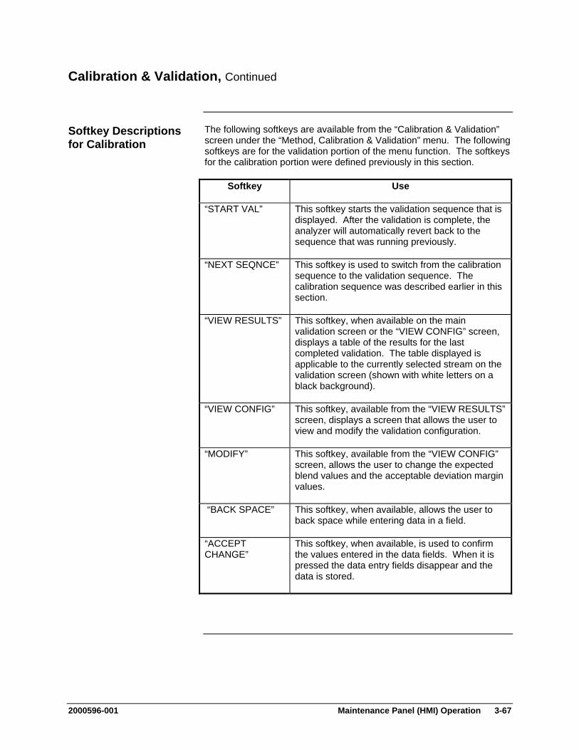
2000596-001 Maintenance Panel (HMI) Operation 3-67
Calibration & Validation, Continued
The following softkeys are available from the “Calibration & Validation” screen under the “Method, Calibration & Validation” menu. The following softkeys are for the validation portion of the menu function. The softkeys for the calibration portion were defined previously in this section.
Softkey Use
“START VAL” This softkey starts the validation sequence that is displayed. After the validation is complete, the analyzer will automatically revert back to the sequence that was running previously.
“NEXT SEQNCE” This softkey is used to switch from the calibration sequence to the validation sequence. The calibration sequence was described earlier in this section.
“VIEW RESULTS” This softkey, when available on the main validation screen or the “VIEW CONFIG” screen, displays a table of the results for the last completed validation. The table displayed is applicable to the currently selected stream on the validation screen (shown with white letters on a black background).
“VIEW CONFIG” This softkey, available from the “VIEW RESULTS” screen, displays a screen that allows the user to view and modify the validation configuration.
“MODIFY” This softkey, available from the “VIEW CONFIG” screen, allows the user to change the expected blend values and the acceptable deviation margin values.
“BACK SPACE” This softkey, when available, allows the user to back space while entering data in a field.
“ACCEPT CHANGE”
This softkey, when available, is used to confirm the values entered in the data fields. When it is pressed the data entry fields disappear and the data is stored.
Softkey Descriptions for Calibration
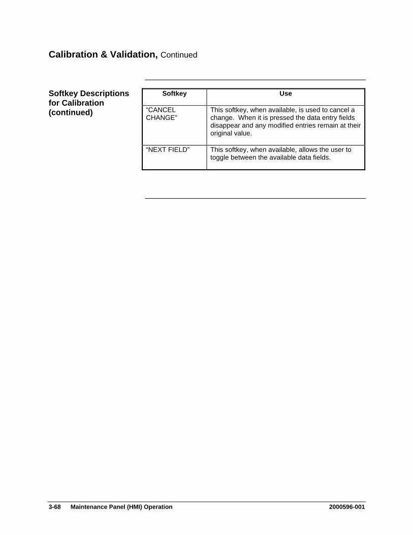
3-68 Maintenance Panel (HMI) Operation 2000596-001
Calibration & Validation, Continued
Softkey Use
“CANCEL CHANGE”
This softkey, when available, is used to cancel a change. When it is pressed the data entry fields disappear and any modified entries remain at their original value.
“NEXT FIELD” This softkey, when available, allows the user to toggle between the available data fields.
Softkey Descriptions for Calibration (continued)
2000596-001 Maintenance Panel (HMI) Operation 3-69
Results & Chromatograms (on Method, Calibration & Validation Menu)
“Results & Chromatograms” which is selection 2 on the “Method, Calibration & Validation” menu is designed to allow maintenance personnel to perform the following functions.
View the latest qualified or preliminary analytical results.
View archived chromatograms and their associated results.
Add chromatograms and their associated results to the archives.
The “Results & Chromatograms” screen may be accessed from the “Method, Calibration & Validation” menu. The “Method, Calibration & Validation” menu is accessed from the Maintenance Menu. If not already displayed, the Maintenance Menu is obtained by pressing the “Home” softkey and then pressing the “SELECT MENU” softkey.
The “Results & Chromatograms” screen available from the “Method, Calibration & Validation” menu is the same screen that can be accessed as option 6 from the main Maintenance Menu. Refer to the previous section, “Results & Chromatograms (Selection 6 on Maintenance Menu)”, for a full description of this screen and all associated sub-screens.
Description
Menu Path
Note:
3-70 Maintenance Panel (HMI) Operation 2000596-001
Adjust Peaks, Blends, & Factors (on Method, Calibration & Validation Menu)
“Adjust Peaks, Blends, & Factors” which is selection 3 on the “Method, Calibration & Validation” menu is designed to allow maintenance personnel to perform the following functions related to calibration.
View and adjust peak expected retention times and retention time windows
View and adjust autocalibration margins and known calibration blends
View and adjust the calibration response factors
The “Adjust Peaks, Blends, & Factors” screen may be accessed from the “Method, Calibration & Validation” menu. The “Method, Calibration & Validation” menu is accessed from the Maintenance Menu. If not already displayed, the Maintenance Menu is obtained by pressing the “Home” softkey and then pressing the “SELECT MENU” softkey.
The “Adjust Peaks, Blends, & Factors” screens available from the “Method, Calibration & Validation” menu are the same screens that can be accessed from the “Calibration & Validation” selection of the same menu. These screens are described in detail previously in this chapter.
For a full description of the “Peaks, Blends, & Factors” screens, refer to the section titled:
“Calibration & Validation (on Method, Calibration & Validation Menu)”
Description
Menu Path
Note:
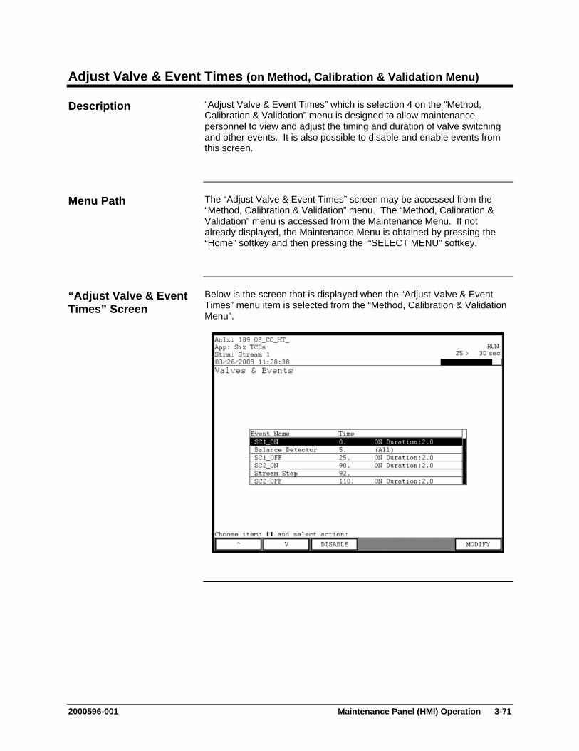
2000596-001 Maintenance Panel (HMI) Operation 3-71
Adjust Valve & Event Times (on Method, Calibration & Validation Menu)
“Adjust Valve & Event Times” which is selection 4 on the “Method, Calibration & Validation” menu is designed to allow maintenance personnel to view and adjust the timing and duration of valve switching and other events. It is also possible to disable and enable events from this screen.
The “Adjust Valve & Event Times” screen may be accessed from the “Method, Calibration & Validation” menu. The “Method, Calibration & Validation” menu is accessed from the Maintenance Menu. If not already displayed, the Maintenance Menu is obtained by pressing the “Home” softkey and then pressing the “SELECT MENU” softkey.
Below is the screen that is displayed when the “Adjust Valve & Event Times” menu item is selected from the “Method, Calibration & Validation Menu”.
Description
Menu Path
“Adjust Valve & Event Times” Screen
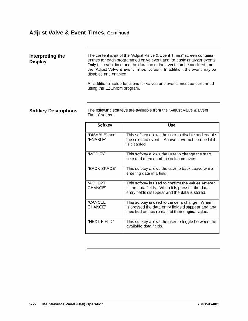
3-72 Maintenance Panel (HMI) Operation 2000596-001
Adjust Valve & Event Times, Continued
The content area of the “Adjust Valve & Event Times” screen contains entries for each programmed valve event and for basic analyzer events. Only the event time and the duration of the event can be modified from the “Adjust Valve & Event Times” screen. In addition, the event may be disabled and enabled.
All additional setup functions for valves and events must be performed using the EZChrom program.
The following softkeys are available from the “Adjust Valve & Event Times” screen.
Softkey Use
“DISABLE” and “ENABLE”
This softkey allows the user to disable and enable the selected event. An event will not be used if it is disabled.
“MODIFY” This softkey allows the user to change the start time and duration of the selected event.
“BACK SPACE” This softkey allows the user to back space while entering data in a field.
“ACCEPT CHANGE”
This softkey is used to confirm the values entered in the data fields. When it is pressed the data entry fields disappear and the data is stored.
“CANCEL CHANGE”
This softkey is used to cancel a change. When it is pressed the data entry fields disappear and any modified entries remain at their original value.
“NEXT FIELD” This softkey allows the user to toggle between the available data fields.
Interpreting the Display
Softkey Descriptions
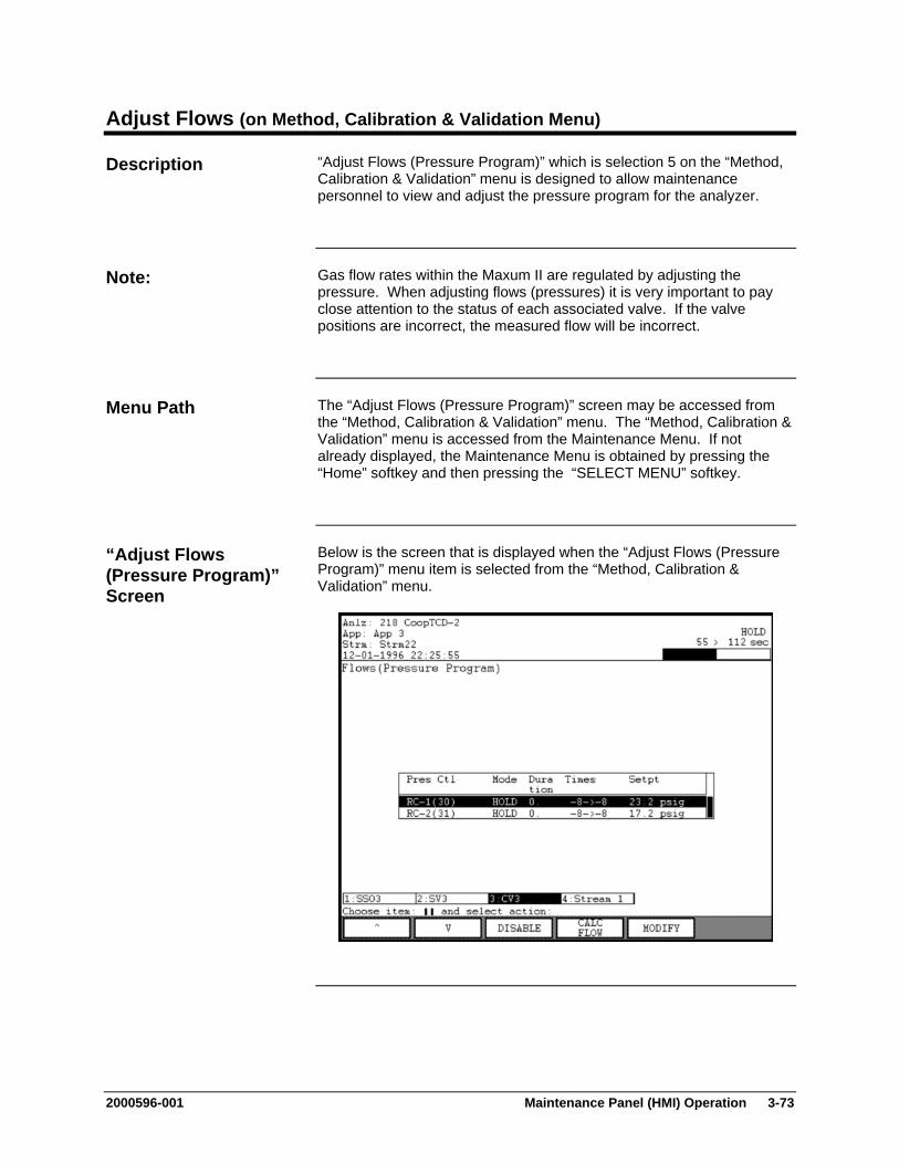
2000596-001 Maintenance Panel (HMI) Operation 3-73
Adjust Flows (on Method, Calibration & Validation Menu)
“Adjust Flows (Pressure Program)” which is selection 5 on the “Method, Calibration & Validation” menu is designed to allow maintenance personnel to view and adjust the pressure program for the analyzer.
Gas flow rates within the Maxum II are regulated by adjusting the pressure. When adjusting flows (pressures) it is very important to pay close attention to the status of each associated valve. If the valve positions are incorrect, the measured flow will be incorrect.
The “Adjust Flows (Pressure Program)” screen may be accessed from the “Method, Calibration & Validation” menu. The “Method, Calibration & Validation” menu is accessed from the Maintenance Menu. If not already displayed, the Maintenance Menu is obtained by pressing the “Home” softkey and then pressing the “SELECT MENU” softkey.
Below is the screen that is displayed when the “Adjust Flows (Pressure Program)” menu item is selected from the “Method, Calibration & Validation” menu.
Description
Note:
Menu Path
“Adjust Flows (Pressure Program)” Screen
3-74 Maintenance Panel (HMI) Operation 2000596-001
Adjust Flows, Continued
The content area of the “Adjust Flows (Pressure Program)” screen contains information concerning the current pressure program. Included are the pressure controller name, the operating mode, the duration of the pressure setting, the calculated time of the pressure setting in seconds, and the pressure set point.
At the bottom of the content area is the valve information bar. This bar gives a basic indication of the status of each valve. When a valve is operated, the background on the valve bar for that valve toggles between white and black. Valves can be operated using the HMI. To operate a valve, use the numeric keypad key that matches the number next to the valve name. Scrolling of the valve bar to the left and right, if possible, is accomplished using the period ( . ) and dash ( - ) numeric keypad keys.
The “CALC FLOW” feature is used to fine-tune the pressure program. The analyzer can be used to determine the proper pressure set point needed to achieve a desired flow rate. The following steps describe how to use the “CALC FLOW” feature.
1. Verify that all valves are in the desired state
2. Measure the flow rate manually.
3. From the “Adjust Flows” screen: Verify that the correct line of the pressure program is selected and press the “CALC FLOW” softkey.
4. In the first field enter the flow rate that was measured
5. Press the “NEXT FIELD” softkey and enter the desired flow rate in the second field
6. The “CALC FLOW” softkey now appears again. Press it to have the analyzer calculate the pressure necessary to achieve the desired flow.
7. Press “ACCEPT CHANGE” to accept the recommended pressure setting (“CANCEL CHANGE” to reject).
8. Re-measure the flow rate manually. If the flow rate is not correct perform the “CALC FLOW” process again.
It may take two or more tries to fine-tune the pressure to achieve the desired flow rate.
Interpreting the Display
Calculating a Pressure Set Point Using “CALC FLOW”
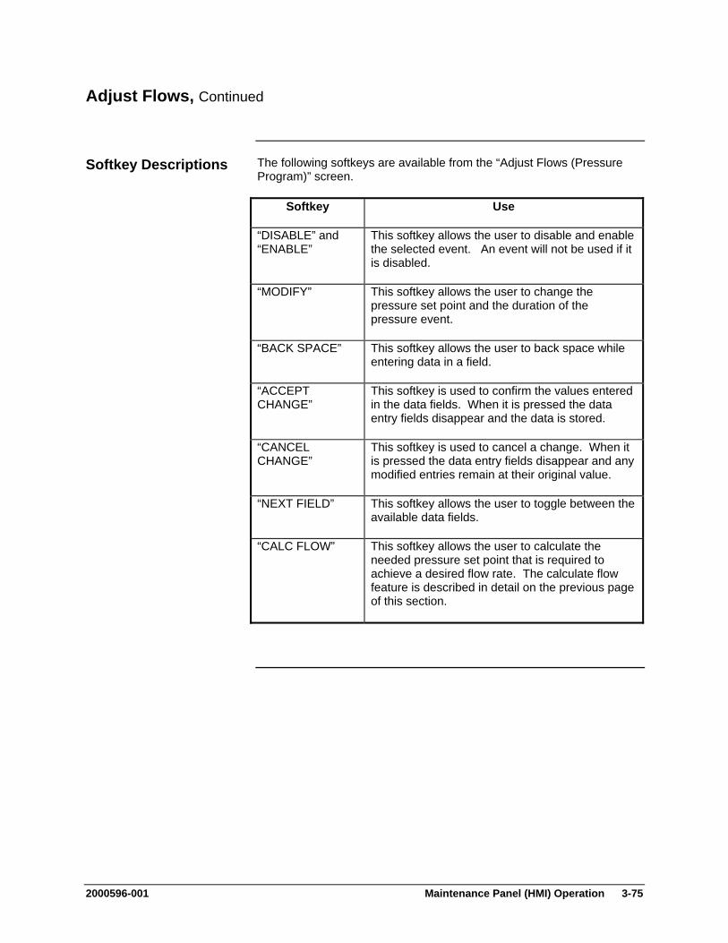
2000596-001 Maintenance Panel (HMI) Operation 3-75
Adjust Flows, Continued
The following softkeys are available from the “Adjust Flows (Pressure Program)” screen.
Softkey Use
“DISABLE” and “ENABLE”
This softkey allows the user to disable and enable the selected event. An event will not be used if it is disabled.
“MODIFY” This softkey allows the user to change the pressure set point and the duration of the pressure event.
“BACK SPACE” This softkey allows the user to back space while entering data in a field.
“ACCEPT CHANGE”
This softkey is used to confirm the values entered in the data fields. When it is pressed the data entry fields disappear and the data is stored.
“CANCEL CHANGE”
This softkey is used to cancel a change. When it is pressed the data entry fields disappear and any modified entries remain at their original value.
“NEXT FIELD” This softkey allows the user to toggle between the available data fields.
“CALC FLOW” This softkey allows the user to calculate the needed pressure set point that is required to achieve a desired flow rate. The calculate flow feature is described in detail on the previous page of this section.
Softkey Descriptions
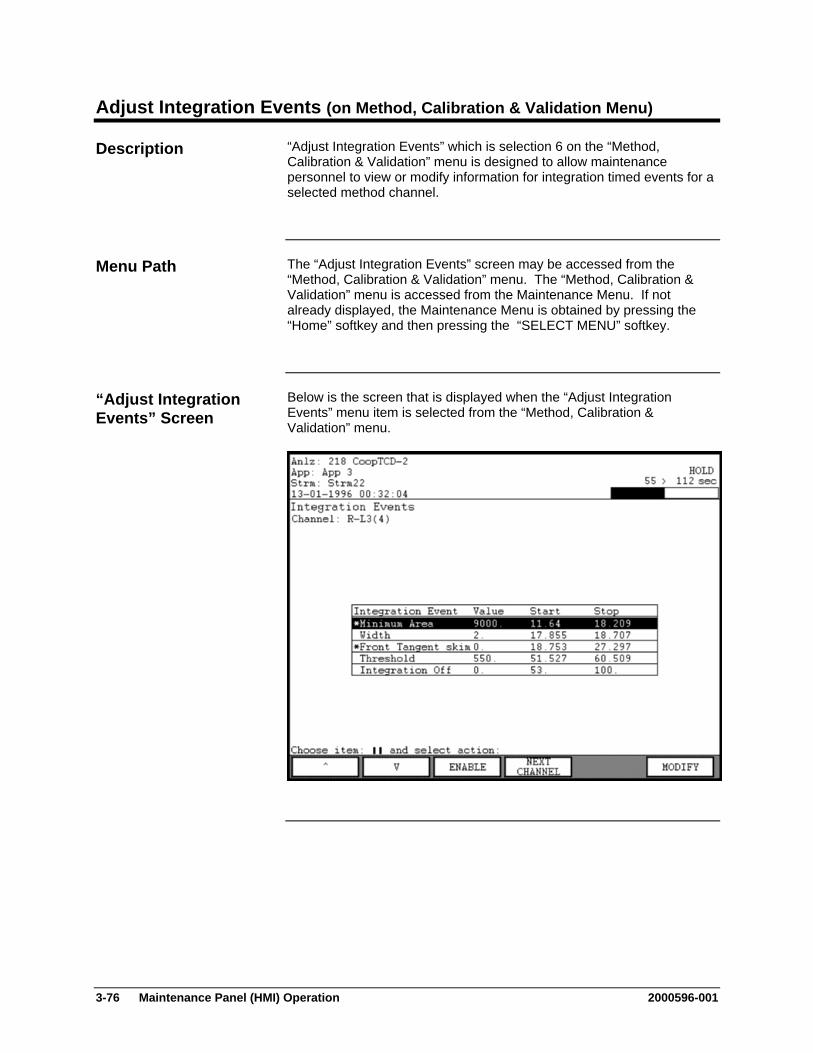
3-76 Maintenance Panel (HMI) Operation 2000596-001
Adjust Integration Events (on Method, Calibration & Validation Menu)
“Adjust Integration Events” which is selection 6 on the “Method, Calibration & Validation” menu is designed to allow maintenance personnel to view or modify information for integration timed events for a selected method channel.
The “Adjust Integration Events” screen may be accessed from the “Method, Calibration & Validation” menu. The “Method, Calibration & Validation” menu is accessed from the Maintenance Menu. If not already displayed, the Maintenance Menu is obtained by pressing the “Home” softkey and then pressing the “SELECT MENU” softkey.
Below is the screen that is displayed when the “Adjust Integration Events” menu item is selected from the “Method, Calibration & Validation” menu.
Description
Menu Path
“Adjust Integration Events” Screen
2000596-001 Maintenance Panel (HMI) Operation 3-77
Adjust Integration Events, Continued
The content area of the “Adjust Integration Events” screen contains the integration event type, integration event value, and the start and stop times of the integration event. Values and/or times which are optional for an event type are shown as zeros in the table.
The information displayed is applicable to a specific method channel. The name of the current channel is displayed at the top of the screen content area under the screen title. Use the “NEXT CHANNEL” softkey to step through the different available channels.
The following softkeys are available from the “Adjust Integration Events” screen.
Softkey Use
“DISABLE” and “ENABLE”
This softkey allows the user to disable and enable the selected integration event. An event will not be used if it is disabled.
“NEXT CHANNEL” This softkey is used to display the integration event information for the next method channel. The name of the current channel is displayed at the top of the screen content area.
“MODIFY” This softkey allows the user to change the start and stop times and the value for the selected integration event.
“BACK SPACE” This softkey allows the user to back space while entering data in a field.
“ACCEPT CHANGE”
This softkey is used to confirm the values entered in the data fields. When it is pressed the data entry fields disappear and the data is stored.
“CANCEL CHANGE”
This softkey is used to cancel a change. When it is pressed the data entry fields disappear and any modified entries remain at their original value.
“NEXT FIELD” This softkey allows the user to toggle between the available data fields.
Interpreting the Display
Softkey Descriptions
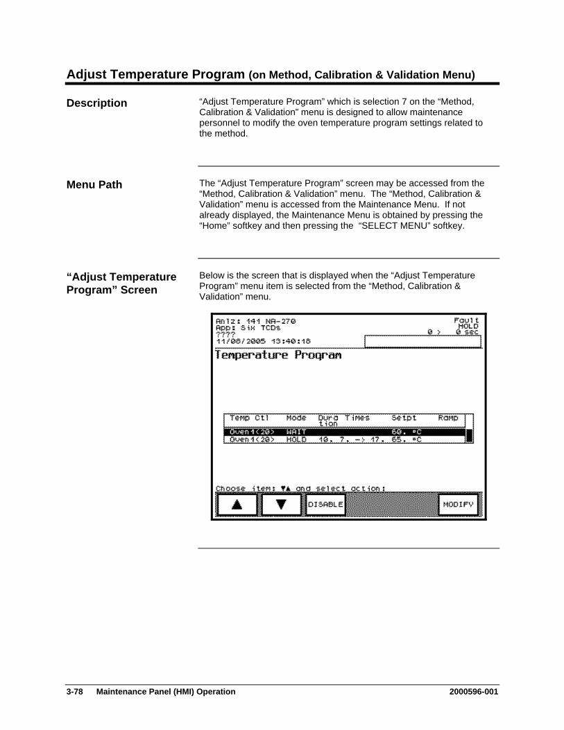
3-78 Maintenance Panel (HMI) Operation 2000596-001
Adjust Temperature Program (on Method, Calibration & Validation Menu)
“Adjust Temperature Program” which is selection 7 on the “Method, Calibration & Validation” menu is designed to allow maintenance personnel to modify the oven temperature program settings related to the method.
The “Adjust Temperature Program” screen may be accessed from the “Method, Calibration & Validation” menu. The “Method, Calibration & Validation” menu is accessed from the Maintenance Menu. If not already displayed, the Maintenance Menu is obtained by pressing the “Home” softkey and then pressing the “SELECT MENU” softkey.
Below is the screen that is displayed when the “Adjust Temperature Program” menu item is selected from the “Method, Calibration & Validation” menu.
Description
Menu Path
“Adjust Temperature Program” Screen

2000596-001 Maintenance Panel (HMI) Operation 3-79
Adjust Temperature Program, Continued
The content area of the “Adjust Temperature Program” screen shows the temperature controller name, the mode (Hold or Wait), the duration of the action, the calculated time for the action (in seconds), the temperature set point, and the temperature ramp rate (if configured).
The following softkeys are available from the “Adjust Temperature Program” screen.
Softkey Use
“DISABLE” and “ENABLE”
This softkey allows the user to disable and enable the selected temperature program event. An event will not be used if it is disabled.
“MODIFY” This softkey allows the user to change the duration, setpoint, and ramp rate of the selected temperature program event.
“BACK SPACE” This softkey allows the user to back space while entering data in a field.
“ACCEPT CHANGE”
This softkey is used to confirm the values entered in the data fields. When it is pressed the data entry fields disappear and the data is stored.
“CANCEL CHANGE”
This softkey is used to cancel a change. When it is pressed the data entry fields disappear and any modified entries remain at their original value.
“NEXT FIELD” This softkey allows the user to toggle between the available data fields.
Interpreting the Display
Softkey Descriptions

3-80 Maintenance Panel (HMI) Operation 2000596-001
Adjust Channel & Cycle (on Method, Calibration & Validation Menu)
“Adjust Channel & Cycle” which is selection 8 on the “Method, Calibration & Validation” menu is designed to allow maintenance personnel to perform the following functions.
Disable and enable detector method channels
Modify start and stop times for data acquisition for specific channels
Turn baseline correction on and off
Modify the cycle start and stop times for the method. Injection lag time can be changed as well.
The “Adjust Channel & Cycle” screen may be accessed from the “Method, Calibration & Validation” menu. The “Method, Calibration & Validation” menu is accessed from the Maintenance Menu. If not already displayed, the Maintenance Menu is obtained by pressing the “Home” softkey and then pressing the “SELECT MENU” softkey.
Below is the screen that is displayed when the “Adjust Channel & Cycle” menu item is selected from the “Method, Calibration & Validation” menu.
Description
Menu Path
“Adjust Channel & Cycle” Screen

2000596-001 Maintenance Panel (HMI) Operation 3-81
Adjust Channel & Cycle, Continued
The central section of the content area of the “Adjust Channel & Cycle” screen shows the method detector channel settings. Information displayed includes the channel number, detector channel name, start time for data acquisition, stop time for data acquisition, data sample rate, and whether the baseline is on or off.
Displayed at the top of the content area (just below the title of the screen), is the cycle start and stop time. This information can be modified using the “CHANGE CYCLE” softkey.
The following softkeys are available from the “Adjust Channel & Cycle” screen.
Softkey Use
“DISABLE” and “ENABLE”
This softkey allows the user to disable and enable the selected detector channel.
“CHANGE CHANNEL”
This softkey allows the user to change the starting and stopping times for data acquisition for a selected channel.
“BACK SPACE” This softkey allows the user to back space while entering data in a field.
“ACCEPT CHANGE”
This softkey is used to confirm the values entered in the data fields. When it is pressed the data entry fields disappear and the data is stored.
“CANCEL CHANGE”
This softkey is used to cancel a change. When it is pressed the data entry fields disappear and any modified entries remain at their original value.
“NEXT FIELD” This softkey allows the user to toggle between the available data fields.
“BASELN ON” & “BASELN OFF”
This softkey activates/deactivates the baseline correction feature.
“CHANGE CYCLE”
This softkey is used to modify the cycle time for the method. The start and stop times may be defined and can include an injection lag time (negative start time).
Interpreting the Display
Softkey Descriptions
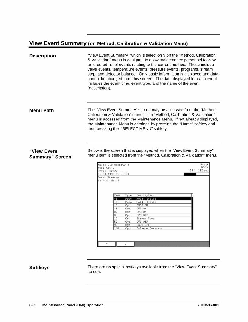
3-82 Maintenance Panel (HMI) Operation 2000596-001
View Event Summary (on Method, Calibration & Validation Menu)
“View Event Summary” which is selection 9 on the “Method, Calibration & Validation” menu is designed to allow maintenance personnel to view an ordered list of events relating to the current method. These include valve events, temperature events, pressure events, programs, stream step, and detector balance. Only basic information is displayed and data cannot be changed from this screen. The data displayed for each event includes the event time, event type, and the name of the event (description).
The “View Event Summary” screen may be accessed from the “Method, Calibration & Validation” menu. The “Method, Calibration & Validation” menu is accessed from the Maintenance Menu. If not already displayed, the Maintenance Menu is obtained by pressing the “Home” softkey and then pressing the “SELECT MENU” softkey.
Below is the screen that is displayed when the “View Event Summary” menu item is selected from the “Method, Calibration & Validation” menu.
There are no special softkeys available from the “View Event Summary” screen.
Description
Menu Path
“View Event Summary” Screen
Softkeys
2000596-001 Maintenance Panel (HMI) Operation 3-83
App I/O, Temperature & Pressure (Selection 8 on Maintenance Menu)
The “App I/O, Temperature & Pressure” function provides a menu of functions related to the selected application. Included are different types of input/output information for peripheral analyzer devices such as detectors and temperature controllers. Also included is input/output information for other external devices such as remote analyzers or other devices. The following functions are listed on the menu.
Analog Input
Analog Output
Digital Input
Digital Output
Temperature Controller
Pressure Controller
The I/O screens are used for troubleshooting, to verify that data is being sent or received, and to manually control a particular I/O.
Each of the selections on the “App I/O, Temperature & Pressure” menu opens a different sub-screen. For the purposes of this manual, descriptions for each of the sub-screens are contained in separate sections within this chapter.
The “App I/O, Temperature & Pressure” menu can be accessed from the Maintenance Menu. If not already displayed, the Maintenance Menu is obtained by pressing the “Home” softkey and then pressing the “SELECT MENU” softkey.
Description
Note:
Menu Path
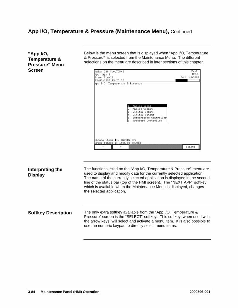
3-84 Maintenance Panel (HMI) Operation 2000596-001
App I/O, Temperature & Pressure (Maintenance Menu), Continued
Below is the menu screen that is displayed when “App I/O, Temperature & Pressure” is selected from the Maintenance Menu. The different selections on the menu are described in later sections of this chapter.
The functions listed on the “App I/O, Temperature & Pressure” menu are used to display and modify data for the currently selected application. The name of the currently selected application is displayed in the second line of the status bar (top of the HMI screen). The “NEXT APP” softkey, which is available when the Maintenance Menu is displayed, changes the selected application.
The only extra softkey available from the “App I/O, Temperature & Pressure” screen is the “SELECT” softkey. This softkey, when used with the arrow keys, will select and activate a menu item. It is also possible to use the numeric keypad to directly select menu items.
“App I/O, Temperature & Pressure” Menu Screen
Interpreting the Display
Softkey Description
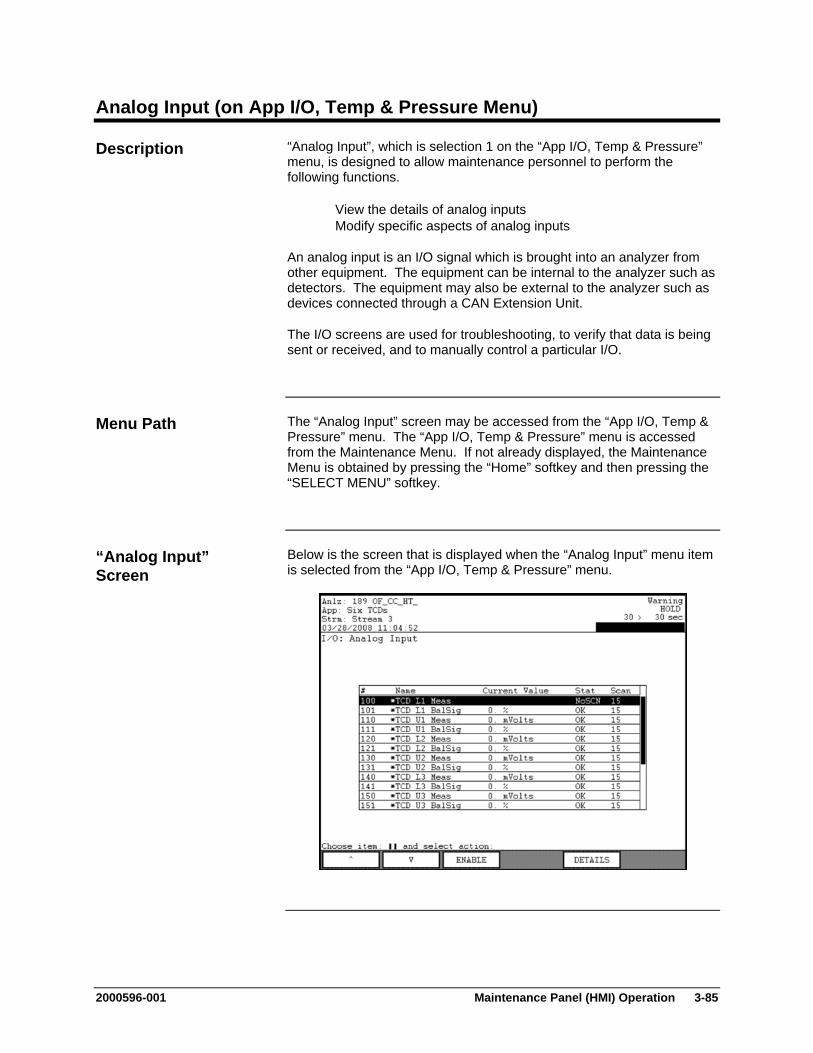
2000596-001 Maintenance Panel (HMI) Operation 3-85
Analog Input (on App I/O, Temp & Pressure Menu)
“Analog Input”, which is selection 1 on the “App I/O, Temp & Pressure” menu, is designed to allow maintenance personnel to perform the following functions.
View the details of analog inputs Modify specific aspects of analog inputs
An analog input is an I/O signal which is brought into an analyzer from other equipment. The equipment can be internal to the analyzer such as detectors. The equipment may also be external to the analyzer such as devices connected through a CAN Extension Unit.
The I/O screens are used for troubleshooting, to verify that data is being sent or received, and to manually control a particular I/O.
The “Analog Input” screen may be accessed from the “App I/O, Temp & Pressure” menu. The “App I/O, Temp & Pressure” menu is accessed from the Maintenance Menu. If not already displayed, the Maintenance Menu is obtained by pressing the “Home” softkey and then pressing the “SELECT MENU” softkey.
Below is the screen that is displayed when the “Analog Input” menu item is selected from the “App I/O, Temp & Pressure” menu.
Description
Menu Path
“Analog Input” Screen
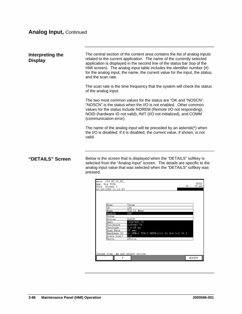
3-86 Maintenance Panel (HMI) Operation 2000596-001
Analog Input, Continued
The central section of the content area contains the list of analog inputs related to the current application. The name of the currently selected application is displayed in the second line of the status bar (top of the HMI screen). The analog input table includes the identifier number (#) for the analog input, the name, the current value for the input, the status, and the scan rate.
The scan rate is the time frequency that the system will check the status of the analog input.
The two most common values for the status are “OK and “NOSCN”. “NOSCN” is the status when the I/O is not enabled. Other common values for the status include NOREM (Remote I/O not responding), NOID (hardware ID not valid), INIT (I/O not initialized), and COMM (communication error).
The name of the analog input will be preceded by an asterisk(*) when the I/O is disabled. If it is disabled, the current value, if shown, is not valid.
Below is the screen that is displayed when the “DETAILS” softkey is selected from the “Analog Input” screen. The details are specific to the analog input value that was selected when the “DETAILS” softkey was pressed.
Interpreting the Display
“DETAILS” Screen

2000596-001 Maintenance Panel (HMI) Operation 3-87
Analog Input, Continued
The following softkeys are available from the “Analog Input” screen and the associated sub-screens.
Softkey Use
“DISABLE” and “ENABLE”
This softkey allows the user to disable and enable the selected analog input.
“DETAILS” This softkey displays a detailed information screen for the selected analog input. Details which have their values shown against a black background may be modified using the “MODIFY” softkey.
“MODIFY” This softkey, when displayed, allows the user to change certain details or values relating to the selected analog input. Some changes toggle the selected value, and other changes cause a modification screen to display.
“GO TO ORIG” When modifying details and a list of multiple preset values is available for selection, this softkey appears. It allows the user to return to the original value that was set when the “MODIFY” softkey was pressed.
“BACK SPACE” This softkey allows the user to back space while entering data in a field.
“NEXT ITEM” This softkey produces unpredictable results. DO NOT USE.
“DONE” This softkey is used to confirm the input of a parameter change and return to the previous menu. It is similar to an “ACCEPT CHANGES” softkey.
The “NEXT ITEM” softkey is known to produce unpredictable results. Do not use this softkey when modifying details.
Softkey Descriptions
Note:

3-88 Maintenance Panel (HMI) Operation 2000596-001
Analog Output (on App I/O, Temp & Pressure Menu)
“Analog Output”, which is selection 2 on the “App I/O, Temp & Pressure” menu, is designed to allow maintenance personnel to perform the following functions.
View the details of analog outputs Modify specific aspects of analog outputs
An analog output is a signal sent from an analyzer to other equipment. The equipment can be internal to the analyzer such as an oven heater. The equipment may also be external to the analyzer such as devices connected through a CAN Extension Unit.
The I/O screens are used for troubleshooting, to verify that data is being sent or received, and to manually control a particular I/O.
The “Analog Output” screen may be accessed from the “App I/O, Temp & Pressure” menu. The “App I/O, Temp & Pressure” menu is accessed from the Maintenance Menu. If not already displayed, the Maintenance Menu is obtained by pressing the “Home” softkey and then pressing the “SELECT MENU” softkey.
Below is the screen that is displayed when the “Analog Output” menu item is selected from the “App I/O, Temp & Pressure” menu.
Description
Menu Path
“Analog Output” Screen

2000596-001 Maintenance Panel (HMI) Operation 3-89
Analog Output, Continued
The central section of the content area contains the list of analog outputs related to the current application. The name of the currently selected application is displayed in the second line of the status bar (top of the HMI screen). The analog output table includes the identifier number (#) for the analog output, the name, the current value, and the status.
The two most common values for the status are “OK and “NOSCN”. “NOSCN” is the status when the I/O is not enabled. Other common values for the status include NOREM (Remote I/O not responding), NOID (hardware ID not valid), INIT (I/O not initialized), and COMM (communication error).
The name of the analog output will be preceded by an asterisk(*) when the I/O is disabled. If it is disabled, the current value, if shown, is not valid.
Below is the screen that is displayed when the “DETAILS” softkey is selected from the “Analog Output” screen. The details are specific to the analog output value that was selected when the “DETAILS” softkey was pressed.
Interpreting the Display
“DETAILS” Screen
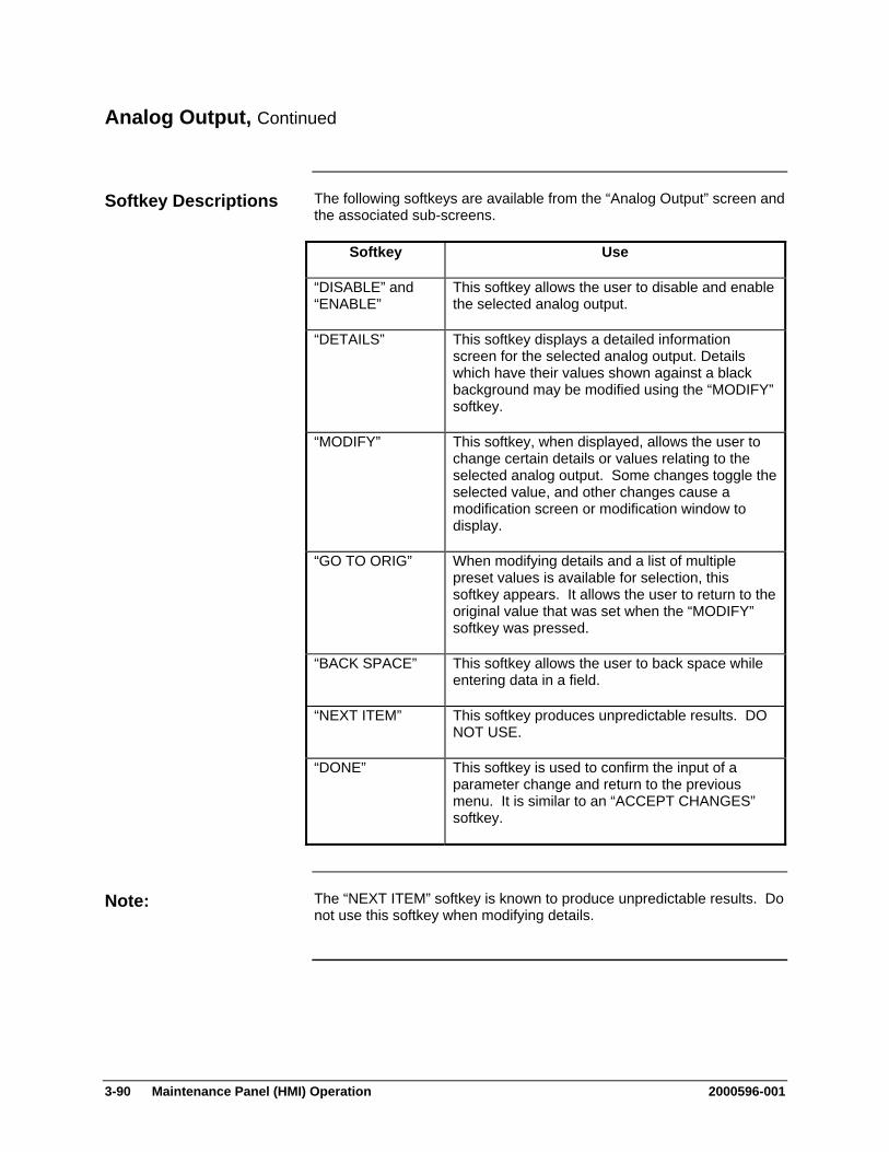
3-90 Maintenance Panel (HMI) Operation 2000596-001
Analog Output, Continued
The following softkeys are available from the “Analog Output” screen and the associated sub-screens.
Softkey Use
“DISABLE” and “ENABLE”
This softkey allows the user to disable and enable the selected analog output.
“DETAILS” This softkey displays a detailed information screen for the selected analog output. Details which have their values shown against a black background may be modified using the “MODIFY” softkey.
“MODIFY” This softkey, when displayed, allows the user to change certain details or values relating to the selected analog output. Some changes toggle the selected value, and other changes cause a modification screen or modification window to display.
“GO TO ORIG” When modifying details and a list of multiple preset values is available for selection, this softkey appears. It allows the user to return to the original value that was set when the “MODIFY” softkey was pressed.
“BACK SPACE” This softkey allows the user to back space while entering data in a field.
“NEXT ITEM” This softkey produces unpredictable results. DO NOT USE.
“DONE” This softkey is used to confirm the input of a parameter change and return to the previous menu. It is similar to an “ACCEPT CHANGES” softkey.
The “NEXT ITEM” softkey is known to produce unpredictable results. Do not use this softkey when modifying details.
Softkey Descriptions
Note:
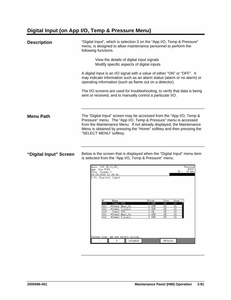
2000596-001 Maintenance Panel (HMI) Operation 3-91
Digital Input (on App I/O, Temp & Pressure Menu)
“Digital Input”, which is selection 3 on the “App I/O, Temp & Pressure” menu, is designed to allow maintenance personnel to perform the following functions.
View the details of digital input signals Modify specific aspects of digital inputs
A digital input is an I/O signal with a value of either “ON” or “OFF”. It may indicate information such as an alarm status (alarm or no alarm) or operating information (such as flame out on a detector).
The I/O screens are used for troubleshooting, to verify that data is being sent or received, and to manually control a particular I/O.
The “Digital Input” screen may be accessed from the “App I/O, Temp & Pressure” menu. The “App I/O, Temp & Pressure” menu is accessed from the Maintenance Menu. If not already displayed, the Maintenance Menu is obtained by pressing the “Home” softkey and then pressing the “SELECT MENU” softkey.
Below is the screen that is displayed when the “Digital Input” menu item is selected from the “App I/O, Temp & Pressure” menu.
Description
Menu Path
“Digital Input” Screen

3-92 Maintenance Panel (HMI) Operation 2000596-001
Digital Input, Continued
The central section of the content area contains the list of digital inputs related to the current application. The name of the currently selected application is displayed in the second line of the status bar (top of the HMI screen). The digital input table includes the identifier number (#) for the digital input, the name, the current value for the input, the status, and the scan rate.
The scan rate is the time frequency that the system will check the status of the digital input.
The two most common values for the status are “OK and “NOSCN”. “NOSCN” is the status when the I/O is not enabled. Other common values for the status include NOREM (Remote I/O not responding), NOID (hardware ID not valid), INIT (I/O not initialized), and COMM (communication error).
The name of the digital input will be preceded by an asterisk(*) when the I/O is disabled. If it is disabled, the current value, if shown, is not valid.
Below is the screen that is displayed when the “DETAILS” softkey is selected from the “Digital Input” screen. The details are specific to the digital input value that was selected when the “DETAILS” softkey was pressed.
Interpreting the Display
“DETAILS” Screen
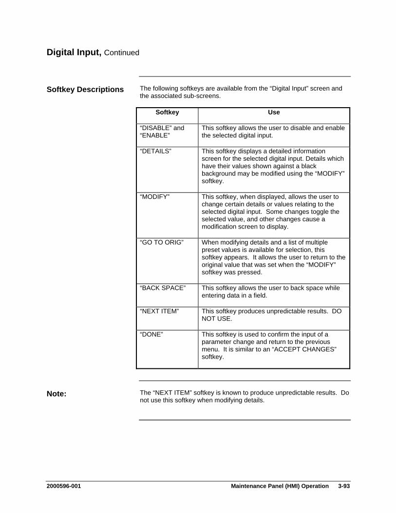
2000596-001 Maintenance Panel (HMI) Operation 3-93
Digital Input, Continued
The following softkeys are available from the “Digital Input” screen and the associated sub-screens.
Softkey Use
“DISABLE” and “ENABLE”
This softkey allows the user to disable and enable the selected digital input.
“DETAILS” This softkey displays a detailed information screen for the selected digital input. Details which have their values shown against a black background may be modified using the “MODIFY” softkey.
“MODIFY” This softkey, when displayed, allows the user to change certain details or values relating to the selected digital input. Some changes toggle the selected value, and other changes cause a modification screen to display.
“GO TO ORIG” When modifying details and a list of multiple preset values is available for selection, this softkey appears. It allows the user to return to the original value that was set when the “MODIFY” softkey was pressed.
“BACK SPACE” This softkey allows the user to back space while entering data in a field.
“NEXT ITEM” This softkey produces unpredictable results. DO NOT USE.
“DONE” This softkey is used to confirm the input of a parameter change and return to the previous menu. It is similar to an “ACCEPT CHANGES” softkey.
The “NEXT ITEM” softkey is known to produce unpredictable results. Do not use this softkey when modifying details.
Softkey Descriptions
Note:
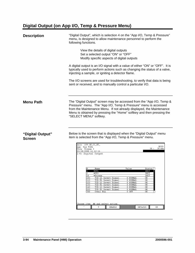
3-94 Maintenance Panel (HMI) Operation 2000596-001
Digital Output (on App I/O, Temp & Pressure Menu)
“Digital Output”, which is selection 4 on the “App I/O, Temp & Pressure” menu, is designed to allow maintenance personnel to perform the following functions.
View the details of digital outputs Set a selected output “ON” or “OFF” Modify specific aspects of digital outputs
A digital output is an I/O signal with a value of either “ON” or “OFF”. It is typically used to perform actions such as changing the status of a valve, injecting a sample, or igniting a detector flame.
The I/O screens are used for troubleshooting, to verify that data is being sent or received, and to manually control a particular I/O.
The “Digital Output” screen may be accessed from the “App I/O, Temp & Pressure” menu. The “App I/O, Temp & Pressure” menu is accessed from the Maintenance Menu. If not already displayed, the Maintenance Menu is obtained by pressing the “Home” softkey and then pressing the “SELECT MENU” softkey.
Below is the screen that is displayed when the “Digital Output” menu item is selected from the “App I/O, Temp & Pressure” menu.
Description
Menu Path
“Digital Output” Screen
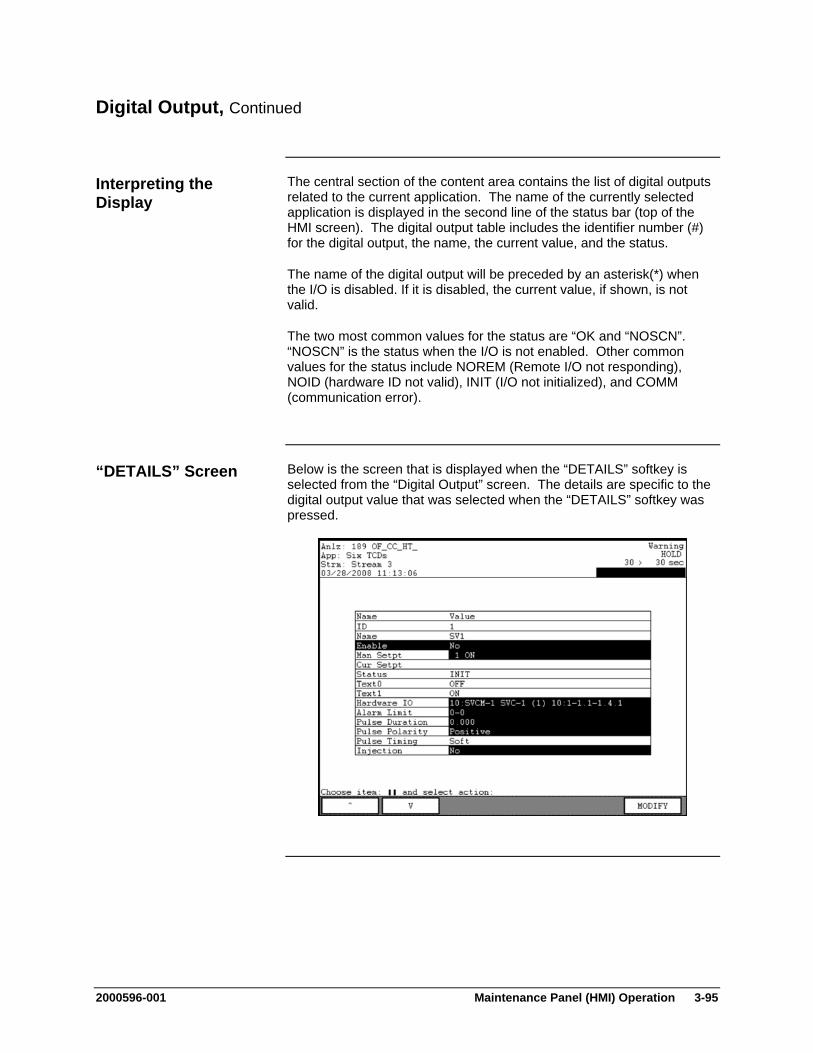
2000596-001 Maintenance Panel (HMI) Operation 3-95
Digital Output, Continued
The central section of the content area contains the list of digital outputs related to the current application. The name of the currently selected application is displayed in the second line of the status bar (top of the HMI screen). The digital output table includes the identifier number (#) for the digital output, the name, the current value, and the status.
The name of the digital output will be preceded by an asterisk(*) when the I/O is disabled. If it is disabled, the current value, if shown, is not valid.
The two most common values for the status are “OK and “NOSCN”. “NOSCN” is the status when the I/O is not enabled. Other common values for the status include NOREM (Remote I/O not responding), NOID (hardware ID not valid), INIT (I/O not initialized), and COMM (communication error).
Below is the screen that is displayed when the “DETAILS” softkey is selected from the “Digital Output” screen. The details are specific to the digital output value that was selected when the “DETAILS” softkey was pressed.
Interpreting the Display
“DETAILS” Screen
3-96 Maintenance Panel (HMI) Operation 2000596-001
Digital Output, Continued
The following softkeys are available from the “Digital Output” screen and the associated sub-screens.
Softkey Use
“DISABLE” and “ENABLE”
This softkey allows the user to disable and enable the selected digital output.
“DETAILS” This softkey displays a detailed information screen for the selected digital output. Details which have their values shown against a black background may be modified using the “MODIFY” softkey.
“MODIFY” This softkey, when displayed, allows the user to change certain details relating to the selected digital output. Some changes toggle the selected value, and other changes cause a modification screen or modification window to display.
“GO TO ORIG” When modifying details and a list of multiple preset values is available for selection, this softkey appears. It allows the user to return to the original value that was set when the “MODIFY” softkey was pressed.
“BACK SPACE” This softkey allows the user to back space while entering data in a field.
“NEXT ITEM” This softkey produces unpredictable results. DO NOT USE.
“DONE” This softkey is used to confirm the input of a parameter change and return to the previous menu. It is similar to an “ACCEPT CHANGES” softkey.
“ON” , “OFF”, and “PULSE”
This softkey is used to turn the digital output on or off. If the digital output signal is a pulsed output, then the softkey reads “PULSE”.
The “NEXT ITEM” softkey is known to produce unpredictable results. Do not use this softkey when modifying details.
Softkey Descriptions
Note:
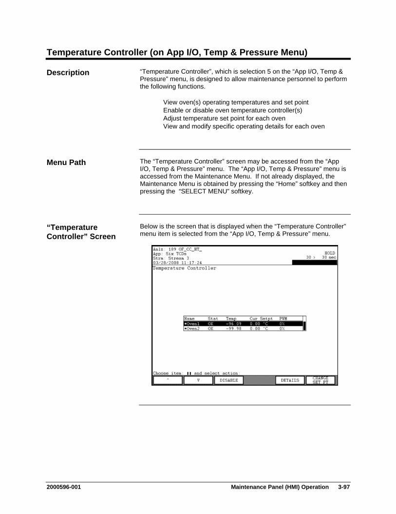
2000596-001 Maintenance Panel (HMI) Operation 3-97
Temperature Controller (on App I/O, Temp & Pressure Menu)
“Temperature Controller”, which is selection 5 on the “App I/O, Temp & Pressure” menu, is designed to allow maintenance personnel to perform the following functions.
View oven(s) operating temperatures and set point Enable or disable oven temperature controller(s) Adjust temperature set point for each oven View and modify specific operating details for each oven
The “Temperature Controller” screen may be accessed from the “App I/O, Temp & Pressure” menu. The “App I/O, Temp & Pressure” menu is accessed from the Maintenance Menu. If not already displayed, the Maintenance Menu is obtained by pressing the “Home” softkey and then pressing the “SELECT MENU” softkey.
Below is the screen that is displayed when the “Temperature Controller” menu item is selected from the “App I/O, Temp & Pressure” menu.
Description
Menu Path
“Temperature Controller” Screen
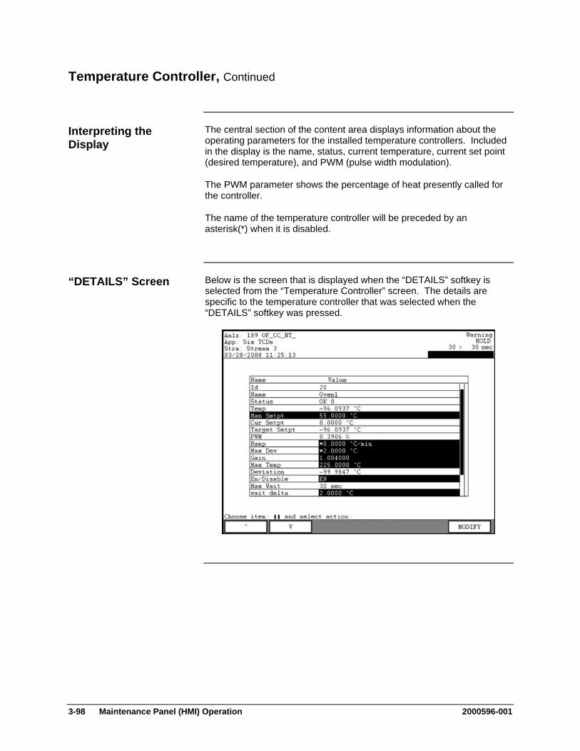
3-98 Maintenance Panel (HMI) Operation 2000596-001
Temperature Controller, Continued
The central section of the content area displays information about the operating parameters for the installed temperature controllers. Included in the display is the name, status, current temperature, current set point (desired temperature), and PWM (pulse width modulation).
The PWM parameter shows the percentage of heat presently called for the controller.
The name of the temperature controller will be preceded by an asterisk(*) when it is disabled.
Below is the screen that is displayed when the “DETAILS” softkey is selected from the “Temperature Controller” screen. The details are specific to the temperature controller that was selected when the “DETAILS” softkey was pressed.
Interpreting the Display
“DETAILS” Screen
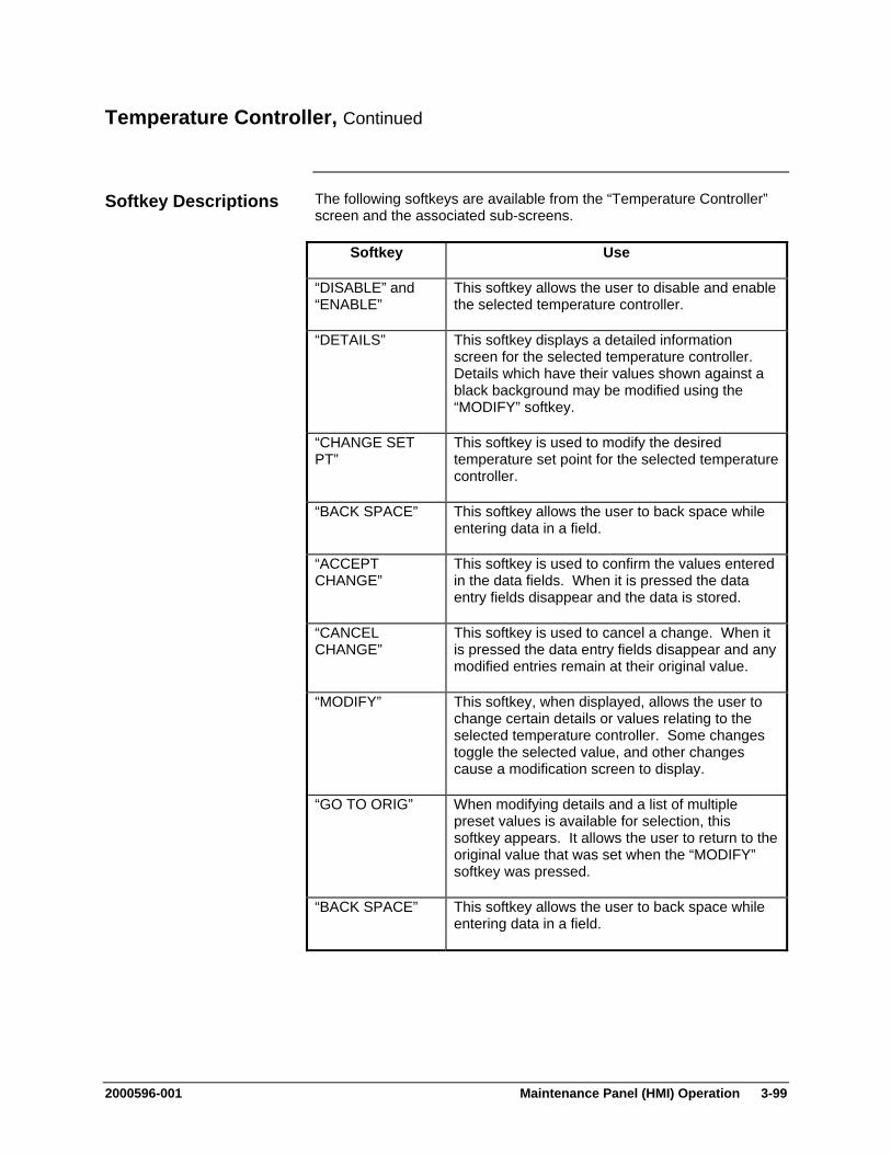
2000596-001 Maintenance Panel (HMI) Operation 3-99
Temperature Controller, Continued
The following softkeys are available from the “Temperature Controller” screen and the associated sub-screens.
Softkey Use
“DISABLE” and “ENABLE”
This softkey allows the user to disable and enable the selected temperature controller.
“DETAILS” This softkey displays a detailed information screen for the selected temperature controller. Details which have their values shown against a black background may be modified using the “MODIFY” softkey.
“CHANGE SET PT”
This softkey is used to modify the desired temperature set point for the selected temperature controller.
“BACK SPACE” This softkey allows the user to back space while entering data in a field.
“ACCEPT CHANGE”
This softkey is used to confirm the values entered in the data fields. When it is pressed the data entry fields disappear and the data is stored.
“CANCEL CHANGE”
This softkey is used to cancel a change. When it is pressed the data entry fields disappear and any modified entries remain at their original value.
“MODIFY” This softkey, when displayed, allows the user to change certain details or values relating to the selected temperature controller. Some changes toggle the selected value, and other changes cause a modification screen to display.
“GO TO ORIG” When modifying details and a list of multiple preset values is available for selection, this softkey appears. It allows the user to return to the original value that was set when the “MODIFY” softkey was pressed.
“BACK SPACE” This softkey allows the user to back space while entering data in a field.
Softkey Descriptions
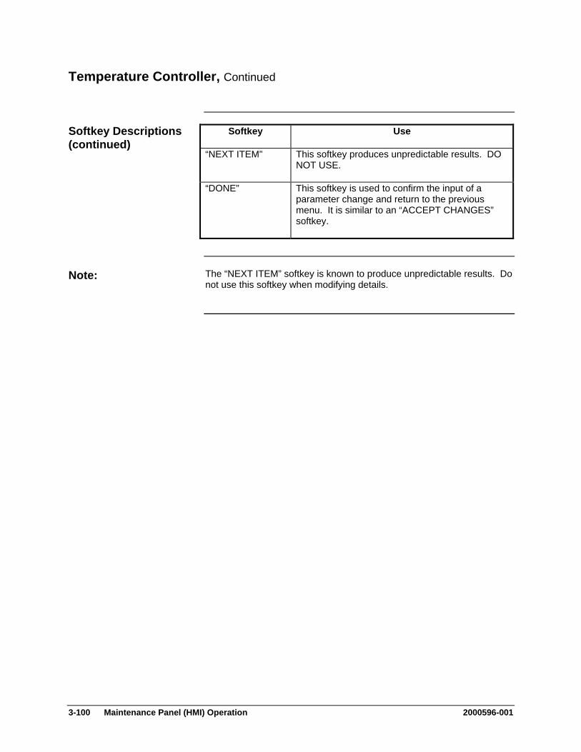
3-100 Maintenance Panel (HMI) Operation 2000596-001
Temperature Controller, Continued
Softkey Use
“NEXT ITEM” This softkey produces unpredictable results. DO NOT USE.
“DONE” This softkey is used to confirm the input of a parameter change and return to the previous menu. It is similar to an “ACCEPT CHANGES” softkey.
The “NEXT ITEM” softkey is known to produce unpredictable results. Do not use this softkey when modifying details.
Softkey Descriptions (continued)
Note:
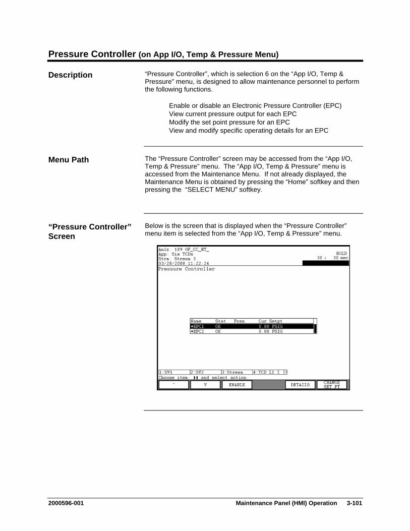
2000596-001 Maintenance Panel (HMI) Operation 3-101
Pressure Controller (on App I/O, Temp & Pressure Menu)
“Pressure Controller”, which is selection 6 on the “App I/O, Temp & Pressure” menu, is designed to allow maintenance personnel to perform the following functions.
Enable or disable an Electronic Pressure Controller (EPC) View current pressure output for each EPC Modify the set point pressure for an EPC View and modify specific operating details for an EPC
The “Pressure Controller” screen may be accessed from the “App I/O, Temp & Pressure” menu. The “App I/O, Temp & Pressure” menu is accessed from the Maintenance Menu. If not already displayed, the Maintenance Menu is obtained by pressing the “Home” softkey and then pressing the “SELECT MENU” softkey.
Below is the screen that is displayed when the “Pressure Controller” menu item is selected from the “App I/O, Temp & Pressure” menu.
Description
Menu Path
“Pressure Controller” Screen

3-102 Maintenance Panel (HMI) Operation 2000596-001
Pressure Controller, Continued
The central section of the content area contains the list of pressure controllers (EPCs) related to the current application. The name of the currently selected application is displayed in the second line of the status bar (top of the HMI screen). The EPC table includes the name of the EPC, the status, the current pressure, and the current pressure set point.
The name of the EPC will be preceded by an asterisk(*) when it is disabled.
Below is the screen that is displayed when the “DETAILS” softkey is selected from the “Pressure Controller” screen. The details are specific to the pressure controller that was selected when the “DETAILS” softkey was pressed.
Interpreting the Display
“DETAILS” Screen
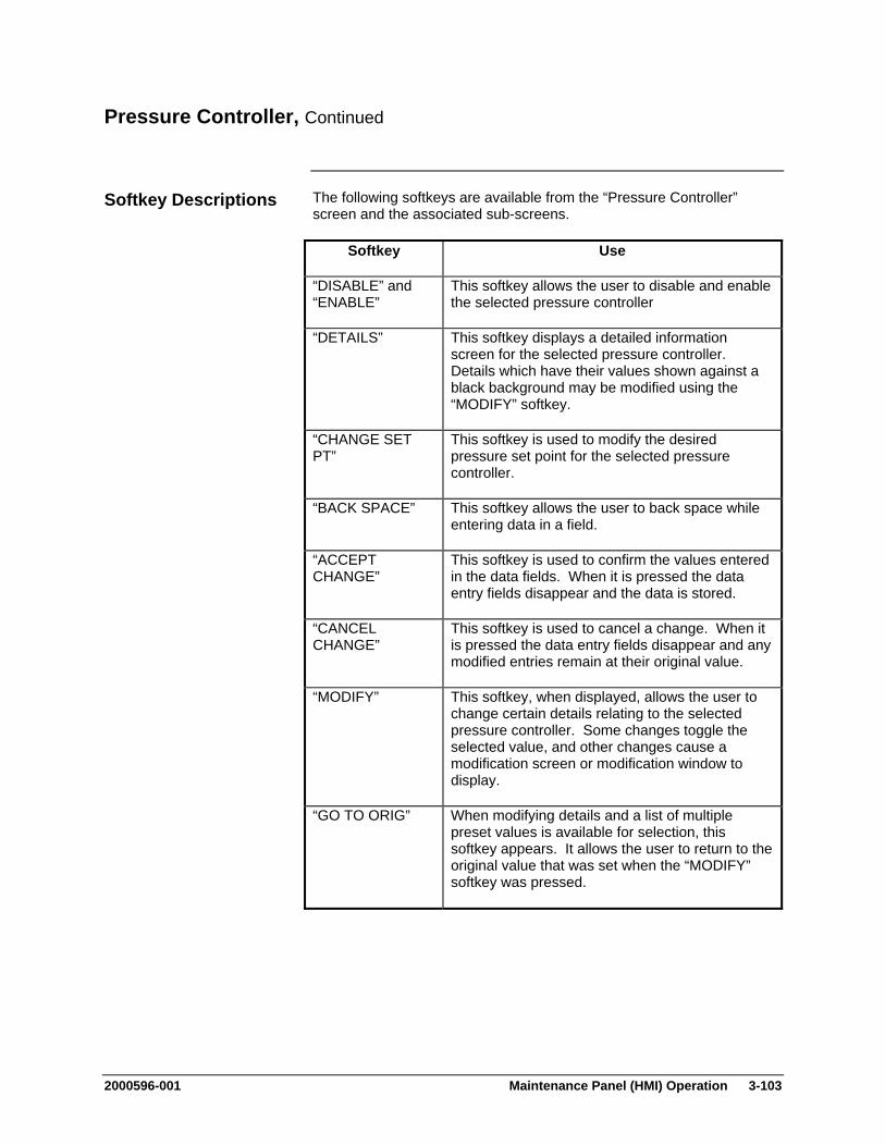
2000596-001 Maintenance Panel (HMI) Operation 3-103
Pressure Controller, Continued
The following softkeys are available from the “Pressure Controller” screen and the associated sub-screens.
Softkey Use
“DISABLE” and “ENABLE”
This softkey allows the user to disable and enable the selected pressure controller
“DETAILS” This softkey displays a detailed information screen for the selected pressure controller. Details which have their values shown against a black background may be modified using the “MODIFY” softkey.
“CHANGE SET PT”
This softkey is used to modify the desired pressure set point for the selected pressure controller.
“BACK SPACE” This softkey allows the user to back space while entering data in a field.
“ACCEPT CHANGE”
This softkey is used to confirm the values entered in the data fields. When it is pressed the data entry fields disappear and the data is stored.
“CANCEL CHANGE”
This softkey is used to cancel a change. When it is pressed the data entry fields disappear and any modified entries remain at their original value.
“MODIFY” This softkey, when displayed, allows the user to change certain details relating to the selected pressure controller. Some changes toggle the selected value, and other changes cause a modification screen or modification window to display.
“GO TO ORIG” When modifying details and a list of multiple preset values is available for selection, this softkey appears. It allows the user to return to the original value that was set when the “MODIFY” softkey was pressed.
Softkey Descriptions
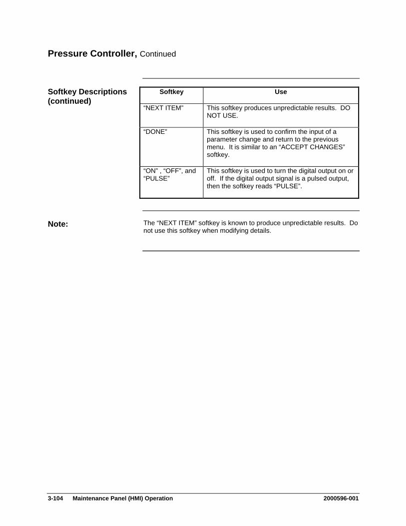
3-104 Maintenance Panel (HMI) Operation 2000596-001
Pressure Controller, Continued
Softkey Use
“NEXT ITEM” This softkey produces unpredictable results. DO NOT USE.
“DONE” This softkey is used to confirm the input of a parameter change and return to the previous menu. It is similar to an “ACCEPT CHANGES” softkey.
“ON” , “OFF”, and “PULSE”
This softkey is used to turn the digital output on or off. If the digital output signal is a pulsed output, then the softkey reads “PULSE”.
The “NEXT ITEM” softkey is known to produce unpredictable results. Do not use this softkey when modifying details.
Softkey Descriptions (continued)
Note:
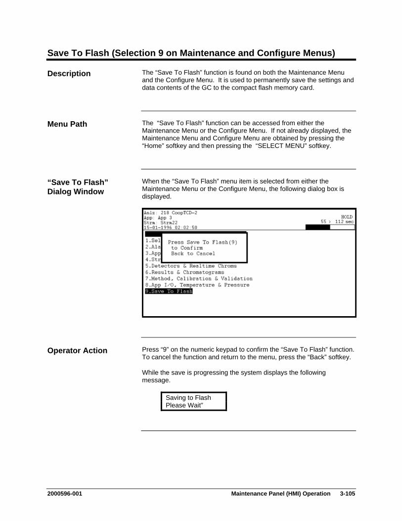
2000596-001 Maintenance Panel (HMI) Operation 3-105
Save To Flash (Selection 9 on Maintenance and Configure Menus)
The “Save To Flash” function is found on both the Maintenance Menu and the Configure Menu. It is used to permanently save the settings and data contents of the GC to the compact flash memory card.
The “Save To Flash” function can be accessed from either the Maintenance Menu or the Configure Menu. If not already displayed, the Maintenance Menu and Configure Menu are obtained by pressing the “Home” softkey and then pressing the “SELECT MENU” softkey.
When the “Save To Flash” menu item is selected from either the Maintenance Menu or the Configure Menu, the following dialog box is displayed.
Press “9” on the numeric keypad to confirm the “Save To Flash” function. To cancel the function and return to the menu, press the “Back” softkey.
While the save is progressing the system displays the following message.
Saving to Flash Please Wait”
Description
Menu Path
“Save To Flash” Dialog Window
Operator Action

3-106 Maintenance Panel (HMI) Operation 2000596-001
System Setup (Selection 1 on Configure Menu)
This function allows a user to view and modify the following types of system settings information.
Version information for the software Communications information\ Information regarding the load (boot) process Time and date settings Information regarding the HMI display System IP (Internet Protocol) settings
Each of these information types are accessible from screens which are activated by softkeys that are displayed when the “System Settings” is selected.
The “System Setup” screen can be accessed from the Configure Menu. If not already displayed, the Configure Menu is obtained by pressing the “Home” softkey and then pressing the “SELECT MENU” softkey.
Six different screens of system settings information are available for viewing. These screens are accessible using softkeys that are displayed on the softkey bar.
There are three types of information listed for each system setting displayed. These include the setting name, the current value for the setting, and (usually) a number that is used to select the setting for editing.
For most other HMI screens the arrow keys are used to select data for modifying. On the settings screens, the numeric keypad is used to select settings. Any setting that has a number listed in the left column of the table may be modified. Press the numeric keypad number that corresponds to the setting. Either a small editing window or a new screen will be displayed.
Any setting that does not have a number displayed in the left hand column is read only and cannot be changed on the HMI.
Individual system settings are described later in this section.
When to Use
Menu Path
Using the Settings Screens
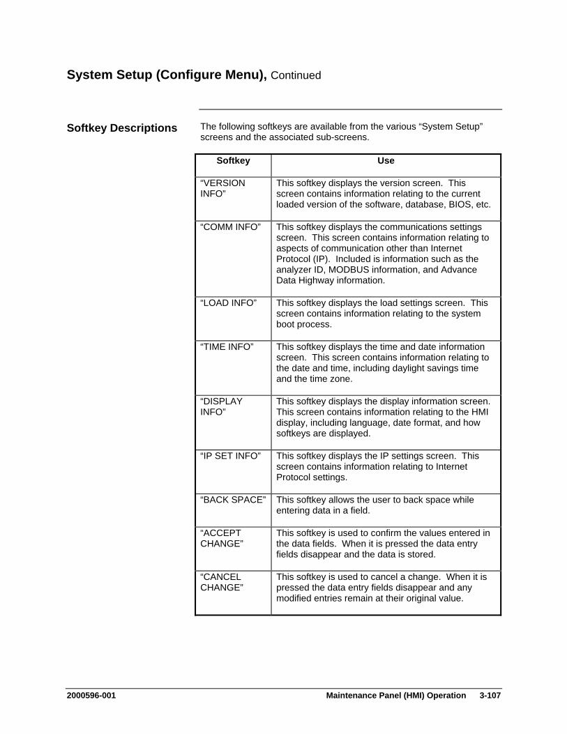
2000596-001 Maintenance Panel (HMI) Operation 3-107
System Setup (Configure Menu), Continued
The following softkeys are available from the various “System Setup” screens and the associated sub-screens.
Softkey Use
“VERSION INFO”
This softkey displays the version screen. This screen contains information relating to the current loaded version of the software, database, BIOS, etc.
“COMM INFO” This softkey displays the communications settings screen. This screen contains information relating to aspects of communication other than Internet Protocol (IP). Included is information such as the analyzer ID, MODBUS information, and Advance Data Highway information.
“LOAD INFO” This softkey displays the load settings screen. This screen contains information relating to the system boot process.
“TIME INFO” This softkey displays the time and date information screen. This screen contains information relating to the date and time, including daylight savings time and the time zone.
“DISPLAY INFO”
This softkey displays the display information screen. This screen contains information relating to the HMI display, including language, date format, and how softkeys are displayed.
“IP SET INFO” This softkey displays the IP settings screen. This screen contains information relating to Internet Protocol settings.
“BACK SPACE” This softkey allows the user to back space while entering data in a field.
“ACCEPT CHANGE”
This softkey is used to confirm the values entered in the data fields. When it is pressed the data entry fields disappear and the data is stored.
“CANCEL CHANGE”
This softkey is used to cancel a change. When it is pressed the data entry fields disappear and any modified entries remain at their original value.
Softkey Descriptions
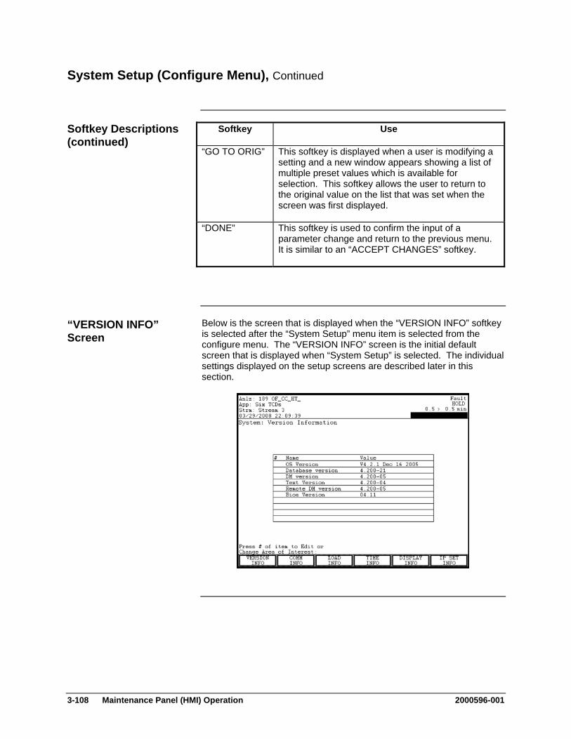
3-108 Maintenance Panel (HMI) Operation 2000596-001
System Setup (Configure Menu), Continued
Softkey Use
“GO TO ORIG” This softkey is displayed when a user is modifying a setting and a new window appears showing a list of multiple preset values which is available for selection. This softkey allows the user to return to the original value on the list that was set when the screen was first displayed.
“DONE” This softkey is used to confirm the input of a parameter change and return to the previous menu. It is similar to an “ACCEPT CHANGES” softkey.
Below is the screen that is displayed when the “VERSION INFO” softkey is selected after the “System Setup” menu item is selected from the configure menu. The “VERSION INFO” screen is the initial default screen that is displayed when “System Setup” is selected. The individual settings displayed on the setup screens are described later in this section.
Softkey Descriptions (continued)
“VERSION INFO” Screen
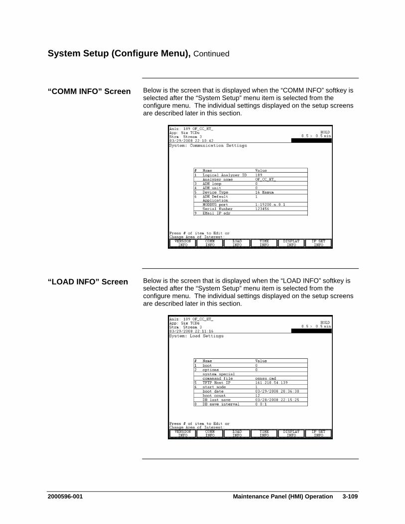
2000596-001 Maintenance Panel (HMI) Operation 3-109
System Setup (Configure Menu), Continued
Below is the screen that is displayed when the “COMM INFO” softkey is selected after the “System Setup” menu item is selected from the configure menu. The individual settings displayed on the setup screens are described later in this section.
Below is the screen that is displayed when the “LOAD INFO” softkey is selected after the “System Setup” menu item is selected from the configure menu. The individual settings displayed on the setup screens are described later in this section.
“COMM INFO” Screen
“LOAD INFO” Screen
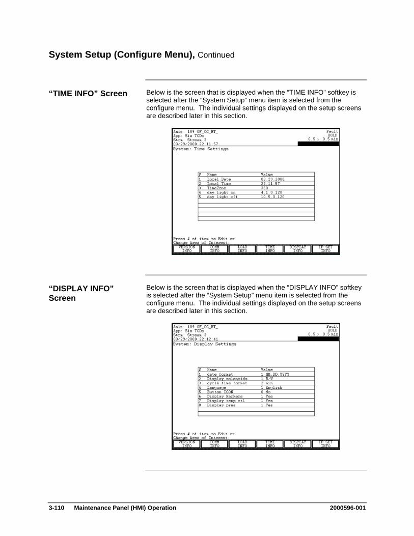
3-110 Maintenance Panel (HMI) Operation 2000596-001
System Setup (Configure Menu), Continued
Below is the screen that is displayed when the “TIME INFO” softkey is selected after the “System Setup” menu item is selected from the configure menu. The individual settings displayed on the setup screens are described later in this section.
Below is the screen that is displayed when the “DISPLAY INFO” softkey is selected after the “System Setup” menu item is selected from the configure menu. The individual settings displayed on the setup screens are described later in this section.
“TIME INFO” Screen
“DISPLAY INFO” Screen

2000596-001 Maintenance Panel (HMI) Operation 3-111
System Setup (Configure Menu), Continued
Below is the screen that is displayed when the “IP SET INFO” softkey is selected after the “System Setup” menu item is selected from the configure menu. The individual settings displayed on the setup screens are described later in this section.
“IP SET INFO” Screen

3-112 Maintenance Panel (HMI) Operation 2000596-001
System Setup (Configure Menu), Continued
The following table defines each of the entries on the settings screens.
Information Line Definition Modify orRead Only
Version Info Screen
OS Version The current version and date of the software loaded on the analyzer.
Read Only
Database Version
The current version of the database loaded on the analyzer.
Read Only
DM Version The current version of the data manager loaded on the analyzer.
Read Only
Text Version The current version of the language loaded on the analyzer.
Read Only
Remote DM Version
The current version of the data manager loaded on the analyzer
Read Only
BIOS Version The current version of the BIOS (Basic Input/Output System) firmware.
Read Only
Communications Info Screen
Logical Analyzer ID
Shows the unique logical ID of the analyzer for the network. Must be < 255 if communicating with Optichrom GCs.
Modify
Analyzer Name Shows the name of the analyzer. This can be edited in the System Manager>System Control Table
Read Only
Screen Line Definitions

2000596-001 Maintenance Panel (HMI) Operation 3-113
System Setup (Configure Menu), Continued
Information Line Definition Modify orRead Only
Communications Info Screen (continued)
ADH Loop Shows the selected data highway loop. This must be unique to communicate on the Advance Data Hiway. This is required for communication with Optichrom GCs.
Modify
ADH Unit Shows the selected data highway unit number. This must be unique to communicate on the Advance Data Hiway. This is required for communication with Optichrom GCs.
Modify
Device Type Specifies the type of device (Maxum, NAU, etc.). This primarily impacts the look of the unit in System Manager.
Modify
ADH Default Application
Shows the default data highway application.. This is important for some Optichrom commands
Read Only
MODBUS port Communication settings for Modbus RTU. This can be edited in the System Manager>System Control Table.
Read Only
Serial Number This is set at the time the unit is created.
Read Only
Email IP Address This is used with the printer table to get email reports. This may be a security issue for some sites.
Modify
Screen Line Definitions (continued)
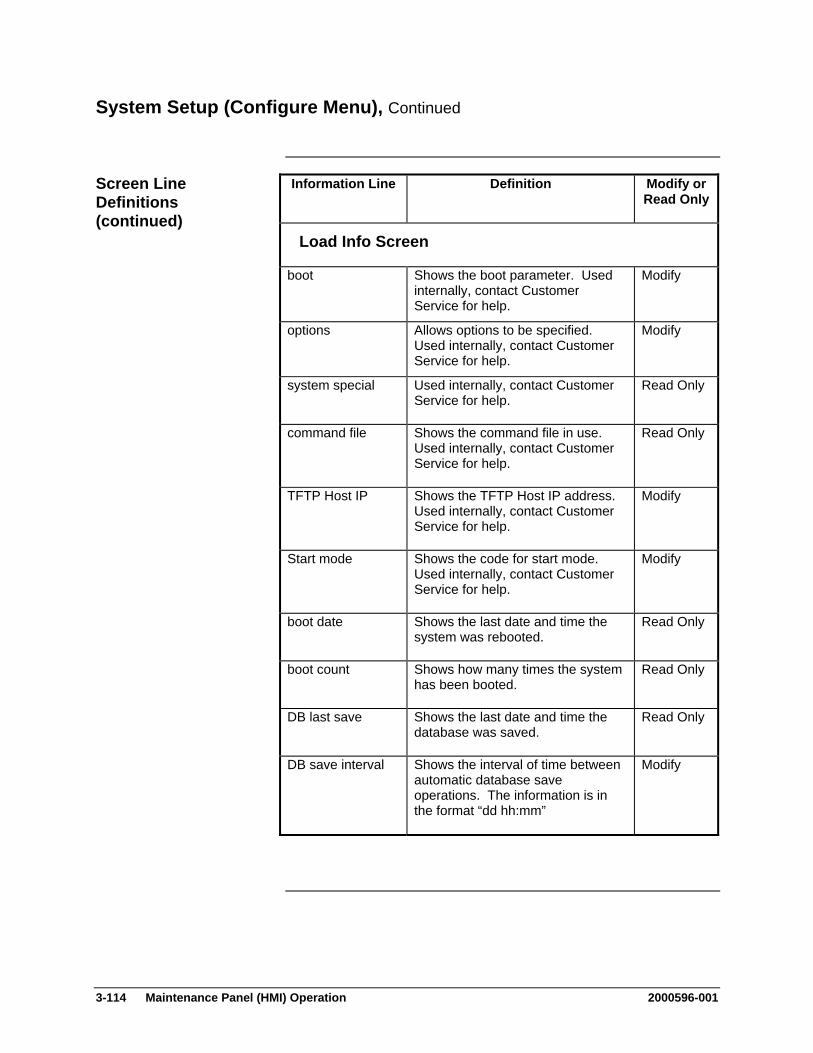
3-114 Maintenance Panel (HMI) Operation 2000596-001
System Setup (Configure Menu), Continued
Information Line Definition Modify orRead Only
Load Info Screen
boot Shows the boot parameter. Used internally, contact Customer Service for help.
Modify
options Allows options to be specified. Used internally, contact Customer Service for help.
Modify
system special Used internally, contact Customer Service for help.
Read Only
command file Shows the command file in use. Used internally, contact Customer Service for help.
Read Only
TFTP Host IP Shows the TFTP Host IP address. Used internally, contact Customer Service for help.
Modify
Start mode Shows the code for start mode. Used internally, contact Customer Service for help.
Modify
boot date Shows the last date and time the system was rebooted.
Read Only
boot count Shows how many times the system has been booted.
Read Only
DB last save Shows the last date and time the database was saved.
Read Only
DB save interval Shows the interval of time between automatic database save operations. The information is in the format “dd hh:mm”
Modify
Screen Line Definitions (continued)

2000596-001 Maintenance Panel (HMI) Operation 3-115
System Setup (Configure Menu), Continued
Information Line Definition Modify orRead Only
Time Info Screen
Local Date Displays the current date. Modify
Local Time Displays the current time. Modify
TimeZone Indicates the longitude of the current analyzer location in minutes west of GMT (negative numbers are “minutes east”). For example, the value is 360 for United States Central Time.
Modify
day light on Indicates the month, week, day of week, and minute when the system will turn on daylight savings time. Example: 4.1.0.120 means that daylight savings turns on in the first week (1) of April (4) on a Sunday (0) at 2 AM (120 minutes into the day).
Modify
day light off Indicates the month, week, day of week, and minute when the system will turn off daylight savings time. Example: 10.5.0.120 means that daylight savings time will end the last week (5) in October (10) on a Sunday (0) at 2 AM (120 into the day).
Modify
Screen Line Definitions (continued)
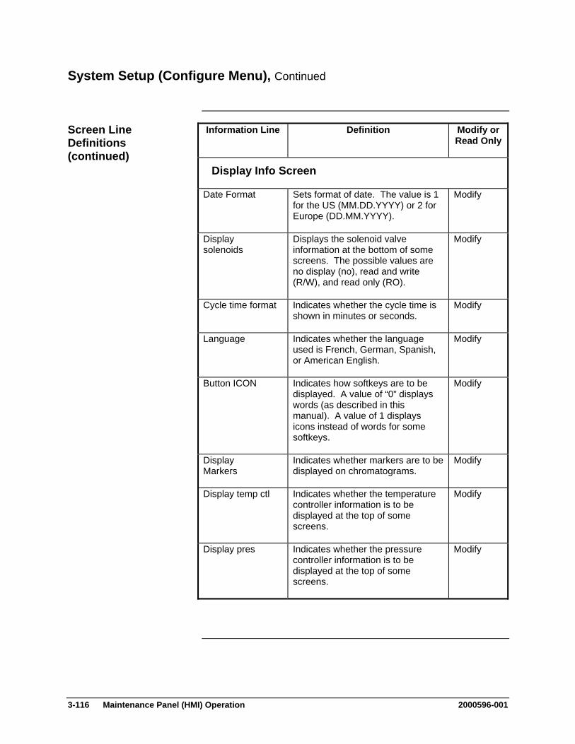
3-116 Maintenance Panel (HMI) Operation 2000596-001
System Setup (Configure Menu), Continued
Information Line Definition Modify orRead Only
Display Info Screen
Date Format Sets format of date. The value is 1 for the US (MM.DD.YYYY) or 2 for Europe (DD.MM.YYYY).
Modify
Display solenoids
Displays the solenoid valve information at the bottom of some screens. The possible values are no display (no), read and write (R/W), and read only (RO).
Modify
Cycle time format Indicates whether the cycle time is shown in minutes or seconds.
Modify
Language Indicates whether the language used is French, German, Spanish, or American English.
Modify
Button ICON Indicates how softkeys are to be displayed. A value of “0” displays words (as described in this manual). A value of 1 displays icons instead of words for some softkeys.
Modify
Display Markers
Indicates whether markers are to be displayed on chromatograms.
Modify
Display temp ctl Indicates whether the temperature controller information is to be displayed at the top of some screens.
Modify
Display pres Indicates whether the pressure controller information is to be displayed at the top of some screens.
Modify
Screen Line Definitions (continued)
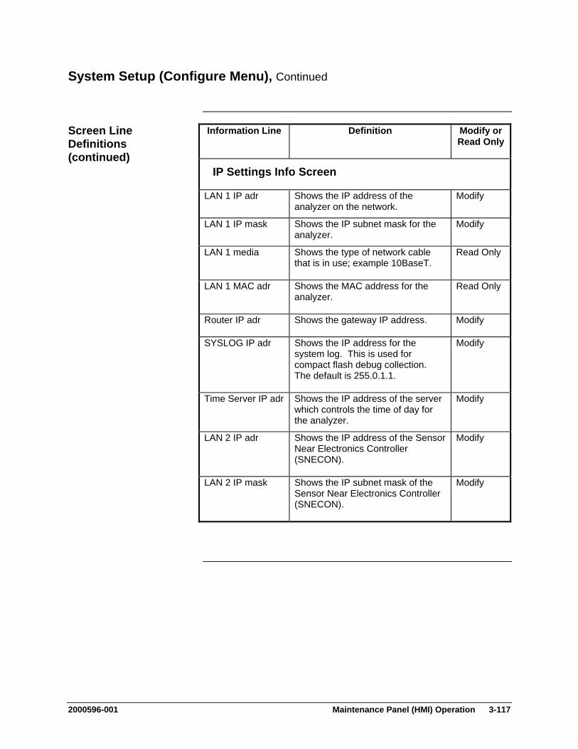
2000596-001 Maintenance Panel (HMI) Operation 3-117
System Setup (Configure Menu), Continued
Information Line Definition Modify orRead Only
IP Settings Info Screen
LAN 1 IP adr Shows the IP address of the analyzer on the network.
Modify
LAN 1 IP mask Shows the IP subnet mask for the analyzer.
Modify
LAN 1 media Shows the type of network cable that is in use; example 10BaseT.
Read Only
LAN 1 MAC adr Shows the MAC address for the analyzer.
Read Only
Router IP adr Shows the gateway IP address. Modify
SYSLOG IP adr Shows the IP address for the system log. This is used for compact flash debug collection. The default is 255.0.1.1.
Modify
Time Server IP adr Shows the IP address of the server which controls the time of day for the analyzer.
Modify
LAN 2 IP adr Shows the IP address of the Sensor Near Electronics Controller (SNECON).
Modify
LAN 2 IP mask Shows the IP subnet mask of the Sensor Near Electronics Controller (SNECON).
Modify
Screen Line Definitions (continued)
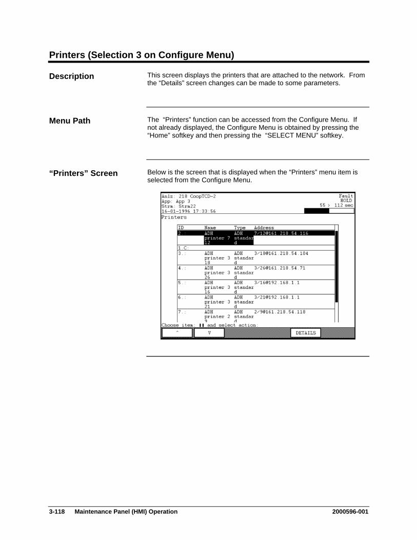
3-118 Maintenance Panel (HMI) Operation 2000596-001
Printers (Selection 3 on Configure Menu)
This screen displays the printers that are attached to the network. From the “Details” screen changes can be made to some parameters.
The “Printers” function can be accessed from the Configure Menu. If not already displayed, the Configure Menu is obtained by pressing the “Home” softkey and then pressing the “SELECT MENU” softkey.
Below is the screen that is displayed when the “Printers” menu item is selected from the Configure Menu.
Description
Menu Path
“Printers” Screen
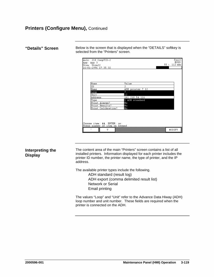
2000596-001 Maintenance Panel (HMI) Operation 3-119
Printers (Configure Menu), Continued
Below is the screen that is displayed when the “DETAILS” softkey is selected from the “Printers” screen.
The content area of the main “Printers” screen contains a list of all installed printers. Information displayed for each printer includes the printer ID number, the printer name, the type of printer, and the IP address.
The available printer types include the following. ADH standard (result log) ADH export (comma delimited result list) Network or Serial Email printing
The values “Loop” and “Unit” refer to the Advance Data Hiway (ADH) loop number and unit number. These fields are required when the printer is connected on the ADH.
“Details” Screen
Interpreting the Display
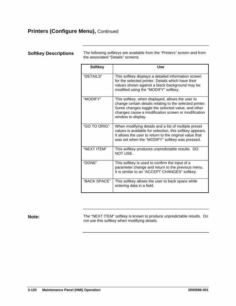
3-120 Maintenance Panel (HMI) Operation 2000596-001
Printers (Configure Menu), Continued
The following softkeys are available from the “Printers” screen and from the associated “Details” screens.
Softkey Use
“DETAILS” This softkey displays a detailed information screen for the selected printer. Details which have their values shown against a black background may be modified using the “MODIFY” softkey.
“MODIFY” This softkey, when displayed, allows the user to change certain details relating to the selected printer. Some changes toggle the selected value, and other changes cause a modification screen or modification window to display.
“GO TO ORIG” When modifying details and a list of multiple preset values is available for selection, this softkey appears. It allows the user to return to the original value that was set when the “MODIFY” softkey was pressed.
“NEXT ITEM” This softkey produces unpredictable results. DO NOT USE.
“DONE” This softkey is used to confirm the input of a parameter change and return to the previous menu. It is similar to an “ACCEPT CHANGES” softkey.
“BACK SPACE” This softkey allows the user to back space while entering data in a field.
The “NEXT ITEM” softkey is known to produce unpredictable results. Do not use this softkey when modifying details.
Softkey Descriptions
Note:

2000596-001 Maintenance Panel (HMI) Operation 3-121
Hosts (Selection 4 on Configure Menu)
The Maxum II system provides serial interfacing to other programmable devices such as control systems or host computers. The “Hosts” screen displays information regarding the available host interfaces. This screen is read only. No information can be changed from the “Hosts” screen.
The “Hosts” function can be accessed from the Configure Menu. If not already displayed, the Configure Menu is obtained by pressing the “Home” softkey and then pressing the “SELECT MENU” softkey.
Below is the screen that is displayed when the “Hosts” menu item is selected from the Configure Menu.
There are no special softkeys available from the “Hosts” screen.
Description
Menu Path
“Hosts” Screen
Softkeys
3-122 Maintenance Panel (HMI) Operation 2000596-001
Hosts (Configure Menu), Continued
The content area of the main “Hosts” screen contains a list of all configured hosts. Information displayed for each host includes the ID number, the name, the IP address, and the host type.
The available host types include the following. HCI-C01 HCI-C04 HCI-H HCI-A Results only format for HCI cards Modbus Modbus Freeform (for TCP printers to provide standard
report) HCI-A (with cycle length as last result) External Results
Only basic host information is displayed from the “Hosts” screen. The full set of host parameters can be viewed and modified via the “Hosts” system table that is accessible in System Manager.
Interpreting the Display
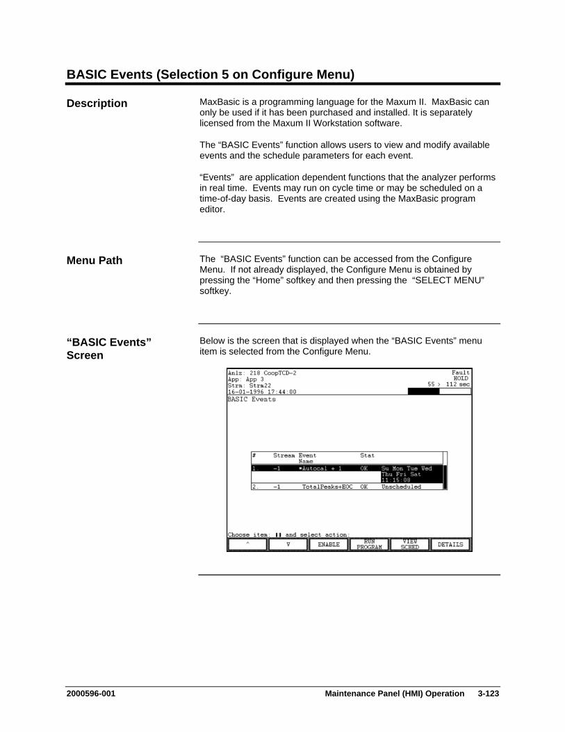
2000596-001 Maintenance Panel (HMI) Operation 3-123
BASIC Events (Selection 5 on Configure Menu)
MaxBasic is a programming language for the Maxum II. MaxBasic can only be used if it has been purchased and installed. It is separately licensed from the Maxum II Workstation software.
The “BASIC Events” function allows users to view and modify available events and the schedule parameters for each event.
“Events” are application dependent functions that the analyzer performs in real time. Events may run on cycle time or may be scheduled on a time-of-day basis. Events are created using the MaxBasic program editor.
The “BASIC Events” function can be accessed from the Configure Menu. If not already displayed, the Configure Menu is obtained by pressing the “Home” softkey and then pressing the “SELECT MENU” softkey.
Below is the screen that is displayed when the “BASIC Events” menu item is selected from the Configure Menu.
Description
Menu Path
“BASIC Events” Screen

3-124 Maintenance Panel (HMI) Operation 2000596-001
BASIC Events (Configure Menu), Continued
Below is the screen that is displayed when the “VIEW SCHED” softkey is selected from the “BASIC Events” main screen. This screen allows the user to modify the scheduled execution program for an event.
Below is the screen that is displayed when the “DETAILS” softkey is selected from the “BASIC Events” main screen.
“VIEW SCHED” Screen
“Details” Screen
2000596-001 Maintenance Panel (HMI) Operation 3-125
BASIC Events (Configure Menu), Continued
The content area of the “BASIC Events” screen includes the ID number, the event name, the streams that are associated with the event, the current status of the event, and a summary of the schedule. A stream value of “-1” refers to all streams. Applicable statuses are “OK” and “ERROR”.
The content area of the “VIEW SCHED” screen shows the execution schedule for a scheduled event and the next planned run time as determined by the schedule. The “VIEW SCHED” screen is blank for unscheduled events.
Programs are set to run either by day and time, or by frequency (not both). The “CHANGE TIME” and “CHANGE DAY” softkeys on the “VIEW SCHED” screen are used to set a program to run on specify days and times. The “CHANGE UNIT” and “CHANGE FREQ” softkeys are used to set a program to run on a certain frequency (interval). For more information refer to the descriptions of the softkeys
Interpreting the Display
3-126 Maintenance Panel (HMI) Operation 2000596-001
BASIC Events (Configure Menu), Continued
The following softkeys are available from the “BASIC Events” screen and from the associated sub-screens.
Softkey Use
“ENABLE” and “DISABLE”
This softkey enables or disables the selected event. When an event is disabled, an asterisk will be displayed next to the event name. Disabled events will not run when commanded from a program schedule or a cycle event. However, disabled events WILL run when commanded from an external command such as a Modbus command.
“RUN PROGRAM” and “CANCEL”
The “RUN PROGRAM” softkey runs the program manually. While the program is running, the “CANCEL” softkey is displayed.
“VIEW SCHED” This softkey displays the schedule screen for the selected event.
“CHANGE TIME”
This softkey is used to set the time of day at which an event is scheduled to execute.
“BACK SPACE” This softkey allows the user to back space while entering data in a field.
“ACCEPT CHANGE”
This softkey is used to confirm the values entered in the data fields. When it is pressed the data entry fields disappear and the data is stored.
“CANCEL CHANGE”
This softkey is used to cancel a change. When it is pressed the data entry fields disappear and any modified entries remain at their original value.
“SHOW DAY” The “SHOW DAY” softkey is used with the “CHANGE DAY” softkey. It is used to verify which days are selected.
Softkey Descriptions

2000596-001 Maintenance Panel (HMI) Operation 3-127
BASIC Events (Configure Menu), Continued
Softkey Use
“CHANGE DAY”
This softkey is used to set the days that an event is scheduled to run. The days of the week are set using a binary mask (i.e. the number 15 represents the binary digits 0000 0111).
The numbers 201-231 are used to run a program on a specific day of the month (e.g. 205 equals the 5th day of each month).
The numbers 0-127 are used to schedule the event to run on specific days of the week. The last 7 digits represent the days of the week. This means that the numbers 0-127 can be used to represent any combination of days. A bit value of 1 indicates that the event is scheduled to run on the applicable day.
Bit 0 (far right) is for Saturday Bit 1 (second from right) is for Friday Bit 2 (third from right) is for Thursday ... Bit 7 is for Sunday
A value of 127 represents “111 1111” which means that the event will run on every day of the week.
Use the “SHOW DAY” softkey to have the system calculate and show the schedule that corresponds to a particular number.
“CHANGE UNIT”
Sets the time units when executing an event based on frequency. The following units are available
1 = Hours 2 = Minutes 3 = Days 4 = Seconds 5 = Milliseconds 6 = Months 7 = Years
“CHANGE FREQ”
This softkey is used with the “CHANGE UNIT” softkey. It determines the frequency that an event should be executed (e.g. 10 days).
Softkey Descriptions (continued)
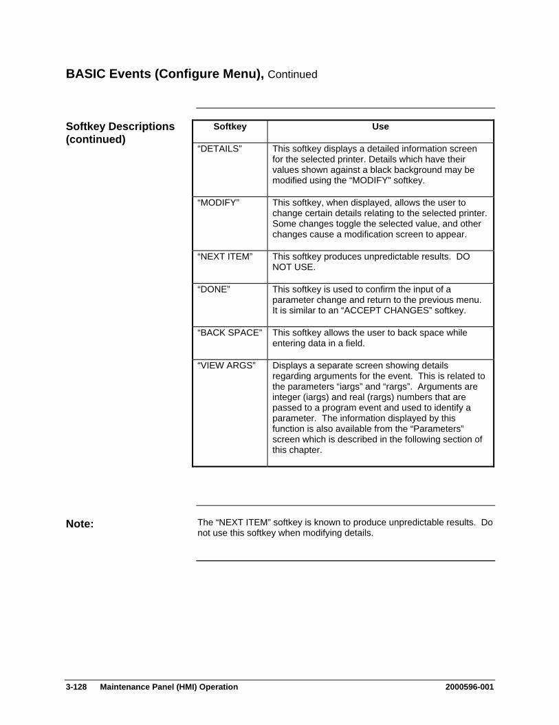
3-128 Maintenance Panel (HMI) Operation 2000596-001
BASIC Events (Configure Menu), Continued
Softkey Use
“DETAILS” This softkey displays a detailed information screen for the selected printer. Details which have their values shown against a black background may be modified using the “MODIFY” softkey.
“MODIFY” This softkey, when displayed, allows the user to change certain details relating to the selected printer. Some changes toggle the selected value, and other changes cause a modification screen to appear.
“NEXT ITEM” This softkey produces unpredictable results. DO NOT USE.
“DONE” This softkey is used to confirm the input of a parameter change and return to the previous menu. It is similar to an “ACCEPT CHANGES” softkey.
“BACK SPACE” This softkey allows the user to back space while entering data in a field.
“VIEW ARGS” Displays a separate screen showing details regarding arguments for the event. This is related to the parameters “iargs” and “rargs”. Arguments are integer (iargs) and real (rargs) numbers that are passed to a program event and used to identify a parameter. The information displayed by this function is also available from the “Parameters” screen which is described in the following section of this chapter.
The “NEXT ITEM” softkey is known to produce unpredictable results. Do not use this softkey when modifying details.
Softkey Descriptions (continued)
Note:
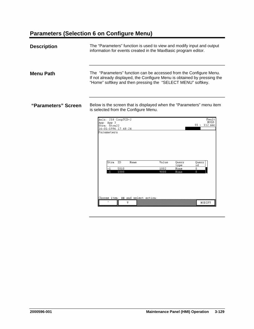
2000596-001 Maintenance Panel (HMI) Operation 3-129
Parameters (Selection 6 on Configure Menu)
The “Parameters” function is used to view and modify input and output information for events created in the MaxBasic program editor.
The “Parameters” function can be accessed from the Configure Menu. If not already displayed, the Configure Menu is obtained by pressing the “Home” softkey and then pressing the “SELECT MENU” softkey.
Below is the screen that is displayed when the “Parameters” menu item is selected from the Configure Menu.
Description
Menu Path
“Parameters” Screen
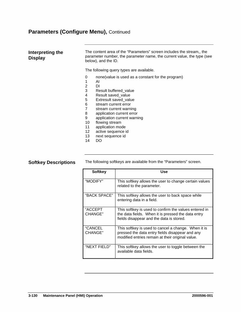
3-130 Maintenance Panel (HMI) Operation 2000596-001
Parameters (Configure Menu), Continued
The content area of the “Parameters” screen includes the stream,, the parameter number, the parameter name, the current value, the type (see below), and the ID.
The following query types are available.
0 none(value is used as a constant for the program) 1 AI 2 DI 3 Result buffered_value 4 Result saved_value 5 Extresult saved_value 6 stream current error 7 stream current warning 8 application current error 9 application current warning 10 flowing stream 11 application mode 12 active sequence id 13 next sequence id 14 DO
The following softkeys are available from the “Parameters” screen.
Softkey Use
“MODIFY” This softkey allows the user to change certain values related to the parameter.
“BACK SPACE” This softkey allows the user to back space while entering data in a field.
“ACCEPT CHANGE”
This softkey is used to confirm the values entered in the data fields. When it is pressed the data entry fields disappear and the data is stored.
“CANCEL CHANGE”
This softkey is used to cancel a change. When it is pressed the data entry fields disappear and any modified entries remain at their original value.
“NEXT FIELD” This softkey allows the user to toggle between the available data fields.
Interpreting the Display
Softkey Descriptions
2000596-001 Maintenance Panel (HMI) Operation 3-131
System I/O (Selection 7 on Configure Menu)
The “System I/O” function provides a menu of functions related to system wide input and output configurations. All inputs and outputs configured in the system are listed in the various sub-screens. The following functions are listed on the menu.
Analog Input
Analog Output
Digital Input
Digital Output
SNE Controllers
SNE Hardware
CAN Modules
The various screens are primarily for viewing the I/O information. Some limited changes can be made to certain types of information.
Each of the selections on the “System I/O” menu opens a different sub-screen. For the purposes of this manual, descriptions for each of the sub-screens are contained in separate sections within this chapter.
The “System I/O” menu can be accessed from the Maintenance Menu. If not already displayed, the Maintenance Menu is obtained by pressing the “Home” softkey and then pressing the “SELECT MENU” softkey.
Description
Note:
Menu Path

3-132 Maintenance Panel (HMI) Operation 2000596-001
System I/O (Configure Menu), Continued
Below is the menu screen that is displayed when “System I/O” is selected from the Configure Menu. The different selections on the menu are described in later sections of this chapter.
The functions listed on the “System I/O” menu are used to display and perform limited modifications on system inputs, outputs, SNE Controllers and Hardware, and CAN Modules. These settings are not specific to any particular method or application. For input and output information related to applications refer to the Maintenance Menu selection “App I/O, Temperature & Pressure”.
The only extra softkey available from the “System I/O” screen is the “SELECT” softkey. This softkey, when used with the arrow keys, will select and activate a menu item. It is also possible to use the numeric keypad to directly select menu items.
“System I/O” Menu Screen
Interpreting the Display
Softkey Description
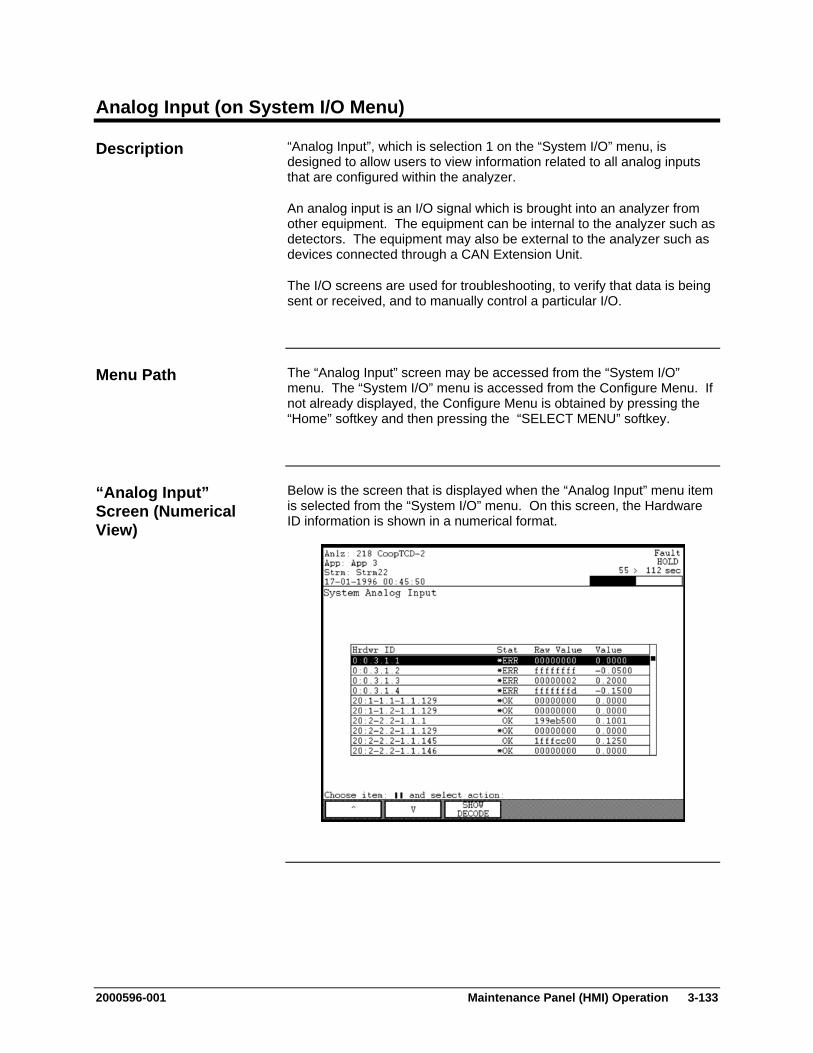
2000596-001 Maintenance Panel (HMI) Operation 3-133
Analog Input (on System I/O Menu)
“Analog Input”, which is selection 1 on the “System I/O” menu, is designed to allow users to view information related to all analog inputs that are configured within the analyzer.
An analog input is an I/O signal which is brought into an analyzer from other equipment. The equipment can be internal to the analyzer such as detectors. The equipment may also be external to the analyzer such as devices connected through a CAN Extension Unit.
The I/O screens are used for troubleshooting, to verify that data is being sent or received, and to manually control a particular I/O.
The “Analog Input” screen may be accessed from the “System I/O” menu. The “System I/O” menu is accessed from the Configure Menu. If not already displayed, the Configure Menu is obtained by pressing the “Home” softkey and then pressing the “SELECT MENU” softkey.
Below is the screen that is displayed when the “Analog Input” menu item is selected from the “System I/O” menu. On this screen, the Hardware ID information is shown in a numerical format.
Description
Menu Path
“Analog Input” Screen (Numerical View)
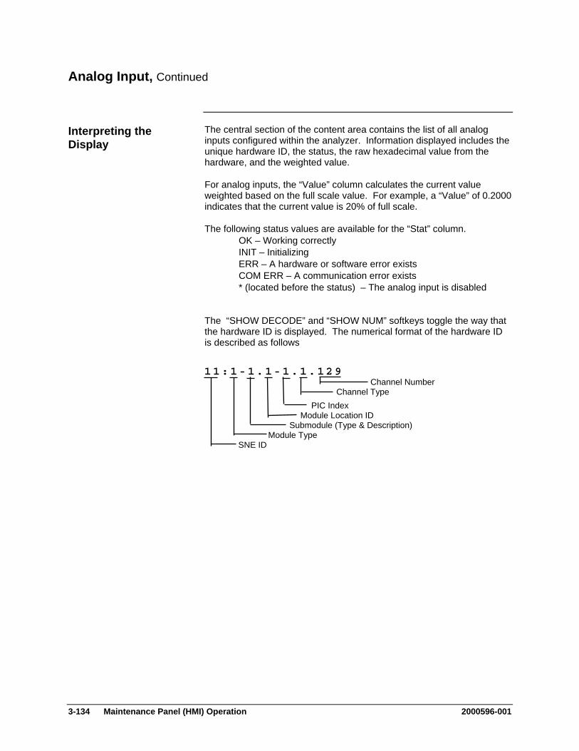
3-134 Maintenance Panel (HMI) Operation 2000596-001
Analog Input, Continued
The central section of the content area contains the list of all analog inputs configured within the analyzer. Information displayed includes the unique hardware ID, the status, the raw hexadecimal value from the hardware, and the weighted value.
For analog inputs, the “Value” column calculates the current value weighted based on the full scale value. For example, a “Value” of 0.2000 indicates that the current value is 20% of full scale.
The following status values are available for the “Stat” column. OK – Working correctly INIT – Initializing ERR – A hardware or software error exists COM ERR – A communication error exists * (located before the status) – The analog input is disabled
The “SHOW DECODE” and “SHOW NUM” softkeys toggle the way that the hardware ID is displayed. The numerical format of the hardware ID is described as follows
Interpreting the Display
11:1-1.1-1.1.129 Channel Number Channel Type PIC Index Module Location ID Submodule (Type & Description) Module Type SNE ID
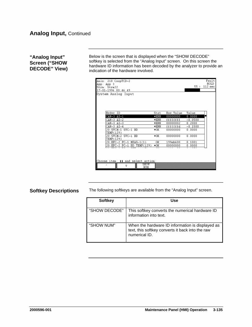
2000596-001 Maintenance Panel (HMI) Operation 3-135
Analog Input, Continued
Below is the screen that is displayed when the “SHOW DECODE” softkey is selected from the “Analog Input” screen. On this screen the hardware ID information has been decoded by the analyzer to provide an indication of the hardware involved.
The following softkeys are available from the “Analog Input” screen.
Softkey Use
“SHOW DECODE” This softkey converts the numerical hardware ID information into text.
“SHOW NUM” When the hardware ID information is displayed as text, this softkey converts it back into the raw numerical ID.
“Analog Input” Screen (“SHOW DECODE” View)
Softkey Descriptions
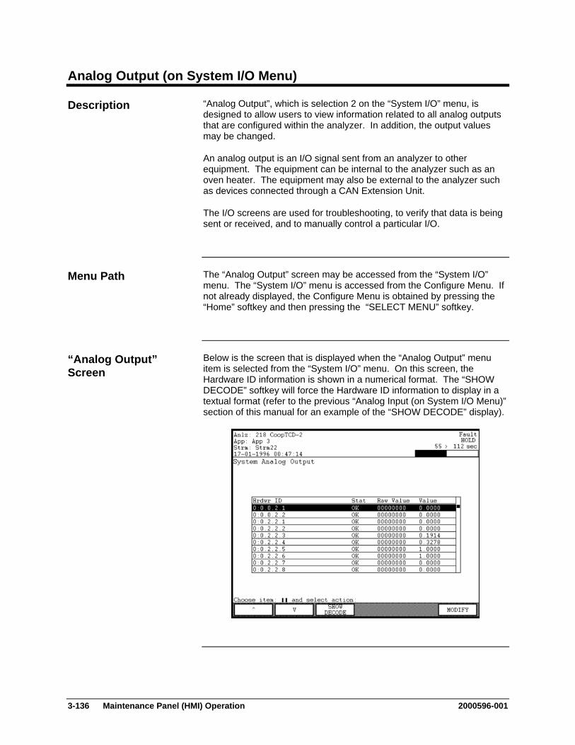
3-136 Maintenance Panel (HMI) Operation 2000596-001
Analog Output (on System I/O Menu)
“Analog Output”, which is selection 2 on the “System I/O” menu, is designed to allow users to view information related to all analog outputs that are configured within the analyzer. In addition, the output values may be changed.
An analog output is an I/O signal sent from an analyzer to other equipment. The equipment can be internal to the analyzer such as an oven heater. The equipment may also be external to the analyzer such as devices connected through a CAN Extension Unit.
The I/O screens are used for troubleshooting, to verify that data is being sent or received, and to manually control a particular I/O.
The “Analog Output” screen may be accessed from the “System I/O” menu. The “System I/O” menu is accessed from the Configure Menu. If not already displayed, the Configure Menu is obtained by pressing the “Home” softkey and then pressing the “SELECT MENU” softkey.
Below is the screen that is displayed when the “Analog Output” menu item is selected from the “System I/O” menu. On this screen, the Hardware ID information is shown in a numerical format. The “SHOW DECODE” softkey will force the Hardware ID information to display in a textual format (refer to the previous “Analog Input (on System I/O Menu)” section of this manual for an example of the “SHOW DECODE” display).
Description
Menu Path
“Analog Output” Screen
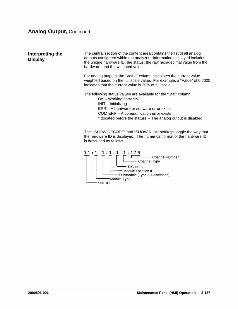
2000596-001 Maintenance Panel (HMI) Operation 3-137
Analog Output, Continued
The central section of the content area contains the list of all analog outputs configured within the analyzer. Information displayed includes the unique hardware ID, the status, the raw hexadecimal value from the hardware, and the weighted value.
For analog outputs, the “Value” column calculates the current value weighted based on the full scale value. For example, a “Value” of 0.2000 indicates that the current value is 20% of full scale.
The following status values are available for the “Stat” column. OK – Working correctly INIT – Initializing ERR – A hardware or software error exists COM ERR – A communication error exists * (located before the status) – The analog output is disabled
The “SHOW DECODE” and “SHOW NUM” softkeys toggle the way that the hardware ID is displayed. The numerical format of the hardware ID is described as follows
Interpreting the Display
11:1-1.1-1.1.129 Channel Number Channel Type PIC Index Module Location ID Submodule (Type & Description) Module Type SNE ID
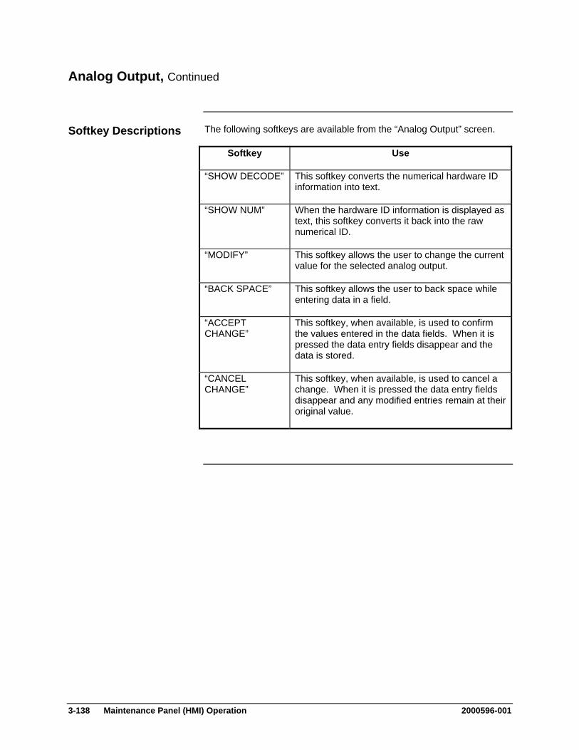
3-138 Maintenance Panel (HMI) Operation 2000596-001
Analog Output, Continued
The following softkeys are available from the “Analog Output” screen.
Softkey Use
“SHOW DECODE” This softkey converts the numerical hardware ID information into text.
“SHOW NUM” When the hardware ID information is displayed as text, this softkey converts it back into the raw numerical ID.
“MODIFY” This softkey allows the user to change the current value for the selected analog output.
“BACK SPACE” This softkey allows the user to back space while entering data in a field.
“ACCEPT CHANGE”
This softkey, when available, is used to confirm the values entered in the data fields. When it is pressed the data entry fields disappear and the data is stored.
“CANCEL CHANGE”
This softkey, when available, is used to cancel a change. When it is pressed the data entry fields disappear and any modified entries remain at their original value.
Softkey Descriptions
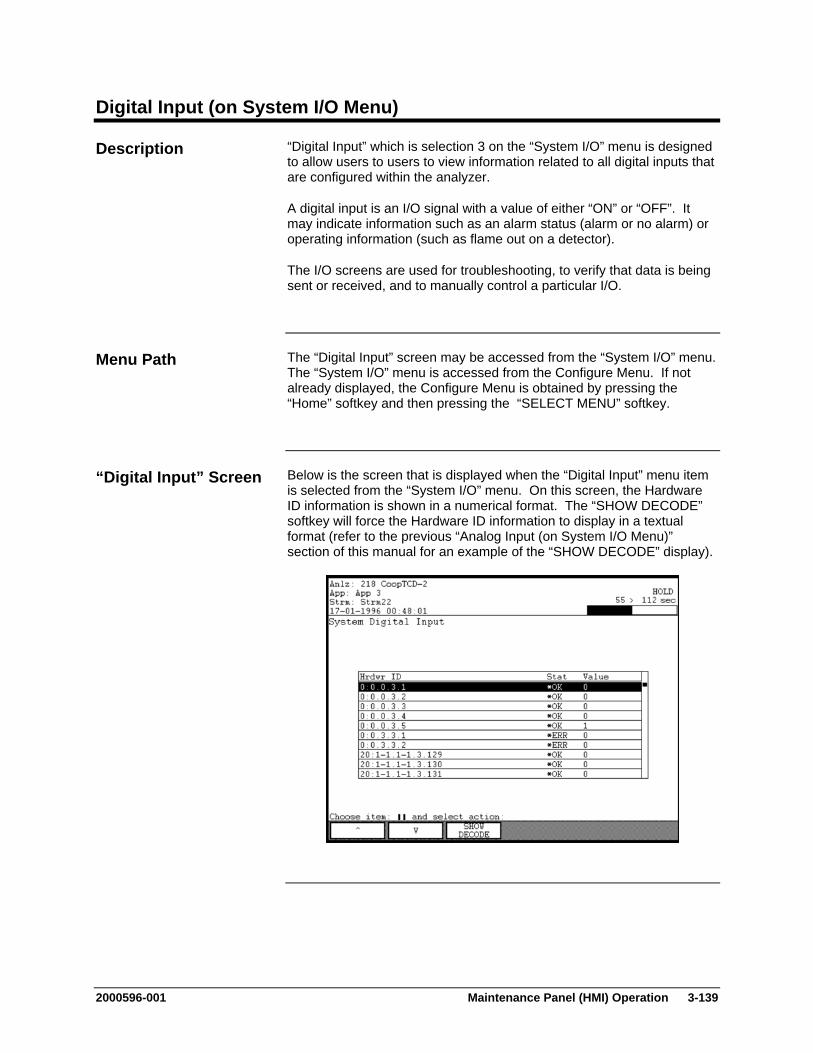
2000596-001 Maintenance Panel (HMI) Operation 3-139
Digital Input (on System I/O Menu)
“Digital Input” which is selection 3 on the “System I/O” menu is designed to allow users to users to view information related to all digital inputs that are configured within the analyzer.
A digital input is an I/O signal with a value of either “ON” or “OFF”. It may indicate information such as an alarm status (alarm or no alarm) or operating information (such as flame out on a detector).
The I/O screens are used for troubleshooting, to verify that data is being sent or received, and to manually control a particular I/O.
The “Digital Input” screen may be accessed from the “System I/O” menu. The “System I/O” menu is accessed from the Configure Menu. If not already displayed, the Configure Menu is obtained by pressing the “Home” softkey and then pressing the “SELECT MENU” softkey.
Below is the screen that is displayed when the “Digital Input” menu item is selected from the “System I/O” menu. On this screen, the Hardware ID information is shown in a numerical format. The “SHOW DECODE” softkey will force the Hardware ID information to display in a textual format (refer to the previous “Analog Input (on System I/O Menu)” section of this manual for an example of the “SHOW DECODE” display).
Description
Menu Path
“Digital Input” Screen
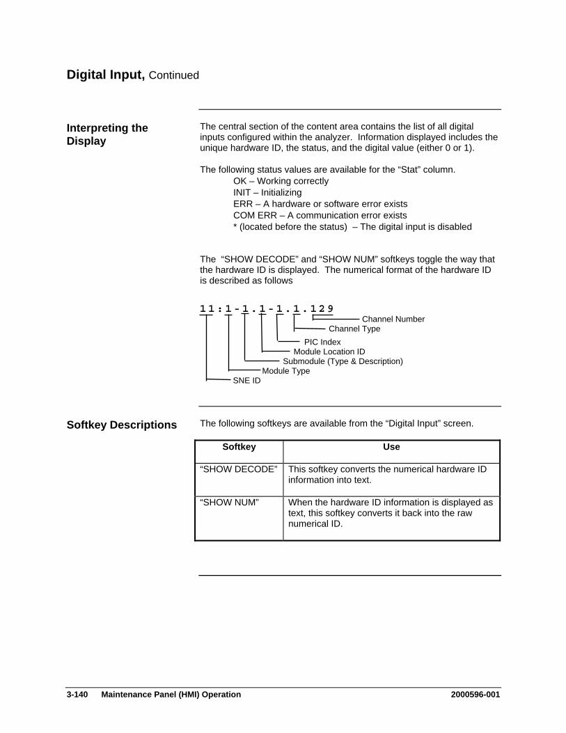
3-140 Maintenance Panel (HMI) Operation 2000596-001
Digital Input, Continued
The central section of the content area contains the list of all digital inputs configured within the analyzer. Information displayed includes the unique hardware ID, the status, and the digital value (either 0 or 1).
The following status values are available for the “Stat” column. OK – Working correctly INIT – Initializing ERR – A hardware or software error exists COM ERR – A communication error exists * (located before the status) – The digital input is disabled
The “SHOW DECODE” and “SHOW NUM” softkeys toggle the way that the hardware ID is displayed. The numerical format of the hardware ID is described as follows
The following softkeys are available from the “Digital Input” screen.
Softkey Use
“SHOW DECODE” This softkey converts the numerical hardware ID information into text.
“SHOW NUM” When the hardware ID information is displayed as text, this softkey converts it back into the raw numerical ID.
Interpreting the Display
11:1-1.1-1.1.129 Channel Number Channel Type PIC Index Module Location ID Submodule (Type & Description) Module Type SNE ID
Softkey Descriptions

2000596-001 Maintenance Panel (HMI) Operation 3-141
Digital Output (on System I/O Menu)
“Digital Output” which is selection 4 on the “System I/O” menu is designed to allow users to view information related to all digital outputs that are configured within the analyzer. In addition, the output value may be changed (toggled between 0 and 1)
A digital output is an I/O signal with a value of either “ON” or “OFF”. It is typically used to perform actions such as changing the status of a valve, injecting a sample, or igniting a detector flame.
The I/O screens are used for troubleshooting, to verify that data is being sent or received, and to manually control a particular I/O.
The “Digital Output” screen may be accessed from the “System I/O” menu. The “System I/O” menu is accessed from the Configure Menu. If not already displayed, the Configure Menu is obtained by pressing the “Home” softkey and then pressing the “SELECT MENU” softkey.
Below is the screen that is displayed when the “Digital Output” menu item is selected from the “System I/O” menu. On this screen, the Hardware ID information is shown in a numerical format. The “SHOW DECODE” softkey will force the Hardware ID information to display in a textual format (refer to the previous “Analog Input (on System I/O Menu)” section of this manual for an example of the “SHOW DECODE” display).
Description
Menu Path
“Digital Output” Screen
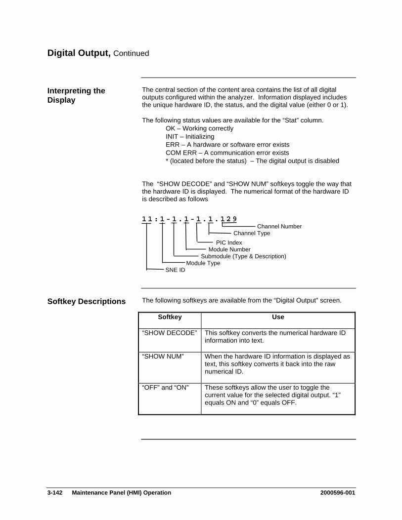
3-142 Maintenance Panel (HMI) Operation 2000596-001
Digital Output, Continued
The central section of the content area contains the list of all digital outputs configured within the analyzer. Information displayed includes the unique hardware ID, the status, and the digital value (either 0 or 1).
The following status values are available for the “Stat” column. OK – Working correctly INIT – Initializing ERR – A hardware or software error exists COM ERR – A communication error exists * (located before the status) – The digital output is disabled
The “SHOW DECODE” and “SHOW NUM” softkeys toggle the way that the hardware ID is displayed. The numerical format of the hardware ID is described as follows
The following softkeys are available from the “Digital Output” screen.
Softkey Use
“SHOW DECODE” This softkey converts the numerical hardware ID information into text.
“SHOW NUM” When the hardware ID information is displayed as text, this softkey converts it back into the raw numerical ID.
“OFF” and “ON” These softkeys allow the user to toggle the current value for the selected digital output. “1” equals ON and “0” equals OFF.
Interpreting the Display
11:1-1.1-1.1.129 Channel Number Channel Type PIC Index Module Number Submodule (Type & Description) Module Type SNE ID
Softkey Descriptions
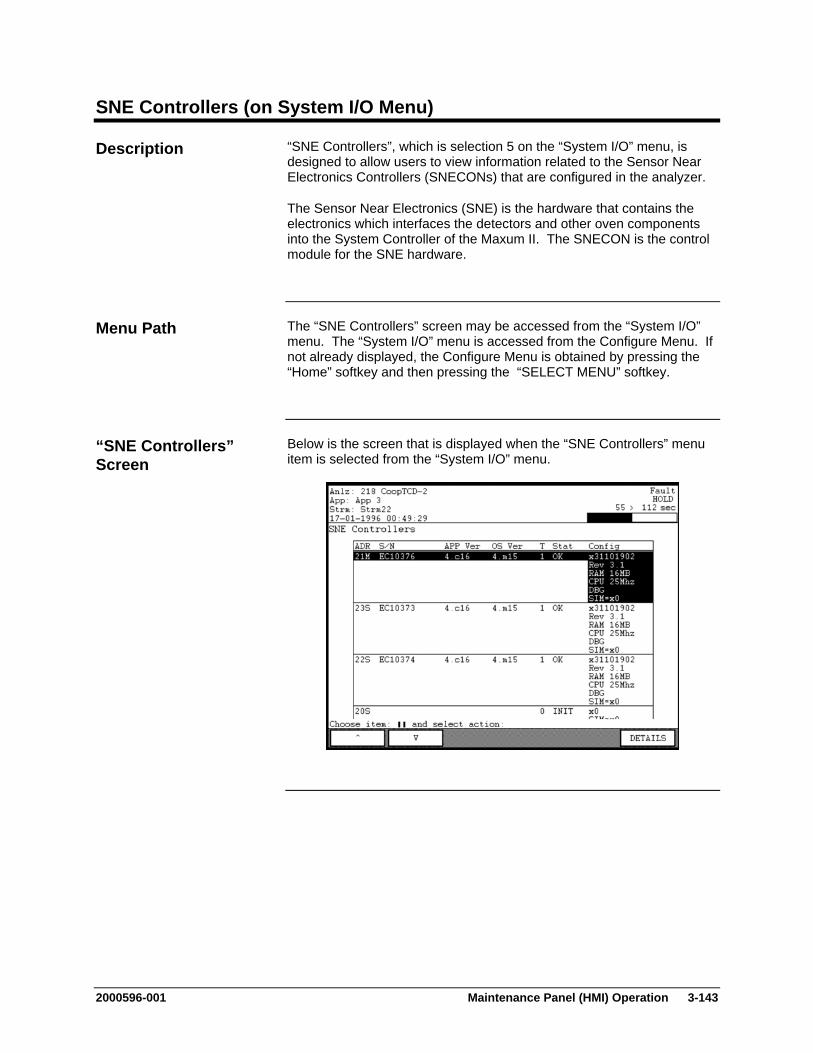
2000596-001 Maintenance Panel (HMI) Operation 3-143
SNE Controllers (on System I/O Menu)
“SNE Controllers”, which is selection 5 on the “System I/O” menu, is designed to allow users to view information related to the Sensor Near Electronics Controllers (SNECONs) that are configured in the analyzer.
The Sensor Near Electronics (SNE) is the hardware that contains the electronics which interfaces the detectors and other oven components into the System Controller of the Maxum II. The SNECON is the control module for the SNE hardware.
The “SNE Controllers” screen may be accessed from the “System I/O” menu. The “System I/O” menu is accessed from the Configure Menu. If not already displayed, the Configure Menu is obtained by pressing the “Home” softkey and then pressing the “SELECT MENU” softkey.
Below is the screen that is displayed when the “SNE Controllers” menu item is selected from the “System I/O” menu.
Description
Menu Path
“SNE Controllers” Screen
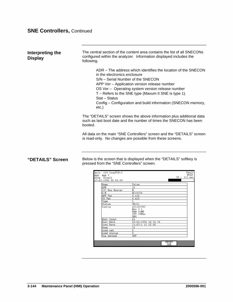
3-144 Maintenance Panel (HMI) Operation 2000596-001
SNE Controllers, Continued
The central section of the content area contains the list of all SNECONs configured within the analyzer. Information displayed includes the following.
ADR – The address which identifies the location of the SNECON in the electronics enclosure
S/N – Serial Number of the SNECON APP Ver – Application version release number OS Ver – Operating system version release number T – Refers to the SNE type (Maxum II SNE is type 1). Stat – Status Config – Configuration and build information (SNECON memory,
etc.)
The “DETAILS” screen shows the above information plus additional data such as last boot date and the number of times the SNECON has been booted.
All data on the main “SNE Controllers” screen and the “DETAILS” screen is read-only. No changes are possible from these screens.
Below is the screen that is displayed when the “DETAILS” softkey is pressed from the “SNE Controllers” screen.
Interpreting the Display
“DETAILS” Screen
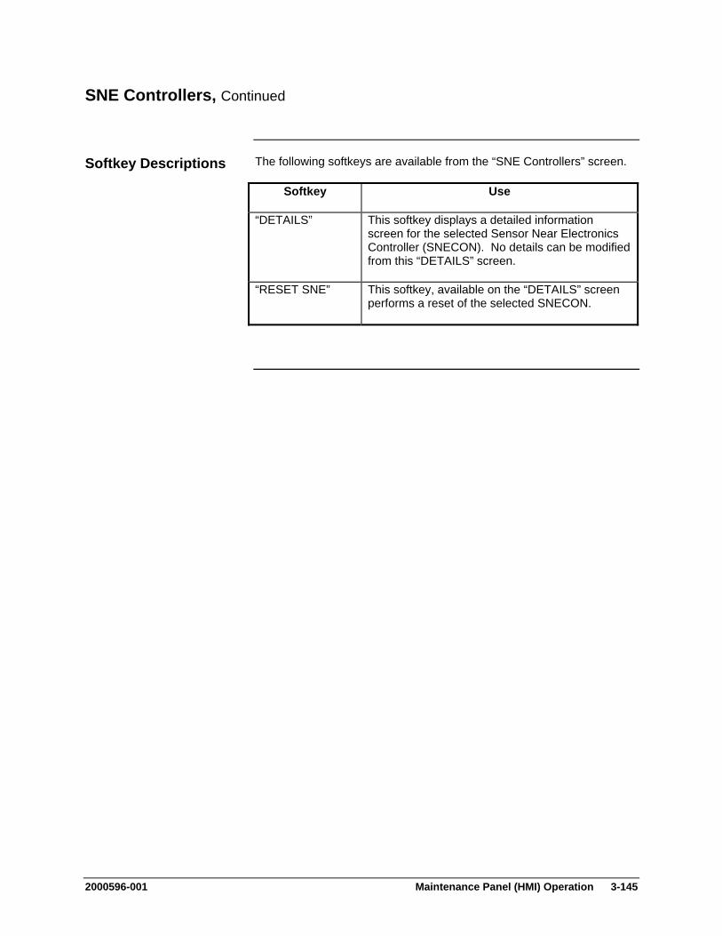
2000596-001 Maintenance Panel (HMI) Operation 3-145
SNE Controllers, Continued
The following softkeys are available from the “SNE Controllers” screen.
Softkey Use
“DETAILS” This softkey displays a detailed information screen for the selected Sensor Near Electronics Controller (SNECON). No details can be modified from this “DETAILS” screen.
“RESET SNE” This softkey, available on the “DETAILS” screen performs a reset of the selected SNECON.
Softkey Descriptions
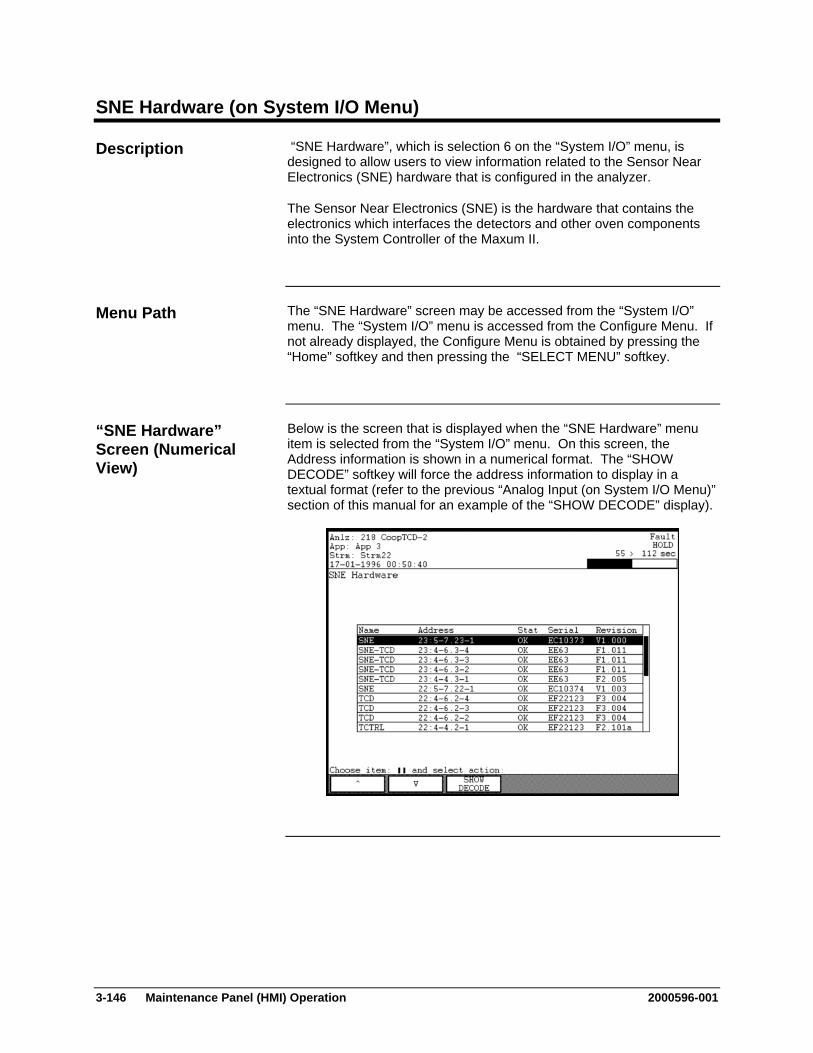
3-146 Maintenance Panel (HMI) Operation 2000596-001
SNE Hardware (on System I/O Menu)
“SNE Hardware”, which is selection 6 on the “System I/O” menu, is designed to allow users to view information related to the Sensor Near Electronics (SNE) hardware that is configured in the analyzer.
The Sensor Near Electronics (SNE) is the hardware that contains the electronics which interfaces the detectors and other oven components into the System Controller of the Maxum II.
The “SNE Hardware” screen may be accessed from the “System I/O” menu. The “System I/O” menu is accessed from the Configure Menu. If not already displayed, the Configure Menu is obtained by pressing the “Home” softkey and then pressing the “SELECT MENU” softkey.
Below is the screen that is displayed when the “SNE Hardware” menu item is selected from the “System I/O” menu. On this screen, the Address information is shown in a numerical format. The “SHOW DECODE” softkey will force the address information to display in a textual format (refer to the previous “Analog Input (on System I/O Menu)” section of this manual for an example of the “SHOW DECODE” display).
Description
Menu Path
“SNE Hardware” Screen (Numerical View)
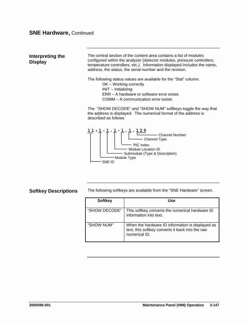
2000596-001 Maintenance Panel (HMI) Operation 3-147
SNE Hardware, Continued
The central section of the content area contains a list of modules configured within the analyzer (detector modules, pressure controllers, temperature controllers, etc.). Information displayed includes the name, address, the status, the serial number and the revision.
The following status values are available for the “Stat” column. OK – Working correctly INIT – Initializing ERR – A hardware or software error exists COMM – A communication error exists
The “SHOW DECODE” and “SHOW NUM” softkeys toggle the way that the address is displayed. The numerical format of the address is described as follows
The following softkeys are available from the “SNE Hardware” screen.
Softkey Use
“SHOW DECODE” This softkey converts the numerical hardware ID information into text.
“SHOW NUM” When the hardware ID information is displayed as text, this softkey converts it back into the raw numerical ID.
Interpreting the Display
11:1-1.1-1.1.129 Channel Number Channel Type PIC Index Module Location ID Submodule (Type & Description) Module Type SNE ID
Softkey Descriptions
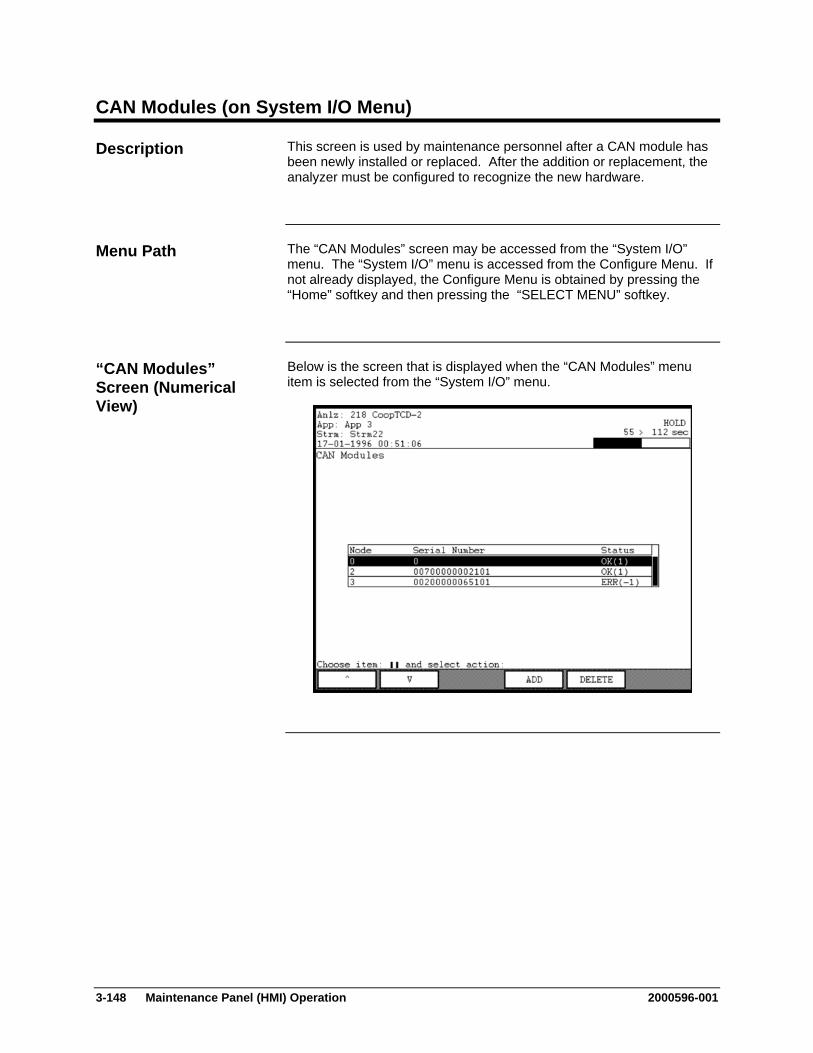
3-148 Maintenance Panel (HMI) Operation 2000596-001
CAN Modules (on System I/O Menu)
This screen is used by maintenance personnel after a CAN module has been newly installed or replaced. After the addition or replacement, the analyzer must be configured to recognize the new hardware.
The “CAN Modules” screen may be accessed from the “System I/O” menu. The “System I/O” menu is accessed from the Configure Menu. If not already displayed, the Configure Menu is obtained by pressing the “Home” softkey and then pressing the “SELECT MENU” softkey.
Below is the screen that is displayed when the “CAN Modules” menu item is selected from the “System I/O” menu.
Description
Menu Path
“CAN Modules” Screen (Numerical View)
2000596-001 Maintenance Panel (HMI) Operation 3-149
CAN Modules, Continued
When a CAN Module is replaced (or added), the analyzer configuration must be updated to reflect the serial number of the new module. The “ADD” and “DELETE” keys on the “CAN Modules” screen are used for this purpose.
If a module is replaced, delete the old value first. Make a note of the node number and then, for the appropriate CAN Module, press the “DELETE” softkey. Press the “DELETE” softkey again to confirm the deletion
To add the new module perform the following steps.
1. Obtain the 14-digit serial number from the label on the CAN module.
2. Press the “ADD” softkey from the “CAN Modules” screen.
3. Enter the 14-digit serial number. Hint: The serial number field has all of the “0” characters filled out and shows question marks (“?”) for the remaining numbers. Use the arrow softkeys to move the cursor to left of the question marks. Then type over the question mark with the correct number from the serial number.
4. Verify that the node number is correct (should match the node number of the deleted module).
5. Press the “DONE” softkey to confirm the entry.
Note: When replacing a CAN Module, the old module information must be deleted first. This is necessary so that the node number can be reused.
Adding and Deleting CAN Modules

3-150 Maintenance Panel (HMI) Operation 2000596-001
CAN Modules, Continued
The following softkeys are available from the “CAN Modules” screen.
Softkey Use
“ADD” This softkey is used to update the analyzer configuration to reflect the serial number of a new or replaced CAN Module.
“DELETE” This softkey is used to delete a CAN Module from the analyzer configuration.
“BACK SPACE” This softkey allows the user to back space while entering data in a field.
“NEXT FIELD” This softkey toggles between data entry fields.
“DONE” This softkey confirms changes that have been entered and returns the user to the previous screen. It is similar to an “ACCEPT CHANGES” softkey.
Softkey Descriptions

2000596-001 Maintenance Panel (HMI) Operation 3-151
Users/Passwords (Selection 8 on Configure Menu)
The “Users/Passwords” function is used to modify user passwords and set the default user for the analyzer.
The “Users/Passwords” function can be accessed from the Configure Menu. If not already displayed, the Configure Menu is obtained by pressing the “Home” softkey and then pressing the “SELECT MENU” softkey.
Below is the screen that is displayed when the “Users/Passwords” menu item is selected from the Configure Menu.
Description
Menu Path
“Users/Passwords” Screen

3-152 Maintenance Panel (HMI) Operation 2000596-001
Users/Passwords (Configure Menu), Continued
The default user for the system is the user that is automatically logged on after timeout or when the system is rebooted. The default user is identified in the user list by an arrow ( >) next to the user name.
By default, six users are defined. These are “public”, “operate”, “calibrate”, “maintain”, “configure”, and “super”. The default access level for each of these users matches their names. Other users (created using System Manager) may exist as well.
These users must have unique names and they can be created with either “operate”, “calibrate”, “maintain”, or “configure” access levels. Creation and deletion of users must be performed in System Manager (refer the the System Manager section of this manual for the steps to create or delete users).
Access levels are defined as follows.
1 Operate – Includes most functions on Monitor Menu 2 Calibrate – All “Operate” level functions plus calibration 3 Maintain – All “Calibrate” functions plus Maintenance Menu
functions 4 Configure – All functions except password functions. 99 Super User – All screens and functions
Interpreting the Display

2000596-001 Maintenance Panel (HMI) Operation 3-153
The following softkeys are available from the “Users/Passwords” screen.
Softkey Use
“SET DEFAULT”
This softkey sets the currently selected user to be the default user (user that gets logged on by default when the system times out or reboots).
“MODIFY” This softkey is used to change the password or access level for a user.
“BACK SPACE” This softkey allows the user to back space while entering data in a field.
“NEXT FIELD” This softkey allows the user to toggle between the available data fields.
“NEXT ITEM” This softkey produces unpredictable results. DO NOT USE.
“DONE” This softkey confirms changes that have been entered and returns the user to the previous screen. It is similar to an “ACCEPT CHANGES” softkey.
The “NEXT ITEM” softkey is known to produce unpredictable results. Do not use this softkey when modifying passwords.
Softkey Descriptions
Note:
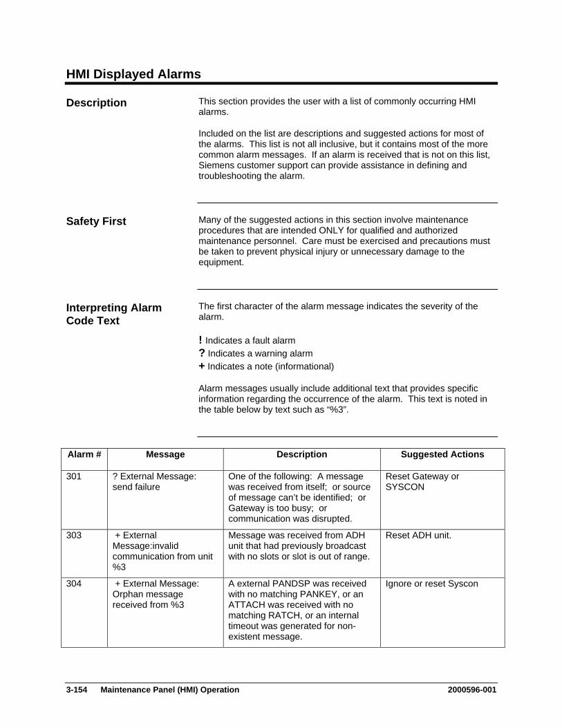
3-154 Maintenance Panel (HMI) Operation 2000596-001
HMI Displayed Alarms
This section provides the user with a list of commonly occurring HMI alarms.
Included on the list are descriptions and suggested actions for most of the alarms. This list is not all inclusive, but it contains most of the more common alarm messages. If an alarm is received that is not on this list, Siemens customer support can provide assistance in defining and troubleshooting the alarm.
Many of the suggested actions in this section involve maintenance procedures that are intended ONLY for qualified and authorized maintenance personnel. Care must be exercised and precautions must be taken to prevent physical injury or unnecessary damage to the equipment.
The first character of the alarm message indicates the severity of the alarm.
! Indicates a fault alarm ? Indicates a warning alarm + Indicates a note (informational)
Alarm messages usually include additional text that provides specific information regarding the occurrence of the alarm. This text is noted in the table below by text such as “%3”.
Alarm # Message Description Suggested Actions
301 ? External Message: send failure
One of the following: A message was received from itself; or source of message can’t be identified; or Gateway is too busy; or communication was disrupted.
Reset Gateway or SYSCON
303 + External Message:invalid communication from unit %3
Message was received from ADH unit that had previously broadcast with no slots or slot is out of range.
Reset ADH unit.
304 + External Message: Orphan message received from %3
A external PANDSP was received with no matching PANKEY, or an ATTACH was received with no matching RATCH, or an internal timeout was generated for non-existent message.
Ignore or reset Syscon
Description
Safety First
Interpreting Alarm Code Text
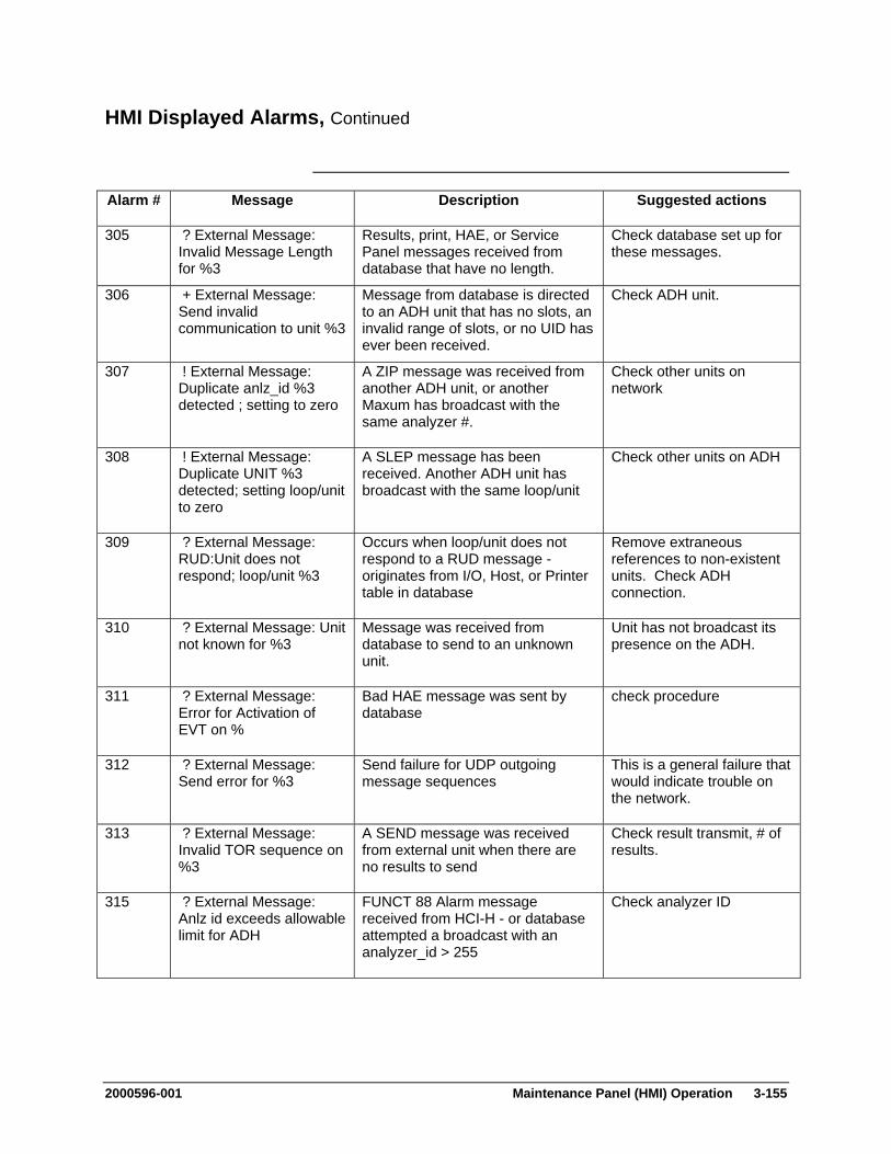
2000596-001 Maintenance Panel (HMI) Operation 3-155
HMI Displayed Alarms, Continued
Alarm # Message Description Suggested actions
305 ? External Message: Invalid Message Length for %3
Results, print, HAE, or Service Panel messages received from database that have no length.
Check database set up for these messages.
306 + External Message: Send invalid communication to unit %3
Message from database is directed to an ADH unit that has no slots, an invalid range of slots, or no UID has ever been received.
Check ADH unit.
307 ! External Message: Duplicate anlz_id %3 detected ; setting to zero
A ZIP message was received from another ADH unit, or another Maxum has broadcast with the same analyzer #.
Check other units on network
308 ! External Message: Duplicate UNIT %3 detected; setting loop/unit to zero
A SLEP message has been received. Another ADH unit has broadcast with the same loop/unit
Check other units on ADH
309 ? External Message: RUD:Unit does not respond; loop/unit %3
Occurs when loop/unit does not respond to a RUD message - originates from I/O, Host, or Printer table in database
Remove extraneous references to non-existent units. Check ADH connection.
310 ? External Message: Unit not known for %3
Message was received from database to send to an unknown unit.
Unit has not broadcast its presence on the ADH.
311 ? External Message: Error for Activation of EVT on %
Bad HAE message was sent by database
check procedure
312 ? External Message: Send error for %3
Send failure for UDP outgoing message sequences
This is a general failure that would indicate trouble on the network.
313 ? External Message: Invalid TOR sequence on %3
A SEND message was received from external unit when there are no results to send
Check result transmit, # of results.
315 ? External Message: Anlz id exceeds allowable limit for ADH
FUNCT 88 Alarm message received from HCI-H - or database attempted a broadcast with an analyzer_id > 255
Check analyzer ID

3-156 Maintenance Panel (HMI) Operation 2000596-001
HMI Displayed Alarms, Continued
Alarm # Message Description Suggested actions
316 ? External Message: Host: Anlz 1 to 50 conflict
FUNCT 89 Alarm message received from HCI-H
check # results and # streams
317 ? External Message: Host: anlz 51-254 - >1 stream or >9 components
FUNCT 90 Alarm message received from HCI-H
check # results and # streams
318 ? External Message: Host: invalid data received from anlz
no results are marked for transmission
check trtval in result table
320 ? External Message: %3 Timeout for %4
message timeout for ADREQ, REXD, results, HAE, Print, FUNCT
reset syscon
321 + External Message connection opened on: %3
Normal message from reset no action required
322 ? no ADH connection detected %3 failed
no message handler reset Syscon check boot options
323 ? External Message: Invalid LOOP %3 detected ; setting loop/unit to zero
A WRLP message has been received from ADH.
Check Loop
331 ! Run Method: No SNE found or bad status on module: %3
The connection between the database and the SNE is invalid.
Check cable between the SNE and Syscon. Check the LEDs on the SNE to see if it is operating.
332 ! Run Method: No module found for detr: %3
The SNE has not reported the detector/pressure/temperature
Check hardware connections to SNE
333 ! Run Method: No Detr found or bad status for method.channel: %3
realtime chrom attempt on invalid detector, or bad status on detector
check hrdwr_id, module for app_detector
334 ! Run Method: No Channel found for method: %3
No channels are present or can't find detector for channel
check app_detector, EZChrom method
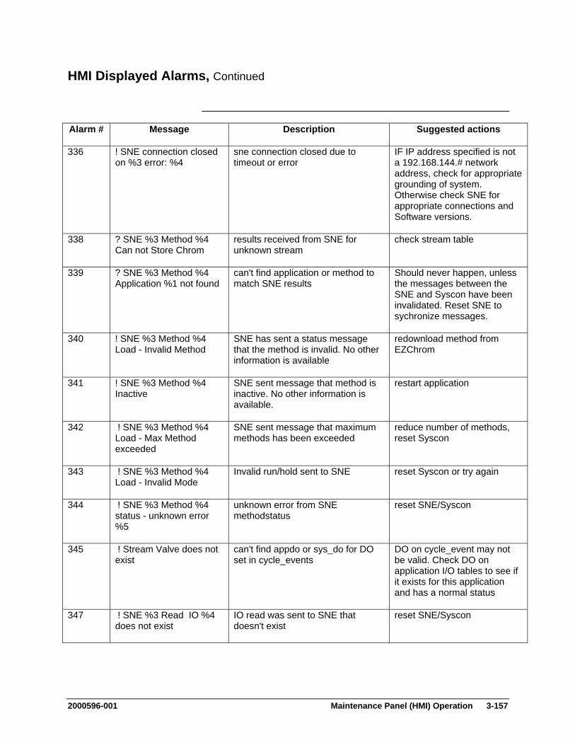
2000596-001 Maintenance Panel (HMI) Operation 3-157
HMI Displayed Alarms, Continued
Alarm # Message Description Suggested actions
336 ! SNE connection closed on %3 error: %4
sne connection closed due to timeout or error
IF IP address specified is not a 192.168.144.# network address, check for appropriate grounding of system. Otherwise check SNE for appropriate connections and Software versions.
338 ? SNE %3 Method %4 Can not Store Chrom
results received from SNE for unknown stream
check stream table
339 ? SNE %3 Method %4 Application %1 not found
can't find application or method to match SNE results
Should never happen, unless the messages between the SNE and Syscon have been invalidated. Reset SNE to sychronize messages.
340 ! SNE %3 Method %4 Load - Invalid Method
SNE has sent a status message that the method is invalid. No other information is available
redownload method from EZChrom
341 ! SNE %3 Method %4 Inactive
SNE sent message that method is inactive. No other information is available.
restart application
342 ! SNE %3 Method %4 Load - Max Method exceeded
SNE sent message that maximum methods has been exceeded
reduce number of methods, reset Syscon
343 ! SNE %3 Method %4 Load - Invalid Mode
Invalid run/hold sent to SNE reset Syscon or try again
344 ! SNE %3 Method %4 status - unknown error %5
unknown error from SNE methodstatus
reset SNE/Syscon
345 ! Stream Valve does not exist
can't find appdo or sys_do for DO set in cycle_events
DO on cycle_event may not be valid. Check DO on application I/O tables to see if it exists for this application and has a normal status
347 ! SNE %3 Read IO %4 does not exist
IO read was sent to SNE that doesn't exist
reset SNE/Syscon
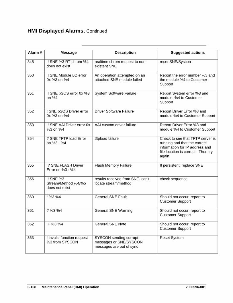
3-158 Maintenance Panel (HMI) Operation 2000596-001
HMI Displayed Alarms, Continued
Alarm # Message Description Suggested actions
348 ! SNE %3 RT chrom %4 does not exist
realtime chrom request to non-existent SNE
reset SNE/Syscon
350 ! SNE Module I/O error 0x %3 on %4
An operation attempted on an attached SNE module failed
Report the error number %3 and the module %4 to Customer Support
351 ! SNE pSOS error 0x %3 on %4
System Software Failure Report System error %3 and module %4 to Customer Support
352 ! SNE pSOS Driver error 0x %3 on %4
Driver Software Failure Report Driver Error %3 and module %4 to Customer Support
353 ! SNE AAi Driver error 0x %3 on %4
AAI custom driver failure Report Driver Error %3 and module %4 to Customer Support
354 ? SNE TFTP load Error on %3 : %4
tftpload failure Check to see that TFTP server is running and that the correct information for IP address and file location is correct. Then try again
355 ? SNE FLASH Driver Error on %3 : %4
Flash Memory Failure If persistent, replace SNE
356 ! SNE %3 Stream/Method %4/%5 does not exist
results received from SNE- can't locate stream/method
check sequence
360 ! %3 %4 General SNE Fault Should not occur, report to Customer Support
361 ? %3 %4 General SNE Warning Should not occur, report to Customer Support
362 + %3 %4 General SNE Note Should not occur, report to Customer Support
363 ! invalid function request %3 from SYSCON
SYSCON sending corrupt messages or SNE/SYSCON messages are out of sync
Reset System
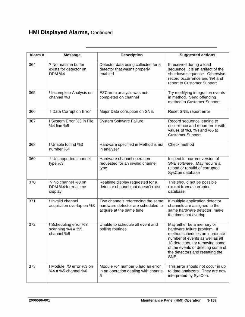
2000596-001 Maintenance Panel (HMI) Operation 3-159
HMI Displayed Alarms, Continued
Alarm # Message Description Suggested actions
364 ? No realtime buffer exists for detector on DPM %4
Detector data being collected for a detector that wasn't properly enabled.
If received during a load sequence, it is an artifact of the shutdown sequence. Otherwise, record occurrence and %4 and report to Customer Support
365 ! Incomplete Analysis on channel %3
EZChrom analysis was not completed on channel
Try modifying integration events in method. Send offending method to Customer Support
366 ! Data Corruption Error Major Data corruption on SNE. Reset SNE, report error
367 ! System Error %3 in File %4 line %5
System Software Failure Record sequence leading to occurrence and report error with values of %3, %4 and %5 to Customer Support
368 ! Unable to find %3 number %4
Hardware specified in Method is not in analyzer
Check method
369 ! Unsupported channel type %3
Hardware channel operation requested for an invalid channel type
Inspect for current version of SNE software. May require a reload or rebuild of corrupted SysCon database
370 ? No channel %3 on DPM %4 for realtime display
Realtime display requested for a detector channel that doesn't exist
This should not be possible except from a corrupted database.
371 ! Invalid channel acquisition overlap on %3
Two channels referencing the same hardware detector are scheduled to acquire at the same time.
If multiple application detector channels are assigned to the same hardware detector, make the times not overlap
372 ! Scheduling error %3 scanning %4 # %5 channel %6
Unable to schedule all event and polling routines.
May either be a memory or hardware failure problem. If method schedules an inordinate number of events as well as all 18 detectors, try removing some of the events or deleting some of the detectors and resetting the SNE.
373 ! Module I/O error %3 on %4 # %5 channel %6
Module %4 number 5 had an error in an operation dealing with channel 6
This error should not occur in up to date analyzers. They are now interpreted by SysCon.
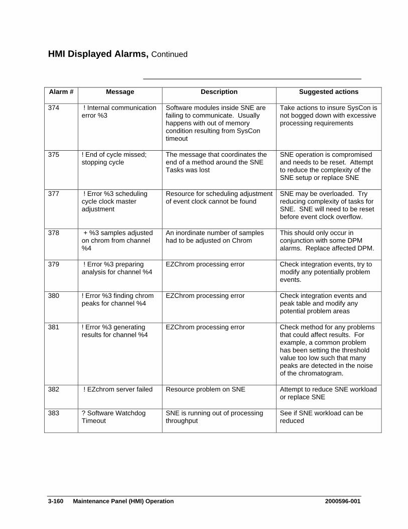
3-160 Maintenance Panel (HMI) Operation 2000596-001
HMI Displayed Alarms, Continued
Alarm # Message Description Suggested actions
374 ! Internal communication error %3
Software modules inside SNE are failing to communicate. Usually happens with out of memory condition resulting from SysCon timeout
Take actions to insure SysCon is not bogged down with excessive processing requirements
375 ! End of cycle missed; stopping cycle
The message that coordinates the end of a method around the SNE Tasks was lost
SNE operation is compromised and needs to be reset. Attempt to reduce the complexity of the SNE setup or replace SNE
377 ! Error %3 scheduling cycle clock master adjustment
Resource for scheduling adjustment of event clock cannot be found
SNE may be overloaded. Try reducing complexity of tasks for SNE. SNE will need to be reset before event clock overflow.
378 + %3 samples adjusted on chrom from channel %4
An inordinate number of samples had to be adjusted on Chrom
This should only occur in conjunction with some DPM alarms. Replace affected DPM.
379 ! Error %3 preparing analysis for channel %4
EZChrom processing error Check integration events, try to modify any potentially problem events.
380 ! Error %3 finding chrom peaks for channel %4
EZChrom processing error Check integration events and peak table and modify any potential problem areas
381 ! Error %3 generating results for channel %4
EZChrom processing error Check method for any problems that could affect results. For example, a common problem has been setting the threshold value too low such that many peaks are detected in the noise of the chromatogram.
382 ! EZchrom server failed Resource problem on SNE Attempt to reduce SNE workload or replace SNE
383 ? Software Watchdog Timeout
SNE is running out of processing throughput
See if SNE workload can be reduced
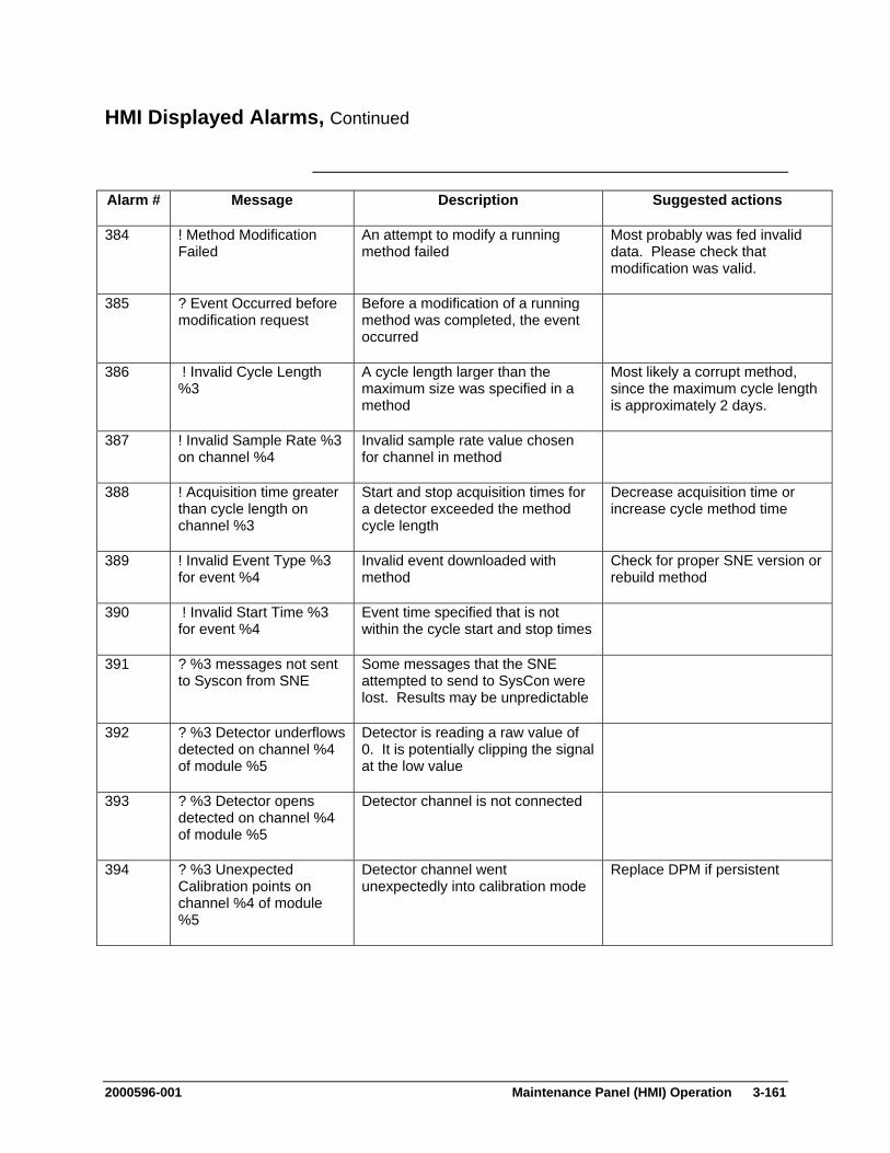
2000596-001 Maintenance Panel (HMI) Operation 3-161
HMI Displayed Alarms, Continued
Alarm # Message Description Suggested actions
384 ! Method Modification Failed
An attempt to modify a running method failed
Most probably was fed invalid data. Please check that modification was valid.
385 ? Event Occurred before modification request
Before a modification of a running method was completed, the event occurred
386 ! Invalid Cycle Length %3
A cycle length larger than the maximum size was specified in a method
Most likely a corrupt method, since the maximum cycle length is approximately 2 days.
387 ! Invalid Sample Rate %3 on channel %4
Invalid sample rate value chosen for channel in method
388 ! Acquisition time greater than cycle length on channel %3
Start and stop acquisition times for a detector exceeded the method cycle length
Decrease acquisition time or increase cycle method time
389 ! Invalid Event Type %3 for event %4
Invalid event downloaded with method
Check for proper SNE version or rebuild method
390 ! Invalid Start Time %3 for event %4
Event time specified that is not within the cycle start and stop times
391 ? %3 messages not sent to Syscon from SNE
Some messages that the SNE attempted to send to SysCon were lost. Results may be unpredictable
392 ? %3 Detector underflows detected on channel %4 of module %5
Detector is reading a raw value of 0. It is potentially clipping the signal at the low value
393 ? %3 Detector opens detected on channel %4 of module %5
Detector channel is not connected
394 ? %3 Unexpected Calibration points on channel %4 of module %5
Detector channel went unexpectedly into calibration mode
Replace DPM if persistent

3-162 Maintenance Panel (HMI) Operation 2000596-001
HMI Displayed Alarms, Continued
Alarm # Message Description Suggested actions
395 ? %3 Detector overflows on channel %4 of module %5
Detector is reading above its maximum value and the signal is being clipped
396 ! SNE out of memory at %3 line %4
Try to alleviate SNE workload. Please report %3 and %4 values to Customer Support
398 ! Invalid Number of Temperature Program Segments
The number of temperature program setpoints was different from the number sent
Try to rebuild temperature program for method
400 ! Sync Bus Failure %3 Sync Bus Test failed Replace SNE
402 + SNE reset requested SysCon requested a reset from the SNE.
Usually means that the communications between the SNE and SysCon timed out. This is can happen when SysCon is overloaded
403 ! Configured Detector %3 Balance Failure
Balance Failure from an Advance+ detector
Check detector elements
404 ? All Methods must be in Hold before Configuring Detectors
All methods must be in hold while describing any configured detectors
420 ! Heartbeat timeout MicroSAM: Check with MicroSam support personnel for assistance
421 ! Heartbeat lost MicroSAM: Check with MicroSam support personnel for assistance
422 ! Cannot connect to RSP MicroSAM: Check with MicroSam support personnel for assistance
423 ! Method %3 has more than 8 simultaneous events
MicroSAM: Check with MicroSam support personnel for assistance
424 ! Method %3 has more than 255 events
MicroSAM: Check with MicroSam support personnel for assistance
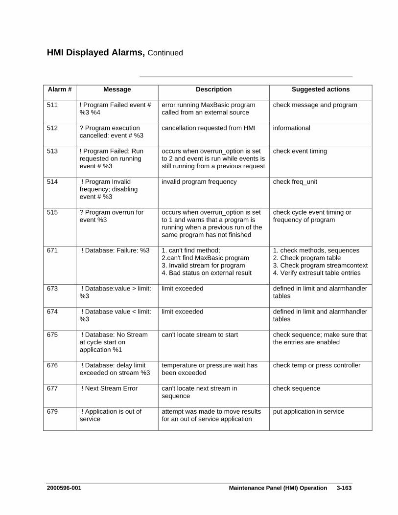
2000596-001 Maintenance Panel (HMI) Operation 3-163
HMI Displayed Alarms, Continued
Alarm # Message Description Suggested actions
511 ! Program Failed event # %3 %4
error running MaxBasic program called from an external source
check message and program
512 ? Program execution cancelled: event # %3
cancellation requested from HMI informational
513 ! Program Failed: Run requested on running event # %3
occurs when overrun_option is set to 2 and event is run while events is still running from a previous request
check event timing
514 ! Program Invalid frequency; disabling event # %3
invalid program frequency check freq_unit
515 ? Program overrun for event %3
occurs when overrun_option is set to 1 and warns that a program is running when a previous run of the same program has not finished
check cycle event timing or frequency of program
671 ! Database: Failure: %3 1. can't find method; 2.can't find MaxBasic program 3. Invalid stream for program 4. Bad status on external result
1. check methods, sequences 2. Check program table 3. Check program streamcontext4. Verify extresult table entries
673 ! Database:value > limit: %3
limit exceeded defined in limit and alarmhandler tables
674 ! Database value < limit: %3
limit exceeded defined in limit and alarmhandler tables
675 ! Database: No Stream at cycle start on application %1
can't locate stream to start check sequence; make sure that the entries are enabled
676 ! Database: delay limit exceeded on stream %3
temperature or pressure wait has been exceeded
check temp or press controller
677 ! Next Stream Error can't locate next stream in sequence
check sequence
679 ! Application is out of service
attempt was made to move results for an out of service application
put application in service
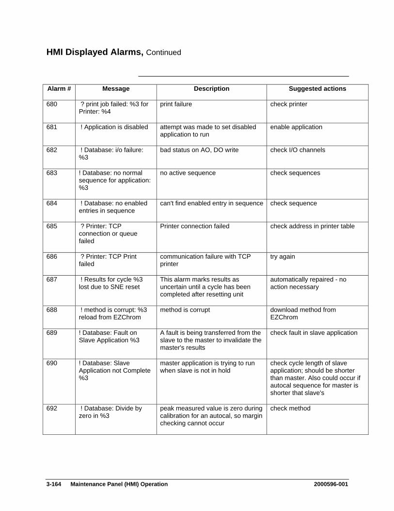
3-164 Maintenance Panel (HMI) Operation 2000596-001
HMI Displayed Alarms, Continued
Alarm # Message Description Suggested actions
680 ? print job failed: %3 for Printer: %4
print failure check printer
681 ! Application is disabled attempt was made to set disabled application to run
enable application
682 ! Database: i/o failure: %3
bad status on AO, DO write check I/O channels
683 ! Database: no normal sequence for application: %3
no active sequence check sequences
684 ! Database: no enabled entries in sequence
can't find enabled entry in sequence check sequence
685 ? Printer: TCP connection or queue failed
Printer connection failed check address in printer table
686 ? Printer: TCP Print failed
communication failure with TCP printer
try again
687 ! Results for cycle %3 lost due to SNE reset
This alarm marks results as uncertain until a cycle has been completed after resetting unit
automatically repaired - no action necessary
688 ! method is corrupt: %3 reload from EZChrom
method is corrupt download method from EZChrom
689 ! Database: Fault on Slave Application %3
A fault is being transferred from the slave to the master to invalidate the master's results
check fault in slave application
690 ! Database: Slave Application not Complete %3
master application is trying to run when slave is not in hold
check cycle length of slave application; should be shorter than master. Also could occur if autocal sequence for master is shorter that slave's
692 ! Database: Divide by zero in %3
peak measured value is zero during calibration for an autocal, so margin checking cannot occur
check method
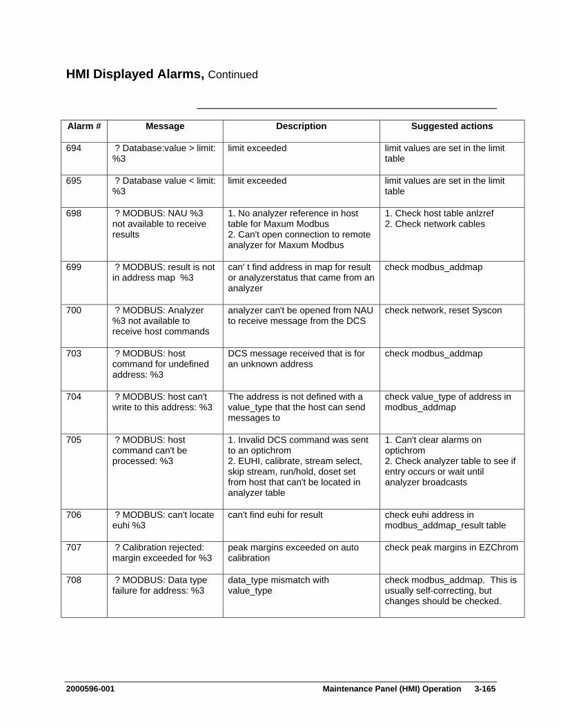
2000596-001 Maintenance Panel (HMI) Operation 3-165
HMI Displayed Alarms, Continued
Alarm # Message Description Suggested actions
694 ? Database:value > limit: %3
limit exceeded limit values are set in the limit table
695 ? Database value < limit: %3
limit exceeded limit values are set in the limit table
698 ? MODBUS: NAU %3 not available to receive results
1. No analyzer reference in host table for Maxum Modbus 2. Can't open connection to remote analyzer for Maxum Modbus
1. Check host table anlzref 2. Check network cables
699 ? MODBUS: result is not in address map %3
can' t find address in map for result or analyzerstatus that came from an analyzer
check modbus_addmap
700 ? MODBUS: Analyzer %3 not available to receive host commands
analyzer can't be opened from NAU to receive message from the DCS
check network, reset Syscon
703 ? MODBUS: host command for undefined address: %3
DCS message received that is for an unknown address
check modbus_addmap
704 ? MODBUS: host can't write to this address: %3
The address is not defined with a value_type that the host can send messages to
check value_type of address in modbus_addmap
705 ? MODBUS: host command can't be processed: %3
1. Invalid DCS command was sent to an optichrom 2. EUHI, calibrate, stream select, skip stream, run/hold, doset set from host that can't be located in analyzer table
1. Can't clear alarms on optichrom 2. Check analyzer table to see if entry occurs or wait until analyzer broadcasts
706 ? MODBUS: can't locate euhi %3
can't find euhi for result check euhi address in modbus_addmap_result table
707 ? Calibration rejected: margin exceeded for %3
peak margins exceeded on auto calibration
check peak margins in EZChrom
708 ? MODBUS: Data type failure for address: %3
data_type mismatch with value_type
check modbus_addmap. This is usually self-correcting, but changes should be checked.
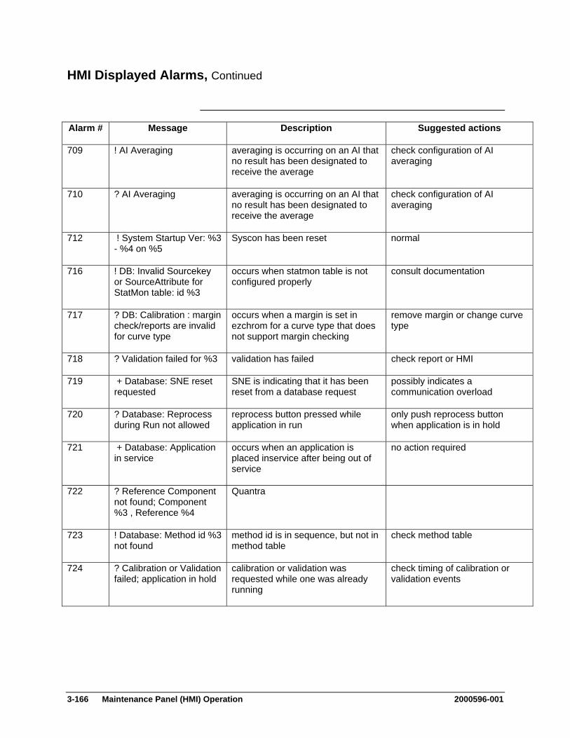
3-166 Maintenance Panel (HMI) Operation 2000596-001
HMI Displayed Alarms, Continued
Alarm # Message Description Suggested actions
709 ! AI Averaging averaging is occurring on an AI that no result has been designated to receive the average
check configuration of AI averaging
710 ? AI Averaging averaging is occurring on an AI that no result has been designated to receive the average
check configuration of AI averaging
712 ! System Startup Ver: %3 - %4 on %5
Syscon has been reset normal
716 ! DB: Invalid Sourcekey or SourceAttribute for StatMon table: id %3
occurs when statmon table is not configured properly
consult documentation
717 ? DB: Calibration : margin check/reports are invalid for curve type
occurs when a margin is set in ezchrom for a curve type that does not support margin checking
remove margin or change curve type
718 ? Validation failed for %3 validation has failed check report or HMI
719 + Database: SNE reset requested
SNE is indicating that it has been reset from a database request
possibly indicates a communication overload
720 ? Database: Reprocess during Run not allowed
reprocess button pressed while application in run
only push reprocess button when application is in hold
721 + Database: Application in service
occurs when an application is placed inservice after being out of service
no action required
722 ? Reference Component not found; Component %3 , Reference %4
Quantra
723 ! Database: Method id %3 not found
method id is in sequence, but not in method table
check method table
724 ? Calibration or Validation failed; application in hold
calibration or validation was requested while one was already running
check timing of calibration or validation events
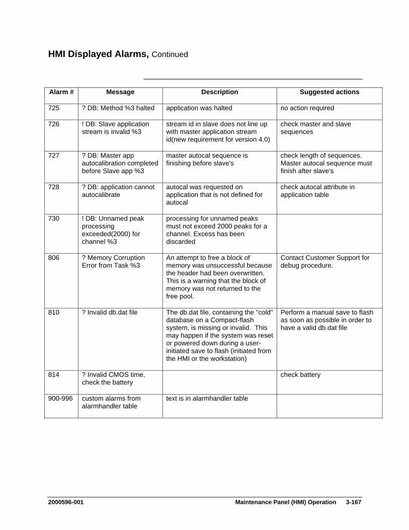
2000596-001 Maintenance Panel (HMI) Operation 3-167
HMI Displayed Alarms, Continued
Alarm # Message Description Suggested actions
725 ? DB: Method %3 halted application was halted no action required
726 ! DB: Slave application stream is invalid %3
stream id in slave does not line up with master application stream id(new requirement for version 4.0)
check master and slave sequences
727 ? DB: Master app autocalibration completed before Slave app %3
master autocal sequence is finishing before slave's
check length of sequences. Master autocal sequence must finish after slave's
728 ? DB: application cannot autocalibrate
autocal was requested on application that is not defined for autocal
check autocal attribute in application table
730 ! DB: Unnamed peak processing exceeded(2000) for channel %3
processing for unnamed peaks must not exceed 2000 peaks for a channel. Excess has been discarded
806 ? Memory Corruption Error from Task %3
An attempt to free a block of memory was unsuccessful because the header had been overwritten. This is a warning that the block of memory was not returned to the free pool.
Contact Customer Support for debug procedure.
810 ? Invalid db.dat file The db.dat file, containing the "cold" database on a Compact-flash system, is missing or invalid. This may happen if the system was reset or powered down during a user-initiated save to flash (initiated from the HMI or the workstation)
Perform a manual save to flash as soon as possible in order to have a valid db.dat file
814 ? Invalid CMOS time, check the battery
check battery
900-996 custom alarms from alarmhandler table
text is in alarmhandler table
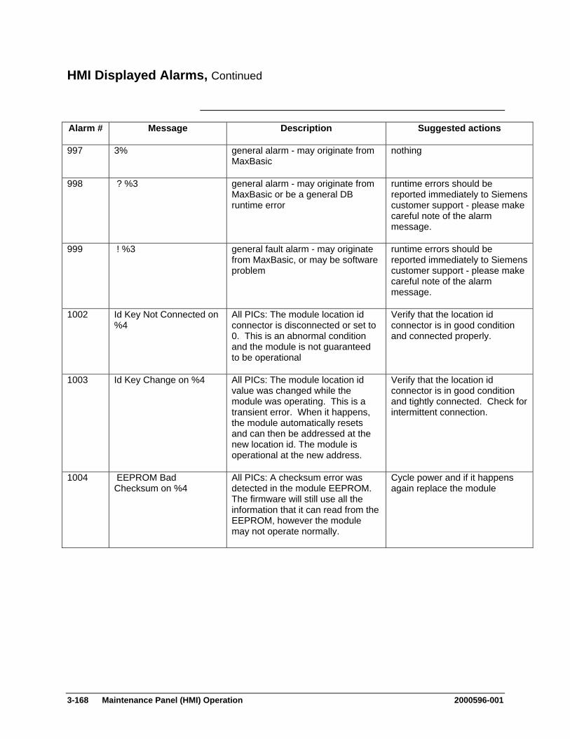
3-168 Maintenance Panel (HMI) Operation 2000596-001
HMI Displayed Alarms, Continued
Alarm # Message Description Suggested actions
997 3% general alarm - may originate from MaxBasic
nothing
998 ? %3 general alarm - may originate from MaxBasic or be a general DB runtime error
runtime errors should be reported immediately to Siemens customer support - please make careful note of the alarm message.
999 ! %3 general fault alarm - may originate from MaxBasic, or may be software problem
runtime errors should be reported immediately to Siemens customer support - please make careful note of the alarm message.
1002 Id Key Not Connected on %4
All PICs: The module location id connector is disconnected or set to 0. This is an abnormal condition and the module is not guaranteed to be operational
Verify that the location id connector is in good condition and connected properly.
1003 Id Key Change on %4 All PICs: The module location id value was changed while the module was operating. This is a transient error. When it happens, the module automatically resets and can then be addressed at the new location id. The module is operational at the new address.
Verify that the location id connector is in good condition and tightly connected. Check for intermittent connection.
1004 EEPROM Bad Checksum on %4
All PICs: A checksum error was detected in the module EEPROM. The firmware will still use all the information that it can read from the EEPROM, however the module may not operate normally.
Cycle power and if it happens again replace the module
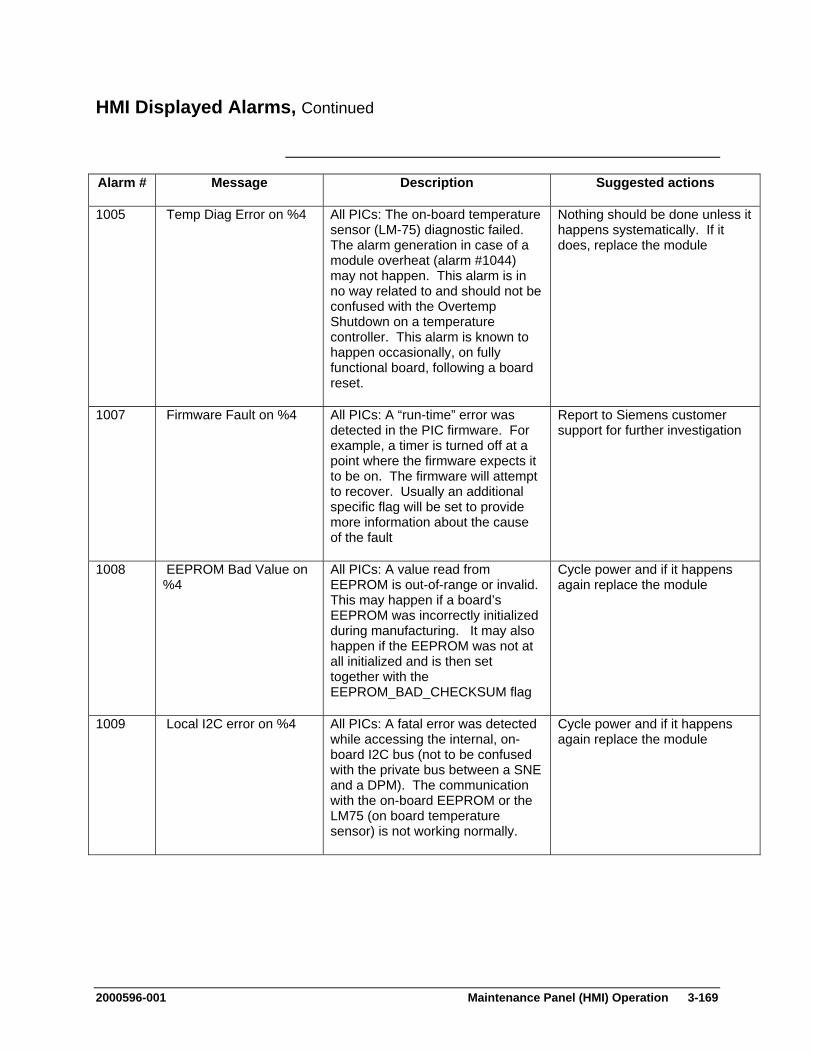
2000596-001 Maintenance Panel (HMI) Operation 3-169
HMI Displayed Alarms, Continued
Alarm # Message Description Suggested actions
1005 Temp Diag Error on %4 All PICs: The on-board temperature sensor (LM-75) diagnostic failed. The alarm generation in case of a module overheat (alarm #1044) may not happen. This alarm is in no way related to and should not be confused with the Overtemp Shutdown on a temperature controller. This alarm is known to happen occasionally, on fully functional board, following a board reset.
Nothing should be done unless it happens systematically. If it does, replace the module
1007 Firmware Fault on %4 All PICs: A “run-time” error was detected in the PIC firmware. For example, a timer is turned off at a point where the firmware expects it to be on. The firmware will attempt to recover. Usually an additional specific flag will be set to provide more information about the cause of the fault
Report to Siemens customer support for further investigation
1008 EEPROM Bad Value on %4
All PICs: A value read from EEPROM is out-of-range or invalid. This may happen if a board’s EEPROM was incorrectly initialized during manufacturing. It may also happen if the EEPROM was not at all initialized and is then set together with the EEPROM_BAD_CHECKSUM flag
Cycle power and if it happens again replace the module
1009 Local I2C error on %4 All PICs: A fatal error was detected while accessing the internal, on-board I2C bus (not to be confused with the private bus between a SNE and a DPM). The communication with the on-board EEPROM or the LM75 (on board temperature sensor) is not working normally.
Cycle power and if it happens again replace the module
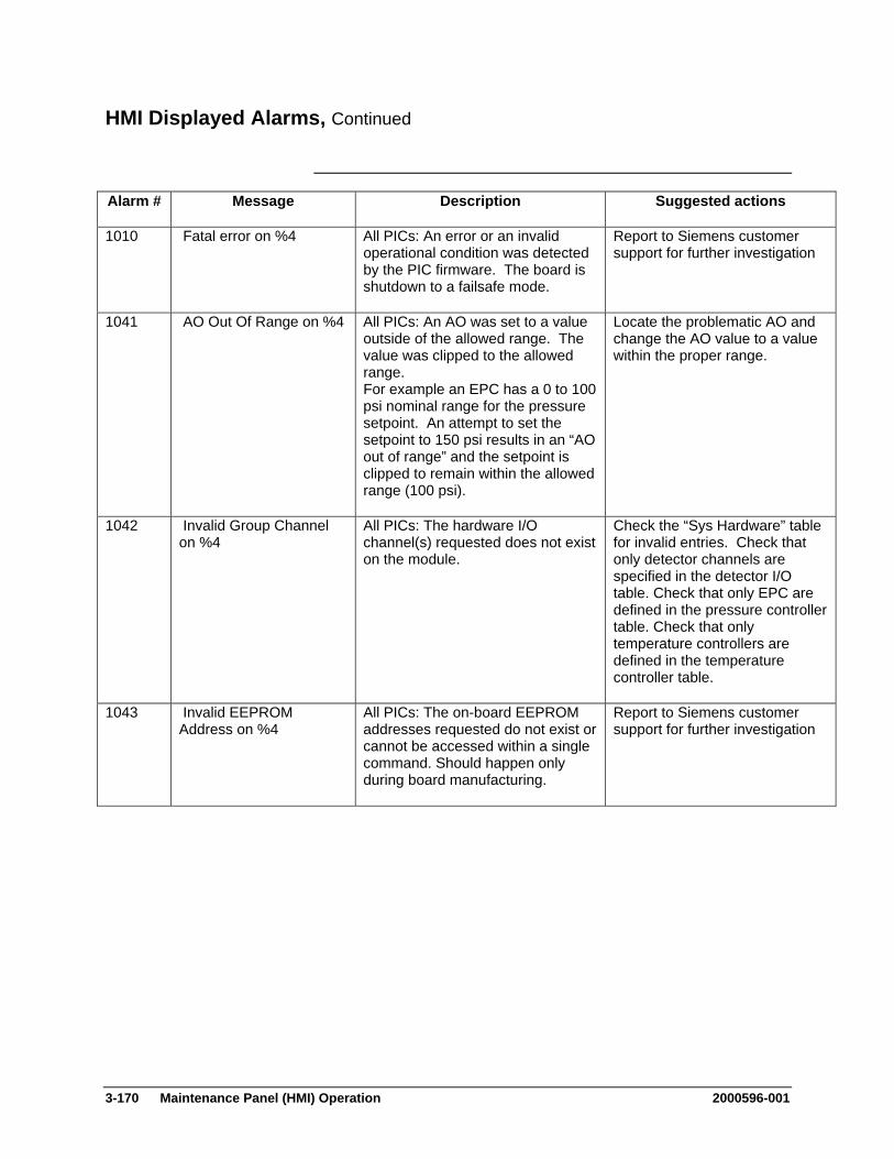
3-170 Maintenance Panel (HMI) Operation 2000596-001
HMI Displayed Alarms, Continued
Alarm # Message Description Suggested actions
1010 Fatal error on %4 All PICs: An error or an invalid operational condition was detected by the PIC firmware. The board is shutdown to a failsafe mode.
Report to Siemens customer support for further investigation
1041 AO Out Of Range on %4 All PICs: An AO was set to a value outside of the allowed range. The value was clipped to the allowed range. For example an EPC has a 0 to 100 psi nominal range for the pressure setpoint. An attempt to set the setpoint to 150 psi results in an “AO out of range” and the setpoint is clipped to remain within the allowed range (100 psi).
Locate the problematic AO and change the AO value to a value within the proper range.
1042 Invalid Group Channel on %4
All PICs: The hardware I/O channel(s) requested does not exist on the module.
Check the “Sys Hardware” table for invalid entries. Check that only detector channels are specified in the detector I/O table. Check that only EPC are defined in the pressure controller table. Check that only temperature controllers are defined in the temperature controller table.
1043 Invalid EEPROM Address on %4
All PICs: The on-board EEPROM addresses requested do not exist or cannot be accessed within a single command. Should happen only during board manufacturing.
Report to Siemens customer support for further investigation
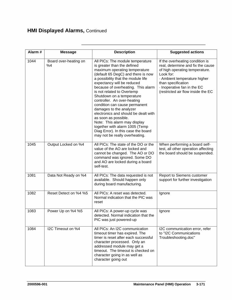
2000596-001 Maintenance Panel (HMI) Operation 3-171
HMI Displayed Alarms, Continued
Alarm # Message Description Suggested actions
1044 Board over-heating on %4
All PICs: The module temperature is greater than the defined maximum operating temperature (default 65 DegC) and there is now a possibility that the module life expectancy will be reduced because of overheating. This alarm is not related to Overtemp Shutdown on a temperature controller. An over-heating condition can cause permanent damages to the analyzer electronics and should be dealt with as soon as possible. Note: This alarm may display together with alarm 1005 (Temp Diag Error). In this case the board may not be really overheating.
If the overheating condition is real, determine and fix the cause of high operating temperature. Look for: · Ambient temperature higher than specification · Inoperative fan in the EC (restricted air flow inside the EC
1045 Output Locked on %4 All PICs: The state of the DO or the value of the AO are locked and cannot be changed. The AO or DO command was ignored. Some DO and AO are locked during a board self-test.
When performing a board self-test, all other operation affecting the board should be suspended.
1081 Data Not Ready on %4 All PICs: The data requested is not available. Should happen only during board manufacturing.
Report to Siemens customer support for further investigation
1082 Reset Detect on %4 %5 All PICs: A reset was detected. Normal indication that the PIC was reset
Ignore
1083 Power Up on %4 %5 All PICs: A power-up cycle was detected. Normal indication that the PIC was just powered-up
Ignore
1084 I2C Timeout on %4 All PICs: An I2C communication timeout timer has expired. The timer is reset after each successful character processed. Only an addressed module may get a timeout. The timeout is checked on character going in as well as character going out
I2C communication error, refer to "I2C Communications Troubleshooting.doc"
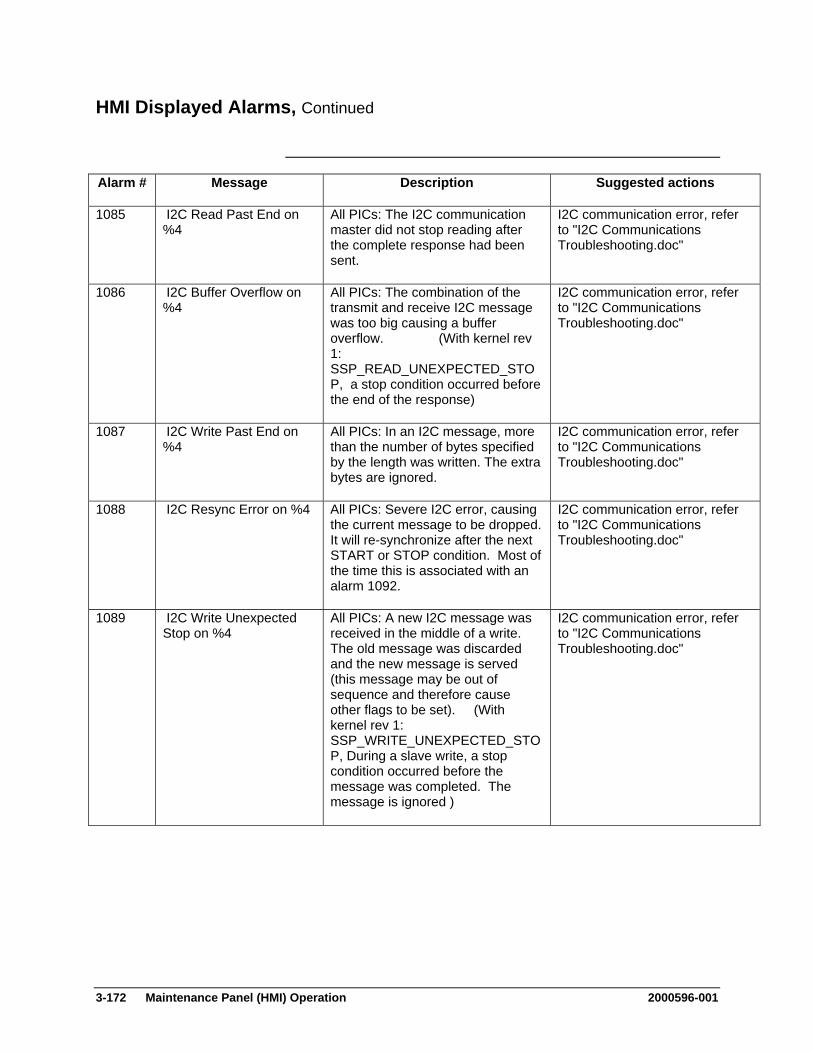
3-172 Maintenance Panel (HMI) Operation 2000596-001
HMI Displayed Alarms, Continued
Alarm # Message Description Suggested actions
1085 I2C Read Past End on %4
All PICs: The I2C communication master did not stop reading after the complete response had been sent.
I2C communication error, refer to "I2C Communications Troubleshooting.doc"
1086 I2C Buffer Overflow on %4
All PICs: The combination of the transmit and receive I2C message was too big causing a buffer overflow. (With kernel rev 1: SSP_READ_UNEXPECTED_STOP, a stop condition occurred before the end of the response)
I2C communication error, refer to "I2C Communications Troubleshooting.doc"
1087 I2C Write Past End on %4
All PICs: In an I2C message, more than the number of bytes specified by the length was written. The extra bytes are ignored.
I2C communication error, refer to "I2C Communications Troubleshooting.doc"
1088 I2C Resync Error on %4 All PICs: Severe I2C error, causing the current message to be dropped. It will re-synchronize after the next START or STOP condition. Most of the time this is associated with an alarm 1092.
I2C communication error, refer to "I2C Communications Troubleshooting.doc"
1089 I2C Write Unexpected Stop on %4
All PICs: A new I2C message was received in the middle of a write. The old message was discarded and the new message is served (this message may be out of sequence and therefore cause other flags to be set). (With kernel rev 1: SSP_WRITE_UNEXPECTED_STOP, During a slave write, a stop condition occurred before the message was completed. The message is ignored )
I2C communication error, refer to "I2C Communications Troubleshooting.doc"

2000596-001 Maintenance Panel (HMI) Operation 3-173
HMI Displayed Alarms, Continued
Alarm # Message Description Suggested actions
1090 I2C Write Unexpected Strt on %4
All PICs: A new I2C message was received in the middle of a read. The old message was discarded and the new message is served (this message may be out of sequence and therefore cause other flags to be set). (With kernel rev 1: SSP_WRITE_UNEXPECTED_START, During a slave write a Start or Repeat Start (RS) condition was detected before the entire message was received (according to the length field). The message is ignored and processing resumes following the Start or Repeat Start )
I2C communication error, refer to "I2C Communications Troubleshooting.doc"
1091 I2C Write Before Read on %4
All PICs: An attempt was made to write an I2C message before reading the response from a previous message. This means that an attempt was made to do a Slave Write - RepeatStart - Slave Write combination
I2C communication error, refer to "I2C Communications Troubleshooting.doc"
1092 I2C Read Unexpected on %4
All PICs: An I2C read from the peripheral was attempted before a slave write loaded a command
I2C communication error, refer to "I2C Communications Troubleshooting.doc"
1093 I2C Invalid Checksum on %4
All PICs: An I2C message with an invalid checksum was received. The message was ignored
I2C communication error, refer to "I2C Communications Troubleshooting.doc"
1094 Data not available on %4
All PICs: Some data was lost and is no longer available. For a detector channel it means that a “Detector Read” command was received with an invalid index. This can happen when a request to retransmit detector data came too late when the data was already gone from the buffer. This situation may also happen while accessing the I/O related to the LM75 (BOARD_TEMPERATURE and OVERTEMP_SETPOINT). It indicates that the local I2C bus was not available to perform the desired action.
Cycle power and if it happens again replace the module or the SNECON
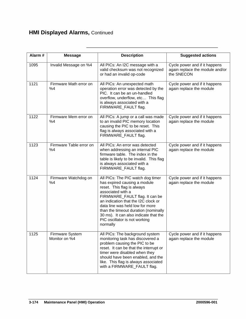
3-174 Maintenance Panel (HMI) Operation 2000596-001
HMI Displayed Alarms, Continued
Alarm # Message Description Suggested actions
1095 Invalid Message on %4 All PICs: An I2C message with a valid checksum was not recognized or had an invalid op-code
Cycle power and if it happens again replace the module and/or the SNECON
1121 Firmware Math error on %4
All PICs: An unexpected math operation error was detected by the PIC. It can be an un-handled overflow, underflow, etc… This flag is always associated with a FIRMWARE_FAULT flag.
Cycle power and if it happens again replace the module
1122 Firmware Mem error on %4
All PICs: A jump or a call was made to an invalid PIC memory location causing the PIC to be reset. This flag is always associated with a FIRMWARE_FAULT flag.
Cycle power and if it happens again replace the module
1123 Firmware Table error on %4
All PICs: An error was detected when addressing an internal PIC firmware table. The index in the table is likely to be invalid. This flag is always associated with a FIRMWARE_FAULT flag.
Cycle power and if it happens again replace the module
1124 Firmware Watchdog on %4
All PICs: The PIC watch dog timer has expired causing a module reset. This flag is always associated with a FIRMWARE_FAULT flag. It can be an indication that the I2C clock or data line was held low for more than the timeout duration (nominally 30 ms). It can also indicate that the PIC oscillator is not working normally
Cycle power and if it happens again replace the module
1125 Firmware System Monitor on %4
All PICs: The background system monitoring task has discovered a problem causing the PIC to be reset. It can be that the interrupt or timer were disabled when they should have been enabled, and the like. This flag is always associated with a FIRMWARE_FAULT flag.
Cycle power and if it happens again replace the module

2000596-001 Maintenance Panel (HMI) Operation 3-175
HMI Displayed Alarms, Continued
Alarm # Message Description Suggested actions
1126 Firmware Application on %4
All PICs: A general PIC firmware error was encountered causing a board reset.
Cycle power and if it happens again replace the module
1317 Valve Switch Error on %4
SVCM PIC: The SVCM firmware has detected an invalid condition in the circuit driving the solenoid valves. One or more valve is likely to be malfunctioning
Replace the module
1318 J10 Disconnected on %4
SVCM PIC: The SVCM J10 connector is not properly connected and the corresponding bank of solenoid may not work
Check the corresponding connection
1319 J11 Disconnected on %4
SVCM PIC: The SVCM J11 connector is not properly connected and the corresponding bank of solenoid may not work
Check the corresponding connection
1617 LWH1 Output Fault on %4
PECM PIC: On-board diagnostic indicating that LWH1 is not working correctly. This diagnostic is active only when a SSR output is configured for PECM self control, when the loop-back connector is present. The diagnostic is not active when the control is from a temperature controller. If this happens when the output is controlled by a temperature controller, it indicates a defective harness between the DPM and the PECM. (The PLUG_DETECT pin (#5) is not grounded and the output is turned on)
If associated with an “Invalid configuration alarm” (1659), then check the corresponding connection on J3 on PECM. Otherwise, replace the PECM or the cable between the DPM and PECM
1618 Lwh2 Output Fault on %4
PECM PIC: On-board diagnostic indicating that LWH2 is not working correctly. See 1617 for more details
Check J4 on PECM … See 1617
1619 Lwh3 Output Fault on %4
PECM PIC: On-board diagnostic indicating that LWH3 is not working correctly. See 1617 for more details
Check J5 on PECM … See 1617
1620 Lwh4 Output Fault on %4
PECM PIC: On-board diagnostic indicating that LWH4 is not working correctly. See 1617 for more details
Check J6 on PECM … See 1617
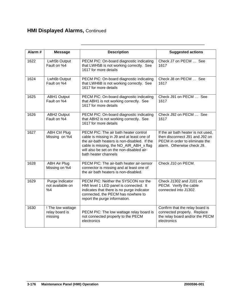
3-176 Maintenance Panel (HMI) Operation 2000596-001
HMI Displayed Alarms, Continued
Alarm # Message Description Suggested actions
1622 Lwh5b Output Fault on %4
PECM PIC: On-board diagnostic indicating that LWH5B is not working correctly. See 1617 for more details
Check J7 on PECM … See 1617
1624 Lwh6b Output Fault on %4
PECM PIC: On-board diagnostic indicating that LWH6B is not working correctly. See 1617 for more details
Check J8 on PECM … See 1617
1625 ABH1 Output Fault on %4
PECM PIC: On-board diagnostic indicating that ABH1 is not working correctly. See 1617 for more details
Check J91 on PECM … See 1617
1626 ABH2 Output Fault on %4
PECM PIC: On-board diagnostic indicating that ABH2 is not working correctly. See 1617 for more details
Check J92 on PECM … See 1617
1627 ABH Ctrl Plug Missing on %4
PECM PIC: The air bath heater control cable is missing in J9 and at least one of the air-bath heaters is non-disabled. If the cable is missing, the NO_AIR_ABH_x flag will also be set on the non-disabled air-bath heater channels
If the air bath heater is not used, then disconnect J91 and J92 on PECM in order to eliminate the alarm. Otherwise check J9.
1628 ABH Air Plug Missing on %4
PECM PIC: The air-bath heater air-sensor connector is missing and at least one of the air bath heaters is non-disabled.
Check J10 on PECM.
1629 Purge Indicator not available on %4
PECM PIC: Neither the SYSCON nor the HMI level 1 LED panel is connected. It indicates that there is no purge indicator connected, the PECM has nowhere to report the purge information.
Check J1302 and J101 on PECM. Verify the cable connected into J1302.
1630 ! The low wattage relay board is missing
PECM PIC: The low wattage relay board is not connected properly to the PECM electronics
Confirm that the relay board is connected properly. Replace the relay board and/or the PECM electronics
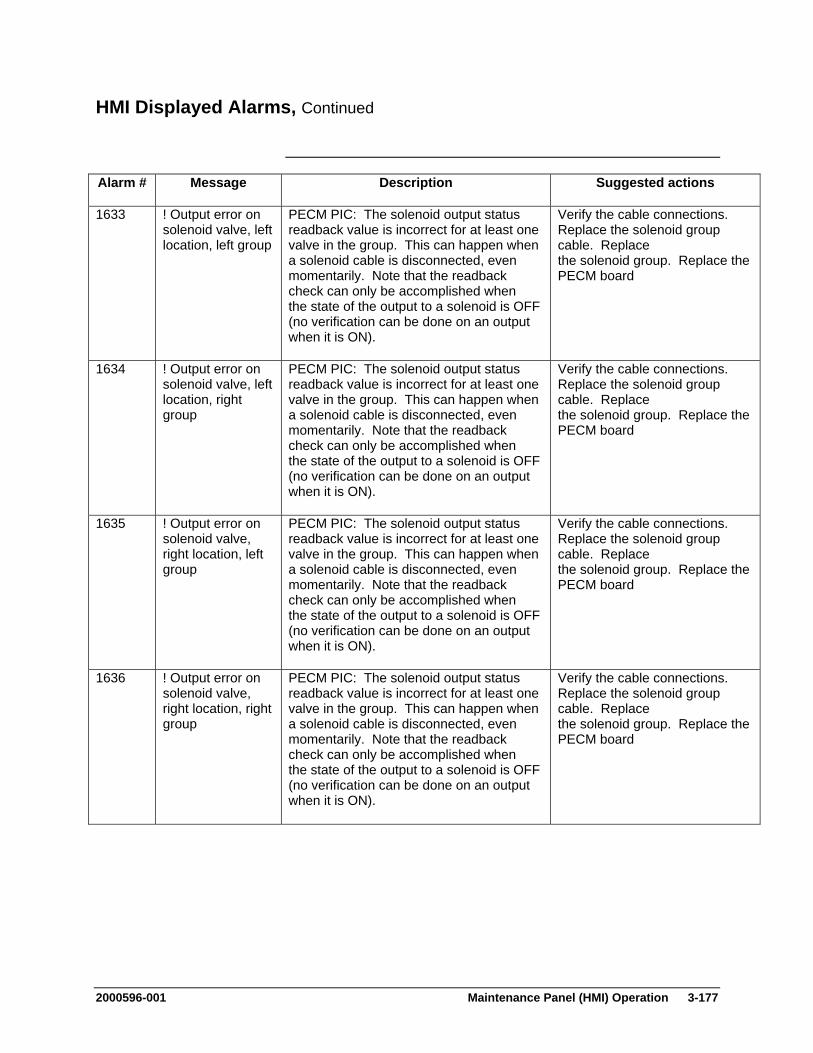
2000596-001 Maintenance Panel (HMI) Operation 3-177
HMI Displayed Alarms, Continued
Alarm # Message Description Suggested actions
1633 ! Output error on solenoid valve, left location, left group
PECM PIC: The solenoid output status readback value is incorrect for at least one valve in the group. This can happen when a solenoid cable is disconnected, even momentarily. Note that the readback check can only be accomplished when the state of the output to a solenoid is OFF (no verification can be done on an output when it is ON).
Verify the cable connections. Replace the solenoid group cable. Replace the solenoid group. Replace the PECM board
1634 ! Output error on solenoid valve, left location, right group
PECM PIC: The solenoid output status readback value is incorrect for at least one valve in the group. This can happen when a solenoid cable is disconnected, even momentarily. Note that the readback check can only be accomplished when the state of the output to a solenoid is OFF (no verification can be done on an output when it is ON).
Verify the cable connections. Replace the solenoid group cable. Replace the solenoid group. Replace the PECM board
1635 ! Output error on solenoid valve, right location, left group
PECM PIC: The solenoid output status readback value is incorrect for at least one valve in the group. This can happen when a solenoid cable is disconnected, even momentarily. Note that the readback check can only be accomplished when the state of the output to a solenoid is OFF (no verification can be done on an output when it is ON).
Verify the cable connections. Replace the solenoid group cable. Replace the solenoid group. Replace the PECM board
1636 ! Output error on solenoid valve, right location, right group
PECM PIC: The solenoid output status readback value is incorrect for at least one valve in the group. This can happen when a solenoid cable is disconnected, even momentarily. Note that the readback check can only be accomplished when the state of the output to a solenoid is OFF (no verification can be done on an output when it is ON).
Verify the cable connections. Replace the solenoid group cable. Replace the solenoid group. Replace the PECM board
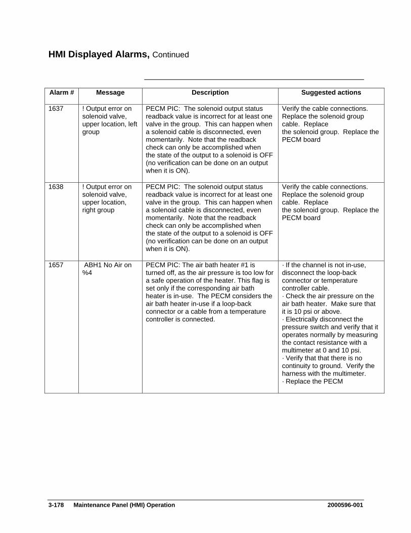
3-178 Maintenance Panel (HMI) Operation 2000596-001
HMI Displayed Alarms, Continued
Alarm # Message Description Suggested actions
1637 ! Output error on solenoid valve, upper location, left group
PECM PIC: The solenoid output status readback value is incorrect for at least one valve in the group. This can happen when a solenoid cable is disconnected, even momentarily. Note that the readback check can only be accomplished when the state of the output to a solenoid is OFF (no verification can be done on an output when it is ON).
Verify the cable connections. Replace the solenoid group cable. Replace the solenoid group. Replace the PECM board
1638 ! Output error on solenoid valve, upper location, right group
PECM PIC: The solenoid output status readback value is incorrect for at least one valve in the group. This can happen when a solenoid cable is disconnected, even momentarily. Note that the readback check can only be accomplished when the state of the output to a solenoid is OFF (no verification can be done on an output when it is ON).
Verify the cable connections. Replace the solenoid group cable. Replace the solenoid group. Replace the PECM board
1657 ABH1 No Air on %4
PECM PIC: The air bath heater #1 is turned off, as the air pressure is too low for a safe operation of the heater. This flag is set only if the corresponding air bath heater is in-use. The PECM considers the air bath heater in-use if a loop-back connector or a cable from a temperature controller is connected.
· If the channel is not in-use, disconnect the loop-back connector or temperature controller cable. · Check the air pressure on the air bath heater. Make sure that it is 10 psi or above. · Electrically disconnect the pressure switch and verify that it operates normally by measuring the contact resistance with a multimeter at 0 and 10 psi. · Verify that that there is no continuity to ground. Verify the harness with the multimeter. · Replace the PECM
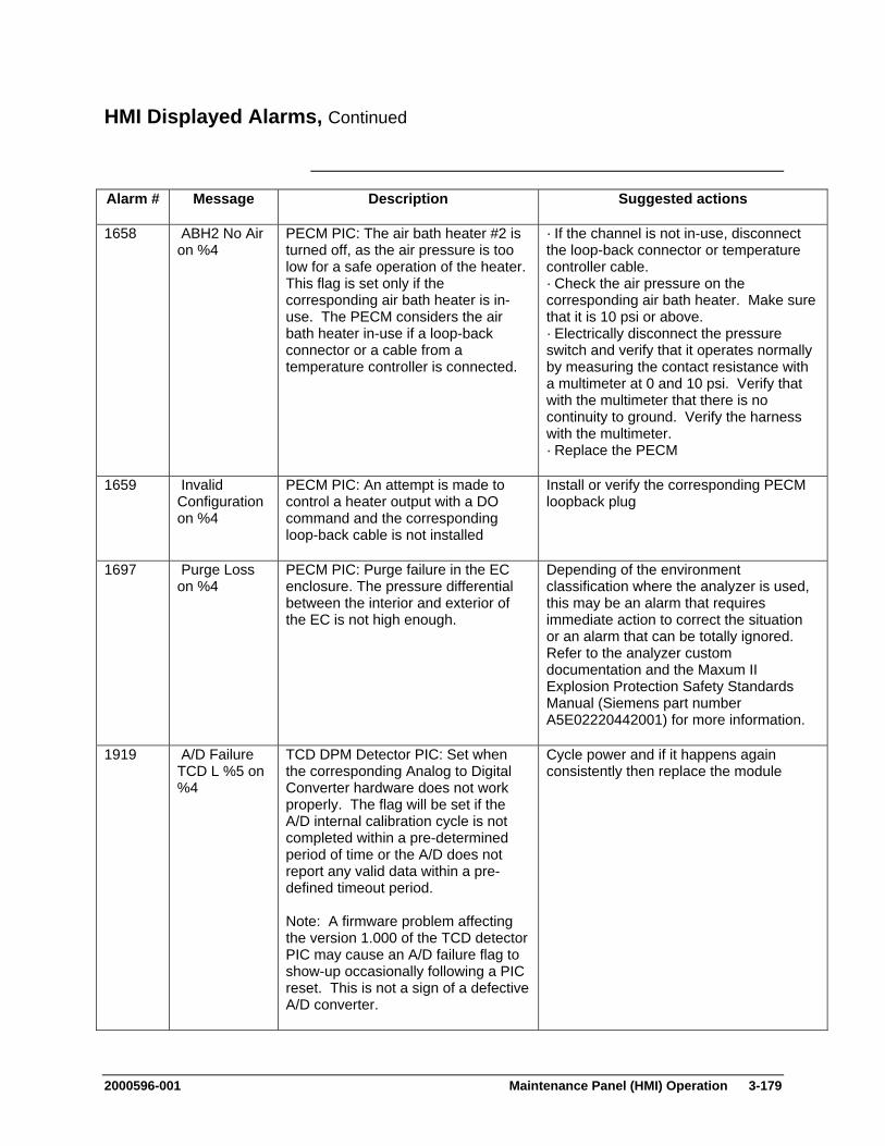
2000596-001 Maintenance Panel (HMI) Operation 3-179
HMI Displayed Alarms, Continued
Alarm # Message Description Suggested actions
1658 ABH2 No Air on %4
PECM PIC: The air bath heater #2 is turned off, as the air pressure is too low for a safe operation of the heater. This flag is set only if the corresponding air bath heater is in-use. The PECM considers the air bath heater in-use if a loop-back connector or a cable from a temperature controller is connected.
· If the channel is not in-use, disconnect the loop-back connector or temperature controller cable. · Check the air pressure on the corresponding air bath heater. Make sure that it is 10 psi or above. · Electrically disconnect the pressure switch and verify that it operates normally by measuring the contact resistance with a multimeter at 0 and 10 psi. Verify that with the multimeter that there is no continuity to ground. Verify the harness with the multimeter. · Replace the PECM
1659 Invalid Configuration on %4
PECM PIC: An attempt is made to control a heater output with a DO command and the corresponding loop-back cable is not installed
Install or verify the corresponding PECM loopback plug
1697 Purge Loss on %4
PECM PIC: Purge failure in the EC enclosure. The pressure differential between the interior and exterior of the EC is not high enough.
Depending of the environment classification where the analyzer is used, this may be an alarm that requires immediate action to correct the situation or an alarm that can be totally ignored. Refer to the analyzer custom documentation and the Maxum II Explosion Protection Safety Standards Manual (Siemens part number A5E02220442001) for more information.
1919 A/D Failure TCD L %5 on %4
TCD DPM Detector PIC: Set when the corresponding Analog to Digital Converter hardware does not work properly. The flag will be set if the A/D internal calibration cycle is not completed within a pre-determined period of time or the A/D does not report any valid data within a pre-defined timeout period. Note: A firmware problem affecting the version 1.000 of the TCD detector PIC may cause an A/D failure flag to show-up occasionally following a PIC reset. This is not a sign of a defective A/D converter.
Cycle power and if it happens again consistently then replace the module

3-180 Maintenance Panel (HMI) Operation 2000596-001
HMI Displayed Alarms, Continued
Alarm # Message Description Suggested actions
1920 A/D Failure TCD U %5 on %4
TCD DPM Detector PIC: Set when the corresponding Analog to Digital Converter hardware does not work properly. The flag will be set if the A/D internal calibration cycle is not completed within a pre-determined period of time or the A/D does not report any valid data within a pre-defined timeout period. Note: A firmware problem affecting the version 1.000 of the TCD detector PIC may cause an A/D failure flag to show-up occasionally following a PIC reset. This is not a sign of a defective A/D converter.
Cycle power and if it happens again consistently then replace the module
1922 Incompatible Hardware on %4
TCD DPM Detector PIC: The PIC firmware is not compatible with the DPM board
Replace the module
1925 Glow Plug Bad on %4
See alarm 2225 See alarm 2225
1926 Invalid PIC index on %4
DPM Detector PIC: The PIC index is not valid, the DPM board is not working normally
Replace the module
1927 Mezzanine disconnected on %4
See alarm 2227 See alarm 2227
1928 Mezzanine ID changed on %4
See alarm 2228 See alarm 2228
1929 Mezzanine ID invalid on %4
See alarm 2229 See alarm 2229
1930 Mezzanine ID reserved
See alarm 2230 See alarm 2230
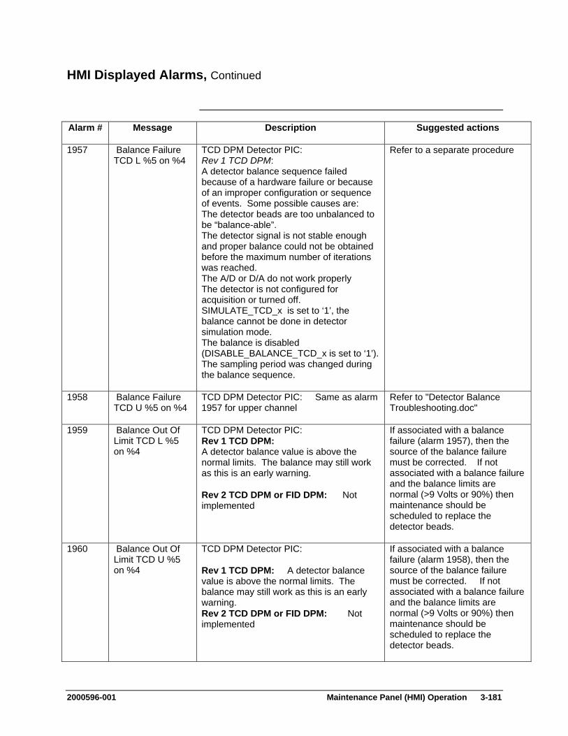
2000596-001 Maintenance Panel (HMI) Operation 3-181
HMI Displayed Alarms, Continued
Alarm # Message Description Suggested actions
1957 Balance Failure TCD L %5 on %4
TCD DPM Detector PIC: Rev 1 TCD DPM: A detector balance sequence failed because of a hardware failure or because of an improper configuration or sequence of events. Some possible causes are: The detector beads are too unbalanced to be “balance-able”. The detector signal is not stable enough and proper balance could not be obtained before the maximum number of iterations was reached. The A/D or D/A do not work properly The detector is not configured for acquisition or turned off. SIMULATE_TCD_x is set to ‘1’, the balance cannot be done in detector simulation mode. The balance is disabled (DISABLE_BALANCE_TCD_x is set to ‘1’).The sampling period was changed during the balance sequence.
Refer to a separate procedure
1958 Balance Failure TCD U %5 on %4
TCD DPM Detector PIC: Same as alarm 1957 for upper channel
Refer to "Detector Balance Troubleshooting.doc"
1959 Balance Out Of Limit TCD L %5 on %4
TCD DPM Detector PIC: Rev 1 TCD DPM: A detector balance value is above the normal limits. The balance may still work as this is an early warning. Rev 2 TCD DPM or FID DPM: Not implemented
If associated with a balance failure (alarm 1957), then the source of the balance failure must be corrected. If not associated with a balance failure and the balance limits are normal (>9 Volts or 90%) then maintenance should be scheduled to replace the detector beads.
1960 Balance Out Of Limit TCD U %5 on %4
TCD DPM Detector PIC: Rev 1 TCD DPM: A detector balance value is above the normal limits. The balance may still work as this is an early warning. Rev 2 TCD DPM or FID DPM: Not implemented
If associated with a balance failure (alarm 1958), then the source of the balance failure must be corrected. If not associated with a balance failure and the balance limits are normal (>9 Volts or 90%) then maintenance should be scheduled to replace the detector beads.
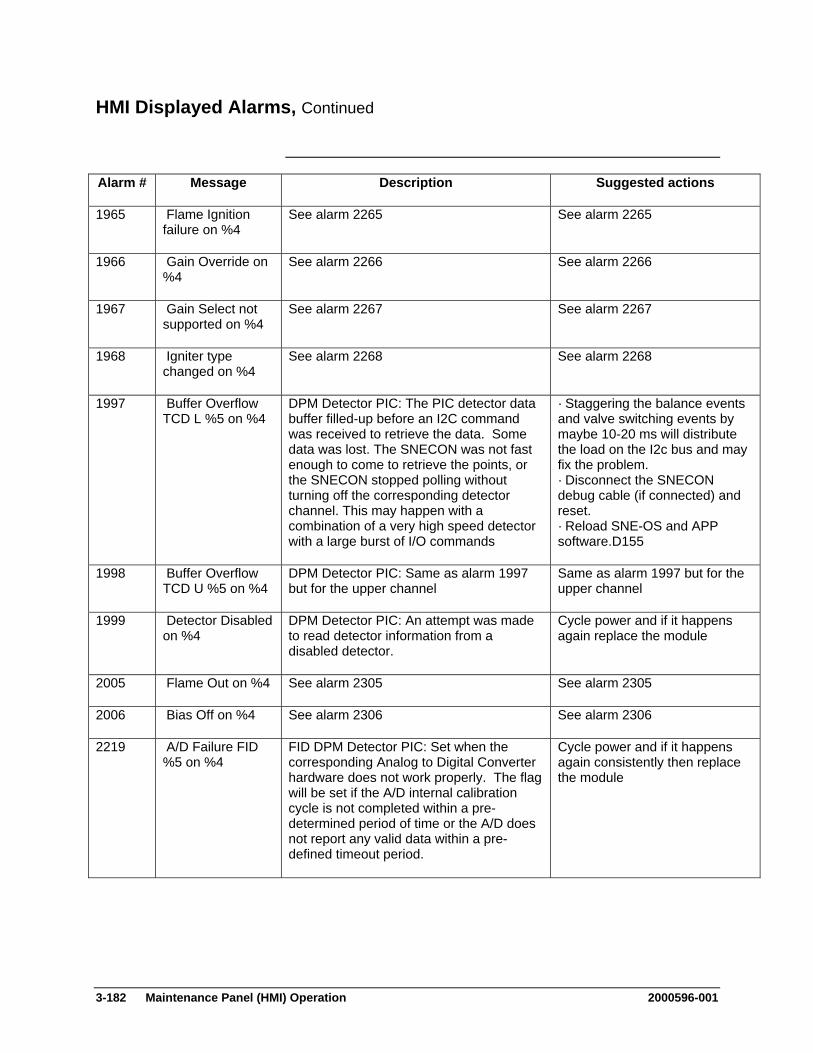
3-182 Maintenance Panel (HMI) Operation 2000596-001
HMI Displayed Alarms, Continued
Alarm # Message Description Suggested actions
1965 Flame Ignition failure on %4
See alarm 2265 See alarm 2265
1966 Gain Override on %4
See alarm 2266 See alarm 2266
1967 Gain Select not supported on %4
See alarm 2267 See alarm 2267
1968 Igniter type changed on %4
See alarm 2268 See alarm 2268
1997 Buffer Overflow TCD L %5 on %4
DPM Detector PIC: The PIC detector data buffer filled-up before an I2C command was received to retrieve the data. Some data was lost. The SNECON was not fast enough to come to retrieve the points, or the SNECON stopped polling without turning off the corresponding detector channel. This may happen with a combination of a very high speed detector with a large burst of I/O commands
· Staggering the balance events and valve switching events by maybe 10-20 ms will distribute the load on the I2c bus and may fix the problem. · Disconnect the SNECON debug cable (if connected) and reset. · Reload SNE-OS and APP software.D155
1998 Buffer Overflow TCD U %5 on %4
DPM Detector PIC: Same as alarm 1997 but for the upper channel
Same as alarm 1997 but for the upper channel
1999 Detector Disabled on %4
DPM Detector PIC: An attempt was made to read detector information from a disabled detector.
Cycle power and if it happens again replace the module
2005 Flame Out on %4 See alarm 2305 See alarm 2305
2006 Bias Off on %4 See alarm 2306 See alarm 2306
2219 A/D Failure FID %5 on %4
FID DPM Detector PIC: Set when the corresponding Analog to Digital Converter hardware does not work properly. The flag will be set if the A/D internal calibration cycle is not completed within a pre-determined period of time or the A/D does not report any valid data within a pre-defined timeout period.
Cycle power and if it happens again consistently then replace the module
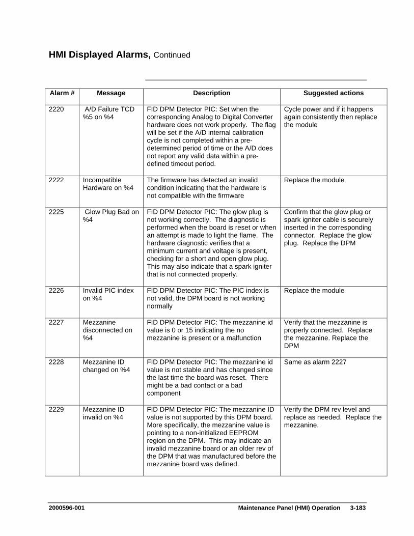
2000596-001 Maintenance Panel (HMI) Operation 3-183
HMI Displayed Alarms, Continued
Alarm # Message Description Suggested actions
2220 A/D Failure TCD %5 on %4
FID DPM Detector PIC: Set when the corresponding Analog to Digital Converter hardware does not work properly. The flag will be set if the A/D internal calibration cycle is not completed within a pre-determined period of time or the A/D does not report any valid data within a pre-defined timeout period.
Cycle power and if it happens again consistently then replace the module
2222 Incompatible Hardware on %4
The firmware has detected an invalid condition indicating that the hardware is not compatible with the firmware
Replace the module
2225 Glow Plug Bad on %4
FID DPM Detector PIC: The glow plug is not working correctly. The diagnostic is performed when the board is reset or when an attempt is made to light the flame. The hardware diagnostic verifies that a minimum current and voltage is present, checking for a short and open glow plug. This may also indicate that a spark igniter that is not connected properly.
Confirm that the glow plug or spark igniter cable is securely inserted in the corresponding connector. Replace the glow plug. Replace the DPM
2226 Invalid PIC index on %4
FID DPM Detector PIC: The PIC index is not valid, the DPM board is not working normally
Replace the module
2227 Mezzanine disconnected on %4
FID DPM Detector PIC: The mezzanine id value is 0 or 15 indicating the no mezzanine is present or a malfunction
Verify that the mezzanine is properly connected. Replace the mezzanine. Replace the DPM
2228 Mezzanine ID changed on %4
FID DPM Detector PIC: The mezzanine id value is not stable and has changed since the last time the board was reset. There might be a bad contact or a bad component
Same as alarm 2227
2229 Mezzanine ID invalid on %4
FID DPM Detector PIC: The mezzanine ID value is not supported by this DPM board. More specifically, the mezzanine value is pointing to a non-initialized EEPROM region on the DPM. This may indicate an invalid mezzanine board or an older rev of the DPM that was manufactured before the mezzanine board was defined.
Verify the DPM rev level and replace as needed. Replace the mezzanine.
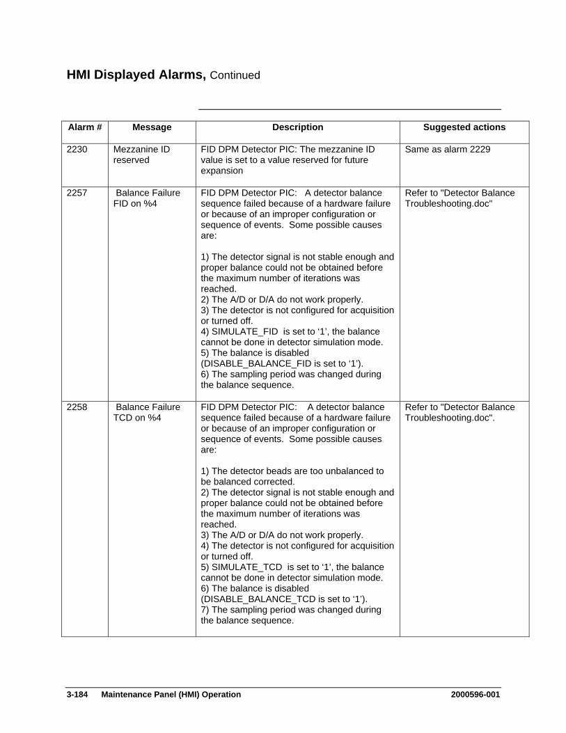
3-184 Maintenance Panel (HMI) Operation 2000596-001
HMI Displayed Alarms, Continued
Alarm # Message Description Suggested actions
2230 Mezzanine ID reserved
FID DPM Detector PIC: The mezzanine ID value is set to a value reserved for future expansion
Same as alarm 2229
2257 Balance Failure FID on %4
FID DPM Detector PIC: A detector balance sequence failed because of a hardware failure or because of an improper configuration or sequence of events. Some possible causes are: 1) The detector signal is not stable enough and proper balance could not be obtained before the maximum number of iterations was reached. 2) The A/D or D/A do not work properly. 3) The detector is not configured for acquisition or turned off. 4) SIMULATE_FID is set to ‘1’, the balance cannot be done in detector simulation mode. 5) The balance is disabled (DISABLE_BALANCE_FID is set to ‘1’). 6) The sampling period was changed during the balance sequence.
Refer to "Detector Balance Troubleshooting.doc"
2258 Balance Failure TCD on %4
FID DPM Detector PIC: A detector balance sequence failed because of a hardware failure or because of an improper configuration or sequence of events. Some possible causes are: 1) The detector beads are too unbalanced to be balanced corrected. 2) The detector signal is not stable enough and proper balance could not be obtained before the maximum number of iterations was reached. 3) The A/D or D/A do not work properly. 4) The detector is not configured for acquisition or turned off. 5) SIMULATE_TCD is set to ‘1’, the balance cannot be done in detector simulation mode. 6) The balance is disabled (DISABLE_BALANCE_TCD is set to ‘1’). 7) The sampling period was changed during the balance sequence.
Refer to "Detector Balance Troubleshooting.doc".
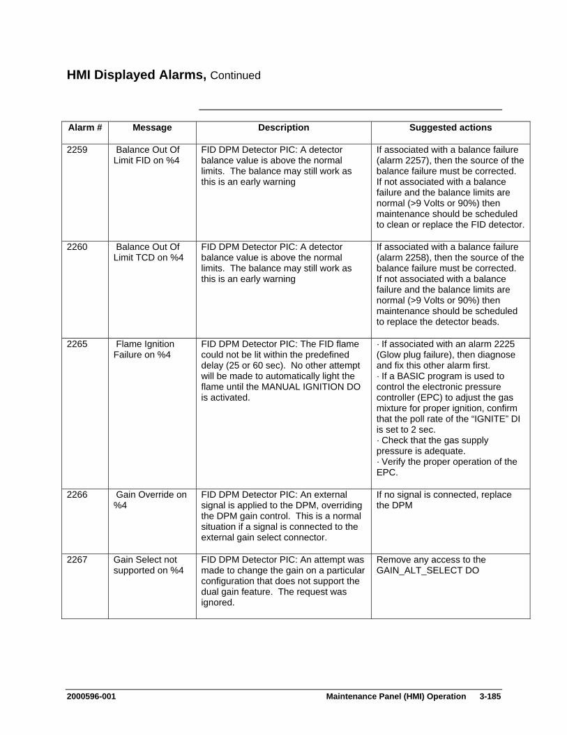
2000596-001 Maintenance Panel (HMI) Operation 3-185
HMI Displayed Alarms, Continued
Alarm # Message Description Suggested actions
2259 Balance Out Of Limit FID on %4
FID DPM Detector PIC: A detector balance value is above the normal limits. The balance may still work as this is an early warning
If associated with a balance failure (alarm 2257), then the source of the balance failure must be corrected. If not associated with a balance failure and the balance limits are normal (>9 Volts or 90%) then maintenance should be scheduled to clean or replace the FID detector.
2260 Balance Out Of Limit TCD on %4
FID DPM Detector PIC: A detector balance value is above the normal limits. The balance may still work as this is an early warning
If associated with a balance failure (alarm 2258), then the source of the balance failure must be corrected. If not associated with a balance failure and the balance limits are normal (>9 Volts or 90%) then maintenance should be scheduled to replace the detector beads.
2265 Flame Ignition Failure on %4
FID DPM Detector PIC: The FID flame could not be lit within the predefined delay (25 or 60 sec). No other attempt will be made to automatically light the flame until the MANUAL IGNITION DO is activated.
· If associated with an alarm 2225 (Glow plug failure), then diagnose and fix this other alarm first. · If a BASIC program is used to control the electronic pressure controller (EPC) to adjust the gas mixture for proper ignition, confirm that the poll rate of the “IGNITE” DI is set to 2 sec. · Check that the gas supply pressure is adequate. · Verify the proper operation of the EPC.
2266 Gain Override on %4
FID DPM Detector PIC: An external signal is applied to the DPM, overriding the DPM gain control. This is a normal situation if a signal is connected to the external gain select connector.
If no signal is connected, replace the DPM
2267 Gain Select not supported on %4
FID DPM Detector PIC: An attempt was made to change the gain on a particular configuration that does not support the dual gain feature. The request was ignored.
Remove any access to the GAIN_ALT_SELECT DO
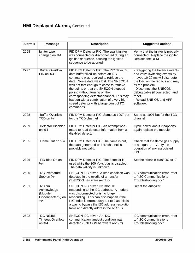
3-186 Maintenance Panel (HMI) Operation 2000596-001
HMI Displayed Alarms, Continued
Alarm # Message Description Suggested actions
2268 Igniter type changed on %4
FID DPM Detector PIC: The spark igniter was connected or disconnected during an ignition sequence, causing the ignition sequence to be aborted.
Verify that the igniter is properly connected. Replace the igniter. Replace the DPM
2297 Buffer Overflow FID on %4
FID DPM Detector PIC: The PIC detector data buffer filled-up before an I2C command was received to retrieve the data. Some data was lost. The SNECON was not fast enough to come to retrieve the points or that the SNECON stopped polling without turning off the corresponding detector channel. This may happen with a combination of a very high speed detector with a large burst of I/O commands
· Staggering the balance events and valve switching events by maybe 10-20 ms will distribute the load on the I2c bus and may fix the problem. · Disconnect the SNECON debug cable (if connected) and reset. · Reload SNE-OS and APP software.
2298 Buffer Overflow TCD on %4
FID DPM Detector PIC: Same as 1997 but for the TCD channel
Same as 1997 but for the TCD channel
2299 Detector Disabled on %4
FID DPM Detector PIC: An attempt was made to read detector information from a disabled detector.
Cycle power and if it happens again replace the module
2305 Flame Out on %4 FID DPM Detector PIC: The flame is out, the data generated on FID channel is probably not valid.
Check that the flame gas supply is adequate. Verify the operation of any associated EPC.
2306 FID Bias Off on %4
FID DPM Detector PIC: The detector is used while the 300 Volts bias is disabled. The data validity is unknown.
Set the “disable bias” DO to ‘0’
2500 I2C Premature Stop on %4
SNECON I2C driver: A stop condition was detected in the middle of a transfer (SNECON hardware rev 2.x)
I2C communication error, refer to "I2C Communications Troubleshooting.doc"
2501 I2C No Acknowledge (Module Disconnected?) on %4
SNECON I2C driver: No module responding to the I2C address. A module was disconnected or is no longer responding. This can also happen if the PIC-index is erroneously set to 0 as this is a way to bypass the I2C address resolution table and directly address the I2C bus
Reset the analyzer
2502 I2C NS486 Timeout Overflow on %4
SNECON I2C driver: An I2C communication timeout condition was detected (SNECON hardware rev 2.x)
I2C communication error, refer to "I2C Communications Troubleshooting.doc"

2000596-001 Maintenance Panel (HMI) Operation 3-187
HMI Displayed Alarms, Continued
Alarm # Message Description Suggested actions
2503 I2C Address is Odd on %4
SNECON I2C driver: Illegal I2C address Reset the analyzer. Reload SNE OS
2505 I2C Driver Not Initialized
SNECON I2C driver: An attempt was made to communicate to the I2C driver before it’s initialized
Reset the analyzer. Reload SNE OS and APP
2508 I2C Improper Acknowledge on %4
SNECON I2C driver: No module responding to the I2C address. A module was disconnected or is no longer responding (SNECON hardware rev 2.x)
I2C communication error, refer to "I2C Communications Troubleshooting.doc"
2509 I2C Invalid Message Checksum Received on %4
SNECON I2C driver: A message was received with an invalid checksum
(SNECON hardware rev 2.x): I2C communication error, refer to "I2C Communications Troubleshooting.doc". Verify that the application does not use a hardware address that does not exist.
2510 I2C Module Not Found: %4
SNECON I2C driver: No module of this “module type” and “location id” is listed in the address table
Reset the analyzer. Verify that the application does not use a hardware address that does not exist.
2511 I2C Invalid Opcode Received from %4
SNECON I2C driver: The message received corresponds to an unrecognized opcode
Reset the analyzer. Reload SNE OS and APP. Replace the SNECON
2512 I2C Error Reading ISR Queue
SNECON I2C driver: An error was detected reading a communication queue (SNECON hardware rev 2.x)
Reset the analyzer.
2513 I2C Message Too Big on %4
SNECON I2C driver: The I2C message received is too big and is not valid
I2C communication error, refer to "I2C Communications Troubleshooting.doc"
2515 I2C Address Table Full
SNECON I2C driver: No free addresses on the I2C bus. There is a limit of 120 addresses per bus, each PIC is taking up one address
Reset the analyzer.
2516 I2C Invalid Bus on %4
SNECON I2C driver: Invalid I2C bus identification number
Reset the analyzer.
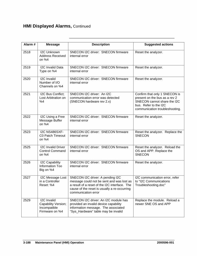
3-188 Maintenance Panel (HMI) Operation 2000596-001
HMI Displayed Alarms, Continued
Alarm # Message Description Suggested actions
2518 I2C Unknown Address Received on %4
SNECON I2C driver: SNECON firmware internal error
Reset the analyzer.
2519 I2C Invalid Data Type on %4
SNECON I2C driver: SNECON firmware internal error
Reset the analyzer.
2520 I2C Invalid Number of I/O Channels on %4
SNECON I2C driver: SNECON firmware internal error
Reset the analyzer.
2521 I2C Bus Conflict; Lost Arbitration on %4
SNECON I2C driver: An I2C communication error was detected (SNECON hardware rev 2.x)
Confirm that only 1 SNECON is present on the bus as a rev 2 SNECON cannot share the I2C bus. Refer to the I2C communication troubleshooting.
2522 I2C Using a Free Message Buffer on %4
SNECON I2C driver: SNECON firmware internal error
Reset the analyzer.
2523 I2C NS486SXF-C0 Patch Timeout on %4
SNECON I2C driver: SNECON firmware internal error
Reset the analyzer. Replace the SNECON
2525 I2C Invalid Driver Control Command on %4
SNECON I2C driver: SNECON firmware internal error
Reset the analyzer. Reload the OS and APP. Replace the SNECON
2526 I2C Capability Information Too Big on %4
SNECON I2C driver: SNECON firmware internal error
Reset the analyzer.
2527 I2C Message Lost in a Controller Reset: %4
SNECON I2C driver: A pending I2C message could not be sent and was lost as a result of a reset of the I2C interface. The cause of the reset is usually a re-occurring communication error
I2C communication error, refer to "I2C Communications Troubleshooting.doc"
2529 I2C Invalid Capability Version; Incompatible Firmware on %4
SNECON I2C driver: An I2C module has provided an invalid device capability information message. The associated “Sys_Hardware” table may be invalid
Replace the module. Reload a newer SNE OS and APP

2000596-001 Maintenance Panel (HMI) Operation 3-189
HMI Displayed Alarms, Continued
Alarm # Message Description Suggested actions
2531 I2C Internal Error; Invalid Info on %4
SNECON I2C driver: SNECON firmware internal error
Reset the analyzer.
2532 I2C Invalid Device ID Version; Incompatible Firmware on %4
SNECON I2C driver: An I2C module has provided an invalid device id information message. The module type and location id information may be invalid
Replace the module. Reload a newer SNE OS and APP
2537 I2C Address Table not initialized on %4
SNECON I2C driver: SNECON firmware internal error
Reset the analyzer.
2538 I2C ISR Lockup SNECON I2C driver: The SNECON message receive indicator is stuck (SNECON rev 3.0 hardware only)
Reset the analyzer. Replace the SNECON
2539 I2C Invalid Message Status Size on %4
SNECON I2C driver: SNECON firmware internal error
Reset the analyzer. Replace the SNECON
2540 I2C Message Too Short on %4
SNECON I2C driver: An I2C message received by the SNECON in too short to be valid
I2C communication error, refer to "I2C Communications Troubleshooting.doc"
2541 I2C FPGA Queue Full on %4
SNECON I2C driver: SNECON firmware internal error (SNECON rev 3.0 hardware only)
Reset the analyzer. Replace the SNECON
2542 I2C FPGA Write Before End on %4
SNECON I2C driver: SNECON firmware internal error (SNECON rev 3.0 hardware only)
Reset the analyzer. Replace the SNECON
2543 I2C FPGA Write After End on %4
SNECON I2C driver: SNECON firmware internal error (SNECON rev 3.0 hardware only)
Reset the analyzer. Replace the SNECON
2544 I2C FPGA Message Too Short on %4
SNECON I2C driver: SNECON firmware internal error (SNECON rev 3.0 hardware only)
Reset the analyzer. Replace the SNECON
2545 I2C FPGA Invalid Checksum on %4
SNECON I2C driver: SNECON on-board communication error. Is known to happen very infrequently with SNECON I2C FPGA rev 23 or lower (SNECON rev 3.0 hardware only)
Ignore the alarm. If happening too frequently, replace the SNECON
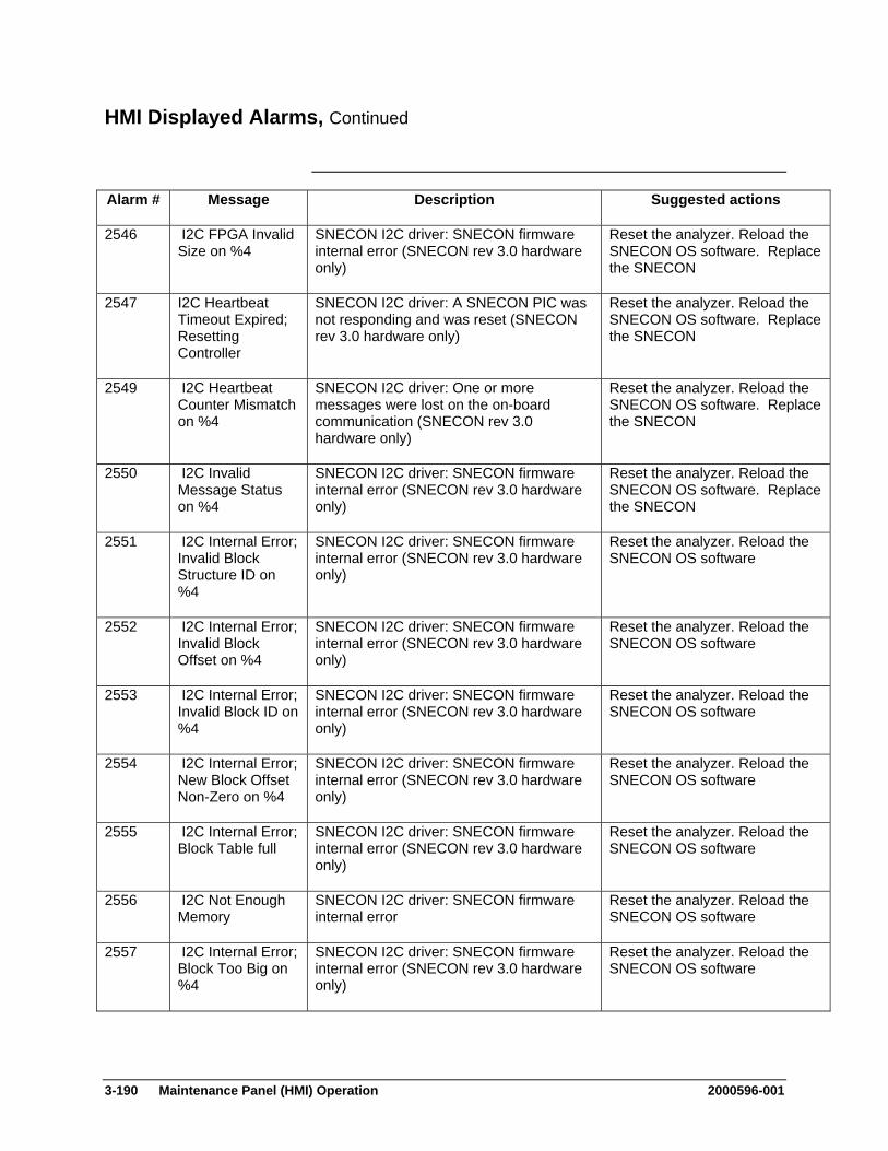
3-190 Maintenance Panel (HMI) Operation 2000596-001
HMI Displayed Alarms, Continued
Alarm # Message Description Suggested actions
2546 I2C FPGA Invalid Size on %4
SNECON I2C driver: SNECON firmware internal error (SNECON rev 3.0 hardware only)
Reset the analyzer. Reload the SNECON OS software. Replace the SNECON
2547 I2C Heartbeat Timeout Expired; Resetting Controller
SNECON I2C driver: A SNECON PIC was not responding and was reset (SNECON rev 3.0 hardware only)
Reset the analyzer. Reload the SNECON OS software. Replace the SNECON
2549 I2C Heartbeat Counter Mismatch on %4
SNECON I2C driver: One or more messages were lost on the on-board communication (SNECON rev 3.0 hardware only)
Reset the analyzer. Reload the SNECON OS software. Replace the SNECON
2550 I2C Invalid Message Status on %4
SNECON I2C driver: SNECON firmware internal error (SNECON rev 3.0 hardware only)
Reset the analyzer. Reload the SNECON OS software. Replace the SNECON
2551 I2C Internal Error; Invalid Block Structure ID on %4
SNECON I2C driver: SNECON firmware internal error (SNECON rev 3.0 hardware only)
Reset the analyzer. Reload the SNECON OS software
2552 I2C Internal Error; Invalid Block Offset on %4
SNECON I2C driver: SNECON firmware internal error (SNECON rev 3.0 hardware only)
Reset the analyzer. Reload the SNECON OS software
2553 I2C Internal Error; Invalid Block ID on %4
SNECON I2C driver: SNECON firmware internal error (SNECON rev 3.0 hardware only)
Reset the analyzer. Reload the SNECON OS software
2554 I2C Internal Error; New Block Offset Non-Zero on %4
SNECON I2C driver: SNECON firmware internal error (SNECON rev 3.0 hardware only)
Reset the analyzer. Reload the SNECON OS software
2555 I2C Internal Error; Block Table full
SNECON I2C driver: SNECON firmware internal error (SNECON rev 3.0 hardware only)
Reset the analyzer. Reload the SNECON OS software
2556 I2C Not Enough Memory
SNECON I2C driver: SNECON firmware internal error
Reset the analyzer. Reload the SNECON OS software
2557 I2C Internal Error; Block Too Big on %4
SNECON I2C driver: SNECON firmware internal error (SNECON rev 3.0 hardware only)
Reset the analyzer. Reload the SNECON OS software

2000596-001 Maintenance Panel (HMI) Operation 3-191
HMI Displayed Alarms, Continued
Alarm # Message Description Suggested actions
2558 I2C Internal Error; Block Not Found on %4
SNECON I2C driver: SNECON firmware internal error (SNECON rev 3.0 hardware only)
Reset the analyzer. Reload the SNECON OS software
2559 I2C Internal Error; Invalid Block Size on %4
SNECON I2C driver: SNECON firmware internal error (SNECON rev 3.0 hardware only)
Reset the analyzer. Reload the SNECON OS software
2560 I2C Driver OS and Application version mismatch
SNECON I2C driver: The version number of the SNECON OS is incompatible with the SNECON APP version
Reload the OS and APP
2562 I2C Internal Error; Bad state on %4
SNECON I2C driver: SNECON firmware internal error
Reset the analyzer. Reload the SNECON OS software
2563 I2C FPGA bad version
SNECON I2C driver: The SNECON I2C FPGA is incompatible or broken
Reload the OS with the newest version. Replace the SNECON
2564 I2C Temperature Block Version Invalid
SNECON I2C driver: The temperature controller PID parameter data block supplied by the SYSCON is incompatible
Reload the SNECON OS and APP to the corresponding SYSCON version
2565 I2C Opcode not expected in current state on %4
SNECON I2C driver: Unexpected I2C message opcode received by the SNECON from a module
I2C communication error, refer to "I2C Communications Troubleshooting.doc"
2566 I2C Modules were reset following multiple errors
SNECON I2C driver: A fatal error or multiple consecutive retries have forced the I2C controller to reset
Usually indicates a severe I2C communication error, refer to "I2C Communications Troubleshooting.doc"
2568 I2C Internal Error; Invalid Block Index on %4
SNECON I2C driver: SNECON firmware internal error (SNECON rev 3.0 hardware only)
Reset the analyzer. Reload the SNECON OS software
2569 I2C FPGA Queue Full on %4
SNECON I2C driver: The SNECON I2C FPGA queue is full, the PIC is no longer processing I2C message
Reset the analyzer. Replace the SNECON
2570 I2C FPGA Packet Too Big on %4
SNECON I2C driver: SNECON firmware internal error (SNECON rev 3.0 hardware only)
Reset the analyzer. Reload the SNECON OS software. Replace the SNECON
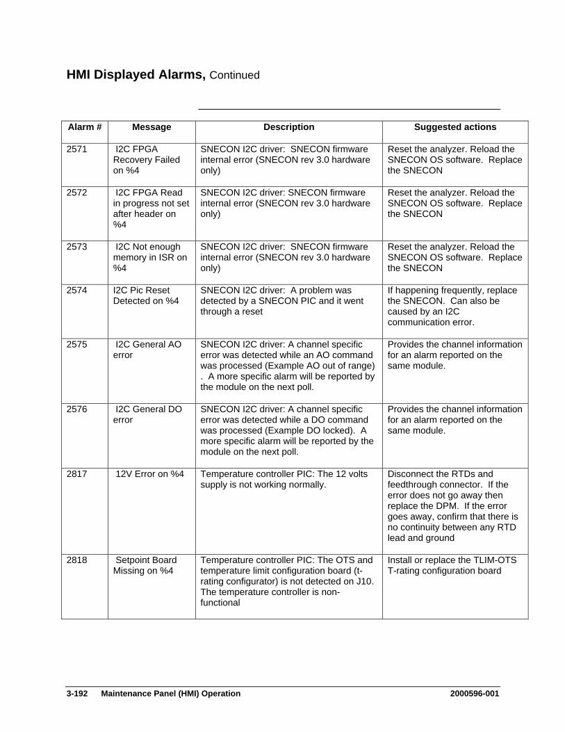
3-192 Maintenance Panel (HMI) Operation 2000596-001
HMI Displayed Alarms, Continued
Alarm # Message Description Suggested actions
2571 I2C FPGA Recovery Failed on %4
SNECON I2C driver: SNECON firmware internal error (SNECON rev 3.0 hardware only)
Reset the analyzer. Reload the SNECON OS software. Replace the SNECON
2572 I2C FPGA Read in progress not set after header on %4
SNECON I2C driver: SNECON firmware internal error (SNECON rev 3.0 hardware only)
Reset the analyzer. Reload the SNECON OS software. Replace the SNECON
2573 I2C Not enough memory in ISR on %4
SNECON I2C driver: SNECON firmware internal error (SNECON rev 3.0 hardware only)
Reset the analyzer. Reload the SNECON OS software. Replace the SNECON
2574 I2C Pic Reset Detected on %4
SNECON I2C driver: A problem was detected by a SNECON PIC and it went through a reset
If happening frequently, replace the SNECON. Can also be caused by an I2C communication error.
2575 I2C General AO error
SNECON I2C driver: A channel specific error was detected while an AO command was processed (Example AO out of range) . A more specific alarm will be reported by the module on the next poll.
Provides the channel information for an alarm reported on the same module.
2576 I2C General DO error
SNECON I2C driver: A channel specific error was detected while a DO command was processed (Example DO locked). A more specific alarm will be reported by the module on the next poll.
Provides the channel information for an alarm reported on the same module.
2817 12V Error on %4 Temperature controller PIC: The 12 volts supply is not working normally.
Disconnect the RTDs and feedthrough connector. If the error does not go away then replace the DPM. If the error goes away, confirm that there is no continuity between any RTD lead and ground
2818 Setpoint Board Missing on %4
Temperature controller PIC: The OTS and temperature limit configuration board (t-rating configurator) is not detected on J10. The temperature controller is non-functional
Install or replace the TLIM-OTS T-rating configuration board
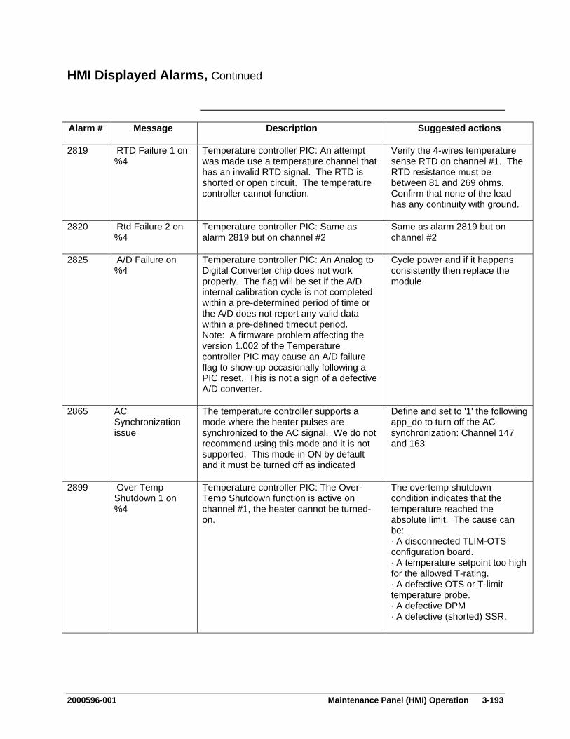
2000596-001 Maintenance Panel (HMI) Operation 3-193
HMI Displayed Alarms, Continued
Alarm # Message Description Suggested actions
2819 RTD Failure 1 on %4
Temperature controller PIC: An attempt was made use a temperature channel that has an invalid RTD signal. The RTD is shorted or open circuit. The temperature controller cannot function.
Verify the 4-wires temperature sense RTD on channel #1. The RTD resistance must be between 81 and 269 ohms. Confirm that none of the lead has any continuity with ground.
2820 Rtd Failure 2 on %4
Temperature controller PIC: Same as alarm 2819 but on channel #2
Same as alarm 2819 but on channel #2
2825 A/D Failure on %4
Temperature controller PIC: An Analog to Digital Converter chip does not work properly. The flag will be set if the A/D internal calibration cycle is not completed within a pre-determined period of time or the A/D does not report any valid data within a pre-defined timeout period. Note: A firmware problem affecting the version 1.002 of the Temperature controller PIC may cause an A/D failure flag to show-up occasionally following a PIC reset. This is not a sign of a defective A/D converter.
Cycle power and if it happens consistently then replace the module
2865 AC Synchronization issue
The temperature controller supports a mode where the heater pulses are synchronized to the AC signal. We do not recommend using this mode and it is not supported. This mode in ON by default and it must be turned off as indicated
Define and set to '1' the following app_do to turn off the AC synchronization: Channel 147 and 163
2899 Over Temp Shutdown 1 on %4
Temperature controller PIC: The Over-Temp Shutdown function is active on channel #1, the heater cannot be turned-on.
The overtemp shutdown condition indicates that the temperature reached the absolute limit. The cause can be: · A disconnected TLIM-OTS configuration board. · A temperature setpoint too high for the allowed T-rating. · A defective OTS or T-limit temperature probe. · A defective DPM · A defective (shorted) SSR.
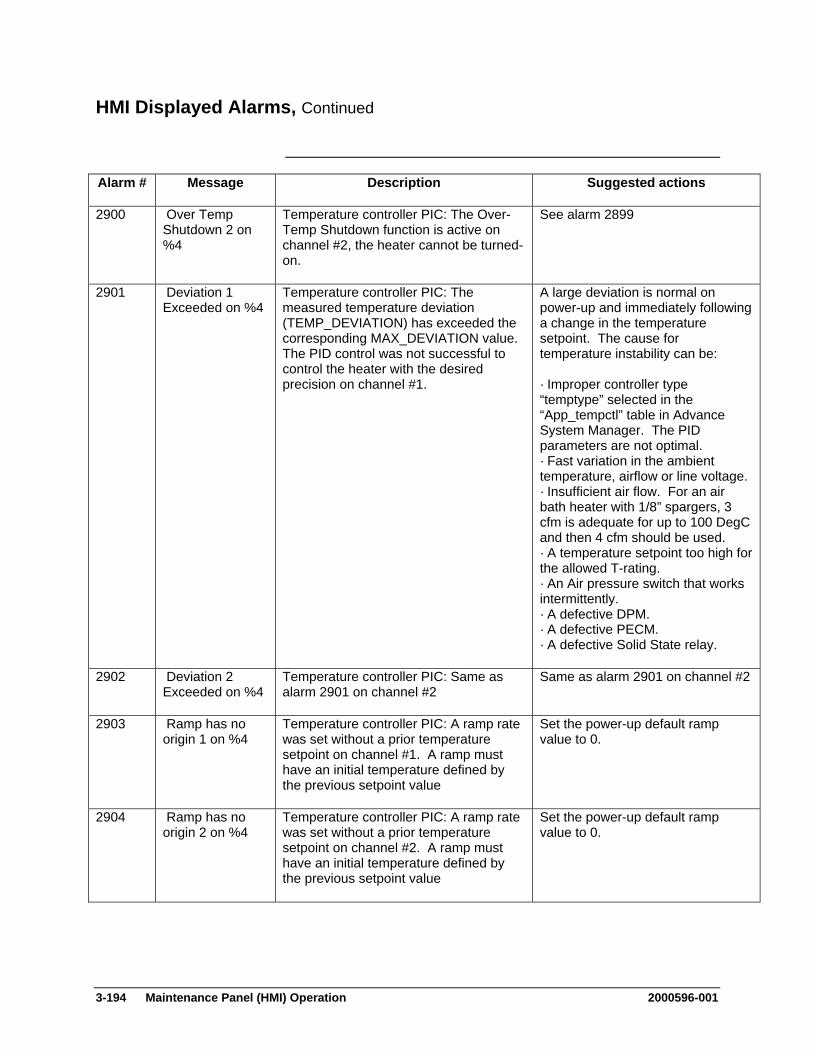
3-194 Maintenance Panel (HMI) Operation 2000596-001
HMI Displayed Alarms, Continued
Alarm # Message Description Suggested actions
2900 Over Temp Shutdown 2 on %4
Temperature controller PIC: The Over-Temp Shutdown function is active on channel #2, the heater cannot be turned-on.
See alarm 2899
2901 Deviation 1 Exceeded on %4
Temperature controller PIC: The measured temperature deviation (TEMP_DEVIATION) has exceeded the corresponding MAX_DEVIATION value. The PID control was not successful to control the heater with the desired precision on channel #1.
A large deviation is normal on power-up and immediately following a change in the temperature setpoint. The cause for temperature instability can be: · Improper controller type “temptype” selected in the “App_tempctl” table in Advance System Manager. The PID parameters are not optimal. · Fast variation in the ambient temperature, airflow or line voltage. · Insufficient air flow. For an air bath heater with 1/8” spargers, 3 cfm is adequate for up to 100 DegC and then 4 cfm should be used. · A temperature setpoint too high for the allowed T-rating. · An Air pressure switch that works intermittently. · A defective DPM. · A defective PECM. · A defective Solid State relay.
2902 Deviation 2 Exceeded on %4
Temperature controller PIC: Same as alarm 2901 on channel #2
Same as alarm 2901 on channel #2
2903 Ramp has no origin 1 on %4
Temperature controller PIC: A ramp rate was set without a prior temperature setpoint on channel #1. A ramp must have an initial temperature defined by the previous setpoint value
Set the power-up default ramp value to 0.
2904 Ramp has no origin 2 on %4
Temperature controller PIC: A ramp rate was set without a prior temperature setpoint on channel #2. A ramp must have an initial temperature defined by the previous setpoint value
Set the power-up default ramp value to 0.
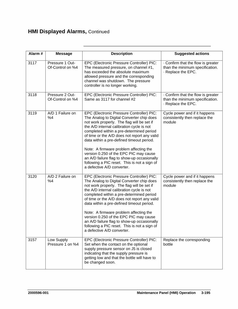
2000596-001 Maintenance Panel (HMI) Operation 3-195
HMI Displayed Alarms, Continued
Alarm # Message Description Suggested actions
3117 Pressure 1 Out-Of-Control on %4
EPC (Electronic Pressure Controller) PIC: The measured pressure, on channel #1, has exceeded the absolute maximum allowed pressure and the corresponding channel was shutdown. The pressure controller is no longer working.
· Confirm that the flow is greater than the minimum specification. · Replace the EPC.
3118 Pressure 2 Out-Of-Control on %4
EPC (Electronic Pressure Controller) PIC: Same as 3117 for channel #2
· Confirm that the flow is greater than the minimum specification. · Replace the EPC.
3119 A/D 1 Failure on %4
EPC (Electronic Pressure Controller) PIC: The Analog to Digital Converter chip does not work properly. The flag will be set if the A/D internal calibration cycle is not completed within a pre-determined period of time or the A/D does not report any valid data within a pre-defined timeout period. Note: A firmware problem affecting the version 0.250 of the EPC PIC may cause an A/D failure flag to show-up occasionally following a PIC reset. This is not a sign of a defective A/D converter.
Cycle power and if it happens consistently then replace the module
3120 A/D 2 Failure on %4
EPC (Electronic Pressure Controller) PIC: The Analog to Digital Converter chip does not work properly. The flag will be set if the A/D internal calibration cycle is not completed within a pre-determined period of time or the A/D does not report any valid data within a pre-defined timeout period. Note: A firmware problem affecting the version 0.250 of the EPC PIC may cause an A/D failure flag to show-up occasionally following a PIC reset. This is not a sign of a defective A/D converter.
Cycle power and if it happens consistently then replace the module
3157 Low Supply Pressure 1 on %4
EPC (Electronic Pressure Controller) PIC: Set when the contact on the optional supply pressure sensor on J5 is closed indicating that the supply pressure is getting low and that the bottle will have to be changed soon.
Replace the corresponding bottle

3-196 Maintenance Panel (HMI) Operation 2000596-001
HMI Displayed Alarms, Continued
Alarm # Message Description Suggested actions
3158 Low Supply Pressure 2 on %4
EPC (Electronic Pressure Controller) PIC: Set when the contact on the optional supply pressure sensor on J6 is closed indicating that the supply pressure is getting low and that the bottle will have to be changed soon.
Replace the corresponding bottle
3159 Deviation 1 Exceeded on %4
EPC (Electronic Pressure Controller) PIC: The measured pressure deviation has exceeded the corresponding MAX_DEVIATION value. The PID control was not successful to control the pressure with the desired precision on channel #1.
· MAX_DEVIATION_x that is too small. · An improper setting of TIME_LIMIT_DEVIATION_UP_x or TIME_LIMIT_DEVIATION_DN_x. · Insufficient supply pressure. · Flow too small or too large. · Defective EPC.
3160 Deviation 2 Exceeded on %4
EPC (Electronic Pressure Controller) PIC: Same as alarm 3159 on channel #2
Same as alarm 3159 on channel #2
3161 Setpoint1 changed following a change in Max Pressure
EPC (Electronic Pressure Controller) PIC: The SETPOINT_1 AO value was modified internally as a result of the SETPOINT_MAX_1 AO value set to a value lower than the SETPOINT_1 value.
Make sure to set the SETPOINT_MAX_1 value first and then set the setpoint
3162 Setpoint2 changed following a change in Max Pressure
EPC (Electronic Pressure Controller) PIC: Same as alarm 3161 on channel #2
Same as alarm 3161 on channel #2
3401 TFTP Protocol Error
Protocol error detected, such as receipt of a non-DATA packet or lack of an expected message acknowledgment
Most likely the gateway settings on the SNE are wrong. It will be necessary to power up the SNE connected to a serial terminal and change the settings in the startup dialog.
3402 TFTP Timeout The TFTP client didn't receive any response from the server.
Either the TFTP server is not running on the host computer or the host computer is not connected to the SNE through the network.

2000596-001 Maintenance Panel (HMI) Operation 3-197
HMI Displayed Alarms, Continued
Alarm # Message Description Suggested actions
3403 TFTP Server out of Sync
The data packets requested by the TFTP client to not match those sent by the TFTP server.
Either the TFTP client or TFTP server is malfunctioning. First try resetting the SNE, if that does not help, try restarting the TFTP server on the host computer.
3404 TFTP Server out of Sockets
TFTP server can't create a portal from which to communicate
SNE or host computer is low on resources.
3405 TFTP Max Channels is exceeded
Too many TFTP load requests have been commanded.
Only request one TFTP load at a time.
3406 TFTP Driver not initialized
TFTP driver was not successfully initialized.
Usually a problem of resource. Ensure that the SNE has 16Mb of memory or isn't otherwise deficient. Try a reset.
3500 TFTP Client out of memory
Client ran out of memory loading file. Ensure SNE has 16Mb SIMM. Try reset.
3501 TFTP Client Checksum Error
File loaded had invalid checksum Check to ensure load file is correct and uncorrupted.
3502 TFTP Client Missing End of File
Attempt to load truncated file Load file may be corrupt.
3503 TFTP Client Invalid OS File
Attempt to load OS with invalid address range.
Load file may be Application file or corrupt
3504 TFTP Client Invalid App File
Attempt to load App with invalid address range
Load file may be OS file or corrupt
3501 Advance Adapter Initialization Failure
Adapter Detected, but responding improperly
Repair or replace adapter
3502 Invalid Channel for Advance Adapter %4
Reference to invalid channel on Advance Adapter
Fix improper database.
3503 Advance Adapter Backplane Timeout on %4
I/O %4 on backplane board did not respond
Try to reseat or replace board corresponding to hardware ID.
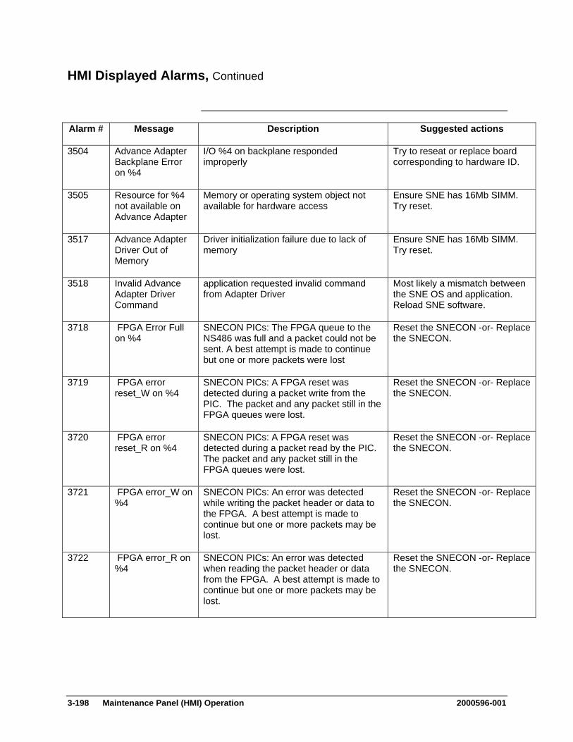
3-198 Maintenance Panel (HMI) Operation 2000596-001
HMI Displayed Alarms, Continued
Alarm # Message Description Suggested actions
3504 Advance Adapter Backplane Error on %4
I/O %4 on backplane responded improperly
Try to reseat or replace board corresponding to hardware ID.
3505 Resource for %4 not available on Advance Adapter
Memory or operating system object not available for hardware access
Ensure SNE has 16Mb SIMM. Try reset.
3517 Advance Adapter Driver Out of Memory
Driver initialization failure due to lack of memory
Ensure SNE has 16Mb SIMM. Try reset.
3518 Invalid Advance Adapter Driver Command
application requested invalid command from Adapter Driver
Most likely a mismatch between the SNE OS and application. Reload SNE software.
3718 FPGA Error Full on %4
SNECON PICs: The FPGA queue to the NS486 was full and a packet could not be sent. A best attempt is made to continue but one or more packets were lost
Reset the SNECON -or- Replace the SNECON.
3719 FPGA error reset_W on %4
SNECON PICs: A FPGA reset was detected during a packet write from the PIC. The packet and any packet still in the FPGA queues were lost.
Reset the SNECON -or- Replace the SNECON.
3720 FPGA error reset_R on %4
SNECON PICs: A FPGA reset was detected during a packet read by the PIC. The packet and any packet still in the FPGA queues were lost.
Reset the SNECON -or- Replace the SNECON.
3721 FPGA error_W on %4
SNECON PICs: An error was detected while writing the packet header or data to the FPGA. A best attempt is made to continue but one or more packets may be lost.
Reset the SNECON -or- Replace the SNECON.
3722 FPGA error_R on %4
SNECON PICs: An error was detected when reading the packet header or data from the FPGA. A best attempt is made to continue but one or more packets may be lost.
Reset the SNECON -or- Replace the SNECON.
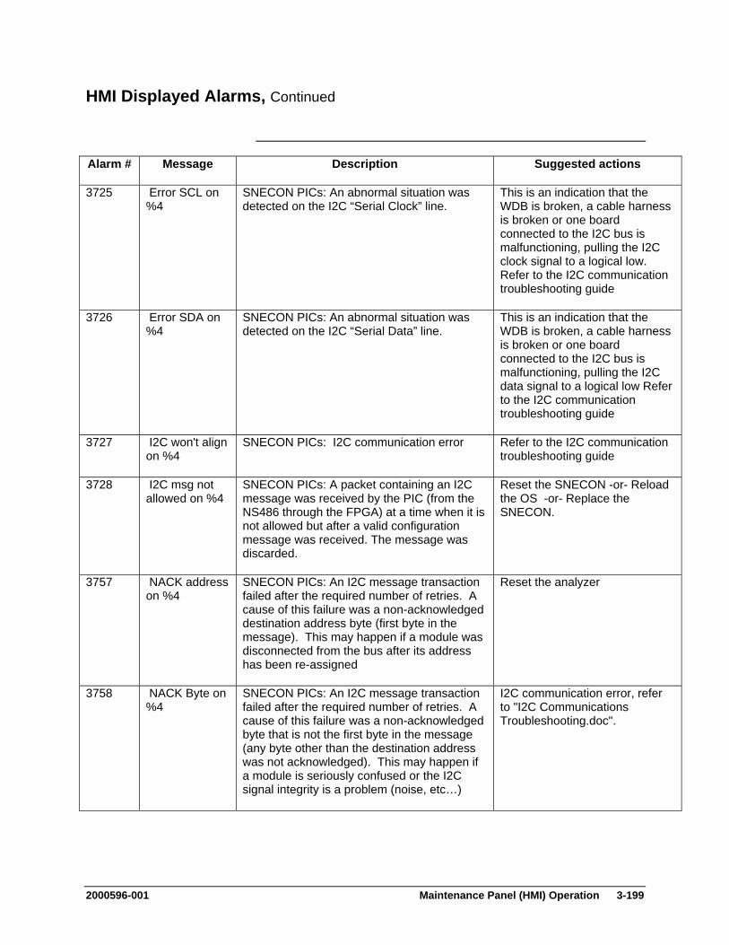
2000596-001 Maintenance Panel (HMI) Operation 3-199
HMI Displayed Alarms, Continued
Alarm # Message Description Suggested actions
3725 Error SCL on %4
SNECON PICs: An abnormal situation was detected on the I2C “Serial Clock” line.
This is an indication that the WDB is broken, a cable harness is broken or one board connected to the I2C bus is malfunctioning, pulling the I2C clock signal to a logical low. Refer to the I2C communication troubleshooting guide
3726 Error SDA on %4
SNECON PICs: An abnormal situation was detected on the I2C “Serial Data” line.
This is an indication that the WDB is broken, a cable harness is broken or one board connected to the I2C bus is malfunctioning, pulling the I2C data signal to a logical low Refer to the I2C communication troubleshooting guide
3727 I2C won't align on %4
SNECON PICs: I2C communication error Refer to the I2C communication troubleshooting guide
3728 I2C msg not allowed on %4
SNECON PICs: A packet containing an I2C message was received by the PIC (from the NS486 through the FPGA) at a time when it is not allowed but after a valid configuration message was received. The message was discarded.
Reset the SNECON -or- Reload the OS -or- Replace the SNECON.
3757 NACK address on %4
SNECON PICs: An I2C message transaction failed after the required number of retries. A cause of this failure was a non-acknowledged destination address byte (first byte in the message). This may happen if a module was disconnected from the bus after its address has been re-assigned
Reset the analyzer
3758 NACK Byte on %4
SNECON PICs: An I2C message transaction failed after the required number of retries. A cause of this failure was a non-acknowledged byte that is not the first byte in the message (any byte other than the destination address was not acknowledged). This may happen if a module is seriously confused or the I2C signal integrity is a problem (noise, etc…)
I2C communication error, refer to "I2C Communications Troubleshooting.doc".
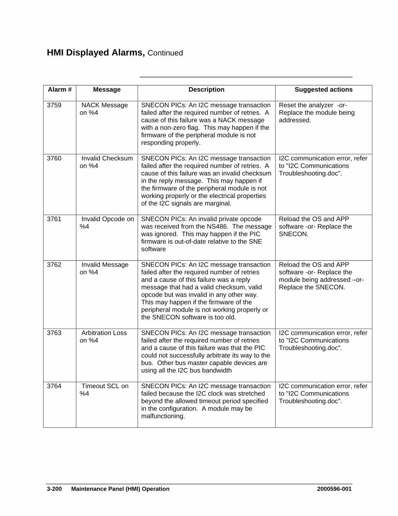
3-200 Maintenance Panel (HMI) Operation 2000596-001
HMI Displayed Alarms, Continued
Alarm # Message Description Suggested actions
3759 NACK Message on %4
SNECON PICs: An I2C message transaction failed after the required number of retries. A cause of this failure was a NACK message with a non-zero flag. This may happen if the firmware of the peripheral module is not responding properly.
Reset the analyzer -or- Replace the module being addressed.
3760 Invalid Checksum on %4
SNECON PICs: An I2C message transaction failed after the required number of retries. A cause of this failure was an invalid checksum in the reply message. This may happen if the firmware of the peripheral module is not working properly or the electrical properties of the I2C signals are marginal.
I2C communication error, refer to "I2C Communications Troubleshooting.doc".
3761 Invalid Opcode on %4
SNECON PICs: An invalid private opcode was received from the NS486. The message was ignored. This may happen if the PIC firmware is out-of-date relative to the SNE software
Reload the OS and APP software -or- Replace the SNECON.
3762 Invalid Message on %4
SNECON PICs: An I2C message transaction failed after the required number of retries and a cause of this failure was a reply message that had a valid checksum, valid opcode but was invalid in any other way. This may happen if the firmware of the peripheral module is not working properly or the SNECON software is too old.
Reload the OS and APP software -or- Replace the module being addressed –or- Replace the SNECON.
3763 Arbitration Loss on %4
SNECON PICs: An I2C message transaction failed after the required number of retries and a cause of this failure was that the PIC could not successfully arbitrate its way to the bus. Other bus master capable devices are using all the I2C bus bandwidth
I2C communication error, refer to "I2C Communications Troubleshooting.doc".
3764 Timeout SCL on %4
SNECON PICs: An I2C message transaction failed because the I2C clock was stretched beyond the allowed timeout period specified in the configuration. A module may be malfunctioning.
I2C communication error, refer to "I2C Communications Troubleshooting.doc".
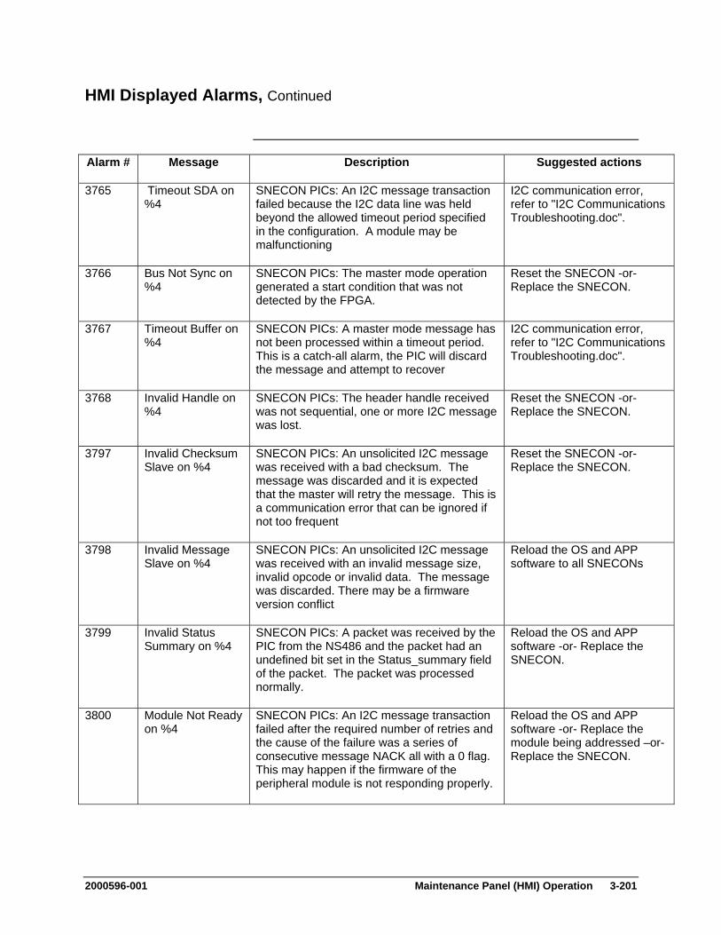
2000596-001 Maintenance Panel (HMI) Operation 3-201
HMI Displayed Alarms, Continued
Alarm # Message Description Suggested actions
3765 Timeout SDA on %4
SNECON PICs: An I2C message transaction failed because the I2C data line was held beyond the allowed timeout period specified in the configuration. A module may be malfunctioning
I2C communication error, refer to "I2C Communications Troubleshooting.doc".
3766 Bus Not Sync on %4
SNECON PICs: The master mode operation generated a start condition that was not detected by the FPGA.
Reset the SNECON -or- Replace the SNECON.
3767 Timeout Buffer on %4
SNECON PICs: A master mode message has not been processed within a timeout period. This is a catch-all alarm, the PIC will discard the message and attempt to recover
I2C communication error, refer to "I2C Communications Troubleshooting.doc".
3768 Invalid Handle on %4
SNECON PICs: The header handle received was not sequential, one or more I2C message was lost.
Reset the SNECON -or- Replace the SNECON.
3797 Invalid Checksum Slave on %4
SNECON PICs: An unsolicited I2C message was received with a bad checksum. The message was discarded and it is expected that the master will retry the message. This is a communication error that can be ignored if not too frequent
Reset the SNECON -or- Replace the SNECON.
3798 Invalid Message Slave on %4
SNECON PICs: An unsolicited I2C message was received with an invalid message size, invalid opcode or invalid data. The message was discarded. There may be a firmware version conflict
Reload the OS and APP software to all SNECONs
3799 Invalid Status Summary on %4
SNECON PICs: A packet was received by the PIC from the NS486 and the packet had an undefined bit set in the Status_summary field of the packet. The packet was processed normally.
Reload the OS and APP software -or- Replace the SNECON.
3800 Module Not Ready on %4
SNECON PICs: An I2C message transaction failed after the required number of retries and the cause of the failure was a series of consecutive message NACK all with a 0 flag. This may happen if the firmware of the peripheral module is not responding properly.
Reload the OS and APP software -or- Replace the module being addressed –or- Replace the SNECON.

3-202 Maintenance Panel (HMI) Operation 2000596-001
HMI Displayed Alarms, Continued
Alarm # Message Description Suggested actions
3801 Invalid Status Data on %4
SNECON PICs: The content of the status buffer “Status_data” was invalid and not recognized by the PIC. This may happen if the PIC firmware is out of date relative to the NS486 software
Reload the OS and APP software -or- Replace the SNECON.
3802 Invalid Status Type on %4
SNECON PICs: The value of the status_type was invalid and not recognized by the PIC. This may happen if the PIC firmware is out of date relative to the NS486 software
Reload the OS and APP software -or- Replace the SNECON.
3803 Invalid Msg Size on %4
SNECON PICs: A packet was received with an invalid I2C message size or no I2C message at all. The packet was discarded
Reload the OS and APP software to all SNECONs
3804 Arbitration Loss Slave on %4
SNECON PICs: The PIC lost a slave read arbitration. It indicates that at least another module responded to the same message request
No action to be taken. If happening too frequently, reset the analyzer.
4001 TFTP cannot load with active method %3
Method currently running when software load was commanded
put method on hold and wait for it to complete before loading SNE software.
4022 I/O Channel not found on %4
Hardware resource requested not present reload and or repair SysCon database
4024 Slope Check failure on Channel %4
Slope check commanded with invalid parameters
Check method for slope check events and review data.
4025 Detector channel underflow occurred on %4
A/D converter for detector reading lowest possible value. This error may also be a secondary error caused by an overflow on a FIDDPM
Check A/D inputs, potentially replace referenced DPM
4026 Detector channel open occurred on %4
Open connection detected on A/D detector input. This error may also be a secondary error caused by an overflow on a FIDDPM
Most detectors can't detect this, probably represents some sort of DPM problem.
4027 Detector channel overflow occurred on %4
A/D converter for detector reading maximum value possible
Check A/D inputs, potentially replace referenced DPM
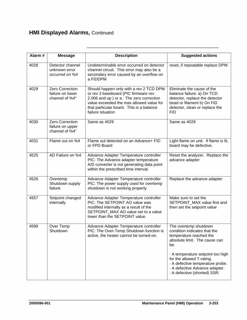
2000596-001 Maintenance Panel (HMI) Operation 3-203
HMI Displayed Alarms, Continued
Alarm # Message Description Suggested actions
4028 Detector channel unknown error occurred on %4
Undeterminable error occurred on detector channel circuit. This error may also be a secondary error caused by an overflow on a FIDDPM
reset, if repeatable replace DPM.
4029 Zero Correction failure on lower channel of %4"
Should happen only with a rev 2 TCD DPM or rev 3 baseboard (PIC firmware rev 2.006 and up ) or a : The zero correction value exceeded the max allowed value for that particular board. This is a balance failure situation
Eliminate the cause of the balance failure: a) On TCD detector, replace the detector bead or filament b) On FID detector, clean or replace the FID
4030 Zero Correction failure on upper channel of %4"
Same as 4029 Same as 4029
4031 Flame out on %4 Flame out detected on an Advance+ FID or FPD Board
Light flame on unit. If flame is lit, board may be defective.
4525 AD Failure on %4 Advance Adapter Temperature controller PIC: The Advance adapter temperature A/D converter is not generating data point within the prescribed time interval.
Reset the analyzer. Replace the advance adapter
4526 Overtemp Shutdown supply failure
Advance Adapter Temperature controller PIC: The power supply used for overtemp shutdown is not working properly
Replace the advance adapter
4557 Setpoint changed internally
Advance Adapter Temperature controller PIC: The SETPOINT AO value was modified internally as a result of the SETPOINT_MAX AO value set to a value lower than the SETPOINT value.
Make sure to set the SETPOINT_MAX value first and then set the setpoint value
4599 Over Temp Shutdown
Advance Adapter Temperature controller PIC: The Over-Temp Shutdown function is active, the heater cannot be turned-on.
The overtemp shutdown condition indicates that the temperature reached the absolute limit. The cause can be: · A temperature setpoint too high for the allowed T-rating. · A defective temperature probe. · A defective Advance adapter. · A defective (shorted) SSR.
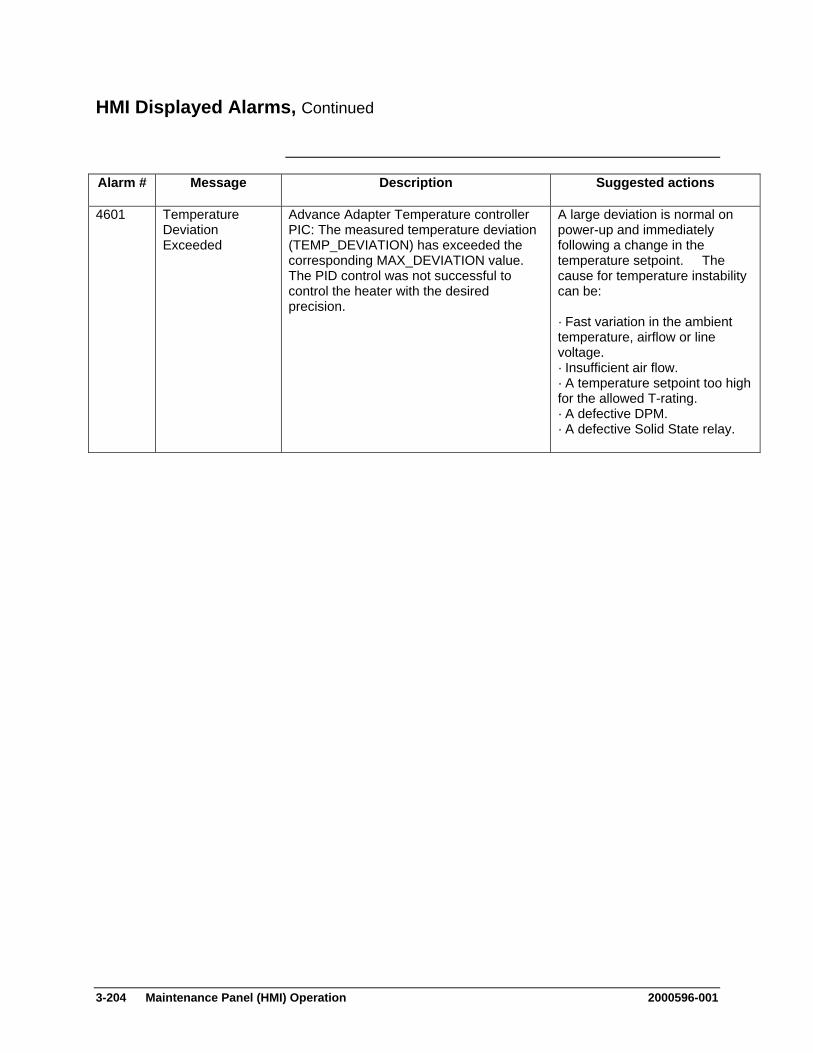
3-204 Maintenance Panel (HMI) Operation 2000596-001
HMI Displayed Alarms, Continued
Alarm # Message Description Suggested actions
4601 Temperature Deviation Exceeded
Advance Adapter Temperature controller PIC: The measured temperature deviation (TEMP_DEVIATION) has exceeded the corresponding MAX_DEVIATION value. The PID control was not successful to control the heater with the desired precision.
A large deviation is normal on power-up and immediately following a change in the temperature setpoint. The cause for temperature instability can be: · Fast variation in the ambient temperature, airflow or line voltage. · Insufficient air flow. · A temperature setpoint too high for the allowed T-rating. · A defective DPM. · A defective Solid State relay.
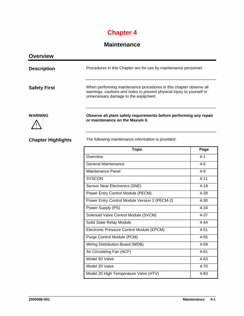
Chapter 4
Maintenance
Overview
Procedures in this Chapter are for use by maintenance personnel. Description
When performing maintenance procedures in this chapter observe all warnings, cautions and notes to prevent physical injury to yourself or unnecessary damage to the equipment.
Safety First
Observe all plant safety requirements before performing any repair or maintenance on the Maxum II.
WARNING
The following maintenance information is provided: Chapter Highlights
Topic Page
Overview 4-1
General Maintenance 4-6
Maintenance Panel 4-9
SYSCON 4-11
Sensor Near Electronics (SNE) 4-18
Power Entry Control Module (PECM) 4-28
Power Entry Control Module Version 2 (PECM-2) 4-30
Power Supply (PS) 4-34
Solenoid Valve Control Module (SVCM) 4-37
Solid State Relay Module 4-44
Electronic Pressure Control Module (EPCM) 4-51
Purge Control Module (PCM) 4-55
Wiring Distribution Board (WDB) 4-59
Air Circulating Fan (ACF) 4-61
Model 50 Valve 4-63
Model 20 Valve 4-70
Model 20 High Temperature Valve (HTV) 4-83
2000596-001 Maintenance 4-1

Overview, Continued
Topic Page
Model 11 and Model 11 Low Dead Volume (LDV) Valves 4-99
Liquid Injection Valve 4-115
Live Tee Switch 4-127
Live Tee Switch Example Application 4-129
Flame Photometric Detector (FPD) 4-140
Flame Ionization Detector (FID) 4-145
Thermal Conductivity Detector (TCD) 4-152
Miscellaneous Maxum II Procedures 4-157
If technical assistance is required during performance of maintenance functions, or if parts are being returned, the customer should contact Siemens at the following address and/or phone number:
Help
Siemens Energy & Automation, Inc. 408 US Highway 60 Bartlesville, Oklahoma 74003
Tel: (800) 448-8224 (USA) Tel: 001 918-662-7030 (International)
Before performing a procedure first read it through. It is recommended that a regular scheduled daily, weekly or monthly maintenance program be established. By doing so, the Maxum II’s downtime will be reduced and the system will operate at optimum analytical efficiency. Siemens recommendations for routine maintenance are listed in table 4-1 on the following page. These recommendations are intended as a guideline. Actual maintenance may change depending on application and the environment in which the Maxum II operates.
How to Use This Chapter
4-2 Maintenance 2000596-001
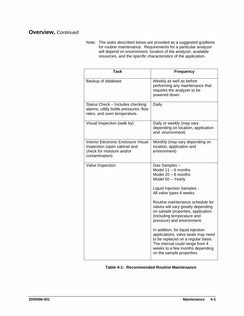
Overview, Continued
Note: The tasks described below are provided as a suggested guidleine for routine maintenance. Requirements for a particular analyzer will depend on environment, location of the analyzer, available resources, and the specific characteristics of the application.
Task Frequency
Backup of database Weekly as well as before performing any maintenance that requires the analyzer to be powered down.
Status Check – Includes checking alarms, utility bottle pressures, flow rates, and oven temperature.
Daily.
Visual Inspection (walk by) Daily or weekly (may vary depending on location, application and. environment)
Interior Electronic Enclosure Visual Inspection (open cabinet and check for moisture and/or contamination)
Monthly (may vary depending on location, application and environment)
Valve Inspection Gas Samples – Model 11 – 6 months Model 20 – 6 months Model 50 – Yearly Liquid Injection Samples - All valve types 6 weeks Routine maintenance schedule for valves will vary greatly depending on sample properties, application (including temperature and pressure) and environment.
In addition, for liquid injection applications, valve seals may need to be replaced on a regular basis. The interval could range from 4 weeks to a few months depending on the sample properties.
Table 4-1: Recommended Routine Maintenance
2000596-001 Maintenance 4-3

Overview, Continued
Note: The tasks described below are provided as a suggested guidleine for routine maintenance. Requirements for a particular analyzer will depend on environment, location of the analyzer, available resources, and the specific characteristics of the application.
Task Frequency
Verification of Calibration Monthly (may vary greatly depending on application). When validation is included automatically as part of the method, the results should be checked daily if possible.
Sample Transport Filters Replace as necessary. Note that wet/dirty samples require more frequent attention than dry/clean samples.
Lithium Battery on SYSCON Replace every 5 years
Table 4-1 (Continued): Recommended Routine Maintenance
4-4 Maintenance 2000596-001
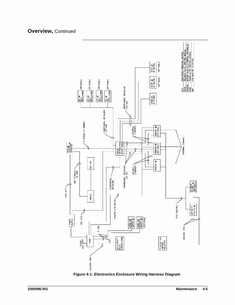
Overview, Continued
Figure 4-1: Electronics Enclosure Wiring Harness Diagram
2000596-001 Maintenance 4-5

General Maintenance
It is important that a preventative maintenance schedule be established to examine the Maxum II for internal and external cleanliness, damage, and proper operation. Refer to Table 4-1 for suggestions regarding maintenance intervals. However, maintenance schedules for a particular analyzer will depend on the application, operating environment, maintenance resources, and geographical location of the analyzer.
Scheduled Maintenance
Even though the Maxum II is tightly sealed against moisture and foreign contamination, it is recommended that the electronic enclosure door be opened periodically and internal components examined for moisture and/or contamination. If contamination is found, the system should be shutdown and corrective procedures performed. If such contamination is not removed, it could render the Maxum II inoperable.
Modular components within the Maxum II are interfaced together via miniature ribbon cables, miniature wiring and connectors. It is therefore important that maintenance personnel follow the information presented in the following sections to prevent their damage.
Component Interface Cabling and Connectors
Therefore, when opening and closing electronic enclosure door for maintenance and/or inspection, care must be exercised so as not to place a sharp bend or crimp in the cable when the door is closed.
Ribbon Cable
Internal components and modules are interfaced together using miniature wiring and associated connectors. It is therefore important that when a module and/or component is to be removed and replaced, that the connector be grasped and gently rocked, back and forth. DO NOT REMOVE A CONNECTOR BY PULLING ON ASSOCIATED CONNECTOR WIRING.
Removing Connectors
With very few exceptions, nut and bolt hardware used to secure modules and/or components in their mounting locations are in metric.
Nut and Bolt Mounting Hardware
Observe all plant safety requirements before performing any repair or maintenance on the Maxum II.
WARNING
4-6 Maintenance 2000596-001
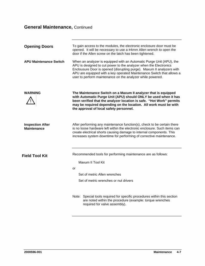
General Maintenance, Continued
To gain access to the modules, the electronic enclosure door must be opened. It will be necessary to use a #4mm Allen wrench to open the door if the Allen screw on the latch has been tightened.
Opening Doors
When an analyzer is equipped with an Automatic Purge Unit (APU), the APU is designed to cut power to the analyzer when the Electronics Enclousure Door is opened (disrupting purge). Maxum II analyzers with APU are equipped with a key operated Maintenance Switch that allows a user to perform maintenance on the analyzer while powered.
APU Maintenance Switch
The Maintenance Switch on a Maxum II analyzer that is equipped with Automatic Purge Unit (APU) should ONLY be used when it has been verified that the analyzer location is safe. “Hot Work” permits may be required depending on the location. All work must be with the approval of local safety personnel.
WARNING
After performing any maintenance function(s), check to be certain there is no loose hardware left within the electronic enclosure. Such items can create electrical shorts causing damage to internal components. This increases system downtime for performing of corrective maintenance.
Inspection After Maintenance
Recommended tools for performing maintenance are as follows: Field Tool Kit Maxum II Tool Kit
or
Set of metric Allen wrenches
Set of metric wrenches or nut drivers
Note: Special tools required for specific procedures within this section are noted within the procedure (example: torque wrenches required for valve assembly).
2000596-001 Maintenance 4-7
General Maintenance, Continued
It is important for proper procedures to be used when cleaning valve and detector parts. All foreign contamination adhering to the part should be removed using an appropriate cleaning solvent, such as hexane, acetone, or methanol and a dust/lint free cloth. Use of an ultrasonic cleaner is often helpful. After cleaning, it is necessary remove excess cleaning fluid from the components by blowing with clean air or shaking. Components must be air dry before reassembling.
Use of Solvents and Detergents
It is also possible and often better to use an appropriate detergent, such as Alconox® for cleaning instead of solvent. However, after cleaning with a detergent, it is necessary to rinse the part thoroughly with deionized water (distilled water is also acceptable) in order to remove detergent residue. All water must then be removed by blowing with clean air or shaking. Components must be completely dry before reassembling.
4-8 Maintenance 2000596-001
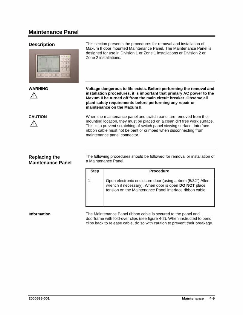
Maintenance Panel
This section presents the procedures for removal and installation of Maxum II door mounted Maintenance Panel. The Maintenance Panel is designed for use in Division 1 or Zone 1 installations or Division 2 or Zone 2 installations.
Description
Voltage dangerous to life exists. Before performing the removal and installation procedures, it is important that primary AC power to the Maxum II be turned off from the main circuit breaker. Observe all plant safety requirements before performing any repair or maintenance on the Maxum II.
WARNING
When the maintenance panel and switch panel are removed from their mounting location, they must be placed on a clean dirt free work surface. This is to prevent scratching of switch panel viewing surface. Interface ribbon cable must not be bent or crimped when disconnecting from maintenance panel connector.
CAUTION
The following procedures should be followed for removal or installation of a Maintenance Panel.
Replacing the Maintenance Panel
Step Procedure
1. Open electronic enclosure door (using a 4mm (5/32”) Allen wrench if necessary). When door is open DO NOT place tension on the Maintenance Panel interface ribbon cable.
The Maintenance Panel ribbon cable is secured to the panel and doorframe with fold-over clips (see figure 4-2). When instructed to bend clips back to release cable, do so with caution to prevent their breakage.
Information
2000596-001 Maintenance 4-9

Maintenance Panel, Continued
Step Procedure
2. Gently bend back clips that hold the ribbon cable to the back of maintenance panel. DO NOT bend back any clips that hold the cable to the door.
3. Disconnect ribbon cable from connector and let ribbon cable hang loose. To release the connector, spread out the two blue locking clips. To remove the maintenance panel it is not necessary to disconnect the ribbon cable from the SYSCON Maintenance Panel connector.
4. To remove the panel from the door, simply remove the four nuts with lock washers that secure the panel to the door.
5. To install a new panel, repeat steps 1 to 4 in reverse order. Ensure that after connecting the ribbon cable to the panel that you push both blue hold-down clips inward to lock the connector in place.
6. Before closing electronic enclosure door ensure that the ribbon cable is not pinched when the door is closed.
Figure 4-2: Rear View of Maintenance Panel
4-10 Maintenance 2000596-001
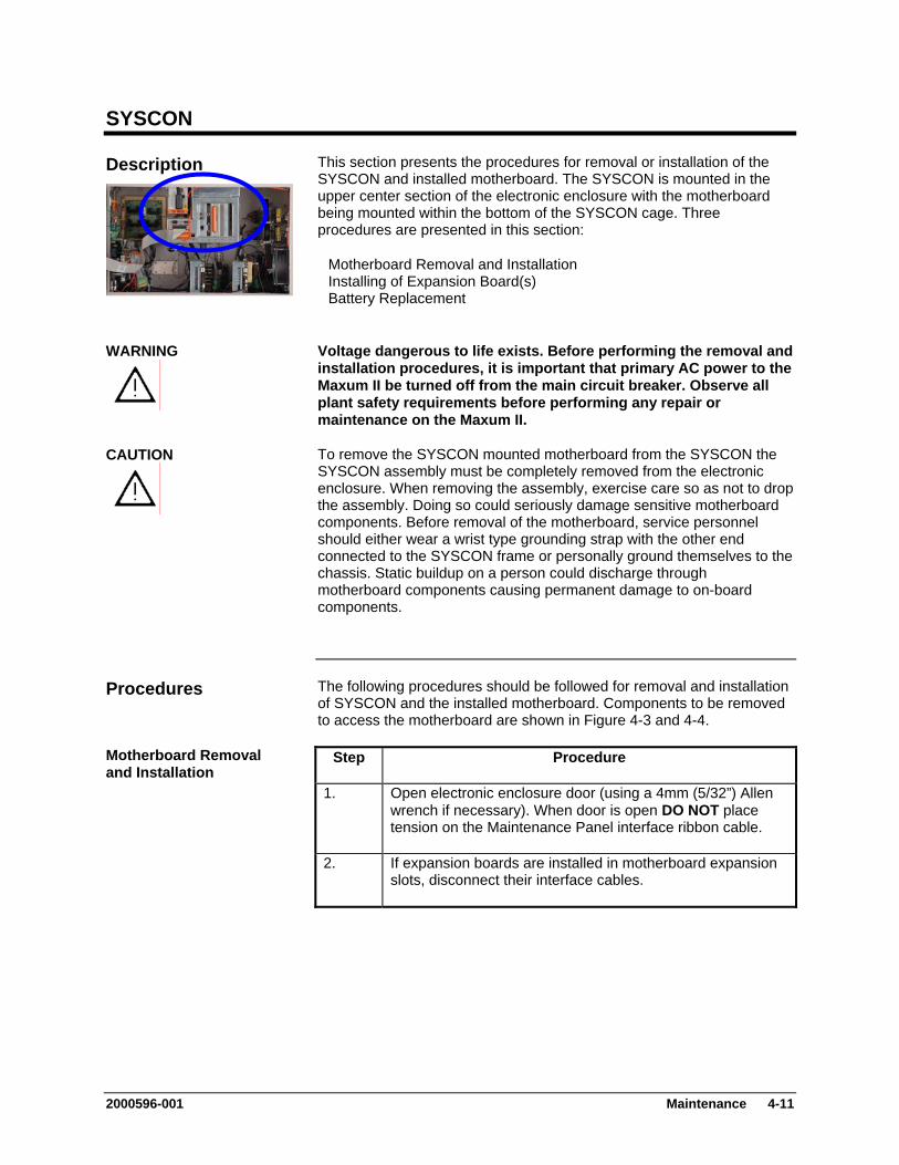
SYSCON
This section presents the procedures for removal or installation of the SYSCON and installed motherboard. The SYSCON is mounted in the upper center section of the electronic enclosure with the motherboard being mounted within the bottom of the SYSCON cage. Three procedures are presented in this section:
Description
Motherboard Removal and Installation Installing of Expansion Board(s) Battery Replacement
Voltage dangerous to life exists. Before performing the removal and installation procedures, it is important that primary AC power to the Maxum II be turned off from the main circuit breaker. Observe all plant safety requirements before performing any repair or maintenance on the Maxum II.
WARNING
To remove the SYSCON mounted motherboard from the SYSCON the SYSCON assembly must be completely removed from the electronic enclosure. When removing the assembly, exercise care so as not to drop the assembly. Doing so could seriously damage sensitive motherboard components. Before removal of the motherboard, service personnel should either wear a wrist type grounding strap with the other end connected to the SYSCON frame or personally ground themselves to the chassis. Static buildup on a person could discharge through motherboard components causing permanent damage to on-board components.
CAUTION
The following procedures should be followed for removal and installation of SYSCON and the installed motherboard. Components to be removed to access the motherboard are shown in Figure 4-3 and 4-4.
Procedures
Motherboard Removal and Installation
Step Procedure
1. Open electronic enclosure door (using a 4mm (5/32”) Allen wrench if necessary). When door is open DO NOT place tension on the Maintenance Panel interface ribbon cable.
2. If expansion boards are installed in motherboard expansion slots, disconnect their interface cables.
2000596-001 Maintenance 4-11

SYSCON, Continued
Verify each expansion board interface cable is labeled with its mounting location.
NOTE
Step Procedure
3. If SYSCON is connected to a network, disconnect the 10BaseT connector.
Motherboard
MotherboardAccessCover
MotherboardAccess Mtg.Thumbscrews(3)
External Inter-face CableConnectors
10BaseTConnector
SYSCONAssy.FasteningScrew (2)
Ex. PWR CableWhite: 24 VDCBlk: PECM Purge
Power Cable toMotherboard
Figure 4-3: Accessing/Removing Motherboard (Original SYSCON is Shown)
4. Disconnect all cable connectors from External Interface Cable Connector panel. Remove the Maintenance Panel ribbon cable from any fold over clips that fasten it to the SYSCON Mounting Assembly. Use care bending clips to prevent breaking them.
5. Using appropriate tools, loosen the topmost SYSCON Assembly fastening hardware that secures the assembly to electronic enclosure mounting bracket.
6. Pull the SYSCON assembly forward and lower it so that it rests on the rubber mounting foot. Refer to Figure 4-4.
4-12 Maintenance 2000596-001
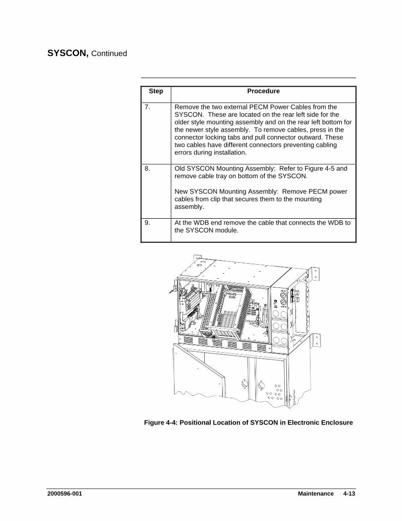
SYSCON, Continued
Step Procedure
7. Remove the two external PECM Power Cables from the SYSCON. These are located on the rear left side for the older style mounting assembly and on the rear left bottom for the newer style assembly. To remove cables, press in the connector locking tabs and pull connector outward. These two cables have different connectors preventing cabling errors during installation.
8. Old SYSCON Mounting Assembly: Refer to Figure 4-5 and remove cable tray on bottom of the SYSCON.
New SYSCON Mounting Assembly: Remove PECM power cables from clip that secures them to the mounting assembly.
9. At the WDB end remove the cable that connects the WDB to the SYSCON module.
Figure 4-4: Positional Location of SYSCON in Electronic Enclosure
2000596-001 Maintenance 4-13

SYSCON, Continued
Figure 4-5: SYSCON Fully Installed View (Old SYSCON Shown)
Step Procedure
10. To remove SYSCON, lift the assembly upwards and pull forward from its mounting rail assembly. It is recommended that the assembly be lifted by one hand and supported by the other. Place assembly on a clean dirt free work surface.
11. (Old SYSCON Mounting Assembly Only) Remove the three motherboard access thumb mounting screws. These screws secure left side mounted perforated cover to SYSCON frame. Remove cover to expose left side of motherboard.
To remove the SYSCON mounted motherboard from the SYSCON, the SYSCON assembly must be completely removed from the electronic enclosure. When removing the assembly, exercise care so as not to drop the assembly. Doing so could seriously damage sensitive motherboard components. Before removal of the motherboard, service personnel should either wear a wrist type grounding strap with the other end connected to the SYSCON frame or personally ground themselves to the chassis. Static buildup on a person could discharge through motherboard components causing permanent damage to on-board components.
CAUTION
4-14 Maintenance 2000596-001
SYSCON, Continued
Step Procedure
12. Disconnect all cable connectors connected to the motherboard. Use care when unplugging the small gold connector of the WDB cable. Carefully remove this connector by pulling firmly (use pliers if necessary).
Before removing cables from motherboard, label each one to identify its motherboard mounting location.
IMPORTANT
13. Remove all motherboard installed expansion boards. Note
slot location for each board so they can be reinstalled in same slot. Also unplug the orange connectors that extend through the front face of the mounting assembly.
14. Remove the six Allen screws securing motherboard to its SYSCON assembly mounting standoffs. Screws are located in each corner and center of motherboard.
When removing motherboard, lift by its sides. DO NOT touch board mounted components. Discharge of body static electricity can damage components.
IMPORTANT
15. (Old Mounting Assembly) Lift-up the motherboard and slide it to the right, then lift-up left side and extract from SYSCON mounting assembly. Motherboard must be lifted up over the two SYSCON frame mounted power connectors.
(New Mounting Assembly) Lift up the motherboard and pull back to remove.
16. Place motherboard in an anti-static bag for return to Siemens.
17. To reinstall motherboard, repeat steps 1 to 15 in reverse order.
18. Before closing door and reapplying AC power, be certain all interface cables are correctly connected.
Be certain expansion boards are installed in their correct motherboard expansion slots.
2000596-001 Maintenance 4-15

SYSCON, Continued
If only an expansion board(s) is to be installed in a motherboard expansion slot, then perform the following procedures. To install a board(s) it is not necessary to disconnect interface cables or to remove the SYSCON from its mounting facility.
Installing of Expansion Board(s)
Step Procedure
1. Open electronic enclosure door (using a 4mm (5/32”) Allen wrench if necessary). When door is open DO NOT place tension on the Maintenance Panel interface ribbon cable.
2. Using appropriate tools, loosen the topmost SYSCON Assembly fastening hardware that secures the assembly to electronic enclosure mounting bracket.
3. Pull the SYSCON assembly forward and lower so it rests on the bottom frame rubber mounting foot.
4. Remove the blank slot cover from the slot that is to be used.
5. Install the expansion board in the appropriate SYSCON motherboard expansion slot. Be certain the board is properly seated in its connector and screw it into the mounting chassis. Refer to Figure 4-3.
6. Connect necessary cables.
7. Push the SYSCON assembly back into its mounting facility and secure in place with the fastening hardware.
8. Attach appropriate interface cable to the expansion board connector.
9. Before closing door and reapplying AC power, be certain the interface cable is securely connected to expansion board.
4-16 Maintenance 2000596-001
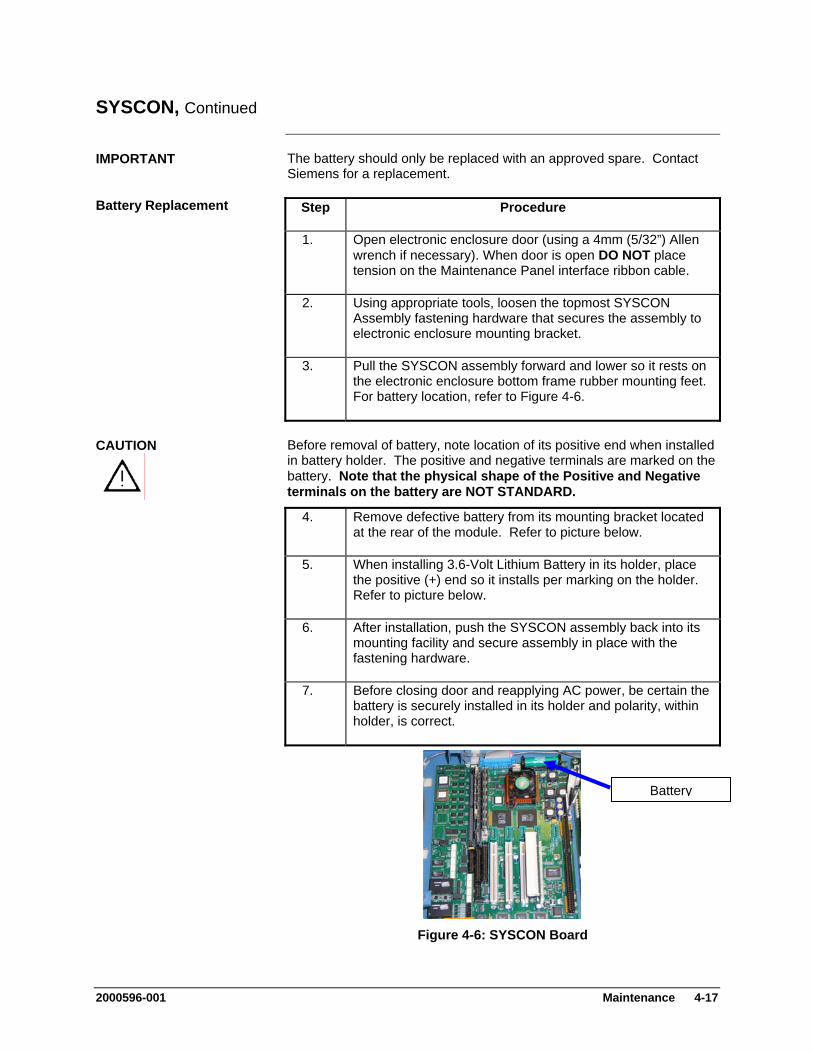
SYSCON, Continued
The battery should only be replaced with an approved spare. Contact Siemens for a replacement.
IMPORTANT
Battery Replacement Step Procedure
1. Open electronic enclosure door (using a 4mm (5/32”) Allen wrench if necessary). When door is open DO NOT place tension on the Maintenance Panel interface ribbon cable.
2. Using appropriate tools, loosen the topmost SYSCON Assembly fastening hardware that secures the assembly to electronic enclosure mounting bracket.
3. Pull the SYSCON assembly forward and lower so it rests on the electronic enclosure bottom frame rubber mounting feet. For battery location, refer to Figure 4-6.
Before removal of battery, note location of its positive end when installed in battery holder. The positive and negative terminals are marked on the battery. Note that the physical shape of the Positive and Negative terminals on the battery are NOT STANDARD.
CAUTION
4. Remove defective battery from its mounting bracket located
at the rear of the module. Refer to picture below.
5. When installing 3.6-Volt Lithium Battery in its holder, place the positive (+) end so it installs per marking on the holder. Refer to picture below.
6. After installation, push the SYSCON assembly back into its mounting facility and secure assembly in place with the fastening hardware.
7. Before closing door and reapplying AC power, be certain the battery is securely installed in its holder and polarity, within holder, is correct.
Battery
Figure 4-6: SYSCON Board
2000596-001 Maintenance 4-17
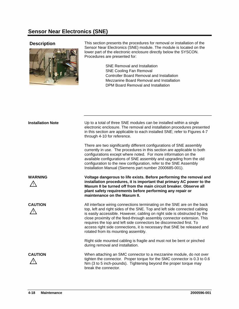
Sensor Near Electronics (SNE)
This section presents the procedures for removal or installation of the Sensor Near Electronics (SNE) module. The module is located on the lower part of the electronic enclosure directly below the SYSCON. Procedures are presented for:
Description
SNE Removal and Installation SNE Cooling Fan Removal Controller Board Removal and Installation Mezzanine Board Removal and Installation
DPM Board Removal and Installation
Up to a total of three SNE modules can be installed within a single electronic enclosure. The removal and installation procedures presented in this section are applicable to each installed SNE; refer to Figures 4-7 through 4-10 for reference.
Installation Note
There are two significantly different configurations of SNE assembly currently in use. The procedures in this section are applicable to both configurations except where noted. For more information on the available configurations of SNE assembly and upgrading from the old configuration to the new configuration, refer to the SNE Assembly Installation Manual (Siemens part number 2000685-001).
Voltage dangerous to life exists. Before performing the removal and installation procedures, it is important that primary AC power to the Maxum II be turned off from the main circuit breaker. Observe all plant safety requirements before performing any repair or maintenance on the Maxum II.
WARNING
All interface wiring connections terminating on the SNE are on the back top, left and right sides of the SNE. Top and left side connected cabling is easily accessible. However, cabling on right side is obstructed by the close proximity of the feed-through assembly connector extension. This requires the top and left side connectors be disconnected first. To access right side connections, it is necessary that SNE be released and rotated from its mounting assembly.
CAUTION
Right side mounted cabling is fragile and must not be bent or pinched during removal and installation.
When attaching an SMC connector to a mezzanine module, do not over tighten the connector. Proper torque for the SMC connector is 0.3 to 0.6 Nm (3 to 5 inch-pounds). Tightening beyond the proper torque may break the connector.
CAUTION
4-18 Maintenance 2000596-001

Sensor Near Electronics (SNE), Continued
The following procedures should be followed for removal and installation of SNE.
Procedures
SNE Removal and Installation
Step Procedure
1. Open electronic enclosure door (using a 4mm (5/32”) Allen wrench if necessary). When door is open DO NOT place tension on the Maintenance Panel interface ribbon cable.
2. Remove interface cables from top and left side of the SNE. Label each cable as to its connection point. This will help avoid making a wrong connection during installation. Long interface cables attach to top mounted connectors and short cables attach to bottom connectors.
3. Remove the one or two nuts from the front SNE mounting bracket; see Figures below.
Mounting Nuts
4. Pull the SNE slightly forward to release assembly from rear mounting guide.
5. Remove SNE from electronic enclosure.
Mounting Nut
Old Assembly
New Assembly
2000596-001 Maintenance 4-19
Sensor Near Electronics (SNE), Continued
In the following steps, if attaching an SMC connector to a mezzanine module, do not over tighten the connector. Proper torque for the SMC connector is 0.3 to 0.6 Nm (3 to 5 inch-pounds). Tightening beyond the proper torque may break the connector.
CAUTION
Step Procedure
6. To reinstall the new SNE, perform steps 1 to 5 in reverse order.
7. Before reapplying AC power, be certain the SNE assembly is securely fastened to electronic enclosure mounting facility, and all interface cables are correctly and securely fastened.
For the old SNE Assembly, there is a small cooling fan located on the side of the assembly chassis. This fan does is not required on the new chassis. This fan is part of the old SNE Assembly and is not available as a spare part. If the fan becomes faulty then the SNE Assembly must be replaced with the newer version.
SNE Cooling Fan
4-20 Maintenance 2000596-001
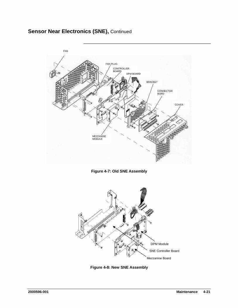
Sensor Near Electronics (SNE), Continued
FAN
COVER
CONNECTOR BORD
BRACKET
FAN PLUG
MEZZANINE MODULE
CONTROLLER BOARD
DPM BOARD
Figure 4-7: Old SNE Assembly
Mezzanine Board
DPM Module
SNE Controller Board
Figure 4-8: New SNE Assembly
2000596-001 Maintenance 4-21
Sensor Near Electronics (SNE), Continued
To replace a SNE installed board, it is necessary to remove the SNE from the EC. See Figure 4-7 (old assembly) or 4-8 (new assembly) for the following procedures.
Controller Board Removal and Installation
Old Assembly: Step Procedure
1. Remove the SNE from its enclosure mounting position by performing steps 1 to 5 in previous section, SNE Removal and Installation.
2. With the SNE fully removed from enclosure remove the screen cover by unscrewing the three fastening screws. These are captive screws and will remain with the panel.
3. See Figure 4-7 or 4-8, the controller board is located in the expansion slot against left side of the assembly. This board incorporates LED status lights. Remove all external cables to and from the Controller board. Note cable locations.
4. Remove controller board and install replacement board.
5. Connect all I/O wiring to the replacement board.
6. Reinstall screen cover and reinstall SNE Assembly in the electronics enclosure.
New Assembly:
Step Procedure
1. Remove the SNE from its enclosure mounting position by performing steps 1 to 5 in previous section, SNE Removal and Installation.
2. The DPM must be removed prior to removing the SNE Controller board. To remove the DPM, remove any cables and then remove the two allen screws securing the board to the assembly. Then pull the board firmly to unplug.
3. Remove any additional cables or jumpers from the SNE Controller board. Make note of cable locations.
4-22 Maintenance 2000596-001

Sensor Near Electronics (SNE), Continued
Step Procedure
4. Unscrew the three fastening screws that secure the SNE Controller to the assembly and then unplug the SNE Controller board.
In the following steps, if attaching an SMC connector to a mezzanine module, do not over tighten the connector. Proper torque for the SMC connector is 0.3 to 0.6 Nm (3 to 5 inch-pounds). Tightening beyond the proper torque may break the connector.
CAUTION
5. Perfrom steps 1 to 4 in reverse order to install new SNE
controller, reinstall DPM and reinstall assembly in the Electronics enclosure.
After installing the SNE in the EC, ensure that the board is securely installed in its SNE expansion slot.
Installation Note
A Mezzanine module can be removed without removing the DPM board. Mezzanine Module Removal and Installation
Step Procedure
1. Remove the SNE from its enclosure mounting position by performing steps 1 to 5 in previous section, SNE Removal and Installation.
2. (Old Assembly Only) With the SNE fully removed from enclosure, remove the screen cover by unscrewing the three fastening screws. These are captive screws and will remain with the panel.
3. Refer to Figure 4-7 or 4-8 and remove the attaching hardware securing the mezzanine module to the controller board.
2000596-001 Maintenance 4-23
Sensor Near Electronics (SNE), Continued
In the following steps, if attaching an SMC connector to a mezzanine module, do not over tighten the connector. Proper torque for the SMC connector is 0.3 to 0.6 Nm (3 to 5 inch-pounds). Tightening beyond the proper torque may break the connector.
CAUTION
Step Procedure
4. To reinstall replacement board, perform steps 1 to 3 in reverse order.
5. Connect all I/O wiring to the module and reinstall SNE in the electronics enclosure.
4-24 Maintenance 2000596-001

Sensor Near Electronics (SNE), Continued
DPM Removal and Installation
To replace a DPM it is necessary to remove the SNE from the EC. See Figure 4-7 (old assembly) or Figure 4-8 (new assembly) for the following procedure.
Step Procedure
1. Remove the SNE from its enclosure mounting position by performing steps 1 to 5 in previous procedure, SNE Removal and Installation.
2. (Old Assembly Only) With the SNE fully removed from enclosure remove the screen cover by unscrewing the three fastening screws. These are captive screws and will remain with the panel.
3. (Old Assembly) Loosen the thumbscrew that secures the connector board assembly to the DPM and remove the assembly.
(New Assembly) Remove the two allen screws that secure the DPM to the mounting assembly.
4. Remove all external cables to and from the DPM board. It may be necessary to partially remove the board in order to remove the cables on the left side of the board.
5. Remove DPM board.
In the following steps, if attaching an SMC connector to a mezzanine module, do not over tighten the connector. Proper torque for the SMC connector is 0.3 to 0.6 Nm (3 to 5 inch-pounds). Tightening beyond the proper torque may break the connector.
CAUTION
6. To reinstall replacement board, perform steps 1 to 5 in reverse order.
7. Connect all I/O wiring to the replacement board and reinstall the SNE into electronic enclosure.
2000596-001 Maintenance 4-25
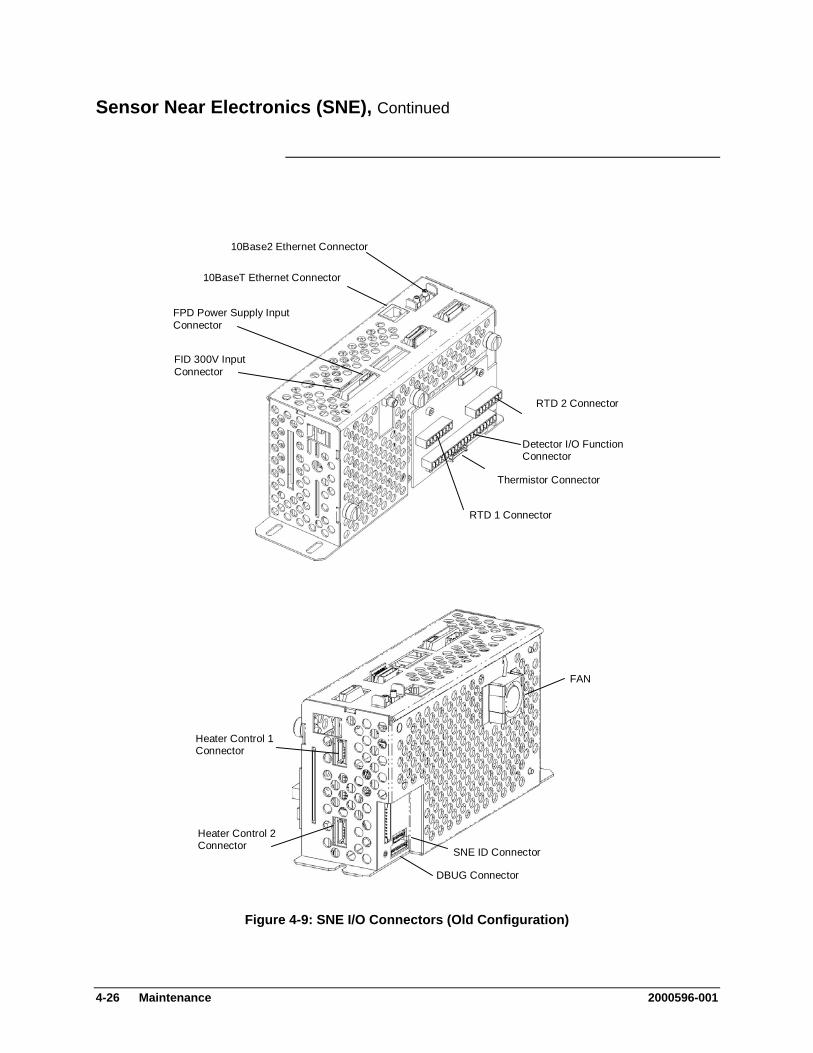
Sensor Near Electronics (SNE), Continued
RTD 1 Connector
RTD 2 Connector
Detector I/O Function Connector
Thermistor Connector
10Base2 Ethernet Connector
10BaseT Ethernet Connector
FID 300V Input Connector
FPD Power Supply Input Connector
FAN
SNE ID Connector
DBUG Connector
Heater Control 1 Connector
Heater Control 2 Connector
Figure 4-9: SNE I/O Connectors (Old Configuration)
4-26 Maintenance 2000596-001
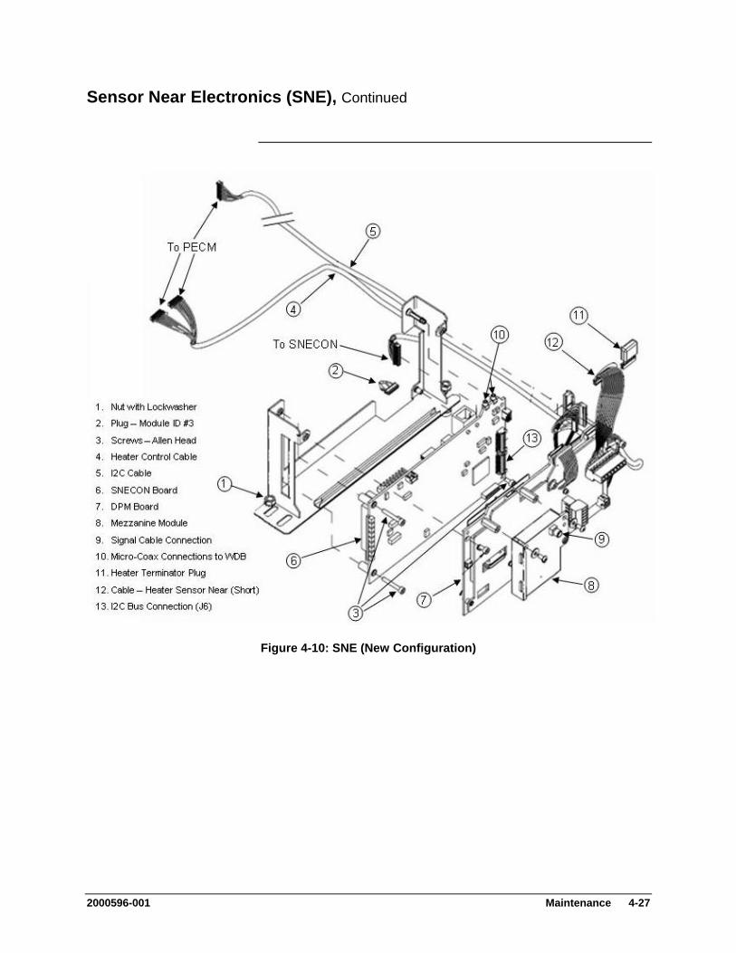
Sensor Near Electronics (SNE), Continued
Figure 4-10: SNE (New Configuration)
2000596-001 Maintenance 4-27
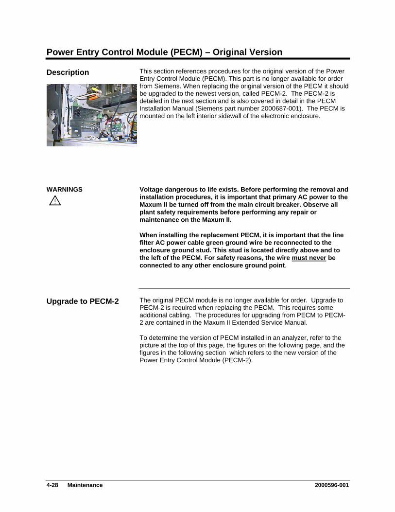
Power Entry Control Module (PECM) – Original Version
This section references procedures for the original version of the Power Entry Control Module (PECM). This part is no longer available for order from Siemens. When replacing the original version of the PECM it should be upgraded to the newest version, called PECM-2. The PECM-2 is detailed in the next section and is also covered in detail in the PECM Installation Manual (Siemens part number 2000687-001). The PECM is mounted on the left interior sidewall of the electronic enclosure.
Description
Voltage dangerous to life exists. Before performing the removal and installation procedures, it is important that primary AC power to the Maxum II be turned off from the main circuit breaker. Observe all plant safety requirements before performing any repair or maintenance on the Maxum II.
WARNINGS
When installing the replacement PECM, it is important that the line filter AC power cable green ground wire be reconnected to the enclosure ground stud. This stud is located directly above and to the left of the PECM. For safety reasons, the wire must never be connected to any other enclosure ground point.
The original PECM module is no longer available for order. Upgrade to PECM-2 is required when replacing the PECM. This requires some additional cabling. The procedures for upgrading from PECM to PECM-2 are contained in the Maxum II Extended Service Manual.
Upgrade to PECM-2
To determine the version of PECM installed in an analyzer, refer to the picture at the top of this page, the figures on the following page, and the figures in the following section which refers to the new version of the Power Entry Control Module (PECM-2).
4-28 Maintenance 2000596-001

Power Entry Control Module (PECM) - Original Version, Continued
Figure 4-11: PECM Configuration
2000596-001 Maintenance 4-29
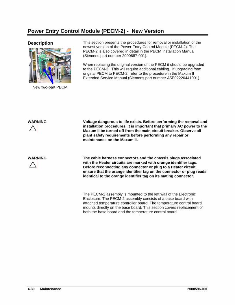
Power Entry Control Module (PECM-2) - New Version
This section presents the procedures for removal or installation of the newest version of the Power Entry Control Module (PECM-2). The PECM-2 is also covered in detail in the PECM Installation Manual (Siemens part number 2000687-001). When replacing the original version of the PECM it should be upgraded to the PECM-2. This will require additional cabling. If upgrading from original PECM to PECM-2, refer to the procedure in the Maxum II Extended Service Manual (Siemens part number A5E02220441001).
Description
New two-part PECM
Voltage dangerous to life exists. Before performing the removal and installation procedures, it is important that primary AC power to the Maxum II be turned off from the main circuit breaker. Observe all plant safety requirements before performing any repair or maintenance on the Maxum II.
WARNING
The cable harness connectors and the chassis plugs associated with the Heater circuits are marked with orange identifier tags. Before reconnecting any connector or plug to a Heater circuit, ensure that the orange identifier tag on the connector or plug reads identical to the orange identifier tag on its mating connector.
WARNING
The PECM-2 assembly is mounted to the left wall of the Electronic Enclosure. The PECM-2 assembly consists of a base board with attached temperature controller board. The temperature control board mounts directly on the base board. This section covers replacement of both the base board and the temperature control board.
4-30 Maintenance 2000596-001
Power Entry Control Module (PECM-2), Continued
The following procedure should be used for replacement of the PECM-2 in the Maxum II. If upgrading from original PECM to PECM-2, refer to the Maxum II Extended Service Manual (part number A5E02220441001).
PECM-2 Removal and Installaton
Step Procedure
1. Turn off power to the Maxum II at the main circuit breaker.
2. Open electronic enclosure door (using a 4mm (5/32”) Allen wrench if necessary). When door is open DO NOT place tension on the Maintenance Panel interface ribbon cable.
3. Remove power connections from PECM-2. Secure and lable these connections for reattachment later.
4. Remove cables connected to PECM-2. Label each cable when it is removed.
5. Unplug the atmospheric reference tube from the purge switch. (connection SW1, tubing connection on the bottom board of the PECM-2, middle right side, back). Refer to Figure 4-12.
6. Use a 5mm nut driver or socket to loosen the two hex nuts at the top of each side of the base plate of the PECM-2. Do not remove the nuts completely.
7. Slide the PECM-2 up and then lift it off of the mounting bolts.
8. On the replacement PECM-2 perform the following:
Verify that the Purge Disable jumper JP2 is set correctly.
Ensure the TL/OT boards are moved to the replacement PECM-2 (J15 & J16) to maintain the same T-rating of the GC.
Install the appropriate fuses for either 115VAC or 230VAC in Fuse locations F1 and F2 and install covers. Refer to the table on the following page for fuse assignments). Be sure to replace the fuse cover over the fuses once the fuses are installed.
Move jumper cables or termination plugs to the replacement PECM-2.
2000596-001 Maintenance 4-31
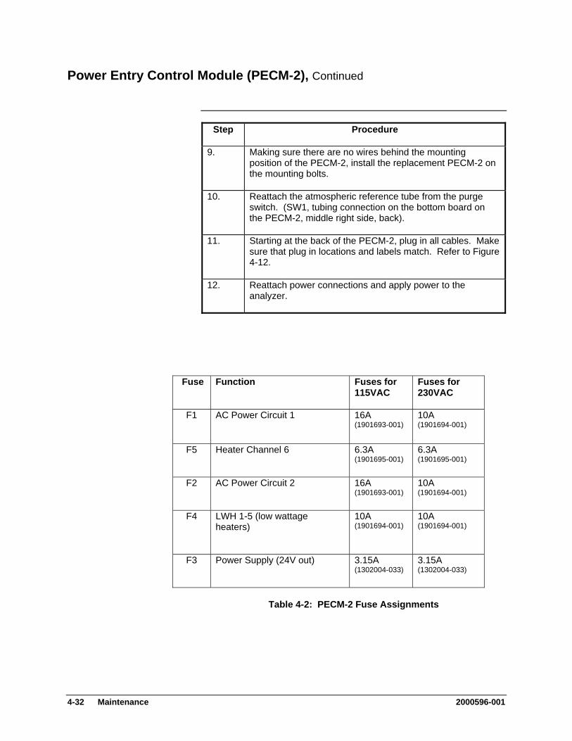
Power Entry Control Module (PECM-2), Continued
Step Procedure
9. Making sure there are no wires behind the mounting position of the PECM-2, install the replacement PECM-2 on the mounting bolts.
10. Reattach the atmospheric reference tube from the purge switch. (SW1, tubing connection on the bottom board on the PECM-2, middle right side, back).
11. Starting at the back of the PECM-2, plug in all cables. Make sure that plug in locations and labels match. Refer to Figure 4-12.
12. Reattach power connections and apply power to the analyzer.
Fuse Function Fuses for 115VAC
Fuses for 230VAC
10A F1 AC Power Circuit 1 16A (1901693-001) (1901694-001)
6.3A F5 Heater Channel 6 6.3A (1901695-001) (1901695-001)
10A F2 AC Power Circuit 2 16A (1901693-001) (1901694-001)
10A F4 LWH 1-5 (low wattage heaters)
10A (1901694-001) (1901694-001)
3.15A F3 Power Supply (24V out) 3.15A (1302004-033) (1302004-033)
Table 4-2: PECM-2 Fuse Assignments
4-32 Maintenance 2000596-001
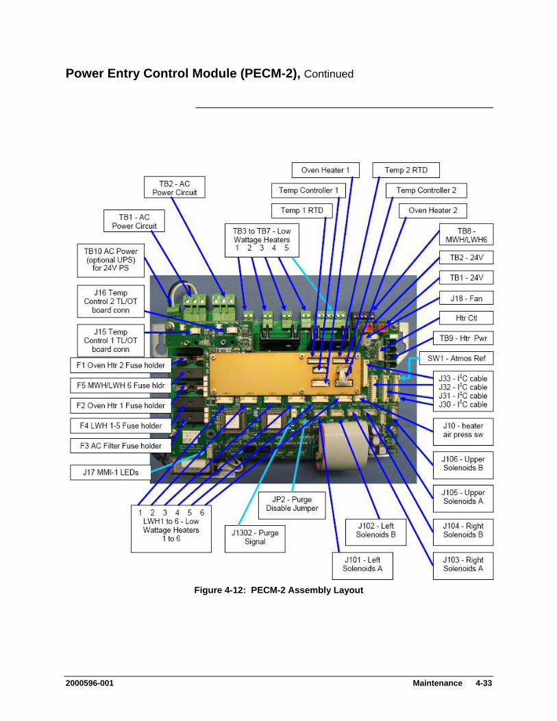
Power Entry Control Module (PECM-2), Continued
Figure 4-12: PECM-2 Assembly Layout
2000596-001 Maintenance 4-33
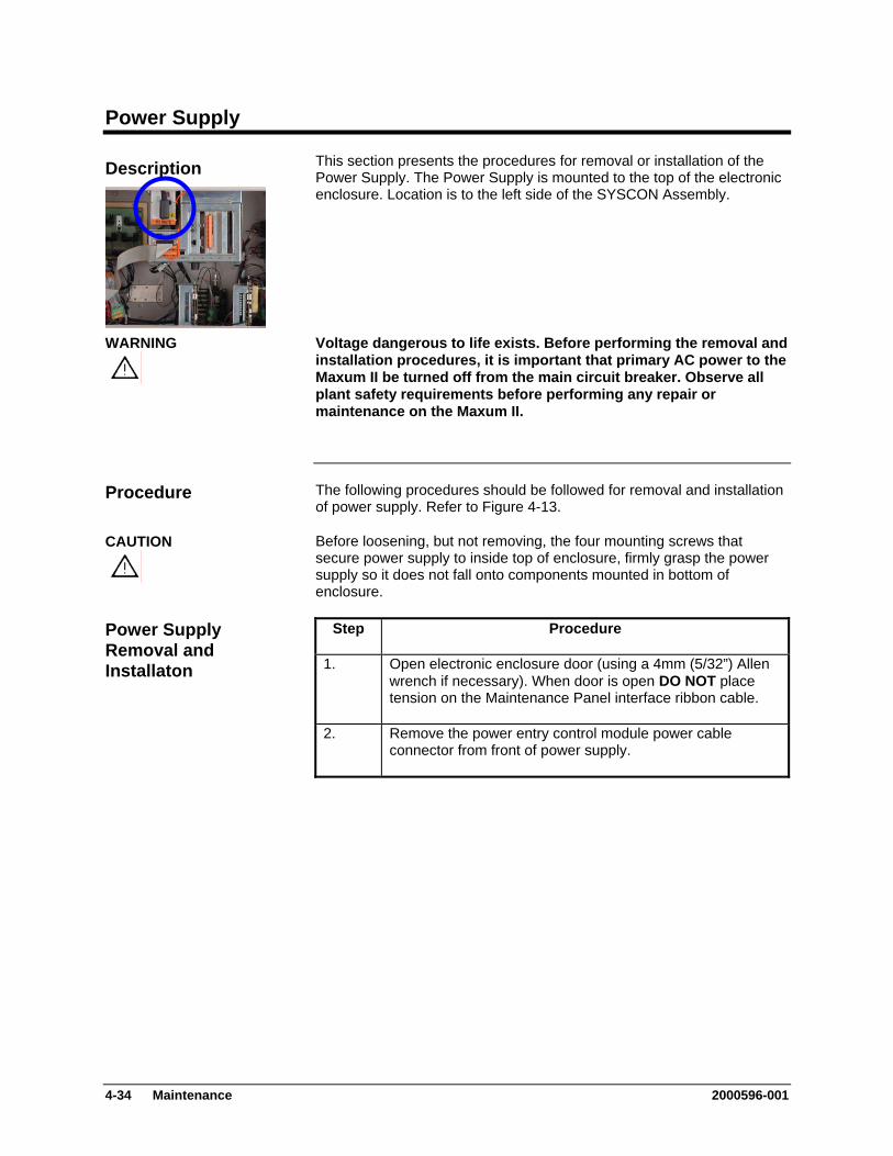
Power Supply
This section presents the procedures for removal or installation of the Power Supply. The Power Supply is mounted to the top of the electronic enclosure. Location is to the left side of the SYSCON Assembly.
Description
Voltage dangerous to life exists. Before performing the removal and installation procedures, it is important that primary AC power to the Maxum II be turned off from the main circuit breaker. Observe all plant safety requirements before performing any repair or maintenance on the Maxum II.
WARNING
The following procedures should be followed for removal and installation of power supply. Refer to Figure 4-13.
Procedure
Before loosening, but not removing, the four mounting screws that secure power supply to inside top of enclosure, firmly grasp the power supply so it does not fall onto components mounted in bottom of enclosure.
CAUTION
Step Procedure Power Supply Removal and Installaton 1. Open electronic enclosure door (using a 4mm (5/32”) Allen
wrench if necessary). When door is open DO NOT place tension on the Maintenance Panel interface ribbon cable.
2. Remove the power entry control module power cable connector from front of power supply.
4-34 Maintenance 2000596-001
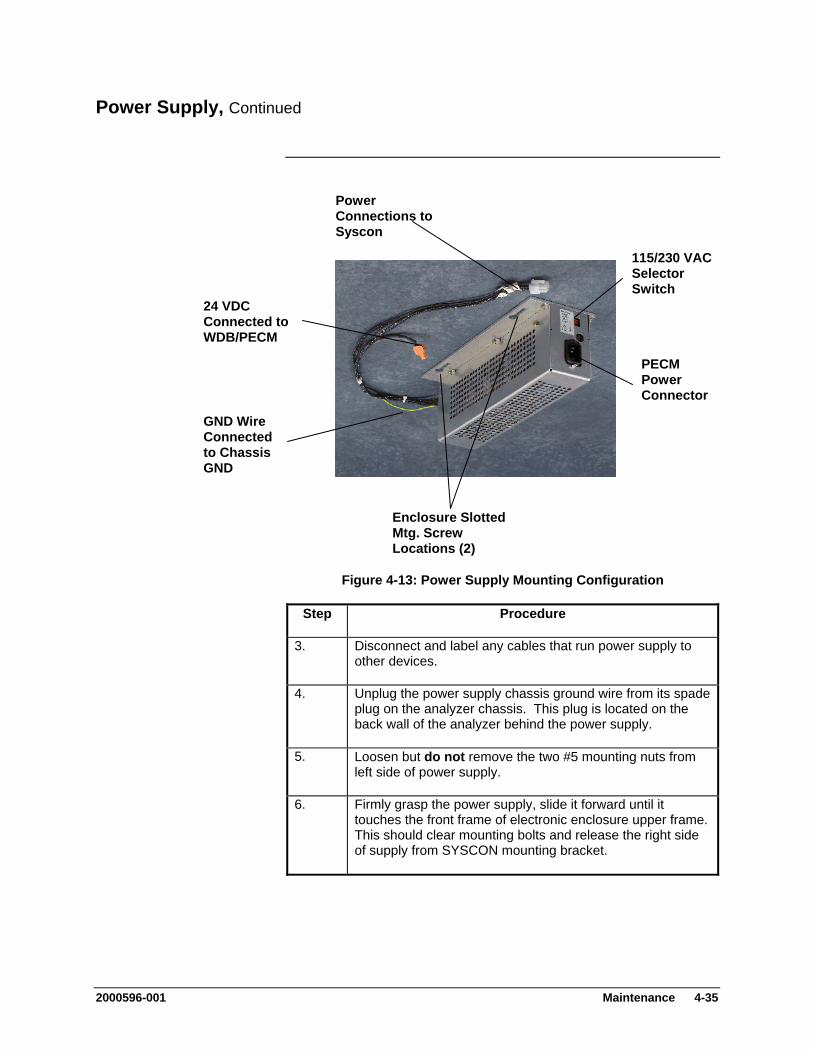
Power Supply, Continued
Power Connections to Syscon
115/230 VAC Selector Switch
24 VDC Connected to WDB/PECM
Figure 4-13: Power Supply Mounting Configuration
Step Procedure
3. Disconnect and label any cables that run power supply to other devices.
4. Unplug the power supply chassis ground wire from its spade plug on the analyzer chassis. This plug is located on the back wall of the analyzer behind the power supply.
5. Loosen but do not remove the two #5 mounting nuts from left side of power supply.
6. Firmly grasp the power supply, slide it forward until it touches the front frame of electronic enclosure upper frame. This should clear mounting bolts and release the right side of supply from SYSCON mounting bracket.
PECM Power Connector
GND Wire Connected to Chassis GND
Enclosure Slotted Mtg. Screw Locations (2)
2000596-001 Maintenance 4-35
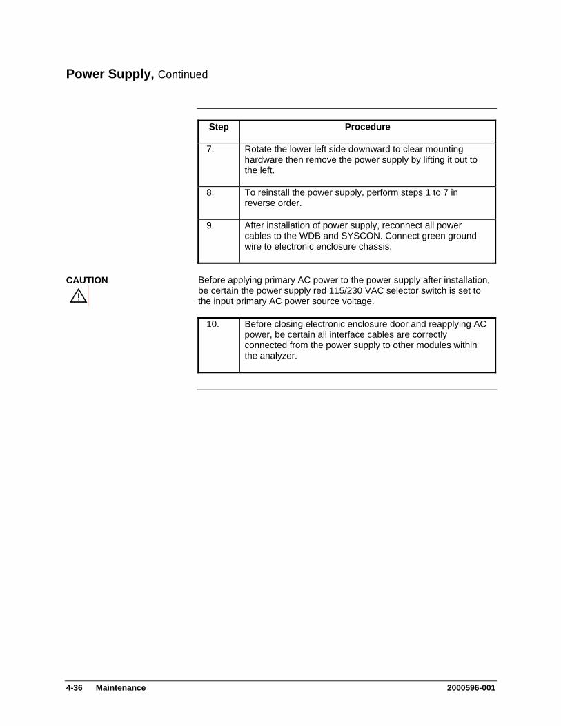
Power Supply, Continued
Step Procedure
7. Rotate the lower left side downward to clear mounting hardware then remove the power supply by lifting it out to the left.
8. To reinstall the power supply, perform steps 1 to 7 in reverse order.
9. After installation of power supply, reconnect all power cables to the WDB and SYSCON. Connect green ground wire to electronic enclosure chassis.
Before applying primary AC power to the power supply after installation, be certain the power supply red 115/230 VAC selector switch is set to the input primary AC power source voltage.
CAUTION
10. Before closing electronic enclosure door and reapplying AC power, be certain all interface cables are correctly connected from the power supply to other modules within the analyzer.
4-36 Maintenance 2000596-001
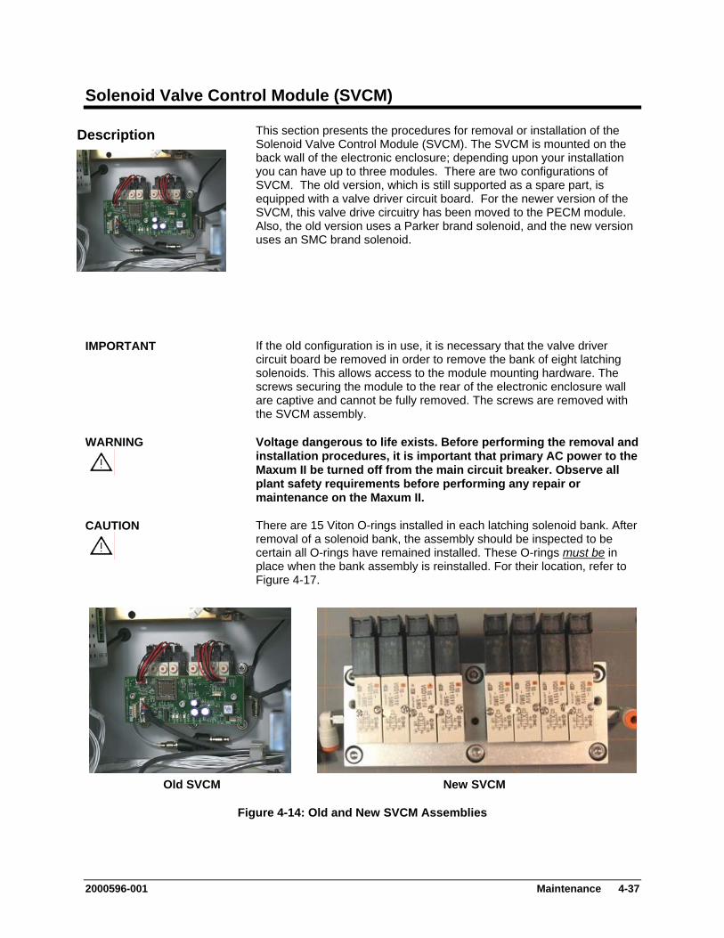
Solenoid Valve Control Module (SVCM)
This section presents the procedures for removal or installation of the Solenoid Valve Control Module (SVCM). The SVCM is mounted on the back wall of the electronic enclosure; depending upon your installation you can have up to three modules. There are two configurations of SVCM. The old version, which is still supported as a spare part, is equipped with a valve driver circuit board. For the newer version of the SVCM, this valve drive circuitry has been moved to the PECM module. Also, the old version uses a Parker brand solenoid, and the new version uses an SMC brand solenoid.
Description
If the old configuration is in use, it is necessary that the valve driver circuit board be removed in order to remove the bank of eight latching solenoids. This allows access to the module mounting hardware. The screws securing the module to the rear of the electronic enclosure wall are captive and cannot be fully removed. The screws are removed with the SVCM assembly.
IMPORTANT
Voltage dangerous to life exists. Before performing the removal and installation procedures, it is important that primary AC power to the Maxum II be turned off from the main circuit breaker. Observe all plant safety requirements before performing any repair or maintenance on the Maxum II.
WARNING
There are 15 Viton O-rings installed in each latching solenoid bank. After removal of a solenoid bank, the assembly should be inspected to be certain all O-rings have remained installed. These O-rings
CAUTION
must be in place when the bank assembly is reinstalled. For their location, refer to Figure 4-17.
Old SVCM New SVCM
Figure 4-14: Old and New SVCM Assemblies
2000596-001 Maintenance 4-37
Solenoid Valve Control Module (SVCM), Continued
Procedures are presented for removal of the circuit board and then the latching solenoids. Refer to Figures 4-14 through 4-17.
Procedures
Depending on the configuration of the Maxum II, it may be necessary to remove an SNE assembly in order to properly access the SVCM assembly for removal. Refer to the SNE maintenance section of this manual for instructions on removing an SNE assembly.
IMPORTANT
Removal SVCM Electronics Controller (Old SVCM Only)
Step Procedure
1. Open electronic enclosure door (using a 4mm (5/32”) Allen wrench if necessary). When door is open DO NOT place tension on the Maintenance Panel interface ribbon cable.
2. Disconnect both solenoid cables J10 and J11 connected to circuit board. Also disconnect J1, J2 and J3. Refer to Figure 4-15.
3. Remove three 5mm Allen mounting screws securing SVCM to relay bank mounting standoffs. These are not captive screws and MUST BE completely removed.
4. Remove circuit board from mounting standoffs. To remove, grasp board by its sides to prevent static discharge which could damage components.
5. To reinstall a new circuit board, perform steps 1 to 4 in reverse order. To prevent damage to SVCM, DO NOT over tighten mounting screws (screws should be tightened firmly but not torqued down).
4-38 Maintenance 2000596-001

Solenoid Valve Control Module (SVCM), Continued
In the following procedure, when removing the older configuration SVCM assembly, DO NOT remove connectors from individual relays. The connectors should remain connected to each relay.
CAUTION
SVCM Solenoid Assembly Removal and Installation
Step Procedure
1. Remove the tubing from each right angled elbow fitting. These fittings are located on the left and right side of SSR mounting assembly. Refer to Figures 4-16 and 4-17.
(Old SVCM) To remove hose from fitting, pushup on fitting collar then pull tubing from fitting. After tubing is removed, collar will return to its original position.
(New SVCM) To remove hose from fitting, pull tubing from fitting while pushing in on orange fitting collar.
Note: For ease in removing tubing from collar, the right angled fittings can be rotated for easier access to collar.
2. (Old SVCM) DO NOT remove cables from installed relays.
(New SVCM) Verify the labeling on the individual cables from the relays. Then, remove the cables from the relays. Do not disconnect the cables at the PECM end.
3. Remove the six 5mm allen head assembly mounting screws. These are captive screws that stay with the assembly. Do NOT remove the six nuts next to the SVCM assembly. These connect the SVCM tubing manifold to the back of the Electronics Assembly
4. Slowly pull the solenoid assembly from its mounting assembly. The mounting standoffs will be removed with the assembly.
2000596-001 Maintenance 4-39

Solenoid Valve Control Module (SVCM), Continued
Step Procedure
5. After the assembly has been removed, examine its electronic enclosure mounting surface to be certain all 15 O-rings are still installed.
Check O-rings to be certain they are not damaged or cut. Any defective O-ring MUST BE replaced.
“O” RING PART REPLACEMENT:
QTY 12: #039006-1/8” QTY 3: #039008-3/16”
6. Install right angled fittings on both the left and right sides of the replacement assembly.
Before installation of a SVCM, check enclosure mounting surface to be certain all 15 O-rings are installed. If any O-ring is lost or damaged, replace it with a new one.
CAUTION
Never install assembly with a defective O-ring. Any contaminants not removed from mating surfaces will allow pressure losses resulting in inaccurate analytical analysis results.
7. To reinstall a new SVCM relay assembly, perform steps 1 to 7 in reverse order.
To reinstall tubing on right angled fittings, simply push tubing into collar as far as it will go. Collar will automatically move with tubing. When installed, pull on tubing to be certain it is securely fastened in fitting.
IMPORTANT
8. (Old SVCM Only) After reinstalling assembly, reinstall the circuit board by performing the removal procedures 1 to 5 in reverse order.
9. Before reapplying AC power, be certain the SVCM assembly is securely fastened to its electronic enclosure mounting surface, hoses are tightly fastened to right angled fittings and assembly wiring harness connectors are connected to correct SVCM connectors.
4-40 Maintenance 2000596-001
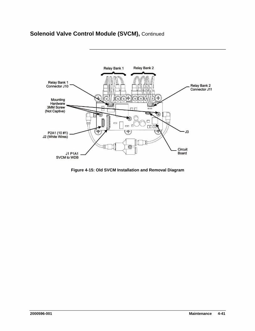
Solenoid Valve Control Module (SVCM), Continued
Figure 4-15: Old SVCM Installation and Removal Diagram
2000596-001 Maintenance 4-41
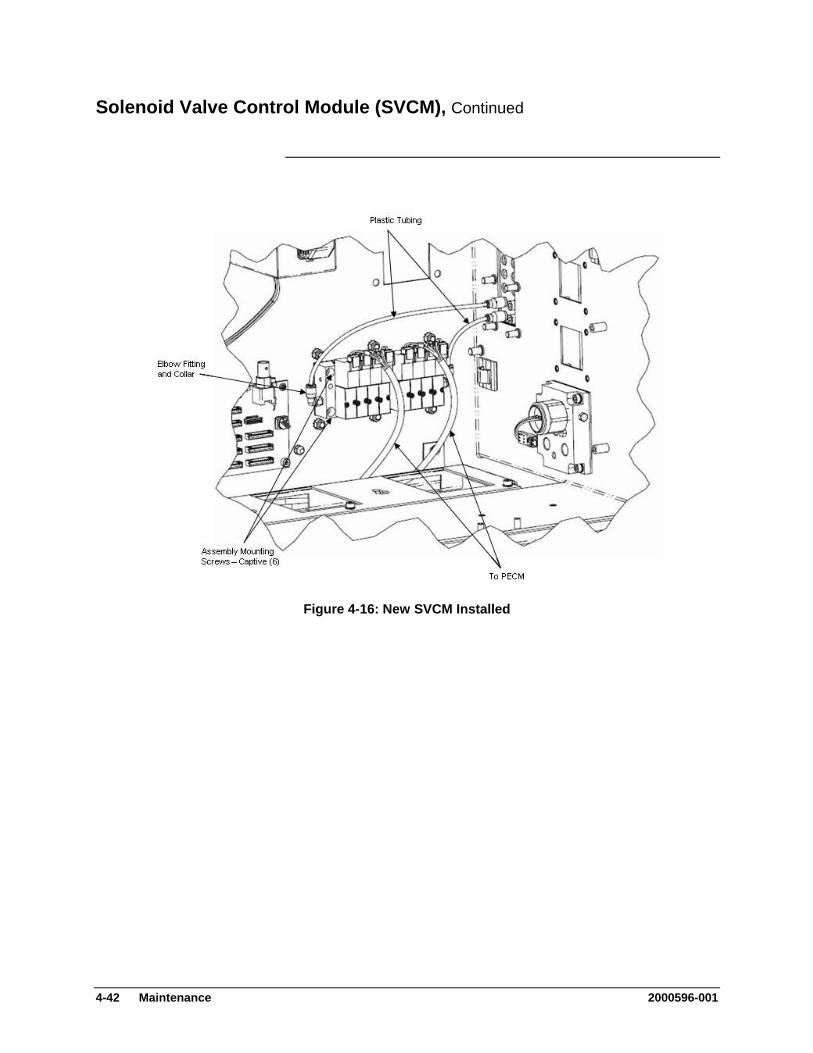
Solenoid Valve Control Module (SVCM), Continued
Figure 4-16: New SVCM Installed
4-42 Maintenance 2000596-001
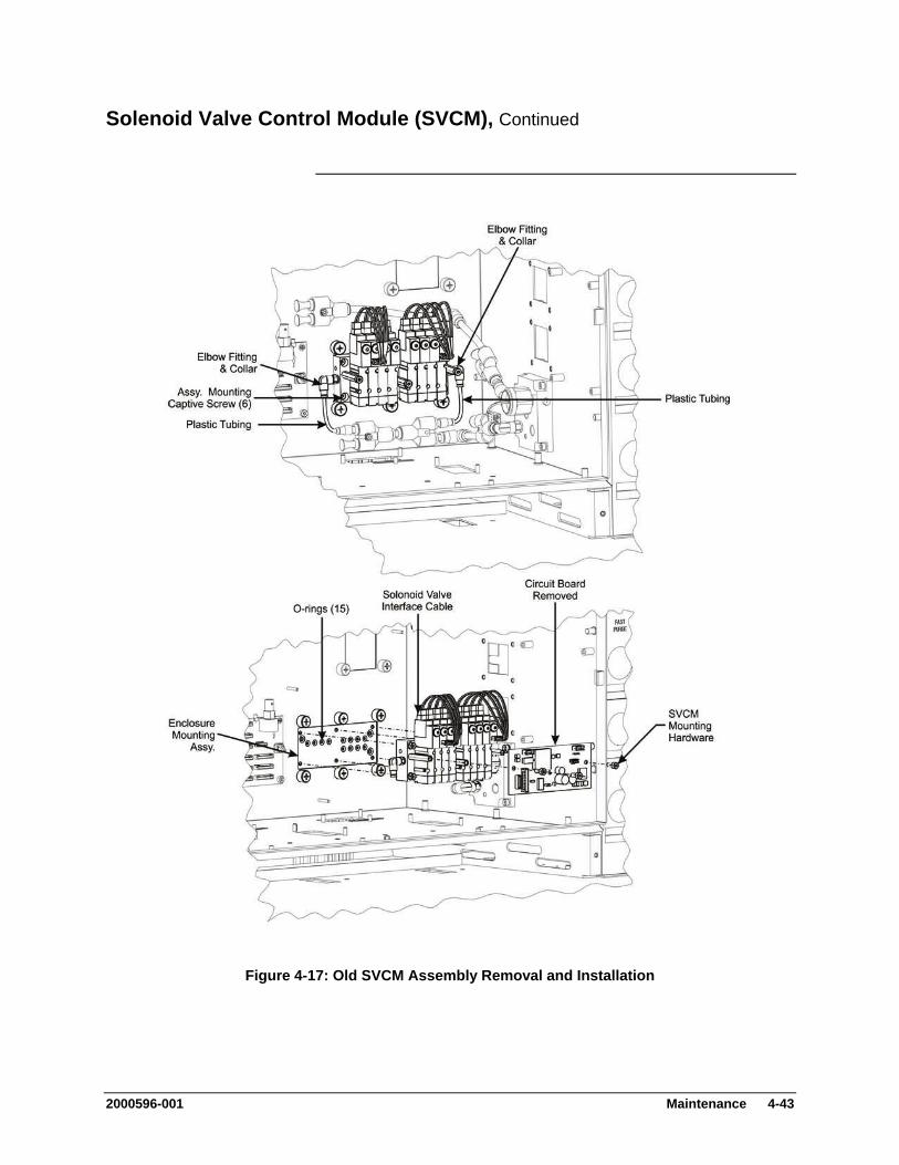
Solenoid Valve Control Module (SVCM), Continued
Figure 4-17: Old SVCM Assembly Removal and Installation
2000596-001 Maintenance 4-43
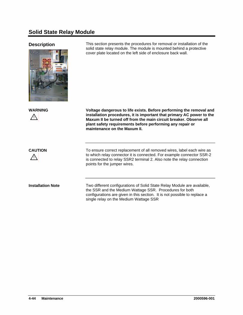
Solid State Relay Module
This section presents the procedures for removal or installation of the solid state relay module. The module is mounted behind a protective cover plate located on the left side of enclosure back wall.
Description
Voltage dangerous to life exists. Before performing the removal and installation procedures, it is important that primary AC power to the Maxum II be turned off from the main circuit breaker. Observe all plant safety requirements before performing any repair or maintenance on the Maxum II.
WARNING
To ensure correct replacement of all removed wires, label each wire as to which relay connector it is connected. For example connector SSR-2 is connected to relay SSR2 terminal 2. Also note the relay connection points for the jumper wires.
CAUTION
Two different configurations of Solid State Relay Module are available, the SSR and the Medium Wattage SSR. Procedures for both configurations are given in this section. It is not possible to replace a single relay on the Medium Wattage SSR
Installation Note
4-44 Maintenance 2000596-001
Solid State Relay Module, Continued
The following procedures should be followed for removal and or installation of solid-state relay module. Also included are procedures to replace a single relay on the SSR module or to replace the Medium Wattage SSR assembly. Refer to Figure 4-18.
Procedures
Solid State Relay Module Removal and Installation (Not the Medium Wattage SSR)
Step Procedure
1. Open electronic enclosure door (using a 4mm (5/32”) Allen wrench if necessary). When door is open DO NOT place tension on the Maintenance Panel interface ribbon cable.
2. Disconnect PECM to SSR Power connector. This allows for easier removal of the module.
For ease in removing relay cover, extend right side of cover outward, lift up on PECM power cable, and then extract cover.
IMPORTANT
3. Remove the two cover plate spring loaded retaining captive screws, and then remove cover. The cover plate is mounted on standoffs and retaining screws are removed when cover is removed.
4. Remove the plastic shield (if installed) that covers the relays on the SSR module.
5. Before removal of each cable harness connector from its relay termination, label the harness connector with its relay connection point. For example, connector SSR-2 is connected to relay SSR2 terminal 2.
6. Loosen cable harness clamp and remove clamp from around harness.
7. Remove all the cable harness connectors connected to the SSR module. DO NOT disconnect the other internal connectors on the SSR module.
2000596-001 Maintenance 4-45
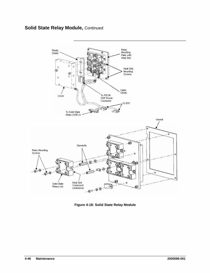
Solid State Relay Module, Continued
Figure 4-18: Solid State Relay Module
4-46 Maintenance 2000596-001
Solid State Relay Module, Continued
Although each cable is identified, it is recommended that you identify each cable as to its relay termination point.
IMPORTANT
Step Procedure
8. Remove the two ground connection lugs from each cover standoff. Depending on configuration standoffs may not need to be removed. If the lugs are a “spade” type then the standoffs will only need to be loosened. If the lugs have a closed hole, then the standoffs must be removed. To loosen or remove standoffs, use a 5mm nut driver.
9. Using a 5mm Allen wrench, remove the six mounting screws securing relays to electronic enclosure back wall standoffs. Remove the solid-state relay module.
Relays are mounted to heat sink assembly.
When the solid-state relay module is removed, the rear mounted heat sink is also removed as part of the relay mounting assembly.
IMPORTANT
10. Remove solid-state relay module assembly.
11. To reinstall the solid-state relay module, repeat steps 1 to 10 in reverse order.
When reinstalling relay cover, lift up on PECM power cable and insert left side of cover at an angle. Before securely tightening fastening screws, be certain wiring harness is installed within cover cutout opening. DO NOT pinch wiring harness.
IMPORTANT
12. Before closing electronic enclosure door and reapplying AC power, be certain all cable harness connectors are connected to their correct relay terminations.
2000596-001 Maintenance 4-47
Solid State Relay Module, Continued
Removal and Installation of a Single Relay
Step Procedure
1. Open electronic enclosure door (using a 4mm (5/32”) Allen wrench if necessary). When door is open DO NOT place tension on the Maintenance Panel interface ribbon cable.
2. Disconnect PECM to SSR Power connector. This allows for easier removal of the module.
3. Remove the two cover plate spring loaded retaining captive screws, and then remove the cover. The cover plate is mounted on standoffs and retaining screws are removed when cover is removed.
4. Remove the plastic plate (if installed) that covers the relays on the SSR module.
5. Before removal of each cable harness connector from its relay termination, label the harness connector with its relay connection point.
Remove each connector from the relay that is to be replaced as well as any other connectors for wires that would prevent the removal of the relay.
6. Remove the screws that secure the relay to the module. Since the heat sink compound on the back of the relay acts as an adhesive, the relay will remain secured to the module.
7. Break the relay free from the adhesive by pulling firmly, and then remove the relay from the enclosure.
8. Install the new relay by applying the heat sink compound and repeating steps 1 to 7 in reverse order.
9. Before closing electronic enclosure door and reapplying AC power, be certain all cable harness connectors are connected to their correct relay terminations.
4-48 Maintenance 2000596-001

Solid State Relay Module, Continued
Refer to Figure 4-19 on the next page when executing the following procedure.
Note
.
Medium Wattage Solid State Relay Module Removal and Installation
Step Procedure
1. Open electronic enclosure door (using a 4mm (5/32”) Allen wrench if necessary). When door is open DO NOT place tension on the Maintenance Panel interface ribbon cable.
2. Unplug the power cable and the control cable from the Medium Wattage Solid State Relay Module. Unplug the cables only at the SSR end. Leave them plugged in at their opposite ends.
3. Remove the Medium Wattage SSR by unscrewing the Allen head screws that secure it to the enclosure.
Note: There is a gasket located between the SSR and the enclosure back wall. Set this gasket aside for use in reinstalling the new SSR.
4. Install the new Medium Wattage SSR by executing steps 1 to 3 in reverse order.
2000596-001 Maintenance 4-49
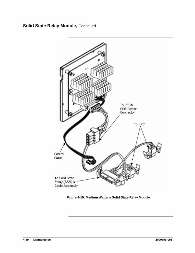
Solid State Relay Module, Continued
Figure 4-19: Medium Wattage Solid State Relay Module
4-50 Maintenance 2000596-001
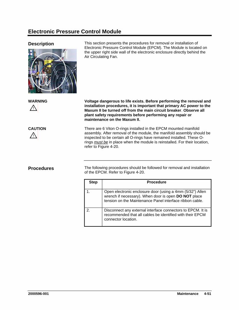
Electronic Pressure Control Module
This section presents the procedures for removal or installation of Electronic Pressure Control Module (EPCM). The Module is located on the upper right side wall of the electronic enclosure directly behind the Air Circulating Fan.
Description
Voltage dangerous to life exists. Before performing the removal and installation procedures, it is important that primary AC power to the Maxum II be turned off from the main circuit breaker. Observe all plant safety requirements before performing any repair or maintenance on the Maxum II.
WARNING
There are 6 Viton O-rings installed in the EPCM mounted manifold assembly. After removal of the module, the manifold assembly should be inspected to be certain all O-rings have remained installed. These O-rings
CAUTION
must be in place when the module is reinstalled. For their location,
refer to Figure 4-20.
The following procedures should be followed for removal and installation of the EPCM. Refer to Figure 4-20.
Procedures
Step Procedure
1. Open electronic enclosure door (using a 4mm (5/32”) Allen wrench if necessary). When door is open DO NOT place tension on the Maintenance Panel interface ribbon cable.
2. Disconnect any external interface connectors to EPCM. It is recommended that all cables be identified with their EPCM connector location.
2000596-001 Maintenance 4-51
Electronic Pressure Control Module, Continued
The EPCM is made up of a manifold that is mounted to the electronic enclosure wall on standoffs and the module itself. To remove the EPCM, it is not necessary to remove the manifold.
IMPORTANT
The ferrules connected on the gas supply side of the EPCM manifold are composed of vespel-graphite. To prevent damage, these ferrules must NOT be over-tightened. Proper tightness is typically ½ turn past finger-tight.
CAUTION
Step Procedure
3. Remove the three 4mm Allen screws from the manifold then remove module from manifold assembly. These are captive screws and will be completely removed with module.
Note: There is an Allen screw located between the solenoids on the assembly. Exercise caution when inserting an Allen wrench to remove this screw.
4. After module has been removed, examine the manifold surface to be certain all 6 O-rings are still installed.
Check O-rings to be certain they are not damaged or cut. Any defective O-rings MUST BE replaced.
O-ring PART REPLACEMENT:
QTY 6: #039006-1/8”
Before installation of EPCM assembly, check enclosure mounting surface to be certain all 6 O-rings are installed. If any O-ring is lost or damaged, replace it with a new one.
CAUTION
Never install EPCM assembly with a defective O-ring. Any contaminants not removed from mating surfaces will allow pressure losses resulting in inaccurate analytical analysis results.
5. If the new EPCM is not equipped with a module ID jumper, move the jumper that is connected to location J2 from the old module to the new module.
6. To reinstall the new EPCM, perform steps 1 to 3 in reverse order.
4-52 Maintenance 2000596-001
Electronic Pressure Control Module, Continued
Step Procedure
7. Before applying AC power, be certain EPCM assembly is securely fastened to manifold assembly and interface cable connectors are correctly connected.
After replacing the EPCM assembly it is necessary to inspect the system for leaks.
IMPORTANT
2000596-001 Maintenance 4-53
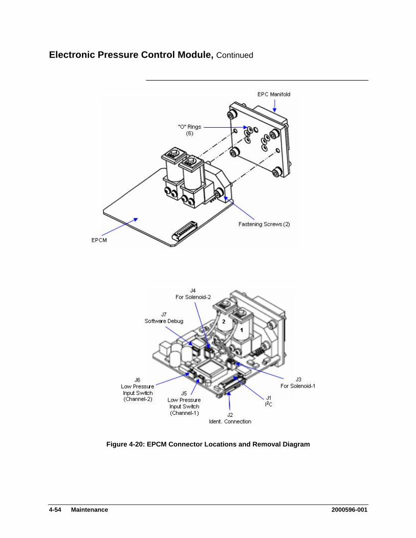
Electronic Pressure Control Module, Continued
Figure 4-20: EPCM Connector Locations and Removal Diagram
4-54 Maintenance 2000596-001

Purge Control Module (PCM)
This section presents the procedures for removal or installation of the Purge Control Module (PCM). The PCM is located on lower right side wall of the electronic enclosure.
Description
Voltage dangerous to life exists. Before performing the removal and installation procedures, it is important that primary AC power to the Maxum II be turned off from the main circuit breaker. Observe all plant safety requirements before performing any repair or maintenance on the Maxum II.
WARNING
The following procedures should be followed for removal and installation of PCM pressure switch. Refer to Figures 4-21 and 4-22.
Procedures
The pressure switch can be removed and replaced without having to remove the PCM module.
IMPORTANT
PCM Pressure Switch Step Procedure
1. Open electronic enclosure door (using a 4mm (5/32”) Allen wrench if necessary). When door is open DO NOT place tension on the Maintenance Panel interface ribbon cable.
2. Note: In order to replace the solenoid pressure switch, it should NOT be necessary to remove the PCM assembly from the enclosure.
Unplug the connector to the faulty solenoid pressure switch. Grasp connector from bottom section and pull straight out from mating section.
Before removal of pressure switch connecting wires, note pressure switch pin location that wires are connected to. It is recommended that each wire be labeled with its pin connector. Wires MUST NOT be interchanged.
IMPORTANT
2000596-001 Maintenance 4-55
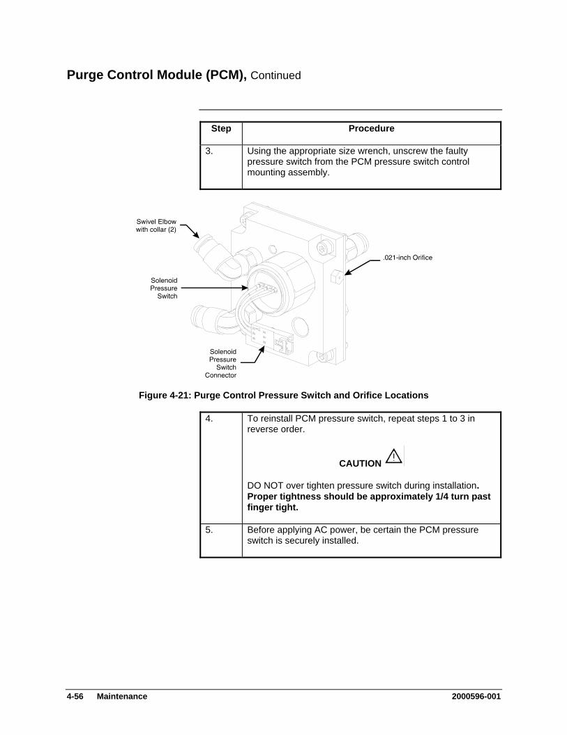
Purge Control Module (PCM), Continued
Step Procedure
3. Using the appropriate size wrench, unscrew the faulty pressure switch from the PCM pressure switch control mounting assembly.
Figure 4-21: Purge Control Pressure Switch and Orifice Locations
4. To reinstall PCM pressure switch, repeat steps 1 to 3 in reverse order.
CAUTION
DO NOT over tighten pressure switch during installation. Proper tightness should be approximately 1/4 turn past finger tight.
5. Before applying AC power, be certain the PCM pressure switch is securely installed.
4-56 Maintenance 2000596-001
Purge Control Module (PCM), Continued
The Orifice is located on the upper right side of the the PCM pressure switch control mounting assembly. The following procedures should be followed for removal and installation of PCM pressure switch .021-inch Orifice. The Orifice should be replaced if it becomes blocked-off or fails to perform its system function. Refer to Figure 4-21.
.021-inch Orifice
Step Procedure
1. Note: In order to replace the Orifice, it should NOT be necessary to remove the PCM assembly from the enclosure.
Unscrew the Orifice assembly then remove from the PCM assembly.
2. Screw the new orifice assembly into the PCM assembly.
3. Before reapplying AC power, be certain the Orifice is securely installed.
DO NOT over tighten Orifice during installation. Proper tightness should be approximately 1/4 turn past finger tight.
The following procedures should be followed for removal and installation of PCM Assembly. Refer to Figure 4-22.
PCM Assembly Removal
Step Procedure
1. Disconnect tubing connected to assembly front and rear mounted right angled elbow fittings.
To remove tubing from fitting, push up on fitting collar then pull tubing from fitting. After tubing is removed, collar will return to its original position.
2. Remove wires connecting to the solenoid pressure switch.
Note pressure switch pin locations where wires are connected. It is recommended that each wire be labeled with its pin connector. Wires MUST NOT be interchanged.
IMPORTANT
2000596-001 Maintenance 4-57
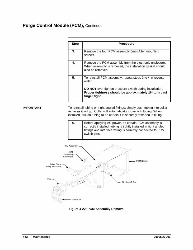
Purge Control Module (PCM), Continued
Step Procedure
3. Remove the four PCM assembly 5mm Allen mounting screws.
4. Remove the PCM assembly from the electronic enclosure. When assembly is removed, the installation gasket should also be removed.
5. To reinstall PCM assembly, repeat steps 1 to 4 in reverse order.
DO NOT over tighten pressure switch during installation. Proper tightness should be approximately 1/4 turn past finger tight.
To reinstall tubing on right angled fittings, simply push tubing into collar as far as it will go. Collar will automatically move with tubing. When installed, pull on tubing to be certain it is securely fastened in fitting.
IMPORTANT
6. Before applying AC power, be certain PCM assembly is correctly installed, tubing is tightly installed in right angled fittings and interface wiring is correctly connected to PCM switch pins.
Figure 4-22: PCM Assembly Removal
4-58 Maintenance 2000596-001
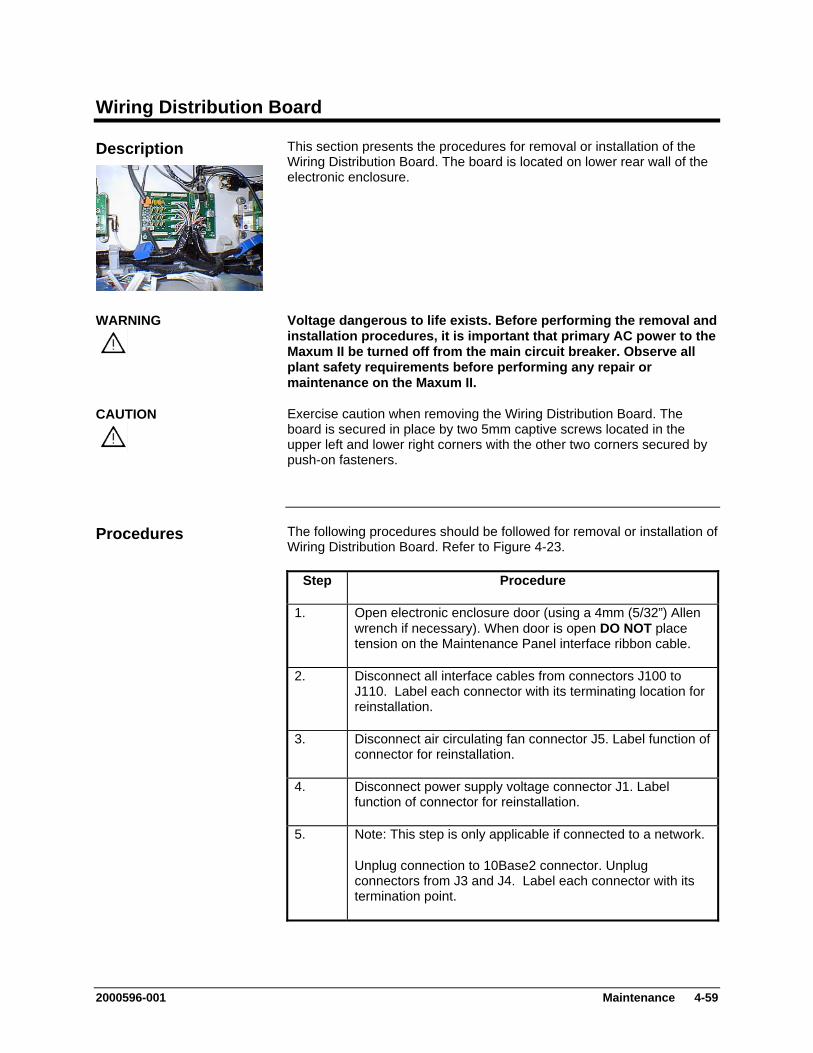
Wiring Distribution Board
This section presents the procedures for removal or installation of the Wiring Distribution Board. The board is located on lower rear wall of the electronic enclosure.
Description
Voltage dangerous to life exists. Before performing the removal and installation procedures, it is important that primary AC power to the Maxum II be turned off from the main circuit breaker. Observe all plant safety requirements before performing any repair or maintenance on the Maxum II.
WARNING
Exercise caution when removing the Wiring Distribution Board. The board is secured in place by two 5mm captive screws located in the upper left and lower right corners with the other two corners secured by push-on fasteners.
CAUTION
The following procedures should be followed for removal or installation of Wiring Distribution Board. Refer to Figure 4-23.
Procedures
Step Procedure
1. Open electronic enclosure door (using a 4mm (5/32”) Allen wrench if necessary). When door is open DO NOT place tension on the Maintenance Panel interface ribbon cable.
2. Disconnect all interface cables from connectors J100 to J110. Label each connector with its terminating location for reinstallation.
3. Disconnect air circulating fan connector J5. Label function of connector for reinstallation.
4. Disconnect power supply voltage connector J1. Label function of connector for reinstallation.
5. Note: This step is only applicable if connected to a network.
Unplug connection to 10Base2 connector. Unplug connectors from J3 and J4. Label each connector with its termination point.
2000596-001 Maintenance 4-59
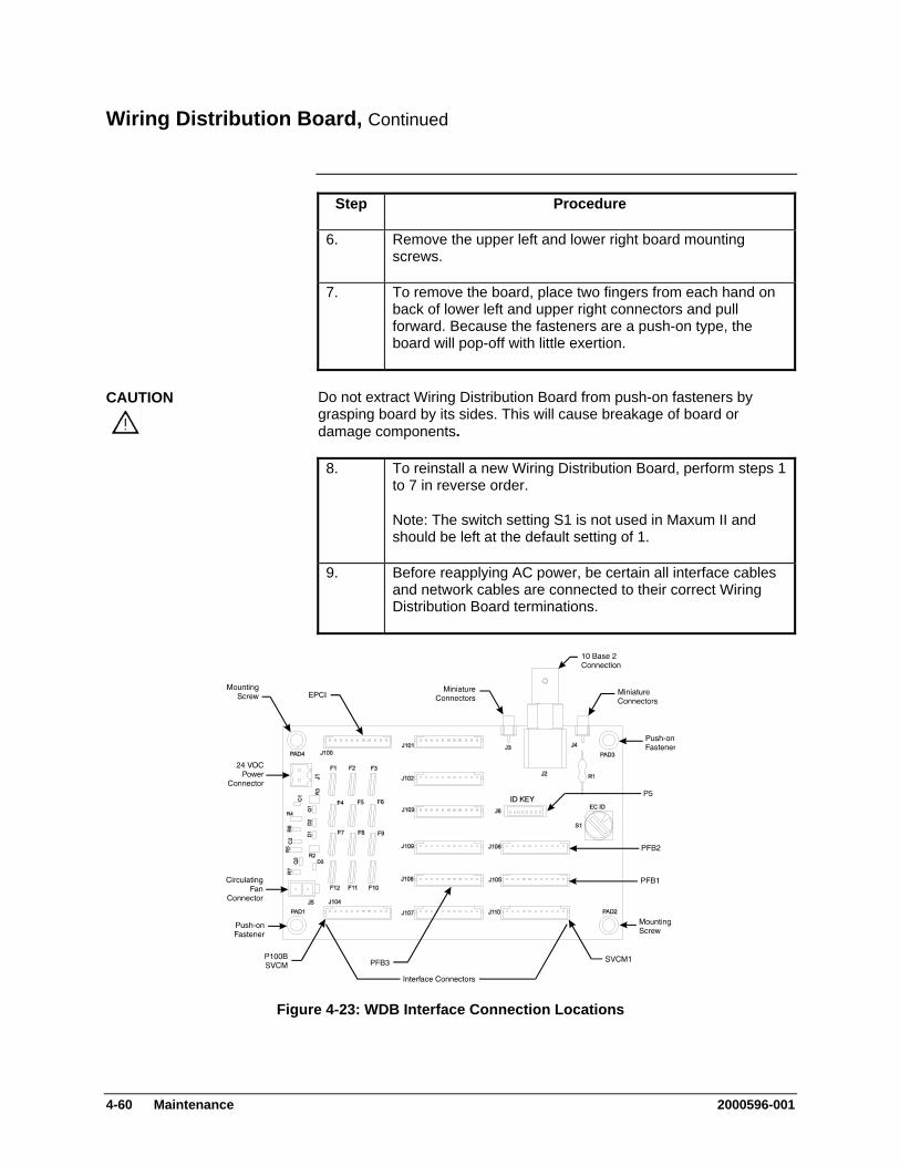
Wiring Distribution Board, Continued
Step Procedure
6. Remove the upper left and lower right board mounting screws.
7. To remove the board, place two fingers from each hand on back of lower left and upper right connectors and pull forward. Because the fasteners are a push-on type, the board will pop-off with little exertion.
Do not extract Wiring Distribution Board from push-on fasteners by grasping board by its sides. This will cause breakage of board or damage components.
CAUTION
8. To reinstall a new Wiring Distribution Board, perform steps 1 to 7 in reverse order.
Note: The switch setting S1 is not used in Maxum II and should be left at the default setting of 1.
9. Before reapplying AC power, be certain all interface cables and network cables are connected to their correct Wiring Distribution Board terminations.
Figure 4-23: WDB Interface Connection Locations
4-60 Maintenance 2000596-001

Air Circulating Fan
This section presents the procedures for removal or installation of the Air Circulating Fan located on the lower right front side wall of the electronic enclosure.
Description
Voltage dangerous to life exists. Before performing the removal and installation procedures, it is important that primary AC power to the Maxum II be turned off from the main circuit breaker. Observe all plant safety requirements before performing any repair or maintenance on the Maxum II.
WARNING
The following procedures should be followed for removal and installation of ACF. Refer to Figure 4-24.
Procedures
Step Procedure
1. Open electronic enclosure door (using a 4mm (5/32”) Allen wrench if necessary). When door is open DO NOT place tension on the Maintenance Panel interface ribbon cable.
2. Disconnect interface cable from Wiring Distribution Board (WDB) connector J5.
3. Remove Air Circulating Fan interface cable from wiring harness bundle.
4. Remove the four 5mm long Allen screws from each corner of Air Circulating Fan.
5. Remove Air Circulating Fan.
6. To reinstall a new Air Circulating Fan, perform steps 1 to 5 in reverse order.
7. Before reapplying AC power, be certain fan power cable is securely connected to WDB connector J5 and power cable is reinstalled in wiring harness bundle.
2000596-001 Maintenance 4-61
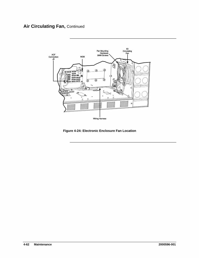
Air Circulating Fan, Continued
Figure 4-24: Electronic Enclosure Fan Location
4-62 Maintenance 2000596-001
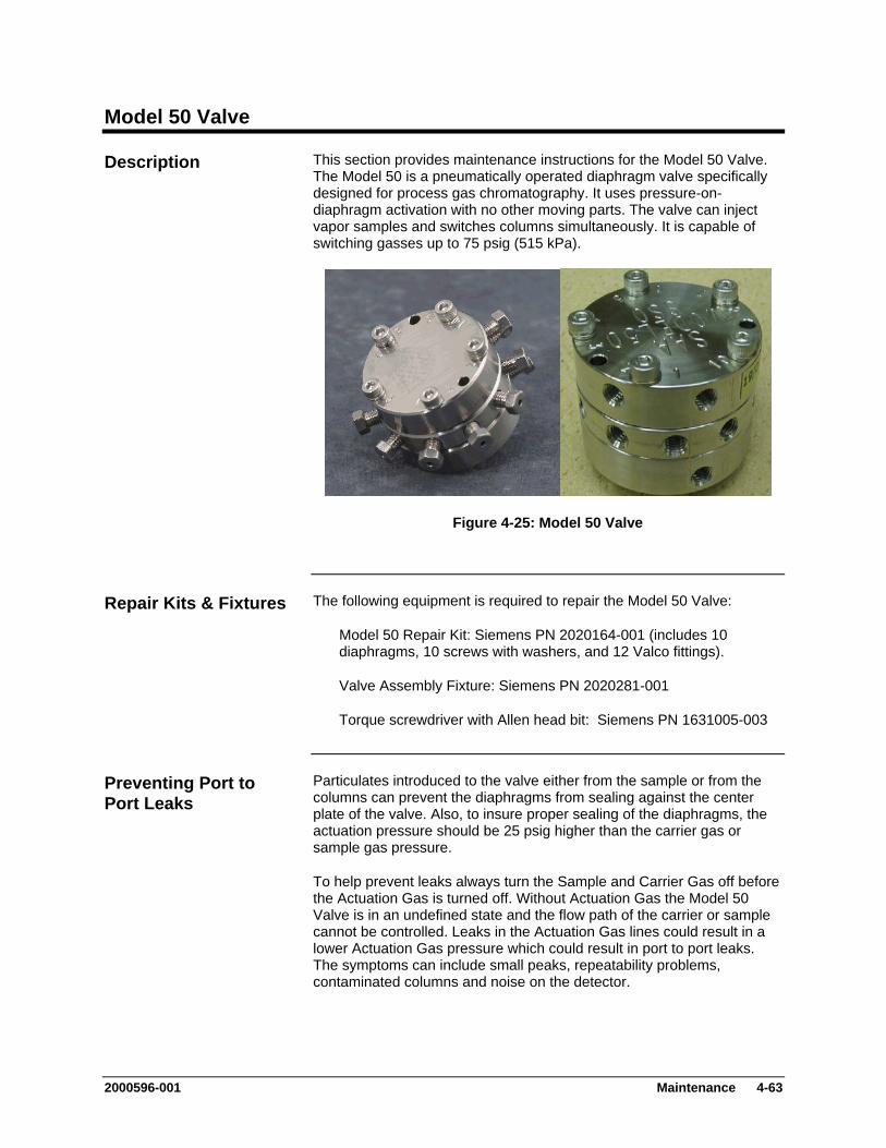
Model 50 Valve
This section provides maintenance instructions for the Model 50 Valve. The Model 50 is a pneumatically operated diaphragm valve specifically designed for process gas chromatography. It uses pressure-on-diaphragm activation with no other moving parts. The valve can inject vapor samples and switches columns simultaneously. It is capable of switching gasses up to 75 psig (515 kPa).
Description
Figure 4-25: Model 50 Valve
The following equipment is required to repair the Model 50 Valve: Repair Kits & Fixtures
Model 50 Repair Kit: Siemens PN 2020164-001 (includes 10 diaphragms, 10 screws with washers, and 12 Valco fittings).
Valve Assembly Fixture: Siemens PN 2020281-001
Torque screwdriver with Allen head bit: Siemens PN 1631005-003
Particulates introduced to the valve either from the sample or from the columns can prevent the diaphragms from sealing against the center plate of the valve. Also, to insure proper sealing of the diaphragms, the actuation pressure should be 25 psig higher than the carrier gas or sample gas pressure.
Preventing Port to Port Leaks
To help prevent leaks always turn the Sample and Carrier Gas off before the Actuation Gas is turned off. Without Actuation Gas the Model 50 Valve is in an undefined state and the flow path of the carrier or sample cannot be controlled. Leaks in the Actuation Gas lines could result in a lower Actuation Gas pressure which could result in port to port leaks. The symptoms can include small peaks, repeatability problems, contaminated columns and noise on the detector.
2000596-001 Maintenance 4-63
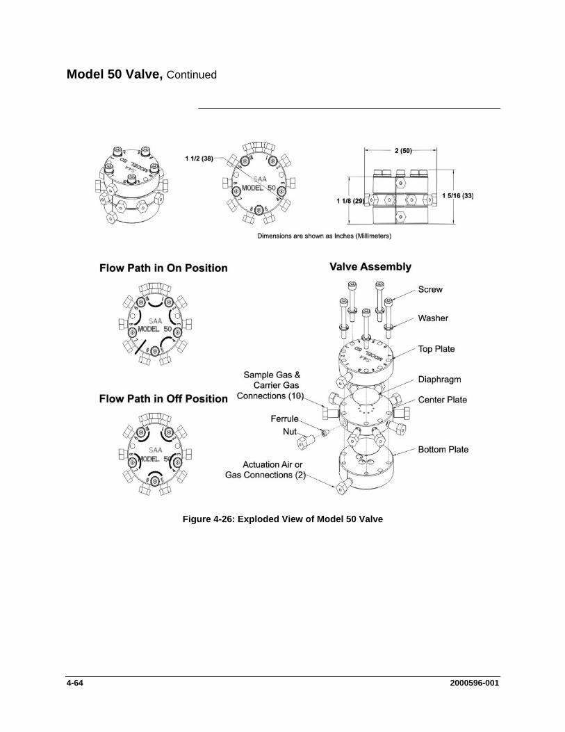
Model 50 Valve, Continued
Figure 4-26: Exploded View of Model 50 Valve
4-64 2000596-001
Model 50 Valve, Continued
If customer maintenance personnel are not technically trained to repair the Model 50 Valve on site, it is recommended that the valve be returned to Siemens for repair or direct replacement.
Maintenance Personnel
If it is determined that the problem is directly related to the Model 50 Valve system performance, the customer must make a determination if the valve can be repaired on site or if it should be returned to Siemens for repair or replacement.
Direct Valve Replacement
To repair the Model 50 Valve on site, the customer must have the necessary maintenance tools and replacement parts. Recommended valve spare parts can be obtained from Siemens.
Repair of Valve
When cleaning the Model 50 Valve and associated components, it is imperative that the maintenance be performed in a clean and contaminant free facility. Components should be placed on a lint free cloth to prevent impurities from contaminating the valve and its components. Hands should be clean and free of contaminants.
Maintenance Facility
If Model 50 Valve maintenance is to be performed on site, the area must be clean and free of foreign contaminants. Presence of any foreign contamination can cause additional valve problems after reinstallation.
All foreign contamination adhering to valve must be removed using cleaning solvent, such as hexane, acetone, or methanol and a dust/lint free cloth. After cleaning Model 50 Valve components, shake or blow with clean air the excess cleaning fluid from the individual components. Ensure that the components are air dry before reassembling.
Do not allow Model 50 Valve polished surfaces to rest on any surface other than a lint free cloth. Clean sample flow openings in top plate, center plate, bottom plate and Valco fitting nuts using a syringe filled with cleaning solvent such as hexane, acetone, or methanol.
CAUTION
Voltage dangerous to life exists. Before performing the removal and installation procedures, it is important that primary AC power to the Maxum II be turned off from the main circuit breaker. Only maintenance personnel with proper authorization should open the electronic enclosure.
WARNING
2000596-001 4-65
Model 50 Valve, Continued
The valve is serviced by disassembling and then thoroughly cleaning the components to remove all particulates. Ultrasonic cleansing with a suitable solvent works very well. During the cleaning and re-assembly process, care must be taken to avoid scratching or damaging the polished surfaces of the valve. After cleaning, the valve is reassembled using new Teflon coated stainless steel diaphragms. DO NOT attempt to reuse old diaphragms. Notice the alignment marks on the three sections of the valve near the actuation ports. The valve should be reassembled so that these marks line up. If the marks to not line up it is possible that the center plate is upside down. The screws should be tightened evenly to 6-8 inch pounds using the appropriate torque screwdriver with an allen head bit.
Maintenance Procedures
Valve Removal and Disassembly (see Figure 4-26)
Step Procedure
1. From primary AC circuit breaker, turn analyzer AC primary power OFF.
2. Shut off the air to the oven heater.
3. Open Maxum II’s oven door using a 4mm (5/32’”) Allen wrench.
4. To remove Model 50 Valve from the oven, first disconnect all tubing to the valve.
When disconnecting Valco fastening nuts from Model 50 Valve, exercise caution not to bend or crimp the stainless steel tubing.
CAUTION
Before removing Model 50 Valve from oven make note of its orientation within the oven.
NOTE
5. Remove the valve from the oven by unscrewing the two M3 x 35 socket head cap screws securing the Model 50 Valve. These mounting screws are located between ports 2 and 3 and ports 8 and 9. Refer to Figure 4-26 for port locations.
6. Place the valve on a clean dust and lint free cloth within a clean work environment.
Do not place polished top plate, center plate or bottom plate against any abrasive surface. Place components on a lint free cloth free of foreign contaminants.
CAUTION
4-66 2000596-001

Model 50 Valve, Continued
Step Procedure
7. Place the valve bottom plate on a lint free cloth. Using a 2.5 mm Allen wrench, remove the five component socket head fastening cap screws. Refer to Figure 4-26.
8. Separate valve Top, Center and Bottom plates, placing them on a lint free cloth.
Both diaphragms are visible.
The ports are machined for a 1/16” Valco internal nut. The Valco ferrule or the 2-piece Swagelok ferrule can be used. It is important to follow the manufacturer’s procedures when cutting tubing and seating ferrules to ensure that the fitting does not leak.
Valco & Swagelok Fittings
Use a wheel-cutting tool (Supelco 58692-U) to score the tubing, and then with a pair of straightening pliers (Supelco 58646) and a pair of needle nose pliers snap the tubing at the score line. Make certain that all tubing ends are cut square with the tube axis, and that both the ID and the OD are thoroughly deburred, use a deburring tool (Supelco 58804). Inspect the end of the tubing where the ferrule will seat for scratches along its length. Visible scratches along the tubing where the ferrule will seat are not acceptable, but those behind the front edge of the ferrule will not interfere with the integrity of the fitting.
Valco & Swagelok Assembly Instructions
Step Procedure
1. Slide the nut and ferrule onto the tubing.
2. Insert this assembly in the fitting detail (valve body), screwing the nut 2 or 3 turns by hand.
3. Push the tubing all the way forward into the details so that it seats firmly.
4. Manually turn the nut until it is finger tight.
2000596-001 4-67
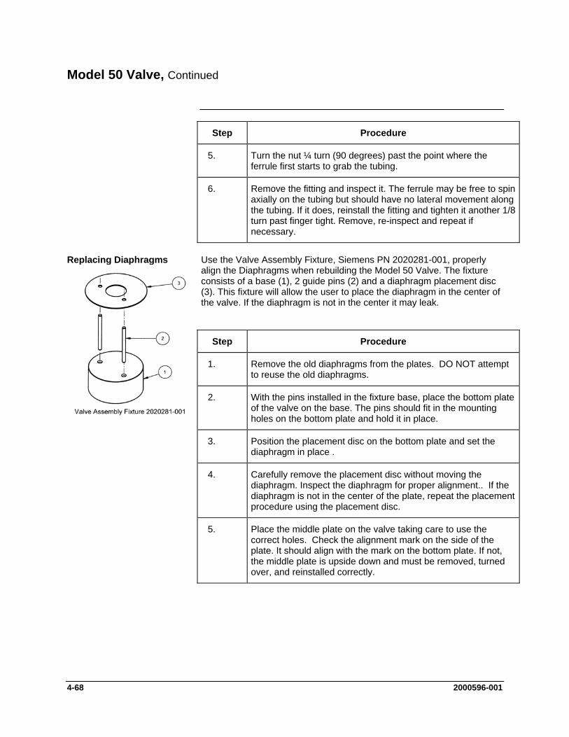
Model 50 Valve, Continued
Step Procedure
5. Turn the nut ¼ turn (90 degrees) past the point where the ferrule first starts to grab the tubing.
6. Remove the fitting and inspect it. The ferrule may be free to spin axially on the tubing but should have no lateral movement along the tubing. If it does, reinstall the fitting and tighten it another 1/8 turn past finger tight. Remove, re-inspect and repeat if necessary.
Use the Valve Assembly Fixture, Siemens PN 2020281-001, properly align the Diaphragms when rebuilding the Model 50 Valve. The fixture consists of a base (1), 2 guide pins (2) and a diaphragm placement disc (3). This fixture will allow the user to place the diaphragm in the center of the valve. If the diaphragm is not in the center it may leak.
Replacing Diaphragms
Step Procedure
1. Remove the old diaphragms from the plates. DO NOT attempt to reuse the old diaphragms.
2. With the pins installed in the fixture base, place the bottom plate of the valve on the base. The pins should fit in the mounting holes on the bottom plate and hold it in place.
3. Position the placement disc on the bottom plate and set the diaphragm in place .
4. Carefully remove the placement disc without moving the diaphragm. Inspect the diaphragm for proper alignment.. If the diaphragm is not in the center of the plate, repeat the placement procedure using the placement disc.
5. Place the middle plate on the valve taking care to use the correct holes. Check the alignment mark on the side of the plate. It should align with the mark on the bottom plate. If not, the middle plate is upside down and must be removed, turned over, and reinstalled correctly.
4-68 2000596-001
Model 50 Valve, Continued
Step Procedure
6. Repeat steps 3 and 4 with the middle plate.
7. Place the top plate on the valve, verifying alignment using the alignment marks.
8. Install the 5 screws and washers finger tight.
9. Tighten the screws down evenly (2.5mm Allen wrench) to 6 to 8 inch-pounds of torque. (It is recommended to use the torque wrench available from Siemens, PN 1631005-001, which is calibrated at 7.2 inch pounds). Remove the assembled valve from the valve fixture.
10. Reinstall the valve in the oven and connect all tubing.
11. Power up and check for leaks. Verify valve operation by running chromatograms.
2000596-001 4-69
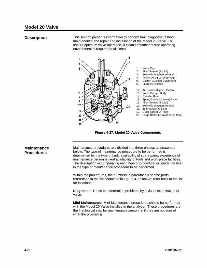
Model 20 Valve
This section presents information to perform fault diagnostic testing, maintenance and repair and installation of the Model 20 Valve. To assure optimum valve operation, a clean contaminant free operating environment is required at all times.
Description
1. Valve Cap 2. Allen Screws (3 total) 3. Belleville Washers (6 total) 4. Teflon Disc Seal Diaphragm 5. Dacron Cushion Diaphragm 6. Plungers (6 total) 12. Air Loaded (Upper) Piston 13. Valve Plunger Body 14. Cylinder Base 15. Spring Loaded (Lower) Piston 16. Allen Screws (3 total) 17. Belleville Washers (6 total) 18. Inner (small) O-Ring 19. Outer (large) O-Rings 20. Large Belleville Washers (3 total)
Figure 4-27: Model 20 Valve Components
Maintenance procedures are divided into three phases as presented below. The type of maintenance procedure to be performed is determined by the type of fault, availability of spare parts, experience of maintenance personnel and availability of tools and work place facilities. The description accompanying each type of procedure will guide the user in the type of maintenance procedure to be performed.
Maintenance Procedures
Within the procedures, the numbers in parenthesis denote parts referenced in the list contained in Figure 4-27 above; refer back to the list for locations.
Diagnostic: These can determine problems by a visual examination of valve.
Mini-Maintenance: Mini-Maintenance procedures should be performed with the Model 20 Valve installed in the analyzer. These procedures are the first logical step for maintenance personnel if they are not sure of what the problem is.
4-70 2000596-001
Model 20 Valve, Continued
If these procedures fail to correct problem with a faulty valve, or visual inspection detects an appreciable amount of foreign contamination on the diaphragm, it is recommended that the valve be returned to Siemens for repair. Procedures include the following:
Valve Cap Disassembly Cleaning Fittings and Tubing Valve Cap Assembly
Maxi-Maintenance: These are procedures which may be performed if the valve fault cannot be corrected using Mini-Maintenance procedures. The valve can either be replaced or the following procedures can be performed. This includes completely disassembling, cleaning, and rebuilding of the entire valve. Procedures include the following:
Valve Cap Disassembly Cleaning Fittings and Tubing Valve Cap Assembly Actuator Disassembly Actuator Assembly
If system operational performance or a visual inspection of the Model 20 Valve indicates a real or potential problem with the valve, the following information will assist maintenance personnel in determining whether the valve can be repaired on site or whether it should be returned to Siemens for repair or replacement.
Visual Valve Inspection
If customer maintenance personnel are not technically trained to repair the valve on site, it is recommended that the valve be returned to Siemens for repair or direct replacement.
Maintenance Personnel
If it is determined that the problem is directly related to Model 20 Valve system performance, the customer must make a determination if the valve can be repaired on site or if it should be returned to Siemens for repair or replacement.
Direct Valve Replacement
To repair the valve on site, the customer must have the necessary maintenance tools and replacement parts. Recommended valve spare parts including the Model 20 repair kit (PN K21000), can be obtained from Siemens.
Repair of Valve
2000596-001 4-71
Model 20 Valve, Continued
When cleaning the valve and associated components, it is imperative that the maintenance be performed in a clean and contaminant free facility. Components should be placed on a lint free cloth to prevent impurities from comtaminating the valve and/or components. Hands should be clean and free of contaminants.
Maintenance Facility
Presence of any foreign contamination can cause additional valve problems after reinstallation.
All foreign contamination adhering to valve must be removed quickly using a dust/lint free cloth and a cleaning solvent such as hexane. After cleaning valve cap and tubing, shake excess cleaning fluid from tubes and let valve cap air dry before reassembling.
Do not allow polished face of valve cap to rest on any surface other than a lint free cloth. Clean metal parts using only a syringe and a cleaning solvent such as hexane, acetone, or methanol.
CAUTION
Depending on the installation, the following tests can be performed with the valve mounted within the analyzer. Other tests require the analyzer to be shut down and valve ports disconnected. These diagnostic tests indicate specific areas of the fault or trouble.
Diagnostic Procedures
Sample Pressures Lower Than Carrier Pressure: Leakage may be from a carrier port to a sample port within the valve regardless of whether valve is actuated or deactivated. With sample inlet flow turned off, sample outlet should be zero. Check carrier and sample gas for leakage.
Valve Leakage
Carrier and Sample Gas Leakage: Bubbles indicate internal leakage. For a liquid carrier, check for liquid dripping from sample outlet tube.
Sample Pressure Higher Than Carrier: Leakage between ports is visually displayed on analyzer recorder as a baseline shift when sample pressure is removed from valve.
If the valve is plugged, plungers are pressed upward by air pressure or spring action and will not release to their open position when sample pressure drops.
Plugged Valve
Escaping air from valve vent hole indicates a ruptured diaphragm (4), which must be replaced. Check for liquid substances escaping from the vent hole. Refer to Figure 4-28.
Ruptured Diaphragm
4-72 2000596-001
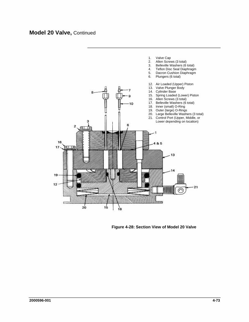
Model 20 Valve, Continued
1. Valve Cap 2. Allen Screws (3 total) 3. Belleville Washers (6 total) 4. Teflon Disc Seal Diaphragm 5. Dacron Cushion Diaphragm 6. Plungers (6 total) 12. Air Loaded (Upper) Piston 13. Valve Plunger Body 14. Cylinder Base 15. Spring Loaded (Lower) Piston 16. Allen Screws (3 total) 17. Belleville Washers (6 total) 18. Inner (small) O-Ring 19. Outer (large) O-Rings 20. Large Belleville Washers (3 total) 21. Control Port (Upper, Middle, or
Lower depending on location)
Figure 4-28: Section View of Model 20 Valve
2000596-001 4-73
Model 20 Valve, Continued
Improper lubrication and/or contamination of Bal-Seal (18) will increase friction on valve-actuating piston. This causes valve switching to be erratic, slow or inoperative. Refer to Figure 4-28. To correct the conditions causing slow or erratic piston switching, perform the following:
Slow or Erratic Piston Switching
Disassemble valve body Discard old O-ring Thoroughly clean all components Lubricate components per specifications Install new O-ring Reassemble the valve
The following additional conditions can be visually observed without the valve being removed or disassembled:
Additional Faults
Port-to-Port Leakage Low Flow Rate (plugging) Double Sampling and other Sample Flow Problems
More serious conditions do require the valve to be disassembled. Procedures for disassembling the Valve are presented in the following sections.
The following procedures should be followed for performing Mini-Maintenance on the Model 20 Valve. Refer to Figures 4-28 and 4-29.
Mini-Maintenance Procedures
4-74 2000596-001
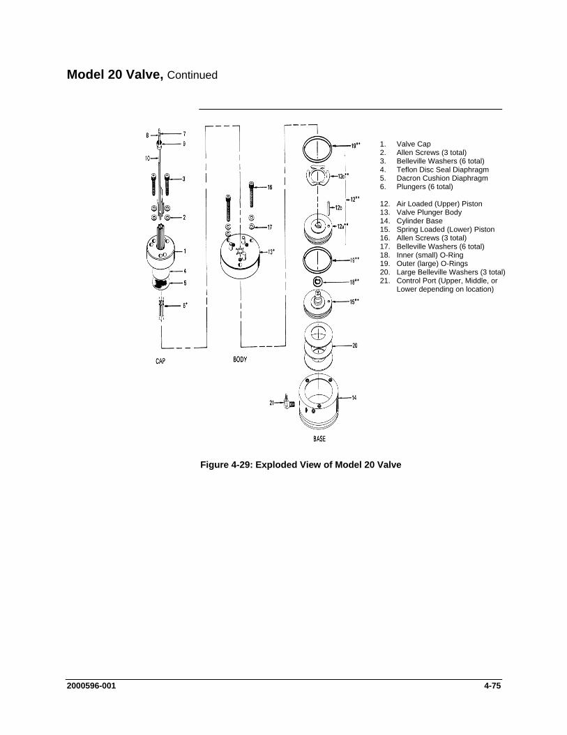
Model 20 Valve, Continued
1. Valve Cap 2. Allen Screws (3 total) 3. Belleville Washers (6 total) 4. Teflon Disc Seal Diaphragm 5. Dacron Cushion Diaphragm 6. Plungers (6 total) 12. Air Loaded (Upper) Piston 13. Valve Plunger Body 14. Cylinder Base 15. Spring Loaded (Lower) Piston 16. Allen Screws (3 total) 17. Belleville Washers (6 total) 18. Inner (small) O-Ring 19. Outer (large) O-Rings 20. Large Belleville Washers (3 total) 21. Control Port (Upper, Middle, or
Lower depending on location)
Figure 4-29: Exploded View of Model 20 Valve
2000596-001 4-75
Model 20 Valve, Continued
Valve Cap Disassembly and Cleaning
Step Procedure
1. Loosen the three Allen screws (16), holding the plunger valve body (13) to the valve cylinder base (14). The screws should be loosened to the point that most of the spring pressure is relieved (approximately 1/8" or 3.2 mm).
DO NOT REMOVE THE THREE ALLEN MOUNTING SCREWS.
2. To remove valve cap (1), remove the three Allen screws (3) and six Belleville washers (2) holding the valve cap (1) to the valve plunger body (13).
3. Remove the valve cap (1) from the plunger valve body (17).
Do not place polished valve cap (1) against any abrasive surface. Place it on a lint free cloth free of foreign contaminants.
CAUTION
4. Inspect the valve cap Teflon base seal disc diaphragm (4) and
the Dacron disc cushion diaphragm (5) for dirt, contamination or breaks.
Regardless of whether damage or contamination is evident, discard old seal and cushion, and replace them with new component(s).
If seal disc diaphragm (4) is brittle and dirty but not ruptured, or if it is ruptured but clean, DO NOT disassemble the rest of the valve.
NOTE
5. Visually inspect the rest of valve. If it is clean and in good condition, install a new disc seal diaphragm (4) and cushion diaphragm (5). To reassemble the valve cap, perform the following procedures.
All fittings and tubing must be cleaned and valve diaphragms inspected for cleanliness, and for catalyst or polymer buildup in the valve cap. Plunger valve body faces should be wiped clean using hexane, acetone, or methanol and a lint free cloth. If port-to-port leakage or blockage exists when a valve flow passage is switched open, then contamination of flow passages or excessive friction in the lower section of the valve may exist. This impedes valve operation and the valve must be thoroughly flushed clean.
Cleaning Fittings & Tubing
4-76 2000596-001
Model 20 Valve, Continued
Step Procedure
6. Prepare a large syringe with a Tygon tubing adapter installed. Fill syringe with a recommended cleaning solvent.
An ultrasonic cleaner filled with a recommended cleaning solvent is recommended for cleaning all components. Solvent must not leave any residue on evaporation.
NOTE
If solvent becomes contaminated during cleaning, it must be replaced with a clean supply.
7. Clean valve cap while it is disassembled. Using syringe, flush solvent through each port in the valve cap.
When reassembling the valve cap, always install a new Teflon Seal Disc diaphragm (4) and Dacron Cushion Disc (5) on plunger valve body (13). Do not install the previously used Teflon Seal (4) and/or Dacron Cushion Disc (5). Before reinstalling seal and cushion on plunger valve body, remove lint and any dust particles.
CAUTION
Valve Cap Assembly 8. Place the actuator assembly upright on a clean lint free cloth surface. Refer to Figures 4-28 and 4-29.
9. Position the Dacron cushion disc diaphragm (5) between the three alignment pins on the plunger valve body (13).
10. Using tweezers, hold Teflon seal disc diaphragm (4) by its edges. Before reinstalling disc, remove lint, dust and oils by sliding disk between your index and middle fingers.
11. Install Teflon seal disc diaphragm (4) over the Dacron diaphragm disc cushion (5).
2000596-001 4-77
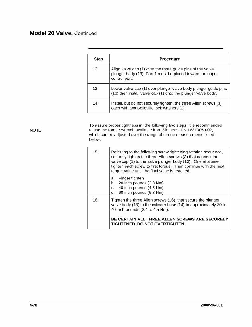
Model 20 Valve, Continued
Step Procedure
12. Align valve cap (1) over the three guide pins of the valve plunger body (13). Port 1 must be placed toward the upper control port.
13. Lower valve cap (1) over plunger valve body plunger guide pins (13) then install valve cap (1) onto the plunger valve body.
14. Install, but do not securely tighten, the three Allen screws (3) each with two Belleville lock washers (2).
To assure proper tightness in the following two steps, it is recommended to use the torque wrench available from Siemens, PN 1631005-002, which can be adjusted over the range of torque measurements listed below.
NOTE
15. Referring to the following screw tightening rotation sequence, securely tighten the three Allen screws (3) that connect the valve cap (1) to the valve plunger body (13). One at a time, tighten each screw to first torque. Then continue with the next torque value until the final value is reached.
a. Finger tighten b. 20 inch pounds (2.3 Nm) c. 40 inch pounds (4.5 Nm) d. 60 inch pounds (6.8 Nm)
16. Tighten the three Allen screws (16) that secure the plunger valve body (13) to the cylinder base (14) to approximately 30 to 40 inch-pounds (3.4 to 4.5 Nm).
BE CERTAIN ALL THREE ALLEN SCREWS ARE SECURELY TIGHTENED. DO NOT OVERTIGHTEN.
4-78 2000596-001

Model 20 Valve, Continued
The following procedures should be followed for performing Maxi-Maintenance on Model 20 Valve. Maxi-Maintenance procedures include the Mini-Maintenance procedures in addition to the disassembly, inspection and assembly of the valve Actuator presented in this section. Refer to Figures 4-28 and 4-29.
Maxi-Maintenance Procedures
Actuator Disassembly Step Procedure
1. Perform the following Maxi-Maintenance procedures in the order presented.
Valve Cap Disassembly (Mini-Maintenance) Cleaning Fittings and Tubing (Mini-Maintenance) Actuator Disassembly (Maxi-Maintenance) Actuator Assembly (Maxi-Maintenance) Valve Cap Assembly (Mini-Maintenance)
2. Check valve plungers (6) for sticking.
3. Using even finger pressure around edges of plunger valve body (13), push valve plunger body against cylinder valve base (14). All six plungers should rise.
4. Release plunger valve body (13). The six plungers should drop. If plungers do not drop, check for oil film on plungers. This can prevent plungers from dropping.
5. Apply gentle pressure to the top of each of the six plungers. If plungers drop, without excessive pressure, the valve is operating normally and does not require additional disassembly. If plungers stick or are sluggish in their operation, they must be thoroughly cleaned with a recommended cleaning solvent, repaired, or the entire actuator must be replaced.
6. Turn actuator on its side. Remove the three screws (16) which secure the plunger valve body (13) to the cylinder valve base (14).
When performing the following procedure, DO NOT allow actuator plungers to fall from plunger valve body (13).
NOTE
2000596-001 4-79
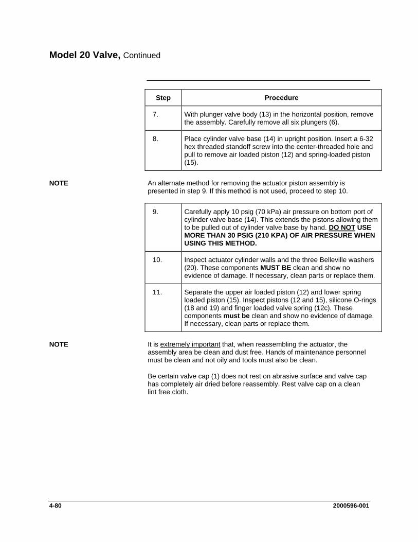
Model 20 Valve, Continued
Step Procedure
7. With plunger valve body (13) in the horizontal position, remove the assembly. Carefully remove all six plungers (6).
8. Place cylinder valve base (14) in upright position. Insert a 6-32 hex threaded standoff screw into the center-threaded hole and pull to remove air loaded piston (12) and spring-loaded piston (15).
An alternate method for removing the actuator piston assembly is presented in step 9. If this method is not used, proceed to step 10.
NOTE
9. Carefully apply 10 psig (70 kPa) air pressure on bottom port of cylinder valve base (14). This extends the pistons allowing them to be pulled out of cylinder valve base by hand. DO NOT USE MORE THAN 30 PSIG (210 KPA) OF AIR PRESSURE WHEN USING THIS METHOD.
10. Inspect actuator cylinder walls and the three Belleville washers (20). These components MUST BE clean and show no evidence of damage. If necessary, clean parts or replace them.
11. Separate the upper air loaded piston (12) and lower spring loaded piston (15). Inspect pistons (12 and 15), silicone O-rings (18 and 19) and finger loaded valve spring (12c). These components must be clean and show no evidence of damage. If necessary, clean parts or replace them.
It is extremely important that, when reassembling the actuator, the assembly area be clean and dust free. Hands of maintenance personnel must be clean and not oily and tools must also be clean.
NOTE
Be certain valve cap (1) does not rest on abrasive surface and valve cap has completely air dried before reassembly. Rest valve cap on a clean lint free cloth.
4-80 2000596-001
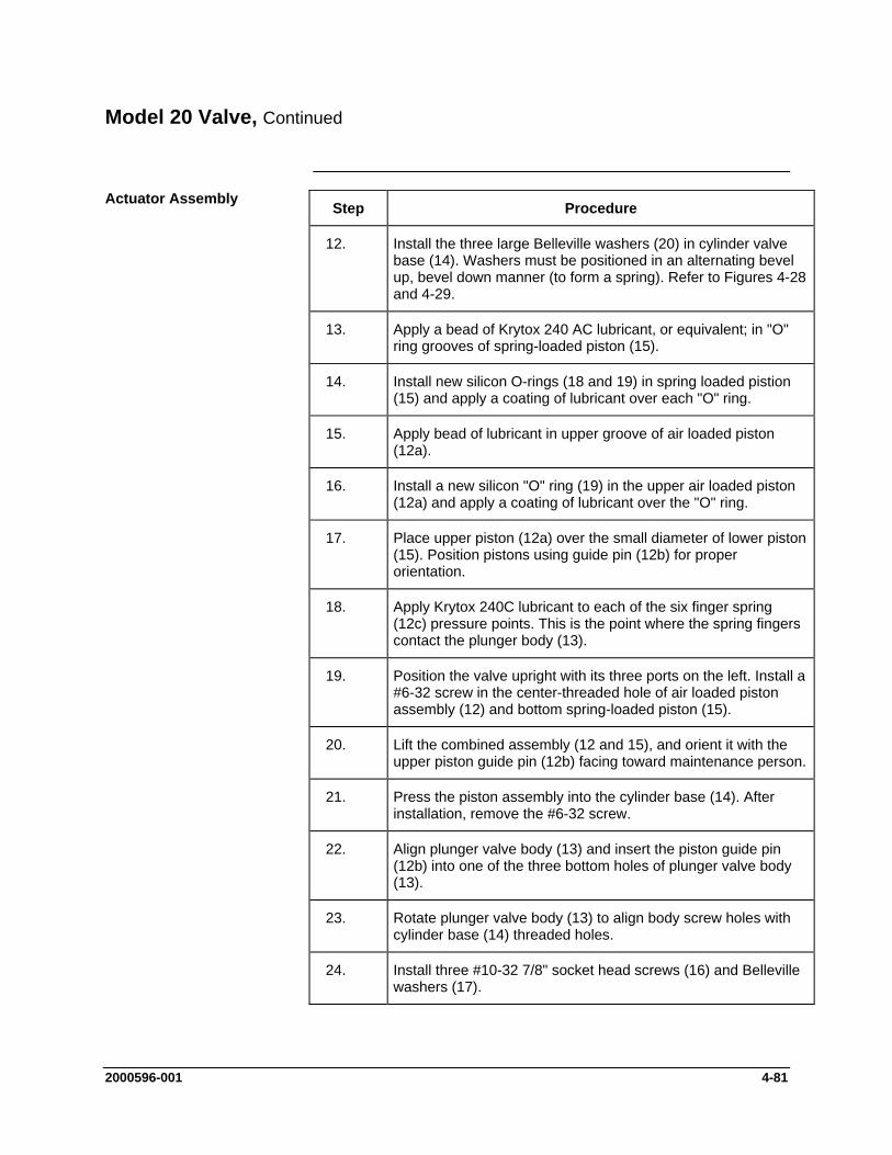
Model 20 Valve, Continued
Actuator Assembly Step Procedure
12. Install the three large Belleville washers (20) in cylinder valve base (14). Washers must be positioned in an alternating bevel up, bevel down manner (to form a spring). Refer to Figures 4-28 and 4-29.
13. Apply a bead of Krytox 240 AC lubricant, or equivalent; in "O" ring grooves of spring-loaded piston (15).
14. Install new silicon O-rings (18 and 19) in spring loaded pistion (15) and apply a coating of lubricant over each "O" ring.
15. Apply bead of lubricant in upper groove of air loaded piston (12a).
16. Install a new silicon "O" ring (19) in the upper air loaded piston (12a) and apply a coating of lubricant over the "O" ring.
17. Place upper piston (12a) over the small diameter of lower piston (15). Position pistons using guide pin (12b) for proper orientation.
18. Apply Krytox 240C lubricant to each of the six finger spring (12c) pressure points. This is the point where the spring fingers contact the plunger body (13).
19. Position the valve upright with its three ports on the left. Install a #6-32 screw in the center-threaded hole of air loaded piston assembly (12) and bottom spring-loaded piston (15).
20. Lift the combined assembly (12 and 15), and orient it with the upper piston guide pin (12b) facing toward maintenance person.
21. Press the piston assembly into the cylinder base (14). After installation, remove the #6-32 screw.
22. Align plunger valve body (13) and insert the piston guide pin (12b) into one of the three bottom holes of plunger valve body (13).
23. Rotate plunger valve body (13) to align body screw holes with cylinder base (14) threaded holes.
24. Install three #10-32 7/8" socket head screws (16) and Belleville washers (17).
2000596-001 4-81
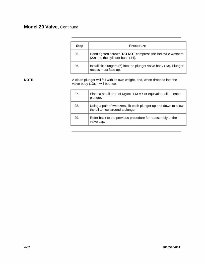
Model 20 Valve, Continued
Step Procedure
25. Hand tighten screws. DO NOT compress the Belleville washers (20) into the cylinder base (14).
26. Install six plungers (6) into the plunger valve body (13). Plunger recess must face up.
A clean plunger will fall with its own weight, and, when dropped into the valve body (13), it will bounce.
NOTE
27. Place a small drop of Krytox 143 AY or equivalent oil on each plunger.
28. Using a pair of tweezers, lift each plunger up and down to allow the oil to flow around a plunger.
29. Refer back to the previous procedure for reassembly of the valve cap.
4-82 2000596-001

Model 20 High Temperature Valve (HTV)
This section presents the user with the necessary information to perform fault diagnostic testing, maintenance and repair, and installation of the Model 20 High Temperature Valve (HTV). The valve is actuated by air pressure. To assure optimum valve operation, a clean contaminant free operating environment is required at all times.
Description
13. Outer (Large) Bal-Seals (2 total) 14. Plungers (6 total) 15. Spring Loaded (Lower) Piston 16. Cylinder Base 17. Valve Plunger Body 18. Air Loaded (Upper) Piston 19. Large Belleville Washers (3 total) 20. Inner (Small) Bal-Seal 21. Control Port (Upper, Middle, or
Lower depending on location) 32. Valve Cap 33. Teflon Disc Seal Diaphragm 34. Nomex Cushion Diaphragm 35. Allen Screws (6 total) 36. Belleville Washers (12 total)
Figure 4-30: Model 20 High Temperature Valve (HTV) Components
Maintenance procedures are divided into three phases as presented below. The type of maintenance procedure to be performed is determined by the type of fault, availability of spare parts, experience of maintenance personnel and availability of tools and work place facilities. The description accompanying each type of procedure will guide the user in the type of maintenance procedure to be performed.
Maintenance Procedures
Within the procedures, the numbers in parenthesis denote parts referenced in the list contained in figure 4-30 above; refer back to the list for locations.
Diagnostic: These can determine problems by a visual examination of the valve.
2000596-001 4-83

Model 20 High Temperature Valve (HTV), Continued
Mini-Maintenance: Mini-Maintenance procedures should be performed with the Model 20 High Temperature Valve (HTV) installed in the analyzer. These procedures are the first logical step for maintenance personnel if they are not sure of what the problem is.
If these procedures fail to correct problem with a faulty valve, or visual inspection detects an appreciable amount of foreign contamination on the diaphragm, it is recommended that the valve be returned to Siemens for repair. Procedures include the following:
Valve Cap Disassembly Cleaning Fittings and Tubing Valve Cap assembly
Maxi-Maintenance: These are procedures, which may be performed if the valve fault cannot be corrected using Mini-Maintenance procedures. The valve can either be replaced or the following procedures can be performed. This includes completely disassembling, cleaning, and rebuilding of the entire valve. Refer to Figure 4-30. Procedures include the following:
Valve Cap Disassembly Cleaning Fittings and Tubing Valve Cap Assembly Actuator Disassembly Actuator Assembly
If system operational performance or a visual inspection of the Model 20 High Temperature Valve (HTV) indicates a real or potential problem with the valve, the following information will assist maintenance personnel in determining whether the valve can be repaired on site or whether it should be returned to Siemens for repair or replacement.
Visual Valve Inspection
If customer maintenance personnel are not technically trained to repair the valve on site, it is recommended that the valve be returned to Siemens for repair or direct replacement.
Maintenance Personnel
If it is determined that the problem is directly related to Model 20 High Temperature Valve (HTV) system performance, the customer must make a determination if the valve can be repaired on site or if it should be returned to Siemens for repair or replacement.
Direct Valve Replacement
To repair the valve on site, the customer must have the necessary maintenance tools and replacement parts. Recommended valve spare parts including the Model 20 HTV repair kit (PN K21021), can be obtained from Siemens.
Repair of Valve
4-84 2000596-001
Model 20 High Temperature Valve (HTV), Continued
When cleaning the valve and associated components, it is imperative that the maintenance be performed in a clean and contaminant free facility. Components should be placed on a lint free cloth to prevent impurities from contaminating the valve and/or components. Hands should be clean and free of contaminants.
Maintenance Facility
Presence of any foreign contamination can cause additional valve problems after installation.
All foreign contamination adhering to valve must be removed quickly using a dust/lint free cloth and a cleaning solvent, such as hexane, acetone or methanol. After cleaning valve cap and tubing, shake excess cleaning fluid from tubes and let valve cap air dry before reassembling.
Do not allow polished face of valve cap to rest on any surface other than a lint free cloth. Clean metal parts using only a syringe and a cleaning solvent such as hexane, acetone, or methane.
CAUTION
Depending on the installation, the following tests can be performed with the valve mounted within the analyzer. Other tests require the analyzer be shut down and valve ports disconnected. These diagnostic tests indicate specific areas of the fault or trouble.
Diagnostic Procedures
Sample Pressures Lower Than Carrier Pressure: Leakage may be from a carrier port to a sample port within the valve regardless of whether valve is actuated or deactivated. With sample inlet flow turned off, sample outlet should be zero. Check carrier and sample gas for leakage.
Valve Leakage
Carrier and Sample Gas Leakage: Bubbles indicate internal leakage. For a liquid carrier, check for liquid dripping from sample outlet tube.
Sample Pressures Higher Than Carrier: Leakage between ports is visually displayed on analyzer recorder as a baseline shift when sample pressure is removed from valve.
If the valve is plugged, plungers are pressed upward by air pressure or spring action and will not release to their open position when sample pressure drops.
Plugged Valve
Escaping air from valve vent hole indicates a ruptured diaphragm (33), which must be replaced. Check for liquid substances escaping from the vent hole. Refer to Figure 4-31.
Ruptured Diaphragm
Improper lubrication and/or contamination of Bal-Seals will increase friction on valve-actuating piston. This causes valve switching to be erratic, slow or inoperative. Refer to Figure 4-31.
Slow or Erratic Piston Switching
2000596-001 4-85
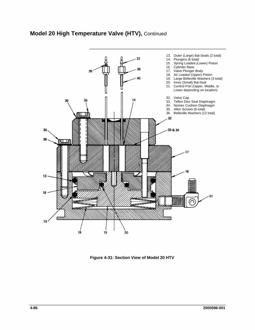
Model 20 High Temperature Valve (HTV), Continued
13. Outer (Large) Bal-Seals (2 total) 14. Plungers (6 total) 15. Spring Loaded (Lower) Piston 16. Cylinder Base 17. Valve Plunger Body 18. Air Loaded (Upper) Piston 19. Large Belleville Washers (3 total) 20. Inner (Small) Bal-Seal 21. Control Port (Upper, Middle, or
Lower depending on location) 32. Valve Cap 33. Teflon Disc Seal Diaphragm 34. Nomex Cushion Diaphragm 35. Allen Screws (6 total) 36. Belleville Washers (12 total)
Figure 4-31: Section View of Model 20 HTV
4-86 2000596-001

Model 20 High Temperature Valve (HTV), Continued
The following additional conditions can be visually observed without the valve being removed or disassembled:
Additional Faults
Port-to-Port Leakage Low Flow Rate (plugging) Double Sampling and other Sample Flow Problems
More serious conditions do require the valve to be disassembled. Procedures for disassembling the Valve are presented in the following sections.
The following procedures should be followed for performing Mini-Maintenance on the Model 20 HTV. Refer to Figure 4-31 and 4-32.
Mini-Maintenance Procedures Valve Cap Disassembly and Cleaning
Step Procedure
1. Loosen the three Allen screws (35), holding the plunger valve body (17) to the valve cylinder base (16). The screws should be loosened to the point that most of the spring pressure is relieved (approximately 1/8” or 3.2 mm)
DO NOT REMOVE THE THREE ALLEN MOUNTING SCREWS.
2. To remove valve cap (32), remove the three Allen screws (35) and six Belleville washers (36) holding the valve cap (32) to the valve plunger body (17).
3. Remove the valve cap (32) from the plunger valve body (17).
Do not place polished valve cap (32) against any abrasive surface. Place it on a lint free cloth free of foreign contaminants.
CAUTION
2000596-001 4-87
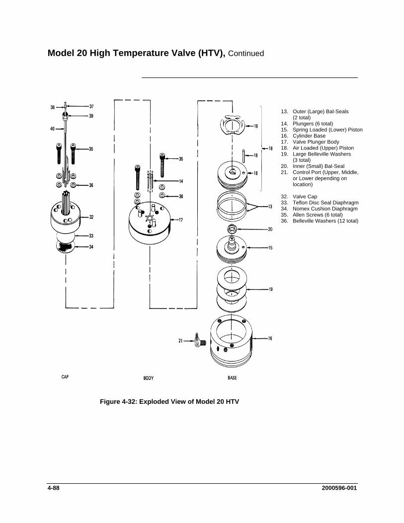
Model 20 High Temperature Valve (HTV), Continued
13. Outer (Large) Bal-Seals (2 total)
14. Plungers (6 total) 15. Spring Loaded (Lower) Piston 16. Cylinder Base 17. Valve Plunger Body 18. Air Loaded (Upper) Piston 19. Large Belleville Washers
(3 total) 20. Inner (Small) Bal-Seal 21. Control Port (Upper, Middle,
or Lower depending on location)
32. Valve Cap 33. Teflon Disc Seal Diaphragm 34. Nomex Cushion Diaphragm 35. Allen Screws (6 total) 36. Belleville Washers (12 total)
Figure 4-32: Exploded View of Model 20 HTV
4-88 2000596-001

Model 20 High Temperature Valve (HTV), Continued
Step Procedure
4. Inspect the Teflon seal disc diaphragm (33) and the Nomex cushion diaphragm (34). Examine valve cap base seal (33) and cushion diaphragm (34) subassembly's for dirt, contamination or breaks.
Regardless of whether damage or contamination is evident, discard old seal and cushion, and replace them with new component(s).
If seal disc diaphragm (33) is brittle and dirty, but not ruptured or if it is ruptured but clean, DO NOT disassemble the rest of the valve.
NOTE
5. Visually inspect the rest of valve. If it is clean and in good condition, install a new seal disc diaphragm (33) and a Nomex cushion diaphragm (34). To reassemble the valve cap, perform the following procedures.
All fittings and tubing must be cleaned and valve diaphragms inspected for cleanliness, and for catalyst or polymer buildup in the valve cap. Plunger valve body faces should be wiped clean using hexane, acetone, or methanol and a lint free cloth. If port-to-port leakage or blockage exists when a valve flow passage is switched open, then contamination of flow passages or excessive friction in the lower section of the valve may exist. This impedes valve operation and the valve must be thoroughly flushed clean. For cleaning parts, an ultrasonic cleaner is recommended.
Cleaning Fittings & Tubing
6. Prepare a large syringe with a Tygon tubing adapter installed. Fill syringe with a recommended cleaning solvent.
If solvent becomes contaminated during cleaning, it must be replaced with a clean supply.
NOTE
7. Clean valve cap while it is disassembled. Using syringe, flush solvent through each port in the valve cap.
2000596-001 4-89
Model 20 High Temperature Valve (HTV), Continued
Step Procedure
8. Place the actuator assembly upright on a clean lint free cloth surface. Refer to Figures 4-31 and Figure 4-32.
Valve Cap Assembly
When reassembling the valve cap, always install a new Teflon Seal Disc diaphragm (33) and Nomex Cushion Disc (34) on plunger valve body (17). Do not install the previously used Teflon Seal (33) and/or Nomex Cushion Disc (34). Before reinstalling seal and cushion on plunger valve body, remove lint and any dust particles.
CAUTION
9. Position the Nomex cushion disc diaphragm (34) between the three alignment pins on the plunger valve body (17).
10. Using tweezers, hold Teflon seal disc diaphragm (33) by its edges. Before reinstalling disc, remove lint, dust and oils by sliding disk between your index and middle fingers.
11. Install Teflon seal disc diaphragm (33) over the Nomex disc cushion diaphragm (34).
12. Align valve cap (32) over the three guide pins of the valve plunger body (17). Port 1 must be placed toward the upper control port.
13. Lower valve cap (32) over valve plunger body guide pins (17) then install valve cap (32) onto the plunger valve body.
14. Install, but do not securely tighten the three Allen screws (35), each with two Belleville lock washers (36), that secure the valve cap (32) to the valve plunger body (17).
4-90 2000596-001
Model 20 High Temperature Valve (HTV), Continued
To assure proper tightness in the following two steps, it is recommended to use the torque wrench (PN 1631005-002) and bit (PN 1631005-701) which are available from Siemens and can be adjusted over the range of torque measurements listed below.
NOTE
Step Procedure
15. Referring to the following screw tightening rotation sequence, securely tighten the three Allen screws (35), that connect the valve cap (32) to the valve plunger body (17). One at a time, tighten each screw to first torque. Then continue with the next torque value until the final value is reached.
a. Finger tighten b. 20 inch-pounds (2.3 N m) c. 40 inch-pounds (4.5 N m) d. 60 inch-pounds (6.8 N m)
BE CERTAIN ALL THREE ALLEN SCREWS ARE SECURELY TIGHTENED. DO NOT OVERTIGHTEN.
16. Tighten the three Allen screws (35) that secure the plunger valve body (17) to the cylinder base (16) to approximately 30 to 40 inch-pounds (3.4 to 4.5 N m).
The following procedures should be followed for performing Maxi-Maintenance on Model 20 HTV . Maxi-Maintenance procedures include the Mini-Maintenance Procedures in addition to the disassembly, inspection and assembly of the valve Actuator presented in this section.
Maxi-Maintenance Procedures
The Model 20 HTV Repair Kit (PN K21021) available from Siemens includes adapters required for use during actuator reassembly. Failure to use the proper tools may cause damage to the Bal-Seals.
CAUTION
Actuator Disassembly Step Procedure
1. Perform the following Maxi Maintenance procedures in the order presented:
Valve Cap Disassembly (Mini-Maintenance) Cleaning Fittings and Tubing (Mini-Maintenance) Actuator Disassembly (Maxi-Maintenance) Actuator Assembly (Maxi-Maintenance) Valve Cap Assembly (Mini-Maintenance)
2000596-001 4-91
Model 20 High Temperature Valve (HTV), Continued
Step Procedure
3. Check valve plungers (14) for sticking.
4. Using even finger pressure around edges of plunger valve body (17), push valve plunger body against cylinder valve base (16). All six plungers should rise.
5. Release plunger valve body (17). The six plungers should drop. If plungers do not drop, check for oil film on plungers. This can prevent plungers from dropping.
6. Apply gentle pressure to the top of each of the six plungers. If plungers drop, without excessive pressure, the valve is operating normally and does not require additional disassembly. If plungers stick or are sluggish in their operation, they must be thoroughly cleaned with a recommended cleaning solvent such as hexane, repaired, or the entire actuator must be replaced.
7. Turn actuator on its side. Remove the three socket head screws (35) which secure the plunger valve body (17) to the cylinder valve base (16).
When performing the following procedure, DO NOT allow actuator plungers to fall from plunger valve body (17).
NOTE
7. With plunger valve body (17) in the horizontal position, remove the assembly. Carefully remove all six plungers (14).
8. Place cylinder valve base (16) in upright position. Insert a 6-32 hex threaded standoff screw into the center-threaded hole and pull to remove air loaded piston (18) and spring-loaded piston (15).
An alternate method for removing the actuator piston assembly is presented in step 9. If this method is not used, proceed to step 10.
NOTE
9. Carefully apply 10 psig (70 kPa) air pressure on bottom port of cylinder valve base (16). This extends the pistons allowing them to be pulled out of cylinder valve base by hand.
DO NOT USE MORE THAN 30 PSIG (210 KPA) OF AIR PRESSURE WHEN USING THIS MEHOD.
4-92 2000596-001
Model 20 High Temperature Valve (HTV), Continued
Step Procedure
10. Inspect actuator cylinder walls and the three Belleville washers (19). These components MUST BE clean and show no evidence of damage. If necessary clean parts or replace them.
11. Separate the upper air loaded piston (18) and lower spring loaded piston (15). Inspect pistons and spring loaded Bal-Seal (20) and Belleville washer (19). These components MUST BE clean and show no evidence of damage. If necessary clean parts or replace them.
Replace all Bal-Seals (20) if they have any nicks, scratches or any other type of deformations.
CAUTION
It is extremely important that, when reassembling the actuator, the assembly area be clean and dust free. Hands of maintenance personnel must be clean and not oily and tools must also be clean.
Be certain valve cap (32) does not rest on abrasive surface and valve cap has completely air dried before reassembly. Rest valve cap on a clean lint free cloth.
NOTE
Actuator Assembly 12. Install the three large Belleville washers (19) in cylinder valve
base (16). Washers must be positioned in an alternating bevel up, bevel down manner (to form a spring). Refer to Figures 4-31 and 4-32.
13. Apply a bead of Krytox 240 AC lubricant, or equivalent, in Bal-Seal grooves of spring loaded piston (15)
14. Lubricate outside diameter of assembly tool (Part Number A00145). Be certain spring-loaded Bal-Seal (13) is properly oriented with the associated spring facing up.
15. Using an "O" ring as a cushion, push spring loaded Bal-Seal (13) down on the assembly tool until it snaps firmly into spring loaded piston (15) ring groove. Refer to Figure 4-33.
When installing Bal-Seals, handle them with extreme care, do not remove Bal-Seal springs for installation and do not nick or scratch Bal-Seals.
CAUTION
2000596-001 4-93

Model 20 High Temperature Valve (HTV), Continued
Figure 4-33: Assembling Bal-Seal (13) on Piston (15)
4-94 2000596-001

Model 20 High Temperature Valve (HTV), Continued
Step Procedure
16. Apply a bead of Krytox 240 AC lubricant, or equivalent, in both Bal-Seal grooves of air-loaded piston (18).
17. Using pad of fingers or "O" ring as a cushion, install the small spring loaded Bal-Seal (20) in air loaded piston (18) groove with associated spring facing up. DO NOT use a fingernail. Refer to Figure 4-34.
18. Push spring loaded Bal-Seal (20) to the bottom of groove.
19. Apply small bead of Krytox 240 AC lubricant, or equivalent, on the small Bal-Seal sealing surface of lower spring loaded piston (15).
20. Place upper air loaded piston (18) over the small diameter of lower piston (25). Position pistons using guide pin for proper orientation.
21. Screw the assembly stud and washer into the threaded hole in the lower spring loaded piston (15) and evenly force the spring loaded Bal-Seal (20) over the bearing surface of lower spring loaded piston (15). LEAVE THE ASSEMBLY STUD AND WASHER IN PLACE.
22. Moderately lubricate outsides of Bal-Seals with Krytox 240 AC lubricant, or equivalent. Also lubricate each of the six fingers of spring. This is where fingers contact plunger valve body (17).
23. Position valve upright with the three ports on the left. Place assembly guide tool (Part Number T11000) on the valve, with the cutout on the lip of assembly tool over the upper tube fitting. Refer to Figure 4-35.
24. Lift piston and Bal-Seal assembly and orient assembly with the upper piston index guide pin towards the maintenance person.
25. Firmly, but evenly, press the piston and Bal-Seal assembly through the assembly guide tool into the cylinder valve base (16). Refer to Figure 4-36.
26. Remove guide tool assembly stud and lock washer.
27. Align plunger valve body (17) and insert piston index guide pin into one of the three bottom plunger valve body holes.
2000596-001 4-95
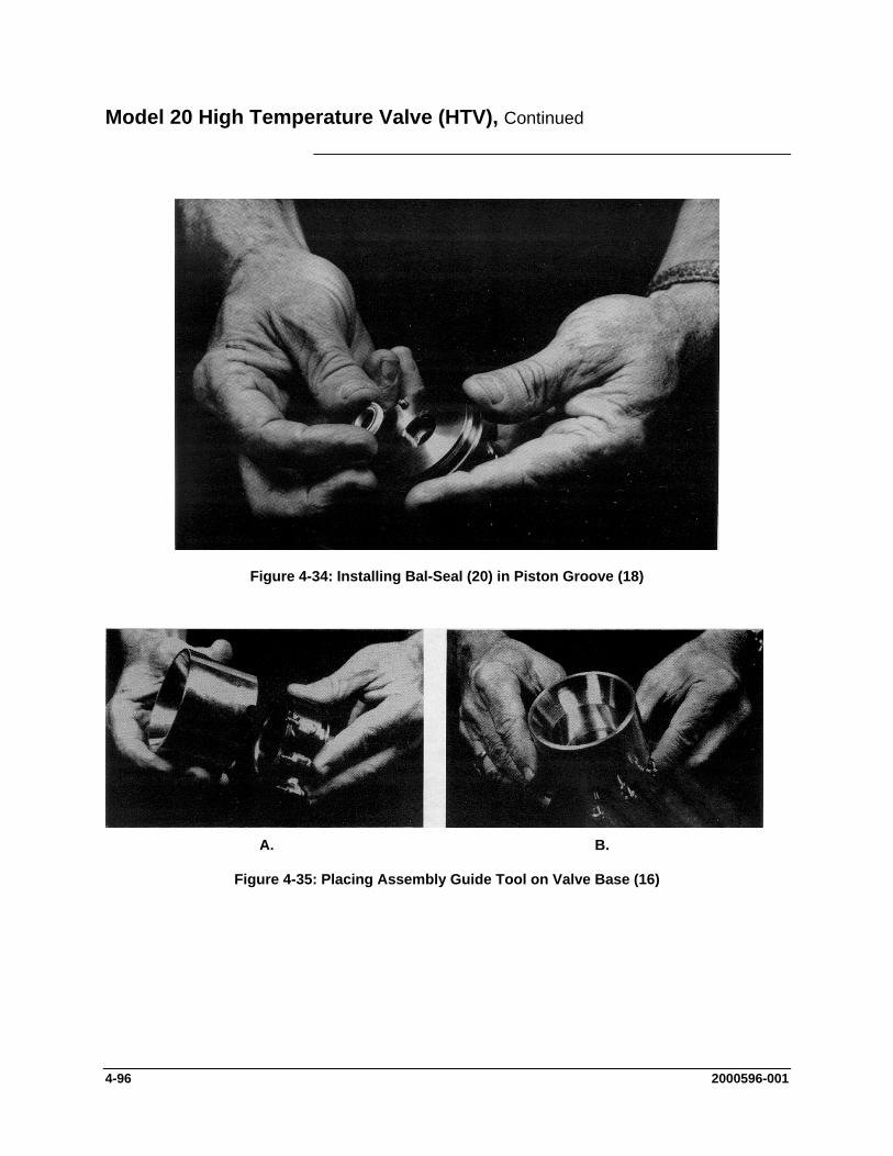
Model 20 High Temperature Valve (HTV), Continued
Figure 4-34: Installing Bal-Seal (20) in Piston Groove (18)
A. B.
Figure 4-35: Placing Assembly Guide Tool on Valve Base (16)
4-96 2000596-001
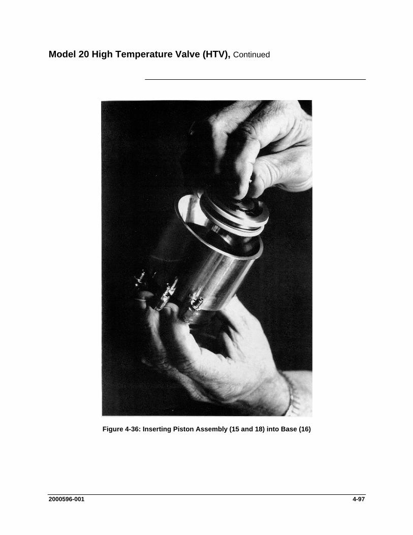
Model 20 High Temperature Valve (HTV), Continued
Figure 4-36: Inserting Piston Assembly (15 and 18) into Base (16)
2000596-001 4-97
Model 20 High Temperature Valve (HTV), Continued
Step Procedure
28. Rotate plunger valve body (17) to align the plunger valve body screw holes with cylinder valve base (16) threaded holes.
29. Install three Allen screws (35) each with two Belleville washers (36). Hand tighten screws but DO NOT compress the Belleville washers (19) in cylinder valve base.
30. With the recess facing up, install the six plungers (14) in the plunger valve body (17). A clean plunger will fall under its own weight and bounce when dropped into the plunger valve body.
31. Place a small drop of Krytox 143 AY or equivalent oil on each plunger. Using a pair of tweezers lift each plunger and move it up and down to allow lubricating oil to flow around the plunger.
32. Refer back to the previous procedure for reassembly of the valve cap.
4-98 2000596-001

Model 11 and Model 11 Low Dead Volume Valves
This section presents the user with the necessary information to perform fault diagnostic testing, maintenance and repair and installation of the Model 11 Valve and the Model 11 Low Dead Volume Valves. These valves are actuated by air pressure. To ensure optimum valve operation, a clean contaminant free operating environment is required at all times. Refer to Figure 4-37.
Description
8. Valve Body 9. O-Ring 10. Finger Spring of Air
Loaded Piston 11. Air Loaded Piston 12. O-Ring 13. O-Ring 14. Spring Loaded Piston 15. Compensation Plate 16. Compression Spring 17. Compression Plate 18. Retaining Base 19. Retaining Ring Clip 20. Ball 5/32” 21. Set Screw 22. O-Rings (3 total) 23. Air Signal Manifold 24. Screw 3/8” 25. Screw 1/2”
Figure 4-37: Model 11 (or Model 11 LDV) Valve Without Valve Cap
2000596-001 4-99
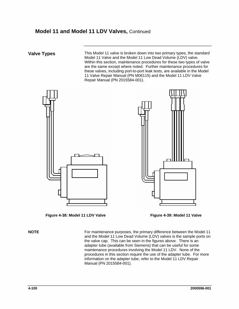
Model 11 and Model 11 LDV Valves, Continued
This Model 11 valve is broken down into two primary types, the standard Model 11 Valve and the Model 11 Low Dead Volume (LDV) valve. Within this section, maintenance procedures for these two types of valve are the same except where noted. Further maintenance procedures for these valves, including port-to-port leak tests, are available in the Model 11 Valve Repair Manual (PN M06115) and the Model 11 LDV Valve Repair Manual (PN 2015584-001).
Valve Types
Figure 4-38: Model 11 LDV Valve Figure 4-39: Model 11 Valve
For maintenance purposes, the primary difference between the Model 11 and the Model 11 Low Dead Volume (LDV) valves is the sample ports on the valve cap. This can be seen in the figures above. There is an adapter tube (available from Siemens) that can be useful for some maintenance procedures involving the Model 11 LDV. None of the procedures in this section require the use of the adapter tube. For more information on the adapter tube, refer to the Model 11 LDV Repair Manual (PN 2015584-001).
NOTE
4-100 2000596-001
Model 11 and Model 11 LDV Valves, Continued
Maintenance procedures are divided into three phases as presented below. The type of maintenance procedure to be performed is determined by the type of fault, availability of spare parts, experience of maintenance personnel and availability of tools and work place facilities. The description accompanying each type of procedure will guide the user in the type of maintenance procedure to be performed.
Maintenance Procedures
Within the procedures, the numbers in parenthesis denote parts referenced in the lists contained in the figures within this section; refer back to the lists for locations.
Diagnostic: These can determine problems by a visual examination of valve.
Mini-Maintenance: Mini-Maintenance procedures should be performed with the valve installed in the analyzer. These procedures are the first logical step for maintenance personnel if they are not sure of what the problem is.
The valve should be returned to Siemens for repair if procedures fail to correct problem of a faulty valve or a visual inspection detects an appreciable amount of foreign contamination on the diaphragm. Valve cap maintenance procedures are as follows:
Valve Cap Disassembly Cleaning, Fittings and Tubing Valve Cap Assembly
Maxi-Maintenance: These procedures may be performed if the valve fault cannot be corrected using Mini-Maintenance procedures. The valve can either be replaced or these procedures can be performed. This includes completely disassembling, cleaning and rebuilding the entire valve. Procedures include the following:
Valve Cap Disassembly Cleaning Fittings and Tubing Valve Cap Assembly Valve Body Disassembly Valve Body Cleaning Valve Body Assembly
If system operational performance or a visual inspection of the Model 11 or Model 11 Low Dead Volume Valve indicates the real or potential problem with the valve, the following information will assist maintenance personnel in determining the problem. Information will indicate whether the valve can be repaired on site or whether it should be returned to Siemens for repair or replacement.
Visual Inspection
2000596-001 4-101

Model 11 and Model 11 LDV Valves, Continued
If customer personnel are not technically trained to repair the valve on site, it is recommended that the valve be returned to Siemens for repair or direct replacement.
Maintenance Personnel
If it is determined that the problem is directly related to Model 11 or Model 11 Low Dead Volum (LDV) Valve system performance, the customer must make a determination if the valve can be repaired on site or if it should be returned to Siemens for repair or replacement.
Direct Valve Replacement
To repair the valve on site, the customer must have the necessary maintenance tools and replacement parts. Recommended valve spare parts including the Model 11 Valve repair kit (PN K21040) and Model 11 LDV repair kit (PN 2015581-001), can be obtained from Siemens.
Repair of Valve
If the Valve shows evidence of poor switching conditions, the following procedures should be performed.
Disassemble the valve body Discard the old O-rings Install new O-rings Thoroughly clean all the components Lubricate components Reassemble the valve
When cleaning the valve and associated components, it is imperative that the maintenance be performed in a clean and contaminant free facility. Components should be placed on a lint free cloth to prevent impurities from contaminating the valve and/or components. Hands should be clean and free of contaminants.
Maintenance Facility
If valve maintenance is to be performed on site, the area must be clean and free of foreign contaminants. Presence of any foreign contamination can cause additional valve problems after reinstallation.
All foreign contamination adhering to valve must be removed quickly using a dust/lint free cloth and a cleaning solvent, such as hexane. After cleaning valve cap and tubing, shake excess cleaning fluid from tubes and let valve cap air dry before reassembling.
Do not allow polished face of valve cap to rest on any surface other than a lint free cloth. Clean metal parts using only a syringe and a cleaning solvent such as hexane, acetone, or methanol.
CAUTION
4-102 2000596-001
Model 11 and Model 11 LDV Valves, Continued
Depending on the installation, the following tests can be performed with the valve mounted in the analyzer. Other tests require the analyzer be shut down and valve ports disconnected. These diagnostic tests indicate specific areas of the fault or trouble.
Diagnostic Procedures
Vapor analyzers generally have the sample at atmospheric pressure, so any leakage would be from a carrier port to a sample port within the valve. With the sample inlet flow turned off, the sample outlet flow should be zero in either the "air off" or "air on" condition. Check for small leaks by immersing the sample outlet tubing in a beaker of water. Bubbles indicate internal leakage.
The liquid sample streams may have pressures several hundred pounds higher than the carrier gas. Leaking between ports will show up on the analyzer chromatogram as base-line shift when the sample pressure is removed from the valve.
Plungers in the valve are pressed upward by air or spring action, but when released depend on their own weight and sample pressure to drop them to the "open" position. Very small sample pressures 1 to 10 oz. (0.4 to 4.3 kPa) may be insufficient to open the flow path if the sealing disc has been held against the cap for a long time (such as a valve in storage). Check for flow across alternate flow paths, such as air on and air off. It may be necessary to temporarily increase the sample pressure to get the flow started, and then reduce it to normal after a few cycles.
Valve Leakage
Plugged Valve
To test for a ruptured sealing disc apply air to valve ports, one at a time, while sealing off all others. Place a small amount of soap solution such as Leak Tec over the upper control port's bleed tube air signal manifold (23). Any escaping air at this point indicates a ruptured disc. If this occurs, proceed with a disc replacement.
Ruptured Sealing Disc
If the disc does not appear to be ruptured, remove the valve from service and replace it with a new valve.
Excessive friction on the actuating pistons of the valve can be caused by lack of lubricant, or dirt or contamination on the O-rings. As a result, the valve may switch erratically, switch slowly or not switch at all. These conditions can cause a leak port to port, across the sealing disc, double sampling, or complete closing of flow between two or more ports.
Slower Erratic Piston Switching
2000596-001 4-103

Model 11 and Model 11 LDV Valves, Continued
The following procedures should be followed for performing Mini-Maintenance on Model 11 or Model 11 Low Dead Volume (LDV) Valve. Figures are of the Model 11 but are also applicable to the Model 11 LDV.
Mini-Maintenance Procedures
Valve Cap Disassembly Step Procedure
1. Relieve the pressure on the base Allen Set Screw (21) by turning it counterclockwise until it turns easily. Refer to Figure 4-37.
1. Screw (3 total) 2. Belleville Washer (6 total) 3. Valve Cap 4. Teflon Seal Disc 5. Dacron Cushion Disc 6. O-Ring 7. Plungers (6 total)
Figure 4-40: Model 11 Valve Cap Exploded View
SEAL DISK(CLEAR)
CUSHION DISK(WHITE)
PLUNGER (6 X)
O-RING
BODY WITH
BASE ASSEMBLY
INSTALLED
VALVE CAP
(C04200)
627-11C
Figure 4-41: Model 11 Valve Major Components
4-104 2000596-001
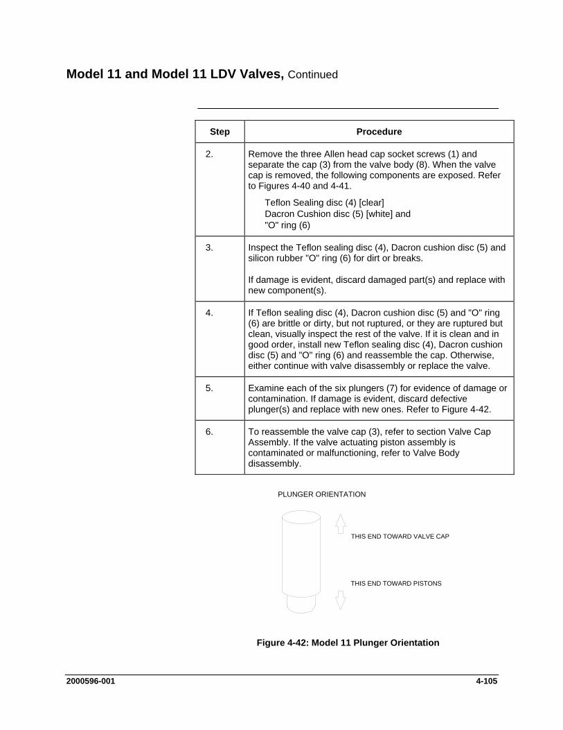
Model 11 and Model 11 LDV Valves, Continued
Step Procedure
2. Remove the three Allen head cap socket screws (1) and separate the cap (3) from the valve body (8). When the valve cap is removed, the following components are exposed. Refer to Figures 4-40 and 4-41.
Teflon Sealing disc (4) [clear] Dacron Cushion disc (5) [white] and "O" ring (6)
3. Inspect the Teflon sealing disc (4), Dacron cushion disc (5) and silicon rubber "O" ring (6) for dirt or breaks.
If damage is evident, discard damaged part(s) and replace with new component(s).
4. If Teflon sealing disc (4), Dacron cushion disc (5) and "O" ring (6) are brittle or dirty, but not ruptured, or they are ruptured but clean, visually inspect the rest of the valve. If it is clean and in good order, install new Teflon sealing disc (4), Dacron cushion disc (5) and "O" ring (6) and reassemble the cap. Otherwise, either continue with valve disassembly or replace the valve.
5. Examine each of the six plungers (7) for evidence of damage or contamination. If damage is evident, discard defective plunger(s) and replace with new ones. Refer to Figure 4-42.
6. To reassemble the valve cap (3), refer to section Valve Cap Assembly. If the valve actuating piston assembly is contaminated or malfunctioning, refer to Valve Body disassembly.
627-11E
THIS END TOWARD VALVE CAP
THIS END TOWARD PISTONS
PLUNGER ORIENTATION
Figure 4-42: Model 11 Plunger Orientation
2000596-001 4-105
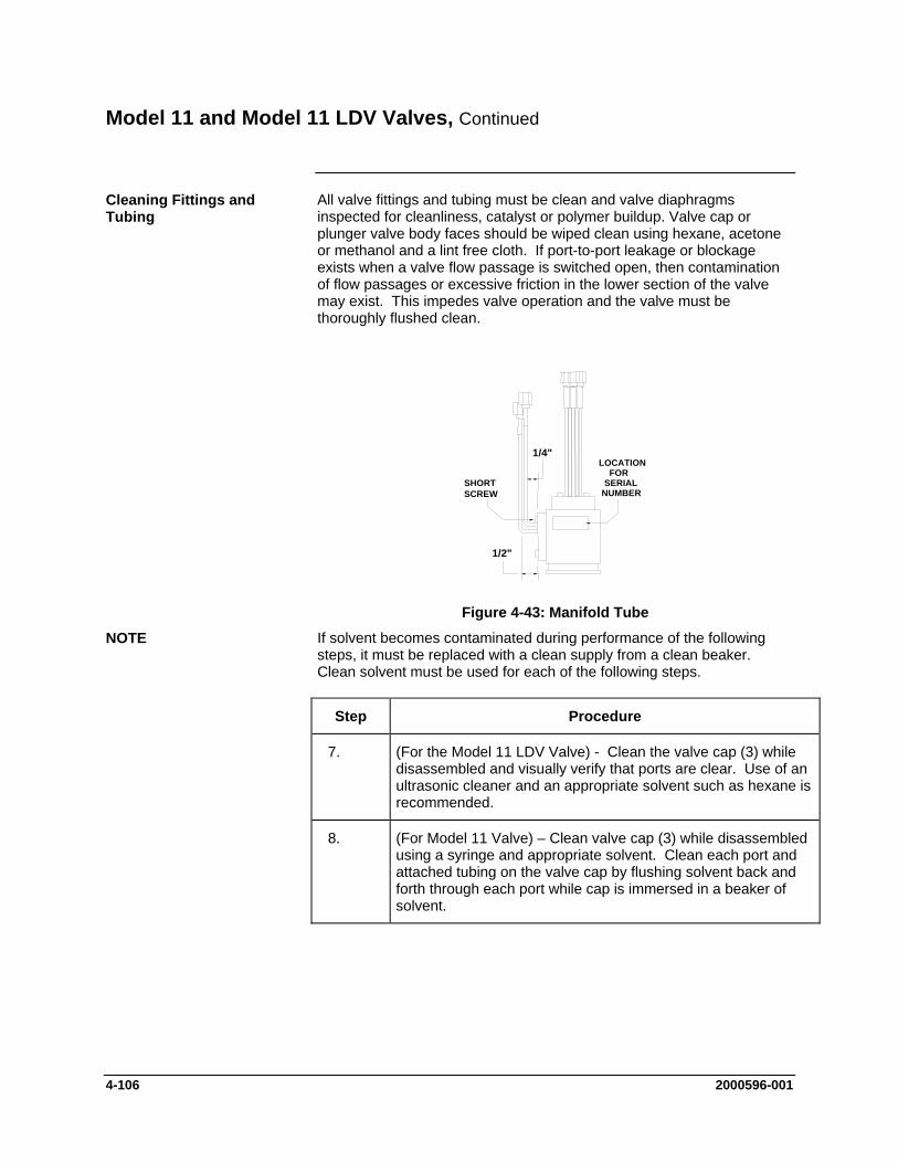
Model 11 and Model 11 LDV Valves, Continued
All valve fittings and tubing must be clean and valve diaphragms inspected for cleanliness, catalyst or polymer buildup. Valve cap or plunger valve body faces should be wiped clean using hexane, acetone or methanol and a lint free cloth. If port-to-port leakage or blockage exists when a valve flow passage is switched open, then contamination of flow passages or excessive friction in the lower section of the valve may exist. This impedes valve operation and the valve must be thoroughly flushed clean.
Cleaning Fittings and Tubing
1/4"
1/2"
SHORTSCREW
LOCATIONFOR
SERIALNUMBER
Figure 4-43: Manifold Tube
If solvent becomes contaminated during performance of the following steps, it must be replaced with a clean supply from a clean beaker. Clean solvent must be used for each of the following steps.
Step
NOTE
Procedure
7. (For the Model 11 LDV Valve) - Clean the valve cap (3) while disassembled and visually verify that ports are clear. Use of an ultrasonic cleaner and an appropriate solvent such as hexane is recommended.
8. (For Model 11 Valve) – Clean valve cap (3) while disassembled using a syringe and appropriate solvent. Clean each port and attached tubing on the valve cap by flushing solvent back and forth through each port while cap is immersed in a beaker of solvent.
4-106 2000596-001
Model 11 and Model 11 LDV Valves, Continued
Step Procedure Valve Cap Assembly
9. Place the actuator assembly upright on a clean lint free cloth surface with the two valve cap guide pins facing upwards.
10. Using a syringe with Krytox 143 AY lubricating oil, place a drop of oil on sidewall of each valve body (8) plunger hole.
11. Reinstall the six plungers (7) into their valve body positions. Using tweezers, move each plunger up and down to thoroughly lubricate them. Plungers must not protrude above valve body (8) top surface. Refer to Figure 4-42 for plunger orientation.
12. Using clean lint free cloths wetted with acetone, remove excess lubricating oil from top of valve body (8).
When installing "O" ring (6), Dacron cushion disc (5) and clear Teflon seal disc (4), do not use any type of grease as a lubricant. There must be no foreign contaminants on discs.
CAUTION
13. Install silicon "O" ring (6), Dacron cushion disc (5) and clear Teflon seal disc (4). Do not lubricate "O" ring (6).
Clear Teflon seal disc (4) MUST BE mounted on top of Dacron cushion disc (5). Refer to Figure 4-41. Align discs over plungers (7).
14. Securely holding valve cap (3), blow out each port and/or tube with compressed air to remove all acetone and foreign matter.
NOTE
2000596-001 4-107
Model 11 and Model 11 LDV Valves, Continued
Do not use grease when installing O-ring.
CAUTION
Step Procedure
15. It is recommended that appropriate torque wrenches be used for this step (available from Siemens – PN’s 1631005-002 and 1631005-003). Install valve cap (3) using the three 10-32 Allen screws (1). Screws must be tightened evenly in sequence 1, 2, 3, 1 sequence. Tightening steps are as follows. Refer to Figure 4-40.
Run screws down until they contact valve cap.
Tighten screws with Allen driver until they are finger tight.
Tighten screws to approximately 15 inch pounds (1.69 Nm). This is a ¼ turn maximum.
Tighten screws to approximately 20 inch pounds (2.26 Nm). This is another ¼ turn maximum.
Tighten screws to approximately 35 inch pounds (3.95 Nm)
Torque bottom adjusting set screw to 6.5 inch pounds (0.73 Nm).
16. Valve is now ready for reinstallation and placing into operational service.
The following procedures should be followed for performing Maxi-Maintenance on the Model 11 Valve or the Model 11 Low Dead Volume Valve. Maxi-Maintenance procedures include the Mini-Maintenance procedures in addition to the disassembly, inspection and assembly of the valve plunger presented in this section. Refer to Figure 4-44.
Maxi-Maintenance Procedures
Step Procedure
1. Perform the following Maintenance Procedures in the order presented:
Valve Cap Disassembly (Mini-Maintenance) Cleaning Fittings and Tubing (Mini-Maintenance) Valve Body Disassembly (Maxi-Maintenance) Valve Body Assembly (Maxi-Maintenance) Valve Cap Assembly (Mini-Maintenance)
4-108 2000596-001
Model 11 and Model 11 LDV Valves, Continued
Valve Body Disassembly Step Procedure
2. Remove the six plungers (7) by inverting valve body (8) and then shaking it. Plungers should fall into the palm of hand.
If a plunger(s) is stuck and does not fall out, delay removing it until after the spring loaded and air loaded pistons (14 and 11) are removed. The plungers can then be forced out from bottom of valve body.
When shaking plungers from valve body, do not allow them to fall on any abrasive surface. It is recommended that a lint free cloth, free of contaminants, be placed under the hand to protect plungers from damage.
CAUTION
3. Examine plungers for damage. Any plunger showing defects, such as nicks, must be discarded and replaced with a new part.
4. Remove air signal manifold (23) by removing the two screws (24&25) that secure it to the valve body (8). After manifold is detached, inspect the three o-rings (22) and replace if necessary. If the o-rings are undamaged, then set them aside (on a clean surface) for installation later.
5. Use the plier tool supplied with the repair kit to remove the retaining ring clip (19).
6. From bottom of valve body, remove retaining base (18), compression plate (17), compression spring (16) and compensation plate (15) from bottom of valve body (8). Refer to Figure 4-44.
7. Use the plier tool supplied with the repair kit to remove spring-loaded piston (14) from valve body (8). Insert the tips of the plier nose into the holes in the underside of the piston and pull slowly.
8. Remove air-loaded piston (11) from valve body (8)
9. Using care to catch plungers (7), as presented in step 2, remove any stuck plunger using retaining ring pliers.
2000596-001 4-109
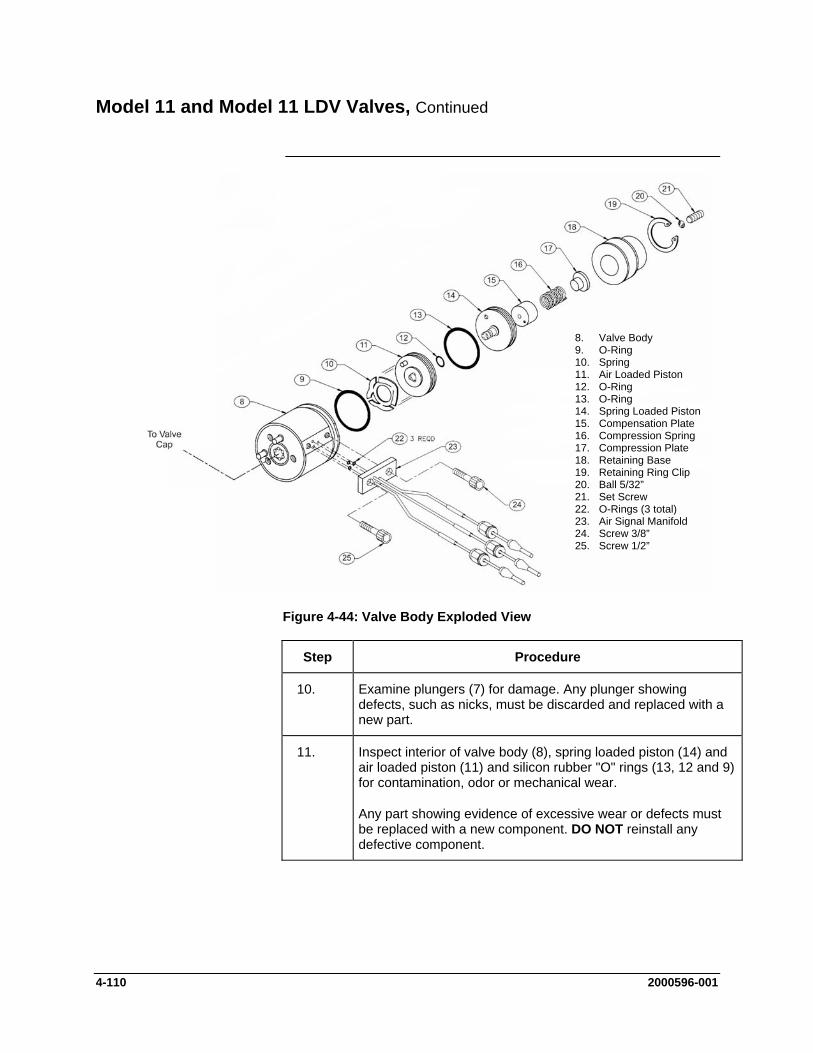
Model 11 and Model 11 LDV Valves, Continued
8. Valve Body 9. O-Ring 10. Spring 11. Air Loaded Piston 12. O-Ring 13. O-Ring 14. Spring Loaded Piston 15. Compensation Plate 16. Compression Spring 17. Compression Plate 18. Retaining Base 19. Retaining Ring Clip 20. Ball 5/32” 21. Set Screw 22. O-Rings (3 total) 23. Air Signal Manifold 24. Screw 3/8” 25. Screw 1/2”
Figure 4-44: Valve Body Exploded View
Step Procedure
10. Examine plungers (7) for damage. Any plunger showing defects, such as nicks, must be discarded and replaced with a new part.
11. Inspect interior of valve body (8), spring loaded piston (14) and air loaded piston (11) and silicon rubber "O" rings (13, 12 and 9) for contamination, odor or mechanical wear.
Any part showing evidence of excessive wear or defects must be replaced with a new component. DO NOT reinstall any defective component.
4-110 2000596-001
Model 11 and Model 11 LDV Valves, Continued
To clean the valve body after it has been disassembled, perform the following procedures.
Valve Body Cleaning
Step Procedure
12. To clean the valve body, the following components are recommended:
Ultrasonic cleaner recommended
Cleaning solution such as strong detergent solution, hexane, acetone or methanol.
Where indicated, use only Krytox Flourinated Grease (Siemens part number G87004).
If a strong detergent solution is used, all cleaned parts must be thoroughly rinsed with a solvent to remove detergent residue before reassembling of valve body.
If cleaning solvent becomes contaminated during performance of the following steps, replace it with a clean supply of cleaning solvent.
Do not place polished valve body (8), or associated parts, against any surface in ultrasonic cleaner or against any abrasive surface. Place parts on a lint free cloth, free of foreign contaminants.
Do not wash O-ring in any type of cleaning solvent.
NOTE
CAUTION
13. Fill Ultrasonic cleaner with cleaning solvent.
14. Before placing valve body parts in Ultrasonic cleaner, wipe off all grease and foreign contaminants from valve parts.
15. Place valve body parts on a lint free cloth in ultrasonic cleaner.
16. Turn Ultrasonic cleaner ON and allow to run for 10 minutes.
17. Remove parts and shake cleaning solvent from tubes. Let parts air dry before reassembling.
2000596-001 4-111
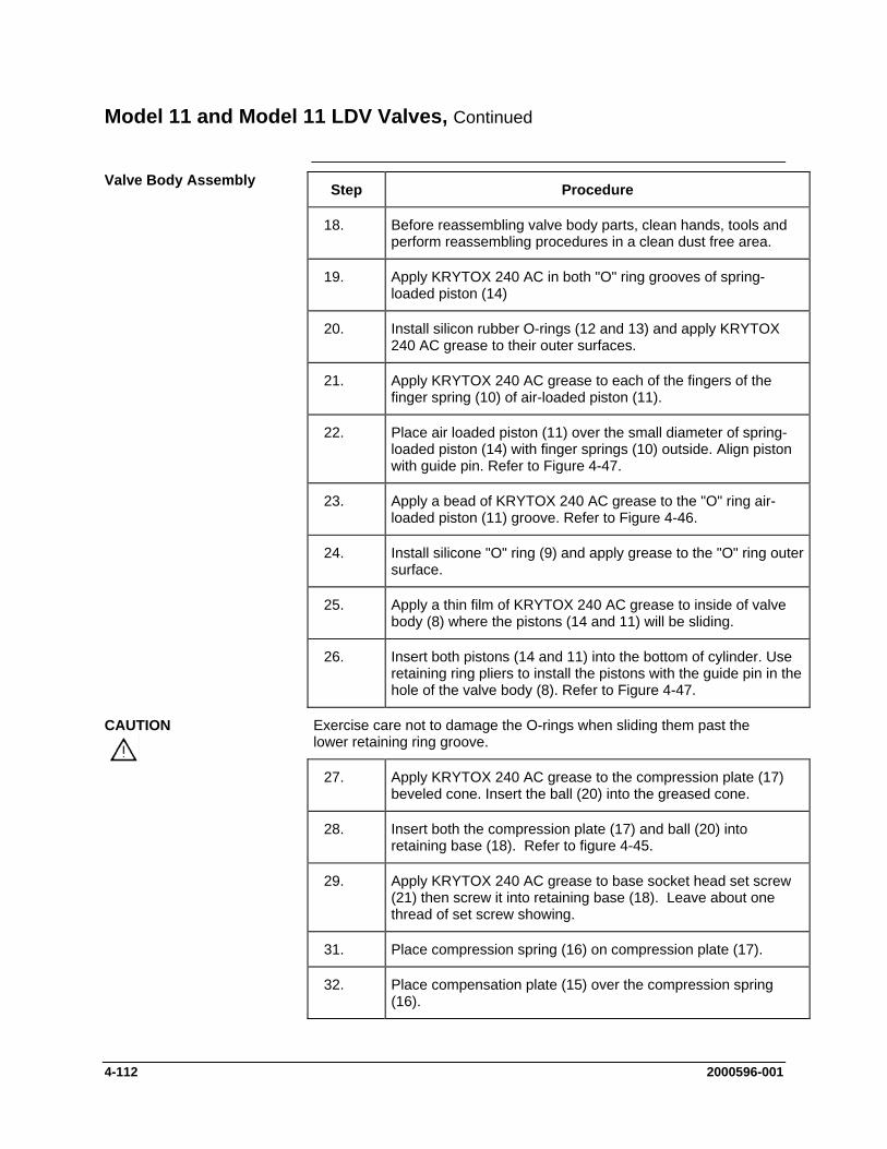
Model 11 and Model 11 LDV Valves, Continued
Valve Body Assembly Step Procedure
18. Before reassembling valve body parts, clean hands, tools and perform reassembling procedures in a clean dust free area.
19. Apply KRYTOX 240 AC in both "O" ring grooves of spring-loaded piston (14)
20. Install silicon rubber O-rings (12 and 13) and apply KRYTOX 240 AC grease to their outer surfaces.
21. Apply KRYTOX 240 AC grease to each of the fingers of the finger spring (10) of air-loaded piston (11).
22. Place air loaded piston (11) over the small diameter of spring-loaded piston (14) with finger springs (10) outside. Align piston with guide pin. Refer to Figure 4-47.
23. Apply a bead of KRYTOX 240 AC grease to the "O" ring air-loaded piston (11) groove. Refer to Figure 4-46.
24. Install silicone "O" ring (9) and apply grease to the "O" ring outer surface.
25. Apply a thin film of KRYTOX 240 AC grease to inside of valve body (8) where the pistons (14 and 11) will be sliding.
26. Insert both pistons (14 and 11) into the bottom of cylinder. Use retaining ring pliers to install the pistons with the guide pin in the hole of the valve body (8). Refer to Figure 4-47.
Exercise care not to damage the O-rings when sliding them past the lower retaining ring groove.
CAUTION
27. Apply KRYTOX 240 AC grease to the compression plate (17)
beveled cone. Insert the ball (20) into the greased cone.
28. Insert both the compression plate (17) and ball (20) into retaining base (18). Refer to figure 4-45.
29. Apply KRYTOX 240 AC grease to base socket head set screw (21) then screw it into retaining base (18). Leave about one thread of set screw showing.
31. Place compression spring (16) on compression plate (17).
32. Place compensation plate (15) over the compression spring (16).
4-112 2000596-001
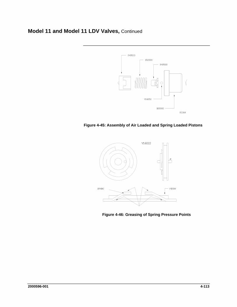
Model 11 and Model 11 LDV Valves, Continued
P49510
S52000
P49500
V16052
B00065
H10648
Figure 4-45: Assembly of Air Loaded and Spring Loaded Pistons
V16022
SPRING PISTON
Figure 4-46: Greasing of Spring Pressure Points
2000596-001 4-113

Model 11 and Model 11 LDV Valves, Continued
ALIGN PIN WITH INDEX HOLE
V16022 V16023(AIR LOADED) (SPRING LOADED)
627-11D
Figure 4-47: Valve Base Alignment Pin
Step Procedure
33. Before final assembly of components, apply a thin film of KRYTOX 240 AC grease to the outside of compensation plate (15) and inside of retaining base (18).
34. Place the compression spring (16), compression plate (17); socket head set screw (21), retaining base (18) and compensation plate (15) into the valve body (8).
35. Use the plier tool supplied with the repair kit to reinstall the retaining ring (19).
Be certain the retaining ring (19) sets into its mounting groove. CAUTION
36. Prepare to to install the manifold (23) by cleaning the flat surface on the side of the valve body (8) and then installing the three small O-rings (22) into the manifold (23).
37. Align and install manifold (23) onto valve body (26) with two 8-32 screws (24 and 25). The shorter screw is installed in the top. Attach the manifold so that inlet holes on the manifold align with inlet holes on the valve body. Refer to Figure 4-44.
38. If necessary, bend the top two manifold (23) tubes straight up ¼" from base of tube. Refer to Figure 4-43. Bend lower middle tube straight up ½" from manifold tube base.
39. Reassemble valve cap (3) using the procedure provided earlier in this section.
4-114 2000596-001
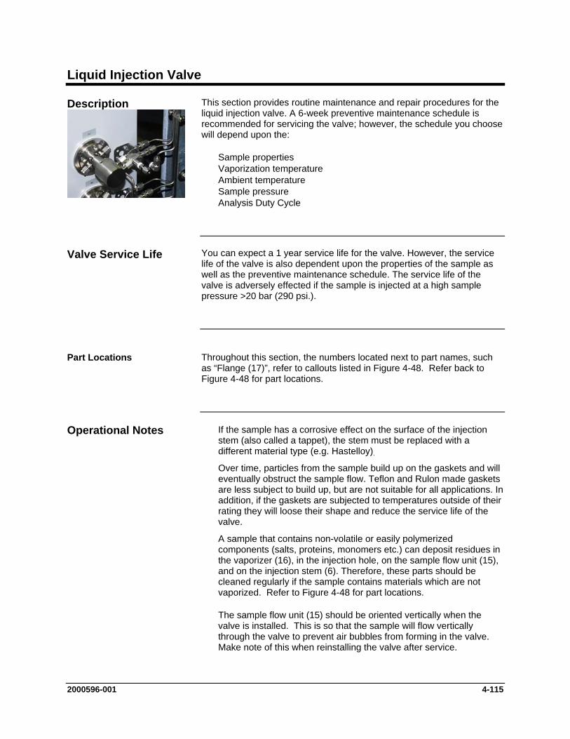
Liquid Injection Valve
This section provides routine maintenance and repair procedures for the liquid injection valve. A 6-week preventive maintenance schedule is recommended for servicing the valve; however, the schedule you choose will depend upon the:
Description
Sample properties Vaporization temperature Ambient temperature Sample pressure Analysis Duty Cycle
You can expect a 1 year service life for the valve. However, the service life of the valve is also dependent upon the properties of the sample as well as the preventive maintenance schedule. The service life of the valve is adversely effected if the sample is injected at a high sample pressure >20 bar (290 psi.).
Throughout this section, the numbers located next to part names, such as “Flange (17)”, refer to callouts listed in Figure 4-48. Refer back to Figure 4-48 for part locations.
If the sample has a corrosive effect on the surface of the injection stem (also called a tappet), the stem must be replaced with a different material type (e.g. Hastelloy).
Valve Service Life
Part Locations
Operational Notes
Over time, particles from the sample build up on the gaskets and will eventually obstruct the sample flow. Teflon and Rulon made gaskets are less subject to build up, but are not suitable for all applications. In addition, if the gaskets are subjected to temperatures outside of their rating they will loose their shape and reduce the service life of the valve.
A sample that contains non-volatile or easily polymerized components (salts, proteins, monomers etc.) can deposit residues in the vaporizer (16), in the injection hole, on the sample flow unit (15), and on the injection stem (6). Therefore, these parts should be cleaned regularly if the sample contains materials which are not vaporized. Refer to Figure 4-48 for part locations.
The sample flow unit (15) should be oriented vertically when the valve is installed. This is so that the sample will flow vertically through the valve to prevent air bubbles from forming in the valve. Make note of this when reinstalling the valve after service.
2000596-001 4-115

Liquid Injection Valve, Continued
Fault/Remedy Troubleshooting Chart
Fault Cause Remedy
All peaks appear smaller
Sample flow unit (15) or injection blocked. Buildup of material on injection stem.
Peaks are becoming wide and shifted to longer times. Baseline becomes negative before injection of sample.
Clean injection hole, stem (6), vaporizer (16) and sample flow unit (15).
Vaporizer (16) is contaminated.
Replace gaskets (14) if necessary.
Baseline becomes positive before injection of sample.
Gasket (14) between sample flow and vaporizer is leaking.
Interruption in chromatogram: sample is not getting injected.
Leaky pneumatic actuator, grease used up, O-rings (4) damaged, control pressure too low.
Clean pneumatic actuator, replace O-rings, and grease sliding surfaces and O-rings.
Peaks too small and too wide, especially those with higher boiling points .
Heating plate is faulty. Vaporization temperature too low.
Replace heating plate. Set higher equalization temperature.
Injection quantity slowly rises until a double peak results (with calibration medium).
Poor peak form, platform following peak. Increase in baseline. Visible discharge of sample.
Worn gaskets (14) and/or stem (6).
Replace gaskets (14) or stem (6).
4-116 2000596-001
Liquid Injection Valve, Continued
Fault Cause Remedy
The section of the injection stem that is normally in the sample flow stream (near the notch) is rough. Material wear on this section of the stem is visible using a magnifying glass. The effect is significantly less on the rest of the stem.
Corrosive sample Possibly replace injection stem (6) by version made of another material (e.g. Hastelloy)
Thin scratches are visible (with a magnifying glass) on the stem near the sample groove. These scratches run along the stem for several millimeters.
Sample is contaminated by particles (most frequent case). The particles get lodged in the gasket and scratch the stem during injection.
Check filter from sample system and replace if necessary.
Replace stem (6) and gasket (14).
The space between the stem (6) and the inside wall of the vaporizer (16) is filled by deposits. This can block the supply of carrier gas.
In extreme cases deposits may result on the stem (6).
The sample contains dissolved salts and other non-volatile materials.
The deposits in the vaporizer (16) may be removed mechanically (drill/reamer with 3.3 mm diameter), or the part may be replaced.
Brown deposits are present on the vaporizer gasket (14) at the outlet to the vaporization area.
2000596-001 4-117
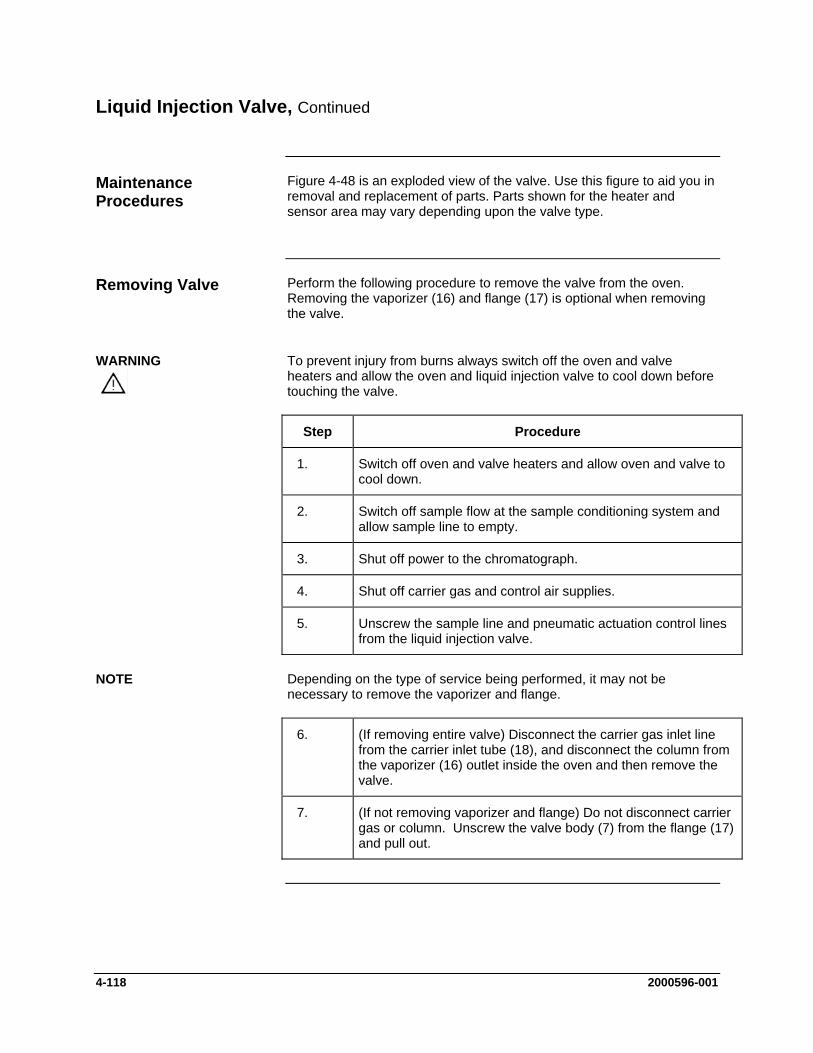
Liquid Injection Valve, Continued
Figure 4-48 is an exploded view of the valve. Use this figure to aid you in removal and replacement of parts. Parts shown for the heater and sensor area may vary depending upon the valve type.
Maintenance Procedures
Removing Valve
Perform the following procedure to remove the valve from the oven. Removing the vaporizer (16) and flange (17) is optional when removing the valve.
To prevent injury from burns always switch off the oven and valve heaters and allow the oven and liquid injection valve to cool down before touching the valve.
WARNING
Step Procedure
1. Switch off oven and valve heaters and allow oven and valve to cool down.
2. Switch off sample flow at the sample conditioning system and allow sample line to empty.
3. Shut off power to the chromatograph.
4. Shut off carrier gas and control air supplies.
5. Unscrew the sample line and pneumatic actuation control lines from the liquid injection valve.
Depending on the type of service being performed, it may not be necessary to remove the vaporizer and flange.
NOTE
6. (If removing entire valve) Disconnect the carrier gas inlet line from the carrier inlet tube (18), and disconnect the column from the vaporizer (16) outlet inside the oven and then remove the valve.
7. (If not removing vaporizer and flange) Do not disconnect carrier gas or column. Unscrew the valve body (7) from the flange (17) and pull out.
4-118 2000596-001

Liquid Injection Valve, Continued
All work should be performed on a clean dry surface. Parts should be placed on a clean lint free cloth and hands should be clean.
Refer to Figure 4-48 for the following procedure.
Step
CAUTION
Disassembling Valve
Procedure
1. If vaporizer (7)and flange (8) were not removed from the analyzer, then skip this step.
Unscrew the valve body (7) from the flange (17) and vaporizer (16) and separate the components.
2. Remove the 2 hex set screws (2) and remove the control cylinder (1).
3. Lift off the sample flow unit (15) and adjustment assembly (13) from the injection stem (6).
4. Remove the sample flow unit and the lens shaped gasket (if the gasket is not present it is stuck in the vaporizer) to allow the Belleville washer plate springs (10) to drop out.
5. Pull the control piston (3) with stem (6) out of the valve body (7). Do NOT use any tools such as a screwdriver as a wedge between the piston and the valve body. This would damage the valve body and control piston.
2000596-001 4-119

Liquid Injection Valve, Continued
Figure 4-48: Liquid Injection Valve Exploded View
Note: The guide pin (5) is only applicable to pistons with the “cross-hole” type stem. Pistons with the much more common “groove/notch” stem are not equipped with a guide pin..
1. Control Cylinder 2. Hex Set Screws 3. Control Piston 4. Large O-Rings 5. Guide Pin (Only on Cross-Hole) 6. Injection Stem (tappet) 7. Valve Body 8. Small O-Ring and Piston Guide Hole 9. Label Indicating Injection Volume 10. Belleville Washer Plate Springs (approx. 8) 11. Adjustment Nut 12. Adjustment Counter Nut 13. Adjustment Assembly 14. Gaskets (2) 15. Sample Flow Unit 16. Vaporizer 17. Flange 18. Carrier Gas Inlet Tube
Figure 4-49: Liquid Injection Valve Body
4-120 2000596-001

Liquid Injection Valve, Continued
Refer to Figure 4-48 for the following procedures. Replacing the Teflon Gasket
Step Procedure
1. Replace the Teflon gaskets if they show any signs of wear or contamination.
2. Remove the gaskets (14) from the adjustment assembly (13) and vaporizer (16). To do this, gently insert the tip of the stem (6) approx. 5 mm into the gasket and then tip to the side until the gasket is loose and can be pulled out with the stem.
3. Insert new gaskets (14) into the adjustment assembly (13) and vaporizer (16). Use the correct type gasket according to the application and temperature class.
4. There should be no play between the new gasket and the injection stem. It should be extremely difficult to move the gasket.
Refer to Figure 4-48 for the following procedures. The silicone O-rings of the pneumatic drive should be regularly greased with Dow Corning Grease 111, 44 or equivalent.
O-ring Replacement
Step Procedure
1. Carefully remove the two large O-rings (4) and the small O-ring (8) out of the valve body (7) and control piston (3) using a small screwdriver or a needle. Only use silicone O-rings, temperature class -40 C to +200 C.
2. Insert new O-rings in all three locations (4 & 8).
3. Liberally grease the new O-rings and the sliding surfaces of the control cylinder (1) and the piston guide (2 & 8). Siemens recommends using Dow Corning 111 with a temperature range from –40 to +260 C or Dow Corning 44 grease with a temperature range from –40 to +200 C
2000596-001 4-121

Liquid Injection Valve, Continued
Read the following notes before performing the assembly procedure. Refer to Figure 4-48 for the following procedures
Valve Assembly
Notes The screw threads on the flange plate (17) must move freely. Grease if necessary.
The diameter of the piston guide hole (8) should be 5.7 mm and be smooth. Replace the part if there are traces of wear on the piston shaft.
The adjustment assembly (13) must slide smoothly down inside the valve body (7).
Step Procedure
Procedures 1. Before assembling the valve, apply a thin film of Dow Corning 44 grease to the following parts. Use Dow Corning 111 or 44 or any grease that has a temperature rating of –40 to +260 C
Internal wall of control cylinder (1) Shaft of Control Piston (3) Piston Guide hole/small O-ring (8) Outside of Large O-rings (4)following reassembly of valve
body (7) and piston (3)
2. Insert the piston (3) with stem (6) into the valve body (7) such that the stem does not become greasy.
3. Drop the Belleville washer plate springs next to one another over the stem into the valve body. Washers must be positioned in an alternating bevel up/bevel down manner (to form a spring). Refer to Figure 4-50 for washer orientation.
4. Slide the adjustment assembly (13) with nut (11), counternut (12) and Teflon gasket (14) onto the stem.
5. Insert the sample flow unit (15) into the valve body (7) over the stem (6). Refer to Figure 4-51.
Note that the stem hole through the sample flow unit is tapered. This tapering is not readily apparent when looking at the uninstalled sample flow unit, but it will be visible when it is installed on the stem. The narrowest side of the hole in the valve body should face outward (toward the vaporizer). The narrowest side of the hole will be apparent because it will have the least spacing between the stem and the side of the hole. Refer to Figure 4-51. Newer sample flow units have this orientation marked with an arrow.
4-122 2000596-001
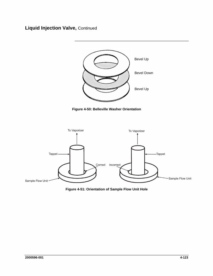
Liquid Injection Valve, Continued
Bevel Up
Bevel Up
Bevel Down
Figure 4-50: Belleville Washer Orientation
Figure 4-51: Orientation of Sample Flow Unit Hole
2000596-001 4-123
Liquid Injection Valve, Continued
Step Procedure
6. Move stem (6) into filling position. This means that the stem should be “pushed in” towards the control cylinder (1)
7. If you have completely removed the liquid injection valve, fit the flange (17) over the vaporizer (16), and screw the valve body (7) and the flange together.
8. If the the flange plate (17) and vaporizer (16) were not removed from the analyzer, screw the partially reassembled valve onto the already installed flange plate.
It may be necessary to adjust the amount that the Belleville washer springs are being compressed. These washers should compress about 2 mm when adjusted appropriately. This compression distance is called “spring travel” and it is adjusted using the following procedure.
Belleville Washer Spring Adjustment
Standard setting with 7 Belleville Washers: smooth round nut (11) extending about 0.5 mm past end of the threads on the adjustment assembly (13).
Standard setting with 8 Belleville Washers; about 0.5 mm of threads showing below the round nut on the adjustment assembly (13). .
The spring travel is not critical, but more compression distance should be used for higher pressures (greater than 20 bars) and less should be used for low pressures (less than 2 bars). Adjust accordingly.
Step Procedure
1. Check the spring travel and correct using the adjustment assembly (13) if necessary. The spring travel is correctly set if the flange (17) can be rotated a further 2.5 rotations starting with the first pressing of the Belleville washer plate springs until the flange rests on the valve body. The plate springs can be viewed through a hole when pressing together. If the flange is tightened firmly, there should be a gap of 0.3 to 0.5 mm between the plate springs.
2. If the adjustment is necessary, loosen the flange from the valve body again, and screw the nut and counternut in or out as necessary. Then repeat the preceding step.
4-124 2000596-001

Liquid Injection Valve, Continued
Step Procedure
3. This step is only necessary if using the less common cross-hole stem and should only be executed if the entire valve including the vaporizer is removed from the analyzer.
Rotate the vaporizer (16) using a 6mm wrench until the carrier gas inlet (18) is parallel to the sample flow unit (15). The carrier gas should flow through the hole in the stem when injecting.
4. If the entire valve was completely removed from the analyzer (including the flange and vaporizer), reinstall it at this time, but do not connect control lines, sample lines, or carrier gas.
When installing the valve, adjust the valve body (7) so that sample will flow vertically through the valve. This is necessary to prevent bubbles from forming in the valve.
5. Position the control cylinder (1), and tighten the two hex set screws (2) on the side. The screws must firmly grip the groove in the valve body (5) wall. Refer to Figure 4-49.
6. Connect the control lines.
7. Activate the actuator pneumatically. Check that you can hear the switching and movement noises.
8. Connect the sample lines. After connecting the sample lines inspect that they are not subjected to any strain and that sample will flow through the valve vertically (to prevent bubbles from collecting in the valve).
9. Complete re-installation of valve into analyzer including reconnection of carrier gas and column tubing (if these were disconnected during removal).
Although it is possible to replace the control piston (3) and stem (6) without disassembling the valve body (7), Siemens recommends that the valve body be disassembled and serviced whenever the stem is replaced.
Dosing Stem Replacement
2000596-001 4-125

Liquid Injection Valve, Continued
To be supplied. Temperature and Heating Components
For Explosion Proof analyzers. If the heating assembly is removed, exchanged or retrofitted, the assembly must be tested and certified in accordance with appropriate regulations before the analyzer can be placed back in service.
CAUTION
4-126 2000596-001
Live Tee Switch
Critical to the operation of the Live Tee Switch valve operation is the correct pressure and flow rates. This section provides procedures for setting the pressure and flow adjustments.
Description
To establish the operating pressures first ensure that the columns are not leaking and that the oven is at its operating temperature.
Procedure for Pressure and Flow Adjustments 1. Shut off vent flows at the splitter/backflush vent, the cut vent and the
purge vent.
2. Establish the desired forward column flow by adjusting the inlet pressure, then read and record the midpoint pressure at the live tee. This can be read directly from the EPC outputs.
3. Adjust the Pm (-) and Pm (+) EPC setpoint to a pressure slightly below the recorded midpoint pressure.
4. Re-establish flows at the vents, nominally 40 to 175 cc/min at the splitter vent, 10 to 70 cc/min at the cut vent and 10-30 cc/min at the purge vent. Optimum flow at the cut vent is approximately 5 times column flow. Flow instructions below 5 times column flow assume that the cut vent is connected to an ITC detector and that the purge vent is connected to the main detector downstream of the main column.
When flows have been established at the cut vent and purge vent, the pressure at the midpoint is reduced, and flow through the pre-column increases. When the pressures at Pm(-) and Pm(+) are adjusted, flow in both columns is influenced, and peak retention times change slightly. It is better to start pressure adjustment of Pm(-) and Pm(+) at pressures slightly below the recorded midpoint pressure since the differential pressures required to operate the tee piece will be kept small and influence on the peak retention times will be minimized.
Notes Concerning Pressure and Flow Adjustments
2000596-001 4-127
Live Tee Switch, Continued
The first adjustment is made in the cut on mode (Pa > Pm(-) > Pm(+)) by reducing the Pm (+) pressure by 20 mbar (0.3 psi) via adjustment of the Pm (+) EPC setpoint. Since two peaks can appear at the main detector from one component, one through the purge vent, and one through the main column, inject a single component test sample to prevent confusion resulting from multiple peaks. A third peak may also appear on the ITC from the cut vent if an ITC is used. A multiple component sample may easily lead to confusion of the identity of various peaks.
If two peaks appear at the main detector, the earlier eluting “pre-peak” has eluted through the purge vent at the retention time of the pre-column. If a third peak has also appeared at the ITC from the cut vent, first address the ITC peak by increasing pressure at Pm (+) (or decrease the pre column inlet pressure, Pa) by 0.1 psi increments until that peak disappears on subsequent injections. Then increase Pm (+) by 0.05 psi increments until the pre-peak just disappears. If no pre-peak appears at the main detector from the purge vent, further decrease Pm (+) in increments of 0.1 psi until a pre-peak appears at the main detector. Once a pre-peak is obtained, increase Pm (+) until it just disappears.
If no ITC is used, the Pm (-) pressure must be adjusted. Reduce the Pm (-) pressure (or increase the Pa pressure) by increments of 5 mbar or 0.1 psi until the main peak at the main detector is noticeably reduced in size, and then increase the Pm (-) pressure (or decrease the Pa pressure) until the size of the peak at the main detector is maximized. Reappearance of a pre-peak at the main detector will require additional adjustment of Pm (+).
To adjust the live tee in the cut off mode of operation, reduce the Pm (-) pressure by 20 mbar (0.3 psi) and inject the test sample. If a peak appears at the main detector, the Pm (-) pressure must be further reduced until the peak at the main detector just disappears. If no peak appears at the main detector, incrementally increase the Pm (-) pressure until a peak appears, then incrementally reduce pressure until the peak just disappears.
To adjust the backflush on pressures, remove pressure from Pa and observe the backpressure at the Pa EPC output. Adjust the Pa EPC pressure to a pressure 0.5 to 1.0 psi higher than the backpressure observed in order to insure that there is a positive purge of carrier gas through the sample valve and carrier inlet to prevent backflush flow from contaminating the carrier inlet system.
Cut On (Pa > Pm(-) > Pm(+))
Cut Off (Pa > Pm(-) <Pm(+))
Backflush On (Pa < Pm(-) < Pm(+))
4-128 2000596-001
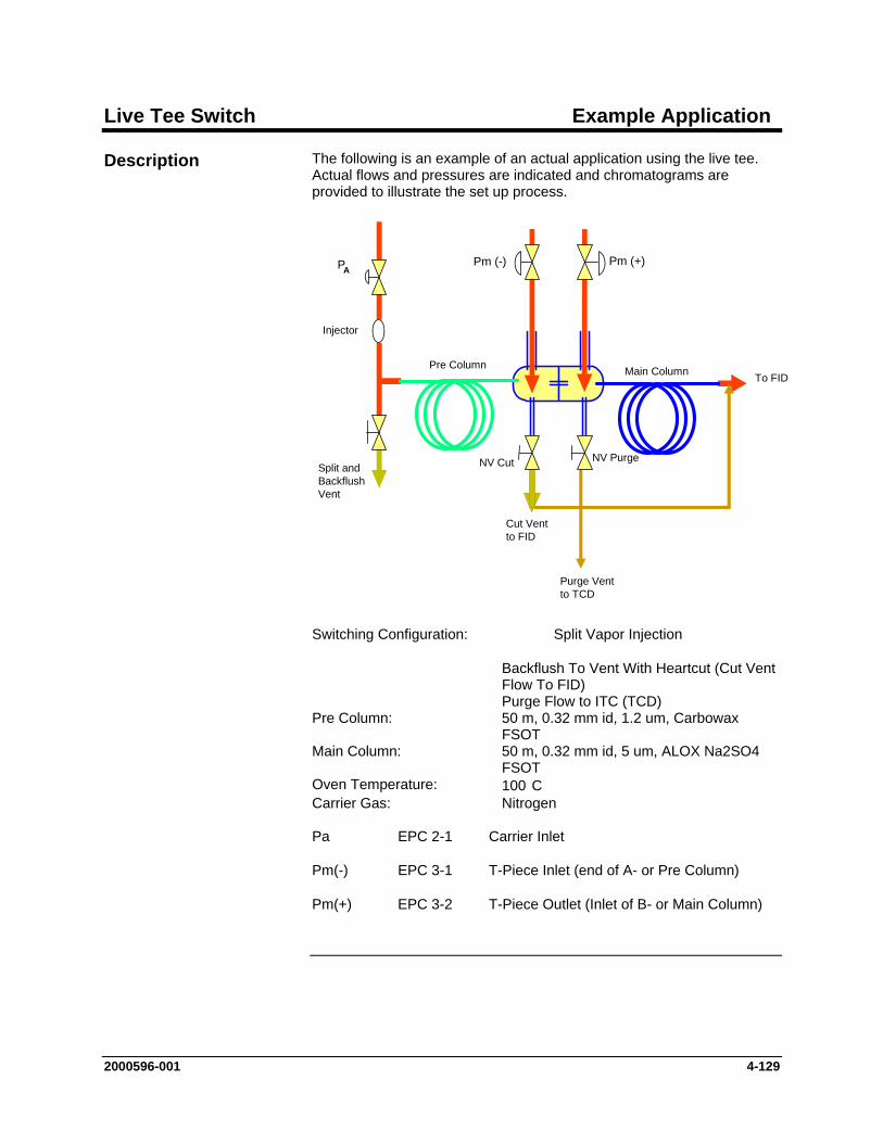
Live Tee Switch Example Application
The following is an example of an actual application using the live tee. Actual flows and pressures are indicated and chromatograms are provided to illustrate the set up process.
Description
Pm (-)
Split andBackflushVent
NV PurgeNV Cut
Cut Vent to FID
Purge Vent to TCD
To FID
PA
Injector
Pre Column Main Column
Pm (+)
Switching Configuration: Split Vapor Injection
Backflush To Vent With Heartcut (Cut Vent Flow To FID)
Purge Flow to ITC (TCD) Pre Column: 50 m, 0.32 mm id, 1.2 um, Carbowax
FSOT Main Column: 50 m, 0.32 mm id, 5 um, ALOX Na2SO4
FSOT Oven Temperature: 100 C Carrier Gas: Nitrogen Pa EPC 2-1 Carrier Inlet
Pm(-) EPC 3-1 T-Piece Inlet (end of A- or Pre Column)
Pm(+) EPC 3-2 T-Piece Outlet (Inlet of B- or Main Column)
2000596-001 4-129
Live Tee Example Application, Continued
1. Columns are installed and leak checked. Operation Checks and Evaluations
2. Based on column length, diameter, carrier gas and oven temperature, Pa was set to 38.2 psi, approximately 3.5 cc/min.
3. In order to determine the midpoint pressure, the split vent and tee piece vents were capped off and Pm (-) and Pm (+) EPCs were turned off.
4. The oven was stabilized at operating temperature of 100 C.
5. A midpoint pressure Pm of 24.8 psi was recorded at Pm (-) and Pm (+) by directly reading the Pm (-) and Pm (+) EPC outputs.
6. All vents were opened and reconnected.
7. Oven temperature was allowed to stabilize.
8. Flows were adjusted as follows:
• Splitter: 60 cc/min. • Cut Vent: 25 cc/min. • Purge Vent: 10 cc/min.
9. Open Fuel Gas and Combustion air and ignite the FID.
10. Adjust EPC pressures as follows:
• Pa 38.2 psi • Pm (-) 22.8 psi • Pm (+) 22.8 psi
11. Inject 100% methane as a single component test sample to perform the fine adjustment of the midpoint pressures. Use of a single component sample will eliminate confusion resulting from multiple peaks.
4-130 2000596-001
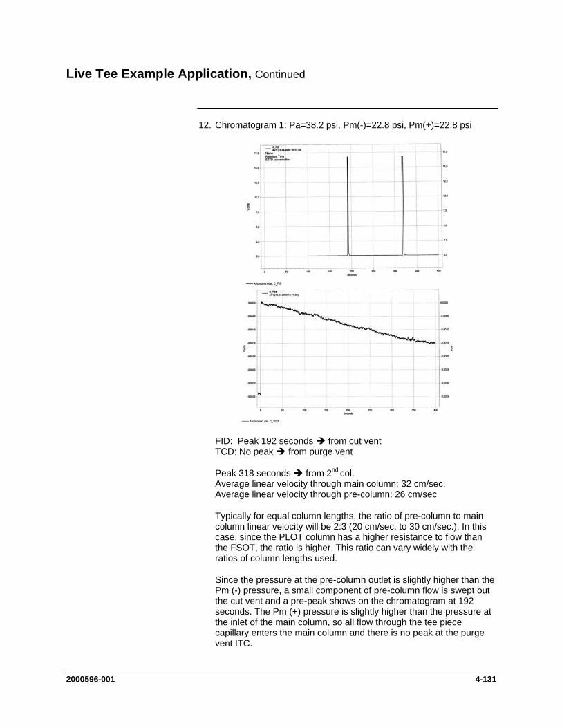
Live Tee Example Application, Continued
12. Chromatogram 1: Pa=38.2 psi, Pm(-)=22.8 psi, Pm(+)=22.8 psi
FID: Peak 192 seconds from cut vent TCD: No peak from purge vent
Peak 318 seconds from 2nd col. Average linear velocity through main column: 32 cm/sec. Average linear velocity through pre-column: 26 cm/sec
Typically for equal column lengths, the ratio of pre-column to main column linear velocity will be 2:3 (20 cm/sec. to 30 cm/sec.). In this case, since the PLOT column has a higher resistance to flow than the FSOT, the ratio is higher. This ratio can vary widely with the ratios of column lengths used.
Since the pressure at the pre-column outlet is slightly higher than the Pm (-) pressure, a small component of pre-column flow is swept out the cut vent and a pre-peak shows on the chromatogram at 192 seconds. The Pm (+) pressure is slightly higher than the pressure at the inlet of the main column, so all flow through the tee piece capillary enters the main column and there is no peak at the purge vent ITC.
2000596-001 4-131
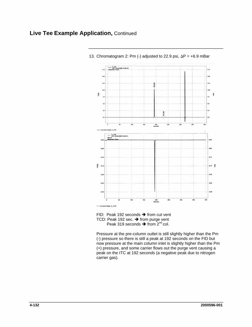
Live Tee Example Application, Continued
13. Chromatogram 2: Pm (-) adjusted to 22.9 psi, ∆P = +6.9 mBar
FID: Peak 192 seconds from cut vent TCD: Peak 192 sec. from purge vent Peak 319 seconds from 2nd col.
Pressure at the pre-column outlet is still slightly higher than the Pm (-) pressure so there is still a peak at 192 seconds on the FID but now pressure at the main column inlet is slightly higher than the Pm (+) pressure, and some carrier flows out the purge vent causing a peak on the ITC at 192 seconds (a negative peak due to nitrogen carrier gas).
4-132 2000596-001
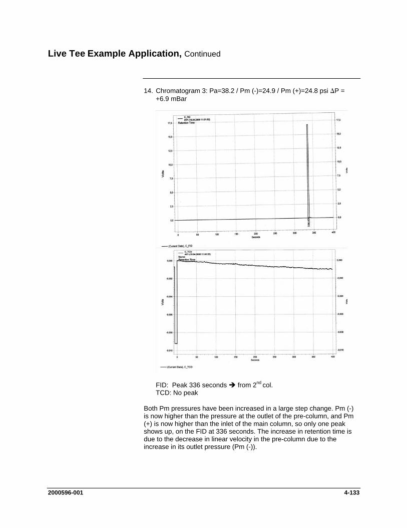
Live Tee Example Application, Continued
14. Chromatogram 3: Pa=38.2 / Pm (-)=24.9 / Pm (+)=24.8 psi ∆P = +6.9 mBar
FID: Peak 336 seconds from 2nd col. TCD: No peak
Both Pm pressures have been increased in a large step change. Pm (-) is now higher than the pressure at the outlet of the pre-column, and Pm (+) is now higher than the inlet of the main column, so only one peak shows up, on the FID at 336 seconds. The increase in retention time is due to the decrease in linear velocity in the pre-column due to the increase in its outlet pressure (Pm (-)).
2000596-001 4-133
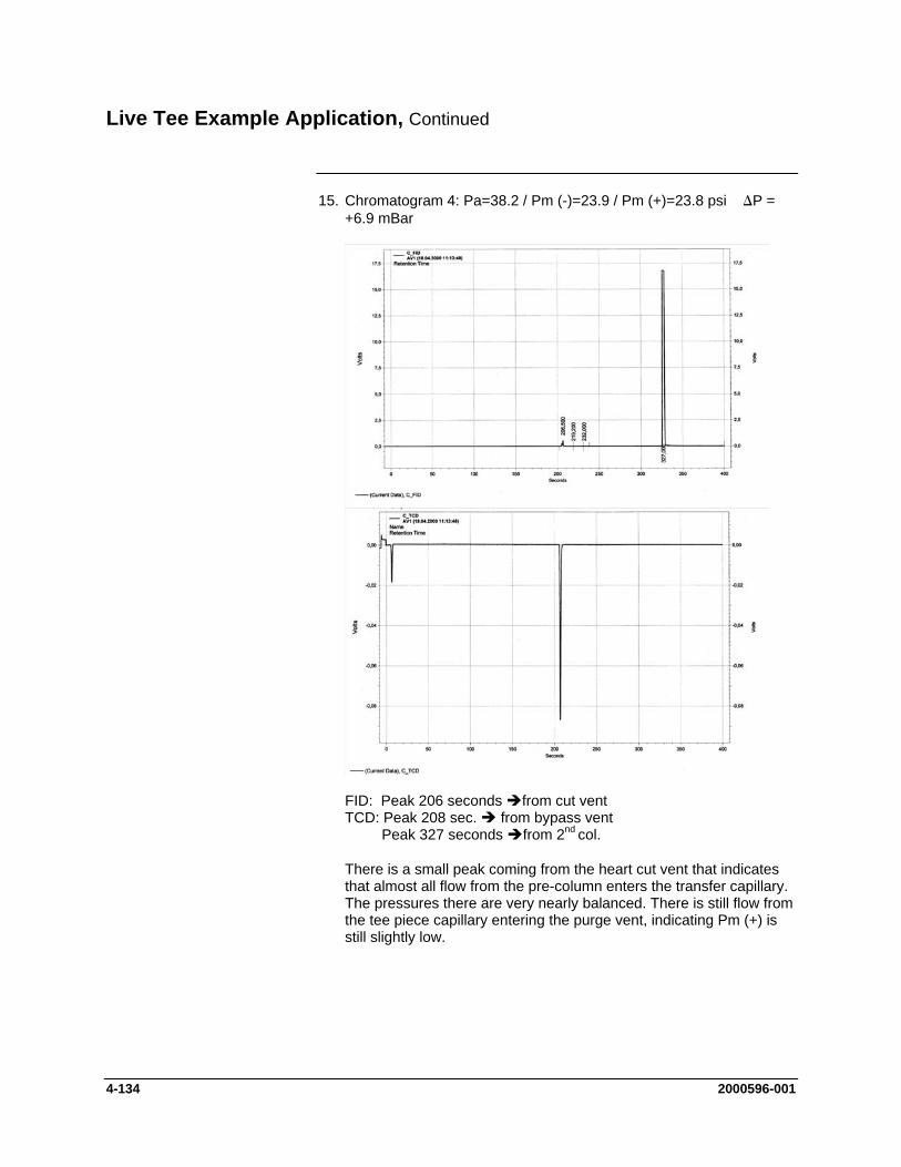
Live Tee Example Application, Continued
15. Chromatogram 4: Pa=38.2 / Pm (-)=23.9 / Pm (+)=23.8 psi ∆P = +6.9 mBar
FID: Peak 206 seconds from cut vent TCD: Peak 208 sec. from bypass vent Peak 327 seconds from 2nd col.
There is a small peak coming from the heart cut vent that indicates that almost all flow from the pre-column enters the transfer capillary. The pressures there are very nearly balanced. There is still flow from the tee piece capillary entering the purge vent, indicating Pm (+) is still slightly low.
4-134 2000596-001

Live Tee Example Application, Continued
16. Chromatogram 5: Pa=38.2 / Pm (-)=24.4 / Pm (+)=24.3 psi ∆P = +6.9 mBar
FID: Peak 211.5 sec. from cut vent TCD: Peak 204 sec. from bypass vent Peak 331 seconds from 2nd col.
There is a very small peak coming from the cut vent that indicates that virtually all flow from the pre column enters the transfer capillary. There is a very small peak coming from the purge vent that indicates that virtually all flow from the tee-piece transfer capillary enters the main column.
These are the threshold settings under these conditions for the Straight or Cut On settings. To ensure perfect conditions even when injecting a high concentration of a fast-eluting, tall peak, the parameters are set to Pa=38.2 / Pm (-)=24.5 / Pm (+)=24.42 psi, ∆P = +5.5 mBar.
2000596-001 4-135

Live Tee Example Application, Continued
17. Chromatogram 6: Pa=38.2 / Pm (-)=23.5 / Pm (+)=24.42 psi ∆P = -63 mBar
FID: Peak 206.6 sec. from cut vent TCD: No peak
There is no peak on the bypass vent or after the second column. Therefore, all flow from the first column is vented through the cut vent. The pressure of Pm (-) is low enough to prevent any pre-column flow from entering the main column. However, since retention times change with the pressures applied, the differential pressures must be kept as low as practical to minimize the influence on retention times.
4-136 2000596-001
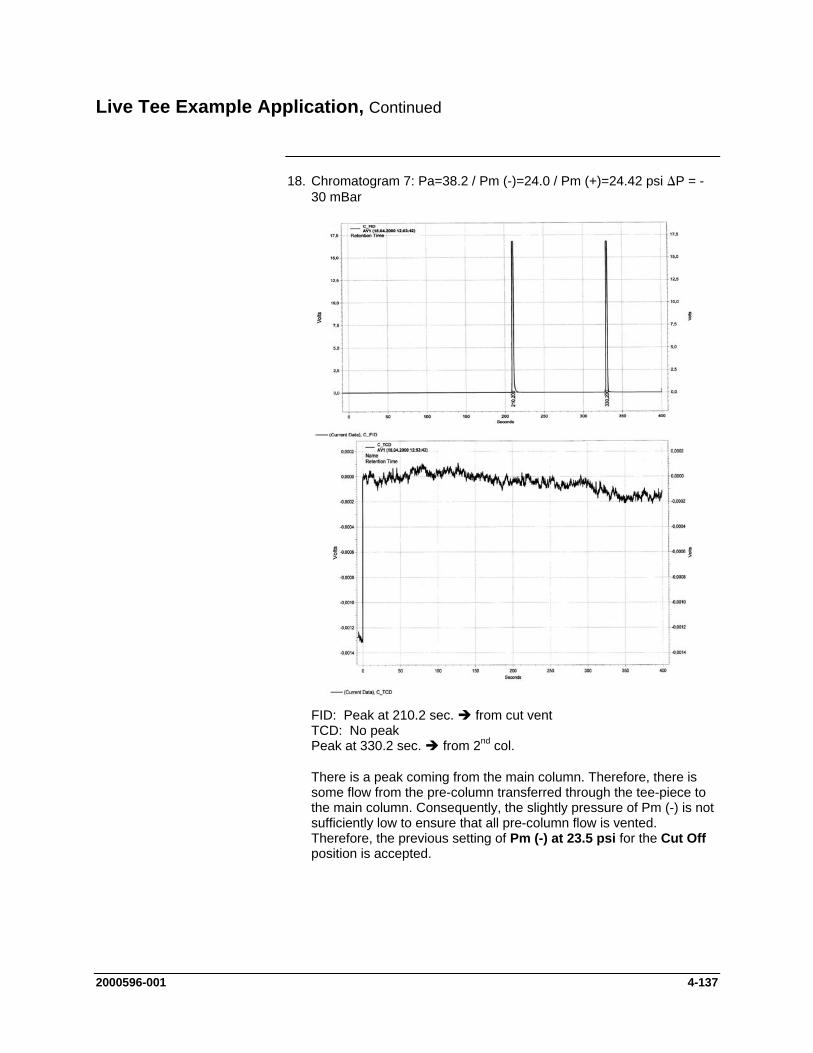
Live Tee Example Application, Continued
18. Chromatogram 7: Pa=38.2 / Pm (-)=24.0 / Pm (+)=24.42 psi ∆P = -30 mBar
FID: Peak at 210.2 sec. from cut vent TCD: No peak Peak at 330.2 sec. from 2nd col.
There is a peak coming from the main column. Therefore, there is some flow from the pre-column transferred through the tee-piece to the main column. Consequently, the slightly pressure of Pm (-) is not sufficiently low to ensure that all pre-column flow is vented. Therefore, the previous setting of Pm (-) at 23.5 psi for the Cut Off position is accepted.
2000596-001 4-137
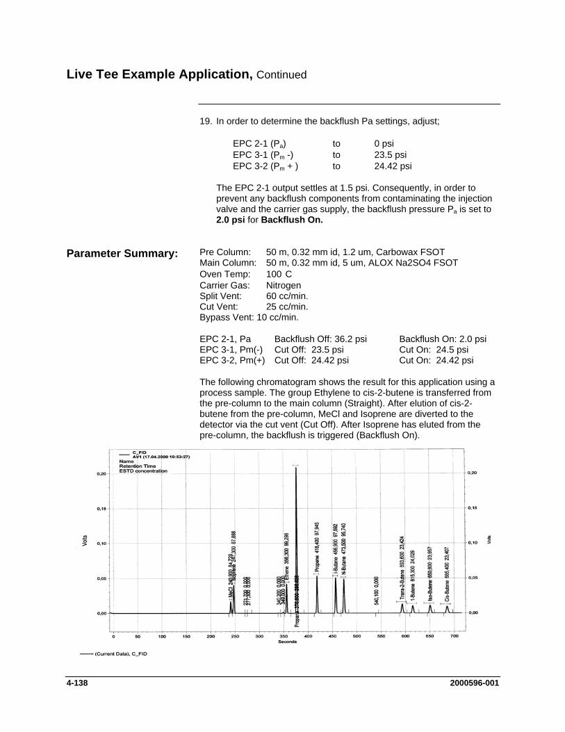
Live Tee Example Application, Continued
19. In order to determine the backflush Pa settings, adjust;
EPC 2-1 (Pa) to 0 psi EPC 3-1 (Pm -) to 23.5 psi EPC 3-2 (Pm + ) to 24.42 psi
The EPC 2-1 output settles at 1.5 psi. Consequently, in order to prevent any backflush components from contaminating the injection valve and the carrier gas supply, the backflush pressure Pa is set to 2.0 psi for Backflush On.
Pre Column: 50 m, 0.32 mm id, 1.2 um, Carbowax FSOT Parameter Summary: Main Column: 50 m, 0.32 mm id, 5 um, ALOX Na2SO4 FSOT Oven Temp: 100 C Carrier Gas: Nitrogen Split Vent: 60 cc/min. Cut Vent: 25 cc/min. Bypass Vent: 10 cc/min.
EPC 2-1, Pa Backflush Off: 36.2 psi Backflush On: 2.0 psi EPC 3-1, Pm(-) Cut Off: 23.5 psi Cut On: 24.5 psi EPC 3-2, Pm(+) Cut Off: 24.42 psi Cut On: 24.42 psi
The following chromatogram shows the result for this application using a process sample. The group Ethylene to cis-2-butene is transferred from the pre-column to the main column (Straight). After elution of cis-2-butene from the pre-column, MeCl and Isoprene are diverted to the detector via the cut vent (Cut Off). After Isoprene has eluted from the pre-column, the backflush is triggered (Backflush On).
4-138 2000596-001
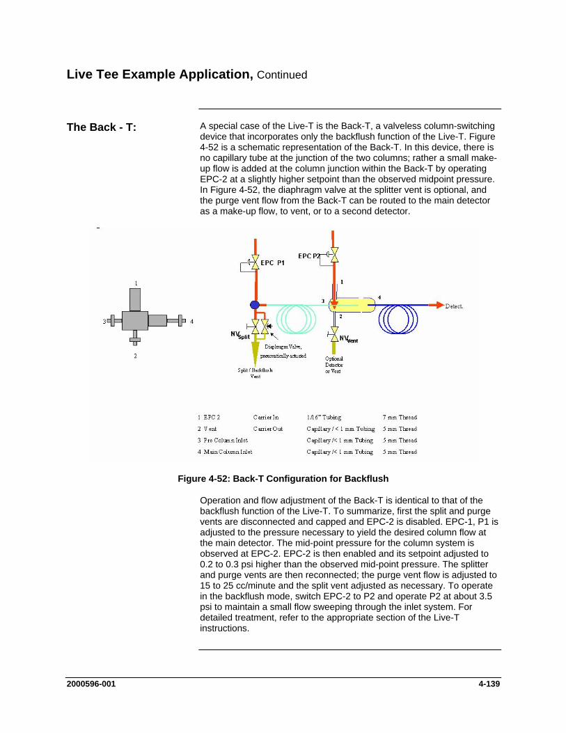
Live Tee Example Application, Continued
A special case of the Live-T is the Back-T, a valveless column-switching device that incorporates only the backflush function of the Live-T. Figure 4-52 is a schematic representation of the Back-T. In this device, there is no capillary tube at the junction of the two columns; rather a small make-up flow is added at the column junction within the Back-T by operating EPC-2 at a slightly higher setpoint than the observed midpoint pressure. In Figure 4-52, the diaphragm valve at the splitter vent is optional, and the purge vent flow from the Back-T can be routed to the main detector as a make-up flow, to vent, or to a second detector.
The Back - T:
Figure 4-52: Back-T Configuration for Backflush
Operation and flow adjustment of the Back-T is identical to that of the backflush function of the Live-T. To summarize, first the split and purge vents are disconnected and capped and EPC-2 is disabled. EPC-1, P1 is adjusted to the pressure necessary to yield the desired column flow at the main detector. The mid-point pressure for the column system is observed at EPC-2. EPC-2 is then enabled and its setpoint adjusted to 0.2 to 0.3 psi higher than the observed mid-point pressure. The splitter and purge vents are then reconnected; the purge vent flow is adjusted to 15 to 25 cc/minute and the split vent adjusted as necessary. To operate in the backflush mode, switch EPC-2 to P2 and operate P2 at about 3.5 psi to maintain a small flow sweeping through the inlet system. For detailed treatment, refer to the appropriate section of the Live-T instructions.
2000596-001 4-139

Flame Photometric Detector
This section provides preventive maintenance and repair procedures for the original flame photometric detector (FPD), and the redesigned flame photometric detector (FPD II). Troubleshooting charts are provided should the detector fail to operate. The troubleshooting charts are applicable to both the FPD and the FPD II.
Description
FPD parts should be removed or replaced only by a trained Siemens maintenance engineer or by the user’s maintenance personnel trained by Siemens.
The photo multiplier in the FPD is sensitive to light. Avoid any unnecessary influence of light on the multiplier, even in the voltage-free condition. Never subject the light entry window to a bright light source.
Before You Begin
Shut down the FPD Switch off chromatograph
Shut-down Procedure Shut off the detector Hydrogen Allow the detector to cool down. If the detector is to be shut down for a longer period, shut off detector
air and cover the detector vent. Never disconnect the fiber optic cable (from either end) while the
power is applied to the PMT module.
The detector baseline noise and balance level should be noted when the analyzer is first installed and then checked on a periodic basis.
Preventive Maintenance
Using a workstation, the baseline noise can be noted manually by zooming in and observing the baseline on a chromatogram. One can also observe the digital signal of the detector on the Maintenance Panel on the “detector” screen. To be effective, the scan rate for the detector AI must be set to 1 second.
If the analyzer has software release 4.2 or higher the noise can be measured automatically by setting up a measurement RMS (root mean square) noise measurement in the “smoothing” module in EZChrom. The measurement can be output as a “result” and handled as any component result is handled.
4-140 2000596-001

Flame Photometric Detector, Continued
The quartz tube requires special handling procedures and special cleaning processes. Do not touch the tube with your hands or any metal object. Plastic tweezers are preferred. Dustless rubber or low lint gloves may be used to handle the tube. When the tube is replaced, replace the o-rings at the same time.
Quartz Tube Handling and Cleaning
The tube is properly cleaned before shipment. If cleaning becomes necessary, cleaning of the quartz tube should be performed either by Siemens or within a properly equipped lab environment by trained personnel. For lab purposes, the recommended cleaning method is placing the tube in an equal-part mixture of H2O (deionized), HCl, and HNO3 in an ultrasonic cleaner for 30 minutes. The tube should be rinsed in deionized water and air dried. Caution should be used handling the tube after it is cleaned to prevent contamination.
The best way to tell if the flame is lit is to use the program supplied with the analyzer. The next best way to tell if the flame is lit is to observe the detector baseline. If the detector is lit the baseline will have a noise level of 100µV or higher. If it not lit the noise will be on the order of 10µV with occasional single spikes of 20-30µV. Also, the noise is at a higher frequency when the flame is not lit than when it is lit. The detector balance signal will be higher with the flame lit than with it off.
An alternative visual test can be used to determine if a flame is not lit. The flame produces water vapor which can be seen on a mirror held up to the detector vent. If there is no water vapor coming from the vent, the flame is not lit. However, water vapor may at times come from the vent when the flame is not lit (because of a condition where water is produced catalytically on the glow plug). Therefore, this test can only be used to verify if the detector flame is NOT lit.
Flame Detection
2000596-001 4-141
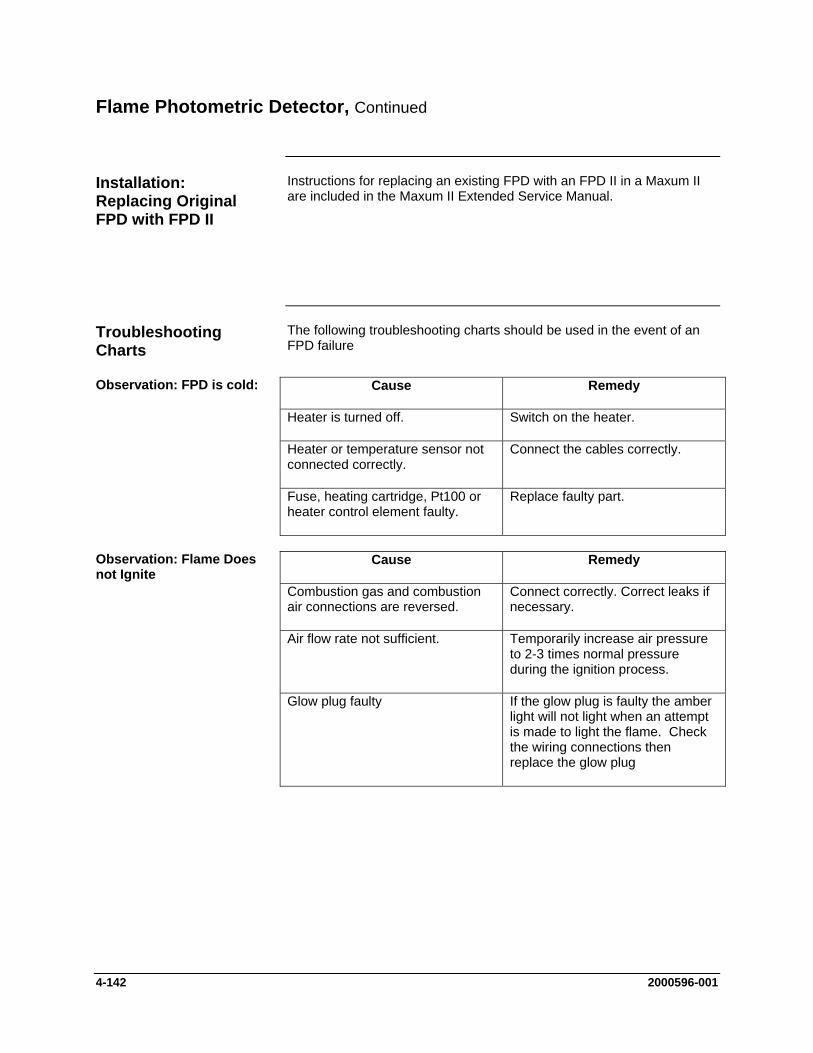
Flame Photometric Detector, Continued
Instructions for replacing an existing FPD with an FPD II in a Maxum II are included in the Maxum II Extended Service Manual.
Installation: Replacing Original FPD with FPD II
The following troubleshooting charts should be used in the event of an FPD failure
Troubleshooting Charts
Observation: FPD is cold: Cause Remedy
Heater is turned off. Switch on the heater.
Heater or temperature sensor not connected correctly.
Connect the cables correctly.
Fuse, heating cartridge, Pt100 or heater control element faulty.
Replace faulty part.
Observation: Flame Does not Ignite
Cause Remedy
Combustion gas and combustion air connections are reversed.
Connect correctly. Correct leaks if necessary.
Air flow rate not sufficient. Temporarily increase air pressure to 2-3 times normal pressure during the ignition process.
Glow plug faulty If the glow plug is faulty the amber light will not light when an attempt is made to light the flame. Check the wiring connections then replace the glow plug
4-142 2000596-001

Flame Photometric Detector, Continued
Observation: Detector Balance Level is Too High
Cause Remedy
Light enters the detector. Check connections on light pipe.
Detector temperature is too high. Set lower detector temperature.
Contaminated combustion or carrier gas.
Use high purity hydrogen and breathing quality air - replace cylinders.
Faulty light pipe (rarely defective) Replace light pipe.
Cause Remedy
Bad electronic connection Check wiring and connections
Electronic failure PMT module and DPM are suspect
Observation: High Detector Noise with Flame Off
Change each one at a time to determine cause. Note: Replace DPM first as PMT modules are rarely defective.
Observation: High Detector Noise with Flame On
Cause Remedy
Contaminated gas Change cylinder
Leak Perform a leak test on the system
Gas flow rates are incorrect Check gas flows and correct
Cause Remedy Observation: No Peaks on Chromatogram
Gas flow rates are incorrect Check gas flows and correct
Sample valve not working correctly Repair/replace sample valve
Flame not lit See below*
No sample flow Check analyzer flow rotometer
Other Causes Refer to low sensitivity section
2000596-001 4-143
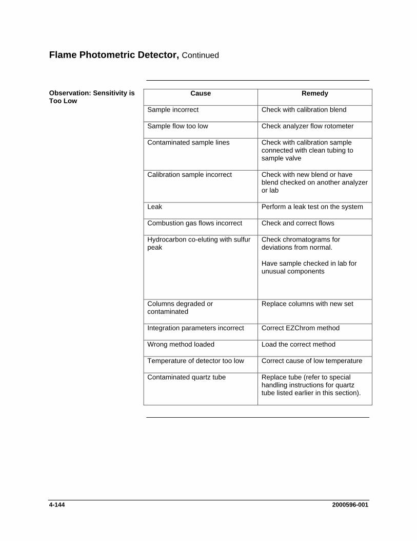
Flame Photometric Detector, Continued
Cause Remedy
Sample incorrect Check with calibration blend
Sample flow too low Check analyzer flow rotometer
Contaminated sample lines
Observation: Sensitivity is Too Low
Check with calibration sample connected with clean tubing to sample valve
Calibration sample incorrect Check with new blend or have blend checked on another analyzer or lab
Leak Perform a leak test on the system
Combustion gas flows incorrect Check and correct flows
Hydrocarbon co-eluting with sulfur peak
Check chromatograms for deviations from normal.
Have sample checked in lab for unusual components
Columns degraded or contaminated
Replace columns with new set
Integration parameters incorrect Correct EZChrom method
Wrong method loaded Load the correct method
Temperature of detector too low Correct cause of low temperature
Contaminated quartz tube Replace tube (refer to special handling instructions for quartz tube listed earlier in this section).
4-144 2000596-001
Flame Ionization Detector (FID)
This section provides preventive maintenance and repair procedures for the Flame Ionization Detector (FID). Troubleshooting charts are provided should the detector fail to operate.
Description
FID parts should be removed or replaced only by a trained Siemens maintenance engineer or by the user’s maintenance personnel trained by Siemens.
1. Shut off the detector Hydrogen and allow the detector to cool down. Carrier gas should remain on during cool down to prevent condensation.
Shut-down Procedure
2. Turn off all supply gasses.
3. Power off the analyzer
4. If the FID is shut down for an extended period of time, the exhaust gas nozzle should be sealed to prevent dust contamination.
The following cleaning procedures can be performed without removing the FID from the oven. Refer to Figure 4-53 for all procedures. However, a clean work surface is necessary for maintenance of detector parts.
Cleaning Procedures
Never open the Ex-FID in explosive areas with the flame burning or with the power on!
Danger
1. Shut down as described above. Clean/Replace Flame Arrestor Insert Assembly 2. Loosen and remove the Flame Arrestor Insert Assembly (1) from the
FID Bottom Body (3) using a 9/16 inch open-end wrench.
3. If Flame Arrestor Insert Assembly is clogged, it may be possible to clean it using solvent and a syringe. However, replacement is recommended. If attempting to clean the assembly, blow out any excess solvent using carrier gas.
4. When cleaning/replacing Flame Arrestor Insert, it is necessary to replace the Flat Washer (2). Because this washer is made of soft aluminum, it should not be reused.
5. Place the Flame Arrestor Insert (1) and the new Flat Washer (2) in the Bottom Body (3) and tighten using a 9/16” open-end wrench. Make sure that the Flat Washer fits into the recessed cavity at the lower end of the Bottom Body (otherwise leaks may result).
2000596-001 4-145

Flame Ionization Detector (FID), Continued
Figure 4-53: FID Assembly
1. Flame Arrestor Insert Assembly 12. Graphite Seal 2. Flat Washer 13. Hammer Drive Screws (for Label) 3. Detector Body (Bottom) 14. Label 4. Filter 15. Socket Heat Cap Screw 5. Retainer - Small 16. Detector Body (Upper) 6. Retainer - Large 17. Teflon Seal 7. Outer Ferrule 18. Collector 8. Graphite Ferrule 19. Socket Heat Cap Screw (M5 x 60) 9. Pressure Ferrule 20. Flame Arrestor Bushing 10. Burner Nut 21. Flat Washer 11. Quartz Jet (with flame tip nozzle) 22. Flame Arrestor
4-146 2000596-001

Flame Ionization Detector (FID), Continued
In the unlikely event that the Quartz Jet (11) becomes dirty or clogged, instructions for replacing the Quartz Jet and associated hardware (7, 8, 9, 10, and 11) are included in the Maxum II Extended Service Manual.
Clean/Replace Quartz Jet Nozzle (11)
Because of the very small diameter of the Combustion Air Restrictors, it is unlikely that the Filter (4) will become dirty or clogged. Because it is difficult to remove this filter without damaging it, if the filter is ever removed during rebuilding/cleaning of the valve, it should be replaced and not reused. Instructions for replacing the Mesh Filter are included in the Maxum II Extended Service Manual.
Replacing/Cleaining of Mesh Filter (4)
1. On the side of the FID loosen the mounting screw (15), which is used to secure the Flame Arrestor (22).
Clean/Replace the Flame Arrestor Hardware (20, 21, and 22) 2. Unscrew/Remove the Flame Arrestor (22), Flat Washer (21) and
Bushing (20). Note: Earlier versions of the FID are equipped with a single piece Flame Arrestor (referred to as a “rattler” because it rattles when shaken). This Flame Arrestor can be replaced with the newer Arrestor/Washer/Bushing combination with no additional hardware.
3. It may be possible to clean the Flame Arrestor with a solvent. However, replacement it recommended. If attempting to clean using solvent, allow all solvent to dry before reinstalling.
4. Reinstall the Flame Arrestor (20, 21, and 22) and secure using the mounting screw (15) on the side of the FID.
2000596-001 4-147
Flame Ionization Detector (FID), Continued
If Combustion Gas or Combustion Air restrictors become clogged, replacement is recommended as the crimps and coils on the restrictors will prevent effective cleaning. Unscrew and replace the restrictor using the appropriate open-ended wrench.
Replace Gas Restrictor Connectors
Install only the prescribed gas connectors with pressure reducers in the Ex-FID, otherwise the ex-protection becomes invalid.
Caution
If the coaxial cable is bent or crushed or if the connectors are damaged or defective, the cable must be replaced. Care should used when replacing the cable so as not to damage the insulation around the electrode connector.
Checking/Replacing Coaxial Cable
Cleaning of the electrodes is NOT recommended. Do NOT use solvent on the electrodes. However, separations involving silicon may lead to buildup of silica (white powder) in the body. This can cause reduced flow and loss of sensitivity. In this instance it is possible to brush off the silica using a glass brush.
Cleaning Upper Body (16) and Electrodes
Igniter Replacement
A few very sporadic issues (refer to the troubleshooting charts in this section) have been observed in association with autoignition of the FID. A redesigned FID igniter board, has been developed to address these issues. If you are experiencing issues with the igniter, contact Siemens regarding the possibility of upgrading to the new igniter. If experiencing issues with the igniter, avoid using auto-ignition until igniter is replaced.
All future igniter replacements will utilize the new version of the igniter. Detailed procedures for upgrading the FID igniter are included in the Maxum II Extended Service Manual.
4-148 2000596-001
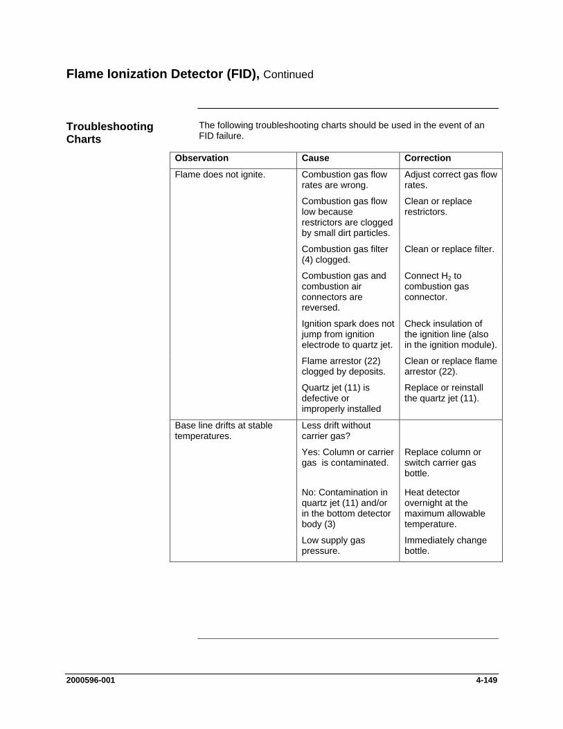
Flame Ionization Detector (FID), Continued
The following troubleshooting charts should be used in the event of an FID failure.
Troubleshooting Charts
Observation Cause Correction
Flame does not ignite. Combustion gas flow rates are wrong.
Adjust correct gas flow rates.
Combustion gas flow low because restrictors are clogged by small dirt particles.
Clean or replace restrictors.
Combustion gas filter (4) clogged.
Clean or replace filter.
Combustion gas and combustion air connectors are reversed.
Connect H2 to combustion gas connector.
Ignition spark does not jump from ignition electrode to quartz jet.
Check insulation of the ignition line (also in the ignition module).
Flame arrestor (22) clogged by deposits.
Clean or replace flame arrestor (22).
Quartz jet (11) is defective or improperly installed
Replace or reinstall the quartz jet (11).
Less drift without carrier gas?
Yes: Column or carrier gas is contaminated. No: Contamination in quartz jet (11) and/or in the bottom detector body (3)
Base line drifts at stable temperatures.
Replace column or switch carrier gas bottle. Heat detector overnight at the maximum allowable temperature.
Low supply gas pressure.
Immediately change bottle.
2000596-001 4-149

Flame Ionization Detector (FID), Continued
Observation Cause Correction
Baseline current is too high. Contamination of: - supply gases
- lines
- detector: signal even without flame.
Filter supply gas.
Clean gas supply lines.
Disassemble and clean detector.
Combustion gas flow is too high.
Optimize flow.
Column contaminated This can be verified by checking baseline current without column attached. If the baseline current is ok without the column connected, then the column is contaminated.
Replace column. Heat detector over night at 160 to 180 C.
Note – this check will not work if using hydrogen carrier.
Baseline is noisy.
If noise is gone when measurement cable is unplugged from the DPM, then either the detector or measurement cable is faulty.
Detector is faulty if noise is gone without flame.
Disassemble and clean detector.
Measurement cable is faulty if noise exists even without flame.
Properly insulate and connect measurement cable/replace measurement cable.
4-150 2000596-001
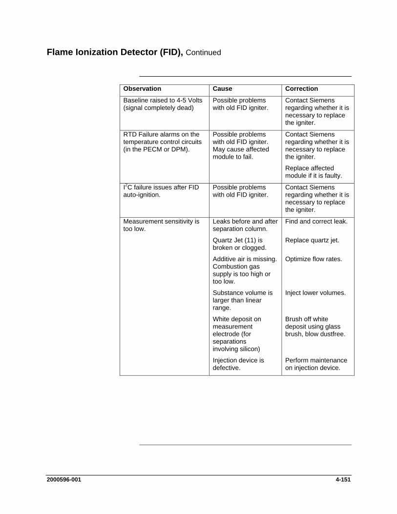
Flame Ionization Detector (FID), Continued
Observation Cause Correction
Baseline raised to 4-5 Volts (signal completely dead)
Possible problems with old FID igniter.
Contact Siemens regarding whether it is necessary to replace the igniter.
RTD Failure alarms on the temperature control circuits (in the PECM or DPM).
Possible problems with old FID igniter. May cause affected module to fail.
Contact Siemens regarding whether it is necessary to replace the igniter.
Replace affected module if it is faulty.
I2C failure issues after FID auto-ignition.
Possible problems with old FID igniter.
Contact Siemens regarding whether it is necessary to replace the igniter.
Measurement sensitivity is too low.
Leaks before and after separation column.
Find and correct leak.
Quartz Jet (11) is broken or clogged.
Replace quartz jet.
Additive air is missing. Combustion gas supply is too high or too low.
Optimize flow rates.
Substance volume is larger than linear range.
Inject lower volumes.
White deposit on measurement electrode (for separations involving silicon)
Brush off white deposit using glass brush, blow dustfree.
Injection device is defective.
Perform maintenance on injection device.
2000596-001 4-151
Thermal Conductivity Detector (TCD)
This section provides preventive maintenance and repair procedures for the Thermal Conductivity Detector (TCD). Troubleshooting charts are provided should the detector fail to operate.
Description
TCD parts should be removed or replaced only by a trained Siemens maintenance engineer or by the user’s maintenance personnel trained by Siemens.
Possible configurations for the TCD include the 2-Cell Filament Detector and the 8-Cell Thermistor Detector. The drawings in this section are for the 8-Cell Thermistor Detector. However, replacement of the Filament Board on the Filament Detector follows the same basic procedure.
It is possible to replace the Filament/Thermistor Board with the detector installed in the analyzer. Within this procedure, the numbers in parenthesis denote parts referenced in the list contained in Figure 4-54; refer back to the figure for locations.
Do NOT attempt to open the TCD with the power on.
TCD Thermistor Board or Filament Board Replacement
Caution
When removing materials from the analyzer, all items must be placed on a clean, non-abrasive surface. Use a clean lint-free cloth.
Important
Step Procedure
1. Shut off flows and shut down power to the analyzer. Allow the detector to cool down.
2. Remove the 4 screws and lockwashers (3) that secure the cover to the detector block (4) and remove the cover.
3. Making note of the connection location for each wire, remove the wiring (8) that is connected to the Thermistor/Filament Board (12) that is to be removed.
4. Remove the Thermistor/Filament Board (12) by removing the Button Head Hex Screw (9), the Lockwasher (10), and the Flat Washer (11).
4-152 2000596-001
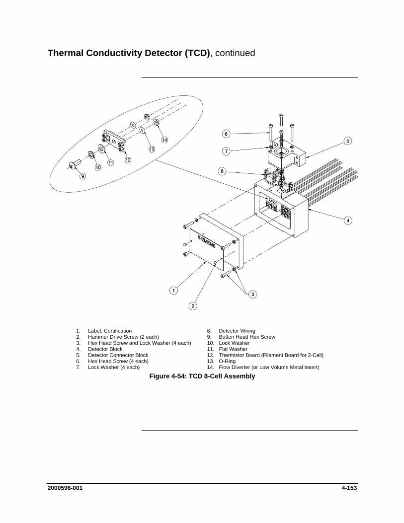
Thermal Conductivity Detector (TCD), continued
Figure 4-54: TCD 8-Cell Assembly
1. Label, Certification 8. Detector Wiring 2. Hammer Drive Screw (2 each) 9. Button Head Hex Screw 3. Hex Head Screw and Lock Washer (4 each) 10. Lock Washer 4. Detector Block 11. Flat Washer 5. Detector Connector Block 12. Thermistor Board (Filament Board for 2-Cell) 6. Hex Head Screw (4 each) 13. O-Ring 7. Lock Washer (4 each) 14. Flow Diverter (or Low Volume Metal Insert)
2000596-001 4-153
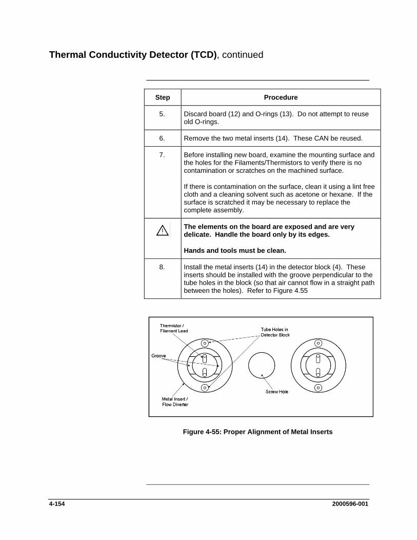
Thermal Conductivity Detector (TCD), continued
Step Procedure
5. Discard board (12) and O-rings (13). Do not attempt to reuse old O-rings.
6. Remove the two metal inserts (14). These CAN be reused.
7. Before installing new board, examine the mounting surface and the holes for the Filaments/Thermistors to verify there is no contamination or scratches on the machined surface.
If there is contamination on the surface, clean it using a lint free cloth and a cleaning solvent such as acetone or hexane. If the surface is scratched it may be necessary to replace the complete assembly.
The elements on the board are exposed and are very delicate. Handle the board only by its edges.
Hands and tools must be clean.
8. Install the metal inserts (14) in the detector block (4). These inserts should be installed with the groove perpendicular to the tube holes in the block (so that air cannot flow in a straight path between the holes). Refer to Figure 4.55
Figure 4-55: Proper Alignment of Metal Inserts
4-154 2000596-001
Thermal Conductivity Detector (TCD), continued
Step Procedure
9. Install the new O-Rings (13) in hole in the Detector Block (4).
It is also possible to install the O-Rings on the Thermistor / Filament board (12) instead of in the hole. If installing the O-Rings on the board, be careful not to damage the element.
10. Install the Board (12) into the Detector Block (4). When installing the board, exercise caution not to damage the exposed elements.
11. Reinstall the Flat Washer (11), Lock Washer (10), and Button Head Hex Screw (9). Do not over tighten the screw as this can damage the Board (12).
12. Reconnect wiring (8) to the board (12). Wiring MUST be connected to the same cells as before. Verify all termination points.
Note: The color coding information for the wiring should be on the Detector Certification Label (1). Also note that there are two wires of each color. For a specific cell it does not matter which wire is connected to which lead as long as the color is correct.
13. Before installing cover back on the Detector Block (4), turn on carrier air to verify there are no leaks between the Board (12) and the Block (4). Turn off carrier after this check is complete.
14. Set the cover in place and reinstall the 4 screws and lockwashers (3) that secure the cover to the detector block (4).
2000596-001 4-155
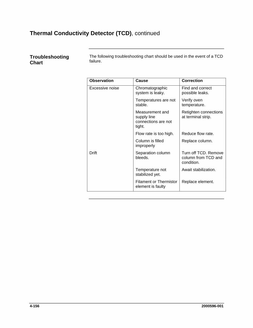
Thermal Conductivity Detector (TCD), continued
The following troubleshooting chart should be used in the event of a TCD failure.
Troubleshooting Chart
Observation Cause Correction
Excessive noise Chromatographic system is leaky.
Find and correct possible leaks.
Temperatures are not stable.
Verify oven temperature.
Measurement and supply line connections are not tight.
Retighten connections at terminal strip.
Flow rate is too high. Reduce flow rate.
Column is filled improperly
Replace column.
Drift Separation column bleeds.
Turn off TCD. Remove column from TCD and condition.
Temperature not stabilized yet.
Await stabilization.
Filament or Thermistor element is faulty
Replace element.
4-156 2000596-001

Miscellaneous Maxum II Procedures
This section contains references to various procedures useful for maintenance of the Maxum II Process Gas Chromatograph. These procedures are all included in the Maxum II CD Document Library (Part Number 2000597-001) which is available from Siemens.
Before You Begin
Startup of the Maxum II is covered in the Maxum II Installation Manual (Siemens Part Number 2000596-001). This procedure contains the elements that should be followed to restart the Maxum II after maintenance.
Maxum II Startup Procedure (Using the Workstation Software)
The procedure to backup the Maxum II Database to the System Manager PC is contained in the System Manager Overview help file of the System Manager program. The procedure is found by clicking the “How To” tab when the help file is first opened.
Backup of Maxum II Database
In addition to being part of the System Manager Software, the System Manager Overview help file is also included on the Maxum II CD Library (under the Maxum System Manager Help Files menu selection).
Alternatively, the procedure to backup the Maxum II database is included in the section of this manual titled “Maxum System Manager”.
Instructions for working with the System Manager software are included in the System Manager Overview help file. Several specific procedures can be accessed by clicking the “How To” tab when the help file is first opened. Topics covered include: adding an analyzer, connecting to an analyzer, adding an analyzer group, clearing alarms, and other topics
Add an Analyzer or Connect to an Analyzer Using Workstation Software
This help file can be accessed from the System Manager software. The help file is also included on the Maxum II CD Library (under the Maxum System Manager Help Files menu selection).
2000596-001 4-157


Chapter 5
Parts
Introduction
This chapter provides maintenance personnel with information concerning parts and assemblies for the Maxum II.
Overview
Chapter Highlights Topic Page
Introduction 5-1
Maxum II Acronyms 5-2
Available Parts 5-3
Part Location Drawings 5-4
Parts can be ordered from: How to Place an Order
Siemens Energy & Automation, Inc. 408 US Highway 60 Bartlesville, Oklahoma 74003
Tel: (800) 448-8224 (USA) Tel: 001 918-662-7030 (International) Fax: (918) 662-7482 (USA) Fax: 001 918-662-7482
To ensure an immediate response to your request, you should provide the following:
Purchase order number. If ordering by phone, a confirming P.O. should be sent.
Address where the parts are to be shipped.
Address where the invoice is to be sent.
Siemens part numbers as listed.
Quantity needed of each part.
Equipment Serial number or project number of the system (especially for warranty related orders).
Preferred method of shipment.
2000596-001 Parts 5-1

Introduction, Continued
AD-4 Analog/Digital Input and Output Board ANCB Advance Network Communications Board;
Connects Ethernet or DataNet to Advance Data Hiway Communication
ANG Advance Network Gateway; connects high- and low-speed networks
AO-8 Analog Output Board CEU CAN Extension Unit; used to house additional input
and output boards DIO-4 Digital Input and Output Board DNH DataNET Hub; connects multiple DataNET
segments together DPM Detector Personality Module; amplifies and digitizes
detector signals EC Electronics Enclosure EPCM Electronic Pressure Control Module FD Filament Detector FID Flame Ionization Detector FPD Flame Photometric Detector GC Gas Chromatograph HMI (MMI) Human to Machine Interface NAU Network Access Unit OEFT Oven Entry Feed Through; linkage between SNE
and detector PCM Purge Control Module; allows entry of purge air to
electronics enclosure PDD Pulsed Discharge Detector PECM Power Entry and Control Module SNE Sensor Near Electronics; controller attached to oven
detectors SNECON SNE Controller Board; processor board inside SNE
enclosure SVCM Solenoid Valve Control Module SYSCON System Controller; main control computer board in
GC and NAU TCD Thermal Conductivity Detector WDB Wiring Distribution Board; distributes cable harness
inside GC electronics
Maxum II Acronyms
5-2 Parts 2000596-001
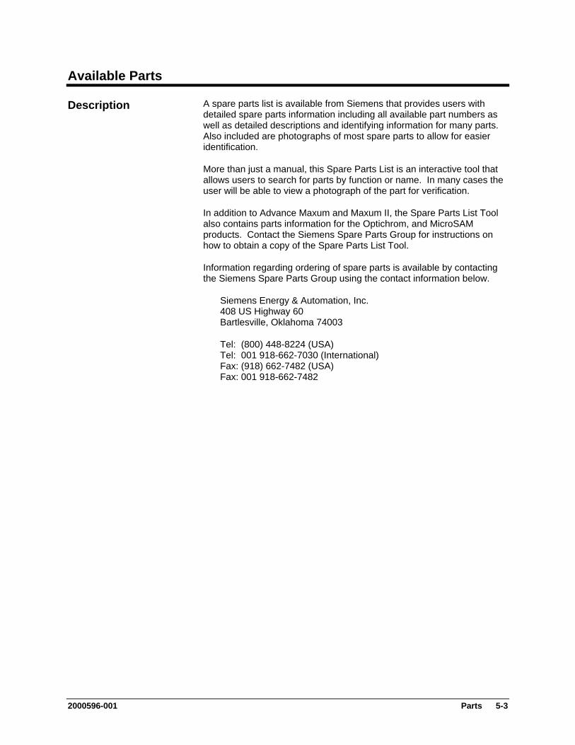
Available Parts
A spare parts list is available from Siemens that provides users with detailed spare parts information including all available part numbers as well as detailed descriptions and identifying information for many parts. Also included are photographs of most spare parts to allow for easier identification.
Description
More than just a manual, this Spare Parts List is an interactive tool that allows users to search for parts by function or name. In many cases the user will be able to view a photograph of the part for verification.
In addition to Advance Maxum and Maxum II, the Spare Parts List Tool also contains parts information for the Optichrom, and MicroSAM products. Contact the Siemens Spare Parts Group for instructions on how to obtain a copy of the Spare Parts List Tool.
Information regarding ordering of spare parts is available by contacting the Siemens Spare Parts Group using the contact information below.
Siemens Energy & Automation, Inc. 408 US Highway 60 Bartlesville, Oklahoma 74003
Tel: (800) 448-8224 (USA) Tel: 001 918-662-7030 (International) Fax: (918) 662-7482 (USA) Fax: 001 918-662-7482
2000596-001 Parts 5-3

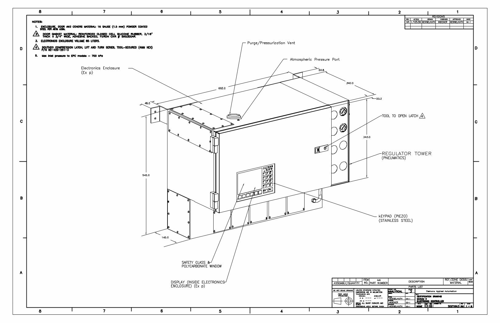
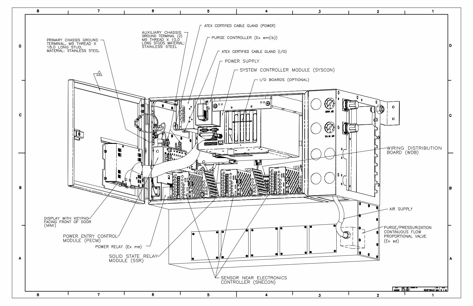
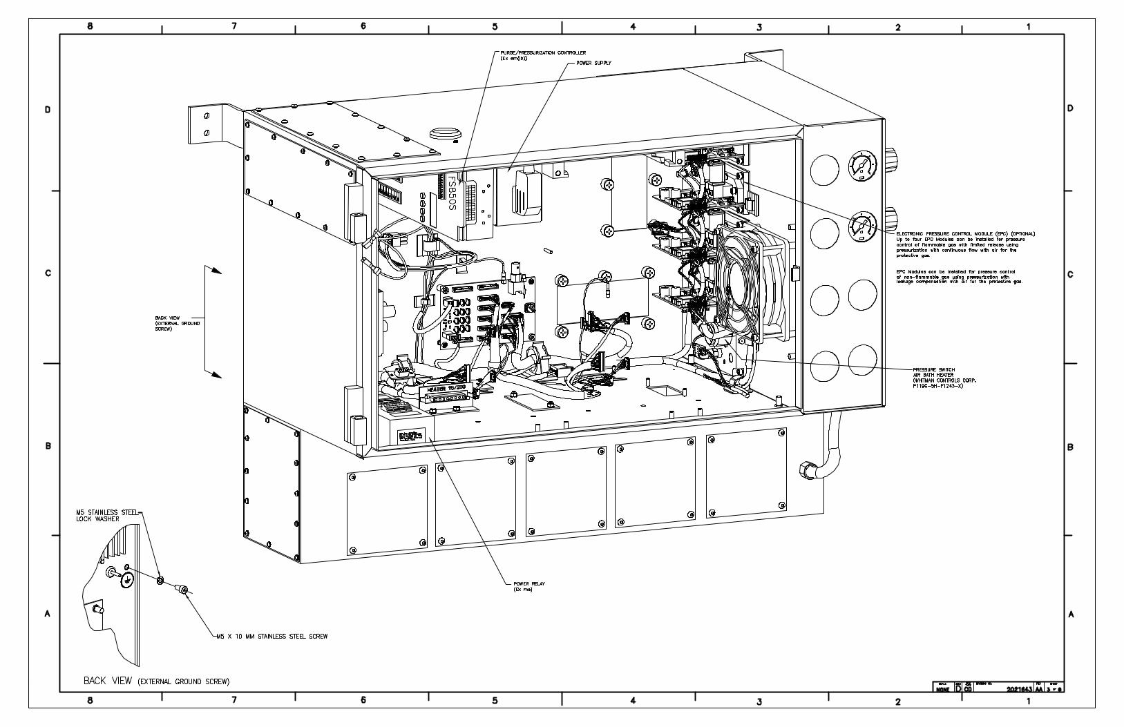
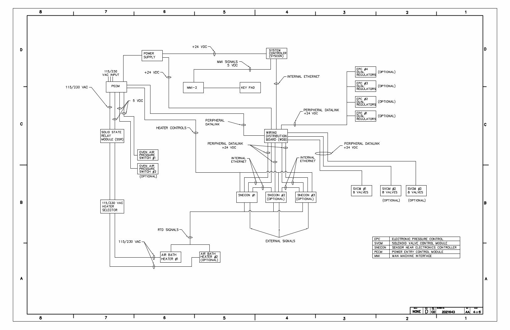

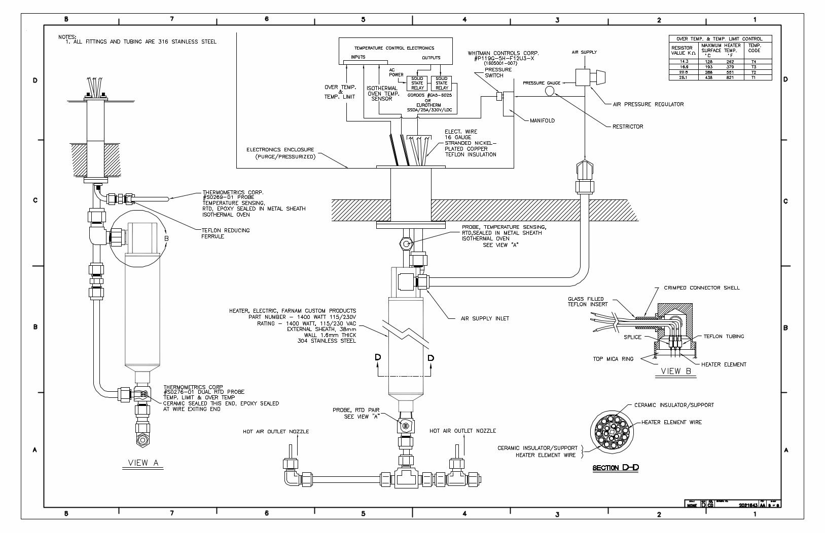
Maxum System Manager Overview
Introduction
This chapter is intended to provide the user with a printed version of the Maxum System Manager on-line help files. It presents a description of the software functions of System Manager and how to use them. The chapter contains a glossary that will answer many questions for both new and experienced users:
Before You Begin
The information in this chapter is written for Maxum software version 4.2. If your version of System Manager is different from version 4.2, then features and functions may appear different. For information regarding your version of System Manager Software refer to the on-line help files that can be accessed by selecting the Help menu while running System Manager. The latest versions of these help files are also available on the latest version of the Maxum II Online Documentation Library CD.
The software version of System Manager can be accessed by choosing the “Help” menu item and then selecting “About Maxum System Manager”. The resulting window shows the version of the installed software.
Advance System Manager • 1

Overview
Chapter Highlights In this Chapter, the following information is provided:
Topic Page
Overview 1
Maxum 3
System Manager Overview 7
Context Sensitive Menus 13
Toolbars 31
How To Use the Maxum System Manager 33
Database and Tables 44
Working with Applications 47
Maxum Utilities 57
StatMon Utility 75
Glossary 82
Appendix 1. Hardware IDs 88
Advance System Manager • 2
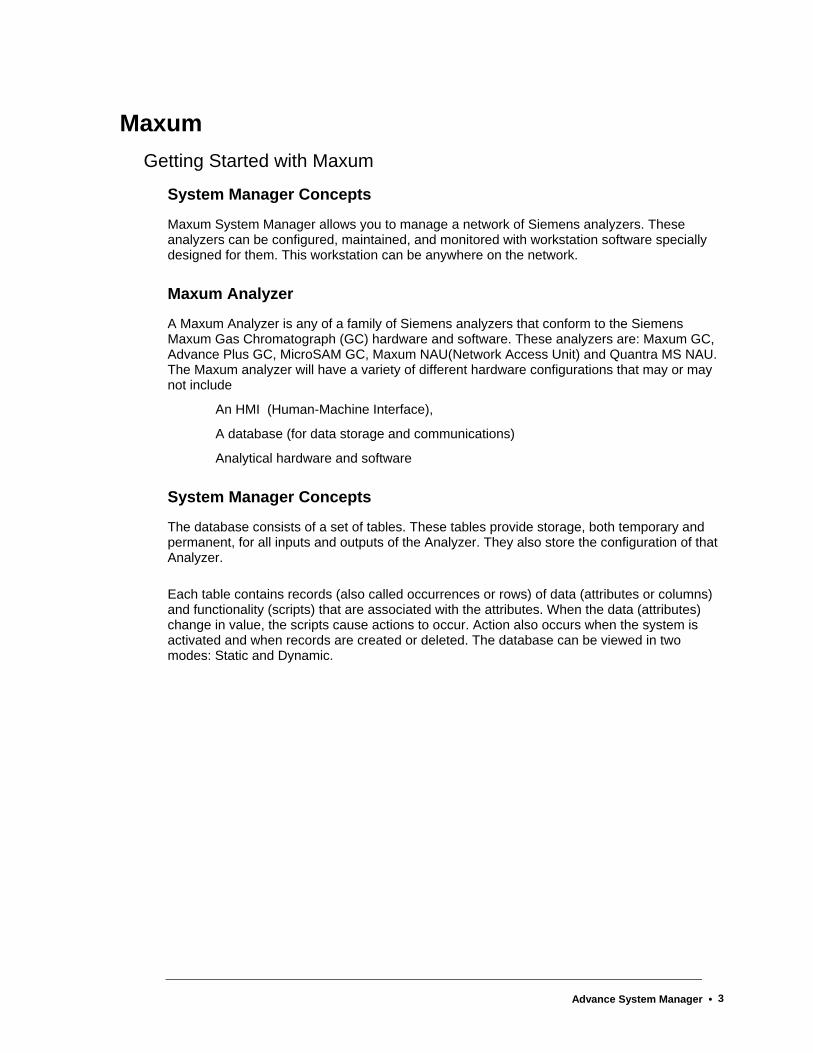
Maxum Getting Started with Maxum
System Manager Concepts
Maxum System Manager allows you to manage a network of Siemens analyzers. These analyzers can be configured, maintained, and monitored with workstation software specially designed for them. This workstation can be anywhere on the network.
Maxum Analyzer
A Maxum Analyzer is any of a family of Siemens analyzers that conform to the Siemens Maxum Gas Chromatograph (GC) hardware and software. These analyzers are: Maxum GC, Advance Plus GC, MicroSAM GC, Maxum NAU(Network Access Unit) and Quantra MS NAU. The Maxum analyzer will have a variety of different hardware configurations that may or may not include
An HMI (Human-Machine Interface),
A database (for data storage and communications)
Analytical hardware and software
System Manager Concepts
The database consists of a set of tables. These tables provide storage, both temporary and permanent, for all inputs and outputs of the Analyzer. They also store the configuration of that Analyzer.
Each table contains records (also called occurrences or rows) of data (attributes or columns) and functionality (scripts) that are associated with the attributes. When the data (attributes) change in value, the scripts cause actions to occur. Action also occurs when the system is activated and when records are created or deleted. The database can be viewed in two modes: Static and Dynamic.
Advance System Manager • 3
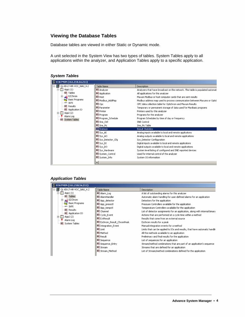
Viewing the Database Tables
Database tables are viewed in either Static or Dynamic mode.
A unit selected in the System View has two types of tables. System Tables apply to all applications within the analyzer, and Application Tables apply to a specific application.
System Tables
Application Tables
Advance System Manager • 4
Application
This term refers to the supporting hardware and software required to perform an analysis. An application can be compared with a single Advance Optichrom® analyzer. The flexibility of the Maxum II analyzer gives it the ability to run multiple applications. Each application has the following:
Streams
I/O
Active Stream Sequence
Multiple Methods
Basic Events
Chromatograms
Temperature and Pressure Control
Results
Applications on a Maxum II Analyzer share hardware and a sample system.
Note: An EZChrom instrument is attached to a single application.
Method
A method is the set of information needed to perform a component analysis on a stream. It is the part of an application that contains the parameters for controlling the hardware. In other words, the method tells the hardware what to do. The method includes instrument setup (detectors, valves, etc.), peaks/groups, data collection events, and integration events. Methods are developed in Maxum EZChrom and exported to the database. They are transmitted to the SNECON at the beginning of each cycle specified in the stream/method sequence.
Sequence
A Sequence, called an Online Sequence in Maxum EZChrom, is an ordered list of stream/Method pairs. Each application has at least a normal process sequence, and a calibration sequence. Additional sequences, such as validation, are allowed. Only one sequence is active, or being used, at a time.
Calibration and Validation sequences have special actions associated with them and return to the process sequence when they are completed.
Advance System Manager • 5
Configuring Maxum
In most cases, an analyzer will come pre-configured. This is done at the time the GC is built by using a database load file. To verify the configuration or add to it, start the System Manager (SM) and select the analyzer of interest in the System View or connect to an offline database (.amd file) using SM [System][Analyzer-Offline].
Note: In the above paragraph, and elsewhere in this chapter the path to execute functions is indicated using the form [System][Analyzer-Offline]. The information in brackets refers to the menu selections.
The local HMI (display screen) is automatically attached to the local GC. To attach the HMI to another analyzer, use the HMI emulator and choose Select Analyzer from the Monitor menu.
The HMI can be used for some of the configuration, as indicated.
Configuration should be executed in the following order. For more information including the step by step process with illustrations of the various windows involved in configuration, refer to the online help file.
Analyzer
Applications
Detectors
Temperature Controllers
Pressure Controllers
I/O
Streams
EZChrom Instrument, Methods, and Sequences
Results
External Results
Printers
Hosts
Advance System Manager • 6
System Manager Overview Workstation Software Overview
The Maxum Workstation Software includes the following functions:
System Manager
Most system functions are handled through this part of the software.
Use System Manager to:
monitor Maxum, MicroSAM, Optichrom, etc. units
edit database tables, configure hardware, application IO, and other related tasks.
control the operation customized MaxBasic programs for analyzer operation.
perform various utility functions, like Network diagnostics, StatMon, and Data Logger, and to launch tools such as Maxum HMI emulation.
Maxum EZChrom
A stand alone program that can be launched from within the System Manager, MaxumEZCHROM is a powerful tool for the analyzer method development tasks, such as setting up the day to day routines. Use the Maxum EZChrom functions to:
configure applications and modify methods such as valve switching, integration events, peak and data acquisition parameter definition, and other related utilities. These activities may be, but are not necessarily, based on acquired chromatograms.
generate stream/method online sequence definitions.
manage chromatograms such as export, import, off-line analysis, re-integration.
Advance System Manager • 7
About the System Manager The main divisions of the System Manager are:
System View
This is the monitoring function of the software. It requires no action on the part of the user, because this is a comprehensive overview of what is happening with any unit that is connected to the system at any given time. For a complete description of this window, see System View Window.
Table Editor
The editor is used to configure database tables, add rows to existing tables and similar activities. Many hardware modules, like the SNE and IO, are completely "plug and play" and will automatically configure themselves. In cases where this is not true, the Table Editor is used. For more information, refer to the “Database and Tables” section of this chapter.
MaxBasic
This powerful programming language is used to change and customize different programs that involve decisions, calculations, alarm generation, and custom printing. Although it can be launched from System Manager, MaxBasic is a stand-alone program that is purchased and licensed separately from Maxum System Manager.
Other Utilities
Some of the main features are:
HMI Emulation - This feature, found on the Tools menu, allows a user to view what can be seen on the Maxum analyzer’s local Maintenance Panel display (called an HMI or, previously, MMI). Only one HMI can run on the workstation at a time.
Maxum Utilities – This powerful application is used for several functions such as upgrading the analyzer, configuring data logging, loading and unloading Modbus maps, and loading and unloading database text files.
Data Logger – This feature allows a user to save all results and alarms of a specific application and stream into a file on a continuous basis. The user selects the Application, Stream, and Unit for logging, and the results are saved in a text file in the Results directory.
Network Diagnosis – If there are concerns about an analyzer's response to the network, this option will check certain aspects of the system. Currently there are four options available which allow a user to check and view reports. Refer to the Network Diagnosis section of this chapter (under “How to Use the Maxum System Manger”) for more information.
Advance System Manager • 8
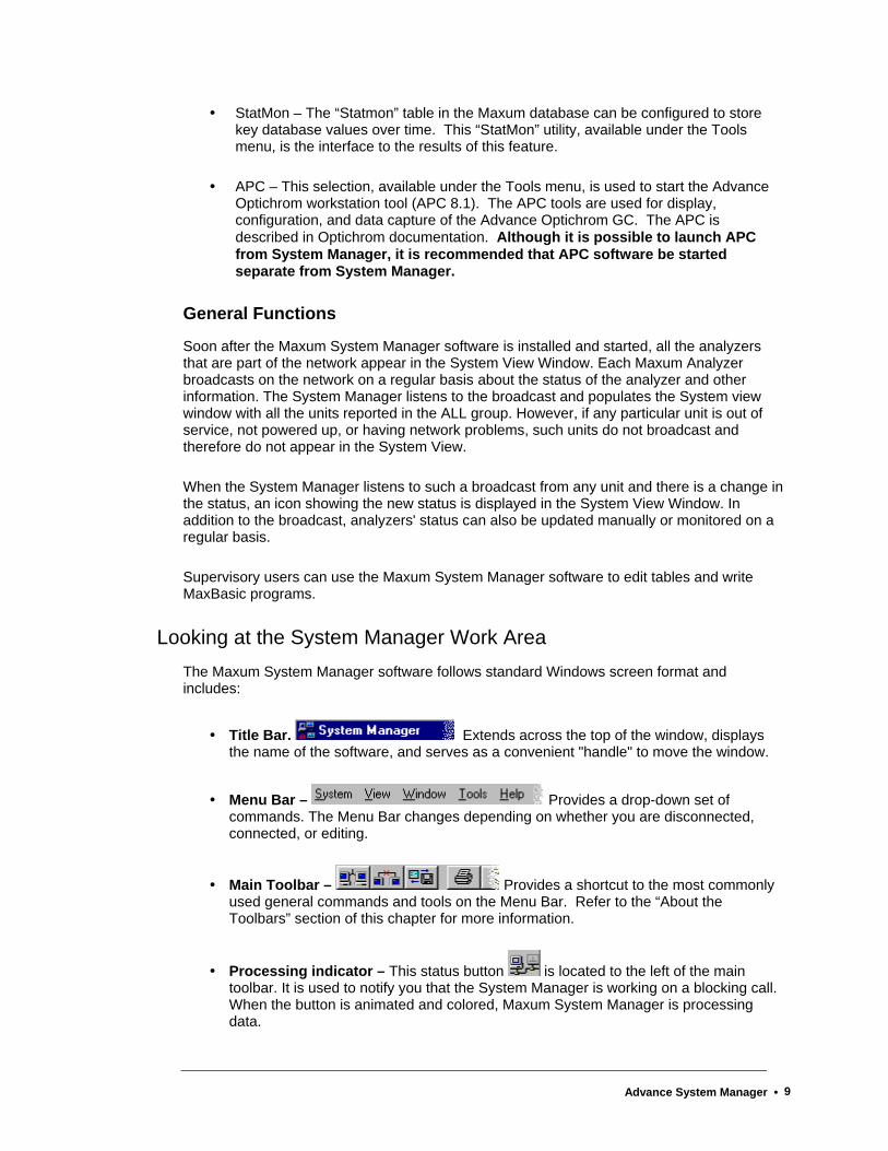
StatMon – The “Statmon” table in the Maxum database can be configured to store key database values over time. This “StatMon” utility, available under the Tools menu, is the interface to the results of this feature.
APC – This selection, available under the Tools menu, is used to start the Advance Optichrom workstation tool (APC 8.1). The APC tools are used for display, configuration, and data capture of the Advance Optichrom GC. The APC is described in Optichrom documentation. Although it is possible to launch APC from System Manager, it is recommended that APC software be started separate from System Manager.
General Functions
Soon after the Maxum System Manager software is installed and started, all the analyzers that are part of the network appear in the System View Window. Each Maxum Analyzer broadcasts on the network on a regular basis about the status of the analyzer and other information. The System Manager listens to the broadcast and populates the System view window with all the units reported in the ALL group. However, if any particular unit is out of service, not powered up, or having network problems, such units do not broadcast and therefore do not appear in the System View.
When the System Manager listens to such a broadcast from any unit and there is a change in the status, an icon showing the new status is displayed in the System View Window. In addition to the broadcast, analyzers' status can also be updated manually or monitored on a regular basis.
Supervisory users can use the Maxum System Manager software to edit tables and write MaxBasic programs.
Looking at the System Manager Work Area The Maxum System Manager software follows standard Windows screen format and includes:
Title Bar. Extends across the top of the window, displays the name of the software, and serves as a convenient "handle" to move the window.
Menu Bar – Provides a drop-down set of commands. The Menu Bar changes depending on whether you are disconnected, connected, or editing.
Main Toolbar – Provides a shortcut to the most commonly used general commands and tools on the Menu Bar. Refer to the “About the Toolbars” section of this chapter for more information.
Processing indicator – This status button is located to the left of the main toolbar. It is used to notify you that the System Manager is working on a blocking call. When the button is animated and colored, Maxum System Manager is processing data.
Advance System Manager • 9
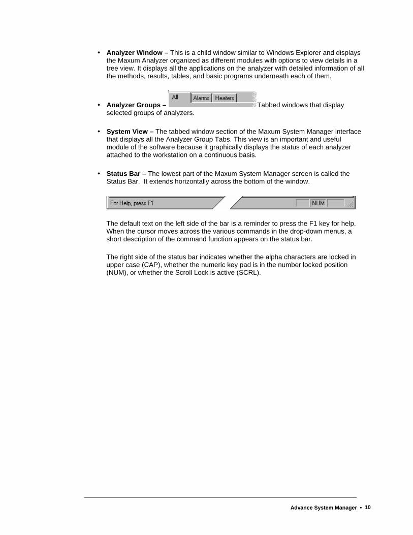
Analyzer Window – This is a child window similar to Windows Explorer and displays the Maxum Analyzer organized as different modules with options to view details in a tree view. It displays all the applications on the analyzer with detailed information of all the methods, results, tables, and basic programs underneath each of them.
Analyzer Groups – Tabbed windows that display selected groups of analyzers.
System View – The tabbed window section of the Maxum System Manager interface that displays all the Analyzer Group Tabs. This view is an important and useful module of the software because it graphically displays the status of each analyzer attached to the workstation on a continuous basis.
Status Bar – The lowest part of the Maxum System Manager screen is called the Status Bar. It extends horizontally across the bottom of the window.
The default text on the left side of the bar is a reminder to press the F1 key for help. When the cursor moves across the various commands in the drop-down menus, a short description of the command function appears on the status bar.
The right side of the status bar indicates whether the alpha characters are locked in upper case (CAP), whether the numeric key pad is in the number locked position (NUM), or whether the Scroll Lock is active (SCRL).
Advance System Manager • 10

Workstation Interface
Advance System Manager • 11

System View Window This is the lower section of the Maxum System Manager window. It is identified by a tab labeled “All” and any custom group tabs you add after installation.
If the View menu option Float System View is selected, this window can be moved around the screen and “docked” in any convenient location similar to the toolbars. The same action can be accomplished if you place the cursor on the System View window frame, click the right mouse button, and select the option from the drop-down menu. When the window is floated, it behaves like a toolbar and can be placed within the window or elsewhere on the desktop. It can also be "docked" on either side, top or bottom of the window itself.
The System View Window can also be hidden using the Toggle System View button when performing a maintenance task, but the window is generally in view for instant status review. Icons on the window represent the analyzers and show their status.
Every unit that is part of the network is represented on the All tab. Depending on the System View Style, the name of the unit and the Internet Protocol (IP) address is displayed either below the icon or beside it.
A "quick menu" is also available in this window using the right mouse button. Position the cursor on an analyzer icon and click the right mouse button to see a menu that includes the Update Unit command.
.
Advance System Manager • 12
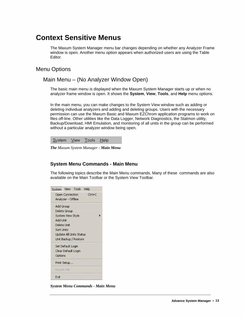
Context Sensitive Menus The Maxum System Manager menu bar changes depending on whether any Analyzer Frame window is open. Another menu option appears when authorized users are using the Table Editor.
Menu Options
Main Menu – (No Analyzer Window Open) The basic main menu is displayed when the Maxum System Manager starts up or when no analyzer frame window is open. It shows the System, View, Tools, and Help menu options.
In the main menu, you can make changes to the System View window such as adding or deleting individual analyzers and adding and deleting groups. Users with the necessary permission can use the Maxum Basic and Maxum EZChrom application programs to work on files off-line. Other utilities like the Data Logger, Network Diagnostics, the Statmon utility, Backup/Download, HMI Emulation, and monitoring of all units in the group can be performed without a particular analyzer window being open.
The Maxum System Manager - Main Menu
System Menu Commands - Main Menu
The following topics describe the Main Menu commands. Many of these commands are also available on the Main Toolbar or the System View Toolbar.
System Menu Commands - Main Menu
Advance System Manager • 13
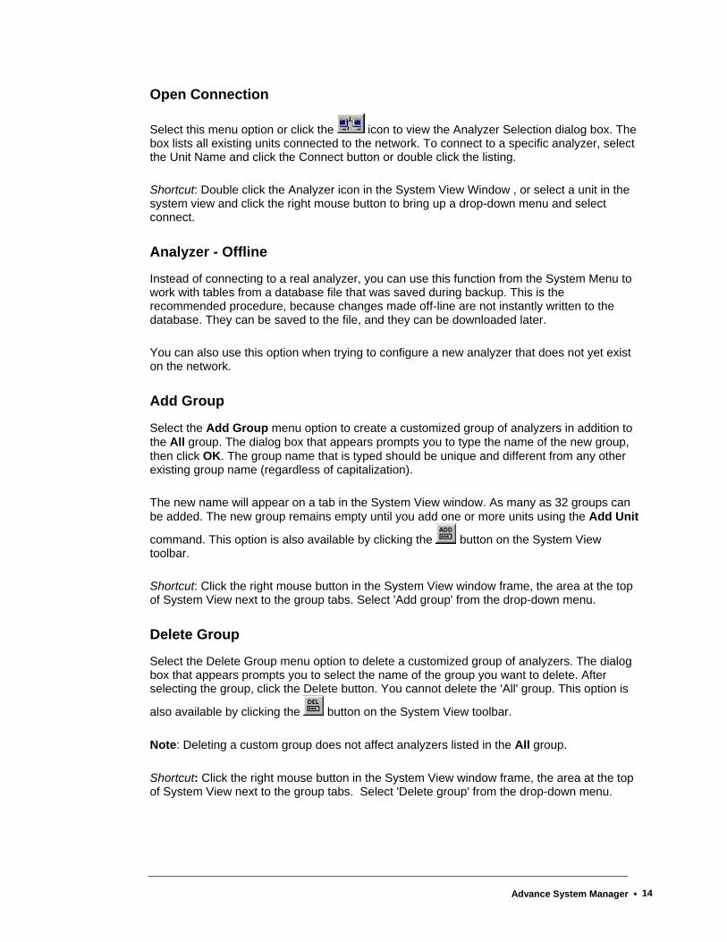
Open Connection
Select this menu option or click the icon to view the Analyzer Selection dialog box. The box lists all existing units connected to the network. To connect to a specific analyzer, select the Unit Name and click the Connect button or double click the listing.
Shortcut: Double click the Analyzer icon in the System View Window , or select a unit in the system view and click the right mouse button to bring up a drop-down menu and select connect.
Analyzer - Offline
Instead of connecting to a real analyzer, you can use this function from the System Menu to work with tables from a database file that was saved during backup. This is the recommended procedure, because changes made off-line are not instantly written to the database. They can be saved to the file, and they can be downloaded later.
You can also use this option when trying to configure a new analyzer that does not yet exist on the network.
Add Group
Select the Add Group menu option to create a customized group of analyzers in addition to the All group. The dialog box that appears prompts you to type the name of the new group, then click OK. The group name that is typed should be unique and different from any other existing group name (regardless of capitalization).
The new name will appear on a tab in the System View window. As many as 32 groups can be added. The new group remains empty until you add one or more units using the Add Unit
command. This option is also available by clicking the button on the System View toolbar.
Shortcut: Click the right mouse button in the System View window frame, the area at the top of System View next to the group tabs. Select 'Add group' from the drop-down menu.
Delete Group
Select the Delete Group menu option to delete a customized group of analyzers. The dialog box that appears prompts you to select the name of the group you want to delete. After selecting the group, click the Delete button. You cannot delete the 'All' group. This option is
also available by clicking the button on the System View toolbar.
Note: Deleting a custom group does not affect analyzers listed in the All group.
Shortcut: Click the right mouse button in the System View window frame, the area at the top of System View next to the group tabs. Select 'Delete group' from the drop-down menu.
Advance System Manager • 14
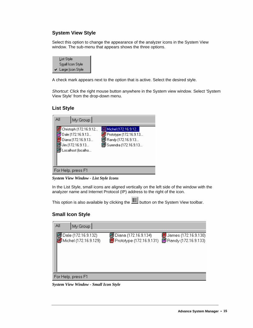
System View Style
Select this option to change the appearance of the analyzer icons in the System View window. The sub-menu that appears shows the three options.
A check mark appears next to the option that is active. Select the desired style.
Shortcut: Click the right mouse button anywhere in the System view window. Select 'System View Style' from the drop-down menu.
List Style
System View Window - List Style Icons
In the List Style, small icons are aligned vertically on the left side of the window with the analyzer name and Internet Protocol (IP) address to the right of the icon.
This option is also available by clicking the button on the System View toolbar.
Small Icon Style
System View Window - Small Icon Style
Advance System Manager • 15
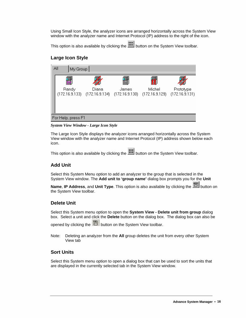
Using Small Icon Style, the analyzer icons are arranged horizontally across the System View window with the analyzer name and Internet Protocol (IP) address to the right of the icon.
This option is also available by clicking the button on the System View toolbar.
Large Icon Style
System View Window - Large Icon Style
The Large Icon Style displays the analyzer icons arranged horizontally across the System View window with the analyzer name and Internet Protocol (IP) address shown below each icon.
This option is also available by clicking the button on the System View toolbar.
Add Unit
Select this System Menu option to add an analyzer to the group that is selected in the System View window. The Add unit to ‘group name’ dialog box prompts you for the Unit
Name, IP Address, and Unit Type. This option is also available by clicking the button on the System View toolbar.
Delete Unit
Select this System menu option to open the System View - Delete unit from group dialog box. Select a unit and click the Delete button on the dialog box. The dialog box can also be
opened by clicking the button on the System View toolbar.
Note: Deleting an analyzer from the All group deletes the unit from every other System View tab
Sort Units
Select this System menu option to open a dialog box that can be used to sort the units that are displayed in the currently selected tab in the System View window.
Advance System Manager • 16

Update All Units Status
Select this command from the System Menu to request the latest broadcast information for all units that are part of the currently selected group. If the current group is the All group then all analyzers known to the System Manager will be updated. This function may also be
accessed by clicking the button on the System View Toolbar.
Unit Backup / Restore
Select this System Menu command to gain access to the Analyzer Backup/ Restore dialog box. It is not necessary for the Analyzer Frame window to be open in order to backup the database. Select the unit from the list box, and type or select a name for the backup file in the File name field. If you do not specify a file extension, the system will add the default extension of .amd.
For Backup, no security login is needed. In addition, the recommended (default) procedure saves all changes to flash, but, using the Advanced button, you have the option to instruct the system not to save recent changes before backup. When the unit and file name have been selected, click the Backup the analyzer button.
The function Restore to the analyzer, that is, to write a file to the Maxum database, is an action that is restricted to users with Super or Configure level passwords. Once the source file name has been chosen and the security options have been entered, click the “Restore to the Analyzer button.
Caution: Unit Restore is a complete download, not individual applications, and it rewrites the entire flash memory. This is an irreversible task and can crash the analyzer.
Set Default Login
Use this System Menu command to type your assigned Login name and Password. Click the Set button to complete the Login. Once you set the default login, this Login name and Password are used for logging into all the units. If you click the checkbox to save the password, the data is stored in the registry, and the System Manager uses it every time a password is requested. To clear the default login, use Clear Default Login (see below)
Reminder: Passwords are case sensitive for alphanumeric characters. However, only numeric passwords can be entered when using the HMI interface. If a password is used that includes other characters, then it will not be possible to login to the HMI with that user name.
Clear Default Login
Select this System Menu command to clear the default Login name and Password. No dialog or message box appears. As soon as the command is selected, the saved parameters are cleared. In order to do more than view the windows, you will need to type the login manually or set the default Login again.
Advance System Manager • 17
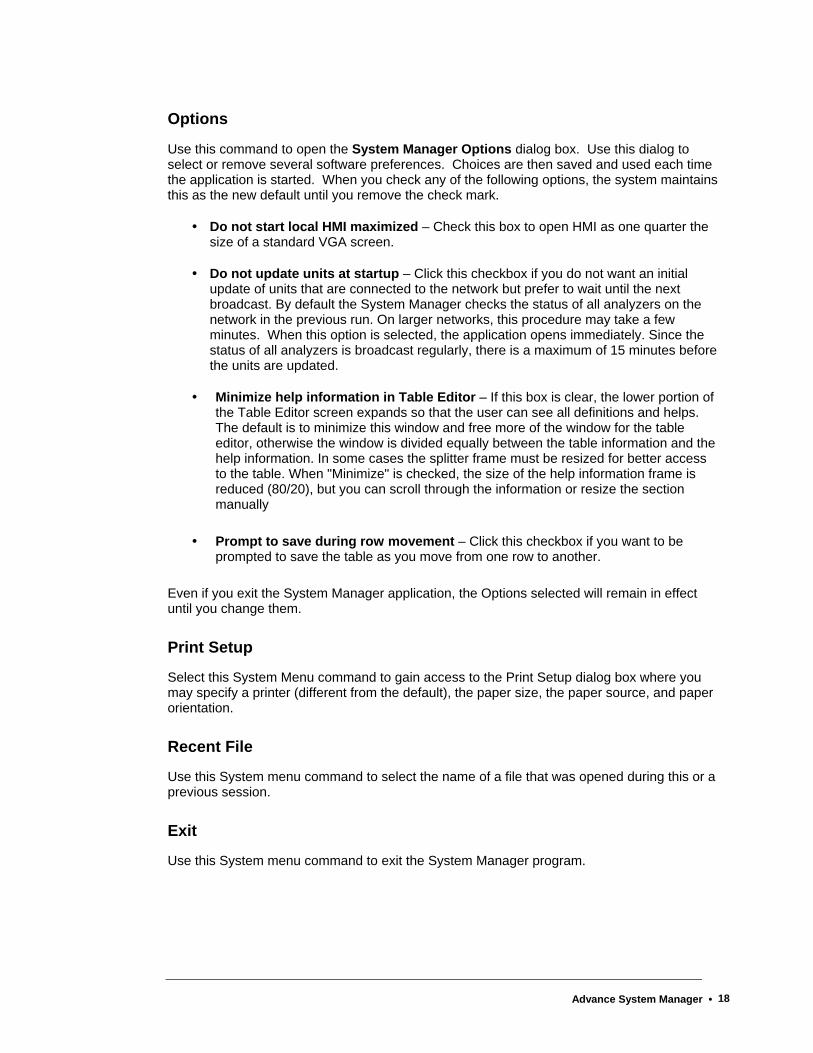
Options
Use this command to open the System Manager Options dialog box. Use this dialog to select or remove several software preferences. Choices are then saved and used each time the application is started. When you check any of the following options, the system maintains this as the new default until you remove the check mark.
Do not start local HMI maximized – Check this box to open HMI as one quarter the size of a standard VGA screen.
Do not update units at startup – Click this checkbox if you do not want an initial update of units that are connected to the network but prefer to wait until the next broadcast. By default the System Manager checks the status of all analyzers on the network in the previous run. On larger networks, this procedure may take a few minutes. When this option is selected, the application opens immediately. Since the status of all analyzers is broadcast regularly, there is a maximum of 15 minutes before the units are updated.
Minimize help information in Table Editor – If this box is clear, the lower portion of the Table Editor screen expands so that the user can see all definitions and helps. The default is to minimize this window and free more of the window for the table editor, otherwise the window is divided equally between the table information and the help information. In some cases the splitter frame must be resized for better access to the table. When "Minimize" is checked, the size of the help information frame is reduced (80/20), but you can scroll through the information or resize the section manually
Prompt to save during row movement – Click this checkbox if you want to be prompted to save the table as you move from one row to another.
Even if you exit the System Manager application, the Options selected will remain in effect until you change them.
Print Setup
Select this System Menu command to gain access to the Print Setup dialog box where you may specify a printer (different from the default), the paper size, the paper source, and paper orientation.
Recent File
Use this System menu command to select the name of a file that was opened during this or a previous session.
Exit
Use this System menu command to exit the System Manager program.
Advance System Manager • 18

View Menu Commands In the Main menu, all commands on this menu are toggle options. This means that a check mark next to the command indicates the option is “on.” By default, all toolbars and windows are checked except the Float System View (which allows the System View Window to be moved around the screen similar to a toolbar).
In addition to "floating" the System View window, use the View menu to hide the System View (window), the Main Toolbar, the System View Toolbar, the Table Editor Toolbar, and the Status Bar. Select the desired option and click it to toggle (hide / display) the selected item.
View Menu - Main Menu and Analyzer Frame Menu
The View menu is the same when an analyzer window is not open (main menus) as it is when an analyzer window is open (analyzer frame menus) .
System View
This command will show or hide the lower portion of the Maxum System Manager window. It is identified by a tab labeled "All" and any custom group tabs you add after installation.
Float System View
Select this View menu option to move and "dock" the System View Window like a toolbar. When the Float System View option is checked, you can click and drag the window anywhere on the screen. If the Maxum System Manager is not maximized, the window can be floated outside the window on the desktop. It can be dragged to either side, top, or bottom of the window itself and "docked." That is, it will connect to that area of the System Manager window.
Main Toolbar
This View menu option will show or hide the Main Toolbar (which is described earlier in this chapter.
System View Toolbar
This View menu option will show or hide the System View Toolbar (which is described later in this chapter.
Advance System Manager • 19
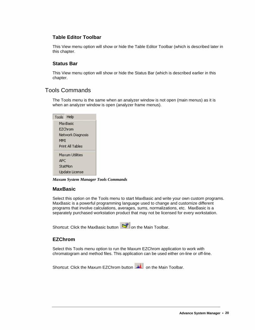
Table Editor Toolbar
This View menu option will show or hide the Table Editor Toolbar (which is described later in this chapter.
Status Bar
This View menu option will show or hide the Status Bar (which is described earlier in this chapter.
Tools Commands The Tools menu is the same when an analyzer window is not open (main menus) as it is when an analyzer window is open (analyzer frame menus).
Maxum System Manager Tools Commands
MaxBasic
Select this option on the Tools menu to start MaxBasic and write your own custom programs. MaxBasic is a powerful programming language used to change and customize different programs that involve calculations, averages, sums, normalizations, etc. MaxBasic is a separately purchased workstation product that may not be licensed for every workstation.
Shortcut: Click the MaxBasic button on the Main Toolbar.
EZChrom
Select this Tools menu option to run the Maxum EZChrom application to work with chromatogram and method files. This application can be used either on-line or off-line.
Shortcut: Click the Maxum EZChrom button on the Main Toolbar.
Advance System Manager • 20

Network Diagnosis
If there are concerns about an analyzer's network response, select this option to run the Network Diagnosis. Refer to the Network Diagnosis section later in this chapter for more information.
Shortcut: Click the Network Diagnosis button on the Main Toolbar.
HMI
Select this Tools menu option to view an HMI window for a selected unit. Use the mouse to click the buttons and make selections to perform tasks as if you were using the physical Maintenance Panel (HMI) device.
Shortcut: Click the HMI button on the Main Toolbar.
Print All Tables
Select this option on the Tools menu to print all the table information for tables that are available in the System Manager. You are prompted to select the analyzer of interest from a list of existing analyzers. System Manager connects to the analyzer, downloads the information, and prints each table sequentially.
As a rule, the default selections are acceptable, but you have the option of changing both Page Setup and Header/Footer Setup. The “Fit to page width” and “Landscape” checkbox options are especially useful and recommended.
Maxum Utilities
This option launches the Maxum Utilities software from within the Maxum System Manager workstation software. Maxum Utilities includes a set of additional Maxum tools including Software Upgrade, Datalogger, and database loaders. Maxum Utilities can be run independently from outside the System Manager program.
Shortcut: Click the Maxum Utilities button on the Main Toolbar.
Advance Personal Computer
This selection is used to start the Advance Optichrom workstation tool (APC 8.1). The APC tools are used for display, configuration, and data capture of the Advance Optichrom GC. These tools include the Service Panel, Datalogger, Table Editor, and Chromatogram display. The APC help file can be viewed from within the APC program. The APC program can be run independently from outside the System Manager program.
Shortcut: Click the APC button on the Main Toolbar.
Advance System Manager • 21

Statmon
Select this Tools Menu item to access the results from the Statmon feature. Starting in version 4.2, the Statmon table in the database can be configured to store key database values over time. These historical archives are available on the workstation with the StatMon utility under System Manager Tools. Timestamp and status information are also available for access from the workstation. At the workstation, the data may be easily imported into Excel or printed.
Shortcut: Click the Statmon button on the Main Toolbar.
Update License
Select this Tools Menu item to update your software license for Maxum Workstation. This selection allows you to see Maxum software modules that are installed. A new software key can be entered to validate installed software.
Maxum II Analyzer Menu When you connect to an analyzer using the Menu - Open Connection function, new selections are available on the drop-down sub-menu. Also an additional drop-down sub-menu, Window, appears on the Maxum System Manager Menu bar when an analyzer window is open.
Within this manual, this modified set of menus is referred to as the Analyzer Menus.
Use the Window drop-down menu to arrange open windows or view a list of unit windows that are opened. The commands on this menu are similar to other Microsoft Windows applications. For example, Cascade stacks the open windows in an offset fashion so the title bar of each window is visible, and Tile sizes all windows proportionally such that an area of each window is visible.
The Maxum System Manager Menu – With Analyzer Connected
Advance System Manager • 22

System Menu Commands - Maxum II Analyzer Menu
When connected to an analyzer, the System drop-down menu provides the selections shown below. Many of these functions are also available on the Main Toolbar and the System View Toolbar.
Selections on this menu that are not on the Main System Menu (with no analyzers connected) are:
- Disconnect
- Login as Different User
- Add/Delete Users
- Clear Alarm
These additional options are described below.
Advance System Manager • 23

Disconnect
Select this System menu command to disconnect from a selected Analyzer. Using the
command is the same as clicking the Disconnect button on the main toolbar.
Login as different user
This System menu selection is available when connected to an analyzer and when the Analyzer window is in focus. Use the option if a user with fewer privileges has logged in and it is necessary to perform more advanced procedures (for example, supervisory functions).
Add/Delete Users
This System menu selection is available to supervisory personnel only (user level =super). It is used to authorize new users or remove authority for others.
Clear Alarm
Select this System menu option to clear a highlighted alarm for a selected analyzer, or you can press the Delete key and remove the alarm. An authorized password is required to clear alarms.
Window - Commands This additional menu entry appears when the Maxum System Manager has an analyzer window open or when editing a table. Most of the commands are similar to the standards set for all Microsoft Windows software applications. The selections available on this menu are:
Window Menu - Maxum II Analyzer Menu
The name(s) of open analyzer window(s) appear as the last entries on this menu. If the windows are maximized, use this menu to switch from one window to another.
Window Menu - Table Editor Mode
When editing tables, the New Window option is not available, but the name(s) of open analyzer window(s) and table(s) are displayed.
Advance System Manager • 24

New Window
This option creates a duplicate of the selected unit window.
Cascade
This option stacks the open windows in an offset fashion so the title bar of each window is visible. This is the function when you want to see windows in a large size and switch easily between different windows.
Tile
This option sizes all windows proportionally such that an area of each window is visible. This is the function to use when you want to see all windows at the same time.
Arrange Icons
Arrange icons at the bottom of the client area in the main window. The icons here represent any minimized child windows (such as analyzer windows or table windows) and not the icons in the System View Window.
Table Editor Menu
Menu - Edit The Edit menu appears on the Maxum System Manager menu bar when you open a table. The commands on the Edit menu are available so that users may change, add, or delete information in the table as well as re-query the database for updated information.
The Maxum System Manager Menu – While Editing Tables
Advance System Manager • 25
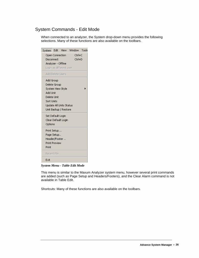
System Commands - Edit Mode When connected to an analyzer, the System drop-down menu provides the following selections. Many of these functions are also available on the toolbars.
System Menu - Table Edit Mode
This menu is similar to the Maxum Analyzer system menu, however several print commands are added (such as Page Setup and Headers/Footers), and the Clear Alarm command is not available in Table Edit.
Shortcuts: Many of these functions are also available on the toolbars.
Advance System Manager • 26

Page Setup
Select this System menu command to configure the print format of a table. The default options for Page Setup are recommended for most situations.
If changes are made, a Preview window reflects the changes to help you visualize the configuration. You may change or specify the following:
- All margins
- Options for titles and gridlines (print or omit)
- Page Order *
- Center vertically or horizontally on the page
- Save special settings for future use
* Many tables exceed the page size. The recommended procedure is to print the balance of a truncated row before continuing with the next rows.
Header/Footer
Select this System menu command to activate the dialog box to add headers and footers to the print format of a table. Access to the Header/Footer dialog box is available on the System menu only when working in Table Editor mode. Headers and footers are used when printing tables. As a rule, the Header and Footer default options are satisfactory. That is, a centered title in the header with the date and page number in the footer at the left and right margins.
Use the Header/Footer dialog to change or specify:
- Font type and size
- Alignment on the page
- Contents of headers or footers
- Proximity of headers or footers to the table frame
- Different starting page numbers
- Save special settings for future use
The format symbols (such as $D to represent date) follow general document print specifications.
Print Preview
Select this System menu command to see a full page representation of the table, logs, or other reports before sending them to print.
Select this System menu command to send the selected items to the printer.
Advance System Manager • 27
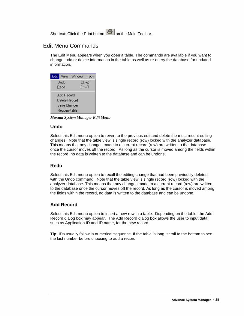
Shortcut: Click the Print button on the Main Toolbar.
Edit Menu Commands The Edit Menu appears when you open a table. The commands are available if you want to change, add or delete information in the table as well as re-query the database for updated information.
Maxum System Manager Edit Menu
Undo
Select this Edit menu option to revert to the previous edit and delete the most recent editing changes. Note that the table view is single record (row) locked with the analyzer database. This means that any changes made to a current record (row) are written to the database once the cursor moves off the record. As long as the cursor is moved among the fields within the record, no data is written to the database and can be undone.
Redo
Select this Edit menu option to recall the editing change that had been previously deleted with the Undo command. Note that the table view is single record (row) locked with the analyzer database. This means that any changes made to a current record (row) are written to the database once the cursor moves off the record. As long as the cursor is moved among the fields within the record, no data is written to the database and can be undone.
Add Record
Select this Edit menu option to insert a new row in a table. Depending on the table, the Add Record dialog box may appear. The Add Record dialog box allows the user to input data, such as Application ID and ID name, for the new record.
Tip: IDs usually follow in numerical sequence. If the table is long, scroll to the bottom to see the last number before choosing to add a record.
Advance System Manager • 28

Delete Record
Select the Delete Record command from the Edit menu to remove a row of data from a table.
To delete a record, first select the row by moving the cursor to the leftmost column of the table (called the row header)> When the cursor changes to a black arrow ( ), click the left mouse button. The row will be highlighted in reverse video. Then select the Delete Record command from the Edit Menu.
The record is displayed with strike-through marks until you update or exit the table. Delete Record cannot be reversed with the Undo command. If you want to restore the record, use the Add Record command and re-type the information.
Note: Records are permanently deleted from the database. When you delete a record, a dialog box will remind you that this is a permanent change and ask for confirmation to continue, but the Save Changes dialog box does not appear when you exit the Table.
Save Changes
Select the Save Changes command from the Edit Menu when you have made changes to a table record. If you are editing several records, the change is saved as soon as you click a different record. Unless saved, changes are not committed to the database, and the Table reverts to the previous settings. If you exit a Table without selecting the Save Changes command, a dialog box prompts you to save changes.
Shortcut: Click on the Table Editor Toolbar to save changes.
Requery Table
Use this Edit menu selection when working in the table editor. The Requery function will refresh the database with any entries made by others since you have opened the table.
Shortcut: Click the Requery Table button on the Table Editor Toolbar.
Advance System Manager • 29
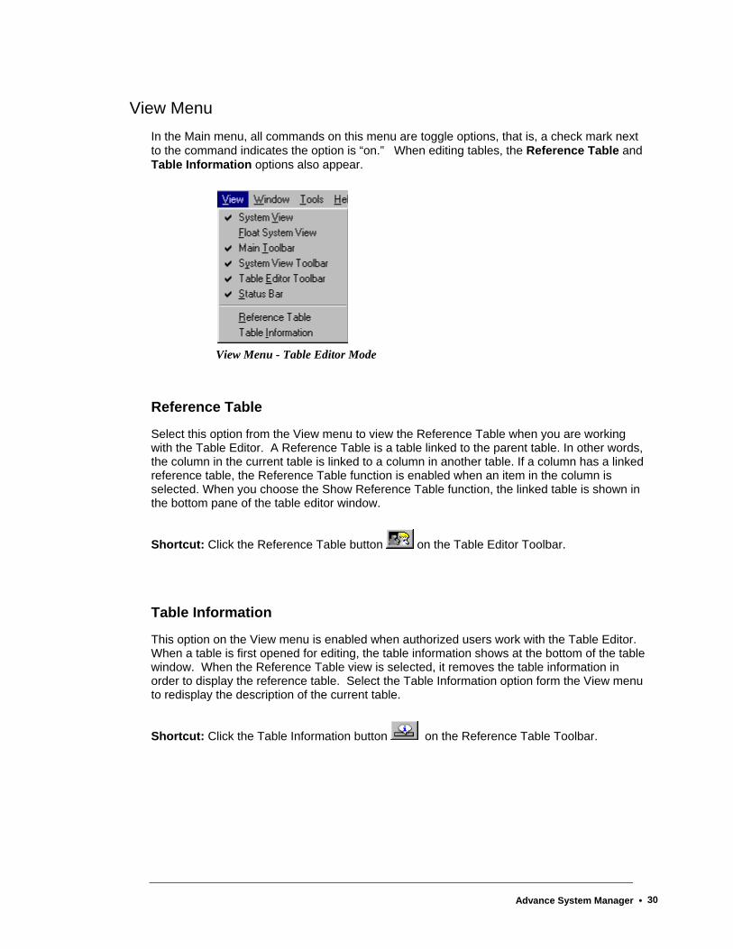
View Menu In the Main menu, all commands on this menu are toggle options, that is, a check mark next to the command indicates the option is “on.” When editing tables, the Reference Table and Table Information options also appear.
View Menu - Table Editor Mode
Reference Table
Select this option from the View menu to view the Reference Table when you are working with the Table Editor. A Reference Table is a table linked to the parent table. In other words, the column in the current table is linked to a column in another table. If a column has a linked reference table, the Reference Table function is enabled when an item in the column is selected. When you choose the Show Reference Table function, the linked table is shown in the bottom pane of the table editor window.
Shortcut: Click the Reference Table button on the Table Editor Toolbar.
Table Information
This option on the View menu is enabled when authorized users work with the Table Editor. When a table is first opened for editing, the table information shows at the bottom of the table window. When the Reference Table view is selected, it removes the table information in order to display the reference table. Select the Table Information option form the View menu to redisplay the description of the current table.
Shortcut: Click the Table Information button on the Reference Table Toolbar.
Advance System Manager • 30

Toolbars About the Toolbars
The Maxum System Manager software contains three separate tool bars. Any toolbar can be moved around the screen and positioned where it is convenient for you.
Main Toolbar The Maxum System Manager Main Toolbar contains buttons that perform various system functions such as connecting and disconnecting with analyzers, as well as launching various utilities. Also included are print and help buttons.
This toolbar can be moved so that it appears to “float” anywhere on the screen. Position the cursor on a blank area of the toolbar (not on a button), click and drag the toolbar across the screen to a different location. To restore it to the original position, double click the title bar.
The Main toolbar is pictured below. Descriptions of the various buttons are included in previous sections of this chapter.
The Maxum System Manager Main Toolbar
System View Toolbar
The System View Toolbar in Maxum System Manager contains buttons that perform various functions related to the System View Window. This includes adding and deleting groups, adding and deleting analyzers, modifying the type of icons used (e.g. large or small icons), updating the status, and turning the System View window on and off.
Like the Main Toolbar, the System View Toolbar can also be moved and “floated” anywhere on the screen. Position the cursor on a blank area of the toolbar (not on a button), click and drag the toolbar across the screen to a different location. To restore it to the original position, double click on the title bar .
The System View toolbar is pictured below. Descriptions of the various buttons are included in previous sections of this chapter.
The Maxum System Manager System View Toolbar
Advance System Manager • 31

Table Editor Toolbar The Maxum System Manager Table Editor Toolbar contains buttons that are used when editing a table. These buttons will only be active when a table is opened for editing. The functions include common edit functions like cut, copy, paste, and save. Commands specific to editing of Maxum tables are also included. These are table reference, table information, add record, and re-query table.
This toolbar can be moved so that it appears to “float” anywhere on the screen. Position the cursor on a blank area of the toolbar (not on a button), click and drag the toolbar across the screen to a different location. To restore it to the original position, double click on the title bar.
The Table Editor toolbar is pictured below. With the exception of Cut, Copy, and Paste, the descriptions of the various buttons are included in previous sections of this chapter. The Cut, Copy, and Paste functions in System Manger are similar to the Cut, Copy, and Paste functions of other windows programs.
The Maxum System Manager Table Editor Toolbar
Advance System Manager • 32
How To Use the Maxum System Manager Add a Group
At times it is convenient to limit the number of analyzers that are monitored. Up to 32 different groups can be added to the System View Window.
To create a group tab that will contain your selection of Analyzers, follow these steps:
1. Click the Add Group button on the System View Toolbar.
2. Type the name of the new group in the New Group dialog box. The name should be unique and different (case insensitive) from all other group names.
3. Click OK.
4. Your new group appears as the next tab on the System View Window.
NOTE: This new group is empty until you add Analyzers. For more information, see Add a Unit.
Add a Record If you want to add a new row (record) to a table, follow these steps:
1. Open the desired analyzer. On the left frame of the analyzer window, select the type of table (system tables, or tables within an application).
2. In the right frame of the analyzer window, double click the name of the table you wish to edit. If you're not logged in, the Login dialog box will request user name and password.
3. When the table window appears, click the Add Record button on the Table Editor toolbar or select Add Record from the Edit menu.
4. If necessary, type the requested information in the Add Record dialog box, and click OK.
5. The new record is added to the table.
Make the desired modifications to other fields in this new record as needed, and save the changes. You will be prompted to save the records to the database.
Note: Some tables cannot be edited. If the Add Record or Delete Record menu commands are not enabled, it indicates that the action is either not permitted or must be performed in another way. For example, Maxum EZChrom Tables cannot be edited in the Table Editor.
Advance System Manager • 33
Add a Unit If you create a new Group, it remains “unpopulated” unless individual Analyzers are added. To Add a Unit, follow these steps:
1. In the System View window, select the group to which you would like to add an analyzer.
2. Click the Add Unit button on the System View Toolbar.
3. The Add unit to dialog box appears.
4. If the analyzer is shown in the list box at the bottom of this dialog box, double click the name. This action will add the unit and close the dialog box.
OR, to add a unit that is not listed:
5. Type the unit name in the Unit Name field. This name can be different from the Analyzer name. If you choose a name other than the Analyzer name, this new name will be shown with the unit display in the system view.
6. Type the Internet Protocol (IP) address in the Ip Address field. This should be a valid IP address in TCP/IP format. The IP address should be unique among all the configured analyzers including the analyzers in the 'ALL' group. Ask you Network Administrator if you do not know the IP address.
7. Click the arrow in the Unit type field and select one of the types from the drop-down list. Maxum, NAU and Optima units can be monitored besides the regular broadcast. Optima does not broadcast. The Maxum , Optima (through HMI emulation), and the Network Access Unit (NAU) can be edited.
NOTE: The Monitoring interval can be changed for the Maxum II, Optima, and NAU.
Assign Passwords Use the Add/Delete Users command on the System menu. This selection is visible only when an analyzer window is open and highlighted. Also, the login process should be completed and a user must have the highest authority level.
1. Select Add/Delete Users on the System Menu.
2. Click the Add User button.
3. Type the new Login and Password on the Database User - Add dialog box, then retype the password to verify.
4. Click the appropriate level of access.
Advance System Manager • 34
5. Click the Add button to return to the Users Configured in the Unit dialog box. The new user is now shown in the list box.
6. Click the Close button.
7. Any user configuration can also be changed by clicking the Update User button on the Users Configured in the Unit dialog box and making the desired revisions.
This authority is available only to those with a Super level password. When a login and password are defined, there are no minimum size requirements for the password. Passwords are case sensitive for alphanumeric characters. However, only numeric passwords can be entered when using the HMI interface. If a password is used that includes other characters, then it will not be possible to login to the HMI with that user name.
Backup/Restore Analyzer All password levels are authorized to make a backup, that is, save the analyzer database to a file. The Analyzer Frame window need not be open in order to backup the database.
Backup
1. Click the button on the Main Toolbar to start the Backup / Restore, or select Unit Backup / Restore from the System drop-down menu.
2. Select the unit to be backed up or downloaded from the list in the dialog box.
3. Type or select a name for the backup file in the File name field. If you do not specify a file extension, the system will add the default extension of .amd.
4. Click the Backup the analyzer button.
5. The Backup/Restore Report dialog informs you of the backup progress through completion.
Restore
Fill out the Analyzer Backup/Restore dialog box just as for the backup function. Once all fields are complete, click the Restore to the analyzer button to restore the analyzer. That is, to write a file to the Maxum database. This is an action that is restricted to those with Super or Configure level passwords.
Caution: Unit Restore is a complete download, not individual applications, and it rewrites the entire flash memory. This is an irreversible task.
Advance System Manager • 35
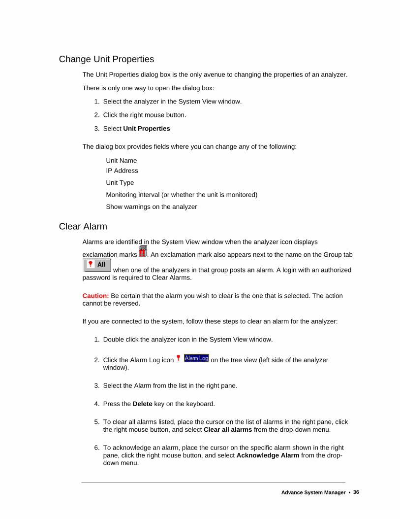
Change Unit Properties The Unit Properties dialog box is the only avenue to changing the properties of an analyzer.
There is only one way to open the dialog box:
1. Select the analyzer in the System View window.
2. Click the right mouse button.
3. Select Unit Properties
The dialog box provides fields where you can change any of the following:
Unit Name IP Address
Unit Type
Monitoring interval (or whether the unit is monitored)
Show warnings on the analyzer
Clear Alarm Alarms are identified in the System View window when the analyzer icon displays
exclamation marks . An exclamation mark also appears next to the name on the Group tab
when one of the analyzers in that group posts an alarm. A login with an authorized password is required to Clear Alarms.
Caution: Be certain that the alarm you wish to clear is the one that is selected. The action cannot be reversed.
If you are connected to the system, follow these steps to clear an alarm for the analyzer:
1. Double click the analyzer icon in the System View window.
2. Click the Alarm Log icon on the tree view (left side of the analyzer window).
3. Select the Alarm from the list in the right pane.
4. Press the Delete key on the keyboard.
5. To clear all alarms listed, place the cursor on the list of alarms in the right pane, click the right mouse button, and select Clear all alarms from the drop-down menu.
6. To acknowledge an alarm, place the cursor on the specific alarm shown in the right pane, click the right mouse button, and select Acknowledge Alarm from the drop-down menu.
Advance System Manager • 36
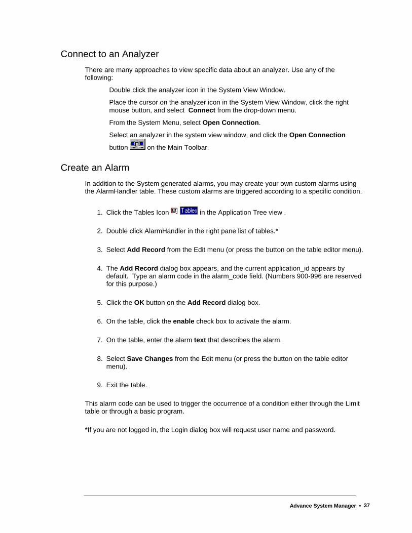
Connect to an Analyzer
There are many approaches to view specific data about an analyzer. Use any of the following:
Double click the analyzer icon in the System View Window.
Place the cursor on the analyzer icon in the System View Window, click the right mouse button, and select Connect from the drop-down menu.
From the System Menu, select Open Connection.
Select an analyzer in the system view window, and click the Open Connection
button on the Main Toolbar.
Create an Alarm In addition to the System generated alarms, you may create your own custom alarms using the AlarmHandler table. These custom alarms are triggered according to a specific condition.
1. Click the Tables Icon in the Application Tree view .
2. Double click AlarmHandler in the right pane list of tables.*
3. Select Add Record from the Edit menu (or press the button on the table editor menu).
4. The Add Record dialog box appears, and the current application_id appears by default. Type an alarm code in the alarm_code field. (Numbers 900-996 are reserved for this purpose.)
5. Click the OK button on the Add Record dialog box.
6. On the table, click the enable check box to activate the alarm.
7. On the table, enter the alarm text that describes the alarm.
8. Select Save Changes from the Edit menu (or press the button on the table editor menu).
9. Exit the table.
This alarm code can be used to trigger the occurrence of a condition either through the Limit table or through a basic program.
*If you are not logged in, the Login dialog box will request user name and password.
Advance System Manager • 37
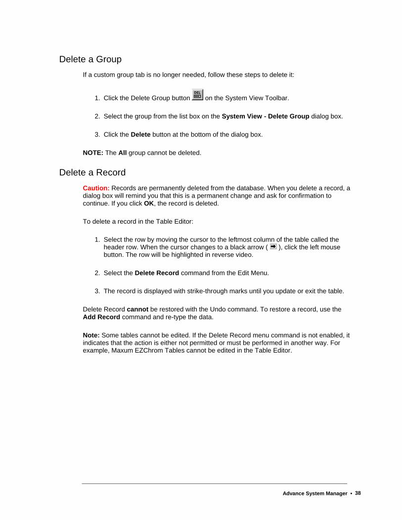
Delete a Group
If a custom group tab is no longer needed, follow these steps to delete it:
1. Click the Delete Group button on the System View Toolbar.
2. Select the group from the list box on the System View - Delete Group dialog box.
3. Click the Delete button at the bottom of the dialog box.
NOTE: The All group cannot be deleted.
Delete a Record Caution: Records are permanently deleted from the database. When you delete a record, a dialog box will remind you that this is a permanent change and ask for confirmation to continue. If you click OK, the record is deleted.
To delete a record in the Table Editor:
1. Select the row by moving the cursor to the leftmost column of the table called the header row. When the cursor changes to a black arrow ( ), click the left mouse button. The row will be highlighted in reverse video.
2. Select the Delete Record command from the Edit Menu.
3. The record is displayed with strike-through marks until you update or exit the table.
Delete Record cannot be restored with the Undo command. To restore a record, use the Add Record command and re-type the data.
Note: Some tables cannot be edited. If the Delete Record menu command is not enabled, it indicates that the action is either not permitted or must be performed in another way. For example, Maxum EZChrom Tables cannot be edited in the Table Editor.
Advance System Manager • 38

Delete a Unit If you wish to remove specific analyzers from a group, follow these steps:
1. Click the Delete Unit button on the System View Toolbar.
2. Select the desired unit from the list box on the Delete unit from group dialog box.
3. Click the Delete button.
NOTE: Deleting a unit from a custom group does not remove it from the All group. If you delete a unit from the All group, the unit is deleted from the All group as well as any custom groups. However, any unit removed from the All group may reappear within ten minutes -- at the next broadcast.
Edit Unit Properties
If a Unit Name, IP Address, or Unit Type changes, use the Unit Properties dialog box to edit them. Refer to the Change Unit Properties information described earlier in this chapter.
Move Toolbars
The Maxum System Manager toolbar appears to be a single unit, but it can be separated into the Main Toolbar, System View Toolbar, and the Table Editor Toolbar. To separate or move a toolbar, follow these steps:
1. Point to a blank area of the toolbar either between or below the buttons.
2. Click and hold the left mouse button.
3. Drag the toolbar to either side or to the top or bottom to “dock” it to that area of the window,
or (to “float” toolbar elsewhere on the screen)
4. Perform steps 1 and 2 and then position the toolbar so it "floats” in a location on the window that is convenient to your work.
5. To return a “floating” toolbar to the default position, double click the title bar.
Advance System Manager • 39
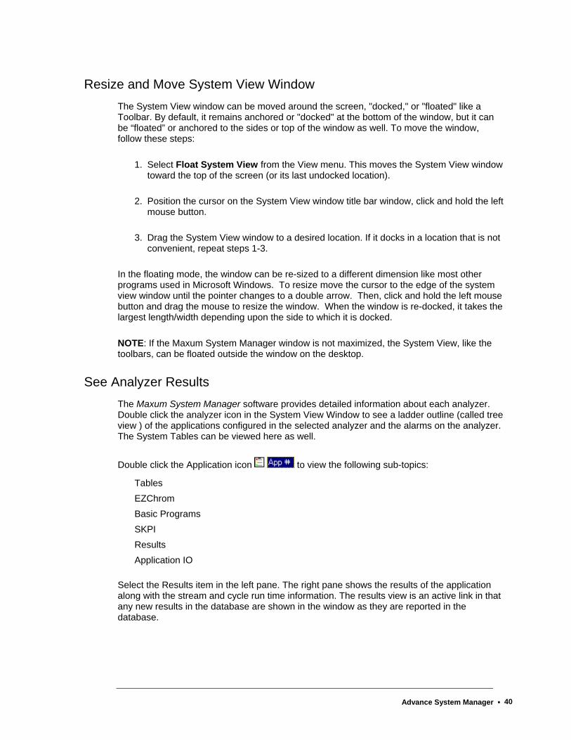
Resize and Move System View Window The System View window can be moved around the screen, "docked," or "floated" like a Toolbar. By default, it remains anchored or "docked" at the bottom of the window, but it can be “floated” or anchored to the sides or top of the window as well. To move the window, follow these steps:
1. Select Float System View from the View menu. This moves the System View window toward the top of the screen (or its last undocked location).
2. Position the cursor on the System View window title bar window, click and hold the left mouse button.
3. Drag the System View window to a desired location. If it docks in a location that is not convenient, repeat steps 1-3.
In the floating mode, the window can be re-sized to a different dimension like most other programs used in Microsoft Windows. To resize move the cursor to the edge of the system view window until the pointer changes to a double arrow. Then, click and hold the left mouse button and drag the mouse to resize the window. When the window is re-docked, it takes the largest length/width depending upon the side to which it is docked.
NOTE: If the Maxum System Manager window is not maximized, the System View, like the toolbars, can be floated outside the window on the desktop.
See Analyzer Results The Maxum System Manager software provides detailed information about each analyzer. Double click the analyzer icon in the System View Window to see a ladder outline (called tree view ) of the applications configured in the selected analyzer and the alarms on the analyzer. The System Tables can be viewed here as well.
Double click the Application icon to view the following sub-topics:
Tables EZChrom Basic Programs SKPI Results Application IO
Select the Results item in the left pane. The right pane shows the results of the application along with the stream and cycle run time information. The results view is an active link in that any new results in the database are shown in the window as they are reported in the database.
Advance System Manager • 40

Set Alarm Limits Add a limit to place references on IO, results, and external results tables.
1. Click the Tables Icon in the Application Tree view.
2. Double click the Limit table in the right pane list of tables.*
3. Select Add Record from the Edit menu.
4. The current application_id appears by default.
5. Type a limit_id of your own choosing.
6. Click the desired limit field(s) to complete the row.
7. Select Save Changes from the Edit menu.
8. Exit the table.
* If you are not logged in, the Login dialog box will request user name and password.
Use Data Logger Use the Data Logger to log the results of the methods running on any analyzer in a text file format. This text file about a specific application, stream, and unit can be used for reports or analysis.
1. Click the Maxum Utilities button on the toolbar to open Maxum Utilities. Alternatively, Maxum Utilities can be opened form the tools menu of System Manager.
2. In Maxum Utilities, select the New Log Setup on the DataLogger menu.
3. Select the IP address of the analyzer from the drop-down list in the Ip Address field, and click OK.
4. Click the check box(s) of the desired applications and streams to be logged, and click the OK button.
5. The files are saved in the Results Directory under the Maxum System Manager directory, for example: C:\MaxumSystemManager\Results. The default file name format is: [analyzer name]-[application number]-[stream number].txt
Once set up, the Data Logger starts logging the data until the user stops it. Data Logger can be run in the background even when the System Manager is closed. When the System Manager Options “Start and Stop Data Logger by default” checkbox is selected, the Data Logger starts logging data on all units previously configured as soon as the System Manager is launched.
To change or stop data logging of any unit, select Modify Log Setup. More detailed instructions for Data Logger are available in the Help function within Maxum Utilities.
Advance System Manager • 41
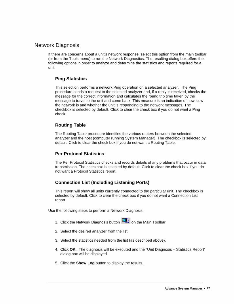
Network Diagnosis If there are concerns about a unit's network response, select this option from the main toolbar (or from the Tools menu) to run the Network Diagnostics. The resulting dialog box offers the following options in order to analyze and determine the statistics and reports required for a unit.
Ping Statistics
This selection performs a network Ping operation on a selected analyzer. The Ping procedure sends a request to the selected analyzer and, if a reply is received, checks the message for the correct information and calculates the round trip time taken by the message to travel to the unit and come back. This measure is an indication of how slow the network is and whether the unit is responding to the network messages. The checkbox is selected by default. Click to clear the check box if you do not want a Ping check.
Routing Table
The Routing Table procedure identifies the various routers between the selected analyzer and the host (computer running System Manager). The checkbox is selected by default. Click to clear the check box if you do not want a Routing Table.
Per Protocol Statistics
The Per Protocol Statistics checks and records details of any problems that occur in data transmission. The checkbox is selected by default. Click to clear the check box if you do not want a Protocol Statistics report.
Connection List (Including Listening Ports)
This report will show all units currently connected to the particular unit. The checkbox is selected by default. Click to clear the check box if you do not want a Connection List report.
Use the following steps to perform a Network Diagnosis.
1. Click the Network Diagnosis button on the Main Toolbar
2. Select the desired analyzer from the list
3. Select the statistics needed from the list (as described above).
4. Click OK. The diagnosis will be executed and the “Unit Diagnosis – Statistics Report” dialog box will be displayed.
5. Click the Show Log button to display the results.
Advance System Manager • 42

Advance System Manager • 43
Database and Tables About the Maxum II Database
The database of the Maxum II consists of a set of tables. These tables provide storage, both temporary and permanent, for all inputs and outputs of the Analyzer. They also store the configuration of that Analyzer.
Each table contains records (also called occurrences or rows) of data (attributes or columns) and functionality (scripts) that are associated with the attributes. When the data (attributes) change in value, the scripts cause actions to occur. Action also occurs when the system is activated and when records are created or deleted.
Maxum System Manager Database Uses Maxum System Manager is the workstation software tool and is used for application configuration and network monitoring. Specific uses include querying and editing certain key database tables and organizing them by table name. All supported analyzers appear in the bottom of the window as they broadcast on the network. The database can be viewed in two modes: Static and Dynamic.
Static: When the data from a database query is captured at the instant of the query and does not change, it is termed static. The table must be re-queried by some user action to see changes that may have occurred. Most of the system Manager table views are static. Static Mode is like a snapshot.
Dynamic: When the data from a database query changes automatically as changes occur in the database, it is termed dynamic. The following dynamic queries are maintained:
Alarm Log
Recent Results
System view (analyzer icon list at the bottom of the window).
Data logging and HMI emulation are available but not a default. The System Manager is used primarily for configuration and high level monitoring of analyzers. It is also the site of the visual Basic program editor.
Advance System Manager • 44

Viewing the Database Tables A unit selected in the System View has two types of tables. System Tables apply to all applications on a unit, and Application Tables apply to a specific application.
To view or change specific information in any table, double click one of the listed Table Names. The system prompts for a required password to open the Table Editor.
Note: When you work in Table Editor, you have a live connection to the Analyzer. After you edit the table and Save it, changes are made to the database.
System Tables
Application Tables
Advance System Manager • 45

Table Editor The Table Editor is used to configure database tables, add rows to existing tables and similar activities. Many hardware modules, like the SNE and IO, are completely "plug and play" and will automatically configure themselves. In cases where this is not true, the Table Editor is used.
The Table Editor mode is invoked when you double click a table entry in the right panel of the main window. You are prompted for a password before the grid of the Table Editor window opens. Use the Table Editor to specify the parameters of the particular table in the database.
To view the list of tables click the Tables icon in the tree view panel that displays when connected to the network.
The Options selection on the System Menu provides a way to change the default appearance of the lower Help window in the Table Editor. To minimize the size of the Help information, go to System | Options and click the checkbox for "Minimize help information in Table Editor."
Table Operating Tips Many drop-down lists are linked to other tables. When certain fields are selected, click
the Reference Table icon to view related tables.
The width of table columns can be changed. Position the cursor over a dividing line in the header row. When the cursor changes to this symbol , click and drag the column either left or right.
Advance System Manager • 46
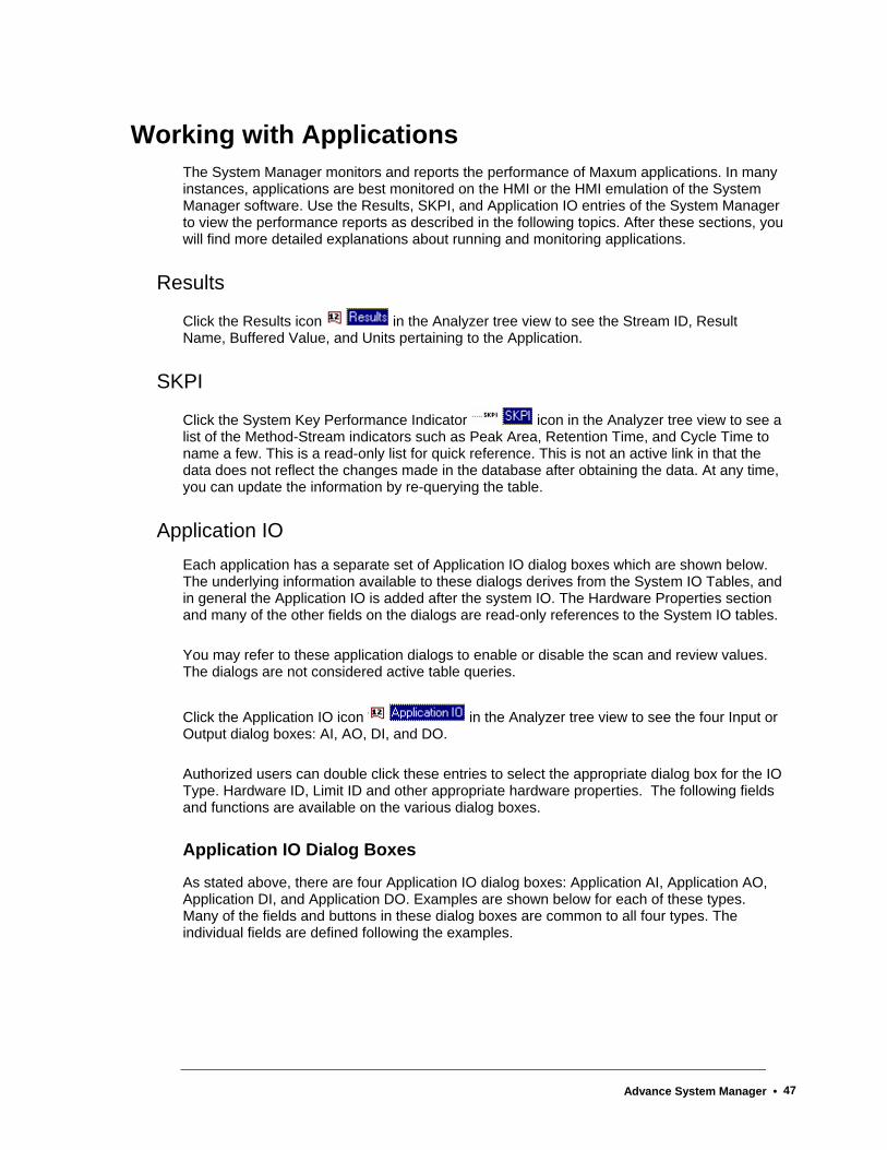
Working with Applications The System Manager monitors and reports the performance of Maxum applications. In many instances, applications are best monitored on the HMI or the HMI emulation of the System Manager software. Use the Results, SKPI, and Application IO entries of the System Manager to view the performance reports as described in the following topics. After these sections, you will find more detailed explanations about running and monitoring applications.
Results
Click the Results icon in the Analyzer tree view to see the Stream ID, Result Name, Buffered Value, and Units pertaining to the Application.
SKPI
Click the System Key Performance Indicator icon in the Analyzer tree view to see a list of the Method-Stream indicators such as Peak Area, Retention Time, and Cycle Time to name a few. This is a read-only list for quick reference. This is not an active link in that the data does not reflect the changes made in the database after obtaining the data. At any time, you can update the information by re-querying the table.
Application IO Each application has a separate set of Application IO dialog boxes which are shown below. The underlying information available to these dialogs derives from the System IO Tables, and in general the Application IO is added after the system IO. The Hardware Properties section and many of the other fields on the dialogs are read-only references to the System IO tables.
You may refer to these application dialogs to enable or disable the scan and review values. The dialogs are not considered active table queries.
Click the Application IO icon in the Analyzer tree view to see the four Input or Output dialog boxes: AI, AO, DI, and DO.
Authorized users can double click these entries to select the appropriate dialog box for the IO Type. Hardware ID, Limit ID and other appropriate hardware properties. The following fields and functions are available on the various dialog boxes.
Application IO Dialog Boxes
As stated above, there are four Application IO dialog boxes: Application AI, Application AO, Application DI, and Application DO. Examples are shown below for each of these types. Many of the fields and buttons in these dialog boxes are common to all four types. The individual fields are defined following the examples.
Advance System Manager • 47
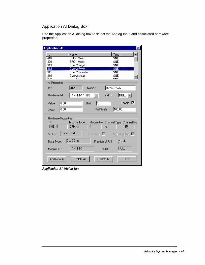
Application AI Dialog Box:
Use the Application AI dialog box to select the Analog Input and associated hardware properties.
Application AI Dialog Box
Advance System Manager • 48

Application AO Dialog Box:
Use the Application AO dialog box to select the Analog Output and associated hardware properties.
Application AO Dialog Box
Advance System Manager • 49

Application DI Dialog Box:
Use the Application DI dialog box to select the Digital Input and associated hardware properties.
Application DI Dialog Box
Advance System Manager • 50
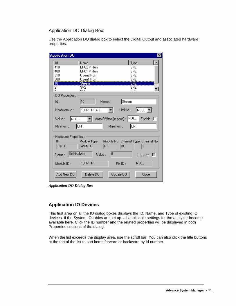
Application DO Dialog Box:
Use the Application DO dialog box to select the Digital Output and associated hardware properties.
Application DO Dialog Box
Application IO Devices
This first area on all the IO dialog boxes displays the ID, Name, and Type of existing IO devices. If the System IO tables are set up, all applicable settings for the analyzer become available here. Click the ID number and the related properties will be displayed in both Properties sections of the dialog.
When the list exceeds the display area, use the scroll bar. You can also click the title buttons at the top of the list to sort items forward or backward by Id number.
Advance System Manager • 51
Enable (check box)
Click this box to instruct the system to scan the device.
If the system encounters an error, it will disable this configuration (clear the check box). If you wish to manually stop the functionality of the device, click the box to remove the check mark.
ID
This read-only field is used to display the identification number of the selected device. If the IO is shown in the list of existing devices, click the ID number in the list display area and information will be added to the appropriate fields.
To add a new number, click the Add New button at the bottom of the dialog box. A smaller dialog prompts you for the New ID and Name that will be associated with another device. When adding a new IO, scan the list of existing names and numbers that are displayed in the list of existing devices. It is advisable to use the next number in sequence. The ID number should be unique.
Hardware ID
This number is similar to an IP address and identifies the IO device. It is a combination of the Module ID, the IO Type and the Channel number of the IO. The Hardware ID number is usually displayed in the field when a device is selected from the list at the top of the dialog box. Refer to Appendix 1 at the end of this chapter for instructions on decoding the Hardware ID.
Name
This field displays the name of the selected device. The field is can be edited, but this is generally unnecessary.
To change the name of the device, click and drag across this field and type a new name, then click the Update button. The new name will appear in the list at the top of the dialog.
Limit ID
Use this field to specify a limit that applies to the particular IO. Limits must be configured in the Limit Table prior to specifying the number in the Application IO dialog box. Once established, click the down arrow in this field and select the desired value from the drop-down list.
Value
Enter the desired value by either clicking the down arrow in this field (for digital IOs) or entering the number directly (for analog IOs). This field is typically used for reading the current value in the database. This field may also be located in the lower portion of the dialog box as a read-only field.
Advance System Manager • 52
Zero
Type a value in this field to specify the percentage value of the analog IO response which corresponds to a zero value.
Units
Specifies the unit of measurement for the selected device such as psig, degrees C, percent (%), and volts.
Full Scale
Type a value in this field to specify the value of the analog IO response which corresponds to 100%.
Minimum
This digital IO field is used to set the name displayed with the digital value is set to OFF (the minimum value). The typical input for this field is “OFF”. However, other values, such as “False” may be set.
Maximum
This digital IO field is used to set the name displayed with the digital value is set to ON (the maximum value). The typical input for this field is “ON”. However, other values, such as “True” may be set.
Injection Valve (check box)
This checkbox indicates whether a DO controls a sample injection valve. This is not usually required for injection valves. It is most commonly used when using baseline correction. During a baseline run, DO’s with Injection valve checked will not be utilized.
Averaging
This function allows averaging of AI values. The following options are available:
non-cycle - usually set to average from a MaxBasic program. Values are sent to the specific result as indicated which is updated each time a value is read.
cycle/current stream - averaging done during a cycle using the current stream using the result_index as indicated(updated at end of cycle only)
cycle/specific stream - averaging done during a cycle using the specific result and stream specified(updated at the end of the cycle only)
The Rate field is used to indicate 5, 10, or 15 second averaging (10 seconds is default). Other fields for this function are Result Output (App && Stream && Result) and Run Manual Averaging. Clicking the Apply/Refresh button on the Averaging dialog box will update the read only fields at the top of the dialog box which indicate the current averaging values.
Advance System Manager • 53
Location
This read-only field displays hardware device location for the IO (e.g. SNE 11)
Type
This read-only field displays the type of device, for example, SVCM. The information comes from the System IO tables.
Module
This read-only field displays the corresponding number of the selected device as determined in the System IO tables.
I/O Type
This read-only field verifies the type of channel, such as AO and DO. The information comes from the System IO tables.
Channel
This read-only field displays the channel number of the selected device. The information comes from the System IO tables.
Module ID
This read-only field displays the first three fields of the Hardware Id which are designated as the Module ID. It is a combination of the module location in the Electronics Enclosure and the PIC Index.
Pic ID
This read-only field displays the PIC (Programmable Integrated Circuit) setting selected in the System IO tables.
Status
This read-only field displays the status of the device, such as Normal.
Scan Rate
This read-only field displays the rate at which the database scans this IO device.
Advance System Manager • 54
Data Type
This read-only field displays a range of values that an AI or AO will read..
Exclusive (check box)
If this device is used exclusively for this application, a check mark is displayed. If the device is shared by other applications, the check box should be clear. The determination of Exclusive status is made in the System IO tables.
Pulse
This read only field indicates whether a DO is pulsed and, if yes, the duration of the pulse. A pulsed DO is turned on only for a specified period of time and is then turned back off. The Pulse field is changeable in the system table Sys_DO.
Negative Pulse (checkbox)
This read only checkbox is associated with the Pulse field for Digital Outputs. A negative pulsed DO is normally on and is turned off only for a specified period of time and is then turned back on. The Negative Pulse field is changeable in the system table Sys_DO.
Scan Enable (check box)
This box is checked if the System IO tables are configured to scan the unit on a regular basis.
Rampable (check box)
This read-only check box is for information only. It is set when you configure the method in Maxum EZChrom and is used for ramping a temperature controller in the Maxum GC. Click the check box in the System IO tables to instruct the system to ramp the temperature. Ramping temperature is used on program temperature GC or simulated distillation applications.
Add New
Click this button on any of the four AppIO dialog boxes when you wish to add information about a new IO device. New devices added here apply to this application only.
When you click the Add New button, a small dialog box prompts you for the New ID and New Name. Type the required information and click the Add button.
The new device is added to the list at the top of the dialog and to the Id and Name fields, but no hardware is attached to this new IO, and the hardware ID value will be set to NULL. You will have to select an available hardware from the list or add a new hardware IO in the SYSIO tables.
Advance System Manager • 55
Delete
Click the Delete button on any of the four AppIO dialog boxes to delete an existing IO displayed in the list box at the top of the Application IO dialog. First, select the Id number in the list box, then click the Delete IO button. If the device is not bound by a referential integrity constraint, it can be deleted.
The device listing is deleted from this application only.
Update
Click this button on any of the four Application IO dialog boxes to preserve the changes made to any of the fields that can be edited.
If, for instance, you change the Value field, and Close or exit the dialog without first clicking the Update button, the system will prompt you that "All changes will be discarded." To save the changes, click the No button on the message box and click the Update button. Then close the dialog.
Close
This button is located on all four of the Application IO dialog boxes. Click the Close button to exit the dialog box. If changes have been made and not updated, a message box prompts you that "All changes will be discarded." You have an option to return to the dialog before exiting.
Advance System Manager • 56

Maxum Utilities Maxum Utilities can be run independently from the Maxum System Manager and gives you the opportunity to continue running the utilities in the background even when System Manager is not opened and running. Use Maxum Utilities for all the functions of Data Logger and Loader.
Maxum Utilities Main Menu
Data Logger
About Data Logger
Use the Data Logger to log the Stream cycle results of any analyzer -- recorded in text format. These text files about specific applications, stream, and units can be printed and used for reports or analysis.
You can open the Maxum Utilities to use the Data Logger in any of the following ways:
• Click the Maxum Utilities button on the System Manager Main Toolbar.
• Select Maxum Utilities from the System Manager Tools Menu.
• In Windows, click the Start Button | Programs | Maxum System Tools | Maxum Utilities.
Once Maxum Utilities is open, click Data Logger on the menu and select from the drop-down options. For information about the options, click on the item in the menu below:
Advance System Manager • 57
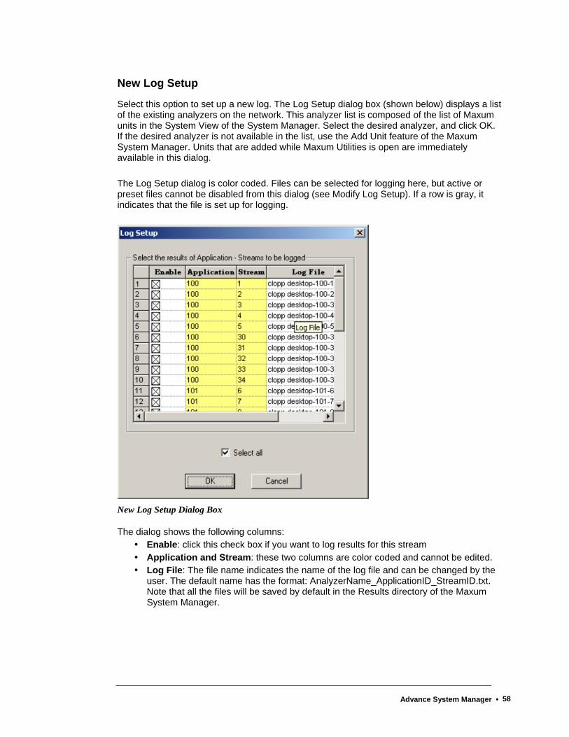
New Log Setup
Select this option to set up a new log. The Log Setup dialog box (shown below) displays a list of the existing analyzers on the network. This analyzer list is composed of the list of Maxum units in the System View of the System Manager. Select the desired analyzer, and click OK. If the desired analyzer is not available in the list, use the Add Unit feature of the Maxum System Manager. Units that are added while Maxum Utilities is open are immediately available in this dialog.
The Log Setup dialog is color coded. Files can be selected for logging here, but active or preset files cannot be disabled from this dialog (see Modify Log Setup). If a row is gray, it indicates that the file is set up for logging.
New Log Setup Dialog Box
The dialog shows the following columns: Enable: click this check box if you want to log results for this stream Application and Stream: these two columns are color coded and cannot be edited. Log File: The file name indicates the name of the log file and can be changed by the
user. The default name has the format: AnalyzerName_ApplicationID_StreamID.txt. Note that all the files will be saved by default in the Results directory of the Maxum System Manager.
Advance System Manager • 58
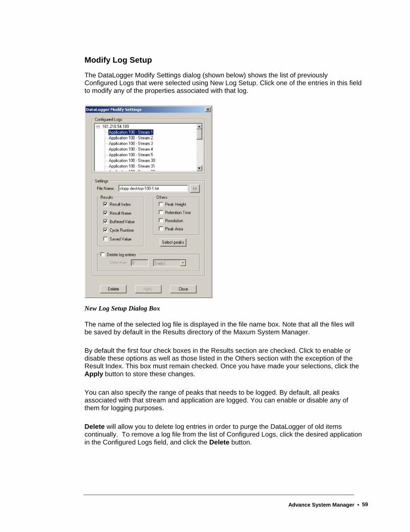
Modify Log Setup
The DataLogger Modify Settings dialog (shown below) shows the list of previously Configured Logs that were selected using New Log Setup. Click one of the entries in this field to modify any of the properties associated with that log.
New Log Setup Dialog Box
The name of the selected log file is displayed in the file name box. Note that all the files will be saved by default in the Results directory of the Maxum System Manager.
By default the first four check boxes in the Results section are checked. Click to enable or disable these options as well as those listed in the Others section with the exception of the Result Index. This box must remain checked. Once you have made your selections, click the Apply button to store these changes.
You can also specify the range of peaks that needs to be logged. By default, all peaks associated with that stream and application are logged. You can enable or disable any of them for logging purposes.
Delete will allow you to delete log entries in order to purge the DataLogger of old items continually. To remove a log file from the list of Configured Logs, click the desired application in the Configured Logs field, and click the Delete button.
Advance System Manager • 59

Open Log Data File
When Open Log Data File is selected, the Open dialog appears. The default directory for these .txt files is the Results directory. Select the file name, and click the Open button.
This action opens the text file in a grid form where you can view, modify, or print the file. All columns can be sorted in ascending or descending order by clicking on the columns. The data can also be saved to another file after necessary modifications.
Settings
The Datalogger Settings dialog box is used to customize several important performance parameters and to enable the Auto-start feature
DataLogger Settings Dialog Box
The available options are described below.
Advance System Manager • 60
Timeouts
Connect: The Connect value is the maximum time DataLogger waits for a response when attempting to connect to a device for the first time. The default value is 10 seconds.
Query: The Query value is the maximum time DataLogger waits for a response to a database query before returning an error. The default value is 202 seconds.
Disconnect: The Disconnect value is the maximum time DataLogger waits for a response when closing an open connection. The default value is 5 seconds.
Duty Cycles
Check Connections: The Check Connections value determines the frequency that open connections are tested to determine if the connection is still valid. The default value is 60 seconds.
Process Queues: The Process Queues value determines the frequency that the message queues are processed. The default value is .25 seconds (250 milliseconds). A smaller value results in the queues being processed more frequently.
Options - Auto Start:
The Auto-start check box is used to enable/disable the DataLogger auto-start feature. The Auto-start feature automatically starts Maxum Utilities \ DataLogger on Windows startup immediately after logon. When combined with an automated logon procedure DataLogger will automatically recover from a power outage or system reboot without user intervention. However, Windows automated logon may violate your company’s network security rules. For more information concerning automatic logon refer to the topic in the Maxum Utilities help file, “How to Automate the Logon Process”.
When Auto-start is enabled DataLogger automatically modifies the Windows Registry to start Maxum Utilities after logon. When the feature is disabled the modifications are removed from the registry.
Specifically, when the feature is enabled a value is added to the HKEY_LOCAL_MACHINE\Software\Microsoft\Windows\CurrentVersion\Run key named SAAMaxumUtilities. The value data field points to the MaxumUtilities.exe file. When the feature is disabled the value is deleted from under the \Run key.
If DataLogger is running please note the message above the OK button. You must stop and restart Data Logger for the changes to take affect. Any changes you make on the Datalogger Settings dialog box will be stored after clicking the OK button. If DataLogger is currently running the changes will not take affect until the next time DataLogger is stopped and re-started.
Advance System Manager • 61
Start DataLogger
Once a Log File is set up and modified (if needed), select Start DataLogger from the menu to begin logging the data. This action starts the Server and logs all the data from all configured application-stream sets. If you want to start a single analyzer-application-stream log, do a right mouse click on the analyzer-application-stream icon in the data logger view and select the "Start Logging" from the drop-down menu. The icon turns from gray to green to indicate that logging is performed on that analyzer-application-stream set.
The server makes a request to each analyzer database to inform the end of cycle event of that application-stream set. On receiving a report from the database, the server queries the database about the results and logs them to a file using a tab de-limited format. You can stop the action by selecting Stop DataLogger from the menu.
Stop DataLogger
Select this option to shut down the logger. Note that all the logs currently enabled will be stopped. If you want to stop a single analyzer-application-stream log, do a right mouse click on the analyzer-application-stream icon in the data logger view and select the "Stop Logging" from the drop-down menu. The icon turns from green back to gray. This indicates that logging is no longer performed on that analyzer-application-stream set.
To run the data logger in the background, close the application without stopping the data logger. The application displays a prompt that asks if you want to run DataLogger in the background. Select 'Yes' and the data logger will run in the background. The icon is minimized and can be seen in the bottom right hand corner of the screen on the Windows task bar. To restore the application, click the icon, and the application returns to the foreground.
Show Server Log
Select this option to view the start and end DataLogging date and times as well as any other server activity. This is not the Data Log, rather it documents server action and any problems.
Any problems in logging and network will be entered in the server log file with information on the problem and time at which it occurred. This file gives a good indication of the analyzer access to the network.
Loader
About Loader
The Loader utility is designed to facilitate data transfer or edit some configurations of data.
You can copy configuration data from one analyzer to another as well as copy data from one version of the Maxum II database to another (version 1.0, 1.01, and 2.0).
Click Loader on the menu and select from the drop-down options.
Advance System Manager • 62
Database Load
This option normally loads data from a text file to an empty database. If the database is not empty and any conflict in the primary key information of the tables involved will result in errors, the data will not be copied over. The function is best used for data transfer between two analyzers and/or during upgrades of database versions. For example, use it to copy configuration data from one analyzer to another analyzer or to copy from one database version to another (1.0, 1.01, or 2.0).
Although the message box has a Cancel option, it isn't advisable to stop this action. If you need to use the Database Load function, it is advisable to call Siemens for assistance before you begin the process. All relational database requirements must be satisfied for a successful Load or Unload.
Once the database is transferred, a message box appears that provides an opportunity to view the log file.
Options for Loading Database Text (Dialog Box)
This dialog box is found by selecting Database Load from the Loader menu. A caution note reminds you to make sure that all SNEs are in hold before proceeding. Click the Yes button, and select the IP address of the analyzer on the Database Load dialog.
Next, click the arrow button (to the right of the File name field) to locate the .txt file. Login with your name and password before you click OK.
The Load DB Options dialog box provides the following:
Delete existing applications first: Click this box if you want to delete any existing applications in the analyzer database before loading the text file.
IDs for application to be loaded: If you wish to select only specific applications from the text file to be loaded, specify the application ID’s of the applications you want to load separated by a comma. This will load specific applications rather than All (represented by a zero), which is the default.
New application IDs to assign: If you want to have a new numbering sequence for the application ID’s rather than the default ones in the text file, type the new numbers in the field. If you want the default numbers in the text file, enter 0.
Skip all SYS_IO and SYS_HARDWARE: Click this box if you want to skip loading of all IO information.
Advance System Manager • 63
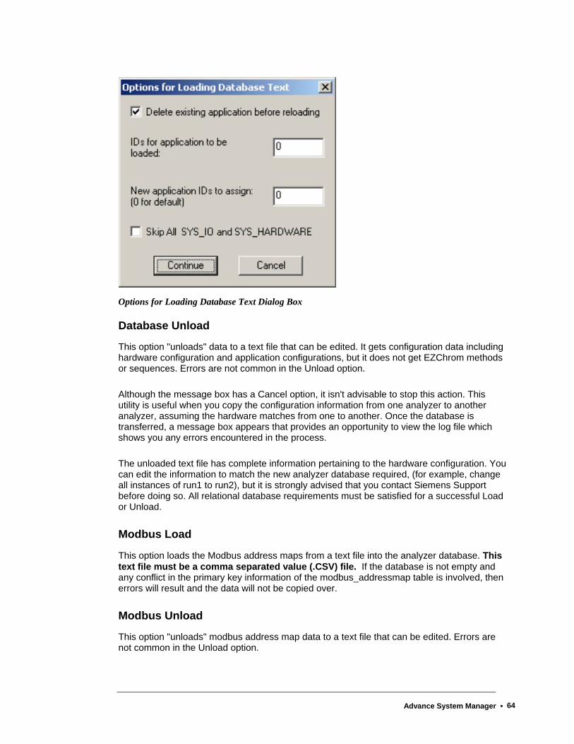
Options for Loading Database Text Dialog Box
Database Unload
This option "unloads" data to a text file that can be edited. It gets configuration data including hardware configuration and application configurations, but it does not get EZChrom methods or sequences. Errors are not common in the Unload option.
Although the message box has a Cancel option, it isn't advisable to stop this action. This utility is useful when you copy the configuration information from one analyzer to another analyzer, assuming the hardware matches from one to another. Once the database is transferred, a message box appears that provides an opportunity to view the log file which shows you any errors encountered in the process.
The unloaded text file has complete information pertaining to the hardware configuration. You can edit the information to match the new analyzer database required, (for example, change all instances of run1 to run2), but it is strongly advised that you contact Siemens Support before doing so. All relational database requirements must be satisfied for a successful Load or Unload.
Modbus Load
This option loads the Modbus address maps from a text file into the analyzer database. This text file must be a comma separated value (.CSV) file. If the database is not empty and any conflict in the primary key information of the modbus_addressmap table is involved, then errors will result and the data will not be copied over.
Modbus Unload
This option "unloads" modbus address map data to a text file that can be edited. Errors are not common in the Unload option.
Advance System Manager • 64

Load HMI language files
This function helps you dynamically change the database text that is used for HMI and alarms to a different language and/or load any new alarm text changes. When you select this option and specify the IP address, this function displays the “Browse for Folder” dialog to locate specific files for language support. Select the directory that contains the file from the "tree" view. The location will typically be /Maxum System Manager/Upgrade x.xx/language where x.xx is the latest version of Maxum System Tools (for example 4.20).
As the text is loading, the message box has a Cancel option, but it isn't advisable to stop this action.
The View Menu The options on this menu are similar to those of Maxum System Manager.
Toolbar: Select this option to hide or display the Maxum Utilities toolbar.
Status Bar: Select this option to hide or display the Maxum Utilities Status Bar at the bottom of the window.
Datalogger Bar: This command is similar to the System View command in Maxum System Manager. The default check mark assures that units attached to the network are displayed in this section of Maxum Utilities. If unchecked, the Datalogger View is hidden.
Float Datalogger View: Like the Float System View command, when this option is selected the Datalogger Bar is no longer anchored to the Maxum Utilities window and can be moved around the screen, resized, or docked in another section of the window. The DataLogger View can be floated outside the Maxum Utilities window.
Tools
About Tools
The Tools Menu gives you access to a number of Maxum and MicroSAM control commands, including upgrading a unit. Except for the Print related selections, all commands are described in the following sections.
The selections from the tools menu that are related to printing (Print, Print Preview, and Print Setup) are used for the printing of information from DataLogger windows.
Advance System Manager • 65
SYSCON Menu Commands (on Tools Menu) The options for this Tools Menu command have different results but common procedures. When you select any of the following options on the sub-menu, you receive:
• A caution message to assure that SNEs are on hold or to remind you that unsaved data may be lost.
• The IP Address Selection dialog box with a list of units. • The Login dialog box.
Software Upgrade
Use this option to replace the SYSCON software with a newer version. This command activates the same System Software Upgrade dialog box as the Upgrade Unit command on the main Tools Menu (see below)
Path: Tools | Syscon | Software Upgrade
Reset
Restart the Maxum SYSCON with one of the following options:
Reset: Equivalent to a power dip. Database may be restarted from SRAM memory or loaded from FlashRAM.
Cold boot: Restart the analyzer and load the database from FlashRAM.
Warm boot: Restart the analyzer and restart the database from SRAM memory, if possible.
In addition, the database may be saved to FlashRAM before performing a reset to ensure that the current database table content is preserved. Note that for analyzers equipped with Compact Flash, all reboots are cold boots (loaded from Compact Flash)
Get Debug Log
Maxum Compact Flash can be set up to continuously write debug output to permanent flash storage, which allows easier trouble shooting after unexpected failures. Select this option to display the debug logs for Maxum analyzers that are equipped with compact flash cards. (NOTE: Maxum must be configured to save this data in order to have debug files.)
Maxum systems that have Compact Flash can be configured to save the debug text file to a file using the steps below. The file can be viewed from the workstation.
In the System_Info table, set the Syslog attribute to 255.0.1.1
Using Maxum Utilities go to Tools->Syscon->Get Debug Log
The files(bootcf.log and debugcf.log) are built in the System manager\System directory. These can be viewed with Notepad or Wordpad.
Advance System Manager • 66
SNE OS Upgrade
STOP! The recommended procedure for upgrading the SNE is to use the Software Upgrade Tool on the Tools menu. Do not use the SNE OS Upgrade Function.
1. Select the Tools | Syscon | Software Upgrade menu path
2. Select the Show Details button on the System Software Upgrade dialog box.
3. Check the SNE component boxes that are to be upgraded on the right hand side of the screen.
4. Uncheck all other boxes on the right hand side.
5. Select the OK button.
SNE Application Upgrade
STOP! The recommended procedure for upgrading the SNE is to use the Software Upgrade Tool on the Tools menu. Do not use the SNE Application Upgrade Function.
1. Select the Tools | Syscon | Software Upgrade menu path
2. Select the Show Details button on the System Software Upgrade dialog box.
3. Check the SNE component boxes that are to be upgraded on the right hand side of the screen.
4. Uncheck all other boxes on the right hand side.
5. Select the OK button.
MicroSAM Menu Commands (on Tools Menu) The MicroSAM Menu (on the Maxum Utilities Tools Menu) only appears if a MicroSAM analyzer has been added to the System View of the System Manager.
Software Upgrade
Use this option to replace the software on the MicroSAM with a newer version. This command activates the same System Software Upgrade dialog box as the Upgrade Unit command on the main Tools Menu (see below)
Path: Tools | MicroSAM | Software Upgrade
Advance System Manager • 67
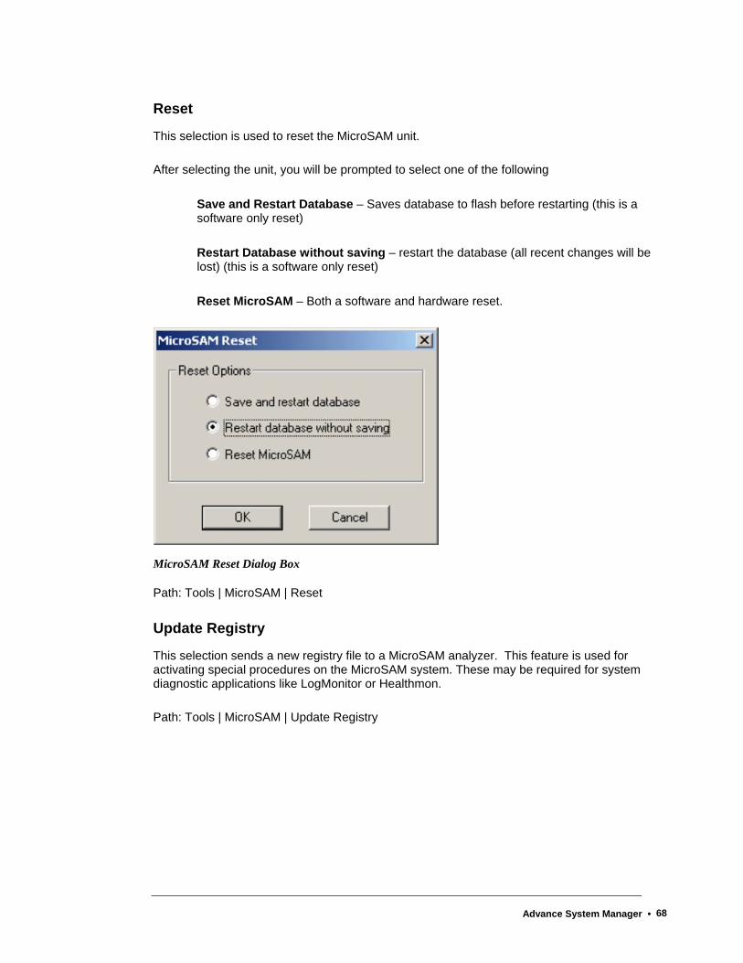
Reset
This selection is used to reset the MicroSAM unit.
After selecting the unit, you will be prompted to select one of the following
Save and Restart Database – Saves database to flash before restarting (this is a software only reset)
Restart Database without saving – restart the database (all recent changes will be lost) (this is a software only reset)
Reset MicroSAM – Both a software and hardware reset.
MicroSAM Reset Dialog Box
Path: Tools | MicroSAM | Reset
Update Registry
This selection sends a new registry file to a MicroSAM analyzer. This feature is used for activating special procedures on the MicroSAM system. These may be required for system diagnostic applications like LogMonitor or Healthmon.
Path: Tools | MicroSAM | Update Registry
Advance System Manager • 68
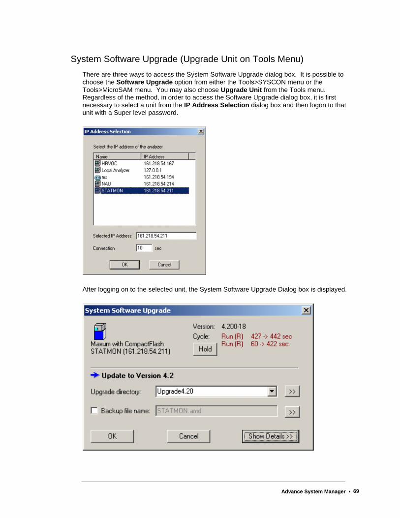
System Software Upgrade (Upgrade Unit on Tools Menu) There are three ways to access the System Software Upgrade dialog box. It is possible to choose the Software Upgrade option from either the Tools>SYSCON menu or the Tools>MicroSAM menu. You may also choose Upgrade Unit from the Tools menu. Regardless of the method, in order to access the Software Upgrade dialog box, it is first necessary to select a unit from the IP Address Selection dialog box and then logon to that unit with a Super level password.
After logging on to the selected unit, the System Software Upgrade Dialog box is displayed.
Advance System Manager • 69
All Maxum and MicroSAM chromatographs can be upgraded to the most recent software or downgraded to any of the currently installed firmware versions. Maxum Utilities will automatically read the installed version numbers on the selected analyzer, compare them with the most recent version numbers, and suggest one of the following courses of action.
1. Upgrade to the most recent database schema (analyzer database schema version is lower than the currently selected version)
2. Update the analyzer (analyzer database schema version is the same as the currently selected version)
3. Do nothing (all version numbers match)
4. Downgrade the analyzer (analyzer database schema version is higher than the currently selected version)
If the course of action is Upgrade or Downgrade, it is still necessary to first import and save all methods to file using Maxum EZChrom, and after the up- or downgrade is complete, re-export all methods from Maxum EZChrom to the new database schema version. All other steps are automatic and may include one or more of the following, depending on what is carried out.
Save database to flash before loading any updates
Back up database to AMD file
Unload tables and Modbus maps to text files
Reset the analyzer and/or SNE
Load database with text files and Modbus maps
Save database to flash at the end of the update procedure
Select components whose version number changes.
Click on the Show Details button within the dialog box to view and manually change all settings suggested by the upgrade tool. Refer to the Show Details topic later in this chapter for more information.
System Type – The upgrade tool will detect whether a Maxum with SRAM/Flash, a MicroSAM, or a Maxum with Compact Flash is to be upgraded and select all appropriate files accordingly. A system change from Maxum SRAM/Flash to Maxum Compact Flash is possible, too, but several manual steps have to be taken (see below).
Advance System Manager • 70
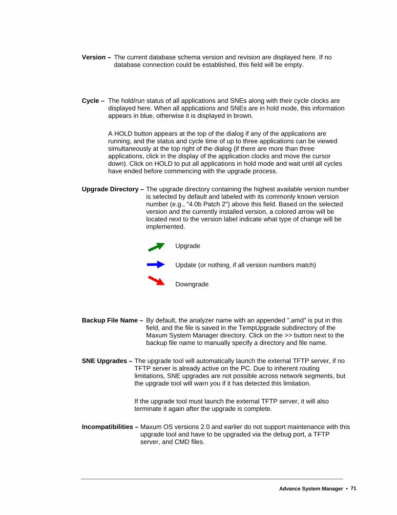
Version – The current database schema version and revision are displayed here. If no database connection could be established, this field will be empty.
Cycle – The hold/run status of all applications and SNEs along with their cycle clocks are displayed here. When all applications and SNEs are in hold mode, this information appears in blue, otherwise it is displayed in brown.
A HOLD button appears at the top of the dialog if any of the applications are running, and the status and cycle time of up to three applications can be viewed simultaneously at the top right of the dialog (if there are more than three applications, click in the display of the application clocks and move the cursor down). Click on HOLD to put all applications in hold mode and wait until all cycles have ended before commencing with the upgrade process.
Upgrade Directory – The upgrade directory containing the highest available version number is selected by default and labeled with its commonly known version number (e.g., "4.0b Patch 2") above this field. Based on the selected version and the currently installed version, a colored arrow will be located next to the version label indicate what type of change will be implemented.
Upgrade
Update (or nothing, if all version numbers match)
Downgrade
Backup File Name – By default, the analyzer name with an appended ".amd" is put in this field, and the file is saved in the TempUpgrade subdirectory of the Maxum System Manager directory. Click on the >> button next to the backup file name to manually specify a directory and file name.
SNE Upgrades – The upgrade tool will automatically launch the external TFTP server, if no TFTP server is already active on the PC. Due to inherent routing limitations, SNE upgrades are not possible across network segments, but the upgrade tool will warn you if it has detected this limitation.
If the upgrade tool must launch the external TFTP server, it will also terminate it again after the upgrade is complete.
Incompatibilities – Maxum OS versions 2.0 and earlier do not support maintenance with this upgrade tool and have to be upgraded via the debug port, a TFTP server, and CMD files.
Advance System Manager • 71
Resuming Failed Upgrades – Each successfully completed upgrade step is recorded by the upgrade tool to support resuming failed or interrupted upgrades. For example, if the network connection between the analyzer and Maxum Utilities fails after a successful SNE OS upgrade and during an SNE application upgrade, or if the PC loses power at that point, another invocation of the upgrade tool will offer to restart the upgrade beginning with an SNE application upgrade, and continuing with all steps that have not been successfully concluded. See details regarding failed upgrades in the topic below, Resume Incomplete Upgrade.
Resume Incomplete Upgrade
An upgrade may be interrupted by a variety of circumstances, such as
Loss of power
Software crashes
Network failures
Time-outs
To facilitate easier recovery from these interruptions, Maxum Utilities records the completion of each successfully completed upgrade step in an external file (System\CurrUpgrade.txt). If, after an interruption, the user again selects to upgrade an analyzer, or if the Maxum Utilities program is restarted and a previous upgrade has not been completed, the Resume Incomplete Upgrade dialog box offers to resume an incomplete upgrade. The user is given the following three options.
Resume – Continue the incomplete upgrade at the point it was interrupted.
Discard – Discard the information about the incomplete upgrade and continue with a new upgrade setup.
Cancel – Close this dialog box without further action.
Advance System Manager • 72

Show Details
On the right-hand side, all files are presented that the upgrade tool has selected for the upgrade step. Each file is also accompanied by an arrow indicating the status of the version change:
Upgrade
Version numbers are the same
Downgrade
One or both version numbers cannot be determined.
Let the mouse pointer hover over these arrows to display the actual version number change.
Use loader file – (Not available for MicroSAMs.) Old-style loading of SRAM/Flash Maxum analyzers with CMD files is still possible with this option. Check this checkbox or select the >> button to specify a CMD file.
Unload/Load Text Automatically – Database data and Modbus maps are stored as text files ({Name}_Db.txt and {Name}_Mod.txt) in the TempUpgrade subdirectory of Maxum System Manager prior to loading any new software into the analyzer, and the contents of these text files is loaded into the analyzer after all software updates have been concluded.
Advance System Manager • 73
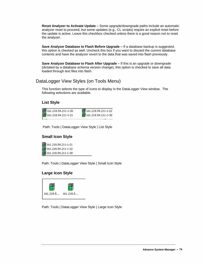
Reset Analyzer to Activate Update – Some upgrade/downgrade paths include an automatic analyzer reset to proceed, but some updates (e.g., CL scripts) require an explicit reset before the update is active. Leave this checkbox checked unless there is a good reason not to reset the analyzer.
Save Analyzer Database to Flash Before Upgrade – If a database backup is suggested, this option is checked as well. Uncheck this box if you want to discard the current database contents and have the analyzer revert to the data that was saved into flash previously.
Save Analyzer Database to Flash After Upgrade – If this is an upgrade or downgrade (dictated by a database schema version change), this option is checked to save all data loaded through text files into flash.
DataLogger View Styles (on Tools Menu) This function selects the type of icons to display in the DataLogger View window. The following selections are available.
List Style
Path: Tools | DataLogger View Style | List Style
Small Icon Style
Path: Tools | DataLogger View Style | Small Icon Style
Large Icon Style
Path: Tools | DataLogger View Style | Large Icon Style
Advance System Manager • 74

StatMon Utility The StatMon utility is the interface to the StatMon table in System Manager, found for an analyzer under System Tables.
Starting in version 4.2, the Statmon table in the database can be configured to store key database values over time. These historical archives are available on the workstation with the StatMon (formerly MaxCems) utility under System Manager Tools. Timestamp and status information are also available for access from the workstation. At the workstation, the data may be easily imported into Excel or printed.
Configuring the StatMon Table
Required Attributes
ID – This is a unique identification number for the StatMon table entry.
SourceAttribute – This is the type of data being archived. The available types of data are listed in the source attribute list (see the Attribute List later in this section).
Sourcekey – This identifies which specific data to archive. For example, which Application, stream, method, channel, and group to collect the data from. The applicable Source Key is dependent on the Source Attribute that is chosen. Refer to the Attribute List later in this section. The SourceKey is a space separated list of primary key values referenced by the SourceAttribute.
Max_values – Number of values to store in circular binaries (in general, max_values*cycle length = length(in time of the archive))
Optional Attributes
Scan_option – default is zero(values stored at end of cycle). Greater than 0 indicates the rate for polling (5,10,15,30,60 seconds)
Status_option – default is zero – use HCI-H status codes 1 = uses whatever is in the Current_status attribute(Set from a MaxBasic program)
Action – default is zero (nothing happens), statistics are done every point collected -1 = empty out buffer and start collecting new archive. Any value greater than zero sets the rate of statistics computation. For example, 3 means to compute the mean, stdev, rangehi, rangelo every 3 values collected.
Name – This is the name for displaying results (defaults to a system generated name, but may be changed). This name must be unique in the StatMon table.
Advance System Manager • 75
Informational Attributes
Current_value – last value stored in binvalues
Current_time – last value stored in bintimes
Current_status – last value stored in binstatus
Counter – position in the archive of the last collected value
Num_values – number of values currently in the archive
Mean – arithmetic average of the values in the archive
Stdev – standard deviation of the values in the archive
Rangehi – largest value in the archive
Rangelo – smallest value in the archive
Streamapp, Streamref – Application and Stream that are indicated by the SourceKey. These are generally the first two fields of the SourceKey.
Other attributes:
Report – Reports can be requested by setting the Report attribute. This attribute is automatically reset. Reports will be directed to any printer designated to receive results. The following reports are available:
Last x values – Enter "L 100" for the last 100 values
Daily reports at different intervals for the current and previous days. Enter C then an increment then a day indicator(3 values)
o "C 15 –1" means print a daily report at 15 * cyclelength intervals for yesterday
o "C -15 1" means print a daily report at 15*cyclelength intervals for today, with a detail line for every value
Paramoffset – Used to designate locations (that must be configured) in the parameter table to store daily averages that can then be reported on for the month. Used with Report.
Report "D" stores the current day’s summary in the appropriate parameter
Report "M" prints the summary lines from the parameter table.
Advance System Manager • 76
Example:
It is desired to archive the Concentration values for a specific peak. The desired information is peak number 3 on Application 1, Stream 2, Method 1, and Channel 17. You wish to keep the last 500 values for this peak.
1. The setup is done in the StatMon system table (System Tables in the Analyzer Tree View). Open the table and click the add record button on the Table Editor toolbar or select Add Record from the Edit menu.
2. From the attribute list, the necessary Source Attribute is 11 (Peak Concentration). The attribute list indicates that the following data are necessary for the Source key “Application stream method channel peak” (1) (2) (1) (17) (3) Therefore, the applicable Source Key is – 1 2 1 17 3
3. The Max_Values attribute should be set at 500 to indicate that you wish to keep the last 500 values. Once the 500 values have been stored, the next value measured will be saved and the oldest archived value will drop off.
4. You may also wish to set the Name for this stored value. In this case, if the peak is Propane, then you may choose the name Propane Concentration.
5. Once the table has been saved, any new data will be archived per the settings in StatMon. After data has been collected, it will be possible to open the StatMon utility and view the results.
Advance System Manager • 77
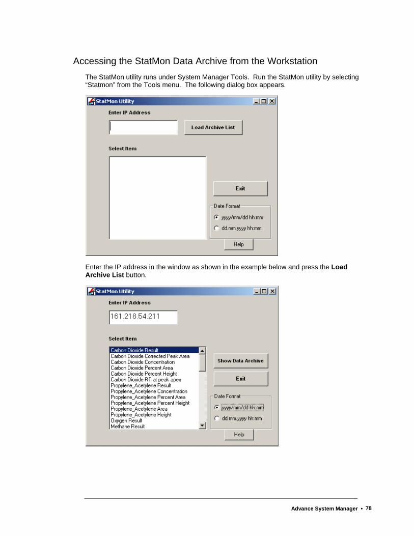
Accessing the StatMon Data Archive from the Workstation The StatMon utility runs under System Manager Tools. Run the StatMon utility by selecting “Statmon” from the Tools menu. The following dialog box appears.
Enter the IP address in the window as shown in the example below and press the Load Archive List button.
Advance System Manager • 78
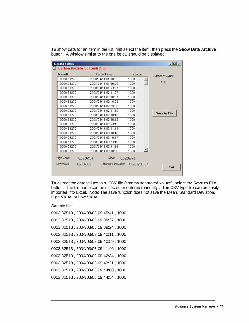
To show data for an item in the list, first select the item, then press the Show Data Archive button. A window similar to the one below should be displayed.
To extract the data values to a .CSV file (comma separated values), select the Save to File button. The file name can be selected or entered manually.. The CSV type file can be easily imported into Excel. Note: The save function does not save the Mean, Standard Deviation, High Value, or Low Value.
Sample file:
0003.82513 , 2004/03/03 09:45:41 , 1000
0003.82513 , 2004/03/03 09:38:37 , 1000
0003.82513 , 2004/03/03 09:39:24 , 1000
0003.82513 , 2004/03/03 09:40:11 , 1000
0003.82513 , 2004/03/03 09:40:59 , 1000
0003.82513 , 2004/03/03 09:41:46 , 1000
0003.82513 , 2004/03/03 09:42:34 , 1000
0003.82513 , 2004/03/03 09:43:21 , 1000
0003.82513 , 2004/03/03 09:44:08 , 1000
0003.82513 , 2004/03/03 09:44:54 , 1000
Advance System Manager • 79

Attribute List
Source Attribute Attribute #
Source Key
EZCHROM_RESULT_CHROMPEAK.QUANTIZE 1 Application stream method channel peak
EZCHROM_RESULT_CHROMPEAK..PEAK_WIDTH5 2 Application stream method channel peak
EZCHROM_RESULT_CHROMPEAK.PEAK_WIDTH10 3 Application stream method channel peak
EZCHROM_RESULT_CHROMPEAK.PEAK_WIDTH50 4 Application stream method channel peak
EZCHROM_RESULT_CHROMPEAK.USP_PEAK_WIDTH 5 Application stream method channel peak
EZCHROM_RESULT_CHROMPEAK.RELATIVE_RET_TIME 6 Application stream method channel peak
EZCHROM_RESULT_CHROMPEAK.THEOR_PLATES 7 Application stream method channel peak
EZCHROM_RESULT_CHROMPEAK.THEOR_PLATES_METER 8 Application stream method channel peak
EZCHROM_RESULT_CHROMPEAK.CAPACITY_FACTOR 9 Application stream method channel peak
EZCHROM_RESULT_CHROMPEAK.RESOLUTION 10 Application stream method channel peak
EZCHROM_RESULT_CHROMPEAK.CONCENTRATION 11 Application stream method channel peak
EZCHROM_RESULT_CHROMPEAK.NORM_CONC 12 Application stream method channel peak
EZCHROM_RESULT_CHROMPEAK.X_INT_AT_UP 13 Application stream method channel peak
EZCHROM_RESULT_CHROMPEAK.Y_INT_AT_UP 14 Application stream method channel peak
EZCHROM_RESULT_CHROMPEAK.X_INT_AT_DWN 15 Application stream method channel peak
EZCHROM_RESULT_CHROMPEAK.Y_INT_AT_DWN 16 Application stream method channel peak
EZCHROM_RESULT_CHROMPEAK.X_SECT_INFL 17 Application stream method channel peak
EZCHROM_RESULT_CHROMPEAK.Y_SECT_INFL 18 Application stream method channel peak
EZCHROM_RESULT_CHROMPEAK.FIT_ERROR 19 Application stream method channel peak
EZCHROM_RESULT_CHROMPEAK.CONC_ERROR 20 Application stream method channel peak
EZCHROM_RESULT_CHROMPEAK.ASYM10 21 Application stream method channel peak
EZCHROM_RESULT_CHROMPEAK.AREA_PERCENT 22 Application stream method channel peak
EZCHROM_RESULT_CHROMPEAK.HEIGHT_PERCENT 23 Application stream method channel peak
EZCHROM_RESULT_CHROMPEAK.FRONT_TIME 24 Application stream method channel peak
EZCHROM_RESULT_CHROMPEAK.BACK_TIME 25 Application stream method channel peak
EZCHROM_RESULT_CHROMPEAK.RETENTION_TIME 26 Application stream method channel peak
EZCHROM_RESULT_CHROMPEAK.BASELINE_START 27 Application stream method channel peak
EZCHROM_RESULT_CHROMPEAK.BASELINE_START_HEIGH 28 Application stream method channel peak
EZCHROM_RESULT_CHROMPEAK.BASELINE_STOP 29 Application stream method channel peak
EZCHROM_RESULT_CHROMPEAK.BASELINE_STOP_HEIGHT 30 Application stream method channel peak
EZCHROM_RESULT_CHROMPEAK.RAW_AREA 31 Application stream method channel peak
EZCHROM_RESULT_CHROMPEAK.CORRECTED_AREA 32 Application stream method channel peak
EZCHROM_RESULT_CHROMPEAK.ASYMMETRY 33 Application stream method channel peak
EZCHROM_RESULT_CHROMPEAK.PEAK_HEIGH 34 Application stream method channel peak
EZCHROM_RESULT_CHROMPEAK.PEAK_BASE_WIDTH 35 Application stream method channel peak
Advance System Manager • 80

Source Attribute Attribute
# Source Key
EZCHROM_RESULT_CHROMPEAK.STRINDX_FRONT_INF 36 Application stream method channel peak
EZCHROM_RESULT_CHROMPEAK.STRINDX_BACK_INFL 37 Application stream method channel peak
EZCHROM_RESULT_CHROMPEAK.PEAK_NOISE 38 Application stream method channel peak
EZCHROM_RESULT_CHROMPEAK.PEAK_SIGNAL_TO_NOISE 39 Application stream method channel peak
EZCHROM_RESULT_CHROMPEAK.CURRENT_RF 40 Application stream method channel peak
EZCHROM_RESULT_GROUP.QUANTIZE 50 Application stream method channel group
EZCHROM_RESULT_GROUP.CONCENTRATION 51 Application stream method channel group
EZCHROM_RESULT_GROUP.NORM_CONC 52 Application stream method channel group
EZCHROM_RESULT_GROUP.GROUP_QVALUE 53 Application stream method channel group
EZCHROM_RESULT_GROUP.FIT_ERROR 54 Application stream method channel group
EZCHROM_RESULT_GROUP.CONC_ERROR 55 Application stream method channel group
EZCHROM_RESULT_GROUP.AREA_PERCENT 56 Application stream method channel group
EZCHROM_RESULT_GROUP.HEIGHT_PERCENT 57 Application stream method channel group
EZCHROM_RESULT_GROUP.CORRECTED_AREA 58 Application stream method channel group
EZCHROM_RESULT_GROUP.GROUP_HEIGHT 59 Application stream method channel group
EZCHROM_RESULT_GROUP.CURRENT_RF 60 Application stream method channel group
RESULT.BUFFERED_VALUE 80 Application stream result_index
RESULT.SAVED_VALUE 81 Application stream result_index
STREAM.CURR_ERROR 100 Application stream
STREAM.CURR_WARNING 101 Application stream
ALARM.COUNT 300 Appcontext Streamcontext alarm_code
CALIBRATION_LEVEL.KNOWN_CONC 310 Application method channel ref_type cal_id level
CALIBRATION_LEVEL.MEASURED_VALUE 311 Application method channel ref_type cal_id level
CALIBRATION_LEVEL.NEW_RESPONSE_FACTOR 312 Application method channel ref_type cal_id level
CALIBRATION_LEVEL.RESPONSE_FACTOR 313 Application method channel ref_type cal_id level
CALIBRATION_LEVEL.RESIDUAL 314 Application method channel ref_type cal_id level
APPAI.VALUE 400 Application Id
APPAI.AVERAGE 401 Application Id
APPDI.VALUE 410 Application Id
APPAO.READBACK 420 Application Id
APPDO.READBACK 430 Application Id
Advance System Manager • 81
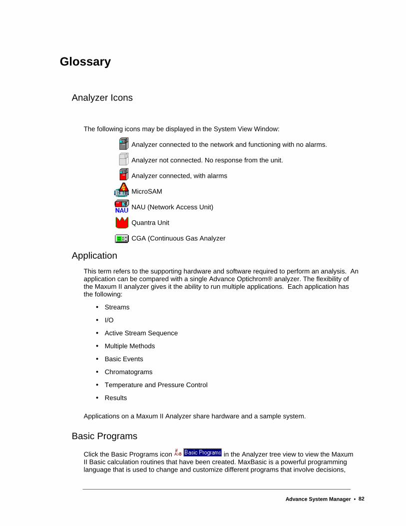
Glossary
Analyzer Icons
The following icons may be displayed in the System View Window:
Analyzer connected to the network and functioning with no alarms.
Analyzer not connected. No response from the unit.
Analyzer connected, with alarms
MicroSAM
NAU (Network Access Unit)
Quantra Unit
CGA (Continuous Gas Analyzer
Application This term refers to the supporting hardware and software required to perform an analysis. An application can be compared with a single Advance Optichrom® analyzer. The flexibility of the Maxum II analyzer gives it the ability to run multiple applications. Each application has the following:
Streams
I/O
Active Stream Sequence
Multiple Methods
Basic Events
Chromatograms
Temperature and Pressure Control
Results
Applications on a Maxum II Analyzer share hardware and a sample system.
Basic Programs
Click the Basic Programs icon in the Analyzer tree view to view the Maxum II Basic calculation routines that have been created. MaxBasic is a powerful programming language that is used to change and customize different programs that involve decisions,
Advance System Manager • 82
calculations, alarm generation, and custom printing. MaxBasic is a separately purchased workstation product that may not be licensed for every workstation.
Broadcast All units on the system are monitored, and every ten to fifteen minutes the system sends (broadcasts) a status report to all units connected to the network. Changes in unit status are displayed in the System View Window each time a new report is broadcast.
Dynamic View When the data from a database query changes automatically as changes occur in the database, it is termed dynamic. Most of the HMI screens and the Alarm Log and Results view in the System Manager are dynamic.
HMI The Human-Machine Interface (HMI) (previously Man Machine Interface, or MMI) for application monitoring and control is the display software for the Maxum that runs on the Maxum, MicroSAM, or the workstation. Like the System Manager, it gives a view of certain key database tables. It differs from the System Manager by organizing the views by function, rather than table name, and by using mostly dynamic queries.
The HMI is the most powerful operations and monitoring tool for the Analyzer, although it has only minimal editing and configuration capability. An HMI can directly connect to all Ethernet-connected Maxum Analyzers. It also supports a subset of Advance Data Hiway panel messages.
Insertion Point The blinking vertical bar that appears in a field waiting for information to be typed. The insertion point can be moved by clicking in a different field.
Limits Automatic limit processing can be placed on I/O, results, and external results by adding a limit then placing a reference to it in the required table. The standard alarms for limits are:
hihi alarm => 673 ! Database:value >limit: %3
lolo alarm => 674 ! Database value < limit: %3
hi alarm => 694 ? Database:value > limit: %3
lo alarm => 695 ? Database value < limit: %3
These are used when no alarmhandler alarm reference is placed in the limit table.
Advance System Manager • 83
MaxBasic MaxBasic is a powerful programming language that is used to change and customize different programs that involve decisions, calculations, alarm generation, and custom printing. MaxBasic is a separately purchased workstation product that may not be licensed for every workstation.
Method A method is the set of information needed to perform a component analysis on a stream. It is the part of an application that contains the parameters for controlling the hardware. In other words, the method tells the hardware what to do. The method includes instrument setup (detectors, valves, etc.), peaks/groups, data collection events, and integration events. Methods are developed in Maxum EZChrom and exported to the database. They are transmitted to the SNECON at the beginning of each cycle specified in the stream/method sequence.
Monitoring interval A time setting, between 1 and 9 minutes, that specifies that the specific analyzer be checked more frequently than the default ten minute broadcast. The default is recommended except for short performance checks (for example, when a new physical unit is added to the network). If the Monitoring interval is set to 0, it reverts to the default. A time interval above ten minutes should not be used, because, with broadcasts coming every ten minutes, it does not provide any information.
The Monitoring Interval field is found on the Add unit to and the Unit Properties dialog boxes.
NAU NAU (Network Access Unit) is used for centralized maintenance access to a large number of chromatographs or other analyzers in a single process network and for centralized data input and output facilities, which are shared by many analyzers on a common network.
Primary Key The Primary Key is unique identifier or set of identifiers in a record. Each table has at least one column designated as primary key. For ready identification, the primary key column(s) are gray. When more than one column is designated as primary, the full combination of information is considered a primary key.
Multiple ampersands (&& or &&&) in the table header identify primary key combinations.
rarg Real (floating point number) arguments for MaxBasic program events. Arguments are numbers that are passed to a program event and used to identify a parameter.
Advance System Manager • 84

iarg Integer arguments for MaxBasic program events. Arguments are numbers that are passed to a program event and used to identify a parameter.
Sequence A Sequence, called an Online Sequence in Maxum EZChrom, is an ordered list of stream/Method pairs. Each application has at least a normal process sequence, and a calibration sequence. Additional sequences, such as validation, are allowed. Only one sequence is active, or being used, at a time.
Calibration and Validation sequences have special actions associated with them and return to the process sequence when they are completed.
SNECON The SNECON, or Sensor Near Electronics Controller, manages and controls chromatography functions to perform the compositional analysis of the input stream. The SNECON is the IO interface to system hardware such as detectors and temperature controllers.
Static View When the data from a database query is captured at the instant of the query and does not change, it is termed static. The table must be re-queried by some user action to see changes that may have occurred. Most of the system Manager table views are static. A Static View is like a snapshot.
Status Bar The lowest part of the Maxum System Manager screen is called the Status Bar, and extends horizontally across the bottom of the window. The default text on the left side of the Status Bar is a reminder to press the F1 key for help. When the cursor moves across the various commands in the toolbars and drop-down menus, a short description of the command function appears on the status bar.
The right side of the status bar indicates whether the alpha characters are locked in upper case (CAP), whether the numeric key pad is in the number locked position (NUM), or whether the Scroll Lock has been pressed (SCRL).
Maxum System Manager Status Bar
SYSCON The SYSCON, or System Controller, is the primary processor for the Maxum II. It contains the control system for the analyzer. It controls all internal communications to the SNECON and all external communications
Advance System Manager • 85
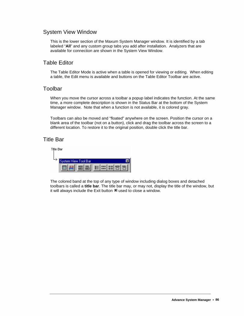
System View Window This is the lower section of the Maxum System Manager window. It is identified by a tab labeled “All” and any custom group tabs you add after installation. Analyzers that are available for connection are shown in the System View Window.
Table Editor The Table Editor Mode is active when a table is opened for viewing or editing. When editing a table, the Edit menu is available and buttons on the Table Editor Toolbar are active.
Toolbar When you move the cursor across a toolbar a popup label indicates the function. At the same time, a more complete description is shown in the Status Bar at the bottom of the System Manager window. Note that when a function is not available, it is colored gray.
Toolbars can also be moved and “floated” anywhere on the screen. Position the cursor on a blank area of the toolbar (not on a button), click and drag the toolbar across the screen to a different location. To restore it to the original position, double click the title bar.
Title Bar
The colored band at the top of any type of window including dialog boxes and detached toolbars is called a title bar. The title bar may, or may not, display the title of the window, but it will always include the Exit button used to close a window.
Advance System Manager • 86
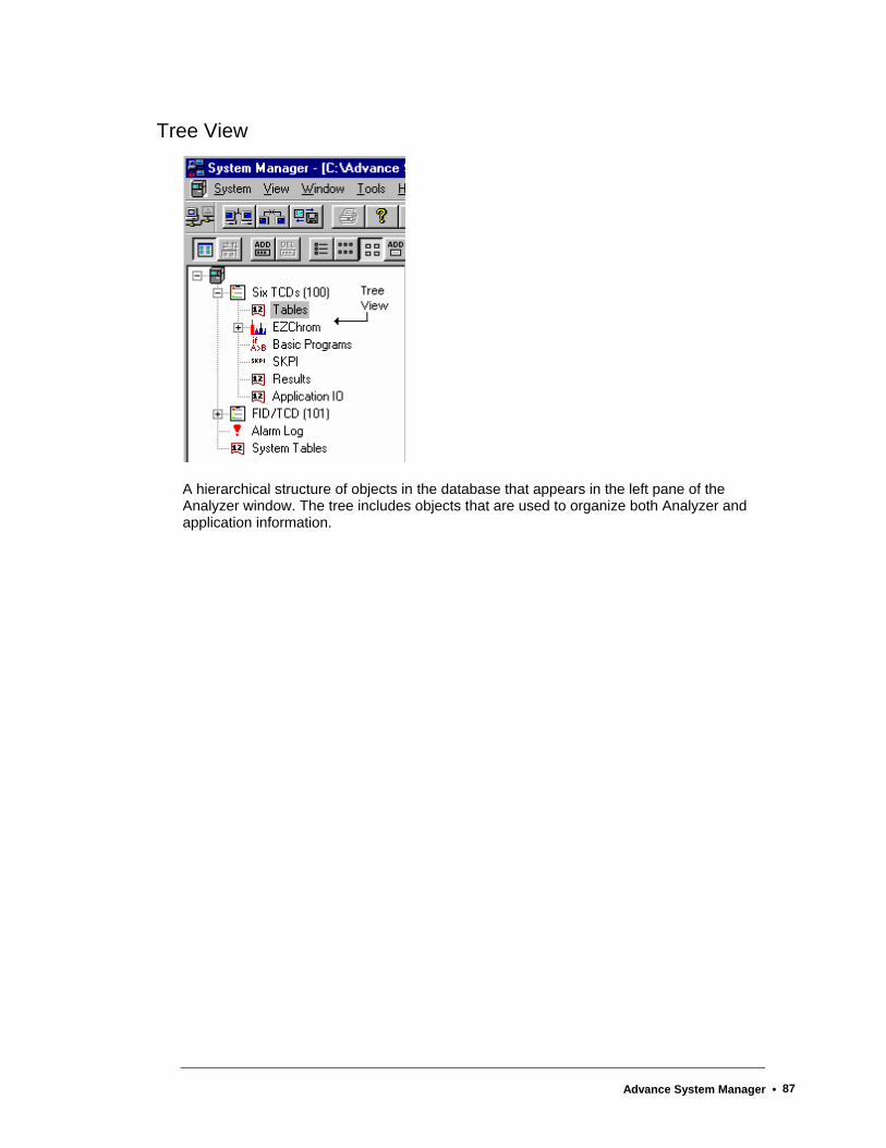
Tree View
A hierarchical structure of objects in the database that appears in the left pane of the Analyzer window. The tree includes objects that are used to organize both Analyzer and application information.
Advance System Manager • 87
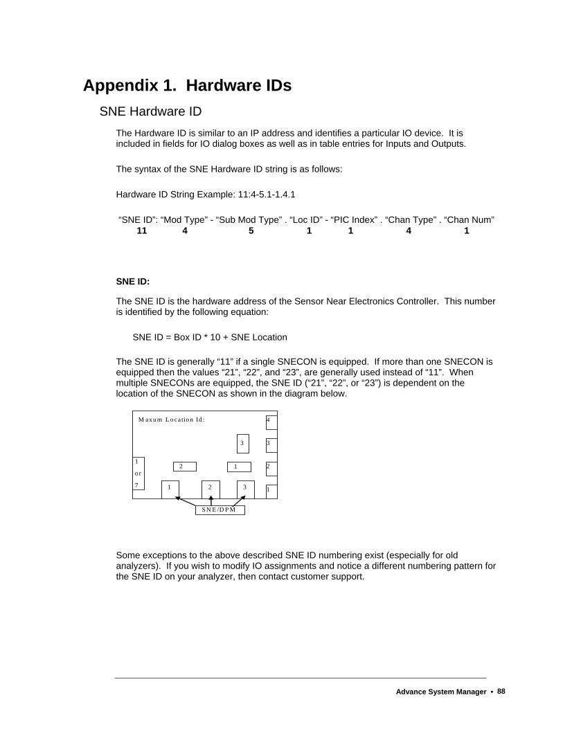
Appendix 1. Hardware IDs SNE Hardware ID
The Hardware ID is similar to an IP address and identifies a particular IO device. It is included in fields for IO dialog boxes as well as in table entries for Inputs and Outputs.
The syntax of the SNE Hardware ID string is as follows:
Hardware ID String Example: 11:4-5.1-1.4.1
“SNE ID”: “Mod Type” - “Sub Mod Type” . “Loc ID” - “PIC Index” . “Chan Type” . “Chan Num” 11 4 5 1 1 4 1
SNE ID:
The SNE ID is the hardware address of the Sensor Near Electronics Controller. This number is identified by the following equation:
SNE ID = Box ID * 10 + SNE Location
The SNE ID is generally “11” if a single SNECON is equipped. If more than one SNECON is equipped then the values “21”, “22”, and “23”, are generally used instead of “11”. When multiple SNECONs are equipped, the SNE ID (“21”, “22”, or “23”) is dependent on the location of the SNECON as shown in the diagram below.
1 2 3
1
o r
7
2
3
4
3
2
1
M axu m L o ca tio n Id :
S N E /D P M
1
Some exceptions to the above described SNE ID numbering exist (especially for old analyzers). If you wish to modify IO assignments and notice a different numbering pattern for the SNE ID on your analyzer, then contact customer support.
Advance System Manager • 88
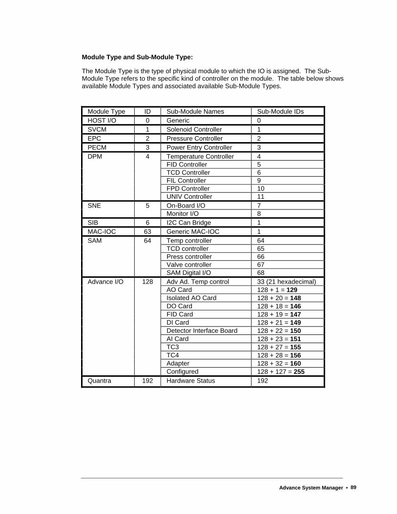
Module Type and Sub-Module Type:
The Module Type is the type of physical module to which the IO is assigned. The Sub-Module Type refers to the specific kind of controller on the module. The table below shows available Module Types and associated available Sub-Module Types.
Module Type ID Sub-Module Names Sub-Module IDs HOST I/O 0 Generic 0 SVCM 1 Solenoid Controller 1 EPC 2 Pressure Controller 2 PECM 3 Power Entry Controller 3
Temperature Controller 4 FID Controller 5 TCD Controller 6 FIL Controller 9 FPD Controller 10
DPM 4
UNIV Controller 11 On-Board I/O 7 SNE 5 Monitor I/O 8
SIB 6 I2C Can Bridge 1 MAC-IOC 63 Generic MAC-IOC 1
Temp controller 64 TCD controller 65 Press controller 66 Valve controller 67
SAM 64
SAM Digital I/O 68 Adv Ad. Temp control 33 (21 hexadecimal) AO Card 128 + 1 = 129 Isolated AO Card 128 + 20 = 148 DO Card 128 + 18 = 146 FID Card 128 + 19 = 147 DI Card 128 + 21 = 149 Detector Interface Board 128 + 22 = 150 AI Card 128 + 23 = 151 TC3 128 + 27 = 155 TC4 128 + 28 = 156 Adapter 128 + 32 = 160
Advance I/O 128
Configured 128 + 127 = 255 Quantra 192 Hardware Status 192
Advance System Manager • 89
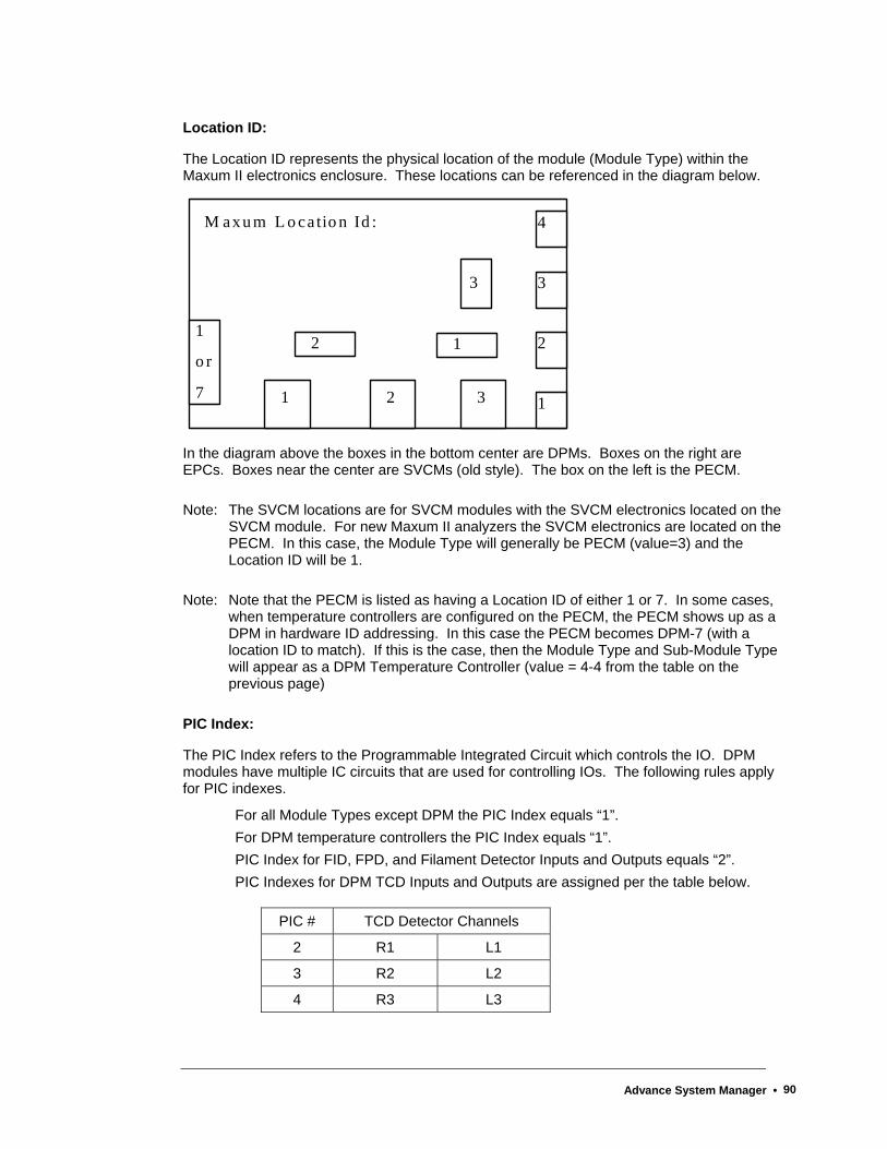
Location ID:
The Location ID represents the physical location of the module (Module Type) within the Maxum II electronics enclosure. These locations can be referenced in the diagram below.
1 2 3
1
o r
7
2
3
4
3
2
1
M axu m L o ca tio n Id :
1
In the diagram above the boxes in the bottom center are DPMs. Boxes on the right are EPCs. Boxes near the center are SVCMs (old style). The box on the left is the PECM.
Note: The SVCM locations are for SVCM modules with the SVCM electronics located on the SVCM module. For new Maxum II analyzers the SVCM electronics are located on the PECM. In this case, the Module Type will generally be PECM (value=3) and the Location ID will be 1.
Note: Note that the PECM is listed as having a Location ID of either 1 or 7. In some cases, when temperature controllers are configured on the PECM, the PECM shows up as a DPM in hardware ID addressing. In this case the PECM becomes DPM-7 (with a location ID to match). If this is the case, then the Module Type and Sub-Module Type will appear as a DPM Temperature Controller (value = 4-4 from the table on the previous page)
PIC Index:
The PIC Index refers to the Programmable Integrated Circuit which controls the IO. DPM modules have multiple IC circuits that are used for controlling IOs. The following rules apply for PIC indexes.
For all Module Types except DPM the PIC Index equals “1”. For DPM temperature controllers the PIC Index equals “1”. PIC Index for FID, FPD, and Filament Detector Inputs and Outputs equals “2”. PIC Indexes for DPM TCD Inputs and Outputs are assigned per the table below.
PIC # TCD Detector Channels
2 R1 L1
3 R2 L2
4 R3 L3
Advance System Manager • 90

Channel Type:
The Channel Type indicates the type of Input or Output to which the Hardware ID refers. The following channel types are available.
Channel Type Type Number Virtual*
Analog Input 1 33
Analog Output 2 34
Digital Input 3 35
Digital Output 4 36
EEPROM Channel 5 37
Temp Controller 6 38
Detector 7 39
Pressure Controller 8 40
* “Virtual” refers to values for virtual IO types. Virtual IOs are used in some situations depending on configuration (for example, to read a detector balance value.) Virtual IOs may be viewed in the System IO Tables.
Channel Number:
The Channel number is the physical channel that is assigned for the IO. The channel number is dependent on the type of hardware and type of signal.
CAN Hardware ID When a CAN IO Module is used, the associated Hardware IDs have a different format
Syntax: 0:0.a.b.c (0:0 indicates CAN module)
a = CAN module node #
b = channel type:
1 = AI
2 = AO
3 = DI
4 = DO
c = channel #
Advance System Manager • 91


6/2008 Edition 2000596-001
Siemens Energy & Automation, Inc.
7101 Hollister Road, Houston, TX 77040United StatesPhone +1 (713) 939-7400Fax +1 (713) 939-9050
www.usa.siemens.com/ia