
Control Products - Siemens USA.
386
Siemens Industry, Inc. SPEEDFAX™ 2017 Product Catalog 17-1 17 CONTROL PRODUCTS Control Products SPEEDFAX TM 2017 Section NEMA & General Purpose Control Product Overview 17-5 Manual Control Fractional HP Starters, Class SMF 17-6 - 17-7 Switches, Class MMS and MRS 17-8 - 17-9 Starters and Switches, Class 11 - 3RV 17-10 - 17-11 NEMA Control Catalog Numbering System 17-12 Non-Combination Starters Features and Benefits 17-13 - 17-14 Non-Reversing Starters, Class 14 17-15 - 17-17 Combination Starters Features and Benefits 17-18 Combination Starters, Class 17 and 18 17-19 - 17-27 Reversing Starters, Class 22 17-28 - 17-29 Combination Reversing Starters, Class 25 and 26 17-30 - 17-31 Two Speed Starters Features and Benefits 17-32 Two Speed Starters, Class 30 17-33 - 17-36 Combination Two Speed Starters, Class 32 17-37 - 17-44 Reduced Voltage Control Reduced Voltage Features and Benefits 17-45 Auto Transformer Starters, Class 36 and 37 17-46 - 17-49 Part Winding Starters, Class 36 and 37 17-50 - 17-53 Wye Delta Open Transition, Class 36 and 37 17-54 - 17-57 Wye Delta Closed Transition, Class 36 and 37 17-58 - 17-61 Heavy Duty Contactors Non-Reversing Contactors, Class 40 17-62 - 17-63 Vacuum Contactors, 17-62 Reversing Contactors, Class 43 17-64 Definite Purpose Contactors 17-66 - 17-72 Overload Relays Class 48, 958 and 3RB20 17-74 - 17-77 Duplex Controllers Features and Benefits 17-78 Non Combination, Class 83 17-79 Combination, Class 84 17-80 - 17-81 Pump Control Panels Slim Line NEMA Pump Controller for Agricultural, Class 82 17-82 - 17-85 Class 87 and 88 Features and Benefits 17-86 - 17-87 Full-Voltage Type, Class 87 17-88 - 17-89 Vacuum Starter Type, Class 87 17-90 Reduced-Voltage Type, Class 88 17-91 - 17-92 Lighting Control Electrically Held Contactors, Class LE 17-93 - 17-98 Electrically Held Contactors, Class LC 17-99 - 17-103 Mechanically Held Contactors, Class CLM 17-104 - 17-106 Control Power Transformers Domestic and International (UL, CSA, CE) Class MT, MTG 17-107 - 17-111 Modifications and Drawings Field Modification Kits 17-112 - 17-122 Enclosure Kits 17-123 - 17-128 Factory Modifications 17-129 - 17-133 Dimensions 17-147 - 17-181 Wiring Diagrams 17-182 - 17-203 Heater Tables and Replacement Parts Overload Relay Heater Tables 17-134 - 17-140 NEMA Coils and Contact Kits 17-141 - 17-142 Coil VA Ratings and Overload Relays 17-143 Lighting Contactor Parts and Kits 17-144 (continued on next page) Scan to connect online to the most up-to- date version of this Section of SPEEDFAX. NEMA & General Purpose Control Class 14 Class 17, 18 Class 82, 83, 84, 87, 88 Class LE, LC, CLM (Section was last modified on 02/06/20)
-
Upload
khangminh22 -
Category
Documents
-
view
1 -
download
0
Transcript of Control Products - Siemens USA.

Siemens Industry, Inc. SPEEDFAX™ 2017 Product Catalog 17-1
17
CON
TROL
PROD
UCTS
Control Products SPEEDFAXTM 2017 Section
N E M A & G e n e r a l P u r p o s e C o n t r o lProduct Overview 17-5Manual Control Fractional HP Starters, Class SMF 17-6 - 17-7 Switches, Class MMS and MRS 17-8 - 17-9 Starters and Switches, Class 11 - 3RV 17-10 - 17-11NEMA Control Catalog Numbering System 17-12 Non-Combination Starters Features and Benefits 17-13 - 17-14 Non-Reversing Starters, Class 14 17-15 - 17-17 Combination Starters Features and Benefits 17-18 Combination Starters, Class 17 and 18 17-19 - 17-27 Reversing Starters, Class 22 17-28 - 17-29 Combination Reversing Starters, Class 25 and 26 17-30 - 17-31 Two Speed Starters Features and Benefits 17-32 Two Speed Starters, Class 30 17-33 - 17-36 Combination Two Speed Starters, Class 32 17-37 - 17-44Reduced Voltage Control Reduced Voltage Features and Benefits 17-45 Auto Transformer Starters, Class 36 and 37 17-46 - 17-49 Part Winding Starters, Class 36 and 37 17-50 - 17-53 Wye Delta Open Transition, Class 36 and 37 17-54 - 17-57 Wye Delta Closed Transition, Class 36 and 37 17-58 - 17-61Heavy Duty Contactors Non-Reversing Contactors, Class 40 17-62 - 17-63 Vacuum Contactors, 17-62 Reversing Contactors, Class 43 17-64Definite Purpose Contactors 17-66 - 17-72Overload Relays Class 48, 958 and 3RB20 17-74 - 17-77Duplex Controllers Features and Benefits 17-78 Non Combination, Class 83 17-79 Combination, Class 84 17-80 - 17-81Pump Control Panels Slim Line NEMA Pump Controller for Agricultural, Class 82 17-82 - 17-85 Class 87 and 88 Features and Benefits 17-86 - 17-87 Full-Voltage Type, Class 87 17-88 - 17-89 Vacuum Starter Type, Class 87 17-90 Reduced-Voltage Type, Class 88 17-91 - 17-92Lighting Control Electrically Held Contactors, Class LE 17-93 - 17-98 Electrically Held Contactors, Class LC 17-99 - 17-103 Mechanically Held Contactors, Class CLM 17-104 - 17-106 Control Power Transformers Domestic and International (UL, CSA, CE) Class MT, MTG 17-107 - 17-111Modifications and Drawings Field Modification Kits 17-112 - 17-122 Enclosure Kits 17-123 - 17-128 Factory Modifications 17-129 - 17-133 Dimensions 17-147 - 17-181 Wiring Diagrams 17-182 - 17-203Heater Tables and Replacement Parts Overload Relay Heater Tables 17-134 - 17-140 NEMA Coils and Contact Kits 17-141 - 17-142 Coil VA Ratings and Overload Relays 17-143 Lighting Contactor Parts and Kits 17-144 (continued on next page)
Scan to connect online to the most up-to-date version of this Section of SPEEDFAX.
NEM
A &
General
Purpose Control
Class 14
Class 17, 18
Class 82, 83, 84, 87, 88
Class LE, LC, CLM
(Section was last modified on 02/06/20)

Siemens Industry, Inc. SPEEDFAX™ 2017 Product Catalog17-2
17
CON
TRO
L PR
OD
UCT
S
Control Products SPEEDFAXTM 2017 Section
Motor Starters, Soft Starters and Load Feeders
Enclosed IEC Controls General information and catalog numbering system 17-204 - 17-205 Enclosed starters 17-206 - 17-208 Enclosed contactors 17-209 - 17-210 Overload Relay 17-211 Field modifications and accessories 17-212 - 17-216 Circuit diagrams 17-217 Dimension drawings 17-218 - 17-220
For Operation in the Control Cabinet 3RW Soft Starters Introduction 17-221 General data 17-222
3RW30 for standard applications Overview 17-223 Application 17-223 Selection and ordering data 17-224 Accessories 17-225 Application examples 17-226 Function 17-263 Technical specifications 17-264 - 17-273 Dimensional drawings 17-310 Schematics 17-315
3RW40 for standard applications Overview 17-227 Application 17-227 Selection and ordering data 17-228 - 17-230 Accessories 17-231 - 17-232 Application examples 17-233 Function 17-274 Technical specifications 17-275 - 17-288 Dimensional drawings 17-311 Schematics 17-316 - 17-317
3RW44 for high-feature applications Configuration 17-234 Overview 17-235 Application 17-235 Selection and ordering data 17-236 - 17-238 Sirius ES engineering software 17-239 - 17-243 Accessories 17-244 - 17-245 Application examples 17-246 - 17-248 Function 17-289 Technical specifications 17-290 - 17-309 Dimensional drawings 17-312 - 17-313 Schematics 17-318 - 17-321
Class 73/74 Enclosed Softstarter applications Overview 17-249 Application 17-249 Selection and ordering data 17-250 - 17-261 Factory Modifications 17-262 Dimensional drawings 17-314 Schematics 17-322
3RE4
3RW44
Class 73/74
3RW40
Soft
Sta
rter
Co
ntro
l

Siemens Industry, Inc. SPEEDFAX™ 2017 Product Catalog 17-3
17
CON
TROL
PROD
UCTS
Control Products SPEEDFAXTM 2017 Section
Pilot Devices
Pilot Devices
SIRIUS ACT 3SU Series Overview 17-323 - 17-324 For more information on the SIRIUS ACT 3SU product line, please see Section 10 of the US Industrial Controls catalog
Class 50 Standard Duty Control Stations Introduction 17-325 Standard Duty Type 1 and 1B 17-326 - 17-330 Heavy Duty Type 4 Stations 17-331 Class 50 Accessories 17-332 Dimension Drawings 17-333
Class 51 NEMA Type 7/9 Hazardous Location Pilot Devices Introduction 17-334 Pushbutton and Push-pull Operators 17-335 Indicator Lights 17-336 Push to Test/Illuminated Pushbutton Complete Units 17-337 Selector Switch Operators 17-338 Keyed Selector Switch Operators 17-339 Cam Selection Guide for Selector Switch 17-340 Stations and Enclosures 17-341 Accessories 17-342 - 17-344
Class 52 30.5mm Mounting Diameter Pilot Devices Introduction 17-345 Momentary Push Button, Non-Illuminated 17-346 - 17-347 2 & 3 Position Push-Pull Mushroom Head Devices, Non-Illuminated 17-348 - 17-349 2 & 3 Position Push-Pull Mushroom Head Devices, Illuminated 17-350 - 17-351 2 Position Twist-to-Release Mushroom Head Devices, Non-Illuminated 17-352 2 Position Twist-to-Release Mushroom Head Devices, Illuminated 17-353 Indicator Light 17-354 - 17-355 Push Button & Push-to-Test, Illuminated 17-356 - 17-357 Push Button Mushroom Head Devices,Illuminated 17-358 Selector Switches, Illuminated 17-359 Selector Switch Short & Long Lever, Non-Illuminated 17-360 - 17-361 Keyed Selector Switch 17-362 - 17-363 Selector Push Button 17-365
Special Devices 17-366 Cam Selection Guide for Selector Switch, Keyed Selector Switch and Selector Pushbutton 17-367 Custom Selector Switch Designs 17-368 Accessories and Spare Parts 17-369 - 17-372 Dimensional Drawings 17-373 - 17-376 Break Glass and EPO Pushbutton Stations 17-377
Class 52 30.5mm Enclosed Pushbutton Stations Assembled Enclosures with Standard Devices 17-378 - 17-379 P30 Empty Enclosures Only 17-380 Enclosure Legend Plates 17-381 Enclosure Dimensions 17-382 Convenience Center 17-384 Technical Specifications 17-383
Class 50
Class 51
Class 52

Siemens Industry, Inc. SPEEDFAX™ 2017 Product Catalog17-4
17
CON
TRO
L PR
OD
UCT
SN
EMA
& G
ener
al
Purp
ose
Cont
rol
Starters at the speed you needSiemens NEMA starters, pump panels and lighting contactors are known for their dependability and rugged-ness, and now they are delivered faster than ever before through Controls Express.
Controls Express puts our most popular products in your hands faster, because we stock more products across our entire product line. Our Class 14 NEMA starters, Class 87 pump panels, and LC & LE lighting contactors are now available in stock for immediate or next day shipping. In addition, thousands of our open and enclosed starters can now be built-to-order and shipped in 1-3 days through Controls Express.
Siemens is committed to making your job easier by stock-ing more products, offering more configurations, expedit-ing factory modifications, and delivering industry leading turnaround times on our most requested control products.
To quickly identify products that are part of Controls Express and therefore available in 3 days or less, appli-cable catalog numbers have a light blue background. See the appropriate selection pages listed below.
Class 14 NEMA Starters see pages 17-15 & 17-17
Class 17 NEMA Combination Starters see pages 17-19 to 17-24. For quick ship versions with factory modifications see on-line at www.usa.siemens.com/controls-express
Class 18 NEMA Combination Starters see pages 17-25 & 17-27.
Class 40 NEMA Contactors see page 17-62
Class 87 Pump Panels see pages 17-88 & 17-89
LE Lighting Contactors see page 17-95
LC Lighting Contactors see page 17-101 & 17-102
Controls Express lead times apply to orders of up to 6 units of the Class 14, Class 87, LC, or LE. Please contact customer service at 1-866-663-7324 for lead times of larger order volumes.
For more information on Controls Express and a complete list of available products, please visit our website at www.usa.siemens.com/controls-express
Control ProductsNEMA & General Purpose Controls Controls Express

Siemens Industry, Inc. SPEEDFAX™ 2017 Product Catalog 17-5
17
CON
TROL
PROD
UCTS
NEM
A &
General
Purpose Control
Siemens / Speedfax Previous folio: SF11 17-4
Class 48, 958, 3RB20 Overload Relays
Page 17-73
Class 43NEMA Reversing
Contactors Page 17-64
Class SMFFractional Horsepower
Manual Starters Page 17-6
Class MMS & MRSFractional Horsepower
Manual Switches Page 17-8
Class 11Manual Starters and
Switches Page 17-10
Class 14NEMA Starters
Page 17-15
Class 17, 18 NEMA Combination
Starters Page 17-19
Class 22NEMA Reversing
Starters Page 17-28
Class 25, 26NEMA Combination Reversing Starters
Page 17-30
Class 30NEMA Multi-Speed
Starters Page 17-33
Class 32NEMA Combination Multi-Speed Starters
Page 17-37
Class 36, 37 Reduced VoltageElectromechanical
Starters Page 17-45
Heater Tables and Replacement Parts
Page 17-134
3RE4 Enclosed IEC motor controllers
Page 17-204
Class 40NEMA Contactors
and Vacuum Contactors Page 17-62
Modifications andDrawings
Page 17-112
Class 82, 83, 84,87, 88
Pump ControlsPage 17-82
Class LE, LC, CLMLighting Contactors
Page 17-93
Class MT, MTGControl Power TransformersPage 17-107
Control ProductsNEMA & General Purpose Controls Product Overview
Class 42, 45Definite Purpose
ContactorsPage 17-66
Revised on 12/31/19

Siemens Industry, Inc. SPEEDFAX™ 2017 Product Catalog17-6
17
CON
TRO
L PR
OD
UCT
SN
EMA
& G
ener
al
Purp
ose
Cont
rol
Siemens / Speedfax Previous folio: SF11 17-5
Class SMFClass SMF fractional horsepower start-ers provide overload protection as well as manual on-off control for small horsepower motors in a variety of industrial and commercial applications. Available in one or two pole versions, these devices are suitable for use with AC single phase motors up to 1 HP. Two pole starters can also be used with DC motors up to 3⁄4 HP. Typical applications include fans, conveyors, pumps, and small machine tools.
Continuous Current Rating16 amperes.Overload Trip AssemblyMotor protection is provided by a Class SMFH heater element which must be installed before the starter will operate.
Two Speed StartersTwo speed manual starters are designed for control of small single phase AC motors having separate windings for high and low speed operation. Two toggle operated start-ers are used, with overload protec-tion included for each motor winding. Surface mounting devices, and those with a gray flush plate, utilize a mechanical interlock which allows direct control of the motor by means of the toggle operators.
EnclosuresClass SMF, NEMA Type 1 surface mounting enclosures are sheet steel with a thermo-plastic wrap-around cover for convenience in wiring. The NEMA Type 1 enclosure is also available in an oversized version which allows more wiring space. A zinc alloy die casting is used for NEMA Type 4 enclosures.
Pilot LightsRed or green neon pilot light units are available for flush mounting plates, NEMA Type 1 enclosures, and NEMA Type 4 enclosures. Pilot lights may be either factory or field installed. (For starters that contain a pilot light, a Red light is standard. For a Green pilot light add ”G” to the end of the catalog number.)
TerminalsBinding head screw type terminals are suitable for #10 or smaller copper wire, and are accessible from the front. All terminals are clearly marked.
MountingOpen types without a pilot light fit standard single gang switch boxes, and can be used with any cover plate hav-ing a standard toggle cutout. Single-unit flush mounting types, including those with pilot lights, are suitable for wall mounting in a standard switch box or for machine cavity mounting without a box.
OperationAvailable with toggle handle or with removable key type operator to discourage unauthorized operation.
Emergency Off ActuatorA toggle operator extender is available for Class SMF, NEMA Type 1 surface mounted units. The extender has a red vinyl button that provides a fast and easy method for locating and switch-ing the device‘s toggle operator into the OFF position. The Emergency Off Actuator is available in kit form only for field installation.
Handle Guard/Lock-OffAn optional handle guard on Class SMF, NEMA Type 1 enclosed starters prevents accidental operation of the toggle operator and also allows the toggle operator to be padlocked in either the “ON” or “OFF” position. This handle guard can be factory installed on NEMA Type 1 enclosed starters and is also available in kit form for field installation on NEMA Type 1 surface and flush mounting enclosures. Standard NEMA Type 4 metallic enclosures include provisions for padlocking the device in the OFF position.
Class SMF Starter in a NEMA Type 1 Enclosure with Pilot Light
Manual ControlFractional HP Starters, Class SMF General

Siemens Industry, Inc. SPEEDFAX™ 2017 Product Catalog 17-7
17
CON
TROL
PROD
UCTS
NEM
A &
General
Purpose Control
Siemens / Speedfax Previous folio: SF11 17-5
Manual ControlFractional HP Starters with Melting Alloy Overload, Class SMF Selection
Product Category: NEMA
a One heater element required.b Furnished with (1) 3⁄4" NPT Outlet in bottom (revers-
ible for top feed).
c Two heater elements required.d Order Open Type starter plus separate handle guard kit.
e For starters that contain a pilot light, a Red light is standard. For a Green pilot light add ”G” to the end of the catalog number.
One Starter in Duplex Enclosure—Class SMF, Single Phasea
GeneralPurposeFlushMounting
OpenStarterwithFlushPlate-(NoEnclosureProvided)
GrayFlushPlate StainlessSteelFlush NEMAType1General ForWallorCavity PlateforWallorCavity PurposeEnclosure Replacement Typeof Number Mounting Mounting SurfaceMounting Starters Operator ofPoles StarterFeaturese CatalogNumber ListPrice$ CatalogNumber ListPrice$ CatalogNumber ListPrice$ CatalogNumber ListPrice$
Toggle 2 Standard — — — — SMFFG02 — — RedPilotLight — — — — SMFFG02P — — Key 2 RedPilotLight — — — — SMFFG04P — —
Two Starters In Duplex Enclosure—Class SMF, Single Phasec
Toggle 2PerStarter Standard SMFFF222 — — SMFFG222 — — RedPilotLightonEachStarter SMFFF222P — — SMFFG222P — — Key 2PerStarter RedPilotLightonEachStarter SMFFF44P SMFFS44P SMFFG44P — —
Starter And “Auto-Off-Hand” SPDT Selector Switch (AC Only)—Class SMF, Single Phasea
1 Standard SMFFF71 — — SMFFG71 — — Toggle RedPilotLight SMFFF71P SMFFS71P SMFFG71P — — 2 Standard — — — — SMFFG72 — — RedPilotLight SMFFF72P SMFFS72P SMFFG72P — — Key 2 RedPilotLight SMFFF74P SMFFS74P SMFFG74P — —
Two Speed Starters (AC Only)—Class SMF, Single Phasec
MechanicalInterlock SMFFF11 — — SMFFG11 SMFF01T 1 MechanicalInterlockand(2)RedPilotLights SMFFF11P — — SMFFG11P SMFF01PT MechanicalInterlock,HIGH-OFF-LOW Toggle SelectorSwitchand(2)RedPilotLights — — — — — — SMFF01PT
MechanicalInterlock SMFFF22 — — SMFFG22 — — 2 MechanicalInterlockand(2)RedPilotLights SMFFF22P — — SMFFG22P SMFF02PT MechanicalInterlock,HIGH-OFF-LOW SelectorSwitchand(2)RedPilotLights — — SMFFS202P — — SMFF02PT
Starter—Class SMF, Single Phasea
GeneralPurposeFlushMounting NEMAType1GeneralPurpose NEMAType NEMA NEMAType OpenStarterwithFlushPlate Enclosure,SurfaceMounting 3R,4&12 Type4 3R,7&9 (NoEnclosureProvided) Watertight, Watertight, Div 1 and Div 2 Dust-tight Dust-tight Class I Groups
Standard Jumbo Metallic Metallic B, C, D &
Gray Stainless Stainless Enclosure Enclosure Class II Groups
Flush Steel Steel with Clear Cover E, F, G
Type OpenType Plate FlushPlate FlushPlate Standard Oversized Enclosures
of No.of Catalog List Catalog List Catalog List Catalog List Catalog List Catalog List Catalog List Catalog List Catalog ListOperator Poles StarterFeaturese Number Price$ Number Price$ Number Price$ Number Price$ Number Price$ Number Price$ Number Price$ Number Price$ Number Price$ 1 Standard SMFF01 SMFFF1 SMFFS1 — — SMFFG1 SMFFGJ1 SMFFWN1 — — — —
Toggle RedPilotLight SMFF01P SMFFF1P SMFFS1P SMFFSJ1P SMFFG1P SMFFGJ1P — — — — 2 Standard SMFF02 SMFFF2 SMFFS2 — — SMFFG2 SMFFGJ2 SMFFWN2 — — — — RedPilotLight SMFF02P SMFFF2P SMFFS2P SMFFSJ2P SMFFG2P SMFFGJ2P — — — — 1 Standard SMFF03 SMFFF3 SMFFS3 — — SMFFG3 SMFFGJ3 SMFFWN3 — — — —
Key RedPilotLight SMFF03P SMFFF3P SMFFS3P SMFFSJ3P SMFFG3P SMFFGJ3P — — — — 2 Standard SMFF04 — — SMFFS4 — — SMFFG4 SMFFGJ4 SMFFWN4 — — — — RedPilotLight SMFF04P SMFFF4P SMFFS4P SMFFSJ4P SMFFG4P SMFFGJ4P — — — —
Starter With Handle Guard/Lock-Off—Class SMF, Single Phasea
Standard — — d — d — d — SMFFG5 SMFFGJ5 — — SMFFW1b SMFFR1b RedPilotLight — — d — d — d — SMFFG5P SMFFGJ5P — — SMFFW1Pb — — 1 (2)3⁄4"NPTOutlets — — d — d — d — — — — — — — SMFFW1H SMFFR1H (2)3⁄4"NPTOutletsToggle andRedPilotLight — — d — d — d — — — — — — — SMFFW1PH — —
Standard — — d — d — d — SMFFG6 SMFFGJ6 — — SMFFW2b SMFFR2b RedPilotLight — — d — d — d — SMFFG6P SMFFGJ6P — — SMFFW2Pb — — 2 (2)3⁄4"NPTOutlets — — d — d — d — — — — — — — SMFFW2H SMFFR2H (2)3⁄4"NPTOutlets andRedPilotLight — — d — d — d — — — — — — — SMFFW2PH — —
Revised on 01/31/18
HeaterElementsseepage17-134.FieldModificationKitsseepage17-112.Dimensionsseepage17-147.WiringDiagramsseepage17-182.
Ordering Information Horsepower Ratings
Class SMF Starter in a NEMA Type 1 Enclosure with Pilot Light
Maximum Horsepower
AC Single Phase DC
Volts 1-Pole 2-Pole 2-Pole
115 1 1 3⁄4
230 1 2 3⁄4
277 1 1 —

Siemens Industry, Inc. SPEEDFAX™ 2017 Product Catalog17-8
17
CON
TRO
L PR
OD
UCT
SN
EMA
& G
ener
al
Purp
ose
Cont
rol
Siemens / Speedfax Previous folio: 16-7, 10IC 8-7
Class MMS, MRSClass MMS and MRS motor starting switches provide manual “ON-OFF” control of single or three phase AC motors where overload protection is not required or is provided separately. Compact construction and a 600 volt rating make these switches suitable for a wide range of industrial and commercial uses. Typical applications include small machine tools, pumps, fans, conveyors and many other types of electrical machinery. They can also be used on non-motor loads such as resistance heating applications.
Continuous Current RatingMMS & MRS: 30 amperes at 250 volts max, 26.4 amperes at 277 volts, 20 amperes at 600 volts max, 30 amperes resistive at 600 volts max.
Two Speed—Class MRSTwo speed manual switches may be used with separate winding three phase or single phase AC motors where overload protection is not required or is provided separately. Two switches are employed to give “ON-OFF” control in each speed.
Reversing—Class MRSReversing manual switches provide a compact means of starting, stopping and reversing AC motors where overload protection is not required or is provided separately. They are suitable for use with three phase squirrel cage motors and for single phase motors which can be reversed by reconnecting motor leads. Two switches are used, one to connect the motor forward rotation and one for reverse.
Enclosures
Class MMS, MRS, NEMA Type 1 surface mounting enclosures are sheet steel with a thermo-plastic wrap-around cover for convenience in wiring. The NEMA Type 1 enclosure is also available in an oversized version which allows more wiring space. A zinc alloy die casting is used for NEMA Type 4 enclosures.
Pilot LightsRed or green neon pilot light units are available for flush mounting plates, NEMA Type 1 enclosures, and NEMA Type 4 enclosures. Pilot lights may be either factory or field installed. (For switches that contain a pilot light, a Red light is standard. For a Green pilot light add ”G” to the end of the catalog number.)
TerminalsBinding head screw type terminals are suitable for #10 or smaller copper wire, and are accessible from the front. All terminals are clearly marked.
MountingOpen types without a pilot light fit standard single gang switch boxes, and can be used with any cover plate having a standard toggle cutout. Single-unit flush mounting types, including those with pilot lights, are suitable for wall mounting in a standard switch box or for machine cavity mounting without a box.
OperationAvailable with toggle handle or with removable key type operator to discourage unauthorized operation.
Emergency Off ActuatorA toggle operator extender is available for Class MMS, MRS, NEMA Type 1 surface mounted units. The extender has a red vinyl button that provides a fast and easy method for locating and switching the device‘s toggle operator into the OFF position. The Emergency Off Actuator is available in kit form only for field installation.
Handle Guard/Lock-OffAn optional handle guard on Class MMS, MRS, NEMA Type 1 enclosed switches prevents accidental operation of the toggle operator and also allows the toggle operator to be padlocked in either the “ON” or “OFF” position. This handle guard is available in kit form for field installation on NEMA Type 1 surface and flush mounting enclosures. Standard NEMA Type 4 metallic enclosures include provisions for padlocking the device in the OFF position.
Class MMS Switch in aNEMA Type 1 Enclosure
Manual ControlFractional HP Switches, Class MMS, MRS General

Siemens Industry, Inc. SPEEDFAX™ 2017 Product Catalog 17-9
17
CON
TROL
PROD
UCTS
NEM
A &
General
Purpose Control
Siemens / Speedfax Previous folio: 16-8, 10IC 8-8
Manual ControlSwitchesa, Class MMS, MRS Selection
Product Category: NEMA
a Manual switches do not include overloads.b Furnished with (1) 3/4" NPT outlet in bottom (reversible
for top feed). In order to obtain a 3⁄4" NPT outlet in top and bottom, add suffix letter “H” to type number with List Price adder.
c Do not use as replacement interiors for NEMA Type 4 metallic enclosures. For replacement unit, order Type MMSK01 or MMSK02 and separate pilot light kit.
d For switches that contain a pilot light, a Red light is standard. For a Green pilot light add ”G” to the end of the catalog number.
Ordering Information
HeaterElementsnotRequired.
FieldModificationKitssee page17-112.
Dimensionsseepage17-147.
WiringDiagramsseepage17-182.
Horsepower Ratings
Noof MotorType MaximumHP DCRatings
Device Poles AC 115V 230V 450–575V 90V 115V 230V
ClassMMS 2 SinglePhase 2 2 3 1 2 11/2
3 3-Phase 2 71/2 10 1 2 11/2
ClassMRS 2 SinglePhase 2 2 3 1 2 11/2
Reversing 3 3-Phase 2 71/2 10 1 2 11/2
ClassMMS 2 SinglePhase 2 2 3 1 2 11/2
TwoSpeed 3 3-Phase,ConstantorVariableTorque 2 71/2 10 1 2 11/2
3 3-Phase,ConstantHorsepower 2 71/2 10 1 2 11/2
Class MMS Switch in a NEMA Type 1 Enclosure
Reversing Switch—Class MRS, Single Phase and 3-Phase GeneralPurpose FlushMounting NEMAType1 OpenSwitchwithFlushPlate GeneralPurpose ReplacementSwitch
Typeof Numberof Suitable SwitchFeaturesd(Including (NoEnclosureProvided) EnclosureSurfaceMounting ClassMRS Operator Poles MotorTypes MechanicalInterlock) CatalogNumber ListPrice$ CatalogNumber ListPrice$ CatalogNumber ListPrice$
SinglePhase Standard MRSKF11 — MRSK01T 2 3-Lead RedPilotDevice—115VAC MRSKF11A — MRSK01AT Repulsion-Induction RedPilotDevice—230VAC MRSKF11B MRSKG11B MRSK01BT Toggle
3-Phase;Also Standard MRSKF22 MRSKG22 — SinglePhaseCapacitor, RedPilotLight—110–120VAC MRSKF22A MRSKG22A MRSK02AT 3 SplitPhase,or4-Lead RedPilotLight—208–220VAC MRSKF22B — MRSK02BT Repulsion-Induction RedPilotLight—440–600VAC MRSKF22C MRSKG22C MRSK02CT
Two Speed Switch—Class MMS, Single Phase and 3-Phase GeneralPurpose FlushMounting NEMAType1 OpenSwitchwithFlushPlate GeneralPurpose ReplacementSwitch
Typeof Numberof Suitable SwitchFeaturesd(Including (NoEnclosureProvided) EnclosureSurfaceMounting ClassMRS Operator Poles MotorTypes MechanicalInterlock) CatalogNumber ListPrice$ CatalogNumber ListPrice$ CatalogNumber ListPrice$
SinglePhase Standard MMSKF11 MMSKG11 MRSK01T 2 TwoWinding (2)RedPilotDevices—115VAC MMSKF11A MMSKG11A MRSK01AT (3-Lead) (2)RedPilotDevices—230VAC MMSKF11B MMSKG11B MRSK01BT Toggle
3-Phase Standard MMSKF22 MMSKG22 MRSK02T 3 SeparateWinding (2)RedPilotLights—208–240VAC MMSKF22B MMSKG22B MRSK02BT (Wye-Connected) (2)RedPilotLights—440–600VAC MMSKF22C MMSKG22C MRSK02CT
Revised on 01/31/18
Switch—Class MMS, Single Phase and 3-Phase
GeneralPurposeFlushMounting NEMAType1GeneralPurpose NEMAType NEMA NEMA OpenSwitchwithFlushPlate EnclosureSurfaceMounting 3R,4&12 Type4
b
Type7&9b
(NoEnclosureProvided) Watertight, Watertight, Class I Groups
Standard Jumbo Dust-tight Dust-tight B, C & D &
Gray Stainless Stainless Metallic Enclosurer Metallic Class II Groups
Flush Steel Steel with Clear Cover Enclosure E, F, G
Type No OpenType Plate FlushPlate FlushPlate Standard Oversized Enclosures
of of Switch Catalog List Catalog List Catalog List Catalog List Catalog List Catalog List Catalog List Catalog List Catalog List Operator PolesFeaturesd Number Price$ Number Price$ Number Price$ Number Price$ Number Price$ Number Price$ Number Price$ Number Price$ Number Price$ 2 Standard MMSK01 MMSKF1 MMSKS1 — MMSKG1 — MMSKWN1 MMSKW1 MMSKR1 RedPilotLight 115VAC MMSK01Ac MMSKF1A MMSKS1A — MMSKG1A MMSKGJ1A MMSKW1A —
Toggle RedPilotLight 230VAC
MMSK01Bc MMSKF1B MMSKS1B MMSKSJ1B MMSKG1B — MMSKW1B —
3 Standard MMSK02 MMSKF2 MMSKS2 — MMSKG2 MMSKGJ2 MMSKWN2 MMSKW2 MMSKR2
RedPilotLight 208-240VAC MMSK02Bc MMSKF2B MMSKS2B — MMSKG2B MMSKGJ2B MMSKW2B —
RedPilotLight 440-600VAC
MMSK02Cc — MMSKS2C MMSKSJ2C MMSKG2C MMSKGJ2C MMSKW2C —
2 Standard MMSK03 MMSKF3 MMSKS3 — MMSKG3 MMSKGJ3 MMSKWN3 — —
RedPilotLight 115VAC — MMSKF3A MMSKS3A MMSKSJ3A MMSKG3A MMSKGJ3A — —
Key RedPilotLight 230VAC
MMSK03B MMSKF3B MMSKS3B MMSKSJ3B MMSKG3B MMSKGJ3B — —
3 Standard MMSK04 MMSKF4 MMSKS4 — MMSKG4 MMSKGJ4 MMSKWN4 — — RedPilotLight 208–240VAC MMSK04B MMSKF4B MMSKS4B MMSKSJ4B MMSKG4B MMSKGJ4B — —
RedPilotLight 440–600VAC
MMSK04C MMSKF4C MMSKS4C MMSKSJ4C MMSKG4C MMSKGJ4C — —

Siemens Industry, Inc. SPEEDFAX™ 2017 Product Catalog17-10
17
CON
TRO
L PR
OD
UCT
SN
EMA
& G
ener
al
Purp
ose
Cont
rol
Siemens / Speedfax Previous folio: 16-9, 10IC 8-9
Class 11 - 3RVClass 11 across the line manual starters and switches provide control for machinery where remote start stop control is not required.
Class 11 - 3RV manual starters are used for single and poly-phase motors up to 20HP @ 575V. Starters have bime-tallic heater elements to provide class 10 overcurrent protection. Each starter has a fourth bimetallic strip that reacts only to the ambient temperature inside the control panel. This ambient compensation helps prevent the starter from nuisance tripping when the panel temperature is higher than the ambient temperature of the motor.
A built-in differential trip bar causes the starter to trip faster on a phase loss condition to help reduce motor damage.
Magnetic trip elements in each starter take the device off line when it senses current of 13 times the maximum FLA dial setting.
Class 11 - 3RV switches provide control for inherently protected motors. Typical applications include metal and woodworking machinery, grinders, power saws, conveyors, fans, pumps, blowers, textile and packaging machinery, and paper cutters.
Each switch is provided with magnetic trip elements which take the device off line when it senses current of 13 times the maximum switch rating.
Class 11 - 3RV manual starters can be used as Type E self-protected manual combination starters (up to 22 amps) per UL508 or as components in Group Installation per NEC 430.53. When using the Class 11 - 3RV as a manual combination starter upstream protection is not required.
Class 11 - 3RV controllers are available with low voltage protection which will automatically open the power poles when the voltage drops or the power is interrupted.
Controllers with the LVP option provide the OSHA requirements for protecting personnel from potential injury caused by the automatic start-up of machinery following a voltage drop or power interruption when low voltage protection is specified.
Class 11 - 3RV is available as Open style, or in NEMA 1, NEMA 7 & 9 or NEMA 7 & 9 / 3 & 4 enclosures.
Standard Features include:b ON/OFF rotary handle with lockout
and visible trip indication
b Adjustment dial for setting to motor FLA (Starters only)
b Low Voltage Protection (LVP) Option
b Short Circuit trip at 13 times the maximum setting of the FLA dial or rated current
b Ambient compensated up to 140°F
b Phase loss sensitivity
b Test trip function
b LVP Option Meets OSHA Requirements
b UL Listed
b CSA Certified
OPEN TYPE Starter
NEMA 1 General Purpose
NEMA 7 & 9 Div 1 & Div 2
Class I Group C & D Class II Group E, F & G
NEMA 3 & 4, NEMA 7 & 9 Div 1 & Div 2
Class I Group C & D Class II Group E, F & G
Now Available with the New 3RV2 Innovations MSP
Manual ControlStarters and Switches, Class 11 - 3RV General

Siemens Industry, Inc. SPEEDFAX™ 2017 Product Catalog 17-11
17
CON
TROL
PROD
UCTS
NEM
A &
General
Purpose Control
Siemens / Speedfax Previous folio: 16-10, 10IC 8-10
a Instantaneous Magnetic Trip will occur at 13 times the maximum FLA dial setting or rated switch current.
b Product Category: IEC
c Shaded Ratings apply for Manual Motor Controllers Only! These Ratings do not apply as UL Listed Manual Combination Starters.
d Add 1 to the end of the catalog number for 1/2 inch drain hole with plug and list price adder. Drain fitting not sup-plied, order separately XDB-2.
Ordering Information
Noheatersrequired. FieldModificationKitsseepage17-112. Dimensionsseepage17-149. WiringDiagramsseepage17-182. Forapplicationsrequiringalowvoltageprotectioncoil
seetableatright.
Class 11 Manual Motor Starter
Low Voltage Protection Coil Table
60 Hz Voltage Letter
120V *F 208V *D 240V *G 460V *H
* Add corresponding letter to end of base Class 11 catalog number for low voltage protection coil with List Price adder.
Note: The LVP option for Open type 3RV is available from the factory, please order separately from the field modification kits on page 17-113.
The coil voltage should correspond with the line voltage.
Manual Switch—Class 11 - 3RVRatedCurrenta
MaxHP Enclosure
SinglePhaseHP Ratings
3-PhaseHP Ratings
OpenType NEMA1General Purpose
NEMA7&9Class I Groups C & D Class II Groups E, F & G
NEMA3&4,NEMA7&9Watertight Class I Groups C & D Class II Groups E, F & G
115V 230V 200V 230V 460V 575V CatalogNo. ListPrice$. CatalogNo. ListPrice$ CatalogNo. ListPrice$. CatalogNo. ListPrice$
1 — — — — 1⁄2c 1⁄2c 3RV2321-0JC10b 111D3B 111D3H 111D3W
5 1⁄6c 1⁄2c 1c 1c 3c 3c 3RV2321-1FC10b 112D3B 112D3H 112D3W
10 1⁄2c 11⁄2c 3c 3c 71⁄2c 10c 3RV2321-1JC10b 113D3B 113D3H 113D3W
20 11⁄2c 3c 5c 71⁄2c 15c 20c 3RV2321-4BC10b 114D3B 114D3H 114D3W
25 2c 5c 71⁄2c 71⁄2c 15c 20c 3RV2321-4DC10b 115D3B 115D3H 115D3W
Manual Starter—Class 11 - 3RVFLAAdjustmentRangea
MaxHP Enclosure
SinglePhaseHP Ratings
3-PhaseHP Ratings
OpenType NEMA1General Purpose
NEMA7&9Class I Groups C & D Class II Groups E, F & G
NEMA3&4,NEMA7&9Watertight Class I Groups C & D Class II Groups E, F & G
115V 230V 200V 230V 460V 575V CatalogNo. ListPrice$. CatalogNo. ListPrice$ CatalogNo. ListPrice$. CatalogNo. ListPrice$
0.11-0.16 — — — — — — 3RV2011-0AA10 b 11AD3B 11AD3H 11AD3W
0.14-0.2 — — — — — — 3RV2011-0BA10b 11BD3B 11BD3H 11BD3W
0.18-0.25 — — — — — — 3RV2011-0CA10b 11CD3B 11CD3H 11CD3W
0.22-0.32 — — — — — — 3RV2011-0DA10b 11DD3B 11DD3H 11DD3W
0.28-0.4 — — — — — — 3RV2011-0EA10b 11ED3B 11ED3H 11ED3W
0.35-0.5 — — — — — — 3RV2011-0FA10b 11FD3B 11FD3H 11FD3W
0.45-0.63 — — — — — — 3RV2021-0GA10b 11GD3B 11GD3H 11GD3W
0.55-0.8 — — — — — 1⁄2 3RV2021-0HA10b 11HD3B 11HD3H 11HD3W
0.7-1 — — — — 1⁄2 1⁄2 3RV2021-0JA10b 11JD3B 11JD3H 11JD3W
0.9-1.25 — — — — 3⁄4 3⁄4 3RV2021-0KA10b 11KD3B 11KD3H 11KD3W
1.1-1.6 — 1⁄10 — — 3⁄4 1 3RV2021-1AA10b 11LD3B 11LD3H 11LD3W
1.4-2 — 1⁄8 — — 1 11⁄2 3RV2021-1BA10b 11MD3B 11MD3H 11MD3W
1.8-2.5 — 1⁄6 1⁄2 1⁄2 11⁄2 11⁄2 3RV2021-1CA10b 11ND3B 11ND3H 11ND3W
2.2-3.2 1⁄101⁄4 3⁄4 3⁄4 11⁄2 2 3RV2021-1DA10b 11PD3B 11PD3H 11PD3W
2.8-4 1⁄8 1⁄3 3⁄4 1 2 3 3RV2021-1EA10b 11QD3B 11QD3H 11QD3W
3.5-5 1⁄6 1⁄2 1 1 3 3 3RV2021-1FA10b 11RD3B 11RD3H 11RD3W
4.5-6.3 1⁄4 3⁄4 11⁄2 11⁄2 5 5 3RV2021-1GA10b 11SD3B 11SD3H 11SD3W
5.5-8 1⁄3 1 2 2 5 5 3RV2021-1HA10b 11TD3B 11TD3H 11TD3W
7-10 1⁄2 11⁄2 3 3 71⁄2 10 3RV2021-1JA10b 11UD3B 11UD3H 11UD3W
9-12.5 1⁄2 2 3 3 71⁄2 10 3RV2021-1KA10b 11VD3B 11VD3H 11VD3W
11-16 1 3 5 5 10 15c 3RV2021-4AA10b 11WD3B 11WD3H 11WD3W
14-20 11⁄2 3 5 71⁄2 15 20c 3RV2021-4BA10b 11XD3B 11XD3H 11XD3W
17-22 2 3 71⁄2 71⁄2 15 20c 3RV2021-4CA10b 11YD3B 11YD3H 11YD3W
20-25 2c 5c 71⁄2c 71⁄2c 15c 20c 3RV2021-4DA10b 11ZD3B 11ZD3H 11ZD3W
Manual ControlStarters and Switches, Class 11 - 3RV Selection
Product Category: NEMA

Siemens Industry, Inc. SPEEDFAX™ 2017 Product Catalog17-12
17
CON
TRO
L PR
OD
UCT
SN
EMA
& G
ener
al
Purp
ose
Cont
rol
Class
14 — Across the Line NEMA Motor Starter22 — Reversing NEMA Motor
Starter40 — Across the Line NEMA Magnetic Contactor43 — Reversing NEMA Magnetic Contactor
Size
B — 00C — 0D — 1E — 13⁄4F — 2G — 21⁄2H — 3I — 31⁄2J — 4L — 5M — 6N — 7P — 8
Model
U — Solid-state OLR size 00–4, Size 7 & 8
P — Thermal size 00–4, Solid state sizes 5 & 6
Enclosure Size
1 — 2 power poles,1-phase 3 — 3 power poles, 3-phase 8 — 3 power poles, 3-phase,
extra wide enclosure
Pilot Control Circuit
2 — suitable for 3-wire control (NO aux. contact incl.)
Enclosure Type
A — OpenB — NEMA 1F — NEMA 4X FiberglassH — NEMA 7/9/3/4, Bolted
(Class 18 & 26 only)0 — NEMA 12 (Field convertible to 3/3R/4)W — NEMA 4/4X 304 Stainless Steel
Coil
Ac— 110–120V/220–240V@60Hz 110V/190–220V@50HzCc— 220–240V/440–480V@60Hz 190–220V/380–440V@50HzD — 200–208V@60HzE — 550–600V@60Hz 550V@50HzF — 120V@60Hz 110V@50HzG — 220–240V@60Hz 190–220V@50HzH — 440–480V@60Hz 380–440V@50HzJf — 24V@60Hz
24V@50HzL — 277V@60Hz 240V@50Hz
a Single phase solid-state OLR available on Class 14 Starters only.
Class
17 — Combination Starter (Non Fusible, Fusible)18 — Combination Starter (Circuit Breaker)25 — Reversing Combination Starter (Non Fusible, Fusible)26 — Reversing Combination Starter (Circuit Breaker)
Size
B — 00C — 0D — 1E — 13⁄4F — 2G — 21⁄2H — 3I — 31⁄2J — 4L — 5M — 6N — 7P — 8
Model
U — Solid-state OLR size 0–4 & size 7 & 8
P — Thermal size 0–31⁄2, Solid state size 5 & 6
Enclosure Size
92 — Standard Width82 — Extra Wide
Enclosure Type
B — NEMA 1F — NEMA 4X FiberglassH — NEMA 7/9/3/4, Bolted (Class 18 & 26 only)N — NEMA 12 (Field convertible to 3/3R/4)W — NEMA 4/4X 304 Stainless Steel
Breaker HP Codeb
Horsepower Rating 200, 230, 460, 575
A — 1⁄2, 1⁄2,1, 1B — 1, 1, 3, 3C — 3, 3, 5, 5D — 3, 3, 71⁄2, 71⁄2E — 71⁄2, 71⁄2, 10, 10F — —, —, 15, 15G — 10, 10, —, —H — 71⁄2, 10, 20, 20Jf — 10, 15, 25, 25K — —, —, 30, 30L — 15, 20, —, —M — —, —, 30, 30N — 25, 30, 50, 50P — 30, 40, 75, 75R — 40, 50, 100, 100
Solid-state OLR Current Rangee
Three Phase
A — 0.25–1 B — 0.75–3.4 C — 3–12D — 5.5–22E — 10–40F — 13–52G — 25–100H — 50–200J — 100–300 w/ CT’sK — 133–400 w/ CT’sL — 200–600 w/ CT’sM — 250–750 w/ CT’sN — 400–1200 w/ CT’s
Solid-state OLR Current Rangee
Three Phase
A — 0.25–1 B — 0.75–3.4 C — 3–12D — 5.5–22E — 10–40F — 13–52G — 25–100H — 50–200J — 100–300 w/ CT’sK — 133–400 w/ CT’sL — 200–600 w/ CT’sM — 250–750 w/ CT’sN — 400–1200 w/ CT’s
Single Phasea
A — 0.25–1 B — 0.75–3.4 C — 3–12 D — 5.5–22
Disconnect Typed
D — Non Fused Disc.F — Fusible Disc.P — MCP
Size
C — 0D — 1E — 13⁄4F — 2G — 21⁄2H — 3I — 31⁄2J — 4L — 5M — 6N — 7P — 8
Model
U — Solid-state OLR size 0–4 & size 7 & 8P — Thermal size 0–31⁄2 Solid state size 5 & 6
Solid-state OLR Current Rangee Type
T — Auto XFMRP — Part Wind.0 — Wye Delta Open Trans.C — Wye Delta Closed Trans.
Line Volts
2 — 2303 — 3804 — 4605 — 5756 — 200/208
CoilEnclosure Type
A — Open DB — NEMA 1 EW — NEMA 4/4X F Stainless Steel G0 — NEMA 12 H L
Class
36 — Non Combination Reduced Voltage Starter
37 — Combination Reduced Voltage Starter
b Not used on Class 17, 25 or with solid-state OLR versions.c Not available on sizes 5–8.d For Class 37 only.
e Position used for solid-state OLR only.f Not available on sizes 7 and 8.
Heavy Duty ControlCatalog Numbering System General

Siemens Industry, Inc. SPEEDFAX™ 2017 Product Catalog 17-13
17
CON
TROL
PROD
UCTS
NEM
A &
General
Purpose Control
Standard FeaturesSize 00–4 magnetic starters include the following standard features:
b Rugged Industrial Design
b Half Sizes for Cost and Space Savings
b Dual Voltage, Dual Frequency Coils
b Solid State or Ambient Compensated Bimetal Overload Protection
b Wide Range of Accessories
b Easy Coil Access
b Overload Test Feature
b Straight Thru Wiring
b Gravity Dropout
b Large Silver Cadmium Contacts
b UL listed file #E14900 (class 14, 22, 30, 40 & 43)
b CSA certified file #LR 6535 (class 14, 22, 30, 40 & 43)
ApplicationHeavy Duty starters are designed for across the line starting of single phase and polyphase motors.
These controls are available in NEMA Sizes 00 through 8. In addition to the usual NEMA Starter Sizes, Siemens offers three exclusive Half Sizes; 13⁄4, 21⁄2 and 31⁄2. These integral sizes offer the same rugged, industrial construction as our NEMA Sizes and ensure efficient operating performance. Half Sizes provide a real cost savings by cutting down on over capacity when NEMA Sizes exceed the motor rat-ings. All Siemens Heavy Duty controls, including our popular Half Sizes comply with applicable NEMA and UL tests.
All starters are supplied with a NO holding interlock that in conjunction with an appropriate pilot device will provide low voltage protection or release.
NEMA starters are ideal for applications requiring dependability and durability. Typical applications include use with machine tools, air conditioning equipment, material handling equipment, compressors, hoists and various production and industrial equipment as well as in demanding automotive applications.
Starters are available as an open type or in NEMA 1, 12/3/3R, 4 (painted), 4/4X (stainless), 4X (fiberglass), and 7 & 9 enclosures.
Gravity DropoutFor added reliability, the gravity dropout of the armature and contacts is assisted by stainless steel springs which help provide quick, precise opening of the contacts.
45 Degree, Wedge Action ContactsThe 45 degree, wedge action contacts reduce tracking and provide faster arc quenching. The resulting self-cleaning and reduced contact bounce mean cooler operation and longer life for the large silver cadmium oxide contacts.
Terminal DesignControl terminals are self-rising pressure type.
Molded CoilMagnetic coils are carefully wound and then sealed in epoxy. Encapsulation helps seal out moisture, promotes heat transfer and resists electrical, mechanical and thermal stresses.
Dual Voltage/Frequency Coil
Starters are available with dual voltage, dual frequency coils. They are designed to operate on either 50 or 60 Hertz.
Molded Stationary Contact BlockThermoset materials resist arc tracking and the stresses of heat and severe impact.
Field Modification KitsAll starters can be modified in the field with a complete range of accessories. These include pushbuttons, selector switches, pilot lights, auxiliary contacts and surge suppressors.
Auxiliary Equipment
b NEMA starters are available with built-in START-STOP push buttons for 3-wire control or a HAND-OFF-AUTO selector switch for 2-wire control
b Field modifications such as auxiliary contacts, pilot lights, push buttons, selector switches, and fuse blocks are available to meet particular application requirements
b Normally opened or normally closedauxiliary power pole kits are available for Sizes 00 through 13⁄4
b Transformers can be ordered as either factory or field modifications. In some cases these may require a larger enclosure
b A full line of replacement parts areavailable including contact kits, coils, and overload relays
Size 5 & 6 Starters Additional Features
b Solid State Overload (3RB type) Standard
b Latest technology in arc quenching to extend contactor life
b Wide variety of enclosures in all starter configurations
Size 7 & 8 Starters Additional Features
b New Compact Design
b Can be mounted in any position
b Same coil voltage is AC or DC
Solid State Starter Class 14
Heavy Duty StartersFeatures and Benefits General

Siemens Industry, Inc. SPEEDFAX™ 2017 Product Catalog17-14
17
CON
TRO
L PR
OD
UCT
SN
EMA
& G
ener
al
Purp
ose
Cont
rol
Siemens / Speedfax Previous folio: 16-13, 10IC 8-13
ESP200™ starters combine the rugged NEMA contactors with a state of the art solid state overload that provides phase loss, phase unbalance ground fault protection. It offers the user greater motor protection and extended life in heavy duty applications. The ESP200™ ultimately results in a cost savings to the user.
ESP200™ Solid State Overload RelaysStandard features provide Improved Starter Performance:
b True phase loss protection; tripswithin 3 seconds
b Phase unbalanced prevents motor running inefficiently
b Ground fault trip when selected
b Selectable trip class 5, 10, 20 or 30
b Reset trip can be selected Auto/Manual restart
b Easy to select and use, Dip Switch selectable
b Overload is self powered, no need for external power source
Half Size StartersHalf-Size starters feature all the rugged performance characteristics of our NEMA rated starter sizes, but are fractionally sized to more closely match your exact motor rating. As a result, significant economic savings are made possible without sacrificing the reliability you expect from a heavy duty starter.
These additional starter sizes have the reserve capacity to handle occasional plugging and jogging applications without derating. Superior operating performance in heavy duty applications is assured by the large current carrying parts, not by derating the device.
Exclusive “half-sizes” save potentially hundreds, even thousands of dollars per project.
Using the table below, simply match the specific size starter to the horsepower rating of your motor. Every half-size starter saves you money—up to 31%.
All “half-sizes” comply to applicable NEMA and UL standards.
ESP200®FLAAdjustmentDial—SettheadjustmentdialontheoverloadtotheFLAofthemotor.
DIP Switch SettingsAdjust DIP switch settings to the Trip Class desired 5, 10, 20, or 30.
b Set Phase Unbalance ON or OFF
b Set Phase Loss ON or OFF
b Set Reset to Manual or Automatic
b Set Ground Fault ON or OFF
Typical Solid-State Overload Adjustment Dial Markings
Each overload is precisely calibrated and labels are laser printed.
Figure 1
ESP200™ Solid State Starter
StandardAuxiliaryContacts
Type Size(3rdCharacter) Configuration Internal/External
B Thru E 1N.O. Internal
All FVNR F Thru J 1N.O. External
Starters &
L Thru M 2N.O., 2N.C. External
Contactors
N Thru P 1N.O., 1N.C. External
Savings for Siemens “Half-Size” Starters in NEMA 1 Enclosures, FVNR
Motor Size StarterSize
HalfSize List Price $
“Half-Size”Savings OverNext Full Size230V 460V
71⁄2 10 1 — —
10 15 — 13⁄4 31%
15 25 2 — —
20 30 — 21⁄2 20%
30 50 3 — —
40 75 — 31⁄2 13%
50 100 4 — —
Heavy Duty StartersFeatures and Benefits Selection
Product Category: NEMA

Siemens Industry, Inc. SPEEDFAX™ 2017 Product Catalog 17-15
17
CON
TROL
PROD
UCTS
NEM
A &
General
Purpose Control
Siemens / Speedfax Previous folio: 16-14, 10IC 8-14
Heavy Duty Motor StartersSolid State Overload with Auto/Manual Reset, Class 14 Selection
Product Category: NEMA
Note: All starter sizes carry one maximum Hp rating (per the National Electric Code).
a Dual voltage coils not available in size 5–8 starters.
b Coils D, F, or G will be wired for incoming voltage. J coil will be wired for separate source. Coils E, H, and L do not apply to single phase starters.
c Enclosure is NEMA Type 4 (painted steel).d F coil 100-250V AC 50/60Hz, or DC,
H coil 150-500V AC 50/60Hz, or DCe Only available F coil100-250V AC 50/60Hz, or DCf To receive a single phase starter in an extra wide enclosure
order an enclosure kit from pg 17-123 and the open style starter from pg 17-15 or 17-17 as separate items.
Coil Table
60Hz Voltage Letter 24 J 120 F 110–120/220–240a A 200–208 D 220–240 G 277 L 220–240/440–480a C 440–480 H 575–600 E For other voltages and frequencies,
see Factory Modifications page 17-129.
Ordering Information
Replacethe(*)withaletterfromthecoiltable.Dualvoltagecoilsarewiredonhighvoltageunlessspecifiedonorder.
FieldModificationKitsseepage17-114. FactoryModificationsseepage17-129. Dimensionsseepages17-150openand17-167enclosed. WiringDiagramsseepage17-183. ReplacementPartsseepage17-141.
Open Type & Standard Width Enclosure, 3-Phase, 3-Pole
Open Type & Standard Width Enclosure, Single Phase, 2-Polebf
MaxHp
NEMASize
Overload Enclosure
115Volts
208/230Volts
AmpRange
FrameSize
OpenTypeStandardAuxiliaryContacts
NEMA1GeneralPurpose
NEMA4/4XStainlessWatertight,Dust-tight,CorrosionResistant@=Wfor304StainlessSteel@=Xfor316StainlessSteel
NEMA4XFiberglassWatertight,Dust-tightCorrosionResistant
NEMA7&9NEMA3&4Div.1andDiv.2ClassIGroupsC&DClassIIGroupsE,F&GClassIIIBoltedEnclosuresIndoor/OutdoorUse
NEMA12NEMA3/3RIndustrialUseWeatherproof
CatalogNumber
ListPrice$
CatalogNumber
ListPrice$
CatalogNumber
ListPrice$
CatalogNumber
ListPrice$
CatalogNumber
ListPrice$
CatalogNumber
ListPrice$
1⁄8 1⁄4 0 0.75–3.4 A 14CUB12A* 14CUB12B* 14CUB12@* 14CUB12F* 14CUB12H* 14CUB120* 1⁄4 1⁄2 0 3–12 A1 14CUC12A* 14CUC12B* 14CUC12@* 14CUC12F* 14CUC12H* 14CUC120* 1 2 0 5.5–22 A1 14CUD12A* 14CUD12B* 14CUD12@* 14CUD12F* 14CUD12H* 14CUD120* 1⁄8 1⁄4 1 0.75–3.4 A 14DUB12A* 14DUB12B* 14DUB12@* 14DUB12F* 14DUB12H* 14DUB120* 1⁄4 1⁄2 1 3–12 A1 14DUC12A* 14DUC12B* 14DUC12@* 14DUC12F* 14DUC12H* 14DUC120* 1 2 1 5.5–22 A1 14DUD12A* 14DUD12B* 14DUD12@* 14DUD12F* 14DUD12H* 14DUD120* 3 71⁄2 2 25-100 B 14FUG12A* 14FUG12B* 14FUG12@* 14FUG12F* 14FUG12H* 14FUG120*71⁄2 15 3 25-100 B 14HUG12A* 14HUG12B* 14HUG12@* 14HUG12F* 14HUG12H* 14HUG120*
MaxHp
NEMASize
HalfSize
Overload Enclosure
200Volts
230Volts
460Volts
575Volts
AmpRange
FrameSize
OpenTypeStandardAuxiliaryContactsg
NEMA1GeneralPurpose
NEMA4/4XStainlessWatertight,Dust-tight,CorrosionResistant@=Wfor304StainlessSteel@=Xfor316StainlessSteel
NEMA4XFiberglassWatertight,Dust-tightCorrosionResistant
NEMA7&9NEMA3&4Div.1andDiv.2ClassIGroupsC&DClassIIGroupsE,F&GClassIIIBoltedEnclosuresIndoor/OutdoorUse
NEMA12NEMA3/3RIndustrialUseWeatherproof
CatalogNumber
ListPrice$
CatalogNumber
ListPrice$
CatalogNumber
ListPrice$
CatalogNumber
ListPrice$
CatalogNumber
ListPrice$
CatalogNumber
ListPrice$
1⁄6 1⁄6 1⁄3 1⁄2 00 — 0.25–1 A 14BUA32A* 14BUA32B* UseSize0 — UseSize0 — UseSize0 — UseSize0 —1⁄2 3⁄4 11⁄2 2 00 — 0.75–3.4 A 14BUB32A* 14BUB32B* UseSize0 — UseSize0 — UseSize0 — UseSize0 —11⁄2 11⁄2 2 — 00 — 3–12 A1 14BUC32A* 14BUC32B* UseSize0 — UseSize0 — UseSize0 — UseSize0 —1⁄6 1⁄6 1⁄3 1⁄2 0 — 0.25–1 A 14CUA32A* 14CUA32B* 14CUA32@* 14CUA32F* 14CUA32H* 14CUA320* 1⁄2 3⁄4 11⁄2 2 0 — 0.75–3.4 A 14CUB32A* 14CUB32B* 14CUB32@* 14CUB32F* 14CUB32H* 14CUB320* 2 2 5 5 0 — 3–12 A1 14CUC32A* 14CUC32B* 14CUC32@* 14CUC32F* 14CUC32H* 14CUC320* 3 3 — — 0 — 5.5–22 A1 14CUD32A* 14CUD32B* 14CUD32@* 14CUD32F* 14CUD32H* 14CUD320* 1⁄6 1⁄6 1⁄3 1⁄2 1 — 0.25–1 A 14DUA32A* 14DUA32B* 14DUA32@* 14DUA32F* 14DUA32H* 14DUA320* 1⁄2 3⁄4 11⁄2 2 1 — 0.75–3.4 A 14DUB32A* 14DUB32B* 14DUB32@* 14DUB32F* 14DUB32H* 14DUB320* 2 2 5 5 1 — 3–12 A1 14DUC32A* 14DUC32B* 14DUC32@* 14DUC32F* 14DUC32H* 14DUC320* 3 3 10 10 1 — 5.5–22 A1 14DUD32A* 14DUD32B* 14DUD32@* 14DUD32F* 14DUD32H* 14DUD320* 71⁄2 71⁄2 — — 1 — 10–40 A1 14DUE32A* 14DUE32B* 14DUE32@* 14DUE32F* 14DUE32H* 14DUE320* 10 10 15 15 — 13⁄4 10–40 A1 14EUE32A* 14EUE32B* 14EUE32@* 14EUE32F* 14EUE32H* 14EUE320* 10 15 25 25 2 — 13–52 B 14FUF32A* 14FUF32B* 14FUF32@* 14FUF32F* 14FUF32H* 14FUF320* 15 20 30 30 — 21⁄2 25–100 B 14GUG32A* 14GUG32B* 14GUG32@* 14GUG32F* 14GUG32H* 14GUG320* 25 30 50 50 3 — 25–100 B 14HUG32A* 14HUG32B* 14HUG32@* 14HUG32F* 14HUG32H* 14HUG320* 30 40 75 75 — 31⁄2 50–200 B 14IUH32A* 14IUH32B* 14IUH32@* 14IUH32F* 14IUH32H* 14IUH320* 40 50 100 100 4 — 50–200 B 14JUH32A* 14JUH32B* 14JUH32@* 14JUH32F* 14JUH32H* 14JUH320* 75 100 200 200 5 — 55–250 — 14LPU32A* 14LPU32B* 14LPU32E*c — — 14LPU32H* 14LPU320* 150 200 400 400 6 — 160–630 — 14MPX32A* 14MPX32B* 14MPX32E*c — — — — 14MPX320* — 300 600 600 7*d — 400–1220 A1+CT 14NUN32A* 14NUN32B* 14NUN32E*c — — — — 14NUN320* — 450 900 900 8e — 400–1220 A1+CT 14PUN32A* 14PUN32B* 14PUN32E*c — — — — 14PUN320*
Revised on 08/31/18

Siemens Industry, Inc. SPEEDFAX™ 2017 Product Catalog17-16
17
CON
TRO
L PR
OD
UCT
SN
EMA
& G
ener
al
Purp
ose
Cont
rol
Siemens / Speedfax Previous folio: 16-15, 10IC 8-15
Heavy Duty Motor StartersSolid State Overload with Auto/Manual Reset, Class 14 Selection
Product Category: NEMA
Revised on 08/31/18
Ordering Information
Replacethe(*)withaletterfromthecoiltable.Dualvoltagecoilsarewiredonhighvoltageunlessspecifiedonorder.
FieldModificationKitsseepage17-114. FactoryModificationsseepage17-129. Dimensionsseepage17-167. WiringDiagramsseepage17-183. ReplacementPartsseepage17-141.
Coil Table
60Hz Voltage Letter 24 J 120 F 110–120/220–240 A 200–208 D 220–240 G 277 L 220–240/440–480 C 440–480 H 575–600 E For other voltages and frequencies,
see Factory Modifications page 17-129.NEMA 1
Note: All starter sizes carry one maximum Hp rating (per the National Electric Code).
Extra Wide Enclosure, 3-Phase, 3-Pole
MaxHp
NEMASize
HalfSize
Overload Enclosure
200Volts
230Volts
460Volts
575Volts
AmpRange
FrameSize
NEMA1GeneralPurpose
NEMA4/4XStainlessWatertight,Dust-tight,CorrosionResistant@=Wfor304StainlessSteel@=Xfor316StainlessSteel
NEMA7&9NEMA3&4Div.1andDiv.2ClassIGroupsC&DClassIIGroupsE,F&GClassIIIBoltedEnclosuresIndoor/OutdoorUse
NEMA12NEMA3/3RIndustrialUseWeatherproof
CatalogNumber
ListPrice$
CatalogNumber
ListPrice$
CatalogNumber
ListPrice$
CatalogNumber
ListPrice$
1⁄6 1⁄6 1⁄3 1⁄2 00 — 0.25–1 A 14BUA82B* UseSize0 — UseSize0 — UseSize0 —1⁄2 3⁄4 11⁄2 2 00 — 0.75–3.4 A 14BUB82B* UseSize0 — UseSize0 — UseSize0 —
11⁄2 11⁄2 2 — 00 — 3–12 A1 14BUC82B* UseSize0 — UseSize0 — UseSize0 —1⁄6 1⁄6 1⁄3 1⁄2 0 — 0.25–1 A 14CUA82B* 14CUA82@* 14CUA82H* 14CUA820* 1⁄2 3⁄4 11⁄2 2 0 — 0.75–3.4 A 14CUB82B* 14CUB82@* 14CUB82H* 14CUB820*
2 2 5 5 0 — 3–12 A1 14CUC82B* 14CUC82@* 14CUC82H* 14CUC820*
3 3 — — 0 — 5.5–22 A1 14CUD82B* 14CUD82@* 14CUD82H* 14CUD820* 1⁄6 1⁄6 1⁄3 1⁄2 1 — 0.25–1 A 14DUA82B* 14DUA82@* 14DUA82H* 14DUA820* 1⁄2 3⁄4 11⁄2 2 1 — 0.75–3.4 A 14DUB82B* 14DUB82@* 14DUB82H* 14DUB820*
2 2 5 5 1 — 3–12 A1 14DUC82B* 14DUC82@* 14DUC82H* 14DUC820*
3 3 10 10 1 — 5.5–22 A1 14DUD82B* 14DUD82@* 14DUD82H* 14DUD820*
71⁄2 71⁄2 — — 1 — 10–40 A1 14DUE82B* 14DUE82@* 14DUE82H* 14DUE820*
10 10 15 15 — 13⁄4 10–40 A1 14EUE82B* 14EUE82@* 14EUE82H* 14EUE820*
10 15 25 25 2 — 13–52 B 14FUF82B* 14FUF82@* 14FUF82H* 14FUF820*
15 20 30 30 — 21⁄2 25–100 B 14GUG82B* 14GUG82@* 14GUG82H* 14GUG820*
25 30 50 50 3 — 25–100 B 14HUG82B* 14HUG82@* 14HUG82H* 14HUG820*
30 40 75 75 — 31⁄2 50–200 B 14IUH82B* 14IUH82@* 14IUH82H* 14IUH820*

Siemens Industry, Inc. SPEEDFAX™ 2017 Product Catalog 17-17
17
CON
TROL
PROD
UCTS
NEM
A &
General
Purpose Control
Siemens / Speedfax Previous folio: 16-16, 10IC 8-16
Heavy Duty Motor StartersAmbient Compensated Bimetal Overload with Manual and Auto Reset, Class 14 Selection
Product Category: NEMA
Ordering Information
Replacethe(*)withaletterfromthecoiltable.Dualvoltagecoilsarewiredonhighvoltageunlessspecifiedonorder.
Heaterelementsseepage17-134.Singlephasestartersrequire1heater element.3-phasestartersrequire3heaterelements.
FieldModificationKitspage17-114. FactoryModificationspage17-129. Dimensionsseepage17-150openand17-167enclosed. WiringDiagramsseepage17-183. ReplacementPartsseepage17-141. ForNO/NCSPDTcontactonoverloadrelay,replace"81"with"91".
"81"indicatesoneNCcontact.
Note: Hp’s shown above are based on the overload amp range for the FLA’s (per the National Electric Code) of typical industrial motors. All Starter Sizes carry one maximum Hp rating. For higher Hp single phase motors, use 3-phase starters, wire and set per diagram on page 17-183.
a To receive a single phase starter in an extra wide enclosure order an enclosure kit from pg 17-123 and the open style starter from pg 17-15 or 17-17 as separate items.
b Coils D, F, or G will be wired for incoming voltage. J coil will be wired for separate source. Coils E, H, and L do not apply to single phase starters.
c Standard Auxiliary Contacts, Same as Contactors, refer to page 17-62.
Coil Table
60Hz Voltage Letter 24 J 120 F 110–120/220–240 A 200–208 D 220–240 G 277 L 220–240/440–480 C 440–480 H 575–600 E For other voltages and frequencies,
see Factory Modifications page 17-129.
Open Type & Standard Width Enclosure, 3-Phase, 3-PoleMaxHp
Cont-actorAmpRating
NEMASize
HalfSize
Enclosure
200Volts
230Volts
460Volts
575Volts
OpenTypeStandardAuxiliaryContactsc
NEMA1GeneralPurpose
NEMA4/4XStainlessWatertight,Dust-tightCorrosionResistant@=Wfor304Stainless@=Xfor316StainlessSteel
NEMA4XFiberglassWatertight,Dust-tightCorrosionResistant
NEMA7&9NEMA3&4ClassIGroupsC&DClassIIGroupsE,F&GClassIIIBoltedEnclosuresIndoor/OutdoorUse
NEMA12NEMA3/3RIndustrialUseWeatherproof
CatalogNo $ CatalogNo $ CatalogNo $ CatalogNo $ CatalogNo $ CatalogNo $1½ 1½ 2 2 9 00 — 14BP32A*81 14BP32B*81 UseSize0 — UseSize0 — UseSize0 — UseSize0 —
3 3 5 5 18 0 — 14CP32A*81 14CP32B*81 14CP32@*81 14CP32F*81 14CP32H*81 14CP320*81 7½ 7½ 10 10 27 1 — 14DP32A*81 14DP32B*81 14DP32@*81 14DP32F*81 14DP32H*81 14DP320*81 10 10 15 15 40 — 1¾ 14EP32A*81 14EP32B*81 14EP32@*81 14EP32F*81 14EP32H*81 14EP320*81 10 15 25 25 45 2 — 14FP32A*81 14FP32B*81 14FP32@*81 14FP32F*81 14FP32H*81 14FP320*81 15 20 30 30 60 — 2½ 14GP32A*81 14GP32B*81 14GP32@*81 14GP32F*81 14GP32H*81 14GP320*81 25 30 50 50 90 3 — 14HP32A*81 14HP32B*81 14HP32@*81 14HP32F*81 14HP32H*81 14HP320*81 30 40 75 75 115 — 3½ 14IP32A*81 14IP32B*81 14IP32@*81 14IP32F*81 14IP32H*81 14IP320*81 40 50 100 100 135 4 — 14JG32A*81 14JG32B*81 14JG32@*81 14JG32F*81 14JG32H*81 14JG320*81
Extra Wide Enclosure, 3-Phase, 3-PoleMaxHp
Cont-actorAmpRating
NEMASize
HalfSize
Enclosure
200Volts
230Volts
460Volts
575Volts
NEMA1GeneralPurpose
NEMA4/4XStainlessWatertight,Dust-tightCorrosionResistant@=Wfor304StainlessSteel@=Xfor316StainlessSteel
NEMA7&9.NEMA3&4Div1andDiv2ClassIIGroupsE,F&GBoltedEnclosures
NEMA12.NEMA3/3RIndustrialUseWeatherproofClassIII
CatalogNo Price$ CatalogNo Price$ CatalogNo Price$ CatalogNo Price$1½ 1½ 2 2 9 00 — 14BP82B*81 UseSize0 — UseSize0 — UseSize0 —
3 3 5 5 18 0 — 14CP82B*81 14CP82@*81 14CP82H*81 14CP820*81 7½ 7½ 10 10 27 1 — 14DP82B*81 14DP82@*81 14DP82H*81 14DP820*81 10 10 15 15 40 — 13⁄4 14EP82B*81 14EP82@*81 14EP82H*81 14EP820*81 10 15 25 25 45 2 — 14FP82B*81 14FP82@*81 14FP82H*81 14FP820*81 15 20 30 30 60 — 21⁄2 14GP82B*81 14GP82@*81 14GP82H*81 14GP820*81 25 30 50 50 90 3 — 14HP82B*81 14HP82@*81 14HP82H*81 14HP820*81 30 40 75 75 115 — 31⁄2 14IP82B*81 14IP82@*81 14IP82H*81 14IP820*81
Open Type & Standard Width Enclosure, Single Phase, 2-Poleab
MaxHp
ContactorAmpRating
NEMASize
HalfSize
Enclosure
115Volts
208/230Volts
OpenTypeNEMA1GeneralPurpose
NEMA4/4XStainlessWatertight,Dust-tightCorrosionResistant@=Wfor304StainlessSteel@=Xfor316StainlessSteel
NEMA4XFiberglassWatertight,Dust-tightCorrosionResistantClassIIGroupsE,F&GClassIII
NEMA7&9NEMA3&4Div1andDiv2ClassIGroupsC&DBoltedEnclosures
NEMA12NEMA3/3RIndustrialUseWeatherproof
CatalogNo $ CatalogNo $ CatalogNo $ CatalogNo $ CatalogNo $ CatalogNo $1⁄3 1 9 00 — 14BP12A*81 14BP12B*81 UseSize0 — UseSize0 — UseSize0 — UseSize0 —1 2 18 0 — 14CP12A*81 14CP12B*81 14CP12@*81 14CP12F*81 14CP12H*81 14CP120*81 2 3 27 1 — 14DP12A*81 14DP12B*81 14DP12@*81 14DP12F*81 14DP12H*81 14DP120*81 3 5 35 1P — 14EP12A*81 14EP12B*81 14EP12@*81 14EP12F*81 14EP12H*81 14EP120*81 3 7½ 45 2 — 14FP12A*81 14FP12B*81 14FP12@*81 14FP12F*81 14FP12H*81 14FP120*81 5 10 60 — 2½ 14GP12A*81 14GP12B*81 14GP12@*81 14GP12F*81 14GP12H*81 14GP120*81
Revised on 08/31/18

Siemens Industry, Inc. SPEEDFAX™ 2017 Product Catalog17-18
17
CON
TRO
L PR
OD
UCT
SN
EMA
& G
ener
al
Purp
ose
Cont
rol
Combination Starter FeaturesCombination starters include the following features:
b Manufactured with Cold Forming “TOX” Process
b Solid State Overloads Standard on Sizes 5–8
b Easy to Install
b Wide Range of Enclosure Types Available
b Heavy Duty Quarter Turns
b 100kA Short Circuit Current Rating when Protected with Class R Fuses to 600V or MCP to 480V
b Visible Blade Disconnect
b Industrial Type Disconnect Handle
b UL listed file #E185287 (class 17, 18, 25, 26 & 32)
b CSA certified file #LR 6535 (class 17, 18, 25, 26 & 32)
ApplicationA combination starter meets National Electrical Code requirements for:
1. A means of providing short circuit motor protection with fused or breaker disconnection of line voltage.
2. A means of safeguarding personnel from contact with live parts and from accidental starting of machinery by disconnecting the motor and the controller.
3. A motor controller with overload protection.
Prewired combination starters eliminate the cost of wiring between separate disconnect and starter. Factory testing assures field performance. Combination starters also provide a more compact and attractive installation than separate units.
Enclosure Types
Combination starters are available in NEMA 1, 12/3/3R/4 (painted), 4/4X
(stainless), 4X fiberglass and 7 & 9 enclosures. Enclosures protect personnel from contact with live parts and depending upon the construction, protect the control in varying degrees from physical damage and harmful atmospheres. All enclosures are supplied with corrosion resistant finishes.
Heavy Duty Disconnect SwitchesThe disconnect switch that goes the distance in durability, performance and reliability has the following advantages:
b Visible blades for the highest level of safety
b Double break switching action to reduce arcing, increase lifetime and eliminate the “electric hinge”
b More rugged positive action switch
b Oversized lugs are standard
b Line side shield to help guard personnel from contact with live parts
b Higher horsepower rating for design E high efficiency motors
b UL listed for IIsco, Burndy and T&B crimp type lugs
b The 200A switch accepts up to 300 MCM versus 250 MCM wire size
Its rugged construction - with a high fault withstand rating of 100kA at 600 VAC when fused with class R rated fuses - meets the most stringent industry standards set forth by the automotive, petro-chemical, and pulp and paper industries. UL recognized and CSA certified, our disconnect switches are available either non-fusible or fusible with class R and class J fuse clips.
Enclosure Kits for NEMA Combination Starters DescriptionYou can assemble a non-stocked com-bination starter per your unanticipated needs in minutes. Say, for example, your customer needs a fusible combina-tion starter that you don’t have in stock. You need in now, but don’t sweat it.
Simply start with the enclosure kit which has the handle preinstalled. You install the required starter and fusible disconnect, connect the power wire and you are finished. Within minutes, you have the required combination starter in your hands. No more waiting on the factory. You need it, you got it!
What Is In It For You!
b Reduce Lead-time - What used to take days to get now takes minutes
b Reduced Inventory - Instead of stocking scores of various combina-tion starters, simply stock a few enclosure kits, disconnect kits, circuit breaker kits and open starters. With these basic “building blocks” you virtually have hundreds of products on-hand
b Quality - The same high level of quality you have been accustomed to with our products will also be found in these new enclosure kits
b UL Listed - By correctly following the instructions included with the kits, the product you build is UL/CSA Listed
Refer to page 17-125 for more details.Siemens Type ETI Circuit BreakerThe ETI circuit breaker is a device designed specifically for application in motor circuits. The ETI is a magnetic only protective device designed to provide protection against short circuit current.
The instantaneous-only type ETI circuit breaker employs adjustable magnetic trip settings to allow broader application ranges and a higher degree of motor short circuit protection.
Heavy Duty StartersThese combination starters use the same starters described in the heavy duty starter section of this catalog.
Combination Heavy Duty StartersFeatures and Benefits General
Siemens Industry, Inc. SPEEDFAX™ 2017 Product Catalog 17-19
17
CON
TROL
PROD
UCTS
NEM
A &
General
Purpose Control
Siemens / Speedfax Previous folio: 16-18, 10IC 8-18
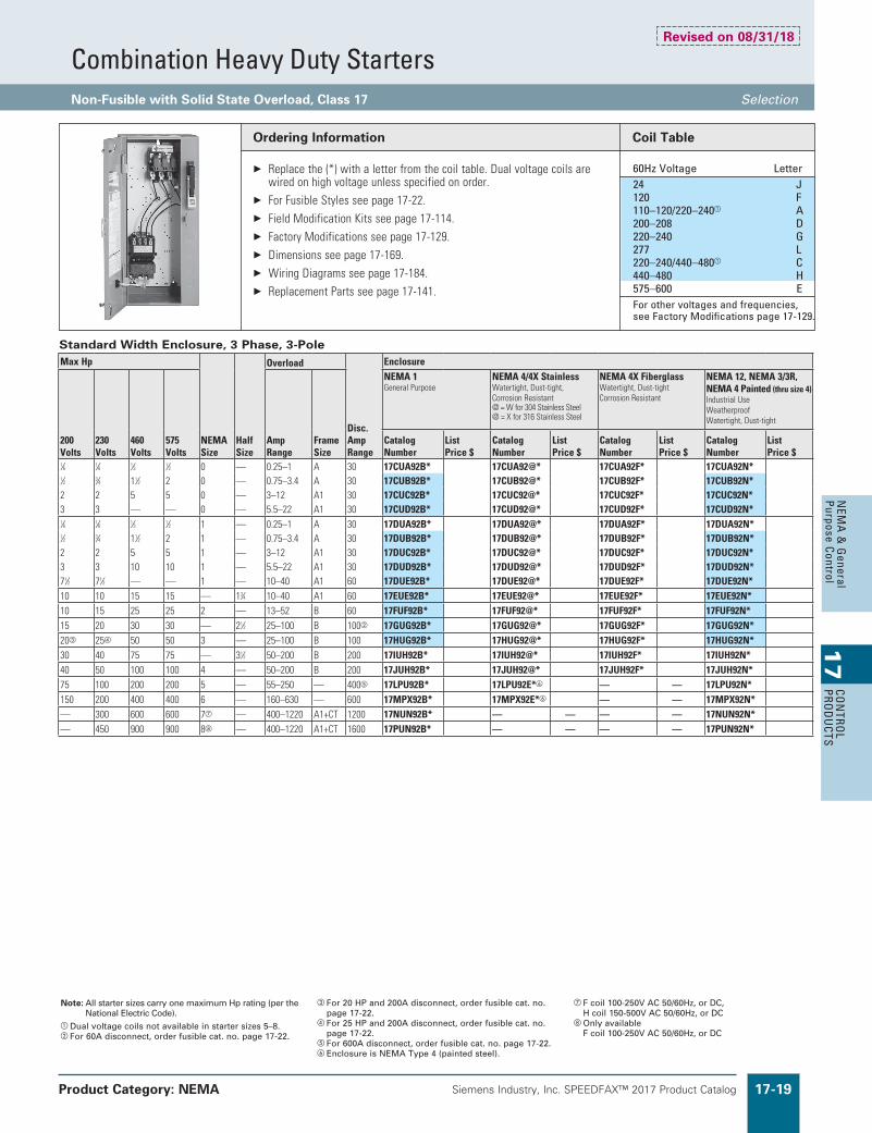
Combination Heavy Duty StartersNon-Fusible with Solid State Overload, Class 17 Selection
Product Category: NEMA
Note: All starter sizes carry one maximum Hp rating (per the National Electric Code).
a Dual voltage coils not available in starter sizes 5–8.b For 60A disconnect, order fusible cat. no. page 17-22.
c For 20 HP and 200A disconnect, order fusible cat. no. page 17-22.
d For 25 HP and 200A disconnect, order fusible cat. no. page 17-22.
e For 600A disconnect, order fusible cat. no. page 17-22.f Enclosure is NEMA Type 4 (painted steel).
g F coil 100-250V AC 50/60Hz, or DC, H coil 150-500V AC 50/60Hz, or DC
Only availableF coil 100-250V AC 50/60Hz, or DC
Ordering Information
Replacethe(*)withaletterfromthecoiltable.Dualvoltagecoilsarewiredonhighvoltageunlessspecifiedonorder.
ForFusibleStylesseepage17-22. FieldModificationKitsseepage17-114. FactoryModificationsseepage17-129. Dimensionsseepage17-169. WiringDiagramsseepage17-184. ReplacementPartsseepage17-141.
Coil Table
60Hz Voltage Letter 24 J 120 F 110–120/220–240a A 200–208 D 220–240 G 277 L 220–240/440–480a C 440–480 H 575–600 E For other voltages and frequencies,
see Factory Modifications page 17-129.
Standard Width Enclosure, 3 Phase, 3-PoleMaxHp
NEMASize
HalfSize
Overload
Disc.AmpRange
Enclosure
200Volts
230Volts
460Volts
575Volts
AmpRange
FrameSize
NEMA1GeneralPurpose
NEMA4/4XStainlessWatertight,Dust-tight,CorrosionResistant@=Wfor304StainlessSteel@=Xfor316StainlessSteel
NEMA4XFiberglassWatertight,Dust-tightCorrosionResistant
NEMA12,NEMA3/3R,NEMA4Painted(thrusize4)IndustrialUseWeatherproofWatertight,Dust-tight
CatalogNumber
ListPrice$
CatalogNumber
ListPrice$
CatalogNumber
ListPrice$
CatalogNumber
ListPrice$
1⁄6 1⁄6 1⁄3 1⁄2 0 — 0.25–1 A 30 17CUA92B* 17CUA92@* 17CUA92F* 17CUA92N* 1⁄2 3⁄4 11⁄2 2 0 — 0.75–3.4 A 30 17CUB92B* 17CUB92@* 17CUB92F* 17CUB92N* 2 2 5 5 0 — 3–12 A1 30 17CUC92B* 17CUC92@* 17CUC92F* 17CUC92N* 3 3 — — 0 — 5.5–22 A1 30 17CUD92B* 17CUD92@* 17CUD92F* 17CUD92N* 1⁄6 1⁄6 1⁄3 1⁄2 1 — 0.25–1 A 30 17DUA92B* 17DUA92@* 17DUA92F* 17DUA92N* 1⁄2 3⁄4 11⁄2 2 1 — 0.75–3.4 A 30 17DUB92B* 17DUB92@* 17DUB92F* 17DUB92N* 2 2 5 5 1 — 3–12 A1 30 17DUC92B* 17DUC92@* 17DUC92F* 17DUC92N* 3 3 10 10 1 — 5.5–22 A1 30 17DUD92B* 17DUD92@* 17DUD92F* 17DUD92N* 71⁄2 71⁄2 — — 1 — 10–40 A1 60 17DUE92B* 17DUE92@* 17DUE92F* 17DUE92N* 10 10 15 15 — 13⁄4 10–40 A1 60 17EUE92B* 17EUE92@* 17EUE92F* 17EUE92N* 10 15 25 25 2 — 13–52 B 60 17FUF92B* 17FUF92@* 17FUF92F* 17FUF92N* 15 20 30 30 — 21⁄2 25–100 B 100b 17GUG92B* 17GUG92@* 17GUG92F* 17GUG92N* 20c 25d 50 50 3 — 25–100 B 100 17HUG92B* 17HUG92@* 17HUG92F* 17HUG92N* 30 40 75 75 — 31⁄2 50–200 B 200 17IUH92B* 17IUH92@* 17IUH92F* 17IUH92N* 40 50 100 100 4 — 50–200 B 200 17JUH92B* 17JUH92@* 17JUH92F* 17JUH92N* 75 100 200 200 5 — 55–250 — 400e 17LPU92B* 17LPU92E*f — — 17LPU92N* 150 200 400 400 6 — 160–630 — 600 17MPX92B* 17MPX92E*f — — 17MPX92N* — 300 600 600 7g — 400–1220 A1+CT 1200 17NUN92B* — — — — 17NUN92N* — 450 900 900 8 — 400–1220 A1+CT 1600 17PUN92B* — — — — 17PUN92N*
Revised on 08/31/18

Siemens Industry, Inc. SPEEDFAX™ 2017 Product Catalog17-20
17
CON
TRO
L PR
OD
UCT
SN
EMA
& G
ener
al
Purp
ose
Cont
rol
Siemens / Speedfax Previous folio: 16-19, 10IC 8-19
Combination Heavy Duty StartersNon-Fusible with Solid State Overload, Class 17 Selection
Product Category: NEMA
Note: All starter sizes carry one maximum Hp rating (per the National Electric Code).
a For 60A disconnect, order fusible cat. no. page 17-23.b For 20 HP and 200A disconnect, order fusible cat. no.
page 17-23.
c For 25 HP and 200A disconnect, order fusible cat. no. page 17-23.
Ordering Information
Replacethe(*)withaletterfromthecoiltable.Dualvoltagecoilsarewiredonhighvoltageunlessspecifiedonorder.
ForFusibleStylesseepage17-23. FieldModificationKitsseepage17-114. FactoryModificationsseepage17-129. Dimensionsseepage17-169. WiringDiagramsseepage17-184. ReplacementPartsseepage17-141.
Coil Table
60Hz Voltage Letter 24 J 120 F 110–120/220–240a A 200–208 D 220–240 G 277 L 220–240/440–480a C 440–480 H 575–600 E For other voltages and frequencies,
see Factory Modifications page 17-129.
Extra Wide Enclosure, 3-Phase, 3-Pole
Hp
NEMASize
HalfSize
Overload
Disc.AmpRange
Enclosure
200Volts
230Volts
460Volts
575Volts
AmpRange
FrameSize
NEMA1GeneralPurpose
NEMA4/4XStainlessWatertight,Dust-tight,CorrosionResistant@=Wfor304StainlessSteel@=Xfor316StainlessSteel
NEMA12,NEMA3/3R,NEMA4PaintedIndustrialUseWeatherproofWatertight,Dust-tight
CatalogNumber
ListPrice$
CatalogNumber
ListPrice$
CatalogNumber
ListPrice$
1⁄6 1⁄6 1⁄3 1⁄2 0 — 0.25–1 A 30 17CUA82B* 17CUA82@* 17CUA82N* 1⁄2 3⁄4 11⁄2 2 0 — 0.75–3.4 A 30 17CUB82B* 17CUB82@* 17CUB82N*
2 2 5 5 0 — 3–12 A1 30 17CUC82B* 17CUC82@* 17CUC82N*
3 3 — — 0 — 5.5–22 A1 30 17CUD82B* 17CUD82@* 17CUD82N* 1⁄6 1⁄6 1⁄3 1⁄2 1 — 0.25–1 A 30 17DUA82B* 17DUA82@* 17DUA82N* 1⁄2 3⁄4 11⁄2 2 1 — 0.75–3.4 A 30 17DUB82B* 17DUB82@* 17DUB82N*
2 2 5 5 1 — 3–12 A1 30 17DUC82B* 17DUC82@* 17DUC82N*
3 3 10 10 1 — 5.5–22 A1 30 17DUD82B* 17DUD82@* 17DUD82N*
71⁄2 71⁄2 — — 1 — 10–40 A1 60 17DUE82B* 17DUE82@* 17DUE82N*
10 10 15 15 — 13⁄4 10–40 A1 60 17EUE82B* 17EUE82@* 17EUE82N*
10 15 25 25 2 — 13–52 B 60 17FUF82B* 17FUF82@* 17FUF82N*
15 20 30 30 — 21⁄2 25–100 B 100a 17GUG82B* 17GUG82@* 17GUG82N*
20b 25c 50 50 3 — 25–100 B 100 17HUG82B* 17HUG82@* 17HUG82N*
Revised on 08/31/18

Siemens Industry, Inc. SPEEDFAX™ 2017 Product Catalog 17-21
17
CON
TROL
PROD
UCTS
NEM
A &
General
Purpose Control
Siemens / Speedfax Previous folio: 16-20, 10IC 8-20
Combination Heavy Duty StartersNon-Fusible with Ambient Compensated Bimetal Overload, Class 17 Selection
Product Category: NEMA
Note: Hp’s shown above are based on the overload amprange for the FLA’s (per the National Electric Code) of typical industrial motors. All starter sizes carry one maximum Hp rating.
a For 60A disc, order fusible cat. no. page 17-24.b For 25 HP and 200A disconnect, order fusible cat. no.
page 17-24.
c For 30 HP and 200A disconnect, order fusible cat. no. page 17-24.
Ordering Information
Replacethe(*)withaletterfromthecoiltable.Dualvoltagecoilsarewiredonhighvoltageunlessspecifiedonorder.
Heaterelementsseepage17-134.(3required) FieldModificationKitsseepage17-114. FactoryModificationsseepage17-129. Dimensionsseepage17-169. WiringDiagramsseepage17-184. ReplacementPartsseepage17-141. ForNO/NCSPDTcontactonoverloadrelay,replace"81"with"91". "81"indicatesoneNCcontact.
Coil Table
60Hz Voltage Letter 24 J 120 F 110–120/220–240 A 200–208 D 220–240 G 277 L 220–240/440–480 C 440–480 H 575–600 E For other voltages and frequencies,
see Factory Modifications page 17-129.
Standard Width Enclosure, 3-Phase, 3-PoleMaxHp
NEMASize
HalfSize
DiscAmpRating
Enclosure
200Volts
230Volts
460Volts
575Volts
NEMA1GeneralPurpose
NEMA4/4XStainlessWatertight,Dust-tightCorrosionResistant@=Wfor304StainlessSteel@=Xfor316StainlessSteel
NEMA4XFiberglassWatertight,Dust-tightCorrosionResistantWeatherproof
NEMA12,NEMA3/3R,NEMA4PaintedIndustrialUseWatertight,Dust-tight
CatalogNumber ListPrice$ CatalogNumber ListPrice$ CatalogNumber ListPrice$ CatalogNumber ListPrice$3 3 5 5 0 — 30 17CP92B*81 17CP92@*81 17CP92F*81 17CP92N*81
71⁄2 71⁄2 10 10 1 — 30 17DP92B*81 17DP92@*81 17DP92F*81 17DP92N*81 10 10 15 15 — 13⁄4 60 17EP92B*81 17EP92@*81 17EP92F*81 17EP92N*81 10 15 25 25 2 — 60 17FP92B*81 17FP92@*81 17FP92F*81 17FP92N*81 15 20 30 30 — 21⁄2 100a 17GP92B*81 17GP92@*81 17GP92F*81 17GP92N*81 25b 30c 50 50 3 — 100 17HP92B*81 17HP92@*81 17HP92F*81 17HP92N*81 30 40 75 75 — 31⁄2 200 17IP92B*81 17IP92@*81 17IP92F*81 17IP92N*81 40 50 100 100 4 — 200 17JP92B*81 17JP92@*81 17JP92F*81 17JP92N*81
Extra Wide Enclosure, 3-Phase, 3-PoleMaxHp
NEMASize
HalfSize
DiscAmpRating
Enclosure
200Volts
230Volts
460Volts
575Volts
NEMA1GeneralPurpose
NEMA4/4XStainlessWatertight,Dust-tightCorrosionResistant@=Wfor304StainlessSteel@=Xfor316StainlessSteel
NEMA12,NEMA3/3R,NEMA4PaintedIndustrialUseWeatherproofWatertight,Dust-tight
CatalogNumber ListPrice$ CatalogNumber ListPrice$ CatalogNumber ListPrice$3 3 5 5 0 — 30 17CP82B*81 17CP82@*81 17CP82N*81
71⁄2 71⁄2 10 10 1 — 30 17DP82B*81 17DP82@*81 17DP82N*81 10 10 15 15 — 13⁄4 60 17EP82B*81 17EP82@*81 17EP82N*81 10 15 25 25 2 — 60 17FP82B*81 17FP82@*81 17FP82N*81 15 20 30 30 — 21⁄2 100a 17GP82B*81 17GP82@*81 17GP82N*81 25b 30c 50 50 3 — 100 17HP82B*81 17HP82@*81 17HP82N*81
Standard Width Enclosure, Single Phase, (Catalog Numbers are three phase, wire for single phase in the field)MaxHp
NEMASize
HalfSize
DiscAmpRating
Enclosure
115Volts
208/230Volts
NEMA1GeneralPurpose
NEMA4/4XStainlessWatertight,Dust-tightCorrosionResistant@=Wfor304StainlessSteel@=Xfor316StainlessSteel
NEMA4XFiberglassWatertight,Dust-tightCorrosionResistant
NEMA12,NEMA3/3R,NEMA4PaintedIndustrialUseWeatherproofWatertight,Dust-tight
CatalogNumber ListPrice$ CatalogNumber ListPrice$ CatalogNumber ListPrice$ CatalogNumber ListPrice$1 2 0 — 30 17CP92B*81 17CP92@*81 17CP92F*81 17CP92N*81 2 3 1 — 30 17DP92B*81 17DP92@*81 17DP92F*81 17DP92N*81 3 5 1P — 60 17EP92B*81 17EP92@*81 17EP92F*81 17EP92N*81 3 71⁄2 2 — 60 17FP92B*81 17FP92@*81 17FP92F*81 17FP92N*81 5 10 — 21⁄2 100a 17GP92B*81 17GP92@*81 17GP92F*81 17GP92N*81
Revised on 08/31/18

Siemens Industry, Inc. SPEEDFAX™ 2017 Product Catalog17-22
17
CON
TRO
L PR
OD
UCT
SN
EMA
& G
ener
al
Purp
ose
Cont
rol
Siemens / Speedfax Previous folio: 16-21, 10IC 8-21
Combination Heavy Duty StartersFusible with Solid State Overload, Class 17 Selection
Note: All starter sizes carry one maximum Hp rating (per the National Electric Code).
a Dual voltage coils not available in starter sizes 5–8.b Use Class J fuses only.
c Enclosure is NEMA Type 4 (painted steel).d Single phase wiring page 17-183.e F coil 100-250V AC 50/60Hz, or DC,
H coil 150-500V AC 50/60Hz, or DC
f Only availableF coil 100-250V AC 50/60Hz, or DC
Ordering Information
Replacethe(*)withaletterfromthecoiltable.Dualvoltagecoilsarewiredonhighvoltageunlessspecifiedonorder.
FieldModificationKitsseepage17-114. FactoryModificationsseepage17-129. Dimensionsseepage17-169. WiringDiagramsseepage17-184. ReplacementPartsseepage17-141.
Coil Table
60Hz Voltage Letter 24 J 120 F 110–120/220–240a A 200–208 D 220–240 G 277 L 220–240/440–480a C 440–480 H 575–600 E For other voltages and frequencies,
see Factory Modifications page 17-129.
Standard Width Enclosure, 3-Phase, 3-Poled
MaxHp
NEMASize
HalfSize
Overload
Disc.AmpRange
FuseClipAmp/Volts
Enclosure
200Volts
230Volts
460Volts
575Volts
AmpRange
FrameSize
NEMA1GeneralPurpose
NEMA4/4XStainlessWatertight,Dust-tight,CorrosionResistant@=Wfor304StainlessSteel@=Xfor316StainlessSteel
NEMA4XFiberglassWatertight,Dust-tightCorrosionResistant
NEMA12,NEMA3/3R,NEMA4Painted(thrusize4)IndustrialUseWeatherproofWatertight,Dust-tight
CatalogNumber
ListPrice$
CatalogNumber
ListPrice$
CatalogNumber
ListPrice$
CatalogNumber
ListPrice$
1⁄6 1⁄6 — — 0 — 0.25–1 A 30 30A/250V 17CUA92B*10 17CUA92@*10 17CUA92F*10 17CUA92N*10 — — 1⁄3 1⁄2 0 — 0.25–1 A 30 30A/600V 17CUA92B*11 17CUA92@*11 17CUA92F*11 17CUA92N*11 1⁄2 3⁄4 — — 0 — 0.75–3.4 A 30 30A/250V 17CUB92B*10 17CUB92@*10 17CUB92F*10 17CUB92N*10 — — 11⁄2 2 0 — 0.75–3.4 A 30 30A/600V 17CUB92B*11 17CUB92@*11 17CUB92F*11 17CUB92N*11 2 2 — — 0 — 3–12 A1 30 30A/250V 17CUC92B*10 17CUC92@*10 17CUC92F*10 17CUC92N*10 — — 5 5 0 — 3–12 A1 30 30A/600V 17CUC92B*11 17CUC92@*11 17CUC92F*11 17CUC92N*11 3 3 — — 0 — 5.5–22 A1 30 30A/250V 17CUD92B*10 17CUD92@*10 17CUD92F*10 17CUD92N*10 1⁄6 1⁄6 — — 1 — 0.25–1 A 30 30A/250V 17DUA92B*10 17DUA92@*10 17DUA92F*10 17DUA92N*10 — — 1⁄3 1⁄2 1 — 0.25–1 A 30 30A/600V 17DUA92B*11 17DUA92@*11 17DUA92F*11 17DUA92N*11 1⁄2 3⁄4 — — 1 — 0.75–3.4 A 30 30A/250V 17DUB92B*10 17DUB92@*10 17DUB92F*10 17DUB92N*10 — — 11⁄2 2 1 — 0.75–3.4 A 30 30A/600V 17DUB92B*11 17DUB92@*11 17DUB92F*11 17DUB92N*11 2 2 — — 1 — 3–12 A1 30 30A/250V 17DUC92B*10 17DUC92@*10 17DUC92F*10 17DUC92N*10 — — 5 5 1 — 3–12 A1 30 30A/600V 17DUC92B*11 17DUC92@*11 17DUC92F*11 17DUC92N*11 3 3 — — 1 — 5.5–22 A1 30 30A/250V 17DUD92B*10 17DUD92@*10 17DUD92F*10 17DUD92N*10 — — 10 10 1 — 5.5–22 A1 30 30A/600V 17DUD92B*11 17DUD92@*11 17DUD92F*11 17DUD92N*11 71⁄2 71⁄2 — — 1 — 10–40 A1 30 30A/250V 17DUE92B*10 17DUE92@*10 17DUE92F*10 17DUE92N*10 71⁄2 71⁄2 — — 1 — 10–40 A1 60 60A/250V 17DUE92B*12 17DUE92@*12 17DUE92F*12 17DUE92N*12 — — 15 15 — 13⁄4 10–40 A1 60 60A/600V 17EUE92B*13 17EUE92@*13 17EUE92F*13 17EUE92N*13 10 10 — — — 13⁄4 10–40 A1 60 60A/250V 17EUE92B*12 17EUE92@*12 17EUE92F*12 17EUE92N*12 10 15 — — 2 — 13–52 B 60 60A/250V 17FUF92B*12 17FUF92@*12 17FUF92F*12 17FUF92N*12 — — 25 25 2 — 13–52 B 60 60A/600V 17FUF92B*13 17FUF92@*13 17FUF92F*13 17FUF92N*13 — — — 30 — 21⁄2 25–100 B 60 60A/600V 17GUG92B*13 17GUG92@*13 17GUG92F*13 17GUG92N*13 — — 30 — — 21⁄2 25–100 B 100 100A/600V 17GUG92B*15 17GUG92@*15 17GUG92F*15 17GUG92N*15 15 20 — — — 21⁄2 25–100 B 100 100A/250V 17GUG92B*14 17GUG92@*14 17GUG92F*14 17GUG92N*14 20 25 — — 3 — 25–100 B 100 100A/250V 17HUG92B*14 17HUG92@*14 17HUG92F*14 17HUG92N*14 — — 50 50 3 — 25–100 B 100 100A/600V 17HUG92B*15 17HUG92@*15 17HUG92F*15 17HUG92N*15 25 30 — — 3 — 25–100 B 200 200A/250V 17HUG92B*16 17HUG92@*16 17HUG92F*16 17HUG92N*16 30 40 — — — 31⁄2 50–200 B 200 200A/250V 17IUH92B*16 17IUH92@*16 17IUH92F*16 17IUH92N*16 — — 75 75 — 31⁄2 50–200 B 200 200A/600V 17IUH92B*17 17IUH92@*17 17IUH92F*17 17IUH92N*17 40 50 — — 4 — 50–200 B 200 200A/250V 17JUH92B*16 17JUH92@*16 17JUH92F*16 17JUH92N*16 — — 100 100 4 — 50–200 B 200 200A/600V 17JUH92B*17 17JUH92@*17 17JUH92F*17 17JUH92N*17 75 100 — — 5 — 55–250 — 400 400A/250V 17LPU92B*18 17LPU92E*18c — — 17LPU92N*18 — 100 — — 5 — 55–250 — 600 600A/250Vb 17LPU92B*20 17LPU92E*20c — — 17LPU92N*20 — — — 125 5 — 55–250 — 200 200A/600V 17LPU92B*17 17LPU92E*17c — — 17LPU92N*17 — — 200 200 5 — 55–250 — 400 400A/600V 17LPU92B*19 17LPU92E*19c — — 17LPU92N*19 — — 200 — 5 — 55–250 — 600 600A/600Vb 17LPU92B*21 17LPU92E*21c — — 17LPU92N*21 150 200 — — 6 — 160–630 — 600 600A/250V 17MPX92B*20 17MPX92E*20c — — 17MPX92N*20 — — 400 400 6 — 160–630 — 600 600A/600V 17MPX92B*21 17MPX92E*21c — — 17MPX92N*21 — — 400 400 6 — 160–630 — 800 800A/600V 17MPX92B*23 17MPX92E*23c — — 17MPX92N*23 — — 600 600 7e — 400–1220 A1+CT 1200 1200A/600V 17NUN92B*24 — — — — 17NUN92N*24 — — 900 900 8f — 400–1220 A1+CT 1600 1600A/600V 17PUN92B*25 — — — — 17PUN92N*25
Revised on 08/31/18

Siemens Industry, Inc. SPEEDFAX™ 2017 Product Catalog 17-23
17
CON
TROL
PROD
UCTS
NEM
A &
General
Purpose Control
Combination Heavy Duty StartersFusible with Solid State Overload, Class 17 Selection
Note: All starter sizes carry one maximum Hp rating (per the National Electric Code).
Ordering Information
Replacethe(*)withaletterfromthecoiltable.Dualvoltagecoilsarewiredonhighvoltageunlessspecifiedonorder.
FieldModificationKitsseepage17-114. FactoryModificationsseepage17-129. Dimensionsseepage17-169. WiringDiagramsseepage17-184. ReplacementPartsseepage17-141.
Coil Table
60Hz Voltage Letter 24 J 120 F 110–120/220–240 A 200–208 D 220–240 G 277 L 220–240/440–480 C 440–480 H 575–600 E For other voltages and frequencies,
see Factory Modifications page 17-129.
Extra Wide Enclosure, 3-Phase, 3-Pole
MaxHp
NEMASize
HalfSize
Overload
Disc.AmpRange
FuseClipAmp/Volts
Enclosure
200Volts
230Volts
460Volts
575Volts
AmpRange
FrameSize
NEMA1GeneralPurpose
NEMA4/4XStainlessWatertight,Dust-tight,@=Wfor304StainlessSteel@=Xfor316StainlessSteel
NEMA12,NEMA3/3R,NEMA4PaintedIndustrialUseWeatherproofWatertight,Dust-tight
CatalogNumber
ListPrice$
CatalogNumber
ListPrice$
CatalogNumber
ListPrice$
1⁄6 1⁄6 — — 0 — 0.25–1 A 30 30A/250V 17CUA82B*10 17CUA82@*10 17CUA82N*10
— —1⁄3 1⁄2 0 — 0.25–1 A 30 30A/600V 17CUA82B*11 17CUA82@*11 17CUA82N*11
1⁄2 3⁄4 — — 0 — 0.75–3.4 A 30 30A/250V 17CUB82B*10 17CUB82@*10 17CUB82N*10
— — 11⁄2 2 0 — 0.75–3.4 A 30 30A/600V 17CUB82B*11 17CUB82@*11 17CUB82N*11
2 2 — — 0 — 3–12 A1 30 30A/250V 17CUC82B*10 17CUC82@*10 17CUC82N*10
— — 5 5 0 — 3–12 A1 30 30A/600V 17CUC82B*11 17CUC82@*11 17CUC82N*11
3 3 — — 0 — 5.5–22 A1 30 30A/250V 17CUD82B*10 17CUD82@*10 17CUD82N*10 1⁄6 1⁄6 — — 1 — 0.25–1 A 30 30A/250V 17DUA82B*10 17DUA82@*10 17DUA82N*10
— —1⁄3 1⁄2 1 — 0.25–1 A 30 30A/600V 17DUA82B*11 17DUA82@*11 17DUA82N*11
1⁄2 3⁄4 — — 1 — 0.75–3.4 A 30 30A/250V 17DUB82B*10 17DUB82@*10 17DUB82N*10
— — 11⁄2 2 1 — 0.75–3.4 A 30 30A/600V 17DUB82B*11 17DUB82@*11 17DUB82N*11
2 2 — — 1 — 3–12 A1 30 30A/250V 17DUC82B*10 17DUC82@*10 17DUC82N*10
— — 5 5 1 — 3–12 A1 30 30A/600V 17DUC82B*11 17DUC82@*11 17DUC82N*11
3 3 — — 1 — 5.5–22 A1 30 30A/250V 17DUD82B*10 17DUD82@*10 17DUD82N*10
— — 10 10 1 — 5.5–22 A1 30 30A/600V 17DUD82B*11 17DUD82@*11 17DUD82N*11
5 5 — — 1 — 10–40 A1 30 30A/250V 17DUE82B*10 17DUE82@*10 17DUE82N*10
71⁄2 71⁄2 — — 1 — 10–40 A1 60 60A/250V 17DUE82B*12 17DUE82@*12 17DUE82N*12
— — 15 15 — 13⁄4 10–40 A1 60 60A/600V 17EUE82B*13 17EUE82@*13 17EUE82N*13
10 10 — — — 13⁄4 10–40 A1 60 60A/250V 17EUE82B*12 17EUE82@*12 17EUE82N*12
10 15 — — 2 — 13–52 B 60 60A/250V 17FUF82B*12 17FUF82@*12 17FUF82N*12
— — 25 25 2 — 13–52 B 60 60A/600V 17FUF82B*13 17FUF82@*13 17FUF82N*13
— — — 30 — 21⁄2 25–100 B 60 60A/600V 17GUG82B*13 17GUG82@*13 17GUG82N*13
— — 30 — — 21⁄2 25–100 B 100 100A/600V 17GUG82B*15 17GUG82@*15 17GUG82N*15
15 20 — — — 21⁄2 25–100 B 100 100A/250V 17GUG82B*14 17GUG82@*14 17GUG82N*14
20 25 — — 3 — 25–100 B 100 100A/250V 17HUG82B*14 17HUG82@*14 17HUG82N*14
— — 50 50 3 — 25–100 B 100 100A/600V 17HUG82B*15 17HUG82@*15 17HUG82N*15
25 30 — — 3 — 25–100 B 200 200A/250V 17HUG82B*16 17HUG82@*16 17HUG82N*16
Revised on 08/31/18

Siemens Industry, Inc. SPEEDFAX™ 2017 Product Catalog17-24
17
CON
TRO
L PR
OD
UCT
SN
EMA
& G
ener
al
Purp
ose
Cont
rol
Siemens / Speedfax Previous folio: 16-23, 10IC 8-23
Combination Heavy Duty StartersFusible with Ambient Compensated Bimetal Overload, Class 17 Selection
Product Category: NEMA
Note: Hp’s shown above are based on the overload amp range for the FLA’s (per the National Electric Code) of typical industrial motors. All starter sizes carry one maximum Hp rating.
a Single phase wiring page 17-183.
Ordering Information
Replacethe(*)withaletterfromthecoiltable.Dualvoltagecoilsarewiredonhighvoltageunlessspecifiedonorder.
Heaterelementsseepage17-134.(3required) FieldModificationKitsseepage17-114. FactoryModificationsseepage17-129. Dimensionsseepage17-169. WiringDiagramsseepage17-184. ReplacementPartsseepage17-141. ForNO/NCSPDTcontactonoverloadrelay,replace"81"with"91". "81"indicatesoneNCcontact.
Coil Table
60Hz Voltage Letter 24 J 120 F 110–120/220–240 A 200–208 D 220–240 G 277 L 220–240/440–480 C 440–480 H 575–600 E For other voltages and frequencies,
see Factory Modifications page 17-129.
Standard Width Enclosure, 3-Phase, 3-Polea
MaxHp
NEMASize
HalfSize
DiscAmpRating
FuseClipSizeAmps/Volts
Enclosure
200Volts
230Volts
460Volts
575Volts
NEMA1GeneralPurpose
NEMA4/4XStainlessWatertight,Dust-tightCorrosionResistant@=Wfor304StainlessSteel@=Xfor316StainlessSteel
NEMA4XFiberglassWatertight,Dust-tightCorrosionResistant
NEMA12,NEMA3/3R,NEMA4PaintedIndustrialUseWeatherproofWatertight,Dust-tight
CatalogNumber
ListPrice$
CatalogNumber
ListPrice$
CatalogNumber
ListPrice$
CatalogNumber
ListPrice$
3 3 — — 0 — 30 30A/250V 17CP92B*1081 17CP92@*1081 17CP92F*1081 17CP92N*1081 — — 5 5 0 — 30 30A/600V 17CP92B*1181 17CP92@*1181 17CP92F*1181 17CP92N*1181 5 5 — — 1 — 30 30A/250V 17DP92B*1081 17DP92@*1081 17DP92F*1081 17DP92N*1081 — — 10 10 1 — 30 30A/600V 17DP92B*1181 17DP92@*1181 17DP92F*1181 17DP92N*1181 71⁄2 71⁄2 — — 1 — 60 60A/250V 17DP92B*1281 17DP92@*1281 17DP92F*1281 17DP92N*1281 10 10 — — — 13⁄4 60 60A/250V 17EP92B*1281 17EP92@*1281 17EP92F*1281 17EP92N*1281 — — 15 15 — 13⁄4 60 60A/600V 17EP92B*1381 17EP92@*1381 17EP92F*1381 17EP92N*1381 10 15 — — 2 — 60 60A/250V 17FP92B*1281 17FP92@*1281 17FP92F*1281 17FP92N*1281 — — 25 25 2 — 60 60A/600V 17FP92B*1381 17FP92@*1381 17FP92F*1381 17FP92N*1381 — — — 30 — 21⁄2 60 60A/600V 17GP92B*1381 17GP92@*1381 17GP92F*1381 17GP92N*1381 — — 30 — — 21⁄2 100 100A/600V 17GP92B*1581 17GP92@*1581 17GP92F*1581 17GP92N*1581 15 20 — — — 21⁄2 100 100A/250V 17GP92B*1481 17GP92@*1481 17GP92F*1481 17GP92N*1481 20 25 — — 3 — 100 100A/250V 17HP92B*1481 17HP92@*1481 17HP92F*1481 17HP92N*1481 — — 50 50 3 — 100 100A/600V 17HP92B*1581 17HP92@*1581 17HP92F*1581 17HP92N*1581 25 30 — — 3 — 200 200A/250V 17HP92B*1681 17HP92@*1681 17HP92F*1681 17HP92N*1681 30 40 — — — 31⁄2 200 200A/250V 17IP92B*1681 17IP92@*1681 17IP92F*1681 17IP92N*1681 — — 75 75 — 31⁄2 200 200A/600V 17IP92B*1781 17IP92@*1781 17IP92F*1781 17IP92N*1781 40 50 — — 4 — 200 200A/250V 17JP92B*1681 17JP92@*1681 17JP92F*1681 17JP92N*1681 — — 100 100 4 — 200 200A/600V 17JP92B*1781 17JP92@*1781 17JP92F*1781 17JP92N*1781
Extra Wide Enclosure, 3-Phase, 3-Pole
MaxHp
NEMASize
HalfSize
DiscAmpRating
FuseClipSizeAmps/Volts
Enclosure
200Volts
230Volts
460Volts
575Volts
NEMA1GeneralPurpose
NEMA4/4XStainlessWatertight,Dust-tightIndustrialUseWeatherproof@=Wfor304StainlessSteel@=Xfor316StainlessSteel
NEMA12,NEMA3/3R,NEMA4PaintedIndustrialUseWeatherproofWatertight,Dust-tight
CatalogNumber ListPrice$ CatalogNumber ListPrice$ CatalogNumber ListPrice$
3 3 — — 0 — 30 30A/250V 17CP82B*1081 17CP82@*1081 17CP82N*1081— — 5 5 0 — 30 30A/600V 17CP82B*1181 17CP82@*1181 17CP82N*11815 5 — — 1 — 30 30A/250V 17DP82B*1081 17DP82@*1081 17DP82N*1081— — 10 10 1 — 30 30A/600V 17DP82B*1181 17DP82@*1181 17DP82N*118171⁄2 71⁄2 — — 1 — 60 60A/250V 17DP82B*1281 17DP82@*1281 17DP82N*128110 10 — — — 13⁄4 60 60A/250V 17EP82B*1281 17EP82@*1281 17EP82N*1281— — 15 15 — 13⁄4 60 60A/600V 17EP82B*1381 17EP82@*1381 17EP82N*138110 15 — — 2 — 60 60A/250V 17FP82B*1281 17FP82@*1281 17FP82N*1281— — 25 25 2 — 60 60A/600V 17FP82B*1381 17FP82@*1381 17FP82N*1381— — — 30 — 21⁄2 60 60A/600V 17GP82B*1381 17GP82@*1381 17GP82N*1381— — 30 — — 21⁄2 100 100A/600V 17GP82B*1581 17GP82@*1581 17GP82N*158115 20 — — — 21⁄2 100 100A/250V 17GP82B*1481 17GP82@*1481 17GP82N*148120 25 — — 3 — 100 100A/250V 17HP82B*1481 17HP82@*1481 17HP82N*1481— — 50 50 3 — 100 100A/600V 17HP82B*1581 17HP82@*1581 17HP82N*158125 30 — — 3 — 200 200A/250V 17HP82B*1681 17HP82@*1681 17HP82N*1681
Revised on 08/31/18

Siemens Industry, Inc. SPEEDFAX™ 2017 Product Catalog 17-25
17
CON
TROL
PROD
UCTS
NEM
A &
General
Purpose Control
Combination Heavy Duty StartersMCP Type with Solid State Overload, Class 18 Selection
Product Category: NEMA
Note: All starter sizes carry one maximum Hp rating (per the National Electric Code).
a Dual voltage coils not available in starter sizes 5–8.
b Enclosure is NEMA Type 4 (painted steel).c F coil 100-250V AC 50/60Hz, or DC,
H coil 150-500V AC 50/60Hz, or DC
d Only availableF coil 100-250V AC 50/60Hz, or DC
Ordering Information
Replacethe(*)withaletterfromthecoiltable.Dualvoltagecoilsarewiredonhighvoltageunlessspecifiedonorder.
FieldModificationKitsseepage17-114. FactoryModificationsseepage17-129. Dimensionsseepage17-169. WiringDiagramsseepage17-184. ReplacementPartsseepage17-141.
Coil Table
60Hz Voltage Letter 24 J 120 F 110–120/220–240a A 200–208 D 220–240 G 277 L 220–240/440–480a C 440–480 H 575–600 E For other voltages and frequencies,
see Factory Modifications page 17-129.
Standard Width Enclosure, 3-Phase, 3-PoleMaxHp
NEMASize
HalfSize
MotorCircuitInterruterETIAmps
Overload Enclosure
200Volts
230Volts
460Volts
575Volts
AmpRange
FrameSize
NEMA1GeneralPurpose
NEMA4/4XStainlessWatertight,Dust-tight,CorrosionResistant@=Wfor304StainlessSteel@=Xfor316StainlessSteel
NEMA4XFiberglassWatertight,Dust-tightCorrosionResistant
NEMA7&9NEMA3&4Div.1andDiv.2ClassIGroupsC&DClassIIGroupsE,F&GClassIIIBoltedEnclosuresIndoor/OutdoorUse
NEMA12,NEMA3/3R,NEMA4Painted(thrusize4)IndustrialUseWeatherproofWatertight,Dust-tight
CatalogNumber
ListPrice$
CatalogNumber
ListPrice$
CatalogNumber
ListPrice$
CatalogNumber
ListPrice$
CatalogNumber
ListPrice$
1⁄2 1⁄2 1 1 0 — 3 0.75–3.4 A 18CUB92B* 18CUB92@* 18CUB92F* 18CUB92H* 18CUB92N*
2 2 5 5 0 — 10 3–12 A1 18CUC92B* 18CUC92@* 18CUC92F* 18CUC92H* 18CUC92N*
3 3 — — 0 — 25 5.5–22 A1 18CUD92B* 18CUD92@* 18CUD92F* 18CUD92H* 18CUD92N* 1⁄2 1⁄2 1 1 1 — 3 0.75–3.4 A 18DUB92B* 18DUB92@* 18DUB92F* 18DUB92H* 18DUB92N*
2 2 5 5 1 — 10 3–12 A1 18DUC92B* 18DUC92@* 18DUC92F* 18DUC92H* 18DUC92N*
3 3 71⁄2 10 1 — 25 5.5–22 A1 18DUD92B* 18DUD92@* 18DUD92F* 18DUD92H* 18DUD92N*
71⁄2 71⁄2 10 — 1 — 30 10–40 A1 18DUE92B* 18DUE92@* 18DUE92F* 18DUE92H* 18DUE92N*
— — 15 15 — 13⁄4 40 10–40 A1 18EUE92B* 18EUE92@* 18EUE92F* 18EUE92H* 18EUE92N*
10 15 25 25 2 — 50 13–52 B 18FUF92B* 18FUF92@* 18FUF92F* 18FUF92H* 18FUF92N*
15 20 30 30 — 21⁄2 100 25–100 B 18GUG92B* 18GUG92@* 18GUG92F* 18GUG92H* 18GUG92N*
25 30 50 50 3 — 125 25–100 B 18HUG92B* 18HUG92@* 18HUG92F* 18HUG92H* 18HUG92N*
30 40 75 75 — 31⁄2 125 50–200 B 18IUH92B* 18IUH92@* 18IUH92F* 18IUH92H* 18IUH92N*
40 50 100 100 4 — 150 50–200 B 18JUH92B* 18JUH92@* 18JUH92F* 18JUH92H* 18JUH92N*
50 75 150 200 5 — 250 55–250 — 18LPT92B* 18LPT92E*b — — 18LPT92H* 18LPT92N*
75 100 200 — 5 — 400 55–250 — 18LPU92B* 18LPU92E*b — — — — 18LPU92N*
100 125 250 300 6 — 400 160–630 — 18MPW92B* 18MPW92E*b — — — — 18MPW92N*
150 200 400 400 6 — 600 160–630 — 18MPX92B* 18MPX92E*b — — — — 18MPX92N*
— 250 500 500 7c — 800 400–1220 A1+CT 18NUV92B* — — — — — — 18NUV92N*
— 300 600 600 7c — 1000 400–1220 A1+CT 18NUY92B* — — — — — — 18NUY92N*
— 400 800 800 8d — 1200 400–1220 A1+CT 18PUW92B* — — — — — — 18PUW92N*
— 450 900 900 8d — 1600 400–1220 A1+CT 18PUZ92B* — — — — — — 18PUZ92N*
Revised on 08/31/18

Siemens Industry, Inc. SPEEDFAX™ 2017 Product Catalog17-26
17
CON
TRO
L PR
OD
UCT
SN
EMA
& G
ener
al
Purp
ose
Cont
rol
Siemens / Speedfax Previous folio: 16-25, 10IC 8-25
Combination Heavy Duty StartersMCP Type with Solid State Overload, Class 18 Selection
Product Category: NEMA
Note: All starter sizes carry one maximum Hp rating (per the National Electric Code).
Ordering Information
Replacethe(*)withaletterfromthecoiltable.Dualvoltagecoilsarewiredonhighvoltageunlessspecifiedonorder.
FieldModificationKitsseepage17-114. FactoryModificationsseepage17-129. Dimensionsseepage17-169. WiringDiagramsseepage17-184. ReplacementPartsseepage17-141.
Coil Table
60Hz Voltage Letter 24 J 120 F 110–120/220–240 A 200–208 D 220–240 G 277 L 220–240/440–480 C 440–480 H 575–600 E For other voltages and frequencies,
see Factory Modifications page 17-129.
Extra Wide Enclosure, 3-Phase, 3-Pole
MaxHp
NEMASize
HalfSize
MotorCircuitInterruterETIAmps
Overload Enclosure
200Volts
230Volts
460Volts
575Volts
AmpRange
FrameSize
NEMA1GeneralPurpose
NEMA4/4XStainlessWatertight,Dust-tight,CorrosionResistant@=Wfor304StainlessSteel@=Xfor316StainlessSteel
NEMA12,NEMA3/3R,NEMA4PaintedIndustrialUseWeatherproofWatertight,Dust-tight
CatalogNumber
ListPrice$
CatalogNumber
ListPrice$
CatalogNumber
ListPrice$
1⁄2 1⁄2 1 1 0 — 3 0.75–3.4 A 18CUB82B* 18CUB82@* 18CUB82N*
2 2 5 5 0 — 10 3–12 A1 18CUC82B* 18CUC82@* 18CUC82N*
3 3 — — 0 — 25 5.5–22 A1 18CUD82B* 18CUD82@* 18CUD82N* 1⁄2 1⁄2 1 1 1 — 3 0.75–3.4 A 18DUB82B* 18DUB82@* 18DUB82N*
2 2 5 5 1 — 10 3–12 A1 18DUC82B* 18DUC82@* 18DUC82N*
3 3 71⁄2 10 1 — 25 5.5–22 A1 18DUD82B* 18DUD82@* 18DUD82N*
71⁄2 71⁄2 10 — 1 — 30 10–40 A1 18DUE82B* 18DUE82@* 18DUE82N*
— — 15 15 — 13⁄4 40 10–40 A1 18EUE82B* 18EUE82@* 18EUE82N*
10 15 25 25 2 — 50 13–52 B 18FUF82B* 18FUF82@* 18FUF82N*
15 20 30 30 — 21⁄2 100 25–100 B 18GUG82B* 18GUG82@* 18GUG82N*
25 30 50 50 3 — 125 25–100 B 18HUG82B* 18HUG82@* 18HUG82N*
Revised on 08/31/18

Siemens Industry, Inc. SPEEDFAX™ 2017 Product Catalog 17-27
17
CON
TROL
PROD
UCTS
NEM
A &
General
Purpose Control
Combination Heavy Duty StartersMCP Type with Ambient Compensated Bimetal Overload, Class 18 Selection
Product Category: NEMA
Note: Hp’s shown above are based on the overload amp range for the FLA’s (per the National Electric Code) of typical industrial motors. All starter sizes carry one maximum Hp rating.
Ordering Information
Replacethe(*)withaletterfromthecoiltable.Dualvoltagecoilsarewiredonhighvoltageunlessspecifiedonorder.
Heaterelementsseepage17-134.(3required) FieldModificationKitsseepage17-114. FactoryModificationsseepage17-129. Dimensionsseepage17-169. WiringDiagramsseepage17-184. ReplacementPartsseepage17-141. ForNO/NCSPDTcontactonoverloadrelay,replace"81"with"91". "81"indicatesoneNCcontact.
Coil Table
60Hz Voltage Letter 24 J 120 F 110–120/220–240 A 200–208 D 220–240 G 277 L 220–240/440–480 C 440–480 H 575–600 E For other voltages and frequencies,
see Factory Modifications page 17-129.
Standard Width Enclosure, 3-Phase, 3-PoleMaxHp
NEMASize
HalfSize
MotorCircuitInterrupterETIAmps
Enclosure
200Volts
230Volts
460Volts
575Volts
NEMA1General PurposeWatertight, Dust-tight
NEMA4/4XStainlessWatertight, Dust-tightCorrosion Resistant@ = W for 304 Stainless Steel@ = X for 316 StainlessSteel
NEMA4XFiberglassNEMA3&4Corrosion ResistantClass I Groups C & DClass II Groups E, F & G
NEMA7&9Div 1 and Div 2 WeatherproofWatertight,Dust-tightClass IIIBolted EnclosuresIndoor/Outdoor Use
NEMA12,NEMA3/3R,NEMA4PaintedIndustrial Use
CatalogNumber
ListPrice$
CatalogNumber
ListPrice$
CatalogNumber
ListPrice$
CatalogNumber
ListPrice$
CatalogNumber
ListPrice$
1⁄2 1⁄2 1 1 0 — 3 18CP92BA*81 18CP92@A*81 18CP92FA*81 18CP92HA*81 18CP92NA*81 1 1 3 3 0 — 10 18CP92BB*81 18CP92@B*81 18CP92FB*81 18CP92HB*81 18CP92NB*81 3 3 5 5 0 — 25 18CP92BC*81 18CP92@C*81 18CP92FC*81 18CP92HC*81 18CP92NC*81 1⁄2 1⁄2 1 1 1 — 3 18DP92BA*81 18DP92@A*81 18DP92FA*81 18DP92HA*81 18DP92NA*81 1 1 3 3 1 — 10 18DP92BB*81 18DP92@B*81 18DP92FB*81 18DP92HB*81 18DP92NB*81 3 3 71⁄2 71⁄2 1 — 25 18DP92BD*81 18DP92@D*81 18DP92FD*81 18DP92HD*81 18DP92ND*81 71⁄2 71⁄2 10 10 1 — 30 18DP92BE*81 18DP92@E*81 18DP92FE*81 18DP92HE*81 18DP92NE*81 — — 15 15 — 13⁄4 40 18EP92BF*81 18EP92@F*81 18EP92FF*81 18EP92HF*81 18EP92NF*81 10 10 — — — 13⁄4 50 18EP92BG*81 18EP92@G*81 18EP92FG*81 18EP92HG*81 18EP92NG*81 — — 20 20 2 — 40 18FP92BH*81 18FP92@H*81 18FP92FH*81 18FP92HH*81 18FP92NH*81 10 15 25 25 2 — 50 18FP92BJ*81 18FP92@J*81 18FP92FJ*81 18FP92HJ*81 18FP92NJ*81 10 15 30 30 — 21⁄2 50 18GP92BK*81 18GP92@K*81 18GP92FK*81 18GP92HK*81 18GP92NK*81 15 20 — — — 21⁄2 100 18GP92BL*81 18GP92@L*81 18GP92FL*81 18GP92HL*81 18GP92NL*81 — — 30 30 3 — 50 18HP92BM*81 18HP92@M*81 18HP92FM*81 18HP92HM*81 18HP92NM*81 25 30 50 50 3 — 125 18HP92BN*81 18HP92@N*81 18HP92FN*81 18HP92HN*81 18HP92NN*81 30 40 75 75 — 31⁄2 125 18IP92BP*81 18IP92@P*81 18IP92FP*81 18IP92HP*81 18IP92NP*81 40 50 100 100 4 — 150 18JP92BR*81 18JP92@R*81 18JP92FR*81 18JP92HR*81 18JP92NR*81
Extra Wide Enclosure, 3-Phase, 3-PoleMaxHp
NEMASize
HalfSize
MotorCircuitInterrupterETIAmps
Enclosure
200Volts
230Volts
460Volts
575Volts
NEMA1General Purpose
NEMA4/4XStainlessWatertight, Dust-tightCorrosion Resistant @=W for 304 Stainless Steel@=X for 316 Stainless Steel
NEMA12,NEMA3/3R ,NEMA4Painted Industrial Use Weatherproof Watertight, Dust-tight
CatalogNumber
ListPrice$
CatalogNumber
ListPrice$
CatalogNumber
ListPrice$
1⁄2 1⁄2 1 1 0 — 3 18CP82BA*81 18CP82@A*81 18CP82NA*81 1 1 3 3 0 — 10 18CP82BB*81 18CP82@B*81 18CP82NB*81 3 3 5 5 0 — 25 18CP82BC*81 18CP82@C*81 18CP82NC*81 1⁄2 1⁄2 1 1 1 — 3 18DP82BA*81 18DP82@A*81 18DP82NA*81 1 1 3 3 1 — 10 18DP82BB*81 18DP82@B*81 18DP82NB*81 3 3 71⁄2 71⁄2 1 — 25 18DP82BD*81 18DP82@D*81 18DP82ND*81 71⁄2 71⁄2 10 10 1 — 30 18DP82BE*81 18DP82@E*81 18DP82NE*81 — — 15 15 — 13⁄4 40 18EP82BF*81 18EP82@F*81 18EP82NF*81 10 10 — — — 13⁄4 50 18EP82BG*81 18EP82@G*81 18EP82NG*81 — — 20 20 2 — 40 18FP82BH*81 18FP82@H*81 18FP82NH*81 10 15 25 25 2 — 50 18FP82BJ*81 18FP82@J*81 18FP82NJ*81 10 15 30 30 — 21⁄2 50 18GP82BK*81 18GP82@K*81 18GP82NK*81 15 20 — — — 21⁄2 100 18GP82BL*81 18GP82@L*81 18GP82NL*81 — — 30 30 3 — 50 18HP82BM*81 18HP82@M*81 18HP82NM*81 25 30 50 50 3 — 125 18HP82BN*81 18HP82@N*81 18HP82NN*81
Revised on 08/31/18

Siemens Industry, Inc. SPEEDFAX™ 2017 Product Catalog17-28
17
CON
TRO
L PR
OD
UCT
SN
EMA
& G
ener
al
Purp
ose
Cont
rol
Siemens / Speedfax Previous folio: 16-27, 10IC 8-27
Reversing Heavy Duty StartersSolid State Overload, Class 22 Selection
Product Category: NEMA
Note: All starter sizes carry one maximum Hp rating (per the National Electric Code).
a Dual voltage coils not available in size 5–8 starters.b Enclosure is rated only NEMA 4 (painted steel).
c Only available F coil 100-250V AC 50/60Hz, or DC H coil 150-500V AC 50/60Hz, or DC
d Only availableF coil 100-250V AC 50/60Hz, or DC
e Auxiliary contacts22B-22E 4th pole built-in 22F-22J 2 NO & 2 NC
Ordering Information
Replacethe(*)withaletterfromthecoiltable.Dualvoltagecoilsarewiredonhighvoltageunlessspecifiedonorder.
FieldModificationKitsseepage17-114. FactoryModificationsseepage17-129. Dimensionsseepage17-152openand17-172enclosed. WiringDiagramsseepage17-186.
Coil Table
60Hz Voltage Letter 24 J 120 F 110–120/220–240a A 200–208 D 220–240 G 277 L 220–240/440–480a C 440–480 H 575–600 E For other voltages and frequencies,
see Factory Modifications page 17-129.
Open Type & Standard Width Enclosure, 3-Phase, 3-Pole
MaxHp
NEMASize
HalfSize
Overload Enclosure
200Volts
230Volts
460Volts
575Volts
AmpRange
FrameSize
OpenTypeStandardAuxiliaryContactse
NEMA1GeneralPurpose
NEMA4/4XStainlessWatertight,Dust-tight,CorrosionResistant304StainlessSteel
NEMA4XFiberglassWatertight,Dust-tightCorrosionResistant
NEMA7&9NEMA3&4Div.1andDiv.2ClassIGroupsC&DClassIIGroupsE,F&GClassIIIBoltedEnclosuresIndoor/OutdoorUse
NEMA12NEMA3/3RIndustrialUseWeatherproof
CatalogNumber
ListPrice$
CatalogNumber
ListPrice$
CatalogNumber
ListPrice$
CatalogNumber
ListPrice$
CatalogNumber
ListPrice$
CatalogNumber
ListPrice$
1⁄6 1⁄6 1⁄3 1⁄2 00 — 0.25–1 A 22BUA32A* 22BUA32B* UseSize0 — UseSize0 — UseSize0 — UseSize0 —1⁄2 3⁄4 11⁄2 2 00 — 0.75–3.4 A 22BUB32A* 22BUB32B* UseSize0 — UseSize0 — UseSize0 — UseSize0 —
11⁄2 11⁄2 2 — 00 — 3–12 A1 22BUC32A* 22BUC32B* UseSize0 — UseSize0 — UseSize0 — UseSize0 —1⁄6 1⁄6 1⁄3 1⁄2 0 — 0.25–1 A 22CUA32A* 22CUA32B* 22CUA32W* 22CUA32F* 22CUA32H* 22CUA320* 1⁄2 3⁄4 11⁄2 2 0 — 0.75–3.4 A 22CUB32A* 22CUB32B* 22CUB32W* 22CUB32F* 22CUB32H* 22CUB320*
2 2 5 5 0 — 3–12 A1 22CUC32A* 22CUC32B* 22CUC32W* 22CUC32F* 22CUC32H* 22CUC320*
3 3 — — 0 — 5.5–22 A1 22CUD32A* 22CUD32B* 22CUD32W* 22CUD32F* 22CUD32H* 22CUD320* 1⁄6 1⁄6 1⁄3 1⁄2 1 — 0.25–1 A 22DUA32A* 22DUA32B* 22DUA32W* 22DUA32F* 22DUA32H* 22DUA320* 1⁄2 3⁄4 11⁄2 2 1 — 0.75–3.4 A 22DUB32A* 22DUB32B* 22DUB32W* 22DUB32F* 22DUB32H* 22DUB320*
2 2 5 5 1 — 3–12 A1 22DUC32A* 22DUC32B* 22DUC32W* 22DUC32F* 22DUC32H* 22DUC320*
3 3 10 10 1 — 5.5–22 A1 22DUD32A* 22DUD32B* 22DUD32W* 22DUD32F* 22DUD32H* 22DUD320*
71⁄2 71⁄2 — — 1 — 10–40 A1 22DUE32A* 22DUE32B* 22DUE32W* 22DUE32F* 22DUE32H* 22DUE320*
10 10 15 15 — 13⁄4 10–40 A1 22EUE32A* 22EUE32B* 22EUE32W* 22EUE32F* 22EUE32H* 22EUE320*
10 15 25 25 2 — 13–52 B 22FUF32A* 22FUF32B* 22FUF32W* 22FUF32F* 22FUF32H* 22FUF320*
15 20 30 30 — 21⁄2 25–100 B 22GUG32A* 22GUG32B* 22GUG32W* 22GUG32F* 22GUG32H* 22GUG320*
25 30 50 50 3 — 25–100 B 22HUG32A* 22HUG32B* 22HUG32W* 22HUG32F* 22HUG32H* 22HUG320*
30 40 75 75 — 31⁄2 50–200 B 22IUH32A* 22IUH32B* 22IUH32W* 22IUH32F* 22IUH32H* 22IUH320*
40 50 100 100 4 — 50–200 B 22JUH32A* 22JUH32B* 22JUH32W* 22JUH32F* 22JUH32H* 22JUH320*
75 100 200 200 5 — 55–250 — 22LPU32A* 22LPU32B* 22LPU32E*b — — — — 22LPU320*
150 200 400 400 6 — 160–630 — 22MPX32A* 22MPX32B* 22MPX32E*b — — — — 22MPX320*
— 300 600 600 7c — 400–1220 A1+CT 22NUN32A* 22NUN32B* — — — — — — 22NUN320*
— 450 900 900 8d — 400–1220 A1+CT 22PUN32A* 22PUN32B* — — — — — — 22PUN320*
Revised on 08/31/18

Siemens Industry, Inc. SPEEDFAX™ 2017 Product Catalog 17-29
17
CON
TROL
PROD
UCTS
NEM
A &
General
Purpose Control
Siemens / Speedfax Previous folio: 16-28, 10IC 8-28
Reversing Heavy Duty StartersAmbient Compensated Bimetal Overload with Manual and Auto Reset, Class 22 Selection
Product Category: NEMA
Note: Hp’s shown above are based on the overload amp range for the FLA’s (per the National Electric Code) of typical industrial motors. All Starter Sizes carry one maximum Hp rating.
a Coil D, F, or G will be wired for Incoming Voltage.J coil will be wired for 24V separate source. Coils E, H, and L do not apply to single phase starters.
b Auxiliary contacts22B-22E 4th pole built-in 22F-22J 2 NO & 2 NC
Ordering Information
Replacethe(*)withaletterfromthecoiltable.Dualvoltagecoilsarewiredonhighvoltageunlessspecifiedonorder.
Heaterelementsseepage17-134.Singlephasestartersrequire1heaterele-ment.3-phasestartersrequire3heaterelements.
FieldModificationKitsseepage17-114. FactoryModificationsseepage17-129. Dimensionsseepages17-152openand17-172enclosed. WiringDiagramsseepage17-185. ReplacementPartsseepage17-141. ForNO/NCSPDTcontactonoverloadrelay,replace"81"with"91". "81"indicatesoneNCcontact.
Coil Table
60Hz Voltage Letter 24 J 120 F 110–120/220–240 A 200–208 D 220–240 G 277 L 220–240/440–480 C 440–480 H 575–600 E For other voltages and frequencies,
see Factory Modifications page 17-129.
MaxHp Enclosure
OpenType NEMA1 NEMA4/4XStainless NEMA4XFiberglass NEMA7&9 NEMA12 General Purpose Watertight, Dust-tight Watertight, Dust-tight NEMA3&4 NEMA3/3R Corrosion Resistant Corrosion Resistant Div 1 and Div 2 Industrial Use 304 Stainless Steel Class I Groups C & D Weatherproof Class II Groups E, F & G Class III Bolted Enclosures 208/ Contactor Indoor/Outdoor Use
115 230 Amp NEMA Catalog List Catalog List Catalog List Catalog List Catalog List Catalog List Volts Volts Rating Size Number Price$ Number Price$ Number Price$ Number Price$ Number Price$ Number Price$
1⁄3 1 9 00 22BP12A*81 22BP12B*81 UseSize0 — UseSize0 — UseSize0 — UseSize0 — 1 2 18 0 22CP12A*81 22CP12B*81 22CP12W*81 22CP12F*81 22CP12H*81 22CP120*81 2 3 27 1 22DP12A*81 22DP12B*81 22DP12W*81 22DP12F*81 22DP12H*81 22DP120*81 3 5 35 1P 22EP12A*81 22EP12B*81 22EP12W*81 22EP12F*81 22EP12H*81 22EP120*81
MaxHp Enclosure
OpenTypeb NEMA1 NEMA4/4XStainless NEMA4XFiberglass NEMA7&9 NEMA12 General Purpose Watertight, Dust-tight Watertight, Dust-tight NEMA3&4 NEMA3/3R Corrosion Resistant Corrosion Resistant Div 1 and Div 2 Industrial Use 304 Stainless Steel Indoor/Outdoor Use Class I Groups C & D Weatherproof Class II Groups E, F & G Cont- Class III actor Bolted Enclosures
200 230 460 575 Amp NEMA Half Catalog List Catalog List Catalog List Catalog List Catalog List Catalog ListVoltsVoltsVoltsVoltsRating Size Size Number Price$ Number Price$ Number Price$ Number Price$ Number Price$ Number Price$
11⁄2 11⁄2 2 2 9 00 — 22BP32A*81 22BP32B*81 UseSize0 — UseSize0 — UseSize0 — UseSize0 — 3 3 5 5 18 0 — 22CP32A*81 22CP32B*81 22CP32W*81 22CP32F*81 22CP32H*81 22CP320*81 71⁄2 71⁄2 10 10 27 1 — 22DP32A*81 22DP32B*81 22DP32W*81 22DP32F*81 22DP32H*81 22DP320*81 10 10 15 15 40 — 13⁄4 22EP32A*81 22EP32B*81 22EP32W*81 22EP32F*81 22EP32H*81 22EP320*81 10 15 25 25 45 2 — 22FP32A*81 22FP32B*81 22FP32W*81 22FP32F*81 22FP32H*81 22FP320*81 15 20 30 30 60 — 21⁄2 22GP32A*81 22GP32B*81 22GP32W*81 22GP32F*81 22GP32H*81 22GP320*81 25 30 50 50 90 3 — 22HP32A*81 22HP32B*81 22HP32W*81 22HP32F*81 22HP32H*81 22HP320*81 30 40 75 75 115 — 31⁄2 22IP32A*81 22IP32B*81 22IP32W*81 22IP32F*81 22IP32H*81 22IP320*81 40 50 100 100 135 4 — 22JG32A*81 22JG32B*81 22JG32W*81 22JG32F*81 22JG32H*81 22JG320*81
Open Type & Standard Width Enclosure, 3-Phase, 3-Pole
Open Type & Standard Width Enclosure, Single Phase, 3-Wire, 2-Polea
Revised on 08/31/18

Siemens Industry, Inc. SPEEDFAX™ 2017 Product Catalog17-30
17
CON
TRO
L PR
OD
UCT
SN
EMA
& G
ener
al
Purp
ose
Cont
rol
Combination Reversing Heavy Duty StartersNon-Fusible, Class 25 Selection
Product Category: NEMA
Note: All starter sizes carry one maximum Hp rating (per the National Electric Code).
a Dual voltage coils not available in starter sizes 5–8.
b Enclosure is NEMA Type 4 (painted steel).c F coil 100-250V AC 50/60Hz, or DC,
H coil 150-500V AC 50/60Hz, or DC
d Only availableF coil 100-250V AC 50/60Hz, or DC
Ordering Information
Replacethe(*)withaletterfromthecoiltable.Dualvoltagecoilsarewiredonhighvoltageunlessspecifiedonorder.
Heaterelementsseepage17-134. Fuseclipsseepage17-130. FieldModificationKitsseepage17-114. FactoryModificationsseepage17-129. Dimensionsseepage17-174. WiringDiagramsseepage17-187. ReplacementPartsseepage17-141. ForNO/NCSPDTcontactonoverload,replace"81"with"91". "81"indicatesoneNCcontact.
Coil Table
60Hz Voltage Letter 24 J 120 F 110–120/220–240a A 200–208 D 220–240 G 277 L 220–240/440–480a C 440–480 H 575–600 E For other voltages and frequencies,
see Factory Modifications page 17-129.
Standard Width Enclosure with Solid State Overload, 3-Phase, 3-Pole
MaxHp
NEMASize
HalfSize
Overload
Disc.AmpRating
Enclosure
200Volts
230Volts
460Volts
575Volts
AmpRange
FrameSize
NEMA1GeneralPurpose
NEMA4/4XStainlessWatertight,Dust-tight,CorrosionResistant304StainlessSteel
NEMA4XFiberglassWatertight,Dust-tightCorrosionResistant
NEMA12,NEMA3/3R,NEMA4Painted(thrusize4)IndustrialUseWeatherproofWatertight,Dust-tight
CatalogNumber
ListPrice$
CatalogNumber
ListPrice$
CatalogNumber
ListPrice$
CatalogNumber
ListPrice$
1⁄6 1⁄6 1⁄3 1⁄2 0 — 0.25–1 A 30 25CUA92B* 25CUA92W* 25CUA92F* 25CUA92N* 1⁄2 3⁄4 11⁄2 2 0 — 0.75–3.4 A 30 25CUB92B* 25CUB92W* 25CUB92F* 25CUB92N* 2 2 5 5 0 — 3–12 A1 30 25CUC92B* 25CUC92W* 25CUC92F* 25CUC92N* 3 3 — — 0 — 5.5–22 A1 30 25CUD92B* 25CUD92W* 25CUD92F* 25CUD92N* 1⁄6 1⁄6 1⁄3 1⁄2 1 — 0.25–1 A 30 25DUA92B* 25DUA92W* 25DUA92F* 25DUA92N* 1⁄2 3⁄4 11⁄2 2 1 — 0.75–3.4 A 30 25DUB92B* 25DUB92W* 25DUB92F* 25DUB92N* 2 2 5 5 1 — 3–12 A1 30 25DUC92B* 25DUC92W* 25DUC92F* 25DUC92N* 3 3 10 10 1 — 5.5–22 A1 30 25DUD92B* 25DUD92W* 25DUD92F* 25DUD92N*
71⁄2 71⁄2 — — 1 — 10–40 A1 60 25DUE92B* 25DUE92W* 25DUE92F* 25DUE92N*
10 10 15 15 — 13⁄4 10–40 A1 60 25EUE92B* 25EUE92W* 25EUE92F* 25EUE92N*
10 15 25 25 2 — 13–52 B 60 25FUF92B* 25FUF92W* 25FUF92F* 25FUF92N*
15 20 30 30 — 21⁄2 25–100 B 100 25GUG92B* 25GUG92W* 25GUG92F* 25GUG92N*
20 25 50 50 3 — 25–100 B 100 25HUG92B* 25HUG92W* 25HUG92F* 25HUG92N*
30 40 75 75 — 31⁄2 50–200 B 200 25IUH92B* 25IUH92W* 25IUH92F* 25IUH92N*
40 50 100 100 4 — 50–200 B 200 25JUH92B* 25JUH92W* 25JUH92F* 25JUH92N*
75 100 200 200 5 — 55–250 — 400 25LPU92B* 25LPU92E*b — — 25LPU92N*
150 200 400 400 6 — 160–630 — 600 25MPX92B* 25MPX92E*b — — 25MPX92N*
— 300 600 600 7c — 400–1220 A1+CT 1200 25NUN92B* — — — — 25NUN92N*
— 450 900 900 8d — 400–1220 A1+CT 1600 25PUN92B* — — — — 25PUN92N*
Standard Width Enclosure with Ambient Compensated Bimetal Overload, 3-Phase, 3-PoleMaxHp
NEMASize
HalfSize
DiscAmpRating
Enclosure
200Volts
230Volts
460Volts
575Volts
NEMA1General Purpose
NEMA4/4XStainlessWatertight, Dust-tightCorrosion Resistant304 Stainless Steel
NEMA4XFiberglassWatertight, Dust-tightCorrosion Resistant
NEMA12NEMA3/3RNEMA4PaintedIndustrial UseWeatherproofWatertight, Dust-tight
CatalogNumber
ListPrice$
CatalogNumber
ListPrice$
CatalogNumber
ListPrice$
CatalogNumber
ListPrice$
3 3 5 5 0 — 30 25CP92B*81 25CP92W*81 25CP92F*81 25CP92N*81 71⁄2 71⁄2 10 10 1 — 30 25DP92B*81 25DP92W*81 25DP92F*81 25DP92N*81 10 10 15 15 — 13⁄4 60 25EP92B*81 25EP92W*81 25EP92F*81 25EP92N*81 10 15 25 25 2 — 60 25FP92B*81 25FP92W*81 25FP92F*81 25FP92N*81 15 20 30 30 — 21⁄2 100 25GP92B*81 25GP92W*81 25GP92F*81 25GP92N*81 25 30 50 50 3 — 100 25HP92B*81 25HP92W*81 25HP92F*81 25HP92N*81 30 40 75 75 — 31⁄2 200 25IP92B*81 25IP92W*81 25IP92F*81 25IP92N*81 40 50 100 100 4 — 200 25JP92B*81 25JP92W*81 25JP92F*81 25JP92N*81
Revised on 08/31/18

Siemens Industry, Inc. SPEEDFAX™ 2017 Product Catalog 17-31
17
CON
TROL
PROD
UCTS
NEM
A &
General
Purpose Control
Combination Reversing Heavy Duty StartersMCP Type, Class 26 Selection
Product Category: NEMA
Note: All starter sizes carry one maximum Hp rating (per the National Electric Code).
a Dual voltage coils not available in starter sizes 5–8.
b Enclosure is NEMA Type 4 (painted steel).c F coil 100-250V AC 50/60Hz, or DC,
H coil 150-500V AC 50/60Hz, or DC
d Only availableF coil 100-250V AC 50/60Hz, or DC
Ordering Information
Replacethe(*)withaletterfromthecoiltable.Dualvoltagecoilsarewiredonhighvoltageunlessspecifiedonorder.
FieldModificationKitsseepage17-114. FactoryModificationsseepage17-129. Dimensionsseepage17-174. WiringDiagramsseepage17-187. ReplacementPartsseepage17-141. ForNO/NCSPDTcontactonoverloadrelay,replace"81"with"91". "81"indicatesoneNCcontact.
Coil Table
60Hz Voltage Letter 24 J 120 F 110–120/220–240a A 200–208 D 220–240 G 277 L 220–240/440–480a C 440–480 H 575–600 E For other voltages and frequencies,
see Factory Modifications page 17-129.
Standard Width Enclosure with Solid State Overload, 3-Phase, 3-PoleMaxHp
NEMASize
HalfSize
MotorCircuitInterruterETIAmps
Overload Enclosure
200Volts
230Volts
460Volts
575Volts
AmpRange
FrameSize
NEMA1GeneralPurpose
NEMA4/4XStainlessWatertight,Dust-tight,CorrosionResistant304StainlessSteel
NEMA4XFiberglassWatertight,Dust-tightCorrosionResistant
NEMA7&9NEMA3&4Div.1andDiv.2ClassIGroupsC&DClassIIGroupsE,F&GClassIIIBoltedEnclosuresIndoor/OutdoorUse
NEMA12,NEMA3/3R,NEMA4Painted(thrusize4)IndustrialUseWeatherproofWatertight,Dust-tight
CatalogNumber
ListPrice$
CatalogNumber
ListPrice$
CatalogNumber
ListPrice$
CatalogNumber
ListPrice$
CatalogNumber
ListPrice$
1⁄2 1⁄2 1 1 0 — 3 0.75–3.4 A 26CUB92B* 26CUB92W* 26CUB92F* 26CUB92H* 26CUB92N* 2 2 5 5 0 — 10 3–12 A1 26CUC92B* 26CUC92W* 26CUC92F* 26CUC92H* 26CUC92N* 3 3 — — 0 — 25 5.5–22 A1 26CUD92B* 26CUD92W* 26CUD92F* 26CUD92H* 26CUD92N* 1⁄2 1⁄2 1 1 1 — 3 0.75–3.4 A 26DUB92B* 26DUB92W* 26DUB92F* 26DUB92H* 26DUB92N* 2 2 5 5 1 — 10 3–12 A1 26DUC92B* 26DUC92W* 26DUC92F* 26DUC92H* 26DUC92N* 3 3 71⁄2 10 1 — 25 5.5–22 A1 26DUD92B* 26DUD92W* 26DUD92F* 26DUD92H* 26DUD92N* 71⁄2 71⁄2 10 — 1 — 30 10–40 A1 26DUE92B* 26DUE92W* 26DUE92F* 26DUE92H* 26DUE92N* — — 15 15 — 13⁄4 40 10–40 A1 26EUE92B* 26EUE92W* 26EUE92F* 26EUE92H* 26EUE92N* 10 15 25 25 2 — 50 13–52 B 26FUF92B* 26FUF92W* 26FUF92F* 26FUF92H* 26FUF92N* 15 20 30 30 — 21⁄2 100 25–100 B 26GUG92B* 26GUG92W* 26GUG92F* 26GUG92H* 26GUG92N* 25 30 50 50 3 — 125 25–100 B 26HUG92B* 26HUG92W* 26HUG92F* 26HUG92H* 26HUG92N* 30 40 75 75 — 31⁄2 125 50–200 B 26IUH92B* 26IUH92W* 26IUH92F* 26IUH92H* 26IUH92N* 40 50 100 100 4 — 150 50–200 B 26JUH92B* 26JUH92W* 26JUH92F* 26JUH92H* 26JUH92N* 50 75 150 200 5 — 250 55–250 — 26LPT92B* 26LPT92E*b — — — — 26LPT92N* 75 100 200 — 5 — 400 55–250 — 26LPU92B* 26LPU92E*b — — — — 26LPU92N* 100 125 250 300 6 — 400 160–630 — 26MPW92B* 26MPW92E*b — — — — 26MPW92N* 150 200 400 400 6 — 600 160–630 — 26MPX92B* 26MPX92E*b — — — — 26MPX92N* — 250 500 500 7*c — 800 400–1220 A1+CT 26NUV92B* — — — — — — 26NUV92N* — 300 600 600 7*c — 1000 400–1220 A1+CT 26NUY92B* — — — — — — 26NUY92N* — 400 800 800 8d — 1200 400–1220 A1+CT 26PUW92B* — — — — — — 26PUW92N* — 450 900 900 8d — 1600 400–1220 A1+CT 26PUZ92B* — — — — — — 26PUZ92N*
Standard Width Enclosure with Ambient Compensated Bimetal Overload, 3-Phase, 3-Pole1⁄2 1⁄2 1 1 0 — 3 26CP92BA*81 26CP92WA*81 26CP92FA*81 26CP92HA*81 26CP92NA*81 1 1 3 3 0 — 10 26CP92BB*81 26CP92WB*81 26CP92FB*81 26CP92HB*81 26CP92NB*81 3 3 5 5 0 — 25 26CP92BC*81 26CP92WC*81 26CP92FC*81 26CP92HC*81 26CP92NC*81 1⁄2 1⁄2 1 1 1 — 3 26DP92BA*81 26DP92WA*81 26DP92FA*81 26DP92HA*81 26DP92NA*81 1 1 3 3 1 — 10 26DP92BB*81 26DP92WB*81 26DP92FB*81 26DP92HB*81 26DP92NB*81 3 3 71⁄2 71⁄2 1 — 25 26DP92BD*81 26DP92WD*81 26DP92FD*81 26DP92HD*81 26DP92ND*81 71⁄2 71⁄2 10 10 1 — 30 26DP92BE*81 26DP92WE*81 26DP92FE*81 26DP92HE*81 26DP92NE*81 — — 15 15 — 13⁄4 40 26EP92BF*81 26EP92WF*81 26EP92FF*81 26EP92HF*81 26EP92NF*81 10 10 — — — 13⁄4 50 26EP92BG*81 26EP92WG*81 26EP92FG*81 26EP92HG*81 26EP92NG*81 — — 20 20 2 — 40 26FP92BH*81 26FP92WH*81 26FP92FH*81 26FP92HH*81 26FP92NH*81 10 15 25 25 2 — 50 26FP92BJ*81 26FP92WJ*81 26FP92FJ*81 26FP92HJ*81 26FP92NJ*81 10 15 30 30 — 21⁄2 50 26GP92BK*81 26GP92WK*81 26GP92FK*81 26GP92HK*81 26GP92NK*81 15 20 — — — 21⁄2 100 26GP92BL*81 26GP92WL*81 26GP92FL*81 26GP92HL*81 26GP92NL*81 — — 30 30 3 — 50 26HP92BM*81 26HP92WM*81 26HP92FM*81 26HP92HM*81 26HP92NM*81 25 30 50 50 3 — 125 26HP92BN*81 26HP92WN*81 26HP92FN*81 26HP92HN*81 26HP92NN*81 30 40 75 75 — 31⁄2 125 26IP92BP*81 26IP92WP*81 26IP92FP*81 26IP92HP*81 26IP92NP*81 40 50 100 100 4 — 150 26JP92BR*81 26JP92WR*81 26JP92FR*81 26JP92HR*81 26JP92NR*81
Revised on 08/31/18

Siemens Industry, Inc. SPEEDFAX™ 2017 Product Catalog17-32
17
CON
TRO
L PR
OD
UCT
SN
EMA
& G
ener
al
Purp
ose
Cont
rol
Siemens / Speedfax Previous folio: 16-31, 10IC 8-31
Featuresb Rugged Industrial Design
b Dual Voltage, Dual Frequency Coils
b Compact Design
b Snap-On Front Removable Auxiliary Contacts
b Electrical and Mechanical Interlocks
b Half Sizes — Space and Cost Savings
b Industrial Type Disconnect Operating Handle
b Visible Blade Disconnect Thru Size 4
b Adjustable Motor Circuit Protector
b 100,000 Amp Fault Protection with MCP or Class R Fuses
b Pilot Device Locations identified on All Enclosures
b UL Listed File #E14900
b CSA Certified File #LR6535
ApplicationsMulti-speed magnetic starters automatically reconnect multi-speed motor windings for the desired speed in response to a signal received from push button stations or other pilot devices.
These starters are available for two speed motors.
Consequent Pole multi-speed motors having two speeds on a single wind-ing (consequent pole) require a starter which reconnects the motor leads to half the number of effective motor poles at the high speed point. In this type of motor, the low speed is one half the high speed.
Separate Windings motors having separate windings for each speed provide more varied speed combinations in that the low speed need not be one half the high speed. Starters for separate winding motors consist of a starter unit for each speed.
Multi-speed motor starters are available for constant torque, variable torque and constant horsepower motors.
Constant Torque motors maintain constant torque at all speeds. Horsepower varies directly with speed. This type of motor is applicable to conveyors, mills and similar applications.
Variable Torque motors produce a torque characteristic which varies as the square of the speed. This type of motor is applicable to fans, blowers and centrifugal pumps.
Constant Horsepower motors maintain constant horsepower at all speeds and therefore torque varies inversely with speed. This type of motor is applicable where the same horsepower is required at all speeds. The higher current required at low speed requires derating on starters for constant horsepower applications. This type of motor is applicable to metal working machines such as drills, lathes, mills, bending machines, punch presses, and power wrenches.
OperationMagnetic starters for multi-speed applications select the desired speed in accordance with the pilot control.
The shock to machinery upon the reduction of speed is greater than when the speed is increased. Therefore, the pilot control should be wired so that the stop button must be depressed before dropping to a lower speed or time delays should be used for applications requiring full automatic operations. The multi-speed controls are available with the necessary interlocks or relays to provide this type of operation.
These controls may be modified for compelling or acceleration pilot control.
Selective Control permits the operator to start the motor at any speed and to change to a higher speed by merely pushing a button. To change to a lower speed it is necessary to first depress the stop button and to then press the proper speed button. Selective control is a function of the pilot control selected and requires no starter modifications.
Compelling Control requires that the motor always be started at the lower speed and that the push buttons be operated in speed sequence to go to the next higher speed. To change to a lower speed, the stop button must be depressed and then the push buttons operated in speed sequence until the desired speed is reached. Compelling control can be added from the factory modification section page 17-132.
Acceleration Control provides that the motor be accelerated auto matically with timers by progressively energizing the controls from the push button station from the lowest to highest speed. To change to a lower speed the stop button is depressed and then it is necessary to proceed as if starting from rest. Acceleration control can be added from the factory modification section page 17-132.
Deceleration Control provides that the motor be decelerated auto matically with a timer when going from high speed to low speed. The timer allows the motor to decelerate from high speed to a lower speed before automatically restarting the motor in low speed. Deceleration control can be added from the factory modification section page 17-132.
Open Style Two Speed Starter(Ambient Compensated Overload)
Open Style Two Speed Starter (ESP100 Overload)
Two Speed Heavy Duty StartersFeatures and Benefits General

Siemens Industry, Inc. SPEEDFAX™ 2017 Product Catalog 17-33
17
CON
TROL
PROD
UCTS
NEM
A &
General
Purpose Control
Siemens / Speedfax Previous folio: 16-32, 10IC 8-32
Two Speed Heavy Duty StartersConstant or Variable Torque with Solid State Overload, Class 30 Selection
Product Category: NEMA
Note: All starter sizes carry one maximum Hp rating (per the National Electric Code).
a If motor FLA are unknown, select overload on the basis that low speed FLA will be no greater than 50% of high speed FLA.
b Auxiliary contacts 30C-30E 4th pole built-in30F-30J 2 NO & 2 NC
Ordering Information Replacethe(*)withaletterfrom
thecoiltable.Dualvoltagecoilsarewiredonhighvoltageunlessspecifiedonorder.
Replacethe(†)withtheletterthatcorrespondstothecorrectlowspeedFLAintheFLAtable.a
FieldModificationKitsseepage17-114.
FactoryModificationsseepage17-129. Dimensionsseepage17-160. WiringDiagramsseepage17-188. ReplacementPartsseepage17-141.
Coil Table
60Hz Voltage Letter
24 J120 F110–120/220–240 A200–208 D220–240 G277 L220–240/440–480 C440–480 H575–600 E
For other voltages and frequencies, see Factory Modifications page 17-129.
Low Speed FLA Table
OLR Size FLA Frame Size †
0,1 0.25–1 A A0,1 0.75–3.4 A B0,1 3–12 A1 C0,1 5.5–22 A1 D0-13/4 10–40 A1 E2-3 13–52 B F2-3 25–100 B G31/2-4 50–200 B H
2S2W Starter(ESP200 Overload)
One Winding Consequent Pole, 3-Phase (Constant or Variable Torque)
Two Separate Windings, 3-Phase (Constant or Variable Torque)MaxHp
NEMASize
HalfSize
Overload Enclosure
200Volts
230Volts
460Volts
575Volts
AmpRange
FrameSize
OpenTypeb
StandardAuxiliaryContactsNEMA1GeneralPurpose
NEMA4/4XStainlessWatertight,Dust-tight,CorrosionResistant304StainlessSteel316StainlessSteel(Optional)
NEMA4XFiberglassWatertight,Dust-tightCorrosionResistant
NEMA12NEMA3/3RIndustrialUseWeatherproof
CatalogNumber
ListPrice$
CatalogNumber
ListPrice$
CatalogNumber
ListPrice$
CatalogNumber
ListPrice$
CatalogNumber
ListPrice$
1⁄2 3⁄4 11⁄2 2 0 — 0.75–3.4 A 30CUB†32A1V* 30CUB†32B1V* 30CUB†32W1V* 30CUB†32F1V* 30CUB†3201V* 2 2 5 5 0 — 3–12 A1 30CUC†32A1V* 30CUC†32B1V* 30CUC†32W1V* 30CUC†32F1V* 30CUC†3201V* 3 3 — — 0 — 5.5–22 A1 30CUD†32A1V* 30CUD†32B1V* 30CUD†32W1V* 30CUD†32F1V* 30CUD†3201V* 1⁄2 3⁄4 11⁄2 11⁄2 1 — 0.75–3.4 A 30DUB†32A1V* 30DUB†32B1V* 30DUB†32W1V* 30DUB†32F1V* 30DUB†3201V* 2 2 5 5 1 — 3–12 A1 30DUC†32A1V* 30DUC†32B1V* 30DUC†32W1V* 30DUC†32F1V* 30DUC†3201V* 3 3 10 10 1 — 5.5–22 A1 30DUD†32A1V* 30DUD†32B1V* 30DUD†32W1V* 30DUD†32F1V* 30DUD†3201V* 71⁄2 71⁄2 — — 1 — 10–40 A1 30DUE†32A1V* 30DUE†32B1V* 30DUE†32W1V* 30DUE†32F1V* 30DUE†3201V* 10 10 15 15 — 13⁄4 10–40 A1 30EUE†32A1V* 30EUE†32B1V* 30EUE†32W1V* 30EUE†32F1V* 30EUE†3201V* 10 15 25 25 2 — 13–52 B 30FUF†32A1V* 30FUF†32B1V* 30FUF†32W1V* 30FUF†32F1V* 30FUF†3201V* 15 20 30 30 — 21⁄2 25–100 B 30GUG†32A1V* 30GUG†32B1V* 30GUG†32W1V* 30GUG†32F1V* 30GUG†3201V* 25 30 50 50 3 — 25–100 B 30HUG†32A1V* 30HUG†32B1V* 30HUG†32W1V* 30HUG†32F1V* 30HUG†3201V* 30 40 75 75 — 31⁄2 50–200 B 30IUH†32A1V* 30IUH†32B1V* 30IUH†32W1V* 30IUH†32F1V* 30IUH†3201V* 40 50 100 100 4 — 50–200 B 30JUH†32A1V* 30JUH†32B1V* 30JUH†32W1V* 30JUH†32F1V* 30JUH†3201V*
MaxHp
NEMASize
HalfSize
Overload Enclosure
200Volts
230Volts
460Volts
575Volts
AmpRange
FrameSize
OpenTypeStandardAuxiliaryContactsb
NEMA1GeneralPurpose
NEMA4/4XStainlessWatertight,Dust-tight,CorrosionResistant304StainlessSteel
NEMA4XFiberglassWatertight,Dust-tightCorrosionResistant
NEMA12NEMA3/3RIndustrialUseWeatherproof
CatalogNumber
ListPrice$
CatalogNumber
ListPrice$
CatalogNumber
ListPrice$
CatalogNumber
ListPrice$
CatalogNumber
ListPrice$
1⁄2 3⁄4 11⁄2 2 0 — 0.75–3.4 A 30CUB†32A2V* 30CUB†32B2V* 30CUB†32W2V* 30CUB†32F2V* 30CUB†3202V* 2 2 5 5 0 — 3–12 A1 30CUC†32A2V* 30CUC†32B2V* 30CUC†32W2V* 30CUC†32F2V* 30CUC†3202V* 3 3 — — 0 — 5.5–22 A1 30CUD†32A2V* 30CUD†32B2V* 30CUD†32W2V* 30CUD†32F2V* 30CUD†3202V* 1⁄2 3⁄4 11⁄2 11⁄2 1 — 0.75–3.4 A 30DUB†32A2V* 30DUB†32B2V* 30DUB†32W2V* 30DUB†32F2V* 30DUB†3202V* 2 2 5 5 1 — 3–12 A1 30DUC†32A2V* 30DUC†32B2V* 30DUC†32W2V* 30DUC†32F2V* 30DUC†3202V* 3 3 10 10 1 — 5.5–22 A1 30DUD†32A2V* 30DUD†32B2V* 30DUD†32W2V* 30DUD†32F2V* 30DUD†3202V* 71⁄2 71⁄2 — — 1 — 10–40 A1 30DUE†32A2V* 30DUE†32B2V* 30DUE†32W2V* 30DUE†32F2V* 30DUE†3202V* 10 10 15 15 — 13⁄4 10–40 A1 30EUE†32A2V* 30EUE†32B2V* 30EUE†32W2V* 30EUE†32F2V* 30EUE†3202V* 10 15 25 25 2 — 13–52 B 30FUF†32A2V* 30FUF†32B2V* 30FUF†32W2V* 30FUF†32F2V* 30FUF†3202V* 15 20 30 30 — 21⁄2 25–100 B 30GUG†32A2V* 30GUG†32B2V* 30GUG†32W2V* 30GUG†32F2V* 30GUG†3202V* 25 30 50 50 3 — 25–100 B 30HUG†32A2V* 30HUG†32B2V* 30HUG†32W2V* 30HUG†32F2V* 30HUG†3202V* 30 40 75 75 — 31⁄2 50–200 B 30IUH†32A2V* 30IUH†32B2V* 30IUH†32W2V* 30IUH†32F2V* 30IUH†3202V* 40 50 100 100 4 — 50–200 B 30JUH†32A2V* 30JUH†32B2V* 30JUH†32W2V* 30JUH†32F2V* 30JUH†3202V*
Revised on 08/31/18

Siemens Industry, Inc. SPEEDFAX™ 2017 Product Catalog17-34
17
CON
TRO
L PR
OD
UCT
SN
EMA
& G
ener
al
Purp
ose
Cont
rol
Siemens / Speedfax Previous folio: 16-33, 10IC 8-33
Two Speed Heavy Duty StartersConstant HP with Solid State Overload, Class 30 Selection
Product Category: NEMA
Note: All starter sizes carry one maximum Hp rating (per the National Electric Code).
a First (†) for high speed, second (†) for low speed. Use motor nameplate information to select FLA. If motor FLA are unknown, select overload on the basis that low speed FLA will be no greater than 50% of high speed FLA.
b Auxiliary contacts30C-30E 4th pole built-in 30F-30J 2 NO & 2 NC
Ordering Information Replacethe(*)withaletterfrom
thecoiltable.Dualvoltagecoilsarewiredonhighvoltageunlessspecifiedonorder.
Replacethe(†)withtheletterthatcorrespondstothecorrectFLAinHigh/LowSpeedFLATable.a
FieldModificationKitsseepage17-114.
FactoryModificationsseepage17-129.
Dimensionsseepage17-160. WiringDiagramsseepage17-188. ReplacementPartsseepage17-141.
Coil Table
60Hz Voltage Letter
24 J120 F110–120/220–240 A200–208 D220–240 G277 L220–240/440–480 C440–480 H575–600 E
For other voltages and frequencies, see Factory Modifications page 17-129.
OLRSize FLA Frame Size †
0,1 0.25–1 A A0,1 0.75–3.4 A B0,1 3–12 A1 C0,1 5.5–22 A1 D0-13/4 10–40 A1 E2-3 13–52 B F2-3 25–100 B G31/2-4 50–200 B H
2S2W Starter(ESP200 Overload)
High/Low Speed FLA Tablea
* First (†) for high speed, second (†) for low speed. Use motor name-plate to select FLA. If motor FLA are unknown, select overload on the bases that the low speed FLA will be no greater than 50 % of high speed FLA.
One Winding Consequent Pole, 3-Phase (Constant Horsepower)
Two Separate Windings, 3-Phase (Constant Horsepower)MaxHp
NEMASize
HalfSize
Enclosure
200Volts
230Volts
460Volts
575Volts
OpenTypeStandardAuxiliaryContactsb
NEMA1GeneralPurpose
NEMA4/4XStainlessWatertight,Dust-tight,CorrosionResistant304StainlessSteel
NEMA4XFiberglassWatertight,Dust-tightCorrosionResistant
NEMA12NEMA3/3RIndustrialUseWeatherproof
CatalogNumber
ListPrice$
CatalogNumber
ListPrice$
CatalogNumber
ListPrice$
CatalogNumber
ListPrice$
CatalogNumber
ListPrice$
2 2 3 3 0 — 30CU††32A1H* 30CU††32B1H* 30CU††32W1H* 30CU††32F1H* 30CU††3201H*
5 5 71⁄2 71⁄2 1 — 30DU††32A1H* 30DU††32B1H* 30DU††32W1H* 30DU††32F1H* 30DU††3201H*
71⁄2 71⁄2 10 10 — 13⁄4 30EU††32A1H* 30EU††32B1H* 30EU††32W1H* 30EU††32F1H* 30EU††3201H*
71⁄2 10 20 20 2 — 30FU††32A1H* 30FU††32B1H* 30FU††32W1H* 30FU††32F1H* 30FU††3201H*
10 15 25 25 — 21⁄2 30GU††32A1H* 30GU††32B1H* 30GU††32W1H* 30GU††32F1H* 30GU††3201H*
20 25 40 40 3 — 30HU††32A1H* 30HU††32B1H* 30HU††32W1H* 30HU††32F1H* 30HU††3201H*
25 30 50 50 — 31⁄2 30IU††32A1H* 30IU††32B1H* 30IU††32W1H* 30IU††32F1H* 30IU††3201H*
30 40 75 75 4 — 30JU††32A1H* 30JU††32B1H* 30JU††32W1H* 30JU††32F1H* 30JU††3201H*
MaxHp
NEMASize
HalfSize
Enclosure
200Volts
230Volts
460Volts
575Volts
OpenTypeStandardAuxiliaryContactsb
NEMA1GeneralPurpose
NEMA4/4XStainlessWatertight,Dust-tight,CorrosionResistant304StainlessSteel
NEMA4XFiberglassWatertight,Dust-tightCorrosionResistant
NEMA12NEMA3/3RIndustrialUseWeatherproof
CatalogNumber
ListPrice$
CatalogNumber
ListPrice$
CatalogNumber
ListPrice$
CatalogNumber
ListPrice$
CatalogNumber
ListPrice$
2 2 3 3 0 — 30CU††32A2H* 30CU††32B2H* 30CU††32W2H* 30CU††32F2H* 30CU††3202H*
5 5 71⁄2 71⁄2 1 — 30DU††32A2H* 30DU††32B2H* 30DU††32W2H* 30DU††32F2H* 30DU††3202H*
71⁄2 71⁄2 10 10 — 13⁄4 30EU††32A2H* 30EU††32B2H* 30EU††32W2H* 30EU††32F2H* 30EU††3202H*
71⁄2 10 20 20 2 — 30FU††32A2H* 30FU††32B2H* 30FU††32W2H* 30FU††32F2H* 30FU††3202H*
10 15 25 25 — 21⁄2 30GU††32A2H* 30GU††32B2H* 30GU††32W2H* 30GU††32F2H* 30GU††3202H*
20 25 40 40 3 — 30HU††32A2H* 30HU††32B2H* 30HU††32W2H* 30HU††32F2H* 30HU††3202H*
25 30 50 50 — 31⁄2 30IU††32A2H* 30IU††32B2H* 30IU††32W2H* 30IU††32F2H* 30IU††3202H*
30 40 75 75 4 — 30JU††32A2H* 30JU††32B2H* 30JU††32W2H* 30JU††32F2H* 30JU††3202H*
Revised on 08/31/18

Siemens Industry, Inc. SPEEDFAX™ 2017 Product Catalog 17-35
17
CON
TROL
PROD
UCTS
NEM
A &
General
Purpose Control
Two Speed Heavy Duty StartersConstant or Variable Torque with Ambient Compensated Bimetal Overload, Class 30 Selection
Product Category: NEMA
Revised on 08/31/18
Note: Hp’s shown above are based on the overload amp range for the FLA’s (per the National Electric Code) of typical industrial motors. All starter sizes carry one maximum Hp rating.
a If motor FLA are unknown, select heater elements on the basis that low speed FLA will be no greater than 50% of high speed FLA.
b Auxiliary contacts30C-30E 4th pole built-in 30F-30J 2 NO & 2 NC
Ordering Information
Replacethe(*)withaletterfromthecoiltable.Dualvoltagecoilsarewiredonhighvoltageunlessspecifiedonorder.
Heaterelementsseepage17-134(6required)a
FieldModificationKitsseepage17-114. FactoryModificationsseepage17-129. Dimensionsseepages17-153openand17-160enclosed. WiringDiagramsseepage17-188. ReplacementPartsseepage17-141. ForNO/NCSPDTcontactonoverloadrelay,replace"81"with"91". "81"indicatesoneNCcontact.
Coil Table
60Hz Voltage Letter
24 J 120 F 110–120/220–240 A 200–208 D 220–240 G 277 L 220–240/440–480 C 440–480 H 575–600 E For other voltages and frequencies,
see Factory Modifications page 17-129.2S2W starter(Amb. Comp. Bimetal OL)
MaxHp Enclosure
OpenTypeb NEMA1 NEMA4/4XStainless NEMA4XFiberglass NEMA12 Cont- General Purpose Watertight, Dust-tight Watertight, Dust-tight NEMA3/3R actor Corrosion Resistant Corrosion Resistant Industrial Use
200 230 460 575 Amp NEMAHalf 304 Stainless Steel Weatherproof
Volts Volts Volts Volts Rating Size Size CatalogNumber ListPrice$ CatalogNumber ListPrice$ CatalogNumber ListPrice$ CatalogNumber ListPrice$ CatalogNumber ListPrice$
3 3 5 5 18 0 — 30CP32A1V*81 30CP32B1V*81 30CP32W1V*81 30CP32F1V*81 30CP3201V*81 71⁄2 71⁄2 10 10 27 1 — 30DP32A1V*81 30DP32B1V*81 30DP32W1V*81 30DP32F1V*81 30DP3201V*81 10 10 15 15 40 — 13⁄4 30EP32A1V*81 30EP32B1V*81 30EP32W1V*81 30EP32F1V*81 30EP3201V*81 10 15 25 25 45 2 — 30FP32A1V*81 30FP32B1V*81 30FP32W1V*81 30FP32F1V*81 30FP3201V*81 15 20 30 30 60 — 21⁄2 30GP32A1V*81 30GP32B1V*81 30GP32W1V*81 30GP32F1V*81 30GP3201V*81 25 30 50 50 90 3 — 30HP32A1V*81 30HP32B1V*81 30HP32W1V*81 30HP32F1V*81 30HP3201V*81 30 40 75 75 115 — 31⁄2 30IP32A1V*81 30IP32B1V*81 30IP32W1V*81 30IP32F1V*81 30IP3201V*81 40 50 100 100 135 4 — 30JG32A1V*81 30JG32B1V*81 30JG32W1V*81 30JG32F1V*81 30JG3201V*81
Two Separate Windings, 3-Phase (Constant or Variable Torque)
MaxHp Enclosure
OpenTypeb NEMA1 NEMA4/4XStainless NEMA4XFiberglass NEMA12 Cont- General Purpose Watertight, Dust-tight Watertight, Dust-tight NEMA3/3R actor Corrosion Resistant Corrosion Resistant Industrial Use
200 230 460 575 Amp NEMA Half 304 Stainless Steel Weatherproof
Volts Volts Volts Volts Rating Size Size CatalogNumber ListPrice$ CatalogNumber ListPrice$ CatalogNumber ListPrice$ CatalogNumber ListPrice$ CatalogNumber ListPrice$
3 3 5 5 18 0 — 30CP32A2V*81 30CP32B2V*81 30CP32W2V*81 30CP32F2V*81 30CP3202V*81 71⁄2 71⁄2 10 10 27 1 — 30DP32A2V*81 30DP32B2V*81 30DP32W2V*81 30DP32F2V*81 30DP3202V*81 10 10 15 15 40 — 13⁄4 30EP32A2V*81 30EP32B2V*81 30EP32W2V*81 30EP32F2V*81 30EP3202V*81 10 15 25 25 45 2 — 30FP32A2V*81 30FP32B2V*81 30FP32W2V*81 30FP32F2V*81 30FP3202V*81 15 20 30 30 60 — 21⁄2 30GP32A2V*81 30GP32B2V*81 30GP32W2V*81 30GP32F2V*81 30GP3202V*81 25 30 50 50 90 3 — 30HP32A2V*81 30HP32B2V*81 30HP32W2V*81 30HP32F2V*81 30HP3202V*81 30 40 75 75 115 — 31⁄2 30IP32A2V*81 30IP32B2V*81 30IP32W2V*81 30IP32F2V*81 30IP3202V*81 40 50 100 100 135 4 — 30JG32A2V*81 30JG32B2V*81 30JG32W2V*81 30JG32F2V*81 30JG3202V*81
One Winding Consequent Pole, 3 Phase (Constant or Variable Torque)

Siemens Industry, Inc. SPEEDFAX™ 2017 Product Catalog17-36
17
CON
TRO
L PR
OD
UCT
SN
EMA
& G
ener
al
Purp
ose
Cont
rol
Siemens / Speedfax Previous folio: 16-35, 10IC 8-35
Two Speed Heavy Duty StartersConstant HP with Ambient Compensated Bimetal Overload, Class 30 Selection
Product Category: NEMA
Note: Hp’s shown above are based on the overload amp range for the FLA’s (per the National Electric Code) of typical industrial motors. All starter sizes carry one maximum Hp rating.
a If motor FLA are unknown, select heater element on the basis that low speed FLA will be no greater than 50% of high speed FLA.
b Auxiliary contacts30C-30E 4th pole built-in 30F-30J 2 NO & 2 NC
Ordering Information
Replacethe(*)withaletterfromthecoiltable.Dualvoltagecoilsarewiredonhighvoltageunlessspecifiedonorder.
Heaterelementsseepage17-134(6required)a. FieldModificationKitsseepage17-114. FactoryModificationsseepage17-129. Dimensionsseepages17-153openand17-160enclosed. WiringDiagramsseepage17-188. ReplacementPartsseepage17-141. ForNO/NCSPDTcontactonoverloadrelay,replace"81"with"91". "81"indicatesoneNCcontact.
Coil Table
60Hz Voltage Letter 24 J 120 F 110–120/220–240 A 200–208 D 220–240 G 277 L 220–240/440–480 C 440–480 H 575–600 E For other voltages and frequencies,
see Factory Modifications page 17-129.2S2W starter(Amb. Comp. Bimetal OL)
MaxHp Enclosure
OpenTypeb NEMA1 NEMA4/4XStainless NEMA4XFiberglass NEMA12 Cont- General Purpose Watertight, Dust-tight Watertight, Dust-tight NEMA3/3R actor Corrosion Resistant Corrosion Resistant Industrial Use
200 230 460 575 Amp NEMA Half 304 Stainless Steel Weatherproof
Volts Volts Volts Volts Rating Size Size CatalogNumber ListPrice$ CatalogNumber ListPrice$ CatalogNumber ListPrice$ CatalogNumber ListPrice$ CatalogNumber ListPrice$
2 2 3 3 18 0 — 30CP32A2H*81 30CP32B2H*81 30CP32W2H*81 30CP32F2H*81 30CP3202H*81 5 5 71⁄2 71⁄2 27 1 — 30DP32A2H*81 30DP32B2H*81 30DP32W2H*81 30DP32F2H*81 30DP3202H*81 71⁄2 71⁄2 10 10 40 — 13⁄4 30EP32A2H*81 30EP32B2H*81 30EP32W2H*81 30EP32F2H*81 30EP3202H*81 71⁄2 10 20 20 45 2 — 30FP32A2H*81 30FP32B2H*81 30FP32W2H*81 30FP32F2H*81 30FP3202H*81 10 15 25 25 60 — 21⁄2 30GP32A2H*81 30GP32B2H*81 30GP32W2H*81 30GP32F2H*81 30GP3202H*81 20 25 40 40 90 3 — 30HP32A2H*81 30HP32B2H*81 30HP32W2H*81 30HP32F2H*81 30HP3202H*81 25 30 50 50 115 — 31⁄2 30IP32A2H*81 30IP32B2H*81 30IP32W2H*81 30IP32F2H*81 30IP3202H*81 30 40 75 75 135 4 — 30JG32A2H*81 30JG32B2H*81 30JG32W2H*81 30JG32F2H*81 30JG3202H*81
One Winding Consequent Pole, 3-Phase (Constant Horsepower)
Two Separate Windings, 3-Phase (Constant Horsepower) MaxHp Enclosure
OpenTypeb NEMA1 NEMA4/4XStainless NEMA4XFiberglass NEMA12 Cont- General Purpose Watertight, Dust-tight Watertight, Dust-tight NEMA3/3R actor Corrosion Resistant Corrosion Resistant Industrial Use
200 230 460 575 Amp NEMA Half 304 Stainless Steel Weatherproof
Volts Volts Volts Volts Rating Size Size CatalogNumber ListPrice$ CatalogNumber ListPrice$ CatalogNumber ListPrice$ CatalogNumber ListPrice$ CatalogNumber ListPrice$
2 2 3 3 18 0 — 30CP32A1H*81 30CP32B1H*81 30CP32W1H*81 30CP32F1H*81 30CP3201H*81 5 5 71⁄2 71⁄2 27 1 — 30DP32A1H*81 30DP32B1H*81 30DP32W1H*81 30DP32F1H*81 30DP3201H*81 71⁄2 71⁄2 10 10 40 — 13⁄4 30EP32A1H*81 30EP32B1H*81 30EP32W1H*81 30EP32F1H*81 30EP3201H*81 71⁄2 10 20 20 45 2 — 30FP32A1H*81 30FP32B1H*81 30FP32W1H*81 30FP32F1H*81 30FP3201H*81 10 15 25 25 60 — 21⁄2 30GP32A1H*81 30GP32B1H*81 30GP32W1H*81 30GP32F1H*81 30GP3201H*81 20 25 40 40 90 3 — 30HP32A1H*81 30HP32B1H*81 30HP32W1H*81 30HP32F1H*81 30HP3201H*81 25 30 50 50 115 — 31⁄2 30IP32A1H*81 30IP32B1H*81 30IP32W1H*81 30IP32F1H*81 30IP3201H*81 30 40 75 75 135 4 — 30JG32A1H*81 30JG32B1H*81 30JG32W1H*81 30JG32F1H*81 30JG3201H*81
Revised on 08/31/18

Siemens Industry, Inc. SPEEDFAX™ 2017 Product Catalog 17-37
17
CON
TROL
PROD
UCTS
NEM
A &
General
Purpose Control
Siemens / Speedfax Previous folio: 16-36, 10IC 8-36
Combination Two Speed Heavy Duty StartersNon-Fusible, Constant or Variable Torque with Solid State Overload, Class 32 Selection
Product Category: NEMA
Note: All starter sizes carry one maximum Hp rating (per the National Electric Code).
a Dual voltage coils not available in modified starters.
b If motor FLA are unknown, select overload on the basis that low speed FLA will be no greater than 50% of high speed FLA.
Ordering Information Replacethe(*)withaletterfrom
thecoiltable.Dualvoltagecoilsarewiredonhighvoltageunlessspecifiedonorder.
Replacethe(†)withtheletterthatcorrespondstothecorrectlowspeedFLAintheFLAtable.b
Fuseclipsseepage17-130. FieldModificationKitsseepage
17-114. FactoryModificationsseepage
17-129. Dimensionsseepage17-176. WiringDiagramsseepage17-188. ReplacementPartsseepage17-141.
Coil Table 60Hz Voltage Letter
24 J120 F110–120/220–240a A200–208 D220–240 G277 L220–240/440–480a C440–480 H575–600 E
For other voltages and frequencies, see Factory Modifications page 17-129.
Low Speed FLA Table OLRSize FLA Frame Size †
0,1 0.25–1 A A0,1 0.75–3.4 A B0,1 3–12 A1 C0,1 5.5–22 A1 D0-13/4 10–40 A1 E2-3 13–52 B F2-3 25–100 B G31/2-4 50–200 B H
One Winding Consequent Pole, 3-Phase (Constant or Variable Torque)
MaxHp
NEMASize
HalfSize
Overload
Disc.AmpRange
Enclosure
200Volts
230Volts
460Volts
575Volts
AmpRange
FrameSize
NEMA1GeneralPurpose
NEMA4/4XStainlessWatertight,Dust-tight,CorrosionResistant304StainlessSteel
NEMA4XFiberglassWatertight,Dust-tightCorrosionResistant
NEMA12,NEMA3/3R,NEMA4PaintedIndustrialUseWeatherproofWatertight,Dust-tight
CatalogNumber
ListPrice$
CatalogNumber
ListPrice$
CatalogNumber
ListPrice$
CatalogNumber
ListPrice$
1⁄2 3⁄4 11⁄2 2 0 — 0.75–3.4 A 30 32CUB†92B2V2* 32CUB†92W2V2* 32CUB†92F2V2* 32CUB†92N2V2* 2 2 5 5 0 — 3–12 A1 30 32CUC†92B2V2* 32CUC†92W2V2* 32CUC†92F2V2* 32CUC†92N2V2* 3 3 — — 0 — 5.5–22 A1 30 32CUD†92B2V2* 32CUD†92W2V2* 32CUD†92F2V2* 32CUD†92N2V2* 1⁄2 3⁄4 11⁄2 11⁄2 1 — 0.75–3.4 A 30 32DUB†92B2V2* 32DUB†92W2V2* 32DUB†92F2V2* 32DUB†92N2V2* 2 2 5 5 1 — 3–12 A1 30 32DUC†92B2V2* 32DUC†92W2V2* 32DUC†92F2V2* 32DUC†92N2V2* 3 3 10 10 1 — 5.5–22 A1 30 32DUD†92B2V2* 32DUD†92W2V2* 32DUD†92F2V2* 32DUD†92N2V2* 71⁄2 71⁄2 — — 1 — 10–40 A1 60 32DUE†92B2V2* 32DUE†92W2V2* 32DUE†92F2V2* 32DUE†92N2V2* 10 10 15 15 — 13⁄4 10–40 A1 60 32EUE†92B2V2* 32EUE†92W2V2* 32EUE†92F2V2* 32EUE†92N2V2* 10 15 25 25 2 — 13–52 B 60 32FUF†92B2V2* 32FUF†92W2V2* 32FUF†92F2V2* 32FUF†92N2V2* 15 20 30 30 — 21⁄2 25–100 B 100 32GUG†92B2V2* 32GUG†92W2V2* 32GUG†92F2V2* 32GUG†92N2V2* 20 25 50 50 3 — 25–100 B 100 32HUG†92B2V2* 32HUG†92W2V2* 32HUG†92F2V2* 32HUG†92N2V2* 30 40 75 75 — 31⁄2 50–200 B 200 32IUH†92B2V2* 32IUH†92W2V2* 32IUH†92F2V2* 32IUH†92N2V2* 40 50 100 100 4 — 50–200 B 200 32JUH†92B2V2* 32JUH†92W2V2* 32JUH†92F2V2* 32JUH†92N2V2*
Two Separate Windings, 3-Phase (Constant or Variable Torque)MaxHp
NEMASize
HalfSize
Overload
Disc.AmpRange
Enclosure
200Volts
230Volts
460Volts
575Volts
AmpRange
FrameSize
NEMA1GeneralPurpose
NEMA4/4XStainlessWatertight,Dust-tight,CorrosionResistant304StainlessSteel
NEMA4XFiberglassWatertight,Dust-tightCorrosionResistant
NEMA12,NEMA3/3R,NEMA4PaintedIndustrialUseWeatherproofWatertight,Dust-tight
CatalogNumber
ListPrice$
CatalogNumber
ListPrice$
CatalogNumber
ListPrice$
CatalogNumber
ListPrice$
1⁄2 3⁄4 11⁄2 2 0 — 0.75–3.4 A 30 32CUB†92B1V2* 32CUB†92W1V2* 32CUB†92F1V2* 32CUB†92N1V2* 2 2 5 5 0 — 3–12 A1 30 32CUC†92B1V2* 32CUC†92W1V2* 32CUC†92F1V2* 32CUC†92N1V2* 3 3 — — 0 — 5.5–22 A1 30 32CUD†92B1V2* 32CUD†92W1V2* 32CUD†92F1V2* 32CUD†92N1V2* 1⁄2 3⁄4 11⁄2 11⁄2 1 — 0.75–3.4 A 30 32DUB†92B1V2* 32DUB†92W1V2* 32DUB†92F1V2* 32DUB†92N1V2* 2 2 5 5 1 — 3–12 A1 30 32DUC†92B1V2* 32DUC†92W1V2* 32DUC†92F1V2* 32DUC†92N1V2* 3 3 10 10 1 — 5.5–22 A1 30 32DUD†92B1V2* 32DUD†92W1V2* 32DUD†92F1V2* 32DUD†92N1V2* 71⁄2 71⁄2 — — 1 — 10–40 A1 60 32DUE†92B1V2* 32DUE†92W1V2* 32DUE†92F1V2* 32DUE†92N1V2* 10 10 15 15 — 13⁄4 10–40 A1 60 32EUE†92B1V2* 32EUE†92W1V2* 32EUE†92F1V2* 32EUE†92N1V2* 10 15 25 25 2 — 13–52 B 60 32FUF†92B1V2* 32FUF†92W1V2* 32FUF†92F1V2* 32FUF†92N1V2* 15 20 30 30 — 21⁄2 25–100 B 100 32GUG†92B1V2* 32GUG†92W1V2* 32GUG†92F1V2* 32GUG†92N1V2* 20 25 50 50 3 — 25–100 B 100 32HUG†92B1V2* 32HUG†92W1V2* 32HUG†92F1V2* 32HUG†92N1V2* 30 40 75 75 — 31⁄2 50–200 B 200 32IUH†92B1V2* 32IUH†92W1V2* 32IUH†92F1V2* 32IUH†92N1V2* 40 50 100 100 4 — 50–200 B 200 32JUH†92B1V2* 32JUH†92W1V2* 32JUH†92F1V2* 32JUH†92N1V2*
Revised on 08/31/18

Siemens Industry, Inc. SPEEDFAX™ 2017 Product Catalog17-38
17
CON
TRO
L PR
OD
UCT
SN
EMA
& G
ener
al
Purp
ose
Cont
rol
Siemens / Speedfax Previous folio: 16-37, 10IC 8-37
Combination Two Speed Heavy Duty StartersNon-Fusible, Constant Horsepower with Solid State Overload, Class 32 Selection
Product Category: NEMA
Note: All starter sizes carry one maximum Hp rating (per the National Electric Code).
a Dual voltage coils not available in modified starters.
b First † for high speed, second † for low speed. Use mo-tor nameplate information to select FLA. If motor FLA are unknown, select overload on the basis that low speed FLA will be no greater than 50% of high speed FLA.
Ordering Information
Replacethe(*)withaletterfromthecoiltable.Dualvoltagecoilsarewiredonhighvoltageunlessspecifiedonorder.
Replacethe(†)withtheletterthatcorrespondstothecorrectFLAintheHigh/LowSpeedFLATable.b
Fuseclipsseepage17-130. FieldModificationKitsseepage17-114. FactoryModificationsseepage17-129. Dimensionsseepage17-176. WiringDiagramsseepage17-188. ReplacementPartsseepage17-141.
Coil Table
60Hz Voltage Letter
24 J 120 F 110–120/220–240a A 200–208 D 220–240 G 277 L 220–240/440–480a C 440–480 H 575–600 E
For other voltages and frequencies see Factory Modifications page 17-129.
High/Low Speed FLA Tableb
OLR Size FLA Frame Size † 0,1 0.25–1 A A 0,1 0.75–3.4 A B 0,1 3–12 A1 C 0,1 5.5–22 A1 D 0-13/4 10–40 A1 E 2-3 13–52 B F 2-3 25–100 B G 31/2-4 50–200 B H
* First (†) for high speed, second (†) for low speed. Use motor name-plate to select FLA. If motor FLA are unknown, select overload on the bases that the low speed FLA will be no greater than 50 % of high speed FLA.
One Winding Consequent Pole, 3-Phase (Constant Horsepower)
Two Separate Windings, 3-Phase (Constant Horsepower)
MaxHp
NEMASize
HalfSize
Overload
Disc.AmpRange
Enclosure
200Volts
230Volts
460Volts
575Volts
AmpRange
FrameSize
NEMA1GeneralPurpose
NEMA4/4XStainlessWatertight,Dust-tight,CorrosionResistant304StainlessSteel
NEMA4XFiberglassWatertight,Dust-tightCorrosionResistant
NEMA12,NEMA3/3R,NEMA4PaintedIndustrialUseWeatherproofWatertight,Dust-tight
CatalogNumber
ListPrice$
CatalogNumber
ListPrice$
CatalogNumber
ListPrice$
CatalogNumber
ListPrice$
2 2 3 3 0 — — — 30 32CU††92B2H2* 32CU††92W2H2* 4054.00 32CU††92F2H2* 32CU††92N2H2*
5 5 71⁄2 71⁄2 1 — — — 30 32DU††92B2H2* 32DU††92W2H2* 4173.00 32DU††92F2H2* 32DU††92N2H2*
71⁄2 71⁄2 10 10 — 13⁄4 — — 60 32EU††92B2H2* 32EU††92W2H2* 4873.00 32EU††92F2H2* 32EU††92N2H2*
71⁄2 10 20 20 2 — — — 60 32FU††92B2H2* 32FU††92W2H2* 6146.00 32FU††92F2H2* 32FU††92N2H2*
10 15 25 25 — 21⁄2 — — 100 32GU††92B2H2* 32GU††92W2H2* 7219.00 32GU††92F2H2* 32GU††92N2H2*
20 25 40 40 3 — — — 100 32HU††92B2H2* 32HU††92W2H2* 9321.00 32HU††92F2H2* 32HU††92N2H2*
25 30 50 50 — 31⁄2 — — 200 32IU††92B2H2* 32IU††92W2H2* 18079.00 32IU††92F2H2* 32IU††92N2H2*
30 40 75 75 4 — — — 200 32JU††92B2H2* 32JU††92W2H2* 19263.00 32JU††92F2H2* 32JU††92N2H2*
MaxHp
NEMASize
HalfSize
Overload
Disc.AmpRange
Enclosure
200Volts
230Volts
460Volts
575Volts
AmpRange
FrameSize
NEMA1GeneralPurpose
NEMA4/4XStainlessWatertight,Dust-tight,CorrosionResistant304StainlessSteel
NEMA4XFiberglassWatertight,Dust-tightCorrosionResistant
NEMA12,NEMA3/3R,NEMA4PaintedIndustrialUseWeatherproofWatertight,Dust-tight
CatalogNumber
ListPrice$
CatalogNumber
ListPrice$
CatalogNumber
ListPrice$
CatalogNumber
ListPrice$
2 2 3 3 0 — — — 30 32CU††92B1H2* 32CU††92W1H2* 32CU††92F1H2* 32CU††92N1H2*
5 5 71⁄2 71⁄2 1 — — — 30 32DU††92B1H2* 32DU††92W1H2* 32DU††92F1H2* 32DU††92N1H2*
71⁄2 71⁄2 10 10 — 13⁄4 — — 60 32EU††92B1H2* 32EU††92W1H2* 32EU††92F1H2* 32EU††92N1H2*
71⁄2 10 20 20 2 — — — 60 32FU††92B1H2* 32FU††92W1H2* 32FU††92F1H2* 32FU††92N1H2*
10 15 25 25 — 21⁄2 — — 100 32GU††92B1H2* 32GU††92W1H2* 32GU††92F1H2* 32GU††92N1H2*
20 25 40 40 3 — — — 100 32HU††92B1H2* 32HU††92W1H2* 32HU††92F1H2* 32HU††92N1H2*
25 30 50 50 — 31⁄2 — — 200 32IU††92B1H2* 32IU††92W1H2* 32IU††92F1H2* 32IU††92N1H2*
30 40 75 75 4 — — — 200 32JU††92B1H2* 32JU††92W1H2* 32JU††92F1H2* 32JU††92N1H2*
Revised on 08/31/18

Siemens Industry, Inc. SPEEDFAX™ 2017 Product Catalog 17-39
17
CON
TROL
PROD
UCTS
NEM
A &
General
Purpose Control
Siemens / Speedfax Previous folio: 16-38, 10IC 8-38
Combination Two Speed Heavy Duty StartersNon-Fusible, Constant or Variable Torque with Ambient Compensated Bimetal Overload, Class 32 Selection
Product Category: NEMA
Note: Hp’s shown above are based on the overload amp range for the FLA’s (per the National Electric Code) of typical industrial motors. All starter sizes carry one maximum Hp rating.
a Dual voltage coils not available in modified starters.
Ordering Information
Replacethe(*)withaletterfromthecoiltable.Dualvoltagecoilsarewiredonhighvoltageunlessspecifiedonorder.
Heaterelementsseepage17-134.(6required) Fuseclipsseepage17-130. FieldModificationKitsseepage17-114. FactoryModificationsseepage17-129. Dimensionsseepage17-176. WiringDiagramsseepage17-188. ReplacementPartsseepage17-141. ForNO/NCSPDTcontactonoverloadrelay,
replace"81"with"91"."81"indicatesoneNCcontact.
Coil Table
60Hz Voltage Letter
24 J120 F110–120/220–240a A200–208 D220–240 G277 L220–240/440–480a C440–480 H575–600 EFor other voltages and frequencies, see Factory Modifications page 17-129.
One Winding Consequent Pole, 3-Phase (Constant or Variable Torque)MaxHp
NEMASize
DiscHalfSize
AmpRating
Enclosure
200Volts
230Volts
460Volts
575Volts
NEMA1General Purpose
NEMA4/4XStainlessWatertight, Dust-tightCorrosion Resistant304 Stainless Steel
NEMA4XFiberglassWatertight, Dust-tightCorrosion Resistant
NEMA12,NEMA3/3RNEMA4PaintedIndustrial Use WeatherproofWatertight, Dust-tight
CatalogNumber
ListPrice$
CatalogNumber
ListPrice$
CatalogNumber
ListPrice$
CatalogNumber
ListPrice$
3 3 5 5 0 — 30 32CP92B2V2*81 32CP92W2V2*81 32CP92F2V2*81 32CP92N2V2*81 71⁄2 71⁄2 10 10 1 — 30 32DP92B2V2*81 32DP92W2V2*81 32DP92F2V2*81 32DP92N2V2*81 10 10 15 15 — 13⁄4 60 32EP92B2V2*81 32EP92W2V2*81 32EP92F2V2*81 32EP92N2V2*81 10 15 25 25 2 — 60 32FP92B2V2*81 32FP92W2V2*81 32FP92F2V2*81 32FP92N2V2*81 15 20 30 30 — 21⁄2 100 32GP92B2V2*81 32GP92W2V2*81 32GP92F2V2*81 32GP92N2V2*81 20 25 50 50 3 — 100 32HP92B2V2*81 32HP92W2V2*81 32HP92F2V2*81 32HP92N2V2*81 30 40 75 75 — 31⁄2 200 32IP92B2V2*81 32IP92W2V2*81 32IP92F2V2*81 32IP92N2V2*81 40 50 100 100 4 — 200 32JP92B2V2*81 32JP92W2V2*81 32JP92F2V2*81 32JP92N2V2*81
Two Separate Windings, 3-Phase (Constant or Variable Torque)MaxHp
NEMASize
DiscHalfSize
AmpRating
Enclosure
200Volts
230Volts
460Volts
575Volts
NEMA1General Purpose
NEMA4/4XStainlessWatertight, Dust-tightCorrosion Resistant304 Stainless Steel
NEMA4XFiberglassWatertight, Dust-tightCorrosion Resistant
NEMA12,NEMA3/3RNEMA4PaintedIndustrial Use WeatherproofWatertight, Dust-tight
CatalogNumber
ListPrice$
CatalogNumber
ListPrice$
CatalogNumber
ListPrice$
CatalogNumber
ListPrice$
3 3 5 5 0 — 30 32CP92B1V2*81 32CP92W1V2*81 32CP92F1V2*81 32CP92N1V2*81 71⁄2 71⁄2 10 10 1 — 30 32DP92B1V2*81 32DP92W1V2*81 32DP92F1V2*81 32DP92N1V2*81 10 10 15 15 — 13⁄4 60 32EP92B1V2*81 32EP92W1V2*81 32EP92F1V2*81 32EP92N1V2*81 10 15 25 25 2 — 60 32FP92B1V2*81 32FP92W1V2*81 32FP92F1V2*81 32FP92N1V2*81 15 20 30 30 — 21⁄2 100 32GP92B1V2*81 32GP92W1V2*81 32GP92F1V2*81 32GP92N1V2*81 20 25 50 50 3 — 100 32HP92B1V2*81 32HP92W1V2*81 32HP92F1V2*81 32HP92N1V2*81 30 40 75 75 — 31⁄2 200 32IP92B1V2*81 32IP92W1V2*81 32IP92F1V2*81 32IP92N1V2*81 40 50 100 100 4 — 200 32JP92B1V2*81 32JP92W1V2*81 32JP92F1V2*81 32JP92N1V2*81
Revised on 08/31/18

Siemens Industry, Inc. SPEEDFAX™ 2017 Product Catalog17-40
17
CON
TRO
L PR
OD
UCT
SN
EMA
& G
ener
al
Purp
ose
Cont
rol
Siemens / Speedfax Previous folio: 16-39, 10IC 8-39
Combination Two Speed Heavy Duty StartersNon-Fusible, Constant Horsepower with Ambient Compensated Bimetal Overload, Class 32 Selection
Product Category: NEMA
Note: Hp’s shown above are based on the overload amp range for the FLA’s (per the National Electric Code) of typical industrial motors. All starter sizes carry one maximum Hp rating.
a Dual voltage coils not available in modified starters.
Ordering Information
Replacethe(*)withaletterfromthecoiltable.Dualvoltagecoilsarewiredonhighvoltageunlessspecifiedonorder.
Heaterelementsseepage17-134.(6Required) Fuseclipsseepage17-130. FieldModificationKitsseepage17-114. FactoryModificationsseepage17-129. Dimensionsseepage17-176. WiringDiagramsseepage17-188. ReplacementPartsseepage17-141. ForNO/NCSPDTcontactonoverloadrelay,replace"81"with"91". "81"indicatesoneNCcontact..
Coil Table
60Hz Voltage Letter 24 J 120 F 110–120/220–240a A 200–208 D 220–240 G 277 L 220–240/440–480a C 440–480 H 575–600 E For other voltages and frequencies,
see Factory Modifications page 17-129.
One Winding Consequent Pole, 3-Phase (Constant Horsepower)MaxHp
NEMASize
DiscHalfSize
AmpRating
Enclosure
200Volts
230Volts
460Volts
575Volts
NEMA1General Purpose
NEMA4/4XStainlessWatertight, Dust-tightCorrosion Resistant304 Stainless Steel
NEMA4XFiberglassWatertight, Dust-tightCorrosion Resistant
NEMA12,NEMA3/3RNEMA4PaintedIndustrial Use WeatherproofWatertight, Dust-tight
CatalogNumber
ListPrice$
CatalogNumber
ListPrice$
CatalogNumber
ListPrice$
CatalogNumber
ListPrice$
2 2 3 3 0 — 30 32CP92B2H2*81 32CP92W2H2*81 32CP92F2H2*81 32CP92N2H2*81 5 5 71⁄2 71⁄2 1 — 30 32DP92B2H2*81 32DP92W2H2*81 32DP92F2H2*81 32DP92N2H2*81
71⁄2 71⁄2 10 10 — 13⁄4 60 32EP92B2H2*81 32EP92W2H2*81 32EP92F2H2*81 32EP92N2H2*81 71⁄2 10 20 20 2 — 60 32FP92B2H2*81 32FP92W2H2*81 32FP92F2H2*81 32FP92N2H2*81 10 15 25 25 — 21⁄2 100 32GP92B2H2*81 32GP92W2H2*81 32GP92F2H2*81 32GP92N2H2*81 20 25 40 40 3 — 100 32HP92B2H2*81 32HP92W2H2*81 32HP92F2H2*81 32HP92N2H2*81 25 30 50 50 — 31⁄2 200 32IP92B2H2*81 32IP92W2H2*81 32IP92F2H2*81 32IP92N2H2*81 30 40 75 75 4 — 200 32JP92B2H2*81 32JP92W2H2*81 32JP92F2H2*81 32JP92N2H2*81
Two Separate Windings, 3-Phase (Constant Horsepower)MaxHp
NEMASize
HalfSize
DiscAmpRating
Enclosure
200Volts
230Volts
460Volts
575Volts
NEMA1General Purpose
NEMA4/4XStainlessWatertight, Dust-tightCorrosion Resistant304 Stainless Steel
NEMA4XFiberglassWatertight, Dust-tightCorrosion Resistant
NEMA12,NEMA3/3RNEMA4PaintedIndustrial Use WeatherproofWatertight, Dust-tight
CatalogNumber
ListPrice$
CatalogNumber
ListPrice$
CatalogNumber
ListPrice$
CatalogNumber
ListPrice$
2 2 3 3 0 — 30 32CP92B1H2*81 32CP92W1H2*81 32CP92F1H2*81 32CP92N1H2*81 5 5 71⁄2 71⁄2 1 — 30 32DP92B1H2*81 32DP92W1H2*81 32DP92F1H2*81 32DP92N1H2*81
71⁄2 71⁄2 10 10 — 13⁄4 60 32EP92B1H2*81 32EP92W1H2*81 32EP92F1H2*81 32EP92N1H2*81 71⁄2 10 20 20 2 — 60 32FP92B1H2*81 32FP92W1H2*81 32FP92F1H2*81 32FP92N1H2*81 10 15 25 25 — 21⁄2 100 32GP92B1H2*81 32GP92W1H2*81 32GP92F1H2*81 32GP92N1H2*81 20 25 40 40 3 — 100 32HP92B1H2*81 32HP92W1H2*81 32HP92F1H2*81 32HP92N1H2*81 25 30 50 50 — 31⁄2 200 32IP92B1H2*81 32IP92W1H2*81 32IP92F1H2*81 32IP92N1H2*81 30 40 75 75 4 — 200 32JP92B1H2*81 32JP92W1H2*81 32JP92F1H2*81 32JP92N1H2*81
Revised on 08/31/18

Siemens Industry, Inc. SPEEDFAX™ 2017 Product Catalog 17-41
17
CON
TROL
PROD
UCTS
NEM
A &
General
Purpose Control
Siemens / Speedfax Previous folio: 16-40, 10IC 8-40
Combination Two Speed Heavy Duty StartersMCP Type, Constant or Variable Torque with Solid State Overload, Class 32 Selection
Product Category: NEMA
Ordering Information Replacethe(*)withaletterfrom
thecoiltable.Dualvoltagecoilsarewiredonhighvoltageunlessspeci-fiedonorder.
Replacethe(†)withtheletterthatcorrespondstothecorrectlowspeedFLAintheFLAtable.b
FieldModificationKitsseepage17-114. FactoryModificationsseepage17-129. Dimensionsseepage17-176. WiringDiagramsseepage17-188. ReplacementPartsseepage17-141.
Coil Table
60Hz Voltage Letter
24 J120 F110–120/220–240a A200–208 D220–240 G277 L220–240/440–480a C440–480 H575–600 E
For other voltages and frequencies, see Factory Modifications page 17-129.
Low Speed FLA Table
OLRSize FLA Frame Size †
0,1 0.25–1 A A0,1 0.75–3.4 A B0,1 3–12 A1 C0,1 5.5–22 A1 D0-13/4 10–40 A1 E2-3 13–52 B F2-3 25–100 B G31/2-4 50–200 B H
Note: All starter sizes carry one maximum Hp rating (per the National Electric Code).
a Dual voltage coils not available in modified starters.
b If motor FLA are unknown, select overload on the basis that low speed FLA will be no greater than 50% of high speed FLA.
One Winding Consequent Pole, 3-Phase (Constant or Variable Torque)
Two Separate Windings, 3-Phase (Constant or Variable Torque)MaxHp
NEMASize
HalfSize
MotorCircuitInterruterETIAmps
Overload Enclosure
200Volts
230Volts
460Volts
575Volts
AmpRange
FrameSize
NEMA1GeneralPurpose
NEMA4/4XStainlessWatertight,Dust-tight,CorrosionResistant304StainlessSteel
NEMA4XFiberglassWatertight,Dust-tightCorrosionResistant
NEMA12,NEMA3/3R,NEMA4PaintedIndustrialUseWeatherproofWatertight,Dust-tight
CatalogNumber
ListPrice$
CatalogNumber
ListPrice$
CatalogNumber
ListPrice$
CatalogNumber
ListPrice$
1⁄2 3⁄4 11⁄2 2 0 — 3 0.75–3.4 A 32CUB†92B1V* 32CUB†92W1V* 32CUB†92F1V* 32CUB†92N1V* 2 2 5 5 0 — 10 3–12 A1 32CUC†92B1V* 32CUC†92W1V* 32CUC†92F1V* 32CUC†92N1V* 3 3 — — 0 — 25 5.5–22 A1 32CUD†92B1V* 32CUD†92W1V* 32CUD†92F1V* 32CUD†92N1V* 1⁄2 3⁄4 11⁄2 11⁄2 1 — 3 0.75–3.4 A 32DUB†92B1V* 32DUB†92W1V* 32DUB†92F1V* 32DUB†92N1V* 2 2 5 5 1 — 10 3–12 A1 32DUC†92B1V* 32DUC†92W1V* 32DUC†92F1V* 32DUC†92N1V* 3 3 10 10 1 — 25 5.5–22 A1 32DUD†92B1V* 32DUD†92W1V* 32DUD†92F1V* 32DUD†92N1V* 71⁄2 71⁄2 — — 1 — 30 10–40 A1 32DUE†92B1V* 32DUE†92W1V* 32DUE†92F1V* 32DUE†92N1V* — — 15 15 — 13⁄4 40 10–40 A1 32EUE†92B1V* 32EUE†92W1V* 32EUE†92F1V* 32EUE†92N1V* 10 15 25 25 2 — 50 13–52 B 32FUF†92B1V* 32FUF†92W1V* 32FUF†92F1V* 32FUF†92N1V* 15 20 30 30 — 21⁄2 100 25–100 B 32GUG†92B1V* 32GUG†92W1V* 32GUG†92F1V* 32GUG†92N1V* 25 30 50 50 3 — 125 25–100 B 32HUG†92B1V* 32HUG†92W1V* 32HUG†92F1V* 32HUG†92N1V* 30 40 75 75 — 31⁄2 125 50–200 B 32IUH†92B1V* 32IUH†92W1V* 32IUH†92F1V* 32IUH†92N1V* 40 50 100 100 4 — 150 50–200 B 32JUH†92B1V* 32JUH†92W1V* 32JUH†92F1V* 32JUH†92N1V*
MaxHp
NEMASize
HalfSize
MotorCircuitInterruterETIAmps
Overload Enclosure
200Volts
230Volts
460Volts
575Volts
AmpRange
FrameSize
NEMA1GeneralPurpose
NEMA4/4XStainlessWatertight,Dust-tight,CorrosionResistant304StainlessSteel
NEMA4XFiberglassWatertight,Dust-tightCorrosionResistant
NEMA12,NEMA3/3R,NEMA4PaintedIndustrialUseWeatherproofWatertight,Dust-tight
CatalogNumber
ListPrice$
CatalogNumber
ListPrice$
CatalogNumber
ListPrice$
CatalogNumber
ListPrice$
1⁄2 3⁄4 11⁄2 2 0 — 3 0.75–3.4 A 32CUB†92B2V* 32CUB†92W2V* 32CUB†92F2V* 32CUB†92N2V* 2 2 5 5 0 — 10 3–12 A1 32CUC†92B2V* 32CUC†92W2V* 32CUC†92F2V* 32CUC†92N2V* 3 3 — — 0 — 25 5.5–22 A1 32CUD†92B2V* 32CUD†92W2V* 32CUD†92F2V* 32CUD†92N2V* 1⁄2 3⁄4 11⁄2 11⁄2 1 — 3 0.75–3.4 A 32DUB†92B2V* 32DUB†92W2V* 32DUB†92F2V* 32DUB†92N2V* 2 2 5 5 1 — 10 3–12 A1 32DUC†92B2V* 32DUC†92W2V* 32DUC†92F2V* 32DUC†92N2V* 3 3 10 10 1 — 25 5.5–22 A1 32DUD†92B2V* 32DUD†92W2V* 32DUD†92F2V* 32DUD†92N2V* 71⁄2 71⁄2 — — 1 — 30 10–40 A1 32DUE†92B2V* 32DUE†92W2V* 32DUE†92F2V* 32DUE†92N2V* — — 15 15 — 13⁄4 40 10–40 A1 32EUE†92B2V* 32EUE†92W2V* 32EUE†92F2V* 32EUE†92N2V* 10 15 25 25 2 — 50 13–52 B 32FUF†92B2V* 32FUF†92W2V* 32FUF†92F2V* 32FUF†92N2V* 15 20 30 30 — 21⁄2 100 25–100 B 32GUG†92B2V* 32GUG†92W2V* 32GUG†92F2V* 32GUG†92N2V* 25 30 50 50 3 — 125 25–100 B 32HUG†92B2V* 32HUG†92W2V* 32HUG†92F2V* 32HUG†92N2V* 30 40 75 75 — 31⁄2 125 50–200 B 32IUH†92B2V* 32IUH†92W2V* 32IUH†92F2V* 32IUH†92N2V* 40 50 100 100 4 — 150 50–200 B 32JUH†92B2V* 32JUH†92W2V* 32JUH†92F2V* 32JUH†92N2V*
Revised on 08/31/18

Siemens Industry, Inc. SPEEDFAX™ 2017 Product Catalog17-42
17
CON
TRO
L PR
OD
UCT
SN
EMA
& G
ener
al
Purp
ose
Cont
rol
Siemens / Speedfax Previous folio: 16-41, 10IC 8-41
Combination Two Speed Heavy Duty StartersMCP Type, Constant Horsepower with Solid State Overload, Class 32 Selection
Product Category: NEMA
Note: All starter sizes carry one maximum Hp rating (per the National Electric Code).
a Dual voltage coils not available in modified starters.
b First † for high speed, second † for low speed. Use mo-tor nameplate information to select FLA. If motor FLA are unknown, select overload on the basis that low speed FLA will be no greater than 50% of high speed FLA.
Ordering Information
Replacethe(*)withaletterfromthecoiltable.Dualvoltagecoilsarewiredonhighvoltageunlessspecifiedonorder.
Replacethe(†)withtheletterthatcorrespondstothecorrectFLAintheHigh/LowSpeedFLAtable.b
FieldModificationKitsseepage17-114. FactoryModificationsseepage17-129. Dimensionsseepage17-176. WiringDiagramsseepage17-188. ReplacementPartsseepage17-141.
Coil Table
60Hz Voltage Letter
24 J 120 F 110–120/220–240a A 200–208 D 220–240 G 277 L 220–240/440–480a C 440–480 H 575–600 E
For other voltages and frequencies see Factory Modifications page 17-129.
High/Low Speed FLA Tableb
OLR Size FLA Frame Size † 0,1 0.25–1 A A 0,1 0.75–3.4 A B 0,1 3–12 A1 C 0,1 5.5–22 A1 D 0-13/4 10–40 A1 E 2-3 13–52 B F 2-3 25–100 B G 31/2-4 50–200 B H
* First (†) for high speed, second (†) for low speed. Use motor name-plate to select FLA. If motor FLA are unknown, select overload on the bases that the low speed FLA will be no greater than 50 % of high speed FLA.
One Winding Consequent Pole, 3-Phase (Constant Horsepower)
Two Separate Windings, 3-Phase (Constant Horsepower)MaxHp
NEMASize
HalfSize
MotorCircuitInterruterETIAmps
Overload Enclosure
200Volts
230Volts
460Volts
575Volts
AmpRange
FrameSize
NEMA1GeneralPurpose
NEMA4/4XStainlessWatertight,Dust-tight,CorrosionResistant304StainlessSteel
NEMA4XFiberglassWatertight,Dust-tightCorrosionResistant
NEMA12,NEMA3/3R,NEMA4PaintedIndustrialUseWeatherproofWatertight,Dust-tight
CatalogNumber
ListPrice$
CatalogNumber
ListPrice$
CatalogNumber
ListPrice$
CatalogNumber
ListPrice$
2 2 3 3 0 — 10 — AorA1 32CU††92B1H* 32CU††92W1H* 32CU††92F1H* 32CU††92N1H*
5 5 71⁄2 71⁄2 1 — 25 — AorA1 32DU††92B1H* 32DU††92W1H* 32DU††92F1H* 32DU††92N1H*
71⁄2 71⁄2 10 10 — 13⁄4 40 — A1 32EU††92B1H* 32EU††92W1H* 32EU††92F1H* 32EU††92N1H*
71⁄2 10 20 20 2 — 50 — B 32FU††92B1H* 32FU††92W1H* 32FU††92F1H* 32FU††92N1H*
10 15 25 25 — 21⁄2 100 — B 32GU††92B1H* 32GU††92W1H* 32GU††92F1H* 32GU††92N1H*
20 25 40 40 3 — 100 — B 32HU††92B1H* 32HU††92W1H* 32HU††92F1H* 32HU††92N1H*
25 30 50 50 — 31⁄2 125 — B 32IU††92B1H* 32IU††92W1H* 32IU††92F1H* 32IU††92N1H*
30 40 75 75 4 — 150 — B 32JU††92B1H* 32JU††92W1H* 32JU††92F1H* 32JU††92N1H*
MaxHp
NEMASize
HalfSize
MotorCircuitInterruterETIAmps
Overload Enclosure
200Volts
230Volts
460Volts
575Volts
AmpRange
FrameSize
NEMA1GeneralPurpose
NEMA4/4XStainlessWatertight,Dust-tight,CorrosionResistant304StainlessSteel
NEMA4XFiberglassWatertight,Dust-tightCorrosionResistant
NEMA12,NEMA3/3R,NEMA4PaintedIndustrialUseWeatherproofWatertight,Dust-tight
CatalogNumber
ListPrice$
CatalogNumber
ListPrice$
CatalogNumber
ListPrice$
CatalogNumber
ListPrice$
2 2 3 3 0 — 10 — AorA1 32CU††92B2H* 32CU††92W2H* 32CU††92F2H* 32CU††92N2H*
5 5 71⁄2 71⁄2 1 — 25 — AorA1 32DU††92B2H* 32DU††92W2H* 32DU††92F2H* 32DU††92N2H*
71⁄2 71⁄2 10 10 — 13⁄4 40 — A1 32EU††92B2H* 32EU††92W2H* 32EU††92F2H* 32EU††92N2H*
71⁄2 10 20 20 2 — 50 — B 32FU††92B2H* 32FU††92W2H* 32FU††92F2H* 32FU††92N2H*
10 15 25 25 — 21⁄2 100 — B 32GU††92B2H* 32GU††92W2H* 32GU††92F2H* 32GU††92N2H*
20 25 40 40 3 — 100 — B 32HU††92B2H* 32HU††92W2H* 32HU††92F2H* 32HU††92N2H*
25 30 50 50 — 31⁄2 125 — B 32IU††92B2H* 32IU††92W2H* 32IU††92F2H* 32IU††92N2H*
30 40 75 75 4 — 150 — B 32JU††92B2H* 32JU††92W2H* 32JU††92F2H* 32JU††92N2H*
Revised on 08/31/18

Siemens Industry, Inc. SPEEDFAX™ 2017 Product Catalog 17-43
17
CON
TROL
PROD
UCTS
NEM
A &
General
Purpose Control
Siemens / Speedfax Previous folio: 16-42, 10IC 8-42
Combination Two Speed Heavy Duty StartersMCP Type, Constant or Variable Torque w/Ambient Compensated Bimetal Overload, Class 32 Selection
Product Category: NEMA
Ordering Information
Replacethe(*)withaletterfromthecoiltable.Dualvoltagecoilsarewiredonhighvoltageunlessspecifiedonorder.
Heaterelementsseepage17-134.(6Required) FieldModificationKitsseepage17-114. FactoryModificationsseepage17-129. Dimensionsseepage17-176. WiringDiagramsseepage17-188. ReplacementPartsseepage17-141. ForNO/NCSPDTcontactonoverloadrelay,replace"81"with"91". "81"indicatesoneNCcontact..
Coil Table
60Hz Voltage Letter 24 J 120 F 110–120/220–240a A 200–208 D 220–240 G 277 L 220–240/440–480a C 440–480 H 575–600 E For other voltages and frequencies,
see Factory Modifications page 17-129.
Note: Hp’s shown above are based on the overload amp range for the FLA’s (per the National Electric Code) of typical industrial motors. All starter sizes carry one maximum Hp rating.
a Dual voltage coils not available in modified starters.
One Winding Consequent Pole, 3-Phase (Constant or Variable Torque) MaxHp Enclosure
NEMA1 NEMA4/4XStainless NEMA4XFiberglass NEMA12,NEMA3/3R General Purpose Watertight, Dust-tight Watertight, Dust-tight NEMA4Painted Corrosion Resistant Corrosion Resistant Industrial Use 304 Stainless Steel Weatherproof
200 230 460 575 NEMA Half Watertight, Dust-tight
Volts Volts Volts Volts Size Size CatalogNumber ListPrice$ CatalogNumber ListPrice$ CatalogNumber ListPrice$ CatalogNumber ListPrice$
1⁄2 1⁄2 1 1 0 — 3 32CP92B2VA*81 32CP92W2VA*81 32CP92F2VA*81 32CP92N2VA*81 1 1 3 3 0 — 10 32CP92B2VB*81 32CP92W2VB*81 32CP92F2VB*81 32CP92N2VB*81 3 3 5 5 0 — 25 32CP92B2VC*81 32CP92W2VC*81 32CP92F2VC*81 32CP92N2VC*81 11⁄2 11⁄2 1 1 1 — 3 32DP92B2VA*81 32DP92W2VA*81 32DP92F2VA*81 32DP92N2VA*81 1 1 3 3 1 — 10 32DP92B2VB*81 32DP92W2VB*81 32DP92F2VB*81 32DP92N2VB*81 3 3 71⁄2 71⁄2 1 — 25 32DP92B2VD*81 32DP92W2VD*81 32DP92F2VD*81 32DP92N2VD*81 71⁄2 71⁄2 10 10 1 — 30 32DP92B2VE*81 32DP92W2VE*81 32DP92F2VE*81 32DP92N2VE*81 — — 15 15 — 13⁄4 40 32EP92B2VF*81 32EP92W2VF*81 32EP92F2VF*81 32EP92N2VF*81 10 10 — — — 13⁄4 50 32EP92B2VG*81 32EP92W2VG*81 32EP92F2VG*81 32EP92N2VG*81 — — 20 20 2 — 40 32FP92B2VH*81 32FP92W2VH*81 32FP92F2VH*81 32FP92N2VH*81 10 15 25 25 2 — 50 32FP92B2VJ*81 32FP92W2VJ*81 32FP92F2VJ*81 32FP92N2VJ*81 10 15 30 30 — 21⁄2 50 32GP92B2VK*81 32GP92W2VK*81 32GP92F2VK*81 32GP92N2VK*81 15 20 — — — 21⁄2 100 32GP92B2VL*81 32GP92W2VL*81 32GP92F2VL*81 32GP92N2VL*81 — — 30 30 3 — 50 32HP92B2VM*81 32HP92W2VM*81 32HP92F2VM*81 32HP92N2VM*81 25 30 50 50 3 — 125 32HP92B2VN*81 32HP92W2VN*81 32HP92F2VN*81 32HP92N2VN*81 30 40 75 75 — 31⁄2 125 32IP92B2VP*81 32IP92W2VP*81 32IP92F2VP*81 32IP92N2VP*81 40 50 100 100 4 — 150 32JP92B2VR*81 32JP92W2VR*81 32JP92F2VR*81 32JP92N2VR*81
MotorCircuitInterrupterETIAmps
MaxHp Enclosure
NEMA1 NEMA4/4XStainless NEMA4XFiberglass NEMA12,NEMA3/3R General Purpose Watertight, Dust-tight Watertight, Dust-tight NEMA4Painted Corrosion Resistant Corrosion Resistant Industrial Use 304 Stainless Steel Weatherproof
200 230 460 575 NEMA Half Watertight, Dust-tight
Volts Volts Volts Volts Size Size CatalogNumber ListPrice$ CatalogNumber ListPrice$ CatalogNumber ListPrice$ CatalogNumber ListPrice$
1⁄2 1⁄2 1 1 0 — 3 32CP92B1VA*81 32CP92W1VA*81 32CP92F1VA*81 32CP92N1VA*81 1 1 3 3 0 — 10 32CP92B1VB*81 32CP92W1VB*81 32CP92F1VB*81 32CP92N1VB*81 3 3 5 5 0 — 25 32CP92B1VC*81 32CP92W1VC*81 32CP92F1VC*81 32CP92N1VC*81 1⁄2 1⁄2 1 1 1 — 3 32DP92B1VA*81 32DP92W1VA*81 32DP92F1VA*81 32DP92N1VA*81 1 1 3 3 1 — 10 32DP92B1VB*81 32DP92W1VB*81 32DP92F1VB*81 32DP92N1VB*81 3 3 71⁄2 71⁄2 1 — 25 32DP92B1VD*81 32DP92W1VD*81 32DP92F1VD*81 32DP92N1VD*81 71⁄2 71⁄2 10 10 1 — 30 32DP92B1VE*81 32DP92W1VE*81 32DP92F1VE*81 32DP92N1VE*81 — — 15 15 — 13⁄4 40 32EP92B1VF*81 32EP92W1VF*81 32EP92F1VF*81 32EP92N1VF*81 10 10 — — — 13⁄4 50 32EP92B1VG*81 32EP92W1VG*81 32EP92F1VG*81 32EP92N1VG*81 — — 20 20 2 — 40 32FP92B1VH*81 32FP92W1VH*81 32FP92F1VH*81 32FP92N1VH*81 10 15 25 25 2 — 50 32FP92B1VJ*81 32FP92W1VJ*81 32FP92F1VJ*81 32FP92N1VJ*81 10 15 30 30 — 21⁄2 50 32GP92B1VK*81 32GP92W1VK*81 32GP92F1VK*81 32GP92N1VK*81 15 20 — — — 21⁄2 100 32GP92B1VL*81 32GP92W1VL*81 32GP92F1VL*81 32GP92N1VL*81 — — 30 30 3 — 50 32HP92B1VM*81 32HP92W1VM*81 32HP92F1VM*81 32HP92N1VM*81 25 30 50 50 3 — 125 32HP92B1VN*81 32HP92W1VN*81 32HP92F1VN*81 32HP92N1VN*81 30 40 75 75 — 31⁄2 125 32IP92B1VP*81 32IP92W1VP*81 32IP92F1VP*81 32IP92N1VP*81 40 50 100 100 4 — 150 32JP92B1VR*81 32JP92W1VR*81 32JP92F1VR*81 32JP92N1VR*81
Two Separate Windings, 3-Phase (Constant or Variable Torque)
MotorCircuitInterrupterETIAmps
Revised on 08/31/18

Siemens Industry, Inc. SPEEDFAX™ 2017 Product Catalog17-44
17
CON
TRO
L PR
OD
UCT
SN
EMA
& G
ener
al
Purp
ose
Cont
rol
Siemens / Speedfax Previous folio: 16-43, 10IC 8-43
Combination Two Speed Heavy Duty StartersMCP, Constant Horsepower w/ Ambient Compensated Bimetal Overload, Class 32 Selection
Product Category: NEMA
Ordering Information
Replacethe(*)withaletterfromthecoiltable.Dualvoltagecoilsarewiredonhighvoltageunlessspecifiedonorder.
Heaterelementsseepage17-134.(6Required) FieldModificationKitsseepage17-114. FactoryModificationsseepage17-129. Dimensionsseepage17-176. WiringDiagramsseepage17-188. ReplacementPartsseepage17-141. ForNO/NCSPDTcontactonoverloadrelay,replace"81"with"91". "81"indicatesoneNCcontact..
Note: Hp’s shown above are based on the overload amp range for the FLA’s (per the National Electric Code) of typical industrial motors. All starter sizes carry one maximum Hp rating.
a Dual voltage coils not available in modified starters.
Coil Table
60Hz Voltage Letter 24 J 120 F 110–120/220–240a A 200–208 D 220–240 G 277 L 220–240/440–480a C 440–480 H 575–600 E For other voltages and frequencies,
see Factory Modifications page 17-129.
MaxHp Enclosure
NEMA1 NEMA4/4XStainless NEMA4XFiberglass NEMA12,NEMA3/3R General Purpose Watertight, Dust-tight Watertight, Dust-tight NEMA4Painted Corrosion Resistant Corrosion Resistant Industrial Use 304 Stainless Steel Weatherproof
200 230 460 575 NEMA Half Watertight, Dust-tight
Volts Volts Volts Volts Size Size CatalogNumberListPrice$ CatalogNumber ListPrice$ CatalogNumber ListPrice$ CatalogNumber ListPrice$
1⁄2 1⁄2 1 1 0 — 3 32CP92B1HA*81 32CP92W1HA*81 32CP92F1HA*81 32CP92N1HA*81 11⁄2 11⁄2 3 3 0 — 10 32CP92B1HB*81 32CP92W1HB*81 32CP92F1HB*81 32CP92N1HB*81 2 2 — — 0 — 25 32CP92B1HC*81 32CP92W1HC*81 32CP92F1HC*81 32CP92N1HC*81 1⁄2 1⁄2 1 1 1 — 3 32DP92B1HA*81 32DP92W1HA*81 32DP92F1HA*81 32DP92N1HA*81 11⁄2 11⁄2 3 3 1 — 10 32DP92B1HB*81 32DP92W1HB*81 32DP92F1HB*81 32DP92N1HB*81 3 3 71⁄2 71⁄2 1 — 25 32DP92B1HD*81 32DP92W1HD*81 32DP92F1HD*81 32DP92N1HD*81 5 5 — — 1 — 30 32DP92B1HE*81 32DP92W1HE*81 32DP92F1HE*81 32DP92N1HE*81 — — 10 10 — 13⁄4 40 32EP92B1HF*81 32EP92W1HF*81 32EP92F1HF*81 32EP92N1HF*81 71⁄2 71⁄2 — — — 13⁄4 50 32EP92B1HG*81 32EP92W1HG*81 32EP92F1HG*81 32EP92N1HG*81 — 71⁄2 15 20 2 — 40 32FP92B1HH*81 32FP92W1HH*81 32FP92F1HH*81 32FP92N1HH*81 71⁄2 10 20 — 2 — 50 32FP92B1HJ*81 32FP92W1HJ*81 32FP92F1HJ*81 32FP92N1HJ*81 — — 30 30 — 21⁄2 50 32GP92B1HK*81 32GP92W1HK*81 32GP92F1HK*81 32GP92N1HK*81 10 15 30 40 3 — 50 32HP92B1HM*81 32HP92W1HM*81 32HP92F1HM*81 32HP92N1HM*81 20 25 40 — 3 — 100 32HP92B1HN*81 32HP92W1HN*81 32HP92F1HN*81 32HP92N1HN*81 25 30 50 50 — 31⁄2 125 32IP92B1HP*81 32IP92W1HP*81 32IP92F1HP*81 32IP92N1HP*81 30 40 75 75 4 — 150 32JP92B1HR*81 32JP92W1HR*81 32JP92F1HR*81 32JP92N1HR*81
Two Separate Windings, 3-Phase (Constant Horsepower)
MaxHp Enclosure
NEMA1 NEMA4/4XStainless NEMA4XFiberglass NEMA12,NEMA3/3R General Purpose Watertight, Dust-tight Watertight, Dust-tight NEMA4Painted Corrosion Resistant Corrosion Resistant Industrial Use 304 Stainless Steel Weatherproof
200 230 460 575 NEMA Half Watertight, Dust-tight
Volts Volts Volts Volts Size Size CatalogNumber ListPrice$ CatalogNumber ListPrice$ CatalogNumber ListPrice$ CatalogNumber ListPrice$
1⁄2 1⁄2 1 1 0 — 3 32CP92B2HA*81 32CP92W2HA*81 32CP92F2HA*81 32CP92N2HA*81 11⁄2 11⁄2 3 3 0 — 10 32CP92B2HB*81 32CP92W2HB*81 32CP92F2HB*81 32CP92N2HB*81 2 2 — — 0 — 25 32CP92B2HC*81 32CP92W2HC*81 32CP92F2HC*81 32CP92N2HC*81 1⁄2 1⁄2 1 1 1 — 3 32DP92B2HA*81 32DP92W2HA*81 32DP92F2HA*81 32DP92N2HA*81 11⁄2 11⁄2 3 3 1 — 10 32DP92B2HB*81 32DP92W2HB*81 32DP92F2HB*81 32DP92N2HB*81 3 3 71⁄2 71⁄2 1 — 25 32DP92B2HD*81 32DP92W2HD*81 32DP92F2HD*81 32DP92N2HD*81 5 5 — — 1 — 30 32DP92B2HE*81 32DP92W2HE*81 32DP92F2HE*81 32DP92N2HE*81 — — 10 10 — 13⁄4 40 32EP92B2HF*81 32EP92W2HF*81 32EP92F2HF*81 32EP92N2HF*81 71⁄2 71⁄2 — — — 13⁄4 50 32EP92B2HG*81 32EP92W2HG*81 32EP92F2HG*81 32EP92N2HG*81 — 71⁄2 15 20 2 — 40 32FP92B2HH*81 32FP92W2HH*81 32FP92F2HH*81 32FP92N2HH*81 71⁄2 10 20 — 2 — 50 32FP92B2HJ*81 32FP92W2HJ*81 32FP92F2HJ*81 32FP92N2HJ*81 — — 30 30 — 21⁄2 50 32GP92B2HK*81 32GP92W2HK*81 32GP92F2HK*81 32GP92N2HK*81 10 15 30 40 3 — 50 32HP92B2HM*81 32HP92W2HM*81 32HP92F2HM*81 32HP92N2HM*81 20 25 40 — 3 — 100 32HP92B2HN*81 32HP92W2HN*81 32HP92F2HN*81 32HP92N2HN*81 25 30 50 50 — 31⁄2 125 32IP92B2HP*81 32IP92W2HP*81 32IP92F2HP*81 32IP92N2HP*81 30 40 75 75 4 — 150 32JP92B2HR*81 32JP92W2HR*81 32JP92F2HR*81 32JP92N2HR*81
One Winding Consequent Pole, 3-Phase (Constant Horsepower)
MotorCircuitInterrupterETIAmps
MotorCircuitInterrupterETIAmps
Revised on 08/31/18

Siemens Industry, Inc. SPEEDFAX™ 2017 Product Catalog 17-45
17
CON
TROL
PROD
UCTS
NEM
A &
General
Purpose Control
Siemens / Speedfax Previous folio: 16-64, 10IC 8-64
Auto Transformer Starter
b Maximum torque per amp
b Three coil auto transformer for bal-anced starting currents
b 50, 65 and 80% voltage taps
b Closed circuit transition
b Adjustable starting time
b Solid-state OLR overload as standard
b CPT supplied as standard
b Wide range of factory modifications
Wye-Delta Starter
b Lowest starting torque
b Closed or open circuit transition
b Adjustable starting time
b Solid-state OLR overload as standard
b CPT supplied as standard
b Wide range of factory modifications
Part-Winding Starter
b Simplest design – most economical
b Adjustable starting time
b Solid-state OLR overload as standard
b CPT supplied as standard
b Wide range of factory modifications
Various Methods of Electro-Mechanical Reduced Voltage Motor Starting —A General Comparison
Autotransformer Part-Winding Wye-Delta
50% 65% 80%Characteristic Tap Tap Tap 2step
Startingcurrentdrawnfromlineas%ofthatwhichwould 25% 42% 64% 65% 33%bedrawnuponfullvoltagestartingStartingcurrentdrawnbythe 50% 65% 80% 65% 58%motorStartingtorquedevelopedas%ofthatwhichwouldbe 25% 42% 64% 40% 33%
developedonfullvoltage Increasesslightly
starting withspeed
Smoothnessofacceleration Firstinorderof Thirdinorderof Secondinorderof Smoothness Smoothness SmoothnessAllowableacceleratingtimes 15secondsat200HP (typical) max.or30secondson 5secondsmax. 5-60seconds 200HPbasedon Limitedbymotor Limitedbymotor NEMAmediumduty design
design transformers
Startingcurrentandtorque Adjustablewithinlimits Fixed Fixedandadjustments ofvarioustaps
Siemens manufactures the three com-monly used electromechanical reduced voltage starters. Each one is designed for specific application requirements and consists of auto transformer, wye-delta and partwinding starters.
The reduced voltage starter:
b Reduces inrush current
b Provides smoother acceleration of the load
b Reduces starting torque
b Reduces stresses on mechanical linkages
Combination and non-combination reduced voltage starter sizes range from 0 to 6 including Siemens exclusive motormatched half-sizes. Enclosure types include 1, 3R/12, 4 painted and 4/4X stainless steel. UL listed file #E14900 (class 36); file #E185287 (class 37). CSA certified file #LR 6535 (class 36 & 37).
Reduced Voltage Heavy Duty StartersFeatures and Benefits General

Siemens Industry, Inc. SPEEDFAX™ 2017 Product Catalog17-46
17
CON
TRO
L PR
OD
UCT
SN
EMA
& G
ener
al
Purp
ose
Cont
rol
Ordering Information
FieldModificationKitsseepage17-114. FactoryModificationsseepage17-129. Dimensionsseepage17-177. WiringDiagramsseepage17-191. ReplacementPartsseepage17-141.
Coil and Control Voltage
The coil voltage will always match the motor voltage. As standard, a CPT is supplied and 120V control voltage is utilized. To change to 120V voltage (CPT not supplied), change the 9th character to “F”. To change to 24VAC voltage (CPT not supplied), change the 9th character to “J”.
Note: All starter sizes carry one maximum Hp rating (per the National Electric Code).
NEMA 1 General Purpose Enclosures
MotorVoltage
MaxHp
NEMASize(1/2Size)
OverloadRelay Non-CombinationCombinationNon-FusibleDisconnect CombinationFusibleDisconnect CombinationCircitBreaker
AmpRange
FrameSize
CatalogNumber
ListPrice$
Disc.AmpRating
CatalogNumber
ListPrice$
FuseClipAmp/VoltRating
CatalogNumber
ListPrice$
CircuitBreakerAmps
CatalogNumber
ListPrice$
200
10 (1¾) 10–40 A1 36EUET6BD 60 37EUET6BDD 60A/250V 37EUET6BDF 50 37EUET6BDP
10 2 13–52 B 36FUFT6BD 60 37FUFT6BDD 60A/250V 37FUFT6BDF 50 37FUFT6BDP
15 (2½) 25–100 B 36GUGT6BD 100 37GUGT6BDD 100A/250V 37GUGT6BDF 100 37GUGT6BDP
25 3 25–100 B 36HUGT6BD 100 37HUGT6BDD 100A/250V 37HUGT6BDF 100 37HUGT6BDP
30 (3½) 50–200 B 36IUHT6BD 200 37IUHT6BDD 200A/250V 37IUHT6BDF 125 37IUHT6BDP
40 4 50–200 B 36JUHT6BD 200 37JUHT6BDD 200A/250V 37JUHT6BDF 150 37JUHT6BDP
50 5 55–250 — — — — — — 250 37LPST6BDP
75 5 55–250 — 36LPUT6BD 400 37LPUT6BDD 400A/250V 37LPUT6BDF 400 37LPUT6BDP
150 6 160–630 — 36MPXT6BD 600 37MPXT6BDD 600A/250V 37MPXT6BDF 600 37MPXT6BDP
230
10 (1¾) 10–40 A1 36EUET2BG 60 37EUET2BGD 60A/250V 37EUET2BGF 50 37EUET2BGP
15 2 13–52 B 36FUFT2BG 60 37FUFT2BGD 60A/250V 37FUFT2BGF 50 37FUFT2BGP
20 (2½) 25–100 B 36GUGT2BG 100 37GUGT2BGD 100A/250V 37GUGT2BGF 100 37GUGT2BGP
30 3 25–100 B 36HUGT2BG 100 37HUGT2BGD 100A/250V 37HUGT2BGF 100 37HUGT2BGP
40 (3½) 50–200 B 36IUHT2BG 200 37IUHT2BGD 200A/250V 37IUHT2BGF 125 37IUHT2BGP
50 4 50–200 B 36JUHT2BG 200 37JUHT2BGD 200A/250V 37JUHT2BGF 150 37JUHT2BGP
75 5 55–250 — — — — — — 250 37LPST2BGP
100 5 55–250 — 36LPUT2BG 400 37LPUT2BGD 400A/250V 37LPUT2BGF 400 37LPUT2BGP
200 6 160–630 — 36MPXT2BG 600 37MPXT2BGD 600A/250V 37MPXT2BGF 600 37MPXT2BGP
460
15 (1¾) 10–40 A1 36EUET4BH 60 37EUET4BHD 60A/600V 37EUET4BHF 50 37EUET4BHP
25 2 13–52 B 36FUFT4BH 60 37FUFT4BHD 60A/600V 37FUFT4BHF 50 37FUFT4BHP
30 (2½) 13–52 B 36GUGT4BH 100 37GUGT4BHD 100A/600V 37GUGT4BHF 100 37GUGT4BHP
50 3 25–100 B 36HUGT4BH 100 37HUGT4BHD 100A/600V 37HUGT4BHF 100 37HUGT4BHP
75 (3½) 50–200 B 36IUHT4BH 200 37IUHT4BHD 200A/600V 37IUHT4BHF 125 37IUHT4BHP
100 4 50–200 B 36JUHT4BH 200 37JUHT4BHD 200A/600V 37JUHT4BHF 150 37JUHT4BHP
150 5 55–250 — — — — — — 250 37LPST4BHP
200 5 55–250 — 36LPUT4BH 400 37LPUT4BHD 400A/600V 37LPUT4BHF 400 37LPUT4BHP
400 6 160–630 — 36MPXT4BH 600 37MPXT4BHD 600A/600V 37MPXT4BHF 600 37MPXT4BHP
575
15 (1¾) 10–40 A1 36EUET5BE 60 37EUET5BED 60A/600V 37EUET5BEF 50 37EUET5BEP
25 2 13–52 B 36FUFT5BE 60 37FUFT5BED 60A/600V 37FUFT5BEF 50 37FUFT5BEP
30 (2½) 13–52 B 36GUGT5BE 100 37GUGT5BED 100A/600V 37GUGT5BEF 100 37GUGT5BEP
50 3 25–100 B 36HUGT5BE 100 37HUGT5BED 100A/600V 37HUGT5BEF 100 37HUGT5BEP
75 (3½) 50–200 B 36IUHT5BE 200 37IUHT5BED 200A/600V 37IUHT5BEF 125 37IUHT5BEP
100 4 50–200 B 36JUHT5BE 200 37JUHT5BED 200A/600V 37JUHT5BEF 150 37JUHT5BEP
150 5 55–250 — — — — — — 250 37LPST5BEP
200 5 55–250 — 36LPUT5BE 400 37LPUT5BED 400A/600V 37LPUT5BEF 400 37LPUT5BEP
400 6 160–630 — 36MPXT5BE 600 37MPXT5BED 600A/600V 37MPXT5BEF 600 37MPXT5BEP
Reduced Voltage Heavy Duty StartersAuto Transformer with Solid State Overload, Class 36 & 37 Selection
Product Category: NEMA

Siemens Industry, Inc. SPEEDFAX™ 2017 Product Catalog 17-47
17
CON
TROL
PROD
UCTS
NEM
A &
General
Purpose Control
Siemens / Speedfax Previous folio: New Page [16-65A] Updated by S. Spencer 1/4/10
Ordering Information
FieldModificationKitsseepage17-114. FactoryModificationsseepage17-129. Dimensionsseepage17-177. WiringDiagramsseepage17-191. ReplacementPartsseepage17-141.
Coil and Control Voltage
The coil voltage will always match the motor voltage. As standard, a CPT is supplied and 120V control voltage is utilized. To change to 120V voltage (CPT not supplied), change the 9th character to “F”. To change to 24VAC voltage (CPT not supplied), change the 9th character to “J”.
Note: All starter sizes carry one maximum Hp rating (per the National Electric Code).
NEMA 4 Painted Enclosures
MotorVoltage
MaxHp
NEMASize(1/2Size)
OverloadRelay Non-CombinationCombinationNon-FusibleDisconnect CombinationFusibleDisconnect CombinationCircitBreaker
AmpRange
FrameSize
CatalogNumber
ListPrice$
Disc.AmpRating
CatalogNumber
ListPrice$
FuseClipAmp/VoltRating
CatalogNumber
ListPrice$
CircuitBreakerAmps
CatalogNumber
ListPrice$
200
10 (1¾) 10–40 A1 36EUET6ED 60 37EUET6EDD 60A/250V 37EUET6EDF 50 37EUET6EDP
10 2 13–52 B 36FUFT6ED 60 37FUFT6EDD 60A/250V 37FUFT6EDF 50 37FUFT6EDP
15 (2½) 25–100 B 36GUGT6ED 100 37GUGT6EDD 100A/250V 37GUGT6EDF 100 37GUGT6EDP
25 3 25–100 B 36HUGT6ED 100 37HUGT6EDD 100A/250V 37HUGT6EDF 100 37HUGT6EDP
30 (3½) 50–200 B 36IUHT6ED 200 37IUHT6EDD 200A/250V 37IUHT6EDF 125 37IUHT6EDP
40 4 50–200 B 36JUHT6ED 200 37JUHT6EDD 200A/250V 37JUHT6EDF 150 37JUHT6EDP
50 5 55–250 — — — — — — 250 37LPST6EDP
75 5 55–250 — 36LPUT6ED 400 37LPUT6EDD 400A/250V 37LPUT6EDF 400 37LPUT6EDP
150 6 160–630 — 36MPXT6ED 600 37MPXT6EDD 600A/250V 37MPXT6EDF 600 37MPXT6EDP
230
10 (1¾) 10–40 A1 36EUET2EG 60 37EUET2EGD 60A/250V 37EUET2EGF 50 37EUET2EGP
15 2 13–52 B 36FUFT2EG 60 37FUFT2EGD 60A/250V 37FUFT2EGF 50 37FUFT2EGP
20 (2½) 25–100 B 36GUGT2EG 100 37GUGT2EGD 100A/250V 37GUGT2EGF 100 37GUGT2EGP
30 3 25–100 B 36HUGT2EG 100 37HUGT2EGD 100A/250V 37HUGT2EGF 100 37HUGT2EGP
40 (3½) 50–200 B 36IUHT2EG 200 37IUHT2EGD 200A/250V 37IUHT2EGF 125 37IUHT2EGP
50 4 50–200 B 36JUHT2EG 200 37JUHT2EGD 200A/250V 37JUHT2EGF 150 37JUHT2EGP
75 5 55–250 — — — — — — 250 37LPST2EGP
100 5 55–250 — 36LPUT2EG 400 37LPUT2EGD 400A/250V 37LPUT2EGF 400 37LPUT2EGP
200 6 160–630 — 36MPXT2EG 600 37MPXT2EGD 600A/250V 37MPXT2EGF 600 37MPXT2EGP
460
15 (1¾) 10–40 A1 36EUET4EH 60 37EUET4EHD 60A/600V 37EUET4EHF 50 37EUET4EHP
25 2 13–52 B 36FUFT4EH 60 37FUFT4EHD 60A/600V 37FUFT4EHF 50 37FUFT4EHP
30 (2½) 13–52 B 36GUGT4EH 100 37GUGT4EHD 100A/600V 37GUGT4EHF 100 37GUGT4EHP
50 3 25–100 B 36HUGT4EH 100 37HUGT4EHD 100A/600V 37HUGT4EHF 100 37HUGT4EHP
75 (3½) 50–200 B 36IUHT4EH 200 37IUHT4EHD 200A/600V 37IUHT4EHF 125 37IUHT4EHP
100 4 50–200 B 36JUHT4EH 200 37JUHT4EHD 200A/600V 37JUHT4EHF 150 37JUHT4EHP
150 5 55–250 — — — — — — 250 37LPST4EHP
200 5 55–250 — 36LPUT4EH 400 37LPUT4EHD 400A/600V 37LPUT4EHF 400 37LPUT4EHP
400 6 160–630 — 36MPXT4EH 600 37MPXT4EHD 600A/600V 37MPXT4EHF 600 37MPXT4EHP
575
15 (1¾) 10–40 A1 36EUET5EE 60 37EUET5EED 60A/600V 37EUET5EEF 50 37EUET5EEP
25 2 13–52 B 36FUFT5EE 60 37FUFT5EED 60A/600V 37FUFT5EEF 50 37FUFT5EEP
30 (2½) 13–52 B 36GUGT5EE 100 37GUGT5EED 100A/600V 37GUGT5EEF 100 37GUGT5EEP
50 3 25–100 B 36HUGT5EE 100 37HUGT5EED 100A/600V 37HUGT5EEF 100 37HUGT5EEP
75 (3½) 50–200 B 36IUHT5EE 200 37IUHT5EED 200A/600V 37IUHT5EEF 125 37IUHT5EEP
100 4 50–200 B 36JUHT5EE 200 37JUHT5EED 200A/600V 37JUHT5EEF 150 37JUHT5EEP
150 5 55–250 — — — — — — 250 37LPST5EEP
200 5 55–250 — 36LPUT5EE 400 37LPUT5EED 400A/600V 37LPUT5EEF 400 37LPUT5EEP
400 6 160–630 — 36MPXT5EE 600 37MPXT5EED 600A/600V 37MPXT5EEF 600 37MPXT5EEP
Reduced Voltage Heavy Duty StartersAuto Transformer with Solid State Overload, Class 36 & 37 Selection
Product Category: NEMA

Siemens Industry, Inc. SPEEDFAX™ 2017 Product Catalog17-48
17
CON
TRO
L PR
OD
UCT
SN
EMA
& G
ener
al
Purp
ose
Cont
rol
Siemens / Speedfax Previous folio: New Page [16-65B] Updated by S. Spencer 1/4/10
Ordering Information
FieldModificationKitsseepage17-114. FactoryModificationsseepage17-129. Dimensionsseepage17-177. WiringDiagramsseepage17-191. ReplacementPartsseepage17-141.
Coil and Control Voltage
The coil voltage will always match the motor voltage. As standard, a CPT is supplied and 120V control voltage is utilized. To change to 120V voltage (CPT not supplied), change the 9th character to “F”. To change to 24VAC voltage (CPT not supplied), change the 9th character to “J”.
Note: All starter sizes carry one maximum Hp rating (per the National Electric Code).
NEMA 4/4X Stainless Steel Enclosures
MotorVoltage
MaxHp
NEMASize(1/2Size)
OverloadRelay Non-CombinationCombinationNon-FusibleDisconnect CombinationFusibleDisconnect CombinationCircitBreaker
AmpRange
FrameSize
CatalogNumber
ListPrice$
Disc.AmpRating
CatalogNumber
ListPrice$
FuseClipAmp/VoltRating
CatalogNumber
ListPrice$
CircuitBreakerAmps
CatalogNumber
ListPrice$
200
10 (1¾) 10–40 A1 36EUET6WD 60 37EUET6WDD 60A/250V 37EUET6WDF 50 37EUET6WDP
10 2 13–52 B 36FUFT6WD 60 37FUFT6WDD 60A/250V 37FUFT6WDF 50 37FUFT6WDP
15 (2½) 25–100 B 36GUGT6WD 100 37GUGT6WDD 100A/250V 37GUGT6WDF 100 37GUGT6WDP
25 3 25–100 B 36HUGT6WD 100 37HUGT6WDD 100A/250V 37HUGT6WDF 100 37HUGT6WDP
30 (3½) 50–200 B 36IUHT6WD 200 37IUHT6WDD 200A/250V 37IUHT6WDF 125 37IUHT6WDP
40 4 50–200 B 36JUHT6WD 200 37JUHT6WDD 200A/250V 37JUHT6WDF 150 37JUHT6WDP
230
10 (1¾) 10–40 A1 36EUET2WG 60 37EUET2WGD 60A/250V 37EUET2WGF 50 37EUET2WGP
15 2 13–52 B 36FUFT2WG 60 37FUFT2WGD 60A/250V 37FUFT2WGF 50 37FUFT2WGP
20 (2½) 25–100 B 36GUGT2WG 100 37GUGT2WGD 100A/250V 37GUGT2WGF 100 37GUGT2WGP
30 3 25–100 B 36HUGT2WG 100 37HUGT2WGD 100A/250V 37HUGT2WGF 100 37HUGT2WGP
40 (3½) 50–200 B 36IUHT2WG 200 37IUHT2WGD 200A/250V 37IUHT2WGF 125 37IUHT2WGP
50 4 50–200 B 36JUHT2WG 200 37JUHT2WGD 200A/250V 37JUHT2WGF 150 37JUHT2WGP
460
15 (1¾) 10–40 A1 36EUET4WH 60 37EUET4WHD 60A/600V 37EUET4WHF 50 37EUET4WHP
25 2 13–52 B 36FUFT4WH 60 37FUFT4WHD 60A/600V 37FUFT4WHF 50 37FUFT4WHP
30 (2½) 13–52 B 36GUGT4WH 100 37GUGT4WHD 100A/600V 37GUGT4WHF 100 37GUGT4WHP
50 3 25–100 B 36HUGT4WH 100 37HUGT4WHD 100A/600V 37HUGT4WHF 100 37HUGT4WHP
75 (3½) 50–200 B 36IUHT4WH 200 37IUHT4WHD 200A/600V 37IUHT4WHF 125 37IUHT4WHP
100 4 50–200 B 36JUHT4WH 200 37JUHT4WHD 200A/600V 37JUHT4WHF 150 37JUHT4WHP
575
15 (1¾) 10–40 A1 36EUET5WE 60 37EUET5WED 60A/600V 37EUET5WEF 50 37EUET5WEP
25 2 13–52 B 36FUFT5WE 60 37FUFT5WED 60A/600V 37FUFT5WEF 50 37FUFT5WEP
30 (2½) 13–52 B 36GUGT5WE 100 37GUGT5WED 100A/600V 37GUGT5WEF 100 37GUGT5WEP
50 3 25–100 B 36HUGT5WE 100 37HUGT5WED 100A/600V 37HUGT5WEF 100 37HUGT5WEP
75 (3½) 50–200 B 36IUHT5WE 200 37IUHT5WED 200A/600V 37IUHT5WEF 125 37IUHT5WEP
100 4 50–200 B 36JUHT5WE 200 37JUHT5WED 200A/600V 37JUHT5WEF 150 37JUHT5WEP
Reduced Voltage Heavy Duty StartersAuto Transformer with Solid State Overload, Class 36 & 37 Selection
Product Category: NEMA

Siemens Industry, Inc. SPEEDFAX™ 2017 Product Catalog 17-49
17
CON
TROL
PROD
UCTS
NEM
A &
General
Purpose Control
Siemens / Speedfax Previous folio: New Page [16-65C] Updated by S. Spencer 1/4/10
Ordering Information
FieldModificationKitsseepage17-114. FactoryModificationsseepage17-129. Dimensionsseepage17-177. WiringDiagramsseepage17-191. ReplacementPartsseepage17-141.
Coil and Control Voltage
The coil voltage will always match the motor voltage. As standard, a CPT is supplied and 120V control voltage is utilized. To change to 120V voltage (CPT not supplied), change the 9th character to “F”. To change to 24VAC voltage (CPT not supplied), change the 9th character to “J”.
Note: All starter sizes carry one maximum Hp rating (per the National Electric Code).
NEMA 12, NEMA 3/3R
MotorVoltage
MaxHp
NEMASize(1/2Size)
OverloadRelay Non-CombinationCombinationNon-FusibleDisconnect CombinationFusibleDisconnect CombinationCircitBreaker
AmpRange
FrameSize
CatalogNumber
ListPrice$
Disc.AmpRating
CatalogNumber
ListPrice$
FuseClipAmp/VoltRating
CatalogNumber
ListPrice$
CircuitBreakerAmps
CatalogNumber
ListPrice$
200
10 (1¾) 10–40 A1 36EUET6ND 60 37EUET6NDD 60A/250V 37EUET6NDF 50 37EUET6NDP
10 2 13–52 B 36FUFT6ND 60 37FUFT6NDD 60A/250V 37FUFT6NDF 50 37FUFT6NDP
15 (2½) 25–100 B 36GUGT6ND 100 37GUGT6NDD 100A/250V 37GUGT6NDF 100 37GUGT6NDP
25 3 25–100 B 36HUGT6ND 100 37HUGT6NDD 100A/250V 37HUGT6NDF 100 37HUGT6NDP
30 (3½) 50–200 B 36IUHT6ND 200 37IUHT6NDD 200A/250V 37IUHT6NDF 125 37IUHT6NDP
40 4 50–200 B 36JUHT6ND 200 37JUHT6NDD 200A/250V 37JUHT6NDF 150 37JUHT6NDP
50 5 55–250 — — — — — — 250 37LPST6NDP
75 5 55–250 — 36LPUT6ND 400 37LPUT6NDD 400A/250V 37LPUT6NDF 400 37LPUT6NDP
150 6 160–630 — 36MPXT6ND 600 37MPXT6NDD 600A/250V 37MPXT6NDF 600 37MPXT6NDP
230
10 (1¾) 10–40 A1 36EUET2NG 60 37EUET2NGD 60A/250V 37EUET2NGF 50 37EUET2NGP
15 2 13–52 B 36FUFT2NG 60 37FUFT2NGD 60A/250V 37FUFT2NGF 50 37FUFT2NGP
20 (2½) 25–100 B 36GUGT2NG 100 37GUGT2NGD 100A/250V 37GUGT2NGF 100 37GUGT2NGP
30 3 25–100 B 36HUGT2NG 100 37HUGT2NGD 100A/250V 37HUGT2NGF 100 37HUGT2NGP
40 (3½) 50–200 B 36IUHT2NG 200 37IUHT2NGD 200A/250V 37IUHT2NGF 125 37IUHT2NGP
50 4 50–200 B 36JUHT2NG 200 37JUHT2NGD 200A/250V 37JUHT2NGF 150 37JUHT2NGP
75 5 55–250 — — — — — — 250 37LPST2NGP
100 5 55–250 — 36LPUT2NG 400 37LPUT2NGD 400A/250V 37LPUT2NGF 400 37LPUT2NGP
200 6 160–630 — 36MPXT2NG 600 37MPXT2NGD 600A/250V 37MPXT2NGF 600 37MPXT2NGP
460
15 (1¾) 10–40 A1 36EUET4NH 60 37EUET4NHD 60A/600V 37EUET4NHF 50 37EUET4NHP
25 2 13–52 B 36FUFT4NH 60 37FUFT4NHD 60A/600V 37FUFT4NHF 50 37FUFT4NHP
30 (2½) 13–52 B 36GUGT4NH 100 37GUGT4NHD 100A/600V 37GUGT4NHF 100 37GUGT4NHP
50 3 25–100 B 36HUGT4NH 100 37HUGT4NHD 100A/600V 37HUGT4NHF 100 37HUGT4NHP
75 (3½) 50–200 B 36IUHT4NH 200 37IUHT4NHD 200A/600V 37IUHT4NHF 125 37IUHT4NHP
100 4 50–200 B 36JUHT4NH 200 37JUHT4NHD 200A/600V 37JUHT4NHF 150 37JUHT4NHP
150 5 55–250 — — — — — — 250 37LPST4NHP
200 5 55–250 — 36LPUT4NH 400 37LPUT4NHD 400A/600V 37LPUT4NHF 400 37LPUT4NHP
400 6 160–630 — 36MPXT4NH 600 37MPXT4NHD 600A/600V 37MPXT4NHF 600 37MPXT4NHP
575
15 (1¾) 10–40 A1 36EUET5NE 60 37EUET5NED 60A/600V 37EUET5NEF 50 37EUET5NEP
25 2 13–52 B 36FUFT5NE 60 37FUFT5NED 60A/600V 37FUFT5NEF 50 37FUFT5NEP
30 (2½) 13–52 B 36GUGT5NE 100 37GUGT5NED 100A/600V 37GUGT5NEF 100 37GUGT5NEP
50 3 25–100 B 36HUGT5NE 100 37HUGT5NED 100A/600V 37HUGT5NEF 100 37HUGT5NEP
75 (3½) 50–200 B 36IUHT5NE 200 37IUHT5NED 200A/600V 37IUHT5NEF 125 37IUHT5NEP
100 4 50–200 B 36JUHT5NE 200 37JUHT5NED 200A/600V 37JUHT5NEF 150 37JUHT5NEP
150 5 55–250 — — — — — — 250 37LPST5NEP
200 5 55–250 — 36LPUT5NE 400 37LPUT5NED 400A/600V 37LPUT5NEF 400 37LPUT5NEP
400 6 160–630 — 36MPXT5NE 600 37MPXT5NED 600A/600V 37MPXT5NEF 600 37MPXT5NEP
Reduced Voltage Heavy Duty StartersAuto Transformer with Solid State Overload, Class 36 & 37 Selection
Product Category: NEMA
Revised on 08/31/18

Siemens Industry, Inc. SPEEDFAX™ 2017 Product Catalog17-50
17
CON
TRO
L PR
OD
UCT
SN
EMA
& G
ener
al
Purp
ose
Cont
rol
Siemens / Speedfax Previous folio: 16-66, [10IC 8-66?] Updated by S. Spencer 1/4/10
Ordering Information
FieldModificationKitsseepage17-114. FactoryModificationsseepage17-129. Dimensionsseepagepage17-177. WiringDiagramsseepage17-190. ReplacementPartsseepage17-141.
Coil and Control Voltage
The coil voltage will always match the motor voltage. As standard, a CPT is supplied and 120V control voltage is utilized. To change to 120V voltage (CPT not supplied), change the 9th character to “F”. To change to 24VAC voltage (CPT not supplied), change the 9th character to “J”.
Note: All starter sizes carry one maximum Hp rating (per the National Electric Code).
NEMA 1 General Purpose Enclosures
MotorVoltage
MaxHp
NEMASize(1/2Size)
OverloadRelay Non-CombinationCombinationNon-FusibleDisconnect CombinationFusibleDisconnect CombinationCircitBreaker
AmpRange
FrameSize
CatalogNumber
ListPrice$
Disc.AmpRating
CatalogNumber
ListPrice$
FuseClipAmp/VoltRating
CatalogNumber
ListPrice$
CircuitBreakerAmps
CatalogNumber
ListPrice$
200
71⁄2 0 5.5–22 A1 36CUDP6BD 60 37CUDP6BDD 60A/250V 37CUDP6BDF 30 37CUDP6BDP 10 1 5.5–22 A1 36DUDP6BD 60 37DUDP6BDD 60A/250V 37DUDP6BDF 50 37DUDP6BDP 15 (1¾) 10–40 A1 36EUEP6BD 100 37EUEP6BDD 100A/250V 37EUEP6BDF 100 37EUEP6BDP 20 2 13–52 B 36FUFP6BD 100 37FUFP6BDD 100A/250V 37FUFP6BDF 100 37FUFP6BDP 30 (2½) 25–100 B 36GUGP6BD 200 37GUGP6BDD 200A/250V 37GUGP6BDF 125 37GUGP6BDP 40 3 25–100 B 36HUGP6BD 200 37HUGP6BDD 200A/250V 37HUGP6BDF 150 37HUGP6BDP 50 (3½) 50–200 B 36IUHP6BD 200 37IUHP6BDD 200A/250V 37IUHP6BDF 250 37IUHP6BDP 75 4 50–200 B 36JUHP6BD 400 37JUHP6BDD 400A/250V 37JUHP6BDF 400 37JUHP6BDP 100 5 55–250 — — — — — — 600 37LPSP6BDP 150 5 55–250 — 36LPUP6BD 600 37LPUP6BDD 600A/250V 37LPUP6BDF 600 37LPUP6BDP
230
71⁄2 0 5.5–22 A1 36CUDP2BG 60 37CUDP2BGD 60A/250V 37CUDP2BGF 30 37CUDP2BGP 10 1 5.5–22 A1 36DUDP2BG 60 37DUDP2BGD 60A/250V 37DUDP2BGF 50 37DUDP2BGP 20 (1½) 10–40 A1 36EUEP2BG 100 37EUEP2BGD 100A/250V 37EUEP2BGF 100 37EUEP2BGP 25 2 13–52 B 36FUFP2BG 100 37FUFP2BGD 100A/250V 37FUFP2BGF 100 37FUFP2BGP 30 (2½) 25–100 B 36GUGP2BG 200 37GUGP2BGD 200A/250V 37GUGP2BGF 100 37GUGP2BGP 50 3 25–100 B 36HUGP2BG 200 37HUGP2BGD 200A/250V 37HUGP2BGF 150 37HUGP2BGP 60 (3½) 50–200 B 36IUHP2BG 200 37IUHP2BGD 200A/250V 37IUHP2BGF 250 37IUHP2BGP 75 4 50–200 B 36JUHP2BG 400 37JUHP2BGD 400A/250V 37JUHP2BGF 250 37JUHP2BGP 125 5 55–250 — — — — — — 400 37LPSP2BGP 150 5 55–250 — 36LPUP2BG 600 37LPUP2BGD 600A/250V 37LPUP2BGF 600 37LPUP2BGP 300 6 160–630 — 36MPXP2BG 1200 37MPXP2BGD 1200A/250V 37MPXP2BGF 1200 37MPXP2BGP
460
10 0 5.5–22 A1 36CUDP4BH 30 37CUDP4BHD 30A/600V 37CUDP4BHF 30 37CUDP4BHP 15 1 5.5–22 A1 36DUDP4BH 60 37DUDP4BHD 60A/600V 37DUDP4BHF 30 37DUDP4BHP 30 (1¾) 10–40 A1 36EUEP4BH 60 37EUEP4BHD 60A/600V 37EUEP4BHF 50 37EUEP4BHP 40 2 13–52 B 36FUFP4BH 100 37FUFP4BHD 100A/600V 37FUFP4BHF 100 37FUFP4BHP 60 (2½) 25–100 B 36GUGP4BH 200 37GUGP4BHD 200A/600V 37GUGP4BHF 100 37GUGP4BHP 75 3 25–100 B 36HUGP4BH 200 37HUGP4BHD 200A/600V 37HUGP4BHF 125 37HUGP4BHP 100 (3½) 50–200 B 36IUHP4BH 200 37IUHP4BHD 200A/600V 37IUHP4BHF 150 37IUHP4BHP 150 4 50–200 B 36JUHP4BH 400 37JUHP4BHD 400A/600V 37JUHP4BHF 250 37JUHP4BHP 250 5 55–250 — — — — — — 400 37LPSP4BHP 350 5 55–250 — 36LPUP4BH 600 37LPUP4BHD 600A/600V 37LPUP4BHF 600 37LPUP4BHP 600 6 160–630 — 36MPXP4BH 1200 37MPXP4BHD 1200A/600V 37MPXP4BHF 1200 37MPXP4BHP
575
10 0 5.5–22 A1 36CUDP5BE 30 37CUDP5BED 30A/600V 37CUDP5BEF 30 37CUDP5BEP 15 1 5.5–22 A1 36DUDP5BE 60 37DUDP5BED 60A/600V 37DUDP5BEF 30 37DUDP5BEP 30 (1¾) 10–40 A1 36EUEP5BE 60 37EUEP5BED 60A/600V 37EUEP5BEF 50 37EUEP5BEP 40 2 13–52 B 36FUFP5BE 60 37FUFP5BED 60A/600V 37FUFP5BEF 50 37FUFP5BEP 60 (2½) 25–100 B 36GUGP5BE 100 37GUGP5BED 100A/600V 37GUGP5BEF 100 37GUGP5BEP 75 3 25–100 B 36HUGP5BE 200 37HUGP5BED 200A/600V 37HUGP5BEF 125 37HUGP5BEP 100 (3½) 50–200 B 36IUHP5BE 400 37IUHP5BED 400A/600V 37IUHP5BEF 150 37IUHP5BEP 150 4 50–200 B 36JUHP5BE 400 37JUHP5BED 400A/600V 37JUHP5BEF 250 37JUHP5BEP 250 5 55–250 — — — — 400A/600V 37LPSP5BEF — —350 5 55–250 — 36LPUP5BE 600 37LPUP5BED 600A/600V 37LPUP5BEF 400 37LPUP5BEP 600 6 160–630 — 36MPXP5BE 1200 37MPXP5BED 1200A/600V 37MPXP5BEF 1200 37MPXP5BEP
Reduced Voltage Heavy Duty Starters2 Step Part Winding with Solid State Overload, Class 36 & 37 Selection
Product Category: NEMA

Siemens Industry, Inc. SPEEDFAX™ 2017 Product Catalog 17-51
17
CON
TROL
PROD
UCTS
NEM
A &
General
Purpose Control
Siemens / Speedfax Previous folio: New Page [16-66A] Updated by S. Spencer 1/4/10
Ordering Information
FieldModificationKitsseepage17-114. FactoryModificationsseepage17-129. Dimensionsseepagepage17-177. WiringDiagramsseepage17-190. ReplacementPartsseepage17-141.
Coil and Control Voltage
The coil voltage will always match the motor voltage. As standard, a CPT is supplied and 120V control voltage is utilized. To change to 120V voltage (CPT not supplied), change the 9th character to “F”. To change to 24VAC voltage (CPT not supplied), change the 9th character to “J”.
Note: All starter sizes carry one maximum Hp rating (per the National Electric Code).
NEMA 4 Painted Enclosures
MotorVoltage
MaxHp
NEMASize(1/2Size)
OverloadRelay Non-CombinationCombinationNon-FusibleDisconnect CombinationFusibleDisconnect CombinationCircitBreaker
AmpRange
FrameSize
CatalogNumber
ListPrice$
Disc.AmpRating
CatalogNumber
ListPrice$
FuseClipAmp/VoltRating
CatalogNumber
ListPrice$
CircuitBreakerAmps
CatalogNumber
ListPrice$
200
7½ 0 5.5–22 A1 36CUDP6ED 60 37CUDP6EDD 60A/250V 37CUDP6EDF 30 37CUDP6EDP 10 1 5.5–22 A1 36DUDP6ED 60 37DUDP6EDD 60A/250V 37DUDP6EDF 50 37DUDP6EDP 15 (1¾) 10–40 A1 36EUEP6ED 100 37EUEP6EDD 100A/250V 37EUEP6EDF 100 37EUEP6EDP 20 2 13–52 B 36FUFP6ED 100 37FUFP6EDD 100A/250V 37FUFP6EDF 100 37FUFP6EDP 30 (2½) 25–100 B 36GUGP6ED 200 37GUGP6EDD 200A/250V 37GUGP6EDF 125 37GUGP6EDP 40 3 25–100 B 36HUGP6ED 200 37HUGP6EDD 200A/250V 37HUGP6EDF 150 37HUGP6EDP 50 (3½) 50–200 B 36IUHP6ED 200 37IUHP6EDD 200A/250V 37IUHP6EDF 250 37IUHP6EDP 75 4 50–200 B 36JUHP6ED 400 37JUHP6EDD 400A/250V 37JUHP6EDF 400 37JUHP6EDP 100 5 55–250 — — — — — — 600 37LPSP6EDP 150 5 55–250 — 36LPUP6ED 600 37LPUP6EDD 600A/250V 37LPUP6EDF 600 37LPUP6EDP
230
7½ 0 5.5–22 A1 36CUDP2EG 60 37CUDP2EGD 60A/250V 37CUDP2EGF 30 37CUDP2EGP 10 1 5.5–22 A1 36DUDP2EG 60 37DUDP2EGD 60A/250V 37DUDP2EGF 50 37DUDP2EGP 20 (1½) 10–40 A1 36EUEP2EG 100 37EUEP2EGD 100A/250V 37EUEP2EGF 100 37EUEP2EGP 25 2 13–52 B 36FUFP2EG 100 37FUFP2EGD 100A/250V 37FUFP2EGF 100 37FUFP2EGP 30 (2½) 25–100 B 36GUGP2EG 200 37GUGP2EGD 200A/250V 37GUGP2EGF 100 37GUGP2EGP 50 3 25–100 B 36HUGP2EG 200 37HUGP2EGD 200A/250V 37HUGP2EGF 150 37HUGP2EGP 60 (3½) 50–200 B 36IUHP2EG 200 37IUHP2EGD 200A/250V 37IUHP2EGF 250 37IUHP2EGP 75 4 50–200 B 36JUHP2EG 400 37JUHP2EGD 400A/250V 37JUHP2EGF 250 37JUHP2EGP 125 5 55–250 — — — — — — 400 37LPSP2EGP 150 5 55–250 — 36LPUP2EG 600 37LPUP2EGD 600A/250V 37LPUP2EGF 600 37LPUP2EGP 300 6 160–630 — 36MPXP2EG 1200 37MPXP2EGD 1200A/250V 37MPXP2EGF 1200 37MPXP2EGP
460
10 0 5.5–22 A1 36CUDP4EH 30 37CUDP4EHD 30A/600V 37CUDP4EHF 30 37CUDP4EHP 15 1 5.5–22 A1 36DUDP4EH 60 37DUDP4EHD 60A/600V 37DUDP4EHF 30 37DUDP4EHP 30 (1¾) 10–40 A1 36EUEP4EH 60 37EUEP4EHD 60A/600V 37EUEP4EHF 50 37EUEP4EHP 40 2 13–52 B 36FUFP4EH 100 37FUFP4EHD 100A/600V 37FUFP4EHF 100 37FUFP4EHP 60 (2½) 25–100 B 36GUGP4EH 200 37GUGP4EHD 200A/600V 37GUGP4EHF 100 37GUGP4EHP 75 3 25–100 B 36HUGP4EH 200 37HUGP4EHD 200A/600V 37HUGP4EHF 125 37HUGP4EHP 100 (3½) 50–200 B 36IUHP4EH 200 37IUHP4EHD 200A/600V 37IUHP4EHF 150 37IUHP4EHP 150 4 50–200 B 36JUHP4EH 400 37JUHP4EHD 400A/600V 37JUHP4EHF 250 37JUHP4EHP 250 5 55–250 — — — — — — 400 37LPSP4EHP 350 5 55–250 — 36LPUP4EH 600 37LPUP4EHD 600A/600V 37LPUP4EHF 600 37LPUP4EHP 600 6 160–630 — 36MPXP4EH 1200 37MPXP4EHD 1200A/600V 37MPXP4EHF 1200 37MPXP4EHP
575
10 0 5.5–22 A1 36CUDP5EE 30 37CUDP5EED 30A/600V 37CUDP5EEF 30 37CUDP5EEP 15 1 5.5–22 A1 36DUDP5EE 60 37DUDP5EED 60A/600V 37DUDP5EEF 30 37DUDP5EEP 30 (1¾) 10–40 A1 36EUEP5EE 60 37EUEP5EED 60A/600V 37EUEP5EEF 50 37EUEP5EEP 40 2 13–52 B 36FUFP5EE 60 37FUFP5EED 60A/600V 37FUFP5EEF 50 37FUFP5EEP 60 (2½) 25–100 B 36GUGP5EE 100 37GUGP5EED 100A/600V 37GUGP5EEF 100 37GUGP5EEP 75 3 25–100 B 36HUGP5EE 200 37HUGP5EED 200A/600V 37HUGP5EEF 125 37HUGP5EEP 100 (3½) 50–200 B 36IUHP5EE 400 37IUHP5EED 400A/600V 37IUHP5EEF 150 37IUHP5EEP 150 4 50–200 B 36JUHP5EE 400 37JUHP5EED 400A/600V 37JUHP5EEF 250 37JUHP5EEP 250 5 55–250 — — — — 400A/600V 37LPSP5EEF — —350 5 55–250 — 36LPUP5EE 600 37LPUP5EED 600A/600V 37LPUP5EEF 400 37LPUP5EEP 600 6 160–630 — 36MPXP5EE 1200 37MPXP5EED 1200A/600V 37MPXP5EEF 1200 37MPXP5EEP
Reduced Voltage Heavy Duty Starters2 Step Part Winding with Solid State Overload, Class 36 & 37 Selection
Product Category: NEMA

Siemens Industry, Inc. SPEEDFAX™ 2017 Product Catalog17-52
17
CON
TRO
L PR
OD
UCT
SN
EMA
& G
ener
al
Purp
ose
Cont
rol
Siemens / Speedfax Previous folio: New Page [16-66B] Updated by S. Spencer 1/4/10
Ordering Information
FieldModificationKitsseepage17-114. FactoryModificationsseepage17-129. Dimensionsseepagepage17-177. WiringDiagramsseepage17-190. ReplacementPartsseepage17-141.
Coil and Control Voltage
The coil voltage will always match the motor voltage. As standard, a CPT is supplied and 120V control voltage is utilized. To change to 120V voltage (CPT not supplied), change the 9th character to “F”. To change to 24VAC voltage (CPT not supplied), change the 9th character to “J”.
Note: All starter sizes carry one maximum Hp rating (per the National Electric Code).
NEMA 4/4X Stainless Steel Enclosures
MotorVoltage
MaxHp
NEMASize(1/2Size)
OverloadRelay Non-CombinationCombinationNon-FusibleDisconnect
CombinationFusibleDisconnect CombinationCircitBreaker
AmpRange
FrameSize
CatalogNumber
ListPrice$
Disc.AmpRating
CatalogNumber
ListPrice$
FuseClipAmp/VoltRating
CatalogNumber
CircuitBreakerAmps
CatalogNumber
ListPrice$
200
7½ 0 5.5–22 A1 36CUDP6WD 60 37CUDP6WDD 60A/250V 37CUDP6WDF 30 37CUDP6WDP 10 1 5.5–22 A1 36DUDP6WD 60 37DUDP6WDD 60A/250V 37DUDP6WDF 50 37DUDP6WDP 15 (1¾) 10–40 A1 36EUEP6WD 100 37EUEP6WDD 100A/250V 37EUEP6WDF 100 37EUEP6WDP 20 2 13–52 B 36FUFP6WD 100 37FUFP6WDD 100A/250V 37FUFP6WDF 100 37FUFP6WDP 30 (2½) 25–100 B 36GUGP6WD 200 37GUGP6WDD 200A/250V 37GUGP6WDF 125 37GUGP6WDP 40 3 25–100 B 36HUGP6WD 200 37HUGP6WDD 200A/250V 37HUGP6WDF 150 37HUGP6WDP 50 (3½) 50–200 B 36IUHP6WD 200 37IUHP6WDD 200A/250V 37IUHP6WDF 250 37IUHP6WDP 75 4 50–200 B 36JUHP6WD 400 37JUHP6WDD 400A/250V 37JUHP6WDF 400 37JUHP6WDP
230
7½ 0 5.5–22 A1 36CUDP2WG 60 37CUDP2WGD 60A/250V 37CUDP2WGF 30 37CUDP2WGP 10 1 5.5–22 A1 36DUDP2WG 60 37DUDP2WGD 60A/250V 37DUDP2WGF 50 37DUDP2WGP 20 (1½) 10–40 A1 36EUEP2WG 100 37EUEP2WGD 100A/250V 37EUEP2WGF 100 37EUEP2WGP 25 2 13–52 B 36FUFP2WG 100 37FUFP2WGD 100A/250V 37FUFP2WGF 100 37FUFP2WGP 30 (2½) 25–100 B 36GUGP2WG 200 37GUGP2WGD 200A/250V 37GUGP2WGF 100 37GUGP2WGP 50 3 25–100 B 36HUGP2WG 200 37HUGP2WGD 200A/250V 37HUGP2WGF 150 37HUGP2WGP 60 (3½) 50–200 B 36IUHP2WG 200 37IUHP2WGD 200A/250V 37IUHP2WGF 250 37IUHP2WGP 75 4 50–200 B 36JUHP2WG 400 37JUHP2WGD 400A/250V 37JUHP2WGF 250 37JUHP2WGP
460
10 0 5.5–22 A1 36CUDP4WH 30 37CUDP4WHD 30A/600V 37CUDP4WHF 30 37CUDP4WHP 15 1 5.5–22 A1 36DUDP4WH 60 37DUDP4WHD 60A/600V 37DUDP4WHF 30 37DUDP4WHP 30 (1¾) 10–40 A1 36EUEP4WH 60 37EUEP4WHD 60A/600V 37EUEP4WHF 50 37EUEP4WHP 40 2 13–52 B 36FUFP4WH 100 37FUFP4WHD 100A/600V 37FUFP4WHF 100 37FUFP4WHP 60 (2½) 25–100 B 36GUGP4WH 200 37GUGP4WHD 200A/600V 37GUGP4WHF 100 37GUGP4WHP 75 3 25–100 B 36HUGP4WH 200 37HUGP4WHD 200A/600V 37HUGP4WHF 125 37HUGP4WHP 100 (3½) 50–200 B 36IUHP4WH 200 37IUHP4WHD 200A/600V 37IUHP4WHF 150 37IUHP4WHP 150 4 50–200 B 36JUHP4WH 400 37JUHP4WHD 400A/600V 37JUHP4WHF 250 37JUHP4WHP
575
10 0 5.5–22 A1 36CUDP5WE 30 37CUDP5WED 30A/600V 37CUDP5WEF 30 37CUDP5WEP 15 1 5.5–22 A1 36DUDP5WE 60 37DUDP5WED 60A/600V 37DUDP5WEF 30 37DUDP5WEP 30 (1¾) 10–40 A1 36EUEP5WE 60 37EUEP5WED 60A/600V 37EUEP5WEF 50 37EUEP5WEP 40 2 13–52 B 36FUFP5WE 60 37FUFP5WED 60A/600V 37FUFP5WEF 50 37FUFP5WEP 60 (2½) 25–100 B 36GUGP5WE 100 37GUGP5WED 100A/600V 37GUGP5WEF 100 37GUGP5WEP 75 3 25–100 B 36HUGP5WE 200 37HUGP5WED 200A/600V 37HUGP5WEF 125 37HUGP5WEP 100 (3½) 50–200 B 36IUHP5WE 400 37IUHP5WED 400A/600V 37IUHP5WEF 150 37IUHP5WEP 150 4 50–200 B 36JUHP5WE 400 37JUHP5WED 400A/600V 37JUHP5WEF 250 37JUHP5WEP
Reduced Voltage Heavy Duty Starters2 Step Part Winding with Solid State Overload, Class 36 & 37 Selection
Product Category: NEMA

Siemens Industry, Inc. SPEEDFAX™ 2017 Product Catalog 17-53
17
CON
TROL
PROD
UCTS
NEM
A &
General
Purpose Control
Siemens / Speedfax Previous folio: New Page [16-66C] Updated by S. Spencer 1/4/10
Ordering Information
FieldModificationKitsseepage17-114. FactoryModificationsseepage17-129. Dimensionsseepagepage17-177. WiringDiagramsseepage17-190. ReplacementPartsseepage17-141.
Coil and Control Voltage
The coil voltage will always match the motor voltage. As standard, a CPT is supplied and 120V control voltage is utilized. To change to 120V voltage (CPT not supplied), change the 9th character to “F”. To change to 24VAC voltage (CPT not supplied), change the 9th character to “J”.
Note: All starter sizes carry one maximum Hp rating (per the National Electric Code).
NEMA 12, NEMA 3/3R
MotorVoltage
MaxHp
NEMASize(1/2Size)
OverloadRelay Non-CombinationCombinationNon-FusibleDisconnect
CallCombinationFusibleDisconnectCall CombinationCircitBreaker
AmpRange
FrameSize
CatalogNumber
ListPrice$
Disc.AmpRating
CatalogNumber
ListPrice$
FuseClipAmp/VoltRating
CatalogNumber
ListPrice$
CircuitBreakerAmps
CatalogNumber
ListPrice$
200
7½ 0 5.5–22 A1 36CUDP6ND 60 37CUDP6NDD 60A/250V 37CUDP6NDF 30 37CUDP6NDP 10 1 5.5–22 A1 36DUDP6ND 60 37DUDP6NDD 60A/250V 37DUDP6NDF 50 37DUDP6NDP 15 (1¾) 10–40 A1 36EUEP6ND 100 37EUEP6NDD 100A/250V 37EUEP6NDF 100 37EUEP6NDP 20 2 13–52 B 36FUFP6ND 100 37FUFP6NDD 100A/250V 37FUFP6NDF 100 37FUFP6NDP 30 (2½) 25–100 B 36GUGP6ND 200 37GUGP6NDD 200A/250V 37GUGP6NDF 125 37GUGP6NDP 40 3 25–100 B 36HUGP6ND 200 37HUGP6NDD 200A/250V 37HUGP6NDF 150 37HUGP6NDP 50 (3½) 50–200 B 36IUHP6ND 200 37IUHP6NDD 200A/250V 37IUHP6NDF 250 37IUHP6NDP 75 4 50–200 B 36JUHP6ND 400 37JUHP6NDD 400A/250V 37JUHP6NDF 400 37JUHP6NDP 100 5 55–250 — — — — — — 600 37LPSP6NDP 150 5 55–250 — 36LPUP6ND 600 37LPUP6NDD 600A/250V 37LPUP6NDF 600 37LPUP6NDP
230
7½ 0 5.5–22 A1 36CUDP2NG 60 37CUDP2NGD 60A/250V 37CUDP2NGF 30 37CUDP2NGP 10 1 5.5–22 A1 36DUDP2NG 60 37DUDP2NGD 60A/250V 37DUDP2NGF 50 37DUDP2NGP 20 (1½) 10–40 A1 36EUEP2NG 100 37EUEP2NGD 100A/250V 37EUEP2NGF 100 37EUEP2NGP 25 2 13–52 B 36FUFP2NG 100 37FUFP2NGD 100A/250V 37FUFP2NGF 100 37FUFP2NGP 30 (2½) 25–100 B 36GUGP2NG 200 37GUGP2NGD 200A/250V 37GUGP2NGF 100 37GUGP2NGP 50 3 25–100 B 36HUGP2NG 200 37HUGP2NGD 200A/250V 37HUGP2NGF 150 37HUGP2NGP 60 (3½) 50–200 B 36IUHP2NG 200 37IUHP2NGD 200A/250V 37IUHP2NGF 250 37IUHP2NGP 75 4 50–200 B 36JUHP2NG 400 37JUHP2NGD 400A/250V 37JUHP2NGF 250 37JUHP2NGP 125 5 55–250 — — — — — — 400 37LPSP2NGP 150 5 55–250 — 36LPUP2NG 600 37LPUP2NGD 600A/250V 37LPUP2NGF 600 37LPUP2NGP 300 6 160–630 — 36MPXP2NG 1200 37MPXP2NGD 1200A/250V 37MPXP2NGF 1200 37MPXP2NGP
460
10 0 5.5–22 A1 36CUDP4NH 30 37CUDP4NHD 30A/600V 37CUDP4NHF 30 37CUDP4NHP 15 1 5.5–22 A1 36DUDP4NH 60 37DUDP4NHD 60A/600V 37DUDP4NHF 30 37DUDP4NHP 30 (1¾) 10–40 A1 36EUEP4NH 60 37EUEP4NHD 60A/600V 37EUEP4NHF 50 37EUEP4NHP 40 2 13–52 B 36FUFP4NH 100 37FUFP4NHD 100A/600V 37FUFP4NHF 100 37FUFP4NHP 60 (2½) 25–100 B 36GUGP4NH 200 37GUGP4NHD 200A/600V 37GUGP4NHF 100 37GUGP4NHP 75 3 25–100 B 36HUGP4NH 200 37HUGP4NHD 200A/600V 37HUGP4NHF 125 37HUGP4NHP 100 (3½) 50–200 B 36IUHP4NH 200 37IUHP4NHD 200A/600V 37IUHP4NHF 150 37IUHP4NHP 150 4 50–200 B 36JUHP4NH 400 37JUHP4NHD 400A/600V 37JUHP4NHF 250 37JUHP4NHP 250 5 55–250 — — — — — — 400 37LPSP4NHP 350 5 55–250 — 36LPUP4NH 600 37LPUP4NHD 600A/600V 37LPUP4NHF 600 37LPUP4NHP 600 6 160–630 — 36MPXP4NH 1200 37MPXP4NHD 1200A/600V 37MPXP4NHF 1200 37MPXP4NHP
575
10 0 5.5–22 A1 36CUDP5NE 30 37CUDP5NED 30A/600V 37CUDP5NEF 30 37CUDP5NEP 15 1 5.5–22 A1 36DUDP5NE 60 37DUDP5NED 60A/600V 37DUDP5NEF 30 37DUDP5NEP 30 (1¾) 10–40 A1 36EUEP5NE 60 37EUEP5NED 60A/600V 37EUEP5NEF 50 37EUEP5NEP 40 2 13–52 B 36FUFP5NE 60 37FUFP5NED 60A/600V 37FUFP5NEF 50 37FUFP5NEP 60 (2½) 25–100 B 36GUGP5NE 100 37GUGP5NED 100A/600V 37GUGP5NEF 100 37GUGP5NEP 75 3 25–100 B 36HUGP5NE 200 37HUGP5NED 200A/600V 37HUGP5NEF 125 37HUGP5NEP 100 (3½) 50–200 B 36IUHP5NE 400 37IUHP5NED 400A/600V 37IUHP5NEF 150 37IUHP5NEP 150 4 50–200 B 36JUHP5NE 400 37JUHP5NED 400A/600V 37JUHP5NEF 250 37JUHP5NEP 250 5 55–250 — — — — 400A/600V 37LPSP5NEF — —350 5 55–250 — 36LPUP5NE 600 37LPUP5NED 600A/600V 37LPUP5NEF 400 37LPUP5NEP 600 6 160–630 — 36MPXP5NE 1200 37MPXP5NED 1200A/600V 37MPXP5NEF 1200 37MPXP5NEP
Reduced Voltage Heavy Duty Starters2 Step Part Winding with Solid State Overload, Class 36 & 37 Selection
Product Category: NEMA
Revised on 08/31/18

Siemens Industry, Inc. SPEEDFAX™ 2017 Product Catalog17-54
17
CON
TRO
L PR
OD
UCT
SN
EMA
& G
ener
al
Purp
ose
Cont
rol
Siemens / Speedfax Previous folio: 16-67, [10IC 8-67?] Updated by S. Spencer 1/4/10
Ordering Information
FieldModificationKitsseepage17-114. FactoryModificationsseepage17-129. Dimensionsseepage17-177. WiringDiagramsseepage17-192. ReplacementPartsseepage17-141.
Coil and Control Voltage
The coil voltage will always match the motor voltage. As standard, a CPT is supplied and 120V control voltage is utilized. To change to 120V voltage (CPT not supplied), change the 9th character to “F”. To change to 24VAC voltage (CPT not supplied), change the 9th character to “J”.
Note: All starter sizes carry one maximum Hp rating (per the National Electric Code).
NEMA 1 General Purpose Enclosures
MotorVoltage
MaxHp
NEMASize(1/2Size)
OverloadRelay Non-CombinationCombinationNon-FusibleDisconnect CombinationFusibleDisconnect CombinationCircitBreaker
AmpRange
FrameSize
CatalogNumber
ListPrice$
Disc.AmpRating
CatalogNumber
ListPrice$
FuseClipAmp/VoltRating
CatalogNumber
ListPrice$
CircuitBreakerAmps
CatalogNumber
ListPrice$
200
10 1 10–40 A1 36DUE06BD 60 37DUE06BDD 60A/250V 37DUE06BDF 50 37DUE06BDP 15 (1¾) 10–40 A1 36EUE06BD 100 37EUE06BDD 100A/250V 37EUE06BDF 100 37EUE06BDP 20 2 13–52 B 36FUF06BD 100 37FUF06BDD 100A/250V 37FUF06BDF 100 37FUF06BDP 30 (2½) 25–100 B 36GUG06BD 200 37GUG06BDD 200A/250V 37GUG06BDF 125 37GUG06BDP 40 3 25–100 B 36HUG06BD 200 37HUG06BDD 200A/250V 37HUG06BDF 150 37HUG06BDP 50 (3½) 50–200 B 36IUH06BD 200 37IUH06BDD 200A/250V 37IUH06BDF 250 37IUH06BDP 60 4 50–200 B 36JUH06BD 400 37JUH06BDD 400A/250V 37JUH06BDF 250 37JUH06BDP 75 5 55–250 — 36LPS06BD 400 37LPS06BDD 400A/250V 37LPS06BDF 400 37LPS06BDP 150 5 55–250 — 36LPU06BD 600 37LPU06BDD 600A/250V 37LPU06BDF 600 37LPU06BDP 300 6 160–630 — 36MPX06BD 1200 37MPX06BDD 1200A/250V 37MPX06BDF 1200 37MPX06BDP
230
10 1 10–40 A1 36DUE02BG 60 37DUE02BGD 60A/250V 37DUE02BGF 50 37DUE02BGP 15 (1¾) 10–40 A1 36EUE02BG 60 37EUE02BGD 60A/250V 37EUE02BGF 50 37EUE02BGP 25 2 13–52 B 36FUF02BG 100 37FUF02BGD 100A/250V 37FUF02BGF 100 37FUF02BGP 30 (2½) 25–100 B 36GUG02BG 200 37GUG02BGD 200A/250V 37GUG02BGF 100 37GUG02BGP 50 3 25–100 B 36HUG02BG 200 37HUG02BGD 200A/250V 37HUG02BGF 150 37HUG02BGP 60 (3½) 50–200 B 36IUH02BG 200 37IUH02BGD 200A/250V 37IUH02BGF 250 37IUH02BGP 75 4 50–200 B 36JUH02BG 400 37JUH02BGD 400A/250V 37JUH02BGF 250 37JUH02BGP 100 5 55–250 — 36LPS02BG 400 37LPS02BGD 400A/250V 37LPS02BGF 400 37LPS02BGP 150 5 55–250 — 36LPU02BG 600 37LPU02BGD 600A/250V 37LPU02BGF 600 37LPU02BGP 350 6 160–630 — 36MPX02BG 1200 37MPX02BGD 1200A/250V 37MPX02BGF 1200 37MPX02BGP
460
15 1 5.5-22 A1 36DUD04BH 30 37DUD04BHD 30A/600V 37DUD04BHF 30 37DUD04BHP 30 (1¾) 10–40 A1 36EUE04BH 60 37EUE04BHD 60A/600V 37EUE04BHF 50 37EUE04BHP 40 2 13–52 B 36FUF04BH 100 37FUF04BHD 100A/600V 37FUF04BHF 100 37FUF04BHP 60 (2½) 25–100 B 36GUG04BH 200 37GUG04BHD 200A/600V 37GUG04BHF 100 37GUG04BHP 75 3 25–100 B 36HUG04BH 200 37HUG04BHD 200A/600V 37HUG04BHF 125 37HUG04BHP 100 (3½) 50–200 B 36IUH04BH 200 37IUH04BHD 200A/600V 37IUH04BHF 150 37IUH04BHP 150 4 50–200 B 36JUH04BH 400 37JUH04BHD 400A/600V 37JUH04BHF 250 37JUH04BHP 200 5 55–250 — 36LPS04BH 400 37LPS04BHD 400A/600V 37LPS04BHF 400 37LPS04BHP 300 5 55–250 — 36LPU04BH 600 37LPU04BHD 600A/600V 37LPU04BHF 600 37LPU04BHP 700 6 160–630 — 36MPX04BH 1600 37MPX04BHD 1600A/600V 37MPX04BHF 1200 37MPX04BHP
575
15 1 5.5-22 A1 36DUD05BE 30 37DUD05BED 30A/600V 37DUD05BEF 30 37DUD05BEP 30 (1¾) 10–40 A1 36EUE05BE 60 37EUE05BED 60A/600V 37EUE05BEF 50 37EUE05BEP 40 2 13–52 B 36FUF05BE 100 37FUF05BED 100A/600V 37FUF05BEF 50 37FUF05BEP 60 (2½) 25–100 B 36GUG05BE 100 37GUG05BED 100A/600V 37GUG05BEF 100 37GUG05BEP 75 3 25–100 B 36HUG05BE 200 37HUG05BED 200A/600V 37HUG05BEF 125 37HUG05BEP 100 (3½) 50–200 B 36IUH05BE 200 37IUH05BED 200A/600V 37IUH05BEF 150 37IUH05BEP 150 4 50–200 B 36JUH05BE 400 37JUH05BED 400A/600V 37JUH05BEF 250 37JUH05BEP 200 5 55–250 — 36LPS05BE 400 37LPS05BED 400A/600V 37LPS05BEF 250 37LPS05BEP 300 5 55–250 — 36LPU05BE 600 37LPU05BED 600A/600V 37LPU05BEF 400 37LPU05BEP 700 6 160–630 — 36MPX05BE 1600 37MPX05BED 1600A/600V 37MPX05BEF 1600 37MPX05BEP
Reduced Voltage Heavy Duty StartersWye Delta, Open Transition with Solid State Overload, Class 36 & 37 Selection
Product Category: NEMA

Siemens Industry, Inc. SPEEDFAX™ 2017 Product Catalog 17-55
17
CON
TROL
PROD
UCTS
NEM
A &
General
Purpose Control
Siemens / Speedfax Previous folio: New Page [16-67A] Updated by S. Spencer 1/4/10
Ordering Information
FieldModificationKitsseepage17-114. FactoryModificationsseepage17-129. Dimensionsseepage17-177. WiringDiagramsseepage17-192. ReplacementPartsseepage17-141.
Coil and Control Voltage
The coil voltage will always match the motor voltage. As standard, a CPT is supplied and 120V control voltage is utilized. To change to 120V voltage (CPT not supplied), change the 9th character to “F”. To change to 24VAC voltage (CPT not supplied), change the 9th character to “J”.
Note: All starter sizes carry one maximum Hp rating (per the National Electric Code).
NEMA 4 Painted Enclosures
MotorVoltage
MaxHp
NEMASize(1/2Size)
OverloadRelay Non-CombinationCombinationNon-FusibleDisconnect CombinationFusibleDisconnect CombinationCircitBreaker
AmpRange
FrameSize
CatalogNumber
ListPrice$
Disc.AmpRating
CatalogNumber
ListPrice$
FuseClipAmp/VoltRating
CatalogNumber
ListPrice$
CircuitBreakerAmps
CatalogNumber
ListPrice$
200
10 1 10–40 A1 36DUE06ED 60 37DUE06EDD 60A/250V 37DUE06EDF 50 37DUE06EDP 15 (1¾) 10–40 A1 36EUE06ED 100 37EUE06EDD 100A/250V 37EUE06EDF 100 37EUE06EDP 20 2 13–52 B 36FUF06ED 100 37FUF06EDD 100A/250V 37FUF06EDF 100 37FUF06EDP 30 (2½) 25–100 B 36GUG06ED 200 37GUG06EDD 200A/250V 37GUG06EDF 125 37GUG06EDP 40 3 25–100 B 36HUG06ED 200 37HUG06EDD 200A/250V 37HUG06EDF 150 37HUG06EDP 50 (3½) 50–200 B 36IUH06ED 200 37IUH06EDD 200A/250V 37IUH06EDF 250 37IUH06EDP 60 4 50–200 B 36JUH06ED 400 37JUH06EDD 400A/250V 37JUH06EDF 250 37JUH06EDP 75 5 55–250 — 36LPS06ED 400 37LPS06EDD 400A/250V 37LPS06EDF 400 37LPS06EDP 150 5 55–250 — 36LPU06ED 600 37LPU06EDD 600A/250V 37LPU06EDF 600 37LPU06EDP 300 6 160–630 — 36MPX06ED 1200 37MPX06EDD 1200A/250V 37MPX06EDF 1200 37MPX06EDP
230
10 1 10–40 A1 36DUE02EG 60 37DUE02EGD 60A/250V 37DUE02EGF 50 37DUE02EGP 15 (1¾) 10–40 A1 36EUE02EG 60 37EUE02EGD 60A/250V 37EUE02EGF 50 37EUE02EGP 25 2 13–52 B 36FUF02EG 100 37FUF02EGD 100A/250V 37FUF02EGF 100 37FUF02EGP 30 (2½) 25–100 B 36GUG02EG 200 37GUG02EGD 200A/250V 37GUG02EGF 100 37GUG02EGP 50 3 25–100 B 36HUG02EG 200 37HUG02EGD 200A/250V 37HUG02EGF 150 37HUG02EGP 60 (3½) 50–200 B 36IUH02EG 200 37IUH02EGD 200A/250V 37IUH02EGF 250 37IUH02EGP 75 4 50–200 B 36JUH02EG 400 37JUH02EGD 400A/250V 37JUH02EGF 250 37JUH02EGP 100 5 55–250 — 36LPS02EG 400 37LPS02EGD 400A/250V 37LPS02EGF 400 37LPS02EGP 150 5 55–250 — 36LPU02EG 600 37LPU02EGD 600A/250V 37LPU02EGF 600 37LPU02EGP 350 6 160–630 — 36MPX02EG 1200 37MPX02EGD 1200A/250V 37MPX02EGF 1200 37MPX02EGP
460
15 1 5.5-22 A1 36DUD04EH 30 37DUD04EHD 30A/600V 37DUD04EHF 30 37DUD04EHP 30 (1¾) 10–40 A1 36EUE04EH 60 37EUE04EHD 60A/600V 37EUE04EHF 50 37EUE04EHP 40 2 13–52 B 36FUF04EH 100 37FUF04EHD 100A/600V 37FUF04EHF 100 37FUF04EHP 60 (2½) 25–100 B 36GUG04EH 200 37GUG04EHD 200A/600V 37GUG04EHF 100 37GUG04EHP 75 3 25–100 B 36HUG04EH 200 37HUG04EHD 200A/600V 37HUG04EHF 125 37HUG04EHP 100 (3½) 50–200 B 36IUH04EH 200 37IUH04EHD 200A/600V 37IUH04EHF 150 37IUH04EHP 150 4 50–200 B 36JUH04EH 400 37JUH04EHD 400A/600V 37JUH04EHF 250 37JUH04EHP 200 5 55–250 — 36LPS04EH 400 37LPS04EHD 400A/600V 37LPS04EHF 400 37LPS04EHP 300 5 55–250 — 36LPU04EH 600 37LPU04EHD 600A/600V 37LPU04EHF 600 37LPU04EHP 700 6 160–630 — 36MPX04EH 1600 37MPX04EHD 1600A/600V 37MPX04EHF 1200 37MPX04EHP
575
15 1 5.5-22 A1 36DUD05EE 30 37DUD05EED 30A/600V 37DUD05EEF 30 37DUD05EEP 30 (1¾) 10–40 A1 36EUE05EE 60 37EUE05EED 60A/600V 37EUE05EEF 50 37EUE05EEP 40 2 13–52 B 36FUF05EE 100 37FUF05EED 100A/600V 37FUF05EEF 50 37FUF05EEP 60 (2½) 25–100 B 36GUG05EE 100 37GUG05EED 100A/600V 37GUG05EEF 100 37GUG05EEP 75 3 25–100 B 36HUG05EE 200 37HUG05EED 200A/600V 37HUG05EEF 125 37HUG05EEP 100 (3½) 50–200 B 36IUH05EE 200 37IUH05EED 200A/600V 37IUH05EEF 150 37IUH05EEP 150 4 50–200 B 36JUH05EE 400 37JUH05EED 400A/600V 37JUH05EEF 250 37JUH05EEP 200 5 55–250 — 36LPS05EE 400 37LPS05EED 400A/600V 37LPS05EEF 250 37LPS05EEP 300 5 55–250 — 36LPU05EE 600 37LPU05EED 600A/600V 37LPU05EEF 400 37LPU05EEP 700 6 160–630 — 37MPX05EF 1600 37MPX05EED 1600A/600V 37MPX05EEF 1600 37MPX05EEP
Reduced Voltage Heavy Duty StartersWye Delta, Open Transition with Solid State Overload, Class 36 & 37 Selection
Product Category: NEMA

Siemens Industry, Inc. SPEEDFAX™ 2017 Product Catalog17-56
17
CON
TRO
L PR
OD
UCT
SN
EMA
& G
ener
al
Purp
ose
Cont
rol
Siemens / Speedfax Previous folio: New Page [16-67B] Updated by S. Spencer 1/4/10
Ordering Information
FieldModificationKitsseepage17-114. FactoryModificationsseepage17-129. Dimensionsseepage17-177. WiringDiagramsseepage17-192. ReplacementPartsseepage17-141.
Coil and Control Voltage
The coil voltage will always match the motor voltage. As standard, a CPT is supplied and 120V control voltage is utilized. To change to 120V voltage (CPT not supplied), change the 9th character to “F”. To change to 24VAC voltage (CPT not supplied), change the 9th character to “J”.
Note: All starter sizes carry one maximum Hp rating (per the National Electric Code).
NEMA 4/4X Stainless Steel Enclosures
MotorVoltage
MaxHp
NEMASize(1/2Size)
OverloadRelay Non-CombinationCombinationNon-FusibleDisconnect CombinationFusibleDisconnect CombinationCircitBreaker
AmpRange
FrameSize
CatalogNumber
ListPrice$
Disc.AmpRating
CatalogNumber
ListPrice$
FuseClipAmp/VoltRating
CatalogNumber
ListPrice$
CircuitBreakerAmps
CatalogNumber
ListPrice$
200
10 1 10–40 A1 36DUE06WD 60 37DUE06WDD 60A/250V 37DUE06WDF 50 37DUE06WDP 15 (1¾) 10–40 A1 36EUE06WD 100 37EUE06WDD 100A/250V 37EUE06WDF 100 37EUE06WDP 20 2 13–52 B 36FUF06WD 100 37FUF06WDD 100A/250V 37FUF06WDF 100 37FUF06WDP 30 (2½) 25–100 B 36GUG06WD 200 37GUG06WDD 200A/250V 37GUG06WDF 125 37GUG06WDP 40 3 25–100 B 36HUG06WD 200 37HUG06WDD 200A/250V 37HUG06WDF 150 37HUG06WDP 50 (3½) 50–200 B 36IUH06WD 200 37IUH06WDD 200A/250V 37IUH06WDF 250 37IUH06WDP 60 4 50–200 B 36JUH06WD 400 37JUH06WDD 400A/250V 37JUH06WDF 250 37JUH06WDP
230
10 1 10–40 A1 36DUE02WG 60 37DUE02WGD 60A/250V 37DUE02WGF 50 37DUE02WGP 15 (1¾) 10–40 A1 36EUE02WG 60 37EUE02WGD 60A/250V 37EUE02WGF 50 37EUE02WGP 25 2 13–52 B 36FUF02WG 100 37FUF02WGD 100A/250V 37FUF02WGF 100 37FUF02WGP 30 (2½) 25–100 B 36GUG02WG 200 37GUG02WGD 200A/250V 37GUG02WGF 100 37GUG02WGP 50 3 25–100 B 36HUG02WG 200 37HUG02WGD 200A/250V 37HUG02WGF 150 37HUG02WGP 60 (3½) 50–200 B 36IUH02WG 200 37IUH02WGD 200A/250V 37IUH02WGF 250 37IUH02WGP 75 4 50–200 B 36JUH02WG 400 37JUH02WGD 400A/250V 37JUH02WGF 250 37JUH02WGP
460
15 1 5.5-22 A1 36DUD04WH 30 37DUD04WHD 30A/600V 37DUD04WHF 30 37DUD04WHP 30 (1¾) 10–40 A1 36EUE04WH 60 37EUE04WHD 60A/600V 37EUE04WHF 50 37EUE04WHP 40 2 13–52 B 36FUF04WH 100 37FUF04WHD 100A/600V 37FUF04WHF 100 37FUF04WHP 60 (2½) 25–100 B 36GUG04WH 200 37GUG04WHD 200A/600V 37GUG04WHF 100 37GUG04WHP 75 3 25–100 B 36HUG04WH 200 37HUG04WHD 200A/600V 37HUG04WHF 125 37HUG04WHP 100 (3½) 50–200 B 36IUH04WH 200 37IUH04WHD 200A/600V 37IUH04WHF 150 37IUH04WHP 150 4 50–200 B 36JUH04WH 400 37JUH04WHD 400A/600V 37JUH04WHF 250 37JUH04WHP
575
15 1 5.5-22 A1 36DUD05WE 30 37DUD05WED 30A/600V 37DUD05WEF 30 37DUD05WEP 30 (1¾) 10–40 A1 36EUE05WE 60 37EUE05WED 60A/600V 37EUE05WEF 50 37EUE05WEP 40 2 13–52 B 36FUF05WE 100 37FUF05WED 100A/600V 37FUF05WEF 50 37FUF05WEP 60 (2½) 25–100 B 36GUG05WE 100 37GUG05WED 100A/600V 37GUG05WEF 100 37GUG05WEP 75 3 25–100 B 36HUG05WE 200 37HUG05WED 200A/600V 37HUG05WEF 125 37HUG05WEP 100 (3½) 50–200 B 36IUH05WE 200 37IUH05WED 200A/600V 37IUH05WEF 150 37IUH05WEP 150 4 50–200 B 36JUH05WE 400 37JUH05WED 400A/600V 37JUH05WEF 250 37JUH05WEP
Reduced Voltage Heavy Duty StartersWye Delta, Open Transition with Solid State Overload, Class 36 & 37 Selection
Product Category: NEMA

Siemens Industry, Inc. SPEEDFAX™ 2017 Product Catalog 17-57
17
CON
TROL
PROD
UCTS
NEM
A &
General
Purpose Control
Siemens / Speedfax Previous folio: New Page [16-67C] Updated by S. Spencer 1/4/10
Ordering Information
FieldModificationKitsseepage17-114. FactoryModificationsseepage17-129. Dimensionsseepage17-177. WiringDiagramsseepage17-192. ReplacementPartsseepage17-141.
Coil and Control Voltage
The coil voltage will always match the motor voltage. As standard, a CPT is supplied and 120V control voltage is utilized. To change to 120V voltage (CPT not supplied), change the 9th character to “F”. To change to 24VAC voltage (CPT not supplied), change the 9th character to “J”.
Note: All starter sizes carry one maximum Hp rating (per the National Electric Code).
NEMA 12, NEMA 3/3R
MotorVoltage
MaxHp
NEMASize(1/2Size)
OverloadRelay Non-CombinationCombinationNon-FusibleDisconnect CombinationFusibleDisconnect CombinationCircitBreaker
AmpRange
FrameSize
CatalogNumber
ListPrice$
Disc.AmpRating
CatalogNumber
ListPrice$
FuseClipAmp/VoltRating
CatalogNumber
ListPrice$
CircuitBreakerAmps
CatalogNumber
ListPrice$
200
10 1 10–40 A1 36DUE06ND 60 37DUE06NDD 60A/250V 37DUE06NDF 50 37DUE06NDP 15 (1¾) 10–40 A1 36EUE06ND 100 37EUE06NDD 100A/250V 37EUE06NDF 100 37EUE06NDP 20 2 13–52 B 36FUF06ND 100 37FUF06NDD 100A/250V 37FUF06NDF 100 37FUF06NDP 30 (2½) 25–100 B 36GUG06ND 200 37GUG06NDD 200A/250V 37GUG06NDF 125 37GUG06NDP 40 3 25–100 B 36HUG06ND 200 37HUG06NDD 200A/250V 37HUG06NDF 150 37HUG06NDP 50 (3½) 50–200 B 36IUH06ND 200 37IUH06NDD 200A/250V 37IUH06NDF 250 37IUH06NDP 60 4 50–200 B 36JUH06ND 400 37JUH06NDD 400A/250V 37JUH06NDF 250 37JUH06NDP 75 5 55–250 — 36LPS06ND 400 37LPS06NDD 400A/250V 37LPS06NDF 400 37LPS06NDP 150 5 55–250 — 36LPU06ND 600 37LPU06NDD 600A/250V 37LPU06NDF 600 37LPU06NDP 300 6 160–630 — 36MPX06ND 1200 37MPX06NDD 1200A/250V 37MPX06NDF 1200 37MPX06NDP
230
10 1 10–40 A1 36DUE02NG 60 37DUE02NGD 60A/250V 37DUE02NGF 50 37DUE02NGP 15 (1¾) 10–40 A1 36EUE02NG 60 37EUE02NGD 60A/250V 37EUE02NGF 50 37EUE02NGP 25 2 13–52 B 36FUF02NG 100 37FUF02NGD 100A/250V 37FUF02NGF 100 37FUF02NGP 30 (2½) 25–100 B 36GUG02NG 200 37GUG02NGD 200A/250V 37GUG02NGF 100 37GUG02NGP 50 3 25–100 B 36HUG02NG 200 37HUG02NGD 200A/250V 37HUG02NGF 150 37HUG02NGP 60 (3½) 50–200 B 36IUH02NG 200 37IUH02NGD 200A/250V 37IUH02NGF 250 37IUH02NGP 75 4 50–200 B 36JUH02NG 400 37JUH02NGD 400A/250V 37JUH02NGF 250 37JUH02NGP 100 5 55–250 — 36LPS02NG 400 37LPS02NGD 400A/250V 37LPS02NGF 400 37LPS02NGP 150 5 55–250 — 36LPU02NG 600 37LPU02NGD 600A/250V 37LPU02NGF 600 37LPU02NGP 350 6 160–630 — 36MPX02NG 1200 37MPX02NGD 1200A/250V 37MPX02NGF 1200 37MPX02NGP
460
15 1 5.5-22 A1 36DUD04NH 30 37DUD04NHD 30A/600V 37DUD04NHF 30 37DUD04NHP 30 (1¾) 10–40 A1 36EUE04NH 60 37EUE04NHD 60A/600V 37EUE04NHF 50 37EUE04NHP 40 2 13–52 B 36FUF04NH 100 37FUF04NHD 100A/600V 37FUF04NHF 100 37FUF04NHP 60 (2½) 25–100 B 36GUG04NH 200 37GUG04NHD 200A/600V 37GUG04NHF 100 37GUG04NHP 75 3 25–100 B 36HUG04NH 200 37HUG04NHD 200A/600V 37HUG04NHF 125 37HUG04NHP 100 (3½) 50–200 B 36IUH04NH 200 37IUH04NHD 200A/600V 37IUH04NHF 150 37IUH04NHP 150 4 50–200 B 36JUH04NH 400 37JUH04NHD 400A/600V 37JUH04NHF 250 37JUH04NHP 200 5 55–250 — 36LPS04NH 400 37LPS04NHD 400A/600V 37LPS04NHF 400 37LPS04NHP 300 5 55–250 — 36LPU04NH 600 37LPU04NHD 600A/600V 37LPU04NHF 600 37LPU04NHP 700 6 160–630 — 36MPX04NH 1600 37MPX04NHD 1600A/600V 37MPX04NHF 1200 37MPX04NHP
575
15 1 5.5-22 A1 36DUD05NE 30 37DUD05NED 30A/600V 37DUD05NEF 30 37DUD05NEP 30 (1¾) 10–40 A1 36EUE05NE 60 37EUE05NED 60A/600V 37EUE05NEF 50 37EUE05NEP 40 2 13–52 B 36FUF05NE 100 37FUF05NED 100A/600V 37FUF05NEF 50 37FUF05NEP 60 (2½) 25–100 B 36GUG05NE 100 37GUG05NED 100A/600V 37GUG05NEF 100 37GUG05NEP 75 3 25–100 B 36HUG05NE 200 37HUG05NED 200A/600V 37HUG05NEF 125 37HUG05NEP 100 (3½) 50–200 B 36IUH05NE 200 37IUH05NED 200A/600V 37IUH05NEF 150 37IUH05NEP 150 4 50–200 B 36JUH05NE 400 37JUH05NED 400A/600V 37JUH05NEF 250 37JUH05NEP 200 5 55–250 — 36LPS05NE 400 37LPS05NED 400A/600V 37LPS05NEF 250 37LPS05NEP 300 5 55–250 — 36LPU05NE 600 37LPU05NED 600A/600V 37LPU05NEF 400 37LPU05NEP 700 6 160–630 — 37MPX05NF 1600 37MPX05NED 1600A/600V 37MPX05NEF 1600 37MPX05NEP
Reduced Voltage Heavy Duty StartersWye Delta, Open Transition with Solid State Overload, Class 36 & 37 Selection
Product Category: NEMA
Revised on 08/31/18

Siemens Industry, Inc. SPEEDFAX™ 2017 Product Catalog17-58
17
CON
TRO
L PR
OD
UCT
SN
EMA
& G
ener
al
Purp
ose
Cont
rol
Siemens / Speedfax Previous folio: 16-68, [10IC 8-68?] Updated by S. Spencer 1/4/10
Ordering Information
FieldModificationKitsseepage17-114. FactoryModificationsseepage17-129. Dimensionsseepage17-177. WiringDiagramsseepage17-193. ReplacementPartsseepage17-141.
Coil and Control Voltage
The coil voltage will always match the motor voltage. As standard, a CPT is supplied and 120V control voltage is utilized. To change to 120V voltage (CPT not supplied), change the 9th character to “F”. To change to 24VAC voltage (CPT not supplied), change the 9th character to “J”.
Note: All starter sizes carry one maximum Hp rating (per the National Electric Code).
NEMA 1 General Purpose Enclosures
MotorVoltage
MaxHp
NEMASize(1/2Size)
OverloadRelay Non-CombinationCombinationNon-FusibleDisconnect CombinationFusibleDisconnect CombinationCircitBreaker
AmpRange
FrameSize
CatalogNumber
ListPrice$
Disc.AmpRating
CatalogNumber
ListPrice$
FuseClipAmp/VoltRating
CatalogNumber
ListPrice$
CircuitBreakerAmps
CatalogNumber
ListPrice$
200
10 1 10–40 A1 36DUEC6BD 60 37DUEC6BDD 60A/250V 37DUEC6BDF 50 37DUEC6BDP 15 (1¾) 10–40 A1 36EUEC6BD 100 37EUEC6BDD 100A/250V 37EUEC6BDF 100 37EUEC6BDP 20 2 13–52 B 36FUFC6BD 100 37FUFC6BDD 100A/250V 37FUFC6BDF 100 37FUFC6BDP 30 (2½) 25–100 B 36GUGC6BD 200 37GUGC6BDD 200A/250V 37GUGC6BDF 125 37GUGC6BDP 40 3 25–100 B 36HUGC6BD 200 37HUGC6BDD 200A/250V 37HUGC6BDF 150 37HUGC6BDP 50 (3½) 50–200 B 36IUHC6BD 200 37IUHC6BDD 200A/250V 37IUHC6BDF 250 37IUHC6BDP 60 4 50–200 B 36JUHC6BD 400 37JUHC6BDD 400A/250V 37JUHC6BDF 250 37JUHC6BDP 75 5 55–250 — 36LPSC6BD 400 37LPSC6BDD 400A/250V 37LPSC6BDF 400 37LPSC6BDP 150 5 55–250 — 36LPUC6BD 600 37LPUC6BDD 600A/250V 37LPUC6BDF 600 37LPUC6BDP 300 6 160–630 — 36MPXC6BD 1200 37MPXC6BDD 1200A/250V 37MPXC6BDF 1200 37MPXC6BDP
230
10 1 10–40 A1 36DUEC2BG 60 37DUEC2BGD 60A/250V 37DUEC2BGF 50 37DUEC2BGP 15 (1¾) 10–40 A1 36EUEC2BG 60 37EUEC2BGD 60A/250V 37EUEC2BGF 50 37EUEC2BGP 25 2 13–52 B 36FUFC2BG 100 37FUFC2BGD 100A/250V 37FUFC2BGF 100 37FUFC2BGP 30 (2½) 25–100 B 36GUGC2BG 200 37GUGC2BGD 200A/250V 37GUGC2BGF 100 37GUGC2BGP 50 3 25–100 B 36HUGC2BG 200 37HUGC2BGD 200A/250V 37HUGC2BGF 150 37HUGC2BGP 60 (3½) 50–200 B 36IUHC2BG 200 37IUHC2BGD 200A/250V 37IUHC2BGF 250 37IUHC2BGP 75 4 50–200 B 36JUHC2BG 400 37JUHC2BGD 400A/250V 37JUHC2BGF 250 37JUHC2BGP 100 5 55–250 — 36LPSC2BG 400 37LPSC2BGD 400A/250V 37LPSC2BGF 400 37LPSC2BGP 150 5 55–250 — 36LPUC2BG 600 37LPUC2BGD 600A/250V 37LPUC2BGF 600 37LPUC2BGP 350 6 160–630 — 36MPXC2BG 1200 37MPXC2BGD 1200A/250V 37MPXC2BGF 1200 37MPXC2BGP
460
15 1 5.5-22 A1 36DUDC4BH 30 37DUDC4BHD 30A/600V 37DUDC4BHF 30 37DUDC4BHP 30 (1¾) 10–40 A1 36EUEC4BH 60 37EUEC4BHD 60A/600V 37EUEC4BHF 50 37EUEC4BHP 40 2 13–52 B 36FUFC4BH 100 37FUFC4BHD 100A/600V 37FUFC4BHF 100 37FUFC4BHP 60 (2½) 25–100 B 36GUGC4BH 200 37GUGC4BHD 200A/600V 37GUGC4BHF 100 37GUGC4BHP 75 3 25–100 B 36HUGC4BH 200 37HUGC4BHD 200A/600V 37HUGC4BHF 125 37HUGC4BHP 100 (3½) 50–200 B 36IUHC4BH 200 37IUHC4BHD 200A/600V 37IUHC4BHF 150 37IUHC4BHP 150 4 50–200 B 36JUHC4BH 400 37JUHC4BHD 400A/600V 37JUHC4BHF 250 37JUHC4BHP 200 5 55–250 — 36LPSC4BH 400 37LPSC4BHD 400A/600V 37LPSC4BHF 400 37LPSC4BHP 300 5 55–250 — 36LPUC4BH 600 37LPUC4BHD 600A/600V 37LPUC4BHF 600 37LPUC4BHP 700 6 160–630 — 36MPXC4BH 1600 37MPXC4BHD 1600A/600V 37MPXC4BHF 1200 37MPXC4BHP
575
15 1 5.5-22 A1 36DUDC5BE 30 37DUDC5BED 30A/600V 37DUDC5BEF 30 37DUDC5BEP 30 (1¾) 10–40 A1 36EUEC5BE 60 37EUEC5BED 60A/600V 37EUEC5BEF 50 37EUEC5BEP 40 2 13–52 B 36FUFC5BE 100 37FUFC5BED 100A/600V 37FUFC5BEF 50 37FUFC5BEP 60 (2½) 25–100 B 36GUGC5BE 100 37GUGC5BED 100A/600V 37GUGC5BEF 100 37GUGC5BEP 75 3 25–100 B 36HUGC5BE 200 37HUGC5BED 200A/600V 37HUGC5BEF 125 37HUGC5BEP 100 (3½) 50–200 B 36IUHC5BE 200 37IUHC5BED 200A/600V 37IUHC5BEF 150 37IUHC5BEP 150 4 50–200 B 36JUHC5BE 400 37JUHC5BED 400A/600V 37JUHC5BEF 250 37JUHC5BEP 200 5 55–250 — 36LPSC5BE 400 37LPSC5BED 400A/600V 37LPSC5BEF 250 37LPSC5BEP 300 5 55–250 — 36LPUC5BE 600 37LPUC5BED 600A/600V 37LPUC5BEF 400 37LPUC5BEP 700 6 160–630 — 37MPXC5BF 1600 37MPXC5BED 1600A/600V 37MPXC5BEF 1600 37MPXC5BEP
Reduced Voltage Heavy Duty StartersWye Delta, Closed Transition with Solid State Overload, Class 36 & 37 Selection
Product Category: NEMA

Siemens Industry, Inc. SPEEDFAX™ 2017 Product Catalog 17-59
17
CON
TROL
PROD
UCTS
NEM
A &
General
Purpose Control
Siemens / Speedfax Previous folio: New Page [16-68A] Updated by S. Spencer 1/4/10
Ordering Information
FieldModificationKitsseepage17-114. FactoryModificationsseepage17-129. Dimensionsseepage17-177. WiringDiagramsseepage17-193. ReplacementPartsseepage17-141.
Coil and Control Voltage
The coil voltage will always match the motor voltage. As standard, a CPT is supplied and 120V control voltage is utilized. To change to 120V voltage (CPT not supplied), change the 9th character to “F”. To change to 24VAC voltage (CPT not supplied), change the 9th character to “J”.
Note: All starter sizes carry one maximum Hp rating (per the National Electric Code).
NEMA 4 Painted Enclosures
MotorVoltage
MaxHp
NEMASize(1/2Size)
OverloadRelay Non-CombinationCombinationNon-FusibleDisconnect CombinationFusibleDisconnect CombinationCircitBreaker
AmpRange
FrameSize
CatalogNumber
ListPrice$
Disc.AmpRating
CatalogNumber
ListPrice$
FuseClipAmp/VoltRating
CatalogNumber
ListPrice$
CircuitBreakerAmps
CatalogNumber
ListPrice$
200
10 1 10–40 A1 36DUEC6ED 60 37DUEC6EDD 60A/250V 37DUEC6EDF 50 37DUEC6EDP 15 (1¾) 10–40 A1 36EUEC6ED 100 37EUEC6EDD 100A/250V 37EUEC6EDF 100 37EUEC6EDP 20 2 13–52 B 36FUFC6ED 100 37FUFC6EDD 100A/250V 37FUFC6EDF 100 37FUFC6EDP 30 (2½) 25–100 B 36GUGC6ED 200 37GUGC6EDD 200A/250V 37GUGC6EDF 125 37GUGC6EDP 40 3 25–100 B 36HUGC6ED 200 37HUGC6EDD 200A/250V 37HUGC6EDF 150 37HUGC6EDP 50 (3½) 50–200 B 36IUHC6ED 200 37IUHC6EDD 200A/250V 37IUHC6EDF 250 37IUHC6EDP 60 4 50–200 B 36JUHC6ED 400 37JUHC6EDD 400A/250V 37JUHC6EDF 250 37JUHC6EDP 75 5 55–250 — 36LPSC6ED 400 37LPSC6EDD 400A/250V 37LPSC6EDF 400 37LPSC6EDP 150 5 55–250 — 36LPUC6ED 600 37LPUC6EDD 600A/250V 37LPUC6EDF 600 37LPUC6EDP 300 6 160–630 — 36MPXC6ED 1200 37MPXC6EDD 1200A/250V 37MPXC6EDF 1200 37MPXC6EDP
230
10 1 10–40 A1 36DUEC2EG 60 37DUEC2EGD 60A/250V 37DUEC2EGF 50 37DUEC2EGP 15 (1¾) 10–40 A1 36EUEC2EG 60 37EUEC2EGD 60A/250V 37EUEC2EGF 50 37EUEC2EGP 25 2 13–52 B 36FUFC2EG 100 37FUFC2EGD 100A/250V 37FUFC2EGF 100 37FUFC2EGP 30 (2½) 25–100 B 36GUGC2EG 200 37GUGC2EGD 200A/250V 37GUGC2EGF 100 37GUGC2EGP 50 3 25–100 B 36HUGC2EG 200 37HUGC2EGD 200A/250V 37HUGC2EGF 150 37HUGC2EGP 60 (3½) 50–200 B 36IUHC2EG 200 37IUHC2EGD 200A/250V 37IUHC2EGF 250 37IUHC2EGP 75 4 50–200 B 36JUHC2EG 400 37JUHC2EGD 400A/250V 37JUHC2EGF 250 37JUHC2EGP 100 5 55–250 — 36LPSC2EG 400 37LPSC2EGD 400A/250V 37LPSC2EGF 400 37LPSC2EGP 150 5 55–250 — 36LPUC2EG 600 37LPUC2EGD 600A/250V 37LPUC2EGF 600 37LPUC2EGP 350 6 160–630 — 36MPXC2EG 1200 37MPXC2EGD 1200A/250V 37MPXC2EGF 1200 37MPXC2EGP
460
15 1 5.5-22 A1 36DUDC4EH 30 37DUDC4EHD 30A/600V 37DUDC4EHF 30 37DUDC4EHP 30 (1¾) 10–40 A1 36EUEC4EH 60 37EUEC4EHD 60A/600V 37EUEC4EHF 50 37EUEC4EHP 40 2 13–52 B 36FUFC4EH 100 37FUFC4EHD 100A/600V 37FUFC4EHF 100 37FUFC4EHP 60 (2½) 25–100 B 36GUGC4EH 200 37GUGC4EHD 200A/600V 37GUGC4EHF 100 37GUGC4EHP 75 3 25–100 B 36HUGC4EH 200 37HUGC4EHD 200A/600V 37HUGC4EHF 125 37HUGC4EHP 100 (3½) 50–200 B 36IUHC4EH 200 37IUHC4EHD 200A/600V 37IUHC4EHF 150 37IUHC4EHP 150 4 50–200 B 36JUHC4EH 400 37JUHC4EHD 400A/600V 37JUHC4EHF 250 37JUHC4EHP 200 5 55–250 — 36LPSC4EH 400 37LPSC4EHD 400A/600V 37LPSC4EHF 400 37LPSC4EHP 300 5 55–250 — 36LPUC4EH 600 37LPUC4EHD 600A/600V 37LPUC4EHF 600 37LPUC4EHP 700 6 160–630 — 36MPXC4EH 1600 37MPXC4EHD 1600A/600V 37MPXC4EHF 1200 37MPXC4EHP
575
15 1 5.5-22 A1 36DUDC5EE 30 37DUDC5EED 30A/600V 37DUDC5EEF 30 37DUDC5EEP 30 (1¾) 10–40 A1 36EUEC5EE 60 37EUEC5EED 60A/600V 37EUEC5EEF 50 37EUEC5EEP 40 2 13–52 B 36FUFC5EE 100 37FUFC5EED 100A/600V 37FUFC5EEF 50 37FUFC5EEP 60 (2½) 25–100 B 36GUGC5EE 100 37GUGC5EED 100A/600V 37GUGC5EEF 100 37GUGC5EEP 75 3 25–100 B 36HUGC5EE 200 37HUGC5EED 200A/600V 37HUGC5EEF 125 37HUGC5EEP 100 (3½) 50–200 B 36IUHC5EE 200 37IUHC5EED 200A/600V 37IUHC5EEF 150 37IUHC5EEP 150 4 50–200 B 36JUHC5EE 400 37JUHC5EED 400A/600V 37JUHC5EEF 250 37JUHC5EEP 200 5 55–250 — 36LPSC5EE 400 37LPSC5EED 400A/600V 37LPSC5EEF 250 37LPSC5EEP 300 5 55–250 — 36LPUC5EE 600 37LPUC5EED 600A/600V 37LPUC5EEF 400 37LPUC5EEP 700 6 160–630 — 37MPXC5EF 1600 37MPXC5EED 1600A/600V 37MPXC5EEF 1600 37MPXC5EEP
Reduced Voltage Heavy Duty StartersWye Delta, Closed Transition with Solid State Overload, Class 36 & 37 Selection
Product Category: NEMA

Siemens Industry, Inc. SPEEDFAX™ 2017 Product Catalog17-60
17
CON
TRO
L PR
OD
UCT
SN
EMA
& G
ener
al
Purp
ose
Cont
rol
Siemens / Speedfax Previous folio: New Page [16-68B] Updated by S. Spencer 1/4/10
Ordering Information
FieldModificationKitsseepage17-114. FactoryModificationsseepage17-129. Dimensionsseepage17-177. WiringDiagramsseepage17-193. ReplacementPartsseepage17-141.
Coil and Control Voltage
The coil voltage will always match the motor voltage. As standard, a CPT is supplied and 120V control voltage is utilized. To change to 120V voltage (CPT not supplied), change the 9th character to “F”. To change to 24VAC voltage (CPT not supplied), change the 9th character to “J”.
Note: All starter sizes carry one maximum Hp rating (per the National Electric Code).
NEMA 4/4X Stainless Steel Enclosures
MotorVoltage
MaxHp
NEMASize(1/2Size)
OverloadRelay Non-CombinationCombinationNon-FusibleDisconnect CombinationFusibleDisconnect CombinationCircitBreaker
AmpRange
FrameSize
CatalogNumber
ListPrice$
Disc.AmpRating
CatalogNumber
ListPrice$
FuseClipAmp/VoltRating
CatalogNumber
ListPrice$
CircuitBreakerAmps
CatalogNumber
ListPrice$
200
10 1 10–40 A1 36DUEC6WD 60 37DUEC6WDD 60A/250V 37DUEC6WDF 50 37DUEC6WDP 15 (1¾) 10–40 A1 36EUEC6WD 100 37EUEC6WDD 100A/250V 37EUEC6WDF 100 37EUEC6WDP 20 2 13–52 B 36FUFC6WD 100 37FUFC6WDD 100A/250V 37FUFC6WDF 100 37FUFC6WDP 30 (2½) 25–100 B 36GUGC6WD 200 37GUGC6WDD 200A/250V 37GUGC6WDF 125 37GUGC6WDP 40 3 25–100 B 36HUGC6WD 200 37HUGC6WDD 200A/250V 37HUGC6WDF 150 37HUGC6WDP 50 (3½) 50–200 B 36IUHC6WD 200 37IUHC6WDD 200A/250V 37IUHC6WDF 250 37IUHC6WDP 60 4 50–200 B 36JUHC6WD 400 37JUHC6WDD 400A/250V 37JUHC6WDF 250 37JUHC6WDP
230
10 1 10–40 A1 36DUEC2WG 60 37DUEC2WGD 60A/250V 37DUEC2WGF 50 37DUEC2WGP 15 (1¾) 10–40 A1 36EUEC2WG 60 37EUEC2WGD 60A/250V 37EUEC2WGF 50 37EUEC2WGP 25 2 13–52 B 36FUFC2WG 100 37FUFC2WGD 100A/250V 37FUFC2WGF 100 37FUFC2WGP 30 (2½) 25–100 B 36GUGC2WG 200 37GUGC2WGD 200A/250V 37GUGC2WGF 100 37GUGC2WGP 50 3 25–100 B 36HUGC2WG 200 37HUGC2WGD 200A/250V 37HUGC2WGF 150 37HUGC2WGP 60 (3½) 50–200 B 36IUHC2WG 200 37IUHC2WGD 200A/250V 37IUHC2WGF 250 37IUHC2WGP 75 4 50–200 B 36JUHC2WG 400 37JUHC2WGD 400A/250V 37JUHC2WGF 250 37JUHC2WGP
460
15 1 5.5-22 A1 36DUDC4WH 30 37DUDC4WHD 30A/600V 37DUDC4WHF 30 37DUDC4WHP 30 (1¾) 10–40 A1 36EUEC4WH 60 37EUEC4WHD 60A/600V 37EUEC4WHF 50 37EUEC4WHP 40 2 13–52 B 36FUFC4WH 100 37FUFC4WHD 100A/600V 37FUFC4WHF 100 37FUFC4WHP 60 (2½) 25–100 B 36GUGC4WH 200 37GUGC4WHD 200A/600V 37GUGC4WHF 100 37GUGC4WHP 75 3 25–100 B 36HUGC4WH 200 37HUGC4WHD 200A/600V 37HUGC4WHF 125 37HUGC4WHP 100 (3½) 50–200 B 36IUHC4WH 200 37IUHC4WHD 200A/600V 37IUHC4WHF 150 37IUHC4WHP 150 4 50–200 B 36JUHC4WH 400 37JUHC4WHD 400A/600V 37JUHC4WHF 250 37JUHC4WHP
575
15 1 5.5-22 A1 36DUDC5WE 30 37DUDC5WED 30A/600V 37DUDC5WEF 30 37DUDC5WEP 30 (1¾) 10–40 A1 36EUEC5WE 60 37EUEC5WED 60A/600V 37EUEC5WEF 50 37EUEC5WEP 40 2 13–52 B 36FUFC5WE 100 37FUFC5WED 100A/600V 37FUFC5WEF 50 37FUFC5WEP 60 (2½) 25–100 B 36GUGC5WE 100 37GUGC5WED 100A/600V 37GUGC5WEF 100 37GUGC5WEP 75 3 25–100 B 36HUGC5WE 200 37HUGC5WED 200A/600V 37HUGC5WEF 125 37HUGC5WEP 100 (3½) 50–200 B 36IUHC5WE 200 37IUHC5WED 200A/600V 37IUHC5WEF 150 37IUHC5WEP 150 4 50–200 B 36JUHC5WE 400 37JUHC5WED 400A/600V 37JUHC5WEF 250 37JUHC5WEP
Reduced Voltage Heavy Duty StartersWye Delta, Closed Transition with Solid State Overload, Class 36 & 37 Selection

Siemens Industry, Inc. SPEEDFAX™ 2017 Product Catalog 17-61
17
CON
TROL
PROD
UCTS
NEM
A &
General
Purpose Control
Ordering Information
FieldModificationKitsseepage17-114. FactoryModificationsseepage17-129. Dimensionsseepage17-177. WiringDiagramsseepage17-193. ReplacementPartsseepage17-141.
Coil and Control Voltage
The coil voltage will always match the motor voltage. As standard, a CPT is supplied and 120V control voltage is utilized. To change to 120V voltage (CPT not supplied), change the 9th character to “F”. To change to 24VAC voltage (CPT not supplied), change the 9th character to “J”.
Note: All starter sizes carry one maximum Hp rating (per the National Electric Code).
NEMA 12, NEMA 3/3R
MotorVoltage
MaxHp
NEMASize(1/2Size)
OverloadRelay Non-CombinationCombinationNon-FusibleDisconnect CombinationFusibleDisconnect CombinationCircitBreaker
AmpRange
FrameSize
CatalogNumber
ListPrice$
Disc.AmpRating
CatalogNumber
ListPrice$
FuseClipAmp/VoltRating
CatalogNumber
ListPrice$
CircuitBreakerAmps
CatalogNumber
ListPrice$
200
10 1 10–40 A1 36DUEC6ND 60 37DUEC6NDD 60A/250V 37DUEC6NDF 50 37DUEC6NDP 15 (1¾) 10–40 A1 36EUEC6ND 100 37EUEC6NDD 100A/250V 37EUEC6NDF 100 37EUEC6NDP 20 2 13–52 B 36FUFC6ND 100 37FUFC6NDD 100A/250V 37FUFC6NDF 100 37FUFC6NDP 30 (2½) 25–100 B 36GUGC6ND 200 37GUGC6NDD 200A/250V 37GUGC6NDF 125 37GUGC6NDP 40 3 25–100 B 36HUGC6ND 200 37HUGC6NDD 200A/250V 37HUGC6NDF 150 37HUGC6NDP 50 (3½) 50–200 B 36IUHC6ND 200 37IUHC6NDD 200A/250V 37IUHC6NDF 250 37IUHC6NDP 60 4 50–200 B 36JUHC6ND 400 37JUHC6NDD 400A/250V 37JUHC6NDF 250 37JUHC6NDP 75 5 55–250 — 36LPSC6ND 400 37LPSC6NDD 400A/250V 37LPSC6NDF 400 37LPSC6NDP 150 5 55–250 — 36LPUC6ND 600 37LPUC6NDD 600A/250V 37LPUC6NDF 600 37LPUC6NDP 300 6 160–630 — 36MPXC6ND 1200 37MPXC6NDD 1200A/250V 37MPXC6NDF 1200 37MPXC6NDP
230
10 1 10–40 A1 36DUEC2NG 60 37DUEC2NGD 60A/250V 37DUEC2NGF 50 37DUEC2NGP 15 (1¾) 10–40 A1 36EUEC2NG 60 37EUEC2NGD 60A/250V 37EUEC2NGF 50 37EUEC2NGP 25 2 13–52 B 36FUFC2NG 100 37FUFC2NGD 100A/250V 37FUFC2NGF 100 37FUFC2NGP 30 (2½) 25–100 B 36GUGC2NG 200 37GUGC2NGD 200A/250V 37GUGC2NGF 100 37GUGC2NGP 50 3 25–100 B 36HUGC2NG 200 37HUGC2NGD 200A/250V 37HUGC2NGF 150 37HUGC2NGP 60 (3½) 50–200 B 36IUHC2NG 200 37IUHC2NGD 200A/250V 37IUHC2NGF 250 37IUHC2NGP 75 4 50–200 B 36JUHC2NG 400 37JUHC2NGD 400A/250V 37JUHC2NGF 250 37JUHC2NGP 100 5 55–250 — 36LPSC2NG 400 37LPSC2NGD 400A/250V 37LPSC2NGF 400 37LPSC2NGP 150 5 55–250 — 36LPUC2NG 600 37LPUC2NGD 600A/250V 37LPUC2NGF 600 37LPUC2NGP 350 6 160–630 — 36MPXC2NG 1200 37MPXC2NGD 1200A/250V 37MPXC2NGF 1200 37MPXC2NGP
460
15 1 5.5-22 A1 36DUDC4NH 30 37DUDC4NHD 30A/600V 37DUDC4NHF 30 37DUDC4NHP 30 (1¾) 10–40 A1 36EUEC4NH 60 37EUEC4NHD 60A/600V 37EUEC4NHF 50 37EUEC4NHP 40 2 13–52 B 36FUFC4NH 100 37FUFC4NHD 100A/600V 37FUFC4NHF 100 37FUFC4NHP 60 (2½) 25–100 B 36GUGC4NH 200 37GUGC4NHD 200A/600V 37GUGC4NHF 100 37GUGC4NHP 75 3 25–100 B 36HUGC4NH 200 37HUGC4NHD 200A/600V 37HUGC4NHF 125 37HUGC4NHP 100 (3½) 50–200 B 36IUHC4NH 200 37IUHC4NHD 200A/600V 37IUHC4NHF 150 37IUHC4NHP 150 4 50–200 B 36JUHC4NH 400 37JUHC4NHD 400A/600V 37JUHC4NHF 250 37JUHC4NHP 200 5 55–250 — 36LPSC4NH 400 37LPSC4NHD 400A/600V 37LPSC4NHF 400 37LPSC4NHP 300 5 55–250 — 36LPUC4NH 600 37LPUC4NHD 600A/600V 37LPUC4NHF 600 37LPUC4NHP 700 6 160–630 — 36MPXC4NH 1600 37MPXC4NHD 1600A/600V 37MPXC4NHF 1200 37MPXC4NHP
575
15 1 5.5-22 A1 36DUDC5NE 30 37DUDC5NED 30A/600V 37DUDC5NEF 30 37DUDC5NEP 30 (1¾) 10–40 A1 36EUEC5NE 60 37EUEC5NED 60A/600V 37EUEC5NEF 50 37EUEC5NEP 40 2 13–52 B 36FUFC5NE 100 37FUFC5NED 100A/600V 37FUFC5NEF 50 37FUFC5NEP 60 (2½) 25–100 B 36GUGC5NE 100 37GUGC5NED 100A/600V 37GUGC5NEF 100 37GUGC5NEP 75 3 25–100 B 36HUGC5NE 200 37HUGC5NED 200A/600V 37HUGC5NEF 125 37HUGC5NEP 100 (3½) 50–200 B 36IUHC5NE 200 37IUHC5NED 200A/600V 37IUHC5NEF 150 37IUHC5NEP 150 4 50–200 B 36JUHC5NE 400 37JUHC5NED 400A/600V 37JUHC5NEF 250 37JUHC5NEP 200 5 55–250 — 36LPSC5NE 400 37LPSC5NED 400A/600V 37LPSC5NEF 250 37LPSC5NEP 300 5 55–250 — 36LPUC5NE 600 37LPUC5NED 600A/600V 37LPUC5NEF 400 37LPUC5NEP 700 6 160–630 — 37MPXC5NF 1600 37MPXC5NED 1600A/600V 37MPXC5NEF 1600 37MPXC5NEP
Reduced Voltage Heavy Duty StartersWye Delta, Closed Transition with Solid State Overload, Class 36 & 37 Selection
Revised on 08/31/18

Siemens Industry, Inc. SPEEDFAX™ 2017 Product Catalog17-62
17
CON
TRO
L PR
OD
UCT
SN
EMA
& G
ener
al
Purp
ose
Cont
rol
Siemens / Speedfax Previous folio: 16-44, 10IC 8-44
Heavy Duty Contactors3-Phase, Class 40 Selection
Product Category: NEMA
Revised on 08/31/18
Note: Hp’s shown above are based on the overload amp range for the FLA’s (per the National Electric Code) of typical industrial motors. All starter sizes carry one maximum Hp rating.
a Dual voltage coils not available in size 5-8 starters.b Enclosure is NEMA Type 4 (painted steel).
c Only available F coil 100-250V AC 50/60Hz, or DC H coil 150-500V AC 50/60Hz, or DC
d Only availableF coil100-250V AC 50/60Hz, or DC
e
f Lugs are not included, refer to page 17-118.
Ordering Information
Replacethe(*)withaletterfromthecoiltable.Dualvoltagecoilsarewiredonhighvoltageunlessspecifiedonorder.
FieldModificationKitsseepage17-114. FactoryModificationsseepage17-129. Dimensionsseepages17-154openand17-167enclosed. WiringDiagramsseepage17-194. ReplacementPartsseepage17-141.
Coil Table
60Hz Voltage Letter 24 J 120 F 110–120/220–240a A 200–208 D 220–240 G 277 L 220–240/440–480a C 440–480 H 575–600 E For other voltages and frequencies,
see Factory Modifications page 17-129.
StandardAuxiliaryContacts
Type Size(3rdCharacter) Configuration Internal/External
B Thru E 1N.O. Internal
All FVNR F Thru J 1N.O. External
Starters &
L Thru M 2N.O., 2N.C. External
Contactors
N Thru P 1N.O., 1N.C. External
MaxHp Enclosure
OpenTypee NEMA1 NEMA4/4X NEMA4X NEMA7&9 NEMA12 General Purpose Stainless Fiberglass NEMA3&4 NEMA3/3R Watertight, Dust-tight Watertight, Dust-tight Div1 and Div 2 Industrial Use Corrosion Resistant Corrosion Resistant Class I Groups C & D Weatherproof 304 Stainless Steel Class II Groups E, F & G Class III Cont- Bolted Enclosures
actor Indoor/Outdoor Use
200 230 460 575 Amp NEMA Half Catalog List Catalog List Catalog List Catalog List Catalog List Catalog ListVolts Volts Volts Volts Rating Size Size Number Price$ Number Price$ Number Price$ Number Price$ Number Price$ Number Price$
11⁄2 11⁄2 2 2 9 00 — 40BP32A* 40BP32B* UseSize0 — UseSize0 — UseSize0 — UseSize0 — 3 3 5 5 18 0 — 40CP32A* 40CP32B* 40CP32W* 40CP32F* 40CP32H* 40CP320* 71⁄2 71⁄2 10 10 27 1 — 40DP32A* 40DP32B* 40DP32W* 40DP32F* 40DP32H* 40DP320* 10 10 15 15 40 — 13⁄4 40EP32A* 40EP32B* 40EP32W* 40EP32F* 40EP32H* 40EP320* 10 15 25 25 45 2 — 40FP32A* 40FP32B* 40FP32W* 40FP32F* 40FP32H* 40FP320* 15 20 30 30 60 — 21⁄2 40GP32A* 40GP32B* 40GP32W* 40GP32F* 40GP32H* 40GP320* 25 30 50 50 90 3 — 40HP32A* 40HP32B* 40HP32W* 40HP32F* 40HP32H* 40HP320* 30 40 75 75 115 — 31⁄2 40IP32A* 40IP32B* 40IP32W* 40IP32F* 40IP32H* 40IP320* 40 50 100 100 135 4 — 40JG32A* 40JG32B* 40JG32W* 40JG32F* 40JG32H* 40JG320* 75 100 200 200 270 5 — 40LP32A* 40LP32B* 40LP32E*b — — 40LP32H* 40LP320* 150 200 400 400 540 6 — 40MP32A* 40MP32B* 40MP32E*b — — — — 40MP320* — 300 600 600 810 7cf — 40NH32A* 40NH32B* 40NH32E*b — — — — 40NH320* — 450 900 900 1215 8df — 40PH32A* 40PH32B* 40PH32E*b — — — — 40PH320*
Open Type & Standard Width Enclosure, 3-Phase, 3-Pole
MaxHp Enclosure
NEMA1e NEMA4/4XStainless NEMA7&9 NEMA12 General Purpose Watertight, Dust-tight NEMA3&4 NEMA3/3R Corrosion Resistant
Class I Groups C & D Industrial Use
304 Stainless Steel Class II Groups E, F & G
Weatherproof
Class III Contactor Bolted Enclosures 200 230 460 575 Amp NEMA Half Indoor/Outdoor Use
Volts Volts Volts Volts Range Size Size CatalogNumber ListPrice$ CatalogNumber ListPrice$ CatalogNumber ListPrice$ CatalogNumber ListPrice$
11⁄2 11⁄2 2 2 9 00 — 40BP82B* UseSize0 — UseSize0 — UseSize0 — 3 3 5 5 18 0 — 40CP82B* 40CP82W* 40CP82H* 40CP820* 71⁄2 71⁄2
10 10 27 1 — 40DP82B* 40DP82W* 40DP82H* 40DP820*
10 10 15 15 40 — 13/4 40EP82B* 40EP82W* 40EP82H* 40EP820* 10 15 25 25 45 2 — 40FP82B* 40FP82W* 40FP82H* 40FP820* 15 20 30 30 60 — 21/2 40GP82B* 40GP82W* 40GP82H* 40GP820* 25 30 50 50 90 3 — 40HP82B* 40HP82W* 40HP82H* 40HP820* 30 40 75 75 115 — 31/2 40IP82B* 40IP82W* 40IP82H* 40IP820* 40 50 100 100 135 4 — 40JG82B* 40JG82W* 40JG82H* 40JG820*
Extra Wide Enclosure, 3-Phase, 3-Pole
Div 1 and Div 2

Siemens Industry, Inc. SPEEDFAX™ 2017 Product Catalog 17-63
17
CON
TROL
PROD
UCTS
NEM
A &
General
Purpose Control
Siemens / Speedfax Previous folio: 16-45, 10IC 8-45
Heavy Duty ContactorsSingle Phase, 4-Pole & Vacuum, Class 40 Selection
Product Category: NEMA
Revised on 08/31/18
Ordering Information
Replacethe(*)withaletterfromthecoiltable.Dualvoltagecoilsarewiredonhighvoltageunlessspecifiedonorder.
FieldModificationKitsseepage17-114. FactoryModificationsseepage17-129. Dimensionsseepages17-154openand
17-167enclosed. WiringDiagramsseepage17-194. ReplacementPartsseepage17-141.
Note: Hp’s shown above are based on the overload amp range for the FLA’s (per the National Electric Code) of typical industrial motors. All starter sizes carry one maximum Hp rating.
a Dual voltage coils not available for vacuum contactors.Refer to Page 17-129 for a complete list of available coil volt-ages.
b To order single phase contactor in an extra wide enclo-sure, order the enclosure kit from Page 17-123 and the open style contactor as separate items.
c Coils D, F, or G will be wired for incoming voltage.J coil will be wired for separate source. Coils E, H, and L do not apply to single phase starters.
d 1 NO Auxiliary.
Coil Table
60Hz Voltage Letter 24 J 120 F 110–120/220–240a A 200–208 D 220–240 G 277 L 220–240/440–480a C 440–480 H 575–600 E For other voltages and frequencies,
see Factory Modifications page 17-129.
MaxHp Enclosure
OpenType NEMA1 NEMA4/4X NEMA4X NEMA7&9 NEMA12 General Purpose Stainless Fiberglass NEMA3&4 NEMA3/3R Watertight, Dust-tight Watertight, Dust-tight Div 1 and Div 2 Industrial Use Corrosion Resistant Corrosion Resistant Class I Groups C & D Weatherproof 304 Stainless Steel Class II Groups E, F & G Cont- Class III actor Bolted Enclosure
200 230 460 575 Amp NEMA Half Indoor/Outdoor Use
Volts Volts Volts Volts Rating Size Size CatalogNoListPrice$ CatalogNo ListPrice$ CatalogNo ListPrice$ CatalogNo ListPrice$ CatalogNo ListPrice$ CatalogNoListPrice$
1⁄3 11⁄2 2 2 9 00 — 40BP22A* 40BP22B* UseSize0 — UseSize0 — UseSize0 — UseSize0 — 2 3 5 5 18 0 — 40CP22A* 40CP22B* 40CP22W* 40CP22F* 40CP22H* 40CP220* 3 71⁄2 10 10 27 1 — 40DP22A* 40DP22B* 40DP22W* 40DP22F* 40DP22H* 40DP220* 5 10 15 15 40 — 13⁄4 40EP22A* 40EP22B* 40EP22W* 40EP22F* 40EP22H* 40EP220*
Open Type & Standard Width Enclosure, 4-Pole
Vacuum Contactors, 3-Phase, 3-Polea
MaxHp Enclosure
OpenTyped NEMA1 NEMA4/4X NEMA4X NEMA7&9 NEMA12 General Purposes Stainless Fiberglass NEMA3&4 NEMA3/3R Watertight, Dust-tight Watertight, Dust-tight Div 1 and Div 2 Industrial Use Corrosion Resistant Corrosion Resistant Class I Groups C & D Weatherproof 304 Stainless Steel Class II Groups E, F & G Cont- Class III 208/ actor Bolted Enclosure
115 230 Amp NEMA Half Indoor/Outdoor Use
Volts Volts Rating Size Size CatalogNo ListPrice$ CatalogNo ListPrice$ CatalogNo ListPrice$ CatalogNo ListPrice$ CatalogNo ListPrice$ CatalogNo ListPrice$
1⁄3 1 9 00 — 40BP12A* 40BP12B* UseSize0 — UseSize0 — UseSize0 — UseSize0 — 1 2 18 0 — 40CP12A* 40CP12B* 40CP12W* 40CP12F* 40CP12H* 40CP120* 2 3 27 1 — 40DP12A* 40DP12B* 40DP12W* 40DP12F* 40DP12H* 40DP120* 3 5 35 1P — 40EP12A* 40EP12B* 40EP12W* 40EP12F* 40EP12H* 40EP120* 3 71⁄2 45 2 — 40FP12A* 40FP12B* 40FP12W* 40FP12F* 40FP12H* 40FP120* 5 10 60 — 21⁄2 40GP12A* 40GP12B* 40GP12W* 40GP12F* 40GP12H* 40GP120* 71⁄2 15 90 3 — 40HP12A* 40HP12B* 40HP12W* 40HP12F* 40HP12H* 40HP120*
Open Type & Standard Width Enclosure, Single Phase, 2-Polebc
MaxHp Contactor OpenType Amp NEMA 200V 230V 460V 575V Rating Size CatalogNumber ListPrice$
40 50 100 100 135 4 40JV32A* 75 100 200 200 270 5 40LV32A* 150 200 400 400 540 6 40MV32A*

Siemens Industry, Inc. SPEEDFAX™ 2017 Product Catalog17-64
17
CON
TRO
L PR
OD
UCT
SN
EMA
& G
ener
al
Purp
ose
Cont
rol
Siemens / Speedfax Previous folio: 16-46, 10IC 8-46
Reversing Heavy Duty ContactorsClass 43 Selection
Product Category: NEMA
Note: Hp’s shown above are based on the overload amp range for the FLA’s (per the National Electric Code) of typical industrial motors. All starter sizes carry one maximum Hp rating.
a Dual voltage coils not available in size 5–8 starters.
b Enclosure is NEMA Type 4 (painted steel).c Coils D, F, or G will be wired for incoming voltage. J
coil will be wired for separate source. Coils E, H, and L do not apply to single phase starters.
d Only available F coil 100-250V AC 50/60Hz, or DC H coil 150-500V AC 50/60Hz, or DC
e Only availableF coil 100-250V AC 50/60Hz, or DC
f Auxiliary contacts43B-43E 4th pole built-in 43F-43J 2 NO & 2 NC
Ordering Information
Replacethe(*)withaletterfromthecoiltable.Dualvoltagecoilsarewiredonhighvoltageunlessspecifiedonorder.
FieldModificationKitsseepage17-114. FactoryModificationsseepage17-129. Dimensionsseepages17-155openand17-172enclosed. WiringDiagramsseepage17-194. ReplacementPartsseepage17-141.
Coil Table
60Hz Voltage Letter 24 J 120 F 110–120/220–240a A 200–208 D 220–240 G 277 L 220–240/440–480a C 440–480 H 575–600 E For other voltages and frequencies,
see Factory Modifications page 17-129.
MaxHp Enclosure
OpenTypef NEMA1 NEMA4/4XStainless NEMA4XFiberglass NEMA7&9 NEMA12 General Purpose Watertight, Dust-tight Watertight, Dust-tight NEMA3&4 NEMA3/3R Corrosion Resistant Corrosion Resistant Div 1 and Div 2 Industrial Use 304 Stainless Steel Class I Groups C & D Weatherproof Class II Groups E, F & G Class III Cont- Bolted Enclosures actor Indoor/Outdoor Use200 230 460 575 Amp NEMA Half Catalog List Catalog List Catalog List Catalog List Catalog List Catalog ListVolts VoltsVolts Volts RatingSize Size Number Price$ Number Price$ Number Price$ Number Price$ Number Price$ Number Price$
1⁄2 1⁄2 2 2 9 00 — 43BP32A* 43BP32B* UseSize0 — UseSize0 — UseSize0 — UseSize0 — 3 3 5 5 18 0 — 43CP32A* 43CP32B* 43CP32W* 43CP32F* 43CP32H* 43CP320* 71⁄2 71⁄2 10 10 27 1 — 43DP32A* 43DP32B* 43DP32W* 43DP32F* 43DP32H* 43DP320* 10 10 15 15 40 — 13⁄4 43EP32A* 43EP32B* 43EP32W* 43EP32F* 43EP32H* 43EP320* 10 15 25 25 45 2 — 43FP32A* 43FP32B* 43FP32W* 43FP32F* 43FP32H* 43FP320* 15 20 30 30 60 — 21⁄2 43GP32A* 43GP32B* 43GP32W* 43GP32F* 43GP32H* 43GP320* 25 30 50 50 90 3 — 43HP32A* 43HP32B* 43HP32W* 43HP32F* 43HP32H* 43HP320* 30 40 75 75 115 — 31⁄2 43IP32A* 43IP32B* 43IP32W* 43IP32F* 43IP32H* 43IP320* 40 50 100 100 135 4 — 43JG32A* 43JG32B* 43JG32W* 43JG32F* 43JG32H* 43JG320* 75 100 200 200 270 5 — 43LP32A* 43LP32B* 43LP32E*b — — — — 43LP320* 100 200 400 400 540 6 — 43MP32A* 43MP32B* 43MP32E*b — — — — 43MP320* — 300 600 600 810 7d — 43NH32A* 43NH32B* 43NH32E*b — — — — 43NH320* — 450 900 900 1215 8e — 43PH32A* — — — — — — — — — —
MaxHp Enclosure
OpenType NEMA1 NEMA4/4XStainless NEMA4XFiberglass NEMA7&9 NEMA12 General Purpose Watertight, Dust-tight Watertight, Dust-tight NEMA3&4 NEMA3/3R Corrosion Resistant Corrosion Resistant Div 1 and Div 2 Industrial Use 304 Stainless Steel Class I Groups C & D Weatherproof
Class II Groups E, F & G Cont- Class III
208/ actor Bolted Enclosures 115 230 Amp NEMA Indoor/Outdoor Use
Volts Volts Rating Size CatalogNo ListPrice$ CatalogNo ListPrice$ CatalogNo ListPrice$ CatalogNo ListPrice$ CatalogNo ListPrice$ CatalogNo ListPrice$
1⁄3 1 9 00 43BP12A* 43BP12B* UseSize0 — UseSize0 — UseSize0 — UseSize0 — 1 2 18 0 43CP12A* 43CP12B* 43CP12W* 43CP12F* 43CP12H* 43CP120* 2 3 27 1 43DP12A* 43DP12B* 43DP12W* 43DP12F* 43DP12H* 43DP120* 3 5 35 1P 43EP12A* 43EP12B* 43EP12W* 43EP12F* 43EP12H* 43EP120*
Open Type & Standard Width Enclosure, Single Phase, 3-Wire, 2-Polec
Open Type & Standard Width Enclosure, 3-Phase, 3-Pole
Revised on 08/31/18

Siemens Industry, Inc. SPEEDFAX™ 2017 Product Catalog 17-65
17
CON
TROL
PROD
UCTS
Reversing Heavy Duty ContactorsClass 43 Notes
Revised on 10/31/19

Siemens Industry, Inc. SPEEDFAX™ 2017 Product Catalog17-66
17
CON
TRO
L PR
OD
UCT
S
Class 42 & 45 Product NomenclatureClass 45DP Contactor
45 C G 2 0 A J A
CLASSAMP RATING MODEL POWER POLES NC POWER POLES ENCLOSURE COIL STD FEATURES
45 DP Contactor
E 30G 40
G 1 1 power pole2 2 power poles
0 None A Open F 120V, 60 HZ 110V, 50 HZ G 208-240V, 60 HZ 190-220V, 50 HZ H 440-480V, 60 HZ 380-440V, 50 HZ J 24V, 60 HZ 24V, 50 HZ L 277V, 60 HZ
A Jumper Bar
* Class F coil standard. Binding head screws (30A)/ lugs (40A) and quad quick connect standard.
* Contact cover comes standard.
Class 42 DP Contactor
42 B F 3 5 A J
CLASSAMP RATING MODEL POWER POLES CONTROL CIRCUIT ENCLOSURE COIL
42 DP Contactor
B 30C 40D 50E 60F 75G 90
FE* *75-90 amp only
1 2 power poles3 3 power poles
5 Without auxiliary contact
A Open F 110V, 50 HZ 120V, 60 HZ G 190-220V, 50 HZ 208-240V, 60 HZ J 24V, 50 HZ 24V, 60 HZ H 380-440V, 50 HZ 440-480V, 60 HZ L 277V, 60 HZ
Information shown on nomenclature sheets is for reference only to identify devices from existing catalog numbers. This information is not to be used for the creation of new catalog numbers.
Information shown on nomenclature sheets is for reference only to identify devices from existing catalog numbers. This information is not to be used for the creation of new catalog numbers.
Definite Purpose ControlClass 42 & 45 Product Nomenclature
Revised on 10/31/19

Siemens Industry, Inc. SPEEDFAX™ 2017 Product Catalog 17-67
17
CON
TROL
PROD
UCTS
Class 45
n Power Terminations: • Quad Quick Connects • 30A: Screws • ≥40A: Box Lugsn Compact Sizen Durable Metal Back Plate
n Enclosed Body and Coiln One Pole Version Includes Shunt Bar n Quiet Operationn Weld-Resistant Silver Cadmium Oxide Contactsn Visual Contact Position Indicationn Class F Coil Insulation
Features
Definite Purpose ControlClass 42 & 45 General Application
45GG10AJA45EG10AJA 45EG20AJ 45GG20AJ
Class 42
n Power Terminations: • Quick Connects • 30A: Screws • ≥40A: Box Lugsn Compact Sizen Durable Metal Back Plate
n Quiet Operationn Weld-Resistant Silver Cadmium Oxide Contactsn Visual Contact Position Indicationn Class F Coil Insulationn Snap-On Auxiliary Contactsn Replacement Coils Available
Features
42CF35AJ42BF35AJ 42CF15AJ 42FE35AJ
Approvals & Standards:
n n ARI 780 & 790 n SCCR 600 VACn Canadian Heater Rated n UL File E14900
Revised on 10/31/19

Siemens Industry, Inc. SPEEDFAX™ 2017 Product Catalog17-68
17
CON
TRO
L PR
OD
UCT
S
Definite Purpose ControlClass 42 & 45 Selection
Ordering Information Coil Selection (●) Use complete catalog number.
Replace the (●) with letter from the coil table on this page
For additional information see www.usa.siemens.com/controls
60Hz Voltage 50Hz Voltage Letter
24 24 J
110–120 110 F
208–240 190–220 G
277 240 L
440–480 380–440 Ha
a Not available on Class 42 2-pole units
ContactorsClass 45 Contactors
FLA
Locked Rotor Amps Non Inductive Amps Poles
Catalog Number240V 277V 480V 600V
30 180 180 — — 40 1 45EG10A●A
40 240 240 — — 50 1 45GG10A●A
30 180 — 150 120 40 2 45EG20A●
40 240 — 200 160 50 2 45GG20A●
Class 42 Contactors
FLA
Locked Rotor AmpsNon Inductive Amps
Horsepower
PolesCatalog Number240V 480V 600V
1 PH 3 PH
120 V 240 V 240V 480V 600V
30 180 150 120 40 2 3 7.5 — — 2 42BF15A●
40 240 200 160 50 3 5 10 — — 2 42CF15A●
30 180 150 120 40 — 3 7.5 10 15 3 42BF35A●
40 240 200 160 50 — 5 10 15 20 3 42CF35A●
50 300 250 200 63 — 5 15 20 25 3 42DF35A●
60 360 300 240 75 — 7.5 20 25 30 3 42EF35A●
75 450 375 300 94 — 15 25 40 40 3 42FE35A●
90 540 450 360 120 — 15 30 50 50 3 42GE35A●
AccessoriesAuxiliary Contacts
Description Class Contactor FLA Auxiliary Contact RatingsAuxiliary Contacts
Catalog Number
Snap-on Side Mounted Auxiliary Contacts
49ACR0
42 30-60
NEMA A60010A 600VAC
1 NO 49ACR0
1 NC 49ACRC
1 NO & 1 NC 49ACR6
2 NO 49ACR7
2 NC 49ACR8
11A 1/2HP 125-250VAC, 0.6A 125VDC, 0.3A 250VDC
1 SPDT 49D36098001
2 SPDT 49D36098003
42 75-90
NEMA A60010A 600V
1 NO 49D22125001
1 NC 49D22125002
11A 1/2HP 125-250VAC,0.6A 125VDC, 0.3A 250VDC 1 SPDT 49CE42SPDT
Revised on 10/31/19

Siemens Industry, Inc. SPEEDFAX™ 2017 Product Catalog 17-69
17
CON
TROL
PROD
UCTS
Replacement CoilsClass 42
Description
Third Character of Cat. No.
Fourth Character of Cat. No. Volts 60 Hz Volts 50 Hz
Catalog Number
75D70646AF
B, C F
24 24 75D70646AJ110-120 110 75D70646AF208-240 190-220 75D70646AG277 240 75D70646AL440-480 380-440 75D70646AH
75D70550AF
D, E F
24 24 75D70550AJ110-120 110 75D70550AF208-240 190-220 75D70550AG277 240 75D70550AL440-480 380-440 75D70550AH
75D54772AF
F, G E
24 24 75D54772AJ110-120 110 75D54772AF208-240 190-220 75D54772AG277 240 75D54772AL440-480 380-440 75D54772AH
Definite Purpose ControlClass 42 & 45 Replacement Parts
Revised on 10/31/19

Siemens Industry, Inc. SPEEDFAX™ 2017 Product Catalog17-70
17
CON
TRO
L PR
OD
UCT
S
Definite Purpose ControlClass 42 & 45 Cross Reference
This cross reference does not purport to cover all details or variations in equipment, nor to provide for every possible contingency to be met in connection with installation, operation, or maintenance. Should further information be desired or should particular problems arise which are not covered sufficiently for the purchaser’s purposes, the matter should be referred to the local Siemens Industry, Inc. sales office.
The contents of this cross reference shall not become part or modify any prior or existing agreement, commitment or relationship. The sales contract contains the entire obligation of Siemens Industry, Inc. The warranty contained in the contract between the parties is the sole warranty of Siemens Industry, Inc. Any statements contained herein do not create new warranties or modify the existing warranty.
Catalog Numbers
Po
les
Am
ps
Coil Volts SIEMENS ABB
Allen Bradley
Arrow Hart
Eaton Cutler Hammer Fasco
General Electric
Joslyn Clark
Products Unlimited Square D Steveco
1 30 24 45EG10AJA DP30C1P-F 400-DP30NJ1 C301NU10 C25CNB130T 1S30-A CR453CC3HAA A77-306653A-3 3100-15Q2 8910DP31V14 94388
120 45EG10AFA DP30C1P-1 400-DP30ND1 C301NU20 C25CNB130A 1S30-B CR453CC3AAA A77-306653A-1 3100-15T2 8910DP31V02 94389
208/240 45EG10AGA DP30C1P-2 400-DP30NA1 C301NU30 C25CNB130B 1S30-C CR453CC3BAA A77-3066531-2 3100-15U2 8910DP31V09 94390
40 24 45GG10AJA — — — C25CNB140T — — — 3100-15Q19 8910DP41V14 —
120 45GG10AFA — — — C25CNB140A — — — 3100-15T19 8910DP41V02 —
208/240 45GG10AGA — — — C25CNB140B — — — 3100-15U19 8910DP41V09 —
2 30 24 45EG20AJ — 400-DP30NJ2 C302U10 C25BNB230T 2S30-A CR453CC2HAA A77-306657A-3 3100-20Q6 8910DPA32V14 90244
120 45EG20AF — 400-DP30ND2 C302U20 C25BNB230A 2S30-B CR453CC2AAA A77-306657A-1 3100-20T6 8910DPA32V02 90245
208/240 45EG20AG — 400-DP30NA2 C302U30 C25BNB230B 2S30-C CR453CC2BAA A77-306657A-2 3100-20U6 8910DPA32V09 90246
277 45EG20AL — 400-DP30NF2 C302050 C25BNB230H — CR453CC2FAA — 3100-20V6 8910DPA32V04 —
40 24 45GG20AJ — — CA01NU10 C25BNB240T — CR453CE2HBB — 3100-20Q18 8910DP42V14 —
120 45GG20AF — — CA01NU20 C25BNB240A — CR453CE2ABB — 3100-20T18 8910DP42V02 —
208/240 45GG20AG — — CA01NU30 C25BNB240B — CR453CE2BBB — 3100-20U18 8910DP42V09 —
3 30 24 42BF35AJ DP30C3P-F 400-DP30NJ3 ACC330UM10 C25DND330T 3M30-A CR453AC3HAA A77-309044A-3 3100-30Q9 8910DPA33V14 90163
120 42BF35AF DP30C3P-1 400-DP30ND3 ACC330UM20 C25DND330A 3M30-B CR453AC3AAA A77-309044A-1 3100-30T99 8910DPA33V02 90164
208/240 42BF35AG DP30C3P-2 400-DP30NA3 ACC330UM30 C25DND330B 3M30-C CR453AC3BAA A77-309044A-2 3100-30U9 8910DPA33V03 90165
40 24 42CF35AJ DP40C4P-F 400-DP40NJ3 ACC430UM10 C25DNF340T 3M40-A CR453AD3HBB A77-309046A-3 3100-30Q10 8910DPA43V14 90170
120 42CF35AF DP40C4P-1 400-DP40ND3 ACC430UM20 C25DNF340A 3M40-B CR453AD3ABB A77-309046A-1 3100-30T10 8910DPA43V02 90171
208/240 42CF35AG DP40C4P-2 400-DP40NA3 ACC430UM30 C25DNF340B 3M40-C CR453AD3BBB A77-309046A-2 3100-30U10 8910DPA43V09 90172
50 24 42DF35AJ — 400-DP50NJ3 ACC530U10 C25FNF350T 3L50-A CR353FE3BH1 A77-288514A-3 3100-30Q16 8910DPA53V14 92459
120 42DF35AF — 400-DP50ND3 ACC530U20 C25FNF350A 3L50-B CR353FE3BA1 A77-288514A-1 3100-30T16 8910DPA53V02 92460
208/240 42DF35AG — 400-DP50NA3 ACC530U30 C25FNF350B 3L50-C CR353FE3BB1 A77-288514A-2 3100-30U16 8910DPA53V09 92461
60 24 42EF35AJ DP60C3P-F 400-DP60NJ3 ACC630U10 C25FNF360T 3L60-A CR353FF3BH1 A77-288517A-3 3100-30Q17 8910DPA63V14 92462
120 42EF35AF DP60C3P-1 400-DP60ND3 ACC630U20 C25FNF360A 3L60-B CR353FF3BA1 A77-288517A-1 3100-30T17 8910DPA63V02 92463
208/240 42EF35AG DP60C3P-2 400-DP60NA3 ACC630U30 C25FNF360B 3L60-C CR353FF3BB1 A77-288517A-2 3100-30U17 8910DPA63V09 92464
75 24 42FE35AJ — 400-DP75NJ3 ACC730U10 C25FNF375T — CR353EG3BH1 A77-288520A-3 3186-30I75 8910DPA73V14 92465
120 42FE35AF — 400-DP75ND3 ACC730U20 C25FNF375A — CR353EG3BA1 A77-288520A-1 3186-30J75 8910DPA73V02 92467
208/240 42FE35AG — 400-DP75NA3 ACC730U30 C25FNF375B — CR353EG3BB1 A77-288520A-2 3186-30K75 8910DPA73V09 92468
90 24 42GE35AJ — — — C25GNF390T — CR353EH3BH1 — 3186-30I90 8910DPA93V14 92469
120 42GE35AF — — ACC930U20 C25GNF390A — CR353EH3BA1 — 3186-30J90 8910DPA93V02 —
208/240 42GE35AG — — ACC930U30 C25GNF390B — CR353EH3BB1 — 3186-30K90 8910DPA93V09 —
Revised on 10/31/19

Siemens Industry, Inc. SPEEDFAX™ 2017 Product Catalog 17-71
17
CON
TROL
PROD
UCTS
30-40A 1 Pole with Shunt
30-40A 2 Pole
30-40A 2 Pole
Definite Purpose ControlClass 42 & 45 Dimensions
Catalog No. FLA Poles
Dimensions Mounting Screw G
Max Wire SizeA B C D D1 E
45EG10A*A 30 1 3.19 1.97 2.46 1.5 1.77 1.61 10 845GG10A*A 40 1 3.19 1.97 2.46 1.5 1.77 1.61 10 445EG20A*A 30 2 3.19 1.97 2.46 1.5 1.77 1.61 10 845GG20A*A 40 2 3.19 1.97 2.46 1.5 1.77 1.61 10 442BF35A* 30 3 3.69 2.38 2.87 3.13 3.25 1.98 10 842CF35A* 40 3 3.69 2.38 2.87 3.13 3.25 1.98 10 442BF15A*42CF15A* 30-40 2(at 3P)* 3.69 2.38 2.87 3.13 3.25 1.98 10 4
Note - 2* Pole is a 3 pole body with center contacts removed.
B0.08"
A
0.42" 0.42"
0.62" B B
A
B
D1
0.30"
0.62"
0.42" 0.42"
0.62"0.62" E
D3.64"
2.38"
0.06"
C
0.42" 0.42"B
B0.62" 0.62"
A
G
G G
G G
GG
A A
AA
B B
B B
E
E
D D1
D1D
C
C
D13.19"
3.64"0.30"
0.31"
1.50"
2.87"2.24"
E
A
3.96"
4.53"B
C E
D1 D
3.50"
2.87"
2.48"
Optional side moutedAuxiliary Switch
Optional side moutedMicroswitch Blocks
C
G
D
2.38"
2.38"
Optional side moutedMicroswitch Blocks
Optional side moutedAuxiliary Switch
Optional side moutedAuxiliary Switch
Optional side moutedMicroswitch Blocks
Optional side moutedMicroswitch Blocks
Optional side moutedAuxiliary Switch
1.50"
5.00"
LABEL
Shunt Shunt
LABEL
LABEL LABEL
LABEL LABEL
LABEL
LABEL
Revised on 10/31/19

Siemens Industry, Inc. SPEEDFAX™ 2017 Product Catalog17-72
17
CON
TRO
L PR
OD
UCT
S
Catalog No. FLA Poles
Dimensions Mounting Screw G
Max Wire SizeA B C D D1 E
42DF35A*42EF35A* 50-60 3 4.04 2.87 3.11 3.13 3.25 2.24 10 2
42FE35A*42GE35A* 75-90 3 5.02 3.5 4.39 4.43 4.63 2.87 10 1/10
50-60A 3 Pole
75-90A 3 Pole
Definite Purpose ControlClass 42 & 45 Dimensions
B0.08"
A
0.42" 0.42"
0.62" B B
A
B
D1
0.30"
0.62"
0.42" 0.42"
0.62"0.62" E
D3.64"
2.38"
0.06"
C
0.42" 0.42"B
B0.62" 0.62"
A
G
G G
G G
GG
A A
AA
B B
B B
E
E
D D1
D1D
C
C
D13.19"
3.64"0.30"
0.31"
1.50"
2.87"2.24"
E
A
3.96"
4.53"B
C E
D1 D
3.50"
2.87"
2.48"
Optional side moutedAuxiliary Switch
Optional side moutedMicroswitch Blocks
C
G
D
2.38"
2.38"
Optional side moutedMicroswitch Blocks
Optional side moutedAuxiliary Switch
Optional side moutedAuxiliary Switch
Optional side moutedMicroswitch Blocks
Optional side moutedMicroswitch Blocks
Optional side moutedAuxiliary Switch
1.50"
5.00"
LABEL
Shunt Shunt
LABEL
LABEL LABEL
LABEL LABEL
LABEL
LABEL
Revised on 10/31/19
B0.08"
A
0.42" 0.42"
0.62" B B
A
B
D1
0.30"
0.62"
0.42" 0.42"
0.62"0.62" E
D3.64"
2.38"
0.06"
C
0.42" 0.42"B
B0.62" 0.62"
A
G
G G
G G
GG
A A
AA
B B
B B
E
E
D D1
D1D
C
C
D13.19"
3.64"0.30"
0.31"
1.50"
2.87"2.24"
E
A
3.96"
4.53"B
C E
D1 D
3.50"
2.87"
2.48"
Optional side moutedAuxiliary Switch
Optional side moutedMicroswitch Blocks
C
G
D
2.38"
2.38"
Optional side moutedMicroswitch Blocks
Optional side moutedAuxiliary Switch
Optional side moutedAuxiliary Switch
Optional side moutedMicroswitch Blocks
Optional side moutedMicroswitch Blocks
Optional side moutedAuxiliary Switch
1.50"
5.00"
LABEL
Shunt Shunt
LABEL
LABEL LABEL
LABEL LABEL
LABEL
LABEL

Siemens Industry, Inc. SPEEDFAX™ 2017 Product Catalog 17-73
17
CON
TROL
PROD
UCTS
NEM
A &
General
Purpose Control
Siemens / Speedfax Previous folio: 16-47, 10IC 8-47
Class
48 — Overload Size
A — Frame AB — Frame B
Model
T — ESP200
No. of Poles
3 — 3 Phase1 — Single Phase
Reset
S — Selectable (Man/Auto)
Trip Curve
00 — Class 5, 10, 20 or 30 Selectable
Current Range
A — 0.25–1a B — 0.75–3.4a C — 3–12a
D — 5.5–22a
E — 10–40F — 13–52G — 25–100H — 50–200J — 100–300 (3.33-10 current range with 300:5 CT and 1 loop with frame A1 (3-12A)-device)K — 133–400 (3.33-10 current range with 400:5 CT and 1 loop with frame A1 (3-12A)-device)L — 200–600 (3.33-10 current range with 600:5 CT and 1 loop with frame A1 (3-12A)-device)M — 250–750 (3.33-10 current range with 750:5 CT and 1 loop with frame A1 (3-12A)-device)N — 400–1200 (3.33-10.17 currant range with 1200:5 CT and 1 loop with frame A1 (3-12A)-device)
Class
958 — Overload
Amp Range
E — 10–40G — 25–100H — 50–200
Model
B — ESP200
No. of Poles
3 — 3 phase
Type
S — Selectable (Man/Auto)
Trip Curve
A — 958
Class
958L — Overload
Amp Range
D — 5.5–22E — 10–40F — 13–52G — 25–100H — 50–200
Model
B — ESP200
No. of Poles
3 — 3 phase
Type
S — Selectable (Man/Auto)
Trip Curve
A — 958L
a Ranges available in Single or 3-phase.
Heavy Duty ControlCatalog Numbering System General

Siemens Industry, Inc. SPEEDFAX™ 2017 Product Catalog17-74
17
CON
TRO
L PR
OD
UCT
SN
EMA
& G
ener
al
Purp
ose
Cont
rol
Features Benefits
b Trip Classes - 5, 10, 20, or 30 Selectable by DIP-switches b Field changeable reduces time and inventory. Suitable for light, normal and heavy starting conditions
b Phase Loss Protection - Trips in less than 3 Seconds b Protects motor burn out and minimizes motor heating up
b Phase Unbalance - Trips based on Trip Class selected b Minimizes temperature rise of the motor on a asymmetrical three-phase-system
b Ground Fault - Trips 60% of Motor Current b Provides optimum system protection of motors against high-resistance short-circuits or ground faults due to moisture, condensation, damage of insulation or any other reason
b Trip Indicator - Visible b Save time, faster to identify overload Trip
b Ambient Insensitive b Prevents nuisance tripping
b No Heaters Required b Saves cost and eliminates time for installation of heaters
b Self-Powered - No outside source required b Reduce cost for external power supply
b FLA dial with wide Adjustment - 4:1 ratio b Provides wide range, reduces inventory
b Self Protected in short circuit condition (when used with proper fuses or motor starter protector)
b Unlike bimetal overloads, this eliminates replacement of the overload heaters after short circuit
b Test Button - Tests Electronics b Tests the complete electronic functions including the trip mechanism. Increases up time
b Thermal Memory b Prevents re-starting motor when it is still hot
b Conformally coated circuit board b Resists against environmental conditions
b 1 NO and 1NC Contacts Standard. B600, R300 b Makes it easier for user to wire local contacts
b Operating Temperature: -25 °C - 65 °C b Wide operating temperature range prevents nuisance tripping with temperature changes
b Repeat Accuracy <1%. b For more precise settings and reduced nuisance tripping
b Removable Terminal Block b Terminal Block can be removed without removing wires. Saves time for replacements
b Automatic reset b Auto. Reset is 3 minutes after tripping, allowing motor to cool down before re-start. If Manual Reset is selected, overload can be reset immediately
b Remote reset b As an alternative to the mechanical RESET options, an electrical remote RESET can be used by applying 24 V DC to terminals A3 and A4
b DIN Rail Mounted b Reduces installation time
b Touch - Safe Terminals b Protects against accidental touching of live circuits
b UL listed CSA certified b Third party approval standard
Overload RelaysSolid State ESP200, Class 48, 958 and 958L General

Siemens Industry, Inc. SPEEDFAX™ 2017 Product Catalog 17-75
17
CON
TROL
PROD
UCTS
NEM
A &
General
Purpose Control
Siemens / Speedfax Previous folio: 16-49, 10IC 8-49
ApplicationsESP200 Solid State Overloads
Designed for a wide variety of applica-tions. The field selectable Trip Class 5, 10, 20 or 30 can easily be set by 2 DIP switches. This eliminates the guess factor of an application requirements and provides reduced inventory for multiple applications. The inherent benefits of the ESP200 ultimately results in cost savings for the user.
ESP200 has a 4:1 current adjustment range with a fine adjustment dial labeled in full load amps. The heaterless overload minimizes the heat trapped in the enclosures, reduces cost for ventila-tion or cooling. Easily accessible Reset button, provides visible and audible indications to ensure the tripped overload is ready to re-start.
Designed to replace thermal, or ESP100 overload relays for any application. It has the same dimensions and footprint of the ESP100 overload relays. It can be directly coupled to the contactors or remotely mounted. In addition to the NEMA contactor applications, it also can be used with other types of controllers for applications requiring DP or IEC contactors. As a retrofit for other brands, it is used with a plate available for retrofitting competitive products.
958 ESP200 Special Use Solid State Overloads
This overload is specifically designed for special applications, to provide excellent protection of hermetically sealed and artificially cooled motors that require ambient insensitive and quick trip response times. Combined with a series lockout relay, it provides unsurpassed protection for hermetically sealed compressor motors in air conditioning applications. The combination of high trip speed, current adjustment, and ease of installation makes it suitable for these applications. The trip curves are customized to provide proper overload protection for these loads without causing nuisance tripping.
It has selectable manual or automatic reset mode, and provides ground fault selection to protect equipment from damage in case of a fault.
958L ESP200 Oil Field Solid State Overloads
Specifically designed for the oil market and the cycling loads experienced with these types of pumping applications. These overload relays provide protec-tion for standard motors, oil well pump motors, multi-torque connections, and ultra-high slip motors.
Rotors can be damaged in less than 15 seconds during motor stall conditions if electrical power is not removed. To prevent damage during motor stall, the 958L solid state overload removes the power in 7 seconds at 250% lock rotor current. Therefore, the motor casing and the rotor will be protected from being damage saving the user money and time.
b Ambient Compensated Bimetal Overloads
— Automatic or manual reset adjustment — A manual test button is provided
to test the operation of the 3-pole overload relay control contacts
— w15% nominal trip current adjustment — Accept either standard Class 20 or
Quick Trip (NEMA Class 10) heater elements without any other chang-es or adjustments
— Available with a normally open contact for an alarm circuit (SPDT) up to 60A
— Compensated bimetal overload relays provide a constant trip time in ambient temperatures from –20°F to r170°F for a given heater rating
b UL Listed File #E22655 or Component Recognized
b CSA Certified File #LR6535
Ambient Compensated Bimetal OverloadsThese thermal type overload relays are used to protect motors from excessive heat resulting from sustained motor overloads, rapid motor cycling and stalled rotor conditions. Although these devices function based on thermal principles they are designed to compensate for the ambient air temperature surrounding the overload. This helps prevent the occurrence of nuisance tripping when there are high surrounding ambient temperatures. The percentage of overload determines the length of time required to open the circuit.
ESP200 Solid State Overload 958 or 958L Solid State OverloadAmbient Compensated Bimetal Single Phase and Three Phase
Overload RelaysSolid State ESP200, Class 48, 958, 958L and Bimetal General

Siemens Industry, Inc. SPEEDFAX™ 2017 Product Catalog17-76
17
CON
TRO
L PR
OD
UCT
SN
EMA
& G
ener
al
Purp
ose
Cont
rol
Siemens / Speedfax Previous folio: 16-50, 10IC 8-50
a To determine frame size of replacement solid state overload, refer to retrofit plates table above.
b Requires use of 300:5 Current Transformers–3 of 97CT005.
c Product Category: IEC.
d Requires use of 600:5 Current Transformers–3 of 97CT008.
e Requires use of 1200:5 Current Transformers–3 of 97CT012.
f Overload has busbar connections.
g Requires use of 750:5 Current Transformers–3 of 97CT009.
Requires use of 400:5 Current Transformers–3 of 97CT006.
Ordering Information
ForCT’sseeAccessoriespage17-77. Dimensionsseepage17-156. Toretrofitordirectmounttoacontactor,order49ASMP1,2,or3separately.See
RetrofitPlatesbelow. ForremotemountingofframesizeAorder49ASMS1terminalsseparately,seepage17-118.
3-Phase, 48ATC3S00
Solid State—Class 48
Solid State—3RB206cf, 3-Phase, Manual/Auto Reset
ReplacementforStarterSizes ESP200OverloadFrameSizea RetrofitPlateSuffix PlateKitSeparate PriceAdder$
Size00–13⁄4 AorA1 1P 49ASMP1 Size2,21⁄2 B 2P 49ASMP2 Size3,31⁄2 B 3P 49ASMP3 Size4 B 4P 49ASMP3
Retrofit Plates for Contactors, Class 48
CurrentAdjustmentRange Phase FrameSize CatalogNumber MRPD/MLFB ListPrice$
0.25–1 3 “A” 48ATA3S00 3UB81134AB2 0.75–3.4 3 “A” 48ATB3S00 3UB81134BB2 3–12 3 “A1” 48ATC3S00 3UB81234CW2 5.5–22 3 “A1” 48ATD3S00 3UB81234DW2 10–40 3 “A1” 48ATE3S00 3UB81234EW2 13–52 3 “B” 48BTF3S00 3UB81334FW2 25–100 3 “B” 48BTG3S00 3UB81334GW2 50–200 3 “B” 48BTH3S00 3UB81334HW2 100–300 3 “A1”b 48ATJ3S00 3UB81234JW2 133–400 3 “A1” 48ATK3S00 3UB81234KW2 200–600 3 “A1”d 48ATL3S00 3UB81234LW2 250–750 3 “A1”g 48ATM3S00 3UB81234MW2 400–1220 3 “A1”e 48ATN3S00 3UB81234NW2 0.25–1 1 “A” 48ATA1S00 3UB88134AB2 0.75–3.4 1 “A” 48ATB1S00 3UB88134BB2 3–12 1 “A1” 48ATC1S00 3UB88234CW2 5.5–22 1 “A1” 48ATD1S00 3UB88234DW2 25-100 1 “B” 48BTG1S00 3UB88334GW2
ForContactorSize SettingRangeAmpsClass10CatalogNumber
ListPrice$Class20CatalogNumber
ListPrice$
5 55-250 3RB2066-1GC2 3RB2066-2GC2 6 160-630 3RB2066-1MC2 3RB2066-2MC2
Ambient Compensated Bimetal—Open Type Class 48 Single Phase, 3-Phase (Panel Mount Only) Amp Contact List Poles Rating AuxiliaryContacts Rating CatalogNumber Price$
25 1NC 48DA18AA4 60 1NC 5A(B600) 48GA18AA4 1 100 1NC & 48HA18AA4 180 1NC 5A(P300) 48JA18AA4 30 1NC 10A(A600) 48DC38AA4 30 1NO/NC & 48DC39AA4 60 1NC 5A(P300) 48GC38AA4 3 60 1NO/NC 48GC39AA4 100 3NC 5A(B600)&5A(P300) 48HA38AA4 180 3NC 48JA38AA4
Overload RelaysSolid State Class 48, ESP200 and 3RB20 Selection
Product Category: NEMA

Siemens Industry, Inc. SPEEDFAX™ 2017 Product Catalog 17-77
17
CON
TROL
PROD
UCTS
NEM
A &
General
Purpose Control
Siemens / Speedfax Previous folio: 16-51, 10IC 8-51
a Temperature rating S25° to R60°C.
Ordering Information
Dimensionsseepage17-156. CurrentTransformers
Time - Current - CharacteristicsCLASS 48
1 2 0.6 10 5 1.5
1
5
10
50
500
1000
multiple of full load amp (FLA)
Tri
p t
ime
in s
eco
nd
s
100
CLASS 5 - cold start
CLASS 5 - warm start
CLASS 10 - cold start
CLASS 20 - cold start
CLASS 30 - cold start
Trip - curve depending on unbalance - CLASS 20
1 2 0.6 10 5 1.5
1
5
10
50
500
1000
multiple of full load amp (FLA)
Tri
p t
ime
in s
eco
nd
s
100
phase unbalance = 0%, CLASS 20phase unbalance = 20%, CLASS 20phase unbalance = 50%, CLASS 20phase unbalance = 80%, CLASS 20phase unbalance = 100%, CLASS 20
Time - Current - CharacteristicsCLASS 958, 958L
1 2 0.6 10 5 1.5
1
5
10
50
500
1000
multiple of full load amp (FLA)
Tri
p t
ime
in s
eco
nd
s
100
CLASS 958L
CLASS 958
Solid State—Class 958 and 958L
Class 958, 958L
Time - Current - Characteristics CLASS 958, 958L
Trip - curve depending on unbalance CLASS 20
Time - Current - Characteristics CLASS 48
multiple of full load amp (FLA) multiple of full load amp (FLA)multiple of full load amp (FLA)
Rating CatalogNo. ListPrice$
150:5 97CT002
200:5 97CT003
250:5 97CT004
300:5 97CT005
400:5 97CT006
600:5 97CT008
750:5 97CT009
1200:5 97CT012
CurrentAdjustmentRange Phase FrameSize CatalogNumber MRPD/MLFB ListPrice$
10–40 3 “A1” 958EB3SA 3UB85235EW2 25–100 3 “B” 958GB3SA 3UB85335GW2 50–200 3 “B” 958HB3SA 3UB85335HW2 5.5–22 3 “A1” 958LDB3SA 3UB85236DW2 10–40 3 “A1” 958LEB3SA 3UB85236EW2 13–52 3 “B” 958LFB3SA 3UB85336FW2 25–100 3 “B” 958LGB3SA 3UB85336GW2 50–200 3 “B” 958LHB3SA 3UB85336HW2
Overload RelaysSpecial Use Solid State Overloads, Class 958 and 958L Selection
Product Category: NEMA

Siemens Industry, Inc. SPEEDFAX™ 2017 Product Catalog17-78
17
CON
TRO
L PR
OD
UCT
SN
EMA
& G
ener
al
Purp
ose
Cont
rol
Siemens / Speedfax Previous folio: 16-52, 10IC 8-52
Featuresb Heavy Duty NEMA Starters
b Solid State or Thermal Overload Relays
b Fusible or MCP
b Heavy Duty Disconnect Handle
b Flexibility with Field Modifications
b Alternator Transfer on De-energization
b UL Listed for Outdoor Use
b UL Listed file #E14900 (class 83); file #E185287 (class 84)
b CSA certified file #LR 6535 (class 83 & 84)
ApplicationDuplex pump controls are designed to perform one or both of two distinct functions: duplexing and alternation. The duplexing function provides capacity for system peaking or above normal demand without having the full motor capacity spinning at all times. It also provides standby capacity for use when one of the motors or pumps is disabled. The duplex-ing function is also referred to as lead/lag or main/standby. When two pumps or compressors are controlled by a duplex controller, they are started in sequence as necessary to attain preset values of pressure, flow or liquid level.
Two field devices such as pressure switches or float switches provide electrical signals to the duplex controller. One remote device is set to initiate the starting of the lead motor. This motor is rated to handle normal system demand. The second motor is usually the same rating and is referred to as the lag motor. It is only energized when the system demand is greater than the capacity of the lead motor. The lag motor is started when the second remote device is signalling for more output than the lead motor can produce.
The alternation function reverses the lead and lag mode for the two motors in a duplex system. Upon alternation the first motor as described above becomes the lag motor and the second motor assumes the lead function. The alternation is usually programmed to occur at any time both pumps come to rest. The alternation function equalizes wear on the two machines and extends the life of seals and bearings.
Enclosure TypesDuplex controllers are available in NEMA 1, 12/3/3R, 4 (painted) and 4/4X (stainless) enclosures. Enclosures protect personnel from contact with live parts and depending upon the construction, protect the control in varying degrees from physical damage and harmful atmospheres. All enclosures are supplied with corrosion resistant finishes.
Heavy Duty StartersThese Duplex controllers use the same starters described in the heavy duty starter section of this catalog.
Siemens Type ETI Circuit BreakerThe ETI circuit breaker is a device designed specifically for application in motor circuits. The ETI is a magnetic only protective device designed to provide protection against short circuit current.
The instantaneous-only type ETI circuit breaker employs adjustable magnetic trip settings to allow broader application ranges and a higher degree of motor short circuit protection.
FeaturesTwo control transformers may be provided for low voltage control to safeguard personnel from high voltage. One transformer is required for each starter to provide independent control circuits.
A Hand-Off-Auto selector switch for each starter may be mounted in the enclosure door or furnished separately for remote control. Test push buttons or pilot lights may also be installed on the enclosure.
Solid-state or Ambient Compensated Bimetal Overload Relays are supplied as standard.
Heavy Duty Disconnect SwitchesThe disconnect switch that goes the distance in durability, performance and reliability has the following advantages:
b Visible blades for the highest level of safety
b Double break switching action to reduce arcing, increase lifetime and eliminate the “electric hinge”
b More rugged positive action switch
b Oversized lugs are standard
b Line side shield to help guard personnel from contact with live parts
b Higher horsepower rating for design E high efficiency motors
b UL listed for IIsco, Burndy and T&B crimp type lugs
b The 200A switch accepts up to 300 MCM versus 250 MCM wire size
Its rugged construction - with a high fault withstand rating of 100kA at 600 VAC when fused with class R rated fuses - meets the most stringent industry standards set forth by the automotive, petro-chemical, and pulp and paper industries. UL recognized and CSA certified, our disconnect switches are available either non-fusible or fusible with class R and class J fuse clips.
Class 83
Class 84
Duplex Heavy Duty Controllers General

Siemens Industry, Inc. SPEEDFAX™ 2017 Product Catalog 17-79
17
CON
TROL
PROD
UCTS
NEM
A &
General
Purpose Control
Siemens / Speedfax Previous folio: 16-53, 10IC 8-53
Duplex Heavy Duty ControllersNon-Combination, Class 83 Selection
Product Category: NEMA
Note: Hp’s shown above are based on the overload amp range for the FLA’s (per the National Electric Code) of typical industrial motors. All starter sizes carry one maximum Hp rating.
a Not available on standard alternator style (‘92’ in the catalog number).
b For NO/NC SPDT contact on overload, replace "81" with "91". "81" will give a NC contact.
Ordering Information Standard duplex controllers include an alternator indicated by characters "92" within the cata-
log number. The standard coil voltage supplied with the alternator is 120V separate control. This is the only control voltage available with the alternator.
To omit the alternator, change the character string within the catalog number from "92" to "95". All coil voltages listed in the coil table are valid with non-alternator controllers.
To change the coil voltage for non-alternator controllers with a solid-state OLR, change the 9th character in the catalog number with a letter shown in the coil table. To change the coil voltage for non-alternator controllers with a bimetal OLR, change the 8th character in the cata-log number with a letter shown in the coil table.
Heater elements for bimetal overloads see page 17-134 (6-Required). Field Modification Kits see page 17-114. Factory Modifications see page 17-129. Dimensions see page 17-178.
Coil Table
60Hz Voltage Letter
24a J 120 F 200–208a D 220–240a G 277a L 440–480a H 550–600a E
Wiring Diagrams see page 17-195. Replacement Parts see page 17-141.
MaxHp Enclosure
NEMA1 NEMA4/4XStainless NEMA4Painted NEMA12/3R General Purpose Watertight, Dust-tight Watertight Industrial Use
Corrosion Resistant Dust-tight Weatherproof
200 230 460 575 NEMA Half 304 Stainless Steel
Volts Volts Volts Volts Size Size CatalogNumber ListPrice$ CatalogNumber ListPrice$ CatalogNumber ListPrice$ CatalogNumber ListPrice$
3 3 5 5 0 — 83CP92BF81 83CP92WF81 83CP92EF81 83CP920F81 71⁄2 71⁄2 10 10 1 — 83DP92BF81 83DP92WF81 83DP92EF81 83DP920F81 10 10 15 15 — 13⁄4 83EP92BF81 83EP92WF81 83EP92EF81 83EP920F81 10 15 25 25 2 — 83FP92BF81 83FP92WF81 83FP92EF81 83FP920F81 15 20 30 30 — 21⁄2 83GP92BF81 83GP92WF81 83GP92EF81 83GP920F81 25 30 50 50 3 — 83HP92BF81 83HP92WF81 83HP92EF81 83HP920F81 30 40 75 75 — 31⁄2 83IP92BF81 83IP92WF81 83IP92EF81 83IP920F81 40 50 100 100 4 — 83JP92BF81 83JP92WF81 83JP92EF81 83JP920F81
Non-Combination (with Ambient Compensated Bimetal Overload)b
Non-Combination (with Solid-State Overload)
MaxHp
NEMASize
HalfSize
Overload Enclosure
200Volts
230Volts
460Volts
575Volts
AmpRange
FrameSize
NEMA1GeneralPurpose
NEMA4/4XStainlessWatertight,Dust-tight,CorrosionResistant304StainlessSteel
NEMA4PaintedWatertight,Dust-tight
NEMA12NEMA3/3RIndustrialUseWeatherproof
CatalogNumber
ListPrice$
CatalogNumber
ListPrice$
CatalogNumber
ListPrice$
CatalogNumber
ListPrice$
1⁄6 1⁄6 1⁄3 1⁄2 0 — 0.25–1 A 83CUA92BF 83CUA92WF 83CUA92EF 83CUA920F 1⁄2 3⁄4 11⁄2 2 0 — 0.75–3.4 A 83CUB92BF 83CUB92WF 83CUB92EF 83CUB920F
2 2 5 5 0 — 3–12 A1 83CUC92BF 83CUC92WF 83CUC92EF 83CUC920F
3 3 — — 0 — 5.5–22 A1 83CUD92BF 83CUD92WF 83CUD92EF 83CUD920F 1⁄6 1⁄6 1⁄3 1⁄2 1 — 0.25–1 A 83DUA92BF 83DUA92WF 83DUA92EF 83DUA920F 1⁄2 3⁄4 11⁄2 2 1 — 0.75–3.4 A 83DUB92BF 83DUB92WF 83DUB92EF 83DUB920F
2 2 5 5 1 — 3–12 A1 83DUC92BF 83DUC92WF 83DUC92EF 83DUC920F
3 3 10 10 1 — 5.5–22 A1 83DUD92BF 83DUD92WF 83DUD92EF 83DUD920F
71⁄2 71⁄2 — — 1 — 10–40 A1 83DUE92BF 83DUE92WF 83DUE92EF 83DUE920F
10 10 15 15 — 13⁄4 10–40 A1 83EUE92BF 83EUE92WF 83EUE92EF 83EUE920F
10 15 25 25 2 — 13–52 B 83FUF92BF 83FUF92WF 83FUF92EF 83FUF920F
15 20 30 30 — 21⁄2 25–100 B 83GUG92BF 83GUG92WF 83GUG92EF 83GUG920F
25 30 50 50 3 — 25–100 B 83HUG92BF 83HUG92WF 83HUG92EF 83HUG920F
30 40 75 75 — 31⁄2 50–200 B 83IUH92BF 83IUH92WF 83IUH92EF 83IUH920F
40 50 100 100 4 — 50–200 B 83JUH92BF 83JUH92WF 83JUH92EF 83JUH920F
Revised on 08/31/18

Siemens Industry, Inc. SPEEDFAX™ 2017 Product Catalog17-80
17
CON
TRO
L PR
OD
UCT
SN
EMA
& G
ener
al
Purp
ose
Cont
rol
Siemens / Speedfax Previous folio: 16-54, 10IC 8-54
Duplex Heavy Duty ControllersCombination Disconnect (Fusible & Non-Fusible), Class 84 Selection
Product Category: NEMA
Ordering Information Standard duplex controllers include an alternator indicated by characters "92" within the cata-
log number. The standard coil voltage supplied with the alternator is 120V separate control. This is the only control voltage available with the alternator.
To omit the alternator, change the character string within the catalog number from "92" to "95". All coil voltages listed in the coil table are valid with non-alternator controllers.
To change the coil voltage for non-alternator controllers with a solid-state OLR, change the 10th character in the catalog number with a letter shown in the coil table. To change the coil voltage for non-alternator controllers with a bimetal OLR, change the 9th character in the cata-log number with a letter shown in the coil table.
Heater elements for bimetal overloads see page 17-134 (6-Required). For factory installed fusible disconnect, see page 17-130. Field Modification Kits see page 17-114. Factory Modifications see page 17-129.
Coil Table
60Hz Voltage Letter
24a J 120 F 200–208a D 220–240a G 277a L 440–480a H 550–600a E
Note: Hp’s shown above are based on the overload amp range for the FLA’s (per the National Electric Code) of typical industrial motors. All starter sizes carry one maximum Hp rating.
a Not available on standard alternator style (‘92’ in the catalog number).
b For NO/NC SPDT contact on overload, replace "81" with "91". "81" will give a NC contact.
Dimensions see page 17-178. Wiring Diagrams see page 17-195. Replacement Parts see page 17-141.
Two Disconnect Switches with Solid-State Overload
MaxHp
NEMASize
HalfSize
Overload
Disc.AmpRange
Enclosure
200Volts
230Volts
460Volts
575Volts
AmpRange
FrameSize
NEMA1GeneralPurpose
NEMA4/4XStainlessWatertight,Dust-tight,CorrosionResistant304StainlessSteel
NEMA4PaintedWatertight,Dust-tight
NEMA12NEMA3/3RIndustrialUseWeatherproof
CatalogNumber
ListPrice$
CatalogNumber
ListPrice$
CatalogNumber
ListPrice$
CatalogNumber
ListPrice$
1⁄6 1⁄6 1⁄3 1⁄2 0 — 0.25–1 A 30 84CUA92BDF 84CUA92WDF 84CUA92EDF 84CUA920DF 1⁄2 3⁄4 11⁄2 2 0 — 0.75–3.4 A 30 84CUB92BDF 84CUB92WDF 84CUB92EDF 84CUB920DF
2 2 5 5 0 — 3–12 A1 30 84CUC92BDF 84CUC92WDF 84CUC92EDF 84CUC920DF
3 3 — — 0 — 5.5–22 A1 30 84CUD92BDF 84CUD92WDF 84CUD92EDF 84CUD920DF 1⁄6 1⁄6 1⁄3 1⁄2 1 — 0.25–1 A 30 84DUA92BDF 84DUA92WDF 84DUA92EDF 84DUA920DF 1⁄2 3⁄4 11⁄2 2 1 — 0.75–3.4 A 30 84DUB92BDF 84DUB92WDF 84DUB92EDF 84DUB920DF
2 2 5 5 1 — 3–12 A1 30 84DUC92BDF 84DUC92WDF 84DUC92EDF 84DUC920DF
3 3 10 10 1 — 5.5–22 A1 30 84DUD92BDF 84DUD92WDF 84DUD92EDF 84DUD920DF
71⁄2 71⁄2 — — 1 — 10–40 A1 30 84DUE92BDF 84DUE92WDF 84DUE92EDF 84DUE920DF
10 10 15 15 — 13⁄4 10–40 A1 60 84EUE92BDF 84EUE92WDF 84EUE92EDF 84EUE920DF
10 15 25 25 2 — 13–52 B 60 84FUF92BDF 84FUF92WDF 84FUF92EDF 84FUF920DF
15 20 30 30 — 21⁄2 25–100 B 100 84GUG92BDF 84GUG92WDF 84GUG92EDF 84GUG920DF
20 25 50 50 3 — 25–100 B 100 84HUG92BDF 84HUG92WDF 84HUG92EDF 84HUG920DF
30 40 75 75 — 31⁄2 50–200 B 200 84IUH92BDF 84IUH92WDF 84IUH92EDF 84IUH920DF
40 50 100 100 4 — 50–200 B 200 84JUH92BDF 84JUH92WDF 84JUH92EDF 84JUH920DF
MaxHp Enclosure
NEMA1 NEMA4/4XStainless NEMA4Painted NEMA12/3R General Purpose Watertight, Dust-tight Watertight Industrial Use
Disc Corrosion Resistant Dust-tight Weatherproof
200 230 460 575 NEMA Half Amp 304 Stainless Steel
Volts Volts Volts Volts Size Size Range CatalogNumber ListPrice$ CatalogNumber ListPrice$ CatalogNumber ListPrice$ CatalogNumber ListPrice$
3 3 5 5 0 — 30 84CP92BDF81 84CP92WDF81 84CP92EDF81 84CP920DF81 71⁄2 71⁄2 10 10 1 — 30 84DP92BDF81 84DP92WDF81 84DP92EDF81 84DP920DF81 10 10 15 15 — 13⁄4 60 84EP92BDF81 84EP92WDF81 84EP92EDF81 84EP920DF81 10 15 25 25 2 — 60 84FP92BDF81 84FP92WDF81 84FP92EDF81 84FP920DF81
15 20 30 30 — 21⁄2 100 84GP92BDF81 84GP92WDF81 84GP92EDF81 84GP920DF81 20 25 50 50 3 — 100 84HP92BDF81 84HP92WDF81 84HP92EDF81 84HP920DF81 30 40 75 75 — 31⁄2 200 84IP92BDF81 84IP92WDF81 84IP92EDF81 84IP920DF81 40 50 100 100 4 — 200 84JP92BDF81 84JP92WDF81 84JP92EDF81 84JP920DF81
Two Disconnect Switches with Ambient Compensated Bimetal Overloadb
Revised on 08/31/18

Siemens Industry, Inc. SPEEDFAX™ 2017 Product Catalog 17-81
17
CON
TROL
PROD
UCTS
NEM
A &
General
Purpose Control
Siemens / Speedfax Previous folio: 16-55, 10IC 8-55
Duplex Heavy Duty ControllersCombination Circuit Breaker, Class 84 Selection
Product Category: NEMA
Note: Hp’s shown above are based on the overload amp range for the FLA’s (per the National Electric Code) of typical industrial motors. All starter sizes carry one maximum Hp rating.
a Not available on standard alternator style (‘92’ in the catalog number).
b For NO/NC SPDT contact on overload, replace "81" with "91". "81" will give a NC contact.
Ordering Information Standard duplex controllers include an alternator indicated by characters "92" within the
catalog number. The standard coil voltage supplied with the alternator is 120V separate control. This is the only control voltage available with the alternator.
To omit the alternator, change the character string within the catalog number from "92" to "95". All coil voltages listed in the coil table are valid with non-alternator controllers.
To change the coil voltage for non-alternator controllers, change the 10th character in the catalog number with a letter shown in the coil table.
Heater elements for bimetal overloads see page 17-134 (6-Required). Field Modification Kits see page 17-114. Factory Modifications see page 17-129.
Coil Table
60Hz Voltage Letter 24a J 120 F 200–208a D 220–240a G 277a L 440–480a H 550–600a E
Dimensions see page 17-178. Wiring Diagrams see page 17-195. Replacement Parts see page 17-141.
MaxHp Enclosure
NEMA1 NEMA4/4XStainless NEMA4Painted NEMA12/3R General Purpose Watertight, Dust-tight Watertight Industrial Use
Corrosion Resistant Dust-tight Weatherproof
304 Stainless Steel
200 230 460 575 NEMA Half Catalog List Catalog List Catalog List Catalog ListVolts Volts Volts Volts Size Size Number Price$ Number Price$ Number Price$ Number Price$
1⁄2 3⁄4 11⁄2 2 0 — 3 84CPB92BMF81 84CPB92WMF81 84CPB92EMF81 84CPB920MF81 2 2 5 5 0 — 10 84CPD92BMF81 84CPD92WMF81 84CPD92EMF81 84CPD920MF81 3 3 — — 0 — 25 84CPE92BMF81 84CPE92WMF81 84CPE92EMF81 84CPE920MF81 1⁄2 3⁄4 11⁄2 2 1 — 3 84DPB92BMF81 84DPB92WMF81 84DPB92EMF81 84DPB920MF81 2 2 5 5 1 — 10 84DPD92BMF81 84DPD92WMF81 84DPD92EMF81 84DPD920MF81 3 3 10 10 1 — 25 84DPE92BMF81 84DPE92WMF81 84DPE92EMF81 84DPE920MF81 71⁄2 71⁄2 — — 1 — 30 84DPF92BMF81 84DPF92WMF81 84DPF92EMF81 84DPF920MF81 — — 15 15 — 13⁄4 40 84EPF92BMF81 84EPF92WMF81 84EPF92EMF81 84EPF920MF81 10 10 — — — 13⁄4 50 84EPG92BMF81 84EPG92WMF81 84EPG92EMF81 84EPG920MF81 — — 15 20 2 — 40 84FPF92BMF81 84FPF92WMF81 84FPF92EMF81 84FPF920MF81 10 15 25 25 2 — 50 84FPH92BMF81 84FPH92WMF81 84FPH92EMF81 84FPH920MF81 — — 30 30 — 21⁄2 50 84GPH92BMF81 84GPH92WMF81 84GPH92EMF81 84GPH920MF81 15 20 — — — 21⁄2 100 84GPJ92BMF81 84GPJ92WMF81 84GPJ92EMF81 84GPJ920MF81 — — 30 40 3 — 50 84HPJ92BMF81 84HPJ92WMF81 84HPJ92EMF81 84HPJ920MF81 20 25 50 50 3 — 100 84HPK92BMF81 84HPK92WMF81 84HPK92EMF81 84HPK920MF81 30 40 75 75 — 31⁄2 125 84IPL92BMF81 84IPL92WMF81 84IPL92EMF81 84IPL920MF81 40 50 100 100 4 — 150 84JPM92BMF81 84JPM92WMF81 84JPM92EMF81 84JPM920MF81
2 Motor Circuit Protectors (with Ambient Compensated Bimetal Overload)b
MotorCircuitInterrupterETI
2 Motor Circuit Protectors (with Solid-State Overload)
MaxHp
NEMASize
HalfSize
Overload
MotorCircuitInterrupterETI
Enclosure
200Volts
230Volts
460Volts
575Volts
AmpRange
FrameSize
NEMA1GeneralPurpose
NEMA4/4XStainlessWatertight,Dust-tight,CorrosionResistant,304StainlessSteel,
NEMA4PaintedWatertight,Dust-tight
NEMA12NEMA3/3RIndustrialUse,Weatherproof
CatalogNumber
ListPrice$
CatalogNumber
ListPrice$
CatalogNumber
ListPrice$
CatalogNumber
ListPrice$
1⁄6 1⁄6 1⁄3 1⁄2 0 — 0.25–1 A 3 84CUA92BMF 84CUA92WMF 84CUA92EMF 84CUA920MF 1⁄2 3⁄4 11⁄2 2 0 — 0.75–3.4 A 3 84CUB92BMF 84CUB92WMF 84CUB92EMF 84CUB920MF 2 2 5 5 0 — 3–12 A1 10 84CUC92BMF 84CUC92WMF 84CUC92EMF 84CUC920MF 3 3 — — 0 — 5.5–22 A1 25 84CUD92BMF 84CUD92WMF 84CUD92EMF 84CUD920MF 1⁄6 1⁄6 1⁄3 1⁄2 1 — 0.25–1 A 3 84DUA92BMF 84DUA92WMF 84DUA92EMF 84DUA920MF 1⁄2 3⁄4 11⁄2 2 1 — 0.75–3.4 A 3 84DUB92BMF 84DUB92WMF 84DUB92EMF 84DUB920MF 2 2 5 5 1 — 3–12 A1 10 84DUC92BMF 84DUC92WMF 84DUC92EMF 84DUC920MF 3 3 10 10 1 — 5.5–22 A1 25 84DUD92BMF 84DUD92WMF 84DUD92EMF 84DUD920MF 71⁄2 71⁄2 — — 1 — 10–40 A1 30 84DUE92BMF 84DUE92WMF 84DUE92EMF 84DUE920MF
— — 15 15 — 13⁄4 10–40 A1 40 84EUE92BMF 84EUE92WMF 84EUE92EMF 84EUE920MF
10 15 25 25 2 — 13–52 B 50 84FUF92BMF 84FUF92WMF 84FUF92EMF 84FUF920MF
15 20 30 30 — 21⁄2 25–100 B 100 84GUG92BMF 84GUG92WMF 84GUG92EMF 84GUG920MF
20 25 50 50 3 — 25–100 B 100 84HUG92BMF 84HUG92WMF 84HUG92EMF 84HUG920MF
30 40 75 75 — 31⁄2 50–200 B 125 84IUH92BMF 84IUH92WMF 84IUH92EMF 84IUH920MF
40 50 100 100 4 — 50–200 B 150 84JUH92BMF 84JUH92WMF 84JUH92EMF 84JUH920MF
Revised on 08/31/18

Siemens Industry, Inc. SPEEDFAX™ 2017 Product Catalog17-82
17
CON
TRO
L PR
OD
UCT
SN
EMA
& G
ener
al
Purp
ose
Cont
rol
FeaturesThe Class 82 Slim Line NEMA Pump was designed specifically for the agricultural market. It is well suited for irrigation and similar pumping applications and is built to withstand the harsh elements of the outdoors
Typical applications include:• Crop irrigation
• Sprinklers, misters and soakers
• Watering for livestock and other dairy applications
• Ground dewatering for excavation and construction sites
Why you should use the Class 82 Pump Panel• Simplicity and its compact lightweight design makes
this an attractive solution to your budgeting challenges.
• The contactor is NEMA rated to provide reliable motor control and protection expected in the most demanding applications.
• The ESP200 solid-state overload relay has a protective coating on the circuit board which gives it superior pro-tection against high humidity, condensation and corro-sive environments.
• Its size and weight is about half that of the Class 87 which increases the ease of installation.
Starter Size
D = 1F = 2
OLR Current Range
B = 0.75-3.4AC = 3-12AD = 5.5-22AE = 10-40AF = 13-52A
Cover Control
6 = HOA selector switch with Start push button
Catalog Numbering System
82 A D C 6 F B H
Disconnect Type
F = Fusible disconnect
Disconnect & Fuse Clip Rating
A = 30A/250VB = 30A/600VC = 60A/250VD = 60A/600V Coil Voltage
F = 110VAC 50HZ / 120VAC 60HZG = 220VAC 50HZ / 240VAC 60HZH = 480VAC 60HZ
Series
A = Standard size enclosureB = Extra large enclosure (starter size 1 only)
Pump Control PanelsSlim Line NEMA Pump Controller for the Agricultural industry, Class 82 General

Siemens Industry, Inc. SPEEDFAX™ 2017 Product Catalog 17-83
17
CON
TROL
PROD
UCTS
NEM
A &
General
Purpose Control
Ordering Information Field Modification Kits
(see accessories on this page) Factory Modifications (NA) Dimensions see page 17-177 Wiring Diagram see page 17-197 Replacement Parts
(refer to instruction sheet A5E35327591A)
Coil Table
50/60Hz Voltage Letter
110VAC 50HZ / F 120VAC 60HZ
220VAC 50HZ / Ga
240VAC 60HZ 480VAC 60HZ Hb
Pump Control PanelsSlim Line NEMA Pump Controller for the Agricultural industry, Class 82 General
Revised on 04/20/17
Accessories
Image DescriptionCatalog Number
List Price
3/4" type 3R conduit hub ECHS075
1" type 3R conduit hub ECHS100
1 1/4" type 3R conduit hub ECHS125
1 1/2" type 3R conduit hub ECHS150
Disconnect switch auxiliary contacts 2 NO/2 NC DPDT (NEMA A600)
HA261234
Fuse puller kit for 30A switch (1 kit required per switch)
HP61
30A, 240V Class R Fuse Clip Kits HR21
30A, 600V Class R Fuse Clip Kits HR612
Image DescriptionCatalog Number
List Price
Contactor auxiliary contacts, side mounted 1 NO/NC (NEMA A300/Q300)
3RH29111DA11
ESP200 tamper resis-tance cover 49ASTC1
Product SelectionMax Hp RatingMotor Voltage
NEMA Size
Overload Relay Amp Range
Disc. Amp Rating
Fuse Clip Amp/Volts
HOA & Start Push ButtonHOA & Start Push Button (Extra wide Encl)
230 460 Catalog Number List Price $ Catalog Number List Price $
— 1 1 0.75–3.4 30 30A/600V 82ADB6FB* 82BDB6FB*c
— 5 1 3–12 30 30A/600V 82ADC6FB* 82BDC6FB*c
— 10 1 5.5–22 30 30A/600V 82ADD6FB* 82BDD6FB*c
— 10 1 10–40 30 30A/600V — 82BDE6FB*c
2 — 1 3–12 30 30A/250V 82ADC6FA* 82BDC6FA*c
3 — 1 5.5–22 30 30A/250V 82ADD6FA* 82BDD6FA*c
7 1/2 — 1 10–40 30 30A/250V 82ADE6FA* 82BDE6FA*c
— 25 2 13-52 60 60A/600V 82AFF6FD*c —15 — 2 13-52 60 60A/250V 82AFF6FC*c —
Replace the (*) with a letter from the coil table.c Available in May 2017.
a G coil is not available with a 600v disconnectb H coil is not available with a 250v disconnect

Siemens Industry, Inc. SPEEDFAX™ 2017 Product Catalog17-84
17
CON
TRO
L PR
OD
UCT
SN
EMA
& G
ener
al
Purp
ose
Cont
rol
Class 82 Technical information
General Technical Data:
Weight Size 1 (Standard Encl.) 23lbs.Size 1 (Extra Wide Encl.) 47lbs.Size 2 (Standard Encl.) 47lbs.
Height x Width x Depth Size 1 (Standard Encl.) 26 x 12 x 5in.Size 1 (Extra Wide Encl.) 35 x 17 x 6in.Size 2 (Standard Encl.) 35 x 17 x 6in.
Maximum altitude 6560 ft.
Ambient (outside enclosure) storage temperature (-30 to 65)°C / (-22 to 149)°F
Ambient (outside enclosure) operating temperature (-20 to 40)°C / (-4 to 104)°F
Country of origin Mexico
Horsepower Rating:
See selection table above See selection table above
Contactor:
Number of NO main contacts 3
Amp rating 32A, 50A
Mechanical operating cycles 10,000,000
Internal / Standard Auxiliary Contact:
Number of NC / NO auxiliary contacts 1NC / 1NO
NEMA contact rating designation A600 AC / Q600 DC
Optional auxiliary contacts available Yes
Coil:
Voltage 220/230V 50/60Hz, 460V 60Hz, or 110/120V 50/60Hz
Apparent pull-in / holding power 81 VA / 10.5 VA
Normal coil operating limits (% of rated voltage) 80% - 110% at 60Hz
Pick-up time / Drop-out time 8-40 / 4-16 msec
Overload Relay:
Current range 0.75 - 3.4 or 3 - 12 or 5.5 - 22 or 10 - 40 Amps or 13 - 52 Amps
Trip Class Class 5 / 10 (factory set) / 20 / 30
Trip detection Overload, phase failure, phase unbalance, ground fault
Phase failure sensitivity Trip time after phase loss: < 3 sec
Repeat accuracy Within 1%
Reset options Manual, automatic and remote
External reset Yes
Test function Electronics and manual actuation
Conformal coating on printed circuit board Yes
Number of NC / NO auxiliary contacts 1NC /1NO
Rating of auxiliary contacts B600 AC / R300 DC
Single contact isolation 600 V
Dual contact isolation 300 V differing polarity / 600 V common polarity
Pump Control PanelsSlim Line NEMA Pump Controller for the Agricultural industry, Class 82 Selection

Siemens Industry, Inc. SPEEDFAX™ 2017 Product Catalog 17-85
17
CON
TROL
PROD
UCTS
NEM
A &
General
Purpose Control
Class 82 Technical information
Disconnect Switch:
Rating 30 A with 30A/600 or 30A/250 V Class H fuse clips60 A with 60A/600 or 60A/250 V Class H fuse clips
Fuse type accepted Class H, J or R
Enclosure:
Type NEMA Type 3/3R enclosure
Rating Weather proof for outdoor use
Standard Control Devices:
Hand-Off-Auto selector switch 3SU1 30mm, round, metal with matte finish
Start push button 3SU1 30mm, round, metal with matte finish
Mounting / Wiring:
Mounting orientation Vertical
Mounting type Pole and surface
Disconnect line side connection type / torque Box lug / 35 lb in (14 - 10); 40 lb in (8); 45 lb in (6 - 4) AWG
Disconnect line side solid and stranded conductors 1x(14 - 2 AWG) 60/75°C AL or CU
Power terminal block connection type / torque Screw / 24 - 32 lb - in
Power terminal block solid and stranded conductors 1x(18 - 2 AWG) 75°C CU
Control terminal block connection type / torque Screw / 12 - 18 lb - in
Control terminal block solid and stranded conductors 1x(22 - 8 AWG) 75°C CU
Coil connection type / torque Screw / 7 - 10 lb in
Coil solid and standed conductors 2x(16 - 12 AWG) CU 60/75°C
Main auxiliary contact connection type / torque Screw / 7 - 10 lb in
Main auxiliary contact solid and stranded conductors 2x(20 - 16), 2x(18 - 14) 75°C CU
OLR auxiliary contact connection type / torque Screw / 7 - 10 lb in
OLR auxiliary contact solid and starnded conductors 2x(20 - 14 AWG) CU 60/75°C
Short Circuit Current Rating:
Fuses 10kA@600V (Class H or K); 85kA@600V (Class R or J)
Certificates / Approvals:
cULus UL (file no. E185287)
UL rated Service Entrance Equipment ISO 9001 certification
Pump Control PanelsSlim Line NEMA Pump Controller for the Agricultural industry, Class 82 Technical Data
Revised on 03/17/17

Siemens Industry, Inc. SPEEDFAX™ 2017 Product Catalog17-86
17
CON
TRO
L PR
OD
UCT
SN
EMA
& G
ener
al
Purp
ose
Cont
rol
ApplicationHeavy duty pump control panels are designed to withstand the most demanding environments. Typical applications include irrigation, agriculture, petrochemical, wastewater treatment and wherever motor control is challenged by harsh elements.
Rugged pump control panels utilized cold forming “tox” process. They are more rainproof, sleet and ice resistant than in the past.
Installation is easy. Panels are factory wired to provide flexible control and protect against short circuits and overloads. Ample space is provided for field modifications and installation of accessories.
The pump control panels feature a full sized removable auxiliary panel for the mounting of accessories. The fusible version features fuse clips for full sized RK5 or compact class J fuses and accessory mounting space for the most commonly used accessories.
Class 87 pump panels become jockey pump panels with the addition of a pressure switch. The jockey pump’s primary function is to maintain water pressure at a preset level and thus compensate for possible shortage of water in the pumping system. When the water pressure drops below the preset level, the pressure switch energizes the starter which in turn activates the jockey pump. The water pressure is then brought back up to the desired level. This insures the maintenance of proper water pressure at all times.
FeaturesSpecified by Fortune 500 companies, Siemens NEMA starters offer prolonged service under severe duty conditions. NEMA rated, these starters utilize large silver cadmium oxide contacts and wide copper heat sinks to ensure rapid heat dissipation and maximum electrical life.
ESP200 solid state overload relay Refer to the section on Class 48 over-load relays for features and benefits. Pump panels are factory set at trip Class 10.The ambient compensated bimetal overload relays are designed to parallel thermal characteristics of typical pump motors. They prevent nuisance trips that may result from operation of the control in a higher ambient tempera-ture than that at the pump. These relays are trip-free, tamperproof and can be set to reset automatically or manually.
HOA and Start PushbuttonEvery pump panel comes with an HOA and a start pushbutton.
Half Size StartersSiemens motor matched starters feature all the rugged performance characteristics of our NEMA rated starter sizes, but are fractionally sized to more closely match your exact motor rating. As a result, significant economic savings are made possible without sacrificing the reliability you expect from a heavy duty starter.
These additional starter sizes have the reserve capacity to handle occasional plugging and jogging without de-rating the device.
Siemens motor matched can save hun-dreds, even thousands of dollars per project.
Siemens motor matched starters comply with NEMA, UL and CSA standards.
Featuresb Fully Gasketed NEMA 3R Rainproof
Enclosures
b 100,000 Amp Interrupting Capacity with Class R Fuses
b Heavy Duty NEMA Starters
b Solid State or Ambient Compensated Bimetal Overload Relays
b Heavy Duty Disconnect Handle
b Available in Reduced Voltage Versions
b Bold Pilot Legend on Front
b Generous Accessory Space
b Copper Grounding Lug For Three #6 Wires
b UL Listed for Outdoor Use and Service Equipment File #E185287
Pump Control PanelsClass 87, 88 General

Siemens Industry, Inc. SPEEDFAX™ 2017 Product Catalog 17-87
17
CON
TROL
PROD
UCTS
NEM
A &
General
Purpose Control
Siemens / Speedfax Previous folio: 16-58, 10IC 8-58
Panels are predrilled for easy repositioning of the fuse trailer block to accommodate 250 and 600 volt fuses and full sized RK or compact J fuses. Circuit breakers are also available.
Heavy Duty Fusible Disconnect SwitchThe disconnect switch has the following advantages:
b Visible blades for the highest level of safety
b Double Break Switching Action to reduce arcing, increase lifetime and eliminate the “electric hinge”
b Oversized lugs are standard
b Line side shield to help guard personnel from contact with live parts
Motor Circuit ProtectorThe motor circuit protector provides fast, accurate fault clearing that will minimize damage to the motor and control apparatus and protect branch circuit conductors. Continuous current ratings and adjustable trip ranges meet NEC requirements for full load and locked rotor currents. The adjustable instantaneous trip point can be set precisely to assure fault protection and eliminate nuisance tripping.
Removable DoorEnclosure door may be lifted off to make wiring easier.
Mounting FlangesConvenient flanges at top and bottom of the enclosure provide easy mounting. They fit pole or flat surfaces using keyhole slots.
Quarter Turn LatchesQuarter turns are utilized to secure the door.
Wind CatchesA wind catch is provided to prevent the door from slamming shut (or open) due to high wind conditions.
Safety Disconnect Handle
Up to three padlocks can be used to lock the disconnect in the OFF position. Maintenance work can be performed without hazard to personnel.
External ResetThe overload relay may be quickly reset by means of a button on the front of the enclosure.
Bold Pilot LegendProvides positive indication of the selector switch position for use to stop the pump motor.
Ground LugsInsures proper connecting of ground wires and lightning arresters.
UL ListedAssures proper construction throughout control panel.
Reduced VoltageAvailable in part winding, wye delta and auto transformer types, these controls may be necessary where the power company limits the amount of current drawn from its lines, or where starting torque must be reduced.
Fully gasketed NEMA 3/12 weather-proof enclosures are supplied with Class 88 reduced voltage starters.
Part Winding Starters apply start-ing current in timed steps to minimize voltage fluctuations.
Auto Transformer Starters maintain a closed circuit during transition and eliminate voltage or current surges. They draw less current than part winding starters and are well suited for starting motors over 20 Hp.
Wye Delta starters and motors are used in areas where the power supply is inadequate to supply full starting current without objectionable voltage drop or for applications where low starting torque is required. Centrifugal pumps and similar apparatus requiring a low starting torque are typical applications. Both ends of all three windings of the wye delta motor are brought out so that they may be accessible for reconnecting from wye to delta.
Auxiliary EquipmentPilot Lights are easily installed on the enclosure. Oil Tight and Heavy Duty, they meet NEMA A600 requirements.
Lightning Arresters protect the con-trol panel from lightning induced surges.
Undervoltage and Phase Sensing Relays protect the pump against low voltage, voltage imbalance, loss of phase and phase reversal.
Anti-Backspin Timers prevent the motor from starting during motor/shaft backspin.
The TOX BoxSiemens uses the TOX process to manufacture the enclosures for the pump panels.
Advantages of the TOX process:
b Joints are 50-70% stronger
b Since the TOX process compresses the metal at the joint, it does not leave the high stresses in the metal
b Increased corrosion resistance. The protective layer on the metal is not damaged in the process, but instead flows with the material
Class 87 NEMA Vacuum Starter Pump Control PanelsThe Siemens vacuum starter pump controllers are designed for the harsh-est environments. Typical environ-ments include chemical, petrochemical, waste water treatment and mining. Contaminations present in these severe environments are detrimental to conventional air-break contacts decreasing their life expectancy and reliability. The Siemens vacuum starter pump controllers are well suited for these environments because the contacts are contained in hermetically sealed contact tubes. This prevents contaminates in the atmosphere from affecting the operation of the contacts. Additionally, neither arcs nor arcing gases are produced which dramatically increases the electrical endurance of the contacts.
Pump Control PanelsClass 87, 88 General

Siemens Industry, Inc. SPEEDFAX™ 2017 Product Catalog17-88
17
CON
TRO
L PR
OD
UCT
SN
EMA
& G
ener
al
Purp
ose
Cont
rol
Siemens / Speedfax Previous folio: 16-59, 10IC 8-59
Note: All starter sizes carry one maximum Hp rating (per the National Electric Code).
a Not available on Size 5 and larger.b For an overload amp range of 0.25-1A, change the
5th character from a ‘B’ to an ‘A’.
c A version with coil code A is also stocked via Controls Express.
Ordering Information Field Modification Kits see page 17-114. Factory Modifications see page 17-129. Dimensions see page 17-179. Wiring Diagrams see page 17-197. Replacement Parts see page 17-141. Sizes 1-4 will be supplied standard with a 240/480 volt coil. To
change the coil voltage, change the 8th character in the catalog number to the letter shown in the coil table.
Sizes 5 & 6 will be supplied standard with a 480 volt coil. To change the coil voltage, change the 8th character in the catalog number to the letter shown in the coil table.
Coil Table
60Hz Voltage Letter
24 J 120 F 110–120/220–240 Aa
200–208 D 220–240 G 220–240/440–480 Ca
277 L 440–480 H 550–600 E
Fusible Disconnect
Circuit Breaker
MaxHpNEMASize
HalfSize
Overload Disc.AmpRange
FuseClipAmp/Volts
CatalogNumber
ListPrice$
200Volts
230Volts
460Volts
575Volts
AmpRange
FrameSize
— — 1 1 1 — 0.75–3.4b A 30 30A/600V 87DUB6FC — — 5 5 1 — 3–12 A1 30 30A/600V 87DUC6FC — — 10 10 1 — 5.5–22 A1 30 30A/600V 87DUD6FC — — 10 10 1 — 5.5–22 A1 60 60A/600V 87DUD60C — — 15 15 — 13⁄4 10–40 A1 30 30A/600V 87EUE6FC — — 15 15 — 13⁄4 10–40 A1 60 60A/600V 87EUE60C — — 25 25 2 — 13–52 B 60 60A/600V 87FUF6FC — — 25 25 2 — 13–52 B 100 100A/600V 87FUF60C — — 30 30 — 21⁄2 25–100 B 60 60A/600V 87GUG6FC — — 30 30 — 21⁄2 25–100 B 100 100A/600V 87GUG60C — — 50 50 3 — 25–100 B 100 100A/600V 87HUG6FC — — 50 50 3 — 25–100 B 200 200A/600V 87HUG60C — — 75 75 — 31⁄2 50–200 B 200 200A/600V 87IUH6FC — — 100 100 4 — 50–200 B 200 200A/600V 87JUH6FC — — 200 200 5 — 55–250 — 400 400A/600V 87LPU6FH — — 250 — 6 — 160–630 — 600 600A/600V 87MSW6FH 2 2 — — 1 — 3–12 A1 30 30A/250V 87DUC6LC 3 3 — — 1 — 5.5–22 A1 30 30A/250V 87DUD6LC 71⁄2 71⁄2 — — 1 — 10–40 A1 30 30A/250V 87DUE6LC 71⁄2 71⁄2 — — 1 — 10–40 A1 60 60A/250V 87DUE6PC 10 10 — — — 13⁄4 10–40 A1 60 60A/250V 87EUE6LC 10 15 — — 2 — 13–52 B 60 60A/250V 87FUF6LC 10 15 — — 2 — 13–52 B 100 100A/250V 87FUF6PC 15 20 — — — 21⁄2 25–100 B 60 60A/250V 87GUG6LC 15 20 — — — 21⁄2 25–100 B 100 100A/250V 87GUG6PC 20 30 — — 3 — 25–100 B 100 100A/250V 87HUG6LC 25 30 — — 3 — 25–100 B 200 200A/250V 87HUG6PC 30 40 — — — 31⁄2 50–200 B 200 200A/250V 87IUH6LC 40 50 — — 4 — 50–200 B 200 200A/250V 87JUH6LC 75 100 — — 5 — 55–250 — 400 400A/250V 87LPU6LG
MaxHpNEMASize
HalfSize
Overload MotorCircuitInterrupterETIAmps
CatalogNumber
ListPrice$
200Volts
230Volts
460Volts
575Volts
AmpRange
FrameSize
1⁄2 1⁄2 1 1 1 — 0.75–3.4b A 3 87DUB6MC 2 2 5 5 1 — 3–12 A1 10 87DUC6MC 3 3 10 10 1 — 5.5–22 A1 25 87DUD6MC 71⁄2 71⁄2 10 — 1 — 10–40 A1 30 87DUE6MC — — 15 15 — 13⁄4 10–40 A1 40 87EUE6MC 10 15 25 25 2 — 13–52 B 50 87FUF6MC 15 20 30 30 — 21⁄2 25–100 B 100 87GUG6MC 25 30 50 50 3 — 25–100 B 100 87HUG6MC 30 40 75 75 — 31⁄2 50–200 B 125 87IUH6MC 40 50 100 100 4 — 50–200 B 150 87JUH6MC 50 75 150 200 5 — 55–250 — 250 87LPT6MH 75 100 200 200 5 — 55–250 — 400 87LPU6MH 100 125 250 300 6 — 160–630 — 400 87MSW6MH 150 200 400 400 6 — 160–630 — 600 87MSX6MH
Pump Control PanelsStandard Pump Panel with Solid State Overload, Class 87 Selection
Product Category: NEMA

Siemens Industry, Inc. SPEEDFAX™ 2017 Product Catalog 17-89
17
CON
TROL
PROD
UCTS
NEM
A &
General
Purpose Control
Siemens / Speedfax Previous folio: 10IC 8-60
Ordering Information Heater elements for bimetal overloads see page 17-134 (3-Required). Field Modification Kits see page 17-114. Factory Modifications see page 17-129. Dimensions see page 17-179. Wiring Diagrams see page 17-197. Replacement Parts see page 17-141. Sizes 1-4 will be supplied standard with a 230/480 volt coil. To change the coil
voltage, change the 8th character in the catalog number to the letter shown in the coil table.
Sizes 5 & 6 will be supplied standard with a 480 volt coil. To change the coil voltage, change the 8th character in the catalog number to the letter shown in the coil table.
Coil Table
60Hz Voltage Letter
24 J 120 F 110–120/220–240 Aa
200–208 D 220–240 G 220–240/440–480 Ca
277 L 440–480 H 550–600 E
Note: Hp’s shown above are based on the overload amp range for the FLA’s (per the National Electric Code) of typical industrial motors. All starter sizes carry one maximum Hp rating.
a Not available on Size 5 or above.
Circuit Breaker
Max HP Motor Circuit Interrupter 200V 230V 460V 575V NEMA Size Half Size ETI Amps Catalog Number List Price $
1⁄2 1⁄2 1 1 1 — 3 87DAA6MC 1 1 3 3 1 — 10 87DAB6MC 3 3 71⁄2 71⁄2 1 — 25 87DAD6MC 71⁄2 71⁄2 10 10 1 — 30 87DAE6MC 71⁄2 71⁄2 15 15 — 13⁄4 40 87EAF6MC 10 10 — — — 13⁄4 50 87EAG6MC — — 15 20 2 — 40 87FAH6MC 10 15 25 25 2 — 50 87FAJ6MC — — 30 30 — 21⁄2 50 87GAK6MC 15 20 — — — 21⁄2 100 87GAL6MC 25 30 50 50 3 — 100 87HAN6MC 30 40 75 75 — 31⁄2 125 87IAP6MC 40 50 100 100 4 — 150 87JAR6MC
Fusible Disconnect
Max HP Disc Fuse Clip 200V 230V 460V 575V NEMA Size Half Size Amp Rating Amps/Volts Catalog Number List Price $
— — 10 10 1 — 30 30A/600V 87DAE6FC — — 10 10 1 — 60 60A/600V 87DAE60C — — 15 15 — 13⁄4 30 30A/600V 87EAF6FC — — 15 15 — 13⁄4 60 60A/600V 87EAF60C — — 25 25 2 — 60 60A/600V 87FAJ6FC — — 25 25 2 — 100 100A/600V 87FAJ60C — — 30 30 — 21⁄2 60 60A/600V 87GAK6FC — — 30 30 — 21⁄2 100 100A/600V 87GAK60C — — 50 50 3 — 100 100A/600V 87HAN6FC — — 50 50 3 — 200 200A/600V 87HAN60C — — 75 75 — 31⁄2 200 200A/600V 87IAP6FC — — 100 100 4 — 200 200A/600V 87JAR6FC 71⁄2 71⁄2 — — 1 — 30 30A/250V 87DAE6LC 71⁄2 71⁄2 — — 1 — 60 60A/250V 87DAE6PC 10 10 — — — 13⁄4 60 60A/250V 87EAG6LC 10 15 — — 2 — 60 60A/250V 87FAJ6LC 10 15 — — 2 — 100 100A/250V 87FAJ6PC 15 20 — — — 21⁄2 100 100A/250V 87GAL6LC 25 30 — — 3 — 100 100A/250V 87HAN6LC 25 30 — — 3 — 200 200A/250V 87HAN6PC 30 40 — — — 31⁄2 200 200A/250V 87IAP6LC 40 50 — — 4 — 200 200A/250V 87JAR6LC
Pump Control PanelsPump Panel with Ambient Compensated Bimetal Overload, Class 87 Selection
Product Category: NEMA

Siemens Industry, Inc. SPEEDFAX™ 2017 Product Catalog17-90
17
CON
TRO
L PR
OD
UCT
SN
EMA
& G
ener
al
Purp
ose
Cont
rol
Siemens / Speedfax Previous folio: 10IC 8-61
Ordering Information Field Modification Kits see page 17-114. Factory Modifications see page 17-129. Dimensions see page 17-179. Wiring Diagrams see page 17-197. Replacement Parts see page 17-141. Replace the (*) in the catalog number with a letter from the coil table. Refer to page 17-49 for information on the 958L OLR
Coil Table
60Hz Voltage Letter
24 J 120 F 200–208 D 220–240 G 277 L 440–480 H 550–600 E
Note: Hp’s shown above are based on the overload amp range for the FLA’s (per the National Electric Code) of typical industrial motors. All starter sizes carry one maximum Hp rating.
a ESP200 overload relay.
Vacuum Break Pump Control Panels (Vacuum Contactor with Trip Class 10 Solid-State Overload Relay)Max Hp
NEMA Size
Overload Relay Range
Fusible Disconnect Circuit Breaker
480 Volts575 Volts
Fuse Clip Amps/Volts Catalog Number MCI Amps Catalog Number
100 100 4 50-200Aa 200A/600V 87JCN6F* 250A 87JCN6M*100 100 4 55-250A 200A/600V 87JCM6F* 250A 87JCM6M*200 200 5 55-250A 400A/600V 87LCU6F* 400A 87LCT6M*250 300 6 160-630A — — 400A 87MCW6M*400 400 6 160-630A — — 600A 87MCX6M*
Oil Well Pump Control Panels (Open Air Contactor with 958L Solid-State Overload Relay)Max Hp
NEMA Size
Overload Relay Range
Fusible Disconnect Circuit Breaker
480 Volts575 Volts
Fuse Clip Amps/Volts Catalog Number MCI Amps Catalog Number
25 25 2 13-52 60A/600V 87FPI6F* 50 87FPI6M*50 50 3 25-100 100A/600V 87HPK6F* 100 87HPK6M*100 100 4 50-200 200A/600V 87JPM6F* 150 87JPM6M*
Vacuum Break and Oil Well Pump Control Panels, Class 87 Selection
Product Category: NEMA
Revised on 01/31/20

Siemens Industry, Inc. SPEEDFAX™ 2017 Product Catalog 17-91
17
CON
TROL
PROD
UCTS
NEM
A &
General
Purpose Control
Ordering Information Field Modification Kits see page 17-114. Factory Modifications see page 17-129. Dimensions see page 17-179. Wiring Diagrams see pages 17-190 and 17-191. Replacement Parts see page 17-141.
Coil and Control Voltage
The coil voltage on the contactors will be the motor voltage. A CPT will be supplied to provide the control voltage. The control voltage will be 120V. To change the control voltage to customer supplied (no CPT included), change the 9th character to the following:for 24V , use ”J”for 120V, use ”F”
Note: All starter sizes carry one maximum Hp rating (per the National Electric Code).
Auto Transformer Type
Part Winding 2 Step
Motor Voltage
Max Hp
Overload
NEMA Size
Half Size
Fusible Disconnect Circuit Breaker
Amp Range
Frame Size
Fuse Clip Size Amps/Volts
Catalog Number
List Price $
Circuit Breaker Amps
Catalog Number
List Price $
230
15 13–52 B 2 — 60A/250V 88FUFT2FG 50 88FUFT2MG
20 25–100 B — 21⁄2 100A/250V 88GUGT2FG 100 88GUGT2MG
30 25–100 B 3 — 100A/250V 88HUGT2FG 100 88HUGT2MG
40 50–200 B — 31⁄2 200A/250V 88IUHT2FG 125 88IUHT2MG
50 50–200 B 4 — 200A/250V 88JUHT2FG 150 88JUHT2MG
75 55–250 — 5 — — — 250 88LPST2MG
100 55–250 — 5 — 400A/250V 88LPUT2FG 400 88LPUT2MG
200 160–630 — 6 — — — 600 88MSXT2MG
460
25 13–52 B 2 — 60A/600V 88FUFT4FH 50 88FUFT4MH
30 25–100 B — 21⁄2 60A/600V 88GUGT4FH 50 88GUGT4MH
50 25–100 B 3 — 100A/600V 88HUGT4FH 100 88HUGT4MH
75 50–200 B — 31⁄2 200A/600V 88IUHT4FH 125 88IUHT4MH
100 50–200 B 4 — 200A/600V 88JUHT4FH 150 88JUHT4MH
150 55–250 — 5 — — — 250 88LPST4MH
200 55–250 — 5 — 400A/600V 88LPST4FH 400 88LPUT4MH
250 160–630 — 6 — — — 400 88MSVT4MH
400 160–630 — 6 — 600A/600V 88MSXT4FH 600 88MSXT4MH
Motor Voltage
Max Hp
Overload
NEMA Size
Half Size
Fusible Disconnect Circuit Breaker
Amp Range
Frame Size
Fuse Clip Size Amps/Volts
Catalog Number
List Price $
Circuit Breaker Amps
Catalog Number
List Price $
230
20 10–40 A1 — 13⁄4 100A/250V 88EUEP2FG 100 88EUEP2MG
25 13–52 B 2 — 100A/250V 88FUFP2FG 100 88FUFP2MG
40 25–100 B — 21⁄2 200A/250V 88GUGP2FG 100 88GUGP2MG
50 25–100 B 3 — 200A/250V 88HUGP2FG 150 88HUGP2MG
60 50–200 B — 31⁄2 200A/250V 88IUHP2FG 250 88IUHP2MG
75 50–200 B 4 — 400A/250V 88JUHP2FG 250 88JUHP2MG
125 55–250 — 5 — — — 400 88LPSP2MG
150 55–250 — 5 — 600A/250V 88LPUP2FG 600 88LPUP2MG
460
30 10–40 A1 — 13⁄4 100A/600V 88EUEP4FH 100 88EUEP4MH
40 13–52 B 2 — 100A/600V 88FUFP4FH 100 88FUFP4MH
60 25–100 B — 21⁄2 200A/600V 88GUGP4FH 100 88GUGP4MH
75 25–100 B 3 — 200A/600V 88HUGP4FH 150 88HUGP4MH
100 50–200 B — 31⁄2 200A/600V 88IUHP4FH 250 88IUHP4MH
150 50–200 B 4 — 400A/600V 88JUHP4FH 250 88JUHP4MH
250 55–250 — 5 — — — 400 88LPSP4MH
350 55–250 — 5 — 600A/600V 88LPUP4FH 600 88LPUP4MH
Reduced Voltage Pump PanelsAuto Transformer & Part winding (2 Step) with Solid State Overload, Class 88 Selection
Product Category: NEMA

Siemens Industry, Inc. SPEEDFAX™ 2017 Product Catalog17-92
17
CON
TRO
L PR
OD
UCT
SN
EMA
& G
ener
al
Purp
ose
Cont
rol
Siemens / Speedfax Previous folio: 16-63, 10IC 8-63
Ordering Information Field Modification Kits see page 17-114. Factory Modifications see page 17-129. Dimensions see page 17-179. Wiring Diagrams see pages 17-192 and 17-193. Replacement Parts see page 17-141.
Coil and Control Voltage
The coil voltage on the contactors will be the motor voltage. A CPT will be supplied to provide the control voltage. The control voltage will be 120V. To change the control voltage to customer supplied (no CPT included), change the 9th character to the following:for 24V , use ”J”for 120V, use ”F”
Note: All starter sizes carry one maximum Hp rating (per the National Electric Code).
Wye Delta
MotorVoltage
MaxHp
Overload
NEMASize
HalfSize
FuseClipSizeAmps/Volts
MotorCircuitInterruterETIAmps
OpenTransition ClosedTransition
AmpRange
FrameSize
FusibleDisconnect CircuitBreaker FusibleDisconnect CircuitBreaker
CatalogNumber
ListPrice$
CatalogNumber
ListPrice$
CatalogNumber
ListPrice$
CatalogNumber
ListPrice$
200
10 10–40 A1 1 — 60A/250V 50 88DUE06FD 88DUE06MD 88DUEC6FD 88DUEC6MD
15 10–40 A1 — 13⁄4 100A/250V 100 88EUE06FD 88EUE06MD 88EUEC6FD 88EUEC6MD
20 13–52 B 2 — 100A/250V 100 88FUF06FD 88FUF06MD 88FUFC6FD 88FUFC6MD
30 25–100 B — 21⁄2 200A/250V 125 88GUG06FD 88GUG06MD 88GUGC6FD 88GUGC6MD
40 25–100 B 3 — 200A/250V 150 88HUG06FD 88HUG06MD 88HUGC6FD 88HUGC6MD
50 50–200 B — 31⁄2 200A/250V 250 88IUH06FD 88IUH06MD 88IUHC6FD 88IUHC6MD
60 50–200 B 4 — 400A/250V 250 88JUH06FD 88JUH06MD 88JUHC6FD 88JUHC6MD
75 55–250 — 5 — 400A/250V 400 88LPS06FD 88LPS06MD 88LPSC6FD 88LPSC6MD
150 55–250 — 5 — 600A/250V 600 88LPU06FD 88LPU06MD 88LPUC6FD 88LPUC6MD
300 160–630 — 6 — — 800 — 88MSX06MD — 88MSXC6MD
230
10 10–40 A1 1 — 60A/250V 50 88DUE02FG 88DUE02MG 88DUEC2FG 88DUEC2MG
15 10–40 A1 — 13⁄4 60A/250V 50 88EUE02FG 88EUE02MG 88EUEC2FG 88EUEC2MG
25 13–52 B 2 — 100A/250V 100 88FUF02FG 88FUF02MG 88FUFC2FG 88FUFC2MG
30 25–100 B — 21⁄2 200A/250V 100 88GUG02FG 88GUG02MG 88GUGC2FG 88GUGC2MG
50 25–100 B 3 — 200A/250V 150 88HUG02FG 88HUG02MG 88HUGC2FG 88HUGC2MG
60 50–200 B — 31⁄2 200A/250V 250 88IUH02FG 88IUH02MG 88IUHC2FG 88IUHC2MG
75 50–200 B 4 — 400A/250V 250 88JUH02FG 88JUH02MG 88JUHC2FG 88JUHC2MG
100 55–250 — 5 — 400A/250V 400 88LPS02FG 88LPS02MG 88LPSC2FG 88LPSC2MG
150 55–250 — 5 — 600A/250V 600 88LPU02FG 88LPU02MG 88LPUC2FG 88LPUC2MG
350 160–630 — 6 — — 1200 — 88MSX02MG — 88MSXC2MG
460
15 5.5-22 A1 1 — 30A/600V 30 88DUD04FH 88DUD04MH 88DUDC4FH 88DUDC4MH
30 10–40 A1 — 13⁄4 60A/600V 50 88EUE04FH 88EUE04MH 88EUEC4FH 88EUEC4MH
40 13–52 B 2 — 100A/600V 100 88FUF04FH 88FUF04MH 88FUFC4FH 88FUFC4MH
60 25–100 B — 21⁄2 200A/600V 100 88GUG04FH 88GUG04MH 88GUGC4FH 88GUGC4MH
75 25–100 B 3 — 200A/600V 125 88HUG04FH 88HUG04MH 88HUGC4FH 88HUGC4MH
100 50–200 B — 31⁄2 200A/600V 150 88IUH04FH 88IUH04MH 88IUHC4FH 88IUHC4MH
150 50–200 B 4 — 400A/600V 250 88JUH04FH 88JUH04MH 88JUHC4FH 88JUHC4MH
200 55–250 — 5 — 400A/600V 400 88LPS04FH 88LPS04MH 88LPSC4FH 88LPSC4MH
300 55–250 — 5 — 600A/600V 600 88LPU04FH 88LPU04MH 88LPUC4FH 88LPUC4MH
700 160–630 — 6 — — 1200 — 88MSX04MH — 88MSXC4MH
575
15 5.5-22 A1 1 — 30A/600V 30 88DUD05FE 88DUD05ME 88DUDC5FE 88DUDC5ME
30 10–40 A1 — 13⁄4 60A/600V 50 88EUE05FE 88EUE05ME 88EUEC5FE 88EUEC5ME
40 13–52 B 2 — 100A/600V 50 88FUF05FE 88FUF05ME 88FUFC5FE 88FUFC5ME
60 25–100 B — 21⁄2 200A/600V 100 88GUG05FE 88GUG05ME 88GUGC5FE 88GUGC5ME
75 25–100 B 3 — 200A/600V 125 88HUG05FE 88HUG05ME 88HUGC5FE 88HUGC5ME
100 50–200 B — 31⁄2 200A/600V 150 88IUH05FE 88IUH05ME 88IUHC5FE 88IUHC5ME
150 50–200 B 4 — 400A/600V 250 88JUH05FE 88JUH05ME 88JUHC5FE 88JUHC5ME
200 55–250 — 5 — 400A/600V 400 88LPS05FE 88LPU05ME 88LPSC5FE 88LPSC5ME
300 55–250 — 5 — 600A/600V 400 88LPU05FE 88LPU05ME 88LPUC5FE 88LPUC5ME
700 160–630 — 6 — — 1200 — 88MSX05ME — 88MSXC5ME
Reduced Voltage Pump PanelsWye Delta with Solid State Overload, Class 88 Selection
Product Category: NEMA

Siemens Industry, Inc. SPEEDFAX™ 2017 Product Catalog 17-93
17
CON
TROL
PROD
UCTS
NEM
A &
General
Purpose Control
Siemens / Speedfax Previous folio: 16-69, 10IC 8-69
Lighting and Heating ControlElectrically Held Lighting Contactors, Class LE Features
Simplicity and compact lightweight design makes Class LE lighting contactors an attractive solution to your budgeting challenges.
• Used in applications where it is not critical that contacts remain closed if control power is lost• Rated for tungsten lighting (incandescent filament), ballast lighting (fluorescent, HID, metal halide, mercury vapor, quartz halogen and sodium-lamp), resistive and general use loads• Contacts are rated 20 - 400 amps at 600 volts• 3 and 4 pole (up to 12 pole for 30 and 60 amp contactors)• Most contactors have built-in auxiliary contacts for convenient 3-wire control• Combination lighting contactors are UL Listed for Service Entrance
• Wide range of coil voltages from 24 to 600 VAC 50/60Hz• Compact design allows for smaller panels and more wiring room• Finger and back-of-hand safe terminals• Panel and DIN rail mounting• Full line of enclosures including NEMA 1, 3/3R, 4, 4/4X stainless steel and 12• Available in combination form with choice of non-fusible disconnect, fusible disconnect or circuit breaker• Full line of factory and field modifications
Revised on 05/31/19

Siemens Industry, Inc. SPEEDFAX™ 2017 Product Catalog17-94
17
CON
TRO
L PR
OD
UCT
SN
EMA
& G
ener
al
Purp
ose
Cont
rol
Siemens / Speedfax Previous folio: 16-70, 10IC 8-70
Disconnect TypeB = Combination Circuit BreakerD = Combination Non-Fused DisconnectF = Combination Fusible DisconnectN = Non-Combination
Disconnect Rating0 = N/AA = 30A/250V DisconnectB = 30A/600V DisconnectC = 60A/250V DisconnectD = 60A/600V DisconnectE = 100A/250V DisconnectF = 100A/600V DisconnectG = 200A/250V DisconnectH = 200A/600V DisconnectJ = 400A/250V DisconnectK = 400A/600V DisconnectT = 20A Circuit BreakerV = 30A Circuit BreakerY = 60A Circuit BreakerZ = 100A Circuit Breaker
Enclosure Type0 = Open1 = NEMA 12 = NEMA 12/3R4 = NEMA 4/4X SS
Contactor Rating (Amp)B = 20C = 30D = 60E = 100F = 200G = 300H = 400
N.C. Poles0 = None
N.O. Poles03 = Three04 = Four06 = Six09 = Nine12 = Twelve
Coil Voltage (AC 60Hz)024 = 24120 = 120208 = 208240 = 240277 = 277347 = 347480 = 480600 = 600
SeriesA = 200 – 400A ContactorsB = 20 – 100A Contactors
LE 0
Catalog Numbering System
Lighting and Heating ControlElectrically Held Lighting Contactors, Class LE Features
Product Category: NEMA

Siemens Industry, Inc. SPEEDFAX™ 2017 Product Catalog 17-95
17
CON
TROL
PROD
UCTS
NEM
A &
General
Purpose Control
Siemens / Speedfax Previous folio: 16-71, 10IC 8-71
a Not available on 200 - 400A contactors.
Max. Amp Rating
Number of Poles
Normally Closed Contacts
Normally Open Contacts
Enclosure Type
Open 1 3/3R/12 4/4X 304 S.S.
Catalog Number
203 0 3 LEN00B003***B LEN01B003***B LEN02B003***B LEN04B003***B
4 0 4 LEN00B004***B LEN01B004***B LEN02B004***B LEN04B004***B
30
3 0 3 LEN00C003***B LEN01C003***B LEN02C003***B LEN04C003***B
4 0 4 LEN00C004***B LEN01C004***B LEN02C004***B LEN04C004***B
6 0 6 LEN00C006***B LEN01C006***B LEN02C006***B LEN04C006***B
9 0 9 LEN00C009***B LEN01C009***B LEN02C009***B LEN04C009***B
12 0 12 LEN00C012***B LEN01C012***B LEN02C012***B LEN04C012***B
60
3 0 3 LEN00D003***B LEN01D003***B LEN02D003***B LEN04D003***B
6 0 6 LEN00D006***B LEN01D006***B LEN02D006***B LEN04D006***B
9 0 9 LEN00D009***B LEN01D009***B LEN02D009***B LEN04D009***B
12 0 12 LEN00D012***B LEN01D012***B LEN02D012***B LEN04D012***B
100 3 0 3 LEN00E003***B LEN01E003***B LEN02E003***B LEN04E003***B
200 3 0 3 LEN00F003***A LEN01F003***A LEN02F003***A LEN04F003***A
300 3 0 3 LEN00G003***A LEN01G003***A LEN02G003***A LEN04G003***A
400 3 0 3 LEN00H003***A LEN01H003***A LEN02H003***A LEN04H003***A
Non-Combination Contactor
Ordering Information Coil Table Replace *** with a number from the coil table. Field Modification Kits see page 17-114. Factory Modifications see page 17-129. Dimensions see page 17-159 for open,
page 17-180 for enclosed. Wiring Diagram see page 17-198. Replacement Parts see page 17-144.
VAC 60Hz ***
24 024
120 120
208 208
240 240
277 277
347a 347
480 480
600 600
Replacethe(***)withanumberfromthecoiltable.
Lighting and Heating ControlElectrically Held Lighting Contactors, Class LE Selection
Product Category: NEMA
Revised on 08/31/18

Siemens Industry, Inc. SPEEDFAX™ 2017 Product Catalog17-96
17
CON
TRO
L PR
OD
UCT
SN
EMA
& G
ener
al
Purp
ose
Cont
rol
Contactor LEN00B003 LEN00B004 LEN00C003 LEN00C004 LEN00D003 LEN00E003 LEN00F003 LEN00G003 LEN00H003
Generaltechnicaldata:Finger-safe(maincircuit/controlcircuit) yes/yes yes/yes yes/yes yes/yes no/yes no/yes no/yes no/yes no/yesDegreeofpollution 3 3 3 3 3 3 3 3 3Altitude(m) 2,000 2,000 2,000 2,000 2,000 2,000 2,000 2,000 2,000Ambientstoragetemperature(°C) -55to80 -55to80 -55to80 -55to80 -55to80 -55to80 -55to80 -55to80 -55to80Ambientoperatingtemperature(°C) 0to40 0to40 0to40 0to40 0to40 0to40 0to40 0to40 0to40Humidity(%non-condensing) 10to95 10to95 10to95 10to95 10to95 10to95 10to95 10to95 10to95Shockresistanceatrectangularimpulse(g/ms) 6.7/5,4.2/10 6.7/5,4.2/10 7.5/5,4.7/10 7.5/5,4.7/10 10/5,5/10 6.8/5,4/10 8.5/5,4.2/10 8.5/5,4.2/10 8.5/5,4.2/10Shockresistanceatsinepulse(g/ms) 10.5/5,6.6/10 10.5/5,6.6/10 11.8/5,7.4/10 11.8/5,7.4/10 15/5,8/10 10.6/5,6.2/10 13.4/5,6.5/10 13.4/5,6.5/10 13.4/5,6.5/10Ratedimpulsevoltageresistance(kV) nodata nodata nodata nodata nodata nodata nodata nodata nodataRatedinsulationvoltage(V) nodata nodata nodata nodata nodata nodata nodata nodata nodataMechanicaloperatingcyclesasoperatingtime: Mechanicaloperatingcyclesasoperatingtime:ofcontactor 30,000,000 30,000,000 10,000,000 10,000,000 10,000,000 10,000,000 10,000,000 10,000,000 10,000,000ofcontactorwithadditionalauxcontacts 10,000,000 10,000,000 10,000,000 10,000,000 10,000,000 10,000,000 10,000,000 10,000,000 10,000,000Maincircuit: Maincircuit:NumberofNC/NOmaincontacts 0NC/3NO 0NC/4NO 0NC/3NO 0NC/4NO 0NC/3NO 0NC/3NO 0NC/3NO 0NC/3NO 0NC/3NOTypicalpowerlossperconductor(W) 0.7 0.7 0.9 0.9 2.6 7.7 13 18 35Off-loadoperatingfrequency(cyclesperhour) 10,000 10,000 5,000 5,000 5,000 5,000 2,000 2,000 2,000Currentratings: Currentratings:
Tungsten(polesperphase)20A@277V1p1ph20A@480V2p1ph20A@480V3p3ph
20A@277V1p1ph20A@480V2p1ph20A@480V3p3ph
30A@277V1p1ph30A@480V2p1ph30A@480V3p3ph
30A@277V1p1ph30A@480V2p1ph30A@480V3p3ph
60A@277V1p1ph60A@480V2p1ph60A@480V3p3ph
100A@277V1p1ph100A@480V2p1ph100A@480V3p3ph
200A@277V1p1ph200A@480V2p1ph200A@480V3p3ph
300A@277V1p1ph300A@480V2p1ph300A@480V3p3ph
400A@277V1p1ph400A@480V2p1ph400A@480V3p3ph
Ballast(polesperphase)20A@347V1p1ph20A@600V2p1ph20A@600V3p3ph
20A@347V1p1ph20A@600V2p1ph20A@600V3p3ph
30A@347V1p1ph30A@600V2p1ph30A@660V3p3ph
30A@347V1p1ph30A@600V2p1ph30A@600V3p3ph
60A@600V1p1ph60A@600V2p1ph60A@600V3p3ph
100A@600V1p1ph100A@600V2p1ph100A@600V3p3ph
200A@600V1p1ph200A@600V2p1ph200A@600V3p3ph
300A@600V1p1ph300A@600V2p1ph300A@600V3p3ph
400A@600V1p1ph400A@600V2p1ph400A@600V3p3ph
Generalandresistive(polesperphase)20A@600V1p1ph20A@600V2p1ph20A@600V3p3ph
20A@600V1p1ph20A@600V2p1ph20A@600V3p3ph
30A@600V1p1ph30A@600V2p1ph30A@600V3p3ph
30A@600V1p1ph30A@600V2p1ph30A@600V3p3ph
60A@600V1p1ph60A@600V2p1ph60A@600V3p3ph
100A@600V1p1ph100A@600V2p1ph100A@600V3p3ph
200A@600V1p1ph200A@600V2p1ph200A@600V3p3ph
300A@600V1p1ph300A@600V2p1ph300A@600V3p3ph
400A@600V1p1ph400A@600V2p1ph400A@600V3p3ph
Coilratings: Coilratings:Nominalvoltage 2) 2) 2) 2) 2) 2) 2) 2) 2)
Inrush/sealedpower(VA) 31.7/4.8 31.7/4.8 87/9.4 87/9.4 166/12.6 300/21 300/5.8 590/6.7 830/9.2Coilvoltagetolerancefactor 0.8-1.1 0.8-1.1 0.8-1.1 0.8-1.1 0.8-1.1 0.8-1.1 0.8-1.1 0.8-1.1 0.8-1.1Internal/standardauxiliarycontact: Internal/standardauxiliarycontact:NumberofNC/NOauxiliarycontacts 0NC/1NO NAa 1NC/1NO 1NC/1NO NA a NAa 2NC/2NO 2NC/2NO 2NC/2NORating A600/Q600 NA A600/Q600 A600/Q600 NA NA A300/Q300 A300/Q300 A300/Q300Installation/mounting/dimensions: Installation/mounting/dimensions:Mountingorientation vertical vertical vertical vertical vertical vertical vertical vertical verticalTypeofmounting:screw/DINrail yes/yes yes/yes yes/yes yes/yes yes/yes yes/yes yes/no yes/no yes/noHeightxWidthxDepth(mm) 57.5x45x73 57.5x45x73 85x45x97 85x60x97 112x55x115 146x70x139 172x120x180 210x145x202 214x160x225Minimumclearancetosides(mm) 0 0 0 0 6 6 10 10 10Minimumclearancetoearthedparts(mm) 6 6 6 6 6 6 10 10 10Connectiontype/torqueformaincircuitterminals screw/7-10lbin screw/7-10lbin screw/18-22lbin screw/18-22lbin screw/27-40lbin screw/36-53lbin screw/90-110lbin screw/180-195lbin screw/180-195lbinConnectiontype/torqueforcontrolcircuitterminals screw/7-10lbin screw/7-10lbin screw/7-10lbin screw/7-10lbin screw/7-10lbin screw/7-10lbin screw/7-10lbin screw/7-10lbin screw/7-10lbin
Solidandstrandedconductorsformaincontacts(AWG)
2x(20-16),2x(18-14),2x(12)
2x(20-16),2x(18-14),2x(12)
2x(6-12),2x(14-8)
2x(6-12),2x(14-8)
2x(18-3),1x(18-2)
2x(10-1/0),1x(10-2/0)
2x(6-3/0) 2x(2/0-500MCM) 2x(2/0-500MCM)
Solidandstrandedconductorsforcontrolcircuit(AWG)
2x(20-16),2x(18-14)
2x(20-16),2x(18-14)
2x(20-16),2x(18-14)
2x(20-16),2x(18-14)
2x(18-14) 2x(18-14) 2x(18-14) 2x(18-14) 2x(18-14)
Conductortypeformainandcontrolcircuits 75°CCU 75°CCU 75°CCU 75°CCU 75°CCU 75°CCU 75°CCU 75°CCU 75°CCUShortcircuitcurrentratingofmaincircuit: Shortcircuitcurrentratingofmaincircuit:Shortcircuitcurrentrating 5kA@600V 5kA@600V 5kA@600V 5kA@600V 5kA@600V 10kA@600V 10kA@600V 18kA@600V 18kA@600V
Maxfuse/circuitbreaker(Amp) 30/25 30/25 60/40 60/40 100/80 200/125 400/250 600/400 800/500Certificates: cULus cULus cULus cULus cULus cULus cULus cULus cULus
a Must use an external (optional) auxiliary contact.2) Refer to catalog selection tables for coil voltages.
Lighting and Heating ControlElectrically Held Lighting Contactors, Class LE Technical Data

Siemens Industry, Inc. SPEEDFAX™ 2017 Product Catalog 17-97
17
CON
TROL
PROD
UCTS
NEM
A &
General
Purpose Control
Lighting and Heating ControlElectrically Held Lighting Contactors, Class LE Technical Data
Contactor LEN00B003 LEN00B004 LEN00C003 LEN00C004 LEN00D003 LEN00E003 LEN00F003 LEN00G003 LEN00H003
Generaltechnicaldata:Finger-safe(maincircuit/controlcircuit) yes/yes yes/yes yes/yes yes/yes no/yes no/yes no/yes no/yes no/yesDegreeofpollution 3 3 3 3 3 3 3 3 3Altitude(m) 2,000 2,000 2,000 2,000 2,000 2,000 2,000 2,000 2,000Ambientstoragetemperature(°C) -55to80 -55to80 -55to80 -55to80 -55to80 -55to80 -55to80 -55to80 -55to80Ambientoperatingtemperature(°C) 0to40 0to40 0to40 0to40 0to40 0to40 0to40 0to40 0to40Humidity(%non-condensing) 10to95 10to95 10to95 10to95 10to95 10to95 10to95 10to95 10to95Shockresistanceatrectangularimpulse(g/ms) 6.7/5,4.2/10 6.7/5,4.2/10 7.5/5,4.7/10 7.5/5,4.7/10 10/5,5/10 6.8/5,4/10 8.5/5,4.2/10 8.5/5,4.2/10 8.5/5,4.2/10Shockresistanceatsinepulse(g/ms) 10.5/5,6.6/10 10.5/5,6.6/10 11.8/5,7.4/10 11.8/5,7.4/10 15/5,8/10 10.6/5,6.2/10 13.4/5,6.5/10 13.4/5,6.5/10 13.4/5,6.5/10Ratedimpulsevoltageresistance(kV) nodata nodata nodata nodata nodata nodata nodata nodata nodataRatedinsulationvoltage(V) nodata nodata nodata nodata nodata nodata nodata nodata nodataMechanicaloperatingcyclesasoperatingtime: Mechanicaloperatingcyclesasoperatingtime:ofcontactor 30,000,000 30,000,000 10,000,000 10,000,000 10,000,000 10,000,000 10,000,000 10,000,000 10,000,000ofcontactorwithadditionalauxcontacts 10,000,000 10,000,000 10,000,000 10,000,000 10,000,000 10,000,000 10,000,000 10,000,000 10,000,000Maincircuit: Maincircuit:NumberofNC/NOmaincontacts 0NC/3NO 0NC/4NO 0NC/3NO 0NC/4NO 0NC/3NO 0NC/3NO 0NC/3NO 0NC/3NO 0NC/3NOTypicalpowerlossperconductor(W) 0.7 0.7 0.9 0.9 2.6 7.7 13 18 35Off-loadoperatingfrequency(cyclesperhour) 10,000 10,000 5,000 5,000 5,000 5,000 2,000 2,000 2,000Currentratings: Currentratings:
Tungsten(polesperphase)20A@277V1p1ph20A@480V2p1ph20A@480V3p3ph
20A@277V1p1ph20A@480V2p1ph20A@480V3p3ph
30A@277V1p1ph30A@480V2p1ph30A@480V3p3ph
30A@277V1p1ph30A@480V2p1ph30A@480V3p3ph
60A@277V1p1ph60A@480V2p1ph60A@480V3p3ph
100A@277V1p1ph100A@480V2p1ph100A@480V3p3ph
200A@277V1p1ph200A@480V2p1ph200A@480V3p3ph
300A@277V1p1ph300A@480V2p1ph300A@480V3p3ph
400A@277V1p1ph400A@480V2p1ph400A@480V3p3ph
Ballast(polesperphase)20A@347V1p1ph20A@600V2p1ph20A@600V3p3ph
20A@347V1p1ph20A@600V2p1ph20A@600V3p3ph
30A@347V1p1ph30A@600V2p1ph30A@660V3p3ph
30A@347V1p1ph30A@600V2p1ph30A@600V3p3ph
60A@600V1p1ph60A@600V2p1ph60A@600V3p3ph
100A@600V1p1ph100A@600V2p1ph100A@600V3p3ph
200A@600V1p1ph200A@600V2p1ph200A@600V3p3ph
300A@600V1p1ph300A@600V2p1ph300A@600V3p3ph
400A@600V1p1ph400A@600V2p1ph400A@600V3p3ph
Generalandresistive(polesperphase)20A@600V1p1ph20A@600V2p1ph20A@600V3p3ph
20A@600V1p1ph20A@600V2p1ph20A@600V3p3ph
30A@600V1p1ph30A@600V2p1ph30A@600V3p3ph
30A@600V1p1ph30A@600V2p1ph30A@600V3p3ph
60A@600V1p1ph60A@600V2p1ph60A@600V3p3ph
100A@600V1p1ph100A@600V2p1ph100A@600V3p3ph
200A@600V1p1ph200A@600V2p1ph200A@600V3p3ph
300A@600V1p1ph300A@600V2p1ph300A@600V3p3ph
400A@600V1p1ph400A@600V2p1ph400A@600V3p3ph
Coilratings: Coilratings:Nominalvoltage 2) 2) 2) 2) 2) 2) 2) 2) 2)
Inrush/sealedpower(VA) 31.7/4.8 31.7/4.8 87/9.4 87/9.4 166/12.6 300/21 300/5.8 590/6.7 830/9.2Coilvoltagetolerancefactor 0.8-1.1 0.8-1.1 0.8-1.1 0.8-1.1 0.8-1.1 0.8-1.1 0.8-1.1 0.8-1.1 0.8-1.1Internal/standardauxiliarycontact: Internal/standardauxiliarycontact:NumberofNC/NOauxiliarycontacts 0NC/1NO NAa 1NC/1NO 1NC/1NO NA a NAa 2NC/2NO 2NC/2NO 2NC/2NORating A600/Q600 NA A600/Q600 A600/Q600 NA NA A300/Q300 A300/Q300 A300/Q300Installation/mounting/dimensions: Installation/mounting/dimensions:Mountingorientation vertical vertical vertical vertical vertical vertical vertical vertical verticalTypeofmounting:screw/DINrail yes/yes yes/yes yes/yes yes/yes yes/yes yes/yes yes/no yes/no yes/noHeightxWidthxDepth(mm) 57.5x45x73 57.5x45x73 85x45x97 85x60x97 112x55x115 146x70x139 172x120x180 210x145x202 214x160x225Minimumclearancetosides(mm) 0 0 0 0 6 6 10 10 10Minimumclearancetoearthedparts(mm) 6 6 6 6 6 6 10 10 10Connectiontype/torqueformaincircuitterminals screw/7-10lbin screw/7-10lbin screw/18-22lbin screw/18-22lbin screw/27-40lbin screw/36-53lbin screw/90-110lbin screw/180-195lbin screw/180-195lbinConnectiontype/torqueforcontrolcircuitterminals screw/7-10lbin screw/7-10lbin screw/7-10lbin screw/7-10lbin screw/7-10lbin screw/7-10lbin screw/7-10lbin screw/7-10lbin screw/7-10lbin
Solidandstrandedconductorsformaincontacts(AWG)
2x(20-16),2x(18-14),2x(12)
2x(20-16),2x(18-14),2x(12)
2x(6-12),2x(14-8)
2x(6-12),2x(14-8)
2x(18-3),1x(18-2)
2x(10-1/0),1x(10-2/0)
2x(6-3/0) 2x(2/0-500MCM) 2x(2/0-500MCM)
Solidandstrandedconductorsforcontrolcircuit(AWG)
2x(20-16),2x(18-14)
2x(20-16),2x(18-14)
2x(20-16),2x(18-14)
2x(20-16),2x(18-14)
2x(18-14) 2x(18-14) 2x(18-14) 2x(18-14) 2x(18-14)
Conductortypeformainandcontrolcircuits 75°CCU 75°CCU 75°CCU 75°CCU 75°CCU 75°CCU 75°CCU 75°CCU 75°CCUShortcircuitcurrentratingofmaincircuit: Shortcircuitcurrentratingofmaincircuit:Shortcircuitcurrentrating 5kA@600V 5kA@600V 5kA@600V 5kA@600V 5kA@600V 10kA@600V 10kA@600V 18kA@600V 18kA@600V
Maxfuse/circuitbreaker(Amp) 30/25 30/25 60/40 60/40 100/80 200/125 400/250 600/400 800/500Certificates: cULus cULus cULus cULus cULus cULus cULus cULus cULus
a Must use an external (optional) auxiliary contact.2) Refer to catalog selection tables for coil voltages.

Siemens Industry, Inc. SPEEDFAX™ 2017 Product Catalog17-98
17
CON
TRO
L PR
OD
UCT
SN
EMA
& G
ener
al
Purp
ose
Cont
rol Combination Contactor
Disconnect Type
Max. Amp Rating
Number of NO Poles
Disc. Amp Rating
Disc Amp/ Fuse Clip Rating
Circuit Breaker Rating
Enclosure Type
1 3/3R/12, 4b 4/4X 304 S.S.
Catalog Number
Non-Fusible
20 3 30A — — LEDB1B003***B LEDB2B003***B LEDB4B003***B
30 3 30A — — LEDB1C003***B LEDB2C003***B LEDB4C003***B
60 3 60A — — LEDD1D003***B LEDD2D003***B LEDD4D003***B
100 3 100A — — LEDF1E003***B LEDF2E003***B LEDF4E003***B
200 3 200A — — LEDH1F003***A LEDH2F003***A LEDH4F003***A
300 3 400A — — LEDK1G003***A LEDK2G003***A LEDK4G003***A
Fusible
203 — 30A/250V — LEFA1B003***B LEFA2B003***B LEFA4B003***B
3 — 30A/600V — LEFB1B003***B LEFB2B003***B LEFB4B003***B
303 — 30A/250V — LEFA1C003***B LEFA2C003***B LEFA4C003***B
3 — 30A/600V — LEFB1C003***B LEFB2C003***B LEFB4C003***B
603 — 60A/250V — LEFC1D003***B LEFC2D003***B LEFC4D003***B
3 — 60A/600V — LEFD1D003***B LEFD2D003***B LEFD4D003***B
1003 — 100A/250V — LEFE1E003***B LEFE2E003***B LEFE4E003***B
3 — 100A/600V — LEFF1E003***B LEFF2E003***B LEFF4E003***B
2003 — 200A/250V — LEFG1F003***A LEFG2F003***A LEFG4F003***A
3 — 200A/600V — LEFH1F003***A LEFH2F003***A LEFH4F003***A
3003 — 400A/250V — LEFJ1G003***A LEFJ2G003***A LEFJ4G003***A
3 — 400A/600V — LEFK1G003***A LEFK2G003***A LEFK4G003***A
Circuit Breaker
20 3 — — 20A LEBT1B003***B LEBT2B003***B LEBT4B003***B
30 3 — — 30A LEBV1C003***B LEBV2C003***B LEBV4C003***B
60 3 — — 60A LEBY1D003***B LEBY2D003***B LEBY4D003***B
100 3 — — 100A LEBZ1E003***B LEBZ2E003***B LEBZ4E003***B
a Not available on 200 - 400A contactors. b Type 4 painted enclosure through 100 Amp only.
Ordering Information Coil Table Replace *** with a number from the coil table. Field Modification Kits see page 17-114. Factory Modifications see page 17-129. Dimensions see page 17-180. Wiring Diagram see page 17-198. Replacement Parts see page 17-144.
VAC 60Hz ***
24 024
120 120
208 208
240 240
277 277
347a 347
480 480
600 600
Replacethe(***)withanumberfromthecoiltable.
Lighting and Heating ControlElectrically Held Lighting Contactors, Class LE Selection
Revised on 08/31/18

Siemens Industry, Inc. SPEEDFAX™ 2017 Product Catalog 17-99
17
CON
TROL
PROD
UCTS
NEM
A &
General
Purpose Control
Class LC lighting contactors deliver unprecedented versatility in application, simplicity in configuration and performance in operation. Ingenious design, rugged construction and a host
of truly useful features make them uniquely appealing to all those who use them.
• Used in all applications where either electrically or mechanically held contactors are specifically suited and also ideal for maximum flexibility and future expansion• Rated for tungsten lighting (incandescent filament), ballast lighting (fluorescent, HID, metal halide, mercury vapor, quartz halogen and sodium-lamp), resistive and general use loads• Contacts are rated up to 30 amps at 600 volts• Up to 12 poles (maximum of 8 normally closed)• Wide range of coil voltages from 24 to 600 VAC 50/60Hz
• Can be ordered as either electrically or mechanically held and can also be converted from electrically to mechanically held in the field with a simple conversion kit• Modular design enables you to stock the building block components to assemble all configurations of both the electrically and mechanically held contactors thus dramatically reducing inventory• Full line of enclosures including NEMA 1, 3/3R, 4, 4/4X stainless steel and 12• Full line of factory and field modifications
Contact position indication – when button protrudes, contact is closed .
Convenient side access field power wiring.
Power poles can easily be added at any time based on changing needs. Furthermore, they may be converted from NO to NC (or vice versa) simply by repositioning.
A simple kit easily converts electrically held units to mechanically held and includes a 2- or 3-wire control module.
Plug-in auxiliary contacts are NO when installed on the left side of the contactor,NC on the right.
Finger and back-of-hand safe terminals.
Standard base enables contactor to be field expandable for flexibility and future needs.
Lighting and Heating ControlElectrically Held Lighting Contactors, Class LC Features

Siemens Industry, Inc. SPEEDFAX™ 2017 Product Catalog17-100
17
CON
TRO
L PR
OD
UCT
SN
EMA
& G
ener
al
Purp
ose
Cont
rol
Controller TypeE0 = Electrically Held (Convertible to MH)
Enclosure Type0 = Open1 = NEMA 12 = NEMA 12/3R4 = NEMA 4/4X Stainless Steel
Contactor Rating (Amp)C = 30
N.C. Poles0 = None1 = One2 = Two3 = Three4 = Four5 = Five6 = Six7 = Seven8 = Eight
N.O. Poles00 = None01 = One02 = Two03 = Three04 = Four05 = Five06 = Six07 = Seven08 = Eight09 = Nine10 = Ten11 = Eleven12 = Twelve
Coil Voltage 024 = 24V 60Hz / 20V 50Hz120 = 115-120V 60Hz / 110V 50Hz208 = 200-208V 60Hz240 = 230-240V 60Hz / 220V 50Hz277 = 277V 60Hz / 240V 50Hz347 = 347V 60Hz480 = 460-480V 60Hz / 440V 50Hz600 = 575-600V 60Hz / 550V 50Hz
LC E0 C A
Catalog Numbering System
Lighting and Heating ControlElectrically Held Lighting Contactors, Class LC Features

Siemens Industry, Inc. SPEEDFAX™ 2017 Product Catalog 17-101
17
CON
TROL
PROD
UCTS
NEM
A &
General
Purpose Control
Non-Combination Contactor (30 Amp max.)
No. of PolesEnclosure Type
Open 1 3/3R/12 4/4X 304 S.S.
N.C. N.O. Catalog Number
2
0
LCE00C200***A LCE01C200***A LCE02C200***A LCE04C200***A3 LCE00C300***A LCE01C300***A LCE02C300***A LCE04C300***A4 LCE00C400***A LCE01C400***A LCE02C400***A LCE04C400***A5 LCE00C500***A LCE01C500***A LCE02C500***A LCE04C500***A6 LCE00C600***A LCE01C600***A LCE02C600***A LCE04C600***A7 LCE00C700***A LCE01C700***A LCE02C700***A LCE04C700***A8 LCE00C800***A LCE01C800***A LCE02C800***A LCE04C800***A1
1
LCE00C101***A LCE01C101***A LCE02C101***A LCE04C101***A2 LCE00C201***A LCE01C201***A LCE02C201***A LCE04C201***A3 LCE00C301***A LCE01C301***A LCE02C301***A LCE04C301***A4 LCE00C401***A LCE01C401***A LCE02C401***A LCE04C401***A5 LCE00C501***A LCE01C501***A LCE02C501***A LCE04C501***A6 LCE00C601***A LCE01C601***A LCE02C601***A LCE04C601***A7 LCE00C701***A LCE01C701***A LCE02C701***A LCE04C701***A8 LCE00C801***A LCE01C801***A LCE02C801***A LCE04C801***A0
2
LCE00C002***A LCE01C002***A LCE02C002***A LCE04C002***A1 LCE00C102***A LCE01C102***A LCE02C102***A LCE04C102***A2 LCE00C202***A LCE01C202***A LCE02C202***A LCE04C202***A3 LCE00C302***A LCE01C302***A LCE02C302***A LCE04C302***A4 LCE00C402***A LCE01C402***A LCE02C402***A LCE04C402***A5 LCE00C502***A LCE01C502***A LCE02C502***A LCE04C502***A6 LCE00C602***A LCE01C602***A LCE02C602***A LCE04C602***A7 LCE00C702***A LCE01C702***A LCE02C702***A LCE04C702***A8 LCE00C802***A LCE01C802***A LCE02C802***A LCE04C802***A0
3
LCE00C003***A LCE01C003***A LCE02C003***A LCE04C003***A1 LCE00C103***A LCE01C103***A LCE02C103***A LCE04C103***A2 LCE00C203***A LCE01C203***A LCE02C203***A LCE04C203***A3 LCE00C303***A LCE01C303***A LCE02C303***A LCE04C303***A4 LCE00C403***A LCE01C403***A LCE02C403***A LCE04C403***A5 LCE00C503***A LCE01C503***A LCE02C503***A LCE04C503***A6 LCE00C603***A LCE01C603***A LCE02C603***A LCE04C603***A7 LCE00C703***A LCE01C703***A LCE02C703***A LCE04C703***A8 LCE00C803***A LCE01C803***A LCE02C803***A LCE04C803***A
Ordering Information Coil Table To order standard electrically held contactor,
simply select catalog number from tables below. To order mechanically held contactor, select cata-
log number from tables below and specify con-version module from factory modification section from page 17-132.
To convert standard electrically held contactor to mechanically held in the field, select catalog number from tables below and select conversion module kit from field modification section on page 17-116.
Replace *** with a number from the coil table. Field Modification Kits see page 17-114. Factory Modifications see page 17-129. Dimensions see page 17-158 open,
page 17-180 enclosed. Wiring Diagrams see page 17-198. Replacement Parts see page 17-144.
VAC 60Hz ***
24 024
120 120
208 208
240 240
277 277
347 347
480 480
600 600
Replacethe(***)withanumberfromthecoiltable.
Lighting and Heating ControlElectrically Held Lighting Contactors, Class LC Selection
Revised on 08/31/18

Siemens Industry, Inc. SPEEDFAX™ 2017 Product Catalog17-102
17
CON
TRO
L PR
OD
UCT
SN
EMA
& G
ener
al
Purp
ose
Cont
rol
No. of PolesEnclosure Type
Open 1 3/3R/12 4/4X 304 S.S.
N.C. N.O. Catalog Number
0
4
LCE00C004***A LCE01C004***A LCE02C004***A LCE04C004***A
1 LCE00C104***A LCE01C104***A LCE02C104***A LCE04C104***A
2 LCE00C204***A LCE01C204***A LCE02C204***A LCE04C204***A
3 LCE00C304***A LCE01C304***A LCE02C304***A LCE04C304***A
4 LCE00C404***A LCE01C404***A LCE02C404***A LCE04C404***A
5 LCE00C504***A LCE01C504***A LCE02C504***A LCE04C504***A
6 LCE00C604***A LCE01C604***A LCE02C604***A LCE04C604***A
7 LCE00C704***A LCE01C704***A LCE02C704***A LCE04C704***A
8 LCE00C804***A LCE01C804***A LCE02C804***A LCE04C804***A
0
5
LCE00C005***A LCE01C005***A LCE02C005***A LCE04C005***A
1 LCE00C105***A LCE01C105***A LCE02C105***A LCE04C105***A
2 LCE00C205***A LCE01C205***A LCE02C205***A LCE04C205***A
3 LCE00C305***A LCE01C305***A LCE02C305***A LCE04C305***A
4 LCE00C405***A LCE01C405***A LCE02C405***A LCE04C405***A
5 LCE00C505***A LCE01C505***A LCE02C505***A LCE04C505***A
6 LCE00C605***A LCE01C605***A LCE02C605***A LCE04C605***A
0
6
LCE00C006***A LCE01C006***A LCE02C006***A LCE04C006***A
1 LCE00C106***A LCE01C106***A LCE02C106***A LCE04C106***A
2 LCE00C206***A LCE01C206***A LCE02C206***A LCE04C206***A
3 LCE00C306***A LCE01C306***A LCE02C306***A LCE04C306***A
4 LCE00C406***A LCE01C406***A LCE02C406***A LCE04C406***A
5 LCE00C506***A LCE01C506***A LCE02C506***A LCE04C506***A
6 LCE00C606***A LCE01C606***A LCE02C606***A LCE04C606***A
0
7
LCE00C007***A LCE01C007***A LCE02C007***A LCE04C007***A
1 LCE00C107***A LCE01C107***A LCE02C107***A LCE04C107***A
2 LCE00C207***A LCE01C207***A LCE02C207***A LCE04C207***A
3 LCE00C307***A LCE01C307***A LCE02C307***A LCE04C307***A
4 LCE00C407***A LCE01C407***A LCE02C407***A LCE04C407***A
0
8
LCE00C008***A LCE01C008***A LCE02C008***A LCE04C008***A
1 LCE00C108***A LCE01C108***A LCE02C108***A LCE04C108***A
2 LCE00C208***A LCE01C208***A LCE02C208***A LCE04C208***A
3 LCE00C308***A LCE01C308***A LCE02C308***A LCE04C308***A
4 LCE00C408***A LCE01C408***A LCE02C408***A LCE04C408***A
0
9
LCE00C009***A LCE01C009***A LCE02C009***A LCE04C009***A
1 LCE00C109***A LCE01C109***A LCE02C109***A LCE04C109***A
2 LCE00C209***A LCE01C209***A LCE02C209***A LCE04C209***A
0
10
LCE00C010***A LCE01C010***A LCE02C010***A LCE04C010***A
1 LCE00C110***A LCE01C110***A LCE02C110***A LCE04C110***A
2 LCE00C210***A LCE01C210***A LCE02C210***A LCE04C210***A
0 11 LCE00C011***A LCE01C011***A LCE02C011***A LCE04C011***A
0 12 LCE00C012***A LCE01C012***A LCE02C012***A LCE04C012***A
Non-Combination Contactor (30 Amp max.)
Lighting and Heating ControlElectrically Held Lighting Contactors, Class LC Selection
Revised on 08/31/18

Siemens Industry, Inc. SPEEDFAX™ 2017 Product Catalog 17-103
17
CON
TROL
PROD
UCTS
NEM
A &
General
Purpose Control
General technical data:Finger-safe(maincircuit/controlcircuit) yes/yesDegreeofpollution 3Altitude(m) 2,000Ambientstoragetemperature(°C) -30to65Ambientoperatingtemperature(°C) -25to40Humidity(%non-condensing) nodataShockresistanceatrectangularimpulse(g/ms) nodataShockresistanceatsinepulse(g/ms) nodataRatedimpulsevoltageresistance(kV) nodataRatedinsulationvoltage(V) 600
Mechanical operating cycles as operating time:ofcontactor 100,000ofcontactorwithadditionalauxcontacts 100,000
Main circuit:Numberofmaincontacts 2-12(maximumof8NC)Typicalpowerlossperconductor(W) nodataOff-loadoperatingfrequency(cyclesperhour) 60forcontinuedoperation
Current ratings:
Tungsten(polesperphase)20A@277V 1p1ph20A@480V 2p1ph20A@480V 3p3ph
Ballast(polesperphase)30A@347V 1p1ph30A@600V 2p1ph30A@600V 3p3ph
Generalandresistive(polesperphase)30A@600V 1p1ph30A@600V 2p1ph30A@600V 3p3ph
Coil ratings:Nominalvoltage (refertocoilvoltagetable)Inrush/sealedpower(VA) 248/28Coilvoltagetolerancefactor 0.85-1.1
External/optional auxiliary contact:NumberofNC/NOauxiliarycontacts 2NC/2NOmaxRating A600,24VDC,24VAC
Installation/mounting/dimensions:Mountingorientation verticalTypeofmounting:screw/DINrail yes/noHeightxWidthxDepth(mm) 188x106x98Minimumclearancetosides(mm) 12.7Minimumclearancetoearthedparts(mm) 12.7
Connection type / torque:Maincontactterminals screw/35lbinCoilterminals screw/15lbinAuxiliarycontactterminals screw/7-12lbinControlmoduleterminals screw/5lbin
Solid and stranded conductors (AWG):Maincontactterminals 1x(14-8),#8solidorstranded
2x(14-8),#8strandedonlyCoilterminals 2x(18-14)Auxiliarycontactterminals 2x(22-12)Controlmoduleterminals 1x(22-12)Conductortypeformain/controlcircuits 75°CCU/60-75°CCU
Short circuit current rating of main circuit:Shortcircuitcurrentrating (seeSCCRtables)
Certificates: cUL
Coil voltages:
24V60Hz/20V50Hz
115-120V60Hz/110V50Hz
200-208V60Hz
230-240V60Hz/220V50Hz
277V60Hz/240V50Hz
347V60Hz
460-480V60Hz/440V50Hz
575-600V60Hz/550V50Hz
Short circuit current ratings with fuses:
Max.Volt. Fuse
Max.DeviceRating(Amps)
SCCR(kA)
600 RKfuse 60 5
Short circuit current ratings with circuit breakers:
Max.Volt.
SiemensListed CircuitBreaker
Max.DeviceRating(Amps)
SCCR(kA)
600 NGG3B040L 40 5
480 HEG3B040L 40 5
480 ED63B040L 40 5
480 NGG3B040L 40 5
Conversion module:
Input Volt.(AC)
Steady State Current @ Rated Volts (mA)
Max.VA
24 80 5
115-120 83 12
200-277 91 30
Conversion module:
Min.pulseduration(3-wiremodule) 250ms
Max.allowableleakagecurrent 1.8mA
EMI 35V/m
Surgetransientpeak 6kV
Frequencyrange 40-70Hz
Lighting and Heating ControlElectrically Held Lighting Contactors, Class LC Technical Data

Siemens Industry, Inc. SPEEDFAX™ 2017 Product Catalog17-104
17
CON
TRO
L PR
OD
UCT
SN
EMA
& G
ener
al
Purp
ose
Cont
rol
Siemens / Speedfax Previous folio: 16-72, 10IC 8-72
Mechanically Latched Lighting and Heating ContactorThe CLM Lighting Contactors can be used with metal halide, mercury vapor, quartz halogen, tungsten and fluores-cent lighting. They provide reliable and convenient lighting control in numerous applications, such as industrial plants, schools, hospitals, office buildings, shopping centers, airports, stadiums . . . literally everywhere lighting is required.
The CLMs are listed under UL 508 with no derating when used open or enclosed. Combination lighting contactors are listed for UL service entrance. UL listed File #E60310 CSA Certified File LR 6535
Type CLM 20 Amp Lighting Contactor Solid State Control ModulesThe CLM 20 amp lighting contactor is an electromagnetically operated, mechanically latched three wire control contactor. The most commonly used method of control is a three position momentary contact switch with a center-off position. The controlling device must be able to make the coil inrush current but need not break it. The coil current is interrupted by the control contacts within the CLM contactor. Power for the control line may come from a separate source or directly from the line side of the CLM contactor. The CLM contactor can also be controlled by devices such as:
b Break-glass control stations
b Timers having single pole, double throw contacts
b Photo-electric cellsa
b Energy management systemsa
b Microprocessorsa
b Occupancy sensorsa
Control modules make it possible to use a controlling device that does not have enough current-carrying capacity to control the CLM contactor directly. Control modules are also used when
the control station is to be located at a distance greater than the allowable contactor line run.
Another use for control modules occurs when the controlling device is only available as a single pole single-throw contact necessitating a two wire control line.
Still another application for control modules is when start-stop three wire control is needed.
Control modules also can make it possible to operate the CLM coil from its own incoming line at one voltage while providing the control at a second, perhaps lower voltage.
Two Wire Control Module (Accessory 47)The advantages of two wire controls are:
1. Control station can have lower ampacity rating.
2. Control station can be located an extended distance from the CLM contactor.
3. Control module can frequently be controlled directly from microprocessor.
4. Control devices can be two wiresingle pole, single-throw types.
5. Control voltage may be different than the CLM coil circuit and at a lower voltage level.
Note: If the control power to the solid state control module is lost while the module is energized the lighting contactor will open. If the line power to the lighting contactor is lost while the contactor is energized the contactor will not change state with return of line voltage. Power will be restored to the load if the control module is still energized. Control station should be the maintained type.
Three Wire Control Module (Accessory 48)1. The accessory 48 consists of two relays with contacts appropriately interconnected which provides for an interlocking that prevents both relays from being energized simultaneously.
2. This module has similar characteristics to the two wire module (Accessory 47) except there is no change of switch contact position upon loss of control line power. Control stations should be the momentary type.
Stop-Start Control Module (Accessory 49)Stop-start three wire maintained control is an arrangement used mostly when controlling motors, but can be used in lighting applications.
Any number of momentary contact control stations consisting of normally open start buttons and normally closed stop buttons can be used. Start buttons are connected in parallel and stop buttons in series.
Operation (Magnetic Latch)A permanent magnet is built into the contactor structure of the 30A, 60A, 100A, and 200A contactors that will maintain the contactor in its energized state indefinitely without using control power. When energized, a DC current is applied that produces a magnetic field that reinforces the polarity of the permanent magnet, and the contac-tor pulls in immediately. The current to the coil is disconnected by the coil clearing interlock. In order to drop out the contactor, it is necessary to apply a field through the OFF coil in the reverse direction to the permanent magnet. This momentarily cancels the magnetic attraction and the contactor drops out. Coil and module failures are possible when used with solid state relays and PLC outputs. 24-volt systems are ok to use, but 120 volts and above should be discouraged. If higher values cannot be avoided, an interposing relay should be used.
(Mechanically Latched)The 300 & 400A lighting and heating contactors operate using a latching mechanism. Closing – When the “close” pushbutton is operated, the closing coil is energized, closing the contactor. As the contactor closes, the latch lever hooks over the latch pin to mechanically latch the contactor closed. The coil-clearing auxiliary contact de-energizes the closing coil.Opening – When the “Trip” pushbutton is operated, the trip solenoid coil is energized, unhooking the latch lever from the latch pin, which allows the contactor to open. As the contactor opens, the coil-clearing auxiliary contact de-energizes the trip solenoid coil.
a Operation through control modules.
CLM 20 Amp CLM 100 Amp
Lighting and Heating ContactorsMechanically and Magnetically Held Lighting Contactors, Class CLM Selection

Siemens Industry, Inc. SPEEDFAX™ 2017 Product Catalog 17-105
17
CON
TROL
PROD
UCTS
NEM
A &
General
Purpose Control
Siemens / Speedfax Previous folio: 16-73, 10IC 8-73
Lighting ControlMechanically and Magnetically Held Lighting Contactors, Class CLM Selection
Product Category: NEMA
Revised on 08/31/19
a Contactors with 2–6-poles will be assembled with all poles located in the top portion of the contactor. Contactors with 8–12-poles will be assembled with 6-poles in the top portion and the remaining poles in the bottom portion of the contactor.
b 24 volt coils are not available on 20, 300 and 400 amp contactor sizes. For 24 volt control of 20 amp contactor select solid state control module.
c CLM 30 & 60A 6-12-pole can be field assembled. Order mounting kit 49MCMPMA and the appropriate number of 2-5 pole contactors.
d 480 or 600 volt coils are not available on 20 amp contactors.
Coil Table
60Hz Voltage Number
24b 024 120 120 208 208 240 240 277 277 480d 480 600d 600
Ordering Information
E Replace***withanumberfromthecoiltable. E Fieldmodificationkitsseepage17-114. E Factorymodificationsseepage17-129. E Dimensionsseepage17-163openpage17-180enclosed.
E WiringDiagramsseepage17-201.
E Replacementpartsseepage17-144.
Max 110–120VCoil50/60Hz 208–240VCoil50/60Hz 265–277VCoil50/60Hz
Amp Number Rating ofPolesa CatalogNumber ListPrice$ CatalogNumber ListPrice$ CatalogNumber ListPrice$
2 CLM22031 CLM22061 CLM22071 3 CLM32031 CLM32061 CLM32071 4 CLM42031 CLM42061 CLM42071 20 6 CLM62031 CLM62061 CLM62071 8 CLM82031 CLM82061 CLM82071 10 CLM102031 CLM102061 CLM102071 12 CLM122031 CLM122061 CLM122071
Open 20 Amp Contactors
OpenTypec Enclosure NEMA1 NEMA12 NEMA4/4XStainlessSteel General Purpose NEMA3/3R Watertight, Dust-tight,
Max Industrial Use
Corrosion Resistant,
Amp
Number Weatherproof 304 Stainless Steel
Rating ofPoles CatalogNumber ListPrice$ CatalogNumber ListPrice$ CatalogNumber ListPrice$ CatalogNumber ListPrice$ 2 CLM1B02*** CLM2B02*** CLMSB02*** 3 CLM1B03*** CLM2B03*** CLMSB03*** 4 CLM1B04*** CLM2B04*** CLMSB04*** 20 6 seetable CLM1B06*** CLM2B06*** CLMSB06*** 8 below CLM1B08*** CLM2B08*** CLMSB08*** 10 CLM1B10*** CLM2B10*** CLMSB10*** 12 CLM1B12*** CLM2B12*** CLMSB12*** 2 CLM0C02*** CLM1C02*** CLM2C02*** CLMSC02*** 3 CLM0C03*** CLM1C03*** CLM2C03*** CLMSC03*** 4 CLM0C04*** CLM1C04*** CLM2C04*** CLMSC04*** 5 CLM0C05*** CLM1C05*** CLM2C05*** CLMSC05*** 30 6 CLM0C06*** CLM1C06*** CLM2C06*** — — 8 CLM0C08*** CLM1C08*** CLM2C08*** — — 9 CLM0C09*** CLM1C09*** CLM2C09*** — — 10 CLM0C10*** CLM1C10*** CLM2C10*** — — 12 CLM0C12*** CLM1C12*** CLM2C12*** — — 2 CLM0D02*** CLM1D02*** CLM2D02*** CLMSD02*** 3 CLM0D03*** CLM1D03*** CLM2D03*** CLMSD03*** 4 CLM0D04*** CLM1D04*** CLM2D04*** CLMSD04*** 5 CLM0D05*** CLM1D05*** CLM2D05*** CLMSD05*** 60 6 CLM0D06*** CLM1D06*** CLM2D06*** — — 8 CLM0D08*** CLM1D08*** CLM2D08*** — — 9 CLM0D09*** CLM1D09*** CLM2D09*** — — 10 CLM0D10*** CLM1D10*** CLM2D10*** — — 12 CLM0D12*** CLM1D12*** CLM2D12*** — — 2 CLM0E02*** CLM1E02*** CLM2E02*** CLMSE02*** 100 3 CLM0E03*** CLM1E03*** CLM2E03*** CLMSE03*** 4 CLM0E04*** CLM1E04*** CLM2E04*** CLMSE04*** 5 CLM0E05*** CLM1E05*** CLM2E05*** CLMSE05*** 2 CLM0F02*** CLM1F02*** CLM2F02*** CLMSF02*** 200 3 CLM0F03*** CLM1F03*** CLM2F03*** CLMSF03*** 4 CLM0F04*** CLM1F04*** CLM2F04*** CLMSF04*** 5 CLM0F05*** CLM1F05*** CLM2F05*** CLMSF05*** 300 2 CLM0G02*** CLM1G02*** CLM2G02*** — — 3 CLM0G03*** CLM1G03*** CLM2G03*** — — 400 2 CLM0H02*** CLM1H02*** CLM2H02*** — — 3 CLM0H03*** CLM1H03*** CLM2H03*** — —
Open and Non-combination Enclosed Contactors

Siemens Industry, Inc. SPEEDFAX™ 2017 Product Catalog17-106
17
CON
TRO
L PR
OD
UCT
SN
EMA
& G
ener
al
Purp
ose
Cont
rol
Product Category: NEMA
Revised on 08/31/18
Lighting & Heating Contactor Ratings CLM
a 24 volt coils are not available on 20 and 300 amp con-tactors. Use solid state control module on 20 amp size.
b 600 volt coils are not available on 20 amp contactors.
Coil Table
60Hz Voltage Number
24a 024 120 120 208 208 240 240 277 277 480 480 600b 600
Ordering Information
E Replace***withanumberfromthecoiltable. E Fieldmodificationkitsseepage17-114. E Factorymodificationsseepage17-129. E Dimensionsseepage17-180.
E WiringDiagramsseepage17-201.
E Replacementpartsseepage17-144.
PolestoLoadLoad Amperes 2for1-PhaseType Continuous 1for1-Phase 3for3-Phase
Tungsten 20 250VAC 250VAC
Ballast 20 347VAC 600VAC
General 30 347VAC 600VAC
General 20 125VDC 250VDC
Maximum AC/DC Voltage and Amp Ratings
InrushCurrentOverFuseSize(ampsRMS)atACControlVoltage20ACLM
Amps 120V 240V 277V 347V 480VInrush 5.0 2.5 2.2 1.8 1.3Fuse 2.0 1.0 1.0 0.75 0.5
ContactorRatingsLoad Amperes MaxVolts MaxVoltsType Continuous LinetoLine LinetoNeutral
Tungsten 30-400 480 277
Ballast 30-400 600 346
Heating 30-400 600 346
ACCoilDataContactor Amperes No.Poles InrushVA DropoutVA
20 2-12 625 6
30 2-5 410 40
60 2-3 410 40
60 4-5 600 40
100/200 2-3 900 200
100/200 4-5 1300 130
300/400 2-3 1600 550
Combination Lighting Contactors
20 3 30A — — CMNB14*** CMNB24*** CMNBS4*** 30 3 30A — — CMNC14*** CMNC24*** CMNCS4*** Non-Fusible 60 3 60A — — CMND15*** CMND25*** CMNDS5*** 100 3 100A — — CMNE16*** CMNE26*** CMNES6*** 200 3 200A — — CMNF17*** CMNF27*** CMNFS7*** 300 3 400A — — CMNG18*** CMNG28*** CMNGS8*** 20 3 — 30A/250V — CMFB10*** CMFB20*** CMFBS0*** 3 — 30A/600V — CMFB11*** CMFB21*** CMFBS1*** 30 3 — 30A/250V — CMFC10*** CMFC20*** CMFCS0*** 3 — 30A/600V — CMFC11*** CMFC21*** CMFCS1*** 60 3 — 60A/250V — CMFD12*** CMFD22*** CMFDS2*** Fusible 3 — 60A/600V — CMFD13*** CMFD23*** CMFDS3*** 100 3 — 100A/250V — CMFE14*** CMFE24*** CMFES4*** 3 — 100A/600V — CMFE15*** CMFE25*** CMFES5*** 200 3 — 200A/250V — CMFF16*** CMFF26*** CMFFS6*** 3 — 200A/600V — CMFF17*** CMFF27*** CMFFS7*** 300 3 — 400A/250V — CMFG18*** CMFG28*** CMFGS8*** 3 — 400A/600V — CMFG19*** CMFG29*** CMFGS9*** 20 3 — — 20A CMBB14*** CMBB24*** CMBBS4*** Circuit 30 3 — — 30A CMBC15*** CMBC25*** CMBCS5*** Breaker 60 3 — — 60A CMBD18*** CMBD28*** CMBDS8*** 100 3 — — 100A CMBE18*** CMBE28*** CMBES8*** 200 3 — — 200A CMBF10*** CMBF20*** CMBFS0*** 300 3 — — 300A CMBG11*** CMBG21*** CMBGS1***
Enclosure
NEMA1 NEMA12,NEMA3/3R NEMA4/4XStainlessSteel General Purpose
NEMA4Painted(thru100amps)
Watertight, Dust-tight, Industrial Use
Corrosion Resistant,
Contactor
Number
Disc
DiscAmp/
Circuit
Weatherproof, Watertight, Dust-tight
304 Stainless Steel Disconnect Amp ofNO Amp FuseClip Breaker Type Rating Poles Rating Rating Rating CatalogNumber ListPrice$ CatalogNumber ListPrice$ CatalogNumber ListPrice$
Lighting ControlCombination Mechanically and Magnetically Held Lighting Contactors, Class CM Selection

Siemens Industry, Inc. SPEEDFAX™ 2017 Product Catalog 17-107
17
CON
TROL
PROD
UCTS
NEM
A &
General
Purpose Control
Siemens / Speedfax Previous folio: 16-75, 10IC 8-75
Featuresb Enclosed coils (50-5000VA);
Completely encloses the transformer coils against moisture, dust, dirt and industrial contaminants for maximum protection in hostile and industrial envi-ronments.
b Fuse clips (most models). Factory mounted for integral fusing on the secondary side to save panel space, save wiring time and save the cost of buying an add-on fuse block or kit
b Integrally finger safe terminals. Between terminals and transformer, protect against electrical creepage. Up to 30% greater terminal contact area permits low-loss connections. Extra-deep barriers reduce the chance of shorts from frayed leads or careless wiring
b Terminals. Molded into the transformer, are difficult to break during wiring. A full quarter-inch of thread on the 8-32 terminal screws prevents stripping and pullout
b Jumpers supplied. Two jumper links are standard with all transformers which can be wired for dual primary voltages
OperationIndustrial control circuits and motor control loads typically require more current when they are initially energized than under normal operating conditions. This period of high current demand, referred to as inrush, may be as great as ten times the current required under steady state (normal) operating conditions, and can last up to 40 milliseconds. A transformer in a circuit subject to inrush will typically attempt to provide the load with the required current during the inrush period. However, it will be at the expense of the secondary voltage stability by allowing the voltage to the load to decrease as the current increases. This period of secondary voltage instability, resulting from increased current, can be of such magnitude that the transformer is unable to supply sufficient voltage to energize the load. The transformer must therefore be designed and constructed to accommodate the high inrush current, while maintaining secondary voltage stability. According to NEMA standards, the secondary voltage would typically be at 85% of the rated voltage.
Industrial Control Power Transformers are specifically designed and built to provide adequate voltage to the load while accommodating the high current levels present at inrush. These transformers deliver excellent secondary voltage regulation and meet or exceed the standards established by NEMA, ANSI, UL and cUL. Their rugged construction and excellent electrical characteristics ensure reliable operation of electromagnetic devices and trouble-free performance.
Specifications
b Laminations are built with silicon steel to minimize core losses and to increase optimum performance and efficiency
b Copper magnet wire of the highest quality assures efficient operation
b Factory mounted type “K” fuse clips are standard on all secondary transformers where possible
b Two jumper links are standard withall transformers which can be wired for dual primary voltages
b cUL Listed and CSA certified
b 50/60 Hz rated
b Insulation materials are of the highest rating available for the temperature class
b Mounting plate is heavy gauge steel to add strength to core construction and provide stable mounting. Slotted mounting feet permit easy installation
b Attractive black finish; easy-to-read nameplate with complete rating data and wiring diagram
b Class 130°C (226°F) insulation system. 80°C (176°F) temperature rise. (50-750VA typical)
b Class 180°C (356°F) insulationsystem. 120°C (248°F) temperature rise. (1000–5000VA typical)
b Optional field mounted 2-pole primary Class CC fuse block is available
Industrial Control Power TransformersClass MT General

Siemens Industry, Inc. SPEEDFAX™ 2017 Product Catalog17-108
17
CON
TRO
L PR
OD
UCT
SN
EMA
& G
ener
al
Purp
ose
Cont
rol
Siemens / Speedfax Previous folio: 16-76, 10IC 8-76
Featuresb Class MTG Industrial Control Transformers are 100%
certified for all domestic and International Applications
b The MTG line has full compliance with IEC Safety standards EN 61 558
b CE Mark in accordance with requirements for EN 61 558
b Meets IP-20 specifications per IEC 529 for finger-safe protection when used with Siemens Touch Safe snap on terminal cover kits. Meets IP-00 specifications when covers are not used.
b UL Listed
b Exceeds applicable requirements for control transformers as determined by NEMA and ANSI
b Insulation requirements is twice that of UL5085
b Available in 50 to 750 VA sizes, in all standard voltagecombinations
b Class 130°C (226°F) insulation system. 80°C (176°F) temperature rise. (50-750VA typical)
b Class 180°C (356°F) insulation system. 120°C (248°F)temperature rise. (1000–5000VA typical)
b Primary and secondary fusing capability available as field installed kits for domestic or international fusing
b Integrally-molded terminals and barriers between terminals make breakage virtually impossible during wiring. The MTG transformer construction is the same as our high quality Class MT transformers
Optional Field Installed Fuse Clip Kits For Panel Mounting
b 2-Pole primary Class CC fuse block
b 1-Pole secondary midget fuse block for 13⁄32 u 11⁄2 fuses
b 2-Pole primary international type fuse blocks
b 1-Pole secondary international type fuse blocks
Optional Touch-Safe Snap-On Terminal Cover KitsThe Touch-Safe terminal covers are designed to comply with IEC 742 and IP 20 requirements. When installed, the covers prevent contact with current carrying parts on the transformer and are available for 4 terminal configurations.
The international fuse block kits have inherent touch safe terminals and fuse clips.
Siemens Meets International StandardsCSA (Canadian Standards Association) was utilized as a Competent Body in reviewing, interpreting and properly complying with the requirements of IEC-742 to place a CE mark on its MTG Series product. As a National Certification Body, CSA also has the proper documentation and reports on file for MTG Series to utilize the CB Scheme ensuring acceptance throughout the world.
The standard Siemens MTG product is available with termi-nal covers which meets the requirements of IEC-529, IP20 degree of protection and meets the applicable requirements for covers per IEC-742.
IEC-742The requirements for industrial control circuit transformers to be used in the European Common Market are identified by the International Electrotechnical Commission (IEC) and specified under IEC-742, Non-Short Circuit Proof Isolating Transformers, under the Low Voltage Directive 73/23/EEC. Manufacturers of control transformers indicate compliance with these requirements by placing a CE mark on the product.
b Winding to winding insulation requirements may be twice that for IEC-742 compared to UL506
b The electrical clearances between current carrying parts are one-third greater to comply with IEC-742 requirements for units up to 250VA with voltages up to 440 volts ac
b Transformers manufactured to IEC-742 requirements will have a minimum of 10% higher overload capacity than those manufactured only to UL506 requirements
While no requirement exists in IEC-742 for the electrical connections to be either finger safe or touch proof, the specification does state that IF a transformer is supplied with a cover to prevent incidental contact with current carrying parts, that cover must utilize two separate methods or places of securing it to the component, with neither being dependent upon the other. Additionally, one of these methods MUST require a tool to remove it.
IEC-529The requirements for finger-safe or touch-proof electrical connections are identified by the International Electrotechnical Commission (IEC) under specification 529, Classification of Degrees of Protection Provided by Enclosures. These various degrees of protection are identified and differentiated by IP ratings.
The IP specification which most closely approximates protection to a human finger is IP20. This IP rating would be the most common degree of touch-proof connection for electrical components such as transformers.
EN 61 558The requirements for industrial control transformers to be used in the European Common Market are identified by the IEC and specified in EN 61 558, Safety of Power Control Transformers, under Low Voltage Directive 73/23/EEC. CE mark on the product indicates compliance.
Industrial Control Power TransformersClass MTG General

Siemens Industry, Inc. SPEEDFAX™ 2017 Product Catalog 17-109
17
CON
TROL
PROD
UCTS
NEM
A &
General
Purpose Control
Siemens / Speedfax Previous folio: 16-77, 10IC 8-77
Transformer Selection ProcessSelecting a transformer for industrial control circuit applications requires knowledge of the following terms:
Inrush VA is the product of load volt-age (V) multiplied by the current (A) that is required during circuit start-up. It is calculated by adding the inrush VA requirements of all devices (contac-tors, timers, relays, pilot lights, sole-noids, etc.), which will be energized together. Inrush VA requirements are best obtained from the component manufacturer.
Sealed VA is the product of load voltage (V) multiplied by the current (A) that is required to operate the circuit after initial start-up or under normal operating conditions. It is calculated by adding the sealed VA requirements of all electrical components of the circuit that will be energized at any given time. Sealed VA requirements are best obtained from the component manufacturer. Sealed VA is also referred to as steady state VA.
Primary Voltage is the voltage avail-able from the electrical distribution system and its operational frequency, which is connected to the transformer supply voltage terminals.
Secondary Voltage is the voltage required for load operation which is con-nected to the transformer load voltage terminals.
Primary Fuse KitIn addition to factory installed second-ary fusing, Siemens offers a primary fuse kit for class MT transformers size 50–750 VA for field installation. The primary fuse kit includes a 2-pole Class CC fuse block, instructions and all associated mounting and wiring hardware. Additionally, this fuse kit will fit most competitors’ units. To order this kit, use catalog number KCCFPX2R. The primary fuse kit, when installed, will add a maximum of 0.69 in. (18 mm) to the transformer “A” dimension and 1.94 in. (49 mm) to the “C” dimension.
Primary Fuse Kit Installation—Class MT Transformer with Primary Fuse Kit, KCCFPX2R
Fuse Clip Kit KCCFPX2R
Once the circuit variables have been determined, transformer selection is a simple 5-step process as follows:
1. Determine the Application Inrush VA by using the following industry accepted formula: Application Inrush VA = √(Inrush VA)2 r (Sealed VA)2
2. Refer to the Regulation Data Chart. If the primary voltage is basically stable and does not vary by more than 5% from nominal, the 90% secondary voltage column should be used. If the primary voltage varies between 5% and 10% of nominal, the 95% secondary voltage column should be used.
3. After determining the proper secondary voltage column, read down until a value equal to or greater than the Application Inrush VA is found. In no case should a figure less than the Application Inrush VA be used.
4. Read left to the Transformer VA Rating column to determine the proper transformer for this application. As a final check, make sure that the Transformer VA Rating is equal to or greater than the total sealed requirements. If not, select a transformer with a VA rating equal to or greater than the total sealed VA.
5. Refer to the following pages to determine the proper catalog number based on the transformer VA, and primary and secondary voltage requirements.
RegulationDataChart
——————————–
To comply with NEMA standards, which require all magnetic devices to operate successfully at 85% of rated voltage, the 90% secondary voltage column is most often used in selecting a transformer.
a For units with Class 105°C insulation systems.b For units with Class 180°C insulation systems.
InrushVAAt20%PowerFactor NEMA/IEC NEMA/IEC NEMA/IECTransformer 95%Sec 90%Sec 85%SecVARatings Voltage Voltage Voltage
25 100/––– 130/––– 150/––– 50 170/190 200/220 240/270 75 310/350 410/460 540/600 100 370/410 540/600 730/810 150 780/860 930/1030 1150/1270 200 810/900 1150/1270 1450/1600 250 1400/1540 1900/2090 2300/2530 300 1900/2090 2700/2970 3850/4240 350 3100/3410 3650/4020 4800/5280 500 4000/4400 5300/5830 7000/7700 750 8300/9130 11000/12100 14000/154001000a 15000/––– 21000/––– 27000/–––1000b 9000/––– 13000/––– 18500/–––1500 10500/––– 15000/––– 205000/–––2000 17000/––– 25500/––– 34000/–––3000 24000/––– 36000/––– 47500/–––5000 55000/––– 92500/––– 115000/–––
Industrial Control Power TransformersClass MT, MTG General

Siemens Industry, Inc. SPEEDFAX™ 2017 Product Catalog17-110
17
CON
TRO
L PR
OD
UCT
SN
EMA
& G
ener
al
Purp
ose
Cont
rol
Primary Volts 50/60 Hz Secondary Volts Letter 240 X 480, 230 X 460, 220 X 440 120/115/110 A 240 X 480 24 B 120 X 240 24 C 115 X 230 24 D 550/575/600 110/115/120 E 208/277 120 F 208/230/460 115 G 230/460/575 95/115 H 380/400/415 110 X 220 I 208/230/460, 200/220/440,240/480 24 X 115, 23 X 110, 25 X 120 J 240/416/480/600, 230/400/460/575, 99/120/130, 95/115/125, 220/380/440/550, 208/500 91/110/120, 85/100/110
L
240 X 480 120 X 240 M
Ordering Information Voltage Table
E UsetheVoltageTabletodeterminetheprimaryandsecondaryvoltagerequired.
E FieldModificationsseepage17-122.E Dimensionsseepage17-165.E WiringDiagramsseepage17-203.E Touchsafecoverchart seepage17-111.
50 MT0050A MT0050B MT0050C MT0050D MT0050E MT0050F 75 MT0075A MT0075B MT0075C MT0075D MT0075E MT0075F 100 MT0100A MT0100B MT0100C MT0100D MT0100E MT0100F 150 MT0150A MT0150B MT0150C MT0150D MT0150E MT0150F 200 MT0200A MT0200B MT0200C MT0200D MT0200E MT0200F 250 MT0250A MT0250B MT0250C MT0250D MT0250E MT0250F 300 MT0300A MT0300B MT0300C MT0300D MT0300E MT0300F 350 MT0350A MT0350B MT0350C MT0350D MT0350E MT0350F 500 MT0500A MT0500B MT0500C MT0500D MT0500E MT0500F 750 MT0750A MT0750B — — — — MT0750E MT0750F 1000 MT1000A — — — — — — MT1000E — — 1500 MT1500A — — — — — — — — — — 2000 MT2000A — — — — — — — — — — 3000 MT3000A — — — — — — — — — — 5000 MT5000A — — — — — — — — — —
VoltageLetter VoltageLetter VoltageLetter VoltageLetter VoltageLetter VoltageLetter VA A B C D E F
Rating CatalogNo ListPrice$ CatalogNo ListPrice$ CatalogNo ListPrice$ CatalogNo ListPrice$ CatalogNo ListPrice$ CatalogNo ListPrice$
50 MT0050G MT0050H MT0050I MT0050J MT0050L MT0050M 75 MT0075G MT0075H MT0075I MT0075J — — MT0075M 100 MT0100G MT0100H MT0100I MT0100J MT0100L MT0100M 150 MT0150G MT0150H MT0150I MT0150J MT0150L MT0150M 200 MT0200G MT0200H MT0200I MT0200J — — MT0200M 250 MT0250G MT0250H MT0250I MT0250J MT0250L MT0250M 300 MT0300G MT0300H MT0300I MT0300J — — MT0300M 350 MT0350G MT0350H — MT0350I MT0350J MT0350L MT0350M 500 MT0500G MT0500H MT0500I MT0500J MT0500L MT0500M 750 MT0750G MT0750H MT0750I — — MT0750L MT0750M 1000 MT1000G MT1000H MT1000I — — — — MT1000M 1500 MT1500G MT1500H MT1500I — — — — MT1500M — 2000 MT2000G MT2000H MT2000I — — — — MT2000M — 3000 MT3000G MT3000H MT3000I — — — — MT3000M — 5000 MT5000G MT5000H — — — — — — MT5000M —
VoltageLetter VoltageLetter VoltageLetter VoltageLetter VoltageLetter VoltageLetter VA G H I J L M
Rating CatalogNo ListPrice$ CatalogNo ListPrice$ CatalogNo ListPrice$ CatalogNo ListPrice$ CatalogNo ListPrice$ CatalogNo ListPrice$
Industrial Control Power TransformersDomestic, Class MT Selection
Product Category: NEMA
Revised on 5/31/18

Siemens Industry, Inc. SPEEDFAX™ 2017 Product Catalog 17-111
17
CON
TROL
PROD
UCTS
NEM
A &
General
Purpose Control
Siemens / Speedfax Previous folio: 16-79, 10IC 8-79
50 MTG0050A MTG0050B MTG0050C MTG0050E MTG0050I MTG0050J MTG0050P 75 MTG0075A MTG0075B MTG0075C MTG0075E MTG0075I MTG0075J MTG0075P 100 MTG0100A MTG0100B MTG0100C MTG0100E MTG0100I MTG0100J MTG0100P 150 MTG0150A MTG0150B MTG0150C MTG0150E MTG0150I MTG0150J MTG0150P 200 MTG0200A MTG0200B MTG0200C MTG0200E MTG0200I MTG0200J MTG0200P 250 MTG0250A MTG0250B MTG0250C MTG0250E MTG0250I MTG0250J MTG0250P 300 MTG0300A MTG0300B MTG0300C MTG0300E MTG0300I MTG0300J MTG0300P 350 MTG0350A MTG0350B MTG0350C MTG0350E MTG0350I MTG0350J MTG0350P 500 MTG0500A MTG0500B MTG0500C MTG0500E MTG0500I MTG0500J MTG0500P 750 MTG0750A MTG0750B MTG0750C MTG0750E MTG0750I MTG0750J MTG0750P 1000 MTG1000A MTG1000B MTG1000C — — — — — MTG1000J — — 1500 MTG1500A — — — — — — — — — — — — 2000 MTG2000A — — — — — — — — — — — — 3000 MTG3000A — — — — — — — — — — — — 5000 MTG5000A — — — — — — — — — — — —
VoltageLetter VoltageLetter VoltageLetter VoltageLetter VoltageLetter VoltageLetter VoltageLetter VA A B C E I J P
Rating CatalogNo ListPrice$ CatalogNo ListPrice$ CatalogNo ListPrice$ CatalogNo ListPrice$ CatalogNo ListPrice$ CatalogNo ListPrice$ CatalogNo ListPrice$
Primary Volts 50/60 Hz Secondary Volts Letter 240 X 480, 230 X 460, 220 X 440 120/115/110 A 240 X 480 24 B 120 X 240 24 C 550/575/600 110/115/120 E 380/400/415 110 X 220 I 208/230/460, 200/220/440, 240/480 24 X 115, 23 X 110, 25 X 120 J 380 24 P
Ordering Information Voltage Table
E UsetheVoltageTabletodeterminetheprimaryandsecondaryvoltagerequired.
E FieldModificationsseepage17-122.E Dimensionsseepage17-165.E WiringDiagramsseepage17-203.E Touchsafecoverchartseebelow.
Touchsafe Covers For MT style CPT
VA Rating Voltage Letter
Primary Side Touchsafe?
Secondary Side Touchsafe?
Secondary Side Fuse Clips?
50 A,B,C,D,E,F,G,H,J Yes Yes Yesa
I,L,M Yes Yes Nob
75 A,B,C,D,E,F,G,H,J Yes Yes Yesa
I,M Yes Yes Nob
100 A,B,C,D,E,F,G,H,J Yes Yes Yesa
I,L,M Yes Yes Nob
150 A,B,C,D,E,F,G,H,J Yes Yes Yesa
I,L,M Yes Yes Nob
200 A,B,C,D,E,F,G,H,J Yes Yes Yesa
I,M Yes Yes Nob
250 A,B,C,D,E,F,G,H,J Yes Yes Yesa
I,L,M Yes Yes Nob
300 A,B,C,D,E,F,G,H,J Yes Yes Yesa
I,M Yes Yes Nob
350 A,B,C,D,E,F,G,H,J Yes Yes Yesa
I,L,M Yes Yes Nob
500 A,B,C,D,E,F,G,H,J Yes Noc Yesa
I,L,M Yes Yes Nob
750 A,B,C,D,E,F,G,H Yes Noc Yesa
I,L,M Yes Yes Nob
1000 A,E,G,H Yes Noc Yesa
I,M Yes Yes Nob
1500 A,G,H Yes Noc Yesa
I Yes Yes Nob
2000 A,G,H Yes Noc Yesa
I Yes Yes Nob
3000 A,G,H,I Yes Yes Nob
5000 A,G,H Yes Yes Nob
a Needs US2:KCCSECFCVR to be Touchsafe b If secondary fuse holder is required, use KCCF1G panel mount fuse holder
c Needs US2:KCCSECFCVR2d International fusing options, see CPT accessory page
Touchsafe Covers For MTG style CPT
VA Rating Voltage Letter
Primary Side Touchsafe?
Secondary Side Touchsafe?
Secondary Side Fuse Clips?d
50 A,B,C,E,I,J,P Yes Yes No75 A,B,C,E,I,J,P Yes Yes No
100 A,B,C,E,I,J,P Yes Yes No150 A,B,C,E,I,J,P Yes Yes No200 A,B,C,E,I,J,P Yes Yes No250 A,B,C,E,I,J,P Yes Yes No300 A,B,C,E,I,J,P Yes Yes No350 A,B,C,E,I,J,P Yes Yes No500 A,B,C,E,I,J,P Yes Yes No750 A,B,C,E,I,J,P Yes Yes No
1000 A,B,C,J Yes Yes No1500 A Yes Yes No2000 A Yes Yes No3000 A Yes Yes No5000 A Yes Yes No
Industrial Control Power TransformersInternational, Class MTG Selection
Product Category: NEMA

Siemens Industry, Inc. SPEEDFAX™ 2017 Product Catalog17-112
17
CON
TRO
L PR
OD
UCT
SN
EMA
& G
ener
al
Purp
ose
Cont
rol
Siemens / Speedfax Previous folio: 16-80, 10IC 8-80
a Pilot lights can be field installed on standard NEMA 1 general purpose surface mount enclosures, and NEMA 3R, 4 and 12 enclosures only. For flush mounting units a complete switch unit with pilot light must be ordered.
Accessories—Class SMF Catalog List Description Number Price$
HandleGuardKitwithPadlockProvision SMFFL1 EmergencyOffActuator SMFPB1 AdditionalKeyforKeyOperatedDevices SMFFK1
Enclosures—Class SMF Catalog List EnclosureType ForUseWithSMF Number Price$
StandardSize FO1,FO1P,FO2,FO2P,FO3, NEMA1 FO3P,FO4,FO4P SMFFE2 GeneralPurpose
Oversized FO1,FO1P,FO2,FO2P,FO3, NEMAType1 FO3P,FO4,FO4P SMFFE1 GeneralPurpose
NEMA3R,4,12 FO1,FO1P,FO2,FO2P,FO3, Watertight FO3P,FO4,FO4P SMF40BC2 Dust-tight
Replacement Parts—Class SMF, MMS
List Description CatalogNumber Price$
ReplacementToggleKits:TypeFWandKW(NEMA4MetallicEnclosure) SMFHW1
Accessories—Class MMS, MRS List Description CatalogNumber Price$
HandleGuardKitwithPadlockProvision SMFFL1 EmergencyOffActuator SMFPB1 AdditionalKeyforKeyOperatedDevices SMFFK1
Enclosures—Class MMS Catalog List EnclosureType ForUseWithMMS Number Price$
StandardSize KO1,KO1P,KO1B,KO2, NEMA1 KO2A,KO2B,KO3,KO3A, MMSKE3 GeneralPurpose KO3B,KO4,KO4A,KO4B Oversized KO1,KO2B,KO2C,KO3, NEMAType1 KO3A,KO3B,KO4,KO4B, SMFKE1 GeneralPurpose KO4C,KO2 Jumbo KO1,KO2B,KO2C,KO3, NEMAType1 KO3A,KO3B,KO4,KO4B, SMFKE2 GeneralPurpose KO4C,KO2 NEMA3R,4,12 KO1,KO2B,KO2C,KO3, Watertight KO3A,KO3B,KO4,KO4B, SMF40BC2 Dust-tight KO4C
Pilot Light Kits—Class MMS, MRSa
Red Green Voltage PilotLight PilotLight
Device Rating CatalogNumber ListPrice$ CatalogNumber ListPrice$
110–120VAC SMFPL11 SMFPL11G ClassMMS 208–277VAC SMFPL12 SMFPL12G 440–600VAC SMFPL13 SMFPL13G
Pilot Light Kits—Class MMS, MRSa
Red Green Voltage PilotLight PilotLight
Device Rating CatalogNumber ListPrice$ CatalogNumber ListPrice$
ClassSMF 115–277VAC SMFPL10 SMFPL10G
Nameplates —Class MMS Without With PilotLight PilotLight
Nameplate Catalog List Catalog ListForUseOn Marking Number Price$ Number Price$
Standardcommercialswitchbox coverincluding None SMFFN1 — — stainlesssteelplatesNEMA1 None SMFFN10 SMFFN20 surfacemounted High SMFFN11 SMFFN21 enclosureor Low SMFFN12 SMFFN22 grayflushplate Forward SMFFN13 — — Reverse SMFFN14 SMFFN24
Nameplates—Class SMF Without With PilotLight PilotLight
Nameplate Catalog List Catalog ListForUseOn Marking Number Price$ Number Price$
Standard commercialswitchbox coverincluding None SMFFN2 — — stainlesssteelplatesStainlessSteelPlate None SMFFSN3 SMFFSN4 NEMA1 None SMFFN30 SMFFN40 surfacemountedenclosure High SMFFN31 SMFFN41 orgrayflushplate Low SMFFN32 SMFFN42
Field Modification KitsClass SMF, MMS, MRS Selection
Product Category: NEMA

Siemens Industry, Inc. SPEEDFAX™ 2017 Product Catalog 17-113
17
CON
TROL
PROD
UCTS
NEM
A &
General
Purpose Control
Siemens / Speedfax Previous folio: 16-81, 10IC 8-81
a 100% on time.b 5 sec. max. on time.c Product Category: PILO.
d Compatible for use in dusty atmospheres. Contacts rated for 1-300mA @ 3-60V.
Description Type Catalog Number List Price $
Auxiliary Contact Blocks
Plugincontactblock1blockper3RVmountableatthefront
1SPDTcontact,NO/NC1NOr1NC1SPDTcontactNO/NCelectroniccontactd
3RV2901-1D3RV2901-1E
3RV2901-1D 3RV2901-1G
Sidemountauxiliarycontactwithscrewconnection1sidemountauxiliarycontactper3RVmountableontheleft-handside
1NOr1NC 3RV2901-1A2NO 3RV2901-1B2NC 3RV2901-1C
2NOr2NC 3RV2901-1J
Signaling Contact BlockSignalingcontact1signalingcontactper3RVmountableontheleft-handside.Canalsobefittedtogetherwithsidemountauxiliarycontact.
1NO+1NCforanytrip+1NO+1NCforshortcircuittriponly.
3RV2921-1M
3RV2901-1A
Auxiliary ReleasesUndervoltagerelease1undervoltagereleaseper3RVmountableontheright-handside.Cannotbefittedtogetherwithshunttrip.
AC50Hz AC60Hz— 120V 3RV2902-1AF0230V 208V 3RV2902-1AM1415V 240V 3RV2902-1AP0
480V 3RV2902-1AV1
Undervoltagereleasewithearlymakecontacts(2NO)1undervoltagereleaseper3RVmountableattheright-handside.Cannotbefittedtogetherwithshunttrip.
AC50Hz AC60Hz230V 240V 3RV2922-1CP0415V 480V 3RV2922-1CV1
3RV2922-1CP0
Shunttrip1shunttripper3RVmountableattheright-handside.Cannotbefittedtogetherwithundervoltagerelease.
AC50Hz/60Hza DCb
20–24V 20–70V 3RV2902-1DB090–110V 70–190V 3RV2902-1DF0200–240V 190–330V 3RV2902-1DP0350–415V 330–500V 3RV2902-1DV0
PilotLights AC 50Hz/60Hz
ForNEMA1enclosureonly.KitincludesRed,Green,andAmberlenses
24V 49SBLBJc
120V 49SBLBFc
240V 49SBLBGc
480V 49SBLBHc
3RV2902-1DP0 600V 49SBLBEc
Lug Kit
RequiredforTypeEManualCombinationStarter
For3RVwithamprange:0.11-22Aupto480VMax.0.11-12.5Aupto575VMax
3RV2928-1H
Mounting
Push-inMountingHoleKitForscrewpanelmountingofthe3RV
Fourmountingholesrequiredforeach3RV. 3RV2928-0B
Sealing device3RV2928-1H
AdjustmentDialcoversForsealingtheFLAadjustmentdial(Kitincludes10covers)
3RV2908-0P
Frontmountauxiliarycover Forsealingthefrontmountauxiliaryopening.(Kitincludes10covers) 3RV2901-0H
3RV2901-0H
Door Operators
Thru-the-dooroperatorsRotaryoperatingmechanism,ratedNEMA12,lockablewithupto3padlocksintheOFFposition.Includesextensionshiftandconnectingelementforthe3RV.
WithBlackHandle
130mmdepth 3RV2926-0B
330mmdepthwithsupportingbracket 3RV2926-0K
Field Modification KitsClass 11 - 3RV Selection
Product Category: NEMA
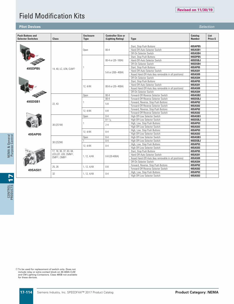
Siemens Industry, Inc. SPEEDFAX™ 2017 Product Catalog17-114
17
CON
TRO
L PR
OD
UCT
SN
EMA
& G
ener
al
Purp
ose
Cont
rol
Start,StopPushButtons 49SAPB5 Open 00-4 Hand-Off-AutoSelectorSwitch 49SASB1 Off-OnSelectorSwitch 49SASB4 Start,StopPushButtons 49SDPB5 00-4or(20–100A) Hand-Off-AutoSelectorSwitch 49SDSBJ Off-OnSelectorSwitch 49SDSB4 14,40,LC,LEN,CLMa 1 Start,StopPushButtons 49SAP05 5-8or(200–400A) Hand-Off-AutoSelectorSwitch 49SAS01 KeyedHand-Off-Auto(keyremovableinallpositions) 49SAS09 Off-OnSelectorSwitch 49SAS04 Start,StopPushButtons 49SAP05 12,4/4X 00-8or(20–400A) Hand-Off-AutoSelectorSwitch 49SAS01 KeyedHand-Off-Auto(keyremovableinallpositions) 49SAS09 Off-OnSelectorSwitch 49SAS04 Open 00-4 Forward-Off-ReverseSelectorSwitch 49SASB2 00-4 Forward-Off-ReverseSelectorSwitch 49SDSBJ 22,43 1 5-8 Forward,Reverse,StopPushButtons 49SAP02 Forward-Off-ReverseSelectorSwitch 49SAS02 12,4/4X 0-8 Forward,Reverse,StopPushButtons 49SAP02 Forward-Off-ReverseSelectorSwitch 49SAS02 Open 0-4 High-Off-LowSelectorSwitch 49SASB3 0-13⁄4 High-Off-LowSelectorSwitch 49SDSBJ 30(2S1W) 1 2-4 High,Low,StopPushButtons 49SAP03 High-Off-LowSelectorSwitch 49SAS03 12,4/4X 0-4 High,Low,StopPushButtons 49SAP03 High-Off-LowSelectorSwitch 49SAS03 Open 0-4 High-Off-LowSelectorSwitch 49SASB3 30(2S2W) 1 0-4 High-Off-LowSelectorSwitch 49SDSBJ 12,4/4X 0-4 High,Low,StopPushButtons 49SAP03 High-Off-LowSelectorSwitch 49SAS03 Start,StopPushButtons 49SAP05 1,12,4/4X 0-8(20-400A) Hand-Off-AutoSelectorSwitch 49SAS01 KeyedHand-Off-Auto(keyremovableinallpositions) 49SAS09 Off-OnSelectorSwitch 49SAS04 25,26 1,12,4/4X 0-8 Forward,Reverse,StopPushButtons 49SAP02 Forward-Off-ReverseSelectorSwitch 49SAS02 32 1,12,4/4X 0-4 High,Low,StopPushButtons 49SAP03 High-Off-LowSelectorSwitch 49SAS03
Siemens / Speedfax Previous folio: 16-82, 10IC 8-82
a To be used for replacement of switch only. Does not include relay or extra contact block on 30-400A CLM and CM Lighting Contactors. Class 49SB not available for these devices.
PushButtonsand Enclosure ControllerSizeor Catalog ListSelectorSwitches Class Type (LightingRating) Type Number Price$
49SDPB5
49SDSB1
49SAP05
49SAS01
17,18,36,37,83,84,LED,LEF,LEB,CMNa,CMFa,CMBa
Field Modification KitsPilot Devices Selection
Product Category: NEMA
Revised on 11/30/19

Siemens Industry, Inc. SPEEDFAX™ 2017 Product Catalog 17-115
17
CON
TROL
PROD
UCTS
NEM
A &
General
Purpose Control
Siemens / Speedfax Previous folio: 16-84, 10IC 8-84
a To use as an OFF indicator, the contactor must have a normally closed (NC) auxiliary contact available for the circuit. Order separately as needed.
b Includes a nomally closed (NC) auxiliary contact for NEMA controller sizes 0–4.
c Incandecsent lamps may be replaced with 52AE* LED lamps listed on this page.
d Class 83 and 84 requires a quantity of two pilot light kits.
e The “OL TRIPPED” pilot light with a bimetal OLR, requires the OLR to have a N.O. contact as well as a N.C. contact.
Field Modification KitsPilot Lights Selection
Product Category: NEMA
Description
Lens Color (Lamp Type) Legend(s) Voltage
Catalog NumberClass
Enclosure Type
Controller Size or (Lighting Rating)
49SDLBU
14, 40, LC, LEN, CLM
1 (with lift-off cover) 00–4 or (20–100A) Red, Green, Amber
(LED lamp)
ON, RUN, OFFa, OLR TRIPPEDe
24 to 240 V AC/DC 49SDLBU
277 V AC 49SDLBL
14, 17, 18, 36, 37, 40, 83d, 84d, 88, CLM, CM, LE, LEN, LC
1 (with hinged cover), 3/3R, 4, 4X, 12
00–8 or (20–400A)
Red (Transformer Type incandecent lamp)c
ON (Refer to voltage table) 49SPL0BR*
OFFab (Refer to voltage table) 49SPL0AR*
Green (Transformer Type incandecent lamp)c
ON (Refer to voltage table) 49SPL0BG*
OFFab (Refer to voltage table) 49SPL0AG*
49SPL0BRF
82, 87 3/3R 1-6
Red (LED lamp)
ON24 to 240 V AC/DC 49SFL0BRU277 V AC 49SFL0BRL
OFFa24 to 240 V AC/DC 49SFL0ARU277 V AC 49SFL0ARL
Green (LED lamp)
ON24 to 240 V AC/DC 49SFL0BGU277 V AC 49SFL0BGL
OFFa24 to 240 V AC/DC 49SFL0AGU277 V AC 49SFL0AGL
49SPL0JRF
22, 43 1 (with lift-off cover) 00–4
Red, Red (LED lamp)
FORWARD, REVERSE
24 to 240 V AC/DC 49SDLB7RU277 V AC 49SDLB7RL
Green, Green (LED lamp)
FORWARD, REVERSE
24 to 240 V AC/DC 49SDLB7GU277 V AC 49SDLB7GL
22, 25, 26, 43
1 (with hinged cover), 3/3R, 4, 4X, 12
00-8
Red, Red (Transformer Type incandecent lamp)c
FORWARD, REVERSE (Refer to voltage table) 49SPL0JR*
Green, Green (Transformer Type incandecent lamp)c
FORWARD, REVERSE (Refer to voltage table) 49SPL0JG*
49SFL0BGU
30 1 (with lift-off cover)
0-1 3/4 (1-winding) 0-4 (2-winding)
Red, Red (LED lamp)
HIGH, LOW
24 to 240 V AC/DC 49SDLB7RU277 V AC 49SDLB7RL
Green, Green (LED lamp)
HIGH, LOW
24 to 240 V AC/DC 49SDLB7GU277 V AC 49SDLB7GL
30, 32
1 (with hinged cover), 3/3R, 4, 4X, 12
0-4 (1- or 2-winding)
Red, Red (Transformer Type incandecent lamp)c
HIGH, LOW (Refer to voltage table) 49SPL0KR*
Green, Green (Transformer Type incandecent lamp)c
HIGH, LOW (Refer to voltage table) 49SPL0KG*
49SBLBL
Lens Kit for pilot light light kits 49SDLB* Red, Green, Amber — — 49SBLBL
52AED2
LED lamp BA9s type used to replace incandecsent or LED lamps. Applies only to 49SP* pilot light kits.
Red
— 24 V AC/DC
52AED2Green 52AED3Amber 52AED4White 52AEDBRed
— 120 - 600 V AC/DC
52AEB2Green 52AEB3Amber 52AEB4White 52AEBB
Voltage TableVoltage Code (*)
24 V AC (Full voltage) J120 V AC F240 V AC G480 V AC H600 V AC E
Revised on 11/30/19

Siemens Industry, Inc. SPEEDFAX™ 2017 Product Catalog17-116
17
CON
TRO
L PR
OD
UCT
SN
EMA
& G
ener
al
Purp
ose
Cont
rol
Siemens / Speedfax Previous folio: 16-83, 10IC 8-83
a These kits are only for use with 20A mechanically held lighting contactors.
Class 14, 22, 30, 40, 43
Class 17, 25, 32, 87
Protective Shielding for NEMA Products
Class 40Class 14
Disconnect with protective shield
Power Pole Kits Class Enclosure type Contactor Size (Amp) DescriptionField Kit Catalog No.
LC Open, 1, 12, 4/4X 30 Single power poleDouble power pole
49LCPP1A49LCPP2A
Electrically Held to Mechanically Held Conversion Modules Class Enclosure type Contactor Size (Amp) Description
Field Kit Catalog No.
LC Open, 1, 12, 4/4X 30 2-wire, 24VAC2-wire, 110-120VAC2-wire, 200-277VAC3-wire, 24VAC3-wire, 110-120VAC3-wire, 200-277VAC
49LCCM1A49LCCM2A49LCCM3A49LCCM4A49LCCM5A49LCCM6A
Contactor or Starter Size 00–13⁄4 List Price $ 2–21⁄2 List Price $ 3–31⁄2 List Price $ 4 List Price $
Contactor Shield Catalog Number 49PSC1 49PSC2 49PSC3 49PSC4
Starter Shield Catalog Number 49PSS1 49PSS2 49PSS3 49PSS4
Disconnect Size
Catalog Number List Price $
30A 49PSD5 60 & 100A 49PSD6 200A 49PSD7
Solid State Control Module Kits For Lighting and Heating Contactorsa
CLM 20 AmpContactor KitDescription Accessory
CatalogNumber
ListPrice $ Accessory
CatalogNumber
ListPrice $ Accessory
CatalogNumber
ListPrice $
120V AC, 50/60 Hz47 (2-Wire Control) (2W)
CLM4379771 48 (3-Wire Control) (3W)
CLM4379781 49 (Start/Stop Control) (3WS)
CLM4379791
24V AC/DC,50/60 Hz CLM4379772 CLM4379782 CLM4379792
240/277V AC,50/60 Hz CLM4379773 CLM4379783 CLM4379793
Field Modification KitsNEMA, Lighting and Heating Contactors, 20 Amp CLM, CMB, CMF, CMN Selection
Product Category: NEMA

Siemens Industry, Inc. SPEEDFAX™ 2017 Product Catalog 17-117
17
CON
TROL
PROD
UCTS
NEM
A &
General
Purpose Control
Siemens / Speedfax Previous folio: 16-85, 10IC 8-85
a Installation of CPTs may require a larger enclosure.b 45VA transformer kits will include secondary but not
primary fusing. Sizes 50VA and higher include
2-pole primary fusing and 1-pole secondary fusing. c For 24VAC control a minimum of 100VA CPT is required.
Disconnect Auxiliary Switch Kits
Control Power Transformer Kitsac
Starter/Contactor Auxiliary Contact Kits Description Class Size Type CatalogNumber ListPrice$
1NO 49AB10 1NC 49AB01 1NCEarlyBreak 49AB01EB 1NCLateBreak 49AB01LB 14,17,18,22,25,26, 1NCExtraLateBreak 49AB01XLB 30,32,36,37,40,43, 00-4 1NOExtraLateMake 49AB10XLM
83,84,87,88 1NO&1NC 49AB11
2NO 49AB20 4NO 49AB40 3NO&1NC 49AB31 2NO&2NC 49AB22 14,17,18,22,25,26, 2NO 3RH1921-1EA20 36,37,40,43,87,88 5,6 1NO&1NC 3RH1921-1DA11 2NC 3RH1921-1EA02
14,17,18,22,25,26 1NO&1NC(InsideLorR) 49CAL18-11 40,43 7,8 1NO&1NC(OutsideLorR) 49CAL18-11B
1NO/NC 49LCAC1PA LC
30
2NO/NC 49LCAC2PA
20 FrontMounted1NO/NC 3RH2911-1HA11 LE 30 SideMounted1NO/NC 3RH2911-1DA11 60-400 SideMounted1NO/NC 3RH1921-1EA11 20Amps 1NO/NCSPDT CLM4097291 2NO/NCSPDT CLM4097292 1NO&1NC CLMFCAK11 30-200Amps 2NC CLMFCAK02 CLM,CMN,CMF,CMB 2NO CLMFCAK20 1CoilClearingNO&NC CLMFCCK11 1NO&1NC CLMHCAK11 300-400Amps 2NC CLMHCAK02 2NO CLMHCAK20 1CoilClearingNO&NC CLMHCCK11
DisconnectAmpor Description Class CBRating Type CatalogNumber ListPrice$
Non-fusible 17,25,32,37,83,84, orFusibleType 87,88,LED,LEF,CMN,CMF 30-200A 2NO/2NCDPDT(NEMAA600) HA261234 MCP 18,26,32,37,83,84,
3A–125A 1NO/1NC240V A02ED62 87,88,LEB,CMB 250A 1NO/1NC480V A02FD64 400A-600A (2)1NO/1NCSPDT-480V A02JLD64
RecommendedTransformerSize VA TransformerTable Description ControlSize TransformerVA Rating CatalogNumber ListPrice$ PrimaryVolts SecondaryVolts Code
00–21⁄2 45or50c 45VA KT*050bc 120 24 1 3–31⁄2 75 50VA KT*050Pc 208 24 G 4 150 100VA KT*100 208 120 H 5-6 150 150VA KT*150 240/480 24 4 7-8 300 200VA KT*200 240/480 120 8 LightingControl 300VA KT*300 277 24 5 CLM 500VA KT*500 277 120 7 20A,2-12P 150 600 24 6 30A,3P 100 Replace*withcodefromTransformertable.KitsusedwithNEMA1 600 120 9 30A,6-12P 200 generalpurposelift-offcovertyperequireextrawideenclosure. 60A,3P 100 Class14Sizes0-21⁄2 60A,4-6P 150 Class30(2S2W)Sizes0-21⁄2 60A,8-12P 250 Class30(2S1W)Sizes0-13⁄4 100/200A,3P 200 100/200A,5P 250 Transformer 300/400A,3P 250 50/60HZ LC&LE LC30A,2-12P 100 LE20,30,60A,3&4P 45 LE30A,6P 45 LE30A,9-12P 100 LE60A,6-12P 150 LE100,200A,3P 100 LE300,400A,3P 150
Field Modification KitsNEMA, Reduced Voltage and Lighting Selection
Product Category: NEMA

Siemens Industry, Inc. SPEEDFAX™ 2017 Product Catalog17-118
17
CON
TRO
L PR
OD
UCT
SN
EMA
& G
ener
al
Purp
ose
Cont
rol
Siemens / Speedfax Previous folio: 16-86, 10IC 8-86
Field Modification KitsESP200 Accessories Selection
Product Category: NEMA
Accessories
Description CatalogNumber ListPrice$
ESP200TamperResistanceCover49ASTC13UB89848
ESP100/200MountingPlate
FrameSize ControllerSize
AorA1 00-13/4 49ASMP1
B 2-21/2 49ASMP2
B 3-4 49ASMP3
MountingKit 49ASMS1
UniversalResetOperator8"forclass36,37and87inNEMA1,12and3/3R
49MARB
OverloadRelayResetOperatorforClass14,22,30and83non-combinationstartersinNEMAtype1,12and4/4Xenclosures
49MBRS
OverloadRelayResetOperatorforClass17,18,25,26,32and84combinationstartersinNEMAtype1enclosures
49MBRS1
OverloadRelayResetOperatorforClass17,18,25,26,32and84combinationstartersinNEMAtype12and4/4Xenclosures
49MBRS2
OverloadRelayResetOperatorwithredbuttonforanyClassinNEMAtype1,3R,4/4Xand12enclosureswitha30mmhole
49MARSR
ESP200ResetExtender 49ASRE
ProtectiveBootOffersprotectionfromiceandforeignsubstancesfrominterferingwithbuttonoperation.Forusewith49MARSRreset.
52AABA
CurrentTransformer300:5usewith3UB81234JW2 97CT005
CurrentTransformer400:5usewith3UB81234KW2 97CT006
CurrentTransformer600:5usewith3UB81234LW2 97CT008
CurrentTransformer750:5usewith3UB81234MW2 97CT009
CurrentTransformer1200:5usewith3UB81234NW2 97CT012
Revised on 01/26/18

Siemens Industry, Inc. SPEEDFAX™ 2017 Product Catalog 17-119
17
CON
TROL
PROD
UCTS
NEM
A &
General
Purpose Control
Miscellaneous Kits
a Surge Suppression for NEMA sizes 5 – 8 are supplied internal with the coil. For size 4 panel mount.
b Only 3 lugs are suplied for line or load.If lugs for line and load are required order 2 kits.
c Lug Kit for contactors include 3 lugs for line or load.75D35994001 for line side.75D35994002 for load side.
3RT1966-4G
Illustration Description Contactor WireSize CatalogNumber ListPrice$
Lug Kit NEMAsize4(Vacuum) 1Kit=1Terminalblock.1kit NEMAsize5 2/0to600MCM,max.one500MCM 3RT1966-4G necessaryforeachlineandload. NEMAsize6 &one600MCM
Item WireRange 49SAAF 2-14 49SAAH 2/0-1475D35994001 250MCM-6
Encl. Controller Catalog List Description Class Type Size Number Price$
MechanicalInterlock 00–1 49CCF22H forHorizontally 14,40 Open 13⁄4 49EEF22H MountedContactors Includeswire 2,21⁄2 49GGF22H 3,31⁄2 49HHP22H 4 49JJG22H InterlockOnly 5,6 3RA1954-2A WireKitOnly 5 3RA1963-2A 14,40 Open 6 3RA1973-2A BasePlateOnly 5 3RA1962-2A 6 3RA1972-2A MechanicalInterlock 14,40 Open 7 49VM750H 8 49VM1650H 00–1 49CCF22HP 13⁄4 49EEF22HP Includeswire& 14,40 Open 2,21⁄2 49GGF22HP
mountingplate 3,31⁄2 49HHP22HP
4 49JJG22HP Includes Left Right mountingplate 14,40 Open 2,21⁄2 3,31⁄2 49L107944 (DifferentFrameSizes) 3,31⁄2 2,21⁄2 49L107945 SurgeSuppressorfor120VAC Surge coil.Limitstransientvoltage Allbut All 00–4a 49D26344 Suppressor producedbythecoilto220% ClassLC,LE,CLM maximumpeaklinevolts.
Auxiliary NO36Aat600VACMax Allbut All 00–13⁄4 49SAF0 PowerPole NC25Aat600VACMax ClassLC,LE,CLM 49SAFC
ToporBottom,2-Pole CLM4097331 MainContacts Top,3-Pole CLM All 20Amps CLM4097332 LightingContactors ToporBottom,4-Pole CLM4097333 ToporBottom,6-Pole CLM4097334
LoadSide Includes3powerlugs PowerTake formakingextra Allbut All 00–13⁄4 49SAE OffKit connectionstotheload ClassLC,LE,CLM sideofthecontactor LugKitforContactors ForAL/CUWire 14,40 All 2-21⁄2 49SAAFc 3-31⁄2 49SAAHc 4Line4Load 75D35994002c
ForAL/CUWire 14,40 All 5,6 3RT1966-4Gb UseCUOnly 14,40 All 7 49ZATK750-3b 8 49ZATK1650-6b ThreeConductorGroundLug KitMeetsUL508andCSA 2-14AWGAL/CUWire All All All 75D28182001 Standard22.2No14-1973
LightningArrestor All All All 49D45584002
Ondelaytimerthatreduces 3RP2025-1AQ30
BackspinTimer riskofstartingintoa 87,88 All All backspin
3RP2025-1AP30
Coverstheholethatis HolePlug typicallyusedforthe 87 All 1-4 49D41149006 conduithub
Coverstheholeintheenclosuredoor/cover HolePlug normallyfilledbyoverloadreset49MBRS. 40,43,LC,LE, 1 All 49MZPB2 Holeplugisusedforenclosedcontactors. CLM&CM
Field Modification KitsNEMA Accessories Selection
Product Category: NEMA

Siemens Industry, Inc. SPEEDFAX™ 2017 Product Catalog17-120
17
CON
TRO
L PR
OD
UCT
SN
EMA
& G
ener
al
Purp
ose
Cont
rol
Siemens / Speedfax Previous folio: 16-88, 10IC 8-88
Field Modification KitsNEMA Accessories Selection
Product Category: NEMA
a Product Category: PILO.b Product Category: HDSS.
Description ConduitSizeInches CatalogNumber ListPrice$
Installinbottomasdrain. Installintopasbreather.Breather/Drain SuitableforClassIgroupsC&Dand 51AADB forClassIIgroupsF&Gapplicationsonly. for1⁄2"NPT.
Hazardous Location Accessories For Enclosure Types 7 & 9
Class R Fuse Conversion Kits CatalogNumber Description ListPrice$
HR21 30A,240V HR612 30A,600V HR612 60A,240V HR62 60A,600V HR63 100A,240/600V HR64 200A,240/600V
Fused and Non-Fused Disconnect Switch Kitsb
Basic Switch Switch LoadBase LoadBase Switch Catalog Catalog Catalog Catalog Lug Ampere Number List Number List Kit Number List Number List Wire Rating Non-Fused Price$ Fused Price$ Description ClassJ Price$ ClassHc Price$ Size
30 HNB612
HFB21 30A, 250V — — HBB21
#14-2AWG(Cu/AI) HFB612 30A, 600V HBB612 HBB612 60 HNB623 HFB22 60A, 250V — — HBB22
#14-2AWG(Cu/AI)
HFB62 60A, 600V HBB62 HBB62 100 HNB623 HFB63 100A, 250V — — HBB63
#14-1/0AWG(Cu/AI) 100A, 600V HBB63 200 HNB64 HFB64 200A, 250V — — HBB64
#6-300AWG(Cu/AI)
200A, 600V HBB64
Metal Conduit Hubs
Description Conduit Size ClassController Size
Enclosure Type
Milbank Catalog No.d
1"
87 All 3R
A7514
1 1/2" A7516
2" A7517
2 1/2" A7518
c For Class R fuses order Class H kit from this table and the Class R conversion kit.
d Milbank catalog numbers are for reference only. Milbank conduit hubs are not sold by Siemens but can be purchased at a typical electrical hardware and supply distributor.
Revised on 08/31/18

Siemens Industry, Inc. SPEEDFAX™ 2017 Product Catalog 17-121
17
CON
TROL
PROD
UCTS
NEM
A &
General
Purpose Control
Siemens / Speedfax Previous folio: 16-89, 10IC 8-89
NEMA Plate Manufacturer Size PartNumber ListPrice$
A-B 0,1 49D57090 A-B 2 49D57161 Sq.D 0,1 49D57091
Competitive Retrofit Overload Plates
Illustration Description ForOverloadType CatalogNumber ListPrice$ Resetmechanisms
Reset plunger Mountsdirectlytooverloadrelay.Requires 3RB206 3RU1900-1A separateresetoperatorinenclosuredoor.Kit includesresetplunger,holderandfunnel.
Cablelength 3RU1900-1B Flexible cable reset mechanism 15.75in(400mm) Requiresa6.5mmholeinthe 3RB206 enclosurewithamaximum Cablelength enclosurethicknessof8mm. 23.62in(600mm) 3RU1900-1C
Covers
Tamperresistantcoverforcurrentsettingandmanual/automaticresetbutton. 3RB206 3RB2984-0
Sirius 3RB20
Resetplungerwithresetbutton
Flexiblereset
21-27V 96-127V 200-277VClass Size ModelType CatalogNumber ListPrice$ CatalogNumber ListPrice$ CatalogNumber ListPrice$ 5 P – – 3RT1965-5PF31 3RT1965-5PP31
All V – – 3RT1966-5PF31 3RT1966-5PP31 6 P – – 3RT1975-5PF31 3RT1975-5PP31 V – – 3RT1976-5PF31 3RT1976-5PP31
Electronic Coil System with Remaining Lifetime Indication and 24VDC PLC Output
Field Modification KitsNEMA, Overload Relays Selection
Product Category: NEMA

Siemens Industry, Inc. SPEEDFAX™ 2017 Product Catalog17-122
17
CON
TRO
L PR
OD
UCT
SN
EMA
& G
ener
al
Purp
ose
Cont
rol
Siemens / Speedfax Previous folio: 16-90, 10IC 8-90
Field Modification KitsClass MT, MTG Selection
Product Category: NEMA
International Fusinga
CatalogNumber Description ListPrice$
1-PoleFuseBlock, Touch-Safe.Upto6.3A for5mmu20mmor 5mmu25mm(Requires DINRailMounting)
1-PoleFuseBlock, Touch-Safe32A,for 10u38mmCylindrical Fuses.(RequiresDIN RailMounting.)
2-PoleFuseBlock, Touch-Safe32A,for 10u38mmCylindrical Fuses.(RequiresDIN RailMounting.)
1-PoleFuseBlock, Touch-Safe4-50A,for 14u51mmCylindrical Fuses.(RequiresDIN RailMounting.)
FuseBlockDINRail Mountingforseparate screwmountingtopanel. (Max2-pole2-25Asize perrail.) (Max1-pole4-50Asize perrail.)
8WA1011-1SF12
3NW7013
3NW7023
3NW7111
8WA1815
a Product Category: IEC.
Fuse Blocks, Touch-Safe Terminal Covers
Catalog Number Description List Price $
KCCF1G SECONDARY FUSE BLOCK,1P,250V MAX
SINGLE POLE FUSE BLOCK COVER KIT
KCCFBCK
2 Pole PRIMARY FUSE BLOCK,2P,600V MAX (block only)
KCCFP2RG
2 Pole PRIMARY FUSE BLOCK KIT with wire Leads
KCCFPX2R
US2:49FCCPT Secondary Fuse Clips, 2 per pack
US2:49JUCPT Terminal Jumpers
Terminal touchsafe cover Secondary Side
US2:KCCSECFCVR
US2:KCCFP3POLE3 pole fuse blk (2 pole primary and 1 pole secondary)
Revised on 06/30/19

Siemens Industry, Inc. SPEEDFAX™ 2017 Product Catalog 17-123
17
CON
TROL
PROD
UCTS
NEM
A &
General
Purpose Control
Siemens / Speedfax Previous folio: 16-91, 10IC 8-91
Heavy Duty ControlNon-Combination Enclosure Kits, Class 49 Selection
Product Category: NEMA
Revised on 08/31/18
49 E B 14 E B 11 07 05 R
Class49 — Field
Kit TypeE — Enclosure
Only ModelB — ModelC — 2002
Product Class14 — Class 14, 4022 — Class 22, 4330 — Class 30
Starter SizeE — 00, 0, 1, 13⁄4G — 2, 21⁄2I — 3, 31⁄2J — 4
NEMA TypeB — NEMA 10 — NEMA 12/3/3RW — NEMA 4 S.S.
Height (In Inches)
Width (In Inches)
Depth (In Inches)
Reset InstallationR — Reset
Note: Dimensions...See appropriate Product ClassOutline Drawing beginning on page 17-167.
a Clamshell enclosure suitable for one operating device and two pilot lights. See Field Mods page 17-114.
b Hinged cover enclosures, except for 49EB14E0130806R, are suitable for one or more class 52 operating devices and one or more class 52 pilot lights. See Field Mods page 17-106.
c Install NEMA 1 hole plug cat. no. 3SB1902-0AR (included) when the cover OL reset is not needed.
d Install NEMA 12 hole plug cat. no. 52ABH6 (not included) when the cover OL reset is not needed.
e Install NEMA 4X stainless steel hole plug cat. no. 52ABHS (not included) when the cover OL reset is not needed.
Non-Reversing Starters & Contactors Class 14, 40
NEMA1 NEMA4/4XStainless NEMA12/3/3R General Purpose (Clamshell)ad Watertight, Dust-tight, Corrosion Resistantbf Industrial Use, Weatherproofbd
WithoutCPT WithCPT(ExtraWide) WithoutCPT WithCPT(ExtraWide) WithoutCPT WithCPT(ExtraWide)
ModelCEnclosure ModelCEnclosure Max ModelBEnclosure ModelBEnclosure Max ModelBEnclosure ModelBEnclosure Max
List CPT List List CPT List List CPT ListSize CatalogNumber Price$ CatalogNumber VA Price$ CatalogNumber Price$ CatalogNumber VA Price$ CatalogNumber Price$ CatalogNumber VA Price$
00–13⁄4 49EC14EB110705R 49EC14IB201208R 200 49EB14EW130806R 49EB22EW131306R 49EB14E0130806R 49EB22E0131306R 2,21⁄2 49EC14GB140807R 49EC14IB201208R 200 49EB14GW160907R 49EB22GW161406R 49EB14G0160907R 49EB22G0161406R 3,31⁄2 49EC14IB201208R 49EC14IB201208R 100 49EB14JW261408R 49EB14JW261408R 49EB14J0261408R 49EB14J0261408R 3,31⁄2 — — 49EC14JB251409R 250 — — — — — — — —4 49EC14JB251409R 49EC14JB251409R 300 49EB14JW261408R 49EB22JW302410R 49EB14J0261408R 49EB22J0302410R
Reversing Starters & Reversing Contactors Class 22, 43
NEMA1 NEMA4/4XStainless NEMA12/3/3R General Purpose (Clamshell)ad Watertight, Dust-tight, Corrosion Resistantbe Industrial Use, Weatherproofbd
WithoutCPT WithCPT(ExtraWide) WithoutCPT WithCPT(ExtraWide) WithoutCPT WithCPT(ExtraWide)
ModelCEnclosure ModelCEnclosure Max ModelBEnclosure ModelBEnclosure Max ModelBEnclosure ModelBEnclosure Max
List CPT List List CPT List List CPT ListSize CatalogNumber Price$ CatalogNumber VA Price$ CatalogNumber Price$ CatalogNumber VA Price$ CatalogNumber Price$ CatalogNumber VA Price$
00–13⁄4 49EC14IB201208R 49EC14IB201208R 200 49EB22EW131306R 49EB22EW131306R 49EB22E0131306R 49EB22E0131306R 2,21⁄2 49EC14IB201208R 49EC14IB201208R 200 49EB22GW161406R 49EB22GW161406R 49EB22G0161406R 49EB22G0161406R 3,31⁄2 49EC14JB251409R 49EC14JB251409R 250 49EB22IW261808R 49EB22JW302410R 49EB22I0261808R 49EB22J0302410R 4 49EC14JB251409R 49EC14JB251409R 300 49EB22JW302410R 49EB22JW302410R 49EB22J0302410R 49EB22J0302410R
Two-Speed Two-Winding Starters Class 30
NEMA1 NEMA4/4XStainless NEMA12/3/3R Watertight, Dust-tight, Corrosion Resistantbe Industrial Use, Weatherproofbd
WithoutCPT WithCPT(ExtraWide) WithoutCPT WithCPT(ExtraWide) WithoutCPT WithCPT(ExtraWide)
ModelCEnclosure ModelCEnclosure Max ModelBEnclosure ModelBEnclosure Max ModelBEnclosure ModelBEnclosure Max
List CPT List List CPT List List CPT ListSize CatalogNumber Price$ CatalogNumber VA Price$ CatalogNumber Price$ CatalogNumber VA Price$ CatalogNumber Price$ CatalogNumber VA Price$
0–13⁄4 49EC14IB201208Ra 49EC14JB251409Ra200 49EB30EW131306R 49EB30GW161808R 49EB30E0131306R 49EB30G0161808R 2,21⁄2 49EC14IB201208Ra 49EC14JB251409Ra200 49EB30GW161406R 49EB30GW161808R 49EB30G0161406R 49EB30G0161808R 3,31⁄2 49EC14JB251409Ra 49EB22JB302410Rb300 49EB30IW261808R 49EB22JW302410R 49EB30I0261808R 49EB22J0302410R 4 49EC14JB251409Ra 49EB22JB302410Rb300 49EB22JW302410R 49EB22JW302410R 49EB22J0302410R 49EB22J0302410R
Two-Speed One-Winding Starters Class 30
NEMA1 NEMA4/4XStainless NEMA12/3/3R General Purpose (Clamshell)ac Watertight, Dust-tight, Corrosion Resistantbe Industrial Use, Weatherproofbd
WithoutCPT WithCPT(ExtraWide) WithoutCPT WithCPT(ExtraWide) WithoutCPT WithCPT(ExtraWide)
ModelCEnclosure ModelCEnclosure Max ModelBEnclosure ModelBEnclosure Max ModelBEnclosure ModelBEnclosure Max
List CPT List List CPT List List CPT ListSize CatalogNumber Price$ CatalogNumber VA Price$ CatalogNumber Price$ CatalogNumber VA Price$ CatalogNumber Price$ CatalogNumber VA Price$
0–13⁄4 49EC14IB201208Ra 49EC14JB251409Ra200 49EB30EW131306R 49EB30GW161808R 49EB30E0131306R 49EB30G0161808R 2,21⁄2 49EB30GB161808Rb 49EB22JB302410Rb300 49EB30GW161808R 49EB22IW261808R 49EB30G0161808R 49EB22I0261808R 3,31⁄2 49EB30IB192208Rb 49EB22JB302410Rb300 49EB22JW302410R 49EB22JW302410R 49EB22J0302410R 49EB22J0302410R 4 49EB22JB302410Rb 49EB22JB302410Rb300 49EB22JW302410R 49EB22JW302410R 49EB22J0302410R 49EB22J0302410R

Siemens Industry, Inc. SPEEDFAX™ 2017 Product Catalog17-124
17
CON
TRO
L PR
OD
UCT
SN
EMA
& G
ener
al
Purp
ose
Cont
rol
Heavy Duty ControlLighting Enclosure Tables Selection
Product Category: NEMA
Note: Dimensions...See appropriate Product ClassOutline Drawing on page 17-180.
a Clamshell enclosure suitable for one operating device and two pilot lights. See Field Mods page 17-114.
b Hinged cover enclosure suitable for one or more class 52 operating devices and one or more class 52 pilot lights. See Field Mods page 17-114.
c Install NEMA 1 hole plug cat. no. 3SB1902-0AR (included) when the cover OL reset is not needed.
d Install NEMA 12 hole plug cat. no. 52ABH6 (not included) when the cover OL reset is not needed.
e Install NEMA 4X stainless steel hole plug cat. no. 52ABHS (not included) when the cover OL reset is not needed.
Lighting Contactors Class LC and LE
Lighting & Heating Contactors Class CLM
NEMA1 NEMA4/4XStainless NEMA12/3/3R General Purpose (Clamshell)ac Watertight, Corrosion Resistantbe Industrial Usebd
WithoutCPT WithCPT(ExtraWide) WithoutCPT WithCPT(ExtraWide) WithoutCPT WithCPT(ExtraWide)
ModelC/BEnclosure ModelC/BEnclosure ModelBEnclosure ModelBEnclosure ModelBEnclosure ModelBEnclosure List Max List List Max List List Max ListSizePole CatalogNumber Price$ CatalogNumber CPT Price$ CatalogNumber Price$ CatalogNumber CPT Price$ CatalogNumber Price$ CatalogNumber CPT Price$
20A 2-12 49EC14GB140807R 49EC14IB201208R 200VA 49EB22GW161406R 49EB22GW161406R — 49EB22G0161406R 49EB22G0161406R — 30A 2-5 49EC14EB110705R 49EC14IB201208R 200VA 49EB22GW161406R 49EB22GW161406R — 49EB22G0161406R 49EB22G0161406R — 30A 6-12 49EB30GB161808R 49EB30GB161808R 200VA 49ECLXXW161406 49EB30GW161808R — 49ECLXX0161406 49EB30G0161808R — 60A 2-5 49EC14GB140807R 49EC14IB201208R 200VA — — — — — — — — — —60A 6-12 49EB30IB192208R 49EB30IB192208R 250VA — — — — — — — — — —100A 2-5 49EC14IB201208R 49EC14IB201208R 200VA — — — — — — — — — —
Contactor Type1 Type4/4XStainlessSteela Type3/3R/12b
WithoutCPT WithCPT Max. WithoutCPT WithCPT Max. WithoutCPT WithCPT Max.
CatalogNumber
CatalogNumber
CPTVA
CatalogNumber
CatalogNumber
CPTVA
CatalogNumber
CatalogNumber
CPTVA
LC30A2-12P 49EC14GB140807R 49EC14IB201208R 200 49EB22GW161406R 49EB30GW161808 49EB22G0161406R 49EB30G0B161808
LE20,30A3-4P 49EC14EB110705R 49EC14IB201208R 200 49EB22GW161406R 49EB22GW161406R 49EB22G0161406R 49EB22G0161406R
LE30A6-9P 49EC14IB201208R 49EC14IB201208R 200 49ECLXXW161406 49EB14JW261408R 49ECLXX0161406 49EB14J0261408R
LE30A12P 49EC14IB201208R 49EC14JB251409R 250 49ECLXXW161406 49EB14JW261408R 49ECLXX0161406 49EB14J0261408R
LE60A3-6P 49EC14GB140807R 49EC14IB201208R 200 49EB22GW161406R 49EB22GW161406R 49EB22G0161406R 49EB22G0161406R
LE60A9-12P 49EC14IB201208R 49EC14IB201209R 250 49ECLXXW161406 49EB14JW261408R 49ECLXX0161406 49EB14J0261408R
LE100A3P 49EC14IB201208R 49EC14IB201208R 200 49EB14JW261408R 49EB14JW261408R 49EB14J0261408R 49EB14J0261408R
Revised on 08/31/19

Siemens Industry, Inc. SPEEDFAX™ 2017 Product Catalog 17-125
17
CON
TROL
PROD
UCTS
NEM
A &
General
Purpose Control
Siemens / Speedfax Previous folio: 16-93, 10IC 8-93
49 E C 17 B B 24 11 08 R
Class49 — Field Kit
TypeE — Enclosure Kit
ModelC — Model C
Product Class17 — Disconnect Type18 — Circuit Breaker Type
Disc / CB Amp RatingB — 30/60 amp disconnectC — 100 amp disconnectD— 125 amp breaker frameE — 150 amp breaker frameF — 200 amp disconnect
Enclosure TypeB — NEMA 1N — NEMA 12/3R, 4 Painted
Height (In Inches)
Width (In Inches)
Depth (In Inches)
Reset InstallationR — Reset Installed
NomenclatureforCombinationEnclosureKits
Featuresb Manufactured with a cold forming “TOX” process
b 100kA short circuit rating when protected with class R fuses to 600V or MCP to 480V and when installing listed components from the instruction guide
b Enclosure types available, NEMA 1, 12, 3/3R and painted NEMA 4.NEMA 12 field convertible to 3/3R/4 with the appropriate conduithub and drain hole
b Pre-Drilled mounting panels
b Heavy duty quarter turns
b Industrial type disconnect handle
Disconnect Type Enclosure Kit
b Used to assemble both non-fusible and fusible combination starters
b Accommodates Class 14 full voltage non-reversing (FVNR) NEMA starters 00 – 4 including Siemens exclusive half sizes
b Handle mechanism, power wire, mounting panel, reset assembly,and instruction guide included. Hardware for panel mounted devices and disconnect switch are not included
MCP Type Enclosure Kit
b Used to assemble combination starters with circuit breakers
b Accommodates Class 14 full voltage non-reversing (FVNR) NEMAstarters 00 – 4 including Siemens exclusive half sizes
b Handle mechanism, power wire, mounting panel, reset assembly and instruction guide included. Circuit breaker not included however, mounting hardware for the circuit breaker is
How to Select the Required Kits to Assemble a Combination Starter
1. From the catalog, select a class 14 open type starter with the requiredstarter size and overload relay type.
2. Based on the starter size, select the enclosure kit from table 1a forfusible or non-fusible combination starters or select from table 1b for combination starters with an MCP.
3. For a non-fusible combination starter, select the disconnect switch kit from table 2a.For a fusible combination starter, select the appropriate disconnect switch, fuse clip kit, and class R rejection kit from table 2b (for H fusing, class R rejection kit not required). For combination starters with MCP, select the appropriate circuit breaker kit from table 3.
Combination Starter Enclosure KitsFeatures and Benefits
Revised on 08/31/19

Siemens Industry, Inc. SPEEDFAX™ 2017 Product Catalog17-126
17
CON
TRO
L PR
OD
UCT
SN
EMA
& G
ener
al
Purp
ose
Cont
rol
Siemens / Speedfax Previous folio: 16-94, 10IC 8-94
Disc.
NEMA1 NEMA12,3/3R,4Painted NEMA4/4XStainlessSteel
Starter Amp GeneralPurpose IndustrialUse,Weatherproof,Watertight,Dust-tight Watertight,Dust-tight,CorrosionResistant
Size Rating CatalogNumber ListPrice$ CatalogNumber ListPrice$ CatalogNumber ListPrice$
0-2 60 49EC17BB241108R 49EC17BN241108R 49EC17BW241108R 21⁄2-3 100 49EC17CB242008R 49EC17CN242008R 49EC17CW242008R 31⁄2-4 200 49EC17FB362408R 49EC17FN362408R 49EC17FW362408R
Table 1a - FVNR Combination Starter Kits for use with Disconnect Devices
Max
NEMA1 NEMA12,3/3R,4Painted NEMA4/4XStainlessSteel
Starter MCP GeneralPurpose IndustrialUse,Weatherproof,Watertight,Dust-tight Watertight,Dust-tight,CorrosionResistant
Size Amps CatalogNumber ListPrice$ CatalogNumber ListPrice$ CatalogNumber ListPrice$
0-2 50 49EC18DB241108R 49EC18DN241108R 49EC18DW241108R 21⁄2-3 125 49EC18DB242008R 49EC18DN242008R 49EC18DW242008R 31⁄2 125 49EC18DB362408R 49EC18DN362408R 49EC18DW362408R 4 150 49EC18EB362408R 49EC18EN362408R 49EC18EW362408R
Table 1b. – FVNR Combination Starter Kits for use with MCP Devices
DisconnectSwitch
SwitchRating CatalogNumber ListPrice$
30A HNB612 60A HNB623 100A HNB623 200A HNB64
Table 2a – Non-Fusible Disconnect Kits
Table 3 – Circuit Breaker Kits
MCPTypeUsedwithSolidState MCPTypeUsedwith OverloadRelay ThermalOverloadRelay
Overload MotorCircuit MotorCircuit Starter Amp Interrupter Circuit Interrupter Circuit Size Range Amps BreakerKit Amps BreakerKit
0.75-3.4 3 ED63A003 3 ED63A003 0 3-12 10 ED63A010 10 ED63A010 5.5-22 25 ED63A025 25 ED63A025
0.75-3.4 3 ED63A003 3 ED63A003 1 3-12 10 ED63A010 10 ED63A010 5.5-22 25 ED63A025 25 ED63A025 10-40 30 ED63A030 30 ED63A030 13⁄4 10-40 40 ED63A040 40 ED63A040 2 13-52 50 ED63A050 50 ED63A050 21⁄2 25-100 100 ED63A100 100 ED63A100 3 25-100 100 ED63A100 100 ED63A100 31⁄2 50-200 125 ED63A125 125 ED63A125 4 50-200 150 FXD63A150L 150 FXD63A150L
DisconnectSwitch LoadBaseforFuse RejectionClipsforClassRFusing
FuseClipRatings Class CatalogNumber ListPrice$ CatalogNumber ListPrice$ CatalogNumber ListPrice$
30A-250V H HFB21 HBB21 HR21 30A-600V H HFB612 HBB612 HR612 60A-250V H HFB22 HBB22 HR612 60A-600V H HFB62 HBB62 HR62 100A-250V H HFB63 HBB63 HR63 100A-600V H HFB63 HBB63 HR63 200A-250V H HFB64 HBB64 HR64 200A-600V H HFB64 HBB64 HR64
Table 2b – Fusible Disconnect Kits
Combination Starter Enclosure Kits Selection
Product Category: NEMA
Revised on 08/31/18

Siemens Industry, Inc. SPEEDFAX™ 2017 Product Catalog 17-127
17
CON
TROL
PROD
UCTS
NEM
A &
General
Purpose Control
Siemens / Speedfax Previous folio Updated by SSpencer 2/28/11
Ordering Information Replace the (*) with a letter from the coil table. Dual voltage coils
are wired on high voltage unless specified on order. Refer to Class 87 section of catalog for pump panel ratings and
other details. Handle mechanism, power wire, mounting panel, reset assembly
and instruction guide are included with the enclosure kit.
Coil Table
60Hz Voltage Letter
24 J 120 F 110–120/220–240 Aa
200–208 D 220–240 G 220–240/440–480 Ca
277 L 440–480 H 550–600 E
Pump Panels with Solid-State Overload Relay Class 87
To Field Assemble This Pump Panel:
Order these components
Enclosure List Price $
Enclosure Catalog Number
Starter with Solid-State Overload Relay
Disconnect Switch
Fuse Load Base
Class R Rejection Clips
Motor Circuit Interrupter
87DUB6F* 49EB87GF242008 14DUB32A* HFB612 HBB612 HR612 — 87DUC6F* 49EB87GF242008 14DUC32A* HFB612 HBB612 HR612 — 87DUD6F* 49EB87GF242008 14DUD32A* HFB612 HBB612 HR612 — 87DUD60* 49EB87GF242008 14DUD32A* HFB62 HBB62 HR62 — 87EUE6F* 49EB87GF242008 14EUE32A* HFB612 HBB612 HR612 — 87EUE60* 49EB87GF242008 14EUE32A* HFB62 HBB62 HR62 — 87FUF6F* 49EB87GF242008 14FUF32A* HFB62 HBB62 HR62 — 87FUF60* 49EB87GF242008 14FUF32A* HFB63 HBB63 HR63 — 87GUG6F* 49EB87GF242008 14GUG32A* HFB62 HBB62 HR62 — 87GUG60* 49EB87GF242008 14GUG32A* HFB63 HBB63 HR63 — 87HUG6F* 49EB87JF362408 14HUG32A* HFB63 HBB63 HR63 — 87HUG60* 49EB87JM362408 14HUG32A* MCS620R FCK620 SSRK34 — 87IUH6F* 49EB87JM362408 14IUH32A* MCS620R FCK620 SSRK34 — 87JUH6F* 49EB87JM362408 14JUH32A* MCS620R FCK620 SSRK34 — 87DUC6L* 49EB87GF242008 14DUC32A* HFB21 HBB21 HR21 — 87DUD6L* 49EB87GF242008 14DUD32A* HFB21 HBB21 HR21 — 87DUE6L* 49EB87GF242008 14DUE32A* HFB21 HBB21 HR21 — 87DUE6P* 49EB87GF242008 14DUE32A* HFB22 HBB22 HR612 — 87EUE6L* 49EB87GF242008 14EUE32A* HFB22 HBB22 HR612 — 87FUF6L* 49EB87GF242008 14FUF32A* HFB22 HBB22 HR612 — 87FUF6P* 49EB87GF242008 14FUF32A* HFB63 HBB63 HR63 — 87GUG6L* 49EB87GF242008 14GUG32A* HFB22 HBB22 HR612 — 87GUG6P* 49EB87GF242008 14GUG32A* HFB63 HBB63 HR63 — 87HUG6L* 49EB87JF362408 14HUG32A* HFB63 HBB63 HR63 — 87HUG6P* 49EB87JM362408 14HUG32A* MCS620R FCK620 SSRK34 — 87IUH6L* 49EB87JM362408 14IUH32A* MCS620R FCK620 SSRK34 — 87JUH6L* 49EB87JM362408 14JUH32A* MCS620R FCK620 SSRK34 — 87DUB6M* 49EB87GB242008 14DUB32A* — — — ED63A003 87DUC6M* 49EB87GB242008 14DUC32A* — — — ED63A010 87DUD6M* 49EB87GB242008 14DUD32A* — — — ED63A025 87DUE6M* 49EB87GB242008 14DUE32A* — — — ED63A030 87EUE6M* 49EB87GB242008 14EUE32A* — — — ED63A040 87FUF6M* 49EB87GB242008 14FUF32A* — — — ED63A050 87GUG6M* 49EB87GB242008 14GUG32A* — — — ED63A100 87HUG6M* 49EB87IB362408 14HUG32A* — — — ED63A100 87IUH6M* 49EB87IB362408 14IUH32A* — — — ED63A125 87JUH6M* 49EB87JB362408 14JUH32A* — — — FXD63A150L
a Dual voltage coils not available in size 5-8 starters.
Heavy Duty ControlClass 87 Pump Panel Enclosure Kits Selection

Siemens Industry, Inc. SPEEDFAX™ 2017 Product Catalog17-128
17
CON
TRO
L PR
OD
UCT
SN
EMA
& G
ener
al
Purp
ose
Cont
rol
Siemens / Speedfax Previous folio Updated by SSpencer 2/28/11
Ordering Information Replace the (*) with a letter from the coil table. Dual voltage coils
are wired on high voltage unless specified on order. Refer to Class 87 section of catalog for pump panel ratings and
other details. Handle mechanism, power wire, mounting panel, reset assembly
and instruction guide are included with the enclosure kit.
Coil Table
60Hz Voltage Letter
24 J 120 F 110–120/220–240 Aa
200–208 D 220–240 G 220–240/440–480 Ca
277 L 440–480 H 550–600 E
Pump Panels with Bimetal Overload Relay Class 87
To Field Assemble This Pump Panel:
Order these components
Enclosure List Price $
Enclosure Catalog Number
Starter with Bimetal Overload Relay
Disconnect Switch
Fuse Load Base
Class R Rejection Clips
Motor Circuit Interrupter
87DAE6F* 49EB87GF242008 14DP32A*81 HFB612 HBB612 HR612 — 87DAE60* 49EB87GF242008 14DP32A*81 HFB62 HBB62 HR62 — 87EAF6F* 49EB87GF242008 14EP32A*81 HFB612 HBB612 HR612 — 87EAF60* 49EB87GF242008 14EP32A*81 HFB62 HBB62 HR62 — 87FAJ6F* 49EB87GF242008 14FP32A*81 HFB62 HBB62 HR62 — 87FAJ60* 49EB87GF242008 14FP32A*81 HFB63 HBB63 HR63 — 87GAK6F* 49EB87GF242008 14GP32A*81 HFB62 HBB62 HR62 — 87GAK60* 49EB87GF242008 14GP32A*81 HFB63 HBB63 HR63 — 87HAN6F* 49EB87JF362408 14HP32A*81 HFB63 HBB63 HR63 — 87HAN60* 49EB87JM362408 14HP32A*81 MCS620R FCK620 SSRK34 — 87IAP6F* 49EB87JM362408 14IP32A*81 MCS620R FCK620 SSRK34 — 87JAR6F* 49EB87JM362408 14JG32A*81 MCS620R FCK620 SSRK34 — 87DAE6L* 49EB87GF242008 14DP32A*81 HFB21 HBB21 HR21 — 87DAE6P* 49EB87GF242008 14DP32A*81 HFB22 HBB22 HR612 — 87EAG6L* 49EB87GF242008 14EP32A*81 HFB22 HBB22 HR612 — 87FAJ6L* 49EB87GF242008 14FP32A*81 HFB22 HBB22 HR612 — 87FAJ6P* 49EB87GF242008 14FP32A*81 HFB63 HBB63 HR63 — 87GAL6L* 49EB87GF242008 14GP32A*81 HFB63 HBB63 HR63 — 87HAN6L* 49EB87JF362408 14HP32A*81 HFB63 HBB63 HR63 — 87HAN6P* 49EB87JM362408 14HP32A*81 MCS620R FCK620 SSRK34 — 87IAP6L* 49EB87JM362408 14IP32A*81 MCS620R FCK620 SSRK34 — 87JAR6L* 49EB87JM362408 14JG32A*81 MCS620R FCK620 SSRK34 — 87DAA6M* 49EB87GB242008 14DP32A*81 — — — ED63A003 87DAB6M* 49EB87GB242008 14DP32A*81 — — — ED63A010 87DAD6M* 49EB87GB242008 14DP32A*81 — — — ED63A025 87DAE6M* 49EB87GB242008 14DP32A*81 — — — ED63A030 87EAF6M* 49EB87GB242008 14EP32A*81 — — — ED63A040 87EAG6M* 49EB87GB242008 14EP32A*81 — — — ED63A050 87FAH6M* 49EB87GB242008 14FP32A*81 — — — ED63A040 87FAJ6M* 49EB87GB242008 14FP32A*81 — — — ED63A050 87GAK6M* 49EB87GB242008 14GP32A*81 — — — ED63A050 87GAL6M* 49EB87GB242008 14GP32A*81 — — — ED63A100 87HAN6M* 49EB87IB362408 14HP32A*81 — — — ED63A100 87IAP6M* 49EB87IB362408 14IP32A*81 — — — ED63A125 87JAR6M* 49EB87JB362408 14JG32A*81 — — — FXD63A150L
a Dual voltage coils not available in size 5-8 starters.b For NO/NC SPDT contact on overload, replace "81" with "91". "81" will give a NC contact.
Heavy Duty ControlClass 87 Pump Panel Enclosure Kits Selection

Siemens Industry, Inc. SPEEDFAX™ 2017 Product Catalog 17-129
17
CON
TROL
PROD
UCTS
NEM
A &
General
Purpose Control
Siemens / Speedfax Previous folio: 10AppendixA-N pg46 Updated by SSpencer 2/1/11
a Pilot lights are transformer type as standard. For LED type bulbs, order suffix FE in addition to the standard device suffix(es). For example, to order red “ON” and green “OFF” pilot lights with LED bulbs, order FA, FK and FE.
Ordering Information
AllmodificationswillconsistofSiemensstandardcomponentsasavailable.Standardequipmentdimensionsandenclosureconstructionmaynotapplywhencertainmodificationsandspecialfeaturesareadded.
Enclosure Description Modification Class Type ModificationCode ListPrice$
Start,Stop 14,17,18,36,37,40,83,84,CLM,CM,LC,LE All A1 e
Forward,Reverse,Stop 22,25,26,43 All A2 PushButtons High,Low,Stop 30,32 All E-Stop 14,17,18,22,25,26,30,32,36,37,40,43 All ES 14,17,18,36,37,40,83,84,LC,LE All A3 e
Hand-Off-Auto
CM,CLM All A3 For24voltHOAcontrol,
CM,CLM 1 EM 20Ampcontactoronly 14,17,18,22,25,26,30,32,36,37,40,43, All A4 e
Off-On 83,84,CLM,CM,LC,LE
SelectorSwitches Auto-Off 14,17,18,40,83,84,CM,CLM,LC,LE All A6 e
Forward-Off-Reverse 22,25,26,43 All A5 High-Off-Low 30,32 All Hand-Off-Auto(Keyed) 14,17,18,36,37,40,83,84,LC,LE,CLM,CM All A9 e
Auto-Off-Low-High 30,32 All A0
PilotDevices
CoilLetter ControllerSize4(VacuumOnly) AC(50–60HZ)orDC Change Size5&6(ALL)
23–26V J 42–48V U 110–127V F 200–220V D 220–240V G 240–277V L 380–420V K 440–480V H 575–600V E
Class14,17,18,22,25,26,30,32,40,43,83f,84f,87,88
CoilLetter ControllerSize—ListPrice$
Volts60HZ Volts50HZ Change 00–21⁄2 3,31⁄2 4
24 24 J 120 110 F 110–120/220–240 110/190–220 A 200–208 — D 220–240 190–220 G 277 240 L 220–240/440–480 190–220/380–440 C 440–480 380–440 H 575–600 550 E
24V Sg DCCoilc 48V U . 125V V 250V W
CoilOptions
Lens Red Green Green LEDBulb Color➔ Red Green Red Green Red Green Amber White Push-To-Test Push-To-Test Push-To-Test Upgrade
On On Control On On For/Rev For/Rev OL Power For/Rev For/Rev Enclosure Legend➔ Low/High Low/High Run Run Off Off Tripped On Low/High Low/High Off
Class Type ModCode➔ FA FB FC FD FJ FK FLd FW FS FT FU FEa
14,40,17,18,36,37, 87,88,LC,LE,CLM,CM All
22,25,26,30,32,43, 83,84 All
PilotLights
b DC coils include 1 NC, late break aux. contact. This aux. contact takes up one side of the starter (00–4 only).
c Price x 2 for Classes 22, 25, 26, 30, 32, 43, 83, 84.d Bimetal OL - Size 00 - 2 1/2 available. Solid-state OL -
Size 00 - 4, 7 & 8 available.
e For Class 83, 84 two devices are provided. Price x 2.f For Class 83, 84 standard enclosure (92) alternating
relay available in 24V or 120V control only.g S coil is not available for size 4 contactors or starters. Class 83 and 84 only.
Factory Modifications Selection
Product Category: NEMA

Siemens Industry, Inc. SPEEDFAX™ 2017 Product Catalog17-130
17
CON
TRO
L PR
OD
UCT
SN
EMA
& G
ener
al
Purp
ose
Cont
rol
Siemens / Speedfax Previous folio: 10AppendixA-N pg47 Updated by SSpencer 2/1/11
Note: Factory will furnish the same voltage coils as transformer secondary voltage (except with class 36,37).
a The standard control transformer supplied for starter sizes 0 through 21⁄2 will be rated 45VA and have the appropriate secondary fuse. Primary fuses will not be supplied as standard. For primary fuse option select appropriate suffix from table.
b For 24VAC control a minimum of 100VA CPT required.c Price x 2 Class 83 and 84.d Class 84 Duplex Controllers require two fusible
disconnects thus multiply the price adder by two.
Ordering Information
Replace(*)withletterfromTransformerTable.
Transformer Table Primary Secondary Volts Volts Letter 120 24 B 208 24 S 208 120 T 240 24 J 240 120 F 277 24 N 277 120 P 380 110 U 415 100 W 480 240 R 480/240 24 D 480/240 120 A 600 24 E 600 120 C
Fuse ClipAmps Volts ModificationCode ListPrice$ 30 250 10 30 600 11 60 250 12 60 600 13 100 250 14 100 600 15 200 250 16 200 600 17 400 250 18 400 600 19 600 250 20 600 600 21 800 600 23 1200 600 24 1600 600 25
Factory Assembled Fuse Clips—Class 25, 32, 84d
ModificationProduct Enclosure 20–60 100 — 200 300–400 — —
Description Code Class Type 0–21⁄2 3 31⁄2,4 5 6 7 8
StandardCapacitya B* 14,17,18,22,25,26,30, 1,3,4,12 — — — — — — with1-SecondaryFuse 32,40,43,83c,84c,87,LE 7&9 — — — — — — StandardCapacity 14,17,18,22,25,26,30, 1,3,4,12 with2-Primaryand D* 32,40,43,83c,84c,87,
7&9 1-SecondaryFuse LC,LE,CLM,CM 100VAExtraCapacity 14,17,18,22,25,26,30,32,40, 1,3,4,12 with2-Primaryand C* 43,83c,84c,87,LC,LE,CLM,CM 7&9 1-SecondaryFuse 36,37,88 All — — 150VAExtraCapacity 14,17,18,22,25,26,30,32,40, with2-Primaryand C*1 43,83c,84c,87,LC,LE,CLM,CM 1,3,4,12
1-SecondaryFuse 36,37,88 All — —
Control Power Transformersb
Lighting&HeatingRatings(Amps)
MotorControllerSize
Factory Modifications Selection
Product Category: NEMA

Siemens Industry, Inc. SPEEDFAX™ 2017 Product Catalog 17-131
17
CON
TROL
PROD
UCTS
NEM
A &
General
Purpose Control
Siemens / Speedfax Previous folio: 10AppendixA-N pg48 Updated by SSpencer 2/1/11
a Auxiliary contacts will be added evenly across contactors. (i.e. Class 22, G02 suffix will add 2 NC contacts (one per contactor).
b Double the price addition for Class 30 and 32.c For class 83 and 84 contacts will be added to both
starters. Price x 2.
ModificationCode
ControllerSize-PriceDeduction$
Description Class 0,1 13⁄4-21⁄2 3 31⁄2,4 5,6 7,8OmitOverloadRelayandResetButton 17,18,25,26 EX1
Additional Auxiliary Contacts
NO NC Modication ControllerSize—ListPrice$
Class Contacts Contacts Code 00–13⁄4 2–4 5–6 7–8
— 1 G01 — — — 2 G02 — 1 — G10 — — 1 1 G11 1 2 G12 — — 2 — G20 — 2 1 G21 — — 2 2 G22 — 2 3 G23 — — 3 1 G31 — 3 2 G32 — — 14,17,18,40,83c,84c 3 3 G33 — — — 4 — G40 — 4 1 G41 — — 4 2 G42 — — — 4 4 G44 — — — 5 — G50 — — 5 1 G51 — — — 5 3 G53 — — — 6 — G60 — — — 6 2 G62 — — — 7 1 G71 — — — 8 — G80 — — — — 2 G02a — — 2 — G20a — — 2 2 G22a — 22,25,26,43& 4 0 G40a — 30,32(2-winding) 4 4 G44a — — 6 2 G62a — — 8 0 G80a — —
0 2 G02a — — — 2 — G20a — — — 2 2 G22a — — 30,32 4 — G40a — — (1-winding) 4 4 G44a — — — 6 2 G62a — — — 8 — G80a — — — LE,CLM,CM 1 1 G11 — — — LC 0 1 G01 1 0 G10 1 1 G11 0 2 G02 2 0 G20 LE,CLM,CM 0 2 G02a — — — 2 0 G20a — — — 2 2 G22a — — —
Factory Modifications Selection
Product Category: NEMA

Siemens Industry, Inc. SPEEDFAX™ 2017 Product Catalog17-132
17
CON
TRO
L PR
OD
UCT
SN
EMA
& G
ener
al
Purp
ose
Cont
rol
Siemens / Speedfax Previous folio: 10AppendixA-N pg49 Updated by SSpencer 2/1/11
Motor Management with PROFIBUS DP Communicationsc
Description Class Enclosure TypeModification Code List Price
SIMOCODE pro C With 0.3-3A Current Module
14,17,18,22,25,26 All
MC1SIMOCODE pro C With 2.4-25A Current Module MC2SIMOCODE pro C With 10-100A Current Module MC3SIMOCODE pro C With 20-200A Current Module MC4SIMOCODE pro C With 63-630A Current Module MC5SIMOCODE pro V With 0.3-3A Current/Voltage Module MV1SIMOCODE pro V With 2.4-25A Current/Voltage Module MV2SIMOCODE pro V With 10-100A Current/Voltage Module MV3SIMOCODE pro V With 20-200A Current/Voltage Module MV4SIMOCODE pro V With 63-630A Current/Voltage Module MV5Factory Parameterization of SIMOCODE MM0
a Supplied as NEMA 12, field convertible to NEMA 3R.b Surge Suppression for NEMA sizes 5 – 8 are supplied
internal with the coil.
c A CPT must also be ordered to power the motor man-agement device. Motor management may be ordered with other product classes as specials.
Modification ControllerSize—ListPrice$
Description Class Code 0 1 13⁄4 2 21⁄2 3 31⁄2 4 5
Reversinginonespeedonly2speed1winding R6 — Reversinginonespeedonly2speed2winding 30,32 R7 — Reversinginbothspeeds2speed1winding R8 — Reversinginbothspeeds2speed2winding R9 — ReversingforReducedVoltage 36,37 R
Reversing Options
Electrically Held to Mechanically Held Conversion Modules Class Enclosure type Contactor Size (Amp) Description
Modification Code
LC Open, 1, 12, 4/4X 30 2-wire, 24VAC2-wire, 110-120VAC2-wire, 200-277VAC3-wire, 24VAC3-wire, 110-120VAC3-wire, 200-277VAC
2W12W22W33W13W23W3
Factory Modifications Selection
Product Category: NEMA
Revised on 05/31/18
Enclosure List
Description Class Type ModificationCode Price$
2W(2-wirecontrolmodule) LightingControlModules(doesnotincludepilotdevices) CLM20Amponly All 3W(3-wirecontrolmodule) 3WS(Start/Stopcontrolmodule) SurgeSuppressionfor120VACCoilb 14,17,18,22,25,26,30,32,36,37,83,84,87,88 All SS DisconnectSwitch Interlock 2NO/2NC DPDT 17,25,32,37,84,CM,LE 1,3,4,4X,12 GY MotorCircuit NO/NC SPDT 18,26,32,37,84,CM,LE All GY ProtectorInterlock LightningArrestor All All L CircuitBreakerShuntTrip 18,26,32,37,84,87,88,CM,LE All L6 CircuitBreakerUndervoltageTrip 18,26,32,37,84,87,88,CM,LE All L7 CircuitBreakerAlarmSwitchTrip 18,26,32,37,84,87,88,CM,LE All L8 GroundLug–3Conductor All All L10 ControlCircuitFuseandHolder All All F1(1fuse) (TransformerPrimaryFusing) F2(2fuses) ControlCircuitCircuitBreaker All All F4 InternallyOperated SpaceHeater(120Vseparatecontrol) All All SH SpaceHeaterwithThermostat(120Vseparatecontrol) All All ST SurgeCapacitor 87,88 All SC AlarmPackage(includeshorn,light,relay&push-button) 83,84,87,88 All M7 BackspinProtection 87,88 All T5 MinimumRunTimer0.2sec.-3mins. 87,88 All T6 BlownControlFuseIndicatorLight 17,25,32,37,84,87,88,CM,LC,LE All L11 SinglePhase120VACCombinationStarter 17,18,25,26 All SP1 SinglePhase240VACCombinationStarter 17,18,25,26 All SP2
Control Options

Siemens Industry, Inc. SPEEDFAX™ 2017 Product Catalog 17-133
17
CON
TROL
PROD
UCTS
NEM
A &
General
Purpose Control
Siemens / Speedfax Previous folio: 10AppendixA-N pg50 Updated by SSpencer 2/1/11
a Not available on Class 36, 37.b Price x 2 Class 83 and 84.
c ETM available with 120V coil only.d For terminal point more than 9 terminals use
additional suffixes. Max 3 suffixes can be selected.
e Class 30 and 32 can be modified with only an elapsed time meter. No other meters apply to class 30 or 32.
Description Class ModificationCode ListPrice$
Functionidentificationplate,withmarkingasspecified All N1
Function Identification Plates
Description Class ModificationCode ListPrice$
3PointTerminal TC3d 6PointTerminal All TC6d 9PointTerminal TC9d
Terminal Blocks
Control Relays Enclosure List Description Class Type Price$
ControlRelay 4NO R40
4-PolesMax 2NO/2NC All 1,3,4,7,9,12 R22
4NC R04
Under/OverVoltage,PhaseFailure,PhaseSequence,PhaseUnbalance All R1
GroundFaultRelay All R5 ElectronicOnDelayRelay(.15s–100h)24V/120V All T1 ElectronicOnDelayRelay(.15s–100h)24V/240Va T2 ElectronicOffDelayRelay(.15s–100s)120V
1,3,4,7,9,12T3
ElectronicOffDelayRelay(.15s–100s)240Va T4 24hourtimeclock T7 24hourtimeclockwithdayomission LC,LE,CLM,CM All T8 7daytimeclock T9 CompellingRelay A6 AccelerationControl 30,32 1,4,12 A7
DecelerationControl A8
DrawingsDescription Class Catalog Number List Price $
Approval/submittal and as-built drawings for factory modified product may be ordered. The drawing set includes an enclo-sure outline, a panel layout and a schematic. When entering the order, use the line item notes to reference a product and modifications or an existing order that the drawings are to be engineered for. Specify the contact information and an email address in the ship to address field. Attach any refer-ence drawings to the order or forward to National Customer Support. Once completed, the drawing set will emailed.
All CONTROLDRAWING
Modifi-cationCode
Enclosure Listb
Description Class Type Price$
Ammeter(includesaC.T.ifnecessary) 1,3,4,4X,12 M1 AmmeterandSwitch(3-Phasewith3C.T.’s) 14,17,18,22, 1,12 M2 Voltmeter 25,26,30e,32e, 1,3,4,4X,12 M3 VoltmeterandSwitch(3-Phase) 36,37,40,43,83, 1,12 M4 ElapsedTimeMeterc 84,87,88 1,3,4,4X,12 M5
Meters—Mounted on Enclosure
ModificationCode
Factory Modifications Selection
Product Category: NEMA
Revised on 05/31/19
Special RatingsDescription Class ModificationCode ListPrice$
ServiceEntranceRatingPlease note Class 87, 88, CM and LE (combination type) are UL Listed for Service Entrance as standard and thus does not need to be modified for such.
17,18,25,26,32,37,84
N3

Siemens Industry, Inc. SPEEDFAX™ 2017 Product Catalog17-134
17
CON
TRO
L PR
OD
UCT
SN
EMA
& G
ener
al
Purp
ose
Cont
rol
Formula—Approximate Full Load Amps for Other Motors208 Volt Full Load Amp P 230 Volt current u 110%2-Phase FLA P 0.866 u the 3-Phase FLA2-Phase, 3-wire current in common wire P 1.41 u that in the other 2 lines
25Hz 1500 RPM, amps P amps of 60Hz, 3600 RPM25Hz 750 RPM, amps P amps of 60Hz, 1800 RPMService factor 1.0 P amps u 0.950°C–55°C motor P amps u 0.9
FullLoadCurrent(60Hz)
Hp 115Volts 230Volts
1⁄8 4.4 2.2 1⁄4 5.8 2.9 1⁄3 7.2 3.6 1⁄2 9.8 4.9 3⁄4 13.8 6.9 1 16 811⁄2 20 10 2 24 12 3 34 17 5 56 2871⁄2 80 40 10 100 50
FullLoadCurrent(60Hz) 50Hz
Syn Speed 200 230 460 575 380 Hp RPM Volts Volts Volts Volts Volts
1800 1.09 0.95 0.48 0.38 0.55 1⁄4 1200 1.61 1.40 0.70 0.56 0.81 900 1.84 1.60 0.80 0.64 0.93 1800 1.37 1.19 0.60 0.48 0.64 1⁄3 1200 1.83 1.59 0.80 0.64 0.92 900 2.07 1.80 0.90 0.72 1.04 1800 1.98 1.72 0.86 0.69 0.99 1⁄2 1200 2.47 2.15 1.08 0.86 1.24 900 2.74 2.38 1.19 0.95 1.38 1800 2.83 2.46 1.23 0.98 1.42 3⁄4 1200 3.36 2.82 1.46 1.17 — 900 3.75 3.26 1.63 1.30 1.88 3600 3.22 2.80 1.40 1.12 1.70 1 1800 4.09 3.56 1.78 1.42 2.06 1200 4.32 3.76 1.88 1.50 2.28 900 4.95 4.30 2.15 1.72 2.60 3600 5.01 4.36 2.18 1.74 2.6911⁄2 1800 5.59 4.86 2.43 1.94 2.94 1200 6.07 5.28 2.64 2.11 3.20 900 6.44 5.60 2.80 2.24 3.39 3600 6.44 5.60 2.80 2.24 3.39 2 1800 7.36 6.40 3.20 2.56 3.84 1200 7.87 6.84 3.42 2.74 4.14 900 9.09 7.90 3.95 3.16 4.77 3600 9.59 8.34 4.17 3.34 5.02 3 1800 10.8 9.40 4.70 3.76 5.70 1200 11.7 10.2 5.12 4.10 6.20 900 13.1 11.4 5.70 4.55 6.80 3600 15.5 13.5 5.76 5.41 8.20 5 1800 16.6 14.4 7.21 5.78 8.74 1200 18.2 15.8 7.91 6.32 9.59 900 18.3 15.9 7.92 6.33 9.60 3600 22.4 19.5 9.79 7.81 11.5071⁄2 1800 24.7 21.5 10.7 8.55 13.00 1200 25.1 21.8 10.9 8.70 13.20 900 26.5 23.0 11.5 9.19 13.90 3600 29.2 25.4 12.7 10.1 15.40 10 1800 30.8 25.8 13.4 10.7 16.30 1200 32.2 28.0 14.0 11.2 16.90 900 35.1 30.5 15.2 12.2 18.50 3600 41.9 36.4 18.2 14.5 22.00 15 1800 45.1 39.2 19.6 15.7 23.70 1200 47.6 41.4 20.7 16.5 25.00 900 51.2 44.5 22.2 17.8 26.90 3600 58.0 50.4 25.2 20.1 30.50 20 1800 58.9 51.2 25.6 20.5 31.00 1200 60.7 52.8 26.4 21.1 31.90 900 63.1 54.9 27.4 21.9 33.20
3-Phase FullLoadCurrent(60Hz) 50Hz
Syn Speed 200 230 460 575 380 Hp RPM Volts Volts Volts Volts Volts
3600 69.9 60.8 30.4 24.3 36.80 25 1800 74.5 64.8 32.4 25.9 39.20 1200 75.4 65.6 32.8 26.2 39.60 900 77.4 67.3 33.7 27.0 40.70 3600 84.8 73.7 36.8 29.4 — 30 1800 86.9 75.6 37.8 30.2 45.70 1200 90.6 78.8 39.4 31.5 47.60 900 94.1 81.8 40.9 32.7 49.50 3600 111 96.4 48.2 38.5 — 40 1800 116 101 50.4 40.3 61.00 1200 117 102 50.6 40.4 61.20 900 121 105 52.2 41.7 63.20 3600 138 120 60.1 48.2 — 50 1800 143 124 62.2 49.7 75.20 1200 145 126 63.0 50.4 76.20 900 150 130 65.0 52.0 78.50 3600 164 143 71.7 57.3 — 60 1800 171 149 74.5 59.4 90.00 1200 173 150 75.0 60.0 91.10 900 177 154 77.0 61.5 93.10 3600 206 179 89.6 71.7 — 75 1800 210 183 91.6 73.2 111.00 1200 212 184 92.0 73.5 112.00 900 222 193 96.5 77.5 117.00 3600 266 231 115 92.2 —100 1800 271 236 118 94.8 144.00 1200 275 239 120 95.6 145.00 900 290 252 126 101 153.00 3600 — 292 146 116 —125 1800 — 293 147 117 177.00 1200 — 298 149 119 180.00 900 — 305 153 122 186.00 3600 — 343 171 137 —150 1800 — 348 174 139 210.00 1200 — 350 174 139 210.00 900 — 365 183 146 211.00 3600 — 458 229 184 —200 1800 — 452 226 181 274.00 1200 — 460 230 184 276.00 900 — 482 241 193 279.00 3600 — 559 279 223 —250 1800 — 568 284 227 343.00 1200 — 573 287 229 345.00 900 — 600 300 240 347.00300 1800 — 278 339 271 392.00 1200 — 684 342 274 395.00400 1800 — 896 448 358 —
3-Phase
1-PhaseUse only when motor full load current is not known. Motor amps will vary depending on the type and manufacturer of the motor. These average values, for motors with service factor of 1.15, are to be used only as a guide. The formulas at the bottom of the page may be used to obtain approximate amps for other motors.Note: RPM shown for 60 cycle motors. For 50 cycle motors, multiply RPM by .83.
CAUTION: Actual motor amps may be higher or lower than the values listed below for a particular motor. For more reliable motor protection, select heater elements by using the full load motor nameplate amps.
Single Phase motor full load amps of the same horsepower, voltage and speed vary over wide ranges. The follow-ing table conforms with table 430.148 of the NEC.
Overload Relay Heater TablesSelection of Heater Elements for Overload Relays General

Siemens Industry, Inc. SPEEDFAX™ 2017 Product Catalog 17-135
17
CON
TROL
PROD
UCTS
NEM
A &
General
Purpose Control
HeaterTableNumber
BimetalStandardTrip(Class20) BimetalQuickTrip(Class10)
Compensated Compensated Size Controller EHeaters KHeaters or Size GreenReset GreenReset
Class Description Amperage Letter 1Ph 3Ph 1Ph 3Ph
SMF Manual All — SeePage17-136 Magnetic 14,22 Non-reversing,
00-4 B–J 213 233 313 332 Reversing
17,18 Combination 25,26 ReversingCombination 30,32a MultiSpeed 0-4 C-J — 233 — 332 83,84 PumpControllers 87,89 MotorControlCenters 48 PanelMounted 25-180A D–J 216 238 316 335 OverloadRelay
ESP200 starters do not require heater elements.a Overload Relay Selection Multi-Speed
Each speed requires a separate set of overloads. The adjustment range must be selected on the basis of the full-load current for each particular speed.
To Select Heater Catalog Number Use
b Product Class
b Controller Size
b Motor Amp
b Phase
1. Find heater table number below, using the Product Class, Controller Size and Phase. Heater table number is found in the column under the type of overload and phase.
2. Refer to the specified table and use the controller size and motor amps to select the heater catalog number.
a. If motor amps are not known, an approximate value may be found on the previous page. These values should be used with caution and only when motor amps are not available.
Heaters shown on the following pages provide a maximum trip rating of 125% of minimum motor amperes for 40˚C motors (service factor 1.15). For other motors (service factor 1.0), select the next lower listed heater catalog number within the designated table which provides a maximum trip rating of approximately 115%.
Overload relays do not provide protection against short circuits. To ensure proper coordination with short circuit protective device, select heaters from the information packaged with the control device.
PhaseSizeClass
14 C P 3 2 B C 81
Catalog No
Siemens / Speedfax Previous folio: 16-151, 10IC 8-151
Overload Relay Heater TablesSelection of Heater Elements for Overload Relays General

Siemens Industry, Inc. SPEEDFAX™ 2017 Product Catalog17-136
17
CON
TRO
L PR
OD
UCT
SN
EMA
& G
ener
al
Purp
ose
Cont
rol
Siemens / Speedfax Previous folio: 16-152, 10IC 8-152
Heater Elements Class SMF
Table B—Special Applications Heater Element Selection
AmbientTemperatureofMotor
Constant10°C Constant10°C Sameas (18°F)Higher (18°F)Lower Continuous Controller ThanController ThanController DutyMotor Ambient Ambient Ambient
ServiceFactor FullLoadCurrentMultiplier
1.15to1.25 1.0 0.9 1.05 1.0 0.9 0.8 0.95
Table A Number of Heater Elements
Numberof Device HeaterElements Notes
SMFF*1 SMFF*2 AllsinglepoleandtwopoleSMF SMFF*3 1 startersrequireonly1Heater SMFF*4 Element. SMFF*5 SMFF*6 SMFF*22 2 DuplexUnit.OneHeaterElement SMFF*44 perstarter. SMFF*11 2 TwoSpeedStarter.OneHeater SMFF*22 Elementperspeed.
Ordering Information
1. Determine number of heater elements required from Table A.
2. Determine motor full load current and service factor. NOTE: If motor amps are unknown, an approximate value may be found on page 17-134. These values should be used with caution and only when motor amps are not available.
3. If the motor and controller are in the same ambient temperature: a. For 1.15 to 1.25 service factor motors use 100% of motor full load current for heater element selection. b. For 1.0 service factor motors use 90% of motor full load current for heater element selection. c. Heater elements are class 20.
4. If the motor and controller are in different ambient temperatures multiply motor full load current by the multiplier in Table B. Use the resultant full load current for heater element selection.
5. Select proper heater element from table below.
6. All tables are based on the operation of the motor and controller in the same ambient temperature, 40°C (104°F) or less. Always be certain the correct heater element is installed in the starter before operating the motor.
Heater MotorFull-Load List CatalogNumber Current(Amps) Price$
SMFH01 0.157–0.173 SMFH02 0.174–0.192 SMFH03 0.193–0.212 SMFH04 0.213–0.235 SMFH05 0.236–0.261 SMFH06 0.262–0.289 SMFH07 0.290–0.321 SMFH08 0.322–0.355 SMFH09 0.356–0.399 SMFH10 0.41–0.44 SMFH11 0.45–0.49 SMFH12 0.50–0.53 SMFH13 0.54–0.58 SMFH14 0.59–0.65 SMFH15 0.66–0.71 SMFH16 0.72–0.78 SMFH17 0.79–0.85 SMFH18 0.86–0.96 SMFH19 0.97–1.04 SMFH20 1.05–1.16 SMFH21 1.17–1.25 SMFH22 1.30–1.39 SMFH23 1.38–1.54 SMFH24 1.48–1.63 SMFH25 1.57–1.75 SMFH26 1.66–1.86
Heater MotorFull-Load List CatalogNumber Current(Amps) Price$
SMFH27 1.80–1.99 SMFH28 1.96–2.15 SMFH29 2.16–2.38 SMFH30 2.39–2.75 SMFH31 2.76–2.84 SMFH32 2.85–3.06 SMFH33 3.07–3.45 SMFH34 3.46–3.70 SMFH35 3.71–4.07 SMFH36 4.08–4.32 SMFH37 4.33–4.90 SMFH38 4.91–5.35 SMFH39 5.36–5.85 SMFH40 5.86–6.41 SMFH41 6.42–6.79 SMFH42 6.80–7.57 SMFH43 7.58–8.15 SMFH44 8.16–8.98 SMFH45 8.99–9.67 SMFH46 9.68–9.95 SMFH47 9.96–10.8 SMFH48 10.9–12.1 SMFH49 12.2–13.1 SMFH50 13.2–13.9 SMFH51 14.0–15.0 SMFH52 15.1–16.0
Manual ControlHeater Elements, Class SMF General
Product Category: NEMA

Siemens Industry, Inc. SPEEDFAX™ 2017 Product Catalog 17-137
17
CON
TROL
PROD
UCTS
NEM
A &
General
Purpose Control
Siemens / Speedfax Previous folio: 16-153, 10IC 8-153
FullLoadAmps Heater Size00,0,1 Size1P Size2,21⁄2 CatalogNo ListPrice$
0.37–0.40 — — E3 0.41–0.44 0.41–0.44 — E4 0.45–0.47 0.45–0.47 — E5 0.48–0.52 0.48–0.52 — E6 0.53–0.57 0.53–0.57 — E7 0.58–0.62 0.58–0.62 — E8 0.63–0.69 0.63–0.69 — E9 0.70–0.74 0.70–0.74 — E11 0.75–0.81 0.75–0.81 — E12 0.82–0.85 0.82–0.85 — E13 0.86–0.93 0.86–0.93 — E14 0.94–1.03 0.94–1.03 — E16 1.04–1.11 1.04–1.11 — E17 1.12–1.22 1.12–1.22 — E18 1.23–1.34 1.23–1.34 — E23 1.35–1.53 1.35–1.53 — E24 1.54–1.71 1.54–1.71 — E26 1.72–1.92 1.72–1.92 — E27 1.93–2.12 1.93–2.12 — E28 2.13–2.24 2.13–2.24 — E29 2.25–2.43 2.25–2.43 — E31 2.44–2.57 2.44–2.57 — E32 2.58–2.86 2.58–2.86 — E33 2.87–3.16 2.87–3.16 — E34 3.17–3.35 3.17–3.35 — E36 3.36–3.58 3.36–3.58 — E37 3.59–3.90 3.59–3.90 — E38 3.91–4.25 3.91–4.25 — E39 4.26–4.77 4.26–4.77 — E41 4.78–5.35 4.78–5.35 — E42 5.36–5.76 5.36–5.76 — E44 5.77–6.33 5.77–6.33 — E46 6.34–6.98 6.34–6.98 — E47 6.99–7.37 6.99–7.37 — E48 7.38–7.71 7.38–7.71 — E49 7.72–8.51 7.72–8.51 — E50 8.52–9.31 8.52–9.31 — E51 9.32–10.1 9.32–10.1 — E52 10.2–10.9 10.2–10.9 — E53 11.0–12.2 11.0–12.2 — E54 12.3–13.5 12.3–13.5 — E55 13.6–15.7 13.6–15.7 — E56 15.8–17.3 15.8–17.3 19.4–22.0 E57 17.4–19.9 17.4–19.9 22.1–23.5 E60 20.0–21.7 20.0–21.7 23.6–25.0 E61 21.8–23.4 21.8–23.4 25.1–27.0 E62 23.5–24.0 23.5–23.7 27.1–28.9 E65 — 23.8–25.1 29.0–31.0 E66 — 25.2–27.9 31.1–34.8 E67 — 28.0–32.2 34.9–36.9 E69 — 32.3–34.0 37.0–43.9 E70 — — 44.0–46.0 E72 — — 46.1–48.3 E73 — — 48.4–55.0 E74 — — 55.1–60.0 E76
Table 213 for Class 14, 22 (1-Phase) FullLoadAmps Heater 48DA,48GA 48HA 48JA CatalogNo ListPrice$
0.34–0.36 — — E3 0.37–0.40 — — E4 0.41–0.43 — — E5 0.44–0.47 — — E6 0.48–0.51 — — E7 0.52–0.56 — — E8 0.57–0.62 — — E9 0.63–0.67 — — E11 0.68–0.73 — — E12 0.74–0.77 — — E13 0.78–0.84 — — E14 0.85–0.93 — — E16 0.94–1.00 — — E17 1.01–1.10 — — E18 — — — E19 1.11–1.21 — — E23 1.22–1.38 — — E24 1.39–1.54 — — E26 1.55–1.73 — — E27 1.74–1.91 — — E28 1.92–2.02 — — E29 2.03–2.19 — — E31 2.20–2.32 — — E32 2.33–2.58 — — E33 2.59–2.85 — — E34 2.86–3.02 — — E36 3.03–3.23 — — E37 3.24–3.52 — — E38 3.53–3.83 — — E39 3.84–4.30 — — E41 4.31–4.82 — — E42 4.83–5.19 — — E44 5.20–5.71 — — E46 5.72–6.29 — — E47 6.30–6.64 — — E48 6.65–6.95 — — E49 6.96–7.67 — — E50 7.68–8.39 — — E51 8.40–9.19 — — E52 9.20–9.94 — — E53 9.95–10.9 — — E54 11.0–12.2 — — E55 12.3–14.2 — — E56 14.3–15.6 — — E57 — — — E59 15.7–17.9 — — E60 18.0–19.6 — — E61 19.7–22.3 — — E62 22.4–24.0 — — E65 24.1–25.9 — — E66 26.0–29.5 27.1–30.0 — E67 29.6–32.5 30.1–33.2 — E69 32.6–33.5 33.3–35.7 — E70 33.6–36.9 35.8–39.4 — E71 37.0–39.2 39.5–43.4 — E72 39.3–43.1 43.5–46.9 — E73 43.2–47.4 47.0–51.5 — E74 47.5–50.0 51.6–57.0 — E76 50.1–55.2 57.1–62.8 — E77 55.3–60.0 62.9–69.1 — E78 — 69.2–75.0 — E79 — 75.1–83.3 — E80 — — 50.0–55.9 E88 — — 56.0–60.9 E89 — — 61.0–65.9 E91 — — 66.0–69.9 E92 — — 70.0–75.9 E93 — — 76.0–81.9 E94 — 83.4–86.9 82.0–86.9 E96 — 87.0–92.9 87.0–92.9 E97 — 93.0–100.0 93.0–97.9 E98 — — 98.0–107.9 E99 — — 108.0–113.9 E101 — — 114.0–125.0 E102 — — 126.0–138.0 E103 — — 139.0–153.0 E104 — — 154.0–163.0 E106 — — 164.0–180.0 E107
Table 216 for Class 48
Overload Relay Heater TablesFull Load Motor Amps, Single Phase, Trip Class 20 – Tables 213, 216 Selection
Product Category: NEMA

Siemens Industry, Inc. SPEEDFAX™ 2017 Product Catalog17-138
17
CON
TRO
L PR
OD
UCT
SN
EMA
& G
ener
al
Purp
ose
Cont
rol
Siemens / Speedfax Previous folio: 16-154, 10IC 8-154
FullLoadAmps Heater Size00,0,1 Size13⁄4 Size2,21⁄2 Size3,31⁄2 Size4 CatalogNo ListPrice$
0.38–0.40 — — — — E6 0.41–0.43 — — — — E7 0.44–0.48 — — — — E8 0.49–0.53 — — — — E9 0.54–0.57 — — — — E11 0.58–0.62 — — — — E12 0.63–0.66 — — — — E13 0.67–0.72 — — — — E14 0.73–0.80 — — — — E16 0.81–0.85 — — — — E17 0.86–0.92 — — — — E18 0.93–0.99 — — — — E19 1.00–1.08 — — — — E23 1.09–1.23 — — — — E24 1.24–1.37 — — — — E26 1.38–1.54 — — — — E27 1.55–1.69 — — — — E28 1.70–1.80 — — — — E29 1.81–1.94 — — — — E31 1.95–2.07 — — — — E32 2.08–2.26 — — — — E33 2.27–2.54 2.27–2.54 — — — E34 2.55–2.69 2.55–2.69 — — — E36 2.70–2.88 2.70–2.88 — — — E37 2.89–3.14 2.89–3.14 — — — E38 3.15–3.40 3.15–3.40 — — — E39 3.41–3.81 3.41–3.81 — — — E41 3.82–4.26 3.82–4.25 — — — E42 4.27–4.62 4.26–4.62 — — — E44 4.63–5.09 4.63–5.09 — — — E46 5.10–5.61 5.10–5.61 — — — E47 5.62–5.91 5.62–5.91 — — — E48 5.92–6.15 5.92–6.15 — — — E49 6.16–6.70 6.16–6.70 — — — E50 6.71–7.54 6.71–7.54 — — — E51 7.55–8.29 7.55–8.29 — — — E52 8.30–8.99 8.30–8.99 — — — E53 9.00–9.85 9.00–9.85 — — — E54 9.86–10.4 9.86–10.4 — — — E55 10.5–12.0 10.5–12.0 10.5–12.0 — — E56 12.1–13.6 12.1–13.6 12.1–13.6 — — E57 13.7–15.6 13.7–15.6 13.7–15.6 — — E60 15.7–17.0 15.7–17.0 15.7–17.1 — — E61 17.1–18.4 17.1–19.4 17.2–19.4 — — E62 18.5–19.4 19.5–20.9 19.5–20.9 — — E65 19.5–21.3 21.0–22.2 21.0–22.2 — — E66 21.4–24.4 22.3–25.3 22.3–25.3 — — E67 24.5–25.9 25.4–26.9 25.4–26.9 30.0–33.5 — E69 26.0–27.0 27.0–30.2 27.0–30.2 33.6–36.4 — E70 — — — 36.5–39.6 — E71 — 30.3–33.3 30.3–33.3 — — E72 — 33.4–36.0 33.4–35.3 39.7–43.6 — E73 — — — 43.7–46.5 — E73A — — 35.4–41.5 46.6–51.6 — E74 — — 41.6–45.0 51.7–54.4 — E76 — — 45.1–52.3 54.5–58.0 — E77 — — 52.4–55.7 58.1–63.0 — E78 — — 55.8–60.0 63.1–67.7 — E79 — — — 67.8–72.4 — E80 — — — — — E88 — — — — 56.9–60.9 E89 — — — — 61.0–63.9 E91 — — — — 64.0–67.7 E92 — — — — 67.8–72.4 E93 — — — 72.5–80.0 72.5–77.7 E94 — — — 80.1–88.1 77.8–85.9 E96 — — — 88.2–91.5 86.0–91.9 E97 — — — 91.6–96.8 92.0–96.7 E98 — — — 96.9–99.0 96.8–105 E99 — — — 99.1–108.0 — E101 — — — — — E102 — — — — 106–115 E103 — — — — 116–130 E104
Table 233 for Class 14, 17, 18, 22, 25, 26, 30, 32, 83, 84, 87 (3-Phase) FullLoadAmps Heater 48DC 48GC 48HA 48JA CatalogNo ListPrice$
0.30–0.32 — — — E3 0.33–0.35 — — — E4 0.36–0.38 — — — E5 0.39–0.41 — — — E6 0.42–0.44 — — — E7 0.45–0.49 — — — E8 0.50–0.54 — — — E9 0.55–0.58 — — — E11 0.59–0.63 — — — E12 0.64–0.67 — — — E13 0.68–0.73 — — — E14 0.74–0.81 — — — E16 0.82–0.87 — — — E17 0.88–0.94 — — — E18 0.95–1.00 — — — E19 1.01–1.10 — — — E23 1.11–1.26 — — — E24 1.27–1.40 — — — E26 1.41–1.58 — — — E27 1.59–1.74 — — — E28 1.75–1.85 — — — E29 1.86–1.99 — — — E31 2.00–2.11 — — — E32 2.12–2.31 — — — E33 2.32–2.59 — — — E34 2.60–2.75 — — — E36 2.76–2.95 — — — E37 2.96–3.21 — — — E38 3.22–3.48 — — — E39 3.49–3.89 — — — E41 3.90–4.35 — — — E42 4.36–4.73 — — — E44 4.74–5.21 — — — E46 5.22–5.74 — — — E47 5.75–6.05 — — — E48 6.06–6.46 — — — E49 6.47–6.95 — — — E50 6.96–8.09 — — — E51 8.10–9.29 — — — E52 9.30–10.4 — — — E53 — — — — E54 10.5–10.9 — — — E55 11.0–12.0 — — — E56 12.1–14.5 — — — E57 14.6–16.8 — — — E60 16.9–18.4 16.9–18.4 — — E61 18.5–20.9 18.5–20.9 — — E62 21.0–22.5 21.0–22.5 — — E65 22.6–24.3 22.6–24.7 — — E66 24.4–27.2 24.8–27.2 27.1–30.0 — E67 27.3–29.2 27.3–29.2 30.1–33.2 — E69 29.3–30.0 29.3–32.0 33.3–35.7 — E70 — 32.1–34.9 35.8–39.4 — E71 — — 39.5–43.4 — E72 — 35.0–37.8 43.5–46.9 — E73 — 37.9–41.7 — — E73A — 41.8–45.9 47.0–51.5 — E74 — 46.0–49.0 51.6–57.0 — E76 — 49.1–54.2 57.1–62.8 — E77 — 54.3–60.0 62.9–69.1 — E78 — — 69.2–75.0 — E79 — — 75.1–83.3 — E80 — — — 50.0–55.9 E88 — — — 56.0–60.9 E89 — — — 61.0–65.9 E91 — — — 66.0–69.9 E92 — — — 70.0–75.9 E93 — — — 76.0–81.9 E94 — — 83.4–86.9 82.0–86.9 E96 — — 87.0–92.9 87.0–92.9 E97 — — 93.0–100.0 93.0–97.9 E98 — — — 98.0–107.9 E99 — — — 108–113.9 E101 — — — 114–125.9 E102 — — — 126–138.9 E103 — — — 139–153.9 E104 — — — 154–163.9 E106 — — — 164–180.9 E107
Table 238 for Class 48
Overload Relay Heater TablesFull Load Motor Amps, 3-Phase, Trip Class 20 – Tables 233, 238 Selection
Product Category: NEMA

Siemens Industry, Inc. SPEEDFAX™ 2017 Product Catalog 17-139
17
CON
TROL
PROD
UCTS
NEM
A &
General
Purpose Control
Siemens / Speedfax Previous folio: 16-155, 10IC 8-155
FullLoadAmps Heater Size00,0,1 Size1P Size2,21⁄2 CatalogNo ListPrice$
1.85–2.05 1.85–2.05 — K21 2.06–2.35 2.06–2.35 — K22 2.36–2.64 2.36–2.64 — K24 2.65–2.96 2.65–2.96 — K27 2.97–3.31 2.97–3.31 — K28 3.32–3.51 3.32–3.51 — K29 3.52–3.87 3.52–3.87 — K31 3.88–4.31 3.88–4.31 — K32 4.32–4.79 4.32–4.79 — K33 4.80–5.21 4.80–5.21 — K34 5.22–5.75 5.22–5.75 — K36 5.76–6.11 5.76–6.11 — K37 6.12–6.95 6.12–6.95 — K39 6.96–7.73 6.96–7.73 — K41 7.74–8.47 7.74–8.47 — K42 8.48–9.52 8.48–9.52 — K43 9.53–10.4 9.53–10.4 — K49 10.5–11.1 10.5–11.1 — K50 11.2–12.4 11.2–12.4 — K52 12.5–13.5 12.5–13.5 — K53 13.6–15.1 13.6–15.1 — K54 15.2–16.6 15.2–16.6 — K55 16.7–17.6 16.7–17.6 — K57 17.7–18.8 17.7–18.8 18.7–19.7 K58 18.9–21.6 18.9–21.6 19.8–21.3 K60 21.7–22.7 21.7–22.7 21.4–22.8 K61 22.8–25.3 22.8–25.3 22.9–24.2 K62 — 25.4–26.6 24.3–26.5 K63 — 26.7–30.1 26.6–29.3 K64 — 30.2–33.0 29.4–32.0 K67 — 33.1–34.1 32.1–35.6 K68 — — 35.7–37.9 K69 — — 38.0–40.3 K70 — — 40.4–44.3 K72 — — 44.4–49.5 K73 — — 49.6–52.1 K74 — — 52.2–53.7 K75 — — 53.8–60.0 K76
Table 313 for Class 14, 22 (1-Phase) FullLoadAmps Heater 48DA 48GA 48HA 48JA CatalogNo ListPrice$
1.69–1.88 — — — K21 1.89–2.05 — — — K22 2.06–2.21 — — — K23 2.22–2.44 — — — K24 2.45–2.70 — — — K26 2.71–2.92 — — — K27 2.93–3.27 — — — K28 3.28–3.56 — — — K29 3.57–3.83 — — — K31 3.84–4.23 — — — K32 4.24–4.57 — — — K33 4.58–4.97 — — — K34 4.98–5.67 — — — K36 5.68–6.11 — — — K37 6.12–6.91 — — — K39 6.92–7.65 — — — K41 7.66–8.4 — — — K42 8.5–8.9 — — — K43 9.0–10.1 9.12–9.6 — — K49 10.2–11.2 9.7–10.4 — — K50 11.3–12.3 10.5–11.4 — — K52 12.4–13.3 11.5–12.1 — — K53 13.4–14.1 12.2–12.9 — — K54 14.2–15.0 13.0–13.7 — — K55 15.1–16.2 13.8–14.8 — — K56 16.3–17.5 14.9–16.4 — — K57 17.6–18.6 16.5–18.2 — — K58 18.7–19.9 18.3–19.5 — — K60 20.0–21.3 19.6–20.9 — — K61 21.4–22.8 21.0–22.8 23.2–25.1 — K62 22.9–25.1 22.9–24.7 25.2–27.3 — K63 25.2–27.6 24.8–27.6 27.4–30.4 — K64 27.7–30.0 27.7–30.5 30.5–33.3 — K67 — 30.6–33.9 33.4–36.5 — K68 — 34.0–37.3 36.6–39.3 — K69 — 37.4–40.2 39.4–43.5 — K70 — 40.3–41.9 43.6–46.6 43.0–46.5 K72 — 42.0–45.9 46.7–51.1 46.6–50.9 K73 — 46.0–50.9 51.2–56.3 51.0–55.9 K74 — 51.0–52.9 56.4–61.1 56.0–59.1 K75 — 53.0–57.7 61.2–64.9 59.2–68.7 K76 — 57.8–60.0 65.0–71.9 — K77 — — 72.0–80.7 68.8–80.7 K78 — — 80.8–92.7 80.8–92.7 K85 — — 92.8–100.0 92.8–103.9 K86 — — — 104.0–113.5 K87 — — — 113.6–127.9 K89 — — — 128.0–143.9 K92 — — — 144.0–163.9 K94 — — — 164.0–180.0 K96
Table 316 for Class 48
Overload Relay Heater TablesFull Load Motor Amps, Single Phase, Trip Class 10 – Tables 313, 316 Selection
Product Category: NEMA

Siemens Industry, Inc. SPEEDFAX™ 2017 Product Catalog17-140
17
CON
TRO
L PR
OD
UCT
SN
EMA
& G
ener
al
Purp
ose
Cont
rol
Siemens / Speedfax Previous folio: 16-156, 10IC 8-156
FullLoadAmps Heater Size00,0,1 Size13⁄4 Size2,21⁄2 Size3,31⁄2 Size4 CatalogNo ListPrice$
1.52–1.65 1.52–1.65 — — — K21 1.66–1.79 1.66–1.79 — — — K22 1.80–1.94 1.80–1.94 — — — K23 1.95–2.15 1.95–2.15 — — — K24 2.16–2.37 2.16–2.37 — — — K26 2.38–2.56 2.38–2.56 — — — K27 2.57–2.87 2.57–2.87 — — — K28 2.88–3.13 2.88–3.13 — — — K29 3.14–3.37 3.14–3.37 — — — K31 3.38–3.72 3.38–3.72 — — — K32 3.73–4.00 3.73–4.00 — — — K33 4.01–4.35 4.01–4.35 — — — K34 4.36–4.99 4.36–4.99 — — — K36 5.00–5.38 5.00–5.38 — — — K37 5.39–5.79 5.39–5.79 — — — K39 5.80–6.43 5.80–6.43 — — — K41 6.44–6.83 6.44–6.83 — — — K42 6.84–7.83 6.84–7.83 — — — K43 7.84–8.23 7.84–8.23 — — — K49 8.24–9.59 8.24–9.59 — — — K50 9.60–9.90 9.60–9.90 — — — K52 10.0–10.7 10.0–10.7 — — — K53 10.8–11.6 10.8–11.6 12.1–12.7 — — K54 11.7–12.3 11.7–12.3 12.8–13.5 — — K55 12.4–13.4 12.4–13.4 13.6–14.6 — — K56 13.5–14.2 13.5–14.2 14.7–15.9 — — K57 14.3–15.1 14.3–15.1 16.0–16.9 — — K58 15.2–17.5 15.2–17.5 17.0–18.2 — — K60 17.6–18.7 17.6–18.7 18.3–19.5 — — K61 18.8–20.0 18.8–20.0 19.6–20.9 — — K62 20.1–21.5 20.1–21.5 21.0–23.1 — — K63 21.6–23.9 21.6–23.9 23.2–25.4 — — K64 24.0–25.8 24.0–25.8 25.5–27.9 — — K67 — 25.9–29.5 — — — K68 — — 28.0–30.5 — — K69 — 29.6–32.7 30.6–33.5 36.8–40.0 — K70 — 32.8–36.0 33.6–37.2 40.1–42.4 — K72 — — 37.3–40.7 42.5–46.3 — K73 — — 40.8–43.0 46.4–49.6 — K74 — — 43.1–47.9 49.7–52.3 49.7–52.3 K75 — — 48.0–52.7 52.4–57.5 52.4–57.5 K76 — — 52.8–58.3 57.6–63.9 57.6–63.0 K77 — — 58.4–60.0 64.0–67.9 63.1–68.1 K78 — — — 68.0–74.3 68.2–74.3 K83 — — — 74.4–77.9 74.4–79.9 K85 — — — 78.0–83.1 80.0–87.4 K86 — — — 83.2–91.4 87.5–90.0 K87 — — — 91.5–99.9 90.1–100.0 K88 — — — 100.0–108.0 100.1–108.0 K89 — — — — 108.1–119.0 K90 — — — — 119.1–130.0 K92 — — — — — K94 — — — — — K96
Table 332 for Class 14, 17, 18, 22, 25, 26, 30, 32, 83, 84, 87 (3-Phase) FullLoadAmps Heater 48DC 48GC 48HA 48JA CatalogNo ListPrice$
1.56–1.69 — — — K21 1.70–1.84 — — — K22 1.85–1.98 — — — K23 1.99–2.19 — — — K24 2.20–2.43 — — — K26 2.44–2.63 — — — K27 2.64–2.95 — — — K28 2.96–3.21 — — — K29 3.22–3.45 — — — K31 3.46–3.81 — — — K32 3.82–4.10 — — — K33 4.11–4.46 — — — K34 4.47–5.10 — — — K36 5.11–5.49 — — — K37 5.50–6.21 — — — K39 6.22–6.76 — — — K41 6.77–7.62 — — — K42 7.63–8.07 — — — K43 8.08–9.19 — — — K49 9.20–10.0 — — — K50 10.1–11.0 — — — K52 11.1–12.0 — — — K53 12.1–12.7 — — — K54 12.8–13.5 — — — K55 13.6–14.5 — — — K56 14.6–15.7 — — — K57 15.8–16.7 — — — K58 16.8–17.9 — — — K60 18.0–19.2 18.0–19.2 — — K61 19.3–20.5 19.3–20.5 23.2–25.1 — K62 20.6–22.5 20.6–22.5 25.2–27.3 — K63 22.6–24.8 22.6–24.8 27.4–30.4 — K64 24.9–27.6 24.9–27.6 30.5–33.3 — K67 27.7–30.0 — 33.4–36.5 — K68 — 27.7–30.1 36.6–39.3 — K69 — 30.2–33.1 39.4–43.5 — K70 — 33.2–36.7 43.6–46.6 43.0–46.5 K72 — 36.8–40.1 46.7–51.1 46.6–50.9 K73 — 40.2–45.5 51.2–56.3 51.0–55.9 K74 — 45.6–47.9 56.4–61.1 56.0–59.1 K75 — 48.0–52.7 61.2–64.9 59.2–68.7 K76 — 52.8–55.1 65.0–71.9 — K77 — 55.2–60.0 72.0–80.7 68.8–80.7 K78 — — 80.8–92.7 80.8–92.7 K85 — — 92.8–100.0 92.8–103.9 K86 — — — 104.0–113.5 K87 — — — 113.6–127.9 K89 — — — 128.0–143.9 K92 — — — 144.0–163.9 K94 — — — 164.0–180.0 K96
Table 335 for Class 48
Overload Relay Heater TablesFull Load Motor Amps, 3-Phase, Trip Class 10 – Tables 332, 335 Selection
Product Category: NEMA

Siemens Industry, Inc. SPEEDFAX™ 2017 Product Catalog 17-141
17
CON
TROL
PROD
UCTS
NEM
A &
General
Purpose Control
Siemens / Speedfax Previous folio: 16-157, 10IC 8-157
Ordering Information
4th character of starter or contactor catalog number indicates model.
AC Coils — For Class 14, 17, 18, 22, 25, 26, 30, 32, 36, 37, 40, 43, 83, 84, 87, 88
a Set of 2 coils. Recommend to change printed circuit board when changing coils. 49ZP1650 see page 17-142.
Volts
Size Model 60Hz 50Hz CatalogNumber ListPrice$
24 24 75D73070J 120 110 75D73070F 110–120/220–240 110/190–220 75D73070A P 208 — 75D73070D 00–21⁄2 U(ESP200) 220–240 190–220 75D73070G 277 240 75D73070L 220–240/440–480 190–220/380–440 75D73070C 440–480 380–440 75D73070H 575–600 550 75D73070E 24 24 75D73251J 120 110 75D73251F 110–120/220–240 110/190–220 75D73251A P 208 — 75D73251D 3,31⁄2 U(ESP200) 220–240 190–220 75D73251G 277 240 75D73251L 220–240/440–480 190–220/380–440 75D73251C 440–480 380–440 75D73251H 575–600 550 75D73251E 24 24 75D70131J 120 110 75D70131F 120/220–240 110/190–220 75D70131A G 208 — 75D70131D 4 U(ESP200) 220–240 190–220 75D70131G 277 240 75D70131L 220–240/440–480 190–220/380–440 75D70131C 440–480 380–440 75D70131H 575–600 550 75D70131E 23-26 23-26 3RT1966-5AB31 110-127 110-127 3RT1966-5AF31 200-220 200-220 3RT1966-5AM31 4,5 V(Vacuum) 220-240 220-240 3RT1966-5AP31 240-277 240-277 3RT1966-5AU31 380-420 380-420 3RT1966-5AV31 440-480 440-480 3RT1966-5AR31 575-600 575-600 3RT1966-5AT31 23-26 23-26 3RT1965-5AB31 110-127 110-127 3RT1965-5AF31 200-220 200-220 3RT1965-5AM31 5 P 220-240 220-240 3RT1965-5AP31 240-277 240-277 3RT1965-5AU31 380-420 380-420 3RT1965-5AV31 440-480 440-480 3RT1965-5AR31 575-600 575-600 3RT1965-5AT31 23-26 23-26 3RT1975-5AB31 110-127 110-127 3RT1975-5AF31 200-220 200-220 3RT1975-5AM31 6 P 220-240 220-240 3RT1975-5AP31 V(Vacuum) 240-277 240-277 3RT1975-5AU31 380-420 380-420 3RT1975-5AV31 440-480 440-480 3RT1975-5AR31 575-600 575-600 3RT1975-5AT31
7 H 100-250 100-250 75ZAF750-70 150-500 150-500 75ZAF750-71
8 H 100-250 100-250 75ZAF1650-70a
Replacement PartsStarters and Contactors – AC Coils Selection
Product Category: NEMA

Siemens Industry, Inc. SPEEDFAX™ 2017 Product Catalog17-142
17
CON
TRO
L PR
OD
UCT
SN
EMA
& G
ener
al
Purp
ose
Cont
rol
Siemens / Speedfax Previous folio: 16-158, 10IC 8-158
Armature and Magnet Kits
Ordering Information
4th character of starter or contactor catalog number indicates model. DC Coils for Size 00-4 require Late Break Interlock.
DC Coils — For Class 14, 17, 18, 22, 25, 26, 30, 32, 40, 43
a On 3-phase controls, all 3-poles should be replaced - 3 kits required.
Late Break Auxiliary Contacts
Note: For sizes 7 & 8 contactors the AC coils are used for DC see page 17-139.
Contact Kits – Single Pole Stationary and Movable Contacts, Contact Springa
Board for Size 8 Contactor
Size Model VoltsDC CatalogNumber ListPrice$
12 75D73070R 24 75D73070S 32 75D73070T 00–21⁄2 P 48 75D73070U U(ESP200) 125 75D73070V 250 75D73070W 12 75D73251R 24 75D73251S 32 75D73251T 3,31⁄2 P 48 75D73251U U(ESP200) 125 75D73251V 250 75D73251W G 48 75D70131U 4 U(ESP200) 125 75D70131V 250 75D70131W 23-26 3RT1966-5AB31 4,5 V(Vacuum) 42-48 3RT1966-5AD31 110-127 3RT1966-5AF31 240-277 3RT1966-5AU31
ControlSize Model CatalogNumber ListPrice$
00–4 P,G,S,T 49AB01LB
Model Description Size NumberofPolesinKit (4th positionin part number) CatalogNumber ListPrice$
InternalAuxContact(00-1-3⁄4) P,U 75AF14 00 P,U 75BF14 0 P,U 75CF14 1 1 P,U 75DF14 13⁄4–1P P,U 75EF14 2 1 P,U 75FP14 21⁄2 1 P,U 75GP14 3 P,U 75HF14 31⁄2 1 P,U 75IF14 4 1 G,T 75JG14 4(Vacuum) 3(Bottles) V,C 3RT1964-6V Class14,17,18,22,25, 5 3 P 3RT1966-6A 26,30,32,36,37,40,43, 5(Vacuum) 3(Bottles) V,C 3RT1966-6V 83,84,87,88 6 3 P 3RT1976-6A 6(Vacuum) 3(Bottles) V,C 3RT1976-6V 14,40 7 3 H 49ZL750 8 3 H 49ZL1650
ControlSize Model CatalogNumber ListPrice
8 H 49ZP1650
Size CatalogNumber ListPrice$00–21⁄2 49AMSA2
3–31⁄2 49AMSA3
4 49AMSA4
Replacement PartsStarters and Contactors – DC Coils, Late Break Aux Contacts, Rectifiers, Contact Kits Selection
Product Category: NEMA

Siemens Industry, Inc. SPEEDFAX™ 2017 Product Catalog 17-143
17
CON
TROL
PROD
UCTS
NEM
A &
General
Purpose Control
Replacement PartsOverload Relays, Lighting Contactors Selection
Product Category: NEMA
a For replacement Solid State overload relays, please see the Overload Relay section found starting on page 17-66.
b Includes overload mounting plate to be coupled to contactor mounting plate.
Overload Relaysab – For Class 14, 17, 18, 22, 25, 26, 30, 32, 83, 84, 87
For Starter and Contactor replacement parts not found in this section, please refer to Field Modification kits found starting on page 17-105.
Half AmbientCompBimetal
Size Size Model NumberPoles CatalogNumber(1)NC ListPrice$ CatalogNumber(1)NO/NC ListPrice$
00–1 — P 1 48DC18AA3 3 48DC38AA3 48DC39AA3 1P — P 1 48EC18AA3 — 13⁄4 P 3 48EC38AA3 48EC39AA3 2 — P 1 48GC18AA3 3 48GC38AA3 48GC39AA3 — 21⁄2 P 1 48GC18AA3 3 48GC38AA3 48GC39AA3 3 — P 3 48HC38AA3 — 31⁄2 P 3 48HC38AA3 4 — G 3 48JC38AA3
Revised on 12/31/19
Power Pole Kits
Class Enclosure type Contactor Size (Amp) Description Catalog No.
LC Open, 1, 12, 4/4X 30Single power poleDouble power pole
49LCPP1A49LCPP2A
Replacement Contact Kits
Class Contactor Size (Amp) Description Catalog No.
LC 30 NA NA
LE
20, 30 NA NA
60100200300400
1 contact kit includes 3 moving and 6 fixed contacts.
3RT2937-6A3RT1945-6A3RT1956-6A3RT1965-6A3RT1975-6A

Siemens Industry, Inc. SPEEDFAX™ 2017 Product Catalog17-144
17
CON
TRO
L PR
OD
UCT
SN
EMA
& G
ener
al
Purp
ose
Cont
rol
Siemens / Speedfax Previous folio: 16-160 10IC 8-160
Replacement PartsLighting Contactors, Type LC, LE, CLM, CMF, CMN Selection
Product Category: NEMA
a Product Category: IEC.b Coil kits for 20 amp CLM contactors include the coil
clearing auxiliary contact.
c For 30–200 amp CLM contactors, in the event that either the coil or the control module fails, it is recommended that both be replaced.
Replacement Coil KitsClass Contactor Size (Amp) Description Catalog No.
LC
30 24V 60Hz / 20V 50Hz115-120V 60Hz / 110V 50Hz200-208V 60Hz230-240V 60Hz / 220V 50Hz277V 60Hz / 240V 50Hz347V 60Hz460-480V 60Hz / 440V 50Hz575-600V 60Hz / 550V 50Hz
75LCC024A75LCC120A75LCC208A75LCC240A75LCC277A75LCC347A75LCC480A75LCC600A
LE
20, 30 NA NA60 24VAC 50/60Hz
110VAC 50Hz / 120VAC 60Hz208VAC 50/60Hz220VAC 50Hz / 240VAC 60Hz277VAC 60Hz480VAC 60Hz600VAC 60Hz
3RT29345AC213RT29345AK613RT29345AM213RT29345AP613RT29345AU613RT29345AV613RT29345AT61
100 24VAC 50/60Hz 110VAC 50Hz / 120VAC 60Hz208VAC 50/60Hz220VAC 50Hz / 240VAC 60Hz277VAC 60Hz480VAC 60Hz600VAC 60Hz
3RT29445AC213RT29445AK613RT29445AM213RT29445AP613RT29445AU613RT29445AV613RT29445AT61
LE
200
23 - 26 V AC 50-60Hz / DC110 - 127 V AC 50-60Hz / DC200 - 220 V AC 50-60Hz / DC220 - 240 V AC 50-60Hz / DC240 - 277 V AC 50-60Hz / DC440 - 480 V AC 50-60Hz / DC575 - 600 V AC 50-60Hz / DC
3RT19555AB313RT19555AF313RT19555AM313RT19555AP313RT19555AU313RT19555AR313RT19555AT31
300
23 - 26 V AC 50-60Hz / DC110 - 127 V AC 50-60Hz / DC200 - 220 V AC 50-60Hz / DC220 - 240 V AC 50-60Hz / DC240 - 277 V AC 50-60Hz / DC440 - 480 V AC 50-60Hz / DC575 - 600 V AC 50-60Hz / DC
3RT19655AB313RT19655AF313RT19655AM313RT19655AP313RT19655AU313RT19655AR313RT19655AT31
400
23 - 26 V AC 50-60Hz / DC110 - 127 V AC 50-60Hz / DC200 - 220 V AC 50-60Hz / DC220 - 240 V AC 50-60Hz / DC240 - 277 V AC 50-60Hz / DC440 - 480 V AC 50-60Hz / DC575 - 600 V AC 50-60Hz / DC
3RT19755AB313RT19755AF313RT19755AM313RT19755AP313RT19755AU313RT19755AR313RT19755AT31
AC Coils 30–400 Ampsc
CLMC4C120
TypeContactorSize
Numberof Poles
Catalog Number
24V AC 120V AC 208V AC 220/240V AC 277V AC 480V AC 600V AC
CLM†C 30Amp2–3-Pole CLMC4C024 CLMC4C120 CLMC4C208 CLMC4C240 CLMC4C277 CLMC4C480 CLMC4C6004-Pole CLMC4C024 CLMC4C120 CLMC4C208 CLMC4C240 CLMC4C277 CLMC4C480 CLMC4C6005-Pole CLMC5C024 CLMC5C120 CLMC5C208 CLMC5C240 CLMC5C277 CLMC5C480 CLMC5C600
CLM†D 60Amp
2–3-Pole CLMD3C024 CLMD3C120 CLMD3C208 CLMD3C240 CLMD3C277 CLMD3C480 CLMD3C600
CLMGU3C120
4-Pole CLMD5C024 CLMD5C120 CLMD5C208 CLMD5C240 CLMD5C277 CLMD5C480 CLMD5C6005-Pole CLMD5C024 CLMD5C120 CLMD5C208 CLMD5C240 CLMD5C277 CLMD5C480 CLMD5C600
CLM†E 100,200Amp
2–3-Pole CLME3C024 CLME3C120 CLME3C208 CLME3C240 CLME3C277 CLME3C480 CLME3C6004-Pole CLME5C024 CLME5C120 CLME5C208 CLME5C240 CLME5C277 CLME5C480 CLME5C6005-Pole CLME5C024 CLME5C120 CLME5C208 CLME5C240 CLME5C277 CLME5C480 CLME5C600
CLM†GLatchingCoil 300/400
Amp
2–3-Pole — CLMGL3C120 CLMGL3C208 CLMGL3C240 CLMGL3C277 CLMGL3C480 CLMGL3C600
UnlatchCoil 2–3-Pole — CLMGU3C120 CLMGU3C208 CLMGU3C240 CLMGU3C277 CLMGU3C480 CLMGU3C600
AC Coils 20 Ampsb
CLM4097341
TypeContactorSize
Numberof Poles
120V, 60Hz110V, 50Hz
240V, 60Hz208V, 50Hz
277V50/60Hz
CLM 20 Amp 2–12 CLM4097341 CLM4097342 CLM4097343
Revised on 12/31/19

Siemens Industry, Inc. SPEEDFAX™ 2017 Product Catalog 17-145
17
CON
TROL
PROD
UCTS
NEM
A &
General
Purpose Control
Replacement PartsLighting Contactors, CLM, CMB, CMF & CMN Selection
Revised on 12/31/19
Control Module Rectifierc
Type Device ContactorSize NumberofPoles CatalogNumber ListPrice$
CLM CLM†Cto 30–200Amps All CLMKCMR CLM†F
Frame Contactor Contact Catalog List Type Size Size Configuration Number Price$
1NOand1NC CLMFCAK11
CtoFb 30–200Amps 2NC CLMFCAK02
2NO CLMFCAK20 1CoilClearing CLMFCCK11 CLM NOandNC
1NOand1NC CLMHCAK11
GtoHa 300–400Amps 2NC CLMHCAK02
2NO CLMHCAK20 1CoilClearing CLMHCCK11 NOandNC
Contactor Catalog ListType Size Contacts Number Price$
CLM 20Amp 1FormCNO,NCContact CLM4097291 2FormCNO,NCContacts CLM4097292
Frame Contactor Numberof Catalog List Type Size Size Poles Number Price$ 2 CLMCCK02 C 30Amp 3 CLMCCK03 4 CLMCCK04 5 CLMCCK05
2 CLMDCK02 D 60Amp 3 CLMDCK03 4 CLMDCK04 5 CLMDCK05
2 CLMECK02 CLM E 100Amp 3 CLMECK03 4 CLMECK04 5 CLMECK05
2 CLMFCK02 F 200Amp 3 CLMFCK03 4 CLMFCK04 5 CLMFCK05
G 300Amp 2 CLMGCK02 3 CLMGCK03
H 400Amp 2 CLMHCK02 3 CLMHCK03
Contactor Numberof Catalog List Type Size Poles Location Number Price$
2 ToporBottom CLM4097331 CLM 20Amp 3 Top CLM4097332 4 ToporBottom CLM4097333 6 ToporBottom CLM4097334
CLM4097334
Main Contacts 20 Amp Lighting Contactors
Auxiliary Contact Blocks 20 Amp Lighting Contactorsb
a Maximum 1 block per contactor.b Maximum 2 blocks per contactor.
c For 30–200 amp CLM contactors, in the event that either the coil or the control module fails, it is recommended that both be replaced.
Main Contacts 30–400 Amp Lighting Contactors
CLMFCAK11
Auxiliary Contact Blocks 30–400 Amp Lighting Contactors
Ordering Information
For CLM: 5th character of contactor catalog number indicates Frame Size. For CMB, CMF, CMN: 4th character of contactor catalog number indicates Frame Size.
Revised on 12/31/19

Siemens Industry, Inc. SPEEDFAX™ 2017 Product Catalog17-146
17
CON
TRO
L PR
OD
UCT
SN
EMA
& G
ener
al
Purp
ose
Cont
rol
Replacement Handle Assemblies and Disconnect Mechanisms Enclosure Types 1, 3R, 4, 4X Stainless Steel & 12
Class Disconnect(Amps) EnclosureSize
HandleAssemblyOnlyHandleAssemblyandDisconnectMechanism
CatalogNumber ListPrice$ CatalogNumber ListPrice$17,25,32,84,87,CM,LE 30,60&100
AllStandardandExtra-wideSizes
75D73944015
75D68257103
37,88 30&60 75D73944018 75D68257048
17,25,32,84 200 75D73944015 75D68257105
37,88,CM,LE 200 75D73944015 75D68257063
87 200 75D73944023 75D68257068
17,25,37,87,88,CM,LE 400&600 75D73944027 75D68257078
ClassMotorCircuitInterrupter(Amps) EnclosureSize
HandleAssemblyOnlyHandleAssemblyandDisconnectMechanism
CatalogNumber ListPrice$ CatalogNumber ListPrice$
18,26,32,CM,LE 3-125(24”Hx11”Wx8”D),(24”Hx20”Wx8”D)
75D73944025
75D68257080
18,26,32 100-125 (36”Hx24”Wx8”D) 75D73944025 75D68257073
18,26,32 150&250
AllStandardSizes
75D73944028 75D68257089
18,26,37,87,88,CM 300-600 75D73944027 75D68257078
87 3-125 75D73944025 75D68257080
87 150 75D73944028 75D68257089
87 250 75D73944011 75D68257077
37,88 30-125 75D73944025 75D68257073
37,84,88,CM 150-250 75D73944011 75D68257077
84 3-125 75D73944025 75D68257074
Quarter Turn Assemblies
Description Class Enclosure Type Catalog Number List Price $
Quarter-Turn Latch 17, 18, 25, 26, 32, 87 & 88
1, 3/3R & 12 75D46260004
4 & 4X 75D46260005
Replacement PartsMiscellaneous Selection
Product Category: NEMA

Siemens Industry, Inc. SPEEDFAX™ 2017 Product Catalog 17-147
17
CON
TROL
PROD
UCTS
NEM
A &
General
Purpose Control
Siemens / Speedfax Previous folio: 16-100, 10IC 8-100
Note: Dimensions for reference, not for construction.Dimensions are in inches (mm).
a Dimensions typical for key operator devices.
Class SMF and MMS Open Type
Class SMFaTypes FO–1, 1P, 2, 2P(with toggle operator)
Class MMSaTypes KO–1, 1A, 1B, 2, 2B, 2C
(with toggle operator)
(Top and Bottom)
Device Class Type
FractionalHPStarter SMF FWN1,1P,FWN2,2P FWN3,3P,FW4,4P MotorStartingSwitch MMS KWN1,1A,1B,KWN2,2B,2C KWN3,3A,3B,KWN4,4B,4C
NEMA Type 4 Watertight Die Cast Zinc Enclosure
DimensionsinInches(mm)
A B C D E F G H I
3.00 2.75 1.13 0.25 3.75 4.69 4.25 4.56 0.78 (76) (70) (28) (6) (95) (119) (108) (116) (20)
Device Class Type
FractionalHPStarter SMF FW1,1P,2,2P MotorStartingSwitch MMS KW1,1A,1B,2,2B,2C
Typeof DimensionsinInches(mm)
Device Operator Type A B C
FF1,1P,2,2P 1.44 2.75 4.50 Toggle FS1,1P,2,2P (37) (70) (114) FSJ1P,2P 1.44 3.50 5.25 ClassSMF (37) (89) (133) Fractional FF3,3P,4,4P 1.44 2.75 4.50 HPStarter Key FS3,3P,4,4P (37) (70) (114) FSJ3P,4P 1.44 3.50 5.25 (37) (89) (133) KF1,1A,1B,2,2B,2C 1.75 2.75 4.50 Toggle KS1,1A,1B,2,2B,2C (44) (70) (114)Class
KSJ1A,1B,2B,2C 1.75 3.50 5.25 MMS (44) (89) (133)Motor
KF3,3A,3B,4,4B,4C 1.75 2.75 4.50Starting
Key KS3,3A,3B,4,4B,4C (44) (70) (114)Switch
KSJ3A,3B,4B,4C 1.75 3.50 5.25 (44) (89) (133)
NEMA Type 1 General Purpose Surface Mounting Enclosures
Standard Size—Class SMF and MMS Types FG & KG (Single-Unit)
Oversized—Class SMF and MMS Types FGJ & KGJ (Single-Unit)
Jumbo MMSKE21⁄20–3⁄40 Knock-Out On Back and Sides
NEMA Type 1B General Purpose Flush Mounting
NEMA Type 3R, 4 and 12
Manual ControlClass SMF, MMS Dimensions

Siemens Industry, Inc. SPEEDFAX™ 2017 Product Catalog17-148
17
CON
TRO
L PR
OD
UCT
SN
EMA
& G
ener
al
Purp
ose
Cont
rol
Siemens / Speedfax Previous folio: 16-101, 10IC 8-101
Note: Dimensions for reference, not for construction.Dimensions are in inches (mm).
a Selector switch is on the left, increases overall depth to 3.50 in. (89 mm).
b Only one pilot light (located on right) is used on MRS switches.
c Dimensions include factory wired power connections.d Selector switch is on the left, extends 1.62 in. (41 mm)
from mounting surface.
Typeof Devicec Operator Class Type A B C D
FF22,22P 5.25 3.75 5.25 1.44 Toggle SMF (133) (95) (133) (37) FS22P 4.56 3.50 4.50 1.44 Two (116) (89) (114) (37) Starters FF44P 5.25 3.75 5.25 1.44 Key SMF (133) (95) (133) (37) FS44P 4.56 3.50 4.50 1.44 (116) (89) (114) (37) FF71,71P,72,72P 5.25 0.75 5.25 2.00 One Toggle SMF (133) (19) (133) (51) Starter FS71P,72P 4.56 3.50 4.50 2.00 andOne (116) (89) (114) (51) Selector FF74P 5.25 3.75 5.25 2.00 Switchd Key SMF (133) (95) (133) (51) FS74P 4.56 3.50 4.50 2.00 (116) (89) (114) (51) Reversing KF11,11A,11B 5.25 3.75 5.25 1.75 Switch Toggle MRS KF22,22A (133) (95) (133) (44) 22B,22C Two 5.25 3.75 5.25 1.44 Speed Toggle SMF FF11,11P,22,22P (133) (95) (133) (37) Switch Two KF11,11A,11B 5.25 3.75 5.25 1.44 Speed Toggle MMS 22,22B,22C (133) (95) (133) (37) Switch
Typeof Device Operator Class Type
OneStarter Toggle SMF FG02,02P Key SMF FG04P TwoStarters Toggle SMF FG222,222P Key SMF FG44P OneStarterand Toggle SMF FG71,71P,72,72P OneSel.Switcha Key SMF FG74P ReversingSwitchb Toggle MRS KG11,11A,11B,22,22A, 22B,22C TwoSpeedStarter Toggle SMF FG11,11P,22,22P TwoSpeedSwitch Toggle MMS KG11,11A,11B,22,22B,22C
NEMA Type 1 General Purpose Enclosure For Two Unit Devices
NEMA Type 1B General Purpose Flush Mounting For Two Unit Devices
NEMA Type 7 and 9 Cast Aluminum Enclosure
DimensionsinInches(mm)
A B C D G H
4.00 5.75 1.38 6.36 4.38 1.20 (101) (146) (35) (161) (111) (30)
Device Class Type
FractionalHPStarter SMF FR1,FR2 MotorStartingSwitch MMS KR1,KR2
Manual ControlClass SMF, MMS Dimensions

Siemens Industry, Inc. SPEEDFAX™ 2017 Product Catalog 17-149
17
CON
TROL
PROD
UCTS
NEM
A &
General
Purpose Control
Siemens / Speedfax Previous folio: 16-102, 10IC 8-102
Note: Dimensions in inches (millimeters). Dimensions for reference, not for construction. Contact Sales Office for dimensions not listed.
3RV102
1/2 NPT
1/2 - 3/4 NPT
1/2 - 3/4 NPT
1/2 - 3/4 NPT1/2 - 3/4 NPT
3/4 - 1 NPT
1/2 - 3/4 NPT
10.20
8.63
1/2 - 3/4 NPT4.63
6.39
1/2 - 3/4 NPT
5.05
1/4 Mounting ScrewTyp. (3) Places
3/4 - 1 NPT
Class 11 - NEMA 1 Enclosure
3/4 NPT
3/8 Mounting Screw
9.88
9.19
8.50
6.066.38
7.50
6.97
5.81
.50
3/4 NPT
Class 11 - NEMA 7 & 9, 3 & 4, and NEMA 7 & 9 Enclosure
Manual ControlClass 11 - 3RV Dimensions

Siemens Industry, Inc. SPEEDFAX™ 2017 Product Catalog17-150
17
CON
TRO
L PR
OD
UCT
SN
EMA
& G
ener
al
Purp
ose
Cont
rol
C1
C
CL
A
MM1
L
E2.50
D2
B
B1
J
D
E1K
D1
G
Figure 4Figure 4 Figure 5
Open Type Solid State Overload
Mounting
OutlineDimensions MountingDimensions Screw ResetDimensions
Size Figure A B B1 B2 C C1 D D1 D2 E E1 E2 G J K L M M1
00–13⁄4 1 7.44 3.50 5.75 — 3.75 3.50 6.50 2.00 0.19 6.27 1.00 — #10 5.60 — 0.18 3.23 3.41
(189) (89) (146) (95) (89) (165) (51) (5) (159) (25) (142) (5) (82) (87)
2–21⁄2 2 8.13 3.50 5.75 4.60 4.00 3.77 7.62 2.00 0.19 — 1.00 — #10 6.87 0.48 0.18 3.88 4.06
(207) (89) (146) (117) (102) (96) (194) (51) (5) (25) (174) (12) (5) (99) (103)
3–31⁄2 3 9.78 4.50 6.75 — 5.19 4.66 9.22 1.44 0.28 — 0.72 — 0.25 8.43 0.48 0.18 4.04 4.22
(248) (114) (171) (132) (118) (234) (37) (7) (18) (6) (214) (12) (5) (103) (107)
4 4 11.06 4.50 6.75 — 5.75 4.66 10.34 1.44 0.44 — 0.72 0.72 0.25 9.35 0.48 0.18 4.04 4.22
(281) (114) (171) (146) (118) (263) (37) (11) (18) (18) (6) (237) (12) (5) (103) (107)
5 5 12.76 5.71 6.89 — 8.54 — 7.09 4.72 — — — — 0.35 — — — — —
(324) (145) (175) (217) (180) (120) (9)
6 6 13.03 6.30 7.48 — 9.29 — 7.09 5.12 — — — — 0.35 — — — — —
(331) (160) (190) (236) (180) (130) (9)
CL
A
B
B1C
C1
J
D
KE1
D1
D2
GMM1
L
.50
Figure 3Figure 3
CL
C
C1
A
MM1
L
J
D
.50 B
B1
KE1
D1B2
G
D2
Figure 2Figure 2
Note: Dimensions in inches (millimeters). Dimensions for reference, not for construction. Contact Sales Office for dimensions not listed.
CL
L
MM1
JE
D
E1D1
G
B.50 .50B1
D2
A
C1C
Figure 1Figure 1
Heavy Duty Motor StartersSolid State Overload, Class 14 Dimensions

Siemens Industry, Inc. SPEEDFAX™ 2017 Product Catalog 17-151
17
CON
TROL
PROD
UCTS
NEM
A &
General
Purpose Control
Siemens / Speedfax Previous folio: 16-104, 10IC 8-104
Open Type Ambient Compensated Bimetal Overload
Mounting OutlineDimensions MountingDimensions Screw ResetDimensionsSize Figure A B B1 C C1 D D1 D2 E E1 G J K L M M1
00–13⁄4 1 7.45 3.50 5.75 3.89 3.50 6.50 — 0.19 1.00 — #10 5.39 — 0.16 2.97 2.81 (189) (89) (146) (99) (89) (165) (4.8) (25) (137) (4) (75) (71) 2–21⁄2 2 8.38 3.50 5.75 4.00 3.77 7.75 2.00 0.19 1.00 — #10 6.28 0.36 0.16 3.22 3.06 (213) (89) (146) (102) (96) (197) (51) (4.8) (25) (160) (9) (4) (82) (78) 3–31⁄2 3 10.66 4.50 6.75 5.06 4.66 9.25 1.44 0.28 0.72 — 0.25 7.81 — 0.12 3.39 3.27 (271) (114) (171) (129) (118) (235) (37) (7) (18) (6) (198) (3) (86) (83) 4 4 12.02 4.50 6.75 5.75 4.66 10.34 1.44 0.44 0.72 0.72 0.25 8.78 — 0.12 3.63 3.51 (305) (114) (171) (146) (118) (263) (37) (11) (18) (18) (6) (223) (3) (92) (89)
Figure 1
Note: Dimensions in inches (millimeters). Dimensions for reference, not for construction. Contact Sales Office for dimensions not listed.
Figure 2
Figure 3 Figure 4
LC
B1
G
B2D1
E
.50B
CC1
L
MM1
D2
A
J
D
FIGURE 3 6/92 DRAWING # D73358
R E TES
CC1
L
MM1
A
D
D2
G
.50B1
B
E1
B2
E
D1
FIGURE 4 6/92 DRAWING D70098
J
LC
3 PHASE
SINGLE PHASE
.50
M1M
L
A
C1C
D2
G E
B1B
DJ
FIGURE 1 6/92 DRAWING # 56172
3 PHASE
SINGLE PHASE
A
MM1
LK
D1E
G
D2
J
D
B1
B .50
FIGURE 2 6/92 DRAWING # D56174
C
C1
CL
Heavy Duty Motor Starters & ContactorsAmbient Compensated Bimetal Class 14 Dimensions

Siemens Industry, Inc. SPEEDFAX™ 2017 Product Catalog17-152
17
CON
TRO
L PR
OD
UCT
SN
EMA
& G
ener
al
Purp
ose
Cont
rol
Note: Dimensions for reference, not for construction.Contact sales office for dimensions not listed. Dimensions are in inches (mm).
Mounting OutlineDimensions MountingDimensions Screw ResetDimensionsSize Figure A B B1 B2 C C1 D D1 E G J K K1 L M M1
00–1¾ 1 7.69 7.75 10.50 3.62 3.92 3.61 7.25 0.22 7.25 #10 5.77 1.25 4.75 0.18 3.58 3.402–2½ 2 8.94 8.25 10.50 3.62 4.17 3.98 8.50 0.22 7.25 #10 7.10 0.77 4.75 0.18 4.23 4.053–3½ 3 11.44 10.94 12.75 — 5.65 5.03 10.75 0.34 10.25 #10 9.18 1.64 6.00 0.18 4.69 4.514 4 11.91 10.94 12.75 — 6.22 5.12 11.22 0.34 10.25 0.25 9.53 0.65 6.00 0.18 4.68 4.50
Class 22 Reversing & Class 30 2 Speed/2 Winding
Class 30 2 Speed/1 Winding
Mounting OutlineDimensions MountingDimensions Screw ResetDimensionsSize Figure A B B1 B2 C C1 D D1 E G J K K1 L M M1
00–1¾ 1 7.69 7.75 10.50 3.62 3.92 3.61 7.25 0.22 7.25 #10 5.77 1.25 4.75 0.18 3.58 3.402–2½ 5 9.19 14.55 16.30 — 3.94 3.85 8.75 0.22 13.00 #10 7.33 0.77 5.75 0.18 4.23 4.053–3½ 6 11.44 16.94 18.75 — 5.65 5.07 10.75 0.34 16.25 #10 9.18 1.64 6.00 0.18 4.68 4.504 7 11.91 16.94 17.75 — 6.22 5.12 10.75 0.82 16.25 #10 9.06 1.64 6.00 0.18 4.68 4.50
A
CL
Figure 1
B
B1
B2
C
C1
J
D
K K1
E
M1
M
L
D1
G
.50
Figure 1C
C1
CL
Figure 2
.50
B
B1
J
D
KB2
K1
E
G
A
M1
M
D1
Figure 2
Figure 4
E
B
B1
J
D
K K1
A
G M1M
L
C1
C
D1
.50
Figure 4E
Figure 5
B1
.50
D
A
D1
K K1
B
J
G
C1
C
4.054.23
L
Figure 5
E
B1
.50
J
K K1
B
D
A
D1
G
C1
C
M1
M
L
Figure 6Figure 6
L3
E
B1
.50
J
K K1
B
D
A
D1
C1
C
M1
M
L
G
Figure 7Figure 7
Figure 3B
CL
Figure 3
M1
M
L
C1
C.50
B1
J
D
D1
K K1
E G
A
Reversing & Multispeed Heavy Duty StartersSolid State Overload Class 22, 30 Dimensions

Siemens Industry, Inc. SPEEDFAX™ 2017 Product Catalog 17-153
17
CON
TROL
PROD
UCTS
NEM
A &
General
Purpose Control
Siemens / Speedfax Previous folio: 16-106, 10IC 8-106
Figure 1a
L
E
2T1 T
X2
T
T3
IP
TR
ES
R
NC
N
MA
.50
CC1
M
M1G
THIS OVERLOADUSED ONMULTISPEEDSTARTERS ONLY
AD
D1
B2K K1
E
J
B1
.50
B
PIRT
NAM
CLCL
CL
Figure 1A - 6/94 DRAWING D73286
E
1T
2X
T
ES
RNC
2T T3
Mounting Mounting OutlineDimensions Screw Dimensions ResetDimensionsSize Figure A B B1 B2 C C1 D D1 E G J K K1 L M M1
00–1¾ 1a 7.69 8.25 10.50 3.62 3.92 3.61 7.25 0.22 7.25 #10 5.60 1.25 4.75 0.16 3.12 3.072–2½ 1b 8.94 8.25 10.50 3.62 4.17 3.98 8.50 0.22 7.25 #10 6.46 0.79 4.75 0.16 3.10 3.053–3½ 2 11.44 10.94 12.94 — 5.66 5.08 10.75 0.34 10.25 #10 8.56 2.12 6.00 0.12 3.83 3.714 3 12.50 10.94 12.75 — 6.22 5.16 11.22 0.34 10.25 0.25 9.11 2.12 6.00 0.12 4.09 3.97
Note: Dimensions for reference, not for construction.Contact sales office for dimensions not listed. Dimensions are in inches (mm).
Figure 2
R E S E T R E S E T
AD
J
G
FIGURE 2 6/94 DRAWING # D74445
L
M1M
CC1
.50
B1
D1E
K K1
L L
B
R E TES R E TES
A
MM1
L
CC1
G
D1
D
J
K K1
B1
BE
FIGURE 3 6/94 DRAWING # D74861
Figure 3
CL CL CL
.50
G
E
1T
2X
T
ES
R
NC
2T 3
E
1T
2X
T
ES
R
NC
2T T3
PIRT
NAM
PIRT
NAM
T
L
M1
CC1
A
K1E
B
J
B1
D
D1
FIGURE 4 6/94 DRAWING # D73293
KM
C
C1
M
L
D1
AD
GK K1
E
B1
J
B
FIGURE 5 - 6/94 DRAWING # D74483
M1
R E S E T R E S E T
LL
Mounting Mounting OutlineDimensions Screw Dimensions ResetDimensionsSize Figure A B B1 B2 C C1 D D1 E G J K K1 L M M1
00–1¾ 1a 7.69 8.25 10.50 3.62 3.92 3.61 7.25 0.22 7.25 #10 5.60 1.25 4.75 0.16 3.12 3.072–2½ 4 9.19 14.56 16.25 — 4.11 3.92 8.75 0.22 13.00 0.25 6.71 0.78 5.75 0.16 3.10 3.053–3½ 5 11.44 16.94 18.75 — 5.66 5.08 10.75 0.34 16.25 0.25 8.56 2.12 6.00 0.12 3.83 3.71
Class 22 Reversing & Class 30 2 Speed/2 Winding with Bimetal Overload
Class 30 2 Speed/1 Winding with Bimetal Overload
Figure 4
Figure 1b
L
E
2T1 T
X2
T
T3
IP
TR
ES
R
NC
N
MA
.50
CC1
M
M1G
THIS OVERLOADUSED ONMULTISPEEDSTARTERS ONLY
AD
D1
B2K K1
E
J
B1
.50
B
PIRT
NAM
CLCL
CL
Figure 1B - 6/94 DRAWING D73286
E
1T
2X
T
ES
RNC
2T T3
Figure 5
Reversing & Multispeed Heavy Duty StartersAmbient Compensated Bimetal Overload Class 22, 30 Dimensions

Siemens Industry, Inc. SPEEDFAX™ 2017 Product Catalog17-154
17
CON
TRO
L PR
OD
UCT
SN
EMA
& G
ener
al
Purp
ose
Cont
rol
Full Voltage Open Type NEMA Contactor Size 00-8
Mounting Mounting 3rdCharacter OutlineDimensions Dimensions Screw
Size ofCatalogNo.a Fig A B B1 B2 C D D1 E G00–13⁄4 C,D,E 1 4.31(110) 3.94(100) 4.25(108) 4.75(121) 3.75(70) 3.94(100) 0.19(5) 1.00(25) #102–21⁄2 F,G 1 4.88(124) 3.94(100) 4.25(108) — 4.00(102) 4.50(114) 0.19(5) 1.00(25) #103–31⁄2 H,I 1 6.13(156) 5.13(130) 5.50(140) — 5.06(129) 5.63(143) 0.25(6) 0.75(19) 0.25(6)4 J 1 7.81(198) 5.19(132) 5.50(140) — 5.75(146) 6.56(167) 0.81(21) 0.75(19) 0.5(13)5 L 2 8.27(210) 5.71(145) 6.89(175) — 8.54(217) 7.09(180) 4.72(120) — 0.35(9)6 M 2 8.43(214) 6.3(160) 7.48(190) — 9.29(236) 7.09(180) 5.12(130) — 0.35(9)7 N 3 14.05(357) 8.27(210) — — 9.53(242) 9.80(249) 2.83(72) — 0.25(6)8 P 4 15.41(392) 17.23(438) — — 10.56(268) 12.28(312) — 5.35(136) 0.35(9)
Open Type
Note: Dimensions for reference, not for construction.Contact sales office for dimensions not listed. Dimensions are in inches (mm).
a 3rd character of catalog number identifies contactor rating.
Figure 1
Figure 3
Figure 4
Figure 2
Heavy Duty ContactorsClass 40 Dimensions

Siemens Industry, Inc. SPEEDFAX™ 2017 Product Catalog 17-155
17
CON
TROL
PROD
UCTS
NEM
A &
General
Purpose Control
Siemens / Speedfax Previous folio: 16-108, 10IC 8-108
Figure 2
Note: Dimensions for reference, not for construction.Contact sales office for dimensions not listed. Dimensions are in inches (mm).
Open Type Horizontal Mounted
Mounting Mouning OutlineDimensions Dimensions Screw Size Fig. A B B1 C C1 D D1 E F G 00–13⁄4 1 7.69(195) 7.75(197) 9.25(235) 3.88(98) — 7.25(184) 0.25(6) 3.63(92) — #10 2,21⁄2 1 8.94(227) 7.75(197) 9.25(235) 4.56(116) — 8.5(216) 0.25(6) 3.63(92) — #10 3–31⁄2 1 11.44(291) 10.94(278) 11.50(292) 5.19(132) — 10.75(273) 0.38(6) 5.13(130) — 0.25 4 1 8.50(216) 10.94(278) 11.50(292) 6.25(159) — 7.81(198) 0.38(6) 5.13(130) — 0.25 5 2 18.07(459) 14.20(361) — 9.44(240) — 17.20(437) — 9.61(244) — 6 2 11.61(295) 18.88(480) 9.45(240) 10.85(276) 7.44(189) 10.44(265) 10.71(272) 17.72(450) 1.18(30) —
Figure 1
Magnetic Reversing ContactorsClass 43 Dimensions

Siemens Industry, Inc. SPEEDFAX™ 2017 Product Catalog17-156
17
CON
TRO
L PR
OD
UCT
SN
EMA
& G
ener
al
Purp
ose
Cont
rol
Siemens / Speedfax Previous folio: 16-109, 10IC 8-109
Dimensions “A1” Frame—ESP200 Solid State Overload
Note: When mounted on a plate, torque screws to 11 lb.in. (1.2 Nm).
Overload (55 - 630 Amps), SIRIUS 3RB20
DimensionsFrameSizeA FrameSizeA1 FrameSizeB
mm in. mm in. mm in.
A 80 3.15 80 3.15 100.4 3.95
B 12.6 0.5 12.6 0.5 8.6 0.34
C 27.7 1.1 28 1.10 32.6 1.28
D 44.85 1.77 44.85 1.77 44.85 1.77
E 34.9 1.37 34.9 1.37 23.5 0.93
F 19.6 0.77 19.6 .077 33.5 1.32
G 48.95 1.93 48.95 1.93 46.23 1.82
H 10.7 0.42 10.7 0.42 10.9 0.43
I 2.3 0.09 2.3 0.09 2.4 0.09
J 80 3.15 80 3.15 104.6 4.12
K 53.9 2.12 53.9 2.12 58.6 2.31
L 66.0 2.6 55.9 2.20 50 1.97
M 89.7 3.53 89.7 3.53 114 4.49
N 10.18 0.40 10.18 0.40 4.7 0.19
O — — 10.77 0.42 23.6 0.93
P — — 8.62 0.34 21.1 0.83
R — — 12.9 0.51 27.1 1.07
S 9.5 0.37 — — 2.45 0.1
T 5.2 0.21 5.2 0.21 5.2 0.21
Dimensions “A” Frame—ESP200 Solid State Overload
Dimensions “B” Frame—ESP200 Solid State Overload
Current Transformers (all CT’s have the same dimensions)
Overload Relays & Current TransformersSolid State Overload Dimensions

Siemens Industry, Inc. SPEEDFAX™ 2017 Product Catalog 17-157
17
CON
TROL
PROD
UCTS
NEM
A &
General
Purpose Control
Mounting Reset Mounting Max Approx Amp OutlineDimensions Dimensions Dimensions Screw Wire ShipWt Ref Description Rating Fig A B C D E J K L G Size Lbs(Kg) Dwg
1-Pole 25 1 31⁄2(89) 7⁄8(22) 33⁄16(81) 3(76) 1⁄2(13) 13⁄4(44) 3⁄4(19) 1⁄8(3) #10 8 2(1) D51820 Bimetal 60 2 47⁄8(124) 7⁄8(22) 33⁄16(81) 3(76) 1⁄2(13) 27⁄16 3⁄4(19) 1⁄8(3) #10 1 2(1) D51830 Ambient 100 3 47⁄8(124) 11⁄4(32) 39⁄16(90) 31⁄2(89) 9⁄16(14) 27⁄16 1⁄2(13) 1⁄8(3) #10 00 3(1) D51833 Compensated 180 4 515⁄16(151) 11⁄4(32) 39⁄16(90) 31⁄2(89) 9⁄16(14) 3(76) 1⁄2(13) 1⁄8(3) #10 250MCM 4(2) D52206
Figure 1 Figure 2 Figure 3
Mounting Reset Mtg Max Approx Amp OutlineDimensions Dimensions Dimensions Screw Wire ShipWt Ref Description Rating Fig A B C D E J K K1 K2 L G Size Lbs(Kg) Dwg
3-Pole 30 5 35⁄8(92) 31⁄16(78) 31⁄8(79) 3(76) 11⁄2(38) 11⁄4(32) 113⁄16(46) — — 3⁄16(5) #10 8 3(1) D54791 Bimetal 60 6 37⁄8(98) 31⁄16(78) 31⁄8(79) 3(76) 11⁄2(38) 11⁄4(32) 113⁄16(46) — — 3⁄16(5) #10 2 3(1) D54823 Ambient 100 7 47⁄8(124) 47⁄16(113) 39⁄16(90) 31⁄2(89) 15⁄8(41) 27⁄16(62) 9⁄16(14) 115⁄16(49) 2(51) 1⁄8(3) #10 00 4(2) D51868 Compensated 180 8 61⁄2(165) 47⁄16(113) 39⁄16(90) 31⁄2(89) 15⁄8(41) 3(76) 9⁄16(14) 115⁄16(49) 2(51) 1⁄8(3) #10 250MCM 5(2) D52038
Figure 5 Figure 6Figure 4
Figure 7 Figure 8
Note: Dimensions for reference, not for construction.Dimensions in inches (mm).
Overload RelaysPanel Mounted Class 48 — Bimetal Dimensions

Siemens Industry, Inc. SPEEDFAX™ 2017 Product Catalog17-158
17
CON
TRO
L PR
OD
UCT
SN
EMA
& G
ener
al
Purp
ose
Cont
rol
Lighting & Heating ContactorsClass LC Open Contactors Dimensions

Siemens Industry, Inc. SPEEDFAX™ 2017 Product Catalog 17-159
17
CON
TROL
PROD
UCTS
NEM
A &
General
Purpose Control
Siemens / Speedfax Previous folio: 16-111, 10IC 8-111
73
29.8
5
45
57.5
LEN00B (20A 3 Pole and 4 Pole)
LEN00C003 (30A 3 Pole)
LEN00C004 (30A 4 Pole)
5
97
43
45
85
35.1
752.
5
4.8
7.5
5
5
5
97
43
4560
87
35.1
752.
5
4.8
7.5
5
5
50
5 53
Lighting & Heating ContactorsOpen Contactors, Class LE Dimensions

Siemens Industry, Inc. SPEEDFAX™ 2017 Product Catalog17-160
17
CON
TRO
L PR
OD
UCT
SN
EMA
& G
ener
al
Purp
ose
Cont
rol
45
95
5
110
5 64
111
64
3517
55
LEN00D003 (60A 3 Pole)
60
130
5
4686
134
5
7
870
22,5
22,5 22,5
104
140
SIEMENS
LEN00E003 (100A 3 Pole)
LEN00C006 (30A 6 Pole) LEN00D006 (60A 6 Pole)
Lighting & Heating ContactorsOpen Contactors, Class LE Dimensions

Siemens Industry, Inc. SPEEDFAX™ 2017 Product Catalog 17-161
17
CON
TROL
PROD
UCTS
NEM
A &
General
Purpose Control
LEN00C009 (30A 9 Pole)
LEN00D009 (60A 9 Pole)
LEN00C012 (30A 12 Pole)
LEN00D012 (60A 12 Pole)
Lighting & Heating ContactorsOpen Contactors, Class LE Dimensions

Siemens Industry, Inc. SPEEDFAX™ 2017 Product Catalog17-162
17
CON
TRO
L PR
OD
UCT
SN
EMA
& G
ener
al
Purp
ose
Cont
rol
LEN00F003 (200A 3 Pole)
LEN00G003 (300A 3 Pole)
LEN00H003 (400A 3 Pole)9
SIEMENS
17 37
170
140
120
10761
169
130
7
100
180
120
9
71
132202
168
210
4896
145
SIEMENS
130
180
9
89
150224
4896
182
200
25
511
160
SIEMENS
Lighting & Heating ContactorsOpen Contactors, Class LE Dimensions

Siemens Industry, Inc. SPEEDFAX™ 2017 Product Catalog 17-163
17
CON
TROL
PROD
UCTS
NEM
A &
General
Purpose Control
CLM Contactor, 20 Amp
Note: Dimensions for reference, not for construction.Dimensions in inches (mm).
Figure 1
Figure 2
A
B
D
E F
C
G
Figure 3
Open Type Lighting and Heating Contactors
ClassFigureNumber
AmpRating
Number ofPoles A B C D E F G
CLM
130 2–4 3.31(84) 1.65(42) 3.95(100) 4.38(111) 0.23(6) 4.61(117) 1.50(38)30 5 4.19(106) 2.09(53) 3.95(100) 4.38(111) 0.23(6) 4.61(117) 1.50(38)
2
60 2,3 3.31(84) 1.65(42) 3.95(100) 4.38(111) 0.23(6) 4.94(125) 1.50(38)60 4,5 5.06(129) 2.53(64) 3.95(100) 4.38(111) 0.23(6) 4.94(125) 1.50(38)100 2,3 4.62(117) 2.31(59) 6.00(152) 6.62(168) 0.38(10) 6.75(171) 1.88(48)100 4,5 7.25(184) 3.62(92) 6.00(152) 6.62(168) 0.38(10) 6.75(171) 1.88(48)200 2,3 4.62(117) 2.31(59) 6.00(152) 6.62(168) 0.38(10) 6.75(171) 1.88(48)200 4,5 7.25(184) 3.62(92) 6.00(152) 6.62(168) 0.38(10) 6.75(171) 1.88(48)
3
30 6,8 8.00(196) 0.31(8) 5.25(129) 5.87(144) 0.31(8) 4.86(119) 7.38(181)30 9,10,12 11.75(289) 0.31(8) 5.25(129) 5.87(144) 0.31(8) 4.86(119) 11.13(273)60 6 8.00(196) 0.31(8) 5.25(129) 5.87(144) 0.31(8) 5.19(127) 7.38(181)60 8,9,10 11.75(289) 0.31(8) 5.25(129) 5.87(144) 0.31(8) 5.19(127) 11.13(273)60 12 16.75(410) 0.31(8) 5.25(129) 5.87(144) 0.31(8) 5.19(127) 16.13(395)
Figure is representative and may not depict the actual number of contactors mounted on the plate. There will be either 2 or 3 contactors. Furthermore, each contactor may have 3, 4 or 5 poles.
Lighting & Heating ContactorsMechanically / Magnetically Held Lighting Contactors, Class CLM Dimensions

Siemens Industry, Inc. SPEEDFAX™ 2017 Product Catalog17-164
17
CON
TRO
L PR
OD
UCT
SN
EMA
& G
ener
al
Purp
ose
Cont
rol
Siemens / Speedfax Previous folio: 16-113, 10IC 8-113
CLM Contactors 300 Amp
CLM Contactors 400 Amp
Note: Dimensions for reference, not for construction.Dimensions in inches (mm).
Lighting ControlMechanically Latched 300 and 400 Amps, Class CLM Dimensions

Siemens Industry, Inc. SPEEDFAX™ 2017 Product Catalog 17-165
17
CON
TROL
PROD
UCTS
NEM
A &
General
Purpose Control
Siemens / Speedfax Previous folio: 16-114, 10IC 8-114
For the latest CAD or PDF dimension drawings, look on our website athttp://www.industry.usa.siemens.com/automation/us/en/industrial-controls/
products/control-circuit-components/control-power-transformers/ Pages/dimensional-drawings.aspx
Industrial Control Power TransformersClass MT Dimensions

Siemens Industry, Inc. SPEEDFAX™ 2017 Product Catalog17-166
17
CON
TRO
L PR
OD
UCT
SN
EMA
& G
ener
al
Purp
ose
Cont
rol
For the latest CAD or PDF dimension drawings, look on our website athttp://www.industry.usa.siemens.com/automation/us/en/industrial-controls/
products/control-circuit-components/control-power-transformers/ Pages/dimensional-drawings.aspx
Industrial Control Power TransformersClass MTG Dimensions

Siemens Industry, Inc. SPEEDFAX™ 2017 Product Catalog 17-167
17
CON
TROL
PROD
UCTS
NEM
A &
General
Purpose Control
Siemens / Speedfax Previous folio: 16-116, [10IC 8-116?] Updated S. Spencer 1/5/11
Figure 1 Figure 2 Figure 3 Figure 4 Figure 5
View is typical for bottom and top
Note: Dimensions are in inches. a G designates mounting screw size.b Enclosures shown in figures 1 - 4 have lift-off covers.
Enclosures shown in figure 5 have hinged covers.
Heavy Duty Motor Starters & ContactorsEnclosed, Class 14, 40 Dimensions
Revised on 10/31/19
Enclosure Type Size Fig.b
Outline Dimensions Mounting
Ga
Conduit Size Approx. Ship Wt Lbs
Reference DrawingA B C D E K1 K2 K3 K4 K5
1 (Standard width for use with or without CPT)
00–1 3/4 (w/o CPT) 1 11.00 6.41 5.00 8.22 4.63 0.25 0.5 0.5-0.75 0.75–1 — — 10 D68870
2–2 1/2 (w/o CPT) 2 13.53 8.00 6.38 10.25 6.00 0.25 0.5-0.75 0.75-1 1–1.25 — — 15 D68870
3–3 1/2 3 19.13 11.38 7.69 15.63 8.25 0.25 0.5-0.75 1–1.25 1.5–2 — — 26 D688704 4 24.88 13.38 8.13 21.75 9.00 0.25 0.5-0.75 1.25–1.5 2–2.5 — — 37 D688705 5 48.00 24.00 12.00 49.56 22.50 0.38 2–3 1356, 7 5 48.00 24.00 12.00 49.56 22.50 0.38 2–2.5 1508 5 60.00 38.00 16.00 61.56 36.50 0.38 275
1 (Extra wide for use with CPT)
00–2 1/2 3 19.13 11.38 7.69 15.63 8.25 0.25 0.5-0.75 1–1.25 1.5–2 — — 26 D68870
3–3 1/2 4 24.88 13.38 8.13 21.75 9.00 0.25 0.5-0.75 1.25–1.5 2–2.5 — — 37 D68870

Siemens Industry, Inc. SPEEDFAX™ 2017 Product Catalog17-168
17
CON
TRO
L PR
OD
UCT
SN
EMA
& G
ener
al
Purp
ose
Cont
rol
Siemens / Speedfax Previous folio: 16-117, [10IC 8-117?] Updated S. Spencer 1/5/11
Heavy Duty Motor Starters & ContactorsEnclosed, Class 14, 40 Dimensions
ETRESET
RES
C MAX
K1 K3E
K2
A
B
D
GFigure 1 Figure 2 Figure 4Figure 3
G
G
Typical viewtop and bottom
Revised on 10/31/19
Enclosure Type Size Fig.b
Outline Dimensions Mounting Conduit Size Approx. Ship Wt Lbs
Reference DrawingA B C D E Ga K1 K2 K3
4/4X Fiberglass (Standard width for use with or without CPT)
0-1 3/4 3 13.00 7.75 5.44 12.25 5.00 0.375 — — — 12 D41547
2-2 1/2 3 16.00 8.13 6.06 15.25 5.00 0.375 — — — 18 D41547
3-4 3 26.00 13.13 7.56 25.25 10.00 0.375 — — — 49 D41552
7/9/3/4 (Standard width for use with or without CPT)
0-1 3/4 (w/o CPT) 2 15.25 10.69 10.00 8.50 9.13 0.375 0.5 1.5 0.75 33 24-139-865-002
0-1 3/4 (w/ CPT) 2 17.75 14.69 10.38 10.63 13.25 0.375 0.5 2 0.75 60 24-139-865-003
2-2 1/2 2 17.75 14.69 10.38 10.63 13.25 0.375 0.5 2 0.75 60 24-139-865-003
3 2 17.75 14.69 10.38 10.63 13.25 0.375 0.5 2 0.75 60 24-139-865-003
3 1/2 - 4 2 28.69 17.75 11.75 18.38 15.75 0.500 0.5 3 0.75 140 24-139-865-004
5 2 48.88 22.88 14.88 29.00 21.60 0.625 0.5 3 0.75 352 24-139-865-006
7/9/3/4 (Extra wide for use with CPT)
0-2 1/2 2 17.75 14.69 10.38 10.63 13.25 0.375 0.5 2 0.75 60 24-139-865-003
12/3/3R (Standard width for use without CPT)
0-1 3/4 3 13.00 7.75 5.44 12.25 5.00 0.25 — — — 12 D41547
2-2 1/2 3 16.00 8.13 6.06 15.25 5.00 0.25 — — — 18 D41547
3-4 3 26.00 13.13 7.56 25.25 10.00 0.25 — — — 49 D41552
12/3/3R (Extra wide for use with CPT)
0–1 3/4 3 13.00 12.63 5.38 12.25 10.00 0.25 — — — 30 D17150
2–2 1/2 3 16.00 13.25 6.13 15.25 11.00 0.25 — — — 33 D17150
3–3 1/2 3 24.00 20.00 8.00 25.56 18.50 0.375 — — — 49 D41552
4 3 30.00 24.00 10.00 31.56 22.50 0.375 — — — 64 D17150
5 4 48.00 24.00 12.00 49.56 22.50 0.375 — — — D65608007
6, 7 4 48.00 24.00 12.00 49.56 22.50 0.375 — — — D65608009
8 5 60.00 38.00 16.00 61.56 36.50 0.375 — — — 275 D65632006
4/4X Stainless Steel (Standard width for use without CPT)
0-1 3/4 3 13.00 7.75 5.44 12.25 5.00 0.25 — — — 18 D41546
2-2 1/2 3 16.00 8.13 6.06 15.25 5.00 0.25 — — — 36 D41546
3-4 3 26.00 13.13 7.56 25.25 10.00 0.25 — — — 67 D41551
4/4X Stainless Steel (Extra wide for use with CPT)
0–1 3/4 3 13.00 12.63 5.38 12.25 10.00 0.25 — — — 30 D41917
2–2 1/2 3 16.00 13.25 6.13 15.25 11.00 0.25 — — — 33 D42935
3–3 1/2 3 24.00 20.00 8.00 25.56 18.50 0.375 — — — 64 D41551
4 3 30.00 24.00 10.00 31.56 22.50 0.375 — — — 67 D43292
5 (Painted) 4 48.00 24.00 12.00 49.56 22.50 0.375 — — — D65608007
6, 7 (Painted) 4 48.00 24.00 12.00 49.56 22.50 0.375 — — — D65608009
8 5 60.00 38.00 16.00 61.56 26.50 0.375 — — — 275 D65632006
Note: Dimensions are in inches. a G designates mounting screw size.b Enclosures shown in figures 1 - 4 have lift-off covers.

Siemens Industry, Inc. SPEEDFAX™ 2017 Product Catalog 17-169
17
CON
TROL
PROD
UCTS
NEM
A &
General
Purpose Control
Figure 1 Figure 2
Figure 3 Figure 4
B6.00(156)
H
C
AG
E D
MountingHoles for
1/4" ScrewsQty. 3
1 X 1 1/4Knockout
Typical viewtop and bottom
1/2 X 3/4 Knockout
AG
H
CB
DE
E D
MountingHoles for
1/4" ScrewsQty. 4
1 1/2 X 2Knockout
1 1/2 X 2Knockout
1/2 X 3/4 Knockout
7.0 3.0 3.0
Typical viewtop and bottom
C
H
A
MountingHoles for
1/4" ScrewsQty. 4
1 1/2 X 2Knockout
3.53.58.5
1 1/2 X 2Knockout
1/2 X 3/4 Knockout
G
DE
B DE
Typical viewtop and bottom
Combination Heavy Duty StartersEnclosed, Class 17, 18 Dimensions
Revised on 10/31/19
Note: Dimensions are in inches.
Enclosure Type Size Fig.
Outline Dimensions Mounting Dimensions Approx. Ship Wt Lbs
Reference DrawingA B C D E G H
1 (Standard width)
0–2 1 24.00 11.00 8.00 6.13 2.13 21.00 3.50 35 D68774001
2 1/2, 3 (except 200A Disc.) 2 24.00 20.00 8.00 15.00 2.13 21.00 3.50 48 D68774002
3 (200A Disc.), 3 1/2, 4 3 36.00 24.00 8.00 14.00 5.00 33.50 5.00 101 D68774003
5 4 72.16 20.00 11.03 71.00 16.00 — — 250 D56032005
6 4 60.00 38.00 12.00 36.50 0.75 61.56 — 275 D56032006
1 (Extra wide)
0–2 2 24.00 20.00 8.00 15.00 2.13 21.00 3.50 48 D68774002
2 1/2, 3 3 36.00 24.00 8.00 14.00 5.00 33.50 5.00 101 D68774003

Siemens Industry, Inc. SPEEDFAX™ 2017 Product Catalog17-170
17
CON
TRO
L PR
OD
UCT
SN
EMA
& G
ener
al
Purp
ose
Cont
rol
Siemens / Speedfax Previous folio: 16-119, 10IC 8-119
Figure 3
CD
AGH
E
B
Mounting Holes for1/4" Screws Qty. 4
Figure 2Figure 1
5.50(140)
E D
BC
AG
H
Mounting Holes for1/4" Screws Qty. 3
C
AGH
BE D
Mounting Holes for1/4" Screws Qty. 4
Mounting Holefor 1/4" screw
C
D A
EB
Figure 4
Mounting Holes forNo. 10 Screws Qty. 4
Figure 5
Combination Heavy Duty StartersEnclosed, Class 17, 18 Dimensions
Enclosure Type Size Fig.
Outline Dimensions Mounting Dimensions Approx. Ship Wt Lbs
Reference DrawingA B C D E G H
3/3R/4/4X/12 (Standard width)
0–2 1 24.00 11.00 8.00 6.00 2.50 25.75 26.75 35 D56033
2 1/2, 3 (except 200A Disc.) 2 24.00 20.00 8.00 15.00 2.50 25.75 26.75 48 D56033
3 (200A Disc.), 3 1/2, 4 3 36.00 24.00 8.00 12.00 6.00 37.75 38.75 101 D56033
5 (Painted) 4 72.16 20.00 11.03 71.00 16.00 — — 250 D56032005
6 (Painted) 4 60.00 38.00 12.00 36.50 0.75 61.56 63.10 275 D56032006
3/3R/4/4X/12 (Extra wide)
0–2 2 24.00 20.00 8.00 15.00 2.50 25.75 26.75 48 D56033
2 1/2, 3 3 36.00 24.00 8.00 12.00 6.00 37.75 38.75 101 D56033
4/4X Fiberglass (Standard width)
0–1 3/4 5 23.75 14.62 7.12 24.09 12.20 — — 42
2–3 1/2 5 23.75 23.75 8.50 24.06 21.30 — — 44
4 5 39.37 29.52 12.20 40.94 27.95 — — 55
Revised on 10/31/19
Note: Dimensions are in inches.

Siemens Industry, Inc. SPEEDFAX™ 2017 Product Catalog 17-171
17
CON
TROL
PROD
UCTS
NEM
A &
General
Purpose Control
Combination Heavy Duty StartersEnclosed, Class 18 Dimensions
Revised on 03/31/18
NEMA 7 & 9, 3, 4 Standard Width 0–4 Mounting Mounting OutlineDimensions Dimensions Screw ConduitSize ApproxShip Size Figure A B C D E G K1 K2 K3 WtLbs(Kg) RefDwg
0–13⁄4 1 17.38(441) 14.69(373) 10.38(264) 10.63(270) 13.25(337) 3⁄8 3⁄4 2 1⁄2 60(27) 24-139-865-003 2–31⁄2 1 28.25(718) 17.75(451) 11.19(284) 18.38(467) 15.75(400) 3⁄8 3⁄4 21⁄2 1⁄2 160(72) 24-139-865-004 4 1 32.25(819) 20.00(508) 11.50(292) 22.50(572) 17.75(451) 5⁄8 3⁄4 21⁄2 1⁄2 250(113) 24-139-865-005 5 1 40.875(1038) 22.875(581) 14.875(378) 29(737) 21.75(552) 5⁄8 1⁄2 3 3⁄4 360(163) —
Note: Dimensions in inches (mm). Dimensions for reference, not for construction. Contact Sales Office for dimensions not listed.
ETRESET
RES
TRIP
ON
OFF
RESET
C MAX
K1 K3E
K2
DA
B
G (Qty. 4)
Typical view bottom and top
Figure 1

Siemens Industry, Inc. SPEEDFAX™ 2017 Product Catalog17-172
17
CON
TRO
L PR
OD
UCT
SN
EMA
& G
ener
al
Purp
ose
Cont
rol
Siemens / Speedfax Previous folio: 16-121, 10IC 8-121
Reversing Heavy Duty Starters & ContactorsEnclosed, Class 22, 43 Dimensions
Revised on 10/31/19
ETRESET
RES
C MAX
K1 K3E
K2
A
B
D
G
Figure 3 Figure 4Figure 2
View is typical for bottom and top
Figure 1
Enclosure Type Size Fig.c
Outline Dimensions Mounting
Ga
Conduit Size Approx. Ship Wt Lbs
Reference DrawingA B C D E K1 K2 K3 K4
1 (Standard width for use with or without CPT)
00–2 1/2 1 19.12 11.38 7.69 15.62 8.25 0.25 0.5-1.25 1-1.25 1.5-2 — 30 D68870
3–4 2 24.88 13.38 8.12 21.75 9.00 0.25 1.25-1.5 1.25-1.5 2-2.5 — 52 D68870
5 3 48.00 24.00 12.00 49.56 22.50 0.38 1.25-1.5 1.25-1.5 0.5-0.75 1.25-1.5 135 D65608
6, 7 3 48.00 24.00 12.00 49.56 22.50 0.38 1.25-1.5 1.25-1.5 0.5-0.75 1.25-1.5 150 D65608013
4/4X Stainless Steel (Standard width for use without CPT)
0–1 3/4 3 12.00 12.00 6.00 12.75 8.00 0.38 — — — — 30 D41917
2–2 1/2 3 16.00 14.00 6.00 16.75 12.00 0.38 — — — — 33 D42935
3–3 1/2 (w/o CPT) 3 24.00 20.00 8.00 25.56 18.50 0.38 — — — — 53 D17423
3–3 1/2 (w/ CPT),4 3 30.00 24.00 10.00 31.56 22.50 0.38 — — — — 64 D43292
5b 3 48.00 24.00 12.00 49.56 22.50 0.38 — — — — D65608007
6, 7b 3 48.00 24.00 12.00 49.56 22.50 0.38 — — — — 65608009
7/9/3/4 (Standard width for use with or without CPT)
0–2 1/2 4 28.25 16.25 9.25 18.38 15.75 0.50 0.50 3 0.75 — 140 24-139-865-004
3-4 4 32.25 18.25 9.56 22.50 17.75 0.50 0.50 3 0.75 — 150 24-139-865-005
Note: Dimensions are in inches. a G designates mounting screw size.b Type 4 painted enclosure.
c Enclosures shown in figures 1 and 2 have lift-off covers. Enclosures shown in figures 3 and 4 have hinged covers.

Siemens Industry, Inc. SPEEDFAX™ 2017 Product Catalog 17-173
17
CON
TROL
PROD
UCTS
NEM
A &
General
Purpose Control
K3K2K1
Figure 5 Figure 6
A
ABC
B C B A
20.00
11.62
0
0.50
7.25
10.0
0
12.7
5
16.5
0
15.25
2.71
.38 HOLE DIA.FOR PADLOCK
COMB. K.O.’s FOR 1.00, 1.25, 1.50, 2.00, OR 2.50 CONDUITCOMB. K.O.’s FOR 1.00, 1.25, OR 1.50 CONDUITCOMB. K.O.’s FOR 0.50 OR 0.75 CONDUIT
29.88DOOROPEN
90ϒ
4-POINT MOUNTINGFOR .31 SCREWS
2.38
5.00 10.00
1.20
45.75
48.00
12.50 .188
.69
Figure 7
View is typical for bottom and top
Reversing Heavy Duty Starters & ContactorsEnclosed, Class 22, 43 Dimensions
Note: Dimensions are in inches. a G designates mounting screw size.
Enclosure Type Size
Outline Dimensions Mounting
Ga
Conduit Size Approx. Ship Wt Lbs
Reference DrawingFig. A B C D E K1 K2 K3
12/3/3R (Standard width for use with or without CPT)
0–1 3/4 5 13.00 12.63 5.63 12.25 10.00 0.25 — — — 30 D17150
2–2 1/2 5 16.00 13.25 6.13 15.25 11.00 0.25 — — — 33 D17150
3–3 1/2 (w/o CPT) 5 24.00 20.00 8.00 25.56 18.50 0.380 — — — 53 D17150
3–4 (w/ CPT) 5 30.00 24.00 10.00 31.56 22.50 0.380 — — — 64 D17150
5 7 48.00 24.00 12.00 49.56 22.50 0.375 — — — D65608007
6 7 48.00 24.00 12.00 49.56 22.50 0.375 — — —
4/4X Fiberglass (Standard width for use with or without CPT)
0–2 1/2 6 24.00 20.00 8.00 25.56 18.50 0.380 — — — 35
3–4 6 30.00 24.00 10.00 31.56 22.50 0.380 — — — 38
Revised on 10/31/19
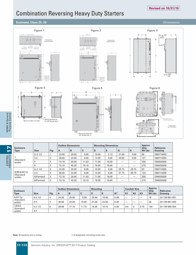
Siemens Industry, Inc. SPEEDFAX™ 2017 Product Catalog17-174
17
CON
TRO
L PR
OD
UCT
SN
EMA
& G
ener
al
Purp
ose
Cont
rol
Siemens / Speedfax Previous folio: 16-123, 10IC 8-123
Combination Reversing Heavy Duty StartersEnclosed, Class 25, 26 Dimensions
AG
H
CB
DE
E D
MountingHoles for
1/4" ScrewsQty. 4
1 1/2 X 2Knockout
1 1/2 X 2Knockout
1/2 X 3/4 Knockout
7.0 3.0 3.0
Typical viewtop and bottom
C
H
A
MountingHoles for
1/4" ScrewsQty. 4
1 1/2 X 2Knockout
3.53.58.5
1 1/2 X 2Knockout
1/2 X 3/4 Knockout
G
DE
B DE
Figure 1 Figure 2 Figure 3
Figure 4
CD
AGH
E
B
Mounting Holes for1/4" Screws Qty. 4
Figure 5
ETRESET
RES
TRIP
ON
OFF
RESET
C MAX
K1 K3E
K2
DA
B
Mounting Holes for 3/8" screws Qty. 4
Figure 6
Typical viewtop and bottom
Typical viewtop and bottom
Revised on 10/31/19
Enclosure Type Size Fig.
Outline Dimensions Mounting Dimensions Approx. Ship Wt Lbs
Reference DrawingA B C D E G H
1 (Standard width)
0–2 1/2 1 24.00 20.00 8.00 15.00 2.13 21.00 3.50 60 D68774002
3-4 2 36.00 24.00 8.00 14.00 5.00 33.50 5.00 121 D68774003
5 3 72.16 20.00 11.03 71.00 16.00 — — 250 D56032005
6 3 72.10 40.20 18.10 78.00 18.00 — — 275 D56032006
3/3R/4/4X/12 (Standard width)
0–2 1/2 5 24.00 20.00 8.00 15.00 3.50 25.75 26.75 63 D68774005
3-4 5 36.00 24.00 8.00 14.00 6.00 37.75 38.75 124 D68774006
5(Painted) 3 72.16 20.00 11.03 71.00 16.00 — — 250 D56032005
6(Painted) 3 72.10 40.20 18.10 78.00 18.00 — — 275 D56032006
Enclosure Type Size Fig.
Outline Dimensions Mounting
Ga
Conduit Size Approx. Ship Wt Lbs
Reference DrawingA B C D E K1 K2 K3
4/4X Fg (Standard width)
0-2 1/2 4 24.00 20.00 8.00 25.56 18.50 0.38 — — — 18 24-139-861-001
3-4 4 30.00 24.00 10.00 31.56 22.50 0.38 — — — 28 24-139-861-003
7/9/3/4 (Standard width)
0-2 1/2 6 28.69 17.75 11.75 18.38 15.75 0.38 0.5 3 0.75 140 24-139-865-004
3-4
Note: Dimensions are in inches. a G designates mounting screw size.

Siemens Industry, Inc. SPEEDFAX™ 2017 Product Catalog 17-175
17
CON
TROL
PROD
UCTS
NEM
A &
General
Purpose Control
Siemens / Speedfax Previous folio: 16-124, 10IC 8-124
K1 K2 K3
K1 K2 K3
D
EB
G
C
A
Figure 2
DA
G EB
C
Figure 3 Figure 4 Figure 1 Figure 1a
Two Speed Heavy Duty StartersEnclosed, Class 30 Dimensions
Note: Dimensions are in inches. a G designates mounting screw size. b Enclosures shown in figures 1and 1a have lift-off covers. Enclosures shown in figures 2, 3 and 4 have hinged covers.
Revised on 10/31/19
Starter Type(Enclosure Type) Size Fig.b
Outline Dimensions Mounting Conduit Size Approx. Ship Wt Lbs
Reference DrawingA B C D E Ga K1 K2 K3
2 Speed 1 Winding (Type 1 for use with or without CPT)
0–1 3/4 w/o CPT 1 19.13 11.38 7.69 15.63 8.25 0.25 0.5-0.75 1.0-1.25 1.5-2 26 D688700–1 3/4 w/ CPT 1a 24.88 13.38 8.13 21.75 9.00 0.25 0.5-0.75 1.25-1.5 2-2.5 52 D688702–2 1/2 2 16.00 17.13 7.63 15.25 14.00 0.25 0.5-0.75 1.25-1.5 1.25-1.5 39 D429320013–3 1/2 2 24.88 13.38 8.13 21.75 9.00 0.25 0.5-0.75 1.25–1.5 2–2.5 60 D729560024 3 24.88 13.38 8.13 21.75 9.00 0.25 0.5-0.75 1.25–1.5 2–2.5 61 D43292001
2 Speed 1 Winding (Type 4/4X Stainless Steel for use with or without CPT)
0–1 3/4 w/o CPT 3 12.00 12.00 6.00 12.75 10.00 0.38 — — — 34 D419170000–1 3/4 w/ CPT 3 16.00 16.00 8.00 17.60 14.50 0.38 — — — 472–2 1/2 w/o CPT 3 16.00 16.00 8.00 17.60 14.50 0.38 — — — 472–2 1/2 w/ CPT 3 30.00 24.00 10.00 31.56 22.50 0.38 — — — 553–3 1/2 3 30.00 24.00 10.00 31.56 22.50 0.38 — — — 61 D432920014 3 30.00 24.00 10.00 31.56 22.50 0.38 — — — 61 D43292001
2 Speed 1 Winding (Type 12/3/3R for use with or without CPT)
0–1 3/4 w/o CPT 3 13.00 12.63 5.38 12.25 10.00 0.25 — — — 340–1 3/4 w/ CPT 3 16.00 17.13 7.63 15.25 14.00 0.25 — — — 47 D171500102–2 1/2 w/o CPT 3 16.00 17.13 7.63 15.25 14.00 0.25 — — — 47 D171500102–2 1/2 w/ CPT 3 24.00 20.00 8.00 25.56 18.50 0.38 — — — 553–4 3 30.00 24.00 10.00 31.56 22.50 0.38 — — — 61 D19673000
2 Speed 1 Winding (Type 4/4X Fg. for use w/ or w/o CPT)
0–2 1/2 4 23.78 23.78 6.89 — — 0.25 — — — 28 24139861003
3–4 4 39.38 29.53 12.60 — — — — — — 24139861004
2 Speed 2 Winding (Type 1 for use with or without CPT)
0–2 1/2 w/o CPT 1 19.13 11.38 7.69 15.63 8.25 0.25 0.5-0.75 1.0-1.25 1.5-2 30 D68870
0–2 1/2 w/ CPT 1a 24.88 13.38 8.13 21.75 9.00 0.25 0.5-0.75 1.25-1.5 2-2.5 52 D68870
3–4 w/o CPT 1a 24.88 13.38 8.13 21.75 9.00 0.25 0.5-0.75 1.25-1.5 2-2.5 52 D68870
2 Speed 2 Winding (Type 4/4X Stainless Steel for use with or without CPT)
0–1 3/4 w/o CPT 3 12.00 12.00 6.00 12.75 10.00 0.38 — — — 340–1 3/4 w/ CPT 3 16.00 16.00 8.00 17.60 14.50 0.38 — — — 412–2 1/2 w/o CPT 3 16.00 16.00 8.00 17.60 14.50 0.38 — — — 412–2 1/2 w/ CPT 3 16.00 16.00 8.00 17.60 14.50 0.38 — — — 413–3 1/2 w/o CPT 3 30.00 24.00 10.00 31.56 22.50 0.38 — — — 553–3 1/2 w/ CPT 3 30.00 24.00 10.00 31.56 22.50 0.38 — — — 61 D432920014 3 30.00 24.00 10.00 31.56 22.50 0.38 — — — 61 D43292001
2 Speed 2 Winding (Type 12/3/3R for use with or without CPT)
0–1 3/4 w/o CPT 3 13.00 12.63 5.38 12.25 10.00 0.25 — — — 340–1 3/4 w/ CPT 3 16.00 17.13 7.63 15.25 14.00 0.25 — — — 41 D171500102–2 1/2 w/o CPT 3 16.00 13.25 6.13 15.25 11.00 0.25 — — — 412–2 1/2 w/ CPT 3 16.00 17.13 7.63 15.25 14.00 0.25 — — — 41 D171500103–3 1/2 w/o CPT 3 24.00 20.00 8.00 25.56 18.50 0.38 — — — 553–4 w/CPT 3 30.00 24.00 10.00 31.56 22.50 0.38 — — — 61 D19673000
2 Speed 2 Winding (Type 4/4X Fg. for use w/ or w/o CPT)
0–2 1/2 4 23.78 23.78 6.89 — — 0.25 — — — 28 24139861003
3–4 4 39.38 29.53 12.60 — — — — — — 24139861004

Siemens Industry, Inc. SPEEDFAX™ 2017 Product Catalog17-176
17
CON
TRO
L PR
OD
UCT
SN
EMA
& G
ener
al
Purp
ose
Cont
rol
Siemens / Speedfax Previous folio: 16-125, 10IC 8-125
OutlineDimensions MountingDimensions MtgScrew ConduitSize ApproxShipWt Size Figure A B C D E G K1 K2 K3 Lbs(Kg) RefDwg
0–13⁄4 3 23.780(604) 14.680(373) 6.890(175) 24.125(613) 12.250(311) 1⁄4 — — — 18(8) —2–4 3 23.780(604) 23.780(604) 6.890(175) 24.125(613) 21.250(540) 1⁄4 — — — 28(13) —
NEMA 1 Standard Width 0–4
NEMA 12/3/3R/4 (Painted), 4/4X Stainless Standard Width 0–4
0–13⁄4 (1Winding) 4 24(610) 20(508) 8(203) 15.00(381) 2.50(64) 25.75(654) 26.75(680) 68(31) D687742–4 (1Winding) 4 36(914) 24(610) 8(203) 12(305) 6.00(152) 37.75(959) 38.75(984) 71(32) D687740–21⁄2, (2Winding) 4 24(610) 20(508) 8(203) 15.00(381) 2.50(64) 25.75(654) 26.75(680) 135(61) D687743–4 (2Winding) 4 36(914) 24(610) 8(203) 12(305) 6.00(152) 37.75(959) 38.75(984) 138(63) D68774
Note: Dimensions in inches (mm).Dimensions for reference, not for construction. Contact sales office for dimensions not listed.
AG
H
CB
DE
E D
MountingHoles for
1/4" ScrewsQty. 4
1 1/2 X 2Knockout
1 1/2 X 2Knockout
1/2 X 3/4 Knockout
7.0 3.0 3.0
Typical viewtop and bottom
CD
AGH
E
B
Mounting Holes for1/4" Screws Qty. 4
Figure 4
Figure 1 Figure 2
Figure 3
C
H
A
MountingHoles for
1/4" ScrewsQty. 4
1 1/2 X 2Knockout
3.53.58.5
1 1/2 X 2Knockout
1/2 X 3/4 Knockout
G
DE
B DE
Typical viewtop and bottom
Mounting Approx OutlineDimensions Dimensions ShipWt Size Figure A B C D E G H Lbs(Kg) RefDwg
0–13⁄4 (1Winding) 1 24(610) 20(508) 8(203) 15.00(381) 2.125(54) 21.00(533) 3.50(90) 68(31) D687742–4 (1Winding) 2 36(914) 24(610) 8(203) 14.00(356) 5.00(127) 33.50(851) 3.50(90) 71(32) D687740–21⁄2, (2Winding) 1 24(610) 20(508) 8(203) 15.00(381) 2.125(54) 21.00(533) 3.50(90) 135(61) D687743–4 (2Winding) 2 36(914) 24(610) 8(203) 14.00(356) 5.00(127) 33.50(851) 3.50(90) 138(63) D68774
Nema 4X Fiberglass 0–4
Combination Two Speed Heavy Duty StartersEnclosed, Class 32 Dimensions

Siemens Industry, Inc. SPEEDFAX™ 2017 Product Catalog 17-177
17
CON
TROL
PROD
UCTS
NEM
A &
General
Purpose Control
Reduced Voltage StartersClass 36, 37, 82 Dimensions
Mounting Holefor 1/4" screw
C
D A
EB
Figure 1
E G
D
J
A
B HC
K
L
(4) .687 Dia Holes
Handle(Optional)
Restricted Areafor
Auto Transformer
Figure 2
Class 82 Size 1 1/2, 2
ALL DIMENSIONS IN INCHES
10.93
5.573.50
3.50
5.08
5.02
26.1325.00
3.50
3.50
MOUNTING HOLES FOR5/16" HARDWARE
∅1.125, ∅1.385, ∅1.750, ∅2.000ECCENTRIC KNOCKOUT
(2 PLACES)
∅1.375, ∅1.700, ∅2.000, ∅2.500ECCENTRIC KNOCKOUT
1.681.81 ∅2.85 O.D. FLANGED
CONDUIT OPENING
2.13
2.75
1/4-20 x1/2"SCREW
3.06
24.27 .37
2.88
2.88
HAND-OFF-AUTO SELECTOR SWITCHSTART BUTTON
.25
Class 36, 37, NEMA 1, 4, 4X, 12/3R, Combination and Non-combination
Enclosure Type
Size
Fig.
Outline Dimensions Reference Drawing
AutoTransformer Part Winding & Wye Delta
Disc. & MCP Type Disc. Type MCP Type A B C D E
1, 4/4X & 12/3R
1 3/4–2 1/2 0–2 0–2 1/2 1 42.00 32.00 12.00 43.60 30.503–3 1/2 2 1/2–3 1/2 3–3 1/2 1 48.00 38.00 12.00 49.60 36.504 4 4 1 60.00 38.00 12.00 61.60 36.505, 6 5, 6 5, 6 2 90.00 29.97 20.00 16.00 24.44
Class 82 size 1
Revised on 10/31/19
Note: Dimensions are in inches.

Siemens Industry, Inc. SPEEDFAX™ 2017 Product Catalog17-178
17
CON
TRO
L PR
OD
UCT
SN
EMA
& G
ener
al
Purp
ose
Cont
rol
Siemens / Speedfax Previous folio: 16-127, 10IC 8-127
Duplex Heavy Duty ControllersClass 83, 84 Dimensions
Revised on 10/31/19
Figure 2 Figure 3Figure 1
A
Class 83 Non-Combination Type
Enclosure Type Size Fig.
Outline Dimensions Mounting
Ga
Conduit Size Approx. Ship Wt Lbs
Reference DrawingA B C D E K1 K2 K3 K4 K5
1 0–1 3/4 1 20.00 20.00 6.00 21.60 18.50 0.38 — — — — — 202, 2 1/2 1 24.00 20.00 8.00 25.60 18.50 0.38 — — — — — 573–4 1 30.00 24.00 10.00 31.60 22.50 0.38 — — — — — 93
12 & 4 0–1 3/4 2 20.00 20.00 6.00 21.60 18.50 0.38 — — — — — 202, 2 1/2 2 24.00 20.00 8.00 25.60 18.50 0.38 — — — — — 573–4 2 30.00 24.00 10.00 31.60 22.50 0.38 — — — — — 93
4X Stainless Steel
0–1 3/4 2 20.00 16.00 6.00 21.60 14.50 0.38 — — — — — 202, 2 1/2 2 24.00 20.00 8.00 25.60 18.50 0.38 — — — — — 573–4 2 30.00 24.00 10.00 31.60 22.50 0.38 — — — — — 93
Class 84 Combination Type
Enclosure Type Size Fig.
Outline Dimensions Mounting
Ga
Conduit Size Approx. Ship Wt Lbs
Reference DrawingA B C D E K1 K2 K3 K4 K5
1, 12/3/3R/40–2 3 34.13 24.63 7.56 33.00 20.00 0.38 0.88 – 1.13 0.88 – 1.13 1.13 – 1.36 1.13 – 1.36 1.36 – 1.72 70
2 1/2–4 3 48.00 36.00 10.00 49.60 34.50 0.38 — — — — — 106
4X Stainless Steel
0–2 3 36.00 24.00 10.00 37.60 22.50 0.38 — — — — — 70
2 1/2–4 3 48.00 36.00 12.00 49.60 34.50 0.38 — — — — — 106
Note: Dimensions are in inches. a G designates mounting screw size.

Siemens Industry, Inc. SPEEDFAX™ 2017 Product Catalog 17-179
17
CON
TROL
PROD
UCTS
NEM
A &
General
Purpose Control
Siemens / Speedfax Previous folio: 16-128, 10IC 8-128
Pump Control PanelsClass 87, 88 Dimensions
Revised on 10/31/19
F
B
F
C
Opening for Conduit HubSize "P"
A D G
Mounting HolesFor 5/16" HardwareL M L N
HI
JK
Mounting Holefor 1/4" screw
C
D A
EB
F
BE CF
A D G
5.000
Figure 3Figure 2
FE G
D
J
A
B HC
K
L
(4) .687 Dia Holes
Handle(Optional)
Figure 4
FE G
D
J
A
B HC
K
L
(4) .687 Dia Holes
Handle(Optional)
Figure 1
Outline Drawings
Open air contacts
Size Fig.
Outline Dimensions Mounting Dimensions Conduit Knockout Hub Reference DrawingA B C D E F G H I J K L M N P
1–2 1/2 1 28.50 20.00 8.06 24.00 — 10.00 27.00 5.50 8.50 11.50 — 0.5 – 0.75 1.25 – 1 0.75 – 1 1.503 – 4 1 40.50 24.00 8.09 36.00 — 12.00 39.00 8.44 11.94 15.44 — 1.97 – 2.47 0.88 – 1.13 — 2.505 2 72.16 20.00 10.00 71.00 16.00 2.13 70.91 — — — — — — — —6 2 60.00 38.00 16.00 61.60 36.50 0.75 — — — — — — — —
Vacuum contacts
Size Fig.
Outline Dimensions Mounting Dimensions Conduit Knockout Hub Reference DrawingA B C D E F G H I J K L M N P
4 2 55.97 24.38 9.69 54.81 20.25 2.13 54.72 26.19 — — 27.44 — — — —5 2 72.16 20.00 10.00 71.00 16.00 2.13 70.91 — — — — — — — —6 2 60.00 38.00 16.00 61.60 36.50 0.75 — — — — — — — —
Reduced voltageSize
Fig.
Outline Dimensions Reference Drawing
AutoTransformer Part Winding & Wye Delta
Disc. & MCP Type Disc. Type MCP Type A B C D E
2-2 1/2 1–2 1–2 1/2 3 42.00 32.00 12.00 43.60 30.503-3 1/2 2 1/2–3 1/2 3–3 1/2 3 48.00 38.00 12.00 49.60 36.504 4 4 3 60.00 38.00 16.00 61.60 36.505, 6 5, 6 5, 6 4 90.00 30.00 20.00 16.00 24.44
Note: Dimensions are in inches. All enclosures are Type 3R

Siemens Industry, Inc. SPEEDFAX™ 2017 Product Catalog17-180
17
CON
TRO
L PR
OD
UCT
SN
EMA
& G
ener
al
Purp
ose
Cont
rol
Siemens / Speedfax Previous folio: 16-129, 10IC 8-129
Lighting ContactorsEnclosed Contactors, Class LC and LE Dimensions
Revised on 10/31/19
Class LC and LE Non-comboEnclosureType Contactor Rating Fig.
Outline Dimensions Mountinga Conduit Size Reference DrawingA B C D E K1 K2 K3 K4 K5
1 without CPT
LE 20/30A 3-4P 1 10.97 6.41 5.03 8.22 4.62 0.5 0.50 – 0.75 0.75 – 1 — —LC 30A 2-12P, LE 60A 3P 1 13.53 7.97 6.38 10.25 6 0.50 – 0.75 0.75 – 1 1 – 1.25 — —LE 30/60A 6-12P, LE 100A 3P 1 19.12 11.38 7.69 15.62 8.25 0.50 – 0.75 1 – 1.25 1.5 – 2 — —LE 200-400A 3P 2 26 17.62 12.5 25.19 15.5 0.50 – 0.75 1.25 – 1.5 1.25 – 1.5 — —
1 with CPT
LC 30A 2-12P, LE 20A 3-4P, LE 30A 3-9P, LE 60A 3-9P, LE 100A 3P
1 19.12 11.38 7.69 15.62 8.25 0.50 – 0.75 1 – 1.25 1.5 – 2 — —
LE 30/60A 12P 1 24.88 13.38 8.12 21.75 9 0.50 – 0.75 1.25 – 1.5 2 – 2.5 — —LE 200-400A 3P 2 26 17.62 12.5 25.19 15.5 — 1.25 – 1.5 1.25 – 1.5 — —
12/3R without CPT
LE 20A 3-4P, LE 30/60A 3-9P, LC 30A 2-12P 2 16 13.25 6.12 15.25 11 — — — — —
LE 30/60A 12P 2 26 13.12 7.56 25.25 10 — — — — —LE 100A 3P 2 26 13.12 7.56 25.25 10 — — — — —LE 200-400A 3P 2 26 17.62 12.5 25.19 15.5 — — — — —
4/4X without CPT
LE 20A 3-4P, LE 30/60A 3-9P,LC 30A 2-12P 2 16 14 6.02 16.75 12 — — — — —
LE 30/60A, 12P 2 24 16 8.76 22.5 14.5 — — — — —LE 100A 3P 2 24 16 8.76 22.5 14.5 — — — — —LE 200-400A,3P 2 24 20 10 22.5 18.5 — — — — —
12/3R with CPT
LE 20A 3-4P, LE 30/60A 3-9P,LC 30A 2-12P 2 16 13.25 6.12 15.25 11 — — — — —
LE 30/60A, 12P 2 26 13.12 7.56 25.25 10 — — — — —LE 100A 3P 2 26 13.12 7.56 25.25 10 — — — — —LE 200-400A,3P 2 26 17.62 12.5 25.19 15.5 — — — — —
4/4X with CPT
LE 20A 3-4P, LE 30/60A 3-9P,LC 30A 2-12P 2 16 14 6.02 16.75 12 — — — — —
LE 30/60A, 12P 2 24 16 8.76 22.5 14.5 — — — — —LE 100A 3P 2 24 16 8.76 22.5 14.5 — — — — —LE 200-400A,3P 2 24 20 10 22.5 18.5 — — — — —
Figure 1 Figure 2 Figure 3
Class LE ComboEnclosure Type Type
ContactorRating Fig.
Outline Dimensions Reference DrawingA B C
1, 12/3R & 4/4X with & without CPT
Fusible and Non-fusible Disconnect
20–60A 3 24 11 8100A 3 24 20 8200A 3 46 20 10300A 3 76 22 13
Circuit Breaker 20–100A 3 24 11 8
Note: Dimensions are in inches. a Mounting screw G size is 0.25".

Siemens Industry, Inc. SPEEDFAX™ 2017 Product Catalog 17-181
17
CON
TROL
PROD
UCTS
NEM
A &
General
Purpose Control
Lighting ContactorsEnclosed Contactors, Class CLM, CM Dimensions
Figure 1 Figure 2 Figure 3
Class CLM Non-comboEnclosureType
Contactor Rating(Class CLM) Fig.
Outline Dimensions Mountinga Conduit Size Reference DrawingA B C D E K1 K2 K3 K4 K5
1 without CPT
30–60A (2-5p) 1 10.97 6.41 5.03 8.22 4.62 0.5 0.50 – 0.75 0.75 – 1 — —20A (2–12p) 1 13.53 7.97 6.38 10.25 6.00 0.50 – 0.75 0.75 – 1 1 – 1.25 — —30–60A (6-12p) 2 16.00 17.12 7.62 15.25 14.00 0.50 – 0.75 1.25 – 1.5 1.25 – 1.5 — —100A (2-5p) 1 19.12 11.38 7.69 15.62 8.25 0.50 – 0.75 1 – 1.25 1.5 – 2 — —200A (2-5p) 1 24.88 13.38 8.12 21.75 9.00 0.50 – 0.75 1.25 – 1.5 2.5 — —300–400A (2-5p) 2 48.00 20.00 12.50 45.19 10.00 2.00 – 2.50 1.25 – 1.5 0.5 – 0.75 1.25 – 1.5 2 – 2.5
1 with CPT
20A (2–12p), 30A (2–5p) 1 19.12 11.38 7.69 15.62 8.25 0.50 – 0.75 1 – 1.25 1.5 – 2 — —30–60A (6–12p) 2 16.00 17.12 7.62 15.25 14.00 0.50 – 0.75 1.25 – 1.5 1.25 – 1.5 — —100-200A (2-5p) 2 26.00 17.62 12.50 25.19 15.50 — 1.25 – 1.5 1.25 – 1.5 — —300–400A (2-5p) 2 48.00 20.00 12.50 45.19 10.00 2.00-2.50 1.25 – 1.5 0.5 – 0.75 1.25 – 1.5 2 – 2.5
12/3R without CPT
20A (2–12p), 30A (2–12p), 60A (2 - 10p) 2 16.00 13.25 6.12 15.25 11.00 — — — — —
100A (2-5p) 2 16.00 13.00 9.50 15.12 11.00 — — — — —60A (12p) 2 19.00 22.00 8.00 — — — — — — —200A (2-5p) 2 26.00 17.62 12.50 23.19 15.50 — — — — —300A -400A (3p) 2 48.00 20.00 12.50 49.00 10.00 — — — — —
12/3R with CPT
20A (2-12p), 30A (2-5p) 2 16.00 13.25 6.12 15.25 11.00 — — — — —30A (6-12p) 2 16.00 17.12 7.62 15.25 14.00 — — — — —60-100A (2-5p) 2 16.00 13.00 9.50 15.12 11.00 — — — — —60A (6-12p) 2 19.00 22.00 8.00 — — — — — — —200A (3p) 2 26.00 17.62 12.50 25.19 15.50 — — — — —300–400A (3p) 2 48.00 20.00 12.50 49.00 10.00 — — — — —
4/4X without CPT
20A (2–12p), 30A (2–12p), 60A (2 - 10p) 2 16.00 14.00 6.02 16.75 12.00 — — — — —
100A (2-5p) 2 16.00 16.00 10.00 14.50 14.50 — — — — —60A (12p) 2 19.00 22.00 8.00 — — — — — — —200A (2-5p) 2 24.00 20.00 10.00 22.50 18.50 — — — — —300A -400A (3p) 2 48.00 20.00 12.50 49.00 10.00 — — — — —
4/4X with CPT
20A (2-12p), 30A (2-5p) 2 16.00 14.00 6.02 16.75 12.00 — — — — —30A (6-12p) 2 16.00 20.00 8.00 14.50 18.50 — — — — —60-100A (2-5p) 2 16.00 16.00 10.00 14.50 14.50 — — — — —60A (6-12p) 2 24.00 20.00 8.00 22.50 18.50 — — — — —200A (3p) 2 24.00 20.00 10.00 22.50 18.50 — — — — —300–400A (3p) 2 48.00 20.00 12.50 49.00 10.00 — — — — —
Class CM Combo
Enclosure Type Type
Contactor Outline Dimensions Reference DrawingRating Fig. A B C
1, 12/3R & 4/4X with & without CPT
Fusible and Non-fusible Disconnect
20–60A 3 24 11 8100A 3 24 20 8200A 3 46 20 10300A 3 76 22 13
Circuit Breaker 20–100A 3 24 11 8
Revised on 10/31/19
Note: Dimensions are in inches. a Mounting screw G size is 0.25".

Siemens Industry, Inc. SPEEDFAX™ 2017 Product Catalog17-182
17
CON
TRO
L PR
OD
UCT
SN
EMA
& G
ener
al
Purp
ose
Cont
rol
Class 11 - 3RV
Signaling Contact for Class 11 - 3RV
3RV1921-1M
Typical Wiring Diagrams—Class SMF
Typical Wiring Diagrams—MMS
AC Reversing Manual Starter and Manual Motor Starting Switches
AC 2-Speed Manual Motor Starting Switches
Reversing Manual Motor Starting Switch 2-Pole, 1-Phase
Reversing Manual Starter 3-Pole, 3-Phase
3-Pole Reversing Switches
2-Pole, 1-Phase with Pilot Lights 3-Pole, 3-Phase
L1 L2
T1 T1L1 L1
L3L3T3 T3
CO
M
FW
D
RE
V
Motor
Pilot Light(if used)
REVERSINGSINGLE PHASE
3-LEADREPULSION-INDUCTION
MOTOR
FWD REVHIGH LOW
L1 L2 L3
T1 T1L1 L1
L3L3T3 T3
L2L2T2 T2T
11
T12
T13
T3
T2
Motor
Pilot Lights(if used)
2-SPEED2-WINDING WYE CONNECTED
3- PHASEMOTOR
T1
HIGH LOWL1 L2
T1 T1L1 L1
L3L3T3 T3
HIG
H
LO
W
CO
M
Motor
Pilot Lights(if used)
2-SPEED2-WINDING
SINGLE PHASEMOTOR
T1 T1L1
T2 L2
T3 L3
L1
L3
T2
FWD(L.H. UNIT)
REV(R.H. UNIT)
T3
L2
SINGLE PHASE 4-LEADREPULSION - INDUCTION MOTOR
LINE ANDMOTOR LEADS
Line
Furnish Jumper
Meter
Pilot LightLeads to
L.H.UNIT
R.H.UNIT
L1 toL2 to
L3 to T2
L1L2
T1 toT4 toT5 toT8 to
T2L3T3T1
L1T2
__
____
__
T4T8 T1 T5
SINGLE PHASE CAPACITOROR SPLIT PHASE MOTOR
LINE ANDMOTOR LEADS
Line
Furnish Jumper
Meter
Pilot LightLeads to
L.H.UNIT
R.H.UNIT
L1 toL2 to
L3 to T2
L1L2
T1 toT4 toT5 toT8 to
T1T3L1T2
T1T3
__
____
__
T5T8 T4
START
RUN
T1
THREE PHASE MOTORLINE AND
MOTOR LEADS
Line
Meter
Pilot LightLeads to
L.H.UNIT
R.H.UNIT
L1 toL2 toL3 to
L1L2L3
T1 toT2 toT3 to
T1T2T3
T1T3
___
___
__
T3T2
Motor
T1
Manual ControlClass 11 - 3RV, SMF, MMS Wiring Diagrams

Siemens Industry, Inc. SPEEDFAX™ 2017 Product Catalog 17-183
17
CON
TROL
PROD
UCTS
NEM
A &
General
Purpose Control
Siemens / Speedfax Previous folio: SF11 17-143
3-Phase and Single Phase Magnetic Starters
Solid State Overload 3-Phase Sizes 5-8
a Warning: The ESP200 Starter and Single Phase Motor must be wired as shown above. For L1, L2 do not use the middle terminal or hole.
b Full Load Amps (FLA): Adjustment of the ESP200 solid state overload relay accommodates the single phase motor.
(WHEN USED, SEE TABLE)
TRANSFORMERCURRENT
O.L.
RELAY(IF USED)
" "C
" "
T3T2
3
2M
A1 A2
L1/1 L2 L3
CIRCUITPROTECTIVE
DEVICE(IF USED)
A B C
INCOMING LINE
T1
LOAD
A
CONTACTOR""
SEPARATE CONTROL SOURCE.OTHER THAN LINE VOLTAGE OR ON ACOIL IS TO OPERATE ON A VOLTAGEREMOVE WIRE C IF THE CONTACTOR
B ""
POWER WIRING:USE 75°C COPPER WIRE ONLY.
95
96
X1 X1X1
X1
NOTE A
NOTES:A: 2CT IS LOCATED ON THE LINE SIDE
OF CONTACTOR ON SIZE 7 STARTERS ONLY.
2CT
1CT 2CT 3CT
750:5
600:5
300:5
CT RATIOSIZE
7
6
5
1200:58
Three Phase Magnetic Starter with DC Coil, Sizes 00–4
M
2
MOTOR
T2T1 T3
WIRING DIAGRAM
CONTROL DEVICE
3
TO PILOT
WV
1
L1 L2 L3TO SUPPLY
IF PROVIDED
ESP2009695 A4-97 98A3+
LATEBREAKCONTACT
NEMA 00 - 4
GROUNDED BYCUSTOMER
MAY BE
(OPTIONAL)
SEC FUSE
CONTROL FUSES
1
C
XF
H1
H4
H3
H2
X2
SEC
X1
CONTROL TRANSFORMER(OPTIONAL)
B 96
THREE PHASE MAGNETIC STARTER WITH D.C. COIL
Three Phase Magnetic Starter, Size 00–4WIRING DIAGRAM
M
2
MOTOR
T2T1 T3
CONTROL DEVICE
3
TO PILOT
WV
1
L1 L2 L3TO SUPPLY
IF PROVIDED
ESP2009695
A4-97 98
A3+
GROUNDED BYCUSTOMER
MAY BE
(OPTIONAL)
SEC FUSE
CONTROL FUSES
1
C
XF
H1
H4
H3
H2
B
X2
SEC
X1
NEMA 00 - 4
CONTROL TRANSFORMER(OPTIONAL)
96
A
3 PHASE MAGNETIC STARTER SIZE 00 - 4
Single Phase Magnetic StarterabWIRING DIAGRAM
T1 T2
L2L1TO SUPPLY
WV
T1 T2
MOTOR
M
1
3
2
IF PROVIDED
ESP2009695
A4-97 98
A3+
GROUNDED BYCUSTOMER
MAY BE
(OPTIONAL)
SEC FUSE
CONTROL FUSES
1
C
XF
H1
H4
H3
H2
B
X2
SEC
X1
NEMA 00 - 4
CONTROL TRANSFORMER(OPTIONAL)
96A
SINGLE PHASE MAGNETIC STARTER SIZE 00 - 4
A1 A3
Ambient CompensatedSingle Phase Sizes 00-2 1/2
Ambient Compensated3-Phase Sizes 00-2 1/2
Ambient Compensated3-Phase Sizes 3-4
Heavy Duty Motor StartersClass 14 Wiring Diagrams

Siemens Industry, Inc. SPEEDFAX™ 2017 Product Catalog17-184
17
CON
TRO
L PR
OD
UCT
SN
EMA
& G
ener
al
Purp
ose
Cont
rol
Size 5–8b
3-Phase WIRING DIAGRAM
M
2
MOTOR
T2T1 T3
CONTROL DEVICE
3
TO PILOT
WV
1
L1 L2 L3TO SUPPLY
IF PROVIDED
ESP2009695
A4-97 98
A3+
GROUNDED BYCUSTOMER
MAY BE
(OPTIONAL)
SEC FUSE
CONTROL FUSES
1
C
XF
H1
H4
H3
H2
B
X2
SEC
X1
NEMA 00 - 4
CONTROL TRANSFORMER(OPTIONAL)
96
A
3 PHASE MAGNETIC STARTER SIZE 00 - 4
Size 00–4a
a Remove wire “C” if control transformer is used. For separate control voltage source, remove jumpers “A” and “B” and connect source to control fuse line terminals.
b Remove wire “C” if the contactor coil is to operate on a voltage other than line voltage or in a separate control source.
SIZE CT RATIO
5 300:5
6 600:5
7 750:5
8 1200:5
“C”
Combination Heavy Duty StartersClass 17, 18 Wiring Diagrams

Siemens Industry, Inc. SPEEDFAX™ 2017 Product Catalog 17-185
17
CON
TROL
PROD
UCTS
NEM
A &
General
Purpose Control
Siemens / Speedfax Previous folio: SF11 17-145
Bimetal Overload Sizes 0-1 3/4
Bimetal OverloadSizes 3-4
Bimetal OverloadSizes 2-2 1/2
TO SUPPLY
REMOVE WIRE "C" IF THE CONTACTORCOIL IS TO OPERATE ON A VOLTAGEOTHER THAN LINE VOLTAGE OR ON A SEPARATE CONTROL SOURCE.
CURRENTTRANSFORMER(SEE TABLE)
"FWD"CONTRACTOR
MECHANICAL
INTERLOCK
"REV"CONTACTOR
O.L.RELAY
"FWD"CONTACTOR
L1 L2 L3
MOTOR
3-Phase Ambient Compensated Overload
Single Phase Ambient Compensated Overload
3-Wire, 2-Pole Sizes 0-1 3/4
Reversing Heavy Duty StartersClass 22 Wiring Diagrams

Siemens Industry, Inc. SPEEDFAX™ 2017 Product Catalog17-186
17
CON
TRO
L PR
OD
UCT
SN
EMA
& G
ener
al
Purp
ose
Cont
rol
Siemens / Speedfax Previous folio: SF11 17-146
3-Phase Solid State Overload
Solid State OverloadSizes 5–6
TO SUPPLY
REMOVE WIRE "C" IF THE CONTACTORCOIL IS TO OPERATE ON A VOLTAGEOTHER THAN LINE VOLTAGE OR ON A SEPARATE CONTROL SOURCE.
CURRENTTRANSFORMER(SEE TABLE)
"FWD"CONTRACTOR
MECHANICAL
INTERLOCK
"REV"CONTACTOR
O.L.RELAY
"FWD"CONTACTOR
L1 L2 L3
MOTOR
3-Phase Reversing Magnetic StarterSizes 00–13⁄4
MOTOR
V VW WFOR REV
L1 L2 L3
5
4
3
2
T2 T3T1
TO SUPPLY
1
67
ESP2009695 A4-97 98A3+
NEMA 00 - 1 34WIRING DIAGRAM
GROUNDED BYCUSTOMER
MAY BE
(OPTIONAL)
SEC FUSE
CONTROL FUSES
1
C
XF
H1
H4
H3
H2
X2
SEC
X1
CONTROL TRANSFORMER(OPTIONAL)
B
96
A
T2
T1 T3
3 PHASE REVERSINGMAGNETIC STARTER
3-Phase Reversing Magnetic StarterSizes 2–4
TO SUPPLY
MOTOR
V FOR W
3
2
L1 L2 L3
WREVV
4
51
A
WIRING DIAGRAM
T1 T2 T3
67
ESP2009695 A4-97 98A3+
NEMA 2 - 4
GROUNDED BYCUSTOMER
MAY BE
(OPTIONAL)
SEC FUSE
CONTROL FUSES
1
C
XF
H1
H4
H3
H2
X2
SEC
X1
CONTROL TRANSFORMER(OPTIONAL)
B
96
3 PHASE REVERSINGMAGNETIC STARTER
3-Phase Reversing Magnetic Starter with DC Coil, Sizes 00–13⁄4WIRING DIAGRAM
LATE BREAK
T1
2 T1
T2
MOTOR T3
T2 T3 4
TO SUPPLY
L1
37 V FOR W
L2 L3
5W
REVV 6
ESP2009695 A4-97 98A3+
NEMA 00 - 1 34
GROUNDED BYCUSTOMER
MAY BE
(OPTIONAL)
SEC FUSE
CONTROL FUSES
96
C
XF
H1
H4
H3
H2
X2
SEC
X1
1
1
B
CONTROL TRANSFORMER(OPTIONAL)
3 PHASE REVERSINGMAGNETIC STARTER W/DC COIL
3-Phase Reversing Magnetic Starter with DC Coil, Sizes 2–4
TO SUPPLY
T1 T3
L3L1
WV
MOTOR
FOR
L2
T2
T1 T2 T3
WIRING DIAGRAM
REV
L.B.
5
7L.B.
V W
2
3
64
ESP2009695 A4-97 98A3+
NEMA 2 - 4
GROUNDED BYCUSTOMER
MAY BE
(OPTIONAL)
SEC FUSE
CONTROL FUSES
1
C
XF
H1
H4
H3
H2
X2
SEC
X1
96
CONTROL TRANSFORMER(OPTIONAL)
B
3 PHASE REVERSINGMAGNETIC STARTER W/DC COIL
Reversing Heavy Duty StartersClass 22 Wiring Diagrams

Siemens Industry, Inc. SPEEDFAX™ 2017 Product Catalog 17-187
17
CON
TROL
PROD
UCTS
NEM
A &
General
Purpose Control
Siemens / Speedfax Previous folio: SF11 17-147
TO SUPPLY
REMOVE WIRE "C" IF THE CONTACTORCOIL IS TO OPERATE ON A VOLTAGEOTHER THAN LINE VOLTAGE OR ON A SEPARATE CONTROL SOURCE.
CURRENTTRANSFORMER(SEE TABLE)
"FWD"CONTRACTOR
MECHANICAL
INTERLOCK
"REV"CONTACTOR
O.L.RELAY
"FWD"CONTACTOR
L1 L2 L3
MOTOR
3-Phase
Size 5–6
3-Phase Reversing Magnetic StarterSizes 00–13⁄4
MOTOR
V VW WFOR REV
L1 L2 L3
5
4
3
2
T2 T3T1
TO SUPPLY
1
67
ESP2009695 A4-97 98A3+
NEMA 00 - 1 34WIRING DIAGRAM
GROUNDED BYCUSTOMER
MAY BE
(OPTIONAL)
SEC FUSE
CONTROL FUSES
1
C
XF
H1
H4
H3
H2
X2
SEC
X1
CONTROL TRANSFORMER(OPTIONAL)
B
96
A
T2
T1 T3
3 PHASE REVERSINGMAGNETIC STARTER
3-Phase Reversing Magnetic StarterSizes 2–4
TO SUPPLY
MOTOR
V FOR W
3
2
L1 L2 L3
WREVV
4
51
A
WIRING DIAGRAM
T1 T2 T3
67
ESP2009695 A4-97 98A3+
NEMA 2 - 4
GROUNDED BYCUSTOMER
MAY BE
(OPTIONAL)
SEC FUSE
CONTROL FUSES
1
C
XF
H1
H4
H3
H2
X2
SEC
X1
CONTROL TRANSFORMER(OPTIONAL)
B
96
3 PHASE REVERSINGMAGNETIC STARTER
Combination Reversing Heavy Duty StartersClass 25, 26 Wiring Diagrams

Siemens Industry, Inc. SPEEDFAX™ 2017 Product Catalog17-188
17
CON
TRO
L PR
OD
UCT
SN
EMA
& G
ener
al
Purp
ose
Cont
rol
1 Winding Constant Horsepower Size 2–4
WIRING DIAGRAM
T6
T4T5
MOTOR
T2T3
T1
L3L2L1
T3T1 T2
WLOWV
4
A
5
WHIGHV
31
2
LV W
T6 T5T4
TO SUPPLY
6 7
6
NEMA 2 - 4
ESP2009695
A4-97 98
A3+
ESP2009695
A4-97 98
A3+
GROUNDED BYCUSTOMER
MAY BE
CONTROL TRANSFORMER(OPTIONAL)
(OPTIONAL)
SEC FUSE
CONTROL FUSES
1
C
XF
H1
H4
H3
H2
X2
SEC
X1
96B
2 SPEED 3 PHASE 1 WINDINGCONSTANT HORSEPOWER
X1
A
(OPTIONAL)
B
961C
WIRING DIAGRAM
8V LOW W37
2
OVERLOAD RELAY
H2
H4SEC FUSE
X2H1
H3
T3 XFT2T1
M
95 96(OPTIONAL)
CONTROL TRANSFORMER
SEC
CONTROL FUSES
L2 L3L1
CIRCUIT BREAKERDISCONNECT or
TO SUPPLY
WV HIGH
OVERLOAD RELAY
56
4
T5T6 T48
95 96
T6T2T1
T6T2
T1
T4
T5
T3
T5VARIABLE TORQUE MOTOR
CONSTANT TORQUE MOTOR
T3
T4
L3
HIGH
HIGH
OLLOW
LOW
LOW
OL
ALL OL'S
HIGH
HIGH
HIGH
HIGH
LOW
T4
T5
T6
T3
T2
T1
ELEMENTARY DIAGRAM
LOW
HIGH
6
7
HIGH
LOW
3
5
2
4
9596
T2T1T5T3L3
T4T2L2
T3
TOGETHER
HIGH
LOW
L2L1
A
T6T1L1
HIGH SPEEDLOW SPEED
POSITION
CIRCUIT BREAKERDISCONNECT or
TO SUPPLY
T1
T6
T3
T5T4
T2
WIRING DIAGRAM
T4 T5T6 T1 T2 T3
T1T2T3T4T5T6
MOTOR
V W LOWVHIGH W
5
4
3
2
8 1
TO SUPPLYL1 L2 L3
6 7
NEMA 00 - 1 34
GROUNDED BYCUSTOMER
MAY BE
CONTROL TRANSFORMER(OPTIONAL)
(OPTIONAL)
SEC FUSE
CONTROL FUSES
1
C
XF
H1
H4
H3
H2
X2
SEC
X1
96B
ESP2009695
A4-97 98
A3+
ESP2009695
A4-97 98
A3+
A
2 SPEED 3 PHASE 1 WINDINGCONSTANT OR VARIABLE TORQUE
1 Winding Constant or Variable Torque Size 0–13/4
1 Winding Constant Horsepower Size 0–13/4
5
4
TOGETHER
LOWOL
HIGHOL
ALL OL'S
POSITIONLOW SPEEDHIGH SPEED
L3T3T5
L2T2T4T6
T1L1
T4 T5
96
CIRCUIT BREAKER
ALOW
LOW
LOW
HIGH
HIGH
HIGH
DISCONNECT or
TO SUPPLY
L1 L2 L3
MOTORCONSTANT HORSEPOWER
T6
95
4
LOW
2
HIGH
5
3
7 HIGH
6 LOW
T2
T3
T1
LOW
LOWT5
T4
T6
T3
T5T2
T4
LOW
HIGH8
T1
T6
6
ELEMENTARY DIAGRAM
CIRCUIT BREAKER
T2T1
95
T1
T6
T3
T5T4
T2
T3
96OVERLOAD RELAY
V LOW W
95
M
T6 T4 T5
96OVERLOAD RELAY
37
2
V8
HIGH W
C
TO SUPPLY
DISCONNECT or
L1 L2 L3
WIRING DIAGRAM
CONTROL TRANSFORMER
H1
H3
XF
H2
H4
SEC FUSE
X2
SEC
X1
(OPTIONAL)
(OPTIONAL)CONTROL FUSES1 96
AB
WIRING DIAGRAM
T2 T3T1 T6 T4 T5
T1T2T3T4 MOTOR
V WLOW V HIGH W
5
4
3
2
8 1
A
L1 L2 L3
67
TO SUPPLY NEMA 00 - 1 34
GROUNDED BYCUSTOMER
MAY BE
CONTROL TRANSFORMER(OPTIONAL)
(OPTIONAL)
SEC FUSE
CONTROL FUSES
1
C
XF
H1
H4
H3
H2
X2
SEC
X1
96B
T5T6
ESP2009695
A4-97 98
A3+
ESP2009695
A4-97 98
A3+
2 SPEED 3 PHASE 1 WINDINGCONSTANT HORSEPOWER
Note: For separate control voltage source, remove jumpers “A” and “B” and connect source to control fuse terminal. Remove jumper “C” if control transformer is used.
Two Speed Heavy Duty StartersClass 30 & 32 Non-Combination and Combination Starters Wiring Diagrams

Siemens Industry, Inc. SPEEDFAX™ 2017 Product Catalog 17-189
17
CON
TROL
PROD
UCTS
NEM
A &
General
Purpose Control
Siemens / Speedfax Previous folio: SF11 17-149
2 Winding Constant Horsepower & 2 Winding Constant or Variable Torque Size 0–4
WIRING DIAGRAM
L3L2L1
T6
T4T5
MOTOR
T2T3
T1
T5T6 T4
WHIGHV
4
A
5
WLOWV
31
2
HV W
T1 T3T2
TO SUPPLY
6 7
GROUNDED BYCUSTOMER
MAY BE
CONTROL TRANSFORMER(OPTIONAL)
(OPTIONAL)
SEC FUSE
CONTROL FUSES
1
C
XF
H1
H4
H3
H2
X2
SEC
X1
96B
ESP2009695
A4-97 98
A3+
ESP2009695
A4-97 98
A3+
2 SPEED 3 PHASE 1 WINDINGCONSTANT OR VARIABLE TORQUE
NEMA 2 - 4
X2H1
H3MT3
T12T11
T13
A
CONTROL FUSES(OPTIONAL)
B
96C 1
WIRING DIAGRAM
W
T13
V
T11
HIGH
T12
85
47
H4SEC FUSE
SEC
XF
H2
95 96OVERLOAD RELAY
(OPTIONAL)CONTROL TRANSFORMER
X1
L3L2L1TO SUPPLY
6
3
2
W
T2
V
T1
LOW
CIRCUIT BREAKER
T3
DISCONNECT or
T13
T3
T2T1
95 96
8
LOW
HIGH
OVERLOAD RELAY
T2
T12
T2
T1
T11
T3
T12
T11
T1
L3
OLLOW
OLHIGH
LOW
LOW
LOW
HIGH
HIGH
HIGH
ELEMENTARY DIAGRAM
6
7
LOW
HIGH
5
3
HIGH
LOW
9596
L2T2 T3
L3
T12 T13
ALL OL'S
2
4
T13TWO WINDING MOTOR
L1
L1LOW SPEEDHIGH SPEED
POSITION
A
T1T11
CIRCUIT BREAKERDISCONNECT or
TO SUPPLYL2
T2 T3T1 T11 T12 T13
T1T2T3T11T12T13
MOTOR
V WLO V HI W
3
2
5 1
A
TO SUPPLY
L1 L2 L3WIRING DIAGRAM
47
8
6
NEMA 2 - 4
GROUNDED BYCUSTOMER
MAY BE
CONTROL TRANSFORMER(OPTIONAL)
(OPTIONAL)
SEC FUSE
CONTROL FUSES
1
C
XF
H1
H4
H3
H2
X2
SEC
X1
96B
ESP2009695
A4-97 98
A3+
ESP2009695
A4-97 98
A3+
2 SPEED 3 PHASE 2 WINDINGSEPARATE WINDING
1 Winding Constant or Variable Torque Size 2–4
D68784002
D68786001
Note: For separate control voltage source, remove jumpers “A” and “B” and connect source to control fuse terminal. Remove jumper “C” if control transformer is used.
Two Speed Heavy Duty StartersClass 30 & 32 Non-Combination and Combination Starters Wiring Diagrams

Siemens Industry, Inc. SPEEDFAX™ 2017 Product Catalog17-190
17
CON
TRO
L PR
OD
UCT
SN
EMA
& G
ener
al
Purp
ose
Cont
rol
Part Winding
EMT
Reduced Voltage Starters & Pump PanelsClass 36, 37, 88 Wiring Diagrams

Siemens Industry, Inc. SPEEDFAX™ 2017 Product Catalog 17-191
17
CON
TROL
PROD
UCTS
NEM
A &
General
Purpose Control
Siemens / Speedfax Previous folio: SF11 17-151
Auto Transformer
OL
2CT
OL
1CT
OL
3CT
CR2
ETM
1LT
4LT
OL
5LT
MR
OL(95) (96)
4FU
MR
1FU
2FU
1S
H1 H4
CPT
X1
TR
3FU
73MR 1S 74
77
OR
DISCONNECT
R
* INTLKMECH
5FU
1S
2S
2S
R MR71 75 76 72
7978
1 3
X2
MR
1
4
L1 L2
2
CIRCUIT BREAKER
2L3
2L2
2L1
0%50%
65%
80%
100%
R
R
R
2S
2S
1L3
1L2
3L3
3L2
L2L1 L3 2S1L1 3L1
T1
1S
1S
T3
T2 MOTOR*
1S
100%
80%
65%
50%
0%
100%
80%
65%
50%
0%
TR
TAS 12
2 3
X2
3
L1 L2
OPTIONAL
(A1) (A2)
(A1) (A2)
(A1) (A2)
(A1) (A2)
CR1
CR1
CR1
NOTC
6 (A2)(A1)
TO SUPPLY
L1LMB
SEKSESSAW
LMB
SEKSESSAW
LMB
SEKSESSAW
L2 L3
SURGE SUPPRESSOR
CONNECTIONS FOR OPTIONAL DEVICES
OPTIONAL DEVICES ARE FURNISHED PER CONTRACT DOCUMENTS
*
*
*
*
*
STOPSTART
HANDOFF
AUTO
AUTOOFF
HAND
OFF ON
1 2 3
1PB 2PB
1 2 3
5
START
2PB
1SS
AUTOCONTACT
1
1
15
AUTOCONTACT
1SS
3
1 31SS
(A1) (A2)
(A1) (A2)
3 4
3 4
1 X2
RUN/ON/
OL TRIPPED9
RUNNING
JUM
PE
R
NOTE ECONNECTVOLTAGEAS SPECIFIEDPER NAMEPLATE
FOR MOTORHP SEECONTROLLERNAMEPLATE
1OFF/STOP
10 X2
FOR STARTERSIZES 1-4, 1CT-3CTARE NOT USED.
SUPPLIED AS REQUIRED
LMB
SEKSESSAW
LMB
SEKSESSAW
Note E:Remove jumper if thermal protection switch is provided.
Reduced Voltage Starters & Pump PanelsClass 36, 37, 88 Wiring Diagrams

Siemens Industry, Inc. SPEEDFAX™ 2017 Product Catalog17-192
17
CON
TRO
L PR
OD
UCT
SN
EMA
& G
ener
al
Purp
ose
Cont
rol
Siemens / Speedfax Previous folio: SF11 17-152
Wye Delta (Open Transition)
Reduced Voltage Starters & Pump PanelsClass 36, 37, 88 Wiring Diagrams

Siemens Industry, Inc. SPEEDFAX™ 2017 Product Catalog 17-193
17
CON
TROL
PROD
UCTS
NEM
A &
General
Purpose Control
Wye Delta (Closed Transition)
Reduced Voltage Starters & Pump PanelsClass 36, 37, 88 Wiring Diagrams

Siemens Industry, Inc. SPEEDFAX™ 2017 Product Catalog17-194
17
CON
TRO
L PR
OD
UCT
SN
EMA
& G
ener
al
Purp
ose
Cont
rol
Siemens / Speedfax Previous folio: SF11 17-154
3-Phase Contactors—Size 00–4
Single Phase Reversing Contactors—Size 00–1P
3-Phase Reversing Contactors—Size 00–4
TO SUPPLY
REMOVE WIRE "C" IF THE CONTACTORCOIL IS TO OPERATE ON A VOLTAGEOTHER THAN LINE VOLTAGE OR ON A SEPARATE CONTROL SOURCE.
CURRENTTRANSFORMER
"FWD"CONTRACTOR
MECHANICAL
INTERLOCK
"REV"CONTACTOR
RELAY
"FWD"
CONTACTOR
L1 L2 L3
LOAD
3-Phase Reversing Contactors—Size 5, 6
3-Phase Magnetic Contactors and Reversing Contactors
Single Phase Magnetic Contactors and Reversing Contactors
Single Phase Contactors—Size 00–4
3-Phase Contactors—Size 5, 6
Heavy Duty Contactors and Reversing ContactorsClass 40, 43 Wiring Diagrams

Siemens Industry, Inc. SPEEDFAX™ 2017 Product Catalog 17-195
17
CON
TROL
PROD
UCTS
NEM
A &
General
Purpose Control
Standard Duplex Pump Panel (92) Duplex Panel w/o alternator (95)
Duplex Heavy Duty ControllersClass 83, 84 Wiring Diagrams

Siemens Industry, Inc. SPEEDFAX™ 2017 Product Catalog17-196
17
CON
TRO
L PR
OD
UCT
SN
EMA
& G
ener
al
Purp
ose
Cont
rol
Siemens / Speedfax Previous folio: SF11 17-156
Duplex Panel with Relay Alternation (93) Duplex Panel with Lead Pump Transfer Switch (94)
Duplex Heavy Duty ControllersClass 83, 84 Wiring Diagrams

Siemens Industry, Inc. SPEEDFAX™ 2017 Product Catalog 17-197
17
CON
TROL
PROD
UCTS
NEM
A &
General
Purpose Control
Standard Class 87 Pump Panel
Standard & Irrigation Pump PanelsClass 82, 87 Wiring Diagrams
T1OLRM
LINEFUSES
DISCONNECT
MOTOR
L1
1L1
1L2
1L3
2L1
2L2
2L3
L2
TO SUPPLY LEGEND
L3
T2
T3
- FIELD WIRING
- TERMINAL ON COMPONENT
- LOAD\CONTROL TERMINAL BLOCK POINT
M(13)(14)
REMOVE JUMPER FOR AUTO - STOP
4 5 6
OLR
M
OFFSTART
AUTORUN
AUTOSTOP
HAND
SS
PB
AUTO
(A2) )69()1A( (95)
Class 82 Pump Panel
Revised on 01/17/17

Siemens Industry, Inc. SPEEDFAX™ 2017 Product Catalog17-198
17
CON
TRO
L PR
OD
UCT
SN
EMA
& G
ener
al
Purp
ose
Cont
rol
LEN00B003 (20A 3 Pole)LEN00D003 (60A 3 Pole)LEN00E003 (100A 3 Pole)
LEN00B004 (20A 4 Pole) LEN00F003 (200A 3 Pole)LEN00G003 (300A 3 Pole)LEN00H003 (400A 3 Pole)
/L1 /L2 L3
/T1 /T2 /T3
A1 1 3 5 13
A2 2 4 6 14
A1 1/L1
2/T1A2
3/L2
4/T2
5/L3
6/T3
/L1 /L2 /L3
/T1 /T2 /T3
/L4
/T4
1 3 5
2 4 6
A1 7
A2 8
/L1 /L2 /L3
/T1 /T2 /T3
1 3 5
2 4 6
A1 13 21 31 43
A2 14 22 32 44
U
LEN00C003 (30A 3 Pole)
/L1 /L2 /L3
/T1 /T2 /T3
1 3 5
2 4 6
12311A
A2 14 22
LEN00C004 (30A 4 Pole)
/L1 /L2 /L3
/T1 /T2 /T3
/L4
/T4
1 3 5
2 4 6
A1 13 21
A2 14 22
7
8
LCE00C (30A 2-12 Pole)
COIL
COIL VOLTAGE
CONTACTSAUXILIARYOPTIONAL
A1
6
A2
LINE
3
4
5
1
2
LOAD
Duplex Heavy Duty ControllersClass LC and LE Electrically Held Contactors Wiring Diagrams

Siemens Industry, Inc. SPEEDFAX™ 2017 Product Catalog 17-199
17
CON
TROL
PROD
UCTS
NEM
A &
General
Purpose Control
ON PB
ONREMOTE
AUTO
REMOTE*FUSE
L1
OFF
ON
DEVICE
DEVICEREMOTE
*L1FUSE
AUTOOFF
SS
CONTACTAUXILIARY
REMOTE OFF
FUSEL1 *
OFF PB
* -- IF USED
CONTACT
OFF
ON
COILA2
AUXILIARY
*A1
FUSEL2
*A2
AUXILIARYCONTACT
FUSECOIL
ON
A1
OFF
OFF
A2
AUXILIARYCONTACT
A1
L2
L2COIL
ON
*FUSE
Optional Pilot Devices for Electrically Held Contactor
ON and OFFPush buttons
OFF-ON orOFF-AUTOSelectorSwitch
OFF-ON-AUTOHAND-OFF-AUTO
SelectorSwitch
Duplex Heavy Duty ControllersClass LC and LE Electrically Held Contactors Wiring Diagrams

Siemens Industry, Inc. SPEEDFAX™ 2017 Product Catalog17-200
17
CON
TRO
L PR
OD
UCT
SN
EMA
& G
ener
al
Purp
ose
Cont
rol
Siemens / Speedfax Previous folio: SF11 17-158
TABLE C : OPTIONAL PILOT DEVICES FOR 3 WIRE CONTROL
TABLE B : OPTIONAL PILOT DEVICES FOR 2 WIRE CONTROL
P1 P2 P3 P4 P5
TABLE A
2/3 WIRE CONTROL OPTIONS
3-WIRE CONTROL
2-WIRE CONTROL
P1 P2 P3 P4 P5
C
L
C
REFER TO TABLE A FOR
LINE
6
5
4
3
2
1
LOAD
P1 P2 P3 P4 P5
ELECTRONIC-MODULE
*
*
*
FUSE
ELECTRONIC-MODULE
*
*
*
*
*P1 P2 P3 P4 P5
P1 P2 P3 P4 P5
OFF ON
P1 P2 P3 P4 P5
OFF ON
OFF ON
REFER TO TABLE B FORCONTROL CONNECTIONS
ELECTRONIC-MODULE
COIL
COIL VOLTAGE
A1 A2
NOT USED
OPT
ION
AL
"N/O
"
AU
X. C
ON
TAC
T
OPT
ION
AL
'N/C
'
AU
XIL
IARY
CO
NTA
CT
ELECTRONIC-MODULEREFER TO TABLE C FORCONTROL CONNECTIONS
COILA1 A2
COIL VOLTAGE
OPT
ION
AL
"N/O
"
AU
X. C
ON
TAC
T
OPT
ION
AL
'N/C
'
AU
XIL
IARY
CO
NTA
CT
O
HA
ND
-OFF
-AU
TO o
r
ON
-OFF
-AU
TO
SELE
CTO
R SW
ITC
H
OFF
-ON
or
OFF
-AU
TO
SELE
CTO
R SW
ITC
H
CO
NTR
OL
VO
LTA
GE
CO
NTR
OL
VO
LTA
GE
CO
ILV
OLT
AG
EC
OIL
VO
LTA
GE
ELECTRONIC-MODULE
ELECTRONIC-MODULE
COIL
COIL
COIL
REMOTEDEVICE
ON
OFF
AUTO
A1A2
ONOFF
SS
(AUTO)
FUSE
FUSE
FUSE
FUSE
FUSE
FUSE
FUSE
A2 A1
CO
NTR
OL
VO
LTA
GE
REMOTEON
REMOTEOFF
A2 A1
CO
ILV
OLT
AG
E
ON
& O
FF
PUSH
BU
TTO
NS
OFF
ON
"NO"AUXILIARY
"NC" AUXILIARY
CO
NTR
OL
VO
LTA
GE
"NO"AUXILIARY
OFF
ON
"NC" AUXILIARYA2 A1
CO
ILV
OLT
AG
E
COIL
* -- IF USED
OFF ON
OFF
-ON
SEL
ECTO
RSW
ITC
H W
ITH
SPR
ING
RETU
RN T
O C
ENTE
R
Lighting and Heating ContactorsClass LC (converted to mechanically held) Wiring Diagrams

Siemens Industry, Inc. SPEEDFAX™ 2017 Product Catalog 17-201
17
CON
TROL
PROD
UCTS
NEM
A &
General
Purpose Control
Siemens / Speedfax Previous folio: Lighting Control Catalog 126 V2 pg24
2 WIRE CONTROL ACC. 47 ON-OFF (FORM 3) CONTROL ACC. 49
CR2
CR1
3 WIRE CONTROL ACC. 48
2 WIRE CONTROL ACC. 47
SELECTOR SWITCHTYPICAL OFF-ON
OFF
ON
MODULEVOLTAGE
CONTROL
CR2
OFF
4
2
CR1 CR2
3 5
CONTROL
VOLTAGEMODULE
ON
OFF
ON
4
3
2
CR2
CR1
5
ON-OFF
MODULEVOLTAGE
CONTROL3
4
CR
CONTROLREMOTE
OFF
CONTROL
VOLTAGEMODULE
HAND
3
4
CR
AUTO
0
C
ON
L
OFF
L
ON
VOLTAGECONTACTOR CONTROL
CR1
CR1
C
0
OFF
COIL
L
L
VOLTAGE
CONTACT KIT.AUXILIARYCLM4097291REQUIRE (1) EA.PILOT LIGHTS
CR2
CR1
C
0 ON
COIL
L
VOLTAGE
CONTACTOR CONTROLOFF
5
CR
CR
L
ON
C
0
OFF
COIL
L
CONTACTOR CONTROLVOLTAGE
CONTACTOR CONTROL
CR
5
CR
ON
CCOIL
0
OFF
L
L
COMMON OR SEPARATECONTROL LINES
CONNECT TERMINAL 4 TO NEGATIVE (-)
CONT. STATION FOR ACC. 47,48 & 49
CONT. STATION FOR ACC. 48 & 49
* FOR 24 VDC CONTROL MODULES
TERMINAL O ON CONTACTOR
TERMINAL C ON CONTACTOR
CONTACTOR CONTROL VOLTAGE
C
O
5
" "
" "
MODULE CONTROL VOLTAGE *
CONNECTIONS TO CONTROL MODULES
MODULETERMINAL
3
4
2
1
CONNECT TO:
NOT USED
Lighting and Heating ContactorsMechanically Latched 20 Amp, Class CLM Wiring Diagrams

Siemens Industry, Inc. SPEEDFAX™ 2017 Product Catalog17-202
17
CON
TRO
L PR
OD
UCT
SN
EMA
& G
ener
al
Purp
ose
Cont
rol
Control relay is required for 2-wire and Hand/Off/Auto Control, as shown in diagram.
Mechanically Latched Type CLM 300 and 400 Amp
Mechanically Latched, CLM 30–200 Amps
Connection Diagram for Common/Separate Control with Momentary Pushbutton or ON-OFF Selector Switch CLMOC, CLMOD, CLMOE, and CLMOF
Connection for 2-Wire Control CLMOC, CLMOD, CLMOE, and CLMOF
Connection for Hand/Off/Auto Control CLMOC, CLMOD, CLMOE, and CLMOF
Connection Diagram for Common/Separate Control with Momentary Pushbutton or ON-OFF Selector Switch CLMOG and CLMOH
Connection for 2-Wire Control CLMOG and CLMOH
Connection for Hand/Off/Auto Control CLMOG and CLMOH
VOLTAGECONTROL
ON OFF
( + )
( - )
BLACK ( + )
( - )
ACAC
L2
RED
WHITE
CLMFCCK11
3
2
RED
ON
OFF
RED
CR
REMOTE
CR CR
(L1)1
(L2)X2
H AO
DEVICE
SELECTORSWITCH
CLM CONTACTOR
VOLTAGECONTROL
ON OFF
CLMHCCK11
3
2
ON
OFF
CR
REMOTE
CR CR
(L1)1
(L2)X2
H AO
DEVICE
SELECTORSWITCH
CLM CONTACTOR
CoilClosing
SolenoidTrip
Coil
L2
Lighting and Heating ContactorsMechanically Latched 30-400 Amps, Class CLM Wiring Diagrams

Siemens Industry, Inc. SPEEDFAX™ 2017 Product Catalog 17-203
17
CON
TROL
PROD
UCTS
NEM
A &
General
Purpose Control
Siemens / Speedfax Previous folio: Lighting Control Catalog 126 V2 pg26
a Includes secondary fuse clips on sizes 50-750VAb Includes secondary fuse clips on sizes 50-500VAc Secondary fuse clips are not included on MTG
transformers.
Voltage Letter Aac
Voltage Letter Db
Voltage Letter Ga
Voltage Letter Jbc
Voltage Letter Bbc
Voltage Letter Eac
Voltage Letter H
Voltage Letter L
Voltage Letter P
Voltage Letter Cbc
Voltage Letter Fa
Voltage Letter I
Voltage Letter Ma
240V230V220V
120V115V110V
480V460V440V
H1 H3
H1 H3
X2 X1FN/A
H2 H4
H2 H4
H1 H3 H2 H4
600V575V550V
120V115V110V
240V
24V
480V
H1 H3
H1 H3
X2 X1FN/A
H2 H4
H2 H4
H1 H3 H2 H4
120V 240V
24V
H1 H3
H1 H3
X2 X1FN/A
X2 X1FN/A
N/A N/A H2H1
H2 H4
H2 H4
H1 H3 H2 H4
115V 230V
24V
H1 H3
H1 H3
X2 X1FN/A
H2 H4
H2 H4
H1 H3 H2 H4
0V
20
8V
27
7V
120V
X2 X1FN/A
H2 N/A H3H1
0V
20
8V
46
0V
115V
X2 X1FN/A
H2 H3 H4H1
23
0V
0V 38
0V
41
5V
H2 H3 H4H1
40
0V
0V
11
5V
95
V
0V
11
5V
24
V
0V
23
0V
57
5V
X3 X1X2F
H2
H2
H3
H3
H4
H4
H1
H1
X2FX1 X3
46
0V
0V
20
8V
46
0V
23
0V
X4 X2 X3 X1
X4 X2 X3 X1
H4 H3 H2 H4
110V 220V
X4 X2
X4
H1 H2 H3 H4 H5
X3 X2 X1
H1 H3 H2 H4 H1 H3 H2 H4
X3 X1 X4 X2 X3 X1
240V 480V
110V 220V
X4 X2 X3 X1 X4 X2 X3 X1
130V125V120V110V
120V115V110V100V
600V575V550V500V
480V460V440V
216V200V380V
99V 91V95V 85V
240V 220V230V 208V
24V
380V
X2 N/A N/A X1
H1 N/A N/A H2
240V230V220V
120V115V110V
480V460V440V
H1 H3
H1 H3
X2 X1FN/A
H2 H4
H2 H4
H1 H3 H2 H4
600V575V550V
120V115V110V
240V
24V
480V
H1 H3
H1 H3
X2 X1FN/A
H2 H4
H2 H4
H1 H3 H2 H4
120V 240V
24V
H1 H3
H1 H3
X2 X1FN/A
X2 X1FN/A
N/A N/A H2H1
H2 H4
H2 H4
H1 H3 H2 H4
115V 230V
24V
H1 H3
H1 H3
X2 X1FN/A
H2 H4
H2 H4
H1 H3 H2 H4
0V
20
8V
27
7V
120V
X2 X1FN/A
H2 N/A H3H1
0V
20
8V
46
0V
115V
X2 X1FN/A
H2 H3 H4H1
23
0V
0V 38
0V
41
5V
H2 H3 H4H1
40
0V
0V
11
5V
95
V
0V
11
5V
24
V
0V
23
0V
57
5V
X3 X1X2F
H2
H2
H3
H3
H4
H4
H1
H1
X2FX1 X3
46
0V
0V
20
8V
46
0V
23
0V
X4 X2 X3 X1
X4 X2 X3 X1
H4 H3 H2 H4
110V 220V
X4 X2
X4
H1 H2 H3 H4 H5
X3 X2 X1
H1 H3 H2 H4 H1 H3 H2 H4
X3 X1 X4 X2 X3 X1
240V 480V
110V 220V
X4 X2 X3 X1 X4 X2 X3 X1
130V125V120V110V
120V115V110V100V
600V575V550V500V
480V460V440V
216V200V380V
99V 91V95V 85V
240V 220V230V 208V
Industrial Control Power TransformersClass MT, MTG Wiring Diagrams

Siemens Industry, Inc. SPEEDFAX™ 2017 Product Catalog17-204
17
CON
TRO
L PR
OD
UCT
SSo
ft S
tart
er
Cont
rol
3RE4 Enclosed IEC Controllers
Product overview3RE4 Enclosed IEC motor controllers are well suited for both industrial and commercial applications. They are durable and dependable, particularly when it comes to motor protection. Protecting the performance of motors is a critical priority and the 3RE4 enclosed starters are offered with either thermal or solid-state overload relays to maximize your motor protection.
Generaln UL motor horsepower rated n From fractional up to 60 Hp at 575 V n Non-combination type starters and contactors n Reversing and non-reversing controllers n Single phase and 3-phase loads n Thermal and solid-state overload relays n NEMA Type enclosures 1, 3/3R/4/12 and 4X 304 stainless steel n Standard size and extra larger enclosures n RoHS compliantn Standards: UL 60947-4-1n Certifications: cULus
Thermal overload relaysn Trip Class 10n Phase failure sensitivityn UL for Single and three phase loadsn Includes NC trip contact and NO alarm contact n Manual and automatic RESET (selectable)n Switch position indicatorn TEST functionn STOP buttonn Sealable cover (optional) n Screw-type terminals
Factory modificationsn Push buttonsn Selector switchesn Pilot lightsn Control power transformers
Contactorn Horsepower rated per ULn High contact reliabilityn NO and NC auxiliary contacts included as standardn Permanently secured with screws on mounting paneln Screw type terminal connections
Solid-state overload relaysn Selectable Trip Class 5, 10, 20 and 30n Overload, phase failure and unbalance protectionn Internal ground fault detection (selectable)n Internal power supplyn Includes NC trip contact and NO alarm contact n Manual and automatic RESET (selectable)n Electrical remote RESET integratedn Switch position indicatorn TEST function and self-monitoring n Sealable cover (optional)n Screw-type terminals
Field kits and accessoriesn Push buttonsn Selector switchesn Pilot lightsn Auxiliary contactsn Control power transformersn Control relays and timersn Control circuit fuse blockn Terminal blocksn etc.
Available Factory Mods, Field Kits, Accessories
Overload Relay Features
Controller Features
Enclosed IEC Controls3RE4 IEC Controllers General information
Revised on 05/31/19

Siemens Industry, Inc. SPEEDFAX™ 2017 Product Catalog 17-205
17
CON
TROL
PROD
UCTS
Soft Starter Control
Controller Type11 = Non-combination non-reversing starter,1-phase, 2-pole12 = Non-combination non-reversing starter,3-phase, 3-pole14 = Non-combination reversing starter, 3-phase, 3-pole16 = Non-combination non-reversing contactor18 = Non-combination reversing contactor
Frame Size: UL60947-4-1 Hp Rating15 = S00: 1-Ph Hp (0.25@115V, 0.5@208V, 0.75@230V), 3-Ph Hp (1.5@208V, 2@230V, 3@460V, 5@575V)23 = S0: 1-Ph Hp (1@115V, 1@208V, 1@230V), 3-Ph Hp (2@208V, 3@230V, 5@460V, 7.5@575V)24 = S0: 1-Ph Hp (1@115V, 2@208V, 2@230V), 3-Ph Hp (3@208V, 3@230V, 7.5@460V, 10@575V)25 = S0: 1-Ph Hp (1@115V, 2@208V, 3@230V), 3-Ph Hp (5@208V, 5@230V, 10@460V, 15@575V)26 = S0: 1-Ph Hp (2@115V, 3@208V, 3@230V), 3-Ph Hp (7.5@208V, 7.5@230V, 15@460V, 20@575V)27 = S0: 1-Ph Hp (2@115V, 5@208V, 5@230V), 3-Ph Hp (10@208V, 10@230V, 20@460V, 25@575V)28 = S0: 1-Ph Hp (3@115V, 5@208V, 5@230V), 3-Ph Hp (10@208V, 10@230V, 25@460V, 25@575V)35 = S2: 1-Ph Hp (3@115V, 5@208V, 7.5@230V), 3-Ph Hp (10@208V, 15@230V, 30@460V, 40@575V)36 = S2: 1-Ph Hp (3@115V, 7.5@208V, 10@230V), 3-Ph Hp (15@208V, 15@230V, 40@460V, 50@575V)37 = S2: 1-Ph Hp (5@115V, 10@208V, 10@230V), 3-Ph Hp (20@208V, 20@230V, 50@460V, 50@575V)38 = S2: 1-Ph Hp (5@115V, 10@208V, 15@230V), 3-Ph Hp (20@208V, 25@230V, 50@460V, 60@575V)
Enclosure Type and SizeA = NEMA Type 1 - standard sizeB = NEMA Type 1 - large sizea
C = NEMA Type 3/3R/4/12 - standard sizeE = NEMA Type 4X 304 SS - standard size
Disconnect TypeA = None
Nominal Coil Voltage1 = 24 V AC 50/60Hz2 = 24 V DC3 = 110/120 V AC 50/60Hz4 = 208 V AC 50/60Hz5 = 220/240 V AC 50/60Hz6 = 277 V AC 60Hz7 = 480 V AC 60Hz8 = 600 V AC 60Hz
Overload Relay Type0 = (none)1 = Thermal fixed trip Class 105 = Solid-state selectable trip Class 5-10-20-30
Overload Relay Amp Range0Y = No overload relay (contactor)See amp range selection on page 17-263.
SpecialY0 = (none)Factory modifications (See selection starting on page 17-266.)
Catalog Numbering System
3RE4 1 2 2 – 3 A A 3 1 – 1 H Y 03RE4 NomenclatureNon-Combination Controllers
a Large size enclosures are not applicable for some configurations. Refer to product selection tables for specifics.
Enclosed IEC Controls3RE4 IEC Controllers Catalog Numbering System
Revised on 05/31/19

Siemens Industry, Inc. SPEEDFAX™ 2017 Product Catalog17-206
17
CON
TRO
L PR
OD
UCT
SSo
ft S
tart
er
Cont
rol
Ordering Information Coil Selection (●)a
Replace the (●) with the code from the coil table on this page.
Replace the () with the overload relay (OLR) code from this page.
Replace the (♦♦) with the OLR current adjustment range from pg. 17-244.
For factory modifications, see page 17-245 – 17-246.
For accessories, see page 17-248 – 17-290. For replacement parts, see page 17-290. For dimensions, see page 17-309. For wiring diagrams, see page 17-312 – 17-318.
Nominal Voltage Code
24 VAC 50/60 Hz 1
24 VDC 2
110/120 VAC 50/60 Hz 3
208 VAC 50/60 Hz 4
220/240 VAC 50/60 Hz 5
277 VAC 60 Hz 6
480 VAC 60 Hz 7
600 VAC 60 Hz 8
Non-Reversing Starter, 3-Phase, 3-Pole, Thermal or Solid-State Overload Relay, Standard Enclosure
3-Phase Motor Hp Rating per UL
NEMA Type Enclosure (Standard Size)
Unused Auxiliary Contacts Frame
SizeContactor(for ref. only)
Type 1General Purpose,Indoor only
Type 3/3R/4/12Weatherproof, Watertight,Dust-tight
Type 4X 304 Stain. SteelWatertight, Dust-tight, Corrosion Resistant
208 V 230 V 460 V 575 V Catalog Number Catalog Number Catalog Number NO NC
1.5 2 3 5 3RE4121–5AA●–♦♦Y0 3RE4121–5CA●–♦♦Y0 3RE4121–5EA●–♦♦Y0 1 0 S00 3RT2015
2 3 5 7.5 3RE4122–3AA●–♦♦Y0 3RE4122–3CA●–♦♦Y0 3RE4122–3EA●–♦♦Y0 1 1 S0 3RT2023
3 3 7.5 10 3RE4122–4AA●–♦♦Y0 3RE4122–4CA●–♦♦Y0 3RE4122–4EA●–♦♦Y0 1 1 S0 3RT2024
5 5 10 15 3RE4122–5AA●–♦♦Y0 3RE4122–5CA●–♦♦Y0 3RE4122–5EA●–♦♦Y0 1 1 S0 3RT20257.5 7.5 15 20 3RE4122–6AA●–♦♦Y0 3RE4122–6CA●–♦♦Y0 3RE4122–6EA●–♦♦Y0 1 1 S0 3RT2026
10 10 20 25 3RE4122–7AA●–♦♦Y0 3RE4122–7CA●–♦♦Y0 3RE4122–7EA●–♦♦Y0 1 1 S0 3RT2027
10 10 25 25 3RE4122–8AA●–♦♦Y0 3RE4122–8CA●–♦♦Y0 3RE4122–8EA●–♦♦Y0 1 1 S0 3RT2028
10 15 30 40 3RE4123–5AA●–♦♦Y0 3RE4123–5CA●–♦♦Y0 3RE4123–5EA●–♦♦Y0 1 1 S2 3RT2035
15 15 40 50 3RE4123–6AA●–♦♦Y0 3RE4123–6CA●–♦♦Y0 3RE4123–6EA●–♦♦Y0 1 1 S2 3RT2036
20 20 50 50 3RE4123–7AA●–♦♦Y0 3RE4123–7CA●–♦♦Y0 3RE4123–7EA●–♦♦Y0 1 1 S2 3RT2037
20 25 50 60 3RE4123–8AA●–♦♦Y0 3RE4123–8CA●–♦♦Y0 3RE4123–8EA●–♦♦Y0 1 1 S2 3RT2038
Thermal overload relay Class 10 =Solid-state overload relay selectable Class =
15
15
15
Non-Reversing Starter, 3-Phase, 3-Pole, Thermal or Solid-State Overload Relay, Large Enclosure
3-Phase Motor Hp Rating per UL
NEMA Type Enclosure (Large Size)
Unused Auxiliary Contacts Frame
SizeContactor(for ref. only)
Type 1General Purpose,Indoor only
Type 3/3R/4/12Weatherproof, Watertight,Dust-tight
Type 4X 304 Stain. SteelWatertight, Dust-tight, Corrosion Resistant
208 V 230 V 460 V 575 V Catalog Number Catalog Number Catalog Number NO NC
1.5 2 3 5 3RE4121–5BA●–♦♦Y0
Not applicable — Standard enclosure includes extra mounting space for accessories.
1 0 S00 3RT2015
2 3 5 7.5 3RE4122–3BA●–♦♦Y0 1 1 S0 3RT2023
3 3 7.5 10 3RE4122–4BA●–♦♦Y0 1 1 S0 3RT20245 5 10 15 3RE4122–5BA●–♦♦Y0 1 1 S0 3RT2025
7.5 7.5 15 20 3RE4122–6BA●–♦♦Y0 1 1 S0 3RT2026
10 10 20 25 3RE4122–7BA●–♦♦Y0 1 1 S0 3RT2027
10 10 25 25 3RE4122–8BA●–♦♦Y0 1 1 S0 3RT2028
Thermal overload relay Class 10 =Solid-state overload relay selectable Class =
15
a For 3-phase controllers, 208 - 600 V coils will be wired for incoming voltage. 24 and120 V coils will be wired as separate source or control power transformer
secondary (if ordered). For single phase controllers, 120 and 240 V coils will be wired for incoming voltage. 24 V coils will be wired as separate source or control
power transformer secondary (if ordered). 277 - 600 V coils do not apply.
Enclosed IEC Controls3RE4 Non-Reversing Starter, 3-Phase, 3-Pole, Thermal or Solid-State Overload Relay Selection
Revised on 05/31/19

Siemens Industry, Inc. SPEEDFAX™ 2017 Product Catalog 17-207
17
CON
TROL
PROD
UCTS
Soft Starter Control
Ordering Information Coil Selection (●)a
Replace the (●) with the code from the coil table on this page.
Replace the () with the overload relay (OLR) code from this page.
Replace the (♦♦) with the OLR current adjustment range from pg. 17-244.
For factory modifications, see page 17-245 – 17-246.
For accessories, see page 17-248 – 17-290. For replacement parts, see page 17-290. For dimensions, see page 17-309. For wiring diagrams, see page 17-312 – 17-318.
Nominal Voltage Code
24 VAC 50/60 Hz 1
24 VDC 2
110/120 VAC 50/60 Hz 3
208 VAC 50/60 Hz 4
220/240 VAC 50/60 Hz 5
277 VAC 60 Hz 6
480 VAC 60 Hz 7
600 VAC 60 Hz 8
Non-Reversing Starter, Single Phase, 2-Pole, Thermal Overload Relay, Standard Enclosure
1-Phase Motor Hp Rating per UL
NEMA Type Enclosure (Standard Size)
Unused Auxiliary Contacts Frame
SizeContactor(for ref. only)
Type 1General Purpose,Indoor only
Type 3/3R/4/12Weatherproof, Watertight,Dust-tight
Type 4X 304 Stain. SteelWatertight, Dust-tight, Corrosion Resistant
115 V 208 V 230 V Catalog Number Catalog Number Catalog Number NO NC
0.25 0.5 0.75 3RE4111–5AA●1–♦♦Y0 3RE4111–5CA●1–♦♦Y0 3RE4111–5EA●1–♦♦Y0 1 0 S00 3RT2015
1 1 1 3RE4112–3AA●1–♦♦Y0 3RE4112–3CA●1–♦♦Y0 3RE4112–3EA●1–♦♦Y0 1 1 S0 3RT2023
1 2 2 3RE4112–4AA●1–♦♦Y0 3RE4112–4CA●1–♦♦Y0 3RE4112–4EA●1–♦♦Y0 1 1 S0 3RT2024
1 2 3 3RE4112–5AA●1–♦♦Y0 3RE4112–5CA●1–♦♦Y0 3RE4112–5EA●1–♦♦Y0 1 1 S0 3RT2025
2 3 3 3RE4112–6AA●1–♦♦Y0 3RE4112–6CA●1–♦♦Y0 3RE4112–6EA●1–♦♦Y0 1 1 S0 3RT2026
2 5 5 3RE4112–7AA●1–♦♦Y0 3RE4112–7CA●1–♦♦Y0 3RE4112–7EA●1–♦♦Y0 1 1 S0 3RT2027
3 5 5 3RE4112–8AA●1–♦♦Y0 3RE4112–8CA●1–♦♦Y0 3RE4112–8EA●1–♦♦Y0 1 1 S0 3RT2028
3 5 7.5 3RE4113–5AA●1–♦♦Y0 3RE4113–5CA●1–♦♦Y0 3RE4113–5EA●1–♦♦Y0 1 1 S2 3RT2035
3 7 10 3RE4113–6AA●1–♦♦Y0 3RE4113–6CA●1–♦♦Y0 3RE4113–6EA●1–♦♦Y0 1 1 S2 3RT2036
5 10 10 3RE4113–7AA●1–♦♦Y0 3RE4113–7CA●1–♦♦Y0 3RE4113–7EA●1–♦♦Y0 1 1 S2 3RT2037
5 10 15 3RE4113–8AA●1–♦♦Y0 3RE4113–8CA●1–♦♦Y0 3RE4113–8EA●1–♦♦Y0 1 1 S2 3RT2038
Non-Reversing Starter, Single Phase, 2-Pole, Thermal Overload Relay, Large Enclosure
1-Phase Motor Hp Rating per UL
NEMA Type Enclosure (Large Size)
Unused Auxiliary Contacts Frame
SizeContactor(for ref. only)
Type 1General Purpose,Indoor only
Type 3/3R/4/12Weatherproof, Watertight,Dust-tight
Type 4X 304 Stain. SteelWatertight, Dust-tight, Corrosion Resistant
115 V 208 V 230 V Catalog Number Catalog Number Catalog Number NO NC
0.25 0.5 0.75 3RE4111–5BA●1–♦♦Y0
Not applicable — Standard enclosure includes extra mounting space for accessories.
1 0 S00 3RT2015
1 1 1 3RE4112–3BA●1–♦♦Y0 1 1 S0 3RT2023
1 2 2 3RE4112–4BA●1–♦♦Y0 1 1 S0 3RT2024
1 2 3 3RE4112–5BA●1–♦♦Y0 1 1 S0 3RT20252 3 3 3RE4112–6BA●1–♦♦Y0 1 1 S0 3RT2026
2 5 5 3RE4112–7BA●1–♦♦Y0 1 1 S0 3RT2027
3 5 5 3RE4112–8BA●1–♦♦Y0 1 1 S0 3RT2028
a For 3-phase controllers, 208 - 600 V coils will be wired for incoming voltage. 24 and120 V coils will be wired as separate source or control power transformer
secondary (if ordered). For single phase controllers, 120 and 240 V coils will be wired for incoming voltage. 24 V coils will be wired as separate source or control
power transformer secondary (if ordered). 277 - 600 V coils do not apply.
Enclosed IEC Controls3RE4 Non-Reversing Starter, 1-Phase, 2-Pole, Thermal Overload Relay Selection
Revised on 05/31/19

Siemens Industry, Inc. SPEEDFAX™ 2017 Product Catalog17-208
17
CON
TRO
L PR
OD
UCT
SSo
ft S
tart
er
Cont
rol
Ordering Information Coil Selection (●)a
Replace the (●) with the code from the coil table on this page.
Replace the () with the overload relay (OLR) code from this page.
Replace the (♦♦) with the OLR current adjustment range from pg. 17-244.
For factory modifications, see page 17-245 – 17-246.
For accessories, see page 17-248 – 17-290. For replacement parts, see page 17-290. For dimensions, see page 17-309. For wiring diagrams, see page 17-312 – 17-318.
Nominal Voltage Code
24 VAC 50/60 Hz 1
24 VDC 2
110/120 VAC 50/60 Hz 3
208 VAC 50/60 Hz 4
220/240 VAC 50/60 Hz 5
277 VAC 60 Hz 6
480 VAC 60 Hz 7
600 VAC 60 Hz 8
Reversing Starter, 3-Phase, 3-Pole, Thermal or Solid-State Overload Relay, Standard Enclosure
3-Phase Motor Hp Rating per UL
NEMA Type Enclosure (Standard Size)
Unused Auxiliary Contacts Frame
SizeContactor(for ref. only)
Type 1General Purpose,Indoor only
Type 3/3R/4/12Weatherproof, Watertight,Dust-tight
Type 4X 304 Stain. SteelWatertight, Dust-tight, Corrosion Resistant
208 V 230 V 460 V 575 V Catalog Number Catalog Number Catalog Number NO NC
1.5 2 3 5 3RE4141–5AA●–♦♦Y0 3RE4141–5CA●–♦♦Y0 3RE4141–5EA●–♦♦Y0 2 2 S00 3RA2315
2 3 5 7.5 3RE4142–3AA●–♦♦Y0 3RE4142–3CA●–♦♦Y0 3RE4142–3EA●–♦♦Y0 2 0 S0 3RA2323
3 3 7.5 10 3RE4142–4AA●–♦♦Y0 3RE4142–4CA●–♦♦Y0 3RE4142–4EA●–♦♦Y0 2 0 S0 3RA2324
5 5 10 15 3RE4142–5AA●–♦♦Y0 3RE4142–5CA●–♦♦Y0 3RE4142–5EA●–♦♦Y0 2 0 S0 3RA23257.5 7.5 15 20 3RE4142–6AA●–♦♦Y0 3RE4142–6CA●–♦♦Y0 3RE4142–6EA●–♦♦Y0 2 0 S0 3RA2326
10 10 20 25 3RE4142–7AA●–♦♦Y0 3RE4142–7CA●–♦♦Y0 3RE4142–7EA●–♦♦Y0 2 0 S0 3RA2327
10 10 25 25 3RE4142–8AA●–♦♦Y0 3RE4142–8CA●–♦♦Y0 3RE4142–8EA●–♦♦Y0 2 0 S0 3RA2328
10 15 30 40 3RE4143–5AA●–♦♦Y0 3RE4143–5CA●–♦♦Y0 3RE4143–5EA●–♦♦Y0 2 0 S2 3RA2335
15 15 40 50 3RE4143–6AA●–♦♦Y0 3RE4143–6CA●–♦♦Y0 3RE4143–6EA●–♦♦Y0 2 0 S2 3RA2336
20 20 50 50 3RE4143–7AA●–♦♦Y0 3RE4143–7CA●–♦♦Y0 3RE4143–7EA●–♦♦Y0 2 0 S2 3RA2337
20 25 50 60 3RE4143–8AA●–♦♦Y0 3RE4143–8CA●–♦♦Y0 3RE4143–8EA●–♦♦Y0 2 0 S2 3RA2338
Thermal overload relay Class 10 =Solid-state overload relay selectable Class =
15
15
15
Reversing Starter, 3-Phase, 3-Pole, Thermal or Solid-State Overload Relay, Large Enclosure
3-Phase Motor Hp Rating per UL
NEMA Type Enclosure (Large Size)
Unused Auxiliary Contacts Frame
SizeContactor(for ref. only)
Type 1General Purpose,Indoor only
Type 3/3R/4/12Weatherproof, Watertight,Dust-tight
Type 4X 304 Stain. SteelWatertight, Dust-tight, Corrosion Resistant
208 V 230 V 460 V 575 V Catalog Number Catalog Number Catalog Number NO NC
1.5 2 3 5 3RE4141–5BA●–♦♦Y0
Not applicable — Standard enclosure includes extra mounting space for accessories.
2 2 S00 3RA2315
2 3 5 7.5 3RE4142–3BA●–♦♦Y0 2 0 S0 3RA2323
3 3 7.5 10 3RE4142–4BA●–♦♦Y0 2 0 S0 3RA23245 5 10 15 3RE4142–5BA●–♦♦Y0 2 0 S0 3RA2325
7.5 7.5 15 20 3RE4142–6BA●–♦♦Y0 2 0 S0 3RA2326
10 10 20 25 3RE4142–7BA●–♦♦Y0 2 0 S0 3RA2327
10 10 25 25 3RE4142–8BA●–♦♦Y0 2 0 S0 3RA2328
Thermal overload relay Class 10 =Solid-state overload relay selectable Class =
15
a For 3-phase controllers, 208 - 600 V coils will be wired for incoming voltage. 24 and120 V coils will be wired as separate source or control power transformer
secondary (if ordered). For single phase controllers, 120 and 240 V coils will be wired for incoming voltage. 24 V coils will be wired as separate source or control
power transformer secondary (if ordered). 277 - 600 V coils do not apply.
Enclosed IEC Controls3RE4 Reversing Starter, 3-Phase, 3-Pole, Thermal or Solid-State Overload Relay Selection
Revised on 05/31/19

Siemens Industry, Inc. SPEEDFAX™ 2017 Product Catalog 17-209
17
CON
TROL
PROD
UCTS
Soft Starter Control
Ordering Information Coil Selection (●)a
Replace the (●) with the code from the coil table on this page.
For factory modifications, see page 17-245 – 17-246.
For accessories, see page 17-248 – 17-290. For replacement parts, see page 17-290. For dimensions, see page 17-309. For wiring diagrams, see page 17-312 – 17-318.
Nominal Voltage Code
24 VAC 50/60 Hz 1
24 VDC 2
110/120 VAC 50/60 Hz 3
208 VAC 50/60 Hz 4
220/240 VAC 50/60 Hz 5
277 VAC 60 Hz 6
480 VAC 60 Hz 7
600 VAC 60 Hz 8
a For 3-phase controllers, 208 - 600 V coils will be wired for incoming voltage. 24 and120 V coils will be wired as separate source or control power transformer
secondary (if ordered). For single phase controllers, 120 and 240 V coils will be wired for incoming voltage. 24 V coils will be wired as separate source or control
power transformer secondary (if ordered). 277 - 600 V coils do not apply.
Non-Reversing Contactor, 3-Pole (for both 1-Phase and 3-Phase), Standard Enclosure
1-Phase Motor Hp Rating per UL
3-Phase Motor Hp Rating per UL
NEMA Type Enclosure (Standard Size)
Unused Auxiliary Contacts Frame
Size
Contactor(for ref. only)
Type 1General Purpose,Indoor only
Type 3/3R/4/12Weatherproof, Watertight, Dust-tight
Type 4X 304 Stain. SteelWatertight, Dust-tight, Corrosion Resistant
115V 208V 230V 208V 230V 460V 575V Catalog Number Catalog Number Catalog Number NO NC
0.25 0.5 0.75 1.5 2 3 5 3RE4161–5AA●0–0YY0 3RE4161–5CA●0–0YY0 3RE4161–5EA●0–0YY0 1 0 S00 3RT2015
1 1 1 2 3 5 7.5 3RE4162–3AA●0–0YY0 3RE4162–3CA●0–0YY0 3RE4162–3EA●0–0YY0 1 1 S0 3RT2023
1 2 2 3 3 7.5 10 3RE4162–4AA●0–0YY0 3RE4162–4CA●0–0YY0 3RE4162–4EA●0–0YY0 1 1 S0 3RT2024
1 2 3 5 5 10 15 3RE4162–5AA●0–0YY0 3RE4162–5CA●0–0YY0 3RE4162–5EA●0–0YY0 1 1 S0 3RT20252 3 3 7.5 7.5 15 20 3RE4162–6AA●0–0YY0 3RE4162–6CA●0–0YY0 3RE4162–6EA●0–0YY0 1 1 S0 3RT2026
2 5 5 10 10 20 25 3RE4162–7AA●0–0YY0 3RE4162–7CA●0–0YY0 3RE4162–7EA●0–0YY0 1 1 S0 3RT2027
3 5 5 10 10 25 25 3RE4162–8AA●0–0YY0 3RE4162–8CA●0–0YY0 3RE4162–8EA●0–0YY0 1 1 S0 3RT2028
3 5 7.5 10 15 30 40 3RE4163–5AA●0–0YY0 3RE4163–5CA●0–0YY0 3RE4163–5EA●0–0YY0 1 1 S2 3RT2035
3 7 10 15 15 40 50 3RE4163–6AA●0–0YY0 3RE4163–6CA●0–0YY0 3RE4163–6EA●0–0YY0 1 1 S2 3RT2036
5 10 10 20 20 50 50 3RE4163–7AA●0–0YY0 3RE4163–7CA●0–0YY0 3RE4163–7EA●0–0YY0 1 1 S2 3RT2037
5 10 15 20 25 50 60 3RE4163–8AA●0–0YY0 3RE4163–8CA●0–0YY0 3RE4163–8EA●0–0YY0 1 1 S2 3RT2038
Non-Reversing Contactor, 3-Pole (for both 1-Phase and 3-Phase), Large Enclosure
1-Phase Motor Hp Rating per UL
3-Phase Motor Hp Rating per UL
NEMA Type Enclosure (Large Size)
Unused Auxiliary Contacts Frame
Size
Contactor(for ref. only)
Type 1General Purpose,Indoor only
Type 3/3R/4/12Weatherproof, Watertight, Dust-tight
Type 4X 304 Stain. SteelWatertight, Dust-tight, Corrosion Resistant
115V 208V 230V 208V 230V 460V 575V Catalog Number Catalog Number Catalog Number NO NC
0.25 0.5 0.75 1.5 2 3 5 3RE4161–5BA●0–0YY0
Not applicable — Standard enclosure includes extra mounting space for accessories.
1 0 S00 3RT2015
1 1 1 2 3 5 7.5 3RE4162–3BA●0–0YY0 1 1 S0 3RT2023
1 2 2 3 3 7.5 10 3RE4162–4BA●0–0YY0 1 1 S0 3RT20241 2 3 5 5 10 15 3RE4162–5BA●0–0YY0 1 1 S0 3RT2025
2 3 3 7.5 7.5 15 20 3RE4162–6BA●0–0YY0 1 1 S0 3RT2026
2 5 5 10 10 20 25 3RE4162–7BA●0–0YY0 1 1 S0 3RT2027
3 5 5 10 10 25 25 3RE4162–8BA●0–0YY0 1 1 S0 3RT2028
Enclosed IEC Controls3RE4 Non-Reversing Contactor, 3-Pole (for both 1-Phase and 3-Phase) Selection
Revised on 05/31/19

Siemens Industry, Inc. SPEEDFAX™ 2017 Product Catalog17-210
17
CON
TRO
L PR
OD
UCT
SSo
ft S
tart
er
Cont
rol
Ordering Information Coil Selection (●)a
Replace the (●) with the code from the coil table on this page.
For factory modifications, see page 17-245 – 17-246.
For accessories, see page 17-248 – 17-290. For replacement parts, see page 17-290. For dimensions, see page 17-309. For wiring diagrams, see page 17-312 – 17-318.
Nominal Voltage Code
24 VAC 50/60 Hz 1
24 VDC 2
110/120 VAC 50/60 Hz 3
208 VAC 50/60 Hz 4
220/240 VAC 50/60 Hz 5
277 VAC 60 Hz 6
480 VAC 60 Hz 7
600 VAC 60 Hz 8
Reversing Contactor, 3-Pole (for both 1-Phase and 3-Phase), Standard Enclosure
1-Phase Motor Hp Rating per UL
3-Phase Motor Hp Rating per UL
NEMA Type Enclosure (Standard Size)
Unused Auxiliary Contacts Frame
Size
Contactor(for ref. only)
Type 1General Purpose,Indoor only
Type 3/3R/4/12Weatherproof, Watertight, Dust-tight
Type 4X 304 Stain. SteelWatertight, Dust-tight, Corrosion Resistant
115V 230V 208V 230V 460V 575V Catalog Number Catalog Number Catalog Number NO NC
0.25 0.75 1.5 2 3 5 3RE4181–5AA●0–0YY0 3RE4181–5CA●0–0YY0 3RE4181–5EA●0–0YY0 2 2 S00 3RA2315
1 1 2 3 5 7.5 3RE4182–3AA●0–0YY0 3RE4182–3CA●0–0YY0 3RE4182–3EA●0–0YY0 2 0 S0 3RA2323
1 2 3 3 7.5 10 3RE4182–4AA●0–0YY0 3RE4182–4CA●0–0YY0 3RE4182–4EA●0–0YY0 2 0 S0 3RA2324
1 3 5 5 10 15 3RE4182–5AA●0–0YY0 3RE4182–5CA●0–0YY0 3RE4182–5EA●0–0YY0 2 0 S0 3RA23252 3 7.5 7.5 15 20 3RE4182–6AA●0–0YY0 3RE4182–6CA●0–0YY0 3RE4182–6EA●0–0YY0 2 0 S0 3RA2326
2 5 10 10 20 25 3RE4182–7AA●0–0YY0 3RE4182–7CA●0–0YY0 3RE4182–7EA●0–0YY0 2 0 S0 3RA2327
3 5 10 10 25 25 3RE4182–8AA●0–0YY0 3RE4182–8CA●0–0YY0 3RE4182–8EA●0–0YY0 2 0 S0 3RA2328
3 7.5 10 15 30 40 3RE4183–5AA●0–0YY0 3RE4183–5CA●0–0YY0 3RE4183–5EA●0–0YY0 2 0 S2 3RA2335
3 10 15 15 40 50 3RE4183–6AA●0–0YY0 3RE4183–6CA●0–0YY0 3RE4183–6EA●0–0YY0 2 0 S2 3RA2336
5 10 20 20 50 50 3RE4183–7AA●0–0YY0 3RE4183–7CA●0–0YY0 3RE4183–7EA●0–0YY0 2 0 S2 3RA2337
5 15 20 25 50 60 3RE4183–8AA●0–0YY0 3RE4183–8CA●0–0YY0 3RE4183–8EA●0–0YY0 2 0 S2 3RA2338
Reversing Contactor, 3-Pole (for both 1-Phase and 3-Phase), Large Enclosure1-Phase Motor Hp Rating per UL
3-Phase Motor Hp Rating per UL
NEMA Type Enclosure (Large Size)
Unused Auxiliary Contacts Frame
Size
Contactor(for ref. only)
Type 1General Purpose,Indoor only
Type 3/3R/4/12Weatherproof, Watertight, Dust-tight
Type 4X 304 Stain. SteelWatertight, Dust-tight, Corrosion Resistant
115V 230V 208V 230V 460V 575V Catalog Number Catalog Number Catalog Number NO NC
0.25 0.75 1.5 2 3 5 3RE4181–5BA●0–0YY0
Not applicable — Standard enclosure includes extra mounting space for accessories.
2 2 S00 3RA2315
1 1 2 3 5 7.5 3RE4182–3BA●0–0YY0 2 0 S0 3RA2323
1 2 3 3 7.5 10 3RE4182–4BA●0–0YY0 2 0 S0 3RA23241 3 5 5 10 15 3RE4182–5BA●0–0YY0 2 0 S0 3RA2325
2 3 7.5 7.5 15 20 3RE4182–6BA●0–0YY0 2 0 S0 3RA2326
2 5 10 10 20 25 3RE4182–7BA●0–0YY0 2 0 S0 3RA2327
3 5 10 10 25 25 3RE4182–8BA●0–0YY0 2 0 S0 3RA2328
a For 3-phase controllers, 208 - 600 V coils will be wired for incoming voltage. 24 and120 V coils will be wired as separate source or control power transformer
secondary (if ordered). For single phase controllers, 120 and 240 V coils will be wired for incoming voltage. 24 V coils will be wired as separate source or control
power transformer secondary (if ordered). 277 - 600 V coils do not apply.
Enclosed IEC Controls3RE4 Reversing Contactor, 3-Pole (for both 1-Phase and 3-Phase) Selection
Revised on 05/31/19

Siemens Industry, Inc. SPEEDFAX™ 2017 Product Catalog 17-211
17
CON
TROL
PROD
UCTS
Soft Starter Control
Selection Information Replace the (♦♦) within the incomplete
3RE4 catalog number with a code selected from the tables below. The frame size must match that of the 3RE4 product.
Current Adjustment Range (Amp)
Code
♦♦
Thermal Overload Relay (reference only)
Frame Size S000.7 - 1 0J 3RU2116-0JB00.9 - 1.25 0K 3RU2116-0KB01.1 - 1.6 1A 3RU2116-1AB01.4 - 2 1B 3RU2116-1BB01.8 - 2.5 1C 3RU2116-1CB02.2 - 3.2 1D 3RU2116-1DB02.8 - 4 1E 3RU2116-1EB03.5 - 5 1F 3RU2116-1FB04.5 - 6.3 1G 3RU2116-1GB05.5 - 8 1H 3RU2116-1HB07 - 10 1J 3RU2116-1JB09 - 12.5 1K 3RU2116-1KB011 - 16 4A 3RU2116-4AB0
Current Adjustment Range (Amp)
Code
♦♦
Thermal Overload Relay (reference only)
Frame Size S01.8 - 2.5 1C 3RU2126-1CB02.2 - 3.2 1D 3RU2126-1DB02.8 - 4 1E 3RU2126-1EB03.5 - 5 1F 3RU2126-1FB04.5 - 6.3 1G 3RU2126-1GB05.5 - 8 1H 3RU2126-1HB07 - 10 1J 3RU2126-1JB09 - 12.5 1K 3RU2126-1KB011 - 16 4A 3RU2126-4AB014 - 20 4B 3RU2126-4BB017 - 22 4C 3RU2126-4CB020 - 25 4D 3RU2126-4DB023 - 28 4N 3RU2126-4NB027 - 32 4E 3RU2126-4EB030 - 36 4P 3RU2126-4PB034 - 40 4F 3RU2126-4FB0
Current Adjustment Range (Amp)
Code
♦♦
Thermal Overload Relay (reference only)
Frame Size S222 - 32 4E 3RU2136-4EB028 - 40 4F 3RU2136-4FB036 - 45 4G 3RU2136-4GB040 - 50 4H 3RU2136-4HB047 - 57 4Q 3RU2136-4QB054 - 65 4J 3RU2136-4JB062 - 73 4K 3RU2136-4KB070 - 80 4R 3RU2136-4RB0
Thermal Overload Relays, Trip Class 10, Single and Three Phase
Solid-State Overload Relays, Selectable Trip Class 5, 10, 20 and 30, Three Phase Only
Features and technical characteristics:
n Phase failure sensitivityn Includes NC trip contact and NO
alarm contact
Features and technical characteristics:
n Overload, phase failure and unbalance protection
n Internal ground fault detection (selectable)n Internal power supply
n Manual and automatic RESET (selectable)n Switch position indicatorn TEST function
n Includes NC trip contact and NO alarm contact
n Manual and automatic RESET (selectable)n Electrical remote RESET integrated
n STOP buttonn Sealable cover (optional) n Screw-type terminals
n Switch position indicatorn TEST function and self-monitoring n Sealable cover (optional)n Screw-type terminals
Current Adjustment Range (Amp)
Code
♦♦
Solid-State Overload Relay (reference only)
Frame Size S00.32 - 1.25 4N 3RB3123-4NB01 - 4 4P 3RB3123-4PB03 - 12 4S 3RB3123-4SB06 - 25 4Q 3RB3123-4QB010 - 40 4V 3RB3123-4VB0
Current Adjustment Range (Amp)
Code
♦♦
Solid-State Overload Relay (reference only)
Frame Size S212 - 50 4U 3RB3133-4UB020 - 80 4W 3RB3133-4WB0
Current Adjustment Range (Amp)
Code
♦♦
Solid-State Overload Relay (reference only)
Frame Size S000.32 - 1.25 4N 3RB3113-4NB01 - 4 4P 3RB3113-4PB03 - 12 4S 3RB3113-4SB04 - 16 4T 3RB3113-4TB0
Selection Tables for 3RE4 Overload Relays
Thermal Overload Relay
Solid-State Overload Relay
Enclosed IEC ControlsSelection Tables for 3RE4 Overload Relays Selection
Revised on 05/31/19

Siemens Industry, Inc. SPEEDFAX™ 2017 Product Catalog17-212
17
CON
TRO
L PR
OD
UCT
SSo
ft S
tart
er
Cont
rol
Selection Information These tables apply to 3RE4 products. Replace the last two characters of the
3RE4 catalog number (Y0), with a code selected from the tables below.
Start-Stop Push Button CombinationsDescription Code (Y0) Restrictions(No modifications included) Y0 —Start-Stop Push Buttons B0 1Start-Stop Push Buttons, Red On Pilot Light B1 1Start-Stop Push Buttons, Red On Pilot Light, Green Off Pilot Light B2 1Start-Stop Push Buttons, CPT Std Capacitya 208:120V B3 1, 2 and 4Start-Stop Push Buttons, CPT Std Capacitya 208:120V, Red On Pilot Light B4 1, 2 and 4Start-Stop Push Buttons, CPT Std Capacitya 208:120V, Red On Pilot Light, Green Off Pilot Light B5 1, 2 and 4Start-Stop Push Buttons, CPT Std Capacitya 208:24V B6 1, 3 and 4Start-Stop Push Buttons, CPT Std Capacitya 208:24V, Red On Pilot Light B7 1, 3 and 4Start-Stop Push Buttons, CPT Std Capacitya 208:24V, Red On Pilot Light, Green Off Pilot Light B8 1, 3 and 4Start-Stop Push Buttons, CPT Std Capacitya 240:120V C0 1 and 2Start-Stop Push Buttons, CPT Std Capacitya 240:120V, Red On Pilot Light C1 1 and 2Start-Stop Push Buttons, CPT Std Capacitya 240:120V, Red On Pilot Light, Green Off Pilot Light C2 1 and 2Start-Stop Push Buttons, CPT Std Capacitya 240:24V C3 1 and 3Start-Stop Push Buttons, CPT Std Capacitya 240:24V, Red On Pilot Light C4 1 and 3Start-Stop Push Buttons, CPT Std Capacitya 240:24V, Red On Pilot Light, Green Off Pilot Light C5 1 and 3Start-Stop Push Buttons, CPT Std Capacitya 480/240:120V C6 1, 2 and 4Start-Stop Push Buttons, CPT Std Capacitya 480/240:120V, Red On Pilot Light C7 1, 2 and 4Start-Stop Push Buttons, CPT Std Capacitya 480/240:120V, Red On Pilot Light, Green Off Pilot Light C8 1, 2 and 4Start-Stop Push Buttons, CPT Std Capacitya 480/240:24V D0 1, 3 and 4Start-Stop Push Buttons, CPT Std Capacitya 480/240:24V, Red On Pilot Light D1 1, 3 and 4Start-Stop Push Buttons, CPT Std Capacitya 480/240:24V, Red On Pilot Light, Green Off Pilot Light D2 1, 3 and 4
Fwd-Rev-Stop Push Button CombinationsDescription Code (Y0) Restrictions(No modifications included) Y0 —Fwd-Rev-Stop Push Buttons D3 5Fwd-Rev-Stop Push Buttons, Red On Pilot Light D4 5Fwd-Rev-Stop Push Buttons, Red On Pilot Light, Green Off Pilot Light D5 5Fwd-Rev-Stop Push Buttons, CPT Std Capacitya 208:120V D6 2, 4 and 5Fwd-Rev-Stop Push Buttons, CPT Std Capacitya 208:120V, Red On Pilot Light D7 2, 4 and 5Fwd-Rev-Stop Push Buttons, CPT Std Capacitya 208:120V, Red On Pilot Light, Green Off Pilot Light D8 2, 4 and 5Fwd-Rev-Stop Push Buttons, CPT Std Capacitya 208:24V E0 3, 4 and 5Fwd-Rev-Stop Push Buttons, CPT Std Capacitya 208:24V, Red On Pilot Light E1 3, 4 and 5Fwd-Rev-Stop Push Buttons, CPT Std Capacitya 208:24V, Red On Pilot Light, Green Off Pilot Light E2 3, 4 and 5Fwd-Rev-Stop Push Buttons, CPT Std Capacitya 240:120V E3 2 and 5Fwd-Rev-Stop Push Buttons, CPT Std Capacitya 240:120V, Red On Pilot Light E4 2 and 5Fwd-Rev-Stop Push Buttons, CPT Std Capacitya 240:120V, Red On Pilot Light, Green Off Pilot Light E5 2 and 5Fwd-Rev-Stop Push Buttons, CPT Std Capacitya 240:24V E6 3 and 5Fwd-Rev-Stop Push Buttons, CPT Std Capacitya 240:24V, Red On Pilot Light E7 3 and 5Fwd-Rev-Stop Push Buttons, CPT Std Capacitya 240:24V, Red On Pilot Light, Green Off Pilot Light E8 3 and 5Fwd-Rev-Stop Push Buttons, CPT Std Capacitya 480/240:120V F0 2, 4 and 5Fwd-Rev-Stop Push Buttons, CPT Std Capacitya 480/240:120V, Red On Pilot Light F1 2, 4 and 5Fwd-Rev-Stop Push Buttons, CPT Std Capacitya 480/240:120V, Red On Pilot Light, Green Off Pilot Light F2 2, 4 and 5Fwd-Rev-Stop Push Buttons, CPT Std Capacitya 480/240:24V F3 3, 4 and 5Fwd-Rev-Stop Push Buttons, CPT Std Capacitya 480/240:24V, Red On Pilot Light F4 3, 4 and 5Fwd-Rev-Stop Push Buttons, CPT Std Capacitya 480/240:24V, Red On Pilot Light, Green Off Pilot Light F5 3, 4 and 5
Restrictions:1. Valid only with non-reversing controllers.2. Valid only with 120 V coil.3. Valid only with 24 VAC coil.4. Not valid with single-phase controllers.5. Not valid in NEMA Type 1 enclosures.
a A CPT in a NEMA type 1 enclosure with a size S00 or S0 controller requires a large size enclosure. A CPT in a NEMA type 1 enclosure with a size S2 controller requires a standard size enclosure. All other enclosure types may be standard size.
Enclosed IEC Controls3RE4 Factory Modifications Selection
Revised on 05/31/19

Siemens Industry, Inc. SPEEDFAX™ 2017 Product Catalog 17-213
17
CON
TROL
PROD
UCTS
Soft Starter Control
Selection Information These tables apply to 3RE4 products. Replace the last two characters of the
3RE4 catalog number (Y0), with a code selected from the tables below.
Hand-Off-Auto Selector Switch CombinationsDescription Code (Y0) Restrictions(No modifications included) Y0 —Hand-Off-Auto Selector Switch F6 1Hand-Off-Auto Selector Switch, Red On Pilot Light F7 1Hand-Off-Auto Selector Switch, Red On Pilot Light, Green Off Pilot Light F8 1Hand-Off-Auto Selector Switch, CPT Std Capacitya 208:120V G0 1, 2 and 4Hand-Off-Auto Selector Switch, CPT Std Capacitya 208:120V, Red On Pilot Light G1 1, 2 and 4Hand-Off-Auto Selector Switch, CPT Std Capacitya 208:120V, Red On Pilot Light, Green Off Pilot Light G2 1, 2 and 4Hand-Off-Auto Selector Switch, CPT Std Capacitya 208:24V G3 1, 3 and 4Hand-Off-Auto Selector Switch, CPT Std Capacitya 208:24V, Red On Pilot Light G4 1, 3 and 4Hand-Off-Auto Selector Switch, CPT Std Capacitya 208:24V, Red On Pilot Light, Green Off Pilot Light G5 1, 3 and 4Hand-Off-Auto Selector Switch, CPT Std Capacitya 240:120V G6 1 and 2Hand-Off-Auto Selector Switch, CPT Std Capacitya 240:120V, Red On Pilot Light G7 1 and 2Hand-Off-Auto Selector Switch, CPT Std Capacitya 240:120V, Red On Pilot Light, Green Off Pilot Light G8 1 and 2Hand-Off-Auto Selector Switch, CPT Std Capacitya 240:24V H0 1 and 3Hand-Off-Auto Selector Switch, CPT Std Capacitya 240:24V, Red On Pilot Light H1 1 and 3Hand-Off-Auto Selector Switch, CPT Std Capacitya 240:24V, Red On Pilot Light, Green Off Pilot Light H2 1 and 3Hand-Off-Auto Selector Switch, CPT Std Capacitya 480/240:120V H3 1, 2 and 4Hand-Off-Auto Selector Switch, CPT Std Capacitya 480/240:120V, Red On Pilot Light H4 1, 2 and 4Hand-Off-Auto Selector Switch, CPT Std Capacitya 480/240:120V, Red On Pilot Light, Green Off Pilot Light H5 1, 2 and 4Hand-Off-Auto Selector Switch, CPT Std Capacitya 480/240:24V H6 1, 3 and 4Hand-Off-Auto Selector Switch, CPT Std Capacitya 480/240:24V, Red On Pilot Light H7 1, 3 and 4Hand-Off-Auto Selector Switch, CPT Std Capacitya 480/240:24V, Red On Pilot Light, Green Off Pilot Light H8 1, 3 and 4
On-Off Selector Switch CombinationsDescription Code (Y0) Restrictions(No modifications included) Y0 —On-Off Selector Switch J0 1On-Off Selector Switch, Red On Pilot Light J1 1On-Off Selector Switch, Red On Pilot Light, Green Off Pilot Light J2 1On-Off Selector Switch, CPT Std Capacitya 208:120V J3 1, 2 and 4On-Off Selector Switch, CPT Std Capacitya 208:120V, Red On Pilot Light J4 1, 2 and 4On-Off Selector Switch, CPT Std Capacitya 208:120V, Red On Pilot Light, Green Off Pilot Light J5 1, 2 and 4On-Off Selector Switch, CPT Std Capacitya 208:24V J6 1, 3 and 4On-Off Selector Switch, CPT Std Capacitya 208:24V, Red On Pilot Light J7 1, 3 and 4On-Off Selector Switch, CPT Std Capacitya 208:24V, Red On Pilot Light, Green Off Pilot Light J8 1, 3 and 4On-Off Selector Switch, CPT Std Capacitya 240:120V K0 1 and 2On-Off Selector Switch, CPT Std Capacitya 240:120V, Red On Pilot Light K1 1 and 2On-Off Selector Switch, CPT Std Capacitya 240:120V, Red On Pilot Light, Green Off Pilot Light K2 1 and 2On-Off Selector Switch, CPT Std Capacitya 240:24V K3 1 and 3On-Off Selector Switch, CPT Std Capacitya 240:24V, Red On Pilot Light K4 1 and 3On-Off Selector Switch, CPT Std Capacitya 240:24V, Red On Pilot Light, Green Off Pilot Light K5 1 and 3On-Off Selector Switch, CPT Std Capacitya 480/240:120V K6 1, 2 and 4On-Off Selector Switch, CPT Std Capacitya 480/240:120V, Red On Pilot Light K7 1, 2 and 4On-Off Selector Switch, CPT Std Capacitya 480/240:120V, Red On Pilot Light, Green Off Pilot Light K8 1, 2 and 4On-Off Selector Switch, CPT Std Capacitya 480/240:24V L0 1, 3 and 4On-Off Selector Switch, CPT Std Capacitya 480/240:24V, Red On Pilot Light L1 1, 3 and 4On-Off Selector Switch, CPT Std Capacitya 480/240:24V, Red On Pilot Light, Green Off Pilot Light L2 1, 3 and 4
Restrictions:1. Valid only with non-reversing controllers.2. Valid only with 120 V coil.3. Valid only with 24 VAC coil.4. Not valid with single-phase controllers.
a A CPT in a NEMA type 1 enclosure with a size S00 or S0 controller requires a large size enclosure. A CPT in a NEMA type 1 enclosure with a size S2 controller requires a standard size enclosure. All other enclosure types may be standard size.
Enclosed IEC Controls3RE4 Factory Modifications Selection
Revised on 05/31/19

Siemens Industry, Inc. SPEEDFAX™ 2017 Product Catalog17-214
17
CON
TRO
L PR
OD
UCT
SSo
ft S
tart
er
Cont
rol
Selection Information These tables apply to 3RE4 products. Replace the last two characters of the
3RE4 catalog number (Y0), with a code selected from the tables below.
Fwd-Off-Rev Selector Switch CombinationsDescription Code (Y0) Restrictions(No modifications included) Y0 —Fwd-Off-Rev Selector Switch L3 —Fwd-Off-Rev Selector Switch, Red On Pilot Light L4 —Fwd-Off-Rev Selector Switch, Red On Pilot Light, Green Off Pilot Light L5 —Fwd-Off-Rev Selector Switch, CPT Std Capacitya 208:120V L6 1 and 3Fwd-Off-Rev Selector Switch, CPT Std Capacitya 208:120V, Red On Pilot Light L7 1 and 3Fwd-Off-Rev Selector Switch, CPT Std Capacitya 208:120V, Red On Pilot Light, Green Off Pilot Light L8 1 and 3Fwd-Off-Rev Selector Switch, CPT Std Capacitya 208:24V M0 2 and 3Fwd-Off-Rev Selector Switch, CPT Std Capacitya 208:24V, Red On Pilot Light M1 2 and 3Fwd-Off-Rev Selector Switch, CPT Std Capacitya 208:24V, Red On Pilot Light, Green Off Pilot Light M2 2 and 3Fwd-Off-Rev Selector Switch, CPT Std Capacitya 240:120V M3 1Fwd-Off-Rev Selector Switch, CPT Std Capacitya 240:120V, Red On Pilot Light M4 1Fwd-Off-Rev Selector Switch, CPT Std Capacitya 240:120V, Red On Pilot Light, Green Off Pilot Light M5 1Fwd-Off-Rev Selector Switch, CPT Std Capacitya 240:24V M6 2Fwd-Off-Rev Selector Switch, CPT Std Capacitya 240:24V, Red On Pilot Light M7 2Fwd-Off-Rev Selector Switch, CPT Std Capacitya 240:24V, Red On Pilot Light, Green Off Pilot Light M8 2Fwd-Off-Rev Selector Switch, CPT Std Capacitya 480/240:120V N0 1 and 3Fwd-Off-Rev Selector Switch, CPT Std Capacitya 480/240:120V, Red On Pilot Light N1 1 and 3Fwd-Off-Rev Selector Switch, CPT Std Capacitya 480/240:120V, Red On Pilot Light, Green Off Pilot Light N2 1 and 3Fwd-Off-Rev Selector Switch, CPT Std Capacitya 480/240:24V N3 2 and 3Fwd-Off-Rev Selector Switch, CPT Std Capacitya 480/240:24V, Red On Pilot Light N4 2 and 3Fwd-Off-Rev Selector Switch, CPT Std Capacitya 480/240:24V, Red On Pilot Light, Green Off Pilot Light N5 2 and 3
Restrictions:1. Valid only with 120 V coil.2. Valid only with 24 VAC coil.3. Not valid with single-phase controllers.a A CPT in a NEMA type 1 enclosure with a size S00 or S0 controller
requires a large size enclosure. A CPT in a NEMA type 1 enclosure with a size S2 controller requires a standard size enclosure. All other enclosure types may be standard size.
Enclosed IEC Controls3RE4 Factory Modifications Selection
Revised on 05/31/19

Siemens Industry, Inc. SPEEDFAX™ 2017 Product Catalog 17-215
17
CON
TROL
PROD
UCTS
Soft Starter Control
Pilot Devices
DeviceaEnclosure NEMA Type
Catalog Number
Start-Stop Push Buttons, momentaryb
1 49SDPB5
3/3R/4/12 & 4X 49SDP05
Fwd-Rev-Stop Push Buttons, momentaryb
1 NA
3/3R/4/12 & 4X 49SDP02
Hand-Off-Auto Selector Switch1 49SDSBJ
3/3R/4/12 & 4X 49SDS01
On-Off Selector Switch1 49SDSB4
3/3R/4/12 & 4X 49SDS04
Fwd-Off-Rev Selector Switch1 49SDSBJ
3/3R/4/12 & 4X 49SDS02
Auxiliary ContactsDevice Frame Size Catalog Number
1 NO & 1 NC laterally mounted, screw terminals
S00 3RH2911-1DA11S0 and S2 3RH2921-1DA11
2 NO laterally mounted, screw terminals
S00 NAS0 and S2 3RH2921-1DA20
2 NC laterally mounted, screw terminals
S00 3RH2911-1DA02S0 and S2 3RH2921-1DA02
a 3SU 22 mm devices. Pilot lights include LED bulbs.b Each contactor must have a normally open (NO)
auxiliary contact available for seal-in circuit. Order separately as needed.
c To use as an OFF indicator, the contactor must have a normally closed (NC) auxiliary contact available for the circuit. Order separately as needed.
d To use as an overload relay (OLR) trip indicator, the OLR must have a normally open (NO) auxiliary contact available for the circuit.
Pilot Lights
DeviceaEnclosure NEMA Type Voltage
Catalog Number
Light module and lens color: RED, GREEN, and AMBER. Legends include: ON, RUN, OFFc, OLR TRIPPEDd
1
24 to 240 V AC/DC 49SDLBU
277 V AC 49SDLBL
Red FORWARD, Red REVERSE
124 to 240 V AC/DC 49SDLB7RU277 V AC 49SDLB7RL
3/3R/4/12 & 4X3/3R/4/12 & 4X
24 to 240 V AC/DC 49SDL07RU
277 V AC 49SDL07RL
Green FORWARD, Green REVERSE
124 to 240 V AC/DC 49SDLB7GU277 V AC 49SDLB7GL
3/3R/4/12 & 4X3/3R/4/12 & 4X
24 to 240 V AC/DC 49SDL07GU
277 V AC 49SDL07GL
Red ON 3/3R/4/12 & 4X3/3R/4/12 & 4X
24 to 240 V AC/DC 49SDL0BRU277 V AC 49SDL0BRL
Red OFFc 3/3R/4/12 & 4X3/3R/4/12 & 4X
24 to 240 V AC/DC 49SDL0ARU277 V AC 49SDL0ARL
Green ON 3/3R/4/12 & 4X3/3R/4/12 & 4X
24 to 240 V AC/DC 49SDL0BGU277 V AC 49SDL0BGL
Green OFFc 3/3R/4/12 & 4X3/3R/4/12 & 4X
24 to 240 V AC/DC 49SDL0AGU277 V AC 49SDL0AGL
49SDPB5
Start Push Button
2-Position Selector Switch
Stop Push Button
3-Position Selector Switch
49SDSBJ 49SDSB4
Enclosed IEC Controls3RE4 Field Modifications and Accessories Selection
Revised on 05/31/19

Siemens Industry, Inc. SPEEDFAX™ 2017 Product Catalog17-216
17
CON
TRO
L PR
OD
UCT
SSo
ft S
tart
er
Cont
rol
Control Power Transformersa
Device Frame SizeCatalog Number
Transformer Table
Primary Volts Secondary Volts Code45 VA, 1-secondary fuse S00 KT*050 120 24 175 VA, 2-primary and 1-secondary fuses S0 & S2 KT*075 208 24 G
Replace * with code from Transformer Table. 45VA CPT does not require primary fuses per NEC.
208 120 H240/480 24 4240/480 120 8277 24 5277 120 7600 24 6600 120 9
Miscellaneous
Device Catalog Number
8WA1808
MTR5
3NW7513-0HG
8WA10111DF11
1-pole fuse block for control circuit, 600V / 30A, DIN rail mounted, CC fuses (not included) 3NW7513-0HG
2-pole fuse block for control circuit, 600V / 30A, DIN rail mounted, CC fuses (not included) 3NW7523-0HG
Ground Lug, 3 Conductor, 2-14 AWG AL/CU Wire 75D28182001
Terminal block, 1-point unwired, DIN rail mounted, 6mm, 26Ab 8WA10111DF11
End retainer for DIN railb 8WA1808
DIN rail kit, 35mm x 5 in, for mounting optional accessoriesa MTR5
Sealable cover for rotary dial on overload relay (10 per package) 3RV29 08-0P
Replacement Parts
Device Catalog Number
Contactor parts (Obtain Cat. No. from device and refer to Industrial Control Catalog). —
Overload relay (Obtain Cat. No. from device and refer to Industrial Control Catalog). —
Overload Relay Reset Operator for all NEMA Type enclosures 49MBRS
a The accessory in a NEMA type 1 enclosure requires a large size enclosure. All other enclosure types may be standard size.
b Requires DIN rail kit or equivalent.
c Enclosure 49EC14GB140807R requires mounting adaptor plate 49EFA070500XXA which is sold seperately.
d Enclosure 49EC14IB201208R requires mounting adaptor plate 49EFA060800XXA which is sold seperately.
Enclosure Kits
Controller Frame Size & Type NR = Non-Reversing R = Reversing
Type 1 Type 1 Type 3/3R/4/12 Type 4X 304 S.S.
Standard Size Large Sizee Standard Sizef Standard Sizef
Catalog Number Catalog Number Catalog Number Catalog Number
S00 NR, S0 NR 49EC14EB110705R 49EC14GB140807Rc 49EFN121006XRX 49EFW121006XRX
S00 R, S0 R 49EC14GB140807Rc 49EC14IB201208Rd 49EFN121006XRX 49EFW121006XRX
S2 NR, S2 R 49EC14IB201208Rdf — 49EFN141208XRX 49EFW141208XRX
Control Relays and Timersab
DeviceCatalog Number
Coil Voltage Table
Voltage Code
Control relay, 4 NO / 0 NC 3RH2140-1●●●0 24 VAC 50/60 Hz AB0
Control relay, 3 NO / 1 NC 3RH2131-1●●●0 24 VDC BB4
Control relay, 2 NO / 2 NC 3RH2122-1●●●0 110/120 VAC 50/60 Hz AK6ON-delay timer, 0.05 sec. – 100 hr., 24 – 240V AC/DC 3RP2525-1BW30 208 VAC 50/60 Hz AM2
OFF-delay timer, 0.05 sec. – 100 hr., 24 – 240V AC/DC 3RP2535-1AW30 220/240 VAC 50/60 Hz AP6
Replace ●●● with code from Coil Voltage Table. Relays and timers include screw terminals.
277 VAC 60 Hz —
480 VAC 60 Hz AV6
600 VAC 60 Hz —Relay Timer
e These large enclosures are required for certain accessories as indicated in the Field Modification pages.
f These standard size enclosures include extra mounting space for accessories.
Enclosed IEC Controls3RE4 Field Modifications, Accessories, and Replacement Parts Selection
Revised on 05/31/19

Siemens Industry, Inc. SPEEDFAX™ 2017 Product Catalog 17-217
17
CON
TROL
PROD
UCTS
Soft Starter Control
3RE4 Non-Combination Type Controllers
EnclosureType Contactor Rating Fig.
Outline Dimensions Mounting Conduit Size
A B C D E K1 K2 K3
1 (standard size)
S00 NR, S0 NR 1 10.97 6.41 5.03 8.22 4.62 0.5 0.50-0.75 0.75–1
S00 R, S0 R 1 13.53 7.97 6.38 10.25 6.00 0.50-0.75 0.75-1 1-1.25
S2 NR, S2 R 1 19.12 11.38 7.69 15.62 8.25 0.50-0.75 1-1.25 1.5-2
1 (large size)S00 NR, S0 NR 1 13.53 7.97 6.38 10.25 6.00 0.50-0.75 0.75-1 1-1.25
S00 R, S0 R 1 19.12 11.38 7.69 15.62 8.25 0.50-0.75 1-1.25 1.5-2
3/3R/4/12 & 4X 304 SSS00 NR, S00 R, S0 NR, S0 R 2 12.00 10.00 6.00 11.30 7.44 — — —
S2 NR, S2 R 2 14.00 12.00 8.00 13.30 9.44 — — —
Sxx = Frame size; NR = Non-reversing; R = ReversingMounting screw G is 0.25”.Dimensions are in inches.
Figure 1 Figure 2
A
B
C
D
E
Enclosed IEC Controls3RE4 Outline Diagrams Technical information
Revised on 05/31/19

Siemens Industry, Inc. SPEEDFAX™ 2017 Product Catalog17-218
17
CON
TRO
L PR
OD
UCT
SSo
ft S
tart
er
Cont
rol
Enclosed IEC Controls3RE4 Wiring Diagrams Technical information
Revised on 05/31/19

Siemens Industry, Inc. SPEEDFAX™ 2017 Product Catalog 17-219
17
CON
TROL
PROD
UCTS
Soft Starter Control
Enclosed IEC Controls3RE4 Wiring Diagrams Technical information
Revised on 05/31/19

Siemens Industry, Inc. SPEEDFAX™ 2017 Product Catalog17-220
17
CON
TRO
L PR
OD
UCT
SSo
ft S
tart
er
Cont
rol
Enclosed IEC Controls3RE4 Wiring Diagrams Technical information
Revised on 05/31/19

Siemens Industry, Inc. SPEEDFAX™ 2017 Product Catalog 17-221
17
CON
TROL
PROD
UCTS
Soft Starter Control
Siemens / Industrial Controls Previous folio: LV1 6/2 & SF 16-162
Overview
desolcnE 47/37 ssalC44WR304WR303WR3Order No. Page
For operation in the control cabinet3RW soft starters for standard applications
• Application areas- Fans- Building/construction machines- Escalators- Air conditioning systems- Assembly lines- Operating mechanisms
- Pumps- Presses- Transport systems- Fans- Compressors and coolers
3RW30 soft starters • SIRIUS 3RW30 soft starters for soft starting and smooth ramp-down of three-phase asynchronous motors
• Performance range of up to 75 Hp (at 460 V)
3RW30
3RW40 soft starters • SIRIUS 3RW40 soft starters with the integral functions - Solid-state motor overload and intrinsic device protection and - Adjustable current limiting
for the soft starting and stopping of three-phase asynchronous motors • Performance range of up to 300 Hp (at 460 V)
3RW40
3RW soft starters for high-feature applications• Application areas
- Pumps- Compressors- Industrial refrigerating systems- Conveying systems- Machine tools
- Fans- Cooling systems- Water transport- Hydraulics- Mills
3RW44 soft starters • In addition to soft starting and soft ramp-down, the solid-state SIRIUS 3RW44 soft starters provide numerous functions for higher-level requirements
• Performance range - Up to 900 Hp (at 460 V) in inline circuit and - Up to 1600 Hp (at 460 V) in inside-delta circuit
3RW44
For enclosed applicationsEnclosures in NEMA 1, 3, 4, & 12 typesUL/CSA listed
• Complete starter includes 3RW40 or 3RW44 and CPT
• Performance Range of up to 600 Hp (at 460 V)
Class 73/74
• Combination options include circuit breaker or fusible disconnect
• Application areas:- Compressors- Pumps- Stamping presses- Cooling towers- Molding and extruding- Chippers and debarkers
- Lumber processing- Pulp & paper processing- Conveyors- Textiles- HVAC
17-223
17-227
17-235
17-302
Motor Starters, Soft Starters and Load Feeders Introduction

Siemens Industry, Inc. SPEEDFAX™ 2017 Product Catalog17-222
17
CON
TRO
L PR
OD
UCT
SSo
ft S
tart
er
Cont
rol
Siemens / Industrial Controls Previous folio: LV1 6/4
Overview
The advantages of the SIRIUS soft starters at a glance:• Soft starting and smooth ramp-down1)
• Stepless starting• Reduction of current peaks• Avoidance of mains voltage fluctuations during starting• Reduced load on the power supply network
• Reduction of the mechanical load in the operating mechanism• Considerable space savings and reduced wiring compared
with conventional starters• Maintenance-free switching• Very easy handling• Fits perfectly in the SIRIUS modular system
Function is available; -- Function is not available.1) Only soft starting available for 3RW30.2) Optional up to size S3 (device variant).3) Available for 3RW40 2. to 3RW40 4.; optional for 3RW40 5. and 3RW40 7..4) Calculate soft starter and motor with size allowance where required.5) Not possible in inside-delta circuit.
6) Trace function with Soft Starter ES software.7) Actual motor start times are load dependent.
You can find further information on the Internet at: www.usa.siemens.com/softstarters
SIRIUS 3RW30 SIRIUS 3RW40 SIRIUS 3RW44Standard applications Standard applications High-Feature applications
Rated current up to 50 °C A 3 ... 98 11 ... 385 26 ... 1076Rated operational voltage 096...002006...002084...002VMotor rating at 460 V• Inline circuit Hp 1.5 ... 75 7.5 ... 300 15 ... 900• Inside-delta circuit Hp -- -- 22 ... 1600 Ambient temperature 06+...006+...52-06+...52-C°
Soft starting/ramp-down 1)
Voltage rampStarting/stopping voltage % 40 ... 100 40 ... 100 20 ... 100
Starting and ramp-down time7) 063...102...002...0s
Torque control -- --Starting/stopping torque 001...02----%Torque limit % -- -- 20 ... 200Ramp time 063...1----s
Integral bypass contact systemIntrinsic device protection --Motor overload protection --Thermistor motor protection -- 2)
Integrated remote RESET -- 3)
Adjustable current limiting --Inside-delta circuit -- --Breakaway pulse ----Creep speed in both directions of rotation -- --Pump ramp-down ---- 4)
DC braking -- -- 4) 5)
Combined braking ---- 4) 5)
Motor heating -- --Communication )lanoitpo( PDSUBIFORP htiW----External display and operator module -- -- (optional)Operating measured value display ----Error logbook -- --Event list ----Slave pointer function -- --Trace function ---- 6)
Programmable control inputs and outputs -- --Number of parameter sets 31 1Parameterization software (Soft Starter ES) -- --Power semiconductors (thyristors) 2 controlled phases 2 contro oc 3sesahp dell ntrolled phasesScrew terminalsSpring-type terminalsUL/CSACE markingSoft starting under heavy starting conditions -- -- 4)
Configuring support Win-Soft Starter, Electronic Application Selector, Technical Assistance Tel.: 1-800-333-7421
For Operation in the Control Cabinet3RW Soft Starters General Data

Siemens Industry, Inc. SPEEDFAX™ 2017 Product Catalog 17-223
17
CON
TROL
PROD
UCTS
Soft Starter Control
Siemens / Industrial Controls Previous folio: LV1 6/5
Overview
The SIRIUS 3RW30 soft starters reduce the motor voltage through variable phase control and increase it in ramp-like mode from a selectable starting voltage up to mains voltage. During starting, these devices limit the torque as well as the current and prevent the shocks which arise during direct starts or wye-delta starts. In this way, mechanical loads and mains voltage dips can be reliably reduced.
Soft starting reduces the stress on the connected equipment and results in lower wear and therefore longer periods of trouble-free production. The selectable start value means that the soft starters can be adjusted individually to the requirements of the application in question and unlike wye-delta starters are not restricted to two-stage starting with fixed voltage ratios.1)
The SIRIUS 3RW30 soft starters are characterized above all by their small space requirements. Integrated bypass contacts mean that minimal power loss is used at the power semiconduc-tors (thyristors) after the motor has started up. This cuts down on heat losses, enabling a more compact design and making exter-nal bypass circuits superfluous.
Various versions of the SIRIUS 3RW30 soft starters are available:• Standard version for fixed-speed three-phase motors, sizes
S00, S0, S2 and S3, with integrated bypass contact system• Version for fixed-speed three-phase motors in a 22.5 mm
enclosure without bypass
Soft starters rated up to 75 Hp (at 460 V) for standard applica-tions in three-phase networks are available. Extremely small sizes, low power losses and simple start-up are just three of the many advantages of this soft starter.
1) Actual motor start times are load dependent.
Application
The 3RW30 soft starters are suitable for soft starting of three-phase asynchronous motors.
Due to two-phase control, the current is kept at minimum values in all three phases throughout the entire starting time. Due to continuous voltage influencing, current and torque peaks, which are unavoidable in the case of wye-delta starters, for instance, do not occur.
Application areas • Pumps• Heat pumps• Hydraulic pumps• Presses• Conveyors• Roller conveyor• Screw conveyors
For Operation in the Control Cabinet3RW Soft Starters 3RW30 for standard applications

Siemens Industry, Inc. SPEEDFAX™ 2017 Product Catalog17-224
17
CON
TRO
L PR
OD
UCT
SSo
ft S
tart
er
Cont
rol
Siemens / Industrial Controls Previous folio: LV1 6/6
Selection and ordering data
1) Stand-alone installation.2) Power connection: screw terminals.
Note:Selection of the soft starter depends on the rated motor current.
The SIRIUS 3RW30 solid-state soft starters are designed for easy starting conditions. JLoad < 10 x JMotor. In the event of deviating conditions or increased switching frequency, it may be necessary to choose a larger device. Siemens recommends the use of the selection and simulation program Win-Soft Starter. For information about rated currents for ambient temperatures > 40 °C, see technical specifications
3RW30 18-1BB14 3RW30 28-1BB14 3RW30 38-1BB14 3RW30 47-1BB14 3RW30 03-2CB54
Ambient temperature 40 °C Ambient temperature 50 °C Size Order No. ListPrice $per PU
PS* Weight per PU approx.
Ratedopera-tional cur-rent Ie1)
Rated power of induc-tion motors for rated operational voltage Ue
Ratedopera-tional cur-rent Ie1)
Rated power of induction motors for rated operational voltage Ue
230 V 400 V 500 V 200 V 230 V 460 V 575 V
A kW kW kW A hp hp hp hp
Rated operational voltage Ue 200 ... 480 V• With screw terminals
3.6 0.75 1.5 -- 3 0.5 0.5 1.5 -- S00 3RW30 13-1BB@4 1 unit 0.5806.5 1.5 3 -- 4.8 1 1 3 -- S00 3RW30 14-1BB@4 1 unit 0.5809 2.2 4 -- 7.8 2 2 5 -- S00 3RW30 16-1BB@4 1 unit 0.580
12.5 3 5.5 -- 11 3 3 7.5 -- S00 3RW30 17-1BB@4 1 unit 0.58017.6 4 7.5 -- 17 3 3 10 -- S00 3RW30 18-1BB@4 1 unit 0.580
• With spring-type terminals
3.6 0.75 1.5 -- 3 0.5 0.5 1.5 -- S00 3RW30 13-2BB@4 1 unit 0.5806.5 1.5 3 -- 4.8 1 1 3 -- S00 3RW30 14-2BB@4 1 unit 0.5809 2.2 4 -- 7.8 2 2 5 -- S00 3RW30 16-2BB@4 1 unit 0.580
12.5 3 5.5 -- 11 3 3 7.5 -- S00 3RW30 17-2BB@4 1 unit 0.58017.6 4 7.5 -- 17 3 3 10 -- S00 3RW30 18-2BB@4 1 unit 0.580
• With screw terminals
25 5.5 11 -- 23 5 5 15 -- S0 3RW30 26-1BB@4 1 unit 0.69032 7.5 15 -- 29 7.5 7.5 20 -- S0 3RW30 27-1BB@4 1 unit 0.69038 11 18.5 -- 34 10 10 25 -- S0 3RW30 28-1BB@4 1 unit 0.690
• With spring-type terminals
25 5.5 11 -- 23 5 5 15 -- S0 3RW30 26-2BB@4 1 unit 0.69032 7.5 15 -- 29 7.5 7.5 20 -- S0 3RW30 27-2BB@4 1 unit 0.69038 11 18.5 -- 34 10 10 25 -- S0 3RW30 28-2BB@4 1 unit 0.690
• With screw-type or spring-type terminals
45 11 22 -- 42 10 15 30 -- S2 3RW30 36-@BB@4 1 unit 1.20063 18.5 30 -- 58 15 20 40 -- S2 3RW30 37-@BB@4 1 unit 1.20072 22 37 -- 62 20 20 40 -- S2 3RW30 38-@BB@4 1 unit 1.200
• With screw-type or spring-type terminals
80 22 45 -- 73 20 25 50 -- S3 3RW30 46-@BB@4 1 unit 1.710106 30 55 -- 98 30 30 75 -- S3 3RW30 47-@BB@4 1 unit 1.710
Order No. supplement for connection types
• With screw terminals 1• With spring-type terminals2) 2
Order No. supplement for rated control supply voltage Us
• 24 V AC/DC 0• 110 ... 230 V 1
Soft starters for easy starting conditions and high switching frequency, rated operational voltage Ue 200 ... 400 V, rated control supply voltage Us 24 ... 230 V AC/DC3 0.55 1.1 -- 2.6 0.5 0.5 -- -- 22.5 mm
• With screw terminals 3RW30 03-1CB54 1 unit 0.207• With spring-type terminals 3RW30 03-2CB54 1 unit 0.188
(see technical information on page 17-263).
For Operation in the Control Cabinet3RW Soft Starters 3RW30 for standard applications

Siemens Industry, Inc. SPEEDFAX™ 2017 Product Catalog 17-225
17
CON
TROL
PROD
UCTS
Soft Starter Control
Siemens / Industrial Controls Previous folio: LV1 6/7
Accessories
1) The operating instructions are included in the scope of supply.
For soft starters Motor starter protectors Order No. List Price $ per PU
PS* Weight per PU approx.
Type Size Size
kgAuxiliary terminals
Auxiliary terminals, 3-pole
3RW30 4. S3 3RT19 46-4F 1 unit 0.035Covers for soft starters
Terminal covers for box terminals Additional touch protection to be fitted at the box termi-nals (2 units required per device)
3RW30 3. S2 3RT19 36-4EA2 1 unit 0.0203RW30 4. S3 3RT19 46-4EA2 1 unit 0.025
Terminal covers for cable lugs and busbar connectionsFor complying with the phase clearances and as touch protection if box terminal is removed (2 units required per contactor)
3RW30 4. S3 3RT19 46-4EA1 1 unit 0.040
Link modules to motor starter protectors3RW30 13, 3RW30 14, 3RW30 16, 3RW30 17, 3RW30 18
S00 S0 3RA19 21-1A 10 units 0.028
3RW30 26 S0 S0 3RA19 21-1A 10 units 0.028
3RW30 36 S2 S2 3RA19 31-1A 5 units 0.033
3RW30 46, 3RW30 47
S3 S3 3RA19 41-1A 5 units 0.072
Operating instructions1)
For soft starters
3RW30 1. 3RW30 2.3RW30 3. 3RW30 4.
S00S0S2S3
3ZX10 12-0RW30-2DA1
Version FunctionalityFunctions
Order No. List Price $per PU
Weight per PU approx.
kgCovers and push-in lugs (only for 3RW30 03)
3RP1 902
3RP1 903
Sealable covers For securing against unauthorized adjust-ment of setting knobs
3RP1 902 5 units 0.004
Push-in lugs For screw fixing
3RP1 903 10 units 0.002
For Operation in the Control Cabinet3RW Soft Starters 3RW30 for standard applications

Siemens Industry, Inc. SPEEDFAX™ 2017 Product Catalog17-226
17
CON
TRO
L PR
OD
UCT
SSo
ft S
tart
er
Cont
rol
Siemens / Industrial Controls Previous folio: LV1 6/8
More information
Application examples for normal starting (Class 10)
Note:These tables present sample set values and device sizes. They are intended only for the purposes of information and are not binding. The set values depend on the application in question and must be optimized during start-up. Actual start times are load dependent.The soft starter dimensions should be checked where necessary with the Win-Soft Starter software or with the help of Technical Assistance.
Configuration
The 3RW solid-state motor controllers are designed for easy starting conditions. In the event of deviating conditions or in-creased switching frequency, it may be necessary to choose a larger device. For accurate dimensioning, use the Win-Soft Starter selection and simulation program.
If necessary, an overload relay for heavy starting must be se-lected where long starting times are involved. PTC sensors are recommended.
In the motor feeder between the SIRIUS 3RW soft starter and the motor, no capacitive elements are permitted (e. g. no reactive-power compensation equipment). In addition, neither static sys-tems for reactive-power compensation nor dynamic PFC (Power Factor Correction) must be operated in parallel during starting and ramp-down of the soft starter. This is important to prevent faults arising on the compensation equipment and/or the soft starter.
All elements of the main circuit (such as fuses, controls and over-load relays) should be dimensioned for direct starting, following the local short-circuit conditions. Fuses, controls and overload relays must be ordered separately. Please observe the maxi-mum switching frequencies specified in the technical specifications.
Note:When induction motors are switched on, voltage drops normally appear on starters of all types (direct starters, wye-delta starters, soft starters). The infeed transformer must always be dimen-sioned such that the voltage dip when starting the motor remains within the permissible tolerance. If the infeed transformer is di-mensioned with only a small margin, it is best for the control volt-age to be supplied from a separate circuit (independently of the main voltage) in order to avoid the potential switching off of the soft starter.
Power electronics schematic circuit diagram
A bypass contact system is already integrated in the 3RW30 soft starter and therefore does not have to be ordered separately.
Status graphs
Win-Soft Starter selection and simulation program
With this software, you can simulate and select all Siemens soft starters, taking into account various parameters such as mains properties, motor and load data, and special application requirements.
The software is a valuable tool, which makes complicated, lengthy manual calculations for determining the required soft starters superfluous.
The Win-Soft Starter selection and simulation program can be downloaded from: http://www.siemens.de/sanftstarter > Software
More information can be found on the Internet at: http://www.sea.siemens.com/softstarters
Normal starting Class 10 (up to 20 s with 300 % In motor),The soft starter rating can be selected to be as high as the rating of the motor used.
Application Conveyor belt Roller conveyor Compressor Small fan Pump Hydraulic pump
Starting parameters
• Voltage ramp and current limiting- Starting voltage % 70 60 50 40 40 40- Starting time s 10 10 20 20 10 10
NS
B0_
0194
0
T1
L1
T2
L2
T3
L3
NS
B0_
0194
1
t
t
UU
U
N
S
ON 13/14
t R on
t R on
For Operation in the Control Cabinet3RW Soft Starters 3RW30 for standard applications

Siemens Industry, Inc. SPEEDFAX™ 2017 Product Catalog 17-227
17
CON
TROL
PROD
UCTS
Soft Starter Control
Siemens / Industrial Controls Previous folio: LV1 6/9
Overview
SIRIUS 3RW40 soft starters have all the same advantages as the 3RW30 soft starters. The SIRIUS 3RW40 soft starters are characterized above all by their small space requirements. Integrated bypass contacts mean that minimal power is used at the power semiconductors (thyristors) after the motor has started up. This cuts down on heat losses, enabling a more compact design and making exter-nal bypass circuits superfluous. At the same time this soft starter comes with additional inte-grated functions such as adjustable current limiting, motor over-load and intrinsic device protection, and optional thermistor mo-tor protection on some models. Internal intrinsic device protection prevents the thermal over-loading of the thyristors and the power section defects this can cause. As an option the thyristors can also be protected by semiconductor fuses from short-circuiting. Thanks to integrated status monitoring and fault monitoring, this compact soft starter offers many different diagnostics options. Up to four LEDs and relay outputs permit differentiated monitor-ing and diagnostics of the operating mechanism by indicating the operating state as well as for example mains or phase failure, missing load, non-permissible tripping time/class setting, ther-mal overloading or device faults.Soft starters rated up to 300 Hp (at 460 V) for standard applica-tions in three-phase systems are available. Extremely small sizes, low power losses and simple start-up are just three of the many advantages of the SIRIUS 3RW40 soft starters.
"Increased safety" type of protection EEx e according to ATEX directive 94/9/EC
The 3RW40 soft starter sizes S0 to S12 are suitable for the start-ing of explosion-proof motors with "increased safety" type of pro-tection EEx e. See "Appendix" –> "Standards and approvals" –> "Type over-view of approved devices for potentially explosive areas (ATEX explosion protection)".
Application
The SIRIUS 3RW40 solid-state soft starters are suitable for soft starting and stopping of three-phase asynchronous motors.Due to two-phase control, the current is kept at minimum values in all three phases throughout the entire starting time and dis-turbing direct current components are eliminated in addition. This not only enables the two-phase starting of motors up to 300 Hp (at 460 V) but also avoids the current and torque peaks which occur e. g. with wye-delta starters.
Application areas • Pumps• Heat pumps• Hydraulic pumps• Presses• Conveyors• Roller conveyor• Screw conveyors• Escalators• Small fans• Centrifugal blowers• Bow thrusters• Stirrers• Extruders• Lathes• Milling machines
For Operation in the Control Cabinet3RW Soft Starters 3RW40 for standard applications

Siemens Industry, Inc. SPEEDFAX™ 2017 Product Catalog17-228
17
CON
TRO
L PR
OD
UCT
SSo
ft S
tart
er
Cont
rol
Siemens / Industrial Controls Previous folio: LV1 6/10
Selection and ordering data
1) Stand-alone installation without auxiliary fan.2) Power connection: screw terminals.
Note:Selection of the soft starter depends on the rated motor current. The SIRIUS 3RW40 solid-state soft starters are designed for easy starting conditions. JLoad < 10 x JMotor. In the event of de-viating conditions or increased switching frequency, it may be necessary to choose a larger device. Siemens recommends the use of the selection and simulation program Win-Soft Starter. For information about rated currents for ambient temperatures other
Ambient temperature 50 °C Size Order No. ListPrice $ per PU
PS* Weight per PU approx.Rated
operational current Ie1)
Rated power of induction motors for rated operational voltage Ue
200 V 230 V 460 V 575 V
A hp hp hp hp kg
Rated operational voltage Ue 200 ... 480 V• With screw terminals
11 3 3 7.5 -- S0 3RW40 24-1BB@4 1 unit 0.77023 5 5 15 -- S0 3RW40 26-1BB@4 1 unit 0.77029 7.5 7.5 20 -- S0 3RW40 27-1BB@4 1 unit 0.77034 10 10 25 -- S0 3RW40 28-1BB@4 1 unit 0.770
• With spring-type terminals
11 3 3 7.5 -- S0 3RW40 24-2BB@4 1 unit 0.77023 5 5 15 -- S0 3RW40 26-2BB@4 1 unit 0.77029 7.5 7.5 20 -- S0 3RW40 27-2BB@4 1 unit 0.77034 10 10 25 -- S0 3RW40 28-2BB@4 1 unit 0.770
• With screw or spring-type terminals
42 10 15 30 -- S2 3RW40 36-@BB@4 1 unit 1.35058 15 20 40 -- S2 3RW40 37-@BB@4 1 unit 1.35062 20 20 40 -- S2 3RW40 38-@BB@4 1 unit 1.350
• With screw or spring-type terminals
73 20 25 50 -- S3 3RW40 46-@BB@4 1 unit 1.90098 30 30 75 -- S3 3RW40 47-@BB@4 1 unit 1.900
Rated operational voltage Ue 400 ... 600 V• With screw terminals
11 -- -- 7.5 10 S0 3RW40 24-1BB@5 1 unit 0.77023 -- -- 15 20 S0 3RW40 26-1BB@5 1 unit 0.77029 -- -- 20 25 S0 3RW40 27-1BB@5 1 unit 0.77034 -- -- 25 30 S0 3RW40 28-1BB@5 1 unit 0.770
• With spring-type terminals
11 -- -- 7.5 10 S0 3RW40 24-2BB@5 1 unit 0.77023 -- -- 15 20 S0 3RW40 26-2BB@5 1 unit 0.77029 -- -- 20 25 S0 3RW40 27-2BB@5 1 unit 0.77034 -- -- 25 30 S0 3RW40 28-2BB@5 1 unit 0.770
• With screw or spring-type terminals
42 -- -- 30 40 S2 3RW40 36-@BB@5 1 unit 1.35058 -- -- 40 50 S2 3RW40 37-@BB@5 1 unit 1.35062 -- -- 40 60 S2 3RW40 38-@BB@5 1 unit 1.350
• With screw or spring-type terminals
73 -- -- 50 60 S3 3RW40 46-@BB@5 1 unit 1.90098 -- -- 75 75 S3 3RW40 47-@BB@5 1 unit 1.900
Order No. supplement for connection types• With screw terminals 1• With spring-type terminals2) 2Order No. supplement for rated control supply voltage Us• 24 V AC/DC 0• 110 ... 230 V AC/DC 1
41BB1-74 04WR341BB1-83 04WR341BB1-82 04WR3
than 50°C, see technical information on page 17-275
For Operation in the Control Cabinet3RW Soft Starters 3RW40 for standard applications

Siemens Industry, Inc. SPEEDFAX™ 2017 Product Catalog 17-229
17
CON
TROL
PROD
UCTS
Soft Starter Control
Siemens / Industrial Controls Previous folio: LV1 6/11
1) Stand-alone installation without auxiliary fan.2) Power connection: screw terminals.
Note:Selection of the soft starter depends on the rated motor current. The SIRIUS 3RW40 solid-state soft starters are designed for easy starting conditions. JLoad < 10 x JMotor. In the event of de-viating conditions or increased switching frequency, it may be necessary to choose a larger device. Siemens recommends the use of the selection and simulation program Win-Soft Starter. For information about rated currents for ambient temperatures
Ambient temperature 50 °C Size Order No. ListPrice $ per PU
PS* Weight per PU approx.Rated
operational current Ie1)
Rated power of induction motors for rated operational voltage Ue
200 V 230 V 460 V 575 V
A hp hp hp hp kg
Rated operational voltage Ue 200 ... 480 V, with thermistor motor protection, rated control supply voltage Us 24 V AC/DC• With screw terminals
11 3 3 7.5 -- S0 3RW40 24-1TB04 1 unit 0.77023 5 5 15 -- S0 3RW40 26-1TB04 1 unit 0.77029 7.5 7.5 20 -- S0 3RW40 27-1TB04 1 unit 0.77034 10 10 25 -- S0 3RW40 28-1TB04 1 unit 0.770
• With spring-type terminals
11 3 3 7.5 -- S0 3RW40 24-2TB04 1 unit 0.77023 5 5 15 -- S0 3RW40 26-2TB04 1 unit 0.77029 7.5 7.5 20 -- S0 3RW40 27-2TB04 1 unit 0.77034 10 10 25 -- S0 3RW40 28-2TB04 1 unit 0.770
• With screw or spring-type terminals
42 10 15 30 -- S2 3RW40 36-@TB04 1 unit 1.35058 15 20 40 -- S2 3RW40 37-@TB04 1 unit 1.35062 20 20 40 -- S2 3RW40 38-@TB04 1 unit 1.350
• With screw or spring-type terminals
73 20 25 50 -- S3 3RW40 46-@TB04 1 unit 1.90098 30 30 75 -- S3 3RW40 47-@TB04 1 unit 1.900Rated operational voltage Ue 400 ... 600 V,with thermistor motor protection, rated control supply voltage Us 24 V AC/DC• With screw terminals
11 -- -- 7.5 10 S0 3RW40 24-1TB05 1 unit 0.77023 -- -- 15 20 S0 3RW40 26-1TB05 1 unit 0.77029 -- -- 20 25 S0 3RW40 27-1TB05 1 unit 0.77034 -- -- 25 30 S0 3RW40 28-1TB05 1 unit 0.770
• With spring-type terminals
11 -- -- 7.5 10 S0 3RW40 24-2TB05 1 unit 0.77023 -- -- 15 20 S0 3RW40 26-2TB05 1 unit 0.77029 -- -- 20 25 S0 3RW40 27-2TB05 1 unit 0.77034 -- -- 25 30 S0 3RW40 28-2TB05 1 unit 0.770
• With screw or spring-type terminals
42 -- -- 30 40 S2 3RW40 36-@TB05 1 unit 1.35058 -- -- 40 50 S2 3RW40 37-@TB05 1 unit 1.35062 -- -- 40 60 S2 3RW40 38-@TB05 1 unit 1.350
• With screw or spring-type terminals
73 -- -- 50 60 S3 3RW40 46-@TB05 1 unit 1.90098 -- -- 75 75 S3 3RW40 47-@TB05 1 unit 1.900
Order No. supplement for connection types• With screw terminals 1• With spring-type terminals2) 2
40BT1-74 04WR340BT1-83 04WR340BT1-82 04WR3
> 40° C, see technical information on page 17-275
For Operation in the Control Cabinet3RW Soft Starters 3RW40 for standard applications

Siemens Industry, Inc. SPEEDFAX™ 2017 Product Catalog17-230
17
CON
TRO
L PR
OD
UCT
SSo
ft S
tart
er
Cont
rol
Siemens / Industrial Controls Previous folio: LV1 6/12
1) Stand-alone installation.2) Power connection: busbar connection. 3) Control by way of the internal 24 V DC supply and direct control by means
of PLC possible.
Note:Selection of the soft starter depends on the rated motor current. The SIRIUS 3RW40 solid-state soft starters are designed for easy starting conditions. JLoad < 10 x JMotor. In the event of de-viating conditions or increased switching frequency, it may be necessary to choose a larger device. Siemens recommends the use of the selection and simulation program Win-Soft Starter. For information about rated currents for ambient temperatures
Ambient temperature 50 °C Size Order No. ListPrice $per PU
PS* Weight per PU approx.Rated
operational current Ie1)
Rated power of induction motors for rated operational voltage Ue
200 V 230 V 460 V 575 V
A hp hp hp hp kg
Rated operational voltage Ue 200 ... 460 V• With screw or spring-type terminals
117 30 40 75 -- S6 3RW40 55-@BB@4 1 unit 4.900145 40 50 100 -- 3RW40 56-@BB@4 1 unit 6.900
• With screw or spring-type terminals
205 60 75 150 -- S12 3RW40 73-@BB@4 1 unit 8.900248 75 100 200 -- 3RW40 74-@BB@4 1 unit 8.900
315 100 125 250 -- 3RW40 75-@BB@4 1 unit 8.900385 125 150 300 -- 3RW40 76-@BB@4 1 unit 8.900
Rated operational voltage Ue 400 ... 600 V• With screw or spring-type terminals
117 -- -- 75 100 S6 3RW40 55-@BB@5 1 unit 4.900145 -- -- 100 150 3RW40 56-@BB@5 1 unit 6.900
• With screw or spring-type terminals
205 -- -- 150 200 S12 3RW40 73-@BB@5 1 unit 8.900248 -- -- 200 250 3RW40 74-@BB@5 1 unit 8.900
315 -- -- 250 300 3RW40 75-@BB@5 1 unit 8.900385 -- -- 300 400 3RW40 76-@BB@5 1 unit 8.900
Order No. supplement for connection types2)
• With screw terminals 6• With spring-type terminals 2Order No. supplement for the rated control supply voltage Us
3)
• 115 V AC 3• 230 V AC 4
44BB6-67 04WR344BB6-65 04WR3
> 40° C, see technical information on page 17-275
For Operation in the Control Cabinet3RW Soft Starters 3RW40 for standard applications

Siemens Industry, Inc. SPEEDFAX™ 2017 Product Catalog 17-231
17
CON
TROL
PROD
UCTS
Soft Starter Control
Siemens/IndustrialControls Previousfolio:LV16/13
Accessories
1) Remote RESET already integrated in the 3RW40 2. to 3RW40 4. soft starters.
For soft starters Version Order No. ListPrice $per PU
PS* Weight per PU approx.
Type Size
kgBox terminal blocks for soft starters
For round and flat wires
3RW40 5. S6 • Up to 70 mm2 3RT19 55-4G 1 unit 0.230• Up to 120 mm2 3RT19 56-4G 1 unit 0.260
3RW40 7. S12 • Up to 240 mm2 3RT19 66-4G 1 unit 0.676
Auxiliary terminalsAuxiliary terminals, 3-pole
3RW40 4. S3 3RT19 46-4F 1 unit 0.035Covers for soft starters
Terminal covers for box terminals
Additional touch protection to be fitted at the box terminals (2 units required per device)
3RW40 3. S2 3RT19 36-4EA2 1 unit 0.0203RW40 4. S3 3RT19 46-4EA2 1 unit 0.025
3RW40 5. S6 3RT19 56-4EA2 1 unit 0.0303RW40 7. S12 3RT19 66-4EA2 1 unit 0.040
Terminal covers for cable lugs and busbar connections
3RW40 4. S3 For complying with the phase clear-ances and as touch protection if box terminal is removed (2 units required per contactor)
3RT19 46-4EA1 1 unit 0.040
3RW40 5. S6 3RT19 56-4EA1 1 unit 0.0703RW40 7. S12 3RT19 66-4EA1 1 unit 0.130
Sealing covers
3RW40 2. to 3RW40 4.
S0,S2,S3
3RW49 00-0PB10 1 unit 0.005
3RW40 5. and3RW40 7.
S6,S12
3RW49 00-0PB00 1 unit 0.010
Modules for RESET1)
Modules for remote RESET, electrical
Operating range 0.85 ... 1.1 x Us,power consumption 80 VA AC, 70 W DC, ON period 0.2 s ... 4 s, switching frequency 60/h
3RW40 5. and3RW40 7.
S6,S12
• 24 ... 30 V AC/DC 3RU19 00-2AB71 1 unit 0.066• 110 ... 127 V AC/DC 3RU19 00-2AF71 1 unit 0.067• 220 ... 250 V AC/DC 3RU19 00-2AM71 1 unit 0.066
Mechanical RESET comprising
3RW40 5. and3RW40 7.
S6,S12
• Resetting plungers, holders and formers
3RU19 00-1A 1 unit 0.038
• Suitable pushbutton IP65, Ø 22 mm, 12 mm stroke
3SB30 00-0EA11 1 unit 0.020
• Extension plunger 3SX13 35 1 unit 0.004
Cable releases with holder for RESET
For Ø 6.5 mm holes in the control panel; max. control panel thickness 8 mm
3RW40 5. and3RW40 7.
S6,S12
• Length 400 mm 3RU19 00-1B 1 unit 0.063• Length 600 mm 3RU19 00-1C 1 unit 0.073
For Operation in the Control Cabinet3RW Soft Starters 3RW40 for standard applications

Siemens Industry, Inc. SPEEDFAX™ 2017 Product Catalog17-232
17
CON
TRO
L PR
OD
UCT
SSo
ft S
tart
er
Cont
rol
Siemens/IndustrialControls Previousfolio:LV16/14
1) The operating instructions are included in the scope of supply.
They are also available on the Internet at: www.usa.siemens.com/softstarters
Spare parts
For soft starters Motor starter protectors
Size
Order No. ListPrice $per PU
PS* Weight per PU approx.
Type Size
kgLink modules to motor starter protectors
3RW40 24, 3RW40 26
S0 S0 3RA19 21-1A 10 units 0.028
3RW40 36 S2 S2 3RA19 31-1A 5 units 0.033
3RW40 46, 3RW40 47
S3 S3 3RA19 41-1A 5 units 0.072
Fans (to increase switching frequency and for device mounting in positions different from the normal position)
3RW40 2. S0 3RW49 28-8VB00 1 unit 0.010
3RW40 3., 3RW40 4.
S2,S3
3RW49 47-8VB00 1 unit 0.020
Operating instructions1)
For soft starters
3RW40 2.3RW40 3. 3RW40 4.
S0S2S3
3ZX10 12-0RW40-1AA1
3RW40 5. 3RW40 7.
S6S12
3ZX10 12-0RW40-2DA1
For soft starters Version Order No. ListPrice $per PU
PS* Weight per PU approx.
Type Size Rated control supply voltage Us
kg
FansFans
3RW40 5.-.BB3. S6 115 V AC 3RW49 36-8VX30 1 unit 0.3003RW40 5.-.BB4. S6 230 V AC 3RW49 36-8VX40 1 unit 0.300
3RW40 7.-.BB3. S12 115 V AC 3RW49 47-8VX30 1 unit 0.5003RW40 7.-.BB4. S12 230 V AC 3RW49 47-8VX40 1 unit 0.500
For Operation in the Control Cabinet3RW Soft Starters 3RW40 for standard applications

Siemens Industry, Inc. SPEEDFAX™ 2017 Product Catalog 17-233
17
CON
TROL
PROD
UCTS
Soft Starter Control
Siemens / Industrial Controls Previous folio: LV1 6/15
More information
Application examples for normal starting (Class 10)
Application examples for heavy starting (Class 20)
Note:These tables present sample set values and device sizes. They are intended only for the purposes of information and are not binding. The set values depend on the application in question and must be optimized during start-up. Actual start times are load dependent.
The soft starter dimensions should be checked where necessary with the Win-Soft Starter software or with the help of Technical Assistance.
Normal starting Class 10 (up to 20 s with 350 % In motor),The soft starter rating can be selected to be as high as the rating of the motor used.
Application Conveyor belt Roller conveyor Small fan Pump Hydraulic pump
Starting parameters
• Voltage ramp and current limiting- Starting voltage % 70 60 40 40 40- Starting time s 10 10 10 10 10- Current limit value 5 x IM 5 x IM 4 x IM 4 x IM 4 x IM
Ramp-down time s 5 5 0 10 0
Heavy starting Class 20 (up to 40 s with 350 % In motor),The soft starter has to be selected at least one rating class higher than the motor used.
Application Stirrer Centrifuge
Starting parameters
• Voltage ramp and current limiting- Starting voltage % 40 40- Starting time s 20 20- Current limit value 4 x IM 4 x IM
Ramp-down time 0 0
For Operation in the Control Cabinet3RW Soft Starters 3RW40 for standard applications

Siemens Industry, Inc. SPEEDFAX™ 2017 Product Catalog17-234
17
CON
TRO
L PR
OD
UCT
SSo
ft S
tart
er
Cont
rol
Siemens / Industrial Controls Previous folio: LV1 6/16
Configuration
The 3RW solid-state soft starters are designed for easy starting conditions. In the event of severe conditions or increased switching frequency, it may be necessary to choose a larger de-vice. For accurate dimensioning, use the Win-Soft Starter selec-tion and simulation program.Where long starting times are involved, the integrated solid-state overload relay for heavy starting should not be disconnected. PTC sensors are recommended. This also applies for the smooth ramp-down because during the ramp-down time an additional current loading applies in contrast to free ramp-down. In the case of high switching frequencies in S4 mode, Siemens recommends the use of PTC sensors. For corresponding device versions with integrated thermistor motor protection or separate thermistor evaluation devices see Industrial Controls catalog Chapter 11 “Function Relays, Interfaces and Converters“.In the motor feeder between the SIRIUS 3RW soft starter and the motor, no capacitive elements are permitted (e. g. no reactive-power compensation equipment, PFC capacitors). In addition, neither static systems for reactive-power compensation nor dy-namic PFC (Power Factor Correction) must be operated in par-allel during starting and ramp-down of the soft starter. This is im-portant to prevent faults arising on the compensation equipment and/or the soft starter.All elements of the main circuit (such as fuses and controls) should be dimensioned for direct starting, following the local short-circuit conditions. Fuses, controls and overload relays must be ordered separately. Please observe the maximum switching frequencies specified in the technical specifications.
Note:When induction motors are switched on, voltage drops normally appear on starters of all types (direct starters, wye-delta starters, soft starters). The infeed transformer must always be dimen-sioned such that the voltage dip when starting the motor remains within the permissible tolerance. If the infeed transformer is di-mensioned with only a small margin, it is best for the control volt-age to be supplied from a separate circuit (independently of the main voltage) in order to avoid the potential switching off of the soft starter.
Power electronics schematic circuit diagram
A bypass contact system and solid-state overload relay are al-ready integrated in the 3RW40 soft starter and therefore do not have to be ordered separately.
1) Un = Full Voltage2) Us = Starting (Initial) Voltage3) tR = Time Running4) Ie = Rated operational current
Status graphs1)
Win-Soft Starter selection and simulation program
With this software, you can simulate and select all Siemens soft starters, taking into account various parameters such as mains properties, motor and load data, and special application requirements.
The software is a valuable tool, which makes complicated, lengthy manual calculations for determining the required soft starters superfluous.
The Win-Soft Starter selection and simulation program can be downloaded from: www.usa.siemens.com/softstarters
www.usa.siemens.com/softstarters
> Software
More information can be found on the Internet at:
L1
NS
B0_
0014
85a
L2 L3
T1 T2 T3
For Operation in the Control Cabinet3RW Soft Starters 3RW40 for standard applications

Siemens Industry, Inc. SPEEDFAX™ 2017 Product Catalog 17-235
17
CON
TROL
PROD
UCTS
Soft Starter Control
Siemens / Industrial Controls Previous folio: LV1 6/17
Overview
In addition to soft starting and soft ramp-down, the solid-state SIRIUS 3RW44 soft starters provide numerous functions for higher-level requirements. They cover a performance range up to 900 Hp (at 460 V) in the inline circuit and up to 1600Hp (at 460 V) in the inside-delta circuit.
The SIRIUS 3RW44 soft starters are characterized by a compact design for space-saving and clearly arranged control cabinet layouts. For optimized motor starting and stopping the innova-tive SIRIUS 3RW44 soft starters are an attractive alternative with considerable savings potential compared to applications with a frequency converter. The new torque control and adjustable cur-rent limiting enable the High-Feature soft starters to be used in nearly every conceivable task. They guarantee the reliable avoidance of sudden torque applications and current peaks dur-ing motor starting and stopping. This creates savings potential when calculating the size of the switchgear and when servicing the machinery installed. Whether it’s for inline circuits or inside-delta circuits – the SIRIUS 3RW44 soft starter offers savings es-pecially in terms of size and equipment costs.
The bypass contacts already integrated in the soft starter by-pass the thyristors after a motor ramp-up is detected. This re-sults in a further reduction in the heat loss occuring during oper-ation of the soft starter.
Combinations of various starting, operating and ramp-down possibilities ensure an optimum adaptation to the application-specific requirements. Operation and commissioning can be performed with the menu-controlled keypad and a menu-prompted, multi-line graphical display with background lighting. The optimized motor ramp-up and ramp-down can be effected quickly, easily and reliably by means of just a few settings with a previously selected language. Four-key operation and plain-text displays for each menu point guarantee full clarity at every mo-ment of the parameterization and operation.
Applicable standards• IEC 60947-4-2• UL/CSA
Soft Starter ES parameterization software
Soft Starter ES software is used for the parameterization, moni-toring and service diagnostics of SIRIUS 3RW44 High Feature soft starters.
Application
The SIRIUS 3RW44 solid-state soft starters are suitable for the torque-controlled soft starting and smooth ramp-down as well as braking of three-phase asynchronous motors.
Application areas, e. g.• Pumps• Fans• Compressors• Water transport• Conveying systems and lifts• Hydraulics• Machine tools• Mills• Saws• Crushers• Mixers• Centrifuges• Industrial cooling and refrigerating systems
For Operation in the Control Cabinet3RW Soft Starters 3RW44 for high-feature applications

Siemens Industry, Inc. SPEEDFAX™ 2017 Product Catalog17-236
17
CON
TRO
L PR
OD
UCT
SSo
ft S
tart
er
Cont
rol
Siemens / Industrial Controls Previous folio: LV1 6/18
For inside delta selection, see page 17-295.
Selection and ordering data
1) Control by way of the internal 24 V DC supply and direct control by means of PLC possible.
2)
Note:Soft starter selection depends on the rated motor current.
The 3RW44 solid-state soft starters are designed for normal starting (Class 10). (Inertia load of the overall operating mecha-nism JLoad <10 x JMotor; starting current 350 % x Ie for 20 s sim-ilar load). For any other conditions of use, the devices should be selected using the Win-Soft Starter selection and simulation pro-gram. See Technical specifications for information about rated currents for ambient temperatures > 40 °C and switching frequency.
3RW44 27-1BC44 3RW44 36-6BC44 3RW44 47-6BC44 3RW44 58-6BC44 3RW44 66-6BC44
Ambient temperature 50 °C Order No. ListPrice $per PU
PS* Weight per PU approx.Rated
operational current Ie
Rated power of induction motors for rated operational voltage Ue
200 V 230 V 460 V 575 V
A hp hp hp hp kg
Inline circuits2), rated operational voltage 200 ... 460 V26 7.5 7.5 15 -- 3RW44 22-@BC@4 1 unit 6.50032 10 10 20 -- 3RW44 23-@BC@4 1 unit 6.50042 10 15 25 -- 3RW44 24-@BC@4 1 unit 6.500
51 15 15 30 -- 3RW44 25-@BC@4 1 unit 6.50068 20 20 50 -- 3RW44 26-@BC@4 1 unit 6.50082 25 25 60 -- 3RW44 27-@BC@4 1 unit 6.500
Order No. supplement for connection types
• With spring-type terminals 3• With screw terminals 1
100 30 30 75 -- 3RW44 34-@BC@4 1 unit 7.900117 30 40 75 -- 3RW44 35-@BC@4 1 unit 7.900145 40 50 100 -- 3RW44 36-@BC@4 1 unit 7.900
180 50 60 125 -- 3RW44 43-@BC@4 1 unit 11.500215 60 75 150 -- 3RW44 44-@BC@4 1 unit 11.500280 75 100 200 -- 3RW44 45-@BC@4 1 unit 11.500
315 100 125 250 -- 3RW44 46-@BC@4 1 unit 11.500385 125 150 300 -- 3RW44 47-@BC@4 1 unit 11.500
494 150 200 400 -- 3RW44 53-@BC@4 1 unit 50.000551 150 200 450 -- 3RW44 54-@BC@4 1 unit 50.000615 200 250 500 -- 3RW44 55-@BC@4 1 unit 50.000
693 200 250 550 -- 3RW44 56-@BC@4 1 unit 50.000780 250 300 600 -- 3RW44 57-@BC@4 1 unit 50.000850 300 350 700 -- 3RW44 58-@BC@4 1 unit 50.000
970 350 400 800 -- 3RW44 65-@BC@4 1 unit 78.0001076 350 400 900 -- 3RW44 66-@BC@4 1 unit 78.000
Order No. supplement for connection types
• With spring-type terminals 2• With screw terminals 6
Order No. supplement for the rated control supply voltage Us1)
• 115 V AC 3• 230 V AC 4
For Operation in the Control Cabinet3RW Soft Starters 3RW44 for high-feature applications

Siemens Industry, Inc. SPEEDFAX™ 2017 Product Catalog 17-237
17
CON
TROL
PROD
UCTS
Soft Starter Control
Siemens / Industrial Controls Previous folio: LV1 6/19
For inside delta selection, see page 17-295.
1) Control by way of the internal 24 V DC supply and direct control by means of PLC possible.
2)
Note:Soft starter selection depends on the rated motor current.
The 3RW44 solid-state soft starters are designed for normal starting (Class 10). (Inertia load of the overall operating mecha-nism JLoad <10 x JMotor; starting current 350 % x Ie for 20 s sim-ilar load). For any other conditions of use, the devices should be selected using the Win-Soft Starter selection and simulation pro-gram. See Technical specifications for information about rated currents for ambient temperatures > 40 °C and switching frequency.
Ambient temperature 50 °C Order No. ListPrice $per PU
PS* Weight per PU approx.Rated
operational current Ie
Rated power of induction motors for rated operational voltage Ue
200 V 230 V 460 V 575 V
A hp hp hp hp kg
Inline circuits2), rated operational voltage 400 ... 600 V26 -- -- 15 20 3RW44 22-@BC@5 1 unit 6.50032 -- -- 20 25 3RW44 23-@BC@5 1 unit 6.50042 -- -- 25 30 3RW44 24-@BC@5 1 unit 6.500
51 -- -- 30 40 3RW44 25-@BC@5 1 unit 6.50068 -- -- 50 50 3RW44 26-@BC@5 1 unit 6.50082 -- -- 60 75 3RW44 27-@BC@5 1 unit 6.500
Order No. supplement for connection types
• With spring-type terminals 3• With screw terminals 1
100 -- -- 75 75 3RW44 34-@BC@5 1 unit 7.900117 -- -- 75 100 3RW44 35-@BC@5 1 unit 7.900145 -- -- 100 125 3RW44 36-@BC@5 1 unit 7.900
180 -- -- 125 150 3RW44 43-@BC@5 1 unit 11.500215 -- -- 150 200 3RW44 44-@BC@5 1 unit 11.500280 -- -- 200 250 3RW44 45-@BC@5 1 unit 11.500
315 -- -- 250 300 3RW44 46-@BC@5 1 unit 11.500385 -- -- 300 400 3RW44 47-@BC@5 1 unit 11.500
494 -- -- 400 500 3RW44 53-@BC@5 1 unit 50.000551 -- -- 450 550 3RW44 54-@BC@5 1 unit 50.000615 -- -- 500 600 3RW44 55-@BC@5 1 unit 50.000
693 -- -- 550 700 3RW44 56-@BC@5 1 unit 50.000780 -- -- 600 800 3RW44 57-@BC@5 1 unit 50.000850 -- -- 700 850 3RW44 58-@BC@5 1 unit 50.000
970 -- -- 800 1000 3RW44 65-@BC@5 1 unit 78.0001076 -- -- 900 1100 3RW44 66-@BC@5 1 unit 78.000
Order No. supplement for connection types
• With spring-type terminals 2• With screw terminals 6
Order No. supplement for the rated control supply voltage Us1)
• 115 V AC 3• 230 V AC 4
For Operation in the Control Cabinet3RW Soft Starters 3RW44 for high-feature applications

Siemens Industry, Inc. SPEEDFAX™ 2017 Product Catalog17-238
17
CON
TRO
L PR
OD
UCT
SSo
ft S
tart
er
Cont
rol
Siemens / Industrial Controls Previous folio: LV1 6/20
1) Control by way of the internal 24 V DC supply and direct control by means of PLC possible.
Note:Soft starter selection depends on the rated motor current.
The 3RW44 solid-state soft starters are designed for normal starting (Class 10). (Inertia load of the overall operating mecha-nism JLoad <10 x JMotor; starting current 350 % x Ie for 20 s sim-ilar load). For any other conditions of use, the devices should be selected using the Win-Soft Starter selection and simulation pro-gram. See Technical specifications for information about rated currents for ambient temperatures > 40 °C and switching frequency.
Ambient temperature 50 °C Order No. ListPrice $per PU
PS* Weight per PU approx.Rated
operational current Ie
Rated power of induction motors for rated operational voltage Ue
200 V 230 V 460 V 575 V
A hp hp hp hp kg
Inline circuits, rated operational voltage 400 ... 690 V26 -- -- 15 20 3RW44 22-@BC@6 1 unit 6.50032 -- -- 20 25 3RW44 23-@BC@6 1 unit 6.50042 -- -- 25 30 3RW44 24-@BC@6 1 unit 6.500
51 -- -- 30 40 3RW44 25-@BC@6 1 unit 6.50068 -- -- 50 50 3RW44 26-@BC@6 1 unit 6.50082 -- -- 60 75 3RW44 27-@BC@6 1 unit 6.500
Order No. supplement for connection types
• With spring-type terminals 3• With screw terminals 1
100 -- -- 75 75 3RW44 34-@BC@6 1 unit 7.900117 -- -- 75 100 3RW44 35-@BC@6 1 unit 7.900145 -- -- 100 125 3RW44 36-@BC@6 1 unit 7.900
180 -- -- 125 150 3RW44 43-@BC@6 1 unit 11.500215 -- -- 150 200 3RW44 44-@BC@6 1 unit 11.500280 -- -- 200 250 3RW44 45-@BC@6 1 unit 11.500
315 -- -- 250 300 3RW44 46-@BC@6 1 unit 11.500385 -- -- 300 400 3RW44 47-@BC@6 1 unit 11.500
494 -- -- 400 500 3RW44 53-@BC@6 1 unit 50.000551 -- -- 450 550 3RW44 54-@BC@6 1 unit 50.000615 -- -- 500 600 3RW44 55-@BC@6 1 unit 50.000
693 -- -- 550 700 3RW44 56-@BC@6 1 unit 50.000780 -- -- 600 800 3RW44 57-@BC@6 1 unit 50.000850 -- -- 700 850 3RW44 58-@BC@6 1 unit 50.000
970 -- -- 800 1000 3RW44 65-@BC@6 1 unit 78.0001076 -- -- 900 1100 3RW44 66-@BC@6 1 unit 78.000
Order No. supplement for connection types
• With spring-type terminals 2• With screw terminals 6
Order No. supplement for the rated control supply voltage Us1)
• 115 V AC 3• 230 V AC 4
For Operation in the Control Cabinet3RW Soft Starters 3RW44 for high-feature applications

Siemens Industry, Inc. SPEEDFAX™ 2017 Product Catalog 17-239
17
CON
TROL
PROD
UCTS
Soft Starter Control
Siemens / Industrial Controls Previous folio: LV1 12/2
Overview
SIRIUS ES engineering software (E-SW)
The programs of the SIRIUS ES software family enable:
• Clearly arranged configuring of device functions and their pa-rameters – online and offline
• Efficient diagnostics functions and display of the most impor-tant measured values
• Time savings through shorter startup times.
The SIRIUS ES programs such as Motor Starter ES, Soft Starter ES and SIMOCODE ES are available in three ver-sions which differ in user-friendliness, scope of functions and price (for details see the descriptions of the individual products).
1) Depending on SIRIUS ES program.
Application
In addition to device-specific parameterization, the programs of the SIRIUS ES software family also provide the following func-tionality in a uniform look and feel. These functions are available in many SIRIUS ES programs.
• Standards-conform printoutsThe programs of the SIRIUS ES software family greatly simplify machine documentation. Parameterization printouts accord-ing to EN ISO 7200 are possible. The elements to be printed are easy to select and compile as required.
• Easy creation of parameter templatesParameter templates can be created for devices and applica-tions with only minimum differences in their parameters. These templates contain all the parameters which are needed for the parameterization. In addition it is possible to specify which of these parameters are fixed and which can be customized, e. g. by the startup engineer.
• Group functionFor the user-friendly parameterization of numerous devices or applications of the same type, the programs of the SIRIUS ES software family offer a group function which enables the pa-rameterization of several devices to be read out or written through PROFIBUS. In conjunction with templates it is even possible to selectively adapt the same parameters in any number of parameterizations.
• Teleservice through MPIThe premium versions of the SIRIUS ES software families sup-port the use of MPI Teleservice (comprising the Teleservice software and various Teleservice adapters) for remote diag-nostics of the devices. This facilitates diagnostics and mainte-nance and it shortens response times for service purposes.
SIRIUS ES Basic Standard PremiumLocal interface on the device (system interface)Basic functions for parameteriz-ing the devices• Parameter assignment
• Operating
• Diagnostics
• Test
Standard functionality• Parameterizing with the
integrated graphics editor1)--
• Creating typicals --
• Exporting parameters --
Complete functionality• Group functions -- --
• S7 Routing -- --
• Teleservice through MPI -- --
• STEP7 Object Manager -- --
PROFIBUS interface -- --
Planning and Configuration with SIRIUS Introduction

Siemens Industry, Inc. SPEEDFAX™ 2017 Product Catalog17-240
17
CON
TRO
L PR
OD
UCT
SSo
ft S
tart
er
Cont
rol
Siemens / Industrial Controls Previous folio: LV1 12/3
Efficient engineering and startup with graphic interfaces and diagnostics options
Types of delivery and license
The programs of the SIRIUS ES software family are available as follows:
• Floating license – the license for any one user at any one time- Authorizes any one user- Independent of the number of installations (unlike the single
license which is allowed to be installed once only)- Only the actual use of the program has to be licensed- Trial license (free use of all program functions for 14 days for
test and evaluation purposes, included on every product CD, available in the download file of the SIRIUS ES program in the Service&Support portal).
Following delivery versions are available in addition for the pro-grams of the SIRIUS ES software family:
• Upgrade Upgrade from an old to a new version with expanded func-tions, e. g. upgrade from Motor Starter ES 2006 to Motor Starter ES 2007
• PowerpackSpecial pack for switching within the same software version to a more powerful version with more functionality, e. g. Powerpack Motor Starter ES 2007 for switching from Standard to Premium
• Software Update ServiceTo keep you up to date at all times we offer a special service which supplies you automatically with all service packs and upgrades
Planning and Configuration with SIRIUS Introduction

Siemens Industry, Inc. SPEEDFAX™ 2017 Product Catalog 17-241
17
CON
TROL
PROD
UCTS
Soft Starter Control
Siemens / Industrial Controls Previous folio: LV1 12/4
Overview
Easy and clearly arranged parameter setting of the 3RW44 soft starter with Soft Starter ES 2007
Graphic presentation of measured values with the trace function (oscillo-scope function) of Soft Starter ES 2007 Standard and Premium
Soft Starter ES 2007
The Soft Starter ES software permits the quick and easy param-eterization, monitoring and diagnostics of SIRIUS 3RW44 High Feature soft starters for service purposes. The device parame-ters can be configured directly on the PC and transferred to the soft starter through a serial cable or an optional PROFIBUS inter-face.
The advantages of Soft Starter ES:• Clearly arranged configuring of device functions and their pa-
rameters – online and offline• Effective diagnostics functions on the soft starter and display
of the most important measured values• Trace function (oscilloscope function) for recording measured
values and events (in the Soft Starter ES Standard and Pre-mium software versions).
Efficient engineering with new program versions
The Soft Starter ES software program is available in three ver-sions which differ in their user-friendliness, scope of functions and price.
1) Templates with Service Pack 1 and higher.
More functions
• Standards-conform printoutsThe software tool greatly simplifies machine documentation. Parameterization printouts according to EN ISO 7200 are pos-sible. The elements to be printed are easy to select and com-pile as required.
• Easy creation of parameter templatesParameter templates can be created for devices and applica-tions with only minimum differences in their parameters. These templates contain all the parameters which are needed for the parameterization. In addition it is possible to specify which of these parameters are fixed and which can be adapted, e. g. by the startup engineer.
• Group functionFor the user-friendly parameterization of numerous devices or applications of the same type, the programs of the SIRIUS ES software family offer a group function which enables the pa-rameterization of several devices to be read out or written through PROFIBUS. In conjunction with typicals it is even pos-sible to selectively adapt the same parameters in any number of parameterizations.
• Teleservice through MPIThe Soft Starter ES Premium version supports the use of MPI Teleservice (comprising the Teleservice software and various Teleservice adapters) for remote diagnostics of the devices. This facilitates diagnostics and maintenance, and it shortens response times for service purposes.
Soft starters ES Basic Standard PremiumAccess through the local interface on the deviceParameter assignmentOperatingDiagnosticsCreating templates -- 1)
Exporting parameters --Comparison functions --Standards-conform printout according to EN ISO 7200
--
Service data (slave pointer, statistics data)
--
Access through PROFIBUS -- --
Group functions -- --
Teleservice through MPI -- --
S7 Routing -- --
STEP7 Object Manager -- --
Planning and Configuration with SIRIUS Soft Starter ES

Siemens Industry, Inc. SPEEDFAX™ 2017 Product Catalog17-242
17
CON
TRO
L PR
OD
UCT
SSo
ft S
tart
er
Cont
rol
Siemens / Industrial Controls Previous folio: LV1 12/5
Types of delivery and license
Soft Starter ES is available as follows: • Floating license – the license for any one user at any one time
- Authorizes any one user- Independent of the number of installations (unlike the single
license which is allowed to be installed once only)- Only the actual use of the program has to be licensed- Trial license (free use of all program functions for 14 days for
test and evaluation purposes, included on every product CD, available in the download file of the SIRIUS ES program in the Service&Support portal).
Following delivery versions are available in addition for Soft Starter ES 2007:• Upgrade
Upgrade from an old to a new version with expanded func-tions, e. g. upgrade from Soft Starter ES 2006 to Soft Starter ES 2007
• PowerpackSpecial pack for switching within the same software version to a more powerful version with more functionality, e. g. Powerpack Soft Starter ES 2007 for switching from Standard to Premium
• Software Update ServiceTo keep you up to date at all times we offer a special service which supplies you automatically with all service packs and upgrades
New licensing procedure
To make licensing easier, the three versions of Soft Starter ES are available with immediate effect with the following license:
14 day trial license for Premium functions:for test and evaluation purposes, included on every product CD, available also in the download file of the SIRIUS Soft Starter ES 2007 program at www.sea.siemens.com/softstarters.
System requirements
1) SIRIUS 3RW44 with firmware version ≥ *E04*. Installed in starters delivered after December 2005.
2) SIRIUS 3RW44 with firmware version ≥ *E06*. Installed in starters delivered after May 2006.
3) Windows Vista Ultimate 32/ Business 32 from Soft Starter ES 2007+SP1.
Selection and ordering data
Parameterization and service software for SIRIUS 3RW44 soft starters• Can be run under WIN 2000/WIN XP PROF/Windows Vista Ultimate 32/Business 32• Without PC cable
Soft Starter ES 2007 parameterization, start-up and diagnostics software for the SIRIUS 3RW44 soft starter
Basic/Standard Premium
Firmware version ≥ *E04* 1) Firmware version ≥ *E06* 2)
Operating system Windows 2000 (Service Pack 3 or 4), Windows XP Professional (Service Pack 2), Windows Vista Ultimate 32/ Business 323)
Processor ≥ Pentium 800 MHz/≥ 1 GHz (Windows Vista)
RAM ≥ 512 MB/≥ 1 GB (Windows Vista)
Free space on hard disk ≥ 150 MB
CD-ROM/DVD drive Yes (only when installing from CD)
Serial interface (COM) Yes
PC cable/parameterization cable/connection cable Yes
PROFIBUS communication module (optional) -- Yes
Version Order No. ListPrice $per PU
PS* Weight per PU approx.
kg
Soft Starter ES 2007 BasicFloating license for one user
E-SW, software and documentation on CD, 3 languages (German/English/French), communication through system interface
• License key on USB stick, Class A, including CD 3ZS1 313-4CC10-0YA5 1 unit 0.230
Soft Starter ES 2007 StandardFloating license for one user
E-SW, software and documentation on CD, 3 languages (German/English/French), communication through system interface
• License key on USB stick, Class A, including CD 3ZS1 313-5CC10-0YA5 1 unit 0.230
Planning and Configuration with SIRIUS Soft Starter ES

Siemens Industry, Inc. SPEEDFAX™ 2017 Product Catalog 17-243
17
CON
TROL
PROD
UCTS
Soft Starter Control
Version Order No. ListPrice $per PU
PS* Weight per PU approx.
kg
Upgrade for Soft Starter ES 2006Floating license for one user,E-SW, software and documentation on CD, license key on USB stick, Class A, 3 languages (German/English/French), communication through the system interface
3ZS1 313-5CC10-0YE5 1 unit 0.230
Powerpack for Soft Starter ES 2007 BasicFloating license for one user,E-SW, software and documentation on CD, license key on USB stick, Class A, 3 languages (German/English/French), communication through the system interface
3ZS1 313-5CC10-0YD5 1 unit 0.230
Software Update Service For 1 year with automatic extension, assuming the current software version is in use, E-SW, software and documentation on CD, communication through the system interface
3ZS1 313-5CC10-0YL5 1 unit 0.230
Soft Starter ES 2007 PremiumFloating license for one userE-SW, software and documentation on CD, 3 languages (German/English/French), communication through system interface or PROFIBUS
• License key on USB stick, Class A, including CD 3ZS1 313-6CC10-0YA5 1 unit 0.230
Upgrade for Soft Starter ES 2006Floating license for one user,E-SW, software and documentation on CD, license key on USB stick, Class A, 3 languages (German/English/French), communication through the system interface or PROFIBUS
3ZS1 313-6CC10-0YE5 1 unit 0.230
Powerpack for Soft Starter ES 2007 StandardFloating license for one user,E-SW, software and documentation on CD, license key on USB stick, Class A, 3 languages (German/English/French), communication through the system interface or PROFIBUS
3ZS1 313-6CC10-0YD5 1 unit 0.230
Software Update Service For 1 year with automatic extension, assuming the current software version is in use, E-SW, software and documentation on CD, communication through the system interface or PROFIBUS
3ZS1 313-6CC10-0YL5 1 unit 0.230
PC cables
3UF7 940-0AA00-0
For PC/PG communication with SIRIUS 3RW44 soft startersThrough the system interface, for connecting to
the serial interface of the PC/PG
3UF7 940-0AA00-0 1 unit 0.150
Serial/USB
Through the system interface, for connecting tothe USB interface of the PC/PG
3UF7 946-0AA00-0 1 unit 0.150For PC/PG communicationwith SIRIUS 3RW44 soft starters
Planning and Configuration with SIRIUS Soft Starter ES

Siemens Industry, Inc. SPEEDFAX™ 2017 Product Catalog17-244
17
CON
TRO
L PR
OD
UCT
SSo
ft S
tart
er
Cont
rol
Siemens / Industrial Controls Previous folio: LV1 6/23
Accessories
Forsoft starters
Version Order No. ListPrice $per PU
PS* Weight per PU approx.
Type kg
PROFINET communication modules
3RW49 00-0NC00
For 3RW44 soft starter integration in thePROFINET network, suitable for deviceswith firmware version E12 or higher
3RW49 00-0NC00 1 unit 0.320
External display and operator modules
3RW49 00-0AC00
For indicating and operating the functions provided by the soft starter using an externally mounted display and operator module in degree of protection IP54, N1, N12(e. g. in the control cabinet door)
3RW49 00-0AC00 1 unit 0.320
Connection cablesFrom the device interface (serial) of the 3RW44 soft starter to the external display and operator module• Length 0.5 m, flat 3UF7 932-0AA00-0 1 unit 0.020• Length 0.5 m, round 3UF7 932-0BA00-0 1 unit 0.050• Length 1.0 m, round 3UF7 937-0BA00-0 1 unit 0.100• Length 2.5 m, round 3UF7 933-0BA00-0 1 unit 0.150
Box terminal blocks for soft starters
3RT19
Box terminal blocks3RW44 2. Included in the scope of supply
3RW44 3. • Up to 70 mm2 3RT19 55-4G 1 unit 0.230• Up to 120 mm2 3RT19 56-4G 1 unit 0.260
3RW44 4. • Up to 240 mm2 3RT19 66-4G 1 unit 0.676
PROFIBUS communication modules
3RW49 00-0KC00
3RW49 00-0KC00 1 unit 0.320Modules can be plugged into the soft starters for integrating the starters in the PROFIBUS network with DPV1 slave functionality.On Y-link the soft starter has only DPV0 slavefunctionality.
For Operation in the Control Cabinet3RW Soft Starters 3RW44 for high-feature applications

Siemens Industry, Inc. SPEEDFAX™ 2017 Product Catalog 17-245
17
CON
TROL
PROD
UCTS
Soft Starter Control
Siemens / Industrial Controls Previous folio: LV1 6/24
Spare parts
Forsoft starters
Version Order No. ListPrice $per PU
PS* Weight per PU approx.
Type kg
2) 3RW44 6. mounting on output side.3) For mounting on front side.
1) The operating instructions are included in the scope of supply.
Covers for soft startersTerminal covers for box terminals
Additional touch protection to be fitted at the box termi-nals (2 units required per device)
3RW44 2. and 3RW44 3.
3RT19 56-4EA2 1 unit 0.030
3RW44 4. 3RT19 66-4EA2 1 unit 0.040
3RT19 .6-4EA1
Terminal covers for cable lugs and busbar connections
3RW44 2. and 3RW44 3.
3RT19 56-4EA1 1 unit 0.070
3RW44 4. 3RT19 66-4EA1 1 unit 0.130
Operating instructions1)
For 3RW44 soft starters 3ZX10 12-0RW44-1AA1
Fans
3RW49
Fans
3RW44 2. and 3RW44 3.
115 V AC 3RW49 36-8VX30 1 unit 0.300230 V AC 3RW49 36-8VX40 1 unit 0.300
3RW44 4. 115 V AC 3RW49 47-8VX30 1 unit 0.500230 V AC 3RW49 47-8VX40 1 unit 0.500
3RW44 5. and 3RW44 6.2)
115 V AC 3RW49 57-8VX30 1 unit 0.800230 V AC 3RW49 57-8VX40 1 unit 0.800
3RW44 6.3) 115 V AC 3RW49 66-8VX30 1 unit 0.300230 V AC 3RW49 66-8VX40 1 unit 0.300
For Operation in the Control Cabinet3RW Soft Starters 3RW44 for high-feature applications

Siemens Industry, Inc. SPEEDFAX™ 2017 Product Catalog17-246
17
CON
TRO
L PR
OD
UCT
SSo
ft S
tart
er
Cont
rol
Siemens / Industrial Controls Previous folio: LV1 6/25
More information
Application examples for normal starting (Class 10)
Application examples for heavy starting (Class 20)
Application examples for very heavy starting (Class 30)
Note:These tables present sample set values and device sizes. They are intended only for the purposes of information and are not binding. The set values depend on the application in question and must be optimized during start-up. The soft starter dimensions should be checked where necessary with the Win-Soft Starter software or with the help of Technical Assistance.
1) Actual motor starting times are load dependent.
Normal starting Class 10 (up to 20 s with 350 % In motor),The soft starter rating can be selected to be as high as the rating of the motor used.
Application Conveyor belt Roller conveyor Compressor Small fan Pump Hydraulic pump
Starting parameters1)
• Voltage ramp and current limiting- Starting voltage % 70 60 50 30 30 30- Starting time s 10 10 10 10 10 10- Current limit value Deactivated Deactivated 4 x IM 4 x IM Deactivated Deactivated
• Torque ramp- Starting torque 60 50 40 20 10 10- End torque 150 150 150 150 150 150- Starting time 10 10 10 10 10 10
• Breakaway pulse Deactivated (0 ms) Deactivated (0 ms) Deactivated (0 ms) Deactivated (0 ms) Deactivated (0 ms) Deactivated (0 ms)
Ramp-down mode Smooth ramp-down
Smooth ramp-down
Free ramp-down Free ramp-down Pump ramp-down Free ramp-down
Heavy starting Class 20 (up to 40 s with 350 % In motor),The soft starter has to be selected one rating class higher than the motor used.
Application Mixer Centrifuge Milling machine
Starting parameters1)
• Voltage ramp and current limiting- Starting voltage % 30 30 30- Starting time s 30 30 30- Current limit value 4 x IM 4 x IM 4 x IM
• Torque ramp- Starting torque 30 30 30- End torque 150 150 150- Starting time 30 30 30
• Breakaway pulse Deactivated (0 ms) Deactivated (0 ms) Deactivated (0 ms)
Ramp-down mode Free ramp-down Free ramp-down Free ramp-down or DC braking
Very heavy starting Class 30 (up to 60 s with 350 % In motor),The soft starter has to be selected two rating classes higher than the motor used.
Application Large fan Mill Crushers Circular saw/bandsaw
Starting parameters1)
• Voltage ramp and current limiting- Starting voltage % 30 50 50 30- Starting time s 60 60 60 60- Current limit value 4 x IM 4 x IM 4 x IM 4 x IM
• Torque ramp- Starting torque 20 50 50 20- End torque 150 150 150 150- Starting time 60 60 60 60
• Breakaway pulse Deactivated (0 ms) 80 %, 300 ms 80 %, 300 ms Deactivated (0 ms)
Ramp-down mode Free ramp-down Free ramp-down Free ramp-down Free ramp-down
For Operation in the Control Cabinet3RW Soft Starters 3RW44 for high-feature applications

Siemens Industry, Inc. SPEEDFAX™ 2017 Product Catalog 17-247
17
CON
TROL
PROD
UCTS
Soft Starter Control
Circuit concept
The SIRIUS 3RW44 soft starters can be operated in two different types of circuit.• Inline circuit
The controls for isolating and protecting the motor are simply connected in series with the soft starter. The motor is con-nected to the soft starter with three cables.
• Inside-delta circuit The wiring is similar to that of wye-delta starters. The phases of the soft starter are connected in series with the individual motor windings. The soft starter then only has to carry the phase cur-rent, amounting to about 58 % of the rated motor current (con-ductor current).
Comparison of the types of circuit
Inline circuit:Rated current Ie corresponds to the rated motor current In,3 cables to the motor
Inside-delta circuit:Rated current Ie corresponds to approx. 58 % of the rated motor current In, 6 cables to the motor (as with wye-delta starters)
Which circuit?
Using the inline circuit involves the lowest wiring outlay. If the soft starter to motor connections are long, this circuit is preferable. With the inside-delta circuit there is double the wiring complexity but a smaller size of device can be used at the same rating. It is also recommended to use an isolating contactor in series with each motor winding.
Thanks to the choice of operating mode between the inline cir-cuit and inside-delta circuit, it is always possible to select the most favorable solution.
The braking function is possible only in the inline circuit.
Configuration
The 3RW44 solid-state soft starters are designed for normal starting. In case of heavy starting or increased starting fre-quency, a larger device must be selected.
For long starting times it is recommended to have a PTC sensor in the motor. This also applies for the ramp-down modes smooth ramp-down, pump ramp-down and DC braking, because during the ramp-down time in these modes, an additional current load-ing applies in contrast to free ramp-down.
In the motor feeder between the SIRIUS 3RW soft starter and the motor, no capacitive elements are permitted (e. g. no reactive-power compensation equipment). In addition, neither static sys-tems for reactive-power compensation nor dynamic PFC (Power Factor Correction) must be operated in parallel during starting and ramp-down of the soft starter. This is important to prevent faults arising on the compensation equipment and/or the soft starter.
All elements of the main circuit (such as fuses and controls) should be dimensioned for direct starting, following the local short-circuit conditions. Fuses, controls and overload relays must be ordered separately.
A bypass contact system and solid-state overload relay are al-ready integrated in the 3RW44 soft starter and therefore do not have to be ordered separately.
The harmonic component load for starting currents must be taken into consideration for the selection of motor starter protec-tors (selection of release).
Note:When induction motors are switched on, voltage drops normally appear on starters of all types (direct starters, wye-delta starters, soft starters). The infeed transformer must always be dimen-sioned such that the voltage dip when starting the motor remains within the permissible tolerance. If the infeed transformer is di-mensioned with only a small margin, it is best for the control volt-age to be supplied from a separate circuit (independently of the main voltage) in order to avoid the potential switching off of the soft starter.
Device interface, PROFIBUS DP communication module, Soft Starter ES parameterizing and operating software
The 3RW44 electronic soft starters have a PC interface for com-municating with the Soft Starter ES software or for connecting the external display and operator module. If the optional PROFIBUS communication module is used, the 3RW44 soft starter can be integrated in the PROFIBUS network and commu-nicate using the GSD file or Soft Starter ES Premium software.
Siemens / Industrial Controls Previous folio: LV1 6/26
For Operation in the Control Cabinet3RW Soft Starters 3RW44 for high-feature applications

Siemens Industry, Inc. SPEEDFAX™ 2017 Product Catalog17-248
17
CON
TRO
L PR
OD
UCT
SSo
ft S
tart
er
Cont
rol
System Manual for SIRIUS 3RW44
Besides containing all important information on configuring, commissioning and servicing, the manual also contains exam-ple circuits and the technical specifications for all devices. This manual can be downloaded off the internet.
Win-Soft Starter selection and simulation program
With this software, you can simulate and select all Siemens soft starters, taking into account various parameters such as mains properties, motor and load data, and special application requirements.
The software is a valuable tool, which makes complicated, lengthy manual calculations for determining the required soft starters superfluous.
The Win-Soft Starter selection and simulation program can be downloaded free of charge from: www.usa.siemens.com/softstarters > Software
More information can be found on the Internet at: www.usa.siemens.com/softstarters
Siemens / Industrial Controls Previous folio: LV1 6/27
For Operation in the Control Cabinet3RW Soft Starters 3RW44 for high-feature applications

Siemens Industry, Inc. SPEEDFAX™ 2017 Product Catalog 17-249
17
CON
TROL
PROD
UCTS
Soft Starter Control
Siemens / Industrial Controls Previous folio: new page
Overview
The family of 3RW40 and 3RW44 softstarters are available in stand alone enclosed control designs for smooth starting and stopping of standard NEMA design B three phase inductive mo-tors, thus eliminating physical stresses to the system and load while minimizing starting current. These pre-engineered en-closed designs offer convenience and flexibility in and UL/CSA certified offering. Enclosed styles are available in combination and non-combination configurations through 600HP and system voltages of 200V, 230V, 480V, and 600V.
The Class 73 offers either the 3RW40 or 3RW44 in a non-combi-nation style offering. These non-combination styles come stan-dard with a choice of Type 1, 3R, 12, 4 NEMA rated enclosure, a control transformer, Sirius softstarter with built-in overload and bypass, line side power terminal block, and a reset pushbutton. The enclosed offering can be powerfully matched with a wide variety of factory modified options such as pushbutton control, pilot lights, metering and other control options such as isolation contactors and emergency start bypass starters. 3RW44 en-closed styles are also available with optional through the door keypad and Profibus communication.
The Class 74 offering includes all of the features of the Class 73 in a combination style design. Standard options are either a cir-cuit breaker or fusible disconnect providing short circuit protec-tion and soft starting in one package.
Application
The Class 73/74 product is a fully enclosed solid state reduced voltage starter designed for a wide variety of industrial applica-tions. The enclosed softstarter offerings are ideal for new as well as existing applications where total motor controls is required.
Proper selection based on application data is made simple fol-lowing these easy steps:
- Select proper RVSS by application• Select the 3RW40 versus the 3RW44 using the application
info provided in the open section of the catalog
- Select the rating chart for normal starting or sever duty starting• Normal starting is rated at 350% of rated motor current
IM for 10 seconds and based on starts per hour – repre-sentative of a class 20 application.
• Severe starting is rated at 350% of rated motor current Im for 20 seconds and based on starts per hour – repre-sentative of a Class 20 application
- Select model using Motor nameplate data• Identify correct motor voltage column• Select rate current or HP row• Find ordering number under desired enclosure type
column (e.g. NEMA 1)• Select appropriate system voltage
- Select factory modification on page 6/401)
Example:3RW44, N12, CB disconnect, 460V, 200HP with a start/stop and red run light
Order No.74MT34BFAP A1 FC
Some modifications will require a larger ‘Modified’ box than the standard boxe.g. Isolation contactor, space heater, etc. See page 17-262 for instructions.
1)
Product Category: IEC
For Operation in the Control Cabinet3RW Soft Starters Soft starters for enclosed applications
Product NomenclatureClass 73 and 74 Enclosed Soft Starters
3RW40AR = 11BR = 23CR = 29DR = 34ER = 42FR = 58GR = 62HR = 73JR = 98AS = 117BS = 145CS = 205DS = 248ES = 315FS = 385
3RW44AT = 26BT = 32CT = 42DT = 51ET = 68FT = 82GT = 100HT = 117JT = 145KT = 180LT = 215MT = 280NT = 315PT = 385QT = 494RT = 551ST = 615TT = 693WT = 780YT = 970ZT = 1076
Phases3 = 3 phase
Supply Voltage6 = 2002 = 2303 = 380/4154 = 4605 = 575
Enclosure TypeB = NEMA 10 = NEMA 12D = NEMA 3RE = NEMA 4W = NEMA 4X SS
Mod Box TypeF = StandardG = Modified
Control VoltageA = None
Class73 = Non-combination type74 = Combination type
Size + Model Rating (Amps)
Disconnect Type Blank = None P = MCP T = Thermal Magnetic F = Fusible
Revised on 12/11/17

Siemens Industry, Inc. SPEEDFAX™ 2017 Product Catalog17-250
17
CON
TRO
L PR
OD
UCT
SSo
ft S
tart
er
Cont
rol
Siemens / Industrial Controls Previous folio:
a Starter size is dependent on the nameplate Full Load Amps (FLA) rating of the motor. HPs are for reference only. Enclosed ratings are at 40°C
b Starter selection is dependent on type of application. Ie = FLA rating of motor
Ordering Information Enclosed devices should be ordered by
the FLA of the motor.
The 3RW40 is designed for normal starting applications.
For factory modifications see page 17-262.
For complete derating and application info see page 17-278
For dimensional drawings see page 17-314.
Class 73 non-combination starters include:b NEMA rated enclosureb 3RW40 Sirius softstarter with built-in OL
and bypassb Control Circuit Transformerb Line side power terminal blockb Reset buttonb Isolation Contactor
Ideal applications for 3RW40 enclosed softstartersb Fansb Pumps b Easy starting loads starting in less than
10 seconds
Class 73 starters are built to UL and CSA standards
3RW40 Enclosed features:b Available in NEMA 1,12,3R,4, and
4 stainless steelb Compact sizeb Built-in Bypass contactorb Voltage ramp up and ramp downb Current limit adjustment of 125 - 550%b Internal overload class 10,15,or 20b Internal self protectionb Fault monitoringb Isolation Contactor
Rated MAXHPa KW Class10LightDuty(350%*Iefor10s)b Operating OPENStyle List List List List NEMA4/4X ListCurrent 200V 230V 460V 575V 380V (StarterOnly) NEMA1 Price$ NEMA3R Price$ NEMA12 Price$ NEMA4 Price$ Stainless Steel Price$ 11 3 3 7.5 — 6 3RW4024-1BB14 73AR3_BFA 73AR3_DFA 73AR3_0FA 73AR3_EFA 73AR3_WFA 23 5 7.5 15 — 13 3RW4026-1BB14 73BR3_BFA 73BR3_DFA 73BR3_0FA 73BR3_EFA 73BR3_WFA 29 7.5 10 20 — 16 3RW4027-1BB14 73CR3_BFA 73CR3_DFA 73CR3_0FA 73CR3_EFA 73CR3_WFA 34 10 10 25 — 18 3RW4028-1BB14 73DR3_BFA 73DR3_DFA 73DR3_0FA 73DR3_EFA 73DR3_WFA42 10 15 30 — 23 3RW4036-1BB14 73ER3_BFA 73ER3_DFA 73ER3_0FA 73ER3_EFA 73ER3_WFA 58 15 20 40 — 31 3RW4037-1BB14 73FR3_BFA 73FR3_DFA 73FR3_0FA 73FR3_EFA 73FR3_WFA 62 20 20 40 — 33 3RW4038-1BB14 73GR3_BFA 73GR3_DFA 73GR3_0FA 73GR3_EFA 73GR3_WFA 73 20 25 50 — 39 3RW4046-1BB14 73HR3_BFA 73HR3_DFA 73HR3_0FA 73HR3_EFA 73HR3_WFA 98 30 30 75 — 52 3RW4047-1BB14 73JR3_BFA 73JR3_DFA 73JR3_0FA 73JR3_EFA 73JR3_WFA
200V 6 6 6 6 6 230V 2 2 2 2 2 380V 3 3 3 3 3 460V 4 4 4 4 4
Enclosed Non-Combination (Starter Only)
3RW40 for Standard Applications
Product Category: IEC
For Operation in the Control Cabinet3RW Soft Starters 3RW40 Size S0-S3 Non-Combo

Siemens Industry, Inc. SPEEDFAX™ 2017 Product Catalog 17-251
17
CON
TROL
PROD
UCTS
Soft Starter Control
a Starter size is dependent on the nameplate Full Load Amps (FLA) rating of the motor. HPs are for reference only. Enclosed ratings are at 40°C.
b Starter selection is dependent on type of application. Im = FLA rating of motor.
Ordering Information
Enclosed devices should be ordered by the FLA of the motor.
The 3RW40 is designed for normal starting applications (Class 10 applications).
For factory modifications see page 17-262. For complete derating and application info
see page 17-278. For dimensional drawings see page 17-314.
Class 73 non-combination starters include:b NEMA rated enclosureb 3RW40 Sirius softstarter with built-in OL
and bypassb Control circuit transformerb Line side power terminal blockb Reset button
Ideal applications for 3RW40 enclosed softstarters:b Fansb Pumps b Building/construction machinesb Pressesb Escalatorsb Transport systemsb Air conditioning systemsb Ventilatorsb Assembly lines
Class 73 starters are built to UL and CSA standards.
3RW40 Enclosed features:b Available in NEMA 1, 12, 3R, 4, and 4
stainless steelb Compact sizeb Built-in bypass contactorb Voltage ramp up and ramp downb Current limit adjustment of 125 - 550%b Internal overload class 10, 15, or 20b Internal self protectionb Fault monitoring
For all technical information, please consult the 2006 Industrial Controls Catalog or contact your local sales support center.
Rated MAXHPa KW Class10LightDuty(350%*Imfor10s)b Operating OPENStyle List List List List NEMA4/4X ListCurrent 200V 230V 460V 575V 380V (StarterOnly) NEMA1 Price$ NEMA3R Price$ NEMA12 Price$ NEMA4 Price$ Stainless Steel Price$117 30 40 75 — 56 3RW4055-6BB34 73AS3_BFA 73AS3_DFA 73AS3_0FA 73AS3_EFA 73AS3_WFA 145 40 50 100 — 75 3RW4056-6BB34 73BS3_BFA 73BS3_DFA 73BS3_0FA 73BS3_EFA 73BS3_WFA 205 60 75 150 — 112 3RW4073-6BB34 73CS3_BFA 73CS3_DFA 73CS3_0FA 73CS3_EFA 73CS3_WFA 248 75 100 200 — 149 3RW4074-6BB34 73DS3_BFA 73DS3_DFA 73DS3_0FA 73DS3_EFA 73DS3_WFA 315 100 125 250 — 186 3RW4075-6BB34 73ES3_BFA 73ES3_DFA 73ES3_0FA 73ES3_EFA 73ES3_WFA 385 125 150 300 — 224 3RW4076-6BB34 73FS3_BFA 73FS3_DFA 73FS3_0FA 73FS3_EFA 73FS3_WFA
200V 6 6 6 6 6 230V 2 2 2 2 2 380V 3 3 3 3 3 460V 4 4 4 4 4117 — — 75 100 — 3RW4055-6BB35 73AS35BFA 73AS35DFA 73AS350FA 73AS35EFA 73AS35WFA 145 — — 100 150 — 3RW4056-6BB35 73BS35BFA 73BS35DFA 73BS350FA 73BS35EFA 73BS35WFA 205 — — 150 200 — 3RW4073-6BB35 73CS35BFA 73CS35DFA 73CS350FA 73CS35EFA 73CS35WFA 248 — — 200 250 — 3RW4074-6BB35 73DS35BFA 73DS35DFA 73DS350FA 73DS35EFA 73DS35WFA 315 — — 250 300 — 3RW4075-6BB35 73ES35BFA 73ES35DFA 73ES350FA 73ES35EFA 73ES35WFA 385 — — 300 400 — 3RW4076-6BB35 73FS35BFA 73FS35DFA 73FS350FA 73FS35EFA 73FS35WFA
Enclosed Non-Combination (Starter Only)
3RW40 for Standard Applications
Enclosed Non-Combination (Starter Only)
Rated MAXHPa KW Class20SevereDuty(350%*Iefor20s)b Operating OPENStyle List List List List NEMA4/4X ListCurrent 200V 230V 460V 575V 380V (StarterOnly) NEMA1 Price$ NEMA3R Price$ NEMA12 Price$ NEMA4 Price$ Stainless Steel Price$112 30 40 75 — 56 3RW4055-6BB34 73AS3_BFA 73AS3_DFA 73AS3_0FA 73AS3_EFA 73AS3_WFA 132 40 50 100 — 75 3RW4056-6BB34 73BS3_BFA 73BS3_DFA 73BS3_0FA 73BS3_EFA 73BS3_WFA 185 60 60 125 — 93 3RW4073-6BB34 73CS3_BFA 73CS3_DFA 73CS3_0FA 73CS3_EFA 73CS3_WFA 205 60 75 150 — 112 3RW4074-6BB34 73DS3_BFA 73DS3_DFA 73DS3_0FA 73DS3_EFA 73DS3_WFA 280 75 100 200 — 149 3RW4075-6BB34 73ES3_BFA 73ES3_DFA 73ES3_0FA 73ES3_EFA 73ES3_WFA 340 100 125 250 — 186 3RW4076-6BB34 73FS3_BFA 73FS3_DFA 73FS3_0FA 73FS3_EFA 73FS3_WFA
200V 6 6 6 6 6 230V 2 2 2 2 2 380V 3 3 3 3 3 460V 4 4 4 4 4112 — — 75 75 — 3RW4055-6BB35 73AS35BFA 73AS35DFA 73AS350FA 73AS35EFA 73AS35WFA 132 — — 100 125 — 3RW4056-6BB35 73BS35BFA 73BS35DFA 73BS350FA 73BS35EFA 73BS35WFA 185 — — 125 150 — 3RW4073-6BB35 73CS35BFA 73CS35DFA 73CS350FA 73CS35EFA 73CS35WFA 205 — — 150 200 — 3RW4074-6BB35 73DS35BFA 73DS35DFA 73DS350FA 73DS35EFA 73DS35WFA 280 — — 200 250 — 3RW4075-6BB35 73ES35BFA 73ES35DFA 73ES350FA 73ES35EFA 73ES35WFA 340 — — 250 300 — 3RW4076-6BB35 73FS35BFA 73FS35DFA 73FS350FA 73FS35EFA 73FS35WFA
Product Category: IEC
For Operation in the Control Cabinet3RW Soft Starters Enclosed 3RW40

Siemens Industry, Inc. SPEEDFAX™ 2017 Product Catalog17-252
17
CON
TRO
L PR
OD
UCT
SSo
ft S
tart
er
Cont
rol
Siemens / Industrial Controls Previous folio:
a Starter size is dependent on the nameplate Full Load Amps (FLA) rating of the motor. HPs are for reference only. Enclosed ratings are at 40°C
b Starter selection is dependent on type of application. Ie = FLA rating of motor
Ordering Information Enclosed devices should be ordered by
the FLA of the motor.
The 3RW40 is designed for normal starting applications.
For factory modifications see page 17-262.
For complete derating and application info see page 17-278
For dimensional drawings see page 17-314.
Class 74 non-combination starters include:b NEMA rated enclosureb Circuit Breaker disconnect with shunt tripb 3RW40 Sirius softstarter with built-in OL
and bypassb Control Circuit Transformerb Isolation Contactor
Ideal applications for 3RW40 enclosed softstartersb Fansb Pumps b Easy starting loads starting in less than
10 seconds
Class 74 starters are built to UL and CSA standards
3RW40 Enclosed features:b Available in NEMA 1, 12, 3R, 4, and
4 stainless steelb Compact sizeb Built-in Bypass contactorb Voltage ramp up and ramp downb Current limit adjustment of 125 - 550%b Internal overload class 10, 15, or 20b Internal self protectionb Fault monitoringb Isolation Contactor
Rated MAXHPa KW Class10LightDuty(350%*Iefor10s)b Operating OPENStyle List List List List NEMA4/4X ListCurrent 200V 230V 460V 575V 380V (StarterOnly) NEMA1 Price$ NEMA3R Price$ NEMA12 Price$ NEMA4 Price$ Stainless Steel Price$ 11 3 3 7.5 — 6 3RW4024-1BB14 74AR3_BFAP 74AR3_DFAP 74AR3_0FAP 74AR3_EFAP 74AR3_WFAP 23 5 7.5 15 — 13 3RW4026-1BB14 74BR3_BFAP 74BR3_DFAP 74BR3_0FAP 74BR3_EFAP 74BR3_WFAP 29 7.5 10 20 — 16 3RW4027-1BB14 74CR3_BFAP 74CR3_DFAP 74CR3_0FAP 74CR3_EFAP 74CR3_WFAP 34 10 10 25 — 18 3RW4028-1BB14 74DR3_BFAP 74DR3_DFAP 74DR3_0FAP 74DR3_EFAP 74DR3_WFAP 42 10 15 30 — 23 3RW4036-1BB14 74ER3_BFAP 74ER3_DFAP 74ER3_0FAP 74ER3_EFAP 74ER3_WFAP 58 15 20 40 — 31 3RW4037-1BB14 74FR3_BFAP 74FR3_DFAP 74FR3_0FAP 74FR3_EFAP 74FR3_WFAP 62 20 20 40 — 33 3RW4038-1BB14 74GR3_BFAP 74GR3_DFAP 74GR3_0FAP 74GR3_EFAP 74GR3_WFAP 73 20 25 50 — 39 3RW4046-1BB14 74HR3_BFAP 74HR3_DFAP 74HR3_0FAP 74HR3_EFAP 74HR3_WFAP 98 30 30 75 — 52 3RW4047-1BB14 74JR3_BFAP 74JR3_DFAP 74JR3_0FAP 74JR3_EFAP 74JR3_WFAP
200V 6 6 6 6 6 230V 2 2 2 2 2 380V 3 3 3 3 3 460V 4 4 4 4 4
Enclosed Circuit Breaker Combination (Starter With Circuit Breaker Disconnect)
3RW40 for Standard Applications
For Operation in the Control Cabinet3RW Soft Starters 3RW40 Size S0-S3 Circuit Breaker
Product Category: IEC

Siemens Industry, Inc. SPEEDFAX™ 2017 Product Catalog 17-253
17
CON
TROL
PROD
UCTS
Soft Starter Control
Siemens / Industrial Controls Previous folio: SF 16-169
a Starter size is dependent on the nameplate Full Load Amps (FLA) rating of the motor. HPs are for reference only. Enclosed ratings are at 40°C.
b Starter selection is dependent on type of application. Im = FLA rating of motor.
Rated MAXHPa KW Class20SevereDuty(350%*Iefor20s)b Operating OPENStyle List List List List NEMA4/4X ListCurrent 200V 230V 460V 575V 380V (StarterOnly) NEMA1 Price$ NEMA3R Price$ NEMA12 Price$ NEMA4 Price$ StainlessSteel Price$112 30 40 75 — 56 3RW4055-6BB34 74AS3_BFAP 74AS3_DFAP 74AS3_0FAP 74AS3_EFAP 74AS3_WFAP 132 40 50 100 — 75 3RW4056-6BB34 74BS3_BFAP 74BS3_DFAP 74BS3_0FAP 74BS3_EFAP 74BS3_WFAP 185 60 60 125 — 93 3RW4073-6BB34 74CS3_BFAP 74CS3_DFAP 74CS3_0FAP 74CS3_EFAP 205 60 75 150 — 112 3RW4074-6BB34 74DS3_BFAP 74DS3_DFAP 74DS3_0FAP 74DS3_EFAP 280 75 100 200 — 149 3RW4075-6BB34 74ES3_BFAP 74ES3_DFAP 74ES3_0FAP 74ES3_EFAP 340 100 125 250 — 186 3RW4076-6BB34 74FS3_BFAP 74FS3_DFAP 74FS3_0FAP 74FS3_EFAP
200V 6 6 6 6 6 230V 2 2 2 2 2 380V 3 3 3 3 3 460V 4 4 4 4 4112 — — 75 75 — 3RW4055-6BB35 74AS35BFAP 74AS35DFAP 74AS350FAP 74AS35EFAP 74AS35WFAP 132 — — 100 125 — 3RW4056-6BB35 74BS35BFAP 74BS35DFAP 74BS350FAP 74BS35EFAP 74BS35WFAP 185 — — 125 150 — 3RW4073-6BB35 74CS35BFAP 74CS35DFAP 74CS350FAP 74CS35EFAP 205 — — 150 200 — 3RW4074-6BB35 74DS35BFAP 74DS35DFAP 74DS350FAP 74DS35EFAP 280 — — 200 250 — 3RW4075-6BB35 74ES35BFAP 74ES35DFAP 74ES350FAP 74ES35EFAP 340 — — 250 300 — 3RW4076-6BB35 74FS35BFAP 74FS35DFAP 74FS350FAP 74FS35EFAP
Enclosed Circuit Breaker Combination (Starter with Circuit Breaker Disconnect)
Rated MAXHPa KW Class10LightDuty(350%*Imfor10s)b Operating OPENStyle List List List List NEMA4/4X ListCurrent 200V 230V 460V 575V 380V (StarterOnly) NEMA1 Price$ NEMA3R Price$ NEMA12 Price$ NEMA4 Price$ StainlessSteel Price$117 30 40 75 — 56 3RW4055-6BB34 74AS3_BFAP 74AS3_DFAP 74AS3_0FAP 74AS3_EFAP 74AS3_WFAP 145 40 50 100 — 75 3RW4056-6BB34 74BS3_BFAP 74BS3_DFAP 74BS3_0FAP 74BS3_EFAP 74BS3_WFAP 205 60 75 150 — 112 3RW4073-6BB34 74CS3_BFAP 74CS3_DFAP 74CS3_0FAP 74CS3_EFAP 248 75 100 200 — 149 3RW4074-6BB34 74DS3_BFAP 74DS3_DFAP 74DS3_0FAP 74DS3_EFAP 315 100 125 250 — 186 3RW4075-6BB34 74ES3_BFAP 74ES3_DFAP 74ES3_0FAP 74ES3_EFAP 385 125 150 300 — 224 3RW4076-6BB34 74FS3_BFAP 74FS3_DFAP 74FS3_0FAP 74FS3_EFAP
200V 6 6 6 6 6 230V 2 2 2 2 2 380V 3 3 3 3 3 460V 4 4 4 4 4 117 — — 75 100 — 3RW4055-6BB35 74AS35BFAP 74AS35DFAP 74AS350FAP 74AS35EFAP 74AS35WFAP 145 — — 100 150 — 3RW4056-6BB35 74BS35BFAP 74BS35DFAP 74BS350FAP 74BS35EFAP 74BS35WFAP 205 — — 150 200 — 3RW4073-6BB35 74CS35BFAP 74CS35DFAP 74CS350FAP 74CS35EFAP 248 — — 200 250 — 3RW4074-6BB35 74DS35BFAP 74DS35DFAP 74DS350FAP 74DS35EFAP 315 — — 250 300 — 3RW4075-6BB35 74ES35BFAP 74ES35DFAP 74ES350FAP 74ES35EFAP 385 — — 300 400 — 3RW4076-6BB35 74FS35BFAP 74FS35DFAP 74FS350FAP 74FS35EFAP
Enclosed Circuit Breaker Combination (Starter with Circuit Breaker Disconnect)
3RW40 for Standard Applications
Ordering Information
Enclosed devices should be ordered by the FLA of the motor.
The 3RW40 is designed for normal starting applications (Class 10 applications).
For factory modifications see page 17-262.
For complete derating and application info see page 17-289.
For dimensional drawings see page 17-314.
Class 74 non-combination starters include:
b NEMA rated enclosure
b Circuit breaker disconnect with shunt trip
b 3RW40 Sirius softstarter with built-in OL and bypass
b Control circuit transformer
Ideal applications for 3RW40 enclosed softstarters:b Fansb Pumps b Building/construction machinesb Pressesb Escalatorsb Transport systemsb Air conditioning systemsb Ventilatorsb Assembly lines
Class 74 starters are built to UL and CSA standards.
3RW40 Enclosed features:b Available in NEMA 1, 12, 3R, 4, and 4
stainless steelb Compact sizeb Built-in bypass contactorb Voltage ramp up and ramp downb Current limit adjustment of 125 - 550%b Internal overload class 10, 15, or 20b Internal self protectionb Fault monitoring
For all technical information, please consult the 2006 Industrial Controls Catalog or contact your local sales support center.
Control Products Enclosed 3RW44
Product Category: IEC

Siemens Industry, Inc. SPEEDFAX™ 2017 Product Catalog17-254
17
CON
TRO
L PR
OD
UCT
SSo
ft S
tart
er
Cont
rol
a Starter size is dependent on the nameplate Full Load Amps (FLA) rating of the motor. HPs are for reference only. Enclosed ratings are at 40°C
b Starter selection is dependent on type of application. Ie = FLA rating of motor
Ordering Information Enclosed devices should be ordered by
the FLA of the motor.
The 3RW40 is designed for normal starting applications.
For factory modifications see page 17-262.
For complete derating and application info see page 17-278
For dimensional drawings see page 17-314.
Class 73 non-combination starters include:b NEMA rated enclosureb Fusible Disconnectb 3RW40 Sirius softstarter with built-in
OL and bypassb Control Circuit Transformerb Isolation Contactor
Ideal applications for 3RW40 enclosed softstartersb Fansb Pumps b Easy starting loads starting in less than
10 seconds
Class 74 starters are built to UL and CSA standards
3RW40 Enclosed features:b Available in NEMA 1, 12, 3R, 4, and
4 stainless steelb Compact sizeb Built-in Bypass contactorb Voltage ramp up and ramp downb Current limit adjustment of 125 - 550%b Internal overload class 10,15,or 20b Internal self protectionb Fault monitoringb Isolation Contactor
Rated MAXHPa KW Class10LightDuty(350%*Iefor10s)b Operating OPENStyle List List List List NEMA4/4X ListCurrent 200V 230V 460V 575V 380V (StarterOnly) NEMA1 Price$ NEMA3R Price$ NEMA12 Price$ NEMA4 Price$ Stainless Steel Price$ 11 3 3 7.5 — 6 3RW4024-1BB14 74AR3_BFAF 74AR3_DFAF 74AR3_0FAF 74AR3_EFAF 74AR3_WFAF 23 5 7.5 15 — 13 3RW4026-1BB14 74BR3_BFAF 74BR3_DFAF 74BR3_0FAF 74BR3_EFAF 74BR3_WFAF 29 7.5 10 20 — 16 3RW4027-1BB14 74CR3_BFAF 74CR3_DFAF 74CR3_0FAF 74CR3_EFAF 74CR3_WFAF 34 10 10 25 — 18 3RW4028-1BB14 74DR3_BFAF 74DR3_DFAF 74DR3_0FAF 74DR3_EFAF 74DR3_WFAF 42 10 15 30 — 23 3RW4036-1BB14 74ER3_BFAF 74ER3_DFAF 74ER3_0FAF 74ER3_EFAF 74ER3_WFAF 58 15 20 40 — 31 3RW4037-1BB14 74FR3_BFAF 74FR3_DFAF 74FR3_0FAF 74FR3_EFAF 74FR3_WFAF 62 20 20 40 — 33 3RW4038-1BB14 74GR3_BFAF 74GR3_DFAF 74GR3_0FAF 74GR3_EFAF 74GR3_WFAF 73 20 25 50 — 39 3RW4046-1BB14 74HR3_BFAF 74HR3_DFAF 74HR3_0FAF 74HR3_EFAF 74HR3_WFAF 98 30 30 75 — 52 3RW4047-1BB14 74JR3_BFAF 74JR3_DFAF 74JR3_0FAF 74JR3_EFAF 74JR3_WFAF
200V 6 6 6 6 6 230V 2 2 2 2 2 380V 3 3 3 3 3 460V 4 4 4 4 4
Enclosed Fusible Combination (Starter With Fusible Disconnect)
3RW40 for Standard Applications
For Operation in the Control Cabinet3RW Soft Starters 3RW40 Size S0-S3 Fusible
Product Category: IEC

Siemens Industry, Inc. SPEEDFAX™ 2017 Product Catalog 17-255
17
CON
TROL
PROD
UCTS
Soft Starter Control
Siemens / Industrial Controls Previous folio: SF 16-170
a Starter size is dependent on the nameplate Full Load Amps (FLA) rating of the motor. HPs are for reference only. Enclosed ratings are at 40°C.
b Starter selection is dependent on type of application. Im = FLA rating of motor.
Rated MAXHPa KW Class20SevereDuty(350%*Iefor20s)b Operating OPENStyle List List List List NEMA4/4X ListCurrent 200V 230V 460V 575V 380V (StarterOnly) NEMA1 Price$ NEMA3R Price$ NEMA12 Price$ NEMA4 Price$ StainlessSteel Price$ 112 30 40 75 — 56 3RW4055-6BB34 74AS3_BFAF 74AS3_DFAF 74AS3_0FAF 74AS3_EFAF 74AS3_WFAF 132 40 50 100 — 75 3RW4056-6BB34 74BS3_BFAF 74BS3_DFAF 74BS3_0FAF 74BS3_EFAF 74BS3_WFAF 185 60 60 125 — 93 3RW4073-6BB34 74CS3_BFAF 74CS3_DFAF 74CS3_0FAF 74CS3_EFAF 205 60 75 150 — 112 3RW4074-6BB34 74DS3_BFAF 74DS3_DFAF 74DS3_0FAF 74DS3_EFAF 280 75 100 200 — 149 3RW4075-6BB34 74ES3_BFAF 74ES3_DFAF 74ES3_0FAF 74ES3_EFAF 340 100 125 250 — 186 3RW4076-6BB34 74FS3_BFAF 74FS3_DFAF 74FS3_0FAF 74FS3_EFAF
200V 6 6 6 6 6 230V 2 2 2 2 2 380V 3 3 3 3 3 460V 4 4 4 4 4112 — — 75 75 — 3RW4055-6BB35 74AS35BFAF 74AS35DFAF 74AS350FAF 74AS35EFAF 74AS35WFAF 132 — — 100 125 — 3RW4056-6BB35 74BS35BFAF 74BS35DFAF 74BS350FAF 74BS35EFAF 74BS35WFAF 185 — — 125 150 — 3RW4073-6BB35 74CS35BFAF 74CS35DFAF 74CS350FAF 74CS35EFAF 205 — — 150 200 — 3RW4074-6BB35 74DS35BFAF 74DS35DFAF 74DS350FAF 74DS35EFAF 280 — — 200 250 — 3RW4075-6BB35 74ES35BFAF 74ES35DFAF 74ES350FAF 74ES35EFAF 340 — — 250 300 — 3RW4076-6BB35 74FS35BFAF 74FS35DFAF 74FS350FAF 74FS35EFAF
Enclosed Fusible Combination (Starter with Fusible Disconnect)
Rated MAXHPa KW Class10LightDuty(350%*Imfor10s)b Operating OPENStyle List List List List NEMA4/4X ListCurrent 200V 230V 460V 575V 380V (StarterOnly) NEMA1 Price$ NEMA3R Price$ NEMA12 Price$ NEMA4 Price$ StainlessSteel Price$117 30 40 75 — 56 3RW4055-6BB34 74AS3_BFAF 74AS3_DFAF 74AS3_0FAF 74AS3_EFAF 74AS3_WFAF 145 40 50 100 — 75 3RW4056-6BB34 74BS3_BFAF 74BS3_DFAF 74BS3_0FAF 74BS3_EFAF 74BS3_WFAF 205 60 75 150 — 112 3RW4073-6BB34 74CS3_BFAF 74CS3_DFAF 74CS3_0FAF 74CS3_EFAF 248 75 100 200 — 149 3RW4074-6BB34 74DS3_BFAF 74DS3_DFAF 74DS3_0FAF 74DS3_EFAF 315 100 125 250 — 186 3RW4075-6BB34 74ES3_BFAF 74ES3_DFAF 74ES3_0FAF 74ES3_EFAF 385 125 150 300 — 224 3RW4076-6BB34 74FS3_BFAF 74FS3_DFAF 74FS3_0FAF 74FS3_EFAF
200V 6 6 6 6 6 230V 2 2 2 2 2 380V 3 3 3 3 3 460V 4 4 4 4 4117 — — 75 100 — 3RW4055-6BB35 74AS35BFAF 74AS35DFAF 74AS350FAF 74AS35EFAF 74AS35WFAF 145 — — 100 150 — 3RW4056-6BB35 74BS35BFAF 74BS35DFAF 74BS350FAF 74BS35EFAF 74BS35WFAF 205 — — 150 200 — 3RW4073-6BB35 74CS35BFAF 74CS35DFAF 74CS350FAF 74CS35EFAF 248 — — 200 250 — 3RW4074-6BB35 74DS35BFAF 74DS35DFAF 74DS350FAF 74DS35EFAF 315 — — 250 300 — 3RW4075-6BB35 74ES35BFAF 74ES35DFAF 74ES350FAF 74ES35EFAF 385 — — 300 400 — 3RW4076-6BB35 74FS35BFAF 74FS35DFAF 74FS350FAF 74FS35EFAF
Enclosed Fusible Combination (Starter with Fusible Disconnect)
3RW40 for Standard Applications
Ordering Information
Enclosed devices should be ordered by the FLA of the motor.
The 3RW40 is designed for normal starting applications (Class 10 applications).
For factory modifications see page 17-262.
For complete derating and application info see page 17-289.
For dimensional drawings see page 17-314.
Class 74 combination starters include:
b NEMA rated enclosure
b Fusible disconnect
b 3RW40 Sirius softstarter with built-in OL and bypass
b Control circuit transformer
Ideal applications for 3RW40 enclosed softstarters:b Fansb Pumps b Building/construction machinesb Pressesb Escalatorsb Transport systemsb Air conditioning systemsb Ventilatorsb Assembly lines
Class 74 starters are built to UL and CSA standards.
3RW40 Enclosed features:b Available in NEMA 1, 12, 3R, 4, and 4
stainless steelb Compact sizeb Built-in bypass contactorb Voltage ramp up and ramp downb Current limit adjustment of 125 - 550%b Internal overload class 10, 15, or 20b Internal self protectionb Fault monitoring
For all technical information, please consult the 2006 Industrial Controls Catalog or contact your local sales support center.
Control Products Enclosed 3RW44
Product Category: IEC

Siemens Industry, Inc. SPEEDFAX™ 2017 Product Catalog17-256
17
CON
TRO
L PR
OD
UCT
SSo
ft S
tart
er
Cont
rol
Siemens / Industrial Controls Previous folio: SF 16-171
Rated MAXHPa KW Class10LightDuty(350%*Imfor10s)b Operating OPENStyle List List List List NEMA4/4X ListCurrent 200V 230V 460V 575V 380V (StarterOnly) NEMA1 Price$ NEMA3R Price$ NEMA12 Price$ NEMA4 Price$ StainlessSteel Price$26 7.5 7.5 15 — 12 3RW4422-1BC34 73AT3_BFA 73AT3_DFA 73AT3_0FA 73AT3_EFA 73AT3_WFA 32 10 10 20 — 15 3RW4423-1BC34 73BT3_BFA 73BT3_DFA 73BT3_0FA 73BT3_EFA 73BT3_WFA 42 10 15 25 — 19 3RW4424-1BC34 73CT3_BFA 73CT3_DFA 73CT3_0FA 73CT3_EFA 73CT3_WFA 51 15 15 30 — 22 3RW4425-1BC34 73DT3_BFA 73DT3_DFA 73DT3_0FA 73DT3_EFA 73DT3_WFA 68 20 25 50 — 37 3RW4426-1BC34 73ET3_BFA 73ET3_DFA 73ET3_0FA 73ET3_EFA 73ET3_WFA 82 25 30 60 — 45 3RW4427-1BC34 73FT3_BFA 73FT3_DFA 73FT3_0FA 73FT3_EFA 73FT3_WFA 100 30 30 75 — 56 3RW4434-6BC34 73GT3_BFA 73GT3_DFA 73GT3_0FA 73GT3_EFA 73GT3_WFA 117 30 40 75 — 56 3RW4435-6BC34 73HT3_BFA 73HT3_DFA 73HT3_0FA 73HT3_EFA 73HT3_WFA 145 40 50 100 — 75 3RW4436-6BC34 73JT3_BFA 73JT3_DFA 73JT3_0FA 73JT3_EFA 73JT3_WFA 180 60 60 125 — 93 3RW4443-6BC34 73KT3_BFA 73KT3_DFA 73KT3_0FA 73KT3_EFA 73KT3_WFA 215 60 75 150 — 112 3RW4444-6BC34 73LT3_BFA 73LT3_DFA 73LT3_0FA 73LT3_EFA 73LT3_WFA 280 75 100 200 — 149 3RW4445-6BC34 73MT3_BFA 73MT3_DFA 73MT3_0FA 73MT3_EFA 73MT3_WFA 315 100 125 250 — 186 3RW4446-6BC34 73NT3_BFA 73NT3_DFA 73NT3_0FA 73NT3_EFA 73NT3_WFA 385 125 150 300 — 224 3RW4447-6BC34 73PT3_BFA 73PT3_DFA 73PT3_0FA 73PT3_EFA 73PT3_WFA 494 150 200 400 — 298 3RW4453-6BC34 73QT3_BFA 73QT3_DFA 73QT3_0FA 73QT3_EFA 551 150 200 450 — 336 3RW4454-6BC34 73RT3_BFA 73RT3_DFA 73RT3_0FA 73RT3_EFA 615 200 250 500 — 373 3RW4455-6BC34 73ST3_BFA 73ST3_DFA 73ST3_0FA 73ST3_EFA 693 200 250 550 — 410 3RW4456-6BC34 73TT3_BFA 73TT3_DFA 73TT3_0FA 73TT3_EFA 780 200 250 600 — 447 3RW4457-6BC34 73WT3_BFA 73WT3_DFA 73WT3_0FA 970 350 350 800 — 597 3RW4465-6BC34 73YT3_BFA 73YT3_0FA 1076 350 400 900 — 972 3RW4466-6BC34 73ZT3_BFA 73ZT3_0FA
200V 6 6 6 6 6 230V 2 2 2 2 2 380V 3 3 3 3 3 460V 4 4 4 4 426 — — 15 20 — 3RW4422-1BC35 73AT35BFA 73AT35DFA 73AT350FA 73AT35EFA 73AT35WFA 32 — — 20 25 — 3RW4423-1BC35 73BT35BFA 73BT35DFA 73BT350FA 73BT35EFA 73BT35WFA 42 — — 25 30 — 3RW4424-1BC35 73CT35BFA 73CT35DFA 73CT350FA 73CT35EFA 73CT35WFA 51 — — 30 40 — 3RW4425-1BC35 73DT35BFA 73DT35DFA 73DT350FA 73DT35EFA 73DT35WFA 68 — — 50 50 — 3RW4426-1BC35 73ET35BFA 73ET35DFA 73ET350FA 73ET35EFA 73ET35WFA 82 — — 60 75 — 3RW4427-1BC35 73FT35BFA 73FT35DFA 73FT350FA 73FT35EFA 73FT35WFA 100 — — 75 75 — 3RW4434-6BC35 73GT35BFA 73GT35DFA 73GT350FA 73GT35EFA 73GT35WFA 117 — — 75 100 — 3RW4435-6BC35 73HT35BFA 73HT35DFA 73HT350FA 73HT35EFA 73HT35WFA 145 — — 100 125 — 3RW4436-6BC35 73JT35BFA 73JT35DFA 73JT350FA 73JT35EFA 73JT35WFA 180 — — 125 150 — 3RW4443-6BC35 73KT35BFA 73KT35DFA 73KT350FA 73KT35EFA 73KT35WFA 215 — — 150 200 — 3RW4444-6BC35 73LT35BFA 73LT35DFA 73LT350FA 73LT35EFA 73LT35WFA 280 — — 200 250 — 3RW4445-6BC35 73MT35BFA 73MT35DFA 73MT350FA 73MT35EFA 73MT35WFA 315 — — 250 300 — 3RW4446-6BC35 73NT35BFA 73NT35DFA 73NT350FA 73NT35EFA 73NT35WFA 385 — — 300 400 — 3RW4447-6BC35 73PT35BFA 73PT35DFA 73PT350FA 73PT35EFA 73PT35WFA 494 — — 400 500 — 3RW4453-6BC35 73QT35BFA 73QT35DFA 73QT350FA 73QT35EFA 551 — — 450 600 — 3RW4454-6BC35 73RT35BFA 73RT35DFA 73RT350FA 73RT35EFA 615 — — 500 700 — 3RW4455-6BC35 73ST35BFA 73ST35DFA 73ST350FA 73ST35EFA 693 — — 550 750 — 3RW4456-6BC35 73TT35BFA 73TT35DFA 73TT350FA 73TT35EFA 780 — — 600 850 — 3RW4457-6BC35 73WT35BFA 73WT35DFA 73WT350FA 73WT35EFA 970 — — 800 1000 — 3RW4465-6BC35 73YT35BFA 73YT350FA 1076 — — 900 1100 — 3RW4466-6BC35 73ZT35BFA 73ZT350FA
Enclosed Non-Combination (Starter Only)3RW44 For High Feature Applications
Ordering Information
Enclosed devices should be ordered by the FLA of the motor.
The 3RW44 is designed for normal starting applications.
For factory modifications see page 17-262.
For complete derating and application info see page 17-289.
For dimensional drawings see page 17-314.
Class 73 non-combination starters include:
b NEMA rated enclosure
b 3RW44 Sirius softstarter with built-in OL and bypass
b Control circuit transformer
b Reset button
Ideal applications for 3RW44 enclosed softstarters:b Fansb Pumps b Conveying systems and liftsb Hydraulicsb Machine toolsb Mills sawsb Crushers and grindersb Mixersb HVAC systems
The 3RW44 severe duty rating table should be applied for high inertia applications such rock crushers, chippers, screw compressors, ect.
Class 73 starters are built to UL and CSA standards.
3RW44 Enclosed features:b Available in NEMA 1, 12, 3R, 4, and 4
stainless steelb Compact sizeb Built-in bypass contactorb Multiple starting/stopping techniques
including torque controlb Internal overload class 5, 10, 15, 20, or 30b Built-in graphical LCD keypadb Internal self protectionb Fault monitoringb 3 parameter setsb Communication capable via opt. Profibus
moduleb Programmable inputs and outputsb External keypad available
a Starter size is dependent on the nameplate Full Load Amps (FLA) rating of the motor. HPs are for reference only. Enclosed ratings are at 40°C.
b Starter selection is dependent on type of application. Im = FLA rating of motor.
Control Products Enclosed 3RW44
Product Category: IEC

Siemens Industry, Inc. SPEEDFAX™ 2017 Product Catalog 17-257
17
CON
TROL
PROD
UCTS
Soft Starter Control
Siemens / Industrial Controls Previous folio: SF 16-172
Rated MAXHPa KW Class20SevereDuty(350%*Imfor20s)b Operating OPENStyle List List List List NEMA4/4X ListCurrent 200V 230V 460V 575V 380V (StarterOnly) NEMA1 Price$ NEMA3R Price$ NEMA12 Price$ NEMA4 Price$ StainlessSteel Price$ 26 7.5 7.5 15 — 12 3RW4422-1BC34 73AT3_BFA 73AT3_DFA 73AT3_0FA 73AT3_EFA 73AT3_WFA 32 10 10 20 — 15 3RW4423-1BC34 73BT3_BFA 73BT3_DFA 73BT3_0FA 73BT3_EFA 73BT3_WFA 42 10 15 25 — 19 3RW4424-1BC34 73CT3_BFA 73CT3_DFA 73CT3_0FA 73CT3_EFA 73CT3_WFA 51 15 15 30 — 22 3RW4425-1BC34 73DT3_BFA 73DT3_DFA 73DT3_0FA 73DT3_EFA 73DT3_WFA 68 20 25 50 — 37 3RW4426-1BC34 73ET3_BFA 73ET3_DFA 73ET3_0FA 73ET3_EFA 73ET3_WFA 82 25 30 60 — 45 3RW4427-1BC34 73FT3_BFA 73FT3_DFA 73FT3_0FA 73FT3_EFA 73FT3_WFA 97 30 30 60 — 45 3RW4434-6BC34 73GT3_BFA 73GT3_DFA 73GT3_0FA 73GT3_EFA 73GT3_WFA 113 30 40 75 — 56 3RW4435-6BC34 73HT3_BFA 73HT3_DFA 73HT3_0FA 73HT3_EFA 73HT3_WFA 134 40 50 75 — 56 3RW4436-6BC34 73JT3_BFA 73JT3_DFA 73JT3_0FA 73JT3_EFA 73JT3_WFA 175 50 60 100 — 75 3RW4443-6BC34 73KT3_BFA 73KT3_DFA 73KT3_0FA 73KT3_EFA 73KT3_WFA 195 60 75 125 — 93 3RW4444-6BC34 73LT3_BFA 73LT3_DFA 73LT3_0FA 73LT3_EFA 73LT3_WFA 243 75 75 150 — 112 3RW4445-6BC34 73MT3_BFA 73MT3_DFA 73MT3_0FA 73MT3_EFA 73MT3_WFA 263 75 100 200 — 149 3RW4446-6BC34 73NT3_BFA 73NT3_DFA 73NT3_0FA 73NT3_EFA 73NT3_WFA 326 100 125 250 — 186 3RW4447-6BC34 73PT3_BFA 73PT3_DFA 73PT3_0FA 73PT3_EFA 73PT3_WFA 494 150 150 400 — 224 3RW4453-6BC34 73QT3_BFA 73QT3_DFA 73QT3_0FA 73QT3_EFA 551 150 200 450 — 298 3RW4454-6BC34 73RT3_BFA 73RT3_DFA 73RT3_0FA 73RT3_EFA 615 200 200 500 — 336 3RW4455-6BC34 73ST3_BFA 73ST3_DFA 73ST3_0FA 73ST3_EFA 634 200 250 500 — 373 3RW4456-6BC34 73TT3_BFA 73TT3_DFA 73TT3_0FA 73TT3_EFA 650 200 250 550 — 410 3RW4457-6BC34 73WT3_BFA 73WT3_DFA 73WT3_0FA 73WT3_EFA 880 300 350 700 — 522 3RW4465-6BC34 73YT3_BFA 73YT3_0FA 940 300 350 750 — 559 3RW4466-6BC34 73ZT3_BFA 73ZT3_0FA
200V 6 6 6 6 6 230V 2 2 2 2 2 380V 3 3 3 3 3 460V 4 4 4 4 4 26 — — 15 20 — 3RW4422-1BC35 73AT35BFA 73AT35DFA 73AT350FA 73AT35EFA 73AT35WFA 32 — — 20 25 — 3RW4423-1BC35 73BT35BFA 73BT35DFA 73BT350FA 73BT35EFA 73BT35WFA 42 — — 25 30 — 3RW4424-1BC35 73CT35BFA 73CT35DFA 73CT350FA 73CT35EFA 73CT35WFA 51 — — 30 40 — 3RW4425-1BC35 73DT35BFA 73DT35DFA 73DT350FA 73DT35EFA 73DT35WFA 68 — — 50 50 — 3RW4426-1BC35 73ET35BFA 73ET35DFA 73ET350FA 73ET35EFA 73ET35WFA 82 — — 60 75 — 3RW4427-1BC35 73FT35BFA 73FT35DFA 73FT350FA 73FT35EFA 73FT35WFA 97 — — 60 75 — 3RW4434-6BC35 73GT35BFA 73GT35DFA 73GT350FA 73GT35EFA 73GT35WFA 113 — — 75 100 — 3RW4435-6BC35 73HT35BFA 73HT35DFA 73HT350FA 73HT35EFA 73HT35WFA 134 — — 75 125 — 3RW4436-6BC35 73JT35BFA 73JT35DFA 73JT350FA 73JT35EFA 73JT35WFA 175 — — 100 150 — 3RW4443-6BC35 73KT35BFA 73KT35DFA 73KT350FA 73KT35EFA 73KT35WFA 195 — — 125 200 — 3RW4444-6BC35 73LT35BFA 73LT35DFA 73LT350FA 73LT35EFA 73LT35WFA 243 — — 150 200 — 3RW4445-6BC35 73MT35BFA 73MT35DFA 73MT350FA 73MT35EFA 73MT35WFA 263 — — 200 250 — 3RW4446-6BC35 73NT35BFA 73NT35DFA 73NT350FA 73NT35EFA 73NT35WFA 326 — — 250 300 — 3RW4447-6BC35 73PT35BFA 73PT35DFA 73PT350FA 73PT35EFA 73PT35WFA 494 — — 400 500 — 3RW4453-6BC35 73QT35BFA 73QT35DFA 73QT350FA 73QT35EFA 551 — — 450 550 — 3RW4454-6BC35 73RT35BFA 73RT35DFA 73RT350FA 73RT35EFA 615 — — 500 600 — 3RW4455-6BC35 73ST35BFA 73ST35DFA 73ST350FA 73ST35EFA 693 — — 500 650 — 3RW4456-6BC35 73TT35BFA 73TT35DFA 73TT350FA 73TT35EFA 780 — — 550 700 — 3RW4457-6BC35 73WT35BFA 73WT35DFA 73WT350FA 73WT35EFA 880 — — 700 850 — 3RW4465-6BC35 73YT35BFA 73YT350FA 940 — — 750 900 — 3RW4466-6BC35 73ZT35BFA 73ZT350FA
Enclosed Non-Combination (Starter Only)3RW44 For High Feature Applications
Ordering Information
Enclosed devices should be ordered by the FLA of the motor.
The 3RW44 is designed for normal starting applications.
For factory modifications see page 17-262.
For complete derating and application info see page 17-289.
For dimensional drawings see page 17-314.
Class 73 non-combination starters include:
b NEMA rated enclosure
b 3RW44 Sirius softstarter with built-in OL and bypass
b Control circuit transformer
b Line side power terminal block
b Reset button
Ideal applications for 3RW44 enclosed softstarters:b Fansb Pumps b Conveying systems and liftsb Hydraulicsb Machine toolsb Mills sawsb Crushers and grindersb Mixersb HVAC systems
The 3RW44 severe duty rating table should be applied for high inertia applications such rock crushers, chippers, screw compressors, ect.
Class 73 starters are built to UL and CSA standards.
3RW44 Enclosed features:b Available in NEMA 1, 12, 3R, 4, and 4
stainless steelb Compact sizeb Built-in bypass contactorb Multiple starting/stopping techniques
including torque controlb Internal overload class 10, 15, or 20b Built-in graphical LCD keypadb Internal self protectionb Fault monitoringb 3 parameter setsb Communication capable via opt. Profibus
moduleb Programmable inputs and outputsb External keypad available
a Starter size is dependent on the nameplate Full Load Amps (FLA) rating of the motor. HPs are for reference only. Enclosed ratings are at 40°C.
b Starter selection is dependent on type of application. Im = FLA rating of motor.
Control Products Enclosed 3RW44
Product Category: IEC

Siemens Industry, Inc. SPEEDFAX™ 2017 Product Catalog17-258
17
CON
TRO
L PR
OD
UCT
SSo
ft S
tart
er
Cont
rol
Enclosed Combination with Circuit Breaker Disconnect
3RW44 For High Feature Applications
Rated MAXHPa KW Class10LightDuty(350%*Imfor10s)b Operating OPENStyle List List List List NEMA4/4X ListCurrent 200V 230V 460V 575V 380V (StarterOnly) NEMA1 Price$ NEMA3R Price$ NEMA12 Price$ NEMA4 Price$ Stainless Steel Price$ 26 7.5 7.5 15 — 12 3RW4422-1BC34 74AT3_BFAP 74AT3_DFAP 74AT3_0FAP 74AT3_EFAP 74AT3_WFAP 32 10 10 20 — 15 3RW4423-1BC34 74BT3_BFAP 74BT3_DFAP 74BT3_0FAP 74BT3_EFAP 74BT3_WFAP 42 10 15 25 — 19 3RW4424-1BC34 74CT3_BFAP 74CT3_DFAP 74CT3_0FAP 74CT3_EFAP 74CT3_WFAP 51 15 15 30 — 22 3RW4425-1BC34 74DT3_BFAP 74DT3_DFAP 74DT3_0FAP 74DT3_EFAP 74DT3_WFAP 68 20 25 50 — 37 3RW4426-1BC34 74ET3_BFAP 74ET3_DFAP 74ET3_0FAP 74ET3_EFAP 74ET3_WFAP 82 25 30 60 — 45 3RW4427-1BC34 74FT3_BFAP 74FT3_DFAP 74FT3_0FAP 74FT3_EFAP 74FT3_WFAP 100 30 30 75 — 56 3RW4434-6BC34 74GT3_BFAP 74GT3_DFAP 74GT3_0FAP 74GT3_EFAP 74GT3_WFAP 117 30 40 75 — 56 3RW4435-6BC34 74HT3_BFAP 74HT3_DFAP 74HT3_0FAP 74HT3_EFAP 74HT3_WFAP 145 40 50 100 — 75 3RW4436-6BC34 74JT3_BFAP 74JT3_DFAP 74JT3_0FAP 74JT3_EFAP 74JT3_WFAP 180 60 60 125 — 93 3RW4443-6BC34 74KT3_BFAP 74KT3_DFAP 74KT3_0FAP 74KT3_EFAP 215 60 75 150 — 112 3RW4444-6BC34 74LT3_BFAP 74LT3_DFAP 74LT3_0FAP 74LT3_EFAP 280 75 100 200 — 149 3RW4445-6BC34 74MT3_BFAP 74MT3_DFAP 74MT3_0FAP 74MT3_EFAP 315 100 125 250 — 186 3RW4446-6BC34 74NT3_BFAP 74NT3_DFAP 74NT3_0FAP 74NT3_EFAP 385 125 150 300 — 224 3RW4447-6BC34 74PT3_BFAP 74PT3_DFAP 74PT3_0FAP 74PT3_EFAP 494 150 200 400 — 298 3RW4453-6BC34 74QT3_BFAT 74QT3_DFAT 74QT3_0FAT 74QT3_EFAT 551 150 200 450 — 336 3RW4454-6BC34 74RT3_BFAT 74RT3_DFAT 74RT3_0FAT 74RT3_EFAT 615 200 250 500 — 373 3RW4455-6BC34 74ST3_BFAT 74ST3_DFAT 74ST3_0FAT 74ST3_EFAT 693 200 250 550 — 410 3RW4456-6BC34 74TT3_BFAT 74TT3_DFAT 74TT3_0FAT 74TT3_EFAT 780 200 250 600 — 447 3RW4457-6BC34 74WT3_BFAT 74WT3_DFAT 74WT3_0FAT 74WT3_EFAT 970 350 350 800 — 597 3RW4465-6BC34 74YT3_BFAT 74YT3_0FAT 1076 350 400 900 — 672 3RW4466-6BC34 74ZT3_BFAT 74ZT3_0FAT
200V 6 6 6 6 6 230V 2 2 2 2 2 380V 3 3 3 3 3 460V 4 4 4 4 426 — — 15 20 — 3RW4422-1BC35 74AT35BFAP 74AT35DFAP 74AT350FAP 74AT35EFAP 74AT35WFAP 32 — — 20 25 — 3RW4423-1BC35 74BT35BFAP 74BT35DFAP 74BT350FAP 74BT35EFAP 74BT35WFAP 42 — — 25 30 — 3RW4424-1BC35 74CT35BFAP 74CT35DFAP 74CT350FAP 74CT35EFAP 74CT35WFAP 51 — — 30 40 — 3RW4425-1BC35 74DT35BFAP 74DT35DFAP 74DT350FAP 74DT35EFAP 74DT35WFAP 68 — — 50 50 — 3RW4426-1BC35 74ET35BFAP 74ET35DFAP 74ET350FAP 74ET35EFAP 74ET35WFAP 82 — — 60 75 — 3RW4427-1BC35 74FT35BFAP 74FT35DFAP 74FT350FAP 74FT35EFAP 74FT35WFAP 100 — — 75 75 — 3RW4434-6BC35 74GT35BFAP 74GT35DFAP 74GT350FAP 74GT35EFAP 74GT35WFAP 117 — — 75 100 — 3RW4435-6BC35 74HT35BFAP 74HT35DFAP 74HT350FAP 74HT35EFAP 74HT35WFAP 145 — — 100 125 — 3RW4436-6BC35 74JT35BFAP 74JT35DFAP 74JT350FAP 74JT35EFAP 74JT35WFAP 180 — — 125 150 — 3RW4443-6BC35 74KT35BFAP 74KT35DFAP 74KT350FAP 74KT35EFAP 215 — — 150 200 — 3RW4444-6BC35 74LT35BFAP 74LT35DFAP 74LT350FAP 74LT35EFAP 280 — — 200 250 — 3RW4445-6BC35 74MT35BFAP 74MT35DFAP 74MT350FAP 74MT35EFAP 315 — — 250 300 — 3RW4446-6BC35 74NT35BFAP 74NT35DFAP 74NT350FAP 74NT35EFAP 385 — — 300 400 — 3RW4447-6BC35 74PT35BFAP 74PT35DFAP 74PT350FAP 74PT35EFAP 494 — — 400 500 — 3RW4453-6BC35 74QT35BFAT 74QT35DFAT 74QT350FAT 74QT35EFAT 551 — — 450 600 — 3RW4454-6BC35 74RT35BFAT 74RT35DFAT 74RT350FAT 74RT35EFAT 615 — — 500 700 — 3RW4455-6BC35 74ST35BFAT 74ST35DFAT 74ST350FAT 74ST35EFAT 693 — — 550 750 — 3RW4456-6BC35 74TT35BFAT 74TT35DFAT 74TT350FAT 74TT35EFAT 780 — — 600 850 — 3RW4457-6BC35 74WT35BFAT 74WT35DFAT 74WT350FAT 74WT35EFAT 970 — — 800 1000 — 3RW4465-6BC35 74YT35BFAT 74YT350FAT 1076 — — 900 1100 — 3RW4466-6BC35 74ZT35BFAT 74ZT350FAT
Ordering Information Enclosed devices should be ordered by
the FLA of the motor. The 3RW44 is designed for normal
starting applications. For factory modifications see page 17-262. For complete derating and application info
see page 17-289. For dimensional drawings see page 17-314. For stocked versions see page 7/89.
Class 74 non-combination starters include:b NEMA rated enclosureb 3RW44 Sirius softstarter with built-in OL
and bypassb Circuit breaker with disconnectb Control circuit transformerb Reset button
Ideal applications for 3RW44 enclosed softstarters:b Fansb Pumps b Conveying systems and liftsb Hydraulicsb Machine toolsb Mills sawsb Crushers and grindersb Mixersb HVAC systems
The 3RW44 severe duty rating table should be applied for high inertia applications such rock crushers, chippers, screw compressors, ect.
Class 74 starters are built to UL and CSA standards.
3RW44 Enclosed features:b Available in NEMA 1, 12, 3R, 4, and 4
stainless steelb Compact sizeb Built-in bypass contactorb Multiple starting/stopping techniques
including torque controlb Internal overload class 5, 10, 15, 20, or 30b Built-in graphical LCD keypadb Internal self protectionb Fault monitoringb 3 parameter setsb Communication capable via opt. Profibus
moduleb Programmable inputs and outputsb External keypad available
a Starter size is dependent on the nameplate Full Load Amps (FLA) rating of the motor. HPs are for reference only. Enclosed ratings are at 40°C.
b Starter selection is dependent on type of application. Im = FLA rating of motor.
Control Products Enclosed 3RW44
Product Category: IEC

Siemens Industry, Inc. SPEEDFAX™ 2017 Product Catalog 17-259
17
CON
TROL
PROD
UCTS
Soft Starter Control
Siemens / Industrial Controls Previous folio: SF 16-174
Rated MAXHPa KW Class20SevereDuty(350%*Imfor20s)b Operating OPENStyle List List List List NEMA4/4X ListCurrent 200V 230V 460V 575V 380V (StarterOnly) NEMA1 Price$ NEMA3R Price$ NEMA12 Price$ NEMA4 Price$ Stainless Steel Price$ 26 7.5 7.5 15 — 12 3RW4422-1BC34 74AT3_BFAP 74AT3_DFAP 74AT3_0FAP 74AT3_EFAP 74AT3_WFAP 32 10 10 20 — 15 3RW4423-1BC34 74BT3_BFAP 74BT3_DFAP 74BT3_0FAP 74BT3_EFAP 74BT3_WFAP 42 10 15 25 — 19 3RW4424-1BC34 74CT3_BFAP 74CT3_DFAP 74CT3_0FAP 74CT3_EFAP 74CT3_WFAP 51 15 15 30 — 22 3RW4425-1BC34 74DT3_BFAP 74DT3_DFAP 74DT3_0FAP 74DT3_EFAP 74DT3_WFAP 68 20 25 50 — 37 3RW4426-1BC34 74ET3_BFAP 74ET3_DFAP 74ET3_0FAP 74ET3_EFAP 74ET3_WFAP 82 25 30 60 — 45 3RW4427-1BC34 74FT3_BFAP 74FT3_DFAP 74FT3_0FAP 74FT3_EFAP 74FT3_WFAP 97 30 30 60 — 45 3RW4434-6BC34 74GT3_BFAP 74GT3_DFAP 74GT3_0FAP 74GT3_EFAP 74GT3_WFAP 113 30 40 75 — 56 3RW4435-6BC34 74HT3_BFAP 74HT3_DFAP 74HT3_0FAP 74HT3_EFAP 74HT3_WFAP 134 40 50 75 — 56 3RW4436-6BC34 74JT3_BFAP 74JT3_DFAP 74JT3_0FAP 74JT3_EFAP 74JT3_WFAP 175 50 60 100 — 75 3RW4443-6BC34 74KT3_BFAP 74KT3_DFAP 74KT3_0FAP 74KT3_EFAP 195 60 75 125 — 93 3RW4444-6BC34 74LT3_BFAP 74LT3_DFAP 74LT3_0FAP 74LT3_EFAP 243 75 75 150 — 112 3RW4445-6BC34 74MT3_BFAP 74MT3_DFAP 74MT3_0FAP 74MT3_EFAP 263 75 100 200 — 149 3RW4446-6BC34 74NT3_BFAP 74NT3_DFAP 74NT3_0FAP 74NT3_EFAP 326 100 125 250 — 186 3RW4447-6BC34 74PT3_BFAP 74PT3_DFAP 74PT3_0FAP 74PT3_EFAP 494 150 150 400 — 224 3RW4453-6BC34 74QT3_BFAT 74QT3_DFAT 74QT3_0FAT 74QT3_EFAT 551 150 200 450 — 298 3RW4454-6BC34 74RT3_BFAT 74RT3_DFAT 74RT3_0FAT 74RT3_EFAT 615 200 200 500 — 336 3RW4455-6BC34 74ST3_BFAT 74ST3_DFAT 74ST3_0FAT 74ST3_EFAT 634 200 250 500 — 373 3RW4456-6BC34 74TT3_BFAT 74TT3_DFAT 74TT3_0FAT 74TT3_EFAT 650 200 250 550 — 410 3RW4457-6BC34 74WT3_BFAT 74WT3_DFAT 74WT3_0FAT 74WT3_EFAT 880 300 350 700 — 522 3RW4465-6BC34 74YT3_BFAT 74YT3_0FAT 940 300 350 750 — 559 3RW4466-6BC34 74ZT3_BFAT 74ZT3_0FAT
200V 6 6 6 6 6 230V 2 2 2 2 2 380V 3 3 3 3 3 460V 4 4 4 4 426 — — 15 20 — 3RW4422-1BC35 74AT35BFAP 74AT35DFAP 74AT350FAP 74AT35EFAP 74AT35WFAP 32 — — 20 25 — 3RW4423-1BC35 74BT35BFAP 74BT35DFAP 74BT350FAP 74BT35EFAP 74BT35WFAP 42 — — 25 30 — 3RW4424-1BC35 74CT35BFAP 74CT35DFAP 74CT350FAP 74CT35EFAP 74CT35WFAP 51 — — 30 40 — 3RW4425-1BC35 74DT35BFAP 74DT35DFAP 74DT350FAP 74DT35EFAP 74DT35WFAP 68 — — 50 50 — 3RW4426-1BC35 74ET35BFAP 74ET35DFAP 74ET350FAP 74ET35EFAP 74ET35WFAP 82 — — 60 75 — 3RW4427-1BC35 74FT35BFAP 74FT35DFAP 74FT350FAP 74FT35EFAP 74FT35WFAP 97 — — 60 75 — 3RW4434-6BC35 74GT35BFAP 74GT35DFAP 74GT350FAP 74GT35EFAP 74GT35WFAP 113 — — 75 100 — 3RW4435-6BC35 74HT35BFAP 74HT35DFAP 74HT350FAP 74HT35EFAP 74HT35WFAP 134 — — 75 125 — 3RW4436-6BC35 74JT35BFAP 74JT35DFAP 74JT350FAP 74JT35EFAP 74JT35WFAP 175 — — 100 150 — 3RW4443-6BC35 74KT35BFAP 74KT35DFAP 74KT350FAP 74KT35EFAP 195 — — 125 200 — 3RW4444-6BC35 74LT35BFAP 74LT35DFAP 74LT350FAP 74LT35EFAP 243 — — 150 200 — 3RW4445-6BC35 74MT35BFAP 74MT35DFAP 74MT350FAP 74MT35EFAP 263 — — 200 250 — 3RW4446-6BC35 74NT35BFAP 74NT35DFAP 74NT350FAP 74NT35EFAP 326 — — 250 300 — 3RW4447-6BC35 74PT35BFAP 74PT35DFAP 74PT350FAP 74PT35EFAP 494 — — 400 500 — 3RW4453-6BC35 74QT35BFAT 74QT35DFAT 74QT350FAT 74QT35EFAT 551 — — 450 550 — 3RW4454-6BC35 74RT35BFAT 74RT35DFAT 74RT350FAT 74RT35EFAT 615 — — 500 600 — 3RW4455-6BC35 74ST35BFAT 74ST35DFAT 74ST350FAT 74ST35EFAT 693 — — 500 650 — 3RW4456-6BC35 74TT35BFAT 74TT35DFAT 74TT350FAT 74TT35EFAT 780 — — 550 700 — 3RW4457-6BC35 74WT35BFAT 74WT35DFAT 74WT350FAT 74WT35EFAT 880 — — 700 850 — 3RW4465-6BC35 74YT35BFAT 74YT350FAT 940 — — 750 900 — 3RW4466-6BC35 74ZT35BFAT 74ZT350FAT
Enclosed Combination with Circuit Breaker Disconnect3RW44 For High Feature Applications
Ordering Information Enclosed devices should be ordered by
the FLA of the motor. The 3RW44 is designed for normal
starting applications. For factory modifications see page 17-262. For complete derating and application info
see page 17-289. For dimensional drawings see page 17-314. For stocked versions see page 7/89.Class 74 non-combination starters include:
b NEMA rated enclosureb 3RW44 Sirius softstarter with built-in OL
and bypassb Circuit breaker with disconnectb Control circuit transformerb Reset button
Ideal applications for 3RW44 enclosed softstarters:b Fansb Pumps b Conveying systems and liftsb Hydraulicsb Machine toolsb Mills sawsb Crushers and grindersb Mixersb HVAC systems
The 3RW44 severe duty rating table should be applied for high inertia applications such rock crushers, chippers, screw compressors, ect.
Class 74 starters are built to UL and CSA standards.
3RW44 Enclosed features:b Available in NEMA 1, 12, 3R, 4, and 4
stainless steelb Compact sizeb Built-in bypass contactorb Multiple starting/stopping techniques
including torque controlb Internal overload class 5, 10, 15, 20, or 30b Built-in graphical LCD keypadb Internal self protectionb Fault monitoringb 3 parameter setsb Communication capable via opt. Profibus
moduleb Programmable inputs and outputsb External keypad available
a Starter size is dependent on the nameplate Full Load Amps (FLA) rating of the motor. HPs are for reference only. Enclosed ratings are at 40°C.
b Starter selection is dependent on type of application. Im = FLA rating of motor.
Control Products Enclosed 3RW44
Product Category: IEC

Siemens Industry, Inc. SPEEDFAX™ 2017 Product Catalog17-260
17
CON
TRO
L PR
OD
UCT
SSo
ft S
tart
er
Cont
rol
Siemens / Industrial Controls Previous folio: SF 16-175
a Starter size is dependent on the nameplate Full Load Amps (FLA) rating of the motor. HPs are for reference only. Enclosed ratings are at 40°C.
b Starter selection is dependent on type of application. Im = FLA rating of motor.
Rated MAXHPa KW Class10LightDutyb (350%*Imfor10s) Operating OPENStyle List List List List NEMA4/4X ListCurrent 200V 230V 460V 575V 380V (StarterOnly) NEMA1 Price$ NEMA3R Price$ NEMA12 Price$ NEMA4 Price$ Stainless Steel Price$ 26 7.5 7.5 15 — 12 3RW4422-1BC34 74AT3_BFAF 74AT3_DFAF 74AT3_0FAF 74AT3_EFAF 74AT3_WFAF 32 10 10 20 — 15 3RW4423-1BC34 74BT3_BFAF 74BT3_DFAF 74BT3_0FAF 74BT3_EFAF 74BT3_WFAF 42 10 15 25 — 19 3RW4424-1BC34 74CT3_BFAF 74CT3_DFAF 74CT3_0FAF 74CT3_EFAF 74CT3_WFAF 51 15 15 30 — 22 3RW4425-1BC34 74DT3_BFAF 74DT3_DFAF 74DT3_0FAF 74DT3_EFAF 74DT3_WFAF 68 20 25 50 — 37 3RW4426-1BC34 74ET3_BFAF 74ET3_DFAF 74ET3_0FAF 74ET3_EFAF 74ET3_WFAF 82 25 30 60 — 45 3RW4427-1BC34 74FT3_BFAF 74FT3_DFAF 74FT3_0FAF 74FT3_EFAF 74FT3_WFAF 100 30 30 75 — 56 3RW4434-6BC34 74GT3_BFAF 74GT3_DFAF 74GT3_0FAF 74GT3_EFAF 74GT3_WFAF 117 30 40 75 — 56 3RW4435-6BC34 74HT3_BFAF 74HT3_DFAF 74HT3_0FAF 74HT3_EFAF 74HT3_WFAF 145 40 50 100 — 75 3RW4436-6BC34 74JT3_BFAF 74JT3_DFAF 74JT3_0FAF 74JT3_EFAF 74JT3_WFAF 180 60 60 125 — 93 3RW4443-6BC34 74KT3_BFAF 74KT3_DFAF 74KT3_0FAF 74KT3_EFAF 215 60 75 150 — 112 3RW4444-6BC34 74LT3_BFAF 74LT3_DFAF 74LT3_0FAF 74LT3_EFAF 280 75 100 200 — 149 3RW4445-6BC34 74MT3_BFAF 74MT3_DFAF 74MT3_0FAF 74MT3_EFAF 315 100 125 250 — 186 3RW4446-6BC34 74NT3_BFAF 74NT3_DFAF 74NT3_0FAF 74NT3_EFAF 385 125 150 300 — 224 3RW4447-6BC34 74PT3_BFAF 74PT3_DFAF 74PT3_0FAF 74PT3_EFAF 494 150 200 400 — 298 3RW4453-6BC34 74QT3_BFAF 74QT3_0FAF 551 150 200 450 — 336 3RW4454-6BC34 74RT3_BFAF 74RT3_0FAF 615 200 250 500 — 373 3RW4455-6BC34 74ST3_BFAF 74ST3_0FAF 693 200 250 550 — 3RW4456-6BC34 74TT3_BFAF 74TT3_0FAF 780 200 250 600 — 447 3RW4457-6BC34 74WT3_BFAF 74WT3_0FAF
200V 6 6 6 6 6 230V 2 2 2 2 2 380V 3 3 3 3 3 460V 4 4 4 4 4 26 — — 15 20 — 3RW4422-1BC35 74AT35BFAF 74AT35DFAF 74AT350FAF 74AT35EFAF 74AT35WFAF 32 — — 20 25 — 3RW4423-1BC35 74BT35BFAF 74BT35DFAF 74BT350FAF 74BT35EFAF 74BT35WFAF 42 — — 25 30 — 3RW4424-1BC35 74CT35BFAF 74CT35DFAF 74CT350FAF 74CT35EFAF 74CT35WFAF 51 — — 30 40 — 3RW4425-1BC35 74DT35BFAF 74DT35DFAF 74DT350FAF 74DT35EFAF 74DT35WFAF 68 — — 50 50 — 3RW4426-1BC35 74ET35BFAF 74ET35DFAF 74ET350FAF 74ET35EFAF 74ET35WFAF 82 — — 60 75 — 3RW4427-1BC35 74FT35BFAF 74FT35DFAF 74FT350FAF 74FT35EFAF 74FT35WFAF 100 — — 75 75 — 3RW4434-6BC35 74GT35BFAF 74GT35DFAF 74GT350FAF 74GT35EFAF 74GT35WFAF 117 — — 75 100 — 3RW4435-6BC35 74HT35BFAF 74HT35DFAF 74HT350FAF 74HT35EFAF 74HT35WFAF 145 — — 100 125 — 3RW4436-6BC35 74JT35BFAF 74JT35DFAF 74JT350FAF 74JT35EFAF 74JT35WFAF 180 — — 125 150 — 3RW4443-6BC35 74KT35BFAF 74KT35DFAF 74KT350FAF 74KT35EFAF 215 — — 150 200 — 3RW4444-6BC35 74LT35BFAF 74LT35DFAF 74LT350FAF 74LT35EFAF 280 — — 200 250 — 3RW4445-6BC35 74MT35BFAF 74MT35DFAF 74MT350FAF 74MT35EFAF 315 — — 250 300 — 3RW4446-6BC35 74NT35BFAF 74NT35DFAF 74NT350FAF 74NT35EFAF 385 — — 300 400 — 3RW4447-6BC35 74PT35BFAF 74PT35DFAF 74PT350FAF 74PT35EFAF 494 — — 400 500 — 3RW4453-6BC35 74QT35BFAF 74QT350FAF 551 — — 450 600 — 3RW4454-6BC35 74RT35BFAF 74RT350FAF 615 — — 500 700 — 3RW4455-6BC35 74ST35BFAF 74ST350FAF 693 — — 550 750 — 3RW4456-6BC35 74TT35BFAF 74TT350FAF 780 — — 600 850 — 3RW4457-6BC35 74WT35BFAF 74WT350FAF
Enclosed Combination with Fusible Disconnect
Ordering Information Enclosed devices should be ordered by
the FLA of the motor. The 3RW44 is designed for normal
starting applications. For factory modifications see page 17-262. For complete derating and application info
see page 17-289. For dimensional drawings see page 17-314.Class 74 non-combination starters include:
b NEMA rated enclosure
b 3RW44 Sirius softstarter with built-in OL and bypass
b Fusible disconnect
b Control circuit transformer
b Reset button
Ideal applications for 3RW44 enclosed softstarters:b Fansb Pumps b Conveying systems and liftsb Hydraulicsb Machine toolsb Mills sawsb Crushers and grindersb Mixersb HVAC systems
The 3RW44 severe duty rating table should be applied for high inertia applications such rock crushers, chippers, screw compressors, ect.
Class 74 starters are built to UL and CSA standards.
For all technical information, please consult the 2006 Industrial Controls Catalog or contact your local sales support center.
3RW44 For High Feature Applications
3RW44 Enclosed features:b Available in NEMA 1, 12, 3R, 4, and 4
stainless steelb Compact sizeb Built-in bypass contactorb Multiple starting/stopping techniques
including torque controlb Internal overload class 5, 10, 15, 20, or 30b Built-in graphical LCD keypadb Internal self protectionb Fault monitoringb 3 parameter setsb Communication capable via opt. Profibus
moduleb Programmable inputs and outputsb External keypad available
Control Products Enclosed 3RW44
Product Category: IEC

Siemens Industry, Inc. SPEEDFAX™ 2017 Product Catalog 17-261
17
CON
TROL
PROD
UCTS
Soft Starter Control
a Starter size is dependent on the nameplate Full Load Amps (FLA) rating of the motor. HPs are for reference only. Enclosed ratings are at 40°C.
b Starter selection is dependent on type of application. Im = FLA rating of motor.
Rated MAXHPa KW Class20SevereDuty(350%*Imfor20s)b Operating OPENStyle List List List List NEMA4/4X ListCurrent 200V 230V 460V 575V 380V (StarterOnly) NEMA1 Price$ NEMA3R Price$ NEMA12 Price$ NEMA4 Price$ Stainless Steel Price$26 7.5 7.5 15 — 12 3RW4422-1BC34 74AT3_BFAF 74AT3_DFAF 74AT3_0FAF 74AT3_EFAF 74AT3_WFAF 32 10 10 20 — 15 3RW4423-1BC34 74BT3_BFAF 74BT3_DFAF 74BT3_0FAF 74BT3_EFAF 74BT3_WFAF 42 10 15 25 — 19 3RW4424-1BC34 74CT3_BFAF 74CT3_DFAF 74CT3_0FAF 74CT3_EFAF 74CT3_WFAF 51 15 15 30 — 22 3RW4425-1BC34 74DT3_BFAF 74DT3_DFAF 74DT3_0FAF 74DT3_EFAF 74DT3_WFAF 68 20 25 50 — 37 3RW4426-1BC34 74ET3_BFAF 74ET3_DFAF 74ET3_0FAF 74ET3_EFAF 74ET3_WFAF 82 25 30 60 — 45 3RW4427-1BC34 74FT3_BFAF 74FT3_DFAF 74FT3_0FAF 74FT3_EFAF 74FT3_WFAF 97 30 30 60 — 45 3RW4434-6BC34 74GT3_BFAF 74GT3_DFAF 74GT3_0FAF 74GT3_EFAF 74GT3_WFAF 113 30 40 75 — 56 3RW4435-6BC34 74HT3_BFAF 74HT3_DFAF 74HT3_0FAF 74HT3_EFAF 74HT3_WFAF 134 40 50 75 — 56 3RW4436-6BC34 74JT3_BFAF 74JT3_DFAF 74JT3_0FAF 74JT3_EFAF 74JT3_WFAF 175 50 60 100 — 75 3RW4443-6BC34 74KT3_BFAF 74KT3_DFAF 74KT3_0FAF 74KT3_EFAF 195 60 75 125 — 93 3RW4444-6BC34 74LT3_BFAF 74LT3_DFAF 74LT3_0FAF 74LT3_EFAF 243 75 75 150 — 112 3RW4445-6BC34 74MT3_BFAF 74MT3_DFAF 74MT3_0FAF 74MT3_EFAF 263 75 100 200 — 149 3RW4446-6BC34 74NT3_BFAF 74NT3_DFAF 74NT3_0FAF 74NT3_EFAF 326 100 125 250 — 186 3RW4447-6BC34 74PT3_BFAF 74PT3_DFAF 74PT3_0FAF 74PT3_EFAF 494 150 150 400 — 298 3RW4453-6BC34 74QT3_BFAF 74QT3_0FAF 551 150 200 450 — 336 3RW4454-6BC34 74RT3_BFAF 74RT3_0FAF 615 200 200 500 — 373 3RW4455-6BC34 74ST3_BFAF 74ST3_0FAF 634 200 250 500 — 373 3RW4456-6BC34 74TT3_BFAF 74TT3_0FAF 650 200 250 550 — 373 3RW4457-6BC34 74WT3_BFAF 74WT3_0FAF
200V 6 6 6 6 6 230V 2 2 2 2 2 380V 3 3 3 3 3 460V 4 4 4 4 426 — — 15 20 — 3RW4422-1BC35 74AT35BFAF 74AT35DFAF 74AT350FAF 74AT35EFAF 74AT35WFAF 32 — — 20 25 — 3RW4423-1BC35 74BT35BFAF 74BT35DFAF 74BT350FAF 74BT35EFAF 74BT35WFAF 42 — — 25 30 — 3RW4424-1BC35 74CT35BFAF 74CT35DFAF 74CT350FAF 74CT35EFAF 74CT35WFAF 51 — — 30 40 — 3RW4425-1BC35 74DT35BFAF 74DT35DFAF 74DT350FAF 74DT35EFAF 74DT35WFAF 68 — — 50 50 — 3RW4426-1BC35 74ET35BFAF 74ET35DFAF 74ET350FAF 74ET35EFAF 74ET35WFAF 82 — — 60 75 — 3RW4427-1BC35 74FT35BFAF 74FT35DFAF 74FT350FAF 74FT35EFAF 74FT35WFAF 97 — — 60 75 — 3RW4434-6BC35 74GT35BFAF 74GT35DFAF 74GT350FAF 74GT35EFAF 74GT35WFAF 113 — — 75 100 — 3RW4435-6BC35 74HT35BFAF 74HT35DFAF 74HT350FAF 74HT35EFAF 74HT35WFAF 134 — — 75 125 — 3RW4436-6BC35 74JT35BFAF 74JT35DFAF 74JT350FAF 74JT35EFAF 74JT35WFAF 175 — — 100 150 — 3RW4443-6BC35 74KT35BFAF 74KT35DFAF 74KT350FAF 74KT35EFAF 195 — — 125 200 — 3RW4444-6BC35 74LT35BFAF 74LT35DFAF 74LT350FAF 74LT35EFAF 243 — — 150 200 — 3RW4445-6BC35 74MT35BFAF 74MT35DFAF 74MT350FAF 74MT35EFAF 263 — — 200 250 — 3RW4446-6BC35 74NT35BFAF 74NT35DFAF 74NT350FAF 74NT35EFAF 326 — — 250 300 — 3RW4447-6BC35 74PT35BFAF 74PT35DFAF 74PT350FAF 74PT35EFAF 494 — — 400 500 — 3RW4453-6BC35 74QT35BFAF 74QT350FAF 551 — — 450 550 — 3RW4454-6BC35 74RT35BFAF 74RT350FAF 615 — — 500 600 — 3RW4455-6BC35 74ST35BFAF 74ST350FAF 693 — — 550 650 — 3RW4456-6BC35 74TT35BFAF 74TT350FAF 780 — — 600 700 — 3RW4457-6BC35 74WT35BFAF 74WT350FAF
Enclosed Combination with Fusible Disconnect
Ordering Information Enclosed devices should be ordered by
the FLA of the motor. The 3RW44 is designed for normal
starting applications. For factory modifications see page 17-262. For complete derating and application info
see page 17-289. For dimensional drawings see page 17-314.Class 74 non-combination starters include:
b NEMA rated enclosure
b 3RW44 Sirius softstarter with built-in OL and bypass
b Fusible disconnect
b Control circuit transformer
b Reset button
Ideal applications for 3RW44 enclosed softstarters:b Fansb Pumps b Conveying systems and liftsb Hydraulicsb Machine toolsb Mills sawsb Crushers and grindersb Mixersb HVAC systems
The 3RW44 severe duty rating table should be applied for high inertia applications such rock crushers, chippers, screw compressors, ect.
Class 74 starters are built to UL and CSA standards.
For all technical information, please consult the 2006 Industrial Controls Catalog or contact your local sales support center.
3RW44 For High Feature Applications
3RW44 Enclosed features:b Available in NEMA 1, 12, 3R, 4, and 4
stainless steelb Compact sizeb Built-in bypass contactorb Multiple starting/stopping techniques
including torque controlb Internal overload class 5, 10, 15, 20, or 30b Built-in graphical LCD keypadb Internal self protectionb Fault monitoringb 3 parameter setsb Communication capable via opt. Profibus
moduleb Programmable inputs and outputsb External keypad available
Control Products Enclosed 3RW44
Product Category: IEC

Siemens Industry, Inc. SPEEDFAX™ 2017 Product Catalog17-262
17
CON
TRO
L PR
OD
UCT
SSo
ft S
tart
er
Cont
rol
Siemens / Industrial Controls Previous folio: SF 17-214 updated 6/12/12
Modification Available modifications in STANDARD enclosure
3RW Version Enclosed Style Enclosure NEMA Type
Mod Suffix List Price Adder $
Push ButtonsStart/Stop 3RW40/44 73/74 ALL A1Emergency Stop 3RW40/44 73/74 ALL ESSelector SwitchesHand-Off-Auto 3RW40/44 73/74 ALL A3Hand-Off-Auto w/ start pushbutton 3RW40/44 73/74 ALL S3Off-On 3RW40/44 73/74 ALL A4Pilot LightRed 'On' 3RW40/44 73/74 ALL FAGreen 'On’ 3RW40/44 73/74 ALL FBRed 'Run’ 3RW40/44 73/74 ALL FCGreen 'Run’ 3RW40/44 73/74 ALL FDLED Bulb Upgrade e 3RW40/44 73/74 ALL FERed 'Off’ 3RW40/44 73/74 ALL FJGreen 'Off’ 3RW40/44 73/74 ALL FKAmber 'Fault' 3RW40/44 73/74 ALL FLWhite 'Control Power On' 3RW40/44 73/74 ALL FWRed, 'On’ Push-to-Test 3RW40/44 73/74 ALL FSGreen 'On’ Push-to-Test 3RW40/44 73/74 ALL FTGreen 'Off’ Push-to-Test 3RW40/44 73/74 ALL FUCustom pilot light (state color and nameplate text) 3RW40/44 73/74 ALL FZThrough the Door MeteringExternal keypad for 3RW44 3RW44 73/74 1,12 K1Elapse time meter 3RW40/44 73/74 1,12 (120V) M5Control OptionsProfibus Communication Module (installed-connection cable not supplied) 3RW44 73/74 ALL P1Profinet Communication Module (installed-connection cable not supplied) 3RW44 73/74 ALL P2Ground Lug - 1 Conductor 3RW40/44 73/74 ALL L10Alarm Package (horn, light, relay & push button) 3RW40/44 73/74 1,3R,12 M7Electronic 8 function timing relay (.05s - 100h) 24V/100-127V supplied mounted and unwired 3RW40/44 73/74 ALL TR
Control Relay supplied mounted and unwired (4 pole max) 3RW40/44 73/74 ALL
R04R22R40
Circuit Breaker Shunt Trip (included std in 3RW40 versions) 3RW44 74 ALL L6Function identification plate w/ marking as specified 3RW40/44 73/74 ALL N1Service Entrance Labeled 3RW40/44 74 ALL N3Terminal Block 3 point 3RW40/44 73/74 ALL TC3Terminal Block 6 point 3RW40/44 73/74 ALL TC6Terminal Block 9 point 3RW40/44 73/74 ALL TC9Terminal Block 12 point 3RW40/44 73/74 ALL TC12
Emergency HP Rated Bypass Starter3RW Version Class
Enclosure NEMA Type
Mod Suffix
Amp Rating (3rd character of catalog number)
List price Adder $
3RW40 new
73/74 1/12/3R/4 A12A,B C,D,E FGH J — — — — —
— — — — —
3RW40 b 73/74 1/12/3R/4 A12— — A B,C D E,F — — —— — — — —
3RW44 73 1/12/3R/4 A12A,B,C d D,E d F,G,H J,K,L M N,P Q R,S,T,W Y,Z a)
3RW44 74 1/12/3R/4 A12A,B,C D,E F,G,H J,K,L M N,P Q R,S,T,W Y,Z a
Available Modifications Requiring the MODIFIED OPTIONS Box Size (to be used with the selections ending in GA*)
3RW Version Class
Enclosure NEMA Type
Mod Suffix
Amp Rating (3rd character of catalog number)
List price Adder $
3RW40 — — A B,C D E,F — — —
3RW44 A,B,C D,E F,G,H J,K,L M N,P Q R,S,T,W Y,Z a
Isolation Contactor c 3RW40/44 73/74 1/12/3R/4 IC
100 VA Extra CPT Capacity 3RW40/44 73/74 ALL CA
Space Heater (120V separate control) 3RW40/44 73/74 ALL SH
Space Heater w/ T-stat (120V separate control) 3RW40/44 73/74 ALL ST
Lightning Arrestor 3RW40/44 73/74 ALL L
a (A) For sizes 73YT & 73ZT, mods IC & A12 are available and can have both either individually or both at the same time; (B) For sizes 74YT & 74ZT (combination w\CB), mods IC & A12 are only available individually (NOT both at the same time); (C) For sizes 74YT & 74ZT (combination w\ fusible disc), mods IC & A12 are NOT available individually or both.
b An isolation contactor is included for 3RW40 version with bypass.
c An isolation contactor is standard on all 3RW40 new stylesd Includes mod box price, change 8th character to G.e Pilot lights are transformer type as standard. For LED type bulbs, order suffix FE in
addition to the standard device suffix(es). For example, to order red “ON” and green “OFF” pilot lights with LED bulbs, order FA, FK and FE.
Product Category: IEC
Control Products Factory Modifications

Siemens Industry, Inc. SPEEDFAX™ 2017 Product Catalog 17-263
17
CON
TROL
PROD
UCTS
Soft Starter Control
Siemens / Industrial Controls Previous folio: LV1T 6/5
graphs see page 17-273)
Overview
The SIRIUS 3RW30 soft starters reduce the motor voltage through variable phase control and increase it in ramp-like mode from a selectable starting voltage up to mains voltage. During starting, these devices limit the torque as well as the current and prevent the shocks which arise during direct starts or wye-delta starts. In this way, mechanical loads and mains voltage dips can be reliably reduced.
Soft starting reduces the stress on the connected equipment and results in lower wear and therefore longer periods of trouble-free production. The selectable start value means that the soft starters can be adjusted individually to the requirements of the application in question and unlike wye-delta starters are not restricted to two-stage starting with fixed voltage ratios.
The SIRIUS 3RW30 soft starters are characterized above all by their small space requirements. Integrated bypass contacts mean that no power loss has to be taken into the bargain at the power semiconductors (thyristors) after the motor has started up. This cuts down on heat losses, enabling a more compact design and making external bypass circuits superfluous.
Various versions of the SIRIUS 3RW30 soft starters are available:• Standard version for fixed-speed three-phase motors, sizes
S00, S0, S2 and S3, with integrated bypass contact system • Version for fixed-speed three-phase motors in a 22.5 mm
enclosure without bypass
Soft starters rated up to 75Hp (at 460 V) for standard applica-tions in three-phase networks are available. Extremely small sizes, low power losses and simple commissioning are just three of the many advantages of this soft starter.
Function
The space required by the compact SIRIUS 3RW30 soft starter is often only about one third of that required by a contactor as-sembly for wye-delta starting of comparable rating. This not only saves space in the control cabinet and on the standard mount-ing rail but also does away completely with the wiring work needed for wye-delta starters. This is notable in particular for higher motor ratings which are only rarely available as fully wired solutions.
At the same time the number of cables from the starter to the motor is reduced from six to three. Compact dimensions, short start-up times, easy wiring and fast commissioning make them-selves felt as clear-cut cost advantages.
The bypass contacts of these soft starters are protected during operation by an integrated solid-state arc quenching system. This prevents damage to the bypass contacts in the event of a fault, e. g. brief disconnection of the control voltage, mechanical shocks or life-related component defects on the coil operating mechanism or main contact spring.
The new series of devices comes with the "polarity balancing" control method, which is designed to prevent direct current components in two-phase controlled soft starters. On two-phase controlled soft starters the current resulting from superimposi-tion of the two controlled phases flows in the uncontrolled phase. This results for physical reasons in an asymmetric distribution of the three phase currents during the motor ramp-up. This phe-nomenon cannot be influenced, but in most applications it is non-critical.
Controlling the power semiconductors results not only in this un-balance, however, but also in the previously mentioned direct current components which can cause severe noise generation on the motor at starting voltages of less than 50 %. The control method used for these soft starters eliminates these direct cur-rent components during the ramp-up phase and prevents the braking torque which they can cause.
It creates a motor ramp-up that is uniform in speed, torque and current rise, thus permitting a particularly gentle, two-phase starting of the motors. At the same time the acoustic quality of the starting operation comes close to the quality of a three-phase controlled soft starter. This is made possible by the on-going dynamic harmonizing and balancing of current half-waves of different polarity during the motor ramp-up. Hence the name "polarity balancing".• Soft starting with voltage ramp; the starting voltage setting
range Us is 40 % to 100 % and the ramp time tR can be set from 0 s to 20 s
• Integrated bypass contact system to minimize power loss• Setting with two potentiometers• Simple mounting and commissioning• Mains voltages at 50/60 Hz, 200 to 480 V• Two control voltage versions 24 V AC/DC and 110 to
230 V AC/DC• Wide temperature range from -25 °C to +60 °C• The built-in auxiliary contact ensures user-friendly control and
possible further processing within the system (for status
For Operation in the Control Cabinet3RW Soft Starters 3RW30 for standard applications

Siemens Industry, Inc. SPEEDFAX™ 2017 Product Catalog17-264
17
CON
TRO
L PR
OD
UCT
SSo
ft S
tart
er
Cont
rol
Siemens / Industrial Controls Previous folio: LV1T 6/6
Technical specifications
1) Mains failure detection only in standby state, not during operation.
Type 3RW30 1. , 3RW30 2. 3RW30 3., 3RW30 4.
Control electronicsRated values Terminal
V2A/1Aegatlov ylppus lortnoc detaR 24 110 ... 230 24 110 ... 230%ecnareloT• ±20 -15/+10 ±20 -15/+10
Rated control supply current AmYBDNATS• < 50 6 20 < 50Ampu-kcip gniruD• < 100 15 < 4000 < 500AmNO• < 100 15 20 < 50
zHycneuqerf detaR 50/60%ecnareloT• ±10
Control inputIN ON/OFFPower consumption with version
AmCDV42• Approx. 12AmCAV032/011• AC: 3/6; DC: 1.5/3
Relay outputs41/31NO1tuptuO Operating indication (NO)
Atnerruc lanoitarepo detaR 3 AC-15/AC-14 at 230 V, A 1 DC-13 at 24 V
Protection against overvoltages Protection by means of varistor through contactShort-circuit protection 4 A gL/gG operational class;
6 A quick (fuse is not included in scope of supply)
Operating indications LEDs DEVICE STATE/BYPASSED/FAILURE
DEVICE STATE/BYPASSED/FAILURE
Off Green Off Green OffStart Green Green flashing Green Green flashingBypass Green Green Green Green
Error signals• 24 V DC: U < 0.75 x Us or U > 1.25 x Us Off Red Off Red• 110 ... 230 V AC: U < 0.75 x Us or U > 1.15 x Us Off Red Off Red
Electrical overloading of bypass (reset by removing IN command)
Yellow Red -- --
Missing mains voltage, phase failure, missing load Green Red Green RedDevice fault Red Red Red Red
Type 3RW30 1. ... 3RW30 4.
Factory default
Control times and parametersControl times
sm)egatlov lortnoc detcennoc htiw( emit gnisolC < 50sm)edom rotcatnoc sniam/citamotua( emit gnisolC < 300
Mains failure bridging timesmegatlov ylppus lortnoC 50
Mains failure response time1)
smtiucric daoL 500
Starting parameterssemit gnitratS• 0 ... 20 7.5%egatlov gnitratS• 40 ... 100 40
Start-up detection No
Operating mode output 13/14dnammoc tratSta egde gnisiR ON
dnammoc ffOta egde gnillaF
For Operation in the Control Cabinet3RW Soft Starters 3RW30 for standard applications

Siemens Industry, Inc. SPEEDFAX™ 2017 Product Catalog 17-265
17
CON
TROL
PROD
UCTS
Soft Starter Control
1) Measurement at 60 °C according to UL/CSA not required.2) With 300 % IM.
3) For intermittent duty S4 with ON period = 30 %, Tu = 40 °C, stand-alone installation vertical. The quoted switching frequencies do not apply for automatic mode.
1) Measurement at 60 °C according to UL/CSA not required.2) With 300 % IM.3) For intermittent duty S4 with ON period = 30 %, Tu = 40 °C, stand-alone
installation vertical. The quoted switching frequencies do not apply for automatic mode.
Type 3RW30 1.-.BB.4 ... 3RW30 4.-.BB.4
Power electronicsRated operational voltage V AC 200 ... 480
%ecnareloT -15/+10
Rated frequency Hz 50/60%ecnareloT ±10
Uninterrupted duty at 40 °C (% of Ie %) 115
Minimum load (% of Ie %) 10 (at least 2 A)
Maximum cable length between soft starter and motor m 300
Permissible installation height m 5000(derating from 1000, see characteristic curves); higher on request
Permissible mounting position(auxiliary fan not available)
Permissible ambient temperatureC°noitarepO -25 ... +60; (derating from +40)C°egarotS -40 ... +80
Degree of protection IP20 for 3RW30 1. and 3RW30 2.; IP00 for 3RW30 3. and 3RW30 4.
NS
B0_
0189
7
10° 10°10°10°
Type 3RW30 13 3RW30 14 3RW30 16 3RW30 17 3RW30 18
Power electronics 40 °C/50 °C/60 °C
Load rating with rated operational current Ie• Acc. to IEC and UL/CSA1), for individual mounting at 40/50/60 °C,
AC-53aA 3.6/3.3/3 6.5/6/5.5 9/8/7 12.5/12/11 17.6/17/14
Power loss• In operation after completed starting with uninterrupted rated opera-
tional current (40 °C) approx.W 0.25 0.5 1 2 4
• During starting with 300 % IM W)C°04( 6 13 20 20 29
Permissible rated motor current and starts per hour for normal starting (Class 10)
- Rated motor current IM2) As01 emit gnitrats , 3.6/3.3/3 6.5/6/5.5 9/8/7 12.5/12/11 17.6/17/14
- Starts per hour3) 1/h 200/150/70 87/60/50 50 85/70/60 62/46/60
- Rated motor current IM2) As02 emit gnitrats , 3.6/3.3/3 6.5/6/5.5 9/8/7 12.5/12/11 17.6/17/14
- Starts per hour3) 1/h 150/100/50 64/46/28 35 62/47/37 45/32/43
Type 3RW30 26 3RW30 27 3RW30 28
Power electronics 40 °C/50 °C/60 °C
Load rating with rated operational current Ie• Acc. to IEC and UL/CSA1), for individual mounting at 40/50/60 °C,
AC-53aA 25.3/23/21 32.2/29/26 38/34/31
Power loss• In operation after completed starting with uninterrupted rated opera-
tional current (40 °C) approx.W 8 13 19
• During starting with 300 % IM W)C°04( 47 55 64
Permissible rated motor current and starts per hour for normal starting (Class 10)
- Rated motor current IM2) As01 emit gnitrats , 25/23/21 32/29/26 38/34/31
- Starts per hour3) 1/h 23 23 19
- Rated motor current IM2) As02 emit gnitrats , 25/23/21 32/29/26 38/34/31
- Starts per hour3) 1/h 15 16 12
For Operation in the Control Cabinet3RW Soft Starters 3RW30 for standard applications

Siemens Industry, Inc. SPEEDFAX™ 2017 Product Catalog17-266
17
CON
TRO
L PR
OD
UCT
SSo
ft S
tart
er
Cont
rol
Siemens / Industrial Controls Previous folio: LV1T 6/8
1) Measurement at 60 °C according to UL/CSA not required.2) With 300 % IM.3) For intermittent duty S4 with ON period = 30 %, Tu = 40 °C, stand-alone
installation vertical. The quoted switching frequencies do not apply for automatic mode.
Type 3RW30 36 3RW30 37 3RW30 38 3RW30 46 3RW30 47
Power electronics 40 °C/50 °C/60 °C
Load rating with rated operational current Ie• Acc. to IEC and UL/CSA1), for individual mounting at 40/50/60 °C,
AC-53aA 45/42/39 63/58/53 72/63/60 80/73/66 106/98/90
Power loss• In operation after completed starting with uninterrupted rated opera-
tional current (40 °C) approx.W 6 12 15 12 21
• During starting with 300 % IM W)C°04( 79 111 125 144 192
Permissible rated motor current and starts per hour for normal starting (Class 10)
- Rated motor current IM2) As01 emit gnitrats , 45/42/39 63/58/53 72/63/60 80/73/66 106/98/90
- Starts per hour3) 1/h 38 23 22 22 15
- Rated motor current IM2) As02 emit gnitrats , 45/42/39 63/58/53 72/63/60 80/73/66 106/98/90
- Starts per hour3) 1/h 26 15 15 15 10
For Operation in the Control Cabinet3RW Soft Starters 3RW30 for standard applications

Siemens Industry, Inc. SPEEDFAX™ 2017 Product Catalog 17-267
17
CON
TROL
PROD
UCTS
Soft Starter Control
Siemens / Industrial Controls Previous folio: LV1T 6/9
Soft starters Type 3RW30 1. 3RW30 2. 3RW30 3. 3RW30 4.
Conductor cross-sectionsScrew terminals Main conductors
Front clamping point connected
mmdiloS• 2 2 x (1 ... 2.5); 2 x (2.5 ... 6) acc. to IEC 60947
2 x (1 ... 2.5); 2 x (2.5 ... 6) acc. to IEC 60947; max. 1 x 10
2 x (1.5 ... 16) 2 x (2.5 ... 16)
• Finely stranded with end sleeve mm2 2 x (1.5 ... 2.5); 2 x (2.5 ... 6)
2 x (1 ... 2.5); 2 x (2.5 ... 6)
1 x (0.75 ... 25) 1 x (2.5 ... 35)
mmdednartS• 2 -- -- 1 x (0.75 ... 35) 1 x (4 ... 70)
• AWG cablesGWAdiloS- 2 x (16 ... 12) 2 x (16 ... 12)GWAdednarts ro diloS- 2 x (14 ... 10) 2 x (14 ... 10) 1 x (18 ... 2) 1 x (10 ... 2/0)GWAdednartS- 1 x 8 1 x 8 -- --
Rear clamping point connected
mmdiloS• 2 -- -- 2 x (1.5 ... 16) 2 x (2.5 ... 16)
• Finely stranded with end sleeve mm2 -- -- 1 x (1.5 ... 25) 1 x (2.5 ... 50)
mmdednartS• 2 -- -- 1 x (1.5 ... 35) 1 x (10 ... 70)
• AWG cablesGWAdednarts ro diloS- -- -- 1 x (16 ... 2) 1 x (10 ... 2/0)
Both clamping points connected
mmdiloS• 2 -- -- 2 x (1.5 ... 16) 2 x (2.5 ... 16)
mmdednartS• 2 -- -- 2 x (1.5 ... 25) 2 x (10 ... 50)
• Finely stranded with end sleeve mm2 -- -- 2 x (1.5 ... 16) 2 x (2.5 ... 35)
• AWG cablesGWAdednarts ro diloS- -- -- 2 x (16 ... 2) 2 x (10 ... 1/0)
MNeuqrot gninethgiT• 2 ... 2.5 2 ... 2.5 4.5 6.5lb.in 18 ... 22 18 ... 22 40 58
Tools PZ 2 PZ 2 PZ 2 Allen screw 4 mm
Degree of protection IP20 IP20 IP20(IP00 terminal compartment)
IP20(IP00 terminal compartment)
Spring-type terminals Main conductors
mmdiloS• 2 1 ... 4 1 ... 10 -- --
• Finely stranded with end sleeve mm2 1 ... 2.5 1 ... 6, end sleeves without plastic collar
-- --
• AWG cables- Solid or stranded (finely stranded) AWG 16 ... 14 16 ... 10 -- --
GWAdednartS- 16 ... 12 1 x 8 -- --
Tools DIN ISO 2380-1A0; 5 x 3
DIN ISO 2380-1A0; 5 x 3
-- --
Degree of protection IP20 IP20 -- --
Busbar connections Main conductors
• With cable lug acc. to DIN 46234 or max. 20 mm wide
mmdednartS- 2 -- -- -- 2 x (10 ... 70)mmdednarts yleniF- 2 -- -- -- 2 x (10 ... 50)
• AWG cables, solid or stranded AWG -- -- -- 2 x (7 ... 1/0)
Soft starters Type 3RW30 1. ... 3RW30 4.
Conductor cross-sectionsAuxiliary conductors (1 or 2 conductors can be connected):
Screw terminals
mmdiloS• 2 2 x (0.5 ... 2.5)• Finely stranded with end sleeve mm2 2 x (0.5 ... 1.5)
• AWG cablesGWAdednarts ro diloS- 2 x (20 ... 14)
- Finely stranded with end sleeve AWG 2 x (20 ... 16)
• Terminal screwsMNeuqrot gninethgiT- 0.8 ... 1.2
lb.in 7 ... 10.3
Spring-type terminals
mmdiloS• 2 2 x (0.25 ... 2.5)• Finely stranded with end sleeve mm2 2 x (0.25 ... 1.5)• AWG cables, solid or stranded AWG 2 x (24 ... 14)
For Operation in the Control Cabinet3RW Soft Starters 3RW30 for standard applications

Siemens Industry, Inc. SPEEDFAX™ 2017 Product Catalog17-268
17
CON
TRO
L PR
OD
UCT
SSo
ft S
tart
er
Cont
rol
Siemens / Industrial Controls Previous folio: LV1T 6/10
1) The rated motor current (specified on the motor's name plate) should at least amount to the specified percentage of the SIRIUS soft starter unit's rated operational current Ie.
2) If this value is exceeded, problems with line capacities may arise, which can result in false firing.
Type 3RW30 03
Control electronicsRated values
Vegatlov ylppus lortnoc detaR 24 ... 230 AC/DC%ecnareloT• ± 10
Am tnerruc ylppus lortnoc detaR 25 ... 4
zHCA ta ycneuqerf detaR 50/60%ecnareloT• ± 10
Starting time s 0.1 ... 20 (adjustable)
Starting voltage % 40 ... 100 (adjustable)
Ramp-down time s 0 ... 20 (adjustable)
Power electronicsRated operational voltage V AC 200 ... 400
%ecnareloT ± 10
Rated frequency Hz 50/60%ecnareloT ±10
Uninterrupted duty (% of Ie %) 100
Minimum load1) (% of Ie %C°04 ta ;) 9
Maximum conductor length between soft starter and motor m 1002)
Degree of protection acc. to IEC 60529 IP20 (IP00 terminal compartment)
Permissible installation height m 5000(derating from 1000, see characteristic curves); higher on request
Permissible mounting position
Permissible ambient temperatureC°noitarepO -25 ... +60; (derating from +40)C°egarotS -40 ... +80
Load rating with rated operational current Ie• Acc. to IEC and UL/CSA1), for individual mounting, AC-53a
AC°04 tA- 3AC°05 tA- 2.6AC°06 tA- 2.2
• Acc. to IEC and UL/CSA1), for butt-mounting, AC-53aAC°04 tA- 2.6AC°05 tA- 2.2AC°06 tA- 1.8
Power loss• In operation after completed starting with uninterrupted rated opera-
tional current (40 °C) approx.W 6.5
• At utilization of max. Wycneuqerf gnihctiws 3
Permissible starts per hour
• For intermittent duty S4, Tu = 40 °C, stand-alone installation vertical 1/h 1500%%07=doirep NO• Ie/s 300/0.2
Conductor cross-sectionsScrew terminals • Main conductors(1 or 2 conductors connectable)For standard screwdriver size 2 and Pozidriv 2
²mmdiloS- 1 x (0.5 ... 4); 2 x (0.5 ... 2.5)
- Finely stranded with end sleeve mm² 1 x (0.5 ... 2.5); 2 x (0.5 ... 1.5)
²mmdednartS- --- AWG cables,
solid or strandedAWG 2 x (20 ... 14)
- Terminal screws M3, PZ2- Tightening torque NM 0.8 ... 1.2
lb.in 7.1 ... 8.9
• Auxiliary conductors²mmdiloS- 1 x (0.5 ... 4);
2 x (0.5 ... 2.5)- Finely stranded with end sleeve mm² 1 x (0.5 ... 2.5); 2 x (0.5 ... 1.5)- AWG cables,
solid or strandedAWG 2 x (20 ... 14)
- Terminal screws M3, PZ2- Tightening torque NM 0.8 ... 1.2
lb.in 7 ... 8.9
Spring-type terminals Main and auxiliary conductors
mmdiloS• 2 2 x (0.25 ... 1.5)
• Finely stranded with end sleeve mm2 2 x (0.25 ... 1)
• AWG cables, solid or stranded
mm2 2 x (24 ... 16)
NS
B0_
0189
7
10° 10°10°10°
For Operation in the Control Cabinet3RW Soft Starters 3RW30 for standard applications

Siemens Industry, Inc. SPEEDFAX™ 2017 Product Catalog 17-269
17
CON
TROL
PROD
UCTS
Soft Starter Control
Siemens / Industrial Controls Previous folio: LV1T 6/11
1) Degree of noise suppression B cannot be obtained through the use of filters as the strength of the electromagnetic field is not attenuated by the filter.
1) The radio interference suppression filter is used to remove the conducted interference from the main circuit. The field-related emissions comply with
degree of noise suppression B. Filter selection applies under standard conditions: 10 starts per hour, start time 4 s at 300 % Ie.
Standard Parameters
Electromagnetic compatibility Acc. to EN 60947-4-2EMC interference immunity Electrostatic discharge (ESD) EN 61000-4-2 ±4 kV contact discharge, ±8 kV air discharge
Electromagnetic RF fields EN 61000-4-3 Frequency range: 80 ... 2000 MHz with 80 % at 1 kHzDegree of severity 3: 10 V/m
Conducted RF interference EN 61000-4-6 Frequency range: 150 kHz ... 80 MHz with 80 % at 1 kHzInterference 10 V
RF voltages and RF currents on cables
• Burst EN 61000-4-4 ±2 kV/5 kHz
• Surge EN 61000-4-5 ±1 kV line to line±2 kV line to earth
EMC interference emission EMC interference field strength EN 55011 Limit value of Class A at 30 ... 1000 MHz,
limit value of Class B for 3RW30 2.; 24 V AC/DC
Radio interference voltage EN 55011 Limit value of Class A at 0.15 ... 30 MHz, limit value of Class B for 3RW30 2.; 24 V AC/DC
Radio interference suppression filtersDegree of noise suppression A (industrial applications) Not required
Degree of noise suppression B (applications for residential areas) Control voltage• 230 V AC/DC Not available1)
• 24 V AC/DC Not required for 3RW30 1. and 3RW30 2.; required for 3RW30 3. and 3RW30 4. (see Table)
Soft starter type Rated current Recommended filters1)
Soft starters Voltage range 200 ... 480 V
Filter type Rated current filters Terminals
A A mm2
3RW30 36 45 4EF1512-1AA10 50 163RW30 37 63 4EF1512-2AA10 66 253RW30 38 72 4EF1512-3AA10 90 25
3RW30 46 80 4EF1512-3AA10 90 253RW30 47 106 4EF1512-4AA10 120 50
Type Number Max. Fuse Class K5, RK5, RK1 Max. Fuse Class J Short Voltage Circuit Voltage
Standard short circuit ratings 3RW303RW30 13 -- 15 A 5 kA 480 V3RW30 14 -- 25 A 5 kA 480 V3RW30 16 -- 36 A 5 kA 480 V3RW30 17 -- 50 A 5 kA 480 V3RW30 18 -- 60 A 5 kA 480 V3RW30 26 100 A 100 A 5 kA 480 V3RW30 27 125 A 125 A 5 kA 480 V3RW30 28 125 A 125 A 5 kA 480 V3RW30 36 175 A 175 A 10 kA 480 V3RW30 37 250 A 250 A 10 kA 480 V3RW30 38 250 A 250 A 10 kA 480 V3RW30 46 -- 300 A 10 kA 480 V3RW30 47 -- 350 A 10 kA 480 VHigh capacity short circuit ratings 3RW303RW30 13 -- 15 A 42 kA 480 V3RW30 14 -- 25 A 42 kA 480 V3RW30 16 -- 25 A 42 kA 480 V3RW30 17 -- 25 A 42 kA 480 V3RW30 18 -- 25 A 42 kA 480 V3RW30 26 60 A 100 A 42 kA 480 V3RW30 27 60 A 125 A 42 kA 480 V3RW30 28 60 A 125 A 42 kA 480 V3RW30 36 100 A 175 A 30 kA 480 V3RW30 37 100 A 200 A 30 kA 480 V3RW30 38 100 A 200 A 30 kA 480 V3RW30 46 110 A 200 A 42 kA 480 V3RW30 47 110 A 200 A 42 kA 480 VFor solid-state motor controller, Type 3RW301: Applicable in an enclosure with minimum overall dimensions of 200 by 120 by 200 mm.For solid-state motor controller, Type 3RW302: Applicable in an enclosure with minimum overall dimensions of 370 by 175 by 195 mm.For solid-state motor controller, Type 3RW303: Applicable in an enclosure with minimum overall dimensions of 450 by 220 by 235 mm.For solid-state motor controller, Type 3RW304: Applicable in an enclosure with minimum overall dimensions of 450 by 220 by 235 mm.
For Operation in the Control Cabinet3RW Soft Starters 3RW30 for standard applications

Siemens Industry, Inc. SPEEDFAX™ 2017 Product Catalog17-270
17
CON
TRO
L PR
OD
UCT
SSo
ft S
tart
er
Cont
rol
Siemens / Industrial Controls Previous folio: LV1T 6/12
Fuse assignment
The type of coordination to which the motor feeder with soft starter is mounted depends on the application-specific require-ments. Normally, fuseless mounting (combination of motor starter protector/circuit breaker and soft starter) is sufficient.
If type of coordination "2" is to be fulfilled, semiconductor fuses must be fitted in the motor feeder.
1) The types of coordination are explained in more detail under "3RA1 Fuse-less Load Feeders".The type of coordination "1" refers only to soft starters in combination with the stipulated protective device (motor starter protector/circuit breaker/fuse), not to any additional components in the feeder.
2) Iq = 50 kA at 400 V.3) 3NA3 805-1 (LV HRC00), 5SB2 61 (DIAZED), 5SE2 201-6 (NEOZED)
1) The types of coordination are explained in more detail under "3RA1 Fuse-less Load Feeders". The type of coordination "2" refers only to soft starters in combination with the stipulated protective device (motor starter protector/circuit breaker/fuse), not to any additional components in the feeder.
2) Iq = 50 kA at 400 V.3) No SITOR fuse required!
Alternatively: 3NA3 803 (LV HRC00), 5SB2 21 (DIAZED), 5SE2 206 (NEOZED).
Fused version (line protection only)
Soft starters Line protection, maximum Line contactors
Ratedcurrent
Rated current Size (optional)
Q11 F1 Q21Type A Type A
Type of coordination "1"1): Iq = 65 kA at 480 V 10 %
3RW30 032) 3 3NA3 8053) 20 000 3RT10 15
3RW30 13 3.6 3NA3 803-6 10 000 3RT10 153RW30 14 6.5 3NA3 805-6 16 000 3RT10 15
3RW30 16 9 3NA3 807-6 20 000 3RT10 163RW30 17 12.5 3NA3 810-6 25 000 3RT10 243RW30 18 17.6 3NA3 814-6 35 000 3RT10 26
3RW30 26 25 3NA3 822-6 63 00 3RT10 263RW30 27 32 3NA3 824-6 80 00 3RT10 343RW30 28 38 3NA3 824-6 80 00 3RT10 35
3RW30 36 45 3NA3 130-6 100 1 3RT10 363RW30 37 63 3NA3 132-6 125 1 3RT10 443RW30 38 72 3NA3 132-6 125 1 3RT10 45
3RW30 46 80 3NA3 136-6 160 1 3RT10 453RW30 47 106 3NA3 136-6 160 1 3RT10 46
NS
B0_
0193
6
M3~
Q11
Q21
F1
1ToC
Fused version with 3NE1 SITOR fuses (semiconductor and line protection)For matching fuse bases see Catalog LV 1 under "SENTRON Switching and Protection Devices for Power Distribution" ––> "Switch Disconnectors", and Catalog ET B1 under "BETA Protecting" ––> "SITOR Semiconductor Fuses" or go towww.siemens.com/sitor ––>"Products" ––>"BETA Protecting"––>"SITOR"
Soft starters All-range fuses Line contactors
Ratedcurrent
Rated current Size (optional)
Q11 F'1 Q21Type A Type A
Type of coordination "2"1): Iq = 65 kA at 480 V 10 %
3RW30 032) 3 3NE1 813-03) 16 000 3RT10 15
3RW30 13 3.6 3NE1 813-0 16 000 3RT10 153RW30 14 6.5 3NE1 813-0 16 000 3RT10 15
3RW30 16 9 3NE1 813-0 16 000 3RT10 163RW30 17 12.5 3NE1 813-0 16 000 3RT10 243RW30 18 17.6 3NE1 814-0 20 000 3RT10 26
3RW30 26 25 3NE1 803-0 35 000 3RT10 263RW30 27 32 3NE1 020-2 80 00 3RT10 343RW30 28 38 3NE1 020-2 80 00 3RT10 35
3RW30 36 45 3NE1 020-2 80 00 3RT10 363RW30 37 63 3NE1 820-0 80 000 3RT10 443RW30 38 72 3NE1 820-0 80 000 3RT10 45
3RW30 46 80 3NE1 021-0 100 00 3RT10 453RW30 47 106 3NE1 022-0 125 00 3RT10 46
NS
B0_
0193
7
M3~
Q11
Q21
F’1
2ToC
Type of coordination "1"
Type of coordination "2"
The types of coordination are explained in more detail under "3RA1 Fuseless Load Feeders".
These types of coordination are indicated in the Technical specifications by gray backgrounds.
1ToC
2ToC
For Operation in the Control Cabinet3RW Soft Starters 3RW30 for standard applications

Siemens Industry, Inc. SPEEDFAX™ 2017 Product Catalog 17-271
17
CON
TROL
PROD
UCTS
Soft Starter Control
1) The types of coordination are explained under "3RA1 Fuseless Load Feeders". The type of coordination "2" refers only to soft starters in combi-nation with the stipulated protective device (motor starter protector/circuit
breaker/fuse), not to any additional components in the feeder.2) Iq = 50 kA at 400 V.3) 3NA3 805-1 (LV HRC00), 5SB2 61 (DIAZED).
Fused version with 3NE3 SITOR fuses (semiconductor protection by fuse, line and overload protection by motor starter protector; alternatively, installation with contactor and overload relay possible)
For matching fuse bases see Catalog LV 1 under "SENTRON Switching and Protection Devices for Power Distribution" ––> "Switch Disconnectors", and Catalog ET B1 under "BETA Protecting" ––> "SITOR Semiconductor Fuses" or go to www.siemens.com/sitor ––>"Products" ––>"BETA Protecting"––>"SITOR"
Soft starters Semiconductor fuses, minimum Semiconductor fuses, maximum Semiconductor fuses, minimum
Rated current Rated current Size Rated current Size Rated current Size
Q11 F3 F3 F3Type A Type A Type A Type A
Type of coordination "2"1): Iq = 65 kA at 480 V 10 %
3RW30 032) 3 -- -- -- -- -- --
3RW30 13 3.6 -- -- -- -- -- -- 3NE4 101 32 03RW30 14 6.5 -- -- -- -- -- -- 3NE4 101 32 0
3RW30 16 9 -- -- -- -- -- -- 3NE4 101 32 03RW30 17 12.5 -- -- -- -- -- -- 3NE4 101 32 03RW30 18 17.6 -- -- -- 3NE3 221 100 1 3NE4 101 32 0
3RW30 26 25 -- -- -- 3NE3 221 100 1 3NE4 102 40 03RW30 27 32 -- -- -- 3NE3 222 125 1 3NE4 118 63 03RW30 28 38 -- -- -- 3NE3 222 125 1 3NE4 118 63 0
3RW30 36 45 -- -- -- 3NE3 224 160 1 3NE4 120 80 03RW30 37 63 -- -- -- 3NE3 225 200 1 3NE4 121 100 03RW30 38 72 3NE3 221 100 1 3NE3 227 250 1 -- -- --
3RW30 46 80 3NE3 222 125 1 3NE3 225 200 1 -- -- --3RW30 47 106 3NE3 224 160 1 3NE3 231 350 1 -- -- --
Soft starters Semiconductor fuses max. Semiconductor fuses min. Semiconductor fuses max. Cylindrical fuses
Rated current Rated current Size Rated current Size Rated current Size Rated current
Q11 F3 F3 F3 F3Type A Type A Type A Type A Type A
Type of coordination "2"1): Iq = 65 kA at 480 V 10 %
3RW30 032) 3 -- -- -- 3NE8 015-1 25 00 3NE8 015-1 25 00 3NC1 010 10
3RW30 13 3.6 -- -- -- 3NE8 015-1 25 00 3NE8 015-1 25 00 3NC2 220 203RW30 14 6.5 -- -- -- 3NE8 015-1 25 00 3NE8 015-1 25 00 3NC2 220 20
3RW30 16 9 -- -- -- 3NE8 015-1 25 00 3NE8 015-1 25 00 3NC2 220 203RW30 17 12.5 -- -- -- 3NE8 015-1 25 00 3NE8 018-1 63 00 3NC2 250 503RW30 18 17.6 -- -- -- 3NE8 003-1 35 00 3NE8 021-1 100 00 3NC2 263 63
3RW30 26 25 3NE4 117 50 0 3NE8 017-1 50 00 3NE8 021-1 100 00 3NC2 263 633RW30 27 32 3NE4 118 63 0 3NE8 018-1 63 00 3NE8 022-1 125 00 3NC2 280 803RW30 28 38 3NE4 118 63 0 3NE8 020-1 80 00 3NE8 022-1 125 00 3NC2 280 80
3RW30 36 45 3NE4 120 80 0 3NE8 020-1 80 00 3NE8 024-1 160 00 3NC2 280 803RW30 37 63 3NE4 121 100 0 3NE8 021-1 100 00 3NE8 024-1 160 00 -- --3RW30 38 72 -- -- -- 3NE8 022-1 125 00 3NE8 024-1 160 00 -- --
3RW30 46 80 -- -- -- 3NE8 022-1 125 00 3NE8 024-1 160 00 -- --3RW30 47 106 -- -- -- 3NE8 024-1 160 00 3NE8 024-1 160 00 -- --
Soft starters Line contactors Motor starter protectors Line protection, maximum
Rated current (optional) 400 V +10 % Rated current Rated current Size
Q11 Q21 Q1 F1Type A Type A Type A
Type of coordination "2"1): Iq = 65 kA at 480 V 10 %
3RW30 032) 3 3RT10 15 3RV10 11-1EA10 4 3NA3 8053) 20 000
3RW30 13 3.6 3RT10 15 3RV10 21-1FA10 5 3NA3 803-6 10 0003RW30 14 6.5 3RT10 15 3RV10 21-1HA10 8 3NA3 805-6 16 000
3RW30 16 9 3RT10 16 3RV10 21-1JA10 10 3NA3 807-6 20 0003RW30 17 12.5 3RT10 24 3RV10 21-1KA10 12.5 3NA3 810-6 25 0003RW30 18 17.6 3RT10 26 3RV10 21-1BA10 20 3NA3 814-6 35 000
3RW30 26 25 3RT10 26 3RV10 31-4DA10 25 3NA3 822-6 63 003RW30 27 32 3RT10 34 3RV10 31-4EA10 32 3NA3 824-6 80 003RW30 28 38 3RT10 35 3RV10 31-4FA10 40 3NA3 824-6 80 00
3RW30 36 45 3RT10 36 3RV10 31-4GA10 45 3NA3 130-6 100 13RW30 37 63 3RT10 44 3RV10 41-4JA10 63 3NA3 132-6 125 13RW30 38 72 3RT10 45 3RV10 41-4KA10 75 3NA3 132-6 125 1
3RW30 46 80 3RT10 45 3RV10 41-4LA10 90 3NA3 136-6 160 13RW30 47 106 3RT10 46 3RV10 41-4MA10 100 3NA3 136-6 160 1
NS
B0_
0193
8
M3~
Q11
Q1
F3
NS
B0_
0193
9
M3~
Q11
Q21
F1
F3
2ToC
2ToC
2ToC
For Operation in the Control Cabinet3RW Soft Starters 3RW30 for standard applications

Siemens Industry, Inc. SPEEDFAX™ 2017 Product Catalog17-272
17
CON
TRO
L PR
OD
UCT
SSo
ft S
tart
er
Cont
rol
Siemens / Industrial Controls Previous folio: LV1T 6/15
Characteristic curves
Permissible installation height
At an installation height above 2000 m, the max. permissible operational voltage is reduced to 460 V.
More information
Application examples for normal starting (Class 10)
Note:These tables present sample set values and device sizes. They are intended only for the purposes of information and are not binding. The set values depend on the application in question and must be optimized during commissioning. The soft starter dimensions should be checked where necessary with the Win-Soft Starter software or with the help of Technical Assistance.
85
105
70
75
80
90
95
100
NS
B0_
0170
4
0 1000 2000 3000 4000 5000
Ope
ratio
nal r
ated
cur
rent
Iin
%
Mounting height in m
e
Normal starting Class 10 (up to 20 s with 300 % In motor),The soft starter rating can be selected to be as high as the rating of the motor used
Application Conveyor belt Roller conveyor Compressor Small fan Pump Hydraulic pump
Starting parameters
• Voltage ramp and current limiting- Starting voltage % 70 60 50 40 40 40- Starting time s 10 10 20 20 10 10
For Operation in the Control Cabinet3RW Soft Starters 3RW30 for standard applications

Siemens Industry, Inc. SPEEDFAX™ 2017 Product Catalog 17-273
17
CON
TROL
PROD
UCTS
Soft Starter Control
Configuration
The 3RW solid-state motor controllers are designed for easy starting conditions. In the event of deviating conditions or in-creased switching frequency, it may be necessary to choose a larger device. For accurate dimensioning, use the Win-Soft Starter selection and simulation program.
If necessary, an overload relay for heavy starting must be se-lected where long starting times are involved. PTC sensors are recommended.
In the motor feeder between the SIRIUS 3RW soft starter and the motor, no capacitive elements are permitted (e. g. no reactive-power compensation equipment). In addition, neither static sys-tems for reactive-power compensation nor dynamic PFC (Power Factor Correction) must be operated in parallel during starting and ramp-down of the soft starter. This is important to prevent faults arising on the compensation equipment and/or the soft starter.
All elements of the main circuit (such as fuses, controls and overload relays) should be dimensioned for direct starting, fol-lowing the local short-circuit conditions. Fuses, controls and overload relays must be ordered separately. Please observe the maximum switching frequencies specified in the technical specifications.
Note:When induction motors are switched on, voltage drops occur as a rule on starters of all types (direct starters, wye-delta starters, soft starters). The infeed transformer must always be dimen-sioned such that the voltage dip when starting the motor remains within the permissible tolerance. If the infeed transformer is di-mensioned with only a small margin, it is best for the control volt-age to be supplied from a separate circuit (independently of the main voltage) in order to avoid the potential switching off of the soft starter.
Schematic circuit diagram
A bypass contact system is already integrated in the 3RW30 soft starter and therefore does not have to be ordered separately.
Status graphs
Win-Soft Starter selection and simulation program
With this software, you can simulate and select all Siemens soft starters, taking into account various parameters such as mains properties, motor and load data, and special application requirements.
The software is a valuable tool, which makes complicated, lengthy manual calculations for determining the required soft starters superfluous.
The Win-Soft Starter selection and simulation program can be downloaded from: www.usa.siemens.com/softstarters > Software
More information can be found on the Internet at: www.usa.siemens.com/softstarters
NS
B0_
0194
0
T1
L1
T2
L2
T3
L3
NS
B0_
0194
1
t
t
UU
U
N
S
ON 13/14
t R on
t R on
For Operation in the Control Cabinet3RW Soft Starters 3RW30 for standard applications

Siemens Industry, Inc. SPEEDFAX™ 2017 Product Catalog17-274
17
CON
TRO
L PR
OD
UCT
SSo
ft S
tart
er
Cont
rol
Siemens / Industrial Controls Previous folio: LV1T 6/17
Overview
SIRIUS 3RW40 soft starters have all the same advantages as the 3RW30 soft starters. The SIRIUS 3RW40 soft starters are characterized above all by their small space requirements. Integrated bypass contacts mean that no power loss has to be taken into the bargain at the power semiconductors (thyristors) after the motor has started up. This cuts down on heat losses, enabling a more compact de-sign and making external bypass circuits superfluous. At the same time this soft starter comes with additional inte-grated functions such as adjustable current limiting, motor over-load and intrinsic device protection, and optional thermistor mo-tor protection. The higher the motor rating, the more important these functions because they make it unnecessary to purchase and install protection equipment such as overload relays. Internal intrinsic device protection prevents the thermal over-loading of the thyristors and the power section defects this can cause. As an option the thyristors can also be protected by semiconductor fuses from short-circuiting. Thanks to integrated status monitoring and fault monitoring, this compact soft starter offers many different diagnostics options. Up to four LEDs and relay outputs permit differentiated monitor-ing and diagnostics of the operating mechanism by indicating the operating state as well as for example mains or phase failure, missing load, non-permissible tripping time/class setting, ther-mal overloading or device faults.Soft starters rated up to 300 Hp (at 460 V) for standard applica-tions in three-phase networks are available. Extremely small sizes, low power losses and simple start-up are just three of the many advantages of the SIRIUS 3RW40 soft starters.
"Increased safety" type of protection EEx e according to ATEXdirective 94/9/EC
The 3RW40 soft starter sizes S0 to S12 are suitable for the start-ing of explosion-proof motors with "increased safety" type of pro-tection EEx e. See "Appendix" –> "Standards and approvals" –> "Type over-view of approved devices for potentially explosive areas (ATEX explosion protection)".
Function
The space required by the compact SIRIUS 3RW40 soft starter is often only about one third of that required by a contactor as-sembly for wye-delta starting of comparable rating. This not only saves space in the control cabinet and on the standard mount-ing rail but also does away completely with the wiring work needed for wye-delta starters. This is notable in particular for higher motor ratings which are only rarely available as fully wired solutions.
At the same time the number of cables from the starter to the mo-tor is reduced from six to three. Compact dimensions, short start-up times, easy wiring and fast commissioning make them-selves felt as clear-cut cost advantages.
The bypass contacts of these soft starters are protected during operation by an integrated solid-state arc quenching system. This prevents damage to the bypass contacts in the event of a fault, e. g. brief disconnection of the control voltage, mechanical shocks or life-related component defects on the coil operating mechanism or main contact spring.
The starting current of particularly powerful operating mecha-nisms can place an unjustifiable load on the local supply system. Soft starters reduce this starting current by means of their volt-age ramp. Thanks to the adjustable current limiting, the SIRIUS 3RW40 soft starter takes even more pressure off the sup-ply system. It leaves the set start ramp during the ramp-up – the ramp gradient is fixed by the starting voltage and the ramp time – as soon as the selected current limit is reached. From this mo-ment the voltage of the soft starter is controlled so that the cur-rent supplied to the motor remains constant. This process is ended either by completion of the motor ramp-up or by tripping by the intrinsic device protection or the motor overload protec-tion. As the result of this function the actual motor ramp-up can well take longer than the ramp time selected on the soft starter.
Thanks to the integrated motor overload protectionaccording to IEC 60947-4-2 there is no need of an additional overload relay on the new soft starters. The rated motor current, the setting of the overload tripping time (Class times) and the re-set of the motor overload protection function can be adjusted easily and quickly. Using a 4-step rotary potentiometer it is pos-sible to set different overload tripping times on the soft starter. In addition to Class 10, 15 and 20 it is also possible to switch off the motor overload protection if a different motor management con-trol device is to be used for this function, e. g. with connection to PROFIBUS.
Device versions with thermistor motor protection evaluation are available up to a rating of 55 kW (at 400 V). A "Thermoclick" mea-suring probe can be connected directly, as can a PTC of type A. Thermal overloading of the motor, open circuits and short-cir-cuits in the sensor circuit all result in the direct disconnection of the soft starter. And if ever the soft starter trips, various reset op-tions are available the same as with intrinsic device protection and motor load protection: manually with the reset button, auto-matically or remotely through brief disconnection of the control voltage.
The new series of devices comes with the "polarity balancing" control method, which is designed to prevent direct current components in two-phase controlled soft starters. On two-phase controlled soft starters the current resulting from superimposi-tion of the two controlled phases flows in the uncontrolled phase. This results for physical reasons in an asymmetric distribution of the three phase currents during the motor ramp-up. This phe-nomenon cannot be influenced, but in most applications it is non-critical.
Controlling the power semiconductors results not only in this un-balance, however, but also in the previously mentioned direct current components which can cause severe noise generation on the motor at starting voltages of less than 50 %.
The control method used for these soft starters eliminates these direct current components during the ramp-up phase and pre-vents the braking torque which they can cause. It creates a mo-tor ramp-up that is uniform in speed, torque and current rise, thus permitting a particularly gentle, two-phase starting of the motors. At the same time the acoustic quality of the starting op-eration comes close to the quality of a three-phase controlled soft starter. This is made possible by the on-going dynamic har-monizing and balancing of current half-waves of different polar-ity during the motor ramp-up. Hence the name "polarity balancing".
For Operation in the Control Cabinet3RW Soft Starters 3RW40 for standard applications

Siemens Industry, Inc. SPEEDFAX™ 2017 Product Catalog 17-275
17
CON
TROL
PROD
UCTS
Soft Starter Control
Siemens / Industrial Controls Previous folio: LV1T 6/18
As an option the thyristors can also be protected by SITOR semi-conductor fuses from short-circuiting so that the soft starter is still functional after a short-circuit (type of coordination 2). Three LEDs are used to indicate the operating state as well as possible errors, e. g. non-permissible tripping time (CLASS setting), mains or phase failure, missing load, thermal overloading or de-vice faults.• Soft starting with voltage ramp; the starting voltage setting
range Us is 40 to 100 % and the ramp time tR can be set from 0 to 20 s.3)
• Smooth ramp-down with voltage ramp; the running down time toff can be set between 0 s to 20 s.3)
• Solid-state motor overload and intrinsic device protection• Optional thermistor motor protection (up to size S3)• Remote reset (integrated up to size S3, optional for size S6 and
larger)• Adjustable current limiting
• Integrated bypass contact system to minimize power loss• Setting with potentiometers• Simple mounting and commissioning• Integrated status monitoring and fault monitoring• Mains voltages 50/60 Hz, 200 to 600 V• Various control voltage versions
- Sizes S0 to S3:24 V AC/DC and 110 to 230 V AC/DC
- Sizes S6 to S12: 115 V AC and 230 V AC. Control by way of the internal 24 V DC supply and direct con-trol by means of PLC are possible.
• Wide temperature range from -25 to +60 °C• Built-in auxiliary contacts ensure user-friendly control and pos-
sible further processing within the system (for status graphs
Technical specifications
1) Factory default: ON mode.
1) Values for the coil power consumption at +10 % Un, 50 Hz.2) Factory default: ON mode.
3) Actual motor start times are load dependent.
Type 3RW40 2. 3RW40 3., 3RW40 4.
Control electronicsRated values TerminalRated control supp V2A/1Aegatlov yl 24 110 ... 230 24 110 ... 230
%ecnareloT• ±20 -15/+10 ±20 -15/+10
Rated control supply current AmYBDNATS• < 150 < 50 < 200 < 50Ampu-kcip gniruD• < 200 < 100 < 5000 < 1500Amnaf tuohtiw NO• < 250 < 50 < 200 < 50Amnaf htiw NO• < 300 < 70 < 250 < 70
zHycneuqerf detaR 50/60%ecnareloT• ±10
Control inputsIN ON/OFF
Rated operational currentAmCA• Approx. 12 3/6 Approx. 12 3/6AmCD• Approx. 12 1.5/3 Approx. 12 1.5/3
Relay outputsedom NUR/NO1tuptuO 1) 13/14 Operating indication (NO)
42/32DESSAPYB2tuptuO Bypass indication (NO)89/69/59ERULIAF/DAOLREVO3tuptuO Overload/error indication (NC/NO)
Atnerruc lanoitarepo detaR 3 AC-15/AC-14 at 230 V, A 1 DC-13 at 24 V
Protection against overvoltages Protection by means of varistor through contact
Short-circuit protection 4 A gL/gG operational class;6 A quick (fuse is not included in scope of supply)
Type 3RW40 5. 3RW40 7 .
Control electronicsRated values TerminalRated control supply CAV2A/1Aegatlov 115 230 115 230
%ecnareloT• -15/+10 -15/+10
AmYBDNATS tnerruc ylppus lortnoc detaR 15 15Rated control supply current ON1) mA 440 200 660 360
zHycneuqerf detaR 50/60 50/60%ecnareloT• ±10 ±10
Control inputsIN ON/OFF
Amtnerruc lanoitarepo detaR Approx. 10 acc. to DIN 19240CDVegatlov lanoitarepo detaR 24 from internal supply dc+ or
external DC supply (acc. to DIN 19240) through terminals and IN
Relay outputsedom NUR/NO1tuptuO 2) 13/14 Operating indication (NO)
42/32DESSAPYB2tuptuO Bypass indication (NO)89/69/59ERULIAF/DAOLREVO3tuptuO Overload/error indication (NC/NO)
Atnerruc lanoitarepo detaRA
3 AC-15/AC-14 at 230 V, 1 DC-13 at 24 V
Protection against overvoltages Protection by means of varistor through contactShort-circuit protection 4 A gL/gG operational class;
6 A quick (fuse is not included in scope of supply)
see page 17-288)
For Operation in the Control Cabinet3RW Soft Starters 3RW40 for standard applications

Siemens Industry, Inc. SPEEDFAX™ 2017 Product Catalog17-276
17
CON
TRO
L PR
OD
UCT
SSo
ft S
tart
er
Cont
rol
Siemens / Industrial Controls Previous folio: LV1T 6/19
Type 3RW40 2., 3RW40 3., 3RW40 4.
Control electronicsOperating indications LEDs DEVICE STATE/BYPASSED/FAILURE OVERLOADOff Green Off OffStart Green Green flashing OffBypass Green Green OffRamp-down Green Green flashing Off
Alarm signalsIe/Class setting not permissible Green Not relevant Red flashingStart inhibited/thyristors too hot Yellow flashing Not relevant Off
Error signals• 24 V: U < 0.75 x Us or U > 1.25 x Us Off Red Off• 110 ... 230 V: U < 0.75 x Us or U > 1.15 x Us Off Red OffNon-permissible Ie/Class setting for edge 0 –> 1 on input IN Green Red Red flashingMotor protection shut-down (overload thermistor) Green Off RedThermistor defective (open circuit, short-circuit) Green Off Red flickering
Thermal overloading of the thyristors Yellow Red Off Missing mains voltage, phase failure, missing load Green Red OffDevice fault Red Red Off
Type 3RW40 5. and 3RW40 7.
Control electronicsOperating indications LEDs DEVICE STATE/BYPASSED FAILURE OVERLOADOff Green Off Off OffStart Green Green flashing Off OffBypass Green Green Off OffRamp-down Green Green flashing Off Off
Alarm signalsIe/Class setting not permissible Green Not relevant Not relevant Red flashingStart inhibited/thyristors too hot Yellow flashing Not relevant Not relevant Off
Error signalsU < 0.75 x Us or U > 1.15 x Us Off Off Red OffNon-permissible Ie/Class setting for edge 0 –> 1 on input IN Green Off Red Red flashingMotor protection shut-down Green Off Off Red
Thermal overloading of the thyristors Yellow Off Red OffMissing mains voltage, phase failure, missing load Green Off Red OffDevice fault Red Off Red Off
For Operation in the Control Cabinet3RW Soft Starters 3RW40 for standard applications

Siemens Industry, Inc. SPEEDFAX™ 2017 Product Catalog 17-277
17
CON
TROL
PROD
UCTS
Soft Starter Control
Siemens / Industrial Controls Previous folio: LV1T 6/20
1) Optional up to size S3 (device variant).2) Integrated remote reset (REMOTE) available only for 3RW40 2. to
3RW40 4.; remote reset with 3RU19 accessory module available for 3RW40 5. and 3RW40 7..
3) Bypass protection up to size S3.
Type 3RW40 . .
Factory default
Protection functionsMotor protection functionsTrips in the event of Thermal overloading of the motor
ssalC1-4-74906CEI ot ssalc pirT 10/15/20 10%ytivitisnes eruliaf esahP > 40
Overload warning NoThermistor protection acc. to IEC 60947-8, type A/IEC 60947-5-1 Yes1)
Reset option after tripping Manual/automatic/remote reset2)
(MAN/AUTO/REMOTE2))nimemit yrevoceR 5
Device protection functionsTrips in the event of Thermal overloading of the thyristors or
bypass3)
Reset option after tripping Manual/automatic/remote reset2)
(MAN/AUTO/REMOTE2))Recovery time
ssrotsiryht eht fo gnidaolrevo gniruD• 30sssapyb eht fo gnidaolrevo gniruD• 60
Control times and parametersControl timesClosing time (with con sm)egatlov lortnoc detcen < 50Closing time (automatic/m sm)edom rotcatnoc snia <300Recovery time (closing command in active ramp-down) ms 100
Mains failure bridging timesmegatlov ylppus lortnoC 50
Mains failure response timesmtiucric daoL 500
Reclosing lockout after overload tripnimpirt noitcetorp rotoM 5
Device protection tripssrotsiryht eht fo gnidaolrevo gniruD• 30sssapyb eht fo gnidaolrevo gniruD• 60
Starting parameterssemit gnitratS 0 ... 20 7.5%egatlov gnitratS 40 ... 100 40
Starting current limit 1.3 ... 5 x Ie 5 x IeRamp-down parameters
semit nwod-pmaR 0 ... 20 0
Reset mode parameters (for motor/device protection shut-down)sDELteser launaM Off OffsDELteser citamotuA Yellow
Remote reset (REMOTE)2) LEDs Green
Start-up detection Yes
Operating mode output 13/14dnammoc tratS ta egde gnisiR
dnammoc ffO ta egde gnillaF ON ONRamp-down end RUN
For Operation in the Control Cabinet3RW Soft Starters

Siemens Industry, Inc. SPEEDFAX™ 2017 Product Catalog17-278
17
CON
TRO
L PR
OD
UCT
SSo
ft S
tart
er
Cont
rol
Siemens / Industrial Controls Previous folio: LV1T 6/21
1) Measurement at 60 °C according to UL/CSA not required.2) With 300 % IM.3) For intermittent duty S4 with ON period = 30 %, Tu = 40 °C, stand-alone
installation vertical. The quoted switching frequencies do not apply for automatic mode.
4) Maximum adjustable rated motor current IM, dependent on CLASS setting.
Type 3RW40 2.-. .B.4, 3RW40 3.-. .B.4, 3RW40 4.-. .B.4
3RW40 2.-. .B.5, 3RW40 3.-. .B.5, 3RW40 4.-. .B.5
3RW40 5.-.BB.4, 3RW40 7.-.BB.4
3RW40 5.-.BB.5, 3RW40 7.-.BB.5
Power electronicsRated operational voltage V AC 200 ... 480 400 ... 600 200 ... 460 400 ... 600
%ecnareloT -15/+10 -15/+10 -15/+10 -15/+10
Maximum blocking voltage (thyristor) V AC 1600 1400 1800
Rated frequency Hz 50/60%ecnareloT ±10
Uninterrupted duty at 40 °C (% of Ie %) 115
Minimum load (% of minimum selectable rated motor current IM) % 20 (at least 2 A)
Maximum cable length between soft starter and motor m 300
Permissible installation height m 5000(derating from 1000, see characteristic curves); higher on request
Permissible mounting position
• With auxiliary fan (for 3RW40 2. ... 3RW40 4.)
• Without auxiliary fan (for 3RW40 2. ... 3RW40 4.) -- (fan integrated in the soft starter)
Permissible ambient temperatureC°noitarepO -25 ... +60; (derating from +40)C°egarotS -40 ... +80
Degree of protection IP20 for 3RW40 2.; IP00 for 3RW40 3. and 3RW40 4.
IP00
NS
B0_
0189
7
10° 10°10°10°
Type 3RW40 24 3RW40 26 3RW40 27 3RW40 28
Power electronics 40 °C/50 °C/60 °C
Load rating with rated operational current Ie• Acc. to IEC and UL/CSA1), for individual mounting at 40/50/60 °C,
AC-53aA 12.5/11/10 25.3/23/21 32.2/29/26 38/34/31
Smallest adjustable rated motor current IMAnoitcetorp daolrevo rotom eht roF 5 10 17 23
Power loss• In operation after completed starting with uninterrupted rated
operational current (40 °C) approx.W 2 8 13 19
• During starting with 300 % IM W)C°04( 17 47 55 64
Permissible rated motor current and starts per hour
• Normal starting (Class 10)- Rated motor current IM
2) As 3 emit gnitrats , 12.5/11/10 25.3/23/21 32.2/29/26 38/34/31- Starts per hour3) 1/h 50 23 23 19
- Rated motor current IM2)4) As 4 emit gnitrats , 12.5/11/10 25.3/23/21 32.2/29/26 38/34/31
- Starts per hour3) 1/h 36 15 16 12
• Normal starting (Class 15)- Rated motor current IM
2) As 5.4 emit gnitrats , 11/10/9 25.3/23/21 32.2/29/26 38/34/31- Starts per hour3) 1/h 49 21 18 18
- Rated motor current IM2)4) As 6 emit gnitrats , 11/10/9 25.3/23/21 32.2/29/26 38/34/31
- Starts per hour3) 1/h 36 14 13 13
• Normal starting (Class 20)- Rated motor current IM
2) As 6 emit gnitrats , 10/9/8 21/19/17 27/24/21 31/28/25- Starts per hour3) 1/h 47 21 20 18
- Rated motor current IM2)4) As 8 emit gnitrats , 10/9/8 21/19/17 27/24/21 31/28/25
- Starts per hour3) 1/h 34 15 14 13
For Operation in the Control Cabinet3RW Soft Starters 3RW40 for standard applications

Siemens Industry, Inc. SPEEDFAX™ 2017 Product Catalog 17-279
17
CON
TROL
PROD
UCTS
Soft Starter Control
Siemens / Industrial Controls Previous folio: LV1T 6/22
1) Measurement at 60 °C according to UL/CSA not required.2) With 300 % IM.3) For intermittent duty S4 with ON period = 30 %, Tu = 40 °C, stand-alone
installation vertical. The quoted switching frequencies do not apply for automatic mode.
4) Maximum adjustable rated motor current IM, dependent on CLASS setting.
Type 3RW40 36 3RW40 37 3RW40 38 3RW40 46 3RW40 47
Power electronics 40 °C/50 °C/60 °C
Load rating with rated operational current Ie• Acc. to IEC and UL/CSA1), for individual mounting at 40/50/60 °C,
AC-53aA 45/42/39 63/58/53 72/63/60 80/73/66 106/98/90
Smallest adjustable rated motor current IMAnoitcetorp daolrevo rotom eht roF 23 26 35 43 46
Power loss• In operation after completed starting with uninterrupted rated
operational current (40 °C) approx.W 6 12 15 12 21
• During starting with 300 % IM W)C°04( 79 111 125 144 192
Permissible rated motor current and starts per hour
• Normal starting (Class 10)- Rated motor current IM
2) As 3 emit gnitrats , 45/42/39 63/58/53 72/63/60 80/73/66 106/98/90- Starts per hour3) 1/h 38 23 22 22 15
- Rated motor current IM2)4) As 4 emit gnitrats , 45/42/39 63/58/53 72/63/60 80/73/66 106/98/90
- Starts per hour3) 1/h 26 15 15 15 10
• Normal starting (Class 15)- Rated motor current IM
2) As 5.4 emit gnitrats , 42/38/34 50/46/42 56/52/46 70/64/58 84/77/70- Starts per hour3) 1/h 30 34 34 24 23
- Rated motor current IM2)4) As 6 emit gnitrats , 42/38/34 50/46/42 56/52/46 70/64/58 84/77/70
- Starts per hour3) 1/h 21 24 24 16 17
• Normal starting (Class 20)- Rated motor current IM
2) As 6 emit gnitrats , 38/34/30 46/42/38 50/46/42 64/58/52 77/70/63- Starts per hour3) 1/h 30 31 34 23 23
- Rated motor current IM2)4) As 8 emit gnitrats , 38/34/30 46/42/38 50/46/42 64/58/52 77/70/63
- Starts per hour3) 1/h 21 22 24 16 16
Type 3RW40 55 3RW40 56 3RW40 73 3RW40 74 3RW40 75 3RW40 76
Power electronics 40 °C/50 °C/60 °C
Load rating with rated operational current Ie• Acc. to IEC and UL/CSA1), for individual mounting at 40/50/60 °C,
AC-53aA 134/117/100 162/145/125 230/205/180 280/248/215 356/315/280 432/385/335
Smallest adjustable rated motor current IMAnoitcetorp daolrevo rotom eht roF 59 87 80 130 131 207
Power loss• In operation after completed starting with uninterrupted rated
operational current (40 °C) approx.W 60 75 75 90 125 165
• During starting with 300 %2) IM W)C°04( 1043 1355 2448 3257 3277 3600
Permissible rated motor current and starts per hour
• Normal starting (Class 10)- Rated motor current IM
2) As 01 emit gnitrats , 134/117/100 162/145/125 230/205/180 280/248/215 356/315/280 432/385/335- Starts per hour3) 1/h 20 8 20 20 16 17
- Rated motor current IM2)4) As 02 emit gnitrats , 134/117/100 162/145/125 230/205/180 280/248/215 356/315/280 432/385/335
- Starts per hour3) 1/h 7 1.4 9 8 5 5
• Normal starting (Class 15)- Rated motor current IM
2) As 51 emit gnitrats , 134/117/100 152/140/125 210/200/180 250/220/190 341/315/280 402/385/335- Starts per hour3) 1/h 11 8 11 13 11 12
- Rated motor current IM2)4) As 03 emit gnitrats , 134/117/100 152/140/125 210/200/180 250/220/190 341/315/280 402/385/335
- Starts per hour3) 1/h 1.2 1.7 1 6 2 2
• Normal starting (Class 20)- Rated motor current IM
2) As 02 emit gnitrats , 124/112/100 142/132/120 200/185/168 230/205/180 311/280/250 372/340/305- Starts per hour3) 1/h 12 9 10 10 10 10
- Rated motor current IM2)4) As 04 emit gnitrats , 124/112/100 142/132/120 200/185/168 230/205/180 311/280/250 372/340/305
- Starts per hour3) 1/h 3 3 1 5 1 1
For Operation in the Control Cabinet3RW Soft Starters 3RW40 for standard applications

Siemens Industry, Inc. SPEEDFAX™ 2017 Product Catalog17-280
17
CON
TRO
L PR
OD
UCT
SSo
ft S
tart
er
Cont
rol
Siemens / Industrial Controls Previous folio: LV1T 6/23
Soft starters Type 3RW40 2. 3RW40 3. 3RW40 4.
Conductor cross-sectionsScrew terminals Main conductors
Front clamping point connected
mmdiloS• 2 2 x (1.5 ... 2.5);2 x (2.5 ... 6) acc. to IEC 60947; max. 1 x 10
2 x (1.5 ... 16) 2 x (2.5 ... 16)
mmeveels dne htiW• 2 2 x (1.5 ... 2.5); 2 x (2.5 ... 6)
1 x (0.75 ... 25) 1 x (2.5 ... 35)
mmdednartS• 2 -- 1 x (0.75 ... 35) 1 x (4 ... 70)
• AWG cables
GWAdiloS- 2 x (16 ... 12)
GWAdednarts ro diloS- 2 x (14 ... 10) 1 x (18 ... 2) 2 x (10 ... 1/0)
GWAdednartS- 1 x 8 -- --
Rear clamping point connected
mmdiloS• 2 -- 2 x (1.5 ... 16) 2 x (2.5 ... 16)
mmeveels dne htiW• 2 -- 1 x (1.5 ... 25) 1 x (2.5 ... 50)
mmdednartS• 2 -- 1 x (1.5 ... 35) 1 x (10 ... 70)
• AWG cables
GWAdednarts ro diloS- -- 1 x (16 ... 2) 2 x (10 ... 1/0)
Both clamping points connected
mmdiloS• 2 -- 2 x (1.5 ... 16) 2 x (2.5 ... 16)
mmeveels dne htiW• 2 -- 2 x (1.5 ... 16) 2 x (2.5 ... 35)
mmdednartS• 2 -- 2 x (1.5 ... 25) 2 x (10 ... 50)
• AWG cables
GWAdednarts ro diloS- -- 2 x (16 ... 2) 1 x (10 ... 2/0)
MNeuqrot gninethgiT• 2 ... 2.5 4.5 6.5lb.in 18 ... 22 40 58
Tools PZ 2 PZ 2 Allen screw 4 mm
Degree of protection IP20 IP20(IP00 terminal compartment)
IP20 (IP00 terminal compartment)
Spring-type terminals Main conductors
mmdiloS• 2 1 ... 10 --
• Finely stranded with end sleeve mm2 1 ... 6 end sleeves with-out plastic collar
--
• AWG cables
- Solid or stranded (finely stranded) AWG 16 ... 10 --
GWAdednartS- 1 x 8 --
Tools DIN ISO 2380-1A0; 5 x 3 --
Degree of protection IP20 --
Busbar connections Main conductors
• With cable lug acc. to DIN 46234 or max. 20 mm wide
mmdednartS- 2 -- 2 x (10 ... 70)
mmdednarts yleniF- 2 -- 2 x (10 ... 50)
• AWG cables, solid or stranded AWG -- 2 x (7 ... 1/0)
For Operation in the Control Cabinet3RW Soft Starters 3RW40 for standard applications

Siemens Industry, Inc. SPEEDFAX™ 2017 Product Catalog 17-281
17
CON
TROL
PROD
UCTS
Soft Starter Control
Siemens / Industrial Controls Previous folio: LV1T 6/24
1) When connecting cable lugs to DIN 46235, use 3RT19 56-4EA1 terminal cover for conductor cross-sections from 95 mm² to ensure phase spacing.
2) When connecting cable lugs to DIN 46234, the 3RT19 66-4EA1 terminal cover must be used for cond. cross-sections of 240 mm² and more as well as DIN 46235 for cond. cross-sections of 185 mm² and more to keep the phase clearance.
Soft starters Type 3RW40 5. 3RW40 7.
Conductor cross-sectionsScrew terminals Main conductors
With box terminal 3RT19 55-4G (55 kW) 3RT19 66-4G
Front clamping point connected
• Finely stranded with end sleeve mm2 16 ... 70 70 ... 240• Finely stranded without end sleeve mm2 16 ... 70 70 ... 240
mmdednartS• 2 16 ... 70 95 ... 300
• Ribbon cable conductors (number x width x thickness)
mm Min. 3 x 9 x 0.8 Max. 6 x 15.5 x 0.8
Min. 6 x 9 x 0.8Max. 20 x 24 x 0.5
• AWG cables, solid or stranded AWG 6 ... 2/0 3/0 ... 600 kcmil
Rear clamping point connected
• Finely stranded with end sleeve mm2 16 ... 70 120 ... 185• Finely stranded without end sleeve mm2 16 ... 70 120 ... 185
mmdednartS• 2 16 ... 70 120 ... 240
• Ribbon cable conductors (number x width x thickness)
mm Min. 3 x 9 x 0.8 Max. 6 x 15.5 x 0.8
Min. 6 x 9 x 0.8Max. 20 x 24 x 0.5
• AWG cables, solid or stranded AWG 6 ... 2/0 250 ... 500 kcmil
Both clamping points connected
• Finely stranded with end sleeve mm2 Max. 1 x 50, 1 x 70 Min. 2 x 50; max. 2 x 185• Finely stranded without end sleeve mm2 Max. 1 x 50, 1 x 70 Min. 2 x 50; max. 2 x 185
mmdednartS• 2 Max. 2 x 70 Max. 2 x 70; max. 2 x 240
• Ribbon cable conductors (number x width x thickness)
mm Max. 2 x (6 x 15.5 x 0.8) Max. 2 x (20 x 24 x 0.5)
• AWG cables, solid or stranded AWG Max. 2 x 1/0 Min. 2 x 2/0 Max. 2 x 500 kcmil
• Terminal screws M10 (hexagon socket, A/F4) M12 (hexagon socket, A/F5)MNeuqrot gninethgiT- 10 ... 12 20 ... 22
lb.in 90 ... 110 180 ... 195
Screw terminals Main conductors
With box terminal 3RT19 56-4G
Front or rear clamping point connected
• Finely stranded with end sleeve mm2 16 ... 120• Finely stranded without end sleeve mm2 16 ... 120
mmdednartS• 2 16 ... 120
• Ribbon cable conductors (number x width x thickness)
mm Min. 3 x 9 x 0.8Max. 6 x 15.5 x 0.8
• AWG cables, solid or stranded AWG 6 ... 250 kcmil
Both clamping points connected
• Finely stranded with end sleeve mm2 Max. 1 x 95, 1 x 120• Finely stranded without end sleeve mm2 Max. 1 x 95, 1 x 120
mmdednartS• 2 Max. 2 x 120
• Ribbon cable conductors (number x width x thickness)
mm Max. 2 x (10 x 15.5 x 0.8)
• AWG cables, solid or stranded AWG Max. 2 x 3/0
Screw terminals Main conductors
Without box terminal/busbar connection
• Finely stranded with cable lug mm2 16 ... 951) 50 ... 2402)
• Stranded with cable lug mm2 25 ... 1201) 70 ... 2402)
• AWG cables, solid or stranded AWG 4 ... 250 kcmil 2/0 ... 500 kcmil
• Connecting bar (max. width) mm 17 25• Terminal screws M8 x 25 (A/F13) M10 x 30 (A/F17)
MNeuqrot gninethgiT- 10 ... 14 14 ... 24lb.in 89 ... 124 124 ... 210
Soft starters Type 3RW40 . .
Conductor cross-sectionsAuxiliary conductors (1 or 2 conductors can be connected):
Screw terminals
mmdiloS• 2 2 x (0.5 ... 2.5)• Finely stranded with end sleeve mm2 2 x (0.5 ... 1.5)
• AWG cablesGWAdednarts ro diloS- 2 x (20 ... 14)
- Finely stranded with end sleeve AWG 2 x (20 ... 16)
• Terminal screwsMNeuqrot gninethgiT- 0.8 ... 1.2
lb.in 7 ... 10.3
Spring-type terminals
• Solid- 3RW40 2. ... 3RW40 4. mm2 2 x (0.25 ... 2.5)- 3RW40 5., 3RW40 7. mm2 2 x (0.25 ... 1.5)
• Finely stranded with end sleeve mm2 2 x (0.25 ... 1.5)• AWG cables, solid or stranded AWG 2 x (24 ... 14) for 3RW40 2. ... 3RW40 4.;
2 x (24 ... 16) for 3RW40 5. and 3RW40 7.
For Operation in the Control Cabinet3RW Soft Starters 3RW40 for standard applications

Siemens Industry, Inc. SPEEDFAX™ 2017 Product Catalog17-282
17
CON
TRO
L PR
OD
UCT
SSo
ft S
tart
er
Cont
rol
Siemens / Industrial Controls Previous folio: LV1T 6/25
1) Degree of noise suppression B cannot be obtained through the use of fil-ters as the strength of the electromagnetic field is not attenuated by thefilter.
1) The radio interference suppression filter is used to remove the conducted interference from the main circuit. The field-related emissions comply with degree of noise suppression B. Filter selection applies under standard conditions: 10 starts per hour, start time 4 s at 300 % Ie.
Standard ParametersElectromagnetic compatibility acc. to EN 60947-4-2EMC interference immunity Electrostatic discharge (ESD) EN 61000-4-2 ±4 kV contact discharge, ±8 kV air discharge
Electromagnetic RF fields EN 61000-4-3 Frequency range: 80 ... 1000 MHz with 80 % at 1 kHzDegree of severity 3: 10 V/m
Conducted RF interference EN 61000-4-6 Frequency range: 150 kHz ... 80 MHz with 80 % at 1 kHz Interference 10 V
RF voltages and RF currents on cables
• Burst EN 61000-4-4 ±2 kV/5 kHz
• Surge EN 61000-4-5 ±1 kV line to line±2 kV line to earth
EMC interference emission EMC interference field strength EN 55011 Limit value of Class A at 30 ... 1000 MHz,
limit value of Class B with 3RW40 2. 24 V AC/DC
Radio interference voltage EN 55011 Limit value of Class A at 0.15 ... 30 MHz, limit value of Class B with 3RW40 2. 24 V AC/DC
Radio interference suppression filtersDegree of noise suppression A (industrial applications) Not required
Degree of noise suppression B (applications for residential areas) Control voltage• 110 ... 230 V AC/DC Not available1)
• 115/230 V AC Not available1)
• 24 V AC/DC Not required for 3RW40 2.; required for 3RW40 3. and 3RW40 4. (see table)
Soft starter type Rated current Recommended filters1)
Soft starters Voltage range 200 ... 480 V
Filter type Rated current filters Terminals
A A mm2
3RW40 36 45 4EF1512-1AA10 50 163RW40 37 63 4EF1512-2AA10 66 253RW40 38 72 4EF1512-3AA10 90 25
3RW40 46 80 4EF1512-3AA10 90 253RW40 47 106 4EF1512-4AA10 120 50
Type Number Max. Fuse Class K5, RK5, RK1 Max. Fuse Class J Short Voltage Circuit Voltage
Standard short circuit ratings 3RW403RW40 24 50 A 60 A 5 kA 600 V3RW40 26 100 A 100 A 5 kA 600 V3RW40 27 125 A 125 A 5 kA 600 V3RW40 28 125 A 125 A 5 kA 600 V3RW40 36 175 A 175 A 10 kA 600 V3RW40 37 250 A 250 A 10 kA 600 V3RW40 38 250 A 250 A 10 kA 600 V3RW40 46 450 A1) 300 A 10 kA 600 V3RW40 47 450 A1) 350 A 10 kA 600 V1) Special purpose fuse Type 3N81333-2 manufactured by Siemens covered in File E167357.
High capacity short circuit ratings 3RW403RW40 24 50 A 50 A 42 kA 600 V3RW40 26 60 A 100 A 42 kA 600 V3RW40 27 60 A 125 A 42 kA 600 V3RW40 28 60 A 125 A 42 kA 600 V3RW40 36 100 A 175 A 30 kA 600 V3RW40 37 100 A 200 A 30 kA 600 V3RW40 38 100 A 200 A 30 kA 600 V3RW40 46 110 A 200 A 42 kA 600 V3RW40 47 110 A 200 A 42 kA 600 VFor solid-state motor controller, Type 3RW402: Applicable in an enclosure with minimum overall dimensions of 370 by 190 by 190 mm.For solid-state motor controller, Type 3RW403: Applicable in an enclosure with minimum overall dimensions of 450 by 210 by 225 mm.For solid-state motor controller, Type 3RW404: Applicable in an enclosure with minimum overall dimensions of 450 by 220 by 235 mm.
For Operation in the Control Cabinet3RW Soft Starters

Siemens Industry, Inc. SPEEDFAX™ 2017 Product Catalog 17-283
17
CON
TROL
PROD
UCTS
Soft Starter Control
Siemens / Industrial Controls Previous folio: LV1T 6/26
Circuit Breaker SCCR
1) The types of coordination are explained under "3RA1 Fuseless Load Feed-ers". The type of coordination "1" refers only to soft starters in combination with the stipulated protective device (motor starter protector/circuit breaker/fuse), not to any additional components in the feeder.
Soft starters Circuit BrakersThermal Magnetic Instantaneous Trip Fuse
Q11Type
Ratedcurrent
480 V Type
SCCRkA
Max.sizeA
600 V Type
SCCRkA
Max.sizeA
480 V Type
SCCRkA
Max.size A
600 V Type
SCCRkA
Max.sizeA
600 V Type
SCCRkA
Max.sizeA
600 V Type
SCCRkA
Max.sizeA
3RW40 24 113RW40 26 233RW40 27 293RW40 28 34
3RW40 36 423RW40 37 583RW40 38 62
3RW40 46 733RW40 47 98
3RW40 55 117 FD63B 100 150 FD63B 50 150 FXD63A 100 150 FXD63A 50 150 RK5 100 200 J 100 4003RW40 56 145 JD63B 100 200 JD63B 50 250 FXD63A 100 250 FXD63A 50 250 RK5 100 250 J 100 500
3RW40 73 205 JD63B 100 300 JD63B 50 300 JXD63A 100 300 JXD63A 50 300 RK5 100 2503RW40 74 248 JD63B 100 400 JD63B 50 400 JXD63A 100 400 JXD63A 50 400 RK5 100 4503RW40 75 315 LD63B 100 500 LD63B 50 450 JXD63A 100 400 JXD63A 50 400 RK5 100 6003RW40 76 385 LD63B 100 600 LD63B 50 600 LXD63H 100 600 LXD63H 50 600 L 100 700
Soft starters Line protection, maximum Line contactorsRated current Rated current Size (optional)
Q11 F1 Q21Type A Type A
Type of coordination "1"1): Iq = 65 kA at 600 V +5 %3RW40 24 12.5 3NA3 820-6 50 00 3RT10 243RW40 26 25 3NA3 822-6 63 00 3RT10 263RW40 27 32 3NA3 824-6 80 00 3RT10 343RW40 28 38 3NA3 824-6 80 00 3RT10 35
3RW40 36 45 3NA3 130-6 100 1 3RT10 363RW40 37 63 3NA3 132-6 125 1 3RT10 443RW40 38 72 3NA3 132-6 125 1 3RT10 45
3RW40 46 80 3NA3 136-6 160 1 3RT10 453RW40 47 106 3NA3 136-6 160 1 3RT10 46
3RW40 55 134 3NA3 244-6 250 2 3RT10 55-6A.363RW40 56 162 3NA3 244-6 250 2 3RT10 56-6A.36
3RW40 73 230 2 x 3NA3 354-6 2 x 355 3 3RT10 65-6A.363RW40 74 280 2 x 3NA3 354-6 2 x 355 3 3RT10 66-6A.363RW40 75 356 2 x 3NA3 365-6 2 x 500 3 3RT10 75-6A.363RW40 76 432 2 x 3NA3 365-6 2 x 500 3 3RT10 76-6A.36
1ToC
NSB0_01904
M3~
Q11
Q21
F1
1ToC
Fused version (line protection only)
For Operation in the Control Cabinet3RW Soft Starters 3RW40 for standard applications

Siemens Industry, Inc. SPEEDFAX™ 2017 Product Catalog17-284
17
CON
TRO
L PR
OD
UCT
SSo
ft S
tart
er
Cont
rol
Siemens / Industrial Controls Previous folio: LV1T 6/27
1) The types of coordination are explained in more detail under "3RA1 Fuse-less Load Feeders". The type of coordination "2" refers only to soft starters in combination with the stipulated protective device (circuit breaker/fuse), not to any additional components in the feeder.
Fused version with 3NE1 SITOR fuses (semiconductor and line protection)For matching fuse bases see Catalog LV 1 under "SENTRON Switching and Protection Devices for Power Distribution" ––> "Switch Disconnectors", and Catalog ET B1 under "BETA Protecting" ––> "SITOR Semiconductor Fuses" or go to www.siemens.com/sitor ––>"Products" ––>"BETA Protecting"––>"SITOR"
Softstarters
All-range fuses Line contactors
Ratedcurrent
Rated current Size (optional)
Q11 F'1 Q21Type A Type A
Type of coordination "2"1): Iq = 65 kA at 600 V +5 %
3RW40 24 12.5 3NE1 814-0 20 000 3RT10 243RW40 26 25 3NE1 803-0 35 000 3RT10 263RW40 27 32 3NE1 020-2 80 00 3RT10 343RW40 28 38 3NE1 020-2 80 00 3RT10 35
3RW40 36 45 3NE1 020-2 80 00 3RT10 363RW40 37 63 3NE1 820-0 80 000 3RT10 443RW40 38 72 3NE1 820-0 80 000 3RT10 45
3RW40 46 80 3NE1 021-0 100 00 3RT10 453RW40 47 106 3NE1 022-0 125 00 3RT10 46
3RW40 55 134 3NE1 227-2 250 1 3RT10 55-6A.363RW40 56 162 3NE1 227-2 250 1 3RT10 56-6A.36
3RW40 73 230 3NE1 331-2 350 2 3RT10 65-6A.363RW40 74 280 3NE1 333-2 450 2 3RT10 66-6A.363RW40 75 356 3NE1 334-2 500 2 3RT10 75-6A.363RW40 76 432 3NE1 435-2 560 3 3RT10 76-6A.36
NS
B0_
0190
5
M3~
Q11
Q21
F’1
2ToC
Type of coordination "1"
Type of coordination "2"
The types of coordination are explained in more detail under "3RA1 Fuseless Load Feeders".
These types of coordination are indicated in the Technical specifications by gray backgrounds.
1ToC
2ToC
For Operation in the Control Cabinet3RW Soft Starters 3RW40 for standard applications

Siemens Industry, Inc. SPEEDFAX™ 2017 Product Catalog 17-285
17
CON
TROL
PROD
UCTS
Soft Starter Control
Siemens / Industrial Controls Previous folio: LV1T 6/28
1) The types of coordination are explained under "3RA1 Fuseless Load Feed-ers". The type of coordination "2" refers only to soft starters in combination
with the stipulated protective device (motor starter protector/circuit breaker/fuse), not to any additional components in the feeder.
Fused version with 3NE3 SITOR fuses (semiconductor protection by fuse, line and overload protection by motor starter protector; alternatively, installation with contactor and overload relay possible)
For matching fuse bases see Catalog LV 1 under "SENTRON Switching and Protection Devices for Power Distribution" ––> "Switch Disconnectors", and Catalog ET B1 under "BETA Protecting" ––> "SITOR Semiconductor Fuses" or go to rwww.siemens.com/sitor ––>"Products" ––>"BETA Protecting"––>"SITOR"
Soft starters Semiconductor fuses, minimum Semiconductor fuses, maximum Semiconductor fuses, minimum
Rated current Rated current Size Rated current Size Rated current Size
Q11 F3 F3 F3Type A Type A Type A Type A
Type of coordination "2"1): Iq = 65 kA at 600 V +5 %
3RW40 24 12.5 -- -- -- -- -- -- 3NE4 101 32 03RW40 26 25 -- -- -- 3NE3 221 100 1 3NE4 102 40 03RW40 27 32 -- -- -- 3NE3 224 160 1 3NE4 118 63 03RW40 28 38 -- -- -- 3NE3 224 160 1 3NE4 118 63 0
3RW40 36 45 -- -- -- 3NE3 224 160 1 3NE4 120 80 03RW40 37 63 -- -- -- 3NE3 225 200 1 3NE4 121 100 03RW40 38 72 3NE3 221 100 1 3NE3 227 250 1 -- -- --
3RW40 46 80 3NE3 222 125 1 3NE3 225 200 1 -- -- --3RW40 47 106 3NE3 224 160 1 3NE3 231 350 1 -- -- --
3RW40 55 134 3NE3 227 250 1 3NE3 335 560 2 -- -- --3RW40 56 162 3NE3 227 250 1 3NE3 335 560 2 -- -- --
3RW40 73 230 3NE3 232-0B 400 1 3NE3 333 450 2 -- -- --3RW40 74 280 3NE3 233 450 1 3NE3 336 630 2 -- -- --3RW40 75 356 3NE3 335 560 2 3NE3 336 630 2 -- -- --3RW40 76 432 3NE3 337-8 710 2 3NE3 340-8 900 2 -- -- --
NS
B0_
0190
3
M3~
Q11
Q1
F3
NS
B0_
0190
6
M3~
Q11
Q21
F1
F3
2ToC
Soft starters Semiconductor fuses max. Semiconductor fuses min. Semiconductor fuses max. Cylindrical fuses
Rated current Rated current Size Rated current Size Rated current Size Ratedcurrent
Q11 F3 F3 F3 F3Type A Type A Type A Type A Type A
Type of coordination "2"1): Iq = 65 kA at 600 V +5 %
3RW40 24 12.5 3NE4 117 50 0 3NE8 015-1 25 00 3NE8 017-1 50 00 3NC2 240 403RW40 26 25 3NE4 117 50 0 3NE8 017-1 50 00 3NE8 021-1 100 00 3NC2 263 633RW40 27 32 3NE4 118 63 0 3NE8 018-1 63 00 3NE8 022-1 125 00 3NC2 280 803RW40 28 38 3NE4 118 63 0 3NE8 020-1 80 00 3NE8 024-1 160 00 3NC2 280 80
3RW40 36 45 3NE4 120 80 0 3NE8 020-1 80 00 3NE8 024-1 160 00 3NC2 280 803RW40 37 63 3NE4 121 100 0 3NE8 021-1 100 00 3NE8 024-1 160 00 -- --3RW40 38 72 -- -- -- 3NE8 022-1 125 00 3NE8 024-1 160 00 -- --
3RW40 46 80 -- -- -- 3NE8 022-1 125 00 3NE8 024-1 160 00 -- --3RW40 47 106 -- -- -- 3NE8 024-1 160 00 3NE8 024-1 160 00 -- --
3RW40 55 134 -- -- -- -- -- -- -- -- -- -- --3RW40 56 162 -- -- -- -- -- -- -- -- -- -- --
3RW40 73 230 -- -- -- -- -- -- -- -- -- -- --3RW40 74 280 -- -- -- -- -- -- -- -- -- -- --3RW40 75 356 -- -- -- -- -- -- -- -- -- -- --3RW40 76 432 -- -- -- -- -- -- -- -- -- -- --
2ToC
Soft starters Line contactors Motor starter protectors/circuit breakers Line protection, maximum
Rated current (optional) 400 V +10 % Rated current 575 V +10 % Rated current Rated current Size
Q11 Q21 Q1 Q1 F1Type A Type A Type A Type A
Type of coordination "2"1): Iq = 65 kA at 600 V +5 %
3RW40 24 12.5 3RT10 24 3RV1 021-4KA10 55 -- -- 3NA3 820-6 50 003RW40 26 25 3RT10 26 3RV1 021-4DA10 55 -- -- 3NA3 822-6 63 003RW40 27 32 3RT10 34 3RV1 031-4EA10 55 -- -- 3NA3 824-6 80 003RW40 28 38 3RT10 35 3RV1 031-4FA10 55 -- -- 3NA3 824-6 80 00
3RW40 36 45 3RT10 36 3RV1 031-4GA10 20 -- -- 3NA3 130-6 100 13RW40 37 63 3RT10 44 3RV1 041-4JA10 20 -- -- 3NA3 132-6 125 13RW40 38 72 3RT10 45 3RV1 041-4KA10 20 -- -- 3NA3 132-6 125 1
3RW40 46 80 3RT10 45 3RV1 041-4LA10 11 -- -- 3NA3 136-6 160 13RW40 47 106 3RT10 46 3RV1 041-4MA10 11 -- -- 3NA3 136-6 160 1
3RW40 55 134 3RT10 55-6A.36 3VL3 720 200 3VL3 720 200 3NA3 244-6 250 23RW40 56 162 3RT10 56-6A.36 3VL3 720 200 3VL3 720 200 3NA3 244-6 250 2
3RW40 73 230 3RT10 65-6A.36 3VL4 731 315 3VL5 731 315 2 x 3NA3 354-6 2 x 355 33RW40 74 280 3RT10 66-6A.36 3VL4 731 315 3VL5 731 315 2 x 3NA3 354-6 2 x 355 33RW40 75 356 3RT10 75-6A.36 3VL4 740 400 3VL5 740 400 2 x 3NA3 365-6 2 x 500 33RW40 76 432 3RT10 76-6A.36 3VL5 750 500 3VL5 750 500 2 x 3NA3 365-6 2 x 500 3
2ToC
For Operation in the Control Cabinet3RW Soft Starters 3RW40 for standard applications

Siemens Industry, Inc. SPEEDFAX™ 2017 Product Catalog17-286
17
CON
TRO
L PR
OD
UCT
SSo
ft S
tart
er
Cont
rol
Characteristic curves
Motor protection tripping characteristics for 3RW40 (with symmetry)
Permissible installation height
At an installation height above 2000 m, the max. permissible operational voltage is reduced to 460 V.
Motor protection tripping characteristics for 3RW40 (with asymmetry)
101
102
103
2
4
6
2
4
6
ex2 4 6 10
NS
B0_
0148
8a
1
Class 10 Class 15 Class 20
[s]
Trip
ping
tim
e
85
105
70
75
80
90
95
100
NS
B0_
0170
4
0 1000 2000 3000 4000 5000
Ope
ratio
nal r
ated
cur
rent
Iin
%
Mounting height in m
e
10 1
10 2
103
2
4
6
2
4
6
ex1,0 10
NS
B0_
0170
5
0,1
Class 10 Class 15 Class 20
[s]
Trip
ping
Tim
e
For Operation in the Control Cabinet3RW Soft Starters 3RW40 for standard applications

Siemens Industry, Inc. SPEEDFAX™ 2017 Product Catalog 17-287
17
CON
TROL
PROD
UCTS
Soft Starter Control
Siemens / Industrial Controls Previous folio: LV1T 6/30
More information
Application examples for normal starting (Class 10)
Application examples for heavy starting (Class 20)
Note:These tables present sample set values and device sizes. They are intended only for the purposes of information and are not binding. The set values depend on the application in question and must be optimized during commissioning. The soft starter dimensions should be checked where necessary with the Win-Soft Starter software or with the help of Technical Assistance.
Normal starting Class 10 (up to 20 s with 350 % In motor),The soft starter rating can be selected to be as high as the rating of the motor used.
Application Conveyor belt Roller conveyor Small fan Pump Hydraulic pump
Starting parameters
• Voltage ramp and current limiting- Starting voltage % 70 60 40 40 40- Starting time s 10 10 10 10 10- Current limit value 5 x IM 5 x IM 4 x IM 4 x IM 4 x IM
Ramp-down time s 5 5 0 10 0
Heavy starting Class 20 (up to 40 s with 350 % In motor),The soft starter has to be selected at least one performance class higher than the motor used.
Application Stirrer Compressor Centrifuge
Starting parameters
• Voltage ramp and current limiting- Starting voltage % 40 50 40- Starting time s 20 10 20- Current limit value 4 x IM 4 x IM 4 x IM
Ramp-down time 0 0 0
For Operation in the Control Cabinet3RW Soft Starters 3RW40 for standard applications

Siemens Industry, Inc. SPEEDFAX™ 2017 Product Catalog17-288
17
CON
TRO
L PR
OD
UCT
SSo
ft S
tart
er
Cont
rol
Siemens / Industrial Controls Previous folio: LV1T 6/31
Configuration
The 3RW solid-state soft starters are designed for easy starting conditions. In the event of deviating conditions or increased switching frequency, it may be necessary to choose a larger de-vice. For accurate dimensioning, use the Win-Soft Starter selec-tion and simulation program.Where long starting times are involved, the integrated solid-state overload relay for heavy starting should not be disconnected. PTC sensors are recommended. This also applies for the smooth ramp-down because during the ramp-down time an additional current loading applies in contrast to free ramp-down. In the case of high switching frequencies in S4 mode, Siemens recommends the use of PTC sensors. For corresponding device versions with integrated thermistor motor protection or separate thermistor evaluation devices see Catalog LV 1.In the motor feeder between the SIRIUS 3RW soft starter and the motor, no capacitive elements are permitted (e. g. no reactive-power compensation equipment). In addition, neither static sys-tems for reactive-power compensation nor dynamic PFC (Power Factor Correction) must be operated in parallel during starting and ramp-down of the soft starter. This is important to prevent faults arising on the compensation equipment and/or the soft starter.All elements of the main circuit (such as fuses and controls) should be dimensioned for direct starting, following the local short-circuit conditions. Fuses, controls and overload relays must be ordered separately. Please observe the maximum switching frequencies specified in the technical specifications.
Note:When induction motors are switched on, voltage drops occur as a rule on starters of all types (direct starters, wye-delta starters, soft starters). The infeed transformer must always be dimen-sioned such that the voltage dip when starting the motor remains within the permissible tolerance. If the infeed transformer is di-mensioned with only a small margin, it is best for the control volt-age to be supplied from a separate circuit (independently of the main voltage) in order to avoid the potential switching off of the soft starter.
Schematic circuit diagram
A bypass contact system and solid-state overload relay are al-ready integrated in the 3RW40 soft starter and therefore do not have to be ordered separately.
Status graphs
Win-Soft Starter selection and simulation program
With this software, you can simulate and select all Siemens soft starters, taking into account various parameters such as mains properties, motor and load data, and special application requirements.
The software is a valuable tool, which makes complicated, lengthy manual calculations for determining the required soft starters superfluous.
The Win-Soft Starter selection and simulation program can be downloaded from: www.usa.siemens.com > Software
More information can be found on the Internet at: www.usa.siemens.com.
L1
NS
B0_
0014
85a
L2 L3
T1 T2 T3
For Operation in the Control Cabinet3RW Soft Starters 3RW40 for standard applications

Siemens Industry, Inc. SPEEDFAX™ 2017 Product Catalog 17-289
17
CON
TROL
PROD
UCTS
Soft Starter Control
Siemens / Industrial Controls Previous folio: LV1T 6/32
Overview
In addition to soft starting and soft ramp-down, the solid-state SIRIUS 3RW44 soft starters provide numerous functions for higher-level requirements. They cover a performance range up to 900 Hp (at 460 V) in the inline circuit and up to 1600 Hp (at 460 V) in the inside-delta circuit.
The SIRIUS 3RW44 soft starters are characterized by a compact design for space-saving and clearly arranged control cabinet layouts. For optimized motor starting and stopping the innova-tive SIRIUS 3RW44 soft starters are an attractive alternative with considerable savings potential compared to applications with a frequency converter. The new torque control and adjustable cur-rent limiting enable the High-Feature soft starters to be used in nearly every conceivable task. They reliably mitagate the sud-den torque applications and current peaks during motor starting and stopping. This creates savings potential when calculating the size of the controlgear and when servicing the machinery in-stalled. Be it for inline circuits or inside-delta circuits – the SIRIUS 3RW44 soft starter offers savings especially in terms of size and equipment costs.
The bypass contacts already integrated in the soft starter by-pass the thyristors after a motor ramp-up is detected. This re-sults in a further great reduction in the heat loss occuring during operation of the soft starter at rated value.
Combinations of various starting, operating and ramp-down possibilities ensure an optimum adaptation to the application-specific requirements. Operation and commissioning can be performed with the menu-controlled keypad and a menu-prompted, multi-line graphic display with background lighting. The optimized motor ramp-up and ramp-down can be effected quickly, easily and reliably by means of just a few settings with a previously selected language. Four-key operation and plain-text displays for each menu point guarantee full clarity at every mo-ment of the parameterization and operation.
Applicable standards • IEC 60947-4-2• UL/CSA
Soft Starter ES parameterization software
Soft Starter ES software is used for the parameterization, moni-toring and service diagnostics of SIRIUS 3RW44 High Feature soft starters. See Catalog LV 1, Chapter 12 "Planning and Configuration with SIRIUS".
Function
Equipped with modern, ergonomic user prompting the SIRIUS 3RW44 soft starters can be commissioned quickly and easily using a keypad and a menu-prompted, multi-line graphic display with background lighting. The optimized motor ramp-up and ramp-down can be effected quickly, easily and reliably by means of just a few settings with a selectable language. Four-key operation and plain-text displays for each menu point guar-antee full clarity at every moment of the parameterization and operation. During operation and when control voltage is applied, the display field continuously presents measured values and op-erating values as well as warnings and fault messages. An ex-ternal display and operator module can be connected by means of a connection cable to the soft starter, thus enabling active in-dications and the like to be read directly from the control cabinet door.
The SIRIUS 3RW44 soft starters are equipped with optimum functionality. An integral bypass contact system reduces the power loss of the soft starter during operation. This reliably prevents heating of the switchgear environment. The SIRIUS 3RW44 soft starters have internal intrinsic device protection. This prevents thermal overloading of the power sec-tion's thyristors, e. g. due to unacceptably high closing operations.
Wiring outlay for installing an additional motor overload relay is no longer needed as the SIRIUS 3RW44 soft starters perform this function too. In addition they offer adjustable trip classes and a thermistor motor protection function. As an option the thy-ristors can also be protected by SITOR semiconductor fuses from short-circuiting so that the soft starter is still functional after a short-circuit (type of coordination 2). And even inrush current peaks are reliably avoided thanks to adjustable current limiting.
As a further option the SIRIUS 3RW44 soft starters can be up-graded with a PROFIBUS DP module. Thanks to their communi-cation capability and their programmable control inputs and re-lay outputs the SIRIUS 3RW44 soft starters can be very easily and quickly integrated in higher-level controllers.
In addition a creep speed function is available for positioning and setting jobs. With this function the motor can be controlled in both directions of rotation with reduced torque and an adjust-able, low speed.
On the other hand the SIRIUS 3RW44 soft starters offer a new, combined DC braking function for the fast stopping of driving loads.
Highlights• Soft starting with breakaway pulse, torque control or voltage
ramp, adjustable torque or current limiting as well as any com-bination of these, depending on load type
• Integrated bypass contact system to minimize power loss• Various setting options for the starting parameters such as
starting torque, starting voltage, ramp-up and ramp-down time, and much more in three separate parameter sets
• Start-up detection• Inside-delta circuit for savings in terms of size and equipment
costs• Various ramp-down modes selectable: free ramp-down,
torque-controlled pump ramp-down, combined DC braking• Solid-state motor overload and intrinsic device protection• Thermistor motor protection• Keypad with a menu-prompted, multi-line graphic display with
background lighting• Interface for communication with the PC for more accurate set-
ting of the parameters as well as for control and monitoring• Simple adaptation to the motor feeder• Simple mounting and commissioning• Display of operating states and fault messages• Connection to PROFIBUS with optional PROFIBUS DP module• External display and operator module• Mains voltages from 200 to 690 V, 50 to 60 Hz• Applicable up to 60 °C (derating from 40 °C)
For Operation in the Control Cabinet3RW Soft Starters 3RW44 for high-feature applications

Siemens Industry, Inc. SPEEDFAX™ 2017 Product Catalog17-290
17
CON
TRO
L PR
OD
UCT
SSo
ft S
tart
er
Cont
rol
1) At the project configuration stage, it is important to make allowance for the voltage drop on the motor cable up to the motor connection. If necessary,
higher values for the rated operational voltage or current must be calcu-lated accordingly for the soft starter.
1) Measurement at 60 °C according to UL/CSA not required.2) With 300 % IM.3) For intermittent duty S4 with ON period = 30 %, Tu = 40 °C, stand-alone
installation vertical. The quoted switching frequencies do not apply for automatic mode.
4) Maximum adjustable rated motor current IM, dependent on CLASS setting.
Type 3RW44 . .-.BC.4 3RW44 . .-.BC.5 3RW44 . .-.BC.6
Power electronicsRated operational voltage for inline circuit V AC 200 ... 460 400 ... 600 400 ... 690
%ecnareloT -15/+10 -15/+10 -15/+10
Maximum blocking voltage (thyristor) V AC 1400 1800 1800
Rated operational voltage for inside-delta circuit V AC 200 ... 460 400 ... 600 400 ... 600%ecnareloT -15/+10 -15/+10 -15/+10
Rated frequency Hz 50 ... 60%ecnareloT ±10
Uninterrupted duty at 40 °C (% of Ie %) 115
Minimum load (% of set motor current IM %) 8
Maximum cable length between soft starter and motor m 5001)
Permissible installation height m 5000 (derating from 1000, see characteristic curves); higher on request
Permissible mounting position
Installation type Stand-alone installation
Permissible ambient temperatureC°noitarepO 0 ... +60; (derating from +40)C°egarotS -25 ... +80
Degree of protection IP00
Type 3RW44 22 3RW44 23 3RW44 24 3RW44 25 3RW44 26 3RW44 27
Power electronics 40 °C/50 °C/60 °C
Load rating with rated operational current Ie• Acc. to IEC and UL/CSA1), for individual mounting at 40/50/60 °C,
AC-53aA 29/26/23 36/33/29 47/42/37 57/51/45 77/68/59 93/82/72
Smallest adjustable rated motor current IMFor the motor overload protection
A 5 7 9 11 15 18
Power loss• In operation after completed starting with uninterrupted rated
W.xorppa )C°04( tnerruc lanoitarepo 8 10 32 36 45 55• During starting with 300 % IM W)C°04( 400 470 600 725 940 1160
Permissible rated motor current and starts per hour
• Normal starting (Class 5)- Rated motor current IM
2) As5 emit gnitrats , 29/26/23 36/33/29 47/42/37 57/51/45 77/68/59 93/82/72- Starts per hour3) 1/h 41 34 41 42 43 44
- Rated motor current IM2)4) As01 emit gnitrats , 29/26/23 36/33/29 47/42/37 57/51/45 77/68/59 93/82/72
- Starts per hour3) 1/h 20 15 20 20 20 20
• Normal starting (Class 10)- Rated motor current IM
2) As01 emit gnitrats , 29/26/23 36/33/29 47/42/37 57/51/45 77/68/59 93/82/72- Starts per hour3) 1/h 20 15 20 20 20 20
- Rated motor current IM2)4) As02 emit gnitrats , 29/26/23 36/33/29 47/42/37 57/51/45 77/68/59 93/82/72
- Starts per hour3) 1/h 10 6 10 10 8 8
• Normal starting (Class 15)- Rated motor current IM
2) As51 emit gnitrats , 29/26/23 36/33/29 47/42/37 57/51/45 77/68/59 93/82/72- Starts per hour3) 1/h 13 9 13 13 13 13
- Rated motor current IM2)4) As03 emit gnitrats , 29/26/23 36/33/29 47/42/37 57/51/45 77/68/59 93/82/72
- Starts per hour3) 1/h 6 4 6 6 6 6
• Normal starting (Class 20)- Rated motor current IM
2) As02 emit gnitrats , 29/26/23 36/33/29 47/42/37 57/51/45 73/66/59 88/80/72- Starts per hour3) 1/h 10 6 10 10 10 10
- Rated motor current IM2)4) As03 emit gnitrats , 29/26/23 36/33/29 47/42/37 57/51/45 73/66/59 88/80/72
- Starts per hour3) 1/h 4 2 4 5 1.8 0.8
• For very heavy starting (Class 30)- Rated motor current IM
2) As03 emit gnitrats , 29/26/23 36/33/29 44/42/37 57/51/45 65/60/54 77/70/63- Starts per hour3) 1/h 6 4 6 6 6 6
- Rated motor current IM2)3) As06 emit gnitrats , 29/26/23 36/33/29 44/42/37 57/51/45 65/60/54 77/70/63
- Starts per hour3) 1/h 1.8 0.8 3.3 1.5 2 1
Siemens / Industrial Controls Previous folio: LV1T 6/36
For Operation in the Control Cabinet3RW Soft Starters 3RW44 for high-feature applications

Siemens Industry, Inc. SPEEDFAX™ 2017 Product Catalog 17-291
17
CON
TROL
PROD
UCTS
Soft Starter Control
1) Measurement at 60 °C according to UL/CSA not required.2) With 300 % IM.3) For intermittent duty S4 with ON period = 30 %, Tu = 40 °C, stand-alone
installation vertical. The quoted switching frequencies do not apply for automatic mode.
4) Maximum adjustable rated motor current IM, dependent on CLASS setting.
Type 3RW44 34 3RW44 35 3RW44 36
Power electronics 40 °C/50 °C/60 °C
Load rating with rated operational current Ie• Acc. to IEC and UL/CSA1), for individual mounting at 40/50/60 °C,
AC-53aA 113/100/88 134/117/100 162/145/125
Smallest adjustable rated motor current IMFor the motor overload protection
A 22 26 32
Power loss• In operation after completed starting with uninterrupted rated
W.xorppa )C°04( tnerruc lanoitarepo 64 76 95• During starting with 300 % IM W)C°04( 1350 1700 2460
Permissible rated motor current and starts per hour
• Normal starting (Class 5)- Rated motor current IM
2) As5 emit gnitrats , 113/100/88 134/117/100 162/145/125- Starts per hour3) 1/h 41 39 41
- Rated motor current IM2)4) As01 emit gnitrats , 113/100/88 134/117/100 162/145/125
- Starts per hour3) 1/h 20 15 20
• Normal starting (Class 10)- Rated motor current IM
2) As01 emit gnitrats , 113/100/88 134/117/100 162/145/125- Starts per hour3) 1/h 20 15 20
- Rated motor current IM2)4) As02 emit gnitrats , 113/100/88 134/117/100 162/145/125
- Starts per hour3) 1/h 9 6 7
• Normal starting (Class 15)- Rated motor current IM
2) As51 emit gnitrats , 113/100/88 134/117/100 162/145/125- Starts per hour3) 1/h 13 9 12
- Rated motor current IM2)4) As03 emit gnitrats , 113/100/88 134/117/100 162/145/125
- Starts per hour3) 1/h 6 6 1
• Normal starting (Class 20)- Rated motor current IM
2) As02 emit gnitrats , 106/97/88 125/113/100 147/134/122- Starts per hour3) 1/h 9 9 10
- Rated motor current IM2)4) As03 emit gnitrats , 106/97/88 125/113/100 147/134/122
- Starts per hour3) 1/h 1.5 2 1
• For very heavy starting (Class 30)- Rated motor current IM
2) As03 emit gnitrats , 91/84/76 110/100/90 120/110/100- Starts per hour3) 1/h 6 6 6
- Rated motor current IM2)4) As06 emit gnitrats , 91/84/76 110/100/90 120/110/100
- Starts per hour3) 1/h 2 2 2
For Operation in the Control Cabinet3RW Soft Starters 3RW44 for high-feature applications

Siemens Industry, Inc. SPEEDFAX™ 2017 Product Catalog17-292
17
CON
TRO
L PR
OD
UCT
SSo
ft S
tart
er
Cont
rol
Siemens / Industrial Controls Previous folio: LV1T 6/38
1) Measurement at 60 °C according to UL/CSA not required.2) With 300 % IM.3) For intermittent duty S4 with ON period = 30 %, Tu = 40 °C, stand-alone
installation vertical. The quoted switching frequencies do not apply for automatic mode.
4) Maximum adjustable rated motor current IM, dependent on CLASS setting.
Type 3RW44 43 3RW44 44 3RW44 45 3RW44 46 3RW44 47
Power electronics 40 °C/50 °C/60 °C
Load rating with rated operational current Ie• Acc. to IEC and UL/CSA1), for individual mounting at 40/50/60 °C,
AC-53aA 203/180/156 250/215/185 313/280/250 356/315/280 432/385/335
Smallest adjustable rated motor current IMFor the motor overload protection
A 40 50 62 71 86
Power loss• In operation after completed starting with uninterrupted rated
W.xorppa )C°04( tnerruc lanoitarepo 89 110 145 174 232• During starting with 300 % IM W)C°04( 3350 4000 4470 5350 5860
Permissible rated motor current and starts per hour
• Normal starting (Class 5)- Rated motor current IM
2) As5 emit gnitrats , 203/180/156 250/215/185 313/280/250 356/315/280 432/385/335- Starts per hour3) 1/h 41 41 41 41 39
- Rated motor current IM2)4) As01 emit gnitrats , 203/180/156 250/215/185 313/280/250 356/315/280 432/385/335
- Starts per hour3) 1/h 20 20 19 17 16
• Normal starting (Class 10)- Rated motor current IM
2) As01 emit gnitrats , 203/180/156 250/215/185 313/280/250 356/315/280 432/385/335- Starts per hour3) 1/h 20 20 19 17 16
- Rated motor current IM2)4) As02 emit gnitrats , 203/180/156 250/215/185 313/280/250 356/315/280 432/385/335
- Starts per hour3) 1/h 9 10 6 4 5
• Normal starting (Class 15)- Rated motor current IM
2) As51 emit gnitrats , 203/180/156 240/215/185 313/280/250 325/295/265 402/385/335- Starts per hour3) 1/h 13 13 10 13 11
- Rated motor current IM2)4) As03 emit gnitrats , 203/180/156 240/215/185 313/280/250 325/295/265 402/385/335
- Starts per hour3) 1/h 3 6 1 2 1
• Normal starting (Class 20)- Rated motor current IM
2) As02 emit gnitrats , 195/175/155 215/195/180 275/243/221 285/263/240 356/326/295- Starts per hour3) 1/h 10 10 10 10 10
- Rated motor current IM2)4) As03 emit gnitrats , 195/175/155 215/195/180 275/243/221 285/263/240 356/326/295
- Rtarts per hour3) 1/h 1 5 1 3 1
• For very heavy starting (Class 30)- Rated motor current IM
2) As03 emit gnitrats , 162/148/134 180/165/150 220/201/182 240/223/202 285/260/235- Starts per hour3) 1/h 6 6 6 6 6
- Rated motor current IM2)4) As06 emit gnitrats , 162/148/134 180/165/150 220/201/182 240/223/202 285/260/235
- Starts per hour3) 1/h 3 3 3 2 1
For Operation in the Control Cabinet3RW Soft Starters 3RW44 for high-feature applications

Siemens Industry, Inc. SPEEDFAX™ 2017 Product Catalog 17-293
17
CON
TROL
PROD
UCTS
Soft Starter Control
Siemens / Industrial Controls Previous folio: LV1T 6/39
1) Measurement at 60 °C according to UL/CSA not required.2) With 300 % IM.3) For intermittent duty S4 with ON period = 30 %, Tu = 40 °C, stand-alone
installation vertical. The quoted switching frequencies do not apply for automatic mode.
4) Maximum adjustable rated motor current IM, dependent on CLASS setting.
Type 3RW44 53 3RW44 54 3RW44 55 3RW44 56 3RW44 57 3RW44 58
Power electronics 40 °C/50 °C/60 °C
Load rating with rated operational current Ie• Acc. to IEC and UL/CSA1), for individual mounting at 40/50/60 °C,
AC-53aA 551/494/438 615/551/489 693/615/551 780/693/615 880/780/693 970/850/760
Smallest adjustable rated motor current IMFor the motor overload protection
A 110 123 138 156 176 194
Power loss• In operation after completed starting with uninterrupted rated
W.xorppa )C°04( tnerruc lanoitarepo 159 186 220 214 250 270• During starting with 300 % IM W)C°04( 7020 8100 9500 11100 13100 15000
Permissible rated motor current and starts per hour
• Normal starting (Class 5)- Rated motor current IM
2) As5 emit gnitrats , 551/494/438 615/551/489 693/615/551 780/693/615 880/780/693 970/850/760- Starts per hour3) 1/h 41 41 37 33 22 17
- Rated motor current IM2)4) As01 emit gnitrats , 551/494/438 615/551/489 693/615/551 780/693/615 880/780/693 970/850/760
- Starts per hour3) 1/h 20 20 16 13 8 5
• Normal starting (Class 10)- Rated motor current IM
2) As01 emit gnitrats , 551/494/438 615/551/489 693/615/551 780/693/615 880/780/693 970/850/760- Starts per hour3) 1/h 20 20 16 13 8 5
- Rated motor current IM2)4) As02 emit gnitrats , 551/494/438 615/551/489 693/615/551 780/693/615 880/780/693 970/850/760
- Starts per hour3) 1/h 10 9 6 4 0.3 0.3
• Normal starting (Class 15)- Rated motor current IM
2) As51 emit gnitrats , 551/494/438 615/551/489 666/615/551 723/693/615 780/710/650 821/755/693- Starts per hour3) 1/h 13 13 11 9 8 8
- Rated motor current IM2)4) As03 emit gnitrats , 551/494/438 615/551/489 666/615/551 723/693/615 780/710/650 821/755/693
- Starts per hour3) 1/h 6 4 3 1 0.4 0.5
• Normal starting (Class 20)- Rated motor current IM
2) As02 emit gnitrats , 551/494/438 591/551/489 633/615/551 670/634/576 710/650/590 740/685/630- Starts per hour3) 1/h 10 10 7 8 8 9
- Rated motor current IM2)4) As03 emit gnitrats , 551/494/438 591/551/489 633/615/551 670/634/576 710/650/590 740/685/630
- Starts per hour3) 1/h 4 2 1 1 0.4 1
• For very heavy starting (Class 30)- Rated motor current IM
2) As03 emit gnitrats , 500/480/438 525/489/455 551/520/480 575/540/490 600/550/500 630/580/530- Starts per hour3) 1/h 6 6 6 6 6 6
- Rated motor current IM2)4) As06 emit gnitrats , 500/480/438 525/489/455 551/520/480 575/540/490 600/550/500 630/580/530
- Starts per hour3) 1/h 2 1 1 1 1.5 1
For Operation in the Control Cabinet3RW Soft Starters 3RW44 for high-feature applications

Siemens Industry, Inc. SPEEDFAX™ 2017 Product Catalog17-294
17
CON
TRO
L PR
OD
UCT
SSo
ft S
tart
er
Cont
rol
Siemens / Industrial Controls Previous folio: LV1T 6/40
1) Measurement at 60 °C according to UL/CSA not required.2) With 300 % IM.3) For intermittent duty S4 with ON period = 30 %, Tu = 40 °C, stand-alone
installation vertical. The quoted switching frequencies do not apply for automatic mode.
4) Maximum adjustable rated motor current IM, dependent on CLASS setting.
Type 3RW44 65 3RW44 66
Power electronics 40 °C/50 °C/60 °C
Load rating with rated operational current Ie• Acc. to IEC and UL/CSA1), for individual mounting at 40/50/60 °C,
AC-53aA 1076/970/880 1214/1076/970
Smallest adjustable rated motor current IMFor the motor overload protection
A 215 242
Power loss• In operation after completed starting with uninterrupted rated
W.xorppa )C°04( tnerruc lanoitarepo 510 630• During starting with 300 % IM W)C°04( 15000 17500
Permissible rated motor current and starts per hour
• Normal starting (Class 5)- Rated motor current IM
2) As5 emit gnitrats , 1076/970/880 1214/1076/970- Starts per hour3) 1/h 30 20
- Rated motor current IM2)4) As01 emit gnitrats , 1076/970/880 1214/1076/970
- Starts per hour3) 1/h 10 6
• Normal starting (Class 10)- Rated motor current IM
2) As01 emit gnitrats , 1076/970/880 1214/1076/970- Starts per hour3) 1/h 11 6
- Rated motor current IM2)4) As02 emit gnitrats , 1076/970/880 1214/1076/970
- Starts per hour3) 1/h 3 0.5
• Normal starting (Class 15)- Rated motor current IM
2) As51 emit gnitrats , 1020/950/850 1090/1000/920- Starts per hour3) 1/h 7 5
- Rated motor current IM2)4) As03 emit gnitrats , 1020/950/850 1090/1000/920
- Starts per hour3) 1/h 1 1
• Normal starting (Class 20)- Rated motor current IM
2) As02 emit gnitrats , 970/880/810 1030/940/860- Starts per hour3) 1/h 7 5
- Rated motor current IM2)4) As03 emit gnitrats , 970/880/810 1030/940/860
- Starts per hour3) 1/h 1 1
• For very heavy starting (Class 30)- Rated motor current IM
2) As03 emit gnitrats , 880/810/740 920/850/780- Starts per hour3) 1/h 6 6
- Rated motor current IM2)4) As06 emit gnitrats , 880/810/740 920/850/780
- Starts per hour3) 1/h 1 1
For Operation in the Control Cabinet3RW Soft Starters 3RW44 for high-feature applications

Siemens Industry, Inc. SPEEDFAX™ 2017 Product Catalog 17-295
17
CON
TROL
PROD
UCTS
Soft Starter Control
Siemens / Industrial Controls Previous folio: LV1 6/21
1) In the selection table, the unit rated current Ie refers to the induction motor's rated operational current in the inside-delta circuit. The actual current of the device is approx. 58 % of this value.
2) 3RW44 2. ... 3RW44 4. soft starters with screw terminals: delivery times } (preferred type),
3) Control by way of the internal 24 V DC supply and direct control by means of PLC possible.
Note:Soft starter selection depends on the rated motor current.
The 3RW44 solid-state soft starters are designed for normal starting (Class 10). (Inertia load of the overall operating mecha-nism JLoad <10 x JMotor; starting current 350 % x Ie for 20 s sim-ilar load). For any other conditions of use, the devices should be selected using the Win-Soft Starter selection and simulation pro-gram. See Technical specifications for information about rated currents for ambient temperatures > 40 °C and switching frequency.
3RW44 27-1BC44 3RW44 36-6BC44 3RW44 47-6BC44 3RW44 58-6BC44 3RW44 66-6BC44
Ambient temperature 40 °C Ambient temperature 50 °C DT Order No. ListPrice $per PU
PU(UNIT, SET, M)
PS* PG Weight per PU approx.
Ratedopera-tionalcurrent Ie
1)
Rated power of induction motors for rated operational voltage Ue
Ratedopera-tionalcurrent Ie
Rated power of induction motors for rated operational voltage Ue
230 V 400 V 500 V 690 V 1000 V 200 V 230 V 460 V 575 V
A kW kW kW kW kW A hp hp hp hp kg
Inside-delta circuits, rated operational voltage 200 ... 460 V2)
50 15 22 -- -- -- 45 10 15 30 -- } 3RW44 22-@BC@4 1 1 unit 131 6.50062 18.5 30 -- -- -- 55 15 20 40 -- } 3RW44 23-@BC@4 1 1 unit 131 6.50081 22 45 -- -- -- 73 20 25 50 -- } 3RW44 24-@BC@4 1 1 unit 131 6.500
99 30 55 -- -- -- 88 25 30 60 -- } 3RW44 25-@BC@4 1 1 unit 131 6.500133 37 75 -- -- -- 118 30 40 75 -- } 3RW44 26-@BC@4 1 1 unit 131 6.500161 45 90 -- -- -- 142 40 50 100 -- } 3RW44 27-@BC@4 1 1 unit 131 6.500
Order No. supplement for connection types
• With spring-type terminals 3• With screw terminals 1
196 55 110 -- -- -- 173 50 60 125 -- B 3RW44 34-@BC@4 1 1 unit 131 7.900232 75 132 -- -- -- 203 60 75 150 -- B 3RW44 35-@BC@4 1 1 unit 131 7.900281 90 160 -- -- -- 251 75 100 200 -- B 3RW44 36-@BC@4 1 1 unit 131 7.900
352 110 200 -- -- -- 312 100 125 250 -- B 3RW44 43-@BC@4 1 1 unit 131 11.500433 132 250 -- -- -- 372 125 150 300 -- B 3RW44 44-@BC@4 1 1 unit 131 11.500542 160 315 -- -- -- 485 150 200 400 -- B 3RW44 45-@BC@4 1 1 unit 131 11.500
617 200 355 -- -- -- 546 150 200 450 -- B 3RW44 46-@BC@4 1 1 unit 131 11.500748 250 400 -- -- -- 667 200 250 600 -- B 3RW44 47-@BC@4 1 1 unit 131 11.500
954 315 560 -- -- -- 856 300 350 750 -- C 3RW44 53-@BC@4 1 1 unit 131 50.0001065 355 630 -- -- -- 954 350 400 850 -- C 3RW44 54-@BC@4 1 1 unit 131 50.0001200 400 710 -- -- -- 1065 350 450 950 -- C 3RW44 55-@BC@4 1 1 unit 131 50.000
1351 450 800 -- -- -- 1200 450 500 1050 -- C 3RW44 56-@BC@4 1 1 unit 131 50.0001524 500 900 -- -- -- 1351 450 600 1200 -- C 3RW44 57-@BC@4 1 1 unit 131 50.0001680 560 1000 -- -- -- 1472 550 650 1300 -- C 3RW44 58-@BC@4 1 1 unit 131 50.000
1864 630 1100 -- -- -- 1680 650 750 1500 -- C 3RW44 65-@BC@4 1 1 unit 131 78.0002103 710 1200 -- -- -- 1864 700 850 1700 -- C 3RW44 66-@BC@4 1 1 unit 131 78.000
Order No. supplement for connection types
• With spring-type terminals 2• With screw terminals 6
Order No. supplement for the rated control supply voltage Us3)
• 115 V AC 3• 230 V AC 4
For Operation in the Control Cabinet3RW Soft Starters 3RW44 for high-feature applications

Siemens Industry, Inc. SPEEDFAX™ 2017 Product Catalog17-296
17
CON
TRO
L PR
OD
UCT
SSo
ft S
tart
er
Cont
rol
Siemens / Industrial Controls Previous folio: LV1 6/22
1) In the selection table, the unit rated current Ie refers to the induction motor's rated operational current in the inside-delta circuit. The actual current of the device is approx. 58 % of this value.
2) Soft starter with screw terminals: 3RW44 2. ... 3RW44 4. Delivery time A3RW44 5. ... 3RW44 6. Delivery time B.
3) Control by way of the internal 24 V DC supply and direct control by means of PLC possible.
Note:Soft starter selection depends on the rated motor current.
The 3RW44 solid-state soft starters are designed for normal starting (Class 10). (Inertia load of the overall operating mecha-nism JLoad <10 x JMotor; starting current 350 % x Ie for 20 s sim-ilar load). For any other conditions of use, the devices should be selected using the Win-Soft Starter selection and simulation pro-gram. See Technical specifications for information about rated currents for ambient temperatures > 40 °C and switching frequency.
Ambient temperature 40 °C Ambient temperature 50 °C DT Order No. ListPrice $per PU
PU(UNIT, SET, M)
PS* PG Weight per PU approx.
Ratedopera-tionalcurrent Ie
1)
Rated power of induction motors for rated operational voltage Ue
Ratedopera-tionalcurrent Ie
Rated power of induction motors for rated operational voltage Ue
230 V 400 V 500 V 690 V 1000 V 200 V 230 V 460 V 575 V
A kW kW kW kW kW A hp hp hp hp kg
Inside-delta circuits, rated operational voltage 400 ... 600 V2)
50 -- 22 30 -- -- 45 -- -- 30 40 A 3RW44 22-@BC@5 1 1 unit 131 6.50062 -- 30 37 -- -- 55 -- -- 40 50 A 3RW44 23-@BC@5 1 1 unit 131 6.50081 -- 45 45 -- -- 73 -- -- 50 60 A 3RW44 24-@BC@5 1 1 unit 131 6.500
99 -- 55 55 -- -- 88 -- -- 60 75 A 3RW44 25-@BC@5 1 1 unit 131 6.500133 -- 75 90 -- -- 118 -- -- 75 100 A 3RW44 26-@BC@5 1 1 unit 131 6.500161 -- 90 110 -- -- 142 -- -- 100 125 A 3RW44 27-@BC@5 1 1 unit 131 6.500
Order No. supplement for connection types
• With spring-type terminals 3• With screw terminals 1
196 -- 110 132 -- -- 173 -- -- 125 150 B 3RW44 34-@BC@5 1 1 unit 131 7.900232 -- 132 160 -- -- 203 -- -- 150 200 B 3RW44 35-@BC@5 1 1 unit 131 7.900281 -- 160 200 -- -- 251 -- -- 200 250 B 3RW44 36-@BC@5 1 1 unit 131 7.900
352 -- 200 250 -- -- 312 -- -- 250 300 B 3RW44 43-@BC@5 1 1 unit 131 11.500433 -- 250 315 -- -- 372 -- -- 300 350 B 3RW44 44-@BC@5 1 1 unit 131 11.500542 -- 315 355 -- -- 485 -- -- 400 500 B 3RW44 45-@BC@5 1 1 unit 131 11.500
617 -- 355 450 -- -- 546 -- -- 450 600 B 3RW44 46-@BC@5 1 1 unit 131 11.500748 -- 400 500 -- -- 667 -- -- 600 750 B 3RW44 47-@BC@5 1 1 unit 131 11.500
954 -- 560 630 -- -- 856 -- -- 750 950 C 3RW44 53-@BC@5 1 1 unit 131 50.0001065 -- 630 710 -- -- 954 -- -- 850 1050 C 3RW44 54-@BC@5 1 1 unit 131 50.0001200 -- 710 800 -- -- 1065 -- -- 950 1200 C 3RW44 55-@BC@5 1 1 unit 131 50.000
1351 -- 800 900 -- -- 1200 -- -- 1050 1350 C 3RW44 56-@BC@5 1 1 unit 131 50.0001524 -- 900 1000 -- -- 1351 -- -- 1200 1500 C 3RW44 57-@BC@5 1 1 unit 131 50.0001680 -- 1000 1200 -- -- 1472 -- -- 1300 1650 C 3RW44 58-@BC@5 1 1 unit 131 50.000
1864 -- 1100 1350 -- -- 1680 -- -- 1500 1900 C 3RW44 65-@BC@5 1 1 unit 131 78.0002103 -- 1200 1500 -- -- 1864 -- -- 1700 2100 C 3RW44 66-@BC@5 1 1 unit 131 78.000
Order No. supplement for connection types
• With spring-type terminals 2• With screw terminals 6
Order No. supplement for the rated control supply voltage Us3)
• 115 V AC 3• 230 V AC 4
For Operation in the Control Cabinet3RW Soft Starters 3RW44 for high-feature applications

Siemens Industry, Inc. SPEEDFAX™ 2017 Product Catalog 17-297
17
CON
TROL
PROD
UCTS
Soft Starter Control
Siemens / Industrial Controls Previous folio: LV1T 6/33
Technical specifications
Type 3RW44 . .-.BC3. 3RW44 . .-.BC4.Terminal
Control electronicsRated valuesRated control supply VEP/2A/1Aegatlov 115 AC 230 AC
%ecnareloT• -15/+10 -15/+10AmYBDNATS tnerruc ylppus lortnoc detaR 30 20
Rated control supply current ONAm.2 44WR3• 300 170Am.3 44WR3• 500 250Am.4 44WR3• 750 400
Am.5 44WR3• 450 200Am.6 44WR3• 650 300
Maximum current (pickup bypass)Am.2 44WR3• 1000 500Am.3 44WR3• 2500 1250Am.4 44WR3• 6000 3000
Am.5 44WR3• 4500 2500Am.6 44WR3• 4500 2500
zHycneuqerf detaR 50 ... 60 50 ... 60%ecnareloT• ±10 ±10
Type 3RW44. .Terminal Factory default
Control electronicsControl inputs
1NI1tupnI Start motor right parameter set 12NI2tupnI No action3NI3tupnI No action4NI4tupnI Trip reset
-L/+LylppuSAmtnerruc lanoitarepo detaR• Approx. 10 per input to DIN 19240
+Legatlov lanoitarepo detaR• Internal voltage: 24 V DC from inter-nal supply through terminal L+ to IN1 ... IN4. Maximum load at L+ approx. 55 mA
L- External voltage: DC external voltage (acc. to DIN 19240) through terminals L- and IN1 ... IN4(min. 12 V DC, max. 30 V DC)
Thermistor motor protection input2T/1TtupnI PTC type A or Thermoclick Deactivated
Relay outputs (floating auxiliary contacts)41/311tuptuO ON period42/322tuptuO No action43/333tuptuO No action
89/69/594tuptuO Group fault
Switching capacity of the relay outputs (auxiliary contacts)A51-CA/V032 3 at 240 VA31-CD/V42 1 at 24 V
Protection against overvoltages Protection by means of varistor through relay contactShort-circuit protection 4 A gL/gG operational class;
6 A quick (fuse is not included in scope of supply)Protection functionsMotor protection functionsTrips in the event of Thermal overloading of the motorTrip class acc. to ssalC1-4-74906CEI 5/10/15/20/30 10
%ytivitisnes eruliaf esahP >40
Overload warning YesReset and recovery Manual/Automatic ManualReset option after tripping Manual/Automatic Manual
.nimemit yrevoceR 1 ... 30 1
Device protection functionsTrips in the event of Thermal overloading of the thyristorsReset option after tripping Manual/Automatic Manual
.nimemit yrevoceR 0.5
Bypass protection functionsTrips in the event of Thermal overloading of the bypass
contactsReset option after tripping Manual
.nimemit yrevoceR 1
For Operation in the Control Cabinet3RW Soft Starters 3RW44 for high-feature applications

Siemens Industry, Inc. SPEEDFAX™ 2017 Product Catalog17-298
17
CON
TRO
L PR
OD
UCT
SSo
ft S
tart
er
Cont
rol
Siemens / Industrial Controls Previous folio: LV1T 6/34
1) Max. current limit value for 3RW44 53 ... 3RW44 57: 500 % and for 3RW44 58 ... 3RW44 66: 450 %.
2) Reference variable depends on the motor used but is always smaller than the rated torque of the motor.
3) Actual motor start times are load dependent.
Type 3RW44. .Factory default
Control times and parametersControl times
sm)egatlov lortnoc detcennoc htiw( emit gnisolC <50sm)edom citamotua( emit gnisolC <4000
Recovery time (closing command in active ramp-down) ms <100
Mains failure bridging timesmegatlov ylppus lortnoC 100
Mains failure response timesmtiucric daoL 100
Reclosing lockout after overload trip.nimpirt noitcetorp rotoM 1 ... 30 1
spirt noitcetorp eciveD 30
Setting options for starting%egatlov gnitrats rof pmar egatloV 20 ... 100 30%euqrot gnitrats rof lortnoc euqroT 10 ... 100 10%euqrot timil rof lortnoc euqroT 20 ... 200 150
semit gnitratS 0 ... 3603) 20semit gnitrats mumixaM 1 ... 1000 Deactivated%eulav timil tnerruC 125 ... 5501) 450
%egatlov yawakaerB 40 ... 100 80semit yawakaerB 0 ... 2 Deactivated%tuptuo taeh rotoM 1 ... 100 20
Creep mode Left/Right runningSpeed factor as function of rated speed (n = nrated/factor) 3 ... 21 7Creep torque2) % 20 ... 100 50
Setting options for ramp-down%euqrot gnippots rof lortnoc euqroT 10 ... 100 10semit nwod-pmaR 0 ... 3603) 10%euqrot gnikarb cimanyD 20 ... 100 50%euqrot gnikarb CD 20 ... 100 50
Operating indicationsTest voltageTest mains phasesReady to start
Start activeMotor runningRamp-down activeEmergency start active
Warnings/error signalsMains voltage missingLeading-edge phase error
Phase failure • L1• L2• L3
Missing load phase• T1• T2• T3
Failure• Contact element 1 (thyristor)• Contact element 2 (thyristor)• Contact element 3 (thyristor)
Flash memory faultySupply voltage • Below 75 %• Below 85 %• Over 110 %
Current unbalance exceededThermal motor model overload
Prewarning limit exceeded• Motor heating• Time-related trip reserve
Bypass element defectiveMains voltage too high
Device not namedWrong naming versionCurrent measuring range exceededBypass element protection disconnection
Power section• Overheated• Overheating
For Operation in the Control Cabinet3RW Soft Starters 3RW44 for high-feature applications

Siemens Industry, Inc. SPEEDFAX™ 2017 Product Catalog 17-299
17
CON
TROL
PROD
UCTS
Soft Starter Control
Siemens / Industrial Controls Previous folio: LV1T 6/35
1) Parameter motor left possible only in conjunction with creep mode.
Type 3RW44 . .Factory default
Control times and parametersWarnings/error signals (continued)
Temperature sensor• Overload• Open circuit• Short-circuit
Ground fault• Detected
Connection abort in manual operating modeMax. number of starts exceededIe limit value overshoot/undershoot
Heat sink sensor• Open circuit• Short-circuit
Quick-stop activeSwitching block defectiveIe/class setting not permissible
No external start-up parameters receivedPAA fault
Control inputsInput 1 Motor right parameter set 1Input 2 No actionInput 3 No actionInput 4 Trip reset
Parameterizing options for control inputs 1 ... 4 No actionLocal manual modeEmergency startCreep speedQuick-stopTrip reset
Motor right parameter set 1Motor left parameter set 11)
Motor right parameter set 2Motor left parameter set 21)
Motor right parameter set 3Motor left parameter set 31)
Relay outputsOutput 1 ON periodOutput 2 No actionOutput 3 No actionOutput 4 Group fault
Parameterizing options for relay outputs 1 ... 3 No actionPAA output 1PAA output 2
Input 1Input 2Input 3Input 4
StartingOperation/BypassRamp-down
ON periodCommand motor onDC braking contactor
Group warningGroup faultBus faultDevice fault
Power onReady to start
Motor temperature sensor DeactivatedThermoclickPTC type A
For Operation in the Control Cabinet3RW Soft Starters 3RW44 for high-feature applications

Siemens Industry, Inc. SPEEDFAX™ 2017 Product Catalog17-300
17
CON
TRO
L PR
OD
UCT
SSo
ft S
tart
er
Cont
rol
Siemens / Industrial Controls Previous folio: LV1T 6/41
1) When connecting cable lugs to DIN 46235, use 3RT19 56-4EA1 terminal cover for conductor cross-sections from 95 mm² to ensure phase spacing.
2) When connecting cable lugs to DIN 46234, the 3RT19 66-4EA1 terminal cover must be used for conductor cross-sections of 240 mm² and more as well as DIN 46235 for conductor cross-sections of 185 mm² and more to keep the phase clearance.
Type 3RW44 2. 3RW44 3. 3RW44 4. 3RW44 5. 3RW44 6.
Conductor cross-sectionsScrew terminals Main conductors
With box terminal 3RT19 55-4G (55 kW)
3RT19 66-4G --
Front clamping point connected
• Finely stranded with end sleeve mm2 2.5 ... 35 16 ... 70 70 ... 240 --• Finely stranded without end sleeve mm2 4 ... 50 16 ... 70 70 ... 240 --
mmdiloS• 2 2.5 ... 16 -- -- --mmdednartS• 2 4 ... 70 16 ... 70 95 ... 300 --
• Ribbon cable conductors (number x width x thickness)
mm 6 x 9 x 0.8 Min. 3 x 9 x 0.8 Max. 6 x 15.5 x 0.8
Min. 6 x 9 x 0.8Max. 20 x 24 x 0.5
--
• AWG cables, solid or stranded AWG 10 ... 2/0 6 ... 2/0 3/0 ... 600 kcmil --
Rear clamping point connected
• Finely stranded with end sleeve mm2 2.5 ... 50 16 ... 70 120 ... 185 --• Finely stranded without end sleeve mm2 10 ... 50 16 ... 70 120 ... 185 --
mmdiloS• 2 2.5 ... 16 -- -- --mmdednartS• 2 10 ... 70 16 ... 70 120 ... 240 --
• Ribbon cable conductors (number x width x thickness)
mm 6 x 9 x 0.8 Min. 3 x 9 x 0.8 Max. 6 x 15.5 x 0.8
Min. 6 x 9 x 0.8Max. 20 x 24 x 0.5
--
• AWG cables, solid or stranded AWG 10 ... 2/0 6 ... 2/0 250 ... 500 kcmil --
Both clamping points connected
• Finely stranded with end sleeve mm2 2 x (2.5 ... 35) Max. 1 x 50, 1 x 70 Min. 2 x 50 Max. 2 x 185
--
• Finely stranded without end sleeve mm2 2 x (4 ... 35) Max. 1 x 50, 1 x 70 Min. 2 x 50 Max. 2 x 185
--
mmdiloS• 2 2 x (2.5 ... 16) -- -- --mmdednartS• 2 2 x (4 ... 50) Max. 2 x 70 Max. 2 x 70
Max. 2 x 240--
• Ribbon cable conductors (number x width x thickness)
mm 2 x (6 x 9 x 0.8) Max. 2 x(6 x 15.5 x 0.8)
Max. 2 x(20 x 24 x 0.5)
--
• AWG cables, solid or stranded AWG 2 x (10 ... 1/0) Max. 2 x 1/0 Min. 2 x 2/0 Max. 2 x 500 kcmil
--
• Terminal screws M6 (hexagon socket, A/F4)
M10 (hexagon socket, A/F4)
M12 (hexagon socket, A/F5)
--
MNeuqrot gninethgiT- 4 ... 6 10 ... 12 20 ... 22 --lb.in 36 ... 53 90 ... 110 180 ... 195 --
Screw terminals Main conductors
With box terminal -- 3RT19 56-4G -- --
Front or rear clamp-ing point connected
• Finely stranded with end sleeve mm2 -- 16 ... 120 -- --• Finely stranded without end sleeve mm2 -- 16 ... 120 -- --
mmdednartS• 2 -- 16 ... 120 -- --
• Ribbon cable conductors (number x width x thickness)
mm -- Min. 3 x 9 x 0.8Max. 6 x 15.5 x 0.8
-- --
• AWG cables, solid or stranded AWG -- 6 ... 250 kcmil -- --
Both clamping points connected
• Finely stranded with end sleeve mm2 -- Max. 1 x 95, 1 x 120
-- --
• Finely stranded without end sleeve mm2 -- Max. 1 x 95, 1 x 120
-- --
mmdednartS• 2 -- Max. 2 x 120 -- --
• Ribbon cable conductors (number x width x thickness)
mm -- Max. 2 x(10 x 15.5 x 0.8)
-- --
• AWG cables, solid or stranded AWG -- Max. 2 x 3/0 -- --
Screw terminals Main conductors
Without box terminal/busbar connection
• Finely stranded with cable lug mm2 -- 16 ... 951) 50 ... 2402) 50 ... 2402)
• Stranded with cable lug mm2 -- 25 ... 1201) 70 ... 2402) 70 ... 2402)
• AWG cables, solid or stranded AWG -- 4 ... 250 kcmil 2/0 ... 500 kcmil 2/0 ... 500 kcmil
• Connecting bar (max. width) mm -- 17 25 60• Terminal screws -- M8 x 25 (A/F13) M10 x 30 (A/F17) M12 x 40
MNeuqrot gninethgiT- -- 10 ... 14 14 ... 24 20 ... 35lb.in -- 89 ... 124 124 ... 210 177 ... 310
For Operation in the Control Cabinet3RW Soft Starters 3RW44 for high-feature applications

Siemens Industry, Inc. SPEEDFAX™ 2017 Product Catalog 17-301
17
CON
TROL
PROD
UCTS
Soft Starter Control
Siemens / Industrial Controls Previous folio: LV1T 6/42
Soft starters Type 3RW44. .
Conductor cross-sectionsAuxiliary conductors (1 or 2 conductors can be connected):
Screw terminals
mmdiloS• 2 2 x (0.5 ... 2.5)• Finely stranded with end sleeve mm2 2 x (0.5 ... 1.5)
• AWG cablesGWAdednarts ro diloS- 2 x (20 ... 14)
- Finely stranded with end sleeve AWG 2 x (20 ... 16)
• Terminal screwsMNeuqrot gninethgiT- 0.8 ... 1.2
lb.in 7 ... 10.3
Spring-type terminals
mmdiloS• 2 2 x (0.25 ... 1.5)• Finely stranded with end sleeve mm2 2 x (0.25 ... 1.5)• AWG cables, solid or stranded AWG 2 x (24 ... 16)
Standard Parameters
Electromagnetic compatibility acc. to EN 60947-4-2EMC interference immunity Electrostatic discharge (ESD) EN 61000-4-2 ±4 kV contact discharge, ±8 kV air discharge
Electromagnetic RF fields EN 61000-4-3 Frequency range: 80 ... 1000 MHz with 80 % at 1 kHzDegree of severity 3, 10 V/m
Conducted RF interference EN 61000-4-6 Frequency range: 150 kHz ... 80 MHz with 80 % at 1 kHzInterference 10 V
RF voltages and RF currents on cables• Burst EN 61000-4-4 ±2 kV/5 kHz• Surge EN 61000-4-5 ±1 kV line to line
±2 kV line to ground
EMC interference emission EMC interference field strength EN 55011 Limit value of Class A at 30 ... 1000 MHz
Radio interference voltage EN 55011 Limit value of Class A at 0.15 ... 30 MHz
Is an RI suppression filter necessary?Degree of noise suppression A (industrial applications) No
For Operation in the Control Cabinet3RW Soft Starters 3RW44 for high-feature applications

Siemens Industry, Inc. SPEEDFAX™ 2017 Product Catalog17-302
17
CON
TRO
L PR
OD
UCT
SSo
ft S
tart
er
Cont
rol
Circuit Breaker SCCR
Soft starters Circuit Brakers
Thermal Magnetic Instantaneous Trip Fuse
Q11Type
Ratedcurrent
480 V Type
SCCRkA
Max. sizeA
600 V Type
SCCRkA
Max.sizeA
480 V Type
SCCRkA
Max.sizeA
600 V Type
SCCRkA
Max.sizeA
600 V Type
SCCRkA
Max.sizeA
600 V Type
SCCRkA
Max.sizeA
3RW44 22 11 ED63B,HEG3G
100 40 ED63A,HEM3M
100 40 ED63A,HEM3M
50 40 RK5 100 50 J 100 100
3RW44 23 23 ED63B,HEG3G
100 50 ED63A,HEM3M
100 50 ED63A,HEM3M
50 50 RK5 100 60 J 100 120
3RW44 24 29 ED63B,HEG3G
100 70 ED63A,HEM3M
100 100 ED63A,HEM3M
50 50 RK5 100 80 J 100 160
3RW44 25 29 ED63B,HEG3G
100 70 ED63A,HEM3M
100 50 ED63A,HEM3M
50 50 RK5 100 80
3RW44 26 29 ED63B,HEG3G
100 100 ED63A,HEM3M
100 100 ED63A,HEM3M
50 100 RK5 100 125 J 100 250
3RW44 27 34 FD63B 100 150 ED63A,HEM3M
100 100 ED63A,HEM3M
50 125 RK5 100 150 J 100 300
3RW44 34 42 FD63B 100 150 FD63B 50 150 ED63A,HEM3M
100 125 FXD63A 50 150 RK5 100 200 J 100 400
3RW44 35 58 FD63B 100 150 FD63B 50 150 FXD63A 100 150 FXD63A 50 150 RK5 100 200 J 100 4003RW44 36 62 JD63B 100 200 JD63B 50 250 FXD63A 100 250 FXD63A 50 250 RK5 100 250 J 100 500
3RW44 43 73 JD63B 100 300 JD63B 50 250 FXD63A 100 250 JXD63A 50 300 RK5 100 300 J 100 6003RW44 44 98 JD63B 100 300 JD63B 50 300 JXD63A 100 300 JXD63A 50 300 RK5 100 3503RW44 45 98 JD63B 100 400 JD63B 50 400 JXD63A 100 400 JXD63A 50 400 RK5 100 4503RW44 46 98 LD63B 100 500 LD63B 50 450 LXD63H 100 400 JXD63A 50 400 RK5 100 6003RW44 47 98 LD63B 100 600 LD63B 50 600 LXD63H 100 600 LXD63H 50 600 L 100 700
3RW44 53 117 HMD6 65 800/800
HMD6 50 800/800
L 100 1000
3RW44 54 145 HND6 100 1200/900
HND6 50 1200/900
L 100 1000
3RW44 55 145 HND6 100 1200/900
HND6 50 1200/900
L 100 1000
3RW44 56 145 HND6 100 1200/1000
HND6 50 1200/1000
L 100 1000
3RW44 57 145 HND6 100 1200/1000
HND6 50 1200/1000
L 100 1000
3RW44 58 145 CND6 65 1200 CND6 65 1200
3RW44 65 205 CND6 42 1600 CND6 42 16003RW44 66 248 CND6 42 1600 CND6 42 1600
Specified Type Others permittedA36DEC ro A36DEHH ,A36DEHA36DE
A36DFC ro A36DXFHA36DXFA36DJC ro A36DXJHA36DXJ
B36DEC ro B36DEHH ,B36DEHB36DEB36DFC ro B36DFHH ,B36DFHB36DF
B36DJC ro B36DJHH ,B36JHB36DJ6DNC ro 6DXNH6DNH
1ToC
Siemens / Industrial Controls Previous folio: LV1T 6/43
For Operation in the Control Cabinet3RW Soft Starters

Siemens Industry, Inc. SPEEDFAX™ 2017 Product Catalog 17-303
17
CON
TROL
PROD
UCTS
Soft Starter Control
Siemens / Industrial Controls Previous folio: LV1T 6/45
1) If the ramp-down function "Combined braking" is selected, no braking con-tactor is required. If the ramp-down function "DC braking" is selected, a braking contactor must be used in addition (see table for type). For applications with large centrifugal masses (JLoad > JMotor) we recom-mend the function "DC braking".
2) Additional auxiliary relay K4: LZX:RT4A4T30 (3RW44 soft starter with rated control supply voltage 230 V AC), LZX:RT4A4S15 (3RW44 soft starter with rated control supply voltage 115 V AC).
3) The type of coordination "2" refers only to soft starters in combination with the stipulated protective device (motor starter protector/circuit breaker/fuse), not to any additional components in the feeder. The types of coordination are explained under "3RA1 Fuseless Load Feeders".
Inline circuit fused version with 3NE1 SITOR all-range fuse (semiconductor and line protection)
For matching fuse bases see Catalog LV 1 under "SENTRON Switching and Protection Devices for Power Distribution" ––> "Switch Disconnectors", and Catalog ET B1 under "BETA Protecting" ––> "SITOR Semiconductor Fuses" or go to www.siemens.com/sitor ––>"Products" ––>"BETA Protecting"––>"SITOR"
Soft starters All-range fuses Line contactorsup to 400 V
Braking contactors1)2)
Ratedcurrent
Rated current Voltage Size (optional)
Q11 F'1 Q21 Q91 Q92Type A Type A V Type Type Type
Type of coordination "2"3): Iq = 65 kA
3RW44 22 29 3NE1 020-2 80 690 +5 % 00 3RT10 34 3RT15 26 --3RW44 23 36 3NE1 020-2 80 690 +5 % 00 3RT10 35 3RT15 26 --3RW44 24 47 3NE1 021-2 100 690 +5 % 00 3RT10 36 3RT15 35 --
3RW44 25 57 3NE1 022-2 125 690 +5 % 00 3RT10 44 3RT15 35 --3RW44 26 77 3NE1 022-2 125 690 +5 % 00 3RT10 45 3RT10 24 3RT10 353RW44 27 93 3NE1 024-2 160 690 +5 % 1 3RT10 46 3RT10 25 3RT10 36
3RW44 34 113 3NE1 225-2 200 690 +5 % 1 3RT10 54 3RT10 34 3RT10 443RW44 35 134 3NE1 227-2 250 690 +5 % 1 3RT10 55 3RT10 36 3RT10 453RW44 36 162 3NE1 227-2 250 690 +5 % 1 3RT10 56 3RT10 44 3RT10 45
3RW44 43 203 3NE1 230-2 315 600 +10 % 1 3RT10 64 3RT10 44 3RT10 543RW44 44 250 3NE1 331-2 350 460 +10 % 2 3RT10 65 3RT10 44 3RT10 553RW44 45 313 3NE1 333-2 450 690 +5 % 2 3RT10 75 3RT10 54 3RT10 56
3RW44 46 356 3NE1 334-2 500 690 +5 % 2 3RT10 75 3RT10 54 3RT10 563RW44 47 432 3NE1 435-2 560 690 +5 % 3 3RT10 76 3RT10 55 3RT10 64
3RW44 53 551 2 x 3NE1 334-2 500 690 +10 % 2 3TF68 3RT10 64 3RT10 663RW44 54 615 2 x 3NE1 334-2 500 690 +10 % 2 3TF68 3RT10 64 3RT10 753RW44 55 693 2 x 3NE1 334-2 500 690 +10 % 2 3TF69 3RT10 65 3RT10 75
3RW44 56 780 2 x 3NE1 435-2 560 690 +10 % 3 3TF69 3RT10 65 3RT10 753RW44 57 880 67 01TR357 01TR33%01+ 0960652-534 1EN3x23RW44 58 970 67 01TR357 01TR33%01+ 0960652-534 1EN3x2
3RW44 65 1076 86FT357 01TR32%01+ 0960052-433 1EN3x33RW44 66 1214 86FT367 01TR33%01+ 0960652-534 1EN3x3
2ToC
(for example circuit see page 17-289)
For Operation in the Control Cabinet3RW Soft Starters 3RW44 for high-feature applications
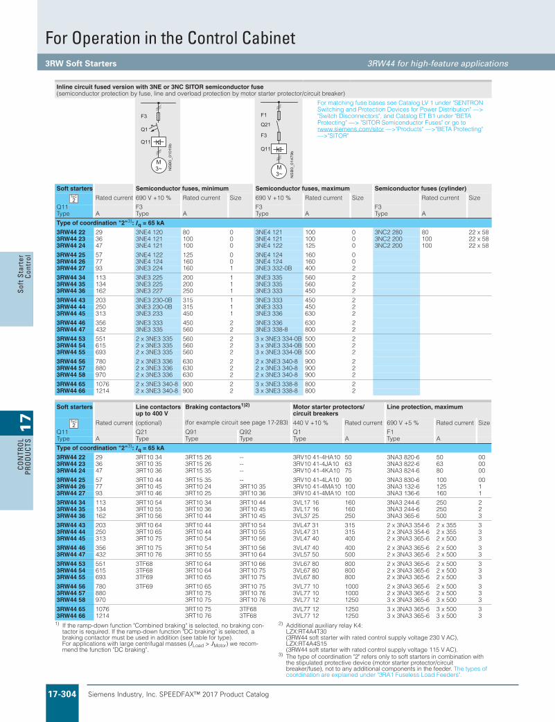
Siemens Industry, Inc. SPEEDFAX™ 2017 Product Catalog17-304
17
CON
TRO
L PR
OD
UCT
SSo
ft S
tart
er
Cont
rol
1) If the ramp-down function "Combined braking" is selected, no braking con-tactor is required. If the ramp-down function "DC braking" is selected, a braking contactor must be used in addition (see table for type). For applications with large centrifugal masses (JLoad > JMotor) we recom-mend the function "DC braking".
2) Additional auxiliary relay K4: LZX:RT4A4T30 (3RW44 soft starter with rated control supply voltage 230 V AC), LZX:RT4A4S15 (3RW44 soft starter with rated control supply voltage 115 V AC).
3) The type of coordination "2" refers only to soft starters in combination with the stipulated protective device (motor starter protector/circuit breaker/fuse), not to any additional components in the feeder. The types of coordination are explained under "3RA1 Fuseless Load Feeders".
Inline circuit fused version with 3NE or 3NC SITOR semiconductor fuse(semiconductor protection by fuse, line and overload protection by motor starter protector/circuit breaker)
For matching fuse bases see Catalog LV 1 under "SENTRON Switching and Protection Devices for Power Distribution" ––> "Switch Disconnectors", and Catalog ET B1 under "BETA Protecting" ––> "SITOR Semiconductor Fuses" or go to rwww.siemens.com/sitor ––>"Products" ––>"BETA Protecting"––>"SITOR"
Soft starters Semiconductor fuses, minimum Semiconductor fuses, maximum Semiconductor fuses (cylinder)
Rated current 690 V +10 % Rated current Size 690 V +10 % Rated current Size Rated current SizeQ11 F3 F3 F3Type A Type A Type A Type A
Type of coordination "2"3): Iq = 65 kA
3RW44 22 29 3NE4 120 80 0 3NE4 121 100 0 3NC2 280 80 22 x 583RW44 23 36 3NE4 121 100 0 3NE4 121 100 0 3NC2 200 100 22 x 583RW44 24 47 3NE4 121 100 0 3NE4 122 125 0 3NC2 200 100 22 x 58
3RW44 25 57 3NE4 122 125 0 3NE4 124 160 03RW44 26 77 3NE4 124 160 0 3NE4 124 160 03RW44 27 93 3NE3 224 160 1 3NE3 332-0B 400 2
3RW44 34 113 3NE3 225 200 1 3NE3 335 560 23RW44 35 134 3NE3 225 200 1 3NE3 335 560 23RW44 36 162 3NE3 227 250 1 3NE3 333 450 2
3RW44 43 203 3NE3 230-0B 315 1 3NE3 333 450 23RW44 44 250 3NE3 230-0B 315 1 3NE3 333 450 23RW44 45 313 3NE3 233 450 1 3NE3 336 630 2
3RW44 46 356 3NE3 333 450 2 3NE3 336 630 23RW44 47 432 3NE3 335 560 2 3NE3 338-8 800 2
3RW44 53 551 2 x 3NE3 335 560 2 3 x 3NE3 334-0B 500 23RW44 54 615 2 x 3NE3 335 560 2 3 x 3NE3 334-0B 500 23RW44 55 693 2 x 3NE3 335 560 2 3 x 3NE3 334-0B 500 2
3RW44 56 780 2 x 3NE3 336 630 2 2 x 3NE3 340-8 900 23RW44 57 880 2 x 3NE3 336 630 2 2 x 3NE3 340-8 900 23RW44 58 970 2 x 3NE3 336 630 2 2 x 3NE3 340-8 900 2
3RW44 65 1076 2 x 3NE3 340-8 900 2 3 x 3NE3 338-8 800 23RW44 66 1214 2 x 3NE3 340-8 900 2 3 x 3NE3 338-8 800 2
Soft starters Line contactors up to 400 V
Braking contactors1)2) Motor starter protectors/circuit breakers
Line protection, maximum
Rated current (optional) 440 V +10 % Rated current 690 V +5 % Rated current SizeQ11 Q21 Q91 Q92 Q1 F1Type A Type Type Type Type A Type A
Type of coordination "2"3): Iq = 65 kA
3RW44 22 29 3RT10 34 3RT15 26 -- 3RV10 41-4HA10 50 3NA3 820-6 50 003RW44 23 36 3RT10 35 3RT15 26 -- 3RV10 41-4JA10 63 3NA3 822-6 63 003RW44 24 47 3RT10 36 3RT15 35 -- 3RV10 41-4KA10 75 3NA3 824-6 80 00
3RW44 25 57 3RT10 44 3RT15 35 -- 3RV10 41-4LA10 90 3NA3 830-6 100 003RW44 26 77 3RT10 45 3RT10 24 3RT10 35 3RV10 41-4MA10 100 3NA3 132-6 125 13RW44 27 93 3RT10 46 3RT10 25 3RT10 36 3RV10 41-4MA10 100 3NA3 136-6 160 1
3RW44 34 113 3RT10 54 3RT10 34 3RT10 44 3VL17 16 160 3NA3 244-6 250 23RW44 35 134 3RT10 55 3RT10 36 3RT10 45 3VL17 16 160 3NA3 244-6 250 23RW44 36 162 3RT10 56 3RT10 44 3RT10 45 3VL37 25 250 3NA3 365-6 500 3
3RW44 43 203 3RT10 64 3RT10 44 3RT10 54 3VL47 31 315 2 x 3NA3 354-6 2 x 355 33RW44 44 250 3RT10 65 3RT10 44 3RT10 55 3VL47 31 315 2 x 3NA3 354-6 2 x 355 33RW44 45 313 3RT10 75 3RT10 54 3RT10 56 3VL47 40 400 2 x 3NA3 365-6 2 x 500 3
3RW44 46 356 3RT10 75 3RT10 54 3RT10 56 3VL47 40 400 2 x 3NA3 365-6 2 x 500 33RW44 47 432 3RT10 76 3RT10 55 3RT10 64 3VL57 50 500 2 x 3NA3 365-6 2 x 500 3
3RW44 53 551 3TF68 3RT10 64 3RT10 66 3VL67 80 800 2 x 3NA3 365-6 2 x 500 33RW44 54 615 3TF68 3RT10 64 3RT10 75 3VL67 80 800 2 x 3NA3 365-6 2 x 500 33RW44 55 693 3TF69 3RT10 65 3RT10 75 3VL67 80 800 2 x 3NA3 365-6 2 x 500 3
3RW44 56 780 3TF69 3RT10 65 3RT10 75 3VL77 10 1000 2 x 3NA3 365-6 2 x 500 33RW44 57 3005x26-563 3AN3x2000101 77LV367 01TR357 01TR30883RW44 58 3005x36-563 3AN3x3052121 77LV367 01TR357 01TR3079
3RW44 65 3005x36-563 3AN3x3052121 77LV386FT357 01TR367013RW44 66 3005x36-563 3AN3x3052121 77LV386FT367 01TR34121
2ToC
2ToC
Siemens / Industrial Controls Previous folio: LV1T 6/46
(for example circuit see page 17-283)
For Operation in the Control Cabinet3RW Soft Starters 3RW44 for high-feature applications

Siemens Industry, Inc. SPEEDFAX™ 2017 Product Catalog 17-305
17
CON
TROL
PROD
UCTS
Soft Starter Control
1) The type of coordination "2" refers only to soft starters in combination with the stipulated protective device (motor starter protector/circuit breaker/fuse), not to any additional components in the feeder.
The types of coordination are explained under "3RA1 Fuseless Load Feeders".
Inside-delta circuit fused version with 3NE or 3NC SITOR fuses(semiconductor protection by fuse, lead and overload protection by motor starter protector/circuit breaker)
For matching fuse bases see Catalog LV 1 under "SENTRON Switching and Protection Devices for Power Distribution" ––> "Switch Disconnectors", and Catalog ET B1 under "BETA Protect-ing" ––> "SITOR Semiconductor Fuses" or go to www.siemens.com/sitor ––>"Products" ––>"BETA Protecting"––>"SITOR"
Softstarters
Semiconductor fuses, minimum Semiconductor fuses, maximum Semiconductor fuses (cylinder)
Ratedcurrent
690 V +10 % Rated current Size 690 V +10 % Rated current Size Rated current Size
Q11 F3 F3 F3Type A Type A Type A Type A
Type of coordination "2"1)
3RW44 22 50 3NE4 120 80 0 3NE4 121 100 0 3NC2 280 80 22 x 583RW44 23 62 3NE4 121 100 0 3NE4 121 100 0 3NC2 200 100 22 x 583RW44 24 81 3NE4 121 100 0 3NE4 122 125 0 3NC2 200 100 22 x 58
3RW44 25 99 3NE4 122 125 0 3NE4 124 160 03RW44 26 133 3NE4 124 160 0 3NE4 124 160 03RW44 27 161 3NE3 224 160 1 3NE3 332-0B 400 2
3RW44 34 196 3NE3 225 200 1 3NE3 335 560 23RW44 35 232 3NE3 225 200 1 3NE3 335 560 23RW44 36 281 3NE3 227 250 1 3NE3 333 450 2
3RW44 43 352 3NE3 230-0B 315 1 3NE3 333 450 23RW44 44 433 3NE3 230-0B 315 1 3NE3 333 450 23RW44 45 542 3NE3 233 450 1 3NE3 336 630 2
3RW44 46 617 3NE3 333 450 2 3NE3 336 630 23RW44 47 748 3NE3 335 560 2 3NE3 338-8 800 2
3RW44 53 954 2 x 3NE3 335 560 2 3 x 3NE3 334-0B 500 23RW44 54 1065 2 x 3NE3 335 560 2 3 x 3NE3 334-0B 500 23RW44 55 1200 2 x 3NE3 335 560 2 3 x 3NE3 334-0B 500 2
3RW44 56 1351 2 x 3NE3 336 630 2 2 x 3NE3 340-8 900 23RW44 57 1524 2 x 3NE3 336 630 2 3 x 3NE3 340-8 900 23RW44 58 1680 2 x 3NE3 336 630 2 3 x 3NE3 340-8 900 2
3RW44 65 1864 2 x 3NE3 340-8 900 2 3 x 3NE3 338-8 800 23RW44 66 2103 2 x 3NE3 340-8 900 2 3 x 3NE3 338-8 800 2
Softstarters
Line contactorsup to 400 V
Motor starter protectors/circuit breakers
Line protection, maximum
Ratedcurrent
(optional) 440 V +10 % Rated current 690 V +5 % Rated current Size
Q11 Q21 Q1 F1Type A Type Type A Type A
Type of coordination "2"1)
3RW44 22 50 3RT10 36-1AP04 3RV10 42-4KA10 75 3NA3 824-6 80 003RW44 23 62 3RT10 44-1AP04 3RV10 42-4LA10 90 3NA3 830-6 100 003RW44 24 81 3RT10 46-1AP04 3RV10 42-4MA10 100 3NA3 132-6 125 1
3RW44 25 99 3RT10 54-1AP36 3VL27 16 160 3NA3 136-6 160 13RW44 26 133 3RT10 55-6AP36 3VL27 16 160 3NA3 240-6 200 23RW44 27 161 3RT10 56-6AP36 3VL37 20 200 3NA3 244-6 250 2
3RW44 34 196 3RT10 64-6AP36 3VL37 25 250 3NA3 360-6 400 33RW44 35 232 3RT10 65-6AP36 3VL47 31 315 3NA3 360-6 400 33RW44 36 281 3RT10 66-6AP36 3VL47 40 400 2 x 3NA3 360-6 2 x 400 3
3RW44 43 352 3RT10 75-6AP36 3VL47 40 400 2 x 3NA3 365-6 2 x 500 33RW44 44 433 3RT10 76-6AP36 3VL57 50 500 2 x 3NA3 365-6 2 x 500 33RW44 45 542 3TF68 44-0CM7 3VL57 63 800 3 x 3NA3 365-6 3 x 500 3
3RW44 46 617 3TF68 44-0CM7 3VL67 80 800 3 x 3NA3 365-6 3 x 500 33RW44 47 748 3TF69 3VL67 80 800 3 x 3NA3 365-6 3 x 500 3
3RW44 53 3005x36-563 3AN3x3000101 77LV34593RW44 54 3005x36-563 3AN3x3052121 77LV356013RW44 55 3005x36-563 3AN3x3006161 78LV30021
3RW44 56 3036x3273 3AN3x3006161 78LV315313RW44 57 3036x3273 3AN3x3006161 78LV342513RW44 58 40001x2084 3AN3x2000202 21LW30861
3RW44 65 40521x2284 3AN3x2005252 21LW346813RW44 66 40521x2284 3AN3x2005252 21LW33012
2ToC
2ToC
For Operation in the Control Cabinet3RW Soft Starters 3RW44 for high-feature applications

Siemens Industry, Inc. SPEEDFAX™ 2017 Product Catalog17-306
17
CON
TRO
L PR
OD
UCT
SSo
ft S
tart
er
Cont
rol
Siemens / Industrial Controls Previous folio: LV1T 6/48
Characteristic curves
Motor protection tripping characteristics for 3RW44 (with symmetry)
Permissible installation height
At an installation height above 2000 m, the max. permissible operational voltage is reduced to 460 V.
Motor protection tripping characteristics for 3RW44 (with asymmetry)
e2 4 6 101
Class 10 Class 15 Class 20
100
101
102
103
2
4
6
2
4
6
2
4
6
Class 5 Class 30
NS
B0_
0150
0a
[s]
x
Trip
ping
tim
e
85
105
70
75
80
90
95
100
NS
B0_
0170
4
0 1000 2000 3000 4000 5000
Ope
ratio
nal r
ated
cur
rent
Iin
%
Mounting height in m
e
e
100,1
Class 10 Class 15 Class 20
100
101
102
103
2
4
6
2
4
6
2
4
6
Class 5 Class 30
NS
B0_
0170
6
[s]
x1,0
Trip
ping
tim
e
For Operation in the Control Cabinet3RW Soft Starters 3RW44 for high-feature applications

Siemens Industry, Inc. SPEEDFAX™ 2017 Product Catalog 17-307
17
CON
TROL
PROD
UCTS
Soft Starter Control
Siemens / Industrial Controls Previous folio: LV1T 6/49
More information
Application examples for normal starting (Class 10)
Application examples for heavy starting (Class 20)
Application examples for very heavy starting (Class 30)
Note:These tables present sample set values and device sizes. They are intended only for the purposes of information and are not binding. The set values depend on the application in question and must be optimized during commissioning. The soft starter dimensions should be checked where necessary with the Win-Soft Starter software or with the help of Technical Assistance.
Normal starting Class 10 (up to 20 s with 350 % In motor), The soft starter rating can be selected to be as high as the rating of the motor used
Application Conveyor belt Roller conveyor Compressor Small fan Pump Hydraulic pump
Starting parameters
• Voltage ramp and current limiting- Starting voltage % 70 60 50 30 30 30- Starting time s 10 10 10 10 10 10- Current limit value Deactivated Deactivated 4 x IM 4 x IM Deactivated Deactivated
• Torque ramp- Starting torque 60 50 40 20 10 10- End torque 150 150 150 150 150 150- Starting time 10 10 10 10 10 10
• Breakaway pulse Deactivated (0 ms) Deactivated (0 ms) Deactivated (0 ms) Deactivated (0 ms) Deactivated (0 ms) Deactivated (0 ms)
Ramp-down mode Smoothramp-down
Smoothramp-down
Free ramp-down Free ramp-down Pump ramp-down Free ramp-down
Heavy starting Class 20 (up to 40 s with 350 % In motor),The soft starter has to be selected one performance class higher than the motor used
Application Stirrer Centrifuge Milling machine
Starting parameters
• Voltage ramp and current limiting- Starting voltage % 30 30 30- Starting time s 30 30 30- Current limit value 4 x IM 4 x IM 4 x IM
• Torque ramp- Starting torque 30 30 30- End torque 150 150 150- Starting time 30 30 30
• Breakaway pulse Deactivated (0 ms) Deactivated (0 ms) Deactivated (0 ms)
Ramp-down mode Free ramp-down Free ramp-down Free ramp-down or DC braking
Very heavy starting Class 30 (up to 60 s with 350 % In motor), The soft starter has to be selected two performance classes higher than the motor used
Application Large fan Mill Crusher Circular saw/bandsaw
Starting parameters
• Voltage ramp and current limiting- Starting voltage % 30 50 50 30- Starting time s 60 60 60 60- Current limit value 4 x IM 4 x IM 4 x IM 4 x IM
• Torque ramp- Starting torque 20 50 50 20- End torque 150 150 150 150- Starting time 60 60 60 60
• Breakaway pulse Deactivated (0 ms) 80 %, 300 ms 80 %, 300 ms Deactivated (0 ms)
Ramp-down mode Free ramp-down Free ramp-down Free ramp-down Free ramp-down
For Operation in the Control Cabinet3RW Soft Starters 3RW44 for high-feature applications

Siemens Industry, Inc. SPEEDFAX™ 2017 Product Catalog17-308
17
CON
TRO
L PR
OD
UCT
SSo
ft S
tart
er
Cont
rol
Siemens / Industrial Controls Previous folio:LV1T 6/50
Circuit concept
The SIRIUS 3RW44 soft starters can be operated in two different types of circuit.• Inline circuit
The controls for isolating and protecting the motor are simply connected in series with the soft starter. The motor is con-nected to the soft starter with three cables.
• Inside-delta circuit The wiring is similar to that of wye-delta starters. The phases of the soft starter are connected in series with the individual motor windings. The soft starter then only has to carry the phase cur-rent, amounting to about 58 % of the rated motor current (con-ductor current).
Comparison of the types of circuit
Inline circuit:Rated current Ie corresponds to the rated motor current In,3 cables to the motor
Inside-delta circuit:Rated current Ie corresponds to approx. 58 % of the rated motor current In, 6 cables to the motor (as with wye-delta starters)
Which circuit?
Using the inline circuit involves the lowest wiring outlay. If the soft starter to motor connections are long, this circuit is prefera-ble.With the inside-delta circuit there is double the wiring complexity but a smaller size of device can be used at the same rating.
Thanks to the choice of operating mode between the inline cir-cuit and inside-delta circuit, it is always possible to select the most favorable solution.
The braking function is possible only in the inline circuit.
Configuration
The 3RW44 solid-state soft starters are designed for normal starting. In case of heavy starting or increased starting fre-quency, a larger device must be selected.
For long starting times it is recommended to have a PTC sensor in the motor. This also applies for the ramp-down modes smooth ramp-down, pump ramp-down and DC braking, because during the ramp-down time in these modes, an additional current load-ing applies in contrast to free ramp-down.
In the motor feeder between the SIRIUS 3RW soft starter and the motor, no capacitive elements are permitted (e. g. no reactive-power compensation equipment). In addition, neither static sys-tems for reactive-power compensation nor dynamic PFC (Power Factor Correction) must be operated in parallel during starting and ramp-down of the soft starter. This is important to prevent faults arising on the compensation equipment and/or the soft starter.
All elements of the main circuit (such as fuses and controls) should be dimensioned for direct starting, following the local short-circuit conditions. Fuses, controls and overload relays must be ordered separately.
A bypass contact system and solid-state overload relay are al-ready integrated in the 3RW44 soft starter and therefore do not have to be ordered separately.
The harmonic component load for starting currents must be taken into consideration for the selection of motor starter protec-tors (selection of release).
Note:When induction motors are switched on, voltage drops occur as a rule on starters of all types (direct starters, wye-delta starters, soft starters). The infeed transformer must always be dimen-sioned such that the voltage dip when starting the motor remains within the permissible tolerance. If the infeed transformer is di-mensioned with only a small margin, it is best for the control volt-age to be supplied from a separate circuit (independently of the main voltage) in order to avoid the potential switching off of the soft starter.
Device interface, PROFIBUS DP communication module, Soft Starter ES parameterizing and operating software
The 3RW44 electronic soft starters have a PC interface for com-municating with the Soft Starter ES software or for connecting the external display and operator module. If the optional PROFIBUS communication module is used, the 3RW44 soft starter can be integrated in the PROFIBUS network and commu-nicate using the GSD file or Soft Starter ES Premium software.
The Soft Starter ES parameterizing and operating software can be downloaded from www.usa.siemens.com > Software with a 14-day trial license.
More information about Soft Starter ES can be found in Chapter 12 of Catalog LV 1.
For Operation in the Control Cabinet3RW Soft Starters

Siemens Industry, Inc. SPEEDFAX™ 2017 Product Catalog 17-309
17
CON
TROL
PROD
UCTS
Soft Starter Control
Siemens / Industrial Controls Previous folio: LV1T 6/51
Manual for SIRIUS 3RW44
Besides containing all important information on configuring, commissioning and servicing, the manual also contains ex-ample circuits and the technical specifications for all devices.
Win-Soft Starter selection and simulation program
With this software, you can simulate and select all Siemens soft starters, taking into account various parameters such as mains properties, motor and load data, and special application requirements.
The software is a valuable tool, which makes complicated, lengthy manual calculations for determining the required soft starters superfluous.
The Win-Soft Starter selection and simulation program can be downloaded from: www.usa.siemens.com > Software
More information can be found on the Internet at: www.usa.siemens.com
For Operation in the Control Cabinet3RW Soft Starters 3RW44 for high-feature applications

Siemens Industry, Inc. SPEEDFAX™ 2017 Product Catalog17-310
17
CON
TRO
L PR
OD
UCT
SSo
ft S
tart
er
Cont
rol
Siemens / Industrial Controls Previous folio: LV1T 6/52
Dimensional drawings
3RW30 for standard applications
1) For mounting onto standard mounting rail TH 35 according to EN 60715.2) Dimension for screw fixing.
Screw fixing with two 3RP1 903 push-in lugs per 3RW30 03 device.
3RW30 1. ... 3RW30 4.
Type/Dimension (mm)
a b c d e f g h i k l m
3RW30 1.-1. 95 45 62 146 126 14.4 63 5 6.5 35 85 953RW30 1.-2. 95 45 62 146 126 14.4 63 5 6.5 35 85 117.2
3RW30 2.-1. 125 45 92 146 126 14.4 63 5 6.5 35 115 1253RW30 2.-2. 125 45 92 146 126 14.4 63 5 6.5 35 115 150
3RW30 3. 160 55 110 163 140 18 63 5 6.5 30 150 1443RW30 4. 170 70 110 181 158 22.5 85 5 10 60 160 160
Clearances to grounded parts (mm) Lateral Top Bottom Fixing screws Tightening torques (Nm)
3RW30 1. 5 60 40 14M3RW30 2. 5 60 40 14M3RW30 3. 30 60 40 14M3RW30 4. 30 60 40 24M
k
l
fhb d
eg
c a 35
NSB0_01945
i
m
)slanimret epyt-gnirps( .2-3003WR3)slanimret wercs( .1-3003WR3
5
NSC00482
101,
6
ca. 7
1
7,2
ca. 9
1
81,6
120
1)
3,1
22,5
For Operation in the Control Cabinet3RW Soft Starters Project Planning aids

Siemens Industry, Inc. SPEEDFAX™ 2017 Product Catalog 17-311
17
CON
TROL
PROD
UCTS
Soft Starter Control
Siemens / Industrial Controls Previous folio: LV1T 6/53
3RW40 for standard applications
Type/Dimension (mm) a b c d e f g h i k l m
3RW40 2.-1. 125 45 92 149 126 14.4 63 5 6.5 35 115 1253RW40 2.-2. 125 45 92 149 126 14.4 63 5 6.5 35 115 150
3RW40 3. 170 55 110 165 140 18 63 5 6.5 30 150 144
3RW40 4. 170 70 110 183 158 22.5 85 5 10 60 160 160
k
l
fhb d
eg
c a 35
NSB0_01891a
i
m
Clearances to grounded parts (mm) Lateral Top Bottom Fixing screws Tightening torques (Nm)
3RW40 2. 5 60 40 14M
3RW40 3. 30 60 40 14M
3RW40 4. 30 60 40 24M
Type/Dimension (mm) a b c d e f g h i k l m n o p q
3RW40 5. 180 120 37 17 167 100 223 250 180 148 6.5 153 7 198 9 M6, 10 Nm
3RW40 7. 210 160 48 25 190 140 240 278 205 166 10 166 9 230 11 M8, 15 Nm
For Operation in the Control Cabinet3RW Soft Starters Project Planning aids

Siemens Industry, Inc. SPEEDFAX™ 2017 Product Catalog17-312
17
CON
TRO
L PR
OD
UCT
SSo
ft S
tart
er
Cont
rol
3RW44 2., 3RW44 3. and 3RW44 4. for High-Feature applicationsl
e
fb
p
k io
hg
m
a
c nd
NSB0_01493a
qr
Type/Dimension (mm)
a b c d e f g h i k l m n o p q r
3RW44 2. 180 170 37 11 167 100 240 270 174 148 7.5 153 7 184 6.6 M6, 10 Nm 10
3RW44 3. 180 170 37 17 167 100 240 270 174 148 7.5 153 7 198 9 M6, 10 Nm 10
3RW44 4. 210 210 48 25 190 140 269 298 205 166 16 166 9 230 11 M8, 15 Nm 10
Siemens / Industrial Controls Previous folio:LV1T 6/54
For Operation in the Control Cabinet3RW Soft Starters Project Planning aids

Siemens Industry, Inc. SPEEDFAX™ 2017 Product Catalog 17-313
17
CON
TROL
PROD
UCTS
Soft Starter Control
3RW44 5. and 3RW44 6. for High-Feature applications
1) For M12 screw, tightening torque max. 35 Nm (310 lb.in).
3RW49 00-0AC00 external display and operator module Installation cutout for 3RW49 00-0AC00 external display and operator module
rs
w
qh
NS
B0_
0183
1
ad
tuv
p
no
m
a
ikl
e d
b
1)
c
f g
6T34T22T1
5L33L21L1
Type/Dimension (mm)
a b c d e f g h i k l m
3RW44 5. 76 40 14 20 15.5 638.5 590 -- 44 470 510 16.5
3RW44 6. 85 50 14 -- -- 667 660 160 37.5 535 576 16.5
Type/Dimension (mm)
n o p q r s t u v W ad
3RW44 5. 105 253 623 -- -- -- 249 162 152 -- 290
3RW44 6. 103 251 693 43.5 40 20 249 162 151.4 123 290
SIRIUS 3RW44DEVICE
SF
60
NS
B0_
0182
9
826929,135,6
NS
B0_
0183
0
92
55
Siemens / Industrial Controls Previous folio: LV1T 6/55
For Operation in the Control Cabinet3RW Soft Starters Project Planning aids

Siemens Industry, Inc. SPEEDFAX™ 2017 Product Catalog17-314
17
CON
TRO
L PR
OD
UCT
SSo
ft S
tart
er
Cont
rol
Siemens / Industrial Controls Previous folio: SF 17-219 updated 6/12/12
Dimensions are in inches and are for reference only (not for construction). Certain styles may deviate from values indicated.
N1, N3R, N12, N4 Standard EnclosureAmps A B C Ref. Drawing
3RW40
11 - 73 24 20 10 98 36 24 10 117-145 36 24 16 205-315 36 30 16 385 60 36 16
3RW44
26 - 68 24 20 16 82 - 117 36 24 16 145 - 215 36 30 16 280 - 385 60 36 16 494 - 780 90 40 18 970 - 1076 90 48 20
N1, N3R, N12, N4 Standard EnclosureAmps A B C Ref. Drawing
3RW40
11 - 62 36 26 8 73 42 32 12 98 42 32 12 117 42 38 16 145 - 248 60 38 16 315 - 385 90 40 18
3RW44
26 - 68 36 32 16 82 - 117 42 38 16 145 - 215 60 38 16 280 72 40 18 315 - 384 90 40 18 494 90 40 18 551 - 780 90 40 18 970 - 1076 90 40 18
N4X Stainless Steel Standard EnclosureAmps A B C Ref. Drawing
3RW4011 - 98 48 38 10 117 - 315 36 30 16 385 60 36 16
3RW4426 - 100 42 32 12 117 - 145 60 38 16 180 - 385 90 40 20
N1, N12 FusibleAmps A B C Ref. Drawing
3RW44 494-780 90 48 20
Non-Combination Class 73
N4X Stainless Steel Standard EnclosureAmps A B C Ref. Drawing
3RW4011 - 98 48 36 10117-315 36 30 16385 60 36 16
3RW44
26 - 68 24 20 1682-117 36 24 12145 36 30 12180-215 36 30 16280-385 60 36 12
Combination Type Class 74
For Operation in the Control Cabinet Class 73, 74
Revised on 10/31/19

Siemens Industry, Inc. SPEEDFAX™ 2017 Product Catalog 17-315
17
CON
TROL
PROD
UCTS
Soft Starter Control
Siemens / Industrial Controls Previous folio: LV1T 6/56
Schematics
1) Caution: Risk of restarting!When operating with a switch (ON/OFF) a new, automatic restart will take place automatically if the start command is still active at terminal 1.
2) As an alternative, the motor feeder can also be installed as a fuseless or as a fused version. For fuse and switching device coordination, see "Technical specifications".The wiring diagrams are provided only as examples.
3RW30 . . connection examples for control circuit
edom citamotuAsehctiws gnisu lortnoC
rotcatnoc niam a fo lortnoCnottubhsup yb lortnoC
3RW30 connection examples for main circuit2)
3RW30 – 3-phase motor with rotcetorp retrats rotomVR3esuf EN3/AN3
A2
ON/OFF
L1 (L +)N(L-)
1A1
Q11
NS
B0_
0191
4
1)
A2 A1 1
ON/OFF
N(L-) L1(L+)
Q11
NS
B0_
0189
5
1)
>5 min
Us
ON
OFF t
NS
B0_
0191
6a
N(L-) L(L+)
NS
B0_
0194
2
A1A2 1
Q11
ON
ON
13
OFF
14NO
ON/OFF
1)
L1(L+)N(L-)
ON
13 14NO
Q21
Q11
A2 1A1
NS
B0_
0199
7
NS
B0_
0194
3
M3~
3RT
F1
Q11
Q21
3RW30
3NA/3NE
NS
B0_
0194
4
M3~
3RV
Q11 3RW30
For Operation in the Control Cabinet3RW Soft Starters Project Planning aids

Siemens Industry, Inc. SPEEDFAX™ 2017 Product Catalog17-316
17
CON
TRO
L PR
OD
UCT
SSo
ft S
tart
er
Cont
rol
Siemens / Industrial Controls Previous folio: LV1T 6/57
1) Caution: Risk of restarting!When operating with a switch (ON/OFF) a new, automatic restart will take place automatically if the start command is still active at terminal 1.
3RW40 2. ... 3RW40 4. connection examples for control circuit
teser etomer htiw lortnoCedom citamotuAsehctiws gnisu lortnoC
Control of 3RW40 2. ... 3RW40 4. by pushbutton
Control of a main contactor
Connection example of 3RW40 2. ... 3RW40 4. for PTC sensors (thermistor motor protection)
Aepyt CTPkcilcomrehT
A2
ON/OFF
L1 (L +)N(L-)
1A1
Q11
NS
B0_
0191
4
1)
A2 A1 1
ON/OFF
N(L-) L1(L+)
Q11
NS
B0_
0189
5
1)
A2
ON/OFF
L1 (L +)N(L-)
1
RESET
A1
Q11
NS
B0_
0189
2
1)
>5 min
Us
ON
OFF t
NS
B0_
0191
6a
NS
B0_
0191
5
>1,5 s
Us
100 %
t
N(L-) L(L+)
NS
B0
0200
7
A1A2 1
Q11
ON
ON
13 23
OFF
14 24NO NO NC NO95 96 98
OVERLOADFAILURE
ON/OFF
L1(L+)N(L-)
RUN
13 2314 24NO NO
Q21
Q11
A2 1A1
NS
B0_
0200
8
1)
NC NO95 96 98
OVERLOADFAILURE
ϑ
T11/T21 T22T12
NS
B0_
0189
3
Q11
ϑ
T11/T21 T12 T22
NS
B0_
0189
4
Q11
For Operation in the Control Cabinet3RW Soft Starters Project Planning aids

Siemens Industry, Inc. SPEEDFAX™ 2017 Product Catalog 17-317
17
CON
TROL
PROD
UCTS
Soft Starter Control
Siemens / Industrial Controls Previous folio: LV1T 6/58
1) Caution: Risk of restarting!When operating with a switch (ON/OFF) a new, automatic restart will take place automatically if the start command is still active at terminal 3.
2) Grounding necessary for fan connection to 3RW40 5...3) As an alternative, the motor feeder can also be installed as a fuseless or as
a fused version. For fuse and switching device coordination, see "Technical specifications".The wiring diagrams are provided only as examples.
3RW40 5. and 3RW40 7. connection examples for control circuit
3RW40 connection examples for main circuit3)
Control by switch using internal 24 V DC supply external power supply
3RW40 – 3-phase motor with 3NA/3NE fuse 3RV motor starter protector/
3VL circuit breaker
Control by pushbutton
Control of a main contactor
NS
B0_
0148
9b
M3~
3RT
F1
Q11
Q21
3RW40
3NA/3NE
NS
B0_
0148
7c
M3~
3RV/3VL
Q11 3RW40
NS
B0_
0148
3b
NL1
A2A1 1
Q11
2 3
ON
2)
ON
13 23 95 96 98
OVERLOADFAILURE
OFF
14 24NO NO NC NO
NS
B0_
0148
4b
NL1
A2A1 1
Q11
2 3
2)
RUN
13 23 95 96 98
OVERLOADFAILURE
14 24NO NO NC NO
Q21
ON/OFF 1)
For Operation in the Control Cabinet3RW Soft Starters Project Planning aids

Siemens Industry, Inc. SPEEDFAX™ 2017 Product Catalog17-318
17
CON
TRO
L PR
OD
UCT
SSo
ft S
tart
er
Cont
rol
Siemens / Industrial Controls Previous folio: LV1T 6/59
1) Permissible values for main and control voltage, see "Technical specifications".
2) Caution: Risk of restarting!Because the output is parameterized to "Motor ON", the start command is automatically active after the reset command and a new, automatic restart will take place. This applies especially in case of motor protection tripping. For safety reasons we recommend connecting the group error output (ter-minals 95/96) in series with the output parameterized to "Motor ON".
3RW44 connection examples for main and control circuitstiucric lortnoCtiucric niaM
:1 ytilibissoP:a1 ytilibissoPInline circuit with motor starter protector and SITOR fuse (semiconductor protection only)
Control by pushbutton
Main circuit
:c1 ytilibissoP:b1 ytilibissoPInline circuit with all-range protection (line and semiconductor protection)
Inline circuit with line and SITOR fuse (semiconductor protection only)
NS
B0_
0149
0b
(optionalsemiconductorprotection fuse)
M3~
Q11
L1 3/N/PE 400 V AC, 50 HzL2L3
PE
L1 L2 L3
T1 T2 T3
Q1
F3
M1U1 V1 W1
NSB0_01494c
PE+
L1 1/N/PE 230 V AC 1), 50 Hz
PTC type Aor
Thermoclick
StopS1
On periodNoaction
Noaction
Grouperror
Mot
or o
n rig
htP
S 1
No
actio
n
No
actio
n
Q11
PE
2T1T1NI
F2
N
L+ L- 4NI3NI2NI1A
A2 13 14 23 24 33 34 95 9896
Sta
rt S
2
Res
et S
3
2)
For Operation in the Control Cabinet3RW Soft Starters Project Planning aids

Siemens Industry, Inc. SPEEDFAX™ 2017 Product Catalog 17-319
17
CON
TROL
PROD
UCTS
Soft Starter Control
Siemens / Industrial Controls Previous folio: LV1T 6/60
1) Permissible values for main and control voltage, see "Technical specifications".
2) Caution: Risk of restarting!The start command (e. g. from the PLC) must be reset prior to a reset com-mand because a new, automatic restart will take place automatically if a start command is active after the reset command. This applies especially in case of motor protection tripping.For safety reasons we recommend incorporating the group error output (terminals 95 and 96) in the controller.
tiucric lortnoCtiucric niaM
:2 ytilibissoP:2 ytilibissoPInline circuit with main contac otcatnoc niam a fo lortnoCrot r and control by means of PLC
NS
B0_
0149
5b
(optionalsemiconductorprotection fuse)
(optional linecontactor if floatingswitching of themotor is planned)
L1 3/N/PE 400 V AC 1), 50 Hz
M3~
Q11
L2L3
PE
L1 L2 L3
T1 T2 T3
Q1
F3
M1U1 V1 W1
Q21
NSB0_01496b
+
L1 1/N/PE 230 V AC 1), 50 Hz
PTC type A orThermoclick
No action
Group error
Mot
or r
ight
PS
1
No
actio
n
No
actio
n
No action
Switch-on duration
(optional line contactorif floating switching of the motor is planned)
PLC outputs PLC inputs
Trip
Res
et
ResetStart 2)
Q11
PE
2T1T1NI
F2
N
L+ L- 4NI3NI2NI1A
A2 13 14 23 24 33 34 95 9896
PE
Q21
+24 V DC
M
For Operation in the Control Cabinet3RW Soft Starters Project Planning aids

Siemens Industry, Inc. SPEEDFAX™ 2017 Product Catalog17-320
17
CON
TRO
L PR
OD
UCT
SSo
ft S
tart
er
Cont
rol
Siemens / Industrial Controls Previous folio: LV1T 6/61
1) Permissible values for main and control voltage, see "Technical specifications".
2) Caution: Risk of restarting!The start command (e. g. from the PLC) must be reset prior to a reset com-mand because a new, automatic restart will take place automatically if a start command is active after the reset command. This applies especially in case of motor protection tripping.For safety reasons we recommend incorporating the group error output (terminals 95 and 96) in the controller.
3) If the ramp-down function "Combined braking" is selected, no braking con-tactor is required. If the ramp-down function "DC braking" is selected, a braking contactor must be used in addition. For type see "Fuse Assignment (Inline Circuit)"
For applications with large centrifugal masses (JLoad > JMotor) we recom-mend the function "DC braking".The output 2 must be switched over to "DC braking contactor".
4) Auxiliary relay K4, e. g.:LZX:RT4A4T30 (230 V AC rated control supply voltage), LZX:RT4A4S15 (115 V AC rated control supply voltage).
tiucric lortnoCtiucric niaM
:a3 ytilibissoP:a3 ytilibissoPInline circuit with ramp-down function DC braking3)
(for device types 3RW44 22 to 3RW44 25)Control of the DC braking contactor3)
tiucric lortnoCtiucric niaM
:b3 ytilibissoP:b3 ytilibissoPInline circuit with ramp-down function DC braking3)
(for device types 3RW44 26 to 3RW44 47)Control of the DC braking contactor3)
NS
B0_
0150
1bL1 3/N/PE 400 V AC 1), 50 Hz
(optionalsemi-conductorprotection)
M3~
Q11
L2L3
PE
L1 L2 L3
T1 T2 T3
Q1
F3
M1U1 V1 W1
Q912
Q91 Q91
NSB0_01502a
+
L1 1/N/PE 230 V AC 1), 50 Hz
PTC type A orThermoclick
No action Group error
No
actio
n
No
actio
n
Switch-on duration
PLC output
Res
et
ResetStart 2)
DC braking contactor 3)
Q11
PE
2T1T1NI
F2
N
L+ L- 4NI3NI2NI1A
A2 13 14 23 24 33 34 95 9896
PE
+24 V DC
M
Q91
Q91
NS
B0_
0150
3b
L1 3/N/PE 400 V AC 1), 50 Hz
(optionalsemi-conductorprotection)
M3~
Q11
L2L3
PE
L1 L2 L3
T1 T2 T3
Q1
F3
M1U1 V1 W1
Q92Q913 3
NSB0_01504a
+
L1 1/N/PE 230 V AC 1), 50 Hz
PTC type A orThermoclick
No action Group error
No
actio
n
No
actio
n
Switch-on duration
PLC output
Res
et
ResetStart 2)
DC braking contactor 3)
Mot
or r
ight
PS
1
Q11
PE
2T1T1NI
F2
N
L+ L- 4NI3NI2NI1A
A2 13 14 23 24 33 34 95 9896
PE
+24 V DC
M
Q91
Q92
K4
Q92
Q91
K4
4)
K4
on pages 17-266 to 17-268.
For Operation in the Control Cabinet3RW Soft Starters Project Planning aids

Siemens Industry, Inc. SPEEDFAX™ 2017 Product Catalog 17-321
17
CON
TROL
PROD
UCTS
Soft Starter Control
Siemens / Industrial Controls Previous folio: LV1T 6/62
1) Permissible values for main and control voltage, see "Technical specifications".
2) Caution: Risk of restarting!The start command (e. g. from the PLC) must be reset prior to a reset com-mand because a new, automatic restart will take place automatically if a start command is active after the reset command. This applies especially in case of motor protection tripping.For safety reasons we recommend incorporating the group error output (terminals 95 and 96) in the controller.
tiucric lortnoCtiucric niaM
Possibility 4a: Possibility 4b: Possibility 4:Inside-delta circuit Change of direction of rotation for
inside-delta circuitControl by means of PLC
NSB0_01498b
+
L1 1/N/PE 230 V AC 1), 50 Hz
PTC type A orThermoclick
No action
Group error
Mot
or r
ight
No
actio
n
No
actio
n
No actionSwitch-on duration
PLC outputs PLC inputs
Trip
Res
et
ResetStart 2)
Q11
PE
2T1T1NI
F2
N
L+ L- 4NI3NI2NI1A
A2 13 14 23 24 33 34 95 9896
PE
+24 V DC
M
For Operation in the Control Cabinet3RW Soft Starters Project Planning aids

Siemens Industry, Inc. SPEEDFAX™ 2017 Product Catalog17-322
17
CON
TRO
L PR
OD
UCT
SSo
ft S
tart
er
Cont
rol
Siemens / Industrial Controls Previous folio: SF 16-179
Control Products Class 73, 74

Siemens Industry, Inc. SPEEDFAX™ 2017 Product Catalog 17-323
17
CON
TROL
PROD
UCTS
Pilot Devices
13/6 Siemens IC 10 N · 04/2016
SIRIUS ACT Pushbuttons and Indicator Lights
General data
13
BenefitsDesign
SIRIUS ACT is available in four design lines.
Ruggedness
• Degree of protection IP66, IP67, IP69 (IP69K)
• Service life of 100 000 hours thanks to use of LEDs• Media resistance (chemicals) thanks to solid stainless steel
and high-grade plastics• Mechanical endurance of 10 x 106 switching cycles• Suitable for use in extreme environments• Reliable, friction-locked fixing with just one screw• Design stability according to use• Simple geometry for mounting holes
Communication
• Direct connection of the enclosure to AS-Interface or IO-Link• Direct connection in the control cabinet to PROFINET, IO-Link
or AS-Interface• Can be integrated easily via the TIA Portal
Easy handling
• Self-holding function of the actuator when mounting• Twist prevention integrated into patented holder design• Stackable contact modules• Self-explanatory and fast installation using one hand• Components can be mounted with holder removed• No special tools required, simple size 2 screwdriver
(cross-tip DIN ISO 87641PZD1, flat-head DIN ISO 2380-1 A/B 1x4.5) is sufficient
IP66
6 = Protection against the ingress of dust
6 = Protection against powerful splash-water
IP67
6 = Protection against the ingress of dust
7 = Protection against temporary immersion
IP69 (IP69K)
6 = Protection against the ingress of dust
9/9K = Protection against water in high-pressure cleaning (approx. 80 bar) and high water jet temperatures (approx. 80 °C)
IC01
_004
78
plasticblackØ 22 mm
Color selection
plasticmetal ringmatteØ 22 mm
metalshinyØ 22 mm
metal matteflatØ 30 mm
SIRIUS_IC10N_chap13_English_2016.book Page 6 Wednesday, June 22, 2016 6:52 PM
Push Button Units and Indicator LightsSIRUS ACT 3SU Series Overview
These two pages are a brief overview of the SIRIUS ACT 3SU Series. Please consult the Siemens Industrial Control products catalog for a complete listing of products or look for info online at usa.siemens.com/sirius-act

Siemens Industry, Inc. SPEEDFAX™ 2017 Product Catalog17-324
17
CON
TRO
L PR
OD
UCT
SPi
lot
Dev
ices
13/8 Siemens IC 10 N · 04/2016
SIRIUS ACT Pushbuttons and Indicator Lights
General data
13
Actuating and signaling elements
System overview of SIRIUS ACT pushbuttons and indicator lights from the plastic design line.Pushbuttons and indicator lights available in 4 design lines.
14
15
16
17
18
19
21
12
11
9
7
45
6
3
2
1
10
13
8
20IC01_00424b
Actuating and signaling elements Pages Modules for front plate mounting Pages$ Pushbuttons, illuminated pushbuttons 2 Contact modules
% Mushroom pushbuttons 3 LED modules
& Selector switches 4 AS-Interface modules
()* Key-operated switches, potentiometers, indicator lights Enclosures Pages+, EMERGENCY STOP mushroom pushbuttons,
backing plates5 Enclosures
-. ID key-operated switches, ID keys, electronic modules Modules for base mounting Pages/ Twin pushbuttons, label holders, labeling plates 6 Contact modules
0 Label holders, labeling plates 7 LED modules
Holders and labels Pages 8 IO-Link modules
1 Holders 9 AS-Interface modules
SIRIUS_IC10N_chap13_English_2016.book Page 8 Wednesday, June 22, 2016 6:52 PM
10/38
10/40
10/41
10/42
10/40
10/57
10/4910/130
10/130
10/107
10/111
10/113
10/117
10/125
10/125
10/128
10/128
Page links above reference the U.S. Industrial Controls catalog available online
Push Button Units and Indicator LightsSIRUS ACT 3SU Series Overview
Revised on 04/30/18

Siemens Industry, Inc. SPEEDFAX™ 2017 Product Catalog 17-325
17
CON
TROL
PROD
UCTS
Pilot Devices
Siemens / Industrial Controls Previous folio: IC10 10/123
Features
• Snap In Legend Inserts
• Flush and Surface Mounted Types
• Convertible Selector
• Double Break Contacts
• Dual Voltage Pilot Light with Snap In Lens
• Conversion Kits
• UL Listed File #E22655
• CSA Certified File #LR6535
Application
Standard duty control stations are used with magnetic controllers to control the starting, stopping, reversing or speed of applicable motors.
Stations are assembled of one, two or three push button, selector switch or pilot light units in a variety of combinations to provide compact control units for remote control of magnetic starters and contactors.
Station enclosures are available in Type 1 surface mounted, 1B flush plate mounted and 4 watertight.
FeaturesType 1 surface mounted bases are con structed of 14 gauge sheet steel, primed and finished in baked gray enamel. The base is predrilled to receive a variety of con tact blocks, pilot lights and accessory de vices. Covers are of 20 gauge sheet steel, wrap- around construction, primed and fin ished in baked gray enamel. Siemens Type 4 watertight heavy duty push button stations are supplied with a provision to padlock the stop button in the depressed position. Enclo sures are predrilled and tapped for 3/4” con duit.
Contact blocks have double break, fine sil ver contacts with a NEMA B600 rating. Type 4 stations have a NEMA A600 rating.
The pilot light assembly is dual voltage with clearly marked pressure type terminals for 120 volt or 240 volt connection.
The lens of the pilot light snaps into the cover and is available in both red and green.
Push buttons are equipped with an operator into which a selected legend insert is snapped. Legend inserts are molded ther moplastic and come in a wide variety of leg ends and colors.
The selector switch operator can be instantly set for two or three positions at any time.
Mushroom Head50ZMH mounts on any standard push button operator. The Mushroom Head is red molded thermoplastic, 1 1/2” in diameter, and provides a large operator for emergency stop or similar applications.
Mechanical Interlock50ZAM is a base mounted zinc plate, dichro mate dipped, steel assembly. When mounted in conjunction with Duplex Contact Block 50ZAC3 (one NO and one NO) the in terlock prevents one contact from being closed while the other contact is closed.
Padlock Attachment Kit50ZAL can be mounted to any Type 1 sur face mounted station by the lower screw which fastens the cover to the station base. Made of heavy steel, chrome plated, the at tachment provides for the padlocking of a push button in the depressed position or a selector switch in any position. When used with a push button operator, raised Legend Insert D53493003 (Red Stop) must be used.
Electrical RatingsNEMA AC Ratings 50/60HzNema B600 5 Continuous Amps
Volts Make Break120 30 3240 15 1.5480 7.5 0.75600 6 0.6VA 3600 360
2 Push ButtonsSurface Mounting, NEMA 1
1 Selector SwitchFlush Mounting
1 Pilot Light2 Push Buttons
2 Push Buttons1 Selector Switch
2 Push ButtonsFlush Mounting, NEMA 1B
1 Push ButtonSurface Mounting
Ordering Information
• Legend Inserts see page 17-332.
• Accessories see page 17-332.
Pushbutton Units and Indicator LightsClass 50 Standard Duty Pushbutton Stations General
Product Category: PILO

Siemens Industry, Inc. SPEEDFAX™ 2017 Product Catalog17-326
17
CON
TRO
L PR
OD
UCT
SPi
lot
Dev
ices
Siemens / Industrial Controls Previous folio: 10/124
Selection and ordering data
Number of com- mandpoints
Order No. Packs Operator identification
Degree of protection
Contacts / voltage
UnitA = Momentary flush pushbutton green,
sur face, label “START”NEMA 1 1NO - 1NC with common
jumper (50ZAC1)1 50AA3D 1
A = Momentary flush pushbutton red, sur face, label “STOP”
NEMA 1 1NO - 1NC with common jumper (50ZAC1)
1 50AA3E 1
A = Momentary raised pushbutton red, sur face, label “STOP”
NEMA 1 1NO - 1NC with common jumper (50ZAC1)
1 50AA3F 1
A = Momentary mushroom head red, sur face, label “STOP”
NEMA 1 1NO - 1NC with common jumper (50ZAC1)
1 50AA3G 1
A = Momentary flush pushbutton less insert, surface
NEMA 1 1NO - 1NC with common jumper (50ZAC1)
1 50AA3A 1
A = 3 position selector switch, surface, label “HAND-OFF-AUTO”
NEMA 1 2 NO 2SPST (50ZAC8) 1 50AA3C3 1
A = 2 position selector switch, surface, label “Off-On”
NEMA 1 2 NO 2SPST (50ZAC8) 1 50AA3C6 1
A = 2/3 selector switch, surface, multiple legends
NEMA 1 2 NO 2SPST (50ZAC8) 1 50AA3B9 1
A = Indicator light, red, surface NEMA 1 120/240V dual voltage 120PSB lamp
1 50BA3Y 1
A = Indicator light, green, surface NEMA 1 120/240V dual voltage 120PSB lamp
1 50BA3Z 1
A = Indicator light, less lens, surface NEMA 1 120/240V dual voltage 120PSB lamp
1 50BA32 1
A = Momentary flush pushbutton green, flush, label “START”
NEMA 1B 1NO - 1NC with common jumper (50ZAC1)
1 50AA2D 1
A = Momentary flush pushbutton red, flush, label “STOP”
NEMA 1B 1NO - 1NC with common jumper (50ZAC1)
1 50AA2E 1
A = Momentary raised pushbutton red, flush, label “STOP”
NEMA 1B 1NO - 1NC with common jumper (50ZAC1)
1 50AA2F 1
A = Momentary flush pushbutton less insert, flush
NEMA 1B 1NO - 1NC with common jumper (50ZAC1)
1 50AA2A 1
A = Momentary flush pushbutton less insert, flush, chrome plate
NEMA 1B 1NO - 1NC with common jumper (50ZAC1)
1 50AA6A 1
A = 3 position selector switch, flush, label “HAND-OFF-AUTO”
NEMA 1B 2 NO 2SPST (50ZAC8) 1 50AA2C3 1
A = 3 position selector switch, flush, label “Off-On”
NEMA 1B 2 NO 2SPST (50ZAC8) 1 50AA2C6 1
A = 2/3 selector switch, multiple legends, flush NEMA 1B 2 NO 2SPST (50ZAC8) 1 50AA2B9 1
A = 2/3 selector switch, multiple legends, chrome plate, flush
NEMA 1B 2 NO 2SPST (50ZAC8) 1 50AA6B9 1
A = Indicator light, red, flush NEMA 1B 120/240V dual voltage 1 50BA2Y 1
A = Indicator light, green, flush NEMA 1B 120/240V dual voltage 1 50BA2Z 1
A = Indicator light, less lens, flush NEMA 1B 120/240V dual voltage 1 50BA22 1
A = Indicator light, less lens, chrome plate, flush
NEMA 1B 120PSB lamp 1 50BA62 1
B = Momentary pushbutton green, surface, label “START”
A = Momentary pushbutton red, surface, label “STOP”
NEMA 1 1NO, 1NC (50ZAC2) 2 50CA3DE 1
B = Momentary pushbutton green, surface, label “START”
A = Momentary raised pushbutton red, sur face, label “STOP”
NEMA 1 1NO, 1NC (50ZAC2) 2 50CA3DF 1
B = Momentary pushbutton green, surface, label “START”
A = Momentary mushroom head pushbutton red, surface, label “STOP”
NEMA 1 1NO, 1NC (50ZAC2) 2 50CA3DG 1
B = Momentary pushbutton, less insert, surface
A = Momentary pushbutton, less insert, surface
NEMA 1 1NO, 1NC (50ZAC2) 2 50CA3AA 1
B = Momentary pushbutton, surface, label “FORWARD”
A = Momentary pushbutton, surface, label “REVERSE”
NEMA 1 2 NO (50ZAC3) 2 50DA3KL 1
1 unit surface mount-momentary pushbutton
1 unit flush mount-momentary push button
2 unit surface mount-momentary pushbutton
Product Category: PILO
Pushbutton Units and Indicator LightsClass 50 Standard Duty Pushbutton Stations 5A 600V AC NEMA B600

Siemens Industry, Inc. SPEEDFAX™ 2017 Product Catalog 17-327
17
CON
TROL
PROD
UCTS
Pilot Devices
Siemens / Industrial Controls Previous folio: 10/125
Selection and ordering data
Number of com- mandpoints
Order No. Packs Operator identification
Degree of protection
Contacts / voltage
UnitB = Momentary pushbutton, surface,
label “OPEN”A = Momentary pushbutton, surface,
label “CLOSE”
NEMA 1 2 NO (50ZAC3) 2 50DA3HJ 1
B = Momentary pushbutton, surface, label “UP”
A = Momentary pushbutton, surface, label “DOWN”
NEMA 1 2 NO (50ZAC3) 2 50DA3NP 1
B = Momentary pushbutton, surface, less insert
A = Momentary pushbutton, surface, less insert
NEMA 1 2 NO (50ZAC3) 2 50DA3AA 1
B = Momentary pushbutton, surface, label “FORWARD”
A = Momentary pushbutton, surface, label “REVERSE”
NEMA 1 2 NO mechanically inter - locked (50ZA3C w/ 50ZAM)
2 50RA3KL 1
B = Momentary pushbutton, surface, label “OPEN”
A = Momentary pushbutton, surface, label “CLOSE”
NEMA 1 2 NO mechanically inter- locked (50ZA3C w/ 50ZAM)
2 50RA3HJ 1
B = Momentary pushbutton, surface, label “UP”
A = Momentary pushbutton, surface, label “DOWN”
NEMA 1 2 NO mechanically inter- locked (50ZA3C w/ 50ZAM)
2 50RA3NP 1
B = Momentary pushbutton, surface, label “ON”
A = Momentary pushbutton, surface, label “OFF”
NEMA 1 2 NO mechanically inter- locked (50ZA3C w/ 50ZAM)
2 50RA334 1
B = Momentary pushbutton, less insert surface
A = Momentary pushbutton, less insert, surface
NEMA 1 2 NO mechanically inter - locked (50ZA3C w/ 50ZAM)
2 50RA3AA 1
B = Momentary pushbutton, surface, label “FORWARD”
A = Momentary pushbutton, surface, label “REVERSE”
NEMA 1 2 NO, 2 NC (2 - 50ZAC2) 2 50EA3KL 1
B = Momentary pushbutton, surface, label “OPEN”
A = Momentary pushbutton, surface, label “CLOSE”
NEMA 1 2 NO, 2 NC (2 - 50ZAC2) 2 50EA3HJ 1
B = Momentary pushbutton, surface, label “UP”
A = Momentary pushbutton, surface, label “DOWN”
NEMA 1 2 NO, 2 NC (2 - 50ZAC2) 2 50EA3NP 1
B = Momentary pushbutton, surface, label “ON”
A = Momentary pushbutton, surface, label “OFF”
NEMA 1 2 NO, 2 NC (2 - 50ZAC2) 2 50EA334 1
B = Momentary pushbutton, surface, less insert
A = Momentary pushbutton, surface, less insert
NEMA 1 2 NO, 2 NC (2 - 50ZAC2) 2 50EA3AA 1
B = Momentary pushbutton green, flush, label “START”
A = Momentary pushbutton red, flush, label “STOP”
NEMA 1B 1NO, 1NC (50ZAC2) 2 50CA2DE 1
B = Momentary pushbutton, less insert, flushA = Momentary pushbutton, less insert, flush
NEMA 1B 1NO, 1NC (50ZAC2) 2 50CA2AA 1
B = Momentary pushbutton green, flush, label “START”
A = Momentary raised pushbutton red, flush, label “STOP”
NEMA 1B 1NO, 1NC (50ZAC2) 2 50CA2DF 1
B = Momentary pushbutton green, flush, label “START”
A = Momentary mushroom head pushbutton red, flush, label “STOP”
NEMA 1B 1NO, 1NC (50ZAC2) 2 50CA2DG 1
B = Momentary pushbutton, less insert, flushA = Momentary pushbutton, less insert, flush
NEMA 1B 1NO, 1NC (50ZAC2) 2 50CA6AA 1
2 unit surface mount-momentary pushbutton
2 unit flush mount-momentary push button
Pushbutton Units and Indicator LightsClass 50 Standard Duty Pushbutton Stations 5A 600V AC NEMA B600

Siemens Industry, Inc. SPEEDFAX™ 2017 Product Catalog17-328
17
CON
TRO
L PR
OD
UCT
SPi
lot
Dev
ices
Siemens / Industrial Controls Previous folio: 10/126
Selection and ordering data
Number of com- mandpoints
Order No. Packs Operator identification
Degree of protection
Contacts / voltage
UnitB = Momentary pushbutton, flush,
label “FORWARD”A = Momentary pushbutton, flush,
label “REVERSE”
NEMA 1B 2 NO (50ZAC3) 2 50DA2KL 1
B = Momentary pushbutton, flush, label “OPEN”
A = Momentary pushbutton, flush, label “CLOSE”
NEMA 1B 2 NO (50ZAC3) 2 50DA2HJ 1
B = Momentary pushbutton, flush, label “UP”
A = Momentary pushbutton, flush, label “DOWN”
NEMA 1B 2 NO (50ZAC3) 2 50DA2NP 1
B = Momentary pushbutton, less insert, flushA = Momentary pushbutton, less insert, flush
NEMA 1B 2 NO (50ZAC3) 2 50DA2AA 1
B = Momentary pushbutton, less insert, chrome plate, flush
A = Momentary pushbutton, less insert, chrome plate, flush
NEMA 1B 2 NO (50ZAC3) 2 50DA6AA 1
B = Momentary pushbutton, flush, label “FORWARD”
A = Momentary pushbutton, flush, label “REVERSE”
NEMA 1B 2 NO mechanically inter locked (50ZA3C w/ 50ZAM)
2 50RA2KL 1
B = Momentary pushbutton, flush, label “OPEN”
A = Momentary pushbutton, flush, label “CLOSE”
NEMA 1B 2 NO mechanically inter locked (50ZA3C w/ 50ZAM)
2 50RA2HJ 1
B = Momentary pushbutton, flush, label “UP”
A = Momentary pushbutton, flush, label “DOWN”
NEMA 1B 2 NO mechanically inter locked (50ZA3C w/ 50ZAM)
2 50RA2NP 1
B = Momentary pushbutton, flush, label “ON”
A = Momentary pushbutton, flush, label “OFF”
NEMA 1B 2 NO mechanically inter locked (50ZA3C w/ 50ZAM)
2 50RA234 1
B = Momentary pushbutton, less insert, flushA = Momentary pushbutton, less insert, flush
NEMA 1B 2 NO mechanically inter locked (50ZA3C w/ 50ZAM)
2 50RA2AA 1
B = Momentary pushbutton, less insert, chrome plate, flush
A = Momentary pushbutton, less insert, chrome plate, flush
NEMA 1B 2 NO mechanically inter locked (50ZA3C w/ 50ZAM)
2 50RA6AA 1
B = Momentary pushbutton, flush, label “FORWARD”
A = Momentary pushbutton, flush, label “REVERSE”
NEMA 1B 2 NO, 2 NC (2 - 50ZAC2) 2 50EA2KL 1
B = Momentary pushbutton, flush, label “OPEN”
A = Momentary pushbutton, flush, label “CLOSE”
NEMA 1B 2 NO, 2 NC (2 - 50ZAC2) 2 50EA2HJ 1
B = Momentary pushbutton, flush, label “UP”
A = Momentary pushbutton, flush, label “DOWN”
NEMA 1B 2 NO, 2 NC (2 - 50ZAC2) 2 50EA2NP 1
B = Momentary pushbutton, flush, label “ON”
A = Momentary pushbutton, flush, label “OFF”
NEMA 1B 2 NO, 2 NC (2 - 50ZAC2) 2 50EA234 1
B = Momentary pushbutton, less insert, flushA = Momentary pushbutton, less insert, flush
NEMA 1B 2 NO, 2 NC (2 - 50ZAC2) 2 50EA2AA 1
B = Momentary pushbutton, less insert, chrome plate, flush
A = Momentary pushbutton, less insert, chrome plate, flush
NEMA 1B 2 NO, 2 NC (2 - 50ZAC2) 2 50EA6AA 1
2 unit flush mount-momentary push button
Pushbutton Units and Indicator LightsClass 50 Standard Duty Pushbutton Stations 5A 600V AC NEMA A600
Product Category: PILO

Siemens Industry, Inc. SPEEDFAX™ 2017 Product Catalog 17-329
17
CON
TROL
PROD
UCTS
Pilot Devices
Siemens / Industrial Controls Previous folio: 10/127
Selection and ordering data
Number of com- mandpoints
Order No. Packs Operator identification
Degree of protection
Contacts / voltage
UnitB = Momentary pushbutton green, surface,
label “START”A = Maintained selector switch, surface, label
“HAND-OFF-AUTO”
NEMA 1 1NO, 1NC (50ZAC1)
2 NO 2SPDT w/ common jumper (50ZAC8)
2 50FA3DC3 1
B = Momentary pushbutton less insert, sur faceA = Maintained selector switch, multiple
leg ends, surface
NEMA 1 1NO, 1NC (50ZAC1)
2 NO 2SPDT w/ common jumper (50ZAC8)
2 50FA3AB9 1
B = Indicator light, red, surface
A = Maintained selector switch, surface, label “HAND-OFF-AUTO”
NEMA 1 120/240V dual voltage (120PSB lamp)2 NO 2SPDT w/ common jumper (50ZAC8)
2 50HA3YC3 1
B = Indicator light, red, surface
A = Maintained selector switch, multiple leg ends, surface
NEMA 1 120/240V dual voltage (120PSB lamp)2 NO 2SPDT w/ common jumper (50ZAC8)
2 50HA32B9 1
B = Indicator light, green, surfaceA = Indicator light, red, surface
NEMA 1 120/240V dual voltage (120PSB lamp)
2 50GA3ZY 1
B = Indicator light, less lens, surfaceA = Indicator light, less lens, surface
NEMA 1 120/240V dual voltage (120PSB lamp)
2 50GA322 1
B = Momentary pushbutton green, flush, label “START”
A = Maintained selector switch, flush, label “HAND-OFF-AUTO”
NEMA 1B 1NO, 1NC (50ZAC1) 2 NO 2SPDT w/ common jumper (50ZAC8)
2 50FA2DC3 1
B = Momentary pushbutton less insert, flushA = Maintained selector switch, multiple
leg ends, flush
NEMA 1B 1NO, 1NC (50ZAC1) 2 NO 2SPDT w/ common jumper (50ZAC8)
2 50FA2AB9 1
B = Momentary pushbutton less insert chrome plate, flush
A = Maintained selector switch, multiple legends, flush
NEMA 1B 1NO, 1NC (50ZAC1) 2 NO 2SPDT w/ common jumper (50ZAC8)
2 50FA6AB9 1
B = Indicator light, red, flushA = Maintained selector switch, flush, label
“HAND-OFF-AUTO”
NEMA 1B 120/240V dual voltage (120PSB lamp)2 NO 2SPDT w/ common jumper (50ZAC8)
2 50HA2YC3 1
B = Indicator light, less lens, flushA = Maintained selector switch, multiple
leg ends, flush
NEMA 1B 120/240V dual voltage (120PSB lamp)2 NO 2SPDT w/ common jumper (50ZAC8)
2 50HA22B9 1
B = Indicator light, less lens, chrome plate, flush
A = Maintained selector switch, multiple leg ends, flush
NEMA 1B 120/240V dual voltage (120PSB lamp)2 NO 2SPDT w/ common jumper (50ZAC8)
2 50HA62B9 1
B = Indicator light, green, flushA = Indicator light, red, flush
NEMA 1B 120/240V dual voltage (120PSB lamp)
2 50GA2ZY 1
B = Indicator light, less lens, flushA = Indicator light, less lens, flush
NEMA 1B 120/240V dual voltage (120PSB lamp)
2 50GA222 1
B = Indicator light, less lens, chrome plate, flush
A = Indicator light, less lens, chrome plate, flush
NEMA 1B 120/240V dual voltage (120PSB lamp)
2 50GA622 1
C = Momentary pushbutton, surface, label “FORWARD”
B = Momentary pushbutton, surface, label “REVERSE”
A = Momentary pushbutton, surface, label “STOP”
NEMA 1 2 NO, 2 NC (2 - 50ZAC2)1NO - 1NC with common jumper (50ZAC1)
3 50MA3KLE 1
C = Momentary pushbutton, surface, label “UP”
B = Momentary pushbutton, surface, label “DOWN”
A = Momentary pushbutton, surface, label “STOP”
NEMA 1 2 NO, 2 NC (2 - 50ZAC2)1NO - 1NC with common jumper (50ZAC1)
3 50MA3NPE 1
C = Momentary pushbutton, surface, label “OPEN”
B = Momentary pushbutton, surface, label “CLOSE”
A = Momentary pushbutton, surface, label “STOP”
NEMA 1 2 NO, 2 NC (2 - 50ZAC2)1NO - 1NC with common jumper (50ZAC1)
3 50MA3HJE 1
2 unit surface mount-momentary pushbutton and selector switch
2 unit surface mount-momentary pushbutton and indicator light
2 unit flush mount-momentary push button and selec tor switch
2 unit flush mount-momentary push button and indica tor light
3 unit surface mount-momentary pushbutton
Pushbutton Units and Indicator LightsClass 50 Standard Duty Pushbutton Stations 5A 600V AC NEMA B600
Product Category: PILO

Siemens Industry, Inc. SPEEDFAX™ 2017 Product Catalog17-330
17
CON
TRO
L PR
OD
UCT
SPi
lot
Dev
ices
Siemens / Industrial Controls Previous folio: 10/128
Selection and ordering data
Number of com- mandpoints
Order No. Packs Operator identification
Degree of protection
Contacts / voltage
UnitC = Momentary pushbutton, surface, label
“FAST”B = Momentary pushbutton, surface, label
“SLOW”A = Momentary pushbutton, surface, label
“STOP”
NEMA 1 2 NO, 2 NC (2 - 50ZAC2)1NO - 1NC with common jumper (50ZAC1)
3 50MA3TUE 1
C = Momentary pushbutton, surface, label “START”
B = Momentary pushbutton, surface, label “JOG”
A = Momentary pushbutton, surface, label “STOP”
NEMA 1 2 NO, 2 NC (2 - 50ZAC2)1NO - 1NC with common jumper (50ZAC1)
3 50MA3DME 1
C = Momentary pushbutton, surface, label less insert
B = Momentary pushbutton, surface, label less insert
A = Momentary pushbutton, surface. label less insert
NEMA 1 2 NO, 2 NC (2 - 50ZAC2)1NO - 1NC with common jumper (50ZAC1)
3 50MA3AAA 1
C = Momentary pushbutton, surface, label “START”
B = Momentary pushbutton, surface, label “STOP”
A = Maintained selector switch, surface, label “HAND-OFF-AUTO”
NEMA 1 1 NO, 1 NC (50ZAC2)2 NO, 2 SPST with common jumper (50ZAC8)
3 50LA3DEC3 1
C = Momentary pushbutton, less insert, sur face
B = Momentary pushbutton, less insert, sur face
A = Maintained selector switch, multiple leg ends, surface
NEMA 1 1 NO, 1 NC (50ZAC2)2 NO, 2 SPST with common jumper (50ZAC8)
3 50LA3AAB9 1
C = Indicator light, red, surfaceB = Momentary pushbutton, surface, label
“START”A = Momentary pushbutton, surface, label
“STOP”
NEMA 1 120/240V dual voltage (120PSB lamp)1 NO, 1 NC (50ZAC2)
3 50JA3YDE 1
C = Indicator light, green, surfaceB = Momentary pushbutton, surface, label
“START”A = Momentary pushbutton, surface, label
“STOP”
NEMA 1 120/240V dual voltage (120PSB lamp)1 NO, 1 NC (50ZAC2)
3 50JA3ZDE 1
C = Indicator light, less lens, surfaceB = Momentary pushbutton, less insert,
sur faceA = Momentary pushbutton, less insert,
sur face
NEMA 1 120/240V dual voltage (120PSB lamp)1 NO, 1 NC (50ZAC2)
3 50JA32AA 1
C = Indicator light, green, surfaceB = Indicator light, red, surfaceA = Maintained selector switch, surface, label
“HAND-OFF-AUTO”
NEMA 1 120/240V dual voltage (120PSB lamp)2 NO, 2 SPST with common jumper (50ZAC8)
3 50NA3ZYC3 1
C = Indicator light, less lens, surfaceB = Indicator light, less lens, surfaceA = Maintained selector switch, multiple
leg ends, surface
NEMA 1 120/240V dual voltage (120PSB lamp)2 NO, 2 SPST with common jumper (50ZAC8)
3 50NA322B9 1
3 unit surface mount-momentary pushbutton and selector switch
3 unit surface mount-momentary pushbutton
3 unit surface mount-momentary pushbutton and indicator light
Pushbutton Units and Indicator LightsClass 50 Standard Duty Pushbutton Stations 5A 600V AC NEMA B600
Product Category: PILO

Siemens Industry, Inc. SPEEDFAX™ 2017 Product Catalog 17-331
17
CON
TROL
PROD
UCTS
Pilot Devices
Siemens / Industrial Controls Previous folio: 10/129
Selection and ordering data
Number of com- mandpoints
Order No. Packs Operator identification
Degree of protection
Contacts / voltage
UnitA = Momentary pushbutton green, surface,
label “START””NEMA 4 1NO - 1NC 1 50HA1E1 1
A = Momentary pushbutton red, surface, label “STOP”
NEMA 4 1NO - 1NC 1 50HA1E2 1
A = Momentary pushbutton green, surface, label “RESET”
NEMA 4 1NO - 1NC 1 50HA1E4 1
A = Momentary pushbutton green, surface, label “JOG”
NEMA 4 1NO - 1NC 1 50HA1E5 1
A = Maintained selector switch, surface, label “SAFE-RUN”
NEMA 4 1NO - 1NC 1 50HA1E6 1
A = Maintained selector switch, surface, label “OFF-ON”
NEMA 4 1NO - 1NC 1 50HA1E7 1
A = Maintained selector switch, surface, label “JOG-RUN”
NEMA 4 1NO - 1NC 1 50HA1E8 1
A = Maintained selector switch, surface, label “HAND-OFF-AUTO”
NEMA 4 1NO - 1NC 1 50HA1E9 1
B = Momentary pushbutton green, surface, label “START”
A = Momentary pushbutton red, surface, label “STOP”
NEMA 4 1NO - 1NC
1NO - 1NC
2 50HA2E1 1
B = Momentary pushbutton green, surface, label “FORWARD”
A = Momentary pushbutton red, surface, label “REVERSE”
NEMA 4 1NO - 1NC
1NO - 1NC
2 50HA2E2 1
B = Momentary pushbutton green, surface, label “UP”
A = Momentary pushbutton red, surface, label “DOWN”
NEMA 4 1NO - 1NC
1NO - 1NC
2 50HA2E3 1
B = Momentary pushbutton green, surface, label “OPEN”
A = Momentary pushbutton red, surface, label “CLOSE”
NEMA 4 1NO - 1NC
1NO - 1NC
2 50HA2E4 1
B = Momentary pushbutton green, surface, label “FAST”
A = Momentary pushbutton red, surface, label “SLOW”
NEMA 4 1NO - 1NC
1NO - 1NC
2 50HA2E5 1
C = Momentary pushbutton green, surface, label “FORWARD”
B = Momentary pushbutton green, surface, label “REVERSE”
A = Momentary pushbutton red, surface, label “STOP”
NEMA 4 1NO - 1NC
1NO - 1NC
1NO - 1NC
3 50HA3E1 1
C = Momentary pushbutton green, surface, label “UP”
B = Momentary pushbutton green, surface, label “DOWN”
A = Momentary pushbutton red, surface, label “STOP”
NEMA 4 1NO - 1NC
1NO - 1NC
1NO - 1NC
3 50HA3E2 1
C = Momentary pushbutton green, surface, label “OPEN”
B = Momentary pushbutton green, surface, label “CLOSE”
A = Momentary pushbutton red, surface, label “STOP”
NEMA 4 1NO - 1NC
1NO - 1NC
1NO - 1NC
3 50HA3E3 1
C = Momentary pushbutton green, surface, label “START”
B = Momentary pushbutton green, surface, label “JOG”
A = Momentary pushbutton red, surface, label “STOP”
NEMA 4 1NO - 1NC
1NO - 1NC
1NO - 1NC
3 50HA3E9 1
C = Momentary pushbutton green, surface, label “FAST”
B = Momentary pushbutton green, surface, label “SLOW”
A = Momentary pushbutton red, surface, label “STOP”
NEMA 4 1NO - 1NC
1NO - 1NC
1NO - 1NC
3 50HA3E4 1
Pushbutton Units and Indicator LightsClass 50 Standard Duty Pushbutton Stations Heavy duty - 10A 600V AC NEMA A600
Product Category: PILO

Siemens Industry, Inc. SPEEDFAX™ 2017 Product Catalog17-332
17
CON
TRO
L PR
OD
UCT
SPi
lot
Dev
ices
Heavy duty station accessories
Siemens / Industrial Controls Previous folio: 10/130
Selection and ordering dataLegend inscription insert for snap-on mounting
Inscription Color Order No. Pack
Unit
CloseDownFastForwardHighHoistJogLowLowerOffOnOpenReverseSlowStartStopStop (raised)Up
OrangeOrangeBlackGreenBlackGreenBlackBlackOrangeRedGreenGreenOrangeBlackGreenRedRedGreen
50D5349300550D5349301050D5349301350D5349300650D5349301550D5349301150D5349300850D5349301650D5349301250D5349301850D5349301750D5349300450D5349300750D5349301450D5349300150D5349300250D5349300350D53493009
111111111111111111
Version Suitable for Color Order No. Pack
Unit
Mushroom head
Padlock attachment
Mechanical interlock kit
Used only for raised buttons
Red 50ZMH
50ZAL
50ZAM
1
1
1
Contact blocks1NO, 1NC2NO, 2SPST1NO, 1NC1NO, 1NO
Single buttonSelector switchTwo buttonTwo button
50ZAC150ZAC850ZAC250ZAC3
1111
Pilot light
Pilot light lens
120/240V Dual Voltage, no lens
RedGreen
50ZAC6
50ZPL0150ZPL02
1
11
Replacement lampsSlide base, lamp type 120PSB
Class 50 type 1, 1B 120V 50D21983001 1
Version Suitable for Color Order No. Pack
Unit
Pushbutton caps NEMA 4 control stationsNEMA 4 control stations
RedBlack
BHP15XBHP16X
11
50ZAC250ZAC1
50ZAC350ZAC8
Pushbutton Units and Indicator LightsClass 50 Standard Duty Pushbutton Stations Standard duty station accessories
Product Category: PILO

Siemens Industry, Inc. SPEEDFAX™ 2017 Product Catalog 17-333
17
CON
TROL
PROD
UCTS
Pilot Devices
Siemens / Industrial Controls Previous folio: 10/131
1 Unit Station Surface Mounting—Type 1 1 Unit Station Flush Mounting—Type 1B
2 Pushbutton Stations Surface Mounting—Type 1
2 Unit Stations Surface Mounting—Type 1 2 Unit Station Flush Mounting—Type 1B
2 Pushbutton Stations Flush Mounting—Type 1B
3 Unit Stations Surface Mounting 1 Unit Stations—Type 4
Pushbutton Units and Indicator LightsClass 50 Standard Duty Pushbutton Stations Standard duty - 5A 600V AC NEMA B600

Siemens Industry, Inc. SPEEDFAX™ 2017 Product Catalog17-334
17
CON
TRO
L PR
OD
UCT
SPi
lot
Dev
ices
Touchsafe Terminals
Siemens / Industrial Controls Previous folio: 10/132
Pushbutton Units and Indicator LightsClass 51 Pilot Devices Hazardous location
Product Category: PILO
Revised on 12/31/19
Ordering Information
• Accessories see page 17-342-17-343.
• Selector Operating Position and Contact Operation page 17-340.
• Legend Plates see page 17-381.
• Enclosures see page 17-341.
• Technical Specifications: page 17-383.
RuggedHazardous location control units are durable one piece castings of a corrosion resistant copper free aluminum alloy with stainless steel springs and type 316 stainless steel shafts to provide a long dependable life. The “0” ring ensures the longest seal life available. Contact blocks have double break bifurcated contacts for increased reliability.
FlexibleControl units mount into industry standard 3/4-14 NPSM threaded holes. Both short bushings for enclosure mounting and long bushings for panel mounting are available.
Pilot light bulbs are removable from the front for ease of maintenance. Many common parts between the Class 51 hazardous loca-tion pilot devices and the Class 52 oil tight pilot devices allow for increased serviceability with fewer parts.
Industrial AppearanceHazardous location control units add luster to panels. They are uniform in appearance and match 52 Class oil tight pilot devices.
Typical Applications
Class I
Class II
Class III
Electrical RatingsNEMA AC Ratings 50/60HzNema A600 10 Continuous AmpsVolts Make Break120 60 6240 30 3480 15 1.5600 12 1.2VA 7200 720
Features
• UL Listed and cUL Listed for Class I, Groups C & D and Class II, Groups E, F & G
• Short or Long Bushing Lengths
• Mount into 3/4-14 NPSM Threaded Hole
• Sealing Lock Nut
• Similar in Appearance to Class 52 Oil Tight Pilot Devices
• Double Break Bifurcated Contacts Rated AC NEMA A600, DC NEMA P600
• Positively Driven Contacts
• Touchsafe Terminals
• UL Listed File # E39935
• CSA File No: 023889_0_000
• ATEX Certificate No.: ITS19ATEX104542U
• IECEx Certificate No.: ETL 19.0007U
Application
When properly installed in a Type 7 & 9 enclosure, these components meet the National Electrical Code’s requirements for Class I, Division 1 & 2, Groups C and D haz-ardous gases, Class II, Division 1, Groups E, F and G hazardous dust, and Class III, hazardous fibers and flyings. Class 51 pilot devices may be used in a location where the presence of flammable gases, vapors or finely pulverized dusts in the atmosphere are sufficient to create a threat of explosion or fire. They may also be required where easily ignitable fibers or flyings are present. Short bushing units are used in most standard Type 7 & 9 enclosures. Long bushings are used when an additional front panel is required or in enclosures up to 2 1/8 inches thick. Class 51 devices also meet Type 4 applications.

Siemens Industry, Inc. SPEEDFAX™ 2017 Product Catalog 17-335
17
CON
TROL
PROD
UCTS
Pilot Devices
Siemens / Industrial Controls Previous folio: 10/133
Selection and ordering data
Version Color of operator
Contacts Short bushingOrder No.
Long bushingOrder No.
Pack
UnitPushbutton with flush cap Black
RedGreen
51PA8A151PA8A251PA8A3
51PA8A1LB51PA8A2LB51PA8A3LB
111
Pushbutton with extended cap BlackRedGreen
51PA8B151PA8B251PA8B3
51PA8B1LB51PA8B2LB51PA8B3LB
111
Dual Pushbutton Flush BlackRaised Red
51PD8A1B2 51PD8A1B2LB 1
Pushbutton with mushroom cap1 5/8"(41.3mm)
BlackRedGreen
51PA9D151PA9D251PA9D3
51PA9D1LB51PA9D2LB51PA9D3LB
111
Pushbutton with mushroom cap2 1/2"(63.5mm)
BlackRedGreenLess head
51PA9E151PA9E251PA9E351PA9
51PA9E1LB51PA9E2LB51PA9E3LB51PA9LB
1111
2 Position Push Pull Maintained, Non IlluminatedSmall Plastic Mushroom Head, 1 5/8" (41.3 mm)
BlackRedGreen
51PA2D151PA2D251PA2D3
51PA2D1LB51PA2D2LB51PA2D3LB
111
Large Plastic Mushroom Head, 2 1/4"(57.2 mm)
BlackRedGreenLess head
51PA2E151PA2E251PA2E351PA2
51PA2E1LB51PA2E2LB51PA2E3LB51PA2LB
1111
2 Position Push Pull Maintained, Non IlluminatedSmall Mushroom Head, 1 5/8"(41.3mm)
BlackRedGreen
1NC + 1NO1NC + 1NO1NC + 1NO
51PA2D1A51PA2D2A51PA2D3A
51PA2D1LBA51PA2D2LBA51PA2D3LBA
111
Large Mushroom Head, 2 1/2"(63.5mm)BlackRedGreen
1NC + 1NO1NC + 1NO1NC + 1NO
51PA2E1A51PA2E2A51PA2E3A
51PA2E1LBA51PA2E2LBA51PA2E3LBA
111
3 Position Push Pull Momentary, Non IlluminatedSmall Mushroom Head, 1 5/8"(41.3mm)
BlackRedGreen
1NC + 1NO1NC + 1NO1NC + 1NO
51PA3A1U51PA3A2U51PA3A3U
51PA3A1ULB51PA3A2ULB51PA3A3ULB
111
3 position push-pull
2 position push-pull
Dual pushbutton
Pushbutton with flat cap
Pushbutton withextended cap
Pushbutton Units and Indicator LightsClass 51, Hazardous Location NEMA Type 7 & 9 Devices Operators only
Product Category: PILO

Siemens Industry, Inc. SPEEDFAX™ 2017 Product Catalog17-336
17
CON
TRO
L PR
OD
UCT
SPi
lot
Dev
ices
Siemens / Industrial Controls Previous folio: 10/134
Pushbutton Units and Indicator LightsClass 51, Hazardous Location NEMA Type 7 & 9 Devices Indicator light
Product Category: PILO
Selection and ordering data
Version Color of operator
Contacts Short bushingOrder No.
Long bushingOrder No.
Pack
UnitIndicator light with glass lens - Full voltage type AC/DC (with 6" pigtail leads) 1) 3)
Operators with Incandescent Lamp6-8V with 755 type
RedGreenAmberLess lens
51PC5B251PC5B351PC5B951PC5BN
51PC5B2LB51PC5B3LB51PC5B9LB51PC5BNLB
1
deRepyt 657 htiw V21GreenAmberLess lens
51PC5C251PC5C351PC5C951PC5CN
51PC5C2LB51PC5C3LB51PC5C9LB51PC5CNLB
1
deRepyt 757 htiw V42GreenAmberLess lens
51PC5D251PC5D351PC5D951PC5DN
51PC5D2LB51PC5D3LB51PC5D9LB51PC5DNLB
1
Operators with LED Lamp 2)
6-8V with BA9 type LEDRedGreenAmber
51PE5B251PE5B351PE5B9
51PE5B2LB51PE5B3LB51PE5B9LB
1
deRDEL epyt 9AB htiw V42GreenAmber
51PE5D251PE5D351PE5D9
51PE5D2LB51PE5D3LB51PE5D9LB
1
Indicator light with glass lens - Transformer type AC/DC 1) 3)
Operators with Incandescent Lamp120V with 6V 755 type lamp
RedGreenAmberLess lens
51PC5G251PC5G351PC5G951PC5GN
51PC5G2LB51PC5G3LB51PC5G9LB51PC5GNLB
1
240V with 6V 755 type lamp RedGreenAmberLess lens
51PC5H251PC5H351PC5H951PC5HN
51PC5H2LB51PC5H3LB51PC5H9LB51PC5HNLB
1
480V with 6V 755 type lamp RedGreenAmberLess lens
51PC5J251PC5J351PC5J951PC5JN
51PC5J2LB51PC5J3LB51PC5J9LB51PC5JNLB
1
600V with 6V 755 type lamp RedGreenAmberLess lens
51PC5K251PC5K351PC5K951PC5KN
51PC5K2LB51PC5K3LB51PC5K9LB51PC5KNLB
1
Operators with LED Lamp 2)
120V with 6V BA9 type LEDRedGreenAmberLess lens
51PE5G251PE5G351PE5G9—
51PE5G2LB51PE5G3LB51PE5G9LB—
1
240V with 6V BA9 type LED RedGreenAmberLess lens
51PE5H251PE5H351PE5H9—
51PE5H2LB51PE5H3LB51PE5H9LB—
1
480V with 6V BA9 type LED RedGreenAmberLess lens
51PE5J251PE5J351PE5J9—
51PE5J3LB51PE5J3LB51PE5J9LB—
1
600V with 6V BA9 type LED RedGreenAmberLess lens
51PE5K251PE5K351PE5K9—
51PE5K2LB51PE5K3LB51PE5K9LB—
1
1) For other colors not listed, order operator less lens and separate lens from page 10/127.
2) LED color must match lens color. 3) All illuminated devices come with std. Touch-safe shield per UL stds.
Indicator light-full voltage
Indicator light-transformer type
Revised on 04/30/18

Siemens Industry, Inc. SPEEDFAX™ 2017 Product Catalog 17-337
17
CON
TROL
PROD
UCTS
Pilot Devices
10/124 Siemens Energy & Automation, IncIndustrial Controls Catalog
Selection and ordering data
Version Color of operator
Contacts Short bushingOrder No.
Long bushingOrder No.
Pack
UnitPush to test/Illuminated pushbutton with glass lens - Full voltage type AC/DC 1) 3)Operators with Incandescent Lamp6V with 755 type lamp
RedGreenAmberLess lens
1NO + 1NC1NO + 1NC1NO + 1NC1NO + 1NC
51PC6B2A51PC6B3A51PC6B9A51PC6BNA
51PC6B2ALB51PC6B3ALB51PC6B9ALB51PC6BNALB
1111
deRpmal epyt 757 htiw V42AmberGreenLess lens
1NO + 1NC1NO + 1NC1NO + 1NC1NO + 1NC
51PC6D2A51PC6D3A51PC6D9A51PC6DNA
51PC6D2ALB51PC6D3ALB51PC6D9ALB51PC6DNALB
1111
Operators with LED Lamp 2)6-8V with BA9 type LED
RedGreenAmber
1NO + 1NC1NO + 1NC1NO + 1NC
51PE6B2A51PE6B3A51PE6B9A
51PE6B2ALB51PE6B3ALB51PE6B9ALB
111
deRDEL epyt 9AB htiw V42GreenAmber
1NO + 1NC1NO + 1NC1NO + 1NC
51PE6D2A51PE6D3A51PE6D9A
51PE6D2ALB51PE6D3ALB51PE6D9ALB
111
Push to test/Illuminated pushbutton with glass lens - Transformer type (50/60 Hz) 1) 3)Operators with Incandescent Lamp120V with 6V 755 type lamp
RedGreenAmberLess lens
1NO + 1NC1NO + 1NC1NO + 1NC1NO + 1NC
51PC6G2A51PC6G3A51PC6G9A51PC6GNA
51PC6G2ALB51PC6G3ALB51PC6G9ALB51PC6GNALB
1111
240V with 6V 755 type lamp RedGreenAmberLess lens
1NO + 1NC1NO + 1NC1NO + 1NC1NO + 1NC
51PC6H2A51PC6H3A51PC6H9A51PC6HNA
51PC6H2ALB51PC6H3ALB51PC6H9ALB51PC6HNALB
1111
480V with 6V 755 type lamp RedGreenAmberLess lens
1NO + 1NC1NO + 1NC1NO + 1NC1NO + 1NC
51PC6J2A51PC6J3A51PC6J9A51PC6JNA
51PC6J2ALB51PC6J3ALB51PC6J9ALB51PC6JNALB
1111
600V with 6V 755 type lamp RedGreenAmberLess lens
1NO + 1NC1NO + 1NC1NO + 1NC1NO + 1NC
51PC6K2A51PC6K3A51PC6K9A51PC6KNA
51PC6K2ALB51PC6K3ALB51PC6K9ALB51PC6KNALB
1111
Operators with LED Lamp 2)120V with 6V BA9 type LED
RedGreenAmber
1NO + 1NC1NO + 1NC1NO + 1NC
51PE6G2A51PE6G3A51PE6G9A
51PE6G2ALB51PE6G3ALB51PE6G9ALB
111
240V with 6V BA9 type LED RedGreenAmber
1NO + 1NC1NO + 1NC1NO + 1NC
51PE6H2A51PE6H3A51PE6H9A
51PE6H2ALB51PE6H3ALB51PE6H9ALB
111
480V with 6V BA9 type LED RedGreenAmber
1NO + 1NC1NO + 1NC1NO + 1NC
51PE6J2A51PE6J3A51PE6J9A
51PE6J2ALB51PE6J3ALB51PE6J9ALB
111
600V with 6V BA9 type LED RedGreenAmber
1NO + 1NC1NO + 1NC1NO + 1NC
51PE6K2A51PE6K3A51PE6K9A‘
51PE6K2ALB51PE6K3ALB51PE6K9ALB
111
Version Color LegendInscription
Order No.
Single unit7/8" diameter reset pad, 10" shaft can be cut to length.
Red Reset 51AAS
Multi unitFor use with multi push operation requirements.
Red Reset 51AAM
Overload reset operators with reset legend plate
1) For other colors not listed, order operator less lens and separate lens from page 10/127.
2) LED color must match lens color. 3) All illuminated devices come with std. Touch-safe shield per UL stds.
Push to testtransformer type
Push to test full voltage
Siemens / Industrial Controls Previous folio: 10/135
Pushbutton Units and Indicator LightsClass 51, Hazardous Location NEMA Type 7 & 9 Devices Push to test complete units
Product Category: PILO

Siemens Industry, Inc. SPEEDFAX™ 2017 Product Catalog17-338
17
CON
TRO
L PR
OD
UCT
SPi
lot
Dev
ices
Selection and ordering data
Version Lever type Colorofinsert
CamCode1) 2)
ShortbushingOrder No.
LongbushingOrder No.
Pack
UnitSelector switches with Short lever, non-Illuminated White A 51SA2AA 51SA2AALB 12 switching positionsMaintained operation
Long lever, non-Illuminated White A 51SB2AA 51SB2AALB
Spring return from Short lever, non-Illuminated White A 51SA2AC 51SA2ACLB 1right operation Long lever, non-Illuminated White A 51SB2AC 51SB2ACLB
Selector switches with Short lever, non-Illuminated White B 51SA2BA 51SA2BALB 13 switching positions Long lever, non-Illuminated White B 51SB2BA 51SB2BALBMaintained operation Short lever, non-Illuminated White C 51SA2CA 51SA2CALB
Long lever, non-Illuminated White C 51SB2CA 51SB2CALBShort lever, non-Illuminated White D 51SA2DA 51SA2DALBLong lever, non-Illuminated White D 51SB2DA 51SB2DALBShort lever, non-Illuminated White E 51SA2EA 51SA2EALBLong lever, non-Illuminated White E 51SB2EA 51SB2EALBShort lever, non-Illuminated White G 51SA2GA 51SA2GALBLong lever, non-Illuminated White G 51SB2GA 51SB2GALB
Spring return from Short lever, non-Illuminated White B 51SA2BC 51SA2BCLB 1right operation Long lever, non-Illuminated White B 51SB2BC 51SB2BCLB
Short lever, non-Illuminated White C 51SA2CC 51SA2CCLBLong lever, non-Illuminated White C 51SB2CC 51SB2CCLBShort lever, non-Illuminated White D 51SA2DC 51SA2DCLBLong lever, non-Illuminated White D 51SB2DC 51SB2DCLBShort lever, non-Illuminated White E 51SA2EC 51SA2ECLBLong lever, non-Illuminated White E 51SB2EC 51SB2ECLBShort lever, non-Illuminated White G 51SA2GC 51SA2GCLBLong lever, non-Illuminated White G 51SB2GC 51SB2GCLB
Spring return from Short lever, non-Illuminated White B 51SA2BB 51SA2BBLB 1left operation Long lever, non-Illuminated White B 51SB2BB 51SB2BBLB
Short lever, non-Illuminated White C 51SA2CB 51SA2CBLBLong lever, non-Illuminated White C 51SB2CB 51SB2CBLBShort lever, non-Illuminated White D 51SA2DB 51SA2DBLBLong lever, non-Illuminated White D 51SB2DB 51SB2DBLBShort lever, non-Illuminated White E 51SA2EB 51SA2EBLBLong lever, non-Illuminated White E 51SB2EB 51SB2EBLBShort lever, non-Illuminated White G 51SA2GB 51SA2GBLBLong lever, non-Illuminated White G 51SB2GB 51SB2GBLB
Spring return from left Short lever, non-Illuminated White B 51SA2BD 51SA2BDLB 1and right operation Long lever, non-Illuminated White B 51SB2BD 51SB2BDLB
Short lever, non-Illuminated White C 51SA2CD 51SA2CDLBLong lever, non-Illuminated White C 51SB2CD 51SB2CDLBShort lever, non-Illuminated White D 51SA2DD 51SA2DDLBLong lever, non-Illuminated White D 51SB2DD 51SB2DDLBShort lever, non-Illuminated White E 51SA2ED 51SA2EDLBLong lever, non-Illuminated White E 51SB2ED 51SB2EDLBShort lever, non-Illuminated White G 51SA2GD 51SA2GDLBLong lever, non-Illuminated White G 51SB2GD 51SB2GDLB
Siemens / Industrial Controls Previous folio: 10/136
2) For contact operation, see CAM selection chart on page 17-340.
1) C CAM limited to 4 single or double pole blocks on spring return operators.
Pushbutton Units and Indicator LightsClass 51, Hazardous Location NEMA Type 7 & 9 Devices Selector switch operators
Product Category: PILO

Siemens Industry, Inc. SPEEDFAX™ 2017 Product Catalog 17-339
17
CON
TROL
PROD
UCTS
Pilot Devices
Siemens / Industrial Controls Previous folio: 10/137
2) For contact operation, see CAM selection chart on page 17-340.
1) C CAM limited to 4 single or double pole blocks on spring return operators.
Pushbutton Units and Indicator LightsClass 51, Hazardous Location NEMA Type 7 & 9 Devices Selector switch operators
Product Category: PILO
Selection and ordering data
Version Keyremovalposition
Locknumber
CAMCode
ShortbushingOrder No.
LongbushingOrder No.
Pack
UnitKey-operated selector switches with Both 550CH A 51SA6AE 51SA6AELB 12 switching positions Left 550CH A 51SA6AF 51SA6AFLBMaintained operation
Spring return from right operation Left 550CH A 51SA6AC 51SA6ACLB 1Key-operated selector switches with All 550CH B 51SA6BE 51SA6BELB 13 switching positions C 51SA6CE 51SA6CELB
Dnoitarepo deniatniaM 51SA6DE 51SA6DELBE 51SA6EE 51SA6EELBG 51SA6GE 51SA6GELB
Left 550CH B 51SA6BF 51SA6BFLB 1C 51SA6CF 51SA6CFLBD 51SA6DF 51SA6DFLBE 51SA6EF 51SA6EFLBG 51SA6GF 51SA6GFLB
Right 550CH B 51SA6BG 51SA6BGLB 1C 51SA6CG 51SA6CGLBD 51SA6DG 51SA6DGLBE 51SA6EG 51SA6EGLBG 51SA6GG 51SA6GGLB
Center 550CH B 51SA6BH 51SA6BHLB 1C 51SA6CH 51SA6CHLBD 51SA6DH 51SA6DHLBE 51SA6EH 51SA6EHLBG 51SA6GH 51SA6GHLB
Left and 550CH B 51SA6BK 51SA6BKLB 1Center C 51SA6CK 51SA6CKLB
D 51SA6DK 51SA6DKLBE 51SA6EK 51SA6EKLBG 51SA6GK 51SA6GKLB
Spring return from right operation Center 550CH B 51SA6BU 51SA6BULB 1C 51SA6CU 51SA6CULBD 51SA6DU 51SA6DULBE 51SA6EU 51SA6EULBG 51SA6GU 51SA6GULB
Spring return from left operation Center 550CH B 51SA6BT 51SA6BTLB 1C 51SA6CT 51SA6CTLBD 51SA6DT 51SA6DTLBE 51SA6ET 51SA6ETLBG 51SA6GT 51SA6GTLB
Spring return from left and right operation Center 550CH B 51SA6BV 51SA6BVLB 1C 51SA6CV 51SA6CVLBD 51SA6DV 51SA6DVLBE 51SA6EV 51SA6EVLBG 51SA6GV 51SA6GVLB
To order special locks for keyed selector switches, append corresponding 'X' suffix to part number Ordering example: #549CH X639 151SA6AEX298 #548CH X640 1
#547CH X641 1#501CH X642 1#506CH X643 1
5 5
1) 2)
Right 550CH A 51SA6AG 51SA6AGLB
Revised on 04/30/18
See page 17-364 for replacement keys, and up-to 15 additional uniquely keyed M - Series Lock Options available for use with the 51SA6 key-operated selector switches.

Siemens Industry, Inc. SPEEDFAX™ 2017 Product Catalog17-340
17
CON
TRO
L PR
OD
UCT
SPi
lot
Dev
ices
Selection and ordering data
Non-illuminated and keyed selector switches (viewed from front)
Illuminated selector switches
Design Ordering Information
• Determine which table to use based upon the type of selector (non-illuminated & keyed on top, illumi-nated on bottom).
• Find the correct number of selector positions (2, 3 or 4 positions).• Select the contact operation required for each selector position. X indicates the contacts are closed,
while O indicates the contacts are open. (For the selector pushbutton, N=normal and D=depressed). Contact block must be assembled in position shown for each circuit application.
• Identify the CAM letter required for the chosen contact operation (only 1 CAM can be used per selector switch or selector pushbutton).
• Contact blocks must be assembled in the position shown for each circuit application. The mounting position is viewed from the front of the device.
Ordering CAMs D, E or G• CAM D, E or G may be ordered at the same price by changing the 6th character of the selector catalog
number. Example: Selector with D cam 51SA2DA.
Size Requirements• C CAM on spring return selectors is limited to 4 contact blocks. Standard push buttons accept 4 contact
blocks on each side, for a maximum of 8 contact blocks.• Selector operators in enclosures are limited to depth of 1 contact block. (2 blocks wide).
2 Selector Positions Contact Blocks CAM MountingthgiRtfeL Left Right
RroLA)CN( JAB25OXRroLA)ON( KAB25XO
3 Selector Positions Contact Blocks CAM MountingLeft Center Right Left Right
RB)ON( KAB25OOXLB)ON( KAB25XOOLB)CN( JAB25OXXRB)CN( JAB25XXO
Rroro
LC KAB25 XOORLC)CN( JAB25OOX
RroLD)ON(
)ON(
KAB25XOORroLD)CN( JAB25OXO
RroLE)ON( KAB25OOXRroLE)CN( JAB25OXO
LG)CN( JAB25OOXRG)CN( JAB25OXORroLG)ON( KAB25XOO
2 Selector Positions Contact Blocks CAM MountingthgiRtfeL Left Right
LA)CN( JAB25OXLA)ON( KAB25XO
1) Wired in parallel.
Siemens / Industrial Controls Previous folio: 10/138
• Contact blocks are ordered separately, see page 17-343.
Product Category: PILO
Pushbutton Units and Indicator LightsClass 51, Hazardous Location NEMA Type 7 & 9 Devices Cam selection

Siemens Industry, Inc. SPEEDFAX™ 2017 Product Catalog 17-341
17
CON
TROL
PROD
UCTS
Pilot Devices
Siemens / Industrial Controls Previous folio: 10/139
Selection and ordering data
Operator Identification1) Degree of operator
Contacts/voltage
Number of commandpoints
Order No. Pack
UnitA = Momentary flush pushbutton black, label "START"
NEMA 7/9 1NO - 1NC 1 51C101H 1
A = Momentary raised pushbut-ton red, label "STOP"
NEMA 7/9 1NO - 1NC 1 51C103H 1
A = Momentary 1 5/8" mushroom head red label "STOP"
NEMA 7/9 1NO - 1NC 1 51C104H 1
A = Momentary dual pushbut-ton red label "START, STOP"
NEMA 7/9 1NO - 1NC 1 51C105H 1
A = 2 position selector switch label "Off-On"
NEMA 7/9 1NO - 1NC 1 51C159H 1
A = 3 position selector switch label "HAND-OFF-AUTO"
NEMA 7/9 1NO - 1NC 1 51C156H 1
A = Indicator light, green, 120 V 19/7 AMEN 51C131H 1A = Indicator light, red, 120 V 19/7 AMEN 51C135H 1
B = Momentary flush pushbutton black, label "START"A = Momentary raised pushbut-ton red, label "STOP"
NEMA 7/9 1NO - 1NC1NO - 1NC
2 51C201H 1
B = Momentary flush pushbutton black, label " FORWARD"A = Momentary flush pushbutton red, label "REV"
NEMA 7/9 1NO - 1NC1NO - 1NC
2 51C204H 1
B = Momentary flush pushbutton black, label "START"A = Momentary 1 5/8" mushroom head pushbutton red, label "STOP"
NEMA 7/9 1NO - 1NC1NO - 1NC
2 51C202H 1
B = Indicator light, red, 120 VA = Indicator light, green, 120 V
NEMA 7/9 1NO - 1NC1NO - 1NC
2 51C230H 1
C = Momentary flush pushbutton black, label "FORWARD"B = Momentary flush pushbutton black, label "REVERSE"A = Momentary raised pushbut-ton red, label "STOP"
NEMA 7/9 1NO - 1NC1NO - 1NC1NO - 1NC
3 51C301H 1
C = Momentary flush pushbutton black, label "OPEN"B = Momentary flush pushbutton black, label "CLOSE"A = Momentary raised pushbut-ton red, label "STOP"
NEMA 7/9 1NO - 1NC1NO - 1NC1NO - 1NC
3 51C303H 1
C = Indicator light, green, 120 VB = Momentary flush pushbutton black, label "START"A = Momentary raised pushbut-ton red, label "STOP"
NEMA 7/91NO - 1NC1NO - 1NC
3 51C307H 1
Enclosures only2)
For field assembly of Type 7 & 9 UL listed and cUL listed control stations. Devices may be installed for either horizontal or vertical mounting using a stand-ard legend. Limited to depth of 1 contact block.
1 51EA1H 12 51EA2H 13 51EA3H 1
1) All enclosures come standard with one conduit entry on top. To get two conduit entries, append X-311 to the end of the order number.
2) For legend plates see page 17-381.
Product Category: PILO
Pushbutton Units and Indicator LightsClass 51, Hazardous Location NEMA Type 7 & 9 Devices Control stations

Siemens Industry, Inc. SPEEDFAX™ 2017 Product Catalog17-342
17
CON
TRO
L PR
OD
UCT
SPi
lot
Dev
ices
Siemens / Industrial Controls Previous folio: 10/140
10/129Siemens Energy & Automation, IncIndustrial Controls Catalog
Selection and ordering data
rof elbatiuSnoisreV Conduitsize (in.)
Color Order No. Pack
UnitMushroom head cap - Plastic For small 1 5/8" (41.3mm) type,
non-illuminated mushroom push-buttons
Black 52RB3D1 1Red 52RB3D2Green 52RB3D3Yellow 52RB3D4Blue 52RB3D5Gray 52RB3D6Orange 52RB3D81 kit of each
52RB3DN
Mushroom head cap - Plastic For large 2 1/2" (63.5mm) type, non-illuminated mushroom push-buttons
Black 52RB3E1 1Red 52RB3E2Green 52RB3E3Yellow 52RB3E4Blue 52RB3E5Gray 52RB3E6Orange 52RB3E81 kit of each
52RB3EN
Replacement lens for pilot lights Red 51RC4G2 1Green 51RC4G3
Glass lens Blue 51RC4G5Amber 51RC4G9Clear 51RC4GA
Replacement lens for push to test/illuminated pushbuttons
Red 51RC5G2 1Green 51RC5G3
Glass lens Amber 51RC5G9
Lever inserts Red 52RA2A2 1Short lever Green 52RA2A3
Blue 52RA2A4Amber 52RA2A5Gray 52RA2A6Orange 52RA2A8White 52RA2AB
Guards Chrome 51AAGM 1Prevents accidental operation
Long lever Red 52RA2B2 1Green 52RA2B3Blue 52RA2B4Amber 52RA2B5Gray 52RA2B6Orange 52RA2B8White 52RA2BB
Padlock attachment Only for raised pushbuttonoperators
51AAL 1
Breather/drain(Stainless Steel)
Installs in bottom as a drain or in the top as a breather. Suitable for Class 1 groups C & D and for Class 2 groups F & G applications only. Fits 1/2" NPT.
Non-illuminated Pushbuttons& Push Pull Operators with MushroomHead Caps 1 5/8” to 1 3/4” in diameter.
51AADB 1
Lock nut wrench All devices 52MAWB 1Spare keys 550CH (1 key) 152KEY-550CH
Product Category: PILO
Pushbutton Units and Indicator LightsClass 51, Hazardous Location NEMA Type 7 & 9 Devices Accessories and spare parts

Siemens Industry, Inc. SPEEDFAX™ 2017 Product Catalog 17-343
17
CON
TROL
PROD
UCTS
Pilot Devices
Selection and ordering data
� Hermetically sealed.� Positive opening according to IEC 60947-5-1, Appendix K.
rof elbatiuSnoisreV Conduitsize (in.)
Color Order No. Pack
Unit
Reducer bushings Cast aluminum, UL recognized and CSA certified. Used to reduce existing tapered NPT conduit opening when required.
3/4 - 1/2 51AARBA 11 - 1/2 51AARCA
1 1/2 - 3/4 51AARDB1 1/2 - 1 51AARDC
2 1/2- 3/4 51AARFB2 1/2 - 1 51AARFC
2 1/2 - 1 1/2 51AARFD2 1/2 - 2 51AARFE
3 - 1 51AARGC3 - 1 1/2 51AARGD
3 - 2 51AARGE3 - 2 1/2 51AARGF
Lamps with screw connection, miniature bayonet incandescent lampsFlashing, type 267 lamp (replaces 755 lamp)
51, 52 6V 52AABNF 1
6V Full voltage, transformer type 755 lamp
51, 52 6V 52AABN 1
12V full voltage, type 756 51, 52 12V 52AACN 124V full voltage, 120/240V resistor push-to-test type 757
51, 52 24V 52AADN 1
Neon (uses resistors) type B2A (NE-51H)
51, 52 120V 52AAPN 1
120V, full voltage type 3S6/5 51, 52 120V 52AAENC 1LEDs, Single element 51, 52 6V Red 52AEB2 1
51, 52 6V Green 52AEB351, 52 6V Yellow 52AEB451, 52 6V White 52AEBB51, 52 6V Blue 52AEB551, 52 24V Red 52AED251, 52 24V Green 52AED351, 52 24V Yellow 52AED451, 52 24V White 52AEDB51, 52 24V Blue 52AED551, 52 120V Red 52AEE251, 52 120V Green 52AEE351, 52 120V Yellow 52AEE451, 52 120V White 52AEEB51, 52 120V Blue 52AEE5
52BAJ
52BAK
52BAR
Touchsafe contact blocks with gold flashing1 NO 52BAK 11 NC 52BAJ1 NO - 1 NC 52BJK1 NO early make closes before 52BAK 52BAH1 NC late break opens after 52BAJ 52BAE1 NO - 1 NC Reed switch
UL listed for class 1 division 2.25A Max, 200V AC, 10 Watt max.5A Max, 200V DC, 10 Watt max
52BAR1)
2)
2)
1 NC extra late break 52BAU
Siemens / Industrial Controls Previous folio: 10/141
Pushbutton Units and Indicator LightsClass 51, Hazardous Location NEMA Type 7 & 9 Devices Accessories and spare parts
Product Category: PILO

Siemens Industry, Inc. SPEEDFAX™ 2017 Product Catalog17-344
17
CON
TRO
L PR
OD
UCT
SPi
lot
Dev
ices
Selection and ordering data
� Hermetically sealed.� Positive opening according to IEC 60947-5-1, Appendix K.
rof elbatiuSnoisreV Conduitsize (in.)
Color Order No. Pack
Unit
Reducer bushings Cast aluminum, UL recognized and CSA certified. Used to reduce existing tapered NPT conduit opening when required.
3/4 - 1/2 51AARBA 11 - 1/2 51AARCA
1 1/2 - 3/4 51AARDB1 1/2 - 1 51AARDC
2 1/2- 3/4 51AARFB2 1/2 - 1 51AARFC
2 1/2 - 1 1/2 51AARFD2 1/2 - 2 51AARFE
3 - 1 51AARGC3 - 1 1/2 51AARGD
3 - 2 51AARGE3 - 2 1/2 51AARGF
Lamps with screw connection, miniature bayonet incandescent lampsFlashing, type 267 lamp (replaces 755 lamp)
51, 52 6V 52AABNF 1
6V Full voltage, transformer type 755 lamp
51, 52 6V 52AABN 1
12V full voltage, type 756 51, 52 12V 52AACN 124V full voltage, 120/240V resistor push-to-test type 757
51, 52 24V 52AADN 1
Neon (uses resistors) type B2A (NE-51H)
51, 52 120V 52AAPN 1
120V, full voltage type 3S6/5 51, 52 120V 52AAENC 1LEDs, Single element 51, 52 6V Red 52AEB2 1
51, 52 6V Green 52AEB351, 52 6V Yellow 52AEB451, 52 6V White 52AEBB51, 52 6V Blue 52AEB551, 52 24V Red 52AED251, 52 24V Green 52AED351, 52 24V Yellow 52AED451, 52 24V White 52AEDB51, 52 24V Blue 52AED551, 52 120V Red 52AEE251, 52 120V Green 52AEE351, 52 120V Yellow 52AEE451, 52 120V White 52AEEB51, 52 120V Blue 52AEE5
52BAJ
52BAK
52BAR
Touchsafe contact blocks with gold flashing1 NO 52BAK 11 NC 52BAJ1 NO - 1 NC 52BJK1 NO early make closes before 52BAK 52BAH1 NC late break opens after 52BAJ 52BAE1 NO - 1 NC Reed switch
UL listed for class 1 division 2.25A Max, 200V AC, 10 Watt max.5A Max, 200V DC, 10 Watt max
52BAR1)
2)
2)
1 NC extra late break 52BAU
Siemens / Industrial Controls Previous folio: 10/142
Pushbutton Units and Indicator LightsClass 51, Hazardous Location NEMA Type 7 & 9 Devices Accessories and spare parts

Siemens Industry, Inc. SPEEDFAX™ 2017 Product Catalog 17-345
17
CON
TROL
PROD
UCTS
Pilot Devices
Features
• Octagonal Mounting Nuts
• Meets Type 1, 3, 3R, 4, 4X, 12, 13 and Automotive Standards
• Heavy Duty Rated NEMA A600/P600 Contacts
• Positively Driven Contacts
• Positive Indexing Selectors
• Bifurcated Movable Contacts
• Attractive Chrome Plating
• Boots Not Required for Type 4
• UL Listed File # E22655
• CSA Certified File # LR6535
• Touchsafe Terminals
Application
Oil tight pilot controls and accessories are designed to provide long, trouble free serv ice in the most demanding industrial appli cations. These controls are oil and dust tight and meet Type 3, 4, 4X, 12 and 13 specifica tions.
Rugged
Industrial control operators are durable one piece castings. Heavy duty plastic buttons resist oils and corrosion. Silver contacts carry heavy duty ratings.
Flexible
Accessories modify standard push buttons, selector switches and pilot lights. Building block construction of contact blocks makes possible many circuitry combinations.
Industrial Appearance
Pilot controls add luster to panels. Chrome plating covers exposed metal parts.
Push Button Operators
The Operator Base consists of a durable, one piece casting equipped with a heavy duty actuator with a stainless steel spring, a neoprene actuator sealing ring to prevent oil and dust from penetrating to the contact blocks, a neoprene gasket to seal operator mounting hole and a chrome plated lock nut.
Mushroom Head Push Button Operators
The Mushroom Head base construction is identical to the push button base. The actua tor is molded of high impact material for ei ther a 1 5⁄8 inch or 2 1⁄2 inch diameter molded head.
E-STOP Mushroom Head Operators according to EN 60947-5-5 Cat. No. 52BP, 52BR, 52PP, and 52PR, 2 Position, Twist-To-Release & 2 Position, Push Pull Maintained operators provided with red operating heads and 52BJK contact blocks meet the requirements of EN 60947-5-5 for Electrical Emergency Stop Device With Mechanical Latching Function (e-stop).
Contact Blocks
Contact Blocks have double break bifurcated silver contacts, with gold flashing as standard, which improves contact reliability. Contact blocks are heavy duty rated NEMA A600 and suitable for applications down to 5V/1MA solid state outputs. 52BJK offers
Positive Opening Contacts according to IEC 60947-5-1, Appendix K. Molded bodies and pushers resist arcing and tracking. All units have stainless steel springs that resist corrosion and provide strong contact pressure. Captive mounting screws speed panel assembly.
Push Pull Operators
Push Pull Operators combine two or three functions in one unit. The maintained opera tor has two positions, typically pull to start, push to stop. The momentary operator with three positions provides spring return from both pull and push positions. In addition, a three position push maintained, pull momen tary operator is available. The actuator come is 1 3/4 inch or 2 1/2 inch diameter and is available in an illuminated version.
2 Button Maintained Operator
Maintained Push Buttons consist of two push buttons and a latching assembly. When ac tuated the button remains depressed and is freed only by the release operator to which it is linked. The button assembly adjusts for mounting from a 1 13⁄16 inch to a 2 5⁄8 inch center.
Transformer Type Pilot Lights
Transformer Type Pilot Lights are available with a 120, 240, 480 or 600 Volt primary (50/60 Hertz) and a separate secondary winding which supplies reduced voltage to a minia ture bayonet base 6 Volt lamp. These units are suitable for applications where vibration is present and long bulb life is desirable.
Full Voltage Type Pilot Lights
Full Voltage Pilot Lights are available for 6,12, 24 and 120 Volt AC and DC applications.
Resistor Type Pilot Lights
Resistor Type Pilot Lights are available for 240 Volt AC and DC applications. The 240 Volt pilot light is supplied with a 120 Volt lamp and a voltage dropping resistor.
LED Type Pilot Lights
LED’s (light emitting diodes) can be used in pilot lights instead of incandescent bulbs because of their long life (up to 10 years), resistance to vibration and ambient sensitivity. Clusted LED options are available for standard pilot lights only. Cluster LED options are not available on Push to test Pilot Lights, Illuminated Pushbuttons, Push-pull, or Twist-to-Release Operators.
Integrated LED Module Type Pilot Lights
The integrated LED module is available for 24, 120, and 240 V. LED modules are vibration resistant and have a long life (up to 10 years). The integrated LED module is available for 24, 120, and 240 V. LED modules are vibra tion resistant and have a long life (up to 10 yrs.).
Selector Operators
Selector Operators have positive action in dexing. Operators are available with either a short or long lever. The molded black lever is designed to accept a color insert. A white in sert is provided as standard. Each operator is equipped with a cam to actuate plungers of contact blocks assembled behind the op erator. Two, three and four position operators are available with seven different cams.
Lever color inserts are available in 8 colors.
Ordering Information
• Accessories: pages 17-369 – 17-372
• Selector Position and Contact Operation: page 17-367 – 17-368.
• Legend Plates: page 17-381.
• Enclosures: page 17-382.
• Technical Specifications: page 17-383.
Electrical RatingsNEMA AC Ratings 50/60HzNEMA A600 10 Continuous Amps
Volts Make Break120 60 6240 30 3480 15 1.5600 12 1.2VA 7200 720
Indicator Light Push Button Selector Switch Selector Push Button
Siemens / Industrial Controls Previous folio: 10/143
Pushbutton Units and Indicator Lights30 mm Heavy Duty, Watertight/Oiltight, Class 52 Pushbutton complete units

Siemens Industry, Inc. SPEEDFAX™ 2017 Product Catalog17-346
17
CON
TRO
L PR
OD
UCT
SPi
lot
Dev
ices
Selection Guid
a Code FinishP Chrome - Command 52
B Epoxy Coated - Black Max
b Code Type
M Momentary Push Button
c Code Style / Head Type
Flush / Extended Cap2
8A Flush
8B Extended
Mushroom Head Metal
9A Small Mushroom Head 1 3/4” (44.5mm)
Mushroom Head Plastic
9W Small Mushroom Head 1 3/4” (44.5mm)
9V Large Mushroom Head 2 1/2” (63.5mm)
Momentary Push Button - Non-Illuminated
d Code Plastic Metal1 Black —
2 Red Red
3 Green Green
4 Yellow —
5 Blue —
6 Gray —
7 All Color Caps —
8 Orange —
C — Chrome
e1 Code Contact BlocksA 1 NO + 1 NC
B 2 NO + 2 NC
C 3 NO + 3 NC
D 4 NO + 4 NC
E 1 NC (LB)
F 2 NO
G 2 NC
H 1NO (EM)
J 1 NC
K 1 NO
Part Number52 M _______ _______ _______
a b c d e
Flush Head Large Mushroom Head 2 1/2˝Extended Head Small Mushroom Head 1 3/4˝
1 For operator without contact blocks leave position e blank.2 Products available fall 2014. For current product offer please refer to the
2010 Industrial Control Catalog.
1
Siemens / Industrial Controls Previous folio: 10/144
Push Buttons & Signaling Devices30mm Water, Oil Tight & Corrosion Resistant – Class 52 Push Button
Product Category: PILO

Siemens Industry, Inc. SPEEDFAX™ 2017 Product Catalog 17-347
17
CON
TROL
PROD
UCTS
Pilot Devices
Momentary Push Button - Non-Illumniated
Selection Tables
Finish
Head Style Contacts Color Chrome Black Max
Flush
—
Less cap 52PM8 52BM8
Black 52PM8A1 52BM8A1
Red 52PM8A2 52BM8A2
Green 52PM8A3 52BM8A3
Yellow 52PM8A4 52BM8A4
1 NO - 1 NC
Black 52PM8A1A 52BM8A1A
Red 52PM8A2A 52BM8A2A
Green 52PM8A3A 52BM8A3A
1 NO
Black 52PM8A1K 52BM8A1K
Red 52PM8A2K 52BM8A2K
Green 52PM8A3K 52BM8A3K
1 NC Red 52PM8A2J 52BM8A2J
Extended
—
Black 52PM8B1 52BM8B1
Red 52PM8B2 52BM8B2
Green 52PM8B3 52BM8B3
1 NOBlack 52PM8B1K 52BM8B1K
Red 52PM8B2K 52BM8B2K
1 NC Red 52PM8B2J 52BM8B2J
Mushroom Head Plastic Ø 1 3/4”
—Less cap 52PM9 52BM9
Red 52PM9W2 52BM9W2
1 NO Green 52PM9W3K 52BM9W3K
1 NO - 1 NCBlack 52PM9W1A 52BM9W1A
Red 52PM9W2A 52BM9W2A
1 NO - 1 NC Green 52PM9W3A 52BM9W3A
Mushroom Head Plastic Ø 2 1/2”
— Red 52PM9V2 52BM9V2
1 NO - 1 NC
Black 52PM9V1A 52BM9V1A
Red 52PM9V2A 52BM9V2A
Green 52PM9V3A 52BM9V3A
Readily available items are in bold.This is a small representation of stocked items.
Siemens / Industrial Controls Previous folio: 10/145
Push Buttons & Signaling Devices30mm Water, Oil Tight & Corrosion Resistant – Class 52 Push Buttons
Product Category: PILO

Siemens Industry, Inc. SPEEDFAX™ 2017 Product Catalog17-348
17
CON
TRO
L PR
OD
UCT
SPi
lot
Dev
ices
a Code FinishP Chrome-Command 52
B Epoxy Coated-Black Max
b Code Type
P Push Pull
c Code Function
2 2 positions - maintained1
3 3 positions - momentary in - momentary out
7 3 positions - maintained in - momentary out
d Code StyleA Small metal 1-3/4” (44.5 mm)
W Small plastic 1-3/4” (44.5 mm)
V Large plastic 2-1/2” (63.5 mm)
e Code Color
Plastic Metal
1 Black —
2 Red1 Red1
3 Green Green
4 Yellow —
5 Blue —
6 Gray —
8 Orange —
C — Chrome
No Operating Head
Z No head
1 EMERGENCY-STOP control devices according to IEC 60947-5-5 when provided with red operating head and positively driven NC contact blocks. Positive opening contacts according to IEC 60947-5-1, Appendix K.
2 Blocks cannot be interchanged (stop-start circuit - pull to start, push to stop).
3 For operator without contact blocks leave position f blank.
2 & 3 Position Push-Pull Mushroom Head Devices - Non-Illuminated
Part Number52 _______ P _______ _______ _______ _______
a b c d e f3
f3 Code Contact Blocks
2 Position
A 1 NO + 1 NC1
B 2 NO + 2 NC1
C 3 NO + 3 NC1
D 4 NO + 4 NC1
E 1 NC (LB)
F 2 NO
G 2 NC1
H 1 NO (EM)
J 1 NC1
K 1 NO
Q 1 NO - 1 NC (ELB)
3 Position
U 1 NO - 1 NC extra late break2
Selection Guide
Mushroom Head Metal Ø 1 3/4˝ Mushroom Head Plastic Ø 2 1/2˝ Mushroom Head Plastic Ø 1 3/4˝
Siemens / Industrial Controls Previous folio: 10/146
Push Buttons & Signaling Devices30mm Water, Oil Tight & Corrosion Resistant – Class 52 Non-Illuminated Push Pull
Product Category: PILO

Siemens Industry, Inc. SPEEDFAX™ 2017 Product Catalog 17-349
17
CON
TROL
PROD
UCTS
Pilot Devices
2 & 3 Position Push-Pull Mushroom Head Devices - Non-Illuminated
Selection Tables
2 pos - maintainedMetal Ø 1 3/4” Plastic Ø 1 3/4” Plastic Ø 2 1/2”
Contacts Color Chrome Black Max Chrome Black Max Chrome Black Max
—
Black — — 52PP2W1 52BP2W1 52PP2V1 2BP2V1
Red 52PP2A2 52BP2A2 52PP2W2 52BP2W2 52PP2V2 52BP2V2
Green 52PP2A3 52BP2A3 52PP2W3 52BP2W3 52PP2V3 52BP2V3
Yellow — — 52PP2W4 52BP2W4 52PP2V4 52BP2V4
1 NO - 1 NC
Red 52PP2A2A1 52BP2A2A1 52PP2W2A1 52BP2W2A1 52PP2V2A1 52BP2V2A1
Green 52PP2A3A 52BP2A3A 52PP2W3A 52BP2W3A 52PP2V3A —
Yellow — — 52PP2W4A 52BP2W4A 52BP2V4A 52BP2V4A
Chrome 52PP2ACA 52BP2ACA — — — —
3 pos - momentary in - momentary outMetal Ø 1 3/4” Plastic Ø 1 3/4” Plastic Ø 2 1/2”
Contacts Color Chrome Black Max Chrome Black Max Chrome Black Max
—
Black — — 52PP3W1 52BP3W1 52PP3V1 52BP3V1
Red 52PP3A2 52BP3A2 52PP3W2 52BP3W2 52PP3V2 52BP3V2
Green 52PP3A3 52BP3A3 52PP3W3 52BP3W3 52PP3V3 2BP3V3
Chrome 52PP3AC 52BP3AC — — — —
1 NO - 1 NCELBRed 52PP3A2U 52BP3A2U 52PP3W2U 52BP3W2U 52PP3V2U 52BP3V2U
Green 52PP3A3U 52BP3A3U 52PP3W3U 52BP3W3U 52PP3V3U 52BP3V3U
3 pos - maintained in - momentary outMetal Ø 1 3/4” Plastic Ø 1 3/4” Plastic Ø 2 1/2”
Contacts Color Chrome Black Max Chrome Black Max Chrome Black Max
—
Black — — 52PP7W1 52BP7W1 52PP7V1 52BP7V1
Red 52PP7A2 52BP7A2 52PP7W2 52BP7W2 52PP7V2 52BP7V2
Green 52PP7A3 52BP7A3 52PP7W3 52BP7W3 52PP7V3 52BP7V3
Chrome 52PP7AC 52BP7AC — — — —
1 NO - 1 NCELBRed 52PP7A2U1 52BP7A2U 52PP7W2U 52BP7W2U 52PP7V2U 52BP7V2U
Green 52PP7A3U 52BP7A3U 52PP7W3U 52BP7W3U 52PP7V3U 52BP7V3U
Readily available items are in bold. This is a small representation of stocked items.
1 EMERGENCY-STOP control devices according to IEC 60947-5-5
Siemens / Industrial Controls Previous folio: 10/147
Push Buttons & Signaling Devices30mm Water, Oil Tight & Corrosion Resistant – Class 52 Non-Illuminated Push Pull
Product Category: PILO

Siemens Industry, Inc. SPEEDFAX™ 2017 Product Catalog17-350
17
CON
TRO
L PR
OD
UCT
SPi
lot
Dev
ices
a Code FinishP Chrome-Command 52
B Epoxy Coated-Black Max
b Code TypeP Push Pull Operator
c Code Function2 2 positions - maintained1
3 3 positions - momentary in - momentary out2
7 3 positions - maintained in - momentary out2
d Code Operation
Full Voltage3 (AC/DC )
Incandescent LED4
B 6-8V 6V
C 12-13V —
D 24-28V 24-28V
E 120V 120V
F — 240V
Transformer3
G 120V AC
H 240V AC
J 480V AC
K 600V AC
1 EMERGENCY-STOP control devices according to IEC 60947-5-5 when provided with red operating head and positively driven NC contact blocks.
Positive opening contacts according to IEC 60947-5-1, Appendix K,
2 Blocks cannot be interchanged (stop-start circuit - pull to start, push to stop).
3 Default bulb type is incandescent. For LED options, append field g. LED option not available on units sold “no head”.
4 LED voltages apply to table g option code B and Y. 6V and 120V are currently AC only. Replaced by AC/DC rated versions end of 2014.
5 Not available in 240V.
2 & 3 Position Push-Pull Mushroom Head Devices - Illuminated
Part Number52 _______ P _______ _______ _______ _______ _______
a b c d e f g
e Code Style / Color
Mushroom Head Metal Ø 1 3/4” (44.5mm)
2 Red1
3 Green
5 Blue
9 Amber
A Clear
B White
Mushroom Head Plastic Ø 1 3/4” (44.5 mm)
R Red1
S Green
T Amber
Mushroom Head Plastic Ø 2 1/2” (63.5mm)
D Red1
E Green
F Amber
No Head (full voltage & transformer only)
Z No head
f Code Contact Blocks
2 Position
A 1 NO + 1 NC1
B 2 NO - 2 NC1
F 2 NO
G 2 NC1
J 1 NC1
K 1 NO
Q 1 NO - 1 NC (ELB)
3 Position
U 1 NO - 1 NC extra late break2
g Code Bulb Type
Blank Incandescent
B LED
Y Super-Bright LED5
Selection Guide
Mushroom Head Metal Ø 1 3/4” Mushroom Head Plastic Ø 2 1/2” Mushroom Head Plastic Ø 1 3/4”
Siemens / Industrial Controls Previous folio: 10/148
Push Buttons & Signaling Devices30mm Water, Oil Tight & Corrosion Resistant – Class 52 Illuminated Push Pull & Push Button
Product Category: PILO

Siemens Industry, Inc. SPEEDFAX™ 2017 Product Catalog 17-351
17
CON
TROL
PROD
UCTS
Pilot Devices
Selection Tables
Operator Type2 pos - maintained
Metal Ø 1 3/4” Plastic Ø 1 3/4”
Type Lamp Type Voltage Color Contacts Chrome Black Max Chrome Black Max
Full Voltage(AC/DC)
LED 24VRed 1 NO - 1 NC 52PP2D2AB1 52BP2D2AB1 52PP2DRAB1 52BP2DRAB1
Green 1 NO - 1 NC 52PP2D3AB 52BP2D3AB 52PP2DSAB 52BP2DSAB
Incandescent
24VRed 1 NO - 1 NC 52PP2D2A1 52BP2D2A1 52PP2DRA1 52BP2DRA1
Green 1 NO - 1 NC 52PP2D3A 52BP2D3A 52PP2DSA 52BP2DSA
120V Red1 NO - 1 NC 52PP2E2A1 52BP2E2A1 52PP2ERA1 52BP2ERA1
— 52PP2E2 52BP2E2 52PP2ER 52BP2ER
Transformer(AC)
LED 120VRed 1 NO - 1 NC 52PP2G2AB1 52BP2G2AB1 52PP2GRAB1 52BP2GRAB1
Green 1 NO - 1 NC 52PP2G3AB 52BP2G3AB 52PP2GSAB 52BP2GSAB
Incandescent 120VRed 1 NO - 1 NC 52PP2G2A1 52BP2G2A1 52PP2GRA1 52BP2GRA1
Green 1 NO - 1 NC 52PP2G3A 52BP2G3A 52PP2GSA 52BP2GSA
Operator Type3 pos - momentary in - momentary outMetal Ø 1 3/4” Plastic Ø 1 3/4”
Type Lamp Type Voltage Color Contacts Chrome Black Max Chrome Black Max
Full Voltage(AC/DC)
LED 24V Green 1 NO - 1 NCELB 52PP3D3UB 52BP3D3UB 52PP3DRUB 52BP3DRUB
Incandescent24V
Green 1 NO - 1 NCELB 52PP3D3U 52BP3D3U 52PP3DSU 52BP3DSU
Red 1 NO - 1 NCELB 52PP3D2U 52BP3D2U 52PP3DRU 52BP3DRU
120V Red — 52PP3E2 52BP3E2 52PP3ER 52BP3ER
Transformer(AC)
LED 120VRed 1 NO - 1 NCELB 52PP3G2UB 52BP3G2UB 52PP3GRUB 52BP3GRUB
Green 1 NO - 1 NCELB 52PP3G3UB 52BP3G3UB 52PP3GSUB 52BP3GSUB
Incandescent 120VRed 1 NO - 1 NCELB 52PP3G2U 52BP3G2U 52PP3GRU 52BP3GRU
Green 1 NO - 1 NCELB 52PP3G3U 52BP3G3U 52PP3GRU 52BP3GRU
Operator Type3 pos - maintained in - momentary outMetal Ø 1 3/4” Plastic Ø 1 3/4”
Type Lamp Type Voltage Color Contacts Chrome Black Max Chrome Black Max
Full Voltage(AC/DC)
LED 24V Green 1 NO - 1 NCELB 52PP7D3UB 52BP7D3UB 52PP7DSUB 52BP7DSUB
Incandescent24V
Green 1 NO - 1 NCELB 52PP7D3U 52BP7D3U 52PP7DSU 52BP7DSU
Red 1 NO - 1 NCELB 52PP7D2U 52BP7D2U 52PP7DRU 52BP7DRU
120V Red — 52PP7E2 52BP7E2 52PP7ER 52BP7ER
Transformer(AC)
LED 120VRed 1 NO - 1 NCELB 52PP7G2UB 52BP7G2UB 52PP7GRUB 52BP7GRUB
Green 1 NO - 1 NCELB 52PP7G3UB 52BP7G3UB 52PP7GSUB 52BP7GSUB
Incandescent 120VRed 1 NO - 1 NCELB 52PP7G2U 52BP7G2U 52PP7GRU 52BP7GRU
Green 1 NO - 1 NCELB 52PP7G3U 52BP7G3U 52PP7GRU 52BP7GRU
Readily available items are in bold. This is a small representation of stocked items.
1 EMERGENCY-STOP control devices according to IEC 60947-5-5
Siemens / Industrial Controls Previous folio: 10/149
Push Buttons & Signaling Devices30mm Water, Oil Tight & Corrosion Resistant – Class 52 Illuminated Push Pull
Product Category: PILO

Siemens Industry, Inc. SPEEDFAX™ 2017 Product Catalog17-352
17
CON
TRO
L PR
OD
UCT
SPi
lot
Dev
ices
a Code FinishP Chrome-Command 52
B Epoxy Coated-Black Max
b Code FunctionR 2 Position Twist-to-Release, Maintained1
c Code Style
8 Plastic 1 3/4” Mushroom Head
d Code Lamp Type
W Non-Illuminated
1 EMERGENCY-STOP control devices according to IEC 60947-5-5 when provided with red operating head and positively driven NC contact blocks. Positive opening contacts according to IEC 60947-5-1, Appendix K.
2 For operator without contact blocks leave position f blank.
2 Position Twist-to-Release Devices Mushroom Head - Non-Illuminated
Part Number52 _______ R 8 W _______ _______
a b c d e f 2
e Code Color2 Red1
3 Green
4 Yellow
Z No head
f2 Code Contact BlocksA 1 NO + 1 NC1
B 2 NO + 2 NC1
C 3 NO + 3 NC1
D 4 NO + 4 NC1
E 1 NC (LB)
F 2 NO
G 2NC1
H 1NO (EM)
J 1 NC1
K 1 NO
Finish Function Style Color Contacts Part NumberChrome 2 Position Twist-to-Release Plastic 1 3/4” Mushroom Head Red 1 NO - 1 NC 52PR8W2A
Black Max 2 Position Twist-to-Release Plastic 1 3/4” Mushroom Head Red 1 NO - 1 NC 52BR8W2A
Chrome 2 Position Twist-to-Release Plastic 1 3/4” Mushroom Head Red None 52PR8W2
Readily available items are in bold.This is a small representation of stocked items.
Selection Guide
Plastic 1 3/4” Mushroom Head - Chrome Plastic 1 3/4” Mushroom Head - Black Max
Siemens / Industrial Controls Previous folio: 10/150
Push Buttons & Signaling Devices30mm Water, Oil Tight & Corrosion Resistant – Class 52 Non-Illuminated Twist-to-Release
Product Category: PILO

Siemens Industry, Inc. SPEEDFAX™ 2017 Product Catalog 17-353
17
CON
TROL
PROD
UCTS
Pilot Devices
a Code FinishP Chrome-Command 52
B Epoxy Coated-Black Max
b Code FunctionR 2 Position Twist-to-Release, Maintained
c Code Style8 Plastic 1 3/4” Mushroom Head
d Code Operation
Full Voltage2 (AC/DC)
Incandescent LED3
B 6-8V 6V
C 12-13V —
D 24-28V 24-28V
E 120V 120V
F — 240V
Transformer2
G 120V AC
H 240V AC
J 480V AC
K 600V AC
1 EMERGENCY-STOP control devices according to IEC 60947-5-5 when provided with red operating head and positively driven NC contact blocks. Positive opening contacts according to IEC 60947-5-1, Appendix K, Molded bodies.
2 Default bulb type is incandescent. For LED options, append field g. LED option not available on units sold “no head.”
3 LED voltages apply to table g option code B and Y. 6V and 120V are currently AC only. Replaced by AC/DC rated versions end of 2014.
4 Not available in 240V.
2 Position Twist-to-Release Mushroom Head Devices - Illuminated
Part Number52 _______ R 8 _______ _______ _______ _______
a b c d e f g
e Code ColorR Red1
S Green
T Amber
Z No head
f Code Contact BlocksA 1 NO + 1 NC1
B 2 NO + 2 NC1
C 3 NO + 3 NC1
D 4 NO + 4 NC1
E 1 NC (LB)
F 2 NO
G 2NC1
H 1NO (EM)
J 1 NC1
K 1 NO
g Code Bulb Type
Blank Incandescent
B LED
Y Super-Bright LED4
Finish Style Voltage Bulb Type Color Contacts Part NumberChrome Plastic 1 3/4” Mushroom Head 24V LED Red 1 NO - 1 NC 52PR8DRAB
Chrome Plastic 1 3/4” Mushroom Head 120V Incandescent Red 1 NO - 1 NC 52PR8ERA
Chrome Plastic 1 3/4” Mushroom Head 120V LED Red 1 NO - 1 NC 52PR8GRAB
Readily available items are in bold.This is a small representation of stocked items.
Selection Guide
Plastic 1 3/4” Mushroom Head - Chrome Plastic 1 3/4” Mushroom Head - Black Max
Siemens / Industrial Controls Previous folio: 10/151
Push Buttons & Signaling Devices30mm Water, Oil Tight & Corrosion Resistant – Class 52 Illuminated Twist-to-Release
Product Category: PILO

Siemens Industry, Inc. SPEEDFAX™ 2017 Product Catalog17-354
17
CON
TRO
L PR
OD
UCT
SPi
lot
Dev
ices
a Code FinishP Chrome-Command 52
B Epoxy Coated-Black Max
b Code TypeL Indicator Light
c Code Style
4 Plastic Lens
5 Glass Lens
d Code Operation
Full Voltage1 (AC/DC)
Incandescent LED2
B 6-8V 6V
C 12-13V —
D 24-28V 24-28V
E 120V 120V
F — 240V
Transformer1
G 120V AC
H 240V AC
J 480V AC
K 600V AC
1 Default bulb type is incandescent. For LED options, append field f. LED option not available on units sold “No Lens”.
2 LED voltages apply to table f option code XB and XY. 6V, 24V (Super Bright only) and 120V are currently AC only. Replaced by AC/DC rated versions end of 2014.
3 Not available in 240V.
Indicator Light
Part Number52 _______ L _______ _______ _______ _______
a b c d e f
e Code Color2 Red
3 Green
5 Blue
7 All Colors
9 Amber
A Clear
B White
N No Lens
f Code Bulb TypeBlank Incandescent
XB LED
XY Super-Bright LED3
Selection Guide
Plastic Lens Glass Lens
Siemens / Industrial Controls Previous folio: 10/152
Push Buttons & Signaling Devices30mm Water, Oil Tight & Corrosion Resistant – Class 52 Indicator Light
Product Category: PILO

Siemens Industry, Inc. SPEEDFAX™ 2017 Product Catalog 17-355
17
CON
TROL
PROD
UCTS
Pilot Devices
Indicator Light
Selection Tables
Plastic Lens
Type Lamp Type Voltage Color Chrome Black Max
Full Voltage(AC/DC)
LED
24V
Red 52PL4D2XB 52BL4D2XB
Green 52PL4D3XB 52BL4D3XB
Blue 52PL4D5XB 52BL4D5XB
Amber 52PL4D9XB 52BL4D9XB
White 52PL4DBXB 52BL4DBXB
120V
Red 52PL4E2XB 52BL4E2XB
Green 52PL4E3XB 52BL4E3XB
Amber 52PL4E9XB 52BL4E9XB
Clear 52PL4EAXB 52BL4EAXB
White 52PL4EBXB 52BL4EBXB
Incandescent
24V
Red 52PL4D2 52BL4D2
Green 52PL4D3 52BL4D3
Blue 52PL4D5 52BL4D5
Amber 52PL4D9 52BL4D9
White 52PL4DB 52BL4DB
No Lens 52PL4DN 52BL4DN
120V
Red 52PL4E2 52BL4E2
Green 52PL4E3 52BL4E3
Amber 52PL4E9 52BL4E9
No Lens 52PL4EN 52BL4EN
Transformer(AC)
LED
120V
Red 52PL4G2XB 52BL4G2XB
Green 52PL4G3XB 52BL4G3XB
Amber 52PL4G9XB 52BL4G9XB
White 52PL4GBXB 52BL4GBXB
480V
Red 52PL4J2XB 52BL4J2XB
Green 52PL4J3XB 52BL4J3XB
White 52PL4JBXB 52BL4JBXB
Incandescent
120V
Red 52PL4G2 52BL4G2
Green 52PL4G3 52BL4G3
Amber 52PL4G9 52BL4G9
White 52PL4GB 52BL4GB
No Lens 52PL4GN 52BL4GN
240VRed 52PL4H2 52BL4H2
Green 52PL4H3 52BL4H3
480V
Red 52PL4J2 52BL4J2
Green 52PL4J3 52BL4J3
Amber 52PL4J9 52BL4J9
Readily available items are in bold.This is a small representation of stocked items.
Siemens / Industrial Controls Previous folio: 10/153
Push Buttons & Signaling Devices30mm Water, Oil Tight & Corrosion Resistant – Class 52 Indicator Lights
Product Category: PILO

Siemens Industry, Inc. SPEEDFAX™ 2017 Product Catalog17-356
17
CON
TRO
L PR
OD
UCT
SPi
lot
Dev
ices
a Code FinishP Chrome-Command 52
B Epoxy Coated-Black Max
b Code FunctionT Illuminated Push Button / Push-to-Test1
c Code Style6 Extended Lens
8 Flush Lens2
d Code Operation
Full Voltage3 (AC/DC)
Incandescent LED4
B 6-8V 6V
C 12-13V —
D 24-28V 24-28V
E 120V 120V
F — 240V
Transformer3
G 120V AC
H 240V AC
J 480V AC
K 600V AC
1 For push-to-test functionality, wire according to wiring diagram below.
2 Products available fall 2014.
Push Button & Push-to-Test - Illuminated
e Code Color2 Red
3 Green
5 Blue
7 All Colors
9 Amber
A Clear
B White
N No Lens
f Code Contact BlocksA 1 NO - 1 NC
B 2 NO + 2 NC
C 3 NO + 3 NC
D 4 NO + 4 NC
E 1 NC (LB)
F 2 NO
G 2 NC
H 1NO (EM)
J 1 NC
K 1 NO
g Code Bulb TypeBlank Incandescent
B LED
Y Super-Bright LED5
Part Number52 _______ T _______ _______ _______ _______
a b c d e f g
Selection Guide
Extended Lens Flush Lens
3 Default bulb type is incandescent. For LED options, append field g. LED option not available on units sold “No Lens”.
4 LED voltages apply to table g option code B and Y. 6V and 120V are currently AC only. Replaced by AC/DC rated versions end of 2014.
5 Not available in 240V.
Siemens / Industrial Controls Previous folio: 10/154
Push Buttons & Signaling Devices30mm Water, Oil Tight & Corrosion Resistant – Class 52 Illuminated Push Button & Push-to-Test
Product Category: PILO

Siemens Industry, Inc. SPEEDFAX™ 2017 Product Catalog 17-357
17
CON
TROL
PROD
UCTS
Pilot Devices
Push Button & Push-to-Test - Illuminated
Selection Tables
Extended Lens
Type Lamp Type Voltage Color Contacts Chrome Black Max
Full Voltage(AC/DC)
LED
24V
Red 1 NO - 1 NC 52PT6D2AB 52BT6D2AB
Green 1 NO - 1 NC 52PT6D3AB 52BT6D3AB
Blue 1 NO - 1 NC 52PT6D5AB 52BT6D5AB
Amber 1 NO - 1 NC 52PT6D9AB 52BT6D9AB
White 1 NO - 1 NC 52PT6DBAB 52BT6DBAB
120VRed 1 NO - 1 NC 52PT6E2AB 52BT6E2AB
Green 1 NO - 1 NC 52PT6E3AB 52BT6E3AB
Incandescent
24V
Red 1 NO - 1 NC 52PT6D2A 52BT6D2A
Green 1 NO - 1 NC 52PT6D3A 52BT6D3A
Blue 1 NO - 1 NC 52PT6D5A 52BT6D5A
Amber 1 NO - 1 NC 52PT6D9A 52BT6D9A
White 1 NO - 1 NC 52PT6DBA 52BT6DBA
120VRed 1 NO - 1 NC 52PT6E2A 52BT6E2A
Green 1 NO - 1 NC 52PT6E3A 52BT6E3A
Transformer(AC)
LED
120V
Red 1 NO - 1 NC 52PT6G2AB 52BT6G2AB
Green 1 NO - 1 NC 52PT6G3AB 52BT6G3AB
Amber 1 NO - 1 NC 52PT6G9AB 52BT6G9AB
White 1 NO - 1 NC 52PT6GBAB 52BT6GBAB
240VRed 1 NO - 1 NC 52PT6H2AB 52BT6H2AB
Green 1 NO - 1 NC 52PT6H3AB 52BT6H3AB
Incandescent
120V
Red 1 NO - 1 NC 52PT6G2A 52BT6G2A
Green 1 NO - 1 NC 52PT6G3A 52BT6G3A
Amber 1 NO - 1 NC 52PT6G9A 52BT6G9A
White 1 NO - 1 NC 52PT6GBA 52BT6GBA
No Lens 1 NO - 1 NC 52PT6GNA 52BT6GNA
240V Green 1 NO - 1 NC 52PT6H3A 52BT6H3A
480V Clear 1 NO - 1 NC 52PT6JAA 52BT6JAA
Readily available items are in bold.This is a small representation of stocked items.
Siemens / Industrial Controls Previous folio: 10/155
Push Buttons & Signaling Devices30mm Water, Oil Tight & Corrosion Resistant – Class 52 Illuminated Push Buttons & Push-to-Test
Product Category: PILO

Siemens Industry, Inc. SPEEDFAX™ 2017 Product Catalog17-358
17
CON
TRO
L PR
OD
UCT
SPi
lot
Dev
ices
a Code FinishP Chrome-Command 52
B Epoxy Coated-Black Max
b Code TypeT Push Button Operator
c Code Function9 2 positions – momentary in
d Code Operation
Full Voltage2 (AC/DC )
Incandescent LED3
B 6-8V 6V
C 12-13V —
D 24-28V 24-28V
E 120V 120V
F — 240V
Transformer2
G 120V AC
H 240V AC
J 480V AC
K 600V AC
1 Positive opening according to IEC 60947-5-1, Appendix K.
2 Default bulb type is incandescent. For LED options, append field g. LED option not available on units sold “no head”.
3 LED voltages apply to table g option code B and Y. 6V and 120V are currently AC only. Replaced by AC/DC rated versions end of 2014.
4 Products available fall 2014.
5 Not available in 240V.
Push Button Mushroom Head Devices – Illuminated4
Part Number52 _______ T 9 _______ _______ _______ _______
a b c d e f g
e Code Style / Color
Mushroom Head Metal Ø 1 3/4” (44.5mm)
2 Red1
3 Green
5 Blue
9 Amber
A Clear
B White
Mushroom Head Plastic Ø 1 3/4” (44.5 mm)
R Red
S Green
T Amber
Mushroom Head Plastic Ø 2 1/2” (63.5mm)
D Red1
E Green
F Amber
No Head (full voltage & transformer only)
Z No head
f Code Contact BlocksA 1 NO + 1 NC
B 2 NO + 2 NC
C 3 NO + 3 NC
D 4 NO + 4 NC
E 1 NC (LB)
F 2 NO
G 2 NC
H 1NO (EM)
J 1 NC
K 1 NO
g Code Bulb Type
Blank Incandescent
B LED
Y Super-Bright LED5
Selection Guide
Mushroom Head Metal Ø 1 3/4” Mushroom Head Plastic Ø 2 1/2” Mushroom Head Plastic Ø 1 3/4”
Siemens / Industrial Controls Previous folio: 10/156
Push Buttons & Signaling Devices30mm Water, Oil Tight & Corrosion Resistant – Class 52 Illuminated Push Button
Product Category: PILO

Siemens Industry, Inc. SPEEDFAX™ 2017 Product Catalog 17-359
17
CON
TROL
PROD
UCTS
Pilot Devices
a Code TypeS Selector Switch
b Code FinishA Chrome - Command 52
X Epoxy Coated - Black Max
c Code Style7 Maintained
d Code FunctionA 2 Position: CAM A
B 3 Position: CAM B
C 3 Position: CAM C
e Code Operation
Full Voltage1 (AC/DC )Incandescent LED2
B 6-8V 6V
C 12-13V —
D 24-28V 24-28V
E 120V 120V
F — 240V
Transformer1
G 120V AC
H 240V AC
J 480V AC
K 600V AC
Selector Switches – Illuminated
f Code Color2 Red
3 Green
5 Blue
9 Amber
A Clear
N No Insert
g Code Contact BlocksA 1 NO - 1 NC
E 1 NC (LB)
H 1 NO (EM)
J 1 NC
K 1 NO
h Code Contact Quantity & Location
A CAM & C CAMLeft
B CAMRight
0 1 —
1 — 1
3 2 —
4 — 2
i Code Bulb TypeBlank Incandescent
B LED
Y Super-Bright LED3
Part Number52 S ______ 7 _____ _____ _____ _____ _____ _____
a b c d e f g h i
Finish Style Cam Type Function Color Contacts Part NumberChrome Maintained 2 Position: CAM A 24-28V AC/DC No Insert None 52SA7ADN
Chrome Maintained 2 Position: CAM A 120V AC (Transformer) No Insert None 52SA7AGN
Chrome Maintained 3 Position: CAM C 120V AC No Insert None 52SA7CGN
Readily available items are in bold.This is a small representation of stocked items.
Selection Guide
Short Lever – Chrome Short Lever – Black Max
1 Default bulb type is incandescent. For LED options, append field i. LED option not available on units sold “no head”.
2 LED voltages apply to table i option code B and Y. 6V and 120V are currently AC only. Replaced by AC/DC rated versions end of 2014.
3 Not available in 240V. For CAM selection see page 17-367.
Siemens / Industrial Controls Previous folio: 10/157
Push Buttons & Signaling Devices30mm Water, Oil Tight & Corrosion Resistant – Class 52 Illuminated Selector Switches
Product Category: PILO

Siemens Industry, Inc. SPEEDFAX™ 2017 Product Catalog17-360
17
CON
TRO
L PR
OD
UCT
SPi
lot
Dev
ices
a Code TypeS Selector Switch
b Code FinishA Chrome - Short Lever
B Chrome - Long Lever
X BlackMax - Short Lever
W BlackMax - Long Lever
c Code Style2 Non-Illuminated
d Code Function
A 2 Position: CAM A
B 3 Position: CAM B
C 3 Position: CAM C 1
D 3 Position: CAM D
E 3 Position: CAM E
G 3 Position: CAM G
H 4 Position: CAM H
e Code Type
2 PositionMaintained Spring Return
A All —
C Left Right
3 PositionMaintained Spring Return
A All —
B Center, Right Left
C Center, Left Right
D Center Left, Right
4 Position
Maintained Position Spring Return
A All —
Selector Switch – Non-Illuminated
f Code Color2 Red
3 Green
4 Yellow
5 Blue
6 Gray
8 Orange
B White
N No Insert (Black)
g2 Code Contact Blocks A 1 NO - 1 NC
E 1 NC (LB)
H 1 NO (EM)
J 1 NC
K 1 NO
h2 Code Contact Quantity & Location
Left Right
0 1 —
1 — 1
2 1 1
3 2 —
4 — 2
5 2 1
6 1 2
7 2 2
8 3 —
9 — 3
Part Number52 S ______ 2 ______ ______ ______ ______ ______
a b c d e f g2 h2
Selection Guide
1 C CAM on spring return selectors is limited to 4 contact blocks. For CAM selection see page 17-367.
2 For operator without contact blocks leave positions g and h blank.
Short Lever Long Lever
Siemens / Industrial Controls Previous folio: 10/158
Push Buttons & Signaling Devices30mm Water, Oil Tight & Corrosion Resistant – Class 52 Non-Illuminated Selector Switch
Product Category: PILO

Siemens Industry, Inc. SPEEDFAX™ 2017 Product Catalog 17-361
17
CON
TROL
PROD
UCTS
Pilot Devices
Selector Switch, Non-Illuminated1)
Switch Position Type Chrome Black Max
Contact Type Contact Left RightM = Maintained S = Spring Return Short Lever Long Lever Short Lever Long Lever
2-Position Operator
No Contacts — — —M M 52SA2AAB 52SB2AAB 52SX2AAB 52SW2AAB
M<---S 52SA2ACB 52SB2ACB 52SX2ACB 52SW2ACB
1 N.O. A O XM M 52SA2AABK1 52SB2AABK1 52SX2AABK1 52SW2AABK1
M<---S 52SA2ACBK1 52SB2ACBK1 52SX2ACBK1 52SW2ACBK1
1 N.O. A O X M M 52SA2AABA1 52SB2AABA1 52SX2AABA1 52SW2AABA1
1 N.C. B X O M<---S 52SA2ACBA1 52SB2ACBA1 52SX2ACBA1 52SW2ACBA1
Switch Position Type Chrome Black Max
Contact Type Contact Left Center Right
M = Maintained S = Spring Return Short Lever Long Lever Short Lever Long Lever
3-Position Operator
No Contacts
— — — —
M M M 52SA2CAB 52SB2CAB 52SX2CAB 52SW2CAB
M M M 52SA2BAB 52SB2BAB 52SX2BAB 52SW2BAB
S--->M M 52SA2BBB 52SB2BBB 52SX2BBB 52SW2BBB
M M<----S 52SA2BCB 52SB2BCB 52SX2BCB 52SW2BCB
S--->M<---S 52SA2BDB 52SB2BDB 52SX2BDB 52SW2BDB
1 N.O. A O O XM M M 52SA2CABA1 52SB2CABA1 52SX2CABA1 52SW2CABA1
S--->M M 52SA2CBBA1 52SB2CBBA1 52SX2CBBA1 52SW2CBBA1
1 N.C. B X O OM M<----S 52SA2CCBA1 52SB2CCBA1 52SX2CCBA1 52SW2CCBA1
S--->M<---S 52SA2CDBA1 52SB2CDBA1 52SX2CDBA1 52SW2CDBA1
1 N.O. A O O X M M M 52SA2CABA2 52SB2CABA2 52SX2CABA2 52SW2CABA2
1 N.C. B X O O S--->M M 52SA2CBBA2 52SB2CBBA2 52SX2CBBA2 52SW2CBBA2
1 N.O. C O O X M M<----S 52SA2CCBA2 52SB2CCBA2 52SX2CCBA2 52SW2CCBA2
1 N.C. D X O O S--->M<---S 52SA2CDBA2 52SB2CDBA2 52SX2CDBA2 52SW2CDBA2
1 N.O. A O O X
M M M 52SA2GABJ2K1 52SB2GABJ2K1 52SX2GABJ2K1 52SW2GABJ2K11 N.C. B X O O
1 N.C. C O X O
Note: X = Closed / O = Open
1) Readily available items are in bold.
This is a small representation of stocked items.
Switch Position Type Chrome Black Max
Contact Type Contact Left
Left Center
Right Center Right
M = Maintained S = Spring Return Short Lever Long Lever Short Lever Long Lever
4-Position Operator
No Contacts
— — — — — M M M M 52SA2HAB 52SB2HAB 52SX2HAB 52SW2HAB
1 N.O. A X O O O
M M M M 52SA2HABJ2K1 52SB2HABJ2K1 52SX2HABJ2K1 52SW2HABJ2K11 N.C. B O X O O
1 N.C. C O O X O
1 N.O. A O O O X
M M M M 52SA2HABJ2K2 52SB2HABJ2K2 52SX2HABJ2K2 52SW2HABJ2K21 N.O. B X O O O
1 N.C. C O X O O
1 N.C. D O O X O
Siemens / Industrial Controls Previous folio: 10/159
Push Buttons & Signaling Devices30mm Water, Oil Tight & Corrosion Resistant – Class 52 Non-Illuminated Selector Switch
Product Category: PILO

Siemens Industry, Inc. SPEEDFAX™ 2017 Product Catalog17-362
17
CON
TRO
L PR
OD
UCT
SPi
lot
Dev
ices
Siemens / Industrial Controls Previous folio: 10/160
Push Buttons & Signaling Devices30mm Water, Oil Tight & Corrosion Resistant – Class 52 Keyed Selector Switch
Product Category: PILO
Selection Guide
a Code TypeS Selector Switch
b Code FinishC Chrome – Command 52
c Code Style5 Non-Standard Lock/Key1a
6 Standard Lock/Key
d Code FunctionA 2 Position: CAM A
B 3 Postion: CAM B
C 3 Postion: CAM C 2
D 3 Postion: CAM D
E 3 Postion: CAM E
G 3 Postion: CAM G
H 4 Postion: CAM H
e Code Lock Type
2 Position
Maintained /Spring Return
Key RemovalLeft Right
E All Maintained X X
F All Maintained X —
G All Maintained — X
X Spring from Right X —
3 Position
Maintained Position
Spring Return
Key Removal
Left Center Right
E All — X X X
F All — X — —
G All — — — X
H All — — X —
J All — X — X
K All — X X —
M All — — X X
T Center, Right Left — X —
U Left, Center Right — X —
V Center Left, Right — X —
W Center, Right Left — — X
Y Center, Right Left — X X
Z Left, Center Right X X X
4 Position
Maintained Position
Key Removal
Left Left Center Right Center Right
E All X X X X
F All X — — —
G All — — — X
1a. See page 17-364 for replacement keys, and up-to 15 additional uniquely keyed M - Series Lock Options available for use with the 52SC6 key-operated selector switches.
1b. To order the specific lock types shown in table h, simply append the corresponding “X” suffix to a standard part number (Ordering Example: 52SC6AEX298).
Note: Same list price applies as standard keyed locks.
2. C CAM on spring return selectors is limited to 4 contact blocks. For CAM selection see page 17-367.
3 For operator without contact blocks leave positions f and g blank.
Keyed Selector Switch
f3 Code Contact Blocks A 1 NO - 1 NC
J 1 NC
K 1 NO
E 1 NC (LB)
H 1 NO (EM)
g3 Code Contact Quantity & Location
Left Right
0 1 —
1 — 1
2 1 1
3 2 —
4 — 2
5 2 1
6 1 2
7 2 2
8 3 —
9 — 3
h Code Key Type1b
Blank 501CH
X298 550CH
X299 549CH
X300 548CH
X301 547CH
X302 506CH
Part Number52 S C ______ ______ ______ ______ ______ ______
a b c d e f 3 g 3 h
Standard Lock/Key
Revised on 04/30/18

Siemens Industry, Inc. SPEEDFAX™ 2017 Product Catalog 17-363
17
CON
TROL
PROD
UCTS
Pilot Devices
Note: X = Closed / O = Open
All Operatores listed above are furnished with Lock No. 501CH
1) Readily available items are in bold.
This is a small representation of stocked items.
Key-operated Selector Switch, Non-Illuminated1)
Switch Position Type Key Removal
Contact Type Contact Left RightM = Maintained S = Spring Return Left Both
2-Position Operator
No Contacts — — —M M 52SC6AF 52SC6AE
M<---S 52SC6AX —
1 N.O. A O XM M 52SC6AFK1 52SC6AEK1
M<---S 52SC6AXK1 —
1 N.O. A O X M M 52SC6AFA1 52SC6AEA1
1 N.C. B X O M<---S 52SC6AXA1 —
Switch Position Type Key Removal
Contact Type
Con-tact Left
Cen-ter Right
M = MaintainedS = Spring Return Left Right Center
Left & Center
Left & Right
Center & Right
All Positions
3-Position Operator
No Con-tacts
— — — —
M M M 52SC6CF 52SC6CG 52SC6CH 52SC6CK 52SC6CJ 52SC6CM 52SC6CE
M M M 52SC6BF 52SC6BG 52SC6BH 52SC6BK 52SC6BJ 52SC6BM 52SC6BE
S--->M M — 52SC6BW 52SC6BT — — 52SC6BY —
M M<----S — — 52SC6BU 52SC6BZ — — —
S--->M<---S — — 52SC6BV — — — —
1 N.O. A O O XM M M 52SC6CFA1 52SC6CGA1 52SC6CHA1 52SC6CKA1 52SC6CJA1 52SC6CMA1 52SC6CEA1
S--->M M — 52SC6CWA1 52SC6CTA1 — — 52SC6CYA1 —
1 N.C. B X O OM M<----S — — 52SC6CUA1 52SC6CZA1 — — —
S--->M<---S — — 52SC6CVA1 — — — —
1 N.O. A O O X M M M 52SC6CFA2 52SC6CGA2 52SC6CHA2 52SC6CKA2 52SC6CJA2 52SC6CMA2 52SC6CEA2
1 N.C. B X O O S--->M M — 52SC6CWA2 52SC6CTA2 — — 52SC6CYA2 —
1 N.O. C O O X M M<----S — — 52SC6CUA2 52SC6CZA2 — — —
1 N.C. D X O O S--->M<---S — — 52SC6CVA2 — — — —
1 N.O. A O O X
M M M 52SC6GFJ2K1 52SC6GGJ2K1 52SC6GHJ2K1 52SC6GKJ2K1 52SC6GJJ2K1 52SC6GMJ2K1 52SC6GEJ2K11 N.C. B X O O
1 N.C. C O X O
Switch Position Type Key Removal
Contact Type Contact LeftLeft Center
Right Center Right
M = Maintained S = Spring Return Right All Positions
4-Position Operator
No Contacts — — — — — M M M M 52SC6HG 52SC6HE
1 N.O. A X O O O
M M M M 52SC6HGJ2K1 52SC6HEJ2K11 N.C. B O X O O
1 N.C. C O O X O
1 N.O. A O O O X
M M M M 52SC6HGJ2K2 52SC6HEJ2K21 N.O. B X O O O
1 N.C. C O X O O
1 N.C. D O O X O
Siemens / Industrial Controls Previous folio: 10/161
Push Buttons & Signaling Devices30mm Water, Oil Tight & Corrosion Resistant – Class 52 Keyed Selector Switch
Product Category: PILO

Siemens Industry, Inc. SPEEDFAX™ 2017 Product Catalog17-364
17
CON
TRO
L PR
OD
UCT
SPi
lot
Dev
ices
Push Buttons & Signaling DevicesActuators and Indicators, Customized Designs Special locks Switch
Options
Special locks for key-operated switches
Siemens Key-Operated Selector Switches beginning with 51SA6 or 52SC6 can be optionally ordered with the 15 uniquely keyed M-Series Locks by appending the corresponding "X" suffixes from the table below to the catalog number. (Ordering Example for Lock Number M705: 52SC6CEX705).
Note: Pricing for M - Series Locks on this page are slightly higher than standard lock types.
Spare Keys for Key-Operated Selector Switches
Suffix Code Lock Number
X705 M705
X709 M709
X713 M713
X714 M714
X715 M715
X723 M723
X725 M725
X738 M738
X749 M749
X750 M750
X757 M757
X766 M766
X779 M779
X782 M782
X795 M795
Spare Key Part Number
550CH (1 Key) 52KEY-550CH
549CH (1 Key) 52KEY-549CH
548CH (1 Key) 52KEY-548CH
547CH (1 Key) 52KEY-547CH
501CH (1 Key) 52KEY-501CH
506CH (1 Key) 52KEY-506CH
M703 (1 Key) 52KEY-M703
M705 (1 Key) 52KEY-M705
M706 (1 Key) 52KEY-M706
M709 (1 Key) 52KEY-M709
M712 (1 Key) 52KEY-M712
M713 (1 Key) 52KEY-M713
M714 (1 Key) 52KEY-M714
M715 (1 Key) 52KEY-M715
M716 (1 Key) 52KEY-M716
M717 (1 Key) 52KEY-M717
M723 (1 Key) 52KEY-M723
M725 (1 Key) 52KEY-M725
M728 (1 Key) 52KEY-M728
M730 (1 Key) 52KEY-M730
M735 (1 Key) 52KEY-M735
M736 (1 Key) 52KEY-M736
M738 (1 Key) 52KEY-M738
M747 (1 Key) 52KEY-M747
M749 (1 Key) 52KEY-M749
M750 (1 Key) 52KEY-M750
M752 (1 Key) 52KEY-M752
M753 (1 Key) 52KEY-M753
M756 (1 Key) 52KEY-M756
M757 (1 Key) 52KEY-M757
M759 (1 Key) 52KEY-M759
M766 (1 Key) 52KEY-M766
M769 (1 Key) 52KEY-M769
M771 (1 Key) 52KEY-M771
M779 (1 Key) 52KEY-M779
M784 (1 Key) 52KEY-M784
M790 (1 Key) 52KEY-M790
M795 (1 Key) 52KEY-M795
M700 (1 Key) 52KEY-M700
M701 (1 Key) 52KEY-M701
M702 (1 Key) 52KEY-M702
M704 (1 Key) 52KEY-M704
M705 (1 Key) 52KEY-M705
M707 (1 Key) 52KEY-M707
M711 (1 Key) 52KEY-M711
M713 (1 Key) 52KEY-M713
M715 (1 Key) 52KEY-M715
M782 (1 Key) 52KEY-M782
M795 (1 Key) 52KEY-M795
Revised on 04/30/18

Siemens Industry, Inc. SPEEDFAX™ 2017 Product Catalog 17-365
17
CON
TROL
PROD
UCTS
Pilot Devices
Selection Guide
Selector Push Button
Part Number52 S A ______ ______ ______ ______
a b c d e f 1
a Code TypeS Selector Push Buttons
b Code FinishA Chrome - Command 52
c Code Style3 Flush Button
4 Extended Button - 1/2”
d Code FunctionP 2 Position: CAM P
Q 2 Position: CAM Q
R 2 Position: CAM R
S 3 Position: CAM S
e Code Color1 Black
2 Red
Finish Style Function Color Contacts Part NumberChrome Flush Selector Push Button 2 Position CAM Q Black None 52SA3Q1
Chrome Flush Selector Push Button 2 Position CAM R Black None 52SA3R1
Chrome Flush Selector Push Button 2 Position CAM P Black None 52SA3P1
Readily available items are in bold.This is a small representation of stocked items.
f 1 Code Contact Blocks
CAM P (2 Selector Position)
Left Center Right Contact Blocks
Mounting PositionN D N/A N/A N D
J0 X O — — O O NC Left
K0 O X — — X X NO Left
CAM Q (2 Selector Position)
Left Center Right Contact Blocks
Mounting PositionN D N/A N/A N D
J0 X X — — O O NC Left
J1 X O — — O O NC Right
K0 O O — — O X NO Left
K1 O X — — O X NO Right
CAM R (2 Selector Position)
Left Center Right Contact Blocks
Mounting PositionN D N/A N/A N D
J0 X X — — X O NC Left
J1 X O — — X X NC Left
K0 O O — — O X NO Right
K1 O X — — O O NO Right
CAM S (3 Selector Position)
Left Center Right Contact Blocks
Mounting PositionN D N D N D
J0 X O O O O O NC Left
J1 X O X X O O NC Right
K0 O O O X O X NO Left
K1 O X O O O X NO Right
Selector Push Buttons
Note: X = Closed / O = Open 1 For operator without contact blocks leave position f blank
Siemens / Industrial Controls Previous folio: 10/162
Push Buttons & Signaling Devices30mm Water, Oil Tight & Corrosion Resistant – Class 52 Selector Push Button
Product Category: PILO

Siemens Industry, Inc. SPEEDFAX™ 2017 Product Catalog17-366
17
CON
TRO
L PR
OD
UCT
SPi
lot
Dev
ices
Selection and ordering data
Version Ohms / color Order no. Pack
Unit
Potentiometer operator 50 52MA3B01 12 Watts, 500 V AC/DC (NEMA Type 4) 150 52MA3B03
250 52MA3B04500 52MA3B06750 52MA3B071 K 52MA3B082.5 K 52MA3B105 K 52MA3B1210 K 52MA3B1415 K 52MA3B1525 K 52MA3B1650 K 52MA3B18100 K 52MA3B20150 K 52MA3B21250 K 52MA3B22500 K 52MA3B241 M 52MA3B261.5 M 52MA3B272 M 52MA3B285 M 52MA3B31
2 Button maintained operator black (flush) / red (flush) 52MP2A1A2 1
black (flush) / red (extended) 52MP2A1B2black (flush) / yellow (mushroom) 52MP2A1W4green (flush) / red (flush) 52MP2A3A2green (flush) / red (extended) 52MP2A3B2green (flush) / red (mushroom) 52MP2A3W2green (flush) / green (mushroom) 52MP2A3W3
Button remains depressed when pushed less caps 52MP2
Wobble stick 2.5” operatorFor use with 52BAJ (NC) contact block red 52ABW2a 1
green 52ABW3a
grey 52ABW6a
Maintained toggle operator 52ABT 1
a For use with 52BAJ (NC) contact block
Siemens / Industrial Controls Previous folio: 10/163
Pushbutton Units and Indicator Lights30mm Water, Oil Tight & Corrosion Resistant – Class 52 Special devices

Siemens Industry, Inc. SPEEDFAX™ 2017 Product Catalog 17-367
17
CON
TROL
PROD
UCTS
Pilot Devices
Siemens / Industrial Controls Previous folio: IC10 10/164
Selection and ordering data
Non-illuminated and keyed selector switches (viewed from front)
Illuminated selector switches (viewed from front)
Selector Pushbuttons (viewed from front)
Ordering Information
• Determine which table to use based upon the type of selector (non-illum selector switch-top, illum selector switch-middle, and selector pushbutton-bottom).
• Find the correct number of selector positions (2, 3 or 4 positions).• Select the contact operation required for each selector position. X indicates the contacts are closed,
while O indicates the contacts are open. (For the selector pushbutton, N=normal and D=depressed). Contact block must be assembled in position shown for each circuit application.
• Identify the CAM letter required for the chosen contact operation (only 1 CAM can be used per selector switch or selector pushbutton).
• Contact blocks must be assembled in the position shown for each circuit application. The mounting position is viewed from the front of the device.
Ordering CAMs D, E or G• CAM D, E or G may be ordered at the same price by changing the 6th character of the selector catalog
number. Example: Selector with D cam 52SX2DAB.Size Requirements• C CAM on spring return selectors is limited to 4 contact blocks. • Selector operators in enclosures are limited to depth of 1 contact block. (2 blocks wide).
2 Selector Positions Contact Blocks CAM MountingthgiRtfeL Left Right
RroRro
LA)JAB25( CNOXLA)KAB25( ONXO
3 Selector Positions Contact Blocks CAM MountingLeft Center Right Left Right
RB)KAB25( ONOOXLB)KAB25( ONXOOLB)JAB25( CNOXX
RB)JAB25( CNXXORdnaLB)KAB25-2( ON2XOXRroLC)JAB25( CNOOXRroLC)KAB25( ONXOORroLD)JAB25( CNOXORroLD)KAB25( ONXOORroLE)KAB25( ONOOXRroLE)JAB25( CNOXO
LG)JAB25( CNOOXRG)JAB25( CNOXORroLG)KAB25( ONXOO
4 Selector Positions Contact Blocks CAM MountingLeft Left Center Right Center Right Left Right
RH)KAB25( ONOOOXLH)JAB25( CNOOXO
RH)JAB25( CNOXOOLH)KAB25( ONXOOO
2 Selector Positions Contact Blocks CAM MountingthgiRtfeL Left Right
LA)JAB25( CNOXLA)KAB25( ONXO
3 Selector Positions Contact Blocks CAM MountingLeft Center Right Left Right
RB)JAB25( CNXOORB)KAB25( ONOXO
LC)JAB25( CNOOXLC)KAB25( ONXOO
2 Selector Positions Contact Blocks CAM MountingthgiRtfeL Left Right
N D N DRQ)JAB25( CNOOOX
LQ)JAB25( CNOOXXRQ)KAB25( ONXOXO
LQ)KAB25( ONXOOORroLP)JAB25( CNOOOXRroLP)KAB25( ONXXXO
LR)JAB25( CNOXXXRR)JAB25( CNXXOXRR)KAB25( ONOOXO
LR)KAB25( ONXOOO3 Selector Positions Contact Blocks CAM Mounting
thgiRtfeL Left RightN D N D
LS)JAB25( CNOOOXRS)JAB25( CNOOOXRS)KAB25( ONXOXO
LS)KAB25( ONXOOO
CenterN D
OOXXOOXO
• Contact blocks are ordered separately, see page 17-367
Product Category: PILO
Pushbutton Units and Indicator Lights30mm Water, Oil Tight & Corrosion Resistant – Class 52 Cam selection

Siemens Industry, Inc. SPEEDFAX™ 2017 Product Catalog17-368
17
CON
TRO
L PR
OD
UCT
SPi
lot
Dev
ices
Siemens / Industrial Controls Previous folio: IC10 10/165
Selection and ordering data
Assembled Non-illuminated Selector Switches
• Determine contact block and location from above.
• Select block suffix. Ex: J = 52BAJ.
• Now select position suffix.
• 1-52BAJ block mounted on right side, suffix will be J 1.
• Additional suffixes allow for multiple quantities and locations.
• Repeat process for next block if required.
• Add list price of blocks to operator list price.
• Consult factory for delivery.
Example 1: X O O Block Suffix Position Suffix O O X Quantity and LocationHAND-OFF-AUTO Maintained Switch A = 1 NO - 1 NC, 52BJK Suffix Left RightCatalog No 52SA2CAB A 1 = 52A2CABA1 E = NC Late Break, 52BAE 0 1 —(52BJK block mounted on right side) H = NO Early Make, 52BAH 1 — 1
J = NC, 52BAJ 2 1 1Example 2: X O O 52BAJ (L) K = NO, 52BAK 3 2 — O X O 52BAJ (R) 4 — 2 O O X 52BAK (L or R) }K1 5 2 1G Cam required 6 1 2Catalog No 52SA2GAB J2 K1 = 52SA2GABJ2K1 7 2 2
8 3 —9 — 3
Product Category: PILO
Pushbutton Units and Indicator Lights30mm Water, Oil Tight & Corrosion Resistant – Class 52 Custom selector switch designs

Siemens Industry, Inc. SPEEDFAX™ 2017 Product Catalog 17-369
17
CON
TROL
PROD
UCTS
Pilot Devices
Siemens / Industrial Controls Previous folio: IC10 10/166
Selection and ordering data
Version Suitable for Color Order no.
Flush actuator lens capThe52RC1Screw-onstylecapsshownareusedonthenew52BM8&52PM8PushbuttonOperators.ToorderSnap-onstylereplacementcapsfortheoldstyle52PA8&52PX8PushbuttonOperatorschangethe4thcharacterfrom“C”to“A”(i.e.52RA1A1).
Forflushtype,non-illuminatedpushbuttonsbagof5caps
black 52RC1A1red 52RC1A2green 52RC1A3yellow 52RC1A4blue 52RC1A5gray 52RC1A6orange 52RC1A8kit- all colors 52RC1AN
Extended actuator lens capThe52RC1Screw-onstylecapsshownareusedonthenew52BM8&52PM8PushbuttonOperators.ToorderSnap-onstylereplacementcapsfortheoldstyle52PA8&52PX8PushbuttonOperatorschangethe4thcharacterfrom“C”to“A”(i.e.52RA1B1).
Forextendedtype,non-illuminatedpushbuttonsbagof5caps
black 52RC1B1red 52RC1B2green 52RC1B3yellow 52RC1B4blue 52RC1B5gray 52RC1B6orange 52RC1B81 of each color cap 52RC1BN
Mushroom head cap - Plasticset-screw typereplacementcapsarefordiscontinued52PB9and52PX9operatorsonly
Forlarge21/2”(63.5mm)type,setscrewnon-illuminatedmushroompushbuttons
black 52RB3E1red 52RB3E2green 52RB3E3yellow 52RB3E4blue 52RB3E5gray 52RB3E6orange 52RB3E81 kit of each color cap 52RB3EN
Forsmall15/8”(41.3mm)type,non-illuminatedmushroompushbuttons
black 52RB3D1red 52RB3D2green 52RB3D3yellow 52RB3D4blue 52RB3D5gray 52RB3D6orange 52RB3D81 of each color cap 52RB3DN
Mushroom head cap - Metalset-screw type
Forsmall15/8”(41.3mm)type,setscrewnon-illuminatedmushroompushbuttons
chrome 52RB3FCred 52RB3F2green 52RB3F3
Replacement Lens for Indicator Lights Forcatalognumbersstartingwith52PLor52BLab red 52RA4S2Plastic green 52RA4S3
blue 52RA4S5amber 52RA4S9clear 52RA4SAwhite 52RA4SB
1 of each color 52RA4SN
Glass red 52RA4T2green 52RA4T3blue 52RA4T5amber 52RA4T9clear 52RA4TAwhite 52RA4TB1 of each color 52RA4TN
Replacement Lens forPush to Test/Illuminated PushbuttonsThe52RA5SRaisedlenscapsshownareusedonthe52BT6&52PT6PTT/IlluminatedPushbuttonOperators.ToorderFlushlenscapsforthenewstyle52BT8&52PT8PTT/IlluminatedPushbuttonOperatorschangethe52RA5Sprefixto52RC5P(i.e.52RC5P2).
Forcatalognumbersstartingwith52PTor52BTbc red 52RA5S2Plastic green 52RA5S3
blue 52RA5S5amber 52RA5S9clear 52RA5SAwhite 52RA5SB
a To order replacement lens for indicator lights starting with 52PA, 52PE, or 52PX, change the 6th digit to P for plastic and G for glass.
b It is possible to retrofit catalog numbers starting with 52PA, 52PE and 52PX with the replacement lens. The new lens have concentric ribs for improved light distribution.
c To order replacement lens for push to test / illuminated pushbuttons starting with 52PA, 52PE, or 52PX, change the 6th digit to a P.
Product Category: PILO
Pushbutton Units and Indicator Lights30mm Water, Oil Tight & Corrosion Resistant – Class 52 Accessories and spare parts

Siemens Industry, Inc. SPEEDFAX™ 2017 Product Catalog17-370
17
CON
TRO
L PR
OD
UCT
SPi
lot
Dev
ices
Siemens / Industrial Controls Previous folio: 10/167
Selection and ordering data
Version Suitable for Color Order no.
Mushroom head push pull illuminated plasticscrew-on type
For small 1 3/4” type, push-pull units red 52RC3JRgreen 52RC3JSamber 52RC3JT
For large 2 1/2” type, push-pull units red 52RC3KRgreen 52RC3KSamber 52RC3KT
Mushroom head push pull illuminated metalscrew-on type
Chrome, for small 1 3/4” type, push-pull units
red 52RB3H2green 52RB3H3amber 52RB3H9white 52RB3HB
BlackMax, for small 1 3/4” type, push-pull units
red 52RX3H2green 52RX3H3amber 52RX3H9white 52RX3HB
Mushroom head push pull non-illuminated plasticscrew-on type
For small 1 3/4” type, push-pull units (catalog numbers starting with 52PP, 52BP, 52PM9 or 52BM9)a
black 52RC3D1red 52RC3D2green 52RC3D3yellow 52RC3D4blue 52RC3D5gray 52RC3D6orange 52RC3D81 of each color 52RC3DN
For large 2 1/2” type, push-pull units (catalog numbers starting with 52PP, 52BP, 52PM9 or 52BM9)a
black 52RC3E1red 52RC3E2green 52RC3E3yellow 52RC3E4blue 52RC3E5gray 52RC3E6orange 52RC3E81 of each color 52RC3EN
Mushroom head push pull non-illuminated metalscrew-on type
For small 1 3/4” type, push-pull units (catalog numbers starting with 52PP or 52BP)a
red 52RC3F2green 52RC3F3chrome 52RC3FC
Twist to release head illuminated plasticscrew-on type
For small twist to release units red 52RC3RRgreen 52RC3RSamber 52RC3RT
Twist to release head non-illuminated plasticscrew-on type
For small twist to release units red 52RC3R2green 52RC3R3yellow 52RC3R4
Replacement lens kit for red 52RA6P2Illuminated selector switches (Knob with Insert)
green 52RA6P3blue 52RA6P5amber 52RA6P9clear 52RA6PAwhite 52RA6PB
Lever inserts red 52RA2A2Short lever green 52RA2A3
yellow 52RA2A4blue 52RA2A5gray 52RA2A6orange 52RA2A8white 52RA2AB
Long lever red 52RA2B2green 52RA2B3yellow 52RA2B4blue 52RA2B5gray 52RA2B6orange 52RA2B8white 52RA2BB
a For push-pull units whose catalog numbers that start with 52PX, 52PA or 52PE, replacement heads are available. Order from the 52RB type “Mushroom head pushbutton cap” section on page 17-367.
Pushbutton Units and Indicator Lights30mm Water, Oil Tight & Corrosion Resistant – Class 52 Accessories and spare parts
Product Category: PILO

Siemens Industry, Inc. SPEEDFAX™ 2017 Product Catalog 17-371
17
CON
TROL
PROD
UCTS
Pilot Devices
Siemens / Industrial Controls Previous folio: 10/168
a These can also be used with the 1 5/8” push-pull devices.b For push-pull units starting with part numbers 52PA, 52PE or 52PX, replacement
locknuts can be ordered using 52AANL (Chrome) and 52AXNL (BlackMax).
c Hermetically Sealed d Positive opening according to IEC 60947-5-1, Appendix K.
Selection and ordering data
Version Suitable for Color Order no.
Protective boot Flush pushbutton operations clear 52AABAOffers protection from ice and foreign sub- stances from interfering with button operation
black 52AAB1
Guards Non-illuminated basic pushbuttons chrome 52AAGPPrevents accidental operation blackmax 52AXGP
1 5/8” mushroom pushbuttons, 1 3/4” push-pull unitsa, and twist to release units
chrome 52AAGMblackmax 52AXGM
Push to test/illuminated pushbutton and indicator lights
chrome 52AAGLblackmax 52AXGL
EMERGENCY-STOP Lock Out Class 52 Illuminated Mushroom Head Pushbuttons; 304 Stainless Steel
chrome (304 SS) 52AALE
EMERGENCY-STOP Backing Ring Yellow 90mm E-STOP Backing Ring 52AAR
Locknuts Non-illuminated basic pushbuttons chrome 52AANPReplacement front ring blackmax 52AXNP
Non-illuminated mushroom pushbuttons chrome 52AANLblackmax 52AXNL
Push-pull and twist-to-release units (only for push-pull units starting with 52PP or 52BP)b
chrome 52CANPblackmax 52CXNP
Indicator Lights blue 52AANLamber 52AXNL
Selector switches chrome 52AANSblackmax 52AXNS
Mounting Accessories Class 52 Trim Washer Kit (Set of 10 pcs) chrome 52AAQClass 52 Washer Kit (Include 2-Neoprene Gaskets, 1-Trim Washer, 1-Index Locking Ring (chrome)
52AAD
Padlock attachments Non-illuminated basic pushbuttons flush 52AALAextended 52AALB
Padlock cover Pushbuttons, selector switches, and non-illuminated mushroom heads
52AALSLock devices in off position
Lock nut wrench All devices 52MAWB
Hole plugs corrosion resistant 52AAH6steel, grey 52ABH6stainless steel 52ABHS
Spare keys Class 52 Standard Keyed Selector Switch. 501CH 52KEY-501CH
(Kit includes 1 Key) Keyed Selector Switch ordered with Suffix X302. 506CH 52KEY-506CHKeyed Selector Switch ordered with Suffix X301. 547CH 52KEY-547CHKeyed Selector Switch ordered with Suffix X300. 548CH 52KEY-548CHKeyed Selector Switch ordered with Suffix X299. 549CH 52KEY-549CHKeyed Selector Switch ordered with Suffix X298. 550CH 52KEY-550CH
Grounding kit All devices 52AL109145
Touchsafe contact blocks with gold flashing
1 NO 52BAK1 NC 52BAJd
1 NO - 1 NC 52BJKd
1 NO early make closes before 52BAK 52BAH1 NC late break opens after 52 BAJ 52BAE1 NO - 1 NC Reed switch; UL listed for class 1 division 2;
.25A Max, 200V AC, 10 Watt max
.5A Max, 200V DC, 10 Watt max
52BARc
1 NC extra late break 52BAU
52 BAJ
52 BAK
52 BAR
Pushbutton Units and Indicator Lights30mm Water, Oil Tight & Corrosion Resistant – Class 52 Accessories and spare parts
Product Category: PILO

Siemens Industry, Inc. SPEEDFAX™ 2017 Product Catalog17-372
17
CON
TRO
L PR
OD
UCT
SPi
lot
Dev
ices
Siemens / Industrial Controls Previous folio: 10/169
a Standard LED lamps are recommended for indoor applications, Super-Bright LED Lamps are recommended for outdoor applications.
b 6V, 24V (Super Bright only) and 120V are currently AC only. Replaced by AC/DC rated versions end of 2014.
Selection and ordering data
Version Suitable for Lampvoltage
Color Order no.
Lamps with screw connection, miniature bayonet (BA 9s style)Incandescent lamps, Flashing, type 267 lamp (replaces 755 lamp) 51, 52 6 V 52AABNF6V type 755 lamp (Rated 150 mA) 51, 52 6 V 52AABN12V type 756 (Rated 80 mA) 51, 52 12 V 52AACN24V type 757 (Rated 80 mA) 51, 52 24 V 52AADN48V, 2W 52 48 V 3SB1902-1AP60V, 2W 52 60 V 3SR9424120V, 2.5W, type #120MB (Rated 250 mA) 52 120 V 52AAENC1Neon (uses resistors) type B2A (NE-51H) 52 120 V 52AAPN
Candelabra,120V, 3W, Full voltage type 3S6/5 52 older revision styles 120 V 52AAENC
LED bulbsa
LED, BA9s typeb Class 52 6 V AC/DC 52AEBm24 V AC/DC 52AEDm120 V AC/DC 52AEEm
Super-Bright LEDb Class 52 6 V AC/DC 52AEBm724 V AC/DC 52AEDm7120 V AC/DC 52AEEm7120 V DC 52AEVm7
LED lighting module with integrated LED.Single LED (Rated 35 mA Maximum) Class 52 24 V AC/DC 52AAILm
120 V AC 52AAIMm240 V AC 52AAINm
Full voltage lighting module accessory with BA9s type lampa
LEDb Class 52 6 V AC/DC 52AAFBmB24 V AC/DC 52AAFDmB120 V AC/DC 52AAFEmB
Super-Bright LEDb Class 52 6 V AC/DC 52AAFBmY24 V AC/DC 52AAFDmY120 V AC/DC 52AAFEmY
Incandescent bulb Class 52 6 V AC/DC 52AAFB24 V AC/DC 52AAFD120 V AC/DC 52AAFE
Transformer lighting module accessory with BA9s type lampa
LED Class 52 120 V AC 52AATGmB240 V AC 52AATHmB480 V AC 52AATJmB600 V AC 52AATKmB
Super-Bright LED Class 52 120 V AC 52AATGmY240 V AC 52AATHmY480 V AC 52AATJmY600 V AC 52AATKmY
Incandescent bulb Class 52 120 V AC 52AATGN240 V AC 52AATHN480 V AC 52AATJN600 V AC 52AATKN
red 2green 3yellow/amber 4blue 5white/clear B
Color options:
Product Category: PILO
Pushbutton Units and Indicator Lights30mm Water, Oil Tight & Corrosion Resistant – Class 52 Accessories and spare parts

Siemens Industry, Inc. SPEEDFAX™ 2017 Product Catalog 17-373
17
CON
TROL
PROD
UCTS
Pilot Devices
Non-Illuminated Push-Pull Metal Mushroom Head
Illuminated Push-Pull Metal Mushroom Head
Non-Illuminated Twist Release Plastic Mushroom Head
Non-Illuminated Push-Pull Small Plastic Mushroom Head
Fully Illuminated Push-Pull Small Plastic Mushroom Head
Illuminated Twist Release Plastic Mushroom Head
Non-Illuminated Push-Pull Large Plastic Mushroom Head
Illuminated Push-Pull Large Plastic Mushroom Head
Illuminated Pushbutton Flush Lens Illuminated Pushbutton Extended Lens Illuminated Push to Test
Siemens / Industrial Controls Previous folio: 10/170
Pushbutton Units and Indicator Lights30mm Water, Oil Tight & Corrosion Resistant – Class 52 Dimensional drawings

Siemens Industry, Inc. SPEEDFAX™ 2017 Product Catalog17-374
17
CON
TRO
L PR
OD
UCT
SPi
lot
Dev
ices
Selector Switch Non-Illuminated
Momentary Pushbutton Non-Illuminated Flush Cap
Momentary Pushbutton Metal Mushroom Head
Selector Switch Illuminated
Momentary Pushbutton Non-Illuminated Raised Cap
Momentary Pushbutton Small Plastic Mushroom Head
Indicator Light Plastic Lens
Indicator Light Glass Lens
Momentary Pushbutton Large Plastic Mushroom Head
Siemens / Industrial Controls Previous folio: 10/171
Pushbutton Units and Indicator Lights30mm Water, Oil Tight & Corrosion Resistant – Class 52 Dimensional drawings

Siemens Industry, Inc. SPEEDFAX™ 2017 Product Catalog 17-375
17
CON
TROL
PROD
UCTS
Pilot Devices
Siemens / Industrial Controls Previous folio: 10/172
Illuminated Momentary Pushbutton Metal Mushroom Head
Selector Switch Keyed
Toggle Switch
Illuminated Momentary Pushbutton Small Plastic Mushroom Head
Wobble Switch
Selector Pushbutton Switch Flush Cap
Illuminated Momentary Pushbutton Large Plastic Mushroom Head
Potentiometer Switch
Selector Pushbutton Switch Raised Cap
Pushbutton Units and Indicator Lights30mm Water, Oil Tight & Corrosion Resistant – Class 52 Dimensional drawings

Siemens Industry, Inc. SPEEDFAX™ 2017 Product Catalog17-376
17
CON
TRO
L PR
OD
UCT
SPi
lot
Dev
ices
Momentary Pushbutton Guard Illuminated Push to Test Guard
Large Metal Legend Plate
Mushroom Head Guard
Automotive Metal Legend Plate
Contact Block
Large Plastic Legend Plate
Siemens / Industrial Controls Previous folio: 10/173
Pushbutton Units and Indicator Lights30mm Water, Oil Tight & Corrosion Resistant – Class 52 Dimensional drawings

Siemens Industry, Inc. SPEEDFAX™ 2017 Product Catalog 17-377
17
CON
TROL
PROD
UCTS
Pilot Devices
Selection and ordering data
Description Degree of protection
Conduit Entry3/4" NPT
No. of command points
Contacta Legend Plate Order no.
Class 52 Oiltight Pushbutton Stationsc
Break GlassPushbutton Station
NEMA 4X
Side
1 1NO-1NC
"EMERGENCY SHUT-OFF" 52G112FB
"EMERGENCY OFF" 52G113FB
"EMERGENCY POWER OFF" 52G114FB
"EMERGENCY GENERATOR STOP" 52G115FB
Rearb
"EMERGENCY SHUT-OFF" 52G112FR
"EMERGENCY OFF" 52G113FR
"EMERGENCY POWER OFF" 52G114FR
"EMERGENCY GENERATOR STOP" 52G115FR
Side and Rearb
"EMERGENCY SHUT-OFF" 52G112FD
"EMERGENCY OFF" 52G113FD
"EMERGENCY POWER OFF" 52G114FD
"EMERGENCY GENERATOR STOP" 52G115FD
NEMA 12/13 N/A 1 1NO-1NC
"EMERGENCY SHUT-OFF" 52G112S
"EMERGENCY OFF" 52G113S
"EMERGENCY POWER OFF" 52G114S
"EMERGENCY GENERATOR STOP" 52G115S
Emergency Power Off EPO Pushbutton Station
NEMA 4X Side 1 1NO-1NC "EMERGENCY POWER OFF" 52C114EB
NEMA 12/13 N/A 1 1NO-1NC "EMERGENCY POWER OFF" 52C114A
AccessoriesBreak Glass Pushbutton with 1NO-1NC, 4 Extra Glass Lens Inserts 52PM8AGA
Break Glass Pushbutton with 1NO-1NC, 4 Extra Glass Lens Inserts, Mallet, Chain, Clip, Mounting Screwd 52PM8AGAH
Replacement Glass Lens Insert Kit (5 piece pack) 52RC1AG
Break Glass Legend Platese
"EMERGENCY SHUT-OFF" 52NL112R
"EMERGENCY OFF" 52NL113R
"EMERGENCY POWER OFF" 52NL114R
"EMERGENCY GENERATOR STOP" 52NL115R
EPO Legend Platee "EMERGENCY POWER OFF" 52NF214R
Enclosure, NEMA 4X Aluminum with ANSI 61 Gray finish comes with one 3/4" - 14 NPT conduit entry in side of enclosure, and one Empty Command Point for fitting 30mm Round Devices. P30EMS01EB
a Pushbutton Station comes with 1) 52BJK, 1NO-1NC contact rated NEMA A600/P600. One additional Class 52 contact block may be field installed if required.
b Versions with Conduit Entry from the Rear available February 2020.c All Glass Break Pushbutton Stations come with 4 Extra Glass Lens Inserts.
d Sealant is not supplied with 52PM8AGAH kits. Note: Teflon Tape or Pipe Dope is required on the Mallet Mounting Clip Screw when field installed in a NEMA 4X Enclosure.
e For a more comprehensive list of our most common legend plates, see page 10/238 of the Siemens IC Catalog.
Break Glass and Emergency Power Off Pushbutton (EPO) Stations
Revised on 01/31/20
Pushbutton Units and Indicator Lights30mm Water, Oil Tight & Corrosion Resistant – Class 52 Emergency Power Off Pushbutton (EPO) Stations

Siemens Industry, Inc. SPEEDFAX™ 2017 Product Catalog17-378
17
CON
TRO
L PR
OD
UCT
SPi
lot
Dev
ices
Siemens / Industrial Controls Previous folio: 10/174
Selection and ordering data
Actuator identificationC = top device in stationB = middle device in stationA = bottom device in station
Degree of protectiona Contact / voltage No. ofcommand
points
Order no. Pack
Unit
A = Momentary flush pushbutton black, label “START” NEMA 12 1NO - 1NC 1 52C101A
A = Momentary raised pushbutton red, label “STOP” NEMA 12 1NO - 1NC 1 52C103A
A = Momentary mushroom head red, label “STOP” NEMA 12 1NO - 1NC 1 52C104A
A = Maintained metal mushroom head red, label“EMERGENCY STOP”
NEMA 12 1NO - 1NC 1 52C117A
A = 2 position selector switch “OFF-ON” NEMA 12 1NO - 1NC 1 52C159A
A = 3 position selector switch “HAND-OFF-AUTO” NEMA 12 1NO - 1NC 1 52C156A
A = Indicator light, red NEMA 12 120V Transformertype
1 52C131A
A = Indicator light, green NEMA 12 120V Transformertype
1 52C135A
A = Momentary flush pushbutton black, label “START” NEMA 4X Stainless Steel 1NO - 1NC 1 52C101S
A = Momentary raised pushbutton red, label “STOP” NEMA 4X Stainless Steel 1NO - 1NC 1 52C103S
A = Momentary mushroom head red, label “STOP” NEMA 4X Stainless Steel 1NO - 1NC 1 52C104S
A = Maintained plastic mushroom head red, label “EMERGENCY STOP”
NEMA 4X Stainless Steel 1NO - 1NC 1 52C116S
A = 2 position selector switch “OFF-ON” NEMA 4X Stainless Steel 1NO - 1NC 1 52C159S
A = 3 position selector switch “HAND-OFF-AUTO” NEMA 4X Stainless Steel 1NO - 1NC 1 52C156S
A = Momentary flush pushbutton black, label “START” NEMA 4X Fiberglass 1NO - 1NC 1 52C101X
A = Momentary raised pushbutton red, label “STOP” NEMA 4X Fiberglass 1NO - 1NC 1 52C103X
A = Momentary mushroom head red, label “STOP” NEMA 4X Fiberglass 1NO - 1NC 1 52C104X
A = Maintained plastic mushroom head red, label “EMERGENCY STOP”
NEMA 4X Fiberglass 1NO - 1NC 1 52C116X
A = 2 position selector switch “OFF-ON” NEMA 4X Fiberglass 1NO - 1NC 1 52C159X
A = 3 position selector switch “HAND-OFF-AUTO” NEMA 4X Fiberglass 1NO - 1NC 1 52C156X
B = Momentary flush pushbutton black, label “START”A = Momentary raised pushbutton red, label “STOP”
NEMA 12 1NO, 1NC 1NO, 1NC
2 52C201A
B = Momentary flush pushbutton black, label “START”A = Momentary Mushroom head pushbutton red,
label “STOP”
NEMA 12 1NO, 1NC1NO, 1NC
2 52C202A
B = Momentary flush pushbutton, label “FORWARD”A = Momentary flush pushbutton, label “REVERSE”
NEMA 12 1NO, 1NC1NO, 1NC
2 52C204A
B = Momentary flush pushbutton, label “UP”A = Momentary flush pushbutton, label “DOWN”
NEMA 12 1NO, 1NC 1NO, 1NC
2 52C223A
B = Indicator light, red, label “RUN”A = Maintained selector switch, label
“HAND-OFF-AUTO”
NEMA 12 120V Transformertype
2 52C224A
B = Indicator light, redA = Indicator light, green
NEMA 12 120V Transformertype
2 52C230A
B = Momentary flush pushbutton black, label “START”A = Momentary raised pushbutton red, label “STOP”
NEMA 4X Stainless Steel 1NO, 1NC 1NO, 1NC
2 52C201S
B = Momentary flush pushbutton black, label “START”A = Momentary Mushroom head pushbutton red, label
“STOP”
NEMA 4X Stainless Steel 1NO, 1NC1NO, 1NC
2 52C202S
B = Momentary flush pushbutton, label “UP”A = Momentary flush pushbutton, label “DOWN”
NEMA 4X Stainless Steel 1NO, 1NC 1NO, 1NC
2 52C223S
B = Indicator light, red, label “RUN”A = Maintained selector switch, label “HAND-OFF-AUTO”
NEMA 4X Stainless Steel 120V Transformertype
1NO, 1NC
2 52C224S
B = Momentary flush pushbutton black, label “START”A = Momentary raised pushbutton red, label “STOP”
NEMA 4X Fiberglass 1NO, 1NC 1NO, 1NC
2 52C201X
B = Momentary flush pushbutton black, label “START”A = Momentary Mushroom head pushbutton red, label
“STOP”
NEMA 4X Fiberglass 1NO, 1NC1NO, 1NC
2 52C202X
B = Momentary flush pushbutton, label “UP”A = Momentary flush pushbutton, label “DOWN”
NEMA 4X Fiberglass 1NO, 1NC 1NO, 1NC
2 52C223X
B = Indicator light, red, label “RUN”A = Maintained selector switch, label “HAND-OFF-AUTO”
NEMA 4X Fiberglass 120V Transformertype
1NO, 1NC
2 52C224X
1 unit controlstation
2 unit controlstation
a NEMA 4X Stainless Steel Enclosure is 304 SS.
Pushbutton Units and Indicator Lights30mm Water, Oil Tight & Corrosion Resistant - Class 52 Class 52 oiltight pushbutton stations
Product Category: PILO

Siemens Industry, Inc. SPEEDFAX™ 2017 Product Catalog 17-379
17
CON
TROL
PROD
UCTS
Pilot Devices
Siemens / Industrial Controls Previous folio: 10/175
Selection and ordering data
Actuator identification Degree of protectiona Contact / voltage
No. ofcommand
points
Order no. Pack
Unit
C = Indicator light, red
B = Momentary flush pushbutton black, label “START”A = Momentary raised pushbutton red, label “STOP”
NEMA 12 120V1NO, 1NC1NO, 1NC1NO, 1NC
3 52C307A
C = Momentary flush pushbutton black, label “FORWARD”B = Momentary flush pushbutton black, label “REVERSE”A = Momentary raised pushbutton red, label “STOP”
NEMA 12 1NO, 1NC1NO, 1NC 1NO, 1NC
3 52C301A
C = Momentary flush pushbutton black, label “UP”B = Momentary flush pushbutton black, label “DOWN”A = Momentary raised pushbutton red, label “STOP”
NEMA 12 1NO, 1NC1NO, 1NC 1NO, 1NC
3 52C332A
C = Momentary flush pushbutton black, label “OPEN”B = Momentary flush pushbutton black, label “CLOSE”A = Momentary raised pushbutton red, label “STOP”
NEMA 12 1NO, 1NC1NO, 1NC 1NO, 1NC
3 52C333A
C = Momentary flush pushbutton black, label “HI”B = Momentary flush pushbutton, black label “LOW”A = Momentary raised pushbutton red, label “STOP”
NEMA 12 1NO, 1NC1NO, 1NC 1NO, 1NC
3 52C334A
C = Indicator light, red
B = Momentary flush pushbutton black, label “START”A = Momentary raised pushbutton red, label “STOP”
NEMA 4X Stainless Steel 120V1NO, 1NC 1NO, 1NC1NO, 1NC
3 52C307S
C = Momentary flush pushbutton black, label “FORWARD”B = Momentary flush pushbutton black, label “REVERSE”A = Momentary raised pushbutton red, label “STOP”
NEMA 4X Stainless Steel 1NO, 1NC 1NO, 1NC 1NO, 1NC
3 52C301S
C = Momentary flush pushbutton black, label “UP”B = Momentary flush pushbutton black, label “DOWN”A = Momentary raised pushbutton red, label “STOP”
NEMA 4X Stainless Steel 1NO, 1NC 1NO, 1NC 1NO, 1NC
3 52C332S
C = Momentary flush pushbutton black, label “OPEN”B = Momentary flush pushbutton black, label “CLOSE”A = Momentary raised pushbutton red, label “STOP”
NEMA 4X Stainless Steel 1NO, 1NC 1NO, 1NC 1NO, 1NC
3 52C333S
C = Momentary flush pushbutton black, label “HI”B = Momentary flush pushbutton, black label “LOW”A = Momentary raised pushbutton red, label “STOP”
NEMA 4X Stainless Steel 1NO, 1NC 1NO, 1NC1NO, 1NC
3 52C334S
C = Indicator light, redB = Momentary flush pushbutton black, label “START”A = Momentary raised pushbutton red, label “STOP”
NEMA 4X Fiberglass 120V1NO, 1NC 1NO, 1NC
3 52C307X
C = Momentary flush pushbutton black, label “FORWARD”B = Momentary flush pushbutton black, label “REVERSE”A = Momentary raised pushbutton red, label “STOP”
NEMA 4X Fiberglass 1NO, 1NC 1NO, 1NC 1NO, 1NC
3 52C301X
C = Momentary flush pushbutton black, label “UP”B = Momentary flush pushbutton black, label “DOWN”A = Momentary raised pushbutton red, label “STOP”
NEMA 4X Fiberglass 1NO, 1NC 1NO, 1NC 1NO, 1NC
3 52C332X
C = Momentary flush pushbutton black, label “OPEN”B = Momentary flush pushbutton black, label “CLOSE”A = Momentary raised pushbutton red, label “STOP”
NEMA 4X Fiberglass 1NO, 1NC 1NO, 1NC 1NO, 1NC
3 52C333X
C = Momentary flush pushbutton black, label “HI”B = Momentary flush pushbutton, black label “LOW”A = Momentary raised pushbutton red, label “STOP”
NEMA 4X Fiberglass 1NO, 1NC 1NO, 1NC 1NO, 1NC
3 52C334X
3 unit controlstation
a NEMA 4X Stainless Steel Enclosure is 304 SS.
Pushbutton Units and Indicator Lights30mm Water, Oil Tight & Corrosion Resistant - Class 52 Class 52 oiltight pushbutton stations
Product Category: PILO

Siemens Industry, Inc. SPEEDFAX™ 2017 Product Catalog17-380
17
CON
TRO
L PR
OD
UCT
SPi
lot
Dev
ices
Siemens / Industrial Controls Previous folio: 10/176
Selection and ordering data
Version Number of command points
Degree of protection
Order No.a Pack
UnitStandard enclosures come with 2 1/4” leg 1 NEMA Type 12/13 P30EMS01center for legend spacing. Automotive 1 NEMA Type 12/13 extra deep P30EMS01Dend plates require 2 1/2 “ spacing. For 1 NEMA Type 4/4X stainless steel P30EMS014more than 2 contact blocks on the right or 1 NEMA Type 4/4X Fiberglass P30EMS01Xleft, use extra deep enclosure. 2 NEMA Type 12/13 P30EMS02
2 NEMA Type 12/13 extra deep P30EMS02DMounting hole arrangement 2 NEMA Type 4/4X stainless steel P30EMS024
2 NEMA Type 4/4X Fiberglass P30EMS02X1 thu 4 are in one row 3 NEMA Type 12/13 P30EMS036 holes are 3 down and 2 across 3 NEMA Type 12/13 extra deep P30EMS03D9 holes are 3 down and 3 across 3 NEMA Type 4/4X stainless steel P30EMS03412 holes are 4 down and 3 across 3 NEMA Type 4/4X Fiberglass P30EMS03X16 holes are 4 down and 4 across 4 NEMA Type 12/13 P30EMS04
4 NEMA Type 12/13 extra deep P30EMS04D4 NEMA Type 4/4X stainless steel P30EMS0444 NEMA Type 4/4X Fiberglass P30EMS04X6 NEMA Type 12/13 P30EMS066 NEMA Type 12/13 extra deep P30EMS06D6 NEMA Type 4/4X stainless steel P30EMS0649 NEMA Type 12/13 P30EMS099 NEMA Type 12/13 extra deep P30EMS09D9 NEMA Type 4/4X stainless steel P30EMS09412 NEMA Type 12/13 P30EMS1212 NEMA Type 12/13 extra deep P30EMS12D12 NEMA Type 4/4X stainless steel P30EMS12416 NEMA Type 12/13 P30EMS1616 NEMA Type 12/13 extra deep P30EMS16D16 NEMA Type 4/4X stainless steel P30EMS164
a NEMA 4X Stainless Steel Enclosure is 304 SS.
Order Form
Ordering Information
To order non-standard control stations select catalog numbers from the previous pages, determine the required position in the enclosure and fill in the table below. If a special legend plate is required, specify description in the table. The combined list prices of the components is the list price of the station.
• Select enclosure
• Vertical or Horizontal. Outline Diagram at left starting at the top left-hand corner. Example: 3 unit vertical outline location No. 1A, 2A and 3A. 3 unit horizontal outline location No. 1A, 1B, and 1C
• List location No. and applicable catalog numbers in the table below. Use complete catalog numbers where possible
Order No./Item No.
Customer
Enclosure Catalog No.
LocationOperatorPB-SEL.-PL
AccessoriesKey Lock, Boot, Etc,
Legend PlateLegend or Blank Special Marking
A
1
2
3
4
B C D
Enclosure Hole Arrangement
Pushbutton Units and Indicator Lights30mm Water, Oil Tight & Corrosion Resistant - Class 52 Empty enclosures
Product Category: PILO

Siemens Industry, Inc. SPEEDFAX™ 2017 Product Catalog 17-381
17
CON
TROL
PROD
UCTS
Pilot Devices
Siemens / Industrial Controls Previous folio: IC10 10/177
Design The 30 mm legend plates are approved for the use with both Class 51 and Class 52 devices. Automotive legend plates require 2 1/2” mounting centers. Plastic legend plates will have white letters ingraved. When ordering custom engraved legend plates, specify the required inscription text.
Selection and ordering data
Inscription Large(1 1/4” x 2”)
Order No.
Automotivea (2 7/16” x 2 7/16”)
Order No.
Large Plasticb (2 1/16” x 2”)
Order No.
Automotive Plasticab (2 7/16” x 2 7/16”)
Order No.
“Blank (brushed aluminum)” 52NL02 52NA02 — —“Blank (red)” 52NL02R 52NA02R 52ND02R 52NE02R“Blank (Black)” 52NL02B 52NA02B 52ND02B 52NE02B
Close 52NL18 52NA18 — —Down 52NL10 52NA10 — —Emerg Stop 52NL16 52NA16 — —Emerg Stop (red) 52NL16R 52NA16R — —Fast-Slow 52NL33 52NA33 — —Forward 52NL05 52NA05 — —For-Off-Rev 52NL38 52NA38 — —For-Rev 52NL31 52NA31 — —Hand-Off-Auto 52NL37 52NA37 — —High 52NL07 52NA07 — —High-Low 52NL30 52NA30 — —High-Off-Low 52NL44 52NA44 — —In 52NL21 52NA21 — —Jog 52NL13 52NA13 — —Jog-Forward 52NL24 52NA24 — —Jog-Reverse 52NL25 52NA25 — —Low 52NL08 52NA08 — —Lower 52NL20 52NA20 — —Man-Auto 52NL35 52NA35 — —Off 52NL12 52NA12 — —Off-On 52NL26 52NA26 — —On 52NL11 52NA11 — —On-Off-Auto 52NL40 52NA40 — —Open 52NL17 52NA17 — —Open-Close 52NL34 52NA34 — —Open-Off-Close 52NL41 52NA41 — —Out 52NL22 52NA22 — —Pull to Start Push to Stop 52NL47 52NA47 — —Raise 52NL19 52NA19 — —Raise-Lower 52NL36 52NA36 — —Reset 52NL14 52NA14 — —Reverse 52NL06 52NA06 — —Run 52NL23 52NA23 — —Run-Jog 52NL29 52NA29 — —Safe-Run 52NL27 52NA27 — —Slow-Off-Fast 52NL39 52NA39 — —Start 52NL03 52NA03 — —Start-Jog 52NL28 52NA28 — —Start-Stop 52NL32 52NA32 — —Stop 52NL04 52NA04 — —Stop (red) 52NL04R 52NA04R — —Up 52NL09 52NA09 — —Up-Down 52NL49 52NA49 — —Up-Off-Down 52NL42 52NA42 — —
“Custom engraved(brushed aluminum)”
52NL02E 52NA02E — —
“Custom engraved (red)” 52NL02RE 52NA02RE 52ND02RE 52NE02RE“Custom engraved (Black)” 52NL02BE 52NA02BE 52ND02BE 52NE02BE
Max. number of rows 2 2 2 2Letter height 5/32” 1/4” 5/32” 1/4”Characters per row 14 16 14 16
a Automotive requires 2 1/2” mounting centersb White letters on plastic nameplate.
Inscribed legend plates with large brushed aluminum background
Inscription plates with custom engraving
2
1 1/4
1 5/82 7/16
2 7/16
Pushbutton Units and Indicator Lights30 mm Heavy Duty, Watertight/Oiltight, Class 52 Legend plates for Class 51 and 52
Product Category: PILO

Siemens Industry, Inc. SPEEDFAX™ 2017 Product Catalog17-382
17
CON
TRO
L PR
OD
UCT
SPi
lot
Dev
ices
Siemens / Industrial Controls Previous folio: IC10 10/178
Standard 4-Way
All dimensions shown in inches and (millimeters). Forreference purposes only. Not to be used for design orconstruction purposes.
1) Grounding stud in body of enclosure.2) For stainless steel add 1.75 (45) to depth.
Enclosure Size Mounting Overall
Units A B C G H L W J T X Y
1 3.50 (89) 3.25 (83) 2.75 (70) 4.00 (102) 2.38 (60) 4.50 (114) 3.47 (88) 2.31 (59) 3.00 (76) 1.73 (44) 1.86 (47)2 5.75 (146) 3.25 (83) 2.75 (70) 6.25 (159) 2.38 (60) 6.75 (171) 3.47 (88) 2.31 (59) 3.00 (76) 1.73 (44) 1.86 (47)3 8.00 (203) 3.25 (83) 2.75 (70) 8.50 (216) 2.38 (60) 9.00 (229) 3.47 (88) 2.31 (59) 3.00 (76) 1.73 (44) 1.86 (47)4 10.25 (260) 3.25 (83) 2.75 (70) 10.75 (273) 2.38 (60) 11.25 (286) 3.47 (88) 2.31 (59) 3.00 (76) 1.73 (44) 1.86 (47)6 9.50 (241) 6.25 (159) 3.00 (76) 10.00 (254) 5.38 (137) 10.50 (267) 6.47 (164) 2.56 (65) 6.00 (152) 2.11 (54) 2.61 (66)9 9.50 (241) 8.50 (216) 3.00 (76) 10.00 (254) 7.62 (194) 10.50 (267) 8.72 (221) 2.56 (65) 8.25 (210) 2.11 (54) 2.61 (66)
12 11.75 (298) 8.50 (216) 3.00 (76) 12.25 (311) 7.62 (194) 12.75 (324) 8.72 (221) 2.56 (65) 8.25 (210) 2.11 (54) 2.61 (66)162) 11.75 (298) 10.75 (273) 3.00 (76) 12.25 (311) 9.88 (251) 12.75 (324) 10.97 (279) 2.56 (65)2) 10.50 (267) 2.11 (54) 2.61 (66)
Enclosure Size Mounting Overall
Units A B C G H L W J T X Y1 4.00 4.00 4.75 4.50 3.12 5.00 4.22 4.31 3.75 2.11 2.112 6.00 4.00 4.75 6.50 3.12 7.00 4.22 4.31 3.75 2.11 1.983 8.00 4.00 4.75 8.50 3.12 4.31 3.75 2.11 1.864 10.00 4.00 4.75 10.50 3.12 11.00 4.22 4.31 3.75 2.11 1.736 9.50 6.25 4.75 10.00 5.38 4.31 6.00 9 9.50 8.50 4.75 10.00 7.62 10.50 8.25 2.11 2.61
12 4.75 12.25 7.62 4.31 8.25 1 4.75 12.25 9.88 12.75 10.97 4.31 10.50 2.11 2.61
Enclosure Size Mounting Overall
Units A B C G H L W1 6.00 3.19 3.63 4.88 2.94 6.63 3.812 6.00 3.19 3.63 4.88 2.94 6.63 3.813 8.26 3.19 3.63 7.13 2.94 8.88 3.814 10.51 3.19 3.63 9.37 2.94
Hole Arrangement
.672(17)
1.210(31)
.190(5)
Type 4X Non-Metallic
Type 12/13 and 4X Stainless Steel
Type 12/13 Extra Deep Enclosures
Type 4X Non-Metallic
162)
Product Category: PILO
Pushbutton Units and Indicator Lights30mm Heavy Duty, Watertight/Oiltight, Class 52 Dimensional drawings

Siemens Industry, Inc. SPEEDFAX™ 2017 Product Catalog 17-383
17
CON
TROL
PROD
UCTS
Pilot Devices
Rated Operational CurrentNEMA A600 – 10 Continuous AmpsVoltage AC Make Amps Break Amps
120V 60 6240V 30 3480V 15 1.5600V 12 1.2Total VA 7200 720
NEMA P600 – Rating Codes for DC Control Circuit ApplicationThermal Continuous Test Current Amps 5.0Maximum Make or Break; Current / Amps125V 1.10250V 0.55301-600V 0.20Maximum Make or BreakVolt amperes at 300V or Less 138
Standards UL Listed File # E22655 CSA Certified File # LR6535
Utilization Category NEMA A600/P600
Degree of Protection 52B, 52P-, 52S-, 52M- Operators NEMA: 1, 3, 3R, 4, 4X, 12 and 13IEC 529; IP10, IP11, IP14, IP52, IP54, IP56 and IP66
Contact Blocks 52BAK, -BAJa, -BAH, -BAU, -BJKa 52BAR
600VAC Maximum, Heavy Duty200VAC .25 Amp, 10 Watt Maximum200VDC .50 Amp, 10 Watt Maximum
a Positively driven contacts. Contact blocks are suitable for applications down to 5V/1MA low voltage applications as found in PLCs. 52BAR are Class 1; Division 2 Compliant
Pilot Light Full VoltageLED ModuleTransformer Type
52PL4/52PL5or52BL4/52BL5
-B (6-8V), -C (12V), -D (24V), -E (120V), -F (240V)-L (24V), -M (120V) -N (240V)-G (120V), -H (240V), -J (480V), -K (600V)
240V AC/DC Max.240V AC Max.600V AC Max., 50/60 Hz
Push-to-Test Full VoltageLED ModuleTransformer Type
52PT6or52BT6
-B (6-8V), -C (12V), -D (24V), -E (120V), -F (240V)-L (24V), -M (120V), -N (240V)-G (120V), -H (240V), -J (480V), -K (600V)
240V AC/DC Max.240V AC Max.600VAC Max., 50/60 Hz
Illuminated Push-Pull
Full Voltage LED ModuleTransformer
52PP2(3,7)or52BP2(3,7)
-B (6-8V), -C (12V), -D (24V), -E (120V), -F (240V)-L (24V), -M (120V), - N (240V)-G (120V), -H (240V), -J (480V), -K (600V)
240V AC/DC Max.240V AC Max.600VAC Max., 50/60 Hz
Twist-to-Release
Full Voltage LED ModuleTransformer
52BR8or52PR8
-B (6-8V), -C (12V), -D (24V), -E (120V), -F (240V)-L (24V), -M (120V), - N (240V)-G (120V), -H (240V), -J (480V), -K (600V)
240V AC/DC Max.240V AC Max.600VAC Max., 50/60 Hz
IlluminatedSelectorSwitch
Full VoltageTransformer
52SA7(A,B,C)or52SX7(A,B,C)
-B (6-8V), -C (12V), -D (24V), -E (120V), -F (240V)-G (120V), -H (240V), -J (480V), -K (600V)
240V AC/DC Max.600V AC Max., 50/60 Hz
Dielectric Strength 2200V for one minute
Mechanical Design Life CyclesVibration Frequency 5 - 60Hz.; Disp. .030 inches, sweep 5 minutes for a duration of 30 minutes on
each axis. Not to exceed 5.5 G’s for maximum of 1 minute.Pushbuttons Momentary, Non-illuminated
Momentary, Illuminated 5,000,000 Operating Cycles 300,000 Operating Cycles
Push-Pull Maintained Momentary
300,000 Operating Cycles2,000,000 Operating Cycles
Twist-to-Release 300,000 Operating Cycles
Selector Switches
Non-illuminated Illuminated, Key-operated
2,000,000 Operating Cycles2,000,000 Operating Cycles
Contact Operation Standard Contact BlackLogic Reed
Wire Gauge #18-12 AWG
Terminal Screw Torque 2-10 lb-in / 20 lb-in max; 8 lb-in recommended
Locknut Torque 15 ft. lbs. max
Temperature Range
Operating Storage
31F to +158F (-35C to +70C)40F to +185F (-40C to +85C)
All parts are designed and manufactured of corrosion resistant material or are plated or painted as corrosion protection. All contact block contacts are gold flashed as a standard offering. Internal return spring mechanisms of operators and contact blocks of stainless steel. RoHS Compliant.Declaration of Conformity — The products listed below, to which this declaration relates, are in conformity with the following standards, following the provisions of the Low Voltage Directive (LVD) (73/23/EEC), and the Electromagnetic Compatibility Directive (89/336/EEC.)Products: Contact Blocks: Cat Nos. 52BAE, 52BAH, 52BAJ, 52BAK, 52BAR, 52BAU and 52BJK, with suffixes. Pilot Lights: Cat Nos 52P, with suffixes. Operators: Cat Nos 52S or 52P, with suffixes.Applicable Standards: EN 60947-5-1 Low-Voltage Switchgear and controlgear. Enclosed devices meet the requirements of environmental ratings of IP10, IP11, IP14, IP52, IP54, and IP56. Open devices, when mounted as instructed, in environmental type IP10, IP11, IP14, IP52, IP54 or IP56 enclosures, main-tain the environmental requirements for those enclosure types. Cat. No. 52BP, 52BR, 52PP, and 52PR, 2 Position, Twist-To-Release and 2 Position, Push Pull Maintained operators provided with red operating heads and 52BJK contact blocks meet the requirements of EN 60947-5-5 for Electrical Emergency Stop Device With Mechanical Latching Function (e-stop).
Siemens / Industrial Controls Previous folio: IC10 10/179
Product Category: PILO
Pushbutton Units and Indicator Lights30 mm Pilot Devices Technical Specifications

Siemens Industry, Inc. SPEEDFAX™ 2017 Product Catalog17-384
17
CON
TRO
L PR
OD
UCT
SPi
lot
Dev
ices
Catalog number:52PL4D2XYP
Pilot light: Red, 24V full voltage with Super-Bright LED and two extra lenses in green and amber; and two legend plates: “On” and “Stop.”
Includes components: (1) Red, 24V Full Voltage, Pilot light, Super-Bright LED 52PL4DXY(1) Green lens 52RA4S3 (1) Amber lens 52RA4S9(1) “On” legend 52NL11(1) “Stop” legend 52NL04
Catalog number:52PL4E2XYP
Pilot light: Red, 120V full voltage with Super-Bright LED; two extra lenses in green and amber; and two legend plates: “On” and “Stop.”
Includes components: (1) Red, 120V Full Voltage Pilot Light, Super-Bright LED 52PL4E2XY(1) Green lens 52RA4S3 (1) Amber lens 52RA4S9 (1) “On” legend 52NL11 (1) “Stop” legend 52NL04
Catalog number:52PL4G2XYP
Pilot light: Red, 120V transformer with Super-Bright LED; two extra lenses in green and amber; and two legend plates: “On” and “Stop.”
Includes components: (1) Red, 120V Transformer Pilot Light, Super-Bright LED 52PL4G2XY(1) Green lens 52RA4S3 (1) Amber lens 52RA4S9 (1) “On” legend 52NL11 (1) “Stop” legend 52NL04
Pilot lights
Catalog number:P30EMS01P
30mm pushbutton station: 1 holeNEMA 12/13 (IP52/54) standard enclosure
Catalog number:P30EMS02P
30mm pushbutton station: 2 holeNEMA 12/13 (IP52/54) standard enclosure
Catalog number:P30EMS03P
30mm pushbutton station: 3 holeNEMA 12/13 (IP52/54) standard enclosure
Enclosures
Catalog number: POP2017
Complete point-of-purchase convenience center This starter kit features all of the devices and stand required for you to start selling Siemens.
Includes point of-purchase components: (8) Pilot light: Red, SB LED, 120V transformer 52PL4G2XYP(4) Pilot light: Red, SB LED, 24V full voltage 52PL4D2XYP(4) Pilot light: Red, SB LED, 120V full voltage 52PL4E2XYP(8) Basic pushbutton: Red extended, 1NC 52PM8B2JP(4) Basic pushbutton: Green flat, 1NO 52PM8A3KP (4) Push-Pull E-STOP: Red mushroom head 52PP2W2AP (4) Twist-to-Release E-STOP: Red Mushroom Head 52PR8W2AP (4) Selector switch: 3-pos, maintained 52SA2CABA1P (4) Selector switch: 2-pos, maintained 52SA2AABA1P (4) Illuminated pushbutton: Red, SB LED, 24V full voltage 52PT6D2AYP (4) Illuminated pushbutton: Red, SB LED, 120V full voltage 52PT6G2AYP(4) 30mm pushbutton station: 1 hole P30EMS01P (2) 30mm pushbutton station: 2 hole P30EMS02P (2) 30mm pushbutton station: 3 hole P30EMS03P (1) Point-of-purchase display stand 52STANDPOP
Complete convenience center
Push Button Units and Indicator Lights30.5mm Pilot Device Class 52 convenience center

Siemens Industry, Inc. SPEEDFAX™ 2017 Product Catalog 17-385
17
CON
TROL
PROD
UCTS
Pilot Devices
Emergency stopPushbuttons
Pushbuttons
Selector switch
Catalog number:52PR8W2AP
Twist-to-release: Red mushroom head 2-Pos, maintained, 1 3⁄4” mushroom head, 1NO-1NC, two “Stop” legends, and a 90mm ring inscribed with “Emergency Stop.”
Includes components: (1) Red, E-STOP with 1 3⁄4” mushroom mushroom head, 2pos, mntd, 1NO-1NC 52PR8W2A (1) “Stop” legend, red 52NL04R (1) “Stop” legend 52NL04 (1) E-STOP ring legend 52AAR
Emergency stop
Display stand
Catalog number:52PP2W2AP
Push-pull: Red mushroom head 2-Pos, maintained, 1 3⁄4” mushroom head, 1NO-1NC, includes extra 2 1⁄2” mushroom head, two “Stop” legends, and a 90mm ring inscribed with “Emergency Stop.”
Includes components: (1) Red, E-STOP with 1 3⁄4” mushroom head, 2-pos, mntd, 1NO-1NC 52PP2W2A (1) 2 1⁄2” mushroom head 52RC3E2 (1) “Stop” legend, red 52NL04R (1) “Stop” legend 52NL04 (1) E-STOP ring legend 52AAR
Catalog number:52PM8A3KP
Basic pushbutton: Green flatmomentary with 1NO. Includes extra caps in black, red, yellow and blue and two legend plates: “On” and “Start.”
Includes components: (1) Green, momentary pushbutton with 1NO 52PM8A3K (1) Black cap 52RC1A1(1) Red cap 52RC1A2(1) Yellow cap 52RC1A4 (1) Blue cap 52RC1A5(1) “On” legend 52NL11 (1) “Start” legend 52NL03
Catalog number:52PM8B2JP
Basic pushbutton: Red extended momentary with 1NC. Includes extra caps in black and green and two legend plates: “Stop” and “Off.”
Includes components: (1) Red, momentary extended head pushbutton with 1NC 52PM8B2J (1) Black cap 52RC1B1 (1) Green cap 52RC1B3 (1) “Stop” legend, red 52NL04R (1) “Off” legend 52NL12
Catalog number:52PT6G2AYP
Illuminated pushbutton: Red 120V transformer, Super-Bright LED,1NC-1NO includes extra lenses in green and amber, and two blank legend plates.
Includes components: (1) Red, illuminated Pushbutton, 120V transformer, Super-Bright LED with 1NC-1NO 52PT6G2AY(1) Green lens 52RA5S3(1) Amber lens 52RA5S9(2) Blank legend 52NL02
Catalog Number:52SA2AABA1P
Selector switch: 2 Position maintained, short lever, 1NO-1NC, with two legend plates: “Forward-Reversing” and “Off-On.”
Includes components: 1) 2-Position maintained short lever selector switch with 1NO-1NC 52SA2AABA1 (1) “Forward-Reversing” legend 52NL31(1) “Off-On” legend 52NL26
Catalog number:52PT6D2AYP
Illuminated pushbutton: Red 24V full voltage, Super-Bright LED, 1NC-1NO includes extra lenses in green and amber, and two blank legend plates.
Includes components: (1) Red, illuminated pushbutton, 24 full voltage, Super-Bright LED with 1NC-1NO 52PT6D2AY(1) Green lens 52RA5S3 (1) Amber lens 52RA5S9 (2) Blank legend 52NL02
Catalog number: 52SA2CABA1P
Selector switch: 3 Position maintained, short lever, 1NO-1NC, with two legend plates: “Hand-Off-Auto” and “For-Off-Rev.”
Includes components: (1) 3-Position maintained short lever selector switch with 1NO-1NC 52SA2CABA1 (1) “Hand-Off-Auto” legend 52NL37(1) “For-Off-Rev” legend 52NL38
Catalog number:52STANDPOP
Point-of-purchase display stand Two side swivel display stand.
POP Stand 52STANDPOP
Push Button Units and Indicator Lights30.5mm Pilot Device Class 52 convenience center

Siemens Industry, Inc. SPEEDFAX™ 2017 Product Catalog17-386
17
CON
TRO
L PR
OD
UCT
SPi
lot
Dev
ices
Push Button Units and Indicator LightsNotes